Platform, Tools and Methodology for Experimental Learning Improvement in Electronics Engineering and their Applications Fields A doctoral thesis submitted by Irene Martija López Supervisors: Dr. Francisco Javier Maseda Rego and Dr. Itziar Martija López Bilbao, April 2017 (c)2017 IRENE MARTIJA LOPEZ

Welcome message from author
This document is posted to help you gain knowledge. Please leave a comment to let me know what you think about it! Share it to your friends and learn new things together.
Transcript
Platform, Tools and Methodology for Experimental
Learning Improvement in Electronics Engineering and
their Applications Fields
A doctoral thesis submitted by
Irene Martija López
Supervisors: Dr. Francisco Javier Maseda Rego and Dr. Itziar Martija López
Bilbao, April 2017
(c)2017 IRENE MARTIJA LOPEZ

Esta tesis está parcialmente financiada por el
proyecto PPG17/33 de la UPV/EHU

En agradecimiento a Javi e Itziar, me han aportado el saber hacer necesario para poder concluir este trabajo. A Andrew por su ayuda y dedicación. A mis compañeros y amigos de departamento Aitor e Izaskun. Y por último, a mi familia y amigos por su paciencia, ánimo y apoyo.
Irene Martija

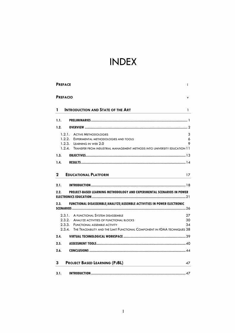
INDEX
PREFACE i
PREFACIO v
1 INTRODUCTION AND STATE OF THE ART 1
1.1. PRELIMINARIES ........................................................................................................... 1
1.2. OVERVIEW .................................................................................................................. 2
1.2.1. ACTIVE METHODOLOGIES 3 1.2.2. EXPERIMENTAL METHODOLOGIES AND TOOLS 6 1.2.3. LEARNING IN WEB 2.0 9 1.2.4. TRANSFER FROM INDUSTRIAL MANAGEMENT METHODS INTO UNIVERSITY EDUCATION 11
1.3. OBJECTIVES............................................................................................................... 13
1.4. RESULTS .................................................................................................................... 14
2 EDUCATIONAL PLATFORM 17
2.1. INTRODUCTION ......................................................................................................... 18
2.2. PROJECT-BASED LEARNING METHODOLOGY AND EXPERIMENTAL SCENARIOS IN POWER ELECTRONICS EDUCATION ........................................................................................................ 21
2.3. FUNCTIONAL DISASSEMBLE/ANALYZE/ASSEMBLE ACTIVITIES IN POWER ELECTRONIC SCENARIOS .............................................................................................................................. 26
2.3.1. A FUNCTIONAL SYSTEM DISASSEMBLE 27 2.3.2. ANALYZE ACTIVITIES OF FUNCTIONAL BLOCKS 30 2.3.3. FUNCTIONAL ASSEMBLE ACTIVITY 34 2.3.4. THE TRACEABILITY AND THE LIMIT FUNCTIONAL COMPONENT IN FDAA TECHNIQUES 38
2.4. VIRTUAL TECHNOLOGICAL WORKSPACE ..................................................................... 39
2.5. ASSESSMENT TOOLS ................................................................................................... 40
2.6. CONCLUSIONS ........................................................................................................... 44
3 PROJECT BASED LEARNING (PJBL) 47
3.1. INTRODUCTION ......................................................................................................... 47
I
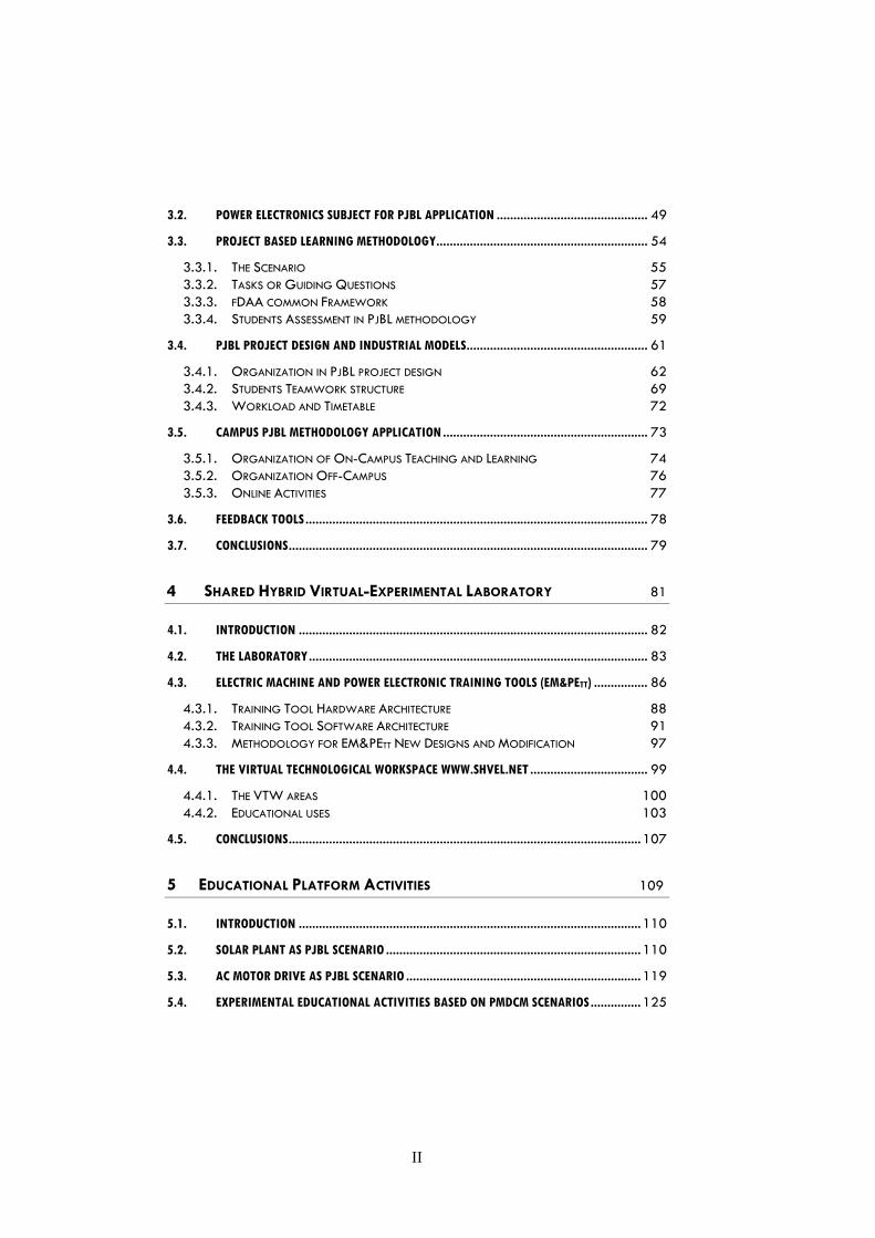
3.2. POWER ELECTRONICS SUBJECT FOR PJBL APPLICATION ............................................. 49
3.3. PROJECT BASED LEARNING METHODOLOGY ............................................................... 54
3.3.1. THE SCENARIO 55 3.3.2. TASKS OR GUIDING QUESTIONS 57 3.3.3. FDAA COMMON FRAMEWORK 58 3.3.4. STUDENTS ASSESSMENT IN PJBL METHODOLOGY 59
3.4. PJBL PROJECT DESIGN AND INDUSTRIAL MODELS ...................................................... 61
3.4.1. ORGANIZATION IN PJBL PROJECT DESIGN 62 3.4.2. STUDENTS TEAMWORK STRUCTURE 69 3.4.3. WORKLOAD AND TIMETABLE 72
3.5. CAMPUS PJBL METHODOLOGY APPLICATION ............................................................. 73
3.5.1. ORGANIZATION OF ON-CAMPUS TEACHING AND LEARNING 74 3.5.2. ORGANIZATION OFF-CAMPUS 76 3.5.3. ONLINE ACTIVITIES 77
3.6. FEEDBACK TOOLS ...................................................................................................... 78
3.7. CONCLUSIONS ........................................................................................................... 79
4 SHARED HYBRID VIRTUAL-EXPERIMENTAL LABORATORY 81 4.1. INTRODUCTION ........................................................................................................ 82
4.2. THE LABORATORY ..................................................................................................... 83
4.3. ELECTRIC MACHINE AND POWER ELECTRONIC TRAINING TOOLS (EM&PETT) ................ 86
4.3.1. TRAINING TOOL HARDWARE ARCHITECTURE 88 4.3.2. TRAINING TOOL SOFTWARE ARCHITECTURE 91 4.3.3. METHODOLOGY FOR EM&PETT NEW DESIGNS AND MODIFICATION 97
4.4. THE VIRTUAL TECHNOLOGICAL WORKSPACE WWW.SHVEL.NET ................................... 99
4.4.1. THE VTW AREAS 100 4.4.2. EDUCATIONAL USES 103
4.5. CONCLUSIONS ......................................................................................................... 107
5 EDUCATIONAL PLATFORM ACTIVITIES 109
5.1. INTRODUCTION ...................................................................................................... 110
5.2. SOLAR PLANT AS PJBL SCENARIO ............................................................................ 110
5.3. AC MOTOR DRIVE AS PJBL SCENARIO ...................................................................... 119
5.4. EXPERIMENTAL EDUCATIONAL ACTIVITIES BASED ON PMDCM SCENARIOS ............... 125
II
5.4.1. DC-MOTOR-GENERATOR TRAINING TOOL WITH SOLAR RECHARGE AND BRAKING ENERGY RECOVERY 126 5.4.2. PMDCM MOTOR-GENERATOR TRAINING TOOL AS PJBL SCENARIO IN CONTROL DIGITAL SYSTEMS SUBJECT 141
5.5. ACIM TRAINING TOOL AS MASTER RESEARCH PROJECTS ...........................................146
5.5.1. STATOR AND ROTOR FLUX ESTIMATION 148 5.5.2. OUTPUT ELECTRONIC CONVERTER: PWM INVERTER 148 5.5.3. EXPERIMENTAL ANALYSIS PERFORMED BY THE MASTER STUDENTS 150
5.6. CONCLUSIONS .........................................................................................................153
6 PROJECT BASED LEARNING IN KINEMATICS AND DYNAMICS OF MACHINES 155
6.1. INTRODUCTION .......................................................................................................155
6.2. THE PROPOSED PROJECT: HOW TO DESIGN A MECHANISM THAT MOVES MATERIAL THROUGH DIFFERENT LEVELS ................................................................................................ 156
6.2.1. CONTEXT OF THE IMPLEMENTATION ...................................................................... 157 6.2.2. GETTING STARTED ................................................................................................. 158 6.2.3. FOLLOW UP DURING THE IMPLEMENTATION ........................................................... 160
6.3. EVALUATION ACTIVITIES .........................................................................................164
6.3.1. RESULTS AND ANALYSIS ......................................................................................... 168
6.4. CONCLUSIONS AND IMPLICATIONS FOR THE FUTURE ................................................176
7 CONCLUSIONS 177
7.1. POWER ELECTRONICS RESULTS .................................................................................177
7.1.1. PJBL RESULTS FOR THE 2014-15 AND THE 2015-16 COURSES 177 7.1.2. EVOLUTION RESULTS 184
7.2. CONCLUSIONS .........................................................................................................185
7.3. FUTURE WORKS .......................................................................................................187
8 APPENDIX A: RESUMEN 189
9 APPENDIX B: CONTRIBUTIONS 197
10 REFERENCES 201
III

Preface
Improvement in research and academic efficiency, dexterity in experimental practice, application in real environments and development of professional competencies for future engineers are a fundamental part of education within the European Higher Education Area (EHEA).
In recent years, different educational strategies have been developed with the goal of improving experimental education through the implementation of innovative solutions. This evolution has been mainly based on computer aided design and simulation and with remote laboratories, among others. In addition, new information and communication techniques using internet and Web 2.0 have allowed access to a wide range of interaction possibilities between students and professors.
Without devaluing the contribution to experimental teaching in technical education with techniques based on computer aided design and simulation, the skills traditionally developed by means of experimentation in the laboratory, learning through project development and industrial equipment design should not be relegated to the background. These activities generally contribute to student motivation by allowing them to put the sometimes seemingly abstract theory into practice, and to develop simulation models based on real systems.
In this thesis, different and novel educational methodologies are analysed, combined and applied, mainly in power electronics and its industrial applications, including an example of their implementation in mechanical design that demonstrates their multidisciplinary character. The thesis also seeks to illustrate the importance of the relationship between academia and industry.
Power Electronics, the same as other subjects within the engineering field, has experienced a series of limitations when developing educational tasks in experimental laboratories. The most important restrictions result from a high student-to-professor ratio, the considerable cost of the laboratory learning equipment and, more specifically, from security issues related to high voltages and currents present in power electronic converters. All this has lead experimental education towards solutions based on simulation software.
The importance of simulation software use as an experimental learning tool is unquestionable in modern education. What has been revealed though is that its exclusive use can present some disadvantages. For example, the lack
i
Preface
of perception of magnitude dimension of the system and the tendency to adopt approaches to the solution of the proposed problem through trial and error techniques, and there not being any real consequences in terms of risk towards people and equipment.
These shortcomings have led to the challenge of creating different proposed physical and virtual scenarios. These scenarios support active learning methodologies based on projects.
Physical scenarios are industrial applications of power electronics and automatic control applied to electrical machines and photovoltaic solar systems. These environments are developed based on a well-defined educational strategy that optimizes the understanding, analysis and dexterity by students in the academic program in which they are enrolled.
Virtual environments have a facilitating and motivating character because, on the one hand, they incorporate selected technological information as complementary material adapted to both the teaching methodology and to the possible scenarios that are programmed in different industrial research fields and, on the other hand, they allow the students to focus their technical curiosity through the remote control of these scenarios.
In engineering education literature there are not many publications about the relationship between industry and academia. This thesis analyzes these relationships in different learning outcomes, for example, those related to multidisciplinary teamwork, including teamwork communication and ethical behavior, economic and environmental concerns in industrial projects, social context of engineering, lifelong learning in an ever changing environment, among others.
The introduction of a novel Project-Based Learning (PjBL) methodology combined with the "functional Disassemble/Analyze/Assemble" (fDAA) practical activities within specific scenarios creates a new educational environment, which becomes possibly one of the most innovative contributions of this thesis. The students’ deeper understanding of the theory required for the development of technological designs, teamwork effectiveness, and the development of relevant professional competencies are other remarkable results of the proposal.
The three main experimental characteristics of the educational environment proposed in this thesis are flexibility, adaptability and feasibility. Flexibility related with its application to different technical levels, depending on the Degree or Master subject. Adaptability related to the software and hardware modifications that facilitate the learning process evolution for teachers and
ii

Preface
students according to industrial and social requirements. And feasibility related to students owning the projects and developing them in a cost effective way.
In summary, the environment created brings together years of traditional educational methodologies with a new vision about the teaching and learning process and with the incorporation of recent technological advances. This environment creates the conditions to allow students to adapt to the increasingly faster evolution of their professional future.
iii

Prefacio
La mejora en el rendimiento académico e investigador, la destreza en las habilidades experimentales y su uso en entornos reales, y las competencias para el desempeño profesional de los futuros ingenieros son una parte fundamental de la formación dentro del espacio europeo de educación superior (EEES).
En los últimos años se han desarrollado diferentes estrategias educativas con el objetivo de mejorar la formación experimental, planteando soluciones innovadoras, basadas fundamentalmente en el diseño asistido por ordenador y la simulación, como eje de dicha evolución, junto con el empleo de laboratorios remotos, entre otros. Por otra parte las nuevas tecnologías de información y comunicación, que emplean internet y la web 2.0, han permitido el acceso a una amplia gama de posibilidades de interacción entre estudiantes y profesores.
Sin restar importancia a la contribución de los recursos relacionados con el diseño asistido por ordenador y la simulación al aprendizaje experimental en las enseñanzas técnicas, es importante no relegar las habilidades que se pueden adquirir mediante la experimentación en el laboratorio, el aprendizaje a través de la realización de proyectos, el rediseño de equipamiento industrial, etc. Estas actividades normalmente contribuyen a la motivación de los estudiantes, dado que les permiten poner en práctica la teoría, muchas veces abstracta, y desarrollar modelos de simulación basados en sistemas reales.
En esta tesis doctoral se han analizado y se han combinado metodologías docentes diferentes y novedosas, fundamentalmente en el área de la electrónica de potencia y sus aplicaciones industriales, incluyendo extrapolaciones de su uso al diseño mecánico para poder comprobar su carácter multidisciplinar. Además se ha buscado la relación que existe entre el mundo académico y el industrial.
La electrónica de potencia, al igual que otras materias dentro del campo de la ingeniería, ha sufrido una serie de limitaciones a la hora de desarrollar las tareas educativas dentro de los laboratorios experimentales. Las restricciones más importantes pueden derivarse del elevado ratio estudiante-profesor, del elevado costo de los equipamientos docentes de laboratorio y, como un problema más específico, de cuestiones de seguridad asociadas con elevados voltajes y corrientes presentes en los convertidores electrónicos de potencia.
v
Prefacio
Todo esto ha conducido a la educación experimental hacia soluciones basadas en el software de simulación.
La utilización del software de simulación como herramienta de aprendizaje experimental es incuestionable dentro de una educación moderna. Por el contrario, frente a esta utilidad demostrada en los últimos años, se puede afirmar también, basándose en la misma experiencia, que su uso exclusivo puede presentar algunos inconvenientes, como por ejemplo: la falta de percepción del orden de magnitud del sistema y la tendencia a adoptar soluciones aproximadas del problema planteado obtenidas mediante técnicas de prueba-error, ya que no existen consecuencias reales en cuanto se refiere a riesgo para las personas y los equipos.
Para responder a estos retos o situaciones mencionadas se han creado unos entornos educativos o escenarios docentes físicos y virtuales que sirven de soporte a las metodologías activas de aprendizaje basadas en proyectos.
Los entornos físicos son aplicaciones industriales de la electrónica de potencia y el control automático, aplicadas a máquinas eléctricas o sistemas solares fotovoltaicos. Estos entornos están desarrollados basándose en una estrategia educativa bien definida, que permite optimizar su comprensión, análisis y mejora de forma eficiente por parte de los estudiantes en la programación académica de las asignaturas donde se integran.
Los entornos virtuales tienen un carácter facilitador y motivador, ya que por una parte incorporaran información técnica como material complementario adaptado tanto a la metodología docente como a los posibles escenarios que se programen en diversos campos de investigación de interés industrial y, por otra parte, permiten al estudiante enfocar su curiosidad tecnológica a través del control remoto de dichos escenarios.
En la literatura sobre enseñanza en la ingeniería no abundan las publicaciones acerca de la relación entre el mundo académico y la industria. Esta tesis analiza esta relación para diferentes resultados de aprendizaje como pueden ser los relativos al trabajo en equipo multidisciplinar, el comportamiento ético en los equipos de trabajo, la comunicación dentro de los equipos, los aspectos económicos y medioambientales en los proyectos industriales, el contexto social en ingeniería, el aprendizaje permanente en entornos volátiles, entre otros.
La introducción de una novedosa metodología de aprendizaje basada en proyectos (PjBL), combinada con la implantación de unas actividades prácticas de desensamblado, análisis y ensamblado funcional (fDAA) y todo ello desarrollado sobre escenarios industriales específicos, crea un nuevo
vi
Prefacio
entorno educativo que se convierte posiblemente en una de las contribuciones más innovadoras de esta tesis. La visión mejorada del estudiante sobre el conocimiento teórico como solución para el diseño tecnológico, la efectividad del trabajo en equipo y, finalmente, el desarrollo de competencias profesionales relevantes son algunos de los resultados más destacables de esta propuesta.
El entorno educativo que se propone en esta tesis doctoral tiene tres características experimentales principales. Es flexible: el entorno se puede aplicar a diferentes niveles académicos en función de que la asignatura sea de grado o de máster. Es adaptable: el entorno admite rediseño de hardware y software que permiten su evolución para adaptarse al sistema de aprendizaje de acuerdo a las necesidades académicas, industriales y sociales del mismo. Y es factible: los alumnos realizan su proyecto bajo el punto de vista de la posibilidad real de su desarrollo tanto a nivel de conocimiento técnico como a nivel de desarrollar prototipos con factibilidad económica.
En resumen, el entorno creado reúne años de experiencia en metodologías educativas tradicionales con una nueva visión del proceso de enseñanza-aprendizaje, incorporando avances tecnológicos. Este entorno crea las condiciones que permiten al estudiante adaptarse a la rápida evolución de su futuro profesional.
vii

Chapter 1- Introduction and State of the Art
1.1. PRELIMINARIES
The roots of engineering education are long, starting over a century ago. In contrast, engineering education research has lacked definition as a research discipline until twenty years ago. In a milestone issue, in a paper by Haghighi (2005) “Quiet no longer: Birth of a new discipline” published in the Journal of Engineering Education, senior scholars in the field argued for a stronger theoretical and empirically driven research agenda. Since then, engineering education has quickly emerged as a research-driven field. The strength of engineering education research and practice is evident in the increase of Ph.D.s in engineering departments at universities and the growth of an international community of engineering education researchers who attend global conferences and increasingly collaborate with each other (Johri & Olds, 2014).
The number of publications in prestigious journals, such as the Journal of Engineering Education, IEEE Transactions on Education, Computers & Education, the International Journal of Engineering Education and the International Journal of Electrical Engineering Education, among others, have increased and have become more important in the international educational community.
Active and cooperative learning is increasing through the evolution of the teaching-learning process in European universities. This has taken place by the creation of the European Higher Education Area (EHEA). An example of the EHEA application is the IKD pedagogical model (Ikasketa Kooperatibo eta Dinamikoa, Cooperative and Active Learning) in the Basque Country University. Based on this model, different educational strategies for improving diverse aspects related with engineering education have been developed in the Faculty of Engineering in Bilbao and are presented in this thesis.
The EHEA model proposes a fundamental change by making the student the center of the educational process. The educational methodology evolves from a system based on teaching to a system based on learning, enhancing and promoting the transfer between theoretical knowledge and its real application, improving technical and teamwork skills, and promoting the acquisition of professional competencies (Johnson & Johnson, 2002; Prince,
2 Chapter 1
2004; Dym et al., 2005; Hsiung, 2012; Chidthachack et al., 2013; Johri & Olds 2014; Rodriguez et al., 2015; Korestsky et al., 2016).
Engineering education with its high practical and technological component is well adapted to develop active learning methods such as the Problem Based Learning (PBL) and Project Based Learning (PjBL) methodologies (Chidthachack et al., 2013; Kumar, Fernando & Panicker, 2013; Jeon, Jarret & Ghim, 2014; Howard et al., 2016). Project Based Learning methodologies facilitate the implementation of the EHEA model proposals, not only focusing on students’ acquisition of specific competencies in each subject, but also on the development of generic competencies such as communication, teamwork, leadership, etc. These competencies are increasingly valued in the professional field (Rodriguez et al., 2015).
In engineering education there is limited time to learn a large body of knowledge. The engineering student upon graduation can immediately begin professional activity and this involves great responsibility. The apparent rigorous and quantitative feature of undergraduate engineering education reduces the spectrum of the population to which it is attractive (King, 2012). These issues have become a challenge for Engineering Degrees in many universities.
1.2. OVERVIEW
The relationship between theoretical knowledge, practical activities and the knowledge transfer to professional development has not been sufficiently documented (Feisel & Rosa, 2005).
In recent years there has been an increase in publications concerning these issues (Underland & Mohan, 2002; Hercog et al., 2007; Dalrymple et al. 2011; Chidthachack et al., 2013; Johnson & Ulseth, 2014; Garousi et al., 2016). The evolution of experimental activities and tools which give support to active teaching and learning methodologies has challenged educators to build adaptable learning environments that will enhance the motivation of the engineering student (Costas-Perez et al., 2008; Maseda et al., 2012; Nikolic et al., 2015; Esquembre, 2015; Zhang et al., 2016).
Computers and simulation software facilitate the enhancement of student motivation (Holbert & Karadi, 2009; Baltzis & Koukias; 2009; Jara et al., 2009; Shih & Hwang, 2011; Potkonjak et al., 2016). The next generation of Web 2.0 technologies reduces the impact of physical boundaries, being information accessible anytime and anywhere (Alexander & Smelser, 2003; Fong 2011).
Introduction and State of the Art 3
Most student learning activities occur through their personal study and classroom lessons. The use of Web 2.0 technologies permits the integration of theoretical concepts with the devices, tools and applications for a specific purpose in a given context (Cagiltay et al., 2009; Gillet et al., 2010; Stefanovic, 2013; Martija et al., 2014; Hoic-Bozic, Dlab & Mornar, 2016;).
The use of experimental and practical learning tools within the laboratory as a basic learning scenario is one of the most important aspects in engineering education (Feisel & Peterson, 2002). These tools can be very useful as observation spaces where students can be introduced into a subject through the real evolution of different parameters and variables. Additionally, student performance can be increased if the laboratory becomes an active site that promotes discussion between peers about different options and where each student can implement their own design (Carlson et al. 1997; Gedra et al., 2004; Dym et al., 2005; Muoka et al., 2015).
The challenge is therefore to build a workplace that adapts the usual materials and teaching resources to modern times with comprehensive and high quality documentation provided on the Internet, and the possibility of communication across the network (Alexander & Smelser 2003; Guerra et al., 2008; Martija et al., 2011; Miller & Bures, 2014; Nickchen & Mertsching, 2016), and to create new work and self-study environments that provide a balanced combination of classroom, home and laboratory activities for the students. In order to improve student learning engagement, and to support better quality learning outcomes, integrated activities are designed to track the learning progress, and facilitate assessment and feedback (Breslow, 2004; Marin-Garcia & Lloret, 2008; Boud & associates, 2010; Anand, Farswan & Fernandes, 2012; Howard et al., 2016).
The acquisition of professional competencies for engineering students reinforces the Academic-Industry relationship and the reciprocal transfer of industrial to educational methodologies. The PjBL methodology, for example, improves the students’ teamwork performance and student participation, reduces freeloading and focuses the vision and goal of the project development (Borrego et al., 2013). In this way educational techniques can evolve towards replicating professional activity and ethical collaboration (Alekseevich et al., 2012; Balakrishnan & Tarlochan, 2015).
1.2.1. ACTIVE METHODOLOGIES
For many years active methodologies in engineering education have been analyzed, firstly designing different educational models (Yaguer et al, 1985;
4 Chapter 1
Barron, 1998; Smith et. al, 2002; Prince, 2004), secondly developing tools and instructional methods (Bidanda & Billo, 1995; Carlson et al., 1997; Mourtos, 1997; Pimmel, 2001, Anand et al., 2012), thirdly reinforcing teamwork strategies (Hwang et al., 2008; Meyers et al., 2010), fourthly developing assessment and feedback strategies (Archer-Kath et al., 1994; Breslow, 2002; Boud D. and Associates, 2010), and finally, focusing on other social and professional aspects (Ditcher, 2001; Balakrishnan & Tarlochan 2015; Litchfield et al., 2016).
Active learning is increasingly more important as a pedagogical approach intended to reinforce student interest, motivation and satisfaction. Also active learning has an impact on lifelong learning, which has been recognized as a vital capacity for engineering students (King, 2012; Stefanovic, 2013; Such, Criado & García, 2015; Michaluk et al., 2016).
Hsiung (2012) reported that cooperative learning provides a natural environment in which to enhance academic and interpersonal skills. Research studies have shown that peers assist each other in learning regardless of the age of the participants, the duration of the study, or the research setting (Haller et al., 2000) and these results are held for many different types of tasks, including verbal, mathematical, and procedural tasks (Rogoff, 1998). A meta-analysis (Johnson & Johnson, 1985) of 378 studies comparing the achievements of people working individually versus those in cooperative groups or in competitive arrangements has shown that more than half of the studies favored cooperation, while less than 10% favored individualistic efforts. These findings cover a broad range of student learning outcomes. In particular, cooperation enhances academic achievement, student attitudes, and student retention.
In European universities, the European Credit Transfer and Accumulation System (ECTS) require engineering students to complete different on and off campus activities. The learning methodologies have to take into account this new task distribution in order to ensure the student’s academic performance. Different studies have shown that active methodologies improve students' academic achievements more than traditional learning (Haller et al., 2000; Dym et al., 2005; Hwang et al., 2008; King, 2012).
The use of projects as a cooperative environment is not new. The theoretical framework for PjBL is in constructivism (Piaget, 1973), social constructivism (Vygotsky, 1978), and constructionism (Papert, 1996). Constructivism explains how students build their own understanding through projects; social constructivism explains the importance to cooperative learning as team member’s work together to solve the stated problem; and
Introduction and State of the Art 5
constructionism justifies the creation of a model, prototype, or illustration as an outcome (Jeon, Jarrett & Ghim, 2014).
Project-based learning (PjBL) is known to be a motivating project-centered teaching method that not only places students at the core of teaching and learning activities but also gives them the ability to transfer their acquired scientific knowledge into industrial practice (Blaabjerg, 2002; Zhang, Hansen & Andersen, 2016).
During recent decades, project based teaching and learning has shown to be an attractive method that can improve engineering education significantly (Blumenfeld et al., 1991; Prince, 2004; Dym, et al., 2005; Froyd, Wankat, & Smith, 2012). In general, project-based learning (PjBL) is a dynamic approach in which students explore real-world problems and challenges. With this type of active and engaged learning, students are inspired to obtain deeper knowledge of the subjects they are studying (Barron et al., 1998; Mills & Treagust, 2003; Dym, Agorino, Eris & Frey, 2005). In particular, applying the PjBL method to courses in the electronics and electrical engineering fields can increase the challenge for students and thereby their motivation level (Blaabjerg, 2002; Yadav, Subedi, & Lundeberg, 2011; Maseda et al., 2014; Zhang, Hansen & Andersen, 2016). Problem oriented and project based learning offers a high number of educational advantages and facilitates teacher control of the learning process (Mills & Treagust, 2003).
However, some researchers have published that active and cooperative methodologies may lead students to spend more time on their studies (Smith, et al., 2005; Marin-Garcia & Lloret, 2008; Hsiung, 2010). The question that emerges is whether the enhanced academic accomplishment of students who study in a cooperative mode is the result of the inherent effectiveness of cooperative learning or is due simply to the students spending a greater amount of time on the task.
The time spent on tasks when implementing active methodologies should be carefully scheduled. Students may spend different amounts of time on their on and off campus activities, as a result of differences in their personalities, levels of motivation, academics conditions, and many other factors. In order to ensure balanced time on tasks and activities, the students have to be requested to attend all classroom and laboratory sessions and to complete their off-campus activities according to a meticulous timetable (Maseda et al., 2015). Questionnaires are recommended to be used as a feedback tool to verify the success of the methodology. Engineering educators have just began to identify the most effective ways to implement concept questions in
6 Chapter 1
class and to understand how these questions influence student thinking and learning and the connections between conceptual understanding and transfer (Korestsky et al., 2016).
Summarizing the results of different studies about the efficacy of active and cooperative learning tasks reveals the student´s improvement in experimental and design skills (Mamaril et al., 2016).
The presented thesis promotes the use of active methodologies based on the application of cooperative learning and on a PjBL industrial model. The management of resources, time, interpersonal relations, multidisciplinary groups, motivation, continuous learning, among others, will be analyzed through the document.
1.2.2. EXPERIMENTAL METHODOLOGIES AND TOOLS
The laboratory plays an important role in teaching engineering skills. “From the earliest days of engineering education, instructional laboratories have been an essential part of undergraduate and graduate programs. Indeed prior to the emphasis on engineering science, it could be said that most engineering instruction took place in the laboratory” (Feisel & Rosa, 2005).
Over the years laboratory methodologies and tools have evolved and been combined looking for efficiency when exposing students to practical situations. These proposed methodologies and combinations have many advantages and some disadvantages which need to be taken into account in the educational research field.
Engineering laboratories often offer limited availability due to hazards associated with their equipment. A first option to resolve this limitation is to show practical demonstrations without student intervention. This is a valid method in which students can observe and take notes. The advantage is that the students can observe the systems operating. The challenge of this approach is to avoid a drop in motivation and self-confidence in the student (Chu, Lu & Sathiakumar, 2008). Other alternatives can be the development of specific low cost equipment with security conditions (Shirsavar, Potter & Ridge, 2006; Muoka et al., 2015).
The use of predefined guides for developing the experiment is one of the most traditional methodologies for experimental practices in engineering laboratories. The students work in groups, following instructions to set up the experiment, take specified readings, and then analyze the results. This approach, however, is also found to be ineffective in generating students'
Introduction and State of the Art 7
enthusiasm and passion for learning, mainly because they are never involved in the design and construction stages of the experiment. By replicating an industrial model that moves away from fixed sequential steps analysis to a model of experimental goals improves student´s motivation for laboratory work (Chu, Lu & Sathiakumar, 2008; Alekseevich et al., 2012; Muoka et al., 2015).
The use of prebuilt circuits is a method where the students can perform some defined tasks, take measurements and deliver the conclusions about the experiment. This again, is a case of the student not being involved in the design and construction of the experiment, a process that does not motivate students. The use of low cost microprocessors (for example, Arduino family) combined with this equipment can significantly improve the students’ engagement (Balog et al., 2005; Choi & Saeedifard, 2012; Martija et al., 2013; Muoka et al., 2015).
Given the importance of simulation software as an educational tool for experimentation, the challenge is a proper balance in its application with the utilization of physical components and instrumentation, so that the interest and perception of the real dimensions of components in the practical experiment is maintained (Shirsavar, Potter & Ridge, 2006; Maseda et al., 2012).
The Web 2.0 application when used in teaching laboratory experiments is an affordable and safe method for operating remote and virtual laboratories. The advantages are evident, being a consequence of the implementation of an intermediate stage between software simulation and the real experiment. With this approach the students can have a hands-on use of physical components and instruments (Jara et al., 2009; Choi & Saeedifard, 2012; Martija et al., 2015).
Different combinations of these experimental methodologies in experiments with real and virtual environments and with the capability for students designs to be introduced into the environment will from a professional viewpoint provide the balance required for improving the performance of experimental education and the development of professional competencies (Maseda et al., 2012; Chidthachack et al., 2013; Johnson & Ulseth, 2014; Martija et al., 2015; Muoka et al., 2015).
The use of microprocessors for developing methodologies based on “learning by doing” accelerates the student learning curve (Hercog et al., 2007; Anand, Farswan & Fernandes, 2012). Hardware/software co-design-based projects can also be based upon these methodologies (Choi & Saeedifard, 2012; Kumar, Fernando & Panicker, 2013).
8 Chapter 1
Experimentation is important for learning and research in the field of power electronics and drives. Substantial investment is required in order to study each of the different topologies, controllers, and functionalities (Blaabjerg, 2002; Maseda et al., 2011; Martija et al., 2013; Zhang, Hansen & Andersen, 2016). Thus, the cost of establishing good laboratories and research centers is high. In dealing with these issues the use of reconfigurable hardware modules, which can be interconnected to achieve different circuit topologies and small power electronics systems, with the accessible software, is a great educational resource (Yelamarthi & Drake 2015). Microprocessors such as Arduino, Freescale and Texas Instruments families allow generalized use in each student project (Maseda et al., 2012 and 2013).
The use of computers for teaching is nowadays generalized; it is used in all manners of varying activities in the classroom, laboratory and home. The same can be stated for the educational use of the Internet (Hoic-Bozic, Dlab & Mornar, 2016). Laboratories and their tools are integrated as experimental education resources, including virtual, remote and traditional laboratories. Virtual laboratories are computer simulations with typically high visualization and interactive capabilities, aimed to help students to perform a given scientific or engineering experiment. Remote laboratories are computer programs that provide a graphical user interface to interact with real hardware performing the experiment, (Esquembre, 2015).
Applied and manipulated abstract concepts and components form a part of the process of engineering education and their study comprises theories, laws and notions that students often find difficult. In order to facilitate comprehension, the use of tools allowing the visualization of technical processes and phenomena becomes a basic requirement (Potkonjak et al., 2016). Visualization on engineering courses is a helpful tool to enhance training quality and efficiency. Different topics and parts of the subjects are easy to present and much easier to comprehend through diagrams, schema, maps and other visual presentations of processes and phenomena. With regard to some tasks, visualization is the most efficient problem solving strategy. These techniques ensure that data is extracted and summarized in a form that is easier to assimilate. Moreover, they provide an additional tool for expression and research (Stefanova, 2014).
In conclusion, experimental laboratory know-how is an important part of engineering education. The contribution of these educational environments is unquestionable and the preceding paragraphs have outlined traditional and innovative solutions to enhance experimental training in practical laboratories. Many of these proposals use the computer and internet as a fundamental part of the new focus of experimental laboratories. But things
Introduction and State of the Art 9
such as “get their hands dirty”, “experience the real world” and “smell the smoke” should be maintained (Feisel & Peterson, 2002; Feisel & Rosa 2005).
The aforementioned topics and their corresponding technologies can open the way to advanced experimental education methodologies and tools in different engineering disciplines.
1.2.3. LEARNING IN WEB 2.0
Following the centuries of steam and plastic, the 21st century is marked as the century of information technologies (Miller & Bures, 2014). Today the majority of industrial engineering methods rely on the availability of highly advanced software products to help meet the challenges facing industrial engineers. At the current rate of information and communication technology development, it is almost unthinkable for a company to maintain a stable market position without using support software tools. This also applies to the field of industrial engineering. The concept of the digital factory today is not only a summary of the software, but also the overall concept of how to approach and work with data (Klemes et al., 2013).
Based on these information technologies, recently there have been a number of new ideas appearing in the literature concerned with the future of education and in particular the teaching of Science, Technology, and Engineering; some of these notions are novel while others are a re-imagining of existing ideas but in a new context (Prince, 2004; Korestsky et al., 2016). The most relevant technological examples for this study are: distance learning, e-learning, virtual laboratories, virtual reality and virtual worlds, avatars, dynamics-based virtual systems, and the overall new concept of immersive education that integrates many of these ideas together (Jara et al., 2009; Esquembre, 2015; Nickchen & Mertsching, 2016).
The Web 2.0 software provides a range of possibilities for new education alternatives (Fong, 2011). In modern industrial engineering education and training, several strategies have been used in order to improve learning outcomes and to provide better education for students and trainers. The importance of this was expressed by Dormido (2002): “Educators must have an open attitude towards new technologies. They should sensibly incorporate new technological development to avoid the risk of teaching the students of today, how to solve the problems of tomorrow, with the tools from yesterday” (Stefanovic, 2013).
10 Chapter 1
Over the years, the nature of laboratories has changed (Feisal & Rosa, 2005). These changes can be defined as changes in the role of laboratory work, as a part of a course, as well as changes in different technologies applied in a laboratory environment. The concept of laboratories for distance learning or e-learning has its place in training and education (Hercog et al., 2007; Cagiltay et al., 2009; Stefanovic, 2013). In this new education and technology era, there are many challenges for engineering education especially enhancing the effectiveness of the teaching and learning process. In this way the structured multimedia can offer meaningful support (Klemes et al., 2013).
Universities across Europe have recently adopted the new Bologna study system and most engineering related departments have already developed new study programs accordingly. Several issues have to be addressed in order to provide high-quality education with improved efficiency and minimal cost (King, 2012). Traditional skills and knowledge should be supplemented by new engineering curricula empowering engineers to manage solving their problems in a sustainable way. The current contribution is based on years of practical teaching and involvement in the formation of the policy for engineering education in Europe (Zhang, Hansen & Andersen, 2016). This policy discusses the application of the Bologna system, the appropriate and wise use of multimedia tools, the innovative introduction of novel communication technologies referred to education, and how it can help achieve the above mentioned goals. The discussion includes the development of methods, tools and multimedia internet-based teaching and learning programs (Klemes et al., 2013).
In engineering education, it is beneficial for students to acquire practical experience of real-world relevance (Yadav, Subedi & Lundeberg, 2011). Although solving engineering problems requires comprehension of the mathematical background, many practice-oriented teaching methods concentrate on the practical engineering part, but neglect the underlying theory. The use of experimental learning scenarios which offer interactive visualizations, web applications and help online can illustrate complex technical facts. The integration of Web 2.0 platforms in classroom teaching, which can be used individually by students, improves the learning process and filling of knowledge gaps (Papert, 1996; Nickchen & Mertsching, 2016).
One of the advantages provided by Web 2.0 is the use of specific sites with highly specialized technical information that can optimize the time students spend looking for project and problem information (Martija et al., 2014). Web 2.0 also provides the capacity for each student and/or group to create their own personal learning environment.
Introduction and State of the Art 11
1.2.4. TRANSFER FROM INDUSTRIAL MANAGEMENT METHODS INTO UNIVERSITY
EDUCATION
The relationship between the industrial world and university is evident, but as mentioned previously, they occasionally develop as two independent environments (Kosogova & Araslanova , 2015; Litchfield, Javenick-Will & Maul, 2016).
Along with the basic relationship being a consequence of students becoming professional in industry, there are three basic levels of Industry-Academia collaboration: the scientific research, the students’ practices, and finally, the professional competencies for improving the educational methods and activities (Karsten-Ulrich & Wolfgang, 2009; Bektas & Tayauova, 2014; Shamshina, 2014; Abdullah et al., 2016; Riel et al., 2016; Upadhayay & Vrat, 2016).
In a modern economy, transferring scientific advances into industrial applications is crucial. In past decades the collaboration between universities and industry, with the transfer of scientific knowledge, has promoted successful technological innovation and economic growth. At the same time, insufficient interaction between universities and industry is one of the main factors for poor commercial and technological performance in high-tech sectors. Increasing university-industry collaboration is a primary policy aim in most developed economies (Banal-Estañola et al., 2015).
University research should be further developed in the future to play an important role in industrial and economic growth. For a successful collaboration, both universities and industry should reinforce communication and overcome cultural divisions that impair their relationship across all categories and undercut their potential (Abdullah et al., 2016). University preserves and mainly contributes with theoretical knowledge and industry with practical knowledge and development requirements. Collaboration complements their respective potentials, promotes new ideas for academic research, finances graduate students grants and laboratory equipment, and enhances the transfer from the research results to industrial advances (Karsten-Ulrich & Wolfgang, 2009; Upadhayay & Vrat, 2016).
Published papers and reports have determined that the competencies engineering students are required to attain can be divided into technical knowledge and professional skills (Borrego, Karlin, McNair & Beddoes, 2013; Litchfield, Javenick-Will & Maul, 2016).
12 Chapter 1
The technical outcomes can be summarized as: the ability to apply a knowledge of mathematics, science, and engineering; the ability to design and conduct experiments, as well as to analyze and interpret data; the ability to design a system, component, or process to meet desired needs; the ability to identify, formulate, and solve engineering problems; the ability to use techniques, skills, and modern engineering tools necessary for engineering practice, among others.
The professional outcomes can be summarized as: the ability to work in multidisciplinary teams; an understanding of professional and ethical responsibility; an ability to communicate effectively; understanding the impact of engineering solutions in a global and social context; recognition of the need for, and ability to engage in, lifelong learning; a knowledge of contemporary issues; the ability to manage a project, including a familiarity with business, market-related, and financial matters; a multidisciplinary systems perspective; an understanding of and appreciation for the diversity of students, faculty, staff, colleagues, and customers; a strong work ethic, among others.
Combining these outcomes offers the following positive results: the effectiveness of an industrial specialists' training increases dramatically, the time required for a graduate to adapt to the professional environment decreases greatly, the graduates ability for creative activity is more intensively developed, and finally, from a research point of view, some of the project results can be unique and could be published in scientific journals (Alekseevich et al., 2012; Xia & Jin, 2012).
The learning methodology proposed in this thesis is devoted to developing the relationship between industry and academia. Efficiency through motivation is a common objective being promoted in both the industrial and university environment. A dynamic organization tends to focus on developing motivation practices such as participation, short explanations on key theoretical issues and quick questions for improving attention, balanced work between individual and team activities, introducing life activities (expert meetings, workshops, competitions, etc.), individual to group explanation and reinforcing positive stimuli.
One basic reality which should be taken into account is that teamwork is the predominant mode of engineering professional practice (Borrego, Karlin, McNair & Beddoes, 2013). Industrial management methods and PjBL methodologies have been implemented into the laboratory to improve the performance of educational activities (Martija et al., 2013; Chidthachack et al., 2013; Johnson & Ulseth, 2014).
Introduction and State of the Art 13
Finally, indicators and measurement tools for obtaining feedback and the implementation of improvement plans ensure a constructive evolution. The replication of an industrial project methodology defining the target quality, cost and plan would be the starting point. Short and long term objectives will permit schedules to be adapted to educational courses (Alekseevich et al., 2012).
1.3. OBJECTIVES
Based on the aforementioned issues, the objectives developed in this thesis can be summarized as follows:
o Improving academic performance in engineering education o Improving the understanding of theoretical knowledge o Improving experimental skills o Improving study motivation in engineering areas o Improving teamwork and ethical behavior in engineering o Improving the transfer model between academia and industry o Facilitating research in industrial environments o Introducing environmental awareness through efficient power
electronic systems and renewable energies
The goal is to make the student feel more involved in experimental work making it more technologically attractive and closer to the social and industrial reality.
The consequence of achieving this is twofold. Firstly, improved academic performance and secondly, the capacity to attract the best students to emerging engineering areas such as electric propulsion systems development and the generation of clean energy.
A combination of different educational strategies and technological environments are proposed to meet the stated objectives, based on a developing industrial-educational hybrid philosophy.
The main idea is improving the development of educational strategies with Project-Based Learning (PjBL) methodology and the implementation of educational activities such as "functional Disassemble / Analyze / Assemble" (fDAA) which is based on the reproduction of industrial procedures and philosophies. The activities assigned to students and student groups are founded on customized real environments and scenarios that have been created for the purpose of analyzing the results of the applied methodologies.
14 Chapter 1
The scenarios proposed in this thesis have some characteristics that will facilitate an efficient application in PjBL methodologies: direct access by the student to the included resources, a design that will be similar to industrial equivalents, simple remote accessibility, and finally, the possibility of being redesigned, modified and improved by the students.
The proposed scenario includes a virtual environment technology in a web platform, www.shvel.net. This environment will provide technical and motivational support for the student, as it will offer a range of specialized resources, related to real scenarios, giving an overall view of the relationship between the academic and professional reality.
Finally some tools are developed for assessing the impact of the proposed teaching methods and of the environments used in the application.
The educational importance of this thesis is justified by the improvement achieved with the implementation of Project Based Learning methodologies. These methodologies provide the capability to focus on theoretical developments, mathematical calculations, simulation models and experimental practices, in a specific and methodologically adapted environment. This will ensure that the academic objectives of improving performance and attracting students to technological areas can be achieved.
Finally, the systematic collection of evidence corroborating the results obtained in the various aspects of the teaching-learning process will be used to improve the technological platform by focusing on its design to meet global challenges.
1.4. RESULTS
The results obtained from 2008 to 2016, have been confirmed by external recognition with publications in international journals and conferences, and they have been referenced in the Chapters of the thesis presented.
The content of Chapters 2 and 3 is based on the article Maseda F.J, Martija I. and Martija I. (2012) IEEE Transactions On Education JCR journal, the article Martija I., Maseda F.J, and Martija I. (2013) submitted to IEEE Global Engineering Education (EDUCON) conference, the article Maseda F.J., Martija I. and Martija I. (2014) submitted to Frontiers in Education (FIE) conference and the article Maseda F.J., Martija I., Martija I. and Garrido A.J. (2015) submitted to International Conference of Education, Research and Innovation (iCERi) conference.

Introduction and State of the Art 15
The content of Chapter 4 is based on the article Maseda F.J, Martija I. and Martija I. (2013) International Journal Engineering Education JCR journal, the article Maseda F.J., Martija I., Garrido A.J., Garrido I., Barambones O. and Martija I. (2008) submitted to Intelligent Systems and Control (ISC) conference, the article Maseda F.J, Martija I. and Martija I. (2011)submitted to Research in Engineering Education Symposium (REES), the article Martija I., Maseda F.J, and Martija I. (2011) submitted to International Conference Of Education, Research And Innovation (iCERI) conference, the article Martija I., Maseda F.J, and Martija I. (2014) submitted to Frontiers in Education (FIE) conference.
The content of Chapter 5 is based on the article Maseda F.J, Martija I. and Martija I. (2013) International Journal of Electrical Engineering Education JCR journal.
The content of Chapter 6 is based on the article Martija I., Maseda F.J, Alkorta P. and Garrido I. (2015) submitted to International Conference of Education, Research and Innovation (iCERI) conference.

Chapter 2 - Educational Platform
A new educational platform based on active teaching and learning activities is presented in this thesis. The proposal combines: Project-Based Learning (PjBL) methodology for changing the learning dynamic from teacher to student, functional Disassemble/Analyze/Assemble (fDAA) activities for enhancing abstract theory understanding, specific industrial scenarios for motivating and connecting the practical use of theoretical knowledge in real applications, and finally, a virtual technological workspace for expanding the learning and teaching activities out of the campus constraint. The objectives are to enhance and to promote the transfer between theoretical knowledge and its real application, to improve technical and teamwork skills, to acquire professional competencies, to work with large student groups where it is difficult to guarantee the level of theory understanding, and finally, to improve the use of educational tools such as engineering simulation software, instrumentation equipment and the use of low cost microprocessors for industrial and individual applications.
The educational platform proposed in this thesis started in the 2008/2009 course for improving the teaching and learning process in the Power Electronics subject and its industrial applications (Maseda et al., 2008). In the 2014/2015 course it was extended to the Digital Control Systems subject and in 2015/2016 course to the Model and Control of Electrical Machines in the Master in Control Engineering, Automation and Robotics. And because of it´s multidisciplinary characteristics it has been introduced into the Kinematics and Dynamics of Machines subject and in the Degree in Mechanical Engineering both of these for the 2014/2015 course (Martija et al, 2015).
The main reasons for selecting the Power Electronics subject for study and research were related to, enhancing understanding of complex theory, the use of sophisticated and expensive experimental equipment, and working with large numbers of students. Other important considerations are, the industrial and social benefits (environmental issues concerning the use of renewable energy and efficient industrial systems), and its close relationship with other subjects, such as, Automatic Control, Electrical Machines, Analogical and Digital Techniques. Also, the flexibility of the platform makes it easy to adapt and implement in other subjects of the Industrial Electronics and Automatics Degree. Finally the decrease in student enrollments in this degree during recent years has also influenced the decision.
18 Chapter 2
2.1. INTRODUCTION
The interest in power electronic systems has increased significantly in modern industrial civilizations as electrical energy transformation through electronic converters has become ever more wide spread. The social and economic development of a country can be measured through its level of electrical energy consumption. The majority of electrical energy being processed through power electronic converters (Bose, 1993; Underland & Mohan, 2002; Blaabjerg, 2002; Max et al., 2012; Zhang et al., 2016).
The traditional applications for power electronics industrial use has been for efficient electrical energy conversion and electric machine power drives (Shirsavar et al., 2006; Chu, Lu & Sathiakumar, 2008; Ndtoungou et al., 2011).
Renewable energy generation has an ever greater responsibility in meeting current and future national and international environmental commitments. The pollution-free and safe electric power generation such as solar, wind, and marine energy systems are considered unlimited, but they are highly dependent on power electronics systems (Kolhe et al., 2000; Femia et al.,2005; Solangi et al., 2011; Maseda et al., 2013; Muoka et al., 2015).
New electrical vehicles such as cars, motorbikes, bicycles, drones, among others, have increased the interest and importance of power electronics.
In this way, it will not be possible to obtain the required progress in the aforementioned fields of application if there is no strong engagement with a solid and active education in the Power Electronics field (Carlson et al., 1997; Feisel & Peterson, 2002; Feisel & Rosa, 2005; Hosseinzadeh & Hesamzadeh, 2009; Campos-Delgado & Espinoza-Trejo, 2010; Maseda et al., 2012).
An important objective is to increase the interest in new power electronic development and research areas to attract the best students. The implementation of active teaching and learning methodologies and the performing of practical work increase the attractiveness of these disciplines (Johnson & Johnson, 1987; Johnson et al., 1991; Johnson & Johnson, 2002; Cerdá Boluda et al., 2006; Hercog et al., 2007; De la Hoz et al., 2009; Vanfretti L. & Milano F. 2012; Maseda et al., 2014; Barata et al., 2015).
Based on the above mentioned conditions, an educational platform which combines different methodologies, tools and behavior models is proposed. The first main objective of the platform is to improve the time needed for the understanding and application of theoretical knowledge through its practical
Educational Platform 19
application. The second objective is the acquisition of the technical and social competencies required for engineering professional development. The third objective is to improve the students’ opinion about the possibilities of industrial applications of power electronics as a future research area (Maseda et al., 2013; Martija et al., 2015). And finally, the last objective, but no less important, is to work on behavioral models, such as, increased group performance, develop good workplace practice and conduct, and to discourage non-participation or loafing (Borrego et al., 2013).
The platform components, which are further detailed in the subsequent chapters of this thesis, can be structured as:
o Project-Based Learning (PjBL) methodology o Shared Hybrid Virtual-Experimental Laboratory (SHVEL) o Educational Platform activities o Multidisciplinary uses
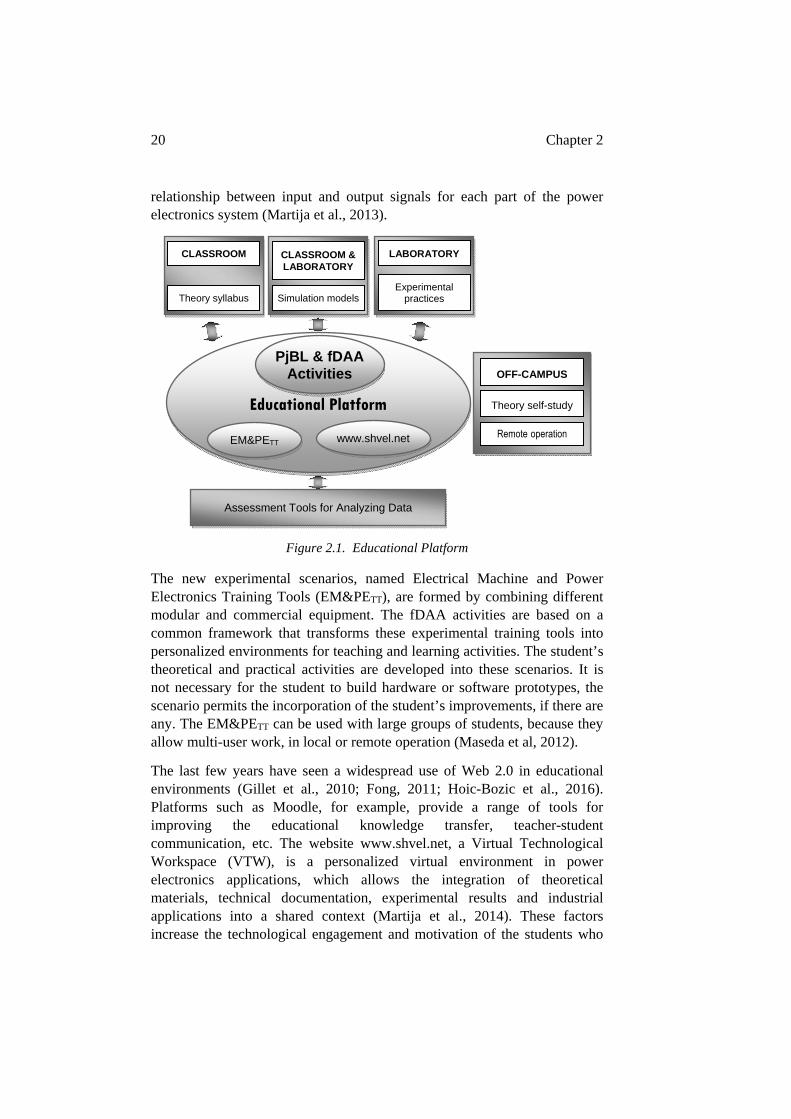
Figure 2.1 shows the global picture of the proposed platform and its interaction with the three basic learning environments for students: the classroom, the hands-on laboratory and the off-campus activities. The platform has different tools for analyzing the results of its use and student feedback questionnaires. These are designed for the continuous improvement of the platform.
The Project based learning (PjBL) methodology provides students with the opportunity to acquire knowledge based skills and to apply them into real industrial designs. In the power electronics field, PjBL helps to reinforce understanding the concepts of electrical energy and its power electronic conversion, give a motivating context for theoretical and experimental practices, and finally, refocusing the learning dynamic from teacher to student (Blaabjerg, 2002; Jeon et al., 2014; Maseda et al., 2014; Zhang et al., 2016).
The concept of “Disassemble/Analyze/Assemble (DAA) activities” was introduced by Ogot and Kremer as a result of the application of reverse engineering and product dissection techniques (Ogot & Kremer, 2006). Their main objectives when applied to educational activities were to increase motivation, promote knowledge transfer and the ability of students to apply and adapt their knowledge to developing novel solutions (Dalrymple, Sears, & Evangelou, 2011). The implementation of fDAA activity in power electronic converters as compared to mechanical applications has been based on the fact that the physical shape of the mechanism may have no relationship with its function. The term “functional” is used based on the
20 Chapter 2
relationship between input and output signals for each part of the power electronics system (Martija et al., 2013).
Figure 2.1. Educational Platform
The new experimental scenarios, named Electrical Machine and Power Electronics Training Tools (EM&PETT), are formed by combining different modular and commercial equipment. The fDAA activities are based on a common framework that transforms these experimental training tools into personalized environments for teaching and learning activities. The student’s theoretical and practical activities are developed into these scenarios. It is not necessary for the student to build hardware or software prototypes, the scenario permits the incorporation of the student’s improvements, if there are any. The EM&PETT can be used with large groups of students, because they allow multi-user work, in local or remote operation (Maseda et al, 2012).
The last few years have seen a widespread use of Web 2.0 in educational environments (Gillet et al., 2010; Fong, 2011; Hoic-Bozic et al., 2016). Platforms such as Moodle, for example, provide a range of tools for improving the educational knowledge transfer, teacher-student communication, etc. The website www.shvel.net, a Virtual Technological Workspace (VTW), is a personalized virtual environment in power electronics applications, which allows the integration of theoretical materials, technical documentation, experimental results and industrial applications into a shared context (Martija et al., 2014). These factors increase the technological engagement and motivation of the students who
Educational Platform
Theory syllabus
CLASSROOM
Experimental practices
LABORATORY
Simulation models
CLASSROOM & LABORATORY
PjBL & fDAA Activities
www.shvel.netEM&PETT
Assessment Tools for Analyzing Data
OFF-CAMPUS
Theory self-study
Remote operation
Educational Platform 21
are immersed in a specialized and optimized environment. The VTW helps, not only in off-campus activities, but even improves the teaching and learning process in the classroom and laboratory.
The following paragraphs give an initial view of platform tools and uses. The different scenario architectures, the fDAA activities, and the www.shvel.net web site will be presented. Finally, the platform assessment tools, their application results and the final conclusions will close the chapter.
2.2. PROJECT-BASED LEARNING METHODOLOGY AND EXPERIMENTAL
SCENARIOS IN POWER ELECTRONICS EDUCATION
The educational technique proposed in this thesis has been based on years of experience in traditional methodologies, theoretical studies, simulation work and practical experiments, contributing to a novel combination of methodology, tools and activities for improving the educational environment and attaining the proposed educational objectives. There will be presented an active and cooperative educational methodology for improving the teaching and learning transfer with theoretical knowledge “just in time”, a common framework for understanding the power converters in an efficient way, and personalized technical environments for motivating applications in the electrical energy transformations fields.
This work proposes a Project based learning (PjBL) methodology which has been implemented in recent years in Power Electronics subject based on experimental scenarios. These scenarios, as training tools, have specific characteristics for different educational activities (Maseda et al., 2014).
The proposed scenarios can be developed in different architectures: commercial, modular and prototype equipment. They offer different possibilities of being physically disassembled from hardware and software modular blocks into discrete components and pieces of software (Martija et al., 2013). These activities offer multiple educational possibilities, related to the fDAA activity level (Shirsavar, 2004; Balog et al., 2005; Dalrymple et al., 2011; Anand et al., 2012; Choi & Saeedifard, 2012; Muoka et al., 2015).
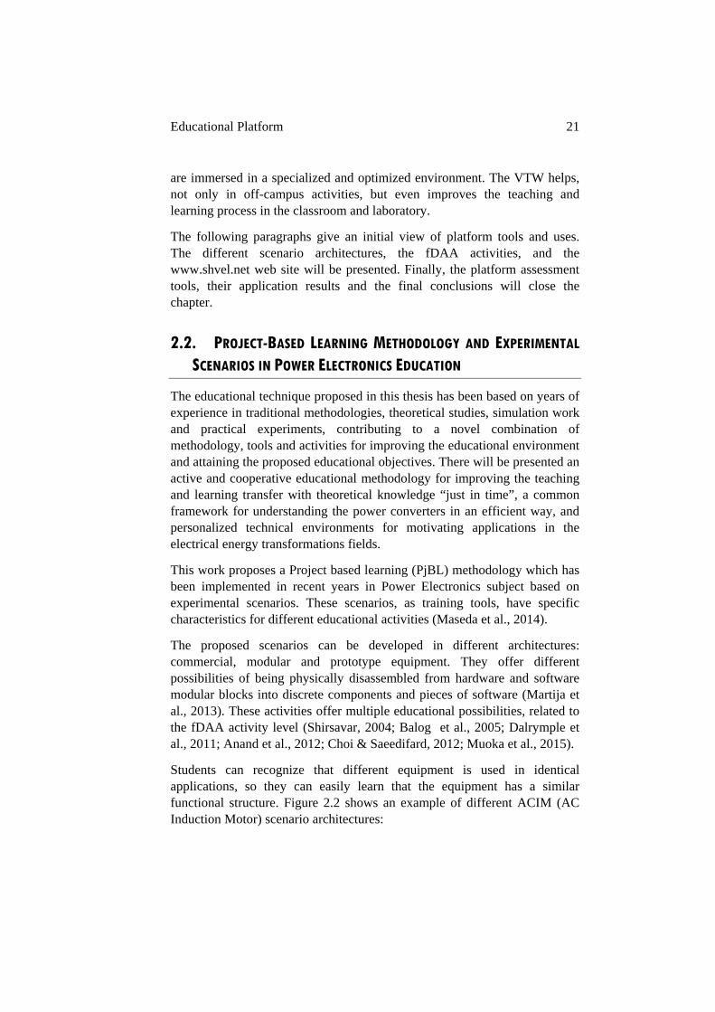
Students can recognize that different equipment is used in identical applications, so they can easily learn that the equipment has a similar functional structure. Figure 2.2 shows an example of different ACIM (AC Induction Motor) scenario architectures:
22 Chapter 2
o Commercial equipment (top-left): students can observe the power components and the main integrated circuits. In this case the connection between them is difficult to be analyzed, and even more so the relationship between hardware and software.
o Modular equipment (top-right): students have access to the hardware and software components, so a parallelism with the commercial equipment components, hardware and software can be established. It allows working with real voltage and current conditions in a secure manner.
o Prototype equipment (bottom-left): students enrolled in the power electronics subject will be able to analyze the hardware and software that other students have built in previous years.
o Commercial power block (bottom-right): the students will be able to analyze it with any controller, because the equipment has the power converters and instrumentation components but it does not have a defined microprocessor controlling it.
Figure 2.2. Different ACIM scenario architectures for PjBL application
To activate the linking of theoretical and experimental knowledge, the PjBL starts with an “encouraging question” and a set of tasks so that the student
Educational Platform 23
groups will develop a solution for a real design situation, (Blumenfeld et al., 1991; Chu et al., 2008; Kumar et al., 2013; Rodríguez et al., 2015). The above ACIM scenario has been used in the 2015/16 course based on an “encouraging question” as simple as: “How do you develop an induction motor drive?”
In previous years different scenarios based on solar and electric machine applications have been used, with a very different physical configuration and level of power. The underlying idea is the identical use of the proposed educational methodology, the same theoretical knowledge requirements and the importance of teamwork in these different scenarios (Jeon et al., 2014; Michaluk et al., 2016).
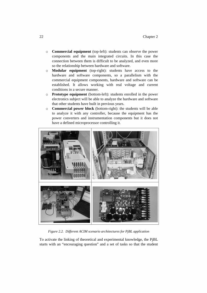
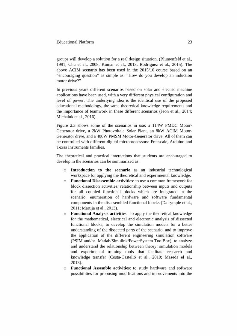
Figure 2.3 shows some of the scenarios in use: a 114W PMDC Motor-Generator drive, a 2kW Photovoltaic Solar Plant, an 8kW ACIM Motor-Generator drive, and a 400W PMSM Motor-Generator drive. All of them can be controlled with different digital microprocessors: Freescale, Arduino and Texas Instruments families.
The theoretical and practical interactions that students are encouraged to develop in the scenarios can be summarized as:
o Introduction to the scenario as an industrial technological workspace for applying the theoretical and experimental knowledge.
o Functional Disassemble activities: to use a common framework for block dissection activities; relationship between inputs and outputs for all coupled functional blocks which are integrated in the scenario; enumeration of hardware and software fundamental components in the disassembled functional blocks (Dalrymple et al., 2011; Martija et al., 2013).
o Functional Analysis activities: to apply the theoretical knowledge for the mathematical, electrical and electronic analysis of dissected functional blocks; to develop the simulation models for a better understanding of the dissected parts of the scenario, and to improve the application of the different engineering simulation software (PSIM and/or Matlab/Simulink/PowerSystem ToolBox); to analyze and understand the relationship between theory, simulation models and experimental training tools that facilitate research and knowledge transfer (Costa-Castelló et al., 2010; Maseda el al., 2013).
o Functional Assemble activities: to study hardware and software possibilities for proposing modifications and improvements into the
24 Chapter 2
scenarios; to simulate these possible changes and, if possible, to introduce the real solution into the scenario (Maseda et al., 2012).
PMDCM Motor-Generator Scenario
Photovoltaic Solar System Scenario
ACIM Motor-Generator Scenario
PMSM Motor-Generator Scenario
Figure 2.3. Different experimental scenarios for PjBL application
Educational Platform 25
o Free use of the experimental scenario for physical running and monitoring (Hercog et al., 2007; Guerra Torres et al., 2008; Costas-Perez et al., 2008).
o Conclusion and extension for other industrial applications
The main novel initiative from the student point of view is using these training tools as motivational environments, for practical application of theoretical knowledge and real mathematical calculus designs (Leva & Donida, 2008). The students are encouraged to perform different modifications in the scenarios for promoting their creativity and for extending the scenario focus with their proposals. Even though these modifications may not be feasible for commercial equipment, they are valuable for students’ understanding of theory.
As previously mentioned, the PjBL methodology starts with an encouraging question. This question is intended to raise interest in the methodology and be directly related to the proposed scenario. Examples of these simple questions, in the 2013/14 course were: “How do you develop a PMDC Motor-Generator drive?” Figure 2.3 (top-left). In the 2014/15 course the question was: “How do you develop a grid for supplying the Power Electronics laboratory based on a solar plant?”, Figure 2.3 (right). In the 2015/16 course it was: “How do you develop an induction motor drive”, Figure 2.3 (center-left). And finally, in the 2016/17 course it has been: “How do you develop a PMSM drive with or without PFC grid rectifier”, Figure 2.3 (bottom-left).
The central idea of the possible encouraging questions for activating students is to create a challenge. The question leads the student to implement, at least, two or three basic power electronic converters into the same power electronic industrial application. The students are thus required to apply their theoretical and experimental knowledge into the proposed scenario. In this way, students or student teams are required to develop three general analysis and design tasks:
o The analysis and design possibilities of power converters and drivers for their command: converter architectures, electronic switch drivers, switching frequencies, and isolation techniques.
o The analysis and design possibilities of instrumentation and converter security conditions: sensors and different signals measurements combined with analogical and digital processing.
o Analysis and design possibilities of digital control: available digital microprocessors, their integrated peripherals, and based on their
26 Chapter 2
technical characteristics the possibilities of a basic operation of the power electronic converter.
One of the basic conditions of the learning objective is that the tasks will be developed by the student group with each student sharing the workload. In addition, the learning objectives have to be completed to a predefined timeline (Halleret al., 2000; Marin-Garcia & Lloret, 2008). The proposed PjBL methodology, which will be further developed in Chapter 3, intends to accomplish both goals with large groups of students (Maseda et al., 2015).
2.3. FUNCTIONAL DISASSEMBLE/ANALYZE/ASSEMBLE ACTIVITIES IN
POWER ELECTRONIC SCENARIOS
As previously mentioned, the functional Disassemble/Analyze/Assemble (fDAA) activities are an educational methodology for improving the practical application of the theory of power electronic converters. The method allows students to better understand one of the most abstract processes of electronic engineering: the electronic transformation of electrical energy and their electromagnetic effects.
Some of the power electronic systems used as scenarios in experimental technological workspaces for fDAA activities have been shown in Figure 2.3. All of them have different power electronic converters which transmit electrical energy following different transformations to the active loads (Bose, 2001). These educational structures are the Electrical Machine and Power Electronics Training Tools (EM&PETT) or SHVEL units which allow integrating students’ hardware and software modifications.
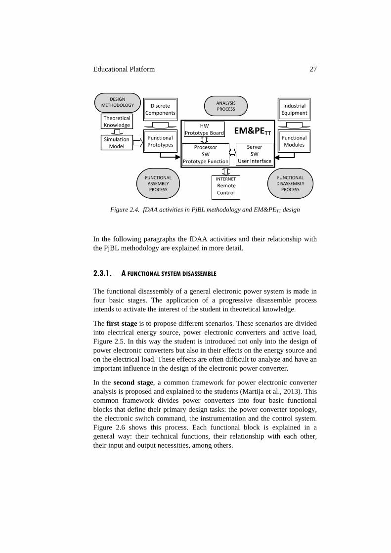
Fig 2.4 shows how the EM&PETT can be designed from discrete components to functional prototypes or from industrial equipment to discrete functional modules. Whether the EM&PETT is designed, from one direction or the other, it has the same common functional blocks and educational objectives (Maseda el al., 2012). The philosophy can be related to industrial models where global projects are divided into different modules. These modules are sized so that management feasibility is achievable and they are then again merged into the global project.
Educational Platform 27
Figure 2.4. fDAA activities in PjBL methodology and EM&PETT design
In the following paragraphs the fDAA activities and their relationship with the PjBL methodology are explained in more detail.
2.3.1. A FUNCTIONAL SYSTEM DISASSEMBLE
The functional disassembly of a general electronic power system is made in four basic stages. The application of a progressive disassemble process intends to activate the interest of the student in theoretical knowledge.
The first stage is to propose different scenarios. These scenarios are divided into electrical energy source, power electronic converters and active load, Figure 2.5. In this way the student is introduced not only into the design of power electronic converters but also in their effects on the energy source and on the electrical load. These effects are often difficult to analyze and have an important influence in the design of the electronic power converter.
In the second stage, a common framework for power electronic converter analysis is proposed and explained to the students (Martija et al., 2013). This common framework divides power converters into four basic functional blocks that define their primary design tasks: the power converter topology, the electronic switch command, the instrumentation and the control system. Figure 2.6 shows this process. Each functional block is explained in a general way: their technical functions, their relationship with each other, their input and output necessities, among others.
HW Prototype Board
ProcessorSW
Prototype Function
ServerSW
User Interface
EM&PETT
INTERNET
Remote Control
Theoretical Knowledge
Simulation Model
Discrete Components
Functional Prototypes
Industrial Equipment
Functional Modules
FUNCTIONAL ASSEMBLY PROCESS
FUNCTIONAL DISASSEMBLY PROCESS
ANALYSIS PROCESS
DESIGN METHODOLOGY
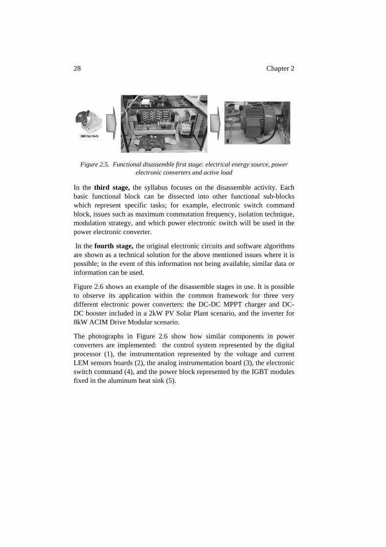
28 Chapter 2
Figure 2.5. Functional disassemble first stage: electrical energy source, power electronic converters and active load
In the third stage, the syllabus focuses on the disassemble activity. Each basic functional block can be dissected into other functional sub-blocks which represent specific tasks; for example, electronic switch command block, issues such as maximum commutation frequency, isolation technique, modulation strategy, and which power electronic switch will be used in the power electronic converter.
In the fourth stage, the original electronic circuits and software algorithms are shown as a technical solution for the above mentioned issues where it is possible; in the event of this information not being available, similar data or information can be used.
Figure 2.6 shows an example of the disassemble stages in use. It is possible to observe its application within the common framework for three very different electronic power converters: the DC-DC MPPT charger and DC-DC booster included in a 2kW PV Solar Plant scenario, and the inverter for 8kW ACIM Drive Modular scenario.
The photographs in Figure 2.6 show how similar components in power converters are implemented: the control system represented by the digital processor (1), the instrumentation represented by the voltage and current LEM sensors boards (2), the analog instrumentation board (3), the electronic switch command (4), and the power block represented by the IGBT modules fixed in the aluminum heat sink (5).
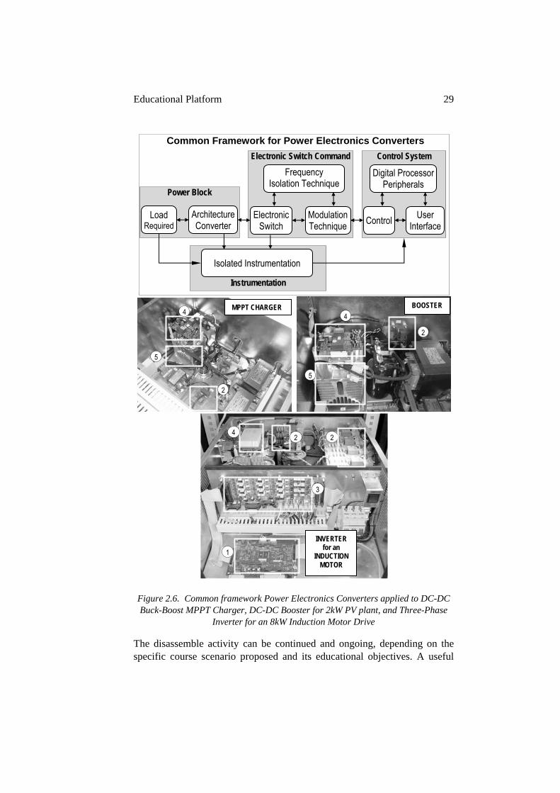
Educational Platform 29
Figure 2.6. Common framework Power Electronics Converters applied to DC-DC Buck-Boost MPPT Charger, DC-DC Booster for 2kW PV plant, and Three-Phase
Inverter for an 8kW Induction Motor Drive
The disassemble activity can be continued and ongoing, depending on the specific course scenario proposed and its educational objectives. A useful
Common Framework for Power Electronics Converters
Instrumentation
Isolated Instrumentation
Power Block
Load Required
Architecture Converter
Control System
ControlUser
Interface
Digital Processor Peripherals
Electronic Switch Command Frequency
Isolation Technique
Electronic Switch
Modulation Technique
2
4
5
BOOSTER
2
4
5
MPPT CHARGER
1
2 2
3
4
INVERTER for an
INDUCTION MOTOR
30 Chapter 2
possibility is to continue until discrete hardware components or simple software functions. Two good examples of this activity are: the relationship between the control algorithm inputs and the hardware needed for their signal feedback, and between the control algorithm output and the hardware, for commanding the electronic power switches. The open access to the scenarios and hardware resources is shown in Figure 2.6.
A controversial issue when using power electronics equipment in education is that related to the hazards involved when managing the internal hardware under medium and high voltages (Shirsavar, Potter & Ridge, 2006). The solution to this problem is that most of the signals are available in low voltage level through the analogical instrumentation boards for local and remote connections, for example in ACIM Drive Modular Scenario (3).
Also in most of the scenarios the students can manipulate their components and hardware blocks as independent modules of the power converters. This capability makes it easier to comprehend the functional disassembled procedure in a secure manner.
2.3.2. ANALYZE ACTIVITIES OF FUNCTIONAL BLOCKS
The analysis procedure of the scenario and its disassemble functional blocks aims to reach two main objectives: the first objective, to apply the theoretical knowledge for understanding the power electronic systems as a general approach, and in particular to understand the four basic power electronic conversions and their properties; and the second objective, to develop technological skills by using the proposed scenario, become actively engaged instead of being passive, think about and consider possible changes and improvements of the experiments technical characteristics. This activity can be developed with the basic theory included in the subject and with other theoretical knowledge attained by the students themselves. The students assuming responsibility and becoming proactive in their own education (Carlson et al., 1997; Dym et al., 2005; De la Hoz, Casas & De Blas del Hoyo, 2009).
The analyze activity assists in understanding the relationship between the theory and its practical application for a better comprehension of abstract theoretical topics, it allows students to identify and compare simulation models with real components implemented in the equipment, and finally, promotes the creativity required to develop new designs. Figure 2.7 shows the simulation model for the MPPT Charger and the simulation model for 2 kW PV panels. It also shows “pills” of the theory related to PV panel
Educational Platform 31
simulation (Villalba et al., 2009) and DC-DC Buck-Boot converter design (Hart, 2001). Finally, a simulation is shown of the power transfer from PV panels to battery bank depending on the solar conditions.
The real hardware components of the DC-DC Buck-Boost power electronic converter have been shown in Figure 2.6 (top, left photograph).
The analyze activity can lead to a range of multiple educational procedures when working from big hardware modules and complex software functions to discrete electronic components in the hardware blocks and the small pieces of software required for simple programming tasks (Shirsavar, 2004). The analysis of each module and the definition of the level of the chosen detail for this activity will depend on different factors: the subject and course in which this analysis is to be applied; the theoretical or practical objective of the analysis and the possibility of redesigning any of these modules and reassembling them in their original position.
The most important issue in the analyze activity is to look for an understanding of the theory and its relationship with the functionality of the block and its possibilities for improvement. These improvements may be implemented or not, but students should be encouraged to do so. Figure 2.7 shows the functional scheme for real data collection, through to the simulation model built according to these physical components, and to results obtained that will be compared with real measurements. This activity promotes the transfer from theoretical knowledge to innovative practical solutions (Agrawal & Henderson, (2002; Alekseevich et al., 2012; Chidthachack et al., 2013).
The option of working in remote mode expands the analyze activity from the classroom and out of the university campus (Hercog et al., 2007; Jagadeesh & Sudhaker, 2009; Martija et al., 2014). Figure 2.8 shows an example of the remote operation screen for the solar plant. The left-side figure shows the control page and the left-right figure shows the recorder page for visualizing and analyzing the power system status. The use of cameras can help students to operate the system: one camera points to the photovoltaic panels to monitor their level of sun, possible shadows, etc. At the same time, it is possible to observe the system data in real time, and compare it with the simulation results.
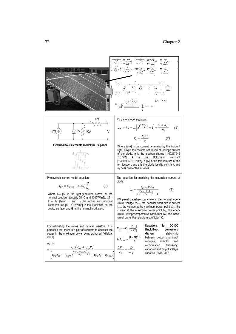
32 Chapter 2
Electrical four elements model for PV panel
PV panel model equation:
1 1
2
Where Ipv[A] is the current generated by the incident light, I0[A] is the reverse saturation or leakage current of the diode, q is the electron charge [1.60217646 ·10−19C], k is the Boltzmann constant [1.3806503·10−23J/K], T [K] is the temperature of the p-n junction, and a is the diode ideality constant, and Ns cells connected in series.
Photovoltaic current model equation:
, ∆ 3
Where Ipv,n [A] is the light-generated current at the nominal condition (usually 25 C and 1000W/m2), ∆T = T – Tn (being T and Tn the actual and nominal Temperatures [K]), G [W/m2] is the irradiation on the device surface, and Gn is the nominal irradiation.
The equation for modeling the saturation current of diode:
∆, ∆
1 5
PV panel datasheet parameters: the nominal open-circuit voltage Voc,n, the nominal short-circuit current Isc,n, the voltage at the maximum power point Vmp, the current at the maximum power point Imp, the open-circuit voltage/temperature coefficient KV, the short-circuit current/temperature coefficient KI.
For estimating the series and parallel resistors, it is proposed that there is a pair of resistors to equalize the power in the maximum power point proposed [Villalba, 2009]:
,
D
DVV SO 1
2)1()(
2
minRD
Lf
RCf
D
V
V
O
O
Equations for DC-DC Buck-Boot converters design: relationship between output and input voltages; inductor and commutation frequency; capacitor and output voltage variation [Bose, 2001].
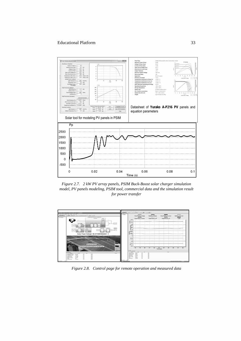
Educational Platform 33
Solar tool for modeling PV panels in PSIM
Datasheet of Yurako A-P216 PV panels and equation parameters
Figure 2.7. 2 kW PV array panels, PSIM Buck-Boost solar charger simulation model, PV panels modeling, PSIM tool, commercial data and the simulation result
for power transfer
Figure 2.8. Control page for remote operation and measured data
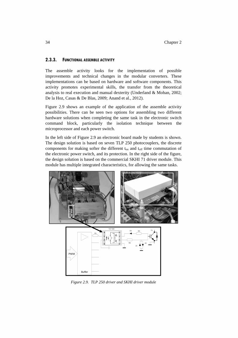
34 Chapter 2
2.3.3. FUNCTIONAL ASSEMBLE ACTIVITY
The assemble activity looks for the implementation of possible improvements and technical changes in the modular converters. These implementations can be based on hardware and software components. This activity promotes experimental skills, the transfer from the theoretical analysis to real execution and manual dexterity (Underland & Mohan, 2002; De la Hoz, Casas & De Blas, 2009; Anand et al., 2012).
Figure 2.9 shows an example of the application of the assemble activity possibilities. There can be seen two options for assembling two different hardware solutions when completing the same task in the electronic switch command block, particularly the isolation technique between the microprocessor and each power switch.
In the left side of Figure 2.9 an electronic board made by students is shown. The design solution is based on seven TLP 250 photocouplers, the discrete components for making softer the different ton and toff time commutation of the electronic power switch, and its protection. In the right side of the figure, the design solution is based on the commercial SKHI 71 driver module. This module has multiple integrated characteristics, for allowing the same tasks.
Figure 2.9. TLP 250 driver and SKHI driver module
PWM
Buffer
TLP 250
R1
R2
R3D1
Z1
Z2
T1
Educational Platform 35
The assembly of these two technical solutions is interesting for students because each of the two options presents advantages and disadvantages in their hardware implementation. The requirements of different power supplies and the Boot-Strap circuitry with a unique power supply help students to understand the concept of galvanic isolation in electronic systems that could be considered abstract and complex. Other issues like space, weight, and cost, related to the build feasibility and commercial interest become important aspects to be taken into account by engineering students. Both solutions can be observed in different power converters in Fig 2.2 of the ACIM scenarios.
Software algorithms present a wide range of possibilities for assemble activities. When the scenario has a modular hardware and software structure with a total access for all the modules, the possibility of changing a software module becomes a feasible task. The alternative use of controllers of varying levels of complexity, such as standard PI controllers or advanced Fuzzy controllers, in the same scenario makes it possible to incorporate them in Degree and Master subjects.
The combined use of standard library controllers and control algorithms programmed by students into microprocessor and simulation models allow varying levels of complexity of software assembly. A significant issue for obtaining and maintaining the student’s motivation is feasibility. This means that the students have to see the results of their designs. This requires a scenario capable of functional disassembly into independent modular blocks with well defined link variables.
The assemble activity is important for activating and motivating students, and as previously said, the students should believe in their capabilities to complete the design to avoid frustration. The assemble activity connects not only hardware and software modules, but also connects different subjects of the Degree course. This is because the theoretical knowledge needed for these activities comes from Instrumentation, Automatic Control, Analogical and Digital Techniques subjects, among others.
Table 2.I shows some theory “pills” for developing a Fuzzy controller (Passino & Yurkovich, 1998) and its simulation in the PSIM software through a C-block element. This C-block is used in a Vector Control PMSM (Permanent Magnet Synchronous Motor) model simulation. The same algorithm will be transferred to the PMSM scenario, Figure 2.3, based on Texas Instruments microprocessors. This example of an assemble activity has been applied in the Model and Control of Electrical Machines Master subject.
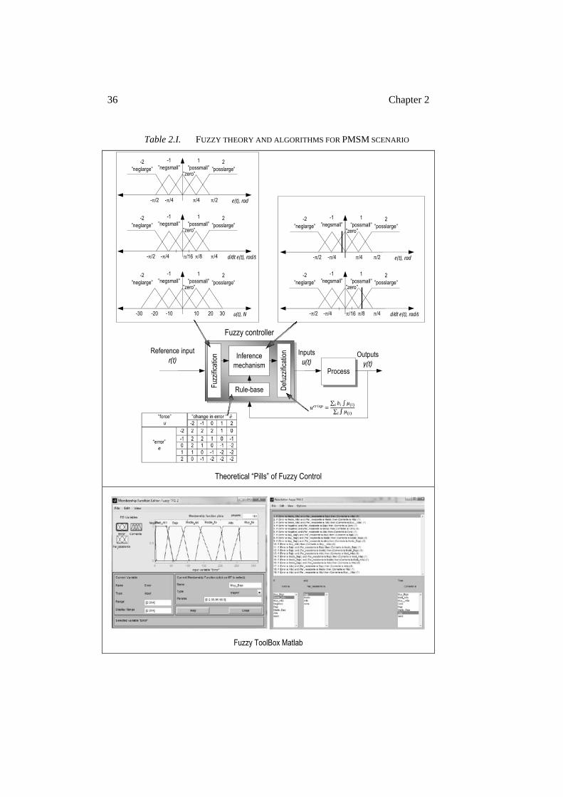
36 Chapter 2
Table 2.I. FUZZY THEORY AND ALGORITHMS FOR PMSM SCENARIO
Theoretical “Pills” of Fuzzy Control
Fuzzy ToolBox Matlab
Fuzz
ifica
tion
Def
uzzi
ficat
ion
Rule-base
Fuzzy controller
Inference mechanism
Reference input r(t)
Inputs u(t)
Process
Outputs y(t)
-2 ”neglarge”
-1 ”negsmall”
”zero”
1 ”possmall”
2 ”posslarge”
-/4 -/2 /2 /4 e(t), rad
-2 ”neglarge”
-1 ”negsmall”
”zero”
1 ”possmall”
2 ”posslarge”
-/4 -/2 /4 /8 d/dt e(t), rad/s
-2 ”neglarge”
-1 ”negsmall”
”zero”
1 ”possmall”
2 ”posslarge”
-10 -20 20 10 u(t), N
/16
-30 30
-2 ”neglarge”
-1 ”negsmall”
”zero”
1 ”possmall”
2 ”posslarge”
-/4 -/2 /2 /4 e(t), rad
-2 ”neglarge”
-1 ”negsmall”
”zero”
1 ”possmall”
2 ”posslarge”
-/4 -/2 /4 /8 d/dt e(t), rad/s /16
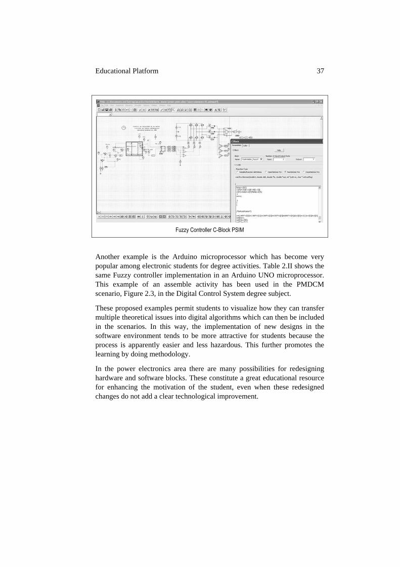
Educational Platform 37
Fuzzy Controller C-Block PSIM
Another example is the Arduino microprocessor which has become very popular among electronic students for degree activities. Table 2.II shows the same Fuzzy controller implementation in an Arduino UNO microprocessor. This example of an assemble activity has been used in the PMDCM scenario, Figure 2.3, in the Digital Control System degree subject.
These proposed examples permit students to visualize how they can transfer multiple theoretical issues into digital algorithms which can then be included in the scenarios. In this way, the implementation of new designs in the software environment tends to be more attractive for students because the process is apparently easier and less hazardous. This further promotes the learning by doing methodology.
In the power electronics area there are many possibilities for redesigning hardware and software blocks. These constitute a great educational resource for enhancing the motivation of the student, even when these redesigned changes do not add a clear technological improvement.
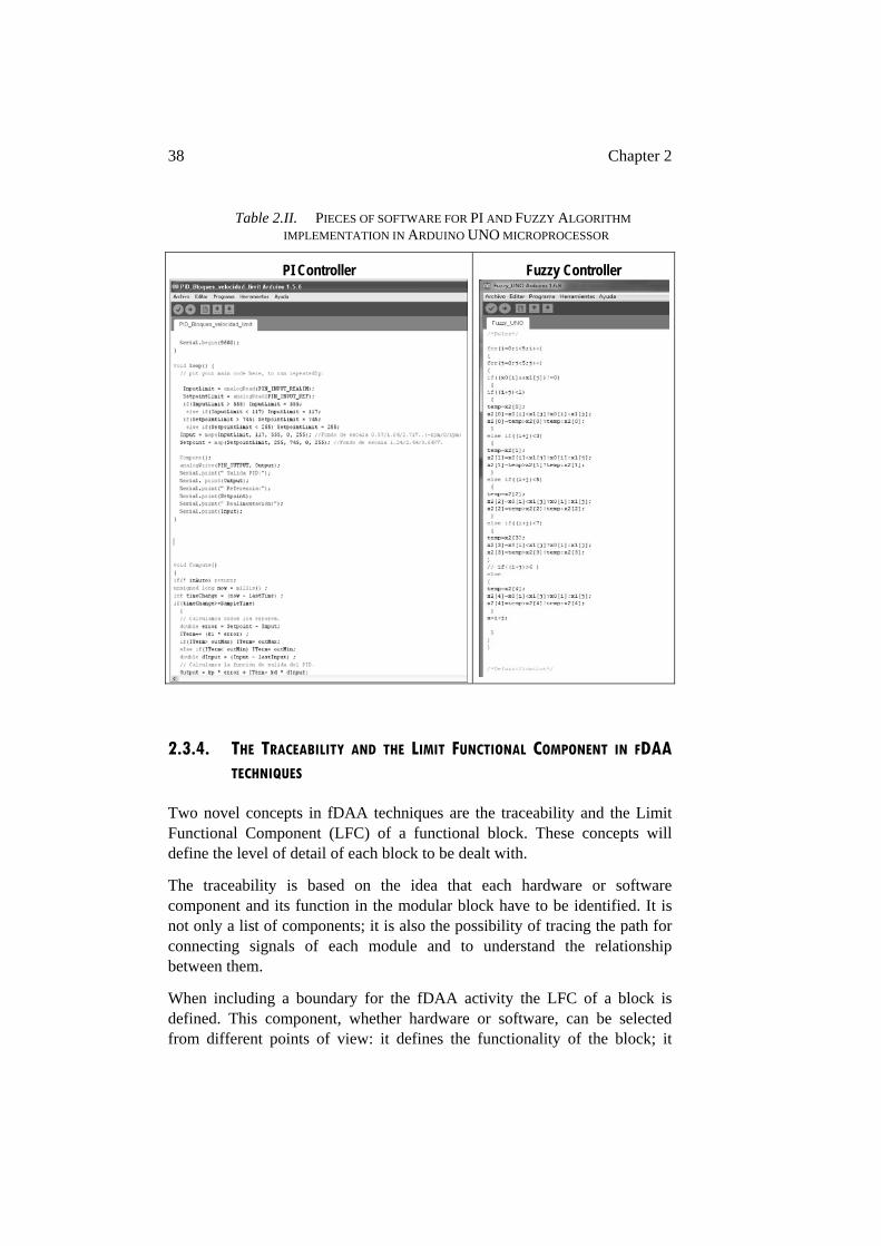
38 Chapter 2
Table 2.II. PIECES OF SOFTWARE FOR PI AND FUZZY ALGORITHM IMPLEMENTATION IN ARDUINO UNO MICROPROCESSOR
PI Controller
Fuzzy Controller
2.3.4. THE TRACEABILITY AND THE LIMIT FUNCTIONAL COMPONENT IN FDAA
TECHNIQUES
Two novel concepts in fDAA techniques are the traceability and the Limit Functional Component (LFC) of a functional block. These concepts will define the level of detail of each block to be dealt with.
The traceability is based on the idea that each hardware or software component and its function in the modular block have to be identified. It is not only a list of components; it is also the possibility of tracing the path for connecting signals of each module and to understand the relationship between them.
When including a boundary for the fDAA activity the LFC of a block is defined. This component, whether hardware or software, can be selected from different points of view: it defines the functionality of the block; it
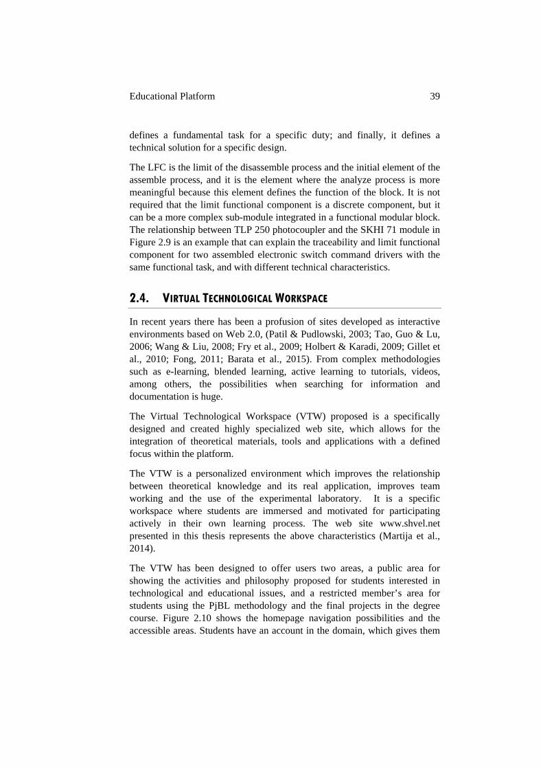
Educational Platform 39
defines a fundamental task for a specific duty; and finally, it defines a technical solution for a specific design.
The LFC is the limit of the disassemble process and the initial element of the assemble process, and it is the element where the analyze process is more meaningful because this element defines the function of the block. It is not required that the limit functional component is a discrete component, but it can be a more complex sub-module integrated in a functional modular block. The relationship between TLP 250 photocoupler and the SKHI 71 module in Figure 2.9 is an example that can explain the traceability and limit functional component for two assembled electronic switch command drivers with the same functional task, and with different technical characteristics.
2.4. VIRTUAL TECHNOLOGICAL WORKSPACE
In recent years there has been a profusion of sites developed as interactive environments based on Web 2.0, (Patil & Pudlowski, 2003; Tao, Guo & Lu, 2006; Wang & Liu, 2008; Fry et al., 2009; Holbert & Karadi, 2009; Gillet et al., 2010; Fong, 2011; Barata et al., 2015). From complex methodologies such as e-learning, blended learning, active learning to tutorials, videos, among others, the possibilities when searching for information and documentation is huge.
The Virtual Technological Workspace (VTW) proposed is a specifically designed and created highly specialized web site, which allows for the integration of theoretical materials, tools and applications with a defined focus within the platform.
The VTW is a personalized environment which improves the relationship between theoretical knowledge and its real application, improves team working and the use of the experimental laboratory. It is a specific workspace where students are immersed and motivated for participating actively in their own learning process. The web site www.shvel.net presented in this thesis represents the above characteristics (Martija et al., 2014).
The VTW has been designed to offer users two areas, a public area for showing the activities and philosophy proposed for students interested in technological and educational issues, and a restricted member’s area for students using the PjBL methodology and the final projects in the degree course. Figure 2.10 shows the homepage navigation possibilities and the accessible areas. Students have an account in the domain, which gives them
40 Chapter 2
permission to access the restricted areas of theoretical material, including technical projects and experimental scenarios.
Figure 2.10. The web www.shvel.net
The proposed VTW is a fundamental part of the novel philosophy of experimental laboratory named “Shared Hybrid Virtual-Experimental Laboratory” (SHVEL) and it will be further explained in Chapter 4 of this thesis.
2.5. ASSESSMENT TOOLS
The assessment tools have different feedback tasks within the teaching and learning process. In the proposal presented in this thesis some of these feedback tasks are to show: the level of theoretical and practical knowledge acquired, the level of performance of the proposed platform in the knowledge acquirement process, the students and professor behavior model, and the students’ opinion about their Degree or Master studies, among others.
During these years of research diverse assessment tools have been used for analyzing the above mentioned issues, some of them with a general character for obtaining a “quick snapshot” (Maseda et al., 2014), and others related to more specific issues (Martija et al., 2015).
Educational Platform 41
Table 2.III and Table 2.IV show two questionnaires and their results. These are intended to obtain a quick general overview about student satisfaction with the proposed platform activities and tools, and their influence in the teaching and learning process.
Chapters 6 and 7 include a final assessment questionnaire used for obtaining feedback about more specific information on the educational methodology proposed in this thesis.
In Table 2.III and Table 2.IV, it is possible to observe the level of general satisfaction by students with the proposed platform, methodology and tools during the study period. At the time of the platform launching, issues related to communication were raised, which are reflected in a lower grading given by the students. When these issues were resolved the results improved.
It should be taken into account that the Table 2.III survey was completed by students studying different subjects (Industrial Electronics and Automatics Degree, the Mechanical Degree and Master in Control Engineering, Automation and Robotics), where the platform has been applied in different levels. The table 2.IV survey is from Power Electronics subject students. It should be noted that there have been a large number of students who have participated in this process since the implementation of the methodology.
Table 2.III shows students’ opinion about the practical activities in the laboratory, this being considered more valuable than the ones in the classroom. It should be taken into account the students surprise with the increase of experimental activities in the environment proposed. The students’ opinion about the cooperative learning activities is always high; the change of teaching and learning dynamic is welcome for the majority of students. Finally the table shows students’ opinion about off-campus activities. The origin of this high level of satisfaction is considered to be related to the organization of the activities and their influence on the students’ final mark. It is possible to observe in Table 2.IV that students’ opinion about the theoretical activities in the classroom has clearly improved and they are more highly regarded than the practical activities. The reason for this improvement can be related to the more time specific application of the proposal in this subject and the students’ prior knowledge about the subject philosophy. It is possible to observe, the improvement in the fDAA activities opinion. In this case the reason is related to the improvement in the assemble activities based on the low cost microprocessors, Arduino and RaspBerry-PI. The application of these kinds of resources provides the students with the possibility of creating personalized sites re-balancing the use of www.svhel.net site. This evolution will be explained in Chapter 4.
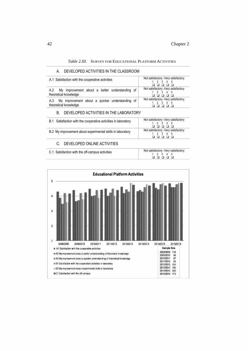
42 Chapter 2
Table 2.III. SURVEY FOR EDUCATIONAL PLATFORM ACTIVITIES
A. DEVELOPED ACTIVITIES IN THE CLASSROOM
A.1 Satisfaction with the cooperative activities Not satisfactory -Very satisfactory 1
2
3
4
5
A.2 My improvement about a better understanding of theoretical knowledge
Not satisfactory -Very satisfactory 1
2
3
4
5
A.3 My improvement about a quicker understanding of theoretical knowledge
Not satisfactory -Very satisfactory 1
2
3
4
5
B. DEVELOPED ACTIVITIES IN THE LABORATORY
B.1 Satisfaction with the cooperative activities in laboratory Not satisfactory -Very satisfactory 1
2
3
4
5
B.2 My improvement about experimental skills in laboratory Not satisfactory -Very satisfactory 1
2
3
4
5
C. DEVELOPED ONLINE ACTIVITIES
C.1 Satisfaction with the off-campus activities Not satisfactory -Very satisfactory 1
2
3
4
5
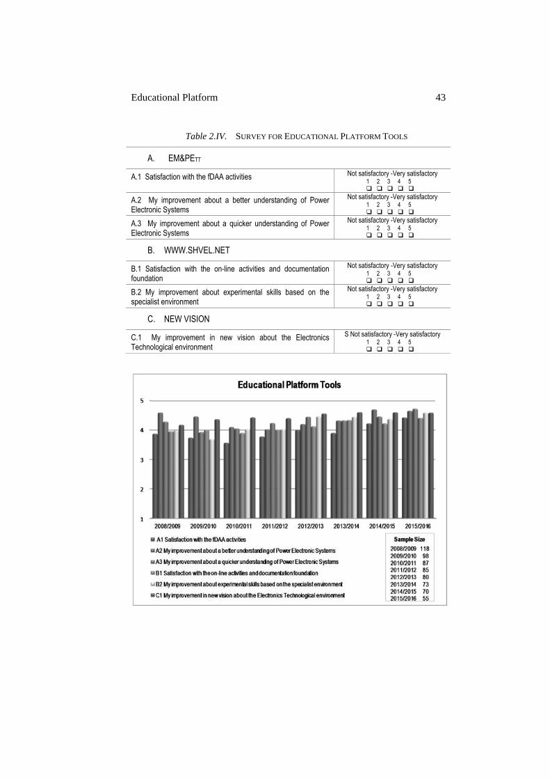
Educational Platform 43
Table 2.IV. SURVEY FOR EDUCATIONAL PLATFORM TOOLS
A. EM&PETT
A.1 Satisfaction with the fDAA activities Not satisfactory -Very satisfactory 1
2
3
4
5
A.2 My improvement about a better understanding of Power Electronic Systems
Not satisfactory -Very satisfactory 1
2
3
4
5
A.3 My improvement about a quicker understanding of Power Electronic Systems
Not satisfactory -Very satisfactory 1
2
3
4
5
B. WWW.SHVEL.NET
B.1 Satisfaction with the on-line activities and documentation foundation
Not satisfactory -Very satisfactory 1
2
3
4
5
B.2 My improvement about experimental skills based on the specialist environment
Not satisfactory -Very satisfactory 1
2
3
4
5
C. NEW VISION
C.1 My improvement in new vision about the Electronics Technological environment
S Not satisfactory -Very satisfactory 1
2
3
4
5
44 Chapter 2
2.6. CONCLUSIONS
The goal of the platform, activities and tools described in this chapter is to achieve a more intensive and widespread implementation of active and cooperative methodologies in engineering education. The Power Electronics subject has been selected as the case study because it presents some special characteristics that make it not only challenging but suitable for new teaching and learning procedures.
From an educational point of view, the objectives focus on three main areas: firstly to improve theoretical knowledge, secondly to improve practical skills, and finally, to improve behavioral and sociological models.
Issues such as increasing the number of enrolled students in engineering degrees and the use of green energies and more efficient electronic equipment have a strong impact in social and industrial environments and are therefore included in the Platform focus.
The application of techniques that companies employ to engage personnel with their general mission and objectives have been adopted in this thesis, focusing on an increasing student engagement and self-reliance with their own education.
The tools and activities shown in this chapter intend to be part of a methodology within a general philosophy capable of being applied in other relevant areas. Chapter 6 proposes the same platform with other scenarios but using the same methodologies and activities to demonstrate its general application, the case study will be Kinematics and Dynamics of Machines, a subject in the Degree in Mechanical Engineering.
The survey results show that the proposal has reached its primary objectives: modifying the teacher and student’s roles and the learning dynamic in the classroom and the laboratory, enhancing the understanding of electronic systems, improving motivation and establishing a connection with the practical use of power electronics, and finally, expanding the learning and teaching activities out of the campus constraint. Competencies have been further developed in areas such as, communication skills, team work, leadership, ethical attitudes, etc.
Experience in industrial objectives and their competencies have been taken into account in this thesis. The industrial world is a multidisciplinary environment, where teamwork predominates within the engineering professional practice. Motivation, ethics and efficiency are the basis for an optimum development of engineering projects, and the importance of

Educational Platform 45
feedback and measuring results ensure a continuous improvement towards excellence.

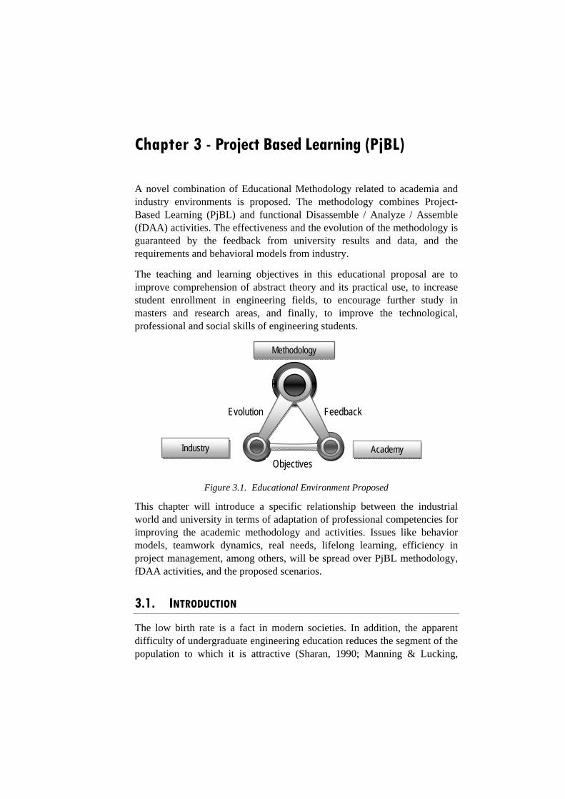
Chapter 3 - Project Based Learning (PjBL)
A novel combination of Educational Methodology related to academia and industry environments is proposed. The methodology combines Project-Based Learning (PjBL) and functional Disassemble / Analyze / Assemble (fDAA) activities. The effectiveness and the evolution of the methodology is guaranteed by the feedback from university results and data, and the requirements and behavioral models from industry.
The teaching and learning objectives in this educational proposal are to improve comprehension of abstract theory and its practical use, to increase student enrollment in engineering fields, to encourage further study in masters and research areas, and finally, to improve the technological, professional and social skills of engineering students.
Figure 3.1. Educational Environment Proposed
This chapter will introduce a specific relationship between the industrial world and university in terms of adaptation of professional competencies for improving the academic methodology and activities. Issues like behavior models, teamwork dynamics, real needs, lifelong learning, efficiency in project management, among others, will be spread over PjBL methodology, fDAA activities, and the proposed scenarios.
3.1. INTRODUCTION
The low birth rate is a fact in modern societies. In addition, the apparent difficulty of undergraduate engineering education reduces the segment of the population to which it is attractive (Sharan, 1990; Manning & Lucking,
Evolution Feedback
Methodology
Industry Academy
Objectives
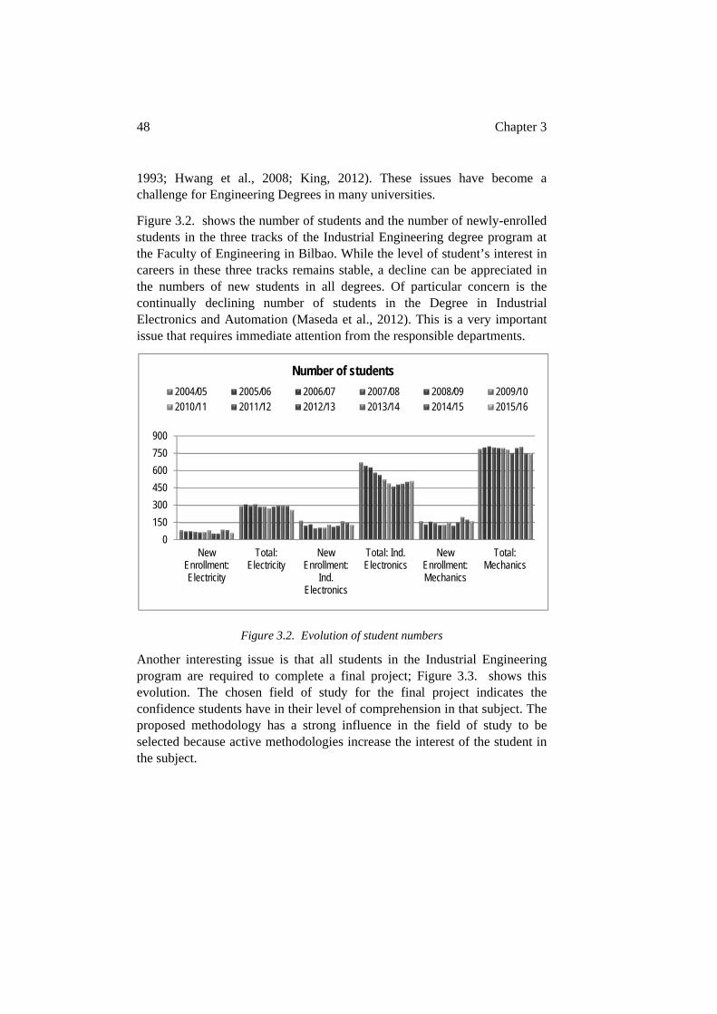
48 Chapter 3
1993; Hwang et al., 2008; King, 2012). These issues have become a challenge for Engineering Degrees in many universities.
Figure 3.2. shows the number of students and the number of newly-enrolled students in the three tracks of the Industrial Engineering degree program at the Faculty of Engineering in Bilbao. While the level of student’s interest in careers in these three tracks remains stable, a decline can be appreciated in the numbers of new students in all degrees. Of particular concern is the continually declining number of students in the Degree in Industrial Electronics and Automation (Maseda et al., 2012). This is a very important issue that requires immediate attention from the responsible departments.
Figure 3.2. Evolution of student numbers
Another interesting issue is that all students in the Industrial Engineering program are required to complete a final project; Figure 3.3. shows this evolution. The chosen field of study for the final project indicates the confidence students have in their level of comprehension in that subject. The proposed methodology has a strong influence in the field of study to be selected because active methodologies increase the interest of the student in the subject.
0
150
300
450
600
750
900
NewEnrollment:Electricity
Total:Electricity
NewEnrollment:
Ind.Electronics
Total: Ind.Electronics
NewEnrollment:Mechanics
Total:Mechanics
Number of students
2004/05 2005/06 2006/07 2007/08 2008/09 2009/102010/11 2011/12 2012/13 2013/14 2014/15 2015/16
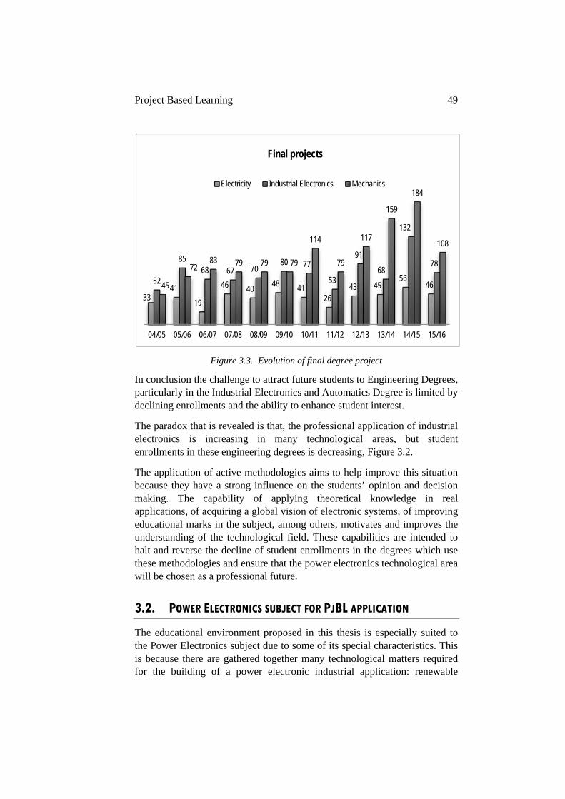
Project Based Learning 49
Figure 3.3. Evolution of final degree project
In conclusion the challenge to attract future students to Engineering Degrees, particularly in the Industrial Electronics and Automatics Degree is limited by declining enrollments and the ability to enhance student interest.
The paradox that is revealed is that, the professional application of industrial electronics is increasing in many technological areas, but student enrollments in these engineering degrees is decreasing, Figure 3.2.
The application of active methodologies aims to help improve this situation because they have a strong influence on the students’ opinion and decision making. The capability of applying theoretical knowledge in real applications, of acquiring a global vision of electronic systems, of improving educational marks in the subject, among others, motivates and improves the understanding of the technological field. These capabilities are intended to halt and reverse the decline of student enrollments in the degrees which use these methodologies and ensure that the power electronics technological area will be chosen as a professional future.
3.2. POWER ELECTRONICS SUBJECT FOR PJBL APPLICATION
The educational environment proposed in this thesis is especially suited to the Power Electronics subject due to some of its special characteristics. This is because there are gathered together many technological matters required for the building of a power electronic industrial application: renewable
3341
19
46 4048 41
2643 45
564652
8568 67 70
80 77
53
91
68
132
78
45
7283 79 79 79
114
79
117
159
184
108
04/05 05/06 06/07 07/08 08/09 09/10 10/11 11/12 12/13 13/14 14/15 15/16
Final projects
Electricity Industrial Electronics Mechanics
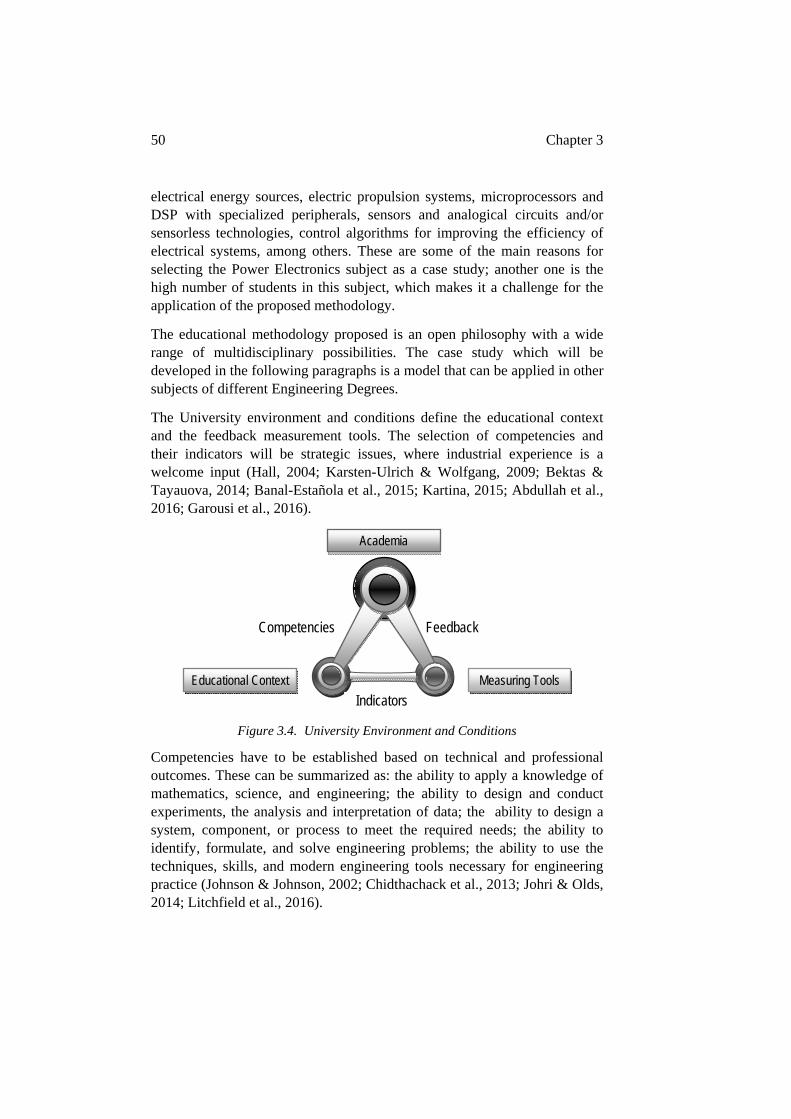
50 Chapter 3
electrical energy sources, electric propulsion systems, microprocessors and DSP with specialized peripherals, sensors and analogical circuits and/or sensorless technologies, control algorithms for improving the efficiency of electrical systems, among others. These are some of the main reasons for selecting the Power Electronics subject as a case study; another one is the high number of students in this subject, which makes it a challenge for the application of the proposed methodology.
The educational methodology proposed is an open philosophy with a wide range of multidisciplinary possibilities. The case study which will be developed in the following paragraphs is a model that can be applied in other subjects of different Engineering Degrees.
The University environment and conditions define the educational context and the feedback measurement tools. The selection of competencies and their indicators will be strategic issues, where industrial experience is a welcome input (Hall, 2004; Karsten-Ulrich & Wolfgang, 2009; Bektas & Tayauova, 2014; Banal-Estañola et al., 2015; Kartina, 2015; Abdullah et al., 2016; Garousi et al., 2016).
Figure 3.4. University Environment and Conditions
Competencies have to be established based on technical and professional outcomes. These can be summarized as: the ability to apply a knowledge of mathematics, science, and engineering; the ability to design and conduct experiments, the analysis and interpretation of data; the ability to design a system, component, or process to meet the required needs; the ability to identify, formulate, and solve engineering problems; the ability to use the techniques, skills, and modern engineering tools necessary for engineering practice (Johnson & Johnson, 2002; Chidthachack et al., 2013; Johri & Olds, 2014; Litchfield et al., 2016).
Competencies Feedback
Academia
Educational Context Measuring Tools
Indicators
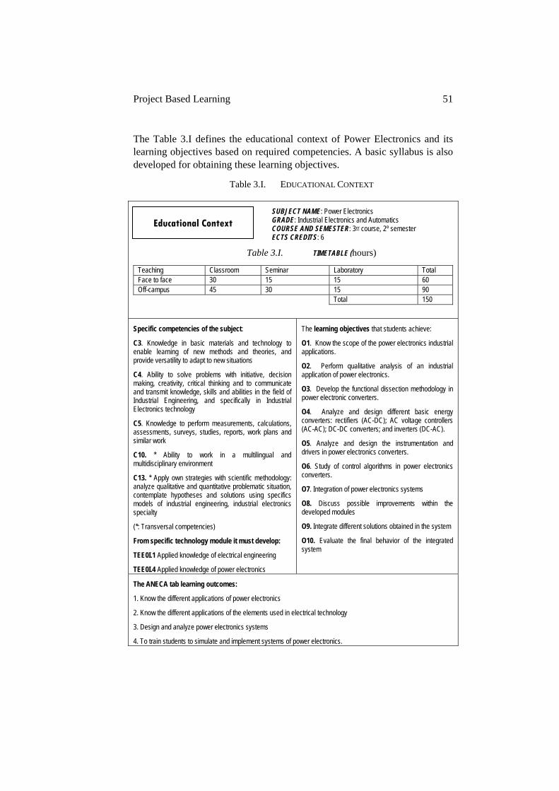
Project Based Learning 51
The Table 3.I defines the educational context of Power Electronics and its learning objectives based on required competencies. A basic syllabus is also developed for obtaining these learning objectives.
Table 3.I. EDUCATIONAL CONTEXT
SUBJECT NAME: Power Electronics GRADE: Industrial Electronics and Automatics COURSE AND SEMESTER: 3er course, 2º semester ECTS CREDITS: 6
Table 3.I. TIMETABLE (hours)
Teaching Classroom Seminar Laboratory Total Face to face 30 15 15 60 Off-campus 45 30 15 90 Total 150
Specific competencies of the subject:
C3. Knowledge in basic materials and technology to enable learning of new methods and theories, and provide versatility to adapt to new situations
C4. Ability to solve problems with initiative, decision making, creativity, critical thinking and to communicate and transmit knowledge, skills and abilities in the field of Industrial Engineering, and specifically in Industrial Electronics technology
C5. Knowledge to perform measurements, calculations, assessments, surveys, studies, reports, work plans and similar work
C10. * Ability to work in a multilingual and multidisciplinary environment
C13. * Apply own strategies with scientific methodology: analyze qualitative and quantitative problematic situation, contemplate hypotheses and solutions using specifics models of industrial engineering, industrial electronics specialty
(*: Transversal competencies)
From specific technology module it must develop:
TEE0I.1 Applied knowledge of electrical engineering
TEE0I.4 Applied knowledge of power electronics
The learning objectives that students achieve:
O1. Know the scope of the power electronics industrial applications.
O2. Perform qualitative analysis of an industrial application of power electronics.
O3. Develop the functional dissection methodology in power electronic converters.
O4. Analyze and design different basic energy converters: rectifiers (AC-DC); AC voltage controllers (AC-AC); DC-DC converters; and inverters (DC-AC).
O5. Analyze and design the instrumentation and drivers in power electronics converters.
O6. Study of control algorithms in power electronics converters.
O7. Integration of power electronics systems
O8. Discuss possible improvements within the developed modules
O9. Integrate different solutions obtained in the system
O10. Evaluate the final behavior of the integrated system
The ANECA tab learning outcomes:
1. Know the different applications of power electronics
2. Know the different applications of the elements used in electrical technology
3. Design and analyze power electronics systems
4. To train students to simulate and implement systems of power electronics.
Educational Context
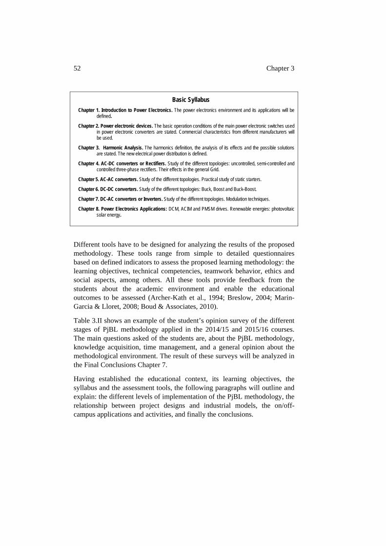
52 Chapter 3
Basic Syllabus
Chapter 1. Introduction to Power Electronics. The power electronics environment and its applications will be defined.
Chapter 2. Power electronic devices. The basic operation conditions of the main power electronic switches used in power electronic converters are stated. Commercial characteristics from different manufacturers will be used.
Chapter 3. Harmonic Analysis. The harmonics definition, the analysis of its effects and the possible solutions are stated. The new electrical power distribution is defined.
Chapter 4. AC-DC converters or Rectifiers. Study of the different topologies: uncontrolled, semi-controlled and controlled three-phase rectifiers. Their effects in the general Grid.
Chapter 5. AC-AC converters. Study of the different topologies. Practical study of static starters.
Chapter 6. DC-DC converters. Study of the different topologies: Buck, Boost and Buck-Boost.
Chapter 7. DC-AC converters or Inverters. Study of the different topologies. Modulation techniques.
Chapter 8. Power Electronics Applications: DCM, ACIM and PMSM drives. Renewable energies: photovoltaic solar energy.
Different tools have to be designed for analyzing the results of the proposed methodology. These tools range from simple to detailed questionnaires based on defined indicators to assess the proposed learning methodology: the learning objectives, technical competencies, teamwork behavior, ethics and social aspects, among others. All these tools provide feedback from the students about the academic environment and enable the educational outcomes to be assessed (Archer-Kath et al., 1994; Breslow, 2004; Marin-Garcia & Lloret, 2008; Boud & Associates, 2010).
Table 3.II shows an example of the student’s opinion survey of the different stages of PjBL methodology applied in the 2014/15 and 2015/16 courses. The main questions asked of the students are, about the PjBL methodology, knowledge acquisition, time management, and a general opinion about the methodological environment. The result of these surveys will be analyzed in the Final Conclusions Chapter 7.
Having established the educational context, its learning objectives, the syllabus and the assessment tools, the following paragraphs will outline and explain: the different levels of implementation of the PjBL methodology, the relationship between project designs and industrial models, the on/off-campus applications and activities, and finally the conclusions.
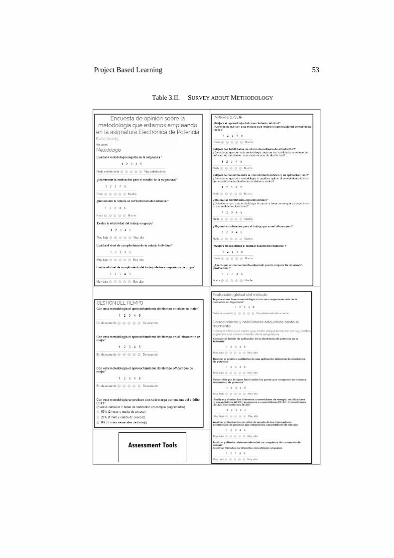
Project Based Learning 53
Table 3.II. SURVEY ABOUT METHODOLOGY
Assessment Tools
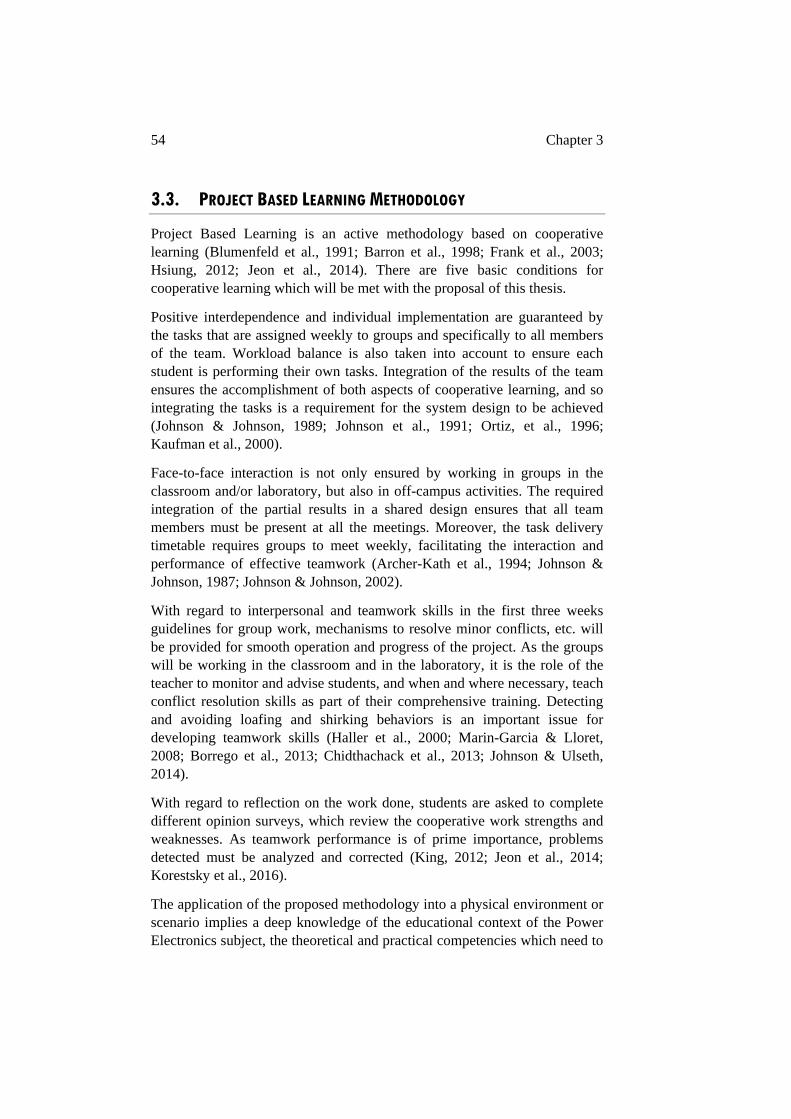
54 Chapter 3
3.3. PROJECT BASED LEARNING METHODOLOGY
Project Based Learning is an active methodology based on cooperative learning (Blumenfeld et al., 1991; Barron et al., 1998; Frank et al., 2003; Hsiung, 2012; Jeon et al., 2014). There are five basic conditions for cooperative learning which will be met with the proposal of this thesis.
Positive interdependence and individual implementation are guaranteed by the tasks that are assigned weekly to groups and specifically to all members of the team. Workload balance is also taken into account to ensure each student is performing their own tasks. Integration of the results of the team ensures the accomplishment of both aspects of cooperative learning, and so integrating the tasks is a requirement for the system design to be achieved (Johnson & Johnson, 1989; Johnson et al., 1991; Ortiz, et al., 1996; Kaufman et al., 2000).
Face-to-face interaction is not only ensured by working in groups in the classroom and/or laboratory, but also in off-campus activities. The required integration of the partial results in a shared design ensures that all team members must be present at all the meetings. Moreover, the task delivery timetable requires groups to meet weekly, facilitating the interaction and performance of effective teamwork (Archer-Kath et al., 1994; Johnson & Johnson, 1987; Johnson & Johnson, 2002).
With regard to interpersonal and teamwork skills in the first three weeks guidelines for group work, mechanisms to resolve minor conflicts, etc. will be provided for smooth operation and progress of the project. As the groups will be working in the classroom and in the laboratory, it is the role of the teacher to monitor and advise students, and when and where necessary, teach conflict resolution skills as part of their comprehensive training. Detecting and avoiding loafing and shirking behaviors is an important issue for developing teamwork skills (Haller et al., 2000; Marin-Garcia & Lloret, 2008; Borrego et al., 2013; Chidthachack et al., 2013; Johnson & Ulseth, 2014).
With regard to reflection on the work done, students are asked to complete different opinion surveys, which review the cooperative work strengths and weaknesses. As teamwork performance is of prime importance, problems detected must be analyzed and corrected (King, 2012; Jeon et al., 2014; Korestsky et al., 2016).
The application of the proposed methodology into a physical environment or scenario implies a deep knowledge of the educational context of the Power Electronics subject, the theoretical and practical competencies which need to
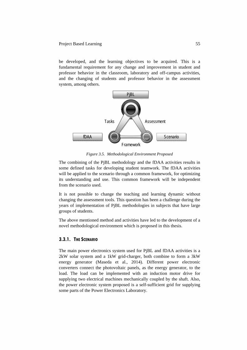
Project Based Learning 55
be developed, and the learning objectives to be acquired. This is a fundamental requirement for any change and improvement in student and professor behavior in the classroom, laboratory and off-campus activities, and the changing of students and professor behavior in the assessment system, among others.
Figure 3.5. Methodological Environment Proposed
The combining of the PjBL methodology and the fDAA activities results in some defined tasks for developing student teamwork. The fDAA activities will be applied to the scenario through a common framework, for optimizing its understanding and use. This common framework will be independent from the scenario used.
It is not possible to change the teaching and learning dynamic without changing the assessment tools. This question has been a challenge during the years of implementation of PjBL methodologies in subjects that have large groups of students.
The above mentioned method and activities have led to the development of a novel methodological environment which is proposed in this thesis.
3.3.1. THE SCENARIO
The main power electronics system used for PjBL and fDAA activities is a 2kW solar system and a 1kW grid-charger, both combine to form a 3kW energy generator (Maseda et al., 2014). Different power electronic converters connect the photovoltaic panels, as the energy generator, to the load. The load can be implemented with an induction motor drive for supplying two electrical machines mechanically coupled by the shaft. Also, the power electronic system proposed is a self-sufficient grid for supplying some parts of the Power Electronics Laboratory.
Tasks Assessment
PjBL
fDAA Scenario
Framework
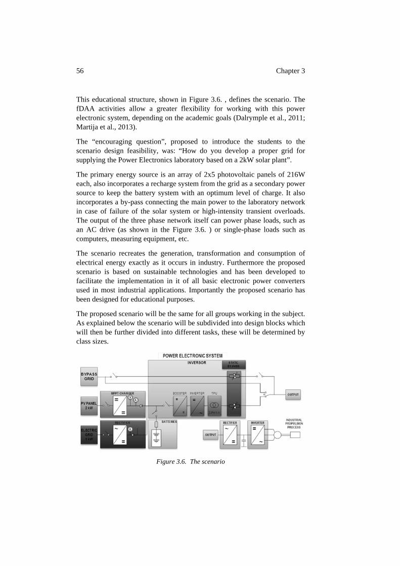
56 Chapter 3
This educational structure, shown in Figure 3.6. , defines the scenario. The fDAA activities allow a greater flexibility for working with this power electronic system, depending on the academic goals (Dalrymple et al., 2011; Martija et al., 2013).
The “encouraging question”, proposed to introduce the students to the scenario design feasibility, was: “How do you develop a proper grid for supplying the Power Electronics laboratory based on a 2kW solar plant”.
The primary energy source is an array of 2x5 photovoltaic panels of 216W each, also incorporates a recharge system from the grid as a secondary power source to keep the battery system with an optimum level of charge. It also incorporates a by-pass connecting the main power to the laboratory network in case of failure of the solar system or high-intensity transient overloads. The output of the three phase network itself can power phase loads, such as an AC drive (as shown in the Figure 3.6. ) or single-phase loads such as computers, measuring equipment, etc.
The scenario recreates the generation, transformation and consumption of electrical energy exactly as it occurs in industry. Furthermore the proposed scenario is based on sustainable technologies and has been developed to facilitate the implementation in it of all basic electronic power converters used in most industrial applications. Importantly the proposed scenario has been designed for educational purposes.
The proposed scenario will be the same for all groups working in the subject. As explained below the scenario will be subdivided into design blocks which will then be further divided into different tasks, these will be determined by class sizes.
Figure 3.6. The scenario
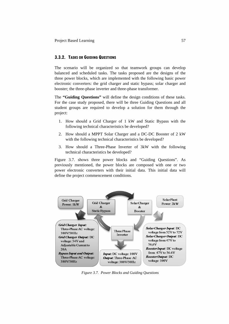
Project Based Learning 57
3.3.2. TASKS OR GUIDING QUESTIONS
The scenario will be organized so that teamwork groups can develop balanced and scheduled tasks. The tasks proposed are the designs of the three power blocks, which are implemented with the following basic power electronic converters: the grid charger and static bypass; solar charger and booster; the three-phase inverter and three-phase transformer.
The “Guiding Questions” will define the design conditions of these tasks. For the case study proposed, there will be three Guiding Questions and all student groups are required to develop a solution for them through the project:
1. How should a Grid Charger of 1 kW and Static Bypass with the following technical characteristics be developed?
2. How should a MPPT Solar Charger and a DC-DC Booster of 2 kW with the following technical characteristics be developed?
3. How should a Three-Phase Inverter of 3kW with the following technical characteristics be developed?
Figure 3.7. shows three power blocks and “Guiding Questions”. As previously mentioned, the power blocks are composed with one or two power electronic converters with their initial data. This initial data will define the project commencement conditions.
Figure 3.7. Power Blocks and Guiding Questions
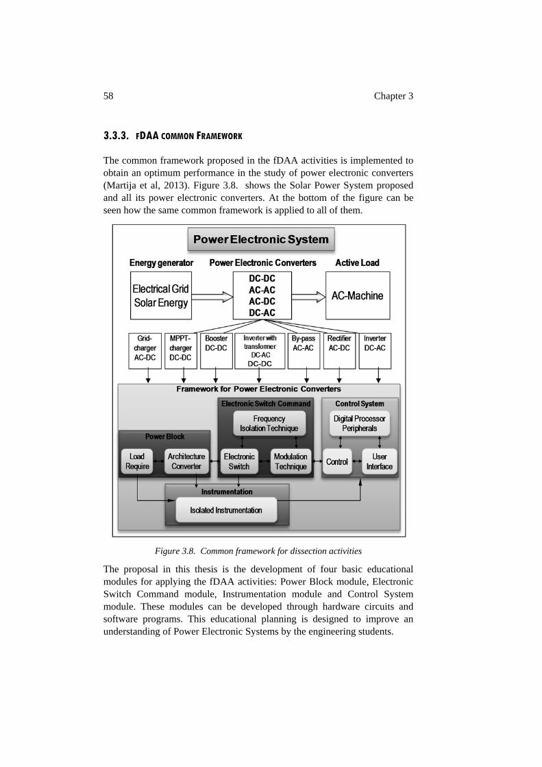
58 Chapter 3
3.3.3. FDAA COMMON FRAMEWORK
The common framework proposed in the fDAA activities is implemented to obtain an optimum performance in the study of power electronic converters (Martija et al, 2013). Figure 3.8. shows the Solar Power System proposed and all its power electronic converters. At the bottom of the figure can be seen how the same common framework is applied to all of them.
Figure 3.8. Common framework for dissection activities
The proposal in this thesis is the development of four basic educational modules for applying the fDAA activities: Power Block module, Electronic Switch Command module, Instrumentation module and Control System module. These modules can be developed through hardware circuits and software programs. This educational planning is designed to improve an understanding of Power Electronic Systems by the engineering students.
Project Based Learning 59
The common framework divides the whole system into educational modules, based on fDAA activities, and intends to guide the student through a complete development of the educational context. Through these activities, the students acquire a global vision of the Power Electronics subject and the required technical competencies and professional skills.
The proposed activities can be summarized as:
o Analysis of power electronic converter topology depending on input and output requirements, selection of the power electronic switch depending on power electronic converter defined, definition of the electronic switch driver for the power electronic switch, analysis of the switching frequency depending on harmonics versus switching losses, choice of the isolation technique between power converter components and controller and study of modulation techniques.
o Analysis of instrumentation system, selection of sensors and signal measurement conditions, choice of the isolation technique between measurement point and ADC controller, definition of the analogical treatment and digital processing, selection of the instrumentation variables: feedback for the controller, monitoring and visualization systems, and security conditions for personnel and machinery.
o Analysis of control systems, selection of specific digital microprocessors applied to power electronic systems, its peripherals (PWM modulators, ADC, DCA, Timers, Decoders, GPIOs, etc.), definition of the possibilities of basic control schemes: open loop and closed loop, and finally, development of basic user interfaces.
3.3.4. STUDENTS ASSESSMENT IN THE PJBL METHODOLOGY
The active methodologies seek to transform the student assessment into an educational tool with positive characteristics (Breslow, 2004; Boud & Associates, 2010). The main traditional assessment idea which has been to obtain the best individual mark based on a final exam should be replaced by work and tests through the semester.
Continual assessment in cooperative learning is useful because students when working individually and as part of a team need to monitor the evolution of their knowledge acquisition. Also this type of assessment gives feedback about how the educational environment is performing (Hsiung, 2010; Howard et al., 2016).
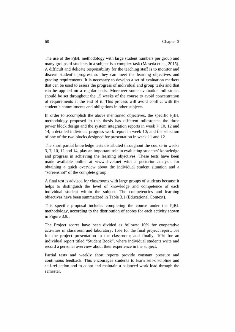
60 Chapter 3
The use of the PjBL methodology with large student numbers per group and many groups of students in a subject is a complex task (Maseda et al., 2015). A difficult and delicate responsibility for the teaching staff is to monitor and discern student´s progress so they can meet the learning objectives and grading requirements. It is necessary to develop a set of evaluation markers that can be used to assess the progress of individual and group tasks and that can be applied on a regular basis. Moreover some evaluation milestones should be set throughout the 15 weeks of the course to avoid concentration of requirements at the end of it. This process will avoid conflict with the student´s commitments and obligations in other subjects.
In order to accomplish the above mentioned objectives, the specific PjBL methodology proposed in this thesis has different milestones: the three power block design and the system integration reports in week 7, 10, 12 and 14; a detailed individual progress work report in week 10; and the selection of one of the two blocks designed for presentation in week 11 and 12.
The short partial knowledge tests distributed throughout the course in weeks 3, 7, 10, 12 and 14, play an important role in evaluating students’ knowledge and progress in achieving the learning objectives. These tests have been made available online at www.shvel.net with a posterior analysis for obtaining a quick overview about the individual student situation and a “screenshot” of the complete group.
A final test is advised for classrooms with large groups of students because it helps to distinguish the level of knowledge and competence of each individual student within the subject. The competencies and learning objectives have been summarized in Table 3.1 (Educational Context).
This specific proposal includes completing the course under the PjBL methodology, according to the distribution of scores for each activity shown in Figure 3.9. .
The Project scores have been divided as follows: 10% for cooperative activities in classroom and laboratory; 15% for the final project report; 5% for the project presentation in the classroom; and finally, 10% for an individual report titled “Student Book”, where individual students write and record a personal overview about their experience in the subject.
Partial tests and weekly short reports provide constant pressure and continuous feedback. This encourages students to learn self-discipline and self-reflection and to adopt and maintain a balanced work load through the semester.
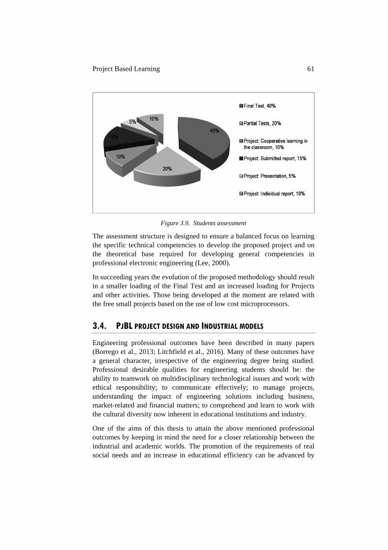
Project Based Learning 61
Figure 3.9. Students assessment
The assessment structure is designed to ensure a balanced focus on learning the specific technical competencies to develop the proposed project and on the theoretical base required for developing general competencies in professional electronic engineering (Lee, 2000).
In succeeding years the evolution of the proposed methodology should result in a smaller loading of the Final Test and an increased loading for Projects and other activities. Those being developed at the moment are related with the free small projects based on the use of low cost microprocessors.
3.4. PJBL PROJECT DESIGN AND INDUSTRIAL MODELS
Engineering professional outcomes have been described in many papers (Borrego et al., 2013; Litchfield et al., 2016). Many of these outcomes have a general character, irrespective of the engineering degree being studied. Professional desirable qualities for engineering students should be: the ability to teamwork on multidisciplinary technological issues and work with ethical responsibility; to communicate effectively; to manage projects, understanding the impact of engineering solutions including business, market-related and financial matters; to comprehend and learn to work with the cultural diversity now inherent in educational institutions and industry.
One of the aims of this thesis to attain the above mentioned professional outcomes by keeping in mind the need for a closer relationship between the industrial and academic worlds. The promotion of the requirements of real social needs and an increase in educational efficiency can be advanced by
62 Chapter 3
the replication of industrial behavioral models (Alekseevich et al., 2012: Borrego et al., 2013).
Figure 3.10. Academia-Industry Relationship
The industrial aspects defining the objectives, the plan and the market conditions are issues to be resolved in academic projects. Also recommended are the use of indicators and measurement tools for feedback and an improvement plan guarantee the constructive evolution of the educational methodology. The schedule of the educational methodology should be designed with different timelines similar to those used in industrial planning.
3.4.1. ORGANIZATION IN PJBL PROJECT DESIGN
The replication of industrial behavioral models that focus on student’s motivation and efficiency, with a detailed task schedule, and showing students the professional and social interest of the technological matter will result in an optimum project design.
In order to ensure the accomplishment of the educational objectives the project is structured into four areas of development: the theoretical possibilities, models simulation, low cost microprocessor practical analysis, and commercial interest. This methodology will result in different projects for each students group.
3.4.1.1. Theoretical possibilities
The theoretical possibilities developed will be based on the theory taught through the course, the proposed scenario, the specific technical information related with the educational fDAA modules and the recommended bibliography. Figure 3.11. shows the above mentioned resources.
Motivation Feedback
Behavior Models
Efficiency Society
Schedules

Project Based Learning 63
INVERTER RECTIFIER
INVERSOR
BATT ERIESRECTIFIER V
A
MPPT CHARG ER
BYPASS GRID
PV PANEL 1,5 kw
V A
ELECTRIC GRID
=
=
=
=
=
=
BO OSTER INVERTER TPU
3-PH Y-Y
STATIC BY-PASS
OUTPUT
POWER ELECTRONICS SYSTEM
OUT PUT
=
=
INDUST RIAL PRO PULSION
PROCESS
Real Power Electronics Converters
MPPT CHARGER
BOOSTER
GRID CHARGER
INVERTER
STATIC BAY-PASS
TRANSFORMER
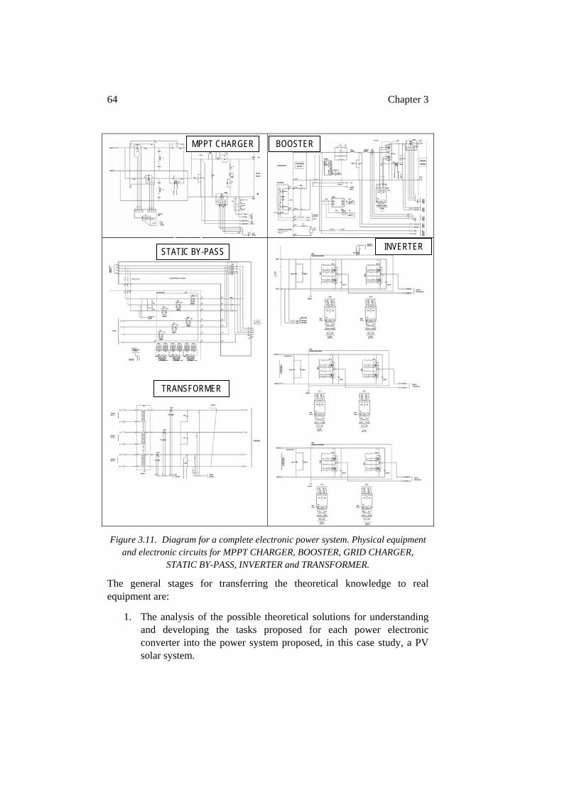
64 Chapter 3
Figure 3.11. Diagram for a complete electronic power system. Physical equipment and electronic circuits for MPPT CHARGER, BOOSTER, GRID CHARGER,
STATIC BY-PASS, INVERTER and TRANSFORMER.
The general stages for transferring the theoretical knowledge to real equipment are:
1. The analysis of the possible theoretical solutions for understanding and developing the tasks proposed for each power electronic converter into the power system proposed, in this case study, a PV solar system.
MPPT CHARGER BOOSTER
STATIC BY-PASS INVERTER
TRANSFORMER
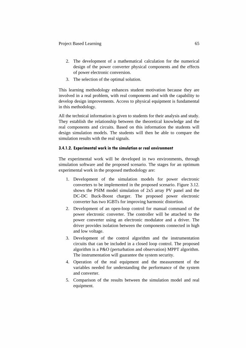
Project Based Learning 65
2. The development of a mathematical calculation for the numerical design of the power converter physical components and the effects of power electronic conversion.
3. The selection of the optimal solution.
This learning methodology enhances student motivation because they are involved in a real problem, with real components and with the capability to develop design improvements. Access to physical equipment is fundamental in this methodology.
All the technical information is given to students for their analysis and study. They establish the relationship between the theoretical knowledge and the real components and circuits. Based on this information the students will design simulation models. The students will then be able to compare the simulation results with the real signals.
3.4.1.2. Experimental work in the simulation or real environment
The experimental work will be developed in two environments, through simulation software and the proposed scenario. The stages for an optimum experimental work in the proposed methodology are:
1. Development of the simulation models for power electronic converters to be implemented in the proposed scenario. Figure 3.12. shows the PSIM model simulation of 2x5 array PV panel and the DC-DC Buck-Boost charger. The proposed power electronic converter has two IGBTs for improving harmonic distortion.
2. Development of an open-loop control for manual command of the power electronic converter. The controller will be attached to the power converter using an electronic modulator and a driver. The driver provides isolation between the components connected in high and low voltage.
3. Development of the control algorithm and the instrumentation circuits that can be included in a closed loop control. The proposed algorithm is a P&O (perturbation and observation) MPPT algorithm. The instrumentation will guarantee the system security.
4. Operation of the real equipment and the measurement of the variables needed for understanding the performance of the system and converter.
5. Comparison of the results between the simulation model and real equipment.
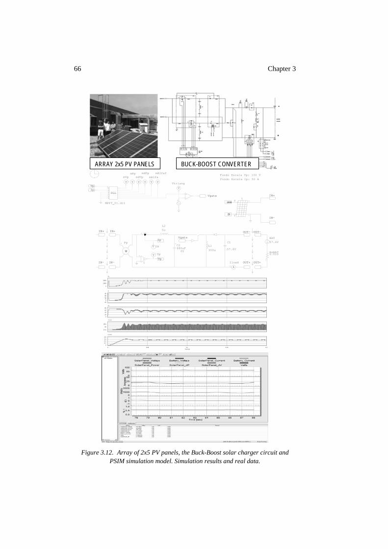
66 Chapter 3
Figure 3.12. Array of 2x5 PV panels, the Buck-Boost solar charger circuit and PSIM simulation model. Simulation results and real data.
DLL
MPPT_01.dll
VpIp
V
mVp
V
mPp
V
mdVp
V
mdPp
V
mAlfa
V
mAlfaf
1Vp
57.6V
C1
Vgate
V
Vtriang
Vgate
5uL2
C2
0V680uF
V Vp300u
L1
Ip
V Ip
Fondo Escala Vp: 100 V
Fondo Escala Ip: 50 A
W
Pp
A
Iload
IN+IN+
IN-IN-
57.6VBAT
0.010RsBAT
OUT-OUT-
OUT+OUT+
IN+
IN-
S
T25
1000
0
1000
2000
Pp
0-10
10203040
Ip
0
20
40
60
80
Vp
57.6
58
58.4
-Vload
0 0.05 0.1 0.15 0.2Time (s)
00.20.40.60.8
mAlfaf
ARRAY 2x5 PV PANELS BUCK-BOOST CONVERTER
Project Based Learning 67
The analyze procedure involves two main activities: understanding the functional tasks of the modular power converter blocks and/or improving their technical qualities.
The analyze activity links the theory with its practical application reinforcing the comprehension of abstract theory topics. It also facilitates the understanding of the relationship between simulation models and real components implemented in the equipment. Figure 3.12. shows the simulation model results for a MPPT charger and the real equipment variables.
The analyze activity can lead to multiple educational procedures, such as, working with complex hardware modules and software functions, or with discrete electronic components in the hardware blocks, and with small pieces of software for executing simple programming tasks.
The proposed methodology links the theoretical and experimental work into a total educational environment strengthening and emphasizing the relationship between academic and real calculus, and motivating further continuous learning.
3.4.1.3. Free experimental work based on digital processor and low-cost hardware
The student groups can opt to do a free experimental work that is based on the design of a prototype of a small power converter that will mimic a power converter that is part of the proposed scenario. In the event of several groups wanting to make the prototype, it is advisable that there is a selection of different designs. All the designs will be implemented with Arduino digital microprocessors, one protoboard and discrete electronics components. The free design is developed in the following steps:
1. To define the power converter for prototyping: rectifier, DC-DC converter or inverter. All of these converters are implemented in the proposed scenario.
2. To define integrated peripheral necessities of the Arduino digital processor.
3. To define and design the external hardware for the processor board: drivers, sensors, instrumentation, communication, security, etc.
4. To develop the algorithms required for the command and control of the converter: signal processing, control algorithms, digital control signals or analog signals, safety, etc.
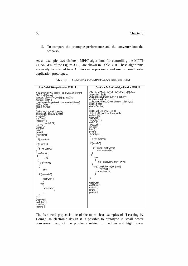
68 Chapter 3
5. To compare the prototype performance and the converter into the scenario.
As an example, two different MPPT algorithms for controlling the MPPT CHARGER of the Figure 3.12. are shown in Table 3.III. These algorithms are easily transferred to a Arduino microprocessor and used in small solar application prototypes.
Table 3.III. CODES FOR TWO MPPT ALGORITHMS IN PSIM
C++ Code P&O algorithm for PSIM .dll
// Inputs: in[0]=Vin, in[1]=IL, in[2]=Vant, in[3]=Pant //Input: in[4]=sreloj //outputs: out[0]=Vref, out[1]= p, out[2]=v #include <math.h> __declspec(dllexport) void simuser (t,delt,in,out) double t, delt; double *in, *out; double vin, i, p, vref, c, sreloj; static double pant, vant, vrefs; sreloj=in[2]; vref=vrefs; if(sreloj<1) vref=0.78; c=0.0001; vin=in[0]; i=in[1]; p=vin*i; if (sreloj=1) if(p-pant!=0) if (p-pant>0) if (vin-vant>0) vref=vref-c; else vref=vref+c; else if (vin-vant>0) vref=vref+c; else vref=vref-c; vrefs=vref; out[0]=vref; vant=vin; pant=p;
C++ Code for IncCond algorithm for PSIM .dll // Inputs: in[0]=Vin, in[1]=IL, in[2]=Vant, in[3]=Pant //Input: in[4]=sreloj //outputs: out[0]=Vref, out[1]= p, out[2]=v #include <math.h> __declspec(dllexport) void simuser (t,delt,in,out) double t, delt; double *in, *out; double vin, i, p, vref, c, sreloj; static double pant, vant, iant, vrefs; sreloj=in[2]; vref=vrefs; if(sreloj<1) vref=0.8; c=0.00001; vin=in[0]; i=in[1]; p=vin*i; if (sreloj==1) if (vin-vant==0) if (i-iant!=0) if (i-iant>0) vref=vref-c; else vref=vref+c; else if (((i-iant)/(vin-vant))!= -(i/vin)) if (((i-iant)/(vin-vant))> -(i/vin)) vref=vref-c; else vref=vref+c; vrefs=vref; out[0]=vref; vant=vin; iant=i; pant=p;
The free work project is one of the more clear examples of “Learning by Doing”. In electronic design it is possible to prototype in small power converters many of the problems related to medium and high power
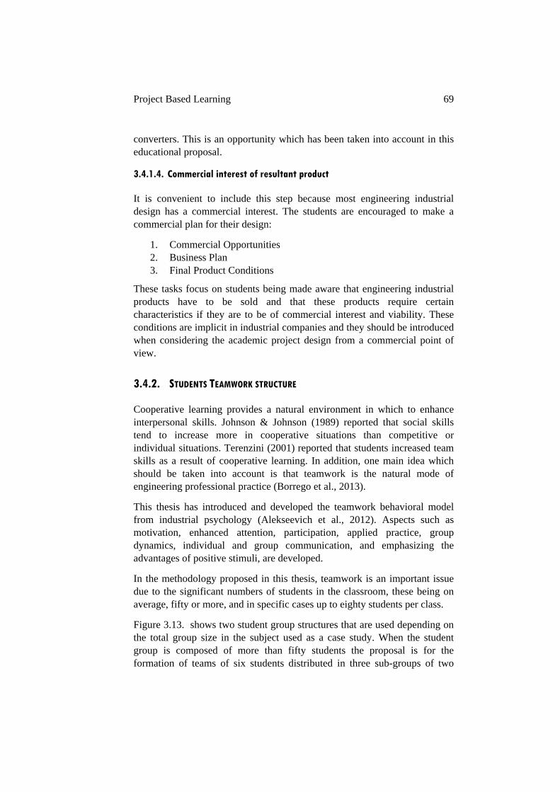
Project Based Learning 69
converters. This is an opportunity which has been taken into account in this educational proposal.
3.4.1.4. Commercial interest of resultant product
It is convenient to include this step because most engineering industrial design has a commercial interest. The students are encouraged to make a commercial plan for their design:
1. Commercial Opportunities 2. Business Plan 3. Final Product Conditions
These tasks focus on students being made aware that engineering industrial products have to be sold and that these products require certain characteristics if they are to be of commercial interest and viability. These conditions are implicit in industrial companies and they should be introduced when considering the academic project design from a commercial point of view.
3.4.2. STUDENTS TEAMWORK STRUCTURE
Cooperative learning provides a natural environment in which to enhance interpersonal skills. Johnson & Johnson (1989) reported that social skills tend to increase more in cooperative situations than competitive or individual situations. Terenzini (2001) reported that students increased team skills as a result of cooperative learning. In addition, one main idea which should be taken into account is that teamwork is the natural mode of engineering professional practice (Borrego et al., 2013).
This thesis has introduced and developed the teamwork behavioral model from industrial psychology (Alekseevich et al., 2012). Aspects such as motivation, enhanced attention, participation, applied practice, group dynamics, individual and group communication, and emphasizing the advantages of positive stimuli, are developed.
In the methodology proposed in this thesis, teamwork is an important issue due to the significant numbers of students in the classroom, these being on average, fifty or more, and in specific cases up to eighty students per class.
Figure 3.13. shows two student group structures that are used depending on the total group size in the subject used as a case study. When the student group is composed of more than fifty students the proposal is for the formation of teams of six students distributed in three sub-groups of two
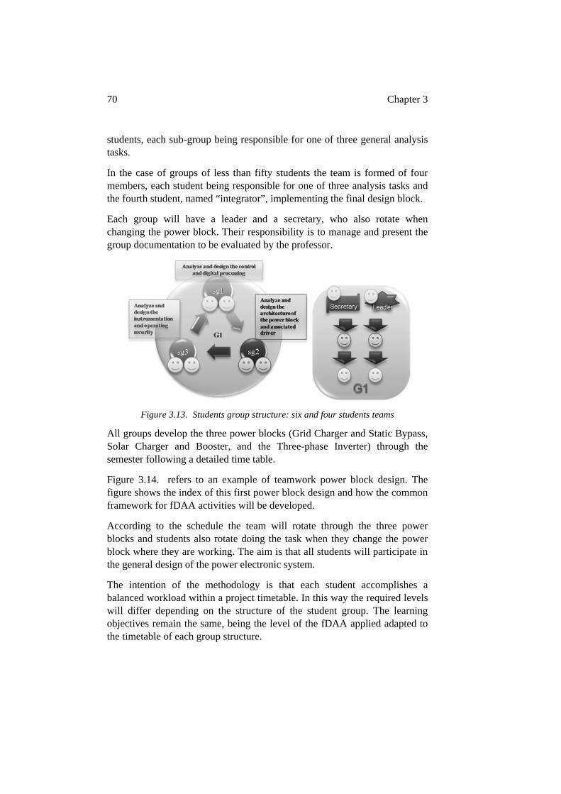
70 Chapter 3
students, each sub-group being responsible for one of three general analysis tasks.
In the case of groups of less than fifty students the team is formed of four members, each student being responsible for one of three analysis tasks and the fourth student, named “integrator”, implementing the final design block.
Each group will have a leader and a secretary, who also rotate when changing the power block. Their responsibility is to manage and present the group documentation to be evaluated by the professor.
Figure 3.13. Students group structure: six and four students teams
All groups develop the three power blocks (Grid Charger and Static Bypass, Solar Charger and Booster, and the Three-phase Inverter) through the semester following a detailed time table.
Figure 3.14. refers to an example of teamwork power block design. The figure shows the index of this first power block design and how the common framework for fDAA activities will be developed.
According to the schedule the team will rotate through the three power blocks and students also rotate doing the task when they change the power block where they are working. The aim is that all students will participate in the general design of the power electronic system.
The intention of the methodology is that each student accomplishes a balanced workload within a project timetable. In this way the required levels will differ depending on the structure of the student group. The learning objectives remain the same, being the level of the fDAA applied adapted to the timetable of each group structure.
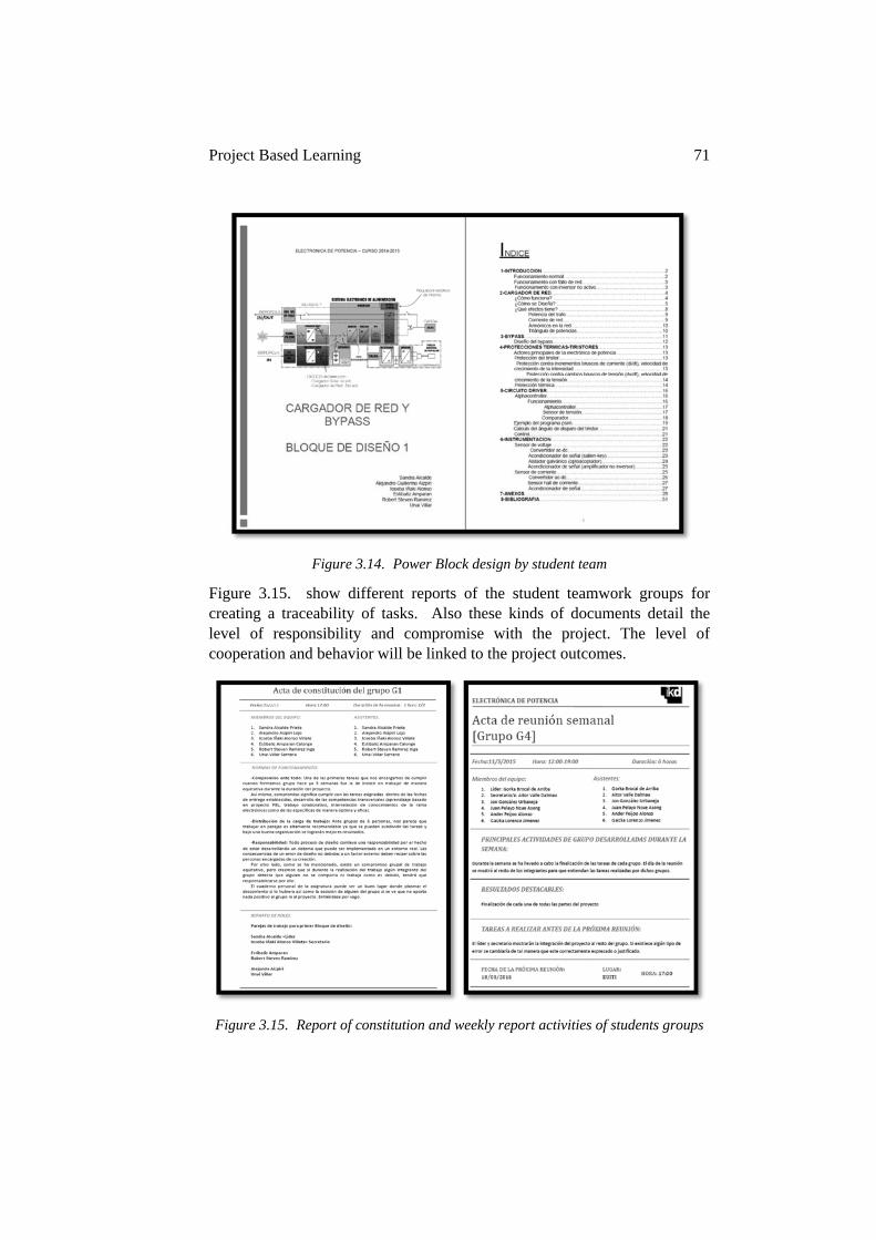
Project Based Learning 71
Figure 3.14. Power Block design by student team
Figure 3.15. show different reports of the student teamwork groups for creating a traceability of tasks. Also these kinds of documents detail the level of responsibility and compromise with the project. The level of cooperation and behavior will be linked to the project outcomes.
Figure 3.15. Report of constitution and weekly report activities of students groups
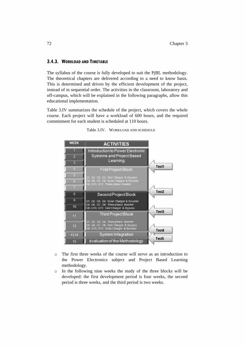
72 Chapter 3
3.4.3. WORKLOAD AND TIMETABLE
The syllabus of the course is fully developed to suit the PjBL methodology. The theoretical chapters are delivered according to a need to know basis. This is determined and driven by the efficient development of the project, instead of in sequential order. The activities in the classroom, laboratory and off-campus, which will be explained in the following paragraphs, allow this educational implementation.
Table 3.IV summarizes the schedule of the project, which covers the whole course. Each project will have a workload of 600 hours, and the required commitment for each student is scheduled at 110 hours.
Table 3.IV. WORKLOAD AND SCHEDULE
o The first three weeks of the course will serve as an introduction to the Power Electronics subject and Project Based Learning methodology.
o In the following nine weeks the study of the three blocks will be developed: the first development period is four weeks, the second period is three weeks, and the third period is two weeks.
Test1
Test2
Test3
Test4
Test5
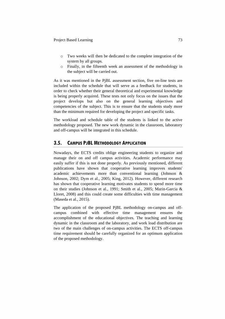
Project Based Learning 73
o Two weeks will then be dedicated to the complete integration of the system by all groups.
o Finally, in the fifteenth week an assessment of the methodology in the subject will be carried out.
As it was mentioned in the PjBL assessment section, five on-line tests are included within the schedule that will serve as a feedback for students, in order to check whether their general theoretical and experimental knowledge is being properly acquired. These tests not only focus on the issues that the project develops but also on the general learning objectives and competencies of the subject. This is to ensure that the students study more than the minimum required for developing the project and specific tasks.
The workload and schedule table of the students is linked to the active methodology proposed. The new work dynamic in the classroom, laboratory and off-campus will be integrated in this schedule.
3.5. CAMPUS PJBL METHODOLOGY APPLICATION
Nowadays, the ECTS credits oblige engineering students to organize and manage their on and off campus activities. Academic performance may easily suffer if this is not done properly. As previously mentioned, different publications have shown that cooperative learning improves students' academic achievements more than conventional learning (Johnson & Johnson, 2002; Dym et al., 2005; King, 2012). However, different research has shown that cooperative learning motivates students to spend more time on their studies (Johnson et al., 1991; Smith et al., 2005; Marin-Garcia & Lloret, 2008) and this could create some difficulties with time management (Maseda et al., 2015).
The application of the proposed PjBL methodology on-campus and off-campus combined with effective time management ensures the accomplishment of the educational objectives. The teaching and learning dynamic in the classroom and the laboratory, and work load distribution are two of the main challenges of on-campus activities. The ECTS off-campus time requirement should be carefully organized for an optimum application of the proposed methodology.
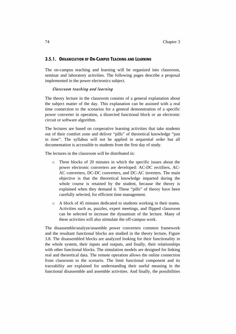
74 Chapter 3
3.5.1. ORGANIZATION OF ON-CAMPUS TEACHING AND LEARNING
The on-campus teaching and learning will be organized into classroom, seminar and laboratory activities. The following pages describe a proposal implemented in the power electronics subject.
Classroom teaching and learning
The theory lecture in the classroom consists of a general explanation about the subject matter of the day. This explanation can be assisted with a real time connection to the scenarios for a general demonstration of a specific power converter in operation, a dissected functional block or an electronic circuit or software algorithm.
The lectures are based on cooperative learning activities that take students out of their comfort zone and deliver “pills” of theoretical knowledge “just in time”. The syllabus will not be applied in sequential order but all documentation is accessible to students from the first day of study.
The lectures in the classroom will be distributed in:
o Three blocks of 20 minutes in which the specific issues about the power electronic converters are developed: AC-DC rectifiers, AC-AC converters, DC-DC converters, and DC-AC inverters. The main objective is that the theoretical knowledge imparted during the whole course is retained by the student, because the theory is explained when they demand it. These “pills” of theory have been carefully selected, for efficient time management.
o A block of 45 minutes dedicated to students working in their teams. Activities such as, puzzles, expert meetings, and flipped classroom can be selected to increase the dynamism of the lecture. Many of these activities will also stimulate the off-campus work.
The disassemble/analyze/assemble power converters common framework and the resultant functional blocks are studied in the theory lecture, Figure 3.8. The disassembled blocks are analyzed looking for their functionality in the whole system, their inputs and outputs, and finally, their relationships with other functional blocks. The simulation models are designed for linking real and theoretical data. The remote operation allows the online connection from classroom to the scenario. The limit functional component and its traceability are explained for understanding their useful meaning in the functional disassemble and assemble activities. And finally, the possibilities
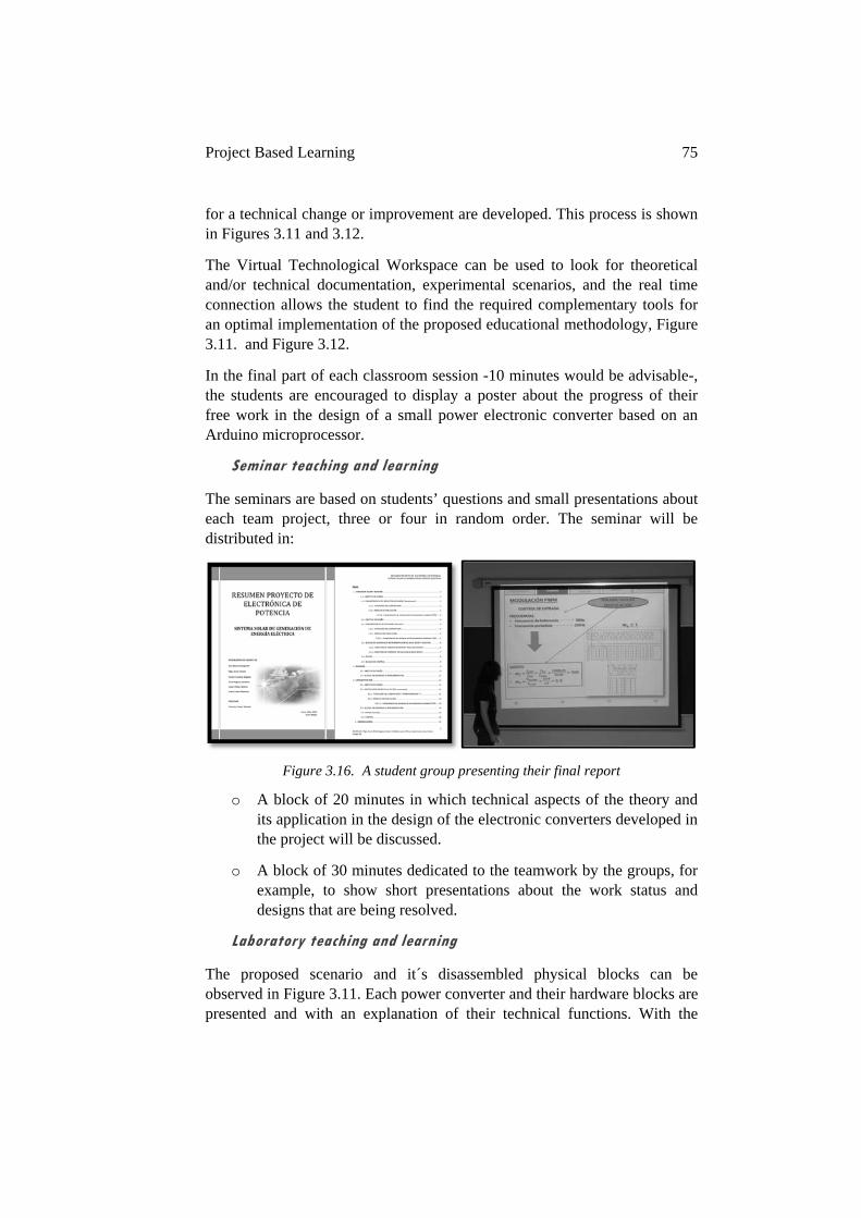
Project Based Learning 75
for a technical change or improvement are developed. This process is shown in Figures 3.11 and 3.12.
The Virtual Technological Workspace can be used to look for theoretical and/or technical documentation, experimental scenarios, and the real time connection allows the student to find the required complementary tools for an optimal implementation of the proposed educational methodology, Figure 3.11. and Figure 3.12.
In the final part of each classroom session -10 minutes would be advisable-, the students are encouraged to display a poster about the progress of their free work in the design of a small power electronic converter based on an Arduino microprocessor.
Seminar teaching and learning
The seminars are based on students’ questions and small presentations about each team project, three or four in random order. The seminar will be distributed in:
Figure 3.16. A student group presenting their final report
o A block of 20 minutes in which technical aspects of the theory and its application in the design of the electronic converters developed in the project will be discussed.
o A block of 30 minutes dedicated to the teamwork by the groups, for example, to show short presentations about the work status and designs that are being resolved.
Laboratory teaching and learning
The proposed scenario and it´s disassembled physical blocks can be observed in Figure 3.11. Each power converter and their hardware blocks are presented and with an explanation of their technical functions. With the
76 Chapter 3
system running the students can observe the function of each power converter. There is a presentation of the software modular blocks to help students understand the control and instrumentation capabilities. Students can work in different team structures depending on the task they decide to develop.
The laboratory time will be distributed in:
o A block of 2 hours to carry out the tasks related to the scenario manipulation, model simulation work (PSIM) or basic microprocessor (Arduino) peripheral applications, all of them included in the block of the project which is being developed.
The scenarios are not static systems as they can evolve or change with students’ ideas. This capability contributes to the enhancement of student´s motivation to understand the electrical power electronic conversion and its effects in the grid and the load.
In conclusion, the PjBL methodology in on-campus activities is fully applied: the theory is delivered when the project demands the knowledge; the seminars are based on students’ questions about how to apply the theory to a specific project design and small presentations about the status of the projects are shown; the practical activities are based on scenario manipulation, the simulation of functional blocks, and development of electronic circuits and software prototypes to implement into parts of the system.
3.5.2. ORGANIZATION OFF-CAMPUS
It is recommended that the off-campus teaching and learning activities in this power electronics case study be distributed as follows, 5 hours per week for fifteen weeks for off-campus activities and 15 hours left for final exam preparation.
Group meeting (1.5 hours per week)
In team meetings the students will share with the group the results of individually performed tasks in both on-campus and off-campus activities. Each of them is responsible for the dissection of a block within the converter that is being designed and will explain to the other members the development of the theoretical and practical work.
The results are the sum of the activities developed and time spent doing them (sent weekly by the leader or secretary to the professor), Figure 3.12.
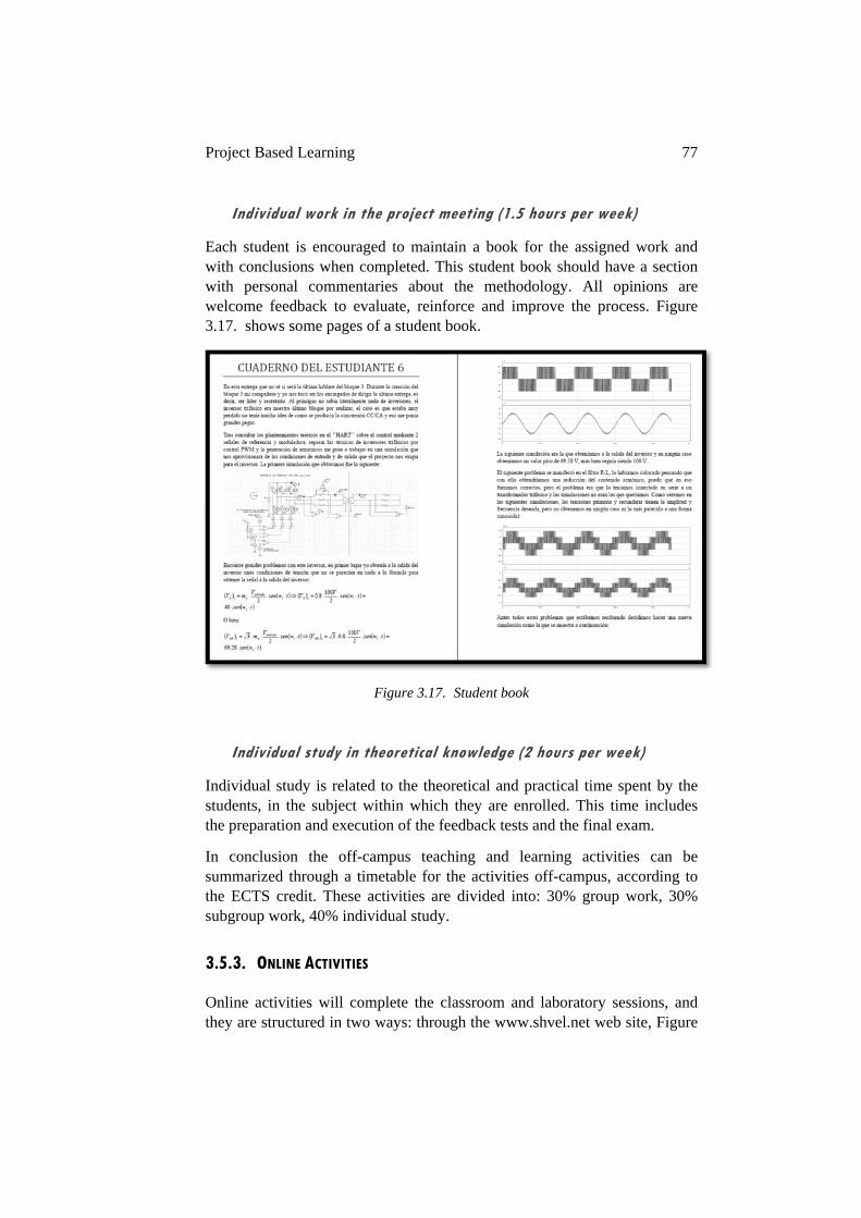
Project Based Learning 77
Individual work in the project meeting (1.5 hours per week)
Each student is encouraged to maintain a book for the assigned work and with conclusions when completed. This student book should have a section with personal commentaries about the methodology. All opinions are welcome feedback to evaluate, reinforce and improve the process. Figure 3.17. shows some pages of a student book.
Figure 3.17. Student book
Individual study in theoretical knowledge (2 hours per week)
Individual study is related to the theoretical and practical time spent by the students, in the subject within which they are enrolled. This time includes the preparation and execution of the feedback tests and the final exam.
In conclusion the off-campus teaching and learning activities can be summarized through a timetable for the activities off-campus, according to the ECTS credit. These activities are divided into: 30% group work, 30% subgroup work, 40% individual study.
3.5.3. ONLINE ACTIVITIES
Online activities will complete the classroom and laboratory sessions, and they are structured in two ways: through the www.shvel.net web site, Figure
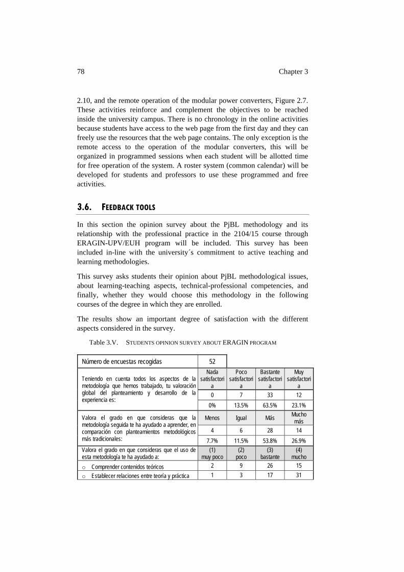
78 Chapter 3
2.10, and the remote operation of the modular power converters, Figure 2.7. These activities reinforce and complement the objectives to be reached inside the university campus. There is no chronology in the online activities because students have access to the web page from the first day and they can freely use the resources that the web page contains. The only exception is the remote access to the operation of the modular converters, this will be organized in programmed sessions when each student will be allotted time for free operation of the system. A roster system (common calendar) will be developed for students and professors to use these programmed and free activities.
3.6. FEEDBACK TOOLS
In this section the opinion survey about the PjBL methodology and its relationship with the professional practice in the 2104/15 course through ERAGIN-UPV/EUH program will be included. This survey has been included in-line with the university´s commitment to active teaching and learning methodologies.
This survey asks students their opinion about PjBL methodological issues, about learning-teaching aspects, technical-professional competencies, and finally, whether they would choose this methodology in the following courses of the degree in which they are enrolled.
The results show an important degree of satisfaction with the different aspects considered in the survey.
Table 3.V. STUDENTS OPINION SURVEY ABOUT ERAGIN PROGRAM
Número de encuestas recogidas 52
Teniendo en cuenta todos los aspectos de la metodología que hemos trabajado, tu valoración global del planteamiento y desarrollo de la experiencia es:
Nada satisfactori
a
Poco satisfactori
a
Bastante satisfactori
a
Muy satisfactori
a
0 7 33 12
0% 13.5% 63.5% 23.1%
Valora el grado en que consideras que la metodología seguida te ha ayudado a aprender, en comparación con planteamientos metodológicos más tradicionales:
Menos Igual Más Mucho más
4 6 28 14
7.7% 11.5% 53.8% 26.9%
Valora el grado en que consideras que el uso de esta metodología te ha ayudado a:
(1) muy poco
(2) poco
(3) bastante
(4) mucho
o Comprender contenidos teóricos 2 9 26 15
o Establecer relaciones entre teoría y práctica 1 3 17 31
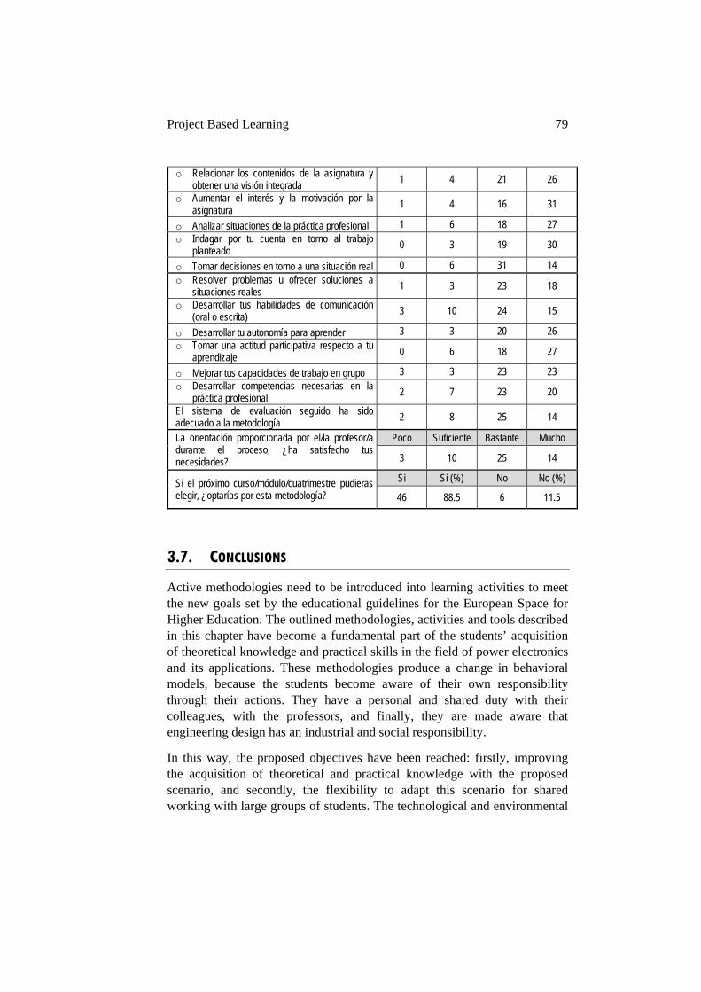
Project Based Learning 79
o Relacionar los contenidos de la asignatura y obtener una visión integrada
1 4 21 26
o Aumentar el interés y la motivación por la asignatura
1 4 16 31
o Analizar situaciones de la práctica profesional 1 6 18 27 o Indagar por tu cuenta en torno al trabajo
planteado 0 3 19 30
o Tomar decisiones en torno a una situación real 0 6 31 14 o Resolver problemas u ofrecer soluciones a
situaciones reales 1 3 23 18
o Desarrollar tus habilidades de comunicación (oral o escrita)
3 10 24 15
o Desarrollar tu autonomía para aprender 3 3 20 26 o Tomar una actitud participativa respecto a tu
aprendizaje 0 6 18 27
o Mejorar tus capacidades de trabajo en grupo 3 3 23 23 o Desarrollar competencias necesarias en la
práctica profesional 2 7 23 20
El sistema de evaluación seguido ha sido adecuado a la metodología
2 8 25 14
La orientación proporcionada por el/la profesor/a durante el proceso, ¿ha satisfecho tus necesidades?
Poco Suficiente Bastante Mucho
3 10 25 14
Si el próximo curso/módulo/cuatrimestre pudieras elegir, ¿optarías por esta metodología?
Si Si (%) No No (%)
46 88.5 6 11.5
3.7. CONCLUSIONS
Active methodologies need to be introduced into learning activities to meet the new goals set by the educational guidelines for the European Space for Higher Education. The outlined methodologies, activities and tools described in this chapter have become a fundamental part of the students’ acquisition of theoretical knowledge and practical skills in the field of power electronics and its applications. These methodologies produce a change in behavioral models, because the students become aware of their own responsibility through their actions. They have a personal and shared duty with their colleagues, with the professors, and finally, they are made aware that engineering design has an industrial and social responsibility.
In this way, the proposed objectives have been reached: firstly, improving the acquisition of theoretical and practical knowledge with the proposed scenario, and secondly, the flexibility to adapt this scenario for shared working with large groups of students. The technological and environmental
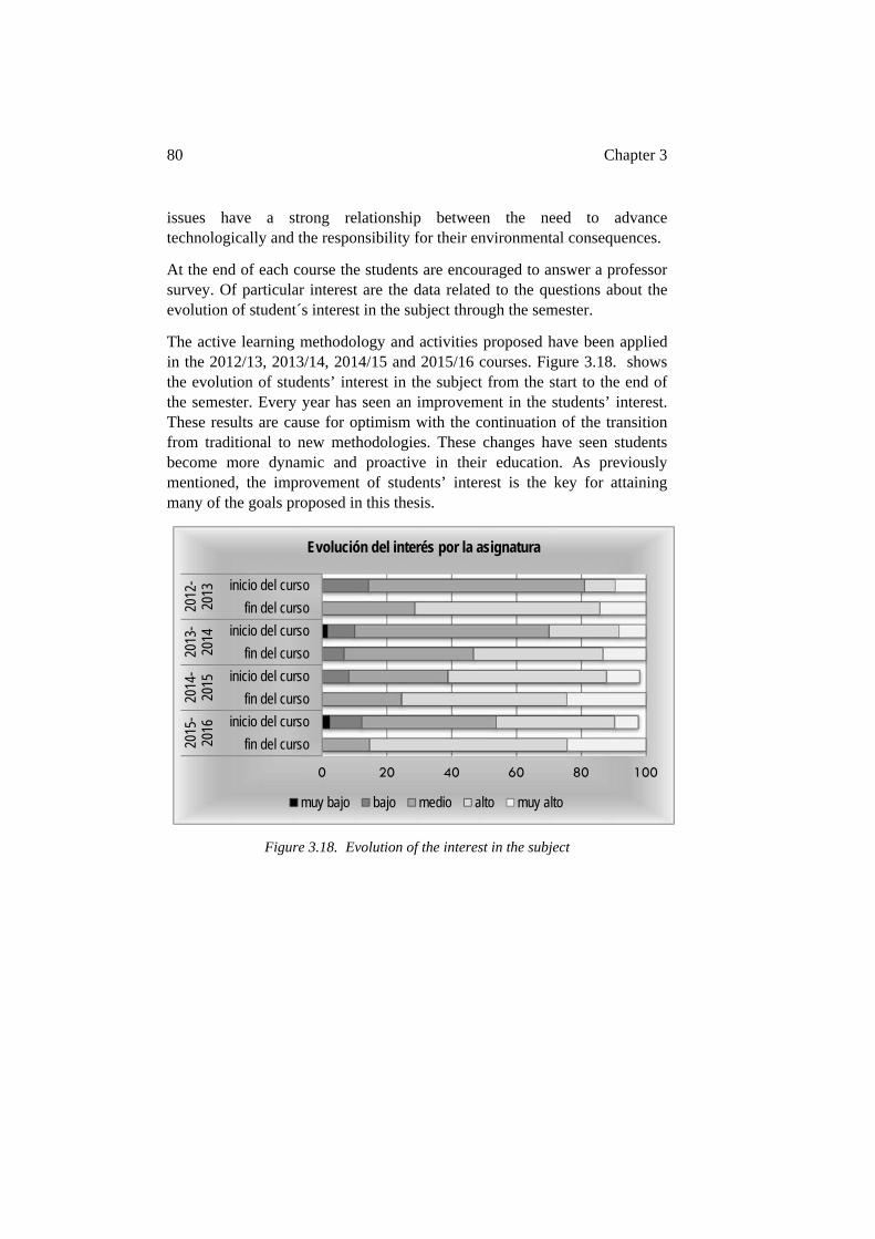
80 Chapter 3
issues have a strong relationship between the need to advance technologically and the responsibility for their environmental consequences.
At the end of each course the students are encouraged to answer a professor survey. Of particular interest are the data related to the questions about the evolution of student´s interest in the subject through the semester.
The active learning methodology and activities proposed have been applied in the 2012/13, 2013/14, 2014/15 and 2015/16 courses. Figure 3.18. shows the evolution of students’ interest in the subject from the start to the end of the semester. Every year has seen an improvement in the students’ interest. These results are cause for optimism with the continuation of the transition from traditional to new methodologies. These changes have seen students become more dynamic and proactive in their education. As previously mentioned, the improvement of students’ interest is the key for attaining many of the goals proposed in this thesis.
Figure 3.18. Evolution of the interest in the subject
0 20 40 60 80 100
fin del curso
inicio del curso
fin del curso
inicio del curso
fin del curso
inicio del curso
fin del curso
inicio del curso
2015
-20
1620
14-
2015
2013
-20
1420
12-
2013
Evolución del interés por la asignatura
muy bajo bajo medio alto muy alto
Chapter 4 - Shared Hybrid Virtual-Experimental Laboratory
This chapter describes in a more detailed way the novel vision of experimental laboratory for developing many of the practical activities in the PjBL methodology shown in Chapter 3. Furthermore, the laboratory proposed has the traditional characteristics of experimental work in electronic engineering in the fields of power electronics and its industrial applications (Feisel & Peterson, 2002; Gedra et al., 2004; Feisel & Rosa, 2005; Shirsavar et al., 2006; De la Hoz et al., 2009; Maseda et al., 2013; Zhang et al., 2016). The experimental learning activities have been developed to improve the technical skills and motivation for practical work and the application of theoretical knowledge (Underland & Mohan., 2002; Max et al., 2009; Ndtoungou et al., 2011; Choi & Saeedifard, 2012). The laboratory facilitates training with software and hardware elements in quasi industrial electronic systems: the main pedagogical objective through experimental work is the transfer from academic understanding to professional practice (Wang & Liu., 2008; Anand et al., 2012; Nikolic et al., 2015).
The remote operation of the scenarios and the specialized technical resources shared on the proposed web site become a great resource for student stimulus (Esquembre, 2015; Hoic-Bozic et al., 2016). The capability of total access to parameters and variables in the proposed educational scenarios, which are difficult to manage in commercial equipment, promotes students curiosity and enhances academic proficiency.
A better use of the hands-on laboratory equipment and the simulation software in real design are topics within the scope of the proposed laboratory.
The Shared Hybrid Virtual-Experimental Laboratory (SHVEL) proposed in this thesis is devoted to make engineering studies more technologically attractive and closer to the reality of industrial environments (Patil & Pudlowski, 2003; Alekseevich et al., 2012; Choi & Saeedifard, 2012). To attain the proposed objectives, the experimental laboratory is divided into physical and virtual environments: the physical environment will be represented by Electrical Machine and Power Electronics Training Tools (EM&PETT) and the virtual environment will be represented by the website www.shvel.net.
82 Chapter 4
4.1. INTRODUCTION
The importance of experimental laboratories in engineering education is not in doubt: they play a fundamental role in the engineering student’s acquisition of practical skills. These skills are basic for engineering students who are not only going to work in research and development but mainly in an industrial context (Feisel & Peterson, 2002; Feisel & Rosa, 2005; Costas-Perez et al., 2008; Chidthachack et al., 2013; Upadhayay & Vrat, 2016).
Over the years problems related with the cost of experimental laboratories, the high ratio of students to professor and subjects associated with high voltages and currents present in electric energy converters have been leading the practical studies in the electronics laboratory to solutions based on simulation software (Allwood et al., 2001; Chung et al., 2001; Tao et al., 2006; Baltzis et al., 2009). In addition, the workbench equipment in hands-on laboratories is usually not flexible enough for incorporating new tasks and this can become a difficulty when technological changes must be incorporated into educational models (Naef, 2006; Tao et al., 2006, Leva & Donida, 2008; Choi & Saeedifard, 2012; Barata et al., 2015). And finally, new solutions based on combining internet technologies and traditional experimental laboratories should be developed (Hercog et al., 2007).
The Web 2.0 technologies have given a new focus for classroom educational methodologies (Wu et al., 2008; Holbert & Karadi, 2009; Jara et al., 2009; Martija et al., 2011; Klemes et al., 2013; Barata et al., 2015). The extension of these ideas into experimental laboratories allowing the integration of theoretical topics and materials with experimental devices, tools and applications in a given industrial context allows for a new experimental scope (Martija et al., 2014).
In the following sections the SHVEL introduces a novel philosophy for improving the experimental work. It introduces the utilization of real and virtual scenarios and tools for improving experimental practice (Maseda et al., 2012; Esquembre, 2015). The combination of the educational features of simulation software, the traditional hands-on laboratory and the internet in these scenarios help increase motivation (Alexander & Smelser, 2003; Aziz et al., 2007; Jara et al., 2009). In summary, focusing on all of these characteristics, it is possible to develop an attractive and modern experimental space which can contribute to improving the experimental and professional competencies of engineering students (Rossiter, 2012).
Shared Hybrid Virtual-Experimental Laboratory 83
4.2. THE LABORATORY
Figure 4.1 shows the proposed Shared Hybrid-Virtual Experimental Laboratory (SHVEL) educational environment. The laboratory is composed of three basic resources: the experimental work methodology for new designs, the EM&PETT or SHVEL units, and the web platform (http://www.shvel.net, accessed 9th November 2016). The SHVEL is integrated with the classroom, the hands-on laboratory and off-campus educational activities. Theoretical issues outlined in the classroom are associated with the technical resources included in the SHVEL for a deeper understanding. The experimental work, the simulation models, and the practical designs are related to functional blocks and the specific parts of the SHVEL units for improving students’ competencies.
The pedagogical objectives of the SHVEL are: improving students’ motivation for working in experiments in real power electronic systems, developing their technical skills in different areas, and enhancing knowledge through a better understanding of abstract theoretical concepts and to reinforce the explanation given in a theory study environment (Strong, 2012; Chidthachack et al., 2013; Litchfield et al., 2016).
The most outstanding technical characteristic of the proposed laboratory is its flexibility. The aim is to create an open environment, within the power electronics and electric machine areas, which allows student interaction. In order to create this environment, the proposed laboratory reduces complete power electronic systems into modular functional blocks (Dalrymple et al., 2011; Martija et al, 2013). These blocks incorporate normalized inputs and outputs, and have a clearly defined function in the system.
The access level to the system resources, for both the controller and the controlled system, can be considered as the major advantage of the proposed laboratory. The possibility of manipulating quasi industrial equipment involves responsibility, and taking into account the security conditions of working with high voltages.
The preparation of the power electronic system environment is an important first step. The students follow a well designed methodology, which will be explained in the next section. The design of the new SHVEL equipment is based on industry experience. A basic knowledge of microprocessors and of its programming tools is necessary for the development of an accessible and secure environment capable of being interfaced by the students (Hercog et al., 2007; Kumar et al., 2013; Muoka et al., 2015).
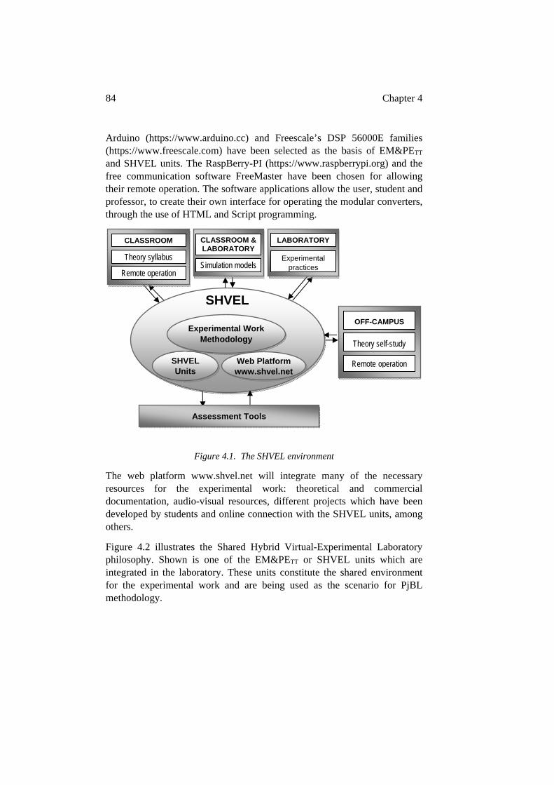
84 Chapter 4
Arduino (https://www.arduino.cc) and Freescale’s DSP 56000E families (https://www.freescale.com) have been selected as the basis of EM&PETT and SHVEL units. The RaspBerry-PI (https://www.raspberrypi.org) and the free communication software FreeMaster have been chosen for allowing their remote operation. The software applications allow the user, student and professor, to create their own interface for operating the modular converters, through the use of HTML and Script programming.
Figure 4.1. The SHVEL environment
The web platform www.shvel.net will integrate many of the necessary resources for the experimental work: theoretical and commercial documentation, audio-visual resources, different projects which have been developed by students and online connection with the SHVEL units, among others.
Figure 4.2 illustrates the Shared Hybrid Virtual-Experimental Laboratory philosophy. Shown is one of the EM&PETT or SHVEL units which are integrated in the laboratory. These units constitute the shared environment for the experimental work and are being used as the scenario for PjBL methodology.
Theory syllabus
CLASSROOM
Experimental practices
LABORATORY
Simulation models
CLASSROOM & LABORATORY
Experimental Work Methodology
Web Platform www.shvel.net
SHVEL Units
Assessment Tools
OFF-CAMPUS
Theory self-study
SHVEL
Remote operation
Remote operation
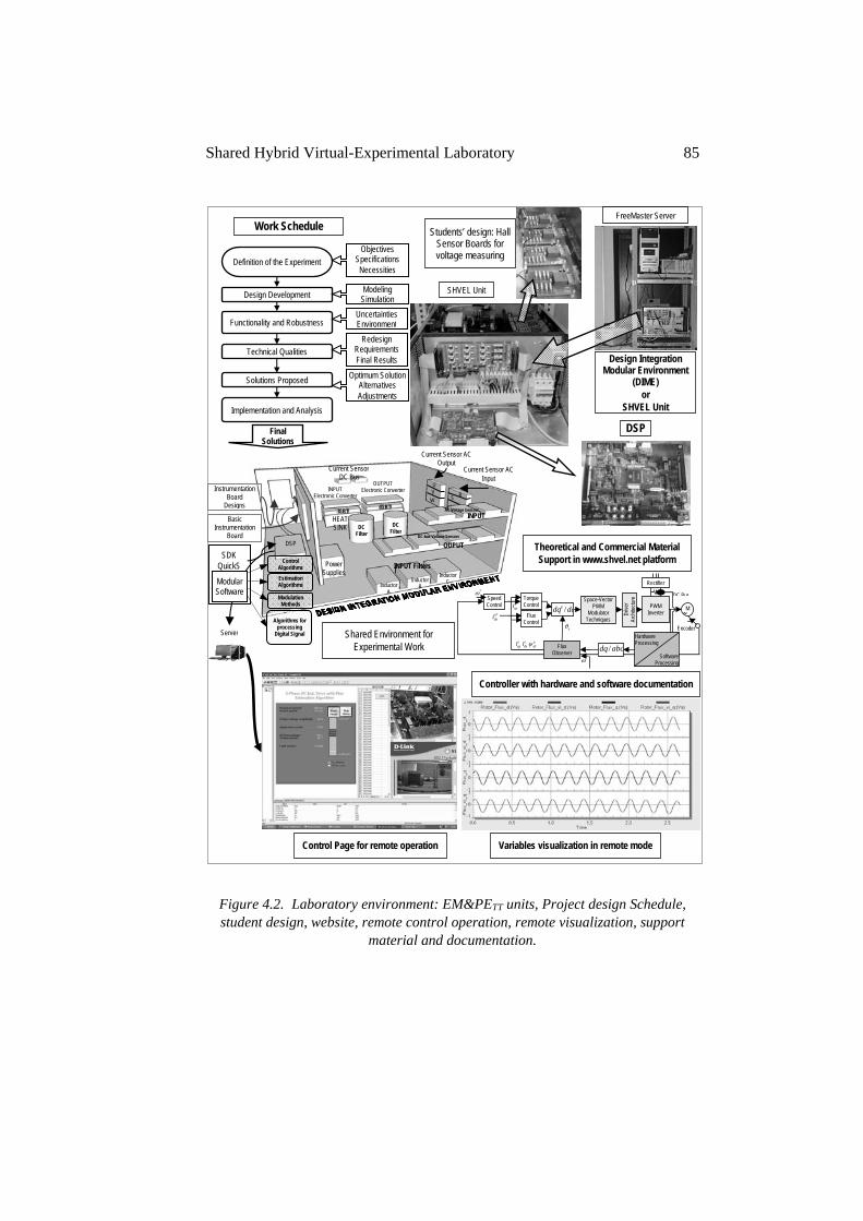
Shared Hybrid Virtual-Experimental Laboratory 85
Figure 4.2. Laboratory environment: EM&PETT units, Project design Schedule, student design, website, remote control operation, remote visualization, support
material and documentation.
Design Development
Functionality and Robustness
Technical Qualities
Solutions Proposed
Implementation and Analysis
Objectives Specifications Necessities
Modeling Simulation
Uncertainties Environment
Redesign Requirements Final Results
Optimum Solution Alternatives Adjustments
Final Solutions
Definition of the Experiment
DSP
FreeMaster Server
Design Integration Modular Environment
(DIME) or
SHVEL Unit
Instrumentation Board
Designs
INPUT Filters
Inductor A
Inductor B
Inductor C
Power Supplies
DC Filter
DC Filter
DC-bus Voltage Sensors
DSP
AC Voltage Sensors
U V R S
Current Sensor AC Output
Current Sensor AC Input
Basic Instrumentation
Board
INPUT Electronic Converter
OUTPUT Electronic Converter
IGBT IGBT
HEAT SINK
SDK QuickS
Control Algorithms
Estimation Algorithms
Modulation Methods
Algorithms for processing
Digital Signal Server
Students’ design: Hall Sensor Boards for voltage measuring
SHVEL Unit
Hardware Processing
Software Processing
Speed Control
Torque Control
Flux Control
dqdqe /Space-Vector
PWM Modulator
Techniques
*eqsi
*
Driv
er
Arch
itect
ure
PWM Inverter
M
Flux Observer
Rectifier
abcdq /
*edsi
DC Bus
Encoder
e
edr
eds
eqs ii
Controller with hardware and software documentation
INPUT
OUPUT
Control Page for remote operation Variables visualization in remote mode
Shared Environment for Experimental Work
Current Sensor DC Bus
Modular Software
Work Schedule
Theoretical and Commercial Material Support in www.shvel.net platform
W
86 Chapter 4
The technical qualities of SHVEL laboratory can be outlined as:
o Total access to the EM&PETT or SHVEL units’ hardware resources: the DSP integrated periphery, the instrumentation sensors, electronic boards and power blocks, among others.
o Total access to the EM&PETT or SHVEL units’ software resources: the control and estimation algorithms, modulation methods and the algorithms for processing digital signals.
o The EM&PETT or SHVEL units’ remote operation: remote control, parameter measurement and visualization of the SHVEL unit. The remote access is multiuser.
o The support material included in the web platform, to assist in the practice development. For example, the relationship between the control architecture used and the software and hardware modules implemented in EM&PETT or SHVEL units.
o And, finally, the capability for the incorporation of new designs into this modular system by the students. Figure 4.2 shows an example of the Hall Sensor Boards designed by the students for voltage measuring. These designs could cover a wide range, such as, hardware and software filters, different parameter estimation algorithms, such as flux or velocity, different architectures to command an electronic switch (IGBT, MOSFET, thyristor, etc) or other subsystems capable of being modulated and integrated into a more complex system.
The proposed laboratory constitutes an educational space that promotes the improvement of students’ skills in different areas. On one hand, students’ motivation is reinforced because they know that they are working in a real power system, testing and improving their technical competency. And, on the other hand, the use of the computer on collaborative platforms not only as a technical instrument but as a tool for communication, from any place at any time, and the possibilities of sharing objectives, resources and results will promote and improve teamwork and social skills.
4.3. ELECTRIC MACHINE AND POWER ELECTRONIC TRAINING TOOLS
(EM&PETT)
There is a limited number of publications that deal with novel training tools in engineering laboratories. However the importance of this educational
Shared Hybrid Virtual-Experimental Laboratory 87
equipment in practical engineering education is unquestionable (Feisel & Rosa, 2005). In the last few years different publications on innovative solutions have been proposed to enhance practical training in experimental laboratories, fundamentally oriented to industrial applications (Alekseevich et al., 2012).
Figure 2.2 and 2.3 in Chapter 2 show different Electric Machine and Power Electronic Training Tool (EM&PETT) scenarios and different architectures which could have a specific scenario. These experimental technological environments are designed to meet experimental learning objectives: to model industrial equipment mathematically and design their simulation models, to design drivers and instrumentation circuits and boards, to develop software algorithms for multiple tasks, to experiment and compare real data with simulation results, to link different communication systems, to develop teamwork and ethical attitudes in the laboratory.
The EM&PETT tools are located in the Power Electronics laboratory and in the Research Clear Energies laboratory. Each EM&PETT is applied as an educational tool in various ways; its complexity varies according to the level of the student. The modularity of the system facilitates comprehension of the physical composition and dimensional range of the hardware system, and of the software structure of the control functions and mathematical algorithms for operating this hardware. Redesigning these modular blocks and introducing them into the original EM&PETT allow students to conduct experimental work with power systems of a category that is generally only simulated. The remote control facilitates the study of components and circuits under high voltages and currents.
As described in Chapter 2, Fig 2.4, an EM&PETT can be designed from industrial equipment and from a series of small prototypes which are connected to obtain a power electronic system. These two simultaneous forms for applying the fDAA activities into a PjBL methodology will result in an optimum educational environment.
There is no doubt that the students benefit from working with experimental educational equipment that allows them to configure an experiment, take data with measurement instrumentation, and draw some conclusions about the experiment; nor is there any doubt of the benefit of simulation software as an experimental learning tool. The opportunity for comparing the results between simulation and real experimental work give students a better overview about the application of theoretical knowledge.
The proposal of this thesis, however, is to go beyond this:
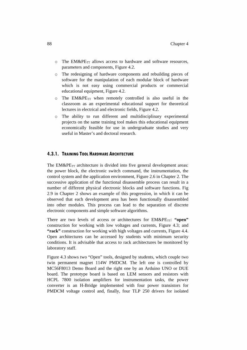
88 Chapter 4
o The EM&PETT allows access to hardware and software resources, parameters and components, Figure 4.2.
o The redesigning of hardware components and rebuilding pieces of software for the manipulation of each modular block of hardware which is not easy using commercial products or commercial educational equipment, Figure 4.2.
o The EM&PETT when remotely controlled is also useful in the classroom as an experimental educational support for theoretical lectures in electrical and electronic fields, Figure 4.2.
o The ability to run different and multidisciplinary experimental projects on the same training tool makes this educational equipment economically feasible for use in undergraduate studies and very useful in Master’s and doctoral research.
4.3.1. TRAINING TOOL HARDWARE ARCHITECTURE
The EM&PETT architecture is divided into five general development areas: the power block, the electronic switch command, the instrumentation, the control system and the application environment, Figure 2.6 in Chapter 2. The successive application of the functional disassemble process can result in a number of different physical electronic blocks and software functions. Fig 2.9 in Chapter 2 shows an example of this progression, in which it can be observed that each development area has been functionally disassembled into other modules. This process can lead to the separation of discrete electronic components and simple software algorithms.
There are two levels of access or architectures for EM&PETT: “open” construction for working with low voltages and currents, Figure 4.3; and “rack” construction for working with high voltages and currents, Figure 4.4. Open architectures can be accessed by students with minimum security conditions. It is advisable that access to rack architectures be monitored by laboratory staff.
Figure 4.3 shows two “Open” tools, designed by students, which couple two twin permanent magnet 114W PMDCM. The left one is controlled by MC56F8013 Demo Board and the right one by an Arduino UNO or DUE board. The prototype board is based on LEM sensors and resistors with HCPL 7800 isolation amplifiers for instrumentation tasks, the power converter is an H-Bridge implemented with four power transistors for PMDCM voltage control and, finally, four TLP 250 drivers for isolated
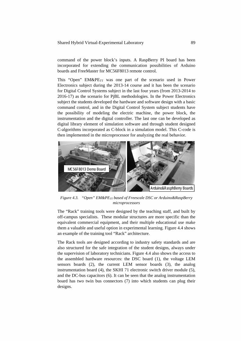
Shared Hybrid Virtual-Experimental Laboratory 89
command of the power block’s inputs. A RaspBerry PI board has been incorporated for extending the communication possibilities of Arduino boards and FreeMaster for MC56F8013 remote control.
This “Open” EM&PETT was one part of the scenario used in Power Electronics subject during the 2013-14 course and it has been the scenario for Digital Control Systems subject in the last four years (from 2013-2014 to 2016-17) as the scenario for PjBL methodologies. In the Power Electronics subject the students developed the hardware and software design with a basic command control, and in the Digital Control System subject students have the possibility of modeling the electric machine, the power block, the instrumentation and the digital controller. The last one can be developed as digital library element of simulation software and through student designed C-algorithms incorporated as C-block in a simulation model. This C-code is then implemented in the microprocessor for analyzing the real behavior.
Figure 4.3. “Open” EM&PETT based of Freescale DSC or Arduino&RaspBerry microprocessors
The “Rack” training tools were designed by the teaching staff, and built by off-campus specialists. These modular structures are more specific than the equivalent commercial equipment, and their multiple educational use make them a valuable and useful option in experimental learning. Figure 4.4 shows an example of the training tool “Rack” architecture.
The Rack tools are designed according to industry safety standards and are also structured for the safe integration of the student designs, always under the supervision of laboratory technicians. Figure 4.4 also shows the access to the assembled hardware resources: the DSC board (1), the voltage LEM sensors boards (2), the current LEM sensor boards (3), the analog instrumentation board (4), the SKHI 71 electronic switch driver module (5), and the DC-bus capacitors (6). It can be seen that the analog instrumentation board has two twin bus connectors (7) into which students can plug their designs.
MC56F8013 Demo Board
Arduino&RasphBerry Boards
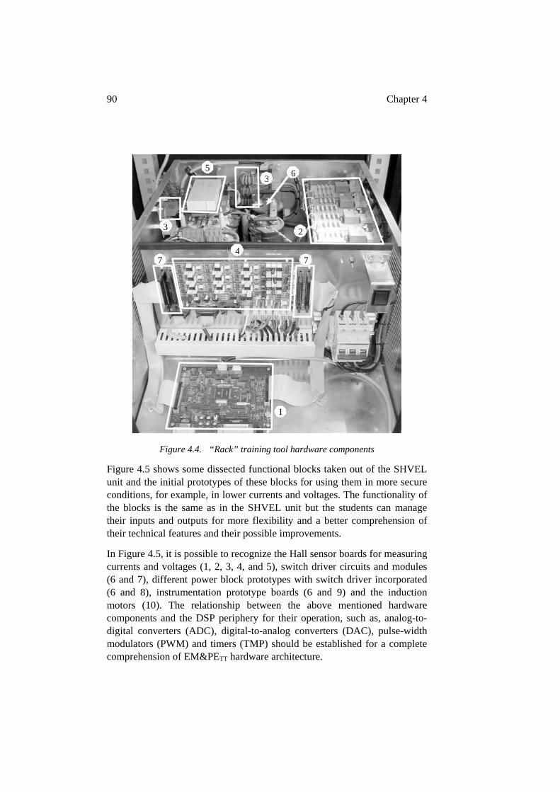
90 Chapter 4
Figure 4.4. “Rack” training tool hardware components
Figure 4.5 shows some dissected functional blocks taken out of the SHVEL unit and the initial prototypes of these blocks for using them in more secure conditions, for example, in lower currents and voltages. The functionality of the blocks is the same as in the SHVEL unit but the students can manage their inputs and outputs for more flexibility and a better comprehension of their technical features and their possible improvements.
In Figure 4.5, it is possible to recognize the Hall sensor boards for measuring currents and voltages (1, 2, 3, 4, and 5), switch driver circuits and modules (6 and 7), different power block prototypes with switch driver incorporated (6 and 8), instrumentation prototype boards (6 and 9) and the induction motors (10). The relationship between the above mentioned hardware components and the DSP periphery for their operation, such as, analog-to-digital converters (ADC), digital-to-analog converters (DAC), pulse-width modulators (PWM) and timers (TMP) should be established for a complete comprehension of EM&PETT hardware architecture.
1
2
3
3
4
5 6
7 7
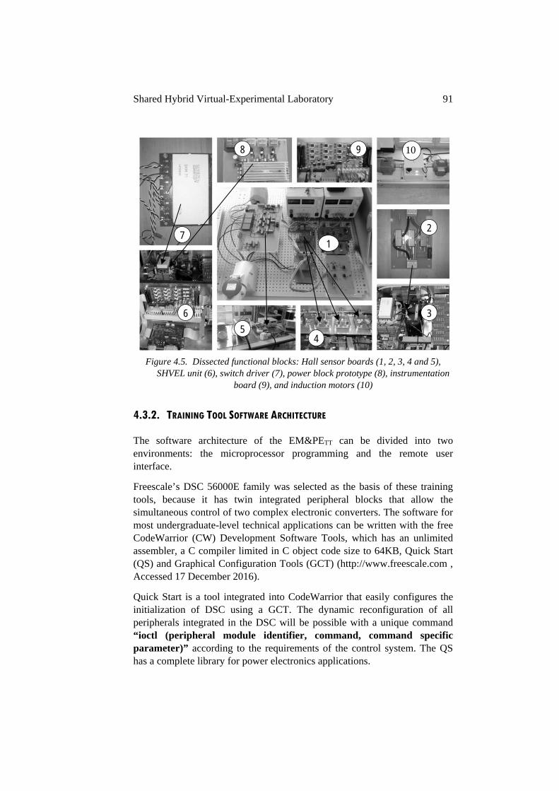
Shared Hybrid Virtual-Experimental Laboratory 91
Figure 4.5. Dissected functional blocks: Hall sensor boards (1, 2, 3, 4 and 5),
SHVEL unit (6), switch driver (7), power block prototype (8), instrumentation board (9), and induction motors (10)
4.3.2. TRAINING TOOL SOFTWARE ARCHITECTURE
The software architecture of the EM&PETT can be divided into two environments: the microprocessor programming and the remote user interface.
Freescale’s DSC 56000E family was selected as the basis of these training tools, because it has twin integrated peripheral blocks that allow the simultaneous control of two complex electronic converters. The software for most undergraduate-level technical applications can be written with the free CodeWarrior (CW) Development Software Tools, which has an unlimited assembler, a C compiler limited in C object code size to 64KB, Quick Start (QS) and Graphical Configuration Tools (GCT) (http://www.freescale.com , Accessed 17 December 2016).
Quick Start is a tool integrated into CodeWarrior that easily configures the initialization of DSC using a GCT. The dynamic reconfiguration of all peripherals integrated in the DSC will be possible with a unique command “ioctl (peripheral module identifier, command, command specific parameter)” according to the requirements of the control system. The QS has a complete library for power electronics applications.
1
2
3
4 5
6
7
8 9 10
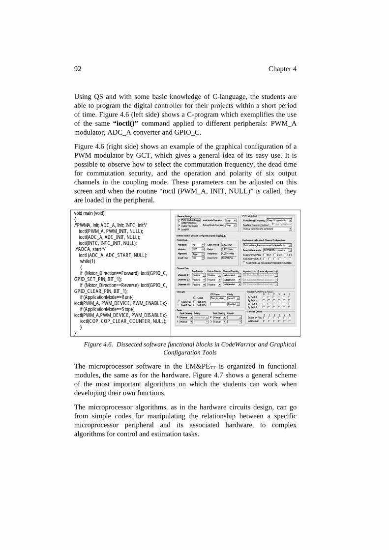
92 Chapter 4
Using QS and with some basic knowledge of C-language, the students are able to program the digital controller for their projects within a short period of time. Figure 4.6 (left side) shows a C-program which exemplifies the use of the same “ioctl()” command applied to different peripherals: PWM_A modulator, ADC_A converter and GPIO_C.
Figure 4.6 (right side) shows an example of the graphical configuration of a PWM modulator by GCT, which gives a general idea of its easy use. It is possible to observe how to select the commutation frequency, the dead time for commutation security, and the operation and polarity of six output channels in the coupling mode. These parameters can be adjusted on this screen and when the routine “ioctl (PWM_A, INIT, NULL)” is called, they are loaded in the peripheral.
void main (void) /*PWMA, init; ADC_A, Init; INTC, init*/ ioctl(PWM_A, PWM_INIT, NULL); ioctl(ADC_A, ADC_INIT, NULL); ioctl(INTC, INTC_INIT, NULL); /*ADCA, start */ ioctl (ADC_A, ADC_START, NULL): while(1) if (Motor_Direction==Forward) ioctl(GPIO_C, GPIO_SET_PIN, BIT_1); if (Motor_Direction==Reverse) ioctl(GPIO_C, GPIO_CLEAR_PIN, BIT_1); if (ApplicationMode==Run) ioctl(PWM_A, PWM_DEVICE, PWM_ENABLE); if (ApplicationMode==Stop) ioctl(PWM_A,PWM_DEVICE, PWM_DISABLE); ioctl(COP, COP_CLEAR_COUNTER, NULL);
Figure 4.6. Dissected software functional blocks in CodeWarrior and Graphical Configuration Tools
The microprocessor software in the EM&PETT is organized in functional modules, the same as for the hardware. Figure 4.7 shows a general scheme of the most important algorithms on which the students can work when developing their own functions.
The microprocessor algorithms, as in the hardware circuits design, can go from simple codes for manipulating the relationship between a specific microprocessor peripheral and its associated hardware, to complex algorithms for control and estimation tasks.
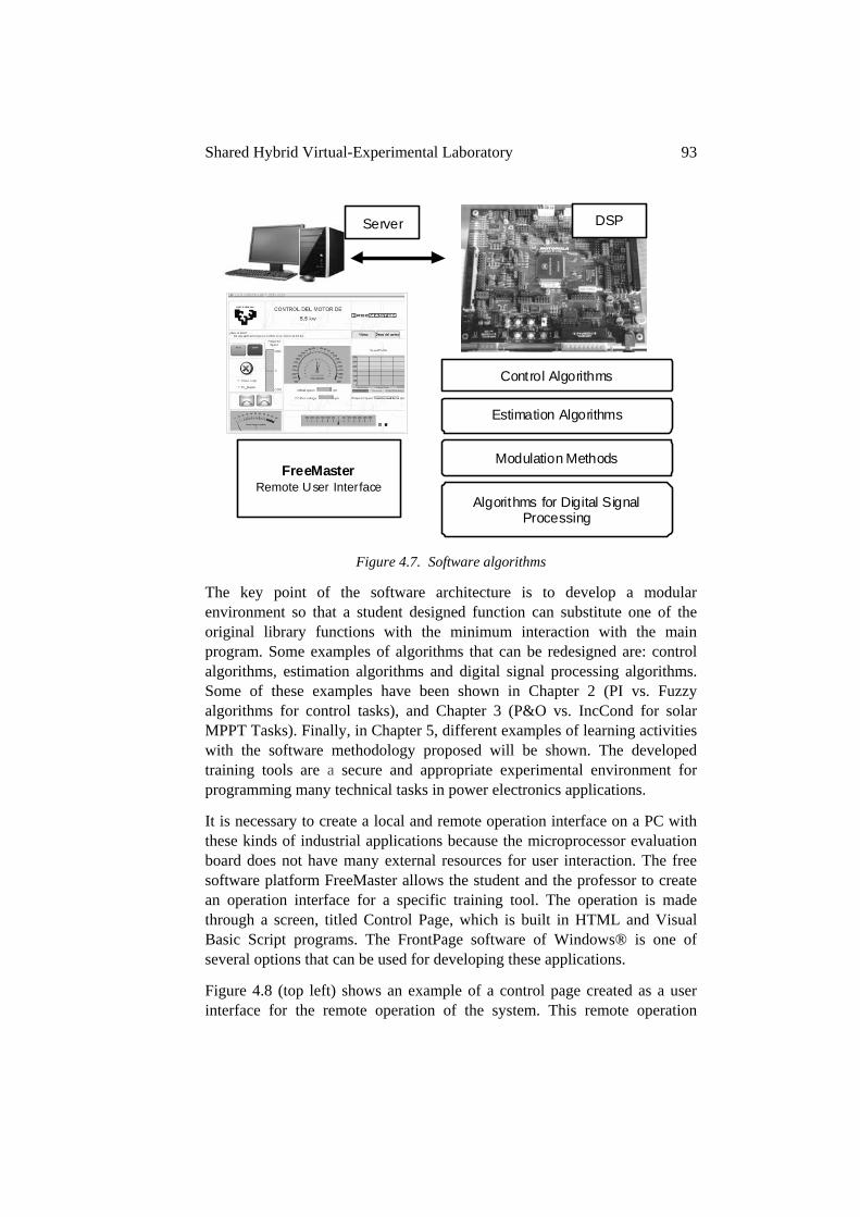
Shared Hybrid Virtual-Experimental Laboratory 93
Figure 4.7. Software algorithms
The key point of the software architecture is to develop a modular environment so that a student designed function can substitute one of the original library functions with the minimum interaction with the main program. Some examples of algorithms that can be redesigned are: control algorithms, estimation algorithms and digital signal processing algorithms. Some of these examples have been shown in Chapter 2 (PI vs. Fuzzy algorithms for control tasks), and Chapter 3 (P&O vs. IncCond for solar MPPT Tasks). Finally, in Chapter 5, different examples of learning activities with the software methodology proposed will be shown. The developed training tools are a secure and appropriate experimental environment for programming many technical tasks in power electronics applications.
It is necessary to create a local and remote operation interface on a PC with these kinds of industrial applications because the microprocessor evaluation board does not have many external resources for user interaction. The free software platform FreeMaster allows the student and the professor to create an operation interface for a specific training tool. The operation is made through a screen, titled Control Page, which is built in HTML and Visual Basic Script programs. The FrontPage software of Windows® is one of several options that can be used for developing these applications.
Figure 4.8 (top left) shows an example of a control page created as a user interface for the remote operation of the system. This remote operation
Control Algorithms
Estimation Algorithms
Algorithms for Digital Signal Processing
Modulation Methods
Server
FreeMaster Remote User Interface
DSP
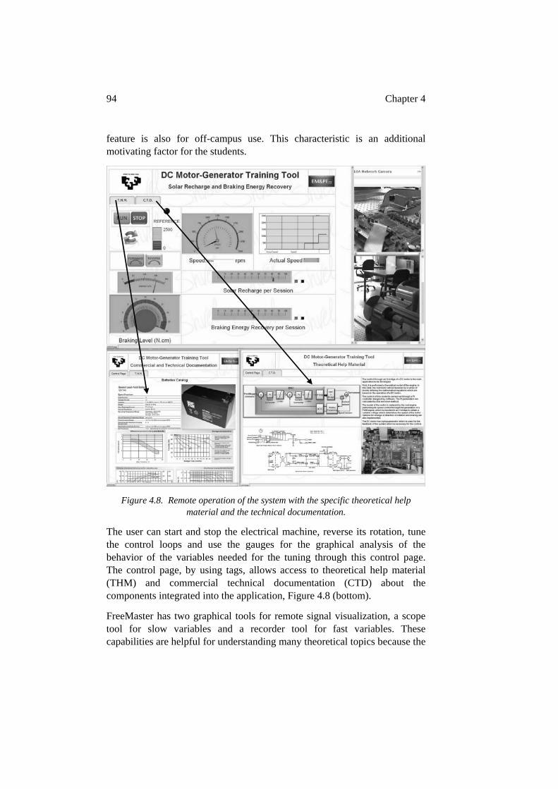
94 Chapter 4
feature is also for off-campus use. This characteristic is an additional motivating factor for the students.
Figure 4.8. Remote operation of the system with the specific theoretical help material and the technical documentation.
The user can start and stop the electrical machine, reverse its rotation, tune the control loops and use the gauges for the graphical analysis of the behavior of the variables needed for the tuning through this control page. The control page, by using tags, allows access to theoretical help material (THM) and commercial technical documentation (CTD) about the components integrated into the application, Figure 4.8 (bottom).
FreeMaster has two graphical tools for remote signal visualization, a scope tool for slow variables and a recorder tool for fast variables. These capabilities are helpful for understanding many theoretical topics because the
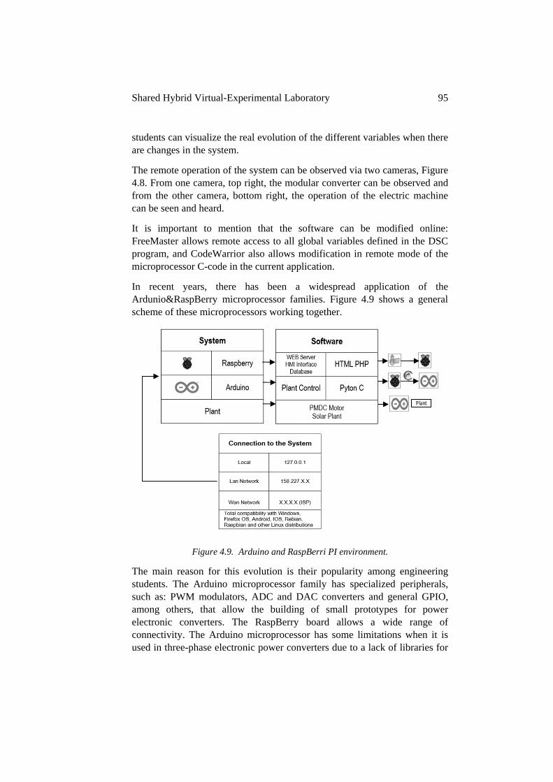
Shared Hybrid Virtual-Experimental Laboratory 95
students can visualize the real evolution of the different variables when there are changes in the system.
The remote operation of the system can be observed via two cameras, Figure 4.8. From one camera, top right, the modular converter can be observed and from the other camera, bottom right, the operation of the electric machine can be seen and heard.
It is important to mention that the software can be modified online: FreeMaster allows remote access to all global variables defined in the DSC program, and CodeWarrior also allows modification in remote mode of the microprocessor C-code in the current application.
In recent years, there has been a widespread application of the Ardunio&RaspBerry microprocessor families. Figure 4.9 shows a general scheme of these microprocessors working together.
Figure 4.9. Arduino and RaspBerri PI environment.
The main reason for this evolution is their popularity among engineering students. The Arduino microprocessor family has specialized peripherals, such as: PWM modulators, ADC and DAC converters and general GPIO, among others, that allow the building of small prototypes for power electronic converters. The RaspBerry board allows a wide range of connectivity. The Arduino microprocessor has some limitations when it is used in three-phase electronic power converters due to a lack of libraries for
Plant
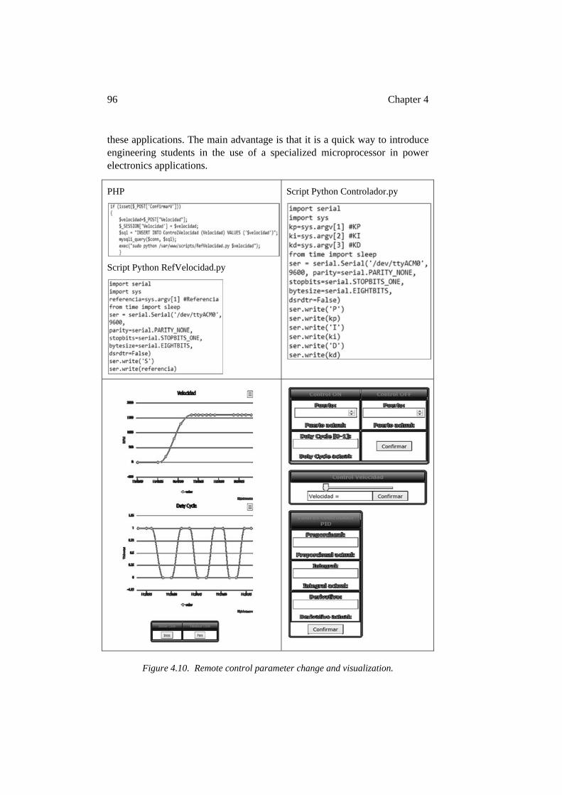
96 Chapter 4
these applications. The main advantage is that it is a quick way to introduce engineering students in the use of a specialized microprocessor in power electronics applications.
PHP
Script Python RefVelocidad.py
Script Python Controlador.py
Figure 4.10. Remote control parameter change and visualization.
Shared Hybrid Virtual-Experimental Laboratory 97
This microprocessor combination offers positive characteristics when applied within the PjBL methodology and increase “Learning by Doing” actions. A wide range of applications, from simple to complex tasks, are feasible with fewer low cost components as part of the fDAA common framework: power electronic switch command tasks, instrumentation tasks and control tasks.
An example of PHP and Scrip Python for connecting Arduino and Raspberry is shown in Figure 4.10. Different visualization parameters and a control page for remote control of the PID controller are also shown, bottom left and right of Figure 4.10. This algorithm is allocated in a PMDCM scenario, Figure 4.3 right side. The Control Page, in Figure 4.10 bottom right side, allows for changes in the controller parameters in real time.
4.3.3. METHODOLOGY FOR EM&PETT NEW DESIGNS AND MODIFICATION
As previously mentioned the most remarkable characteristic of EM&PETT is its flexibility for hardware and software use and evolution.
When an EM&PETT is being used as a scenario for the PjBL methodology, in Final Degree Projects and Final Master Projects, the need for possible improvements can arise. This possibility should be supported by a special development methodology, because the EM&PETT functions with real conditions and are being used by students that generally do not have experience with experimental equipment.
A diagram summarizing the methodology for developing different hardware and software projects to be assembled in the training tools is shown in Figure 4.11. For an optimal implementation of the proposed methodology, the training tool and its remote access are fully functional at the beginning of the project so that the students can see an example of the tool in operation, and the parts to be redesigned or improved. The remote access ensures that the system can be operated from any place, at any time.
The design methodology for a specific project is applied in five stages:
In the first stage, the project’s goals, the technical specifications and the required hardware and software equipment must be clearly defined. All the important design parameters should be identified.
In the second stage, the models and its simulations are analyzed (PSim® and Matlab®/Simulink® can help in this task). Depending on the simulation results, the designs are validated, as determined by the prerequisites defined in step one.
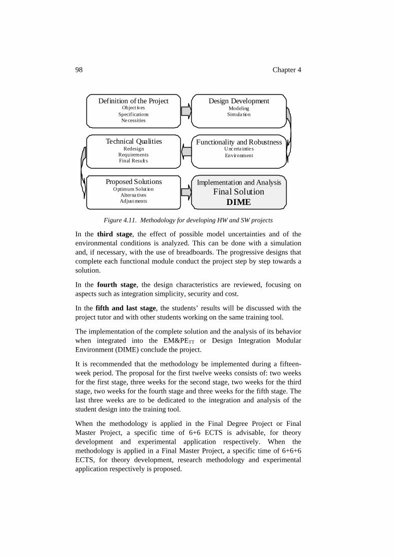
98 Chapter 4
Figure 4.11. Methodology for developing HW and SW projects
In the third stage, the effect of possible model uncertainties and of the environmental conditions is analyzed. This can be done with a simulation and, if necessary, with the use of breadboards. The progressive designs that complete each functional module conduct the project step by step towards a solution.
In the fourth stage, the design characteristics are reviewed, focusing on aspects such as integration simplicity, security and cost.
In the fifth and last stage, the students’ results will be discussed with the project tutor and with other students working on the same training tool.
The implementation of the complete solution and the analysis of its behavior when integrated into the EM&PETT or Design Integration Modular Environment (DIME) conclude the project.
It is recommended that the methodology be implemented during a fifteen-week period. The proposal for the first twelve weeks consists of: two weeks for the first stage, three weeks for the second stage, two weeks for the third stage, two weeks for the fourth stage and three weeks for the fifth stage. The last three weeks are to be dedicated to the integration and analysis of the student design into the training tool.
When the methodology is applied in the Final Degree Project or Final Master Project, a specific time of 6+6 ECTS is advisable, for theory development and experimental application respectively. When the methodology is applied in a Final Master Project, a specific time of 6+6+6 ECTS, for theory development, research methodology and experimental application respectively is proposed.
Design Development Modeling
Simula tion
Functionality and Robustness Uncerta intie s Environment
Technical Qualities Redesign
Requirements Final Result s
Proposed Solutions Optimum Solut ion
Alterna tives Adjust ments
Definition of the Project Object ives
Specifications Necessities
Implementation and Analysis Final Solution
DIME
Shared Hybrid Virtual-Experimental Laboratory 99
Although the above described methodology was developed for changing or improving the EM&PETT, with the introduction of the Ardunio&RaspBerry microprocessor families in PjBL methodology for promoting the “Learning by Doing” activities, this scheme has been applied for developing small power electronic prototypes. These small projects are included in the proposed free work component for students. The presented methodology assists in ensuring a more standardized development of the prototypes.
4.4. THE VIRTUAL TECHNOLOGICAL WORKSPACE WWW.SHVEL.NET
The web platform proposed is an environment that facilitates improving the connection between theory and its experimental application, the students and teacher, and lastly, the conventional self-study places and the experimental laboratory. The initiative intends to build a shared space with personalized technical qualities (Patil & Pudlowski., 2003; Gillet et al., 2010; Martija el al, 2014).
Figure 4.12 shows the website organization: the documentation area, the web tools, the EM&PETT applied to experimental activities and the project based learning area.
The documentation area incorporates the necessary resources, aiming to improve the self-study performance of the students. Theory manuals, technical handbooks and audiovisual material are included, all of them focused on specific practical aspects which are related to the experimental scenarios. Access to the final projects developed by students in previous years is also available. These previous projects also constitute an interesting and valuable data base for new students. The main idea is that students can access highly focused technical documentation which provides them with specific and applicable information for their projects.
Web tools play a fundamental role in the daily work organization and in the social aspects related with engineering education. The chat and the email offer easier and more dynamic communication between students and with the teacher. Calendars permit programming tasks in a timetable schedule. All these tools facilitate collaborative teamwork (Haller et al., 2000).
The integration of different EM&PETT experimental scenarios in the web platform opens the possibility of immediate demonstration of the theoretical topics, allowing experiments in the real systems located in the hands-on laboratory. The online connection from the classroom to the laboratory allows the direct demonstration of the theoretical concepts treated in the
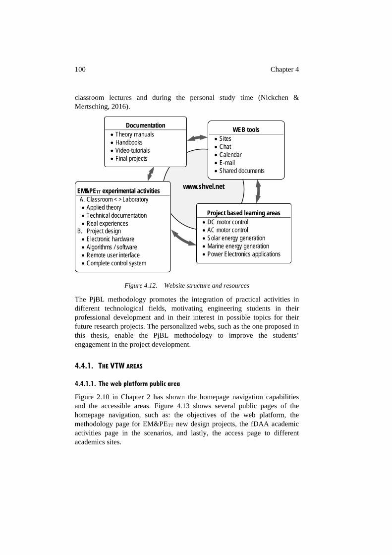
100 Chapter 4
classroom lectures and during the personal study time (Nickchen & Mertsching, 2016).
Figure 4.12. Website structure and resources
The PjBL methodology promotes the integration of practical activities in different technological fields, motivating engineering students in their professional development and in their interest in possible topics for their future research projects. The personalized webs, such as the one proposed in this thesis, enable the PjBL methodology to improve the students’ engagement in the project development.
4.4.1. THE VTW AREAS
4.4.1.1. The web platform public area
Figure 2.10 in Chapter 2 has shown the homepage navigation capabilities and the accessible areas. Figure 4.13 shows several public pages of the homepage navigation, such as: the objectives of the web platform, the methodology page for EM&PETT new design projects, the fDAA academic activities page in the scenarios, and lastly, the access page to different academics sites.
www.shvel.net EM&PETT experimental activities A. Classroom < > Laboratory Applied theory Technical documentation Real experiences
B. Project design Electronic hardware Algorithms / software Remote user interface Complete control system
Documentation Theory manuals Handbooks Video-tutorials Final projects
WEB tools Sites Chat Calendar E-mail Shared documents
Project based learning areas DC motor control AC motor control Solar energy generation Marine energy generation Power Electronics applications
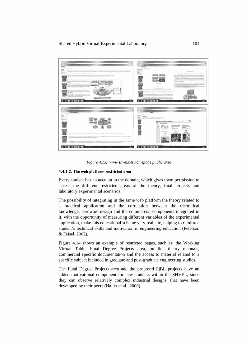
Shared Hybrid Virtual-Experimental Laboratory 101
Figure 4.13. www.shvel.net homepage public area
4.4.1.2. The web platform restricted area
Every student has an account in the domain, which gives them permission to access the different restricted areas of the theory, final projects and laboratory experimental scenarios.
The possibility of integrating in the same web platform the theory related to a practical application and the correlation between the theoretical knowledge, hardware design and the commercial components integrated in it, with the opportunity of measuring different variables of the experimental application, make this educational scheme very realistic, helping to reinforce student’s technical skills and motivation in engineering education (Peterson & Feisel, 2002).
Figure 4.14 shows an example of restricted pages, such as: the Working Virtual Table, Final Degree Projects area, on line theory manuals, commercial specific documentation and the access to material related to a specific subject included in graduate and post-graduate engineering studies.
The Final Degree Projects area and the proposed PjBL projects have an added motivational component for new students within the SHVEL, since they can observe relatively complex industrial designs, that have been developed by their peers (Haller et al., 2000).
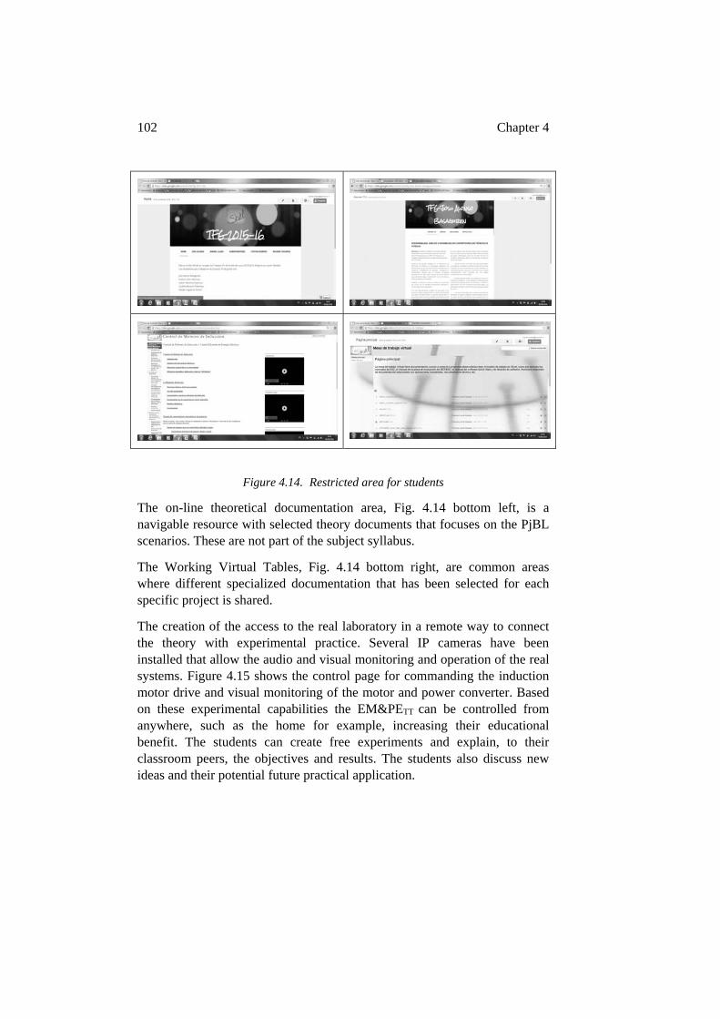
102 Chapter 4
Figure 4.14. Restricted area for students
The on-line theoretical documentation area, Fig. 4.14 bottom left, is a navigable resource with selected theory documents that focuses on the PjBL scenarios. These are not part of the subject syllabus.
The Working Virtual Tables, Fig. 4.14 bottom right, are common areas where different specialized documentation that has been selected for each specific project is shared.
The creation of the access to the real laboratory in a remote way to connect the theory with experimental practice. Several IP cameras have been installed that allow the audio and visual monitoring and operation of the real systems. Figure 4.15 shows the control page for commanding the induction motor drive and visual monitoring of the motor and power converter. Based on these experimental capabilities the EM&PETT can be controlled from anywhere, such as the home for example, increasing their educational benefit. The students can create free experiments and explain, to their classroom peers, the objectives and results. The students also discuss new ideas and their potential future practical application.
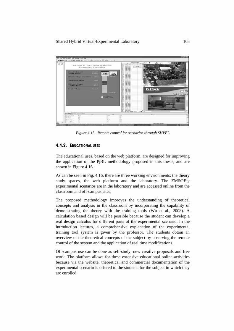
Shared Hybrid Virtual-Experimental Laboratory 103
Figure 4.15. Remote control for scenarios through SHVEL
4.4.2. EDUCATIONAL USES
The educational uses, based on the web platform, are designed for improving the application of the PjBL methodology proposed in this thesis, and are shown in Figure 4.16.
As can be seen in Fig. 4.16, there are three working environments: the theory study spaces, the web platform and the laboratory. The EM&PETT experimental scenarios are in the laboratory and are accessed online from the classroom and off-campus sites.
The proposed methodology improves the understanding of theoretical concepts and analysis in the classroom by incorporating the capability of demonstrating the theory with the training tools (Wu et al., 2008). A calculation based design will be possible because the student can develop a real design calculus for different parts of the experimental scenario. In the introduction lectures, a comprehensive explanation of the experimental training tool system is given by the professor. The students obtain an overview of the theoretical concepts of the subject by observing the remote control of the system and the application of real time modifications.
Off-campus use can be done as self-study, new creative proposals and free work. The platform allows for these extensive educational online activities because via the website, theoretical and commercial documentation of the experimental scenario is offered to the students for the subject in which they are enrolled.
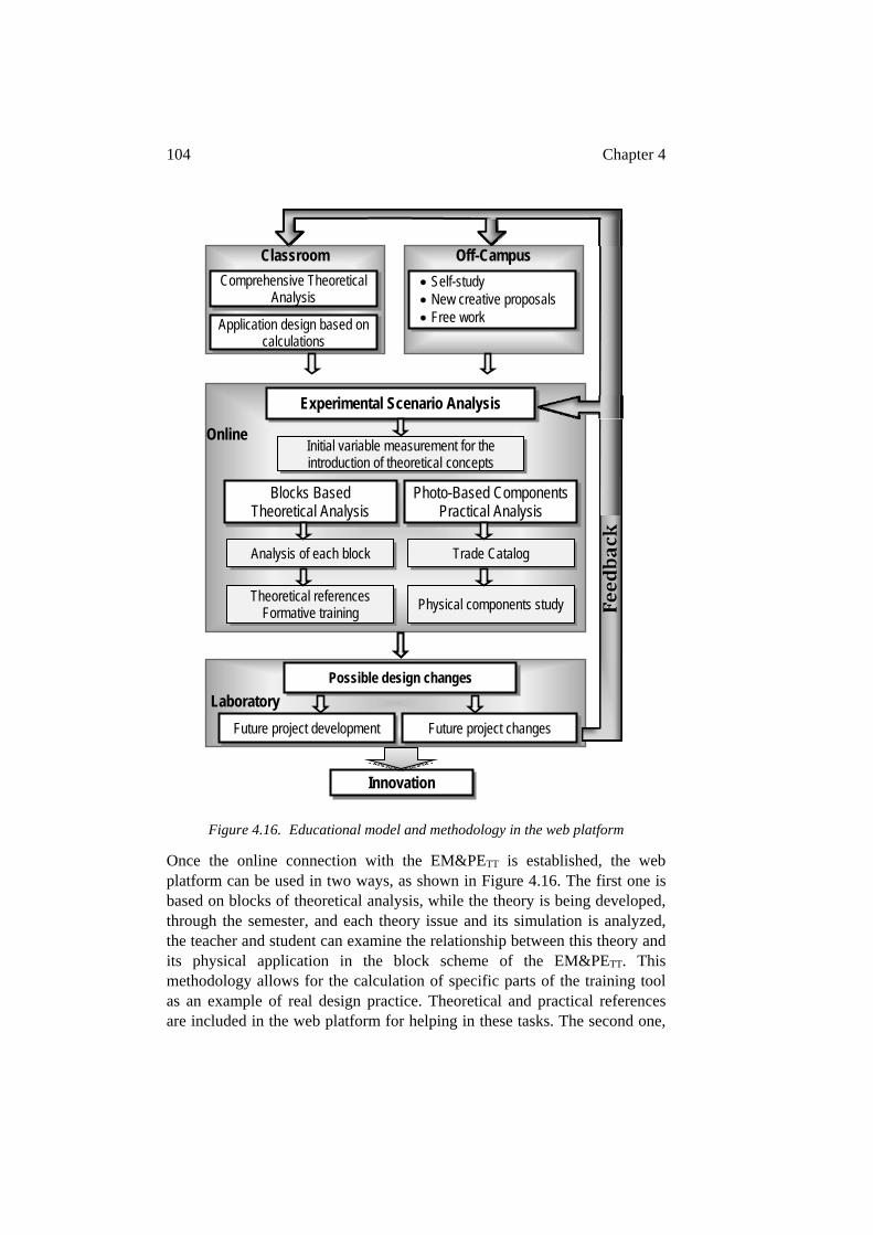
104 Chapter 4
Figure 4.16. Educational model and methodology in the web platform
Once the online connection with the EM&PETT is established, the web platform can be used in two ways, as shown in Figure 4.16. The first one is based on blocks of theoretical analysis, while the theory is being developed, through the semester, and each theory issue and its simulation is analyzed, the teacher and student can examine the relationship between this theory and its physical application in the block scheme of the EM&PETT. This methodology allows for the calculation of specific parts of the training tool as an example of real design practice. Theoretical and practical references are included in the web platform for helping in these tasks. The second one,
Laboratory
Online
Experimental Scenario Analysis
Blocks Based Theoretical Analysis
Photo-Based Components Practical Analysis
Analysis of each block
Theoretical references Formative training
Trade Catalog
Physical components study
Classroom Comprehensive Theoretical
Analysis
Application design based on calculations
Possible design changes
Future project development Future project changes
Innovation
Initial variable measurement for the introduction of theoretical concepts
Off-Campus
Self-study New creative proposals Free work
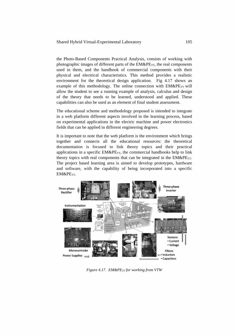
Shared Hybrid Virtual-Experimental Laboratory 105
the Photo-Based Components Practical Analysis, consists of working with photographic images of different parts of the EM&PETT, the real components used in them, and the handbook of commercial components with their physical and electrical characteristics. This method provides a realistic environment for the theoretical design application. Fig 4.17 shows an example of this methodology. The online connection with EM&PETT will allow the student to see a running example of analysis, calculus and design of the theory that needs to be learned, understood and applied. These capabilities can also be used as an element of final student assessment.
The educational scheme and methodology proposed is intended to integrate in a web platform different aspects involved in the learning process, based on experimental applications in the electric machine and power electronics fields that can be applied in different engineering degrees.
It is important to note that the web platform is the environment which brings together and connects all the educational resources: the theoretical documentation is focused to link theory topics and their practical applications in a specific EM&PETT, the commercial handbooks help to link theory topics with real components that can be integrated in the EM&PETT. The project based learning area is aimed to develop prototypes, hardware and software, with the capability of being incorporated into a specific EM&PETT.
Figure 4.17. EM&PETT for working from VTW
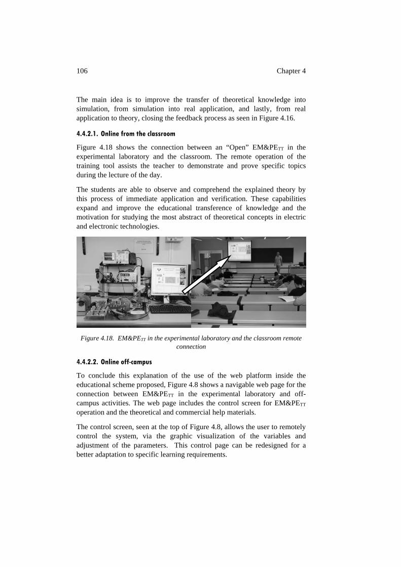
106 Chapter 4
The main idea is to improve the transfer of theoretical knowledge into simulation, from simulation into real application, and lastly, from real application to theory, closing the feedback process as seen in Figure 4.16.
4.4.2.1. Online from the classroom
Figure 4.18 shows the connection between an “Open” EM&PETT in the experimental laboratory and the classroom. The remote operation of the training tool assists the teacher to demonstrate and prove specific topics during the lecture of the day.
The students are able to observe and comprehend the explained theory by this process of immediate application and verification. These capabilities expand and improve the educational transference of knowledge and the motivation for studying the most abstract of theoretical concepts in electric and electronic technologies.
Figure 4.18. EM&PETT in the experimental laboratory and the classroom remote connection
4.4.2.2. Online off-campus
To conclude this explanation of the use of the web platform inside the educational scheme proposed, Figure 4.8 shows a navigable web page for the connection between EM&PETT in the experimental laboratory and off-campus activities. The web page includes the control screen for EM&PETT operation and the theoretical and commercial help materials.
The control screen, seen at the top of Figure 4.8, allows the user to remotely control the system, via the graphic visualization of the variables and adjustment of the parameters. This control page can be redesigned for a better adaptation to specific learning requirements.
Shared Hybrid Virtual-Experimental Laboratory 107
At the bottom of Figure 4.8 an example of specific theoretical help material for the EM&PETT is shown. Following a block diagram, accessible through the Theoretical Help Material (THM) tag, the students are immersed in the theoretical parts included in the training tool, analyzing their experimental behaviors and the evolution of their online parameter values. The students can observe through the training tool the results of the questions proposed by the teacher. The Commercial and Technical Documentation (CTD) tag permits the students access to data from commercial catalogs of components used in the EM&PETT.
The main difference with other similar educational systems is that the students have online access to all variables and parameters defined in the electronic boards and the microprocessor software functions. The students can finally observe and compare the real and simulated behavior of any resource that is integrated in the training tool.
4.5. CONCLUSIONS
As conclusion, it is possible summarize that the training tool and web environment proposed improve the technical skills and the motivation of engineering students in experimental work. The training tool has successfully allowed concurrent multidisciplinary experimental projects to be carried out, based on a functional partition of industrial equipment, the analysis of the resulting modular software and hardware blocks for their redesign or improvement, and the reassembly process of these blocks.
The use of the tool within the classroom has helped students to better understand complex electrical and electronic concepts, because it allows the online demonstration of quasi-industrial power electronic equipment. This experimental training tool has now become a standard teaching resource for classroom lectures in the power electronics field in the Faculty of Engineering in Bilbao.
The educational activities of the EM&PETT have achieved an increase in student interest in undergraduate and graduate level study in the fields of power electronics and electrical machine control. The remote control capability allows the tool to be used from any place and at any time, making this experimental learning methodology practical for engineering education. Lastly, the development of a shared work platform for the theoretical and practical execution of each task improves students’ social and team working skills.
108 Chapter 4
The PjBL methodology and it´s web platform with the proposed educational plan have sought to take advantage of the relationship between students and the internet. It has become necessary to incorporate novel technologies and environments to extend the efficacy of traditional university educational methodologies. Because of this the proposal has linked three elements: the conventional spaces for theoretical study, such as, the classroom and home, the experimental laboratory and the Web 2.0 resources.
The combining of these three environments in a unique web platform has resulted in the development of the website www.shvel.net with carefully selected theoretical and commercial documentation, a flexible remote access to the experimental scenarios in the hands-on laboratory, and, the necessary customized web tools for making the teamwork between teacher and students realistic for multidisciplinary engineering education.
The objective has been to improve the performance of conventional theory environments. The theoretical lectures in the classroom are more complete and interesting. The capability of observing the studied theory applied in real equipment, and also, the possibility of using this equipment from off-campus improves the efficacy of the student’s self-study time. These facts reinforce the student’s technical skills and motivation for experimental work.
Chapter 5 – Educational Platform Activities
This chapter contains different examples of how to apply the teaching and learning methodology and activities related to experimental tasks based on the scenarios included in the educational platform proposed in this thesis. These activities incorporate and highlight many of the goals and philosophies of the educational methodology proposed. The students are required to understand the scenarios, to disassemble their different power blocks and converters, to analyze each power converter under the common framework proposed, to model the power converters and their components (hardware or software), to compare the simulation results with the measured parameters in real conditions, to connect systems with different levels of power and voltages, to take into account the effects of electronic transformation of electrical energy, to know the new clean energy sources, and finally, to analyze possible improvements which they will be able to implement into the scenarios by themselves.
The experimental activities have been selected to demonstrate the transfer between the theoretical knowledge and its industrial application, and to acquire the technical and experimental skills required for professional development. These objectives are obtained by implementing the integration of the maximum number of technological components, the most theoretical of concepts with an increasing difficulty of understanding and the use of commercial equipment with real data. Extracts of students’ final reports of different subjects where the students have worked with different scenarios will be included to illustrate the accomplishment of these objectives.
Additionally to the above mentioned technical skills and competencies, the educational proposal developed here seeks to go further. This thesis is devoted to changing and extending the focus of the student´s vision about the social responsibilities of industrial engineering. Ethical behavior and environmental questions are part of the focus when team working within the scenarios thematic. These personal qualities will be developed with teamwork interaction, peer relationships, shared work activities, responsibilities, failures and success. Moreover, the need for quick industrial adaptation is another aspect focused upon in the thesis.
110 Chapter 5
5.1. INTRODUCTION
The power electronic systems proposed as scenarios in this Chapter are the 2kW photovoltaic solar plant and different motor drives. One of the main ideas for developing the scenarios is the requirement to implement at least two or three power converters. It is possible that the proposed scenario shows some differences with the real equipment which it is representing. For example, it is possible to include a DC-DC power converter in an ACIM driver for controlling the DC-bus voltage. This modified driver could not be implemented in commercial equipment, but from an educational point of view, it is a very interesting capability. This capability allows the student to compare the technical characteristics of the two proposed drivers, the commercial and the modified ones. The benefit of this for the student is enhanced technical creativity.
The most remarkable characteristic of the EM&PETT is the flexibility of its use and design. The same training tool adapted for a scenario in a Degree or Master Studies subject can be used for different theoretical and research activities. The students will be able to work with hardware development, software development or both of them.
In the following sections the abovementioned technical qualities will be developed through different scenarios with different levels of technical difficulties and with different educational goals. This will be achieved by the implementation of a comprehensive PjBL methodology, with a common framework for understanding power converters, with specifically designed physical and virtual tools, and with combined university and industry behavior models.
5.2. SOLAR PLANT AS PJBL SCENARIO
The solar plant scenario for PjBL in the Power Electronics subject has been analyzed in Chapter 2. This section will outline aspects related to the tasks that the students are required to develop.
The most significant converter in this scenario has been selected as an application example. The Solar Charger Buck-Boost DC-DC converter with Maximum Power Point Tracking MPPT (Femia et al., 2005; Villalva et al., 2009) demonstrates the educational capabilities that the methodology proposes. Figure 5.1 shows the array of the photovoltaic solar panels, the bank of batteries and the electronic power converter for coupling them with the maximum power transference from solar panels to batteries.
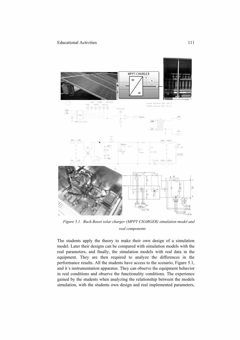
Educational Activities 111
Figure 5.1. Buck-Boost solar charger (MPPT CHARGER) simulation model and
real components
The students apply the theory to make their own design of a simulation model. Later their designs can be compared with simulation models with the real parameters, and finally, the simulation models with real data in the equipment. They are then required to analyze the differences in the performance results. All the students have access to the scenario, Figure 5.1, and it´s instrumentation apparatus. They can observe the equipment behavior in real conditions and observe the functionality conditions. The experience gained by the students when analyzing the relationship between the models simulation, with the students own design and real implemented parameters,
MPPT CHARGER V
A =
=
DLL
MPPT_01.dll
VpIp
V
mVp
V
mPp
V
mdVp
V
mdPp
V
mAlfa
V
mAlfaf
1Vp
57.6V
C1
Vgate
V
Vtriang
Vgate
5uL2
C2
0V680uF
V Vp300u
L1
Ip
V Ip
Fondo Escala Vp: 100 V
Fondo Escala Ip: 50 A
W
Pp
A
Iload
IN+IN+
IN-IN-
57.6VBAT
0.010RsBAT
OUT-OUT-
OUT+OUT+
IN+
IN-
S
T25
1000
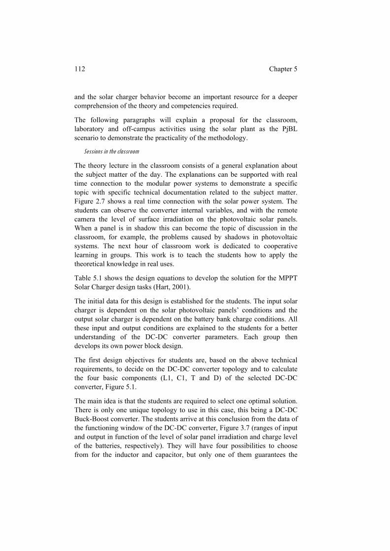
112 Chapter 5
and the solar charger behavior become an important resource for a deeper comprehension of the theory and competencies required.
The following paragraphs will explain a proposal for the classroom, laboratory and off-campus activities using the solar plant as the PjBL scenario to demonstrate the practicality of the methodology.
Sessions in the classroom
The theory lecture in the classroom consists of a general explanation about the subject matter of the day. The explanations can be supported with real time connection to the modular power systems to demonstrate a specific topic with specific technical documentation related to the subject matter. Figure 2.7 shows a real time connection with the solar power system. The students can observe the converter internal variables, and with the remote camera the level of surface irradiation on the photovoltaic solar panels. When a panel is in shadow this can become the topic of discussion in the classroom, for example, the problems caused by shadows in photovoltaic systems. The next hour of classroom work is dedicated to cooperative learning in groups. This work is to teach the students how to apply the theoretical knowledge in real uses.
Table 5.1 shows the design equations to develop the solution for the MPPT Solar Charger design tasks (Hart, 2001).
The initial data for this design is established for the students. The input solar charger is dependent on the solar photovoltaic panels’ conditions and the output solar charger is dependent on the battery bank charge conditions. All these input and output conditions are explained to the students for a better understanding of the DC-DC converter parameters. Each group then develops its own power block design.
The first design objectives for students are, based on the above technical requirements, to decide on the DC-DC converter topology and to calculate the four basic components (L1, C1, T and D) of the selected DC-DC converter, Figure 5.1.
The main idea is that the students are required to select one optimal solution. There is only one unique topology to use in this case, this being a DC-DC Buck-Boost converter. The students arrive at this conclusion from the data of the functioning window of the DC-DC converter, Figure 3.7 (ranges of input and output in function of the level of solar panel irradiation and charge level of the batteries, respectively). They will have four possibilities to choose from for the inductor and capacitor, but only one of them guarantees the
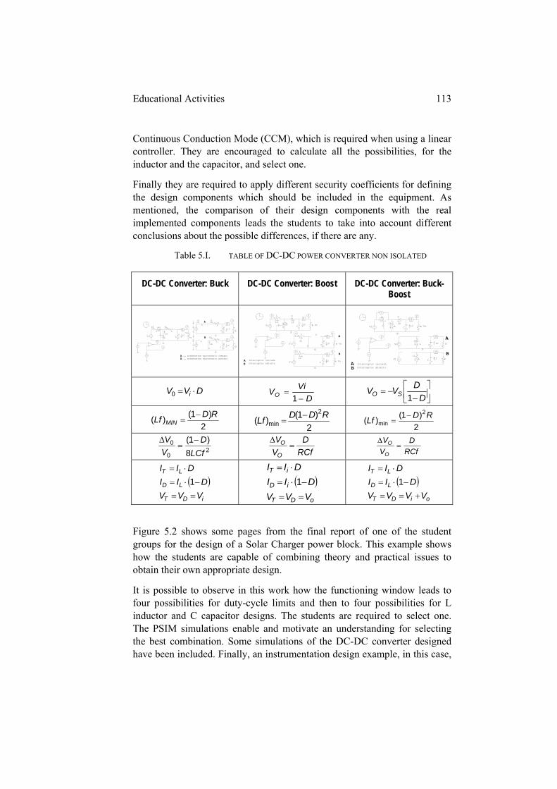
Educational Activities 113
Continuous Conduction Mode (CCM), which is required when using a linear controller. They are encouraged to calculate all the possibilities, for the inductor and the capacitor, and select one.
Finally they are required to apply different security coefficients for defining the design components which should be included in the equipment. As mentioned, the comparison of their design components with the real implemented components leads the students to take into account different conclusions about the possible differences, if there are any.
Table 5.I. TABLE OF DC-DC POWER CONVERTER NON ISOLATED
DC-DC Converter: Buck DC-DC Converter: Boost DC-DC Converter: Buck-Boost
DVV i 0 D
ViVO
1
D
DVV SO 1
2)1()( RD
Lf MIN
2
)1()(2
minRDD
Lf
2
)1()(2
minRD
Lf
20
0
8)1(
LCf
D
V
V
RCf
D
V
V
O
O
RCf
D
V
V
O
O
iDT
LD
LT
VVV
DII
DII
1
oDT
iD
iT
VVV
DII
DII
1 oiDT
LD
LT
VVVV
DII
DII
1
Figure 5.2 shows some pages from the final report of one of the student groups for the design of a Solar Charger power block. This example shows how the students are capable of combining theory and practical issues to obtain their own appropriate design.
It is possible to observe in this work how the functioning window leads to four possibilities for duty-cycle limits and then to four possibilities for L inductor and C capacitor designs. The students are required to select one. The PSIM simulations enable and motivate an understanding for selecting the best combination. Some simulations of the DC-DC converter designed have been included. Finally, an instrumentation design example, in this case,
V
V
V
A
Vi
Vo
iS
iD
iL
iC
S
D
L
C R
VA
iS iL
iC
S L
C R
VA
iD
iL
iC
S
D
L
C
A
B
A INTERRUPTOR ELECTRÓNICO CERRADO
B INTERRUPTOR ELECTRÓNICO ABIERTO
R
V
V
V
AV L
S
D
C RiL iD
iCVi Vo
VA
V L
S
D
C RiL
iC Vo
VA
V L
C RiL
iC Vo
Vi
Vi
A
B
A Interruptor cerrado
B Interruptor abierto
V
V
V
A
L
D
C RiL iD
iCVi Vo
V
A
L C RiL
iCVi
A
L
D
C RiL
iCVi
A
B
A Interruptor cerrado
B Interruptor abierto
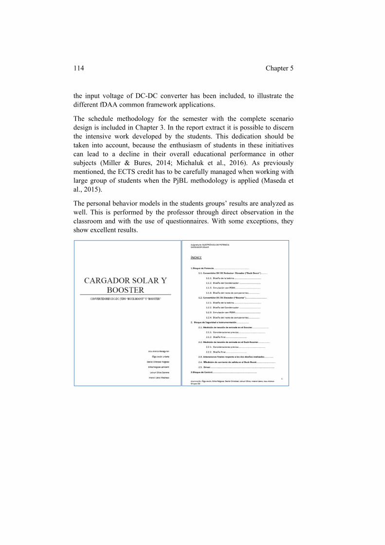
114 Chapter 5
the input voltage of DC-DC converter has been included, to illustrate the different fDAA common framework applications.
The schedule methodology for the semester with the complete scenario design is included in Chapter 3. In the report extract it is possible to discern the intensive work developed by the students. This dedication should be taken into account, because the enthusiasm of students in these initiatives can lead to a decline in their overall educational performance in other subjects (Miller & Bures, 2014; Michaluk et al., 2016). As previously mentioned, the ECTS credit has to be carefully managed when working with large group of students when the PjBL methodology is applied (Maseda et al., 2015).
The personal behavior models in the students groups’ results are analyzed as well. This is performed by the professor through direct observation in the classroom and with the use of questionnaires. With some exceptions, they show excellent results.
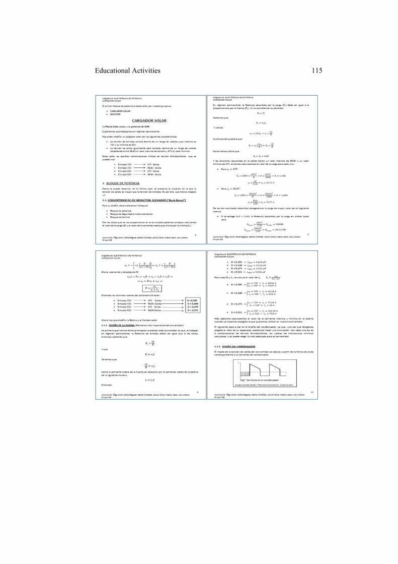
Educational Activities 115
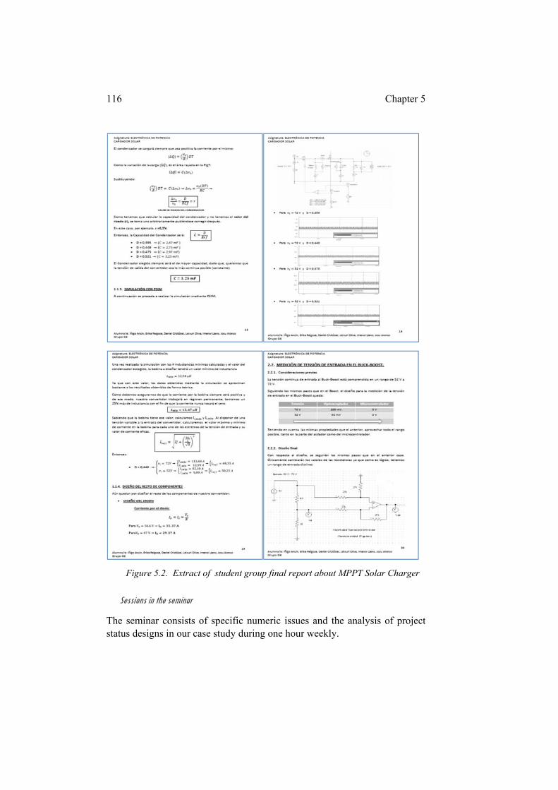
116 Chapter 5
Figure 5.2. Extract of student group final report about MPPT Solar Charger
Sessions in the seminar
The seminar consists of specific numeric issues and the analysis of project status designs in our case study during one hour weekly.
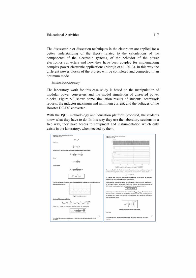
Educational Activities 117
The disassemble or dissection techniques in the classroom are applied for a better understanding of the theory related to the calculations of the components of the electronic systems, of the behavior of the power electronics converters and how they have been coupled for implementing complex power electronic applications (Martija et al., 2013). In this way the different power blocks of the project will be completed and connected in an optimum mode.
Sessions in the laboratory
The laboratory work for this case study is based on the manipulation of modular power converters and the model simulation of dissected power blocks. Figure 5.3 shows some simulation results of students’ teamwork reports: the inductor maximum and minimum current, and the voltages of the Booster DC-DC converter.
With the PjBL methodology and education platform proposed, the students know what they have to do. In this way they use the laboratory sessions in a free way, they have access to equipment and instrumentation which only exists in the laboratory, when needed by them.
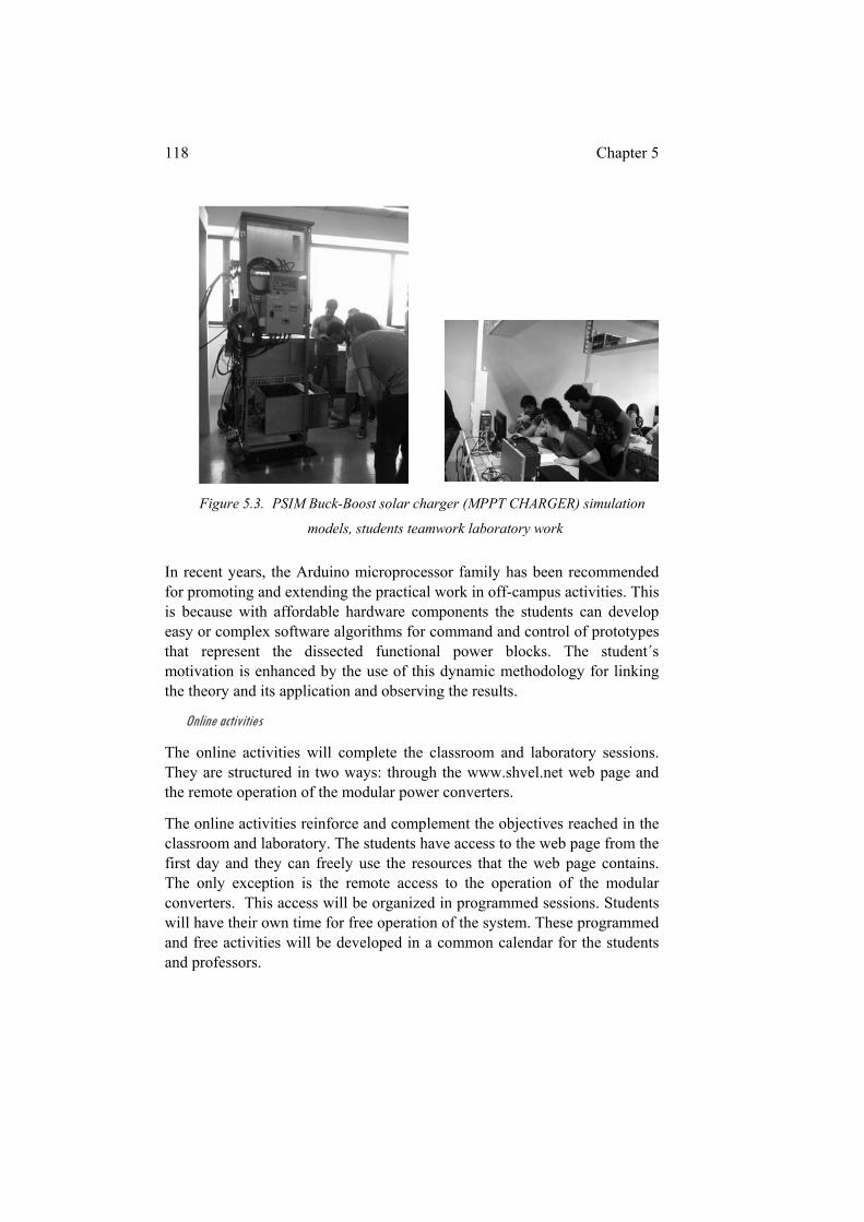
118 Chapter 5
Figure 5.3. PSIM Buck-Boost solar charger (MPPT CHARGER) simulation
models, students teamwork laboratory work
In recent years, the Arduino microprocessor family has been recommended for promoting and extending the practical work in off-campus activities. This is because with affordable hardware components the students can develop easy or complex software algorithms for command and control of prototypes that represent the dissected functional power blocks. The student´s motivation is enhanced by the use of this dynamic methodology for linking the theory and its application and observing the results.
Online activities
The online activities will complete the classroom and laboratory sessions. They are structured in two ways: through the www.shvel.net web page and the remote operation of the modular power converters.
The online activities reinforce and complement the objectives reached in the classroom and laboratory. The students have access to the web page from the first day and they can freely use the resources that the web page contains. The only exception is the remote access to the operation of the modular converters. This access will be organized in programmed sessions. Students will have their own time for free operation of the system. These programmed and free activities will be developed in a common calendar for the students and professors.
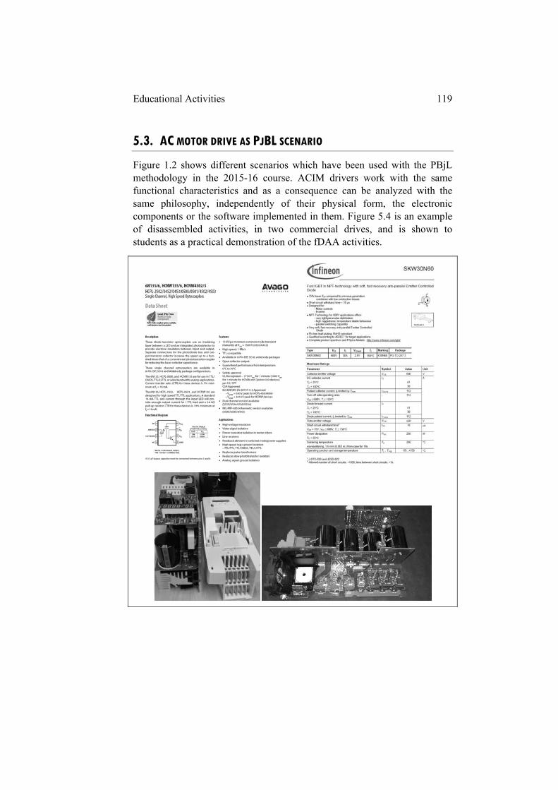
Educational Activities 119
5.3. AC MOTOR DRIVE AS PJBL SCENARIO
Figure 1.2 shows different scenarios which have been used with the PBjL methodology in the 2015-16 course. ACIM drivers work with the same functional characteristics and as a consequence can be analyzed with the same philosophy, independently of their physical form, the electronic components or the software implemented in them. Figure 5.4 is an example of disassembled activities, in two commercial drives, and is shown to students as a practical demonstration of the fDAA activities.
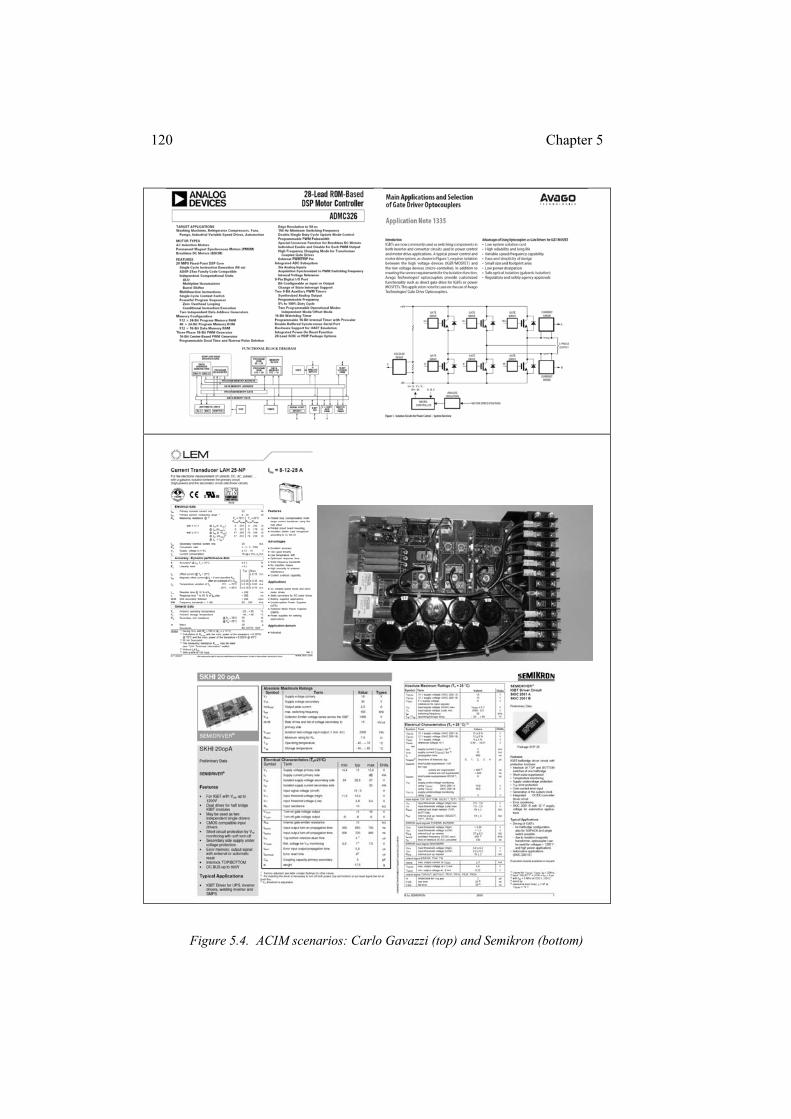
120 Chapter 5
Figure 5.4. ACIM scenarios: Carlo Gavazzi (top) and Semikron (bottom)
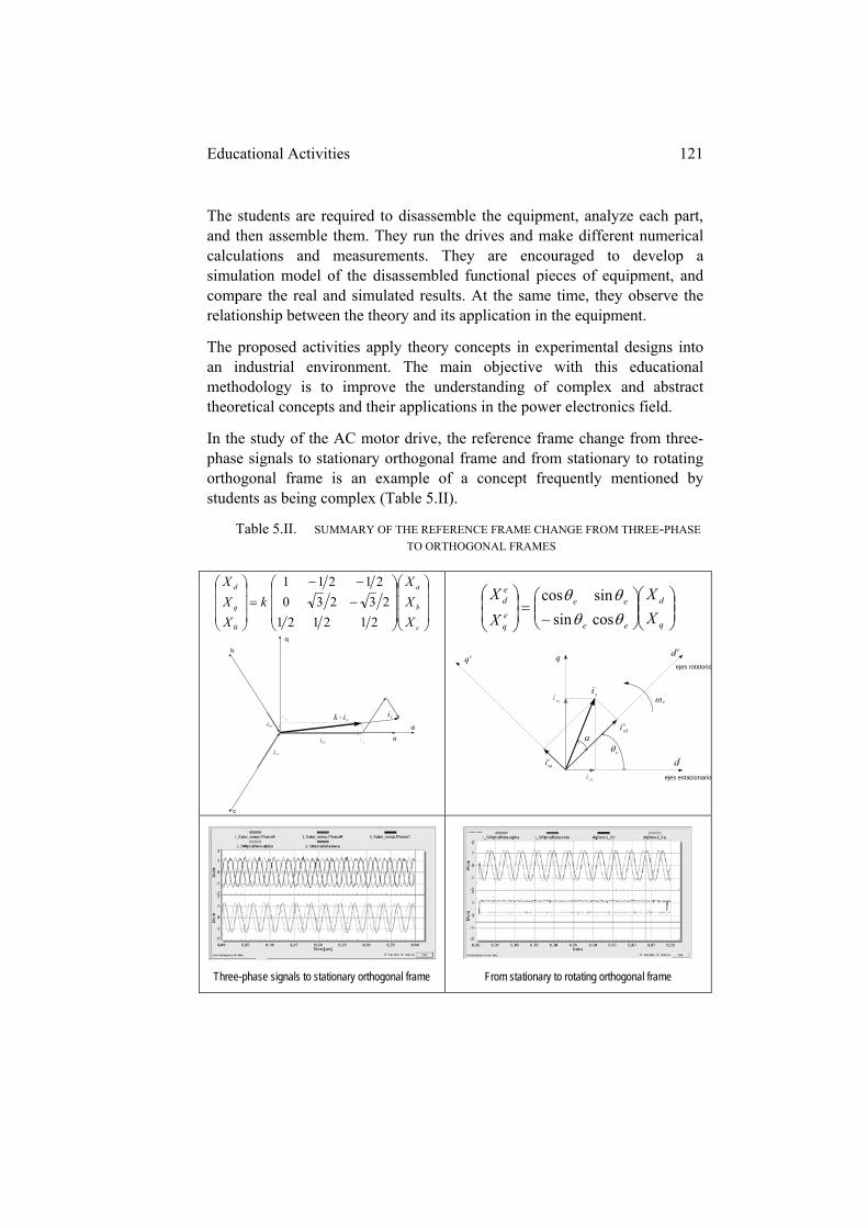
Educational Activities 121
The students are required to disassemble the equipment, analyze each part, and then assemble them. They run the drives and make different numerical calculations and measurements. They are encouraged to develop a simulation model of the disassembled functional pieces of equipment, and compare the real and simulated results. At the same time, they observe the relationship between the theory and its application in the equipment.
The proposed activities apply theory concepts in experimental designs into an industrial environment. The main objective with this educational methodology is to improve the understanding of complex and abstract theoretical concepts and their applications in the power electronics field.
In the study of the AC motor drive, the reference frame change from three-phase signals to stationary orthogonal frame and from stationary to rotating orthogonal frame is an example of a concept frequently mentioned by students as being complex (Table 5.II).
Table 5.II. SUMMARY OF THE REFERENCE FRAME CHANGE FROM THREE-PHASE
TO ORTHOGONAL FRAMES
c
b
a
q
d
X
X
X
k
X
X
X
212121
23230
21211
0
b
c
a
q
d
dsi
qsi
asi
bsi
csi
sisixk
q
d
ee
ee
eq
ed
X
X
X
X
cossin
sincos
si
q
d
eqed
ejes estacionario
ejes rotatorio
e
esqi
esdi
sdi
esqi
Three-phase signals to stationary orthogonal frame
From stationary to rotating orthogonal frame

122 Chapter 5
Theoretical knowledge of the transformation matrix and the graphical explanation through spatial vectors may not be sufficient for a deep understanding. The use of the AC drive scenario and the measurement of the real time variables in the three reference frames (bottom side of table 5.II) allow the students to better comprehend how three phase currents become two stationary decoupled currents, one for torque control and the other for magnetic field control.
The remote access to the scenario from the classroom or home for controlling the motor and visualizing the parameters, permit the professor and students to perform different educational activities. The professors can instruct the students to anticipate theoretical issues which they will be required to explain to their peers in a flipped classroom activity and the students will be able operate the scenario.
Figure 5.5 shows extracts from a PjBL final report. The pages follow the progress of the student work, how they developed the fDAA activities and the related documentation that they obtained from www.shvel.net.
In the report it is explained how the functional blocks were disassembled and physically analyzed. Students have applied PSIM simulation software to the dissected blocks and analyzed the results and the theory related to them. They have run the different drives using the scenarios shown in Figure 2.2 (Chapter 2), in order to compare the simulation results with the real measurements. Finally, students conclusions about the issues studied in the design have been presented.
In addition, the students are required to incorporate in the report how they propose to use an Arduino microprocessor for controlling one part of the scenario. The students are encouraged to create a design and have the option to make a small prototype based on it.
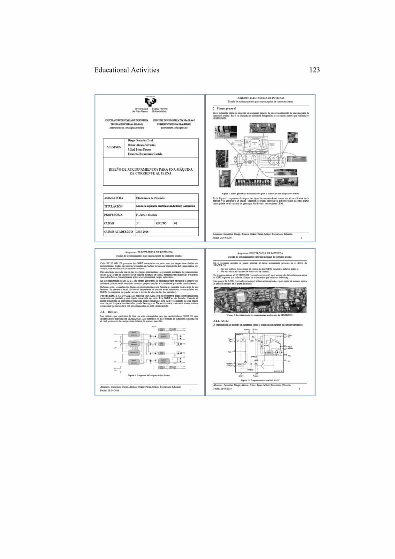
Educational Activities 123
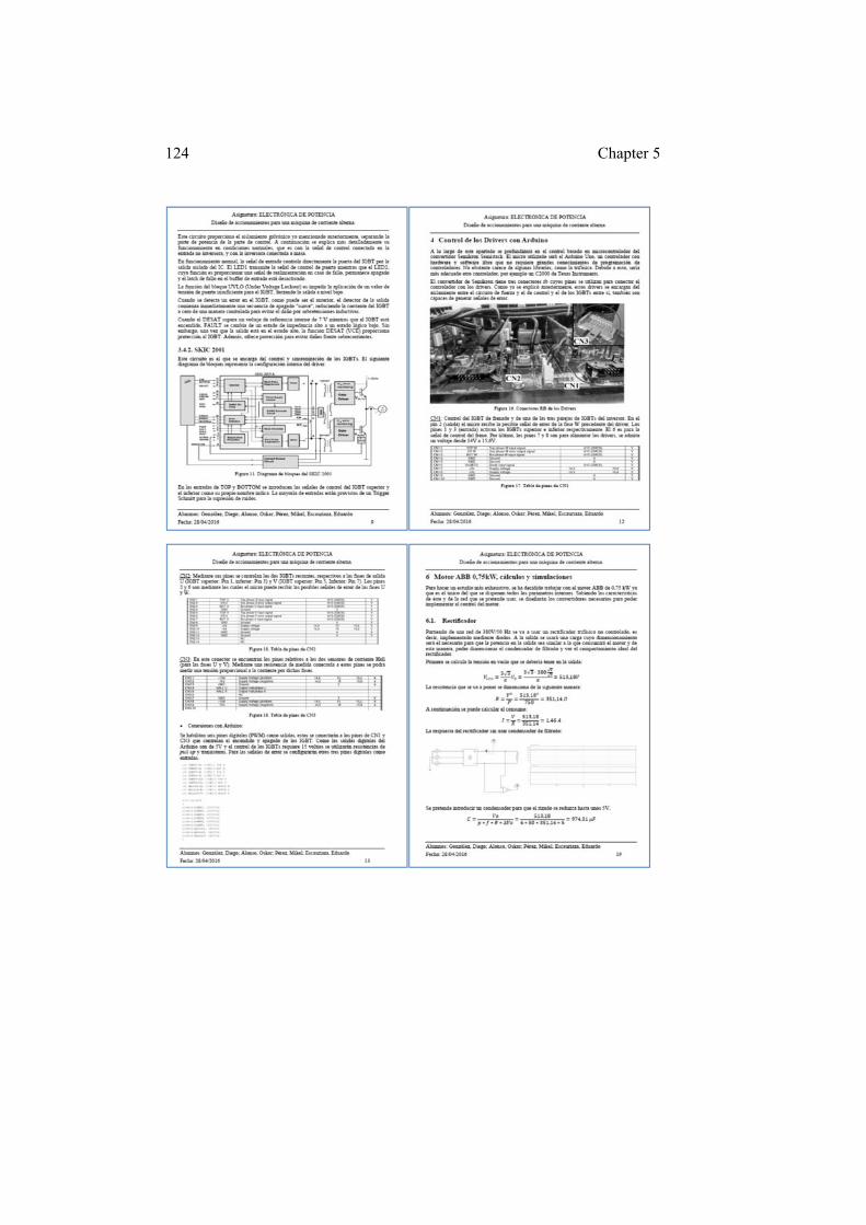
124 Chapter 5
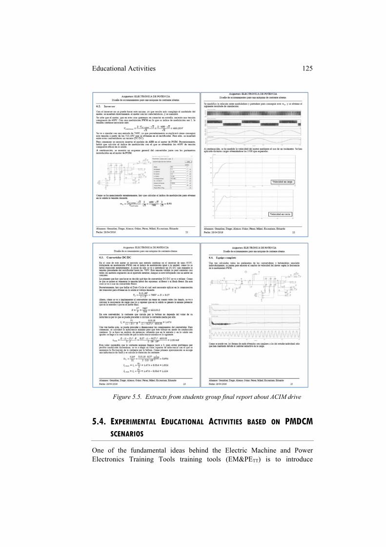
Educational Activities 125
Figure 5.5. Extracts from students group final report about ACIM drive
5.4. EXPERIMENTAL EDUCATIONAL ACTIVITIES BASED ON PMDCM
SCENARIOS
One of the fundamental ideas behind the Electric Machine and Power Electronics Training Tools training tools (EM&PETT) is to introduce
126 Chapter 5
engineering students to the concepts of electric propulsion control through electronic power converters, with energy efficiency criteria and solar energy generation. Both the operation and adjustment of the scenario and the display of the variables that are included in the EM&PETT can be done locally or remotely by several users. The Permanent Magnet DC Motor (PMDCM) is an EM&PETT which was cited in a paper published in the International Journal of Electrical Engineering Education (Maseda et al., 2013), being an example of student´s creativity. The evolution of the EM&PETT through the Final Degree and Final Master Projects and its widespread use in different degree subjects has been closely observed to calibrate the educational capabilities of the proposed methodology.
This EM&PETT was started as a scenario to use in the PjBL 2013/14 course, and has since been used in 2014-15, 2015-16 and 2016-17 in the Control Digital System subject of the Industrial Electronics and Automatics Degree.
In the following paragraphs the training tool will be explained with the aim of demonstrating the relationship between theoretical concepts and the experimental skills which have to be developed.
5.4.1. DC-MOTOR-GENERATOR TRAINING TOOL WITH SOLAR RECHARGE AND
BRAKING ENERGY RECOVERY
This training tool is formed by a motor-generator group with two twin Permanent Magnet DC Motors (PMDCM), three 12V7Ah sealed lead-acid batteries and an array of three BP MSX-5 solar panels. The tool permits the analysis of the concepts of energy efficiency and renewable energies and how power electronics and control theory together have a high impact on their appropriate use and future development (Solangi et al., 2011). This tool becomes a common scenario where different students and student teams can work and collaborate.
Studies of the tool energy sustainability are made by two sources: the solar panels recharge the batteries through a Buck DC-DC converter and the generator performs the recharge through a Boost DC-DC converter when the motor-generator group is running.
5.4.1.1. The training tool structural blocks: DC motor-generator group and energy systems
The architecture of the tool integrates a permanent magnet DC motor-generator group, in this case 30W each, coupled so that the DC machine that serves as a generator has the function of intelligent load for practical
Educational Activities 127
activities related to control of the speed and torque of the DC machine that has the master motor function.
The power supply system consists of a network of three 12V batteries that via an H-bridge transistor adjusts the master motor voltage and therefore its speed and torque. The battery network receives the recharge power from two sources: a 3x1 array of 5W solar panels and the energy recovered from the generator that is driven by the master motor when practical propulsion activities are undertaken.
The subjects related with electrical propulsion are an area of significant industrial and research activity as the electric car, electric motorbike and even the electric bicycle are the future of road transport. In the case of the electric motorbike and bicycle the permanent magnet DC motor is a feasible alternative as an electric propulsion machine.
The energy returning to the batteries from the active brake improves the energy efficiency of the training tool, against energy dissipated or wasted as heat in a set of resistors that would also be possible to use to simulate a mechanical load on the generator output voltage.
The first disassemble step of the training tool is to divide it into three structural blocks: master motor propulsion, solar recharge and braking energy recovery. Each structural block can be divided in four common functional blocks: the electronic power converter, the instrumentation, the switch command and the control algorithm. The students are required to design and develop the simulation models of these functional blocks. The power converter, the instrumentation and the switch command blocks will be resolved through hardware designs and the control algorithm will be implemented in software functions for both, DLL simulation block and training tool microprocessor.
i. Master motor propulsion block
The DC motor is an electric machine well known by engineering students because it is commonly used in classical control books. Figure 5.6 shows the circuit for master motor propulsion simulation. Following the above established division, it is possible to observe the energy supply system that represents the network of three 12V batteries, simulated through a DC voltage source with the battery float charging voltage (41.4V) and a small internal resistor, an H-bridge DC-DC converter connecting the supply system to the master motor and allowing the control of the speed and torque as it turns in both directions, and finally, the motor-generator group.
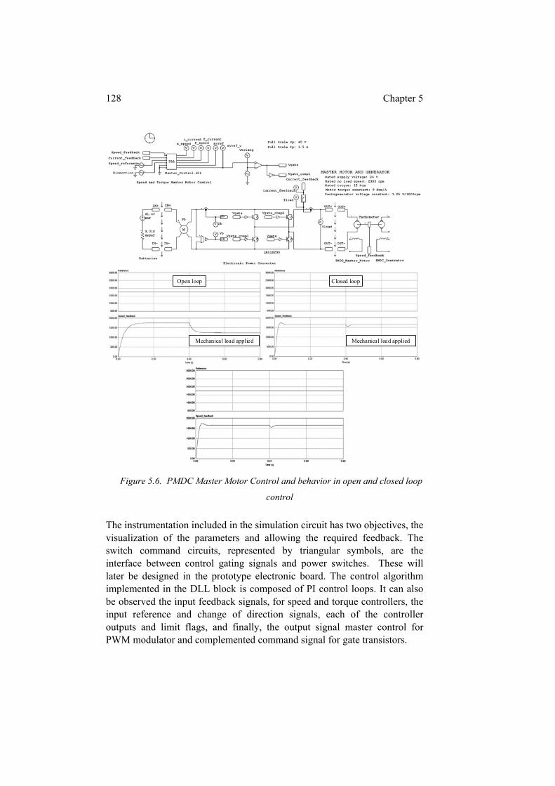
128 Chapter 5
Figure 5.6. PMDC Master Motor Control and behavior in open and closed loop
control
The instrumentation included in the simulation circuit has two objectives, the visualization of the parameters and allowing the required feedback. The switch command circuits, represented by triangular symbols, are the interface between control gating signals and power switches. These will later be designed in the prototype electronic board. The control algorithm implemented in the DLL block is composed of PI control loops. It can also be observed the input feedback signals, for speed and torque controllers, the input reference and change of direction signals, each of the controller outputs and limit flags, and finally, the output signal master control for PWM modulator and complemented command signal for gate transistors.
Open loop
Mechanical load applied
Closed loop
Mechanical load applied
Educational Activities 129
The simulation results show the behavior in open and closed loop when the mechanical load is applied. In the first case there is a loss of control of the speed and in the second one the control system reacts and adjusts the master motor speed. There is a vast bibliography for tuning PI controllers in DC motor applications in different control algorithms and DC-DC converters (Bose, 2001; Shirsavar, 2004).
Different analyses are proposed in order to study the behavior of the DC motor in a wide variety of modes, in open loop, with only speed control loop or adding an inner torque control loop, and from stable behavior to clearly unstable behavior with different transitional adjustments. Several tests and simulations are to be performed by the students for tuning these controllers. One advantage of the small power PMDC motors is that they are suitable for testing in conditions of instability, which in medium and high power DC motors is not advisable because the electronic converter and even the motor can be damaged.
ii. Solar recharge block
Photovoltaic energy generation is one of the future sources of energy because it is clean and abundant with few environmental problems. The efficiency and the power transfer of the electric load connected to the solar panels are the most significant issues which contribute to make this energy source expensive. Figure 5.7 shows the solar panels connected to the batteries through a Buck DC-DC converter that implements a MPPT (Maximum Power Point Tracking) algorithm to improve the power transference from the panels in different situations of solar radiation and temperature. The array of three PV panels is represented in the simulation circuit by a solar block with a total voltage in the maximum power point of 50.4V and a current of 270mA. The battery bank is represented with a DC voltage source of 41.4V (float charging voltage) and a small internal resistor. The necessary instrumentation and the switch command circuit are also included in the simulation diagram.
Reviewing the theory of DC-DC converters, it can be determined that the average output voltage in the Buck converters is DEV 0 and in a Boost
converter )1/(0 DEV , being )/( offonon tttD duty-cycle in steady state
and E the voltage supplied by the batteries. The duty-cycle can vary between10 D . The dynamics of Buck and Boost converters can be described by
equations (5.1) and (5.2), respectively (Fuad et al., 2001):
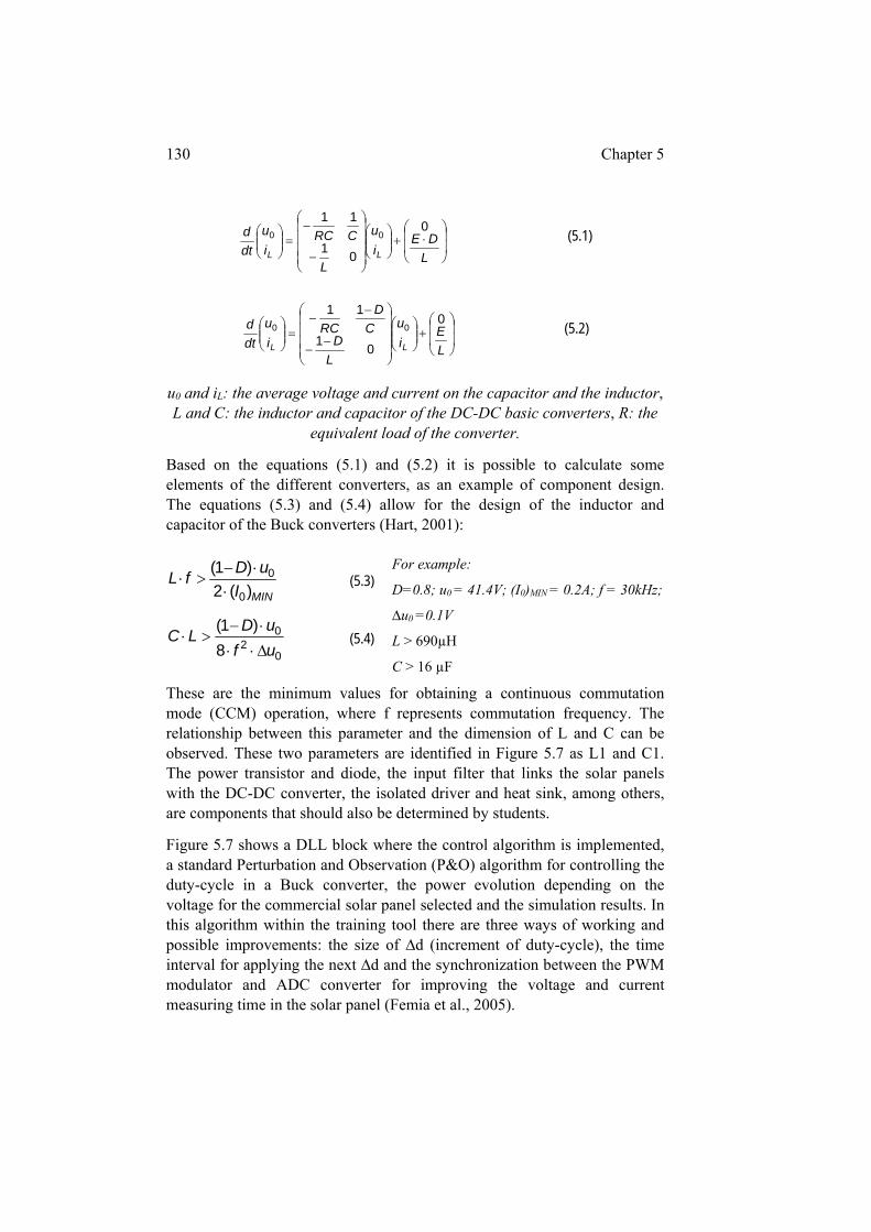
130 Chapter 5
L
DEi
u
L
CRCi
u
dt
d
LL
0
01
1100 (5.1)
L
Ei
u
L
DC
D
RCi
u
dt
d
LL
0
01
1100 (5.2)
u0 and iL: the average voltage and current on the capacitor and the inductor, L and C: the inductor and capacitor of the DC-DC basic converters, R: the
equivalent load of the converter.
Based on the equations (5.1) and (5.2) it is possible to calculate some elements of the different converters, as an example of component design. The equations (5.3) and (5.4) allow for the design of the inductor and capacitor of the Buck converters (Hart, 2001):
MINI
uDfL
)(2)1(
0
0
(5.3)
02
0
8)1(
uf
uDLC
(5.4)
For example:
D=0.8; u0 = 41.4V; (I0)MIN = 0.2A; f = 30kHz;
∆u0 =0.1V
L > 690µH
C > 16 µF
These are the minimum values for obtaining a continuous commutation mode (CCM) operation, where f represents commutation frequency. The relationship between this parameter and the dimension of L and C can be observed. These two parameters are identified in Figure 5.7 as L1 and C1. The power transistor and diode, the input filter that links the solar panels with the DC-DC converter, the isolated driver and heat sink, among others, are components that should also be determined by students.
Figure 5.7 shows a DLL block where the control algorithm is implemented, a standard Perturbation and Observation (P&O) algorithm for controlling the duty-cycle in a Buck converter, the power evolution depending on the voltage for the commercial solar panel selected and the simulation results. In this algorithm within the training tool there are three ways of working and possible improvements: the size of ∆d (increment of duty-cycle), the time interval for applying the next ∆d and the synchronization between the PWM modulator and ADC converter for improving the voltage and current measuring time in the solar panel (Femia et al., 2005).
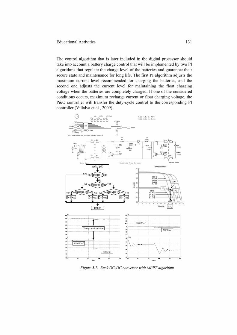
Educational Activities 131
The control algorithm that is later included in the digital processor should take into account a battery charge control that will be implemented by two PI algorithms that regulate the charge level of the batteries and guarantee their secure state and maintenance for long life. The first PI algorithm adjusts the maximum current level recommended for charging the batteries, and the second one adjusts the current level for maintaining the float charging voltage when the batteries are completely charged. If one of the considered conditions occurs, maximum recharge current or float charging voltage, the P&O controller will transfer the duty-cycle control to the corresponding PI controller (Villalva et al., 2009).
Figure 5.7. Buck DC-DC converter with MPPT algorithm
Change sun irradiation
1000W/m2
500W/m2
1000W/m2
500W/m2
Vp(k), Ip(k)
D = D+d D = D-d D = D+d D = D-d
Return
Yes
Yes No
No NoYes Yes
No Pp(k)-Pp(k-1)=0
Pp(k)-Pp(k-1)>0
Vp(k)-Vp(k-1)>0 Vp(k)-Vp(k-1)>0
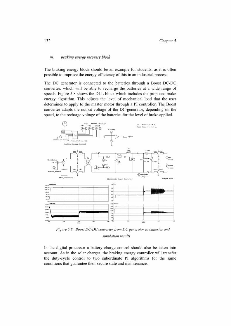
132 Chapter 5
iii. Braking energy recovery block
The braking energy block should be an example for students, as it is often possible to improve the energy efficiency of this in an industrial process.
The DC generator is connected to the batteries through a Boost DC-DC converter, which will be able to recharge the batteries at a wide range of speeds. Figure 5.8 shows the DLL block which includes the proposed brake energy algorithm. This adjusts the level of mechanical load that the user determines to apply to the master motor through a PI controller. The Boost converter adapts the output voltage of the DC-generator, depending on the speed, to the recharge voltage of the batteries for the level of brake applied.
Figure 5.8. Boost DC-DC converter from DC generator to batteries and
simulation results
In the digital processor a battery charge control should also be taken into account. As in the solar charger, the braking energy controller will transfer the duty-cycle control to two subordinate PI algorithms for the same conditions that guarantee their secure state and maintenance.
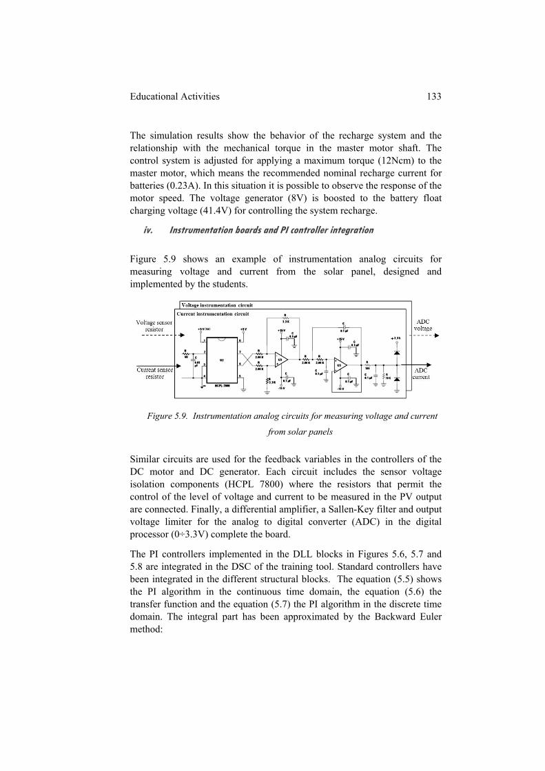
Educational Activities 133
The simulation results show the behavior of the recharge system and the relationship with the mechanical torque in the master motor shaft. The control system is adjusted for applying a maximum torque (12Ncm) to the master motor, which means the recommended nominal recharge current for batteries (0.23A). In this situation it is possible to observe the response of the motor speed. The voltage generator (8V) is boosted to the battery float charging voltage (41.4V) for controlling the system recharge.
iv. Instrumentation boards and PI controller integration
Figure 5.9 shows an example of instrumentation analog circuits for measuring voltage and current from the solar panel, designed and implemented by the students.
Figure 5.9. Instrumentation analog circuits for measuring voltage and current
from solar panels
Similar circuits are used for the feedback variables in the controllers of the DC motor and DC generator. Each circuit includes the sensor voltage isolation components (HCPL 7800) where the resistors that permit the control of the level of voltage and current to be measured in the PV output are connected. Finally, a differential amplifier, a Sallen-Key filter and output voltage limiter for the analog to digital converter (ADC) in the digital processor (0÷3.3V) complete the board.
The PI controllers implemented in the DLL blocks in Figures 5.6, 5.7 and 5.8 are integrated in the DSC of the training tool. Standard controllers have been integrated in the different structural blocks. The equation (5.5) shows the PI algorithm in the continuous time domain, the equation (5.6) the transfer function and the equation (5.7) the PI algorithm in the discrete time domain. The integral part has been approximated by the Backward Euler method:
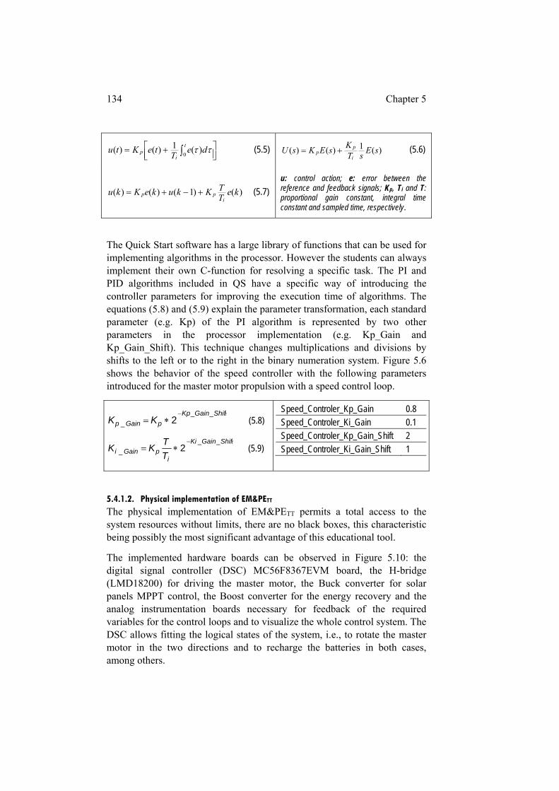
134 Chapter 5
t
ip de
TteKtu
0)(1)()( (5.5) )(1)()( sE
sTK
sEKsUi
pp (5.6)
)()1()()( keTTKkukeKku
ipp (5.7)
u: control action; e: error between the reference and feedback signals; Kp, Ti and T: proportional gain constant, integral time constant and sampled time, respectively.
The Quick Start software has a large library of functions that can be used for implementing algorithms in the processor. However the students can always implement their own C-function for resolving a specific task. The PI and PID algorithms included in QS have a specific way of introducing the controller parameters for improving the execution time of algorithms. The equations (5.8) and (5.9) explain the parameter transformation, each standard parameter (e.g. Kp) of the PI algorithm is represented by two other parameters in the processor implementation (e.g. Kp_Gain and Kp_Gain_Shift). This technique changes multiplications and divisions by shifts to the left or to the right in the binary numeration system. Figure 5.6 shows the behavior of the speed controller with the following parameters introduced for the master motor propulsion with a speed control loop.
tShifGainKp
pGainp KK__
_ 2
(5.8)
tShifGainKi
ipGaini T
TKK
___ 2
(5.9)
Speed_Controler_Kp_Gain 0.8 Speed_Controler_Ki_Gain 0.1 Speed_Controler_Kp_Gain_Shift 2 Speed_Controler_Ki_Gain_Shift 1
5.4.1.2. Physical implementation of EM&PETT The physical implementation of EM&PETT permits a total access to the system resources without limits, there are no black boxes, this characteristic being possibly the most significant advantage of this educational tool.
The implemented hardware boards can be observed in Figure 5.10: the digital signal controller (DSC) MC56F8367EVM board, the H-bridge (LMD18200) for driving the master motor, the Buck converter for solar panels MPPT control, the Boost converter for the energy recovery and the analog instrumentation boards necessary for feedback of the required variables for the control loops and to visualize the whole control system. The DSC allows fitting the logical states of the system, i.e., to rotate the master motor in the two directions and to recharge the batteries in both cases, among others.
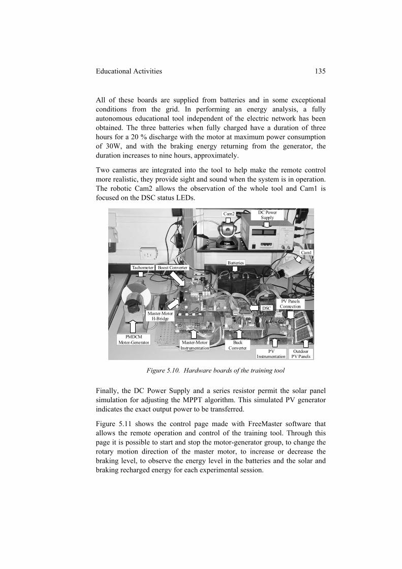
Educational Activities 135
All of these boards are supplied from batteries and in some exceptional conditions from the grid. In performing an energy analysis, a fully autonomous educational tool independent of the electric network has been obtained. The three batteries when fully charged have a duration of three hours for a 20 % discharge with the motor at maximum power consumption of 30W, and with the braking energy returning from the generator, the duration increases to nine hours, approximately.
Two cameras are integrated into the tool to help make the remote control more realistic, they provide sight and sound when the system is in operation. The robotic Cam2 allows the observation of the whole tool and Cam1 is focused on the DSC status LEDs.
Figure 5.10. Hardware boards of the training tool
Finally, the DC Power Supply and a series resistor permit the solar panel simulation for adjusting the MPPT algorithm. This simulated PV generator indicates the exact output power to be transferred.
Figure 5.11 shows the control page made with FreeMaster software that allows the remote operation and control of the training tool. Through this page it is possible to start and stop the motor-generator group, to change the rotary motion direction of the master motor, to increase or decrease the braking level, to observe the energy level in the batteries and the solar and braking recharged energy for each experimental session.
DC Power Supply
Cam1
Cam2
BatteriesTachometer Boost Converter
PMDCM Motor- Master-Motor
InstrumentatioPV
Instrumentation
Master-Motor Instrumentation
PV Panels Connection DSC
PMDCM Motor-Generator
Master-MotorH-Bridge
Buck Converter
Outdoor PV Panels
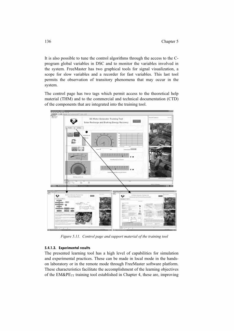
136 Chapter 5
It is also possible to tune the control algorithms through the access to the C-program global variables in DSC and to monitor the variables involved in the system. FreeMaster has two graphical tools for signal visualization, a scope for slow variables and a recorder for fast variables. This last tool permits the observation of transitory phenomena that may occur in the system.
The control page has two tags which permit access to the theoretical help material (THM) and to the commercial and technical documentation (CTD) of the components that are integrated into the training tool.
Figure 5.11. Control page and support material of the training tool
5.4.1.3. Experimental results The presented learning tool has a high level of capabilities for simulation and experimental practices. These can be made in local mode in the hands-on laboratory or in the remote mode through FreeMaster software platform. These characteristics facilitate the accomplishment of the learning objectives of the EM&PETT training tool established in Chapter 4, these are, improving
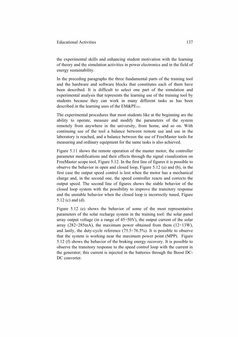
Educational Activities 137
the experimental skills and enhancing student motivation with the learning of theory and the simulation activities in power electronics and in the field of energy sustainability.
In the preceding paragraphs the three fundamental parts of the training tool and the hardware and software blocks that constitutes each of them have been described. It is difficult to select one part of the simulation and experimental analysis that represents the learning use of the training tool by students because they can work in many different tasks as has been described in the learning uses of the EM&PETT.
The experimental procedures that most students like at the beginning are the ability to operate, measure and modify the parameters of the system remotely from anywhere in the university, from home, and so on. With continuing use of the tool a balance between remote use and use in the laboratory is reached, and a balance between the use of FreeMaster tools for measuring and ordinary equipment for the same tasks is also achieved.
Figure 5.11 shows the remote operation of the master motor, the controller parameter modifications and their effects through the signal visualization on FreeMaster scope tool, Figure 5.12. In the first line of figures it is possible to observe the behavior in open and closed loop, Figure 5.12 (a) and (b), in the first case the output speed control is lost when the motor has a mechanical charge and, in the second one, the speed controller reacts and corrects the output speed. The second line of figures shows the stable behavior of the closed loop system with the possibility to improve the transitory response and the unstable behavior when the closed loop is incorrectly tuned, Figure 5.12 (c) and (d).
Figure 5.12 (e) shows the behavior of some of the most representative parameters of the solar recharge system in the training tool: the solar panel array output voltage (in a range of 45÷50V), the output current of the solar array (282÷285mA), the maximum power obtained from them (12÷13W), and lastly, the duty-cycle reference (75.5÷76.5%). It is possible to observe that the system is working near the maximum power point (MPP). Figure 5.12 (f) shows the behavior of the braking energy recovery. It is possible to observe the transitory response to the speed control loop with the current in the generator; this current is injected in the batteries through the Boost DC-DC converter.
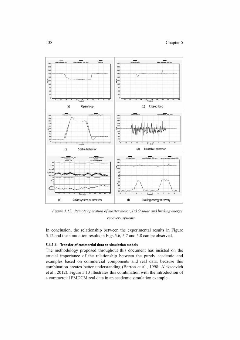
138 Chapter 5
(a) Open loop
(b) Closed loop
(c) Stable behavior
(d) Unstable behavior
(e) Solar system parameters
(f) Braking energy recovery
Figure 5.12. Remote operation of master motor, P&O solar and braking energy
recovery systems
In conclusion, the relationship between the experimental results in Figure 5.12 and the simulation results in Figs 5.6, 5.7 and 5.8 can be observed.
5.4.1.4. Transfer of commercial data to simulation models The methodology proposed throughout this document has insisted on the crucial importance of the relationship between the purely academic and examples based on commercial components and real data, because this combination creates better understanding (Barron et al., 1998; Alekseevich et al., 2012). Figure 5.13 illustrates this combination with the introduction of a commercial PMDCM real data in an academic simulation example.
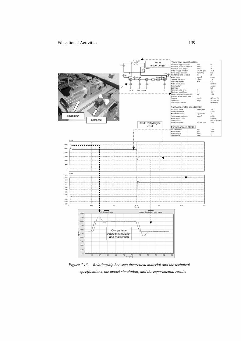
Educational Activities 139
Figure 5.13. Relationship between theoretical material and the technical
specifications, the model simulation, and the experimental results
PMDCM 30W
PMDCM 114W
Data for model design
Results of checking the model
Comparison between simulation
and real results
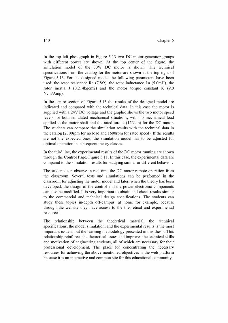
140 Chapter 5
In the top left photograph in Figure 5.13 two DC motor-generator groups with different power are shown. At the top center of the figure, the simulation model of the 30W DC motor is shown. The technical specifications from the catalog for the motor are shown at the top right of Figure 5.13. For the designed model the following parameters have been used: the rotor resistance Ra (7.8Ω), the rotor inductance La (5.0mH), the rotor inertia J (0.214kgcm2) and the motor torque constant K (9.0 Ncm/Amp).
In the centre section of Figure 5.13 the results of the designed model are indicated and compared with the technical data. In this case the motor is supplied with a 24V DC voltage and the graphic shows the two motor speed levels for both simulated mechanical situations, with no mechanical load applied to the motor shaft and the rated torque (12Ncm) for the DC motor. The students can compare the simulation results with the technical data in the catalog (2300rpm for no load and 1600rpm for rated speed). If the results are not the expected ones, the simulation model has to be adjusted for optimal operation in subsequent theory classes.
In the third line, the experimental results of the DC motor running are shown through the Control Page, Figure 5.11. In this case, the experimental data are compared to the simulation results for studying similar or different behavior.
The students can observe in real time the DC motor remote operation from the classroom. Several tests and simulations can be performed in the classroom for adjusting the motor model and later, when the theory has been developed, the design of the control and the power electronic components can also be modified. It is very important to obtain and check results similar to the commercial and technical design specifications. The students can study these topics in-depth off-campus, at home for example, because through the website they have access to the theoretical and experimental resources.
The relationship between the theoretical material, the technical specifications, the model simulation, and the experimental results is the most important issue about the learning methodology presented in this thesis. This relationship reinforces the theoretical issues and improves the technical skills and motivation of engineering students, all of which are necessary for their professional development. The place for concentrating the necessary resources for achieving the above mentioned objectives is the web platform because it is an interactive and common site for this educational community.
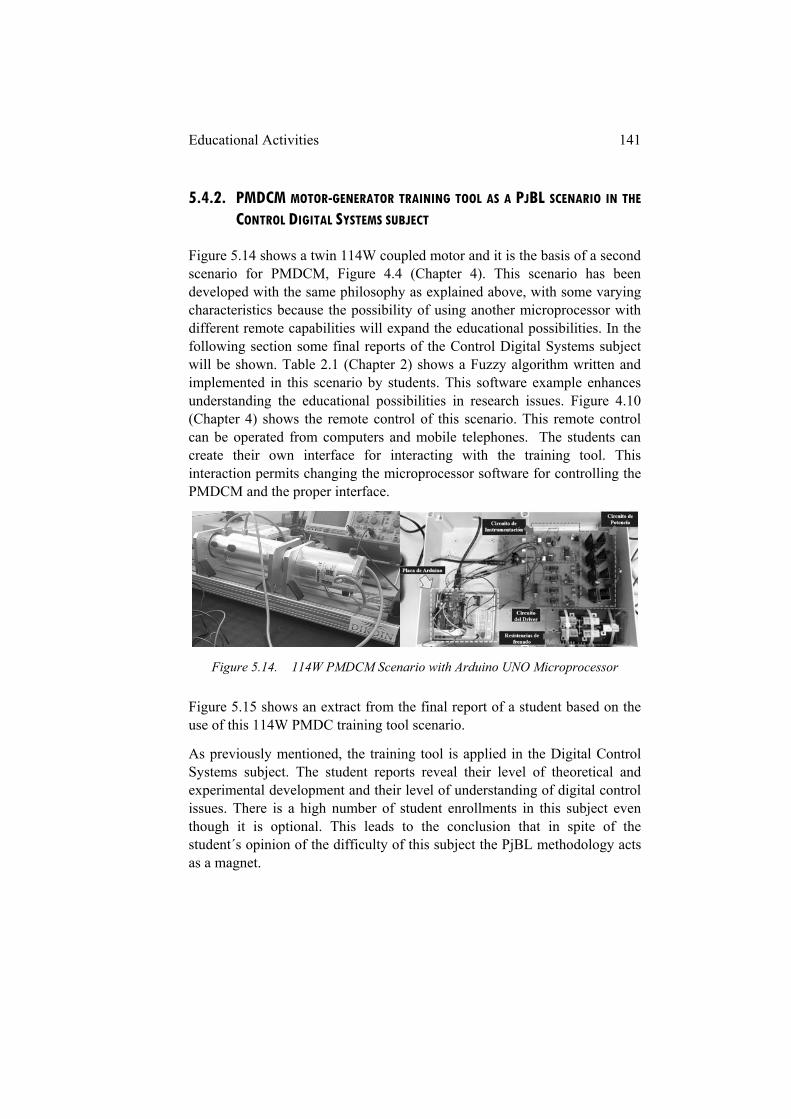
Educational Activities 141
5.4.2. PMDCM MOTOR-GENERATOR TRAINING TOOL AS A PJBL SCENARIO IN THE
CONTROL DIGITAL SYSTEMS SUBJECT
Figure 5.14 shows a twin 114W coupled motor and it is the basis of a second scenario for PMDCM, Figure 4.4 (Chapter 4). This scenario has been developed with the same philosophy as explained above, with some varying characteristics because the possibility of using another microprocessor with different remote capabilities will expand the educational possibilities. In the following section some final reports of the Control Digital Systems subject will be shown. Table 2.1 (Chapter 2) shows a Fuzzy algorithm written and implemented in this scenario by students. This software example enhances understanding the educational possibilities in research issues. Figure 4.10 (Chapter 4) shows the remote control of this scenario. This remote control can be operated from computers and mobile telephones. The students can create their own interface for interacting with the training tool. This interaction permits changing the microprocessor software for controlling the PMDCM and the proper interface.
Figure 5.14. 114W PMDCM Scenario with Arduino UNO Microprocessor
Figure 5.15 shows an extract from the final report of a student based on the use of this 114W PMDC training tool scenario.
As previously mentioned, the training tool is applied in the Digital Control Systems subject. The student reports reveal their level of theoretical and experimental development and their level of understanding of digital control issues. There is a high number of student enrollments in this subject even though it is optional. This leads to the conclusion that in spite of the student´s opinion of the difficulty of this subject the PjBL methodology acts as a magnet.
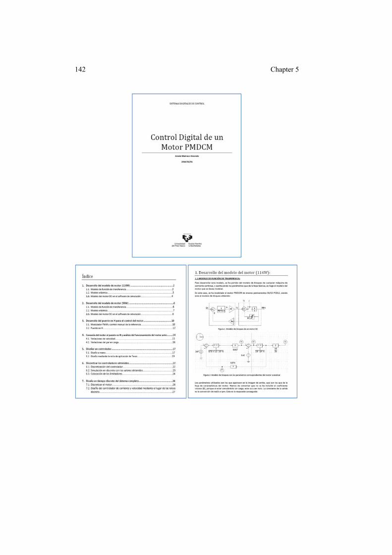
142 Chapter 5

Educational Activities 143
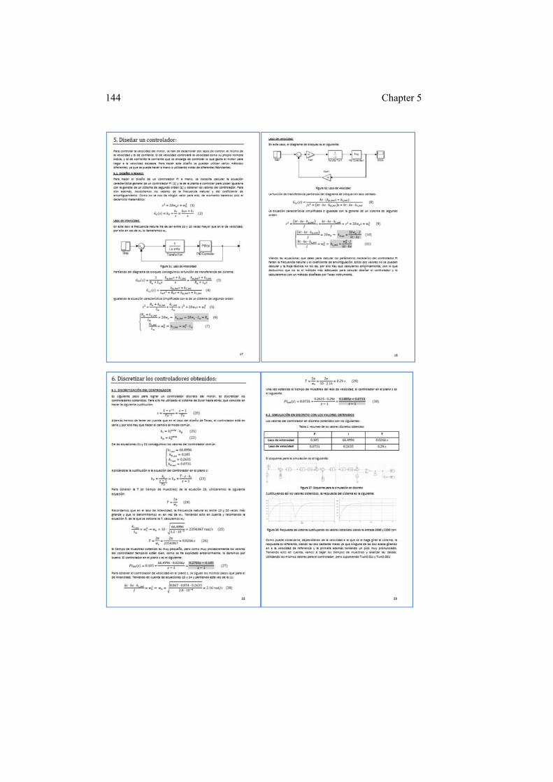
144 Chapter 5
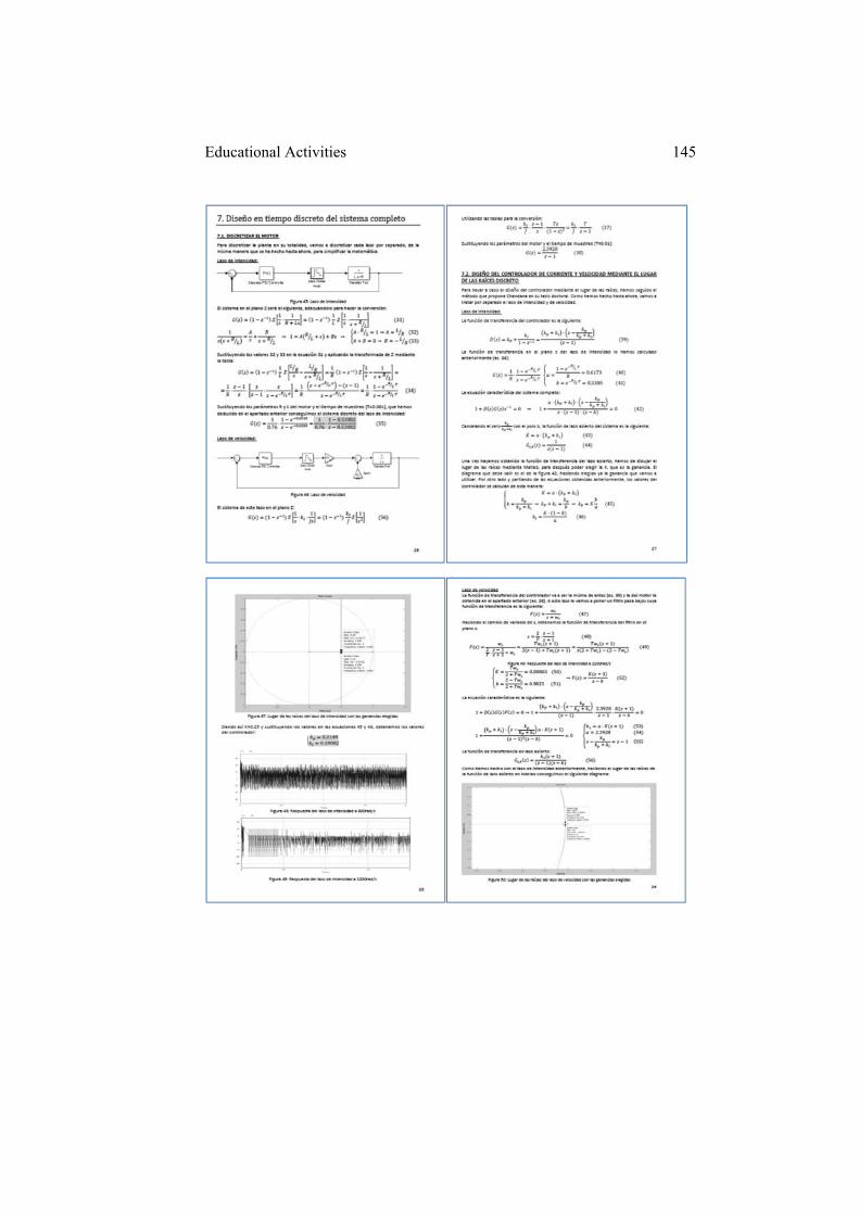
Educational Activities 145
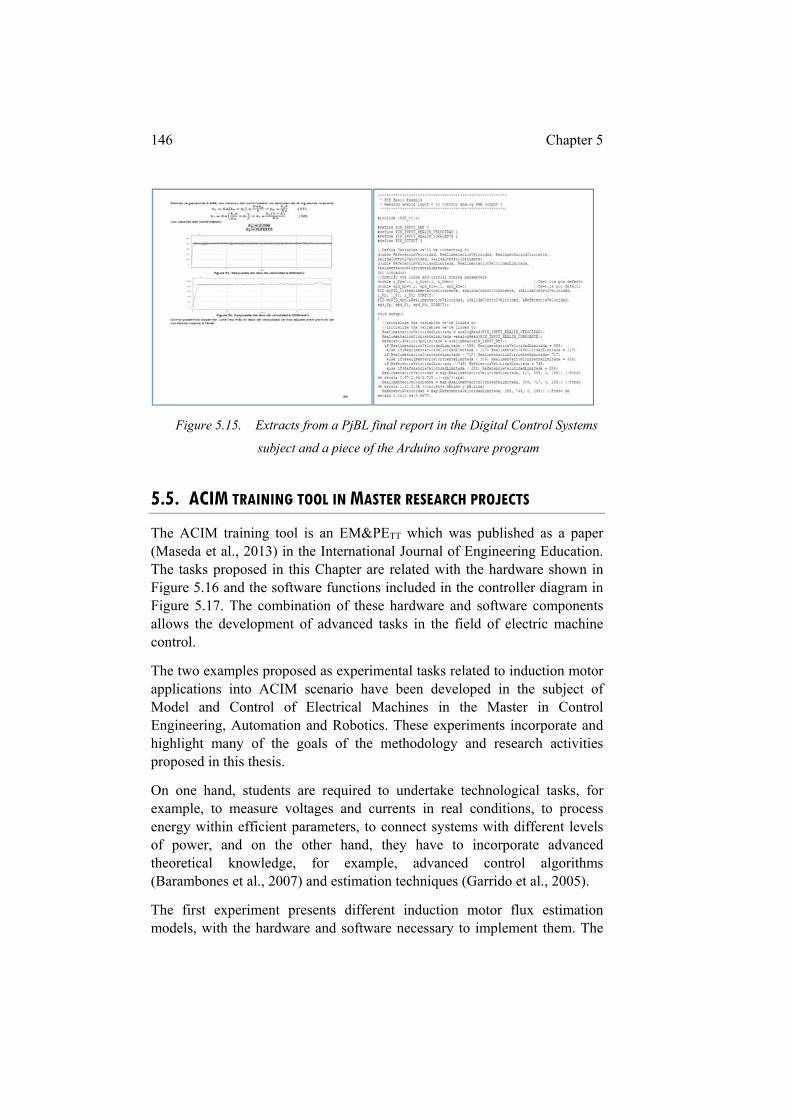
146 Chapter 5
Figure 5.15. Extracts from a PjBL final report in the Digital Control Systems
subject and a piece of the Arduino software program
5.5. ACIM TRAINING TOOL IN MASTER RESEARCH PROJECTS
The ACIM training tool is an EM&PETT which was published as a paper (Maseda et al., 2013) in the International Journal of Engineering Education. The tasks proposed in this Chapter are related with the hardware shown in Figure 5.16 and the software functions included in the controller diagram in Figure 5.17. The combination of these hardware and software components allows the development of advanced tasks in the field of electric machine control.
The two examples proposed as experimental tasks related to induction motor applications into ACIM scenario have been developed in the subject of Model and Control of Electrical Machines in the Master in Control Engineering, Automation and Robotics. These experiments incorporate and highlight many of the goals of the methodology and research activities proposed in this thesis.
On one hand, students are required to undertake technological tasks, for example, to measure voltages and currents in real conditions, to process energy within efficient parameters, to connect systems with different levels of power, and on the other hand, they have to incorporate advanced theoretical knowledge, for example, advanced control algorithms (Barambones et al., 2007) and estimation techniques (Garrido et al., 2005).
The first experiment presents different induction motor flux estimation models, with the hardware and software necessary to implement them. The
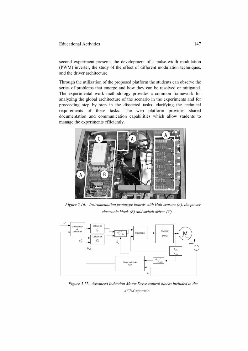
Educational Activities 147
second experiment presents the development of a pulse-width modulation (PWM) inverter, the study of the effect of different modulation techniques, and the driver architecture.
Through the utilization of the proposed platform the students can observe the series of problems that emerge and how they can be resolved or mitigated. The experimental work methodology provides a common framework for analyzing the global architecture of the scenario in the experiments and for proceeding step by step in the dissected tasks, clarifying the technical requirements of these tasks. The web platform provides shared documentation and communication capabilities which allow students to manage the experiments efficiently.
Figure 5.16. Instrumentation prototype boards with Hall sensors (A), the power
electronic block (B) and switch driver (C)
Controladorde
velocidad
Cálculo de
Inversor
PWMModulador M
Observador deflujo
abci
abcv
*eqsi
eθ*e
drψ
edrψ
Cálculo de*e
dsi
abcdq
abcdqe
*w
w
Figure 5.17. Advanced Induction Motor Drive control blocks included in the
ACIM scenario
A
A A
B
C
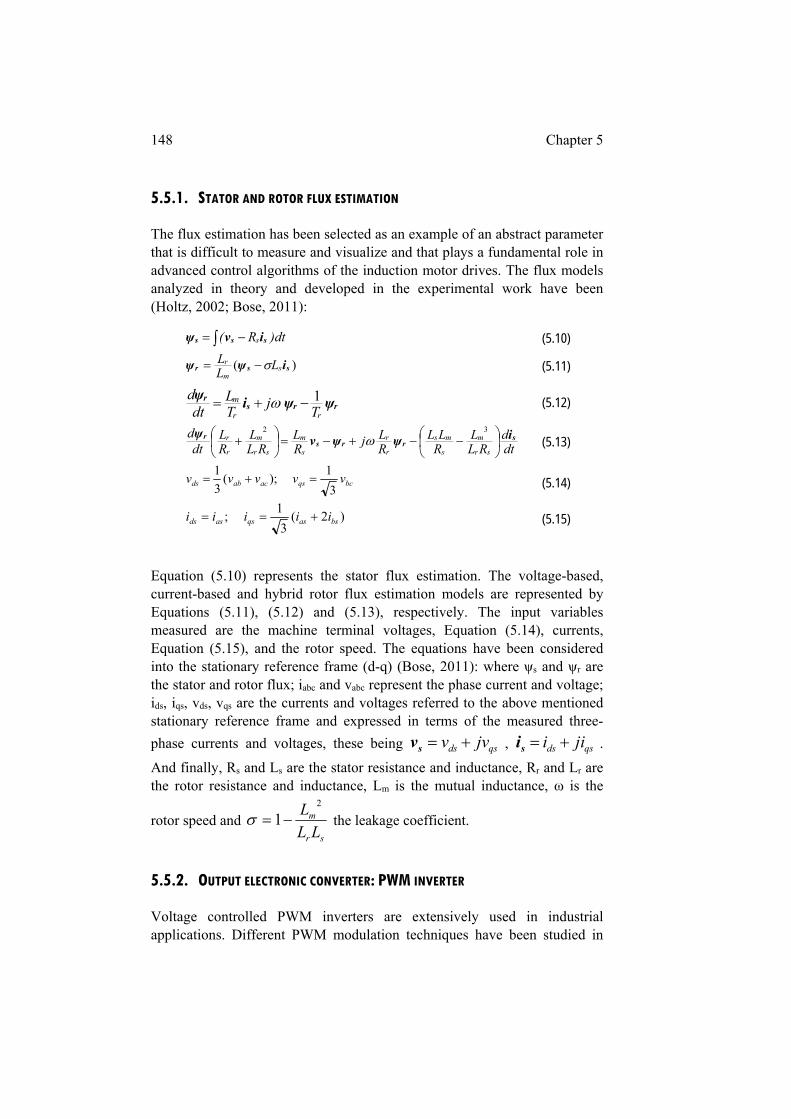
148 Chapter 5
5.5.1. STATOR AND ROTOR FLUX ESTIMATION
The flux estimation has been selected as an example of an abstract parameter that is difficult to measure and visualize and that plays a fundamental role in advanced control algorithms of the induction motor drives. The flux models analyzed in theory and developed in the experimental work have been (Holtz, 2002; Bose, 2011):
)dtR( s sss ivψ
(5.10)
)( ssr iψψ sm
r LLL (5.11)
rrsr ψψi
ψrr
m
Tj
TL
dtd 1 (5.12)
dtd
RLL
RLL
RLj
RL
RLL
RL
dtd
sr
m
s
ms
r
r
s
m
sr
m
r
r srrs
r iψψvψ
32
(5.13)
bcqsacabds vvvvv3
1 );(
3
1 (5.14)
)2(3
1 ; bsasqsasds iiiii (5.15)
Equation (5.10) represents the stator flux estimation. The voltage-based, current-based and hybrid rotor flux estimation models are represented by Equations (5.11), (5.12) and (5.13), respectively. The input variables measured are the machine terminal voltages, Equation (5.14), currents, Equation (5.15), and the rotor speed. The equations have been considered into the stationary reference frame (d-q) (Bose, 2011): where ψs and ψr are the stator and rotor flux; iabc and vabc represent the phase current and voltage; ids, iqs, vds, vqs are the currents and voltages referred to the above mentioned stationary reference frame and expressed in terms of the measured three-
phase currents and voltages, these being qsds jvv sv , qsds jii si .
And finally, Rs and Ls are the stator resistance and inductance, Rr and Lr are the rotor resistance and inductance, Lm is the mutual inductance, ω is the
rotor speed and sr
m
LL
L 2
1 the leakage coefficient.
5.5.2. OUTPUT ELECTRONIC CONVERTER: PWM INVERTER
Voltage controlled PWM inverters are extensively used in industrial applications. Different PWM modulation techniques have been studied in
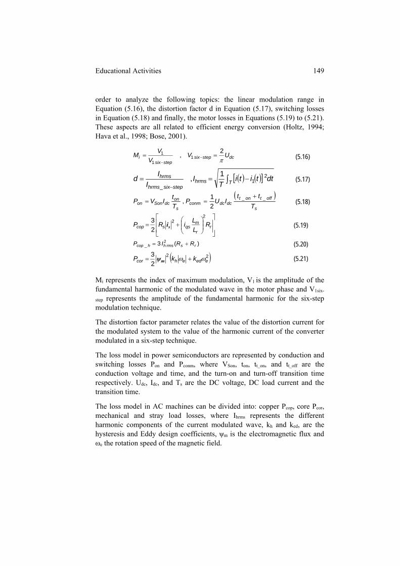
Educational Activities 149
order to analyze the following topics: the linear modulation range in Equation (5.16), the distortion factor d in Equation (5.17), switching losses in Equation (5.18) and finally, the motor losses in Equations (5.19) to (5.21). These aspects are all related to efficient energy conversion (Holtz, 1994; Hava et al., 1998; Bose, 2001).
dcstepsixstepsix
i UVV
VM
2, 1
1
1
(5.16)
Thrmsstepsixhrms
hrms dttitiT
II
Id 2
1_
1, (5.17)
s
offtontdcdcconm
s
ondcSonon T
ttIUP
T
tIVP __
21,
(5.18)
r
r
mqsscop R
L
LiRP
22
23
si (5.19)
)(3 2_ rsrmshhcop RRIP (5.20)
22
23
eedehcor kkP mψ (5.21)
Mi represents the index of maximum modulation, V1 is the amplitude of the fundamental harmonic of the modulated wave in the motor phase and V1six-
step represents the amplitude of the fundamental harmonic for the six-step modulation technique.
The distortion factor parameter relates the value of the distortion current for the modulated system to the value of the harmonic current of the converter modulated in a six-step technique.
The loss model in power semiconductors are represented by conduction and switching losses Pon and Pconm, where VSon, ton, tt_on, and tt_off are the conduction voltage and time, and the turn-on and turn-off transition time respectively. Udc, Idc, and Ts are the DC voltage, DC load current and the transition time.
The loss model in AC machines can be divided into: copper Pcop, core Pcor, mechanical and stray load losses, where Ihrms represents the different harmonic components of the current modulated wave, kh and ked, are the hysteresis and Eddy design coefficients, ψm is the electromagnetic flux and ωe the rotation speed of the magnetic field.
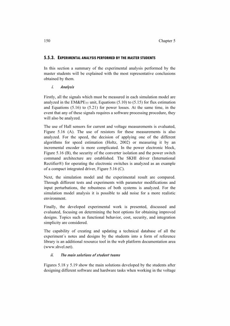
150 Chapter 5
5.5.3. EXPERIMENTAL ANALYSIS PERFORMED BY THE MASTER STUDENTS
In this section a summary of the experimental analysis performed by the master students will be explained with the most representative conclusions obtained by them.
i. Analysis
Firstly, all the signals which must be measured in each simulation model are analyzed in the EM&PETT unit, Equations (5.10) to (5.15) for flux estimation and Equations (5.16) to (5.21) for power losses. At the same time, in the event that any of these signals requires a software processing procedure, they will also be analyzed.
The use of Hall sensors for current and voltage measurements is evaluated, Figure 5.16 (A). The use of resistors for these measurements is also analyzed. For the speed, the decision of applying one of the different algorithms for speed estimation (Holtz, 2002) or measuring it by an incremental encoder is more complicated. In the power electronic block, Figure 5.16 (B), the security of the converter isolation and the power switch command architecture are established. The SKHI driver (International Rectifier®) for operating the electronic switches is analyzed as an example of a compact integrated driver, Figure 5.16 (C).
Next, the simulation model and the experimental result are compared. Through different tests and experiments with parameter modifications and input perturbations, the robustness of both systems is analyzed. For the simulation model analysis it is possible to add noise for a more realistic environment.
Finally, the developed experimental work is presented, discussed and evaluated, focusing on determining the best options for obtaining improved designs. Topics such as functional behavior, cost, security, and integration simplicity are considered.
The capability of creating and updating a technical database of all the experiment´s notes and designs by the students into a form of reference library is an additional resource tool in the web platform documentation area (www.shvel.net).
ii. The main solutions of student teams
Figures 5.18 y 5.19 show the main solutions developed by the students after designing different software and hardware tasks when working in the voltage
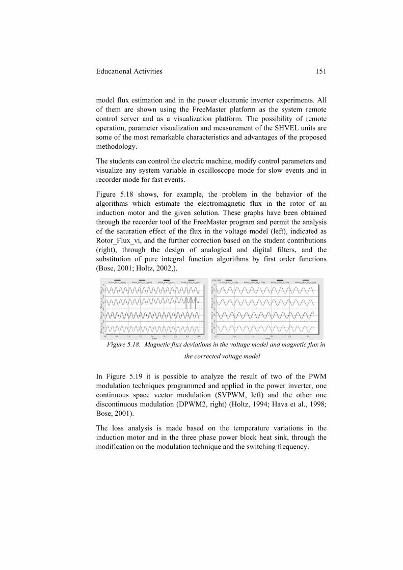
Educational Activities 151
model flux estimation and in the power electronic inverter experiments. All of them are shown using the FreeMaster platform as the system remote control server and as a visualization platform. The possibility of remote operation, parameter visualization and measurement of the SHVEL units are some of the most remarkable characteristics and advantages of the proposed methodology.
The students can control the electric machine, modify control parameters and visualize any system variable in oscilloscope mode for slow events and in recorder mode for fast events.
Figure 5.18 shows, for example, the problem in the behavior of the algorithms which estimate the electromagnetic flux in the rotor of an induction motor and the given solution. These graphs have been obtained through the recorder tool of the FreeMaster program and permit the analysis of the saturation effect of the flux in the voltage model (left), indicated as Rotor_Flux_vi, and the further correction based on the student contributions (right), through the design of analogical and digital filters, and the substitution of pure integral function algorithms by first order functions (Bose, 2001; Holtz, 2002,).
Figure 5.18. Magnetic flux deviations in the voltage model and magnetic flux in
the corrected voltage model
In Figure 5.19 it is possible to analyze the result of two of the PWM modulation techniques programmed and applied in the power inverter, one continuous space vector modulation (SVPWM, left) and the other one discontinuous modulation (DPWM2, right) (Holtz, 1994; Hava et al., 1998; Bose, 2001).
The loss analysis is made based on the temperature variations in the induction motor and in the three phase power block heat sink, through the modification on the modulation technique and the switching frequency.
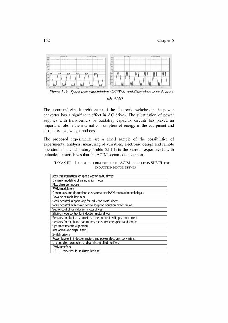
152 Chapter 5
Figure 5.19. Space vector modulation (SVPWM) and discontinuous modulation
(DPWM2)
The command circuit architecture of the electronic switches in the power converter has a significant effect in AC drives. The substitution of power supplies with transformers by bootstrap capacitor circuits has played an important role in the internal consumption of energy in the equipment and also in its size, weight and cost.
The proposed experiments are a small sample of the possibilities of experimental analysis, measuring of variables, electronic design and remote operation in the laboratory. Table 5.III lists the various experiments with induction motor drives that the ACIM scenario can support.
Table 5.III. LIST OF EXPERIMENTS IN THE ACIM SCENARIO IN SHVEL FOR
INDUCTION MOTOR DRIVES
Axis transformation for space vector in AC drives Dynamic modeling of an induction motor Flux observer models PWM modulators Continuous and discontinuous space vector PWM modulation techniques Power electronic inverters Scalar control in open loop for induction motor drives Scalar control with speed control loop for induction motor drives Vector control for induction motor drives Sliding mode control for induction motor drives Sensors for electric parameters measurement: voltages and currents Sensors for mechanic parameters measurement: speed and torque Speed estimation algorithms Analogical and digital filters Switch drivers Power losses in induction motors and power electronic converters Uncontrolled, controlled and semi-controlled rectifiers PWM rectifiers DC-DC converter for resistive braking
Educational Activities 153
5.6. CONCLUSIONS
The activities described in this Chapter reveal the educational qualities of the proposed platform. The PjBL methodology, the fDAA activities, the real and virtual experimental work spaces have been combined for obtaining a novel educational environment.
For a correct analysis of the examples shown as case studies the current educational conditions and challenges should be taken into account: the traditional teaching and learning dynamic, large student groups, the real work conditions, the level of access to equipment, the creativity to change equipment or the development of new projects.
The first fundamental objective in the educational activities proposed in this thesis has been to develop independent learning by the student. A second objective has been to facilitate the understanding of complex and abstract theory by developing projects in technological scenarios that replicate industrial equipment. A third objective has been to reinforce the self-confidence of students. This is achieved by students working with scenarios that have been developed or changed by students from previous courses, and in which they will have the opportunity to include their own ideas. And lastly, the fourth and final objective has been to prepare engineering professionals to enter into industry with the highest technical and social qualities.
The students’ reports are clear indicators about the level of accomplishment of the above objectives.
Finally, the proposed platform has demonstrated the possibility of these scenarios to evolve and be adapted to future educational requirements.

Chapter 6 - Project Based Learning in Kinematics and Dynamics of Machines
In this chapter a case study of the Project Based Learning (PjBL) methodology as applied in the Kinematics and Dynamics of Machines subject will be shown. Firstly, the proposal is to show the multidisciplinary characteristic of the platform, the methodology, the activities and the tools developed in this thesis. Secondly, the chapter demonstrates the PjBL application with especially large student groups. And finally, this chapter introduces the capability of using the PjBL methodology in a transversal mode in other related subjects of the Mechanical Degree.
6.1. INTRODUCTION
The PjBL methodology as applied in the Kinematics and Dynamics of Machines subject leads the students through the different parts of a mechanical system and provides them with a clear understanding of its real functionality (Martija et al., 2015). The educational application of Disassemble/Analyze/Assemble (DAA) activities has been widely used with small mechanical artifacts (Ogot et al., 2008; Dalrymple, et al., 2011; Rothe & Schwandt, 2013) and in this case study the proposal is to study industrial machinery.
The combination of the theoretical knowledge and specific mechanical design simulation software (Petuya et al., 2011) is an experimental procedure to enable the students to better comprehend complex and abstract concepts related to static and dynamic mechanical mechanism theory as applied to big machines.
Most of the academic and technical resources are included in the web platform www.shvel.net (Martija et al., 2014). The use of multimedia tools, photographs and videos for understanding the behavior of the complex mechanical system in different work situations are an extended path for cooperative learning (Patil et al., 2003; Stefanova, 2014; Miller & Bures, 2014; Nickchen & Mertsching, 2016).
The analysis of the educational application and functioning of PjBL teamwork in subjects with more than eighty students is especially difficult and not usually found in papers. This chapter will focus on the qualitative

156 Chapter 6
aspects of the PjBL application because of the level of compromise the students are required to have with the methodology to attain the desired results. In addition, it is not unusual in engineering education subjects with large numbers of students that there is a higher failure rate. The results of the proposal presented in this thesis have shown a clear improvement in the student´s rank scores in the subject.
Finally, the relationship between continuous student assessment and the level of student dedication to the subject should be carefully analyzed.
6.2. THE PROPOSED PROJECT: HOW TO DESIGN A MECHANISM THAT
MOVES MATERIAL THROUGH DIFFERENT LEVELS
The scenario proposed in the PjBL methodology in Kinematics and Dynamics of Machines subject is an artifact for moving materials between different levels (Martija et al., 2015).
Figure 6.1. Learning scenario
There are clear differences between the mechanical and power electronics scenarios for the proposed PjBL activities. Mechanical artifacts give students a clear vision of their functionality with their physical structure. With mechanical artifacts being complex and expensive to prototype, simulation software is the final step in educational practice. In power electronics though, it is much easier to build a specific physical prototype for recreating the real functionality of the scenario. These differences are taken into account when the PjBL is applied in engineering education subjects. The versatility of the methodology as presented in this proposal facilitates its application in varied types of experimental activities. The fundamental idea in both cases is that students realize that they can make and deliver the tasks so that they learn and know that theoretical knowledge is the solution for resolving the technical questions which emerge in the project.
PBL in Kinematics and Dynamics of Machines 157
The objective is to create an environment for working with real scenarios. These motivate the student through the real design of an industrial system in different work applications to learn about the relationship with theoretical calculation, its implementation in a simulation model and the visualization of its real behavior, all the while increasing their academic proficiency.
6.2.1. CONTEXT OF THE IMPLEMENTATION
The Kinematic and Dynamic of Machines is a nine credits subject and it is studied in the first semester of the third course in the Faculty of Engineering in Bilbao. The subject credits include six face-to-face hours and nine off-campus work hours per week.
The methodology is usually implemented in a single group of about 80 students. The number of students in a theory group is conditioned by the University, independently of the educational methodology that is applied. These especially large groups of students are a challenge in engineering education, and in cooperative learning and more specifically with the PjBL methodology they have become a very interesting research issue.
Due to the amount of students, the face-to-face time is divided into three hours for theory classes given to the whole group, two hours in which the students are divided into two subgroups for classroom practices, and one hour in which the students are divided into 4 subgroups for laboratory practices.
The 2014/15 course was the first year that the proposed PjBL methodology was totally implemented and it has been the case study used for the analysis in this chapter. The students were divided into twenty groups for team working. This is because the DAA activities applied to mechanical scenarios were decided adequate for 4 students in each group.
For the proposed excavator scenario, there are three mechanical blocks to be designed: the deeper or arm, the boom and the bucket. These disassemble mechanical systems require a team of three experts, one for each mechanical block, and one integrator. The integrator, functions in a leadership role.
As mentioned in Chapter 1, the engineering students are required to acquire technical and professional skills in a short period of time (Hwang et al., 2008; King, 2012), so project structure plays a fundamental role in this acquisition. The project is structured in three phases, Figure 6.2. The first two phases are developed in five consecutive weeks and the third phase ending the project during weeks 11, 12 and 13 of the term.
158 Chapter 6
6.2.2. GETTING STARTED
The first step is a general description of the subject, explaining its development through the project. The student guide is explained and added to the virtual classroom.
The second step is a presentation of the scenario, Figure 6.1. It seeks to contain the maximum theoretical knowledge of the subject. This step is followed by an explanation of the subject learning objectives and their relationship with the scenario, what is expected of the students and how they are to attain the required results.
The methodology of cooperative learning is explained. The fundamental aspects of active methodologies and cooperative learning are presented, and students are told what the groups are expected to do and that these groups need to work as teams. The activities which are going to be performed during the duration of the project are briefly explained.
The assessment system is presented and explained, where the weight of the project in the subject mark is outlined. There is a comprehensive explanation of the planning of the project and the on-campus and off-campus work that is required to be done. The importance of personal and group dedication is reiterated. All of the above is considered necessary to get the students to understand the methodology before forming the groups.
It is recommended that the students complete a preliminary knowledge survey. The reasons for this are so that the students are made aware of their level of knowledge in basic subjects and their relationship with the subject. Also the students will be able evaluate their progress when compared with the end of project survey.
For the initial example of cooperative learning, the teamwork starts with an analysis exercise, so that every member of the group briefly analyzes a part of the description of the objectives and desired results of the students’ project. The experts then meet to review their corresponding parts and explain it to their partners. Finally, the integrator of each student group is required to present a brief description of each part of the workbook and draw a poster on the whiteboard, completing their first activity of cooperative learning.
Figure 6.2 (top) shows the three project phases of a boom design for active learning activities. The Disassemble/Analysis/Assemble (DAA) activities for teamwork groups are:
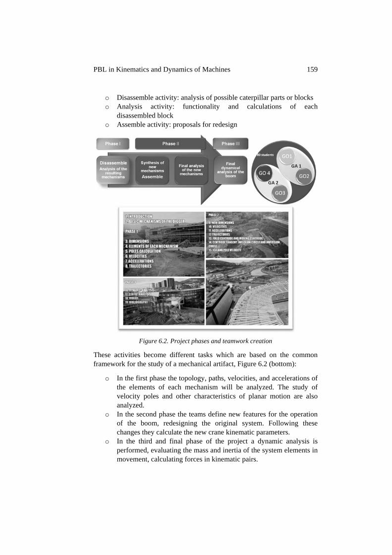
PBL in Kinematics and Dynamics of Machines 159
o Disassemble activity: analysis of possible caterpillar parts or blocks o Analysis activity: functionality and calculations of each
disassembled block o Assemble activity: proposals for redesign
Figure 6.2. Project phases and teamwork creation
These activities become different tasks which are based on the common framework for the study of a mechanical artifact, Figure 6.2 (bottom):
o In the first phase the topology, paths, velocities, and accelerations of the elements of each mechanism will be analyzed. The study of velocity poles and other characteristics of planar motion are also analyzed.
o In the second phase the teams define new features for the operation of the boom, redesigning the original system. Following these changes they calculate the new crane kinematic parameters.
o In the third and final phase of the project a dynamic analysis is performed, evaluating the mass and inertia of the system elements in movement, calculating forces in kinematic pairs.
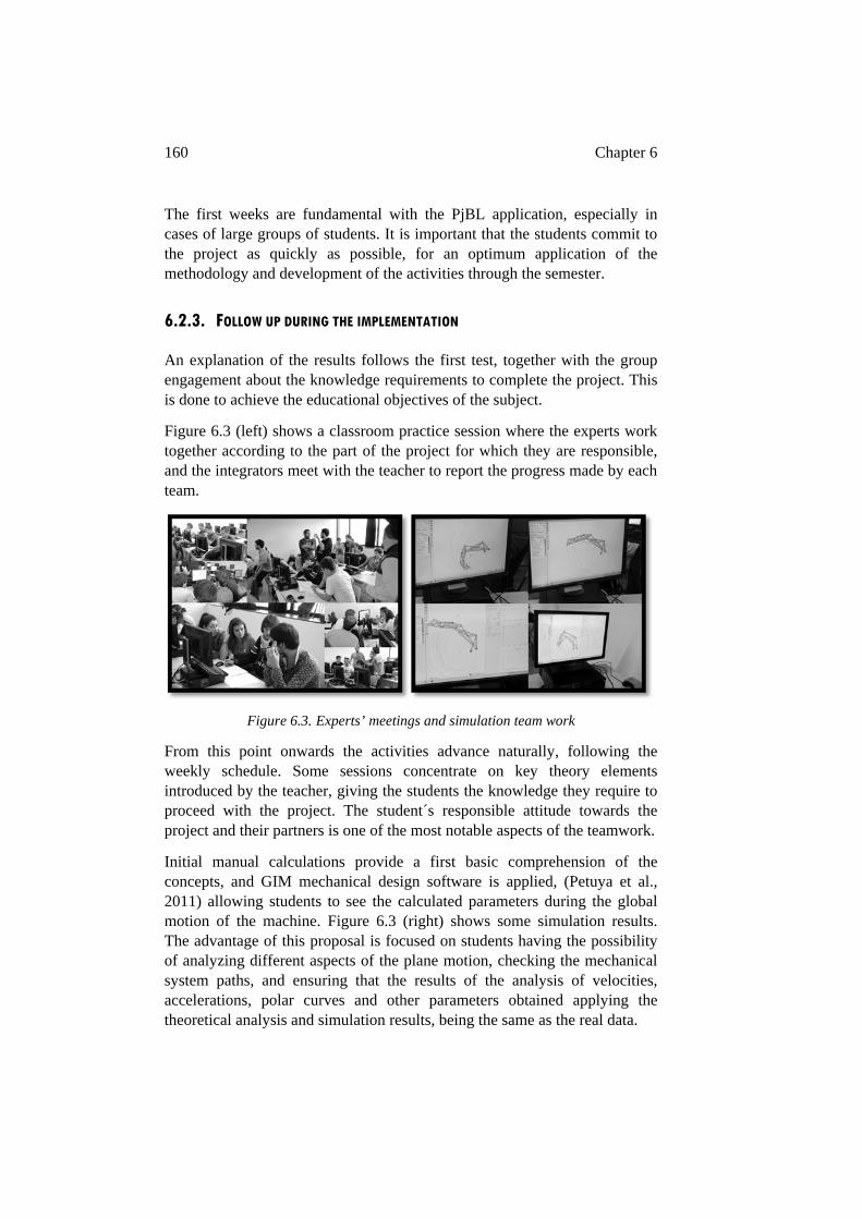
160 Chapter 6
The first weeks are fundamental with the PjBL application, especially in cases of large groups of students. It is important that the students commit to the project as quickly as possible, for an optimum application of the methodology and development of the activities through the semester.
6.2.3. FOLLOW UP DURING THE IMPLEMENTATION
An explanation of the results follows the first test, together with the group engagement about the knowledge requirements to complete the project. This is done to achieve the educational objectives of the subject.
Figure 6.3 (left) shows a classroom practice session where the experts work together according to the part of the project for which they are responsible, and the integrators meet with the teacher to report the progress made by each team.
Figure 6.3. Experts’ meetings and simulation team work
From this point onwards the activities advance naturally, following the weekly schedule. Some sessions concentrate on key theory elements introduced by the teacher, giving the students the knowledge they require to proceed with the project. The student´s responsible attitude towards the project and their partners is one of the most notable aspects of the teamwork.
Initial manual calculations provide a first basic comprehension of the concepts, and GIM mechanical design software is applied, (Petuya et al., 2011) allowing students to see the calculated parameters during the global motion of the machine. Figure 6.3 (right) shows some simulation results. The advantage of this proposal is focused on students having the possibility of analyzing different aspects of the plane motion, checking the mechanical system paths, and ensuring that the results of the analysis of velocities, accelerations, polar curves and other parameters obtained applying the theoretical analysis and simulation results, being the same as the real data.
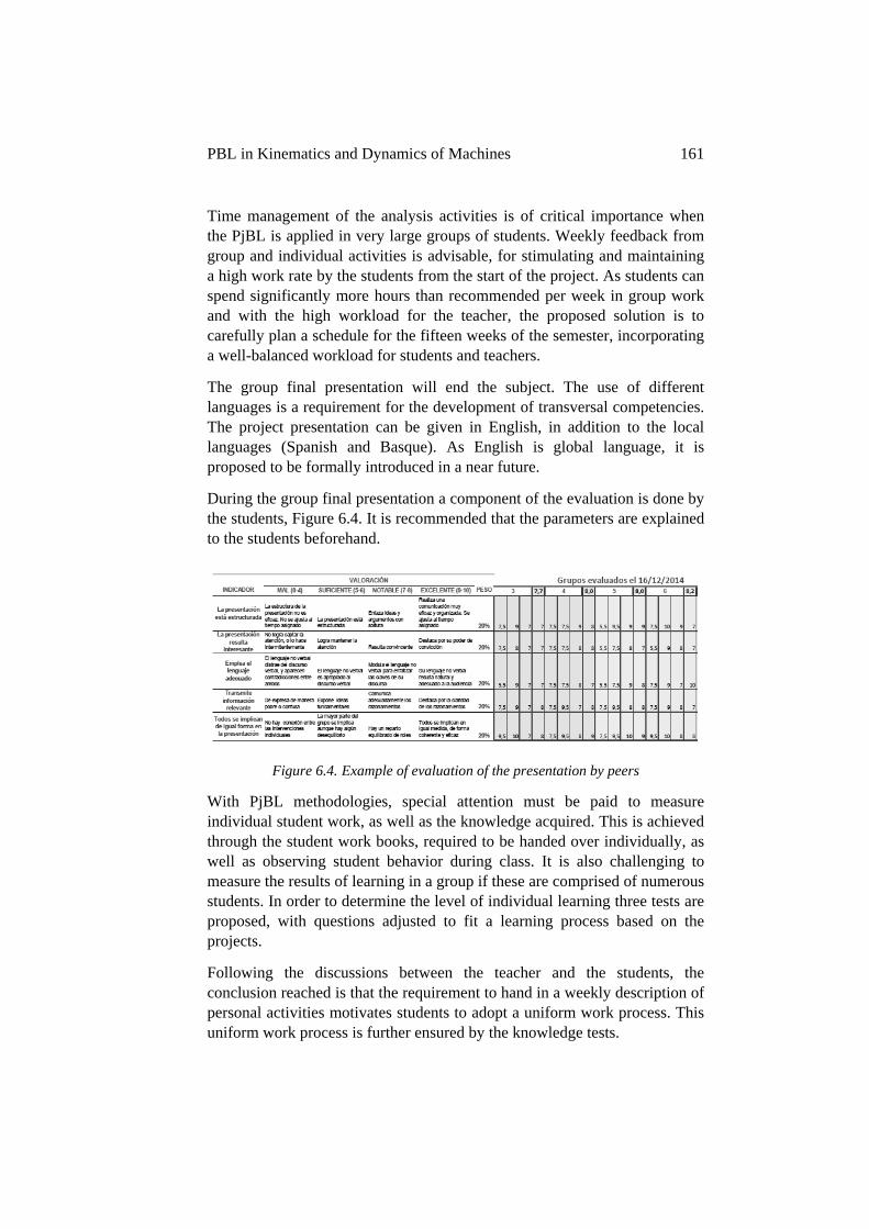
PBL in Kinematics and Dynamics of Machines 161
Time management of the analysis activities is of critical importance when the PjBL is applied in very large groups of students. Weekly feedback from group and individual activities is advisable, for stimulating and maintaining a high work rate by the students from the start of the project. As students can spend significantly more hours than recommended per week in group work and with the high workload for the teacher, the proposed solution is to carefully plan a schedule for the fifteen weeks of the semester, incorporating a well-balanced workload for students and teachers.
The group final presentation will end the subject. The use of different languages is a requirement for the development of transversal competencies. The project presentation can be given in English, in addition to the local languages (Spanish and Basque). As English is global language, it is proposed to be formally introduced in a near future.
During the group final presentation a component of the evaluation is done by the students, Figure 6.4. It is recommended that the parameters are explained to the students beforehand.
Figure 6.4. Example of evaluation of the presentation by peers
With PjBL methodologies, special attention must be paid to measure individual student work, as well as the knowledge acquired. This is achieved through the student work books, required to be handed over individually, as well as observing student behavior during class. It is also challenging to measure the results of learning in a group if these are comprised of numerous students. In order to determine the level of individual learning three tests are proposed, with questions adjusted to fit a learning process based on the projects.
Following the discussions between the teacher and the students, the conclusion reached is that the requirement to hand in a weekly description of personal activities motivates students to adopt a uniform work process. This uniform work process is further ensured by the knowledge tests.
162 Chapter 6
Attitude towards PjBL methodology
The student´s attitude towards the PjBL methodology has been positive. The students start the subject knowing that it is challenging to learn through a project in a class with numerous participants and complex theory.
The application of cooperative activities and the feasibility of the project encourage the students, and they quickly engage with tasks that have been assigned by the group. The students are committed and stay until the assigned task is completed.
The majority of students are satisfied with the methodology. Although many of them have called attention to the fact that it has been a challenge to do off-campus work consistently. There has been an improvement in student marks compared with previous years.
When the PjBL is applied in large groups of students, it is possible to distinguish different attitudes:
o The project can be seen as an opportunity to demonstrate student commitment to the subject, especially by students with previous knowledge of the subject. Students are motivated after observing abstract concepts being put into action. Their work shows initiative, criteria and decision making.
o In some teams that are made up of new students, the groups work well together. They are very motivated and are a good example for the more passive groups. These teams share their work with other teams, creating a climate of cooperation and thinking of activities other than those programmed.
With the experience acquired from working with student groups, an idea has been developed to improve the performance of all the groups. A group formed of students with previous knowledge on the subject, will be titled “high performance group” and their function is to support and motivate other groups.
It is of interest and value to note that there has been the request by students to apply the methodology in other subjects. This proposition would facilitate a more transversal project, with the inclusion of more subjects into a global project, as occurs when managing large projects in industry. This is a proposed next step to further develop the methodology.
PBL in Kinematics and Dynamics of Machines 163
Attitude towards teamwork
Team-working helped students to acquire autonomous knowledge efficiently, thanks to the cooperative attitude in the groups.
Additionally, an attitude of cooperation among the different teams is developed, especially during laboratory practice, including spontaneous cooperation activities that had not been programmed by the teacher.
The self-evaluation and evaluation surveys between group partners about their attitude towards work show a high satisfaction among the students, as shown in Figures 6.5 and 6.6, in the PjBL assessment section.
The direct commentaries during tutorials and in the classroom show a positive attitude towards cooperative learning. Students have proposed doing additional work outside of the group project, these are acceptable depending on time management, so that other subjects are not negatively affected.
The role of the integrator
The role of the integrator is rotational, and it is fundamental for the efficient management of the teams.
A balanced workload is required within the teams. The integration of results, after the assembly and partial calculations require the final assembly and the final calculations. The integrator has the responsibility to put the results together to complete the global system.
During the weekly planning the integrators direct the tasks, lead the discussion, answering the guide questions and establishing time limits for individual tasks in order to ensure time to integrate the results. They have the fundamental job of, organizing, linking and integrating the individual work to obtain the best results. They are responsible for handing over the weekly reports and act as a spokesperson for the group, for both, tutorials and intergroup activities.
All students take on the role of integrator at some point during the project. The teacher determines when the transversal competencies developed have been properly achieved.
Implementation
A well balanced and adjusted timetable is strongly advisable to guide, as in the case study, 20 groups of 4 people towards the objective, for both the on-campus and off-campus activities.
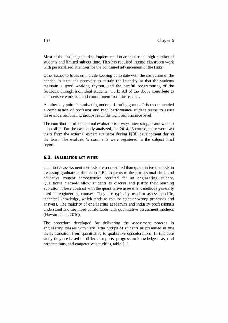
164 Chapter 6
Most of the challenges during implementation are due to the high number of students and limited subject time. This has required intense classroom work with personalized attention for the continued advancement of the tasks.
Other issues to focus on include keeping up to date with the correction of the handed in texts, the necessity to sustain the intensity so that the students maintain a good working rhythm, and the careful programming of the feedback through individual students’ work. All of the above contribute to an intensive workload and commitment from the teacher.
Another key point is motivating underperforming groups. It is recommended a combination of professor and high performance student teams to assist these underperforming groups reach the right performance level.
The contribution of an external evaluator is always interesting, if and when it is possible. For the case study analyzed, the 2014-15 course, there were two visits from the external expert evaluator during PjBL development during the term. The evaluator’s comments were registered in the subject final report.
6.3. EVALUATION ACTIVITIES
Qualitative assessment methods are more suited than quantitative methods in assessing graduate attributes in PjBL in terms of the professional skills and educative context competencies required for an engineering student. Qualitative methods allow students to discuss and justify their learning evolution. These contrast with the quantitative assessment methods generally used in engineering courses. They are typically used to assess specific, technical knowledge, which tends to require right or wrong processes and answers. The majority of engineering academics and industry professionals understand and are more comfortable with quantitative assessment methods (Howard et al., 2016).
The procedure developed for delivering the assessment process in engineering classes with very large groups of students as presented in this thesis transition from quantitative to qualitative considerations. In this case study they are based on different reports, progression knowledge tests, oral presentations, and cooperative activities, table 6. I.
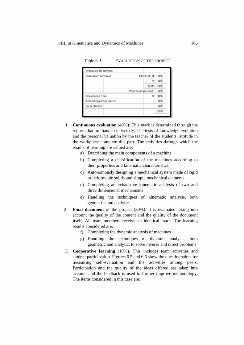
PBL in Kinematics and Dynamics of Machines 165
Table 6. I. EVALUATION OF THE PROJECT
1. Continuous evaluation (40%): This mark is determined through the reports that are handed in weekly. The tests of knowledge evolution and the personal valuation by the teacher of the students’ attitude in the workplace complete this part. The activities through which the results of learning are valued are:
a) Describing the main components of a machine b) Completing a classification of the machines according to
their properties and kinematic characteristics c) Autonomously designing a mechanical system made of rigid
or deformable solids and simple mechanical elements d) Completing an exhaustive kinematic analysis of two and
three dimensional mechanisms e) Handling the techniques of kinematic analysis, both
geometric and analytic 2. Final document of the project (30%). It is evaluated taking into
account the quality of the content and the quality of the document itself. All team members receive an identical mark. The learning results considered are:
f) Completing the dynamic analysis of machines g) Handling the techniques of dynamic analysis, both
geometric and analytic, to solve inverse and direct problems 3. Cooperative learning (10%). This includes team activities and
student participation. Figures 6.5 and 6.6 show the questionnaires for measuring self-evaluation and the activities among peers. Participation and the quality of the ideas offered are taken into account and the feedback is used to further improve methodology. The items considered in this case are:
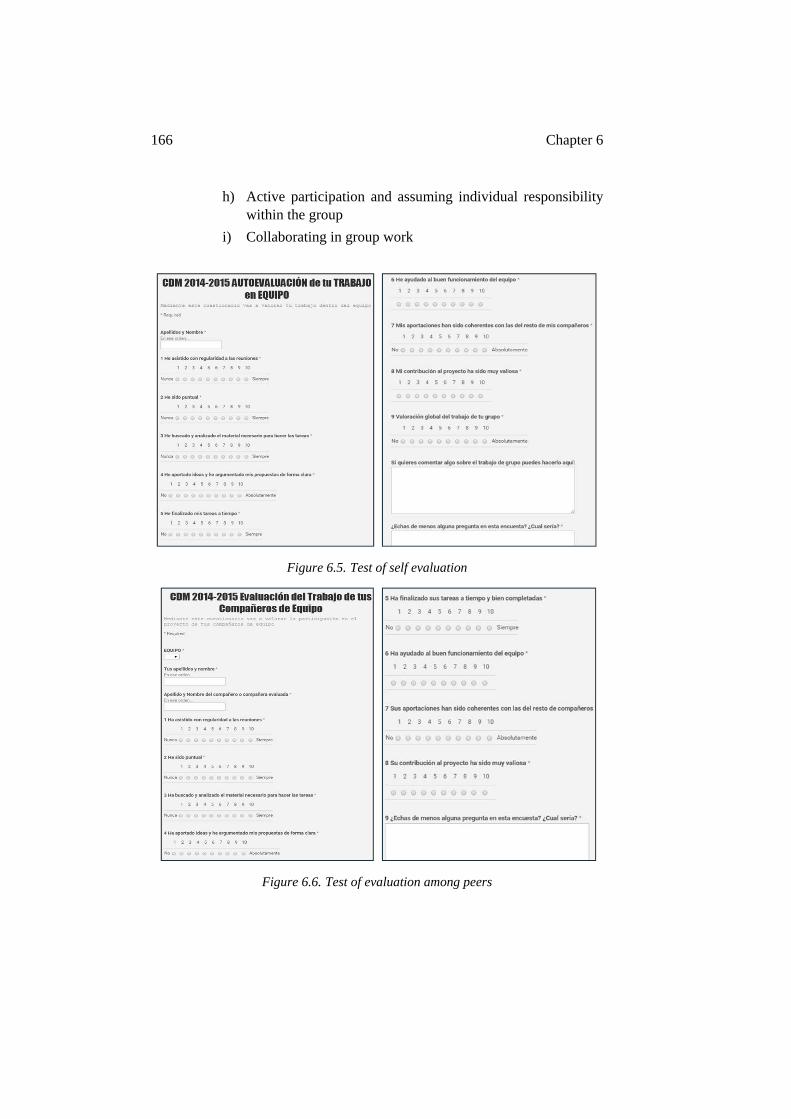
166 Chapter 6
h) Active participation and assuming individual responsibility within the group
i) Collaborating in group work
Figure 6.5. Test of self evaluation
Figure 6.6. Test of evaluation among peers
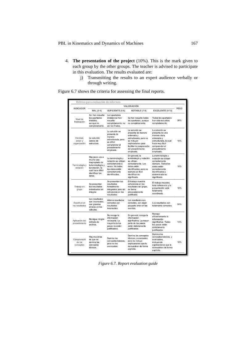
PBL in Kinematics and Dynamics of Machines 167
4. The presentation of the project (10%). This is the mark given toeach group by the other groups. The teacher is advised to participatein this evaluation. The results evaluated are:
j) Transmitting the results to an expert audience verbally orthrough writing.
Figure 6.7 shows the criteria for assessing the final reports.
Figure 6.7. Report evaluation guide
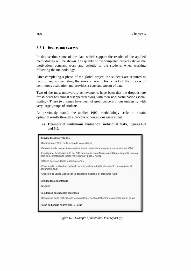
168 Chapter 6
6.3.1. RESULTS AND ANALYSIS
In this section some of the data which support the results of the applied methodology will be shown. The quality of the completed projects shows the motivation, constant work and attitude of the students when working following the methodology.
After completing a phase of the global project the students are required to hand in reports including the weekly tasks. This is part of the process of continuous evaluation and provides a constant stream of data.
Two of the most noteworthy achievements have been that the dropout rate for students has almost disappeared along with their non-participation (social loafing). These two issues have been of great concern in our university with very large groups of students.
As previously stated, the applied PjBL methodology seeks to obtain optimum results through a process of continuous assessment.
a) Example of continuous evaluation: individual tasks, Figures 6.8 and 6.9.
Figure 6.8. Example of individual task report (a)
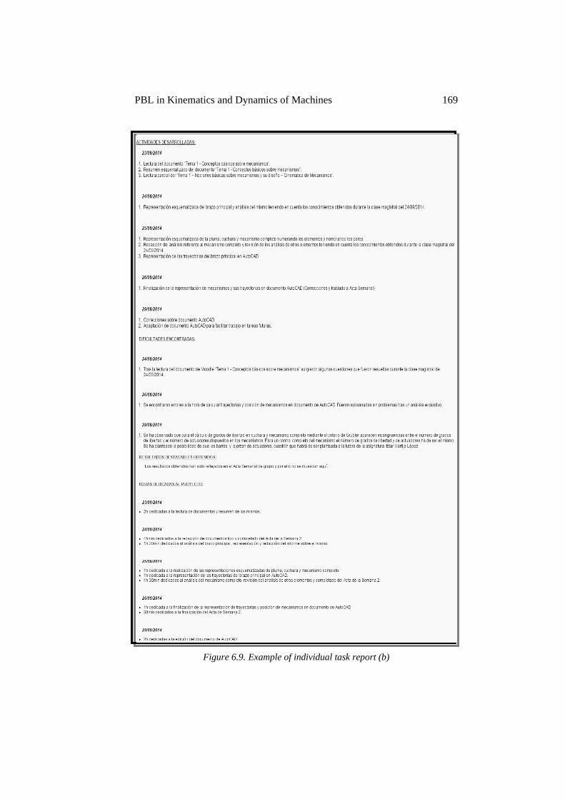
PBL in Kinematics and Dynamics of Machines 169
Figure 6.9. Example of individual task report (b)
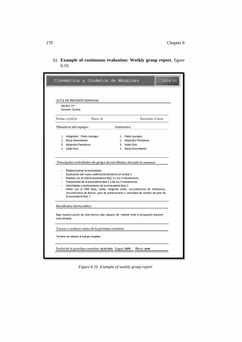
170 Chapter 6
b) Example of continuous evaluation: Weekly group report, figure 6.10.
Figure 6.10. Example of weekly group report
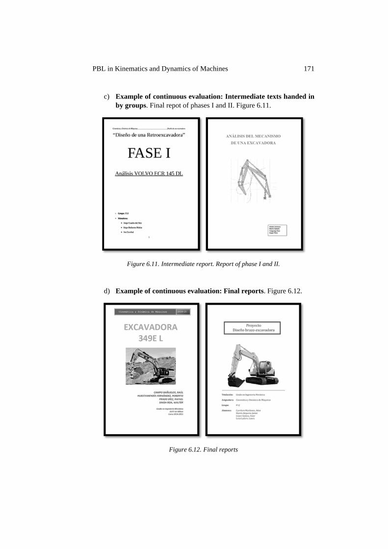
PBL in Kinematics and Dynamics of Machines 171
c) Example of continuous evaluation: Intermediate texts handed in by groups. Final repot of phases I and II. Figure 6.11.
Figure 6.11. Intermediate report. Report of phase I and II.
d) Example of continuous evaluation: Final reports. Figure 6.12.
Figure 6.12. Final reports
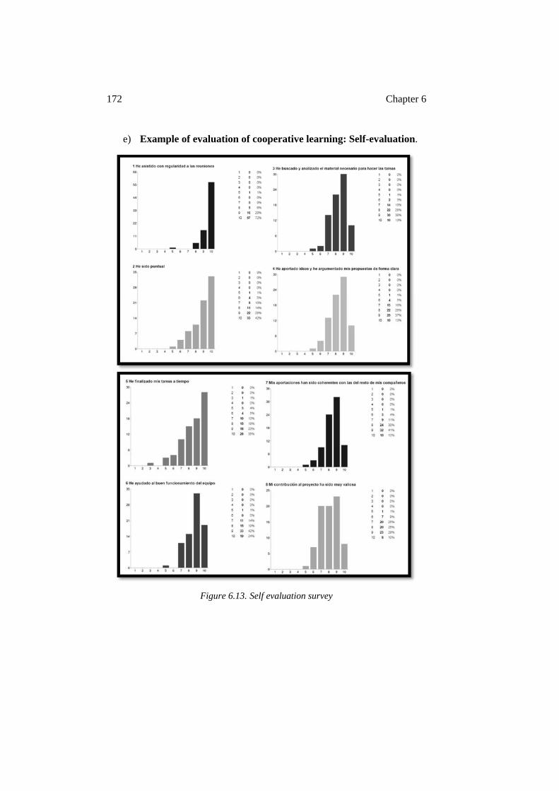
172 Chapter 6
e) Example of evaluation of cooperative learning: Self-evaluation.
Figure 6.13. Self evaluation survey
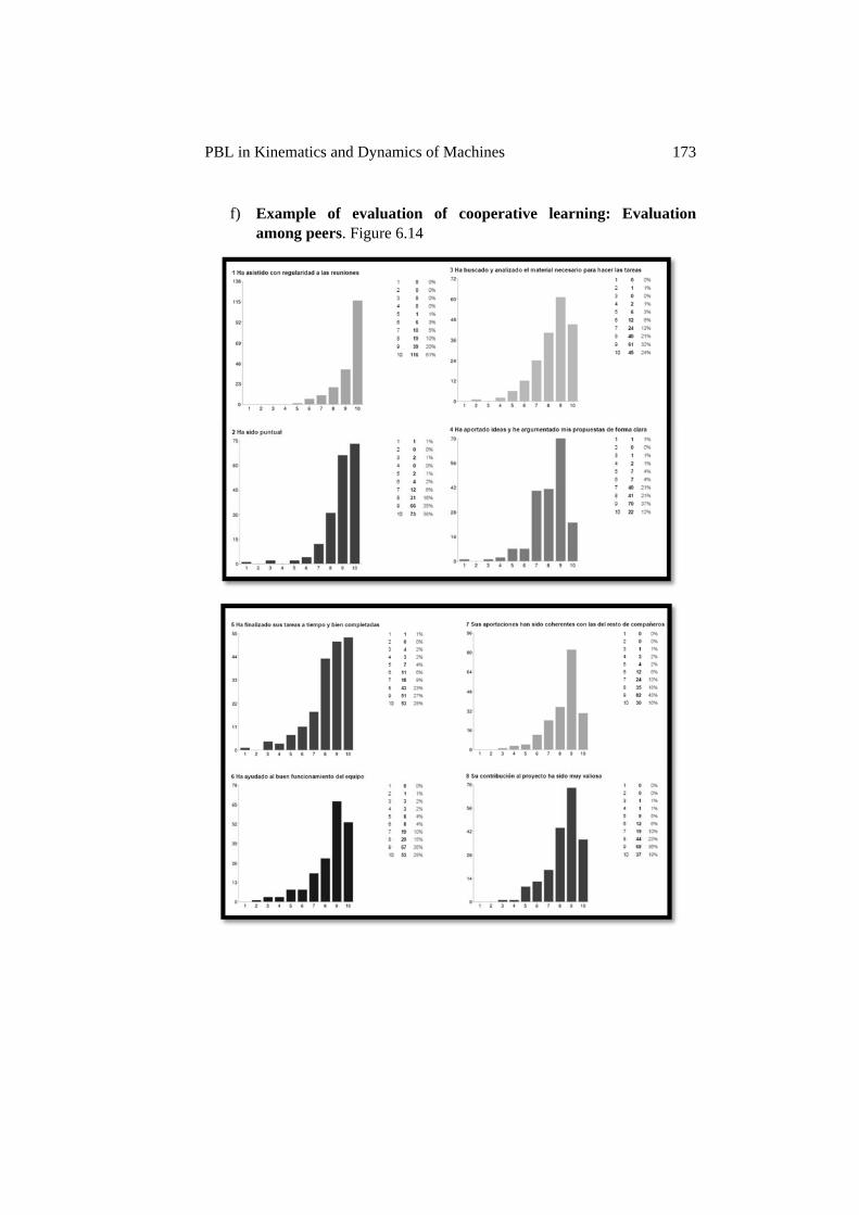
PBL in Kinematics and Dynamics of Machines 173
f) Example of evaluation of cooperative learning: Evaluation among peers. Figure 6.14
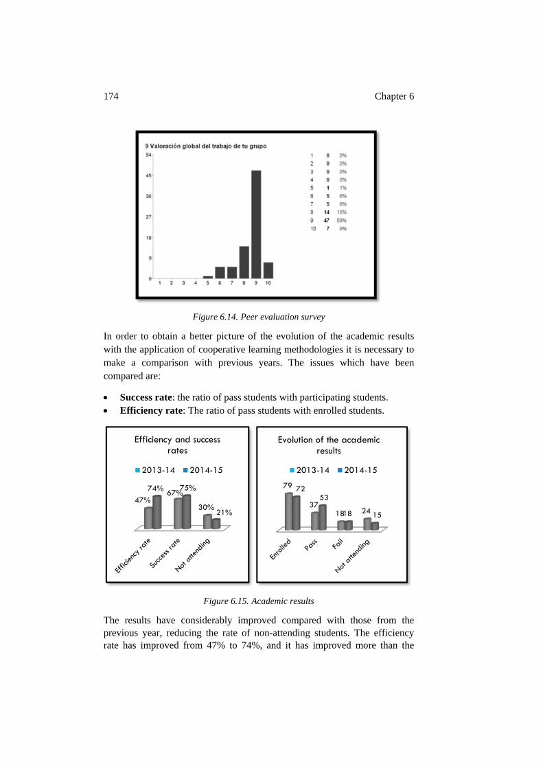
174 Chapter 6
Figure 6.14. Peer evaluation survey
In order to obtain a better picture of the evolution of the academic results with the application of cooperative learning methodologies it is necessary to make a comparison with previous years. The issues which have been compared are:
Success rate: the ratio of pass students with participating students. Efficiency rate: The ratio of pass students with enrolled students.
Figure 6.15. Academic results
The results have considerably improved compared with those from the previous year, reducing the rate of non-attending students. The efficiency rate has improved from 47% to 74%, and it has improved more than the
47%67%
30%
74% 75%
21%
Efficiency and success rates
2013-14 2014-15
79
3718 24
7253
18 15
Evolution of the academic results
2013-14 2014-15
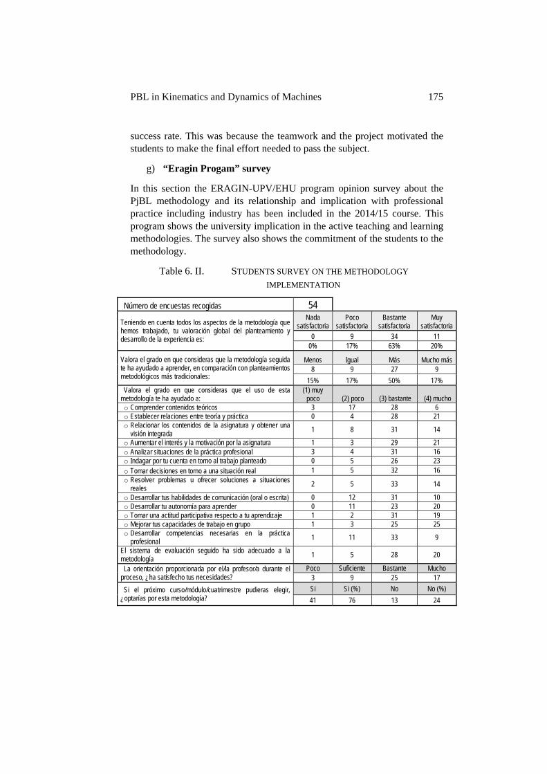
PBL in Kinematics and Dynamics of Machines 175
success rate. This was because the teamwork and the project motivated the students to make the final effort needed to pass the subject.
g) “Eragin Progam” survey
In this section the ERAGIN-UPV/EHU program opinion survey about the PjBL methodology and its relationship and implication with professional practice including industry has been included in the 2014/15 course. This program shows the university implication in the active teaching and learning methodologies. The survey also shows the commitment of the students to the methodology.
Table 6. II. STUDENTS SURVEY ON THE METHODOLOGY IMPLEMENTATION
Número de encuestas recogidas 54
Teniendo en cuenta todos los aspectos de la metodología que hemos trabajado, tu valoración global del planteamiento y desarrollo de la experiencia es:
Nada satisfactoria
Poco satisfactoria
Bastante satisfactoria
Muy satisfactoria
0 9 34 11 0% 17% 63% 20%
Valora el grado en que consideras que la metodología seguida te ha ayudado a aprender, en comparación con planteamientos metodológicos más tradicionales:
Menos Igual Más Mucho más 8 9 27 9
15% 17% 50% 17% Valora el grado en que consideras que el uso de esta
metodología te ha ayudado a: (1) muy
poco (2) poco (3) bastante (4) mucho o Comprender contenidos teóricos 3 17 28 6 o Establecer relaciones entre teoría y práctica 0 4 28 21 o Relacionar los contenidos de la asignatura y obtener una
visión integrada 1 8 31 14
o Aumentar el interés y la motivación por la asignatura 1 3 29 21 o Analizar situaciones de la práctica profesional 3 4 31 16 o Indagar por tu cuenta en torno al trabajo planteado 0 5 26 23 o Tomar decisiones en torno a una situación real 1 5 32 16 o Resolver problemas u ofrecer soluciones a situaciones
reales 2 5 33 14
o Desarrollar tus habilidades de comunicación (oral o escrita) 0 12 31 10 o Desarrollar tu autonomía para aprender 0 11 23 20 o Tomar una actitud participativa respecto a tu aprendizaje 1 2 31 19 o Mejorar tus capacidades de trabajo en grupo 1 3 25 25 o Desarrollar competencias necesarias en la práctica
profesional 1 11 33 9
El sistema de evaluación seguido ha sido adecuado a la metodología
1 5 28 20
La orientación proporcionada por el/la profesor/a durante el proceso, ¿ha satisfecho tus necesidades?
Poco Suficiente Bastante Mucho 3 9 25 17
Si el próximo curso/módulo/cuatrimestre pudieras elegir, ¿optarías por esta metodología?
Si Si (%) No No (%)
41 76 13 24
176 Chapter 6
6.4. CONCLUSIONS AND IMPLICATIONS FOR THE FUTURE
The active learning methodology proposed in this chapter has been applied in the 2014/15, 2015/16 and 2016/17 courses and the results in this initiative have been positive. The educational environment developed has become a fundamental part of the students’ acquisition of theoretical and practical skills in the Kinematics and Dynamics of Machines subject.
This chapter confirms that the platform, methodology and tools proposed in this thesis have characteristics that make it appropriate for multidisciplinary applications and for large groups of students.
The application of PjBL methodology in the Kinematics and Dynamics of Machines subject has contributed to the connection between theoretical and practical knowledge and industrial machinery scenarios. It has involved an enhancement in the application of the common design framework allowing for more efficient simulation and analysis, and the application of mechanical mechanism scenarios to industrial machinery. This has allowed educational projects to be developed that focus on the competencies required of the educational context in this subject.
One of the most remarkable outcomes which has emerged in the presented case study is the improvement in the level of compromise by the students. This has been confirmed by the questionnaire results. This level of satisfaction with the PjBL implementation means that the educational objectives have been reached, that the role change between students and professor has been effective, that the students are satisfied with the change in the assessment methodology and the improvement in the subject scores, among others.
The decision making process which require technical criteria and aptitudes that mirror professional practice motivate the students and make them more responsible for their projects, enhance their commitment to teamwork and improve their attitude and commitment with the teaching and learning process. These are aptitudes that are traditionally camouflaged in the final exam. Here they have been developed and assessed throughout the semester.
The possibility of coordinating different subjects applying cooperative methodologies into one scenario, as occurs in professional practice, is a future goal. This can lead to the reinforcement of efficient behavior models both in the university and industrial world.
Chapter 7 - Conclusions
This chapter summarizes the main results of the proposed educational environment and details the most relevant conclusions of this thesis. Important partial results have been outlined through the different chapters. Examples of these partial results and conclusions can be seen in Chapter 2, about the general use of the educational platform, and in Chapter 6 with a case study about the extension of the proposed methodology, tools and activities as applied in the field of mechanics engineering.
7.1. POWER ELECTRONICS RESULTS
The Power Electronics subject has been selected as the main research subject in which to implement the cooperative learning platform, tools and activities proposed in this thesis. This selection was based on the transversality of the subject, connecting different fields through the application of electronic systems and the considerable size of the student group, as stated in detail in the initial chapters. The effective extension into other subjects has been demonstrated through the document regarding application examples.
In the following section the application results from the 2014-15 and the 2015-16 courses are detailed. During these courses the complete educational platform and the experimental scenarios and activities have been implemented within the educational context offered by the Power Electronics subject. In the 2016-17 course the practical application is going a step further with active student participation in terms of the philosophy and the tools being implemented. The last section is dedicated to future implementation and briefly describes some of these innovative changes.
7.1.1. PJBL RESULTS FOR THE 2014-15 AND THE 2015-16 COURSES
Tables 7.I and 7.II show the methodology application results during the 2014-15 and the 2015-2016 courses.
The questionnaires are intended to separate different aspects related to the practical application of the PjBL methodology. These are the level of improvement in learning as stated by students, the time management related to on campus and off campus activities, and finally, the global evaluation of the educational platform and environment.
178 Chapter 7
A positive student vision about the above mentioned topics has been observed, together with specific considerations about time management (Maseda et al., 2015).
The highlighted opinions of students about the time management in the survey refer to the workload involved in carrying out the project. The weekly task timetable for each student is properly established. The practical application of work sharing in 4 member teams is difficult in terms of balancing the workload, and even more so in 6 member teams. It is imperative to ensure that each team member is participating equally in the projects tasks. The individual student book is a helpful tool that reveals the level of participation by each student.
The time management analysis reveals other aspects such as the students perception about their own time spent in the subject, on-campus and mainly off-campus. They are clearly of the opinion that they dedicate more hours than are required, as seen in the ECTS credits graphics (last graphic in time management blocks), in both the 2014-15 and the 2015-2016 courses. The reality is that students want to continue working on the project and it is the professor who has to prevent them from exceeding their scheduled time. This is because it can affect the student´s performance in other subjects.
Another point of interest is revealed in the class time management graphic. When comparing Table 7.I of the 2014-2015 course with Table 7.II of the 2015-2016 course, there is an evident improvement. In the 2014-2015 course, the perception of the students is related to their initial resistance to participating with this type of active training and to the time spent by the teacher advocating the virtues of active methodologies instead of explaining theory. Due to this information, in the 2015-2016 course, the idea of obsolescence of technical knowledge and the importance of lifelong learning methodologies and philosophies was reinforced in the classroom and with an insistence on the importance of changing the perception of the students about time management in engineering education.
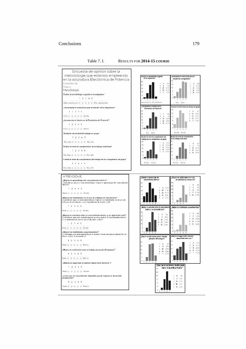
Conclusions 179
Table 7. I. RESULTS FOR 2014-15 COURSE
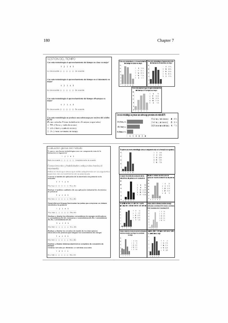
180 Chapter 7
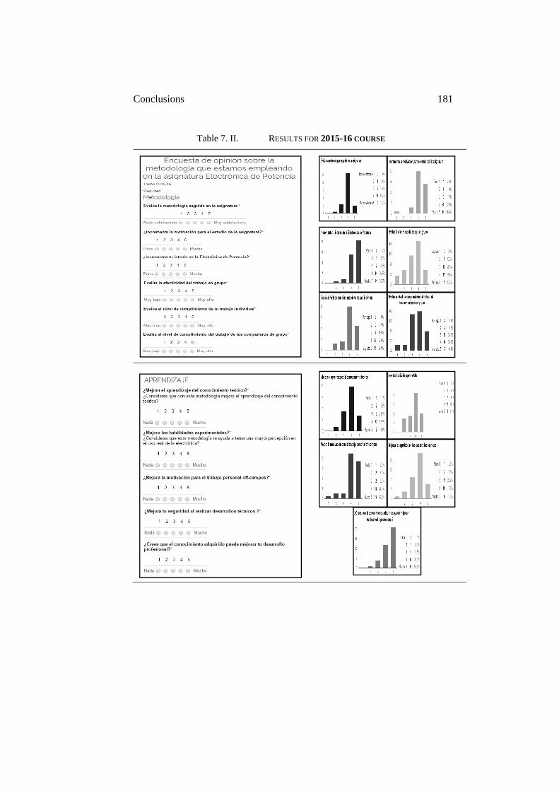
Conclusions 181
Table 7. II. RESULTS FOR 2015-16 COURSE
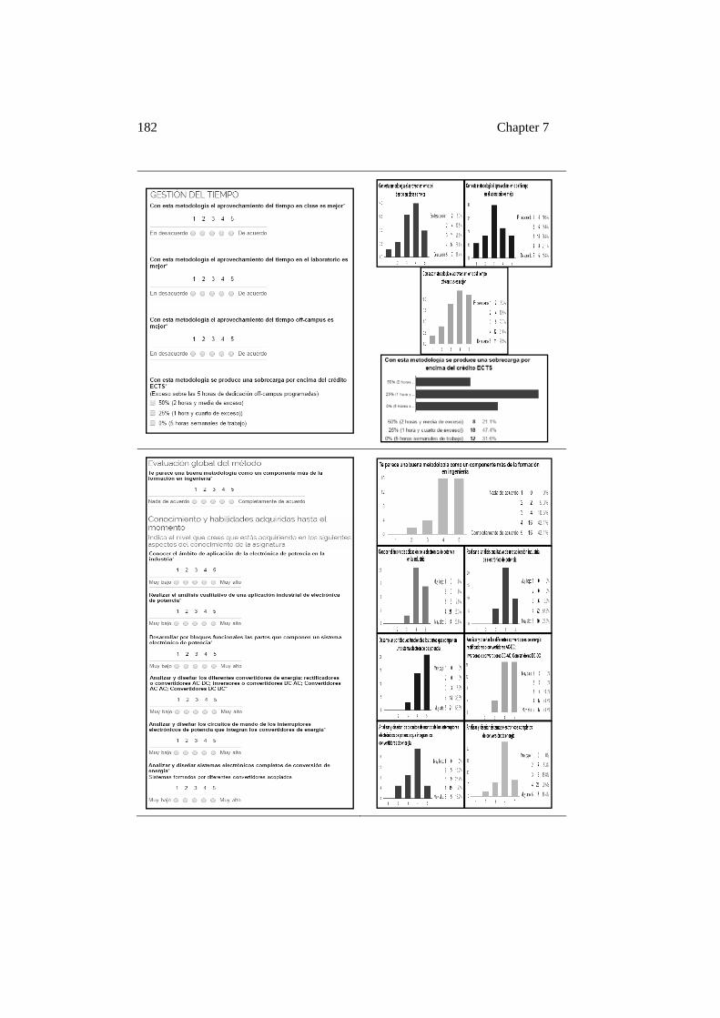
182 Chapter 7
Conclusions 183
The proposal made in this thesis that includes the application of the PjBL methodology with its specific characteristics has proven to students that by changing the philosophy of how theoretical matters can be studied through the semester, the student´s learning curve is improved, both in terms of quality and quantity. The students realize that not only have they reached their educational objectives with a high level of understanding, they have in addition, obtained a variety of other skills. This is one of the most valuable elements of the cooperative and active methodologies.
The global evaluation of the proposed methodology is very high and the results of the questionnaires in the fourth block (Tables 7.I and 7.II) show this clearly. The students have been motivated and state they have been positively assessed. The similarity of the project with professional practice, the ability to make decisions with technical criteria, and the teamwork skills that students have been able to demonstrate are better reflected in the final mark with the proposed methodology. This is an improvement when compared to the traditional methodology of a final exam where these qualities are difficult to evaluate.
The students have developed the capability to move from the initial uncertainties with the project tasks to being able to resolve these situations, creating a final feeling of satisfaction. They know they have autonomously resolved design tasks in a quasi industrial environment, managed technical resources, and determined what the important elements are in the power electronic equipment. This evolution in the student´s educational progress results in these high evaluations, as much in the learning block of questions (second block, Tables 7.I and 7.II) as in the global evaluation of the methodology (fourth block, Tables 7.I and 7.II).
In the 2014-2015 course, the continuous assessment with numerous groups of students was challenging for both teacher and student. This can become the biggest difficulty with the implementation of the methodology. Delivering and reviewing weekly tasks, the individual notebooks and projects also require a significant commitment.
In the 2015-2016 course, the teacher and student workload was reorganized and the timetable for the deliverables was more sequential, seeking a more effective use of study time. The number of deliverables was reduced, maintaining the evaluation percentages so that the resultant workload was balanced.
It is possible to conclude from the results presented in this section that the methodology and the environment proposed have had excellent results.
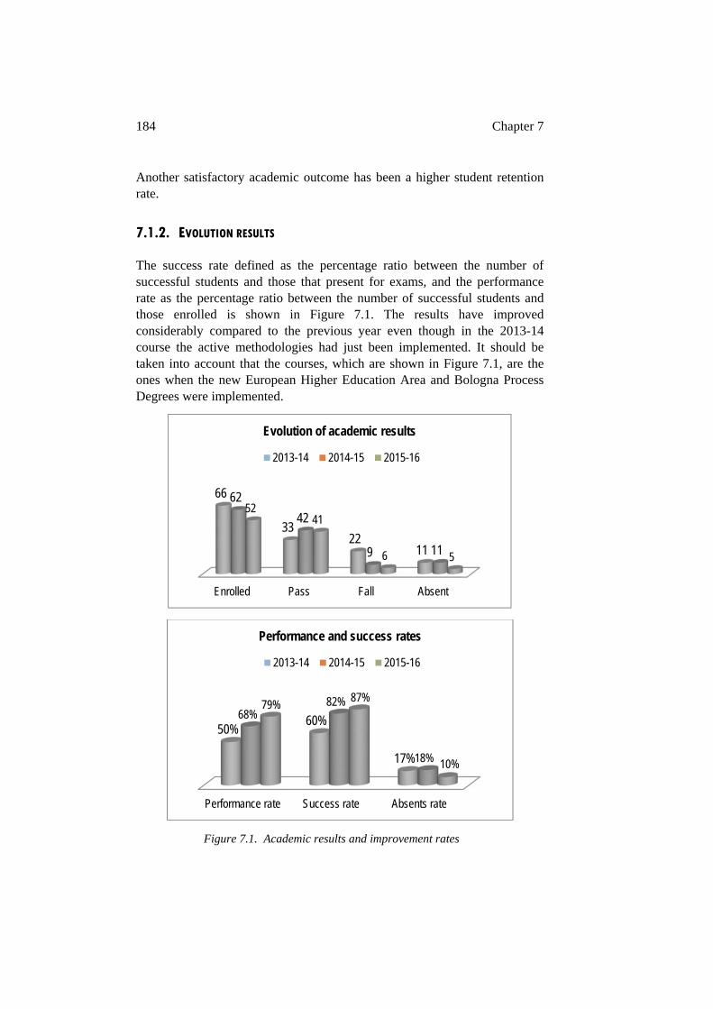
184 Chapter 7
Another satisfactory academic outcome has been a higher student retention rate.
7.1.2. EVOLUTION RESULTS
The success rate defined as the percentage ratio between the number of successful students and those that present for exams, and the performance rate as the percentage ratio between the number of successful students and those enrolled is shown in Figure 7.1. The results have improved considerably compared to the previous year even though in the 2013-14 course the active methodologies had just been implemented. It should be taken into account that the courses, which are shown in Figure 7.1, are the ones when the new European Higher Education Area and Bologna Process Degrees were implemented.
Figure 7.1. Academic results and improvement rates
Enrolled Pass Fall Absent
66
3322
11
62
42
9 11
5241
6 5
Evolution of academic results
2013-14 2014-15 2015-16
Performance rate Success rate Absents rate
50%60%
17%
68%82%
18%
79%87%
10%
Performance and success rates
2013-14 2014-15 2015-16
Conclusions 185
The most remarkable improvement is the performance rate increase which went from 50% to 68% - and success rate which has risen from 60% to 82%. The main reason for this improvement is the global and combined application of the methodologies and environments proposed in this thesis.
7.2. CONCLUSIONS
As mentioned in the preface, the most important goals of this thesis have been the improvement in academic efficiency, dexterity in experimental environments, application in real environments and in the required competencies for professional development of future engineers. These are a fundamental part of engineering education within the European Higher Education Area (EHEA).
Chapter 2 to Chapter 6 are a summary of the development of the educational environment, from the first idea of developing new training tools to improve students experimental work, leading up to the proposed environment of this thesis. This educational environment is a complete platform comprised of four independent components, PjBL methodology, fDAA activities, EM&PETT and www.shvel.net, each of these with its own specific characteristics, functioning together to attain the above mentioned goals.
The environment presented in this thesis provides a novel approach for educational methodologies and experimental tools to improve the students’ opinion about their technological field of study. This is achieved by a better understanding of theoretical material and the learning by doing process. This results in the study of engineering degrees being more attractive. This is also because the scenarios replicate industrial models, which improves the student´s capacity to see the possibilities for innovative research and professional development in the new technological fields. The proposed methodology incorporates a teamwork behavior model. These are based on engineering practices from current industry behavior models that lead to the improvement of individual personal qualities of the student.
The educational proposal has reached these objectives: the roles of the teacher and student are changing, the students becoming more proactive with their own learning, the improvement in power electronics understanding which is important for managing new equipment, the energy system is more secure for personnel and the environment, and the students positive change of attitude to self-learning and lifelong learning. These are important because of the rapid evolution of new technological equipment and their
186 Chapter 7
requirements, and the need to incorporate social considerations in engineering education.
The application of the methodology with large groups of students and the time and opportunity needed to implement new changes from one year to the next are challenges for the proposed educational activities. Another challenge is the difficulty in defining measurement parameters to obtain accurate feedback about the latest innovations in the proposed educational environment.
It is important to understand that not all innovation in education results in better education. The proposal is the result of years of experience with traditional methodologies combined with the introduction of new and innovative educational ideas and with the relationship between academia and industry.
The results of the above mentioned combination have achieved the following improvements: the combining of the PjBL methodology with the fDAA activities, the experimental scenarios as training tools and the virtual environment have improved the technical skills and the motivation of engineering students; the multidisciplinary characteristic and flexibility of the platform has been proved and this is an interesting point to note because the boundaries of different engineering fields become permeable; the teamwork in different group sizes help increase the ethical and social qualities of the students; the remote control of the training tools and the www.shvel.net expand this learning methodology to where it can be used from any place and at any time and extends the student’s self-study time with an optimum performance; the educational environment developed allows the implementation of students ideas with a high level of autonomy in the experimental projects which increases their responsibility because these ideas have to be feasible; and finally, as previously mentioned, the educational activities in the proposed platform are without clear limitations because the platform can be adapted to meet different changes in educational requirements.
The proposed methodology has been proven. It has been applied into four subjects as case studies in the following master and degrees: Master of Automation, Control and Robotics and Degrees in Mechanical Engineering and Industrial Electronics and Automation in the Faculty of Engineering in Bilbao. Currently there are over 180 students learning through the PjBL environment. And it is estimated that during 9 years of development there have been 1000 students who have been involved in different applications of the proposed platform, methodology and tools.
Conclusions 187
The experience and positive results obtained from the implementation of this new methodology has led to a systematic progressive modification of the educational environment. The benefit to students of these improvements is expected to increase in the following years, and in this way, will be an influence of positive change in other subjects with educational contexts similar to the one outlined here. An example of this is the increase in student interest in the Industrial Electronics and Automation Degree in the Faculty of Engineering in Bilbao. The required mark to enroll in this degree has been rising in recent years from 5 to 10.5 within a range of 14 points.
In conclusion the platform, methodologies and tools proposed in this thesis have demonstrated a promising potential. They can be considered as a reference and a starting point for other subjects in which to apply the proposed educational environment. This thesis has been developed following the pedagogical model IKD (Ikasketa Kooperatibo eta Dinamikoa, Cooperative and Active Learning), one of the main educational strategies of the Basque Country University.
7.3. FUTURE WORKS
The future for the proposed environment is promising because of the results attained and the expectation that other subjects can utilize this platform in their educational proposals. Different institutional programs are already functioning, promoting active and cooperative methodologies as a part of the strategic research commitment of the Basque Country University. And this work can be a reference and support for future education professionals and researchers interested in these methodologies.
The development of new scenarios with multidisciplinary characteristics, the connectivity based on new low cost microprocessors and new simulation tools make it a real possibility to expand the horizons of the platform presented in this thesis.
The individual experimental learning where students manage their own progress and goals within a flexible environment adapted to their needs can be part of the future of engineering education. As an example of this flexibility, in the 2016-17 course, a first step for the students will be the requirement to build their personal learning environment based on Arduino

188 Chapter 7
and Raspberry-PI microprocessors. From this remote environment they will be required to control different small power electronic prototypes.
In this course, based on the above mentioned evolution, the assessment procedures have also been modified. There will be a new strategy to evaluate the results in students groups, reducing the weight of the final exam and reinforcing the measurement of competencies, academic knowledge and professional skills.
The motivation for this thesis is that continuous changes and innovation are required in teaching and learning processes, methodologies and tools, and this question has become one of the most important challenges facing the future of engineering education.
Appendix A: Resumen La adaptación al nuevo Espacio Europeo de Educación Superior (EEES) está suponiendo un reto en muchas universidades, entre ellas la Universidad del País Vasco, para poner en marcha una transformación de las metodologías enseñanza-aprendizaje, de las actitudes tanto de los profesores como de los estudiantes y, por supuesto, de los sistemas evaluación, entre otras muchas cuestiones. Como ejemplo de esta transformación, la Universidad de País Vasco lleva años promoviendo el aprendizaje activo y cooperativo mediante el modelo pedagógico IKD (Ikasketa Kooperatibo eta Dinamikoa, Aprendizaje Dinámico y Cooperativo). Basándose en este modelo pedagógico, en la Escuela de Ingeniería de Bilbao se han venido desarrollando diferentes estrategias educativas que buscan mejorar muchos de los aspectos relacionados con la educación en ingeniería.
En la tesis presentada se han aplicado como casos de estudio tres asignaturas de grado y una asignatura de máster. Entre las asignaturas de grado hay dos del Grado en Ingeniería Electrónica Industrial y Automática y una del Grado en Ingeniería Mecánica.
La Electrónica de Potencia dentro del grado en Ingeniería Electrónica Industrial y Automática ha sido la asignatura con la que el grupo de investigación empezó el proceso de implantación de las primeras herramientas y entornos, conformando a lo largo de los años la metodología presentada en esta tesis. La Electrónica de Potencia suponía un reto por la dificultad técnica de la materia teórica, debido al elevado grado de abstracción que supone la transformación de energía eléctrica mediante convertidores electrónicos de potencia, el peligro de la manipulación de los convertidores electrónicos de potencia en aplicaciones industriales, el alto índice de fracaso y el elevado número de estudiantes, con más de 100 alumnos en el curso 2007-2008. Mucho más recientemente, en el curso 2012-2013, y con metodologías y herramientas más desarrolladas se ha implantado la metodología en la asignatura Sistemas Digitales de Control, que es una asignatura optativa de cuarto curso con aproximadamente 25 alumnos por grupo.
En el grado en Ingeniería Mecánica, la asignatura seleccionada para su implantación ha sido Cinemática y Dinámica de Máquinas, ya que el contexto educativo y el tamaño actual de sus grupos, con alrededor de 80 alumnos por grupo, permitía el análisis de la metodología y herramientas actuales en un grupos particularmente grandes.

190 Resumen
Por último, la asignatura del Máster Universitario en Ingeniería de Control, Automatización y Robótica, Modelado y Control de Máquinas Eléctricas, con un número de alumnos de alrededor de 20 estudiantes por grupo, ha servido para analizar la propuesta en un entorno más destinado a la investigación y a estudios avanzados.
Teniendo en cuenta la progresiva puesta en marcha de la las diferentes fases de la propuesta educativa, a lo largo de los 9 años de desarrollo de la misma, se estima que el número de alumnos participantes ha sido de alrededor de 1000.
Con unos objetivos bien definidos, buscando una mejora en las tasas de éxito académico, en el manejo de equipamiento científico en entornos reales y en el cumplimiento de competencias para el progreso tanto académico como profesional de los futuros ingenieros, se han ido tejiendo, con el paso de los años, muchas de las estrategias educativas presentadas en esta tesis doctoral.
Un elemento nuclear de la misma va a ser la relación entre el mundo industrial y el académico, cuya conexión debe cuidarse especialmente en las titulaciones técnicas. Los resultados de aprendizaje a valorar deben incluir tanto competencias técnicas como profesionales.
Con objeto de centrar el objetivo de mejora se describen competencias técnicas y habilidades profesionales que un estudiante de ingeniería debería atesorar al finalizar sus estudios ya que, como se menciona en el Capítulo 1 de esta tesis, los títulos de grado en estas ingenierías permiten al graduado ejercer la profesión con la simple obtención del título sin ningún requisito adicional, lo que debe ser tenido en cuenta en la formación ya que además del conocimiento técnico, el futuro graduado debe estar formado en una serie de habilidades complementarias para ejercer la profesión con la requerida responsabilidad.
Entre las competencias técnicas cabría destacar: la capacidad de aplicar conocimientos de matemáticas, ciencia e ingeniería; la capacidad de diseñar y realizar experimentos, así como analizar e interpretar los datos; la capacidad de diseñar un sistema, componente o proceso para satisfacer las necesidades deseadas; la capacidad para identificar, formular y resolver problemas de ingeniería; la capacidad de utilizar las técnicas, habilidades y herramientas de la ingeniería moderna necesarias para la práctica de la ingeniería, entre otras muchas.
Así mismo, entre las habilidades profesionales cabría destacar: la capacidad para trabajar en equipos multidisciplinares; la asunción de la responsabilidad profesional; la capacidad de comunicarse de manera efectiva; la visión
191
necesaria para entender el impacto de las soluciones de ingeniería en un contexto global y social; el reconocimiento de la necesidad y la capacidad de participar en el aprendizaje permanente; un conocimiento de los problemas contemporáneos; la capacidad de gestionar un proyecto, incluyendo familiaridad con el mundo empresarial, relación con el mercado, y cuestiones financieras; la comprensión y el aprecio por la diversidad de los estudiantes, profesores, personal, colegas, clientes y proveedores; una apropiada ética de trabajo, entre otras muchas.
En esta tesis se combinan las técnicas educativas y profesionales de forma que promuevan los procesos de enseñanza-aprendizaje con el objetivo de obtener el máximo beneficio académico para los estudiantes y transformar el entorno educativo de manera gratificante tanto para los profesores como para los alumnos.
La interacción entre formación, motivación y eficiencia es un marco de trabajo que puede ser sustanciado entre el mundo industrial y la universidad. Como base para el desarrollo de esa interacción se tienen en cuenta la motivación para mejorar la transmisión del conocimiento, elementos de teoría y acciones basadas en preguntas rápidas para mejorar la atención, la participación y la puesta en práctica de ideas para fomentar el trabajo en equipo, el equilibrio entre las tareas individuales y de grupo para promover el desarrollo óptimo de proyectos con base teórica y tecnológica, la introducción de actividades como reuniones de expertos y concursos para mejorar la dinámica en clase, la promoción de diferentes actividades de presentación entre alumnos para mejorar el compromiso y la comunicación, y por último, el refuerzo de los estímulos positivos.
Por otra parte, la emulación de los proyectos industriales en base a la definición de los objetivos en diferentes horizontes temporales, la planificación del proyecto y la proyección del resultado final será una primera cuestión a resolver; los indicadores y medidores para la retroalimentación y mejora del método que aseguran la evolución constructiva del proyecto propuesto será la segunda parte que conducirá el mismo hacia la excelencia. Una cuestión que debe ser tenida en cuenta en los sistemas educativos universitarios es que la planificación y ejecución de los proyectos educativos en las asignaturas tienen un recorrido anual, por lo que deben buscarse asignaturas en diferentes semestres que aseguren una mejor realimentación de resultados y permitan un mayor poder de reacción en la metodología desarrollada.
192 Resumen
Para el cumplimiento de los objetivos señalados se presenta una nueva plataforma o entorno educativo basado en actividades de enseñanza-aprendizaje de tipo activo y cooperativo. La propuesta combina:
• Una metodología de Aprendizaje Basado en Proyectos (Project BasedLearning - PjBL) para cambiar la dinámica de aprendizaje profesor-alumno, con el objetivo de mejorar la comprensión del conocimientoteórico y de desarrollar habilidades sociales y éticas mediante el trabajoen equipo.
• Unas actividades de Desensamblado/Análisis/Ensamblado funcional,para motivar y conectar el uso práctico de la teórica aprendida medianteel desarrollo de unos escenarios industriales específicos con vocacióndocente, con cultura medioambiental y de eficiencia energética.
• Por último, se crea un espacio de trabajo virtual para expandir, encualquier lugar y a cualquier hora, el aprendizaje y la enseñanza de lasactividades universitarias, sin la restricción de tener que estar ubicado enel campus universitario.
El objetivo de todo lo anterior es mejorar y promover la transferencia entre el conocimiento teórico y su aplicación práctica, mejorar las habilidades técnicas y de trabajo en equipo, tomar conciencia de los problemas del medio ambiente a través del uso de energías renovables y la eficiencia energética, trabajar con grupos grandes de estudiantes donde en ocasiones es difícil obtener un elevado nivel de comprensión teórica en el aula y, finalmente, mejorar el uso de herramientas educativas, tales como el software de simulación de ingeniería, equipos de instrumentación o el uso de microprocesadores de bajo coste para aplicaciones industriales o de uso social.
Por otra parte y debido a diferentes causas se ha producido una disminución en el número de alumnos en algunos grados de ingeniería dentro de la Escuela de Ingeniería de Bilbao, siendo uno de los más afectados el grado en Ingeniería Eléctrica y también, aunque en menor medida el grado en Ingeniería Electrónica Industrial y Automática. Los motivos, además del puramente demográfico, pueden relacionarse con la dificultad de los estudios, la abstracción que requiere el conocimiento de la energía eléctrica y su trasformación electrónica, la dificultad de control de las máquinas eléctricas en sus nuevas aplicaciones, y por último, con un sector laboral con un histórico de buenas perspectivas de futuro no completamente alcanzadas y de nuevo con un elevado potencial de empleo e investigación a corto plazo.
193
La recuperación en el número de alumnos y la búsqueda de estudiantes con una elevada motivación será un reto importante para las universidades del futuro, especialmente en carreras que auguran un importante nivel de empleabilidad, tanto en empresas como en centros de investigación.
Basándose en lo anterior, los objetivos desarrollados en la propuesta de tesis presentada se pueden resumir en:
• Mejorar el rendimiento académico en los espacios de estudio tradicionales: aula, laboratorio y fuera del campus
• Mejorar las habilidades experimentales y su relación con el conocimiento teórico
• Mejorar la motivación para el estudio en las áreas de la ingeniería donde se aplican metodologías que favorecen la educación activa y cooperativa
• Mejorar la transferencia de conocimiento entre el ámbito académico y el profesional
• Posibilitar la investigación en un entorno próximo al industrial • Introducir la conciencia medioambiental a través de sistemas
industriales eficientes y de las energías renovables • Desarrollar las habilidades sociales para trabajar en equipos
multidisciplinares • Potenciar la ética dentro del trabajo en equipo y en relación al
entorno social
La meta es hacer que el estudiante se sienta más seguro con el conocimiento teórico y más implicado en el trabajo experimental de forma que se mejore su atractivo tecnológico y su cercanía a la realidad social e industrial en la que va a desarrollar su vida profesional.
El objetivo que se plantea es por tanto doble: mejorar el rendimiento académico y atraer a los mejores estudiantes a estas áreas de la ingeniería que se perfilan como unas de las de un mayor potencial de base tecnológica, entre otros motivos debido al desarrollo de los sistemas de propulsión eléctricos, a la gestión inteligente de la energía y a la generación de energía limpia.
Para poder cumplir con los objetivos indicados se propone la combinación de diferentes estrategias educativas, y basarlas en entornos tecnológicos desarrollados con una filosofía híbrida industrial-académica. Estos escenarios tecnológicos emulan entornos industriales con una vocación y un diseño educativo modular seguro para la interacción con el estudiante.
194 Resumen
Los escenarios que se proponen presentan unas características propias que buscan su aplicación de forma eficiente en el aprendizaje basado en proyectos: los recursos que los integran son totalmente accesibles para el estudiante, la accesibilidad permite su modelado mediante software de simulación, el modelo desarrollado permite la comparación de resultados con los desarrollos teóricos, su diseño muy cercano a sus homólogos comerciales da verisimilitud a los cálculos teóricos, incluyen entornos accesibles de forma remota lo que va a permitir extender la practica experimental fuera de los laboratorios, y por último, y si cabe más importante, pueden ser rediseñados y mejorados por los estudiantes.
Por otra parte se crea un entorno virtual tecnológico en la plataforma web cuya dirección en internet es www.shvel.net. El objetivo de este entorno es servir de soporte técnico y motivador para el estudiante, de forma que ofrezca una serie de recursos especializados relacionados con los escenarios reales y que facilite una visión de la relación entre el entorno académico y el profesional.
La utilización de aplicaciones basadas en microprocesadores de bajo costo completa el ciclo del aprendizaje basado en estrategias de “aprender haciendo” (Learning by Doing), permitiendo la combinación de prototipos para la implementación de equipos complejos a través de pequeños desarrollos con un acceso local o remoto. Se potencia el desarrollo de entornos virtuales personales o grupales de los estudiantes que den proyección en internet a sus proyectos. Estos entornos personales son desarrollados por los propios estudiantes utilizando software libre y microcomputadores con muy bajas limitaciones de costo.
El desarrollo de herramientas específicas para la evaluación del impacto de de la plataforma presentada y su aplicación a las metodologías docentes propuestas, permitirá realimentar el entorno educativo propuesto para mejorarlo en la medida que evolucionen las herramientas o los procesos de enseñanza-aprendizaje y se tengan que adaptar a las nuevas situaciones docentes de las asignaturas en las que se aplican.
Para ampliar el foco de la propuesta metodológica y probar su valor multidisciplinar se ha puesto en marcha, en los tres últimos cursos, una asignatura de grado en Ingeniería Mecánica. Además, debido a las circunstancias académicas de la asignatura propuesta, se han podido analizar la plataforma propuesta y sus herramientas en grupos especialmente grandes. Los buenos resultados obtenidos en la asignatura Cinemática y Dinámica de Máquinas permiten ser optimistas en su posible extensión a otras asignaturas
195
del mismo grado y a asignaturas de otros grados en ingenierías en las que se prevea un elevado número de alumnos.
El interés educativo de la tesis propuesta se justifica en la mejora que supone para la aplicación del aprendizaje basado en proyectos, ya que permite focalizar los desarrollos teóricos, cálculos matemáticos, modelos de simulación y prácticas experimentales, en un entorno específico y adaptado metodológicamente. Por lo tanto el rendimiento académico y la atracción de los estudiantes hacia las áreas tecnológicas objeto de los entornos desarrollados, o aplicaciones industriales que se puedan ver reflejadas en ellos, se deberían ver sensiblemente mejorados.
Los resultados esperados son fundamentalmente la mejora en el uso de las herramientas tecnológicas especialmente diseñadas para el trabajo cooperativo, una evaluación de las competencias más sistematizada y basada en los proyectos de equipo, y en definitiva una mejora global, tanto cuantitativa como cualitativa, en el rendimiento de los estudiantes.
Asimismo, la recogida sistemática de evidencias que corroboren los resultados que se obtienen en los distintos aspectos del proceso de enseñanza–aprendizaje se empleará para la mejora de la plataforma tecnológica y un mejor diseño de su uso.
Los resultados obtenidos a lo largo de estos años se contrastan mediante el reconocimiento externo, con la publicación en revistas internacionales, tales como IEEE Transaction on Education, International Journal Engineering Education, International Journal of Electrical Engineering Education (indexadas en el JCR) o en congresos internacionales de elevado prestigio, tales como el Research in Engineering Education Symposium (REES) 2011, IEEE Global Engineering Education Conference EDUCON de 2013 Frontiers in Education (FIE) de 2014, o International Conference of Education, Research and Innovation (iCERi) de 2015.
Con el conocimiento adquirido en estos años y resumido en el trabajo aquí presentado se puede establecer como un objetivo a medio plazo la extensión de la propuesta en asignaturas de los diferentes grados de la Escuela de Ingeniería de Bilbao. Se persigue el mantenimiento y si es posible el incremento del número de estudiantes, así como atraer a los mejores estudiantes a los grados impartidos por el Centro. Como ya ha ocurrido en los últimos cursos académicos donde la nota de acceso en el grado en Ingeniería en Electrónica Industrial y Automática ha pasado de 5,5 a 10,4.
La creación de nuevos entornos tecnológicos que permitan una mejor transferencia entre el mundo académico y el profesional, una mayor

196 Resumen
conciencia tecnológica en los ámbitos de la generación de energías limpias y sistemas más eficientes, y el empleo de estos conocimientos en aplicaciones sociales del más amplio espectro, promoverá que los actuales y los futuros estudiantes tengan un mejor concepto de la utilidad profesional y social de la Ingeniería.
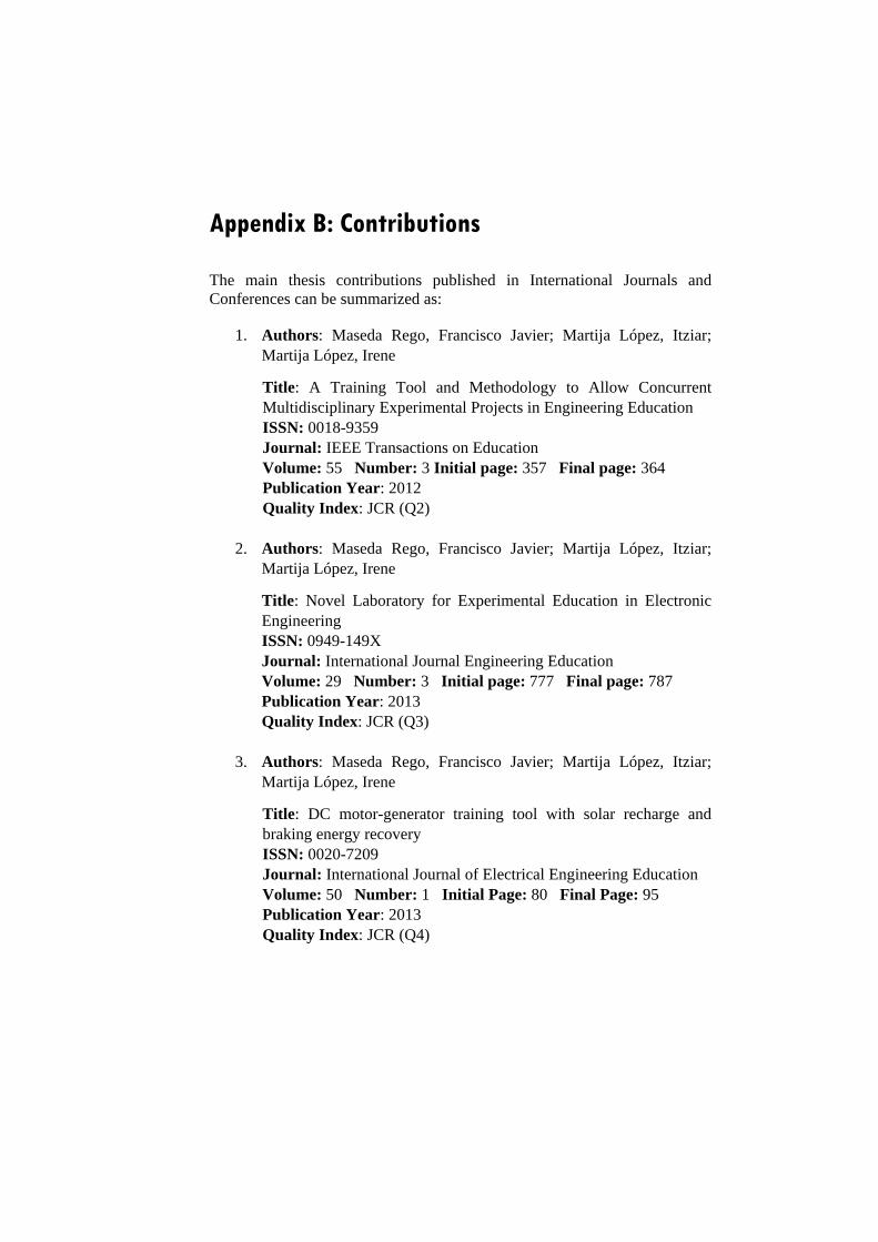
Appendix B: Contributions
The main thesis contributions published in International Journals and Conferences can be summarized as:
1. Authors: Maseda Rego, Francisco Javier; Martija López, Itziar;Martija López, Irene
Title: A Training Tool and Methodology to Allow ConcurrentMultidisciplinary Experimental Projects in Engineering EducationISSN: 0018-9359Journal: IEEE Transactions on EducationVolume: 55 Number: 3 Initial page: 357 Final page: 364Publication Year: 2012Quality Index: JCR (Q2)
2. Authors: Maseda Rego, Francisco Javier; Martija López, Itziar;Martija López, Irene
Title: Novel Laboratory for Experimental Education in ElectronicEngineeringISSN: 0949-149XJournal: International Journal Engineering EducationVolume: 29 Number: 3 Initial page: 777 Final page: 787Publication Year: 2013Quality Index: JCR (Q3)
3. Authors: Maseda Rego, Francisco Javier; Martija López, Itziar;Martija López, Irene
Title: DC motor-generator training tool with solar recharge andbraking energy recoveryISSN: 0020-7209Journal: International Journal of Electrical Engineering EducationVolume: 50 Number: 1 Initial Page: 80 Final Page: 95Publication Year: 2013Quality Index: JCR (Q4)
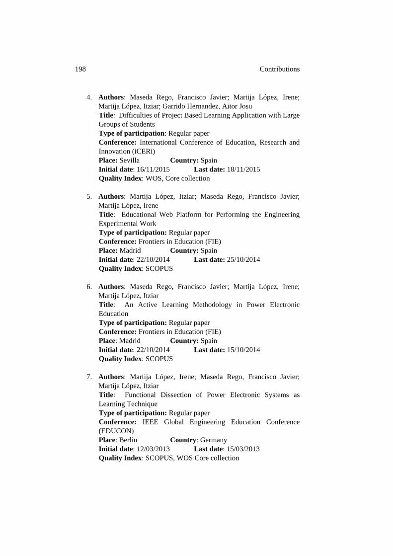
198 Contributions
4. Authors: Maseda Rego, Francisco Javier; Martija López, Irene;Martija López, Itziar; Garrido Hernandez, Aitor JosuTitle: Difficulties of Project Based Learning Application with LargeGroups of StudentsType of participation: Regular paperConference: International Conference of Education, Research andInnovation (iCERi)Place: Sevilla Country: SpainInitial date: 16/11/2015 Last date: 18/11/2015Quality Index: WOS, Core collection
5. Authors: Martija López, Itziar; Maseda Rego, Francisco Javier;Martija López, IreneTitle: Educational Web Platform for Performing the EngineeringExperimental WorkType of participation: Regular paperConference: Frontiers in Education (FIE)Place: Madrid Country: SpainInitial date: 22/10/2014 Last date: 25/10/2014Quality Index: SCOPUS
6. Authors: Maseda Rego, Francisco Javier; Martija López, Irene;Martija López, ItziarTitle: An Active Learning Methodology in Power ElectronicEducationType of participation: Regular paperConference: Frontiers in Education (FIE)Place: Madrid Country: SpainInitial date: 22/10/2014 Last date: 15/10/2014Quality Index: SCOPUS
7. Authors: Martija López, Irene; Maseda Rego, Francisco Javier;Martija López, ItziarTitle: Functional Dissection of Power Electronic Systems asLearning TechniqueType of participation: Regular paperConference: IEEE Global Engineering Education Conference(EDUCON)Place: Berlin Country: GermanyInitial date: 12/03/2013 Last date: 15/03/2013Quality Index: SCOPUS, WOS Core collection
199
8. Authors: Martija López, Itziar; Maseda Rego, Francisco Javier;Martija López, IreneTitle: Theoretical Knowledge and Experiences from theExperimental Laboratory to the Classroom for Learning inEngineering Education: A Case StudyType of participation: Regular paperConference: International Conference of Education, Research andInnovation (ICERI2011)Place: Madrid Country: SpainInitial date: 14/11/2011 Last date: 17/11/2011Quality Index: WOS Core collection
9. Authors: Maseda Rego, Francisco Javier; Martija López, Itziar;Martija López, IreneTitle: Novel Hybrid Training Tool Based on Experimental Projectsin Electronic Engineering EducationType of participation: Regular paperConference: Research in Engineering Education Symposium(REES 2011)Place: Madrid Country: SpainInitial date: 04/10/2011 Last date: 07/10/2011Quality Index: SCOPUS
10. Authors: Maseda Rego, Francisco Javier; Martija López, Itziar;Garrido Hernandez, Aitor Josu; Garrido Hernandez, Izaskun;Barambones Caramazana, Oscar; Martija López, IreneTitle: Shared Hybrid Virtual-Experimental Laboratory for Trainingin Power Electronics TechniquesType of participation: Regular paperConference: Intelligent Systems and Control (ISC)Place: Orlando Country: USAInitial date: 16/11/2008 Last date: 18/11/2008Quality Index: SCOPUS

References
[1] Abdullah, A.; Gutub, S.A.; Ebrahim, M.A.B.; Shafeek, H.; Soliman, M.F.; and Abdel-Aziz, M.H.; “Integration between industry and university: Case study,” Faculty of Engineering at Rabigh, Saudi Arabia, Education for Chemical Engineers, 2016, vol. 14, pp. 24–34.
[2] Agrawal, A. and Henderson, R.; “Putting patents in context: exploring knowledge transfer from MIT,” Management Science, 2002, vol. 48 (1) pp. 44–60.
[3] Alekseevich, S.A.; Alexandrovich, S.A.; Ivanovich, P.V.; and Stanislavovich, P.S.; “Engineering Education Technique based on Professional Activity Imitation,” International Conference on New Horizons in Education (INTE), Procedia - Social and Behavioral Sciences, 2012, vol. 55, pp. 707–709.
[4] Alexander, D.G.; and Smelser, R.F.; “Delivering an Engineering Laboratory Course Using the Internet, the Post Office and Campus Visit,” Journal of Engineering Education, an Educational Brief, 2003, pp: 79-84.
[5] Allwood, J.M.; Cox, B.M.; and Latif, S.S.; “The Structured Development of Simulation-Based Learning Tools with an Example for the Taguchi Method,” IEEE Transactions on Education, 2001, vol. 44 (4), pp. 347-353.
[6] Anand, S.; Farswan, R. S.; and Fernandes, B. G.; “Unique Power Electronics and Drives Experimental Bench (PEDEB) to Facilitate Learning and Research,” IEEE Transactions on Education, 2012, vol. 55 (4), pp. 573-579.
[7] Archer-Kath, J.; Johnson, D. W.; and Johnson, R. T.; “Individual versus group feedback in cooperative groups,” The Journal of Social Psychology, 1994, vol. 134(5), pp. 681–694.
[8] Aziz, E.; Esche, S.K.; and Chassapis, C.; “IT-Enhanced Laboratory Experience within a Modern Undergraduate Engineering Curriculum,” International Conference of Engineering Education ICEE´2007.
202 Bibliography
[9] Balakrishnan, B. and Tarlochan, F.; “Engineering Students’ Attitude towards Engineering Ethics Education,” IEEE Global Engineering Education Conference 2015 (EDUCON), pp: 16–22.
[10] Balog, R. S.; Sorchini, Z.; Kimball, J. W.; Chapman, P. L.; Krein, P. T.; and Sauer, P. W.; “Blue-box approach to power electronics and machines educational laboratories,” Proceedings of the IEEE 36th Power Electronics Specialists Conference 2005 (PESC'05), vol. 2, pp. 1176–1184.
[11] Baltzis, K. B. and Koukias, K. D.; “Using Laboratory Experiments and Circuit Simulation IT Tools in an Undergraduate Course in Analog Electronics,” Journal of Science Education and Technology, 2009, vol. 8, pp. 546–555.
[12] Banal-Estañola, A.; Jofre-Bonet, M.; and Lawson, C.; “The double-edged sword of industry collaboration: Evidence from engineering academics in the UK,” Research Policy, 2015, vol. 44, pp. 1160-1175.
[13] Barambones, O.; Garrido, A.J.; and Maseda, F. J.; “Integral sliding-mode controller for induction motor based on field-oriented control theory,” IET Control Theory and Applications, 2007, vol.1 (3), pp. 786-794.
[14] Barata, P.N.A.; Filho, M.R.; and Nunes, V.A.; “Consolidating Learning in Power Systems: Virtual Reality Applied to the Study of the Operation Electric Power Transformers,” IEEE Transactions on Education, 2015, vol. 58 (4), pp. 225-261.
[15] Barron, B.J.S.; Schwartz, D.L.; Vye, N.J.; Moore, A.; Petrosino, A.; Zech, L.; Bransford, J.D.; “Doing with Understanding: Lessons from Research on Problem and Project-Based Learning,” Journal of the Learning Sciences, 1998, vol. 7 (3/4), pp. 271–311.
[16] Bektas, C. and Tayauova, G.; “A Model Suggestion for Improving the Efficiency of Higher Education: University–Industry Cooperation,” 5th World Conference on Educational Science (WCES), Procedia - Social and Behavioral Sciences, 2014, vol. 116, pp. 2270–2274.
203
[17] Berggren, K.F.; Brodeur, D.; Crawley, E.F.; Ingermarsson, I.; Litant, W.T.C.; Malmqvist, J.; and Östlund, S.; “CDIO: An international initiative for reforming engineering education,” World Transaction on Engineering and Technology Education, 2003, vol. 2 (1), pp. 49-52.
[18] Bidanda, B.; and Billo, R. E.; “On the Use of Students for Developing Engineering Laboratories,” Journal of Engineering Education, 1995, vol. 84 (2), pp. 205-215.
[19] Blaabjerg, F.; “A power electronics and drives curriculum with project oriented and problem-based learning: A dynamic teaching approach for the future,” Journal in Power Electronics, 2002, vol. 2 (4), pp. 240-249.
[20] Blumenfeld, P. C.; Soloway, E.; Marx R.W.; Krajcik, J.S.; Guzdial, M.; and Palincsar, A.; “Motivating project-based-learning: Sustaining the doing, supporting the learning,” Educational Psychologist, 1991, vol. 26 (3–4), pp. 369-398.
[21] Borrego, M.; Karlin, J.; McNair, L.D.; and Beddoes, K.; “Team Effectiveness Theory from Industrial and Organizational Psychology Applied to Engineering Student Project Teams: A Research Review,” Journal of Engineering Education, 2013, vol. 102(4), pp. 472–512.
[22] Bose, B.K.; “Power Electronics and Motion Control-Technology Status and Recent Trends,” IEEE Transactions on Industry Applications, 1993, vol. 29 (5), pp. 902-909.
[23] Bose, B.K.; Modern power electronics and AC drives, NJ: Prentice-Hall, 2001.
[24] Boud, D. and Associates, “Assessment 2020: Seven propositions for assessment reform in higher education,” Sydney: Australian Learning and Teaching Council, 2010.
[25] Braae, M.; “A design project for electrical engineering students,” International Journal of Electrical Engineering Education, 2006, vol. 43 (4), pp. 288-298.
[26] Bradley, D.; “What is mechatronics and why teach it?” International Journal of Electrical Engineering Education, 2004, vol. 41(4), pp: 275-291.
204 Bibliography
[27] Breslow, L.; “Strategic Assessment at the Massachusetts Institute of Technology,” Conference on e-Technologies in Engineering Education: Learning Outcomes Providing Future Possibilities, 2002, P1 (2), pp: 20-26.
[28] Cagiltay, N.E.; Aydin, E.; Oktem, R.; Kara, A.; Alexandru, M.; and Reiner, B.; “Requirements for Remote RF Laboratory Applications: An Educators’ Perspective,” IEEE Transactions on Education, 2009, vol. 52 (1), pp: 75-81.
[29] Campos-Delgado, D.U. and Espinoza-Trejo, D.R.; “Educational experiments in power electronics and control theory: D.C. switched power supplies,” International Journal of Electrical Engineering Education, 2010, vol. 47 (4), pp. 430-447.
[30] Carlson, B.; Schoch, P.; Kalsher, M.; and Racicot, B.; “A Motivational First-year Electronics Lab Course,” Journal of Engineering Education, 1997, pp. 357–362.
[31] Castles, R. T.; Zephirin, T.; Lohari, V.K.; and Kachroo, P.; “Design and Implementation of a Mechatronics Learning Module in a Large First-Semester Engineering Course,” IEEE Transactions on Education, 2009, vol. 53 (3), pp. 445-454.
[32] Cerdá Boluda, J.; Martinez Peiró, M. A.; Larrea Torres, M.A.; Gadea Gironés, R.; and Colon Palero, R. J.; “An active Methodology for Teaching Electronic Systems Design,” IEEE Transactions on Education, 2006, vol. 49 (3), pp. 355-359.
[33] Chidthachack, S.; Schulte, M.A.; Ntow, F.D.; Lin, J.L.; and Moore, T.J.; “Engineering Students Learn ABET Professional Skills: A Comparative Study of Project-Based-Learning (PBL) versus Traditional Students,” ASEE Conference, 2013, Fargo, North Dakota.
[34] Choi, S. and Saeedifard, M.; “An educational laboratory for digital control and rapid prototyping of power electronic circuits,” IEEE Transactions on Education, 2012, vol. 55 (2), pp. 263–270.
[35] Chu, R. H.; Lu, D. D.; and Sathiakumar, S.; “Project-based lab teaching for power electronics and drives,” IEEE Transactions on Education, 2008, vol. 51 (1), pp. 108–113.
205
[36] Chua, K.J.; “Performance Differences between First-time Students Undergoing Hybrid and Pure Project-based Learning,” International Journal of Engineering Education, 2014, vol. 30(5), pp. 1200–1212.
[37] Chung, G. K. W. K.; Harmon, T. C.; and Baker, E. L.; “The Impact of a Simulation-Based Learning Design Project on Student Learning,” IEEE Transactions on Education, 2001, vol. 44 (4), pp. 390-398.
[38] Costa-Castelló, R.; Vallés, M.; Jiménez, L.M.; Diaz-Guerra, L.; Valera, A.; and Puerto, R.; “Integración de dispositivos físicos en un laboratorio remoto de control mediante diferentes plataformas Labview, Matlab y C/C++,” Revista Iberoamericana de Automática e Informática Industrial, 2010, DOI: 10.4995, pp.23-34.
[39] Costas-Perez, L.; Lago, D.; Fariña, J.; and Rodriguez-Andina, J.J.; “Optimization of an Industrial Sensor and Data Acquisition Laboratory through Time Sharing and Remote Access,” IEEE Transactions on Industrial Electronics, 2008, vol. 55(6), pp. 2397-2404.
[40] Crawley, E. F.; “Creating the CDIO Syllabus, a Universal Template for Engineering Education,” 32ndASEE/IEEE Frontiers in Education Conference, 2002, F3F-8.
[41] Dalrymple, O.; Sears, D. A.; and Evangelou, D.; “The Motivational and Transfer Potential of Disassemble/Analyze/Assemble (DAA) Activities,” Journal of Engineering Education, 2011, vol. 100 (4), pp.741-759
[42] Dalrymple, O.; Sears, D. A. and Evangelou, D.; “Disassemble/Analyze/Assemble (DAA) activities: Learning Engineering through Artifact Interactions,” Proc. Research in Engineering Education Symposium, 2011.
[43] De la Hoz, J.; Casas, I.; and de Blas del Hoyo, A.; ““Learning by doing” methodology applied to the practical teaching of electrical machines,” International Journal of Electrical Engineering Education, 2009, vol. 46 (2), pp. 133-149.
[44] Dewey, J.; The School and Society and the Child and the Curriculum, University of Chicago Press, Chicago, 2013.
206 Bibliography
[45] Digital Signal Controller DSC56000E, CodeWarrior development software tools, Quick Start and FreeMaster, free software and documentation, Freescale Semiconductor Inc.; Austin, TX, http://www.freescale.com , Accessed 17 December 2016.
[46] Ditcher, A. K.; “Effective Teaching and Learning in Higher Education, with Particular Reference to the Undergraduate Education of Professional Engineers,” International Journal of Engineering Education, 2001, vol. 17 (1), pp. 24-29.
[47] Dormido, S.; “Control learning: present and future,” In Proc. 15th IFAC world congress on automatic control, 2002, Barcelona, pp. 314–319.
[48] Dym, C. L.; Agogino, A.M.; Eris, O.; Frey, D.D.; and Leifer, L.J.; “Engineering Design Thinking, Teaching, and Learning,” Journal of Engineering Education, 2005, vol. 94 (1), pp.103-120.
[49] Esquembre, F.; “Facilitating the Creation of Virtual and Remote Laboratories for Science and Engineering Education,” IFAC Workshop on Internet Based Control Education IBCE15, 2015, vol. 48 (29), pp: 49–58.
[50] Feisel, L. D. and Peterson, J. D.; “The Challenge of the Laboratory in Engineering Education,” Journal of Engineering Education, 2002, vol. 91 (4), pp. 367-368.
[51] Feisel, L. D. and Rosa, A. J.; “The Role of the Laboratory in Undergraduate Engineering Education,” Journal of Engineering Education, 2005, vol. 94 (1), pp. 121-130.
[52] Felder, R. M.; Felder, G. N.; and Dietz, E. J.; “A longitudinal study of engineering student performance and retention. V. Comparisons with traditionally-taught students,” Journal of Engineering Education, 1998, vol. 87(4), 469–480.
[53] Femia, N.; Petrone, G.; Spagnuolo, G.; and Vitelli, M.; “Optimization of Perturb and Observe Maximum Power Point Tracking Method,” IEEE Transactions on Power Electronics, 2005, vol. 20 (4), pp. 963-973.
207
[54] Fong, W. W.; “From Web 2.0 to Classroom 3.0,” Lecture Notes in Computer Science, 2011, 6837/2011, 298-305.
[55] Frank, M.; Lavy, I.; Elata, D.; “Implementing the project based learning approach in an academic engineering course,” International Journal of Technology and Design Education, 2003, vol.13 (3), pp. 273–288.
[56] Fry, H.; Ketteridge, S. and Marshall, S.; A Handbook for Teaching and Learning in Higher Education, 3rd Ed. New York & London: Routledge, Taylor & Francis Group, 2009.
[57] Froyd, J. E.; Wankat, P. C.; and Smith, K. A.; “Five major shifts in 100 years of engineering education,” Proceedings IEEE, 2012, vol. 100, (Centennial), pp. 1344–1360.
[58] Fuad, Y.; De Koning, W.L.; and Van der Woude, J.W.; “Pulse-width modulated DC-DC converters,” International Journal of Electrical Engineering Education, 2001, vol. 38 (1), pp. 54-79.
[59] Garousi, V.; Petersen, K.; and Ozkan, B.; “Challenges and best practices in industry-academia collaborations in software engineering: A systematic literature review,” Information and Software Technology, 2016, vol. 79, pp. 106–127.
[60] Garrido, A.J.; Maseda, F. J.; Barambones, O.; and De la Sen, M.; “Observed Based Flux Estimation Models Implementation for Direct Field Oriented Control of Induction Machine Drives,” Proceedings of the 5th Wseas Int Conf on Instrumentation, Control, Circuits and Systems, 2005.
[61] Gedra, T. W.; An, S.; Arsalan, Q. H.; and Ray, S.; “Unified Power Engineering Laboratory for Electromechanical Energy Conversion, Power Electronics, and Power Systems,” IEEE Transactions on Power Systems, 2004, vol. 19 (1), pp. 112-119.
[62] Guerra Torres, C.; de León Morales, J.; Glumineau, A.; Traore, D. and Boisliveau, R.; “Teleoperation of an Experimental Platform of Electrical Machines through the Internet,” iJOE, vol. 20084(1), pp. 26-31.
208 Bibliography
[63] Gillet, D.; Law, E. C.; and Chatterjee A.; “Personal learning environments in a global higher engineering education web 2.0 Realm,” IEEE EDUCON Education Engineering 2010 Conference, 2010, pp. 897-906.
[64] Haghighi, K.; “Quiet no longer: Birth of a new discipline,” Journal of Engineering Education, 2005, vol. 94(4), pp. 351–353.
[65] Hall, B.; “University-industry research partnerships in the United States,” Rethinking Science Systems and Innovation Policies, Purdue University Press, 2004
[66] Haller, C. R.; Gallagher, V. J.; Weldon, T. L.; and Felder, R. M.; “Dynamics of peer education in cooperative learning workgroups,” Journal of Engineering Education, 2000, vol. 89(3), pp. 285–293.
[67] Hart, D.W.; Electrónica de Potencia. NJ: Prentice-Hall, 2001.
[68] Hava, A.M.; Kerkman, R.J.; and Lipo, T.A.; “A High-Performance Generalize Discontinuous PWM Algorithm,” IEEE Transactions on Industrial Applications, 1998, vol. 34(5), pp. 1059-1071.
[69] Helle, L.; Tynjala, P.; and Olkinuora, E.; “Project-based learning in post-secondary education-theory, practice and rubber sling shots,” Higher Education, 2006, vol. 51(2), pp. 287–314.
[70] Hercog, D.; Gergic, B.; Uran, S.; and Jezernik, K.; “A DSP-Based Remote Control Laboratory,” IEEE Transactions on Industrial Electronics, 2007, vol. 54 (6), pp. 3057-3068.
[71] Hoic-Bozic, N.; Dlab, M. H.; and Mornar, V.; “Recommender System and Web 2.0 to Enhance a Blended Learning Model,” IEEE Transactions on Education, 2016, vol. 59 (1), pp. 39-44.
[72] Holbert, K.E. and Karadi, G. G.; “Strategies, Challenges and Prospects for Active Learning in the Computer-Based Classroom,” IEEE Transactions on Education, 2009, vol. 52 (1), pp. 31-38.
[73] Holtz, J.; “Sensorless Control of Induction Motor Drives,” Proceedings of the IEEE, 2002, vol. 90(8), pp. 1359-1394.
[74] Holtz, J.; “Pulse width Modulation for Electronic Power Converters,” Proceedings of the IEEE, 1994, vol. 82(8), pp. 1194-1214.
209
[75] Hosseinzadeh, N. and Hesamzadeh, M.R.; “A Course in Power System Analysis based on Project Based Learning Methodology,” Power & Energy Society General Meeting, 2009, pp. 1-6.
[76] Howard, P.; Eliot, M.; Rasui, M.G.; Nouwens, F.; and Lawson, J.; “Assesment in PBL- Do We Assess the Learner or the Product?” International Journal of Engineering Education, 2016, vol. 32(1), pp. 348–363.
[77] Hsiung, C. M.; “Identification of dysfunctional cooperative learning teams based on students' academic achievement,” Journal of Engineering Education, 2010, vol. 99(1), pp. 45–54.
[78] Hsiung, C-M.; “The Effectiveness of Cooperative Learning,” Journal of Engineering Education, 2012, vol. 101(1), pp. 119–137.
[79] Hwang, G. J.; Yin, P. Y.; Hwang, C. W.; and Tsai, C. C.; “An enhanced genetic approach to composing cooperative learning groups for multiple grouping criteria,” Journal of Educational Technology & Society, 2008, vol. 11(1), pp.148–167.
[80] Jagadeesh Chandra, A.P. and Sudhaker Samuel, R.D.; “Design of Novel Online Access and Control Interface for Remote Experiment on DC Drives,” iJOE, 2009, vol. 5(2), pp. 11-17.
[81] Jara, C. A.; Candelas, F. A.; Torres, F.; Dormido, S.; Esquembre, F.; and Reinoso, O.; “Real-time collaboration of virtual laboratories through the Internet,” Computers & Education, 2009, vol. 52, pp. 126-140.
[82] Jeon, K.; Jarret, O.S.; and Ghim, H.; “Project-Based Learning in Engineering Education: Is it motivational?” International Journal of Engineering Education, 2014, vol. 30(2), pp. 438–448.
[83] Johnson, B. and Ulseth, R.; “Professional Competency Attainment in a Project-Based Learning Curriculum,” Frontiers in Education (FIE), 2014, pp. 844-847.
[84] Johnson, D.; Johnson, R.; and Smith, K.; Active Learning: Cooperation in the College Classroom, Interaction Book Co.; Edina, MN, 1998.
210 Bibliography
[85] Johnson, D. W. and Johnson, R. T.; Learning together and alone: Cooperative, competitive, and individualistic learning, Englewood Cliffs, NJ: Prentice-Hall, 1987.
[86] Johnson, D. W. and Johnson, R. T.; Cooperation and competition: Theory and Research, Edina, MN: Interaction Book Co, 1989.
[87] Johnson, D. W.; Johnson, R. T.; and Smith, K. A.; “Cooperative learning: Increasing college faculty instructional productivity,” ASHE-ERIC Higher Education Report No. 4, George Washington University, 1991.
[88] Johnson, D. W.; Johnson, R. T.; Ortiz, A. E.; and Stanne, M. B.; “The impact of positive goal and resource interdependence on achievement, interaction, and attitudes,” The Journal of General Psychology, 1991, vol. 118(4), pp. 341–347.
[89] Johnson, D. W. and Johnson, F. P.; Joining together: Group theory and group skills. Boston, MA: Allyn and Bacon, 2002.
[90] Johri, A. and Olds, B.M.; “The Cambridge Handbook of Engineering Education Research and Reflections on the Future of the Field,” Journal of Engineering Education, 2014, vol. 103(3), pp. 363–368.
[91] Karsten-Ulrich, K. and Wolfgang M.; “Perspectives for process systems engineering—Personal views from academia and industry,” Computers and Chemical Engineering, 2009, vol. 33, pp.536–550.
[92] Kartina, J.; “Perception of Students towards Lecturers Teaching Engineering Courses with Industry Experience: A Case Study in Malaysia Technical University,” World Conference on Technology, Innovation and Entrepreneurship. Procedia - Social and Behavioral Sciences, 2015, vol. 195, pp. 925–931.
[93] Kaufman, D.B.; Felder, R.M.; and Fuller, H.; “Accounting for individual effort in cooperative learning teams,” Journal of Engineering Education, 2000, vol. 89(2), pp. 133–140.
[94] Keytack, H. O.; “Computers and industrial engineering education: perspectives from the University of Toledo,” Computers & Industrial Engineering, 1994, vol. 27(1–4), pp. 517–520.
211
[95] King, C. J.; “Restructuring Engineering Education: Why, How and When,” Journal of Engineering Education, 2012, vol. 101(1), pp. 1–5.
[96] Kjersdam, F. and Enemark, S.; The Aalborg Experiment: Project Innovation in University Education. Aalborg University Press, Denmark, 1994.
[97] Klemes, J.J.; Kravanja, Z.; Varbanov, P.S.; and Lam, H.L.; “Advanced multimedia engineering education in energy, process integration and optimization,” Applied Energy, 2013, vol. 101, pp. 33-40.
[98] Kolhe, M.; Kolhe, S.; and Joshi, J. C.; “Determination of magnetic field constant of DC permanent magnet motor powered by photovoltaic for maximum mechanical energy output,” Renewable Energy, 2000, vol. 21, pp. 563-571.
[99] Korestsky, M.D.; Brooks, B.J.; White, R. M.; and Bowen, A.S.; “Querying the Questions: Students Responses and Reasoning in an Active Learning Class,” Journal of Engineering Education, 2016, vol. 105(2), pp. 219–244.
[100] Kosogova, A.; and Araslanova, A.; “The Role of the "Human Factor" in the Context of Strengthening Interaction between Higher Education and Industry in the USSR (the Second Half of the XX Century),” Worldwide trends in the development of educational and academic research. Procedia - Social and Behavioral Sciences, 2015, vol. 214, pp. 168–173.
[101] Krajcik, J.; Czerniak, C.; and Berger, C.; Teaching Science: A Project-Based Approach, McGraw-Hill College, New York, 1999.
[102] Kumar, A.; Fernando, S.; and Panicker, R. C.; “Project-Based Learning in Embedded Systems Education Using an FPGA Platform,” IEEE Transactions on Education, 2013, vol. 56 (4), pp. 407-415.
[103] Lee, Y.S.; “The sustainability of university–industry research collaboration: an empirical assessment,” J. Technol. Transfer, 2000, vol. 25 (2), pp.111–133.
[104] Leva, A. and Donida, F.; “Multifunctional Remote Laboratory for Education in Automatic Control: the CrAutoLab Experience,” IEEE Transactions on Education, 2008, vol. 55(6), pp. 2376-2384.
212 Bibliography
[105] Litchfield, K.; Javernick-Will, A.; and Maul, A.; “Technical and Professional Skills of Engineers Involved and Not Involved in Engineering Service”, Journal of Engineering Education, 2016, vol. 105(1), pp. 70–92.
[106] López-Martín, A. J.; “Attracting Prospective Engineering Students in the Emerging European Space for Higher Education,” IEEE Transactions on Education, 2010, vol. 53 (1), pp. 46-52.
[107] Luxhol, J.T. and Hansen, P.H.K.; “Engineering curriculum reform at Aalborg,” Journal of Engineering Education, 1996, vol. 85 (3), p. 83–84.
[108] Macías, M. E.; Cázares, V. M.; and Ramos, E. E.; “A Virtual Laboratory for Introductory Electrical Engineering Courses to Increase the Student Performance,” Proc. ASSE/IEEE´2001, Reno, USA.
[109] Macías-Guarasa, J.; Montero, J. M.; San-Segundo, R.; Araujo, A.; and Nieto-Taladriz, O.; “A Project-Based Learning Approach to Design Electronic Systems Curricula,” IEEE Transactions on Education, 2006, vol. 49 (3), pp. 389-397.
[110] Mamaril, N.A, Usher, E.L.; Li, C.R.; and Kennedy, M.S.; “Measuring Undergraduate Students´Engineering Self-Efficacy: A Validation Study,” Journal of Engineering Education, 2016, vol. 105(2), pp. 366–395.
[111] Manning, M. L. and Lucking, R.; “Cooperative learning and multicultural classrooms, Clearing House,” 1993, vol. 67(1), pp. 12–16.
[112] Marin-Garcia, J. A. and Lloret, J.; “Improving teamwork with university engineering students: The effect of an assessment method to prevent shirking,” WSEAS Transactions on Advances in Engineering Education, 2008, vol. 5(1), pp. 1–11.
[113] Martija, I.; Maseda, F.J.; and Martija, I.; “Educational web platform for performing the engineering experimental work,” Frontiers in Education (FIE), 2014.
213
[114] Martija, I.; Maseda, F.J.; and Martija, I.; “Functional Dissection of Power Electronic Systems as Learning Technique,” IEEE Global Engineering Education Conference (EDUCON), 2013.
[115] Martija, I.; Maseda, F.J.; and Martija, I.; “Theoretical Knowledge and Experiences from the Experimental Laboratory to the Classroom for Learning in Engineering Education: A Case Study,” International Conference of Education, Research and Innovation (iCERi), 2011.
[116] Martija, I.; Maseda, F.J.; Alkorta, P.; and Garrido, I.; “Project Based Learning in Kinematics and Dynamics of Machines,” International Conference of Education, Research and Innovation (iCERi), 2015.
[117] Martínez, F.; Herrero, L.C.; and De Pablo, S.; “Project-Based Learning and Rubrics in the Teaching of Power Supplies and Photovoltaic Electricity,” IEEE Transactions on Education, 2011, vol. 54 (1), pp. 87-96.
[118] Maseda, F. J.; Martija, I.; and Martija, I.; “Novel Hybrid Training Tool Based on Experimental Projects in Electronic Engineering Education,” Research in Engineering Education Symposium, 2011.
[119] Maseda, F.J.; Martija, I.; and Martija, I.; “A Training Tool and Methodology to Allow Concurrent Multidisciplinary Experimental Projects in Engineering Education,” IEEE Transactions on Education, 2012, vol. 55 (3), pp. 357-364.
[120] Maseda, F.J.; Martija, I.; and Martija, I.; “Novel Laboratory for Experimental Education in Electronic Engineering,” International Journal of Engineering Education, 2013, vol. 29 (3), pp. 777-787.
[121] Maseda, F.J.; Martija, I.; and Martija, I.; “D.C. motor-generator training tool with solar recharge and braking energy recovery,” International Journal of Electrical Engineering Education, 2013, vol. 50(1), pp. 80-95.
[122] Maseda, F.J.; Martija, I.; Martija, I.; and Garrido, A.J.; “Difficulties of Project Based Learning Application with Large Groups of Students,” International Conference of Education, Research and Innovation (iCERi), 2015.
214 Bibliography
[123] Maseda, F.J.; Martija, I.; and Martija, I.; “An Active Learning Methodology in Power Electronic Education,” Frontiers in Education (FIE), 2014.
[124] Maseda, F.J.; Martija, I.; Garrido, A.; Garrido, I.; Barambones, O.; and Martija, I.; “Shared Hybrid Virtual-Experimental Laboratory for Training in Power Electronics Techniques,” Proc. ISC, 2008, pp. 140-145.
[125] Max, L.; Thiringer, T.; Underland, T.; and Karlsson, R.; “Power Electronics Design Laboratory Exercise for Final-Year M.Sc. Students,” IEEE Transactions on Education, 2009, vol. 52 (4), pp. 524-531.
[126] Meyers, K.L.; Ohland, M.W.; and Pawley, A.L.; “The Importance of Formative Experiences for Engineering Student Identity,” International Journal of Engineering Education, 2010, vol. 26(6), pp. 1550-1560.
[127] Michaluk, L.M.; Martens, J.; Damron, R.L.; and High, K.A.; “Developing a Methodology for Teaching and Evaluating Critical Thinking Skills in First-Year Engineering Students,” International Journal of Engineering Education, 2016, vol. 32(1), pp. 84–99.
[128] Miller, A. and Bures, M.; “New approach to industrial engineering education with the help of interactive tools,” International Conference on New Horizons in Education (INTE), Procedia - Social and Behavioral Sciences, 2014, vol. 174, pp. 3413–3419.
[129] Mills, J.E.; and Treagust, D.F.; “Engineering education – is problem based or project-based learning the answer?” Australasian Journal of Engineering Education 3, 2003.
[130] Mosterman, P.J.; Campbell, J.O.; Brodersen, A.J.; and Bourne, J.R.; “Design and Implementation of an Electronics Laboratory Simulator,” IEEE Transactions on Education, 1996, vol. 39 (3), pp. 309-313.
[131] Mourtos, N. J.; “The nuts and bolts of cooperative learning in engineering,” Journal of Engineering Education, 1997, vol. 86 (1), pp. 35–37.
215
[132] Mukerjee, A.K. and Dasgupta, N.; “DC power supply used as photovoltaic simulator for testing MPPT algorithms,” Renewable Energy, 2007, vol. 32, pp. 587-592.
[133] Muoka, P.I.; Haque, M.E.; Gargoom, A.; and Negnevitsky, M.; “DSP-Based Hands-On Laboratory Experiments for Phovoltaic Power Systems,” IEEE Transactions on Education, 2015, vol. 58 (1), pp. 39-47.
[134] Naef, O.; “Real laboratory, virtual laboratory or remote laboratory: What is the most efficient way?” iJOE, 2006, vol. 2(3).
[135] Ndtoungou, A.; Hamadi, AB.; and Al-Haddad, K.; “An Improved Approach to Better Understand Power Electronics Variables,” International Journal of Engineering Education, 2011, vol. 27(1), pp. 200-213.
[136] Nickchen, D. and Mertsching, B.; “Combining mathematical revision courses with hands-on approaches for engineering education using web-based interactive multimedia applications,” 2th International Conference on Higher Education Advances. Procedia - Social and Behavioral Sciences, 2016, vol. 228, pp. 482–488.
[137] Nikolic, S.; Ritz, C.; Vial, P.J.; Ros, M.; and Stirling, D.; “Decoding Student Satisfaction: How to Manage and Improve the Laboratory Experience,” IEEE Transactions on Education, 2015, vol. 58 (3), pp. 151-158.
[138] Ogot, M. and Kremer, G.; Engineering Design, A Practical Guide, Pittsburgh, PA. Togo Press LLC, 2006.
[139] Ogot, M.; Okudan, G. E.; Simpson, T. W.; and Lamancusa, J. S.; “A Framework for Classifying Disassemble/Analyse/Assemble Activities in Engineering Education,” Journal of Design Research, 2008, vol. 7(2), pp. 120-135.
[140] Ohland, M. W.; Layton, R. A.; Loughry, M. L.; and Yuhasz, A. G.; “Effects of Behavioral Anchors on Peer Evaluation Reliability,” Journal of Engineering Education, 2005, vol. 94(3), pp. 319–326.
[141] Ortiz, A. E.; Johnson, D. W.; and Johnson, R. T.; “The effect of positive goal and resource interdependence on individual
216 Bibliography
performance,” The Journal of Social Psychology, 1996, vol. 136(2), pp. 243–249.
[142] Papert, S.; The Connected Family: Bridging the Digital Generation Gap, Longstreet Press, Atlanta, GA, 1996.
[143] Passino, K.M. and Yurkovich, S.; Fuzzy Control, Addison-Wesley, 1998.
[144] Patil, A.S. and Pudlowski, Z.J.; “Instructional Design Strategies for Interactive Web-Based Tutorials and Laboratory Procedures in Engineering Education,” World Transactions on Engineering and Technology Education, 2003, vol. 2(1), pp. 107-110.
[145] Peters, V. L. and Hewitt, J.; “An Investigation of Student Practices in Asynchronous Computer Conferencing Courses,” Computers & Education, 2010, vol. 54, pp. 952-961.
[146] Peterson, G. D. and Feisel, L. D.; “e-Learning: The Challenge for Engineering Education,” eTechnologies in Engineering Education, 2002, Davos, Switzerland.
[147] Petuya, V.; Macho, E.; Altuzarra, O.; Pinto, C.; and Hernández, A.; “Educational Software Tools for the Kinematic Analysis of Mechanisms,” Computer Applications in Engineering Education, 2011, vol. 22(1).
[148] Piaget, J.; To Understand is to Invent: The Future of Education, Penguin Books, New York, 1973.
[149] Pimmel, R.; “Cooperative learning instructional activities in a capstone design course,” Journal of Engineering Education, 2001, vol. 90(3), pp. 413–422.
[150] Potkonjak, V.; Gardner, M.; Callaghan, V.; Mattila, P.; Guetl, C.; Petrovic, V.M.; and Jovanovic, K.; “Virtual laboratories for education in science, technology, and engineering: A review,” Computers & Education, 2016, vol. 95, pp. 309-327.
[151] Prince, M.; “Does active learning work? A review of the research,” Journal of Engineering Education, 2004, vol. 93(3), pp. 223–231.
217
[152] Prince, M.J. and Felder, R.M.; “Inductive Teaching and Learning Methods: Definitions, Comparisons, and Research Bases,” Journal of Engineering Education, 2006, vol. 95(2), pp. 123-138.
[153] Riel, A.; Tichkiewitch, S.; Stolfa, J.; Stolfa, S.; Kreiner, C.; Messnarz, R.; and Rodic M.; “Industry-Academia Cooperation to Empower Automotive Engineering Designers,” 26th CIRP Design Conference. 2016, Procedia CIRP, vol. 50, pp. 739–744.
[154] Rodríguez, J.; Laverón-Simavilla, A.; del Cura, J.M.; Ezquerro, J.M.; Lapuerta, V.; and Cordero-Gracia, M.; “Project Based Learning experience in the space engineering education at Technical University of Madrid,” Advances in Space Research, 2015, vol. 56, pp. 1319-1330.
[155] Rogoff, B.; Cognition as a collaborative process, in W. Damon (Ed.), Handbook of Child Psychology (pp. 679–744). New York, NY: Wiley, 1998.
[156] Rosenberg, N. and Nelson, R.; “American universities and technical advance in industry,” Research Policy, 1994, vol. 23, pp. 323–348.
[157] Rossiter, J. A.; “Which technology can really enhance learning within engineering?” International Journal of Electrical Engineering Education, 2012, vol. 48(3), pp. 231-244.
[158] Rothe, I. and Schwandt, A.; “Using an Embroidery Machine to Achieve a Deeper Understanding of Electromechanical Applications,” IEEE Frontiers in Education Conference, 2013, pp. 435-438.
[159] Shamshina, I. G.; “Professional competences necessary for the bachelor-degree-holding engineer specialising in engineering industries,” ScienceDirect, 2014, vol. 16, pp.85-88.
[160] Sharan, S. Cooperative learning and helping behavior in the multi-ethnic classroom, in H. C. Foot, M. J. Morgan, & R. H. Shute (Eds.), Children helping children (pp. 151–176). New York, NY: Wiley, 1990.
[161] Shared Hybrid-Virtual Experimental Laboratory (SHVEL), http://www.shvel.net.
218 Bibliography
[162] Shih, C. C. and Hwang, L. J.; “Learning Embedded Software Design in an Open 3A Multiuser Laboratory,” IEEE Transactions on Education, 2011, vol. 54(2), pp. 279-285.
[163] Shirsavar, S. A.; Potter, B. A.; and Ridge, I. M. L.; “Three-Phase Machines and Drives-Equipment for a Laboratory-Based Course,” IEEE Transactions on Education, 2006, vol. 49(3), pp. 383-388.
[164] Shirsava, S. A.; “Teaching Practical Design of Switch-Mode Power Supplies,” IEEE Transactions on Education, 2004, vol. 47(4), pp. 467-473.
[165] Siegel, D.S.; Waldman, D.; and Link, A.; “Assessing the impact of organizational practices on the relative productivity of university technology transfer offices: an exploratory study,” Research Policy, 2003, vol. 32, pp.27–48.
[166] Smith, K. A.; Sheppard, S. D.; Johnson, D. W.; and Johnson, R. T.; “Pedagogies of engagement: Classroom-based practices,” Journal of Engineering Education, 2005, vol. 94(1), pp. 87–101.
[167] Solangi, K.H.; Islam, M.R.; Saidur, R.; Rahim, N.A.; and Fayaz, H.; “A review on global solar energy policy,” Renewable and Sustainable Energy Reviews, 2011, vol. 15, pp. 2149-2163.
[168] Springer, L.; Stanne, M. E.; and Donovan, S. S.; “Effects of small-group learning on undergraduates in science, mathematics, engineering, and technology: A meta-analysis,” Review of Educational Research, 1999, vol. 69(1), pp. 21–51.
[169] Stefanova, T.A.; “Using of Training Video Films in Engineering Education,” 5th World Conference on Education Sciences (WCES), Procedia - Social and Behavioral Sciences, 2014, vol. 116, pp. 1181–1186.
[170] Stefanovic, M.; “The objectives, architectures and effects of distance learning laboratories for industrial engineering education,” Computers & Education, 2013, vol. 69, pp. 250-362.
219
[171] Strong, D.A.; “An Approach for Improving Design and Innovation Skills in Engineering Education: The Multidisciplinary Design Stream,” International Journal of Engineering Education, 2012, vol. 28(2), pp. 339-348.
[172] Stump, G.S.; Hilpert, J.C.; Chung, W-T.; and Kim, W.; “Collaborative Learning in Engineering Students: Gender and Achievement,” Journal of Engineering Education, 2011, vol. 100(3), pp. 475–497.
[173] Such, J.M.; Criado, N.; and Garcia-Fornes, A.; “An Active Learning Technique Enhanced with Electronic Polls,” International Journal of Engineering Education, 2015, vol. 30(4), pp. 1048–1057.
[174] Tao, Y. H.; Guo, S. M.; and Lu, Y. H.; “The design and the formative evaluation of a web-based course for simulation analysis experiences,” Computers & Education, 2006, vol. 47, pp. 414-432.
[175] Tao, Y. H.; Guo, S. M.; and Lu, Y. H.; “A Remote-Control Engineering Laboratory,” IEEE Transactions on Industrial Electronics, 2006, vol. 55(6), pp. 2368-2375.
[176] Terenzini, P. T.; “Collaborative learning vs. lecture/discussion: Students' reported learning gains,” Journal of Engineering Education, 2001, vol. 90(1), pp. 123–130.
[177] Tharp, R. G. and Gallimore, R.; Rousing minds to life: Teaching, learning, and schooling in social context, Cambridge, England: Cambridge University Press, 1988.
[178] Thomas, J.W.; A review of research on project based learning, Report prepared for The Autodesk Foundation, 2000.
[179] Underland, T. and Mohan, N.; “Meeting the Challenge: Revitalizing Courses in Power Electronics and Electric Drives,” Nordic Workshop Power Industrial Electronic, 2002, Norpie.
[180] Upadhayay, L. and Vrat, P. Analysis of impact of industry-academia interaction on quality of technical education: A system dynamics approach, Computers & Industrial Engineering, 2016, vol. 101, pp. 313–324.
220 Bibliography
[181] Vanfretti, L. and Milano, F.; “Facilitating Constructive Alignment in Power Systems Engineering Education Using Free and Open-Source Software,” IEEE Transactions on Education, 2012, vol. 55(3), pp. 309-318.
[182] Villalva, M.G.; Gazoli, J.R.; and Filho, E.R.; “Comprehensive Approach to Modeling and Simulation of Photovoltaic Arrays,” IEEE Transactions on Power Electronics, 2009, vol. 24(5), pp.1198-1208.
[183] Vygotsky, L. S.; Mind in Society, Harvard University Press, Cambridge, MA, 1978.
[184] Wang, S-Ch. and Liu, Y-H.; “Software-reconfigurable e-learning Platform for Power Electronics Courses,” IEEE Transactions on Education, 2008, vol. 55(6), pp. 2416-2424.
[185] Wankat, P.C.; “Analysis of First Ten Years of the Journal of Engineering Education,” Journal of Engineering Education, 2004.
[186] What is Project-Based Learning? (2011). http://pbl-online.org, Accessed 1 September 2011.
[187] Wu, M.; She, J.H.; Zeng, G-X.; and Ohyama, Y.; “Internet-Based Teaching and Experiment System for Control Engineering Course,” IEEE Transactions on Industrial Electronics, 2008, vol. 55(6), pp. 2386-2396.
[188] Xia, F. and Jin, W.; “On the Factors that Affect the Proneness of University- Industry Cooperation: a System Engineering Perspective,” Systems Engineering, 2012, vol. 3, pp. 275–281.
[189] Yadav, A.; Subedi, D.; and Lundeberg, M. A.; “Problem-based learning: Influence on students' learning in an electrical engineering course,” Journal of Engineering Education, 2011, vol. 100(2), pp. 253–280.
[190] Yager, S.; Johnson, D. W.; and Johnson, R. T.; “Oral discussion, group-to-individual transfer, and achievement in cooperative learning groups,” Journal of Educational Psychology, 1985, vol. 77(1), pp. 60–66.
221
[191] Yelamarthi, K. and Drake, E.; “A Flipped First-Year Digital Circuits Course for Engineering and Technology Students,” IEEE Transactions on Education, 2015, vol. 52(3), pp. 179-186.
[192] Zhang, Z.; Hansen, C.T.; and Andersen, M.E.A.; “Teaching Power Electronics with a Design-Oriented Project-Based Learning Method at the Technical University of Denmark,” IEEE Transactions on Education, 2016, vol. 59(1), pp. 32-38.
Related Documents