OPERATION AND PARTS MANUAL THIS MANUAL MUST ACCOMPANY THE EQUIPMENT AT ALL TIMES. To find the latest revision of this publication, visit our website at: www.multiquip.com SERIES MODEL MVH-502DSB REVERSIBLE PLATE COMPACTOR (HATZ 1D81S DIESEL ENGINE) Revision #4 (06/18/10)

Plate Compactors Reversible MVH502DSB Rev 4 Manual
Oct 29, 2015
Welcome message from author
This document is posted to help you gain knowledge. Please leave a comment to let me know what you think about it! Share it to your friends and learn new things together.
Transcript
OPERATION AND PARTS MANUAL
THIS MANUAL MUST ACCOMPANY THE EQUIPMENT AT ALL TIMES.
To find the latest revision of thispublication, visit our website at:
www.multiquip.com
SERIESMODEL MVH-502DSB
REVERSIBLE PLATE COMPACTOR(HATZ 1D81S DIESEL ENGINE)
Revision #4 (06/18/10)
PAGE 2 — MQ-MIKASA MVH-502DSB PLATE COMPACTOR — OPERATION & PARTS MANUAL — REV. #4 (06/18/10)
Diesel engine exhaust and some of
MQ-MIKASA MVH-502DSB PLATE COMPACTOR — OPERATION & PARTS MANUAL — REV. #4 (06/18/10) — PAGE 3
PAGE 4 — MQ-MIKASA MVH-502DSB PLATE COMPACTOR — OPERATION & PARTS MANUAL — REV. #4 (06/18/10)
TABLE OF CONTENTS
HATZ1D81S DIESEL ENGINECrankcase Assembly ......................................... 50-51Crankcase Assembly (External Parts) ............... 52-53Crankshaft Assembly ......................................... 54-55Camshaft Assembly ........................................... 56-57Piston/Rings Assembly....................................... 58-59Cylinder Head Assembly .................................... 60-63Flywheel Assembly ............................................ 64-65Oil Pump Assembly ............................................ 66-67Timing Cover Assembly ..................................... 68-69Fuel Device Assembly ........................................ 70-71Air Ducting Assembly ......................................... 72-73Breather Assembly ............................................. 74-75Fuel Tank Assembly ........................................... 76-77Fuel Pump Assembly ......................................... 78-79Air Filter Assembly ............................................. 80-81Exhaust Silencer Assembly ................................ 82-83Starter/Alternator Assembly ............................... 84-85Instrument Box Assembly .................................. 86-87Lifting Magnet/Stop Device Assembly ............... 88-89
Terms and Conditions Of Sale — Parts .................. 90
NOTE
Specification andpart number aresubject to changewithout notice.
MIKASA MVH-502DSBPLATE COMPACTORProposition 65 Warning ..............................................2Here's How To Get Help .............................................3Table Of Contents ......................................................4Parts Ordering Procedures ........................................5Safety Message Alert Symbols .............................. 6-7Rules for Safe Operation ....................................... 8-9Operation and Safety Decals ...................................10Specifications ...........................................................11Dimensions ..............................................................12Features ...................................................................13Plate Compactor Components .................................14Engine Components ................................................15Pre-Inspection ..........................................................16Operation ........................................................... 17-19Maintenance ...................................................... 20-23Troubleshooting (Engine) .........................................24Troubleshooting (Compactor) ..................................25Explanation Of Code In Remarks Column ...............26Suggested Spare Parts ............................................27
PARTS ILLUSTRATIONSDecal Placement ................................................ 28-29Vibrating Plate Assembly ................................... 30-31Base and Engine Assembly ............................... 32-35Vibrator Assembly .............................................. 36-39Hydraulic System Assembly ............................... 40-41Control Handle Assembly .................................. 42-45Battery Assembly ............................................... 46-47Throttle Assembly .............................................. 48-49
MQ-MIKASA MVH-502DSB PLATE COMPACTOR — OPERATION & PARTS MANUAL — REV. #4 (06/18/10) — PAGE 5
PARTS ORDERING PROCEDURES
ww
w.m
ultiq
uip
.com
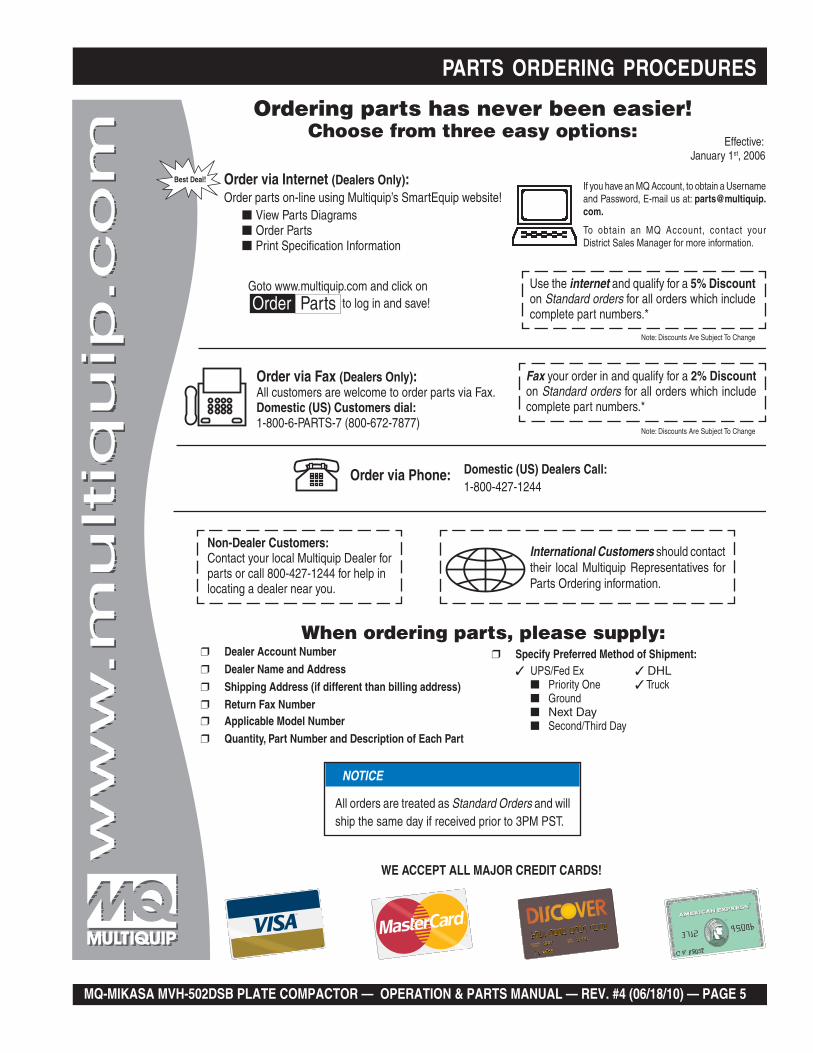
Ordering parts has never been easier! Choose from three easy options:
WE ACCEPT ALL MAJOR CREDIT CARDS!
When ordering parts, please supply: Dealer Account Number Dealer Name and Address Shipping Address (if different than billing address) Return Fax Number Applicable Model Number Quantity, Part Number and Description of Each Part
Specify Preferred Method of Shipment:UPS/Fed Ex DHL
Priority One Truck Ground
Next Day Second/Third Day
If you have an MQ Account, to obtain a Username and Password, E-mail us at: [email protected].
To obtain an MQ Account, contact your District Sales Manager for more information.
Order via Internet (Dealers Only):Order parts on-line using Multiquip’s SmartEquip website! View Parts Diagrams Order Parts Print Specification Information
Note: Discounts Are Subject To Change
Goto www.multiquip.com and click on Order Parts to log in and save!
Use the internet and qualify for a 5% Discount on Standard orders for all orders which include complete part numbers.*
Order via Fax (Dealers Only):All customers are welcome to order parts via Fax.Domestic (US) Customers dial: 1-800-6-PARTS-7 (800-672-7877)
Fax your order in and qualify for a 2% Discount on Standard orders for all orders which include complete part numbers.*
Order via Phone: Domestic (US) Dealers Call: 1-800-427-1244
Best Deal!
International Customers should contact their local Multiquip Representatives for Parts Ordering information.
Non-Dealer Customers: Contact your local Multiquip Dealer for parts or call 800-427-1244 for help in locating a dealer near you.
Note: Discounts Are Subject To Change
Effective: January 1st, 2006
NOTICE
All orders are treated as Standard Orders and will ship the same day if received prior to 3PM PST.
PAGE 6 — MQ-MIKASA MVH-502DSB PLATE COMPACTOR — OPERATION & PARTS MANUAL — REV. #4 (06/18/10)
MVH-502DSB — SAFETY MESSAGE ALERT SYMBOLS
Safety precautions should be followed at all times whenoperating this equipment. Failure to read and understand theSafety Messages and Operating Instructions could result ininjury to yourself and others.
FOR YOUR SAFETY AND THE SAFETY OF OTHERS!
This Owner's Manual hasbeen developed to providecomplete instructions for thesafe and efficient operationof the Multiquip ModelMVH-502DSB ReversiblePlate Compactor. Refer tothe engine manufacturer’sinstructions for data relativeto its safe operation.
SAFETY MESSAGE ALERT SYMBOLS
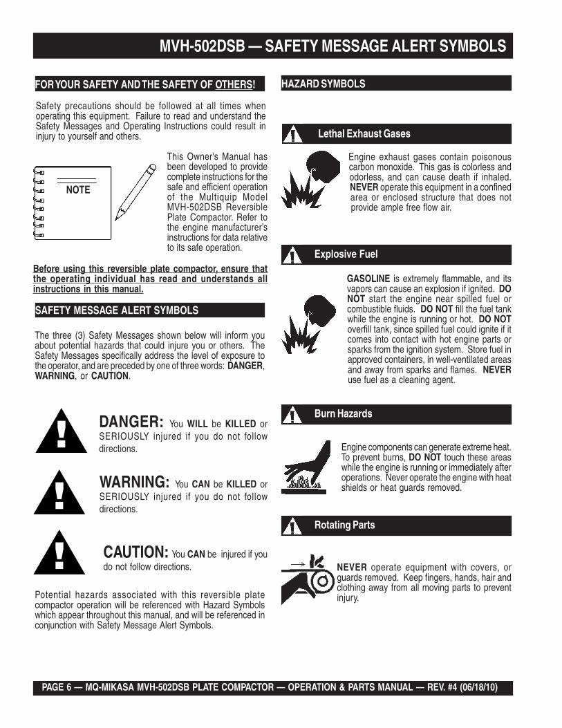
The three (3) Safety Messages shown below will inform youabout potential hazards that could injure you or others. TheSafety Messages specifically address the level of exposure tothe operator, and are preceded by one of three words: DANGER,WARNING, or CAUTION.
DANGER: You WILL be KILLED orSERIOUSLY injured if you do not followdirections.
WARNING: You CAN be KILLED orSERIOUSLY injured if you do not followdirections.
CAUTION: You CAN be injured if youdo not follow directions.
HAZARD SYMBOLS
Engine exhaust gases contain poisonouscarbon monoxide. This gas is colorless andodorless, and can cause death if inhaled.NEVER operate this equipment in a confinedarea or enclosed structure that does notprovide ample free flow air.
Potential hazards associated with this reversible platecompactor operation will be referenced with Hazard Symbolswhich appear throughout this manual, and will be referenced inconjunction with Safety Message Alert Symbols.
GASOLINE is extremely flammable, and itsvapors can cause an explosion if ignited. DONOT start the engine near spilled fuel orcombustible fluids. DO NOT fill the fuel tankwhile the engine is running or hot. DO NOToverfill tank, since spilled fuel could ignite if itcomes into contact with hot engine parts orsparks from the ignition system. Store fuel inapproved containers, in well-ventilated areasand away from sparks and flames. NEVERuse fuel as a cleaning agent.
Explosive Fuel
Lethal Exhaust Gases
Burn Hazards
Engine components can generate extreme heat.To prevent burns, DO NOT touch these areaswhile the engine is running or immediately afteroperations. Never operate the engine with heatshields or heat guards removed.
Rotating Parts
NEVER operate equipment with covers, orguards removed. Keep fingers, hands, hair andclothing away from all moving parts to preventinjury.
NOTE
Before using this reversible plate compactor, ensure thatthe operating individual has read and understands allinstructions in this manual.

MQ-MIKASA MVH-502DSB PLATE COMPACTOR — OPERATION & PARTS MANUAL — REV. #4 (06/18/10) — PAGE 7
Accidental Starting
MVH-502DSB — SAFETY MESSAGE ALERT SYMBOLS
ALWAYS place the engine ON/OFF switch inthe OFF position, when the reversible platecompactor is not in use.
Respiratory Hazard
ALWAYS wear approved respiratoryprotection.
Equipment Damage Messages
Other important messages are provided throughout this manualto help prevent damage to your reversible plate compactor,other property, or the surrounding environment.ALWAYS wear approved eye and hearing
protection.
Sight and Hearing hazard
This reversible platecompactor, other property, orthe surrounding environmentcould be damaged if you donot follow instructions.
NOTE
PAGE 8 — MQ-MIKASA MVH-502DSB PLATE COMPACTOR — OPERATION & PARTS MANUAL — REV. #4 (06/18/10)
MVH-502DSB — RULES FOR SAFE OPERATION
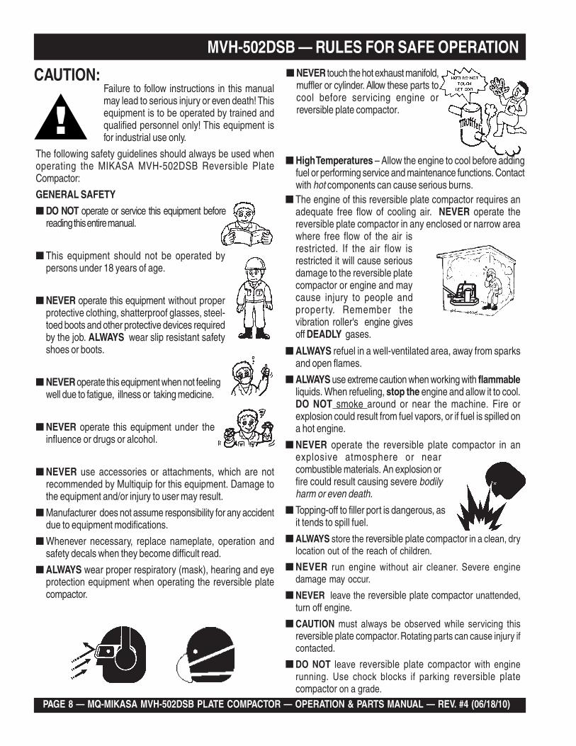
■ ALWAYS refuel in a well-ventilated area, away from sparksand open flames.
■ ALWAYS use extreme caution when working with flammableliquids. When refueling, stop the engine and allow it to cool.DO NOT smoke around or near the machine. Fire orexplosion could result from fuel vapors, or if fuel is spilled ona hot engine.
■ NEVER operate the reversible plate compactor in anexplosive atmosphere or nearcombustible materials. An explosion orfire could result causing severe bodilyharm or even death.
■ Topping-off to filler port is dangerous, asit tends to spill fuel.
■ ALWAYS store the reversible plate compactor in a clean, drylocation out of the reach of children.
■ NEVER run engine without air cleaner. Severe enginedamage may occur.
■ NEVER leave the reversible plate compactor unattended,turn off engine.
■ CAUTION must always be observed while servicing thisreversible plate compactor. Rotating parts can cause injury ifcontacted.
■ DO NOT leave reversible plate compactor with enginerunning. Use chock blocks if parking reversible platecompactor on a grade.
■ NEVER touch the hot exhaust manifold,muffler or cylinder. Allow these parts tocool before servicing engine orreversible plate compactor.
■ The engine of this reversible plate compactor requires anadequate free flow of cooling air. NEVER operate thereversible plate compactor in any enclosed or narrow areawhere free flow of the air isrestricted. If the air flow isrestricted it will cause seriousdamage to the reversible platecompactor or engine and maycause injury to people andproper ty. Remember thevibration roller's engine givesoff DEADLY gases.
■ High Temperatures – Allow the engine to cool before addingfuel or performing service and maintenance functions. Contactwith hot components can cause serious burns.
Failure to follow instructions in this manualmay lead to serious injury or even death! Thisequipment is to be operated by trained andqualified personnel only! This equipment isfor industrial use only.
The following safety guidelines should always be used whenoperating the MIKASA MVH-502DSB Reversible PlateCompactor:
GENERAL SAFETY
■ DO NOT operate or service this equipment beforereading this entire manual.
■ This equipment should not be operated bypersons under 18 years of age.
■ NEVER operate this equipment without properprotective clothing, shatterproof glasses, steel-toed boots and other protective devices requiredby the job. ALWAYS wear slip resistant safetyshoes or boots.
■ NEVER operate this equipment when not feelingwell due to fatigue, illness or taking medicine.
■ NEVER operate this equipment under theinfluence or drugs or alcohol.
■ NEVER use accessories or attachments, which are notrecommended by Multiquip for this equipment. Damage tothe equipment and/or injury to user may result.
■ Manufacturer does not assume responsibility for any accidentdue to equipment modifications.
■ Whenever necessary, replace nameplate, operation andsafety decals when they become difficult read.
■ ALWAYS wear proper respiratory (mask), hearing and eyeprotection equipment when operating the reversible platecompactor.
CAUTION:
MQ-MIKASA MVH-502DSB PLATE COMPACTOR — OPERATION & PARTS MANUAL — REV. #4 (06/18/10) — PAGE 9
MVH-502DSB — RULES FOR SAFE OPERATION■ NEVER disconnect any "emergency or safety devices".
These devices are intended for operator safety. Disconnectionof these devices can cause severe injury, bodily harm or evendeath! Disconnection of any of these devices will void allwarranties.
■ NEVER disconnect any "emergency or safety devices".These devices are intended for operator safety. Disconnectionof these devices can cause severe injury, bodily harm or evendeath! Disconnection of any of these devices will void allwarranties.
Loading and Unloading (Crane)■ Before lifting, make sure that machine parts (hook and
vibration insulator) are not damaged and screws are notloosened or lost.
■ Always make sure crane or lifting device has been properlysecured to the hook of guard frame on compactor.
■ NEVER lift the machine while the engine is running.
■ Use adequate lifting cable (wire or rope) of sufficient strength.
■ Use one point suspension hook and lift straight upwards.
■ NEVER allow any person or animal to stand underneath themachine while lifting.
■ Try not to lift machine to unnecessary heights.
Transporting
■ ALWAYS shutdown engine before transporting.
■ Tighten fuel tank cap securely and close fuel cock to preventfuel from spilling.
■ Drain fuel when transporting compactor over long distancesor bad roads.
■ ALWAYS tie down the compactor during transportation bysecuring the compactor's guard frame with rope.
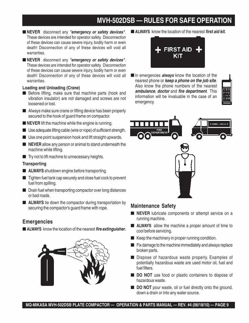
Emergencies■ ALWAYS know the location of the nearest fire extinguisher.
Maintenance Safety■ NEVER lubricate components or attempt service on a
running machine.
■ ALWAYS allow the machine a proper amount of time tocool before servicing.
■ Keep the machinery in proper running condition.
■ Fix damage to the machine immediately and always replacebroken parts.
■ Dispose of hazardous waste properly. Examples ofpotentially hazardous waste are used motor oil, fuel andfuel filters.
■ DO NOT use food or plastic containers to dispose ofhazardous waste.
■ DO NOT pour waste, oil or fuel directly onto the ground,down a drain or into any water source.
■ In emergencies always know the location of thenearest phone or keep a phone on the job site.Also know the phone numbers of the nearestambulance, doctor and fire department. Thisinformation will be invaluable in the case of anemergency.
■ ALWAYS know the location of the nearest first aid kit.
PAGE 10 — MQ-MIKASA MVH-502DSB PLATE COMPACTOR — OPERATION & PARTS MANUAL — REV. #4 (06/18/10)
MVH-502DSB — OPERATION AND SAFETY DECALS
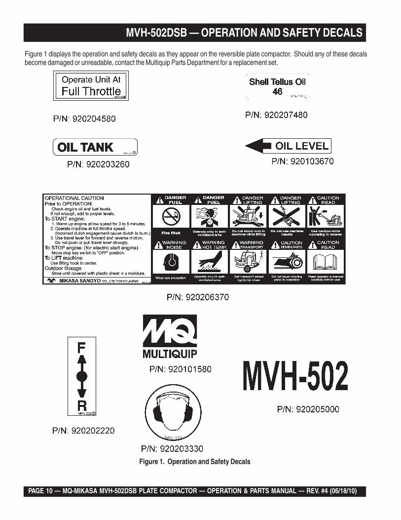
Figure 1. Operation and Safety Decals
Figure 1 displays the operation and safety decals as they appear on the reversible plate compactor. Should any of these decalsbecome damaged or unreadable, contact the Multiquip Parts Department for a replacement set.
MQ-MIKASA MVH-502DSB PLATE COMPACTOR — OPERATION & PARTS MANUAL — REV. #4 (06/18/10) — PAGE 11
MVH-502DSB —SPECIFICATIONS
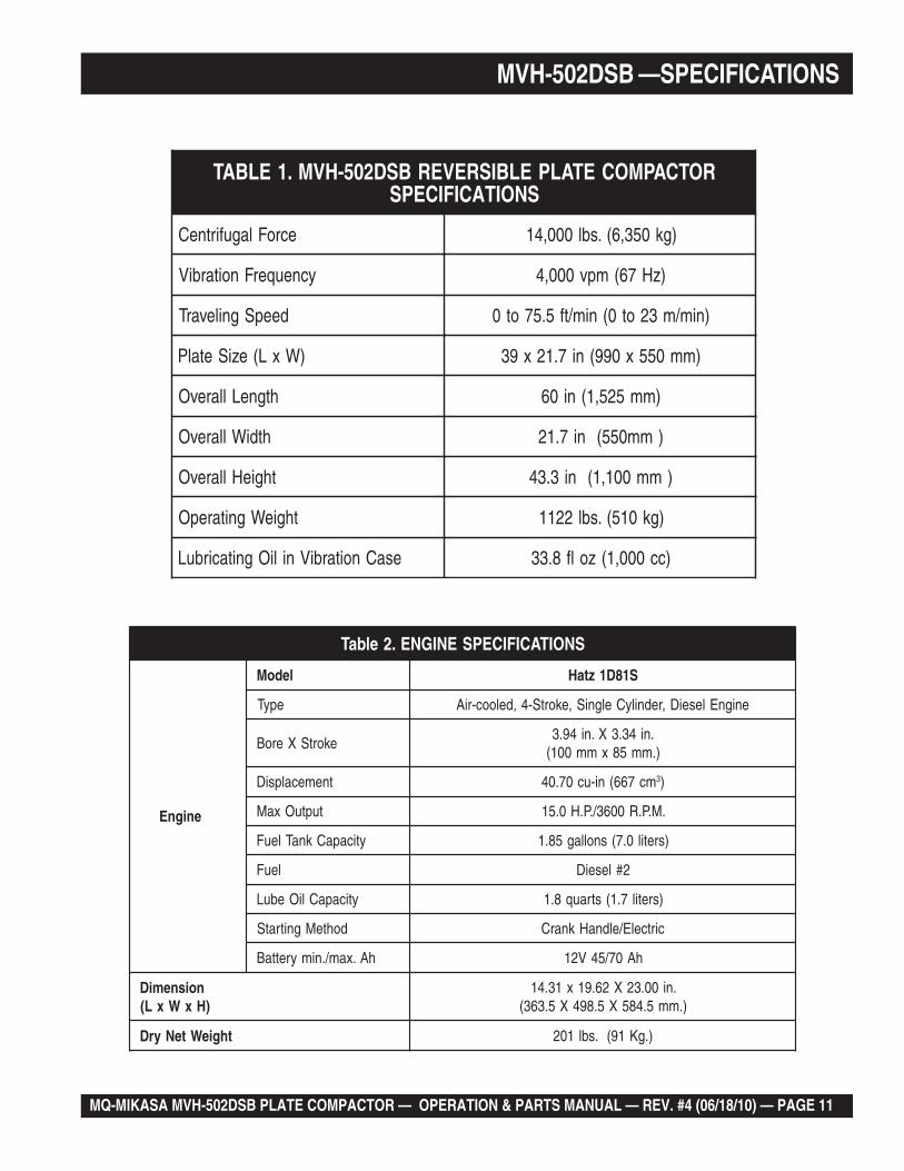
SNOITACIFICEPSENIGNE.2elbaT
enignE
ledoM S18D1ztaH
epyT enignEleseiD,rednilyCelgniS,ekortS-4,delooc-riA
ekortSXeroB.ni43.3X.ni49.3).mm58xmm001(
tnemecalpsiD mc766(ni-uc07.04 3)
tuptuOxaM .M.P.R0063/.P.H0.51
yticapaCknaTleuF )sretil0.7(snollag58.1
leuF 2#leseiD
yticapaCliOebuL )sretil7.1(strauq8.1
dohteMgnitratS cirtcelE/eldnaHknarC
hA.xam/.nimyrettaB hA07/54V21
noisnemiD)HxWxL(
.ni00.32X26.91x13.41).mm5.485X5.894X5.363(
thgieWteNyrD ).gK19(.sbl102
ELBISREVERBSD205-HVM.1ELBAT ROTCAPMOCETALPSNOITACIFICEPS
ecroFlagufirtneC )gk053,6(.sbl000,41
ycneuqerFnoitarbiV )zH76(mpv000,4
deepSgnilevarT )nim/m32ot0(nim/tf5.57ot0
)WxL(eziSetalP )mm055x099(ni7.12x93
htgneLllarevO )mm525,1(ni06
htdiWllarevO )mm055(ni7.12
thgieHllarevO )mm001,1(ni3.34
thgieWgnitarepO )gk015(.sbl2211
esaCnoitarbiVniliOgnitacirbuL )cc000,1(zolf8.33
PAGE 12 — MQ-MIKASA MVH-502DSB PLATE COMPACTOR — OPERATION & PARTS MANUAL — REV. #4 (06/18/10)
MVH-502DSB — DIMENSIONS
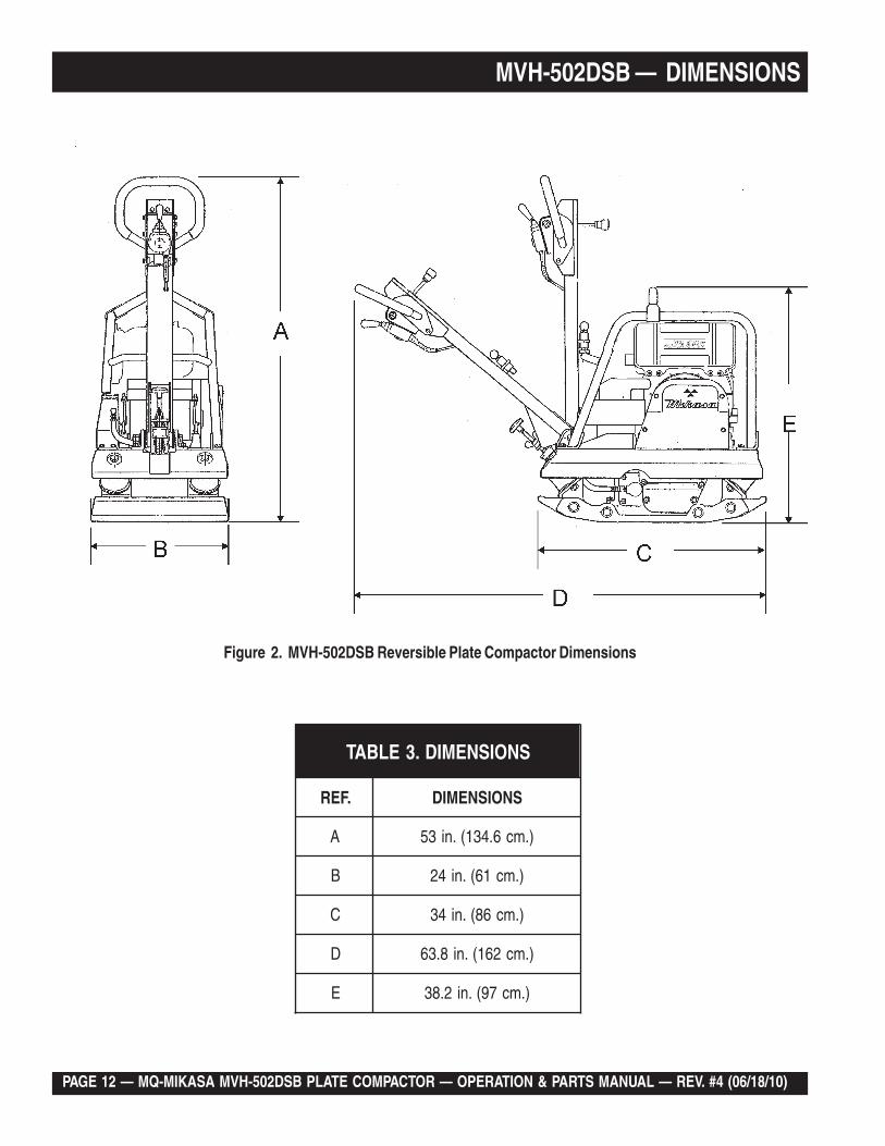
Figure 2. MVH-502DSB Reversible Plate Compactor Dimensions
SNOISNEMID.3ELBAT
.FER SNOISNEMID
A ).mc6.431(.ni35
B ).mc16(.ni42
C ).mc68(.ni43
D ).mc261(.ni8.36
E ).mc79(.ni2.83
MQ-MIKASA MVH-502DSB PLATE COMPACTOR — OPERATION & PARTS MANUAL — REV. #4 (06/18/10) — PAGE 13
MVH-502DSB — FEATURES
Plate Compactor
The Mikasa MVH-502DSB is a walk behind, reversible platecompactor designed for the compaction of sand, clay andasphalt. This plate compactor is a powerful compacting toolcapable of applying a tremendous force in consecutive highfrequency vibrations to a soil surface. Its applications includesoil compacting for road, embankments and reservoirs as wellas backfilling for gas pipelines, water pipelines and cableinstallation work.
Vibratory Plates
The vibratory plates of the MVH-502DSB produce low amplitudehigh frequency vibrations, designed to compact granular soils.
The resulting vibrations cause forward motion. The engine andhandle are vibration isolated from the vibrating plate. The heavierthe plate, the more compaction force it generates.
Reversible Vibratory Plates
Reversible vibratory plates have two eccentric weights that allowa smooth transition for forward and reverse travel, plus increasedcompaction force as the result of dual weights.
Due to their weight and force, reversible plates are ideal forsemi-cohesive soils.
Frequency/Speed
The compactor's vibrating plate maximum frequency is 4000vpm (vibrations per minute). The forward and reverse travel speedof the compactor is approximately 75.5 ft./minute (23 meters/minute).
Engine
The Mikasa MVH-502DSB Plate Compactor is equipped with aHATZ 1D81S diesel engine.
Controls
Before starting the MVH-502DSB Plate Compactor, identify andunderstand the function of the controls and components asindicated in Figure 3.
PAGE 14 — MQ-MIKASA MVH-502DSB PLATE COMPACTOR — OPERATION & PARTS MANUAL — REV. #4 (06/18/10)
MVH-502DSB — PLATE COMPACTOR COMPONENTS
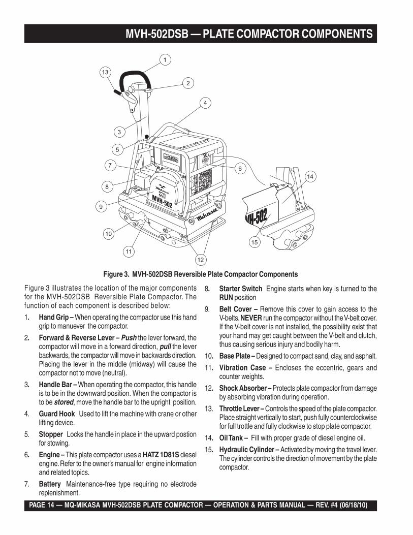
Figure 3. MVH-502DSB Reversible Plate Compactor Components
Figure 3 illustrates the location of the major componentsfor the MVH-502DSB Reversible Plate Compactor. Thefunction of each component is described below:
1. Hand Grip – When operating the compactor use this handgrip to manuever the compactor.
2. Forward & Reverse Lever – Push the lever forward, thecompactor will move in a forward direction, pull the leverbackwards, the compactor will move in backwards direction.Placing the lever in the middle (midway) will cause thecompactor not to move (neutral).
3. Handle Bar – When operating the compactor, this handleis to be in the downward position. When the compactor isto be stored, move the handle bar to the upright position.
4. Guard Hook Used to lift the machine with crane or otherlifting device.
5. Stopper Locks the handle in place in the upward postionfor stowing.
6. Engine – This plate compactor uses a HATZ 1D81S dieselengine. Refer to the owner’s manual for engine informationand related topics.
7. Battery Maintenance-free type requiring no electrodereplenishment.
8. Starter Switch Engine starts when key is turned to theRUN position
9. Belt Cover – Remove this cover to gain access to theV-belts. NEVER run the compactor without the V-belt cover.If the V-belt cover is not installed, the possibility exist thatyour hand may get caught between the V-belt and clutch,thus causing serious injury and bodily harm.
10. Base Plate – Designed to compact sand, clay, and asphalt.
11. Vibration Case – Encloses the eccentric, gears andcounter weights.
12. Shock Absorber – Protects plate compactor from damageby absorbing vibration during operation.
13. Throttle Lever – Controls the speed of the plate compactor.Place straight vertically to start, push fully counterclockwisefor full trottle and fully clockwise to stop plate compactor.
14. Oil Tank – Fill with proper grade of diesel engine oil.
15. Hydraulic Cylinder – Activated by moving the travel lever.The cylinder controls the direction of movement by the platecompactor.
MQ-MIKASA MVH-502DSB PLATE COMPACTOR — OPERATION & PARTS MANUAL — REV. #4 (06/18/10) — PAGE 15
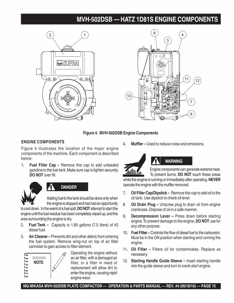
Figure 4. MVH-502DSB Engine Components
ENGINE COMPONENTS
Figure 4 illustrates the location of the major enginecomponents of the machine. Each component is describedbelow:
1. Fuel Filler Cap – Remove this cap to add unleadedgasoline to the fuel tank. Make sure cap is tighten securely.DO NOT over fill.
7. Oil Filler Cap/Dipstick – Remove this cap to add oil to theoil tank. Use dipstick to check oil level.
8. Oil Drain Plug – Unscrew plug to drain oil from enginecrankcase. Dispose of oil in a safe manner.
9. Decompression Lever – Press down before startingengine. To prevent damage to the engine, DO NOT use forany other purpose.
10. Fuel Filter – Controls the flow of diesel fuel to the carburetor.Must be in the ON position when starting and running theengine.
11. Oil Filter – Filters oil for contaminates. Replace asnecessary.
12. Starting Handle Guide Sleeve – Insert starting handleinto the guide sleeve and turn to crank start engine.
MVH-502DSB — HATZ 1D81S ENGINE COMPONENTS
DANGER
Adding fuel to the tank should be done only whenthe engine is stopped and has had an opportunity
to cool down. In the event of a fuel spill, DO NOT attempt to start theengine until the fuel residue has been completely wiped up, and thearea surrounding the engine is dry.2. Fuel Tank – Capacity is 1.85 gallons (7.0 liters) of #2
diesel fuel.
3. Air Cleaner – Prevents dirt and other debris from enteringthe fuel system. Remove wing-nut on top of air filtercannister to gain access to filter element.
Operating the engine withoutan air filter, with a damaged airfilter, or a filter in need ofreplacement will allow dirt toenter the engine, causing rapidengine wear.
4. Muffler – Used to reduce noise and emissions.
NOTE
WARNING
Engine components can generate extreme heat.To prevent burns, DO NOT touch these areas
while the engine is running or immediately after operating. NEVERoperate the engine with the muffler removed.
PAGE 16 — MQ-MIKASA MVH-502DSB PLATE COMPACTOR — OPERATION & PARTS MANUAL — REV. #4 (06/18/10)
MVH-502DSB — PRE-INSPECTION
Checking Engine Oil Level
1. Make sure that the machine is situated in a flatsurface so that level measurements will be accurate.
2. Pull out the dipstick from the oil tank (Figure 5).
Checking The Fuel
1. Remove the fuel cap located on top of fuel tank.
2. Visually inspect to see if fuel level is low. If fuel is low, replenishwith diesel fuel (Figure 6).
3. When refueling, be sure to use a strainer for filtration. DONOT top-off fuel. Wipe up any spilled fuel.
Figure 5. Oil Dipstick
DO NOT overfill oil tank. This could cause oilleaks and sluggish operation. Clean cap andsurrounding area before opening to prevent dirtfrom entering tank.
CAUTION :
HOLDER
ENGINE OIL
DIPSTICK
Figure 6. Refueling
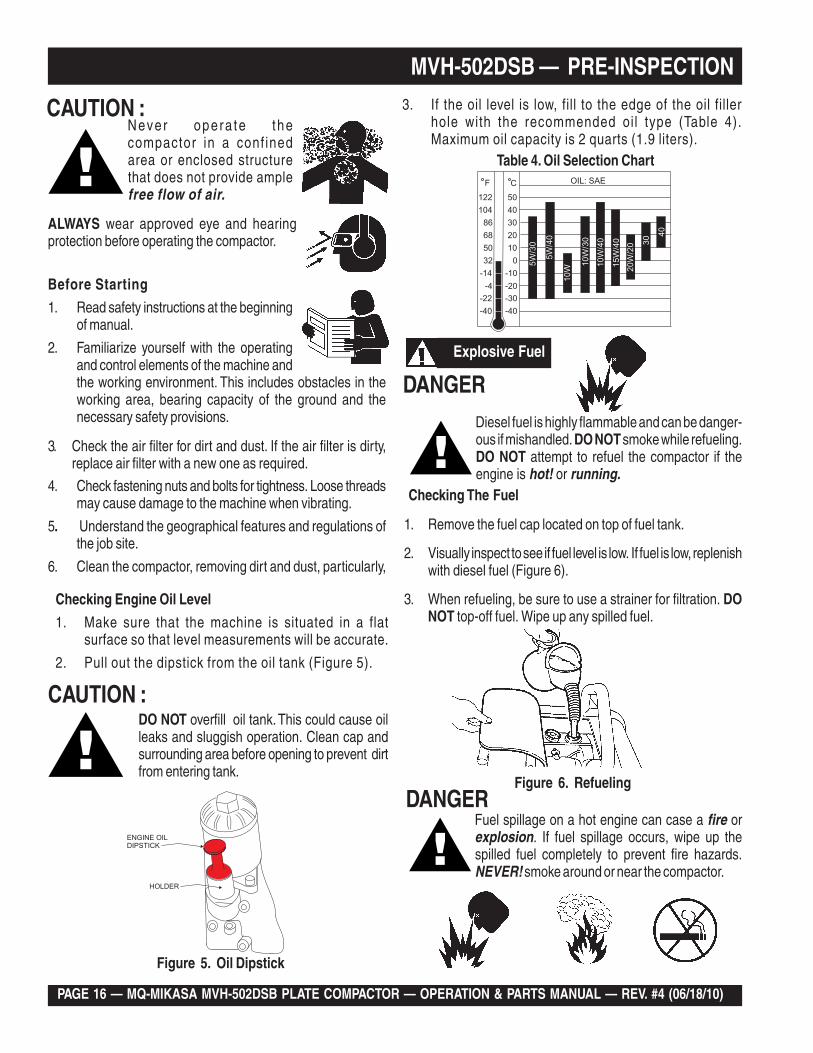
Table 4. Oil Selection Chart
-40
-30
-10
-20
-22
-40
-4
-14
032
50
68
86
104
122
10
20
30
40
50
F C
5W
/30
5W
/40
10
W
10
W/3
0
10
W/4
0
15
W/4
0
20
W/2
0 30
40
OIL: SAE
CAUTION :Never opera te thecompactor in a conf inedarea or enclosed structurethat does not provide amplefree flow of air.
Before Starting
1. Read safety instructions at the beginningof manual.
2. Familiarize yourself with the operatingand control elements of the machine andthe working environment. This includes obstacles in theworking area, bearing capacity of the ground and thenecessary safety provisions.
3. Check the air filter for dirt and dust. If the air filter is dirty,replace air filter with a new one as required.
4. Check fastening nuts and bolts for tightness. Loose threadsmay cause damage to the machine when vibrating.
5. Understand the geographical features and regulations ofthe job site.
6. Clean the compactor, removing dirt and dust, particularly,
ALWAYS wear approved eye and hearingprotection before operating the compactor.
3. If the oil level is low, fill to the edge of the oil fillerhole with the recommended oil type (Table 4).Maximum oil capacity is 2 quarts (1.9 liters).
Explosive Fuel
DANGERDiesel fuel is highly flammable and can be danger-ous if mishandled. DO NOT smoke while refueling.DO NOT attempt to refuel the compactor if theengine is hot! or running.
Explosive Fuel
DANGERFuel spillage on a hot engine can case a fire orexplosion. If fuel spillage occurs, wipe up thespilled fuel completely to prevent fire hazards.NEVER! smoke around or near the compactor.
MQ-MIKASA MVH-502DSB PLATE COMPACTOR — OPERATION & PARTS MANUAL — REV. #4 (06/18/10) — PAGE 17
STARTING THE ENGINE
Electric Start
1. Move the throttle lever to the START position by opening itto about 20 degrees (Figure 9).
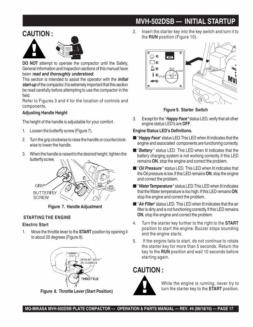
2. Insert the starter key into the key switch and turn it tothe RUN position (Figure 10).
MVH-502DSB — INITIAL STARTUP
Adjusting Handle Height
The height of the handle is adjustable for your comfort .
1. Loosen the butterfly screw (Figure 7).
2. Turn the grip clockwise to raise the handle or counterclock-wise to lower the handle.
3. When the handle is raised to the desired height, tighten thebutterfly screw.
Figure 7. Handle Adjustment
CAUTION :
DO NOT attempt to operate the compactor until the Safety,General Information and Inspection sections of this manual havebeen read and thoroughly understood.This section is intended to assist the operator with the initialstart-up of the compactor. It is extremely important that this sectionbe read carefully before attempting to use the compactor in thefield.Refer to Figures 3 and 4 for the location of controls andcomponents.
Figure 9. Starter Switch
Figure 8. Throttle Lever (Start Position)
3. Except for the "Happy Face" status LED, verify that all otherengine status LED's are OFF.
Engine Status LED's Definitions.
■ "Happy Face" status LED. This LED when lit indicates that theengine and associated components are functioning correctly.
■ "Battery " status LED. This LED when lit indicates that thebattery charging system is not working correctly. If this LEDremains ON, stop the engine and correct the problem.
■ "Oil Pressure " status LED. This LED when lit indicates thatthe Oil pressure is low. If this LED remains ON, stop the engineand correct the problem.
■ "Water Temperature " status LED. This LED when lit indicatesthat the Water temperature is too high. If this LED remains ON,stop the engine and correct the problem.
■ "Air Filter" status LED. This LED when lit indicates that the airfilter is dirty and is not functioning correctly. If this LED remainsON, stop the engine and correct the problem.
While the engine is running, never try toturn the starter key to the START position.
CAUTION :
4. Turn the star ter key fur ther to the right to the STARTposition to start the engine. Buzzer stops soundingand the engine starts.
5. If the engine fails to start, do not continue to rotatethe starter key for more than 5 seconds. Return thekey to the RUN position and wait 10 seconds beforestarting again.
PAGE 18 — MQ-MIKASA MVH-502DSB PLATE COMPACTOR — OPERATION & PARTS MANUAL — REV. #4 (06/18/10)
4. To make the compactor move in the reverse direction pull thetravel lever ( Figure 13) backwards.
5. Firmly gasp the compactor's hand grip, the compactor willbegin moving in the desired position when the direction leverhas been placed in the desired position.
Crank Handle Start
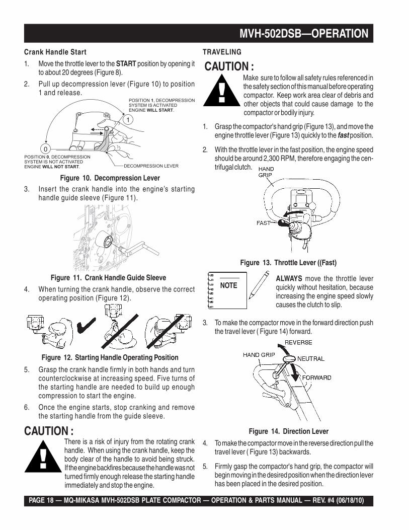
1. Move the throttle lever to the START position by opening itto about 20 degrees (Figure 8).
2. Pull up decompression lever (Figure 10) to position1 and release.
Figure 11. Crank Handle Guide Sleeve
Figure 10. Decompression Lever
Make sure to follow all safety rules referenced inthe safety section of this manual before operatingcompactor. Keep work area clear of debris andother objects that could cause damage to thecompactor or bodily injury.
CAUTION :
1. Grasp the compactor's hand grip (Figure 13), and move theengine throttle lever (Figure 13) quickly to the fast position.
2. With the throttle lever in the fast position, the engine speedshould be around 2,300 RPM, therefore engaging the cen-trifugal clutch.
Figure 13. Throttle Lever ((Fast)
ALWAYS move the throttle leverquickly without hesitation, becauseincreasing the engine speed slowlycauses the clutch to slip.
NOTE
3. To make the compactor move in the forward direction pushthe travel lever ( Figure 14) forward.
Figure 14. Direction Lever
MVH-502DSB—OPERATIONTRAVELING
3. Inser t the crank handle into the engine’s star tinghandle guide sleeve (Figure 11).
4. When turning the crank handle, observe the correctoperating position (Figure 12).
5. Grasp the crank handle firmly in both hands and turncounterclockwise at increasing speed. Five turns ofthe starting handle are needed to build up enoughcompression to start the engine.
6. Once the engine starts, stop cranking and removethe starting handle from the guide sleeve.
Figure 12. Starting Handle Operating Position
There is a risk of injury from the rotating crankhandle. When using the crank handle, keep thebody clear of the handle to avoid being struck.If the engine backfires because the handle was notturned firmly enough release the starting handleimmediately and stop the engine.
CAUTION :
MQ-MIKASA MVH-502DSB PLATE COMPACTOR — OPERATION & PARTS MANUAL — REV. #4 (06/18/10) — PAGE 19
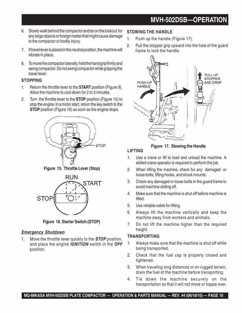
Figure 15. Throttle Lever (Stop)
Emergency Shutdown1. Move the throttle lever quickly to the STOP position,
and place the engine IGNITION switch in the OFFposition.
STOWING THE HANDLE
1. Push up the handle (Figure 17).
2. Pull the stopper grip upward into the hole of the guardframe to lock the handle.
Figure 17. Stowing the HandleLIFTING
1. Use a crane or lift to load and unload the machine. Askilled crane operator is required to perform the job.
2. When lifting the machine, check for any damaged orloose bolts, lifting hooks, and shock mounts.
3. Check any damaged or loose bolts in the guard frame toavoid machine sliding off.
4. Make sure that the machine is shut off before machine islifted.
5. Use reliable cable for lifting.
6. Always lift the machine vertically and keep themachine away from workers and animals.
7. Do not lift the machine higher than the requiredheight.
TRANSPORTING
1. Always make sure that the machine is shut off whilebeing transported.
2. Check that the fuel cap is properly closed andtightened.
3. When traveling long distances or on rugged terrain,drain the fuel of the machine before transporting.
4. T ie down the mach ine secure ly on thetransportation so that it will not move or topple over.
MVH-502DSB—OPERATION
Figure 16. Starter Switch (STOP)
6. Slowly walk behind the compactor and be on the lookout forany large objects or foreign matter that might cause damageto the compactor or bodily injury.
7. If travel lever is placed in the neutral position, the machine willvibrate in place.
8. To move the compactor laterally, hold the hand grip firmly andswing compactor. Do not swing compactor while gripping thetravel lever.
STOPPING
1. Return the throttle lever to the START position (Figure 9).Allow the machine to cool down for 2 to 3 minutes.
2. Turn the throttle lever to the STOP position (Figure 15) tostop the engine. In a motor start, return the key switch to theSTOP position (Figure 16) as soon as the engine stops.
PAGE 20 — MQ-MIKASA MVH-502DSB PLATE COMPACTOR — OPERATION & PARTS MANUAL — REV. #4 (06/18/10)
MVH-502DSB — MAINTENANCE
Inspection and Maintenance Service Tables.
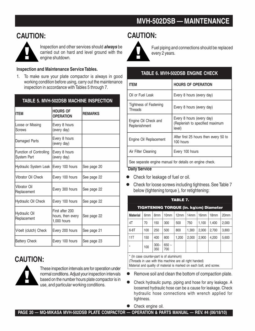
1. To make sure your plate compactor is always in goodworking condition before using, carry out the maintenanceinspection in accordance with Tables 5 through 7.
Daily Service
Check for leakage of fuel or oil.
Check for loose screws including tightness. See Table 7below (tightening torque ), for retightening:
Remove soil and clean the bottom of compaction plate.
Check hydraulic pump, piping and hose for any leakage. Aloosened hydraulic hose can be a cause for leakage. Checkhydraulic hose connections with wrench applied fortightness.
Check engine oil.
CAUTION:Inspection and other services should always becarried out on hard and level ground with theengine shutdown.
CAUTION:These inspection intervals are for operation undernormal conditions. Adjust your inspection intervalsbased on the number hours plate compactor is inuse, and particular working conditions.
CAUTION:
Fuel piping and connections should be replacedevery 2 years.
BSD205-HVM.5ELBAT NOITCEPSNIENIHCAM
METIFOSRUOHNOITAREPO
SKRAMER
gnissiMroesooLswercS
sruoh8yrevE)yadyreve(
straPdegamaDsruoh8yrevE
)yadyreve(
gnillortnoCfonoitcnuFtraPmetsyS
sruoh8yrevE)yadyreve(
kaeLmetsySciluardyH sruoh001yrevE 02egapeeS
kcehCliOrotarbiV sruoh001yrevE 22egapeeS
liOrotarbiVtnemecalpeR
sruoh003yrevE 22egapeeS
kcehCliOciluardyH sruoh001yrevE 22egapeeS
liOciluardyHtnemecalpeR
002retfatsriFyreveneht,sruoh
sruoh000,122egapeeS
kcehC)hctulc(tleb-V sruoh002yrevE 12egapeeS
kcehCyrettaB sruoh001yrevE 32egapeeS
BSD205-HVM.6ELBAT KCEHCENIGNE
METI NOITAREPOFOSRUOH
kaeLleuFroliO )yadyreve(sruoh8yrevE
gninetsaFfossenthgiTsdaerhT
)yadyreve(sruoh8yrevE
dnakcehCliOenignEtnemhsinelpeR
)yadyreve(sruoh8yrevEmumixamdeificepsothsinelpeR(
)level
tnemecalpeRliOenignEot05yrevenehtsruoh52tsrifretfA
sruoh001
gninaelCretliFriA sruoh001yrevE
.kcehcenignenosliatedroflaunamenigneetarapeseeS
.7ELBAT
retemaiD)mc/gk.ni(EUQROTGNINETHGIT
lairetaM mm6 mm8 mm01 mm21 mm41 mm61 mm81 mm02
T4 07 051 003 005 057 001,1 004,1 000,2
T8-6 001 052 005 008 003,1 000,2 007,2 008,3
T11 051 004 008 002,1 000,2 009,2 002,4 006,5
* 001 ~003053
~056007
)munimulafositrap-retnuocesacnI(*)dednahthgirllaeraenihcamsihthtiwesunisdaerhT(
.wercsdna,tlobhcaenodekramsilairetamfoytilauqdnalairetaM
MQ-MIKASA MVH-502DSB PLATE COMPACTOR — OPERATION & PARTS MANUAL — REV. #4 (06/18/10) — PAGE 21
MVH-502DSB — MAINTENANCE
Engine Oil Replacement:
1. Replace engine oil, first in 25 hours of operation and every50 to 100 hours afterwards.
2. Oil may be drained more easily when it is warm afteroperation (For more details, see separate engine Owner'sManual).
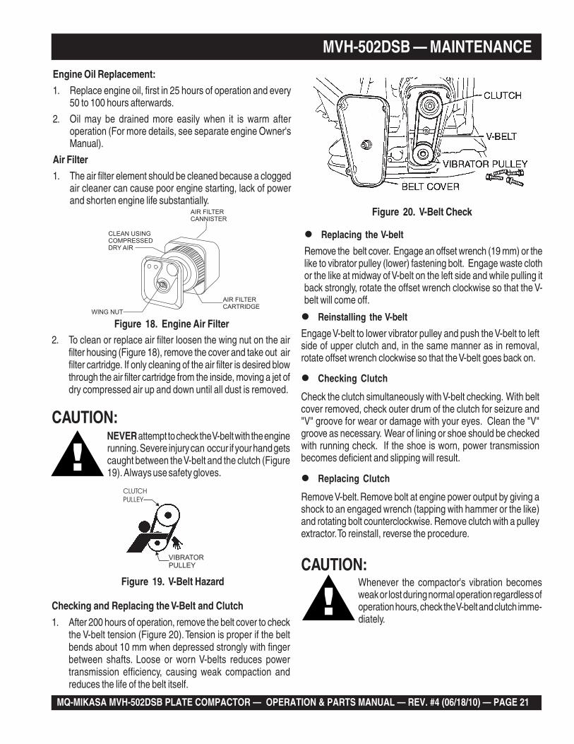
Air Filter
1. The air filter element should be cleaned because a cloggedair cleaner can cause poor engine starting, lack of powerand shorten engine life substantially.
2. To clean or replace air filter loosen the wing nut on the airfilter housing (Figure 18), remove the cover and take out airfilter cartridge. If only cleaning of the air filter is desired blowthrough the air filter cartridge from the inside, moving a jet ofdry compressed air up and down until all dust is removed.
Reinstalling the V-belt
Engage V-belt to lower vibrator pulley and push the V-belt to leftside of upper clutch and, in the same manner as in removal,rotate offset wrench clockwise so that the V-belt goes back on.
Replacing the V-belt
Remove the belt cover. Engage an offset wrench (19 mm) or thelike to vibrator pulley (lower) fastening bolt. Engage waste clothor the like at midway of V-belt on the left side and while pulling itback strongly, rotate the offset wrench clockwise so that the V-belt will come off.
Checking Clutch
Check the clutch simultaneously with V-belt checking. With beltcover removed, check outer drum of the clutch for seizure and"V" groove for wear or damage with your eyes. Clean the "V"groove as necessary. Wear of lining or shoe should be checkedwith running check. If the shoe is worn, power transmissionbecomes deficient and slipping will result.
Replacing Clutch
Remove V-belt. Remove bolt at engine power output by giving ashock to an engaged wrench (tapping with hammer or the like)and rotating bolt counterclockwise. Remove clutch with a pulleyextractor. To reinstall, reverse the procedure.
CAUTION:Whenever the compactor's vibration becomesweak or lost during normal operation regardless ofoperation hours, check the V-belt and clutch imme-diately.
Figure 19. V-Belt Hazard
CLUTCH
PULLEY
VIBRATOR
PULLEY
Figure 18. Engine Air Filter
Figure 20. V-Belt Check
CAUTION:NEVER attempt to check the V-belt with the enginerunning. Severe injury can occur if your hand getscaught between the V-belt and the clutch (Figure19). Always use safety gloves.
Checking and Replacing the V-Belt and Clutch
1. After 200 hours of operation, remove the belt cover to checkthe V-belt tension (Figure 20). Tension is proper if the beltbends about 10 mm when depressed strongly with fingerbetween shafts. Loose or worn V-belts reduces powertransmission efficiency, causing weak compaction andreduces the life of the belt itself.
AIR FILTER
CANNISTER
AIR FILTER
CARTRIDGEWING NUT
CLEAN USING
COMPRESSED
DRY AIR
PAGE 22 — MQ-MIKASA MVH-502DSB PLATE COMPACTOR — OPERATION & PARTS MANUAL — REV. #4 (06/18/10)
Figure 21. Vibrator Oil Maintenance
MVH-502DSB—MAINTENANCE
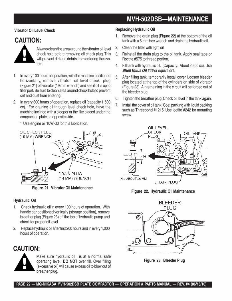
Vibrator Oil Level Check
1. In every 100 hours of operation, with the machine positionedhorizontally, remove vibrator oil level check plug(Figure 21) off vibrator (19 mm wrench) and see if oil is up tofiller port. Be sure to clean area around check hole to preventdirt and dust from entering.
2. In every 300 hours of operation, replace oil (capacity 1,500cc). For draining oil through level check hole, have themachine inclined with a sleeper or the like placed under thecompaction plate on opposite side.
* Use engine oil 10W-30 for this lubrication.
Hydraulic Oil
1. Check hydraulic oil in every 100 hours of operation. Withhandle bar positioned vertically (storage position), removebreather plug (Figure 23) off the top of hydraulic pump andcheck for proper oil level.
2. Replace hydraulic oil after first 200 hours and in every 1,000hours of operation.
Replacing Hydraulic Oil
1. Remove the drain plug (Figure 22) at the bottom of the oiltank with a 6 mm hex wrench and drain the hydraulic oil.
2. Clean the filter with light oil.
3. Reinstall the drain plug to the oil tank. Apply seal tape orRoctite #575 to thread portion.
4. Fill tank with hydraulic oil. (Capacity: About 2,500 cc). UseShell Tellus Oil #46 or equivalent.
5. After filling tank, temporarily install cover. Loosen bleederplug located at the top of the cylinders on side of vibrator(Figure 23). Air remaining in the circuit will be forced out ofthe bleeder plug.
6. Tighten the breather plug. Check oil level in the tank again.
7. Install the cover of oil tank. Coat packing with liquid packingsuch as Threebond #1215. Use loctite #242 for mountingscrew.
Make sure hydraulic oil i is at a normal safeoperating level. DO NOT over fill. Over filling(excessive oil) will cause excess oil to blow out ofbreather plug.
CAUTION:
CAUTION:Always clean the area around the vibrator oil levelcheck hole before removing oil check plug. Thiswill prevent dirt and debris from entering the sys-tem.
Figure 22. Hydraulic Oil Maintenance
Figure 23. Bleeder Plug
MQ-MIKASA MVH-502DSB PLATE COMPACTOR — OPERATION & PARTS MANUAL — REV. #4 (06/18/10) — PAGE 23
MVH-502DSB—MAINTENANCE
Troubleshooting
See Tables 8 (engine) and 9 (plate compactor) on proceedingpages for troubleshooting guide.
BATTERY MAINTENANCE
1. Check the battery terminals periodically to ensurethat they are in good condition.
2. Use wire brush or sand paper to clean the batteryterminals.
3. Check battery for cracks or any other damage. If whitepattern appears inside the battery or paste hasaccumulated at the bottom, replace the battery.
4.. If the machine will not be in operation for a longperiod of time, store in cool dry place and check thebattery charge level every month to maintain theperformance of the battery.
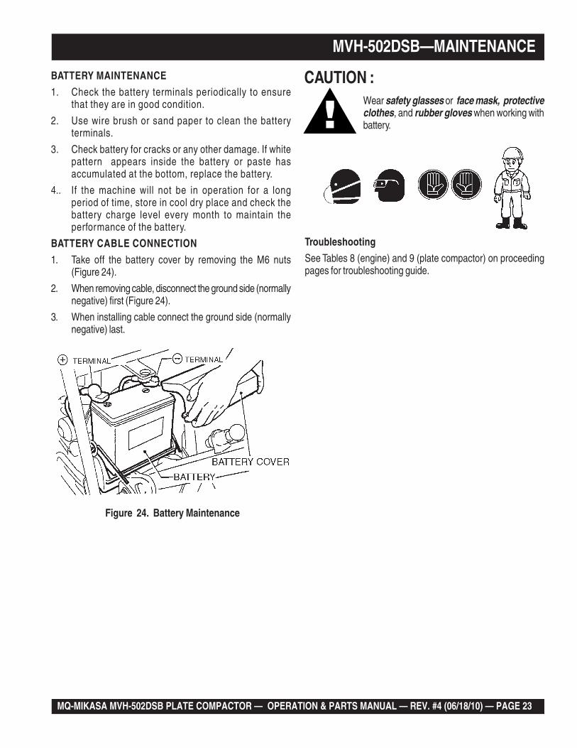
BATTERY CABLE CONNECTION
1. Take off the battery cover by removing the M6 nuts(Figure 24).
2. When removing cable, disconnect the ground side (normallynegative) first (Figure 24).
3. When installing cable connect the ground side (normallynegative) last.
Figure 24. Battery Maintenance
Wear safety glasses or face mask, protectiveclothes, and rubber gloves when working withbattery.
CAUTION :
PAGE 24 — MQ-MIKASA MVH-502DSB PLATE COMPACTOR — OPERATION & PARTS MANUAL — REV. #4 (06/18/10)
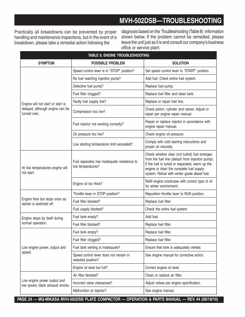
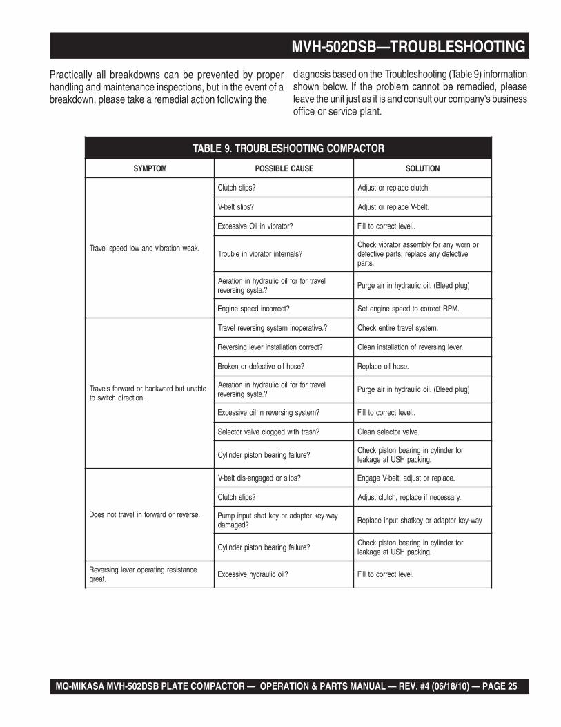
MVH-502DSB—TROUBLESHOOTINGPractically all breakdowns can be prevented by properhandling and maintenance inspections, but in the event of abreakdown, please take a remedial action following the
diagnosis based on the Troubleshooting (Table 8) informationshown below. If the problem cannot be remedied, pleaseleave the unit just as it is and consult our company's businessoffice or service plant.
GNITOOHSELBUORTENIGNE.8ELBAT
MOTPMYS MELBORPELBISSOP NOITULOS
sitratsrotratstonlliwenignEebnacenignehguohtla,deyaled
.revodenrut
?noitisop"POTS"nisirevellortnocdeepS .noitisop"TRATS"otrevellortnocdeepsteS
?pmupnoitcejnignihcaerleufoN .metsysleuferitnekcehC.leufddA
?pmupleufevitcefeD .pmupleufecalpeR
?deggolcretlifleuF .knatnaelcdnaretlifleufecalpeR
?enilylppusleufytluaF .enilleufriaperroecalpeR
?wolootnoisserpmoCrotsujdA.sevlavdnarednilyc,notsipkcehC
.launamriaperenignerepriaper
?yltcerrocgnikrowtonrotcejnileuFhtiwecnadroccanirotcejniecalperroriapeR
.launamriaperenigne
?wolooterusserpliO .erusserplioenignekcehC
?dedeecxetimilerutarepmetgnitratswoLdnasnoitcurtsnignitratsdlochtiwylpmoC
.ytisocsivlioreporp
lliwenigneserutarepmetwoltA.tratston
otecnatsiseretauqedanisahsetarapesleuF?serutarepmetwol
segremeleuf)dibrutton(raelcrehtehwkcehC.)pmupnoitcejnimorfhcated(enilleufehtmorf
ehtpumraw,detarapesrodibrutsileufehtfIylppusleufetelpmocehtniardroenigne
.leufleseidedargretniwhtiwleufeR.metsys
?kcihtootlioenignEliofoepyttcerrochtiwesacknarcenignellifeR
.tnemnorivneretniwrof
sanoosspotstubserifenignE.ffodehctiwssiretrats
?noitisopPOTSnirevelelttorhT .noitisopNURotrevelelttorhtnoitisopeR
?dekcolbretlifleuF .retlifleufecalpeR
?dekcolbylppusleuF .metsysleuferitneehtkcehC
gnirudflestiybspotsenignE.noitarepolamron
?ytpmeknatleuF .leufddA
?dekcolbretlifleuF .retlifleufecalpeR
dnatuptuo,rewopenignewoL.deeps
?ytpmeknatleuF .retlifleufecalpeR
?deggolcretlifleuF .retlifleufecalpeR
?etauqedanisignitnevknatleuF .detnevyletauqedasiknattahterusnE
niniamertonseodrevellortnocdeepS?noitisopdetceles
.noitcaevitcerrocroflaunamenigneeeS
?llufootlevellioenignE .levellioenignetcerroC
dnatuptuorewopenignewoL.ekomstsuahxekcalb,deepswol
?dekcolbretlifriA .retlifriaecalperronaelC
?secnaraelcevlavtcerrocnI .noitacificepsenignerepsevlavtsujdA
?rotcejnitanoitcnuflaM .launamenigneeeS
MQ-MIKASA MVH-502DSB PLATE COMPACTOR — OPERATION & PARTS MANUAL — REV. #4 (06/18/10) — PAGE 25
MVH-502DSB—TROUBLESHOOTING
Practically all breakdowns can be prevented by properhandling and maintenance inspections, but in the event of abreakdown, please take a remedial action following the
diagnosis based on the Troubleshooting (Table 9) informationshown below. If the problem cannot be remedied, pleaseleave the unit just as it is and consult our company's businessoffice or service plant.
ROTCAPMOCGNITOOHSELBUORT.9ELBAT
MOTPMYS ESUACELBISSOP NOITULOS
.kaewnoitarbivdnawoldeepslevarT
?spilshctulC .hctulcecalperrotsujdA
?spilstleb-V .tleb-VecalperrotsujdA
?rotarbivniliOevissecxE ..leveltcerrocotlliF
?slanretnirotarbivnielbuorTronrowynarofylbmessarotarbivkcehC
evitcefedynaecalper,strapevitcefed.strap
levartrofrofliociluardyhninoitareA?.etsysgnisrever )gulpdeelB(.liociluardyhniriaegruP
?tcerrocnideepsenignE .MPRtcerrocotdeepsenigneteS
elbanutubdrawkcabrodrawrofslevarT.noitceridhctiwsot
?.evitareponimetsysgnisreverlevarT .metsyslevarteritnekcehC
?tcerrocnoitallatsnirevelgnisreveR .revelgnisreverfonoitallatsninaelC
?esohlioevitcefedronekorB .esohlioecalpeR
levartrofrofliociluardyhninoitareA?.etsysgnisrever )gulpdeelB(.liociluardyhniriaegruP
?metsysgnisrevernilioevissecxE ..leveltcerrocotlliF
?hsarthtiwdeggolcevlavrotceleS .evlavrotcelesnaelC
?eruliafgniraebnotsiprednilyC rofrednilycnigniraebnotsipkcehC.gnikcapHSUtaegakael
.esreverrodrawrofnilevarttonseoD
?spilsrodegagne-sidtleb-V .ecalperrotsujda,tleb-VegagnE
?spilshctulC .yrassecenfiecalper,hctulctsujdA
yaw-yekretpadaroyektahstupnipmuP?degamad yaw-yekretpadaroyektahstupniecalpeR
?eruliafgniraebnotsiprednilyC rofrednilycnigniraebnotsipkcehC.gnikcapHSUtaegakael
ecnatsisergnitareporevelgnisreveR.taerg ?liociluardyhevissecxE .leveltcerrocotlliF
PAGE 26 — MQ-MIKASA MVH-502DSB PLATE COMPACTOR — OPERATION & PARTS MANUAL — REV. #4 (06/18/10)
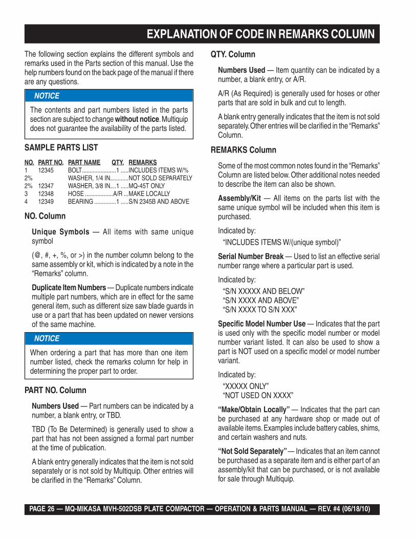
EXPLANATION OF CODE IN REMARKS COLUMN
The following section explains the different symbols and remarks used in the Parts section of this manual. Use the help numbers found on the back page of the manual if there are any questions.
SAMPLE PARTS LIST
NO. PART NO. PART NAME QTY. REMARKS1 12345 BOLT ......................1 .....INCLUDES ITEMS W/%2% WASHER, 1/4 IN. ...........NOT SOLD SEPARATELY2% 12347 WASHER, 3/8 IN. ...1 .....MQ-45T ONLY3 12348 HOSE ..................A/R ...MAKE LOCALLY4 12349 BEARING ..............1 .....S/N 2345B AND ABOVE
NO. Column
Unique Symbols — All items with same unique symbol
(@, #, +, %, or >) in the number column belong to the same assembly or kit, which is indicated by a note in the “Remarks” column.
Duplicate Item Numbers — Duplicate numbers indicate multiple part numbers, which are in effect for the same general item, such as different size saw blade guards in use or a part that has been updated on newer versions of the same machine.
PART NO. Column
Numbers Used — Part numbers can be indicated by a number, a blank entry, or TBD.
TBD (To Be Determined) is generally used to show a part that has not been assigned a formal part number at the time of publication.
A blank entry generally indicates that the item is not sold separately or is not sold by Multiquip. Other entries will be clarified in the “Remarks” Column.
NOTICE
The contents and part numbers listed in the parts section are subject to change without notice. Multiquip does not guarantee the availability of the parts listed.
NOTICE
When ordering a part that has more than one item number listed, check the remarks column for help in determining the proper part to order.
QTY. Column
Numbers Used — Item quantity can be indicated by a number, a blank entry, or A/R.
A/R (As Required) is generally used for hoses or otherparts that are sold in bulk and cut to length.
A blank entry generally indicates that the item is not sold separately. Other entries will be clarified in the “Remarks” Column.
REMARKS Column
Some of the most common notes found in the “Remarks” Column are listed below. Other additional notes needed to describe the item can also be shown.
Assembly/Kit — All items on the parts list with thesame unique symbol will be included when this item is purchased.
Indicated by:“INCLUDES ITEMS W/(unique symbol)”
Serial Number Break — Used to list an effective serial number range where a particular part is used.
Indicated by: “S/N XXXXX AND BELOW”“S/N XXXX AND ABOVE”“S/N XXXX TO S/N XXX”
Specific Model Number Use — Indicates that the part is used only with the specific model number or model number variant listed. It can also be used to show a part is NOT used on a specific model or model number variant.
Indicated by:“XXXXX ONLY”“NOT USED ON XXXX”
“Make/Obtain Locally” — Indicates that the part can be purchased at any hardware shop or made out of available items. Examples include battery cables, shims, and certain washers and nuts.
“Not Sold Separately” — Indicates that an item cannot be purchased as a separate item and is either part of an assembly/kit that can be purchased, or is not available for sale through Multiquip.
MQ-MIKASA MVH-502DSB PLATE COMPACTOR — OPERATION & PARTS MANUAL — REV. #4 (06/18/10) — PAGE 27
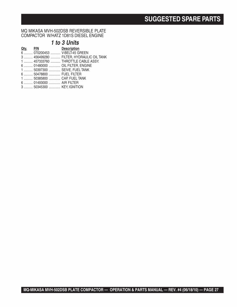
SUGGESTED SPARE PARTS
MQ MIKASA MVH-502DSB REVERSIBLE PLATECOMPACTOR W/HATZ 1D81S DIESEL ENGINE
1 to 3 UnitsQty. P/N Description6 .......... 070200453 ........... V-BELT-45 GREEN3 .......... 456499280 ........... FILTER, HYDRAULIC OIL TANK1 .......... 457333760 ........... THROTTLE CABLE ASSY.6 .......... 01480000 ............. OIL FILTER, ENGINE1 .......... 50397300 ............. SEIVE, FUEL TANK6 .......... 50478800 ............. FUEL FILTER1 .......... 50385800 ............. CAP, FUEL TANK6 .......... 01493000 ............. AIR FILTER3 .......... 50345300 ............. KEY, IGNITION
PAGE 28 — MQ-MIKASA MVH-502DSB PLATE COMPACTOR — OPERATION & PARTS MANUAL — REV. #4 (06/18/10)
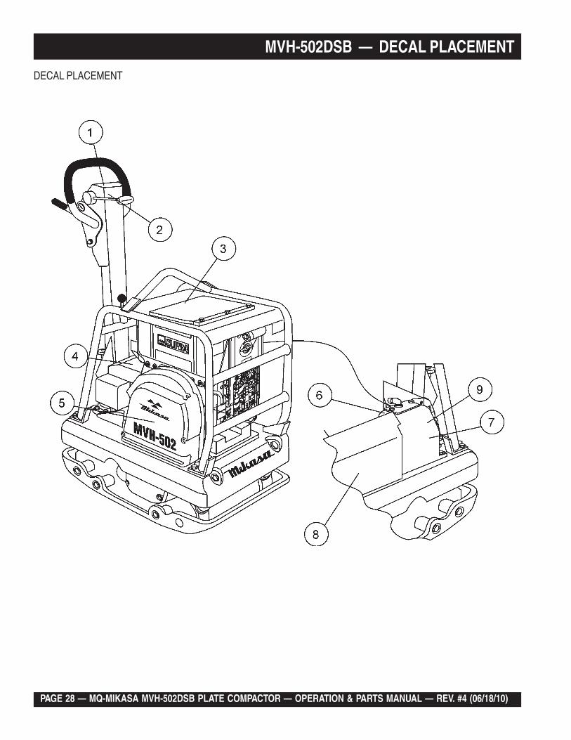
MVH-502DSB — DECAL PLACEMENT
DECAL PLACEMENT
MQ-MIKASA MVH-502DSB PLATE COMPACTOR — OPERATION & PARTS MANUAL — REV. #4 (06/18/10) — PAGE 29
MVH-502DSB — DECALS PLACEMENT
DECAL PLACEMENT
NO. PART NO. PART NAME QTY. REMARKS1 920204580 FULL THROTTLE DECAL 1 NPA-4582 920202220 FORWARD/REVERSE DECAL 1 NPA-2223 920206370 OPERATIONAL CAUTION DECAL 1 NPA-5384 920203330 HEARING PROTECTION DECAL .............. 1 ......... NPA-3335 920201580 MULTIQUIP LOGO DECAL 16 920103670 OIL LEVEL INDICATOR DECAL 1 NPA-3677 920207480 SHELL OIL #46DECAL 1 NPA-7488 920205000 MVH-502 DECAL 19 920203260 OIL TANK DECAL 1 NPA-326
PAGE 30 — MQ-MIKASA MVH-502DSB PLATE COMPACTOR — OPERATION & PARTS MANUAL — REV. #4 (06/18/10)
MVH-502DSB — VIBRATING PLATE ASSY.
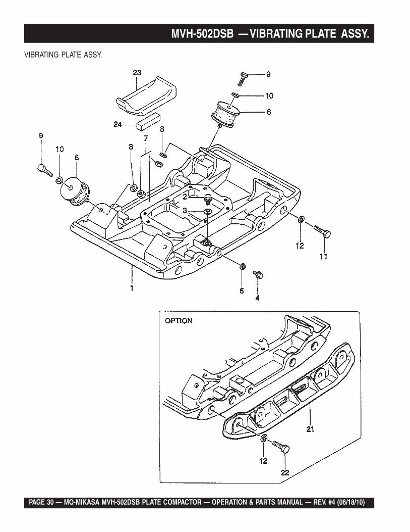
VIBRATING PLATE ASSY.
MQ-MIKASA MVH-502DSB PLATE COMPACTOR — OPERATION & PARTS MANUAL — REV. #4 (06/18/10) — PAGE 31
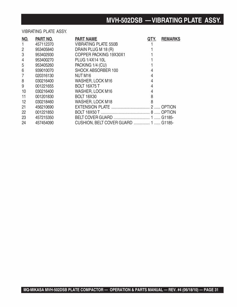
MVH-502DSB — VIBRATING PLATE ASSY.VIBRATING PLATE ASSY.
NO. PART NO. PART NAME QTY. REMARKS1 457112370 VIBRATING PLATE 550B 12 953405840 DRAIN PLUG M 18 (R) 13 953402930 COPPER PACKING 19X30X1 14 953400270 PLUG 1/4X14 10L 15 953405260 PACKING 1/4 (CU) 16 939010070 SHOCK ABSORBER 100 47 020316130 NUT M16 48 030216400 WASHER, LOCK M16 49 001221655 BOLT 16X75 T 410 030216400 WASHER, LOCK M16 411 001201830 BOLT 18X30 812 030218460 WASHER, LOCK M18 821 456210690 EXTENSION PLATE .................................... 2 ...... OPTION22 001221850 BOLT 18X50 T .............................................. 8 ...... OPTION23 457215350 BELT COVER GUARD .................................. 1 ...... G1185-24 457454090 CUSHION, BELT COVER GUARD ............... 1 ...... G1185-
PAGE 32 — MQ-MIKASA MVH-502DSB PLATE COMPACTOR — OPERATION & PARTS MANUAL — REV. #4 (06/18/10)
MVH-502DSB — BASE AND ENGINE ASSY.
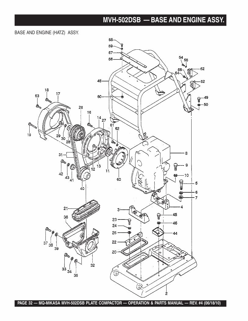
BASE AND ENGINE (HATZ) ASSY.
MQ-MIKASA MVH-502DSB PLATE COMPACTOR — OPERATION & PARTS MANUAL — REV. #4 (06/18/10) — PAGE 33
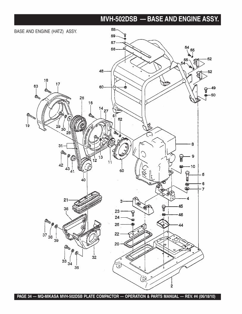
MVH-502DSB — BASE AND ENGINE ASSY.
BASE AND ENGINE (HATZ) ASSY.
NO. PART NO. PART NAME QTY. REMARKS2 457116080 BASE 13 457333670 ENGINE PLATE (F) 14 457333680 ENGINE PLATE (R) 15 001221252 BOLT 12X60 T 46 030212300 WASHER, LOCK M12 47 031112230 WASHER, FLAT M12 48 918400600 ENGINE AY 1D81S 19 001221225 BOLT 12X25 T 410 030212300 WASHER, LOCK M12 411 457336260 STUB SHAFT (1D81) 111 457339570 STUB SHAFT (1D- 81) ................................. 1 ...... G1195-12 001220830 BOLT 8X30 T 412 001221025 BOLT 10X25 T .............................................. 1 ...... G1195-13 030208200 WASHER, LOCK M8 414 457114280 BELT COVER (IN) 116 001521040 SOCKET HEAD BOLT 10X40 T 417 457114290 BELT COVER (OUT) 118 001521055 SOCKET HEAD BOLT 10X75 T 119 001521058 SOCKET HEAD BOLT 10X90 T 220 457445880 DUST PACKING 121 457112431 DUST COVER 122 457335980 HOLDER, DUST COVER 223 001220615 BOLT 6X15 T 424 030206150 WASHER, LOCK M6 425 031106100 WASHER, FLAT M6 426 457336370 CLUTCH AY B2- 175 127 951400360 KEY 7X7X49 128 952401390 WASHER 11X40X6 129 001221035 BOLT 10X35 T 130 030210250 WASHER, LOCK M10 131 070200453 V- BELT - 45 GREEN 232 457112440 BELT COVER (LOWER- IN) 1
PAGE 34 — MQ-MIKASA MVH-502DSB PLATE COMPACTOR — OPERATION & PARTS MANUAL — REV. #4 (06/18/10)
MVH-502DSB — BASE AND ENGINE ASSY.
BASE AND ENGINE (HATZ) ASSY.
MQ-MIKASA MVH-502DSB PLATE COMPACTOR — OPERATION & PARTS MANUAL — REV. #4 (06/18/10) — PAGE 35
MVH-502DSB — BASE AND ENGINE ASSY. (CONTINUED)
BASE AND ENGINE (HATZ) ASSY.
NO. PART NO. PART NAME QTY. REMARKS33 001221025 BOLT 10X25 T 434 030210250 WASHER, LOCK M10 435 031110160 WASHER, FLAT M10 436 457212400 BELT COVER (LOWER- OUT) 137 001220835 BOLT 8X35 T 438 030208200 WASHER, LOCK M8 439 031108160 WASHER, FLAT M8 440 457332401 PULLEY B2- 125 / 131- 68 141 456437920 WASHER, PULLEY 142 001221235 BOLT 12X35 T 143 030212300 WASHER, LOCK M12 144 457333710 DRAIN GUIDE 145 001221015 BOLT 10X15 T 146 030210250 WASHER, LOCK M10 148 457116020 GUARD FRAME 149 001221430 BOLT 14X30 T 450 030214350 WASHER, LOCK M14 452 452312020 STOPPER, CRANK HANDLE 254 001220812 BOLT 8X12 T 455 030208200 WASHER, LOCK M8 456 457452690 RUBBER COVER, GUARD FRAME 157 457452710 PLATE, COVER 158 001220825 BOLT 8X25 T 459 031108160 WASHER, FLAT M8 460 457336380 FAN 161 001220820 BOLT 8X20 T 662 030208200 WASHER, LOCK M8 663 001521052 SOCKET HEAD BOLT 10X60 T 1
PAGE 36 — MQ-MIKASA MVH-502DSB PLATE COMPACTOR — OPERATION & PARTS MANUAL — REV. #4 (06/18/10)
MVH-502DSB — VIBRATOR ASSY.
VIBRATOR ASSY.
MQ-MIKASA MVH-502DSB PLATE COMPACTOR — OPERATION & PARTS MANUAL — REV. #4 (06/18/10) — PAGE 37
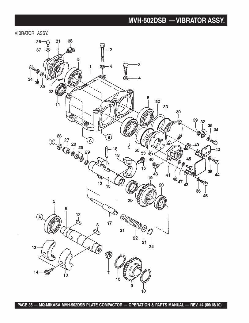
MVH-502DSB — VIBRATOR ASSY.
VIBRATOR ASSY.
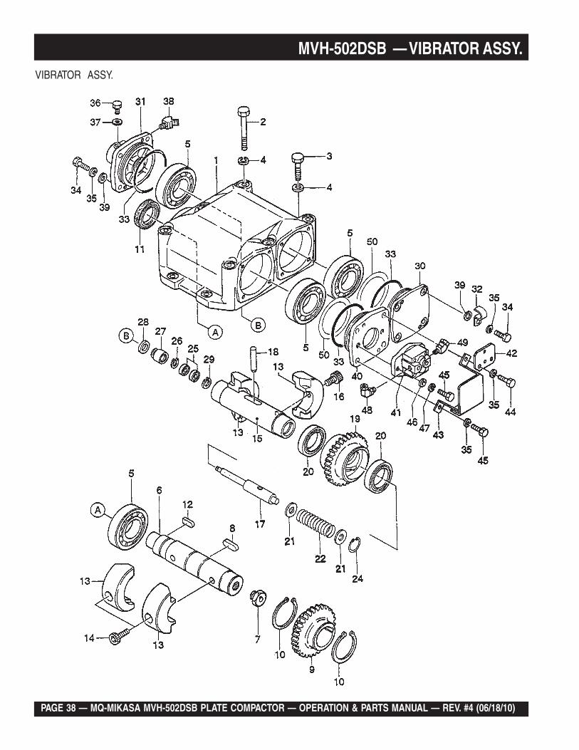
NO. PART NO. PART NAME QTY. REMARKS1 457112460 VIBRATING CASE 12 001221470 BOLT 14X150 T 63 001221450 BOLT 14X50 T 44 030214350 WASHER, LOCK M14 105 047920060 ROLLER BEARING NJ310MC4 46 457212410 ROTARY SHAFT, DRIVE 17 457445831 ADAPTER, PUMP ( 30L ) 18 951405370 KEY 15X10X39 RR 19 456327150 GEAR, DRIVE 110 080200550 STOP RING S- 55 211 060105030 OIL SEAL SB- 50729 112 951404970 KEY 12X8X30 R 113 457333720 ECCENTRIC ROTOR 414 009120301 SOCKET HEAD BOLT 16X40 T 215 456337670 ROTARY SHAFT, DRIVEN 116 009120302 SOCKET HEAD BOLT 16X30 T 217 456337380 PISTON ROD 118 456010010 KNOCK PIN 10X70 119 456327120 GEAR, DRIVEN 120 040006911 BEARING 6911 221 455435020 COLLAR 17X30X3 222 456451280 SPRING 3.2- 26.3- 102L 124 080100300 STOP RING R- 30 125 042506000 BEARING 6000ZZSG 2
PAGE 38 — MQ-MIKASA MVH-502DSB PLATE COMPACTOR — OPERATION & PARTS MANUAL — REV. #4 (06/18/10)
MVH-502DSB — VIBRATOR ASSY.VIBRATOR ASSY.
MQ-MIKASA MVH-502DSB PLATE COMPACTOR — OPERATION & PARTS MANUAL — REV. #4 (06/18/10) — PAGE 39
MVH-502DSB — VIBRATOR ASSY. (CONTINUED)
VIBRATOR ASSY.
NO. PART NO. PART NAME QTY. REMARKS26 080200100 STOP RING S- 10 127 455435051 PISTON, 22.4D 128 455010070 PACKING USH- 22.4X30X5 129 080100260 STOP RING R-26 130 456327130 BEARING COVER 131 456210646 CYLINDER ( R) ( AC) 132 954405550 CLAMP 15 R 133 050101050 O- RING G- 105 334 001221025 BOLT 10X25 T 735 030210250 WASHER, LOCK M10 1236 001220812 BOLT 8X12 T 137 953404600 COPPER PACKING 8X16X2 138 455010020 ELBOW 45 15- 0404 139 031110160 WASHER, FLAT M10 740 457332430 FLANGE, PUMP 141 457010010 PUMP FBL 142 457445840 BRACKET, CLAMP 143 457212420 PUMP COVER 144 001221035 BOLT 10X35 T 245 001221030 BOLT 10X30 T 546 952405540 WASHER 10.5- 22- 3 247 030210250 WASHER, LOCK M10 248 954010140 ELBOW 90 UES90G02G02 149 954001780 ELBOW 45 PF3/8- PF1/4 150 952405470 SHIM 90X110X0.5 2
PAGE 40 — MQ-MIKASA MVH-502DSB PLATE COMPACTOR — OPERATION & PARTS MANUAL — REV. #4 (06/18/10)
MVH-502DSB — HYDRAULIC SYSTEM ASSY.
HYDRAULIC SYSTEM ASSY.
MQ-MIKASA MVH-502DSB PLATE COMPACTOR — OPERATION & PARTS MANUAL — REV. #4 (06/18/10) — PAGE 41
MVH-502DSB — HYDRAULIC SYSTEM ASSY.
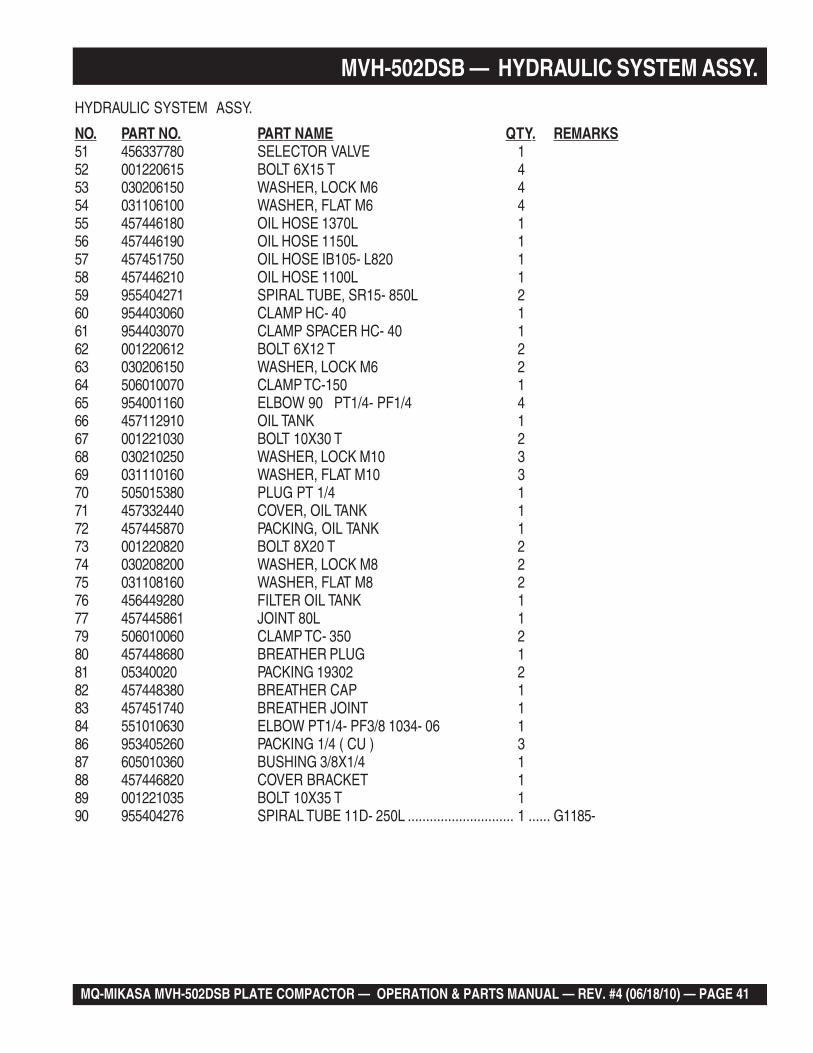
HYDRAULIC SYSTEM ASSY.
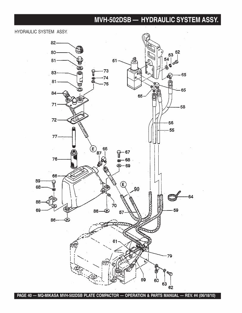
NO. PART NO. PART NAME QTY. REMARKS51 456337780 SELECTOR VALVE 152 001220615 BOLT 6X15 T 453 030206150 WASHER, LOCK M6 454 031106100 WASHER, FLAT M6 455 457446180 OIL HOSE 1370L 156 457446190 OIL HOSE 1150L 157 457451750 OIL HOSE IB105- L820 158 457446210 OIL HOSE 1100L 159 955404271 SPIRAL TUBE, SR15- 850L 260 954403060 CLAMP HC- 40 161 954403070 CLAMP SPACER HC- 40 162 001220612 BOLT 6X12 T 263 030206150 WASHER, LOCK M6 264 506010070 CLAMP TC-150 165 954001160 ELBOW 90 PT1/4- PF1/4 466 457112910 OIL TANK 167 001221030 BOLT 10X30 T 268 030210250 WASHER, LOCK M10 369 031110160 WASHER, FLAT M10 370 505015380 PLUG PT 1/4 171 457332440 COVER, OIL TANK 172 457445870 PACKING, OIL TANK 173 001220820 BOLT 8X20 T 274 030208200 WASHER, LOCK M8 275 031108160 WASHER, FLAT M8 276 456449280 FILTER OIL TANK 177 457445861 JOINT 80L 179 506010060 CLAMP TC- 350 280 457448680 BREATHER PLUG 181 05340020 PACKING 19302 282 457448380 BREATHER CAP 183 457451740 BREATHER JOINT 184 551010630 ELBOW PT1/4- PF3/8 1034- 06 186 953405260 PACKING 1/4 ( CU ) 387 605010360 BUSHING 3/8X1/4 188 457446820 COVER BRACKET 189 001221035 BOLT 10X35 T 190 955404276 SPIRAL TUBE 11D- 250L ............................. 1 ...... G1185-
PAGE 42 — MQ-MIKASA MVH-502DSB PLATE COMPACTOR — OPERATION & PARTS MANUAL — REV. #4 (06/18/10)
MVH-502DSB — CONTROL ASSY.
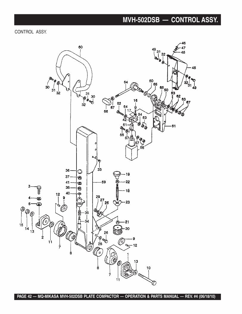
CONTROL ASSY.
MQ-MIKASA MVH-502DSB PLATE COMPACTOR — OPERATION & PARTS MANUAL — REV. #4 (06/18/10) — PAGE 43
MVH-502DSB — CONTROL ASSY.CONTROL ASSY.
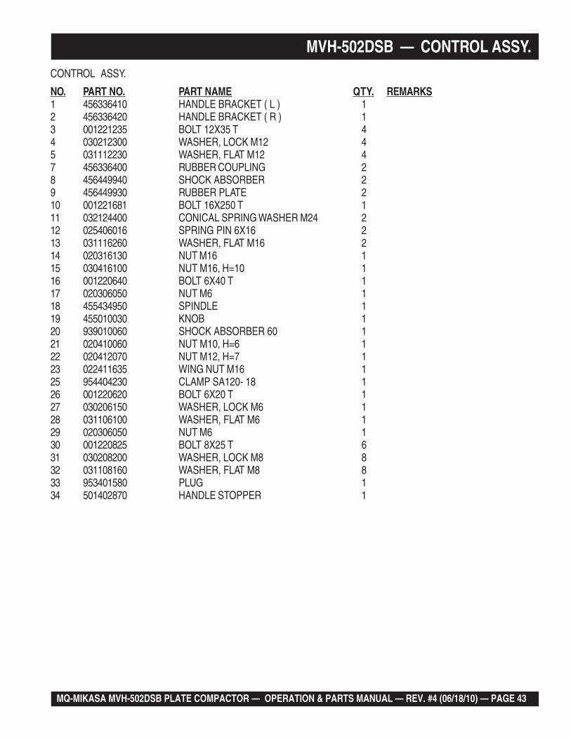
NO. PART NO. PART NAME QTY. REMARKS1 456336410 HANDLE BRACKET ( L ) 12 456336420 HANDLE BRACKET ( R ) 13 001221235 BOLT 12X35 T 44 030212300 WASHER, LOCK M12 45 031112230 WASHER, FLAT M12 47 456336400 RUBBER COUPLING 28 456449940 SHOCK ABSORBER 29 456449930 RUBBER PLATE 210 001221681 BOLT 16X250 T 111 032124400 CONICAL SPRING WASHER M24 212 025406016 SPRING PIN 6X16 213 031116260 WASHER, FLAT M16 214 020316130 NUT M16 115 030416100 NUT M16, H=10 116 001220640 BOLT 6X40 T 117 020306050 NUT M6 118 455434950 SPINDLE 119 455010030 KNOB 120 939010060 SHOCK ABSORBER 60 121 020410060 NUT M10, H=6 122 020412070 NUT M12, H=7 123 022411635 WING NUT M16 125 954404230 CLAMP SA120- 18 126 001220620 BOLT 6X20 T 127 030206150 WASHER, LOCK M6 128 031106100 WASHER, FLAT M6 129 020306050 NUT M6 130 001220825 BOLT 8X25 T 631 030208200 WASHER, LOCK M8 832 031108160 WASHER, FLAT M8 833 953401580 PLUG 134 501402870 HANDLE STOPPER 1
PAGE 44 — MQ-MIKASA MVH-502DSB PLATE COMPACTOR — OPERATION & PARTS MANUAL — REV. #4 (06/18/10)
MVH-502DSB — CONTROL ASSY.
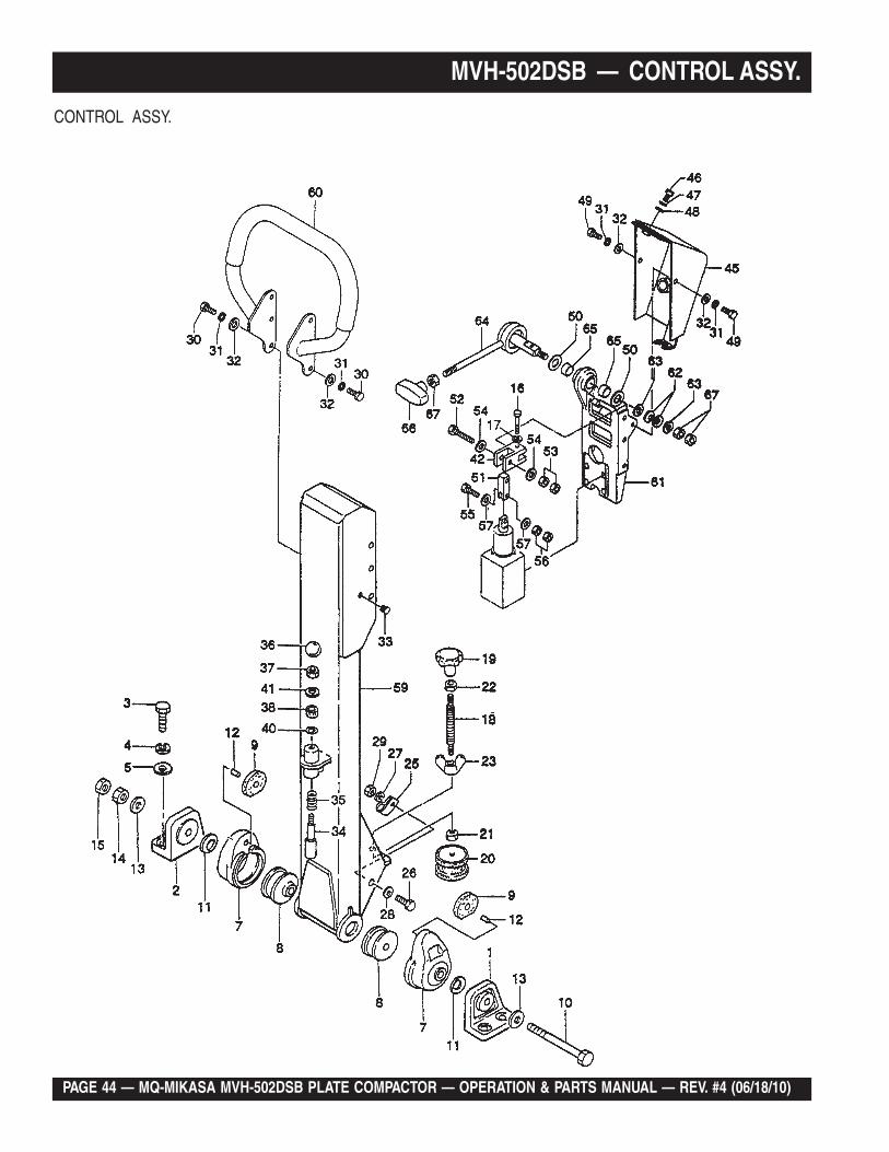
CONTROL ASSY.
MQ-MIKASA MVH-502DSB PLATE COMPACTOR — OPERATION & PARTS MANUAL — REV. #4 (06/18/10) — PAGE 45
MVH-502DSB — CONTROL ASSY. (CONTINUED)CONTROL ASSY.
NO. PART NO. PART NAME QTY. REMARKS35 501402880 SPRING/ HANDLE ( 1.4X18X44 ) 136 959403460 BALL GRIP 32D- M10 137 020410060 NUT M10, H=6 138 456449980 RUBBER PACKING 9D- 20D- 5T 140 953405260 PACKING 1/4 ( CU ) 141 031110160 WASHER, FLAT M10 142 456450760 JOINT 145 457214910 LEVER BRACKET 146 001220820 BOLT 8X20 T 147 030208200 WASHER, LOCK M8 148 031108160 WASHER, FLAT M8 149 001220815 BOLT 8X15 T 250 033910020 THRUST WASHER 20- 36- 1.5T 251 457445910 CLEVIS 152 001220850 BOLT 8X50 T 153 020308060 NUT M8 254 031108160 WASHER, FLAT M8 255 001220630 BOLT 6X30 T 156 020306050 NUT M6 257 031106100 WASHER, FLAT M6 259 457116030 HANDLE 160 456214220 HANDLE GRIP 160 456214222 HANDLE GRIP 161 456214210 VALVE BRACKET 162 032112220 CONICAL SPRING WASHER M12 263 456451400 WASHER 12.2- 27- 0.6T 264 456337400 TRAVEL LEVER 165 608010090 BUSHING MB2015DU 266 457332480 GRIP, TRAVEL LEVER 00 167 020412070 NUT M12, H=7 3
PAGE 46 — MQ-MIKASA MVH-502DSB PLATE COMPACTOR — OPERATION & PARTS MANUAL — REV. #4 (06/18/10)
MVH-502DSB — BATTERY ASSY.
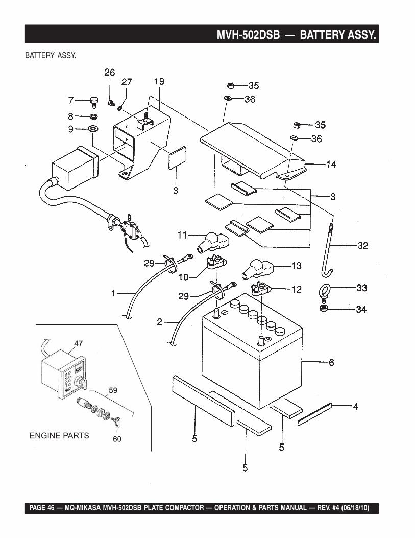
BATTERY ASSY.
MQ-MIKASA MVH-502DSB PLATE COMPACTOR — OPERATION & PARTS MANUAL — REV. #4 (06/18/10) — PAGE 47
MVH-502DSB — BATTERY ASSY.BATTERY ASSY.
NO. PART NO. PART NAME QTY. REMARKS1 456438080 BATTERY CORD () 370L 12 456438090 BATTERY CORD (+) 200L 13 959406070 RUBBER PLATE 3- 50- 60 64 456447580 RUBBER PLATE (D) 15X130X3 15 456447600 RUBBER PLATE 50X240X10 36 955010070 BATTERY (DC22-NF) 17 001221020 BOLT 10X20 T 28 030210250 WASHER, LOCK M10 29 031110160 WASHER, FLAT M10 210 955404130 BATTERY TERMINAL , BE511 111 955300220 TERMINAL COVER ( BLACK) 112 955404140 BATTERY TERMINAL + , BE513 113 955300210 TERMINAL COVER ( RED) 114 457115960 BATTERY COVER 119 457214900 SWITCH BOX 126 001220625 BOLT 6X25 T 327 030206150 WASHER, LOCK M6 329 454010020 CLAMP TC- 100 232 457452700 BATTERY BOLT 133 959403830 EYE BOLT M10X18 134 020310080 NUT M10 135 022710809 NYLON NUT M8 236 031108160 WASHER, FLAT M8 247 01551802 INSTRUMENT BOX 12V 159 50384401 SWITCH, KEY A, Y/ID81 160 50404900 IGNITION SWITCH KEY 1
PAGE 48 — MQ-MIKASA MVH-502DSB PLATE COMPACTOR — OPERATION & PARTS MANUAL — REV. #4 (06/18/10)
MVH-502DSB — THROTTLE ASSY.
THROTTLETHROTTLE ASSY.
MQ-MIKASA MVH-502DSB PLATE COMPACTOR — OPERATION & PARTS MANUAL — REV. #4 (06/18/10) — PAGE 49
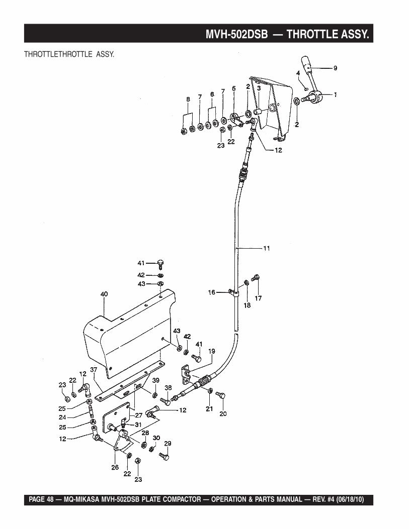
MVH-502DSB — THROTTLE ASSY.
THROTTLETHROTTLE ASSY.
NO. PART NO. PART NAME QTY. REMARKS1 456337690 THROTTLE LEVER 12 953402930 COPPER PACKING 19X30X1 23 509010130 BUSHING MB1825DU 14 951401431 KEY 5X5X8 15 457446840 THROTTLE LEVER 16 032112220 CONICAL SPRING WASHER M12 27 031112230 WASHER, FLAT M12 28 020412070 NUT M12, H= 7 29 959403840 BAR GRIP, I.D. 12MM 111 457333760 CABLE AY 33075E1400 112 457010070 ROD END PBL- 6 416 954404100 CLAMP CLA0 117 001220610 BOLT 6X10 T 118 030206150 WASHER, LOCK M6 119 457333730 CABLE SUPPORT ( E/G ) 502 120 001220820 BOLT 8X20 T 221 030208200 WASHER, LOCK M8 222 030206150 WASHER, LOCK M6 423 020306050 NUT M6 424 457446860 LINK ARM 125 020306050 NUT M6 226 457333740 LINK LEVER 127 457333750 LINK BRACELET 128 952402610 WASHER 8.5X25X3 129 001220825 BOLT 8X25 T 130 030208200 WASHER, LOCK M8 131 301010090 GREASE FITTING - PT1/8 137 457212920 COVER BRACKET 138 001220820 BOLT 8X20 T 239 030208200 WASHER, LOCK M8 240 457112930 SIDE COVER 141 001220815 BOLT 8X15 T 642 030208200 WASHER, LOCK M8 643 031108160 WASHER, FLAT M8 6
PAGE 50 — MQ-MIKASA MVH-502DSB PLATE COMPACTOR — OPERATION & PARTS MANUAL — REV. #4 (06/18/10)
HATZ 1D81S ENGINE — CRANKCASE ASSY.
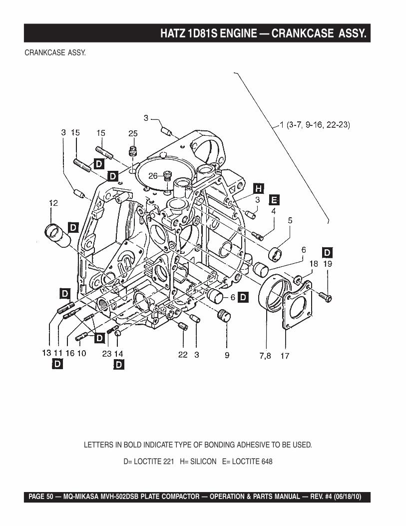
CRANKCASE ASSY.
LETTERS IN BOLD INDICATE TYPE OF BONDING ADHESIVE TO BE USED.
D= LOCTITE 221 H= SILICON E= LOCTITE 648
MQ-MIKASA MVH-502DSB PLATE COMPACTOR — OPERATION & PARTS MANUAL — REV. #4 (06/18/10) — PAGE 51
HATZ 1D81S ENGINE — CRANKCASE ASSY.
CRANKCASE ASSY.
NO. PART NO. PART NAME QTY. REMARKS1 01249051 CRANKCASE ...................................... 1 ........ INCLUDES ITEMS W/*3* 50249101 CYL. PIN 6/20 44* 03793900 NOZZLE 15* 03793800 BEARING BUSH 16* 03794000 PLUG 1..27* 03793700 MAIN BEARING 18 04033700 MAIN BEARING -O.5 19* 04000800 PLUG 110* 50144300 STUD M 6X16 211* 03794510 STUD 112* 03794800 INTERMEDIATE PIECE 113* 50098300 STUD 8 X 20 214* 50325500 COVER 10 115* 50037800 STUD M 8 X 22 816* 50328200 STUD M 16 X 22 217 04011650 THRUST PLATE 118 04069500 SHIM 1.05 0..419 04062010 HEX SCREW M 9 X 28 422* 50357700 GRUB SCREW M 8 X 10 123* 04087400 STUD M 6 X 22 125 04084500 SEALING RING 226 04084500 SEALING RING 2
PAGE 52 — MQ-MIKASA MVH-502DSB PLATE COMPACTOR — OPERATION & PARTS MANUAL — REV. #4 (06/18/10)
HATZ 1D81S ENGINE — CRANKCASE ASSY. (EXTERNAL PARTS)
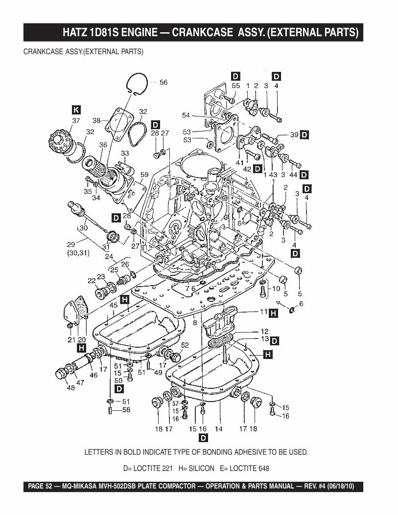
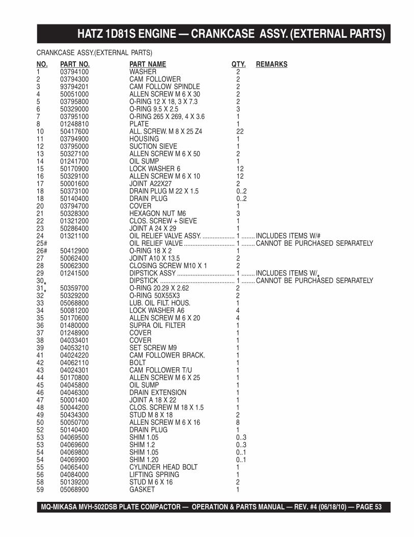
CRANKCASE ASSY.(EXTERNAL PARTS)
LETTERS IN BOLD INDICATE TYPE OF BONDING ADHESIVE TO BE USED.
D= LOCTITE 221 H= SILICON E= LOCTITE 648
MQ-MIKASA MVH-502DSB PLATE COMPACTOR — OPERATION & PARTS MANUAL — REV. #4 (06/18/10) — PAGE 53
HATZ 1D81S ENGINE — CRANKCASE ASSY. (EXTERNAL PARTS)CRANKCASE ASSY.(EXTERNAL PARTS)
NO. PART NO. PART NAME QTY. REMARKS1 03794100 WASHER 22 03794300 CAM FOLLOWER 23 93794201 CAM FOLLOW SPINDLE 24 50051000 ALLEN SCREW M 6 X 30 25 03795800 O-RING 12 X 18, 3 X 7.3 26 50329000 O-RING 9.5 X 2.5 37 03795100 O-RING 265 X 269, 4 X 3.6 18 01248810 PLATE 110 50417600 ALL. SCREW. M 8 X 25 Z4 2211 03794900 HOUSING 112 03795000 SUCTION SIEVE 113 50327100 ALLEN SCREW M 6 X 50 214 01241700 OIL SUMP 115 50170900 LOCK WASHER 6 1216 50329100 ALLEN SCREW M 6 X 10 1217 50001600 JOINT A22X27 218 50373100 DRAIN PLUG M 22 X 1.5 0..218 50140400 DRAIN PLUG 0..220 03794700 COVER 121 50328300 HEXAGON NUT M6 322 01321200 CLOS. SCREW + SIEVE 123 50286400 JOINT A 24 X 29 124 01321100 OIL RELIEF VALVE ASSY. ................... 1 ........ INCLUDES ITEMS W/#25# OIL RELIEF VALVE .............................. 1 ........ CANNOT BE PURCHASED SEPARATELY26# 50412900 O-RING 18 X 2 127 50062400 JOINT A10 X 13.5 228 50062300 CLOSING SCREW M10 X 1 229 01241500 DIPSTICK ASSY .................................. 1 ........ INCLUDES ITEMS W/*30* DIPSTICK ............................................ 1 ........ CANNOT BE PURCHASED SEPARATELY31* 50359700 O-RING 20.29 X 2.62 232 50329200 O-RING 50X55X3 233 05068800 LUB. OIL FILT. HOUS. 134 50081200 LOCK WASHER A6 435 50170600 ALLEN SCREW M 6 X 20 436 01480000 SUPRA OIL FILTER 137 01248900 COVER 138 04033401 COVER 139 04053210 SET SCREW M9 141 04024220 CAM FOLLOWER BRACK. 142 04062110 BOLT 143 04024301 CAM FOLLOWER T/U 144 50170800 ALLEN SCREW M 6 X 25 145 04045800 OIL SUMP 146 04046300 DRAIN EXTENSION 147 50001400 JOINT A 18 X 22 148 50044200 CLOS. SCREW M 18 X 1.5 149 50434300 STUD M 8 X 18 250 50050700 ALLEN SCREW M 6 X 16 852 50140400 DRAIN PLUG 153 04069500 SHIM 1.05 0..353 04069600 SHIM 1.2 0..354 04069800 SHIM 1.05 0..154 04069900 SHIM 1.20 0..155 04065400 CYLINDER HEAD BOLT 156 04084000 LIFTING SPRING 158 50139200 STUD M 6 X 16 259 05068900 GASKET 1
PAGE 54 — MQ-MIKASA MVH-502DSB PLATE COMPACTOR — OPERATION & PARTS MANUAL — REV. #4 (06/18/10)
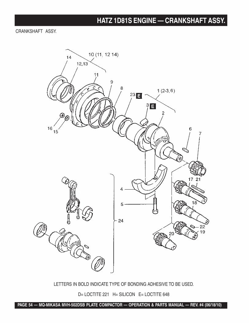
HATZ 1D81S ENGINE — CRANKSHAFT ASSY.CRANKSHAFT ASSY.
LETTERS IN BOLD INDICATE TYPE OF BONDING ADHESIVE TO BE USED.
D= LOCTITE 221 H= SILICON E= LOCTITE 648
MQ-MIKASA MVH-502DSB PLATE COMPACTOR — OPERATION & PARTS MANUAL — REV. #4 (06/18/10) — PAGE 55
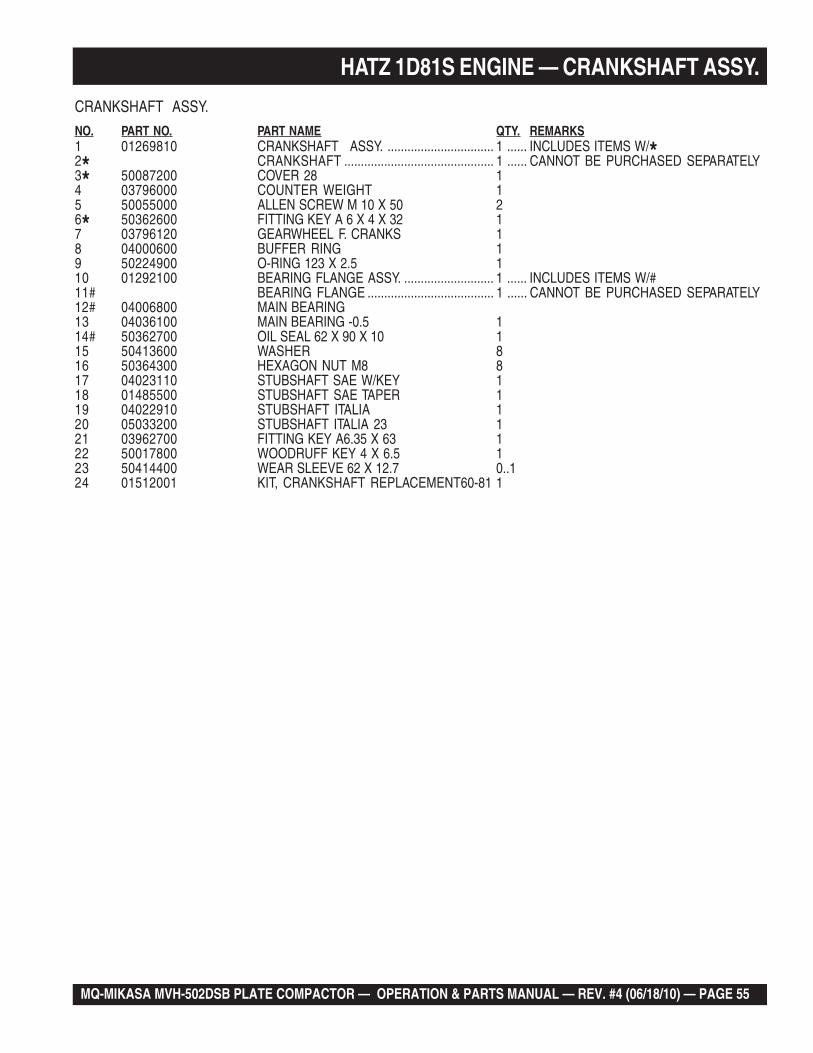
CRANKSHAFT ASSY.
NO. PART NO. PART NAME QTY. REMARKS1 01269810 CRANKSHAFT ASSY. ................................ 1 ...... INCLUDES ITEMS W/*2* CRANKSHAFT ............................................. 1 ...... CANNOT BE PURCHASED SEPARATELY3* 50087200 COVER 28 14 03796000 COUNTER WEIGHT 15 50055000 ALLEN SCREW M 10 X 50 26* 50362600 FITTING KEY A 6 X 4 X 32 17 03796120 GEARWHEEL F. CRANKS 18 04000600 BUFFER RING 19 50224900 O-RING 123 X 2.5 110 01292100 BEARING FLANGE ASSY. ........................... 1 ...... INCLUDES ITEMS W/#11# BEARING FLANGE ...................................... 1 ...... CANNOT BE PURCHASED SEPARATELY12# 04006800 MAIN BEARING13 04036100 MAIN BEARING -0.5 114# 50362700 OIL SEAL 62 X 90 X 10 115 50413600 WASHER 816 50364300 HEXAGON NUT M8 817 04023110 STUBSHAFT SAE W/KEY 118 01485500 STUBSHAFT SAE TAPER 119 04022910 STUBSHAFT ITALIA 120 05033200 STUBSHAFT ITALIA 23 121 03962700 FITTING KEY A6.35 X 63 122 50017800 WOODRUFF KEY 4 X 6.5 123 50414400 WEAR SLEEVE 62 X 12.7 0..124 01512001 KIT, CRANKSHAFT REPLACEMENT60-81 1
HATZ 1D81S ENGINE — CRANKSHAFT ASSY.
PAGE 56 — MQ-MIKASA MVH-502DSB PLATE COMPACTOR — OPERATION & PARTS MANUAL — REV. #4 (06/18/10)
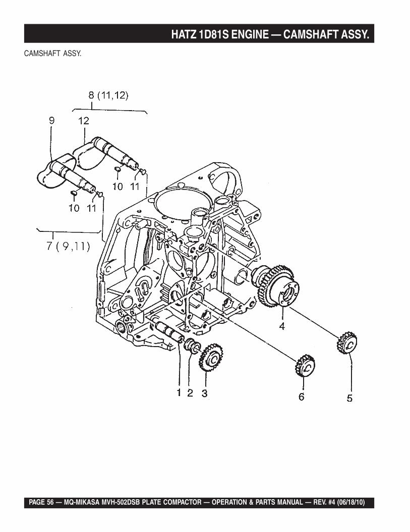
HATZ 1D81S ENGINE — CAMSHAFT ASSY.CAMSHAFT ASSY.
MQ-MIKASA MVH-502DSB PLATE COMPACTOR — OPERATION & PARTS MANUAL — REV. #4 (06/18/10) — PAGE 57
HATZ 1D81S ENGINE — CAMSHAFT ASSY.
CAMSHAFT ASSY.
NO. PART NO. PART NAME QTY. REMARKS1 03796400 SHAFT 22 03796500 BUSH 23 01242000 GEARWHEEL 24 04099900 CAMSHAFT 15 03796800 GEARWHEEL 16 03796900 GEARWHEEL 17 01267300 SHAFT, PUMP SIDE ............................ 1 ........ INCLUDES ITEMS W/*8 01267200 SHAFT STARTER SIDE...................... 1 ........ INCLUDES ITEMS W/#9* COUNTER BALANCE ......................... 1 ........ CANNOT BE PURCHASED SEPARATELY10 50324900 WOODRUFF KEY 3 X 3.7 211*# PIN ....................................................... 2 ........ CANNOT BE PURCHASED SEPARATELY12# COUNTERBALANCE ......................... 1 ........ CANNOT BE PURCHASED SEPARATELY
PAGE 58 — MQ-MIKASA MVH-502DSB PLATE COMPACTOR — OPERATION & PARTS MANUAL — REV. #4 (06/18/10)
HATZ 1D81S ENGINE — PISTON/RINGS ASSY.
PISTON/RINGS ASSY.
MQ-MIKASA MVH-502DSB PLATE COMPACTOR — OPERATION & PARTS MANUAL — REV. #4 (06/18/10) — PAGE 59
HATZ 1D81S ENGINE — PISTON/RINGS ASSY.
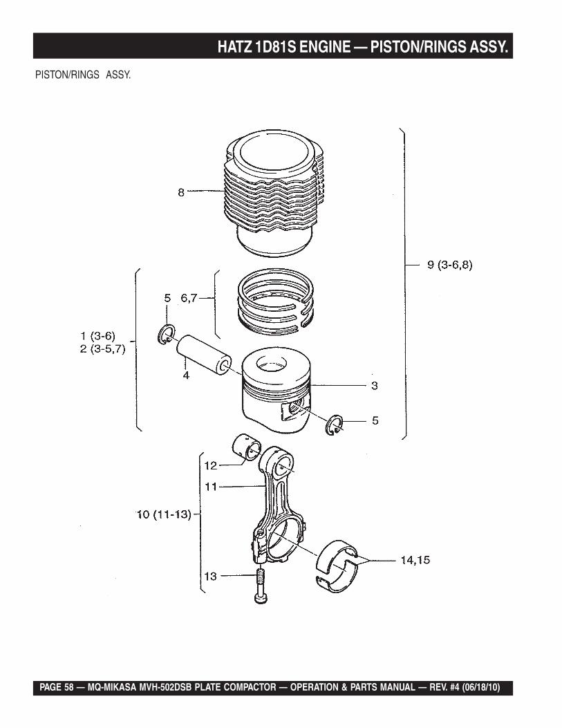
PISTON/RINGS ASSY.
NO. PART NO. PART NAME QTY. REMARKS1 01243901 PISTON ASSY. STD. ................................ 1 .............. INCLUDES ITEMS W/*1 01313510 PISTON ASSY. OVERSIZED ................... 1 .............. INCLUDES ITEMS W/*2 01265101 PISTON ASSY. 100+0.5 ........................... 1 .............. INCLUDES ITEMS W/#2 01265201 PISTON ASSY. 100+1.0 ........................... 1 .............. INCLUDES ITEMS W/#2 01314610 PISTON ASSY. 100+0.5 .......................... 1 .............. INCLUDES ITEMS W/#2 01314710 PISTON ASSY. 100+1.0 ........................... 1 .............. INCLUDES ITEMS W/#3*#+ PISTON .................................................... 1 .............. CANNOT BE PURCHASED SEPARATELY4*#+ 50353600 WRIST PIN 15*#+ 50020800 CIRCLIP 30 X 1.2 26*+ 01247300 PISTON RING SET 100 17# 01264500 PISTON RING SET +0.5 17# 01265000 PISTON RING SET +1.0 18+ CYLINDER ............................................... 1 .............. CANNOT BE PURCHASED SEPARATELY9 01508301 CYLINDER ASSY. W/ PISTON ............... 1 .............. INCLUDES ITEMS W/+10 01244001 CONROD ASSY. ..................................... 1 .............. INCLUDES ITEMS W/%11% CONROD ................................................. 1 .............. CANNOT BE PURCHASED SEPARATELY12% 04032200 BUSH FOR CONROD 113% 04001800 CONROD SCREW 214 04001900 BIG END BEARING 115 04033100 ROD BEARING -0.5 1
PAGE 60 — MQ-MIKASA MVH-502DSB PLATE COMPACTOR — OPERATION & PARTS MANUAL — REV. #4 (06/18/10)
HATZ 1D81S ENGINE — CYLINDER HEAD ASSY.
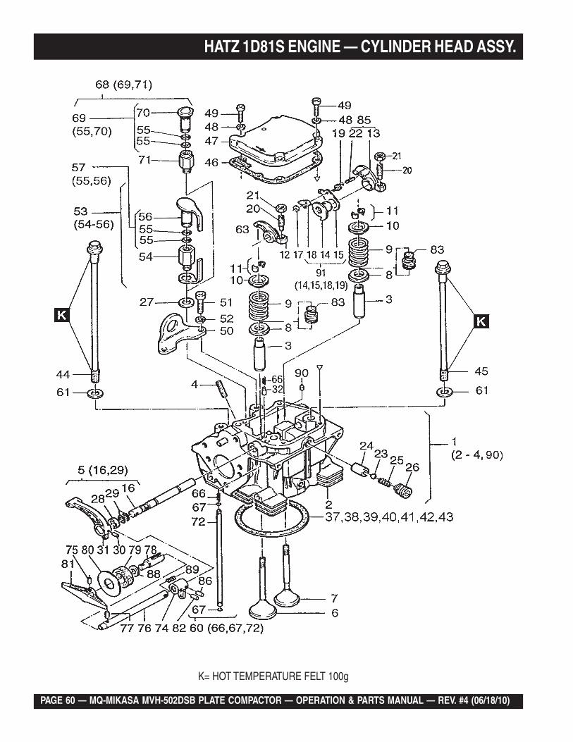
K= HOT TEMPERATURE FELT 100g
MQ-MIKASA MVH-502DSB PLATE COMPACTOR — OPERATION & PARTS MANUAL — REV. #4 (06/18/10) — PAGE 61
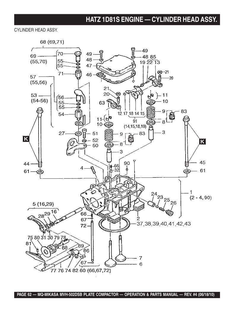
HATZ 1D81S ENGINE — CYLINDER HEAD ASSY.
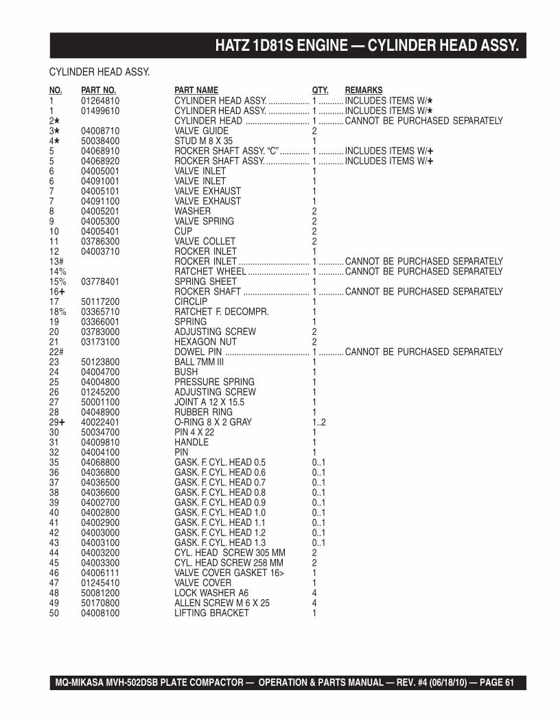
CYLINDER HEAD ASSY.
NO. PART NO. PART NAME QTY. REMARKS1 01264810 CYLINDER HEAD ASSY. .................. 1 ........... INCLUDES ITEMS W/*1 01499610 CYLINDER HEAD ASSY. .................. 1 ........... INCLUDES ITEMS W/*2* CYLINDER HEAD ............................ 1 ........... CANNOT BE PURCHASED SEPARATELY3* 04008710 VALVE GUIDE 24* 50038400 STUD M 8 X 35 15 04068910 ROCKER SHAFT ASSY. “C” ............. 1 ........... INCLUDES ITEMS W/+5 04068920 ROCKER SHAFT ASSY. ................... 1 ........... INCLUDES ITEMS W/+6 04005001 VALVE INLET 16 04091001 VALVE INLET 17 04005101 VALVE EXHAUST 17 04091100 VALVE EXHAUST 18 04005201 WASHER 29 04005300 VALVE SPRING 210 04005401 CUP 211 03786300 VALVE COLLET 212 04003710 ROCKER INLET 113# ROCKER INLET ............................... 1 ........... CANNOT BE PURCHASED SEPARATELY14% RATCHET WHEEL ........................... 1 ........... CANNOT BE PURCHASED SEPARATELY15% 03778401 SPRING SHEET 116+ ROCKER SHAFT ............................. 1 ........... CANNOT BE PURCHASED SEPARATELY17 50117200 CIRCLIP 118% 03365710 RATCHET F. DECOMPR. 119 03366001 SPRING 120 03783000 ADJUSTING SCREW 221 03173100 HEXAGON NUT 222# DOWEL PIN ..................................... 1 ........... CANNOT BE PURCHASED SEPARATELY23 50123800 BALL 7MM III 124 04004700 BUSH 125 04004800 PRESSURE SPRING 126 01245200 ADJUSTING SCREW 127 50001100 JOINT A 12 X 15.5 128 04048900 RUBBER RING 129+ 40022401 O-RING 8 X 2 GRAY 1..230 50034700 PIN 4 X 22 131 04009810 HANDLE 132 04004100 PIN 135 04068800 GASK. F. CYL. HEAD 0.5 0..136 04036800 GASK. F. CYL. HEAD 0.6 0..137 04036500 GASK. F. CYL. HEAD 0.7 0..138 04036600 GASK. F. CYL. HEAD 0.8 0..139 04002700 GASK. F. CYL. HEAD 0.9 0..140 04002800 GASK. F. CYL. HEAD 1.0 0..141 04002900 GASK. F. CYL. HEAD 1.1 0..142 04003000 GASK. F. CYL. HEAD 1.2 0..143 04003100 GASK. F. CYL. HEAD 1.3 0..144 04003200 CYL. HEAD SCREW 305 MM 245 04003300 CYL. HEAD SCREW 258 MM 246 04006111 VALVE COVER GASKET 16> 147 01245410 VALVE COVER 148 50081200 LOCK WASHER A6 449 50170800 ALLEN SCREW M 6 X 25 450 04008100 LIFTING BRACKET 1
PAGE 62 — MQ-MIKASA MVH-502DSB PLATE COMPACTOR — OPERATION & PARTS MANUAL — REV. #4 (06/18/10)
HATZ 1D81S ENGINE — CYLINDER HEAD ASSY.CYLINDER HEAD ASSY.
MQ-MIKASA MVH-502DSB PLATE COMPACTOR — OPERATION & PARTS MANUAL — REV. #4 (06/18/10) — PAGE 63
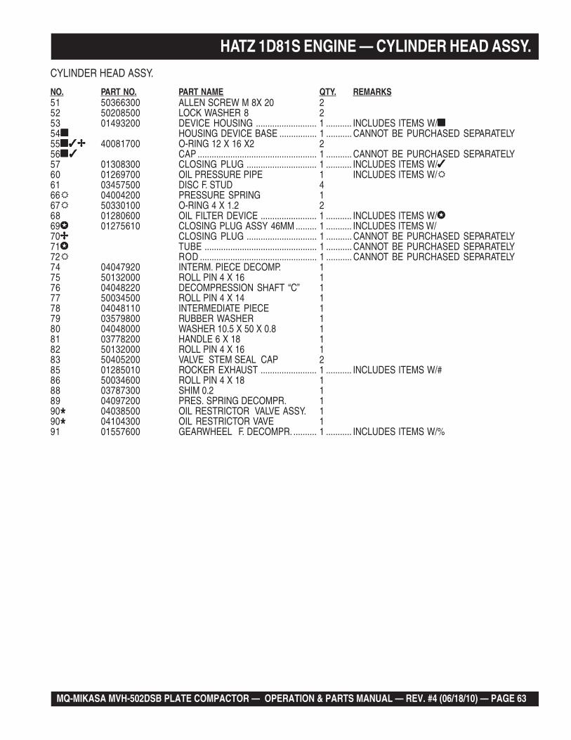
CYLINDER HEAD ASSY.
NO. PART NO. PART NAME QTY. REMARKS51 50366300 ALLEN SCREW M 8X 20 252 50208500 LOCK WASHER 8 253 01493200 DEVICE HOUSING .......................... 1 ........... INCLUDES ITEMS W/■■■■■54■■■■■ HOUSING DEVICE BASE ................ 1 ........... CANNOT BE PURCHASED SEPARATELY55■✓✢■✓✢■✓✢■✓✢■✓✢ 40081700 O-RING 12 X 16 X2 256■✓■✓■✓■✓■✓ CAP ................................................... 1 ........... CANNOT BE PURCHASED SEPARATELY57 01308300 CLOSING PLUG .............................. 1 ........... INCLUDES ITEMS W/✓✓✓✓✓60 01269700 OIL PRESSURE PIPE 1 INCLUDES ITEMS W/61 03457500 DISC F. STUD 466 04004200 PRESSURE SPRING 167 50330100 O-RING 4 X 1.2 268 01280600 OIL FILTER DEVICE ........................ 1 ........... INCLUDES ITEMS W/✪✪✪✪✪69✪✪✪✪✪ 01275610 CLOSING PLUG ASSY 46MM ......... 1 ........... INCLUDES ITEMS W/70✢✢✢✢✢ CLOSING PLUG .............................. 1 ........... CANNOT BE PURCHASED SEPARATELY71✪✪✪✪✪ TUBE ................................................ 1 ........... CANNOT BE PURCHASED SEPARATELY72 ROD .................................................. 1 ........... CANNOT BE PURCHASED SEPARATELY74 04047920 INTERM. PIECE DECOMP. 175 50132000 ROLL PIN 4 X 16 176 04048220 DECOMPRESSION SHAFT “C” 177 50034500 ROLL PIN 4 X 14 178 04048110 INTERMEDIATE PIECE 179 03579800 RUBBER WASHER 180 04048000 WASHER 10.5 X 50 X 0.8 181 03778200 HANDLE 6 X 18 182 50132000 ROLL PIN 4 X 16 183 50405200 VALVE STEM SEAL CAP 285 01285010 ROCKER EXHAUST ........................ 1 ........... INCLUDES ITEMS W/#86 50034600 ROLL PIN 4 X 18 188 03787300 SHIM 0.2 189 04097200 PRES. SPRING DECOMPR. 190* 04038500 OIL RESTRICTOR VALVE ASSY. 190* 04104300 OIL RESTRICTOR VAVE 191 01557600 GEARWHEEL F. DECOMPR. .......... 1 ........... INCLUDES ITEMS W/%
HATZ 1D81S ENGINE — CYLINDER HEAD ASSY.
PAGE 64 — MQ-MIKASA MVH-502DSB PLATE COMPACTOR — OPERATION & PARTS MANUAL — REV. #4 (06/18/10)
HATZ 1D81S ENGINE — FLYWHEEL ASSY.
FLYWHEEL ASSY.
MQ-MIKASA MVH-502DSB PLATE COMPACTOR — OPERATION & PARTS MANUAL — REV. #4 (06/18/10) — PAGE 65
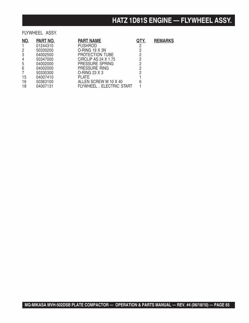
HATZ 1D81S ENGINE — FLYWHEEL ASSY.
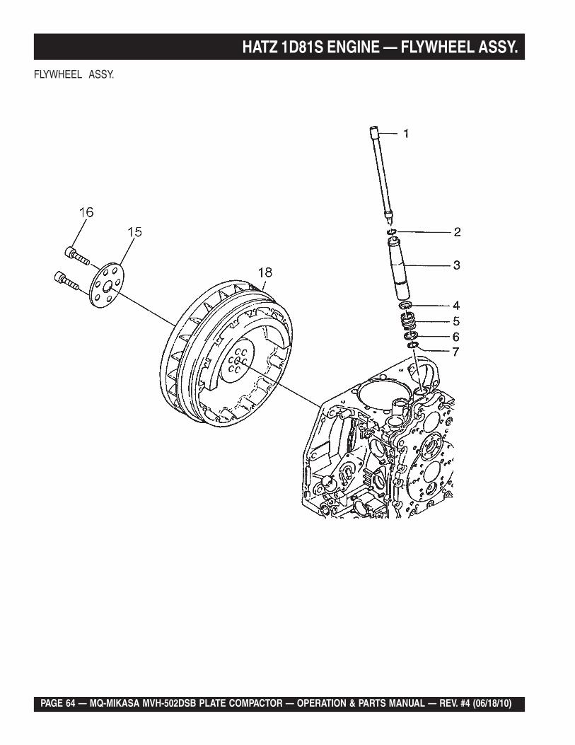
FLYWHEEL ASSY.
NO. PART NO. PART NAME QTY. REMARKS1 01244310 PUSHROD 22 50330200 O-RING 19 X 3N 23 04002500 PROTECTION TUBE 24 50347000 CIRCLIP AS 24 X 1.75 25 04002000 PRESSURE SPRING 26 04002000 PRESSURE RING 27 50330300 O-RING 23 X 3 215 04007410 PLATE 116 50363100 ALLEN SCREW M 10 X 40 618 04007131 FLYWHEEL , ELECTRIC START 1
PAGE 66 — MQ-MIKASA MVH-502DSB PLATE COMPACTOR — OPERATION & PARTS MANUAL — REV. #4 (06/18/10)
HATZ 1D81S ENGINE — OIL PUMP ASSY.
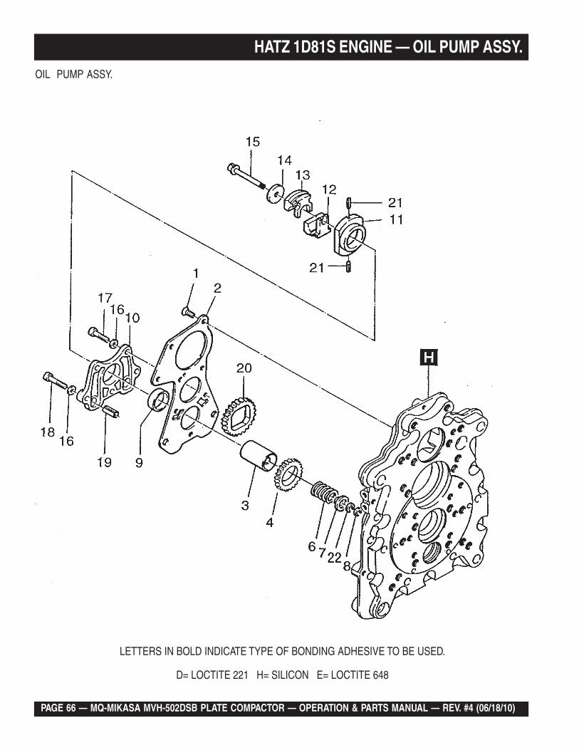
OIL PUMP ASSY.
LETTERS IN BOLD INDICATE TYPE OF BONDING ADHESIVE TO BE USED.
D= LOCTITE 221 H= SILICON E= LOCTITE 648
MQ-MIKASA MVH-502DSB PLATE COMPACTOR — OPERATION & PARTS MANUAL — REV. #4 (06/18/10) — PAGE 67
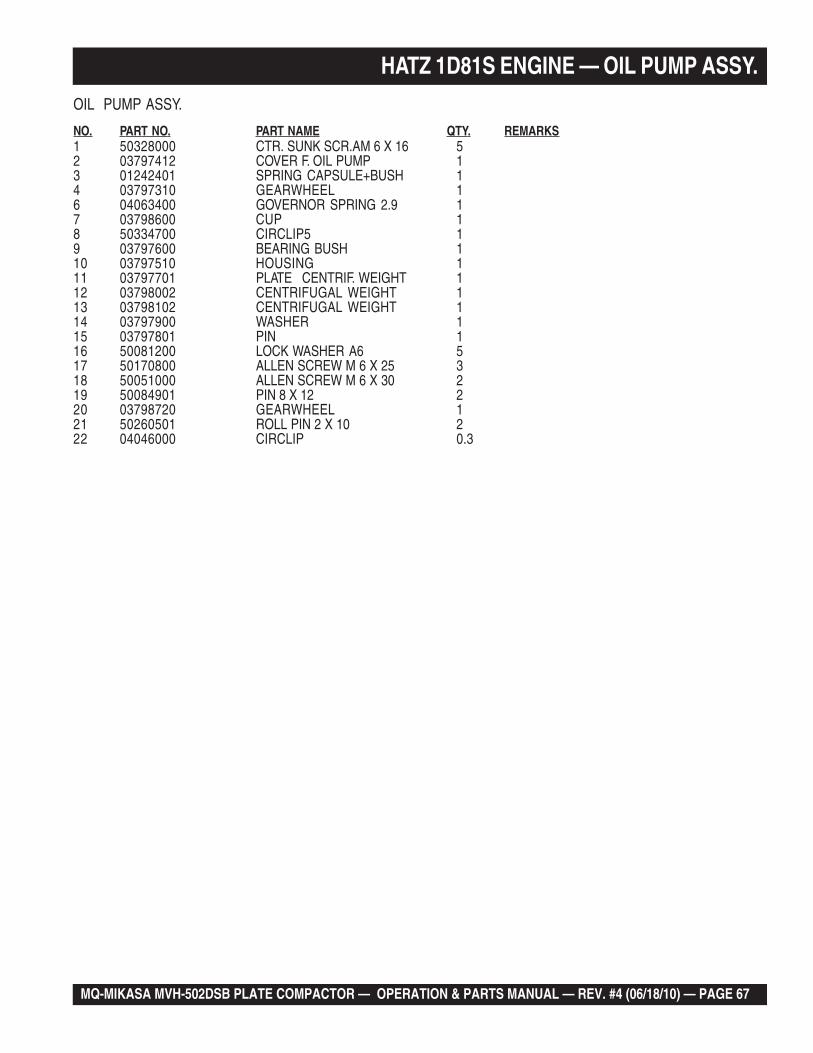
HATZ 1D81S ENGINE — OIL PUMP ASSY.
OIL PUMP ASSY.
NO. PART NO. PART NAME QTY. REMARKS1 50328000 CTR. SUNK SCR.AM 6 X 16 52 03797412 COVER F. OIL PUMP 13 01242401 SPRING CAPSULE+BUSH 14 03797310 GEARWHEEL 16 04063400 GOVERNOR SPRING 2.9 17 03798600 CUP 18 50334700 CIRCLIP5 19 03797600 BEARING BUSH 110 03797510 HOUSING 111 03797701 PLATE CENTRIF. WEIGHT 112 03798002 CENTRIFUGAL WEIGHT 113 03798102 CENTRIFUGAL WEIGHT 114 03797900 WASHER 115 03797801 PIN 116 50081200 LOCK WASHER A6 517 50170800 ALLEN SCREW M 6 X 25 318 50051000 ALLEN SCREW M 6 X 30 219 50084901 PIN 8 X 12 220 03798720 GEARWHEEL 121 50260501 ROLL PIN 2 X 10 222 04046000 CIRCLIP 0.3
PAGE 68 — MQ-MIKASA MVH-502DSB PLATE COMPACTOR — OPERATION & PARTS MANUAL — REV. #4 (06/18/10)
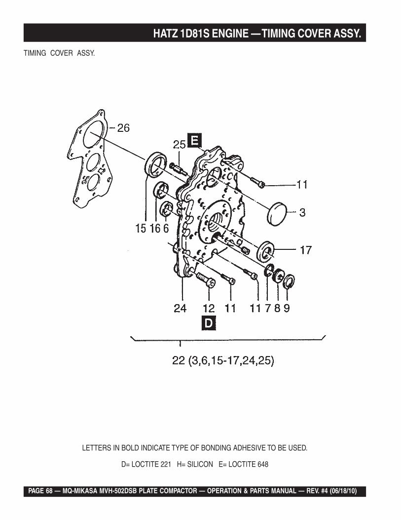
HATZ 1D81S ENGINE — TIMING COVER ASSY.
TIMING COVER ASSY.
LETTERS IN BOLD INDICATE TYPE OF BONDING ADHESIVE TO BE USED.
D= LOCTITE 221 H= SILICON E= LOCTITE 648
MQ-MIKASA MVH-502DSB PLATE COMPACTOR — OPERATION & PARTS MANUAL — REV. #4 (06/18/10) — PAGE 69
HATZ 1D81S ENGINE — TIMING COVER ASSY.
TIMING COVER ASSY.
NO. PART NO. PART NAME QTY. REMARKS3# 05325600 COVER 50 16# 03797600 BEARING BUSH 17 50330400 O-RING 27 X 2N 18 04000400 COVER 19 50399000 CIRCLIP 32 X 1.2 111 50417400 ALLEN SCREW M 8 X 30 Z3 1312 50329500 ALLEN SCREW M 12 X 40 115# 04000310 BEARING BUSH 116# 04023210 BEARING BUSH 117# 50364700 OIL SEAL 32 X 52 X 7 122 01281001 TIMING COVER ASSY. NO. 3 ............ 1 .......... INCLUDES ITEMS W/#24# TIMING COVER ................................ 1 .......... CANNOT BE PURCHASED SEPARATELY25# 04052400 NOZZLE 126 03797412 COVER F. OIL PUMP 1
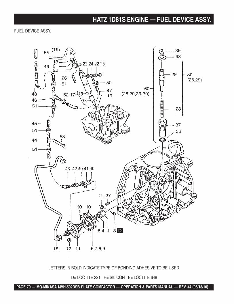
PAGE 70 — MQ-MIKASA MVH-502DSB PLATE COMPACTOR — OPERATION & PARTS MANUAL — REV. #4 (06/18/10)
HATZ 1D81S ENGINE — FUEL DEVICE ASSY.
FUEL DEVICE ASSY.
LETTERS IN BOLD INDICATE TYPE OF BONDING ADHESIVE TO BE USED.
D= LOCTITE 221 H= SILICON E= LOCTITE 648
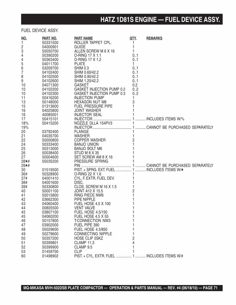
MQ-MIKASA MVH-502DSB PLATE COMPACTOR — OPERATION & PARTS MANUAL — REV. #4 (06/18/10) — PAGE 71
HATZ 1D81S ENGINE — FUEL DEVICE ASSY.FUEL DEVICE ASSY.
NO. PART NO. PART NAME QTY. REMARKS1 50331500 ROLLER TAPPET CPL. 12 04000901 GUIDE 13 50050700 ALLEN SCREW M 6 X 16 14 50390200 O-RING 17 X 1.1 0..14 50363400 O-RING 17 X 1.2 0..15 04011700 PLATE 16 03209700 SHIM 0.3 0..17 04102400 SHIM 0.60/42.2 0..18 04102500 SHIM 0.90/42.2 0..19 04102600 SHIM 1.20/42.2 0..110 04071300 GASKET 0.210 04102200 GASKET INJECTION PUMP 0.2 0..210 04102300 GASKET INJECTION PUMP 0.3 0..211 50416200 INJECTION PUMP 113 50148000 HEXAGON NUT M8 315 01313600 FUEL PRESSURE PIPE 116 04025800 JOINT WASHER 116 40085001 INJECTOR SEAL 117 50415101 INJECTOR........................................ 1 ........... INCLUDES ITEMS W/%18% 50415200 NOZZLE DLLA 154PV3 119% INJECTOR........................................ 1 ........... CANNOT BE PURCHASED SEPARATELY20 03792400 FLANGE 121 04035700 WASHER 122 50000800 COPPER WASHER 224 50333400 BANJO UNION 125 50313000 BANJO BOLT M6 126 50038400 STUD M 8 X 35 127 50004600 SET SCREW AM 8 X 16 128*# 05035200 PRESSURE SPRING 129*# PIN .................................................... 1 ........... CANNOT BE PURCHASED SEPARATELY30 01519500 PIST. + SPRG. EXT. FUEL ................ 1 ........... INCLUDES ITEMS W/*36# 50328900 O-RING 22 X 1.6 137# 04001410 CYL. F. EXTR. FUEL DEV. 138# 04001600 DISC. 139# 50330800 CLOS. SCREW M 16 X 1.5 140 50001100 JOINT A12 X 15.5 241 50015800 RING PIECE NW6 142 03662300 PIPE NIPPLE 143 04060400 FUEL HOSE 4.5 X 100 144 00805500 VENT VALVE 145 03807100 FUEL HOSE 4.5/150 145 04060200 FUEL HOSE 4.5 X 55 146 50157800 T-CONNECTION NW3 147 03902000 FUEL PIPE 390 148 05029600 FUEL HOSE 4.5/850 149 50279600 CONNECTING NIPPLE 150 50357200 HOSE CLIP 5SKZ 251 50399801 CLAMP 11.3 452 50399900 CLAMP 9.5 153 01459700 CLIP 160 01498902 PIST. + CYL. EXTR. FUEL ................ 1 ........... INCLUDES ITEMS W/#
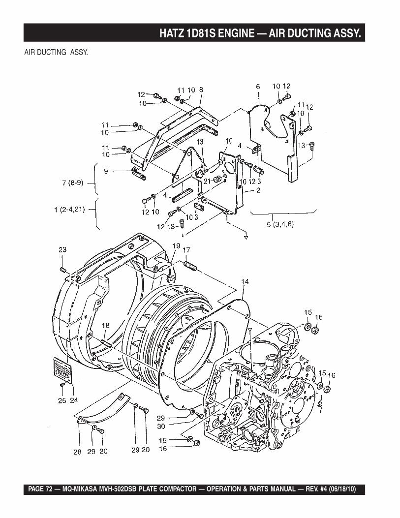
PAGE 72 — MQ-MIKASA MVH-502DSB PLATE COMPACTOR — OPERATION & PARTS MANUAL — REV. #4 (06/18/10)
HATZ 1D81S ENGINE — AIR DUCTING ASSY.
AIR DUCTING ASSY.
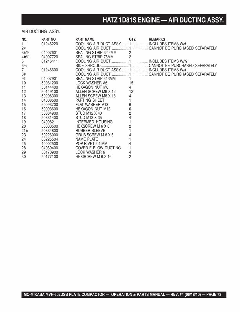
MQ-MIKASA MVH-502DSB PLATE COMPACTOR — OPERATION & PARTS MANUAL — REV. #4 (06/18/10) — PAGE 73
HATZ 1D81S ENGINE — AIR DUCTING ASSY.
AIR DUCTING ASSY.
NO. PART NO. PART NAME QTY. REMARKS1 01246220 COOLING AIR DUCT ASSY .......1 ................. INCLUDES ITEMS W/*2* COOLING AIR DUCT ................. 1 ................. CANNOT BE PURCHASED SEPARATELY3*% 04007601 SEALING STRIP 32.2MM 24*% 04007720 SEALING STRIP 76MM 25 01246411 COOLING AIR DUCT ................. 1 ................. INCLUDES ITEMS W/%6% SIDE SHROUD ............................1 ................. CANNOT BE PURCHASED SEPARATELY7 01246600 COOLING AIR DUCT ASSY. .......1 ................. INCLUDES ITEMS W/#8# COOLING AIR DUCT ................. 1 ................. CANNOT BE PURCHASED SEPARATELY9# 04007901 SEALING STRIP 413MM 110 50081200 LOCK WASHER A6 1511 50144400 HEXAGON NUT M6 412 50149100 ALLEN SCREW M6 X 12 1213 50206300 ALLEN SCREW M8 X 18 414 04008500 PARTING SHEET 115 50093700 FLAT WASHER A13 616 50093600 HEXAGON NUT M12 617 50364900 STUD M12 X 40 218 50331400 STUD M12 X 35 419 04008211 INTERMED. HOUSING 120 50333500 HEXSCREW M 6 X 8 221* 50334800 RUBBER SLEEVE 123 50226000 GRUB SCREW M 8 X 6 424 03225504 NAME PLATE 125 40002500 POP RIVET 2.4 MM 428 04080400 COVER F. BLOW DUCTING 129 50170900 LOCK WASHER 6 430 50177100 HEXSCREW M 6 X 16 2
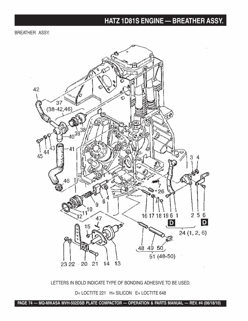
PAGE 74 — MQ-MIKASA MVH-502DSB PLATE COMPACTOR — OPERATION & PARTS MANUAL — REV. #4 (06/18/10)
HATZ 1D81S ENGINE — BREATHER ASSY.
BREATHER ASSY.
LETTERS IN BOLD INDICATE TYPE OF BONDING ADHESIVE TO BE USED.
D= LOCTITE 221 H= SILICON E= LOCTITE 648
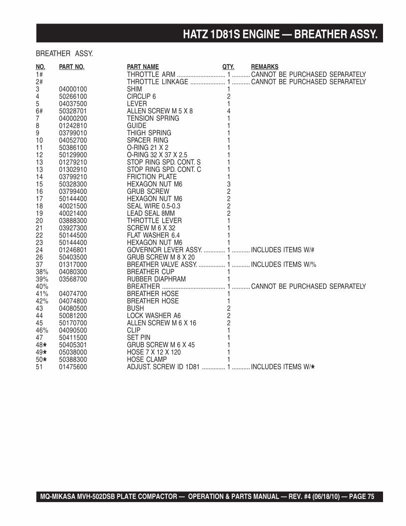
MQ-MIKASA MVH-502DSB PLATE COMPACTOR — OPERATION & PARTS MANUAL — REV. #4 (06/18/10) — PAGE 75
BREATHER ASSY.
NO. PART NO. PART NAME QTY. REMARKS1# THROTTLE ARM ............................. 1 ........... CANNOT BE PURCHASED SEPARATELY2# THROTTLE LINKAGE ..................... 1 ........... CANNOT BE PURCHASED SEPARATELY3 04000100 SHIM 14 50266100 CIRCLIP 6 25 04037500 LEVER 16# 50328701 ALLEN SCREW M 5 X 8 47 04000200 TENSION SPRING 18 01242810 GUIDE 19 03799010 THIGH SPRING 110 04052700 SPACER RING 111 50386100 O-RING 21 X 2 112 50129900 O-RING 32 X 37 X 2.5 113 01279210 STOP RING SPD. CONT. S 113 01302910 STOP RING SPD. CONT. C 114 03799210 FRICTION PLATE 115 50328300 HEXAGON NUT M6 316 03799400 GRUB SCREW 217 50144400 HEXAGON NUT M6 218 40021500 SEAL WIRE 0.5-0.3 219 40021400 LEAD SEAL 8MM 220 03888300 THROTTLE LEVER 121 03927300 SCREW M 6 X 32 122 50144500 FLAT WASHER 6.4 123 50144400 HEXAGON NUT M6 124 01246801 GOVERNOR LEVER ASSY. ............. 1 ........... INCLUDES ITEMS W/#26 50403500 GRUB SCREW M 8 X 20 137 01317000 BREATHER VALVE ASSY. ................ 1 ........... INCLUDES ITEMS W/%38% 04080300 BREATHER CUP 139% 03568700 RUBBER DIAPHRAM 140% BREATHER ...................................... 1 ........... CANNOT BE PURCHASED SEPARATELY41% 04074700 BREATHER HOSE 142% 04074800 BREATHER HOSE 143 04080500 BUSH 244 50081200 LOCK WASHER A6 245 50170700 ALLEN SCREW M 6 X 16 246% 04090500 CLIP 147 50411500 SET PIN 148* 50405301 GRUB SCREW M 6 X 45 149* 05038000 HOSE 7 X 12 X 120 150* 50388300 HOSE CLAMP 151 01475600 ADJUST. SCREW ID 1D81 .............. 1 ........... INCLUDES ITEMS W/*
HATZ 1D81S ENGINE — BREATHER ASSY.
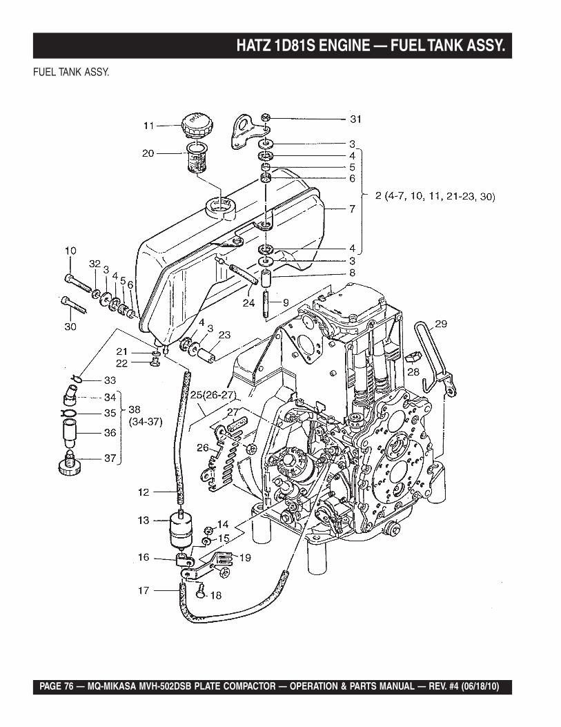
PAGE 76 — MQ-MIKASA MVH-502DSB PLATE COMPACTOR — OPERATION & PARTS MANUAL — REV. #4 (06/18/10)
HATZ 1D81S ENGINE — FUEL TANK ASSY.
FUEL TANK ASSY.
MQ-MIKASA MVH-502DSB PLATE COMPACTOR — OPERATION & PARTS MANUAL — REV. #4 (06/18/10) — PAGE 77
HATZ 1D81S ENGINE — FUEL TANK ASSY.
FUEL TANK ASSY.
NO. PART NO. PART NAME QTY. REMARKS2 01494200 FUEL TANK ASSY ( 7 LTRS.) ................. 1 ............ INCLUDES ITEMS W/#3 05097600 WASHER 124# 03981802 RUBBER WASHER 125# 03981701 BUSH 8.4 X 13 X 7.5 66# 03981900 RUBBER SHELL 67# FUEL TANK ............................................. 1 ............ CANNOT BE PURCHASED SEPARATELY8 03989800 BUSH 8.5 X 20 X 49 29 50377001 STUD M 8 X 75 210# 50177500 ALLEN SCREW M 8 X 40 411# 50385800 CAP, FUEL TANK 112 03801200 FUEL HOSE 7/220 113 50478800 FUEL FILTER ......................................... 1 ............ REPLACES 4008940114 50144400 HEXAGON NUT M6 115 50144500 FLAT WASHER 6.4 116 03165500 PIPE CLIP 117 03493600 FUEL HOSE 7/330 118 50165500 HEXSCREW M 6 X 12 119 05031900 GUARD 120 50387300 SIEVE 121# 50001000 JOINT A 10 X 16 122# 50359800 HEXSCREW M 10 X 12 123# 05029200 BUSH 9 X 18 X 8 424 03663700 FUEL PIPE L W 4.5 X 50 125 01490300 PROTEC. GUARD TOP.......................... 1 ............ INCLUDES ITEMS W/%26% FINGER GUARD .................................... 1 ............ CANNOT BE PURCHASED SEPARATELY27% 04030901 SEALING STRIP 29 MM 128 03150900 CLAMP 129 01402200 GUARD 130# 50183000 ALLEN SCREW M 8 X 35 431 50148000 HEXAGON NUT M8 232 50208500 LOCK WASHER 8 433 05045300 CLAMP 21 MM 134* 05044001 HOSE 10/12 MM 135* 05036900 HOSE CLIP 136* 05043900 WATER SEPARATOR 137* 50414800 CLOS. SCREW M 10 138 01519401 WATER SEPARATOR............................. 1 ............ INCLUDES ITEMS W/*
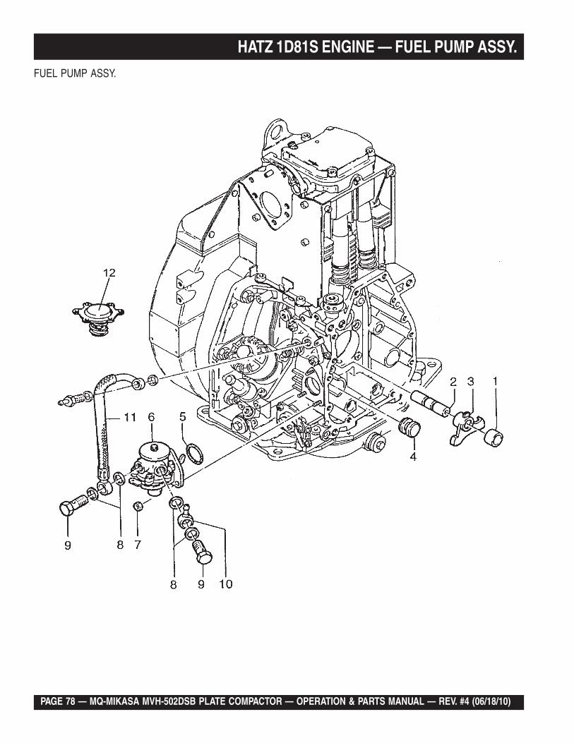
PAGE 78 — MQ-MIKASA MVH-502DSB PLATE COMPACTOR — OPERATION & PARTS MANUAL — REV. #4 (06/18/10)
HATZ 1D81S ENGINE — FUEL PUMP ASSY.FUEL PUMP ASSY.
MQ-MIKASA MVH-502DSB PLATE COMPACTOR — OPERATION & PARTS MANUAL — REV. #4 (06/18/10) — PAGE 79
FUEL PUMP ASSY.
NO. PART NO. PART NAME QTY. REMARKS1 04011900 BUSH 12 03796400 SHAFT 13 04011801 LEVER F. FEED PUMP 14 04000800 PLUG 15 50331800 O-RING 16 50332301 FUEL FEED PUMP 17 50328300 HEXAGON NUT M6 38 50001200 JOINT A 14 X 18 49 50006400 BANJO BOLT A8 210 50015900 RING PIECE N W 8 111 01468801 FUEL PIPE 112 49062501 DIAPHRAM 1
HATZ 1D81S ENGINE — FUEL PUMP ASSY.
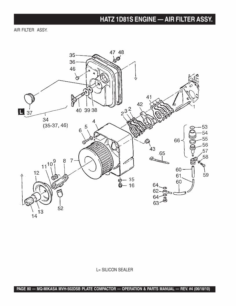
PAGE 80 — MQ-MIKASA MVH-502DSB PLATE COMPACTOR — OPERATION & PARTS MANUAL — REV. #4 (06/18/10)
HATZ 1D81S ENGINE — AIR FILTER ASSY.
L= SILICON SEALER
AIR FILTER ASSY.
MQ-MIKASA MVH-502DSB PLATE COMPACTOR — OPERATION & PARTS MANUAL — REV. #4 (06/18/10) — PAGE 81
HATZ 1D81S ENGINE — AIR FILTER ASSY.
AIR FILTER ASSY.
NO. PART NO. PART NAME QTY. REMARKS1 50038900 STUD M 8 X 60 22 04006300 GASKET 23 04006200 INSULATING FLANGE 14 04004312 AIRFILTER HOUSING 15 50095100 LOCK WASHER A8 16 50398400 CYLINDER HEAD BOLT 17 01493000 AIR FILTER 18 01483400 RETAINING STRAP 19 50148100 FLAT WASHER 8.4 210 50129500 HEXAGON NUT M8 211 50412000 CIRCLIP 10 X 1 112 05036400 CENTERING COVER 113 05039300 BUSH 33 X 35 X 23.5 114 03579400 SEALING RING 115 50062400 JOINT A 10 X 13.5 116 50062300 CLOSING SCREW M 10 X 1 134 01496800 COVER AIRFILTER ............................. 1 ........ INCLUDES ITEMS W/*35* 04047701 SEALING STRIP LG 704 137* 05039401 CLOSING CAP 136* CLOSING COVER............................... 1 ........ CANNOT BE PURCHASED SEPARATELY38 03814100 INSULATING DISC 139 05038700 WASHER 11 X 36 X 3 140 01490800 WING SCREW 141 01287900 GASKET AIRFILTER 142 04047300 INTERMEDIATE FLANGE 143 50395700 COVER 15 146* 50411900 CLOSING PLUG 7 247 50120000 DISC A 6.4 248 40028300 HEXAGON NUT M 6 252 05033500 VALVE PLATE 153# 05044501 INDIC. PLATE 154# 05043601 RUBBER CAP 155# 05045600 SIGNAL RING 156# 05043700 ADAPTER 157 50173500 PIPE CLIP 158 50170900 LOCK WASHER 6 159 50170600 ALLEN SCREW M 6 X 20 160 03961400 FUEL HOSE 3.51-50 261 05043800 HOSE 2 X 4 X 170 162 50159500 RING PIECE N W 4 463 50006200 BANJO BOLT A 4 164 50062400 JOINT A 10 X 13.5 265 50358400 STRAP 166 01499800 MAINT. INDICATOR ............................ 1 ........ INCLUDES ITEMS W/#
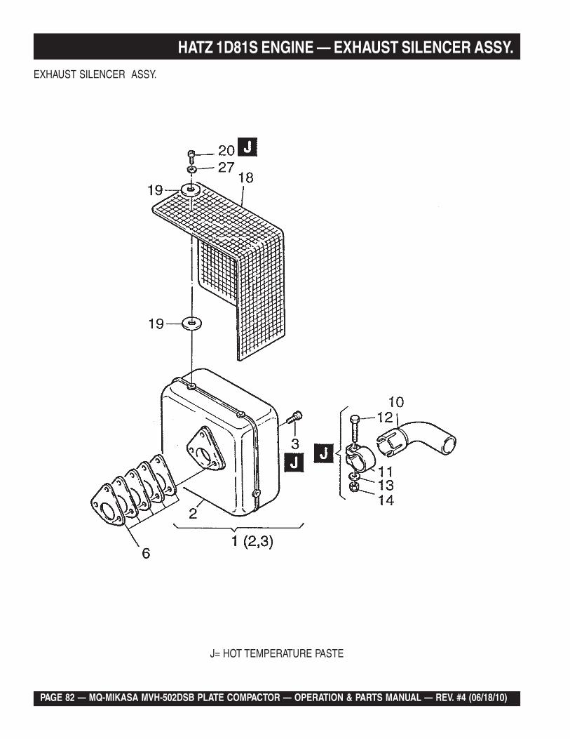
PAGE 82 — MQ-MIKASA MVH-502DSB PLATE COMPACTOR — OPERATION & PARTS MANUAL — REV. #4 (06/18/10)
HATZ 1D81S ENGINE — EXHAUST SILENCER ASSY.
J= HOT TEMPERATURE PASTE
EXHAUST SILENCER ASSY.
MQ-MIKASA MVH-502DSB PLATE COMPACTOR — OPERATION & PARTS MANUAL — REV. #4 (06/18/10) — PAGE 83
EXHAUST SILENCER ASSY.
NO. PART NO. PART NAME QTY. REMARKS1 01498800 EXHAUST SILENCER S ASSY. ......... 1 .......... INCLUDES ITEMS W/*2* EXHAUST SILENCER ....................... 1 .......... CANNOT BE PURCHASED SEPARATELY3* 50404000 ALLEN SCREW M 8 X 30 36 01471110 GASKET SET EXHAUST SIL. 110 03877300 ELBOW 111 03877700 PIPE CLIP 52.5 112 50249500 HEX SCREW M 10 X 50 113 50145900 FLAT WASHER 10.5 114 40028600 HEX NUT M 10 116 03997100 EXHAUST TUBE 118 01191901 MUFFLER GUARD ID 119 05034200 LOCK WASHER 1020 50255700 ALLEN SCREW M 6 X 12 5
HATZ 1D81S ENGINE — EXHAUST SILENCER ASSY.
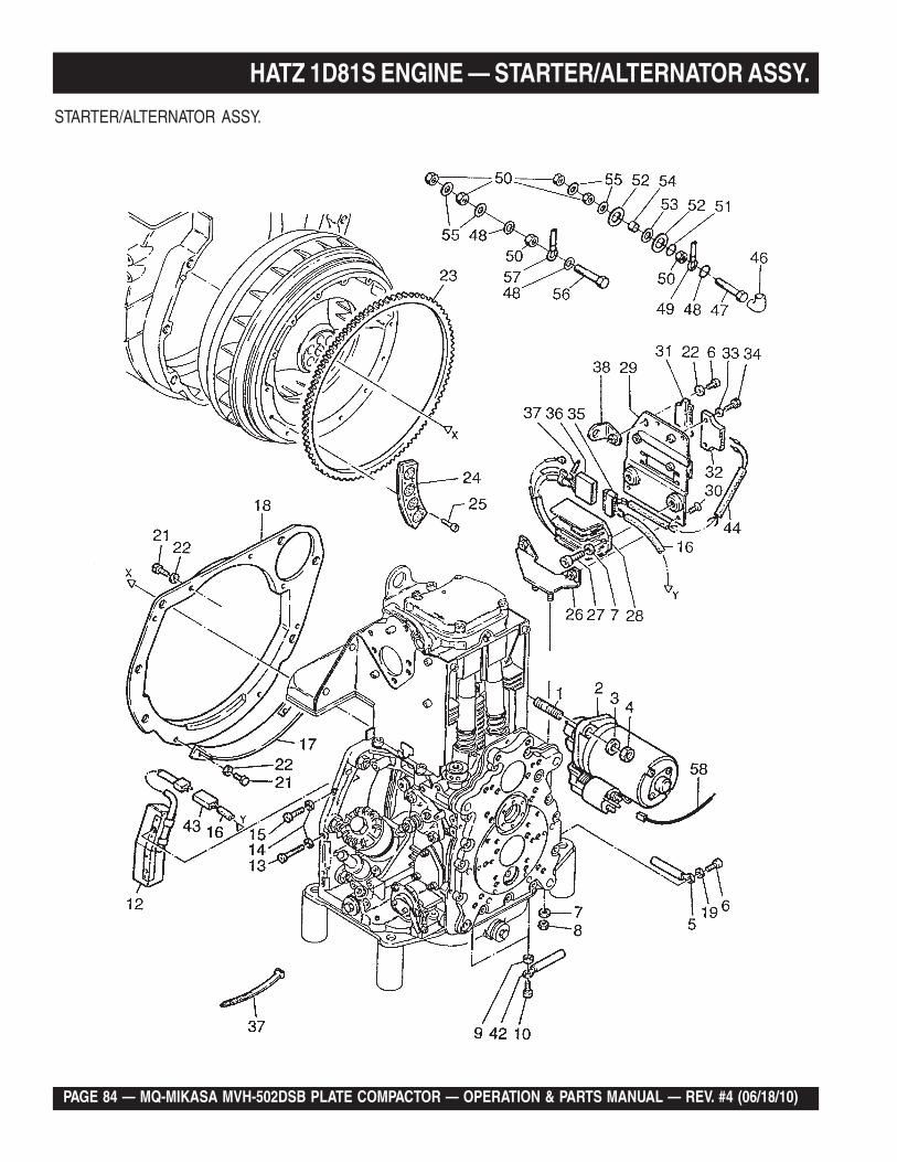
PAGE 84 — MQ-MIKASA MVH-502DSB PLATE COMPACTOR — OPERATION & PARTS MANUAL — REV. #4 (06/18/10)
HATZ 1D81S ENGINE — STARTER/ALTERNATOR ASSY.
STARTER/ALTERNATOR ASSY.
MQ-MIKASA MVH-502DSB PLATE COMPACTOR — OPERATION & PARTS MANUAL — REV. #4 (06/18/10) — PAGE 85
HATZ 1D81S ENGINE — STARTER/ALTERNATOR ASSY.
STARTER/ALTERNATOR ASSY.
NO. PART NO. PART NAME QTY. REMARKS1 50201200 STUD M 12 X 50 22 50353420 STARTER 12 V 10 TOOTH 13 50093700 FLAT WASHER A 13 24 50380600 HEXAGON NUT M 12 25 01459700 CLIP 26 50149100 ALLEN SCREW M 6 X 12 27 50208500 LOCK WASHER 8 48 50148000 HEXAGON NUT M 8 29 04021000 BUSH 6.3 X 12.15 X 5 210 50170700 ALLEN SCREW M 6 X 16 212 01439000 COIL WITH WIRE 12 V 113 50401200 ALLEN SCREW M 6 X 35 114 50165600 LOCK WASHER 215 50236600 ALLEN SCREW M 6 X 25 116 01462800 ELECTRIC WIRE 117 04021100 PROTECT. ALTERNATOR 118 04009920 PARTING SHEET 119 50144500 FLAT WASHER 6.4 121 50165500 HEXSCREW M 6 X 12 522 50170900 LOCK WASHER 6 623 04021210 GEAR RING 123 TEETH 124 04020421 MAGNET SEGMENT 725 50397100 ALLEN SCREW M 4 X 10 1426 01440300 SUPPORT 127 50165400 ALLEN SCREW M 8 X 16 228 01248121 REGULATOR 12 V 128 01425021 REGULATOR 24 V 129 01440100 FASTENING PLATE 130 50380800 CTR. SUNK SCREW M 6 X 10 231 50373700 PLUG SLEEVE HOUSING 132 50373600 PIN TERM. HOUSING 6 WAY 133 50216300 WASHER 5.3 234 50335700 HEXSCREW M 5 X 25 235 50402100 PLUG SLEEVE HOUSING 136 50402000 PLUG SLEEVE HOUSING 137 50358400 STRAP 438 01440200 SUPPORT 142 01470200 CLIP 243 50379700 PLUG SLEEVE HOUSING 144 01439400 WIRING HARNESS 146 40026600 PROTECTION CAP. RUBBER 147 50400300 HEXSCREW M 8 X 40 148 50179900 STAR WASHER 1..249 01430800 BATTERY CABLE PLUS 150 50023000 HEXAGON NUT M 8 351 50426900 SERRATED WASH. A 8.4 152 03814100 INSULATING DISC 253 50426800 TOOTH LOCK J 10.5 154 03814200 INSULATING TUBE 155 50016800 DISC 8.4 256 50275300 HEXSCREW M 8 X 35 157 01430900 BATTERY CABLE MINUS 158 01193401 ELECTRIC WIRE 1
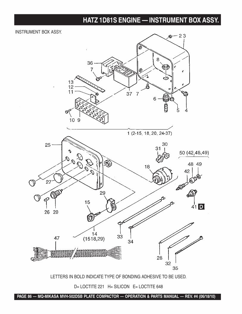
PAGE 86 — MQ-MIKASA MVH-502DSB PLATE COMPACTOR — OPERATION & PARTS MANUAL — REV. #4 (06/18/10)
HATZ 1D81S ENGINE — INSTRUMENT BOX ASSY.
INSTRUMENT BOX ASSY.
LETTERS IN BOLD INDICATE TYPE OF BONDING ADHESIVE TO BE USED.
D= LOCTITE 221 H= SILICON E= LOCTITE 648
MQ-MIKASA MVH-502DSB PLATE COMPACTOR — OPERATION & PARTS MANUAL — REV. #4 (06/18/10) — PAGE 87
HATZ 1D81S ENGINE — INSTRUMENT BOX ASSY.INSTRUMENT BOX ASSY.
NO. PART NO. PART NAME QTY. REMARKS1 01407000 INSTRUMENT BOX 12 V ................. 1 ........... INCLUDES ITEMS W/*1 01457700 INSTRUMENT BOX 24 V ................. 1 ........... INCLUDES ITEMS W/*2* 40028200 HEX. NUT M5 13* 00716311 INSRTUMENT BOX, ENCL. 14* 50289200 HEXSCREW M 6 X 12 45* 50160800 CLOSING PLUG, PLASTIC 16* 50159010 MALE CABLE COUPLING 17* 50049300 ALLEN SCREW M 5 X 10 38* 50159100 HEXAGON NUT, PLASTIC 19* 50160700 CONNECTING BLOCK 110* 50158800 ALLEN SCREW M 4 X 20 211* 03666700 BRACKET 212* 50147100 HEXAGON NUT M 4 213* 05004300 DECAL F. INST. BOX 114* 50276502 GLOW START. SWITCH .................. 1 ........... INCLUDES ITEMS W/%14 50384401 GLOW STARTSWITCH ................... 1 ........... S/N G-1185 AND ABOVE15*% 50345300 IGN. KEY DS 14603 1 S/N G-1184 AND BELOW15 50404900 IGN. KEY .......................................... 1 ........... S/N G-1185 AND ABOVE18%* KEY SWITCH (S/N G-1184) ............. 1 ........... CANNOT BE PURCHASED SEPARATELY20* 50176501 INDICATOR LAMP, BATTERY 121 50176600 INDICATOR LAMP, OIL 122 50176400 INDICATOR LAMP, TEMP. 124* 40096000 CLOSING PLUG 0..325* 03509211 INSTRU. BOX FRONT 126* 40009700 BULB 12 V 2 W 0..426* 40009800 BULB 24 V 2 W 0..427* 40091400 CLOSING PLUG, PLASTIC 0..228* 01150101 DIODE ASSY. 129*% 49050900 FLAP FOR SWITCHBOX 130* 50276600 PLUG SLEEVE HOUSING 131* 50276700 PLUG SLEEVE HOUSING 132* 01090201 DIODE ASSY. 233* 01089801 DIODE ASSY. 134* 01089901 DIODE ASSY. 135* 50358400 STRAP 136* 50276000 RELAY SOCKET 137* 50275802 MOTOR START RELAY 137* 50275902 RELAY ENG. PROT. 24 V 141 40021300 OIL PRESSURE SWITCH 142# 50268600 TEMP. SWITCH 147 01433601 WIRING HARNESS 148# 05027800 INTERMED. PIECE. TEMP 149# 50001000 JOINT A 10 X 16 150 01475200 TEMP. SWITCH 12 V “C” .................. 1 ........... INCLUDES ITEMS W/#
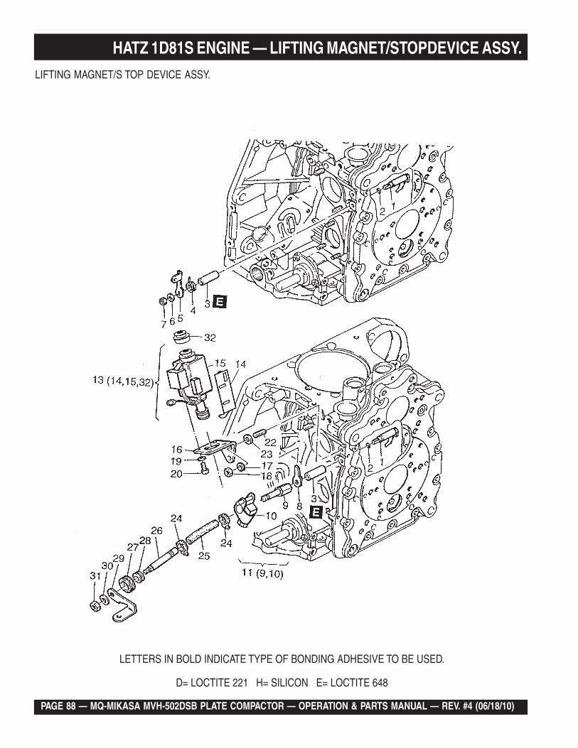
PAGE 88 — MQ-MIKASA MVH-502DSB PLATE COMPACTOR — OPERATION & PARTS MANUAL — REV. #4 (06/18/10)
HATZ 1D81S ENGINE — LIFTING MAGNET/STOPDEVICE ASSY.
LETTERS IN BOLD INDICATE TYPE OF BONDING ADHESIVE TO BE USED.
D= LOCTITE 221 H= SILICON E= LOCTITE 648
LIFTING MAGNET/S TOP DEVICE ASSY.
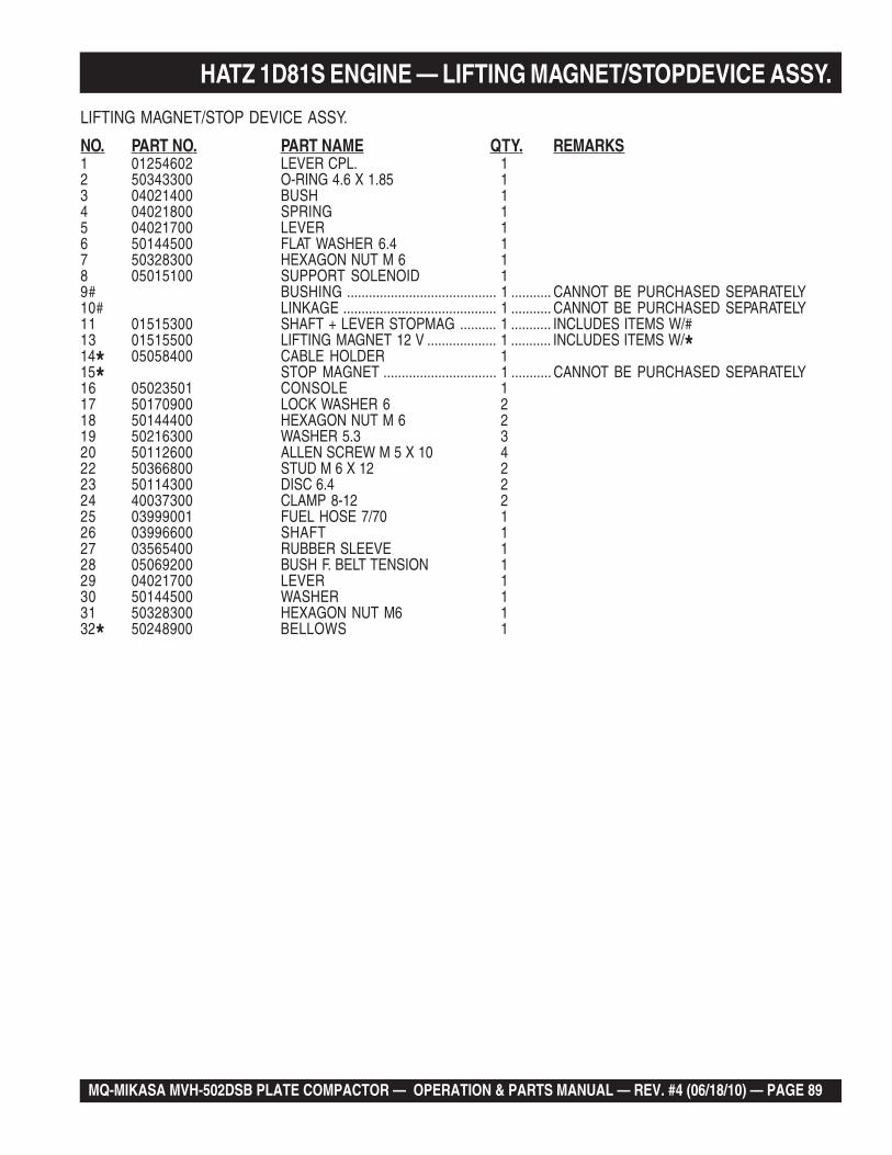
MQ-MIKASA MVH-502DSB PLATE COMPACTOR — OPERATION & PARTS MANUAL — REV. #4 (06/18/10) — PAGE 89
LIFTING MAGNET/STOP DEVICE ASSY.
NO. PART NO. PART NAME QTY. REMARKS1 01254602 LEVER CPL. 12 50343300 O-RING 4.6 X 1.85 13 04021400 BUSH 14 04021800 SPRING 15 04021700 LEVER 16 50144500 FLAT WASHER 6.4 17 50328300 HEXAGON NUT M 6 18 05015100 SUPPORT SOLENOID 19# BUSHING ......................................... 1 ........... CANNOT BE PURCHASED SEPARATELY10# LINKAGE .......................................... 1 ........... CANNOT BE PURCHASED SEPARATELY11 01515300 SHAFT + LEVER STOPMAG .......... 1 ........... INCLUDES ITEMS W/#13 01515500 LIFTING MAGNET 12 V ................... 1 ........... INCLUDES ITEMS W/*14* 05058400 CABLE HOLDER 115* STOP MAGNET ............................... 1 ........... CANNOT BE PURCHASED SEPARATELY16 05023501 CONSOLE 117 50170900 LOCK WASHER 6 218 50144400 HEXAGON NUT M 6 219 50216300 WASHER 5.3 320 50112600 ALLEN SCREW M 5 X 10 422 50366800 STUD M 6 X 12 223 50114300 DISC 6.4 224 40037300 CLAMP 8-12 225 03999001 FUEL HOSE 7/70 126 03996600 SHAFT 127 03565400 RUBBER SLEEVE 128 05069200 BUSH F. BELT TENSION 129 04021700 LEVER 130 50144500 WASHER 131 50328300 HEXAGON NUT M6 132* 50248900 BELLOWS 1
HATZ 1D81S ENGINE — LIFTING MAGNET/STOPDEVICE ASSY.
PAGE 90 — MQ-MIKASA MVH-502DSB PLATE COMPACTOR — OPERATION & PARTS MANUAL — REV. #4 (06/18/10)
TERMS AND CONDITIONS OF SALE — PARTSPAYMENT TERMSTerms of payment for parts are net 30 days.
FREIGHT POLICYAll parts orders will be shipped collect or prepaid with the charges added to the invoice. All shipments are F.O.B. point of origin. Multiquip’s responsibility ceases when a signed manifest has been obtained from the carrier, and any claim for shortage or damage must be settled between the consignee and the carrier.
MINIMUM ORDERThe minimum charge for orders from Multiquip is $15.00 net. Customers will be asked for instructions regarding handling of orders not meeting this requirement.
RETURNED GOODS POLICYReturn shipments will be accepted and credit will be allowed, subject to the following provisions:
A Returned Material Authorization 1. must be approved by Multiquip prior to shipment.
To obtain a Return Material Authorization, 2. a list must be provided to Multiquip Parts Sales that defines item numbers, quantities, and descriptions of the items to be returned.
The parts numbers and descriptions a. must match the current parts price list.
The list must be typed or computer b. generated.
The list must state the reason(s) c. for the return.
The list must reference the sales d. order (s) or invoice (s) under which the items were originally purchased.
The list must include the name e. and phone number of the person requesting the RMA.
A copy of the Return Material Authorization 3. must accompany the return shipment.
Freight is at the sender’s expense. All 4. parts must be returned freight prepaid to Multiquip’s designated receiving point.
Parts must be in new and resalable 5. condition, in the original Multiquip package (if any), and with Multiquip part numbers clearly marked.
The following items are not returnable:6.
Obsolete parts. (If an item is in the a. price book and shows as being replaced by another item, it is obsolete.)
Any parts with a limited shelf life b. (such as gaskets, seals, “O” rings, and other rubber parts) that were purchased more than six months prior to the return date.
Any line item with an extended c. dealer net price of less than $5.00.
Special order items.d.
Electrical components.e.
Paint, chemicals, and lubricants.f.
Decals and paper products.g.
Items purchased in kits.h.
The sender will be notified of any material 7. received that is not acceptable.
Such material will be held for five 8. working days from notification, pending instructions. If a reply is not received within five days, the material will be returned to the sender at his expense.
Credit on returned parts will be issued 9. at dealer net price at time of the original purchase, less a 15% restocking charge.
In cases where an item is accepted, for 10. which the original purchase document can not be determined, the price will be based on the list price that was effective twelve months prior to the RMA date.
Credit issued will be applied to future 11. purchases only.
PRICING AND REBATESPrices are subject to change without prior notice. Price changes are effective on a specific date and all orders received on or after that date will be billed at the revised price. Rebates for price declines and added charges for price increases will not be made for stock on hand at the time of any price change.
Multiquip reserves the right to quote and sell direct to Government agencies, and toOriginal Equipment Manufacturer accounts who use our products as integral parts of their own products.
SPECIAL EXPEDITING SERVICEA $35.00 surcharge will be added to the invoice for special handling including busshipments, insured parcel post or in cases where Multiquip must personally deliver the parts to the carrier.
LIMITATIONS OF SELLER’S LIABILITYMultiquip shall not be liable hereunder fordamages in excess of the purchase price of the item with respect to which damages are claimed, and in no event shall Multiquip be liable for loss of profit or good will or for any other special, consequential or incidental damages.
LIMITATION OF WARRANTIESNo warranties, express or implied, are made in connection with the sale of parts or trade accessories nor as to any engine not manufactured by Multiquip. Such warranties made in connection with the sale of new, complete units are made exclusively by a statement of warranty packaged with such units, and Multiquip neither assumes nor authorizes any person to assume for it any other obligation or liability whatever in connection with the sale of its products. Apart from such written statement of warranty, there are no warranties, express, implied or statutory, which extend beyond the description of the products on the face hereof.
Effective: February 22, 2006
MQ-MIKASA MVH-502DSB PLATE COMPACTOR — OPERATION & PARTS MANUAL — REV. #4 (06/18/10) — PAGE 91
NOTE PAGE
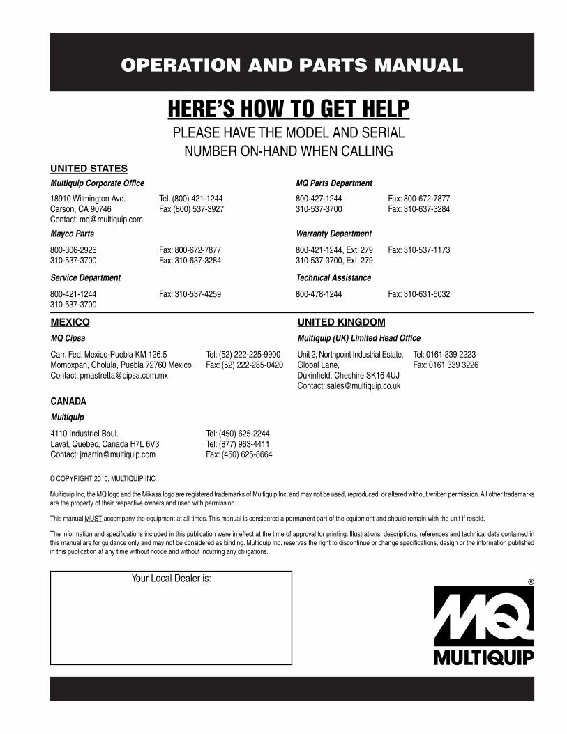
OPERATION AND PARTS MANUAL
Your Local Dealer is:
HERE’S HOW TO GET HELPPLEASE HAVE THE MODEL AND SERIAL
NUMBER ON-HAND WHEN CALLING
© COPYRIGHT 2010, MULTIQUIP INC.
Multiquip Inc, the MQ logo and the Mikasa logo are registered trademarks of Multiquip Inc. and may not be used, reproduced, or altered without written permission. All other trademarksare the property of their respective owners and used with permission.
This manual MUST accompany the equipment at all times. This manual is considered a permanent part of the equipment and should remain with the unit if resold.
The information and specifications included in this publication were in effect at the time of approval for printing. Illustrations, descriptions, references and technical data contained inthis manual are for guidance only and may not be considered as binding. Multiquip Inc. reserves the right to discontinue or change specifications, design or the information published in this publication at any time without notice and without incurring any obligations.
UNITED STATESMultiquip Corporate Office MQ Parts Department
18910 Wilmington Ave.Carson, CA 90746 Contact: [email protected]
Tel. (800) 421-1244Fax (800) 537-3927
800-427-1244310-537-3700
Fax: 800-672-7877Fax: 310-637-3284
Mayco Parts Warranty Department
800-306-2926310-537-3700
Fax: 800-672-7877Fax: 310-637-3284
800-421-1244, Ext. 279310-537-3700, Ext. 279
Fax: 310-537-1173
Service Department Technical Assistance
800-421-1244310-537-3700
Fax: 310-537-4259 800-478-1244 Fax: 310-631-5032
MEXICO UNITED KINGDOM
MQ Cipsa Multiquip (UK) Limited Head Office
Carr. Fed. Mexico-Puebla KM 126.5Momoxpan, Cholula, Puebla 72760 MexicoContact: [email protected]
Tel: (52) 222-225-9900Fax: (52) 222-285-0420
Unit 2, Northpoint Industrial Estate, Global Lane,Dukinfield, Cheshire SK16 4UJContact: [email protected]
Tel: 0161 339 2223 Fax: 0161 339 3226
CANADA
Multiquip
4110 Industriel Boul.Laval, Quebec, Canada H7L 6V3Contact: [email protected]
Tel: (450) 625-2244 Tel: (877) 963-4411Fax: (450) 625-8664
Related Documents