VUF-3016 JFINAL REPORT UN, ~ Ito 'p flCOB94ý -" ~Z R GMO M14S1 O ? &n"Treatmrent Planti ecipija tý tlerl Ia~ 21reatment Plant

Welcome message from author
This document is posted to help you gain knowledge. Please leave a comment to let me know what you think about it! Share it to your friends and learn new things together.
Transcript

VUF-3016JFINAL REPORT
UN, ~ Ito 'p
flCOB94ý -"
~Z R GMO M14S1 O ?
&n"Treatmrent Planti ecipija tý tlerl
Ia~ 21reatment Plant

.'UttC avTM I-)
#I T P| • I q ..............................Wat, iNI!UI ir~ ,,•LT! S C7IOI
DIST. Art - ECIAL
LEGAL NOTICEW r was M* aesam cm Of tivimit ipoered w•ft. "er *Ah nite
Ifties, iu Ow Cowmi..ha. mr my~ perso sating esbohaft ofs *A ~ i~A. MaUms "y smuwaty or op'wmi;itom, exprmessd or I5pited. with resemct to the seve-
racy, iemdtouml, or mweebwo *I the lairmatuam omuaised to hWe reort. or tha Me woof omr Afuarsdo. r--, mnd. or proceso Odmisod Is th report #uy mt lafrigoilhWMIy .wd rigbiet or
S. AJmo may WtdUt•ae wift respeo td me oat. or for dawai resltpia from them el m Imsm'Uatioa, aftrs th mr~od. or pmcss t disclosad in thia repo
A*si Imed to O bAe. "pinmg. eg a bohl atd do Camsausom" icla.die my om-pke or at orsewt d to Cos.i.m los, or em I w - of muh ooustactor. tothe staset thatomch smle of omtrmmuqr of fte Co•amiilm. or otnopyu of much centractor •W p-ee.dOusmate or provdwe* "ccosi to, tny iamatim pWafat" Ia ta emu gymmet or uetrmotwft s• Comadmiom. or Us smploym•nt with sofh oemetroir.
This report has been reproduced directly from the bestavailable copy.
Printed in USA. Price $1.00. Available from the Clearing-house for Federal Scientific and Technical Information, Na-tional Bureau of Standards, U. S. Department of Commerce,Springfield, Virginia 22151.
PW-

VUF 3016
PROJECT DRIBBLESALMON EVENT
VENT-GAS TREATMENT PLANT
D. Snoeberger and R. Heckman, Editors
Lawrence Radiation LaboratoryUniversity of CaliforniaLivermore, California
March 1966
VENT GAS TREATMENT PLANT
J. Ackerman, R. Bundrick, J Cowles, V. DuVal, J. Grens,
R. Holzman, C. Hannon, J. Harrar, C. Morris, L. Rigdon,
R, Heckman and D. Snoeberger
Lawrence Radiation Laboratory, University of California
Livermore, California
INTRODUCTION
As part of the Vela Uniform prog: am, Project Dribble was concerned
with the measurement of seismic signals generated by nuclear detonation in
a salt dome. The principal objective of the project was a test of the decoupling
theory proposed by Latter et al. 1,2
In September 1962. after resumption of underground nuclear testing,
Project Dribble was redefined. Certain technical responsibilities including
the detailed design of the experiment, development of the technical program
and execution of the on-site portion of the technical program were assigned
to the Lawrence Radiation Laboratory through the Atomic Energy Commission.
The planned 5-kiloton detonation occurred October 22, 1964, in the
Tatum Salt Dome near Hattiesburg, Mississippi.
Technical objectives of the post-shot program for this event were to:
I) Obtain samples of radioactive debris for yield determination.
iLatter, A. L. , E. LeLevier, E. Martinelli, and W. McMillan, "A Methodof Concealing Underground Nuclear Explosions, " J. Geophys. Research, 66,943-946 (1961).
2Werth, G. , and P. Randolph, "Prepared Statement on the Theory ofDecoupling and the Status of Project Dribble, for the Joint Committee onAtomic Energy, Congress of United States, ' UCRL-7323, March 6, 1963. I.

-2-
2) Sample the gas in the cavity to determine whether ridioactive
material which might cause a public safety problem had escaped.
3) Examine the feasibility of re-use of the cavity for firing decoupled
nuclear shots. Measurements to be made included distribution
of radioactivity, temperature, volume, geophysical logging, and
television survey.
4) Extract core from a second drill hole passing close to the cavity
for property measurements.
To accomplish this post-shot technical program, an assured means of
obtaining access to the cavity was required. Based on studies completed in
1961 on the cost and engineering feasibility of the various means of assuring
cavity access, it was decided that a vent-gas treatment facility was needed.
This facility was to be connected to the post-shot drilling rig at the well head
and was to remove radioactive particulates from the cavity effluents and control
release rate of gaseous radioactivity to meet public health safety standards.
Process engineering studies resumed in September 1962. The problem
was redefined with more stringent performance requirements added. The
new requirements included the following points: The facility must remove
radioiodine to eliminate any possible public safety problems. The release
rate for the noble gas fission products, xenon and krypton, must not exceed
limitations set by the limited test ban treaty, i. e., no detectable activity
beyond national borders. The plant must be removable before shot time and
be quickly reinstalled to prevent damage to the plant components by nuclear
seismic shockwave. Absolute reliability and control of plant radioactivity
releases was to be accomplished by use of shut-off valves at the well head.
-.3-
It was recognized that an explosive mixture of gases might be present
in the post-shot cavity. To prevent any possibility of catastrophic failure
of the plant components with subsequent radioactivity release, an air dilution
venturi was added at the plant inlet. The flow rate of cavity gas into the
dilution venturi was controlled so that an explosive mixture was never
possible beyond the dilution venturi. In addition, all the well head piping
upstream of the venturi was designed to contain any gas explosion that might
occur.
Since drill back into the cavity might occur as early as D + 7 d-.ys, the
facility must be capable of handling the following fission pruduct activity mixed
with the gas: particulate - 4 X 10⁵ curies; radioiodine - 8 X 10⁵ curies; and
6 6radioxenon and krypton - 1 X 10 curies; or a total of 2.2 X 10 curies.
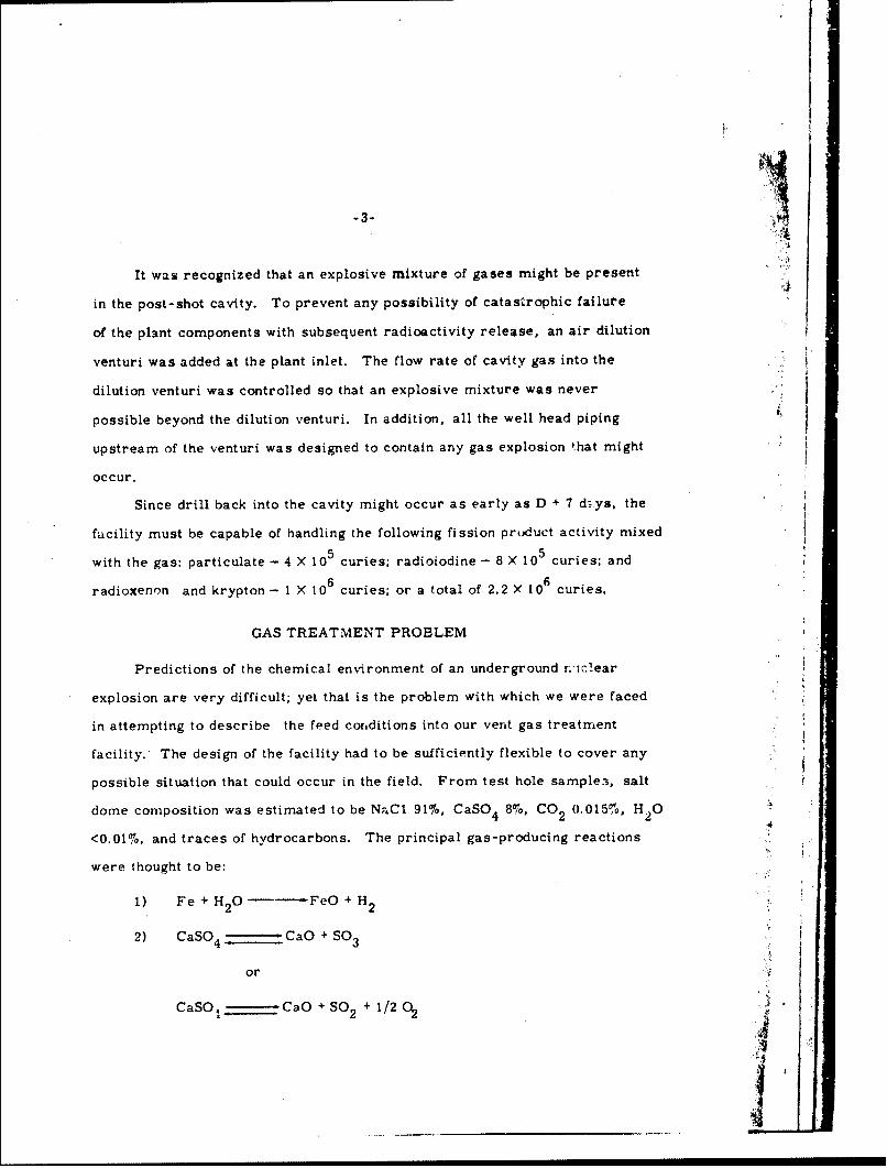
GAS TREATMENT PROBLEM
Predictions of the chemical environment of an underground r.'iclear
explosion are very difficult; yet that is the problem with which we were faced
in attempting to describe the feed conditions into our vent gas treatment
facility. The design of the facility had to be sufficiently flexible to cover any
possible situation that could occur in the field. From test hole sample3, salt
dome composition was estimated to be Ns-.Cl 91%, CaSO4 8%, CO 0.015%, H 02 2
<0.01%, and traces of hydrocarbons. The principal gas-producing reactions
were thought to be:
1) Fe + H 20 . .FeO + H2
2) CaSO 4 - CaO + SO3
or
CaSO, - CaO + SO + 1/2 0 2
______ ___ 4
.1 -4-
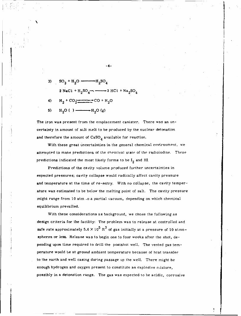
3) SO 3 + H 2 0 - H- 2 2so4
2 NaC1 + H 2 S04----- 2 HCI + Na 2SO 4
4) H 2 +CO 2 CO + H 2 0
5) H 2 0 ( ) - H2 0 (g)
The iron was present from the emplacement canister. There was an un-
certainty in amount of salt melt to be produced by the nuclear detonation
and therefore the amount of CaSO 4 available for reaction.
With these great uncertainties in the general chemical environment, we
attempted to make predictions of the chemical state of the radioiodine. These
predictions indicated the most likely forms to be 12 and HI.
Predictions of the cavity volume produced further uncertainties in
expected pressures; cavity collapse would radically affect cavity pressure
and temperature at the time of re-entry. With no collapse, the cavity temper-
ature was estimated to be below the melting point of salt. The cavity pressure
might range from 10 atm ,o a partial vacuum, depending on which chemical
equilibrium prevailed.
With these considerations as background, we chose the following as
design criteria for the facility: The problem was to release at controlled and
safe rate approximately 5.6 X 105 ft 3 of gas initially at a pressure of 10 atmo-
spheres or less. Release was to begin one to four weeks after the shot, de-
pending upon time required to drill the postshot well. The vented gas tem-
perature would be at ground ambient temperature because of hcat transfer
to the earth and well casing during passage up the well. There might be
enough hydrogen and oxygen present to constitute an explosive nixture,
possibly in a detonation range. The gas was expected to be acidic, corrosive
___ __
-5-
and saturated with water. It might carry suspended salt particles capable
of plugging flow passages. Radioactivity was estimated to be a maximum
of 4.0 curie per cubic foot of gas fed to the plant.
Later times of re-entry and bleed dowr would allow further decay of
radioact'ivity. Radioiodine activity, 11 3 3 , predominate.s after 10 days, but
decreases by a factor of 10 per month. Xenon activity falls off a little faster
but krypton 85 activity predominates over those of xenon and iodine after
roughly three months, contributing approximately a total of 200 curies.
A controlled release of the cavity gas these further effects were ex-
pected: Excess water vapor would condense on the wall or on cold salt,
dissolve salt, and return to the cavity. This process might continue by
reflux. There may be a net beneficial effect in separation of gases and
particulates by this "wetted wall column." There might be problems with
salt plugging in the well.
Radioactive particulates and iodine were to be removed from the vented
gas; xenon and krypton were to be dispersed in the atmosphere.
The release rate was limited to allowable rates for iodine, xenon and
krypton as determined by publc safety and limited test ban treaty considera-
tion. It was important to complete bleed down in as short a time as possible
to minimize cost and degradation of data for the post shot programs.
Pre-operational tests with radioactive iodine were made in July 1964.
The plant was removed to avoid shock d&.mage, then reinstalled after the
test detnation. Operational use began in February 1965, and continued
intermittently through May 1965. Figure I shows the plant piped to the re-
entry well late in the operational period. The plant is now in caretaker
status pending development of requirements in connection with re-use of the
cavity for further experiments.
-6-
Prior to the actual detonation the decision was made to delay start of
post-shot drill back for 60 days to accomplish additional technical require-
ments for the detection program. Because of this delay a large fraction of
radioactivity decayer', and the cavity cooled to 2040 C. At the time of cavity
penetration, the cavity was found to be under a partial vacuum of 313 millibars.
On the basis of pre-operaaonal performance tests and the actual operating
experience, we feel that we successfully designed and built a vent gas treat-
ment facility whose performance exceeded our original design specifications.
The desired flexibility was demonstrated by our ability to support a 'Vide variety
of down-hole operations that resulted from actual conditions found in the field.
However, our ability to predict the chemical environment of a.i underground
nuclear explosion leaves something to be desired. We recognized our
ignorance in this area and by use of a very conservative design we did conduct
a post-shot technical program successfully without endangering the publib:
safety or violating the limited test ban treaty.
DESCRIPTION OF PROCESS AND PLANT
The process is a remotely operated gas scrubbing and filtering system
with charcoal adsorption units incorporated with the filters. It is sized to
3 3take up to 200 ft /min of cavity gas mixed with 2000 ft /min of air to dilute
nydrogen. Effluent gas is discharged from a 150-foot stack after mixing with
20,000 cfm of additional air. Liquid wastes from the scrubbers are st d
in four 25,000-gal tanks for later disposal. Figure 2 shows the sutdown,
flow control and main process units,
i Well Head
Well ,The well head includes the cavity gas shut-off valves. There are six,
two in series plus a sampling valve on each of the two connections to the plant.
Io w oncin otepat

-7-
These valves ate remotely operable. They are designed to fail to a closed
position and will close automatically on loss of electric power or failure of
the process equipment.
Flow Control and Dilution
Flow control valves, adjacent to the well, limit flow to rates based on
the hydrogen dilution requirement or radioactivity release limit. The venturi
serves to dilute cavity gas to below the lower explosive limit for hydrogen and
provide suction for faster flow at low cavity pressures. Equipment working
pressure ratings are 3000 psig prior to dilution and 150 psig after dilution.
Gas Scrubbers
The two scrubbers, in series, are a venturi-type and an impingement
plate type. Their purposes are to remove particulates, protecting the filters
from excess loading, and remove iodine. The scrubbing liquid is aqueous
sodium hydroxide.
Filter Adsorbers
Each of three units installed in parallel consist.3 of an activated charcoal
bed with an "absolute" type filter preceding and following. A prefilter is
used with each to avoid caustic damage to the glass fiber media of the high
efficiency filters. These are modified Cambridge Filter Company C. B. R.,
units. Their purpose is to remove particulates carrying radioactivity and
to adsorb radioiodine. One of the three is a reserve unit.
Stack
The stack is 150 feet high, clearing local trees and hills by 50 to 100 feet.
A stack blower adds air at 20,000 ft 3/min for local dilution. All effluent and
contaminated tank vent gas is discharged through the stack,
Chemical Biological Radiological.

"-8-
Laboratory Trailer
A gas chromatograph provides feed gas analysis by sample pipe or
bottle. Scrubbing solution analysis is provided by "auto analyzer" and pH
and density instruments.
PREOPERATIONAL TESTS
During the course of the project increasing emphasis was placed on
removal of radioactive ;odine. Although quantities and the compounds of
iodine to be expected in the gas were not predictable, tests with a probable
form, I2' were made using 1-131 as a gamma tracer. Results were excellent.
The removal factor for the combined scrubbers and charcoal beds was 4 X
510
OPERATION OF FACILITY
This period began on February 26, 1965. It can be divided roughly
into three phases: 1) a standby period prior to cavity penetration (Feb. 26 to
Mar. 3); 2) an operation period during which the greatest part of actual vent
gas treatment took place (Mar. 4 to Mar. 13); 3) a continuing period of stand-
by and occasional operation (Mar. 14 onward).
A summary of operational experience follows:
1. Cleaning of air drilling returns
A crossover line was installed from the drill rig "blooie line" into the
plant 10-inch process gas line. This system allowed the plant to provide
protection against spreading of radioactive salt dust and release of radiogas
encountered in the final stages of drilling. Drilling returns were diverted

-9-to the plant for cleaning when radioactivity release limits were approached.
This was done on penetration drilling into the cavity and later while drilling
for cores below the cavity.
2. Vent gas treatment
The true operating phase began at cavity penetration, early on March
4. A pressure measurement shortly after penetration showed 0.8-inch Hg
vacuum, so no immediate attempt was made to bleed off cavity gas.
Gas sample bottles and temperature measuring instruments were lowered
into the cavity, and the plant gas chromatography unit analyzed a sample of
this gas. This important findings were that the gas was primarily air, with
CO 2 the primary additional constituent. Both H2 and SO2 were present, but
in concentrations too low to be of concern in operations.
The first appreciable quantity of gas vented from the cavity occurred
of March 6, following pressurization of the cavity to one-half atmosphere
positive pressure with drilling compressors for purposes of cavity volume
measurements. This gas was released through the rossover pipe installed
for drilling returns, which allowed flows at approximately 1000 cfm. Cyclic
flow pulses, with a period of about 30 to 60 seconds, were observed during
bleeding off of the gas. These may have been caused by a reflux water leg,
which also may have been responsible for closing the hole with a salt plug.
Activity release was very low. The maximum release rate of radio-
active rare gas is estimated at less than 200 millicuries/minute. Approximately
30 curies of rare gas, mostly Kr5, were released in the initial bleed down
of the 300,000 cubic feet of air added for cavity volume measurement. Due
to dilution by the stack blower, 5 microcuries per cubic foot was the maximum
concentration in effluent gas. 1131 was so slight as to be detectable only with
difficulty.

-10-
The second and final major release of cavity gas was from the flushing
operation. This was a procedure to reduce the concentration of radio-
active gas to such a level that treatment of vent gases would no longer be
required. Three cavity volumes of air were pumped into the cavity and
bled off, reducing residual gas to 40 microcuries per cubic foot rare gas
radioactivity.
Release rate was a maximum of 50 millicuries per minute early in the
operation, and declined slightly. Total release was approximately 50 curies,
primarily Kr 8 5 .
3. Downhole operations support
Regulated flows of nitrogen and air and slight suctions were provided
to the well on demand to assist in the use of well logging instruments and
television cameras. Cavity pressures were decreased to just below atmospheric
pressure to establish downdrafts during insertion and removal of drilling
equipment and instruments.
Repeated use of plant equipment was made to test by pressurization and
pressure decay measurement for communication between well and cavity. The
dilution venturi suction was used to speed up final stages of gas pressure
bleed down for the time saving benefit.
Suction of gas downward from the well head was used to reduce gas
hazards on the rig floor when unsealed insertions or removals were necessary.
CONCLUSIONS GAINED FROM OPERATIONAL EXPERIET&CE
The experience gained from the design and operation of this unique
vent gas treatment facility has initiated a number of research and development
studies to overcome many of the process engineering problems uncovered.

We are actively studying methods of arresting detonation waves.
Solution of this problem would eliminate necessity of air dilution, with a
subsequent decrease in size of processing equipment capacity by an order
of magInitude.
From the measured performance of the charcoal scrubbers, we believe
much of the radioiodine released was present as organic compounds possibly
CH 3 I. We have completed studies on improving the performance of charcoal
adsorption beds for the removal of CH 3 1. We are now studying new analytical
techniqucs which will allow us to determine the chemical state of iodine in
future field experiments.
Basic studies of the chemical nature of an undergound nuclear explosion
are underway. We plan to use computer calculation tenchiques and laboratory
scale experiments, as well as actual field experiments involving underground
nuclear detonations.
With the results obtained from these basic studies, we expect to be able
to make better predictions of inlet feed streams and to design more ccmpact,
higher performance vent gas treatment plants in the future.

IA
Cd
Cu

.2
4-,- f0
-0 0
-cc
IL9L
00
0
1;0
3t0
a ILI-
a- I- .
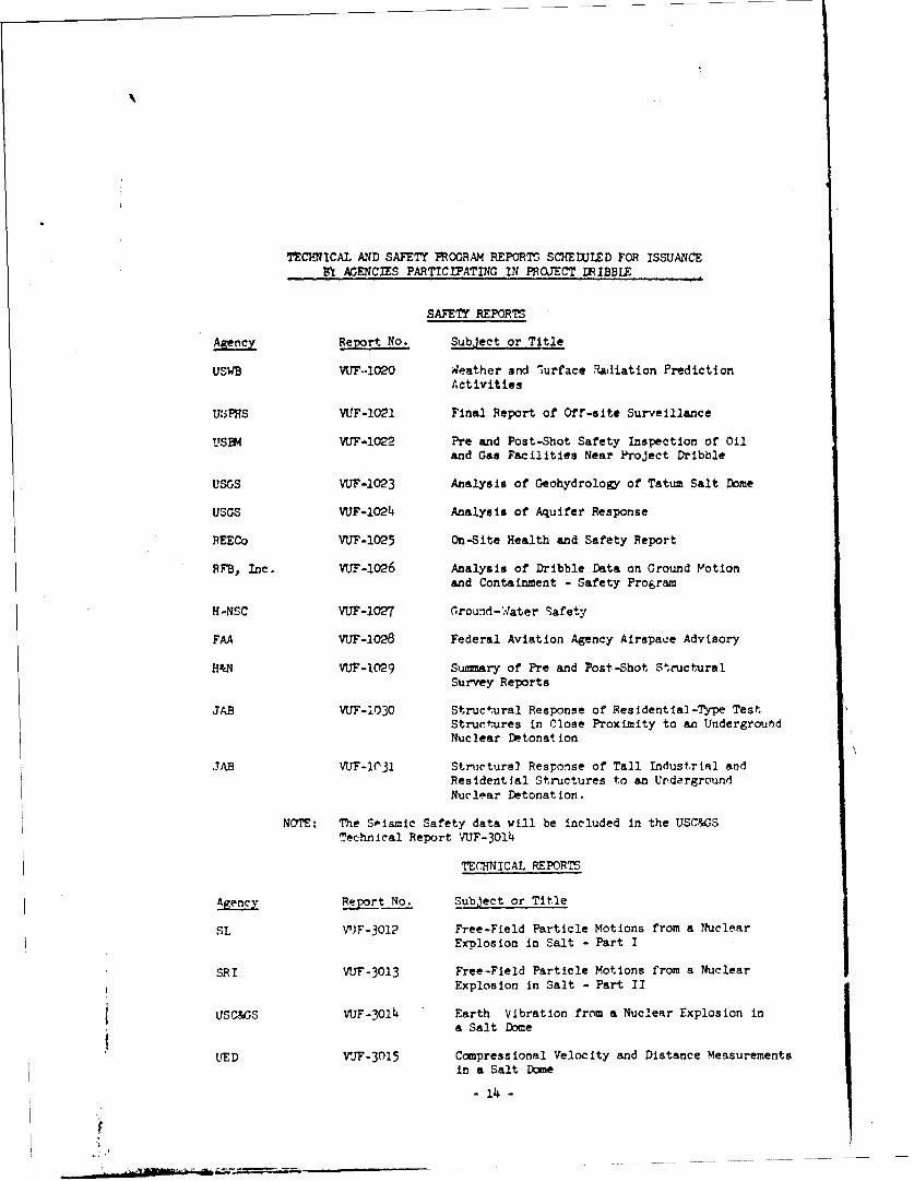
TECHNICAL AND SAFETY PROGRAM REPORTS SCHEDULED FOR ISSUANCEB1 AGENCIES PARTICIPATING IN PROJECT UIBBE
SAFETY REPORTS
Agency Report No. Subject or Title
USWB V'F.*120O Weather and lurface Radiation PredictionActivities
U[•PHS VUF-O121 Final Report of Off-site Surveillance
US3M VUF-1O02 Pre and Post-Shot Safety Inspection of Oiland Gas Facilities Near Project Dribble
USGS VUF-1023 Analysis of Geohydrology of Tatum Salt Dome
USGS VUF-IO24 Analysis of Aquifer Response
REECo VU?-1025 On-Site Health and Safety Report
RFB, Inc. VUF-IO26 Analysis of Dribble Data on Ground Motionand Containment - Safety Program
H-NSC VUF-1027 ,round-;.ater Safety
FAA VUF-1028 Federal Aviation Agency Airspace Advisory
H&N VUF-1029 Summary of Pre and Post-Shot StructuralSurvey Reports
JAB VUF-I030 Structural Response of Residential-Type TestStructures in Close Proximity to an UndergroundNuclear Detonat ion
JAB VUF-1031 Structurel Response of Tall Industrial andResidential Structures to an UndergroundNuclear Detonat ion.
NOTE: The Seismic Safety data will be included in the USC&GSTechnical Report VUF-3OI4
TECMNICAL REPORTS
Agency Report No. Subject or Title
SL VTJF-3012 Free-Field Particle Motions from a NuclearExplosion in Salt - Part I
SRI VUF-3013 Free-Field Particle Motions from a NuclearExplosion in Salt - Part II
USC&3S VUF-3014 Earth Vibration from a Nuclear Explosion ina Salt Dome
UED VJF-3015 Compressional Velocity and Distance MeasurementsIn a Salt Dome
- 14 -

IAL uF-3016 Vant-G.s Treatment Plant
IAL PNE-300e 0 Response of Test Structures to Ground Motionfro an Underground Nuclear Explosion
SRI VF-3017 Feasibility of Cavity Pressure and TemperatureMeasurements for a Decoupled Nuclear Explosion
ILL VUF-3OI8 Backround Engineering rata and Summary ofInstrumentation for a Nuclear Test in Salt
WES VUF-3019 Laboratory Desig and Analyses and Field Controlof Grouting Mixtures Employed at a Nuclear Testin Salt
ILL VUF-30O0 Geology and Physical and Chemical Properties of
the Site for a Nuclear Explosion in Salt
E VTF-J2 Timing and Firing
This report number was assigned by SAN
In addition to the reports listed above as scheduled for issuance by the ProjectDRIBBLE test organization, a number of papers covering interpretation of the SAI4ONdata are to be submitted to the American Geophysical Union for publication. Asof February 1, 1965, the list of these papers consists of the following:
Title Author(s) Agency(s)
Shock Wave Calculations of Salmon L. A. Rogers LRL
Nuclear Decoupling, Full and Partial D. W. Patterson IRL
Calculation of P-Wave Amplitudes for D. L. Springer andSalmon W. D. Hurdlow LRL
Travel Times and Amplitudes of Salmon J. N. Jordan USC&GSExplosion W. V. Mickey AFTAC
W. Helterbran UED
Detection, Analysis and Interpretation A. Archambeau andof Teleseismic Signals from the Salmon E. A. Flinn SDCEvent
Epicenter Locations of Salmon Event E. Herrin and SmiJ. Taggart USC&GS
The Post-Explosion Environment Resulting D. E. Ravson andfrom the Salmon Event S. M. *Hansen L
Measurements of the Crustal Structure in D. H. WarrenMississippi J. H. Healy
W. H. Jackson USGS
All but the last paper in the above list will be read at the annual meeting of
the American Geophysical Union in April 1965.
- 15 -
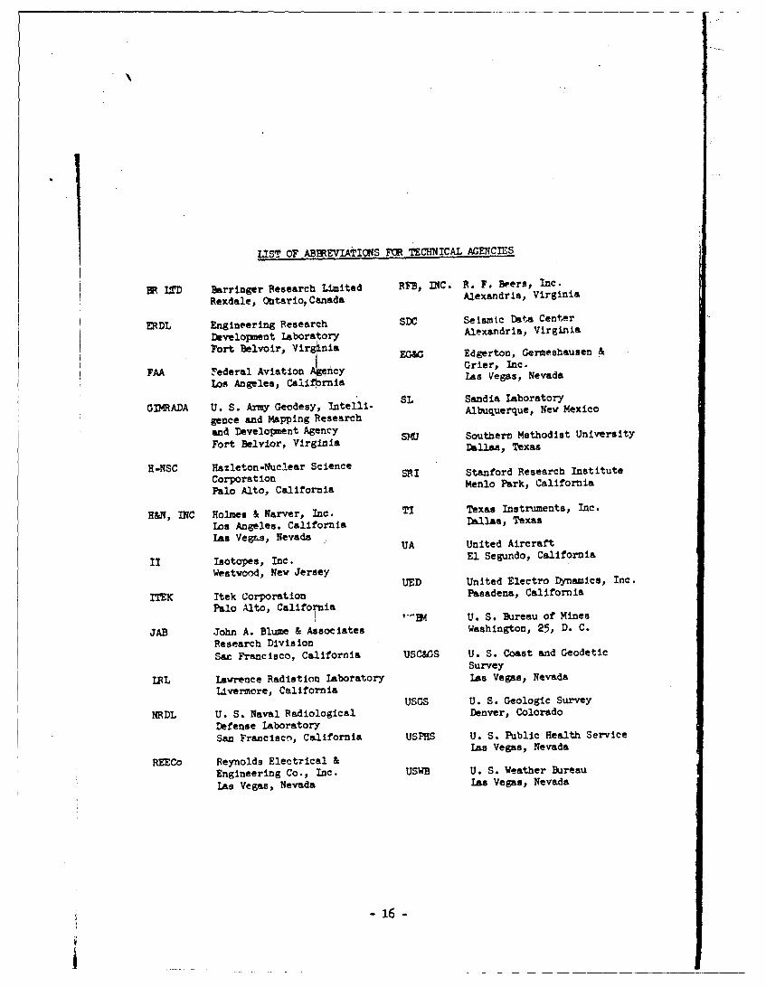
LIST OF ABBREVIATIONS ?tM TECHNICAL AGENCIES
BK LTD hrringer Research Limited RFB, INC. R. F. Beers, Inc.
Rexdale, OntarioCanada Alexandria, Virginia
ERDL Engineering Research SDC Seismic D&+A Center
Development laboratory Alexandria, Virginia
Fort Belvoir, Virgnia EG&G Edgerton, Germeshausen &I Grier, Inc.
FAA Federal Aviation 4Ency Crier, Nc.Los Angeles, Caliornia
GIMRADA U. S. Army Geodesy, Intelni- SL Sandia laboratoryAlbuquerque, New Mexicogence and Msapping Research
and Development Agency SMU Southern Methodist University
Fort Belvior, Virginia Dalls, Texas
X-NSC Hazleton-Nuclear ScienceCroainSRI Stanford Research InstituteCorporation MnoPrClfri
Palo Alto, California Menlo Park, California
H&O, INC Holmes & Narver, Inc. TI Texas Instruments, Inc.
Los Angeles, California Dallas, Texas
"Las VegLs, UA United Aircraft
II Isotopes, Inc. El Segundo, CaliforniaWeatwood, New Jersey
NUED United Electro Dynamics, Inc.
MTEK Itek Corporation Pasadena, CaliforniaPalo Alto, California
I ,'•]E4 U. S. Bureau of Mines
JAB John A. Blume & Associates Washington, 25, D. C.
Research DivisionSat Francisco, California USC&GS U. S. Coast and Geodetic
Survey
IRL Lawrence Radiation laboratory Las Vegas, NevadaLivermore, California
USGS U. S. Geologic SurveyNRDL U. S. Naval Radiological Denver, Colorado
Defense LaboratorySan Francisco, California USPHS U. S. Public Health Service
Las Vegas, Nevada
REECo Reynolds Electrical &Engineering Co., Inc. USWB U. S. Weather BureauLas Vegas, Nevada Las Vegas, Nevada
- 16 -
j____________________ ___________

PROJECY DRIBBLE.
?100 ?4.4.lc.1 add Saft.y Fro0Qm, Rav-Et.
0isetto t11* Swo~r7vr of 09?...s4 (000.1. tEo.,Q)
I ,Ashnton, D. C. 30330
10 A150.4drt, vi401 rgi Ia 4U, AM3 TZIZA-81 Direcorot, 4"pos Systam f0.104010 Orop, QCD, Roc 00880,
33. S. military admeI. MY ObtaLn Copies of this 1 0.Nt.. .ttgo. .C 00vP"Out directly from M. 000*r q..a1lef14 mos.~ Cowado,, Field Command 3ASA, 25.061. 09., Albqwq.06~
1L61rqettrU Ws*MIca15 A1,21 FCW0
oiler or Rtme.5.04 "A1 tb.41omt, O/A. 9..atag".. D. C.2 0310 A1Wý AtloI5C D111.100 Comido,, Fild;c16 od, WA,0 -101. bass. Alboqua..o.,
16 ft- Mexico. 01113Chief of Mutioner, D/A. WookLAOUN, 0. C. 20310 At.o2p0,0,2. .too,..C. 01
1 U(3C-z Lm4 A1.500 .010t1lt1 1*b0.0t0ry. P. 1. Ibn 1661, LOS k29-S,1 $oa Mexico. Al-": P.qo,1 Librarm (For Dr. A. .2o*
2 D. C. 20310. ArM ANCO-2.i. 01f 1a..1f10 Toc1eft1 library, lhnic.l Wno,..tlsoSO- 10. . 000 t-srW ,0104100. ... shl.4tt-. D. C.
Omed1 4 00.*,01, Ab4,400" PIo".O Gr"ý"1 0". 'o 06I AtsO.d 09*71*06 21005, AM:~ D01..t~rOL mm ,bULq*Oerto fl* . . tmcVw
D21,00000, U. S. Ara Rase,04 se4 Ob4.M.1 a0 lab.oraory, 1 C~ossosn P. 0. 09 121 loq.qo. 400 . MWolc1 M. Nloli, Virosi*t 2260, ATM: 001., Tx900. 907,4,0 0,0.02
mrvta~' wter%,"ft~uma 3atin, . S Any Cr f1 .. or. 09oada 009,0010 Office, MIAEC, EM. Vegas. %.,*A*
D1,sc~otoo U. 3oa. 21jw .Carp . 1 5 s~C3s of oea rtin
1 C1,9w Livrort., C.llfoool. Zdag.wto -- ,ha..s.- & Gr1er, l-c, P. 0. 0-. 394, K-1otain Boston 9.0., ftes. 21215 Attn: Mary3 E. 5.000.,, Uhr-1-~
RAVINxs90,loor et 1tat"tlo. Office, Ado,0,ted Research Proýact. A4.03,
Chief of we"l 0 erattlos', Navy 19mox-wot, waamiagift, 2. C. 3 anar0ot of Worse... 4.0104000, D. C. 203012 30330 , AT" : OF.751 OF-03 Adoýod P0.00,00 7,07.000 0(0007. 1sW.R.01
5 W.s0i4e0M. D. C. 20301 P0r: ". U~salchief, 09,4.5 a, l.,ds sod .oo0, m~o Owyarmex. '09.01p.40.
1 D. C. 30Y00, cow~ 191. o Mr.2 . 1.2.5 t..b.0 R.U, U. S. ;ol.1 . -y .00.. . ofI1,d 0.4. I... 1 b7.1¶ntAl Sooloa. Devi. of lIntaror, 1.001lnslt, D. C. 2WI.2
Chief Of M&SM1 9..4OSO , 09. 4p.*et, ft"Lot... D. C. Mr. Ctwrl~o P. GOU~oo., U. S. km Zoo.,o A Dfl1..,.ot AAocy.1 03901w AIM 006. Dot2 0. of -tat*, ootz .C
CGo flog Sf710., & Director, U. 2. 09.01 Civil Endineering tb.010009 f0,1sr Oafs- A- t., 18235 C-ooti,ut A-.., X. 4J.
1 1*0,0 Post 29 -0000, C&al~fO0.1 A1.", 0od. L 31 1 Washington, D. C. Atnt. Al Nblos0.10
Commade, V1. S. 090.1l Ordemae Laborato7, Siloer 117rtos 19 14.11l Dr..lo0.00 Compamy, P. 0. Box '.81, ...sto, Texas 770011 ~ ~ " L,'io A Ii. AITR Dr. 3id...y 10.~ffso, tplotati~on Division
1 ~ 'ts~ KVKZ.4 golso010010.1 54o0., c/o Po-dquaru.,. LSCA7/AFAC,
1 200.0,. 3. S 09.l 9.4.2 14..to.p, b&1.tin 2.0 3095 botlaston 25, D. C.
U. S. Me.61 4.d110410a1 Caroms. t.0mirto.", Sa pb4.o1.o 1 or. P. 5.I C-lIft. 91.135
Y.1. 54taml Info reati0., Aialy-lo Coot.,, Voloo.Ity of Mich140*1 P . 0. Bo 0O, Am. Arbor, Mi1h0I0Ra
Us~prt. 0Oar-abamemm 6 Otte, 10.., loots Vrbsrao LaboratoryDlraw00, of Research mad Davalopmrt. DC/I. I5k, USAF,. I P. 0. amgo O.1.0.. Cat If., 93017 Attos M. 9. C4,pftot.
I Wash1ington, 0. C. 23)03, AM: ,O~d-ao a woopme 21,140.U. 2. At~oo Emrqy Coxo.qjoo, D101.10. of ?ochol.al Inforeotlo,
AMRL, L. 0. R.on�?old 71 1. adfold, 1..oho90tu 01731, 10 000. P. 0. 82, 5.9 d104, CTnos-... r3131
U. 3. Steele 7E0.'w Cc..ýo, Itois, of Technical 1noreatlon..
I OWbL. Xlrtlsod API. ft- 109.10 77?117 1 weabift000, 0. C . 20'551 C46.n0, 10.010.0. of Twhmoao~ , vriat-Astter.4 Anl,
Ohio. 6543133 A1~i AC1J-147,2R0 0. S. 500.10 7o9r C15410, Soosl, of 7339,Otonl ,fO
1 6.041.40,0, D. C. 205U531 WD, 09,0.- Anl, C..llfora.1. 92"0
vb,.000 of Civil 09410..PO.4M, 4 UWA? A..obla40o.. D.C. 20330, 1 ,...01 2u'o 6.04104olt, . .2'2D~ Fort L~onar, M "2pmyI AMU: APOM
0950.5 M. P-n, Coast and 0006.01 '.,o-y, P. 0. 09.. 16761 AYM, T"" P4014. D, Whoi"sUt. D. C. 20333, A?": IP 1 I.. Vow., ft'%f. 89101.
01im., .Ts..ny.1, E .06r ~ associate.. 5701 morth2wet 9*044y______ 1 19 Plaines, 1111001. 16=
21.0.00, of 1sftm.. Aoxsb & Magineer1.4. Wasa50104 ,00. . C. D, A. 0. %ttl ., J,. , Ag1,I-It,. 1 - so4 olo 210114. It Tv-..,3 0330, 0A": 7.04. ULos07 1 olo 0011.. n Tel"..14.
-17-
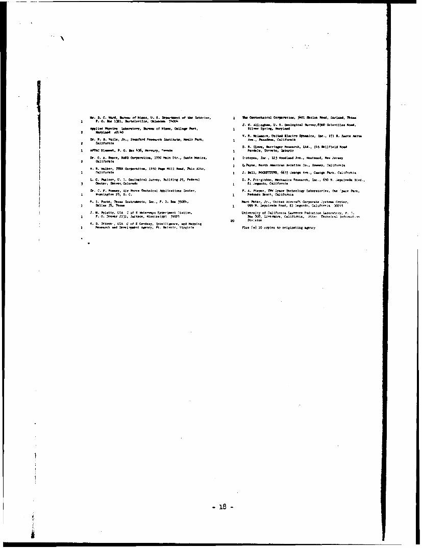
or. 2. C. Ward, u~..Of Nb., U. S. borpuf t of b. Interior, 1 w 0.et.. caatc.1 ore.ttai. 360 Ahlo A1Ib , CrlA.W, ?*..
1 P. 0. Dow 1321, bmolt.Alh., akwbaw 7W04I. .AL.,U.S. ON10lAS~tl SMY,3 Oot.'1-i1. Plow.
Appied "9f Lab. SMt7, 3.,. of Mtm., Colleg park, 1 1..Spring, ".7Nd
1.. reL. , Unit" a 1.to Opmic., w .. 171 1. SAO" Asti&Dr I. a. Vail., .h., St~ft~'d O.N.rOvh 1htttwk, wivalo . 1ok ANN. '-..dess, c.1.tron,1
2 C.I,1foml. V. A. Clawe, &Lrru~r 5.....oh, Ltd., 14.5 Wllfto1d RoatI AFTAc 11.t, P. 0. bs 436, Now....y, -w".o 1 e 4.10, To-to, Ct~io
I,0. A. 10-0., MR. ,'P*-tlo, 17.C 1%, Sir., Mont. ,I.1 Iolopws, 6..,, 223 Wodland Aw., NMtood Is""oooV.fym
Not N.enAvainC.
os~,C~fr0.W~. maroatw 1450 raw :::;%sNd Palo Alto., hS
Dr C .Rmny, Air YAom# ?Nohnlr.1 App~leatton. COot., F. A. Pieper, PWO SrfO ?..bnOoIlg ltborstorles, CiOs p Park1 VWaftigtom 25, D. C. I .1.4. h*dl, ca.11tont
I akhN. 35, Th.-1 999 W. 3.plv~da Pod, El 1.gu.do, U11forn,1 9ce.5
J. If. 1btty. USA C of I Waterways uAwri...t ltmtmn Un~vers;L4of :!altfornislavv.,oen Rodlatfo. lab.,,tory, P. 1.1 P. 0. Drs", 2131. J~oksoa. M.ississppi 39Oe5 a- 14.0,.,, California, Attn! Tgchtn~lc Inomxt:)n
20 Dt.:.Ion0. D. Dib"o , WSA C of I Cndo..y, tnt.111o8n.. -4 Y.221ng
I Pw"otl -. d JO..1,.0,t 44 y Pt. SN1.o1,, vIrocinta plusC, 10 copies to Originating Agency
- 18 -
Related Documents


