INTRODUCTION PIPE RACK Pipe Rack design criteria • Shapes • Future Space • Width of Pipe Rack • Clearance • Pipe Rack Loading RACK PIPING • Positions of Lines (Process & Utilities) • Hot Lines & Cold Lines • Bigger Size Lines • Pipe Spacing • Anchor Bay • Unit Battery Limit • Expansion Loops • Pipe Route • Trays Contents www.pipingguide.net

Welcome message from author
This document is posted to help you gain knowledge. Please leave a comment to let me know what you think about it! Share it to your friends and learn new things together.
Transcript

INTRODUCTION
PIPE RACK Pipe Rack design criteria
• Shapes• Future Space• Width of Pipe Rack• Clearance
• Pipe Rack Loading
RACK PIPING• Positions of Lines (Process & Utilities)• Hot Lines & Cold Lines• Bigger Size Lines• Pipe Spacing• Anchor Bay• Unit Battery Limit• Expansion Loops• Pipe Route• Trays
Contentswww.pipingguide.net

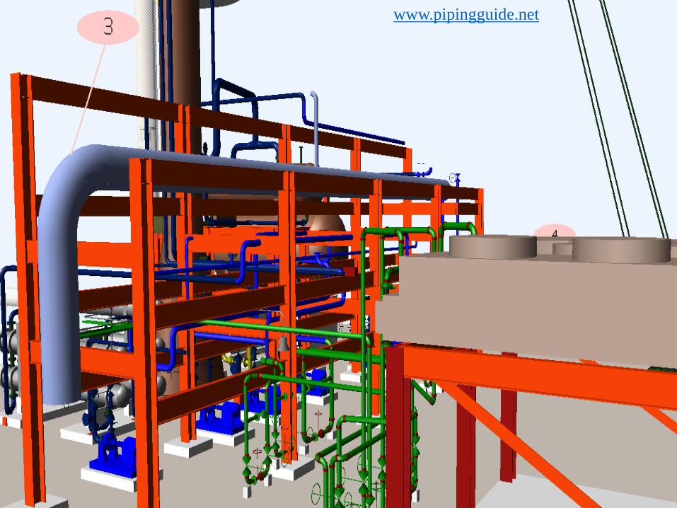
A pipe rack is the main artery of a process unit. It connects all equipment with lines that cannot run through adjacent areas. Because it is located in the middle of the most plants, the pipe rack must be erected first, before it becomes obstructed by rows of equipment. Pipe racks carry process, utility piping and also include instrument and electrical cable trays as well as equipment mounted over all of these.
The primary data required for detailed development of a pipe rack :- Plot Plan P&ID’s Client Specification Construction Materials Fire proofing requirements Statutory requirements
INTRODUCTIONwww.pipingguide.net


Shapes There are various shapes of pipe rack like L/T/U/H/Z. These shapes
shall be considered based on the area available.
Future Space The total width of the pipe rack shall include 25% extra space for
future expansion/modification in unit for rack-width upto 16m and 10% for rack-width above 16m. The future space %age is normally based on the client requirements.
Width of Pipe rack The width of the rack shall be 6m, 8m or 10m for single bay and
12m, 16m or 20m for double bay having 4 tiers maximum. The spacing between pipe rack portals shall be taken as 6m in general. However it can be increased to 8m depending on the size of the pumps to be housed below pipe rack.
PIPE RACK DESIGN CRITERIAwww.pipingguide.net


DIFFERENT SHAPES OF PIPE RACKS
DEAD END YARD LINES ENTER & LEAVE ONE END OF THE RACK
STRAIGHT THROUGH YARD LINES CAN ENTER & LEAVE BOTH ENDS OF THE RACK
L-SHAPED YARD LINES CAN ENTER & LEAVE NORTH & EAST OF THE RACK
T-SHAPED RACK PIPING CAN ENTER & LEAVE THREE SIDES OF THE RACK
www.pipingguide.net

DIFFERENT SHAPES OF PIPE RACKS
COMPBINATION OF I & T SHAPED RACK
U-SHAPED YARD LINE CAN ENTER & LEAVE ALL FOUR SIDES OF THE RACK
COMPLEX RACK PIPING ARRANGEMENT FOR VERY LARGE CHEMICAL PLANT
www.pipingguide.net
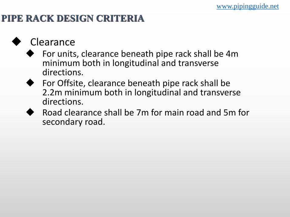
Clearance For units, clearance beneath pipe rack shall be 4m
minimum both in longitudinal and transverse directions.
For Offsite, clearance beneath pipe rack shall be 2.2m minimum both in longitudinal and transverse directions.
Road clearance shall be 7m for main road and 5m for secondary road.
PIPE RACK DESIGN CRITERIAwww.pipingguide.net

Pipe rack loads shall be given by stress group to Civil & structural discipline for pipe rack design.
Sustain Load (Dead Load) Weight of piping, valve and load insulation
Thermal Laod Load by thermal expansion of piping & Reaction force by
internal pressure of expansion bellows
Dynamic Laod Load by vibration of piping & by wind and earthquake
Sustained Load (Live Load) Liquid load for hydrostatic pressure test
PIPE RACK LOADING www.pipingguide.net

Position of Lines Predominantly process lines are to be kept at
lower tier and, utility & hot process lines on upper tier.
Hot Lines & Cold Lines Generally hot lines & cold lines are to kept at
different tiers or at different groups on a tier.
Pipe Spacing Minimum spacing between adjacent lines shall be decided
based on O.D. of bigger size flange (minimum rating 300# to be considered), O.D. of the smaller pipe, individual insulation thickness and additional 25mm clearance. Even if flange is not appearing the min. spacing shall be based on above basis only. Actual line spacing, especially at ‘L’ bend and loop locations, shall take care thermal expansion/thermal contraction/non-expansion of adjacent line. Non-expansion/thermal contraction may stop the free expansion of the adjacent line at ‘L’ bend location.
RACK PIPINGwww.pipingguide.net

Bigger Size Lines Large size lines (14” and larger) shall be arranged close to the
column in order to decrease the bending moment of beam. Water lines more than 30” shall not be routed over pipe rack, these shall be routed underground.
Anchor Bay Anchors on the racks are to be provided on the anchor bay if
the concept of anchor bay is adopted. Otherwise anchor shall be distributed over two to three consecutive bays.
Anchors shall be provided within unit on all hot lines leaving the unit.
Pipe Route Racks shall be designed to give the piping shortest possible run
and to provide clear head rooms over main walkways, secondary walkways and platforms.
RACK PIPINGwww.pipingguide.net

Trays Generally top tier is to be kept for Electrical cable trays (if not
provided in underground trench) and Instrument cable ducts/trays. Cable tray laying to take care of necessary clearances for the fire proofing of structure.
Battery Limit (ISBL) Process lines crossing units (within units or from unit to main
pipeway) are normally provided with a block valve, spectacle blind and drain valve. Block valves are to be grouped and locations of block valves in vertical run of pipe are preffered. If the block valves have to be located in an overhead pipe-way, staircase access to a platform above the lines shall be provided.
RACK PIPINGwww.pipingguide.net


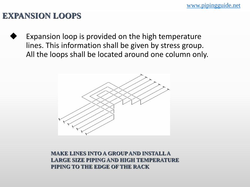
Expansion loop is provided on the high temperature lines. This information shall be given by stress group. All the loops shall be located around one column only.
EXPANSION LOOPS
MAKE LINES INTO A GROUP AND INSTALL A LARGE SIZE PIPING AND HIGH TEMPERATURE PIPING TO THE EDGE OF THE RACK
www.pipingguide.net
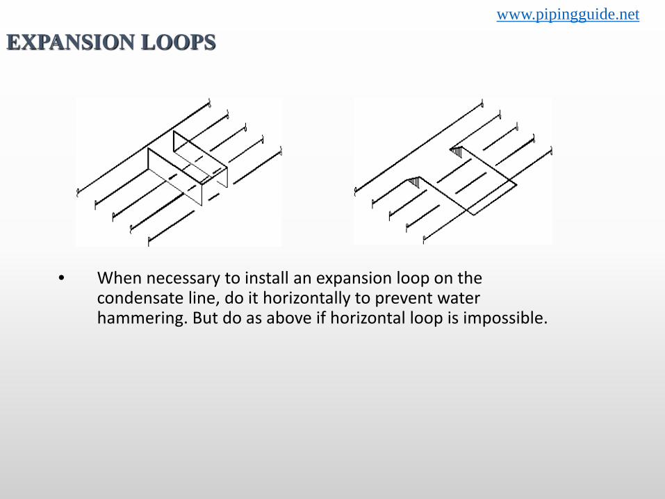
• When necessary to install an expansion loop on the condensate line, do it horizontally to prevent water hammering. But do as above if horizontal loop is impossible.
EXPANSION LOOPSwww.pipingguide.net


THANK YOU
Related Documents