AVIATION TRAINING Pilot’s Operating Handbook Aero AT3 R100 HA-VOA Reconciled with the Aeroplane Date: 10.04.2016 Signature:

Welcome message from author
This document is posted to help you gain knowledge. Please leave a comment to let me know what you think about it! Share it to your friends and learn new things together.
Transcript
AVIATION TRAINING
Pilot’s Operating Handbook
Aero AT3 R100 HA-VOA
Reconciled with the Aeroplane Date: 10.04.2016 Signature:
„„AERO” Sp. z o. o. 03-942 WARSAW, POLAND
UL. WAŁ MIEDZESZYŃSKI 844
WARSAW SEPTEMBER, 2004
AEROPLANE FLIGHT MANUAL
for the AT-3R100
VERY LIGHT AEROPLANE
Aeroplane registration (Call sign): HA-VOA
Aeroplane Serial No.: 0022
Registered under No: .......................................
Approved:
CIVIL AVIATION OFFICE
President of the CAO
( Originally signed for President of the CAO by Mr. Z. Mazan)
Date: 2004-09-23
This aeroplane must be operated in accordance with information and limitations contained in this Manual.
This Manual must be carried in the aeroplane at all times
Doc. No. ATL3.04
„AERO” Sp. z o.o. AT-3 R100 GENERAL INFORMATION
Page 0-2 SEPTEMBER, 2004 AEROPLANE FLIGHT MANUAL
Editor:
“AERO” Sp. z o.o.
O3-942 WARSAW, POLAND
UL. WAŁ MIEDZESZYŃSKI 844
Approval of translation has been done to the best knowledge and judgment. In any case, the original Polish language version is authoritive.
English language version of the Polish Document No. ATL3.03 AFM, translated under delegation of authority CAIB No. 54C.
Jan A.Jasiński, B.S.(Eng.)
„AERO” Sp. z o.o. GENERAL INFORMATION AT-3 R100
SEPTEMBER, 2004 Page 0-3 AEROPLANE FLIGHT MANUAL
CONTENTS
SECTION
GENERAL 1
LIMITATIONS 2
EMERGENCY PROCEDURES 3
NORMAL PROCEDURES 4
PERFORMANCE 5
WEIGHT AND BALANCE 6
DESCRIPTION OF THE AEROPLANE AND ITS EQUIPMENT 7
SERVICING 8
SUPPLEMENTS 9
„AERO” Sp. z o.o. AT-3 R100 GENERAL INFORMATION
Page 0-4 AUGUST, 2008 AEROPLANE FLIGHT MANUAL
RECORDING OF REVISIONS
All revisions to this manual, with the exception of actual changes of
weighing data must be recorded in the table below.
The new or corrected text in the corrected pages, is to be marked at the
margin with a vertical line and the number of the revision and the date of
the revision is to be printed at the bottom of the page. For each revision,
the pages specified in the Log of Revisions must be replaced.
6
„AERO” Sp. z o.o. GENERAL INFORMATION AT-3 R100
NOVEMBER, 2012 Page 0-5 AEROPLANE FLIGHT MANUAL
List of Effective Pages
Section Page Date of issue
0 0-1 SEPTEMBER, 2004
0 0-2 SEPTEMBER, 2004
0 0-3 SEPTEMBER, 2004
0 0-4 AUGUST, 2008
0 0-5 NOVEMBER, 2012
0 0-6 NOVEMBER, 2012
0 0-7 NOVEMBER, 2012
0 0-8 JULY, 2010
0 0-9 NOVEMBER, 2012
0 0-10 JANUARY, 2012
0 0-11 NOVEMBER, 2012
0 0-12 NOVEMBER, 2012
1 1-1 SEPTEMBER, 2004
1 1-2 JANUARY, 2012
1 1-3 AUGUST, 2008
1 1-4 SEPTEMBER, 2004
1 1-5 SEPTEMBER, 2004
1 1-6 SEPTEMBER, 2004
1 1-7 SEPTEMBER, 2004
1 1-8 SEPTEMBER, 2004
1 1-9 SEPTEMBER, 2004
1 1-10 SEPTEMBER, 2004
1 1-11 SEPTEMBER, 2004
1 1-12 SEPTEMBER, 2004
1 1-11 SEPTEMBER, 2004
1 1-12 SEPTEMBER, 2004
2 Appvd. 2-1 SEPTEMBER, 2004
2 Appvd. 2-2 SEPTEMBER, 2004
2 Appvd. 2-3 SEPTEMBER, 2004
2 Appvd. 2-4 SEPTEMBER, 2004
2 Appvd. 2-5 AUGUST, 2008
2 Appvd. 2-6 AUGUST, 2008
2 Appvd. 2-7 SEPTEMBER, 2004
2 Appvd. 2-8 JULY, 2010
2 Appvd. 2-9 SEPTEMBER, 2004
2 Appvd. 2-10 SEPTEMBER, 2004
2 Appvd. 2-11 MARCH, 2011
„AERO” Sp. z o.o. AT-3 R100 GENERAL INFORMATION
Page 0-6 NOVEMBER, 2012 AEROPLANE FLIGHT MANUAL
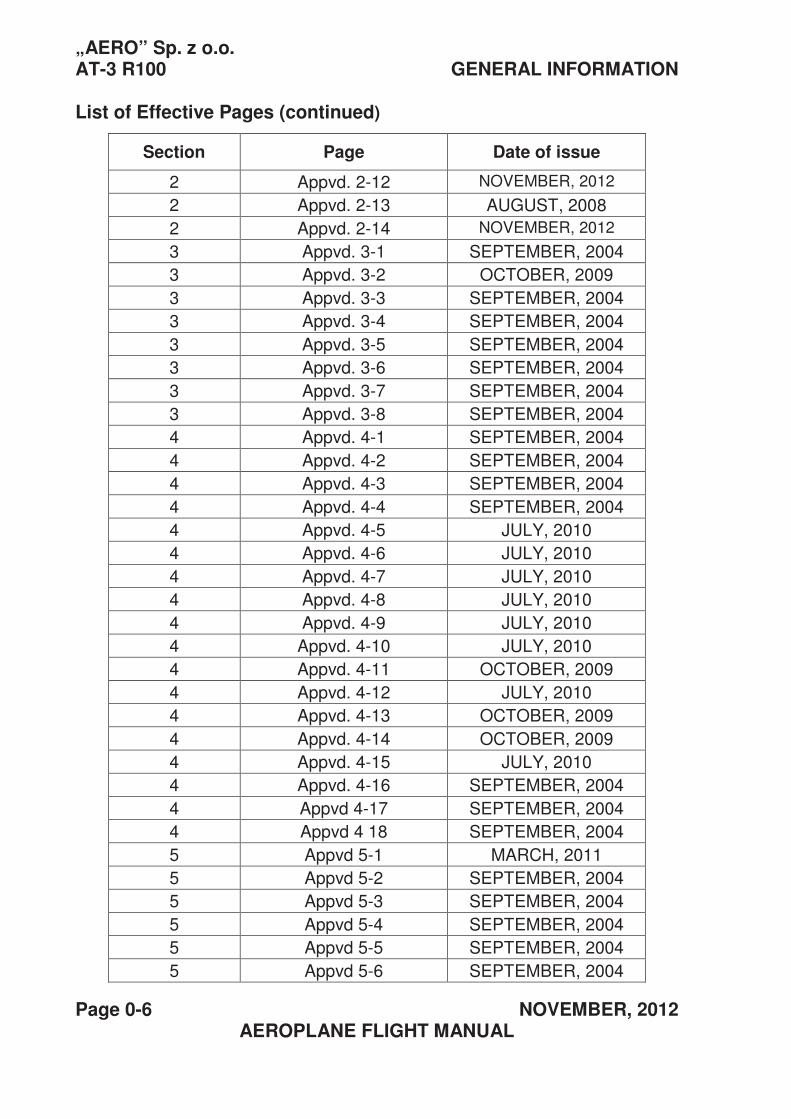
List of Effective Pages (continued)
Section Page Date of issue
2 Appvd. 2-12 NOVEMBER, 2012
2 Appvd. 2-13 AUGUST, 2008
2 Appvd. 2-14 NOVEMBER, 2012
3 Appvd. 3-1 SEPTEMBER, 2004
3 Appvd. 3-2 OCTOBER, 2009
3 Appvd. 3-3 SEPTEMBER, 2004
3 Appvd. 3-4 SEPTEMBER, 2004
3 Appvd. 3-5 SEPTEMBER, 2004
3 Appvd. 3-6 SEPTEMBER, 2004
3 Appvd. 3-7 SEPTEMBER, 2004
3 Appvd. 3-8 SEPTEMBER, 2004
4 Appvd. 4-1 SEPTEMBER, 2004
4 Appvd. 4-2 SEPTEMBER, 2004
4 Appvd. 4-3 SEPTEMBER, 2004
4 Appvd. 4-4 SEPTEMBER, 2004
4 Appvd. 4-5 JULY, 2010
4 Appvd. 4-6 JULY, 2010
4 Appvd. 4-7 JULY, 2010
4 Appvd. 4-8 JULY, 2010
4 Appvd. 4-9 JULY, 2010
4 Appvd. 4-10 JULY, 2010
4 Appvd. 4-11 OCTOBER, 2009
4 Appvd. 4-12 JULY, 2010
4 Appvd. 4-13 OCTOBER, 2009
4 Appvd. 4-14 OCTOBER, 2009
4 Appvd. 4-15 JULY, 2010
4 Appvd. 4-16 SEPTEMBER, 2004
4 Appvd 4-17 SEPTEMBER, 2004
4 Appvd 4 18 SEPTEMBER, 2004
5 Appvd 5-1 MARCH, 2011
5 Appvd 5-2 SEPTEMBER, 2004
5 Appvd 5-3 SEPTEMBER, 2004
5 Appvd 5-4 SEPTEMBER, 2004
5 Appvd 5-5 SEPTEMBER, 2004
5 Appvd 5-6 SEPTEMBER, 2004
„AERO” Sp. z o.o. GENERAL INFORMATION AT-3 R100
NOVEMBER, 2012 Page 0-7 AEROPLANE FLIGHT MANUAL
List of Effective Pages (continued)
Section Page Date of issue
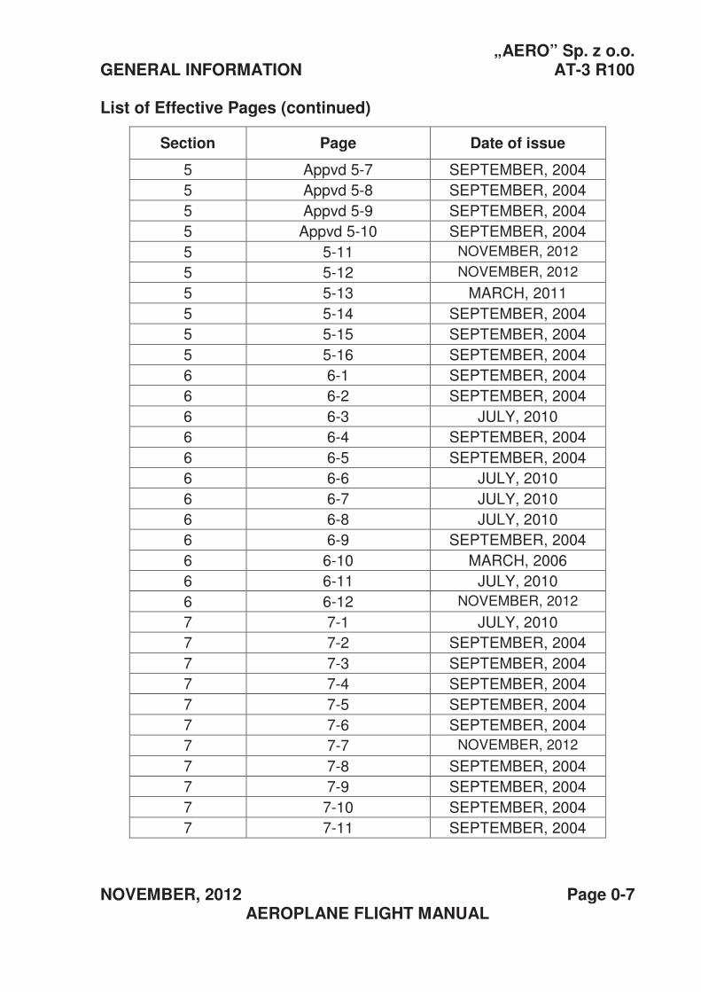
5 Appvd 5-7 SEPTEMBER, 2004
5 Appvd 5-8 SEPTEMBER, 2004
5 Appvd 5-9 SEPTEMBER, 2004
5 Appvd 5-10 SEPTEMBER, 2004
5 5-11 NOVEMBER, 2012
5 5-12 NOVEMBER, 2012
5 5-13 MARCH, 2011
5 5-14 SEPTEMBER, 2004
5 5-15 SEPTEMBER, 2004
5 5-16 SEPTEMBER, 2004
6 6-1 SEPTEMBER, 2004
6 6-2 SEPTEMBER, 2004
6 6-3 JULY, 2010
6 6-4 SEPTEMBER, 2004
6 6-5 SEPTEMBER, 2004
6 6-6 JULY, 2010
6 6-7 JULY, 2010
6 6-8 JULY, 2010
6 6-9 SEPTEMBER, 2004
6 6-10 MARCH, 2006
6 6-11 JULY, 2010
6 6-12 NOVEMBER, 2012
7 7-1 JULY, 2010
7 7-2 SEPTEMBER, 2004
7 7-3 SEPTEMBER, 2004
7 7-4 SEPTEMBER, 2004
7 7-5 SEPTEMBER, 2004
7 7-6 SEPTEMBER, 2004
7 7-7 NOVEMBER, 2012
7 7-8 SEPTEMBER, 2004
7 7-9 SEPTEMBER, 2004
7 7-10 SEPTEMBER, 2004
7 7-11 SEPTEMBER, 2004
„AERO” Sp. z o.o. AT-3 R100 GENERAL INFORMATION
Page 0-8 JULY, 2010 AEROPLANE FLIGHT MANUAL
List of Effective Pages (continued)
Section Page Date of issue
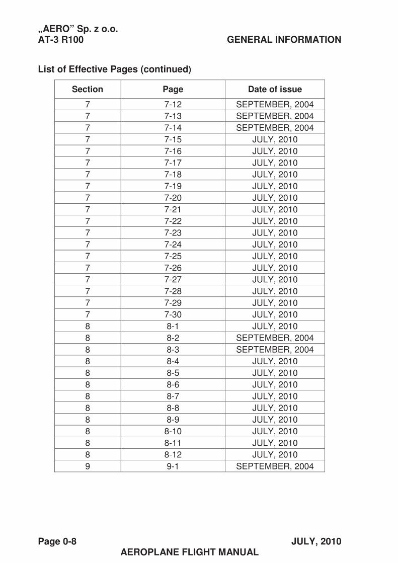
7 7-12 SEPTEMBER, 2004
7 7-13 SEPTEMBER, 2004
7 7-14 SEPTEMBER, 2004
7 7-15 JULY, 2010
7 7-16 JULY, 2010
7 7-17 JULY, 2010
7 7-18 JULY, 2010
7 7-19 JULY, 2010
7 7-20 JULY, 2010
7 7-21 JULY, 2010
7 7-22 JULY, 2010
7 7-23 JULY, 2010
7 7-24 JULY, 2010
7 7-25 JULY, 2010
7 7-26 JULY, 2010
7 7-27 JULY, 2010
7 7-28 JULY, 2010
7 7-29 JULY, 2010
7 7-30 JULY, 2010
8 8-1 JULY, 2010
8 8-2 SEPTEMBER, 2004
8 8-3 SEPTEMBER, 2004
8 8-4 JULY, 2010
8 8-5 JULY, 2010
8 8-6 JULY, 2010
8 8-7 JULY, 2010
8 8-8 JULY, 2010
8 8-9 JULY, 2010
8 8-10 JULY, 2010
8 8-11 JULY, 2010
8 8-12 JULY, 2010
9 9-1 SEPTEMBER, 2004
„AERO” Sp. z o.o. AT-3 R100 GENERAL INFORMATION
NOVEMBER, 2012 Page 0-9 AEROPLANE FLIGHT MANUAL
List of Effective Pages (continued)
Section Page Date of issue
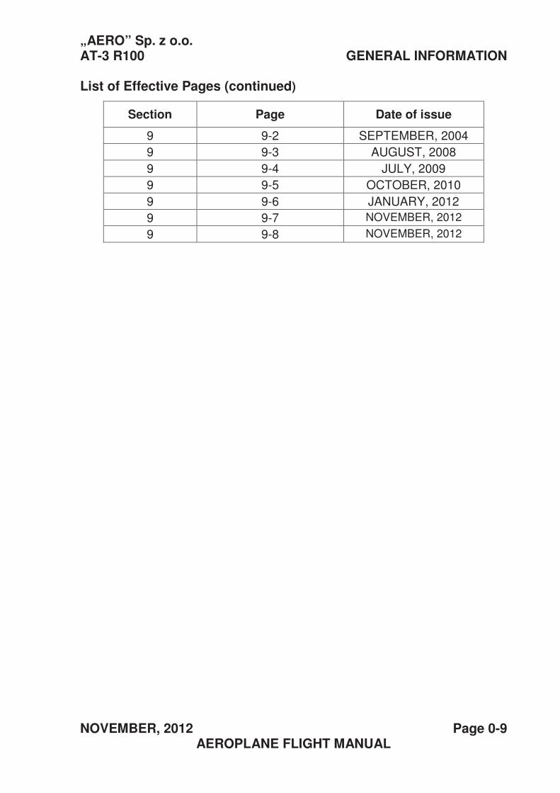
9 9-2 SEPTEMBER, 2004
9 9-3 AUGUST, 2008
9 9-4 JULY, 2009
9 9-5 OCTOBER, 2010
9 9-6 JANUARY, 2012
9 9-7 NOVEMBER, 2012
9 9-8 NOVEMBER, 2012
„AERO” Sp. z o.o. AT-3 R100 GENERAL INFORMATION
Page 0-10 JANUARY, 2012 AEROPLANE FLIGHT MANUAL
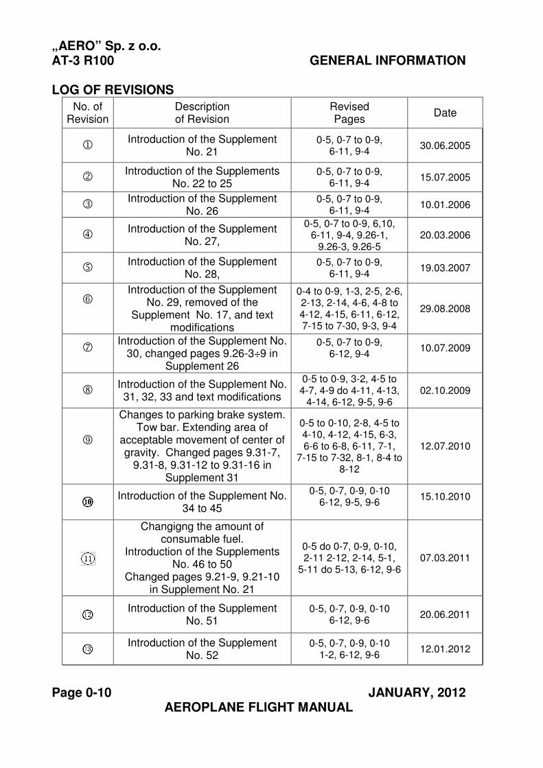
LOG OF REVISIONS
No. of Revision
Description of Revision
Revised Pages
Date
1Introduction of the Supplement
No. 21 0-5, 0-7 to 0-9,
6-11, 9-4 30.06.2005
2Introduction of the Supplements
No. 22 to 25 0-5, 0-7 to 0-9,
6-11, 9-4 15.07.2005
3 Introduction of the Supplement
No. 26 0-5, 0-7 to 0-9,
6-11, 9-4 10.01.2006
4 Introduction of the Supplement
No. 27,
0-5, 0-7 to 0-9, 6,10, 6-11, 9-4, 9.26-1,
9.26-3, 9.26-5 20.03.2006
5 Introduction of the Supplement
No. 28, 0-5, 0-7 to 0-9,
6-11, 9-4 19.03.2007
6 Introduction of the Supplement
No. 29, removed of the Supplement No. 17, and text
modifications
0-4 to 0-9, 1-3, 2-5, 2-6, 2-13, 2-14, 4-6, 4-8 to 4-12, 4-15, 6-11, 6-12, 7-15 to 7-30, 9-3, 9-4
29.08.2008
7 Introduction of the Supplement No.
30, changed pages 9.26-3÷9 in Supplement 26
0-5, 0-7 to 0-9, 6-12, 9-4
10.07.2009
8 Introduction of the Supplement No. 31, 32, 33 and text modifications
0-5 to 0-9, 3-2, 4-5 to 4-7, 4-9 do 4-11, 4-13,
4-14, 6-12, 9-5, 9-6 02.10.2009
9
Changes to parking brake system. Tow bar. Extending area of
acceptable movement of center of gravity. Changed pages 9.31-7,
9.31-8, 9.31-12 to 9.31-16 in Supplement 31
0-5 to 0-10, 2-8, 4-5 to 4-10, 4-12, 4-15, 6-3, 6-6 to 6-8, 6-11, 7-1,
7-15 to 7-32, 8-1, 8-4 to 8-12
12.07.2010
Introduction of the Supplement No. 34 to 45
0-5, 0-7, 0-9, 0-10 6-12, 9-5, 9-6
15.10.2010
Changigng the amount of consumable fuel.
Introduction of the Supplements No. 46 to 50
Changed pages 9.21-9, 9.21-10 in Supplement No. 21
0-5 do 0-7, 0-9, 0-10, 2-11 2-12, 2-14, 5-1,
5-11 do 5-13, 6-12, 9-6 07.03.2011
Introduction of the Supplement No. 51
0-5, 0-7, 0-9, 0-10 6-12, 9-6
20.06.2011
Introduction of the Supplement No. 52
0-5, 0-7, 0-9, 0-10 1-2, 6-12, 9-6
12.01.2012
„AERO” Sp. z o.o. AT-3 R100 GENERAL INFORMATION
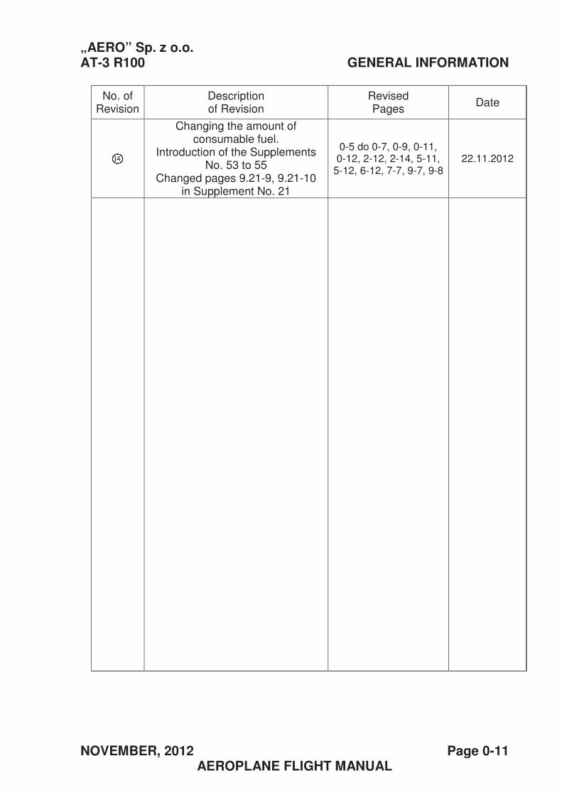
NOVEMBER, 2012 Page 0-11 AEROPLANE FLIGHT MANUAL
No. of Revision
Description of Revision
Revised Pages
Date
Changing the amount of consumable fuel.
Introduction of the Supplements No. 53 to 55
Changed pages 9.21-9, 9.21-10 in Supplement No. 21
0-5 do 0-7, 0-9, 0-11, 0-12, 2-12, 2-14, 5-11,
5-12, 6-12, 7-7, 9-7, 9-8 22.11.2012
„AERO” Sp. z o.o. AT-3 R100 GENERAL INFORMATION
Page 0-12� NOVEMBER, 2012 AEROPLANE FLIGHT MANUAL
PAGE INTENTIONALLY LEFT BLANK
„AERO” Sp. z o.o. SECTION 1 AT-3 R100 GENERAL
SEPTEMBER, 2004 Page 1-1 AEROPLANE FLIGHT MANUAL
Section 1
GENERAL
Page
1.1 Introduction.................................................................................. 1-2
1.2 Basis of certification..................................................................... 1-3
1.3 Warnings, cautions and remarks ................................................. 1-3
1.4 Descriptive data........................................................................... 1-4
1.4.1 Airframe.................................................................................... 1-4
1.4.2 Engine...................................................................................... 1-5
1.4.3 Propeller................................................................................... 1-5
1.5 View of the aeroplane (three projections) .................................... 1-6
1.6 List of definitions and abbreviations............................................. 1-7
SECTION 1 „AERO” Sp. z o. o. GENERAL AT-3R100
Page 1-2 JANUARY, 2012 AEROPLANE FLIGHT MANUAL
1.1 Introduction
This Aeroplane Flight Manual is intended to provide pilots and instructors
with information for safe and effective operation of this aeroplane which
belongs to the Very Light Aeroplane category. This manual contains
informative material, which is to be supplied to the pilot according to the
requirements of JAR-VLA. Some supplementary information is also
introduced into the content by the aeroplane manufacturer. It is the pilot’s
responsibility to acquaint him/herself with the contents of this manual, as
well as with any revisions to it.
CAUTION
THIS AEROPLANE FLIGHT MANUAL IS NOT A FLIGHT TRAINING MANUAL. SEPARATE FLIGHT TRAINING MANUALS EXIST FOR
THAT PURPOSE
Should this manual be lost, the General Inspectorate of Civil Aviation –
Civil Aircraft Inspection Board is to be notified immediately, and if outside
Poland, the local civil aviation authority. Anybody who finds this manual
is requested to deliver it promptly to the manufacturer:
AERO AT Sp. z o. o. , ul. COP-u 2,
39-300 Mielec,
Poland
tel. +48 177745703
fax. +48 177745718;
e-mail: [email protected]
and if outside Poland, to the local civil aviation authority.
„AERO” Sp. z o. o. SECTION 1 AT-3 R100 NORMAL PROCEDURES
AUGUST, 2008 Page 1-3 AEROPLANE FLIGHT MANUAL
1.2 Basis of certification
This aircraft type has been approved by European Aviation Safety
Agency in accordance with JAR-VLA regulations, amended through to
amendment VLA/92/1 and holds a Type Certificate No. A.021.
1.3 Warnings, cautions and remarks
The definitions below concern the following expressions:
warning, caution, note.
WARNING means that if the warnings concerned are not followed, this
will lead to an immediate or significant reduction in flight safety
CAUTION means that if the precautions concerned are not followed this
will lead to an immediate or significant reduction in flight safety
NOTE indicates all special issues, which do not directly affect flight
safety, but are essential or unusual.
6
SECTION 1 „AERO” Sp. z o o. GENERAL AT-3 R100
Page 1-4 SEPTEMBER, 2004 AEROPLANE FLIGHT MANUAL
1.4 Descriptive data
This AT-3 R100 Very Light Aeroplane is a two-seat, single engine, low
wing, all metal aeroplane, with a three-wheel fixed landing gear with a
nose wheel.
1.4.1. Airframe:
1. Dimensions:
- Span 7.550 m / 24’ 9¼”
- Length 6.150 m / 20’ 6”
- Height 2.230 m / 7’ 3¾”
- Dihedral 3 °
- Lifting area 9.30 m2 / 100.1 ft2
- Mean aerodynamic chord 1.27 m / 4’ 2”
- Wing loading 62.6 kg/m2 / 12.8 lb/ft2
- Wing profile NACA 4415
2. Control surface displacements:
- Slab tail (angles related to the fuselage base – red mark on the
fuselage)
Trailing edge down 10° ±1°
Trailing edge up 12° ±1°
- Trim & balancing tab (angles related to the fuselage
base – red mark at the fuselage)
When the slab tail trailing edge is down,
the tab is displaced downward, i.e. by maximum 26° ±3°
When the slab tail trailing edge is up,
the tab is displaced upwards, i.e. by maximum 44° ±3°
„AERO” Sp. z o.o. SECTION 1 AT-3 R100 GENERAL
SEPTEMBER, 2004 Page 1-5 AEROPLANE FLIGHT MANUAL
- Ailerons (angles related to the wing chord)
- Up 20° ±2°
- Down 15° ±2°
- Rudder (angles related to the chord of the fin)
- Each side 25° ±2°
- Wing flaps (angles related to the wing chord)
- Retracted 0° ±2°
- For takeoff 15° ±2°
- For landing 40° +5/-2°
3. Landing gear
- Wheel track 2.26 m / 7’ 5” - Main wheel tyre- Type 380 x 150
- Pressure 2.5 bar / 36 psi - Nose wheel tyre- Type 5.00-4
- Pressure 2.5 bar / 36 psi - Disc brakes - Type of shock absorber elastic strut
1.4.2. Engine
Four cylinder, horizontally opposed BOMBARDIER ROTAX, model
912S2 engine. The cylinders are air-cooled, the cylinder heads, by liquid
coolant. Dual ignition. 98.5 HP take-off power, 92.5 HP continuous
power.
1.4.3. Propeller
Carbon-fibre, fixed pitch, three-blade ELPROP 3-1-1P propeller with 1.73
m (5’ 8”) diameter and clockwise direction of rotation
SECTION 1 „AERO” Sp. z o o. GENERAL AT-3 R100
Page 1-6 SEPTEMBER, 2004 AEROPLANE FLIGHT MANUAL
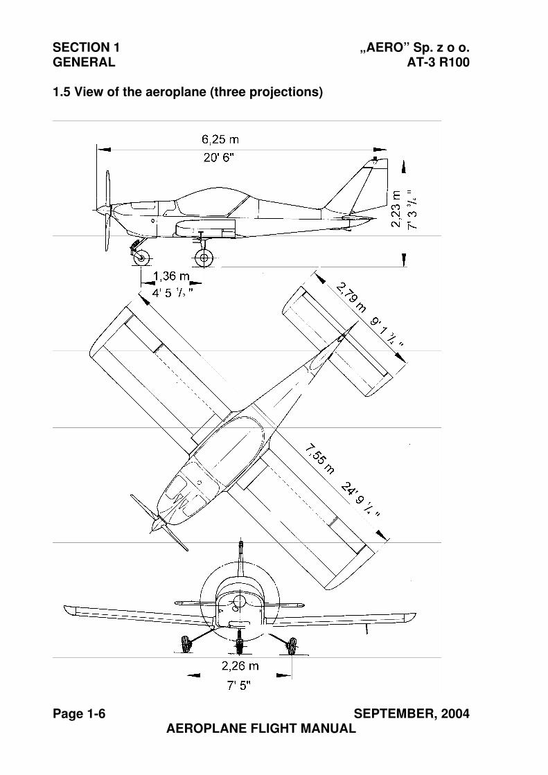
1.5 View of the aeroplane (three projections)
„AERO” Sp. z o.o. SECTION 1 AT-3 R100 GENERAL
SEPTEMBER, 2004 Page 1-7 AEROPLANE FLIGHT MANUAL
1.6 List of definitions and abbreviations
The following words or expressions have been used or may be helpful in
particular Sections of this manual.
Basic speeds and their denotations:
IAS – “INDICATED AIRSPEED” means the speed of an air vessel
indicated by its airspeed indicator co-operating with a Pitot tube,
which is calibrated for the compressibility of an adiabatic airflow
in the conditions of the standard atmosphere at sea level, without
corrected errors of the airspeed measuring system. All IAS
values in this manual presume the airspeed measuring system
error to be zero.
CAS – “CALIBRATED AIRSPEED” means the speed of an air vessel
after aerodynamic and instrument correction. The calibrated
airspeed is equal to the true airspeed in the conditions of the
standard atmosphere at sea level.
TAS – “TRUE AIRSPEED” means the airspeed of an air vessel,
relative to the undisturbed airflow. It is CAS corrected by the
change of air density depending on altitude and temperature.
TAS = CAS ρρο
ρ - air density at the particular altitude
SECTION 1 „AERO” Sp. z o o. GENERAL AT-3 R100
Page 1-8 SEPTEMBER, 2004 AEROPLANE FLIGHT MANUAL
VNE – Maximum never exceed airspeed. This is a limit speed, which
cannot be exceeded in any conditions.
VNO – Maximum structural cruising speed. This is a limit speed which
cannot be exceeded except in non-turbulent conditions, and then,
only with care.
VA – Manoeuvring speed. Above this speed, rapid or full displacement
of the control surfaces may in certain circumstances result in
exceeding the maximum permissible loads of the structure.
VFE – Maximum airspeed with wing flaps extended. This is the maximum
permitted airspeed of the aeroplane with wing flaps extended.
VS1 – Stalling speed, or minimum airspeed of steady flight, at which the
aeroplane is steerable in any other configuration than the landing
configuration.
VS0 – Stalling speed, or minimum airspeed of steady flight, at which the
aeroplane is steerable in the landing configuration.
VX – Airspeed for the maximum angle of climb. This is the airspeed, at
which the maximum increase of altitude over the shortest distance
may be achieved.
VY – Airspeed for the maximum rate of climb. This is the airspeed at
which the maximum increase of altitude in the shortest time may
be achieved.
„AERO” Sp. z o.o. SECTION 1 AT-3 R100 GENERAL
SEPTEMBER, 2004 Page 1-9 AEROPLANE FLIGHT MANUAL
Meteorological denotations
ISA – International Standard Atmosphere.
ISA assumptions:
- The air is a dry perfect gas
- The temperature at sea level is 15 °C / 59°F,
- The pressure at sea level is 1013.25 hPa,
- The drop in the temperature is 3.25 °C per each 500 m of altitude
(3.564°F for each 1000 ft) in the range from sea l evel up to the
altitude, at which the temperature is
–56.5 °C / -70°F .
OAT – Outside Air Temperature. This is the temperature of the static air,
read from the thermometer, or received from the ground meteorological
service, with instrument error and air compressibility effect corrected.
Pressure altitude – This is the altitude read from the altimeter, preset to
the standard pressure at the average sea level (1013 hPa).
Denotation of power and rating
Take-off power – Maximum power.
Maximum continuous power – Maximum power permitted for the
whole flight.
Engine failure – any engine malfunction, engine stop included.
SECTION 1 „AERO” Sp. z o o. GENERAL AT-3 R100
Page 1-10 SEPTEMBER, 2004 AEROPLANE FLIGHT MANUAL
Terminology used for weights and definition of the centre of gravity
of the aeroplane.
Maximum takeoff weight – it is the maximum aeroplane weight at the
moment of beginning the takeoff
Maximum landing weight – it is the maximum aeroplane weight in the
moment of touch down.
Empty aeroplane weight – It is the weight of the equipped aeroplane,
with unusable fuel and full amount of operational agents (oil, cooling
agent and hydraulic fluid).
Centre of Gravity – imaginary point on the aeroplane. The aeroplane
suspended at this point is in equilibrium.
Limits of the CG – range of C.G positions, which must not be exceeded,
when loading the aeroplane to a given total weight.
MAC – the Mean Aerodynamic Chord.
Consumable fuel – This is the amount of fuel which may be consumed,
without symptoms of a rough engine running.
Unusable fuel – The amount of fuel, not less than that which gives the
first symptoms of rough engine running, under the least favourable
conditions for fuel feeding the fuel tank, which may occur during normal
operation of the aeroplane.
„AERO” Sp. z o.o. SECTION 1 AT-3 R100 GENERAL
SEPTEMBER, 2004 Page 1-11 AEROPLANE FLIGHT MANUAL
Operational denotations
Take-off run – the distance from the location where the aeroplane
begins to move, to the location where the aeroplane lifts-off from the
takeoff surface.
Take-off distance – the distance from the location where the aeroplane
begins to move, to the location where the aeroplane reaches the altitude
of 15 m / 50 ft. This distance is to be measured parallel to the takeoff
surface.
Landing distance – the distance from the location where the aeroplane
has the altitude of 15 m / 50 ft, to the location where the aeroplane stops.
This distance is to be measured parallel to the takeoff surface.
Landing run – the distance from the location where the aeroplane
touches down on the landing surface, to the location where the
aeroplane stops.
Demonstrated crosswind capabilities – value of crosswind velocity for
which it has been demonstrated that for take-off and landing no exten-
sive pilot force, skill or concentration is required.
SECTION 1 „AERO” Sp. z o o. GENERAL AT-3 R100
Page 1-12 SEPTEMBER, 2004 AEROPLANE FLIGHT MANUAL
THIS PAGE IS LEFT INTENTIONALLY BLANK
„AERO” Sp. z o. o. SECTION 2 AT-3 R100 LIMITATIONS
SEPTEMBER, 2004 Page 2-1 AEROPLANE FLIGHT MANUAL
Section 2
LIMITATIONS
Page
2.1. Introduction ............................................................................... 2-2
2.2. Airspeeds.................................................................................. 2-2
2.3. Marking of the airspeed indicator.............................................. 2-3
2.4. Power plant............................................................................... 2-4
2.5. Marking of the engine monitoring instruments.......................... 2-6
2.6. Weight....................................................................................... 2-7
2.7. Centre of Gravity....................................................................... 2-8
2.8. Approved manoeuvres.............................................................. 2-9
2.9. Controlled Load Factors ......................................................... 2-10
2.10. Crew of the aircraft ............................................................... 2-10
2.11. Types of operation ................................................................ 2-10
2.12. Fuel....................................................................................... 2-12
2.13. Number of seats ................................................................... 2-12
2.14. Limitation placards................................................................ 2-12
SECTION 2 „AERO” Sp. z o. o. LIMITATIONS AT-3 R100
Page 2-2 AUGUST, 2008 AEROPLANE FLIGHT MANUAL
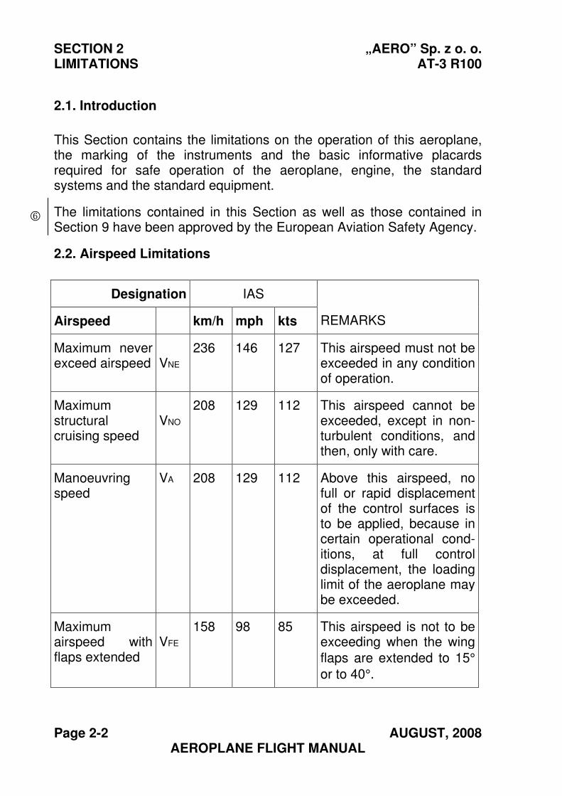
2.1. Introduction
This Section contains the limitations on the operation of this aeroplane, the marking of the instruments and the basic informative placards required for safe operation of the aeroplane, engine, the standard systems and the standard equipment.
The limitations contained in this Section as well as those contained in Section 9 have been approved by the European Aviation Safety Agency.
2.2. Airspeed Limitations
Designation IAS
Airspeed km/h mph kts REMARKS
Maximum never exceed airspeed VNE
236 146 127 This airspeed must not be exceeded in any condition of operation.
Maximum structural cruising speed
VNO
208 129 112 This airspeed cannot be exceeded, except in non-turbulent conditions, and then, only with care.
Manoeuvring speed
VA 208 129 112 Above this airspeed, no full or rapid displacement of the control surfaces is to be applied, because in certain operational cond-itions, at full control displacement, the loading limit of the aeroplane may be exceeded.
Maximum airspeed with flaps extended
VFE
158 98 85 This airspeed is not to be exceeding when the wing
flaps are extended to 15°
or to 40°.
6
„AERO” Sp. z o. o. SECTION 2 AT-3 R100 LIMITATIONS
SEPTEMBER, 2004 Page 2-3 AEROPLANE FLIGHT MANUAL
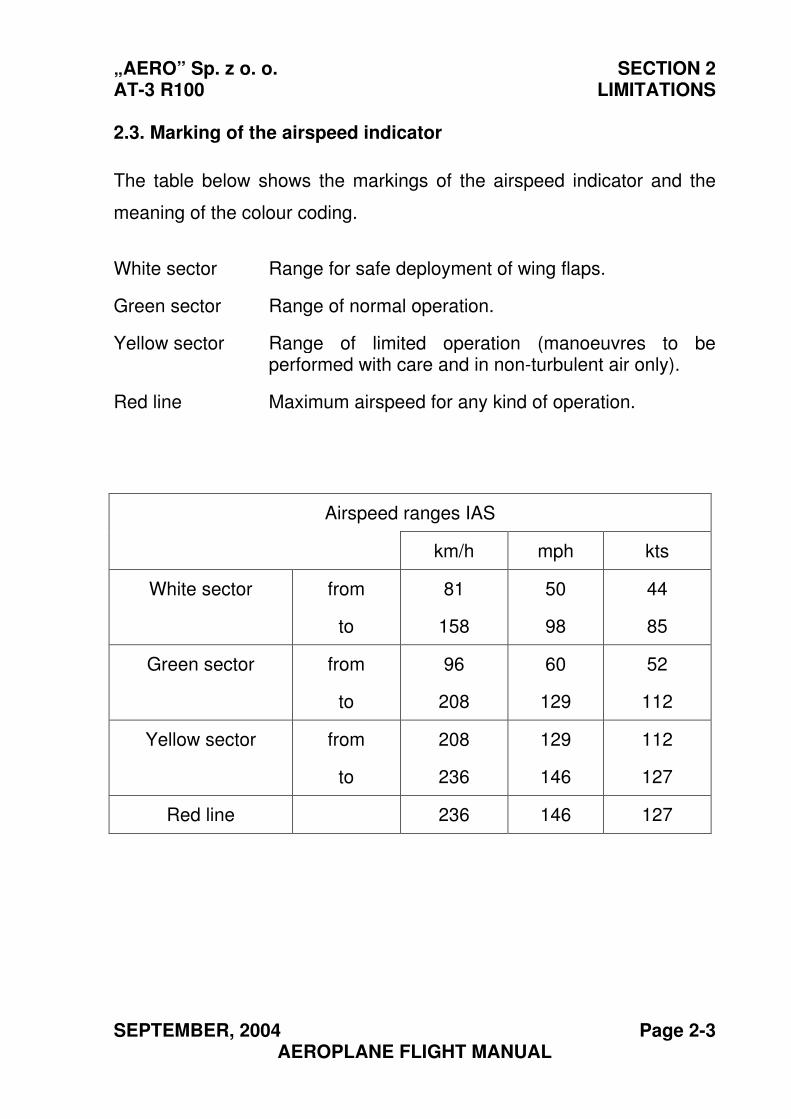
2.3. Marking of the airspeed indicator
The table below shows the markings of the airspeed indicator and the
meaning of the colour coding.
White sector Range for safe deployment of wing flaps.
Green sector Range of normal operation.
Yellow sector Range of limited operation (manoeuvres to be performed with care and in non-turbulent air only).
Red line Maximum airspeed for any kind of operation.
Airspeed ranges IAS
km/h mph kts
White sector from
to
81
158
50
98
44
85
Green sector from
to
96
208
60
129
52
112
Yellow sector from
to
208
236
129
146
112
127
Red line 236 146 127
SECTION 2 „AERO” Sp. z o. o. LIMITATIONS AT-3 R100
Page 2-4 SEPTEMBER, 2004 AEROPLANE FLIGHT MANUAL
2.4. Power plant
ENGINE
Manufacturer
Engine model
Maximum takeoff power
Maximum continuous power
BOMBARDIER-ROTAX
912S2
98.5 HP
69 kW / 92.5 HP Engine maximum RPM
- take-off (5 MIN.)
- continuous
- idle
5 800 rpm
5 500 rpm
~1 400 rpm
Maximum cylinder head temperature (CHT) 135°C / 275°F
Oil temperature
-maximum 130°C / 266°F
-minimum 50°C / 122°F
-normal operational 90 to 110 °C
194 to 230°F
Oil pressure:
-minimum
-maximum
-normal
0.8 bar / 11.6 psi
7 bar / 101.5 psi
2 - 5 bar / 29 -72.5 psi
Fuel pressure:
-maximum
-minimum
0.40 bar / 5.8 psi
0.15 bar / 2.2 psi
Engine Starting Temperatures
-maximum
-minimum
50 °C / 122°F
-25 °C / -13°F
„AERO” Sp. z o. o. SECTION 2 AT-3 R100 LIMITATIONS
AUGUST, 2008 Page 2-5 AEROPLANE FLIGHT MANUAL
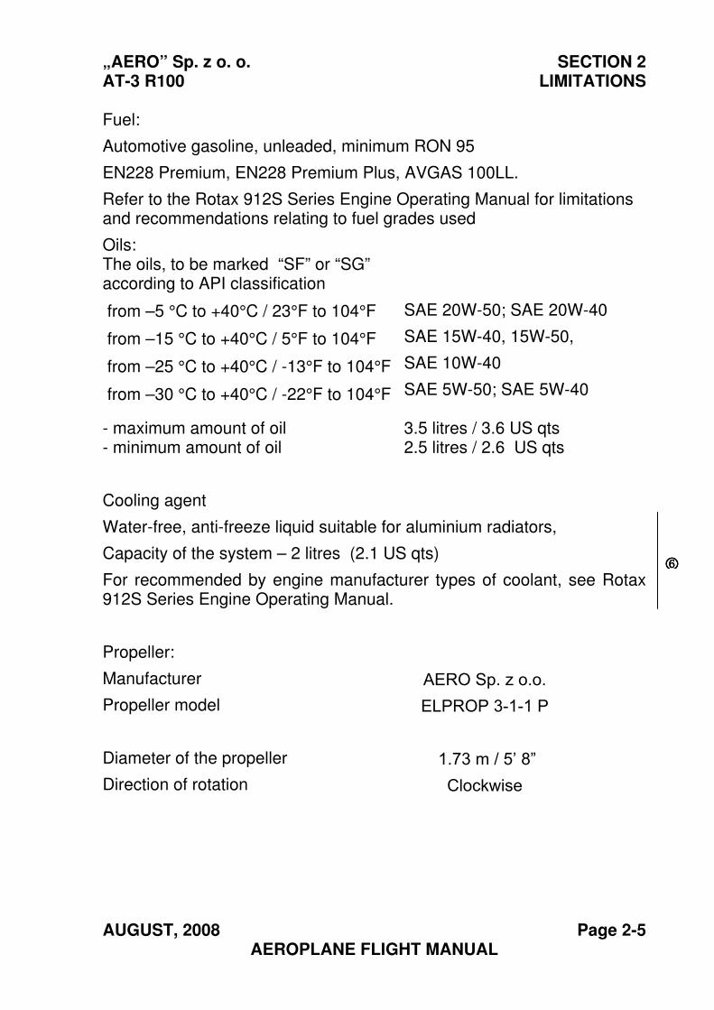
Fuel:
Automotive gasoline, unleaded, minimum RON 95
EN228 Premium, EN228 Premium Plus, AVGAS 100LL.
Refer to the Rotax 912S Series Engine Operating Manual for limitations and recommendations relating to fuel grades used
Oils: The oils, to be marked “SF” or “SG” according to API classification
from –5 °C to +40°C / 23°F to 104°F
from –15 °C to +40°C / 5°F to 104°F
from –25 °C to +40°C / -13°F to 104°F
from –30 °C to +40°C / -22°F to 104°F
SAE 20W-50; SAE 20W-40
SAE 15W-40, 15W-50,
SAE 10W-40
SAE 5W-50; SAE 5W-40
- maximum amount of oil - minimum amount of oil
3.5 litres / 3.6 US qts 2.5 litres / 2.6 US qts
Cooling agent
Water-free, anti-freeze liquid suitable for aluminium radiators,
Capacity of the system – 2 litres (2.1 US qts)
For recommended by engine manufacturer types of coolant, see Rotax 912S Series Engine Operating Manual.
Propeller:
Manufacturer
Propeller model
Diameter of the propeller
Direction of rotation
AERO Sp. z o.o. ELPROP 3-1-1 P
1.73 m / 5’ 8” Clockwise
6666
SECTION 2 „AERO” Sp. z o. o. LIMITATIONS AT-3 R100
Page 2-6 AUGUST, 2008 AEROPLANE FLIGHT MANUAL
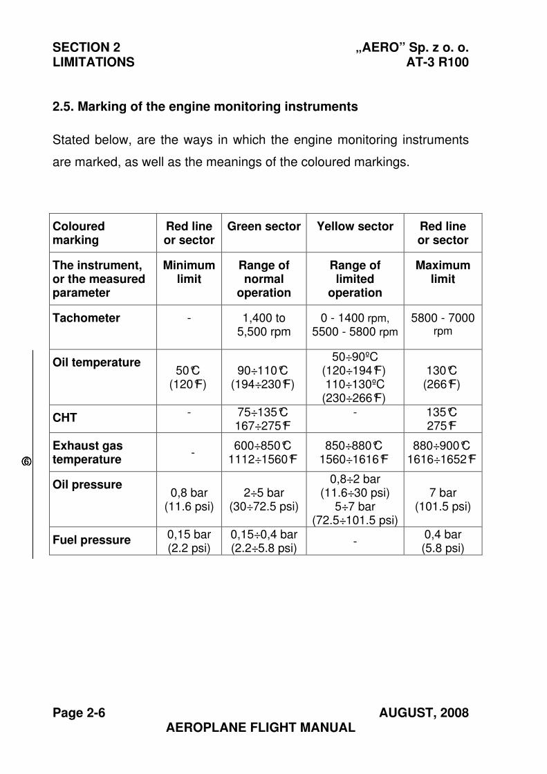
2.5. Marking of the engine monitoring instruments
Stated below, are the ways in which the engine monitoring instruments
are marked, as well as the meanings of the coloured markings.
Coloured marking
Red line or sector
Green sector Yellow sector Red line or sector
The instrument, or the measured parameter
Minimum limit
Range of normal
operation
Range of limited
operation
Maximum limit
Tachometer - 1,400 to 5,500 rpm
0 - 1400 rpm,
5500 - 5800 rpm
5800 - 7000rpm
Oil temperature 50°C
(120°F) 90÷110°C
(194÷230°F)
50÷90ºC (120÷194°F) 110÷130ºC
(230÷266°F)
130°C (266°F)
CHT - 75÷135°C 167÷275°F
- 135°C 275°F
Exhaust gas temperature
- 600÷850°C
1112÷1560°F850÷880°C
1560÷1616°F 880÷900°C
1616÷1652°F
Oil pressure 0,8 bar
(11.6 psi) 2÷5 bar
(30÷72.5 psi)
0,8÷2 bar (11.6÷30 psi)
5÷7 bar (72.5÷101.5 psi)
7 bar (101.5 psi)
Fuel pressure 0,15 bar (2.2 psi)
0,15÷0,4 bar (2.2÷5.8 psi)
- 0,4 bar (5.8 psi)
6666
„AERO” Sp. z o. o. SECTION 2 AT-3 R100 LIMITATIONS
SEPTEMBER, 2004 Page 2-7 AEROPLANE FLIGHT MANUAL
2.6. Weight
Maximum take-off weight 582 kg / 1283 lb
Maximum landing weight 582 kg / 1283 lb
Empty, equipped aeroplane weight 350 kg / 772 lb
Maximum load in the luggage compartment:
- port luggage compartment (large)
- starboard luggage compartment (small)
30 kg / 66 lb
20 kg / 44 lb
10 kg / 22 lb
SECTION 2 „AERO” Sp. z o. o. LIMITATIONS AT-3 R100
Page 2-8 JULY, 2010 AEROPLANE FLIGHT MANUAL
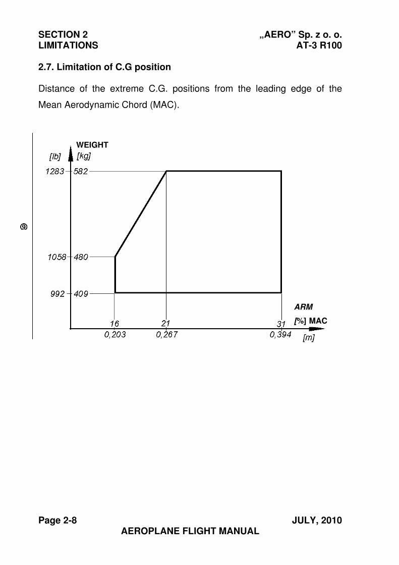
2.7. Limitation of C.G position
Distance of the extreme C.G. positions from the leading edge of the
Mean Aerodynamic Chord (MAC).
WEIGHT
ARM
[%] MAC
9999
„AERO” Sp. z o. o. SECTION 2 AT-3 R100 LIMITATIONS
SEPTEMBER, 2004 Page 2-9 AEROPLANE FLIGHT MANUAL
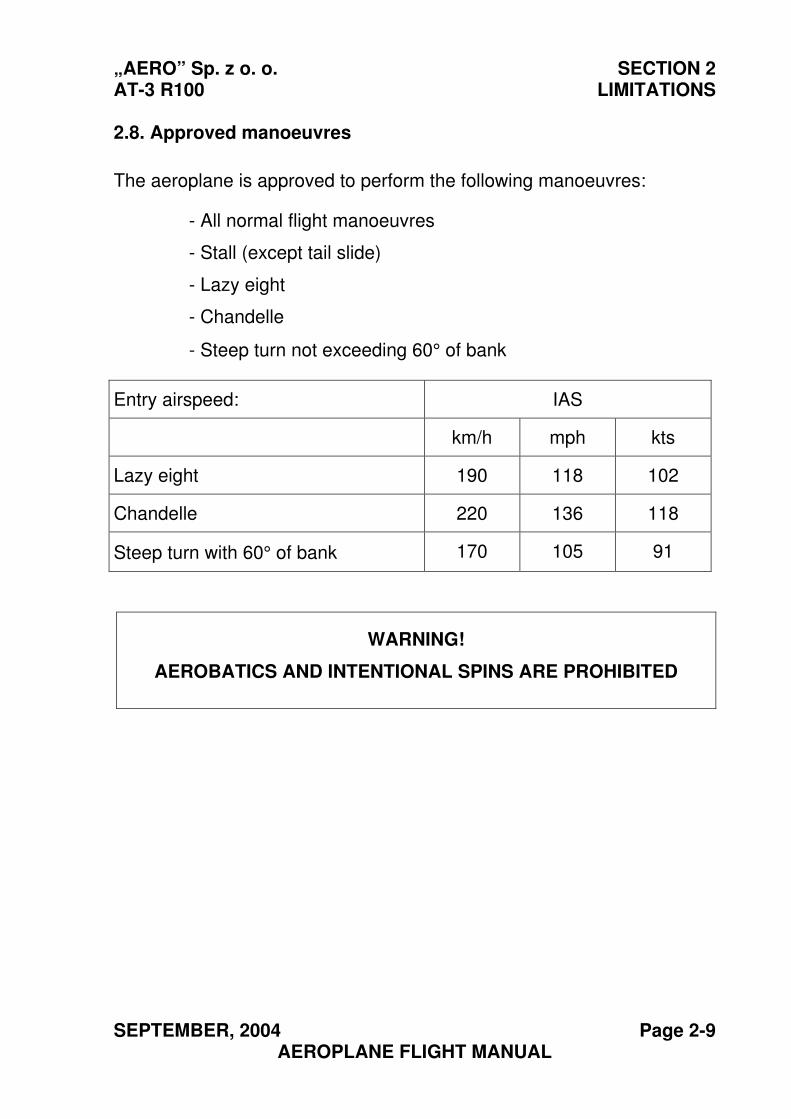
2.8. Approved manoeuvres
The aeroplane is approved to perform the following manoeuvres:
- All normal flight manoeuvres
- Stall (except tail slide)
- Lazy eight
- Chandelle
- Steep turn not exceeding 60° of bank
Entry airspeed: IAS
km/h mph kts
Lazy eight 190 118 102
Chandelle 220 136 118
Steep turn with 60° of bank 170 105 91
WARNING!
AEROBATICS AND INTENTIONAL SPINS ARE PROHIBITED
SECTION 2 „AERO” Sp. z o. o. LIMITATIONS AT-3 R100
Page 2-10 SEPTEMBER, 2004 AEROPLANE FLIGHT MANUAL
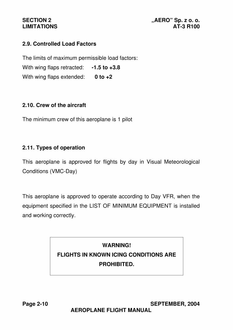
2.9. Controlled Load Factors
The limits of maximum permissible load factors:
With wing flaps retracted: -1.5 to +3.8
With wing flaps extended: 0 to +2
2.10. Crew of the aircraft
The minimum crew of this aeroplane is 1 pilot
2.11. Types of operation
This aeroplane is approved for flights by day in Visual Meteorological
Conditions (VMC-Day)
This aeroplane is approved to operate according to Day VFR, when the
equipment specified in the LIST OF MINIMUM EQUIPMENT is installed
and working correctly.
WARNING!
FLIGHTS IN KNOWN ICING CONDITIONS ARE
PROHIBITED.
„AERO” Sp. z o. o. SECTION 2 AT-3 R100 LIMITATIONS
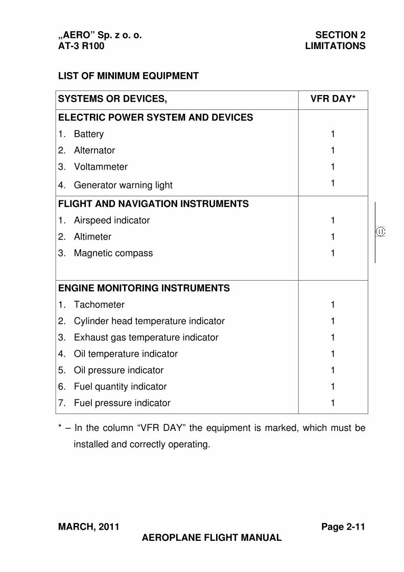
MARCH, 2011 Page 2-11 AEROPLANE FLIGHT MANUAL
LIST OF MINIMUM EQUIPMENT
SYSTEMS OR DEVICES, VFR DAY*
ELECTRIC POWER SYSTEM AND DEVICES
1. Battery
2. Alternator
3. Voltammeter
4. Generator warning light
1
1
1
1
FLIGHT AND NAVIGATION INSTRUMENTS
1. Airspeed indicator
2. Altimeter
3. Magnetic compass
1
1
1
ENGINE MONITORING INSTRUMENTS
1. Tachometer
2. Cylinder head temperature indicator
3. Exhaust gas temperature indicator
4. Oil temperature indicator
5. Oil pressure indicator
6. Fuel quantity indicator
7. Fuel pressure indicator
1
1
1
1
1
1
1
* – In the column “VFR DAY” the equipment is marked, which must be
installed and correctly operating.
SECTION 2 „AERO” Sp. z o. o. LIMITATIONS AT-3 R100
Page 2-12 NOVEMBER, 2012 AEROPLANE FLIGHT MANUAL
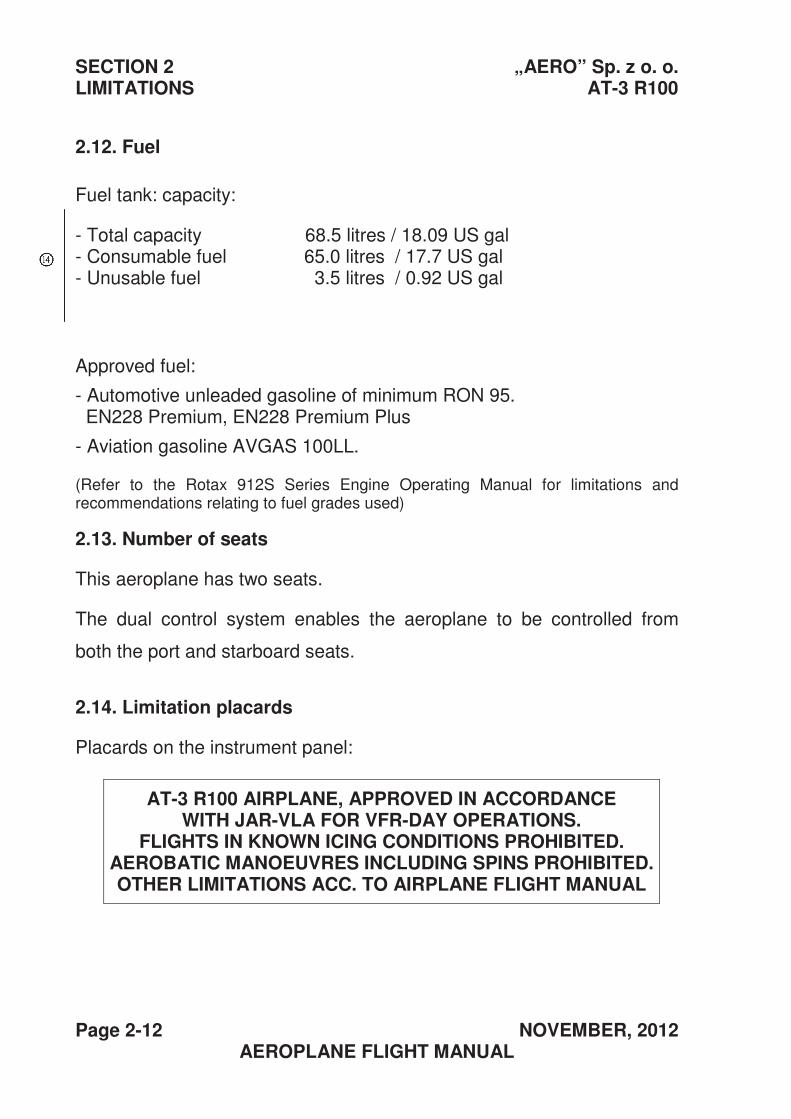
2.12. Fuel
Fuel tank: capacity:
- Total capacity 68.5 litres / 18.09 US gal - Consumable fuel 65.0 litres / 17.7 US gal - Unusable fuel 3.5 litres / 0.92 US gal
Approved fuel:
- Automotive unleaded gasoline of minimum RON 95. EN228 Premium, EN228 Premium Plus
- Aviation gasoline AVGAS 100LL.
(Refer to the Rotax 912S Series Engine Operating Manual for limitations and recommendations relating to fuel grades used)
2.13. Number of seats
This aeroplane has two seats.
The dual control system enables the aeroplane to be controlled from
both the port and starboard seats.
2.14. Limitation placards
Placards on the instrument panel:
AT-3 R100 AIRPLANE, APPROVED IN ACCORDANCE WITH JAR-VLA FOR VFR-DAY OPERATIONS.
FLIGHTS IN KNOWN ICING CONDITIONS PROHIBITED. AEROBATIC MANOEUVRES INCLUDING SPINS PROHIBITED. OTHER LIMITATIONS ACC. TO AIRPLANE FLIGHT MANUAL
„AERO” Sp. z o. o. SECTION 2 AT-3 R100 LIMITATIONS
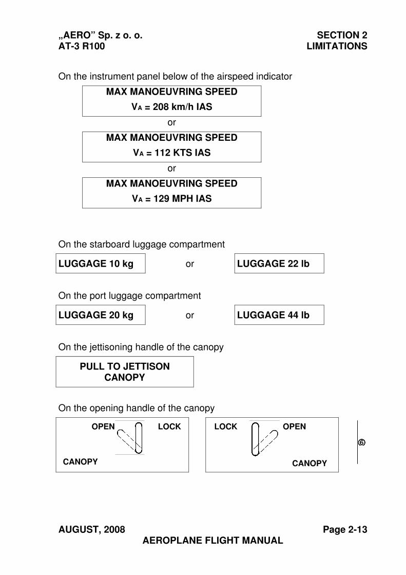
AUGUST, 2008 Page 2-13 AEROPLANE FLIGHT MANUAL
On the instrument panel below of the airspeed indicator
MAX MANOEUVRING SPEED
VA = 208 km/h IAS
or
MAX MANOEUVRING SPEED
VA = 112 KTS IAS
or
MAX MANOEUVRING SPEED
VA = 129 MPH IAS
On the starboard luggage compartment
LUGGAGE 10 kg or LUGGAGE 22 lb
On the port luggage compartment
LUGGAGE 20 kg or LUGGAGE 44 lb
On the jettisoning handle of the canopy
PULL TO JETTISON CANOPY
On the opening handle of the canopy
OPEN LOCK
CANOPY
LOCK OPEN
CANOPY
6666
SECTION 2 „AERO” Sp. z o. o. LIMITATIONS AT-3 R100
Page 2-14 NOVEMBER, 2012 AEROPLANE FLIGHT MANUAL
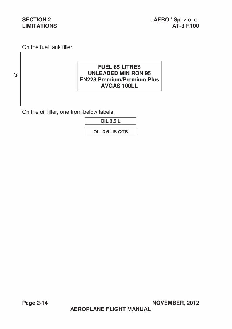
On the fuel tank filler
FUEL 65 LITRES UNLEADED MIN RON 95
EN228 Premium/Premium Plus AVGAS 100LL
On the oil filler, one from below labels:
OIL 3,5 L
OIL 3.6 US QTS
„AERO” ,Sp. z o.o. SECTION 3 AT-3 R100 EMERGENCY PROCEDURES
SEPTEMBER, 2004 Page 3-1 AEROPLANE FLIGHT MANUAL
Section 3
EMERGENCY PROCEDURES
Page
3.1. Introduction ............................................................................... 3-2
3.2. Engine failure............................................................................ 3-2
3.2.1. Engine failure during takeoff .............................................. 3-2
3.2.2. Engine failures in flight ....................................................... 3-2
3.3. Engine re-starting in flight ......................................................... 3-3
3.4. Smoke and fire.......................................................................... 3-4
3.4.1. Fire on ground.................................................................... 3-4
3.4.2. Fire in flight......................................................................... 3-4
3.5. Gliding ...................................................................................... 3-5
3.6. Emergency landing ................................................................... 3-5
3.6.1. Precautionary landing ........................................................ 3-5
3.6.2. Landing after engine failure................................................ 3-6
3.7. Recovering from unintentional spin .......................................... 3-6
3.8. Other emergency procedures ................................................... 3-7
3.8.1. Icing ................................................................................... 3-7
3.8.2. Abandoning the aeroplane with use of parachute.............. 3-7
3.8.3. Failure of the electric system ............................................. 3-7
3.8.4. Failure of the static or pitot pressure systems.................... 3-8
3.8.5. Failure of balancing tab control system of slab tail ............ 3-8
SECTION 3 „AERO” Sp. z 0.0. EMERGENCY PROCEDURES AT-3 R100
Page 3-2 OCTOBER, 2009 AEROPLANE FLIGHT MANUAL
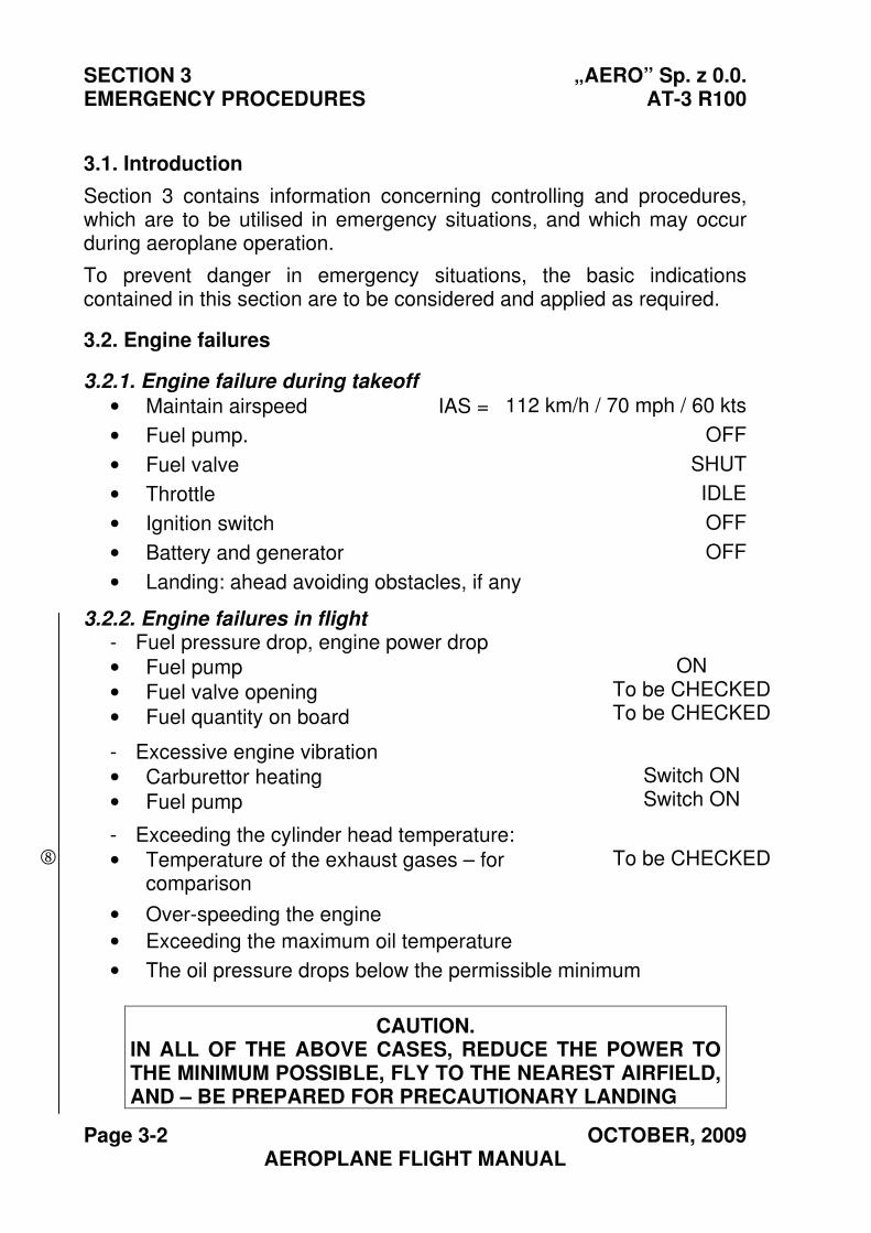
3.1. Introduction
Section 3 contains information concerning controlling and procedures, which are to be utilised in emergency situations, and which may occur during aeroplane operation.
To prevent danger in emergency situations, the basic indications contained in this section are to be considered and applied as required.
3.2. Engine failures
3.2.1. Engine failure during takeoff
• Maintain airspeed IAS = 112 km/h / 70 mph / 60 kts
• Fuel pump. OFF
• Fuel valve SHUT
• Throttle IDLE
• Ignition switch OFF
• Battery and generator OFF
• Landing: ahead avoiding obstacles, if any
3.2.2. Engine failures in flight - Fuel pressure drop, engine power drop
• Fuel pump
• Fuel valve opening
• Fuel quantity on board
ON To be CHECKEDTo be CHECKED
- Excessive engine vibration
• Carburettor heating
• Fuel pump
Switch ON Switch ON
- Exceeding the cylinder head temperature:
• Temperature of the exhaust gases – forcomparison
To be CHECKED
• Over-speeding the engine
• Exceeding the maximum oil temperature
• The oil pressure drops below the permissible minimum
CAUTION. IN ALL OF THE ABOVE CASES, REDUCE THE POWER TO THE MINIMUM POSSIBLE, FLY TO THE NEAREST AIRFIELD, AND – BE PREPARED FOR PRECAUTIONARY LANDING
�
„AERO” ,Sp. z o.o. SECTION 3 AT-3 R100 EMERGENCY PROCEDURES
SEPTEMBER, 2004 Page 3-3 AEROPLANE FLIGHT MANUAL
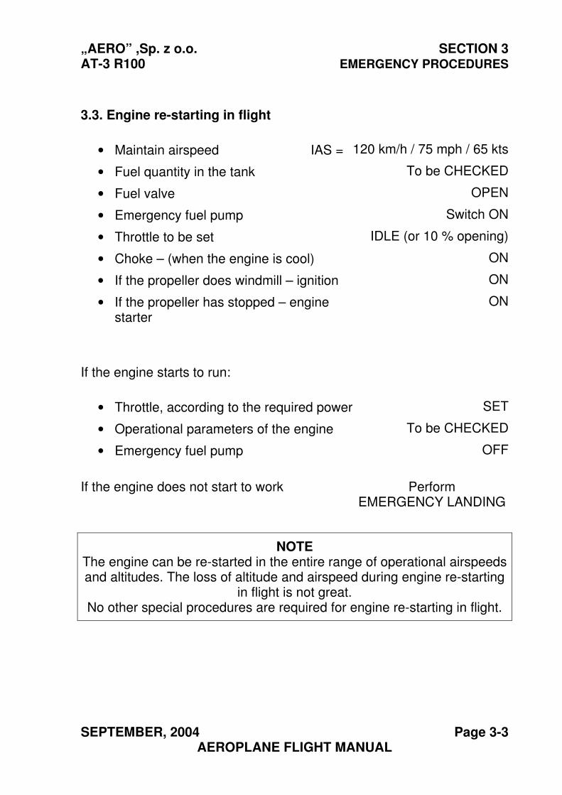
3.3. Engine re-starting in flight
• Maintain airspeed IAS = 120 km/h / 75 mph / 65 kts
• Fuel quantity in the tank To be CHECKED
• Fuel valve OPEN
• Emergency fuel pump Switch ON
• Throttle to be set IDLE (or 10 % opening)
• Choke – (when the engine is cool) ON
• If the propeller does windmill – ignition ON
• If the propeller has stopped – enginestarter
ON
If the engine starts to run:
• Throttle, according to the required power SET
• Operational parameters of the engine To be CHECKED
• Emergency fuel pump OFF
If the engine does not start to work Perform EMERGENCY LANDING
NOTE The engine can be re-started in the entire range of operational airspeeds and altitudes. The loss of altitude and airspeed during engine re-starting
in flight is not great. No other special procedures are required for engine re-starting in flight.
SECTION 3 „AERO” Sp. z 0.0. EMERGENCY PROCEDURES AT-3 R100
Page 3-4 SEPTEMBER, 2004 AEROPLANE FLIGHT MANUAL
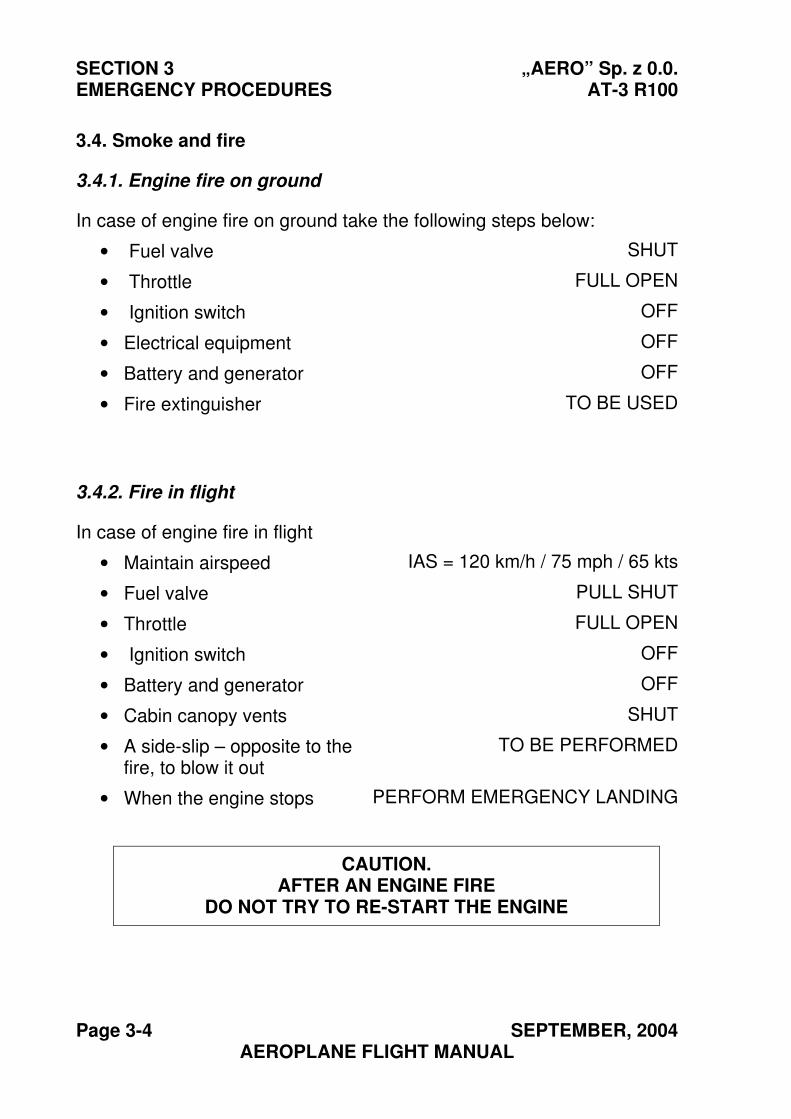
3.4. Smoke and fire
3.4.1. Engine fire on ground
In case of engine fire on ground take the following steps below:
• Fuel valve SHUT
• Throttle FULL OPEN
• Ignition switch OFF
• Electrical equipment OFF
• Battery and generator OFF
• Fire extinguisher TO BE USED
3.4.2. Fire in flight
In case of engine fire in flight
• Maintain airspeed IAS = 120 km/h / 75 mph / 65 kts
• Fuel valve PULL SHUT
• Throttle FULL OPEN
• Ignition switch OFF
• Battery and generator OFF
• Cabin canopy vents SHUT
• A side-slip – opposite to thefire, to blow it out
TO BE PERFORMED
• When the engine stops PERFORM EMERGENCY LANDING
CAUTION. AFTER AN ENGINE FIRE
DO NOT TRY TO RE-START THE ENGINE
„AERO” ,Sp. z o.o. SECTION 3 AT-3 R100 EMERGENCY PROCEDURES
SEPTEMBER, 2004 Page 3-5 AEROPLANE FLIGHT MANUAL
In case of fire in the electrical system
• Maintain airspeed IAS = 120 km/h / 75 mph / 65 kts
• Electrical equipment OFF
• Fire extinguisher (if fire is in the cabin) TO BE USED
• Cabin canopy vents KEEP OPEN
• If the fire persists, decide upon a place for landing.
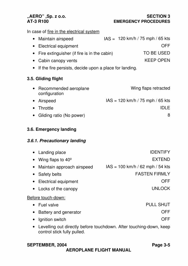
3.5. Gliding flight
• Recommended aeroplaneconfiguration
Wing flaps retracted
• Airspeed IAS = 120 km/h / 75 mph / 65 kts
• Throttle IDLE
• Gliding ratio (No power) 8
3.6. Emergency landing
3.6.1. Precautionary landing
• Landing place IDENTIFY
• Wing flaps to 40º EXTEND
• Maintain approach airspeed IAS = 100 km/h / 62 mph / 54 kts
• Safety belts FASTEN FIRMLY
• Electrical equipment OFF
• Locks of the canopy UNLOCK
Before touch-down:
• Fuel valve PULL SHUT
• Battery and generator OFF
• Ignition switch OFF
• Levelling out directly before touchdown. After touching-down, keepcontrol stick fully pulled.
SECTION 3 „AERO” Sp. z 0.0. EMERGENCY PROCEDURES AT-3 R100
Page 3-6 SEPTEMBER, 2004 AEROPLANE FLIGHT MANUAL
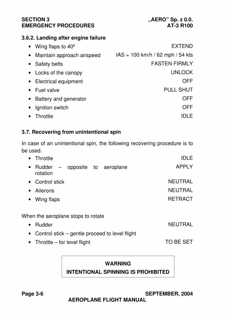
3.6.2. Landing after engine failure
• Wing flaps to 40º EXTEND
• Maintain approach airspeed IAS = 100 km/h / 62 mph / 54 kts
• Safety belts FASTEN FIRMLY
• Locks of the canopy UNLOCK
• Electrical equipment OFF
• Fuel valve PULL SHUT
• Battery and generator OFF
• Ignition switch OFF
• Throttle IDLE
3.7. Recovering from unintentional spin
In case of an unintentional spin, the following recovering procedure is to
be used.
• Throttle IDLE
• Rudder – opposite to aeroplanerotation
APPLY
• Control stick NEUTRAL
• Ailerons NEUTRAL
• Wing flaps RETRACT
When the aeroplane stops to rotate
• Rudder NEUTRAL
• Control stick – gentle proceed to level flight
• Throttle – for level flight TO BE SET
WARNING
INTENTIONAL SPINNING IS PROHIBITED
„AERO” ,Sp. z o.o. SECTION 3 AT-3 R100 EMERGENCY PROCEDURES
SEPTEMBER, 2004 Page 3-7 AEROPLANE FLIGHT MANUAL
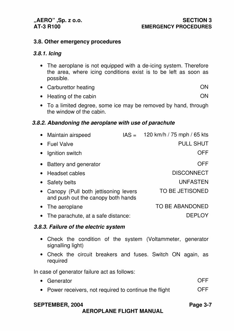
3.8. Other emergency procedures
3.8.1. Icing
• The aeroplane is not equipped with a de-icing system. Thereforethe area, where icing conditions exist is to be left as soon aspossible.
• Carburettor heating ON
• Heating of the cabin ON
• To a limited degree, some ice may be removed by hand, throughthe window of the cabin.
3.8.2. Abandoning the aeroplane with use of parachute
• Maintain airspeed IAS = 120 km/h / 75 mph / 65 kts
• Fuel Valve PULL SHUT
• Ignition switch OFF
• Battery and generator OFF
• Headset cables DISCONNECT
• Safety belts UNFASTEN
• Canopy (Pull both jettisoning leversand push out the canopy both hands
TO BE JETISONED
• The aeroplane TO BE ABANDONED
• The parachute, at a safe distance: DEPLOY
3.8.3. Failure of the electric system
• Check the condition of the system (Voltammeter, generatorsignalling light)
• Check the circuit breakers and fuses. Switch ON again, asrequired
In case of generator failure act as follows:
• Generator OFF
• Power receivers, not required to continue the flight OFF
SECTION 3 „AERO” Sp. z 0.0. EMERGENCY PROCEDURES AT-3 R100
Page 3-8 SEPTEMBER, 2004 AEROPLANE FLIGHT MANUAL
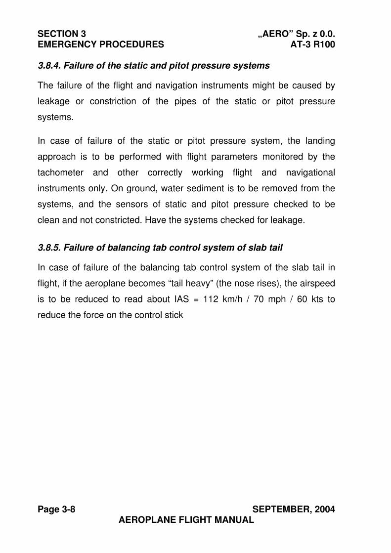
3.8.4. Failure of the static and pitot pressure systems
The failure of the flight and navigation instruments might be caused by
leakage or constriction of the pipes of the static or pitot pressure
systems.
In case of failure of the static or pitot pressure system, the landing
approach is to be performed with flight parameters monitored by the
tachometer and other correctly working flight and navigational
instruments only. On ground, water sediment is to be removed from the
systems, and the sensors of static and pitot pressure checked to be
clean and not constricted. Have the systems checked for leakage.
3.8.5. Failure of balancing tab control system of slab tail
In case of failure of the balancing tab control system of the slab tail in
flight, if the aeroplane becomes “tail heavy” (the nose rises), the airspeed
is to be reduced to read about IAS = 112 km/h / 70 mph / 60 kts to
reduce the force on the control stick
„AERO” Sp. z o. o. SECTION 4 AT-3 R100 NORMAL PROCEDURES
SEPTEMBER, 2004 Page 4-1 AEROPLANE FLIGHT MANUAL
Section 4
NORMAL PROCEDURES
Page
4.1. Introduction ......................................................................... 4-2
4.2. Rigging and de-rigging the aeroplane................................. 4-2
4.3. Daily pre-flight and post-flight inspection ............................ 4-2
4.4. Preparation for flight............................................................ 4-4
4.4.1. Determining weight and centre of gravity............................ 4-4
4.4.2. Pre-flight Inspection of the aeroplane ................................. 4-5
4.5. Normal procedures and list of inspection tasks................... 4-8
4.5.1. Airspeeds for safe operation ............................................... 4-8
4.5.2. Before starting engine......................................................... 4-8
4.5.3. Using an electric ground power source............................... 4-9
4.5.4. Engine starting .................................................................... 4-9
4.5.5. Before taxiing .................................................................... 4-12
4.5.6. Taxiing .............................................................................. 4-12
4.5.7. Before takeoff.................................................................... 4-13
4.5.8. Takeoff .............................................................................. 4-13
4.5.9. Climb................................................................................. 4-13
4.5.10. Cruise................................................................................ 4-14
4.5.11 Descent............................................................................. 4-14
4.5.12. Before landing................................................................... 4-14
4.5.13. Landing ............................................................................. 4-14
4.5.14. Balked landing .................................................................. 4-14
4.5.15. After the landing................................................................ 4-14
4.5.16. Engine shutdown .............................................................. 4-15
4.5.17. After the flight.................................................................... 4-15
4.6. Additional information ....................................................... 4-15
4.6.1. Stall ................................................................................... 4-15
4.6.2. Flight manoeuvres ............................................................ 4-16
4.6.3. Flight with a passenger ..................................................... 4-16
4.6.4. Crosswind takeoff or landing............................................. 4-16
4.6.5. Operational speed during takeoff and landing .................. 4-17
SECTION 4 „AERO” Sp. z o. o. NORMAL PROCEDURES AT-3 R100
Page 4-2 SEPTEMBER, 2004 AEROPLANE FLIGHT MANUAL
4.1. Introduction
Section 4 contains the list of inspection tasks and detailed procedures for
normal aeroplane operation with standard equipment installed. Normal
procedures concerning the optional equipment or systems are contained
in Section 9.
4.2. Rigging and de-rigging the aeroplane
If de-rigging the aeroplane and preparation for transportation is
necessary, refer to Aeroplane Maintenance Manual of AT-3 R100
Aeroplane, Section 2.6 – Transport of the de-rigged Aeroplane
4.3. Daily pre-flight and post-flight inspection
Recommended daily pre-flight inspection:
- Check amount of fuel, oil and engine coolant
- Check for leaks of oil, fuel and coolant.
- Drain fuel sediment
- Check condition of exhaust pipes.
- Check condition of nose and main landing gear: - condition of the tyres, - tyre pressure, (visually) - condition of rubber shock absorber of the nose landing gear.
- Check condition of engine cowling, its locking and securing.
- Visually check propeller blades are clean and in good condition.
- Visually check the cockpit canopy is clean.
- Check the canopy for correct opening and locking.
- Check the inspection holes in the fuselage and wing are closed and
locked.
„AERO” Sp. z o. o. SECTION 4 AT-3 R100 NORMAL PROCEDURES
SEPTEMBER, 2004 Page 4-3 AEROPLANE FLIGHT MANUAL
- Check the sensor of pitot and static pressure is clean
- Check the sediment tanks of the pitot and static pressure systems in
the following way:
- Unscrew the caps.
- Check the caps are dry (if not, evacuate the sediment)
- Screw on and tighten the caps onto the sediment tanks.
- Check condition and cleanliness of radio antennas.
- Visually check condition of the stabilisers and control surfaces.
- Visually check condition and secure fixing of the safety belts.
- Check free and smooth movement of the flight control system i.e. the
elevator, rudder, ailerons and wing flaps, and check it for significant
play or excessive friction.
- Check the levers controlling the engine move smoothly.
- Visually check condition of all board instruments.
- Check condition of battery and of the electric system.
- BATTERY switch ON
- Indication of voltammeter CHECK
- Turn indicator, artificial horizon CHECK
- Radio equipment CHECK
The battery is serviceable if the voltammeter reads not less than 12 V.
SECTION 4 „AERO” Sp. z o. o. NORMAL PROCEDURES AT-3 R100
Page 4-4 SEPTEMBER, 2004 AEROPLANE FLIGHT MANUAL
Recommended daily post-flight inspection
- Check the fuel, oil and cooling systems for leaks.
- Check fixing and general condition of the radio antennas
- Check the general condition of the aeroplane and its landing gear.
4.4. Preparation for flight
4.4.1. Determining weight and Centre of Gravity
The pilot is responsible for the correct aeroplane loading. It is his duty to
ensure that the C.G. position does not move outside the permissible
limits defined in item 2.7 Centre of Gravity. The method for calculating
total weight and C of G position is given in Section 6 “Weight and
Balance”
„AERO” Sp. z o. o. SECTION 4 AT-3 R100 NORMAL PROCEDURES
JULY, 2010 Page 4-5 AEROPLANE FLIGHT MANUAL
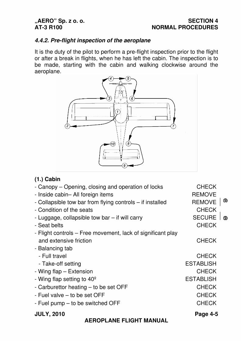
4.4.2. Pre-flight inspection of the aeroplane
It is the duty of the pilot to perform a pre-flight inspection prior to the flight or after a break in flights, when he has left the cabin. The inspection is to be made, starting with the cabin and walking clockwise around the aeroplane.
(1.) Cabin
- Canopy – Opening, closing and operation of locks CHECK
- Inside cabin– All foreign items REMOVE
- Collapsible tow bar from flying controls – if installed REMOVE
- Condition of the seats
- Luggage, collapsible tow bar – if will carry
CHECK
SECURE
- Seat belts CHECK
- Flight controls – Free movement, lack of significant play
and extensive friction CHECK
- Balancing tab
- Full travel
- Take-off setting
CHECK
ESTABLISH
- Wing flap – Extension CHECK
- Wing flap setting to 40º ESTABLISH
- Carburettor heating – to be set OFF CHECK
- Fuel valve – to be set OFF CHECK
- Fuel pump – to be switched OFF CHECK
9999
9999
SECTION 4 „AERO” Sp. z o. o. NORMAL PROCEDURES AT-3 R100
Page 4-6 JULY, 2010 AEROPLANE FLIGHT MANUAL
- Ignition – to be set OFF CHECK
- Fuel level – to be checked with the gauge CHECK
- Battery and generator – to be switched OFF CHECK
- All electrical equipment– to be switched OFF CHECK
- Parking brake – if installed ON
(2.) Port wing
- Structure – Condition and cleanliness CHECK
- Wing flap – Condition of structure and play in control system and hinges CHECK
- Ailerons – Condition of structure and play in control system and hinges CHECK
- Pitot tube – Fixing and cleanliness CHECK
- Inspection flap – to be closed and locked CHECK
(3.) Port landing gear
- Tyre – Check the tyre pressure (visually) CHECK
- Brake system CHECK
(3.) (4.) Fuselage front part
- Canopy – Visually check cleanliness CHECK
- Fuel tank – Fuel quantity and locking the filler-cap CHECK
- Engine cowling – Locking and leaks CHECK
- Propeller and spinner – Condition and cleanliness CHECK
- Exhaust pipes – Condition CHECK
- Antenna of transponder – Condition and fixing CHECK
- Fuselage bottom surface –Condition and cleanliness CHECK
- Air intake covers - installed CHECK
(5.) Nose landing gear
Tyre – Check the tyre pressure (visually) CHECK
Shock absorber – Condition CHECK
Towing bar – to be removed from the aeroplane CHECK
NOTE It is recommended that Air Intake Covers are installed
when operating the aircraft in ambient temperature below 120C/540F
9999
„AERO” Sp. z o. o. SECTION 4 AT-3 R100 NORMAL PROCEDURES
JULY, 2010 Page 4-7 AEROPLANE FLIGHT MANUAL
(6.). Starboard landing gear and front part of fuselage
Tyre – Check the tyre pressure (visually) CHECK
- Brake system CHECK
- Oil level and presence of the dipstick (turn the propeller several times first)
CHECK
(7.) Starboard wing - Structure – Condition and cleanliness CHECK
- Ailerons – Condition of structure and play in control system and hinges CHECK.
- Wing flap – Condition of structure and play in control system and hinges CHECK.
- Inspection flap – to be closed and locked CHECK
(8.) Fuselage rear part, starboard
- Structure – Condition and cleanliness CHECK
- Antennae – Condition and cleanliness CHECK
(9.) Empennage
- Fin – Condition and cleanliness CHECK
- Rudder – Hinges and their play CHECK
- Slab tail – Hinges and their play CHECK
- Trim & balancing tab – Hinges and their play CHECK
(10.) Fuselage rear part, port
- Structure – Condition and cleanliness CHECK
- Inspection flap – to be locked CHECK
CAUTION
When turning the propeller by hand, special care is to be observed and the following is to be checked:
- the ignition is switched off, - the parking valve is on, or
- the chocks are put under wheels. The possibility of spontaneous ignition always exists
9999
SECTION 4 „AERO” Sp. z o. o. NORMAL PROCEDURES AT-3 R100
Page 4-8 JULY, 2010 AEROPLANE FLIGHT MANUAL
4.5. Normal procedures and list of inspection tasks
4.5.1. Airspeeds for safe operation
IAS
Airspeed Flaps km/h mph kts
Take off: – lift-off
– at altitude 15 m
15º 77
112
48
70
42
60
Maximum angle of climb (VX) 0º 110 68 59
Maximum rate of climb (VY) 0º 120 75 65
Maximum angle of climb (VX) 15º 100 62 54
Maximum rate of climb (VY) 15º 110 68 59
In rough air (recommended) 0º 160 99 86
Landing approach 40º 100 62 54
Maximum cross-wind component
0 to 40º 21.6 13.4 11.7
4.5.2. Before starting engine
- Seat in the cabin TO BE OCCUPIED
- Canopy SHUT AND LOCK
- Luggage – stow & secure CHECK
- Seat belts FASTEN
- Reading of the fuel quantity indicator CHECK
- Ignition – to be switched off CHECK
- Battery and generator – to be switched off CHECK
- All electrical equipment – to be switched off CHECK
- Trim and balancing tab – to be set to “TAKEOFF” CHECK
- Flight controls – full and free movement of CHECK
- Wing flaps RETRACT
- Parking brake (if installed) OFF
9999
„AERO” Sp. z o. o. SECTION 4 AT-3 R100 NORMAL PROCEDURES
JULY, 2010 Page 4-9 AEROPLANE FLIGHT MANUAL
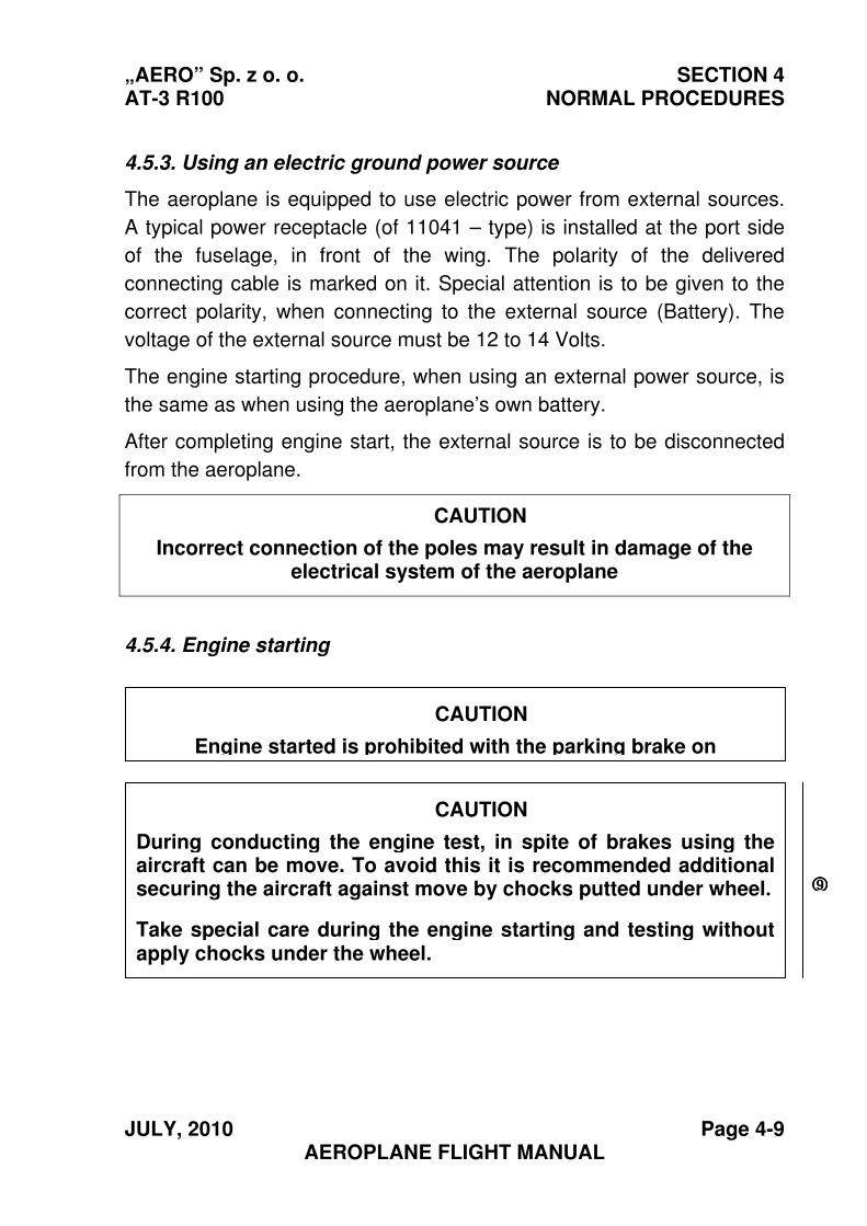
4.5.3. Using an electric ground power source
The aeroplane is equipped to use electric power from external sources.
A typical power receptacle (of 11041 – type) is installed at the port side
of the fuselage, in front of the wing. The polarity of the delivered
connecting cable is marked on it. Special attention is to be given to the
correct polarity, when connecting to the external source (Battery). The
voltage of the external source must be 12 to 14 Volts.
The engine starting procedure, when using an external power source, is
the same as when using the aeroplane’s own battery.
After completing engine start, the external source is to be disconnected
from the aeroplane.
CAUTION
Incorrect connection of the poles may result in damage of the electrical system of the aeroplane
4.5.4. Engine starting
CAUTION
During conducting the engine test, in spite of brakes using the aircraft can be move. To avoid this it is recommended additional securing the aircraft against move by chocks putted under wheel.
Take special care during the engine starting and testing without apply chocks under the wheel.
CAUTION
Engine started is prohibited with the parking brake on
9999
SECTION 4 „AERO” Sp. z o. o. NORMAL PROCEDURES AT-3 R100
Page 4-10 JULY, 2010 AEROPLANE FLIGHT MANUAL
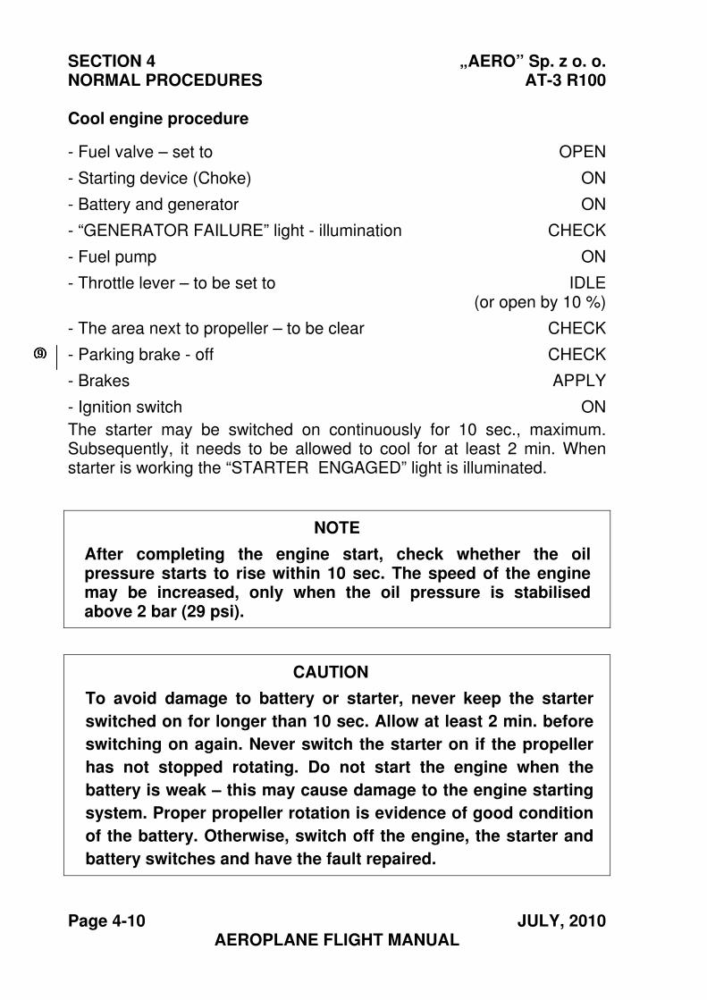
Cool engine procedure
- Fuel valve – set to OPEN
- Starting device (Choke) ON
- Battery and generator ON
- “GENERATOR FAILURE” light - illumination CHECK
- Fuel pump ON
- Throttle lever – to be set to IDLE(or open by 10 %)
- The area next to propeller – to be clear CHECK
- Parking brake - off CHECK
- Brakes APPLY
- Ignition switch ON
The starter may be switched on continuously for 10 sec., maximum. Subsequently, it needs to be allowed to cool for at least 2 min. When starter is working the “STARTER ENGAGED” light is illuminated.
NOTE
After completing the engine start, check whether the oil pressure starts to rise within 10 sec. The speed of the engine may be increased, only when the oil pressure is stabilised above 2 bar (29 psi).
CAUTION
To avoid damage to battery or starter, never keep the starter
switched on for longer than 10 sec. Allow at least 2 min. before
switching on again. Never switch the starter on if the propeller
has not stopped rotating. Do not start the engine when the
battery is weak – this may cause damage to the engine starting
system. Proper propeller rotation is evidence of good condition
of the battery. Otherwise, switch off the engine, the starter and
battery switches and have the fault repaired.
9999
„AERO” Sp. z o. o. SECTION 4 AT-3 R100 NORMAL PROCEDURES
OCTOBER, 2009 Page 4-11 AEROPLANE FLIGHT MANUAL
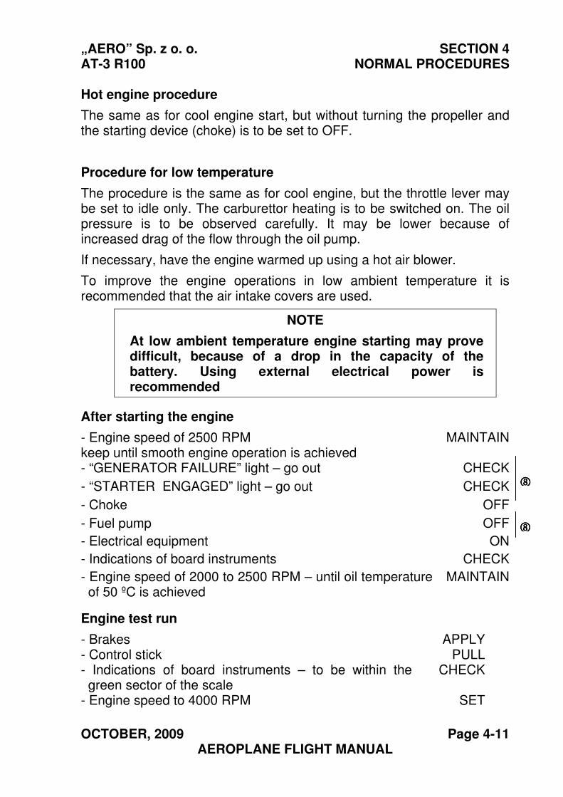
Hot engine procedure
The same as for cool engine start, but without turning the propeller and the starting device (choke) is to be set to OFF.
Procedure for low temperature
The procedure is the same as for cool engine, but the throttle lever may be set to idle only. The carburettor heating is to be switched on. The oil pressure is to be observed carefully. It may be lower because of increased drag of the flow through the oil pump.
If necessary, have the engine warmed up using a hot air blower.
To improve the engine operations in low ambient temperature it is recommended that the air intake covers are used.
NOTE
At low ambient temperature engine starting may prove difficult, because of a drop in the capacity of thebattery. Using external electrical power is recommended
After starting the engine
- Engine speed of 2500 RPM keep until smooth engine operation is achieved
MAINTAIN
- “GENERATOR FAILURE” light – go out CHECK
- “STARTER ENGAGED” light – go out CHECK
- Choke OFF
- Fuel pump OFF
- Electrical equipment ON
- Indications of board instruments CHECK
- Engine speed of 2000 to 2500 RPM – until oil temperature of 50 ºC is achieved
MAINTAIN
Engine test run
- Brakes APPLY- Control stick PULL- Indications of board instruments – to be within the green sector of the scale
CHECK
- Engine speed to 4000 RPM SET
8888
8888
SECTION 4 „AERO” Sp. z o. o. NORMAL PROCEDURES AT-3 R100
Page 4-12 JULY, 2010 AEROPLANE FLIGHT MANUAL
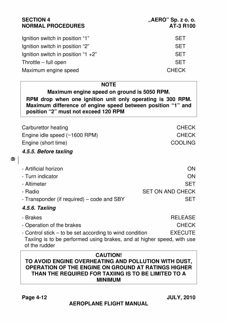
Ignition switch in position “1” SET
Ignition switch in position “2” SET
Ignition switch in position “1 +2” SET
Throttle – full open SET
Maximum engine speed CHECK
NOTE
Maximum engine speed on ground is 5050 RPM.
RPM drop when one ignition unit only operating is 300 RPM. Maximum difference of engine speed between position “1” and position “2” must not exceed 120 RPM
Carburettor heating CHECK
Engine idle speed (~1600 RPM) CHECK
Engine (short time) COOLING
4.5.5. Before taxiing
- Artificial horizon ON
- Turn indicator ON
- Altimeter SET
- Radio SET ON AND CHECK
- Transponder (if required) – code and SBY SET
4.5.6. Taxiing
- Brakes RELEASE
- Operation of the brakes CHECK
- Control stick – to be set according to wind condition EXECUTE
Taxiing is to be performed using brakes, and at higher speed, with use of the rudder
CAUTION! TO AVOID ENGINE OVERHEATING AND POLLUTION WITH DUST, OPERATION OF THE ENGINE ON GROUND AT RATINGS HIGHER
THAN THE REQUIRED FOR TAXIING IS TO BE LIMITED TO AMINIMUM
9999
„AERO” Sp. z o. o. SECTION 4 AT-3 R100 NORMAL PROCEDURES
OCTOBER, 2009 Page 4-13 AEROPLANE FLIGHT MANUAL
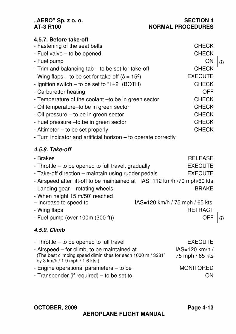
4.5.7. Before take-off - Fastening of the seat belts CHECK
- Fuel valve – to be opened CHECK
- Fuel pump ON
- Trim and balancing tab – to be set for take-off CHECK
- Wing flaps – to be set for take-off (δ = 15º) EXECUTE
- Ignition switch – to be set to “1+2” (BOTH) CHECK
- Carburettor heating OFF
- Temperature of the coolant –to be in green sector CHECK
- Oil temperature–to be in green sector CHECK
- Oil pressure – to be in green sector CHECK
- Fuel pressure –to be in green sector CHECK
- Altimeter – to be set properly CHECK
- Turn indicator and artificial horizon – to operate correctly
4.5.8. Take-off
- Brakes RELEASE
- Throttle – to be opened to full travel, gradually EXECUTE
- Take-off direction – maintain using rudder pedals EXECUTE
- Airspeed after lift-off to be maintained at IAS=112 km/h /70 mph/60 kts
- Landing gear – rotating wheels BRAKE
- When height 15 m/50’ reached – increase to speed to IAS=120 km/h / 75 mph / 65 kts
- Wing flaps RETRACT
- Fuel pump (over 100m (300 ft)) OFF
4.5.9. Climb
- Throttle – to be opened to full travel EXECUTE
- Airspeed – for climb, to be maintained at (The best climbing speed diminishes for each 1000 m / 3281’ by 3 km/h / 1.9 mph / 1.6 kts )
IAS=120 km/h / 75 mph / 65 kts
- Engine operational parameters – to be MONITORED
- Transponder (if required) – to be set to ON
����
����
SECTION 4 „AERO” Sp. z o. o. NORMAL PROCEDURES AT-3 R100
Page 4-14 OCTOBER, 2009 AEROPLANE FLIGHT MANUAL
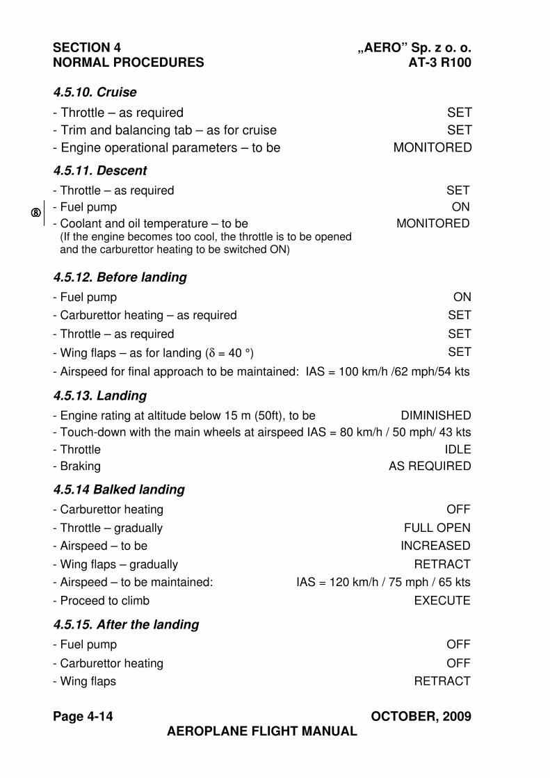
4.5.10. Cruise
- Throttle – as required SET
- Trim and balancing tab – as for cruise SET
- Engine operational parameters – to be MONITORED
4.5.11. Descent
- Throttle – as required SET
- Fuel pump ON
- Coolant and oil temperature – to be (If the engine becomes too cool, the throttle is to be opened and the carburettor heating to be switched ON)
MONITORED
4.5.12. Before landing
- Fuel pump ON
- Carburettor heating – as required SET
- Throttle – as required SET
- Wing flaps – as for landing (δ = 40 °) SET
- Airspeed for final approach to be maintained: IAS = 100 km/h /62 mph/54 kts
4.5.13. Landing
- Engine rating at altitude below 15 m (50ft), to be DIMINISHED
- Touch-down with the main wheels at airspeed IAS = 80 km/h / 50 mph/ 43 kts
- Throttle IDLE
- Braking AS REQUIRED
4.5.14 Balked landing
- Carburettor heating OFF
- Throttle – gradually FULL OPEN
- Airspeed – to be INCREASED
- Wing flaps – gradually RETRACT
- Airspeed – to be maintained: IAS = 120 km/h / 75 mph / 65 kts
- Proceed to climb EXECUTE
4.5.15. After the landing
- Fuel pump OFF
- Carburettor heating OFF
- Wing flaps RETRACT
����
„AERO” Sp. z o. o. SECTION 4 AT-3 R100 NORMAL PROCEDURES
JULY, 2010 Page 4-15 AEROPLANE FLIGHT MANUAL
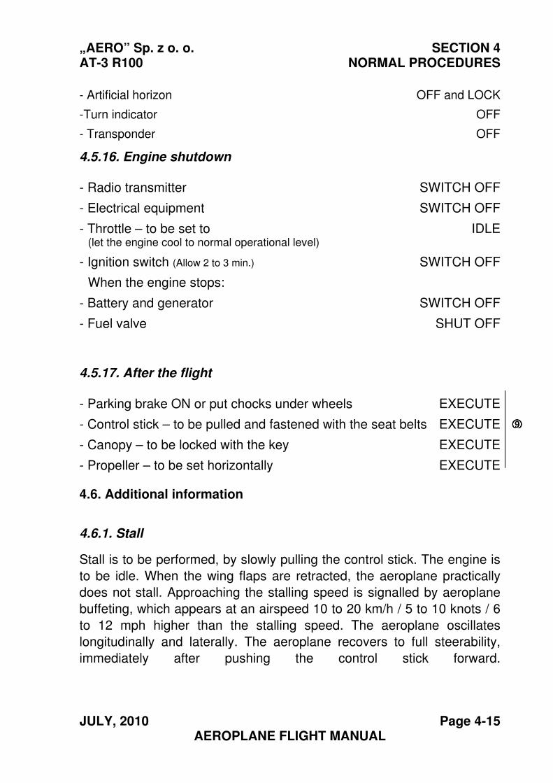
- Artificial horizon OFF and LOCK
-Turn indicator OFF
- Transponder OFF
4.5.16. Engine shutdown
- Radio transmitter SWITCH OFF
- Electrical equipment SWITCH OFF
- Throttle – to be set to (let the engine cool to normal operational level)
IDLE
- Ignition switch (Allow 2 to 3 min.) SWITCH OFF
When the engine stops:
- Battery and generator SWITCH OFF
- Fuel valve SHUT OFF
4.5.17. After the flight
- Parking brake ON or put chocks under wheels EXECUTE
- Control stick – to be pulled and fastened with the seat belts EXECUTE
- Canopy – to be locked with the key EXECUTE
- Propeller – to be set horizontally EXECUTE
4.6. Additional information
4.6.1. Stall
Stall is to be performed, by slowly pulling the control stick. The engine is
to be idle. When the wing flaps are retracted, the aeroplane practically
does not stall. Approaching the stalling speed is signalled by aeroplane
buffeting, which appears at an airspeed 10 to 20 km/h / 5 to 10 knots / 6
to 12 mph higher than the stalling speed. The aeroplane oscillates
longitudinally and laterally. The aeroplane recovers to full steerability,
immediately after pushing the control stick forward.
9999
SECTION 4 „AERO” Sp. z o. o. NORMAL PROCEDURES AT-3 R100
Page 4-16 SEPTEMBER, 2004 AEROPLANE FLIGHT MANUAL
CAUTION!
NEVER TRY TO STALL AT LOW ALTITUDE
For stall speed – refer to Section 5.
NOTE
At engine ratings higher than idle, the stalling speed is lower than that given in the table, by 2 to 15 km/h / 1.2 to 9.3 mph / 1 to 8 kts depending on wing flap position and aeroplane weight.
4.6.2. Flight manoeuvres
The flight manoeuvres are to be performed in accordance with the limits given in item 2.8. Approved manoeuvres.
Steep turns are to be flown with the throttle fully opened.
4.6.3. Flight with a passenger
The pilot is obliged to instruct the passenger on how to behave in an aeroplane cabin.
4.6.4. Crosswind take-off or landing
The correct aeroplane handling characteristics during takeoff and landing have been demonstrated at crosswind velocity up to 6 m/s (21.6 km/h / 13.4 mph / 11.7 kts).
Take-off
The control stick is to be displaced against the crosswind. The take-off direction is to be controlled by use of the rudder. The nose wheel is to be kept down until lift-off speed is achieved. After taking-off, try to avoid touching the ground again.
Landing
The wing flaps are to be extended as required for the conditions of the landing field. Have the aeroplane banked towards the crosswind. In a
„AERO” Sp. z o. o. SECTION 4 AT-3 R100 NORMAL PROCEDURES
SEPTEMBER, 2004 Page 4-17 AEROPLANE FLIGHT MANUAL
strong crosswind, also turn the aeroplane axis from the landing direction towards the crosswind.
Turn back to the landing direction immediately before touchdown.
Lowering the nose wheel earlier after touchdown helps to maintain
direction. After touchdown keep the nose wheel down and control the
direction with the rudder, and later with the brakes. At the end of the
landing run keep the control stick against the crosswind.
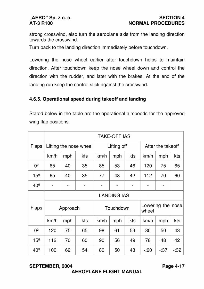
4.6.5. Operational speed during takeoff and landing
Stated below in the table are the operational airspeeds for the approved
wing flap positions.
TAKE-OFF IAS
Lifting the nose wheel Lifting off After the takeoff Flaps
km/h mph kts km/h mph kts km/h mph kts
0º 65 40 35 85 53 46 120 75 65
15º 65 40 35 77 48 42 112 70 60
40º - - - - - - - -
LANDING IAS
Approach Touchdown Lowering the nose wheel
Flaps
km/h mph kts km/h mph kts km/h mph kts
0º 120 75 65 98 61 53 80 50 43
15º 112 70 60 90 56 49 78 48 42
40º 100 62 54 80 50 43 <60 <37 <32
SECTION 4 „AERO” Sp. z o. o. NORMAL PROCEDURES AT-3 R100
Page 4-18 SEPTEMBER, 2004 AEROPLANE FLIGHT MANUAL
THIS PAGE IS LEFT INTENTIONALLY BLANK
“AERO” Sp. z o.o. SECTION 5 AT-3 R100 PERFORMANCE
MARCH, 2011 Page 5-1 AEROPLANE FLIGHT MANUAL
Section 5
PERFORMANCE
Page
5.1. Introduction ............................................................................... 5-2
5.2. Approved data .......................................................................... 5-3
5.2.1. Calibration of the airspeed indicator system ...................... 5-3
5.2.2. Stalling speed..................................................................... 5-4
5.2.3. Take-off performance......................................................... 5-5
5.2.4. Landing distance................................................................ 5-6
5.2.5. Climb performance............................................................. 5-8
5.3. Supplementary information..................................................... 5-11
5.3.1. Cruise.............................................................................. 5-11
5.3.2. Climb after balked landing............................................... 5-13
5.3.3. Take-off and landing on grass airstrips ........................... 5-13
5.3.4. Affect of rain or insect remains on aeroplane performance and handling ........................ 5-13
5.3.5 Demonstrated range of operational temperatures........... 5-13
5.3.6. Demonstrated crosswind on take-off and landing ........... 5-14
5.3.7 Combined diagram of aeroplane characteristics ............. 5-15
5.3.8. Noise ............................................................................... 5-16
SECTION 5 “AERO” Sp. z o.o. PERFORMANCE AT-3 R100
Page 5-2 SEPTEMBER, 2004 AEROPLANE FLIGHT MANUAL
5.1. Introduction
This Section contains approved data concerning the following issues:
- Calibration of the airspeed indicator system.
- Stalling speeds
- Take-off performance.
- Supplementary information from the manufacturer.
The diagrams have been computed on the basis of actual flight test data,
for correct engine and aircraft operation and applying average piloting
techniques.
“AERO” Sp. z o.o. SECTION 5 AT-3 R100 PERFORMANCE
SEPTEMBER, 2004 Page 5-3 AEROPLANE FLIGHT MANUAL
5.2. Approved data
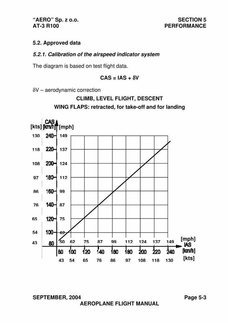
5.2.1. Calibration of the airspeed indicator system
The diagram is based on test flight data.
CAS = IAS + δδδδV
δV – aerodynamic correction
CLIMB, LEVEL FLIGHT, DESCENT
WING FLAPS: retracted, for take-off and for landing
[mph]
149
137
124
99
112
87
75
62
50[mph]
62 75 87 99 112 124 137 149
[kts] 43 54 65 76 86 97 108 118 130
130
118
108
86
97
76
65
54
43
[kts]
SECTION 5 “AERO” Sp. z o.o. PERFORMANCE AT-3 R100
Page 5-4 SEPTEMBER, 2004 AEROPLANE FLIGHT MANUAL
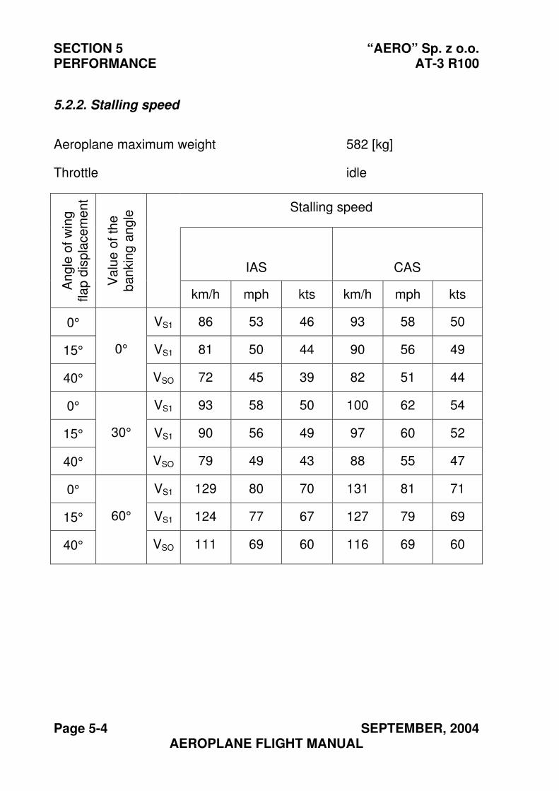
5.2.2. Stalling speed
Aeroplane maximum weight 582 [kg]
Throttle idle
Stalling speed
IAS CAS
An
gle
of w
ing
fla
p d
isp
lacem
en
t
Va
lue
of
the
b
an
kin
g a
ng
le
km/h mph kts km/h mph kts
0° VS1 86 53 46 93 58 50
15° VS1 81 50 44 90 56 49
40°
0°
VSO 72 45 39 82 51 44
0° VS1 93 58 50 100 62 54
15° VS1 90 56 49 97 60 52
40°
30°
VSO 79 49 43 88 55 47
0° VS1 129 80 70 131 81 71
15° VS1 124 77 67 127 79 69
40°
60°
VSO 111 69 60 116 69 60
“AERO” Sp. z o.o. SECTION 5 AT-3 R100 PERFORMANCE
SEPTEMBER, 2004 Page 5-5 AEROPLANE FLIGHT MANUAL
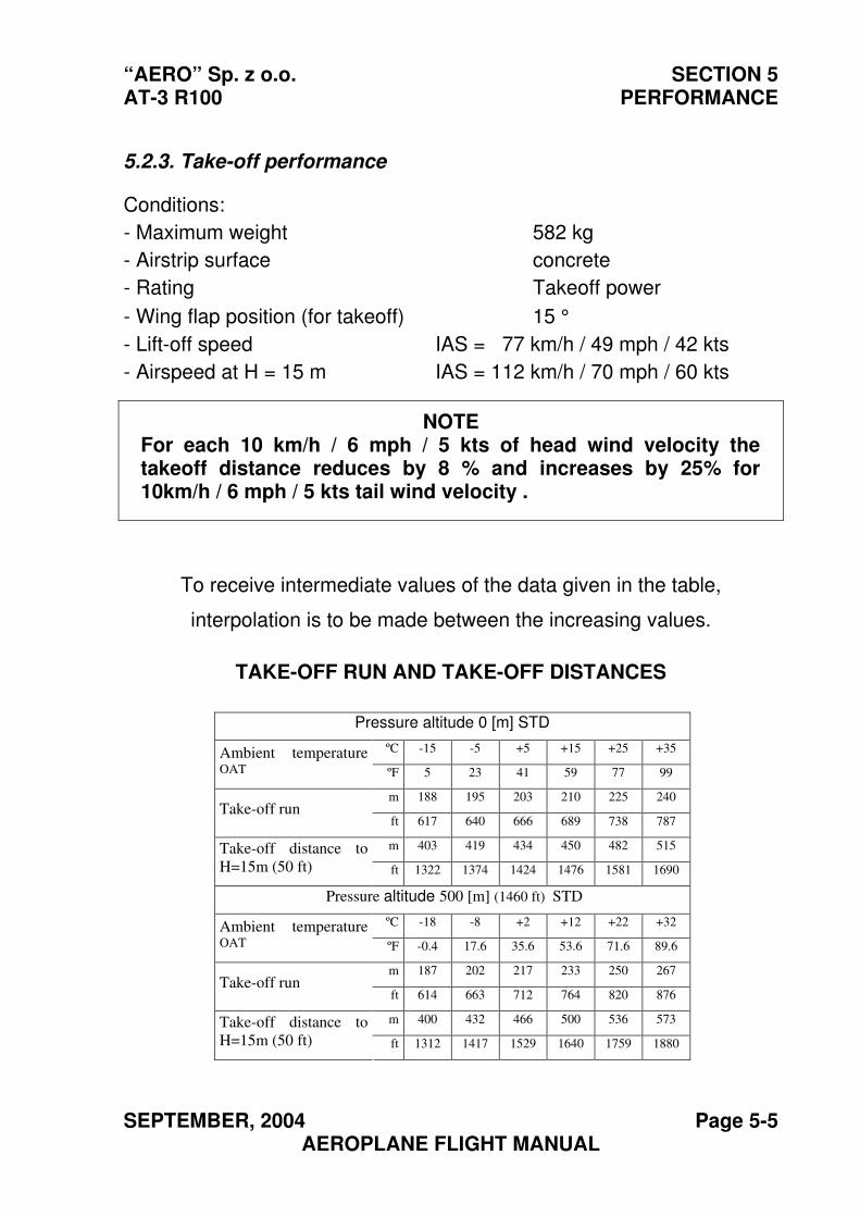
5.2.3. Take-off performance
Conditions:
- Maximum weight 582 kg
- Airstrip surface concrete
- Rating Takeoff power
- Wing flap position (for takeoff) 15 °
- Lift-off speed IAS = 77 km/h / 49 mph / 42 kts
- Airspeed at H = 15 m IAS = 112 km/h / 70 mph / 60 kts
NOTE For each 10 km/h / 6 mph / 5 kts of head wind velocity the takeoff distance reduces by 8 % and increases by 25% for 10km/h / 6 mph / 5 kts tail wind velocity .
To receive intermediate values of the data given in the table,
interpolation is to be made between the increasing values.
TAKE-OFF RUN AND TAKE-OFF DISTANCES
Pressure altitude 0 [m] STD
ºC -15 -5 +5 +15 +25 +35Ambient temperature
OAT ºF 5 23 41 59 77 99
m 188 195 203 210 225 240Take-off run
ft 617 640 666 689 738 787
m 403 419 434 450 482 515Take-off distance to
H=15m (50 ft) ft 1322 1374 1424 1476 1581 1690
Pressure altitude 500 [m] (1460 ft) STD
ºC -18 -8 +2 +12 +22 +32 Ambient temperature
OAT ºF -0.4 17.6 35.6 53.6 71.6 89.6
m 187 202 217 233 250 267 Take-off run
ft 614 663 712 764 820 876
m 400 432 466 500 536 573 Take-off distance to
H=15m (50 ft) ft 1312 1417 1529 1640 1759 1880
SECTION 5 “AERO” Sp. z o.o. PERFORMANCE AT-3 R100
Page 5-6 SEPTEMBER, 2004 AEROPLANE FLIGHT MANUAL
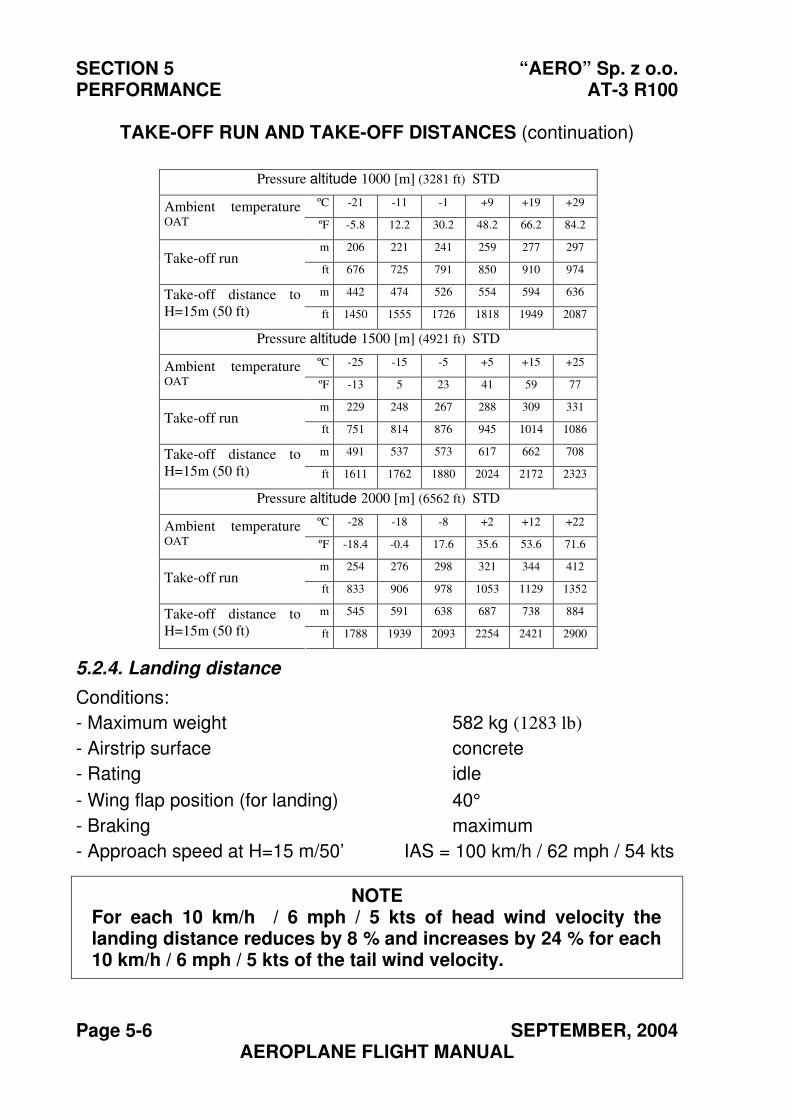
TAKE-OFF RUN AND TAKE-OFF DISTANCES (continuation)
Pressure altitude 1000 [m] (3281 ft) STD
ºC -21 -11 -1 +9 +19 +29 Ambient temperature
OAT ºF -5.8 12.2 30.2 48.2 66.2 84.2
m 206 221 241 259 277 297 Take-off run
ft 676 725 791 850 910 974
m 442 474 526 554 594 636 Take-off distance to
H=15m (50 ft) ft 1450 1555 1726 1818 1949 2087
Pressure altitude 1500 [m] (4921 ft) STD
ºC -25 -15 -5 +5 +15 +25 Ambient temperature
OAT ºF -13 5 23 41 59 77
m 229 248 267 288 309 331 Take-off run
ft 751 814 876 945 1014 1086
m 491 537 573 617 662 708 Take-off distance to
H=15m (50 ft) ft 1611 1762 1880 2024 2172 2323
Pressure altitude 2000 [m] (6562 ft) STD
ºC -28 -18 -8 +2 +12 +22 Ambient temperature
OAT ºF -18.4 -0.4 17.6 35.6 53.6 71.6
m 254 276 298 321 344 412 Take-off run
ft 833 906 978 1053 1129 1352
m 545 591 638 687 738 884 Take-off distance to
H=15m (50 ft) ft 1788 1939 2093 2254 2421 2900
5.2.4. Landing distance
Conditions:
- Maximum weight 582 kg (1283 lb)
- Airstrip surface concrete
- Rating idle
- Wing flap position (for landing) 40°
- Braking maximum
- Approach speed at H=15 m/50’ IAS = 100 km/h / 62 mph / 54 kts
NOTE For each 10 km/h / 6 mph / 5 kts of head wind velocity the landing distance reduces by 8 % and increases by 24 % for each 10 km/h / 6 mph / 5 kts of the tail wind velocity.

“AERO” Sp. z o.o. SECTION 5 AT-3 R100 PERFORMANCE
SEPTEMBER, 2004 Page 5-7 AEROPLANE FLIGHT MANUAL
LANDING DISTANCES
Pressure altitude 0 [m] STD ºC -15 -5 +5 +15 +25 +35Ambient temperature.
OAT ºF 5 23 41 59 77 99
m 403 419 434 450 466 481 Landing distance from 15m
(50 ft) ft 1322 1375 1424 1476 1529 1578
m 179 186 193 200 207 214 Landing run
ft 587 610 633 656 679 702
Pressure altitude 500 m (1460 ft) STD ºC -18 -8 +2 +12 +22 +32 Ambient temperature
OAT ºF -0.4 17.6 35.6 53.6 71.6 89.6
m 423 439 456 472 489 505 Landing distance from 15m
(50 ft) ft 1388 1440 1496 1549 1604 1657
m 188 195 203 210 217 224 Landing run
ft 617 640 666 689 712 735
Pressure altitude 1000 m (3281 ft) STD ºC -21 -11 -1 +9 +19 +29 Ambient temperature
OAT ºF -5.8 12.2 30.2 48.2 66.2 84.2
m 444 461 479 496 513 530 Landing distance from 15m
(50 ft) ft 1457 1512 1572 1627 1683 1739
m 197 205 213 220 228 236 Landing run
ft 646 673 699 722 748 774
Pressure altitude 1500 m (4921 ft) STD ºC -25 -15 -5 +5 +15 +25 Ambient temperature
OAT ºF -13 5 23 41 59 77
m 467 485 503 521 539 557 Landing distance from 15m
(50 ft) ft 1532 1591 1650 1709 1768 1827
m 207 215 224 232 240 248 Landing run
ft 679 705 735 761 787 814
Pressure altitude 2000 m (6562 ft) STD ºC -28 -18 -8 +2 +12 +22 Ambient temperature
OAT ºF -18.4 -0.4 17.6 35.6 53.6 71.6
m 491 510 529 548 567 586 Landing distance from 15m
(50 ft) ft 1611 1673 1736 1798 1860 1923
m 218 227 235 243 252 260 Landing run
ft 715 745 771 797 827 853
SECTION 5 “AERO” Sp. z o.o. PERFORMANCE AT-3 R100
Page 5-8 SEPTEMBER, 2004 AEROPLANE FLIGHT MANUAL
5.2.5. Climb performance
Wing flaps retracted (0º)
Conditions:
- Maximum weight 582 kg (1283 lb)
- Rating (Power setting) (full) nominal power
- Airspeed VY =120 km/h / 75 mph / 65 kts IAS
This airspeed is to be reduced by 3 km/h for each 1000 m of altitude (0.57 mph / 0.5 kts for each 1000 ft of altitude).
Wing flaps for takeoff (15º)
Conditions:
- Maximum weight 582 kg (1283 lb)
- Rating nominal power
- Airspeed VY =110 km/h / 68 mph / 59 kts IAS
This airspeed is to be reduced by 3 km/h for each 1000 m of the altitude (0.57 mph / 0.5 kts for each 1000 ft of the altitude).
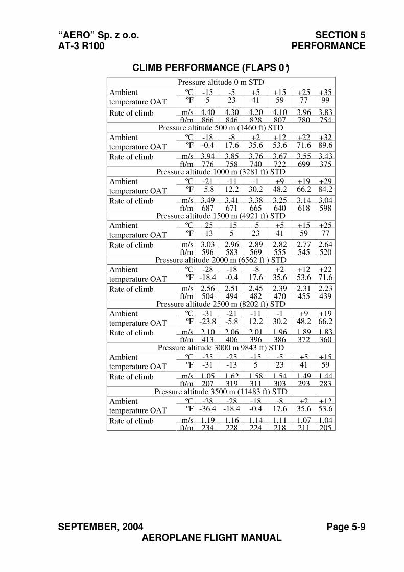
“AERO” Sp. z o.o. SECTION 5 AT-3 R100 PERFORMANCE
SEPTEMBER, 2004 Page 5-9 AEROPLANE FLIGHT MANUAL
CLIMB PERFORMANCE (FLAPS 0°)
Pressure altitude 0 m STD
ºC -15 -5 +5 +15 +25 +35Ambient
temperature OAT ºF 5 23 41 59 77 99
m/s 4,40 4,30 4,20 4,10 3,96 3,83Rate of climb ft/m 866 846 828 807 780 754
Pressure altitude 500 m (1460 ft) STD
ºC -18 -8 +2 +12 +22 +32Ambient
temperature OAT ºF -0.4 17.6 35.6 53.6 71.6 89.6
m/s 3,94 3,85 3,76 3,67 3,55 3,43Rate of climb ft/m 776 758 740 722 699 375
Pressure altitude 1000 m (3281 ft) STD
ºC -21 -11 -1 +9 +19 +29Ambient
temperature OAT ºF -5.8 12.2 30.2 48.2 66.2 84.2
m/s 3,49 3,41 3,38 3,25 3,14 3,04Rate of climb ft/m 687 671 665 640 618 598
Pressure altitude 1500 m (4921 ft) STD
ºC -25 -15 -5 +5 +15 +25Ambient
temperature OAT ºF -13 5 23 41 59 77
m/s 3,03 2,96 2,89 2,82 2,77 2,64Rate of climb ft/m 596 583 569 555 545 520
Pressure altitude 2000 m (6562 ft ) STD
ºC -28 -18 -8 +2 +12 +22Ambient
temperature OAT ºF -18.4 -0.4 17.6 35.6 53.6 71.6
m/s 2,56 2,51 2,45 2,39 2,31 2,23Rate of climb ft/m 504 494 482 470 455 439
Pressure altitude 2500 m (8202 ft) STD
ºC -31 -21 -11 -1 +9 +19Ambient
temperature OAT ºF -23.8 -5.8 12.2 30.2 48.2 66.2
m/s 2,10 2,06 2,01 1,96 1,89 1,83Rate of climb ft/m 413 406 396 386 372 360
Pressure altitude 3000 m 9843 ft) STD
ºC -35 -25 -15 -5 +5 +15Ambient
temperature OAT ºF -31 -13 5 23 41 59
m/s 1,05 1,62 1,58 1,54 1,49 1,44Rate of climb ft/m 207 319 311 303 293 283
Pressure altitude 3500 m (11483 ft) STD
ºC -38 -28 -18 -8 +2 +12Ambient
temperature OAT ºF -36.4 -18.4 -0.4 17.6 35.6 53.6
m/s 1,19 1,16 1,14 1,11 1,07 1,04Rate of climb ft/m 234 228 224 218 211 205
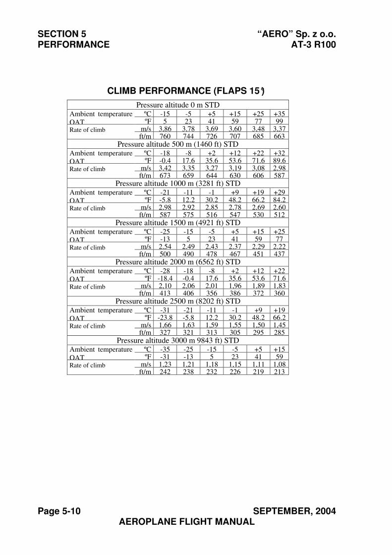
SECTION 5 “AERO” Sp. z o.o. PERFORMANCE AT-3 R100
Page 5-10 SEPTEMBER, 2004 AEROPLANE FLIGHT MANUAL
CLIMB PERFORMANCE (FLAPS 15°)
Pressure altitude 0 m STDºC -15 -5 +5 +15 +25 +35Ambient temperature
OAT ºF 5 23 41 59 77 99m/s 3,86 3,78 3,69 3,60 3,48 3,37Rate of climbft/m 760 744 726 707 685 663
Pressure altitude 500 m (1460 ft) STDºC -18 -8 +2 +12 +22 +32Ambient temperature
OAT ºF -0.4 17.6 35.6 53.6 71.6 89.6m/s 3,42 3,35 3,27 3,19 3,08 2,98Rate of climbft/m 673 659 644 630 606 587
Pressure altitude 1000 m (3281 ft) STDºC -21 -11 -1 +9 +19 +29Ambient temperature
OAT ºF -5.8 12.2 30.2 48.2 66.2 84.2m/s 2,98 2,92 2,85 2,78 2,69 2,60Rate of climbft/m 587 575 516 547 530 512
Pressure altitude 1500 m (4921 ft) STDºC -25 -15 -5 +5 +15 +25Ambient temperature
OAT ºF -13 5 23 41 59 77m/s 2,54 2,49 2,43 2,37 2,29 2,22Rate of climbft/m 500 490 478 467 451 437
Pressure altitude 2000 m (6562 ft) STDºC -28 -18 -8 +2 +12 +22Ambient temperature
OAT ºF -18.4 -0.4 17.6 35.6 53.6 71.6m/s 2,10 2,06 2,01 1,96 1,89 1,83Rate of climbft/m 413 406 356 386 372 360
Pressure altitude 2500 m (8202 ft) STDºC -31 -21 -11 -1 +9 +19Ambient temperature
OAT ºF -23.8 -5.8 12.2 30.2 48.2 66.2m/s 1,66 1,63 1,59 1,55 1,50 1,45Rate of climbft/m 327 321 313 305 295 285
Pressure altitude 3000 m 9843 ft) STDºC -35 -25 -15 -5 +5 +15Ambient temperature
OAT ºF -31 -13 5 23 41 59m/s 1,23 1,21 1,18 1,15 1,11 1,08Rate of climbft/m 242 238 232 226 219 213
“AERO” Sp. z o.o. SECTION 5 AT-3 R100 PERFORMANCE
NOVEMBER, 2012 Page 5-11 AEROPLANE FLIGHT MANUAL
5.3. Supplementary information
5.3.1. Cruise
Airspeed, range and endurance
Conditions:
- Maximum weight 582 kg (1283 lb)
- Wing flaps retracted
- Automotive gasoline, unleaded RON 95
- Consumable fuel: 65 litres / 17.17 US GAL
NOTE
Range and endurance data given in the table relate to using of all of the fuel at the given altitude. Taxiing, take-off and climb are not considered in this calculation.
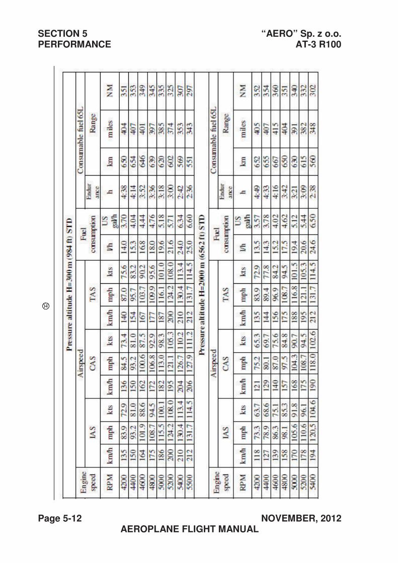
SECTION 5 “AERO” Sp. z o.o. PERFORMANCE AT-3 R100
Page 5-12 NOVEMBER, 2012 AEROPLANE FLIGHT MANUAL
“AERO” Sp. z o.o. SECTION 5 AT-3 R100 PERFORMANCE
MARCH, 2011 |Page 5-13 AEROPLANE FLIGHT MANUAL
5.3.2. Climb after balked landing
It is possible to retract the flaps by hand in not more than 2 sec., without
loss of altitude, or abrupt change in angle of attack, or special piloting
skill. After retracting the wing flaps, the performance of the aeroplane is
as given under 5.2.5. Climb performance
5.3.3. Take-off and landing on grass airstrips
It is possible to perform take-off or landing from grass strips with grass
not longer than 15 cm (a bit less than a half of the wheel diameter). On
short cut grass, the takeoff run increases about 10 %.
5.3.4. Affect of rain or insect remains on aeroplane performance and handling
No observable affect of rain or sediment of insects on the aeroplane
performance or handling has been noted.
5.3.5. Demonstrated range of operational temperatures
During the test flights, which have been performed in ambient
temperatures from –15 °C to +30 °C, it has been proven that all systems
operate correctly and the temperature of the components of the power
plant, as well as the engine fluids, remain within the limits established by
the manufacturer of the engine.
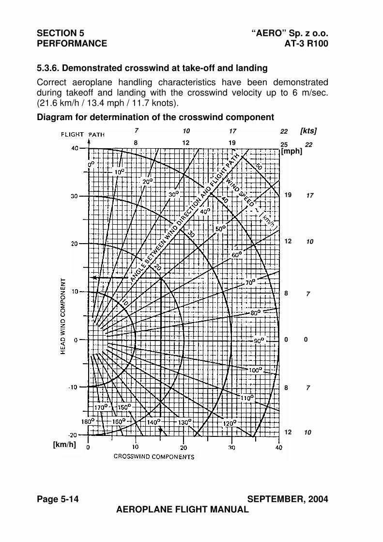
SECTION 5 “AERO” Sp. z o.o. PERFORMANCE AT-3 R100
Page 5-14 SEPTEMBER, 2004 AEROPLANE FLIGHT MANUAL
5.3.6. Demonstrated crosswind at take-off and landing
Correct aeroplane handling characteristics have been demonstrated during takeoff and landing with the crosswind velocity up to 6 m/sec. (21.6 km/h / 13.4 mph / 11.7 knots).
Diagram for determination of the crosswind component
[mph]
[km/h]
8 12 25 19
19
12
8
8
0
12
[kts] 7 10 17
22
17
10
7
7
10
0
22
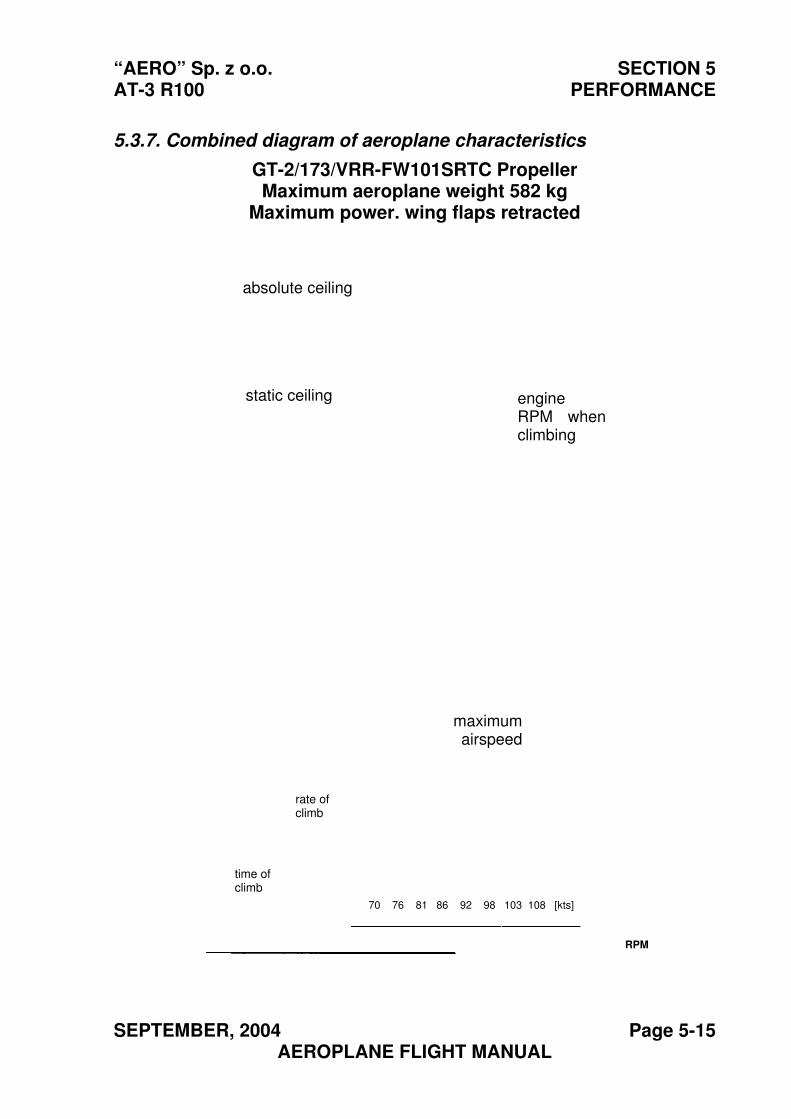
“AERO” Sp. z o.o. SECTION 5 AT-3 R100 PERFORMANCE
SEPTEMBER, 2004 Page 5-15 AEROPLANE FLIGHT MANUAL
5.3.7. Combined diagram of aeroplane characteristics
GT-2/173/VRR-FW101SRTC Propeller Maximum aeroplane weight 582 kg
Maximum power. wing flaps retracted
absolute ceiling
static ceiling engine RPM when climbing
maximum airspeed
rate of climb
time of climb
RPM
70 76 81 86 92 98 103 108 [kts]
SECTION 5 “AERO” Sp. z o.o. PERFORMANCE AT-3 R100
Page 5-16 SEPTEMBER, 2004 AEROPLANE FLIGHT MANUAL
5.3.8. Noise
The outside noise level of the AT-3 R100 aeroplane, determined in
accordance with the procedure in Chapter 10 Annex 16 ICAO is:
66.6 +0.35 dB (A), while the permissible level is 70.32 dB (A).
“AERO” Sp. z o.o. SECTION 6 AT-3 R100 WEIGHT AND BALANCE
SEPTEMBER, 2004 Page 6-1 AEROPLANE FLIGHT MANUAL
Section 6
WEIGHT AND BALANCE
Page
6.1. Introduction ............................................................................... 6-2
6.2. Weight and Balance Calculation............................................... 6-2
6.3. Weight and Balance Schedule ………………………………..6-9
6.4. AT-3 R100 Equipment List…………………………………….6-10
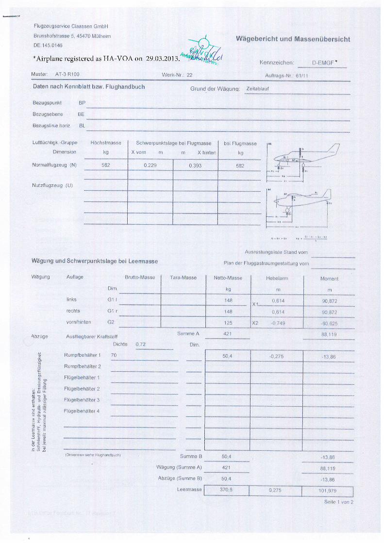
z uo^ I alas
61.6',0r I slz'o I s'oze
98 e r t'09
6 | r'88
98'€ r-
6 il'88
uoa 6unyle1sebruner1se66n13 iap ueld
txoA puels alsrlsEunlsn.rsny
asseulJas-l
(E auruns) abpzqy
(V stuurns) 6un6B11
I OUJIIJnS {qonQpueLl6nlJ €qsrs uorsuauro)
f ralleqaqlaOntJ
g ra1pqeq1e6nl3
Z rall?qeqtebnlJ
1 re11eqeq1aDn13
Z relleqaqldunU
1 ralleqaqldung
uolurrl/uJoA
slqceJ
srull
aOegny
;:.f= +-Etq.=il lo
-ofI +l6-*il
=< G9-+ug'= D;i:3fi=f;=U
-mt4:a J
qH65
=6
zL'o
OL
alqc!o'rulo
v auuJns #otsUery rereqOargsny abnzqg
7q
ttcl
IU!CI
6unbe.1111
asse u!ee'] I aq a6 q sllu nd;eanq c g p un 6u n6p.A,\
(n) Dnaz6ngztnN
(g) 6nazOn91eLu.ro11
uorsuaulo
eddnlg- 1611qcr31gn1
szg e6' 6't'0- zx 9ZL
z/8'06 tt9'0 gvl
zr.B'06 tt9'0 'x Brl
tU
luauor\l
u,
urElsqaH
61
assEn-oDaN assBu!-eJel assey\l-ollnrg
-lg 'zuoq arurlsOnzeg
3g auages6nzag
dB llundsonzeg
Jnelqeltaz :bunbgM Jap punie qrnqpupq6nlJ '^ruq uqquuay qceu uolEo
1 1719 rp-s6ergny
"kJ9l ,ll-cl :uotl3tezuuay
lr.lsrsroqnuossegl| pun lqoilaqeoPM
zz : rN-IlaM 00tu e-l-v :ielsny!
h". - €I0z'90'67, uo vo^-vH se perelsl8ar auuldrrv*
IrtO's?t fourlaqf nw 0 Lrgn' g asserlsJoqsunig
HqurC uosseelC ecrruasbnez6nl3
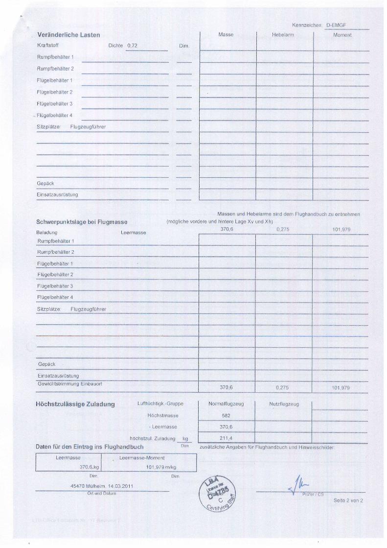
z uo^ z ailes
raplulsssra ^ulH
pun qsnqpuBq6nlJ iu ueqe6uv eqstl4esnz
v'tLz
9'0/€
6nez6npzlnp
zeg
6nezbn;11eurro11
uinleo pun L,o
t, r0z' ta' r r'urleqlnw 0/t9t'ru!o
6llur 626' r.O i | 6lg'OZe
luou.rolnl-€ss?urJsol I assetuJaa-l
rulo wnqpueqonH sul 6equl3 uap JnJ uspo-6!- ounpelnz tnzlsq.orl
ssseuJaal -
asseulsr.lcQH
addnrO- I6rlqcntunl
uonequrl6ungsprsnezlesur3
{caoe0
rerqilEnez6nlj :ezlpld4rS
t rellgqaqle6nll
e:alleqeqtabnll
Z :ellBtlaqla6nlJ
l reltFqeqtabnlJ
z rallEr.{ocllounu
6unpe1n7 aqssplnzlsrlagH
t ra]tBqaqJdrunU
6unpelegosseuJJe€l626't0 t 9r.z'0 s'oze
(qX pun ny e6e1 elolurq pun arapJo^ atlcrlOgtu) esseuBnlJ lsq o6eFllundreaqcsueurqaulue nz qcnqpueq6nll uap puts sureloqeH pun uesset4
6unlsnrsnezgesut3
lcpdeC
rejqry6nez0nlj :a4pdzlrS
y ralleqaq;abn11
g relgqeqla6ntJ
7 raleqaqge6nlg
1 .la1|eqaq1a6n11
T raleqaqdung
! ra]leqoqlduinU
'ur!clJJolsua){
ualsel aqilFapuslanJCtJ\I3-O .uaqilszuuaX
z/'0 elqctc
SECTION 6 “AERO” Sp. z o.o. WEIGHT AND BALANCE AT-3 R100
Page 6-2 SEPTEMBER, 2004 AEROPLANE FLIGHT MANUAL
6.1. Introduction
This Section contains the limitations of the useful load, within which the aeroplane may be operated safely.
The procedure for weighing aeroplane is contained in the Maintenance Manual of the AT-3 R100 aeroplane. Any change in the weight of the empty aeroplane, e.g. after new equipment is fitted, repairs or re-painting, will necessitate re-calculation of the table 6.3 “Weight and Balance Schedule” of this manual. The equipment installed in this aeroplane is shown in the List of Equipment in Section 6-4.
6.2. Weight and Balance Calculation
In order to calculate the weight and centre of gravity of the aeroplane, one of the following procedures should be followed.
WARNING
When calculating the aircraft weight and balance,
the planned fuel consumption should
be taken into consideration.
A decrease in fuel level will result in the Centre of the Gravity moving aft.
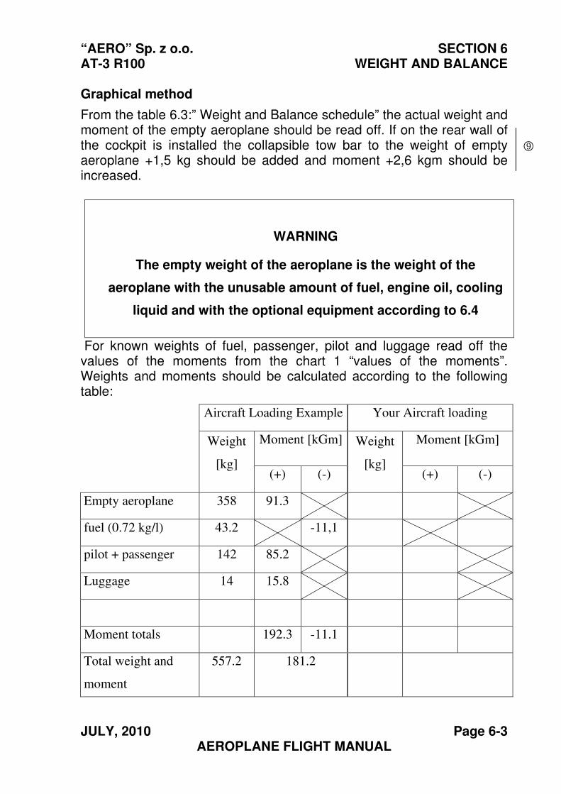
“AERO” Sp. z o.o. SECTION 6 AT-3 R100 WEIGHT AND BALANCE
JULY, 2010 Page 6-3 AEROPLANE FLIGHT MANUAL
Graphical method
From the table 6.3:” Weight and Balance schedule” the actual weight and moment of the empty aeroplane should be read off. If on the rear wall of the cockpit is installed the collapsible tow bar to the weight of empty aeroplane +1,5 kg should be added and moment +2,6 kgm should be increased.
WARNING
The empty weight of the aeroplane is the weight of the
aeroplane with the unusable amount of fuel, engine oil, cooling
liquid and with the optional equipment according to 6.4
For known weights of fuel, passenger, pilot and luggage read off the values of the moments from the chart 1 “values of the moments”. Weights and moments should be calculated according to the following table:
Aircraft Loading Example Your Aircraft loading
Moment [kGm] Moment [kGm] Weight
[kg] (+) (-)
Weight
[kg] (+) (-)
Empty aeroplane 358 91.3
fuel (0.72 kg/l) 43.2 -11,1
pilot + passenger 142 85.2
Luggage 14 15.8
Moment totals 192.3 -11.1
Total weight and
moment
557.2 181.2
9
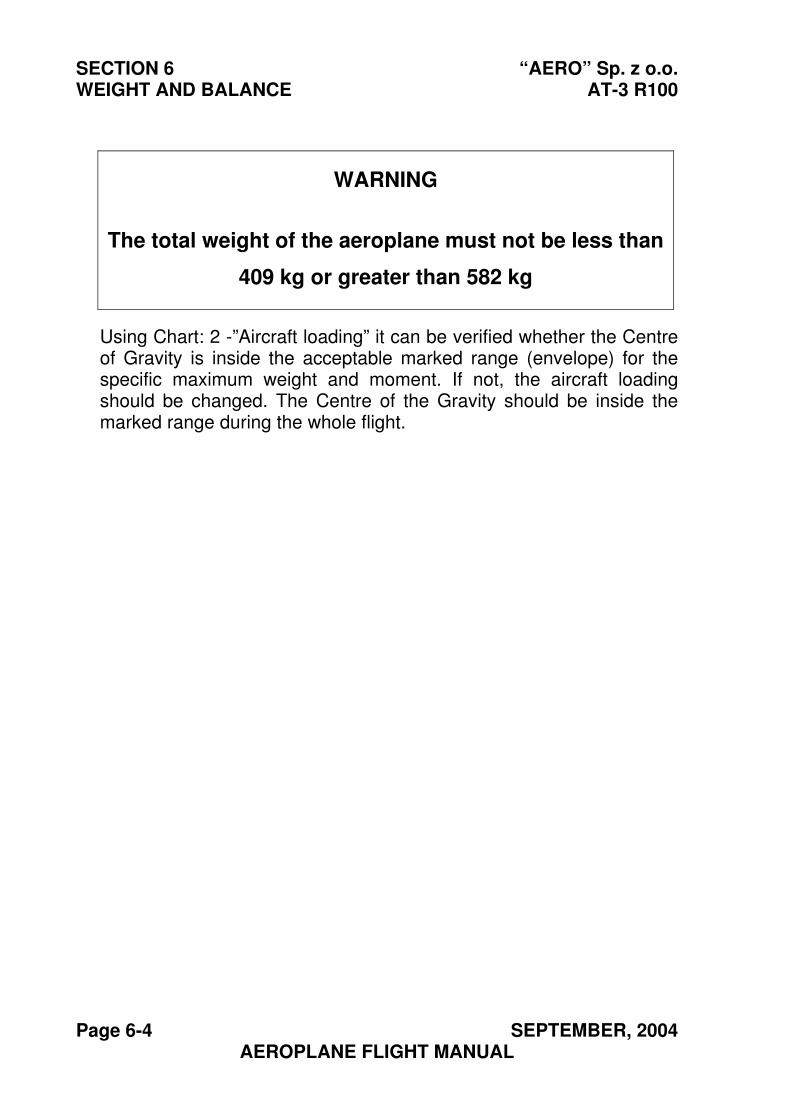
SECTION 6 “AERO” Sp. z o.o. WEIGHT AND BALANCE AT-3 R100
Page 6-4 SEPTEMBER, 2004 AEROPLANE FLIGHT MANUAL
WARNING
The total weight of the aeroplane must not be less than
409 kg or greater than 582 kg
Using Chart: 2 -”Aircraft loading” it can be verified whether the Centre of Gravity is inside the acceptable marked range (envelope) for the specific maximum weight and moment. If not, the aircraft loading should be changed. The Centre of the Gravity should be inside the marked range during the whole flight.
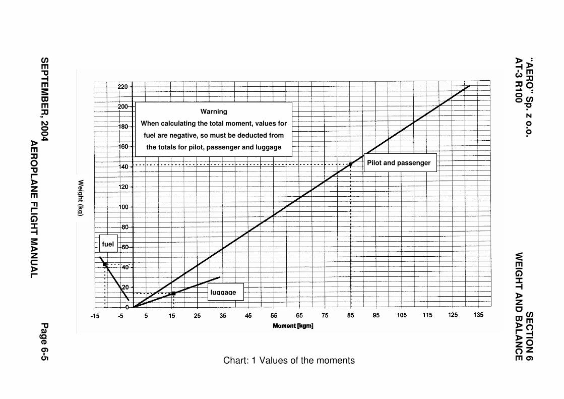
“A
ER
O” S
p. z
o.o
. S
EC
TIO
N 6
A
T-3
R1
00
W
EIG
HT
AN
D B
AL
AN
CE
SE
PT
EM
BE
R, 2
00
4
Pa
ge
6-5
A
ER
OP
LA
NE
FL
IGH
T M
AN
UA
L
Chart: 1 Values of the moments
Warning
When calculating the total moment, values for
fuel are negative, so must be deducted from
the totals for pilot, passenger and luggage
Pilot and passenger
fuel
luggage
We
igh
t (kg
)
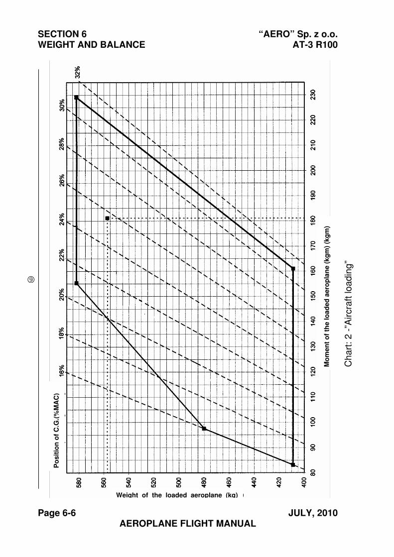
SECTION 6 “AERO” Sp. z o.o. WEIGHT AND BALANCE AT-3 R100
Page 6-6 JULY, 2010 AEROPLANE FLIGHT MANUAL
Weight of the loaded aeroplane (kg)
Mo
men
t o
f th
e lo
ad
ed
aero
pla
ne
(k
gm
)(k
gm
)
Po
sit
ion
of
C.G
.(%
MA
C)
Ch
art
: 2
-”A
ircra
ft lo
ad
ing”
9
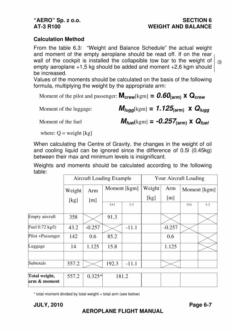
“AERO” Sp. z o.o. SECTION 6 AT-3 R100 WEIGHT AND BALANCE
JULY, 2010 Page 6-7 AEROPLANE FLIGHT MANUAL
Calculation Method
From the table 6.3: “Weight and Balance Schedule” the actual weight and moment of the empty aeroplane should be read off. If on the rear wall of the cockpit is installed the collapsible tow bar to the weight of empty aeroplane +1,5 kg should be added and moment +2,6 kgm should be increased. Values of the moments should be calculated on the basis of the following formula, multiplying the weight by the appropriate arm:
Moment of the pilot and passenger: Mcrew[kgm] = 0.60(arm) x Qcrew
Moment of the luggage: Mlugg[kgm] = 1.125(arm) x Qlugg
Moment of the fuel Mfuel[kgm] = -0.257(arm) x Qfuel
where: Q = weight [kg]
When calculating the Centre of Gravity, the changes in the weight of oil and cooling liquid can be ignored since the difference of 0.5l (0.45kg) between their max and minimum levels is insignificant.
Weights and moments should be calculated according to the following table:
Aircraft Loading Example Your Aircraft Loading
Moment [kgm] Weight
[kg]
Arm
[m]
Moment [kgm]Weight
[kg]
Arm
[m] (+) (-) (+) (-)
Empty aircraft 358 91.3
Fuel 0.72 kg/l)
kg/l)
43.2 -0.257 -11.1 -0.257
Pilot +Passenger 142 0.6 85.2 0.6
Luggage 14 1.125 15.8 1.125
Subtotals 557.2 192.3 -11.1
Total weight,
arm & moment 557.2 0.325* 181.2
* total moment divided by total weight = total arm (see below)
9
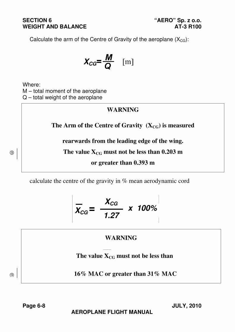
SECTION 6 “AERO” Sp. z o.o. WEIGHT AND BALANCE AT-3 R100
Page 6-8 JULY, 2010 AEROPLANE FLIGHT MANUAL
Calculate the arm of the Centre of Gravity of the aeroplane (XCG):
Where: M – total moment of the aeroplane Q – total weight of the aeroplane
calculate the centre of the gravity in % mean aerodynamic cord
WARNING
The Arm of the Centre of Gravity (XCG) is measured
rearwards from the leading edge of the wing.
The value XCG must not be less than 0.203 m
or greater than 0.393 m
WARNING
The value XCG must not be less than
16% MAC or greater than 31% MAC
XCG
9
XCG
XCG
1.27x 100%
__
9
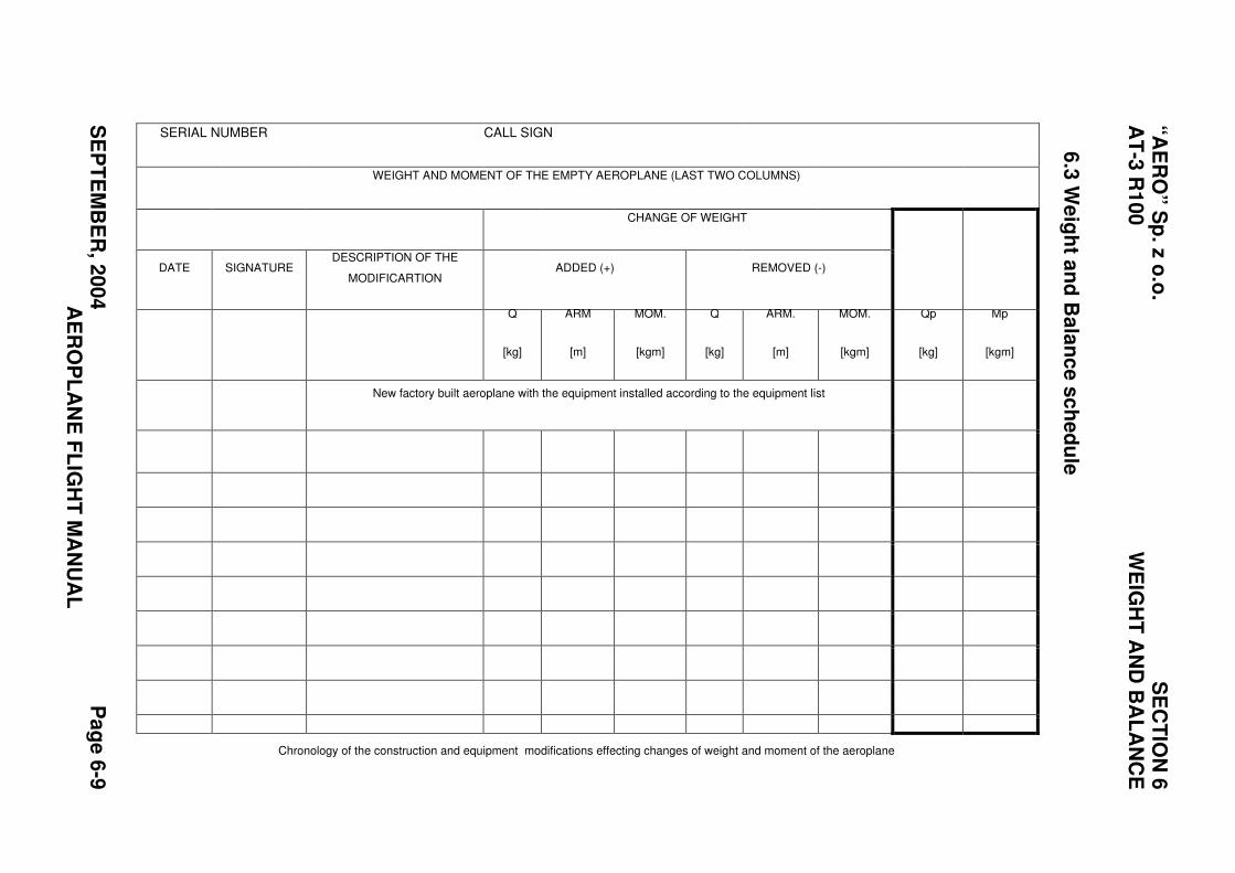
“A
ER
O” S
p. z
o.o
. S
EC
TIO
N 6
A
T-3
R1
00
W
EIG
HT
AN
D B
AL
AN
CE
SE
PT
EM
BE
R, 2
00
4
Pa
ge
6-9
A
ER
OP
LA
NE
FL
IGH
T M
AN
UA
L
6.3
We
igh
t an
d B
ala
nc
e s
ch
ed
ule
Mp
[kgm]
Qp
[kg]
MOM.
[kgm]
ARM.
[m]
REMOVED (-)
Q
[kg]
MOM.
[kgm]
ARM
[m]
CHANGE OF WEIGHT
ADDED (+)
Q
[kg]
DESCRIPTION OF THE
MODIFICARTION
New factory built aeroplane with the equipment installed according to the equipment list
SIGNATURE
SERIAL NUMBER CALL SIGN
WEIGHT AND MOMENT OF THE EMPTY AEROPLANE (LAST TWO COLUMNS)
DATE
Chronology of the construction and equipment modifications effecting changes of weight and moment of the aeroplane
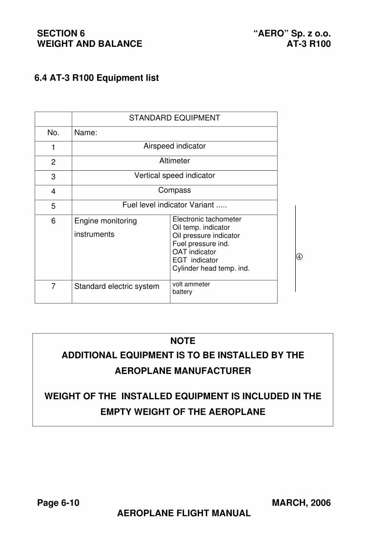
SECTION 6 “AERO” Sp. z o.o. WEIGHT AND BALANCE AT-3 R100
Page 6-10 MARCH, 2006 AEROPLANE FLIGHT MANUAL
STANDARD EQUIPMENT
No. Name:
1 Airspeed indicator
2 Altimeter
3 Vertical speed indicator
4 Compass
5 Fuel level indicator Variant .....
6 Engine monitoring
instruments
Electronic tachometer Oil temp. indicator Oil pressure indicator Fuel pressure ind. OAT indicator EGT indicator Cylinder head temp. ind.
7 Standard electric system volt ammeter battery
6.4 AT-3 R100 Equipment list
NOTE
ADDITIONAL EQUIPMENT IS TO BE INSTALLED BY THE
AEROPLANE MANUFACTURER
WEIGHT OF THE INSTALLED EQUIPMENT IS INCLUDED IN THE
EMPTY WEIGHT OF THE AEROPLANE
4
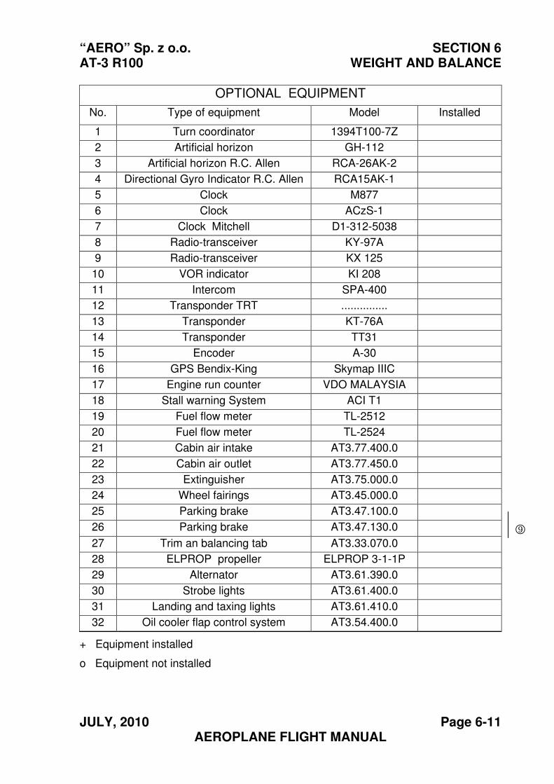
“AERO” Sp. z o.o. SECTION 6 AT-3 R100 WEIGHT AND BALANCE
JULY, 2010 Page 6-11 AEROPLANE FLIGHT MANUAL
+ Equipment installed
o Equipment not installed
OPTIONAL EQUIPMENT
No. Type of equipment Model Installed
1 Turn coordinator 1394T100-7Z
2 Artificial horizon GH-112
3 Artificial horizon R.C. Allen RCA-26AK-2
4 Directional Gyro Indicator R.C. Allen RCA15AK-1
5 Clock M877
6 Clock ACzS-1
7 Clock Mitchell D1-312-5038
8 Radio-transceiver KY-97A
9 Radio-transceiver KX 125
10 VOR indicator KI 208
11 Intercom SPA-400
12 Transponder TRT ...............
13 Transponder KT-76A
14 Transponder TT31
15 Encoder A-30
16 GPS Bendix-King Skymap IIIC
17 Engine run counter VDO MALAYSIA
18 Stall warning System ACI T1
19 Fuel flow meter TL-2512
20 Fuel flow meter TL-2524
21 Cabin air intake AT3.77.400.0
22 Cabin air outlet AT3.77.450.0
23 Extinguisher AT3.75.000.0
24 Wheel fairings AT3.45.000.0
25 Parking brake AT3.47.100.0
26 Parking brake AT3.47.130.0
27 Trim an balancing tab AT3.33.070.0
28 ELPROP propeller ELPROP 3-1-1P
29 Alternator AT3.61.390.0
30 Strobe lights AT3.61.400.0
31 Landing and taxing lights AT3.61.410.0
32 Oil cooler flap control system AT3.54.400.0
9
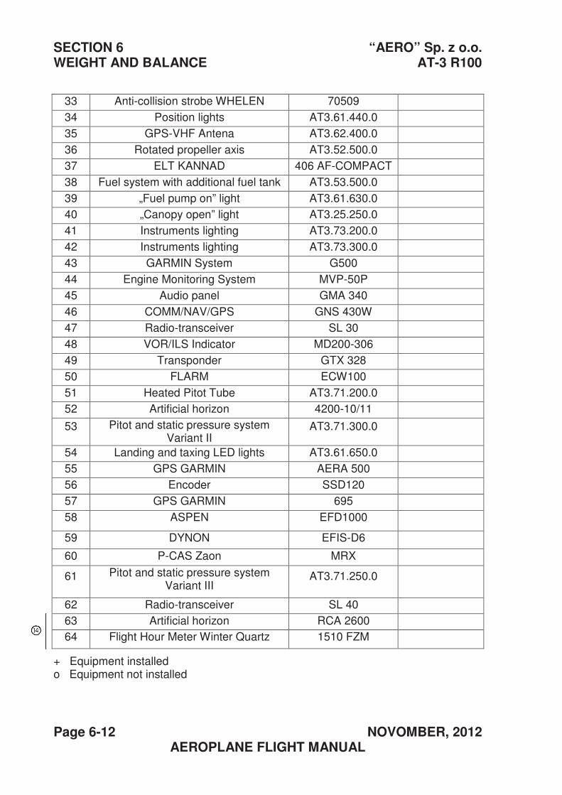
SECTION 6 “AERO” Sp. z o.o. WEIGHT AND BALANCE AT-3 R100
Page 6-12 NOVOMBER, 2012 AEROPLANE FLIGHT MANUAL
+ Equipment installed o Equipment not installed
33 Anti-collision strobe WHELEN 70509
34 Position lights AT3.61.440.0
35 GPS-VHF Antena AT3.62.400.0
36 Rotated propeller axis AT3.52.500.0
37 ELT KANNAD 406 AF-COMPACT
38 Fuel system with additional fuel tank AT3.53.500.0
39 „Fuel pump on” light AT3.61.630.0
40 „Canopy open” light AT3.25.250.0
41 Instruments lighting AT3.73.200.0
42 Instruments lighting AT3.73.300.0
43 GARMIN System G500
44 Engine Monitoring System MVP-50P
45 Audio panel GMA 340
46 COMM/NAV/GPS GNS 430W
47 Radio-transceiver SL 30
48 VOR/ILS Indicator MD200-306
49 Transponder GTX 328
50 FLARM ECW100
51 Heated Pitot Tube AT3.71.200.0
52 Artificial horizon 4200-10/11
53 Pitot and static pressure system Variant II
AT3.71.300.0
54 Landing and taxing LED lights AT3.61.650.0
55 GPS GARMIN AERA 500
56 Encoder SSD120
57 GPS GARMIN 695
58 ASPEN EFD1000
59 DYNON EFIS-D6
60 P-CAS Zaon MRX
61 Pitot and static pressure system Variant III
AT3.71.250.0
62 Radio-transceiver SL 40
63 Artificial horizon RCA 2600
64 Flight Hour Meter Winter Quartz 1510 FZM
“AERO” Sp. z o.o. SECTION 7 AT-3 R100 DESCRIPTION OF THE AEROPLANE
AND ITS EQUIPMENT
JULY, 2010 Page 7-1 AEROPLANE FLIGHT MANUAL
Section 7
DESCRIPTION OF THE AEROPLANE AND ITS EQUIPMENT
Page
7.1. Introduction ............................................................................... 7-2
7.2. Airframe .................................................................................... 7-2
7.2.1. Fuselage ............................................................................ 7-2
7.2.2. Wings ................................................................................. 7-3
7.2.3. Slab tail .............................................................................. 7-4
7.2.4. Fin and rudder.................................................................... 7-5
7.3. Flight control ............................................................................. 7-6
7.3.1. Control of the ailerons ........................................................ 7-6
7.3.2. Control of the wing flaps..................................................... 7-7
7.3.3. Control of the elevator........................................................ 7-8
7.3.4. Control of the trim & balancing tab..................................... 7-9
7.3.5. Control of the rudder ........................................................ 7-10
7.4. Instrument panel ..................................................................... 7-11
7.5. Landing gear system .............................................................. 7-15
7.5.1. Brake system ................................................................... 7-15
7.5.2. Parking brake................................................................... 7-17
7.6. Seats and seat belts ............................................................... 7-20
7.7. Luggage compartment............................................................ 7-21
7.8. Canopy ................................................................................... 7-22
7.9. Power unit............................................................................... 7-23
7.9.1. Engine.............................................................................. 7-23
7.9.2. Propeller........................................................................... 7-23
7.10. Fuel system .......................................................................... 7-24
7.11. Pitot and static pressure systems ......................................... 7-26
7.12. Electric system...................................................................... 7-27
7.13. Aeroplane equipment............................................................ 7-29
7.13.1. Ventilation and cabin heating………………………………..7-29
7.13.2. Carburettor heating system………………………………….7-30
7.13.3. Air intake covers ...............………………………………….7-31
9
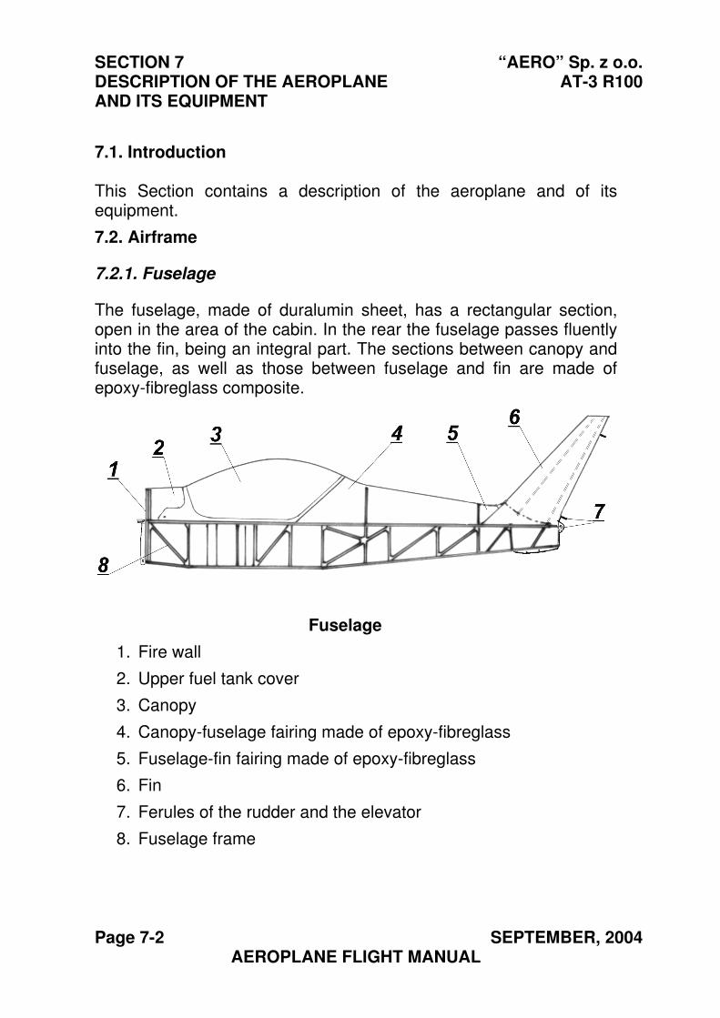
SECTION 7 “AERO” Sp. z o.o. DESCRIPTION OF THE AEROPLANE AT-3 R100 AND ITS EQUIPMENT
Page 7-2 SEPTEMBER, 2004 AEROPLANE FLIGHT MANUAL
7.1. Introduction
This Section contains a description of the aeroplane and of its equipment.
7.2. Airframe
7.2.1. Fuselage
The fuselage, made of duralumin sheet, has a rectangular section, open in the area of the cabin. In the rear the fuselage passes fluently into the fin, being an integral part. The sections between canopy and fuselage, as well as those between fuselage and fin are made of epoxy-fibreglass composite.
Fuselage
1. Fire wall
2. Upper fuel tank cover
3. Canopy
4. Canopy-fuselage fairing made of epoxy-fibreglass
5. Fuselage-fin fairing made of epoxy-fibreglass
6. Fin
7. Ferules of the rudder and the elevator
8. Fuselage frame
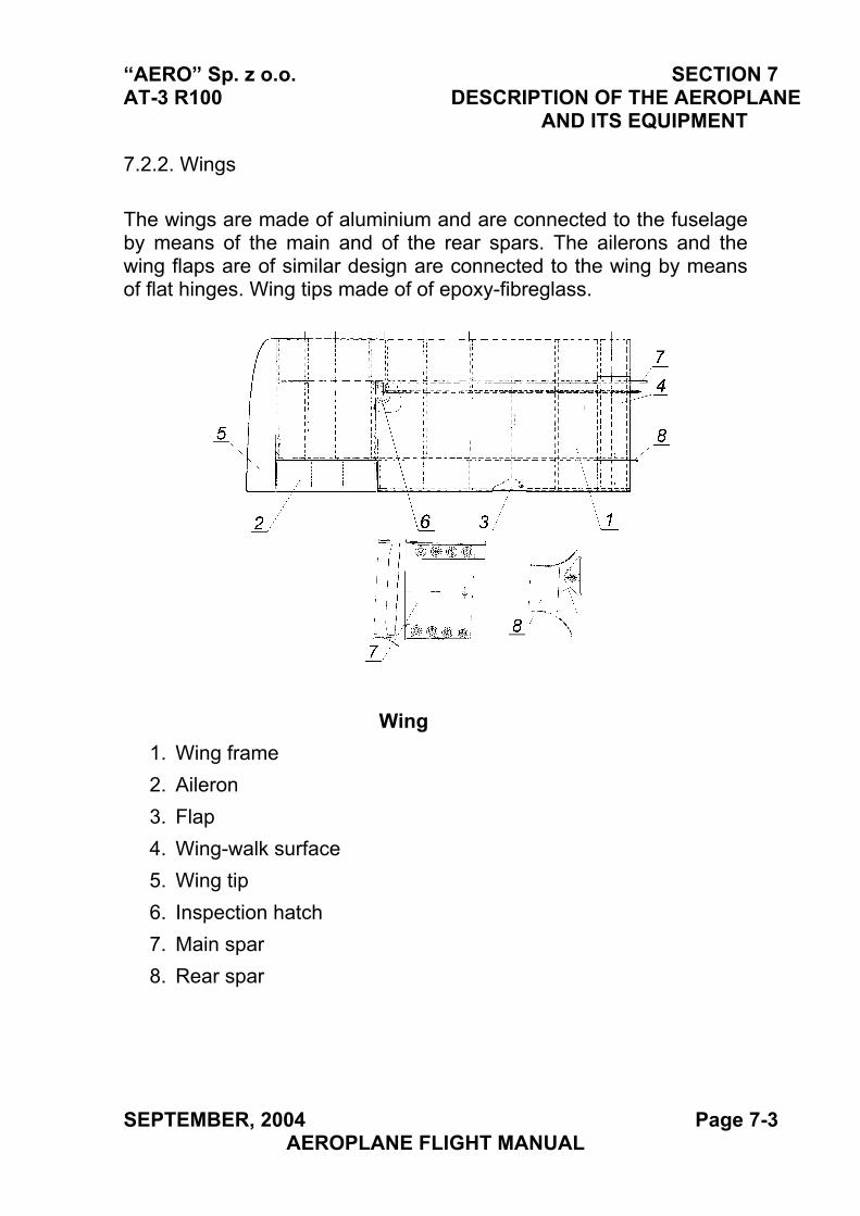
“AERO” Sp. z o.o. SECTION 7 AT-3 R100 DESCRIPTION OF THE AEROPLANE
AND ITS EQUIPMENT
7.2.2. Wings
The wings are made of aluminium and are connected to the fuselage by means of the main and of the rear spars. The ailerons and the wing flaps are of similar design are connected to the wing by means of flat hinges. Wing tips made of of epoxy-fibreglass.
Wing
1. Wing frame
2. Aileron
3. Flap
4. Wing-walk surface
5. Wing tip
6. Inspection hatch
7. Main spar
8. Rear spar
SEPTEMBER, 2004 Page 7-3 AEROPLANE FLIGHT MANUAL
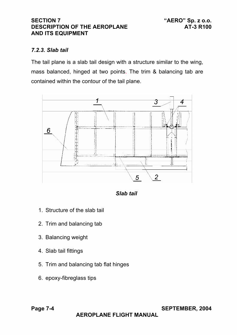
SECTION 7 “AERO” Sp. z o.o. DESCRIPTION OF THE AEROPLANE AT-3 R100 AND ITS EQUIPMENT
7.2.3. Slab tail
The tail plane is a slab tail design with a structure similar to the wing,
mass balanced, hinged at two points. The trim & balancing tab are
contained within the contour of the tail plane.
Slab tail
1. Structure of the slab tail
2. Trim and balancing tab
3. Balancing weight
4. Slab tail fittings
5. Trim and balancing tab flat hinges
6. epoxy-fibreglass tips
Page 7-4 SEPTEMBER, 2004 AEROPLANE FLIGHT MANUAL
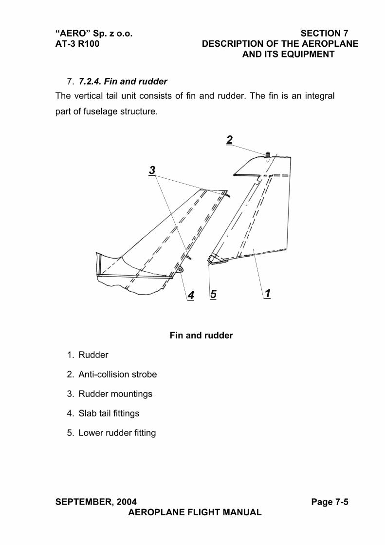
“AERO” Sp. z o.o. SECTION 7 AT-3 R100 DESCRIPTION OF THE AEROPLANE
AND ITS EQUIPMENT
7. 7.2.4. Fin and rudder
The vertical tail unit consists of fin and rudder. The fin is an integral
part of fuselage structure.
Fin and rudder
1. Rudder
2. Anti-collision strobe
3. Rudder mountings
4. Slab tail fittings
5. Lower rudder fitting
SEPTEMBER, 2004 Page 7-5 AEROPLANE FLIGHT MANUAL
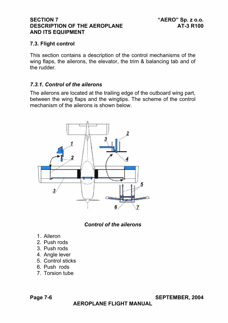
SECTION 7 “AERO” Sp. z o.o. DESCRIPTION OF THE AEROPLANE AT-3 R100 AND ITS EQUIPMENT
7.3. Flight control
This section contains a description of the control mechanisms of the wing flaps, the ailerons, the elevator, the trim & balancing tab and of the rudder.
7.3.1. Control of the ailerons
The ailerons are located at the trailing edge of the outboard wing part, between the wing flaps and the wingtips. The scheme of the control mechanism of the ailerons is shown below.
Control of the ailerons
1. Aileron2. Push rods3. Push rods4. Angle lever5. Control sticks6. Push rods7. Torsion tube
Page 7-6 SEPTEMBER, 2004 AEROPLANE FLIGHT MANUAL
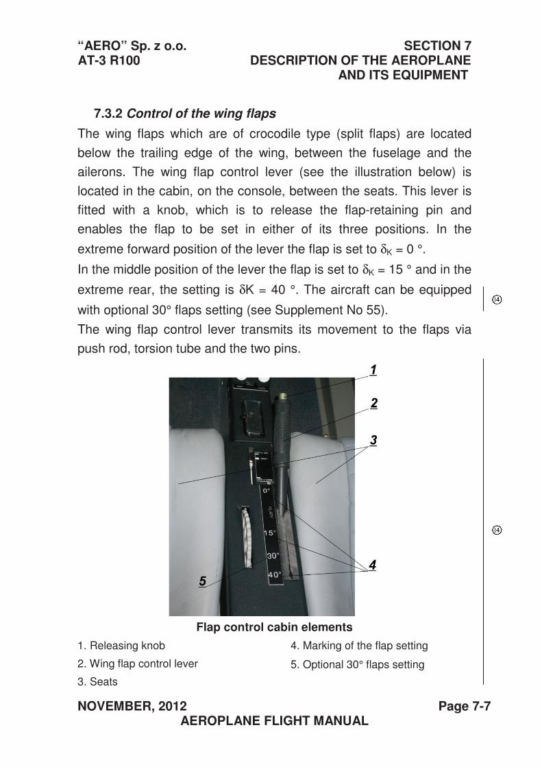
“AERO” Sp. z o.o. SECTION 7 AT-3 R100 DESCRIPTION OF THE AEROPLANE
AND ITS EQUIPMENT
NOVEMBER, 2012 Page 7-7 AEROPLANE FLIGHT MANUAL
7.3.2 Control of the wing flaps
The wing flaps which are of crocodile type (split flaps) are located
below the trailing edge of the wing, between the fuselage and the
ailerons. The wing flap control lever (see the illustration below) is
located in the cabin, on the console, between the seats. This lever is
fitted with a knob, which is to release the flap-retaining pin and
enables the flap to be set in either of its three positions. In the
extreme forward position of the lever the flap is set to δK = 0 °.
In the middle position of the lever the flap is set to δK = 15 ° and in the
extreme rear, the setting is δK = 40 °. The aircraft can be equipped
with optional 30° flaps setting (see Supplement No 55).
The wing flap control lever transmits its movement to the flaps via
push rod, torsion tube and the two pins.
Flap control cabin elements
1. Releasing knob
2. Wing flap control lever
3. Seats
4. Marking of the flap setting
5. Optional 30° flaps setting
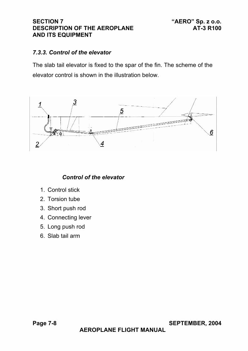
SECTION 7 “AERO” Sp. z o.o. DESCRIPTION OF THE AEROPLANE AT-3 R100 AND ITS EQUIPMENT
7.3.3. Control of the elevator
The slab tail elevator is fixed to the spar of the fin. The scheme of the
elevator control is shown in the illustration below.
Control of the elevator
1. Control stick
2. Torsion tube
3. Short push rod
4. Connecting lever
5. Long push rod
6. Slab tail arm
Page 7-8 SEPTEMBER, 2004 AEROPLANE FLIGHT MANUAL
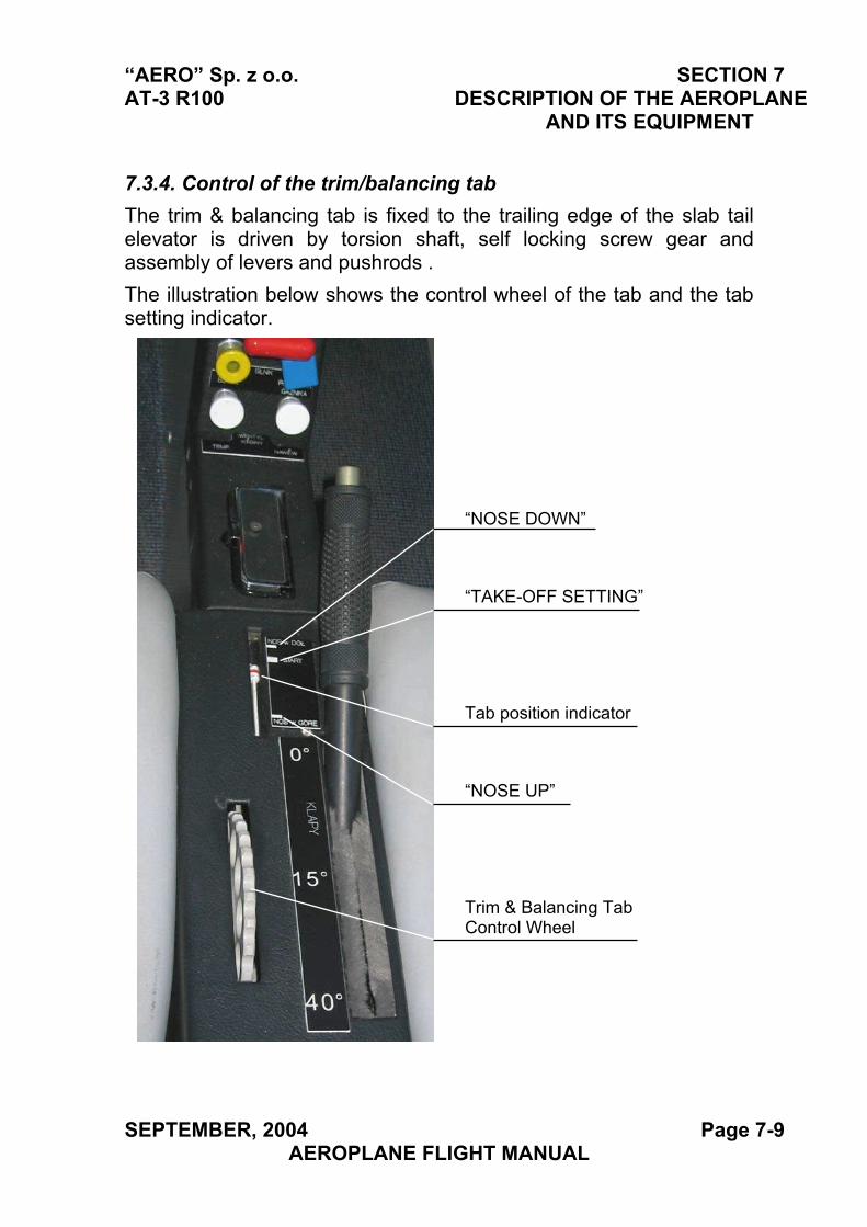
“AERO” Sp. z o.o. SECTION 7 AT-3 R100 DESCRIPTION OF THE AEROPLANE
AND ITS EQUIPMENT
7.3.4. Control of the trim/balancing tab
The trim & balancing tab is fixed to the trailing edge of the slab tail elevator is driven by torsion shaft, self locking screw gear and assembly of levers and pushrods .
The illustration below shows the control wheel of the tab and the tab setting indicator.
“NOSE DOWN”
“TAKE-OFF SETTING”
Tab position indicator
“NOSE UP”
Trim & Balancing Tab Control Wheel
SEPTEMBER, 2004 Page 7-9 AEROPLANE FLIGHT MANUAL
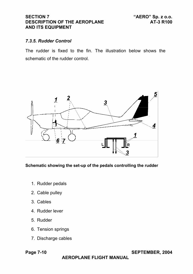
SECTION 7 “AERO” Sp. z o.o. DESCRIPTION OF THE AEROPLANE AT-3 R100 AND ITS EQUIPMENT
7.3.5. Rudder Control
The rudder is fixed to the fin. The illustration below shows the
schematic of the rudder control.
Schematic showing the set-up of the pedals controlling the rudder
1. Rudder pedals
2. Cable pulley
3. Cables
4. Rudder lever
5. Rudder
6. Tension springs
7. Discharge cables
Page 7-10 SEPTEMBER, 2004 AEROPLANE FLIGHT MANUAL
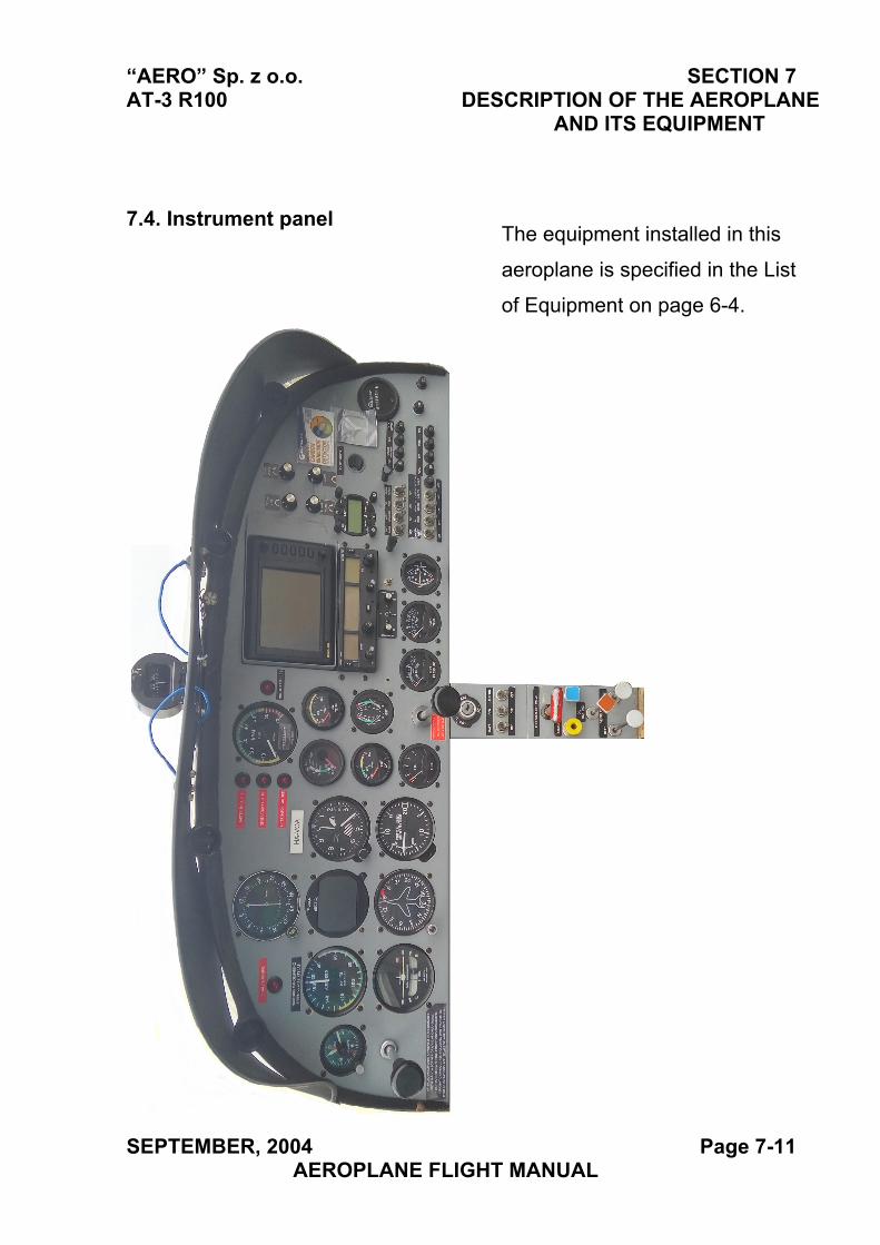
“AERO” Sp. z o.o. SECTION 7 AT-3 R100 DESCRIPTION OF THE AEROPLANE
AND ITS EQUIPMENT
7.4. Instrument panel The equipment installed in this
aeroplane is specified in the List
of Equipment on page 6-4.
SEPTEMBER, 2004 Page 7-11 AEROPLANE FLIGHT MANUAL
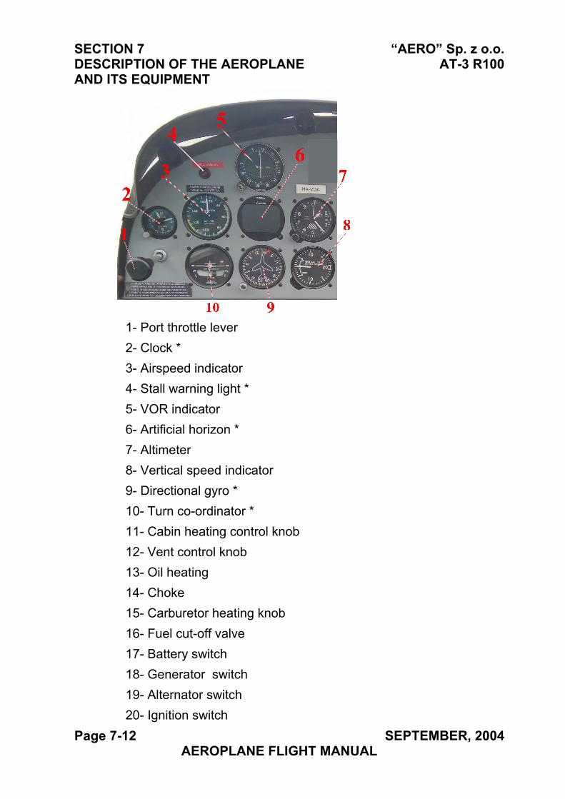
SECTION 7 “AERO” Sp. z o.o. DESCRIPTION OF THE AEROPLANE AT-3 R100 AND ITS EQUIPMENT
1- Port throttle lever 2- Clock * 3- Airspeed indicator 4- Stall warning light * 5- VOR indicator6- Artificial horizon *7- Altimeter8- Vertical speed indicator 9- Directional gyro *10- Turn co-ordinator *11- Cabin heating control knob 12- Vent control knob13- Oil heating14- Choke15- Carburetor heating knob 16- Fuel cut-off valve17- Battery switch18- Generator switch19- Alternator switch20- Ignition switch
Page 7-12 SEPTEMBER, 2004 AEROPLANE FLIGHT MANUAL
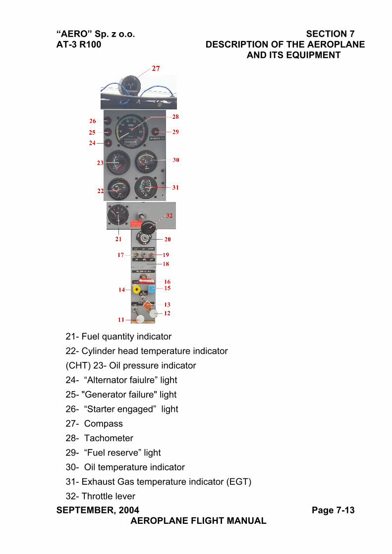
“AERO” Sp. z o.o. SECTION 7 AT-3 R100 DESCRIPTION OF THE AEROPLANE
AND ITS EQUIPMENT
21- Fuel quantity indicator22- Cylinder head temperature indicator (CHT) 23- Oil pressure indicator24- “Alternator faiulre” light25- "Generator failure" light26- “Starter engaged” light 27- Compass28- Tachometer29- “Fuel reserve” light30- Oil temperature indicator31- Exhaust Gas temperature indicator (EGT) 32- Throttle lever
SEPTEMBER, 2004 Page 7-13 AEROPLANE FLIGHT MANUAL
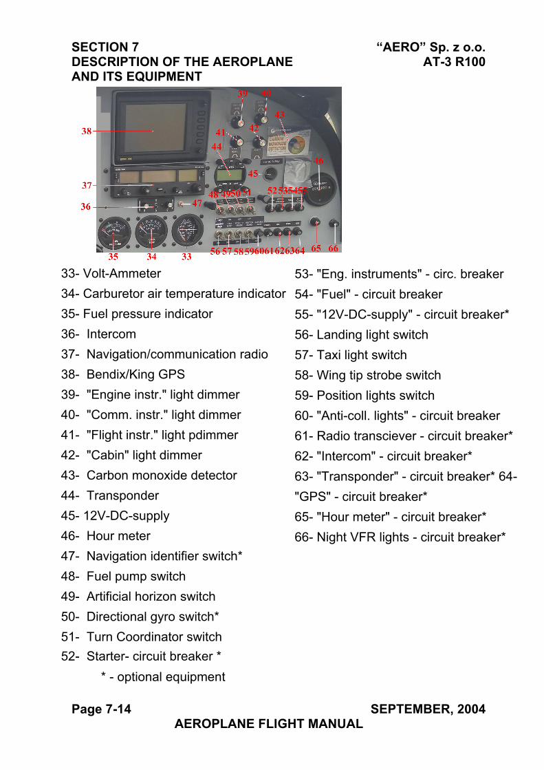
SECTION 7 “AERO” Sp. z o.o. DESCRIPTION OF THE AEROPLANE AT-3 R100 AND ITS EQUIPMENT
33- Volt-Ammeter34- Carburetor air temperature indicator 35- Fuel pressure indicator 36- Intercom 37- Navigation/communication radio38- Bendix/King GPS39- "Engine instr." light dimmer40- "Comm. instr." light dimmer41- "Flight instr." light pdimmer42- "Cabin" light dimmer43- Carbon monoxide detector44- Transponder45- 12V-DC-supply46- Hour meter47- Navigation identifier switch*48- Fuel pump switch49- Artificial horizon switch50- Directional gyro switch*51- Turn Coordinator switch52- Starter- circuit breaker *
* - optional equipment
Page 7-14 SEPTEMBER, 2004 AEROPLANE FLIGHT MANUAL
53- "Eng. instruments" - circ. breaker54- "Fuel" - circuit breaker 55- "12V-DC-supply" - circuit breaker* 56- Landing light switch57- Taxi light switch58- Wing tip strobe switch 59- Position lights switch60- "Anti-coll. lights" - circuit breaker 61- Radio transciever - circuit breaker* 62- "Intercom" - circuit breaker*63- "Transponder" - circuit breaker* 64- "GPS" - circuit breaker*65- "Hour meter" - circuit breaker* 66- Night VFR lights - circuit breaker*
“AERO” Sp. z o.o. SECTION 7 AT-3 R100 DESCRIPTION OF THE AEROPLANE
AND ITS EQUIPMENT
JULY, 2010 Page 7-15 AEROPLANE FLIGHT MANUAL
7.5. Landing gear system
The aircraft has a three-wheel, fixed landing gear, with nose wheel.
The main landing gear is of a flat spring design. The nose wheel is
fitted with a rubber shock absorber
7.5.1. Braking system
The aeroplane is fitted with hydraulic disc brakes. The system
consists of two hydraulic circuits that activate independent callipers of
left and right wheels of the main landing gear. Each of the circuits
consists of two brake cylinders [3] located on rudder pedals. In
version 1 they are connected via insulating valve [4] and flexible
pressure lines with brake callipers [8]. The brake fluid container [1] is
located at the highest point of the brake system on the firewall and it
supplies each pump independently. Cylinders of the left brake are
activated by the left rudder pedals and the right cylinders are
activated by the right rudder pedals of both the pilot and the
passenger. The insulating valve are located on the firewall in the
cabin and prevent the transfer of brake fluid under high pressure from
one cylinder to the other instead of the callipers. In version 2 pumps
on right rudder pedals activate additional callipers.
In both variations it is possible to install a parking brake valve.
9
9
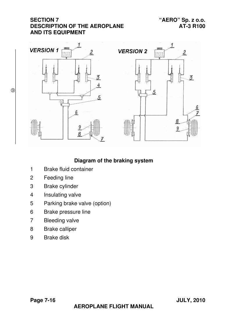
SECTION 7 “AERO” Sp. z o.o. DESCRIPTION OF THE AEROPLANE AT-3 R100 AND ITS EQUIPMENT
Page 7-16 JULY, 2010 AEROPLANE FLIGHT MANUAL
Diagram of the braking system
1 Brake fluid container
2 Feeding line
3 Brake cylinder
4 Insulating valve
5 Parking brake valve (option)
6 Brake pressure line
7 Bleeding valve
8 Brake calliper
9 Brake disk
9
“AERO” Sp. z o.o. SECTION 7 AT-3 R100 DESCRIPTION OF THE AEROPLANE
AND ITS EQUIPMENT
JULY, 2010 Page 7-17 AEROPLANE FLIGHT MANUAL
7.5.2. Parking Brake
The parking brake valve is installed in between the seats tunnel and
the parking brake lever is accessible from the left seat.
The parking valve can occur in two types. Type of installed parking
brake is specified in Section 6 of this manual, see table “Optional
equipment”.
For parking brake variant 2 the valve is installed in break installation
of left seat.
For role of the parking brake and the flight controls securing can be
used the collapsible tow bar installed on control stick and rudder
control pedals. For collapsible tow bar using description see Section
8.4.2 „Parking”.
CAUTION
ENGINE STARTING WITH PARKING BRAKE ON IS PROHIBITED
NOTE
IN ORDER TO APPLY THE PARKING BRAKE IT IS NECESSARY:- FROM THE LEFT SEAT PUSH ON TOE BRAKES
- ROTATE PARKING VALVE LEVER TO POSITION “ON”
NOTE
DUE TO POSSIBLE DECREASE IN PRESSURE IN THE BRAKE LINES OVER A LONGER PERIOD OF PARKING TIME IT IS
RECOMMENDED TO FURTHER SECURE THE AIRPLANE AS A PREVENTIVE MEASURE FROM ROLLING.
9
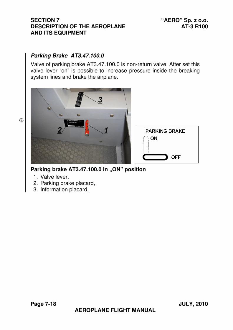
SECTION 7 “AERO” Sp. z o.o. DESCRIPTION OF THE AEROPLANE AT-3 R100 AND ITS EQUIPMENT
Page 7-18 JULY, 2010 AEROPLANE FLIGHT MANUAL
Parking Brake AT3.47.100.0
Valve of parking brake AT3.47.100.0 is non-return valve. After set this valve lever “on” is possible to increase pressure inside the breaking system lines and brake the airplane.
Parking brake AT3.47.100.0 in „ON” position
1. Valve lever,2. Parking brake placard,3. Information placard,
9
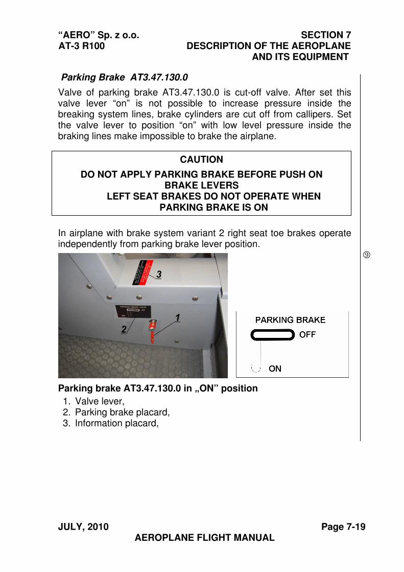
“AERO” Sp. z o.o. SECTION 7 AT-3 R100 DESCRIPTION OF THE AEROPLANE
AND ITS EQUIPMENT
JULY, 2010 Page 7-19 AEROPLANE FLIGHT MANUAL
Parking Brake AT3.47.130.0
Valve of parking brake AT3.47.130.0 is cut-off valve. After set this valve lever “on” is not possible to increase pressure inside the breaking system lines, brake cylinders are cut off from callipers. Set the valve lever to position “on” with low level pressure inside the braking lines make impossible to brake the airplane.
In airplane with brake system variant 2 right seat toe brakes operate independently from parking brake lever position.
Parking brake AT3.47.130.0 in „ON” position
1. Valve lever,2. Parking brake placard,3. Information placard,
CAUTION
DO NOT APPLY PARKING BRAKE BEFORE PUSH ON BRAKE LEVERS
LEFT SEAT BRAKES DO NOT OPERATE WHEN PARKING BRAKE IS ON
9
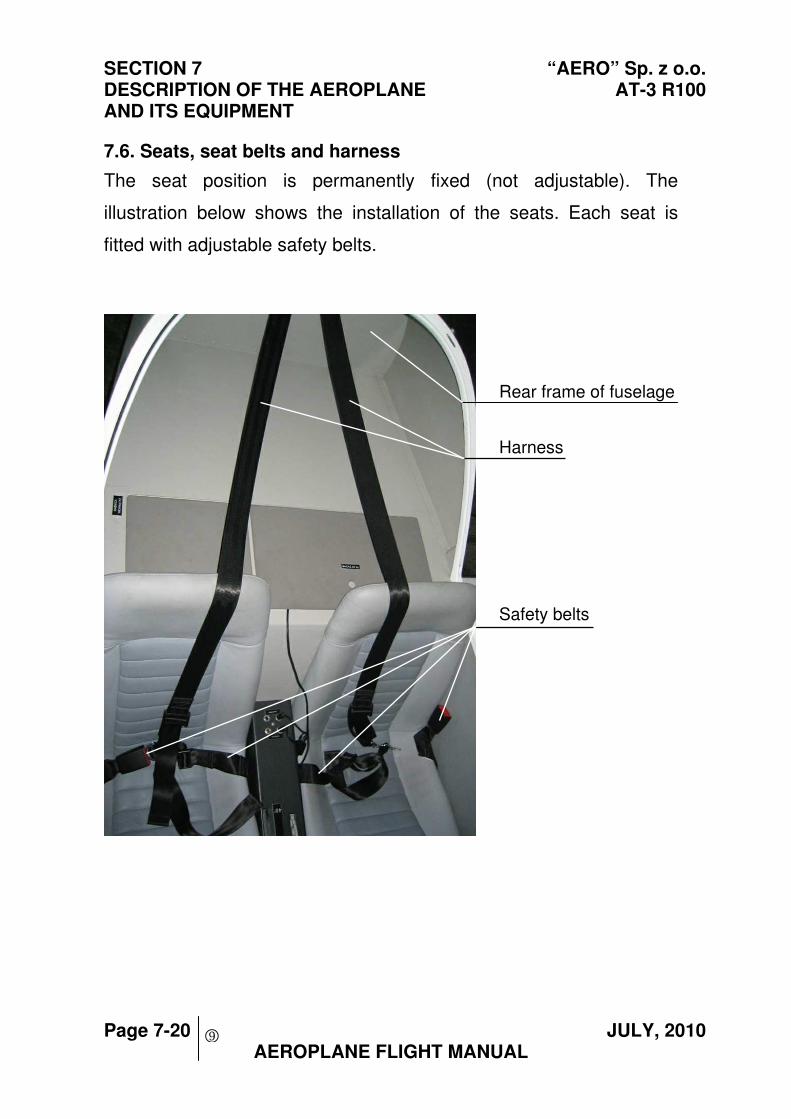
SECTION 7 “AERO” Sp. z o.o. DESCRIPTION OF THE AEROPLANE AT-3 R100 AND ITS EQUIPMENT
Page 7-20 JULY, 2010 AEROPLANE FLIGHT MANUAL
7.6. Seats, seat belts and harness
The seat position is permanently fixed (not adjustable). The
illustration below shows the installation of the seats. Each seat is
fitted with adjustable safety belts.
Rear frame of fuselage
Harness
Safety belts
9
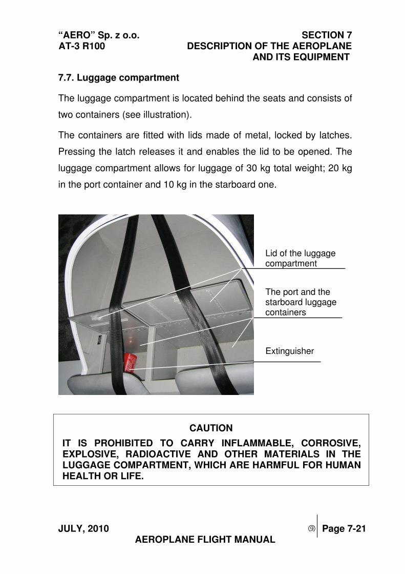
“AERO” Sp. z o.o. SECTION 7 AT-3 R100 DESCRIPTION OF THE AEROPLANE
AND ITS EQUIPMENT
JULY, 2010 Page 7-21 AEROPLANE FLIGHT MANUAL
7.7. Luggage compartment
The luggage compartment is located behind the seats and consists of
two containers (see illustration).
The containers are fitted with lids made of metal, locked by latches.
Pressing the latch releases it and enables the lid to be opened. The
luggage compartment allows for luggage of 30 kg total weight; 20 kg
in the port container and 10 kg in the starboard one.
Lid of the luggage compartment
The port and the starboard luggage containers
Extinguisher
CAUTION
IT IS PROHIBITED TO CARRY INFLAMMABLE, CORROSIVE, EXPLOSIVE, RADIOACTIVE AND OTHER MATERIALS IN THE LUGGAGE COMPARTMENT, WHICH ARE HARMFUL FOR HUMAN HEALTH OR LIFE.
9
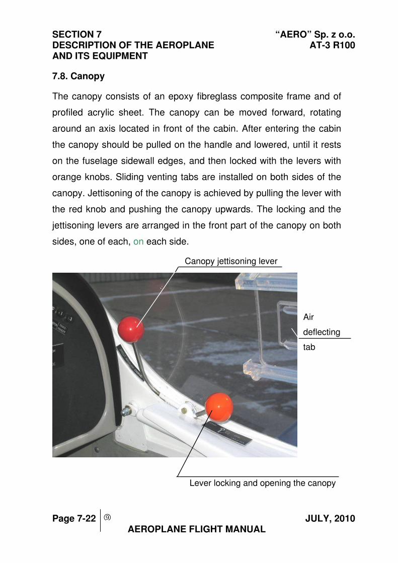
SECTION 7 “AERO” Sp. z o.o. DESCRIPTION OF THE AEROPLANE AT-3 R100 AND ITS EQUIPMENT
Page 7-22 JULY, 2010 AEROPLANE FLIGHT MANUAL
7.8. Canopy
The canopy consists of an epoxy fibreglass composite frame and of
profiled acrylic sheet. The canopy can be moved forward, rotating
around an axis located in front of the cabin. After entering the cabin
the canopy should be pulled on the handle and lowered, until it rests
on the fuselage sidewall edges, and then locked with the levers with
orange knobs. Sliding venting tabs are installed on both sides of the
canopy. Jettisoning of the canopy is achieved by pulling the lever with
the red knob and pushing the canopy upwards. The locking and the
jettisoning levers are arranged in the front part of the canopy on both
sides, one of each, on each side.
Canopy jettisoning lever
Air
deflecting
tab
Lever locking and opening the canopy
9
“AERO” Sp. z o.o. SECTION 7 AT-3 R100 DESCRIPTION OF THE AEROPLANE
AND ITS EQUIPMENT
JULY, 2010 Page 7-23 AEROPLANE FLIGHT MANUAL
7.9. Power unit
7.9.1. Engine
Rotax 912S2 engine
- Four-stroke, opposed, four cylinder engine
- Cylinder heads cooled with fluid, cylinders cooled with air
- Pressure lubrication
- Dual magneto ignition
- Propeller driven via reduction gear
- Electric starter
- Generator
Two interconnected throttle levers, located on the instrument panel,
are used to control the engine.
7.9.2. Propeller
Carbon-fibre, fixed pitch, three-blade ELPROP 3-1-1P propeller with
1.73 m (5’ 8”) diameter
The propeller rotates in a clockwise direction (when viewed from the
cockpit)
9
SECTION 7 “AERO” Sp. z o.o. DESCRIPTION OF THE AEROPLANE AT-3 R100 AND ITS EQUIPMENT
Page 7-24 JULY, 2010 AEROPLANE FLIGHT MANUAL
7.10. Fuel system
The fuel is contained in the fuel tank, which is located between the
instrument panel and the firewall. The fuel tank, made of composite,
is contained in a sack, made of fabric resistant to smoke and to fuel.
There are drains installed in the sack, to drain any spilled fuel out of
the aeroplane. The fuel tank is fitted with a filler which is drained. A
measuring stick is attached to the filler cap. The fuel quantity is
measured by the fuel level sensor. The signal from this sensor is
transmitted to the fuel quantity indicator and to the reserve fuel
sensor. The reserve fuel signal lamp starts to light, when the fuel tank
contains 10 litres of consumable fuel.
The fuel is filtered by the coarse filter located on the fuel tank outlet,
by the filter in the electric driven emergency fuel pump and by the fine
filter, located behind the engine driven pump.
The fuel shut-off valve is located under the fuel tank, behind the
firewall, and is operated from the cabin.
The engine driven pump feeds the fuel under pressure via a five-way
connector to the carburettors and to the fuel pressure sensor. Surplus
fuel is drained back to the fuel tank.
9
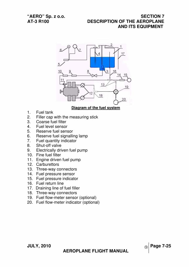
“AERO” Sp. z o.o. SECTION 7 AT-3 R100 DESCRIPTION OF THE AEROPLANE
AND ITS EQUIPMENT
JULY, 2010 Page 7-25 AEROPLANE FLIGHT MANUAL
Diagram of the fuel system
1. Fuel tank2. Filler cap with the measuring stick3. Coarse fuel filter4. Fuel level sensor5. Reserve fuel sensor6. Reserve fuel signalling lamp7. Fuel quantity indicator8. Shut-off valve9. Electrically driven fuel pump10. Fine fuel filter11. Engine driven fuel pump12. Carburettors13. Three-way connectors14. Fuel pressure sensor15. Fuel pressure indicator16. Fuel return line17. Draining line of fuel filler18. Three-way connectors19. Fuel flow-meter sensor (optional)20. Fuel flow-meter indicator (optional)
9
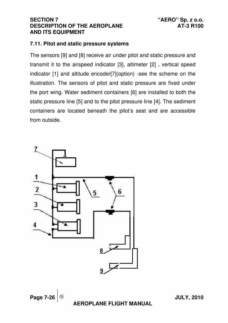
SECTION 7 “AERO” Sp. z o.o. DESCRIPTION OF THE AEROPLANE AT-3 R100 AND ITS EQUIPMENT
Page 7-26 JULY, 2010 AEROPLANE FLIGHT MANUAL
7.11. Pitot and static pressure systems
The sensors [9] and [8] receive air under pitot and static pressure and
transmit it to the airspeed indicator [3], altimeter [2] , vertical speed
indicator [1] and altitude encoder[7](option) -see the scheme on the
illustration. The sensors of pitot and static pressure are fixed under
the port wing. Water sediment containers [6] are installed to both the
static pressure line [5] and to the pitot pressure line [4]. The sediment
containers are located beneath the pilot’s seat and are accessible
from outside.
9
“AERO” Sp. z o.o. SECTION 7 AT-3 R100 DESCRIPTION OF THE AEROPLANE
AND ITS EQUIPMENT
JULY, 2010 Page 7-27 AEROPLANE FLIGHT MANUAL
7.12. Electrical system
The source of on board electric power is the generator and the
battery. It is a 12 Volt system. Automatic circuit breakers located on
the instrument panel protect the system. The BATTERY switch
switches on the system. The switches BATTERY and GENERATOR
perform the task of the system master switch. In case of generator
failure, the GENERATOR signalling lamp lights up. In such a case the
system is fed from the on board battery.
There is also an electrical ground power receptacle installed into the
system, being located in front of the wing, on the port wall of the
fuselage, in front of the firewall. An electric board socked is installed
in the cabin, on the instrument panel. When using the ground power
source, the on board battery is automatically switched off. Switching
of the electric power receivers in this case is the same as when using
the on board battery.
The following options are available:
- Anti-collision strobe
- Navigation lights and the landing light
9
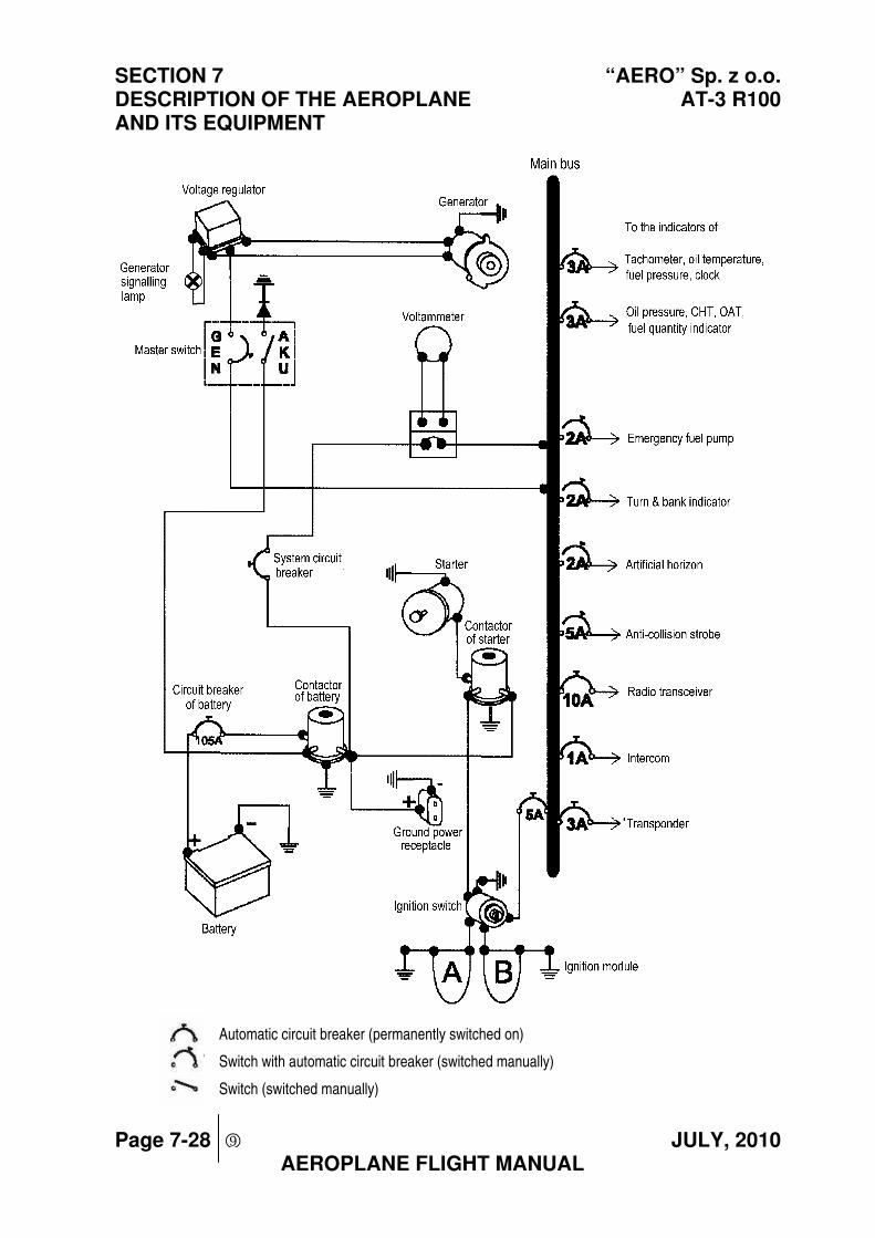
SECTION 7 “AERO” Sp. z o.o. DESCRIPTION OF THE AEROPLANE AT-3 R100 AND ITS EQUIPMENT
Page 7-28 JULY, 2010 AEROPLANE FLIGHT MANUAL
Automatic circuit breaker (permanently switched on)
Switch with automatic circuit breaker (switched manually)
Switch (switched manually)
9
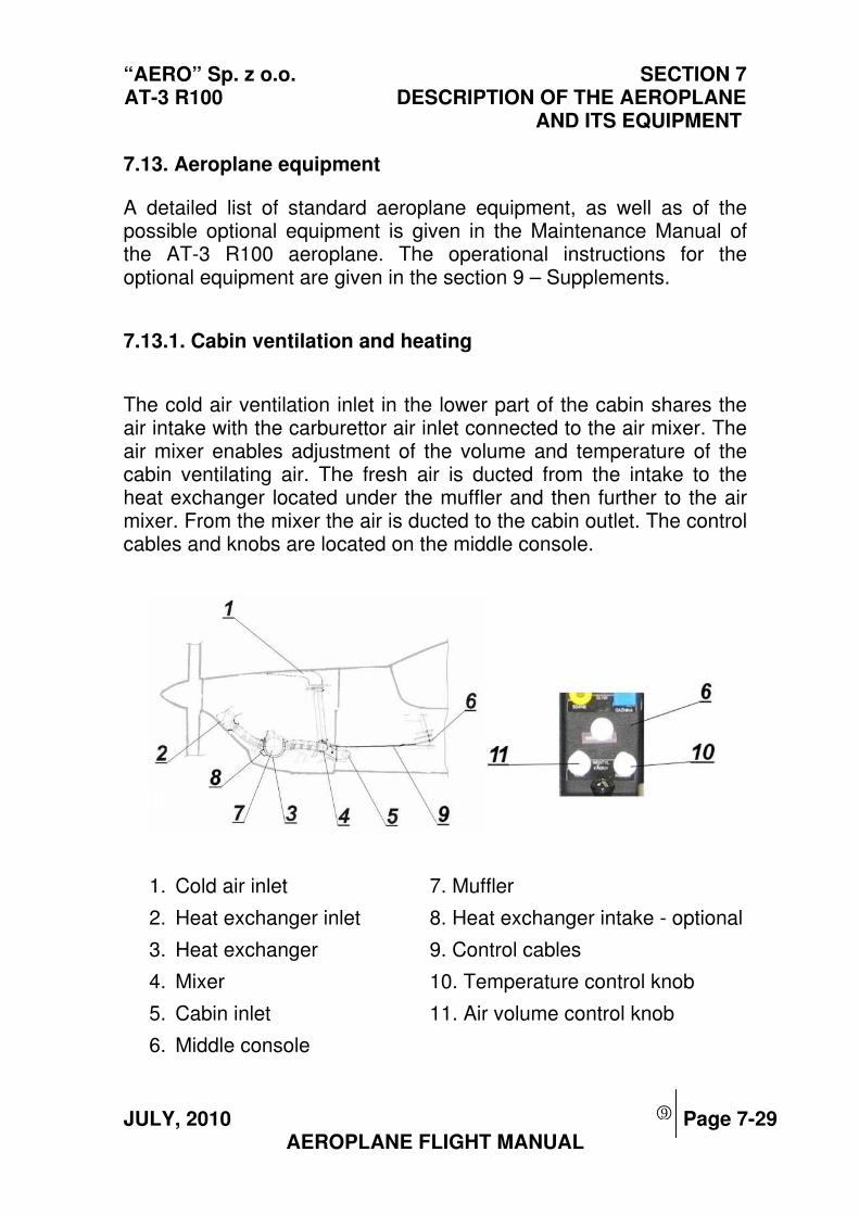
“AERO” Sp. z o.o. SECTION 7 AT-3 R100 DESCRIPTION OF THE AEROPLANE
AND ITS EQUIPMENT
JULY, 2010 Page 7-29 AEROPLANE FLIGHT MANUAL
7.13. Aeroplane equipment
A detailed list of standard aeroplane equipment, as well as of the possible optional equipment is given in the Maintenance Manual of the AT-3 R100 aeroplane. The operational instructions for the optional equipment are given in the section 9 – Supplements.
7.13.1. Cabin ventilation and heating
The cold air ventilation inlet in the lower part of the cabin shares the air intake with the carburettor air inlet connected to the air mixer. The air mixer enables adjustment of the volume and temperature of the cabin ventilating air. The fresh air is ducted from the intake to the heat exchanger located under the muffler and then further to the air mixer. From the mixer the air is ducted to the cabin outlet. The control cables and knobs are located on the middle console.
1. Cold air inlet 7. Muffler
2. Heat exchanger inlet 8. Heat exchanger intake - optional
3. Heat exchanger 9. Control cables
4. Mixer 10. Temperature control knob
5. Cabin inlet 11. Air volume control knob
6. Middle console
9
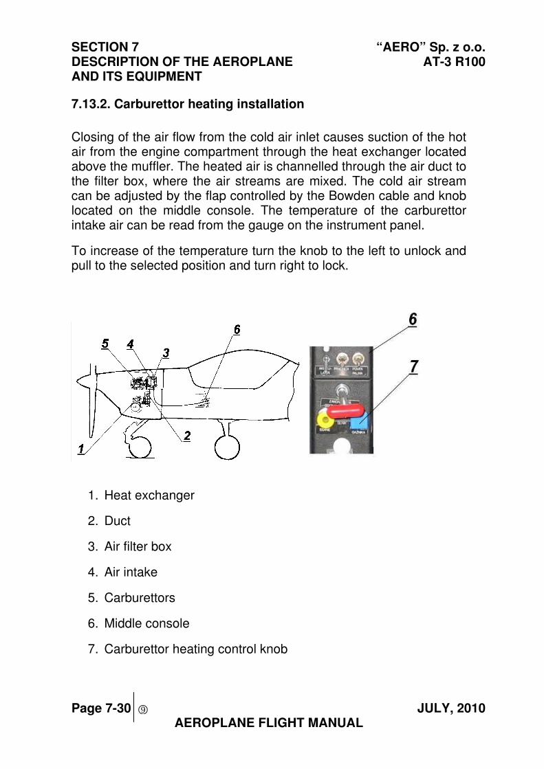
SECTION 7 “AERO” Sp. z o.o. DESCRIPTION OF THE AEROPLANE AT-3 R100 AND ITS EQUIPMENT
Page 7-30 JULY, 2010 AEROPLANE FLIGHT MANUAL
7.13.2. Carburettor heating installation
Closing of the air flow from the cold air inlet causes suction of the hot air from the engine compartment through the heat exchanger located above the muffler. The heated air is channelled through the air duct to the filter box, where the air streams are mixed. The cold air stream can be adjusted by the flap controlled by the Bowden cable and knob located on the middle console. The temperature of the carburettor intake air can be read from the gauge on the instrument panel.
To increase of the temperature turn the knob to the left to unlock and pull to the selected position and turn right to lock.
1. Heat exchanger
2. Duct
3. Air filter box
4. Air intake
5. Carburettors
6. Middle console
7. Carburettor heating control knob
9
“AERO” Sp. z o.o. SECTION 7 AT-3 R100 DESCRIPTION OF THE AEROPLANE
AND ITS EQUIPMENT
JULY, 2010 Page 7-31 AEROPLANE FLIGHT MANUAL
7.13.3 Air intake covers
In case of airplane operation in low ambient temperature it is
recommended that intake air covers are used to reduce the intensity
of the cooling effect. Inlet covers are installed in the lower cowling by
the means of screws.
NOTE
It is recommended that Air Intake Covers are installed when operating the aircraft in ambient
temperature below 120C/540F
9
SECTION 7 “AERO” Sp. z o.o. DESCRIPTION OF THE AEROPLANE AT-3 R100 AND ITS EQUIPMENT
Page 7-32 JULY, 2010 AEROPLANE FLIGHT MANUAL
THIS PAGE IS LEFT INTENTIONALLY BLANK
9
“AERO” Sp. z o.o. SECTION 8 AT-3 R100 SERVICING
JULY, 2010 Page 8-1 AEROPLANE FLIGHT MANUAL
Section 8
SERVICING
Page
8.1. Introduction ............................................................................... 8-2
8.2. Scheduled aeroplane inspections............................................. 8-2
8.3 Aeroplane repair or modification................................................ 8-3
8.4. Ground servicing....................................................................... 8-3
8.4.1. Relocating the aeroplane on ground .................................. 8-4
8.4.2. Parking............................................................................... 8-5
8.4.3. Tying down......................................................................... 8-7
8.4.4. Lifting ................................................................................. 8-8
8.4.5. Levelling ............................................................................. 8-9
8.5. Cleaning and basic maintenance............................................ 8-10
8.5.1. External painted surfaces................................................. 8-10
8.5.2. Glass panels .................................................................... 8-11
8.5.3. Propeller........................................................................... 8-12
8.5.4. Engine.............................................................................. 8-12
8.5.5. Cabin interior.................................................................... 8-12
9999
SECTION 8 “AERO” Sp. z o.o. SERVICING AT-3 R100
Page 8-2 SEPTEMBER, 2004 AEROPLANE FLIGHT MANUAL
8.1. Introduction
This Section contains procedures for the correct control of the aeroplane
on the ground and servicing, recommended by the aeroplane
manufacturer. It also contains some requirements concerning
inspections and basic maintenance, which are to be observed in order to
maintain the performance and reliability of a new aeroplane. It is
reasonable to proceed according to a prescheduled scheme of
lubrication and maintenance, appropriate to the operating conditions and
climate.
8.2. Scheduled aeroplane inspections
The scope and the intervals of the inspection schedule are defined in the
Aeroplane Maintenance Manual. A separate inspection system may be
required for the aeroplane by the appropriate Civil Aviation Authority in
order to renew the Certificate of Airworthiness. Tasks to be carried out in
relation to scheduled inspections of engine, propeller and equipment, are
defined in the respective applicable manuals or operating and
maintenance instructions.
The owner and operator are responsible and must insure, that all
servicing and maintenance is only carried out by qualified personnel.
“AERO” Sp. z o.o. SECTION 8 AT-3 R100 SERVICING
SEPTEMBER, 2004 Page 8-3 AEROPLANE FLIGHT MANUAL
8.3 Aeroplane repairs or modifications
Any repair or modification of the aeroplane design may only be
performed by authorized personal.
NOTE Prior to any modification of the aeroplane, ensure with the Civil
Aviation Authority, that the intended modification will not negatively affect the airworthiness of the aeroplane
After completing the modification, according to the instructions given in
the Aeroplane Maintenance Manual, the aircraft should be re-weighed,
and the respective weighing report sheet completed and the Weight and
Balance schedule in section 6-3 of this manual must be revised. Also
Section 9 of this manual is to be supplemented accordingly.
8.4. Ground servicing
The dimensions of the standard aeroplane are given in the aeroplane
drawings (see Section 1). This allows the size of the area required for the
aeroplane in a hangar or for parking to be defined.
NOTE. The size of the required area is to be increased respectively, to
provide space for supplementary equipment such as antennas of radio equipment (or other equipment installed according to the
operators options).
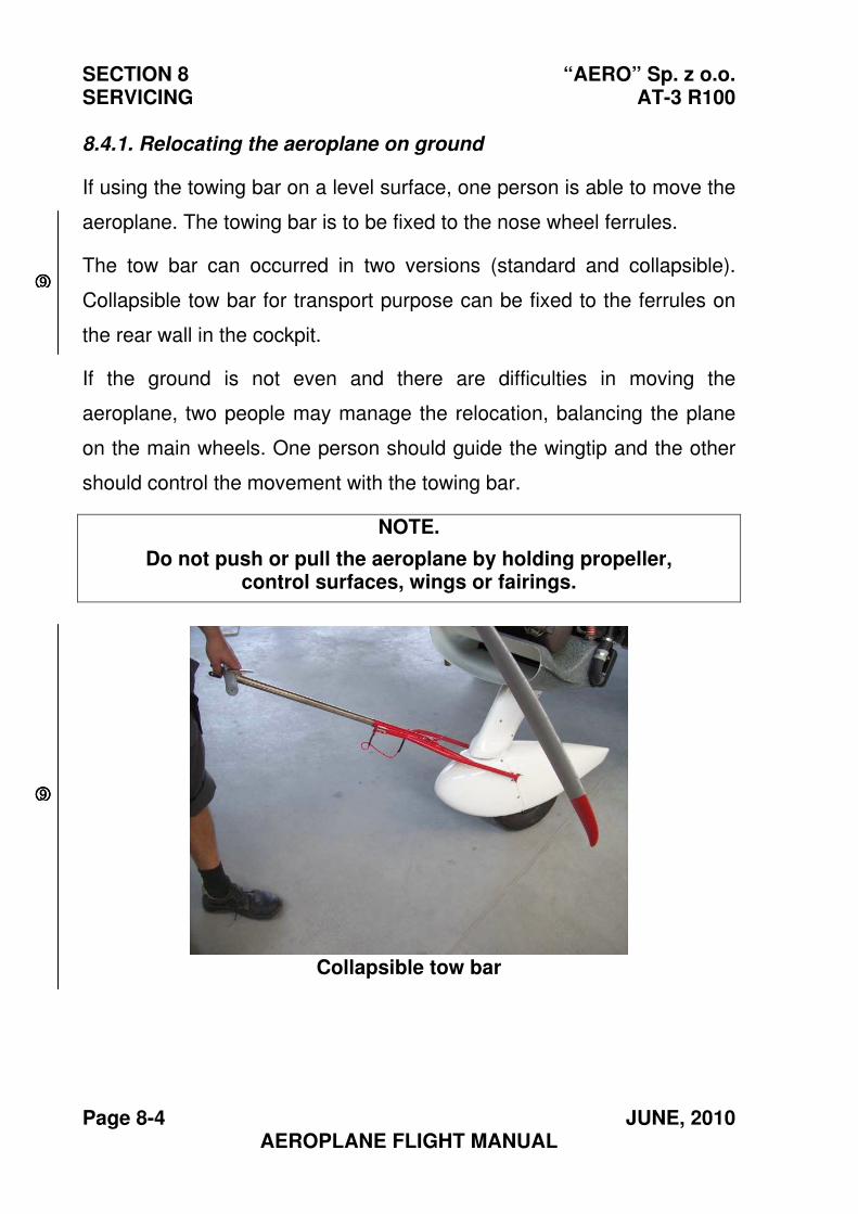
SECTION 8 “AERO” Sp. z o.o. SERVICING AT-3 R100
Page 8-4 JUNE, 2010 AEROPLANE FLIGHT MANUAL
8.4.1. Relocating the aeroplane on ground
If using the towing bar on a level surface, one person is able to move the
aeroplane. The towing bar is to be fixed to the nose wheel ferrules.
The tow bar can occurred in two versions (standard and collapsible).
Collapsible tow bar for transport purpose can be fixed to the ferrules on
the rear wall in the cockpit.
If the ground is not even and there are difficulties in moving the
aeroplane, two people may manage the relocation, balancing the plane
on the main wheels. One person should guide the wingtip and the other
should control the movement with the towing bar.
NOTE.
Do not push or pull the aeroplane by holding propeller, control surfaces, wings or fairings.
Collapsible tow bar
9999
9999
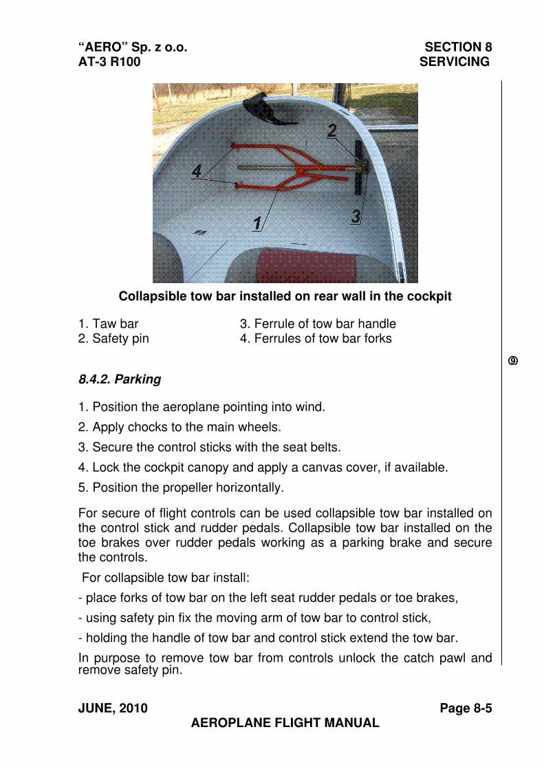
“AERO” Sp. z o.o. SECTION 8 AT-3 R100 SERVICING
JUNE, 2010 Page 8-5 AEROPLANE FLIGHT MANUAL
Collapsible tow bar installed on rear wall in the cockpit
1. Taw bar 3. Ferrule of tow bar handle2. Safety pin 4. Ferrules of tow bar forks
8.4.2. Parking
1. Position the aeroplane pointing into wind.
2. Apply chocks to the main wheels.
3. Secure the control sticks with the seat belts.
4. Lock the cockpit canopy and apply a canvas cover, if available.
5. Position the propeller horizontally.
For secure of flight controls can be used collapsible tow bar installed on the control stick and rudder pedals. Collapsible tow bar installed on the toe brakes over rudder pedals working as a parking brake and secure the controls.
For collapsible tow bar install:
- place forks of tow bar on the left seat rudder pedals or toe brakes,
- using safety pin fix the moving arm of tow bar to control stick,
- holding the handle of tow bar and control stick extend the tow bar.
In purpose to remove tow bar from controls unlock the catch pawl and remove safety pin.
9999
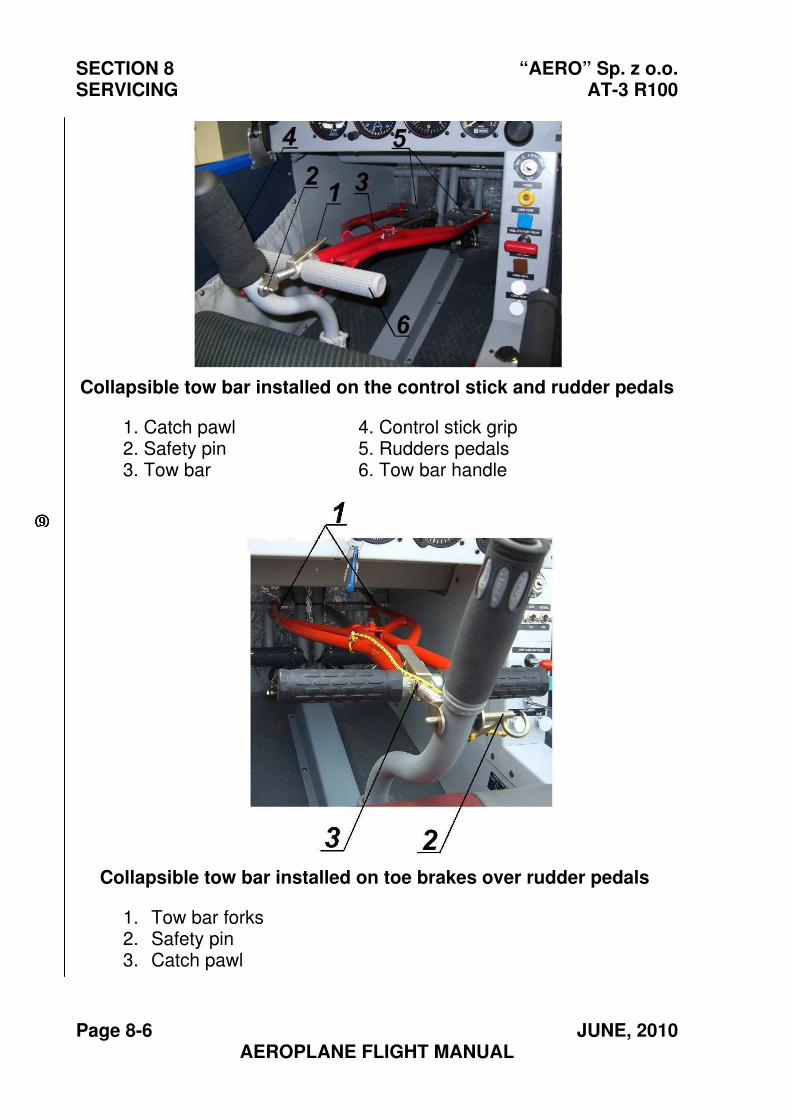
SECTION 8 “AERO” Sp. z o.o. SERVICING AT-3 R100
Page 8-6 JUNE, 2010 AEROPLANE FLIGHT MANUAL
Collapsible tow bar installed on the control stick and rudder pedals
1. Catch pawl 4. Control stick grip2. Safety pin 5. Rudders pedals3. Tow bar 6. Tow bar handle
Collapsible tow bar installed on toe brakes over rudder pedals
1. Tow bar forks2. Safety pin3. Catch pawl
9999
“AERO” Sp. z o.o. SECTION 8 AT-3 R100 SERVICING
JUNE, 2010 Page 8-7 AEROPLANE FLIGHT MANUAL
8.4.3. Tying down
There are lugs for the tie-down ropes on the aeroplane. They are located
under the wingtips, at the rear of the aeroplane (tail skid) and at the front
(nose landing gear ferrules).
When tying down, the following should be observed:
1. It is recommended to have the aeroplane pointing into wind.
2. Put chocks in front of the main wheels.
3. Apply locks to the ailerons, rudder and elevator, or fasten the control
sticks with safety belts.
4. Put the ropes through the specified lugs and drive the mooring
anchors in the ground. There should only be slight tension on the tie-
downs to prevent sagging.
5. Apply the cover to the pitot and static pressure sensors.
6. Lock the canopy and put on the cover.
7. Position the propeller horizontally.
9
SECTION 8 “AERO” Sp. z o.o. SERVICING AT-3 R100
Page 8-8 JUNE, 2010 AEROPLANE FLIGHT MANUAL
8.4.4. Lifting
When jacking the aeroplane the following procedure should be followed:
1. Put a stand (under a rib) under each wing to prevent the aeroplane
from tilting.
NOTE.
Instead of using jacks, the aeroplane may also be lifted by hand, when holding the lower fuselage edges in the area between the
firewall and the wing and in front of the horizontal stabilizer.
2. Locate one of the jacks under the nose landing gear ferrule and the
other two, each side next to the cabin walls, under the main landing
gear box. Apply wooden blocks
3. Lift the aeroplane gradually to the required height. Lift the aeroplane,
raising each jack evenly at the same time and avoid swaying.
9
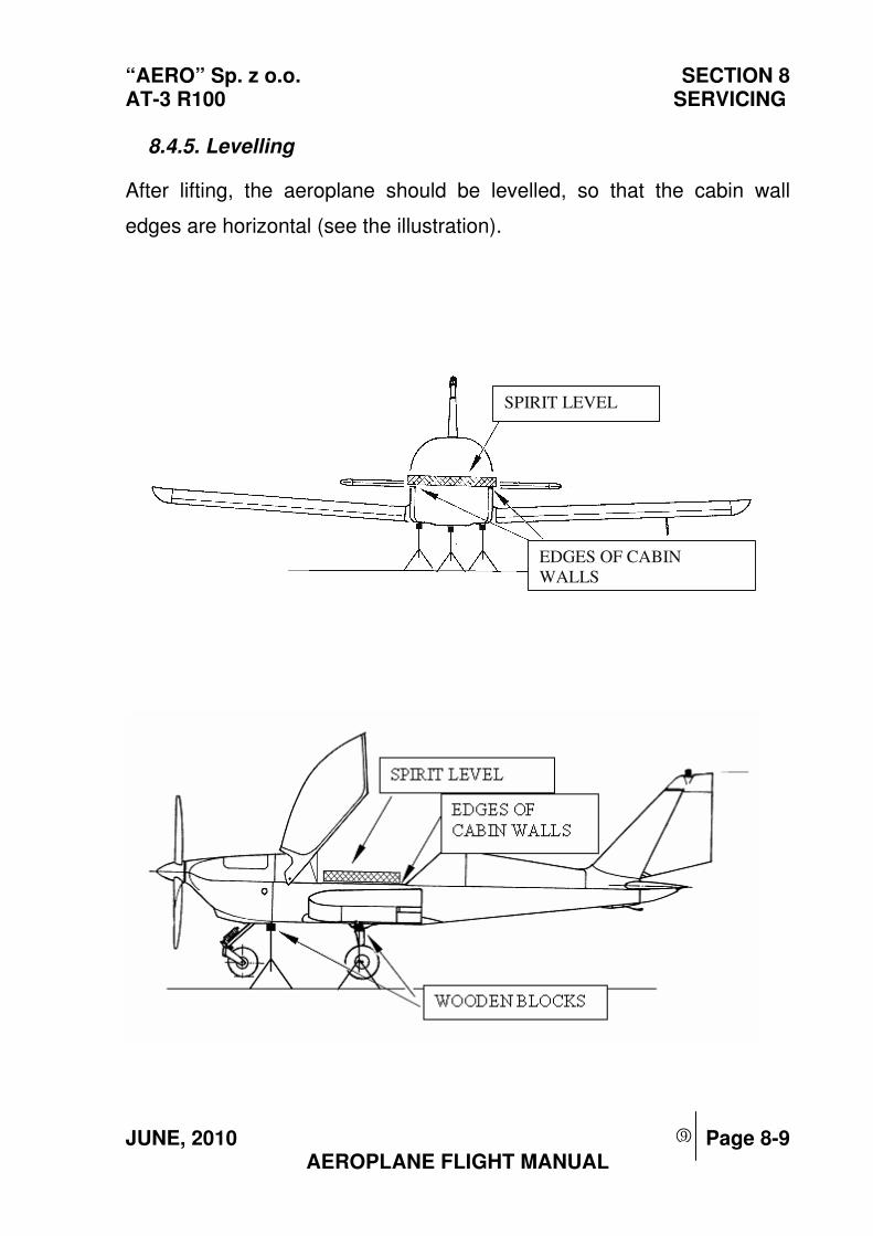
“AERO” Sp. z o.o. SECTION 8 AT-3 R100 SERVICING
JUNE, 2010 Page 8-9 AEROPLANE FLIGHT MANUAL
8.4.5. Levelling
After lifting, the aeroplane should be levelled, so that the cabin wall
edges are horizontal (see the illustration).
SPIRIT LEVEL
EDGES OF CABIN
WALLS
9
SECTION 8 “AERO” Sp. z o.o. SERVICING AT-3 R100
Page 8-10 JUNE, 2010 AEROPLANE FLIGHT MANUAL
8.5. Cleaning and basic maintenance
It is essential for the reliability of the aeroplane components to always
keep them clean.
8.5.1. External painted surfaces
Prior to cleaning, take the following steps:
- Protect the wheels, especially the brake discs, covering them.
- Put the cover on the pitot and static pressure sensors.
- Mask off all holes and orifices.
Use clean water to remove all fine particles and then wash the surface
with water adding mild soap. Do not use detergents or soaps which are
acid, alkaline or abrasive.
To remove spots of grease or oil, use a piece of cloth with naphtha or
aliphatic petrol.
After use of naphtha the surface should be re-waxed and polished.
To polish the painted surfaces, a soft cloth or chamois leather should be
used. Aged painted surfaces may be treated with automotive waxes or
good quality polishing compounds.
9
“AERO” Sp. z o.o. SECTION 8 AT-3 R100 SERVICING
JUNE, 2010 Page 8-11 AEROPLANE FLIGHT MANUAL
8.5.2. Glass panels
The greatest care should be taken to avoid scratches when cleaning
glass panels of Plexiglas.
Never wipe the glass panels when dry. Rinse the panel with clean water
or solution of mild soap and then wipe with soft clean cloth, sponge or
chamois-leather.
To remove films of oil or grease, use tribasic sodium phosphate, well
dissolved in water.
Sediments of grease or oil, if difficult to remove, should be cleaned with
methanol, hexane, or naphtha. Finally rinse with clean water avoiding
excessive rubbing of the glass panel surface.
CAUTION!
DO NOT USE PETROL, BENZENE, ACETONE, ANTI-ICING
COMPOUNDS, OR PAINT SOLVENTS, BECAUSE THESE
SUBSTANCES SOFTEN THE PLEXIGLASS,
OR MAY GIVE RISE TO A NETWORK OF FINE CRACKS
9
SECTION 8 “AERO” Sp. z o.o. SERVICING AT-3 R100
Page 8-12 JUNE, 2010 AEROPLANE FLIGHT MANUAL
8.5.3. Propeller
The propeller is to be cleaned in the same way as the painted surfaces,
but with great care.
8.5.4. Engine
The engine is to be cleaned as indicated in the Engine Maintenance
Manual.
8.5.5. Cabin interior
The seats, carpets and upholstery are to be cleaned with a vacuum
cleaner.
Do not use water to clean items of cloth or fabric.
Foam-based shampoos for general use on automotive upholstery may
be applied, but the indications given on the packing should be strictly
observed.
9
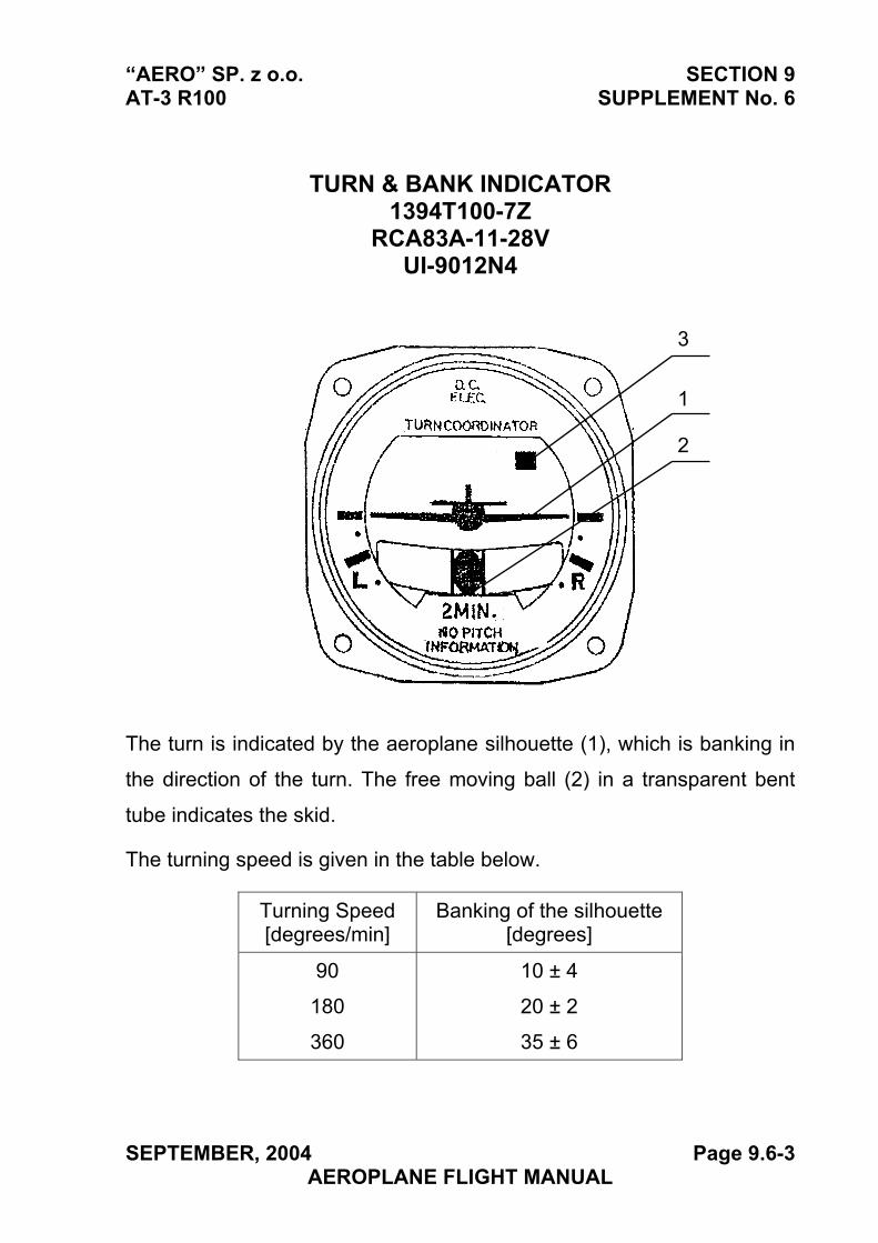
“AERO” SP. z o.o. SECTION 9 AT-3 R100 SUPPLEMENT No. 6
TURN & BANK INDICATOR 1394T100-7Z
RCA83A-11-28V UI-9012N4
2
1
3
The turn is indicated by the aeroplane silhouette (1), which is banking in
the direction of the turn. The free moving ball (2) in a transparent bent
tube indicates the skid.
The turning speed is given in the table below.
Turning Speed [degrees/min]
Banking of the silhouette [degrees]
90
180
360
10 ± 4
20 ± 2
35 ± 6
SEPTEMBER, 2004 Page 9.6-3 AEROPLANE FLIGHT MANUAL
SECTION 9 “AERO” Sp. z o.o. SUPPLEMENT No. 6 AT-3 R100
The instrument signals (red marking (3) in the instrument face) lack of
electric power or too low rpm of the gyro.
The switch of the turn & bank indicator is located on the column below
the middle panel of engine monitoring Instruments.
Page 9.6-4 SEPTEMBER, 2004 AEROPLANE FLIGHT MANUAL
“AERO” Sp. z o.o. SECTION 9 AT-3 R100 SUPPLEMENT No. 10
Section 9 SUPPLEMENT No. 10
Directional Gyro Indicator R.C. Allen RCA 15 AK-1
APPROVED:
CIVIL AIRCRAFT INSPECTION BOARD
( Originally signed by Mr. Z. Mazan) 2004-09-23
-------------------------------- ------------- Signature Date
English language version of the Polish document,
translated under delegation of authority CAIB No. 54C.
/-/
Jan A. Jasinski,B.S.(Eng.)
SEPTEMBER, 2004 Page 9.10-1 AEROPLANE FLIGHT MANUAL
SECTION 9 AERO” Sp. z o.o. SUPPLEMENT No. 10 AT-3 R100
Section 1. General The same as for the standard aeroplane
Section 2. Limitations The same as for the standard aeroplane
Section 3. Emergency procedures The same as for the standard aeroplane
Section 4. Normal procedures The same as for the standard aeroplane
Section 5. Performance The same as for the standard aeroplane
Section 6. Weight and balance Weight of the equipment included
in the weight of the empty aeroplane
Section 7. Description of the aeroplane and its equipment The same as for the standard aeroplane
Section 8. Servicing. The same as for the standard aeroplane
Page 9.10-2 SEPTEMBER, 2004 AEROPLANE FLIGHT MANUAL
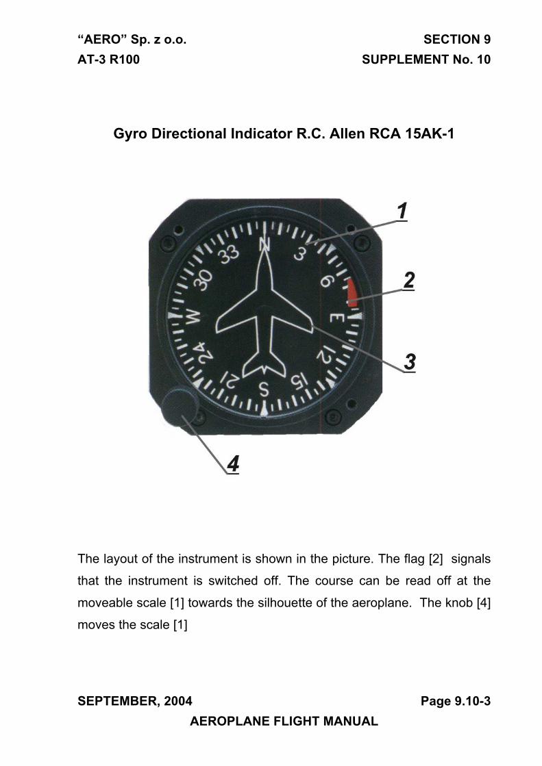
“AERO” Sp. z o.o. SECTION 9 AT-3 R100 SUPPLEMENT No. 10
Gyro Directional Indicator R.C. Allen RCA 15AK-1
The layout of the instrument is shown in the picture. The flag [2] signals
that the instrument is switched off. The course can be read off at the
moveable scale [1] towards the silhouette of the aeroplane. The knob [4]
moves the scale [1]
SEPTEMBER, 2004 Page 9.10-3 AEROPLANE FLIGHT MANUAL

SECTION 9 AERO” Sp. z o.o. SUPPLEMENT No. 10 AT-3 R100
THIS PAGE IS LEFT INTENTIONALLY BLANK
Page 9.10-4 SEPTEMBER, 2004 AEROPLANE FLIGHT MANUAL
“AERO” Sp. z o.o. SECTION 9 AT-3 R100 SUPPLEMENT No. 11
Section 9 SUPPLEMENT No. 11
Clock Mitchell 99500-ELT D1-312-5038
APPROVED:
CIVIL AIRCRAFT INSPECTION BOARD
( Originally signed by Mr. Z. Mazan) 2004-09-23
-------------------------------- ------------- Signature Date
English language version of the Polish document,
translated under delegation of authority CAIB No. 54C.
/-/
Jan A. Jasinski,B.S.(Eng.)
SEPTEMBER, 2004 Page 9.11-1 AEROPLANE FLIGHT MANUAL

SECTION 9 AERO” Sp. z o.o. SUPPLEMENT No. 11 AT-3 R100
Section 1. General The same as for the standard aeroplane
Section 2. Limitations The same as for the standard aeroplane
Section 3. Emergency procedures The same as for the standard aeroplane
Section 4. Normal procedures The same as for the standard aeroplane
Section 5. Performance The same as for the standard aeroplane
Section 6. Weight and balance Weight of the equipment included
in the weight of the empty aeroplane
Section 7. Description of the aeroplane and its equipment The same as for the standard aeroplane
Section 8. Servicing. The same as for the standard aeroplane
Page 9.11-2 SEPTEMBER, 2004 AEROPLANE FLIGHT MANUAL
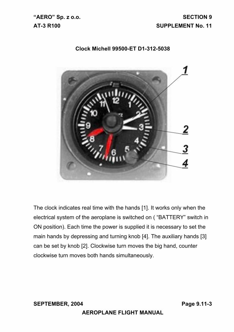
“AERO” Sp. z o.o. SECTION 9 AT-3 R100 SUPPLEMENT No. 11
Clock Michell 99500-ET D1-312-5038
The clock indicates real time with the hands [1]. It works only when the
electrical system of the aeroplane is switched on ( “BATTERY” switch in
ON position). Each time the power is supplied it is necessary to set the
main hands by depressing and turning knob [4]. The auxiliary hands [3]
can be set by knob [2]. Clockwise turn moves the big hand, counter
clockwise turn moves both hands simultaneously.
SEPTEMBER, 2004 Page 9.11-3 AEROPLANE FLIGHT MANUAL

SECTION 9 AERO” Sp. z o.o. SUPPLEMENT No. 11 AT-3 R100
THIS PAGE IS LEFT INTENTIONALLY BLANK
Page 9.11-4 SEPTEMBER, 2004 AEROPLANE FLIGHT MANUAL
“AERO” Sp. z o.o. SECTION 9 AT-3 R100 SUPPLEMENT No. 13
Section 9 SUPPLEMENT No. 13
GPS – SKYMAP III C
APPROVED:
CIVIL AIRCRAFT INSPECTION BOARD
( Originally signed by Mr. Z. Mazan) 2004-09-23
-------------------------------- ------------- Signature Date
English language version of the Polish document,
translated under delegation of authority CAIB No. 54C.
/-/
Jan A. Jasinski,B.S.(Eng.)
SEPTEMBER, 2004 Page 9.13-1 AEROPLANE FLIGHT MANUAL
SECTION 9 “AERO” Sp. z o.o. SUPPLEMENT No. 13 AT-3 R100
Section 1. General The same as for the standard aeroplane
Section 2. Limitations The same as for the standard aeroplane
Section 3. Emergency procedures The same as for the standard aeroplane
Section 4. Normal procedures The same as for the standard aeroplane
Section 5. Performance The same as for the standard aeroplane
Section 6. Weight and balance Weight of the equipment included
in the weight of the empty aeroplane
Section 7. Description of the aeroplane and its equipment The same as for the standard aeroplane
Section 8. Servicing. The same as for the standard aeroplane
Page 9.13-2 SEPTEMBER, 2004 AEROPLANE FLIGHT MANUAL
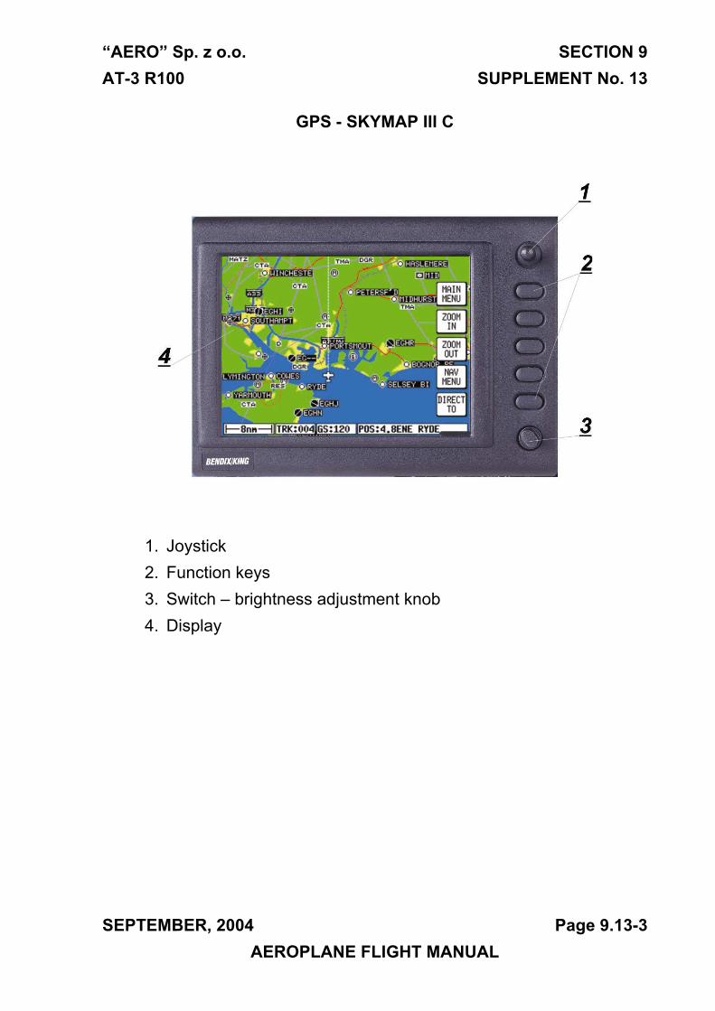
“AERO” Sp. z o.o. SECTION 9 AT-3 R100 SUPPLEMENT No. 13
GPS - SKYMAP III C
1. Joystick2. Function keys3. Switch – brightness adjustment knob4. Display
SEPTEMBER, 2004 Page 9.13-3 AEROPLANE FLIGHT MANUAL
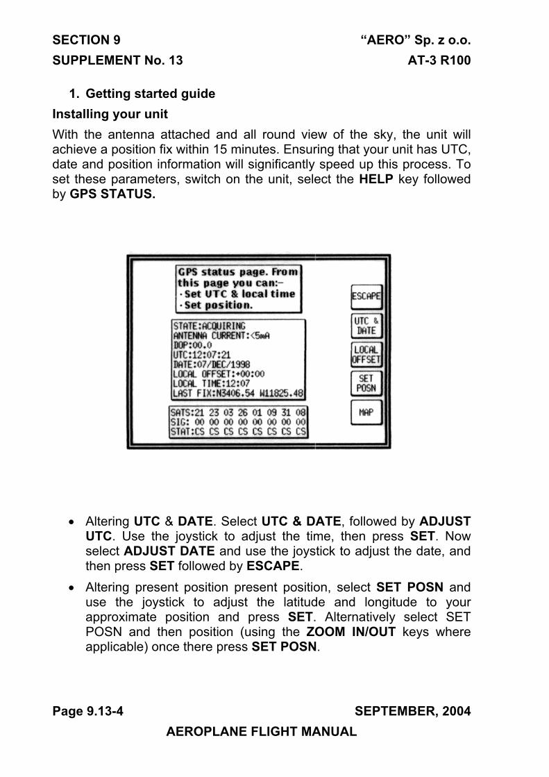
SECTION 9 “AERO” Sp. z o.o. SUPPLEMENT No. 13 AT-3 R100
1. Getting started guideInstalling your unit With the antenna attached and all round view of the sky, the unit will achieve a position fix within 15 minutes. Ensuring that your unit has UTC, date and position information will significantly speed up this process. To set these parameters, switch on the unit, select the HELP key followed by GPS STATUS.
• Altering UTC & DATE. Select UTC & DATE, followed by ADJUSTUTC. Use the joystick to adjust the time, then press SET. Nowselect ADJUST DATE and use the joystick to adjust the date, andthen press SET followed by ESCAPE.
• Altering present position present position, select SET POSN anduse the joystick to adjust the latitude and longitude to yourapproximate position and press SET. Alternatively select SETPOSN and then position (using the ZOOM IN/OUT keys whereapplicable) once there press SET POSN.
Page 9.13-4 SEPTEMBER, 2004 AEROPLANE FLIGHT MANUAL
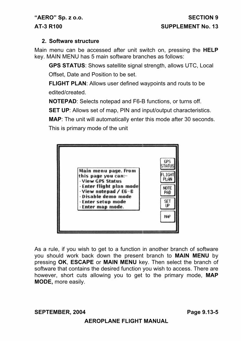
“AERO” Sp. z o.o. SECTION 9 AT-3 R100 SUPPLEMENT No. 13
2. Software structureMain menu can be accessed after unit switch on, pressing the HELP key. MAIN MENU has 5 main software branches as follows:
GPS STATUS: Shows satellite signal strength, allows UTC, Local Offset, Date and Position to be set.
FLIGHT PLAN: Allows user defined waypoints and routs to be edited/created. NOTEPAD: Selects notepad and F6-B functions, or turns off.
SET UP: Allows set of map, PIN and input/output characteristics. MAP: The unit will automatically enter this mode after 30 seconds.
This is primary mode of the unit
As a rule, if you wish to get to a function in another branch of software you should work back down the present branch to MAIN MENU by pressing OK, ESCAPE or MAIN MENU key. Then select the branch of software that contains the desired function you wish to access. There are however, short cuts allowing you to get to the primary mode, MAP MODE, more easily.
SEPTEMBER, 2004 Page 9.13-5 AEROPLANE FLIGHT MANUAL
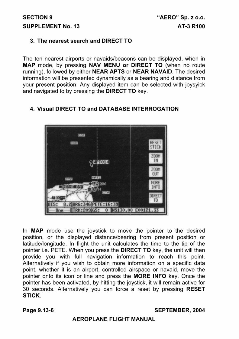
SECTION 9 “AERO” Sp. z o.o. SUPPLEMENT No. 13 AT-3 R100
3. The nearest search and DIRECT TO
The ten nearest airports or navaids/beacons can be displayed, when in MAP mode, by pressing NAV MENU or DIRECT TO (when no route running), followed by either NEAR APTS or NEAR NAVAID. The desired information will be presented dynamically as a bearing and distance from your present position. Any displayed item can be selected with joysyick and navigated to by pressing the DIRECT TO key.
4. Visual DIRECT TO and DATABASE INTERROGATION
In MAP mode use the joystick to move the pointer to the desired position, or the displayed distance/bearing from present position or latitude/longitude. In flight the unit calculates the time to the tip of the pointer i.e. PETE. When you press the DIRECT TO key, the unit will then provide you with full navigation information to reach this point. Alternatively if you wish to obtain more information on a specific data point, whether it is an airport, controlled airspace or navaid, move the pointer onto its icon or line and press the MORE INFO key. Once the pointer has been activated, by hitting the joystick, it will remain active for 30 seconds. Alternatively you can force a reset by pressing RESET STICK.
Page 9.13-6 SEPTEMBER, 2004 AEROPLANE FLIGHT MANUAL
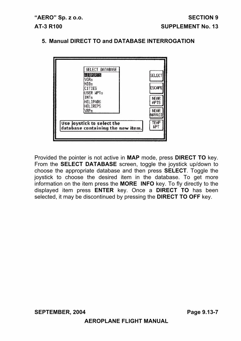
“AERO” Sp. z o.o. SECTION 9 AT-3 R100 SUPPLEMENT No. 13
5. Manual DIRECT TO and DATABASE INTERROGATION
Provided the pointer is not active in MAP mode, press DIRECT TO key. From the SELECT DATABASE screen, toggle the joystick up/down to choose the appropriate database and then press SELECT. Toggle the joystick to choose the desired item in the database. To get more information on the item press the MORE INFO key. To fly directly to the displayed item press ENTER key. Once a DIRECT TO has been selected, it may be discontinued by pressing the DIRECT TO OFF key.
SEPTEMBER, 2004 Page 9.13-7 AEROPLANE FLIGHT MANUAL
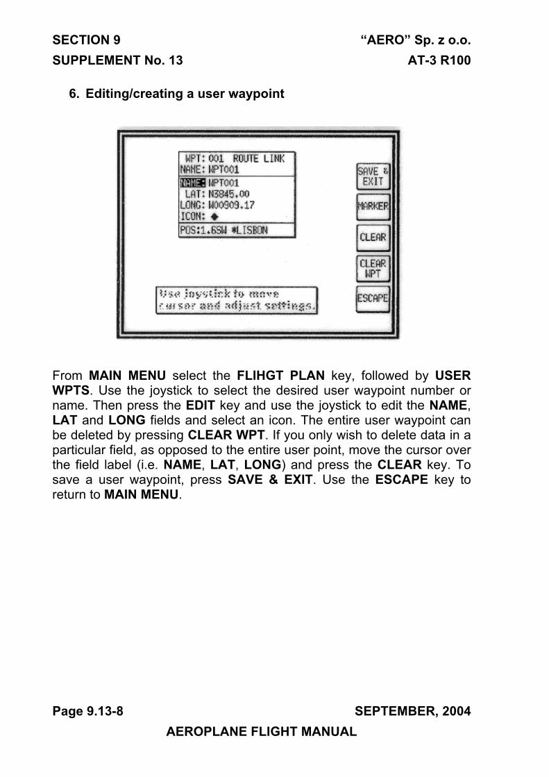
SECTION 9 “AERO” Sp. z o.o. SUPPLEMENT No. 13 AT-3 R100
6. Editing/creating a user waypoint
From MAIN MENU select the FLIHGT PLAN key, followed by USER WPTS. Use the joystick to select the desired user waypoint number or name. Then press the EDIT key and use the joystick to edit the NAME, LAT and LONG fields and select an icon. The entire user waypoint can be deleted by pressing CLEAR WPT. If you only wish to delete data in a particular field, as opposed to the entire user point, move the cursor over the field label (i.e. NAME, LAT, LONG) and press the CLEAR key. To save a user waypoint, press SAVE & EXIT. Use the ESCAPE key to return to MAIN MENU.
Page 9.13-8 SEPTEMBER, 2004 AEROPLANE FLIGHT MANUAL
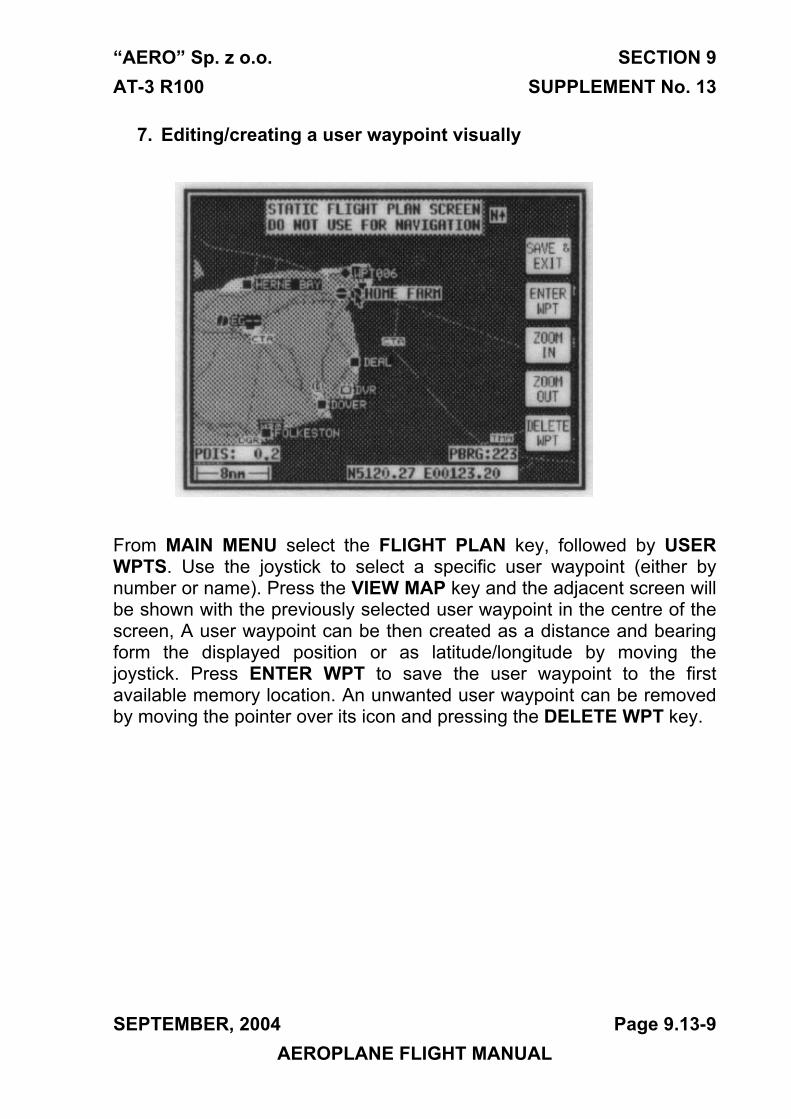
“AERO” Sp. z o.o. SECTION 9 AT-3 R100 SUPPLEMENT No. 13
7. Editing/creating a user waypoint visually
From MAIN MENU select the FLIGHT PLAN key, followed by USER WPTS. Use the joystick to select a specific user waypoint (either by number or name). Press the VIEW MAP key and the adjacent screen will be shown with the previously selected user waypoint in the centre of the screen, A user waypoint can be then created as a distance and bearing form the displayed position or as latitude/longitude by moving the joystick. Press ENTER WPT to save the user waypoint to the first available memory location. An unwanted user waypoint can be removed by moving the pointer over its icon and pressing the DELETE WPT key.
SEPTEMBER, 2004 Page 9.13-9 AEROPLANE FLIGHT MANUAL
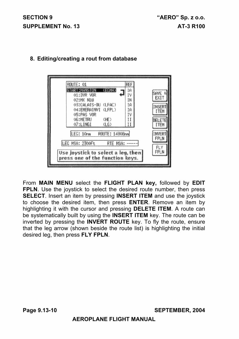
SECTION 9 “AERO” Sp. z o.o. SUPPLEMENT No. 13 AT-3 R100
8. Editing/creating a rout from database
From MAIN MENU select the FLIGHT PLAN key, followed by EDIT FPLN. Use the joystick to select the desired route number, then press SELECT. Insert an item by pressing INSERT ITEM and use the joystick to choose the desired item, then press ENTER. Remove an item by highlighting it with the cursor and pressing DELETE ITEM. A route can be systematically built by using the INSERT ITEM key. The route can be inverted by pressing the INVERT ROUTE key. To fly the route, ensure that the leg arrow (shown beside the route list) is highlighting the initial desired leg, then press FLY FPLN.
Page 9.13-10 SEPTEMBER, 2004 AEROPLANE FLIGHT MANUAL
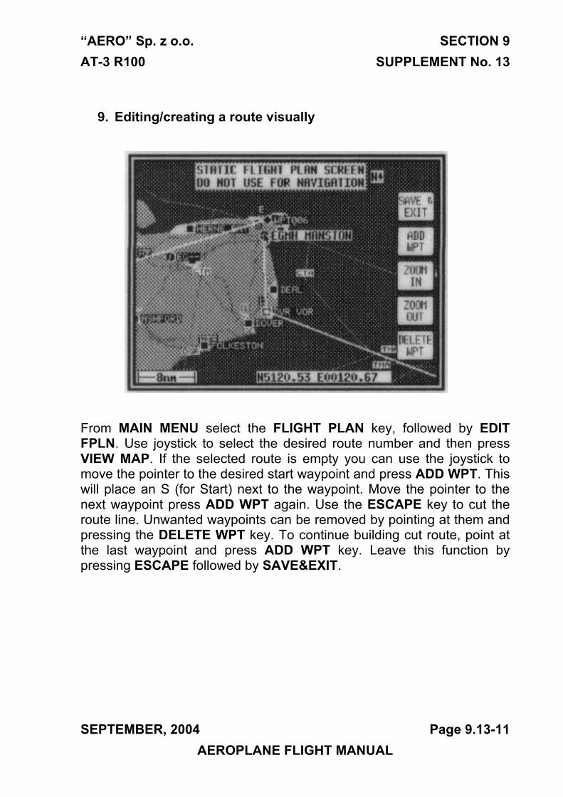
“AERO” Sp. z o.o. SECTION 9 AT-3 R100 SUPPLEMENT No. 13
9. Editing/creating a route visually
From MAIN MENU select the FLIGHT PLAN key, followed by EDIT FPLN. Use joystick to select the desired route number and then press VIEW MAP. If the selected route is empty you can use the joystick to move the pointer to the desired start waypoint and press ADD WPT. This will place an S (for Start) next to the waypoint. Move the pointer to the next waypoint press ADD WPT again. Use the ESCAPE key to cut the route line. Unwanted waypoints can be removed by pointing at them and pressing the DELETE WPT key. To continue building cut route, point at the last waypoint and press ADD WPT key. Leave this function by pressing ESCAPE followed by SAVE&EXIT.
SEPTEMBER, 2004 Page 9.13-11 AEROPLANE FLIGHT MANUAL
SECTION 9 “AERO” Sp. z o.o. SUPPLEMENT No. 13 AT-3 R100
10.Selecting a route and a navigationFrom MAIN MENU select the MAP key, followed by NAV MENU and FLIGHT PLAN. Use the joystick to select desired route number and press the SELECT key followed by FLY FPLN. To select the Navigation Mode (Large Map/Large Text/CDI IFR/VFR), select NAV MENU in MAP mode, toggle the joystick until desired selection is shown in MAP MODE field, Return to the map by pressing MAP.
Page 9.13-12 SEPTEMBER, 2004 AEROPLANE FLIGHT MANUAL
SECTION 9 SUPPLEMENT No. 13
AERO” Sp. z o.o. AT-3 R100
THIS PAGE IS LEFT INTENTIONALLY BLANK
Page 9.13-13 SEPTEMBER, 2004 AEROPLANE FLIGHT MANUAL
“AERO” Sp. z o.o. SECTION 9 AT-3 R100 SUPPLEMENT No. 15
Section 9 SUPPLEMENT No. 15
CABIN AIR INTAKE
APPROVED:
CIVIL AIRCRAFT INSPECTION BOARD
( Originally signed by Mr. Z. Mazan) 2004-09-23
-------------------------------- ------------- Signature Date
English language version of the Polish document,
translated under delegation of authority CAIB No. 54C.
/-/
Jan A. Jasinski,B.S.(Eng.)
SEPTEMBER, 2004 Page 9.15-1 AEROPLANE FLIGHT MANUAL

SECTION 9 AERO” Sp. z o.o. SUPPLEMENT No. 15 AT-3 R100
Section 1. General The same as for the standard aeroplane
Section 2. Limitations The same as for the standard aeroplane
Section 3. Emergency procedures The same as for the standard aeroplane
Section 4. Normal procedures The same as for the standard aeroplane
Section 5. Performance The same as for the standard aeroplane
Section 6. Weight and balance Weight of the equipment included
in the weight of the empty aeroplane
Section 7. Description of the aeroplane and its equipment The same as for the standard aeroplane
Section 8. Servicing. The same as for the standard aeroplane
Page 9.15-2 SEPTEMBER, 2004 AEROPLANE FLIGHT MANUAL
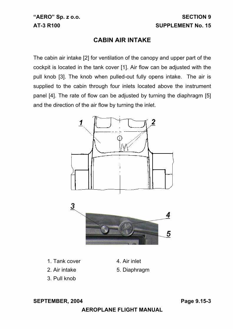
“AERO” Sp. z o.o. SECTION 9 AT-3 R100 SUPPLEMENT No. 15
CABIN AIR INTAKE
The cabin air intake [2] for ventilation of the canopy and upper part of the
cockpit is located in the tank cover [1]. Air flow can be adjusted with the
pull knob [3]. The knob when pulled-out fully opens intake. The air is
supplied to the cabin through four inlets located above the instrument
panel [4]. The rate of flow can be adjusted by turning the diaphragm [5]
and the direction of the air flow by turning the inlet.
1. Tank cover 4. Air inlet2. Air intake 5. Diaphragm3. Pull knob
SEPTEMBER, 2004 Page 9.15-3 AEROPLANE FLIGHT MANUAL

SECTION 9 AERO” Sp. z o.o. SUPPLEMENT No. 15 AT-3 R100
THIS PAGE IS LEFT INTENTIONALLY BLANK
Page 9.15-4 SEPTEMBER, 2004 AEROPLANE FLIGHT MANUAL

“AERO” Sp. z o.o. SECTION 9 AT-3 R100 SUPPLEMENT No. 16
Section 9 SUPPLEMENT No. 16
CABIN AIR OUTLET
APPROVED:
CIVIL AIRCRAFT INSPECTION BOARD
( Originally signed by Mr. Z. Mazan) 2004-09-23
-------------------------------- ------------- Signature Date
English language version of the Polish document,
translated under delegation of authority CAIB No. 54C.
/-/
Jan A. Jasinski,B.S.(Eng.)
SEPTEMBER, 2004 Page 9.16-1 AEROPLANE FLIGHT MANUAL
SECTION 9 AERO” Sp. z o.o. SUPPLEMENT No. 16 AT-3 R100
Section 1. General The same as for the standard aeroplane
Section 2. Limitations The same as for the standard aeroplane
Section 3. Emergency procedures The same as for the standard aeroplane
Section 4. Normal procedures The same as for the standard aeroplane
Section 5. Performance The same as for the standard aeroplane
Section 6. Weight and balance Weight of the equipment included
in the weight of the empty aeroplane
Section 7. Description of the aeroplane and its equipment The same as for the standard aeroplane
Section 8. Servicing. The same as for the standard aeroplane
Page 9.16-2 SEPTEMBER, 2004 AEROPLANE FLIGHT MANUAL
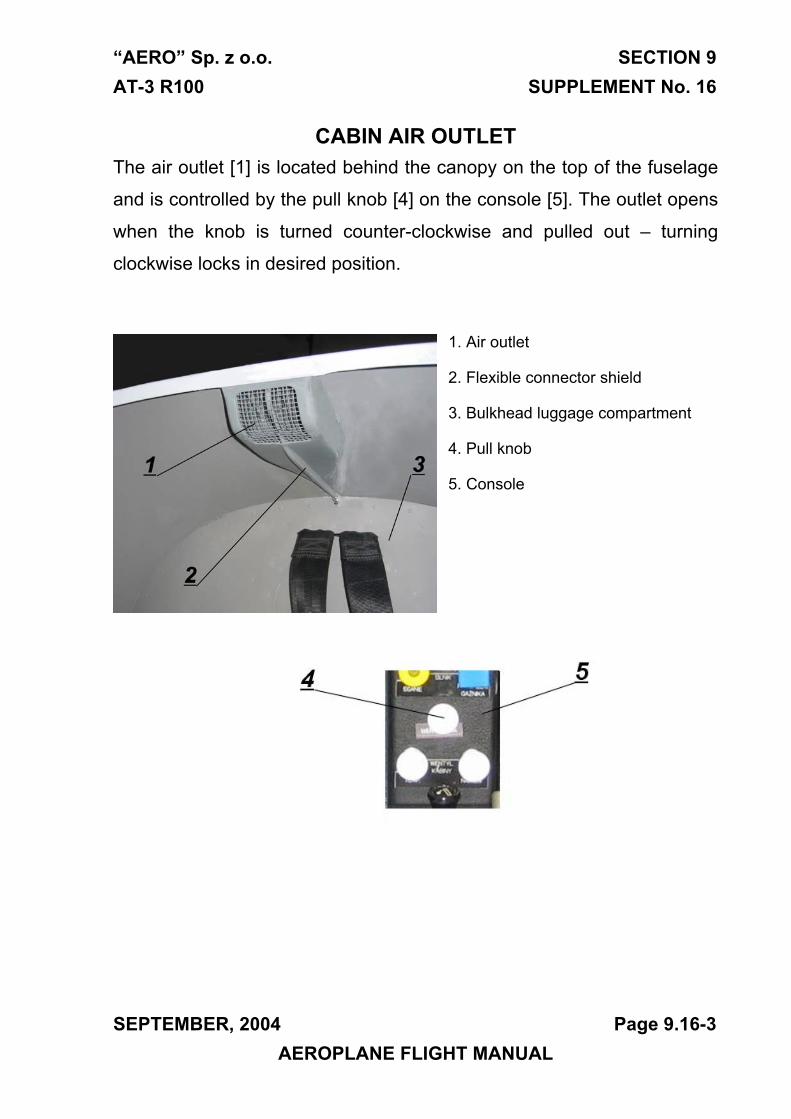
“AERO” Sp. z o.o. SECTION 9 AT-3 R100 SUPPLEMENT No. 16
CABIN AIR OUTLET The air outlet [1] is located behind the canopy on the top of the fuselage
and is controlled by the pull knob [4] on the console [5]. The outlet opens
when the knob is turned counter-clockwise and pulled out – turning
clockwise locks in desired position.
1. Air outlet
2. Flexible connector shield
3. Bulkhead luggage compartment
4. Pull knob
5. Console
SEPTEMBER, 2004 Page 9.16-3 AEROPLANE FLIGHT MANUAL
SECTION 9 AERO” Sp. z o.o. SUPPLEMENT No. 16 AT-3 R100
THIS PAGE IS LEFT INTENTIONALLY BLANK
Page 9.16-4 SEPTEMBER, 2004 AEROPLANE FLIGHT MANUAL
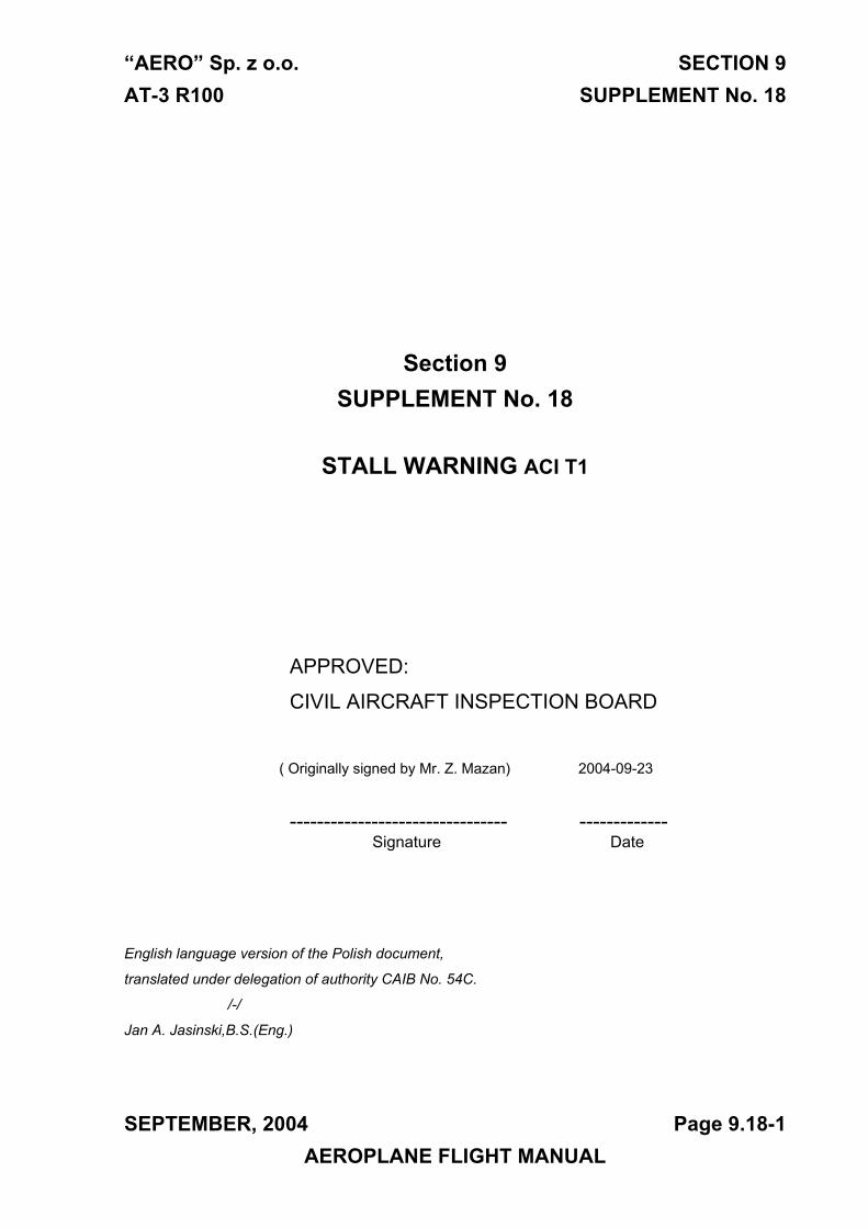
“AERO” Sp. z o.o. SECTION 9 AT-3 R100 SUPPLEMENT No. 18
Section 9 SUPPLEMENT No. 18
STALL WARNING ACI T1
APPROVED:
CIVIL AIRCRAFT INSPECTION BOARD
( Originally signed by Mr. Z. Mazan) 2004-09-23
-------------------------------- ------------- Signature Date
English language version of the Polish document,
translated under delegation of authority CAIB No. 54C.
/-/
Jan A. Jasinski,B.S.(Eng.)
SEPTEMBER, 2004 Page 9.18-1 AEROPLANE FLIGHT MANUAL

SECTION 9 AERO” Sp. z o.o. SUPPLEMENT No. 18 AT-3 R100
Section 1. General The same as for the standard aeroplane
Section 2. Limitations The same as for the standard aeroplane
Section 3. Emergency procedures The same as for the standard aeroplane
Section 4. Normal procedures The same as for the standard aeroplane
Section 5. Performance The same as for the standard aeroplane
Section 6. Weight and balance Weight of the equipment included
in the weight of the empty aeroplane
Section 7. Description of the aeroplane and its equipment The same as for the standard aeroplane
Section 8. Servicing. The same as for the standard aeroplane
Page 9.18-2 SEPTEMBER, 2004 AEROPLANE FLIGHT MANUAL
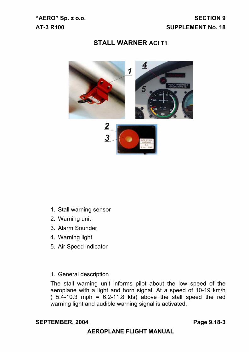
“AERO” Sp. z o.o. SECTION 9 AT-3 R100 SUPPLEMENT No. 18
STALL WARNER ACI T1
1. Stall warning sensor2. Warning unit3. Alarm Sounder4. Warning light5. Air Speed indicator
1. General descriptionThe stall warning unit informs pilot about the low speed of the aeroplane with a light and horn signal. At a speed of 10-19 km/h ( 5.4-10.3 mph = 6.2-11.8 kts) above the stall speed the red warning light and audible warning signal is activated.
SEPTEMBER, 2004 Page 9.18-3 AEROPLANE FLIGHT MANUAL
SECTION 9 AERO” Sp. z o.o. SUPPLEMENT No. 18 AT-3 R100
The stall warning installation consists of: [1] Stall warning sensor installed on the leading edge of the left wing, [2] audible warning unit installed behind the instrument panel and warning light [4] installed on instrument panel near the airspeed indicator [5] .
The stall warning system is supplied from the electrical system of the aeroplane and protected by the “STARTER” fuse. Additional protection is given by a 1.0 A fuse inside the warning unit.
Page 9.18-4 SEPTEMBER, 2004 AEROPLANE FLIGHT MANUAL
“AERO” Sp. z o.o. SECTION 9 AT-3 R100 SUPPLEMENT No. 20
Section 9 SUPPLEMENT No. 20
TRIM TAB AT3.33.070.0
APPROVED:
CIVIL AIRCRAFT INSPECTION BOARD
( Originally signed by Mr. Z. Mazan) 2004-09-23
-------------------------------- ------------- Signature Date
English language version of the Polish document,
translated under delegation of authority CAIB No. 54C.
/-/
Jan A. Jasinski,B.S.(Eng.)
SEPTEMBER, 2004 Page 9.20-1 AEROPLANE FLIGHT MANUAL
SECTION 9 AERO” Sp. z o.o. SUPPLEMENT No. 20 AT-3 R100
Section 1. General
1.4.1. Frame:
Trim & balancing tab (angles related to the fuselage base – red mark on the fuselage) When the slab tail trailing edge is down,
the tab is displaced downward, i.e. by maximum 26° ±3°
When the slab tail trailing edge is up,
the tab is displaced upwards, i.e. by maximum 35° ±3°
The rest of the section the same as for the standard aeroplane
Section 2. Limitations
The same as for the standard aeroplane
Section 3. Emergency procedures
The same as for the standard aeroplane
Section 4. Normal procedures
The same as for the standard aeroplane
Section 5. Performance
The same as for the standard aeroplane
Section 6. Weight and balance
Weight of the equipment included
in the weight of the empty aeroplane
Page 9.20-2 SEPTEMBER, 2004 AEROPLANE FLIGHT MANUAL
“AERO” Sp. z o.o. SECTION 9 AT-3 R100 SUPPLEMENT No. 20
Section 7. Description of the aeroplane and its equipment
7.2.3. Slab tail
The tail plane is a slab tail design. The trim & balancing is integrated into
the whole span of the slab tail elevator.
trim & balancing tab
SEPTEMBER, 2004 Page 9.20-3 AEROPLANE FLIGHT MANUAL
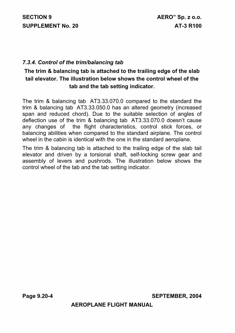
SECTION 9 AERO” Sp. z o.o. SUPPLEMENT No. 20 AT-3 R100
7.3.4. Control of the trim/balancing tab The trim & balancing tab is attached to the trailing edge of the slab tail elevator. The illustration below shows the control wheel of the
tab and the tab setting indicator.
The trim & balancing tab AT3.33.070.0 compared to the standard the trim & balancing tab AT3.33.050.0 has an altered geometry (increased span and reduced chord). Due to the suitable selection of angles of deflection use of the trim & balancing tab AT3.33.070.0 doesn’t cause any changes of the flight characteristics, control stick forces, or balancing abilities when compared to the standard airplane. The control wheel in the cabin is identical with the one in the standard aeroplane. The trim & balancing tab is attached to the trailing edge of the slab tail elevator and driven by a torsional shaft, self-locking screw gear and assembly of levers and pushrods. The illustration below shows the control wheel of the tab and the tab setting indicator.
Page 9.20-4 SEPTEMBER, 2004 AEROPLANE FLIGHT MANUAL
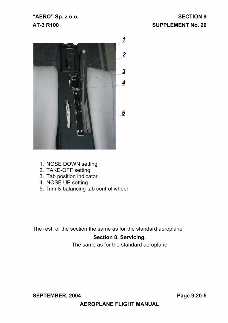
“AERO” Sp. z o.o. SECTION 9 AT-3 R100 SUPPLEMENT No. 20
1. NOSE DOWN setting 2. TAKE-OFF setting 3. Tab position indicator 4. NOSE UP setting 5. Trim & balancing tab control wheel
The rest of the section the same as for the standard aeroplane
Section 8. Servicing. The same as for the standard aeroplane
SEPTEMBER, 2004 Page 9.20-5 AEROPLANE FLIGHT MANUAL
SECTION 9 AERO” Sp. z o.o. SUPPLEMENT No. 20 AT-3 R100
THIS PAGE IS LEFT INTENTIONALLY BLANK
Page 9.20-6 SEPTEMBER, 2004 AEROPLANE FLIGHT MANUAL
“AERO” Sp. z o.o. SECTION 9
AT-3 R100 SUPPLEMENT No. 21
JUNE, 2005 Page 9.21-1
AEROPLANE FLIGHT MANUAL
Section 9
SUPPLEMENT No. 21
3-1-1P ELPROP Propeller
APPROVED:
CIVIL AIRCRAFT INSPECTION BOARD
( Originally signed by Mr. Z. Mazan) 21.07.2005
-------------------------------- ------------- Signature Date
English language version of the Polish document,
translated under delegation of authority CAIB No. 54C.
/-/
Jan A. Jasinski,B.S.(Eng.)
“AERO” Sp. z o.o. SECTION 9
AT-3 R100 SUPPLEMENT No. 21
Page 9.21-2 JUNE, 2005
AEROPLANE FLIGHT MANUAL
Section 1. General
1.4.3 Propeller
Ground adjustable 3-1-1P ELPROP three blade propeller prop with the
outside diameter of 1,73 m (5’ 8”), with blades manufactured from
carbon fibre and with an aluminium hub .
The rest of the section is the same as for the standard aeroplane.
Section 2. Limitations
2.4. Power plant
Propeller:
Manufacturer AERO Sp. z o.o.
Propeller model ELPROP 3-1-1P
Diameter of the propeller 1.73 m / 5’ 8”
Direction of rotation Clockwise
Blade angle of incidence 21,5˚ ±0,5˚
The rest of the section is the same as for the standard aeroplane.
Section 3. Emergency procedures
The same as for the standard aeroplane
“AERO” Sp. z o.o. SECTION 9
AT-3 R100 SUPPLEMENT No. 21
JUNE, 2005 Page 9.21-3
AEROPLANE FLIGHT MANUAL
Section 4. Normal procedures
4.5.4. Engine starting
NOTE
The maximum speed of the engine on the
ground is approx. 5300 RPM.
The rest of the section is the same as for the standard aeroplane.
Section 5. Performance
5.2.3. Take-off performance
Conditions:
- Maximum weight 582 kg(1283 lb)
- Airstrip surface concrete
- Rating Takeoff power
- Wing flap position (for takeoff) 15 °
- Lift-off speed IAS = 75 km/h / 47 mph / 41 kts
- Airspeed at H = 15 m IAS = 112 km/h / 70 mph / 60 kts
NOTE For each 10 km/h / 6 mph / 5 kts of head wind velocity the takeoff distance reduces by 8 %
and increases by 25% for 10km/h / 6 mph / 5 kts tail wind velocity .
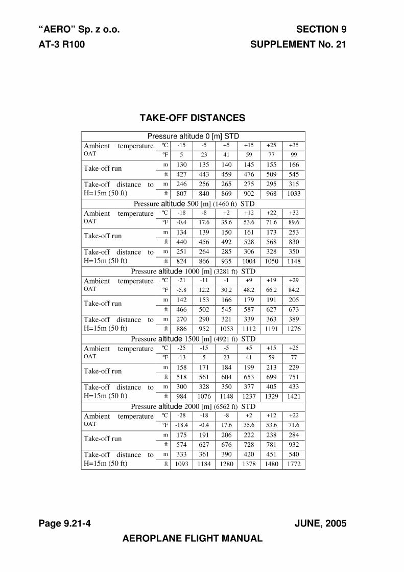
“AERO” Sp. z o.o. SECTION 9
AT-3 R100 SUPPLEMENT No. 21
Page 9.21-4 JUNE, 2005
AEROPLANE FLIGHT MANUAL
TAKE-OFF DISTANCES
Pressure altitude 0 [m] STD
Ambient temperature
OAT
ºC -15 -5 +5 +15 +25 +35
ºF 5 23 41 59 77 99
Take-off run m 130 135 140 145 155 166
ft 427 443 459 476 509 545
Take-off distance to
H=15m (50 ft)
m 246 256 265 275 295 315
ft 807 840 869 902 968 1033
Pressure altitude 500 [m] (1460 ft) STD
Ambient temperature
OAT
ºC -18 -8 +2 +12 +22 +32
ºF -0.4 17.6 35.6 53.6 71.6 89.6
Take-off run m 134 139 150 161 173 253
ft 440 456 492 528 568 830
Take-off distance to
H=15m (50 ft)
m 251 264 285 306 328 350
ft 824 866 935 1004 1050 1148
Pressure altitude 1000 [m] (3281 ft) STD
Ambient temperature
OAT
ºC -21 -11 -1 +9 +19 +29
ºF -5.8 12.2 30.2 48.2 66.2 84.2
Take-off run m 142 153 166 179 191 205
ft 466 502 545 587 627 673
Take-off distance to
H=15m (50 ft)
m 270 290 321 339 363 389
ft 886 952 1053 1112 1191 1276
Pressure altitude 1500 [m] (4921 ft) STD
Ambient temperature
OAT
ºC -25 -15 -5 +5 +15 +25
ºF -13 5 23 41 59 77
Take-off run m 158 171 184 199 213 229
ft 518 561 604 653 699 751
Take-off distance to
H=15m (50 ft)
m 300 328 350 377 405 433
ft 984 1076 1148 1237 1329 1421
Pressure altitude 2000 [m] (6562 ft) STD
Ambient temperature
OAT
ºC -28 -18 -8 +2 +12 +22
ºF -18.4 -0.4 17.6 35.6 53.6 71.6
Take-off run m 175 191 206 222 238 284
ft 574 627 676 728 781 932
Take-off distance to
H=15m (50 ft)
m 333 361 390 420 451 540
ft 1093 1184 1280 1378 1480 1772
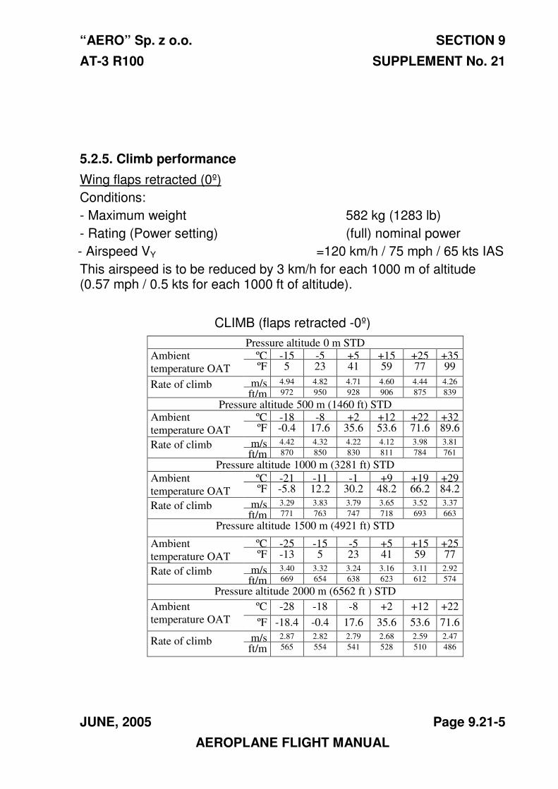
“AERO” Sp. z o.o. SECTION 9
AT-3 R100 SUPPLEMENT No. 21
JUNE, 2005 Page 9.21-5
AEROPLANE FLIGHT MANUAL
5.2.5. Climb performance
Wing flaps retracted (0º)
Conditions:
- Maximum weight 582 kg (1283 lb)
- Rating (Power setting) (full) nominal power
- Airspeed VY =120 km/h / 75 mph / 65 kts IAS
This airspeed is to be reduced by 3 km/h for each 1000 m of altitude (0.57 mph / 0.5 kts for each 1000 ft of altitude).
CLIMB (flaps retracted -0º)
Pressure altitude 0 m STD Ambient
temperature OAT
ºC -15 -5 +5 +15 +25 +35 ºF 5 23 41 59 77 99
Rate of climb m/s 4.94 4.82 4.71 4.60 4.44 4.26
ft/m 972 950 928 906 875 839
Pressure altitude 500 m (1460 ft) STD Ambient
temperature OAT
ºC -18 -8 +2 +12 +22 +32 ºF -0.4 17.6 35.6 53.6 71.6 89.6
Rate of climb m/s 4.42 4.32 4.22 4.12 3.98 3.81
ft/m 870 850 830 811 784 761
Pressure altitude 1000 m (3281 ft) STD
Ambient
temperature OAT
ºC -21 -11 -1 +9 +19 +29 ºF -5.8 12.2 30.2 48.2 66.2 84.2
Rate of climb m/s 3.29 3.83 3.79 3.65 3.52 3.37
ft/m 771 763 747 718 693 663
Pressure altitude 1500 m (4921 ft) STD
Ambient
temperature OAT
ºC -25 -15 -5 +5 +15 +25 ºF -13 5 23 41 59 77
Rate of climb m/s 3.40 3.32 3.24 3.16 3.11 2.92
ft/m 669 654 638 623 612 574
Pressure altitude 2000 m (6562 ft ) STD
Ambient
temperature OAT
ºC -28 -18 -8 +2 +12 +22
ºF -18.4 -0.4 17.6 35.6 53.6 71.6
Rate of climb m/s 2.87 2.82 2.79 2.68 2.59 2.47
ft/m
in
565 554 541 528 510 486
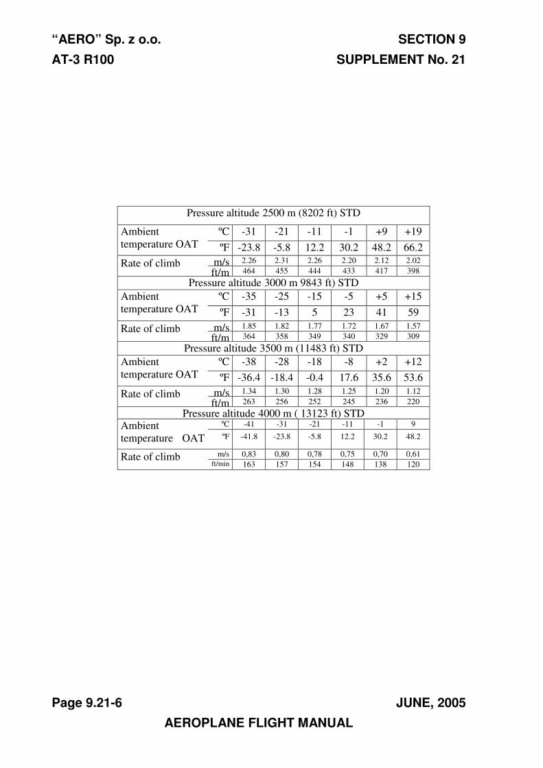
“AERO” Sp. z o.o. SECTION 9
AT-3 R100 SUPPLEMENT No. 21
Page 9.21-6 JUNE, 2005
AEROPLANE FLIGHT MANUAL
Pressure altitude 2500 m (8202 ft) STD
Ambient
temperature OAT
ºC -31 -21 -11 -1 +9 +19
ºF -23.8 -5.8 12.2 30.2 48.2 66.2
Rate of climb m/s 2.26 2.31 2.26 2.20 2.12 2.02
ft/m 464 455 444 433 417 398
Pressure altitude 3000 m 9843 ft) STD
Ambient
temperature OAT
ºC -35 -25 -15 -5 +5 +15
ºF -31 -13 5 23 41 59
Rate of climb m/s 1.85 1.82 1.77 1.72 1.67 1.57
ft/m 364 358 349 340 329 309
Pressure altitude 3500 m (11483 ft) STD
Ambient
temperature OAT
ºC -38 -28 -18 -8 +2 +12
ºF -36.4 -18.4 -0.4 17.6 35.6 53.6
Rate of climb m/s 1.34 1.30 1.28 1.25 1.20 1.12
ft/m 263 256 252 245 236 220
Pressure altitude 4000 m ( 13123 ft) STD Ambient
temperature OAT
ºC -41 -31 -21 -11 -1 9
ºF -41.8 -23.8 -5.8 12.2 30.2 48.2
Rate of climb m/s 0,83 0,80 0,78 0,75 0,70 0,61
ft/min 163 157 154 148 138 120
“AERO” Sp. z o.o. SECTION 9
AT-3 R100 SUPPLEMENT No. 21
JUNE, 2005 Page 9.21-7
AEROPLANE FLIGHT MANUAL
Wing flaps for takeoff (15º)
Conditions:
- Maximum weight 582 kg (1283 lb)
- Rating nominal power
- Airspeed VY =110 km/h / 68 mph / 59 kts IAS
This airspeed is to be reduced by 3 km/h for each 1000 m of the altitude (0.57 mph / 0.5 kts for each 1000 ft of the altitude).
“AERO” Sp. z o.o. SECTION 9
AT-3 R100 SUPPLEMENT No. 21
Page 9.21-8 JUNE, 2005
AEROPLANE FLIGHT MANUAL
CLIMB PERFORMANCE (FLAPS 15°)
Pressure altitude 0 m STD
Ambient
temperature
OAT
ºC -15 -5 +5 +15 +25 +35
ºF 5 23 41 59 77 99
Rate of
climb
m/s 4.61 4.51 4.41 4.30 4.16 4.03
ft/min 760 889 868 846 818 792
Pressure altitude 500 m (1460 ft) STD
Ambient
temperature
OAT
ºC -18 -8 +2 +12 +22 +32
ºF -0.4 17.6 35.6 53.6 71.6 89.6
Rate of
climb
m/s 4.08 4.00 3.91 3.81 3.68 3.56
ft/min 804 788 769 750 724 701
Pressure altitude 1000 m (3281 ft) STD
Ambient
temperature
OAT
ºC -21 -11 -1 +9 +19 +29
ºF -5.8 12.2 30.2 48.2 66.2 84.2
Rate of
climb
m/s 3.56 3.49 3.40 3.32 3.21 3.11
ft/min 701 687 670 654 632 611
Pressure altitude 1500 m (4921 ft) STD
Ambient
temperature
OAT
ºC -25 -15 -5 +5 +15 +25
ºF -13 5 23 41 59 77
Rate of
climb
m/s 3.03 2.97 2.90 2.83 2.74 2.65
ft/min 597 585 571 557 538 522
Pressure altitude 2000 m (6562 ft) STD
Ambient
temperature
OAT
ºC -28 -18 -8 +2 +12 +22
ºF -18.4 -0.4 17.6 35.6 53.6 71.6
Rate of
climb
m/s 2.51 2.46 2.40 2.34 2.26 2.18
ft/min 494 484 473 461 444 430
Pressure altitude 2500 m (8202 ft) STD
Ambient
temperature
OAT
ºC -31 -21 -11 -1 +9 +19
ºF -23.8 -5.8 12.2 30.2 48.2 66.2
Rate of
climb
m/s 1.98 1.95 1.90 1.85 1.79 1.73
ft/min 390 383 374 364 353 341
Pressure altitude 3000 m (9843 ft) STD
Ambient
temperature
OAT
ºC -35 -25 -15 -5 +5 +15
ºF -31 -13 5 23 41 59
Rate of
climb
m/s 1.47 1.45 1.41 1.37 1.33 1.29
ft/min 289 285 277 270 261 254
“AERO” Sp. z o.o. SECTION 9
AT-3 R100 SUPPLEMENT No. 21
NOVEMBER, 2012 Page 9.21-9
AEROPLANE FLIGHT MANUAL
5.3.1. Cruise
Airspeed, range and endurance
Conditions:
• Maximum weight 582 kg (1283 lb)
• Wing flaps retracted
• Consumable fuel: 65 litres / 18.5 US GAL
NOTE
Range and endurance data given in the table relate to using of all of the fuel at the given altitude. Taxiing, take-off and climb are not considered in this calculation.
“AERO” Sp. z o.o. SECTION 9
AT-3 R100 SUPPLEMENT No. 21
Page 9.21-10 NOVEMBER, 2012
AEROPLANE FLIGHT MANUAL
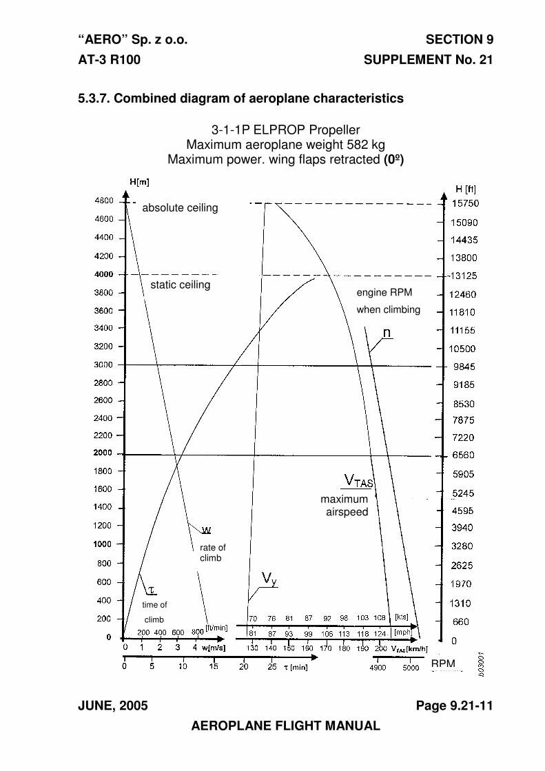
“AERO” Sp. z o.o. SECTION 9
AT-3 R100 SUPPLEMENT No. 21
JUNE, 2005 Page 9.21-11
AEROPLANE FLIGHT MANUAL
5.3.7. Combined diagram of aeroplane characteristics
3-1-1P ELPROP Propeller
Maximum aeroplane weight 582 kg Maximum power. wing flaps retracted (0º)
absolute ceiling
static ceiling engine RPM
when climbing
maximum airspeed
rate of climb
time of
climb
RPM
“AERO” Sp. z o.o. SECTION 9
AT-3 R100 SUPPLEMENT No. 21
Page 9.21-12 JUNE, 2005
AEROPLANE FLIGHT MANUAL
5.3.8. Noise
The outside noise level of the AT-3 R100 aeroplane, determined in accordance with the procedure in Chapter 10 Annex 16 ICAO is: 65.73 dB (A), while the permissible level is 70.32 dB (A).
Section 6. Weight and balance
The propeller installation didn’t influence the aeroplane weight and balance
Section 7. Description of the aeroplane and its equipment
The same as for the standard aeroplane
Section 8. Servicing.
The same as for the standard aeroplane
SECTION 9 SUPPLEMENT No. 21
AERO” Sp. z o.o. AT-3 R100
THIS PAGE IS LEFT INTENTIONALLY BLANK
Page 9.21-13 JUNE, 2005 AEROPLANE FLIGHT MANUAL
“AERO” Sp. z o.o. SECTION 9 AT-3 R100 SUPPLEMENT No. 22
JULY, 2005 Page 9.22-1
Section 9 SUPPLEMENT No. 22
KX 125 Nav/Com System, incorporating: Radio, VOR Transceiver,
KI 208 Indicator, SPA-400 Intercom.
APPROVED:
CIVIL AIRCRAFT INSPECTION BOARD
(Originally signed by Mr. Z. Mazan) 28.07.2005
-------------------------------- ------------- Signature Date
English language version of the Polish document,
translated under delegation of authority CAIB No. 54C.
/-/
Jan A. Jasinski,B.S.(Eng.)
AEROPLANE FLIGHT MANUAL
SECTION 9 “AERO” Sp. z o.o. SUPPLEMENT No. 22 AT-3 R100
Section 1. General The same as for the standard aeroplane
Section 2. Limitations The same as for the standard aeroplane
Section 3. Emergency procedures The same as for the standard aeroplane
Section 4. Normal procedures The same as for the standard aeroplane
Section 5. Performance The same as for the standard aeroplane
Section 6. Weight and balance Weight of the equipment included
in the weight of the empty aeroplane
Section 7. Description of the aeroplane and of its equipment The same as for the standard aeroplane
Section 8. Servicing. The same as for the standard aeroplane
Page 9.22-2 JULY, 2005 AEROPLANE FLIGHT MANUAL
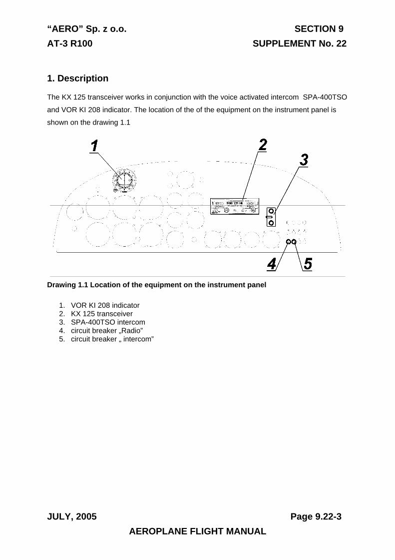
“AERO” Sp. z o.o. SECTION 9 AT-3 R100 SUPPLEMENT No. 22
JULY, 2005 Page 9.22-3
1. Description
The KX 125 transceiver works in conjunction with the voice activated intercom SPA-400TSO
and VOR KI 208 indicator. The location of the of the equipment on the instrument panel is
shown on the drawing 1.1
Drawing 1.1 Location of the equipment on the instrument panel
1. VOR KI 208 indicator 2. KX 125 transceiver 3. SPA-400TSO intercom 4. circuit breaker „Radio” 5. circuit breaker „ intercom”
AEROPLANE FLIGHT MANUAL
SECTION 9 “AERO” Sp. z o.o. SUPPLEMENT No. 22 AT-3 R100
2. KX 125 TRANSCEIVER
The KX 125 transceiver is designed for radio communication within a frequency range from
118 MHz to 139.975 MHz on 760 channels, with increments of 25 kH. The front panel of the
transceiver is shown on drawing 2.1. The active frequency is shown in the upper line of the
left-hand display, the standby frequency is shown below. During the transmit mode of
operation a “TX” annunciator will appear next to the frequency display. Additionally the
transceiver is equipped with a navigation signal receiver working within a frequency range
from 108 do 117.95 on 200 channels, with increments of 50 kH. The active frequency of the
signal received is shown in the upper line of the right-hand display, the standby frequency is
shown below. The central display shows navigation information, depending on the operating
mode.
2.1. Turning on
To turn on the transceiver, switch on the “BATTERY” switch and rotate the volume knob
clockwise to the ON position. When power is turned on, the displays will show the active and
standby frequencies of COM and NAV used before power down and navigation information
depending on the operating mode. After turning on the power, pull the VOL knob out to
override the automatic squelch and rotate the VOL knob to the desired audio level. Push the
VOL knob back in to activate the automatic squelch.
WARNING! IT IS PROHIBITED TO START THE ENGINE WITH THE
TRANSCEIVER SWITCHED ON
Page 9.22-4 JULY, 2005 AEROPLANE FLIGHT MANUAL
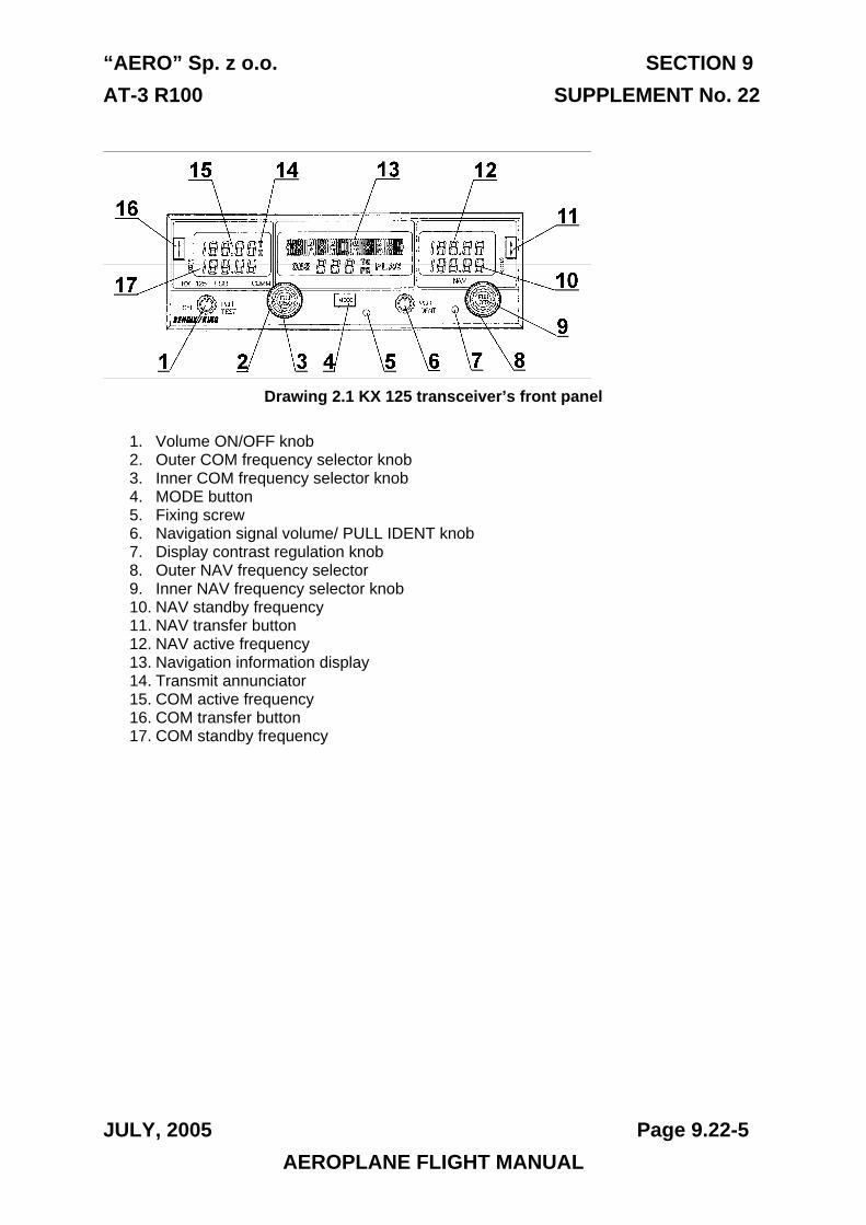
“AERO” Sp. z o.o. SECTION 9 AT-3 R100 SUPPLEMENT No. 22
JULY, 2005 Page 9.22-5
Drawing 2.1 KX 125 transceiver’s front panel
1. Volume ON/OFF knob 2. Outer COM frequency selector knob 3. Inner COM frequency selector knob 4. MODE button 5. Fixing screw 6. Navigation signal volume/ PULL IDENT knob 7. Display contrast regulation knob 8. Outer NAV frequency selector 9. Inner NAV frequency selector knob 10. NAV standby frequency 11. NAV transfer button 12. NAV active frequency 13. Navigation information display 14. Transmit annunciator 15. COM active frequency 16. COM transfer button 17. COM standby frequency
AEROPLANE FLIGHT MANUAL
SECTION 9 “AERO” Sp. z o.o. SUPPLEMENT No. 22 AT-3 R100
2.2. Transceiver control The OFF/PULL TEST knob: rotatng the knob fully anti-clockwise switches off the transceiver. Rotating the knob clockwise switches on the transceiver and increases its volume. The KX 125 transceiver is equipped with an automatic squelch. Pulling out the VOL knob switches off the squelch and allows the radio volume to be set according to the ambient noise conditions and desired volume setting.
The back-up frequency can be selected using the COM frequency selector knob. Turning the outer knob will increase or decrease the MHz portion of the display in 1 MHz increments, the inner knob will increase or decrease the kHz portion of the display in 50kHz increments, or in 25 kHz increments if the knob is pulled out.
The NAV button switches between three modes available with the KX125: CDI, Radial and Bearing. If the NAV receiver is correctly receiving a VOR or localiser signal, a short press of the MODE button changes the NAV receiver mode from CDI to BRG and RAD. Pressing and holding the MODE button for two seconds enters the AUTO-TO mode.
To listen to the navigation identification signal pull the PULL IDENT knob, turning the knob clockwise will increase the volume.
The backup frequency can be selected using the NAV frequency selector knob. Turning the outer knob will increase or decrease the MHz portion of the display in 1 MHz increments. Turning the inner knob will increase or decrease the kHz portion of the display in 50kHz increments. In the CDI mode the setting of the OBS radial can be changed with the outer knob pulled out.
A short press of the COM transfer button switches from the active frequency to the standby frequency. Pressing and holding the COM transfer button for two seconds switches the radio to active frequency entry mode. A short press of the COM transfer button returns the transceiver to the normal mode of operation.
A short press of the NAV transfer button switches from the active frequency to the standby frequency. Pressing and holding the NAV transfer button for two seconds switches the radio to active frequency entry mode. A short press of the NAV transfer button returns the transceiver to the normal mode of operation.
Page 9.22-6 JULY, 2005 AEROPLANE FLIGHT MANUAL
“AERO” Sp. z o.o. SECTION 9 AT-3 R100 SUPPLEMENT No. 22
JULY, 2005 Page 9.22-7
2.3. Transmission annunciator While transmitting on the left-hand COM frequency display, a “TX” annunciator will appear
next to the COM frequency. After 30 seconds of undisrupted transmission the transmitter will
be automatically switched off and the TX annunciator will start flashing. To continue the
transmission the transmission button must be momentarily released. The TX annunciator will
stop flashing and further transmission will be possible.
AEROPLANE FLIGHT MANUAL
SECTION 9 “AERO” Sp. z o.o. SUPPLEMENT No. 22 AT-3 R100
2.4. NAV Modes The operating modes of the NAV receiver are changed by a short press of the MODE button. The KX 125 AV receiver works in following modes:
NAV CDI MODE – VOR OPERATION - If the NAV receiver is correctly receiving a VOR beacon signal, the deviation from the selected OBS radial is displayed (drawing 2.2). The OBS setting can be changed by pulling and rotating the inner NAV FREQ selection knob. The upper line of the central display indicates the deviation from the radial of the chosen active NAV beacon. Each deviation bar represents 0.4 degree and each reference dot represents 2 degrees. In the lower line of the display the OBS annunciator is shown, with the three digit OBS bearing and appropriate “TO” or “FR”(from) annunciator. If an invalid signal is received, a “FLAG” annunciator and all CDI deviation bars will be displayed (drawing 2.3).
Drawing 2.2 NAV info display in CDI Mode with a valid VOR signal
Page 9.22-8 JULY, 2005 AEROPLANE FLIGHT MANUAL
“AERO” Sp. z o.o. SECTION 9 AT-3 R100 SUPPLEMENT No. 22
JULY, 2005 Page 9.22-9
Drawing 2.3 NAV info display in CDI Mode with an invalid VOR signal
NAV CDI MODE – LOCALISER OPERATION- If the NAV receiver is correctly receiving a LOCALISER signal the deviation from the selected LOCALISER is displayed (drawing 2.4). The upper line of the central display indicates the deviation from the radial of the chosen active LOCALISER beacon. In the lower line of the display the LOC annunciator is shown. If an invalid signal is received, a FLAG annunciator and all CDI deviation bars will be displayed (drawing 2.5).
Drawing 2.4 NAV info display in CDI Mode with a valid LOCALISER signal
AEROPLANE FLIGHT MANUAL
SECTION 9 “AERO” Sp. z o.o. SUPPLEMENT No. 22 AT-3 R100
Drawing 2.5 NAV info display in CDI Mode with an invalid LOCALISER signal
NAV BEARING MODE - If the NAV receiver is correctly receiving the VOR signal the NAV info display shows the bearing to the selected VOR and the “TO” annunciator (drawing 2.6).. If an invalid signal is received, a FLAG annunciator and three horizontal dashes are displayed (drawing 2.7).
Drawing 2.6 NAV info display in BEARING Mode with a valid VOR signal
Page 9.22-10 JULY, 2005 AEROPLANE FLIGHT MANUAL
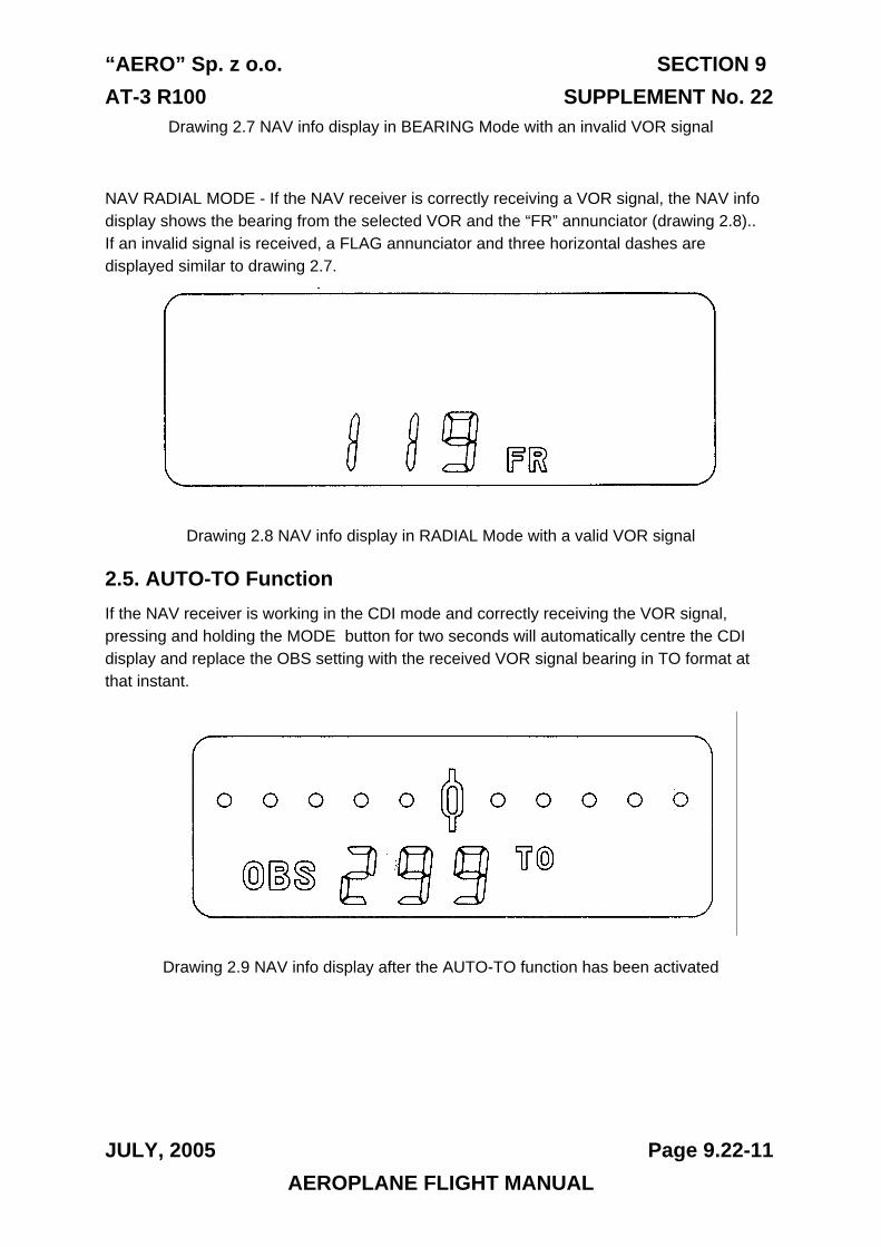
“AERO” Sp. z o.o. SECTION 9 AT-3 R100 SUPPLEMENT No. 22
JULY, 2005 Page 9.22-11
Drawing 2.7 NAV info display in BEARING Mode with an invalid VOR signal
NAV RADIAL MODE - If the NAV receiver is correctly receiving a VOR signal, the NAV info display shows the bearing from the selected VOR and the “FR” annunciator (drawing 2.8).. If an invalid signal is received, a FLAG annunciator and three horizontal dashes are displayed similar to drawing 2.7.
Drawing 2.8 NAV info display in RADIAL Mode with a valid VOR signal
2.5. AUTO-TO Function If the NAV receiver is working in the CDI mode and correctly receiving the VOR signal, pressing and holding the MODE button for two seconds will automatically centre the CDI display and replace the OBS setting with the received VOR signal bearing in TO format at that instant.
Drawing 2.9 NAV info display after the AUTO-TO function has been activated
AEROPLANE FLIGHT MANUAL
SECTION 9 “AERO” Sp. z o.o. SUPPLEMENT No. 22 AT-3 R100
2.6. COM active entry mode Pressing and holding the COM or NAV channel transfer button for two seconds enters the active entry mode on the NAV or COM display respectively. The standby frequency is not displayed at this moment and the active frequency can be selected with the frequency selection knob. To exit the active entry mode, momentarily press the COM/NAV transfer button. If the KX125 is powered up with either the COM or NAV transfer button depressed, it will be default into the COM/NAV entry mode. Both COM active and standby frequency will be set at 120.00 MHz and both NAV active and standby frequency will be set at 110.00 MHz.
WARNING! THE TRANSCEIVER SHOULD BE
SWITCHED OFF BEFORE ENGINE STOP
Page 9.22-12 JULY, 2005 AEROPLANE FLIGHT MANUAL
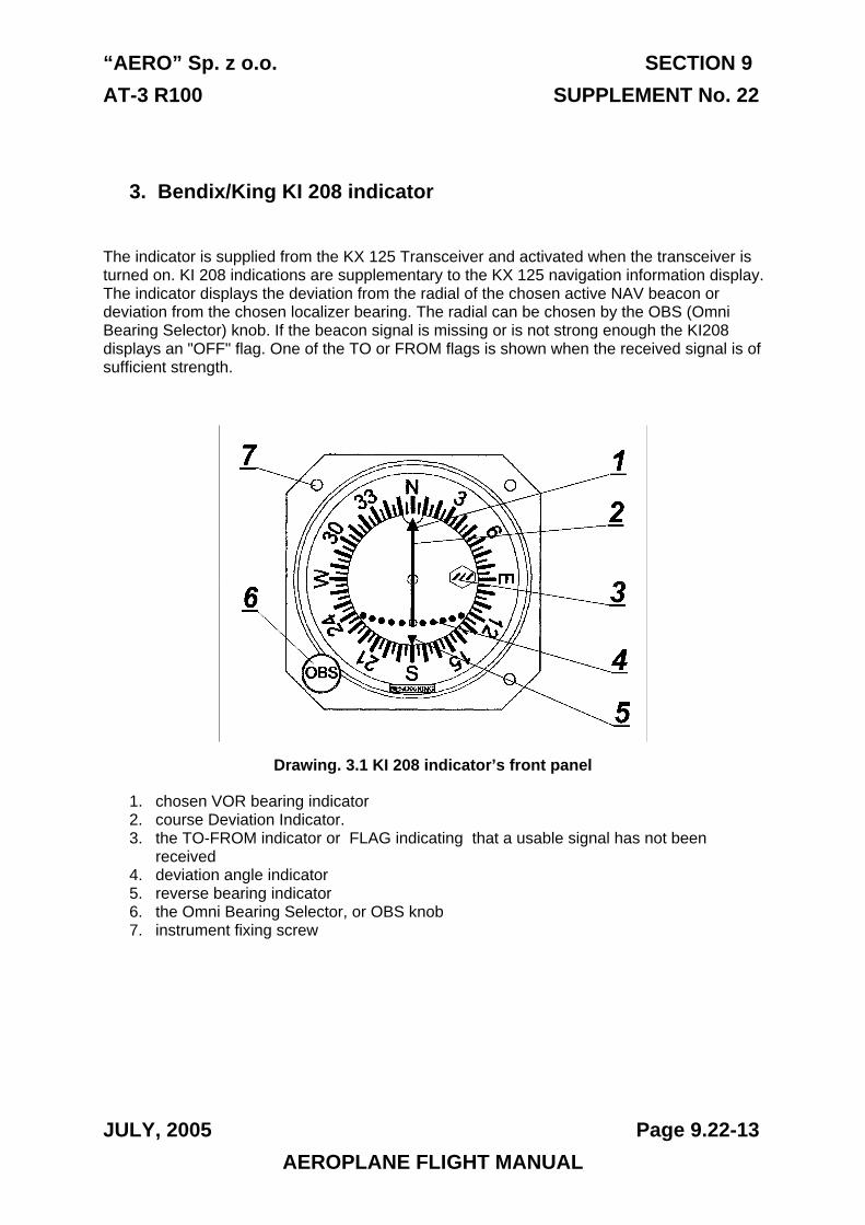
“AERO” Sp. z o.o. SECTION 9 AT-3 R100 SUPPLEMENT No. 22
JULY, 2005 Page 9.22-13
3. Bendix/King KI 208 indicator
The indicator is supplied from the KX 125 Transceiver and activated when the transceiver is turned on. KI 208 indications are supplementary to the KX 125 navigation information display. The indicator displays the deviation from the radial of the chosen active NAV beacon or deviation from the chosen localizer bearing. The radial can be chosen by the OBS (Omni Bearing Selector) knob. If the beacon signal is missing or is not strong enough the KI208 displays an "OFF" flag. One of the TO or FROM flags is shown when the received signal is of sufficient strength.
Drawing. 3.1 KI 208 indicator’s front panel
1. chosen VOR bearing indicator 2. course Deviation Indicator. 3. the TO-FROM indicator or FLAG indicating that a usable signal has not been
received 4. deviation angle indicator 5. reverse bearing indicator 6. the Omni Bearing Selector, or OBS knob 7. instrument fixing screw
AEROPLANE FLIGHT MANUAL
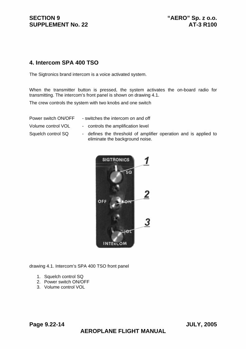
SECTION 9 “AERO” Sp. z o.o. SUPPLEMENT No. 22 AT-3 R100
4. Intercom SPA 400 TSO
The Sigtronics brand intercom is a voice activated system.
When the transmitter button is pressed, the system activates the on-board radio for transmitting. The intercom’s front panel is shown on drawing 4.1.
The crew controls the system with two knobs and one switch
Power switch ON/OFF - switches the intercom on and off
Volume control VOL - controls the amplification level
Squelch control SQ - defines the threshold of amplifier operation and is applied to eliminate the background noise.
drawing 4.1. Intercom’s SPA 400 TSO front panel
1. Squelch control SQ 2. Power switch ON/OFF 3. Volume control VOL
Page 9.22-14 JULY, 2005 AEROPLANE FLIGHT MANUAL
“AERO” Sp. z o.o. SECTION 9 AT-3 R100 SUPPLEMENT No. 22
JULY, 2005 Page 9.22-15
4.1. Intercom mode Put on your headset and place the microphone next to your mouth, similarly as you would do with a hand-held microphone. The best voice quality is usually achieved when the microphone is drawn aside and about 0.5 cm (¼ in.) from your lips.
Switch the intercom ON and set the volume at a lower level [the best signal/noise ratio may be achieved when the volume is set to 1/4 to 1/3 of its range].
Turn the squelch knob clockwise until the background noise can be heard in your earphones. Then turn it slightly back until this noise is inaudible. Now the knob should be slowly turned clockwise, until the voice activates the system [the above procedure is used, because the noise cancellation system is of a „fast on, slow off” type]. Some re-tuning of the squelch level might be required if the background noise changes significantly, e.g. if the engine power setting is changed of from idle to maximum power.
4.2. Radio transmission mode Radio transmissions may be made from either of the pilot seats. Pressing the RADIO button on the control stick automatically switches the signal to the COM transmitter. Transmitting from one microphone disables the ability to transmit from the other one at the same time.
AEROPLANE FLIGHT MANUAL
SECTION 9 “AERO” Sp. z o.o. SUPPLEMENT No. 22 AT-3 R100
4.3. Radio receiving mode
The radio receives automatically. The receiving circuits are always active, even when the Power Switch of the intercom is set into the OFF position [intercom switched off].
4.4. Solo flight
For solo flight the intercom is not required and may be switched off. The pilot will hear the radio because respective circuits of the intercom are always active. The pilot may also transmit through the radio after pressing its "TRANSMITTING” button on the control stick. [Transmitting from the co-pilot’s seat is not possible, when the intercom is switched off.]
2.5. Means of security
If a malfunction of the intercom is suspected, this device should simply be switched off. The audio received from the radio will be heard and radio transmissions can still be made from the pilot’s seat.
Page 9.22-16 JULY, 2005 AEROPLANE FLIGHT MANUAL
SECTION 9 SUPPLEMENT No. 22
AERO” Sp. z o.o. AT-3 R100
THIS PAGE IS LEFT INTENTIONALLY BLANK
Page 9.22-17 JULY, 2005AEROPLANE FLIGHT MANUAL
“AERO” Sp. z o.o. SECTION 9 AT-3 R100 SUPPLEMENT No. 23
JULY, 2005 Page 9.23-1
Section 9 SUPPLEMENT No. 23
Alternator
APPROVED:
CIVIL AIRCRAFT INSPECTION BOARD
( Originally signed by Mr. Z. Mazan) 28.07.2005
-------------------------------- ------------- Signature Date
English language version of the Polish document,
translated under delegation of authority CAIB No. 54C.
/-/
Jan A. Jasinski,B.S.(Eng.)
AEROPLANE FLIGHT MANUAL
SECTION 9 “AERO” Sp. z o.o. SUPPLEMENT No. 23 AT-3 R100
Section 1. General The same as for the standard aeroplane
Section 2. Limitations The same as for the standard aeroplane
Section 3. Emergency procedures
3.2.1. Engine failure during take-off • Alternator OFF
3.4.1. Engine fire on ground • Alternator OFF
3.4.2. Fire in flight • Alternator OFF
3.6.1. Precautionary landing Before touch-down: • Alternator OFF
3.6.2. Landing after engine failure • Alternator OFF
3.8.3. Failure of the electric system In case of Alternator failure act as follows: • Alternator OFF
• Power receivers, not required to continue the flight OFF
The rest of the section is the same as for the standard aeroplane.
Page 9.23-2 JULY, 2005 AEROPLANE FLIGHT MANUAL
“AERO” Sp. z o.o. SECTION 9 AT-3 R100 SUPPLEMENT No. 23
JULY, 2005 Page 9.23-3
Section 4. Normal procedures
4.5.2. Before starting engine • Alternator – to be switched off CHECK4.5.4. Engine starting
Cool engine procedure
• Alternator – after battery and generator ON
4.5.16. Engine shutdown • Alternator OFF
The rest of the section is the same as for the standard aeroplane. Section 5. Performance
The same as for the standard aeroplane
Section 6. Weight and balance Weight of the equipment included
in the weight of the empty aeroplane
Section 7. Description of the aeroplane and of its equipment The same as for the standard aeroplane
Section 8. Servicing. The same as for the standard aeroplane
AEROPLANE FLIGHT MANUAL
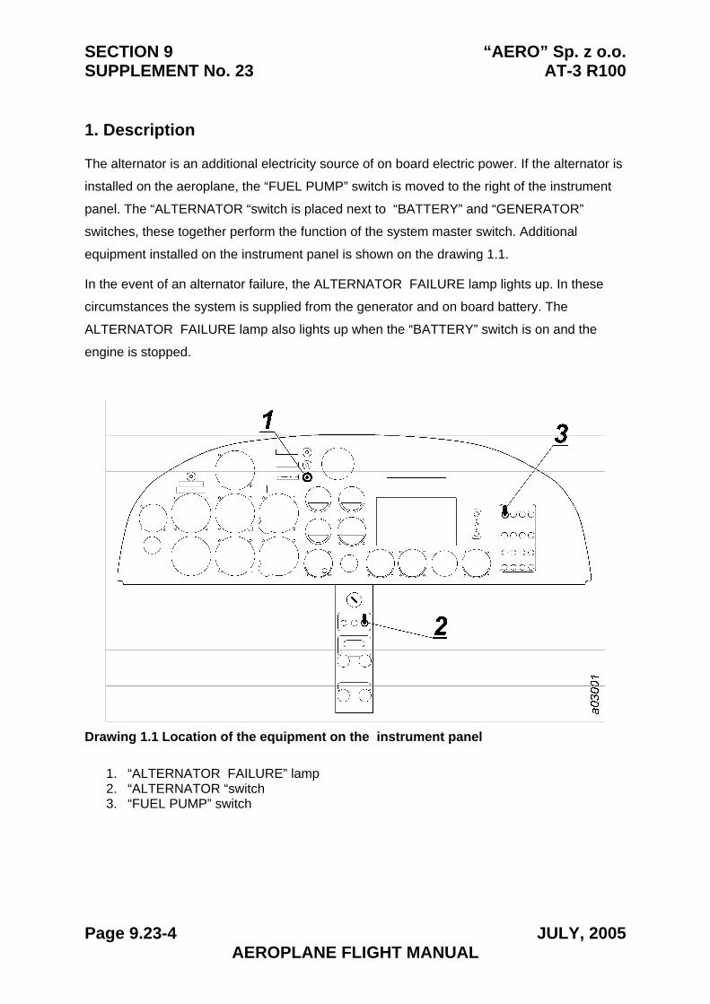
SECTION 9 “AERO” Sp. z o.o. SUPPLEMENT No. 23 AT-3 R100
1. Description
The alternator is an additional electricity source of on board electric power. If the alternator is
installed on the aeroplane, the “FUEL PUMP” switch is moved to the right of the instrument
panel. The “ALTERNATOR “switch is placed next to “BATTERY” and “GENERATOR”
switches, these together perform the function of the system master switch. Additional
equipment installed on the instrument panel is shown on the drawing 1.1.
In the event of an alternator failure, the ALTERNATOR FAILURE lamp lights up. In these
circumstances the system is supplied from the generator and on board battery. The
ALTERNATOR FAILURE lamp also lights up when the “BATTERY” switch is on and the
engine is stopped.
Drawing 1.1 Location of the equipment on the instrument panel
1. “ALTERNATOR FAILURE” lamp2. “ALTERNATOR “switch3. “FUEL PUMP” switch
Page 9.23-4 JULY, 2005 AEROPLANE FLIGHT MANUAL
SECTION 9 SUPPLEMENT No. 23
AERO” Sp. z o.o. AT-3 R100
THIS PAGE IS LEFT INTENTIONALLY BLANK
Page 9.23-5 JULY, 2005AEROPLANE FLIGHT MANUAL
“AERO” Sp. z o.o. SECTION 9 AT-3 R100 SUPPLEMENT No. 24
JULY, 2005 Page 9.24-1
Section 9 SUPPLEMENT No. 24
LANDING AND TAXIING LIGHTS
APPROVED:
CIVIL AIRCRAFT INSPECTION BOARD
(Originally signed by Mr. Z. Mazan) 28.07.2005
-------------------------------- ------------- Signature Date
English language version of the Polish document,
translated under delegation of authority CAIB No. 54C.
/-/
Jan A. Jasinski,B.S.(Eng.)
AEROPLANE FLIGHT MANUAL
SECTION 9 “AERO” Sp. z o.o. SUPPLEMENT No. 24 AT-3 R100
Section 1. General The same as for the standard aeroplane
Section 2. Limitations The same as for the standard aeroplane
Section 3. Emergency procedures The same as for the standard aeroplane
Section 4. Normal procedures The same as for the standard aeroplane
Section 5. Performance The same as for the standard aeroplane
Section 6. Weight and balance Weight of the equipment included
in the weight of the empty aeroplane
Section 7. Description of the aeroplane and of its equipment The same as for the standard aeroplane
Section 8. Servicing. The same as for the standard aeroplane
Page 9.24-2 JULY, 2005 AEROPLANE FLIGHT MANUAL
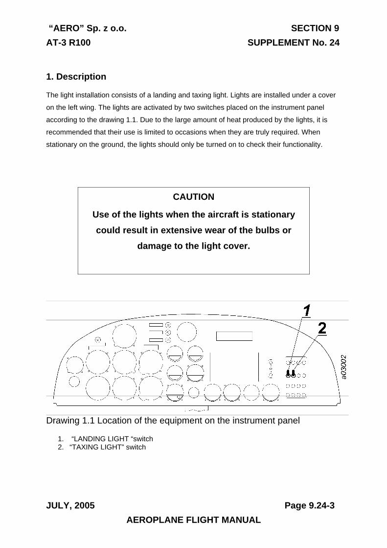
“AERO” Sp. z o.o. SECTION 9 AT-3 R100 SUPPLEMENT No. 24
JULY, 2005 Page 9.24-3
1. Description
The light installation consists of a landing and taxing light. Lights are installed under a cover
on the left wing. The lights are activated by two switches placed on the instrument panel
according to the drawing 1.1. Due to the large amount of heat produced by the lights, it is
recommended that their use is limited to occasions when they are truly required. When
stationary on the ground, the lights should only be turned on to check their functionality.
CAUTION
Use of the lights when the aircraft is stationary could result in extensive wear of the bulbs or
damage to the light cover.
Drawing 1.1 Location of the equipment on the instrument panel
1. “LANDING LIGHT “switch 2. “TAXING LIGHT” switch
AEROPLANE FLIGHT MANUAL
SECTION 9 “AERO” Sp. z o.o. SUPPLEMENT No. 24 AT-3 R100
THIS PAGE IS LEFT INTENTIONALLY BLANK
Page 9.24-4 JULY, 2005 AEROPLANE FLIGHT MANUAL
“AERO” Sp. z o.o. SECTION 9 AT-3 R100 SUPPLEMENT No. 25
JULY, 2005 Page 9.25-1
Section 9 SUPPLEMENT No. 25
STROBE LIGHTS
APPROVED:
CIVIL AIRCRAFT INSPECTION BOARD
( Originally signed by Mr. Z. Mazan) 28.07.2005
-------------------------------- ------------- Signature Date
English language version of the Polish document,
translated under delegation of authority CAIB No. 54C.
/-/
Jan A. Jasinski,B.S.(Eng.)
AEROPLANE FLIGHT MANUAL
SECTION 9 “AERO” Sp. z o.o. SUPPLEMENT No. 25 AT-3 R100
Section 1. General The same as for the standard aeroplane
Section 2. Limitations The same as for the standard aeroplane
Section 3. Emergency procedures The same as for the standard aeroplane
Section 4. Normal procedures The same as for the standard aeroplane
Section 5. Performance The same as for the standard aeroplane
Section 6. Weight and balance Weight of the equipment included
in the weight of the empty aeroplane
Section 7. Description of the aeroplane and of its equipment The same as for the standard aeroplane
Section 8. Servicing. The same as for the standard aeroplane
Page 9.25-2 JULY, 2005 AEROPLANE FLIGHT MANUAL
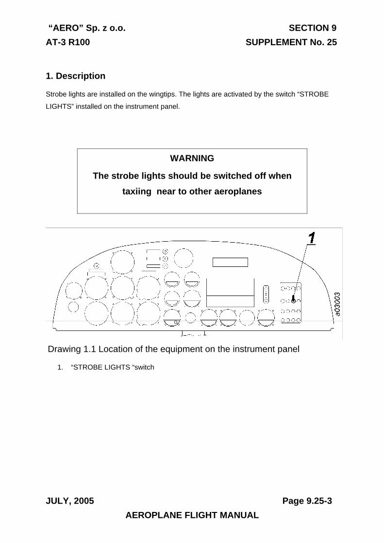
“AERO” Sp. z o.o. SECTION 9 AT-3 R100 SUPPLEMENT No. 25
JULY, 2005 Page 9.25-3
1. Description
Strobe lights are installed on the wingtips. The lights are activated by the switch “STROBE
LIGHTS” installed on the instrument panel.
WARNING
The strobe lights should be switched off when taxiing near to other aeroplanes
Drawing 1.1 Location of the equipment on the instrument panel
1. “STROBE LIGHTS “switch
AEROPLANE FLIGHT MANUAL
SECTION 9 “AERO” Sp. z o.o. SUPPLEMENT No. 25 AT-3 R100
THIS PAGE IS LEFT INTENTIONALLY BLANK
Page 9.25-4 JULY, 2005 AEROPLANE FLIGHT MANUAL
AERO Sp. z o.o. SECTION 9
AT-3 R100 SUPPLEMENT No. 26
MARCH, 2006 Page 9.26-1
AEROPLANE FLIGHT MANUAL
SECTION 9
SUPPLEMENT No. 26
Transponder TRT
APPROVED:
CIVIL AIRCRAFT INSPECTION BOARD
( Originally signed by Mr. Z. Mazan) 08.02.2006
-------------------------------- ----------- Signature Date
English language version of the Polish document, translated under delegation of authority CAIB No. 54C.
/-/ Jan A. Jasinski,B.S.(Eng.)
�
SECTION 9 AERO Sp. z o.o.
SUPPLEMENT No. 26 AT-3 R100
Page 9.26-2 JANUARY, 2006
AEROPLANE FLIGHT MANUAL
Section 1. General
The same as for the standard aeroplane.
Section 2. Limitations
The same as for the standard aeroplane.
Section 3. Emergency procedures
The same as for the standard aeroplane.
Section 4. Normal procedures
The same as for the standard aeroplane.
Section 5. Performance
The same as for the standard aeroplane.
Section 6. Weight and balance
Weight of equipment included in the weight of the empty
aeroplane.
Section. Description of the aeroplane and its equipment
The same as for the standard aeroplane.
Section 8. Servicing
The same as for the standard aeroplane.
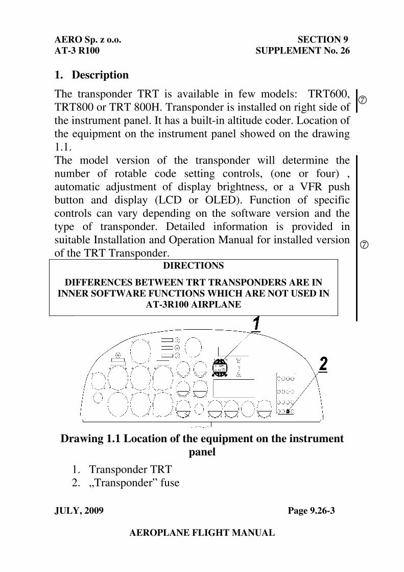
AERO Sp. z o.o. SECTION 9
AT-3 R100 SUPPLEMENT No. 26
JULY, 2009 Page 9.26-3
AEROPLANE FLIGHT MANUAL
1. Description
The transponder TRT is available in few models: TRT600,
TRT800 or TRT 800H. Transponder is installed on right side of
the instrument panel. It has a built-in altitude coder. Location of
the equipment on the instrument panel showed on the drawing
1.1.
The model version of the transponder will determine the
number of rotable code setting controls, (one or four) ,
automatic adjustment of display brightness, or a VFR push
button and display (LCD or OLED). Function of specific
controls can vary depending on the software version and the
type of transponder. Detailed information is provided in
suitable Installation and Operation Manual for installed version
of the TRT Transponder. DIRECTIONS
DIFFERENCES BETWEEN TRT TRANSPONDERS ARE IN
INNER SOFTWARE FUNCTIONS WHICH ARE NOT USED IN
AT-3R100 AIRPLANE
Drawing 1.1 Location of the equipment on the instrument
panel
1. Transponder TRT
2. „Transponder” fuse
7
7
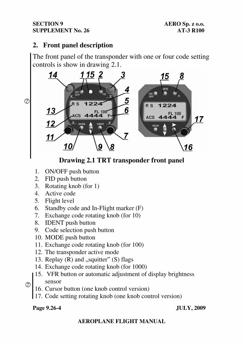
SECTION 9 AERO Sp. z o.o.
SUPPLEMENT No. 26 AT-3 R100
Page 9.26-4 JULY, 2009
AEROPLANE FLIGHT MANUAL
2. Front panel description
The front panel of the transponder with one or four code setting
controls is show in drawing 2.1.
Drawing 2.1 TRT transponder front panel
1. ON/OFF push button
2. FID push button
3. Rotating knob (for 1)
4. Active code
5. Flight level
6. Standby code and In-Flight marker (F)
7. Exchange code rotating knob (for 10)
8. IDENT push button
9. Code selection push button
10. MODE push button
11. Exchange code rotating knob (for 100)
12. The transponder active mode
13. Replay (R) and „squitter” (S) flags
14. Exchange code rotating knob (for 1000)
15. VFR button or automatic adjustment of display brightness
sensor
16. Cursor button (one knob control version)
17. Code setting rotating knob (one knob control version)
7
7
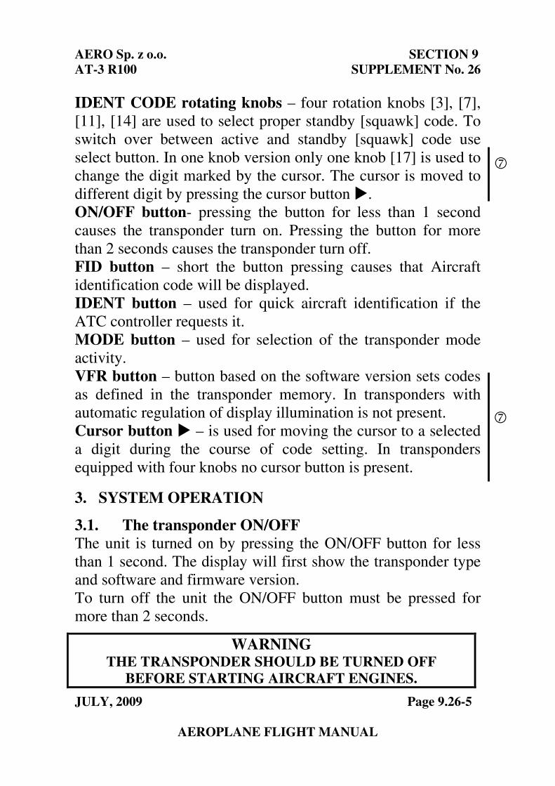
AERO Sp. z o.o. SECTION 9
AT-3 R100 SUPPLEMENT No. 26
JULY, 2009 Page 9.26-5
AEROPLANE FLIGHT MANUAL
IDENT CODE rotating knobs – four rotation knobs [3], [7],
[11], [14] are used to select proper standby [squawk] code. To
switch over between active and standby [squawk] code use
select button. In one knob version only one knob [17] is used to
change the digit marked by the cursor. The cursor is moved to
different digit by pressing the cursor button �.
ON/OFF button- pressing the button for less than 1 second
causes the transponder turn on. Pressing the button for more
than 2 seconds causes the transponder turn off.
FID button – short the button pressing causes that Aircraft
identification code will be displayed.
IDENT button – used for quick aircraft identification if the
ATC controller requests it.
MODE button – used for selection of the transponder mode
activity.
VFR button – button based on the software version sets codes
as defined in the transponder memory. In transponders with
automatic regulation of display illumination is not present.
Cursor button � – is used for moving the cursor to a selected
a digit during the course of code setting. In transponders
equipped with four knobs no cursor button is present.
3. SYSTEM OPERATION
3.1. The transponder ON/OFF
The unit is turned on by pressing the ON/OFF button for less
than 1 second. The display will first show the transponder type
and software and firmware version.
To turn off the unit the ON/OFF button must be pressed for
more than 2 seconds.
WARNING THE TRANSPONDER SHOULD BE TURNED OFF
BEFORE STARTING AIRCRAFT ENGINES.
7
7
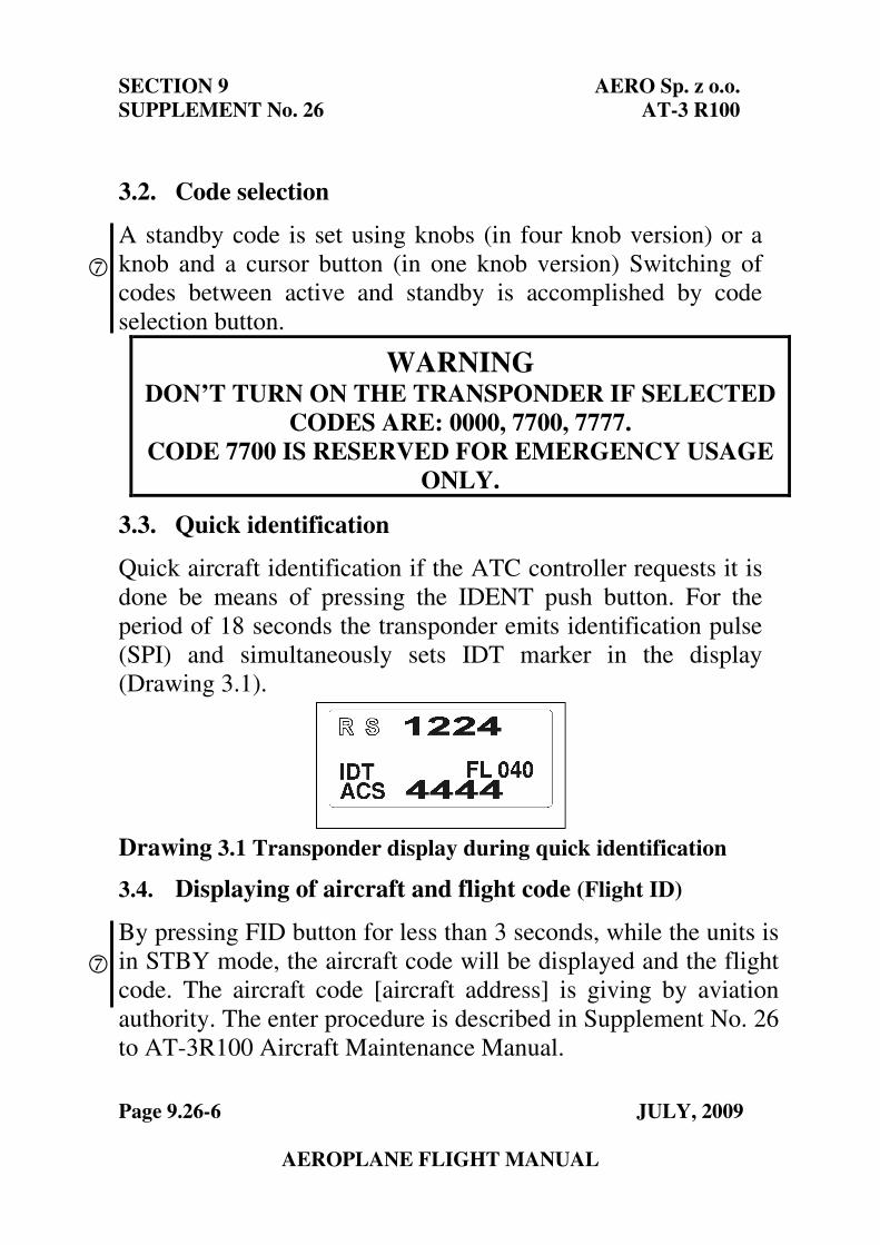
SECTION 9 AERO Sp. z o.o.
SUPPLEMENT No. 26 AT-3 R100
Page 9.26-6 JULY, 2009
AEROPLANE FLIGHT MANUAL
3.2. Code selection
A standby code is set using knobs (in four knob version) or a
knob and a cursor button (in one knob version) Switching of
codes between active and standby is accomplished by code
selection button.
3.3. Quick identification
Quick aircraft identification if the ATC controller requests it is
done be means of pressing the IDENT push button. For the
period of 18 seconds the transponder emits identification pulse
(SPI) and simultaneously sets IDT marker in the display
(Drawing 3.1).
Drawing 3.1 Transponder display during quick identification
3.4. Displaying of aircraft and flight code (Flight ID)
By pressing FID button for less than 3 seconds, while the units is
in STBY mode, the aircraft code will be displayed and the flight
code. The aircraft code [aircraft address] is giving by aviation
authority. The enter procedure is described in Supplement No. 26
to AT-3R100 Aircraft Maintenance Manual.
WARNING DON’T TURN ON THE TRANSPONDER IF SELECTED
CODES ARE: 0000, 7700, 7777.
CODE 7700 IS RESERVED FOR EMERGENCY USAGE
ONLY.
7
7
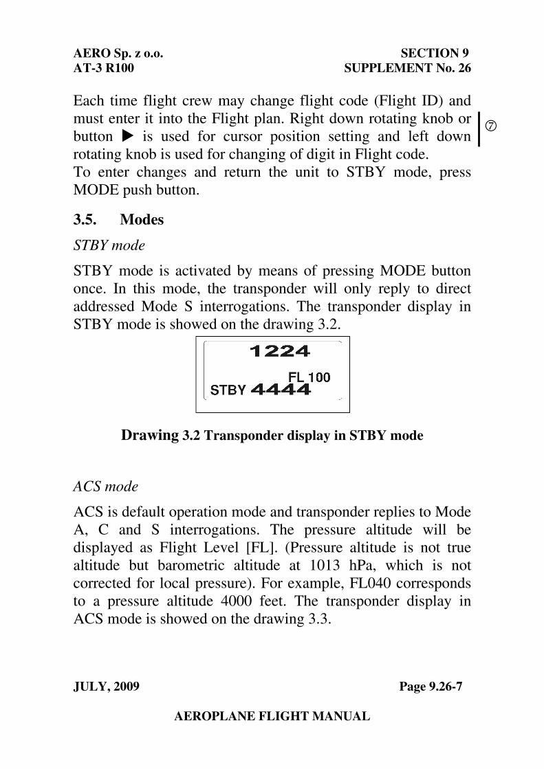
AERO Sp. z o.o. SECTION 9
AT-3 R100 SUPPLEMENT No. 26
JULY, 2009 Page 9.26-7
AEROPLANE FLIGHT MANUAL
Each time flight crew may change flight code (Flight ID) and
must enter it into the Flight plan. Right down rotating knob or
button � is used for cursor position setting and left down
rotating knob is used for changing of digit in Flight code.
To enter changes and return the unit to STBY mode, press
MODE push button.
3.5. Modes
STBY mode
STBY mode is activated by means of pressing MODE button
once. In this mode, the transponder will only reply to direct
addressed Mode S interrogations. The transponder display in
STBY mode is showed on the drawing 3.2.
Drawing 3.2 Transponder display in STBY mode
ACS mode
ACS is default operation mode and transponder replies to Mode
A, C and S interrogations. The pressure altitude will be
displayed as Flight Level [FL]. (Pressure altitude is not true
altitude but barometric altitude at 1013 hPa, which is not
corrected for local pressure). For example, FL040 corresponds
to a pressure altitude 4000 feet. The transponder display in
ACS mode is showed on the drawing 3.3.
7
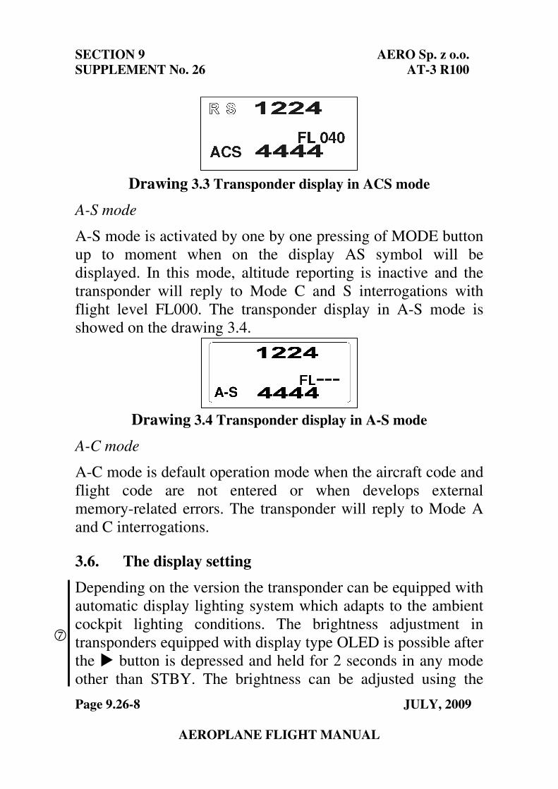
SECTION 9 AERO Sp. z o.o.
SUPPLEMENT No. 26 AT-3 R100
Page 9.26-8 JULY, 2009
AEROPLANE FLIGHT MANUAL
Drawing 3.3 Transponder display in ACS mode
A-S mode
A-S mode is activated by one by one pressing of MODE button
up to moment when on the display AS symbol will be
displayed. In this mode, altitude reporting is inactive and the
transponder will reply to Mode C and S interrogations with
flight level FL000. The transponder display in A-S mode is
showed on the drawing 3.4.
Drawing 3.4 Transponder display in A-S mode
A-C mode
A-C mode is default operation mode when the aircraft code and
flight code are not entered or when develops external
memory-related errors. The transponder will reply to Mode A
and C interrogations.
3.6. The display setting
Depending on the version the transponder can be equipped with
automatic display lighting system which adapts to the ambient
cockpit lighting conditions. The brightness adjustment in
transponders equipped with display type OLED is possible after
the � button is depressed and held for 2 seconds in any mode
other than STBY. The brightness can be adjusted using the
7
AERO Sp. z o.o. SECTION 9
AT-3 R100 SUPPLEMENT No. 26
JULY, 2009 Page 9.26-9
AEROPLANE FLIGHT MANUAL
knob. The transponder will return to normal operation after
approximately 5 seconds or after the button is pressed one more
time.
4. Error reporting
The transponder automatically controls the operation
parameters with self-testing. If any error occurs due to
malfunction of the transponder following messages will be
displayed:
ANT – antenna is defective or antenna cable is disconnected
FLerr – an error with altimeter or if the aircraft is outside the
altitude range (FL010 to FL350)
DC – faulty transmitter power supply
BAT – power supply voltage below 10V
FPG – internal communication errors
TRX – transmitter error – the transponder automatically will
change to STBY mode
After the transponder turn on, in case when the aircraft code is
not entered, the display will show message OUT OF ORDER
Cradle OFF. The transponder automatically goes to A-C
mode.
7
SECTION 9
SUPPLEMENT No. 26
AERO Sp. z o.o.
AT-3 R100
Page 9.26-10 JANUARY, 2006 AEROPLANE FLIGHT MANUAL
PAGE INTENTIONALLY LEFT BLANK
SECTION 9 AERO Sp. z o.o.
SUPPLEMENT No. 27 AT-3 R100
Page 9.27-4 MARCH, 2006
AEROPLANE FLIGHT MANUAL
PAGE INTENTIONALLY LEFT BLANK
AERO Sp. z o.o. SECTION 9
AT-3 R100 SUPPLEMENT No. 27
MARCH, 2006 Page 9.27-1
AEROPLANE FLIGHT MANUAL
SECTION 9
SUPPLEMENT No. 27
Operation of oil cooler shutter
APPROVED:
CIVIL AIRCRAFT INSPECTION BOARD
( Originally signed by Mr. Z. Mazan) 12.01.2006
-------------------------------- ------------- Signature Date
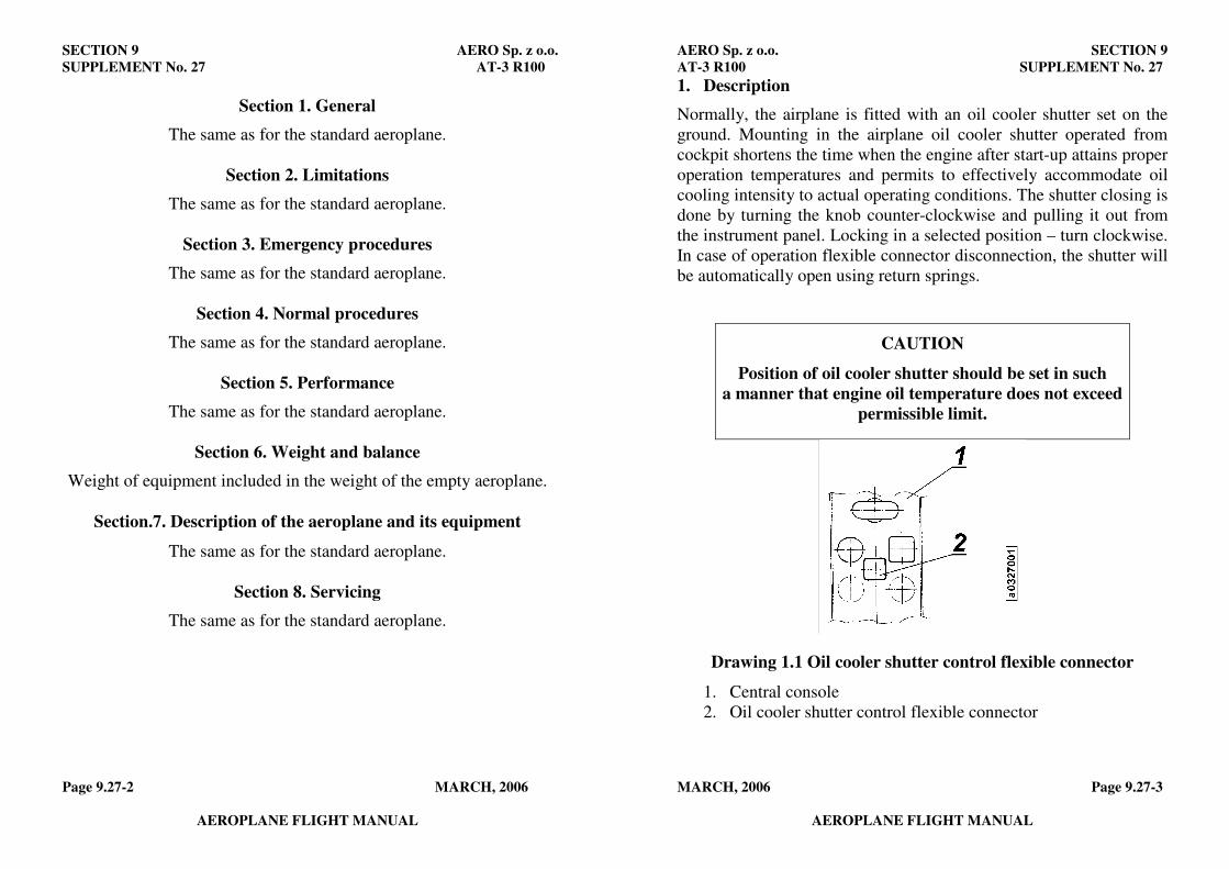
SECTION 9 AERO Sp. z o.o.
SUPPLEMENT No. 27 AT-3 R100
Page 9.27-2 MARCH, 2006
AEROPLANE FLIGHT MANUAL
Section 1. General
The same as for the standard aeroplane.
Section 2. Limitations
The same as for the standard aeroplane.
Section 3. Emergency procedures
The same as for the standard aeroplane.
Section 4. Normal procedures
The same as for the standard aeroplane.
Section 5. Performance
The same as for the standard aeroplane.
Section 6. Weight and balance
Weight of equipment included in the weight of the empty aeroplane.
Section.7. Description of the aeroplane and its equipment
The same as for the standard aeroplane.
Section 8. Servicing
The same as for the standard aeroplane.
AERO Sp. z o.o. SECTION 9
AT-3 R100 SUPPLEMENT No. 27
MARCH, 2006 Page 9.27-3
AEROPLANE FLIGHT MANUAL
1. Description
Normally, the airplane is fitted with an oil cooler shutter set on the
ground. Mounting in the airplane oil cooler shutter operated from
cockpit shortens the time when the engine after start-up attains proper
operation temperatures and permits to effectively accommodate oil
cooling intensity to actual operating conditions. The shutter closing is
done by turning the knob counter-clockwise and pulling it out from
the instrument panel. Locking in a selected position – turn clockwise.
In case of operation flexible connector disconnection, the shutter will
be automatically open using return springs.
CAUTION
Position of oil cooler shutter should be set in such
a manner that engine oil temperature does not exceed
permissible limit.
Drawing 1.1 Oil cooler shutter control flexible connector
1. Central console
2. Oil cooler shutter control flexible connector
AERO Sp. z o.o. SECTION 9 AT-3R100 SUPPLEMENT No. 28
MARCH, 2007 Page 9.28-1 AERPOLANE FLIGHT MANUAL
Section 9
SUPPLEMENT No. 28
POSITION LIGHTS
APPROVED:
CIVIL AIRCRAFT INSPECTION BOARD
( Originally signed by Mr. Z. Mazan) 17.05.2007
------------------------------------------- --------------- Signature Date
SECTION 9 AERO Sp. z o.o. SUPPLEMENT No. 28 AT-3R100
Page 9.28-2 MARCH, 2007 AEROPLANE FLIGHT MANUAL
Section 1. General
The same as for the standard airplane
Section 2. Limitations
The same as for the standard airplane
Section 3. Emergency procedures
The same as for the standard airplane
Section 4. Normal procedures
The same as for the standard airplane
Section 5. Performance
The same as for the standard airplane
Section 6. Weight and balance
The same as for the standard airplane. Weight of the equipment included in the weight of the empty
airplane
Section 7. Description of the airplane and of its equipment
The same as for the standard airplane
Section 8. Handling, Servicing & Maintenance
The same as for the standard airplane
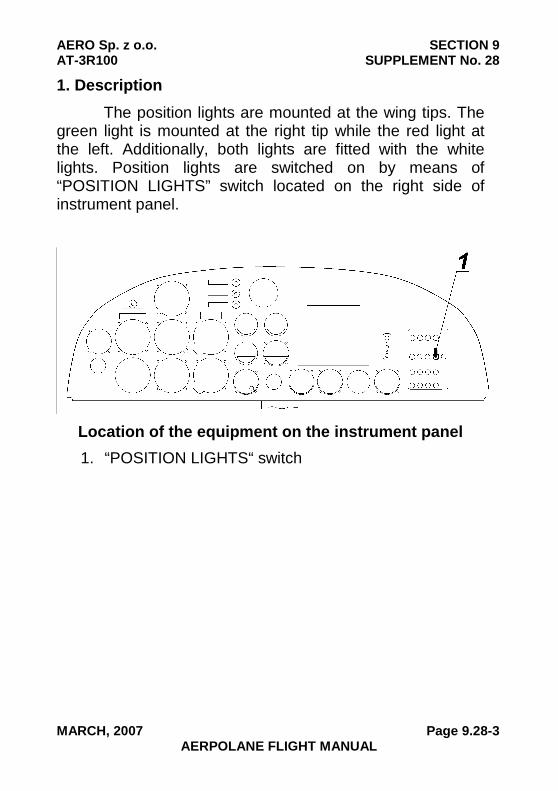
AERO Sp. z o.o. SECTION 9 AT-3R100 SUPPLEMENT No. 28
MARCH, 2007 Page 9.28-3 AERPOLANE FLIGHT MANUAL
1. Description
The position lights are mounted at the wing tips. The green light is mounted at the right tip while the red light at the left. Additionally, both lights are fitted with the white lights. Position lights are switched on by means of “POSITION LIGHTS” switch located on the right side of instrument panel.
Location of the equipment on the instrument panel
1. “POSITION LIGHTS“ switch
SECTION 9 AERO Sp. z o.o. SUPPLEMENT No. 28 AT-3R100
Page 9.28-4 MARCH, 2007 AEROPLANE FLIGHT MANUAL
PAGE INTENTIONALLY LEFT BLANK
AERO Sp. z o.o. SECTION 9 AT-3 R100 SUPPLEMENT No. 30
JULY, 2009 Page 9.30-1
AEROPLANE FLIGHT MANUAL
SECTION 9
SUPPLEMENT No. 30
ELT KANNAD 406 AF - COMPACT
SECTION 9 AERO Sp. z o.o. SUPPLEMENT No. 30 AT-3 R100
Page 9.30-2 JULY, 2009
AEROPLANE FLIGHT MANUAL
Section 1. General
The same as for the standard aeroplane.
Section 2. Limitations
The same as for the standard aeroplane.
Section 3. Emergency procedures
The same as for the standard aeroplane.
Section 4. Normal procedures
The same as for the standard aeroplane.
4.4.2. Pre-flight inspection of the aeroplane
In addition to standard airplane pre-flight inspection perform the following: � Switch controlling the ELT mounted
on a instrument panel in position ARMED CHECK � Switch on the main ELT unit in position “ARM” CHECK
NOTE Automatic or manual activation of the ELT transmitter is only possible when the switch on the main ELT unit
is in the ARM position.
The rest of the section is the same as for the standard aeroplane.
AERO Sp. z o.o. SECTION 9 AT-3 R100 SUPPLEMENT No. 30
JULY, 2009 Page 9.30-3
AEROPLANE FLIGHT MANUAL
Section 5. Performance
The same as for the standard aeroplane.
Section 6. Weight and balance
Weight of equipment included in the weight of the empty aeroplane.
Section 7. Description of the aeroplane and its equipment
The same as for the standard aeroplane.
Section 8. Servicing
The same as for the standard aeroplane.
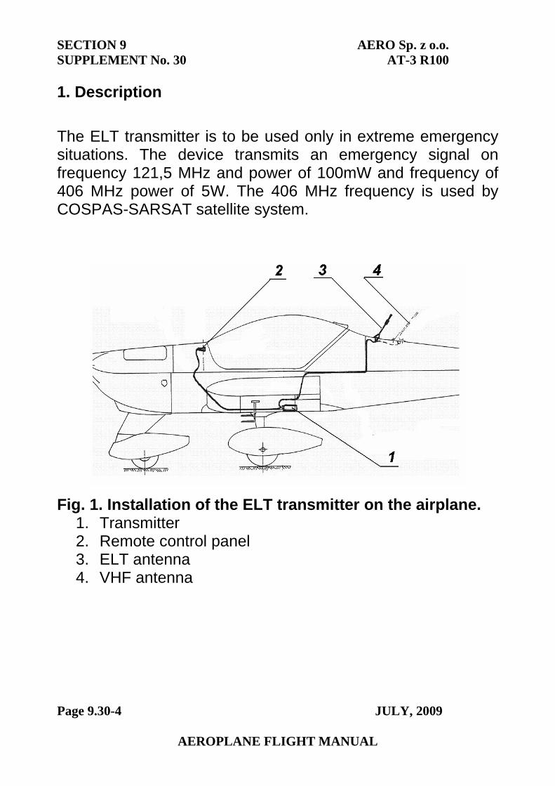
SECTION 9 AERO Sp. z o.o. SUPPLEMENT No. 30 AT-3 R100
Page 9.30-4 JULY, 2009
AEROPLANE FLIGHT MANUAL
1. Description
The ELT transmitter is to be used only in extreme emergency situations. The device transmits an emergency signal on frequency 121,5 MHz and power of 100mW and frequency of 406 MHz power of 5W. The 406 MHz frequency is used by COSPAS-SARSAT satellite system.
Fig. 1. Installation of the ELT transmitter on the airplane. 1. Transmitter2. Remote control panel3. ELT antenna4. VHF antenna
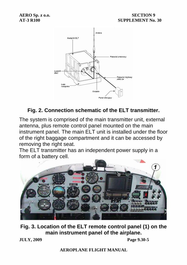
AERO Sp. z o.o. SECTION 9 AT-3 R100 SUPPLEMENT No. 30
JULY, 2009 Page 9.30-5
AEROPLANE FLIGHT MANUAL
Fig. 2. Connection schematic of the ELT transmitter.
The system is comprised of the main transmitter unit, external antenna, plus remote control panel mounted on the main instrument panel. The main ELT unit is installed under the floor of the right baggage compartment and it can be accessed by removing the right seat. The ELT transmitter has an independent power supply in a form of a battery cell.
Fig. 3. Location of the ELT remote control panel (1) on the main instrument panel of the airplane.
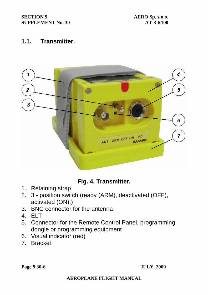
SECTION 9 AERO Sp. z o.o. SUPPLEMENT No. 30 AT-3 R100
Page 9.30-6 JULY, 2009
AEROPLANE FLIGHT MANUAL
1.1. Transmitter.
Fig. 4. Transmitter. 1. Retaining strap2. 3 - position switch (ready (ARM), deactivated (OFF),
activated (ON),)3. BNC connector for the antenna4. ELT5. Connector for the Remote Control Panel, programming
dongle or programming equipment6. Visual indicator (red)7. Bracket
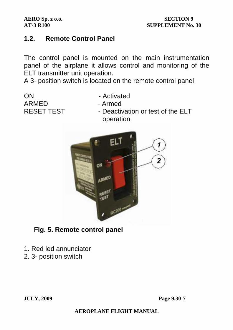
AERO Sp. z o.o. SECTION 9 AT-3 R100 SUPPLEMENT No. 30
JULY, 2009 Page 9.30-7
AEROPLANE FLIGHT MANUAL
1.2. Remote Control Panel
The control panel is mounted on the main instrumentation panel of the airplane it allows control and monitoring of the ELT transmitter unit operation. A 3- position switch is located on the remote control panel
ON - Activated ARMED - Armed RESET TEST - Deactivation or test of the ELT
operation
Fig. 5. Remote control panel
1. Red led annunciator2. 3- position switch
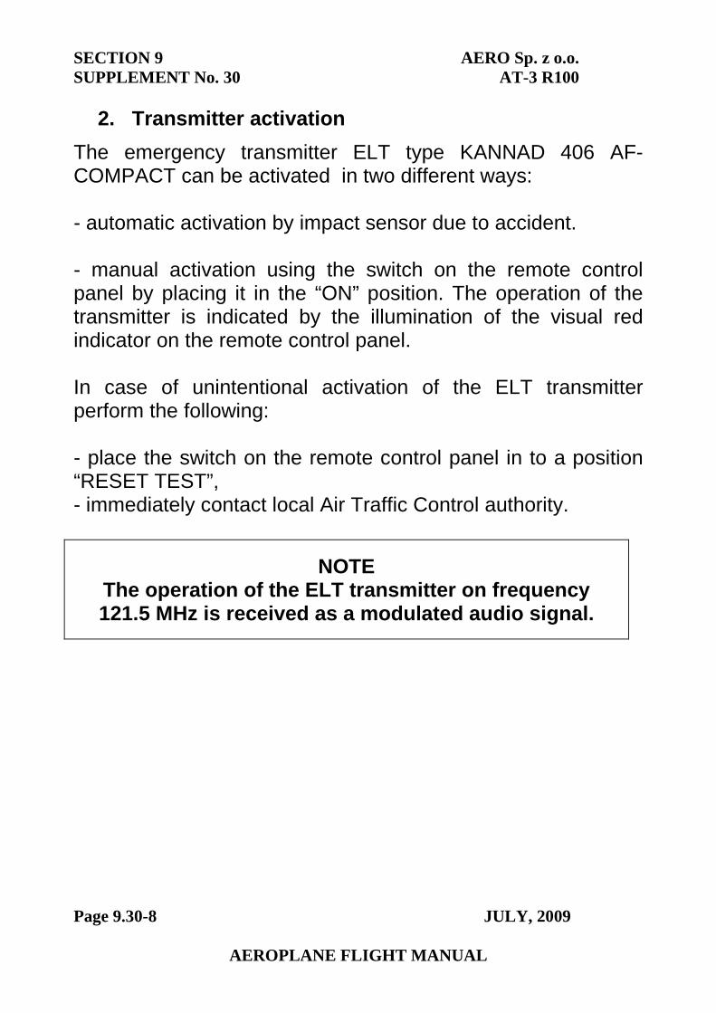
SECTION 9 AERO Sp. z o.o. SUPPLEMENT No. 30 AT-3 R100
Page 9.30-8 JULY, 2009
AEROPLANE FLIGHT MANUAL
2. Transmitter activation
The emergency transmitter ELT type KANNAD 406 AF-COMPACT can be activated in two different ways:
- automatic activation by impact sensor due to accident.
- manual activation using the switch on the remote control panel by placing it in the “ON” position. The operation of the transmitter is indicated by the illumination of the visual red indicator on the remote control panel.
In case of unintentional activation of the ELT transmitter perform the following:
- place the switch on the remote control panel in to a position “RESET TEST”, - immediately contact local Air Traffic Control authority.
NOTE The operation of the ELT transmitter on frequency 121.5 MHz is received as a modulated audio signal.
SECTION 9
SUPPLEMENT No. 30AERO Sp. z o.o.
AT-3 R100
Page 9.30-9 JULY, 2009
PAGE INTENTIONALLY LEFT BLANK
AERO Sp. z o.o. SECTION 9 AT-3R100 SUPPLEMENT No. 44
OCTOBER, 2010 Page 9.44-1
AEROPLANE FLIGHT MANUAL
Section 9
SUPPLEMENT No. 44
VFR-NIGHT (analog instruments)
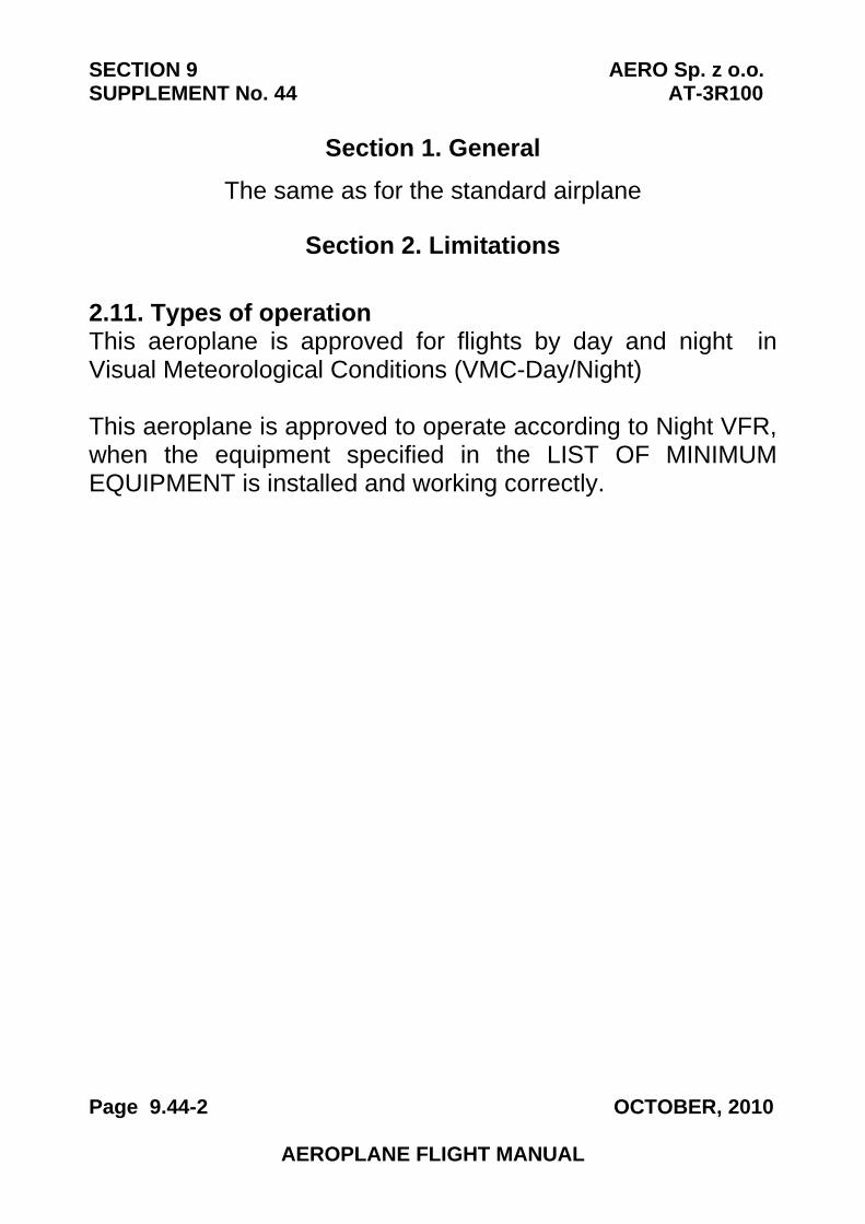
SECTION 9 AERO Sp. z o.o. SUPPLEMENT No. 44 AT-3R100
Page 9.44-2 OCTOBER, 2010
AEROPLANE FLIGHT MANUAL
Section 1. General
The same as for the standard airplane
Section 2. Limitations
2.11. Types of operation This aeroplane is approved for flights by day and night in Visual Meteorological Conditions (VMC-Day/Night)
This aeroplane is approved to operate according to Night VFR, when the equipment specified in the LIST OF MINIMUM EQUIPMENT is installed and working correctly.
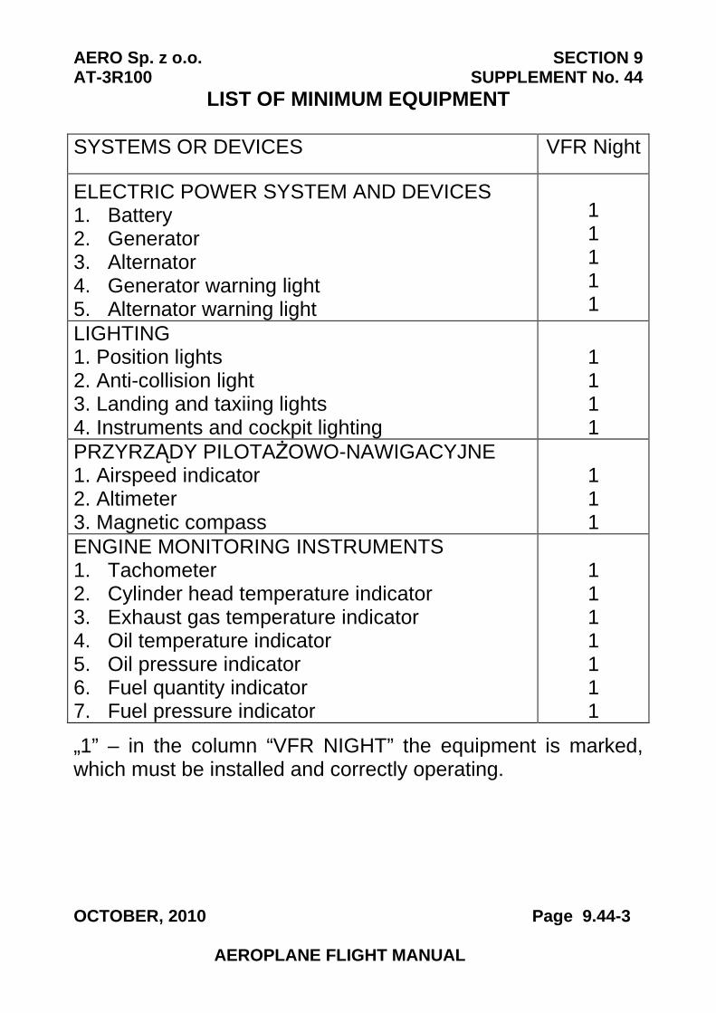
AERO Sp. z o.o. SECTION 9 AT-3R100 SUPPLEMENT No. 44
OCTOBER, 2010 Page 9.44-3
AEROPLANE FLIGHT MANUAL
LIST OF MINIMUM EQUIPMENT
SYSTEMS OR DEVICES VFR Night
ELECTRIC POWER SYSTEM AND DEVICES 1. Battery2. Generator3. Alternator4. Generator warning light5. Alternator warning light
1 1 1 1 1
LIGHTING 1. Position lights2. Anti-collision light3. Landing and taxiing lights4. Instruments and cockpit lighting
1 1 1 1
PRZYRZĄDY PILOTAŻOWO-NAWIGACYJNE 1. Airspeed indicator2. Altimeter3. Magnetic compass
1 1 1
ENGINE MONITORING INSTRUMENTS 1. Tachometer2. Cylinder head temperature indicator3. Exhaust gas temperature indicator4. Oil temperature indicator5. Oil pressure indicator6. Fuel quantity indicator7. Fuel pressure indicator
1 1 1 1 1 1 1
„1” – in the column “VFR NIGHT” the equipment is marked, which must be installed and correctly operating.
SECTION 9 AERO Sp. z o.o. SUPPLEMENT No. 44 AT-3R100
Page 9.44-4 OCTOBER, 2010
AEROPLANE FLIGHT MANUAL
2.14. Limitation placards
AT-3 R100 AIRPLANE, APPROVED IN ACCORDANCE WITH JAR-VLA FOR VFR-DAY/NIGHT OPERATIONS.
FLIGHTS IN KNOWN ICING CONDITIONS PROHIBITED. AEROBATIC MANOEUVRES INCLUDING SPINS
PROHIBITED. OTHER LIMITATIONS ACC. TO AIRPLANE FLIGHT
MANUAL
The rest of the section is the same as for the standard aeroplane.
Section 3. Emergency procedures
The same as for the standard airplane
Section 4. Normal procedures
4.4. Preparation for flight
CAUTION FLIGHT IN VFR NIGHT CONDITION MUST BE
CONDUCT IN ACCORDANCE WITH APPLAING COUNTRY FLIGHT RULES.
It is recommended to flight in VFR Night condition with efficiency and full charging battery. Must be ensure additional emergency light source such as torch, one for each flight crew member. For cross country flight it is recommended to take off with maximum fuel quantity.
AERO Sp. z o.o. SECTION 9 AT-3R100 SUPPLEMENT No. 44
OCTOBER, 2010 Page 9.44-5
AEROPLANE FLIGHT MANUAL
In purpose to reduce light flesh on the canopy plexi it is recommended to use instrument panel shade assembled per Supplement No 44 „VFR-Night (analog instruments)” to Maintenance Manual.
4.4.2. Pre-flight inspection of the aeroplane
1 Cabin • Position lights – operating CHECK • Taxiing light – operating CHECK • Landing light – operating CHECK • Anti-collision light – operating CHECK • Instruments and cockpit lighting – operating CHECK • Instruments and cockpit lighting – switch off CHECK
4.5.4. Engine starting
Cool engine procedure • Baterry, generator, alternator ON • Cockpit lighting ON • Engine instruments lighting ON
4.5.5. Before taxiing • Instruments lighting ON • Radio equipment lighting ON • Position lights ON • Anti-collision light ON • Taxiing light (if necessary) ON
SECTION 9 AERO Sp. z o.o. SUPPLEMENT No. 44 AT-3R100
Page 9.44-6 OCTOBER, 2010
AEROPLANE FLIGHT MANUAL
4.5.12. Before landing • Landing light ON
4.5.15. After landing • Landing light OFF • Taxiing light (if necessary) ON
The rest of the section is the same as for the standard aeroplane.
Section 5. Performance
The same as for the standard airplane
Section 6. Weight and balance
VFR night equipment weight is included in the empty aircraft weight.
Section 7. Description of the airplane and of its equipment
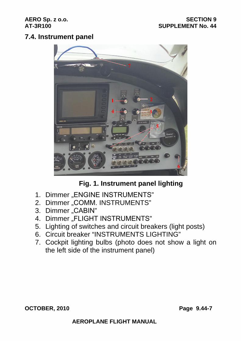
AERO Sp. z o.o. SECTION 9 AT-3R100 SUPPLEMENT No. 44
OCTOBER, 2010 Page 9.44-7
AEROPLANE FLIGHT MANUAL
7.4. Instrument panel
Fig. 1. Instrument panel lighting
1. Dimmer „ENGINE INSTRUMENTS”2. Dimmer „COMM. INSTRUMENTS”3. Dimmer „CABIN”4. Dimmer „FLIGHT INSTRUMENTS”5. Lighting of switches and circuit breakers (light posts)6. Circuit breaker “INSTRUMENTS LIGHTING”7. Cockpit lighting bulbs (photo does not show a light on
the left side of the instrument panel)
SECTION 9 AERO Sp. z o.o. SUPPLEMENT No. 44 AT-3R100
Page 9.44-8 OCTOBER, 2010
AEROPLANE FLIGHT MANUAL
The cabin and instrument lighting consists of four independent circuits:
- flight and navigation instruments - engine monitoring instruments and lighting of switches
and circuit breakers. - radio equipment - cockpit lighting
Rotating the knob to the left, to the point detectable switch function causes deactivation of selected circuit of lighting. Rotation to the right knob causes an activation and subsequent increase in lighting intensity.
Two bulb lights are installed over the instrument panel for cabin lighting. The direction of the light bulbs can be changed by rotating an internal spherical part of the light. Those lights can be used to lighting maps or if needed as a additional lighting of the instrumentation panel.
The lighting circuit is protected by a fuse labeled “INSTRUMENTS LIGHTING”.
The rest of the section is the same as for the standard
aeroplane.
Section 8. Servicing
The same as for the standard airplane

SECTION 9
SUPPLEMENT No. 44AERO Sp. z o.o.
AT-3 R100
Page 9.44-9 OCTOBER, 2010
PAGE INTENTIONALLY LEFT BLANK
AERO Sp. z o.o. SECTION 9 AT-3R100 SUPPLEMENT No. 51
JUNE, 2011 Page 9.51-1
AEROPLANE FLIGHT MANUAL
Section 9
SUPPLEMENT No. 51
PITOT AND STATIC PRESSURE INSTALLATION VARIANT III
SECTION 9 AERO Sp. z o.o. SUPPLEMENT No. 51 AT-3R100
Page 9.51-2 JUNE, 2011
AEROPLANE FLIGHT MANUAL
Section 1. General
The same as for the standard airplane
Section 2. Limitations
The same as for the standard airplane
Section 3. Emergency procedures
The same as for the standard airplane
Section 4. Normal procedures
The same as for the standard airplane
Section 5. Performance
The same as for the standard airplane
Section 6. Weight and balance
The same as for the standard airplane. Weight of the equipment included in the weight of the empty
airplane
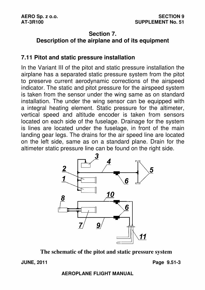
AERO Sp. z o.o. SECTION 9 AT-3R100 SUPPLEMENT No. 51
JUNE, 2011 Page 9.51-3
AEROPLANE FLIGHT MANUAL
Section 7. Description of the airplane and of its equipment
7.11 Pitot and static pressure installation
In the Variant III of the pitot and static pressure installation the airplane has a separated static pressure system from the pitot to preserve current aerodynamic corrections of the airspeed indicator. The static and pitot pressure for the airspeed system is taken from the sensor under the wing same as on standard installation. The under the wing sensor can be equipped with a integral heating element. Static pressure for the altimeter, vertical speed and altitude encoder is taken from sensors located on each side of the fuselage. Drainage for the system is lines are located under the fuselage, in front of the main landing gear legs. The drains for the air speed line are located on the left side, same as on a standard plane. Drain for the altimeter static pressure line can be found on the right side.
The schematic of the pitot and static pressure system
SECTION 9 AERO Sp. z o.o. SUPPLEMENT No. 51 AT-3R100
Page 9.51-4 JUNE, 2011
AEROPLANE FLIGHT MANUAL
1. Vertical speed indicator2. Altimeter3. Altitude encoder4. Static pressure line5. Fuselage static pressure sensor6. Drains7. Airspeed indicator8. Additional flight instruments – optional9. Pitot pressure line10. Airspeed indicator static pressure line.11. Pitot and static pressure sensor for airspeed indicator
Remaining contents of this chapter same as for standard
airplane
Section 8. Servicing
The same as for the standard airplane

SECTION 9
SUPPLEMENT No. 51AERO Sp. z o.o.
AT-3 R100
Page 9.51-5 JUNE, 2011
PAGE INTENTIONALLY LEFT BLANK
AERO Sp. z o.o. SECTION 9 AT-3R100 SUPPLEMENT No. 53
NOVEMBER, 2012 Page 9.53-1
AEROPLANE FLIGHT MANUAL
Section 9
SUPPLEMENT No. 53
ARTIFICIAL HORIZON
RCA 2600
SECTION 9 AERO Sp. z o.o. SUPPLEMENT No. 53 AT-3R100
Page 9.53-2 NOVEMBER, 2012
AEROPLANE FLIGHT MANUAL
Section 1. General
The same as for the standard aeroplane.
Section 2. Limitations
The same as for the standard aeroplane.
Section 3. Emergency procedures
The same as for the standard aeroplane.
Section 4. Normal procedures
The same as for the standard aeroplane.
Section 5. Performance
The same as for the standard aeroplane.
Section 6. Weight and balance
The same as for the standard aeroplane. Weight of the equipment included in the weight of the empty
aeroplane.
Section 7. Description of the airplane and of its equipment
The same as for the standard aeroplane.
Section 8. Servicing
The same as for the standard aeroplane.
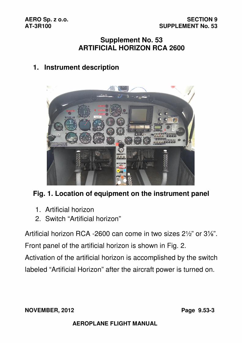
AERO Sp. z o.o. SECTION 9 AT-3R100 SUPPLEMENT No. 53
NOVEMBER, 2012 Page 9.53-3
AEROPLANE FLIGHT MANUAL
Supplement No. 53 ARTIFICIAL HORIZON RCA 2600
1. Instrument description
Fig. 1. Location of equipment on the instrument panel
1. Artificial horizon
2. Switch “Artificial horizon”
Artificial horizon RCA -2600 can come in two sizes 2½” or 3⅛”.
Front panel of the artificial horizon is shown in Fig. 2.
Activation of the artificial horizon is accomplished by the switch
labeled “Artificial Horizon” after the aircraft power is turned on.
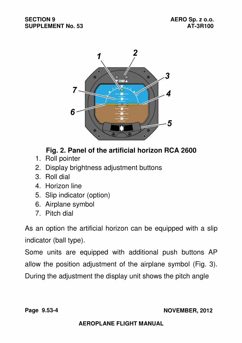
SECTION 9 AERO Sp. z o.o. SUPPLEMENT No. 53 AT-3R100
Page 9.53-4 NOVEMBER, 2012
AEROPLANE FLIGHT MANUAL
Fig. 2. Panel of the artificial horizon RCA 2600 1. Roll pointer
2. Display brightness adjustment buttons
3. Roll dial
4. Horizon line
5. Slip indicator (option)
6. Airplane symbol
7. Pitch dial
As an option the artificial horizon can be equipped with a slip
indicator (ball type).
Some units are equipped with additional push buttons AP
allow the position adjustment of the airplane symbol (Fig. 3).
During the adjustment the display unit shows the pitch angle
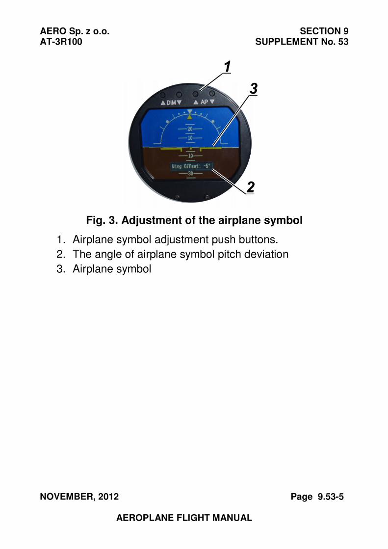
AERO Sp. z o.o. SECTION 9 AT-3R100 SUPPLEMENT No. 53
NOVEMBER, 2012 Page 9.53-5
AEROPLANE FLIGHT MANUAL
Fig. 3. Adjustment of the airplane symbol
1. Airplane symbol adjustment push buttons.
2. The angle of airplane symbol pitch deviation
3. Airplane symbol
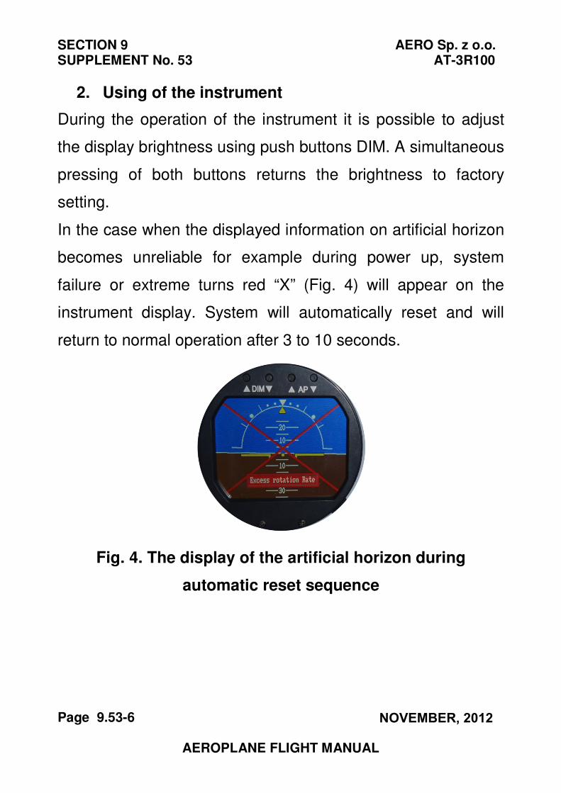
SECTION 9 AERO Sp. z o.o. SUPPLEMENT No. 53 AT-3R100
Page 9.53-6 NOVEMBER, 2012
AEROPLANE FLIGHT MANUAL
2. Using of the instrument
During the operation of the instrument it is possible to adjust
the display brightness using push buttons DIM. A simultaneous
pressing of both buttons returns the brightness to factory
setting.
In the case when the displayed information on artificial horizon
becomes unreliable for example during power up, system
failure or extreme turns red “X” (Fig. 4) will appear on the
instrument display. System will automatically reset and will
return to normal operation after 3 to 10 seconds.
Fig. 4. The display of the artificial horizon during
automatic reset sequence

SECTION 9
SUPPLEMENT No. 53AERO Sp. z o.o.
AT-3 R100
Page 9.53-7 NOVEMBER, 2012
PAGE INTENTIONALLY LEFT BLANK
Related Documents