Author Richard E Carter - KEIEV ([email protected]) Abstract This paper describes the PIC-E-II project. It includes information gathered from various sources or researched directly using test equipment. From a high-level, it describes what a packet is, what a PIC is, and how the PIC-E-II works. Keywords PIC, NMEA, APRS, AX.25, packet. Overview The PIC-E-II is an extension ofthe existing TAPR PIC-E kit. It shares the same modem chip and uses a processor chip from the same PIC family. The functional requirements of the project are significantly more ambitious however. The design attempts to extend the capabilities of a simple encoder to a self-contained APRS station. It is capable of not only transmitting a position, but of also receiving and processing APRS packets. System and software functional specifications are included as appendices at the end of this document. Consult these documents for details concerning system requirements. The project has been supported with several volunteers. The hardware design has been a collaborative effort. We also cooperated in the selection of tools and development environment. A single software application is in process. It is being written by a single contributor, the author of this paper. Source is available on request. It is planned to provide open source for this software; restricting use to non-commercial projects. The software design for this application is described in this document. Spare I/O ports are provided and a small breadboard area is planned for the board. Consideration was given to supporting inexpensive development tools, including a C compiler and an in-circuit debugger. The kit should be considered a potential breadboard for many amateur projects, not just those requiring AX.25. I started this project because APRS holds a lot of promise for the marine community, but existing equipment doesn't address these needs. There is a strong need for a station that collects and transmits weather and position data collected from an NMEA bus. It should accept and store packets addressed to the station. It must be small and consume little power. It would also be useful if the station could monitor the ship's battery voltage, flood, fire and theft alarms; generating an emergency status message if parameters are out of limits. I also think there is a need for a generic embedded processor kit that could be used for a variety of amateur radio applications. These applications need not be APRS related. In fact, then need not make use of the TNC interface provided by the kit. 7

Welcome message from author
This document is posted to help you gain knowledge. Please leave a comment to let me know what you think about it! Share it to your friends and learn new things together.
Transcript

Author Richard E Carter - KEIEV ([email protected])
Abstract This paper describes the PIC-E-II project. It includes information gathered from various sources or researched directly using test equipment. From a high-level, it describes what a packet is, what a PIC is, and how the PIC-E-II works.
Keywords PIC, NMEA, APRS, AX.25, packet.
Overview The PIC-E-II is an extension ofthe existing TAPR PIC-E kit. It shares the same modem chip and uses a processor chip from the same PIC family. The functional requirements of the project are significantly more ambitious however. The design attempts to extend the capabilities of a simple encoder to a self-contained APRS station. It is capable of not only transmitting a position, but of also receiving and processing APRS packets. System and software functional specifications are included as appendices at the end of this document. Consult these documents for details concerning system requirements.
The project has been supported with several volunteers. The hardware design has been a collaborative effort. We also cooperated in the selection of tools and development environment. A single software application is in process. It is being written by a single contributor, the author of this paper. Source is available on request. It is planned to provide open source for this software; restricting use to non-commercial projects. The software design for this application is described in this document.
Spare I/O ports are provided and a small breadboard area is planned for the board. Consideration was given to supporting inexpensive development tools, including a C compiler and an in-circuit debugger. The kit should be considered a potential breadboard for many amateur projects, not just those requiring AX.25.
I started this project because APRS holds a lot of promise for the marine community, but existing equipment doesn't address these needs. There is a strong need for a station that collects and transmits weather and position data collected from an NMEA bus. It should accept and store packets addressed to the station. It must be small and consume little power. It would also be useful if the station could monitor the ship's battery voltage, flood, fire and theft alarms; generating an emergency status message if parameters are out of limits.
I also think there is a need for a generic embedded processor kit that could be used for a variety of amateur radio applications. These applications need not be APRS related. In fact, then need not make use of the TNC interface provided by the kit.
7

Ax.25 The process of sending data over a radio using audio tones is described in the AX.25 specification. This transfer uses a network protocol. Industry uses a conceptual model to describe the basis for a network protocol implementation. This model describes the process in terms of network layers, sometimes called the ISO reference model. This model describes seven layers, three ofwhich are used by APRS.
Physical Layer - Layer-1 At the physical layer, ax.25 is implemented using two audio tones, 1200hz and 2400hz. The bit rate is 1200 baud (833uslbit). This is suitable for 2m FM operation. Data is transmitted as eight-bit ASCII characters LSB first. During each bit period, one of the two tones is transmitted. The tone does not directly correspond to either a one or a zero. Instead, a change of tone indicates a zero bit and no change indicates a one. This is more easily explained using the illustration below.
The two tones are represented as A and B. If the byte being transmitted is OlllOOOOb, the tones transmitted would be ABABBBA or BABAAAB (NB: bits are transmitted from right to left).
If a long series of sequential ones were transmitted, there would be no change of tone. Differences of the clock frequency of the transmitter and receiver stations could make reliable decoding of such a packet umeliable. To avoid problems caused by clock drift, the spec restricts transmissions to sequences of five or fewer sequential ones. This is accomplished using a process called bit-stuffing. Whenever five sequential ones are detected in the output data stream, a zero is stuffed in the sequence. This "stuffed" zero is removed by the receiver.
If the byte being transmitted is 01 1111 lOb, after stuffing it would be 01Olllll0b. The tones transmitted would be AAAAAABBA or BBBBBBAAB. Notice that the eight bit transmission takes nine tone periods to send.
Data Link Layer - Layer-2 Data is transferred between host and client in frames. Each frame of data is called a packet, each of which is bound by a special flag marker. In order to initially synchronize the transmitter and receiver, this special flag is transmitted before the first data byte ofthe packet. This flag has six sequential ones bracketed by zeros (Ox7E). Bit stuffing is not performed on this byte. This is the only normal condition where more than five sequential ones are found in a packet. If more than six sequential ones are detected at the receiver, the spec requires the receiver to abort the packet and search for the beginning of a new packet flag. A two byte CRC is appended to the end of the packet, followed by a flag. It is common practice for a transmitter to send a sequence of consecutive flags at the beginning of a packet. The transmitter may send a series of flags at the end also.
There is no acknowledgement defined by AX.25 at the data link layer.
8

Application Layer - Layer-7 APRS is an application that uses the AX.25 network protocol. The APRS spec defines the frame format for APRS as a VI frame (unnumbered) with nine fields of data. Some of these fields are really part of lower layers, but are described in the spec for completeness.
1. Flag - Ox7E 2. Destination - Callsign and SSID of the destination station. 3. Source - Callsign and SSID of the originating station. 4. Digipeater Address - variable number ofdigipeater station addresses. 5. Control- Defined as UI frame for APRS. 6. Protocol - No layer 3 7. Information - This field is implementation specific. The first byte defines the
format of this field. 8. FCS - l6-bit CRC
There are many specific application formats for APRS data. The PIC-E-II transmits packets using the MIC-E1 format. Since generic APRS messages have no particular destination address, the destination address field is unused. The MIC-E format makes use of this unused field to place some of the position data. The remaining part is included in the information field. There is an advantage to making packet length as short as possible, so the position information is packed to shorten the packet as much as possible. AX.25 restricts transmitted bytes to legal ASCII characters, so the packing algorithm is restricted to fewer than 256 codes per byte. This packing method is described in the APRS spec.
NMEA-183 This paper would not be complete if it didn't cover the NMEA-l83 protocol. This is a serial communications protocol defined by the National Marine Electronics Association for the purpose of communicating between marine instruments. It should be noted that this protocol is not restricted to passing GPS data. It is important to the PIC-E-II project because almost all GPS instruments use this protocol to send out position information. A detailed description of the spec is beyond the scope of this paper. The NMEA specification is not available online, but there is a lot of information available on the web. Peter Bennett's website is the best place to find this information http://vancouverwebpages.com/peterl . Interested readers should consult this page.
In brief, NMEA is a serial ASCII protocol that runs at 4800 baud. It is not RS-232 compatible, but the signalleve1s are close enough to work with most generic computer ports. Data is sent in what are called sentences. There are 46 standard sentences and a number of proprietary sentences. These sentences include not only position information, but also information about wind, water temperature, compass heading and various other information of interest to marine instruments. Unfortunately, there is no standard sentence that includes barometric pressure, humidity, or air temperature.
I MIC-E is a trademark of APRS Engineering LLC and Bob Bruninga WB4APR
9

These sentences vary in length, but are typically fewer than lOO bytes. They begin with a dollar-sign and end with an asterisk followed by a two-byte checksum. They are typically transmitted at a one-second interval. Most instruments cycle through a sequence of messages, taking several seconds to repeat the sequence. This means that data may be several seconds old before it is received.
An example GPS sentence is included below.
$GPRMC,2l29ll,A,49l5.607,N,l23l0.537,W,000.0,360.0,llll98,020.3,E*6l
PIC Processor The microchip PIC processor midrange line offers a very low cost solution for simple embedded applications. The chip offers internal RAM and ROM. I/O devices such as line drivers and receivers, analog input, and serial I/O are included in the same package. For most applications, only an external crystal, three-terminal regulator, and rs-232 signal conditioner are needed to support the PIC chip. The chip comes in several configurations. Only chips with flash ROM are considered suitable for low-volume projects. This limits the selection of processor chips to the l6F84, l6F628, and l6F87x. The original PIC-E design used a l6F84 PIC processor. This chip does not include enough memory or I/O to support our requirements, nor does the l6F628. We chose the more powerful l6F876 chip. This chip has the added advantage of providing support for a low-cost in-circuit debugger.
The chip l6F876 architecture provides 8k words of program space, 368 bytes of RAM, and 256 bytes ofEEPROM. One hardware DART is implemented in the PIC. A second serial interface is provided for synchronous serial communication. This port can be configured as a SPI bus interface. The SPI bus is a medium speed bi-directional serial bus that is used to connect a variety of low cost sensor and memory devices. The SPI bus uses three lines, data, clock, and chip select. Data is bi-directional.
It should be noted that a more advanced processor with flash memory is now available from microchip. This more powerful chip was not available when we started the design. A more powerful high-end chip which overcomes many of the midrange limitations is . now available. We are evaluating the possibility ofmigrating to one of these chips in the near future. A high-end chip may make a multi-tasking real-time OS possible. This would significantly simplify the software design.
PIC Midrange Architecture Limitations The midrange PIC processors lack a data stack. In theory, a stack could be implemented using part of the limited internal memory on the chip, but the overhead required to support an operating system context could not reasonably be supported without expanding the on-chip memory. Off-chip memory is either very slow or requires too many I/O pins. To compound these difficulties, available compilers for this chip do not make use of a stack. This prevents the use of a multi-tasking real-time operating system.
10

An 8-deep program address stack is implemented in hardware in the PIC. This limits program nesting to 8 levels. Only the top-most entry is visible to the software. This prevents the call stack from being saved during a context switch.
Although clock speeds for the PIC processors are advertised as high as 20mhz, it takes four clock cycles to execute one machine instruction. This reduces the effective speed of the chip to 5mhz.
The PIC architecture has only one data register. This means that it takes several instructions to execute even the simplest of operations. This restriction not only reduces the effective throughput of the processor, but also eats program space.
The PIC processor has only one level of interrupt. All other interrupts will be blocked while an interrupt service routine is executing. This means that ISRs must be kept short.
The lack of a data stack coupled with a lack of general purpose registers make it almost impossible to write re-entrant code. As a minimum, this implies duplicate copies of software functions that are used in the ISR context and the application context.
Both program space and data space are paged. Paging adds overhead to the system by requiring register settings before switching pages. This overhead reduces system performance. Page changes in program space are infrequent, but page changes to access on-chip RAM can be very frequent. Paging to access RAM can be minimized by positioning related data on the same page and by careful use of the few shadowed RAM locations.
The PIC processor has no hardware multiply or divide instructions. These operations are performed using a math library using software routines. Multiply operations and particularly divide operations should be avoided. Floating point operations in a time critical thread may have serious throughput implications and should also be avoided.
Development Tools It is a team goal to provide a kit that is relatively easy to adapt. The choice of development tools is a key consideration. We were also aware that fellow amateurs are frugal. We attempted to strike a balance between cost and performance.
Development Environment Microchip supplies a free development environment available for download from their website, the Microchip MPLAB IDE. This toolkit runs on Microsoft Windows platforms. It provides an assembler, debugger, simulator, and project facility. Note that it lacks a compiler. Without external hardware, the debugger only works with the MPLAB simulator.
Compiler Assembly code is considered difficult for the average amateur to use, so we included a commercial compiler in our requirements. Several third-party compilers are available for the PIC chip. We restricted our selection to those that are low cost (less than $100). After evaluating several products, we selected the CCS PIC-C compiler. This is a C
11
compiler. The compiler has limitations, most of which can be overcome by the programmer. Our first copy had problems generating reliable code, but a later version fixed many of these bugs. The compiler does not conform to the ANSI standard, but the most recent version is close enough to make coding straightforward. I found that the compiler is more reliable if the C statements are kept simple. This also makes the code more readable for inexperienced programmers.
The CCS compiler comes with a support library that is specific to the PIC chip. These services provide drivers for most of the PIC devices, including the serial ports. They use blocking calls however. A blocking call locks out the processor until the service completes. As an example, a call to printf to print a character string does not return until the last character is queued in the output port. At 9600 baud, it takes over 1ms for each character to be transmitted. A string of 10 characters would take over lams to send out. During this period of time, the processor can service interrupts, but no other threads could run. Response requirements of the PIC-E-II design cannot be satisfied if blocking calls are used. I overcame this limitation by writing my own drivers.
Debugger Various debuggers and in-circuit emulators are available. We restricted our selection to an inexpensive in-circuit debugger available through Microchip for less than $100. The debugger uses the Microchip MPLAB IDE software package.
12
The PIC-E-II design
Hardware Design The schematic and assembly drawings for this board should be posted on the TAPR website in the near future. Those interested in examining the design should look there for the latest copy.
As stated earlier, the PIC-E-II hardware design started with the PIC-E design. It therefore resembles the earlier kit. Several changes were made to better support the new requirements. The earlier kit supported only one serial port, a GPS port. We added a second port to connect to a host computer.
The NMEA spec requires an opto-isolator to support the GPS interface. We wanted to make the sensor interface more generic than just GPS, so we supported the interface with an RS-232 compliant design. The signal level provided by the PIC is not in compliance with the RS-232 spec, so an external buffer/driver chip (MAX-232) was added.
The PIC processor includes one serial UART interface. A second serial port is needed for our implementation. The driver for this port is implemented in software. This means that each serial bit for this port must be shifted by the processor.
The inputs and outputs are conditioned using the same buffer/driver chip. Flow control for data from the host to the target is required to throttle packet data. This line is not properly conditioned as specified by the RS-232 spec. The MAX-232 chip only provides two buffered outputs which are used by the two serial port data output lines. A third was not available for this signa1. Since the signal is a level rather than edge sensitive, the marginal signal level provided by the PIC output should work with most host processors.
The radio audio interface is supported with the same modem chip used in the original PIC design. Connection to the radio microphone was simplified to reduce parts count. Pin mapping from the TNC to the microphone can be done in the harness rather than on the board. It is necessary to toggle one of the mode bits when switching between transmit and receive. This is directly connected to the PIC TX line that goes through a transistor driver and then to the mic PTT.
There is not enough RAM provided in the PIC chip for packet buffering. We added an external RAM chip to the design. This chip is a Ramtron FM65640. It provides 8k bytes of buffer memory. Access to this chip is through the SPI serial bus running at one fourth the CPU clock speed. The slow access speed of the SPI interface precludes the use of this device for local data, but it is adequate for packet storage.
Software Design The software implementation is too complicated to be described in detail in this paper. This section covers key parts of the software design. In some cases, code fragments from the software are included where it may help describe the design. Complete source for this project is available from the author on request. Code fragments included below are copyrighted. The author reserves all rights. Permission to use this code may be obtained by contacting the author.
13

Due to the physical limitations of the PIC processor, design and coding methods that are considered "normal good engineering practices" such as information hiding and encapsulation had to be ignored. During the implementation phase of development, code generation problems with an early version of the compiler forced me to write the code in an unusual style. This has resulted in an implementation that looks awkward when first examined. The code is well commented and should be easy to follow however.
I used a common coding standard for this code. Indents are four spaces. Close braces align with the corresponding statement. Macros are all capitol letters. Macros are used to make the code more readable or more portable. Macros represent a small block of code and are defined before they are used. An example of a macro used in the code is LEDl ON. This macro is defined in a header file that defines how the PIC chip is wired to the board. If the board layout changed, it would only be necessary to change this single definition to correct the code.
Real-time Considerations Real-time requirements imposed by system require a multi-threaded solution. Each thread of execution supports a flow of data through the system. At a minimum, the following threads are required to implement the PIC-E-II design.
1. GPS receive - This device is implemented in software using a single I/O bit. Each received bit is sampled at the appropriate time until an entire byte is captured.
2. GPS transmit - This is implemented in software using a single I/O bit. Each transmit bit is loaded into the output port at the appropriate time.
3. Computer port receive - This interface is implemented in hardware using the PIC DART. An interrupt line is set whenever data is available from this port. Hardware flow control can be activated from this ISR to throttle receive data.
4. Computer port transmit - Computer port receive - This interface is implemented in hardware using the PIC DART. A hardware interrupt is available that indicates that the port is available, but the software does not enable this interrupt. The sending thread is responsible for polling the output port status.
5. APRS receive- This is implemented in software using a single I/O bit. Each received bit is sampled at the appropriate time until an entire byte is captured.
6. APRS transmit - This is implemented in software using a single I/O bit. Each transmit bit is loaded into the output port at the appropriate time.
Each thread has a real-time response requirement that is imposed by system requirements. Response times for these threads are listed below.
1. GPS receive - ~ bit time at 4800 baud = 104us. The receive data is sampled at the middle of the bit period. To insure accurate samples, this sample must occur before the end of the bit period.
2. GPS transmit - Yz bit at 4800 baud = 104us. It is assumed that the receiver implements an algorithm similar to the PIC receiver.
14

3. Computer port receive - 1 byte to set hardware flow control = 1.04ms. The receiver can buffer an entire received byte. When we detect the start of a transmission, we need to set the flow control bit before the end of the received byte.
4. Computer port transmit - no response requirement
5. APRS receive - 12 bit at 1200 baud = 416 us
6. APRS transmit - 12 bit at 1200 baud = 416 us
The above response times are absolute worst case. A margin of safety is required for a robust system implementation. Reducing each of these times by 25% is advisable. Some of these time constraints are mutually exclusive. As an example, it is not possible to both transmit and receive on the APRS port at the same time, so the software does not need to consider satisfying both ofthese constraints at the same time.
The Grand Loop As stated earlier, the PIC processor supports only one level of interrupt. Without multitasking, there are only two contexts that run in the processor, the ISR context and the application context.
Consider a simple thread that is only required to blink an LED once each second. A function such as this might be used to display a heartbeat. This is useful during the test and integration phase to indicate that the application software is cycling. The state diagram for this thread is shown below. When it first runs, it enters the LED on state where it turns on the LED. After 200 ms enters the LED Off state where it turns off the LED. After 800ms, it reenters the LED on state.
Entry
In a traditional embedded implementation, the above function would be implemented with a small task that executes two wait service calls. While waiting, the processor would be available to run other tasks. Without a multi-tasking real-time operating system, there is no scheduler that can load other tasks during the wait period. This means that during a wait condition, the processor is not available to run other ready tasks.
One method for overcoming the lack of an operating system is to design the software to operate in what is called a "grand loop". Since threads of execution cannot make use of multi-tasking OS, they are serviced in sequence within a single task context. Each thread is executed in turn within an infinite loop loop. Threads run until they gives up the
15

processor. Each thread is polled in sequence to allow it to continue execution. The polled thread is responsible to determine if it has the resources necessary to continue running. If not, it exits as quickly as possible. Under no circumstances maya thread block. When a thread begins execution, it must determine where it was when it last ran. It then must determine if it can continue execution. If resources required to continue execution are not available, the thread must exit.
Each thread is implemented as what is called a "state machine". Threads sequence through a set of "states" until they require a resource that is not available. Resources include data, devices, or events. An example data resource could be a message placed in a data queue by another thread. A device resource might be a free queue entry in the SPI interface. An event resource might be a timer event. In order to advance to the next state, the state machine must have the resources necessary to continue. It then completes as much of the thread of execution that it can until it requires an unavailable resource. The state machine remembers the state it was in when it stalled. It then exits, giving the next thread in sequence a chance to run. On the next invocation, the state machine checks to see if it has the resource it needs. Our example simple thread above looks like this when implemented as a state machine.
The thread above initially enters the 'LED on wait state'. It exits if the timer has not expired. When the timer expires, it advances the 'LED on state' where it turns on the LED, then advances to the 'LED offwait state'. If the timer has not expired, it exits.
16
- -
- -
- -
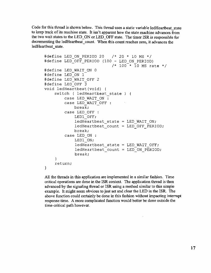
Code for this thread is shown below. This thread uses a static variable ledHeartbeat state to keep track of its machine state. It isn't apparent how the state machine advances from the two wait states to the LED_ON or LED_OFF state. The timer ISR is responsible for decrementing the ledHeartbeat count. When this count reaches zero, it advances the ledHeartbeat state.
#define LED ON PERIOD 20 /* 20 * 10 MS */ #define LED OFF PERIOD (100 - LED_ON_PERIOD)
/* 100 * 10 MS rate */ #define LED WAIT ON a #define LED ON 1 #define LED WAIT OFF 2 #define LED OFF 3 void ledHeartbeat(void) {
switch ( ledHeartbeat state ) {
case LED WAIT ON : case LED WAIT OFF
break; case LED OFF :
LED1 OFF; ledHeartbeat state LED WAIT ON; ledHeartbeat count LED OFF PERIOD; break;
case LED ON : LED1 ON; ledHeartbeat state LED WAIT OFF; ledHeartbeat count LED ON PERIOD; break;
return; }
All the threads in this application are implemented in a similar fashion. Time critical operations are done in the ISR context. The application thread is then advanced by the signaling thread or ISR using a method similar to this simple example. It might seem obvious to just set and clear the LED in the ISR. The above function could certainly be done in this fashion without impacting interrupt response time. A more complicated function would better be done outside the time-critical path however.
17

As described above, the main routine is an infinite loop. Each thread is executed in tum. The application main routine is implemented as shown below.
int main (void) { /* do initialization stuff ...* /
while ( 1 ) { /* Check for serial data to transmit
via the computer port */ serXmtSvc() ;
ledHeartbeat();
switch ( pice_state ) case SYS TEST :
extmemtst(); break;
case SYS APRS /* APRS mode */ gps rx () ; /* check GPS data */ aprs_time() ; /* check to see if
APRS message should be sent */
/* transmit queued APRS messages */
aprs rcv(); /* check for received messages */
/* fall through and service KISS engine */ case SYS KISS :
kiss_xmt service(); break;
}
Interrupt Service Routines Some of the real-time response requirements are relative to external events while others are related to system time. Once we begin sending a byte ofdata to the GSP through the sensor port, we must shift a new bit into the output port within the specified period of time relative to our own internal clock. This is true for the AX.25 transmission as well. These service routines are managed as part of the system timer, running at 208us (4800 baud).
Received data from the GPS through the sensor port is being sent relative to the system clock of the GPS device, not our own clock. This means that we must capture and edge
18

interrupt at the start of a GPS data byte, and then set a timer to sample the eight data bits in that transmission. Capturing the edge and servicing this second timer require an interrupt service routine. The last interrupt service routine is the computer port receiver. This port is implemented by the PIC with a hardware DART, but the flow control bit has to be set before the receiver register overruns. An ISR catches the receiver in operation and sets this flow control bit.
It should be noted that the CCS compiler provides automatic registration of ISRs for devices supported by the CCS support library. The programmer normally doesn't have to deal with interrupt handlers unless he has special requirements. Event at that, the CCS compiler generates the code necessary to save and restore scratch registers and vector to the registered routines. I bypassed this code for performance reasons. I also added support code for saving and restoring registers. I did not show this support code below in order to make the code more readable.
INTERRUPT_ENTRY (pic_int) () { /* schedule timed events.
Sensor port serial transmitter serviced here AX.25 transmit port serviced here AX.25 receive port polled here */
sys_timer_isr() ;
/* check the serial computer port to see if there is data */
/* if there is, notify any pending recipient and set flow control */
sensor rcv isr();
/* check the serial computer port to see if there is data */
/* if there is, notify any pending recipient and set flow control */
ser_rcv_isr();
19
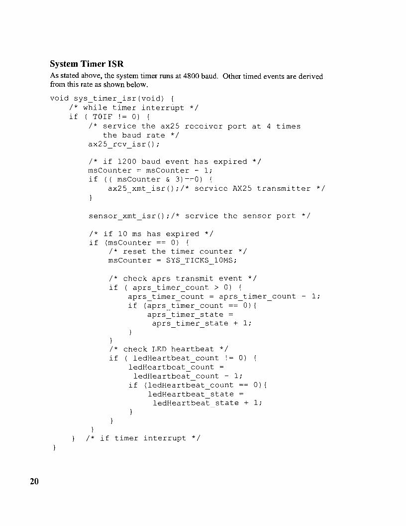
System Timer ISR As stated above, the system timer runs at 4800 baud. Other timed events are derived from this rate as shown below.
void sys timer_isr(void) { /* while timer interrupt */ if ( TOIF != 0) {
/* service the ax25 receiver port at 4 times the baud rate */
ax25 rcv_isr();
/* if 1200 baud event has expired */ msCounter = msCounter - 1; if (( msCounter & 3) ==0) {
ax25 xmt isr();/* service AX25 transmitter */
sensor xmt isr() ;/* service the sensor port */
/* if 10 ms has expired */ if (msCounter == 0) {
/* reset the timer counter */ msCounter = SYS TICKS 10MS;
/* check aprs transmit event */ if ( aprs_timer count> 0) {
aprs_timer_count = aprs_timer_count - 1; if (aprs_timer_count == 0) {
aprs timer state = aprs timer state + 1;
}
/* check LED heartbeat */ if ( ledHeartbeat_count != 0)
ledHeartbeat count = ledHeartbeat count - 1;
if (ledHeartbeat_count == 0) { ledHeartbeat state = ledHeartbeat state + 1;
}
/* if timer interrupt */
20

- - -
- -
- - -
AX.25 receiver Other implementations that I've seen for this device set a timer to go off at the center of each bit. The input bit is then sampled. Since the system timer for this design runs at 4800 baud, I chose instead to sample the input bit at each interrupt. When I detect a change in state, I count how many bit periods have expired. The system timer runs at exactly four times the AX.25 data rate, so converting to 1200 baud periods simply requires shifting the count over by two places. It is first rounded up by half a bit period.
At each state change, the number of bits received is computed. The code that does this processing is shown below.
/* count number of bit times (rounded) */ ax25 rcv num bits =
(ax25rcv_period_ctr + 2)/4; ax25rcv_period_ctr = 0;
/* if nobody wants the data */ if ( pax25_rx_state_callback == 0) {
/* don't process it */ ax25 rxisr state = AX25 RXISR IDLE; abort detected TRUE; return;
/* check for FCS */ if ( ax25_rcv_num_bits == 7) {
fcs detected = TRUE; ax25
-rxisr- state = AX25 RXISR FCS;
ax25 rx data = 0; ax25 rx bit ctr = 8; /* let them-know data is avail */ isr_ptr_increment(pax25_rx_state_callback); pax25_rx_state_callback = 0; /* they must request again */ return;
/* check for ABORT */ else if ( ax25_rcv_num_bits > 7) {
abort detected = TRUE; ax25 rxisr state = AX25 RXISR IDLE; ax25 rx data = 0; ax25 rx bit ctr = 8; /* let them-know data is avail */ isr_ptr_increment(pax25_rx_state_callback); pax25_rx_state_callback = 0;
21

- - - -
/* they must request again */ return;
for ( ax25_rcv_i=0; ax25 rcv_i < ax25 rcv num bits; ax25_rcv_i++) {
/* we have a zero optionally followed by a series of ones. This isn't initially obvious. A zero is indicated by a change in frequency. A one in indicated by no change. An interrupt occurs at each change of frequency (zero) its period is a minimum of one bit length. It will extend by one bit length for each successive 1.
*/
/* Zeros get skipped if they are stuffed or if it is the trailing zero at the end of an fcs */
/* if we should skip this bit */ if ( ( ax25_rxisr_state == AX25_RXISR_FCS) 1 1
(ax25_rxisr_state == AX25_RXISR_STUFFED) ) ax25 rxisr state AX25 RXISR RCV; continue;
}
/* otherwise shift in data */ ax25 rx data = ax25 rx data » 1; ax25 rx bit ctr = ax25 rx bit ctr - 1; /* first bit is zero, ~est are one's */ if (ax25_rcv_i != 0) {
ax25 rX_data 1= Ox80; }
/* if we received a character and someone wants it */
if ( ax25 rx bit ctr == 0 ) { /* let them know data is avail */ isr_ptr increment (pax25_rx_state_callback) ; pax25 rx state callback = 0; /* they ~ust request again */ *pax25_rx_data = ax25_rx_data; /* they get the data */ ax25 rx data = 0; ax25 rx bit ctr = 8;
22
}
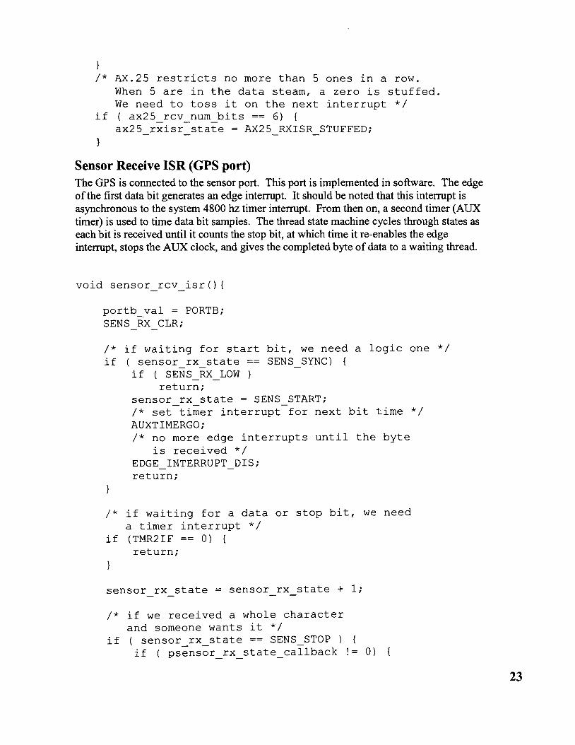
/* AX.25 restricts no more than 5 ones in a row. When 5 are in the data steam, a zero is stuffed. We need to toss it on the next interrupt */
if ( ax25_rcv_num_bits == 6) { ax25 rxisr state AX25 RXISR STUFFED;
Sensor Receive ISR (GPS port) The GPS is connected to the sensor port. This port is implemented in software. The edge ofthe first data bit generates an edge interrupt. It should be noted that this interrupt is asynchronous to the system 4800 hz timer interrupt. From then on, a second timer (AUX timer) is used to time data bit samples. The thread state machine cycles through states as each bit is received until it counts the stop bit, at which time it re-enables the edge interrupt, stops the AUX clock, and gives the completed byte of data to a waiting thread.
portb_val = PORTB; SENS RX CLR;
/* if waiting for start bit, we need a logic one */ if (sensor_rx_state SENS SYNC) {
if ( SENS_RX_LOW ) return;
sensor rx state = SENS START; /* set timer interrupt for next bit time */ AUXTIMERGO; /* no more edge interrupts until the byte
is received */ EDGE INTERRUPT DIS; return;
/* if waiting for a data or stop bit, we need a timer interrupt */
if (TMR2IF == 0) { return;
sensor rx state = sensor rx state + 1;
/* if we received a whole character and someone wants it */
if ( sensor_rx_state == SENS_STOP ) { if ( psensor_rx_state_callback != 0)
23

/* let them know data is avail */ isr ptr increment(psensor rx state callback); /* they-must request agai~ *7 psensor rx state callback = 0;
}
/* disable the auxiliary timer interrupt */ AUXTIMERSTOP; /* next time we need a zero to one transition */ /* reenable edge interrupts */ EDGE_INTERRUPT_EN; /* wait for next sync */ sensor_rx state SENS SYNC; return;
/* shift in data */ sensor_rx_data = (sensor rx data » 1); /* set timer interrupt for next bit time */ AUXTIMERCONTINUE; if (SENS_RX_LOW) {
sensor rx data sensor rx data + OX80;
return ;
Real-time Threads
Message Queues The AX.25 message frame can be built from fragments in various parts of system memory. Some parts such as station callsign can come from EEPROM, other parts such as GSP position can come from internal RAM or external RAM. Rather than collect these parts and copy them into a single contiguous block of memory, I chose to implement a queueing mechanism that includes pointers to various parts of memory. This avoids the overhead of having to copy fragments into a contiguous block. Rather than queue this block, a pointer to each fragment is queued.
Each message queue entry is a I6-bit entry, consisting of a 3-bit type indicator followed by a I3-bit data field consisting of a pointer or literal field. The following queue entries are supported:
1. Text Data- Data field points to a null-terminated string in program memory. 2. ExtRAM - Data field points to a null-terminated string in external memory. 3. RAM - Data field points to a null-terminated string in internal memory. 4. EEPROM - Data field points to a null-terminated string in EEPROM memory. 5. Literal- Data field has a single byte to transmit. 6. Begin CRC - Don't transmit anything. Initialize the global CRC value.
24

7. Transmit CRC - Data filed contains nothing. Transmit the two-byte global CRC value.
8. Transmit KISS packet - Data field points to an FESC terminated KISS packet in external memory.
Two queues are used in this software design, the AX.25 transmit queue and the computer port transmit queue. Using the above queue entries, the process of sending a mic-e encoded packet is coded as shown in the following example. Each statement queues an entry in the AX.25 transmit queue.
TRANSMITCRCBEGIN; transrnitRarnString(rnice_buf dest); transrnitEeString(CALLSIGN); transrnitEeString(PACKET_PATH); transrnitLiteral(AX25_CONTROL_FLD_UI); transrnitLiteral(AX25_PROTOCOL_ID); transrnitRarnString(rnice_buf_info); transrnitEeString(STATUS_TXT); transrnitEeString(COMMENT); TRANSMITCRC;
Time Keeping for APRS messages Various timed events need to be managed in order to comply with the APRS and AX.25 specs. These events include transmitting position information at a periodic rate and managing the packet transmission itself. This includes transmit hold-off, persistence, and time from key closure to first data byte. A timer thread is dedicated to managing these events. All of these timed events are multiples of 1Oms. The system timer ISR keeps track of lOms events. When a programmable number of periods have elapsed, the state of this thread is advanced.
GPS Receiver Thread Data bytes from the sensor port are collected by the sensor receive ISR. When a completed byte is available, it is forwarded to the GPS receiver thread. This thread processes the Recommend Minimum Specific GPS/TRANSIT Data sentence (RMC). This sentence is in a fixed format. The thread recognizes the sentence header and processes the data by counting byte position. As each field is received, it is converted to mic-e format and saved for later transmission as part of the station position packet.
APRS Receiver Thread Data bytes collected by the AX.25 receive ISR are stored in external memory by this thread. As they are received, a running CRC is computed. If the CRC indicates a valid packet, a check is done to see if an external host is connected. If an external host is attached, the record is closed and forwarded to the computer port queue for transmission as a KISS packet to that host. If a host is not connected, a check is done on the packet to
25

see if it is addressed to this station. If it is, the record is closed. If external memory has space for an additional packet, a new record is opened.
KISS Transmitter Thread Any time that a host is connected to the TNC it can send a packet. This packet is queued in external memory.
Project Status Currently, the prototype hardware is in test. A version of the software is in integration. It supports all the requirements defined in the software functional spec in the appendix. It transmits and receives packet data, receives and parses GPS sentences, logs packets, forwards packets to a host computer, and performs self-test. Significantly more test is needed before it can be distributed to the amateur community.
More work is needed in the APRS receive and KISS transmit threads. Both of these threads require a host application to run before they can be debugged.
Program space has become an issue on the target. I am at over 90% utilization. I've gone through a couple of redesign efforts to reduce code size. One of these efforts reduced code size by removing any information hiding in the design. The implementation can be scaled. As an example, self-test can be disabled by using a preprocessor directive. I used l6-bit data pointers when I started the design. This caused code generation to produce a lot of code to manage paging when accessing data. I suspect that reverting to 8-bit pointers and making use of special CCS services to access pages 2 and 3 for message queues would reduce the code size by as much as 20%.
Where to go from here Work on this project began more than 18 months ago. It has been a challenge finding time to complete the project. Considerable work has been done on the software, while work on the production board layout and fabrication has languished.
Several attempts have been made to get help with board layout, packaging, testing, and host software application. Enthusiastic volunteers have come forward, but there is no follow-through. We all have day-jobs and family responsibilities that reduce our free time. It is easy to volunteer for a project such as this, and then lose interest when the size ofthe job becomes apparent.
Work on host application has also stalled. The team member who signed up to do this assignment has vanished. This software allows the TNC to connect to a host computer and upload stored messages. It also allows downloading setup parameters and sending asynchronous packets. I'm hoping that the winter months might provide more time from the rest of the team.
Reference List • Internetworking with TCP/IP, Douglas E. Comer • AX.25 Link Access Protocol for Amateur Packet Radio
26

Appendix-1 System Functional Spec The product will be user programmable. It will either include all necessary support hardware to perfonn in-circuit programming, or will be programmable using an external device. If external hardware is required, it will cost less than $25.
Source for the product will be available for modification and upgrades. Source will be built using development tools that cost no more than $100. The availability of a C compiler is highly desirable, but not a requirement.
The product will run on 12v(nominal) external power, 1 amp max. An internal replaceable backup battery may be needed. The product will be fuse protected.
The product will provide a bi-directional interface to an external radio at 1200 baud using AX.25 audio tones. It will provide the ability for the software to detect a busy channel.
A method will be provided to sense the microphone PTT line. The product will be capable of detecting key closure of the microphone.
The product will be capable of servicing all interface ports simultaneously. Full duplex operation will be supported.
The product will display three indicators for power, PTT, and channel busy.
The product will accept data from an external device such as a GPS or weather station. Data will be received serially using the RS232 protocol at baud rates between 1200 and 4800 baud. The product will be capable of transmitting to the same device at the same baud rates.
Support will be provided for the Tripmate GPS. This support includes jumpers to supply DTR and to wrap tx to rx. A jumper will be provided to supply 5v power or 12v power to pin-9.
The product will interface with an external serial tenninal device using a bi-directional RS-232 port running at 9600baud. Hardware flow control (DTR only) will be provided to throttle the external device. This device will be a tenninal, printer, or computer device.
The product will have the capacity to save non-volatile parameters. This storage area will be sufficient to save call-sign, path, station icon, position data (for fixed station), position comment, status text, transmit method (key, periodic), and transmit interval. A minimum of eight bytes of application specific parameters will be also available.
A method will be identified to set time and non-volatile parameters using the tenninal port.
27

The product will have the capacity to internally record a minimum of four APRS formatted messages for later retrieval.
A method will be identified to display recorded messages using the terminal port.
Appendix-2 Software Functional Spec
Overview This document defines the software functional requirements for the PIC-E-II APRS TNC.
The PIC-E-II will function as a stand-alone APRS station. It will operate in the following basis modes:
1. Startup - in this mode of operation, the PIC-E-II will print out a startup banner including software version. It will then enter the system default mode of operation (see configuration parameters).
2. Idle - in this mode of operation, the PIC-E-II will monitor the terminal port for user commands.
3. Self-test - in this mode of operation, the PIC-E-II will test external memory and peripheral interfaces.
4. KISS - in this mode ofoperation, the PIC-E-II will send and receive packets to a host system using the KISS protocol.
5. APRS - in this mode of operation, the PIC-E-II will transmit position reports at a programmable rate. It will receive and log messages that are addressed for the station.
6. Program - in this mode ofoperation, the PIC-E-II will accept and load a new Image.
7. Update - in this mode ofoperation, the PIC-E-I1 will accept and load configuration parameters.
8. Monitor - in this mode ofoperation, the PIC-E-II will provide a user interface to allow examining RAM, ROM, and external RAM.
9. NY-Load - in this mode of operation, the PIC-E-II will accept non-volatile parameters.
Note: Due to program memory size constraints, it may not be possible to support all these modes in one load image. At this point, it looks possible.
Idle During idle, the PIC-E-I1 will monitor the terminal for a user command. User commands will consist of one-byte codes defined as follows:
1. T - Test 2. K- KISS 3. A-APRS 4. N - Parameter Update
28
5. M-Monitor 6. E - Echo
When a command is recognized, the system will exit idle and enter the commanded mode. If a command is not recognized, a warning message will be displayed and the system will remain in idle. An example warning message is shown below.
??? [TKANME]
Self Test Self-test mode will load a test pattern into external memory and verify contents. It will forward characters received on the terminal port to the sensor port, implementing hardware flow control to prevent data loss. It will send a test pattern to the modem port to allow level adjustment. Self-test mode will terminate when an escape character is received on the terminal port. When received, the system will enter the idle mode.
KISS During Kiss mode, the PIC-E-II will read packets detected on the modem port. It will compute a CRC on the received packet and compare it with the packet FCS. If the CRCs do not match, the packet will be discarded. Otherwise, it will examine the destination address for a match with station ID. If a match is found, the packet will be formatted as a KISS packet and forwarded to the host system via the terminal port. If the packet is not addressed for this station, the first entry in the path will be examined for a match with the station alias. If a match is detected, the packet will be reformatted and retransmitted. Packets received from the host will be transmitted through the modem port. Kiss mode will terminate when directed by a return command packet from the host or when an escape character is received on the terminal port outside a packet. When received, the system will enter the idle mode.
In addition to data packets, the following command packets will be recognized and processed by the system.
1. TX delay 2. Persistence 3. Slot time 4. TX tail 5. Full Duplex 6. Set Hardware 7. Return
Note: Storage will be provided for buffers with a maximum size of 1024 bytes. This will support KISS packets of a length of 1022 bytes max. Two transmit and two received buffers are planned. Hardware follow control is supported to control data flow from the host to the target. Support is not provided for flow control from the target to the host.
APRS While in APRS mode of operation, the system will operate as either a mobile or fixed station. As a mobile station, it will receive position reports from an external NMEA-183
29

compliant GPS sensor at 4800 baud. As a fixed station, it will use a fixed position defined in system configuration parameters. It will format and send a position report at a programmable interval. This message will use the mic-e format. It will read packets detected on the modem port. It will compute a CRC on the received packet and compare it with the packet FCS. If the CRCs do not match or if the packet is too short, the packet will be discarded. Otherwise, it will examine the destination address for a match with station ID. If a match is found, the packet will be logged in memory for later retrieval by the host system. An external beeper will briefly sound to indicate data reception. A front-panel lamp will blink to indicate the number or stored messages. A notification will be sent to the host system (optionally connected) in the form of a single byte code byte (Oxll). An auto-reply message will be sent. If the packet is not addressed for this station and the beacon mode is enabled, the first entry in the path will be examined for a match with the station alias. If a match is detected, the packet will be reformatted and retransmitted. When a query request is received from the terminal port, stored packets will be forwarded to the host system using the KISS protocol. A query request will consist of a single byte (Oxll). When a query request is received, the system will send the oldest stored packet to the host and then delete it. If additional packets are stored, the packet will be followed by another ready byte code (Oxll). Ifno packets are stored, an empty byte code will be returned (OX13). Up to twelve (tbr) packets will be stored, each with a maximum length of 256 bytes. When used as a mobile station, the system position received by the GPS can be saved as a configuration parameter. When an'S' character is received on the serial port in mobile operation, the current position will be saved. The current position can be queried by the host using a I\E (Ox05) character. When received on the terminal port, a copy of the last GPS RMC sentence will be sent to the host. During APRS operation packets can be sent from the host using the KISS message format. No formatting or validation will be performed by the TNC. The message will be sent out as soon as a time slot is available.
APRS mode will terminate when an escape character is received on the terminal port. When received, the system will enter the idle mode.
(Future enhancements) Various sensors other than a simple GPS could be connected to the PIC-E-II, including integrated instruments (NMEA instruments that include weather data) barometric pressure sensors and weather stations.
(Future enhancement) Sending the position ofreceived packets out to the GPS using WPL NMEA sentence.
(Future enhancement) Sending received NMEA payload data out the terminal port for remote processing.
Note: It is possible to recover stored packets after re-powering. I may add this feature. The FRAM chip that we selected has 8Kbytes of non volatile storage. 4 K is assigned to KISS packet buffers and the remaining 4 K is assigned to APRS packet storage. These modes are mutually exclusive, so some savings could be achieved by combining these buffers.
30

Update The Update mode of operation will allow system configuration parameters stored in nonvolatile memory to be updated. During an update, the host system will send these parameters to the PIC-E-II using a hex record format. When the system enters this state, an 'N' will echo on the terminal port. Subsequent hex characters will not echo. The following configuration parameters will be stored. (Consult eeprom.h for data definitions.)
1. Callsign 2. Position Lat 3. Position Lon 4. Status Text 5. Group Code 6. Packet Path 7. Transmit Method 8. Position Method 9. Symbol Code 10. Symbol Table ill 11. Transmit Rate 12. My Alias 13. Mode (Mobile, Fixed) 14. TX delay 15. Persistence 16. Slot time 17. TX tail 18. Full Duplex 19. Default system mode (T,K,A,M) 20. Beep (Mine, All, None) 21. Beacon (On, Off) 22. Checksum
Update mode will terminate when an escape character is received on the terminal port. When received, the system will enter the idle mode.
(Future enhancement) A provision to upload configuration parameters to a host system might be useful.
Monitor The monitor mode will allow the user to examine internal and external memory. The system will accept monitor commands from the terminal input. Commands will consist of a single command character followed by a hex number terminated by 'CR'. Commands recognized are listed below.
1. Display RAM 'D' 2. Display EEPROM 'E' 3. Display External Memory 'X'
31
If a command is not recognized, a question mark will be displayed. Monitor mode will terminate when an escape character is received on the terminal port. When received, the system will enter the idle mode.
Echo This mode will allow testing the sensor port. It is also useful to verify the proper connection of a GPS. Characters received on the console port will echo to the sensor port. Characters on the sensor port will echo on the console port.
Loader Program mode will be entered when the system powers up with a program jumper in place. This code will reside on the last page of program memory, space normally assigned to the ICD. It will be built as a separate image. When entered, the system will display a startup banner including the version number of the loader program. It will accept a program file from the system terminal port using an S-record format. It will load this image into program space, protecting its own address space and the reset vector from being overwritten. Program mode will terminate when a load image is received. It will then boot the loaded image.
NB: Kits will be shipped with the loader image burned into flash.
Support Software The following support software will be required for system operation.
APRS Host Software This software will allow a host computer system to connect to the PIC-E-II to allow examining stored messages and to set configuration parameters. Received packets should be parsed and displayed in an intelligent fashion. A clear display should be provided to set configuration parameters. This software will be described in its own functional spec. Suggested host platforms include Windows, CE, Palm, and Unix variants.
Host Loader This software will allow a user to re-flash the program image in the PIC-E-II. A simple terminal program such as Hyperterminal or tip might be sufficient to support this feature. Some sensible method to set configuration parameters is needed however. If this APRS host software is not provided in the initial release, the loader will need to support this. Gary's application needs a method to load configuration parameters too, and his software doesn't use the APRS host software. Some coordination is needed here.
32
Related Documents