University of Calgary PRISM: University of Calgary's Digital Repository Graduate Studies The Vault: Electronic Theses and Dissertations 2021-01-08 Physical Layer Security Analysis of mmWave Ad Hoc Networks Darwesh, Ahmed Fathy Mohamed Helmy Darwesh, A. F. M. H. (2021). Physical Layer Security Analysis of mmWave Ad Hoc Networks (Unpublished doctoral thesis). University of Calgary, Calgary, AB. http://hdl.handle.net/1880/113013 doctoral thesis University of Calgary graduate students retain copyright ownership and moral rights for their thesis. You may use this material in any way that is permitted by the Copyright Act or through licensing that has been assigned to the document. For uses that are not allowable under copyright legislation or licensing, you are required to seek permission. Downloaded from PRISM: https://prism.ucalgary.ca

Welcome message from author
This document is posted to help you gain knowledge. Please leave a comment to let me know what you think about it! Share it to your friends and learn new things together.
Transcript
University of Calgary
PRISM: University of Calgary's Digital Repository
Graduate Studies The Vault: Electronic Theses and Dissertations
2021-01-08
Physical Layer Security Analysis of mmWave Ad Hoc
Networks
Darwesh, Ahmed Fathy Mohamed Helmy
Darwesh, A. F. M. H. (2021). Physical Layer Security Analysis of mmWave Ad Hoc Networks
(Unpublished doctoral thesis). University of Calgary, Calgary, AB.
http://hdl.handle.net/1880/113013
doctoral thesis
University of Calgary graduate students retain copyright ownership and moral rights for their
thesis. You may use this material in any way that is permitted by the Copyright Act or through
licensing that has been assigned to the document. For uses that are not allowable under
copyright legislation or licensing, you are required to seek permission.
Downloaded from PRISM: https://prism.ucalgary.ca
UNIVERSITY OF CALGARY
Physical Layer Security Analysis of mmWave Ad Hoc Networks
by
Ahmed Fathy Mohamed Helmy Darwesh
A THESIS
SUBMITTED TO THE FACULTY OF GRADUATE STUDIES
IN PARTIAL FULFILLMENT OF THE REQUIREMENTS FOR THE
DEGREE OF DOCTOR OF PHILOSOPHY
GRADUATE PROGRAM IN ELECTRICAL AND COMPUTER ENGINEERING
CALGARY, ALBERTA
JANUARY, 2021
© Ahmed Fathy Mohamed Helmy Darwesh 2021
Abstract
In this thesis, the physical layer security analysis of millimeter wave (mmWave) ad hoc
networks with multi-array antenna transmission is studied in the presence of different eaves-
droppers’ attacks. By exploiting the tools of stochastic geometry, the average achievable
secrecy rate is derived in the presence of non-colluding and colluding passive eavesdroppers,
taking into consideration the impact of blockages, directional beamforming, and Nakagami-m
fading. Moreover, the mathematical expressions are derived in the presence of passive/active
eavesdroppers for the secrecy performance metrics including connection outage probability,
secrecy outage probability, and average achievable secrecy rate. The passive/active eaves-
droppers operate in the full-duplex mode which can intercept the message signal and transmit
a jamming signal simultaneously. Further, to establish secure transmission against the high
eavesdroppers’ capabilities, a simple yet two effective artificial noise (AN) transmission with
either sectoring (Tx-AN technique) or null space linear precoder (Tx-AN/LP technique) is
applied at the transmitting nodes. For both approaches, the total transmit power is divided
into message transmit power and AN transmit power. In the Tx-AN technique, the main lobe
beam of the AN array antenna of each transmitting node is not directed to its corresponding
receiver and steered everywhere else to degrade the received data rate at the eavesdroppers.
On the other hand, the Tx-AN/LP technique injects the AN into the null space of the le-
gitimate receiver’s channel with perfect knowledge of the channel state information between
the typical transmitter and its receiver. Numerical and simulation results show that using
the Tx-AN technique achieves up to three-fold improvement of the average secrecy rate over
that without in the high power transmit regime (> 20 dBm). Besides, in the presence of
passive/active eavesdroppers, the Tx-AN/LP technique is very effective in mitigating the
effect of the jamming signals, achieving up to two-fold improvement in the average secrecy
rate over that without. The results demonstrate the secrecy robustness of the Tx-AN and
ii
Tx-AN/LP techniques against increasing eavesdroppers’ intensity. Finally, this thesis proves
that the Tx-AN or Tx-AN/LP techniques are useful to improve the secrecy performance of
the interference-limited mmWave ad hoc networks under various eavesdropping strategies.

Acknowledgements
Firstly, I would like to start off by thanking God for his blessings throughout my research
work and for the fulfillment of this doctoral endeavor.
I am highly indebted to my supervisor, Prof. Abraham Fapojuwo, for his guidance
and constant supervision as well as providing necessary and helpful information during my
study. I would like to express my gratitude to Prof. Fapojuwo for the fruitful and enjoyable
experience of learning from him.
I owe infinite gratitude to my parent, who are thousands of miles away in my home
country, my wife, Aliaa, my father in law, my mother in law, my Kids, Fatma, Abdelrahman,
and Adam, my siblings, without their help, this success could never be completed.
I would like to thank my best friends Ahmed Bendary, Ahmed Bayram, and Ashraf
Kamal for supporting me.
Last but most importantly, I would like to thank my colleague, Dr. Okechukwu Ochia,
and the rest of my current and past colleagues at the Wireless Networking Research Labo-
ratory.
iv

Table of Contents
Abstract . . . . . . . . . . . . . . . . . . . . . . . . . . . . . . . . . . . . . . . . iiAcknowledgements . . . . . . . . . . . . . . . . . . . . . . . . . . . . . . . . . . ivTable of Contents . . . . . . . . . . . . . . . . . . . . . . . . . . . . . . . . . . . . vList of Tables . . . . . . . . . . . . . . . . . . . . . . . . . . . . . . . . . . . . . . viiList of Figures . . . . . . . . . . . . . . . . . . . . . . . . . . . . . . . . . . . . . . viiiList of Symbols . . . . . . . . . . . . . . . . . . . . . . . . . . . . . . . . . . . . . x1 Introduction . . . . . . . . . . . . . . . . . . . . . . . . . . . . . . . . . . . . 11.1 Context and Background . . . . . . . . . . . . . . . . . . . . . . . . . . . . 1
1.1.1 Types of Threats in Physical Layer Wireless Communication . . . . . 31.1.2 The PLS Approach . . . . . . . . . . . . . . . . . . . . . . . . . . . . 51.1.3 Performance Metrics of the PLS . . . . . . . . . . . . . . . . . . . . . 61.1.4 PLS in Millimeter-wave Bands . . . . . . . . . . . . . . . . . . . . . . 81.1.5 PLS in MmWave Ad Hoc Networks . . . . . . . . . . . . . . . . . . . 8
1.2 Motivation of the Thesis . . . . . . . . . . . . . . . . . . . . . . . . . . . . . 91.3 Problem Statement and Thesis Objectives . . . . . . . . . . . . . . . . . . . 101.4 Contributions and Outline . . . . . . . . . . . . . . . . . . . . . . . . . . . . 122 Literature Review . . . . . . . . . . . . . . . . . . . . . . . . . . . . . . . . . 152.1 Physical Layer Security Survey . . . . . . . . . . . . . . . . . . . . . . . . . 152.2 Millimeter-wave Channel Characteristics . . . . . . . . . . . . . . . . . . . . 172.3 Critical Assessment of the Existing Literature . . . . . . . . . . . . . . . . . 17
2.3.1 PLS in Microwave Ad Hoc Networks . . . . . . . . . . . . . . . . . . 182.3.2 PLS in the Presence of Active Eavesdroppers . . . . . . . . . . . . . . 192.3.3 PLS in MmWave Wireless Networks . . . . . . . . . . . . . . . . . . . 202.3.4 PLS in MmWave Ad Hoc Networks . . . . . . . . . . . . . . . . . . . 22
2.4 Thesis Work in the Context of Existing Research . . . . . . . . . . . . . . . 232.5 Chapter Summary . . . . . . . . . . . . . . . . . . . . . . . . . . . . . . . . 243 Physical Layer Security in the Presence of Passive Eavesdroppers . . . . . . 263.1 Introduction . . . . . . . . . . . . . . . . . . . . . . . . . . . . . . . . . . . . 263.2 System Model . . . . . . . . . . . . . . . . . . . . . . . . . . . . . . . . . . . 27
3.2.1 Network Model . . . . . . . . . . . . . . . . . . . . . . . . . . . . . . 273.2.2 MmWave Model . . . . . . . . . . . . . . . . . . . . . . . . . . . . . . 283.2.3 Simplified LoS MmWave Ball Model . . . . . . . . . . . . . . . . . . 313.2.4 Passive Eavesdroppers Interception Strategies . . . . . . . . . . . . . 31
3.3 Analysis of Average Achievable Secrecy Rate under Non-Colluding Eavesdrop-pers . . . . . . . . . . . . . . . . . . . . . . . . . . . . . . . . . . . . . . . . 34
3.4 Analysis of Average Achievable Secrecy Rate under Colluding Eavesdroppers 383.5 Numerical Results and Discussion . . . . . . . . . . . . . . . . . . . . . . . . 403.6 Chapter Summary . . . . . . . . . . . . . . . . . . . . . . . . . . . . . . . . 444 Physical Layer Security in the Presence of Passive/Active Eavesdroppers . . 464.1 Introduction . . . . . . . . . . . . . . . . . . . . . . . . . . . . . . . . . . . . 464.2 System Model . . . . . . . . . . . . . . . . . . . . . . . . . . . . . . . . . . . 474.3 Analysis of Connection Outage Probability under Passive/Active Eavesdroppers 50
v
4.3.1 Analysis for Noise-Limited Networks . . . . . . . . . . . . . . . . . . 514.3.2 Analysis for PE Eavesdroppers . . . . . . . . . . . . . . . . . . . . . 52
4.4 Analysis of Secrecy Outage Probability under Passive/Active Eavesdroppers 524.5 Analysis of Average Achievable Secrecy Rate under Passive/Active Eaves-
droppers . . . . . . . . . . . . . . . . . . . . . . . . . . . . . . . . . . . . . . 544.6 Numerical Results and Discussion . . . . . . . . . . . . . . . . . . . . . . . . 554.7 Chapter Summary . . . . . . . . . . . . . . . . . . . . . . . . . . . . . . . . 605 Physical Layer Security under the Tx-AN and Tx-AN/LP Techniques . . . 625.1 Introduction . . . . . . . . . . . . . . . . . . . . . . . . . . . . . . . . . . . . 625.2 Secrecy Performance with Tx-AN Technique . . . . . . . . . . . . . . . . . . 63
5.2.1 Analysis of Average Achievable Secrecy Rate with Tx-AN Techniqueunder Non-Colluding Eavesdroppers . . . . . . . . . . . . . . . . . . . 64
5.2.2 Analysis of Average Achievable Secrecy Rate with Tx-AN Techniqueunder Colluding Eavesdroppers . . . . . . . . . . . . . . . . . . . . . 69
5.3 Secrecy Performance with Tx-AN/LP Technique . . . . . . . . . . . . . . . . 725.3.1 Analysis of Average Achievable Secrecy Rate with Tx-AN/LP Tech-
nique under Passive Colluding Eavesdroppers . . . . . . . . . . . . . 725.3.2 Analysis of Secrecy Outage Probability with Tx-AN/LP Technique
under Passive/Active Eavesdroppers . . . . . . . . . . . . . . . . . . 755.3.3 Analysis of Average Achievable Secrecy Rate with Tx-AN/LP Tech-
nique under Passive/Active Eavesdroppers . . . . . . . . . . . . . . . 765.4 Numerical Results and Discussion . . . . . . . . . . . . . . . . . . . . . . . . 775.5 Chapter Summary . . . . . . . . . . . . . . . . . . . . . . . . . . . . . . . . 896 Conclusions and Future Work . . . . . . . . . . . . . . . . . . . . . . . . . . 906.1 Thesis Summary and Conclusions . . . . . . . . . . . . . . . . . . . . . . . . 906.2 Engineering Significance of Thesis Findings . . . . . . . . . . . . . . . . . . . 926.3 Thesis Limitations and Suggestions for Future Work . . . . . . . . . . . . . . 93
6.3.1 Limitations of the Thesis . . . . . . . . . . . . . . . . . . . . . . . . . 936.3.2 Future Work . . . . . . . . . . . . . . . . . . . . . . . . . . . . . . . . 94
Bibliography . . . . . . . . . . . . . . . . . . . . . . . . . . . . . . . . . . . . . . 96A Proof of Lemma 3.1 . . . . . . . . . . . . . . . . . . . . . . . . . . . . . . . . 103B Proof of Lemma 3.2 . . . . . . . . . . . . . . . . . . . . . . . . . . . . . . . . 105C Proof of Lemma 4.1 . . . . . . . . . . . . . . . . . . . . . . . . . . . . . . . . 106D Proof of Lemma 4.2 . . . . . . . . . . . . . . . . . . . . . . . . . . . . . . . . 108E Proof of Lemma 4.3 . . . . . . . . . . . . . . . . . . . . . . . . . . . . . . . . 109F Proof of Lemma 5.1 . . . . . . . . . . . . . . . . . . . . . . . . . . . . . . . . 111G Proof of Lemma 5.2 . . . . . . . . . . . . . . . . . . . . . . . . . . . . . . . . 112H Proof of Lemma 5.5 . . . . . . . . . . . . . . . . . . . . . . . . . . . . . . . . 114I Proof of Lemma 5.6 . . . . . . . . . . . . . . . . . . . . . . . . . . . . . . . . 115J Proof of Lemma 5.8 . . . . . . . . . . . . . . . . . . . . . . . . . . . . . . . . 116
vi
List of Tables
1.1 Summary of Main Contributions of Thesis. . . . . . . . . . . . . . . . . . . . 14
2.1 Comparison of Main Features and Capabilities of Proposed PLS Analysis withExisting PLS Analysis in Literature . . . . . . . . . . . . . . . . . . . . . . . 25
3.1 Antenna parameters of a single-array UPA antenna, where n is the number ofantenna elements in an array. . . . . . . . . . . . . . . . . . . . . . . . . . . 31
3.2 Summary of values of system parameters. . . . . . . . . . . . . . . . . . . . . 41
4.1 Summary of values of system parameters. . . . . . . . . . . . . . . . . . . . . 56
5.1 Summary of values of system parameters. . . . . . . . . . . . . . . . . . . . . 77
vii
List of Figures and Illustrations
1.1 Simplest model of the PLS problem. . . . . . . . . . . . . . . . . . . . . . . 21.2 The difference between cryptography and PLS approach . . . . . . . . . . . 6
3.1 Network topology showing Tx-Rx pairs with a multi-array antenna (i.e., Nt
single-array antennas) for transmission and one single-array antenna for re-ception. The (desired Tx-Rx receiver) pair is formed by (Alice - Bob) pair.In addition, a group of eavesdroppers colludes and intercepts Alice’s messagesignal at Main-Eve. . . . . . . . . . . . . . . . . . . . . . . . . . . . . . . . . 28
3.2 The pdf of the distance between Alice and Eve given that Alice is interceptedby an LoS or NLoS eavesdropper fj(z), j ∈ L,N, parameterized by theeavesdroppers’ intensity λe. . . . . . . . . . . . . . . . . . . . . . . . . . . . 33
3.3 Average achievable secrecy rate vs. Pt (λe = 0.00005/km2). . . . . . . . . . . 413.4 Average achievable secrecy rate vs. λe (Pt = 30 dBm). . . . . . . . . . . . . 423.5 Average achievable secrecy rate vs. Pt (λe = 0.00005/km2). . . . . . . . . . . 433.6 Average achievable secrecy rate vs. Pt and λe (λB = 0.00005/km2). . . . . . 443.7 Average achievable secrecy rate vs. λB and λe (Pt = 30 dBm). . . . . . . . . 45
4.1 The distances between Alice, Bob, and the nearest eavesdropper (Eve). . . . 484.2 Connection outage probability vs. Threshold SINR T0 (λB = 0.0001/km2). . 564.3 Secrecy outage probability vs. Threshold secrecy rate J0 (λe = 0.0001/km2). 574.4 Average achievable secrecy rate vs. Total transmit power Pt (λe = 0.0001/km2,
noise-limited network). . . . . . . . . . . . . . . . . . . . . . . . . . . . . . . 574.5 Average achievable secrecy rate vs. Total transmit power Pt (λB = 0.0001/km2,
interference-limited network). . . . . . . . . . . . . . . . . . . . . . . . . . . 584.6 Secrecy outage probability vs. Eavesdroppers’ intensity λe (λB = 0.0001/km2). 594.7 Average achievable secrecy rate vs. Eavesdroppers’ intensity (λB = 0.0001/km2). 60
5.1 The implementation of the Tx-AN technique in a mmWave ad hoc networkwith multi-array antenna transmission in the presence of passive eavesdroppers. 65
5.2 Average achievable secrecy rate vs. Pt (λe = 0.00005/km2). . . . . . . . . . . 785.3 Average achievable secrecy rate vs. λe (Pt = 30 dBm, λB = 0.00005/km2). . 785.4 Average achievable secrecy rate vs. Pt and λe (λB = 0.00005/km2). . . . . . 795.5 Average achievable secrecy rate vs. λB (Pt = 30 dBm, λe = 0.00005/km2). . 805.6 Average achievable secrecy rate vs. λB and λe (Pt = 30 dBm). . . . . . . . . 805.7 AN power fraction for maximum average achievable secrecy rate ς vs. Pt
(λB = λe = 0.00005/km2). . . . . . . . . . . . . . . . . . . . . . . . . . . . . 825.8 Average achievable secrecy rate vs. total transmit power with and without
Tx-AN/LP technique, for different number of antenna elements per array atthe transmitting nodes nt. . . . . . . . . . . . . . . . . . . . . . . . . . . . . 83
5.9 Average achievable secrecy rate vs. eavesdroppers’ intensity with and withoutTx-AN/LP technique, for different number of antenna elements per array atthe transmitting nodes nt and Pt = 30 dBm. . . . . . . . . . . . . . . . . . . 83
viii
5.10 Average achievable secrecy rate vs. interferers’ intensity with and withoutTx-AN/LP technique, for different number of antenna elements per array atthe transmitting nodes nt and Pt = 30 dBm. . . . . . . . . . . . . . . . . . . 84
5.11 The optimum AN power fraction vs. the total transmit power with Tx-AN/LPtechnique, for different number of antenna elements per array at the trans-mitting nodes nt. . . . . . . . . . . . . . . . . . . . . . . . . . . . . . . . . . 85
5.12 Secrecy outage probability vs. Threshold secrecy rate J0 (λB = 0.0001/km2). 865.13 Average achievable secrecy rate vs. Total transmit power Pt (λB = 0.0001/km2,
interference-limited network). . . . . . . . . . . . . . . . . . . . . . . . . . . 875.14 Secrecy outage probability vs. Eavesdroppers’ intensity λe (λB = 0.0001/km2). 885.15 Average achievable secrecy rate vs. Eavesdroppers’ intensity (λB = 0.0001/km2). 88
ix

List of Symbols, Abbreviations and Nomenclature
Symbol Definition
PLS Physical layer security
Tx-Rx Transmitter-receiver
CSI Channel state information
CSIT Channel state information at transmitter
FD Full-duplex
SINR Signal-to-interference-plus-noise ratio
SNR Signal-to-noise ratio
SANR Signal-to-AN-plus-noise ratio
mmWave Millimeter wave
GHz Gigahertz
LoS Line-of-sight
NLoS Non-LoS
AN Artificial noise
PPP Poisson point process
UPA Uniform planar array
ULA Uniform Linear array
MRT Maximum ratio transmitting
MIMO Multiple-input multiple-output
MISO Multiple-input single-output
TR-BF Transmit and receive beamforming
MRC Maximal ratio combining
ΦB PPP of interferers
Φe PPP of eavesdroppers
x
λB Intensity of interferers
λe Intensity of eavesdroppers
Pt Total transmit power
P t Transmit power per array antenna
Nt Number of total transmit single-array antennas
Ns Number of message transmit single-array antennas
Na Number of AN transmit single-array antennas
nt Number of antenna elements per array antenna for total transmit signal
ns Number of antenna elements per array antenna for message transmit signal
na Number of antenna elements per array antenna for AN transmit signal
Θ Main-lobe beamwidth of desired transmitter (Alice)/interferer i array
antenna
θ Main-lobe beamwidth of desired receiver (Bob) array antenna
ϑ Main-lobe beamwidth of eavesdropper e array antenna
ro Distance between Alice and Bob
re Distance between Alice and Eve
ra Distance between P/AE and Bob
GtM Main-lobe gain of desired transmitter (Alice)/interferer i array antenna
GuM Main-lobe gain of desired receiver (Bob) array antenna
GeM Main-lobe gain of eavesdropper e array antenna
Gtm Side-lobe gain of desired transmitter (Alice)/interferer i array antenna
Gum Side-lobe gain of desired receiver (Bob) array antenna
Gem Side-lobe gain of eavesdropper e array antenna
Gi Effective antenna gain seen by Bob from each interferer i ∈ ΦB
Ge Effective antenna gain seen by each eavesdropper from Alice/interferer i
Ga Effective antenna gain seen by Bob from the transmit antenna of P/AE
xi
βlw Probability that the effective antenna gain GtlGuw occurs, l, w ∈ M,m
µlw Probability that the effective antenna gain GtlGew occurs, l, w ∈ M,m
γlw Probability that the effective antenna gain Gel Guw occurs, l, w ∈ M,m
αL Path loss exponent for LoS link
αN Path loss exponent for NLoS link
ζL(r) Probability of a communication link being LoS
ζN(r) Probability of a communication link being NLoS
L(r) Path loss at a distance r from the transmitter
ε Path loss intercept constant
fc Operating frequency
c Speed of light
` Reference distance
$ Blockages constant
ς AN power fraction
h Nakagami-m random variable
h2 Gamma distributed random variable
κL Gamma shape parameter for LoS
κN Gamma shape parameter for NLoS
RL Radius of LoS region
fj(z) Pdf of the distance between Alice and Eve in Φje, j ∈ L,N
fL(z) Pdf of the distance between Alice and LoS Eve in ΦLe
Dj Probability that Alice is intercepted by an eavesdropper in Φje
Pj(z) Conditional pdf of the distance from the nearest eavesdropper to Alice
ξu SINR received at Bob
ξua SINR received at Bob under P/AE
ξu SINR at Bob with Tx-AN technique under non-colluding eavesdroppers
xii

ξcu SINR at Bob with Tx-AN technique under colluding eavesdroppers
ξ∗u SINR at Bob with Tx-AN/LP technique under P/AE eavesdroppers
ξe SNR received at Eve
ξce SNR received at Main-Eve
ξea SNR received at P/AE
ξe SANR received at Eve with Tx-AN technique
ξce SANR received at Main-Eve with Tx-AN technique
ξ∗e SANR received at P/AE with Tx-AN/LP technique
σu Thermal noise power at Bob
σe Thermal noise power at Eve
T0 SINR threshold
J0 Secrecy rate threshold
RS Average achievable secrecy rate under non-colluding eavesdroppers
RcS Average achievable secrecy rate under colluding eavesdroppers
RSa Average achievable secrecy rate under P/AE
RS Average secrecy rate with Tx-AN technique under non-colluding
eavesdroppers
RcS Average secrecy rate with Tx-AN technique under colluding
eavesdroppers
R∗Sa Average secrecy rate with Tx-AN/LP technique under P/AE
Ru Average achievable rate at Bob
Rua Average achievable rate at Bob under P/AE
Ru Average achievable rate at Bob with Tx-AN Technique
R∗u Average achievable rate at Bob with Tx-AN/LP Technique
Re Average achievable rate at Eve
Rce Average achievable rate at Main-Eve
xiii
Rea Average achievable rate at P/AE
Re Average achievable rate at Eve with Tx-AN Technique
Rce Average achievable rate at Main-Eve with Tx-AN Technique
R∗e Average achievable rate at P/AE with Tx-AN/LP Technique
Cout Connection outage probability
CNout Connection outage probability in noise-limited network
Cpout Connection outage probability under PE
Sout Secrecy outage probability
x Bold lower-case letters denotes vectors
X Bold upper-case letters denotes matrices
||x||2 Squared Euclidean norm of the vector x
IN Identity matrix of a size N
|A| Determinant of a matrix A
x ∼ Γ(κ, 1/κ) Gamma-distributed random variable x with shape κ and scale 1/κ
[g]+ Denotes maxg, 0
E[x] Expectation of a random variable x
E[e−ys] Laplace transform of y
2F1
(a, b; c; z) Gauss hypergeometric function
F1
(a, b1, b2; c;x, y) Appell hypergeometric function of two variables x and y
t Transmitting node
u Legitimate receiver node
e Eavesdropper node
’’ Signify the analysis under Tx-AN techniques
’∗’ Signify the analysis under Tx-AN/LP techniques
xiv
Chapter 1
Introduction
1.1 Context and Background
In recent years, the physical layer security (PLS) attracts rapid interest due to low computa-
tional power and ease of implementation using signal processing, communication, and coding
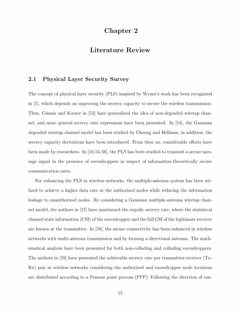
techniques. The simplest way to describe the physical layer problem is depicted in Figure
1.2. This model consists of three main nodes which are the authorized transmitter (Alice),
the legitimate receiver (Bob), and the illegitimate receiver (Eve). The frequent scenario is
that Alice encodes a useful message and transmits it to Bob. At the same time, Eve tries
to intercept this message and decode it via his channel. The main task for Alice beside
transmitting the message is to ensure that it will be secured from any attack. To achieve
that, Alice must use some transmission techniques which exploit the channel characteristics,
dispersion, interference, and fading. Furthermore, it is considered that the legitimate and
illegitimate channels are independent and there is not any correlation between them. Some
special cases assume that there is a correlation between the two channels when the distance
between Bob and Eve is so close [1–3].
The first investigation of the principle of PLS has been presented in [4] to measure the
secrecy capacity. The pioneering work on PLS has been proposed in [5]. In this work, Wyner
proved that the transmitter-receiver (Tx-Rx) pairs do not need a secret key if the channel
between them is better than the channel between Alice and Eve. However, this assumption is
not practical because the channel conditions between Alice and Bob, and between Alice and
Eve cannot be guaranteed due to the random location of the nodes and random locations of
obstacles. Consequently, it is worth defining the channel state information (CSI) in wireless
1
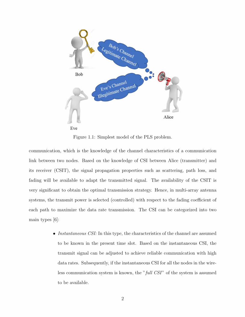
Figure 1.1: Simplest model of the PLS problem.
communication, which is the knowledge of the channel characteristics of a communication
link between two nodes. Based on the knowledge of CSI between Alice (transmitter) and
its receiver (CSIT), the signal propagation properties such as scattering, path loss, and
fading will be available to adapt the transmitted signal. The availability of the CSIT is
very significant to obtain the optimal transmission strategy. Hence, in multi-array antenna
systems, the transmit power is selected (controlled) with respect to the fading coefficient of
each path to maximize the data rate transmission. The CSI can be categorized into two
main types [6]:
• Instantaneous CSI: In this type, the characteristics of the channel are assumed
to be known in the present time slot. Based on the instantaneous CSI, the
transmit signal can be adjusted to achieve reliable communication with high
data rates. Subsequently, if the instantaneous CSI for all the nodes in the wire-
less communication system is known, the ”full CSI ” of the system is assumed
to be available.
2
• Statistical CSI: The statistical channel conditions are exploited when it is diffi-
cult to get the current channel conditions i.e., ”instantaneous CSI”. Similarly,
the statistical information of the channel is utilized to obtain higher data rate
transmission. The expression ”partial CSI ” is used when the statistical CSI
of some nodes in the wireless network is known and the instantaneous CSI is
available for the rest nodes.
Note that the CSI is classified also to ”perfect CSI” and ”imperfect CSI” based on the
absence and presence of channel estimation error, respectively.
1.1.1 Types of Threats in Physical Layer Wireless Communication
This study focuses on the threats in the wireless channel, which is the physical medium
for transmission between devices. Due to the broadcast nature of wireless channel, it is easy
for any eavesdropper to intercept the message signal and decode it for their use or transmit a
jamming signal to decrease the received signal-to-noise ratio (SNR) at the legitimate receiver
[7]. Typically, the physical layer attacks, which threaten the successful communication in
wireless networks, can be classified as three categories: namely passive attack and active
attack.
• Passive Attack: In this type of eavesdropping, the information signal can be
intercepted by unauthorized receivers but without any active measures di-
rected toward the legitimate receiver. The danger of passive attack is that the
legitimate receiver does not know that it is under attack. Moreover, the eaves-
droppers can be divided into non-colluding and colluding eavesdroppers. In
the non-colluding eavesdroppers’ case, each eavesdropper collects and decodes
the data by itself independently of the other eavesdroppers in the network.
Conversely, in the colluding eavesdroppers’ scenario, all the eavesdroppers can
3
combine and send their intercepted signals to a super processor (Main-Eve) to
decode the message.
• Active Attack: Here, the legitimate receiver is exposed to an undesired sig-
nal from the eavesdropper(s) which affects accurate demodulation of the de-
sired signal. We can divide the active attack into a direct and indirect attack.
Firstly, for direct attack, other transmitters directing their signals at full power
towards the legitimate receiver’s antenna which is called jamming. There are
different categories of jamming techniques that have been used to be com-
patible with the type of modulation used in communication [10]. Secondly,
the indirect attack can be represented by the interference received from other
non-intended devices in the network. In this case, the received desired signal
is mixed with unwanted signals generated from non-intended devices trans-
mitting at the same operating frequency as the intended transmitter.
• Passive/Active Attack: This type of attack is considered as a hybrid of the
passive attack and active attack. Hence, it is categorized as one of the most
dangerous attacks that threaten the secure transmission in the wireless net-
works. The passive/active eavesdropper operates in the full-duplex (FD) mode
where it can intercept the message signal from the typical transmitter and at
the same time transmits a jamming signal towards the legitimate receiver to de-
grade its received message signal. This kind of attack requires a self-protection
technique to avoid jamming on itself.
In summary, the passive attack aims to decode the message and get the information.
Moreover, it is hard to know that the legitimate receiver is under attack. On the other hand,
the active attack aims to cease the communication between Alice and its receiver. Finally,
a combination of the passive and active attacks generates the most dangerous threat on the
wireless networks i.e., passive/active eavesdroppers.
4
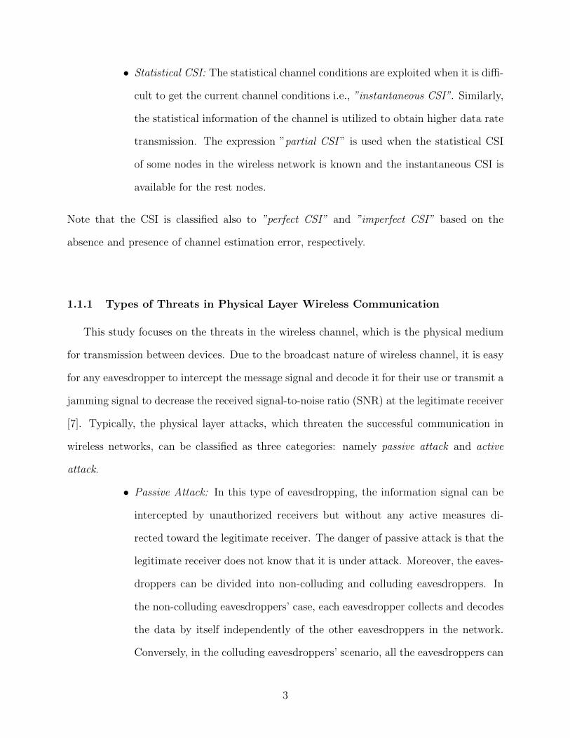
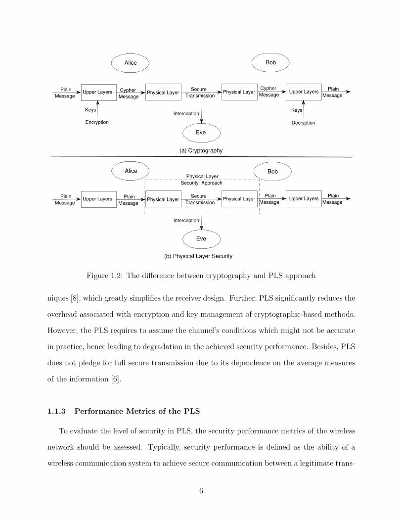
1.1.2 The PLS Approach
Wireless communication is a common method to link different nodes with each other.
However, it faces a great challenge in security because of the broadcast transmission of the
wireless signal. In view of that, the PLS is an appropriate solution to mitigate the possible
attacks. The PLS becomes one of the attractive topics with the improvement of the wire-
less transmission schemes which exploit the wireless channel’s characteristics [6]. Moreover,
PLS aims at increasing the security level in the physical layer whereas the conventional
cryptographic-based security methods are implemented at the upper layers. For example,
Figure 1.2 shows the difference between encryption and PLS. In Figure 1.2a, the traditional
scheme of cryptography is presented, where the transmitter (Alice) encrypts the transmitted
message signal by using a secret key in the upper layers. On the other side, the legiti-
mate receiver (Bob), which has the secret key, decrypts the cipher message to obtain the
information. Conversely, PLS utilizes the physical layer to achieve a secure transmission
by preventing the eavesdropper (Eve) from intercepting the transmitted signal, as seen in
Figure 1.2b. The PLS approach can be defined as signal processing mechanism, performed
at the physical layer (e.g., beamforming, precoding, artificial noise (AN) transmission), that
maximizes the performance difference between the legitimate channel and eavesdroppers’
channels.
This thesis focuses on the PLS approach to reinforce the message signal’s protection by
complementing the traditional cryptographic-based security mechanisms at the upper layers.
The potential to combine the PLS with the upper layer encryption techniques is to obtain
further improvement in the secrecy performance of wireless communications. Moreover, one
of the main advantage of the PLS approaches is that eavesdroppers’ computational capa-
bility does not compromise the achieved security performance. The PLS approaches are a
promising way to reduce computational effort at the receiver side using the precoding tech-
5
0.1
0.2
0.3
0.4
0.5
0.6
0.7
0.8
0.9
1
0.5
0.6
0.7
0.8
0.9
1
Upper Layers Upper LayersPhysical Layer
Decryption
KeysKeys
Physical Layer
Interception
Secure
Transmission
Plain
Message
Plain
Message Cypher
Message
Cypher
Message
Upper Layers Upper Layers Plain
Message
Interception
Physical Layer Secure
TransmissionPhysical Layer
Plain
Message
Plain
Message Plain
Message
Encryption
(a) Cryptography
(b) Physical Layer Security
Alice Bob
Alice
Eve
Eve
Bob Physical Layer
Security Approach
Figure 1.2: The difference between cryptography and PLS approach
niques [8], which greatly simplifies the receiver design. Further, PLS significantly reduces the
overhead associated with encryption and key management of cryptographic-based methods.
However, the PLS requires to assume the channel’s conditions which might not be accurate
in practice, hence leading to degradation in the achieved security performance. Besides, PLS
does not pledge for full secure transmission due to its dependence on the average measures
of the information [6].
1.1.3 Performance Metrics of the PLS
To evaluate the level of security in PLS, the security performance metrics of the wireless
network should be assessed. Typically, security performance is defined as the ability of a
wireless communication system to achieve secure communication between a legitimate trans-
6
mitter and receiver in the presence of eavesdropper(s). Based on the signal-to-interference-
plus-noise ratio (SINR) received by Bob and Eve, the most common information-theoretic
security performance metrics can be presented as follows:
• Secrecy Capacity: It is considered as the essence metric in the PLS to assess
the secrecy performance of wireless networks in the presence of eavesdroppers.
The secrecy capacity is defined as the difference between Bob’s channel ca-
pacity and Eve’s channel capacity [5]. The channel capacity is the maximum
rate at which information can be reliably transmitted over a communication
channel, calculated by the Shannon-Hartley theorem [4]. However, the secrecy
capacity is usually used when the channel fading is ignored i.e., fixed channel
assumption [9].
• Ergodic Secrecy Capacity: To characterize the time-varying feature of the wire-
less channels, the ergodic secrecy capacity is one of the metrics to evaluate the
average secrecy transmission [6]. Ergodic secrecy capacity evaluates the aver-
age ability of secrecy transmission over fading channels. However, the ergodic
secrecy capacity is very difficult to obtain because it requires the solution to a
non-convex optimization problem, hence the average achievable secrecy rate,
which is strictly a lower bound of the ergodic secrecy capacity, is usually used
to evaluate the secrecy performance [9].
• Average Achievable Secrecy Rate: It is the difference between the average
achievable data rate at the legitimate receiver and the average achievable data
rate at the eavesdropper, which is measured in bits per second per Hertz.
• Secrecy Outage Probability: It is the likelihood of Bob channel’s achievable
secrecy rate falling below a certain threshold secrecy rate [10]. In other words,
when the current secrecy capacity does not exceed a predetermined target
secrecy rate, the secrecy outage occurs [11].
7
• Secrecy Throughput: It is the average secrecy rate achieved multiplied by the
bandwidth assigned to the legitimate receiver which is measured in bits per
second. It can be defined also as the average achievable secrecy rate over all
channel realizations, subjected to a target secrecy outage probability [9].
1.1.4 PLS in Millimeter-wave Bands
This thesis studies the PLS of the ad hoc networks that operate in the millimeter-wave
(mmWave) band, which plays a crucial role in the future wireless networks, as it enables
the use of frequency bands above 6 GHz [12]. In this regard, mmWave networks offer a
huge spectrum to increase the data transfer rate compared to the microwave networks [13].
Moreover, the small wavelength in the mmWave band and, hence, the small antenna size
permits the use of a large number of antennas. On the other hand, a mmWave network
is plagued with many challenges including high propagation loss, orientation sensitivity,
penetration loss, and blockage sensitivity [14]. Consequently, many recent studies aim to
overcome the drawbacks of the mmWave spectrum using techniques such as directional
beamforming to mitigate the high propagation loss and decrease the probability of mmWave
signals’ interception as well. In addition, the Nakagami-m fading is used to characterize the
mmWave channel model instead of Rayleigh fading used in the microwave channel because
of the large amount of scattering that exists in the microwave bands is not available in the
mmWave bands, especially when directional beamforming is applied [13,15].
1.1.5 PLS in MmWave Ad Hoc Networks
The mmWave band is also very beneficial for ad hoc networks to achieve a data rate
performance better than that of an ad hoc network operating in the microwave bands [16].
Besides, more interference immunity is attained because of the high vulnerability to blockages
8
and the use of directional antenna arrays for transmission and reception [17]. The mmWave
ad hoc network performance is evaluated using the stochastic geometry framework in [16,18].
Thus, references [19–24] study the PLS in a microwave ad hoc network in the presence of
eavesdroppers. However, the secrecy analysis of the mmWave ad hoc network will be signif-
icantly different than that of the traditional microwave ad hoc network, due to the distinct
characteristics of the mmWave channel. Recent works evaluate the secrecy performance for
different types of mmWave networks [25–37]. Despite that, a little progress has been made
in the PLS of mmWave ad hoc network subject to eavesdroppers [38, 39]. Subsequently,
more work is still needed to analyze and enhance the secrecy performance in mmWave ad
hoc networks, which motivates this thesis as seen in the next section.
1.2 Motivation of the Thesis
In this section, the motivation of this thesis is presented considering PLS challenges in the
mmWave ad hoc networks. By and large, the major concern for the future wireless networks is
the information security. This concern escalates with the rapid increase of the eavesdroppers’
computational capabilities and use of various eavesdropping strategies, as discussed in the
previous section. This forces the network designers to assume the worst-case scenario, such
as the eavesdroppers can collude to increase the probability of signal intercept and cancel the
unwanted signals i.e., interference signals. Therefore, the conventional secrecy techniques,
that consider any limitation on the adversary side, are not convenient to achieve a secure
information transmission. Recently, researchers have demonstrated a significant interest in
the PLS to give additional layer security [40–43].
On account of the importance of the ad hoc networks, many works have studied the PLS
of the mmWave ad hoc networks in the presence of eavesdroppers. Most of these studies have
been applied to ad hoc networks that operate in the traditional microwave band. Motivated
by that, this thesis analyzes the PLS for the mmWave ad hoc networks in the presence of
9
various types of eavesdroppers.
In addition, there is a lack of mmWave ad hoc network secrecy performance results in the
existing literature that jointly considers mmWave ad hoc network characteristics of multi-
array antenna transmission, directional beamforming, and small-scale fading. Accounting
for these three factors, an extensive secrecy rate analysis of a mmWave ad hoc network with
multi-array antenna transmission in the presence of non-colluding and colluding eavesdrop-
pers forms the inspiration of Chapter 3.
The few previous studies [44–48] present the PLS analysis on active eavesdroppers, but
treated in the context of microwave wireless networks without any focusing on the ad hoc
wireless networks. A knowledge gap exists on the secrecy performance analysis of a mmWave
ad hoc network in the presence of passive/active eavesdroppers. Hence, Chapter 4 fills this
gap.
Finally, in the PLS approaches, choosing a suitable secrecy transmission technique is
very substantial to mitigate the expected threats (i.e., passive or active attacks) and, in
turn, increase the security performance of the wireless network. This is the main driver for
presenting two different physical layer secure transmission techniques in Chapter 5, based
on the AN transmission and the available knowledge of the CSIT.
1.3 Problem Statement and Thesis Objectives
Generally, the main unaddressed research problems in the research for PLS of mmWave
ad hoc networks include: i) The lack of secrecy performance results in the existing works on
the mmWave ad hoc networks in the presence of passive eavesdroppers, taking into consid-
eration the multi-array antenna, blockages, and small-scale fading. ii) A gap in knowledge
exists on the secrecy performance analysis of a mmWave ad hoc network with multi-array
antenna transmission in the presence of passive/active eavesdroppers that can intercept the
information signal and transmit jamming signal, simultaneously. iii) The appropriate choice
10
of secure physical layer transmission techniques should be re-examined to enhance the se-
crecy performance of the mmWave ad hoc network in the presence of both passive and
passive/active eavesdroppers.
Based on the aforementioned problems, a comprehensive study for the secrecy perfor-
mance of the mmWave ad hoc networks under eavesdroppers’ attack has been investigated
in this thesis. Therefore, the thesis objectives are summarized as follows:
• The first objective in this thesis is the modeling and analysis of the mmWave
ad hoc networks in the presence of eavesdroppers using the tools of stochastic
geometry that characterizes the random locations of transmitting nodes and
eavesdroppers. Moreover, the main mmWave channel characteristics are taken
into account such as the high propagation loss, blockages’ sensitivity, and
the fading characteristics of the line-of-sight (LoS) link and non-LoS (NLoS)
link. Further, the directional beamforming is considered to mitigate the high
attenuation of the mmWave signal, with multi-array antenna and single-array
antenna at the transmitting nodes and receiving nodes, respectively.
• Second, the thesis evaluates the secrecy performance of the mmWave ad hoc
network in the presence of different types of eavesdropping scenarios. Hence,
the passive and passive/active eavesdroppers scenarios are the focus of Chap-
ters 3 and 4, respectively. In this regard, suitable performance metrics have
been used to assess the secrecy performance of the network.
• Finally, the counter-measure of the various types of eavesdropping attacks
to enhance the secrecy performance of the mmWave ad hoc network forms
the core of Chapter 5. Besides, choosing the suitable secrecy transmission
technique based on the availability of the channel characteristics to enhance
the secrecy performance represents a great challenge in this thesis.
11
1.4 Contributions and Outline
Based on the research problems mentioned in Section 1.3, the achieved main contributions
of this thesis are three-fold:
1. The secrecy performance of mmWave ad hoc networks under passive eaves-
dropping attack is introduced in chapter 3, where the random locations of the
transmitting nodes and passive eavesdroppers are modeled by spatial point
processes and, thus, performance analysis relies on the tools of stochastic
geometry. Hence, the mathematical expressions are derived for the average
achievable secrecy rate in mmWave ad hoc networks in the presences of pas-
sive eavesdroppers, taking into account directional beamforming, multi-array
antenna transmission, blockages, and Nakagami-m fading. Results are derived
from the two scenarios of passive non-colluding and colluding eavesdroppers.
Moreover, approximate average achievable secrecy rate results are proposed
under a simplified LoS mmWave model. The analytical results provide in-
sights on the impact of the main system parameters such as the total transmit
power, the distance between the desired Tx-Rx pair, transmitting nodes’ in-
tensity, and eavesdroppers’ intensity, on the system performance.
2. In Chapter 4, the secrecy performance of the mmWave ad hoc networks is
assessed in the presence of passive/active eavesdroppers which can intercept
the message signal and transmit a jamming signal simultaneously to degrade
the received SNR at the legitimate receiver i.e., eavesdropper operating in full
duplex mode. The mathematical expressions are derived for the secrecy per-
formance metrics—connection outage probability, secrecy outage probability,
and average achievable secrecy rate. Further, the analysis compares the effect
of the passive/active eavesdropper and passive eavesdropper on the secrecy
performance in the noise-limited and interference-limited networks. The re-
12

sults show that the passive/active eavesdroppers increase the connection and
secrecy outage probabilities and decrease the average achievable secrecy rate
compared to the passive eavesdroppers. Moreover, the impact of the total
transmit power and the intensity of eavesdroppers on the secrecy performance
is evaluated.
3. For the goal of improving the secrecy performance of mmWave ad hoc net-
works, two different secure physical layer transmission techniques are presented
in Chapter 5. Firstly, a simple yet effective sectored AN transmission (Tx-AN)
technique that does not require knowledge of the CSIT is proposed to enhance
the average achievable secrecy rate in the presence of passive non-colluding
and colluding eavesdroppers. The results show that at the high transmit power
(> 20 dBm), the Tx-AN technique achieves up to three-fold improvement in
the average secrecy rate over that without. Secondly, the potential benefits of
AN transmission by using a null space linear precoder are investigated, based
on the CSIT’s knowledge, henceforth referred to as the Tx-AN/LP technique.
The Tx-AN/LP technique is very effective in mitigating the effect of the jam-
ming signals in the presence of passive/active eavesdroppers, which achieves
up to two-fold gain in the secrecy performance over that without using this
technique. Consequently, the mathematical expressions for the improved se-
crecy performance are derived under the Tx-AN and Tx-AN/LP techniques.
Moreover, the results demonstrate the secrecy robustness of both techniques
against increasing the eavesdroppers’ intensity. Finally, the impact of varying
the power allocation between the message and AN signals on the secrecy per-
formance is studied along with a numerical determination of the appropriate
AN power fraction that maximizes the average achievable secrecy rate.
In Table 1.1, the contributions of this thesis are summarized, including the corresponding
13
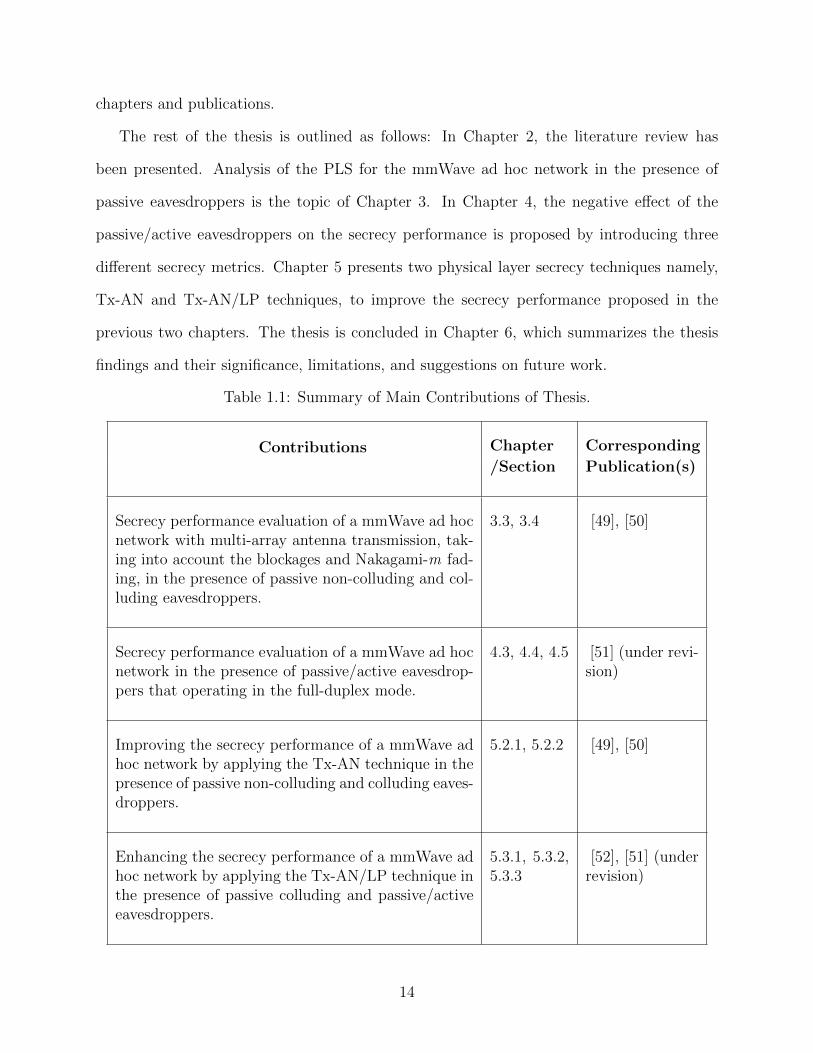
chapters and publications.
The rest of the thesis is outlined as follows: In Chapter 2, the literature review has
been presented. Analysis of the PLS for the mmWave ad hoc network in the presence of
passive eavesdroppers is the topic of Chapter 3. In Chapter 4, the negative effect of the
passive/active eavesdroppers on the secrecy performance is proposed by introducing three
different secrecy metrics. Chapter 5 presents two physical layer secrecy techniques namely,
Tx-AN and Tx-AN/LP techniques, to improve the secrecy performance proposed in the
previous two chapters. The thesis is concluded in Chapter 6, which summarizes the thesis
findings and their significance, limitations, and suggestions on future work.
Table 1.1: Summary of Main Contributions of Thesis.
Contributions Chapter Corresponding
/Section Publication(s)
Secrecy performance evaluation of a mmWave ad hocnetwork with multi-array antenna transmission, tak-ing into account the blockages and Nakagami-m fad-ing, in the presence of passive non-colluding and col-luding eavesdroppers.
3.3, 3.4 [49], [50]
Secrecy performance evaluation of a mmWave ad hocnetwork in the presence of passive/active eavesdrop-pers that operating in the full-duplex mode.
4.3, 4.4, 4.5 [51] (under revi-sion)
Improving the secrecy performance of a mmWave adhoc network by applying the Tx-AN technique in thepresence of passive non-colluding and colluding eaves-droppers.
5.2.1, 5.2.2 [49], [50]
Enhancing the secrecy performance of a mmWave adhoc network by applying the Tx-AN/LP technique inthe presence of passive colluding and passive/activeeavesdroppers.
5.3.1, 5.3.2,5.3.3
[52], [51] (underrevision)
14
Chapter 2
Literature Review
2.1 Physical Layer Security Survey
The concept of physical layer security (PLS) inspired by Wyner’s work has been recognized
in [5], which depends on improving the secrecy capacity to secure the wireless transmission.
Then, Csiszar and Korner in [53] have generalized the idea of non-degraded wiretap chan-
nel, and more general secrecy rate expressions have been presented. In [54], the Gaussian
degraded wiretap channel model has been studied by Cheong and Hellman, in addition, the
secrecy capacity derivations have been introduced. From then on, considerable efforts have
been made by researchers. In [10,55,56], the PLS has been studied to transmit a secure mes-
sage signal in the presence of eavesdroppers in respect of information-theoretically secure
communication rates.
For enhancing the PLS in wireless networks, the multiple-antenna system has been uti-
lized to achieve a higher data rate at the authorized nodes while reducing the information
leakage to unauthorized nodes. By considering a Gaussian multiple-antenna wiretap chan-
nel model, the authors in [57] have maximized the ergodic secrecy rate, where the statistical
channel state information (CSI) of the eavesdropper and the full CSI of the legitimate receiver
are known at the transmitter. In [58], the secure connectivity has been enhanced in wireless
networks with multi-antenna transmission and by forming a directional antenna. The math-
ematical analysis have been presented for both non-colluding and colluding eavesdroppers.
The authors in [59] have presented the achievable secrecy rate per transmitter-receiver (Tx-
Rx) pair in wireless networks considering the authorized and eavesdropper node locations
are distributed according to a Poisson point process (PPP). Following the direction of ran-
15
domly located eavesdroppers, the secrecy outage probability of the multi-antenna system has
been evaluated in [60]. Depending on the feedback of the CSI from the legitimate users, the
ergodic secrecy sum-rate in multi-user multi-antenna downlink networks has been proposed
in [61].
For confusing the eavesdroppers, the artificial noise (AN) has been inserted into the
transmit signal to degrade the data rate at the unauthorized nodes to improve the secrecy
performance of the wireless networks. However, the challenge of this technique is to protect
the legitimate receiver from receiving the AN signal whereas the eavesdropper should be
affected. In this context, the authors in [62] have used the AN transmission in two scenarios,
a transmitter with multiple transmit antennas and amplifying relays that represent the
impact of multiple antennas. However, the CSI has been assumed to be known at all nodes
including the eavesdroppers. The work in [62] has been extended for fast fading secure
transmission in [63], with a knowledge of statistical CSI of the adversary’s channel at the
transmitter and full CSI of the legitimate channel.
In [64], the AN is exploited to give mask beamforming, hence the power allocation has
been investigated for the multiple-input single-output (MISO) wiretap channel to minimize
the secrecy outage probability. Following this direction, two AN transmission schemes have
been proposed in [65] to achieve effective secrecy throughput of MISO wiretap channels in
the presence of a passive eavesdropper. Under the secrecy outage constraint in [66], the
secrecy rate has been maximized with the AN-aided beamforming scheme. In [67], a robust
AN-aided transmission scheme has been proposed to maximize the secrecy rate via imperfect
CSI in both the legitimate and illegitimate channels. The results show that more AN power
should be allocated when a high uncertainty of the eavesdropper’s channel is obtained, and
vice versa when the level of uncertainty on the legitimate channel is high.
16
2.2 Millimeter-wave Channel Characteristics
The achieved secrecy gain in the above section can not be applied to mmWave networks
directly due to the substantial difference between the characteristics of the millimeter-wave
(mmWave) channel and the traditional microwave channel. For instance, the blockage sensi-
tivity of the mmWave signal divides the mmWave signal links into line-of-sight (LoS) link and
non-LoS (NLoS) link with different fading features [14]. Therefore, many mmWave channel
models, depending on the impact of the blockages, have been introduced in [17, 18, 68, 69].
The most common blockage model has been investigated in [17], namely the exponential
blockage model. In this blockage model, the random building has been assumed as rectan-
gles with random heights, orientations, and sizes. The connectivity, coverage probability, and
average rate have been studied under this blockage model applied to the cellular networks in
urban areas. The exponential blockage model has been used in [18] to evaluate the capacity
and coverage of the mmWave ad hoc networks. Following this model, the authors in [68]
proposed the approximated LoS ball blockage. In [69], the experimental measurements in
Chicago and New York have been exploited to validate the proposed ball based blockage
model.
In [70], a 3D physical blockage model of the human body of outdoor mmWave cellular
networks has been proposed. On account of the dynamic statistics and mobility, the hu-
man blockage model shows higher complications than the blockage models of terrains and
buildings. Statistical blockage models have been introduced in [71], where these models
demonstrate the effect of the user itself (hand or body) or vehicles on the mmWave signal
propagation. The experimental measurements have been focused on 28 GHz mmWave signal.
2.3 Critical Assessment of the Existing Literature
In this section, the critical assessment of the related literature for this thesis is presented.
17
Firstly, the recent works that evaluate the PLS of the ad hoc networks in the presence of
passive eavesdroppers are assessed. Secondly, the review of the existing works of relevance
to the active eavesdropping that attacks the wireless networks is presented. Finally, the new
works in recent years that study the secrecy performance in the different types of mmWave
wireless networks are introduced.
2.3.1 PLS in Microwave Ad Hoc Networks
The secrecy transmission capacity of the noisy wireless ad hoc network has been presented
in [19], taking into consideration the thermal noise and interference signals. Moreover, the
connection outage probability, secrecy transmission capacity, and bounds on secrecy outage
probability have been derived when the transmission distance is the same for all transmis-
sions. Besides, the more practical case has been analyzed when each transmitter transmits
to its nearest receiver. The secrecy transmission capacity of the large-scale decentralized
wireless networks has been evaluated in [20]. Furthermore, a simple technique that can be
used to reduce the throughput cost of achieving highly secure networks has been realized by
applying a secrecy guard zone with AN.
In [21], a wireless ad hoc network with a hybrid full-/half-duplex receiver deployment
strategy under a stochastic geometry framework has been introduced. The connection and
secrecy outage probabilities analysis have been further presented with an optimum frac-
tion of the full-duplex (FD) receivers which maximizes the secrecy performance. In [22],
the scalability of keyless secrecy in a microwave ad hoc network in the presence of passive
eavesdroppers with unknown locations has been studied. Moreover, to obtain a non-zero
throughput, a sufficient condition on the eavesdroppers’ number has been derived. In [23],
the mathematical expressions have been derived for the connection and secrecy outage prob-
abilities and the tradeoff between them demonstrated for a wireless ad hoc network under
two different secrecy schemes. Further, the secrecy throughput performance for both secrecy
18
schemes in [23] has been introduced concerning the secrecy transmission capacity. In [24],
the secrecy transmission capacity of the wireless ad hoc networks under the Rayleigh fading
model has been analyzed. Moreover, based on tools of stochastic geometry, the connection
outage probability and the bounds on the secrecy outage probability have been proposed.
Further, the authors in [24] have characterized the important conditions to achieve the tar-
get outage constraints and a positive secrecy transmission capacity from the point of the
transmitters’ and eavesdroppers’ densities, and link length of Tx-Rx pairs, respectively.
Note that all the previous works in [19–24] focus on the PLS in wireless ad hoc networks
designed for the sub-6 GHz bands. Therefore, this thesis provides a comprehensive study of
the PLS in the wireless ad hoc networks that operate in the mmWave band. Consequently,
this thesis addresses the study of the secrecy performance of the mmWave ad hoc networks
in the presence of passive/active eavesdroppers.
2.3.2 PLS in the Presence of Active Eavesdroppers
A few works that study the PLS of microwave wireless networks in the presence of active
eavesdroppers have been presented. For example, a resource allocation framework has been
proposed in [44] to improve the secrecy performance in the presence of active eavesdroppers.
Furthermore, the secrecy data rate has been maximized where both a legitimate receiver
and eavesdropper are FD. In [45], the secrecy degree of freedom maximization problem of
a multiple-input multiple-output (MIMO) Gaussian wiretap channel in the presence of an
active eavesdropper has been analyzed. Moreover, the FD legitimate receiver scheme has
been introduced, where the antenna set of the legitimate receiver has been divided into two
sets, one for receiving and the other for jamming.
In [46], with the help of game-theoretic tools, the effects of the active eavesdroppers have
been evaluated. Furthermore, the secrecy capacity in the presence of active and passive
eavesdroppers has been captured. The average achievable secrecy rate of wireless multi-
19
user networks has been investigated in [47] under passive and active eavesdroppers attacks.
The results have demonstrated the difference between the active and passive eavesdroppers
by the fact that the former can introduce some false information to deceive the legitimate
transmitter. In [48], the ergodic secrecy capacity of the wireless network has been presented
in the presence of an eavesdropper who can intercept the message signal and transmit the
jamming signal at the same time i.e., operates in the FD mode. Moreover, a game scenario
has been considered where the legitimate transmitter aims to target a certain transmission
rate and interfere with the eavesdropper by exploiting the remaining power as an AN signal.
On the other hand, the eavesdroppers attempt to force the legitimate transmitter to decrease
the AN by sending a jamming signal.
Again, these works just pay attention to the sub-6 GHz bands secrecy wireless networks
in the presence of active eavesdroppers. Moreover, the effect of the active eavesdroppers on
the ad hoc wireless network has not been investigated.
2.3.3 PLS in MmWave Wireless Networks
Based on the mmWave band, the secrecy outage probability achieved via an on-off trans-
mission scheme with AN transmission strategy has been analyzed in [25], where the secrecy
performance of the mmWave network relies on the destination’s and the eavesdropper’s di-
rections and propagation paths. By exploiting the small size of the antenna, [26] proposed
antenna subset modulation (ASM), for point-to-point secure wireless mmWave communica-
tion to develop the directional radiation pattern. Following this trend, [27] has extended
this ASM technique to secure the mmWave vehicular communication systems. Based on
an iterative fast Fourier transform, the authors in [28] have designed an optimized antenna
subset selection that provides low computational complexity and improved secrecy perfor-
mance. In [29], the secrecy throughput of the mmWave network has been proposed. In
addition, three transmission schemes have been investigated, namely, maximum ratio trans-
20
mitting (MRT) beamforming, AN beamforming, and partial MRT (PMRT) beamforming to
improve the secrecy performance. This work has been extended against randomly located
eavesdroppers in [30], in which the secrecy throughput under a secrecy outage probability
constraint has been maximized. The works in [29] and [30] assume that the instantaneous
CSI between the desired user and its transmitter is perfectly known.
In [31], the secrecy performance of the hybrid mmWave/microwave network in the pres-
ence of multiple eavesdroppers has been proposed. For the LoS and NLoS links, the upper
and lower bounds of the conditional secrecy outage probability have been derived. Further,
the tradeoff between outage probability and secrecy outage probability in the context of
blockages has been investigated. This work has been extended in [32] to investigate the se-
crecy outage probability and the average secrecy rate of mmWave-overlaid microwave cellular
network in the presence of colluding eavesdroppers, where the effect of the blockages on the
secrecy outage probability in mmWave networks has been studied. However, a single-array
antenna has been used in the transmission and reception without using any secure transmis-
sion technique to enhance the secrecy performance. In [33], two PLS techniques have been
proposed to improve the secrecy rate of the vehicular mmWave communication systems. The
multi-antenna has been applied in the first technique with a single radio-frequency chain to
transmit information symbols. The second technique transmits the AN signal in a certain
direction to confuse the eavesdroppers.
The secure connection probability and the average number of perfect communication links
in both noise and interference-limited conditions of mmWave network have been introduced
in [34] in the presence of non-colluding and colluding eavesdroppers. However, the desired
user and the eavesdropper have been assumed to use a single omnidirectional antenna. In [35],
a hybrid analog-digital precoder design has been proposed to enhance the PLS of mmWave
MISO systems with partial channel knowledge. In addition to maximizing the secrecy rate
lower bound, a low-complexity AN-aided hybrid precoder design has been introduced. In
21
[36], the secrecy throughput has been evaluated in the downlink mmWave cellular network
for both delay-tolerant and delay-limited transmission modes. The ergodic secrecy rate
analysis has been proposed based on the perfect CSI of the desired user in the presence of
eavesdroppers. In [37], a joint beamforming design of mmWave two-way amplify-and-forward
MIMO relaying networks for the PLS has been presented. The achievable secrecy sum rate
has been enhanced with the proposed algorithm.
2.3.4 PLS in MmWave Ad Hoc Networks
Mainly, the massive data transmission needs to be highly secured in a mmWave ad hoc
network subject to eavesdroppers with high capabilities [72]. In this vein, PLS techniques
are more appropriate due to the less computational complexity than needed at the higher
protocol layers. Hence, focusing on the PLS in a mmWave ad hoc network, the authors
in [38] have evaluated the secrecy performance in a large-scale mmWave ad hoc network
with and without AN scheme. The average achievable secrecy rate has been presented
when the uniform planer array (UPA) and uniform linear array (ULA) have been utilized.
Moreover, the directional beamforming has been used between the transmitters and their
corresponding receivers using a single-array antenna at all nodes. The most recent work
for enhancing the secure communication of the mmWave ad hoc network in the presence of
passive non-colluding eavesdroppers has been presented in [39]. In this research, a Sight-
based Cooperative Jamming (SCJ) scheme has been investigated to improve the secrecy
performance by utilizing the signal attenuation difference between the LoS and NLoS links
of the mmWave signal. The SCJ scheme relies on inserting a group of jamming transmitters
in the mmWave ad hoc network to transmit AN signal with a certain probability that
deteriorates the signal-to-noise ratio (SNR) at the eavesdroppers. Moreover, the secrecy
transmission capacity has been presented to evaluate the secrecy performance under the
SCJ scheme.
22
2.4 Thesis Work in the Context of Existing Research
Unlike the existing works in [19–24] that study the PLS of microwave ad hoc networks
in the presence of passive eavesdroppers, Chapter 3 focuses on the secrecy performance
analysis of mmWave ad hoc networks, taking into account the impact of blockages, directional
beamforming, and Nakagami-m fading.
Moreover, with exception of a few works that address the impact of the active attack
on the secrecy performance of the wireless microwave networks as seen in [44–48], a gap
exists in the study of the PLS of the mmWave ad hoc networks in the presence of active
eavesdroppers. Subsequently, Chapter 4 addresses this shortage by proposing the evaluation
of the secrecy analysis for ad hoc networks, which utilize the mmWave band, in the presence
of passive/active eavesdroppers and comparing with the traditional passive eavesdroppers.
Although, many recent works interested in the PLS in the wireless networks that operate
in the mmWave band [25–32,35,36], a few PLS work has been done to analyze the PLS in the
context of mmWave ad hoc networks [38,39]. Therefore, focusing on the PLS in mmWave ad
hoc networks, this thesis accounts for small scale fading and multi-array antenna transmission
in the presence of various types of eavesdroppers’ strategies, different than [38] which analyzes
the average secrecy rate in mmWave ad hoc network, neglecting the small-scale fading and
using a single-array antenna transmission in the presence of non-colluding eavesdroppers.
Besides, in contrast with the complected jamming secrecy transmission technique used
in [39], Chapter 5 in the thesis examined the impact of transmitting AN on the secrecy per-
formance of the mmWave ad hoc networks in the presence of different types of eavesdropping
and applying two simple AN transmission techniques to improve the secrecy performance
namely, Tx-AN and Tx-AN/LP techniques. In addition, the work in [39] considered a single-
array antenna transmission in the presence of non-colluding eavesdroppers, which are the
expectation of the less dangerous threat of wireless networks.
23
2.5 Chapter Summary
This chapter highlights the literature review in the context of the thesis proposal. First,
the PLS based on the multi-antenna system and AN transmission is surveyed. In addition,
the most important work that models the mmWave channel characteristics is presented as
well. Second, the state-of-the-art of the PLS in microwave ad hoc networks in the presence of
passive eavesdroppers is introduced. The impact of the active eavesdroppers in the microwave
wireless networks in the previous work is further reviewed. Moreover, the studies of the
PLS in the different types of mmWave wireless networks, including the mmWave ad hoc
networks, are presented. Finally, the contributions of the thesis are compared with the
above work especially the differences with the work on the PLS for mmWave ad hoc networks.
Furthermore, Table 2.1 summarizes the main differences between the existing work and the
contributions of the thesis.
24
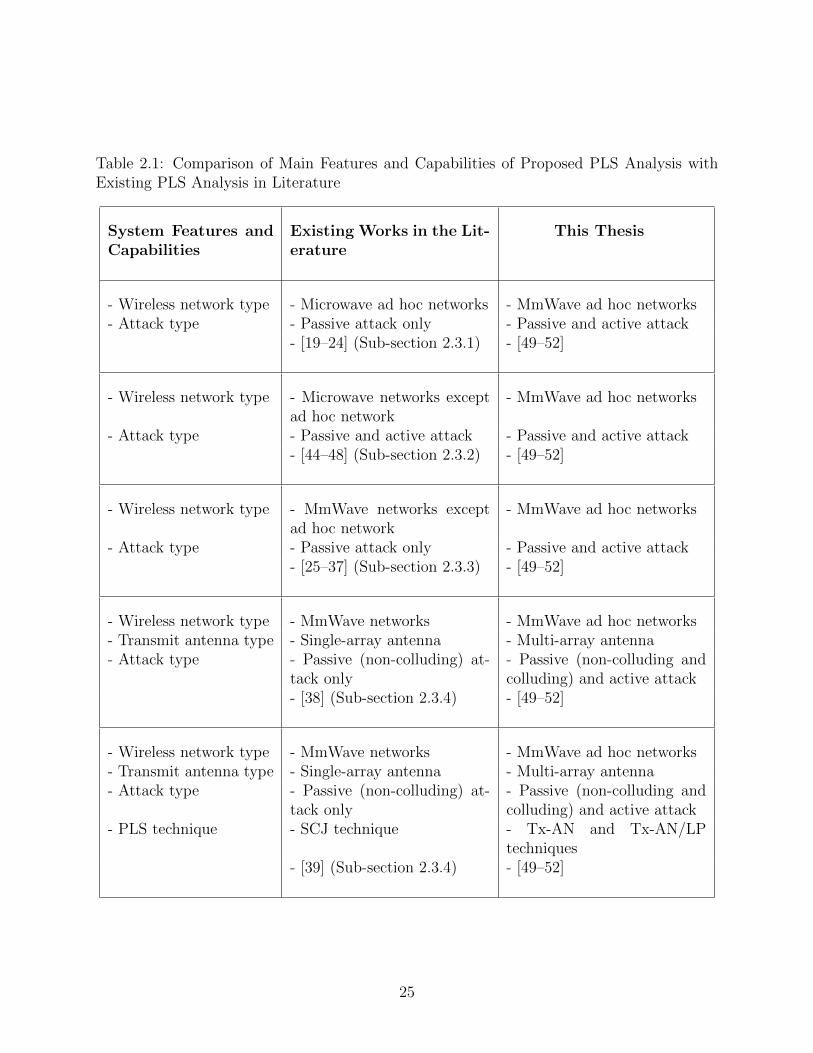
Table 2.1: Comparison of Main Features and Capabilities of Proposed PLS Analysis withExisting PLS Analysis in Literature
System Features andCapabilities
Existing Works in the Lit-erature
This Thesis
- Wireless network type - Microwave ad hoc networks - MmWave ad hoc networks- Attack type - Passive attack only - Passive and active attack
- [19–24] (Sub-section 2.3.1) - [49–52]
- Wireless network type - Microwave networks exceptad hoc network
- MmWave ad hoc networks
- Attack type - Passive and active attack - Passive and active attack- [44–48] (Sub-section 2.3.2) - [49–52]
- Wireless network type - MmWave networks exceptad hoc network
- MmWave ad hoc networks
- Attack type - Passive attack only - Passive and active attack- [25–37] (Sub-section 2.3.3) - [49–52]
- Wireless network type - MmWave networks - MmWave ad hoc networks- Transmit antenna type - Single-array antenna - Multi-array antenna- Attack type - Passive (non-colluding) at-
tack only- Passive (non-colluding andcolluding) and active attack
- [38] (Sub-section 2.3.4) - [49–52]
- Wireless network type - MmWave networks - MmWave ad hoc networks- Transmit antenna type - Single-array antenna - Multi-array antenna- Attack type - Passive (non-colluding) at-
tack only- Passive (non-colluding andcolluding) and active attack
- PLS technique - SCJ technique - Tx-AN and Tx-AN/LPtechniques
- [39] (Sub-section 2.3.4) - [49–52]
25
Chapter 3
Physical Layer Security in the Presence of Passive
Eavesdroppers 1
3.1 Introduction
This chapter highlights the potential of the physical layer security (PLS) of millimeter-wave
(mmWave) ad hoc networks with multi-array antenna transmission in the presence of passive
eavesdroppers. The main contribution of this chapter is the derivations of the mathematical
expressions for the average achievable secrecy rate of a mmWave ad hoc network in the
presence of non-colluding and colluding eavesdroppers, taking into consideration the effect
of blockages, Nakagami-m fading, and directional beamforming in the transmission and
reception. Based on the simplified line-of-sight (LoS) mmWave ball model, approximate
results for the average achievable secrecy rate of a mmWave ad hoc network are further
presented. Moreover, the impacts of key system parameters are introduced such as the total
transmit power, the distance between the desired transmitter-receiver (Tx-Rx) pair, and the
intensities of the transmitting nodes and eavesdroppers on the secrecy performance.
Our results show that the effect of increasing the total transmit power on the secrecy
performance in the presence of non-colluding and colluding eavesdroppers. Furthermore, the
results confirm the reduction in the average achievable secrecy rate due to increasing the in-
tensities of the transmitting nodes and eavesdroppers. Besides, the shorter distance between
1The content of this chapter has presented as a part of two papers: 1) Published as a conference paper [49],A. F. Darwesh and A. O. Fapojuwo, ”Achievable Secrecy Rate in mmWave Multiple-Input Single-Output AdHoc Networks,” 2020 IEEE 91st Vehicular Technology Conference (VTC2020-Spring), Antwerp, Belgium,2020, pp. 1-6, doi: 10.1109/VTC2020-Spring48590.2020.9128769. 2) Submitted as a manuscript of a journalpaper to the Wireless Communications and Mobile Computing (Wiley, Hindawi) [50], A. F. Darwesh and A.O. Fapojuwo, ”Achievable Secrecy Rate Analysis in mmWave Ad Hoc Networks with Multi-Array AntennaTransmission and Artificial Noise,”, 2020. Currently undergoing peer review.
26
the Tx-Rx pair achieves better secrecy performance for the mmWave ad hoc networks in the
presence of passive eavesdroppers.
3.2 System Model
In this section, the network model of a mmWave ad hoc network including the secrecy
threats is analyzed by exploiting the tools of stochastic geometry. Moreover, the mmWave
propagation parameters are presented such as blockages, fading models, and directional
beamforming.
3.2.1 Network Model
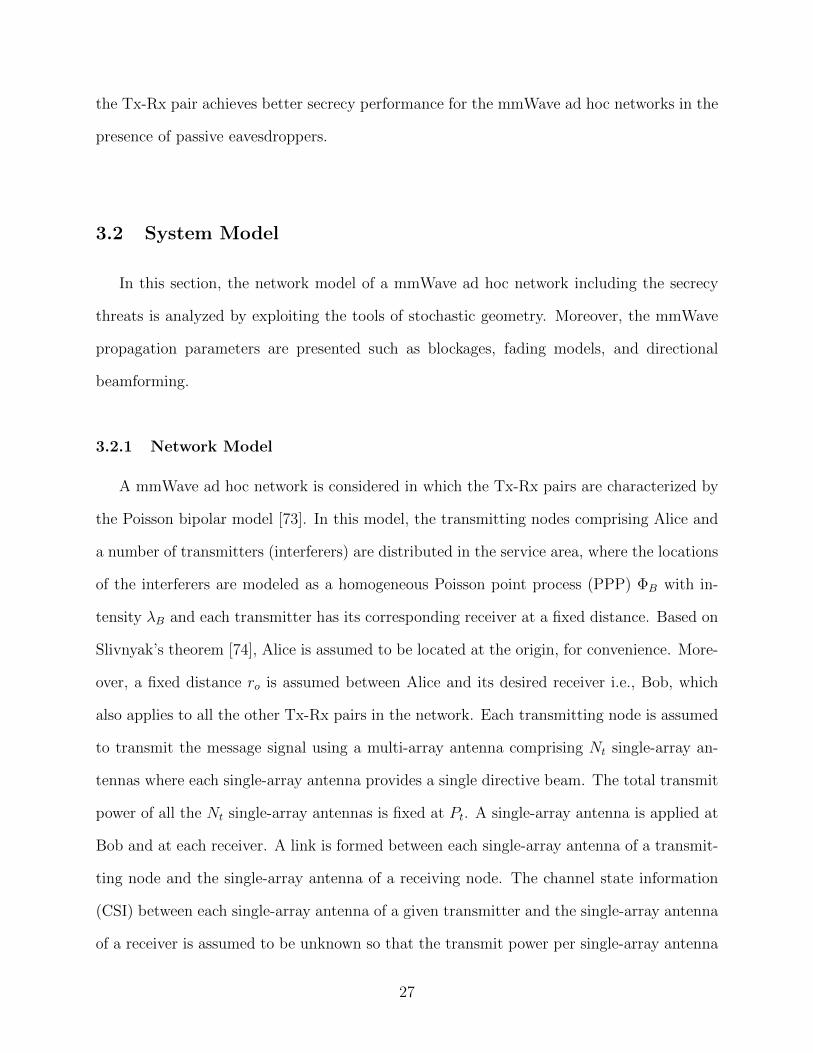
A mmWave ad hoc network is considered in which the Tx-Rx pairs are characterized by
the Poisson bipolar model [73]. In this model, the transmitting nodes comprising Alice and
a number of transmitters (interferers) are distributed in the service area, where the locations
of the interferers are modeled as a homogeneous Poisson point process (PPP) ΦB with in-
tensity λB and each transmitter has its corresponding receiver at a fixed distance. Based on
Slivnyak’s theorem [74], Alice is assumed to be located at the origin, for convenience. More-
over, a fixed distance ro is assumed between Alice and its desired receiver i.e., Bob, which
also applies to all the other Tx-Rx pairs in the network. Each transmitting node is assumed
to transmit the message signal using a multi-array antenna comprising Nt single-array an-
tennas where each single-array antenna provides a single directive beam. The total transmit
power of all the Nt single-array antennas is fixed at Pt. A single-array antenna is applied at
Bob and at each receiver. A link is formed between each single-array antenna of a transmit-
ting node and the single-array antenna of a receiving node. The channel state information
(CSI) between each single-array antenna of a given transmitter and the single-array antenna
of a receiver is assumed to be unknown so that the transmit power per single-array antenna
27
will be P t = Pt/Nt. The system also comprises a set of eavesdroppers whose locations are
modeled by an independent homogeneous PPP Φe with intensity λe. Each eavesdropper
employs a single-array antenna for the interception. Eavesdroppers are commonly assumed
to possess strong processing capabilities and can collaborate with each other to cancel the
interference [75,76]. The assumed network topology is shown in Figure 3.1.
Figure 3.1: Network topology showing Tx-Rx pairs with a multi-array antenna (i.e., Nt
single-array antennas) for transmission and one single-array antenna for reception. The(desired Tx-Rx receiver) pair is formed by (Alice - Bob) pair. In addition, a group ofeavesdroppers colludes and intercepts Alice’s message signal at Main-Eve.
3.2.2 MmWave Model
Blockages and Path Loss Models
For each link, the blockages model in [18] is adopted, where obstacles divide an incident
mmWave signal path into two paths: LoS path and non-LoS (NLoS) path with path loss
28
exponent αL and αN , respectively. The probability of a communication link being LoS is
ζL(r) = e−$r, where r is the path length and $ is a constant that depends on the density
of the buildings and their average width and length. On the other hand, ζN(r) = 1− ζL(r)
is the probability of a communication link being NLoS. Then, the path loss at a distance r
from the transmitter can be expressed as [38,77]
L(r) = ε(max(`, r)
)−αj , w.p. ζj(r), j ∈ L,N (3.1)
where ε is the path loss intercept constant which depends on the operating frequency fc,
normally set as (c/(4πfc))2 [38] with c the speed of light, and ` is the reference distance
that makes the path loss model suitable for a small distance and large intensities of the
transmitting nodes and eavesdroppers [78]. Furthermore, based on the lowest mmWave
path loss exponents, the commonly used mmWave operating frequencies are 28 GHz, 38
GHz, 60 GHz, and 73 GHz [79,80].
Small-Scale Fading
For each link, the small-scale fading amplitude h is modeled by the Nakagami-m random
variable where the shape parameter κ is represented by κL and κN for LoS and NLoS links,
respectively [68]. Subsequently, the channel fading power gain is modeled as a gamma-
distributed random variable, h2 ∼ Γ(κj, 1/κj) and j ∈ L,N. Note that the Rayleigh fading
model is not suitable for the mmWave bands, especially when directional beamforming is
applied. The reason is that the large amount of scattering that exists at the microwave bands
is not available at the mmWave bands [13,15]. The independent Nakagami-m fading is more
convenient and analytically tractable, hence it is adopted in most of the recent studies on
mmWave networks [15,32,34].
Directional Beamforming
To overcome the high propagation loss at the mmWave bands, all transmitting and
receiving nodes including the eavesdroppers use directional beamforming. The sectored
29
model is applied to analyze the beam pattern by using the uniform planer array (UPA)
antenna for each array [81]. In this model, the beamwidth θ, main-lobe gain GM , and
side-lobe gain Gm each is a function of n, the number of antenna elements per single-array
antenna, as shown in Table 3.1 [81].
Recall the assumption of no prior knowledge of the CSI of the links between each Tx-Rx
pair. Hence, the blind transmit and receive beamforming (TR-BF) discovery mechanism
in [82] is utilized by each Tx-Rx pair to accurately determine the antenna direction with
respect to each other. Subsequently, the maximum gain GtMGuM can be achieved between
Alice and Bob while the effective antenna gain seen by Bob from each interferer i ∈ ΦB can
be written as [32]
Gi =
GtMGuM , w.p. βMM = Θθ(2π)2 ,
GtMGum, w.p. βMm = Θ(2π−θ)(2π)2 ,
GtmGuM , w.p. βmM = (2π−Θ)θ(2π)2 ,
GtmGum, w.p. βmm = (2π−Θ)(2π−θ)(2π)2 ,
(3.2)
where βlw, l, w ∈ M,m denotes the probability that the effective antenna gain GtlGuw
occurs. Here, Θ and θ are the beamwidth of the transmitting node and Bob, respectively.
Similarly, the effective antenna gain seen by each eavesdropper e ∈ Φe from Alice or
interferer i can be written as follows:
Ge =
GtMGeM , w.p. µMM = Θϑ(2π)2 ,
GtMGem, w.p. µMm = Θ(2π−ϑ)(2π)2 ,
GtmGeM , w.p. µmM = (2π−Θ)ϑ(2π)2 ,
GtmGem, w.p. µmm = (2π−Θ)(2π−ϑ)(2π)2 ,
(3.3)
where µlw, denotes the probability that the effective antenna gain GtlGew occurs, and ϑ is the
beamwidth of the eavesdropper e ∈ Φe.
30
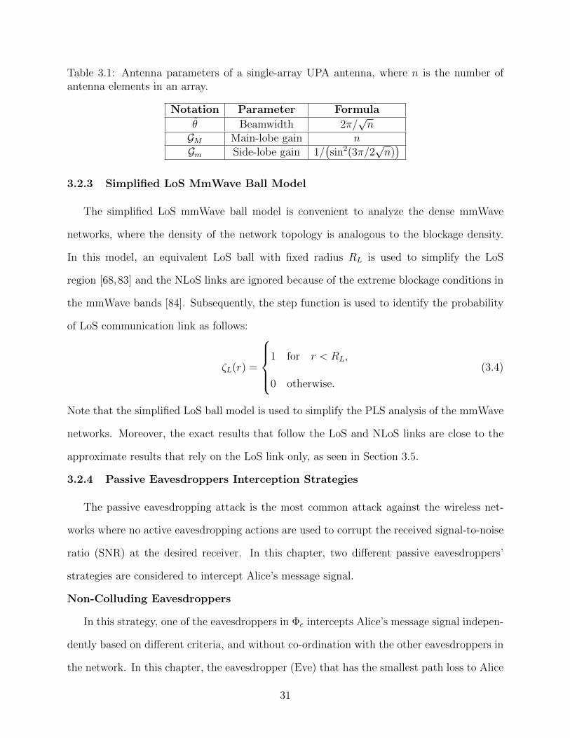
Table 3.1: Antenna parameters of a single-array UPA antenna, where n is the number ofantenna elements in an array.
Notation Parameter Formula
θ Beamwidth 2π/√n
GM Main-lobe gain nGm Side-lobe gain 1/
(sin2(3π/2
√n))
3.2.3 Simplified LoS MmWave Ball Model
The simplified LoS mmWave ball model is convenient to analyze the dense mmWave
networks, where the density of the network topology is analogous to the blockage density.
In this model, an equivalent LoS ball with fixed radius RL is used to simplify the LoS
region [68,83] and the NLoS links are ignored because of the extreme blockage conditions in
the mmWave bands [84]. Subsequently, the step function is used to identify the probability
of LoS communication link as follows:
ζL(r) =
1 for r < RL,
0 otherwise.
(3.4)
Note that the simplified LoS ball model is used to simplify the PLS analysis of the mmWave
networks. Moreover, the exact results that follow the LoS and NLoS links are close to the
approximate results that rely on the LoS link only, as seen in Section 3.5.
3.2.4 Passive Eavesdroppers Interception Strategies
The passive eavesdropping attack is the most common attack against the wireless net-
works where no active eavesdropping actions are used to corrupt the received signal-to-noise
ratio (SNR) at the desired receiver. In this chapter, two different passive eavesdroppers’
strategies are considered to intercept Alice’s message signal.
Non-Colluding Eavesdroppers
In this strategy, one of the eavesdroppers in Φe intercepts Alice’s message signal indepen-
dently based on different criteria, and without co-ordination with the other eavesdroppers in
the network. In this chapter, the eavesdropper (Eve) that has the smallest path loss to Alice
31
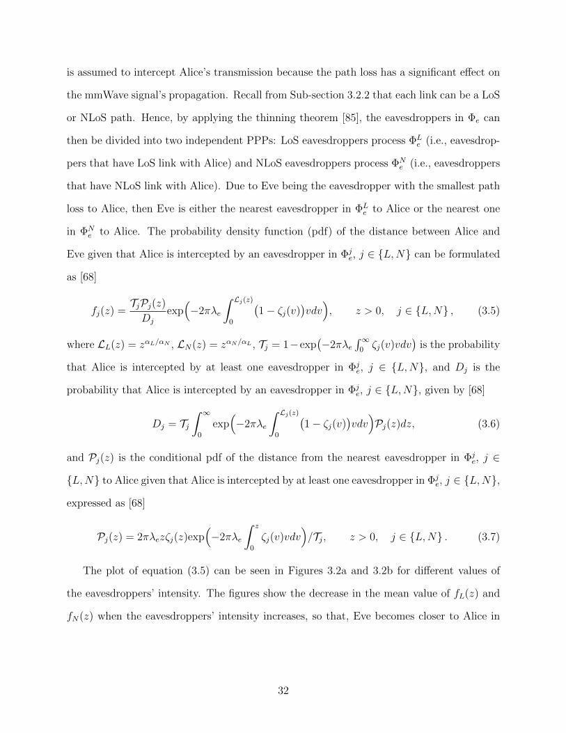
is assumed to intercept Alice’s transmission because the path loss has a significant effect on
the mmWave signal’s propagation. Recall from Sub-section 3.2.2 that each link can be a LoS
or NLoS path. Hence, by applying the thinning theorem [85], the eavesdroppers in Φe can
then be divided into two independent PPPs: LoS eavesdroppers process ΦLe (i.e., eavesdrop-
pers that have LoS link with Alice) and NLoS eavesdroppers process ΦNe (i.e., eavesdroppers
that have NLoS link with Alice). Due to Eve being the eavesdropper with the smallest path
loss to Alice, then Eve is either the nearest eavesdropper in ΦLe to Alice or the nearest one
in ΦNe to Alice. The probability density function (pdf) of the distance between Alice and
Eve given that Alice is intercepted by an eavesdropper in Φje, j ∈ L,N can be formulated
as [68]
fj(z) =TjPj(z)
Dj
exp(−2πλe
∫ Lj(z)0
(1− ζj(v)
)vdv), z > 0, j ∈ L,N , (3.5)
where LL(z) = zαL/αN , LN(z) = zαN/αL , Tj = 1−exp(−2πλe
∫∞0ζj(v)vdv
)is the probability
that Alice is intercepted by at least one eavesdropper in Φje, j ∈ L,N, and Dj is the
probability that Alice is intercepted by an eavesdropper in Φje, j ∈ L,N, given by [68]
Dj = Tj∫ ∞
0
exp(−2πλe
∫ Lj(z)0
(1− ζj(v)
)vdv)Pj(z)dz, (3.6)
and Pj(z) is the conditional pdf of the distance from the nearest eavesdropper in Φje, j ∈
L,N to Alice given that Alice is intercepted by at least one eavesdropper in Φje, j ∈ L,N,
expressed as [68]
Pj(z) = 2πλezζj(z)exp(−2πλe
∫ z
0
ζj(v)vdv)/Tj, z > 0, j ∈ L,N . (3.7)
The plot of equation (3.5) can be seen in Figures 3.2a and 3.2b for different values of
the eavesdroppers’ intensity. The figures show the decrease in the mean value of fL(z) and
fN(z) when the eavesdroppers’ intensity increases, so that, Eve becomes closer to Alice in
32
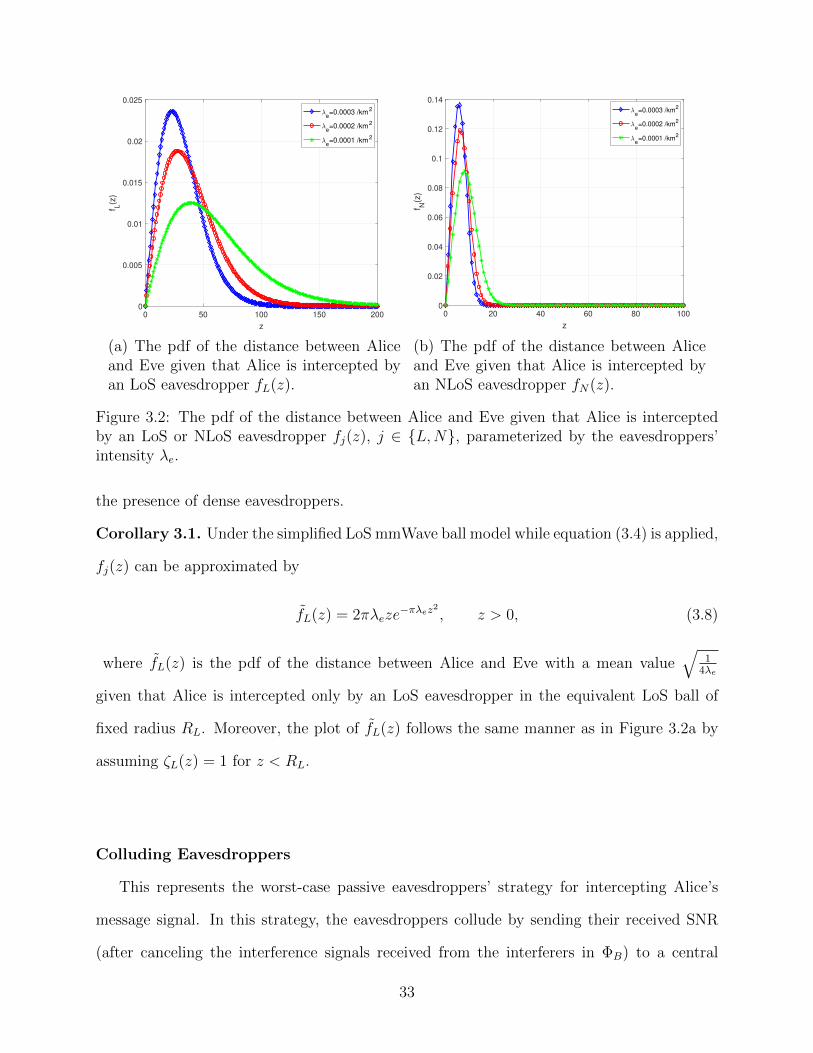
0 50 100 150 200
z
0
0.005
0.01
0.015
0.02
0.025
f L(z
)e=0.0003 /km
2
e=0.0002 /km
2
e=0.0001 /km
2
(a) The pdf of the distance between Aliceand Eve given that Alice is intercepted byan LoS eavesdropper fL(z).
0 20 40 60 80 100
z
0
0.02
0.04
0.06
0.08
0.1
0.12
0.14
fN
(z)
e=0.0003 /km
2
e=0.0002 /km
2
e=0.0001 /km
2
(b) The pdf of the distance between Aliceand Eve given that Alice is intercepted byan NLoS eavesdropper fN(z).
Figure 3.2: The pdf of the distance between Alice and Eve given that Alice is interceptedby an LoS or NLoS eavesdropper fj(z), j ∈ L,N, parameterized by the eavesdroppers’intensity λe.
the presence of dense eavesdroppers.
Corollary 3.1. Under the simplified LoS mmWave ball model while equation (3.4) is applied,
fj(z) can be approximated by
fL(z) = 2πλeze−πλez2
, z > 0, (3.8)
where fL(z) is the pdf of the distance between Alice and Eve with a mean value√
14λe
given that Alice is intercepted only by an LoS eavesdropper in the equivalent LoS ball of
fixed radius RL. Moreover, the plot of fL(z) follows the same manner as in Figure 3.2a by
assuming ζL(z) = 1 for z < RL.
Colluding Eavesdroppers
This represents the worst-case passive eavesdroppers’ strategy for intercepting Alice’s
message signal. In this strategy, the eavesdroppers collude by sending their received SNR
(after canceling the interference signals received from the interferers in ΦB) to a central
33
super processor(referred to, henceforth, as the main eavesdropper (Main-Eve)
)to decode
the message [32, 75]. In this chapter, Main-Eve uses the maximal ratio combining (MRC)
technique to combine the SNRs received from the eavesdroppers. In addition, it is assumed
that Main-Eve is strong enough to receive signals from the eavesdroppers without errors, so
that, the propagation losses between Main-Eve and the distributed eavesdroppers in Φe can
be neglected.
3.3 Analysis of Average Achievable Secrecy Rate under Non-Colluding
Eavesdroppers
In this section, the average achievable secrecy rate is derived for a mmWave ad hoc
network with message signal transmission via a multi-array antenna transmission in the
presence of non-colluding eavesdroppers, taking into account the impact of blockages, direc-
tional beamforming, and Nakagami-m fading. Then, approximate expressions for the average
achievable secrecy rate are derived, considering the simplified LoS mmWave ball model.
The average achievable secrecy rate in the presence of non-colluding eavesdroppers can
be calculated by [86]:
RS ,[Ru −Re
]+
, (3.9)
where Ru and Re are the average achievable data rates at Bob and Eve, respectively.
Bob Rate:
Firstly, the signal-to-interference-plus-noise ratio (SINR) at Bob ξu must be characterized
to compute its average achievable data rate, Ru. In addition to the useful signal obtained
by Bob from Alice, it receives unwanted signals from interferers in ΦB added to the thermal
noise power, σ2u. Hence, the SINR received at Bob can be formulated as
ξu =P t||hTo ||2GtMGuML(ro)∑
i∈ΦB\o P t||hTi ||2GiL(ri) + σ2u
, (3.10)
34
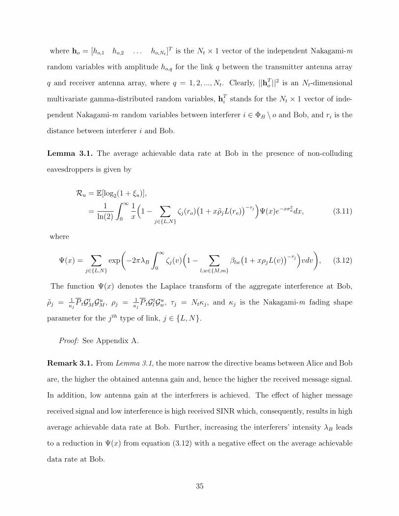
where ho = [ho,1 ho,2 . . . ho,Nt ]T is the Nt × 1 vector of the independent Nakagami-m
random variables with amplitude ho,q for the link q between the transmitter antenna array
q and receiver antenna array, where q = 1, 2, ..., Nt. Clearly, ||hTo ||2 is an Nt-dimensional
multivariate gamma-distributed random variables, hTi stands for the Nt × 1 vector of inde-
pendent Nakagami-m random variables between interferer i ∈ ΦB \ o and Bob, and ri is the
distance between interferer i and Bob.
Lemma 3.1. The average achievable data rate at Bob in the presence of non-colluding
eavesdroppers is given by
Ru = E[log2(1 + ξu)],
=1
ln(2)
∫ ∞0
1
x
(1−
∑j∈L,N
ζj(ro)(1 + xρjL(ro)
)−τj)Ψ(x)e−xσ2udx, (3.11)
where
Ψ(x) =∑
j∈L,N
exp
(−2πλB
∫ ∞0
ζj(v)(
1−∑
l,w∈M,m
βlw(1 + xρjL(v)
)−τj)vdv), (3.12)
The function Ψ(x) denotes the Laplace transform of the aggregate interference at Bob,
ρj = 1κjP tGtMGuM , ρj = 1
κjP tGtlGuw, τj = Ntκj, and κj is the Nakagami-m fading shape
parameter for the jth type of link, j ∈ L,N.
Proof: See Appendix A.
Remark 3.1. From Lemma 3.1, the more narrow the directive beams between Alice and Bob
are, the higher the obtained antenna gain and, hence the higher the received message signal.
In addition, low antenna gain at the interferers is achieved. The effect of higher message
received signal and low interference is high received SINR which, consequently, results in high
average achievable data rate at Bob. Further, increasing the interferers’ intensity λB leads
to a reduction in Ψ(x) from equation (3.12) with a negative effect on the average achievable
data rate at Bob.
35
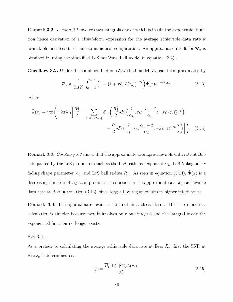
Remark 3.2. Lemma 3.1 involves two integrals one of which is inside the exponential func-
tion hence derivation of a closed-form expression for the average achievable data rate is
formidable and resort is made to numerical computation. An approximate result for Ru is
obtained by using the simplified LoS mmWave ball model in equation (3.4).
Corollary 3.2. Under the simplified LoS mmWave ball model, Ru can be approximated by
Ru ≈1
ln(2)
∫ ∞0
1
x
(1−
(1 + xρLL(ro)
)−τL)Ψ(x)e−xσ2udx, (3.13)
where
Ψ(x) = exp
(−2πλB
[R2L
2−
∑l,w∈M,m
βlw
(R2L
22F1
( 2
αL, τL;
αL − 2
αL;−xρLεR−αLL
)
− `2
22F1
( 2
αL, τL;
αL − 2
αL;−xρLε`−αL
))]). (3.14)
Remark 3.3. Corollary 3.2 shows that the approximate average achievable data rate at Bob
is impacted by the LoS parameters such as the LoS path loss exponent αL, LoS Nakagami-m
fading shape parameter κL, and LoS ball radius RL. As seen in equation (3.14), Ψ(x) is a
decreasing function of RL, and produces a reduction in the approximate average achievable
data rate at Bob in equation (3.13), since larger LoS region results in higher interference.
Remark 3.4. The approximate result is still not in a closed form. But the numerical
calculation is simpler because now it involves only one integral and the integral inside the
exponential function no longer exists.
Eve Rate:
As a prelude to calculating the average achievable data rate at Eve, Re, first the SNR at
Eve ξe is determined as:
ξe =P t||hTe ||2GeL(re)
σ2e
, (3.15)
36
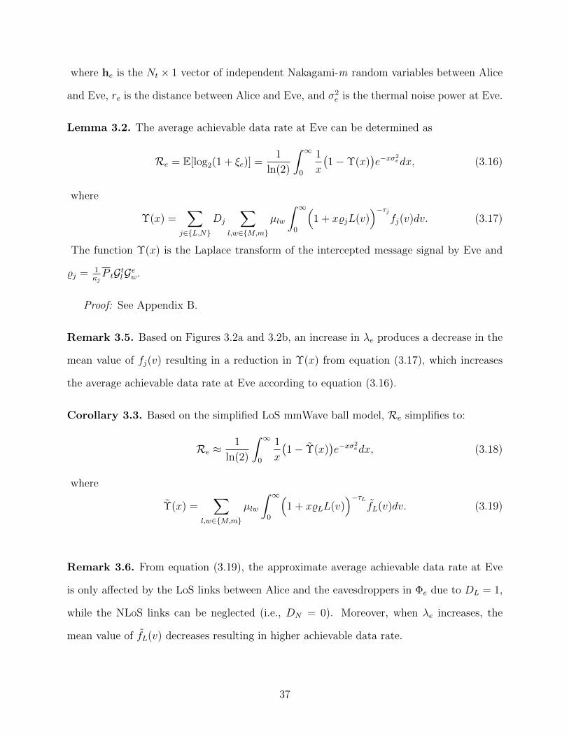
where he is the Nt × 1 vector of independent Nakagami-m random variables between Alice
and Eve, re is the distance between Alice and Eve, and σ2e is the thermal noise power at Eve.
Lemma 3.2. The average achievable data rate at Eve can be determined as
Re = E[log2(1 + ξe)] =1
ln(2)
∫ ∞0
1
x
(1−Υ(x)
)e−xσ
2edx, (3.16)
where
Υ(x) =∑
j∈L,N
Dj
∑l,w∈M,m
µlw
∫ ∞0
(1 + x%jL(v)
)−τjfj(v)dv. (3.17)
The function Υ(x) is the Laplace transform of the intercepted message signal by Eve and
%j = 1κjP tGtlGew.
Proof: See Appendix B.
Remark 3.5. Based on Figures 3.2a and 3.2b, an increase in λe produces a decrease in the
mean value of fj(v) resulting in a reduction in Υ(x) from equation (3.17), which increases
the average achievable data rate at Eve according to equation (3.16).
Corollary 3.3. Based on the simplified LoS mmWave ball model, Re simplifies to:
Re ≈1
ln(2)
∫ ∞0
1
x
(1− Υ(x)
)e−xσ
2edx, (3.18)
where
Υ(x) =∑
l,w∈M,m
µlw
∫ ∞0
(1 + x%LL(v)
)−τLfL(v)dv. (3.19)
Remark 3.6. From equation (3.19), the approximate average achievable data rate at Eve
is only affected by the LoS links between Alice and the eavesdroppers in Φe due to DL = 1,
while the NLoS links can be neglected (i.e., DN = 0). Moreover, when λe increases, the
mean value of fL(v) decreases resulting in higher achievable data rate.
37

Finally, by substituting equations (3.11) and (3.16) in equation (3.9), the exact aver-
age achievable secrecy rate of a mmWave ad hoc network with message transmission via
a multi-array antenna in the presence of non-colluding eavesdroppers can be determined.
Moreover, by substituting equations (3.13) and (3.18) in equation (3.9), the approximate
average achievable secrecy rate is obtained.
3.4 Analysis of Average Achievable Secrecy Rate under Colluding
Eavesdroppers
Unlike the previous section on non-colluding eavesdroppers where only one eavesdropper
Eve with the smallest path loss to Alice is assumed to intercept Alice’s signal, in this section
all the eavesdroppers in Φe can intercept Alice’s signal and transmit the intercepted signal
along with their background noise σ2e to Main-Eve where the signals are combined. However,
the average achievable data rate at Bob Ru remains the same as equation (3.11) in Lemma
3.1, because only the eavesdroppers’ interception strategy has changed.
Main-Eve Rate:
The SNRs collected at Main-Eve will be
ξce =∑e∈Φe
P t||hTe ||2GeL(re)
σ2e
, (3.20)
where he is the Nt × 1 vector of independent Nakagami-m random variables between Alice
and the eavesdropper e ∈ Φe and re is the distance between Alice and the eavesdropper e.
Lemma 3.3. The average achievable data rate at Main-Eve Rce can be calculated by:
Rce =E[log2(1 + ξce)],
=1
ln(2)
∫ ∞0
1
x
(1−Υc(x)
)e−xσ
2edx, (3.21)
where
Υc(x) =∑
j∈L,N
exp
(−2πλe
∫ ∞0
ζj(v)
(1−
∑l,w∈M,m
µlw
(1 + x%jL(v)
)−τj)vdv
), (3.22)
38
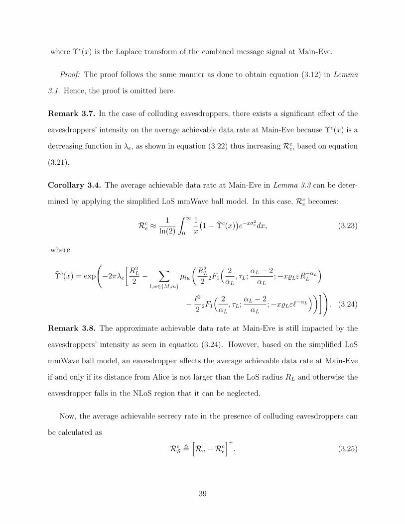
where Υc(x) is the Laplace transform of the combined message signal at Main-Eve.
Proof: The proof follows the same manner as done to obtain equation (3.12) in Lemma
3.1. Hence, the proof is omitted here.
Remark 3.7. In the case of colluding eavesdroppers, there exists a significant effect of the
eavesdroppers’ intensity on the average achievable data rate at Main-Eve because Υc(x) is a
decreasing function in λe, as shown in equation (3.22) thus increasing Rce, based on equation
(3.21).
Corollary 3.4. The average achievable data rate at Main-Eve in Lemma 3.3 can be deter-
mined by applying the simplified LoS mmWave ball model. In this case, Rce becomes:
Rce ≈
1
ln(2)
∫ ∞0
1
x
(1− Υc(x)
)e−xσ
2edx, (3.23)
where
Υc(x) = exp
(−2πλe
[R2L
2−
∑l,w∈M,m
µlw
(R2L
22F1
( 2
αL, τL;
αL − 2
αL;−x%LεR−αLL
)
− `2
22F1
( 2
αL, τL;
αL − 2
αL;−x%Lε`−αL
))]). (3.24)
Remark 3.8. The approximate achievable data rate at Main-Eve is still impacted by the
eavesdroppers’ intensity as seen in equation (3.24). However, based on the simplified LoS
mmWave ball model, an eavesdropper affects the average achievable data rate at Main-Eve
if and only if its distance from Alice is not larger than the LoS radius RL and otherwise the
eavesdropper falls in the NLoS region that it can be neglected.
Now, the average achievable secrecy rate in the presence of colluding eavesdroppers can
be calculated as
RcS ,
[Ru −Rc
e
]+
. (3.25)
39
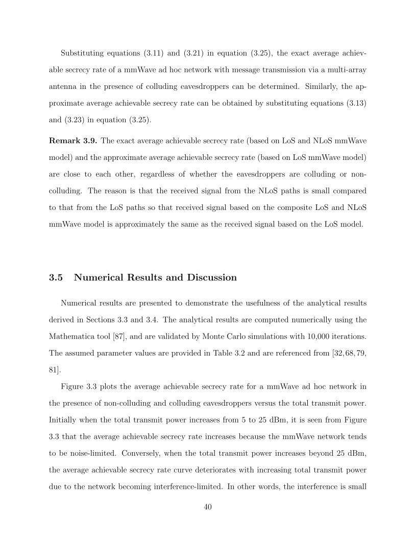
Substituting equations (3.11) and (3.21) in equation (3.25), the exact average achiev-
able secrecy rate of a mmWave ad hoc network with message transmission via a multi-array
antenna in the presence of colluding eavesdroppers can be determined. Similarly, the ap-
proximate average achievable secrecy rate can be obtained by substituting equations (3.13)
and (3.23) in equation (3.25).
Remark 3.9. The exact average achievable secrecy rate (based on LoS and NLoS mmWave
model) and the approximate average achievable secrecy rate (based on LoS mmWave model)
are close to each other, regardless of whether the eavesdroppers are colluding or non-
colluding. The reason is that the received signal from the NLoS paths is small compared
to that from the LoS paths so that received signal based on the composite LoS and NLoS
mmWave model is approximately the same as the received signal based on the LoS model.
3.5 Numerical Results and Discussion
Numerical results are presented to demonstrate the usefulness of the analytical results
derived in Sections 3.3 and 3.4. The analytical results are computed numerically using the
Mathematica tool [87], and are validated by Monte Carlo simulations with 10,000 iterations.
The assumed parameter values are provided in Table 3.2 and are referenced from [32,68,79,
81].
Figure 3.3 plots the average achievable secrecy rate for a mmWave ad hoc network in
the presence of non-colluding and colluding eavesdroppers versus the total transmit power.
Initially when the total transmit power increases from 5 to 25 dBm, it is seen from Figure
3.3 that the average achievable secrecy rate increases because the mmWave network tends
to be noise-limited. Conversely, when the total transmit power increases beyond 25 dBm,
the average achievable secrecy rate curve deteriorates with increasing total transmit power
due to the network becoming interference-limited. In other words, the interference is small
40
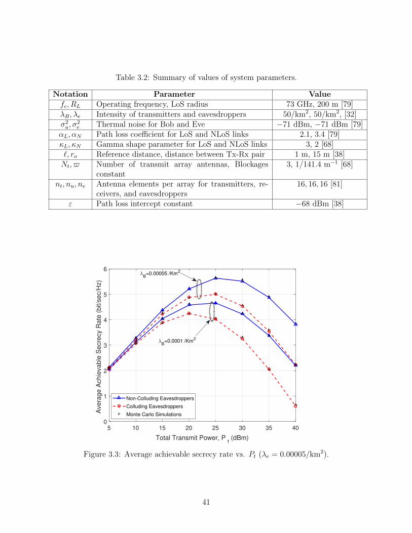
Table 3.2: Summary of values of system parameters.
Notation Parameter Valuefc, RL Operating frequency, LoS radius 73 GHz, 200 m [79]
λB, λe Intensity of transmitters and eavesdroppers 50/km2, 50/km2, [32]σ2u, σ
2e Thermal noise for Bob and Eve −71 dBm, −71 dBm [79]
αL, αN Path loss coefficient for LoS and NLoS links 2.1, 3.4 [79]κL, κN Gamma shape parameter for LoS and NLoS links 3, 2 [68]`, ro Reference distance, distance between Tx-Rx pair 1 m, 15 m [38]Nt, $ Number of transmit array antennas, Blockages
constant3, 1/141.4 m−1 [68]
nt, nu, ne Antenna elements per array for transmitters, re-ceivers, and eavesdroppers
16, 16, 16 [81]
ε Path loss intercept constant −68 dBm [38]
5 10 15 20 25 30 35 40
Total Transmit Power, Pt (dBm)
0
1
2
3
4
5
6
Avera
ge A
chie
vable
Secre
cy R
ate
(bit/s
ec/H
z)
Non-Colluding Eavesdroppers
Colluding Eavesdroppers
Monte Carlo Simulations
B=0.00005 /Km
2
B=0.0001 /Km
2
Figure 3.3: Average achievable secrecy rate vs. Pt (λe = 0.00005/km2).
41
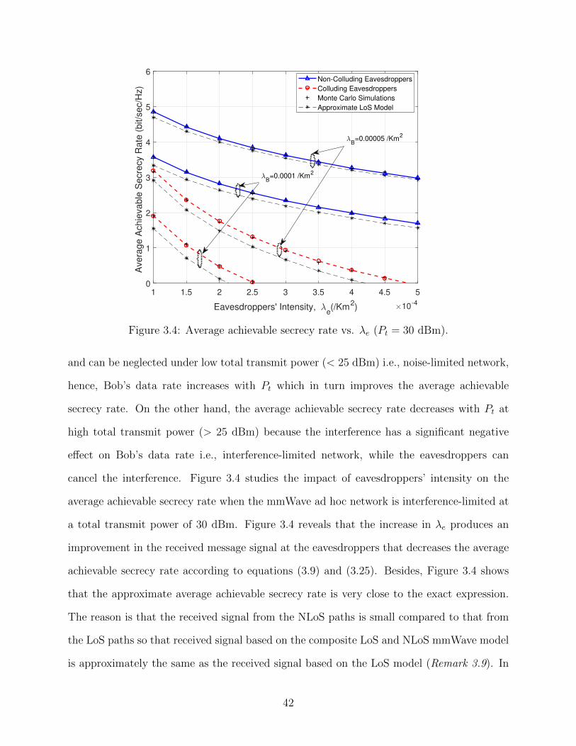
1 1.5 2 2.5 3 3.5 4 4.5 5
Eavesdroppers' Intensity, e(/Km
2) 10
-4
0
1
2
3
4
5
6
Avera
ge A
chie
vable
Secre
cy R
ate
(bit/s
ec/H
z)
Non-Colluding Eavesdroppers
Colluding Eavesdroppers
Monte Carlo Simulations
Approximate LoS Model
B=0.00005 /Km
2
B=0.0001 /Km
2
Figure 3.4: Average achievable secrecy rate vs. λe (Pt = 30 dBm).
and can be neglected under low total transmit power (< 25 dBm) i.e., noise-limited network,
hence, Bob’s data rate increases with Pt which in turn improves the average achievable
secrecy rate. On the other hand, the average achievable secrecy rate decreases with Pt at
high total transmit power (> 25 dBm) because the interference has a significant negative
effect on Bob’s data rate i.e., interference-limited network, while the eavesdroppers can
cancel the interference. Figure 3.4 studies the impact of eavesdroppers’ intensity on the
average achievable secrecy rate when the mmWave ad hoc network is interference-limited at
a total transmit power of 30 dBm. Figure 3.4 reveals that the increase in λe produces an
improvement in the received message signal at the eavesdroppers that decreases the average
achievable secrecy rate according to equations (3.9) and (3.25). Besides, Figure 3.4 shows
that the approximate average achievable secrecy rate is very close to the exact expression.
The reason is that the received signal from the NLoS paths is small compared to that from
the LoS paths so that received signal based on the composite LoS and NLoS mmWave model
is approximately the same as the received signal based on the LoS model (Remark 3.9). In
42
both Figures 3.3 and 3.4, the average achievable secrecy rate in the presence of colluding
eavesdroppers is worse than that of non-colluding eavesdroppers, as expected. Similarly, the
average achievable secrecy rate at a low interferers’ intensity λB = 0.00005/km2 is better
than that at high intensity λB = 0.0001/km2.
10 15 20 25 30 35 40
Distance between Typical Tx-Rx, ro (m)
0
1
2
3
4
5
6
7
Avera
ge A
chie
vable
Secre
cy R
ate
(bit/s
ec/H
z)
Non-Colluding Eavesdroppers
Colluding Eavesdroppers
Monte Carlo Simulations
B=0.00005 /Km
2
B=0.0001 /Km
2
Figure 3.5: Average achievable secrecy rate vs. Pt (λe = 0.00005/km2).
Figure 3.5 illustrates the effect of varying the distance between Alice and Bob on the av-
erage achievable secrecy rate of mmWave ad hoc network. The results show that the average
achievable secrecy rate decreases when the separation distance increases. The degradation
happens due to the reduction in the received message signal power from Alice when Bob is
farther away. Besides, the figure confirms that the secrecy threats on the mmWave ad hoc
network in the presence of colluding eavesdroppers are high compared to the presence of
non-colluding eavesdroppers. Moreover, a dense network with high interferers’ intensity λB
reduces the secrecy performance.
The surface plot showing the combined impact of the total transmit power and the
eavesdroppers’ intensity on the average achievable secrecy rate is depicted in Figure 3.6. The
43
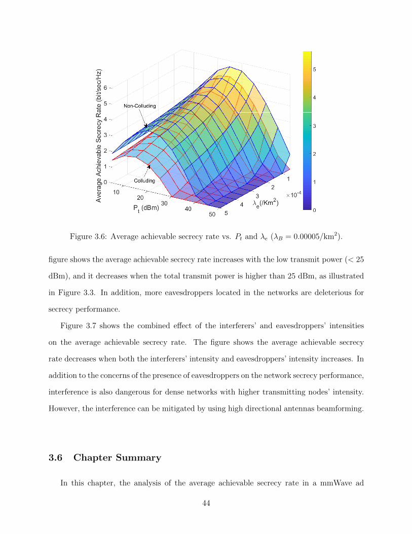
Figure 3.6: Average achievable secrecy rate vs. Pt and λe (λB = 0.00005/km2).
figure shows the average achievable secrecy rate increases with the low transmit power (< 25
dBm), and it decreases when the total transmit power is higher than 25 dBm, as illustrated
in Figure 3.3. In addition, more eavesdroppers located in the networks are deleterious for
secrecy performance.
Figure 3.7 shows the combined effect of the interferers’ and eavesdroppers’ intensities
on the average achievable secrecy rate. The figure shows the average achievable secrecy
rate decreases when both the interferers’ intensity and eavesdroppers’ intensity increases. In
addition to the concerns of the presence of eavesdroppers on the network secrecy performance,
interference is also dangerous for dense networks with higher transmitting nodes’ intensity.
However, the interference can be mitigated by using high directional antennas beamforming.
3.6 Chapter Summary
In this chapter, the analysis of the average achievable secrecy rate in a mmWave ad
44
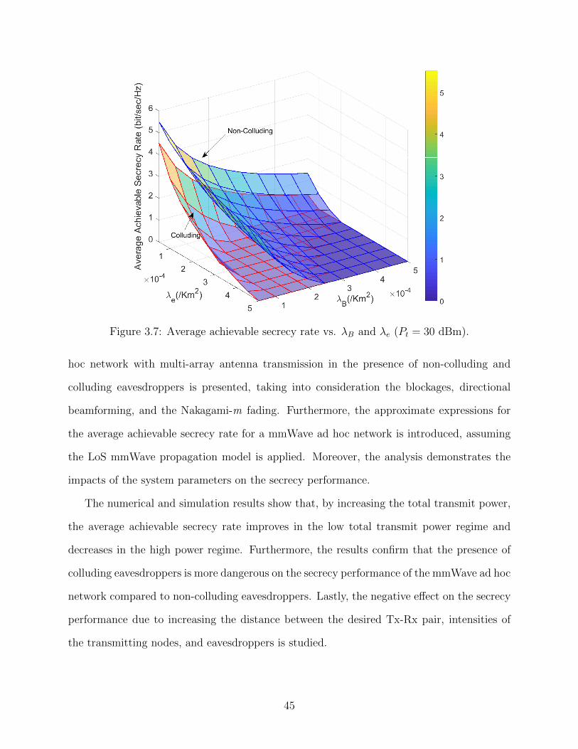
Figure 3.7: Average achievable secrecy rate vs. λB and λe (Pt = 30 dBm).
hoc network with multi-array antenna transmission in the presence of non-colluding and
colluding eavesdroppers is presented, taking into consideration the blockages, directional
beamforming, and the Nakagami-m fading. Furthermore, the approximate expressions for
the average achievable secrecy rate for a mmWave ad hoc network is introduced, assuming
the LoS mmWave propagation model is applied. Moreover, the analysis demonstrates the
impacts of the system parameters on the secrecy performance.
The numerical and simulation results show that, by increasing the total transmit power,
the average achievable secrecy rate improves in the low total transmit power regime and
decreases in the high power regime. Furthermore, the results confirm that the presence of
colluding eavesdroppers is more dangerous on the secrecy performance of the mmWave ad hoc
network compared to non-colluding eavesdroppers. Lastly, the negative effect on the secrecy
performance due to increasing the distance between the desired Tx-Rx pair, intensities of
the transmitting nodes, and eavesdroppers is studied.
45
Chapter 4
Physical Layer Security in the Presence of
Passive/Active Eavesdroppers 1
4.1 Introduction
This chapter analyzes the physical layer security (PLS) of millimeter-wave (mmWave) ad
hoc networks in the presence of passive/active eavesdroppers. In the considered model,
the passive/active eavesdroppers operate in the full-duplex (FD) mode while most works
in the literature focus on passive eavesdroppers and conventional microwave ad hoc net-
works [19–24]. In this chapter, the mathematical expressions are derived for the secrecy
performance metrics including connection outage probability, secrecy outage probability,
and average achievable secrecy rate, taking into consideration the directional beamforming,
multi-array antennas, blockages, and Nakagami-m fading. Furthermore, the impact of the
signal-to-interference-plus-noise ratio (SINR) and secrecy rate thresholds on the connection
and secrecy outage probabilities has been studied, respectively. Besides, the effects of the
eavesdroppers’ intensity, interferers’ intensity, total transmit message power, and jamming
power on the secrecy performance are investigated.
The numerical and simulation results show that the presence of passive/active eavesdrop-
pers has a more deleterious impact on the secrecy performance compared to the presence
of passive eavesdroppers in both noise-limited and interference-limited networks. Moreover,
the results demonstrate the negative effect of increasing the eavesdropper’s jamming power
on the secrecy performance. For example, at 30 dBm jamming power, the average achievable
1The content of this chapter has been submitted to the IEEE Transactions on Wireless Communications[51], A. F. Darwesh and A. O. Fapojuwo, ”Physical Layer Security Analysis of mmWave Ad Hoc Networksin the Presence of Passive/Active Eavesdroppers,”, 2020. Currently undergoing peer review.
46
secrecy rate is less than that achieved at 20 dBm jamming power by a factor of 2. Further,
the secrecy performance faces a high degradation in the presence of dense passive/active
eavesdroppers.
4.2 System Model
A mmWave ad hoc network is considered following the same network model in subsection
3. However, the channel state information (CSI) between each array antenna of Alice and
the array antenna of Bob is assumed to be perfectly known. Hence, the maximum ratio
transmitting (MRT) technique is used to maximize the received signal at Bob by multiplying
the transmitted signal with a channel linear precoder.
Furthermore, the simplified line-of-sight (LoS) mmWave model in subsection 3.2.3 is
applied. Therefore, the LoS propagation is parameterized by a LoS radius RL [15]. Hence,
the path loss function for a LoS link of length r is given by [38,84]:
LL(r) = ε(max`, r)−αLU(RL − r), (4.1a)
where
U(RL − r) =
1, r ≤ RL,
0, r > RL,
(4.1b)
and αL is the LoS path loss exponent. Moreover, for each LoS link, the Nakagami random
variable is used to model the small-scale fading amplitude h with shape parameter κL [68].
Subsequently, the received faded signal power h2 is modeled as a gamma random variable,
h2 ∼ Γ(κL, δ) with pdf as follows:
fh2(x) = Γ(κL, δ) =xκL−1e
−xδ
Γ(κL)δκL, (4.1)
where δ = 1κL
is the scale parameter of the gamma random variable.
Further, a group of passive/active eavesdroppers whose locations are modeled by an
independent homogeneous Poisson point process (PPP) Φe with intensity λe is considered
47
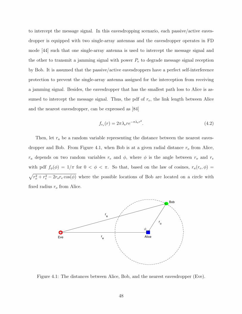
to intercept the message signal. In this eavesdropping scenario, each passive/active eaves-
dropper is equipped with two single-array antennas and the eavesdropper operates in FD
mode [44] such that one single-array antenna is used to intercept the message signal and
the other to transmit a jamming signal with power Pe to degrade message signal reception
by Bob. It is assumed that the passive/active eavesdroppers have a perfect self-interference
protection to prevent the single-array antenna assigned for the interception from receiving
a jamming signal. Besides, the eavesdropper that has the smallest path loss to Alice is as-
sumed to intercept the message signal. Thus, the pdf of re, the link length between Alice
and the nearest eavesdropper, can be expressed as [84]
fre(r) = 2πλere−πλer2
. (4.2)
Then, let ra be a random variable representing the distance between the nearest eaves-
dropper and Bob. From Figure 4.1, when Bob is at a given radial distance ro from Alice,
ra depends on two random variables re and φ, where φ is the angle between ro and re
with pdf fφ(φ) = 1/π for 0 < φ < π. So that, based on the law of cosines, ra(re, φ) =√r2o + r2
e − 2rore cos(φ) where the possible locations of Bob are located on a circle with
fixed radius ro from Alice.
0
0.1
0.2
0.3
0.4
0.5
0.6
0.7
0.8
0.9
1
Bob
Alicere
ra
Eve
ro
Figure 4.1: The distances between Alice, Bob, and the nearest eavesdropper (Eve).
48
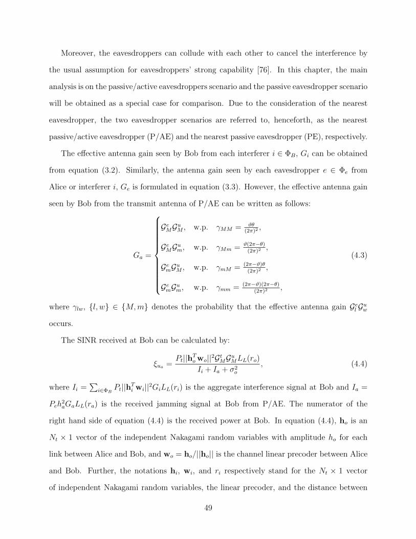
Moreover, the eavesdroppers can collude with each other to cancel the interference by
the usual assumption for eavesdroppers’ strong capability [76]. In this chapter, the main
analysis is on the passive/active eavesdroppers scenario and the passive eavesdropper scenario
will be obtained as a special case for comparison. Due to the consideration of the nearest
eavesdropper, the two eavesdropper scenarios are referred to, henceforth, as the nearest
passive/active eavesdropper (P/AE) and the nearest passive eavesdropper (PE), respectively.
The effective antenna gain seen by Bob from each interferer i ∈ ΦB, Gi can be obtained
from equation (3.2). Similarly, the antenna gain seen by each eavesdropper e ∈ Φe from
Alice or interferer i, Ge is formulated in equation (3.3). However, the effective antenna gain
seen by Bob from the transmit antenna of P/AE can be written as follows:
Ga =
GeMGuM , w.p. γMM = ϑθ(2π)2 ,
GeMGum, w.p. γMm = ϑ(2π−θ)(2π)2 ,
GemGuM , w.p. γmM = (2π−ϑ)θ(2π)2 ,
GemGum, w.p. γmm = (2π−ϑ)(2π−θ)(2π)2 ,
(4.3)
where γlw, l, w ∈ M,m denotes the probability that the effective antenna gain Gel Guw
occurs.
The SINR received at Bob can be calculated by:
ξua =Pt||hTo wo||2GtMGuMLL(ro)
Ii + Ia + σ2o
, (4.4)
where Ii =∑
i∈ΦBPt||hTi wi||2GiLL(ri) is the aggregate interference signal at Bob and Ia =
Peh2aGaLL(ra) is the received jamming signal at Bob from P/AE. The numerator of the
right hand side of equation (4.4) is the received power at Bob. In equation (4.4), ho is an
Nt × 1 vector of the independent Nakagami random variables with amplitude ho for each
link between Alice and Bob, and wo = ho/||ho|| is the channel linear precoder between Alice
and Bob. Further, the notations hi, wi, and ri respectively stand for the Nt × 1 vector
of independent Nakagami random variables, the linear precoder, and the distance between
49
interferer i and Bob. Finally, ha denotes an independent Nakagami random variable, ra is
the distance between P/AE and Bob.
The signal-to-noise ratio (SNR) received at P/AE is calculated as follows:
ξea =Pt||hTe wo||2GeLL(re)
σ2e
, (4.5)
where he is the Nt×1 vector of the independent Nakagami random variables with amplitude
he for each link between Alice and P/AE.
4.3 Analysis of Connection Outage Probability under Passive/Active
Eavesdroppers
In this section, it is necessary to study the connection outage probability due to the
received jamming signal at Bob, which is transmitted by P/AE, plus the existence of inter-
fering signals and small-scale fading. Therefore, the connection outage probability is defined
as the probability that the received SINR ξua at Bob falls below a threshold SINR of T0:
Cout(T0) = Prξua < T0
, (4.6)
Lemma 4.1. For a given threshold SINR T0, the connection outage probability Cout(T0), of
a mmWave ad hoc network under the effects of interference signals and P/AE’s jamming
signal is given by:
Cout(T0) = 1−τL∑b=1
(τLb
)(−1)b+1e−
b$T0σ2u
A ψ1(T0)ψ2(T0), (4.7)
where τL = NtκL, $ = κL(τL!)−1τL , and A = PtGtMGuMLL(ro); ψ1(T0) and ψ2(T0) are the
Laplace transform of the interference and jamming signals at Bob, respectively, obtained as
follows:
50
ψ1(T0) = exp
(−2πλB
∫ RL
0
(1−
∑l,w∈M,m
βlw
(1 +
1
κL
b$T0PtGtlGuwLL(v)
A
)−τL)vdv
),
(4.8)
ψ2(T0) =
∫ ∞0
∫ π
0
∑l,w∈M,m
γlw
(1 +
1
κL
b$T0PeGel GuwL(ra(v, t)
)A
)−κLfre(v)fφ(t)dtdv. (4.9)
Proof: See Appendix C.
Remark 4.1. From observing equation (4.7), the connection outage probability Cout(T0)
increases with increasing the threshold SINR T0. Furthermore, increasing the interferers’
intensity λB produces a deterioration in ψ1(T0) as seen in equation (4.8) (for example, e−x is
a decreasing function with increasing x), which in turn increases Cout(T0). In addition, from
equation (4.9), ψ2(T0) decreases with more transmit jamming power Pe by P/AE that leads
also to an increase in Cout(T0).
4.3.1 Analysis for Noise-Limited Networks
In this subsection, the connection outage probability is calculated for a special case when
there is no interference in the network. In this case, it is expected to reduce the connection
outage probability due to the higher received SINR at Bob (see equation (4.4)).
Corollary 4.1. For the noise-limited network scenario, the interference signal part ψ1(T0)
in equation (4.7) will be neglected and the connection outage probability can be calculated
as follows:
CNout(T0) = 1−τL∑b=1
(τLb
)(−1)b+1e−
b$T0σ2u
A ψ2(T0). (4.10)
51
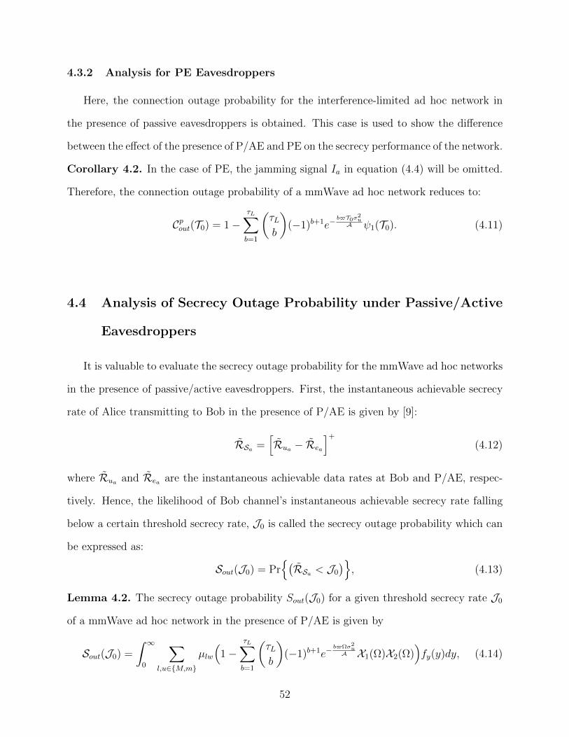
4.3.2 Analysis for PE Eavesdroppers
Here, the connection outage probability for the interference-limited ad hoc network in
the presence of passive eavesdroppers is obtained. This case is used to show the difference
between the effect of the presence of P/AE and PE on the secrecy performance of the network.
Corollary 4.2. In the case of PE, the jamming signal Ia in equation (4.4) will be omitted.
Therefore, the connection outage probability of a mmWave ad hoc network reduces to:
Cpout(T0) = 1−τL∑b=1
(τLb
)(−1)b+1e−
b$T0σ2u
A ψ1(T0). (4.11)
4.4 Analysis of Secrecy Outage Probability under Passive/Active
Eavesdroppers
It is valuable to evaluate the secrecy outage probability for the mmWave ad hoc networks
in the presence of passive/active eavesdroppers. First, the instantaneous achievable secrecy
rate of Alice transmitting to Bob in the presence of P/AE is given by [9]:
RSa =[Rua − Rea
]+
(4.12)
where Rua and Rea are the instantaneous achievable data rates at Bob and P/AE, respec-
tively. Hence, the likelihood of Bob channel’s instantaneous achievable secrecy rate falling
below a certain threshold secrecy rate, J0 is called the secrecy outage probability which can
be expressed as:
Sout(J0) = Pr(RSa < J0
), (4.13)
Lemma 4.2. The secrecy outage probability Sout(J0) for a given threshold secrecy rate J0
of a mmWave ad hoc network in the presence of P/AE is given by
Sout(J0) =
∫ ∞0
∑l,u∈M,m
µlw
(1−
τL∑b=1
(τLb
)(−1)b+1e−
b$Ωσ2u
A X1(Ω)X2(Ω))fy(y)dy, (4.14)
52
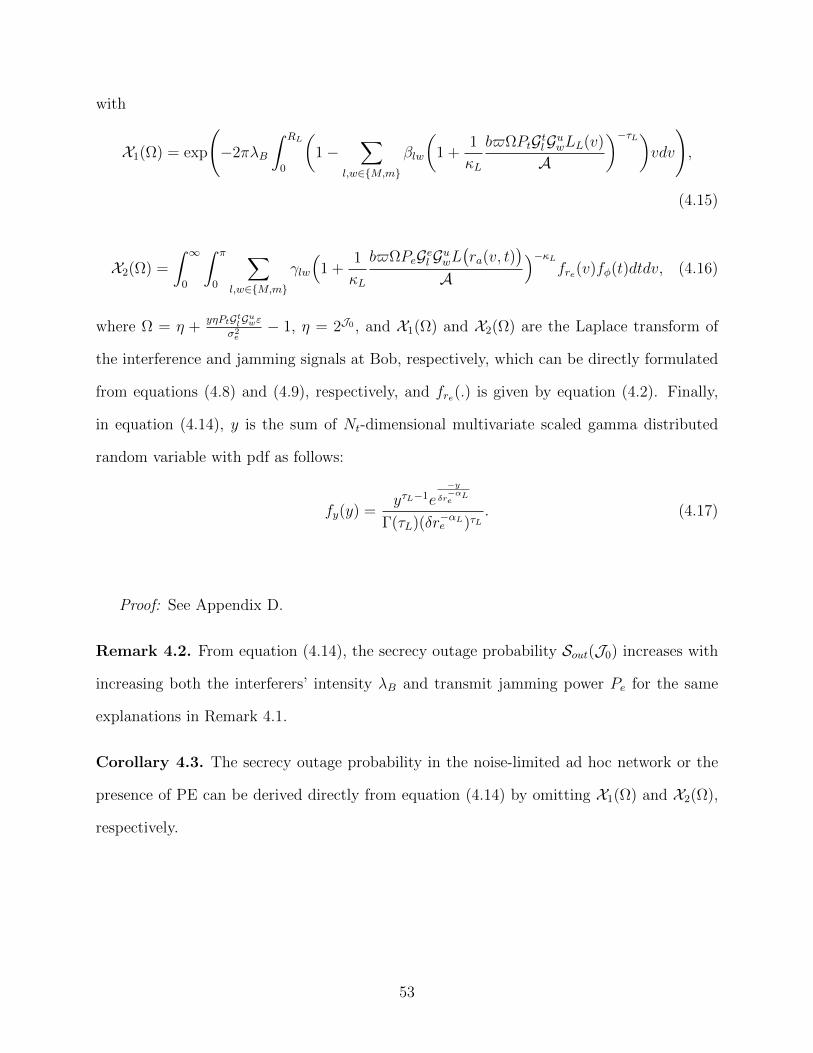
with
X1(Ω) = exp
(−2πλB
∫ RL
0
(1−
∑l,w∈M,m
βlw
(1 +
1
κL
b$ΩPtGtlGuwLL(v)
A
)−τL)vdv
),
(4.15)
X2(Ω) =
∫ ∞0
∫ π
0
∑l,w∈M,m
γlw
(1 +
1
κL
b$ΩPeGel GuwL(ra(v, t)
)A
)−κLfre(v)fφ(t)dtdv, (4.16)
where Ω = η +yηPtGtlG
uwε
σ2e
− 1, η = 2J0 , and X1(Ω) and X2(Ω) are the Laplace transform of
the interference and jamming signals at Bob, respectively, which can be directly formulated
from equations (4.8) and (4.9), respectively, and fre(.) is given by equation (4.2). Finally,
in equation (4.14), y is the sum of Nt-dimensional multivariate scaled gamma distributed
random variable with pdf as follows:
fy(y) =yτL−1e
−yδr−αLe
Γ(τL)(δr−αLe )τL. (4.17)
Proof: See Appendix D.
Remark 4.2. From equation (4.14), the secrecy outage probability Sout(J0) increases with
increasing both the interferers’ intensity λB and transmit jamming power Pe for the same
explanations in Remark 4.1.
Corollary 4.3. The secrecy outage probability in the noise-limited ad hoc network or the
presence of PE can be derived directly from equation (4.14) by omitting X1(Ω) and X2(Ω),
respectively.
53
4.5 Analysis of Average Achievable Secrecy Rate under Passive/Active
Eavesdroppers
The average achievable secrecy rate is the difference between the average achievable data
rate at the legitimate receiver Rua , and the average data rate at the eavesdropper Rea , which
can be expressed as:
RSa ,[E[
log2
(1 + ξua
)]− E
[log2
(1 + ξea
)]]+
(4.18)
Lemma 4.3. The average achievable secrecy rate of a mmWave ad hoc network in the
presence of interference and P/AE can be expressed as
RSa ,[Rua −Rea
]+
. (4.19)
Achievable rate at Bob, Rua :
Then, the average achievable data rate at Bob in the presence of interference and P/AE is
expressed as:
Rua =1
ln(2)
∫ ∞0
1
x
(1−
(1 +
1
κLxPtGtMGuMLL(ro)
)−τL)υ1(x)υ2(x)e−xσ2udx, (4.20)
with
υ1(x) = exp
(−2πλB
∫ RL
0
(1−
∑l,w∈M,m
βl,w(1 +
1
κLxPtGtlGuwLL(v)
)−τL)vdv), (4.21)
υ2(x) =
∫ ∞0
∫ π
0
∑l,w∈M,m
γlw
(1 +
1
κLPeGel GuwL
(ra(v, t)
))−κLfre(v)fφ(t)dtdv, (4.22)
where υ1(x) and υ2(x) denote the Laplace transform of the aggregate interference signals
and jamming signal at Bob, respectively.
Achievable rate at Eve, Rea :
On the other hand, the average achievable data rate at P/AE can be obtained as follows:
Rea =1
ln(2)
∫ ∞0
1
x
(1− Ξ(x)
)e−xσ
2edx, (4.23)
54
where Ξ(x) is the Laplace transform of the intercepted message signal at P/AE, which is
given by
Ξ(x) =
∫ ∞0
∑l,w∈M,m
µlw
(1 +
1
κLxPtGtlGewLL(v)
)−τLfre(v)dv. (4.24)
Finally, by substituting equations (4.20) and (4.23) in equation (4.19), the average achiev-
able secrecy rate of a mmWave ad hoc network in the presence of interference and P/AE is
obtained.
Proof : See Appendix E.
Remark 4.3. As seen in equation (4.20), Rua improves with increasing Nt, however, υ1(x)
decreases which in turn decreases Rua . On the other hand, from equation (4.24), Ξ(x)
decreases with increasing Nt which leads to an increase in Rea , from equation (4.23).
Corollary 4.4. For the noise-limited ad hoc network, the average achievable secrecy rate
can be formulated from equation (4.20) by removing υ1(x). Moreover, the average achievable
secrecy rate in the presence of PE is expressed by omitting υ2(x) in equation (4.20).
4.6 Numerical Results and Discussion
In this section, the numerical results of Sections 4.3, 4.4, and 4.5 are validated by sim-
ulation results. The secrecy performance of a mmWave ad hoc network in the presence of
passive/active eavesdroppers is presented and compared with the presence of passive eaves-
droppers for both noise-limited and interference-limited networks. The assumed parameter
values are provided in Table 3.2 (Section 3.5) and Table 4.1.
Figure 4.2 plots the connection outage probability of a mmWave ad hoc network in the
presence of P/AE and PE versus threshold SINR T0 and parameterized by eavesdroppers’
intensity. The figure shows that the connection outage probability increases with the higher
55
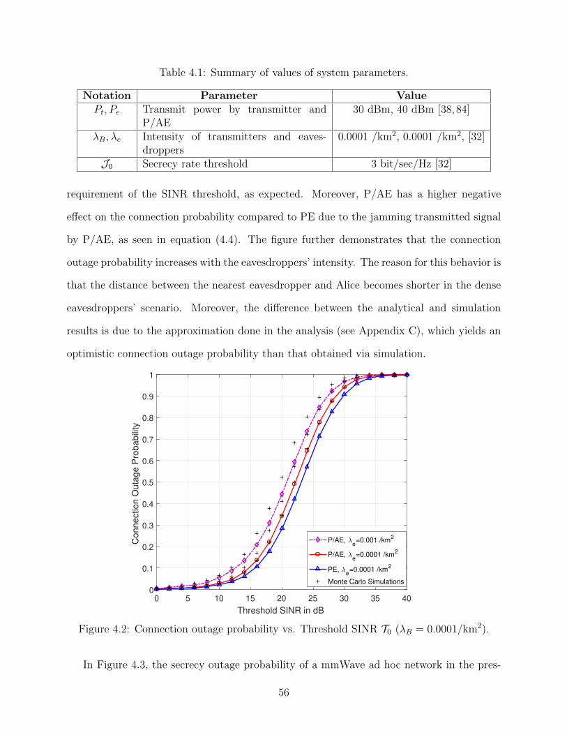
Table 4.1: Summary of values of system parameters.
Notation Parameter ValuePt, Pe Transmit power by transmitter and
P/AE30 dBm, 40 dBm [38,84]
λB, λe Intensity of transmitters and eaves-droppers
0.0001 /km2, 0.0001 /km2, [32]
J0 Secrecy rate threshold 3 bit/sec/Hz [32]
requirement of the SINR threshold, as expected. Moreover, P/AE has a higher negative
effect on the connection probability compared to PE due to the jamming transmitted signal
by P/AE, as seen in equation (4.4). The figure further demonstrates that the connection
outage probability increases with the eavesdroppers’ intensity. The reason for this behavior is
that the distance between the nearest eavesdropper and Alice becomes shorter in the dense
eavesdroppers’ scenario. Moreover, the difference between the analytical and simulation
results is due to the approximation done in the analysis (see Appendix C), which yields an
optimistic connection outage probability than that obtained via simulation.
0 5 10 15 20 25 30 35 40
Threshold SINR in dB
0
0.1
0.2
0.3
0.4
0.5
0.6
0.7
0.8
0.9
1
Connection O
uta
ge P
robabili
ty
P/AE, e=0.001 /km
2
P/AE, e=0.0001 /km
2
PE, e=0.0001 /km
2
Monte Carlo Simulations
Figure 4.2: Connection outage probability vs. Threshold SINR T0 (λB = 0.0001/km2).
In Figure 4.3, the secrecy outage probability of a mmWave ad hoc network in the pres-
56
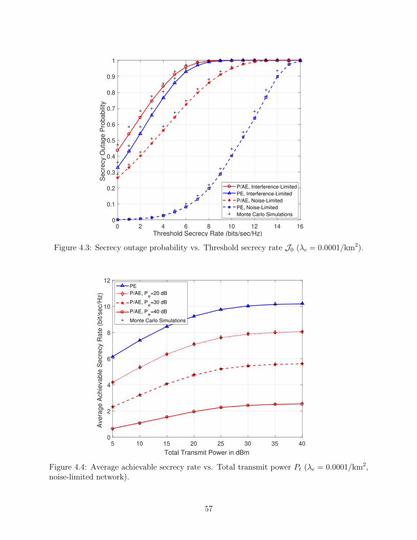
0 2 4 6 8 10 12 14 16
Threshold Secrecy Rate (bits/sec/Hz)
0
0.1
0.2
0.3
0.4
0.5
0.6
0.7
0.8
0.9
1
Secre
cy O
uta
ge P
robabili
ty
P/AE, Interference-Limited
PE, Interference-Limited
P/AE, Noise-Limited
PE, Noise-Limited
Monte Carlo Simulations
Figure 4.3: Secrecy outage probability vs. Threshold secrecy rate J0 (λe = 0.0001/km2).
5 10 15 20 25 30 35 40
Total Transmit Power in dBm
0
2
4
6
8
10
12
Avera
ge A
chie
vable
Secre
cy R
ate
(bit/s
ec/H
z)
PE
P/AE, Pe=20 dB
P/AE, Pe=30 dB
P/AE, Pe=40 dB
Monte Carlo Simulations
Figure 4.4: Average achievable secrecy rate vs. Total transmit power Pt (λe = 0.0001/km2,noise-limited network).
57
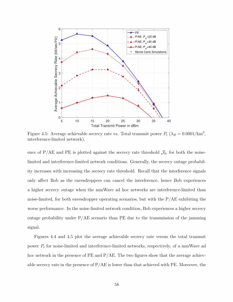
5 10 15 20 25 30 35 40
Total Transmit Power in dBm
0
1
2
3
4
5
6
Avera
ge A
chie
vable
Secre
cy R
ate
(bit/s
ec/H
z)
PE
P/AE, Pe=20 dB
P/AE, Pe=30 dB
P/AE, Pe=40 dB
Monte Carlo Simulations
Figure 4.5: Average achievable secrecy rate vs. Total transmit power Pt (λB = 0.0001/km2,interference-limited network).
ence of P/AE and PE is plotted against the secrecy rate threshold J0, for both the noise-
limited and interference-limited network conditions. Generally, the secrecy outage probabil-
ity increases with increasing the secrecy rate threshold. Recall that the interference signals
only affect Bob as the eavesdroppers can cancel the interference, hence Bob experiences
a higher secrecy outage when the mmWave ad hoc networks are interference-limited than
noise-limited, for both eavesdropper operating scenarios, but with the P/AE exhibiting the
worse performance. In the noise-limited network condition, Bob experiences a higher secrecy
outage probability under P/AE scenario than PE due to the transmission of the jamming
signal.
Figures 4.4 and 4.5 plot the average achievable secrecy rate versus the total transmit
power Pt for noise-limited and interference-limited networks, respectively, of a mmWave ad
hoc network in the presence of PE and P/AE. The two figures show that the average achiev-
able secrecy rate in the presence of P/AE is lower than that achieved with PE. Moreover, the
58
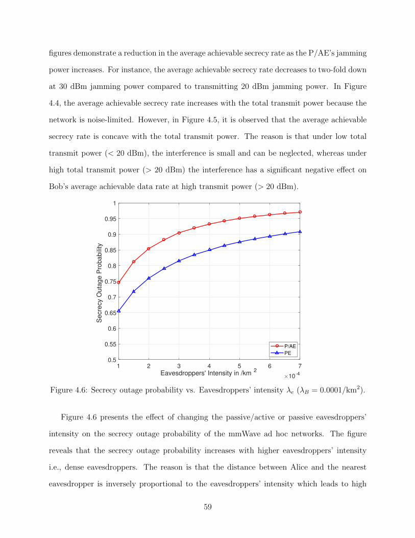
figures demonstrate a reduction in the average achievable secrecy rate as the P/AE’s jamming
power increases. For instance, the average achievable secrecy rate decreases to two-fold down
at 30 dBm jamming power compared to transmitting 20 dBm jamming power. In Figure
4.4, the average achievable secrecy rate increases with the total transmit power because the
network is noise-limited. However, in Figure 4.5, it is observed that the average achievable
secrecy rate is concave with the total transmit power. The reason is that under low total
transmit power (< 20 dBm), the interference is small and can be neglected, whereas under
high total transmit power (> 20 dBm) the interference has a significant negative effect on
Bob’s average achievable data rate at high transmit power (> 20 dBm).
1 2 3 4 5 6 7
Eavesdroppers' Intensity in /km2
10-4
0.5
0.55
0.6
0.65
0.7
0.75
0.8
0.85
0.9
0.95
1
Secre
cy O
uta
ge P
robabili
ty
P/AE
PE
Figure 4.6: Secrecy outage probability vs. Eavesdroppers’ intensity λe (λB = 0.0001/km2).
Figure 4.6 presents the effect of changing the passive/active or passive eavesdroppers’
intensity on the secrecy outage probability of the mmWave ad hoc networks. The figure
reveals that the secrecy outage probability increases with higher eavesdroppers’ intensity
i.e., dense eavesdroppers. The reason is that the distance between Alice and the nearest
eavesdropper is inversely proportional to the eavesdroppers’ intensity which leads to high
59
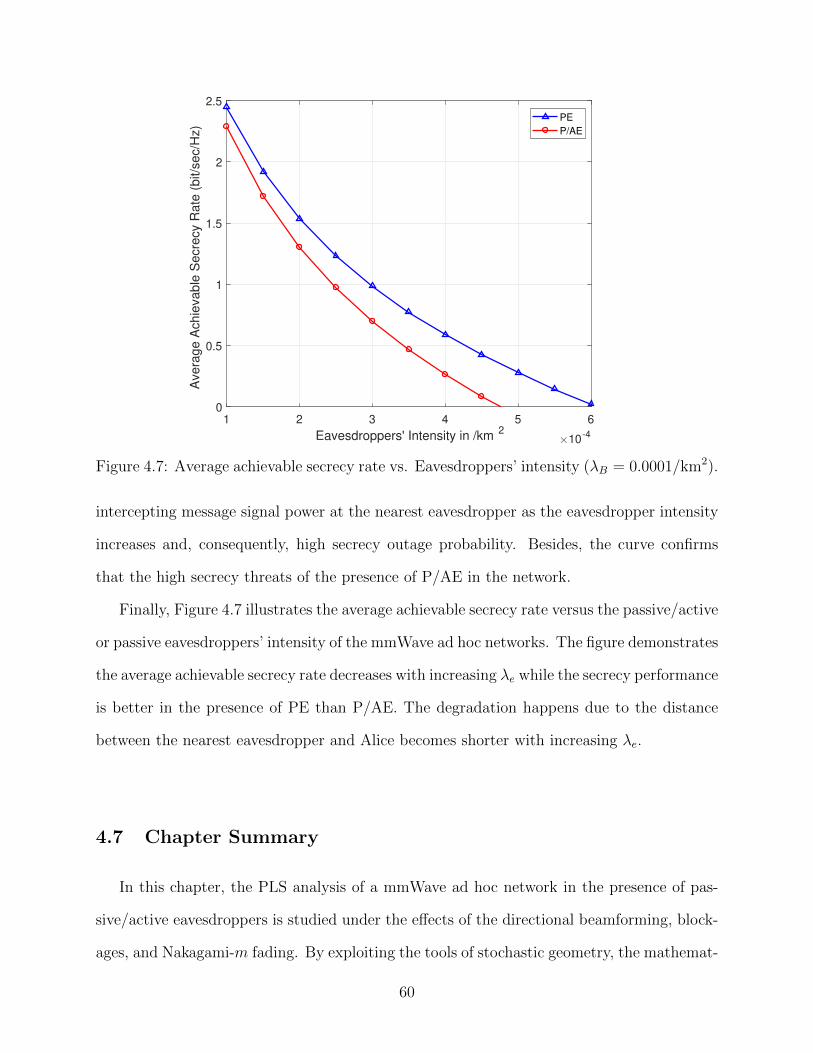
1 2 3 4 5 6
Eavesdroppers' Intensity in /km2
10-4
0
0.5
1
1.5
2
2.5
Avera
ge A
chie
vable
Secre
cy R
ate
(bit/s
ec/H
z)
PE
P/AE
Figure 4.7: Average achievable secrecy rate vs. Eavesdroppers’ intensity (λB = 0.0001/km2).
intercepting message signal power at the nearest eavesdropper as the eavesdropper intensity
increases and, consequently, high secrecy outage probability. Besides, the curve confirms
that the high secrecy threats of the presence of P/AE in the network.
Finally, Figure 4.7 illustrates the average achievable secrecy rate versus the passive/active
or passive eavesdroppers’ intensity of the mmWave ad hoc networks. The figure demonstrates
the average achievable secrecy rate decreases with increasing λe while the secrecy performance
is better in the presence of PE than P/AE. The degradation happens due to the distance
between the nearest eavesdropper and Alice becomes shorter with increasing λe.
4.7 Chapter Summary
In this chapter, the PLS analysis of a mmWave ad hoc network in the presence of pas-
sive/active eavesdroppers is studied under the effects of the directional beamforming, block-
ages, and Nakagami-m fading. By exploiting the tools of stochastic geometry, the mathemat-
60

ical expressions for the secrecy performance metrics—connection outage probability, secrecy
outage probability, and average achievable secrecy rate are derived to evaluate the level of
the network’s secure transmission. The insight from the analysis is that the presence of the
passive/active eavesdroppers in a mmWave ad hoc network is more dangerous on the secrecy
performance compared to the presence of traditional passive eavesdroppers because of the
P/AE’s jamming transmit power.
The analytical and simulation results show the secrecy performance of the mmWave ad
hoc network in the presence of P/AE and PE with varying the main system parameter such
as the gain of the array antennas for the transmitting and receiving nodes, the eavesdroppers’
intensity, the interferers’ intensity, and the value of the jamming signal power by P/AE.
61
Chapter 5
Physical Layer Security under the Tx-AN and
Tx-AN/LP Techniques 1
5.1 Introduction
In this chapter, the impact of adding artificial noise (AN) into the transmission on the se-
crecy performance of the millimeter-wave (mmWave) ad hoc networks is analyzed in the
presence of different types of eavesdropping scenarios. The purpose of AN transmission is
to reduce the illegitimate channels’ capacity between the eavesdroppers and Alice and thus
attain a reasonable secrecy performance, even if the eavesdroppers have a better channel
than that seen by Bob [89]. In addition, using AN transmission achieves perfect secrecy
without depending on the fading channel characteristics and it does not require extra pro-
cessing at the legitimate receiver. However, it sacrifices of power resources may degrade
the legitimate receiver’s signal-to-interference-plus-noise ratio (SINR). Therefore, two dif-
ferent secure physical layer transmission techniques are presented to enhance the secrecy
1The content of this chapter has been presented as a part of five papers: 1) Published as a conference paper[52], A. F. Darwesh and A. O. Fapojuwo, ”Secrecy Rate Analysis of mmWave MISO Ad Hoc Networks withNull Space Precoding,” 2020 IEEE Wireless Communications and Networking Conference (WCNC), Seoul,Korea (South), 2020, pp. 1-6, doi: 10.1109/WCNC45663.2020.9120483. 2) Published as a conference paper[49], A. F. Darwesh and A. O. Fapojuwo, ”Achievable Secrecy Rate in mmWave Multiple-Input Single-OutputAd Hoc Networks,” 2020 IEEE 91st Vehicular Technology Conference (VTC2020-Spring), Antwerp, Belgium,2020, pp. 1-6, doi: 10.1109/VTC2020-Spring48590.2020.9128769. 3) Submitted as a manuscript of a journalpaper to the Wireless Communications and Mobile Computing (Wiley, Hindawi) [50], A. F. Darwesh and A.O. Fapojuwo, ”Achievable Secrecy Rate Analysis in mmWave Ad Hoc Networks with Multi-Array AntennaTransmission and Artificial Noise,”, 2020. Currently undergoing peer review. 4) submitted manuscript tothe IEEE transactions on Wireless Communications [51], A. F. Darwesh and A. O. Fapojuwo, ”PhysicalLayer Security Analysis of mmWave Ad Hoc Networks in the Presence of Passive/Active Eavesdroppers,”,2020. Currently undergoing peer review. 5) submitted manuscript to the IEEE Transactions on WirelessCommunications [88], A. F. Darwesh, O. E. Ochia, and A. O. Fapojuwo, ”Achievable Secrecy Rate in ammWave Cellular Network with Memory and File Size-Aware Caching and Null Space Precoding,”, 2020.Currently undergoing second peer review.
62
performance of the mmWave ad hoc networks. First, a sectored AN transmission (Tx-AN)
technique is applied to mitigate the attack of the eavesdroppers when there is an imperfect
channel state information between Alice and its receiver (CSIT) knowledge. However, with
the perfect CSIT knowledge, the potential benefits of transmitting AN by using a null space
linear precoder, henceforth referred to as the Tx-AN/LP technique, are investigated. More-
over, under both secrecy techniques, the mathematical expressions are derived to evaluate
the secrecy performance of the mmWave ad hoc networks in the presence of passive and
passive/active eavesdroppers as assumed in chapters 3 and 4. Furthermore, the impact of
the eavesdroppers’ intensity and the number of antenna elements per transmit array on the
secrecy performance is investigated.
Our results demonstrate the improvement achieved in the secrecy performance of the
mmWave ad hoc networks with applying Tx-AN or Tx-AN/LP techniques in the presence
of different types of eavesdroppers. For example, at the high transmit power (> 20 dBm),
the Tx-AN technique achieves up to three-fold improvement in the average secrecy rate
over that without. Further, in the presence of passive/active eavesdroppers, the Tx-AN/LP
technique is very effective in mitigating the effect of the jamming signals, achieving up
to two-fold improvement in the average secrecy rate over that without applying the Tx-
AN/LP technique. Moreover, the analysis presents the secrecy robustness of the Tx-AN and
Tx-AN/LP techniques against increasing the eavesdroppers’ intensity. Finally, the impact of
varying the power allocation between the message and AN signals on the secrecy performance
is studied along with a numerical determination of the appropriate AN power fraction that
maximizes the average achievable secrecy rate.
5.2 Secrecy Performance with Tx-AN Technique
In this section, a sectored AN transmission via a multi-array antenna at the transmitting
63
nodes, referred to as Tx-AN technique, is proposed. The Tx-AN technique is implemented
to enhance the secrecy performance of a mmWave ad hoc network in the presence of eaves-
droppers when the CSIT is unknown. In this technique, the total transmit power is divided
into message transmit power Ps = (1 − ς)Pt and AN transmit power Pa = ςPt assigned for
message signal and AN signal transmission, respectively, where ς is the AN power fraction.
Moreover, the total transmit array antenna Nt is split into the message signal transmit ar-
ray antennas and AN signal transmit array antennas denoted by Ns and Na, respectively,
where Nt = Ns + Na arrays. Recalling from sub-section 3.2.2, the blind transmit and re-
ceive beamforming (TR-BF) discovery mechanism is exploited by each transmitter-receiver
(Tx-Rx) pair to accurately determine the antenna direction with respect to each other. Con-
sequently, the main-lobe beam of the AN array antenna of each transmitting node is not
directed to its corresponding receiver to ensure that each legitimate receiver never receives
the transmitted AN from its intended transmitter. The implementation of the Tx-AN tech-
nique in a mmWave ad hoc network in the presence of eavesdroppers is illustrated in Figure
5.1.
Although the Tx-AN technique is simple and easy to implement practically as illustrated
above, it exhibits a significant improvement in the secrecy performance in the presence of
passive non-colluding and colluding eavesdroppers as will be demonstrated in the following
sub-sections. Note that the Tx-AN technique neither requires the CSIT nor the CSI between
Alice and the eavesdropper as assumed in Chapter 3.
5.2.1 Analysis of Average Achievable Secrecy Rate with Tx-AN Technique un-
der Non-Colluding Eavesdroppers
The average achievable secrecy rate of a mmWave ad hoc network in the presence of
non-colluding eavesdroppers under the Tx-AN technique can be calculated as
RS ,[Ru − Re
]+
, (5.1)
64
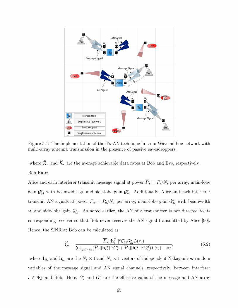
Figure 5.1: The implementation of the Tx-AN technique in a mmWave ad hoc network withmulti-array antenna transmission in the presence of passive eavesdroppers.
where Ru and Re are the average achievable data rates at Bob and Eve, respectively.
Bob Rate:
Alice and each interferer transmit message signal at power P s = Ps/Ns per array, main-lobe
gain GsM with beamwidth φ, and side-lobe gain Gsm. Additionally, Alice and each interferer
transmit AN signals at power P a = Pa/Na per array, main-lobe gain GaM with beamwidth
ϕ, and side-lobe gain Gam. As noted earlier, the AN of a transmitter is not directed to its
corresponding receiver so that Bob never receives the AN signal transmitted by Alice [90].
Hence, the SINR at Bob can be calculated as:
ξu =P s||hTo ||2GsMGuML(ro)∑
i∈ΦB\o(P s||hiTs ||2Gs
i + P a||hiTa ||2Gai
)L(ri) + σ2
u
, (5.2)
where his and hia are the Ns × 1 and Na × 1 vectors of independent Nakagami-m random
variables of the message signal and AN signal channels, respectively, between interferer
i ∈ ΦB and Bob. Here, Gsi and Ga
i are the effective gains of the message and AN array
65
antennas, respectively, seen by Bob from the transmitting interferer i. However, Bob cannot
simultaneously receive the main-lobe of the interference and the main-lobe of the AN signals
which are transmitted by the same interferer i ∈ ΦB. The reason is that the main-lobe of the
interference and that of the AN signals are always pointing in a different direction by design,
i.e., these two events are mutually exclusive Pr(GsM ∩ GaM
)= 0. Hence, the total effective
antenna gain Gi = Gsi +Ga
i seen by Bob from the interferer i ∈ ΦB can be written as follows:
Gi =
(GsM + Gam)GuM , w.p. ∆MmM = φθ(2π)2 ,
(GsM + Gam)Gum, w.p. ∆Mmm = φ(2π−θ)(2π)2 ,
(Gsm + GaM)GuM , w.p. ∆mMM = ϕθ(2π)2 ,
(Gsm + GaM)Gum, w.p. ∆mMm = ϕ(2π−θ)(2π)2 ,
(Gsm + Gam)GuM , w.p. ∆mmM = (2π−φ−ϕ)θ(2π)2 ,
(Gsm + Gam)Gum, w.p. ∆mmm = (2π−φ−ϕ)(2π−θ)(2π)2 ,
(5.3)
where ∆lwq, l, w, q ∈ M,m denotes the probability that the effective antenna gains
Gsl Guq and GawGuq occur simultaneously.
Lemma 5.1. The average achievable data rate at Bob when the Tx-AN technique is imple-
mented at the transmitters, Ru can be determined by
Ru = E[log2(1 + ξu)]
=1
ln(2)
∫ ∞0
1
x
(1−
∑j∈L,N
ζj(ro)(1 + xρsjL(ro)
)−τsj )Ψ(x)e−xσ2
dx, (5.4)
where
Ψ(x) =∑j∈L,N
exp
(−2πλB
∫ ∞0
ζj(v)(
1−∑
(l,w,q)∈Ω
∆lwq
(1+xρsjL(v)
)−τsj (1+xρajL(v))−τaj )vdv).
(5.5)
The function Ψ(x) denotes the Laplace transform of the interference plus AN signals
at Bob, ρsj = 1κjP sGsMGuM , ρsj = 1
κjP sGsl Guq , ρaj = 1
κjP aGawGuq , τ sj = Nsκj, τ
aj = Naκj,
66
κj is the Nakagami fading shape parameter for the jth type of link, j ∈ L,N, and
Ω = (M,m,M), (M,m,m), (m,M,M), (m,M,m), (m,m,M), (m,m,m), the set of all
possible values of (l, w, q).
Proof: See Appendix F.
Remark 5.1. By applying the Tx-AN technique, the average achievable data rate at Bob
increases as the power fraction ς increases. Besides, the width of the directive beams for the
message and AN signals, which affects directly on the values of ρsj , ρsj , and ρaj , dominates
also the average achievable data rate. The directivity of the transmit and receive beams can
be designed based on the number of antenna elements per array, as seen in Table 3.1.
Corollary 5.1. When a simplified line-of-sight (LoS) mmWave model is used, the results in
Lemma 5.1 can be approximated as follows:
Ru ≈1
ln(2)
∫ ∞0
1
x
(1−
(1 + xρsjL(r0)
)−τsj )Ψ(x)e−xσ2
dx, (5.6)
where
Ψ(x) = exp
(−2πλB
[R2L
2−
∑l,w∈M,m
∆lwq
(R2L
2F1
( 2
αL, τ sL, τ
aL;αL − 2
αL;−xρsLεR
−αLL ,−xρaLεR
−αLL
)
− `2
2F1
( 2
αL, τ sL, τ
aL;αL − 2
αL;−xρsLε`−αL ,−xρaLε`−αL
))]). (5.7)
Eve Rate:
Next, with the Tx-AN technique, the received signal-to-noise ratio (SNR) at Eve becomes
the received signal-to-AN-plus-noise ratio (SANR), ξe is calculated by
ξe =P s||heTs ||2Gs
eL(re)
P a||heTa ||2GaeL(re) +
∑i∈ΦB\0 P a||hieTa ||2Ga
eL(rie) + σ2e
, (5.8)
where hes and hea are the Ns × 1 and Na × 1 vectors of independent Nakagami-m random
variables of the message signal and AN signal channels, respectively, between Alice and Eve.
67
hiea is the Na × 1 vector of independent Nakagami-m random variables of the AN signal
channel between the interferer i ∈ ΦB and Eve. Gae is the effective antenna gain seen by Eve
from an interferer i ∈ ΦB which can be obtained from equation (3.3) by replacing GtM , Gtm and
Θ with GaM , Gam and ϕ, respectively, with probability ωlw, l, w ∈ M,m that the effective
antenna gain Gal Gew occurs. Here, Gse and Ga
e are respectively the message and AN effective
antenna gains seen by Eve from Alice. Recall that for each transmitter, the main-lobe of the
AN array and message array are pointing in different directions. Hence, Eve cannot receive
simultaneously the main-lobe of the message and AN signals, i.e., Pr(GsM ∩ GaM
)= 0. The
total effective antenna gain Ge = Gse +Ga
e seen by Eve from Alice can be written as follows:
Ge =
(GsM + Gam)GeM , w.p. ∂MmM = φϑ(2π)2 ,
(GsM + Gam)Gem, w.p. ∂Mmm = φ(2π−ϑ)(2π)2 ,
(GSm + GaM)GeM , w.p. ∂mMM = ϕϑ(2π)2 ,
(GSm + GaM)Gem, w.p. ∂mMm = ϕ(2π−ϑ)(2π)2 ,
(Gsm + Gam)GeM , w.p. ∂mmM = (2π−φ−ϕ)ϑ(2π)2 ,
(Gsm + Gam)Gem, w.p. ∂mmm = (2π−φ−ϕ)(2π−ϑ)(2π)2 ,
(5.9)
where ∂lwq, l, w, q ∈ M,m denotes the probability that the effective antenna gains Gsl Geq
and GawGeq occur simultaneously.
Lemma 5.2. The average achievable data rate at Eve with the Tx-AN technique imple-
mented at Alice and all the interferers can be calculated by
Re =1
ln(2)
∫ ∞0
1
x
(Υ1(x)− Υ2(x)
)Υ3(x)e−xσ
2edx, (5.10)
where
Υ1(x) =∑
j∈L,N
Dj
∑l,w∈M,m
ωlw
∫ ∞0
(1 + x%ajL(v)
)−τaj fj(v)dv, (5.11)
Υ2(x) =∑
j∈L,N
Dj
∫ ∞0
∑(l,w,q)∈Ω
∂lwq(1 + x%sjL(v)
)−τsj (1 + x%ajL(v))−τaj fj(v)dv, (5.12)
68
Υ3(x) =∑
j∈L,N
exp
(−2πλB
∫ ∞0
ζj(v)(
1−∑
l,w∈M,m
ωlw(1 + x%ajL(v)
)−τaj )vdv). (5.13)
The functions Υ1(x), Υ2(x), and Υ3(x) are the Laplace transform of the received AN
signal at Eve from Alice, the received message plus AN signals at Eve from Alice, and
the received AN signal at Eve from the interferers in ΦB, respectively, %sj = 1κjP sGsl Geq ,
%aj = 1κjP aGal Gew, %aj = 1
κjP aGawGeq , Dj is given by equation (3.6), and κj is the Nakagami
fading shape parameter for the jth type of link, j ∈ L,N.
Proof: See Appendix G.
Remark 5.2. From Remark 3.5 (Section 3.3), an increase in the eavesdroppers’ intensity
λe results in an increased achievable data rate at Eve. However, with the Tx-AN technique
implemented at the transmitting nodes, the average achievable data rate at Eve has a small
increase with increasing λe that decreases the mean value of fj(z) as seen in Figure 3.2. The
reason is that the increase of λe affects both Υ1(x) and Υ2(x) simultaneously from equations
(5.11) and (5.12). Therefore, the increase of λe has a small impact on the average achievable
data rate at Eve from equation (5.10). Moreover, a dense network with high interferers’
intensity λB reduces the value of Υ3(x), as shown in equation (5.13), which decreases the
average achievable data rate at Eve.
Substituting equations (5.4) and (5.10) in equation (5.1), the average achievable secrecy
rate of a mmWave ad hoc network with the Tx-AN technique implemented at the transmit-
ters in the presence of non-colluding eavesdroppers can be determined. Note that equation
(5.1) is solved numerically as done in equations (3.9) and (3.25).
5.2.2 Analysis of Average Achievable Secrecy Rate with Tx-AN Technique un-
der Colluding Eavesdroppers
The average achievable secrecy rate of mmWave ad hoc network with the Tx-AN tech-
69
nique in the presence of colluding eavesdroppers can be calculated as
RcS ,
[Rcu − Rc
e
]+
, (5.14)
where Rcu and Rc
e are the average achievable data rates at Bob and Main-Eve, respectively,
with applying the Tx-AN technique.
Bob Rate:
To simplify the analysis in this sub-section, the Tx-AN technique is assumed to be used by
Alice only. Hence, the SINR at Bob can be calculated as
ξcu =P s||hTo ||2GsMGuML(ro)∑
i∈ΦB\o P t||hTi ||2GiL(ri) + σ2. (5.15)
Lemma 5.3. Recall that the AN transmitted by Alice is not received by Bob. Subsequently,
Rcu is obtained by
Rcu = E[log2(1 + ξcu)]
=1
ln(2)
∫ ∞0
1
x
(1−
∑j∈L,N
ζj(ro)(1 + xρsjL(ro)
)−τsj )Ψ(x)e−xσ2
dx, (5.16)
where Ψ(x) is the Laplace transform of the aggregate interference at Bob which is determined
in equation (3.12).
Main-Eve Rate:
Based on the eavesdroppers’ intercepted message signals, AN signals and their background
noise σ2e , the SANR at Main-Eve is calculated by
ξce =∑e∈Φe
P s||hTea ||2Gs
eL(re)
P a||hTea||2GaeL(re) + σ2
e
, (5.17)
where hes and hea are the Ns × 1 and Na × 1 vectors of independent Nakagami-m random
variables of the message and AN signal channels, respectively, between Alice and eavesdrop-
per e ∈ Φe.
70
Lemma 5.4. The average achievable data rate at Main-Eve when the Tx-AN technique is
implemented by Alice is given by:
Rce = E[log2(1 + ξce)] =
1
ln(2)
∫ ∞0
1
x
(Υc
1(x)− Υc2(x)
)e−xσ
2edx, (5.18)
where
Υc1(x) =
∑j∈L,N
exp
(−2πλe
∫ ∞0
ζj(v)(
1−∑
l,w∈M,m
ωlw(1 + x%ajL(v)
)−τaj )vdv), (5.19)
Υc2(x) =
∑j∈L,N
exp
(−2πλe
∫ ∞0
ζj(v)(
1−∑
(l,w,q)∈Ω
∂lwq(1+x%sjL(v)
)−τsj (1+x%ajL(v))−τaj )vdv).
(5.20)
The functions Υc1(x) and Υc
2(x) are the Laplace transform of the received AN signal (from
Alice) and the received message plus AN signal at the eavesdroppers in Φe, respectively.
Proof: The proof of equations (5.19) and (5.20) follows the same manner as was done
to obtain equation (3.12) in Lemma 3.1 (Section 3.3) and equation (5.5) in Lemma 5.1,
respectively.
Remark 5.3. In general, when the intensity of the colluding eavesdroppers increases, the
average achievable data rate at Main-Eve increases, as seen in Remark 3.5 (Section 3.3).
However, from equations (5.19) and (5.20), an increase in λe decreases Υc1(x) and Υc
2(x)
simultaneously resulting in a small effect, as seen in equation (5.18). Consequently, the
increase in λe has a negligible effect on the average achievable data rate at Main-Eve under
the Tx-AN technique. This manifests the secrecy robustness of the Tx-AN technique against
the most dangerous eavesdropping scenario (i.e., colluding eavesdropping).
Finally, by substituting equations (5.16) and (5.18) in equation (5.14), the average achiev-
able secrecy rate of a mmWave ad hoc network with the Tx-AN technique implemented only
by Alice in the presence of colluding eavesdroppers can be determined.
71
5.3 Secrecy Performance with Tx-AN/LP Technique
In this section, to enhance the secrecy performance of the mmWave ad hoc network in
the presence of eavesdroppers, AN transmission with null space linear precoder (referred to
as the Tx-AN/LP technique) at Alice is used. This technique is applied when there exists
perfect knowledge of the CSIT. Therefore, a null space linear precoder can be designed to
transmit the AN power signal into the null space of Bob such that the AN signal is nulled
at Bob, but negatively affects the eavesdroppers in the network. Similarly, as mentioned in
Section 5.2, the total transmit power of Alice is divided into message power and AN power.
Consequently, Alice divides its available signal space into two independent signal spaces, the
message signal space zs and the AN signal null space za. The null space exists for each
channel vector h0 provided the number of transmit antennas is greater than the number of
receive antennas. Therefore, a null space linear precoder wa ∈ C(Nt×Nt−1) is used at Alice
to exploit this null space where the linear precoder aligns the AN into Nullh0. To design
wa, Alice performs the singular value decomposition of h0 and obtains:
hT0 =a0d0BT0 , (5.21a)
=a0[d0s|01×(Nt−1)][B0a|b0s ]T , (5.21b)
where a0 ∈ C(1×1), d0 is a 1×Nt vector which contains the nonzero singular values of h0, and
B0 ∈ C(Nt×Nt) is an orthogonal matrix. The matrix B0 can be partitioned into a sub-matrix
B0a ∈ C(Nt×Nt−1) whose columns lie in Nullh0 where any column of B0a can be a null space
linear precoder wa ∈ C(Nt×1) (i.e., hT0 wa = 0) and a vector b0s ∈ C(Nt×1) whose columns are
in the span of h0.
5.3.1 Analysis of Average Achievable Secrecy Rate with Tx-AN/LP Technique
under Passive Colluding Eavesdroppers
Practically, the Tx-AN/LP technique can be implemented for all the transmitting nodes
72
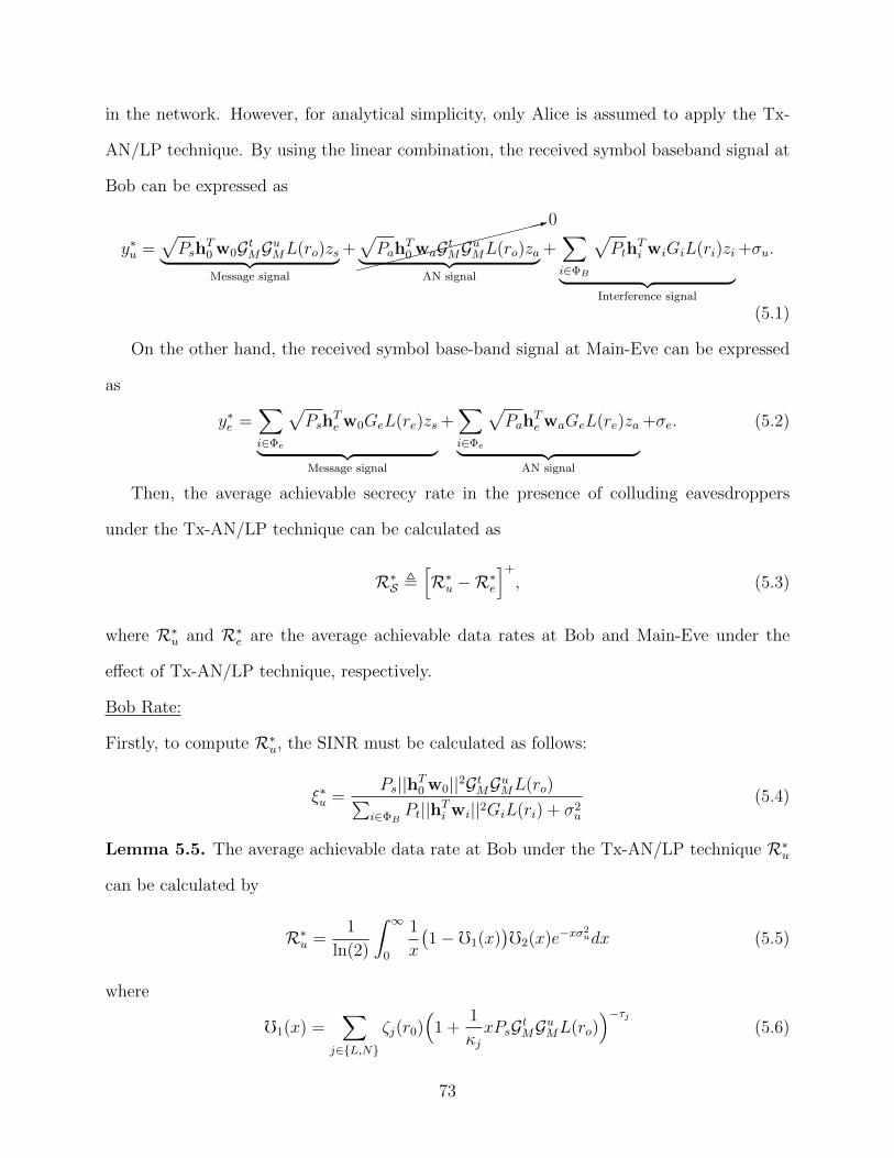
in the network. However, for analytical simplicity, only Alice is assumed to apply the Tx-
AN/LP technique. By using the linear combination, the received symbol baseband signal at
Bob can be expressed as
y∗u =√Psh
T0 w0GtMGuML(ro)zs︸ ︷︷ ︸Message signal
+
:0√
PahT0 waGtMGuML(ro)za︸ ︷︷ ︸
AN signal
+∑i∈ΦB
√Pth
Ti wiGiL(ri)zi︸ ︷︷ ︸
Interference signal
+σu.
(5.1)
On the other hand, the received symbol base-band signal at Main-Eve can be expressed
as
y∗e =∑i∈Φe
√Psh
Te w0GeL(re)zs︸ ︷︷ ︸
Message signal
+∑i∈Φe
√Pah
Te waGeL(re)za︸ ︷︷ ︸
AN signal
+σe. (5.2)
Then, the average achievable secrecy rate in the presence of colluding eavesdroppers
under the Tx-AN/LP technique can be calculated as
R∗S ,[R∗u −R∗e
]+
, (5.3)
where R∗u and R∗e are the average achievable data rates at Bob and Main-Eve under the
effect of Tx-AN/LP technique, respectively.
Bob Rate:
Firstly, to compute R∗u, the SINR must be calculated as follows:
ξ∗u =Ps||hT0 w0||2GtMGuML(ro)∑
i∈ΦBPt||hTi wi||2GiL(ri) + σ2
u
(5.4)
Lemma 5.5. The average achievable data rate at Bob under the Tx-AN/LP technique R∗u
can be calculated by
R∗u =1
ln(2)
∫ ∞0
1
x
(1− f1(x)
)f2(x)e−xσ
2udx (5.5)
where
f1(x) =∑
j∈L,N
ζj(r0)(
1 +1
κjxPsGtMGuML(ro)
)−τj(5.6)
73
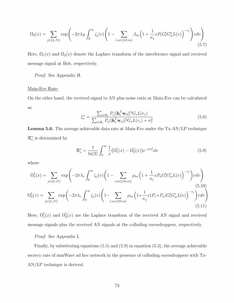
f2(x) =∑
j∈L,N
exp
(−2πλB
∫ ∞0
ζj(v)
(1−
∑l,w∈M,m
βlw
(1 +
1
κjxPtG
tlG
uwL(v)
)−τj)vdv
)(5.7)
Here, f1(x) and f2(x) denote the Laplace transform of the interference signal and received
message signal at Bob, respectively.
Proof: See Appendix H.
Main-Eve Rate:
On the other hand, the received signal to AN plus noise ratio at Main-Eve can be calculated
as
ξ∗e =
∑i∈Φe
Ps||hTe w0||2GeL(re)∑i∈Φe
Pa||hTe wa||2GeL(re) + σ2e
(5.8)
Lemma 5.6. The average achievable data rate at Main-Eve under the Tx-AN/LP technique
R∗e is determined by
R∗e =1
ln(2)
∫ ∞0
1
x
(f†1(x)− f†2(x)
)e−xσ
2edx (5.9)
where
f†1(x) =∑
j∈L,N
exp
(−2πλe
∫ ∞0
ζj(v)
(1−
∑l,w∈M,m
µlw
(1 +
1
κjxPaG
tlG
ewL(v)
)−τj)vdv
)(5.10)
f†2(x) =∑
j∈L,N
exp
(−2πλe
∫ ∞0
ζj(v)
(1−
∑l,w∈M,m
µlw
(1+
1
κjx(Ps+Pa)G
tlG
ewL(v)
)−τj)vdv
)(5.11)
Here, f†1(x) and f†2(x) are the Laplace transform of the received AN signal and received
message signals plus the received AN signals at the colluding eavesdroppers, respectively.
Proof: See Appendix I.
Finally, by substituting equations (5.5) and (5.9) in equation (5.3), the average achievable
secrecy rate of mmWave ad hoc network in the presence of colluding eavesdroppers with Tx-
AN/LP technique is derived.
74
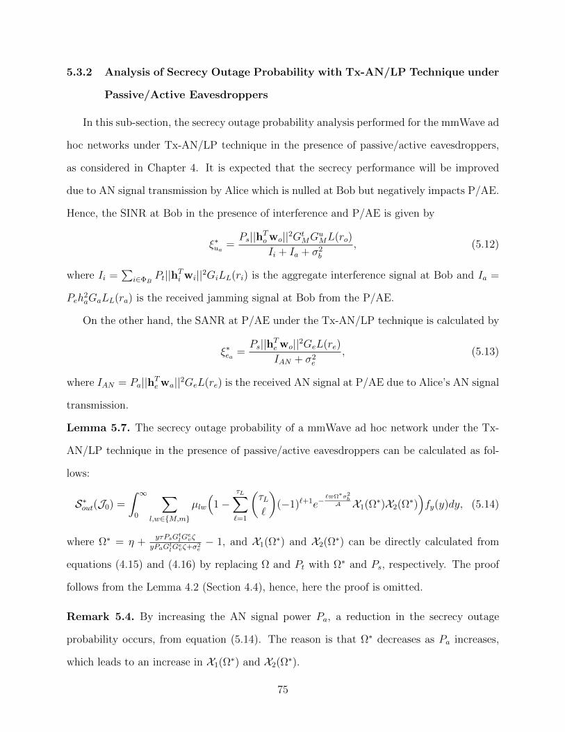
5.3.2 Analysis of Secrecy Outage Probability with Tx-AN/LP Technique under
Passive/Active Eavesdroppers
In this sub-section, the secrecy outage probability analysis performed for the mmWave ad
hoc networks under Tx-AN/LP technique in the presence of passive/active eavesdroppers,
as considered in Chapter 4. It is expected that the secrecy performance will be improved
due to AN signal transmission by Alice which is nulled at Bob but negatively impacts P/AE.
Hence, the SINR at Bob in the presence of interference and P/AE is given by
ξ∗ua =Ps||hTo wo||2Gt
MGuML(ro)
Ii + Ia + σ2b
, (5.12)
where Ii =∑
i∈ΦBPt||hTi wi||2GiLL(ri) is the aggregate interference signal at Bob and Ia =
Peh2aGaLL(ra) is the received jamming signal at Bob from the P/AE.
On the other hand, the SANR at P/AE under the Tx-AN/LP technique is calculated by
ξ∗ea =Ps||hTe wo||2GeL(re)
IAN + σ2e
, (5.13)
where IAN = Pa||hTe wa||2GeL(re) is the received AN signal at P/AE due to Alice’s AN signal
transmission.
Lemma 5.7. The secrecy outage probability of a mmWave ad hoc network under the Tx-
AN/LP technique in the presence of passive/active eavesdroppers can be calculated as fol-
lows:
S∗out(J0) =
∫ ∞0
∑l,w∈M,m
µlw
(1−
τL∑`=1
(τL`
)(−1)`+1e−
`$Ω∗σ2b
A X1(Ω∗)X2(Ω∗))fy(y)dy, (5.14)
where Ω∗ = η +yτPsGtlG
evζ
yPaGtlGevζ+σ
2e− 1, and X1(Ω∗) and X2(Ω∗) can be directly calculated from
equations (4.15) and (4.16) by replacing Ω and Pt with Ω∗ and Ps, respectively. The proof
follows from the Lemma 4.2 (Section 4.4), hence, here the proof is omitted.
Remark 5.4. By increasing the AN signal power Pa, a reduction in the secrecy outage
probability occurs, from equation (5.14). The reason is that Ω∗ decreases as Pa increases,
which leads to an increase in X1(Ω∗) and X2(Ω∗).
75
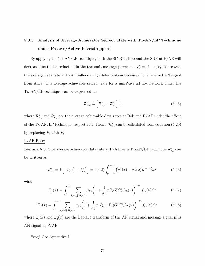
5.3.3 Analysis of Average Achievable Secrecy Rate with Tx-AN/LP Technique
under Passive/Active Eavesdroppers
By applying the Tx-AN/LP technique, both the SINR at Bob and the SNR at P/AE will
decrease due to the reduction in the transmit message power i.e., Ps = (1− ς)Pt. Moreover,
the average data rate at P/AE suffers a high deterioration because of the received AN signal
from Alice. The average achievable secrecy rate for a mmWave ad hoc network under the
Tx-AN/LP technique can be expressed as
R∗Sa ,[R∗ua −R
∗ea
]+
, (5.15)
where R∗ua and R∗ea are the average achievable data rates at Bob and P/AE under the effect
of the Tx-AN/LP technique, respectively. Hence, R∗ua can be calculated from equation (4.20)
by replacing Pt with Ps.
P/AE Rate:
Lemma 5.8. The average achievable data rate at P/AE with Tx-AN/LP technique R∗ea can
be written as
R∗ea = E[
log2
(1 + ξ∗ea
)]= log(2)
∫ ∞0
1
x
(Ξ†1(x)− Ξ†2(x)
)e−xσ
2edx, (5.16)
with
Ξ†1(x) =
∫ ∞0
∑l,w∈M,m
µlw
(1 +
1
κLxPaG
tlG
ewLL(ν)
)−τLfre(ν)dν, (5.17)
Ξ†2(x) =
∫ ∞0
∑l,w∈M,m
µlw
(1 +
1
κLx(Ps + Pa)G
tlG
ewLL(ν)
)−τLfre(ν)dν, (5.18)
where Ξ†1(x) and Ξ†2(x) are the Laplace transform of the AN signal and message signal plus
AN signal at P/AE.
Proof: See Appendix J.
76
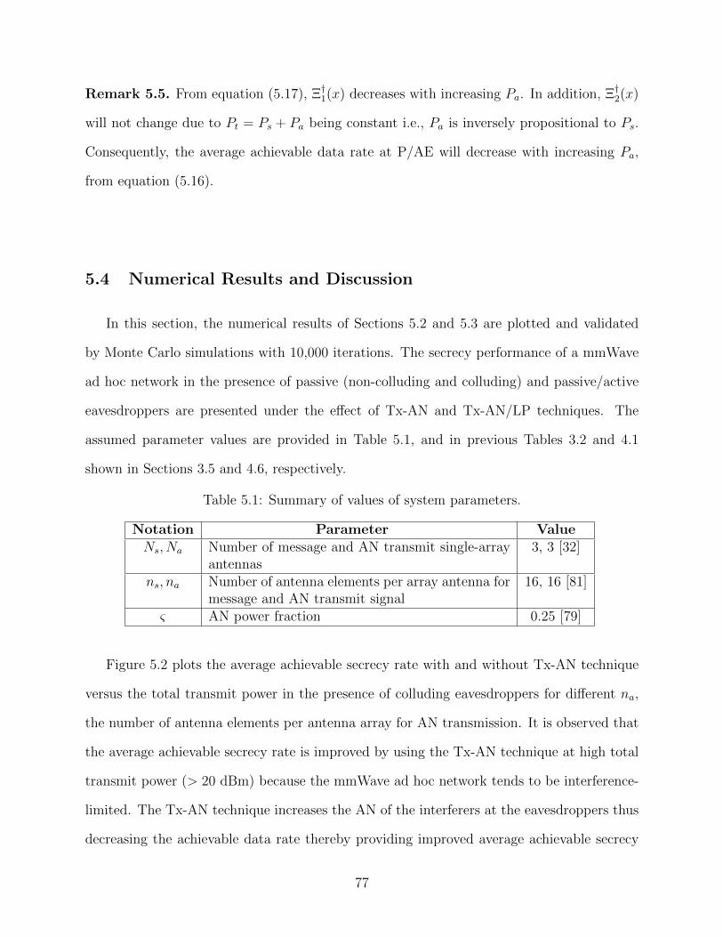
Remark 5.5. From equation (5.17), Ξ†1(x) decreases with increasing Pa. In addition, Ξ†2(x)
will not change due to Pt = Ps + Pa being constant i.e., Pa is inversely propositional to Ps.
Consequently, the average achievable data rate at P/AE will decrease with increasing Pa,
from equation (5.16).
5.4 Numerical Results and Discussion
In this section, the numerical results of Sections 5.2 and 5.3 are plotted and validated
by Monte Carlo simulations with 10,000 iterations. The secrecy performance of a mmWave
ad hoc network in the presence of passive (non-colluding and colluding) and passive/active
eavesdroppers are presented under the effect of Tx-AN and Tx-AN/LP techniques. The
assumed parameter values are provided in Table 5.1, and in previous Tables 3.2 and 4.1
shown in Sections 3.5 and 4.6, respectively.
Table 5.1: Summary of values of system parameters.
Notation Parameter ValueNs, Na Number of message and AN transmit single-array
antennas3, 3 [32]
ns, na Number of antenna elements per array antenna formessage and AN transmit signal
16, 16 [81]
ς AN power fraction 0.25 [79]
Figure 5.2 plots the average achievable secrecy rate with and without Tx-AN technique
versus the total transmit power in the presence of colluding eavesdroppers for different na,
the number of antenna elements per antenna array for AN transmission. It is observed that
the average achievable secrecy rate is improved by using the Tx-AN technique at high total
transmit power (> 20 dBm) because the mmWave ad hoc network tends to be interference-
limited. The Tx-AN technique increases the AN of the interferers at the eavesdroppers thus
decreasing the achievable data rate thereby providing improved average achievable secrecy
77
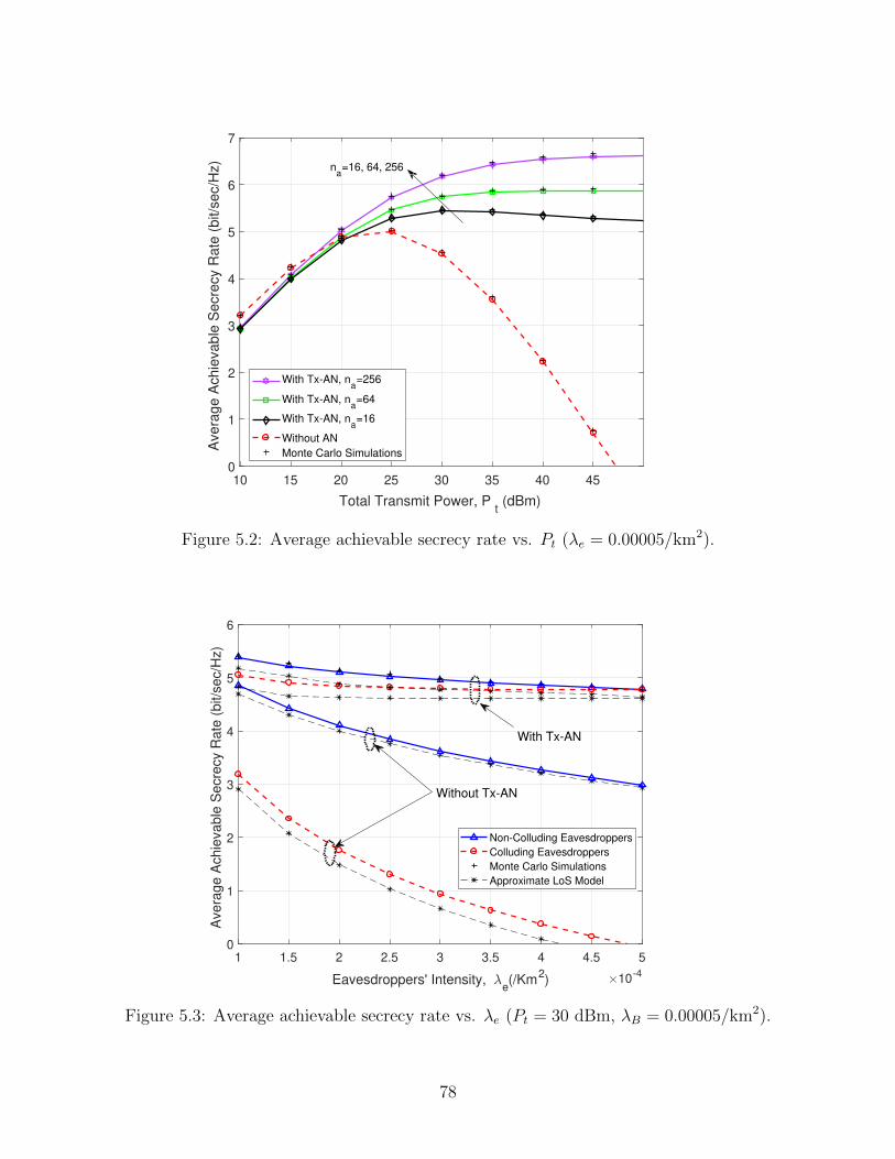
10 15 20 25 30 35 40 45
Total Transmit Power, Pt (dBm)
0
1
2
3
4
5
6
7
Avera
ge A
chie
vable
Secre
cy R
ate
(bit/s
ec/H
z)
With Tx-AN, na=256
With Tx-AN, na=64
With Tx-AN, na=16
Without AN
Monte Carlo Simulations
na=16, 64, 256
Figure 5.2: Average achievable secrecy rate vs. Pt (λe = 0.00005/km2).
1 1.5 2 2.5 3 3.5 4 4.5 5
Eavesdroppers' Intensity, e(/Km
2) 10
-4
0
1
2
3
4
5
6
Ave
rag
e A
ch
ieva
ble
Se
cre
cy R
ate
(b
it/s
ec/H
z)
Non-Colluding Eavesdroppers
Colluding Eavesdroppers
Monte Carlo Simulations
Approximate LoS Model
With Tx-AN
Without Tx-AN
Figure 5.3: Average achievable secrecy rate vs. λe (Pt = 30 dBm, λB = 0.00005/km2).
78
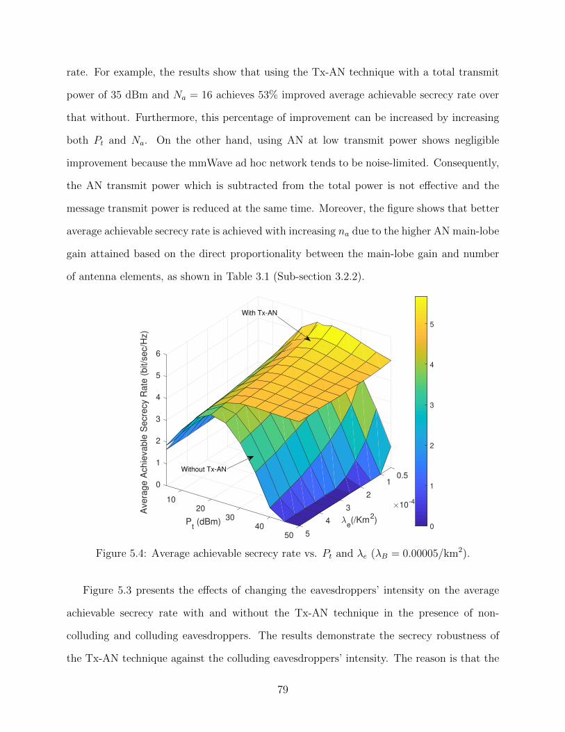
rate. For example, the results show that using the Tx-AN technique with a total transmit
power of 35 dBm and Na = 16 achieves 53% improved average achievable secrecy rate over
that without. Furthermore, this percentage of improvement can be increased by increasing
both Pt and Na. On the other hand, using AN at low transmit power shows negligible
improvement because the mmWave ad hoc network tends to be noise-limited. Consequently,
the AN transmit power which is subtracted from the total power is not effective and the
message transmit power is reduced at the same time. Moreover, the figure shows that better
average achievable secrecy rate is achieved with increasing na due to the higher AN main-lobe
gain attained based on the direct proportionality between the main-lobe gain and number
of antenna elements, as shown in Table 3.1 (Sub-section 3.2.2).
Pt (dBm)
0.51
e(/Km
2)
0
2
1
10
2
10-4
Avera
ge A
chie
vable
Secre
cy R
ate
(bit/s
ec/H
z)
320
3
4
30 4
5
40
6
5500
1
2
3
4
5
Without Tx-AN
With Tx-AN
Figure 5.4: Average achievable secrecy rate vs. Pt and λe (λB = 0.00005/km2).
Figure 5.3 presents the effects of changing the eavesdroppers’ intensity on the average
achievable secrecy rate with and without the Tx-AN technique in the presence of non-
colluding and colluding eavesdroppers. The results demonstrate the secrecy robustness of
the Tx-AN technique against the colluding eavesdroppers’ intensity. The reason is that the
79
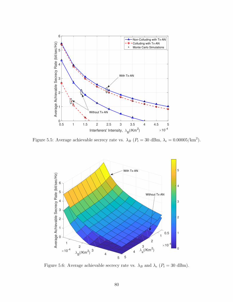
0.5 1 1.5 2 2.5 3 3.5 4 4.5 5
Interferers' Intensity, B(/Km
2) 10
-4
0
1
2
3
4
5
6
Avera
ge A
chie
vable
Secre
cy R
ate
(bit/s
ec/H
z)
Non-Colluding with Tx-AN
Colluding with Tx-AN
Monte Carlo Simulations
With Tx-AN
Without Tx-AN
Figure 5.5: Average achievable secrecy rate vs. λB (Pt = 30 dBm, λe = 0.00005/km2).
0.510
2
1
1
2
10-4
e(/Km
2)
32
3
Avera
ge A
chie
vable
Secre
cy R
ate
(bit/s
ec/H
z)
10-4
B(/Km
2)
4
3 4
5
4
6
55
0
1
2
3
4
5With Tx-AN
Without Tx-AN
Figure 5.6: Average achievable secrecy rate vs. λB and λe (Pt = 30 dBm).
80
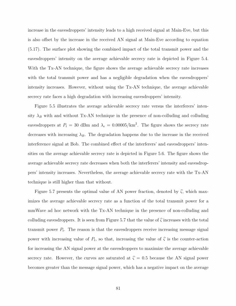
increase in the eavesdroppers’ intensity leads to a high received signal at Main-Eve, but this
is also offset by the increase in the received AN signal at Main-Eve according to equation
(5.17). The surface plot showing the combined impact of the total transmit power and the
eavesdroppers’ intensity on the average achievable secrecy rate is depicted in Figure 5.4.
With the Tx-AN technique, the figure shows the average achievable secrecy rate increases
with the total transmit power and has a negligible degradation when the eavesdroppers’
intensity increases. However, without using the Tx-AN technique, the average achievable
secrecy rate faces a high degradation with increasing eavesdroppers’ intensity.
Figure 5.5 illustrates the average achievable secrecy rate versus the interferers’ inten-
sity λB with and without Tx-AN technique in the presence of non-colluding and colluding
eavesdroppers at Pt = 30 dBm and λe = 0.00005/km2. The figure shows the secrecy rate
decreases with increasing λB. The degradation happens due to the increase in the received
interference signal at Bob. The combined effect of the interferers’ and eavesdroppers’ inten-
sities on the average achievable secrecy rate is depicted in Figure 5.6. The figure shows the
average achievable secrecy rate decreases when both the interferers’ intensity and eavesdrop-
pers’ intensity increases. Nevertheless, the average achievable secrecy rate with the Tx-AN
technique is still higher than that without.
Figure 5.7 presents the optimal value of AN power fraction, denoted by ς, which max-
imizes the average achievable secrecy rate as a function of the total transmit power for a
mmWave ad hoc network with the Tx-AN technique in the presence of non-colluding and
colluding eavesdroppers. It is seen from Figure 5.7 that the value of ς increases with the total
transmit power Pt. The reason is that the eavesdroppers receive increasing message signal
power with increasing value of Pt, so that, increasing the value of ς is the counter-action
for increasing the AN signal power at the eavesdroppers to maximize the average achievable
secrecy rate. However, the curves are saturated at ς = 0.5 because the AN signal power
becomes greater than the message signal power, which has a negative impact on the average
81
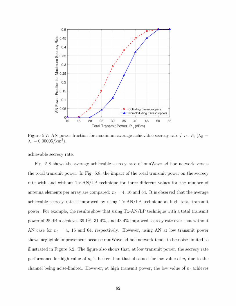
10 15 20 25 30 35 40 45 50 55
Total Transmit Power, Pt (dBm)
0
0.05
0.1
0.15
0.2
0.25
0.3
0.35
0.4
0.45
0.5
AN
Pow
er
Fra
ction for
Maxim
um
Secre
cy R
ate
Colluding Eavesdroppers
Non-Colluding Eavesdroppers
Figure 5.7: AN power fraction for maximum average achievable secrecy rate ς vs. Pt (λB =λe = 0.00005/km2).
achievable secrecy rate.
Fig. 5.8 shows the average achievable secrecy rate of mmWave ad hoc network versus
the total transmit power. In Fig. 5.8, the impact of the total transmit power on the secrecy
rate with and without Tx-AN/LP technique for three different values for the number of
antenna elements per array are compared: nt = 4, 16 and 64. It is observed that the average
achievable secrecy rate is improved by using Tx-AN/LP technique at high total transmit
power. For example, the results show that using Tx-AN/LP technique with a total transmit
power of 25 dBm achieves 39.1%, 31.4%, and 43.4% improved secrecy rate over that without
AN case for nt = 4, 16 and 64, respectively. However, using AN at low transmit power
shows negligible improvement because mmWave ad hoc network tends to be noise-limited as
illustrated in Figure 5.2. The figure also shows that, at low transmit power, the secrecy rate
performance for high value of nt is better than that obtained for low value of nt due to the
channel being noise-limited. However, at high transmit power, the low value of nt achieves
82
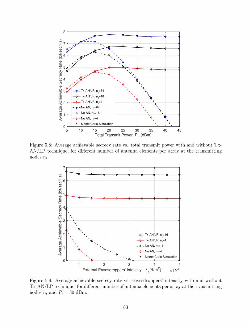
5 10 15 20 25 30 35 40 45
Total Transmit Power, Pt (dBm)
0
1
2
3
4
5
6
7
8
Avera
ge A
chie
vable
Secre
cy R
ate
(bit/s
ec/H
z)
Tx-AN/LP, nt=64
Tx-AN/LP, nt=16
Tx-AN/LP, nt=4
No AN, nt=64
No AN, nt=16
No AN, nt=4
Monte Carlo Simulation
Figure 5.8: Average achievable secrecy rate vs. total transmit power with and without Tx-AN/LP technique, for different number of antenna elements per array at the transmittingnodes nt.
1 2 3 4 5
External Eavesdroppers' Intensity, e(/Km
2) 10
-4
0
1
2
3
4
5
6
7
Avera
ge A
chie
vable
Secre
cy R
ate
(bit/s
ec/H
z)
Tx-AN/LP, nt=16
Tx-AN/LP, nt=4
No AN, nt=16
No AN, nt=4
Monte Carlo Simulation
Figure 5.9: Average achievable secrecy rate vs. eavesdroppers’ intensity with and withoutTx-AN/LP technique, for different number of antenna elements per array at the transmittingnodes nt and Pt = 30 dBm.
83
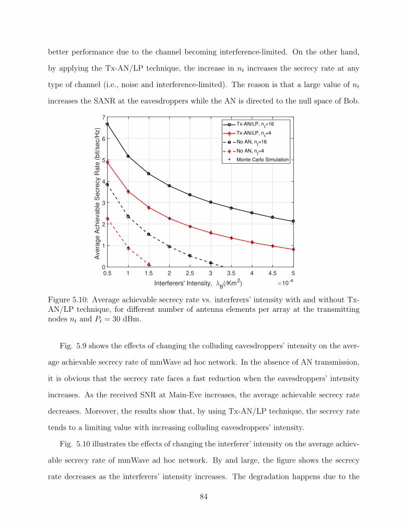
better performance due to the channel becoming interference-limited. On the other hand,
by applying the Tx-AN/LP technique, the increase in nt increases the secrecy rate at any
type of channel (i.e., noise and interference-limited). The reason is that a large value of nt
increases the SANR at the eavesdroppers while the AN is directed to the null space of Bob.
0.5 1 1.5 2 2.5 3 3.5 4 4.5 5
Interferers' Intensity, B(/Km
2) 10
-4
0
1
2
3
4
5
6
7
Avera
ge A
chie
vable
Secre
cy R
ate
(bit/s
ec/H
z)
Tx-AN/LP, nt=16
Tx-AN/LP, nt=4
No AN, nt=16
No AN, nt=4
Monte Carlo Simulation
Figure 5.10: Average achievable secrecy rate vs. interferers’ intensity with and without Tx-AN/LP technique, for different number of antenna elements per array at the transmittingnodes nt and Pt = 30 dBm.
Fig. 5.9 shows the effects of changing the colluding eavesdroppers’ intensity on the aver-
age achievable secrecy rate of mmWave ad hoc network. In the absence of AN transmission,
it is obvious that the secrecy rate faces a fast reduction when the eavesdroppers’ intensity
increases. As the received SNR at Main-Eve increases, the average achievable secrecy rate
decreases. Moreover, the results show that, by using Tx-AN/LP technique, the secrecy rate
tends to a limiting value with increasing colluding eavesdroppers’ intensity.
Fig. 5.10 illustrates the effects of changing the interferer’ intensity on the average achiev-
able secrecy rate of mmWave ad hoc network. By and large, the figure shows the secrecy
rate decreases as the interferers’ intensity increases. The degradation happens due to the
84
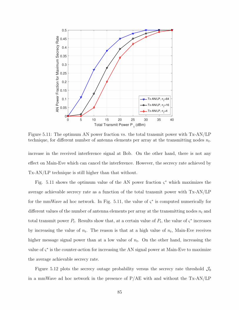
0 5 10 15 20 25 30 35 40
Total Transmit Power Pt (dBm)
0
0.05
0.1
0.15
0.2
0.25
0.3
0.35
0.4
0.45
0.5
AN
Po
we
r F
ractio
n f
or
Ma
xim
um
Se
cre
cy R
ate
Tx-AN/LP, nt=64
Tx-AN/LP, nt=16
Tx-AN/LP, nt=4
Figure 5.11: The optimum AN power fraction vs. the total transmit power with Tx-AN/LPtechnique, for different number of antenna elements per array at the transmitting nodes nt.
increase in the received interference signal at Bob. On the other hand, there is not any
effect on Main-Eve which can cancel the interference. However, the secrecy rate achieved by
Tx-AN/LP technique is still higher than that without.
Fig. 5.11 shows the optimum value of the AN power fraction ς∗ which maximizes the
average achievable secrecy rate as a function of the total transmit power with Tx-AN/LP
for the mmWave ad hoc network. In Fig. 5.11, the value of ς∗ is computed numerically for
different values of the number of antenna elements per array at the transmitting nodes nt and
total transmit power Pt. Results show that, at a certain value of Pt, the value of ς∗ increases
by increasing the value of nt. The reason is that at a high value of nt, Main-Eve receives
higher message signal power than at a low value of nt. On the other hand, increasing the
value of ς∗ is the counter-action for increasing the AN signal power at Main-Eve to maximize
the average achievable secrecy rate.
Figure 5.12 plots the secrecy outage probability versus the secrecy rate threshold J0
in a mmWave ad hoc network in the presence of P/AE with and without the Tx-AN/LP
85
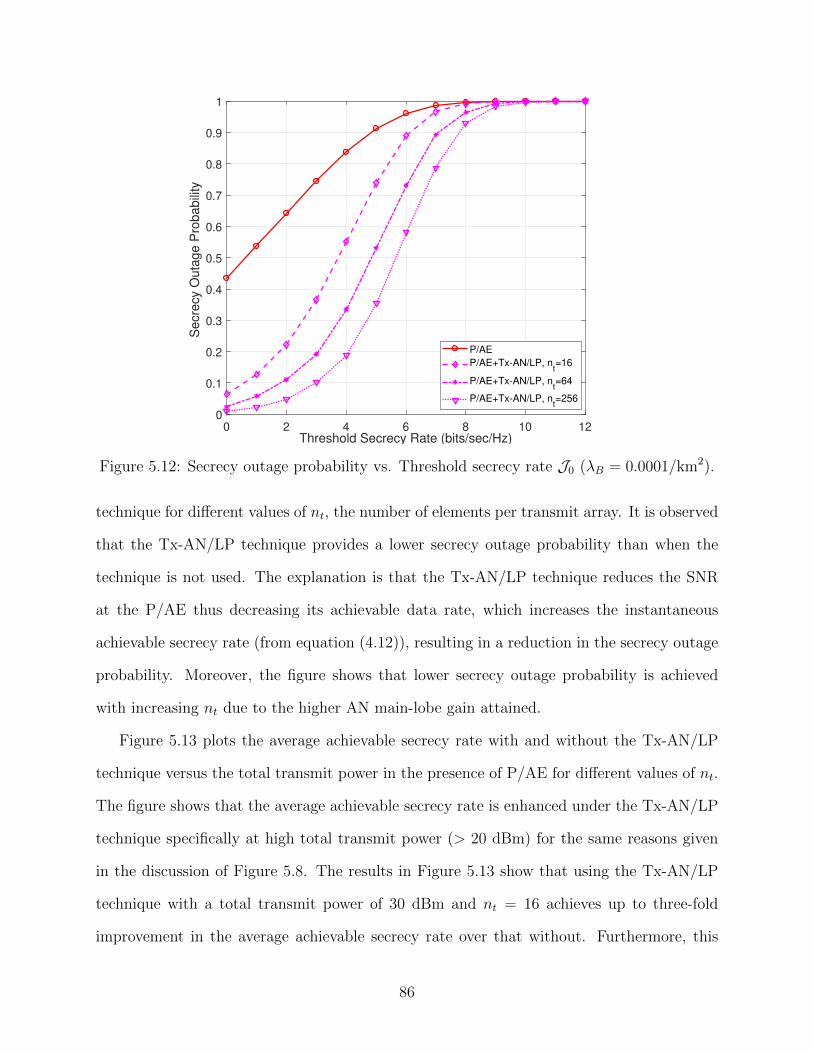
0 2 4 6 8 10 12Threshold Secrecy Rate (bits/sec/Hz)
0
0.1
0.2
0.3
0.4
0.5
0.6
0.7
0.8
0.9
1
Secre
cy O
uta
ge P
robabili
ty
P/AE
P/AE+Tx-AN/LP, nt=16
P/AE+Tx-AN/LP, nt=64
P/AE+Tx-AN/LP, nt=256
Figure 5.12: Secrecy outage probability vs. Threshold secrecy rate J0 (λB = 0.0001/km2).
technique for different values of nt, the number of elements per transmit array. It is observed
that the Tx-AN/LP technique provides a lower secrecy outage probability than when the
technique is not used. The explanation is that the Tx-AN/LP technique reduces the SNR
at the P/AE thus decreasing its achievable data rate, which increases the instantaneous
achievable secrecy rate (from equation (4.12)), resulting in a reduction in the secrecy outage
probability. Moreover, the figure shows that lower secrecy outage probability is achieved
with increasing nt due to the higher AN main-lobe gain attained.
Figure 5.13 plots the average achievable secrecy rate with and without the Tx-AN/LP
technique versus the total transmit power in the presence of P/AE for different values of nt.
The figure shows that the average achievable secrecy rate is enhanced under the Tx-AN/LP
technique specifically at high total transmit power (> 20 dBm) for the same reasons given
in the discussion of Figure 5.8. The results in Figure 5.13 show that using the Tx-AN/LP
technique with a total transmit power of 30 dBm and nt = 16 achieves up to three-fold
improvement in the average achievable secrecy rate over that without. Furthermore, this
86
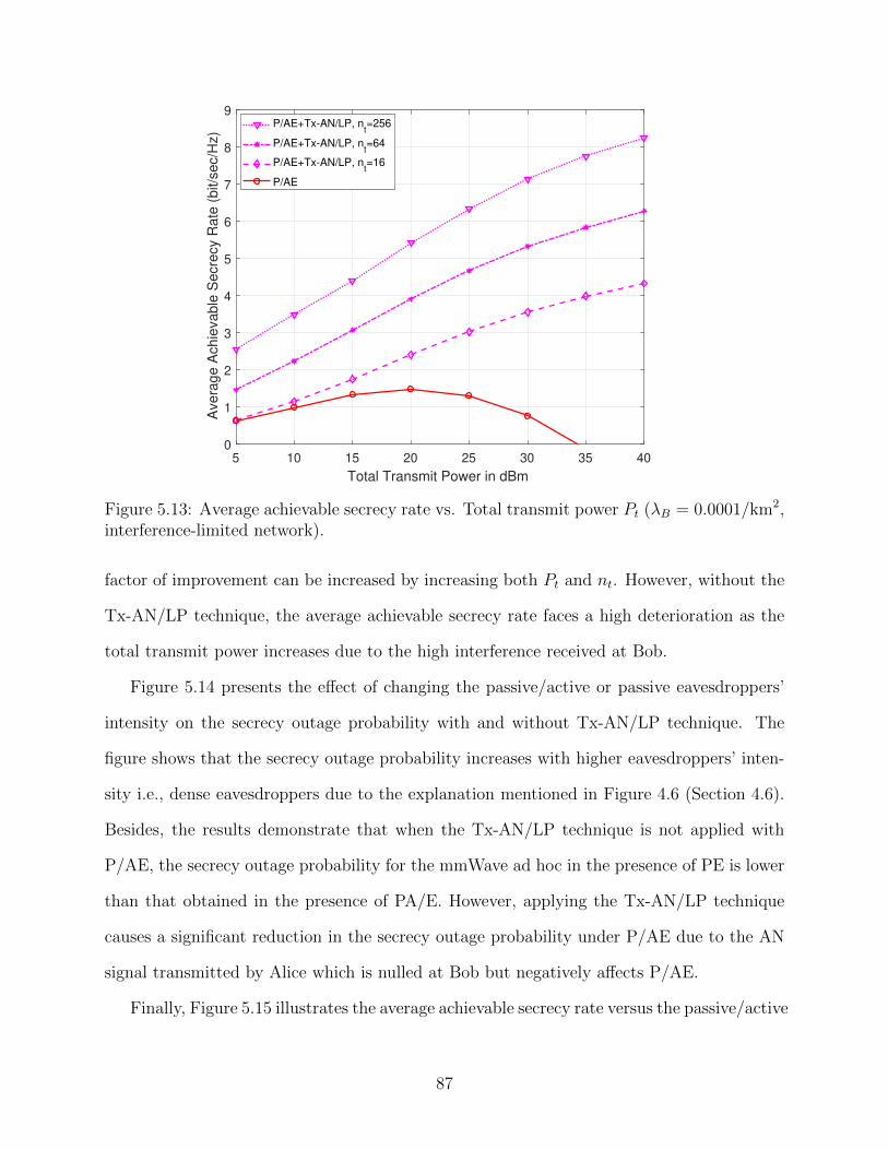
5 10 15 20 25 30 35 40
Total Transmit Power in dBm
0
1
2
3
4
5
6
7
8
9
Avera
ge A
chie
vable
Secre
cy R
ate
(bit/s
ec/H
z)
P/AE+Tx-AN/LP, nt=256
P/AE+Tx-AN/LP, nt=64
P/AE+Tx-AN/LP, nt=16
P/AE
Figure 5.13: Average achievable secrecy rate vs. Total transmit power Pt (λB = 0.0001/km2,interference-limited network).
factor of improvement can be increased by increasing both Pt and nt. However, without the
Tx-AN/LP technique, the average achievable secrecy rate faces a high deterioration as the
total transmit power increases due to the high interference received at Bob.
Figure 5.14 presents the effect of changing the passive/active or passive eavesdroppers’
intensity on the secrecy outage probability with and without Tx-AN/LP technique. The
figure shows that the secrecy outage probability increases with higher eavesdroppers’ inten-
sity i.e., dense eavesdroppers due to the explanation mentioned in Figure 4.6 (Section 4.6).
Besides, the results demonstrate that when the Tx-AN/LP technique is not applied with
P/AE, the secrecy outage probability for the mmWave ad hoc in the presence of PE is lower
than that obtained in the presence of PA/E. However, applying the Tx-AN/LP technique
causes a significant reduction in the secrecy outage probability under P/AE due to the AN
signal transmitted by Alice which is nulled at Bob but negatively affects P/AE.
Finally, Figure 5.15 illustrates the average achievable secrecy rate versus the passive/active
87
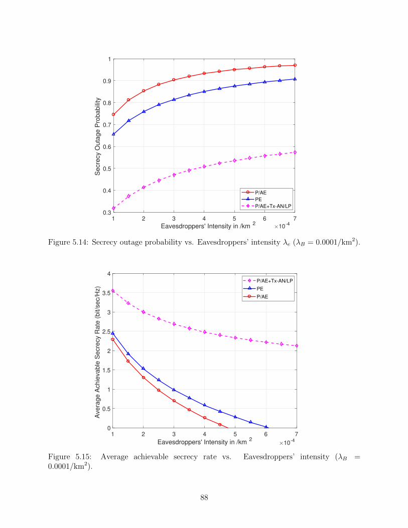
1 2 3 4 5 6 7
Eavesdroppers' Intensity in /km2
10-4
0.3
0.4
0.5
0.6
0.7
0.8
0.9
1
Secre
cy O
uta
ge P
robabili
ty
P/AE
PE
P/AE+Tx-AN/LP
Figure 5.14: Secrecy outage probability vs. Eavesdroppers’ intensity λe (λB = 0.0001/km2).
1 2 3 4 5 6 7
Eavesdroppers' Intensity in /km2
10-4
0
0.5
1
1.5
2
2.5
3
3.5
4
Avera
ge A
chie
vable
Secre
cy R
ate
(bit/s
ec/H
z)
P/AE+Tx-AN/LP
PE
P/AE
Figure 5.15: Average achievable secrecy rate vs. Eavesdroppers’ intensity (λB =0.0001/km2).
88
or passive eavesdroppers’ intensity with and without Tx-AN/LP technique. The average
achievable secrecy rate when the TX-AN/LP technique is not applied (Figure 4.7) is in-
cluded, for comparison. Clearly, for all the scenarios in Figure 5.15, the average achievable
secrecy rate decreases as the eavesdroppers’ intensity λe increases. However, the average
achievable secrecy rate of a mmWave ad hoc network in the presence of P/AE with the
Tx-AN/LP technique is much higher than that without.
5.5 Chapter Summary
In this chapter, the impact of applying two AN physical layer transmission techniques
namely, Tx-AN and Tx-AN/LP techniques, on the secrecy performance of the mmWave ad
hoc networks is proposed. The secrecy performance analysis is studied under various types
of eavesdroppers’ attacks such as passive non-colluding, colluding, and passive/active eaves-
droppers. In the absence of CSIT knowledge, it is recommended to use the Tx-AN technique
for improving the secrecy performance. Conversely, under CSIT knowledge, the Tx-AN/LP
technique is more suitable to use. Moreover, the mathematical expressions and derivations of
the average achievable secrecy rate and secrecy outage probability are derived. Besides, the
Tx-AN and Tx-AN/LP techniques show high secrecy robustness in the average achievable
data rate against the eavesdroppers’ intensity. However, without the Tx-AN or Tx-AN/LP
techniques, the secrecy performance faces a fast deterioration with increasing intensity of
the eavesdroppers. Finally, based on the system model parameters, the appropriate AN
power fraction to maximize the average secrecy rate for different eavesdropping strategies is
presented.
89
Chapter 6
Conclusions and Future Work
In this chapter, a summary of the thesis findings and conclusions is presented, as well as the
engineering significance of the findings. Moreover, the thesis limitations and suggestions for
future work are provided.
6.1 Thesis Summary and Conclusions
In this thesis, the physical layer security (PLS) of millimeter-wave (mmWave) ad hoc
networks is studied under various types of eavesdropping strategies, taking into consideration
the mmWave channel’s characteristics. The overall objective is to assess the effectiveness
of the strategies in enhancing the security performance of the network in the presence of
eavesdroppers.
The system model of the mmWave ad hoc networks is characterized by exploiting the
Poisson point process (PPP) model for characterizing the spatial distribution of the transmit-
ting nodes and eavesdroppers in Chapter 3. The directional beamforming is considered for
all network’s nodes to overcome the high attenuation of the mmWave signal’s propagation.
Hence, the achieved signal-to-interference-plus-noise ratio (SINR) at the authorized receiver
and the signal-to-noise ratio (SNR) at the eavesdroppers are determined. The analysis of
the secrecy performance in a mmWave ad hoc network with multi-array antenna transmis-
sion in the presence of non-colluding and colluding eavesdroppers is presented, taking into
account mmWave blockages and Nakagami-m fading. The mathematical derivations of the
average achievable secrecy rate are presented for both the line-of-sight (LoS) and non-LoS
(NLoS) of the mmWave signal links. By applying the simplified LoS mmWave model, the
90
mathematical formulas of the average achievable secrecy rate are further presented. The
results show the effect of varying the total transmit power on the average achievable secrecy
rate. Moreover, the results demonstrate the reduction in the secrecy performance due to
increasing the intensities of the transmitting nodes (interfering) and eavesdroppers. Finally,
the combined impact of the total transmit power and the eavesdroppers’ intensity on the
average achievable secrecy rate is investigated.
In Chapter 4, the PLS analysis of a mmWave ad hoc network in the presence of pas-
sive/active eavesdroppers is presented. This type of eavesdroppers can intercept the mes-
sage signal and simultaneously transmit a jamming signal toward the legitimate receiver to
interfere with its received useful signal. First, the SINR at the legitimate receiver is charac-
terized under the effect of the passive/active eavesdroppers (P/AE). By exploiting the tools
of stochastic geometry, the mathematical expressions for three different metrics: connection
outage probability, secrecy outage probability, and average achievable secrecy rate, are de-
rived to evaluate the secrecy performance. The derived expressions are presented for the
noise-limited and interference-limited networks. The results demonstrate the impact of the
main system parameters such as the gain of the array antennas for the transmitting and
receiving nodes, the eavesdroppers’ intensity, the interferers’ intensity, and the value of the
jamming signal power by P/AE, on the secrecy performance.
Aiming at enhancing the secrecy performance of the mmWave ad hoc network in the
presence of eavesdroppers, two artificial noise (AN)-based secure transmission techniques,
namely Tx-AN technique and Tx-AN/LP technique are investigated in Chapter 5. The
mathematical expressions of the secrecy performance metrics mentioned above are derived
under both techniques. Firstly, in the Tx-AN technique, the total transmit power at the typ-
ical legitimate transmitter is divided into message power and AN power, where the main lobe
beam of the AN arrays is not being directed to the legitimate receiver. The potential benefits
of this technique are its simplicity and neither requires the channel state information between
91
Alice and its receiver (CSIT) nor the CSI between Alice and the eavesdroppers. By applying
the Tx-AN technique to the mmWave networks in the presence of passive non-colluding and
colluding eavesdroppers, up to three-fold gain on the average achievable secrecy rate is ob-
tained over that without using this technique in the interference-limited networks. Besides,
the Tx-AN technique demonstrates high robustness of the secrecy performance against the
eavesdroppers’ intensity. However, without the Tx-AN technique, the average achievable se-
crecy rate faces a fast degradation with increasing intensity of the eavesdroppers. Secondly,
the Tx-AN/LP technique is applied to the mmWave ad hoc network under the eavesdrop-
pers’ attack with knowledge of the CSIT. In this technique, a part of the transmitted power
at the legitimate transmitter is assigned to transmit the AN signal into the null space of the
legitimate receiver while the SNR is reduced at the eavesdroppers. The results show that
considerable secrecy performance gain is achieved by applying the Tx-AN/LP technique in
the presence of passive colluding and passive/active eavesdroppers. Hence, the impact of
the total transmit power or jamming power, the array antennas’ gain, and eavesdroppers’
intensity is studied. Finally, based on the system model parameters, the numerical assign-
ment of the appropriate AN power fraction to maximize the average secrecy rate under both
techniques is presented.
6.2 Engineering Significance of Thesis Findings
The findings from this thesis are of engineering significance, as discussed in the following:
• The PLS is very beneficial to increase the wireless networks’ security due to
the low computational power and simplicity of its implementations. Moreover,
the type of attack that faces the wireless network controls the threats level
on this network. For instance, the presence of the P/AE in a mmWave ad
hoc network is more dangerous on the secrecy performance compared to the
presence of traditional passive eavesdroppers because of the P/AE’s jamming
92
transmit power.
• The proposed research provided a comprehensive understanding of the PLS
security in the mmWave ad hoc networks under various kinds of eavesdropping
attacks and the impacts of the significant controllable parameters to help the
networks’ designers to achieve a substantial security performance.
• Particularly, the design of the secure transmission based on the PLS approach
in the presence of eavesdroppers needs a simple and effective technique that is
presented in this thesis (Tx-AN and Tx-AN/LP techniques).
6.3 Thesis Limitations and Suggestions for Future Work
In this section, a general view of the thesis limitations and restrictions are presented.
In addition, these limitations lead to many interesting areas that are worthwhile for future
investigations.
6.3.1 Limitations of the Thesis
• Most of the proposed mathematical expressions in this thesis are in integral-
form, hence the results are computed numerically using the Mathematica tool.
Therefore, it is recommended to consider some reasonable assumptions, which
are consistent with the mmWave channel characteristics, to simplify these
expressions.
• Although, the two PLS techniques applied in the thesis (Tx-AN and Tx-
AN/LP) enhance the security performance of the mmWave ad hoc networks,
the performance can be further improved by protecting the other legitimate
93
receivers in the network from receiving the AN that is transmitted by Alice.
In this vein, more information may be required at Alice about the other le-
gitimate receivers in the network. For example, the locations of the receivers
in the case of the Tx-AN technique and the CSI between Alice and the other
receivers when the Tx-AN/LP technique is applied.
• The two applied PLS transmission techniques achieve a significant improve-
ment in the security performance of the mmWave ad hoc networks at high to-
tal transmit power regime, i.e., interference-limited network. However, for the
noise-limited network, i.e. low transmit power regime, it is not recommended
to use the AN, as illustrated in Figure 5.2. Subsequently, it is interesting to
upgrade the two PLS techniques to exploit the AN in the low transmit power
regime.
• In the presence of non-colluding eavesdroppers, the special case when the
eavesdropper is very close to the legitimate receiver needs to be studied. In
that scenario, the AN will affect the legitimate receiver as well as the eaves-
droppers due to both nodes being in the same direction and almost having the
same channel characteristics.
6.3.2 Future Work
• Even though the PLS approaches ensure potential security independently of
cryptography, it is a promising way to improve the security performance for
wireless networks by collaborating the PLS with the encryption schemes in the
upper layers, which are called cross-layer protocols [6]. The main challenge of
this research is how to design a standard that produces a precise evaluation of
the security performance of cross-layer designing schemes.
94
• An optimization problem can be formulated to determine the optimum power
allocation between the message and AN signals for the two presented PLS
transmission techniques to maximize the security performance of the mmWave
ad hoc networks in the presence of different types of eavesdroppers.
• The presented PLS analysis for the mmWave ad hoc network can be extended
to the massive multiple-input multiple-output (MIMO) systems which give
more opportunities for exploiting the channel features. Furthermore, this PLS
analysis can be applied to future next-generation wireless networks that oper-
ate in the mmWave bands. For example, the PLS work in the thesis has been
applied to the study of cache-enabled mmWave cellular networks, to achieve
increased secrecy performance [88].
95
Bibliography
[1] M. Li, S. Kundu, D. A. Pados, and S. N. Batalama, “Waveform design for secure SISOtransmissions and multicasting,” IEEE Journal on Selected Areas in Communications,vol. 31, no. 9, pp. 1864–1874, 2013.
[2] W.-C. Liao, T.-H. Chang, W.-K. Ma, and C.-Y. Chi, “QoS-based transmit beamformingin the presence of eavesdroppers: An optimized artificial-noise-aided approach,” IEEETransactions on Signal Processing, vol. 59, no. 3, pp. 1202–1216, 2010.
[3] H. Reboredo, J. Xavier, and M. R. Rodrigues, “Filter design with secrecy constraints:The MIMO gaussian wiretap channel,” IEEE transactions on signal processing, vol. 61,no. 15, pp. 3799–3814, 2013.
[4] C. E. Shannon, “Communication theory of secrecy systems,” The Bell system technicaljournal, vol. 28, no. 4, pp. 656–715, 1949.
[5] A. D. Wyner, “The wire-tap channel,” Bell system technical journal, vol. 54, no. 8, pp.1355–1387, 1975.
[6] L. Wang, Physical Layer Security in Wireless Cooperative Networks. Springer, 2018.
[7] A. Mpitziopoulos, D. Gavalas, C. Konstantopoulos, and G. Pantziou, “A survey onjamming attacks and countermeasures in wsns,” IEEE Communications Surveys & Tu-torials, vol. 11, no. 4, pp. 42–56, 2009.
[8] C.-C. J. Kuo, S.-H. Tsai, L. Tadjpour, and Y.-H. Chang, Precoding techniques for digitalcommunication systems. Springer, 2008.
[9] H.-M. Wang and T.-X. Zheng, Physical layer security in random cellular networks.Springer, 2016.
[10] M. Bloch, J. Barros, M. R. Rodrigues, and S. W. McLaughlin, “Wireless information-theoretic security,” IEEE Transactions on Information Theory, vol. 54, no. 6, pp. 2515–2534, 2008.
[11] J. D. V. Sanchez, L. Urquiza-Aguiar, M. C. P. Paredes, and D. P. M. Osorio, “Surveyon physical layer security for 5g wireless networks,” Annals of Telecommunications, pp.1–20, 2020.
[12] R. Fellers, “Millimeter waves and their applications,” Electrical Engineering, vol. 75,no. 10, pp. 914–917, 1956.
[13] T. S. Rappaport, S. Sun, R. Mayzus, H. Zhao, Y. Azar, K. Wang, G. N. Wong, J. K.Schulz, M. Samimi, and F. Gutierrez, “Millimeter wave mobile communications for 5Gcellular: It will work!” IEEE access, vol. 1, pp. 335–349, 2013.
[14] S. Rangan, T. S. Rappaport, and E. Erkip, “Millimeter wave cellular wireless networks:Potentials and challenges,” Proceedings of the IEEE, vol. 102, pp. 366–385, 2014.
[15] J. G. Andrews, T. Bai, M. N. Kulkarni, A. Alkhateeb, A. K. Gupta, and R. W. Heath,“Modeling and analyzing millimeter wave cellular systems,” IEEE Transactions onCommunications, vol. 65, no. 1, pp. 403–430, 2016.
[16] A. Thornburg and R. W. Heath, “Ergodic rate of millimeter wave ad hoc networks,”IEEE Transactions on Wireless Communications, vol. 17, no. 2, pp. 914–926, 2017.
96
[17] T. Bai, R. Vaze, and R. W. Heath, “Analysis of blockage effects on urban cellularnetworks,” IEEE Transactions on Wireless Communications, vol. 13, no. 9, pp. 5070–5083, 2014.
[18] A. Thornburg, T. Bai, and R. W. Heath, “Performance analysis of outdoor mmwave adhoc networks,” IEEE Transactions on Signal Processing, vol. 64, no. 15, pp. 4065–4079,2016.
[19] J. Zhu, Y. Chen, Y. Shen, O. Takahashi, X. Jiang, and N. Shiratori, “Secrecy transmis-sion capacity in noisy wireless ad hoc networks,” Ad hoc networks, vol. 21, pp. 123–133,2014.
[20] X. Zhou, R. K. Ganti, J. G. Andrews, and A. Hjorungnes, “On the throughput costof physical layer security in decentralized wireless networks,” IEEE Transactions onWireless Communications, vol. 10, no. 8, pp. 2764–2775, 2011.
[21] T.-X. Zheng, H.-M. Wang, J. Yuan, Z. Han, and M. H. Lee, “Physical layer security inwireless ad hoc networks under a hybrid full-/half-duplex receiver deployment strategy,”IEEE Transactions on Wireless Communications, vol. 16, no. 6, pp. 3827–3839, 2017.
[22] S. Vasudevan, D. Goeckel, and D. F. Towsley, “Security-capacity trade-off in large wire-less networks using keyless secrecy,” in Proceedings of the eleventh ACM internationalsymposium on Mobile ad hoc networking and computing. ACM, 2010, pp. 21–30.
[23] X. Zhang, X. Zhou, and M. R. McKay, “Enhancing secrecy with multi-antenna trans-mission in wireless ad hoc networks,” IEEE Transactions on Information Forensics andSecurity, vol. 8, no. 11, pp. 1802–1814, 2013.
[24] K. Yu, J. Yu, X. Cheng, and T. Song, “Theoretical analysis of secrecy transmissioncapacity in wireless ad hoc networks,” in 2017 IEEE Wireless Communications andNetworking Conference (WCNC). IEEE, 2017, pp. 1–6.
[25] Y. Ju, H.-M. Wang, T.-X. Zheng, and Q. Yin, “Secure transmission with artificial noisein millimeter wave systems,” in 2016 IEEE Wireless Communications and NetworkingConference. IEEE, 2016, pp. 1–6.
[26] M. E. Eltayeb, J. Choi, T. Y. Al-Naffouri, and R. W. Heath, “On the security ofmillimeter wave vehicular communication systems using random antenna subsets,” in2016 IEEE 84th Vehicular Technology Conference (VTC-Fall). IEEE, 2016, pp. 1–5.
[27] N. Valliappan, A. Lozano, and R. W. Heath, “Antenna subset modulation for se-cure millimeter-wave wireless communication,” IEEE Transactions on communications,vol. 61, no. 8, pp. 3231–3245, 2013.
[28] C. Chen, Y. Dong, X. Cheng, and N. Yi, “An iterative FFT-based antenna subset mod-ulation for secure millimeter wave communications,” in 2017 International Conferenceon Computing, Networking and Communications (ICNC). IEEE, 2017, pp. 454–459.
[29] Y. Ju, H.-M. Wang, T.-X. Zheng, and Q. Yin, “Secure transmissions in millimeter wavesystems,” IEEE Transactions on Communications, vol. 65, no. 5, pp. 2114–2127, 2017.
[30] Y. Ju, H.-M. Wang, T.-X. Zheng, Q. Yin, and M. H. Lee, “Safeguarding millimeterwave communications against randomly located eavesdroppers,” IEEE Transactions onWireless Communications, vol. 17, no. 4, pp. 2675–2689, 2018.
97
[31] S. Vuppala, S. Biswas, and T. Ratnarajah, “An analysis on secure communicationin millimeter/micro-wave hybrid networks,” IEEE Transactions on Communications,vol. 64, no. 8, pp. 3507–3519, 2016.
[32] S. Vuppala, Y. J. Tolossa, G. Kaddoum, and G. Abreu, “On the physical layer securityanalysis of hybrid millimeter wave networks,” IEEE Transactions on Communications,vol. 66, no. 3, pp. 1139–1152, 2017.
[33] M. E. Eltayeb, J. Choi, T. Y. Al-Naffouri, and R. W. Heath, “Enhancing secrecy withmultiantenna transmission in millimeter wave vehicular communication systems,” IEEETransactions on Vehicular Technology, vol. 66, no. 9, pp. 8139–8151, 2017.
[34] C. Wang and H.-M. Wang, “Physical layer security in millimeter wave cellular net-works,” IEEE Transactions on Wireless Communications, vol. 15, no. 8, pp. 5569–5585,2016.
[35] Y. R. Ramadan and H. Minn, “Artificial noise aided hybrid precoding design for securemmwave miso systems with partial channel knowledge,” IEEE Signal Processing Letters,vol. 24, no. 11, pp. 1729–1733, 2017.
[36] L. Wang, M. Elkashlan, T. Q. Duong, and R. W. Heath, “Secure communication in cel-lular networks: The benefits of millimeter wave mobile broadband,” in 2014 IEEE 15thInternational Workshop on Signal Processing Advances in Wireless Communications(SPAWC). IEEE, 2014, pp. 115–119.
[37] S. Gong, C. Xing, Z. Fei, and S. Ma, “Millimeter-wave secrecy beamforming designs fortwo-way amplify-and-forward mimo relaying networks,” IEEE Transactions on Vehicu-lar Technology, vol. 66, no. 3, pp. 2059–2071, 2016.
[38] Y. Zhu, L. Wang, K.-K. Wong, and R. W. Heath, “Secure communications in millimeterwave ad hoc networks,” IEEE Transactions on Wireless Communications, vol. 16, no. 5,pp. 3205–3217, 2017.
[39] Y. Zhang, Y. Shen, X. Jiang, and S. Kasahara, “Secure millimeter-wave ad hoc com-munications using physical layer security,” arXiv preprint arXiv:2009.01988, 2020.
[40] A. Mazin, K. Davaslioglu, and R. D. Gitlin, “Secure key management for 5g physi-cal layer security,” in 2017 IEEE 18th Wireless and Microwave Technology Conference(WAMICON). IEEE, 2017, pp. 1–5.
[41] Y. Wu, A. Khisti, C. Xiao, G. Caire, K.-K. Wong, and X. Gao, “A survey of physicallayer security techniques for 5g wireless networks and challenges ahead,” IEEE Journalon Selected Areas in Communications, vol. 36, no. 4, pp. 679–695, 2018.
[42] N. Ebrahimi, B. Yektakhah, K. Sarabandi, H. S. Kim, D. Wentzloff, and D. Blaauw, “Anovel physical layer security technique using master-slave full duplex communication,”in 2019 IEEE MTT-S International Microwave Symposium (IMS). IEEE, 2019, pp.1096–1099.
[43] L. Li, Y. Hu, H. Zhang, W. Liang, and A. Gao, “Deep learning based physical layersecurity of d2d underlay cellular network,” China Communications, vol. 17, no. 2, pp.93–106, 2020.
[44] M. R. Abedi, N. Mokari, H. Saeedi, and H. Yanikomeroglu, “Robust resource allocationto enhance physical layer security in systems with full-duplex receivers: Active adver-sary,” IEEE Transactions on Wireless Communications, vol. 16, no. 2, pp. 885–899,2016.
98
[45] L. Li, A. P. Petropulu, and Z. Chen, “MIMO secret communications against an ac-tive eavesdropper,” IEEE Transactions on Information Forensics and Security, vol. 12,no. 10, pp. 2387–2401, 2017.
[46] A. Chorti, S. M. Perlaza, Z. Han, and H. V. Poor, “On the resilience of wireless mul-tiuser networks to passive and active eavesdroppers,” IEEE Journal on Selected Areasin Communications, vol. 31, no. 9, pp. 1850–1863, 2013.
[47] ——, “Physical layer security in wireless networks with passive and active eavesdrop-pers,” in 2012 IEEE Global Communications Conference (GLOBECOM). IEEE, 2012,pp. 4868–4873.
[48] Z. Liu, N. Li, X. Tao, S. Li, J. Xu, and B. Zhang, “Artificial-noise-aided secure commu-nication with full-duplex active eavesdropper,” in 2017 IEEE 28th Annual InternationalSymposium on Personal, Indoor, and Mobile Radio Communications (PIMRC). IEEE,2017, pp. 1–7.
[49] A. F. Darwesh and A. O. Fapojuwo, “Achievable secrecy rate in mmwave multiple-inputsingle-output ad hoc networks,” in 2020 IEEE 91st Vehicular Technology Conference(VTC2020-Spring). IEEE, 2020, pp. 1–6.
[50] ——, “Achievable secrecy rate analysis in mmwave ad hoc networks with multi-arrayantenna transmission and artificial noise,” Wireless Communications and Mobile Com-puting, 2020 (Under Review).
[51] ——, “Physical layer security analysis of mmwave ad hoc networks in the presence ofpassive/active eavesdroppers,” IEEE Transactions on Wireless Communications, 2020(Under Review).
[52] ——, “Secrecy rate analysis of mmwave MISO ad hoc networks with null space precod-ing,” in 2020 IEEE Wireless Communications and Networking Conference (WCNC).IEEE, 2020, pp. 1–6.
[53] I. Csiszar and J. Korner, “Broadcast channels with confidential messages,” IEEE trans-actions on information theory, vol. 24, no. 3, pp. 339–348, 1978.
[54] S. Leung-Yan-Cheong and M. Hellman, “The gaussian wire-tap channel,” IEEE trans-actions on information theory, vol. 24, no. 4, pp. 451–456, 1978.
[55] P. K. Gopala, L. Lai, and H. El Gamal, “On the secrecy capacity of fading channels,”IEEE Transactions on Information Theory, vol. 54, no. 10, pp. 4687–4698, 2008.
[56] Y. Liang, H. V. Poor, and S. Shamai, “Secure communication over fading channels,”IEEE Transactions on Information Theory, vol. 54, no. 6, pp. 2470–2492, 2008.
[57] J. Li and A. P. Petropulu, “Ergodic secrecy rate for multiple-antenna wiretap channelswith rician fading,” IEEE Transactions on Information Forensics and Security, vol. 6,no. 3, pp. 861–867, 2011.
[58] X. Zhou, R. K. Ganti, and J. G. Andrews, “Secure wireless network connectivity withmulti-antenna transmission,” IEEE Transactions on Wireless Communications, vol. 10,no. 2, pp. 425–430, 2010.
[59] O. O. Koyluoglu, C. E. Koksal, and H. El Gamal, “On secrecy capacity scaling in wirelessnetworks,” IEEE Transactions on Information Theory, vol. 58, no. 5, pp. 3000–3015,2012.
99
[60] T.-X. Zheng, H.-M. Wang, and Q. Yin, “On transmission secrecy outage of a multi-antenna system with randomly located eavesdroppers,” IEEE communications letters,vol. 18, no. 8, pp. 1299–1302, 2014.
[61] X. Chen and R. Yin, “Performance analysis for physical layer security in multi-antennadownlink networks with limited csi feedback,” IEEE Wireless Communications Letters,vol. 2, no. 5, pp. 503–506, 2013.
[62] S. Goel and R. Negi, “Guaranteeing secrecy using artificial noise,” IEEE transactionson wireless communications, vol. 7, no. 6, pp. 2180–2189, 2008.
[63] P.-H. Lin, S.-H. Lai, S.-C. Lin, and H.-J. Su, “On secrecy rate of the generalizedartificial-noise assisted secure beamforming for wiretap channels,” IEEE Journal onSelected Areas in Communications, vol. 31, no. 9, pp. 1728–1740, 2013.
[64] J. Xiong, K.-K. Wong, D. Ma, and J. Wei, “A closed-form power allocation for mini-mizing secrecy outage probability for miso wiretap channels via masked beamforming,”IEEE Communications Letters, vol. 16, no. 9, pp. 1496–1499, 2012.
[65] N. Yang, S. Yan, J. Yuan, R. Malaney, R. Subramanian, and I. Land, “Artificial noise:Transmission optimization in multi-input single-output wiretap channels,” IEEE Trans-actions on Communications, vol. 63, no. 5, pp. 1771–1783, 2015.
[66] B. Wang, P. Mu, and Z. Li, “Secrecy rate maximization with artificial-noise-aided beam-forming for miso wiretap channels under secrecy outage constraint,” IEEE Communi-cations Letters, vol. 19, no. 1, pp. 18–21, 2014.
[67] Y. Tang, J. Xiong, D. Ma, and X. Zhang, “Robust artificial noise aided transmit designfor miso wiretap channels with channel uncertainty,” IEEE communications letters,vol. 17, no. 11, pp. 2096–2099, 2013.
[68] T. Bai and R. W. Heath, “Coverage and rate analysis for millimeter-wave cellular net-works,” IEEE Transactions on Wireless Communications, vol. 14, no. 2, pp. 1100–1114,2014.
[69] S. Singh, M. N. Kulkarni, A. Ghosh, and J. G. Andrews, “Tractable model for rate inself-backhauled millimeter wave cellular networks,” IEEE Journal on Selected Areas inCommunications, vol. 33, no. 10, pp. 2196–2211, 2015.
[70] B. Han, L. Wang, and H. D. Schotten, “A 3d human body blockage model for outdoormillimeter-wave cellular communication,” Physical Communication, vol. 25, pp. 502–510, 2017.
[71] V. Raghavan, L. Akhoondzadeh-Asl, V. Podshivalov, J. Hulten, M. A. Tassoudji, O. H.Koymen, A. Sampath, and J. Li, “Statistical blockage modeling and robustness of beam-forming in millimeter-wave systems,” IEEE Transactions on Microwave Theory andTechniques, vol. 67, no. 7, pp. 3010–3024, 2019.
[72] L. Zhou and Z. J. Haas, “Securing ad hoc networks,” IEEE network, vol. 13, no. 6, pp.24–30, 1999.
[73] F. Baccelli, B. B laszczyszyn et al., “Stochastic geometry and wireless networks: VolumeII applications,” Foundations and Trends in Networking, vol. 4, no. 1–2, pp. 1–312, 2010.
[74] M. Haenggi, R. K. Ganti et al., “Interference in large wireless networks,” Foundationsand Trends® in Networking, vol. 3, no. 2, pp. 127–248, 2009.
100
[75] G. Geraci, S. Singh, J. G. Andrews, J. Yuan, and I. B. Collings, “Secrecy rates in broad-cast channels with confidential messages and external eavesdroppers,” IEEE Transac-tions on Wireless Communications, vol. 13, no. 5, pp. 2931–2943, 2014.
[76] G. Geraci, H. S. Dhillon, J. G. Andrews, J. Yuan, and I. B. Collings, “Physical layersecurity in downlink multi-antenna cellular networks,” IEEE Transactions on Commu-nications, vol. 62, no. 6, pp. 2006–2021, 2014.
[77] T. S. Rappaport, G. R. MacCartney, M. K. Samimi, and S. Sun, “Wideband millimeter-wave propagation measurements and channel models for future wireless communicationsystem design,” IEEE Transactions on Communications, vol. 63, no. 9, pp. 3029–3056,2015.
[78] F. Baccelli, B. Blaszczyszyn, and P. Muhlethaler, “An aloha protocol for multihopmobile wireless networks,” IEEE Transactions on Information Theory, vol. 52, no. 2,pp. 421–436, 2006.
[79] S. Deng, M. K. Samimi, and T. S. Rappaport, “28 GHz and 73 GHz millimeter-waveindoor propagation measurements and path loss models,” in 2015 IEEE InternationalConference on Communication Workshop (ICCW). IEEE, 2015, pp. 1244–1250.
[80] T. S. Rappaport, E. Ben-Dor, J. N. Murdock, and Y. Qiao, “38 GHz and 60 GHz angle-dependent propagation for cellular & peer-to-peer wireless communications,” in 2012IEEE international conference on communications (ICC). IEEE, 2012, pp. 4568–4573.
[81] K. Venugopal, M. C. Valenti, and R. W. Heath, “Interference in finite-sized highly densemillimeter wave networks,” in 2015 Information Theory and Applications Workshop(ITA). IEEE, 2015, pp. 175–180.
[82] R. Ramanathan, J. Redi, C. Santivanez, D. Wiggins, and S. Polit, “Ad hoc networkingwith directional antennas: a complete system solution,” IEEE Journal on selected areasin communications, vol. 23, no. 3, pp. 496–506, 2005.
[83] J. Park, S.-L. Kim, and J. Zander, “Tractable resource management with uplink decou-pled millimeter-wave overlay in ultra-dense cellular networks,” IEEE Transactions onWireless Communications, vol. 15, no. 6, pp. 4362–4379, 2016.
[84] W. Yi, Y. Liu, and A. Nallanathan, “Cache-enabled hetnets with millimeter wave smallcells,” IEEE Transactions on Communications, vol. 66, no. 11, pp. 5497–5511, 2018.
[85] M. Haenggi, J. G. Andrews, F. Baccelli, O. Dousse, and M. Franceschetti, “Stochasticgeometry and random graphs for the analysis and design of wireless networks,” IEEEJournal on Selected Areas in Communications, vol. 27, no. 7, pp. 1029–1046, 2009.
[86] G. Geraci, M. Egan, J. Yuan, A. Razi, and I. B. Collings, “Secrecy sum-rates for multi-user mimo regularized channel inversion precoding,” IEEE Transactions on Communi-cations, vol. 60, no. 11, pp. 3472–3482, 2012.
[87] M. Di Renzo, “Stochastic geometry modeling and analysis of multi-tier millimeter wavecellular networks,” IEEE Transactions on Wireless Communications, vol. 14, no. 9, pp.5038–5057, 2015.
[88] A. F. Darwesh, O. E. Ochia, and A. O. Fapojuwo, “Achievable secrecy rate in a mmwavecellular network with memory and file size-aware caching and null space precoding,”IEEE Transactions on Communications, 2020 (Under Review).
101
[89] S. Goel and R. Negi, “Secret communication in presence of colluding eavesdroppers,”in MILCOM, vol. 3. Citeseer, 2005, p. 1501.
[90] N. Yang, L. Wang, G. Geraci, M. Elkashlan, J. Yuan, and M. Di Renzo, “Safeguarding5G wireless communication networks using physical layer security,” IEEE Communica-tions Magazine, vol. 53, no. 4, pp. 20–27, 2015.
[91] K. A. Hamdi, “Capacity of mrc on correlated rician fading channels,” IEEE Transactionson Communications, vol. 56, no. 5, pp. 708–711, 2008.
[92] D. Vere-Jones, “Alpha-permanents and their applications to multivariate gamma, neg-ative binomial and ordinary binomial distributions,” New Zealand J. Math, vol. 26, pp.125–149, 1997.
[93] M. Marcus et al., “Multivariate gamma distributions,” Electronic Communications inProbability, vol. 19, 2014.
102
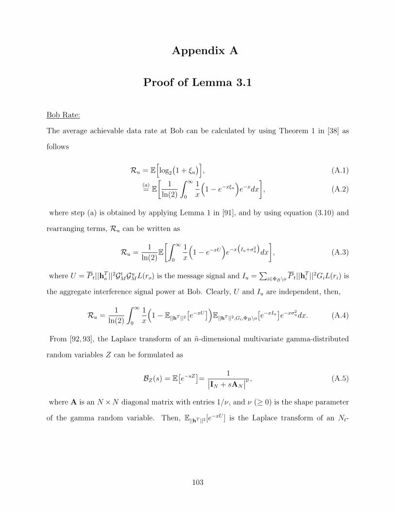
Appendix A
Proof of Lemma 3.1
Bob Rate:
The average achievable data rate at Bob can be calculated by using Theorem 1 in [38] as
follows
Ru = E[log2
(1 + ξu
)], (A.1)
(a)= E
[1
ln(2)
∫ ∞0
1
x
(1− e−xξu
)e−xdx
], (A.2)
where step (a) is obtained by applying Lemma 1 in [91], and by using equation (3.10) and
rearranging terms, Ru can be written as
Ru =1
ln(2)E[∫ ∞
0
1
x
(1− e−xU
)e−x(Iu+σ2
u
)dx
], (A.3)
where U = P t||hTo ||2GtMGuML(ro) is the message signal and Iu =∑
i∈ΦB\o P t||hTi ||2GiL(ri) is
the aggregate interference signal power at Bob. Clearly, U and Iu are independent, then,
Ru =1
ln(2)
∫ ∞0
1
x
(1− E||hT ||2
[e−xU
])E||hT ||2,Gi,ΦB\o
[e−xIu
]e−xσ
2udx. (A.4)
From [92, 93], the Laplace transform of an n-dimensional multivariate gamma-distributed
random variables Z can be formulated as
BZ(s) = E[e−sZ
]=
1∣∣IN + sAN
∣∣ν , (A.5)
where A is an N ×N diagonal matrix with entries 1/ν, and ν (≥ 0) is the shape parameter
of the gamma random variable. Then, E||hT ||2 [e−xU ] is the Laplace transform of an Nt-
103
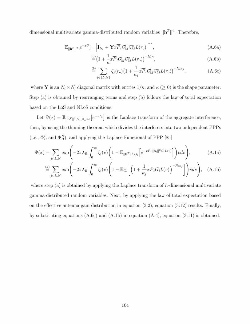
dimensional multivariate gamma-distributed random variables ||hT ||2. Therefore,
E||hT ||2 [e−xU ] =∣∣∣INt + YxP tGtMGuML(ro)
∣∣∣−κ, (A.6a)
(a)=(1 +
1
κxP tGtMGuML(ro)
)−Ntκ, (A.6b)
(b)=
∑j∈L,N
ζj(ro)(1 +
1
κjxP tGtMGuML(ro)
)−Ntκj , (A.6c)
where Y is an Nt×Nt diagonal matrix with entries 1/κ, and κ (≥ 0) is the shape parameter.
Step (a) is obtained by rearranging terms and step (b) follows the law of total expectation
based on the LoS and NLoS conditions.
Let Ψ(x) = E||hT ||2,Gi,ΦB\o[e−xIu
]is the Laplace transform of the aggregate interference,
then, by using the thinning theorem which divides the interferers into two independent PPPs
(i.e., ΦLB and ΦN
B ), and applying the Laplace Functional of PPP [85]
Ψ(x) =∑j∈L,N
exp
(−2πλB
∫ ∞0
ζj(v)
(1− E||hT ||2,Gi
[e−xP t||hi||
2GiL(v)])vdv
), (A.1a)
(a)=∑j∈L,N
exp
(−2πλB
∫ ∞0
ζj(v)
(1− EGi
[(1 +
1
κjxP tGiL(v)
)−Ntκj])vdv
), (A.1b)
where step (a) is obtained by applying the Laplace transform of n-dimensional multivariate
gamma-distributed random variables. Next, by applying the law of total expectation based
on the effective antenna gain distribution in equation (3.2), equation (3.12) results. Finally,
by substituting equations (A.6c) and (A.1b) in equation (A.4), equation (3.11) is obtained.
104
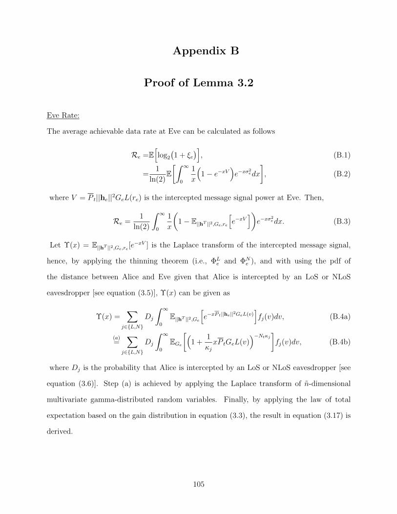
Appendix B
Proof of Lemma 3.2
Eve Rate:
The average achievable data rate at Eve can be calculated as follows
Re =E[log2
(1 + ξe
)], (B.1)
=1
ln(2)E[∫ ∞
0
1
x
(1− e−xV
)e−xσ
2edx
], (B.2)
where V = P t||he||2GeL(re) is the intercepted message signal power at Eve. Then,
Re =1
ln(2)
∫ ∞0
1
x
(1− E||hT ||2,Ge,re
[e−xV
])e−xσ
2edx. (B.3)
Let Υ(x) = E||hT ||2,Ge,re [e−xV ] is the Laplace transform of the intercepted message signal,
hence, by applying the thinning theorem (i.e., ΦLe and ΦN
e ), and with using the pdf of
the distance between Alice and Eve given that Alice is intercepted by an LoS or NLoS
eavesdropper [see equation (3.5)], Υ(x) can be given as
Υ(x) =∑
j∈L,N
Dj
∫ ∞0
E||hT ||2,Ge[e−xP t||he||
2GeL(v)]fj(v)dv, (B.4a)
(a)=
∑j∈L,N
Dj
∫ ∞0
EGe[(
1 +1
κjxP tGeL(v)
)−Ntκj]fj(v)dv, (B.4b)
where Dj is the probability that Alice is intercepted by an LoS or NLoS eavesdropper [see
equation (3.6)]. Step (a) is achieved by applying the Laplace transform of n-dimensional
multivariate gamma-distributed random variables. Finally, by applying the law of total
expectation based on the gain distribution in equation (3.3), the result in equation (3.17) is
derived.
105
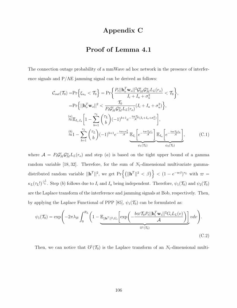
Appendix C
Proof of Lemma 4.1
The connection outage probability of a mmWave ad hoc network in the presence of interfer-
ence signals and P/AE jamming signal can be derived as follows:
Cout(T0) =Prξua < T0
= Pr
Pt||hTo wo||2GtMGuMLL(ro)
Ii + Ia + σ2u
< T0
,
=Pr||hTo wo||2 <
T0
PtGtMGuMLL(ro)(Ii + Ia + σ2
u),
(a)≈EIi,Ia
[1−
τL∑b=1
(τLb
)(−1)b+1e−
b$T0A (Ii+Ia+σ2
u)
],
(b)≈1−
τL∑b=1
(τLb
)(−1)b+1e−
b$xσ2u
A EIi[e−
b$T0IiA
]︸ ︷︷ ︸
ψ1(T0)
EIa[e−
b$T0IaA
]︸ ︷︷ ︸
ψ2(T0)
, (C.1)
where A = PtGtMGuMLL(ro) and step (a) is based on the tight upper bound of a gamma
random variable [18, 32]. Therefore, for the sum of Nt-dimensional multivariate gamma-
distributed random variable ||hT ||2, we get Pr(||hT ||2 < β
)< (1 − e−$β)τL with $ =
κL(τL!)−1τL . Step (b) follows due to Ii and Ia being independent. Therefore, ψ1(T0) and ψ2(T0)
are the Laplace transform of the interference and jamming signals at Bob, respectively. Then,
by applying the Laplace Functional of PPP [85], ψ1(T0) can be formulated as:
ψ1(T0) = exp
(−2πλB
∫ RL
0
(1− E||hT ||2,Gi
[exp
(−b$T0Pt||hTi wi||2GiLL(v)
A
)]︸ ︷︷ ︸
f†(T0)
vdv
).
(C.2)
Then, we can notice that f†(T0) is the Laplace transform of an Nt-dimensional multi-
106
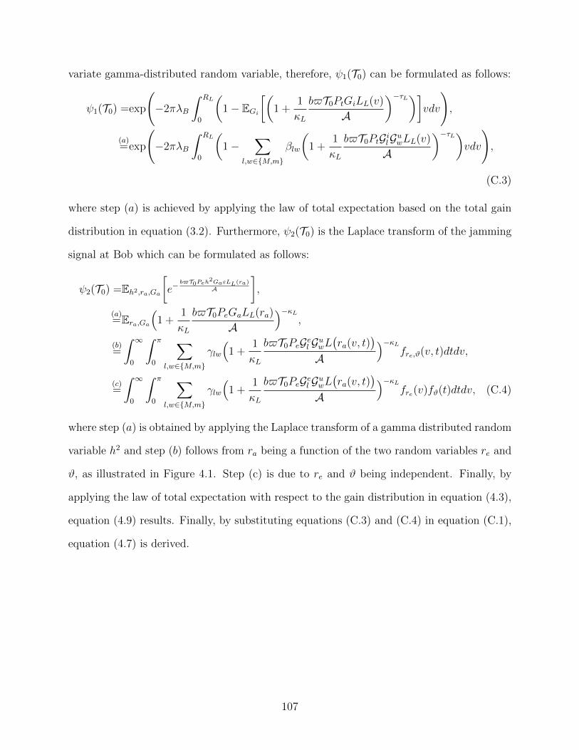
variate gamma-distributed random variable, therefore, ψ1(T0) can be formulated as follows:
ψ1(T0) =exp
(−2πλB
∫ RL
0
(1− EGi
[(1 +
1
κL
b$T0PtGiLL(v)
A
)−τL)]vdv
),
(a)=exp
(−2πλB
∫ RL
0
(1−
∑l,w∈M,m
βlw
(1 +
1
κL
b$T0PtGilGuwLL(v)
A
)−τL)vdv
),
(C.3)
where step (a) is achieved by applying the law of total expectation based on the total gain
distribution in equation (3.2). Furthermore, ψ2(T0) is the Laplace transform of the jamming
signal at Bob which can be formulated as follows:
ψ2(T0) =Eh2,ra,Ga
[e−
b$T0Peh2GaεLL(ra)
A
],
(a)=Era,Ga
(1 +
1
κL
b$T0PeGaLL(ra)
A
)−κL,
(b)=
∫ ∞0
∫ π
0
∑l,w∈M,m
γlw
(1 +
1
κL
b$T0PeGel GuwL(ra(v, t)
)A
)−κLfre,ϑ(v, t)dtdv,
(c)=
∫ ∞0
∫ π
0
∑l,w∈M,m
γlw
(1 +
1
κL
b$T0PeGel GuwL(ra(v, t)
)A
)−κLfre(v)fϑ(t)dtdv, (C.4)
where step (a) is obtained by applying the Laplace transform of a gamma distributed random
variable h2 and step (b) follows from ra being a function of the two random variables re and
ϑ, as illustrated in Figure 4.1. Step (c) is due to re and ϑ being independent. Finally, by
applying the law of total expectation with respect to the gain distribution in equation (4.3),
equation (4.9) results. Finally, by substituting equations (C.3) and (C.4) in equation (C.1),
equation (4.7) is derived.
107
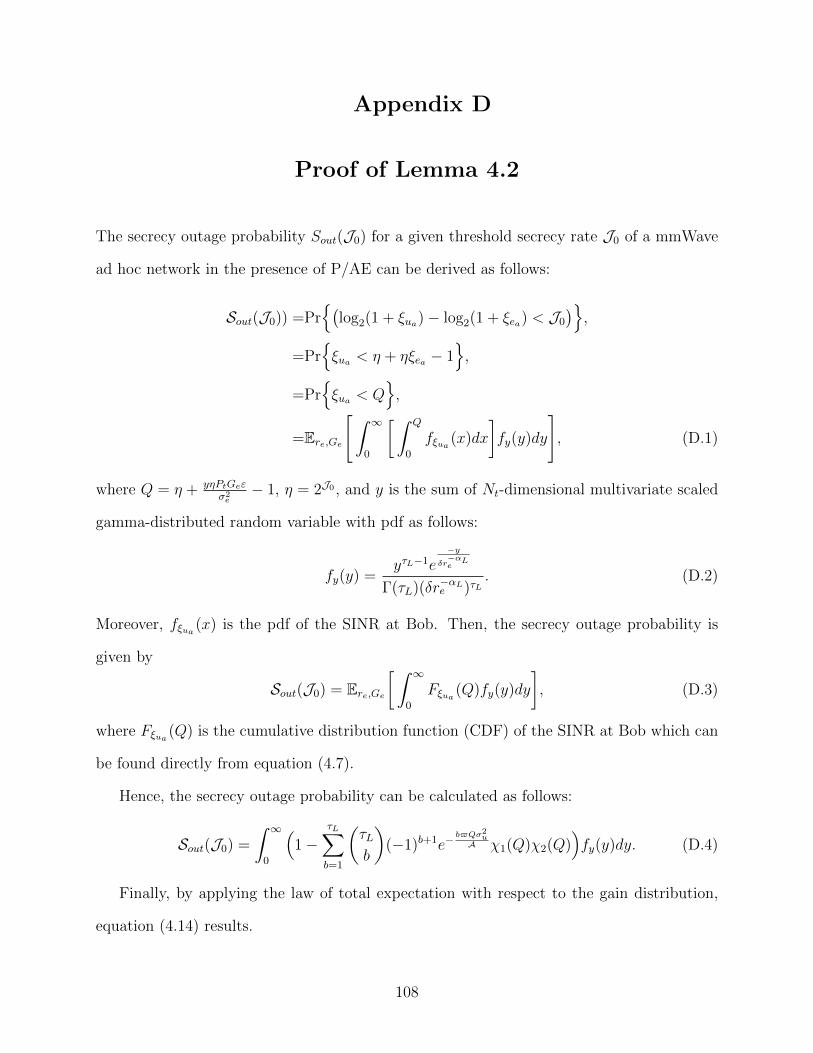
Appendix D
Proof of Lemma 4.2
The secrecy outage probability Sout(J0) for a given threshold secrecy rate J0 of a mmWave
ad hoc network in the presence of P/AE can be derived as follows:
Sout(J0)) =Pr(
log2(1 + ξua)− log2(1 + ξea) < J0
),
=Prξua < η + ηξea − 1
,
=Prξua < Q
,
=Ere,Ge
[∫ ∞0
[ ∫ Q
0
fξua (x)dx
]fy(y)dy
], (D.1)
where Q = η + yηPtGeεσ2e− 1, η = 2J0 , and y is the sum of Nt-dimensional multivariate scaled
gamma-distributed random variable with pdf as follows:
fy(y) =yτL−1e
−yδr−αLe
Γ(τL)(δr−αLe )τL. (D.2)
Moreover, fξua (x) is the pdf of the SINR at Bob. Then, the secrecy outage probability is
given by
Sout(J0) = Ere,Ge[ ∫ ∞
0
Fξua (Q)fy(y)dy
], (D.3)
where Fξua (Q) is the cumulative distribution function (CDF) of the SINR at Bob which can
be found directly from equation (4.7).
Hence, the secrecy outage probability can be calculated as follows:
Sout(J0) =
∫ ∞0
(1−
τL∑b=1
(τLb
)(−1)b+1e−
b$Qσ2u
A χ1(Q)χ2(Q))fy(y)dy. (D.4)
Finally, by applying the law of total expectation with respect to the gain distribution,
equation (4.14) results.
108
Appendix E
Proof of Lemma 4.3
Bob Rate:
The average achievable data rate at Bob in the presence of interference and P/AE is obtained
as
Rua =E
[1
ln(2)
∫ ∞0
1
x(1− e−xξua )e−xdx
],
(a)=
1
ln(2)E
[∫ ∞0
1
x(1− e−xWu)e−x(Ii+Ia+σ2
u)dx
],
(b)=
1
ln(2)
∫ ∞0
1
x
(1− E||hT ||2 [e−xWu ]︸ ︷︷ ︸
υ(x)
)EΦB ,||hT ||2,Gi [e
−xIi ]︸ ︷︷ ︸υ1(x)
Eh2,ra,Ga [e−xIa ]︸ ︷︷ ︸
υ2(x)
e−xσ2udx, (E.1)
whereWu = Pt||hTo wo||2GtMGuMLL(ro), Ii =∑
i∈ΦBPt||hTi wi||2GiLL(ri), and Ia = Peh
2aGaLL(ra)
are the received message signal, the aggregate interference signal, and the received jamming
signal at Bob, respectively. Step (a) is obtained by rearranging terms, and step (b) follows
from the independence of Wu, Ii, and Ia.
Then, from equation (E.1), υ(x) = E||hT ||2 [e−xWu ] is the Laplace transform of an Nt-
dimensional multivariate gamma-distributed random variable ||hT ||2. Therefore, we attain
υ(x) =(1 +
1
κLxPtGtMGuMLL(ro)
)−τL . (E.2)
Moreover, υ1(x) can be obtained in the same manner as equation (C.3). Hence, we obtain
υ1(x) = exp
(−2πλB
∫ RL
0
(1−
∑l,w∈M,m
βl,w(1 +
1
κLxPtGtlGuwLL(v)
)−τL)vdv). (E.3)
Then, υ2(x) is the Laplace transform of the received jamming signal at Bob. Therefore,
by following the same manner as done in equation (C.4), we get
υ2(x) =
∫ ∞0
∑l,w∈M,m
∂lw
(1 +
1
κLPeGel GuwL
(re(v, t)
))−κLfrefϑ(t)dt(v)dv. (E.4)
109
Finally, by substituting equations (E.2), (E.3), and (E.4) in equation (E.1), the average
achievable data rate at Bob will be obtained.
Eve Rate:
On the other hand, the average achievable data rate for intercepting message signal at P/AE
can be calculated as follows:
Rea =E
[1
ln(2)
∫ ∞0
1
x(1− e−xξea )e−xdx
],
=1
ln(2)
∫ ∞0
1
x
(1− E||hT ||2,Ge,re
[e−xWe
]︸ ︷︷ ︸Ξ(x)
)e−xσ
2edx, (E.5)
where We = Pt||hTe wo||2GeLL(re) is the intercepted message signal at P/AE. Then, by
following the same manner as done in equation (C.4), we get
Ξ(x) =
∫ ∞0
∑l,w∈M,m
µlw
(1 +
1
κxPtGtlGewLL(v)
)−τLfre(v)dv. (E.6)
Finally, by subtracting the average data rate at P/AE in equation (E.5) from the average
data rate at Bob in equation (E.1), the average achievable secrecy rate of the mmWave ad
hoc network in the presence of interference and P/AE can be obtained.
110
Appendix F
Proof of Lemma 5.1
By following the same steps provided in Appendix A, the average achievable data rate at
Bob with applying the Tx-AN technique will be:
Ru =1
ln(2)
∫ ∞0
1
x
(1−
∑j∈L,N
ζj(ro)(1 +
1
κjxP sGsMGuML(ro)
)−τsj )Ψ(x)e−xσ2
dx, (F.1)
where
Ψ(x) = E||hT ||2,Gi,ΦB\o[e−x
∑i∈ΦB\o
(P s||hiTs ||2Gsi+Pa||hiTa ||2Gai
)L(ri)
]. (F.2)
Then, by using the thinning theorem, and applying the Laplace Functional of PPP, Ψ(x)
can be expressed as:
Ψ(x) =∑j∈L,N
exp
(−2πλB
∫ ∞0
ζj(v)(
1− E||hT ||2,Gi[e−x(P s||hiTs ||2Gsi+Pa||hiTa ||2Gai
)L(v)])vdv
),
(F.3a)
(a)=∑j∈L,N
exp
(−2πλB
∫ ∞0
ζj(v)(
1−∑
(l,w,q)∈Ω
∆lwqE||hT ||2[e−x(P s||hiTs ||2Gsl +Pa||hiTa ||2Gaw
)Guq L(v)
])vdv
),
(F.3b)
(b)=∑j∈L,N
exp
(−2πλB
∫ ∞0
ζj(v)×
(1−
∑(l,w,q)∈Ω
∆lwqE||hT ||2[e−xP s||hi
Ts ||2Gsl G
uq L(v)
]E||hT ||2
[e−xPa||hi
Ta ||2GawGuq L(v)
])vdv
),
(F.3c)
where step (a) is obtained by applying the law of total expectation based on the total
effective antenna gain distribution in equation (5.3), and Ω is the set of all possible values of
(l, w, q), defined in sub-section 5.2.1. Step (b) is obtained by rearranging terms. Eventually,
by applying the Laplace transform of the n-dimensional multivariate gamma-distributed
random variables, equation (5.5) is obtained.
111
Appendix G
Proof of Lemma 5.2
The average achievable data rate at Eve when the Tx-AN technique is used by all the
transmitters (i.e., Alice and the interferers) can be calculated as follows
Re =1
ln(2)E[∫ ∞
0
1
x
(1− e−xV
)e−x(Ie+Iie+σ
2e
)dx
], (G.1)
where V = P s||heTs ||2GseL(re) is the received message signal power at Eve and Ie =
P a||heTa ||2GaeL(re) is the received AN power at Eve from Alice and Iie =
∑i∈ΦB\o P a||hieTa ||2Ga
eL(rie)
is the received AN at Eve from the interferers in ΦB. Due to V and IE are dependent and
they are independent of IiE, we have:
Re =1
ln(2)
∫ ∞0
1
x
(E||hT ||2,Gae ,re
[e−xIe
]︸ ︷︷ ︸Υ1(x)
−E||hT ||2,Ge,re[e−x(V+Ie)
]︸ ︷︷ ︸Υ2(x)
)E||hT ||2,Gae ,ΦB\o
[e−xIie
]︸ ︷︷ ︸Υ3(x)
e−xσ2edx,
(G.2)
where Υ1(x) is proved using the same approach as equation (3.17) in Appendix B by
replacing Pt, he and Ge with P a, hea and Gae , respectively, then equation (5.11) is obtained.
Then, by applying the thinning theorem in Υ2(x), and using the pdf of the distance
between Alice and Eve given that Alice is intercepted by an LoS or NLoS eavesdropper,
Υ2(x) can be written as
Υ2(x) =∑
j∈L,N
Dj
∫ ∞0
E||hT ||2,Ge[e−x(P s||heTs ||2Gse+Pa||heTa ||2Gae
)L(v)]fj(v)dv, (G.3a)
(a)=
∑j∈L,N
Dj
∫ ∞0
∑(l,w,q)∈Ω
∂lwqE||hT ||2[e−x(P s||heTs ||2Gsl +Pa||heTa ||2Gaw
)GeqL(v)
]fj(v)dv,
(G.3b)
where step (a) is achieved by applying the law of total expectation based on the total gain
distribution in equation (5.9). Hence, by applying the Laplace transform of the n-dimensional
112

multivariate gamma-distributed random variables, equation (5.12) is obtained. Finally, by
following the same procedure for deriving equation (3.12) in Appendix A, equation (5.13) is
obtained.
113
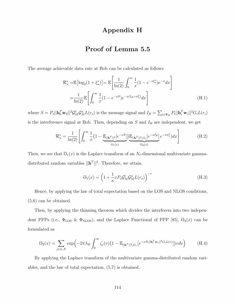
Appendix H
Proof of Lemma 5.5
The average achievable data rate at Bob can be calculated as follows
R∗u =E[log2(1 + ξ∗u)
]= E
[1
ln(2)
∫ ∞0
1
x(1− e−xξ∗u)e−xdx
]
=1
ln(2)E
[∫ ∞0
1
x(1− e−xS)e−x(IR+σ2
u)dx
](H.1)
where S = Ps||hT0 w0||2GtMGuML(ro) is the message signal and IR =∑
i∈ΦBPt||hTi wi||2GiL(ri)
is the interference signal at Bob. Then, depending on S and IR are independent, we get
R∗u =1
ln(2)
[∫ ∞0
1
x
(1− E||hT ||2 [e−xS]︸ ︷︷ ︸
f1(x)
)E||hT ||2,Gi [e
−xIR ]︸ ︷︷ ︸f2(x)
e−xσ2u)dx
](H.2)
Then, we see that f1(x) is the Laplace transform of an Nt-dimensional multivariate gamma-
distributed random variables ||hT ||2. Therefore, we attain
f1(x) =(
1 +1
κxPsGtMGuML(ro)
)−τ(H.3)
Hence, by applying the law of total expectation based on the LOS and NLOS conditions,
(5.6) can be obtained.
Then, by applying the thinning theorem which divides the interferers into two indepen-
dent PPPs (i.e., ΦLOS & ΦNLOS), and the Laplace Functional of PPP [85], f2(x) can be
formulated as
f2(x) =∑j∈L,N
exp(−2πλB
∫ ∞0
ζj(v)(1− E||hT ||2,Gi
[e−xPt||h
Ti wi||2GiL(v)]
)vdv)
(H.4)
By applying the Laplace transform of the multivariate gamma-distributed random vari-
ables, and the law of total expectation, (5.7) is obtained.
114
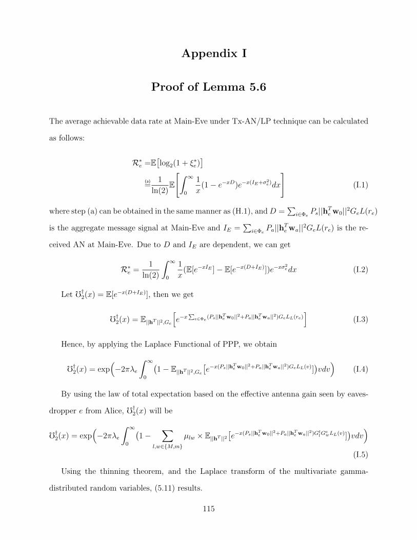
Appendix I
Proof of Lemma 5.6
The average achievable data rate at Main-Eve under Tx-AN/LP technique can be calculated
as follows:
R∗e =E[log2(1 + ξ∗e )
](a)=
1
ln(2)E
[∫ ∞0
1
x(1− e−xD)e−x(IE+σ2
e)dx
](I.1)
where step (a) can be obtained in the same manner as (H.1), andD =∑
i∈ΦePs||hTe w0||2GeL(re)
is the aggregate message signal at Main-Eve and IE =∑
i∈ΦePa||hTe wa||2GeL(re) is the re-
ceived AN at Main-Eve. Due to D and IE are dependent, we can get
R∗e =1
ln(2)
∫ ∞0
1
x(E[e−xIE ]− E[e−x(D+IE)])e−xσ
2edx (I.2)
Let f†2(x) = E[e−x(D+IE)], then we get
f†2(x) = E||hT ||2,Ge[e−x
∑e∈Φe
(Ps||hTe w0||2+Pa||hTe wa||2)GeLL(re)]
(I.3)
Hence, by applying the Laplace Functional of PPP, we obtain
f†2(x) = exp(−2πλe
∫ ∞0
(1− E||hT ||2,Ge
[e−x(Ps||hTe w0||2+Pa||hTe wa||2)GeLL(v)]
)vdv)
(I.4)
By using the law of total expectation based on the effective antenna gain seen by eaves-
dropper e from Alice, f†2(x) will be
f†2(x) = exp(−2πλe
∫ ∞0
(1−
∑l,w∈M,m
µlw × E||hT ||2[e−x(Ps||hTe w0||2+Pa||hTe wa||2)GtlG
ewLL(v)]
)vdv)
(I.5)
Using the thinning theorem, and the Laplace transform of the multivariate gamma-
distributed random variables, (5.11) results.
115
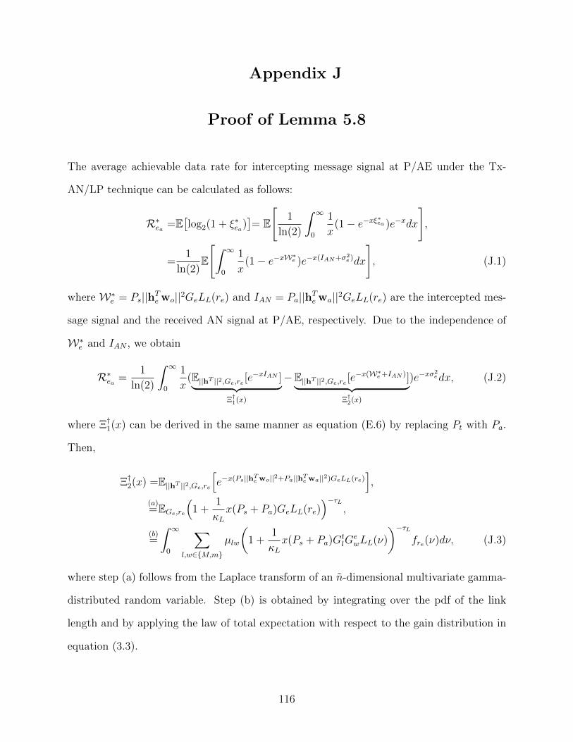
Appendix J
Proof of Lemma 5.8
The average achievable data rate for intercepting message signal at P/AE under the Tx-
AN/LP technique can be calculated as follows:
R∗ea =E[log2(1 + ξ∗ea)
]= E
[1
ln(2)
∫ ∞0
1
x(1− e−xξ∗ea )e−xdx
],
=1
ln(2)E
[∫ ∞0
1
x(1− e−xW∗e )e−x(IAN+σ2
e)dx
], (J.1)
where W∗e = Ps||hTe wo||2GeLL(re) and IAN = Pa||hTe wa||2GeLL(re) are the intercepted mes-
sage signal and the received AN signal at P/AE, respectively. Due to the independence of
W∗e and IAN , we obtain
R∗ea =1
ln(2)
∫ ∞0
1
x(E||hT ||2,Ge,re [e
−xIAN ]︸ ︷︷ ︸Ξ†1(x)
−E||hT ||2,Ge,re [e−x(W∗e+IAN )]︸ ︷︷ ︸
Ξ†2(x)
)e−xσ2edx, (J.2)
where Ξ†1(x) can be derived in the same manner as equation (E.6) by replacing Pt with Pa.
Then,
Ξ†2(x) =E||hT ||2,Ge,re[e−x(Ps||hTe wo||2+Pa||hTe wa||2)GeLL(re)
],
(a)=EGe,re
(1 +
1
κLx(Ps + Pa)GeLL(re)
)−τL,
(b)=
∫ ∞0
∑l,w∈M,m
µlw
(1 +
1
κLx(Ps + Pa)G
tlG
ewLL(ν)
)−τLfre(ν)dν, (J.3)
where step (a) follows from the Laplace transform of an n-dimensional multivariate gamma-
distributed random variable. Step (b) is obtained by integrating over the pdf of the link
length and by applying the law of total expectation with respect to the gain distribution in
equation (3.3).
116
Related Documents