Network-Layer Resource Allocation for Wireless Ad Hoc Networks by Atef Abdrabou A thesis presented to the University of Waterloo in fulfillment of the thesis requirement for the degree of Doctor of Philosophy in Electrical and Computer Engineering Waterloo, Ontario, Canada, 2008 c Atef Abdrabou 2008

Welcome message from author
This document is posted to help you gain knowledge. Please leave a comment to let me know what you think about it! Share it to your friends and learn new things together.
Transcript

Network-Layer Resource
Allocation for Wireless Ad Hoc
Networks
by
Atef Abdrabou
A thesis
presented to the University of Waterloo
in fulfillment of the
thesis requirement for the degree of
Doctor of Philosophy
in
Electrical and Computer Engineering
Waterloo, Ontario, Canada, 2008
c© Atef Abdrabou 2008

I hereby declare that I am the sole author of this thesis. This is a true copy of the
thesis, including any required final revisions, as accepted by my examiners.
I understand that my thesis may be made electronically available to the public.
ii

Abstract
This thesis contributes toward the design of a quality-of-service (QoS) aware
network layer for wireless ad hoc networks. With the lack of an infrastructure in
ad hoc networks, the role of the network layer is not only to perform multihop
routing between a source node and a destination node, but also to establish an
end-to-end connection between communicating peers that satisfies the service level
requirements of multimedia applications running on those peers.
Wireless ad hoc networks represent autonomous distributed systems that are
infrastructure-less, fully distributed, and multi-hop in nature. Over the last few
years, wireless ad hoc networks have attracted significant attention from researchers.
This has been fueled by recent technological advances in the development of mul-
tifunction and low-cost wireless communication gadgets. Wireless ad hoc networks
have diverse applications spanning several domains, including military, commercial,
medical, and home networks. Projections indicate that these self-organizing wire-
less ad hoc networks will eventually become the dominant form of the architecture
of telecommunications networks in the near future. Recently, due to increasing
popularity of multimedia applications, QoS support in wireless ad hoc networks
has become an important yet challenging objective. The challenge lies in the need
to support the heterogeneous QoS requirements (e.g., data rate, packet loss prob-
ability, and delay constraints) for multimedia applications and, at the same time,
to achieve efficient radio resource utilization, taking into account user mobility and
dynamics of multimedia traffic.
In terms of research contributions, we first present a position-based QoS routing
framework for wireless ad-hoc networks. The scheme provides QoS guarantee in
terms of packet loss ratio and average end-to-end delay (or throughput) to ad hoc
networks loaded with constant rate traffic. Via cross-layer design, we apply call ad-
mission control and temporary bandwidth reservation on discovered routes, taking
into consideration the physical layer multi-rate capability and the medium access
control (MAC) interactions such as simultaneous transmission and self interference
from route members.
Next, we address the network-layer resource allocation where a single-hop ad hoc
iii

network is loaded with random traffic. As a starting point, we study the behavior
of the service process of the widely deployed IEEE 802.11 DCF MAC when the
network is under different traffic load conditions. Our study investigates the near-
memoryless behavior of the service time for IEEE 802.11 saturated single-hop ad
hoc networks. We show that the number of packets successfully transmitted by
any node over a time interval follows a general distribution, which is close to a
Poisson distribution with an upper bounded distribution distance. We also show
that the service time distribution can be approximated by a geometric distribution
and illustrate that a simplified queuing system can be used efficiently as a resource
allocation tool for single hop IEEE 802.11 ad hoc networks near saturation.
After that, we shift our focus to providing probabilistic packet delay guarantee
to multimedia users in non-saturated IEEE 802.11 single hop ad hoc networks. We
propose a novel stochastic link-layer channel model to characterize the variations of
the IEEE 802.11 channel service process. We use the model to calculate the effective
capacity of the IEEE 802.11 channel. The channel effective capacity concept is the
dual of the effective bandwidth theory. Our approach offers a tool for distributed
statistical resource allocation in single hop ad hoc networks, which combines both
efficient resource utilization and QoS provisioning to a certain probabilistic limit.
Finally, we propose a statistical QoS routing scheme for multihop IEEE 802.11
ad hoc networks. Unlike most of QoS routing schemes in literature, the proposed
scheme provides stochastic end-to-end delay guarantee, instead of average delay
guarantee, to delay-sensitive bursty traffic sources. Via a cross-layer design ap-
proach, the scheme selects the routes based on a geographical on-demand ad hoc
routing protocol and checks the availability of network resources by using traffic
source and link-layer channel models, incorporating the IEEE 802.11 characteristics
and interaction. Our scheme extends the well developed effective bandwidth theory
and its dual effective capacity concept to multihop IEEE 802.11 ad hoc networks in
order to achieve an efficient utilization of the shared radio channel while satisfying
the end-to-end delay bound.
iv

Acknowledgements
First of all, I would like to express my sincere gratitude to my supervisor Pro-
fessor Weihua Zhuang, for her guidance, encouragement, and contributions in the
development of my research. Without her vision, deep insight, advice, and will-
ingness to provide funding, this work would not have been possible. Her extensive
knowledge, strong analytical skills, and commitment to the excellence of research
are certainly treasures to her students. She gives students freedom to explore the
uncharted areas while providing the needed assistance at the right time. She is
willing to share her knowledge and career experience and give emotional and moral
encouragement. Her hard working attitude and high expectation toward research
have inspired me to mature into a better researcher. I feel she is not just an ad-
viser but a role model and a friend. Working with her is proved to be a rewarding
experience. I would like to thank her genuinely for everything I have achieved in
my research so far.
I would also like to thank Prof. Pin-Han Ho, Prof Liang-Liang Xie., Prof.
Xinzhi Liu and Prof. Hossam Hassanein for serving on my dissertation committee
and providing valuable advice on my research. They have devoted precious time
reading my thesis. Their constructive comments and valuable suggestions have
greatly improved this dissertation.
Special thanks go to Dr. Jon W. Mark and Dr. Xuemin Shen of the Centre
for Wireless Communications (CWC). They created such a wonderful collaborative
research environment and pleasant work atmosphere. I benefit greatly from their
solid and broad knowledge, insightful comments, and invaluable advice.
I would like to thank my fellow graduate students in the CWC, with whom I
have shared numerous hours (days and nights), and have had several intellectually
stimulating discussions covering a wide range of topics.
This dissertation is dedicated to my parents and brothers (especially Essam)
whose love, sacrifice, support, and prayers have always been the greatest inspira-
tion for me in my pursuit for betterment. My deepest and final acknowledgment
goes to my sincere wife Dalia for her dedicated support and encouragement. This
dissertation could not be completed without her presence beside me.
v

To my dear parents and my brothers
To my sincere wife Dalia
vi
Contents
Table of Contents . . . . . . . . . . . . . . . . . . . . . . . . . . . . . . . vi
List of Figures . . . . . . . . . . . . . . . . . . . . . . . . . . . . . . . . . xii
1 Introduction 1
1.1 Research Motivations and Challenges . . . . . . . . . . . . . . . . . 2
1.2 Research Objectives and Contributions . . . . . . . . . . . . . . . . 5
1.3 Thesis Outline . . . . . . . . . . . . . . . . . . . . . . . . . . . . . . 9
2 Literature Review and Background 11
2.1 End-to-end Network Resource Allocation . . . . . . . . . . . . . . . 11
2.1.1 Call Admission Control . . . . . . . . . . . . . . . . . . . . . 12
2.1.2 Theory of Effective Bandwidth . . . . . . . . . . . . . . . . 13
2.1.3 Effective Capacity Model . . . . . . . . . . . . . . . . . . . . 16
2.2 Routing in Wireless Ad Hoc Networks . . . . . . . . . . . . . . . . 17
2.2.1 Route Discovery Classification . . . . . . . . . . . . . . . . . 18
2.2.1.1 Proactive Routing Protocols . . . . . . . . . . . . . 18
2.2.1.2 Reactive Routing Protocols . . . . . . . . . . . . . 19
2.2.2 Routing Topology Classification . . . . . . . . . . . . . . . . 19
2.2.2.1 Flat Routing . . . . . . . . . . . . . . . . . . . . . 19
2.2.2.2 Hierarchical Routing . . . . . . . . . . . . . . . . . 20
2.2.2.3 Geographical Routing . . . . . . . . . . . . . . . . 20
2.3 QoS Routing in Wireless Ad hoc Networks . . . . . . . . . . . . . . 21
2.3.1 QoS Routing Metrics . . . . . . . . . . . . . . . . . . . . . . 21
vii
2.3.2 QoS Routing Design and MAC Interaction . . . . . . . . . . 22
2.3.2.1 QoS Routing Protocols Based on Contention-free
MAC . . . . . . . . . . . . . . . . . . . . . . . . . 22
2.3.2.2 QoS Routing Protocols Based on Contention-based
MAC . . . . . . . . . . . . . . . . . . . . . . . . . 23
2.3.2.3 MAC Independent QoS Routing Protocols . . . . . 24
2.4 Summary . . . . . . . . . . . . . . . . . . . . . . . . . . . . . . . . 25
3 System Model and Problem Description 26
3.1 System Model . . . . . . . . . . . . . . . . . . . . . . . . . . . . . . 26
3.1.1 Network Topology and Configuration . . . . . . . . . . . . . 26
3.1.2 Physical Layer . . . . . . . . . . . . . . . . . . . . . . . . . . 27
3.1.3 MAC Layer . . . . . . . . . . . . . . . . . . . . . . . . . . . 27
3.1.4 Network Layer . . . . . . . . . . . . . . . . . . . . . . . . . 29
3.2 Problem Description . . . . . . . . . . . . . . . . . . . . . . . . . . 30
3.2.1 Discovery and maintenance of a QoS-enabled path . . . . . . 31
3.2.2 MAC Layer Service Process Modeling and End-to-end Delay
Guarantee . . . . . . . . . . . . . . . . . . . . . . . . . . . . 34
3.2.3 Probabilistic Delay Guarantees for Multihop Ad hoc Networks 36
4 Measurement-based QoS Routing Framework 37
4.1 Related Works . . . . . . . . . . . . . . . . . . . . . . . . . . . . . . 38
4.2 System Model . . . . . . . . . . . . . . . . . . . . . . . . . . . . . . 39
4.2.1 Physical Layer . . . . . . . . . . . . . . . . . . . . . . . . . . 39
4.2.2 MAC Layer . . . . . . . . . . . . . . . . . . . . . . . . . . . 40
4.2.3 Network Layer . . . . . . . . . . . . . . . . . . . . . . . . . 41
4.3 QoS-GPSR . . . . . . . . . . . . . . . . . . . . . . . . . . . . . . . 41
4.3.1 Route Discovery . . . . . . . . . . . . . . . . . . . . . . . . . 41
4.3.2 Call Admission Control . . . . . . . . . . . . . . . . . . . . . 44
4.3.2.1 MAC Contention Awareness . . . . . . . . . . . . . 45
viii
4.3.2.2 Simultaneous Transmission . . . . . . . . . . . . . 46
4.3.2.3 Call Admission Control for a CSMA/CA-Based MAC 48
4.3.2.4 Call Admission Control for Centralized Control TDMA
MAC . . . . . . . . . . . . . . . . . . . . . . . . . 50
4.3.3 Route Repair . . . . . . . . . . . . . . . . . . . . . . . . . . 51
4.4 Performance Evaluation . . . . . . . . . . . . . . . . . . . . . . . . 53
4.5 Summary . . . . . . . . . . . . . . . . . . . . . . . . . . . . . . . . 59
5 Service Time Approximation for IEEE 802.11 DCF Ad hoc Net-
works 60
5.1 Related Works . . . . . . . . . . . . . . . . . . . . . . . . . . . . . . 63
5.2 System Model . . . . . . . . . . . . . . . . . . . . . . . . . . . . . . 64
5.3 The Near-Memoryless Behavior of IEEE 802.11 . . . . . . . . . . . 67
5.3.1 Chen-Stein Approximation . . . . . . . . . . . . . . . . . . . 67
5.3.2 MAC Fairness . . . . . . . . . . . . . . . . . . . . . . . . . . 68
5.3.3 Distribution Distance . . . . . . . . . . . . . . . . . . . . . . 68
5.4 Service Time Approximation . . . . . . . . . . . . . . . . . . . . . . 72
5.4.1 M/Geo/1 Queuing Model . . . . . . . . . . . . . . . . . . . 73
5.5 Simulation Results . . . . . . . . . . . . . . . . . . . . . . . . . . . 75
5.5.1 Distribution distance verification . . . . . . . . . . . . . . . 76
5.5.2 M/Geo/1 queuing system verification . . . . . . . . . . . . . 78
5.6 Summary . . . . . . . . . . . . . . . . . . . . . . . . . . . . . . . . 81
6 Stochastic Delay Guarantees for Single hop Ad-Hoc Networks 83
6.1 Related Works . . . . . . . . . . . . . . . . . . . . . . . . . . . . . . 86
6.2 System Model . . . . . . . . . . . . . . . . . . . . . . . . . . . . . . 86
6.2.1 Service Time Statistics . . . . . . . . . . . . . . . . . . . . . 86
6.3 The MMPP Link-Layer Model and the CAC Algorithm . . . . . . . 89
6.3.1 IEEE 802.11 Behavior Under Different Traffic Loads . . . . . 89
6.3.2 MMPP Link-Layer Model for IEEE 802.11 . . . . . . . . . . 93
ix

6.3.3 The MMPP Model with Heterogeneous On-Off Sources . . . 94
6.3.4 The Distributed Model-based CAC Algorithm . . . . . . . . 95
6.4 Model Validation and Simulation Results . . . . . . . . . . . . . . . 97
6.4.1 Model Validation . . . . . . . . . . . . . . . . . . . . . . . . 98
6.4.2 Average-Delay-based CAC and the Proposed Model-based CAC 99
6.4.3 The Admission Region . . . . . . . . . . . . . . . . . . . . . 101
6.5 Summary . . . . . . . . . . . . . . . . . . . . . . . . . . . . . . . . 103
7 Statistical QoS Routing Scheme for Mulithop Ad hoc Networks 105
7.1 Related Works . . . . . . . . . . . . . . . . . . . . . . . . . . . . . . 106
7.2 System Model . . . . . . . . . . . . . . . . . . . . . . . . . . . . . . 108
7.3 Cross-layer Design for QoS Routing . . . . . . . . . . . . . . . . . . 108
7.3.1 The QoS Routing Problem . . . . . . . . . . . . . . . . . . . 109
7.3.2 Capacity Prediction for a Multihop Connection . . . . . . . 110
7.3.3 Awareness of Available Network Resources . . . . . . . . . . 112
7.4 Statistical QoS Routing Scheme . . . . . . . . . . . . . . . . . . . . 114
7.4.1 Route Discovery and Maintenance . . . . . . . . . . . . . . . 114
7.4.2 Resource Allocation . . . . . . . . . . . . . . . . . . . . . . . 116
7.5 Simulation Results . . . . . . . . . . . . . . . . . . . . . . . . . . . 119
7.5.1 QoS Routing Scheme Validation . . . . . . . . . . . . . . . . 120
7.5.2 Effect of Mobility on Performance Metrics . . . . . . . . . . 122
7.6 Summary . . . . . . . . . . . . . . . . . . . . . . . . . . . . . . . . 126
8 Conclusions and Further Work 128
8.1 Major Research Contributions . . . . . . . . . . . . . . . . . . . . . 128
8.2 Further Research Works . . . . . . . . . . . . . . . . . . . . . . . . 130
Appendix A Service Time Statistics at Low Traffic Load 133
Appendix B The On-Off Packet Arrival Assumption Justification 135
x

References 138
Abbreviations 150
Symbols 152
xi

List of Tables
5.1 IEEE 802.11 system parameters [1] . . . . . . . . . . . . . . . . . . 66
6.1 Variation of calculated delay bound with normalized traffic load
(λ/λsat) . . . . . . . . . . . . . . . . . . . . . . . . . . . . . . . . . 102
7.1 The number of routing packets of the proposed routing scheme. . . 125
xii
List of Figures
1.1 WPAN applications [2]. . . . . . . . . . . . . . . . . . . . . . . . . . 3
2.1 Statistical multiplexing of traffic streams [23]. . . . . . . . . . . . . 14
2.2 Rate bounds for a real traffic sample [23]. . . . . . . . . . . . . . . . 15
3.1 Greedy forwarding, node B is A’s closest neighbor to E. . . . . . . 30
4.1 The flowchart of the proposed QoS-GPSR. . . . . . . . . . . . . . . 42
4.2 Route discovery procedure. . . . . . . . . . . . . . . . . . . . . . . . 43
4.3 Contention among nodes. . . . . . . . . . . . . . . . . . . . . . . . . 45
4.4 MAC interference among a chain of nodes. . . . . . . . . . . . . . . 47
4.5 The beginning of the call admission control procedure. . . . . . . . 48
4.6 Route repair procedure. . . . . . . . . . . . . . . . . . . . . . . . . 52
4.7 Call acceptance ratio vs. number of flows. . . . . . . . . . . . . . . 55
4.8 Call completion ratio vs. number of flows. . . . . . . . . . . . . . . 56
4.9 Packet delivery successful percentage vs. number of flows. . . . . . 56
4.10 Percentage late packets vs. number of flows. . . . . . . . . . . . . . 57
4.11 Number of routing packets vs. number of flows. . . . . . . . . . . . 57
4.12 Percentage Overhead vs. number of flows. . . . . . . . . . . . . . . 58
5.1 Virtual time slots. . . . . . . . . . . . . . . . . . . . . . . . . . . . . 65
5.2 Successful transmission virtual time slots for a node. . . . . . . . . 70
5.3 The actual CDF and the Poisson CDF for the number of successfully
transmitted packets in one second (5 nodes). . . . . . . . . . . . . . 76
xiii
5.4 The actual CDF and the Poisson CDF for the number of successfully
transmitted packets in one second (10 nodes). . . . . . . . . . . . . 77
5.5 The actual CDF and the Poisson CDF for the number of successfully
transmitted packets in one second (30 nodes). . . . . . . . . . . . . 77
5.6 Distribution distance upper bound. . . . . . . . . . . . . . . . . . . 78
5.7 Average queue length. . . . . . . . . . . . . . . . . . . . . . . . . . 79
5.8 The CDF of the number of packets in the actual queuing system and
the M/Geo/1 queue (5 nodes). . . . . . . . . . . . . . . . . . . . . . 79
5.9 The CDF of the number of packets in the actual queuing system and
the M/Geo/1 queue (10 nodes). . . . . . . . . . . . . . . . . . . . . 80
5.10 The CDF of the number of packets in the actual queuing system and
the M/Geo/1 queue (20 nodes). . . . . . . . . . . . . . . . . . . . . 80
6.1 Utilization factor variations with λ/λsat. . . . . . . . . . . . . . . . 90
6.2 Collision probability variations with λ/λsat. . . . . . . . . . . . . . . 90
6.3 Throughput variations with ρ. . . . . . . . . . . . . . . . . . . . . . 91
6.4 The MMPP link-layer model. . . . . . . . . . . . . . . . . . . . . . 93
6.5 The distributed model-based CAC algorithm. . . . . . . . . . . . . 96
6.6 Violation probability variations with λ/λsat . . . . . . . . . . . . . . 98
6.7 Number of admitted nodes at different traffic loads for MMPP model
and average delay based CAC. . . . . . . . . . . . . . . . . . . . . . 99
6.8 Violation probability at different traffic loads for MMPP model and
average delay based CAC. . . . . . . . . . . . . . . . . . . . . . . . 100
6.9 Admission region for homogeneous sources with two service classes. 101
6.10 Admission region for heterogeneous sources with two service classes. 101
7.1 Network topology for illustrating spatial reuse and interference aware-
ness. . . . . . . . . . . . . . . . . . . . . . . . . . . . . . . . . . . . 113
7.2 Network topology for illustrating the route discovery procedure. . . 114
7.3 Admitted flows from the proposed scheme and admissible flows with
different flow rates. . . . . . . . . . . . . . . . . . . . . . . . . . . . 120
xiv

7.4 The admission region with two classes of traffic. . . . . . . . . . . . 121
7.5 Call admission ratio in percentage. . . . . . . . . . . . . . . . . . . 122
7.6 Call drop ratio in percentage. . . . . . . . . . . . . . . . . . . . . . 123
7.7 Successful packet delivery percentage. . . . . . . . . . . . . . . . . . 123
7.8 Delay bound violation probability in percentage. . . . . . . . . . . . 124
7.9 Overhead percentage. . . . . . . . . . . . . . . . . . . . . . . . . . . 125
B.1 Packet forwarding by node D. . . . . . . . . . . . . . . . . . . . . . 137
xv
Chapter 1
Introduction
Nowadays, many people carry multiple portable devices, such as laptops, cell
phones, personal digital assistants (PDAs) for use in their professional and pri-
vate lives. The proliferation of communication devices is revolutionizing our way
of sharing information. We are about to enter a ubiquitous communication era in
which a user is technically able to access all the available information whenever and
wherever needed. The ubiquitous communication nature advocates wireless ad hoc
networks as a very promising solution.
A wireless ad hoc network is a collection of mobile nodes equipped with wireless
transceivers that can send data packets to one another without using any fixed
networking infrastructure. The absence of any fixed infrastructure, such as base
stations or access points, makes ad hoc networks radically different from other
networks such as cellular networks and wireless local area networks (WLANs).
Whereas communication from a mobile terminal in a cellular network is always
maintained with a fixed base-station, a mobile node in an ad hoc network can
connect directly to another node that is located within its radio transmission range
in a peer-to-peer fashion.
An ad hoc network is referred to as a single-hop network, if all the source nodes
can connect to their destinations directly. However, when a source node needs to
connect to a destination node that is located outside its radio range, data packets
are relayed over a sequence of intermediate nodes forming a multihop connection.
Basically, all the nodes in an ad hoc network can serve as hosts or routers in order
1

Network-Layer Resource Allocation for Wireless Ad Hoc Networks
to relay packets on behalf of other nodes. This implies that a multihop routing is
required. In multihop routing, a packet is forwarded from the source node until it
reaches the destination node via a route selected by an appropriate routing protocol
that discovers the route based on certain given criteria.
This thesis focuses on the network layer of wireless ad hoc networks. Without
an infrastructure, the role of the network layer is not only to perform multihop
routing between a source node and a destination node but also to establish an end-
to-end connection between communicating peers, which satisfies the service level
requirements of the application.
1.1 Research Motivations and Challenges
Ad hoc networks are ideally suited for applications where it is economically imprac-
tical or physically impossible to establish a reliable network infrastructure. Typical
applications include fast establishment of military communication in battlefields,
emergency rescue operations for communication in areas without adequate wireless
coverage, and communication in times of natural disasters where the existing com-
munication infrastructure is non-operational (e.g., disaster relief workers can quickly
form an ad hoc network using hand-held devices equipped with transceivers using
the widely deployed IEEE 802.11 protocol [1] in the ad hoc mode).
Because of its easy and relatively low deployment cost, ad hoc networks are
also used in places where it is less expensive to deploy than its infrastructure-based
counterparts especially if the network is intended to be used for a limited amount
of time. Examples of these applications include collaborations among temporary
associates as in a business conference or lecture. Moreover, home area networks or
wireless personal area networks (WPANs) are actually ad hoc networks that con-
nect relatively short range devices. The applications of WPANs are limited only by
the imagination. They are envisioned to support communications between personal
devices such as personal computers (PCs), laptops, PDAs, smart appliances, con-
sumer electronics, and entertainment systems. Figure 1.1 illustrates some of these
applications.
Indeed, ad hoc networks can serve numerous applications with multimedia ser-
2

Chapter 1. Introduction
Broadband services:Cable, xDSL,Satelite,
Terestrial
PDA
Camcorder
DVD
Desktopcomputer
Printer
DigitalCamera
Laptopcomputer
TV
Home Gateway
Monitor
Audio
Figure 1.1: WPAN applications [2].
vices, which require quality-of-service (QoS) support. QoS implies an agreement
or a guarantee by the network to provide pre-determined and measurable service
attribute(s) to the user, such as delay, jitter, available bandwidth, packet loss, etc.
For wireless multimedia communications, different traffic types are characterized by
different QoS requirements. Real-time traffic (e.g., voice or video) is usually delay-
sensitive but can tolerate a certain level of packet loss. Packet delay in wireless
communication systems consists mainly of two components. The first component
is queuing delay, which is the time that a data packet waits in the queue until
it is ready to be serviced by the communication channel. The second component
is the service time, which is the time that the wireless channel takes to serve the
packet. Actually, the delay required by real-time application is subject to human
perception (e.g. a packet delay of 150ms and 300ms during a voice conversation
is perceived as a slight hesitation, while a delay higher than 300ms may make the
conversation almost impossible [3]). Non-real-time traffic (e.g., data transfer) is
usually non delay-sensitive but requires reliable end-to-end transmission.
QoS provisioning in wireless ad hoc networks is very challenging due to three
main reasons. The first reason is mobility, where all nodes in an ad hoc network
(either source nodes, destinations, or relay nodes) may be mobile. As the wire-
3

Network-Layer Resource Allocation for Wireless Ad Hoc Networks
less transmission range is limited, the link between a pair of communicating nodes
breaks as soon as they move out of range. Hence, the network topology, that is
defined as the set of wireless links between all pairs of nodes that can directly com-
municate with each other, can change frequently and unpredictably. This implies
that a multihop path for any given pair of source and destination nodes may also
change with time. Although it has been shown in [4] that mobility may increase ad
hoc network capacity, the scheme presented in [4] does not provide any guarantee
on the time that a packet takes to reach its destination or on the size of the buffers
at the intermediate nodes in a route [5]. This implies that packet delay may be
arbitrary large, which is not suitable for QoS provisioning.
The second reason stems from the lack of a centralized controller. All networking
functions such as multiple access, resource allocation and packet routing over the
most suitable multihop paths, must be performed using distributed algorithms. The
design of these algorithms is particularly challenging since they should take into
account the efficient use of the scarce wireless channel bandwidth and the limited
amount of energy available for battery-powered devices.
Shared wireless medium also represents a challenge to QoS provisioning in wire-
less ad hoc networks. In wireline networks, only data flows traversing the same
link contend for the capacity of that link. This is in sharp contrast with wireless
networks, where all the links share the same wireless channel, traffic flows that
traverse the same geographical vicinity contend for the same wireless channel. This
implies a complex interference relationship among all the active wireless network
links.
Due to the absence of central control and the shared wireless medium, a dis-
tributed end-to-end QoS provisioning algorithm at the network layer cannot func-
tion efficiently if it does not take into account the medium access control (MAC)
protocol interaction. The MAC protocol scheduling organizes the access to the
medium among the competing nodes and so it plays a significant role in allocating
network resources for different wireless links in the network. Two main types of
MAC protocols can be identified in literature as follows.
• The first one is single-channel MAC, where the multiple access mechanism
4

Chapter 1. Introduction
organizes the channel acquisition either by a contention-based method such
as carrier sense multiple access with collision avoidance (CSMA/CA) (e.g.,
IEEE 802.11 [1]) or by a contention free method such as time division multiple
access (TDMA) [6].
• The second type is multi-channel MAC, where the multiple users can access
the wireless medium simultaneously by using multiple different channels. The
channels are usually identified by unique spreading codes such as code divi-
sion multiple access (CDMA) or unique carriers such as orthogonal frequency
division multiplexing (OFDM) or both [7].
Therefore, it is mandatory for an efficient design (in terms of resource utilization)
of a QoS-aware network layer for ad hoc networks to follow a cross-layer design
approach.
1.2 Research Objectives and Contributions
The main objective of this research is to develop an effective resource allocation
scheme for wireless ad hoc networks that guarantees satisfactory end-to-end QoS
to multimedia applications according to certain QoS measures such as delay, band-
width or packet loss, while achieving efficient network resource utilization. The
resource allocation scheme includes call admission control (CAC) and resource reser-
vation procedures. The CAC procedure allows the admission of a new multimedia
call only if the network is able to satisfy its QoS requirements without effecting
other calls already in-service. The resource reservation procedure prevents allocat-
ing the same network resources multiple times to more than one call competing
for network admission. In a multi-hop ad hoc wireless network environment, call
admission control and resource reservation protocols cannot work independently
without the involvement of the routing protocol, since the inability to admit a traf-
fic flow in one route does not mean that it cannot be admitted in the network since
another route may have sufficient resources for it.
In order to realize the objective, we conduct the research work in three stages
as follows.
5

Network-Layer Resource Allocation for Wireless Ad Hoc Networks
In the first stage, a novel QoS routing framework is proposed [8] [9]. The frame-
work aims at finding the path from a traffic source to its destination that is able to
satisfy both the packet loss ratio and the bandwidth (for throughput-sensitive appli-
cations) or average end-to-end delay (for delay-sensitive applications) requirements
of the multimedia application. The proposed framework uses a location-based on
demand ad hoc routing protocol. The location information is obtained using one of
the powerful features of the ultra wideband (UWB) emerging technology [10]. The
framework has the following features:
• The resource allocation procedure is contention-aware. Via cross-layer design,
it incorporates the distributed nature of the CSMA/CA-based MAC protocols
and guarantees that the newly admitted flows will not affect the QoS support
of the ones already in service. Moreover, the framework almost seamlessly
supports a centralized TDMA MAC protocol as long as the centralized con-
troller provides a proper packet scheduling.
• The route selection process exploits multiple transmission rate support that
may be available in the underlying physical layer.
• The call admission control procedure is destination initiated. This increases
the efficiency of the resource allocation process and network utilization since
the whole route is known before the available resources are estimated. Hence,
the self interference from the same route members and also the possibility of
simultaneous transmissions can be detected, with a small amount of overhead,
and can be used in the admission control and resource reservation procedures.
• The proposed framework does not flood the network in the route discovery
phase, so it does not consume the scarce wireless bandwidth in non useful
signaling overhead. Simulation results show the efficiency of the proposed
framework in terms of resource allocation and the signaling overhead.
Our proposed QoS routing framework is described in details in Chapter 4.
The proposed framework partially meets the main research objective for three
reasons. First, it considers constant bit rate traffic sources and satisfies only the
6
Chapter 1. Introduction
average end-to-end delay. Indeed, loading the network with constant bit rate traf-
fic represents the worst case but does not reflect the practical situation where the
traffic rate may be variable and bursty. The second reason is that the satisfaction
of the average end-to-end delay requirements of some delay-sensitive multimedia
applications may not be sufficient if those applications are intolerable to delay vari-
ations. The third reason relates to the estimation of the available bandwidth, which
depends on measuring channel utilization. If the network is loaded with statistical
traffic, measurement of channel utilization should be carried out to the level of the
second order statistics for efficient resource allocation. Accurate measurements of
high-order statistics need continuous channel monitoring, which may not be con-
venient for some ad hoc network nodes where the energy should be conserved for
a long time. Indeed, the framework can serve either multimedia applications that
require a certain amount of throughput to be provided by the network or the mul-
timedia applications that are sensitive to average packet delay but tolerant to delay
variations.
In the second stage, we address the network-layer resource allocation where a
single-hop ad hoc network is loaded with random traffic. We also focus on providing
probabilistic packet delay guarantees to multimedia users, which implies that we
allow only for certain small fraction (e.g., 5%) of the successfully received packets
to exceed a specified delay bound. We consider the IEEE 802.11 distributed coordi-
nation function (DCF) as the MAC layer that serves the data packet sent through
the network. We study the behavior of the service process of the IEEE 802.11 DCF
when the network is under different traffic load conditions. First, we study IEEE
802.11 DCF service process when the network is saturated1 in Chapter 5. Next,
we characterize the IEEE 802.11 DCF service process by an approximate mathe-
matical model (when the network is non-saturated) in Chapter 6. Moreover, we
propose model-based resource allocation tools that depend on the service process
characteristics under network traffic loads in Chapter 5 and 6, respectively. The
outcome of this research stage can be summerized as follows [11] [12]:
• In chapter 5, it is shown that the service time distribution of IEEE 802.11
1By the term saturated network we refer to a network of active nodes where each node always
has backlogged packets in its queue.
7

Network-Layer Resource Allocation for Wireless Ad Hoc Networks
DCF has a partial memoryless behavior. We demonstrate that the distribu-
tion of the number of packets successfully transmitted over a time interval
from any of the active nodes in a saturated ad hoc network follows a general
distribution that is close to the Poisson distribution with an upper bounded
distribution distance. We obtain this bound analytically using the Chen-Stein
approximation method [13] and verify it by simulations. We also show that
the bound is almost a constant, which depends mainly on some system pa-
rameters and varies slightly with the number of active nodes in the network
[11] [12].
• We illustrate that the service time distribution of IEEE 802.11 DCF, with its
near memoryless behavior and the discrete nature, can be approximated by
the geometric distribution in Chapter 5. We characterize the distribution by
analytically deriving its parameter [11] [12].
• Following the geometric distribution approximation of the IEEE 802.11 DCF
service time, we propose to use the discrete-time queuing system (M/Geo/1)
as a queuing model for IEEE 802.11 single-hop ad hoc networks near satu-
ration [11] [12]. The accuracy of the proposed queuing model indicates the
feasibility of the service time approximation and suggests the usage of the
queuing analysis (based on the characterized service time approximation) in
resource allocation decisions.
• Inspired by the resource allocation approaches developed for statistical multi-
plexers in wireline networks [14], a Markov modulated Poisson process (MMPP)
link-layer channel model for the IEEE 802.11 DCF-based non-saturated ad
hoc networks is proposed in Chapter 6. The MMPP model has been used
extensively in characterizing the arrival process of statistically multiplexed
multimedia traffic sources [14]. However, we use the MMPP model in a novel
way to characterize the service process (not the arrival process) of the IEEE
802.11 DCF shared channel [15] [16].
• Based on the proposed MMPP link-layer channel model, a fully distributed
mode-based call admission control (CAC) algorithm for IEEE 802.11 DCF
8

Chapter 1. Introduction
single-hop ad hoc networks is also introduced in Chapter 6. The CAC algo-
rithm offers a step ahead of the other proposed CAC schemes in the literature,
as it provides stochastic delay guarantees instead of average delay guarantees.
It exploits the well studied effective bandwidth theory of traffic sources and
its dual the effective capacity for a channel to achieve efficient utilization of
the wireless channel [15] [16].
In the third stage, we address the problem of selecting a path between a source
node of random traffic and the destination node [17] [18]. Actually, this research
stage is an extension to the QoS routing framework proposed in the first stage
(Chapter 4). The proposed scheme is described in Chapter 7. Via cross-layer
design, the scheme selects a route satisfying the end-to-end delay bound proba-
bilistically based on a statistical resource allocation process without consuming the
limited processing power of the ad hoc network nodes or the channel bandwidth
in continuous measurements or traffic monitoring. The scheme mainly serves mul-
timedia applications with strict packet delay variations requirements. This makes
it substantially different from the QoS routing framework introduced in Chapter 4
that addresses the first order statistics (average) of the packet delay or throughput
and PLR as QoS requirements. The statistical multiplexing capability of the IEEE
802.11 DCF [16] is exploited by extending the effective bandwidth theory and its
dual the effective capacity concept to multihop connections using the MMPP link
layer channel model developed in Chapter 6 in order to achieve an efficient utiliza-
tion of the shared radio channel while satisfying the end-to-end delay bound [17]
[18] to a probabilistic limit.
1.3 Thesis Outline
The rest of the thesis is organized as follows. Chapter 2 provides the necessary
background and a literature review for the topics related to this research. It provides
a brief overview of different resource allocation approaches such as call admission
control, the effective bandwidth theory, and the effective capacity concept. It also
illustrates the classifications of ad hoc routing protocols and QoS routing schemes
9

Network-Layer Resource Allocation for Wireless Ad Hoc Networks
previously proposed in literature and highlights some relevant research works. A
general system model and a detailed description of the problem formulation are
presented in Chapter 3. Chapter 4 provides the details of the proposed QoS routing
framework for wireless ad hoc networks. It also presents the performance evaluation
metrics and simulation results for the proposed framework. Chapter 5 studies the
dynamics of the service time of the IEEE 802.11 for single hop ad hoc networks
showing its memoryless behavior, and describes an approximated queuing model
that can be used as a tool for model-based resource allocation near-saturation.
Chapter 6 introduces a link-layer channel model and provides a realization of a fully
distributed model-based call admission control scheme for ad hoc networks loaded
with random traffic. Chapter 7 presents the details of a statistical QoS routing
scheme for multihop ad hoc networks based on the IEEE 802.11. The scheme
modifies the proposed QoS routing framework to support statistical real time traffic
that is sensitive to delay variations. Finally, Chapter 8 gives the conclusions of this
research and highlights possible further research works.
10

Chapter 2
Literature Review and
Background
The field of wireless ad hoc networks has been recognized as an area of intensive
research for the past few years. The desire for spontaneous and robust wireless
communications is the main driving force of this research due the decentralized,
self-configuring and dynamic nature of ad hoc networks.
In this chapter, we provide a literature survey on end-to-end resource allocation
in wireless ad hoc networks. In a multi-hop ad hoc wireless network environment,
a resource allocation procedure cannot work independently without the involve-
ment of a routing protocol, since the inability to admit a traffic flow in one route
does not mean that it cannot be admitted in the network since another route may
have sufficient resources for it. Therefore, we begin the survey with a brief general
overview of end-to-end network resource allocation approaches, and then we intro-
duce some ad hoc routing classifications and techniques of a close relevance to this
work. Finally, we provide a literature review regarding the recent research works
of QoS routing in wireless ad hoc networks.
2.1 End-to-end Network Resource Allocation
Multimedia applications often have stringent QoS requirements. A multimedia call
has to negotiate with the network for the availability of sufficient resources to satisfy
11
Network-Layer Resource Allocation for Wireless Ad Hoc Networks
its QoS requirements before joining the network. In other words, a resource allo-
cation procedure running by the network should employ a call admission control
mechanism that achieves the best possible utilization of network resources while
satisfying the QoS required by the multimedia call. The resource allocation proce-
dure should also reserve the resources allocated for the new call from being depleted
by another call competing for network admission.
2.1.1 Call Admission Control
Although the wireless ad hoc network architecture is really different from broad-
band wireline networks such as asynchronous transfer mode (ATM) or broadband
integrated service digital network (B-ISDN), the admission control objective does
not change and hence some of the wireline admission control concepts and tech-
niques can be borrowed and extended. The main objective of admission control is
to check the ability to admit a newly arrived call that has specific QoS requirements
such as bandwidth, packet error rate, and end-to-end delay. In B-ISDN networks,
for any arrived call, a virtual circuit (VC) (that will be contained in a virtual path)
is established between the source node and destination node. In order to achieve
the admission control objective, control messages are sent along the complete path
to check whether or not the QoS objectives can be met without affecting other calls
that are already in progress. This basically not only implies the checking of the
virtual path that contains the virtual circuit but also any other virtual path that
shares a part or all of the route with the VC in question [19].
In order to guarantee satisfactory end-to-end network performance, different ap-
proaches have been developed. The simplest approach is to allocate the bandwidth
based on the peak rate requirements. However, this allocation does not take the
advantage of statistical multiplexing, requiring much larger bandwidth and hence
leading to inefficient usage of network resources [14]. Other approaches are based on
the end-to-end delay bounds needed to achieve the required network performance.
Two types of bounds have been proposed; namely, deterministic bound and stochas-
tic bound. In deterministic (worst-case) bound, the end-to-end delay of any packet
in a certain traffic class is guaranteed never to exceed this bound. Actually, this
12

Chapter 2. Literature Review and Background
kind of bounds succeeds in achieving the absolute delay bound for every packet,
but leads to a sizable amount of allocated bandwidth than that can otherwise be
obtained. On contrary, the stochastic bound does not guarantee the end-to-end
delay for every packet but only for certain agreed upon percentage such as 95% or
97% of packets, which is tolerable to most multimedia applications. The effective
bandwidth of a traffic source is one of the most popular schemes for achieving the
stochastic bound [14].
Call admission control for wireless networks is more complicated than the wire-
line counterparts because of users’ mobility. In cellular networks, an accepted call
that is not completed in the current cell may have to be handed off to another cell.
The problem is that the system may not find any available resources in the new
cell to continue its service for the call [20]. Since call dropping is more sensitive
to users than call blocking, higher priority is assigned to handoff calls than to new
calls. Several handoff schemes have been proposed [21] [22]. They can be classified
in two general categories. The first category reserves some channels for handoff
calls. The second category queues handoff calls and block new calls if most of the
channels are busy.
In fact, the research work in this thesis is similar to the case of wireline networks
in the sense that a route is discovered first by a routing protocol and an admission
control scheme is applied after. The discovered route, if not broken for any reason,
remains fixed (acts like a virtual circuit) and different traffic classes with different
QoS requirements are supposed to share the route. Therefore, in this research we
shall try to extend the effective bandwidth concept to the wireless ad-hoc networks.
We shed some light on this concept in the following.
2.1.2 Theory of Effective Bandwidth
Broadband networks are expected to integrate a large number of multimedia traffic
streams with diverse traffic characteristics, while still providing some guaranteed
quality of service (such as packet loss rate and delay bound). The traffic sources
generating these streams can transmit data at variable data rates that may vary
between zero and some peak rate. By using statistical multiplexing, we can achieve
13

Network-Layer Resource Allocation for Wireless Ad Hoc Networks
a positive gain by allowing the cumulative peak rate of a set of different traffic
streams to exceed the available link capacity and, hence, increasing the utilization
of the networks resources as shown in Figure 2.1 [23].
Figure 2.1: Statistical multiplexing of traffic streams [23].
The effective bandwidth approach is to show that the queue length and the cor-
responding delay at a node can be bounded exponentially for different stochastic
traffic types if an amount of bandwidth equal to the effective bandwidth of each
source sharing the node’s buffer is provided to each source [14]. This estimation of
the effective bandwidth varies between the mean and the peak rate of the traffic
source. Figure 2.2 shows the effective bandwidth of a source traffic sample. Actu-
ally, as the source traffic becomes more burstier, the effective bandwidth estimation
approaches more closely the peak rate of the source.
Consider a queue of infinite buffer size served by a channel of constant service
rate c . Let D denote the total delay (queuing delay + service time) that a source
packet experiences. By using the large deviation theory [24]-[26], it can be shown
that the probability ǫ that D exceeds a delay bound of Dmax is given by
ǫ= PrD ≥ Dmax ≈ e−θbDmax (2.1)
where the exponent θb is the solution of
θb = cη−1b (c). (2.2)
In (2.2), η−1b (.) is the inverse function of ηb(.) which is the effective bandwidth of
the traffic source , given by
ηb(x) = limt→∞
1
t
1
xlogE[exA(t)],∀x > 0 (2.3)
14

Chapter 2. Literature Review and Background
Figure 2.2: Rate bounds for a real traffic sample [23].
where A(t) is the arrival process of the source, i.e. the number of packet arrivals in
the interval [0, t] . Thus, the source (having a delay bound Dmax) will experience
a delay-bound violation probability of at most ǫ if the constant channel capacity c
is at least equal to its effective bandwidth [26].
In fact, (2.3) can be explained using the following set of equations for a station-
ary and exponential process A(t):
Pr A(t) ≥ ct+ δ = Pr
eA(t) ≥ ect+δ
Pr A(t) ≥ ct+ δ ≤E[
exA(t)]
ex(ct+δ)
limt→∞
1
tlog Pr A(t) ≥ ct+ δ ≤ lim
t→∞
1
tlog
E[
exA(t)]
−x(ct+ δ)
t
limt→∞
1
t
1
xlog Pr A(t) ≥ ct+ δ ≤ lim
t→∞
1
t
1
xlog
E[
exA(t)]
− c
The effective bandwidth indicates that the amount of source traffic brought
by the process A(t) equals to or exceeds a linear envelope, which is a function
of the channel service rate c and a burst size δ, with an exponentially decaying
15

Network-Layer Resource Allocation for Wireless Ad Hoc Networks
probability. It can be shown that the event A(t) > ct + δ is equivalent to the
event D > Dmax (at the steady state) using the large deviation theory [24]-[25].
2.1.3 Effective Capacity Model
The effective capacity link model has been proposed in [26]. The model addresses
the wireless channels with capacities varying randomly with time. In this model,
wireless channels are characterized in terms of functions that can be mapped to link-
level QoS metrics such as data rate, delay, and delay bound violation probability
[26].
Physical layer channel models have been extremely helpful in the design of the
wireless transmitters and receivers. They can be used to predict the performance
characteristics of the physical layer such as bit error rates as a function of signal-to-
noise ratio (SNR). They are also very useful for circuit switched applications, such
as the early versions of cellular telephony that only supports voice. However, future
wireless systems increasingly need to handle multimedia traffic, which are expected
to be mainly packet switched [26]. The main difference between circuit switching
and packet switching, from a link-layer design perspective, is that packet switching
requires queuing analysis of the link. Thus, it becomes important to characterize
the effect of the traffic pattern, as well as the channel behavior, on the performance
of the communication system.
QoS guarantees in the wired networks, such as ATM networks, rely on that the
source traffic and the network service are matched using a queue. The queue pre-
vents loss of packets that could occur when the source rate is more than the service
rate, at the expense of increasing the delay. The effective bandwidth theory has
been developed to address the problem of finding the capacity that will bound the
queue for a random source traffic process that is served by a fixed capacity channel.
However, by considering a randomly time varying channel and a fixed rate source,
the problem can be addressed in a similar way by the effective capacity model. The
duality between the effective bandwidth theory and the effective capacity model
has been shown in [26].
Let S(t) denote the service process of the channel (the amount of data that
16
Chapter 2. Literature Review and Background
the channel can carry) in bits over the time interval [0, t]. The effective capacity
function is defined as [26]
ηc(x) = − limt→∞
1
t
1
xlogE[e−xS(t)],∀x > 0. (2.4)
Similar to the effective bandwidth theory, it can be shown that the probability
of the delay D exceeding a certain delay bound Dmax satisfies [27]
Pr D ≥ Dmax ≈ e−θcDmax (2.5)
where the exponent θc is the solution of
θc = uη−1c (u). (2.6)
Therefore, a source should limit its data rate to a maximum of u in order to ensure
that its delay bound (Dmax) is violated with a probability of at most ǫ.
It has been shown in [27] that, if both the traffic source rate and the channel
capacity are time varying, both the effective bandwidth of the source and the effec-
tive capacity of the channel should be equal in order to satisfy the stochastic delay
bound. Then for a large enough Dmax, the total delay satisfies
1
Dmax
log Pr(D > Dmax) = −θ (2.7)
where θ is given by
θ = rηc(r) (2.8)
and r is the unique solution of the equation
ηc(r) = ηb(r). (2.9)
In fact, (2.7) also holds if there are intermediate wireless links from the traffic source
to the sink, regardless if the service statistics of those wireless links are independent
or not [27].
2.2 Routing in Wireless Ad Hoc Networks
Since ad hoc networks are infrastructure-less networks, they have no fixed routers.
All nodes are capable of moving and can be connected dynamically in an arbitrary
17

Network-Layer Resource Allocation for Wireless Ad Hoc Networks
manner. In many ad hoc networks, two nodes that want to communicate may not be
within the wireless transmission range of each other, but they still can communicate
if the other nodes in between help them to do so by forwarding their packets.
Indeed, routing in ad-hoc networks is not easy due to the inherent propagation
characteristics of wireless transmissions and the mobility of the concerned nodes.
In literature, we can distinguish two main different classifications of ad hoc
routing protocols. The first classification is based on the route discovery method.
The second classification is based on the way that routing protocol uses the network
topology to route data packets.
2.2.1 Route Discovery Classification
Ad-hoc routing protocols can be divided into two unique categories; namely, proac-
tive or table-driven protocols and reactive or on-demand protocols.
2.2.1.1 Proactive Routing Protocols
Table-driven routing protocols maintain routing information between all source-
destination pairs in a periodic manner even if those routes are not needed [61].
Therefore, these protocols require each node to have one or more tables to store
periodically updated views for the network topology. They mainly differ in the
number of necessary routing-related tables and in the way they broadcast changes
in the network structure [28].
Destination-sequenced distance vector (DSDV) [29] is an example of proactive
ad hoc routing protocols. In this protocol, every mobile node maintains a routing
table that contains all the possible destinations in the network and the number of
hops required to reach each of them. Each entry in this table is uniquely identified
by a sequence number, which is assigned by the destination node and incremented
by each node that sends updates to its neighbors. This sequence number also
indicates the freshness of the entry with respect to the same destination. Routing
table updates are periodically transmitted through the whole network. Each node
updates its routing table based on the most recent sequence number corresponding
to that entry.
18
Chapter 2. Literature Review and Background
2.2.1.2 Reactive Routing Protocols
These protocols discover a route between a source and a destination only if the
source needs to send a data packet to the destination and the route to this destina-
tion is not known. Once a route has been established, it will be maintained until
the route is no longer desired or the destination becomes unreachable along every
path of the source [28].
Ad-hoc On-demand Distance Vector (AODV) is an example of on-demand ad
hoc routing protocols. Actually, it is the on-demand version of the DSDV protocol.
It minimizes the number of broadcasts by creating routes only on-demand basis
instead of maintaining a complete list of routes as in the DSDV algorithm [30].
In order to determine the freshness of the routing information, AODV records the
instance of the last time that an entry has been utilized. The routing table entry
will be expired after certain time threshold [30]. When a node needs a route to
some destination, it broadcasts a “Route Request” packet to its neighbors which
forward the request to their neighbors and so on until either the destination or a
node that has a fresher route is reached. Once the “Route Request” packet has
been received by the destination or an intermediate node that has a fresher route,
whichever receives this packet will respond by a “Route Reply” packet, which will
be propagated back to the “Route Request” originator.
2.2.2 Routing Topology Classification
Topology classification of ad-hoc routing protocols defines three different classes;
namely, flat, hierarchical, and geographical-based routing [31].
2.2.2.1 Flat Routing
In flat routing, all the ad hoc network nodes play an equal role in route discovery
and route maintenance. The approach is fairly simple and adheres to the nature
of ad hoc networks, where all the nodes are equal peers. However, the routing
protocols relying on this approach usually use network flooding in order to discover
the route since the network topology is always changing and there is no centralized
19
Network-Layer Resource Allocation for Wireless Ad Hoc Networks
entity in the network to keep track of those changes. Network flooding consumes
the scarce wireless bandwidth in a non useful overhead, which makes flat routing
does not scale well with the network size. On the other hand, flat routing does not
contain any complex procedures to elect some powerful nodes that can do more
advanced functionalities regarding route discovery and maintenance. DSDV [29]
and AODV [30] are examples of flat routing protocols.
2.2.2.2 Hierarchical Routing
Hierarchical or cluster-based routing is a well-known technique proposed originally
in wireline networks. The advantages of this technique are mainly scalability and
efficient communication. Hierarchical routing divides the network into clusters [32]
with an elected cluster head in every cluster, or distinguishes the network nodes
as normal nodes and core nodes [33]. The hierarchical organization of the network
topology allows the routing protocol to discover the route between two distant
peers without flooding the whole network as only the cluster heads or core nodes
are allowed to make inter-cluster communication. Routing among cluster heads
or core nodes is usually done in a way similar to flat routing. Cluster heads also
participate in intra-cluster routing.
Generally, hierarchical routing consumes less bandwidth in control (signaling)
messages and so it is more scalable than flat routing. However, in hierarchical
routing the cluster heads or core nodes are involved in more routing functions than
other network nodes, which implies more energy consumption and shorter battery
life of those nodes. Besides, the cluster head or core node election procedures con-
sume a non-negligible part of the wireless bandwidth, making hierarchical routing
mainly suitable for large scale networks.
2.2.2.3 Geographical Routing
Position-based routing protocols reduce the limitations of topology-based routing
schemes by using the physical position information of the participating nodes [34].
Generally, each node determines its own position through the use of GPS [35] or
some other type of positioning service [36] [37]. Commonly, the location deter-
20

Chapter 2. Literature Review and Background
mination is performed by a location service, which is used by the source node to
determine the position of the destination and to include it in the packets destination
address [35] [38].
The routing decision at each node is then based on the destinations position con-
tained in the packet and the position of the forwarding node’s neighbors. Position-
based routing offers a datagram or packet-by-packet based forwarding, thus it does
not require any route establishment or maintenance procedures [34]. Moreover,
the source and relay nodes do not need to store routing tables nor to update
routing tables or to flood the network to find the path for packet destinations.
Therefore, position-based routing produces minimal amount of overhead, which is
mainly caused by the update of location information that every node sends only
to its neighbors in its transmission range. However, this location update can also
be done on-demand [38]. In order to support QoS provisioning, a position-based
routing protocol has to keep a fixed route between a source and a destination; or in
other words it has to apply a connection oriented routing instead of datagram-based
routing.
2.3 QoS Routing in Wireless Ad hoc Networks
Network-layer resource allocation for multihop ad hoc networks involves the selec-
tion of a routing path from a source node to a destination node, which is able to
satisfy the QoS requirements of the multimedia application running on the source
node. In the following, we provide a brief overview about the QoS routing metrics
commonly used in literature and some key relevant QoS routing proposals classi-
fied based on their dependency on the MAC layer (usage of a cross-layer design
approach) and the type of MAC layer used.
2.3.1 QoS Routing Metrics
The QoS routing problem is complicated since the resources required by the appli-
cations are often diverse and application-dependent. The amount of complexity in
the QoS routing problem is primarily determined by the composition rules of the
21

Network-Layer Resource Allocation for Wireless Ad Hoc Networks
QoS metrics. In this these, three basic composition rules are of interest as follows
[39]. Let v(P ) be a certain QoS metric defined on the path P = (i, j, k, . . . , l)
and v(i, j) the value of the metric for link (i, j). The metric v(P ) is defined as an
additive metric, if it satisfies
v(P ) = v(i, j) + v(j, k) + · · · + v(l, n)
while it is a multiplicative metric if it satisfies
v(P ) = v(i, j) × v(j, k) × . . . × v(l, n)
and is a concave metric if it satisfies
v(P ) = min[v(i, j), v(j, k) , . . . , v(l, n)].
In this research work, we focus on three QoS metrics that are typically needed
by the vast of multimedia applications; namely, delay, bandwidth, and packet loss
ratio (PLR). End-to-end packet delay is an example of an additive QoS metric. It
is a very essential metric for real time multimedia applications. PLR is an example
of a multiplicative metric since its complement (successful packet delivery) is a
multiplicative metric. PLR implies the ratio of packets lost at the link to the
amount of packets successfully transmitted. PLR is very influential for data transfer
applications. Available bandwidth of a routing path is a concave metric that is very
important to throughput-sensitive applications such as file transfer.
2.3.2 QoS Routing Design and MAC Interaction
Because of the shared wireless medium and the absence of a central controller, the
effect of the MAC layer operation on the QoS routing process is significant. Here,
we classify QoS routing protocols based on the type of MAC layer used. We give
a brief overview about each type, referring to some examples of the most relevant
research works, as in the following.
2.3.2.1 QoS Routing Protocols Based on Contention-free MAC
In wireline networks, where there are no unpredictable channel conditions and node
movements, hard QoS guarantees can be achieved. The QoS routing protocols that
22
Chapter 2. Literature Review and Background
depend on contention-free MAC protocols, such as time division or code division
multiple access (CDMA [40], or TDMA [41]), or both (CDMA/TDMA) MAC [42],
are able to provide near hard QoS guarantees since they rely on deterministically
quantified resource availability information and resource reservation. Only channel
fluctuations and node movements in wireless ad hoc networks prevent contention-
free MAC protocols from providing the same QoS level as in wireline networks
[43].
However, providing wireline-like QoS guarantees comes at the expense of many
implementation assumptions that contradict with the nature of ad hoc networks.
First, most of the QoS routing protocol proposals based on CDMA [40] do not
provide any feasible solution to the spreading codes assignment problem, which
is difficult to solve given the distributed nature of ad hoc networks. The second
assumption is related to the TDMA-based MAC [41], which lies in the usage of
time slots in a time frame structure. Since each frame has to start exactly at
the same time at each node, the node must be globally synchronized. Network-
wide synchronization incurs extra overhead and it is almost practically infeasible
to achieve it with mobility. Moreover, time slot assignments have to be updated
continuously as the nodes move or when calls are admitted or teared down, which
is difficult to realize within an infrastructure-less network.
2.3.2.2 QoS Routing Protocols Based on Contention-based MAC
This type of QoS routing protocols relies only on a contended MAC protocol that
organizes the access to the channel in a fully distributed fashion, based on a certain
packet transmission probability that depends on the number of nodes in the network
and the amount of packet collisions (e.g., IEEE 802.11 DCF [1]). Therefore, the
available resources or achievable performance are to be estimated statistically. Such
protocols typically use these estimations to provide soft QoS guarantees, which
implies that the QoS constraints are not absolutely guaranteed to every packet in
a given multimedia session. Call admission control and resource reservation are
performed by not admitting data sessions which are likely to degrade the QoS of
previously admitted ones. One of the most challenging problems in designing QoS
23

Network-Layer Resource Allocation for Wireless Ad Hoc Networks
routing protocols over contention-based MAC protocols is the estimation of the
available network resources in a fully distributed way, without significant overhead
taking into consideration the nature of the variable rate multimedia traffic, MAC
characteristics, and dynamics of the channel service process.
Core-extraction distributed algorithm (CEDAR) [33] is an example of hierar-
chical QoS routing protocols, which is based on a contention-based MAC protocol.
CEDAR relies mainly on topology management as it selects some nodes in the
network to serve like a routing backbone of the network. It provides efficient core
broadcast and link capacity dissemination mechanisms, but without any technique
to estimate the available link bandwidths. Some other protocols (e.g., [44]) measure
the available channel bandwidth but without taking into consideration simultane-
ous transmission and self route interference. Besides, they consider only constant
bit rate traffic [44].
2.3.2.3 MAC Independent QoS Routing Protocols
This category does not follow a cross-layer design since the QoS routing protocol
is completely independent of the MAC layer interaction. Actually, the protocols
do not offer QoS guarantees that rely on a certain level of channel access [43].
Most of the QoS routing protocols of this category estimate node or link states
and attempt to route using those nodes or links for which more favorable condi-
tions exist. However, the achievable level of performance is usually not quantified
and hence no guaranteed level of service is provided to applications with stringent
QoS requirements [43]. Basically, the objective of such protocols is to improve the
all-round average QoS experienced by packets under some metrics by discovering
longer-lasting routes, which improves the QoS robustness to route failures usually
caused by mobility [45]. However, this usually comes at the expense of other perfor-
mance metrics or increased complexity and extra message overhead. For instance,
the QoS optimized link state routing (QOLSR) protocol [46] relies on the OLSR
protocol to discover the shortest and also the widest path (has the maximum link
bandwidth). However, it is a proactive routing protocol and does not take into
consideration any intrinsic MAC characteristics. This affects its performance in
24

Chapter 2. Literature Review and Background
terms of signaling overhead and accuracy of resource estimation.
2.4 Summary
In this chapter, we present a literature review on end-to-end resource allocation
techniques for QoS provisioning in wireless ad hoc networks. Since multimedia
applications often have stringent QoS requirements, a multimedia call has to ne-
gotiate with the network, via appropriate call admission control mechanism, the
availability of sufficient resources to satisfy its QoS requirements before joining the
network. Thus, we first introduce a brief overview of the well-developed effective
bandwidth theory and its dual effective capacity concept as call admission control
approaches. Next, we provide an overview of two different classifications of ad hoc
routing protocols since in a multi-hop ad hoc wireless network environment a re-
source allocation procedure cannot work independently without the involvement
of a routing protocol. Finally, we introduce some proposed QoS routing schemes
classified based on their dependency on the MAC layer and the type of MAC pro-
tocol used since the MAC scheduling plays a significant role in QoS provisioning in
wireless ad hoc networks.
25
Chapter 3
System Model and Problem
Description
This chapter contains two main sections. The first section illustrates the generic
system model used throughout this thesis. The general network topology and con-
figuration are described as the first part of the system model; then the general
aspects of the physical layer, the MAC layer, and the network layer are introduced.
The second section describes the research problem formulation.
3.1 System Model
3.1.1 Network Topology and Configuration
Consider a relatively small scale ad hoc network, consisting of a number of mobile
nodes (e.g., around 50 nodes) moving randomly in unobstructed plane over certain
area. The nodes are equipped with communication devices and may be powered
with lightweight batteries. Limited battery life for battery-powered devices imposes
restrictions on communication activity (both transmission and reception) and com-
putational power of these devices.
We assume that nodes are identified by fixed IDs (can be based on Internet
Protocol (IP) addresses). All the network nodes have equal capabilities. They are
all equipped with identical communication devices and are capable of performing
26

Chapter 3. System Model and Problem Description
all the required networking functions and services. We assume a random traffic
pattern in the network, where a source node sends packets to a randomly chosen
destination. We also assume that all the nodes in the ad hoc network cooperate in
relaying data packets whenever a multihop connection has to be established between
a source and a destination. Although forwarding data packets may drain some of the
battery power of the relay nodes, we assume that the multimedia sessions in ad hoc
networks are generally short compared to their infrastructure-based counterparts
[47], and hence the amount of power used to relay packets is not very significant.
3.1.2 Physical Layer
We assume a single physical channel shared among all the nodes and, hence, the
channel access is controlled by a MAC protocol. The radio technologies used in the
physical channel can be widely deployed ones, such as WiFi [48] or UWB [49]. For
simplicity, we assume an error-free channel condition unless otherwise mentioned.
3.1.3 MAC Layer
Resource allocation at the network layer aims at end-to-end QoS provisioning. In
single channel ad-hoc networks, the admission control and reservation decisions are
closely dependent on the MAC layer. This is quite different from wireline networks
since the medium is shared among all the nodes in the ad hoc network. In fact,
the packet scheduling procedure provided by the MAC protocol affects the call
admission control process at the network layer. The reason lies in the amount of
the delay that this scheduling imposes for every packet to be transmitted, which
in turn affects the queue length at the transmitting node. In this thesis, we focus
mainly on IEEE 802.11 DCF due to its wide deployment, simplicity, and distributed
nature (it does not require synchronization or centralized control) that fits the ad
hoc network environment. A brief description for the IEEE 802.11 DCF [50] [48]
and its packet scheduling algorithm is given in the following.
• Before transmission, a node senses the wireless medium to determine if the
channel is busy or idle. The node can sense the carrier up to certain threshold
27

Network-Layer Resource Allocation for Wireless Ad Hoc Networks
power level, and the distance range that corresponds to this power level is
called the carrier-sense range. This is different from the transmission range,
which is the range corresponding to the minimum required power for the node
to decode the signal.
• If the channel is being used, the node backs off for some time. However, if
the channel is idle, the node will check if it remains idle for more than a
specific period of time, called distributed interframe space (DIFS), and then
it transmits immediately if its backoff counter equals zero.
• The backoff time interval is discretized (i.e., it consists of an integer number
of fixed-period time slots). A slot time period depends only on the physical
layer.
• The node selects a backoff time uniformly in the range (0,Wi-1). Basically, the
contention window size Wi ∈ CWmin, CWmax depends on the backoff stage
of the node. The backoff stage can be determined by the number of collisions
happened when the node was transmitting the packet. The contention window
size can be determined according to the following relation
Wi = 2i(CWmin + 1) (3.1)
where i is the number of collisions.
• A node will decrement the backoff counter as long as it senses the channel
idle for an empty slot time, otherwise the node will freeze it. If the backoff
timer is frozen, it will be reactivated again when the channel is detected idle
for more than a specific period of time (DIFS in 802.11 MAC).
• To resolve the hidden terminal problem [51], the MAC layer has a mechanism
such as the four-way handshake mechanism (RTS-CTS-DATA-ACK) that is
implemented in 802.11 DCF. A node transmits the RTS packet when its
backoff timer reaches zero. If the destination node successfully receives the
RTS packet, it responds with a CTS packet after a short inter-frame space
(SIFS) time interval. Upon the reception of the CTS packet, the sender
sends the data packet. The receiver then waits for an SIFS time interval
28

Chapter 3. System Model and Problem Description
and transmits an acknowledgment (ACK) packet. If the ACK packet is not
received within a specified ACK timeout interval, the data packet is assumed
lost and a retransmission will be scheduled.
• Every node that has packets to transmit repeats the mentioned procedure for
every packet.
The default setting for the node radio transmission range is 250m. The carrier
sense range is setup to be 550m unless otherwise mentioned.
3.1.4 Network Layer
Recently, there has been a growing research focus on location based routing in
order to improve network scalability and reduce the total routing overhead [52]-[55].
Location based routing for ad hoc networks becomes possible and practical with the
availability of advanced localization techniques that do not depend on the GPS [36]
[37] and with the emerging of UWB technology that offers low power and precise
location determination methods [10]. As a result, we choose greedy perimeter
stateless routing (GPSR), which is an on-demand location-based ad hoc routing
protocol as the network layer protocol used for route discovery and maintenance in
multihop ad hoc networks.
The GPSR is proved to outperform Dynamic Source Routing (DSR) proto-
col with regards to almost all criteria (such as successful delivery percentage and
overhead), provided that the position of the destination is accurately determined;
whereas DSR has been shown [56] to be superior to many other existing routing
protocols. The GPSR uses a technique called greedy packet forwarding [38] [34].
In this technique, the sender of a packet includes the approximate position of the
recipient in the packet. When an intermediate node receives the packet, it forwards
the packet to the geographically closest neighbor with respect to the packets des-
tination. This process is repeated at each discovered hop until the destination is
reached, as illustrated in Figure 3.1. When node A receives a packet destined to
E, it forwards the packet to B, as the distance between E and B is less than that
between E and any of A’s other neighbors. After B receives the packet, it follows
the same procedure, and so on, until E is reached.
29

Network-Layer Resource Allocation for Wireless Ad Hoc Networks
A
B
E
Figure 3.1: Greedy forwarding, node B is A’s closest neighbor to E.
Since each node in the greedy forwarding process must know its neighbors’ po-
sitions, the GPSR implements a simple beaconing protocol that provides all nodes
with their neighbors’ positions. In the protocol, each node periodically broadcasts
a beacon to their neighbors, which contains the node’s IP address1 and its position
[38]. Note that the beacon broadcasting does not congest the network for two rea-
sons: (i) In multi-hop routing, the number of the neighboring nodes is substantially
less than the total number of nodes in the network; (ii) The frequency of the bea-
con broadcasting is not required to be high. Indeed, this beacon mechanism can
be made “on demand”; however, it seems to be unnecessary according to computer
simulations [38].
3.2 Problem Description
Multimedia traffic flows usually require some QoS guarantees (such as bandwidth,
upper bounds on packet error rate, average end-to-end delay, and delay variations)
in order to function properly. The satisfaction of QoS guarantees has been an
active area of research in wireline networks for many years. QoS provisioning in ad
hoc networks is a much more challenging task since, in addition to obeying QoS
constraints, the dynamic network topology and shared wireless medium should
1The ad hoc routing layer lies under the IP layer in the protocol stack. We use here the IP
address as a node ID but no IP routing is involved as all the ad hoc network nodes belong to the
same IP segment.
30

Chapter 3. System Model and Problem Description
be taken into consideration. In this research, the main focus is on network layer
aspects for resource allocation (admission control and resource reservation) in order
to guarantee the QoS requirements.
In a multi-hop ad-hoc wireless network environment, call admission control and
resource reservation protocols cannot work independently of the underlying routing
protocol, since the inability to admit a traffic flow2 in one route does not mean that
the flow cannot be admitted in another route. Therefore, the source node should
examine if there are enough resources in any discovered route so that the traffic
flow can be admitted and be provided the required QoS without violating QoS of
the already admitted flows. If the source finds that there are enough resources,
the minimum amount of resources required for its QoS satisfaction should be re-
served for that flow to prevent any other competing flows from getting the same
resources. In fact, this research contains three inherent problems: (i) discovery and
maintenance of a QoS-enabled path; (ii) MAC layer service process modeling and
end-to-end delay guarantee, (iii) probabilistic control of packet delay variations for
multihop ad hoc networks. The three problems are illustrated in the following.
3.2.1 Discovery and maintenance of a QoS-enabled path
Finding a path that satisfies a certain bandwidth requirement in addition to delay
and packet error rate requirements is proved to be an NP-complete problem, even
if the interference is not taken into consideration. In multihop wireline networks,
each link is physically isolated from all other links, including those links connected
to the same node.
In order to guarantee QoS, admission control in multihop wireline networks
involves finding a path from the source to the destination where all the links in
this path have sufficient remaining bandwidth. Remaining bandwidth of a link
means the bandwidth left out of the whole available capacity after subtracting
the reserved bandwidth. The admission control and reservation for bandwidth in
wireline networks can be done simply by letting each node announce the remaining
capacity of its links periodically in the network [57]. However, the situation in
2In this thesis, the terms “flow” and “call” are used interchangeably.
31

Network-Layer Resource Allocation for Wireless Ad Hoc Networks
multihop wireless ad-hoc network is different and more complicated. Basically, all
the links may share the same channel. The traffic flows carried by neighbor links
may interfere with each other. In order to study the impact of interference on
the behavior of each node, the following generic scheme of bandwidth allocation is
defined for a multihop ad-hoc network [58] :
• The transmission range is bounded by g meters. A node must not transmit
if another node within a distance less than g is transmitting. This imposed
constraint is similar to the environment of CSMA/CA-based networks.
• For each node i, its interference area is defined as the set of nodes fi at a
maximum distance of g from i.
• Each node l is allowed to reserve a channel bandwidth c(l) if, for any node e
in the network, the sum of the bandwidth reservations of the node set fe in
its interference range is less than or equal to the available bandwidth b(fe) in
this set. This can be expressed by
∑
i∈fe
c(i) ≤ b(fe). (3.2)
Due to the spatial reuse, the available bandwidth may be different from one
interference area to another. Also, two nodes can share the same interference
area.
• If a multihop route is established between two nodes, for instance i and e,
the request of bandwidth reservation c(i) of node i must be accepted on every
node in the route between i and e.
By using this generic scheme, the objective is either to achieve the maximum band-
width utilization or to satisfy the maximum number of reservation requests. This
objective can be expressed as [58]
N∑
i=1
kjixi ≤ bj, j ∈ [1, h] (3.3)
to maximizeN∑
i=1
cixi (3.4)
32

Chapter 3. System Model and Problem Description
where N is the number of nodes in the network ; h is the number of interference
areas; bj (≤ B) is the available bandwidth in the area fj, and B is the maximum
available bandwidth of the network; kij = c(i) if the node i ∈ fj, kij = 0 otherwise;
xi = 1 if the request c(i) of node i is accepted, xi = 0 otherwise; ci = c(i) if
the goal is to maximize the bandwidth utilization, or ci = 1 if the number of
requests accepted is to be maximized. Actually, this optimization problem is an
example of the well-known 0-1 multidimensional knapsack problem. The classic 0-1
knapsack problem (obtained when h = 1) states that, if items of different values
and volumes are given, find the most valuable set of items that fit in a knapsack
of fixed volume. Basically, the 0-1 multidimensional knapsack problem is known to
be an NP-complete problem.
Note that in the aforementioned scheme, all bandwidth requests are available
at the beginning of time. In fact, the complexity for admitting a new request by
addressing the “path with remaining capacity” problem assuming proactive routing
protocol is studied in [57]. It is shown that the remaining capacity problem is also
an NP-complete one [57]. Moreover, it is proved that, for a slotted wireless system
to satisfy a given bandwidth request, finding a slot scheduling along a given path
is an NP-complete problem [59].
Therefore, finding a path that can satisfy a QoS requirement (such as band-
width) is an NP-complete problem. We can only seek a heuristic solution to this
problem [60]. Actually, any efficient heuristic solution should take into considera-
tion the following issues:
• Bandwidth efficiency: The NP-completeness of the problem has been proved
even when all the link state information for the whole network is known.
Actually, any heuristic approximation has serious limitations if it depends on
having the full link state information for two reasons: First, the overhead of
storing and updating the link state information will be large; Second, keeping
a precise link state information needs frequent updates and hence a lot of
bandwidth consumption [60]. If a QoS routing protocol works heuristically,
it should be as bandwidth-efficient as possible.
• Timely route recovery: The timeliness of the routing protocol adaptation is
33
Network-Layer Resource Allocation for Wireless Ad Hoc Networks
essential. A broken route interrupts the running communication until a new
route is established. It is difficult to predict when an operating route expires
in a wireless ad hoc environment since the mobility may cause path breakage.
Therefore, a QoS routing protocol should be able to repair the broken route
rapidly [60, 61].
• MAC layer characteristics: In CSMA/CA MAC protocols, the channel is
inherently shared among all the mobile nodes. This shared medium is different
from the wired shared medium (such as in local area networks) in that every
node contends for the channel with a unique set of neighbors, and hence it
has its own view of the channel occupancy state [62]. This means that a QoS
routing scheme can take a correct decision regarding resource allocation only
if the bandwidth availability information is obtained from the MAC layer for
this distributed control environment. This is because a node that does not
belong to a path (traffic flow) may contend with nodes on the path for the
same resources as long as they are in the same carrier-sense range.
We address the QoS-enabled path finding problem in Chapter 4, where we pro-
posed a measurement-based QoS routing framework that implements a heuristic to
solve the problem, taking into account the bandwidth efficiency, fast route recovery,
and MAC layer interactions.
3.2.2 MAC Layer Service Process Modeling and End-to-
end Delay Guarantee
Service or capacity process refers to the amount of packets that the MAC layer is
able to transmit successfully within a certain time. In fact, characteristics of the
packet service time or service process significantly affects packet delay. Studying
packet delay in communication networks is vital for most applications. For in-
stance, interactive multimedia sessions require a limited end-to-end delay to reach
an acceptable QoS levels, while multimedia application uses packet delay to com-
pute the size of the buffers in order to compensate packet jitter. Moreover, elastic
traffic such as in web browsing relies on the ability of the transport layer to predict
34

Chapter 3. System Model and Problem Description
the end-to-end delay for triggering retransmissions.
In this problem we consider the IEEE 802.11 DCF as the MAC layer, which pro-
vides distributed contention-based channel access according to the rules mentioned
in Section 3.1. The channel under the IEEE 802.11 DCF acts like a shared server
for the packets waiting to be transmitted in the queues of the active nodes in an ad
hoc network. Packet delay consists of two main components; namely, service time
and queuing delay. We focus mainly on packet service time since it depends on the
inherent characteristics of the MAC layer (IEEE 802.11 DCF), while queuing delay
occurs when the packet inter-arrival time is significantly shorter than the service
time and hence it is affected mainly by the packet arrival process.
The IEEE 802.11 DCF service process shows different behavior with network
traffic load. Previous research shows that packet service time in IEEE 802.11 varies
significantly from its average value when the network is saturated [63], while it turns
to be deterministic when the traffic load is sufficiently low [64]. Thus, an accurate
estimation of the available channel bandwidth is based on the traffic load in the
network. This increases the complexity of the network layer resource allocation
process as it may not be sufficient to estimate the available bandwidth of any link
in the ad hoc network on the first order statistics level. Moreover, measuring the
channel utilization needs continuous monitoring in order to obtain accurate higher
order statistics. This leads to the necessity of an accurate yet simple modeling for
the packet service process of IEEE 802.11 DCF.
We tackle the problem of service process characterization and satisfaction of the
end-to-end delay in Chapters 5 and 6, respectively. We study the service process
of IEEE 802.11 DCF in saturated single-hop ad hoc networks in Chapter 5, while
in Chapter 6 we study the behavior of the IEEE 802.11 DCF in the non-saturated
case under different traffic loads. In addition, we provide a simple queuing model
for nearly saturated IEEE 802.11 DCF ad hoc networks in Chapter 5 and a fully
distributed CAC algorithm in Chapter 6 as two model-based resource allocation
tools.
35

Network-Layer Resource Allocation for Wireless Ad Hoc Networks
3.2.3 Probabilistic Delay Guarantees for Multihop Ad hoc
Networks
Real-time multimedia applications often require stringent packet delay. The satis-
faction of the delay bound for every packet (deterministic delay guarantees) rep-
resents the worst case scenario for the QoS provisioning since it requires a large
amount of network resources to be assigned to each application, which implies in-
efficient resource utilization. On the other hand, QoS provisioning that is based on
satisfaction of the average delay can lead to high resource utilization at the expense
of a large fraction of the received packets exceeding the delay bound, which is not
desirable for the applications intolerable to delay variations. Probabilistic delay
guarantees allow the packets to arrive at their destinations within the delay bound
with a certain predetermined probability (e.g., 95%).
Finding a routing path that is able to satisfy the required end-to-end delay con-
straint probabilistically is an NP-hard problem [65]. A heuristic algorithm should
be developed in order to solve this problem in a reasonable time for IEEE 802.11-
based ad hoc networks. An efficient heuristic approach should be based on the
following: (i) characteristics of statistical traffic such as variable transmission rate
and its bursty nature; (ii) accurate estimation of the available network resources by
considering the dynamics of the service process of the IEEE 802.11 DCF without
consuming the wireless channel scarce bandwidth in excessive signaling messages
or the energy of the ad hoc network nodes in performing continuous channel mon-
itoring and measurements.
In Chapter 7, we propose a model-based QoS routing scheme in order to pro-
vide stochastic delay guarantees to IEEE 802.11 DCF multihop ad hoc networks
loaded with statistical traffic. Actually, the scheme is an extension to the QoS
routing framework proposed in Chapter 4, which addresses constant rate traffic by
a measurement-based resource allocation procedure.
36

Chapter 4
Measurement-based QoS Routing
Framework
In this chapter, we tackle the problem of finding a QoS-enabled path for multihop
IEEE 802.11 ad hoc networks. The QoS metrics are PLR and packet delay or
throughput based on the application. We present a QoS routing framework (referred
to as QoS-GPSR) that performs network-layer resource allocation via call admission
control and resource reservation procedures on a routing path discovered using the
GPSR protocol. With the recent advances in localization techniques that can fit
small and low power devices [36] [66] and with the emerging of UWB technology
that offers low power and precise location determination methods [10], requiring
position information of ad hoc network nodes no longer represents a limitation to
location-based routing.
For medium access control, we consider multi-rate CSMA/CA single-channel
MAC protocols such as IEEE 802.11 DCF; however, the proposed network layer
resource allocation scheme can also work with centralized control TDMA MAC pro-
tocols such as IEEE 802.15.3, provided that a proper packet transmission scheduling
algorithm is in place, as indicated throughout the chapter. We follow a cross-layer
design approach in order to provide QoS guarantees, since providing such guar-
antees in a single-channel multi-hop distributed ad hoc network requires support
from multiple layers in the protocol stack. For instance, in single channel wireless
networks such as IEEE 802.11, the bandwidth availability information should be
37

Network-Layer Resource Allocation for Wireless Ad Hoc Networks
obtained from the MAC layer. This is because a node that is not belonging to a
path (traffic flow) may contend with the nodes on the path for the same resources
as long as they are in its carrier-sense range.
Since the QoS-GPSR framework addresses a two-constraint (PLR and delay)
QoS routing problem, we consider constant rate sources and deterministic service
rate for the IEEE 802.11 DCF channel as two simplifying assumptions. However,
in Chapter 7, we relax both assumptions as we consider variable rate traffic sources
and non-deterministic service process for the IEEE 802.11 DCF.
The remainder of this chapter is organized as follows. Section 4.1 briefly reviews
the related works and compares them with our work. Section 4.2 describes the
system model under consideration. The QoS-GPSR is presented in details in Section
4.3, and evaluated in Section 4.4 based on computer simulations. Finally, Section
4.5 summarizes this chapter.
4.1 Related Works
Most of the current QoS routing proposals in literature depend on ad hoc rout-
ing protocols that use flooding such as the AODV and temporally ordered routing
algorithm (TORA) [67] [68] and they are not bandwidth efficient. Also, some of
those protocols use distributed TDMA MAC protocols, which usually require ac-
curate synchronization among all the nodes in the network [59] [67] [68]. Other
proposals use multi-channel CDMA/TDMA centralized MAC protocols in order to
eliminate interference among simultaneous transmissions [42]. However, using a
CDMA/TDMA scheme is fairly complicated (as it needs a distributed code assign-
ment technique), and hence it is not suitable to be used for ad hoc networks where
the energy and processing powers of the nodes are limited. Also, using proactive
routing such as DSDV [42] is not bandwidth efficient.
Another QoS routing protocol has been proposed in [69] for ad hoc networks.
The proposal works with single rate contention-based MAC. However, it takes only
the transmission range into account (but not the carrier-sense range) when mak-
ing admission control decisions. It does not use the position information both in
38
Chapter 4. Measurement-based QoS Routing Framework
route discovery and in bandwidth reservation, does not facilitate multi-rate MAC
schemes, and does not provide any guarantee for packet loss rate.
The QoS routing protocol presented in [62] has a route discovery phase and
a distributed call admission control scheme that uses idle time measurements to
calculate the average available bandwidth. However, the route discovery phase
uses flooding to find a path to the destination, which is not bandwidth efficient
and no route recovery procedure is introduced. Bandwidth is the only QoS metric
supported in [62] with no consideration of the simultaneous transmissions from the
nodes that belong to the same route.
4.2 System Model
We consider an ad hoc network with one physical channel. Hence, the medium is
shared among all the nodes, and the access to the channel is controlled by a MAC
protocol. All the traffic sources are assumed to be constant bit rate sources for
simplicity, with different QoS requirements. We differentiate between QoS classes
by using three parameters; namely, data rate, packet loss rate, end-to-end delay
bound or effective throughput.
With a cross-layer approach in our design, more details of the physical layer,
MAC layer, and network layer of the system are given in the following.
4.2.1 Physical Layer
The system model supports WiFi [48] or UWB [49] physical layers. We consider
L channel access data rates , R1, R2, . . . , RL, with R1 < R2 < . . . < RL,
and the corresponding transmission ranges are g1, g2, . . ., gL, respectively, with
g1 > g2 > . . . > gL. The ranges are specified for the required packet error rate
(PER) [48] [49]. The transmission data rate changes in a discrete manner as the
distance between the communicating nodes changes due to user mobility. This
rate change intends to maintain a fixed value for PER per hop. As in [49], the
sensitivity of the receiver at the lowest rate R1 is used for the CCA (Clear Channel
Assignment) mechanism, which is used to sense the carrier for the CSMA/CA based
39

Network-Layer Resource Allocation for Wireless Ad Hoc Networks
protocols in the MAC layer. Therefore, the carrier sense range is at the g1 range
and hence the nodes still can decode the transmission of each other at that range.
4.2.2 MAC Layer
The call admission control and reservation decisions at the network layer are closely
dependent on the MAC layer. Here, we consider two single-channel MAC proto-
cols: contention-based MAC and centralized control TDMA MAC protocols. The
contention-based MAC protocol works similarly to 802.11 DCF as described in
Chapter 3.
With the centralized control TDMA MAC protocol (such as IEEE 802.15.3) [6],
the control is done by one of the nodes with special capabilities. The exchange of
control information is done by the direct communication between the nodes and the
controller for specific or common control messages. Therefore, the controller must
be in range with every node in the network. However, for data transmission, all the
nodes communicate directly with each other in an ad hoc manner. In the TDMA-
based MAC, time is partitioned to time slots, and the access to the channel is done
by assigning a time slot to one (and only one) node that wants to transmit. The
controller allocates resources (i.e., time slots) to the nodes on demand, according
to a packet transmission scheduling algorithm.
With the multiple data rates supported at the physical layer, the MAC layer
at each transmitting node that sends a packet with a certain rate Ri (where i ∈
1, 2, . . . , L) and waits for the ACK. If no ACK is received due to packet collisions
or channel impairments, it retransmits the packet again and so on until a certain
limit on retransmissions is reached, and it drops the packet and notify the routing
protocol. Thus, the PER is translated to a fixed PLR per link since the routing
protocol selects (after the maximum number of retransmission retries is exceeded)
either another receiving node that can be reached at rate Ri or selects the same
node but connects to it with a data rate of Rj, where Rj < Ri and j 6= i.
40

Chapter 4. Measurement-based QoS Routing Framework
4.2.3 Network Layer
The resource allocation at the network layer is coupled with the GPSR routing
protocol. It is assumed that every node knows its own position and each packet
source can determine precisely the location of the packet destination via an appro-
priate location service [38]. The GPSR protocol is modified to work with our call
admission control and reservation procedures for QoS support, as discussed in the
following section.
4.3 QoS-GPSR
The proposed QoS-GPSR contains three main procedures: (i) route discovery, (ii)
admission control and resource reservation, and (iii) route repair. Figure 4.1 shows
a flowchart which summarizes the three procedures. When a source node requests
to start a new traffic flow transmission, the procedure is executed. The source
can start the transmission only when the procedure reaches the end point of the
flowchart; otherwise, the request from the source is declined.
4.3.1 Route Discovery
Figure 4.2 illustrates a network topology for the route discovery procedure. The
procedure works as follows:
Step 1: The source node A starts to discover the route by using a modified GPSR
protocol. The protocol is modified in two aspects. The first modification is
to accommodate the multi-rate transmission capability of the physical layer,
as explained in the following:
• The node ID and the location information reach neighboring nodes through
the beacon broadcasting to the one-hop neighbors that are located within
the carrier-sense range of this node. The carrier-sense range is the range
of the lowest transmission rate (i.e., g1).
41

Network-Layer Resource Allocation for Wireless Ad Hoc Networks
! ! " !
! ! !
!
#$%
&'()'
*+,
-.' /0!12 )34)1 ,.) -.' - 5(0) 4)1 ,.)
6(77 8,90!!0+6+')74)1 ,.)
! ! " !
! ! !
!
#$%
&'()'
*+,
-.' /0!12 )34)1 ,.) -.' - 5(0) 4)1 ,.)
6(77 8,90!!0+6+')74)1 ,.)
Figure 4.1: The flowchart of the proposed QoS-GPSR.
42

Chapter 4. Measurement-based QoS Routing Framework
AB
CD
E
Route Request Message
Figure 4.2: Route discovery procedure.
• An ordered neighbor list is generated. The list is ordered in terms of
the distance between the neighbor and the destination, where the node
closest to the destination is listed first.
• The protocol selects the first one-hop neighbor from the list, which can
be communicated with a rate higher than R1. If no such neighbor ex-
ists, it takes the first node in the list (note that all the nodes can be
communicated with rate R1).
Step 2: The source node A sends a “Route Request” message. The message contains
the following traffic flow information: the total delay bound, the total PLR
bound, the flow ID, the node ID, and the current PLR for every hop.
Step 3: After sending the message, node A starts a route discovery timer.
Step 4: Every node that receives the message updates the current accumulated PLR
value by the PLR value of its hop. The node then compares that to the
total required PLR bound value given in the message. If the PLR bound
is exceeded, it sends a “Route Failure” message back to the source node.
Upon receiving the “Route Failure” message, the source node starts the route
discovery procedure again (without restarting the timer) to discover a new
route as in Step 1, excluding the first node in the route that it has discovered
43
Network-Layer Resource Allocation for Wireless Ad Hoc Networks
before from its neighbor list in order to discover a completely new route. In
this way, the packet loss bound will not be exceeded in any discovered route.
Step 5: If the PLR bound is not exceeded, the node appends its ID and its current
location to the packet. This is the second modification to the GPSR proto-
col. With the modification, the protocol uses a source route that is found in
every data packet. This source route contains the IDs of the route’s nodes
in addition to their locations. This means that each route is discovered only
once and, after that, a kind of virtual circuit is established between the source
and the destination. The introduction of the source route adds an overhead
to the packet, but the overhead is not very significant for two reasons: (i)
The two-dimensional position of each node is encoded to four bytes. After
adding the IP address (node ID), the total overhead per node is 8 bytes [38];
(ii) With the small-scale ad hoc network, a single route is not expected to
contain a large number of nodes.
Step 6: The node records necessary information of the traffic flow in a table, referred
to as Traffic Flow Table, and then starts discovering another intermediate
node as node A does in Step 1 and forwarding the “Route Request” message
to the node, and so on, till the destination is reached.
Step 7: If the route discovery timer is expired before the flow is admitted, the source
node A sends an “Admission Stop” message to every node in the route to
cancel the flow and to stop any running activity associated with it.
4.3.2 Call Admission Control
The call admission control is MAC contention-aware. Also, it takes into consid-
eration simultaneous transmission that affects the traffic effective throughput. So
before describing the call admission control procedure, we will shed more light on
the two features.
44

Chapter 4. Measurement-based QoS Routing Framework
A B C D
Carrier-Sense Range
Transmission Range
Figure 4.3: Contention among nodes.
4.3.2.1 MAC Contention Awareness
In single-channel MAC, the channel is inherently shared among all the mobile nodes.
Any node can contend for the channel and send data. This shared medium is dif-
ferent from the wired shared medium (such as in local area networks) in that every
node has its own view of the state of the communication channel [62]. For instance,
in Figure 4.3, the traffic from node A impacts both node B (in the transmission
range of node A) and node C (in the carrier-sense range of node A). Also, although
node A knows that nodes B and C are sharing the channel with it, it does not know
about any other nodes that share the channel with node B but are out of node A’s
carrier-sense range. This means that nodes A and B do not see the same channel
state since node B knows about nodes A, C and D but node A knows only about
nodes B and C [62]. To illustrate the meaning of different channel state, consider
the following example. If the total channel rate is R and both node D and node C
are using the channel each with R/4, the average available channel bandwidth is
R/2 for node B since both C and D consume half of the average channel time for
their transmission. However, node A sees the average available channel bandwidth
for itself and for nodes B and C is (3/4)R since it cannot sense D and hence sees
only 1/4 of the channel time is used. The MAC contention is handled in QoS-GPSR
as follows:
45

Network-Layer Resource Allocation for Wireless Ad Hoc Networks
• Every node calculates its average available channel time by monitoring the
network activities in order to measure the channel idle time Tidle . The channel
is considered idle if the node is not in one of the following three states [62]:
(i) The node is transmitting or receiving a packet; (ii) The node senses a
busy carrier larger than its carrier-sense threshold; (iii) The node receives a
message indicating that the reservation of the channel for some time such as
RTS or CTS if the (RTS-CTS-DATA-ACK) handshaking is used.
• The local available channel time for a node can be estimated using a moving
average every Tp period of time [62]
Tlocal =Tidle
Tp
(4.1)
This estimation is relatively accurate and simple as compared with other
methods [62].
• The node sends a broadcast message to its neighbors in its carrier-sense range
to indicate the required channel time of the flow and ask for the availability
of the channel.
• Based on (4.1), the neighbors compare the available channel time with the
time already used and the time already reserved (if any), as to be illustrated
in the admission control procedure.
4.3.2.2 Simultaneous Transmission
The per-flow effective throughput for an ad hoc network where a chain of nodes
are engaged in a transmission of a data traffic flow is studied in [71]. As illustrated
in Figure 4.4, the chain starts from the source node (node 1) and ends at the
destination (node 6). When a node transmits, it occupies the full channel rate. In
the absence of interference, if node 1 and node 4 (in Figure 4.4) cannot transmit
at the same time, but node 5 can, the per-flow effective throughput is 1/4 of the
single-hop throughput as only one node (out of nodes 1 to 4) can transmit at a
time.
Note that our network model is different from that illustrated in Figure 4.4.
In general, our network topology does not contain only one chain of nodes. There
46
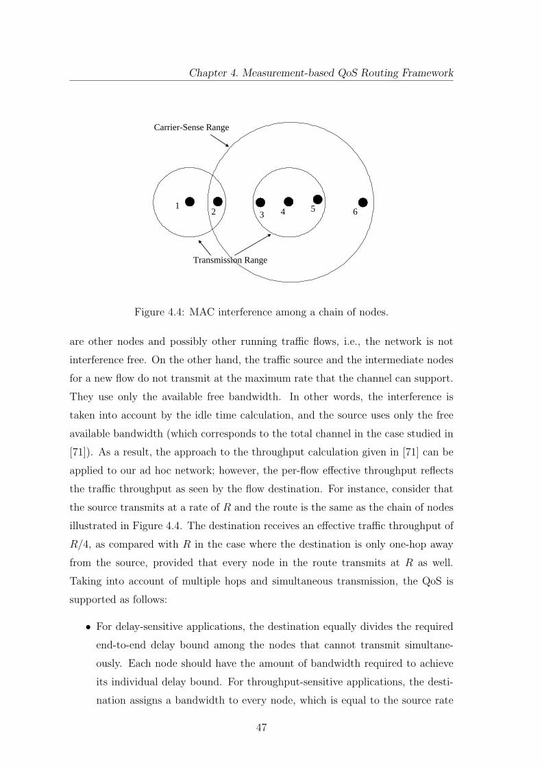
Chapter 4. Measurement-based QoS Routing Framework
12 3 4 5 6
Carrier-Sense Range
Transmission Range
Figure 4.4: MAC interference among a chain of nodes.
are other nodes and possibly other running traffic flows, i.e., the network is not
interference free. On the other hand, the traffic source and the intermediate nodes
for a new flow do not transmit at the maximum rate that the channel can support.
They use only the available free bandwidth. In other words, the interference is
taken into account by the idle time calculation, and the source uses only the free
available bandwidth (which corresponds to the total channel in the case studied in
[71]). As a result, the approach to the throughput calculation given in [71] can be
applied to our ad hoc network; however, the per-flow effective throughput reflects
the traffic throughput as seen by the flow destination. For instance, consider that
the source transmits at a rate of R and the route is the same as the chain of nodes
illustrated in Figure 4.4. The destination receives an effective traffic throughput of
R/4, as compared with R in the case where the destination is only one-hop away
from the source, provided that every node in the route transmits at R as well.
Taking into account of multiple hops and simultaneous transmission, the QoS is
supported as follows:
• For delay-sensitive applications, the destination equally divides the required
end-to-end delay bound among the nodes that cannot transmit simultane-
ously. Each node should have the amount of bandwidth required to achieve
its individual delay bound. For throughput-sensitive applications, the desti-
nation assigns a bandwidth to every node, which is equal to the source rate
47

Network-Layer Resource Allocation for Wireless Ad Hoc Networks
AB
CD
E
Admission Request Message
Reservation Request Message
Figure 4.5: The beginning of the call admission control procedure.
multiplied by the number of hops with no simultaneous transmission (i.e. 4Rb
in the previous example).
• Every node compares the available bandwidth with the bandwidth required
to achieve the delay bound or throughput. If there is no sufficient bandwidth,
the node refuses to admit the flow.
4.3.2.3 Call Admission Control for a CSMA/CA-Based MAC
The call admission control starts after the route is discovered. The bandwidth
reservation procedure proceeds side by side with the admission control procedure.
Note that the bandwidth reservation for any node lasts until the node cancels
it. Consider the route as shown in Figure 4.5, where the nodes are labeled by
A, B, . . . , E from the source to the destination. The call admission control and
bandwidth reservation procedure is proposed in the following:
Step 1: After the destination (node E in Figure 4.5) receives the “Route Request”
message, it records the source route and the locations of all the nodes in
the route. The destination E knows, by simple calculations, which nodes of
48
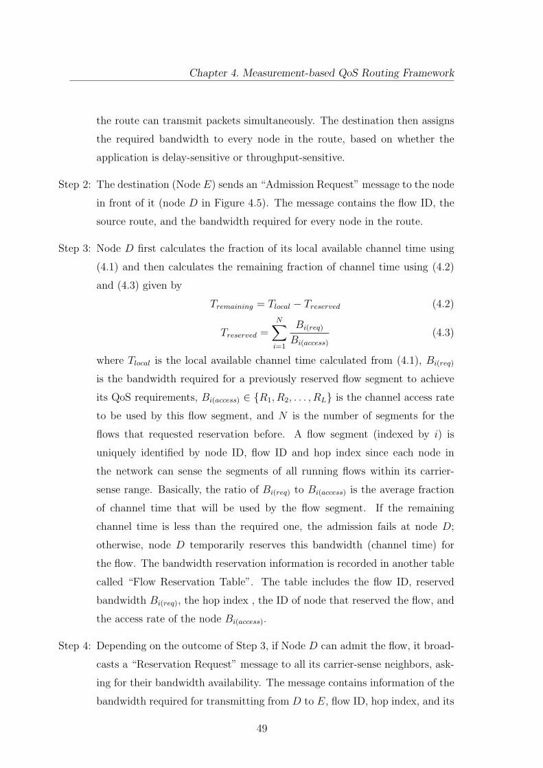
Chapter 4. Measurement-based QoS Routing Framework
the route can transmit packets simultaneously. The destination then assigns
the required bandwidth to every node in the route, based on whether the
application is delay-sensitive or throughput-sensitive.
Step 2: The destination (Node E) sends an “Admission Request” message to the node
in front of it (node D in Figure 4.5). The message contains the flow ID, the
source route, and the bandwidth required for every node in the route.
Step 3: Node D first calculates the fraction of its local available channel time using
(4.1) and then calculates the remaining fraction of channel time using (4.2)
and (4.3) given by
Tremaining = Tlocal − Treserved (4.2)
Treserved =N∑
i=1
Bi(req)
Bi(access)
(4.3)
where Tlocal is the local available channel time calculated from (4.1), Bi(req)
is the bandwidth required for a previously reserved flow segment to achieve
its QoS requirements, Bi(access) ∈ R1, R2, . . . , RL is the channel access rate
to be used by this flow segment, and N is the number of segments for the
flows that requested reservation before. A flow segment (indexed by i) is
uniquely identified by node ID, flow ID and hop index since each node in
the network can sense the segments of all running flows within its carrier-
sense range. Basically, the ratio of Bi(req) to Bi(access) is the average fraction
of channel time that will be used by the flow segment. If the remaining
channel time is less than the required one, the admission fails at node D;
otherwise, node D temporarily reserves this bandwidth (channel time) for
the flow. The bandwidth reservation information is recorded in another table
called “Flow Reservation Table”. The table includes the flow ID, reserved
bandwidth Bi(req), the hop index , the ID of node that reserved the flow, and
the access rate of the node Bi(access).
Step 4: Depending on the outcome of Step 3, if Node D can admit the flow, it broad-
casts a “Reservation Request” message to all its carrier-sense neighbors, ask-
ing for their bandwidth availability. The message contains information of the
bandwidth required for transmitting from D to E, flow ID, hop index, and its
49
Network-Layer Resource Allocation for Wireless Ad Hoc Networks
channel access rate. If node D cannot admit the flow, it sends an “Admission
Refused” message to the node just in front of it in the source route (node C
in Figure 4.5).
Step 5: In the case that D sent an “Admission Refused” message to node C, node C
starts a route repair procedure (to be described). In the case that D sent a
“Reservation Request” message, the neighboring nodes check their local avail-
able bandwidth in the same way as node D does in Step 3. If a node finds out
there are sufficient resources available, it reserves this bandwidth temporarily
for the flow, records the message information in the Flow Reservation Table
and sends the “Reservation Accepted” message; Otherwise, the node sends a
“Reservation Refused”’ message.
Step 6: Node D acts according to what it has received from its neighbors. If the
reservation is accepted from all the neighbors, it forwards the “Admission
Request” message to the node just before it in the source route (node C
in Figure 4.5), and node C in turn starts the same procedure from Step 3;
Otherwise, if node D received a reservation refusal, it sends an “Admission
Refused” message to node C which in turn starts a route repair procedure.
Step 7: The procedure is repeated until the source node is reached.
It is worth noting that the bandwidth reservation is temporary (to be deleted
after some time) since the idle time calculations take into consideration any traffic
flows already in service. The objective of this reservation is to prevent any false
calculations that may occur if several flows are competing to be admitted at the
same time.
4.3.2.4 Call Admission Control for Centralized Control TDMA MAC
With the centralized medium access control, the controller is in charge of the re-
source reservation and the assignment of time slots. Multiple transmissions in the
same time slot are not allowed. The admission control procedure is presented in
the following:
50

Chapter 4. Measurement-based QoS Routing Framework
Step 1: When the destination (node E in Figure 4.5) receives the “Route Request”
message, it records the source route and then assigns the bandwidth required
for every node in the route, using only the total number of hops.
Step 2: The destination (Node E) sends an “Admission Request” message containing
the flow ID, source route, and the bandwidth required for every node in the
route to its predecessor in the source route (node D in Figure 4.5).
Step 3: Upon receiving the “Admission Request” message, node D sends a “Reserva-
tion Request” message to the controller, indicating the required bandwidth
and its current access rate.
Step 4: The controller decides the acceptance or the refusal of the reservation based
on the packet transmission scheduling algorithm.
Step 5: If node D receives a “Reservation Accepted” message, it forwards the “Ad-
mission Request message to its predecessor in the source route (node C in
Figure 4.5); Otherwise, if note D receives a “Reservation Refused” message
from the controller, it sends an “Admission Refused” message to node C.
Step 6: If node C receives an “Admission Refused” message, it will start a route repair
procedure. On contrary, if node C receives an “Admission Request” message,
it will repeat Step 3 and so on till the source is reached.
4.3.3 Route Repair
The route repair procedure is initiated if any of the following two cases has hap-
pened: (i) A node, except the source, receives an “Admission Refused” message
from the node that follows it in the source route. Note that, if the source node re-
ceives an “Admission Refused” message, it will initiate a route discovery procedure
again but without restarting the route request timer; (ii) A node is no longer able
to communicate to the next node in the source route (as indicated in Figure 4.6)
because the location of this node becomes too far away or the range between the
two nodes increases so that the data communication rate becomes smaller than the
51

Network-Layer Resource Allocation for Wireless Ad Hoc Networks
Figure 4.6: Route repair procedure.
required one. In both cases, we consider the route is broken and the next node is
lost. The route repair procedure acts as follows:
Step 1: The node that initiates this procedure (node C in Figure 4.6) starts to discover
another route originating from it to the destination. This is done by repeating
Step 1 of the route discovery procedure, after excluding the lost node from
its ordered neighbor list.
Step 2: Node C sends to the newly discovered node (D1 in Figure 4.6) a “Route
Repair” message. The message has the same content as the “Route Request”
message.
Step 3: When a node (such asD1) receives the “Route Repair” message, it first checks
if the PLR bound given in the message will be exceeded or not as in Step 4
of the route discovery procedure. If the PLR bound is exceeded, the node
sends a “Route Failure” message back to the node from which it received
52

Chapter 4. Measurement-based QoS Routing Framework
the “Route Repair” message; otherwise, it repeats Steps 1 and 2 until the
destination is reached.
Step 4: When the destination receives the “Route Repair” message, it compares the
old source route with the new source route. It then assigns a delay bound
value for each node in the new part of the route, starting from the node where
the old route broke. This is the same as what the destination has done earlier
in the route discovery procedure.
Step 5: The destination starts a route repair timer (only if the route has been admit-
ted before but broken), and sends two messages. The first is an “Admission
Request” message in order to start an admission control procedure for the
newly discovered part. The second one is an “Admission Cancel” message,
which contains the old source route and a one bit flag that indicates whether
the node belongs to the new route or not.
Step 6: Every node that receives “Admission Cancel” message and does not belong
to the new route removes all the route information.
Step 7: The new admission control procedure ends at the node where the old route
broke. The flow is resumed at that time. When the destination starts receiv-
ing data, it stops the repair timer.
Step 8: If the route repair timer is expired before the flow is resumed, the destination
sends an “Admission Stop” message to every node in the route to cancel the
flow and to stop any running activity associated with it.
4.4 Performance Evaluation
The performance of the proposed QoS-GPSR protocol is evaluated via computer
simulations using the wireless extension of the ns-2 simulator [72]. The ns-2 wireless
simulation model simulates nodes moving in an unobstructed plane [38]. The node
motion follows the random way point model [73]. In the model, a node chooses
its speed and its destination uniformly random and then moves to the destination.
53
Network-Layer Resource Allocation for Wireless Ad Hoc Networks
Upon reaching the destination, a node pauses for a while and then starts the same
process again. The pause time presents the degree of mobility in the simulation; a
longer pause time means more nodes are stationary for more time in the simulation.
In the simulation, the ns-2 WaveLAN implementation for MAC 802.11 is used.
The selection of this implementation is to compare the performance of the newly
proposed QoS-GPSR protocol with some non-QoS routing algorithms given in [73].
The simulation is done for a network of 50 mobile nodes with a maximum speed
of 1m/s. Each node is moving in an area of 670 × 670m2. The node radios have
a transmission range of 250m and a carrier-sense range of 550m. Different pause
times of 0, 30, 60 and 90 s are simulated. There are three QoS classes, differentiated
in terms of bandwidth, delay bound and PLR: Class 1 has a transmission rate of
8kbps with a delay bound of 100ms and PLR bound of 10%, class 2 has a rate
of 16kbps with a delay bound of 150ms and PLR bound of 8%, and class 3 has a
rate of 32Kbps with a delay bound of 200ms and PLR bound of 5%. We assume
1% PLR per hop. A power control mechanism is in place to mitigate any channel
fading impairments in the low mobility environment. The number of traffic flows
varies from 9 to 18 with a step size of 3. The packet size of 1024 bytes has been
used. We ran the simulation for 900s. The flows start at random time and continue
for a session time uniformly distributed from 5 minutes to 15 minutes (the whole
simulation time).
To our knowledge, no benchmark metrics have been defined so far to evaluate
the performance of QoS routing protocols for ad-hoc networks. We have measured
the following six metrics:
• Call acceptance ratio, defined as the ratio of the number of the admitted flows
to the number of the offered flows;
• Call completion ratio, defined as the ratio of the number of the completed
flows to the number of the admitted flows;
• Successful delivery percentage, defined as the ratio of the number of packets
delivered successfully to the total number of packets transmitted;
• Percentage late packets, defined as ratio of the packets that arrived after the
54
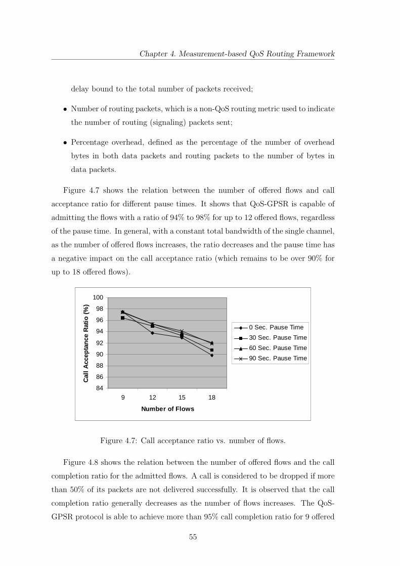
Chapter 4. Measurement-based QoS Routing Framework
delay bound to the total number of packets received;
• Number of routing packets, which is a non-QoS routing metric used to indicate
the number of routing (signaling) packets sent;
• Percentage overhead, defined as the percentage of the number of overhead
bytes in both data packets and routing packets to the number of bytes in
data packets.
Figure 4.7 shows the relation between the number of offered flows and call
acceptance ratio for different pause times. It shows that QoS-GPSR is capable of
admitting the flows with a ratio of 94% to 98% for up to 12 offered flows, regardless
of the pause time. In general, with a constant total bandwidth of the single channel,
as the number of offered flows increases, the ratio decreases and the pause time has
a negative impact on the call acceptance ratio (which remains to be over 90% for
up to 18 offered flows).
84
86
88
90
92
94
96
98
100
9 12 15 18
Number of Flows
Cal
l A
ccep
tan
ce R
atio
(%
)
0 Sec. Pause Time
30 Sec. Pause Time
60 Sec. Pause Time
90 Sec. Pause Time
Figure 4.7: Call acceptance ratio vs. number of flows.
Figure 4.8 shows the relation between the number of offered flows and the call
completion ratio for the admitted flows. A call is considered to be dropped if more
than 50% of its packets are not delivered successfully. It is observed that the call
completion ratio generally decreases as the number of flows increases. The QoS-
GPSR protocol is able to achieve more than 95% call completion ratio for 9 offered
55

Network-Layer Resource Allocation for Wireless Ad Hoc Networks
60
65
70
75
80
85
90
95
100
9 12 15 18
Number of Flows
Cal
l C
om
ple
tio
n R
atio
(%
)0 Sec. Pause Time
30 Sec. Pause Time
60 Sec. Pause Time
90 Sec. Pause Time
Figure 4.8: Call completion ratio vs. number of flows.
flows with pause times of 60s and 90s. It is clear that the QoS-GPSR protocol
is affected by the mobility profile. The call completion ratio is around 85% for 9
and 12 admitted flows for 0 and 30s pause times. As user mobility increases, the
chances of a broken path increases, resulting in a degraded performance of QoS
GPSR.
70
75
80
85
90
95
100
9 12 15 18
Number of Flows
Pac
ket
Del
iver
y P
erce
nta
ge
0 Sec. Pause Time
30 Sec. Pause Time
60 Sec. Pause Time
90 Sec. Pause Time
Figure 4.9: Packet delivery successful percentage vs. number of flows.
Figure 4.9 shows the average percentage of packets successfully delivered for
each pause time for different number of offered flows. The figure does not show
an increasing or decreasing trend since the percentage of successful packet delivery
56

Chapter 4. Measurement-based QoS Routing Framework
depends on both the number of flows admitted and the number of flows dropped.
It is observed that QoS-GPSR performs very well in terms of packet delivery. It
delivers successfully 90% − 95% of the packets for both cases of 9 and 12 offered
flows with 60s and 90s pause times. For 15 and 18 flows, it achieves almost the same
percentage, with a reduced number of admitted flows and an increased number of
dropped flows. Higher user mobility (i.e., smaller pause times) negatively affects
the delivery percentage.
0
0.05
0.1
0.15
0.2
0.25
0.3
9 12 15 18
Number of Flows
Per
cen
tag
e L
ate
Pac
kets
0 Sec. Pause Time
30 Sec. Pause Time
60 Sec. Pause Time
90 Sec. Pause Time
Figure 4.10: Percentage late packets vs. number of flows.
45000
45500
46000
46500
47000
47500
48000
48500
9 12 15 18
Number of Flows
Nu
mb
er o
f R
ou
tin
g P
acke
ts
0 Sec. Pause Time
30 Sec. Pause Time
60 Sec. Pause Time
90 Sec. Pause Time
Figure 4.11: Number of routing packets vs. number of flows.
Figure 4.10 shows the percentage of packets that arrived after the delay bound.
57

Network-Layer Resource Allocation for Wireless Ad Hoc Networks
It is obvious that QoS-GPSR is very successful in guaranteeing the end-to-end delay
requirement. In the worst case, the late packets do not exceed 0.27% of the packets
sucessfully delivered.
0
2
4
6
8
10
12
14
16
18
9 12 15 18
Number of Flows
Per
cen
tag
e O
verh
ead
0 Sec. Pause Time
30 Sec. Pause Time
60 Sec. Pause Time
90 Sec. Pause Time
Figure 4.12: Percentage Overhead vs. number of flows.
Figure 4.11 shows the number of routing packets used for different number of
offered flows. This is a non-QoS parameter. We use this parameter to measure
the cost of the QoS support in the QoS-GPSR protocol by making a performance
comparison with the previous GPSR protocol [38] and other routing protocols [73].
Even though the simulation parameters have some minor differences, the compari-
son is valid to a large extent. The number of flows that have been used in [38] [73]
was quite high (30 flows) but with very low data rates in order of 2Kbps, which
corresponds to a similar traffic load as to our case (a smaller number of flows with
higher data rates) [73]. The packet size used in [38] [73] was 64 bytes. Figure 4.11
shows that the order of the number of routing packets compares very well with
different routing protocols such as DSDV which has approximately 41000 routing
packets and TORA which has more than 50000 routing packets. However, com-
pared with GPSR (having approximately 16000 routing packets), the QoS-GPSR
protocol has a much larger number of routing packets, due to its QoS support
mechanisms.
Figure 4.12 shows the percentage overhead for different number of offered flows.
The percentage overhead decreases as the number of flows increases. This results
58

Chapter 4. Measurement-based QoS Routing Framework
from a relatively increased number of data packets sent for a lower number of flows,
due to a higher ratio in both call admission and call completion. The maximum
percentage overhead does not exceed 17%, which seems to be acceptable taking
into account the distributed control in an ad hoc environment and the extra cost
for QoS support.
4.5 Summary
We have proposed the QoS-GPSR protocol for multihop ad hoc networks, which
provides per-flow end-to-end QoS guarantees in terms of packet loss ratio and end-
to-end delay or effective throughput depending on the applications. The QoS-GPSR
protocol efficiently utilizes the network radio resources by using location information
to discover a path to the destination. After that, it starts the call admission control
and reservation procedures on the discovered path. The admission control takes
into consideration the MAC interactions to ensure that the new flow will not affect
the QoS provisioning to other existing flows. Simulation results demonstrate that
the QoS-GPSR protocol is effective and efficient in the end-to-end QoS provisioning.
59

Chapter 5
Service Time Approximation for
IEEE 802.11 DCF Ad hoc
Networks
In recent years, contention-based MAC protocols (such as IEEE 802.11) are widely
adopted in WLANs. There are many different research works that address IEEE
802.11 performance analysis in the open literature (for example, [70], [64], [74] and
references therein). Nevertheless, in the bulk of the research works, the analysis of
very important design parameters (such as MAC packet delay and service time) is
done in terms of the first order statistics only. The MAC service time under con-
sideration in this chapter is defined as the delay seen by a packet from the instant
of being at the head of the queue to the instant of being successfully transmitted.
The service time is vital for handling any IEEE 802.11 queuing model. Our ob-
jective in this chapter, in contrary to most of previous research works, is not to
analyze the performance of IEEE 802.11 by including the impact of the queuing
model. We mainly aim at reaching a sufficiently accurate approximation for the
service time distribution that can easily be used in statistical resource allocation
(call admission control and/or resource reservation) decisions. In fact, using the
first order statistics may lead to inefficient network resource utilization or ineffective
QoS provisioning.
Although not much researches in the literature study the queuing models of
60
Chapter 5. Service Time Approximation for IEEE 802.11 DCF Ad hoc Networks
802.11 [63] [64] [75] [76], we can identify four different queuing disciplines; namely,
M/G/1 [64] [77] [78] , M/MMGI/1/K [75], G/G/1 [63, 79] and M/M/1/K [64, 76].
Two of these disciplines M/G/1 [64], [77] and G/G/1 [63, 79] treat the IEEE 802.11
as a server with a general service time distribution. The queuing analysis with
a general service time distribution can be carried out either by (i) finding the
distribution itself; (ii) using the estimated average and variance of an unknown
distribution; or (iii) approximating the general distribution, if possible, to an easy-
handling one such as exponential or geometric. Finding a close-form expression for
the service time probability density function (PDF) is a mathematically challenging
task. In fact, the distribution is complicated since, between two successful packet
transmissions of any node, three different random variables (in the case of a fixed
packet size) are involved; namely, the number of idle time slots, the number of
collisions happened (either to other nodes or to the node under consideration),
and the number of successful transmissions of the other nodes. Moreover, these
random variables are not independent since the number of successful transmissions
and collisions from the others nodes (between successful transmissions of a given
node) depends on the backoff counter value. As the counter value increases, more
successful transmissions and collisions are likely to happen. Also, the number of
successful transmissions of the other nodes depends on how many collisions they
suffered. On the other hand, previous analysis and simulation results indicate that a
large number of packets have a very short service time and a small number of packets
experience a very long one (i.e., the packet service time is not close to its average
value) [64, 63, 79, 80, 81, 82]. Using only the average value in resource allocation
may lead eventually to a conservative estimation of the available resources, which
in turn reduces the utilization of the network resources.
In this chapter, we study the service time distribution for the 802.11 DCF with
the RTS/CTS access method. We seek a simplified approximation mainly to be
used for efficient statistical call admission control and resource reservation in ad
hoc networks. The paper presents three related contributions that lead to the
realization of this objective:
• It is shown that the service time distribution has a partial memoryless be-
havior. We demonstrate that the distribution of the number of packets suc-
61

Network-Layer Resource Allocation for Wireless Ad Hoc Networks
cessfully transmitted over a time interval from any of the active nodes in a
saturated ad hoc network follows a general distribution that is close to the
Poisson distribution with an upper bounded distribution distance. The Pois-
son process is a renewal counting process with a memoryless distribution for
the renewal inter-arrival times [83]. We obtain this bound analytically using
the Chen-Stein approximation method [13] and verify it by simulations. We
also show that the bound is almost a constant, which depends mainly on
some system parameters and very slightly on the number of active nodes in
the network.
• We illustrate that the service time distribution, with its near memoryless
behavior and the discrete nature shown in [64] [77] [80], can be approximated
by the geometric distribution. We characterize the distribution by analytically
deriving its parameter.
• We propose to use the discrete-time queuing system (M/Geo/1) as a queuing
model for IEEE 802.11 single-hop ad hoc networks near saturation. We show
that the average queue length and the probability distribution of the number
of packets in the queuing system obtained by computer simulations match
closely the analytical results obtained from the M/Geo/1 queuing system.
The significance of this research lies in the introduction of a simple approximation
to the service time distribution, which can be used with sufficient accuracy in the
queuing analysis and the prediction of the buffer occupancy for the sake of QoS
provisioning. Distributed resource allocation mechanisms (such as call admission
control) are mandatory in ad hoc networks which lack a centralized controller. This
research offers a step toward a fully distributed statistical call admission control for
single-hop ad hoc networks, based on the PDF of the buffer occupancy instead of
just first or second order statistics. Any node with a minimal amount of informa-
tion from its neighbors (i.e. the number of neighboring nodes) can determine the
possibility of its call being admitted with its QoS constraints (such as delay) being
satisfied without degrading the QoS provisioning of the ongoing calls.
The rest of chapter is organized as follows. Section 5.1 presents some related
works. We introduce the system model in Section 5.2. In Section 5.3, we discuss
62

Chapter 5. Service Time Approximation for IEEE 802.11 DCF Ad hoc Networks
the partial memoryless behavior of the service time in the IEEE 802.11 at satura-
tion. Section 5.4 presents our proposed approximation to the service time and the
M/Geo/1 queuing system. We verify the analysis by simulation results in Section
5.5. Finally, Section 5.6 summarizes this chapter.
5.1 Related Works
Studying the service time distribution of the IEEE 802.11 DCF has drawn the
attention of many researchers since it is essential for performance evaluation and
queuing analysis. In [63], [79], [77], [80] and [78], exact close-form expressions of
the probability generating function (PGF) of the service time are derived. The
PGF expressions can be converted to the PDF only numerically, which makes them
not practical to use in making dynamic statistical resource allocation decisions. In
[84], an approximation to the service time PGF has been given and shown to be
accurate. However, the approximated PGF is a general distribution, which is not
easy to handle with queuing analysis although it is simpler than the exact close-
form expressions. In [85], an approximation to the asymptotic distribution of the
total delay (M/G/1 queuing delay plus the service time) has been shown to follow
a power law. This approximation is given under certain assumptions such as large
total delay and non-integer binary logarithm of the collision probability.
The assumption of Markovian service time in the IEEE 802.11 queuing disci-
pline (such as M/M/1/K [64, 76]) has not been analytically verified, to the best of
our knowledge. Zhai et al. in [64] compare the service time distribution obtained
by simulations graphically with standard distributions and conclude that an ex-
ponential distribution may give a good approximation to the inter-arrival times of
successfully received packets. Foh and Zukerman [86] and Tantra et al. [87] study
the IEEE 802.11 DCF performance by modeling a WLAN with K nodes using an
M/PH/1/K queuing analysis (where each node waits in the queue to be served). In
[86] and [87], a phase type distribution (such as Erlang with parameter 8 in [86])
is used to approximate the service time based on simulation results and graphical
comparison to the actual service time distribution (obtained by simulations). It
is also assumed in [86] and [87] that every node can only keep one data frame in
63

Network-Layer Resource Allocation for Wireless Ad Hoc Networks
its queue (low utilization factor), which impacts the service time distribution for a
low or medium number of nodes. Pham et al. in [76] use the M/M/1/K discipline,
assuming that the service time is exponential without verifying the assumption.
In [88], it is shown that the service interval distribution can converge to an expo-
nential distribution when the number of nodes in the network is sufficiently large.
However, the definition of the service interval or the service time for a node in [88]
is the same as the slot time in [70]. The author in [88] uses the expression for the
average slot time given in [70] to analytically describe the average service interval
for a node. The operation of the IEEE 802.11 protocol is based on a slotted time.
The slot time in [70] is defined as either the unit slot time (when the channel is
idle), or the packet transmission time (when the channel is busy sending a packet),
or the time for a collision to be detected on the channel. The service time definition
under consideration in this chapter is substantially different; it is also used by many
other researchers [64, 74], [80]-[82].
5.2 System Model
We consider a single-channel IEEE 802.11 single-hop ad hoc network that contains a
cluster of terminals (nodes). The nodes use the DCF mechanism to access the chan-
nel. The random access employs the four-way RTS-CTS-DATA-ACK handshaking
procedure. All the nodes have the same transmission range, and are randomly dis-
tributed in an area with dimensions limited to the node’s transmission range. As
a result, all the nodes can hear each other, and there are no hidden or exposed
terminals. Only half of the nodes are active traffic sources, the other half are only
receivers. The network represents a single-hop ad hoc network; every sender (active)
node sends data packets to one unique receiver node. For simplicity in studying
the 802.11 protocol operation, we assume that the transmitted packets may be lost
only due to collision. We consider that the network is in saturation condition unless
otherwise specified. We follow the CSMA/CA protocol as described in the IEEE
802.11 standard [1] and Section 3.1.3.
We assume a fixed packet size. The total packet transmission time Ts is given
by [70]
64

Chapter 5. Service Time Approximation for IEEE 802.11 DCF Ad hoc Networks
Emptyvirtual time slot(channel idle)
Ts TsTc
Virtual time slotwith successful transmission
Virtual time slotwith collision
σ
Emptyvirtual time slot(channel idle)
Ts TsTc
Virtual time slotwith successful transmission
Virtual time slotwith collision
σ
Figure 5.1: Virtual time slots.
Ts = TRTS + TCTS + 3 SIFS + TACK + T +DIFS (5.1)
and the packet collision time is given by [70]
Tc = TRTS +DIFS. (5.2)
The symbols TRTS , TCTS and TACK represent the transmission times for the RTS,
CTS and ACK packets, respectively; T is the data packet transmission time, which
is constant for a fixed packet size.
Here we differentiate two types of time slots: physical time slot and virtual
time slot. The physical time slot (the unit time) has a fixed length denoted by
σ . A virtual time slot is the time during which the channel does not change its
state (busy or idle) as indicated in Figure 5.1. A virtual time slot may contain
one or more physical time slots. If the node is backing off and the channel is idle,
the virtual time slot is equal to one physical slot (σ). If the channel is detected
busy, the node stops decrementing its backoff counter and waits for two virtual
time slots (one when the channel is busy and one when it is idle) before it starts
decrementing its backoff counter again. The virtual time slot is equal to Ts if the
channel is busy sending a packet successfully, or equal to Tc if a collision happened.
If the node is transmitting, it takes one virtual time slot (with duration Ts if no
collision happens or Tc otherwise) to finish its transmission. Thus, a virtual time
slot duration is a random variable, denoted by s , that has three possible values
65

Network-Layer Resource Allocation for Wireless Ad Hoc Networks
System Parameter Value
Packet payload 256 Bytes
PHY header 128 bits
ACK 112 + PHY header
RTS 160 + PHY header
CTS 112 + PHY header
Slot Time 50 µs
SIFS 28 µs
DIFS 128 µs
Basic Rate 1 Mbps
Data Rate 2 Mbps
CWmin 16
Backoff stages (mb) 5
Table 5.1: IEEE 802.11 system parameters [1]
.
with different probabilities as follows:
s =
σ, P (s = σ) = 1 − Ptr
Ts, P (s = Ts) = PtrPs
Tc, P (s = Tc) = Ptr(1 − Ps)
(5.3)
where [70]
Ptr = 1 − (1 − τ)N (5.4)
is the probability that the channel has at least one transmission in the considered
slot time, τ is the probability that a node transmits in a randomly chosen time slot,
given by
τ =2(1 − 2p)
(1 − 2p)(CWmin + 1) + p CWmin(1 − (2p)mb)(5.5)
and
Ps =Nτ(1 − τ)N−1
Ptr
(5.6)
is the probability that the channel has a successful transmission. The average
virtual slot time is then given by
E[s] = (1 − Ptr)σ + PtrPsTs + Ptr(1 − Ps)Tc. (5.7)
66

Chapter 5. Service Time Approximation for IEEE 802.11 DCF Ad hoc Networks
5.3 The Near-Memoryless Behavior of IEEE 802.11
In this section, we study the behavior of the random counting process that controls
the number of packets successfully transmitted by any of the contending nodes in
the saturated network. We show that this counting process has a nearly memoryless
behavior. We prove analytically using the Chen-Stein approximation method that
the probability of the number of packets sent over a time interval by any active node
follows a distribution that is close to a Poisson distribution with an upper bounded
distribution distance. We also discuss the possible causes of this behavior; namely,
the fairness of the IEEE 802.11 and the randomness of the CSMA/CA backoff
procedure. In the following, brief overviews of the Chen-Stein approximation and
the IEEE 802.11 fairness are given for the sake of completeness.
5.3.1 Chen-Stein Approximation
The Chen-Stein approximation is a more generalized form of the “law of small
numbers”. The law states that the distribution B(n,pb) can converge to the Poisson
distribution Pν , where ν = npb, for small pb and very large n [13] [88] as long as
B(n,pb) can be represented as the sum of n independent and identically distributed
Bernoulli (indicator) random variables where each indicator equals to one with
probability pb. The law of small numbers applies only to this class of variables.
However, the Chen-Stein approximation method extends the law to measuring the
convergence rate (the distribution distance) between Pν and B(n,pb) as n goes large
and relaxes to some extent both the identical distribution and the independence
assumptions [13]. In our case, the indicator random variables are independent
and identically distributed. Therefore, the distribution under consideration can be
described by the random variable X as follows
X =n∑
i=1
Ii (5.8)
where I1, I2, . . . , In are independent and identically distributed random variables
and
pbi = P (Ii = 1) = E[Ii]. (5.9)
67
Network-Layer Resource Allocation for Wireless Ad Hoc Networks
According to the Chen-Stein method [13], the distribution distance between the
cumulative distribution function (CDF) of the actual distribution P(X∈ H) and
the Poisson CDF Pν(H), where H ⊂ Z+, is bounded by
|P (X ∈ H) − Pν(H)| ≤(1 − e−ν)
ν
n∑
i=1
p2bi. (5.10)
5.3.2 MAC Fairness
MAC fairness refers to the ability of the link layer to allow contending nodes to
equally access a channel. The CSMA/CA technique used in IEEE 802.11 is not
perfectly fair, but it can achieve long-term fairness with a high fairness index [89].
This implies that the probability (the fraction of the number of times) the channel
has been accessed by one node successfully can be considered to be 1/N on the long
term, where N is the number of contending nodes. Since we aim at approximating
the distribution of the number of packets successfully transmitted over a time in-
terval, a question here is how short the time interval could be. Recently it has been
shown in [90] and [91] that the IEEE 802.11 MAC intrinsically (without the hidden
terminal problem) also has a short-term fairness. The short term is in the order
of tens of milliseconds [90]. As our aim is to provide a tool for statistical resource
allocation in order to provision QoS, the short term fairness implies the validity
of our analysis for multimedia traffic sessions which usually have durations in the
order of minutes [92] [47]. The short-term fairness can be proved as long as the
CSMA/CA backoff procedure, as mentioned in the system model, follows the IEEE
802.11 standard [1]. We limit our analysis only to the IEEE 802.11 standard since
other implementations of the CSMA/CA backoff procedure (such as WaveLAN) is
proved to be short-term unfair [89].
5.3.3 Distribution Distance
The motivation to study the distance between the distribution of the number of
successfully transmitted packets and the Poisson distribution is driven by our intu-
ition that the IEEE 802.11 has a kind of memoryless behavior. This behavior can
be explained from the following two aspects:
68

Chapter 5. Service Time Approximation for IEEE 802.11 DCF Ad hoc Networks
• The number of packets successfully transmitted by any active node at satura-
tion over a time interval is a renewal process, since the node restarts again its
contention window to the minimum size after every successful transmission
and it always has backlogged packets;
• The node contends for the channel with the same collision probability, irre-
spective of the number of retransmissions it had before, though the contention
window size doubles after every retransmission [70]. In fact, the probability
of a successful transmission of any node (when contending for the channel) is
the same irrespective of how long it has been waiting for the transmission.
We use the Chen-Stein approximation as a tool to quantify mathematically the
distribution distance. We introduce a mathematical model to the random counting
process that describes the number of successfully transmitted packets over a time
interval (one second for simplicity).
In this model, any active node has a number of virtual time slots with successful
transmissions in one second. This number can be considered as the number of
successful trials out of the total number of other virtual time slots that the channel
has in one second, as illustrated in Figure 5.2. The figure shows the virtual time
slots that contain successful transmissions for a certain active node in black, and
other white slots corresponding to successful transmissions or collisions from other
nodes, idle channel or collisions associated with the same node.
Under the assumption that the packet of any node sees a collision with constant
and independent packet collision probability p , the relation between the probability
τ that a node sends a packet at a random time slot and p is given by [70]
p = 1 − (1 − τ)N−1. (5.11)
We model the number of successfully transmitted packets over a time interval
of one second from a certain node as the summation of indicator random variables
Ii, where
Ii =
1, A certain node transmitted a packet
successfully (no collision) in slot i
0, Otherwise
(5.12)
69
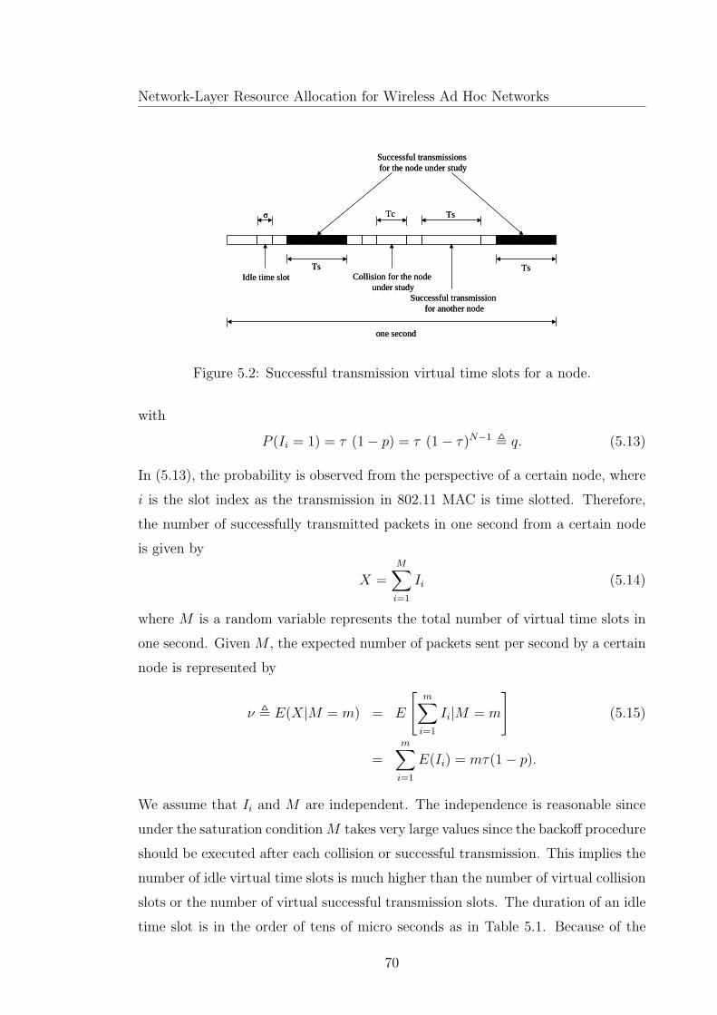
Network-Layer Resource Allocation for Wireless Ad Hoc Networks
Idle time slotTs Ts
Tc
Successful transmissionsfor the node under study
Collision for the node under study
σ
Successful transmissionfor another node
Ts
one second
Idle time slotTs Ts
Tc
Successful transmissionsfor the node under study
Collision for the node under study
σ
Successful transmissionfor another node
Ts
one second
Figure 5.2: Successful transmission virtual time slots for a node.
with
P (Ii = 1) = τ (1 − p) = τ (1 − τ)N−1 , q. (5.13)
In (5.13), the probability is observed from the perspective of a certain node, where
i is the slot index as the transmission in 802.11 MAC is time slotted. Therefore,
the number of successfully transmitted packets in one second from a certain node
is given by
X =M∑
i=1
Ii (5.14)
where M is a random variable represents the total number of virtual time slots in
one second. Given M , the expected number of packets sent per second by a certain
node is represented by
ν , E(X|M = m) = E
[
m∑
i=1
Ii|M = m
]
(5.15)
=m∑
i=1
E(Ii) = mτ(1 − p).
We assume that Ii and M are independent. The independence is reasonable since
under the saturation conditionM takes very large values since the backoff procedure
should be executed after each collision or successful transmission. This implies the
number of idle virtual time slots is much higher than the number of virtual collision
slots or the number of virtual successful transmission slots. The duration of an idle
time slot is in the order of tens of micro seconds as in Table 5.1. Because of the
70

Chapter 5. Service Time Approximation for IEEE 802.11 DCF Ad hoc Networks
fairness of the MAC and the saturation condition, all the active nodes are treated
similarly. Hence, the distribution distance in (5.10) for any node is bounded by
|P (X ∈ H|M = m) − Pν(H|M = m)| ≤N(1 − e−ν)
ν
m∑
i=1
τ 2(1 − τ)2(N−1)
By evaluating the summation and substituting the value of ν, we have
|P (X ∈ H|M = m) − Pν(H|M = m)| ≤ Nτ(1 − τ)N−1(1 − e−ν)
which leads to
|P (X ∈ H) − Pν(H)| ≤ Nτ(1 − τ)N−1∑
m
(1 − e−ν)P (M = m)
The random variable M represents the number of virtual slots within a certain time
period (one second). The duration of a virtual time slot with successful transmis-
sion, Ts, is longer than the other two types of virtual slots; namely, an idle slot
and a slot with collision. Therefore, if almost all1 the virtual slots contain success-
ful transmission, the random variable M would take its smallest value and hence
ν, which directly depends on M , would take its smallest value. In this case, M
roughly takes the value 1/Ts, which is in the order of hundreds virtual slots per
second (according to the parameters given in Table 5.1 ) making ν in the order of
tens of packets per second. Therefore, the exponential term e−ν approaches zero
and the distribution distance can be approximately bounded by
|P (X ∈ H) − Pν(H)| ≤ Nτ(1 − τ)N−1. (5.16)
It has been shown in [70] that the saturation throughput, for a certain number
of active nodes in the network, has a maximum value that can be achieved by fine
tuning of the probability τ . The tuning can be done by changing the minimum size
of the contention window CWmin and/or the number of backoff stages mb . It can
be noticed from [70] that the maximum saturation throughput for the RTS/CTS
access scheme approaches the saturation throughput calculated at the standardized
values for both CWmin and mb [1] (i.e. 16, 32 or 64 for CWmin and 5 for mb) and
a sufficiently large number of nodes (N ≥ 5). As indicated in Table 5.1, we use
1The channel should be idle for at least one time slot between two successful transmissions.
71

Network-Layer Resource Allocation for Wireless Ad Hoc Networks
the standard values for both CWmin and mb (i.e. CWmin = 16 and mb = 5). For
these standard values, the transmission probability for a maximum throughput is
approximately given by [70]
τ ≈1
Nκ(5.17)
where
κ =
√
Tc
2σ(5.18)
which leads to
Nτ(1 − τ)N−1 ≈1 − e−1/κ
κ(e1/κ − 1). (5.19)
Thus, the distribution distance becomes
|P (X ∈ H) − Pν(H)| ≤1 − e−1/κ
κ(e1/κ − 1). (5.20)
Equation (5.20) shows that there is an almost constant upper bound on the distri-
bution distance. The bound depends mainly on κ, which in turn depends on system
parameters Tc (i.e. TRTS and DIFS) and σ. An approximated upper bound value
of 0.3 is obtained from (5.20) when using the IEEE system parameters given in
Table 5.1. It implies that IEEE 802.11 has a kind of near-memoryless behavior,
which is aligned with our intuition, but not completely memoryless since the upper
bound is not small. This is due to that IEEE 802.11 is not completely fair, as the
protocol may favor the node that had a successful transmission before to transmit
successfully again and again. Also, the discrete nature of the slotted operation
limits the packet service time to discrete values. Therefore, the renewal count-
ing process for successfully transmitted packets does not exactly have independent
increments, which explains the deviation from the Poisson process.
5.4 Service Time Approximation
Our service time approximation stems from the mathematical model introduced in
the previous section for the counting process of the number of successfully trans-
mitted packets. Here, we approximate the random length of the virtual time slot
by its average value E[s]. By this approximation, the number of virtual time slots
72

Chapter 5. Service Time Approximation for IEEE 802.11 DCF Ad hoc Networks
over a time interval becomes a deterministic value. Thus, the counting process now
describes the number of virtual time slots with successful transmissions (successful
trials) out of the total number of virtual time slots (total number of trials) over a
time interval t, which is the typical binomial process
B(t) =
⌊t/E[s]⌋∑
i=1
Ii (5.21)
where Ii is defined in (5.12). It can be shown that, for a binomial process, the
time between successive events (the service time in our case) follows a geometric
distribution [83]. The geometric distribution is a probability distribution for dis-
crete random variables, and suits well the discrete slotted nature of IEEE 802.11.
In addition, it has a memoryless nature [93]. This can be intuitively explained: the
fact that we have done n trials and got failures does not change how many more
times we still have to try to get the next success.
Therefore, the probability that the service time equals n virtual time slots is
given by
Pts = n = q (1 − q)n−1 (5.22)
where the distribution parameter q is the successful transmission probability given
by (5.13).
As a result, the average service rate µs can be obtained from
µs =
⌊1/E[s]⌋∑
i=1
E[Ii] =τ · (1 − p)
E[s](5.23)
which is consistent with (5.13). The service time distribution given by (5.22) is
discrete with an exponential-like decay that really resembles the actual distributions
shown in [64], [77] and [80]. Moreover, the average value given in (6.19) is consistent
with the expressions obtained by the previous researchers [82] [94] for the average
packet delay when substituting the value of τ by (5.5).
5.4.1 M/Geo/1 Queuing Model
Here, we propose using the discrete-time queuing discipline (M/Geo/1) as a queu-
ing model for nearly saturated IEEE 802.11 single-channel ad hoc networks (with
73

Network-Layer Resource Allocation for Wireless Ad Hoc Networks
Possion traffic sources). This model describes a queuing system with a Possion
arrival process, and an output server (channel) that is subjected to interruptions
controlled by a geometric distribution [95]. The output channel is capable of sending
one packet successfully per unit service interval (virtual time slot). The probability
that the output channel is available (i.e. available to send the packet successfully)
at saturation is given by q, which is defined by (5.13). The probability the chan-
nel is blocked (cannot send the packet successfully) for exactly (n− 1) consecutive
service intervals at saturation is given by (5.22). We do the queuing analysis at
near saturation (with utilization factor ρ very close to but less than 1) to guarantee
the stability of the queue and also to take the advantage of high network through-
put [70]. At saturation, the queue may not be stable and hence it is impractical
for resource allocation and QoS provisioning. We note that, in IEEE 802.11, the
service rate of the queuing system is not constant but depends on the arrival rate.
In most queuing systems, we can simply choose the arrival rate for a required ρ
value. However, in IEEE 802.11, when the arrival rate increases toward saturation,
the service rate decreases until it reaches a saturation value. In fact, the satura-
tion service rate is the minimum achievable value before the queue becomes totally
unstable. The M/Geo/1 queuing model is sufficiently accurate for 0.98 ≤ ρ < 1
, which is very close to saturation (ρ = 1). As ρ decreases, the approximation
error increases. The service rate (the number of successfully transmitted packets
per virtual slot) in a non-saturated case, denoted by µ , can be calculated with
sufficient accuracy using the method described in [96]. Actually, Cai et. al give
basic equations in [96] that can be solved to get the average service rate and the
collision probability p for a certain utilization factor ρ and a certain arrival rate
in non saturated conditions. We use the service rate obtained from the solution of
those equations to get the average queue length and the probability distribution of
the buffer occupancy based on the M/Geo/1 analysis given by (5.24)-(5.25). We
assume an infinite buffer model for simplicity. The assumption is reasonable due
to the huge available capacity of the latest memory chips, e.g. those used in small
devices such as PDAs. Based on [95], the average queue length for the Poisson
74

Chapter 5. Service Time Approximation for IEEE 802.11 DCF Ad hoc Networks
arrivals and geometric service time can be exactly calculated by
Lq =ρ (2 − λ)
2 (1 − ρ)(5.24)
where λ is the number of packet arrivals per virtual slot and ρ is the utilization
factor given by
ρ =λ
µ.
The probability distribution of m packets in the queuing system can be approx-
imated (as the average virtual slot time is small) by [97]
pm ≈
(1−γ) γm
1−µ (1−γ), m > 0
(1−µ) (1−γ)1−µ (1−γ)
, m = 0
(5.25)
where
γ =λ (1 − µ)
µ (1 − λ).
In the next section, we verify by computer simulations that both the average queue
length and the probability distribution of the number of packets given in (5.24)-
(5.25) are very accurate.
5.5 Simulation Results
We verify our analysis using the ns-2 simulator [72]. The simulation model simulates
nodes moving in an unobstructed plane following the random waypoint model [73]
with a maximum speed of 1m/s. In the model, a node chooses its speed and its
destination randomly and then moves to the destination. The simulation is done for
a network having a variable number of mobile nodes over an area of 250 × 250m2.
Only half of the nodes are active traffic sources, the other half are only receivers.
The node radios have a transmission range of 250m and a carrier-sense range of
550m. The network represents a single-hop ad hoc network; every sender sends
data packets to one unique receiver. To verify the distribution distance bound
(5.20), we use constant bit rate traffic sources with a high data rate to force the
active nodes to be in a saturation state (always have backlogged packets). For the
queuing analysis verification, we use Poisson traffic sources.
75

Network-Layer Resource Allocation for Wireless Ad Hoc Networks
20 30 40 50 60 70 80 90 100 110 1200
0.1
0.2
0.3
0.4
0.5
0.6
0.7
0.8
0.9
1
Number of packets sent in 1 sec
CD
F
Actual Distribution (simulation)Poisson Disribution
Figure 5.3: The actual CDF and the Poisson CDF for the number of successfully
transmitted packets in one second (5 nodes).
Basically, the ns-2 simulator uses the WaveLAN implementation for medium
access control. This MAC implementation has two main differences from the IEEE
802.11 standard as follows: (i) The backoff counter does not stop, when a transmis-
sion of another node is in progress; (ii) The CSMA/CA implementation is short-
term unfair [89] since the node doubles its backoff window if it sensed the channel
busy after its backoff counter is already decremented to zero. This gives a higher
chance for the node currently transmitting a packet to continue transmission. Ac-
cording to the IEEE 802.11 standard [1], the node doubles its contention window
only when collision is detected. Therefore, we modified the ns-2 implementation
to comply with the standard. In the following, we verify the distribution distance
analysis and the queuing analysis. Table 5.1 gives the system parameter values
used in the analysis and simulations.
5.5.1 Distribution distance verification
We measure the probability distribution of the number of packets successfully trans-
mitted by any node over a duration of one second for different numbers of active
source nodes, namely, 5, 10 and 30 nodes. Figures 5.3-5.5 show the cumulative dis-
tribution function (CDF) of the number of successfully transmitted packets for the
different numbers of active nodes, respectively. For comparison, the corresponding
76

Chapter 5. Service Time Approximation for IEEE 802.11 DCF Ad hoc Networks
0 10 20 30 40 50 60 70 80 90 1000
0.1
0.2
0.3
0.4
0.5
0.6
0.7
0.8
0.9
1
CD
F
Number of packets sent in 1 sec
Actual Distribution (simulation)Poisson Distribution
Figure 5.4: The actual CDF and the Poisson CDF for the number of successfully
transmitted packets in one second (10 nodes).
0 5 10 15 20 25 30 35 400
0.1
0.2
0.3
0.4
0.5
0.6
0.7
0.8
0.9
1
Number of packets sent in 1 second
CD
F
Poisson DistributionActual Distribution (simulation)
Figure 5.5: The actual CDF and the Poisson CDF for the number of successfully
transmitted packets in one second (30 nodes).
77

Network-Layer Resource Allocation for Wireless Ad Hoc Networks
0 5 10 15 20 25 30 350
0.1
0.2
0.3
0.4
0.5
Number of Nodes
Dis
trib
utio
n D
ista
nce
Bou
nd
Theoritical Distribution Distance BoundSimulation Results for Distribution Distance Bound Approximated Distribution Distance Bound
Figure 5.6: Distribution distance upper bound.
Poisson distribution is also included. Figure 5.6 shows a comparison between the
calculated upper bounds for different numbers of active source nodes (5, 10, 20 and
30 nodes) using (5.16) and (5.20) respectively, and the results from the computer
simulations. The figure shows a close match between the analysis and simulation
results. The upper bound, as can be seen from the figure, is almost constant and
slightly affected by the number of active nodes. The figure also shows that the
upper bound for different number of active nodes is very close to the approximated
theoretical value obtained from (5.20). From Figures 5.3-5.5, it can be seen that the
upper bound has been reached mainly at a small number of packets, which reflects
a higher probability of a long service time than the exponential distribution. When
the number of packets increases, getting closer to the average and larger, the dis-
tribution distance becomes smaller than the upper bound. The difference between
the distributions results from the discrete nature of the service time distribution,
in addition to the fact that the service time is not completely memoryless.
5.5.2 M/Geo/1 queuing system verification
We calculate the average queue length and the probability distribution of the num-
ber of packets in the queuing system using (5.24) and (5.25). Figure 5.7 compares
the average queue length for different numbers of active nodes based on both the
analysis and simulations. It is observed that, the difference between the analytical
78

Chapter 5. Service Time Approximation for IEEE 802.11 DCF Ad hoc Networks
5 10 15 20
80
90
100
110
120
130
140
150
160
Number of nodes
Ave
rage
Que
ue L
engt
h
Actual Average Queue Length (simulation) M/Geo/1 Average Queue Length
Figure 5.7: Average queue length.
0 100 200 300 400 500 600 700 8000
0.1
0.2
0.3
0.4
0.5
0.6
0.7
0.8
0.9
1
Buffer Occupancy (packets)
CD
F
Actual Distribution (simulation)M/Geo/1 Approximation
Figure 5.8: The CDF of the number of packets in the actual queuing system and
the M/Geo/1 queue (5 nodes).
79

Network-Layer Resource Allocation for Wireless Ad Hoc Networks
0 100 200 300 400 500 6000
0.1
0.2
0.3
0.4
0.5
0.6
0.7
0.8
0.9
1
Buffer Occupancy (Packets)
CD
F
Actual Distibution (simulation)M/Geo/1 Approximation
Figure 5.9: The CDF of the number of packets in the actual queuing system and
the M/Geo/1 queue (10 nodes).
0 100 200 300 400 500 600 7000
0.1
0.2
0.3
0.4
0.5
0.6
0.7
0.8
0.9
1
Buffer Occupancy (Packets)
CD
F
Actual Distribution (simulation)M/Geo/1 Approximation
Figure 5.10: The CDF of the number of packets in the actual queuing system and
the M/Geo/1 queue (20 nodes).
80

Chapter 5. Service Time Approximation for IEEE 802.11 DCF Ad hoc Networks
and simulation results is small (around 5% to 7%). Figures 5.8-5.10 show a com-
parison between the simulation and analysis results for the CDF of the number of
packets in the queuing system for 5, 10 and 20 active source nodes, respectively.
The two distributions in each of the figures are in a close match. The result indi-
cates that the geometric distribution is effective in approximating the actual service
time. We notice that, although the counting process of the successful transmitted
packets deviates from the true memoryless behavior, the deviation does not sig-
nificantly affect the queuing analysis when the discrete memoryless distribution
is considered for the service time. As a result, we suggest to use the M/Geo/1
analysis as a tool for statistical QoS provisioning (such as statistical call admission
control). The accurate match between the analytical and simulation results of the
probability distribution of the buffer occupancy implies that the M/Geo/1 analysis
can be used to provide stochastic QoS guarantees for any type of traffic flows (as
long as their arrival process can be modeled approximately as a Poisson process).
5.6 Summary
In this chapter, we aim at reaching a simplified and sufficiently accurate approxi-
mation for the service time distribution in IEEE 802.11 nearly saturated single-hop
ad hoc networks. The approximated distribution can be used in statistical resource
allocation for efficient resource utilization and QoS provisioning. Through investi-
gating the memoryless behavior of the service time, we have shown that the number
of successful packet transmissions by any node in the network over a time interval
has a probability distribution that is close to Poisson by an upper bounded distri-
bution distance. By using the Chen-Stein approximation, we calculate the bound
and illustrate that it depends mainly on some system parameters and slightly on
the number of active nodes. Further we propose to use the geometric distribution
with the appropriate parameter as an approximation of the probability distribution
of the actual discrete service time. We illustrate that a discrete-time queuing disci-
pline (M/Geo/1) can be used as a queuing model for IEEE 802.11 ad hoc networks
(fed by Poisson traffic sources). The analytical results and computer simulation
results show a very close match not only in the average queue length but also in
81

Network-Layer Resource Allocation for Wireless Ad Hoc Networks
the probability distribution of the number of packets in the queuing system.
82

Chapter 6
Stochastic Delay Guarantees for
Single hop Ad-Hoc Networks
Supporting multimedia applications in IEEE 802.11 based ad hoc networks is a
challenging task. The increasing demand for bandwidth from multimedia applica-
tions, the QoS constraints (such as delay bound), and the distributed control of
ad hoc networks represent the main challenges. In this chapter, we focus on the
delay bound as a QoS constraint. As the IEEE 802.11 DCF allocates the channel
bandwidth equally among the nodes in an ad hoc network, resource allocation such
as CAC is vital for QoS provisioning. An effective CAC scheme for ad hoc net-
works should work in a distributed manner and should use the wireless bandwidth
efficiently (i.e. with a minimal amount of information exchanges). Indeed, as fully
statistical (model based) CAC is efficient in bandwidth usage (involves only com-
putations with minimal signaling exchanges) and does not need assistance from a
central controller, it is very suitable for ad hoc networks.
Basically, the service time distribution of the IEEE 802.11 DCF channel (server)
follows a very complex general distribution that can be evaluated only numerically,
specially in a non-saturated case [79] [64]. This implies that a G/G/1 queuing
analysis is required in order to provide statistical CAC for different multimedia
traffic types [79]. The G/G/1 analysis is difficult when the arrival and service time
distributions are complicated. Moreover, only first order statistics such as average
waiting time can be used in CAC if it is based on a standard queuing analysis
83

Network-Layer Resource Allocation for Wireless Ad Hoc Networks
by using the Little’s theorem. The resource allocation (e.g. CAC) based on first
order statistics can guarantee only that the average end-to-end delay in a packet
transmission does not exceed a delay bound. However, this may not be efficient for
real-time multimedia applications specially if the actual packet service time is not
close to its average value as in the case of IEEE 802.11 DCF [79]. On the other
hand, CAC decisions that depend on stochastic bounds, such as Pr(D > Dmax) ≤
ǫ (where D represents the total packet delay, Dmax is the delay bound, and ǫ is
the QoS violation probability upper bound), is more effective, but unfortunately
cannot be realized by the standard queuing analysis.
Our objective in this chapter is to achieve stochastic delay guarantees by using
a fully distributed model-based CAC algorithm. In order to realize our objective,
we propose a link-layer stochastic channel model for IEEE 802.11 networks. We
aim at characterizing statistically the IEEE 802.11 DCF channel capacity (service)
variations at different traffic loads. The model offers a tool for statistical CAC
in order to provide stochastic performance bounds without the need of a queu-
ing analysis. Our link-layer channel model is based on the effective capacity link
model presented in [26] for a wireless channel with capacity varying randomly with
time. It is different from a physical-layer channel model that is used to predict the
characteristics of the physical layer, although both channel models have a similar
objective. The effective capacity for a channel is the dual of the effective band-
width theory, which has been developed for wired networks [26, 14]. The effective
bandwidth theory addresses the problem of finding the capacity to bound the queue
for a random source traffic process served by a fixed capacity channel. However,
by considering a random time-varying channel, the problem of bounding the queue
can be addressed in a similar way by finding the effective capacity of the channel.
It has been shown in [27] that the effective capacity for a channel model can also be
extended to work with statistical traffic sources. We propose to use source traffic
and channel modeling in making the CAC decisions without consuming the limited
processing power of the ad hoc network nodes or the bandwidth of the channel
in frequent measurements or traffic monitoring. The effective bandwidth approach
has been used before to solve the classical resource allocation problem of finding
the number of multiplexed traffic sources sharing a first-in first-out (FIFO) buffer
84
Chapter 6. Stochastic Delay Guarantees for Single hop Ad-Hoc Networks
with fixed server capacity under a probabilistic QoS constraint [14]. In fact, our
approach tackles the CAC problem in a single-hop IEEE 802.11 ad hoc network
in a way similar to the classical one by introducing the effective capacity of the
IEEE 802.11 channel. The IEEE 802.11 DCF as a server resembles a FIFO statis-
tical multiplexer that multiplexes the traffic from different traffic sources but on a
distributed fashion.
This chapter presents two main contributions. First, we propose an MMPP
link-layer channel model for the IEEE 802.11 DCF. The MMPP model has been
used extensively in characterizing the arrival process of statistically multiplexed
multimedia traffic sources [14]. However, we use the MMPP model here in a novel
way to characterize the service process (not the arrival process) of the IEEE 802.11
DCF shared channel and to derive its effective capacity. To the best of our knowl-
edge, there is no related work in the literature that addresses the effective capacity
calculation for IEEE 802.11 DCF either in an ad hoc mode or in an infrastructure-
based mode (WLANs). Moreover, our resource allocation technique (by using the
effective bandwidth and the effective capacity) offers a step ahead of the other pro-
posed schemes in the literature, as our scheme provides stochastic delay guarantees
instead of average delay guarantees. We show that the derived effective capacity
is sufficiently accurate in computing the number of nodes that can be admitted
under the QoS constraint in terms of the delay bound. Second, we introduce a
simple distributed model-based CAC algorithm for an IEEE 802.11 single-hop ad
hoc network.
The rest of the chapter is organized as follows. Section 6.1 presents the most
relevant related works. The system model is introduced in Section 6.2. Section
6.3 consists of four parts, where we first illustrate the behavior of IEEE 802.11
DCF under different traffic loads, present our proposed MMPP link-layer channel
model, then show the applicability of the MMPP link-layer model to the case of
heterogeneous traffic sources and provide the distributed CAC algorithm. Section
6.4 presents the simulation results to validate the proposed link-layer channel model
and to demonstrate the performance of the proposed CAC algorithm. Section 6.5
summarizes this chapter.
85

Network-Layer Resource Allocation for Wireless Ad Hoc Networks
6.1 Related Works
To the best of our knowledge, the majority of the related works are either measurement-
based admission control (e.g., [98]) or model-assisted measurement-based admission
control (e.g., [99]-[101]). In [100], a CAC strategy is proposed based on the satu-
rated throughput estimate. However, it is difficult to provide QoS guarantees in the
saturated case since the node queues would be unstable. In [101], a centralized CAC
algorithm has been proposed based on the effective bandwidth concept to guarantee
a certain buffer loss rate. The CAC decision is based on a comparison between the
effective bandwidth and the difference between the saturated throughput and the
unsaturated throughput in average values without considering the randomness of
the service time. Also, the saturation throughput is not necessarily the maximum
throughput that the network can reach [70].
6.2 System Model
We consider an IEEE 802.11 DCF single-hop ad hoc network, with a single and
error-free physical channel. All the nodes can hear each other, so there are no
hidden or exposed terminals. The network nodes are either active nodes (traffic
sources) or just receivers. In what follows, unless ambiguity occurs, the term node
refers to an active node. Consider the network in a non-saturated condition [70].
All the traffic sources are iid exponential on-off traffic sources (i.e. the on and
off times are independent exponential random variables). It has been shown in
[14] that the on-off sources can be used successfully to model different multimedia
traffic types. Each active node i has a traffic source with average on time 1/αi ,
average off time 1/βi , a constant data rate Ri during an on time period and the
QoS requirement captured by Dimaxand ǫ. Here, we follow the CSMA/CA protocol
as described in Sections 3.1.3.
6.2.1 Service Time Statistics
In this subsection we address the first and the second order statistics of the service
time distribution of the IEEE 802.11 DCF. These statistics help us in specifying
86

Chapter 6. Stochastic Delay Guarantees for Single hop Ad-Hoc Networks
the network operation region and in formulating our proposed MMPP model, as
described in Subsections 6.3.1 and 6.3.2.
The service time distribution of the IEEE 802.11 is complicated since, between
two successful packet transmissions of any node, three different random variables
(in the case of a fixed packet size) are involved; namely, the time W spent in the idle
backoff time slots, the time Tcl wasted in collisions happened either to other nodes
or to the node under consideration, and the time Tst consumed in the successful
transmissions of the other nodes. The analysis of the unsaturated case is harder
than the saturated counterpart since every node may or may not have backlogged
packets in its queue based on the value of the node queue utilization factor ρ (the
probability of non-empty queue). In the unsaturated case, the system (from the
point of view of any node that wants to transmit a packet) can be viewed as having
different states. Each state has a number of nodes with backlogged packets. The
system spends a random time in each state before transferring to another state. In
fact, the first and second order statistics of the packet service time for any node can
be obtained in a unified way if we conditioned all the associate random variables on
the number of the nodes having backlogged packets, n, in the system [102]. If the
exact stationary distribution of the states is known, both the average service time
and the variance can be calculated. The actual state distribution is computationally
complex even for much simpler types of CSMA-based MAC protocols [103]. We
use the average service rate conditioned on n in our proposed model.
Let pn be the collision probability that a packet of the node under consideration
will see, given n other nodes having backlogged packets (n + 1 nodes compete for
transmission). We have
pn = 1 − (1 −1
W n
)n (6.1)
where W n is the conditional average backoff time (idle time slots) given n nodes
having backlogged packets, represented by [104]
Wn = E[E[Wn|Bo = k]] =
mb∑
k=0
pkn(1 − pn)
2kCWmin
2(6.2)
+ pmb+1n
2mbCWmin
2
87

Network-Layer Resource Allocation for Wireless Ad Hoc Networks
≈1 − pn − pn(2pn)mb
1 − 2pn
(
CWmin
2
)2
with Bo being the backoff stage.
The variance of Wn can then be calculated using the following equation
V ar[Wn] = V ar[E[Wn|Bo = k]] + E[V ar[Wn|Bo = k]].
The first term on the right hand side can be derived as
V ar (E[Wn|Bo = k]) ≈1 − pn − pn (4pn)mb
1 − 4pn
CW 2min
4−Wn
2
while the second term approximately equals to
E (V ar[Wn|Bo = k]) ≈1 − pn − pn (4pn)mb
1 − 4pn
CW 2min
12
and this finally leads to
V ar[Wn] ≈1 − pn − pn(4pn)mb
1 − 4pn
(
CW 2min
3
)
−Wn2. (6.3)
The time spent in successful transmissions for the n nodes (having backlogged
packets) between two successful transmissions of the node under consideration fol-
lows a geometric distribution [102] with parameter ψ
PrTst = sTs|n = ψ(1 − ψ)s, s = 0, 1, 2,... (6.4)
where ψ equals to 1/(n + 1) as the IEEE 802.11 is shown to be fair both on short
and long term basis [90]. Therefore, the conditional average of Tst is given by
E[Tst|n] =1−ψ
ψTs = nTs (6.5)
and the conditional variance is
V ar[Tst|n] = n(n+ 1)T 2s . (6.6)
The conditional average and variance of Tcl can be obtained following the same way
as in [102]
E[Tcl|n] =n+ 1
2
pn
1 − pn
Tc (6.7)
88

Chapter 6. Stochastic Delay Guarantees for Single hop Ad-Hoc Networks
V ar[Tcl|n] =
(
n+ 1
2
pn
1 − pn
+
(
n+ 1
2
pn
1 − pn
)2)
T 2c . (6.8)
The total conditional average of the service time Tt equals to the sum of the
above conditional averages plus the packet transmission time (Ts) of the node under
consideration, given by
E[Tt|n] = (n+ 1)Ts +n+ 1
2
pn
1 − pn
Tc +Wn (6.9)
and hence the conditional service rate is
µn =1
(n+ 1)Ts + n+12
pn
1−pnTc +Wn
. (6.10)
As the calculation of the service rate needs the stationary distribution of the states,
another approach based on the first order statistics followed by [96] leads to the
following average service rate
µ =1
ρ(N − 1)[
Ts + Tc
2p
1−p
]
+W + Ts + Tc
2p
1−p
. (6.11)
In (6.11), p is the unconditional collision probability, given by
p = 1 − (1 −ρ
W)N−1 (6.12)
where N is the number of active nodes, and W is the average backoff window given
by
W ≈1 − p− p(2p)mb
1 − 2p
CWmin
2. (6.13)
However, the service time variance can not be obtained using the same approach
but only by numerical techniques [79] [64].
6.3 The MMPP Link-Layer Model and the CAC
Algorithm
6.3.1 IEEE 802.11 Behavior Under Different Traffic Loads
We study in this subsection the IEEE 802.11 DCF operation region (in terms of
traffic load) over which our model can work with sufficient accuracy. In fact, the
89
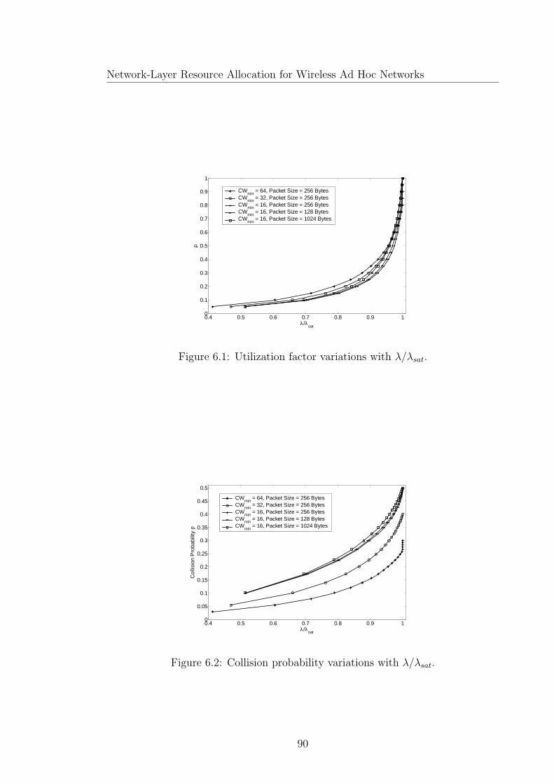
Network-Layer Resource Allocation for Wireless Ad Hoc Networks
0.4 0.5 0.6 0.7 0.8 0.9 10
0.1
0.2
0.3
0.4
0.5
0.6
0.7
0.8
0.9
1
λ/λsat
ρCW
min = 64, Packet Size = 256 Bytes
CWmin
= 32, Packet Size = 256 BytesCW
min = 16, Packet Size = 256 Bytes
CWmin
= 16, Packet Size = 128 BytesCW
min = 16, Packet Size = 1024 Bytes
Figure 6.1: Utilization factor variations with λ/λsat.
0.4 0.5 0.6 0.7 0.8 0.9 10
0.05
0.1
0.15
0.2
0.25
0.3
0.35
0.4
0.45
0.5
λ/λsat
Col
lisio
n P
roba
bilit
y p
CWmin
= 64, Packet Size = 256 BytesCW
min = 32, Packet Size = 256 Bytes
CWmin
= 16, Packet Size = 256 BytesCW
min = 16, Packet Size = 128 Bytes
CWmin
= 16, Packet Size = 1024 Bytes
Figure 6.2: Collision probability variations with λ/λsat.
90
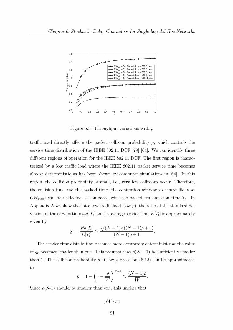
Chapter 6. Stochastic Delay Guarantees for Single hop Ad-Hoc Networks
0 0.1 0.2 0.3 0.4 0.5 0.6 0.7 0.8 0.9 10.2
0.4
0.6
0.8
1
1.2
1.4
1.6
ρ
Thr
ough
put (
Mbp
s)CW
min = 64, Packet Size = 256 Bytes
CWmin
= 32, Packet Size = 256 BytesCW
min = 16, Packet Size = 256 Bytes
CWmin
= 16, Packet Size = 128 BytesCW
min = 16, Packet Size = 1024 Bytes
Figure 6.3: Throughput variations with ρ.
traffic load directly affects the packet collision probability p, which controls the
service time distribution of the IEEE 802.11 DCF [79] [64]. We can identify three
different regions of operation for the IEEE 802.11 DCF. The first region is charac-
terized by a low traffic load where the IEEE 802.11 packet service time becomes
almost deterministic as has been shown by computer simulations in [64]. In this
region, the collision probability is small, i.e., very few collisions occur. Therefore,
the collision time and the backoff time (the contention window size most likely at
CWmin) can be neglected as compared with the packet transmission time Ts. In
Appendix A we show that at a low traffic load (low ρ), the ratio of the standard de-
viation of the service time std(Tt) to the average service time E[Tt] is approximately
given by
qr =std[Tt]
E[Tt]≈
√
(N − 1)ρ ((N − 1)ρ+ 3)
(N − 1)ρ+ 1.
The service time distribution becomes more accurately deterministic as the value
of qr becomes smaller than one. This requires that ρ(N − 1) be sufficiently smaller
than 1. The collision probability p at low ρ based on (6.12) can be approximated
to
p = 1 −
(
1 −ρ
W
)N−1
≈(N − 1)ρ
W.
Since ρ(N-1) should be smaller than one, this implies that
pW < 1
91
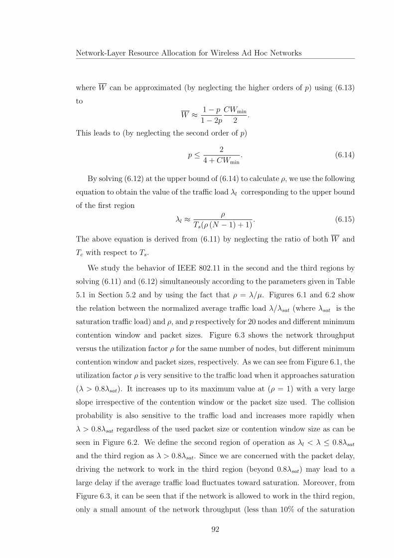
Network-Layer Resource Allocation for Wireless Ad Hoc Networks
where W can be approximated (by neglecting the higher orders of p) using (6.13)
to
W ≈1 − p
1 − 2p
CWmin
2.
This leads to (by neglecting the second order of p)
p ≤2
4 + CWmin
. (6.14)
By solving (6.12) at the upper bound of (6.14) to calculate ρ, we use the following
equation to obtain the value of the traffic load λl corresponding to the upper bound
of the first region
λl ≈ρ
Ts(ρ (N − 1) + 1). (6.15)
The above equation is derived from (6.11) by neglecting the ratio of both W and
Tc with respect to Ts.
We study the behavior of IEEE 802.11 in the second and the third regions by
solving (6.11) and (6.12) simultaneously according to the parameters given in Table
5.1 in Section 5.2 and by using the fact that ρ = λ/µ. Figures 6.1 and 6.2 show
the relation between the normalized average traffic load λ/λsat (where λsat is the
saturation traffic load) and ρ, and p respectively for 20 nodes and different minimum
contention window and packet sizes. Figure 6.3 shows the network throughput
versus the utilization factor ρ for the same number of nodes, but different minimum
contention window and packet sizes, respectively. As we can see from Figure 6.1, the
utilization factor ρ is very sensitive to the traffic load when it approaches saturation
(λ > 0.8λsat). It increases up to its maximum value at (ρ = 1) with a very large
slope irrespective of the contention window or the packet size used. The collision
probability is also sensitive to the traffic load and increases more rapidly when
λ > 0.8λsat regardless of the used packet size or contention window size as can be
seen in Figure 6.2. We define the second region of operation as λl < λ ≤ 0.8λsat
and the third region as λ > 0.8λsat. Since we are concerned with the packet delay,
driving the network to work in the third region (beyond 0.8λsat) may lead to a
large delay if the average traffic load fluctuates toward saturation. Moreover, from
Figure 6.3, it can be seen that if the network is allowed to work in the third region,
only a small amount of the network throughput (less than 10% of the saturation
92
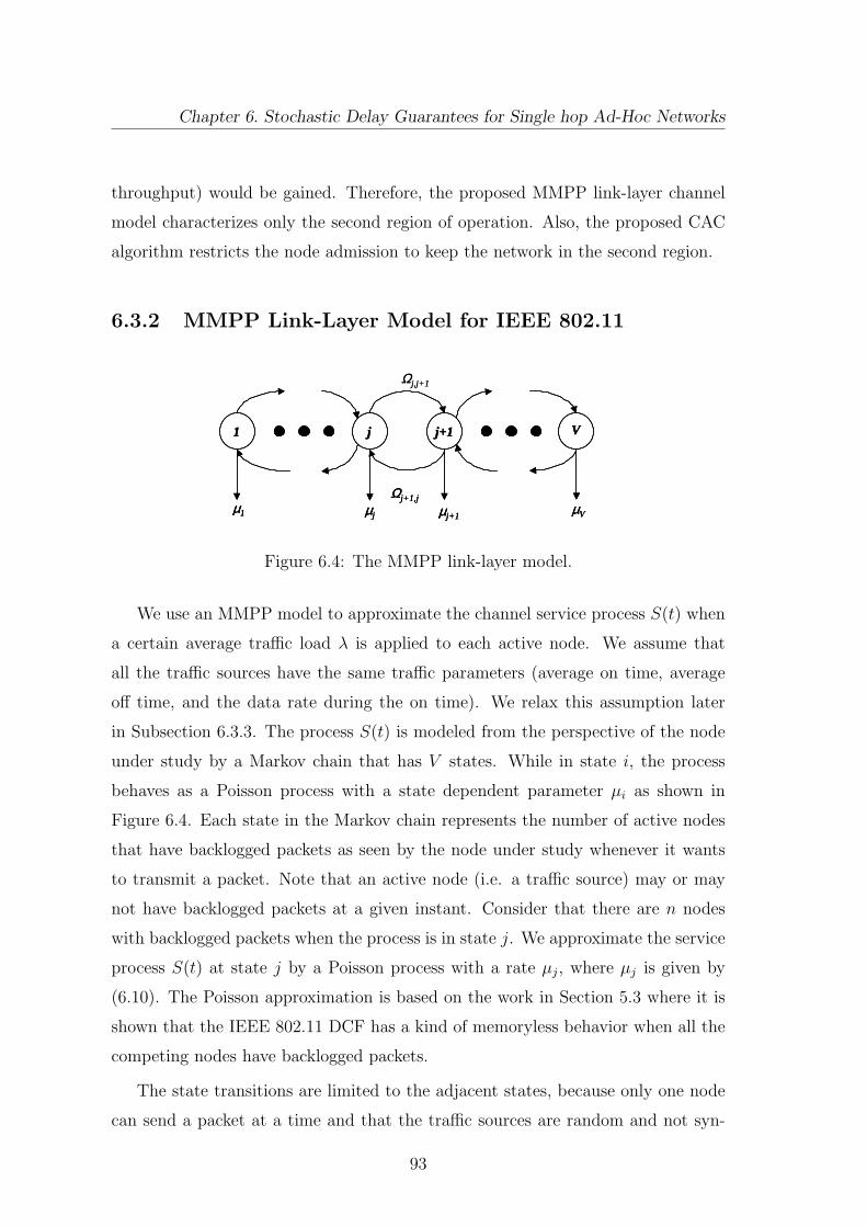
Chapter 6. Stochastic Delay Guarantees for Single hop Ad-Hoc Networks
throughput) would be gained. Therefore, the proposed MMPP link-layer channel
model characterizes only the second region of operation. Also, the proposed CAC
algorithm restricts the node admission to keep the network in the second region.
6.3.2 MMPP Link-Layer Model for IEEE 802.11
Ωj,j+1
1 j j+1 V
µj µj+1µ1 µV
Ωj+1,j
Ωj,j+1
1 j j+1 V
µj µj+1µ1 µV
Ωj+1,j
1 j j+1 V
µj µj+1µ1 µV
Ωj+1,j
Figure 6.4: The MMPP link-layer model.
We use an MMPP model to approximate the channel service process S(t) when
a certain average traffic load λ is applied to each active node. We assume that
all the traffic sources have the same traffic parameters (average on time, average
off time, and the data rate during the on time). We relax this assumption later
in Subsection 6.3.3. The process S(t) is modeled from the perspective of the node
under study by a Markov chain that has V states. While in state i, the process
behaves as a Poisson process with a state dependent parameter µi as shown in
Figure 6.4. Each state in the Markov chain represents the number of active nodes
that have backlogged packets as seen by the node under study whenever it wants
to transmit a packet. Note that an active node (i.e. a traffic source) may or may
not have backlogged packets at a given instant. Consider that there are n nodes
with backlogged packets when the process is in state j. We approximate the service
process S(t) at state j by a Poisson process with a rate µj, where µj is given by
(6.10). The Poisson approximation is based on the work in Section 5.3 where it is
shown that the IEEE 802.11 DCF has a kind of memoryless behavior when all the
competing nodes have backlogged packets.
The state transitions are limited to the adjacent states, because only one node
can send a packet at a time and that the traffic sources are random and not syn-
93

Network-Layer Resource Allocation for Wireless Ad Hoc Networks
chronized. To find the rates of transitions we approximate the busy period of the
queue of any active node by an exponential random variable. If state j + 1 and
state j represents m− 1 and m nodes having backlogged packets respectively, then
the rate of transition Ωj,j+1 from state j to state j + 1 can be calculated as the
reciprocal of the average busy period of the queue [105] multiplied by m as
Ωj,j+1 = m
(
µj(α+ β)
R− β
)
. (6.16)
The rate of transition Ωj+1,j from state j + 1 to j simply equals to (N −m) β
since both the on time and the off time of the traffic sources follow an exponential
distribution. The model captures the states when the node under consideration is
competing with two active nodes or more. We ignore the states when the node
under consideration is sending alone or competing just with one node (i.e. just
one node has backlogged packets) as these states will not last for a significant time
for the traffic loads in the considered region of operation. These leads to V equal
to N − 2. We found by the computer simulations that the state corresponds to
two nodes with backlogged packets becomes insignificant, when the value of the
traffic load is high enough (closer to 0.8λsat than to λl). The model accuracy is
affected by the number of nodes in the network since the assumption of constant and
independent collision probability of [70] becomes more reasonable as the number of
nodes increases.
From the MMPP model for S(t), the effective capacity of the IEEE 802.11 DCF
can be derived (using the results in [106] and [26]) as
ηc(x) =sp (Q+ (e−x − 1) Φ)
x(6.17)
where Q is the transition rate matrix , Φ = diag(µ1, µ2, . . . , µV ) , and sp(A) is
the spectral radius of matrix A.
6.3.3 The MMPP Model with Heterogeneous On-Off Sources
The MMPP link-layer model can be applied to the case of heterogeneous on-off
sources (sources with different traffic parameters) if we use homogeneous sources
with equivalent statistics to represent them approximately. We match the average,
94

Chapter 6. Stochastic Delay Guarantees for Single hop Ad-Hoc Networks
the variance, and the autocovariance of the heterogeneous sources with the homo-
geneous ones in order to obtain the traffic parameters of them in a way similar to
that in [14]. The autocovariance function of an on-off source is given by [14]
C(y) = R2u(1 − u)e−(β+α)y
where u is the probability that the source is in the on state and given by
u =β
β + α(6.18)
and 1/α is the average on time, 1/β is the average off time, and R is the constant
data rate during the on time period. In order to compute the parameters (α, β,
and R) of the equivalent homogeneous sources we solve the following equations
MuR =L∑
l=1
MlRlul (6.19)
MR2u(1 − u) =L∑
l=1
MlR2l ul(1 − ul) (6.20)
MR2u(1 − u)e−(β
u) =L∑
l=1
MlR2l ul(1 − ul)e
−(
βlul
)
(6.21)
M =L∑
l=1
Ml (6.22)
where L is the number of source groups with the same traffic parameters and Ml
is the number of sources per group and M is the number of equivalent sources.
By (6.18)-(6.22), we can obtain all the parameters for the equivalent homogeneous
sources. We use those parameters to compute the effective capacity as described in
Subsection 6.3.2.
6.3.4 The Distributed Model-based CAC Algorithm
Our distributed model-based CAC algorithm is based on the MMPP link-layer
channel model. We assume that: (i) The traffic source model parameters are known
at each active node; (ii) No active nodes leave the network during the execution of
the algorithm. The following are the steps of the algorithm:
95

Network-Layer Resource Allocation for Wireless Ad Hoc Networks
Start
- Get N- Calc. service rates (6.10)- Calc.. transition rates
- Calc. λl (6.15)Calc. µ (6.11)
R < µ ?
Solve (2.2) using (6.24) to obtain θb
Solve (2.9) by using (6.24) and (6.17) to calc. r, then using (2.8) obtain θs
Using (2.7) calc. Dact
λ > 0.8λsat?
Call Accepted
Call Rejected
Call Rejected
Yes
No
Yes No
Yes
No
Yes No
λ< λl?
Dmax≤ NDact?
StartStart
- Get N- Calc. service rates (6.10)- Calc.. transition rates
- Calc. λl (6.15)
- Get N- Calc. service rates (6.10)- Calc.. transition rates
- Calc. λl (6.15)Calc. µ (6.11)
R < µ ?R < µ ?
Solve (2.2) using (6.24) to obtain θb
Solve (2.9) by using (6.24) and (6.17) to calc. r, then using (2.8) obtain θs
Using (2.7) calc. Dact
λ > 0.8λsat?λ > 0.8λsat?
Call Accepted
Call RejectedCall Rejected
Call Rejected
Yes
No
Yes No
Yes
No
Yes No
λ< λl?
Dmax≤ NDact?
Figure 6.5: The distributed model-based CAC algorithm.
Step 1: A new node that wants to join the network exchanges information with
the network and knows the number of active nodes in the network and also the
traffic source parameters, following a procedure such as those given in [107] [108]. If
the sources have different parameters, the node calculates equivalent homogeneous
traffic source parameters using (6.18)-(6.22). The new node then calculates the
service rates and the transition rates of the Markov chain using (6.10) and (6.16).
Step 2: The new node calculates its average traffic rate (λ) using the following
equation
λ = Ru. (6.23)
If λ < λl, the node goes to Step 3; otherwise the node jumps to Step 4.
Step 3: The node calculates the service rate µ using (6.11)-(6.13). If R < µ,
the node can be admitted to the network; otherwise, the node solves (2.2) after
replacing c with µ to get the value of θb. The effective bandwidth for an on-off
source is given by [106]
ηb(x) =
(
R
2−β + α
2x
)
+
√
[
R
2−β + α
2x
]2
+βR
x. (6.24)
96

Chapter 6. Stochastic Delay Guarantees for Single hop Ad-Hoc Networks
The node then proceeds to Step 5.
Step 4: The node compares the value of λ and the value of λsat after its admis-
sion. If λ > 0.8λsat, the node does not admit itself in order to prevent the network
from being driven to the region of operation beyond 0.8λsat (the third region as in
Subsection 6.3.1). If λ ≤ 0.8λsat, the node solves (2.9) by using (6.24) and (6.17)
in order to calculate r. By applying the value of r in (2.8), the node obtains θs.
Step 5: Let Dact denote the delay that results in a violation probability less than
or equal to ǫ from the perspective of the node under study (if it uses the channel all
the time to send its packets). By replacing Dmax with Dact in (2.7) and using the
values of θ or θs obtained by Step 3 or Step 4 respectively, the delay bound Dact
can be calculated. If more than one service class is available, Dmax represents the
strictest delay bound among the different service classes. Since all the other nodes
equally share the same channel with the node under study, if Dmax ≥ NDact the
node can admit itself into the network, otherwise it cannot.
Figure 6.5 illustrates the fully distributed CAC procedure. Every node that
wants to join the network can do the calculations to know if it can admit itself
to the network or not with a minimal amount of information. This implies more
efficient usage of the scarce bandwidth of the wireless channel. Also, the algorithm
does not depend on any measurements or traffic monitoring, which is very essential
for battery-powered ad hoc network nodes.
6.4 Model Validation and Simulation Results
We verify the MMPP model and the effective capacity approach using the ns-2
simulator [72]. The simulation model simulates nodes moving in an unobstructed
plane following the random waypoint model [73] with a maximum speed of 1m/s.
In the simulation, a node chooses its speed and its destination randomly and then
moves to the destination. The simulation is done for a network having a variable
number of mobile nodes over an area of 250 × 250m2. The node radios have a
transmission range of 250m and a carrier-sense range of 550m. Only half of the
nodes are active traffic sources, the other half are only receivers. The network
97

Network-Layer Resource Allocation for Wireless Ad Hoc Networks
represents a single-hop ad hoc network, where every sender sends data packets to
one unique receiver.
6.4.1 Model Validation
0.55 0.6 0.65 0.7 0.75 0.80
0.01
0.02
0.03
0.04
0.05
0.06
0.07
0.08
0.09
0.1
λ/λsat
Vio
latio
n P
roba
bilit
y ∈
20 nodes (simulations)25 nodes (simulations)30 nodes (simulations)MMPP model
Figure 6.6: Violation probability variations with λ/λsat .
In order to validate our approach, we simulate on-off exponential traffic sources
with the same (α, β) parameters as those used in the MMPP model. We calculate
the delay bound for a violation probability ǫ of 0.05 for different number of nodes
and different traffic loads by using the procedure described in Subsection 6.3.4. This
delay bound is then used as an input to the ns2 simulator in order to measure the
actual violation probability at different traffic loads. Table 6.1 shows the calculated
delay bounds (using the IEEE 802.11 parameters given in Table 5.1) in seconds for
different traffic loads. Here, we validate the model only for λl < λ ≤ 0.8λsat (which
is the operating region characterized by the model). The results in Table 6.1 indi-
cate that, when the traffic load in the network increases, the delay bound required
to satisfy ǫ increases as less network resources become available for each active node
with increasing traffic load. Figure 6.6 shows the measured violation probability
compared with the 5% value obtianed by calculating the effective capacity using
the MMPP model for 20, 25 and 30 nodes respectively. The figure shows that using
the MMPP model to calculate the effective capacity is generally conservative. As
the traffic increases towards 0.8 λsat, the model becomes more accurate. When the
98

Chapter 6. Stochastic Delay Guarantees for Single hop Ad-Hoc Networks
traffic load increases to more than 0.8λsat, the model becomes slightly optimistic
since in this region the queue utilization is very sensitive to the variation of the
traffic load.
0.22 0.24 0.26 0.28 0.3 0.32 0.34 0.3615
20
25
30
35
40
45
Traffic Load R (Mbps)
Num
ber
of a
dmitt
ed n
odes
CAC based on MMPP modelCAC based on average delay
Figure 6.7: Number of admitted nodes at different traffic loads for MMPP model
and average delay based CAC.
6.4.2 Average-Delay-based CAC and the Proposed Model-
based CAC
Figures 6.7 and 6.8 compare the CAC based on average delay guarantees and the
CAC based on the effective capacity approach and the MMPP link-layer model
which provide stochastic delay guarantees for the same delay bound Dmax. Figure
6.7 shows the relation between the number of admitted nodes based on the average
delay, the number of admitted nodes based on our proposed approach and the
traffic load is represented by the peak rate of the traffic source R. The figure shows
that we can admit more nodes based on the average delay criterion. However, this
comes with the expense of having a much higher violation probability ǫ as shown
in Figure 6.8. In fact, this result is aligned with that in [14] which illustrates
how the effective bandwidth can be used to provide stochastic QoS guarantees for
a number of traffic sources sharing the buffer of an FIFO statistical multiplexer
served by a fixed capacity server. It has been shown in [14] that the CAC based
99

Network-Layer Resource Allocation for Wireless Ad Hoc Networks
0.22 0.24 0.26 0.28 0.3 0.32 0.34 0.360
0.05
0.1
0.15
0.2
0.25
0.3
0.35
Traffic Load R (Mbps)
Vio
latio
n P
roba
bilit
y ∈
CAC based on MMPP ModelCAC based on average delay
Figure 6.8: Violation probability at different traffic loads for MMPP model and
average delay based CAC.
on the average source rate results in a larger number of traffic sources that can be
admitted into the multiplexer buffer to achieve certain stochastic QoS guarantee.
The number of sources that can be admitted decreases if the CAC is based on the
effective bandwidth concept [14] and decreases even more if the CAC is based on
the peak rate of the sources where a strict deterministic QoS guarantee is provided
(i.e. transmission of every packet should satisfy the delay bound). The similarity
between the results shown in Figures 6.7 and 6.8 and those given in [14] illustrates
that the effective capacity approach using the MMPP model is effective. The IEEE
802.11 DCF operates in a way similar to a statistical multiplexer in the sense that
the shared channel multiplexes statistically the traffic from different sources but on
a distributed manner.
Figures 6.7 and 6.8 also show that the CAC based on the first order statistic
(average total delay) is not effective for real time applications, as it provides no
control on the violation probability. Actually, the IEEE 802.11 server capacity
variations should be taken into consideration as its service time distribution does
not have a negligible variance. The MMPP model captures the service variations
and makes the CAC decision based on the stochastic delay bound requirement. It
does not require the variance of the service time distribution of the non-saturated
IEEE 802.11 DCF, which is quite complicated to obtain as we indicate in Subsection
100
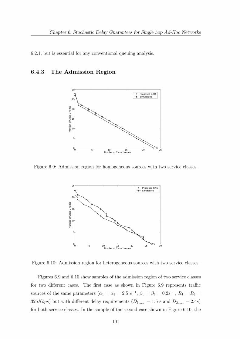
Chapter 6. Stochastic Delay Guarantees for Single hop Ad-Hoc Networks
6.2.1, but is essential for any conventional queuing analysis.
6.4.3 The Admission Region
0 5 10 15 20 250
5
10
15
20
25
30
Number of Class 1 nodes
Num
ber
of C
lass
2 n
odes
Proposed CACSimulations
Figure 6.9: Admission region for homogeneous sources with two service classes.
0 5 10 15 20 25 300
5
10
15
20
25
Number of Class 1 nodes
Num
ber
of C
lass
2 n
odes
Proposed CACSimulations
Figure 6.10: Admission region for heterogeneous sources with two service classes.
Figures 6.9 and 6.10 show samples of the admission region of two service classes
for two different cases. The first case as shown in Figure 6.9 represents traffic
sources of the same parameters (α1 = α2 = 2.5 s−1, β1 = β2 = 0.2s−1, R1 = R2 =
325Kbps) but with different delay requirements (D1max= 1.5 s and D2max
= 2.4s)
for both service classes. In the sample of the second case shown in Figure 6.10, the
101

Net
wor
k-L
ayer
Res
ourc
eA
lloca
tion
for
Wir
eles
sA
dH
oc
Net
wor
ks
Table 6.1: Variation of calculated delay bound with normalized traffic load (λ/λsat)
.
λ/λsat (20 nodes) Delay Bound (s) λ/λsat (25 nodes) Delay Bound (s) λ/λsat (30 nodes) Delay Bound (s)
0.56 1.45 0.62 1.34 0.68 1.25
0.60 1.67 0.69 1.60 0.72 1.37
0.69 2.10 0.73 2.46 0.75 2.17
0.77 3.17 0.79 2.70 0.78 2.28
102

Chapter 6. Stochastic Delay Guarantees for Single hop Ad-Hoc Networks
parameters of the traffic sources are α1 = α2 = 2.5s−1, β1 = β2 = 0.2 s−1, R1 =
325 Kbps, and R2 = 380 Kbps. The delay requirement for class 1 is D1max= 2.4s
and for class 2 is D2max= 2.7s. The CAC in Figure 6.10 is done by finding the
equivalent homogeneous sources for both service classes and then applying the CAC
procedure as described in Subsection 6.3.4. As we can see from Figure 6.9, when
the traffic sources have the same parameters, the IEEE 802.11 server deals with all
of them in a similar way and hence the CAC procedure admits only the number
of sources that satisfy the service class with the strictest delay criterion (class 1).
When no class 1 nodes are available, the IEEE 802.11 can serve more of class 2
nodes. This is a typical behavior when homogeneous traffic sources are multiplexed
in an FIFO buffer [109]. Figure 6.9 also shows that our proposed CAC approach is in
a good match with the simulation results. Figure 6.10 shows a comparison between
the admission regions obtained by our proposed CAC approach and by computer
simulations. The proposed CAC admits the number of equivalent sources that
satisfy the strictest delay bound among the two classes. The figures shows that
the proposed CAC algorithm based on equivalent source parameters is also in a
good agreement with the simulation results. The figure is also similar to the FIFO
admission region shown in [14].
6.5 Summary
In this chapter, we propose a new approach to achieve stochastic delay guarantees to
IEEE 802.11 single hop ad hoc networks. Our approach tackles the CAC problem in
IEEE 802.11 DCF in a way that resembles the classical one of finding the number of
traffic sources that can be admitted in an FIFO statistical multiplexer. We present
an MMPP link-layer channel model for IEEE 802.11 DCF. The model aims at
characterizing the random service process variations in order to provide an effective
capacity for the IEEE 802.11 DCF channel. The effective capacity model is the dual
of the effective bandwidth theory. It can be used to allocate network resources in
order to provide stochastic QoS guarantees for multimedia traffic sources served by
a channel of time varying capacity. We also illustrate that the IEEE 802.11 behaves
differently according to the traffic load in the network. Based on this illustration
103

Network-Layer Resource Allocation for Wireless Ad Hoc Networks
and by using the effective capacity model, we propose a distributed statistical CAC
algorithm for IEEE 802.11 single-hop ad hoc networks. We validate the model and
the algorithm by computer simulations. It is shown that the our model can be used
effectively in allocating network resources and providing a stochastic guarantee for
the delay bound.
104
Chapter 7
Statistical QoS Routing Scheme
for Mulithop Ad hoc Networks
In multihop wireline networks, each link is physically isolated from other links
including those links connected to the same node. In order to guarantee QoS,
resource allocation in multihop wireline networks involves finding a path from the
source to the destination, over which all the links have sufficient available resources,
by letting each node announce the remaining resources of its links periodically in
the network. However, the situation in a multihop wireless ad-hoc network is more
complicated. For instance, in shared channel MAC protocols, all the links share
the same channel and the traffic flows carried by neighbor links affect whether or
not a new flow can join the network.
We consider the end-to-end delay as a QoS measure in this chapter. In literature,
three approaches to guarantee the end-to-end delay for multihop wireline networks
are identified [14]. In the first approach the allocated network resources provide
deterministic worst case delay guarantee, which implies that every packet should
arrive to its destination before the delay bound. This leads to inefficient network
resource utilization. The second approach provides average delay guarantees, which
leads to high network resource utilization but at the expense of the number of
packets whose delay bound is violated. The third approach provides stochastic
delay guarantee, such as Pr(D > Dmax) ≤ ǫ (where D represents the total packet
delay, Dmax is the delay bound, and ǫ is the delay violation probability upper
105

Network-Layer Resource Allocation for Wireless Ad Hoc Networks
bound). In fact, the second approach is suitable when first-order statistics are
sufficient to describe both the arrival process of the traffic sources and the service
process of the channel or when the multimedia application is not sensitive to packet
delay variations.
In this research, we follow the third approach to guarantee the end-to-end delay,
as we consider delay-sensitive bursty traffic sources where the peak-to-average rate
ratio is not close to one. Moreover, we consider multihop connections over a shared
wireless channel with IEEE 802.11 DCF as the access control mechanism, which has
been shown in Chapter 5 to have a very complicated packet service time distribution
with a non-negligible variance.
In this chapter, we present a model-based QoS routing scheme for IEEE 802.11
DCF multihop ad hoc wireless networks loaded with statistical traffic. The discov-
ered route is tested for admission using a fully distributed and model-based resource
allocation process, which checks if the discovered route can satisfy the required de-
lay bound of the new flow probabilistically without affecting other network flows
already in service. Following novel cross-layer design, the resource allocation pro-
cess takes into account the interaction of the IEEE 802.11 DCF and the dynamics
of its service process by using both traffic and link-layer channel models. We extend
the well developed effective bandwidth theory and effective capacity concept [27]
to IEEE 802.11-based ad hoc networks in order to provide stochastic end-to-end
delay guarantees to multihop connections.
The rest of the chapter is organized as follows. Section 7.1 gives an overview
of the most relevant research works. The system model is introduced in Section
7.2. Section 7.3 discusses cross-layer design aspects of QoS routing over the IEEE
802.11 DCF. Section 7.4 presents the proposed QoS routing scheme. Section 7.5
provides the simulation results for the QoS routing scheme validation and perfor-
mance evaluation. Section 7.6 summerizes this chapter.
7.1 Related Works
Several QoS routing protocols have been introduced in literature. In wireless ad hoc
networks context, MAC layer affects the way that the QoS routing protocol selects
106

Chapter 7. Statistical QoS Routing Scheme for Mulithop Ad hoc Networks
a QoS-enabled path. Here, we address IEEE 802.11 DCF as it is fully distributed in
terms of network control and data communication, which conforms with the nature
of ad hoc networks. Some QoS routing research based on other MAC protocols such
as TDMA MAC is introduced in literature [67]-[68]. Mobile nodes in a TDMA-
based ad hoc network are difficult to be synchronized in time without a centralized
controller, which has to be within a range of all the nodes in the network. QoS
routing protocols that are based on multi-channel MAC protocols (e.g. [42]) are
not suitable for an ad hoc networking environment as assigning different spreading
codes or carriers to different mobile nodes in a distributed fashion is one of the
most prominent problems of those protocols [43].
Recently, several IEEE 802.11-based QoS routing protocols have been pro-
posed. They can be classified into measurement-based and model-based schemes.
Measurement-based schemes such as [44] [62] [98] [110] may involve channel mon-
itoring and probing for available resources, which consumes the energy of the
battery-powered devices and the scarce radio bandwidth. The QoS routing schemes
proposed in [69] [111] provide average delay guarantees without taking into account
the effects of statistical traffic and the variation of the service time of IEEE 802.11
DCF under different traffic loads. In [112], a traffic-aware routing scheme for real-
time traffic is introduced. The scheme provides link and path transmission time
model-based prediction in order to control the average end-to-end delay without
any call admission control or resource reservation techniques. Jacquet et al. [113]
propose a routing scheme to provide a stochastic end-to-end delay guarantee for
IEEE 802.11 ad hoc networks. The scheme is model-assisted measurement based
as it measures both the collision probability and the average channel occupancy. It
does not support any call admission control or resource reservation for QoS provi-
sioning.
In comparison, the novelty of this research lies in two aspects: (i) The proposed
scheme, via cross-layer design, selects the routes satisfying the end-to-end delay
bound probabilistically based on a statistical resource allocation process without
consuming the limited processing power of the ad hoc network nodes or the channel
bandwidth in frequent measurements or traffic monitoring; (ii) The statistical mul-
tiplexing capability of the IEEE 802.11 DCF as shown in Chapter 6 is exploited by
107

Network-Layer Resource Allocation for Wireless Ad Hoc Networks
applying the effective bandwidth theory and its dual the effective capacity concept
to multihop connections in order to achieve an efficient utilization of the shared
radio channel while satisfying the end-to-end delay bound.
7.2 System Model
Consider an ad hoc network with a single and error-free physical channel. The net-
work nodes may be active nodes (traffic sources) and/or packet forwarders (routers),
or just receivers (sinks). All network nodes are moving with limited mobility. Con-
sider the network in a non-saturated condition [70]. All the traffic sources are iid
exponential on-off traffic sources (i.e., the on and off times are independent expo-
nential random variables). It has been shown in [14] that the on-off sources can
be used successfully to model different multimedia traffic types. For each node, i,
that has a traffic source, the traffic parameters are the average on time 1/αi, the
average off time 1/βi, and a constant data rate Ri during an on time period. The
QoS requirement is captured by Dimaxand ∈.
The MAC protocol is the IEEE 802.11 DCF. We follow the CSMA/CA protocol
as described in Sections 3.1.3 and 6.2. We assume that the carrier sense range is
adjusted properly to completely eliminate the hidden terminal problem as in [114].
The network layer protocol used for route discovery and maintenance is the GPSR
protocol.
7.3 Cross-layer Design for QoS Routing
In this section, we discuss three different cross-layer design aspects, which are re-
lated to the characteristics of multihop IEEE 802.11 DCF connections and strongly
affect the design of our model-based QoS routing scheme. First, we address the
complexity of the QoS routing problem and our heuristic approach to solve it. Sec-
ond, we obtain a general formula for the capacity process of a multihop connection
on a shared wireless channel, calculate the effective capacity of that connection,
and estimate the capacity variation of an IEEE 802.11 DCF multihop connection.
108
Chapter 7. Statistical QoS Routing Scheme for Mulithop Ad hoc Networks
Third, we discuss how the IEEE 802.11 contention-based access affects the network
resource allocation.
7.3.1 The QoS Routing Problem
We address the QoS routing problem of finding a path that satisfies a stochastic
end-to-end delay guarantee, i.e.,
Pr
(
n∑
i=1
di > Dmax
)
≤ ǫ (7.1)
where di is the packet delay for link i, and n is the number of hops in the route.
This problem has been shown to be an NP-hard problem even if there is a
network topology database available to keep state information of nodes and links
in the network [65]. Hence, a heuristic approach is required in order to obtain a
solution in a reasonable time and with a minimal amount of signaling, as there is
no centralized entity that can hold state information in an ad hoc network.
Under the assumption of random traffic pattern (i.e., each source node initiates
packets to a randomly chosen destination), it has been indicated in [71] that the
geographical routing helps to find routes that are close in distance to straight line
paths between traffic sources and their corresponding destinations and hence it
approaches the upper bound on per node capacity for an IEEE 802.11 DCF ad
hoc network. High per node capacity translates directly to less delay per hop. In
fact, hop count should be taken into account in order to reduce the inefficient use
of bandwidth due to shared channel interference and packet collisions. Actually, a
small number of hops indicates that a small number of nodes compete for the shared
channel, which in turn reduces the packet collision probability. As a result, short
routes represent good candidates to be tested for network admission in order to
achieve the end-to-end delay bound, as they minimize the overall network resources
used for the transmission of a packet from its source to its destination. However,
routes with an increasing hop count should be tested whenever short routes pass a
congested area of the network.
Our heuristic approach takes into consideration the IEEE 802.11 characteristics,
while taking the hop count into account by using the GPSR protocol to discover
109

Network-Layer Resource Allocation for Wireless Ad Hoc Networks
short routes in terms of distance. A resource allocation procedure is applied after
the route discovery in order to check if there are sufficient network resources avail-
able for the new call request. If the admission fails, another route will be selected
subsequently using the GPSR protocol after forcing it to choose a longer route and
then the resource allocation procedure repeats.
7.3.2 Capacity Prediction for a Multihop Connection
One design objective of our QoS routing protocol is to guarantee that the admission
of a new call will not affect the QoS guarantee of calls already in service. Due to
the random nature of traffic flows, a stochastic estimation of the capacity process
of the multihop connection is required, in order to guarantee sufficient network
resources for the whole call duration. Actually, a stochastic model for the capacity
variations of any route strongly depends on the behavior of the service process of
the MAC protocol. This implies a difficulty in designing a QoS routing protocol as
an independent network layer, and hence cross-layer design is mandatory.
Consider a multihop connection that consists of a source, a sink, and K interme-
diate links. The service provided by this multihop connection over a time interval
[0, t] is given by [27]
S(0, t) = inf0=t0≤t1≤...≤tK−1≤tK=t
K∑
k=1
Sk(tk−1, tk)
(7.2)
where Sk(tk−1, tk), k = 1,2, . . . , K, is the service process of link k over a time
interval [tk−1, tk]. Directly from (7.2), we can infer that [27]
S(0, t) ≤ minkSk(0, t), k = 1, 2, . . . , K. (7.3)
The IEEE 802.11 DCF is used as an access mechanism for the multihop connec-
tion over a shared wireless channel, where all the K links are in the same carrier
sense range and hence only one of them can transmit at a time. The IEEE 802.11
DCF has been shown to have a short and a long term fairness properties [90].
Therefore, without loss of generality, we consider every link will seize a chance to
transmit only at some time interval (tk−1, tk) out of the whole interval (0, t), where
110
Chapter 7. Statistical QoS Routing Scheme for Mulithop Ad hoc Networks
0≤ t1≤. . .≤tK−1≤tK=t. The service process of the end-to-end connection S(0, t)
in an IEEE 802.11 DCF channel can be obtained from (7.3) as
SDCF (0, t) = minkSk(tk−1, tk), k = 1, 2, . . . , K (7.4)
since any link k has the chance to transmit only during the time interval (tk−1, tk).
It is worth noting that, although all the K links can hear each other, each link k
has a unique service process since it contends for the channel with a unique set of
neighbors.
According to [27], the effective capacity for a multihop connection ηmc(x) is
given by
ηcm(x) = minkηck(x) (7.5)
where ηck(x) is the effective capacity of link k. In fact, (7.5) is also applicable
when there are two portions of the multihop connection, which can simultaneously
transmit (out of the CS range of each other). The traffic flow in this case is
approximated as a continuous fluid flow for which the available capacity is controlled
by the bottleneck link.
As an example, consider the K links in a multihop connection that use the same
IEEE 802.11 DCF channel with rate c. If we assume a deterministic service process
ct for each hop, which is the case of a low traffic load as shown in Section 6.3, then
by using (7.4), taking the MAC fairness into consideration, we can approximate the
service of the IEEE 802.11 DCF end-to-end connection by
SDCF (0, t) = c(tk − tk−1) =ct
K. (7.6)
By using (7.5) and (2.4), we can obtain the effective capacity of the multihop
connection for the DCF as c/K, while it is equal to c for the single hop case. This
is consistent with what is illustrated in [71].
In Section 6.3, we have shown that the service process of the IEEE 802.11 DCF
channel has a different behavior dependent on the traffic load in the network, and
defined different regions of operation based on the traffic load. In the first region
111

Network-Layer Resource Allocation for Wireless Ad Hoc Networks
with a low traffic load (up to 50% of the saturation traffic load), the collision proba-
bility is low (less than or equal to 0.1), and the service process can be approximated
by a deterministic process. In the second region where the traffic load is higher (up
to 80% of the saturation load), the service process of the IEEE 802.11 DCF channel
fed by on-off traffic sources can be approximated by an MMPP. Both the first and
second regions of operation are characterized by a low utlization factor (around
0.2), as when the traffic load approaches saturation, the increase of the utlization
factor with traffic load becomes very steep (as the service rate decreases rapidly)
and hence the packet delay becomes very sensitive to traffic load variaton. From
Section 6.3 and Figure 6.3, we can infer that by increasing the utilization factor up
to one, a less than 10% increase of network throughput can be achieved.
The effective capacity of an IEEE 802.11 DCF multihop connection can be
obtained based on (7.5). The effective capacity for an IEEE 802.11 DCF link
(single-hop connection) is given by the average service rate in the first operation
region and in the second operation region by (6.17).
The resource allocation procedure embedded in our QoS routing protocol en-
sures that when the effective bandwidth of an on-off traffic source feeding a multihop
wireless connection is equal to the effective capacity of this connection, the end-to-
end packet delay exceeds the required delay bound with a violation probability of at
most ǫ. The proposed resource allocation procedure solves (2.9) (using (6.24) and
the operation region-dependent effective capacity) at every hop, calculates the ac-
tual delay bound, and finally compares it with the required delay bound. If the hop
with minimum effective capacity does not achieve the delay bound, the multihop
connection will not achieve it according to (7.5).
7.3.3 Awareness of Available Network Resources
The spatial frequency reuse in an IEEE 802.11 DCF-based network allows multiple
simultaneous transmissions over the single radio channel in the network since, for
any node, the physical channel covers only the area of the node’s carrier sense (CS)
range. Nevertheless, the spatial reuse complicates the resource allocation process
for IEEE 802.11 DCF ad hoc networks. Every node may contend for the physical
112

Chapter 7. Statistical QoS Routing Scheme for Mulithop Ad hoc Networks
A
B E
Node A CS Range
Node B CS Range
Figure 7.1: Network topology for illustrating spatial reuse and interference aware-
ness.
channel on a different coverage area associated with a different set of neighbors.
The transmission is completely prohibited when the channel is sensed busy even if
it does not cause any intolerable interference. Therefore, a cross-layer design for any
network-layer resource allocation process that works over the IEEE 802.11 MAC
protocol is mandatory, in order to take into consideration its special characteristics.
According to (7.5), the available effective capacity of a multihop connection is
determined by the minimum effective capacity among its hops. Due to the spatial
reuse and the shared nature of the IEEE 802.11 DCF channel, the effective capacity
of any hop in a multihop connection is the minimum effective capacity among the
CS neighbors of that hop. For example, in Figure 7.1 where nodes A and E are
not in the CS range of each other, node A cannot join the network if it requires an
effective capacity of 3R/4 given that B and E have already running flows with an
effective capacity of R/4 each. If node A relies only on its own effective capacity
calculation, it would admit itself into the network, depleting the network resources
from node B.
113

Network-Layer Resource Allocation for Wireless Ad Hoc Networks
EA
B
C D
Figure 7.2: Network topology for illustrating the route discovery procedure.
7.4 Statistical QoS Routing Scheme
The proposed statistical QoS routing scheme contains a route discovery and main-
tenance procedure and a resource allocation procedure (for admission control and
resource reservation). The two procedures are described in the following subsec-
tions.
7.4.1 Route Discovery and Maintenance
The procedure consists of two phases. The first phase is the discovery part, which is
responsible for discovering possible routes to be tested for admission by the resource
allocation process. The second phase is the route maintenance, which is invoked
either during the resource allocation process or when the route is broken. Consider
the route as shown in Figure 7.2, where the nodes are labeled by A, B, . . . , E from
the source to the destination. The procedure works as follows.
Step 1: The GPSR protocol provides every node with a neighbor list, including
the neighbor position and ID, via a simple beaconing procedure [38]. The source
node A starts to discover a route by sending a “Route Request” (RR) message
to the geographically closest neighbor with respect to the packet destination [38]
as shown in Figure 7.2. The message includes the approximate position (the xy-
coordinates) of the destination and the following traffic flow information: the total
delay bound, the flow ID, the node ID, and the traffic tuple (α, β, R). Node A
also stores the ID of the discovered node to be used later in forwarding the data
packets. After that, node A starts a call setup timer.
Step 2: The node records necessary information of the traffic flow in a table,
114

Chapter 7. Statistical QoS Routing Scheme for Mulithop Ad hoc Networks
referred to as Flow Table, and appends its ID to the RR packet. The node then
starts discovering another intermediate node as node A does in Step 1 and forwards
the RR message to it, and so on, till the destination is reached.
Step 3: Every node that receives the RR message records the ID of the node
that it forwards the packets to (referred to as “next hop”) and the ID of the node
that it receives the packets from (referred to as “previous hop”). In fact, the GPSR
protocol discovers the route on a packet-by-packet basis, which is not suitable for
QoS provisioning. As a result, the proposed scheme discovers the route only once
by the GPSR protocol, and then uses the “next hop” and the “previous hop” in-
formation in forwarding data and signaling packets. This implies that a kind of
virtual circuit is established between the source and the destination, which facili-
tates resource allocation.
The route is considered broken at some point, if it cannot admit the traffic flow
or is no longer able to forward the packets of an admitted flow (i.e., the maximum
retransmission limit of the MAC protocol is reached) at that point. The route
repair part acts differently based on the status of the traffic flow as follows.
• If there is no sufficient resources at any intermediate hop (e.g., node B or
node C in Figure 7.2) during the resource allocation procedure, node C for
instance initiates the discovery of a new route by excluding the current “next
hop” node from its neighbor list and applying again the three steps mentioned
precedingly. When the destination receives an RR packet again for a flow, it
implies that the route is broken and so the destination initiates a new resource
allocation procedure for that flow.
• If the flow is already admitted and the route breaks at any intermediate hop
other than the first hop, the node at the route breakage point starts to repair
the route following the three steps mentioned precedingly, but by sending a
“Route Repair” (RP) message instead of an RR message. When the desti-
nation receives the RP message, it starts the resource allocation procedure
only for the repaired section of the route in order to reduce the amount of
signaling used and to shorten the route breakage time. The destination also
115

Network-Layer Resource Allocation for Wireless Ad Hoc Networks
starts a route repair timer.
If the route breaks at the first hop (at node A) for any reason, the source node
initiates a new route discovery process.
7.4.2 Resource Allocation
The procedure consists of a fully distributed statistical CAC procedure and a re-
source reservation procedure. The resource reservation proceeds side by side with
the CAC procedure in order to resolve the competition among flows that want to
join the network simultaneously. Note that the resource reservation for any node
is temporary, it lasts until the node cancels it.
We assume that every node acting as a packet forwarder (whether or not it
has a local traffic source) is able to measure the statistics of the packet arrival
process such as average number of packet arrivals per unit time, the variance,
and the autocovariance (the covariance between the arrival process and a unit
time-shifted version of it). As these measurements do not require any channel
monitoring, the receiver is not kept on all the time, saving the energy for the battery-
powered devices. The packet arrivals at a packet forwarder are characterized by an
exponential on-off traffic model. The validity of this approximation is discussed in
Appendix B. Using these measurements and the approximation, node i is able to
obtain the traffic tuple (αi, βi, Ri) based on the following set of equations
ui =βi
βi + αi
(7.7)
Ravg = Riui (7.8)
Rσ = R2iui(1 − ui) (7.9)
Rcov = R2iui(1 − ui)e
−(
βiui
)
(7.10)
where Ravg, Rσ and Rcov are the measured time average, variance and autocovari-
ance of the packet arrival process for node i. It is worth noting that the node stores
traffic tuples (its tuple and the tuples of its CS neighbors) in a table (referred to as
“CS Information Table“) only for a certain amount of time (based on how fast the
116

Chapter 7. Statistical QoS Routing Scheme for Mulithop Ad hoc Networks
network topology changes) and available to be used for other admission inquiries,
hence keeping a minimal amount of signaling exchanges.
The call admission control and the resource reservation procedure is presented
in the following:
Step 1: After the destination (node E in Figure 7.2) receives the RR message, it
records the source route and sends an “Admission Request” message to its
neighbor in the route (node D in Figure 7.2).
Step 2: Node D broadcasts a “Reservation Request” message to its CS neighbors us-
ing one of the methods indicated in [62] or by using a lower data rate so that
its transmission can reach a longer distance than the original transmission
range. The message contains the flow ID and source node traffic tuple. The
nodes in the CS range of node D that do not have a valid “CS Information
Table” obtain the traffic tuples of the nodes in their CS ranges by sending
“Information Request” messages and receiving “Information Response” mes-
sages from those nodes.
Step 3: By using the “CS Information Table”, the traffic tuples for the reserved flows,
and the traffic tuple of the new flow, each CS neighbor of node D runs the
CAC algorithm introduced in Section 6.3.4, which can be briefly summarized
in the following.
• Check operation region: Each neighbor determines whether the service
process in its CS range can be approximated by a deterministic process
(the first region) or by an MMPP (the second region) by calculating the
average traffic rate (λ) using
λ =Rβ
α+ β(7.11)
and then checking the operating region of its channel. If the average
rate is close to the saturation (around 80% or higher of the saturation
traffic load), the node declines the reservation request.
• Check admission: Each neighbor checks the admission by solving (2.9),
to get the unique solution r and then applies r in (2.8) to get θ. By
117

Network-Layer Resource Allocation for Wireless Ad Hoc Networks
replacing Dmax with Dact in (2.7) and using the value of θ, the delay
bound Dact that can achieve a violation probability of at most ǫ can be
calculated. If the local or relayed traffic flows of the neighbor have more
than one service class, Dmax represents the strictest delay bound among
the different service classes. As the channel of the neighbor is equally
shared among N other active nodes, if Dmax ≥ NDact, then the flow can
be admitted into the network, otherwise it cannot.
Note that in the first operation region, if the average service rate is higher
than the constant rate of the traffic flow (at the on time), the flow can be
admitted to the network.
Step 4: Each CS neighbor of node D replies to the “Reservation Request” message
based on the outcome of the CAC algorithm either by a “Reservation Ac-
cept” or an “Admission Decline” message. If the reservation is accepted, the
neighbor stores the traffic tuple of the new flow in another table called “Flow
Reservation Table” with the flow ID, the hop index and the ID of node that
reserved the resources of the flow. The information in the “Flow Reserva-
tion Table” is stored temporarily for some time to prevent reserving the same
network resources for more than one flow. The reservation information also
allows the resource allocation procedure to take the self interference from the
hops of the same traffic flow into consideration. The neighbor also includes
its own traffic tuple in the “Reservation Accept” message. If the reservation
is rejected, the neighbor sends an “Admission Decline” message to node D.
Step 5: Node D proceeds according to the outcome of Step 4. If node D receives
any “Admission Decline” message, it will go directly to Step 6. If node D
receives only “Reservation Accept” messages, it will use the traffic tuples of
its CS neighbors included in the received messages and the traffic tuples of
the previously reserved flows in order to apply the CAC introduced in Section
6.3.4. This lets node D check if the the admission of the new flow will affect
the flows originated or forwarded by it. Based on the CAC result, node D
accepts or rejects the flow admission.
118
Chapter 7. Statistical QoS Routing Scheme for Mulithop Ad hoc Networks
Step 6: In the case thatD rejects the flow or receives an “Admission Decline” message
from any of its CS neighbors, it notifies node C by sending an “Admission
Decline” message, then node C invokes the route discovery and maintenance
procedure. On the other hand, if node D accepts the flow, it stores the flow
information in its own “Flow Reservation Table”. After that, it forwards the
“Admission Request” message to node C (Figure 7.2), and node C in turn
starts the same procedure from Step 2.
Step 7: The procedure is repeated until the source node is reached and the flow is
admitted. If any of the setup timer or repair timer expires, the source node
or the destination node, respectively, sends an “Admission Stop” message to
all the nodes in the route in order to remove all the flow-related information
from the “Flow Table” and the “Flow Reservation Table” and to stop any
running activity associated with it.
Note that we assume that the topology does not change dramatically during the
resource allocation procedure. Indeed, high user mobility represents a limitation to
our scheme as it is difficult to estimate the available resources in an infrastructure-
less network where the topology changes fast and there is no centralized entity to
keep track of the locations of available resources.
7.5 Simulation Results
The performance of the proposed statistical QoS routing protocol is evaluated using
the ns-2 simulator. Mobile nodes move in an unobstructed plane [38] following the
random waypoint model [73]. In the model, a node chooses its speed and destination
randomly, moves to the destination, then pauses for a certain pause time, and so
on. A longer pause time means a lower mobility profile. The simulation is done
for a network having 50 mobile nodes, which move over an area of 670 × 670m2
with a certain speed. The node radios have a transmission range of 250m and
a carrier-sense range of 550m. Table 5.1 gives the system parameter values used
in the analysis and simulations. We run the simulation for 15 minutes of system
time. Traffic flows start at random times and continue for a session time uniformly
119
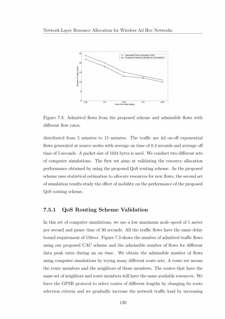
Network-Layer Resource Allocation for Wireless Ad Hoc Networks
0.35 0.4 0.45 0.5 0.550
5
10
15
20
25
Peak Flow Rate (Mbps)
Num
ber
of T
raffi
c F
low
s
Admissible Flows (Simulation Only)Proposed Scheme (Calculations & Simulation)
Figure 7.3: Admitted flows from the proposed scheme and admissible flows with
different flow rates.
distributed from 5 minutes to 15 minutes. The traffic are iid on-off exponential
flows generated at source nodes with average on time of 0.4 seconds and average off
time of 5 seconds. A packet size of 1024 bytes is used. We conduct two different sets
of computer simulations. The first set aims at validating the resource allocation
performance obtained by using the proposed QoS routing scheme. As the proposed
scheme uses statistical estimation to allocate resources for new flows, the second set
of simulation results study the effect of mobility on the performance of the proposed
QoS routing scheme.
7.5.1 QoS Routing Scheme Validation
In this set of computer simulations, we use a low maximum node speed of 1 meter
per second and pause time of 30 seconds. All the traffic flows have the same delay
bound requirement of 150ms. Figure 7.3 shows the number of admitted traffic flows
using our proposed CAC scheme and the admissible number of flows for different
data peak rates during an on time. We obtain the admissible number of flows
using computer simulations by trying many different route sets. A route set means
the route members and the neighbors of those members. The routes that have the
same set of neighbors and route members will have the same available resources. We
force the GPSR protocol to select routes of different lengths by changing its route
selection criteria and we gradually increase the network traffic load by increasing
120

Chapter 7. Statistical QoS Routing Scheme for Mulithop Ad hoc Networks
0 1 2 3 4 5 6 7 8 9 100
2
4
6
8
10
12
Class 2 Number of Flows
Cla
ss 1
Num
ber
of F
low
sAdmissible Flows (Simulation only)Proposed Scheme (Calculations and Simulation)
Figure 7.4: The admission region with two classes of traffic.
the number of traffic flows in order to find the maximum admissible number of
flows having the satisfactory end-to-end delay bound with a violation probability
of 0.05. As shown in Figure 7.3, the number of admitted flows using our proposed
scheme is very close to the admissible number.
In order to study the admission performance of our QoS routing protocol with
different service classes, we conduct another experiment using two service classes
with two corresponding peak flow rates. The first service class has a data rate of
550Kbps at the on time and requires a delay bound of 150ms, while the second
service class has an on time data rate of 650Kbps and requires a 200ms delay
bound. We load the network with a different number of flows in each class and
obtain the admissible number of flows by following the same way as in the preceding
experiment. Figure 7.4 shows the admission region of the two service classes. It is
observed that the flow number pairs from our QoS routing scheme closely match
those of admissible flows.
121

Network-Layer Resource Allocation for Wireless Ad Hoc Networks
9 10 11 12 13 14 15 16 17 180
10
20
30
40
50
60
70
80
90
100
Number of Offered Flows
Per
cent
age
Cal
l Adm
issi
on R
atio
1 m/s5 m/s10 m/s15 m/s
Figure 7.5: Call admission ratio in percentage.
7.5.2 Effect of Mobility on Performance Metrics
To the best of our knowledge, there are no unified performance metrics to evaluate
QoS routing protocols for ad hoc networks. Here, we study the performance of our
QoS routing scheme under different user speeds of 1m/s, 5m/s, 10m/s, and 15m/s
with zero pause time. The offered traffic load is increased from 9 to 18 flows (by
3 in each step). All the traffic flows have a peak rate of 500Kbps and require a
delay bound of 150ms. We evaluate the performance of the proposed QoS routing
scheme by the six metrics we used in Chapter 4 as follows.
• Figure 7.5 shows that the call admission ratio (the ratio of the number of
admitted flows to the number of offered flows) decreases with the number
of offered traffic flows, leading to an almost constant amount of traffic flows
admitted simultaneously in the network. Figure 7.5 also shows that the call
admission ratio is slightly affected by the speed of mobile nodes.
• Figure 7.6 shows that the call drop ratio (the ratio of the the number of
dropped flows to the number of the admitted flows) is less than 5% for low
node speeds (i.e., 1m/s and 5m/s); however, the ratio increases when node
speed increases since high mobility causes frequent route breakages.
• Figure 7.7 shows that the successful delivery percentage (the ratio of the num-
ber of packets delivered successfully to the total number of packets transmit-
122

Chapter 7. Statistical QoS Routing Scheme for Mulithop Ad hoc Networks
9 10 11 12 13 14 15 16 17 180
5
10
15
20
25
30
35
40
45
50
Number of Offered Flows
Per
cent
age
Cal
l Dro
p R
atio
1 m/s5 m/s10 m/s15 m/s
Figure 7.6: Call drop ratio in percentage.
9 10 11 12 13 14 15 16 17 1855
60
65
70
75
80
85
90
95
100
Number of Offered Flows
Suc
cess
ful D
eliv
ery
Per
cent
age
1 m/s5 m/s10 m/s15 m/s
Figure 7.7: Successful packet delivery percentage.
123

Network-Layer Resource Allocation for Wireless Ad Hoc Networks
9 10 11 12 13 14 15 16 17 180
2
4
6
8
10
12
Number of Offered Flows
Pre
cent
age
Vio
latio
n P
roba
bilit
y1 m/s5 m/s10 m/s15 m/sTarget Violation Probability
Figure 7.8: Delay bound violation probability in percentage.
ted for the completed flows) is higher than 95% for all the node speeds, which
indicates the effectiveness of the proposed route discovery and maintenance
procedure.
• Figure 7.8 shows the achieved percentage delay violation probability with re-
spect to the 5% target probability. It indicates that our proposed resource
allocation procedure is effective in satsifying the required delay bound prob-
abilistically. From Figure 7.8, we notice that there is an increasing trend of
the violation proability with an increasing number of offered traffic flows for
high mobility (for 9 flows, the network is under utilized as shown in Figure
7.3 for the same peak rate). The reason for the trend is the inaccuracy of the
temporary reservation process when a large number of flows tries to join the
network at the same time while some of the nodes that temporarily reserved
resources for those flows may move to far locations during the call admission
process.
• Figure 7.9 shows that the overhead percentage is affected slightly by mobility,
where it is generally less than 10% for all the node speeds except for 15m/s,
where it is slightly higher than 10%.
124

Chapter 7. Statistical QoS Routing Scheme for Mulithop Ad hoc Networks
9 10 11 12 13 14 15 16 17 180
5
10
15
Number of Offered Flows
Ove
rhea
d P
erce
ntag
e
1 m/s5 m/s10 m/s15 m/s
Figure 7.9: Overhead percentage.
Table 7.1: The number of routing packets of the proposed routing scheme.
Node Speed 1m/s 5m/s 10m/s 15m/s
Routing Packets 48880 49648 49486 50455
125
Network-Layer Resource Allocation for Wireless Ad Hoc Networks
• Number of routing packets is introduced as a metric for the sake of comparison
with other non-QoS routing protocols such as DSDV, ad hoc on demand
distance vector (AODV), and TORA [73]. The number of flows that have
been used in [73] is high (20 flows) but with very low data rates in the order
of 2Kbps. We simulate a network with the same coverage area, node density,
and equivalent traffic load as in [73]. We use 9 traffic flows and 500Kbps
peak rate for each flow since it has been indicated that varying the number
of traffic sources is equivalent to varying the sending rate [73]. Table 7.1
indicates that the number of routing packets slightly increases with the node
speed due to the signaling overhead in the maintenance procedure to repair
broken routes. From Table 7.1, we observe that the order of the routing packet
number compares well with non-QoS routing protocols such as DSDV which
has approximately 41000 routing packets, AODV which has around 40000
with a node speed of 20m/s but with a long pause time (200–300 seconds),
and TORA which has more than 50000 routing packets at a node speed of
1m/s.
Although we evaluate the QoS routing framework (described in Chapter 4)
against the same metrics, it is difficult to compare the two schemes as they
address different QoS requirements. For instance, the QoS routing framework
considers packet loss due to physical channel impairments, which make the
QoS-GPSR routing protocol performance more sensitive to mobility than the
statistical routing protocol presented in this chapter. Physical channel impair-
ments can cause excessive delay variations due to packet retransmissions. The
MMPP channel model used in this chapter assumes perfect physical channel
conditions for simplicity. Modifying our proposed statistical channel model
to accommodate more realistic physical layer is an area of future work.
7.6 Summary
In this chapter, we propose a model-based QoS routing scheme for IEEE 802.11-
based ad hoc networks loaded with bursty and delay-sensitive traffic. Following
a cross-layer design approach, the proposed scheme offers a stochastic end-to-end
126

Chapter 7. Statistical QoS Routing Scheme for Mulithop Ad hoc Networks
delay guarantees. The scheme relies on a location-based ad hoc on-demand routing
protocol (GPSR) to discover routes to the destination of a new traffic flow. A fully
distributed and model-based resource allocation process (for admission control and
resource reservation) checks if the selected route can admit the traffic flow without
affecting other flows already in service. The resource allocation process extends
the well developed effective bandwidth theory and effective capacity concept to
IEEE 802.11 DCF mulithop connections in order to estimate the available network
resources for a new traffic flow. Extensive computer simulations validate the pro-
posed QoS routing scheme and show that it is efficient in resource utilization while
satisfying the delay bound probabilistically with a low overhead.
127

Chapter 8
Conclusions and Further Work
The deployment of wireless ad hoc networks in the real world is strongly tied to the
performance of the resource allocation mechanisms used to provision the QoS level
required by the variety of supported applications. An efficient resource allocation
mechanism requires collaboration from different protocol layers. As we focus on
the network layer, the characteristics of the MAC layer have a significant influence
on the QoS provisioning. This thesis has covered important cross-layer design
aspects of network-layer resource allocation for wireless ad hoc networks. The MAC
interaction and the dynamics of its service process have been taken into account
in the selection of a QoS-enabled path that satisfies the packet loss ratio and the
delay (or bandwidth) requirements of statistical traffic that may be sensitive to
delay variations.
In this chapter, we summarize the thesis major research contributions and give
a brief discussion of possible further research topics.
8.1 Major Research Contributions
The major research contributions in this thesis are summarized in the following:
• The QoS-GPSR protocol is proposed for wireless ad hoc networks, which
provides per-flow end-to-end QoS guarantees in terms of packet loss and end-
to-end delay or effective throughput depending on the applications. The QoS-
GPSR protocol performs call admission control and reservation procedures on
128
Chapter 8. Conclusions and Further Work
the discovered path. The admission control takes into consideration the MAC
interactions (such as contention, simultaneous transmission and multi-rate
capability) to ensure that the new flow will not affect the QoS provisioning
to other existing flows. Simulation results demonstrate that the QoS-GPSR
protocol is effective and efficient in the end-to-end QoS provisioning. The
QoS-GPSR protocol serves as the framework for our research work.
• We have introduced a simplified and sufficiently accurate approximation for
the service time distribution in IEEE 802.11 nearly saturated single-hop
ad hoc networks. The approximated distribution can be used in statisti-
cal resource allocation for efficient resource utilization and QoS provisioning.
Through investigating the near-memoryless behavior of the service time, we
have shown that the number of successful packet transmissions by any node
in the network over a time interval has a probability distribution that is close
to Poisson by an upper bounded distribution distance. By using the Chen-
Stein approximation, we calculate the bound and illustrate that it depends
mainly on some system parameters and slightly on the number of active nodes.
Further, we propose to use the geometric distribution with the appropriate
parameter as an approximation of the probability distribution of the actual
discrete service time. We illustrate that a discrete-time queuing discipline
(M/Geo/1) can be used as a queuing model for IEEE 802.11 ad hoc networks
(fed by Poisson traffic sources). The analytical results and computer simula-
tion results show a very close match not only in the average queue length but
also in the probability distribution of the number of packets in the queuing
system.
• A new approach to achieve stochastic delay guarantees to IEEE 802.11 single
hop ad hoc networks is provided. The approach tackles the CAC problem in
IEEE 802.11 DCF in a way that resembles the classical one of finding the num-
ber of traffic sources that can be admitted in a FIFO statistical multiplexer.
We present an MMPP link-layer channel model for IEEE 802.11 DCF. The
model aims at characterizing the random service process variations in order to
provide an effective capacity for the IEEE 802.11 DCF channel. The effective
129

Network-Layer Resource Allocation for Wireless Ad Hoc Networks
capacity model is the dual of the effective bandwidth theory. It can be used
to allocate network resources in order to provide stochastic QoS guarantees
for multimedia traffic sources served by a channel of time varying capacity.
We also illustrate that the IEEE 802.11 DCF behaves differently according
to the traffic load in the network. Based on this illustration and by using the
effective capacity model, we propose a distributed statistical CAC algorithm
for IEEE 802.11 single-hop ad hoc networks. We validate the model and the
algorithm by computer simulations. It is shown that the our model can be
used effectively in allocating network resources and providing a stochastic
guarantee for the delay bound.
• We propose a model-based QoS routing scheme for IEEE 802.11-based ad hoc
networks loaded with bursty and delay-sensitive traffic. Following a cross-
layer design approach, the proposed scheme offers a stochastic end-to-end
delay guarantees. The scheme relies on a location-based ad hoc on-demand
routing protocol (GPSR) to discover routes to the destination of a new traffic
flow. A fully distributed and model-based resource allocation process (for
admission control and resource reservation) checks if the selected route can
admit the traffic flow without affecting other flows already in service. The re-
source allocation process extends the well developed effective bandwidth the-
ory and effective capacity concept to IEEE 802.11 DCF mulithop connections
in order to estimate the available network resources for a new traffic flow.
Extensive computer simulations validate the proposed QoS routing scheme
and show that it is efficient in resource utilization while satisfying the delay
bound probabilistically with a low overhead.
8.2 Further Research Works
The thesis mainly addresses network-layer resource allocation and QoS provisioning
for multimedia applications in multihop ad hoc networks. We focus on satisfying
the QoS constraints of variable bit rate data flows in a fully distributed manner.
The QoS constraints can be satisfied if the required resources are available, which
130
Chapter 8. Conclusions and Further Work
requires call admission control and resource reservation procedures to be in place.
Although the thesis work has realized the main research objective, the challenging
nature of the QoS provisioning problem over ad hoc networks determines that some
open issues need to be addressed to extend this research as follows:
• Physical channel impairments such as shadowing and multi-path fading rep-
resent a major challenge to the provision of QoS in wireless ad hoc networks.
Studying the impact of a more realistic physical layer model on network-layer
resource allocation in general and QoS routing in particular is an interesting
area of further work. In fact, mobile ad hoc nodes in IEEE 802.11 DCF-
based networks cannot determine if a packet is incorrectly received due to
collision or due to channel impairments. Hence, a transmitter who dose not
receive an ACK packet double its contention window size before retransmit-
ting the packet, which leads to excessive delay, although the packet collision
probability may be very low.
• Supporting QoS requirements for multimedia applications in a fast changing
network topology such as in vehicular ad hoc networks (VANETs) is a diffi-
cult problem and an open research issue. Indeed, high mobility leads to an
unpredictable topology, which implies frequent route breakages and continu-
ous change of resources availability since it is difficult to maintain a virtual
circuit or a persistent connection between a source and its destination. The
distributed nature of ad hoc networks adds more complexity to the resource
allocation problem in a high mobility scenario since a lot of signaling is needed
to reflect the topology changes.
• So far, we have considered network layer resource allocation for IEEE 802.11
DCF ad hoc networks. In fact, the IEEE 802.11 DCF is not designed with QoS
provisioning in mind. It offers an almost fair channel access to all the nodes
that can sense each other. Providing service differentiation and channel access
priority on the MAC layer greatly enhances QoS provisioning on the network
layer. The emerging IEEE 802.11e standard [48] provides QoS features, while
maintaining full backward compatibility with the IEEE 802.11. The IEEE
131

Network-Layer Resource Allocation for Wireless Ad Hoc Networks
802.11e MAC employs contention-based access mechanism (an enhanced ver-
sion of the DCF) called enhanced distributed channel access (EDCA), which
provides a priority scheme by differentiating the interframe space and the
initial and maximum contention window sizes for backoff procedures. This
implies that traffic types such as voice, video, and data traffic are differenti-
ated with different QoS parameters (i.e., different interframe spaces, different
initial window sizes, and different maximum window sizes). However, with-
out an efficient call admission control scheme, it is difficult to guarantee QoS
requirements to multimedia calls. Therefore, an effective design of a QoS-
aware network layer over IEEE 802.11e should exploit its QoS features to the
maximum advantage.
• In this thesis, we have addressed wireless ad hoc networking as a peer-to-
peer network architecture that can be rapidly deployed without relying on
pre-existing fixed network infrastructure. Wireless mesh networking is a new
broadband access technology that is gaining significant momentum as a cost
effective way to provide a wireless backbone for last-mile broadband Inter-
net access. A wireless mesh network (WMN) operates just like a network
of fixed routers, except that they are connected only by wireless links. A
WMN represents an infrastructure-less wireless backbone that has no central-
ized controller available to manage the network resources. Although WMNs
have a similar architecture to wireless ad hoc networks, QoS provisioning
for WMNs faces different challenges that stem from the nature of the traffic
pattern carried by the wireless routers, which interconnect access networks
(not just mobile users) with Internet gateways. Traffic pattern in WMNs
comes in an aggregate form (e.g., traffic from WLANs). It is large in volume,
which may change slowly with time. However, a small decrease in the rate
of any aggregate may free a usable portion of the bandwidth, which compli-
cates the task of allocating resource efficiently. A large portion of traffic flows
travel to/from gateways of the wired Internet. This constitutes a collision
(interference) domain around a gateway. Achieving an efficient and fully dis-
tributed network-layer resource allocation for multihop communication in an
infrastructure-less WMN backbone is an interesting area of further research.
132

Appendix A
Service Time Statistics at Low
Traffic Load
In order to simplify the derivation of the service time statistics for a low traffic
load, we assume that Tst, W and Tcl are independent random variables. The as-
sumption is reasonable since, as the traffic load is low, the backoff window size will
be minimum most of the time and hence will not have a significant effect on Tst.
This implies that the variance of Tt conditioned on the number of nodes having
backlogged packets is given by
V ar[Tt|n] = V ar[Tst|n] + V ar[Tcl|n] + V ar[Wn]. (A.1)
Actually, Tcl is very small and can be ignored compared to Tst and the same
holds for W as p is very small. Therefore, the conditional expectation of the service
time in (6.9) is approximated by
E[Tt|n] ≈ E[Tst|n] = (n+ 1)Ts
and the conditional variance in (A.1) is approximated by
V ar[Tt|n] ≈ V ar[Tst|n] = n(n+ 1)T 2s .
The variance of the service time can be obtained by using
V ar[Tt] = V ar[E[Tt|n]] + E[V ar[Tt|n]]. (A.2)
133
Network-Layer Resource Allocation for Wireless Ad Hoc Networks
We approximate the stationary state distribution by a binomial distribution of
parameters N − 1 and ρ in order to roughly estimate the variance. This leads to
E[V ar[Tt|n]] ≈ [(N − 1)ρ ((N − 1)ρ− ρ+ 1) + (N − 1)ρ]T 2s
and
V ar[E[Tt|n]] ≈[
(N − 1)ρ− (N − 1)ρ2]
T 2s .
By ignoring the second order of ρ and by using (A.2), we obtain
std[Tt]
E[Tt]≈
√
(N − 1)ρ ((N − 1)ρ+ 3)
(N − 1)ρ+ 1.
134

Appendix B
The On-Off Packet Arrival
Assumption Justification
In this appendix, we justify our assumption that the packet arrivals from other
nodes to a packet forwarder (that has or does not have a traffic source) can be
modeled as a virtual on-off source. First we consider the case of a packet forwarding
node which does not have any locally generated traffic. Let this node be node D
in Figure B.1. Let M denotes the total number of active nodes in the carrier sense
range of D, including node D. We define two node groups. The first group contains
all the nodes which forward their packets to node D, such as nodes A, B, and C
in Figure B.1. Let G denote the number of nodes in the group. The other group
contains all other active nodes that are in the carrier sense range of node D and
including node D itself, which has M −G nodes. We investigate the approximate
distribution of the on time Ton (i.e., a duration over which node D receives packets
with relatively short inter-arrival time less than the average packet service time).
We define Rj as the residual backoff time of node j in the first group. Similarly,
Ri is the residual backoff time of node i in the second group. We can show the
approximate memoryless behavior of Ton by the aid of the following two equations
Pr(Ton > s) = Pr(minjRj > s) Pr(min
jRj < min
iRi) (B.1)
Pr(Ton > s+ t|Ton > t) ≈ Pr(minjRj > s) Pr(min
jRj < min
iRi) (B.2)
135

Network-Layer Resource Allocation for Wireless Ad Hoc Networks
where s and t are two different arbitrary time intervals. In right hand side of
(B.1), the first term is the probability that the minimum residual backoff time
among the nodes in the forwarding group is longer than s, which implies that those
nodes have packets waiting to be transmitted. The second term is the probability
that the minimum residual backoff time of the forwarding group is less than the
minimum residual backoff time of the other active nodes in the carrier sense range.
Actually, if the nodes that are not in the forwarding group seize the channel, node
D will start its off time. We can explain (B.2) by considering the following three
cases: (i) A successful transmission (by one of the nodes in the forwarding group)
happened over the interval [t, s + t]. In this case, the backoff counter of the node
which successfully sent a packet will be reset to a new value, giving a chance to
the residual time of any nodes in the forwarding group to be longer than s with
the same probability as in (B.1) regardless the time t; (ii) A collision happened to
the packet sent by one of the forwarding nodes. The backoff counter value for the
node that sent the packet will be reset and selected uniformly from the doubled
contention window size. Again the time t will not affect the probability of the
minimum residual time being longer than s, since that minimum may be selected
from a different node; (iii) No transmission happened in between t and s + t. In
this case, Pr(Ton > s+t)|Ton > t) is different from Pr(Ton > s). However, this case
may happen only for short values of s, and so the Ton distribution is not exactly
exponential.
The near memoryless behavior of the off time can be explained by the following
equation
Pr(Toff > s) = e−s
G∑
j=1
βj G∏
j=1
(1 − ρj) +
[(
1 −G∏
j=1
(1 − ρj)
)
Pr(minjRj > min
iRi)
]
(B.3)
where ρj is the utilization factor at node j of the packet forwarder group. Since the
utilization factor is kept low by the CAC in the first and second operation regions
as in Section 6.3, (B.3) can be approximated to
Pr(Toff > s) ≈ e−s
G∑
j=1
βj
. (B.4)
This concludes the justification of the exponential on-off traffic model approxima-
136

Appendix B. The On-Off Packet Arrival Assumption Justification
A
B
C D
Figure B.1: Packet forwarding by node D.
tion at packet forwarders (routers).
The second case is when the packet forwarder has already a local exponential
on-off traffic source. It has been shown in [115] that the superposition of the two
on-off sources (one for packets to be forwarded and the other for local traffic) has
the same characteristics and effect on the node queue in terms of packet delay as
an exponential on-off source on the long term and relatively short term as well.
The results in [115] support our approximation of modeling the packet arrivals in
source/router nodes as exponential on-off sources.
137

References
[1] IEEE Standard for Wireless LAN Medium Access Control (MAC) and Phys-
ical Layer (PHY) specifications, ISO/IE 8802-11: 1999(E), June 1999.
[2] D. Porcino, G. Shor, “Response to CFA - ULTRAWAVES”,IEEE P802.15
Working Group for Wireless Personal Area Networks (WPANs), IEEE 802.15-
SGAP3a-02/119r0, Mar. 2002.
[3] D. Miras. (2002, November). A survey on network QoS
needs of advanced Internet applications [Online]. Available:
http://qos.internet2.edu/wg/apps/fellowship/Docs/Internet2AppsQoSNeeds.html
[4] M. Grossglauser and D. Tse, “Mobility increases the capacity of ad-hoc wire-
less networks,” Proc. of IEEE Infocom01, Apr. 2001, pp. 477–486.
[5] N. Bansal and Z. Liu,“Capacity, delay and mobility in wireless ad-hoc net-
works,” Proc. of IEEE Infocom03, Apr. 2003, pp. 1553–1563.
[6] IEEE 802.15.3, Part 15.3 Wireless Medium Access Control (MAC) and Phys-
ical Layer (PHY) Specifications for High Rate Personal Wireless Area Net-
works (WPANs), Sep. 2003.
[7] F. Cuomo, A. Baiocchi and R. Cautelier, “A MAC protocol for a wireless
LAN based on OFDM-CDMA,” IEEE Commun. Magazine, vol. 38, no. 9,
pp. 152–159, Sep. 2000.
[8] A. Abdrabou and W. Zhuang, ”A position-based QoS routing scheme for
UWB ad hoc networks,” IEEE J. Select. Areas Commun., vol. 24, no. 4,
April 2006, pp. 850–856.
138
References
[9] A. Abdrabou and W. Zhuang, “A position-based QoS routing scheme for
UWB ad-hoc networks,” Proc. IEEE ICC’06, vol. 8, Jun. 2006, pp. 3578–
3584.
[10] S. Gezici, Z. Tian, G. Giannakis, H. Kobayashi, A. Molisch, V. Poor, and
Z. Sahinoglu,“Localization via ultra-wideband radios: a look at positioning
aspects for future sensor networks,” IEEE Signal Processing Mag., vol. 22,
no. 4, Jul. 2005, pp. 70–84.
[11] A. Abdrabou and W. Zhuang, “Service time approximation in IEEE 802.11
single-hop ad hoc networks,” IEEE Trans. Wireless Commun., vol. 7, no. 1,
Jan. 2008, pp. 305–313.
[12] A. Abdrabou and W. Zhuang, “Service time approximation in IEEE 802.11
ad hoc networks,” Proc. IEEE Infocom’07, May 2007, pp. 2346–2350.
[13] C. Goldschmidt, “The Chen-Stein method for convergence of distribu-
tions ”, Masters-level essay, University of Cambridge, UK, 2000 [online]
http://www.statslab.cam.ac.uk/ cag27/chen-stein.ps.gz.
[14] M. Schwartz, Broadband integrated networks, Prentice Hall, 1998.
[15] A. Abdrabou and W. Zhuang, “Stochastic delay guarantees and statistical
call admission control for IEEE 802.11 single-hop ad hoc networks,” IEEE
Trans. Wireless Commun., to appear.
[16] A. Abdrabou and W. Zhuang, “A link-layer channel model for IEEE 802.11
ad hoc networks,” Proc. IEEE Globecom’07, Nov. 2007, pp. 881–886.
[17] A. Abdrabou and W. Zhuang, “Statisitcal QoS routing for multihop IEEE
802.11 ad hoc networks,” submitted to IEEE Trans. Wireless Commun. .
[18] A. Abdrabou and W. Zhuang, “Statistical call admission control for multihop
IEEE 802.11 ad hoc networks,” submitted to IEEE Globecom’08.
[19] H. Perros and K. Elsayed,“Call admission control schemes: A review,” IEEE
Communications Magazine, Nov. 1996, pp. 82–91.
139

References
[20] Y. Fang and Y. Zhang,“Call admission control schemes and performance anal-
ysis in wireless mobile networks”, IEEE Trans. on Vehicular Technology, vol.
15, no. 2, Mar. 2002, pp. 371–382.
[21] I. Katzela and M. Naghshineh, “Channel assignment schemes for cellular
mobile telecommunication systems: A comprehensive survey,”IEEE Personal
Commun., vol. 3, , June 1996, pp. 10-31.
[22] S. Tekinay and B. Jabbari, “Handover and channel assignment in mobile
cellular networks,” IEEE Commun. Mag., Nov. 1991, pp. 42-46.
[23] T. Harleman. (Oct 18,1999). An overview of ef-
fective bandwidth methods [online]. Available:
http://keskus.hut.fi/opetus/s38149/s99/reports/1018thijs.pdf
[24] C. Chang, “Stability, queue length, and delay of deterministic and stochastic
queuing networks,” IEEE Trans. Automatic Control, vol. 39, no. 5, May 1994,
pp. 913–931.
[25] C. Chang and J. Thomas,“Effective bandwidth in high speed digital net-
works,” IEEE J. Select. Areas Commun., vol. 13, no. 6, Aug. 1995, pp. 1091–
1011.
[26] D. Wu and R. Negi, “Effective capacity: a wireless link model for support of
quality of service,” IEEE Trans. Wireless Commun., vol. 2, no. 4, July 2003,
pp. 630-643.
[27] D. Wu and R. Negi, “Effective capacity-based quality of service measures for
wireless networks,” ACM Mob. Nets. and App. (MONET), vol. 11, Feb. 2006,
pp. 91–99.
[28] E. M. Royer and C. K. Toh., “A review of current routing protocols for ad
hoc mobile wireless networks,” IEEE Pers. Comm., Apr. 1999, pp. 46-55.
[29] C. Perkins and P. Bhagwat,“Highly dynamic destination-sequenced distance-
vector routing (DSDV) for mobile computers,” Proc. ACM SIGCOMM 94,
Aug. 1994, pp. 234–244.
140
References
[30] C. Perkins and E. Royer. Ad hoc on demand distance vector (AODV)
routing [Online]. Available: http://www.ietf.org/internet-drafts/draft-ietf-
manet-aodv-02.txt (IETF Internet Draft), Nov. 1998.
[31] J. Al-Karaki and A. Kamal, Quality of service routing in mobile ad hoc net-
works: Current and future trends, Mobile Computing Handbook, CRC Pub-
lishers, 2004.
[32] A. Iwata, C. Chiang, G. Pei, M. Gerla, and T. Chen, “Scalable routing strate-
gies for ad hoc wireless networks,”IEEE J. Select. Areas Commun., vol. 17,
no. 8, Aug. 1999, pp. 1369–1379.
[33] R. Sivakumar, P. Sinha, and V. Bharghavan, “CEDAR: a core extraction
distributed ad hoc routing algorithm,” IEEE J. Select. Areas Commun., vol.
17, no. 8, Aug. 1999, pp. 1454–1465.
[34] M. Mauve, J. Widmer, and H. Hartenstein, “A Survey on Position-Based
Routing in Mobile Ad Hoc Networks”, IEEE Network, Dec. 2001, pp. 30–39.
[35] S. Basagni, I. Chlamtac and V. Syrotiuk, “Dynamic source routing for ad
hoc networks using the global positioning system,” IEEE WCNC 1999, vol.
1, 1999, pp. 301–305.
[36] S. Capkun, M. Hamdi, and J. Hubaux, “GPS-free positioning in mobile ad-
hoc networks,” Springer Cluster Computing J., vol. 5, no. 2, Apr. 2002, pp.
157–167.
[37] S. Gezici, “A survey on wireless position estimation,” Springer Wirel. Pers.
Commun., vol. 44, no. 3, Feb. 2008, pp. 263–282.
[38] B. Karp and H. Kung, “Greedy Perimeter Stateless Routing for Wireless Net-
works,” Proc.6th Annual ACM/IEEE Int’l. Conf. Mobile Comp. Net., Boston,
MA, Aug.2000, pp.243-54.
[39] Z. Wang and J. Crowcroft, “Quality-of-service routing for supporting multi-
media applications,” IEEE J. Select. Areas Commun., vol. 14, Sept.1996, pp.
1228–1234.
141

References
[40] T. Chen, J. Tsai, and M. Gerla, “QoS routing performance in multihop,
multimedia, wireless networks,” Proc. IEEE 6th Int. Conf. Universal Pers.
Communi., vol. 2, Oct 1997, pp. 557–561.
[41] D. Kim, C. Min, and S. Kim, “On-demand SIR and bandwidth-guaranteed
routing with transmit power assignment in ad hoc mobile networks,” IEEE
Trans. Veh. Technol., vol. 53, no. 4, Jul. 2004, pp. 1215–1223.
[42] C. R. Lin and J.-S. Liu, “QoS routing in ad hoc wireless networks,” IEEE J.
Select. Areas Commun., vol. 17,no. 8, Dec. 1999, pp. 1426-1438.
[43] L. Hanzo and R. Tafazolli, “A survey of QoS routing solutions for mobile ad
hoc networks”, IEEE Communi. Surv. and Tutor., vol. 9, no. 2, pp. 50–70,
2nd Quarter 2007.
[44] L. Chen and W. Heinzelman,“QoS-aware routing based on bandwidth esti-
mation for mobile ad hoc networks”, IEEE J. Select. Areas Commun., vol.
23, no. 3, Mar. 2005, pp. 561–572.
[45] I. Rubin and Y.Liu, “Link stability models for QoS ad hoc routing algo-
rithms,” Proc. IEEE VTC’03, vol. 5, Oct. 2003, pp. 3084–3088.
[46] H. Badis and K.Agha, “QOLSR, QoS routing for ad hoc wireless networks
using OLSR,” Wiley Trans. Telecommun., vol. 15, no. 4, 2005, pp. 427–442.
[47] W. Song, H. Jiang, W. Zhuang, and X. Shen, “Resource management for QoS
support in cellular/WLAN interworking,” IEEE Network, vol. 19, Sep. 2005,
pp. 12–18.
[48] IEEE Standard for Wireless LAN Medium Access Control (MAC) and Phys-
ical Layer (PHY) specifications, ISO/IE 8802-11: 2007(E), June 2007
[49] A. Batra, Multi-band OFDM Physical Layer Proposal for IEEE 802.15 Task
Group 3a, Sept. 2003.
[50] B. Crow, I. Widjaja, J. Kim and P. Sakai, “IEEE 802.11 Wireless Local Area
Networks,” IEEE Commun. Mag., Sep. 1997, pp. 116–126.
142

References
[51] F. Tobagi, and L. Kleinrock, “Packet Switching in Radio Channels: Part II -
The Hidden Terminal Problem in Carrier Sensing Multiple Access and Busy
Tone Solution,” IEEE Trans. on Commun., vol. 23, no. 12, pp. 1417–1433,
1975.
[52] S. Basagni, I. Chlamtac, V. Syrotiuk, and B. Woodward, “A distance routing
effect algorithm for mobility (DREAM),” Proc. ACM Mobicom’98, 1998, pp.
76–84.
[53] Y. Ko and N. Vaidya, “Location-aided routing in mobile ad hoc networks,”
ACM Wirel. Net., vol. 6, no. 4, Jul. 2000, pp. 307–321.
[54] R. Jain, A. Puri, and R. Sengupta, “Geographical routing using partial in-
formation for wireless ad hoc networks,” IEEE Pers. Commun., vol. 8, no. 1,
Feb. 2001, pp. 48–57.
[55] L. Blazevic, J. Boudec, and S. Giordano, “A location-based routing method
for mobile ad hoc networks,” IEEE Trans. Mob. Comp., vol. 4, no. 2, Apr.
2005, pp. 97–110.
[56] D. Johnson, D. Maltz, and J. Broch, DSR: The Dynamic Source Routing
Protocol for Multihop Wireless Ad Hoc networks, in Ad hoc networking,
edited by C. Perkins, Addison-Wesley, 2001.
[57] L. Georgiadis, P. Jacquet and B. Mans, “Bandwidth reservation in multi-
hop wireless networks: complexity and mechanisms,” Proc. IEEE Int. Conf.
Distributed Computing Systems, 2004, pp. 762–767.
[58] K. Bertet, C. Chaudet, I.G. Lassous, and L. Viennot, “Impact of interference
on bandwidth reservation for ad hoc networks: a first theoretical study,” Proc.
IEEE GLOBECOM ’01, Vol.5, 2001, pp. 2907-2910.
[59] C. Zhu and M. Corson,“QoS routing for mobile ad hoc networks,” Proc. IEEE
Infocom’2002, vol. 2, Jun. 2002, pp.958–967.
[60] K. Wu and J. Harms, “QoS support in mobile ad hoc networks,” Computer
Science Department, University of Alberta.
143

References
[61] A. Nasipuri, “Mobile Ad Hoc Networks”, in Handbook of RF and Wireless
Technologies, edited by Farid Dowla, Newnes (an imprint of Elsevier), 2004.
[62] Y. Yang and R. Kravets, “Contention-Aware Admission Control for Ad Hoc
Networks,” Technical Report, Department of Computer Science, University
of Illinois, Urbana-Champaign, UIUCDCS-R-2003-2337, Dec. 2003.
[63] O. Tickoo and B. Sikdar, “Queueing analysis and delay mitigation in IEEE
802.11 random access MAC based wireless networks,” Proc. INFOCOM 2004,
vol. 2, Mar. 2004, pp. 1404–1413.
[64] H. Zhai, Y. Kwon, and Y. Fang, “Performance analysis of IEEE 802.11 MAC
protocols in wireless LANs,” Wiley Wireless Commun. Mob. Comput., vol. 4,
2004, pp. 917–931.
[65] R. Guerin and A. Orda, “QoS routing in networks with inaccurate informa-
tion: theory and algorithms,” IEEE/ACM Trans. Networking, vol. 7, no. 3,
Jun. 1999, pp. 350–364.
[66] N. Bulusu, J. Heidemann, and D. Estrin, “GPS-less low cost outdoor local-
ization for very small devices,” IEEE Pers. Commun. Mag., vol. 7, no. 5, Oct.
2000, pp. 28–34.
[67] I. Gerasimov and R. Simon, “Performance analysis for ad hoc QoS routing
protocols,” Proc. IEEE MobiWac’02, 2002, pp. 87–94.
[68] I. Gerasimov and R. Simon, “A bandwidth-reservation mechanism for on-
demand ad hoc path finding,” Proc. 35th IEEE Annual Simulation Sympo-
sium, 2002, pp. 27–34.
[69] Q. Xue and A. Ganz, “Ad hoc QoS on-demand routing (AQOR) in mobile
ad hoc networks,” Elsevier J. Parallel and Distributed Computing, Oct. 2002,
pp. 154-165.
[70] G. Bianchi,“Performance analysis of the IEEE 802.11 distributed coordina-
tion function,”IEEE J. Select. Areas Commun., vol. 18, Issue 3, Mar. 2000,
pp. 535–547.
144

References
[71] J. Li, C. Blake, D. Couto, H. Lee, and R. Morris, “Capacity of ad hoc wireless
networks,” Proc. ACM Mobicom’01, pp. 61–69.
[72] The VINT Project. The UCB/LBNL/VINT Network Simulator-ns (version
2). http://mash.cs.berkeley.edu/ns.
[73] J. Broch, D. Maltz, D. Jonthon, Y. Hu, and J. Jetcheva, “A performance
comparison of multi-hop wireless ad-hoc network routing protocols,” Proc.
ACM/IEEE Mobicom’98, pp. 85–97.
[74] P. Raptis, V. Vitsas, K. Paparrizos, P. Chatzimisios, A. C. Boucouvalas, and
P. Adamidis, “ Packet delay modeling of IEEE 802.11 Wireless LANs ,” Proc.
Intl. Conf. Cyber. Info. Tech. Sys. Apps. (CITSA 2005), Jul. 2005.
[75] M. Ozdemir and A. McDonald, “An M/MMGI/1/K queuing model for IEEE
802.11 ad hoc networks,” Proc. 1st ACM Intl. Workshop on Perf. Eval. of
Wirel. Ad Hoc Sensor Ubiquit. Net. PE-WASUN ’04, Apr. 2004, pp. 107–111.
[76] P. Pham, S. Perreau, and A. Jayasuriya, “New cross-layer design approach
to ad hoc networks under Rayleigh fading,”IEEE J. Select. Areas Commun.,
vol. 23, no. 1, Jan. 2005, pp. 28–39.
[77] Y. Zheng, K. Lu, D. Wu, and Y. Fang, “Performance analysis of IEEE 802.11
DCF in binary symmetric channels,” Proc. IEEE GLOBECOM 2005, vol. 5,
Dec. 2005, pp. 3144–3148.
[78] P. Engelstad and O. sterb, “Analysis of the total delay of IEEE 802.11e EDCA
and 802.11 DCF,” Proc. IEEE ICC 2006, Jun. 2006.
[79] O. Tickoo and B. Sikdar,“A queueing model for finite load IEEE 802.11 ran-
dom access MAC,”Proc. IEEE ICC 2004, vol. 1, Jun. 2004, pp. 175–179.
[80] A. Zanella and F. De Pellegrini, “Statistical characterization of the service
time in saturated IEEE 802.11 networks,”IEEE Commun. Lett., vol. 9, Mar.
2005, pp. 225–227.
[81] P. Raptis, K. Paparrizos, P. Chatzimisios, and A.C. Boucouvalas, “Packet de-
lay distribution of the IEEE 802.11 distributed coordination function,”Proc.
145

References
6th IEEE Intl. Symp. World of Wirel. Mob. Multimed. Net. WoWMoM’05,
Jun. 2005, pp. 299–304.
[82] P. Chatzimisios, A.C. Boucouvalas, and V. Vitsas, “IEEE 802.11 packet delay
– a finite retry limit analysis,” Proc. IEEE GLOBECOM 2003, vol. 2, 2003,
pp. 950–954.
[83] S. Ross, Introduction to Probability Models, 7th ed., Harcourt Academic Press,
2000.
[84] A. Banchs, “Analysis of the distribution of the backoff delay in 802.11 DCF:
a step towards end-to-end delay guarantees in WLANs,” Proc. QoFIS 2004,
LNCS 3266, Sep. 2004, pp. 64-73.
[85] P. Jacquet, A. Naimi, and G. Rodolakis, “Routing on asymptotic delays in
IEEE 802.11 wireless ad hoc networks,” Proc. RAWNET 2005, Apr. 2005.
[86] C. Foh and M. Zukerman, “Performance analysis of the IEEE 802.11 MAC
protocol,” Proc. European Wireless 2002,Italy, Feb. 2002.
[87] J. Tantra, C. Foh, I. Tinnirello, and G. Bianchi, “Analysis of the IEEE 802.11e
EDCA Under Statistical Traffic,” Proc. IEEE ICC 2006, Jun. 2006.
[88] S. Sitharaman, “Modeling queues using Poisson approximation in IEEE
802.11 ad hoc networks,” IEEE Local Metropolitan Area Net. LANMAN 2005,
Sep. 2005, pp. 1–6.
[89] C.E. Koksal, H. Kassab, and H. Balakrishnan, “An analysis of short-term
fairness in wireless media access protocols,” Proc. ACM SIGMETRICS, Jun.
2000.
[90] G. Berger-Sabbatel, A. Duda, M. Heusse, and F. Rousseau, “Short-term fair-
ness of 802.11 networks with several hosts,” Proc. 6th IFIP/IEEE Intl. Conf.
Mob. Wireless Communi. Net., Oct. 2004, pp. 263–274.
[91] G. Berger-Sabbatel, A. Duda, O. Gaudoin, M. Heusse, and F. Rousseau,
“Fairness and its impact on delay in 802.11 networks,” Proc. IEEE GLOBE-
COM ’04, vol. 5, Dec. 2004, pp. 2967–2973.
146
References
[92] C. Trabelsi,“Access protocol for broadband multimedia centralized wireless
local area networks ,” Proc. Second IEEE Symp. Comp. and Communi., Jul.
1997, pp. 540–544.
[93] J. Walrand (Nov. 2003), EECS 126 - Probability and Random Processes,
[Online] Available: http://robotics.eecs.berkeley.edu/ wlr/126/w11.htm
[94] P. Chatzimisios, A.C. Boucouvalas, and V. Vitsas, “Packet delay analysis of
IEEE 802.11 MAC protocol,” Elect. Lett.,vol. 39, Sep. 2003, pp. 1358–1359.
[95] J. Hsu, “Buffer behavior with Poisson arrivals and geometric output pro-
cesses,” IEEE Trans. Communications., vol. 22, Dec. 1974, pp. 1940 – 1941.
[96] L. X. Cai, X. Shen, J. Mark, L. Cai, and Y. Xiao, “Voice capacity analysis
of WLAN with unbalanced traffic,” IEEE Trans. Vech. Tech., vol. 55, May
2006, pp. 752–761.
[97] M. Woodward, Communication and Computer Networks: Modeling with
Discrete-Time Queues, Los Alamitos, Calif., IEEE Computer Society Press,
1994.
[98] Y. Xiao and H. Li, “Local data control and admission control for QoS support
in wireless ad hoc networks,” IEEE Trans. Vech. Tech., vol. 53, Sep. 2004,
pp. 1558–1572.
[99] S. Valaee and B. Li, “Distributed call admission control for ad hoc networks,”
Proc. IEEE VTC’02, Sep. 2002, pp. 1244–1248.
[100] D. Pong and T. Moors, “Call admission control for IEEE 802.11 contention
access mechanism,” Proc. IEEE Globecom’03, Dec. 2003, pp. 3514–3518 .
[101] L. Lin, H. Fu, and W. Jia, “An efficient admission control for IEEE 802.11
networks based on throughput analysis of unsaturated traffic,” Proc. IEEE
Globecom’05, Dec. 2005, pp. 3017–3021.
[102] K. Medepalli and F. Tobagi,“System centric and user centric queueing models
for IEEE 802.11 based wireless LANs,” Proc. IEEE Broadband Networks, vol.
1, Oct. 2005, pp. 612–621.
147

References
[103] F. Tobagi and L. Kleinrock, “Packet switching in radio channels: part IV-
stability considerations and dynamic control in carrier sense multiple access,”
IEEE Trans. Communi., vol. 25, Issue 10, Oct. 1977, pp. 1103–1119.
[104] Y. Tay and K. Chua, “A capacity analysis for the IEEE 802.11 MAC proto-
col”, Wireless Networks, vol. 7, Kluwer Academic Publisher, 2001, pp. 159–
171.
[105] Y. Liu and W. Gong, “On fluid queueing systems with strict priority,” IEEE
Trans. Automatic Cont., vol. 48, Dec. 2003, pp. 2079–2088.
[106] G. Kesedis, J. Walrand, and C.S. Chang, “Effective bandwidth for multiclass
Markov fluids and other ATM sources,” IEEE/ACM Trans. Networking, vol.
1, Aug. 1993, pp. 424–428.
[107] W. Chen, N. Jain and S. Singh, “ANMP: ad hoc network management pro-
tocol,” IEEE J. Select. Areas Commun., Vol. 17, No. 8, Aug. 1999, pp. 1506–
1531.
[108] C. Shen, C. Jaikaeo, C. Srisathapornphat, and H. Zhuochuan, “The Guerrilla
management architecture for ad hoc networks,” Proc. IEEE MILCOM’02,
Vol. 1, Oct. 2002, pp.467–472.
[109] A. Berger and W. Whitt, “Extending the effective bandwidth concept to
networks with priority classes,”IEEE Communi. Mag., Vol. 36, No. 8, Aug.
1998, pp. 78–83.
[110] L. Luo, M. Gruteser, H. Liu, D. Raychaudhuri, K. Huang, and S. Chen,“A
QoS routing and admission control scheme for 802.11 ad hoc networks”, Proc.
ACM DIWANS’06, Sep. 2006, pp. 19–28.
[111] H. Badis, “An efficient bandwidth guaranteed routing for ad hoc networks
using IEEE 802.11 with interference consideration”, Proc. ACM MSWIM’07,
Oct. 2007, pp. 252–260.
148

References
[112] S. Yin, Y. Xiong, Q. Zhang, and X. Lin, “Traffic-aware routing for real-time
communications in wireless multi-hop networks”, Wiley Wireless Commun.
Mob. Comp., vol. 6, no. 6, Aug. 2006, pp. 825–843.
[113] P. Jacquet, A. Naimi, and Georgios Rodolakis, “Asymptotic delay analysis
for cross-layer delay-based routing in ad hoc networks,” Hindawi Advances in
Multimedia, vol. 2007, ID 90879, May 2007.
[114] K. Xu, M. Gerla, and S. Bae, “How effective is the IEEE 802.11 RTS/CTS
handshake in ad hoc networks?” Proc. IEEE GLOBECOM’02, vol. 1, Nov.
2002, pp. 72–76.
[115] K. Sriram and W. Whitt, “Characterizing superposition arrival processes in
packet multiplexers for voice and data,” IEEE J. Select. Areas Commun., vol.
4, no. 6, Sep. 1986, pp. 833–846.
149
Abbreviations
QoS Quality-of-Service
MAC Medium Access Control
PDA Personal Digital Assistant
WLAN Wireless Local Area Network
WPAN Wireless Personal Area Network
PC Personal Computer
UWB Ultra Wideband
CSMA/CA Carrier Sense Multiple Access with Collision Avoidance
TDMA Time Division Multiple Access
CDMA Code Division Multiple Access
OFDM Orthogonal Frequency Division Multiplexing
DCF Distributed Coordination Function
MMPP Markov Modulated Poisson Process
CAC Call Admission Control
ATM Asynchronous Transfer Mode
B-ISDN Broadband Integrated Service Digital Network
VC Virtual Circuit
PLR Packet Loss Ratio
GPS Global Positioning System
SNR Signal-to-Noise Ratio
DSDV Destination-Sequenced Distance Vector
AODV Ad-hoc On-demand Distance Vector
150

Abbreviations
CEDAR Core-extraction distributed algorithm
QOLSR QoS optimized link state routing
DIFS Distributed Inter-frame Space
SIFS Short Inter-frame Space
DSR Dynamic Source Routing
TORA Temporally Ordered Routing Algorithm
PDF Probability Density Function
PGF Probability Generating Function
CDF Cumulative Distribution Function
FIFO First-in First-out
VANET Vehicular Ad Hoc Networks
EDCA Enhanced Distributed Channel Access
WMN Wireless Mesh Network
151

Symbols
c Constant channel service rate . . . . . . . . . . . . . . . . . . . . . . . . . . . . 14
D End-to-end total delay . . . . . . . . . . . . . . . . . . . . . . . . . . . . . . . . . . . 14
Dmax End-to-end delay bound . . . . . . . . . . . . . . . . . . . . . . . . . . . . . . . . . 14
ηb(.) Effective bandwidth function of a traffic source .. . . . . . . . . .14
A(t) The arrival process of the traffic source . . . . . . . . . . . . . . . . . . 15
t Time variable . . . . . . . . . . . . . . . . . . . . . . . . . . . . . . . . . . . . . . . . . . . . 15
ǫ Delay-bound violation probability . . . . . . . . . . . . . . . . . . . . . . . . 15
S(t) Channel service process . . . . . . . . . . . . . . . . . . . . . . . . . . . . . . . . . . 16
ηc(.) Effective capacity function . . . . . . . . . . . . . . . . . . . . . . . . . . . . . . . 17
Wi The contention window size for backoff stage i . . . . . . . . . . . 28
CWmin The minimum contention window size . . . . . . . . . . . . . . . . . . . .28
CWmax The maximum contention window size . . . . . . . . . . . . . . . . . . . 28
N Number of nodes in the network . . . . . . . . . . . . . . . . . . . . . . . . . 33
R Constant Data Rate . . . . . . . . . . . . . . . . . . . . . . . . . . . . . . . . . . . . . 39
Tidle Channel idle time . . . . . . . . . . . . . . . . . . . . . . . . . . . . . . . . . . . . . . . . 46
Tlocal The local available channel time . . . . . . . . . . . . . . . . . . . . . . . . . 46
Tremaining The remaining channel time . . . . . . . . . . . . . . . . . . . . . . . . . . . . . 49
Treserved The reserved channel time . . . . . . . . . . . . . . . . . . . . . . . . . . . . . . . 49
Bi(req) The bandwidth required for flow segment i . . . . . . . . . . . . . . . 49
Bi(access) The channel access rate for flow segment i . . . . . . . . . . . . . . . 49
Ts Total packet transmission time . . . . . . . . . . . . . . . . . . . . . . . . . . .64
TRTS RTS packet transmission time .. . . . . . . . . . . . . . . . . . . . . . . . . . .65
152

Symbols
TCTS CTS packet transmission time . . . . . . . . . . . . . . . . . . . . . . . . . . . 65
TACK Acknowledgment transmission time . . . . . . . . . . . . . . . . . . . . . . 65
T Data packet transmission time . . . . . . . . . . . . . . . . . . . . . . . . . . . 65
σ Physical time slot length . . . . . . . . . . . . . . . . . . . . . . . . . . . . . . . . . 65
Tc Packet collision time . . . . . . . . . . . . . . . . . . . . . . . . . . . . . . . . . . . . . 65
s Virtual time slot duration .. . . . . . . . . . . . . . . . . . . . . . . . . . . . . . .65
Ptr Probability of at least one transmission on the channel in the
considered slot time .. . . . . . . . . . . . . . . . . . . . . . . . . . . . . . . . . . . . .66
τ Probability that a node transmits in a randomly chosen time
slot . . . . . . . . . . . . . . . . . . . . . . . . . . . . . . . . . . . . . . . . . . . . . . . . . . . . . . 66
Ps Probability that the channel has a successful transmission .66
I Indicator random variable . . . . . . . . . . . . . . . . . . . . . . . . . . . . . . . 67
p Packet collision probability . . . . . . . . . . . . . . . . . . . . . . . . . . . . . . 69
mb Number of backoff stages . . . . . . . . . . . . . . . . . . . . . . . . . . . . . . . . 71
ρ Queue utilization factor . . . . . . . . . . . . . . . . . . . . . . . . . . . . . . . . . . 74
µ Average packet service rate . . . . . . . . . . . . . . . . . . . . . . . . . . . . . . 74
Lq Average queue length . . . . . . . . . . . . . . . . . . . . . . . . . . . . . . . . . . . . 74
λ Average packet arrival rate . . . . . . . . . . . . . . . . . . . . . . . . . . . . . . 75
1/α Average on time for on-off traffic source . . . . . . . . . . . . . . . . . .86
1/αi Average on time for on-off traffic source i . . . . . . . . . . . . . . . . 86
1/β Average off time for on-off traffic source . . . . . . . . . . . . . . . . . .86
1/βi off time for on-off traffic source i . . . . . . . . . . . . . . . . . . . . . . . . . 86
W Average backoff window . . . . . . . . . . . . . . . . . . . . . . . . . . . . . . . . . 89
λl Traffic load corresponds to the lower bound of the non-
deterministic operation region of the IEEE 802.11 DCF . . 92
λsat Saturation traffic load of the IEEE 802.11 DCF . . . . . . . . . . 92
Q Transition rate matrix . . . . . . . . . . . . . . . . . . . . . . . . . . . . . . . . . . . 94
Φ Diagonal service rates matrix . . . . . . . . . . . . . . . . . . . . . . . . . . . . 94
sp(A) Spectral radius of matrix A . . . . . . . . . . . . . . . . . . . . . . . . . . . . . . 94
153

Symbols
u Probability that the traffic source is in the on state . . . . . . 95
154
Related Documents