PHOTOELECTRIC SENSITIVITY SMOKE DETECTION SYSTEM FC2 OPERATION MANUAL ES1604 K0 Thank you for purchasing this product. In this manual, we have shown the important notice in order for you to use the device just and the method of handling this system. In addition to you read this manual well before the utilization, understanding well, and use. After you read, in the place where it is seen with anytime, please be sure to keep.

Welcome message from author
This document is posted to help you gain knowledge. Please leave a comment to let me know what you think about it! Share it to your friends and learn new things together.
Transcript
PHOTOELECTRIC SENSITIVITY SMOKE
DETECTION SYSTEM
FC2
OPERATION MANUAL
ES1604 K0
Thank you for purchasing this product. In this manual, we have shown the important notice in order for you to use the device just and the method of handling this system. In addition to you read this manual well before the utilization, understanding well, and use. After you read, in the place where it is seen with anytime, please be sure to keep.
TABLE OF CONTENTS 1.Safety instructions ―――――――――――――――――――――― 1 2.System Configuration ―――――――――――――――――――― 3
2-1 Power supply ――――――――――――――――――――― 3 2-2 Installation ―――――――――――――――――――――― 3 2-3 Wiring ――――――――――――――――――――――――― 5
3.System activation ――――――――――――――――――――――― 7 3-1 Power ON ―――――――――――――――――――――――― 7 3-2 Registration at the time of turning the power on ――――――― 7
4.RECEIVER (FC2) ―――――――――――――――――――――――― 8 4-1 Name and Description of Each Function ―――――――――― 8 4-2 Trouble LED ――――――――――――――――――――――― 14 4-3 External Appearance ――――――――――――――――――― 15 4-4 Electrical Specifications ―――――――――――――――――― 16 4-5 Environmental Specifications ――――――――――――――― 18 4-6 Mechanical Specifications ――――――――――――――――― 18
5. Procedures/steps to be taken in the event of alarm occurrence ――― 19
5-1 Alarm ―――――――――――――――――――――――――― 19 5-2 Zone Alarm ――――――――――――――――――――――― 19
6.Trouble ―――――――――――――――――――――――――――― 20
7.Procedures/steps to be taken in the event of trouble occurrence―――― 21 8.Maintenance and Inspection ―――――――――――――――――――― 22
8-1 Daily Inspection ――――――――――――――――――― 22 8-2 Periodically Inspection ―――――――――――――――― 23
9.Disposal ―――――――――――――――――――――――――― 25 10. Support ―――――――――――――――――――――――― 25

1
1. Safety instructions Before the using, read this chapter and use correctly. The contents which it occurs when you handle erroneously are divided in two of “warning” and “caution”. This division states clearly the size and impendence of the harm and the damage.
△Warning ! The Warning symbol is used to indicate situations and conditions that can cause operator serious injury and/or equipment damage.
△ Caution ! The Caution symbol is used to indicate situations and conditions that can cause operator injury and/or equipment damage.

2
・As the safety precautions, please observe the following items.
△ Warning ! ・ The system has been designed for indoor use only. Please do not use the product in the place of any of the following or outdoors.
※ Place subject to direct radiant heat from heating equipment.
※ Splashing or oil liquid.
※ Direct sunlight.
※ Corrosive gas is generated
※ Severe temperature changes
※ Condensation or freezing ※ Big shock and vibration
・ The system is intended to notify the occurrence of fire, and does not constitute or prevention of fire, the fire fighting.
・ Keep the environmental specifications in place for installing the equipment. It may cause malfunction or inappropriate case.
・ Do not disassemble, repair, or modify the equipment absolutely. Doing so may cause malfunction.
・ Do Never remove the detector during monitoring. I can not find a fire in the fire at the time.
・ Do not use equipment that shocked and fall. Also, please stop that to cover the painting equipment.
・ Please do not let water get into the equipment. Which could cause damage or electric shock.
・ Please stop the use and handling of in a manner not described in this manual. It becomes the cause of failure and malfunction.
・ Please take the distance as much as possible to equipment that generates strong surge and high frequency( High frequency welding
machine, high-frequency sewing machine etc).
3
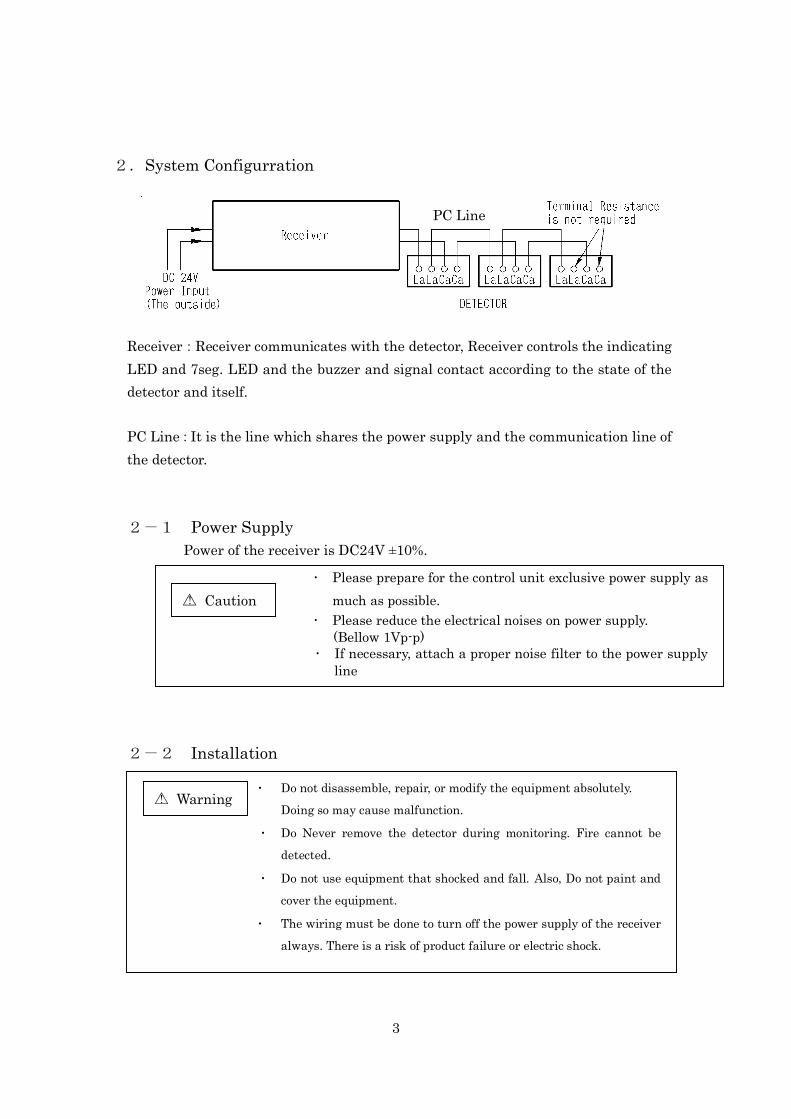
2.System Configurration
Receiver:Receiver communicates with the detector, Receiver controls the indicating LED and 7seg. LED and the buzzer and signal contact according to the state of the detector and itself. PC Line:It is the line which shares the power supply and the communication line of the detector. 2-1 Power Supply Power of the receiver is DC24V ±10%.
2-2 Installation
△ Caution ! ・ Please prepare for the control unit exclusive power supply as
much as possible. ・ Please reduce the electrical noises on power supply.
(Bellow 1Vp-p) ・ If necessary, attach a proper noise filter to the power supply
line
PC Line
△ Warning ! ・ Do not disassemble, repair, or modify the equipment absolutely.
Doing so may cause malfunction.
・ Do Never remove the detector during monitoring. Fire cannot be detected.
・ Do not use equipment that shocked and fall. Also, Do not paint and cover the equipment.
・ The wiring must be done to turn off the power supply of the receiver always. There is a risk of product failure or electric shock.
4
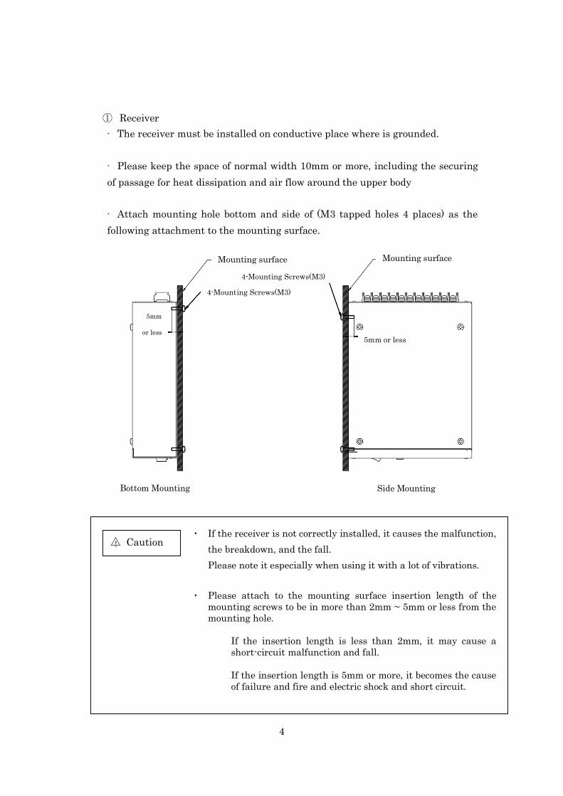
① Receiver · The receiver must be installed on conductive place where is grounded. · Please keep the space of normal width 10mm or more, including the securing of passage for heat dissipation and air flow around the upper body · Attach mounting hole bottom and side of (M3 tapped holes 4 places) as the following attachment to the mounting surface.
△ Caution ! ・ If the receiver is not correctly installed, it causes the malfunction,
the breakdown, and the fall. Please note it especially when using it with a lot of vibrations.
・ Please attach to the mounting surface insertion length of the
mounting screws to be in more than 2mm ~ 5mm or less from the mounting hole.
If the insertion length is less than 2mm, it may cause a short-circuit malfunction and fall. If the insertion length is 5mm or more, it becomes the cause of failure and fire and electric shock and short circuit.
Mounting surface Mounting surface
4-Mounting Screws(M3)
4-Mounting Screws(M3)
5mm or less
5mm
or less
Side Mounting Bottom Mounting

5
2-3 Wiring
① Receiver (1)Power wire
When turning on power source, rush current is between several mS, but above 3A it flows. Wiring please tries to withstand this.
Earthing connection of the ground terminal please goes in order to protect the equipment from electric shock accident prevention and electric noise, securely.
(2)Communication wire
The communication line is connected with receiver and detector as the power line and the signal line. Therefore, use the shield cable of 0.75mm2, and connect the shield part in the shield cable with the terminal FG. Divergence wiring is possible concerning wiring. In addition also polarity is non polar characteristics. Do not bundle with line which gives out other electric noise and separate from it.
・ Please do the wiring after the external power supply off. It may get an electric shock or the receiver may break down.
・ Please use the terminal cover for the receiver when the unit is energized, after do the wiring. If the terminal cover is not used, it may get an electric shock.
! △Warning !
・ When miss-wiring or connecting to a power supply different from ratings, it causes a fire and the breakdown.
・ Please give the noise of power supply (DC24V±10%) to the receiver as 1Vp-p or less.
・ Please decrease with the power supply filter etc, when the influence of the noise is strong.
△ Caution !
6
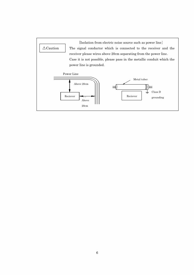
[Isolation from electric noise source such as power line] The signal conductor which is connected to the receiver and the receiver please wires above 20cm separating from the power line. Case it is not possible, please pass in the metallic conduit which the power line is grounded.
△Caution !
Power Line
Above
20cm
Above 20cm
Reciever
Metal tuber
RecieverClass D
grounding
7
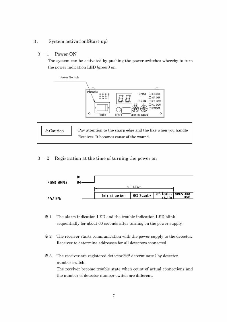
3. System activation(Start-up) 3-1 Power ON
The system can be activated by pushing the power switches whereby to turn the power indication LED (green) on.
3-2 Registration at the time of turning the power on
※1 The alarm indication LED and the trouble indication LED blink sequentially for about 60 seconds after turning on the power supply.
※2 The receiver starts communication with the power supply to the detector. Receiver to determine addresses for all detectors connected.
※3 The receiver are registered detector(※2 determinate ) by detector
number switch. The receiver become trouble state when count of actual connections and the number of detector number switch are different.
・Pay attention to the sharp edge and the like when you handle Receiver. It becomes cause of the wound.
△Caution !
Power Switch
8
4. RECEIVER(FC2) 4-1 Name and Description of Each Function
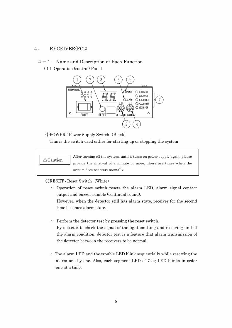
(1)Operation (control) Panel
①POWER : Power Supply Switch(Black) This is the switch used either for starting up or stopping the system
②RESET : Reset Switch(White) ・ Operation of reset switch resets the alarm LED, alarm signal contact
output and buzzer rumble (continual sound). However, when the detector still has alarm state, receiver for the second time becomes alarm state.
・ Perform the detector test by pressing the reset switch. By detector to check the signal of the light emitting and receiving unit of the alarm condition, detector test is a feature that alarm transmission of the detector between the receivers to be normal.
・ The alarm LED and the trouble LED blink sequentially while resetting the alarm one by one. Also, each segment LED of 7seg LED blinks in order one at a time.
After turning off the system, until it turns on power supply again, please
provide the interval of a minute or more. There are times when the
system does not start normally.
△Caution !
9
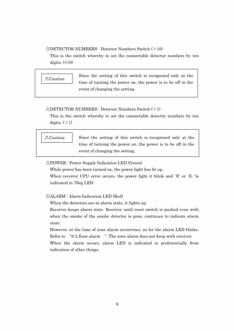
③DETECTOR NUMBERS : Detector Numbers Switch (×10)
This is the switch whereby to set the connectable detector numbers by ten digits. (×10)
④DETECTOR NUMBERS : Detector Numbers Switch (×1) This is the switch whereby to set the connectable detector numbers by ten digits. (×1)
⑤POWER : Power Supply Indication LED (Green) While power has been turned on, the power light has lit up. When receiver CPU error occurs, the power light it blink and `E' or `E. 'is indicated in 7Seg LED.
⑥ALARM : Alarm Indication LED (Red)
When the detectors are in alarm state, it lights up. Receiver keeps alarm state. Receiver until reset switch is pushed even with when the smoke of the smoke detector is gone, continues to indicate alarm state. However, at the time of zone alarm occurrence, as for the alarm LED blinks. Refer to “6-2.Zone alarm “. The zone alarm does not keep with receiver. When the alarm occurs, alarm LED is indicated in preferentially from indication of other things.
Since the setting of this switch is recognized only at the time of turning the power on, the power is to be off in the event of changing the setting.
△Caution !
Since the setting of this switch is recognized only at the time of turning the power on, the power is to be off in the event of changing the setting.
△Caution !

10
⑦TROUBLE : Trouble Indication LED (Yellow)
While trouble occurs in the system, the trouble LED which corresponds to the contents of trouble lights up or blinks. Details of trouble contents please refer to “8. Procedures/steps to be taken in the event of trouble occurrence”.
⑧7seg LED(Red) Address of the detector where the alarm occurs is indicated. When the alarm occurs with the plural detectors, the scroll it indicates in the order where the alarm generates the address which is in the midst of alarm occurring 2 seconds. First address indicates the decimal point in simultaneously
Address of the detector where trouble occurs is indicated. When the trouble occurs with the plural detectors, the scroll it indicates in the order where the trouble generates the address which is in the midst of alarm occurring 2 seconds. First address indicates the decimal point in simultaneously
At the time of zone alarm occurrence “00” is indicated.
When alarm occurs in trouble state, for alarm priority indication, the address where trouble occurs is not indicated.
△Caution !
When trouble occurs in alarm state, for alarm priority indication, the address where trouble occurs is not indicated. However, I unless the receiver CPU error has occurred.
△Caution !
When the alarm occurs in zone alarm state, the alarm LED from blinking becomes lighting because of alarm priority indication. In addition, As for 7seg. LED indication “00” the scroll it indicates in the order where the alarm generates indication and the address indication to which the alarm occurs.
△Caution !
11
Ex. Buzzer (Embedded)
In case of alarm state it rumbles with continual sound. In case of trouble state it rumbles with intermittent sound. However, at the time of receiver CPU error to continue rumble, the contents are indicated in 7Seg LED.
When the alarm occurs in a trouble state where receiver CPU error is excluded, rumble of the buzzer changes to continual sound from intermittent sound because of alarm priority indication.
△Caution !

12
(2)BACK TERMINAL BASE
Conformity wire 0.75m㎡ Screw (Square washer with screw)
M3×6L
①P.S (Terminal No 1,2,3) DC24V This terminal to connect the power supply line. (No2:-,No3:+)
FG It is the terminal which connects the ground line.
②PC LINE (Terminal No 4,5) It is the terminal which connects the communication line.
2 1 4 3
Please install the bundled terminal cover in order to prevent accident such as electric shock.
△Warning !
・ Do not input the power source other than DC 24V to the terminal. Do not exceed the service voltage range. It becomes cause of accident such as fire.
・ Making a mistake in polarity and connect, the equipment breaks down.
△Warning !
Do not connect wiring other than the communication line to this terminal absolutely. It becomes cause of breakdown such that it stops starting normally.
△Warning !
13
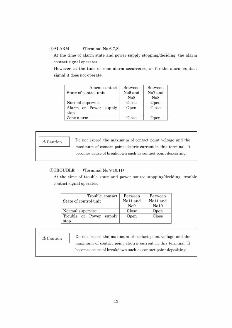
③ALARM (Terminal No 6,7,8)
At the time of alarm state and power supply stopping/deciding, the alarm contact signal operates. However, at the time of zone alarm occurrence, as for the alarm contact signal it does not operate.
Alarm contact Between No6 and
No8
Between No7 and
No8 State of control unit
Normal supervise Close Open Alarm or Power supply stop
Open Close
Zone alarm Close Open
④TROUBLE (Terminal No 9,10,11) At the time of trouble state and power source stopping/deciding, trouble contact signal operates.
Trouble contact Between No11 and
No9
Between No11 and
No10 State of control unit
Normal supervise Close Open Trouble or Power supply stop
Open Close
Do not exceed the maximum of contact point voltage and the maximum of contact point electric current in this terminal. It becomes cause of breakdown such as contact point depositing.
△Caution !
Do not exceed the maximum of contact point voltage and the maximum of contact point electric current in this terminal. It becomes cause of breakdown such as contact point depositing.
△Caution !

14
4-2 Trouble LED
①DETECTOR LED It lights up when sensitivity revision over or inside the detector, trouble occurs in the detector. (Refer to “8. Procedures/steps to be taken in the event of trouble occurrence”) In addition, address of the detector where trouble occurs is indicated in 7seg LED.
②DET.OVER LED It lights up when the number of detectors which have been recognized is greater than specification at the detector number switch of receiver.
③DET.UNDER LED It lights up when the number of detectors which have been recognized is less than specification at the detector number switch of receiver. Receiver, the numbers of detectors recognizing few, lights up similarly even when being disconnected of the communication line and broken wire inside the detector.
④PCL.SHORT LED
When the communication line is short, it lights up.
⑤RECEIVER LED It lights up when specification of detector number switches of receiver 0 or 32 or more. In addition, it lights when it is determined to be abnormal in the self diagnosis of the receiver. In this case of receiver trouble, please exchange.
15
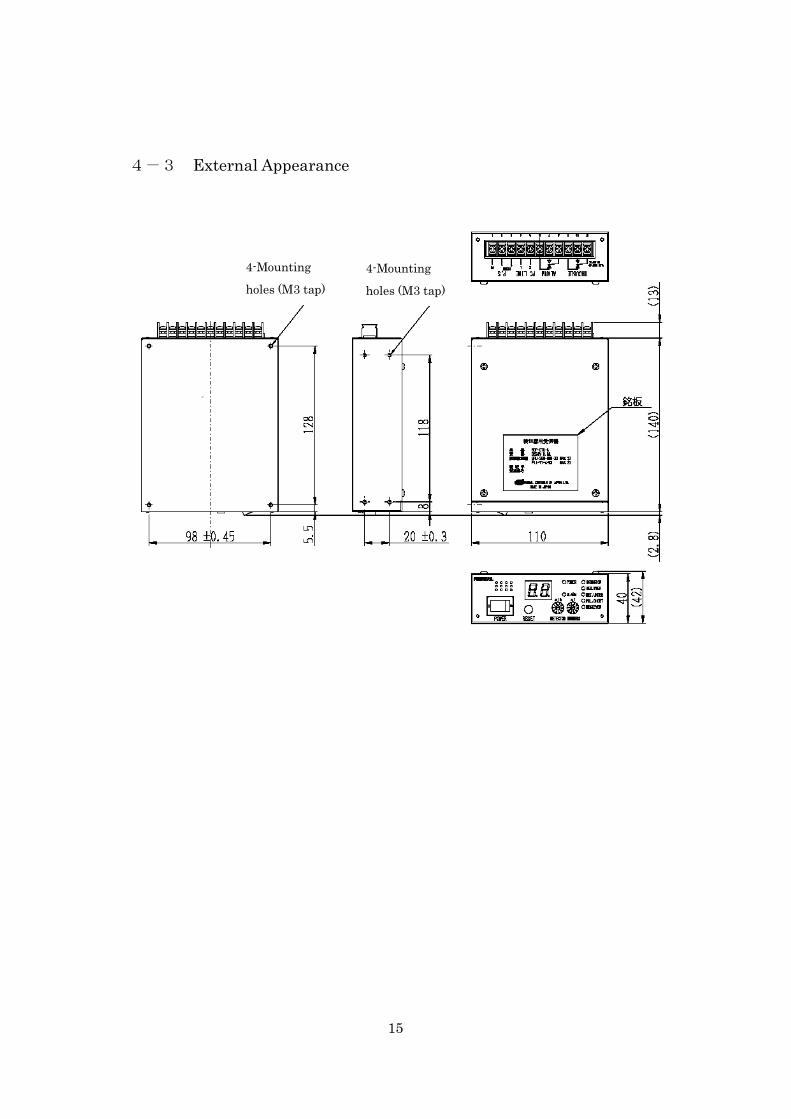
4-3 External Appearance
4-Mounting holes (M3 tap)
4-Mounting holes (M3 tap)
16
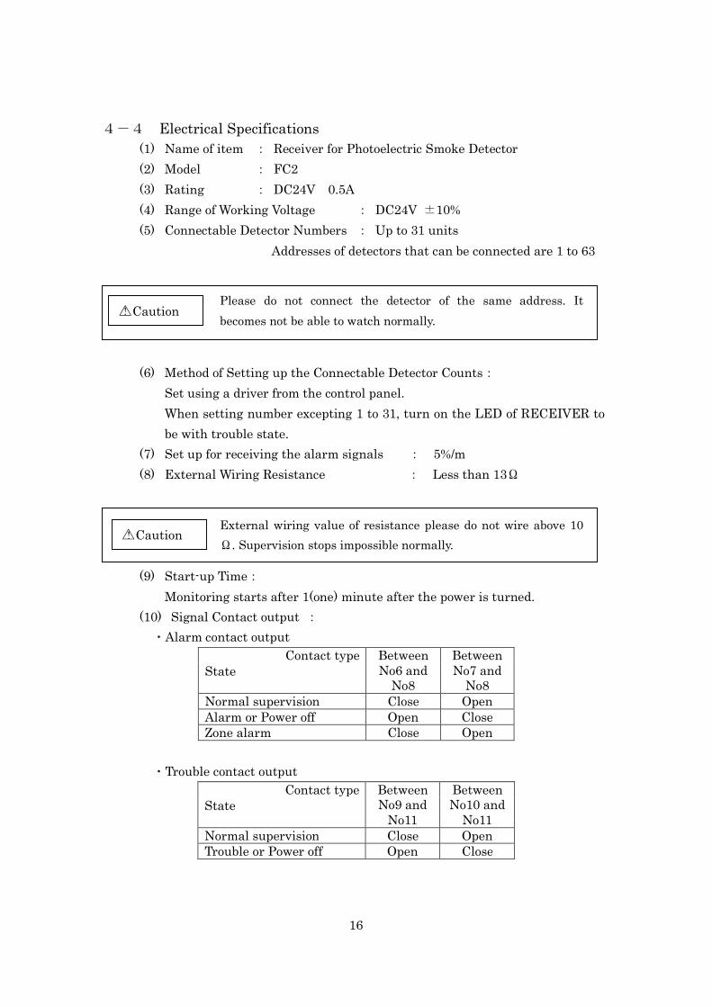
4-4 Electrical Specifications (1) Name of item : Receiver for Photoelectric Smoke Detector (2) Model : FC2 (3) Rating : DC24V 0.5A (4) Range of Working Voltage : DC24V ±10% (5) Connectable Detector Numbers : Up to 31 units
Addresses of detectors that can be connected are 1 to 63
(6) Method of Setting up the Connectable Detector Counts:
Set using a driver from the control panel. When setting number excepting 1 to 31, turn on the LED of RECEIVER to be with trouble state.
(7) Set up for receiving the alarm signals : 5%/m (8) External Wiring Resistance : Less than 13Ω
(9) Start-up Time:
Monitoring starts after 1(one) minute after the power is turned. (10) Signal Contact output :
・Alarm contact output Contact type Between
No6 and No8
Between No7 and
No8 State
Normal supervision Close Open Alarm or Power off Open Close Zone alarm Close Open
・Trouble contact output
Contact type Between No9 and
No11
Between No10 and
No11 State
Normal supervision Close Open Trouble or Power off Open Close
Please do not connect the detector of the same address. It becomes not be able to watch normally.
△Caution !
External wiring value of resistance please do not wire above 10Ω. Supervision stops impossible normally.
△Caution !
17
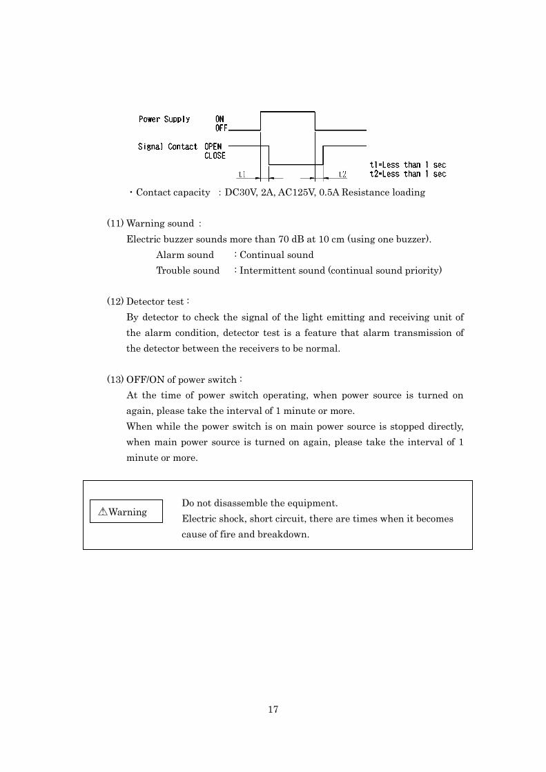
・Contact capacity :DC30V, 2A, AC125V, 0.5A Resistance loading
(11) Warning sound : Electric buzzer sounds more than 70 dB at 10 cm (using one buzzer).
Alarm sound : Continual sound Trouble sound : Intermittent sound (continual sound priority)
(12) Detector test : By detector to check the signal of the light emitting and receiving unit of the alarm condition, detector test is a feature that alarm transmission of the detector between the receivers to be normal.
(13) OFF/ON of power switch : At the time of power switch operating, when power source is turned on again, please take the interval of 1 minute or more. When while the power switch is on main power source is stopped directly, when main power source is turned on again, please take the interval of 1 minute or more.
Do not disassemble the equipment. Electric shock, short circuit, there are times when it becomes cause of fire and breakdown.
△Warning !
18
4-5 Environmental Specifications. (1)Working Temperature Range : 0℃~60℃ (2)Storage Temperature Range : -20℃~70℃ (3)Working Humidity Range : 30~85%RH (without condensation)
4-6 Mechanical Specifications.
(1)External form : W110×D151×H40 (2)Main Material : SPCC t0.8 electrostatic spray paint(black) (3)Mass : Approx.450g
Do not use at the place where it exceeds environmental specification and the place where the volatilization gas and the corrosiveness gas occur. It becomes cause of breakdown such that it stops operating normally.
△Warning !

19
5. Procedures/steps to be taken in the event of alarm occurrence When this system detected smoke, the following warning is output from receiver. When warning is output, please take the necessary actions to make sure the fire.
5-1 Alarm
When receiver receives the alarm event from detector, and the smoke density data exceed the set point of the receiver in addition, the alarm is generated.
(1)The alarm LED lights up. (2)The buzzer (continual sound) rumbles. (3)The alarm signal contact is output. (4)The alarm detector address is indicated in 7seg LED indication.
5-2 Zone Alarm
The zone alarm is one of alarm information, which occurs when address recognition becomes impossible in communication obstacle and receiver or breakdown of the detector.
(1)The alarm LED blinks. (2)The buzzer (continual sound) rumbles. (3)“00” is indicated in 7seg LED indication.
The state indicating LED of the detector at the time of alarm state and zone alarm state blinks 1 times at a time in 2 seconds.
20
6. Trouble When this system detected trouble, the following warning is output from receiver.
(1)The trouble LED which responds to the contents of trouble lights up. (2)The buzzer (intermittent sound) rumbles. (3)The trouble signal contact is output. (4)The trouble address of the detector which occurs is indicated in 7seg LED
indication.
When there is a trouble primary factor in the detector, the state indicating LED (Red) of the detector which is trouble state goes out. When warning is output, verifying the contents of trouble, to following “8. Procedures/steps to be taken in the event of trouble occurrence” , please correspond appropriately.
△ Caution ! The time of trouble occurrence, when you redo wiring or exchanging the detector, Do it after turning off power
21
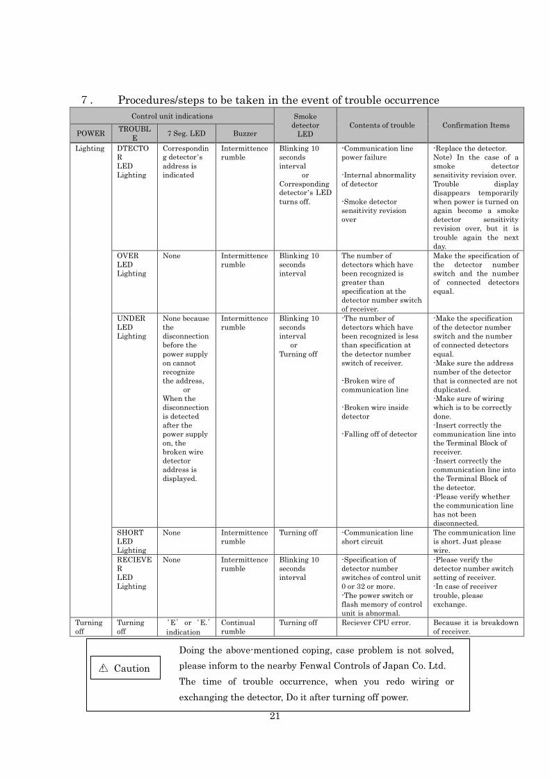
7. Procedures/steps to be taken in the event of trouble occurrence Control unit indications Smoke
detector LED
Contents of trouble Confirmation Items POWER TROUBL
E 7 Seg. LED Buzzer
Lighting DTECTOR LED Lighting
Corresponding detector’s address is indicated
Intermittence rumble
Blinking 10 seconds interval
or Corresponding detector’s LED turns off.
-Communication line power failure -Internal abnormality of detector -Smoke detector sensitivity revision over
-Replace the detector. Note) In the case of a smoke detector sensitivity revision over. Trouble display disappears temporarily when power is turned on again become a smoke detector sensitivity revision over, but it is trouble again the next day.
OVER LED Lighting
None Intermittence rumble
Blinking 10 seconds interval
The number of detectors which have been recognized is greater than specification at the detector number switch of receiver.
Make the specification of the detector number switch and the number of connected detectors equal.
UNDER LED Lighting
None because the disconnection before the power supply on cannot recognize the address,
or When the disconnection is detected after the power supply on, the broken wire detector address is displayed.
Intermittence rumble
Blinking 10 seconds interval
or Turning off
-The number of detectors which have been recognized is less than specification at the detector number switch of receiver. -Broken wire of communication line -Broken wire inside detector -Falling off of detector
-Make the specification of the detector number switch and the number of connected detectors equal. -Make sure the address number of the detector that is connected are not duplicated. -Make sure of wiring which is to be correctly done. -Insert correctly the communication line into the Terminal Block of receiver. -Insert correctly the communication line into the Terminal Block of the detector. -Please verify whether the communication line has not been disconnected.
SHORT LED Lighting
None Intermittence rumble
Turning off -Communication line short circuit
The communication line is short. Just please wire.
RECIEVER LED Lighting
None Intermittence rumble
Blinking 10 seconds interval
-Specification of detector number switches of control unit 0 or 32 or more. -The power switch or flash memory of control unit is abnormal.
-Please verify the detector number switch setting of receiver. -In case of receiver trouble, please exchange.
Turning off
Turning off
‘E’ or ‘E.’ indication
Continual rumble
Turning off Reciever CPU error. Because it is breakdown of receiver.
△ Caution !
Doing the above-mentioned coping, case problem is not solved, please inform to the nearby Fenwal Controls of Japan Co. Ltd. The time of trouble occurrence, when you redo wiring or exchanging the detector, Do it after turning off power.

22
8. Maintenance and Inspection 8-1 Daily Inspection
The items that must be inspected daily are listed in bellow Table. № Item Object Inspection Method Judgment
Criteria Remedy
1 Installation Common Looseness, rattling
Move the module to check.
The module must be installed solidly.
Retighten the screws. If the modules are loose, fix it with screws.
2 Appearance Common Dirt and foreign matter.
Check visually.
Dirt and foreign matter must not be present.
Remove and clean.
Damage. Check visually.
There is no damage on the modules.
Equipment is exchanged in consideration of the influence on the performance.
3 Wiring Common Damage. Check visually.
There is no damage on the wires.
Rewiring by conformity wire.
Dirt and foreign matter.
Check visually.
Dirt and foreign matter must not be present on the terminals.
Remove and clean.
Looseness terminal screws.
Retighten. Screws should not be loose.
Retighten the terminal screws with the proper torque.
4 Behavior Normal Supervision
The Receiver
Power LED Check visually.
The LED must be ON.(Green)
Please refer to section 8.
The rest of LED except the Power LED
Check visually.
The LED must be Off.
Buzzer Listening. The buzzer must be off.
The Detector
State indic1ation LED
Check visually.
Blinking 10 seconds interval
Please refer to section 5-3,(6) State Indication LED
△ Warning !
・Please do not touch the terminal while the unit is energized. It may get an
electric shock.
・Please do the cleaning and the increase tightening of the screw after the power supply off. If not the power supply off, it may get an electric shock.
・Do not soak a detector in water, and do not put a detector into water.
△ Caution !
・Under tightening can cause a drop, malfunction.
・Over tightening can cause a drop, malfunction due to damage to the screw or
equipments and malfunction.
・Please use the dry cloth or wring the water out tightly cloth for the cleaning. ・After Cleaning, Do not leave a foreign substance such as sawdust or wiring debris
on a detector. Such debris could cause erroneous operation.
・Do not use alcohol and neutral detergent, chlorine bleach, benzene, thinner to
clean. It may scratch the surface equipment.

23
8-2 Periodically Inspection The items that must be inspected one or two times every 6 months to 1 year are listed below. When the equipment is moved or modified, or layout of the wiring is changed, also perform this inspection.
№ Item Object Inspection Method Judgment
Criteria Remedy
1 Ambient temperature Common Within the specification
Temperature measurement
In the specification of each equipment
Changed to the temperature within the specification.
2 Ambient humidity Common Within the specification
Humidity measurement
In the specification of each equipment
Changing at the humidity within the specification.
3 Atmosphere Common Existence of volatility and causticity gas
Gas measurement
There must be neither volatility nor a causticity gas.
Volatility and the causticity gas of atmosphere are excluded.
4 Power voltage Common In the ratings Voltage measurement
In the ratings of each equipment
Changed to the voltage within the ratings.
5 Installation Common Looseness, rattling
Move the module to check.
The module must be installed solidly.
Retighten the screws. If the modules are loose, fix it with screws.
6 Appearance Common Dirt and foreign matter.
Check visually.
Dirt and foreign matter must not be present.
Remove and clean.
Damage. Check visually.
There is no damage on the modules.
Equipment is exchanged in consideration of the influence on the performance.
7 Wiring Common Damage. Check visually.
There is no damage on the wires.
Rewiring by conformity wire.
Dirt and foreign matter.
Check visually.
Dirt and foreign matter must not be present on the terminals.
Remove and clean.
Looseness terminal screws.
Retighten. Screws should not be loose.
Retighten the terminal screws with the proper torque.
8 Detector Number setting
The Receiver
The same number as detector installed
Confirmation of number of detectors actually installed.
The setting and the number of detectors actually installed are the same.
The setting is matched to the number of detectors actually installed.

24
№ Item Object Inspection Method Judgment
Criteria Remedy
9 Behavior Normal Supervision
The Receiver
Power LED Check visually.
The LED must be ON.(Green)
Please refer to section 8.
The rest of LED except the Power LED
Check visually.
The LED must be Off.
Buzzer Listening. The buzzer must be off.
Signal contact output
Signal check The same output as「4-1(2)③,④」
Please exchange the Receiver.
The Detector
State indic1ation LED
Check visually.
Blinking 10 seconds interval
Please refer to section 5-3,(6) State Indication LED
△ Warning !
△ Caution !
・Under tightening can cause a drop, malfunction. ・Over tightening can cause a drop, malfunction due to damage to the screw or
equipments and malfunction.
・Please use the dry cloth or wring the water out tightly cloth for the cleaning.
・After Cleaning, Do not leave a foreign substance such as sawdust or wiring debris
on a detector. Such debris could cause erroneous operation.
・Do not use alcohol and neutral detergent, chlorine bleach, benzene, thinner to clean. It may scratch the surface equipment.
・Please do not touch the terminal while the unit is energized. It may get an electric shock.
・Please do the cleaning and the increase tightening of the screw after the power
supply off. If not the power supply off, it may get an electric shock. ・Do not soak a detector in water, and do not put a detector into water.
25
9. Disposal
This product is as general industrial waste disposal. Disposal methods are specific criteria depending on each municipality.
10. SUPPORT
Please inquire about this control unit to the Fenwal Controls of Japan Co. Ltd. Tokyo headquarters.
TOKYO HEAD QUARTERS : 03-3237-3561
TOHOKU OFFICE : 022-221-3141
OSAKA OFFICE : 06-309-1001
CHUBU OFFIC : 052-804-8220
SHINETSU OFFICE : 0263-72-6244
KYUUSHUU OFFICE : 092-522-0787
Related Documents