DC62900 Series Electromechanical Closer-Holder

Welcome message from author
This document is posted to help you gain knowledge. Please leave a comment to let me know what you think about it! Share it to your friends and learn new things together.
Transcript
DC62900 SeriesElectromechanical Closer-Holder
IntroductionDC62900
Table of Contents
Applications .........................2Functions and Features ....... 3Overview ..........................4-5Mountings .......................6-7Brackets and Covers .............8Track Assemblies & Parts .9-10How to Order ...................11Specification ......................12
www.corbinrusswin.com
DC62900.2
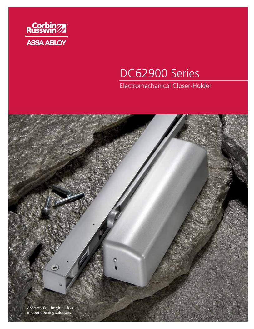
ApplicationsCorbin Russwin Electric Track Closer-Holders combine the functions of a single-point electromechanical door holder with the DC6200 door closer. The track assembly contains an arm slide and solenoid-operated hold open mechanism and is available with or without an integral smoke detector. The closer is mounted on the door. The track is mounted to the frame face for pull side installations or the frame soffit for push side installations.
The track is an aluminum extrusion which incorporates a solenoid-actuated cam that locks the arm slide in the
track at a selected point. The degree of door hold open is selected by adjustment of the telescoping arm. When there is power to the unit, the door will hold open at the selected hold open point. Any power interruption will release the arm slide and the door will close. The door can be released manually at any time.
Corbin Russwin Electric Track Closer-Holders are available in two basic functions for controlling fire/smoke doors.
45523-7/13

Functions and FeaturesDC62900
DC62900.3
Functions: Master Unit – This unit is comprised of an integral smoke detector, a solenoid hold open mechanism in the slide track and a door closer. The Master Unit can be used to control a single door or a pair of doors in conjunction with a Support Unit. Quick Code: ETD
Support Unit – This unit is comprised of a solenoid hold open mechanism in the slide track and a door closer. These units can be installed on a single door or a pair of doors when controlled by compatible U.L. listed detection equipment such as area ceiling detectors, pull stations, and remote alarm panels. They can also be used in conjunction with a Master Unit on a pair of doors when the Master Unit smoke detector signals conditions (standby, trouble/alarm) to an alarm system’s panel. The alarm panel controls the hold open function of both the Support Unit and the Master Unit. Quick Code: ET
Note: Application of any Corbin Russwin Electric Track Single-Point Hold Open Closer-Holder Releasing Device should be checked for compliance with both state and local codes.
Features: Selective Single-Point Hold Open: The DC62900 has one template position. The single-point hold open position is selected by adjusting the telescoping arm with a hex drive set-screw. Hold open range is 85° thru 110° in approximately 3° increments.
Spring Cushioned Dead Stop: A spring loaded buffer block at the point of hold open prevents overtravel of the arm slide and provides a cushioned dead stop. Use of an additional wall or floor stop is always recommended.
Non-Handed: Non-handed except when ordered with "DE" (Double Egress) arms.
Pull/Push Installations: The track can be ordered for installation on either side of the door. List number DC62940 can be installed on the push side only. List number DC62930 can be installed on the pull side only.
Choice of Supply Voltage: Corbin Russwin Electric Tracks are available in the most commonly used operating voltages of 24 Volts AC/DC or 12OVAC, 60Hz. Power to these devices must be within a range of (+) 10% (-) 15% of the stated voltage.
Fail Safe: In the event of a power outage, solenoid will be de-energized and the Closer-Holder will then operate as a normal door closer.
Wiring Option: Both pull side and push side application will accommodate either concealed or surface wiring. The hook-up box will accept a 3/4" (19mm) conduit. Each DC62900 is supplied with a thin-walled conduit nut to attach the conduit clamp. State and local building codes will dictate the type of wiring permitted.
Door Closer: The DC62900 is a non-handed, narrow projection closer with a full plastic cover. It has an adjustable spring for sizes 1-6. It also has four independent valves to control latch speed, closing speed, backcheck positioning and intensity. QUIK-INSTALL mounting bracket speeds installation.
Warranty: 2-year limited
U.L. Listing: All Master Units with integral smoke detectors have been tested and evaluated for public safety by Underwriter's Laboratories and are listed for application on smoke barrier and labeled fire doors. All Support Units are U.L. listed for application with any compatible U.L. listed fire/smoke detection equipment.
ANSI / BHMA: The DC62900 Series is ANSI/BHMA certified for A156.15.
45523-7/13

FeaturesDC62900
DC62900.4
Features – Smoke Detector: Photoelectric SensingDetector employs a photoelectric chamber to substantially reduce the probability of false alarms.
Fire/Smoke Control CircuitInterprets the alarm signal from the detector and provides switching contacts to interrupt power to the hold open solenoid and divert it to activate optional audio/visual alarms.
Alarm (Relay) ContactsNormally open in standby condition (energized, non-alarm state). These contacts close during an alarm condition (smoke detected) and switch power from the solenoid to an optional local alarm.
Trouble (Relay) ContactsNormally closed in standby condition, these supervisory contacts monitor the continuity of power within the detector circuit. Any power interruption within the detector circuit will open these contacts. They can then be used to simultaneously indicate a trouble condition to the alarm panel on a separate trouble circuit.
Quick Disconnect ModulesEach component, solenoid coil, detector and control feature quick disconnect wiring for easy servicing and replacement.
Locked-In AlarmWhen a unit alarms, it must be manually reset. This can be accomplished by remote control from the alarm console or by the reset button in the smoke detector. Reset button is accessible through the center louver in the underside of the track. Reset by rotating LED chamber using small flat blade screwdriver.
Indicator Lights Normal Mode: A red LED flashes once every eight (8) seconds. Clean Mode: A red LED flashes once every second.Alarm Mode: A red LED illuminates continuously.
Spring Cushioned Dead Stop
Hold Open Solenoid and
Roller Assembly
Slide Track Smoke Detector
Hook-Up Board Cover
Red LED Alarm Light
Telescoping Arm
Slide AssemblyHook-Up Board
45523-7/13

Electrical Information
DC62900
DC62900.5
“ETD” Master Units•Twocomponentsrequireelectricalpower: - Integral smoke detector requires 24VDC input power. - Hold open solenoid requires 24VDC input.• Hook-upboxreceivesprimaryvoltageinputand
distributes it to the smoke detector and hold open solenoid(s).
•Availablewithtwovoltageoptions: - ETD-24 suffix – - Accepts 24VAC or 24VDC power input. - A rectifier in the hook-up box will rectify alternating current to direct current for operation of both the smoke detector and hold open solenoid(s). - ETD-120 suffix – - Accepts 120VAC power input. - A 120VAC to 24VAC transformer in the hook-up
box steps the input voltage down to 24VAC. It is then rectified to 24VDC for operation of both the smoke detector and the 24VDC hold open solenoid(s).
“ET” Support Units •Holdopensolenoidrequireselectricalpower.•Solenoidcontrolledbysmokedetectionequipment
(ceiling detectors) or remote alarm panels.•Availableforoperationon24VAC/DCor120VAC,60Hz.•Holdopensolenoidoperatesondirectcurrent.•Containsbuilt-inrectifierthatconvertsalternatingcurrent
to direct current.
Type of Unit Model#ofPower
Input LinesChoices of Voltage Input Can beusedwith
Master
ETD-24
1
24 VAC/DC
Support Model ET
ETD-120 120 VAC, 60 Hz
Support
ET-24
1
24 VAC/DCArea Smoke Detection System or
Master Model ETD24-120
ET-120 120 VAC, 60Hz Area Smoke Detection System
Operating voltage or voltages for the control of fire/smoke doors are specified by the architect, electrical engineer and alarm system engineer and/or contractor. Consulting with these sources will verify which operating voltage(s) should be ordered.
Ordering Voltages:
45523-7/13

MountingsDC62900
DC62900.6
DC62930 Pull (Hinge) Side Mounting
Door(s) Opening Inches (cm) Model Number & Type
Max. Min*
Sin
gle
Do
or
48" (122) 36" (91) (1) DC62930 x ETD Master Unit
48" (122) 32" (81) (1) DC62930 x ET Support Unit
Pair
of
Do
ors
96" (244) 68" (173)(1) DC62930 x ETD Master Unit and(1) DC62930 x ET Support Unit
96" (244) 64" (163) (2) DC62930 x ET Support Units
36-1/4(921)
32-5/8(829)
36-1/4(921)
32-5/8(829)
Model # Description
DC62930 x ETD Master Unit Controlled by Integral Smoke Detector
DC62930 x ET Support Unit Controlled by Remote Detection Equipment
Master Unit DC62930 x ETD
Minimum ceiling clearance 2-1/8" (54mm)
* Minimum door opening for standard installation. Consult factory for door openings narrower than those shown.
Support Unit Track
45523-7/13
MountingsDC62900
DC62900.7
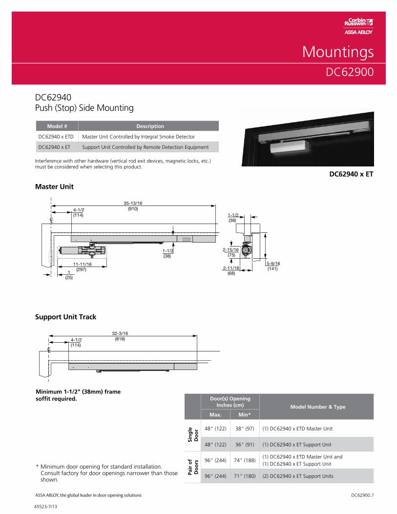
35-13/16(910)
32-3/16(818)
DC62940Push (Stop) Side Mounting
Door(s) OpeningInches (cm) Model Number & Type
Max. Min*
Sin
gle
D
oo
r 48" (122) 38" (97) (1) DC62940 x ETD Master Unit
48" (122) 36" (91) (1) DC62940 x ET Support Unit
Pair
of
Do
ors 96" (244) 74" (188)
(1) DC62940 x ETD Master Unit and(1) DC62940 x ET Support Unit
96" (244) 71" (180) (2) DC62940 x ET Support Units
Model # Description
DC62940 x ETD Master Unit Controlled by Integral Smoke Detector
DC62940 x ET Support Unit Controlled by Remote Detection Equipment
35-13/16(910)
32-3/16(818)
Master Unit
Minimum 1-1/2" (38mm) frame soffit required.
Interference with other hardware (vertical rod exit devices, magnetic locks, etc.) must be considered when selecting this product.
DC62940 x ET
Support Unit Track
* Minimum door opening for standard installation. Consult factory for door openings narrower than those shown.
45523-7/13

Full Cover•StandardonallDC6000seriesdoorclosers•Completelycoverscloserbody•Non-handed•Dimensions:11-5/8"(295mm)x3"(76mm)x2-3/4"(70mm)deep•Availableinpaintedfinishesonly
Full Metal Cover•Foruseinhigh-abuseapplications•Specifyhand;notfieldreversible•Availableinpaintedandplatedfinishes•Dimensions:11-1/2"(292mm)x2-7/8"(73mm)x2-3/4"(70mm)deep•ToorderspecifycloserxM73
597F78
Quik-Install™ Mounting Bracket•Standardonallclosers•Reducesinstallationtime•Ensurescorrectmounting•Bracketisfirstmountedtodoororframe,thencloserisattached•Bracketsize:1-3/4"(44mm)(vertical)x6"(152mm)(horizontal)•Holespacing:1"(25mm)(vertical)x4-5/16"(110mm)(horizontal)
188F03
Cover Model #
RH/LHR 603F55
LH/RHR 603F57
Brackets and CoversDC62900
DC62900.8
45523-7/13

Master Unit Track Assemblies include track, slider assembly, solenoid block assembly and detector. Hook-up box not included. Support Unit Track Assemblies include track, slider assembly and solenoid block assembly. Hook-up box not included.
PartsDC62900
Description VoltagePart Number
Hinge Side Stop Side
Master or Support Unit 24V 754F52 754F53
Spring Plate
Buffer Spring Roll Pin
End Cap692F16
Stationary Block Assembly
CushionBlock
Roller AssemblySlide
Assembly692F14
Slide Track Assembly(See Chart)
Arm Stud Clip692F15
(included when 692F14 is ordered)
NOTE:Mountinghardwareincludedwithallpartsorders.
Description VoltagePart Number
Hook-Up Board
Master or Support24V 754F54
120V 754F55
DC62900.9
Miscellaneous Parts
Description Part Number
Fuse 754F66
Smoke Detector Board 754F73
Solenoid Block Assembly 692F17
Hook-Up Box Cover Kit (Master) 754F71
Hook-Up Box Cover Kit (Support) 754F72
Hook-Up Boxes
Description Voltage Hinge Side Push Side
Master24V 754F56 754F61
120V 754F57 754F62
Support24V 754F58 754F63
120V 754F59 754F64
Metal covers and arm assemblies are available in painted or plated finishes. Plastic covers and track assemblies are available in painted finishes only.
45523-7/13

PartsDC62900
DC62900.10
692F25 – Adjusting Head and Tube Assembly 692F19 – Adjusting Rod Assembly
692F23 – Arm Length Adjusting Screw
692F20 – Arm Stud 692F21 – Retaining Ring
692F23 – Arm Length Adjusting Screw
692F20 – Arm Stud 692F21 – Retaining Ring
754F04 – Adjusting Head and Tube Assembly RH 754F05 – Adjusting Head and Tube Assembly LH
692F19 – Adjusting Rod Assembly
754F02 – (Right Hand)1,2 754F03 – (Left Hand)1,2
Double Egress Arm Assembly(Specify model x Quick Code A6)
692F241, 2
Standard Arm Assembly
NOTE:Mountinghardwareincludedwithallpartsorders.
1 Includes arm length adjusting screw #692F23 2 Includes arm tube & adjusting rod assembly
45523-7/13
How To OrderDC62900
DC62900.11
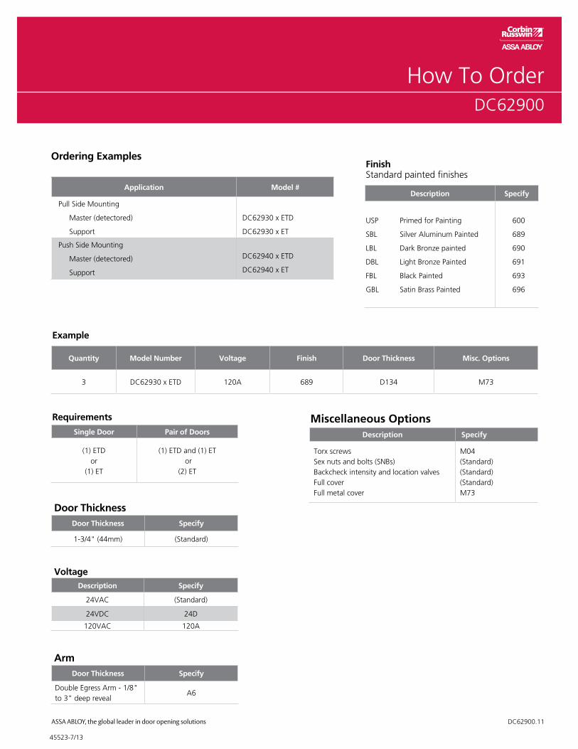
Example
Quantity Model Number Voltage Finish Door Thickness Misc. Options
3 DC62930 x ETD 120A 689 D134 M73
Requirements
Single Door Pair of Doors
(1) ETDor
(1) ET
(1) ETD and (1) ET or
(2) ET
Miscellaneous OptionsDescription Specify
Torx screwsSex nuts and bolts (SNBs)Backcheck intensity and location valvesFull coverFull metal cover
M04(Standard)(Standard)(Standard)M73
FinishStandard painted finishes
Description Specify
USP Primed for Painting
SBL Silver Aluminum Painted
LBL Dark Bronze painted
DBL Light Bronze Painted
FBL Black Painted
GBL Satin Brass Painted
600
689
690
691
693
696
Ordering Examples
Application Model #
Pull Side Mounting
Master (detectored)
Support
DC62930 x ETD
DC62930 x ET
Push Side Mounting
Master (detectored)
Support
DC62940 x ETD
DC62940 x ET
Door ThicknessDoor Thickness Specify
1-3/4" (44mm) (Standard)
VoltageDescription Specify
24VAC (Standard)
24VDC 24D
120VAC 120A
ArmDoor Thickness Specify
Double Egress Arm - 1/8" to 3" deep reveal
A6
45523-7/13

SpecificationDC62900
DC62900.12
Closer for ____________ doors shall be electromechanical closer-holder. Hold open to be achieved by electric solenoid locking of the closer arm slide in its track. Track, arm, slide (and) solenoid (and integral smoke detector) to be contained in a single aluminum extrusion 1-1/2" (38mm) high, 1-1/2" (38mm) deep. Closer shall be door mounted. Track and hold open mechanism shall be surface mounted to the frame face for application on the pull side of the door and frame soffit mounted for application on the push side of the door.
Single point hold open shall be selective through a range of 85° to 110°. Hold open point to be achieved by adjustment of a telescoping closer arm.
Closer shall be hydraulic with full rack and pinion enclosed in a cast iron shell. Hydraulic fluid shall be non-gumming and non-freezing. Closer shall have two non-critical values to independently regulate sweep speed and latch speed. It shall have an adjustable backcheck cushioning valve.
(Master units to have an integral smoke detector with photoelectric chamber. Master units integral smoke detector shall have latching alarm and reset switch.) (Support units to be controlled by U.L. Listed Smoke Detection Equipment.) Units to be fail safe and close the door during any interruption to the electrical power. The hold open solenoid coil shall have a maximum amperage draw of (.090 Amps at 24 volts) (.035 Amps at 120 volts). Unit shall have a switch to permit testing of the releasing device function without alarming the system.
All wiring connections shall be made without the need of wire nuts or soldering.
(Master unit(s) shall require a (24VAC/DC) (12OVAC, 60Hz) power input.) (Support unit(s) shall require a (24VAC/DC) (I2OVAC, 60Hz.) power input.) Supplier to coordinate electrical requirements with electrical and alarm system engineers. Wiring (and conduit) by others.
Suggested Specification
45523-7/13

NotesDC62900
DC62900.13
45523-7/13

For more information regarding Corbin Russwin Locksets, Exit Devices, Door Controls and Key Systems, contact your authorized Corbin Russwin Distributor or Sales Representative.
In U.S.Corbin RusswinArchitectural Hardware225 Episcopal RoadBerlin, CT 06037Phone: 800-543-3658Fax: 800-447-6714corbinrusswin.com
In CanadaASSA ABLOY DoorSecurity Solutions Canada160 Four Valley DriveVaughan, OntarioCanada L4K 4T9Phone: 800-461-3007Fax: 888-940-3242www.assaabloycanadadss.ca
Corbin Russwin and Design® is a registered trademark of Corbin Russwin, Inc., an ASSA ABLOY Group company. Quik-Install™ is a trademark of Corbin Russwin, Inc., an ASSA ABLOY Group company. Other products’ brand names may be trademarks or registered trademarks of their respective owners and are mentioned for reference purposes only. These materials are protected under US copyright laws. All contents current at time of publication. Corbin Russwin, Inc. reserves the right to change availability of any item in this catalog, its design, construction, and/or its materials. Copyright © 2006, 2013 Corbin Russwin, Inc. All rights reserved. Reproduction in whole or in part without the express written permission of Corbin Russwin, Inc. is prohibited.
45523-7/13
Related Documents