Product Data PG8MVA/JVA 4--WAY MULTIPOISE INDUCED COMUBSTION GAS FURNACE INPUT CAPACITIES: 70,000 THRU 135,000 BTUH SERIES A A10257 THE PAYNE 80 GAS FURNACE The PG8MVA/JVA 4--way Multipoise Gas Furnaces offer deluxe features not found in other two--stage 80% gas furnaces. The variable--speed ECM motor and Payne’s control logic combine to provide the benefits of longer, more gentle cycles, and less temperature differences between rooms. The gas furnace control system provides a dehumidification mode and a motor speed selection for continuous fan operation selectable at the thermostat. Applications are easy with 4--way multipoise design, through--the--furnace downflow venting, 13 different venting options, and an overall design for easy service access. The PG8MVA/JVA furnaces are approved for use with natural or propane gas, and the PG8JVA is approved for use in Low NOx Air Quality Management Districts. STANDARD FEATURES S Variable--speed ECM blower motor S Two heating stages S Humidity control when using a humidity sensing thermostat S Adjustable constant fan speed from the thermostat S Certified to leak 2 percent or less of its nominal air conditioning CFM delivered when pressurized to 1--In. Water Gauge with all present air inlets and air outlets sealed. S LED diagnostics and self test feature S Stores fault codes during power outages S Adjustable heating air temperature rise S Adjustable cooling airflow S 4--way Multipoise furnace, 13 vent applications S Hot surface ignition S Draft safeguard switch to ensure proper furnace venting S Dual fuel compatible (including 13.0 SEER Heat Pumps) S All models are chimney friendly when used with accessory vent kit

Welcome message from author
This document is posted to help you gain knowledge. Please leave a comment to let me know what you think about it! Share it to your friends and learn new things together.
Transcript

Product Data
PG8MVA/JVA4--WAY MULTIPOISE
INDUCED COMUBSTION GAS FURNACEINPUT CAPACITIES: 70,000 THRU 135,000 BTUH
SERIES A
A10257
THE PAYNE 80 GAS FURNACEThe PG8MVA/JVA 4--way Multipoise Gas Furnaces offer deluxefeatures not found in other two--stage 80% gas furnaces. Thevariable--speed ECM motor and Payne’s control logic combine toprovide the benefits of longer, more gentle cycles, and lesstemperature differences between rooms.
The gas furnace control system provides a dehumidification modeand a motor speed selection for continuous fan operation selectable
at the thermostat. Applications are easy with 4--way multipoisedesign, through--the--furnace downflow venting, 13 differentventing options, and an overall design for easy service access. ThePG8MVA/JVA furnaces are approved for use with natural orpropane gas, and the PG8JVA is approved for use in Low NOx AirQuality Management Districts.
STANDARD FEATURES
S Variable--speed ECM blower motor
S Two heating stages
S Humidity control when using a humidity sensing thermostat
S Adjustable constant fan speed from the thermostat
S Certified to leak 2 percent or less of its nominal air
conditioning CFM delivered when pressurized to 1--In.Water Gauge with all present air inlets and air outlets sealed.
S LED diagnostics and self test feature
S Stores fault codes during power outages
S Adjustable heating air temperature rise
S Adjustable cooling airflow
S 4--way Multipoise furnace, 13 vent applications
S Hot surface ignition
S Draft safeguard switch to ensure proper furnace venting
S Dual fuel compatible (including 13.0 SEER Heat Pumps)
S All models are chimney friendly when used with accessory
vent kit
2
DIMENSIONS
A B
29[7
36.9
]
7/8
[22.
2]A
CCES
SORY
5 15
/16
[150
.7]
28 3
/8[7
21.2
]
7/8
[22.
2]A
CCES
SORY
14 7
/8[3
37.3
](B
OTH
SID
ES)
7/8
[22.
2]A
CCES
SORY
7/8
[22.
2]A
CCES
SORY
1 3/
4[4
4.5]
GA
S EN
TRY
1/2
[12.
7]TH
ERM
OST
AT
WIR
E EN
TRY
22 1
/16
[560
]SI
DE
INLE
T(B
OTH
SID
ES)
11 7
/16
[290
.7]
9 11
/16
[245
.4]
7 13
/16
[197
.8]
7/8
[22.
2]A
LTER
NA
TEJU
NCT
ION
BO
XLO
CATI
ON
7/8
[22.
2]JU
NCT
ION
BO
XLO
CATI
ON
1 3/
4[4
4.5]
GA
S EN
TRY
1 15
/16
[49.
2]
1 [25.
4]1
1/4
[31.
8]
29 9
/16
[750
.7]
1/2
[12.
7]TH
ERM
OST
AT
WIR
E EN
TRY
19[4
81.7
]O
UTL
ET
D21
5/8
[549
.5]
BOTT
OM
INLE
T
33 1
/4[8
43.9
]
9 9/
16[2
43.3
]
3/4
[19.
1]
5 7/
8[1
48.5
]
3 7/
16[8
6.8]
9 7/
8[2
50.7
]
27 3
/4[7
04.7
]
2 5/
16[5
9]
4 13
/16
[122
.2]
27 3
/4[7
04.7
]
5 1/
2[1
40.3
]
8 7/
16[2
13.5
]
6 1/
8[1
55.7
]
19 3
/4[5
01.6
]
21 5
/8[5
49.3
]
22 9
/16
[573
.1]
22 3
/4[5
77.8
]
22 1
5/16
[582
.6]
26 1
/16
[662
.0]
26 7
/16
[671
.5]
5 1/
8[1
30.5
]
2 1/
16[5
1.6] C
1 11
/16
[43.
5]
7/8
[22.
2]A
CCES
SORY
(2)
C
26 1
/8[6
63.6
]
PAR
T NU
MBE
R
S
D497
3-4
SH
T 1
RE
V B N
EXT
SHEE
T
NO
NE
FURN
ACE
SIZ
E(M
OD
ELS)
A
(CA
BIN
ET W
IDTH
)B
(OU
TLET
WID
TH)
CTO
P A
ND
BO
TTO
M(V
ENT
KNO
CKO
UT
LO
CATI
ON
)
D(B
OTT
OM
INLE
T W
IDTH
)FL
UE
COLL
AR
SHIP
PIN
G
WEI
GH
T
(PG
8MVA
/PG
8JVA
)in
ches
mm
inch
esm
min
ches
mm
inch
esm
min
ches
mm
LBS
KG
036-
070
14 3
/16
360
12 9
/16
319
9 5/
1623
712
11/
16
322
410
2
115
52.1
048-
090
17 1
/244
515
7/8
403
11 9
/16
294
16
406
130
59.0
060-
110
2153
319
3/8
495
13 5
/16
338
19 1
/249
515
570
.3
066-
135
24 1
/262
222
7/8
584
15 1
/16
383
2358
416
675
.3
AIR
FLO
W
KNO
CK O
UTS
FO
RVE
NTI
NG
(5 P
LACE
S)
BOTT
OM
RET
URN
WID
TH
AIR
FLO
W
AIR
FLO
W
ZZ
SE
CTI
ON
Z-Z
61:3 ELACS
*135 size furnaces requires a 5 or 6---in. (127 or 152 mm) vent. Use a vent adapter between furnace and vent stack. See Installation Instructions for completeinstallation requirements.
A12051

3
CLEARANCE TO COMBUSTIBLES
A10269
Always Ask For
Use of the AHRI Certified TM Mark indicates amanufacturer’s participation in the program. Forverification of certification for individual products,go to www.ahridirectory.org.
PG8MVA/JVA
4
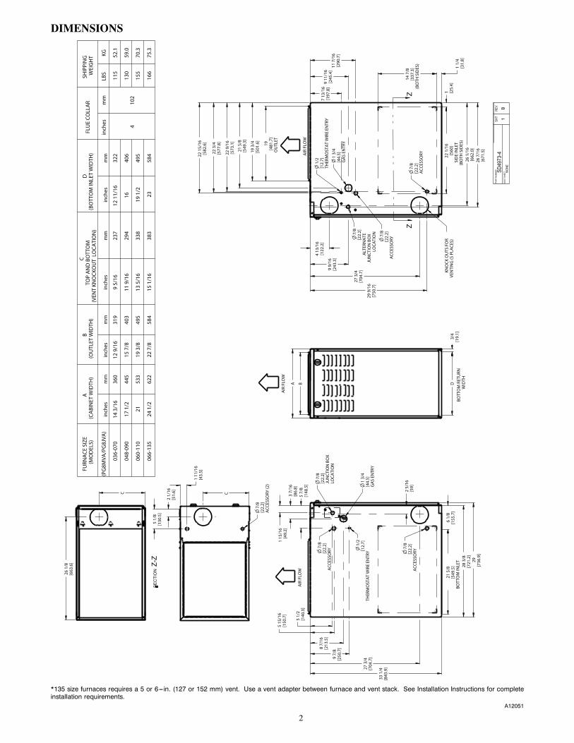
SPECIFICATIONS
UNIT SIZE 036070 048090 060110 066135
RATINGS AND PERFORMANCE
Input Btuh*Nonweatherized ICS
PG8JVA Upflow; all PG8MVAHigh 66,000 88,000 110,000 132,000
Low 43,500 58,000 72,500 87,000
PG8JVA Downflow/HorizontalHigh 63,000 84,000 105,000 126,000
Low 43,500 58,000 72,500 87,000
Output Capacity (Btuh)†Nonweatherized ICS
PG8JVA Upflow; all PG8MVAHigh 54,000 71,000 89,000 107,000
Low 35,000 47,000 59,000 70,000
PG8JVA Downflow/HorizontalHigh 51,000 68,000 85,000 102,000
Low 35,000 47,000 59,000 70,000
AFUE† 80.0 80.0 80.0 80.0
Certified Temperature Rise Range --- ° F (° C)
High 30-60(17---33)
40-70(22---39)
40-70(22---39)
40-70(22---39)
Low 30-60(17---33)
30-60(17---33)
25-55(14---30)
25-55(14---30)
Certified External Static Pressure Heat/Cool 0.12/0.50 0.15/0.50 0.20/0.50 0.20/0.50
Airflow CFM‡Heating High/Low 1060/615 1090/825 1330/1110 1725/1430
Cooling 1225 1400 2095 2100
ELECTRICAL
Unit Volts---Hertz---Phase 115-60-1
Operating Voltage Range Min-Max 104-127
Maximum Unit Amps 9.0 9.6 15.1 14.9
Maximum Wire Length (Measure 1 Way in Ft (M) 30 (9.1) 29 (8.8) 29 (8.8) 30 (9.1)
Minimum Wire Size 14 12
Maximum Fuse or Ckt Bkr Size (Amps)** 15 20
Transformer (24v) 40va
External Control Heating 12va
Power Available Cooling 35va
Air Conditioning Blower Relay Standard
CONTROLS
Limit Control SPST
Heating Blower Control Solid-State Time Operation
Burners (Monoport) 3 4 5 6
Gas Connection Size 1/2-in. NPT
GAS CONTROLS
Gas Valve (Redundant) Mfr. White-Rodgers
Min. inlet pressure (In. W.C.) 4.5 (Natural Gas)
Max. inlet pressure (In. W.C.) 13.6 (Natural Gas)
Ignition Device Hot Surface
Factory-installed orifice Size 43
BLOWER DATA
Direct-Drive Motor HP (ECM) 1/2 1/2 1 1
Motor Full Load Amps 7.7 7.7 12.8 12.8
RPM (Nominal)-Speeds 300-1300 300-1300 300-1300 300-1300
Blower Wheel Diameter x Width --- In. (mm) 10 x 6(254 x 152)
10 x 8(254 x 203)
11 x 10(279 x 254)
11 x 11(279 x 279)
* Gas input ratings are certified for elevations to 2000 ft. (610 M) In USA for elevations above 2000 ft (610 M), reduce ratings 4 percent for each 1000 ft (305M) above sea level. Refer to National Fuel Gas Code NFPA 54/ANSI Z223.1---2012 Table F.4 or furnace installation instructions.
† Capacity in accordance with U.S. Government DOE test procedures.‡ Airflow shown is for bottom only return-air supply for the as-shipped speed tap. For air delivery above 1800 CFM, see Air Delivery table for other options. A
filter is required for each return-air supply. An airflow reduction of up to 7 percent may occur when using the factory-specified 4-5/16 in. (110 mm) wide, highefficiency media filter.
** Time---delay type is recommended.ICS Isolated Combustion System
PG8MVA/JVA

5
A02058
SEE NOTES: 1,2,4,7,8,9UPFLOW
SEE NOTES: 1,2,3,4,7,8,9UPFLOW
SEE NOTES: 1,2,4,5,7,8,9DOWNFLOW
A02059 A02061
SEE NOTES:1,2,3,4,5,7,8,9DOWNFLOW
SEE NOTES: 1,2,3,4,5,7,8,9DOWNFLOW
SEE NOTES: 1,2,4,5,6,7,8,9DOWNFLOW
A02060 A02063 A02062
Venting Notes1. For common vent, vent connector sizing and vent material: United States, latest edition of the National Fuel GasCode (NFGC), ANSI Z223.1/NFPA 54.
2. Immediately increase to 5-in. (127 mm) vent connector outside furnace casing when 5-in. (127 mm) vent connectorrequired, refer to Note 1.
3. Side outlet vent for upflow and downflow installations must use Type B vent immediately after exiting the furnace,except when Downflow Vent Guard is used in downflow position.
4. Type B vent where required, refer to Note 1.5. 4--- in. (102 mm) single wall vent must be used inside furnace casing and the Downflow Vent Guard Kit.6. Accessory Downflow Vent Guard Kit required in downflow installations with bottom vent configuration.7. Chimney Adapter Kit required for exterior masonry chimney applications. Refer to Chimney Adapter Kits for sizingand complete application details.
8. Secure vent connector to furnace elbow with (2) corrosion-resistant sheet metal screws, space approximately 180°apart.
9. Secure all other single wall vent connector joints with (3) corrosion-resistant screws spaced approximately 120°apart. Secure Type B vent connectors per vent connector manufacturer’s recommendations.
PG8MVA/JVA

6
SEE NOTES: 1,2,4,5,7,8,9HORIZONTAL RIGHT
A02068
SEE NOTES: 1,2,4,5,7,8,9HORIZONTAL RIGHT
A02070
SEE NOTES: 1,2,4,7,8,9HORIZONTAL RIGHT
A02069
SEE NOTES: 1,2,4,7,8,9HORIZONTAL LEFT
A02064
SEE NOTES: 1,2,4,5,7,8,9HORIZONTAL LEFT
A02065
SEE NOTES: 1,2,4,5,7,8,9HORIZONTAL LEFT
A02066
SEE NOTES: 1,2,4,5,7,8,9HORIZONTAL LEFT
A02067
PG8MVA/JVA
7
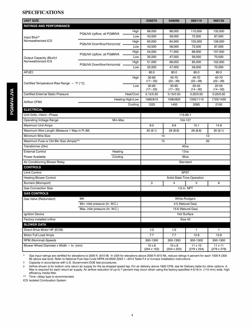
ACCESSORIES
DESCRIPTION PART NUMBER 036070 048090 060110 066135
External Bottom Return Filter Rack
KGBFR0401B14 X
KGBFR0501B17 X
KGBFR0601B21 X
KGBFR0701B24 X
External Side Return Filter Rack KGAFR0201ALL X X X X
Unframed Filter, 3/4-in. (19 mm)
KGAWF1306UFR† X X
KGAWF1406UFR X
KGAWF1506UFR X
Flue Extension KGAFE0112UPH X X X X
Combustible Floor Base KGASB0201ALL X X X X
Downflow Vent Guard KGBVG0101DFG X X X X
Vent Extension Kit KGAVE0101DNH X X X X
Chimney Adapter KitKGACA02014FC X X X
KGACA02015FC X
Natural-to-Propane Conversion Kit * KGBNP5201VSP X X X X
Propane-to-Natural Conversion Kit KGBPN4401VSP X X X X
Label Kit KGALB0301KIT X X X X
ECM Motor Simulator KGBSD0301FMS X X X X
Gas Orifice
LH32DB207
See Installation Instructions for model, altitude, and heat value usages.
LH32DB202
LH32DB200
LH32DB205
LH32DB208
LH32DB078
LH32DB076
LH32DB203
LH32DB201
LH32DB206
LH32DB209
LH32DB210
* Factory authorized, field installed. Fuel conversion kits are CSA (Formerly AGA/CGA) recognized.† Suitable for Side Return Filter Rack.X = AccessoryS = Standard
PG8MVA/JVA

8
AIR DELIVERY -- CFM (With Filter)*
Unit Size Operating ModeCFMAirflowSetting
ExternalStaticPressureRange*(In. W.C.)
External Static Pressure (ESP) (In. W.C.)
0.1 0.2 0.3 0.4 0.5 0.6 0.7 0.8 0.9 1
036070 AIRFLOW (CFM)†† Low Heat 735 (615)† 0---0.50 735 735 735 735 725
High Heat 1180(1060)† 0---1.0 1160 1165 1175 1180 1180 1180 1180 1180 1180 1175
†† 1---1/2---Ton Cooling 525 0---0.50‡ 515 500 500 490 485†† 2---Ton A/C Cooling 700 0---0.50‡ 690 680 675 680 675
2---1/2---Ton A/C Cooling 875 0---1.0‡ 875 875 875 870 865 855 850 835 825 8203---Ton A/C Cooling 1050 0---1.0‡ 1050 1050 1050 1050 1050 1050 1045 1035 1020 1000
3---1/2---Ton A/C Cooling 1225 0---1.0 1220 1225 1225 1225 1225 1220 1205 1190 1185 1170Maximum 1400 0---1.0 1395 1400 1400 1400 1395 1385 1370 1340 1300 1245
048090Low Heat 985 (825)† 0---1.0 950 970 985 985 985 985 985 985 985 980
High Heat 1210(1090)† 0---1.0 1190 1205 1210 1210 1210 1210 1210 1210 1210 1200
†† 1---1/2---Ton A/C Cooling 525 0---0.50‡ 525 520 525 495 475†† 2---Ton A/C Cooling 700 0---0.50‡ 680 680 680 675 670
2---1/2---Ton A/C Cooling 875 0---1.0‡ 815 845 845 855 850 850 845 835 820 8053---Ton A/C Cooling 1050 0---1.0‡ 1005 1005 1015 1035 1040 1040 1035 1030 1025 1010
3---1/2---Ton A/C Cooling 1225 0---1.0 1190 1200 1200 1205 1205 1215 1205 1200 1185 11704---Ton A/C Cooling 1400 0---1.0 1350 1370 1390 1390 1400 1390 1380 1380 1360 1340
Maximum 1600 0---1.0 1595 1600 1600 1600 1595 1555 1505 1465 1430 1390060110***
Low Heat 1320(1110)† 0---1.0 1275 1295 1315 1320 1320 1320 1320 1320 1320 1315
High Heat 1475(1330)† 0---1.0 1460 1465 1475 1475 1475 1475 1475 1475 1465 1465
†† 2---Ton A/C Cooling 700 0---0.50‡ 700 700 700 700 700†† 2---1/2---Ton A/C Cooling 875 0---0.50‡ 875 875 875 875 875†† 3---Ton A/C Cooling 1050 0---0.50‡ 1050 1050 1050 1050 1050
3---1/2---Ton A/C Cooling 1225 0---1.0‡ 1225 1225 1225 1225 1225 1225 1225 1225 1225 12254---Ton A/C Cooling 1400 0---1.0‡ 1400 1400 1400 1400 1400 1400 1400 1400 1400 14005---Ton A/C Cooling 1750 0---1.0‡ 1750 1750 1750 1750 1750 1750 1750 1750 1740 17256---Ton A/C Cooling 2100 0---1.0 2100 2100 2100 2100 2090 2075 2055 2040 2005 1970
Maximum 2200 0---1.0 2200 2190 2190 2180 2155 2145 2125 2100 2080 2020066135
Low Heat 1700(1430)† 0---1.0 1700 1700 1700 1700 1700 1695 1700 1695 1685 1670
High Heat 1915(1725)† 0---1.0 1900 1905 1915 1915 1915 1915 1915 1915 1915 1915
†† 2---Ton A/C Cooling 700 0---0.50‡ 700 700 700 700 665†† 2---1/2---Ton A/C Cooling 875 0---0.50‡ 870 870 865 865 865†† 3---Ton A/C Cooling 1050 0---0.50‡ 1010 1030 1050 1050 1050
3---1/2---Ton A/C Cooling 1225 0---1.0‡ 1155 1180 1200 1210 1220 1225 1225 1225 1225 12254---Ton A/C Cooling 1400 0---1.0‡ 1395 1400 1400 1400 1400 1400 1400 1390 1375 13555---Ton A/C Cooling 1750 0---1.0‡ 1740 1750 1750 1750 1735 1740 1735 1730 1715 17006---Ton A/C Cooling 2100 0---1.0 2075 2085 2090 2100 2100 2100 2090 2080 2055 2025
Maximum 2200 0---1.0 2180 2195 2200 2200 2200 2200 2185 2165 2140 2095
*Actual external static pressure (ESP) can be determined by using the fan laws (CFM 2 proportional to ESP); such as, a system with 1180 CFMat 0.5 ESP would operate at cooling airflow of 1050 CFM at 0.4 ESP and low---heating airflow of 735 CFM at 0.19 ESP.{Comfort airflow values are shown in parenthesis. Comfort airflow is selected when the low---heat rise adjustment switch (SW1---3) is OFF andthe comfort/efficiency switch (SW1---4) is ON.}Ductwork must be sized for high---heating CFM within the operational range of ESP.{{Operation within the blank areas of the chart is not recommended because high---heat operation will be above 1.0 ESP.***All airflows on 110 size furnace are 5% less on side return only installations.
PG8MVA/JVA
9
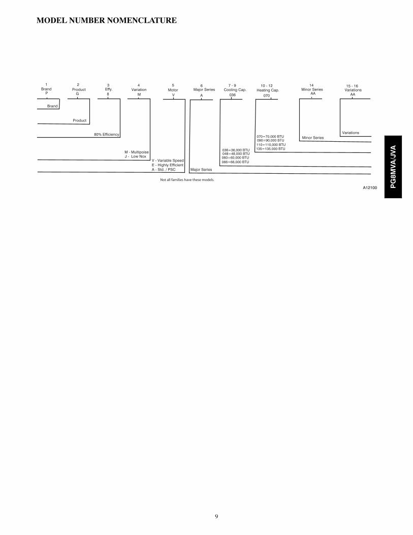
MODEL NUMBER NOMENCLATURE
P 8 M V A 036 070 AA AA
Product
M - MultipoiseJ - Low Nox
Brand
Major Series
Minor Series
1Brand
2Product Effy.
3 4Variation
5Motor Major Series
6Cooling Cap.
7 - 9 10 - 12Heating Cap.
14Minor Series Variations
15 - 16
G
80% Efficiency Variations070=70,000 BTU 090=90,000 BTU 110=110,000 BTU 135=135,000 BTU
Not all families have these models.
036=36,000 BTU
060=60,000 BTU 066=66,000 BTU
048=48,000 BTU
V - Variable SpeedE - Highly Efficient A - Std. / PSC
A12100 PG8MVA/JVA

10
GUIDE SPECIFICATIONS
Gas FurnacePG8MVA/JVAGeneralSYSTEM DESCRIPTION
Furnish a _________________ fixed capacity gas-firedfurnace for use with natural gas or propane (factoryauthorized conversion kit required for propane).QUALITY ASSURANCE
Unit will be designed, tested and constructed to thecurrent ANSI Z 21.47/CSA 2.3 design standard forgas-fired central furnaces.
Unit will be 3rd party certified by CSA to the currentANSI Z 21.47/CSA 2.3 design standard for gas-firedcentral furnaces.
Unit will carry the CSA Blue StarR label.Unit efficiency testing will be performed per the current
DOE test procedure as listed in the Federal Register.Unit will be certified for capacity and efficiency and
listed in the latest AHRI Consumer’s Directory ofCertified Efficiency Ratings.
Unit shall carry the current Federal Trade CommissionEnergy Guide efficiency label.DELIVERY, STORAGE AND HANDLING
Unit shall be shipped as single package only and isstored and handled per unit manufacturer’srecommendations.WARRANTY (for inclusion by specifying engineer)
U.S. only. Warranty certificate available upon request.EQUIPMENT
Components shall include: slow-opening gas valve toreduce ignition noise, regulate gas flow, with electricswitch gas shut-off; flame proving sensor, hot surfaceigniter, pressure switch assembly, flame rollout switch,blower and inducer assembly, 40va transformer;low--voltage (heating) (heating/cooling) thermostat.Blower Wheel and Blower Motor
Galvanized blower wheel shall be centrifugal type,statically and dynamically balanced. Variable--speed ECMblower motor shall be permanently lubricated with sealedbearings, of _______hp, and shall be multiple-speed directdrive. Blower motor shall be soft mounted to the blowerscroll to reduce vibration transmission.Filters
Furnace may have reusable-type filters. Filter shall be_______ in. (mm) (x) _______in. (mm).Casing
Casing shall be of .030--in. (.76 mm) thicknessminimum, pre--painted steel.
Inducer Motor
Inducer motor shall be soft mounted to reduce vibrationtransmission.Draft Safeguard Switch
Draft Safeguard Switch (blocked vent safeguard) shallbe factory installed to reduce the possibility of vent gasinfiltration due to a blocked or restricted vent pipe.Heat Exchangers
Heat exchangers shall be a 4-Pass 20 gage aluminizedsteel of fold-and-crimp sectional design when appliedoperating under negative pressure.Controls
Control shall include a micro-processor basedintegrated electronic control board with at least 11 servicetroubleshooting codes displayed via enhanced flashingLED diagnostic light on the control, a self-test feature thatchecks all major functions of the furnace within oneminute, and a replaceable automotive-type circuitprotection fuse. Multiple operational settings availableincluding, separate blower speeds for low heat, high heat,low cooling, high cooling and continuous fan. Continuousfan speed may be adjusted from the thermostat. Coolingairflow will be selectable between 325, 350, 370 or 400CFM per ton of air conditioning. Features will also includetemporary reduced airflow in the cooling mode forimproved dehumidification.OPERATING CHARACTERISTICS
Heating Capacity shall be ________ Btuh input;________ Btuh output capacity.
Fuel Gas Efficiency shall be 80% AFUE.Air delivery shall be ___________ CFM minimum at
0.50 In. W.C. external static pressure.Dimensions shall be: depth __________ in. (mm);
width _________ in. (mm); height_________in. (mm)(casing only). Height shall be_________in. (mm) withA/C coil and _____________in. (mm) overall withplenum.ELECTRICAL REQUIREMENTS
Electrical supply shall be 115 volts, 60 Hz,single--phase (nominal). Minimum wire size shallbe_________AWG; maximum fuse size or circuit breakershall be __________Amps.SPECIAL FEATURES
Refer to section of the product data sheet identifyingaccessories and descriptions for specific features andavailable enhancements.
E2013 Payne Heating & Cooling Systems D 7310 W. Morris St. D Indianapolis, IN 46231 Edition Date: 08/13
Manufacturer reserves the right to change, at any time, specifications and designs without notice and without obligations.
Catalog No: SS---PG8MVA---03
Replaces: SS---PG8MVA---02
PG8MVA/JVA
Related Documents