International Journal of Computer Science & Engineering Survey (IJCSES) Vol.6, No.3, June 2015 DOI:10.5121/ijcses.2015.6302 9 PERFORMANCE EVALUATION OF MC-CDMA SYSTEM OVER RAYLEIGH FADING CHANNEL A. M. Abdulsattar 1 , A. D. Alwazzan 2 and K. M.Quboa 2 1 Alhdba University College, Mousel, Iraq 2 Mousel University, Mousel, Iraq ABSTRACT Multi Carrier Code Division Multiple Access (MC-CDMA) is a well known technique for high speed wireless data transmission .Two advanced technology was included in the MC-CDMA structure, such as orthogonal frequency division multiplex (OFDM) and the code division multiple access (CDMA),so that it benefits from the robustness of OFDM against multipath environment and from the capability of multiuser multiplexing services that is achieved via (CDMA) system. MC-CDMA is a multicarrier spread spectrum system which is classified as the candidate scheme for future mobile radio systems. In this paper MC- CDMA system, with Rayleigh fading channel and 16QAM array modulation, was simulated to investigate the effects of different parameters on the system performance, such as processing gain; number of paths; number of users; interleaving; and coding ratio.MC-CDMA performances can be considerably improved by proper selection of these parameters. As expected, results show that MC-CDMA has a better performance over CDMA system. KEYWORDS CDMA, OFDM, MC-CDMA, Rayleigh fading, Convolutional Encoder. 1. INTRODUCTION People use mobile not only for making their calls but also to transmit and receive different data types like: music, video, games and many other applications. Due to the large number of people request for different communication services, the multiple access technique has been necessary to deal with all requests. The mobile radio channel is considered as one of the difficult channels to deal with. The multipath effect is one of the complicated problems in mobile radio channel and heavily affects the system performance due to the effect of Inter symbol Interference (ISI). Many communication systems used techniques that are known as orthogonal frequency division multiplexing (OFDM) and code division multiple access (CDMA) [1]. OFDM and CDMA techniques are used in high speed wireless communications. One of the advanced technique for broadband wireless communication is Multi-Carrier Code Division Multiple Access (MC- CDMA)[2]. MC-CDMA system benefits from the robustness of OFDM against multipath environment and from the capability of multiuser multiplexing services that is achieved via (CDMA)system[2,3].In this paper MC-CDMA performance under Rayleigh fading channelusing16-QAM array modulation, was evaluated for different system parameters such as number of users, number of paths, processing gain, ratio of convolutional encoder, and interleaver. 2. MC-CDMA SYSTEM To support high data rates services, several 4G systems utilizes MC-CDMA to minimize the inter symbol interference (ISI) that occurs when transmission through multipath wireless channels are

PERFORMANCE EVALUATION OF MC-CDMA SYSTEM OVER RAYLEIGH FADING CHANNEL
Aug 06, 2015
Welcome message from author
This document is posted to help you gain knowledge. Please leave a comment to let me know what you think about it! Share it to your friends and learn new things together.
Transcript
International Journal of Computer Science & Engineering Survey (IJCSES) Vol.6, No.3, June 2015
DOI:10.5121/ijcses.2015.6302 9
PERFORMANCE EVALUATION OF MC-CDMA
SYSTEM OVER RAYLEIGH FADING CHANNEL
A. M. Abdulsattar1, A. D. Alwazzan
2 and K. M.Quboa
2
1Alhdba University College, Mousel, Iraq
2Mousel University, Mousel, Iraq
ABSTRACT
Multi Carrier Code Division Multiple Access (MC-CDMA) is a well known technique for high speed
wireless data transmission .Two advanced technology was included in the MC-CDMA structure, such as
orthogonal frequency division multiplex (OFDM) and the code division multiple access (CDMA),so that it
benefits from the robustness of OFDM against multipath environment and from the capability of multiuser
multiplexing services that is achieved via (CDMA) system. MC-CDMA is a multicarrier spread spectrum
system which is classified as the candidate scheme for future mobile radio systems. In this paper MC-
CDMA system, with Rayleigh fading channel and 16QAM array modulation, was simulated to investigate
the effects of different parameters on the system performance, such as processing gain; number of paths;
number of users; interleaving; and coding ratio.MC-CDMA performances can be considerably improved
by proper selection of these parameters. As expected, results show that MC-CDMA has a better
performance over CDMA system.
KEYWORDS
CDMA, OFDM, MC-CDMA, Rayleigh fading, Convolutional Encoder.
1. INTRODUCTION
People use mobile not only for making their calls but also to transmit and receive different data
types like: music, video, games and many other applications. Due to the large number of people
request for different communication services, the multiple access technique has been necessary to
deal with all requests. The mobile radio channel is considered as one of the difficult channels to
deal with. The multipath effect is one of the complicated problems in mobile radio channel and
heavily affects the system performance due to the effect of Inter symbol Interference (ISI). Many
communication systems used techniques that are known as orthogonal frequency division
multiplexing (OFDM) and code division multiple access (CDMA) [1]. OFDM and CDMA
techniques are used in high speed wireless communications. One of the advanced technique for
broadband wireless communication is Multi-Carrier Code Division Multiple Access (MC-
CDMA)[2]. MC-CDMA system benefits from the robustness of OFDM against multipath
environment and from the capability of multiuser multiplexing services that is achieved via
(CDMA)system[2,3].In this paper MC-CDMA performance under Rayleigh fading
channelusing16-QAM array modulation, was evaluated for different system parameters such as
number of users, number of paths, processing gain, ratio of convolutional encoder, and
interleaver.
2. MC-CDMA SYSTEM
To support high data rates services, several 4G systems utilizes MC-CDMA to minimize the inter
symbol interference (ISI) that occurs when transmission through multipath wireless channels are
International Journal of Computer Science & Engineering Survey (IJCSES) Vol.6, No.3, June 2015
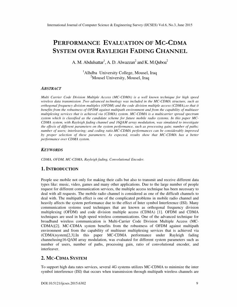
used. The OFDM, as a kind of multicarrier modulation, is an efficient low complex technique
modulated multiple subcarriers using digital signal processing (DSP).
sub-streams was achieved by the multi
high data rate stream already injected at system input.
different sub-carrier as shown in Figure 1
Figure 1.
One of the important targets in using multicarrier transmission based on OFDM technique is that
the mobile radio channel can be cons
type fading which is already considered
[4].
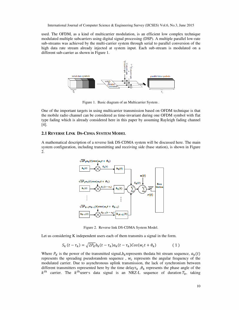
2.1 REVERSE LINK DS-CDMA
A mathematical description of a
system configuration, including transmitting
2.
Figure 2.
Let us considering K independent users e ���� � ��� 2� Where � is the power of the transmitted
represents the spreading pseudorandom sequence ,
modulated carrier. Due to asynchronous uplink transmission, the l
different transmitters represented here by��� carrier. The ���user ,s data signal is a
International Journal of Computer Science & Engineering Survey (IJCSES) Vol.6, No.3, June 2015
The OFDM, as a kind of multicarrier modulation, is an efficient low complex technique
modulated multiple subcarriers using digital signal processing (DSP). A multiple parallel low
by the multi-carrier system through serial to parallel conversi
already injected at system input. Each sub-stream is modulated on a
as shown in Figure 1.
Figure 1. Basic diagram of an Multicarrier System .
in using multicarrier transmission based on OFDM technique is that
the mobile radio channel can be considered as time-invariant during one OFDM symbol with flat
which is already considered here in this paper by assuming Rayleigh fading
DMA SYSTEM MODEL
A mathematical description of a reverse link DS-CDMA system will be discussed here. The main
including transmitting and receiving side (base station), is shown
Figure 2. Reverse link DS-CDMA System Model.
independent users each of them transmits a signal in the form.
���� � ������� � ���������� � ����1�power of the transmitted signal,��represents thedata bit stream sequence,
pseudorandom sequence , �� represents the angular frequency
carrier. Due to asynchronous uplink transmission, the lack of synchronism between
represented here by the time delay�� ,�� represents the phase angle of the
s data signal is an NRZ-L sequence of duration
International Journal of Computer Science & Engineering Survey (IJCSES) Vol.6, No.3, June 2015
10
The OFDM, as a kind of multicarrier modulation, is an efficient low complex technique
multiple parallel low-rate
conversion of the
stream is modulated on a
in using multicarrier transmission based on OFDM technique is that
one OFDM symbol with flat
Rayleigh fading channel
CDMA system will be discussed here. The main
is shown in Figure
� sequence, �����
angular frequency of the
ack of synchronism between
he phase angle of the
duration !, taking

International Journal of Computer Science & Engineering Survey (IJCSES) Vol.6, No.3, June 2015
values"�1#, �#1$. If �is the chip period, then
factor for user k. By considering the desired user as
interference (MAI) comes mainly
signal formula at the input of the receiver %���
Where &����is the complex low pass equivalent impulse response of the the transmitted channel
and n(t) is Additive White Gaussian Noise (AWGN)
at the input of the receiver after Considering (1) and (2)
%���� ' ' 2��()
*)+,
-,
�+./�
� 0���
Where ∅�,*) is the phase of the multipath component,
of multipath components. α3,*) is
the magnitude of the 4�� multipath
2.2 OFDM BASIC SYSTEM
The OFDM system block diagram
Figure 3
Binary data was generated and coded using convolutional
converted from bits to symbols using M
was inserted into modulated signal , then symbols are converted from serial to parallel substream
with size equal to the number of subcarriers.
The cyclic prefix (CP) was added to eliminate ISI and inter carrier
transmission purposes, data was converted from parallel to serial one.
received signal, after CP removing,
circuit to get the useful data and pilots which are use
signal is equalized depending on the channel es
channel. The equalized signal is back converted from parallel to serial st
demodulated, deinterleaved, and decoded in order to recover the original bits[
International Journal of Computer Science & Engineering Survey (IJCSES) Vol.6, No.3, June 2015
is the chip period, then 5� 6768 is the processing gain (PG) or the spreading
By considering the desired user as k=0, then the introduced multiple access
mainly from the contribution of all other users. Equation (
of the receiver.
�� &��������� � 0����2� is the complex low pass equivalent impulse response of the the transmitted channel
ive White Gaussian Noise (AWGN). Equation (3) gives the formula
of the receiver after Considering (1) and (2)[5] [6].
�,*)��9� � ��,*): ; �����<��9� � ��,*):<��9=�� � >�3�
is the phase of the multipath component, ��,*) is the path delay, and @� is the number
is a random process with Rayleigh distribution which represents
multipath .
block diagram is shown in Figure 3.
Figure 3. The block diagram of an OFDM System.
Binary data was generated and coded using convolutional encoder. After interleaving data was
converted from bits to symbols using M-arry modulation. For channel estimation purposes pilots
was inserted into modulated signal , then symbols are converted from serial to parallel substream
ber of subcarriers. Those substreams are modulated using IFFT circuit.
was added to eliminate ISI and inter carrier interference
transmission purposes, data was converted from parallel to serial one. At the receiver sid
after CP removing, is converted from serial to parallel, then signal is fed into FFT
circuit to get the useful data and pilots which are used to estimate the effect of the
signal is equalized depending on the channel estimation information to compensate the effect of
channel. The equalized signal is back converted from parallel to serial stream. The signal is
, and decoded in order to recover the original bits[7].
International Journal of Computer Science & Engineering Survey (IJCSES) Vol.6, No.3, June 2015
11
or the spreading
multiple access
Equation (2) gives the
is the complex low pass equivalent impulse response of the the transmitted channel
. Equation (3) gives the formula of the signal
>�,*):
is the number
which represents
encoder. After interleaving data was
. For channel estimation purposes pilots
was inserted into modulated signal , then symbols are converted from serial to parallel substream
substreams are modulated using IFFT circuit.
interference (ICI ) . For
At the receiver side, the
is converted from serial to parallel, then signal is fed into FFT
d to estimate the effect of the channel. The
timation information to compensate the effect of
ream. The signal is

International Journal of Computer Science & Engineering Survey (IJCSES) Vol.6, No.3, June 2015
12
2.3 MC-CDMA SYSTEM MATHEMATICAL MODEL
MC-CDMA scheme spreads the original data on large bandwidth by using a given spreading code
and converts the high rate of serial stream to parallel low rate substream then transmits N chips
simultaneously by assigning each chip to a separate carrier, by using OFDM transmitter, so that
each input symbol is transmitted on N subcarriers. By correlating the signal samples at the OFDM
outputwith the code sequence used for signal dispreading, the transmitted symbol will be
extracted at theoutput of the receiver.MC-CDMA transmitter system is shown by figure 4, where aB[i] represents binary data input sequence belong to the uth user at ith time.
Figure 4. MC-CDMA transmitter.
Considering the case where the length of processing gain PG is equal to the number of subcarrier
Nc(Nc=PG ), the ith input dataaB[i],is first copied to Nc subchannels and then multiplied by the
spreading codeCGB which corresponds to the uth user, modulated by Nc subcarriers, then summed
and digitized to generate the transmitted MC-CDMA signalxI[i] which is given by [9].
xI[i] ' XG[i]eKLMNOPQRS-,
I+. , n 0,1, … , Nc � 1�4�
WhereXG[i] ' aB[i]\-,
B+.CGB �5�
Where CGB is the spreading code given by (6). CGB C.B, C,B, … , C^_-,B �6� The transmitted signal, xn[i]in (4) has a similar formula as that of the OFDM transmitted
signal,except that it contains the multiuser multiplexing capability which is introduced basically
by the CDMA technology. For simplicity, the index (i) could be omitted in case of one OFDM
symbol and assuming multipath fading channel consists of L-paths, then the received signal, yI,
is given by (7).
yI 'hI,*b-,
*+.xI-* �wI … �7�

International Journal of Computer Science & Engineering Survey (IJCSES) Vol.6, No.3, June 2015
13
Where hI,* represents the channel impulse response of the lthpath at time n and wI is the noise
component. Without inter carrier interference(ICI ),the received signal in the frequency domain is
given by (8):
YG f'H*.e-KLMhNPQb-,
*+.i XG �WG
αmXG �WG … (8)
WhereWG is the noise component in frequency domain, L represents the number of paths,
AndαGrepresents the multipath fading effect and is given by (9).
αj 'H*.e-KLMhkPQb-,
*+.�9�
Where H*.represents the channel transfer function.
If the channel is assumed to be time invariant during the symbol period, then it could be easily
compensated by frequency domain equalizer, where the output of the equalizer is given by (10).
X = H-1 YT (10)
WhereH-1
is the estimated invers channel transfer function.
Based on equations (7,8,10), Figure 5shows the channel estimation and equalization system for
MC-CDMA receiver which is already adopted in this paper.
Figure 5. MC-CDMA receiver.
3. SIMULATION AND RESULTS
The system simulation is carried out using MC-CDMA Simulator, designed and built in
MATLAB to study the performance of MC-CDMA system for different lengths of processing
gain, number of paths, coding ratios of the convolutional encoder, number of users and
interleaver.
3.1 MC-CDMA SIMULATOR
In this section, a simulator built for the uplink scenario of MC-CDMA system is described. It is
composed of four basic units to simulate the transmitter, channel, receiver and BER calculator.

International Journal of Computer Science & Engineering Survey (IJCSES) Vol.6, No.3, June 2015
14
3.1.1 TRANSMITTER SECTION
MC-CDMA transmitter block diagram is shown in Figure 6.
Figure 6. Structure of the MC-CDMA transmitter.
The information bits are generated at 1 in Figure 6 for number of users. These binary bits are
coded by using a convolutional encoder with different coding ratios of 1/2, 2/3 and 3/4.
Convolutional encoder is performed according to IEEE 802.11a standard and is built as shown in
Figure 7with six Shift Registers (SR)[10].
Figure 7. Convolutional encoder structure.
Higher rates (2/3 & 3/4) are derived from the same structure by employing “puncturing”. Some of
the encoded bits in the transmitter will be omitted using Puncturing procedure, thus reducing the
number of transmitted bits and increasing the coding rate. At the receiver a “zero” will be inserted
into the convolutional decoder on the place of the omitted bits. In this case Viterbi algorithm is
recommended for the decoder. Table (1) shows the specifications of the IEEE 802.11a
Convolutional encoder[10].
Table 1. The IEEE 802.11a Convolutional encoder specifications.
The coded bits are interleaved by using an interleaver. The interleaved bits are modulated
(mapped) to data symbols according to the symbol modulation type which transforms the binary
bits into complex data symbols according to the value of modulation index (M). In this paper; 16-
QAM modulation type is taken into consideration. The spreading operation was performed using
Gold code, which is chosen here due to its good cross correlation property, which is an essential
International Journal of Computer Science & Engineering Survey (IJCSES) Vol.6, No.3, June 2015
15
requirement for CDMA system, where many users share the same medium and to assuring the
ability for the receiver to distinguish between them especially in the reverse-link (uplink) case
where the transmission is subject to asynchronous behavior between the different transmitted
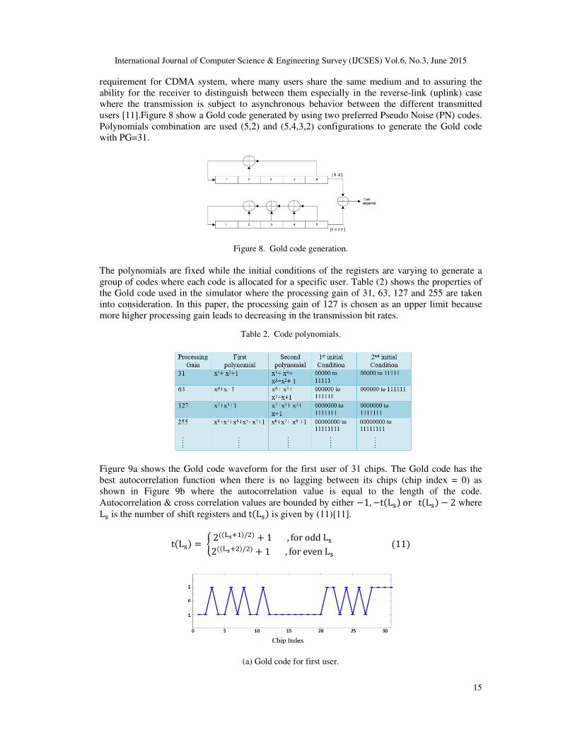
users [11].Figure 8 show a Gold code generated by using two preferred Pseudo Noise (PN) codes.
Polynomials combination are used (5,2) and (5,4,3,2) configurations to generate the Gold code
with PG=31.
Figure 8. Gold code generation.
The polynomials are fixed while the initial conditions of the registers are varying to generate a
group of codes where each code is allocated for a specific user. Table (2) shows the properties of
the Gold code used in the simulator where the processing gain of 31, 63, 127 and 255 are taken
into consideration. In this paper, the processing gain of 127 is chosen as an upper limit because
more higher processing gain leads to decreasing in the transmission bit rates.
Table 2. Code polynomials.
Figure 9a shows the Gold code waveform for the first user of 31 chips. The Gold code has the
best autocorrelation function when there is no lagging between its chips (chip index = 0) as
shown in Figure 9b where the autocorrelation value is equal to the length of the code.
Autocorrelation & cross correlation values are bounded by either �1,�t�Lo�ort�Lo� � 2 where Lo is the number of shift registers and t�Lo� is given by (11)[11].
t�Lo� q 2��brs,�/u� � 1, foroddLo2��brsu�/u� � 1, forevenLo�11�#
(a) Gold code for first user.
International Journal of Computer Science & Engineering Survey (IJCSES) Vol.6, No.3, June 2015
16
(b) Autocorrelation of first Gold code.
Figure 9. Characteristics of first user Gold code.
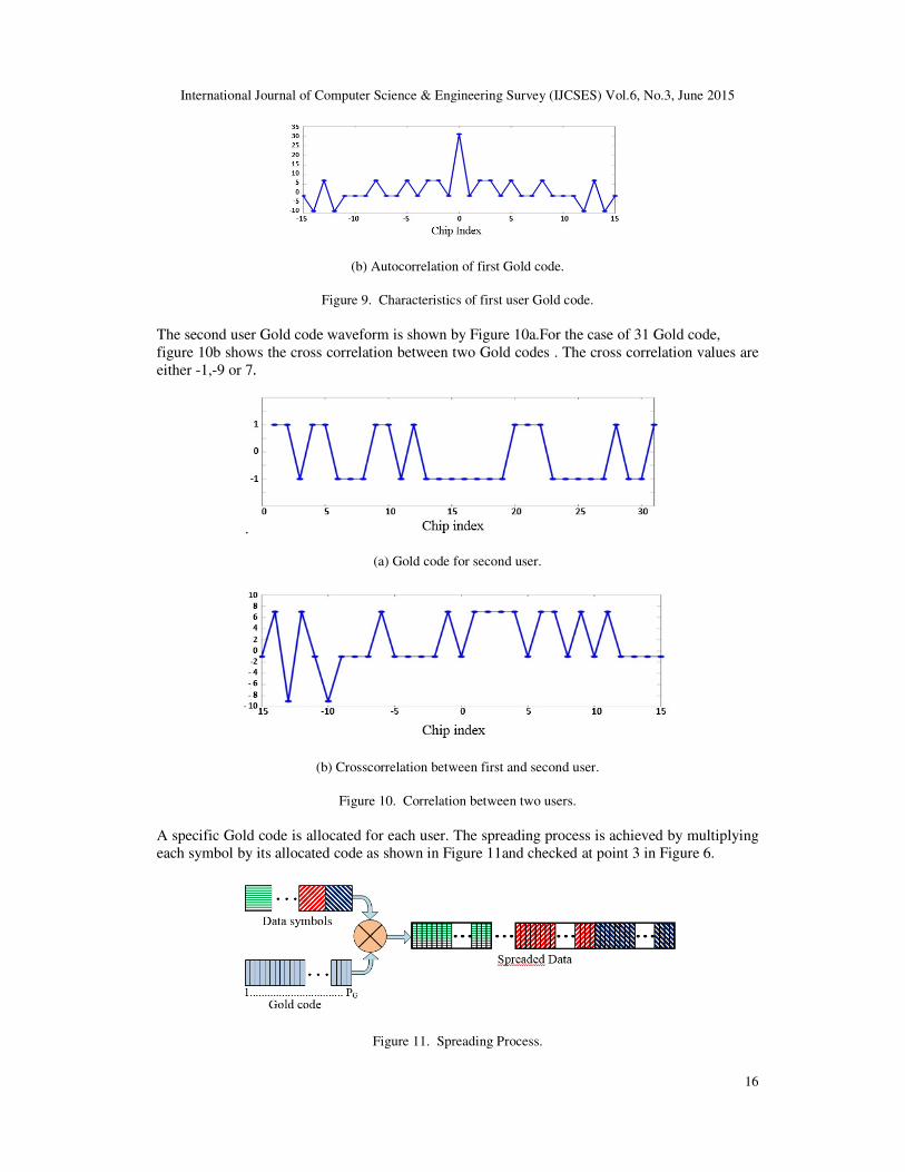
The second user Gold code waveform is shown by Figure 10a.For the case of 31 Gold code,
figure 10b shows the cross correlation between two Gold codes . The cross correlation values are
either -1,-9 or 7.
.
(a) Gold code for second user.
(b) Crosscorrelation between first and second user.
Figure 10. Correlation between two users.
A specific Gold code is allocated for each user. The spreading process is achieved by multiplying
each symbol by its allocated code as shown in Figure 11and checked at point 3 in Figure 6.
Figure 11. Spreading Process.

International Journal of Computer Science & Engineering Survey (IJCSES) Vol.6, No.3, June 2015
17
The pilot insertion process is used to insert pilots with known values in the transmitter and the
receiver units. This could be done by choosing a Comb type estimator proposed in this paper. In
the proposed Comb type, the number of pilots is chosen to be 12, because in IEEE802.11a
standard it is specified that only 48 subcarriers are used for data in the OFDM symbol and the 16
subcarriers, including nulls, to achieve a 64-point for the IFFT implementation. Figure 12 show
the replacement of the 12 data subcarriers by those of 12 pilots and checked at point 4 in Figure 6.
Figure 12. Pilot insertion in Comb type.
The serial stream is converted into 64 parallel substreams which are equal to the size of IFFT
circuit. The IFFT circuit modulates each chip of data to the subcarrier where the IFFT circuit
ensures the orthogonality between subcarriers and checked at point 5 in Figure 6.The parallel
substreams are reconverted to serial streams. The cyclic prefix(CP) is added by copying the last
part with length of 16 (equivalent to Ts/4) resulting in 80 bits symbol length as shown in Figure
13.
Figure 13. Adding cyclic prefix.
Finally the MC-CDMA symbols are transmitted to the mobile radio channel at point 6 in Figure
6.
3.1.2. MOBILE RADIO CHANNEL SECTION
To include the effect of the multipath fading channel and Additive White Gaussian Noise
(AWGN), the mobile radio channel is divided into two parts as shown in Figure 14.Multipath
Rayleigh fading channel is considered in this paper. The uplink case is taken into consideration
where each user is affected by certain multipath channel and the faded signals from different
users are added together. The last step is represented by adding the AWGN effect before the
signal reaches the receiver. All the processes which established at the transmitter site was
reversed at the receiver site to get the transmitted message by considering perfect carriers and
symbol synchronization.
International Journal of Computer Science & Engineering Survey (IJCSES) Vol.6, No.3, June 2015
18
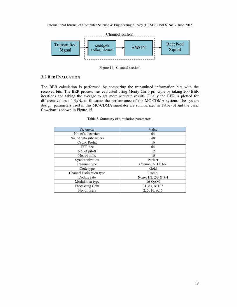
Figure 14. Channel section.
3.2 BER EVALUATION
The BER calculation is performed by comparing the transmitted information bits with the
received bits. The BER process was evaluated using Monty Carlo principle by taking 200 BER
iterations and taking the average to get more accurate results. Finally the BER is plotted for
different values of Eb/N0 to illustrate the performance of the MC-CDMA system. The system
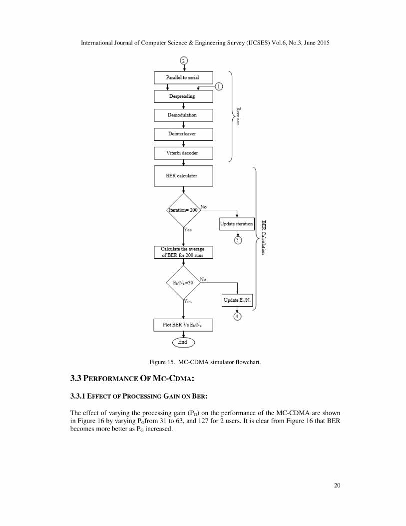
design parameters used in this MC-CDMA simulator are summarized in Table (3) and the basic
flowchart is shown in Figure 15.
Table 3. Summary of simulation parameters.

International Journal of Computer Science & Engineering Survey (IJCSES) Vol.6, No.3, June 2015
19
….. to be continued
International Journal of Computer Science & Engineering Survey (IJCSES) Vol.6, No.3, June 2015
20
Figure 15. MC-CDMA simulator flowchart.
3.3 PERFORMANCE OF MC-CDMA:
3.3.1 EFFECT OF PROCESSING GAIN ON BER:
The effect of varying the processing gain (PG) on the performance of the MC-CDMA are shown
in Figure 16 by varying PGfrom 31 to 63, and 127 for 2 users. It is clear from Figure 16 that BER
becomes more better as PG increased.

International Journal of Computer Science & Engineering Survey (IJCSES) Vol.6, No.3, June 2015
21
Figure 16. Effect of processing gain on MC-CDMA performance.
3.3.2 EFFECT OF NUMBER OF PATHS ON BER Figure 17 shows the effect of number of channel paths on the BER of the system for 2 users for
1,2,3 and 4 paths.It is clear that more degradation in system performance occurs as the number of
paths increases.
Figure 17. Effect of number of paths on MC-CDMA performance.
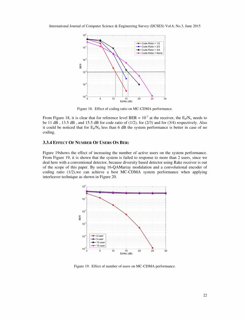
3.3.3 EFFECT OF CODE RATIO OF CONVOLUTIONAL ENCODER ON BER:
Convolutional encoder is used to handle the deep fading caused by the channel. Figure 18shows
the effect of using different coding ratios for 2 users.
International Journal of Computer Science & Engineering Survey (IJCSES) Vol.6, No.3, June 2015
22
Figure 18. Effect of coding ratio on MC-CDMA performance.
From Figure 18, it is clear that for reference level BER = 10-3 at the receiver, the Eb/No needs to
be 11 dB , 13.5 dB , and 15.5 dB for code ratio of (1/2), for (2/3) and for (3/4) respectively. Also
it could be noticed that for Eb/N0 less than 6 dB the system performance is better in case of no
coding.
3.3.4 EFFECT OF NUMBER OF USERS ON BER:
Figure 19shows the effect of increasing the number of active users on the system performance.
From Figure 19, it is shown that the system is failed to response to more than 2 users, since we
deal here with a conventional detector, because diversity based detector using Rake receiver is out
of the scope of this paper. By using 16-QAMarray modulation and a convolutional encoder of
coding ratio (1/2),we can achieve a best MC-CDMA system performance when applying
interleaver technique as shown in Figure 20.
Figure 19. Effect of number of users on MC-CDMA performance.

International Journal of Computer Science & Engineering Survey (IJCSES) Vol.6, No.3, June 2015
23
Figure 20. Effect of interleaver on MC-CDMA performance.
4. CONCLUSION
The combination between OFDM technology and CDMA technology resulting an attractive high
speed wireless MC-CDMA communication system. The obtained results showns that the
performance of the MC-CDMA is affected by different parameters such as processing gain,
number of paths, number of active users, coding ratio of convolutional encoder, and
interleaver.MC-CDMA system performance becomes better by increasing the processinggain,
decreasing number of paths, and decreasing the coding ratio. As the number of users increases,
multi access interference(MAI) increases, causing a degradation in system performance. We can
conclude also, depending on the obtained results, that MC-CDMA system performance look
better for higher processing gain lower code ratio using interleaver.
REFERENCES
[1] H.Schulze and C.Luders, Theory and Applications of OFDM and CDMA. Southern Gate, Chichester:
John Wiley and Sons Ltd,2005.
[2] K.Fazel and S. Kaiser, Multi-Carrier and Spread Spectrum Systems. Southern Gate, Chichester: John
Wiley and Sons Ltd,2003.
[3] A.Mourad, On The System Level Performance of MC-CDMA Systems in The Downlink” Ph.D.
dissertation, Rennes Univ.,France, 2006.
[4] W.M.Abdul-Latef, “Performance Improvement of Cellular Communication Systems Using MIMO –
OFDM”, M.S. thesis, Dept. Elect. Eng., Mosul Univ., Iraq, 2006.
[5] Reem Sultan “ Evaluating the Capaciyt of CDMA using SDMATechnique”,Thesis at the University
of Mosul, College of Engineering.2012.
[6] U.S.Goni, and A.M.Turkmani, “BER performance of a direct-sequence CDMA system in multipath
fading mobile radio channels with Rake reception,” Vehicular Technology Conference, 1994 IEEE
44th, ISSN: 1090-3038, Vol.2, pp.747 – 751, Stockholm, 1994.
[7] S.Cho, J. Kim, W.Y.Yang and C.G. Kang " MIMO-OFDM Wireless Communications With
MATLAB ", 1st Ed., John Wiley and Sons (Asia) Ltd, Singapore, 2010.
[8] S.Hara and R.Prasad, "Overview of Multicarrier CDMA", Communications Magazine, IEEE, Vol.35,
No.12, PP 126 - 133, December 1997.
[9] W.G.Jeon, K.H.Chang and Y.S. Cho, "An Equalization Technique For OFDM and MC-CDMA in a
Time-Varying Multipath Fading Channels", Acoustics, Speech and Signal Processing, IEEE
International Conference, Vol.3, PP 2529 - 2532, Munich, Germany, (21-24) April 1997.

International Journal of Computer Science & Engineering Survey (IJCSES) Vol.6, No.3, June 2015
24
[10] IEEE Std. 802.11a-1999, "Part 11: Wireless LAN Medium AccessControl (MAC) and Physical Layer
(PHY) specifications High-speed Physical Layerin the 5 GHz Band", 1999.
[11] B.G Lee and B. Kim, ''Scrambling Techniques for CDMACommunications", Kluwer Academic
Publishers, USA, 2002.
Authors
1.A.M Abdulsattar was born in Mousel-Iraq on 1954. Lecturer at Alhdba University
College-Mousel-Iraq. R&D contribution and consultant in wireless communication.
Received BSc degrees from MTC College-Baghdad in 1977. Received MSc and Ph.D.
degrees from ENSAE-France in 1979 and 1983 respectively. From 1983 to 1987
Lecturer at MTC College–Baghdad- Iraq. From 1987 to 2004 Researcher at Industrial
sector for development of Electronic and Communication systems. From 2004 to 2006
contribute in development of a privet sector companies for wireless applications. From
2006 to 2015, Lecturer at Mousel University and Alhdba university college-Mousel-
Iraq.Having many Publications in local and International magazines in the digital communication sector.
2.A. D. Alwazzanwas born in Mousel- Iraq on 1985. Working for privet sector in wireless communication
services. He received the B.Sc. degree from University of Mosul, Mosul, Iraq in 2008,the M.Sc. degree
from University of Mosul, Mosul, Iraq, in 2012.Consultant in wireless communication.
3. KAYDAR MAJEED QUBOA was born in Mosul, Iraq, in 1953. He received the B.Sc.
degree from University of Mosul, Mosul, Iraq, in 1976, the M.Sc.degree from
University of Mosul, Mosul, Iraq, in 1979 and the Ph.D. degree from the University of
Salford, Greater Manchester, United Kingdom, in 1990, all in electrical engineering. He
joint the Electrical Engineering Department, College of Engineerin, University of Mosul
since 1977. He was the Head of Communication Engineering Department, College of
Elrectronics, University of Mosul, from 2002 to 2006. Now he is an Asst. Professor in
Electrical Engineering Department, University of Mosul, Mosul, Iraq. His area of interest
is the effects of EMF on biological materials.
Related Documents


![Measurement of Small-Scale Fading Distributions in a ......“Hyper-Rayleigh” fading, though this occurs only in specific, highly dispersive cases [3]. Rayleigh statistics assumes](https://static.cupdf.com/doc/110x72/607791c4063fc447bf4d2f0d/measurement-of-small-scale-fading-distributions-in-a-aoehyper-rayleigha.jpg)