1312 IEEE TRANSACTIONS ONVEHICULAR TECHNOLOGY, VOL. 54, NO. 4, JULY 2005 Analysis of Transmit Antenna Selection/Maximal-Ratio Combining in Rayleigh Fading Channels Zhuo Chen, Member, IEEE, Jinhong Yuan, Member, IEEE, and Branka Vucetic, Fellow, IEEE Abstract—In this paper, we investigate a multiple-input- multiple-output (MIMO) scheme combining transmit antenna selection and receiver maximal-ratio combining (the TAS/MRC scheme). In this scheme, a single transmit antenna, which maxi- mizes the total received signal power at the receiver, is selected for uncoded transmission. The closed-form outage probability of the system with transmit antenna selection is presented. The bit error rate (BER) of the TAS/MRC scheme is derived for binary phase- shift keying (BPSK) in flat Rayleigh fading channels. The BER analysis demonstrates that the TAS/MRC scheme can achieve a full diversity order at high signal-to-noise ratios (SNRs), as if all the transmit antennas were used. The average SNR gain of the TAS/MRC is quantified and compared with those of uncoded re- ceiver MRC and space-time block codes (STBCs). The analytical results are verified by simulation. It is shown that the TAS/MRC scheme outperforms some more complex space-time codes of the same spectral efficiency. The cost of the improved performance is a low-rate feedback channel. We also show that channel estimation errors based on pilot symbols have no impact on the diversity order over quasi-static fading channels. Index Terms—Antenna selection, diversity, fading channels, maximal-ratio combining, space-time code. I. INTRODUCTION R ECENT papers [1], [2] have demonstrated that a multiple- input-multiple-output (MIMO) system can significantly increase system capacity and improve performance. The MIMO channels can be exploited to increase the bandwidth efficiency through the layered structure [3] or to achieve a full diver- sity order through space-time coding techniques, such as space- time block codes (STBCs) [4], [5], and space-time trellis codes (STTCs) [6]. Because of the size and power limitations, most of the current handheld devices can accommodate only one or at most two antennas. Therefore, for high data rate downlink trans- mission, a high diversity order is possible only if space-time codes with a large number of transmit antennas are employed at Manuscript received August 20, 2003; revised June 09, 2004. This project is proudly supported by the Innovation Access Programme-International Sci- ence and Technology, under the Australian Government’s innovation statement, Backing Australia’s Ability. It is also supported by Australian Research Council (ARC) Grant DP0345271, by SingTel Optus Pty Limited, and by UNSW Fac- ulty Research Grant (FRG). The review of this paper was coordinated by Prof. A. Annamalai. Z. Chen and B. Vucetic are with the School of Electrical & Informa- tion Engineering, the University of Sydney, NSW 2006, Australia (e-mail: [email protected]; [email protected]). J. Yuan is with the School of Electrical Engineering & Telecommunications, the University of New South Wales, NSW 2052, Australia (e-mail: jinhong@ ee.unsw.edu.au). Digital Object Identifier 10.1109/TVT.2005.851319 the base station. However, design and implementation of such space-time codes is challenging. For STBCs with complex con- stellations, a full code rate can be achieved only for two transmit antennas [5]. For STTCs, the code design for a large number of transmit antennas is computationally difficult [7]–[11], and maximum-likelihood decoding becomes very complex. On the other hand, a conventional multiple-antenna system requires the number of radio frequency (RF) chains to be equal to the total number of antennas, which presents a hardware challenge in terms of complexity and cost. Therefore, a scheme with a small number of antennas at the mobile set and simple receiver com- plexity as well as a reduced number of RF chains is desirable for downlink transmission. It is well known that maximal-ratio combining (MRC) [12] is the optimal linear combining technique. However, with re- ceiver MRC, most of the system complexity concentrates at the receiver side. To decrease the receiver complexity in terms of the number of RF chains, a simple suboptimal combining scheme, referred to as selection combining (SC), was proposed in [13], in which only one receive antenna with the largest signal-to-noise ratio (SNR) is selected for demodulation. The SC scheme has been extended to the cases where the signals on more than one receive antenna with the largest instantaneous SNRs are combined [14]–[19]. This scheme is referred to as hybrid selection/maximal-ratio combining (HS/MRC) in [16]. The main feature of an HS/MRC scheme is the reduction of the number of RF chains but not the number of antennas deployed at the mobile set for downlink transmission. In this paper, we investigate a transmit antenna selection (TAS) scheme with MRC at the receiver [20]. A single trans- mit antenna, which maximizes the total received signal power at the receiver, is selected for uncoded transmission. We refer to it as the TAS/MRC scheme. The contribution of this paper resides in both the closed-form analytical results and the numer- ical comparisons. The outage probability, which is indicative of performance, is first derived. Then we derive a closed-form bit error rate (BER) expression for the TAS/MRC. Based on the BER expression, it is shown that the TAS/MRC scheme can asymptotically achieve a full diversity order, although only a single transmit antenna is selected for transmission. The aver- age SNR gain of the TAS/MRC is quantified and compared with those of uncoded receiver MRC and STBCs. Extensive simu- lation results are presented to validate the analysis. Through this paper, the cases of practical interest with one and two re- ceive antennas are highlighted. With a specified diversity order as the system design target, the TAS/MRC scheme can deploy 0018-9545/$20.00 © 2005 IEEE

Welcome message from author
This document is posted to help you gain knowledge. Please leave a comment to let me know what you think about it! Share it to your friends and learn new things together.
Transcript

1312 IEEE TRANSACTIONS ON VEHICULAR TECHNOLOGY, VOL. 54, NO. 4, JULY 2005
Analysis of Transmit AntennaSelection/Maximal-Ratio Combining in Rayleigh
Fading ChannelsZhuo Chen, Member, IEEE, Jinhong Yuan, Member, IEEE, and Branka Vucetic, Fellow, IEEE
Abstract—In this paper, we investigate a multiple-input-multiple-output (MIMO) scheme combining transmit antennaselection and receiver maximal-ratio combining (the TAS/MRCscheme). In this scheme, a single transmit antenna, which maxi-mizes the total received signal power at the receiver, is selected foruncoded transmission. The closed-form outage probability of thesystem with transmit antenna selection is presented. The bit errorrate (BER) of the TAS/MRC scheme is derived for binary phase-shift keying (BPSK) in flat Rayleigh fading channels. The BERanalysis demonstrates that the TAS/MRC scheme can achieve afull diversity order at high signal-to-noise ratios (SNRs), as if allthe transmit antennas were used. The average SNR gain of theTAS/MRC is quantified and compared with those of uncoded re-ceiver MRC and space-time block codes (STBCs). The analyticalresults are verified by simulation. It is shown that the TAS/MRCscheme outperforms some more complex space-time codes of thesame spectral efficiency. The cost of the improved performance is alow-rate feedback channel. We also show that channel estimationerrors based on pilot symbols have no impact on the diversity orderover quasi-static fading channels.
Index Terms—Antenna selection, diversity, fading channels,maximal-ratio combining, space-time code.
I. INTRODUCTION
R ECENT papers [1], [2] have demonstrated that a multiple-input-multiple-output (MIMO) system can significantly
increase system capacity and improve performance. The MIMOchannels can be exploited to increase the bandwidth efficiencythrough the layered structure [3] or to achieve a full diver-sity order through space-time coding techniques, such as space-time block codes (STBCs) [4], [5], and space-time trellis codes(STTCs) [6]. Because of the size and power limitations, most ofthe current handheld devices can accommodate only one or atmost two antennas. Therefore, for high data rate downlink trans-mission, a high diversity order is possible only if space-timecodes with a large number of transmit antennas are employed at
Manuscript received August 20, 2003; revised June 09, 2004. This projectis proudly supported by the Innovation Access Programme-International Sci-ence and Technology, under the Australian Government’s innovation statement,Backing Australia’s Ability. It is also supported by Australian Research Council(ARC) Grant DP0345271, by SingTel Optus Pty Limited, and by UNSW Fac-ulty Research Grant (FRG). The review of this paper was coordinated by Prof.A. Annamalai.
Z. Chen and B. Vucetic are with the School of Electrical & Informa-tion Engineering, the University of Sydney, NSW 2006, Australia (e-mail:[email protected]; [email protected]).
J. Yuan is with the School of Electrical Engineering & Telecommunications,the University of New South Wales, NSW 2052, Australia (e-mail: [email protected]).
Digital Object Identifier 10.1109/TVT.2005.851319
the base station. However, design and implementation of suchspace-time codes is challenging. For STBCs with complex con-stellations, a full code rate can be achieved only for two transmitantennas [5]. For STTCs, the code design for a large numberof transmit antennas is computationally difficult [7]–[11], andmaximum-likelihood decoding becomes very complex. On theother hand, a conventional multiple-antenna system requires thenumber of radio frequency (RF) chains to be equal to the totalnumber of antennas, which presents a hardware challenge interms of complexity and cost. Therefore, a scheme with a smallnumber of antennas at the mobile set and simple receiver com-plexity as well as a reduced number of RF chains is desirablefor downlink transmission.
It is well known that maximal-ratio combining (MRC) [12]is the optimal linear combining technique. However, with re-ceiver MRC, most of the system complexity concentrates atthe receiver side. To decrease the receiver complexity in termsof the number of RF chains, a simple suboptimal combiningscheme, referred to as selection combining (SC), was proposedin [13], in which only one receive antenna with the largestsignal-to-noise ratio (SNR) is selected for demodulation. TheSC scheme has been extended to the cases where the signalson more than one receive antenna with the largest instantaneousSNRs are combined [14]–[19]. This scheme is referred to ashybrid selection/maximal-ratio combining (HS/MRC) in [16].The main feature of an HS/MRC scheme is the reduction of thenumber of RF chains but not the number of antennas deployedat the mobile set for downlink transmission.
In this paper, we investigate a transmit antenna selection(TAS) scheme with MRC at the receiver [20]. A single trans-mit antenna, which maximizes the total received signal powerat the receiver, is selected for uncoded transmission. We referto it as the TAS/MRC scheme. The contribution of this paperresides in both the closed-form analytical results and the numer-ical comparisons. The outage probability, which is indicative ofperformance, is first derived. Then we derive a closed-form biterror rate (BER) expression for the TAS/MRC. Based on theBER expression, it is shown that the TAS/MRC scheme canasymptotically achieve a full diversity order, although only asingle transmit antenna is selected for transmission. The aver-age SNR gain of the TAS/MRC is quantified and compared withthose of uncoded receiver MRC and STBCs. Extensive simu-lation results are presented to validate the analysis. Throughthis paper, the cases of practical interest with one and two re-ceive antennas are highlighted. With a specified diversity orderas the system design target, the TAS/MRC scheme can deploy
0018-9545/$20.00 © 2005 IEEE

CHEN et al.: ANALYSIS OF TRANSMIT ANTENNA SELECTION/MAXIMAL-RATIO COMBINING IN RAYLEIGH FADING CHANNELS 1313
Fig. 1. An (Lt , 1;Lr ) TAS/MRC system.
most of the antennas at the transmitter side with a single RFchain regardless of a potentially large number of transmit an-tennas. At the mobile set, the simplicity of MRC with a smallnumber of receive antennas can be maintained. Therefore, theTAS/MRC scheme is suitable for downlink communications incellular radio systems.
In this paper, we mainly focus on the error performance ofthe TAS/MRC scheme, instead of capacity. For the capacityissue related to the antenna selection in MIMO channels, severalexcellent references could be found [21]–[27].
The remainder of the paper is organized as follows. Systemand channel model is introduced in Section II. The outage proba-bility is evaluated in Section III. The BER performance analysisof the TAS/MRC system is presented in Section IV, followedby the simulation results and discussion in Section V. The feed-back requirement and channel estimation issues are dealt within Section VI. Finally, we present conclusions in Section VII.
II. SYSTEM AND CHANNEL MODEL
We consider a wireless link in a flat Rayleigh fading envi-ronment equipped with Lt transmit and Lr receive antennas.If at any time, N (N ≤ Lt) transmit antennas are selected andactivated for transmission, and all the other transmit antennasare inactive, we refer to it as an (Lt, N ;Lr) system. Similarly,(Lt;Lr,M) denotes a system with receive antenna selectiononly, in which M (M ≤ Lr) receive antennas are selected forreception. By contrast, (Lt, Lr) denotes a system without an-tenna selection, in which all the Lt transmit and Lr receiveantennas are used. For a fair comparison, the schemes with andwithout transmit antenna selection are assumed to have the sametotal radiated power.
In this paper, we consider an (Lt, 1;Lr) TAS/MRC system inflat Rayleigh fading channels, which is illustrated in Fig. 1. LetH denote the Lr × Lt channel matrix. Its entries are the fadingcoefficients hi,j , 1 ≤ i ≤ Lt, 1 ≤ j ≤ Lr, which are modeledas independent samples of complex Gaussian random variableswith a zero mean and the variance of 0.5 per dimension. AnLr × 1 vector h, which is a column of H, is used to denote thechannel between the single selected transmit antenna and Lr
receive antennas. The single selected transmit antenna, denoted
Fig. 2. The frame structure.
by I , is determined by
I = argmax1≤i≤Lt
Ci =
Lr∑j=1
|hi,j |2 (1)
which maximizes the total received signal power. Through afeedback channel, the value of I is available to the transmit-ter. It is well known that the output SNR of a maximal-ratiocombiner, also referred to as post-processing SNR, is just thesum of the SNRs at different receive antennas [28]. Therefore,the selection criterion in (1) is equivalent to maximizing the in-stantaneous post-processing SNR. This justifies the optimalityof the selection criterion. The selection criterion of maximizingthe total received power has been widely adopted in the systemwith antenna selection, such as [14], [20], and [29]–[32].
The frame structure of transmission is presented in Fig. 2. Ineach frame, pilot symbols are followed by data. Note that onlya single RF chain is available at the transmitter. Therefore, pilotsymbol block Pi, 1 ≤ i ≤ Lt, are transmitted from each trans-mit antenna at different time slots, starting with the transmissionof P1 from transmit antenna 1 and ending with the transmissionof PLt
from transmit antenna Lt. Each pilot symbol block Pi
has the same number of pilot symbols. The total number of pilotsymbols across all the pilot symbol blocks within one frame isdefined as training length. At the receiver, channel estimationis conducted based on the pilot symbols. In this paper, we as-sume that fading channels vary slowly and fading coefficientsare kept constant within one frame and change independentlyfrom one frame to another. This fading model is referred to asquasi-static fading. It is also assumed that there is no feedbackerror or delay. To isolate the problem of system performanceanalysis from that of channel estimation, we first assume thatthe channel state information (CSI) is perfectly available to thereceiver.
At any time instant t, if the uncoded signal x is transmittedover the single selected antenna, the received signal vector canbe expressed as
y = hx+ n (2)
where y = (y1, y2, . . . , yLr )T is the received signal vector,n = (n1, n2, . . . , nLr )T is the noise vector, and superscript(·)T denotes the transpose. The complex additive white Gaus-sian noise (AWGN) on the jth receive antenna, denoted by nj ,1 ≤ j ≤ Lr, has the one-side power spectral density of N0.
We rearrange the random variables Ci, 1 ≤ i ≤ Lt, in as-cending order of magnitude and denote them by C(l), where1 ≤ l ≤ Lt and C(1) ≤ C(2) ≤ · · · ≤ C(Lt ). According to (1),the transmit antenna corresponding to the Ltth order statistic,C(Lt ), will be selected for transmission.

1314 IEEE TRANSACTIONS ON VEHICULAR TECHNOLOGY, VOL. 54, NO. 4, JULY 2005
In a flat Rayleigh MIMO channel, Ci are independent identi-cally distributed (i.i.d.) chi-squared variables with 2Lr degreesof freedom. The probability density function (pdf) ofCi is givenby [28]
p(x) =1
(Lr − 1)!xLr −1e−x, x ≥ 0 (3)
and the cumulative distribution function (cdf) is given by [28]
P (x) = 1 − e−xLr −1∑i=0
xi
i!, x ≥ 0. (4)
Therefore, the pdf of C(Lt ) is [33]
p(Lt )(x) = Lt[P (x)]Lt−1p(x)
=Lt
(Lr − 1)!
(1 − e−x
Lr −1∑i=0
xi
i!
)Lt−1
xLr −1e−x.
(5)
III. OUTAGE PROBABILITY
In this section, the closed-form outage probability of the(Lt, 1;Lr) system in flat Rayleigh fading channels is derivedand compared with the MIMO systems without antenna selec-tion.
A general instantaneous capacity expression for an (Lt, Lr)MIMO system over a fading channel is given by [2]
C(SNR) = log2 det[ILr
+SNRLt
HHH
]bits/s/Hz, (6)
where ILris an Lr × Lr identity matrix and SNR denotes
the signal-to-noise ratio per receive antenna. Superscript ( · )H
denotes the transpose conjugate. The outage probability, de-noted by Pout, is defined as the probability that the instan-taneous capacity C is less than a given capacity R, i.e.,Pout = Pr{C(SNR) < R} [1].
For an (Lt, 1;Lr) system, the selection criterion in (1) isassumed. We have its outage probability as
Pout(R,SNR) = Pr{log2
(1 + SNR‖h‖2
F
)< R
}= Pr
{C(Lt ) <
2R − 1SNR
}(7)
where ‖ · ‖F denotes Frobenius norm. Let
y =2R − 1SNR
(8)
the outage probability in (7) can be expressed as
Pout(R,SNR)
=∫ y
0
p(Lt )(x) dx
=Lt
(Lr − 1)!
Lt−1∑k=0
(−1)k
(Lt − 1k
) k(Lr −1)∑t=0
bt(Lr, k)
×[− e−(k+1)y
Lr +t−1∑j=0
j!(
Lr + t − 1j
)(k + 1)j+1
yLr +t−j−1
+(Lr + t− 1)!(k + 1)Lr +t
](9)
in which bt(Lr, k) is the coefficient of zt, t = 0, 1, . . . , k(Lr −1), in the expansion of (
Lr −1∑i=0
zi
i!
)k
. (10)
For the (Lt, 1; 1) case, we have bt(Lr = 1, k) = 1. Therefore,
Pout(R,SNR)
= Lt
Lt−1∑k=0
(−1)k
(Lt − 1k
)k + 1
[1 − e−(k+1)y
]
= (2R − 1)Lt
(1
SNR
)Lt
+ o(
SNR−Lt
), SNR 1.
(11)
We write
f(x) = o[g(x)], as x→ x0 (12)
if
limx→x0
f(x)g(x)
= 0. (13)
For the (Lt, 1; 2) case, (10) can be simplified as∑k
t=0 ( kt )zt,
from which we have bt(Lr = 2, k) = ( kt ). Therefore, the outage
probability (9) in this case can be simplified as
Pout(R,SNR)
= Lt
Lt−1∑k=0
(−1)k
(Lt − 1k
) k∑t=0
(kt
)
×
−e−(k+1)y
t+1∑j=0
j!(
t + 1j
)(k + 1)j+1
yt+1−j +(t+ 1)!
(k + 1)t+2
=(2R − 1)2Lt
2Lt
(1
SNR
)2Lt
+ o(SNR−2Lt ), SNR 1.
(14)
In general, for SNR 1, (9) can be written as
Pout(R,SNR) =(2R − 1)Lt Lr
(Lr!)Lt
(1
SNR
)Lt Lr
+ o(SNR−Lt Lr ). (15)
This indicates that an (Lt, 1;Lr) system can potentiallyachieve a full diversity order.

CHEN et al.: ANALYSIS OF TRANSMIT ANTENNA SELECTION/MAXIMAL-RATIO COMBINING IN RAYLEIGH FADING CHANNELS 1315
For the (Lt, Lr) MIMO system, the general closed-form out-age probability expression is difficult to derive. For the purposeof illustration, we only consider the (Lt, 1) case. Here, we have
Pout(R,SNR)
= Pr{
log2
(1 +
SNRLt
‖H‖2F
)< R
}
= Pr{‖H‖2
F <2R − 1
SNR/Lt
}
= 1 − e−y
(Lt − 1)!
Lt−1∑k=0
k!(Lt − 1k
)yLt−k−1, y =
2R − 1SNR/Lt
=LLt
t
Lt!(2R − 1)Lt
(1
SNR
)Lt
+ o(SNR−Lt ) (16)
for SNR 1.For a meaningful comparison, let us consider a symmetric
system that has one transmit and Lt receive antennas. It is de-noted by (1, Lt). Similarly, the outage probability for (1, Lt)can be derived as
Pout(R,SNR)
= 1 − e−y
(Lt − 1)!
Lt−1∑k=0
k!(Lt − 1k
)yLt−k−1, y =
2R − 1SNR
=LLt
t
Lt!(2R − 1)Lt
(1
LtSNR
)Lt
+ o(SNR−Lt ) (17)
for SNR 1.The comparison between (11), (16), and (17) shows that
(1, Lt) receive diversity and (Lt, 1; 1) transmit antenna se-lection is superior to (Lt, 1) transmit diversity by 10 logLt
and 10 log(Lt/(Lt!)1/Lt ) dB, respectively, in terms of the out-age probability. The outage probability comparison for R = 1bit/s/Hz between (Lt, 1), (Lt, 1; 1), and (1, Lt) is illustrated inFig. 3 for Lt = 2 and 4. The figure clearly shows the supe-riority of an (Lt, 1; 1) system with transmit antenna selectionover an (Lt, 1) system without antenna selection. Also note thatan (Lt, 1; 1) system with single transmit antenna selection isequivalent to a (1;Lt, 1) system with single receive antennaselection. And a (1;Lt, 1) system is worse than a (1, Lt) sys-tem without antenna selection in terms of outage probability.Therefore, it is natural that (Lt, 1; 1) has worse performance interms of outage probability than (1, Lt). In general, if Lt > 1,an (Lt, Lr) system incurs an SNR loss, when compared with thebenchmark (1, LtLr), due to the power distribution across thetransmit antennas [34]. The (Lt, 1;Lr) system has the potentialto reduce this SNR loss dramatically, as evidenced by the outageprobability.
IV. ERROR PERFORMANCE ANALYSIS OF THE
TAS/MRC SCHEME
In this section, a closed-form BER expression for a binaryphase-shift keying (BPSK) (Lt, 1;Lr) TAS/MRC system is de-
Fig. 3. Outage probability comparison between (Lt , 1), (Lt , 1; 1), and(1, Lt), 1 bit/s/Hz.
rived for flat Rayleigh fading channels. Based on the BER ex-pression, the asymptotic performance at high SNRs will be in-vestigated. Furthermore, the average SNR gain of the TAS/MRCwill be quantified and compared with those of uncoded receiverMRC and STBCs of the same diversity order.
A. Exact BER for the TAS/MRC Scheme
According to [28], for a (1, Lr) MRC system with Lr receiveantennas, an asymptotic diversity order of Lr is achieved andthe instantaneous post-processing SNR, γb, is given by
γb = γLr∑j=1
|h1,j |2 (18)
in which γ = Eb/N0, where Eb is the average energy per bit atthe transmitter.
For the (Lt, 1;Lr) TAS/MRC scheme with BPSK modula-tion, the BER can be expressed as [28]
P2 =∫ ∞
0
Q(√
2γb)pγb(γb) dγb (19)
where γb in this case is given by
γb = γ · C(Lt ) (20)
and the pdf of C(Lt ) is given in (5). With γb defined in (20), wehave
pγb(γb) =
1γp(Lt )
(γb
γ
). (21)

1316 IEEE TRANSACTIONS ON VEHICULAR TECHNOLOGY, VOL. 54, NO. 4, JULY 2005
Substituting (5) and (21) into (19) and letting x = γb/γreaches
P2 =Lt
(Lr − 1)!
Lt−1∑k=0
∫ ∞
0
Q(√
2γx)(−1)k
(Lt − 1k
)
× e−(k+1)x
[Lr −1∑i=0
(xi
i!
)]k
xLr −1dx. (22)
After variable transforms and multinomial expansion [35]–[37],following ([38], (3.63)), the integral in (22) can be further writtenas∫ ∞
0
Q(√
2γx)(−1)k
(Lt − 1k
)
× e−(k+1)x
[Lr −1∑i=0
(xi
i!
)]k
xLr −1dx
=(−1)k
(Lt − 1
k
)[2(k + 1)]Lr
×k(Lr −1)∑
t=0
at(Lr, k)(Lr + t− 1)!
×(
1 −√
γ
γ + k + 1
)Lr +t
×Lr +t−1∑
j=0
2−j
(Lr + t− 1 + j
j
)
×(
1 +√
γ
γ + k + 1
)j (23)
where at(Lr, k) is the coefficient of z2t, t = 0, 1, . . . , k(Lr −1), in the expansion of
Lr −1∑i=0
[z2
2(k+1)
]i
i!
k
. (24)
Therefore, the exact BER expression of an (Lt, 1;Lr)TAS/MRC system can be written as
P2 =Lt
(Lr − 1)!
Lt−1∑k=0
{(−1)k
(Lt − 1
k
)[2(k + 1)]Lr
×k(Lr −1)∑
t=0
[at(Lr, k)(Lr + t− 1)!
×(
1 −√
γ
γ + k + 1
)Lr +t
×Lr +t−1∑
j=0
2−j
(Lr + t− 1 + j
j
)
×(
1 +√
γ
γ + k + 1
)j ]}. (25)
B. Asymptotic Performance
In practical downlink transmission, most of the handsets canonly accommodate one or at most two antennas. Therefore, theperformance of the cases with one and two receive antennas willbe highlighted.
First we investigate the (Lt, 1; 1) TAS/MRC, in which thereis only one receive antenna. For this case, we have at(Lr =1, k) = 1, and the BER in (25) becomes
P2 = Lt
Lt−1∑k=0
(−1)k(
Lt − 1k
)2(k + 1)
(1 −
√γ
γ + k + 1
). (26)
This expression is the same as the BER for a (1;Lt, 1) receiveantenna selection system presented in [39]. This could be eas-ily understood because of the symmetry of the two systems.Considering
limγ→∞
P2γLt =
(2Lt − 1)!22Lt (Lt − 1)!
(27)
we see that the BER in (26) can be approximated as
P2 ≈ (2Lt − 1)!22Lt (Lt − 1)!
(1γ
)Lt
, γ 1. (28)
From (28), it is observed that the BER decreases inversely withthe Ltth power of γ. This means that an asymptotic diversityorder of Lt is achieved by the (Lt, 1; 1) TAS/MRC, as if all thetransmit antennas were used.
Next, we investigate the (Lt, 1; 2) TAS/MRC. For Lr = 2,(24) can be simplified as
k∑t=0
(kt
)[2(k + 1)]t
z2t (29)
from which we have
at(Lr = 2, k) =
(kt
)[2(k + 1)]t
. (30)
Similarly, (25) becomes
P2 =Lt
4
Lt−1∑k=0
(−1)k(
Lt − 1k
)(k + 1)2
×k∑
t=0
[(t+ 1)!
(kt
)[2(k + 1)]t
(1 −
√γ
γ + k + 1
)t+2
×t+1∑j=0
2−j
(t+ j + 1
j
)(1 +
√γ
γ + k + 1
)j](31)
from which we have
limγ→∞
P2γ2Lt =
(4Lt − 1)!25Lt · (2Lt − 1)!
. (32)

CHEN et al.: ANALYSIS OF TRANSMIT ANTENNA SELECTION/MAXIMAL-RATIO COMBINING IN RAYLEIGH FADING CHANNELS 1317
This means that if γ 1, (31) can be approximated as
P2 ≈ (4Lt − 1)!25Lt · (2Lt − 1)!
(1γ
)2Lt
(33)
which indicates a full diversity order of 2Lt.In general, we find that for the (Lt, 1;Lr) TAS/MRC scheme,
(25) can be written as
P2 =(2LtLr − 1)!
22Lt Lr (Lr!)Lt (LtLr − 1)!
(1γ
)Lt Lr
+ o(γ−Lt Lr )
(34)
for γ 1. This suggests that a full diversity order of LtLr isachieved asymptotically, as predicted by the outage probabilityin Section III.
C. Average SNR Gain Comparison With Receiver MRCand STBCS
It has been shown that the (Lt, 1;Lr) TAS/MRC couldachieve a full diversity order of LtLr, which is the same asfor (1, LtLr) MRC and (Lt, Lr) STBC. To compare the errorperformance of these three schemes, the average SNR gain ofeach scheme is considered. The average SNR gain is defined asthe ratio between the average post-processing SNR,E{γb}, andγ, where E{ · } denotes expected value.
For the (Lt, 1;Lr) TAS/MRC, the average SNR gain is theexpected value of C(Lt ) in (20). With the pdf of C(Lt ) given in(5), we obtain the corresponding average SNR gain as
E{C(Lt )
}=
Lt
(Lr − 1)!
Lt−1∑k=0
(−1)k
(Lt − 1k
)
×k(Lr −1)∑
t=0
bt(Lr, k)(Lr + t)!(k + 1)Lr +t+1
(35)
where bt(Lr, k) is defined in Section III.LetLr = 1, we have bt(Lr = 1, k) = 1, and the average SNR
gain for the (Lt, 1; 1) TAS/MRC can be simplified as
E{C(Lt )
}= Lt
Lt−1∑k=0
(−1)k(
Lt − 1k
)(k + 1)2
=Lt∑
k=1
1k. (36)
This expression is the same as that in ([13] (5.2-8)) for a(1;Lt, 1) SC scheme.
Let Lr = 2, we have bt(Lr = 2, k) = ( kt ), and the average
SNR gain for the (Lt, 1; 2) TAS/MRC becomes
E{C(Lt )
}= Lt
Lt−1∑k=0
(−1)k
(Lt − 1k
) k∑t=0
(kt
)(t+ 2)!
(k + 1)t+3.
(37)
For (1, LtLr) uncoded receiver MRC, we obtain from (18)that the corresponding average SNR gain is
E
Lt Lr∑j=1
|h1,j |2 = LtLr. (38)
For an (Lt, Lr) STBC, the SNR at the combiner output isgiven by [4]
γb =γ
Lt‖H‖2
F =γ
Lt
Lt∑i=1
Lr∑j=1
|hi,j |2 (39)
from which we obtain its average SNR gain as
E
1Lt
Lt∑i=1
Lr∑j=1
|hi,j |2 = Lr. (40)
The average SNR gains of the (Lt, 1; 1) and (Lt, 1; 2)TAS/MRC schemes are compared with the receiver MRC andSTBCs of the same diversity order in Fig. 4. In Fig. 4(a), we seethat the (1,2) MRC, (2,1;1) TAS/MRC, and (2,1) STBC have anaverage SNR gain of 2, 1.5, and 1, respectively. Therefore, the(1,2) MRC is 1.25 dB superior to the (2,1;1) TAS/MRC, and the(2,1;1) TAS/MRC is 1.75 dB superior to the (2,1) STBC. Whenthe diversity order is increased to 4, the advantage is 2.83 and3.17 dB, respectively. Fig. 4(b) shows that the (1,4) MRC is 1.63dB superior to the (2,1;2) TAS/MRC, and the (2,1;2) TAS/MRCis 1.37 dB superior to the (2,2) STBC.
V. SIMULATION RESULTS
In this section, we illustrate the analytical and simulationperformance for the TAS/MRC scheme in flat Rayleigh fadingchannels.
Fig. 5 presents the comparison of the exact expression in(26), the approximation in (28), and the simulation for (2,1;1),(3,1;1), and (4,1;1) TAS/MRC schemes, all for BPSK modula-tion. The figure clearly shows that the analytical results matchthe simulation ones. It also indicates that (26) asymptoticallyapproaches (28), which is a tight bound of (26) at high SNRs.
Fig. 6 illustrates the comparison of the exact expression in(31), the approximation in (33), and the simulation for (2,1;2),(3,1;2), and (4,1;2) TAS/MRC schemes with BPSK modulation.It can also be observed that, at high SNRs, (33) gives a goodapproximation of (31).
Fig. 7 gives the performance of the TAS/MRC schemescompared with the STBCs of the same diversity order for BPSK.It shows that the (2,1;1) TAS/MRC scheme gives a 1.6 dB im-provement over the Alamouti scheme [4] with a single receiveantenna. The gain has been increased to 2.8 dB for the (4,1;1)TAS/MRC compared with the (4,1) STBC [5]. It also shows thatthe (2,1;2) TAS/MRC scheme gives around 1 dB improvementover the Alamouti scheme with two receive antennas. Theseresults are consistent with those predicted in Fig. 4.
Fig. 8 presents the performance comparison for 4-PSKmodulation between the TAS/MRC schemes and the STTCs of

1318 IEEE TRANSACTIONS ON VEHICULAR TECHNOLOGY, VOL. 54, NO. 4, JULY 2005
Fig. 4. Average SNR gain comparison. (a) Diversity order Lt . (b) Diversity order 2Lt .
Fig. 5. Comparison of the exact expression, approximation, and simulationfor a single receive antenna, BPSK.
Fig. 6. Comparison of the exact expression, approximation, and simulationfor two receive antennas, BPSK.

CHEN et al.: ANALYSIS OF TRANSMIT ANTENNA SELECTION/MAXIMAL-RATIO COMBINING IN RAYLEIGH FADING CHANNELS 1319
Fig. 7. Performance comparison of the TAS/MRC schemes with the STBCsof the same diversity order, BPSK.
the same diversity order. In Fig. 8, the frame size is 130 datasymbols and performance is evaluated in terms of frame errorrate (FER). In the figure, Es denotes the average total energyper symbol at the transmitter. Fig. 8 shows that, for a singlereceive antenna and at the FER of 10−3, the (2,1;1) TAS/MRCscheme is by 0.7 dB superior to the 8-state STTC ([40], Table I)with two transmit antennas, and the (3,1;1) TAS/MRC schemeis around 1 dB better than the 32-state STTC ([7], Table I)with three transmit antennas. To the best of our knowledge,the STTCs presented here for comparison are the best availablecodes in the literature for a single receive antenna.
Figs. 7 and 8 show that the uncoded (Lt, 1;Lr) TAS/MRCcan provide better performance than STBCs and some complexSTTCs with Lt transmit and Lr receive antennas.
Note that the BER analysis for BPSK can also be extendeddirectly to higher modulation schemes. We only consider theTAS/MRC with uncoded transmission, but an extension tocoded transmission is straightforward.
The results of the TAS/MRC suggest that transmit antennaselection with more than one active transmit antenna can becombined with other well known space-time coding schemes,such as STBCs and STTCs. In such systems, we can use agood space-time code designed for a small number of transmitantennas and achieve a higher diversity order by antennaselection at the transmitter. The error performance of these twoschemes have been investigated in [32] and [31]. It was foundthat these two schemes, similar to the TAS/MRC scheme, alsoachieve a full diversity order, as if all the transmit antennas wereused. Therefore, transmit antenna selection provides a newapproach to the design of MIMO systems with a high diversityorder based on the existing diversity-achieving schemes.
Fig. 8. Performance comparison of the TAS/MRC schemes with the STTCsof the same diversity order, 4-PSK.
VI. FEEDBACK REQUIREMENT AND CHANNEL ESTIMATION
It has been shown that the TAS/MRC scheme can providea full diversity order and significantly decrease the mobile setcomplexity by deploying most of the antennas at the trans-mitter side. However, a feedback link has to be provided. Thetransmitter only needs to know which single transmit antennais selected and activated whenever channel condition changes.The feedback information, which is determined at the receiverside based on the calculation of (1), has �log2 Lt� bits, where�x� denotes the minimum integer not smaller than x. For exam-ple, an (Lt, 1;Lr) TAS/MRC system with Lt = 4 only needs 2bits of feedback. For a MIMO system working in a quasi-staticflat fading channel at a high data rate, the feedback transmissionrate is comparatively low.
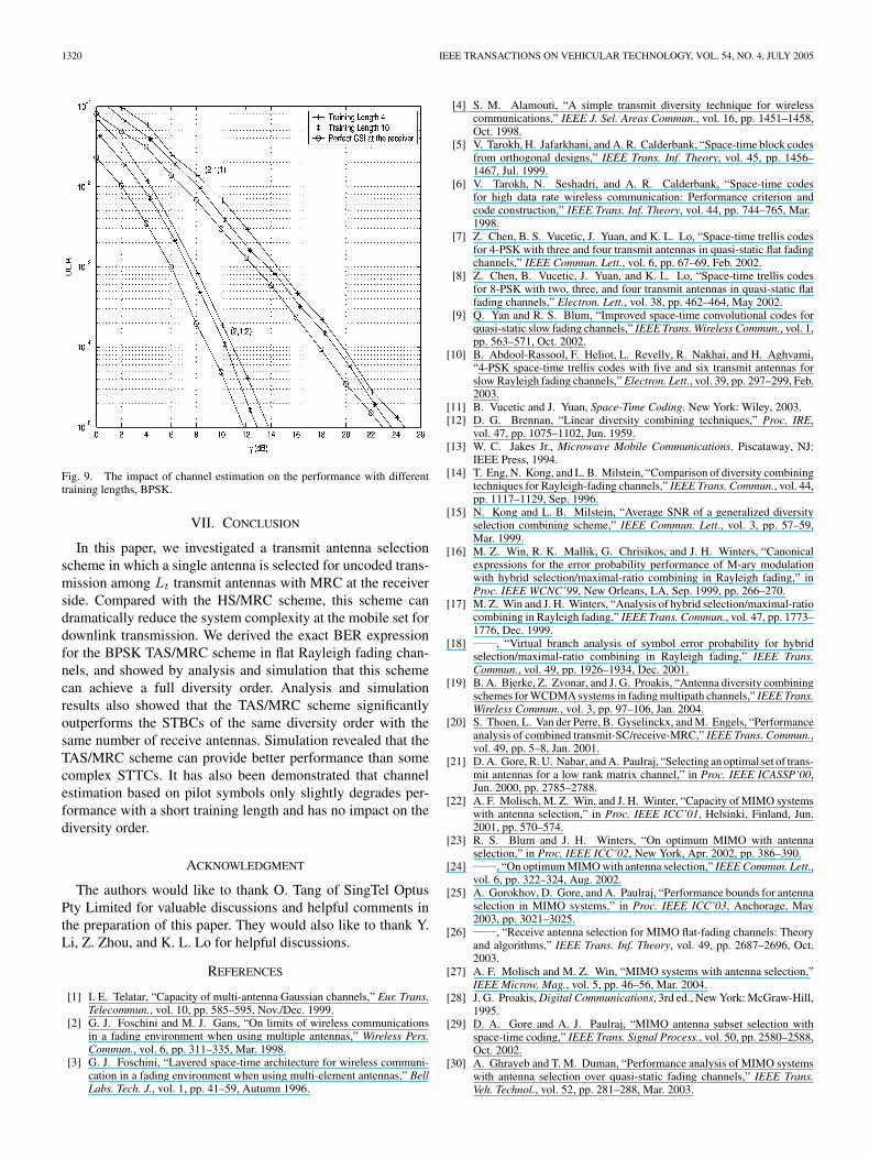
In the performance analysis, the perfect CSI is assumed at thereceiver. In a real system, the CSI has to be estimated based onpilot signals, as shown in Fig. 2. If channel estimation error hap-pens, it will degrade the system performance. Fig. 9 illustratesthe impact of channel estimation on the performance with var-ious training lengths in quasi-static fading channels for BPSKmodulation. In the simulation, a frame size of 130 data bits isassumed. Fig. 9 shows that for the (2,1;1) TAS/MRC, the train-ing with length 4 incurs a 1.7 dB performance loss at the BERof 10−5 compared with the case with perfect CSI. Increasing thetraining length from 4 to 10 decreases the SNR loss to 0.7 dBat the BER of 10−5. For the (2,1;2) TAS/MRC, the loss due tochannel estimation error is 2.0 and 1.2 dB for training lengths4 and 10, respectively. Fig. 9 shows that the channel estima-tion error has no impact on the diversity order. For a frame sizeof 130, extra 4 and 10 training bits will incur an SNR penaltyby 0.13 and 0.32 dB, respectively. This SNR penalty has beenaccounted for in the performance curves.
1320 IEEE TRANSACTIONS ON VEHICULAR TECHNOLOGY, VOL. 54, NO. 4, JULY 2005
Fig. 9. The impact of channel estimation on the performance with differenttraining lengths, BPSK.
VII. CONCLUSION
In this paper, we investigated a transmit antenna selectionscheme in which a single antenna is selected for uncoded trans-mission among Lt transmit antennas with MRC at the receiverside. Compared with the HS/MRC scheme, this scheme candramatically reduce the system complexity at the mobile set fordownlink transmission. We derived the exact BER expressionfor the BPSK TAS/MRC scheme in flat Rayleigh fading chan-nels, and showed by analysis and simulation that this schemecan achieve a full diversity order. Analysis and simulationresults also showed that the TAS/MRC scheme significantlyoutperforms the STBCs of the same diversity order with thesame number of receive antennas. Simulation revealed that theTAS/MRC scheme can provide better performance than somecomplex STTCs. It has also been demonstrated that channelestimation based on pilot symbols only slightly degrades per-formance with a short training length and has no impact on thediversity order.
ACKNOWLEDGMENT
The authors would like to thank O. Tang of SingTel OptusPty Limited for valuable discussions and helpful comments inthe preparation of this paper. They would also like to thank Y.Li, Z. Zhou, and K. L. Lo for helpful discussions.
REFERENCES
[1] I. E. Telatar, “Capacity of multi-antenna Gaussian channels,” Eur. Trans.Telecommun., vol. 10, pp. 585–595, Nov./Dec. 1999.
[2] G. J. Foschini and M. J. Gans, “On limits of wireless communicationsin a fading environment when using multiple antennas,” Wireless Pers.Commun., vol. 6, pp. 311–335, Mar. 1998.
[3] G. J. Foschini, “Layered space-time architecture for wireless communi-cation in a fading environment when using multi-element antennas,” BellLabs. Tech. J., vol. 1, pp. 41–59, Autumn 1996.
[4] S. M. Alamouti, “A simple transmit diversity technique for wirelesscommunications,” IEEE J. Sel. Areas Commun., vol. 16, pp. 1451–1458,Oct. 1998.
[5] V. Tarokh, H. Jafarkhani, and A. R. Calderbank, “Space-time block codesfrom orthogonal designs,” IEEE Trans. Inf. Theory, vol. 45, pp. 1456–1467, Jul. 1999.
[6] V. Tarokh, N. Seshadri, and A. R. Calderbank, “Space-time codesfor high data rate wireless communication: Performance criterion andcode construction,” IEEE Trans. Inf. Theory, vol. 44, pp. 744–765, Mar.1998.
[7] Z. Chen, B. S. Vucetic, J. Yuan, and K. L. Lo, “Space-time trellis codesfor 4-PSK with three and four transmit antennas in quasi-static flat fadingchannels,” IEEE Commun. Lett., vol. 6, pp. 67–69, Feb. 2002.
[8] Z. Chen, B. Vucetic, J. Yuan, and K. L. Lo, “Space-time trellis codesfor 8-PSK with two, three, and four transmit antennas in quasi-static flatfading channels,” Electron. Lett., vol. 38, pp. 462–464, May 2002.
[9] Q. Yan and R. S. Blum, “Improved space-time convolutional codes forquasi-static slow fading channels,” IEEE Trans. Wireless Commun., vol. 1,pp. 563–571, Oct. 2002.
[10] B. Abdool-Rassool, F. Heliot, L. Revelly, R. Nakhai, and H. Aghvami,“4-PSK space-time trellis codes with five and six transmit antennas forslow Rayleigh fading channels,” Electron. Lett., vol. 39, pp. 297–299, Feb.2003.
[11] B. Vucetic and J. Yuan, Space-Time Coding. New York: Wiley, 2003.[12] D. G. Brennan, “Linear diversity combining techniques,” Proc. IRE,
vol. 47, pp. 1075–1102, Jun. 1959.[13] W. C. Jakes Jr., Microwave Mobile Communications. Piscataway, NJ:
IEEE Press, 1994.[14] T. Eng, N. Kong, and L. B. Milstein, “Comparison of diversity combining
techniques for Rayleigh-fading channels,” IEEE Trans. Commun., vol. 44,pp. 1117–1129, Sep. 1996.
[15] N. Kong and L. B. Milstein, “Average SNR of a generalized diversityselection combining scheme,” IEEE Commun. Lett., vol. 3, pp. 57–59,Mar. 1999.
[16] M. Z. Win, R. K. Mallik, G. Chrisikos, and J. H. Winters, “Canonicalexpressions for the error probability performance of M-ary modulationwith hybrid selection/maximal-ratio combining in Rayleigh fading,” inProc. IEEE WCNC’99, New Orleans, LA, Sep. 1999, pp. 266–270.
[17] M. Z. Win and J. H. Winters, “Analysis of hybrid selection/maximal-ratiocombining in Rayleigh fading,” IEEE Trans. Commun., vol. 47, pp. 1773–1776, Dec. 1999.
[18] , “Virtual branch analysis of symbol error probability for hybridselection/maximal-ratio combining in Rayleigh fading,” IEEE Trans.Commun., vol. 49, pp. 1926–1934, Dec. 2001.
[19] B. A. Bjerke, Z. Zvonar, and J. G. Proakis, “Antenna diversity combiningschemes for WCDMA systems in fading multipath channels,” IEEE Trans.Wireless Commun., vol. 3, pp. 97–106, Jan. 2004.
[20] S. Thoen, L. Van der Perre, B. Gyselinckx, and M. Engels, “Performanceanalysis of combined transmit-SC/receive-MRC,” IEEE Trans. Commun.,vol. 49, pp. 5–8, Jan. 2001.
[21] D. A. Gore, R. U. Nabar, and A. Paulraj, “Selecting an optimal set of trans-mit antennas for a low rank matrix channel,” in Proc. IEEE ICASSP’00,Jun. 2000, pp. 2785–2788.
[22] A. F. Molisch, M. Z. Win, and J. H. Winter, “Capacity of MIMO systemswith antenna selection,” in Proc. IEEE ICC’01, Helsinki, Finland, Jun.2001, pp. 570–574.
[23] R. S. Blum and J. H. Winters, “On optimum MIMO with antennaselection,” in Proc. IEEE ICC’02, New York, Apr. 2002, pp. 386–390.
[24] , “On optimum MIMO with antenna selection,” IEEE Commun. Lett.,vol. 6, pp. 322–324, Aug. 2002.
[25] A. Gorokhov, D. Gore, and A. Paulraj, “Performance bounds for antennaselection in MIMO systems,” in Proc. IEEE ICC’03, Anchorage, May2003, pp. 3021–3025.
[26] , “Receive antenna selection for MIMO flat-fading channels: Theoryand algorithms,” IEEE Trans. Inf. Theory, vol. 49, pp. 2687–2696, Oct.2003.
[27] A. F. Molisch and M. Z. Win, “MIMO systems with antenna selection,”IEEE Microw. Mag., vol. 5, pp. 46–56, Mar. 2004.
[28] J. G. Proakis, Digital Communications, 3rd ed., New York: McGraw-Hill,1995.
[29] D. A. Gore and A. J. Paulraj, “MIMO antenna subset selection withspace-time coding,” IEEE Trans. Signal Process., vol. 50, pp. 2580–2588,Oct. 2002.
[30] A. Ghrayeb and T. M. Duman, “Performance analysis of MIMO systemswith antenna selection over quasi-static fading channels,” IEEE Trans.Veh. Technol., vol. 52, pp. 281–288, Mar. 2003.

CHEN et al.: ANALYSIS OF TRANSMIT ANTENNA SELECTION/MAXIMAL-RATIO COMBINING IN RAYLEIGH FADING CHANNELS 1321
[31] Z. Chen, B. Vucetic, and J. Yuan, “Space-time trellis codes with transmitantenna selection,” Electron. Lett., vol. 39, pp. 854–855, May 2003.
[32] Z. Chen, J. Yuan, B. Vucetic, and Z. Zhou, “Performance of Alamoutischeme with transmit antenna selection,” Electron. Lett., vol. 39, pp. 1666–1668, Nov. 2003.
[33] H. A. David, Order Statistics. New York: Wiley, 1970.[34] M. K. Simon, “A moment generating function (MGF)-based approach
for performance evaluation of space-time coded communication systems,”Wireless Commun. Mobile Comput., vol. 2, pp. 667–692, Nov. 2002.
[35] P. M. Hahn, “Theoretical diversity improvement in multiple frequencyshift keying,” IEEE Trans. Commun., vol. 10, pp. 177–184, Jun. 1962.
[36] A. Annamalai and C. Tellambura, “Error rates for Nakagami-m fad-ing mutlichannel reception of binary and M -ary signals,” IEEE Trans.Commun., vol. 49, pp. 58–68, Jan. 2001.
[37] , “A moment-generating function (MGF) derivative-based unifiedanalysis of incoherent diversity reception of M-ary orthogonal signalsover independent and correlated fading channels,” Int. J. Wireless Inf.Netw., vol. 10, pp. 41–55, Jan. 2003.
[38] S. Verdu, Multiuser Detection. Cambridge, U.K.: Cambridge UniversityPress, 1998.
[39] M. Kavehrad and P. J. McLane, “Performance of low-complexity channelcoding and diversity for spread spectrum in indoor, wireless communica-tions,” AT&T Tech. J., vol. 64, pp. 1927–1965, Oct. 1985.
[40] Z. Chen, B. Vucetic, J. Yuan, and K. L. Lo, “Space-time trellis codes withtwo, three and four transmit antennas in quasi-static flat fading channels,”in Proc. IEEE ICC’02, New York, Apr. 2002, pp. 1589–1595.
Zhuo Chen (S’01–M’05) was born in Sichuan,China, in 1977. He received the B.S. degree in elec-trical engineering from Shanghai Jiao Tong Univer-sity, Shanghai, China, in 1997. He received the M.S.and Ph.D. degrees from the School of Electrical andInformation Engineering, the University of Sydney,Australia, in 2001 and 2004, respectively.
A list of his publications is available fromwww.ee.usyd.edu.au/˜zhuochen. His research inter-ests include wireless communications, multiple-input-multiple-output (MIMO) systems, space-time
coding, and error control coding techniques.Dr. Chen was awarded the Electrical Engineering Foundation Award for
Excellence in Teaching (Tutoring) from the University of Sydney in 1999.
Jinhong Yuan (S’96–A’97–M’03) received the B.E.and Ph.D. degrees in electronics engineering fromthe Beijing Institute of Technology, Beijing, China,in 1991 and 1997, respectively.
From 1997 to 1999, he was a Research Fellow atthe School of Electrical and Information Engineer-ing, the University of Sydney, Sydney, Australia. In2000, he joined the School of Electrical Engineer-ing and Telecommunications, the University of NewSouth Wales, Sydney, Australia, where he is currentlya Senior Lecturer.
A list of his publications is available from http://www.ee.unsw.edu.au/˜jinhong. His current research interests include information theory, wire-less communications, error control coding, and digital modulations.
Branka Vucetic (M’83–SM’00–F’03) received theB.S.E.E., M.S.E.E., and Ph.D. degrees in electri-cal engineering from the University of Belgrade,Belgrade, Serbia, in 1972, 1978, and 1982, respec-tively.
During her career, she has held various researchand academic positions in Yugoslavia, Australia, andU.K. Since 1986, she has been with the Sydney Uni-versity School of Electrical and Information Engi-neering, Sydney, Australia, where she is currentlythe Head of the School of Electrical and Information
Engineering and the Director of the Telecommunications Laboratory. In thepast decade, she has been working on a number of industry-sponsored projectsin wireless communications and mobile Internet. She has taught a wide rangeof undergraduate, postgraduate, and continuing education courses worldwide.She has published three books and more than 200 papers in telecommuni-cations journals and conference proceedings. Her research interests includewireless communications, digital communication theory, coding, and multiuserdetection.
Related Documents