PERFORMANCE EVALUATION OF 48” DIAMETER CORRUGATED HIGH DENSITY POLYETHYLENE PIPE UNDER 315,000 LBS (143,010 kg) RAIL CAR LOADING Shawn R Coombs, PE Project Manager/Primary Author Advanced Drainage Systems, Inc. 2009 Whiskery Court York, SC 29745 Phone: (704) 451-8844 Fax: (803) 684-2987 Email: [email protected] Michael Pluimer, PE Project Review/Supporting Author Plastics Pipe Institute 105 Decker Court, Suite 825 Irving, TX 75062 Phone: (469) 499-1049 Email: [email protected] Word Count: 3,784 written; 2,000 photos/Charts/etc.; Total 5,784 - For AREMA Review May 2010

Welcome message from author
This document is posted to help you gain knowledge. Please leave a comment to let me know what you think about it! Share it to your friends and learn new things together.
Transcript
PERFORMANCE EVALUATION OF 48” DIAMETER CORRUGATED
HIGH DENSITY POLYETHYLENE PIPE
UNDER 315,000 LBS (143,010 kg) RAIL CAR LOADING
Shawn R Coombs, PE
Project Manager/Primary Author
Advanced Drainage Systems, Inc.
2009 Whiskery Court
York, SC 29745
Phone: (704) 451-8844
Fax: (803) 684-2987
Email: [email protected]
Michael Pluimer, PE
Project Review/Supporting Author
Plastics Pipe Institute
105 Decker Court, Suite 825
Irving, TX 75062
Phone: (469) 499-1049
Email: [email protected]
Word Count: 3,784 written; 2,000 photos/Charts/etc.; Total 5,784 - For AREMA Review May 2010
ABSTRACT
The Plastic Pipe Institute (PPI) sponsored minimum cover testing for 48 inch (1200 mm) diameter
corrugated high density polyethylene (HDPE) pipe under heavy haul railroad loading conditions. The
Transportation Technology Center, Inc. (TTCI), Facility for Accelerated Service Testing (FAST), was
used for the project. The FAST train consisted of four locomotives and eighty 315,000 lbs (143,010 kg)
rail cars. The Fast Train cycled over the two buried 48 inch (1200 mm) diameter HDPE pipes until 101
Million Gross Tons (MGT) (91,607,000 Mg) of rail traffic had been reached. The first pipe was
backfilled with fabric wrapped, vibrated in place #57 stone. The second pipe was backfilled with onsite
ASTM Class III backfill at 94% of Standard Proctor Density (SPD). Each buried pipe run had a 58 inch
(1,473 mm) long instrumented section that was joined in place with a split band coupler and an inline
bell/spigot connection. Joints were placed directly under the rail to ensure maximum loading. Deflection
gauges, strain gauges, circumferential shortening gauges, and joint separation measurements were used to
evaluate the pipe and joints. Each pipe had four feet (1.2 m) of cover from the bottom of tie to top of
pipe. At the conclusion of the 101 MGT (91,607,000 Mg) load cycle, minimal pipe deflection and
negligible joint movement was noted. The final results indicate that the HDPE pipe and backfill behave
elastically, and support that the AASHTO Section 12 minimum cover height calculations are inline with
field evaluated pipe performance. A very interesting portion of the test was the video and data cycles of
the heavy haul live loading and the visual evidence of elastic soil behavior. The test verifies that
corrugated HDPE pipe will withstand heavy haul railroad loading over large load cycles.
INTRODUCTION
For years many railroad designers and contractors have used corrugated HDPE pipe under highway
loading conditions with great success. Many of these designers who have successfully used corrugated
HDPE pipe are now using the product to avoid corrosion caused by stray current in electrified rail and/or
corrosion caused by chemical exposure in railroad mining applications. Because their success with
corrugated HDPE pipe, railroad designers are interested in expanding the use of his product. In order for
them to feel more comfortable with corrugated HDPE pipe, they are seeking field verification of the
product’s structural field performance under heavy haul railroad load conditions. As a result of the
railroad industries interest in Corrugated HDPE pipe, Members of the American Railway Engineering and
Maintenance-of-Way Association (AREMA) contacted Plastics Pipe Institute (PPI) Members and asked
them to assist with the evaluation of corrugated HDPE pipe under heavily loaded track. To accomplish
the requested field testing, PPI with the assistance AREMA selected the Transportation Technology
Center, Inc. (TTCI), and their Facility for Accelerated Service Testing (FAST) as the best facility to
perform the tests. The reason TTCI was selected to conduct heavy haul testing is because of their ability
to simulate long-term heavy haul loading conditions at an accelerated rate at FAST. The FAST train is a
13,000 ton (11,791 Mg) train comprising of four (4) locomotives and eighty (80) 315,000 lbs (143,010
kg) rail cars that run at average speeds of 40 mph (64.4 km/h). The load generated by the FAST train is
similar to a Cooper E-80 load.
CALCULATED FIELD PERFORMANCE
Many studies have been done to determine the performance characteristics of corrugated HDPE pipe in
field applications. However, no in field structural testing has been done for corrugated HDPE pipe under
heavy railroad loading conditions. The intent of the test at TTCI was to pay greater attention to the
details of pipe performance using instrumentation and see how it compared to the previously calculated
performance values. The current industry practice for calculating corrugated HDPE pipe performance is
found in the American Association of State Highway and Transportation Officials (AASHTO), Load
Resistance Factor Design (LRFD), Bridge Design Specifications, Section 12 – Buried Structures and
Tunnel Liners (Section 12). By using set values for corrugated HDPE pipe established in AASHTO M
294 - Standard Specification for Corrugated Polyethylene 12 to 60 inch (300 to 1500 mm), Section 12
allows designers to evaluate how corrugated HDPE pipe is expected to perform under Cooper E-80 loads.
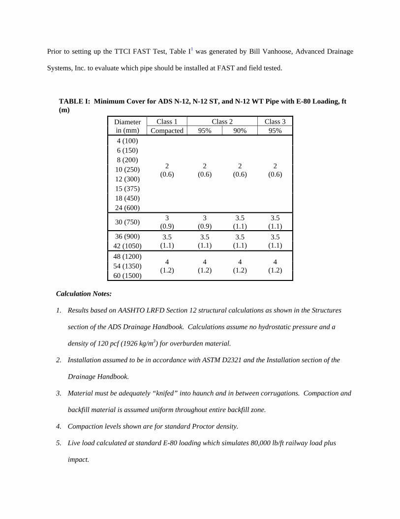
Prior to setting up the TTCI FAST Test, Table I1 was generated by Bill Vanhoose, Advanced Drainage
Systems, Inc. to evaluate which pipe should be installed at FAST and field tested.
TABLE I: Minimum Cover for ADS N-12, N-12 ST, and N-12 WT Pipe with E-80 Loading, ft (m)
Diameter in (mm)
Class 1 Class 2 Class 3 Compacted 95% 90% 95%
4 (100)
2 (0.6)
2 (0.6)
2 (0.6)
2 (0.6)
6 (150) 8 (200)
10 (250) 12 (300) 15 (375) 18 (450) 24 (600)
30 (750) 3
(0.9) 3
(0.9) 3.5
(1.1) 3.5
(1.1)
36 (900) 3.5 (1.1)
3.5 (1.1)
3.5 (1.1)
3.5 (1.1) 42 (1050)
48 (1200) 4
(1.2) 4
(1.2) 4
(1.2) 4
(1.2) 54 (1350) 60 (1500)
Calculation Notes:
1. Results based on AASHTO LRFD Section 12 structural calculations as shown in the Structures
section of the ADS Drainage Handbook. Calculations assume no hydrostatic pressure and a
density of 120 pcf (1926 kg/m3) for overburden material.
2. Installation assumed to be in accordance with ASTM D2321 and the Installation section of the
Drainage Handbook.
3. Material must be adequately “knifed” into haunch and in between corrugations. Compaction and
backfill material is assumed uniform throughout entire backfill zone.
4. Compaction levels shown are for standard Proctor density.
5. Live load calculated at standard E-80 loading which simulates 80,000 lb/ft railway load plus
impact.

Once the pipe table was complete the PPI project team along with AREMA Committee 1, Subcommittee
4 reviewed the data and agreed upon the pipe diameter should be used in the TTCI FAST Test.
PIPE SELECTION
Selecting the appropriate size pipe from among the most commonly manufactured corrugated HDPE
pipes was somewhat of a challenge. By comparing the calculated acceptable minimum fill heights (Table
I), to the resulting safety factors produced by the calculations, and then evaluating field performance
history of various pipe diameters, it was determined that a 48 inch (1200mm) diameter pipe would be the
best pipe diameter to test at TTCI. It represented the largest diameter that is commonly manufactured by
the greatest number of PPI member manufacturers. Also, when the 48 inch (1200mm) pipe is compared
to the performance characteristics of Advanced Drainage Systems, Inc.’s (ADS) 60 inch (1500 mm)
diameter pipe, the ADS 60 inch (1500) corrugated HDPE pipe out performed the 48 inch (1200 mm)
diameter pipe selected for the test.
MEASURED VALUES
From the AASHTO and ASTM Standards there are many performance indicators in determining if HDPE
pipe is performing adequately in the field. From the many indicators available, deflection and strain are
the most commonly used and simplest to field verify.
Deflection
Based on AASHTO Section 30 – Thermoplastic Pipe, the recommended allowable deflection is 5% of the
pipe’s actual diameter. An additional 2.5% deflection is allowed if a designer reviews and verifies that
the system is structural sound. This allows for a total permitted deflection of 7.5%, before standards
recommend that the excessively deflected product is removed. To measure deflection in the TTCI FAST
Test, 5 inch (127 mm) string pots were mounted inside the pipe test sections and oriented to measure
vertical, horizontal and diagonal deflections in real time while the FAST train passes over the top of the
pipes. Diagonal deflection normally isn’t a concern, unless construction loads is excessive, but we added
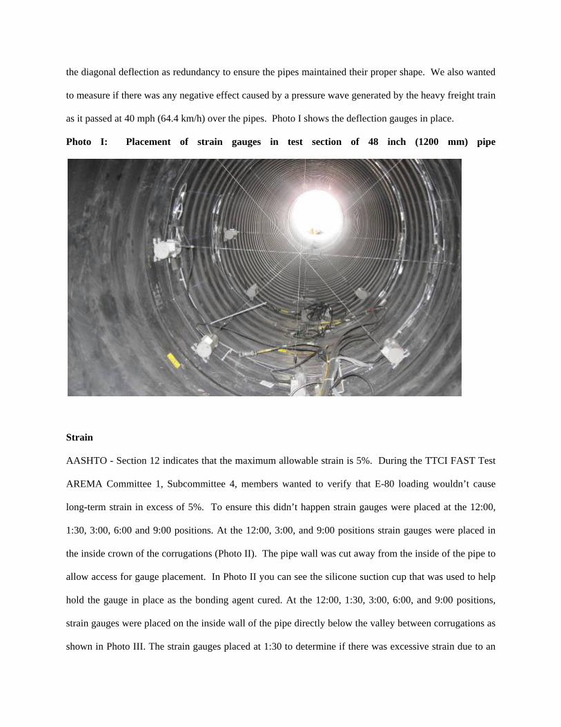
the diagonal deflection as redundancy to ensure the pipes maintained their proper shape. We also wanted
to measure if there was any negative effect caused by a pressure wave generated by the heavy freight train
as it passed at 40 mph (64.4 km/h) over the pipes. Photo I shows the deflection gauges in place.
Photo I: Placement of strain gauges in test section of 48 inch (1200 mm) pipe
Strain
AASHTO - Section 12 indicates that the maximum allowable strain is 5%. During the TTCI FAST Test
AREMA Committee 1, Subcommittee 4, members wanted to verify that E-80 loading wouldn’t cause
long-term strain in excess of 5%. To ensure this didn’t happen strain gauges were placed at the 12:00,
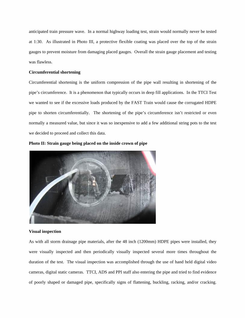
1:30, 3:00, 6:00 and 9:00 positions. At the 12:00, 3:00, and 9:00 positions strain gauges were placed in
the inside crown of the corrugations (Photo II). The pipe wall was cut away from the inside of the pipe to
allow access for gauge placement. In Photo II you can see the silicone suction cup that was used to help
hold the gauge in place as the bonding agent cured. At the 12:00, 1:30, 3:00, 6:00, and 9:00 positions,
strain gauges were placed on the inside wall of the pipe directly below the valley between corrugations as
shown in Photo III. The strain gauges placed at 1:30 to determine if there was excessive strain due to an
anticipated train pressure wave. In a normal highway loading test, strain would normally never be tested
at 1:30. As illustrated in Photo III, a protective flexible coating was placed over the top of the strain
gauges to prevent moisture from damaging placed gauges. Overall the strain gauge placement and testing
was flawless.
Circumferential shortening
Circumferential shortening is the uniform compression of the pipe wall resulting in shortening of the
pipe’s circumference. It is a phenomenon that typically occurs in deep fill applications. In the TTCI Test
we wanted to see if the excessive loads produced by the FAST Train would cause the corrugated HDPE
pipe to shorten circumferentially. The shortening of the pipe’s circumference isn’t restricted or even
normally a measured value, but since it was so inexpensive to add a few additional string pots to the test
we decided to proceed and collect this data.
Photo II: Strain gauge being placed on the inside crown of pipe
Visual inspection
As with all storm drainage pipe materials, after the 48 inch (1200mm) HDPE pipes were installed, they
were visually inspected and then periodically visually inspected several more times throughout the
duration of the test. The visual inspection was accomplished through the use of hand held digital video
cameras, digital static cameras. TTCI, ADS and PPI staff also entering the pipe and tried to find evidence
of poorly shaped or damaged pipe, specifically signs of flattening, buckling, racking, and/or cracking.

AASHTO recommends that a post installation visual inspection be conducted on all storm drainage pipes.
Post installation inspection has become a key criterion to fight against installer error and/or post
installation damage. During the test, pipe joints were hand measured to determine if there was
movement in the joints.
Photo III: Strain gauge being placed on the pipe’s inside wall over the corrugation valley
TEST SECTION CONFIGURATION AND INSTALLATION STANDARD
Once the appropriate pipe size and gauge type and placement was determined, tested section length, joint
types and backfill selection came next.
Test Section Length
For the purpose of the TTCI FAST Test, it was assumed that the maximum load on the pipe would be
located directly under each of the track’s rails. With the rails set at 59.5 inches (1511 mm) apart a 58 inch
(1473 mm) long pipe test section was selected for gauging and testing. This length of pipe was the best
sice that ensured maximum loading over the weakest part of the pipe, the joints. The 58 inch (1473 mm)
length allowed the pipe to be easily cut in the pipe valley between corrugations. It also allowed a pipe
joint to be placed as close to center of rail as possible.
Joint Selection
Because of concern over joint separation due to transverse soil movement or pipe settlement, the railroad
industry traditionally have used extremely good pipe connections to help hold the storm drainage system
together. The movement pipe that causes joint separation is typically tied to the use of poor bedding and
backfill. In order to see if joint pull apart strength really makes a huge difference in pipe performance, at
TTCI we reversed the normal philosophy and used good backfill with non-constrained standard joints.
The typical watertight bell and spigot joint was used for one side of the test section and a typical plain end
pipe with a fabric wrapped split coupler connected with nylon zip ties was used on the other end of the
test section.
Bedding and Backfill
After reviewing the minimum covers listed in Table I, AREMA and PPI agreed that the test sections at
FAST should be backfilled with a fabric wrapped, vibrated in place #57 stone and an onsite ASTM Class
III soils compacted to ASTM 95% Standard Proctor Density. Both of backfills are considered to be good
backfill, which is what should be used when installing storm drainage pipe under track.
Final Placement of Test Sections
Pipe 1, which is the pipe that was closest to the bridge at FAST, was approximately 60 feet (18.3 m) long
with a 58 inch (1473 mm) long 48 inch (1200 mm) diameter section of pipe located directly under the
rails. Pipe 1 was backfilled with local #57 Stone meeting the requirements of an ASTM Class I soil type.
The #57 stone was wrapped with a Propex 1201 geotextile fabric to prevent migration of fines into the
select backfill. To compact the #57 stone it was vibrated in place with a jumping jack in approximate 15
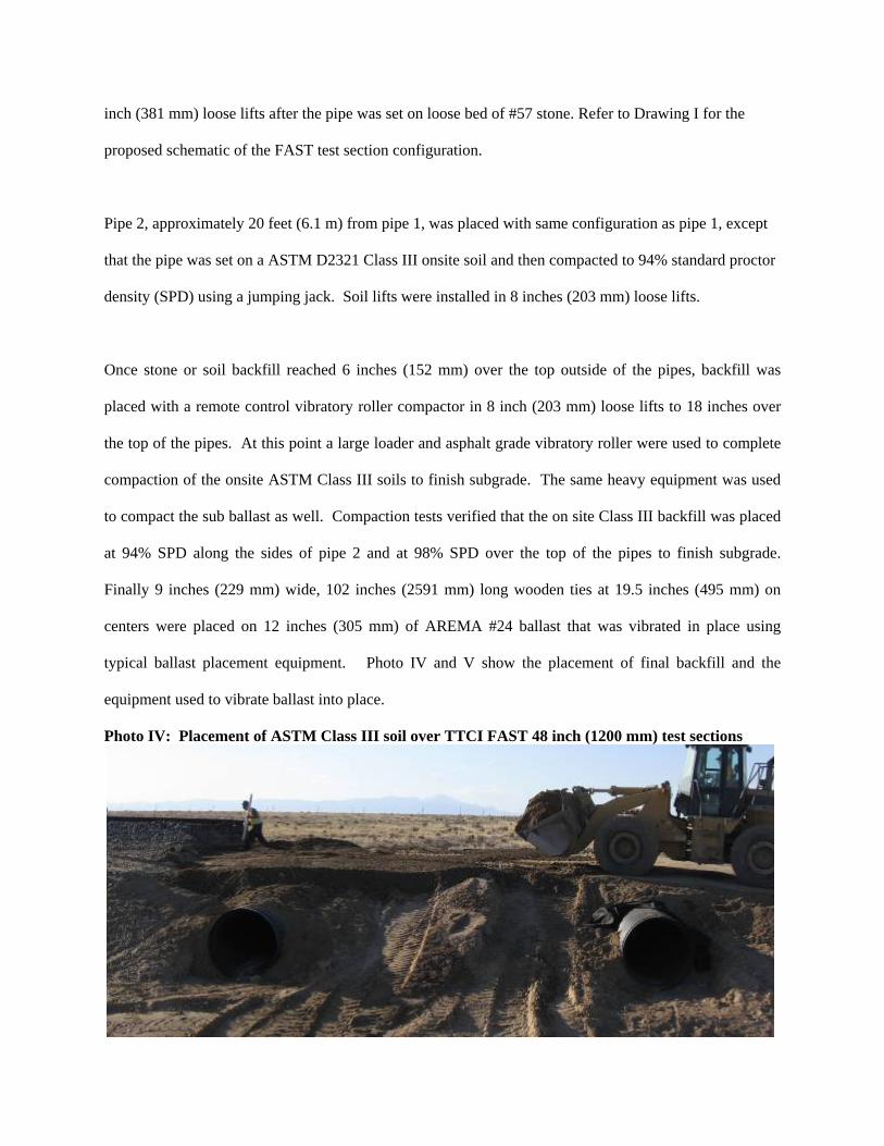
inch (381 mm) loose lifts after the pipe was set on loose bed of #57 stone. Refer to Drawing I for the
proposed schematic of the FAST test section configuration.
Pipe 2, approximately 20 feet (6.1 m) from pipe 1, was placed with same configuration as pipe 1, except
that the pipe was set on a ASTM D2321 Class III onsite soil and then compacted to 94% standard proctor
density (SPD) using a jumping jack. Soil lifts were installed in 8 inches (203 mm) loose lifts.
Once stone or soil backfill reached 6 inches (152 mm) over the top outside of the pipes, backfill was
placed with a remote control vibratory roller compactor in 8 inch (203 mm) loose lifts to 18 inches over
the top of the pipes. At this point a large loader and asphalt grade vibratory roller were used to complete
compaction of the onsite ASTM Class III soils to finish subgrade. The same heavy equipment was used
to compact the sub ballast as well. Compaction tests verified that the on site Class III backfill was placed
at 94% SPD along the sides of pipe 2 and at 98% SPD over the top of the pipes to finish subgrade.
Finally 9 inches (229 mm) wide, 102 inches (2591 mm) long wooden ties at 19.5 inches (495 mm) on
centers were placed on 12 inches (305 mm) of AREMA #24 ballast that was vibrated in place using
typical ballast placement equipment. Photo IV and V show the placement of final backfill and the
equipment used to vibrate ballast into place.
Photo IV: Placement of ASTM Class III soil over TTCI FAST 48 inch (1200 mm) test sections
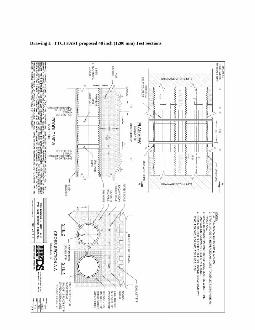
Drawing I: TTCI FAST proposed 48 inch (1200 mm) Test Sections

ON SITE SOILS
A sample representing the FAST onsite soils was provided by Joe LoPresti the FAST Project Manager.
The onsite soil type was non plastic silty sand, Unified Classification SM. Practical size gradation100%
passing #4 sieve, 99.8 passing #10 sieve, 94.6 passing #20 sieve, 78.5 passing #40 sieve, 54.5% passing
#100 sieve, and 36.6 passing #200 sieve.
Photo V: Equipment used to place vibrate AREMA #24 ballast into place
PIPE SAMPLE TESTING
As a part of the test, remnant samples were saved from the cut ends of the tested samples and taken to
Texas Research Institute (TRI) for verification of AASHTO M 294 material property verification.
TEST DURARION AND DATA COLLECTION
After the pipe was placed and the tracks were set to grade, the FAST train commenced operations over
the test sections. Operations continued until 101 MGT (91,607,000 Mg) had passed over the pipe. Two
dynamic data sets were taken during the test. The first was taken just after the first MGT (907,000 Mg)
passed over the pipes and the second after 96 MGT (87,072,000 Mg) passed over the system. Both data

sets lasted for 24 hours. In addition to the two dynamic data sets, two static tests were recorded during the
test. The first static test was taken in the lab to zero out the instruments and the second static test was
taken just after construction.
To evaluate the effect of parked rail cars over the test samples, TTCI parked two 315,000 lbs (143,010
kg) rail cars over the test sections such that two axles were set directly over the top of the buried pipes.
The parked cars sat over the pipes for approximately 3 months.
Multiple visual inspections were made of the inside of the pipe, and joint movements were hand measured
throughout the test.
TEST RESULTS
Pipe Material Properties
The pipe test samples taken to Texas Research Institute met the requirements of AASHTO M 294 testing
standard. The pipe test samples were from separate production runs yet had similar material properties.
Deflection
Deflection was measured in the 0 degree (vertical), 45 degree (diagonal), 180 degree (horizontal), and 315
degree (diagonal) locations. The maximum deflection values listed below2 are based on an actual
measured diameter of 47.6 inches (1,209 mm) pipe.
Maximum horizontal deflection after construction = 0.7 inches (17.8 mm) (+1.5%).
Maximum horizontal deflection after 96 MGT = 0.6 inches (15.2 mm) (+1.3%)
Maximum vertical deflection after construction = 0.1 inches (2.5 mm) (-0.2%)
Maximum vertical deflection after 96 MGT = 0.5 inches (12.7 mm) (-1.05%)
Maximum deflection due to 96 MGT loading alone = 0.065 inches (1.7 mm) (0.14%)
Deflection results are all well below the allowable AASHTO Section 30 recommended construction limit
values of 5.0% deflection. As anticipated, the diagonal deflections were much less than vertical or
horizontal deflection values.
Strain
The maximum strain (compressive) caused by construction loading was 7,300 microstrain (0.73% strain).
The maximum strain (compressive) caused after 96 MGT (87,072,000 Mg) from the FAST train
combined with construction loading was 8,800 microstrain (0.88% strain). These values are well below
the AASHTO Section 12, 5% recommended strain limit.
Circumferential Shortening
The maximum circumferential shortening from construction was 0.4 inches (10.2 mm) (0.27%), and after
96 MGT (87,072,000 Mg) circumferential shortening was 0.8 inches (20.3 mm) (0.54%). Although
circumferential shortening doesn’t have a set limit, when compared to set strain and deflection limits, the
measured values are very acceptable.
Joint Separation
Minor movement was noted in the joints; however, maximum joint movement was below 0.25 inch (6.35
mm). With temperatures varying over 80˚F (44.4˚C) outside the pipe, this could have been caused by
pipe elongation and contraction due to thermo expansion. All joints looked and were performing
extremely well with no notable visual variation from the beginning to end of the test.
Elastic Soil Reaction
Figure I2 illustrates dynamic strain and deflection during 40 mph (64.4 kmph) train operations, evidencing
how the buried pipes at TTCI FAST reacted elastically. As load is applied, the structure compresses and
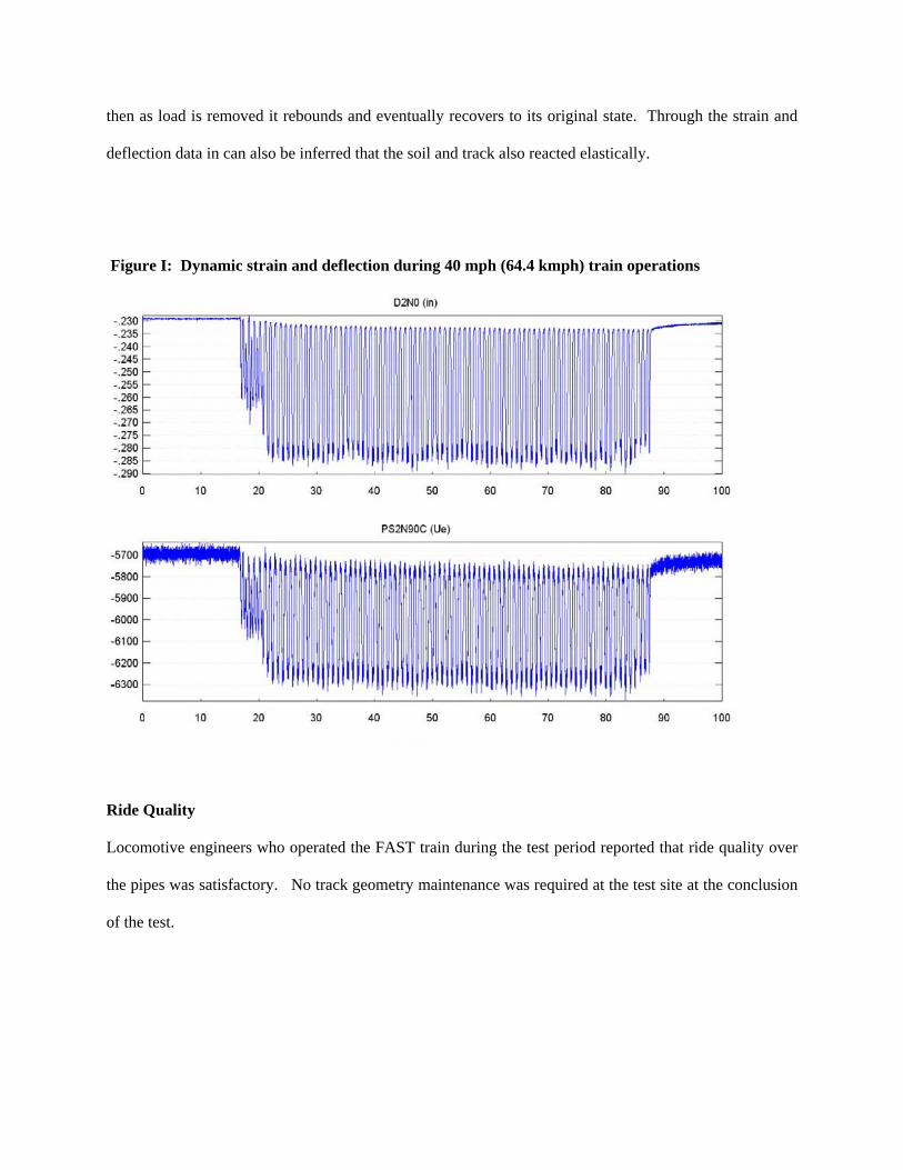
then as load is removed it rebounds and eventually recovers to its original state. Through the strain and
deflection data in can also be inferred that the soil and track also reacted elastically.
Figure I: Dynamic strain and deflection during 40 mph (64.4 kmph) train operations
Ride Quality
Locomotive engineers who operated the FAST train during the test period reported that ride quality over
the pipes was satisfactory. No track geometry maintenance was required at the test site at the conclusion
of the test.
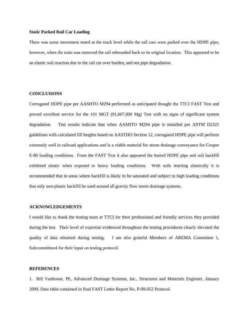
Static Parked Rail Car Loading
There was some movement noted at the track level while the rail cars were parked over the HDPE pipe;
however, when the train was removed the rail rebounded back to its original location. This appeared to be
an elastic soil reaction due to the rail car over burden, and not pipe degradation.
CONCLUSIONS
Corrugated HDPE pipe per AASHTO M294 performed as anticipated thought the TTCI FAST Test and
proved excellent service for the 101 MGT (91,607,000 Mg) Test with no signs of significant system
degradation. Test results indicate that when AASHTO M294 pipe is installed per ASTM D2321
guidelines with calculated fill heights based on AASTHO Section 12, corrugated HDPE pipe will perform
extremely well in railroad applications and is a viable material for storm drainage conveyance for Cooper
E-80 loading conditions. From the FAST Test it also appeared the buried HDPE pipe and soil backfill
exhibited elastic when exposed to heavy loading conditions. With soils reacting elastically it is
recommended that in areas where backfill is likely to be saturated and subject to high loading conditions
that only non-plastic backfill be used around all gravity flow storm drainage systems.
ACKNOWLEDGEMENTS
I would like to thank the testing team at TTCI for their professional and friendly services they provided
during the test. Their level of expertise evidenced throughout the testing procedures clearly elevated the
quality of data obtained during testing. I am also grateful Members of AREMA Committee 1,
Subcommittee4 for their input on testing protocol.
REFERENCES
1. Bill Vanhoose, PE, Advanced Drainage Systems, Inc., Structures and Materials Engineer, January
2009, Data table contained in final FAST Letter Report No. P-09-052 Protocol.
2. Corrugated Polyethylene Pipe Testing under 315,000-Pound Cars at FAST
Letter Report No. P-09-052, Prepared for Plastic Pipe Institute, by Joseph A. LoPresti
Transportation Technology Center, Inc., Revised January 14, 2010.
LIST OF TABLES, DRAWINGS, FIGURES, AND PHOTOS
Table I: Minimum Cover for ADS N-12, N-12 ST, and N-12 WT Pipe with E-80 Loading, ft (m), Pg. 4
Drawing I: TTCI FAST proposed 48 inch (1200 mm) Test Sections, Pg. 11
Figure I: Dynamic strain and deflection during 40 mph (64.4 kmph) train operations, Pg. 15
Photo I: Placement of strain gauges in test section of 48 inch (1200 mm) pipe, Pa. 6
Photo II: Strain gauge being placed on the inside crown of pipe, Pg. 7
Photo III: Strain gauge being placed on the pipe’s inside wall over the corrugation valley, Pg. 8
Photo IV: Placement of ASTM Class III soil over TTCI FAST 48 inch (1200 mm) test sections, Pg. 10
Photo V: Equipment used to place vibrate AREMA #24 ballast into place, Pg. 12
Related Documents