CIVIL AVIATION AUTHORITY OF MALAYSIA PERFORMANCE BASED NAVIGATION CIVIL AVIATION GUIDANCE MATERIAL – 6008(II) ISSUE 01 REVISION 00 – 1 ST APRIL 2021 PBN

Welcome message from author
This document is posted to help you gain knowledge. Please leave a comment to let me know what you think about it! Share it to your friends and learn new things together.
Transcript
CIVIL AVIATION AUTHORITY OF MALAYSIA
PERFORMANCE
BASED NAVIGATION
CIVIL AVIATION GUIDANCE MATERIAL – 6008(II)
ISSUE 01
REVISION 00 – 1S T APRIL 2021
PBN

INTENTIONALLY LEFT BLANK

Introduction
Issue 01/Rev 00 CAD 6009 – CC
i
Introduction
This Civil Aviation Guidance Material 6008 Part III (CAGM – 6008 (III)) is issued by the Civil
Aviation Authority of Malaysia (CAAM) to provide guidance on the operational approval
process in the context of performance-based navigation (PBN). It is intended for operators
involved for the approval of PBN operations., pursuant to Civil Aviation Directives 6 Part 1 –
Commercial Air Transport (CAD 6 Part 1 – CAT), Civil Aviation Directives 6 Part 2 – General
Aviation (CAD 6 Part 2 – GA) and Civil Aviation Directives 6 Part 3 - Helicopters (collectively
referred to as “CAD”).
Organisations may use these guidelines to ensure compliance with the respective provisions
of the relevant CAD’s issued. Notwithstanding the Regulation 204 and Regulation 205 of the
Malaysian Civil Aviation Regulations 2016 (MCAR 2016), when the CAGMs issued by the
CAAM are complied with, the related requirements of the CAD’s may be deemed as being
satisfied and further demonstration of compliance may not be required.
(Captain Chester Voo Chee Soon) Chief Executive Officer
Civil Aviation Authority of Malaysia
Introduction
Issue 01/Rev 00 CAD 6009 – CC
ii
Civil Aviation Guidance Material components and Editorial practices
This Civil Aviation Guidance Material is made up of the following components and are defined as follows: Standards: Usually preceded by words such as “shall” or “must”, are any specification for physical characteristics, configuration, performance, personnel or procedure, where uniform application is necessary for the safety or regularity of air navigation and to which Operators must conform. In the event of impossibility of compliance, notification to the CAAM is compulsory. Recommended Practices: Usually preceded by the words such as “should” or “may”, are any specification for physical characteristics, configuration, performance, personnel or procedure, where the uniform application is desirable in the interest of safety, regularity or efficiency of air navigation, and to which Operators will endeavour to conform. Appendices: Material grouped separately for convenience, but forms part of the Standards and Recommended Practices stipulated by the CAAM. Definitions: Terms used in the Standards and Recommended Practices which are not self-explanatory in that they do not have accepted dictionary meanings. A definition does not have an independent status but is an essential part of each Standard and Recommended Practice in which the term is used, since a change in the meaning of the term would affect the specification. Tables and Figures: These add to or illustrate a Standard or Recommended Practice, and which are referred to therein, form part of the associated Standard or Recommended Practice and have the same status. Notes: Included in the text, where appropriate, Notes give factual information or references bearing on the Standards or Recommended Practices in question but not constituting part of the Standards or Recommended Practices; Attachments: Material supplementary to the Standards and Recommended Practices or included as a guide to their application.
The units of measurement used in this document are in accordance with the International System of Units (SI) as specified in CAD 5. Where CAD 5 permits the use of non-SI alternative units, these are shown in parentheses following the basic units. Where two sets of units are quoted it must not be assumed that the pairs of values are equal and interchangeable. It may, however, be inferred that an equivalent level of safety is achieved when either set of units is used exclusively. Any reference to a portion of this document, which is identified by a number and/or title, includes all subdivisions of that portion. Throughout this Civil Aviation Guidance Material, the use of the male gender should be understood to include male and female persons.

Records of Revision
Issue 01/Rev 00 CAGM 6008 (II) – PBN iii
Record of Revisions
Revisions to this CAGM shall be made by authorised personnel only. After inserting the
revision, enter the required data in the revision sheet below. The ‘Initials’ has to be signed off
by the personnel responsible for the change.
Rev No. Revision Date Revision Details Initials

Records of Revision
Issue 01/Rev 00 CAGM 6008 (II) – PBN iv
INTENTIONALLY LEFT BLANK
Table of Content
Issue 01/Rev 00 CAGM 6008 (II) – PBN v
Table of Contents
1 PERFORMANCE-BASED NAVIGATION.................................................................................. 1-1 1.1 INTRODUCTION ........................................................................................................................ 1-1 1.2 DEFINITIONS ............................................................................................................................ 1-1 1.3 ABBREVIATIONS ....................................................................................................................... 1-4 1.4 PBN OVERVIEW ....................................................................................................................... 1-7 1.5 RNAV AND RNP ...................................................................................................................... 1-8 1.6 NAVIGATION SPECIFICATIONS ..................................................................................................... 1-8 1.7 PBN APPLICATIONS .................................................................................................................. 1-9
2 CERTIFICATION AND OPERATIONAL APPROVAL .................................................................. 2-1 2.1 OVERVIEW .............................................................................................................................. 2-1 2.2 STATE REGULATORY RESPONSIBILITIES .......................................................................................... 2-3 2.3 OPERATIONAL APPROVAL ........................................................................................................... 2-3 2.4 DOCUMENTATION OF OPERATIONAL APPROVAL ........................................................................... 2-10 2.5 CAAM PBN OPERATIONAL APPROVAL PROCESS ......................................................................... 2-11 2.6 INTERNATIONAL OPERATIONS ................................................................................................... 2-13
3 OPERATIONAL APPROVAL GUIDELINES ............................................................................... 3-1 3.1 AIRCRAFT ELIGIBILITY................................................................................................................. 3-1 3.2 STANDARD OPERATING PROCEDURES .......................................................................................... 3-2 3.3 TRAINING ................................................................................................................................ 3-4 3.4 NAVIGATION DATABASES ........................................................................................................... 3-7
4 NAVIGATION SPECIFICATION JOB AIDS ............................................................................... 4-1 4.1 GENERAL ................................................................................................................................ 4-1 4.2 JOB AID GUIDANCE ................................................................................................................... 4-1 4.3 RNAV 10 ............................................................................................................................... 4-4 4.4 RNAV 5 ............................................................................................................................... 4-13 4.5 RNAV 1 AND RNAV 2 ............................................................................................................ 4-21 4.6 RNP 4 .................................................................................................................................. 4-31 4.7 RNP 2 .................................................................................................................................. 4-37 4.8 RNP 1 .................................................................................................................................. 4-48 4.9 RNP APCH ........................................................................................................................... 4-55 4.10 RNP 0.3 ............................................................................................................................... 4-78 4.11 ADVANCED RNP (A-RNP) ....................................................................................................... 4-93 4.12 RNP AR ............................................................................................................................. 4-114
5 APPENDICES ...................................................................................................................... 5-1 5.1 APPENDIX A – AREA NAVIGATION SYSTEMS.................................................................................. 5-1 5.2 APPENDIX B – EXAMPLE REGULATORY TEXT .................................................................................. 5-8 5.3 APPENDIX C – EXAMPLE OF PBN OPERATIONS SPECIFICATIONS (OPS SPEC) ENTRIES ....................... 5-11 5.4 APPENDIX E – FLIGHT OPERATIONAL SAFETY ASSESSMENTS (FOSAS) ............................................. 5-12 5.5 APPENDIX F – FLIGHT SIMULATION TRAINING DEVICE FUNCTIONALITY AND QUALIFICATION FOR RNP AR
APCH 5-20
6 ATTACHMENTS .................................................................................................................. 6-1 6.1 ATTACHMENT A – PBN APPLICATION FORM ................................................................................ 6-1

Table of Content
Issue 01/Rev 00 CAGM 6008 (II) – PBN vi
INTENTIONALLY LEFT BLANK
Chapter 1 – Performance – Based Navigation
Issue 01/Rev 00 CAGM 6008 (II) – PBN 1-1
1 Performance-Based Navigation
1.1 Introduction
1.1.1 Conventional navigation is dependent upon ground-based radio navigation aids.
It has been the mainstay of aviation for the last seventy years, and pilots,
operators, manufacturers and ANSPs are all familiar with the associated
technology, avionics, instrumentation, operations, training and performance.
1.1.2 Performance-based avigation (PBN) detailed in the Performance-based
Navigation (PBN) Manual (ICAO Doc 9613), is based upon area navigation
principles. While various methods of area navigation have been in existence for
many years, the widespread use of area navigation as a primary navigation
function is a more recent phenomenon. The PBN concept is intended to better
define the use of area navigation systems and is expected to replace many of the
existing conventional navigation routes within the next twenty years.
1.1.3 The fundamentals of PBN operations are relatively straightforward, and
operational approval need not be a complicated process for either applicant or
regulator. However, the transition to new technology, new navigation and new
operational concepts and the dependence on data-driven operations require
careful management. The PBN operational approval process is intended to ensure
that the appropriate level of oversight is provided for all PBN operations in an
environment where there are currently many variables in terms of State regulations
as well as experience in the related equipment, engineering and operational
issues. In this way, the benefits of PBN will be achieved consistently and safely.
1.1.4 The key to successful PBN implementation is knowledge and experience. This GM
is intended to assist in improving this level of knowledge.
1.2 Definitions
Aircraft-based augmentation system (ABAS) is an augmentation system that augments
and/or integrates the information obtained from the other GNSS elements with information
available on board the aircraft.
Note.— The most common form of ABAS is receiver autonomous integrity monitoring (RAIM).
Airspace concept is an airspace concept describes the intended operations within an
airspace. Airspace concepts are developed to satisfy explicit strategic objectives such as
improved safety, increased air traffic capacity and mitigation of environmental impact.
Airspace concepts can include details of the practical organization of the airspace and its users
based on particular CNS/ATM assumptions, e.g. ATS route structure, separation minima,
route spacing and obstacle clearance.
Chapter 1 – Performance – Based Navigation
Issue 01/Rev 00 CAGM 6008 (II) – PBN 1-2
Airworthiness inspector (AWI) is a representative of the Civil Aviation Authority of Malaysia
in charge of initial authorisation and/or continued oversight of the operator’s maintenance and
engineering organisation and processes. The assessment performed by the AWI may include
(but not be limited to):
a) the adequacy of maintenance facilities, equipment and procedures;
b) the adequacy of the training programmes and competence of employees;
c) the adequacy of the programme or schedule for periodic maintenance and overhauls;
and
d) the airworthiness of the aircraft.
Approach procedure with vertical guidance (APV) is an instrument procedure which
utilizes lateral and vertical guidance but does not meet the requirements established for
precision approach and landing operations.
Area navigation defines a method of navigation which permits aircraft operation on any
desired flight path within the coverage of ground or space-based navigation aids or within the
limits of the capability of self-contained aids, or a combination of these.
Note.— Area navigation includes Performance-based Navigation as well as other RNAV
operations that do not meet the definition of Performance-based Navigation.
Area navigation route is an ATS route established for the use of aircraft capable of employing
area navigation.
ATS surveillance service is a term used to indicate a service provided directly by means of
an ATS surveillance system.
ATS surveillance system is a generic term meaning variously, ADS-B, PSR, SSR or any
comparable ground-based system that enables the identification of aircraft.
Note.— A comparable ground-based system is one that has been demonstrated, by
comparative assessment or other methodology, to have a level of safety and performance
equal to or better than monopulse SSR.
Cyclic redundancy check (CRC) refers to a mathematical algorithm applied to the digital
expression of data that provides a level of assurance against loss or alteration of data.
Flight operations inspector (FOI) Is a representative of the Civil Aviation Authority of
Malaysia in charge of initial authorisation and/or continued oversight of the operator’s flight
operations organisation and processes. The assessment performed by the FOI may include
(but not be limited to):
a) the adequacy of flight operations facilities, equipment and procedures;
b) the adequacy of the training programmes and competence of employees; and
c) the adequacy of the programme to ensure safe operations of the aircraft.
Mixed navigation environment is an environment where different navigation specifications
may be applied within the same airspace (e.g., RNP 10 routes and RNP 4 routes in the same
airspace) or where operations using conventional navigation are allowed in the same airspace
with RNAV or RNP applications.
Navigation aid (NAVAID) infrastructure refers to space-based and or ground-based
NAVAIDs available to meet the requirements in the navigation specification.
Chapter 1 – Performance – Based Navigation
Issue 01/Rev 00 CAGM 6008 (II) – PBN 1-3
Navigation application means the application of a navigation specification and the
supporting NAVAID infrastructure, to routes, procedures, and/or defined airspace volume, in
accordance with the intended airspace concept.
Note.— The navigation application is one element, along with communications, ATS
surveillance and ATM procedures which meet the strategic objectives in a defined airspace
concept.
Navigation function is the detailed capability of the navigation system (such as the execution
of leg transitions, parallel offset capabilities, holding patterns, navigation databases) required
to meet the airspace concept.
Note.— Navigational functional requirements are one of the drivers for the selection of a
particular navigation specification. Navigation functionalities (functional requirements) for each
navigation specification can be found in Volume II, Parts B and C.
Navigation specification are a set of aircraft and aircrew requirements needed to support
Performance-based Navigation operations within a defined airspace. There are two kinds of
navigation specification:
RNAV specification. A navigation specification based on area navigation that does not
include the requirement for on-board performance monitoring and alerting, designated
by the prefix RNAV, e.g. RNAV 5, RNAV 1.
RNP specification. A navigation specification based on area navigation that includes
the requirement for on-board performance monitoring and alerting, designated by the
prefix RNP, e.g. RNP 4, RNP APCH.
Note.— Volume II of this manual contains detailed guidance on navigation
specifications.
Performance-based navigation is defined as area navigation based on performance
requirements for aircraft operating along an ATS route, on an instrument approach procedure
or in a designated airspace.
Note.— Performance requirements are expressed in navigation specifications in terms of
accuracy, integrity, continuity and functionality needed for the proposed operation in the
context of a particular airspace concept. Availability of GNSS SIS or some other NAVAID
infrastructure is considered within the airspace concept in order to enable the navigation
application.
Procedural control refers to air traffic control service provided by using information derived
from sources other than an ATS surveillance system.
Receiver autonomous integrity monitoring (RAIM) is a form of ABAS whereby a GNSS
receiver processor determines the integrity of the GNSS navigation signals using only GPS
signals or GPS signals augmented with altitude (baroaiding). This determination is achieved
by a consistency check among redundant pseudo-range measurements. At least one
additional satellite needs to be available with the correct geometry over and above that needed
for the position estimation, for the receiver to perform the RAIM function.
RNAV operations refers to aircraft operations using area navigation for RNAV applications.
RNAV operations include the use of area navigation for operations which are not developed
in accordance with this manual.
Chapter 1 – Performance – Based Navigation
Issue 01/Rev 00 CAGM 6008 (II) – PBN 1-4
RNAV system is defined as a navigation system which permits aircraft operation on any
desired flight path within the coverage of station-referenced navigation aids or within the limits
of the capability of self-contained aids, or a combination of these. An RNAV system may be
included as part of a flight management system (FMS).
RNP operations refers to aircraft operations using an RNP system for RNP navigation
applications. Explanation of Terms
RNP route is an ATS route established for the use of aircraft adhering to a prescribed RNP
navigation specification.
RNP system is an area navigation system which supports on-board performance monitoring
and alerting.
Satellite-based augmentation system (SBAS) is a wide coverage augmentation system in
which the user receives augmentation information from a satellite-based transmitter.
Standard instrument arrival (STAR) is defined as a designated instrument flight rule (IFR)
arrival route linking a significant point, normally on an ATS route, with a point from which a
published instrument approach procedure can be commenced.
Standard instrument departure (SID) is defined as a designated instrument flight rule (IFR)
departure route linking the aerodrome or a specified runway of the aerodrome with a specified
significant point, normally on a designated ATS route, at which the en-route phase of a flight
commences.
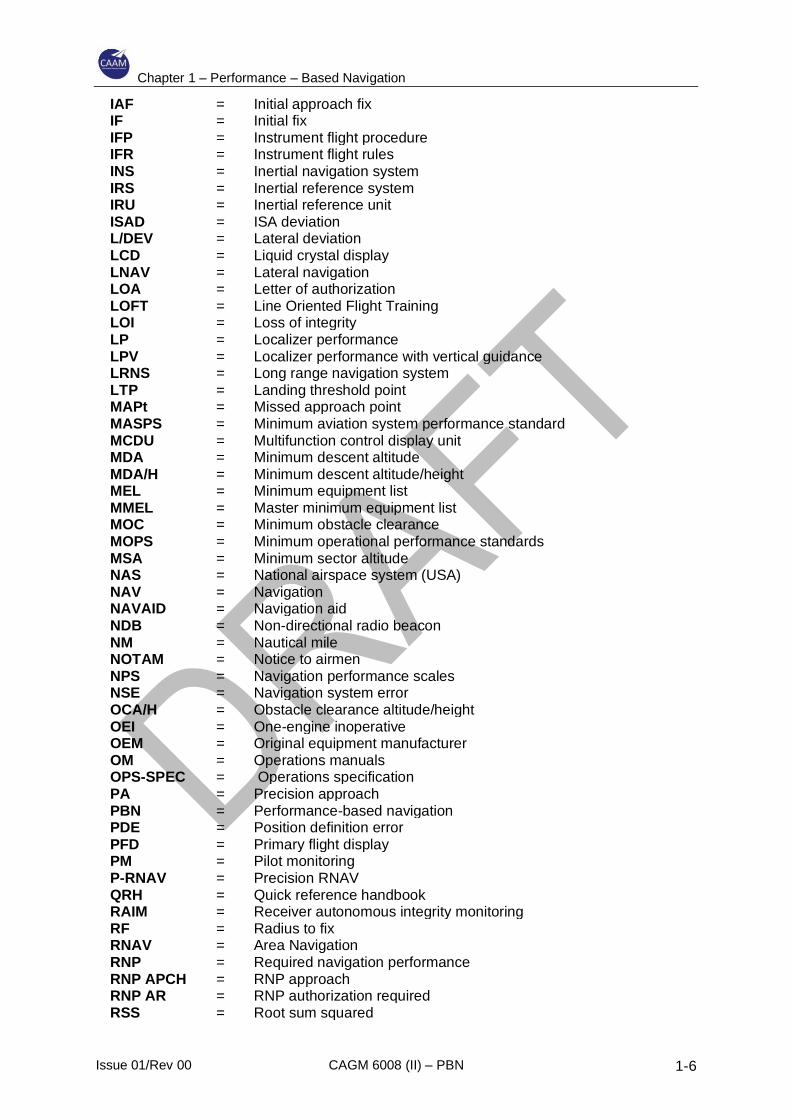
1.3 Abbreviations
AAIM = Aircraft autonomous integrity monitoring AC = Advisory Circular ACCUR = Accuracy AFARP = As far as reasonably practical AFM = Aircraft flight manual AGL = Above ground level AHRS = Attitude and heading reference system AIP = Aeronautical information publication AIRAC = Aeronautical information regulation and control ALARP = As low as reasonably practical AMC = Acceptable means of compliance AMM = Aircraft maintenance manual ANPE = Actual navigation performance error ANSP = Air navigation service provider AO = Air operator AOC = Air operator certificate AP = Auto pilot AR = Authorization required A-RNP = Advanced RNP ARP = Aerodrome reference point ASE = Altimetry system error ATC = Air traffic control ATCO = Air traffic controller ATIS = Automatic terminal information service AWI = Airworthiness Inspector Baro-VNAV = Barometric VNAV B-RNAV = Basic RNAV BG = Body geometry
Chapter 1 – Performance – Based Navigation
Issue 01/Rev 00 CAGM 6008 (II) – PBN 1-5
CA = Certificating authority CAA = Civil aviation authority CAAP = Civil aviation advisory publication CASA = Civil Aviation Safety Authority (Australia) CAT = Commercial air transport CCF = Common cause failure CDI = Course deviation indicator CDU = Control display unit CRC = Cyclic Redundancy Check CS = Certification specification DA = Decision altitude DA/H = Decision altitude/height DF = Direct to a fix DGCA = Directorate General of Civil Aviation DME = Distance measuring equipment DOP = Dilution of precision DR = Dead reckoning EASA = European Aviation Safety Agency EGPWS = Enhanced ground proximity warning system EHSI = Electronic Horizontal Situation Indicator ENR = En-route EPE = Estimated position error ETSO = European Technical Standards Order EUROCAE = European Organization for Civil Aviation Equipment FA = Fix to an altitude FAA = Federal Aviation Administration FAF = Final approach fix FAP = Final approach point FAS = Final approach segment FCOM = Flight crew operations manual FD = Flight director FDE = Fault detection and exclusion FGS = Flight guidance system FM = Fix to a manual termination FMS = Flight management system FOI = Flight Operations Inspector FOSA = Flight operational safety assessment FPA = Flight path angle FPL = Flight plan FRT = Fixed radius transition FSD = Full-scale deflection FSTD = Flight simulation training device FTE = Flight technical error FTP = Fictitious threshold point GA = General aviation GNSS = Global navigation satellite system GPS = Global positioning system HA = Holding/racetrack to an altitude HAL = Horizontal alert limit HF = Holding/racetrack to a fix HFOM = Horizontal figure of merit HIL = Horizontal integrity limit HM = Holding/racetrack to a manual termination HPL = Horizontal protection limit HIS = Horizontal situation indicator
Chapter 1 – Performance – Based Navigation
Issue 01/Rev 00 CAGM 6008 (II) – PBN 1-6
IAF = Initial approach fix IF = Initial fix IFP = Instrument flight procedure IFR = Instrument flight rules INS = Inertial navigation system IRS = Inertial reference system IRU = Inertial reference unit ISAD = ISA deviation L/DEV = Lateral deviation LCD = Liquid crystal display LNAV = Lateral navigation LOA = Letter of authorization LOFT = Line Oriented Flight Training LOI = Loss of integrity LP = Localizer performance LPV = Localizer performance with vertical guidance LRNS = Long range navigation system LTP = Landing threshold point MAPt = Missed approach point MASPS = Minimum aviation system performance standard MCDU = Multifunction control display unit MDA = Minimum descent altitude MDA/H = Minimum descent altitude/height MEL = Minimum equipment list MMEL = Master minimum equipment list MOC = Minimum obstacle clearance MOPS = Minimum operational performance standards MSA = Minimum sector altitude NAS = National airspace system (USA) NAV = Navigation NAVAID = Navigation aid NDB = Non-directional radio beacon NM = Nautical mile NOTAM = Notice to airmen NPS = Navigation performance scales NSE = Navigation system error OCA/H = Obstacle clearance altitude/height OEI = One-engine inoperative OEM = Original equipment manufacturer OM = Operations manuals OPS-SPEC = Operations specification PA = Precision approach PBN = Performance-based navigation PDE = Position definition error PFD = Primary flight display PM = Pilot monitoring P-RNAV = Precision RNAV QRH = Quick reference handbook RAIM = Receiver autonomous integrity monitoring RF = Radius to fix RNAV = Area Navigation RNP = Required navigation performance RNP APCH = RNP approach RNP AR = RNP authorization required RSS = Root sum squared
Chapter 1 – Performance – Based Navigation
Issue 01/Rev 00 CAGM 6008 (II) – PBN 1-7
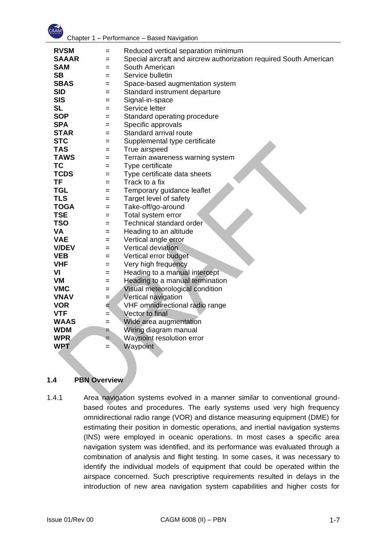
RVSM = Reduced vertical separation minimum SAAAR = Special aircraft and aircrew authorization required South American SAM = South American SB = Service bulletin SBAS = Space-based augmentation system SID = Standard instrument departure SIS = Signal-in-space SL = Service letter SOP = Standard operating procedure SPA = Specific approvals STAR = Standard arrival route STC = Supplemental type certificate TAS = True airspeed TAWS = Terrain awareness warning system TC = Type certificate TCDS = Type certificate data sheets TF = Track to a fix TGL = Temporary guidance leaflet TLS = Target level of safety TOGA = Take-off/go-around TSE = Total system error TSO = Technical standard order VA = Heading to an altitude VAE = Vertical angle error V/DEV = Vertical deviation VEB = Vertical error budget VHF = Very high frequency VI = Heading to a manual intercept VM = Heading to a manual termination VMC = Visual meteorological condition VNAV = Vertical navigation VOR = VHF omnidirectional radio range VTF = Vector to final WAAS = Wide area augmentation WDM = Wiring diagram manual WPR = Waypoint resolution error WPT = Waypoint
1.4 PBN Overview
1.4.1 Area navigation systems evolved in a manner similar to conventional ground-
based routes and procedures. The early systems used very high frequency
omnidirectional radio range (VOR) and distance measuring equipment (DME) for
estimating their position in domestic operations, and inertial navigation systems
(INS) were employed in oceanic operations. In most cases a specific area
navigation system was identified, and its performance was evaluated through a
combination of analysis and flight testing. In some cases, it was necessary to
identify the individual models of equipment that could be operated within the
airspace concerned. Such prescriptive requirements resulted in delays in the
introduction of new area navigation system capabilities and higher costs for
Chapter 1 – Performance – Based Navigation
Issue 01/Rev 00 CAGM 6008 (II) – PBN 1-8
maintaining appropriate certification. The PBN concept was developed with
globally applicable performance requirements, detailed in accompanying
navigation specifications, in order to avoid these high costs and delays.
1.4.2 The PBN concept requires that the aircraft area navigation system performance
be defined in terms of the accuracy, integrity, availability, continuity and
functionality necessary to operate in the context of a particular airspace concept.
Appropriate positioning sensors are also identified; these may include VOR/DME,
DME/DME, GNSS and/or inertial systems. Performance is detailed in a navigation
specification in sufficient detail to facilitate global harmonization. The navigation
specification not only lays out the aircraft system performance requirements but
also the aircrew requirements in terms of crew procedures and training, as well as
any appropriate maintenance requirements, such as the provision of navigation
databases.
1.4.3 Area navigation systems are described in more detail in Appendix A
1.5 RNAV and RNP
1.5.1 RNAV specifications were developed to support existing capabilities in aircraft
equipped with area navigation systems which, in the general case, were not
designed to provide on-board performance monitoring and alerting. RNAV
specifications are similar to RNP specifications but do not require an on-board
performance monitoring and alerting capability.
1.5.2 RNP specifications developed from a need to support operations that require
greater integrity assurance, where the pilot is able to detect when the navigation
system is not achieving, or cannot guarantee with appropriate integrity, the
navigation performance required for the operation. Such systems are known as
RNP systems. RNP systems provide greater assurance of integrity and, hence,
can offer safety, efficiency, capacity and other operational benefits.
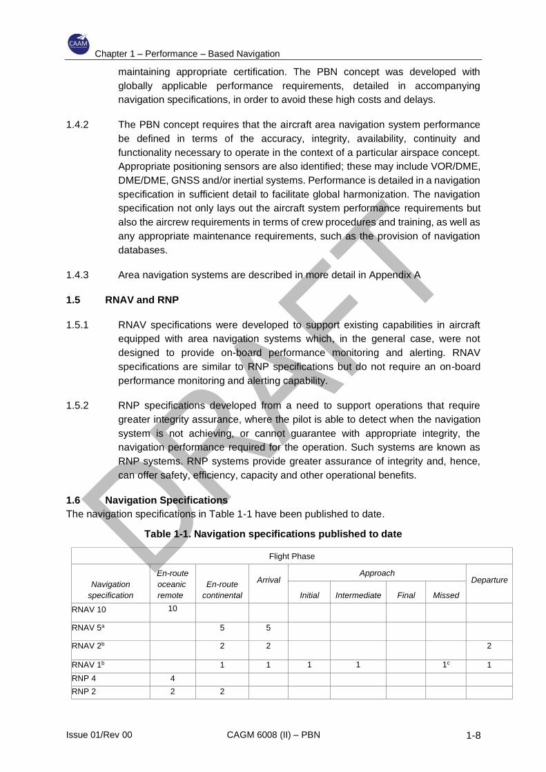
1.6 Navigation Specifications
The navigation specifications in Table 1-1 have been published to date.
Table 1-1. Navigation specifications published to date
Flight Phase
Navigation
specification
En-route
oceanic
remote
En-route
continental
Arrival
Approach Departure
Initial
Intermediate
Final
Missed
RNAV 10 10
RNAV 5a 5 5
RNAV 2b 2 2 2
RNAV 1b 1 1 1 1 1c 1
RNP 4 4
RNP 2 2 2
Chapter 1 – Performance – Based Navigation
Issue 01/Rev 00 CAGM 6008 (II) – PBN 1-9
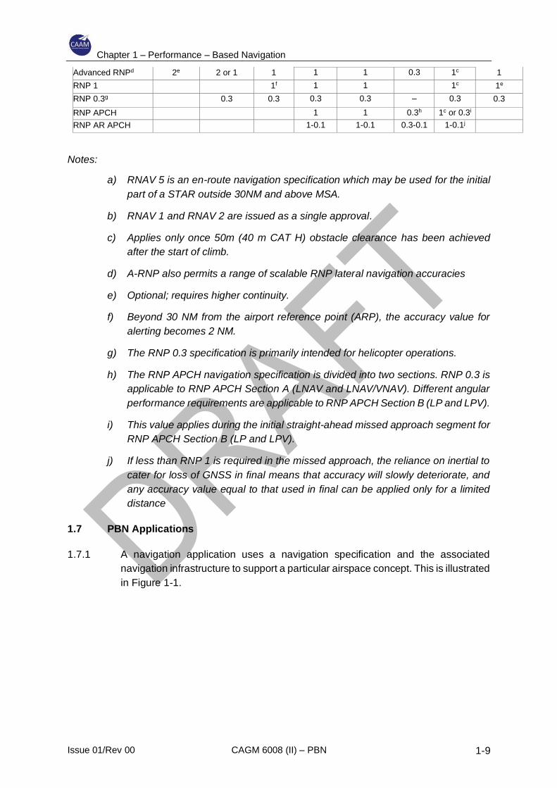
Advanced RNPd 2e 2 or 1 1 1 1 0.3 1c 1
RNP 1 1f 1 1 1c 1e
RNP 0.3g 0.3 0.3 0.3 0.3 – 0.3 0.3
RNP APCH 1 1 0.3h 1c or 0.3i
RNP AR APCH 1-0.1 1-0.1 0.3-0.1 1-0.1j
Notes:
a) RNAV 5 is an en-route navigation specification which may be used for the initial
part of a STAR outside 30NM and above MSA.
b) RNAV 1 and RNAV 2 are issued as a single approval.
c) Applies only once 50m (40 m CAT H) obstacle clearance has been achieved
after the start of climb.
d) A-RNP also permits a range of scalable RNP lateral navigation accuracies
e) Optional; requires higher continuity.
f) Beyond 30 NM from the airport reference point (ARP), the accuracy value for
alerting becomes 2 NM.
g) The RNP 0.3 specification is primarily intended for helicopter operations.
h) The RNP APCH navigation specification is divided into two sections. RNP 0.3 is
applicable to RNP APCH Section A (LNAV and LNAV/VNAV). Different angular
performance requirements are applicable to RNP APCH Section B (LP and LPV).
i) This value applies during the initial straight-ahead missed approach segment for
RNP APCH Section B (LP and LPV).
j) If less than RNP 1 is required in the missed approach, the reliance on inertial to
cater for loss of GNSS in final means that accuracy will slowly deteriorate, and
any accuracy value equal to that used in final can be applied only for a limited
distance
1.7 PBN Applications
1.7.1 A navigation application uses a navigation specification and the associated
navigation infrastructure to support a particular airspace concept. This is illustrated
in Figure 1-1.

Chapter 1 – Performance – Based Navigation
Issue 01/Rev 00 CAGM 6008 (II) – PBN 1-10
Figure 1-1. Navigation specifications to support a particular airspace concept
Chapter 2 – Certification and Operational Approval
Issue 01/Rev 00 CAGM 6008 (II) – PBN 2-1
2 Certification and Operational Approval
2.1 Overview
2.1.1 The PBN concept requires that the aircraft meets certain airworthiness certification
standards, including the necessary navigation system performance and
functionality, to be eligible for a particular application and that the operator has
operational approval from the appropriate regulatory body before the system can
be used. A PBN navigation specification operational approval is an approval that
authorizes an operator to carry out defined PBN operations with specific aircraft in
designated airspace. The operational approval for an operator may be issued
when the operator has demonstrated to the CAAM that the specific aircraft are in
compliance with the relevant airworthiness standards and that the continued
airworthiness and flight operations requirements are satisfied.
a) The airworthiness element ensures that the aircraft meets the aircraft eligibility
and safety requirements for the functions and performance defined in the
navigation specifications (or other referenced certification standards) and the
installation meets the relevant airworthiness standards, (e.g. U.S. 14 CFR
Part 25/EASA CS-25 and the applicable AC/AMC). The AC/AMC may also
include other non-navigation equipment required to conduct the operation
such as communications and surveillance equipment.
b) The continued airworthiness element of the operational approval is not directly
addressed in the PBN manual since it is inherent in the aircraft airworthiness
approval through the airworthiness requirements, (i.e. U.S. 14 CFR
25.1529/EASA CS-25.1529,) but the operator is expected to be able to
demonstrate that the navigation system will be maintained compliant with the
type design. For navigation system installations there are few specific
continued airworthiness requirements other than database and configuration
management, systems modifications and software revisions, but the element
is included for completeness and consistency with other CNS/ATM
operational approvals, e.g. RVSM.
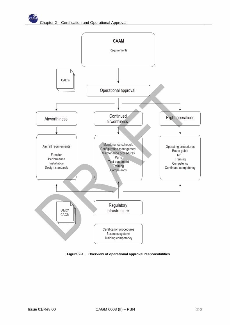
c) The flight operations element considers the operator’s infrastructure for
conducting PBN operations and flight crew operating procedures, training and
competency demonstrations. This element also considers the operator’s MEL,
operations manual, checklists, instrument flight procedure approval
processes, navigation database validation procedures, dispatch procedures,
etc.
This is illustrated in Figure 2-1
Chapter 2 – Certification and Operational Approval
Issue 01/Rev 00 CAGM 6008 (II) – PBN 2-2
CAAM
Requirements
CAD’s
Operational approval
Flight operations Continued airworthiness
Airworthiness
Maintenance schedule
Configuration management
Maintenance procedures
Parts
Test equipment
Training
Competency
Aircraft requirements Operating procedures Route guide
MEL
Training
Competency
Continued competency
Function
Performance
Installation
Design standards
Regulatory
infrastructure AMC/
CAGM
Certification procedures
Business systems
Training competency
Figure 2-1. Overview of operational approval responsibilities
Chapter 2 – Certification and Operational Approval
Issue 01/Rev 00 CAGM 6008 (II) – PBN 2-3
2.2 State regulatory responsibilities
2.2.1 Normally, individual States develop national regulatory material which address the
PBN applications relevant to their airspace or relevant to operations conducted in
another State by the operators and aircraft registered in that State. Therefore, prior
to conducting PBN operations, the operator would require approval from the
individual States.
2.2.2 There may be up to three different States and regulatory agencies involved in
operational approval:
a) State of Design/Manufacture: The organization which has designed the
aircraft applies for a type certificate (TC) from the State of Design. The State
of Design also approves the master minimum equipment list (MMEL), the
mandatory maintenance tasks and intervals, and the aircraft flight manual
(AFM) and its amendments, which determine the PBN capabilities and
limitations of the aircraft. A State of Design, which may be different from the
State which issued the original TC, may issue a design change approval for
an aircraft as a supplemental type certificate (STC).
b) State of Registry: The State of Registry is the State in which the aircraft is
registered. The State of Registry is responsible for the airworthiness of the
aircraft. It approves the aircraft maintenance programme, in accordance with
its regulations, and issues the certificate of airworthiness. It also approves
aircraft repairs and modifications (as stand-alone modifications or as STCs).
For general aviation, the State of Registry approves the minimum equipment
list (MEL) and the conduct of specified PBN operations.
c) State of the Operator: The state of the operator (which may be different from
the State of Registry for commercial air transport operations) usually accepts
the aircraft maintenance programme and approves the MEL, the flight crew
training programmes and the conduct of specified PBN operations, in
accordance with its regulations.
Note1. – 2.2.3 describes general definitions of the different types of States.
Note 2. – For example, when a 9M registered aircraft is operated by a Malaysian
AOC holder, the State of Registry and State of the Operator is the same.
2.2.3 Usually, the CAAM does not re-approve technical data approved by another State.
Re-approving already approved technical data effectively transfers the regulatory
responsibility for that data to the CAAM as its re-approving the data with respect
to aircraft registered under its jurisdiction. When the CAAM does use technical
data approved by another State, the CAAM will review the data, determine that
the data are acceptable for use, and formally accept the data; in this way, the
regulatory responsibility remains with the State that originally approved the data.
An example of regulatory text is provided in Appendix B.
2.3 Operational approval
Chapter 2 – Certification and Operational Approval
Issue 01/Rev 00 CAGM 6008 (II) – PBN 2-4
2.3.1 Operational approval is usually the responsibility of the CAAM for commercial air
transport operations and the State of Registry for general aviation operations.
2.3.2 The following factors usually influences CAAM’s decision to require a formal
operational approval process and specific documentation of approval:
a) the degree of linkage to the basis for aircraft/avionics certification, i.e. whether
the aircraft, including its RNAV or RNP navigation system, has an
airworthiness approval covering the type of envisaged PBN operations;
b) the complexity of the PBN operation and the level of associated challenges to
operators and regulators;
c) the maturity of the related operational concept and systems and, specifically,
whether the issues are well understood and relatively stable;
d) the risk associated with improper conduct of operations and operator-specific
safety expectations, as well as those of third parties in the air and on the
ground;
e) the availability of appropriate training, and checking standards and
procedures for the respective type of PBN operations (mainly for pilots but
also for maintenance and dispatcher personnel, as appropriate); and
f) the promulgation of information from holders of TCs to air operators (e.g.
MMEL and training requirements) throughout the life cycle of the aircraft.
2.3.3 CAAM’s decisions in this area are based upon balancing the efficient use of
available regulatory resources to ensure proper initial operator compliance and to
promote ongoing operational safety, while also enabling the use of new
technologies and operations in the interest of enhanced safety and efficiency.
2.3.4 In order to facilitate expedited approvals, provided all airworthiness and
operational requirements are satisfied, CAAM may “bundle” certain operations,
particularly by flight phase, thereby allowing for leveraging of an operator’s higher-
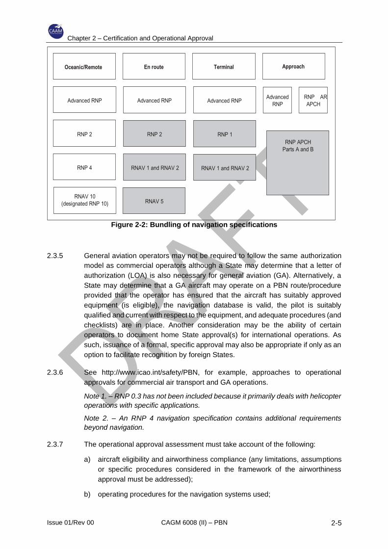
level capabilities (see Figure 2-2). For example, an operator approved for RNP 1
operations might be readily approved for RNAV 1 operations provided guidance is
in place. The CAAM may also approach certain operations, such as those shown
in the shaded area of Figure 2-2, as having less operational risk if adequate control
mechanisms are implemented overall.
Chapter 2 – Certification and Operational Approval
Issue 01/Rev 00 CAGM 6008 (II) – PBN 2-5
Figure 2-2: Bundling of navigation specifications
2.3.5 General aviation operators may not be required to follow the same authorization
model as commercial operators although a State may determine that a letter of
authorization (LOA) is also necessary for general aviation (GA). Alternatively, a
State may determine that a GA aircraft may operate on a PBN route/procedure
provided that the operator has ensured that the aircraft has suitably approved
equipment (is eligible), the navigation database is valid, the pilot is suitably
qualified and current with respect to the equipment, and adequate procedures (and
checklists) are in place. Another consideration may be the ability of certain
operators to document home State approval(s) for international operations. As
such, issuance of a formal, specific approval may also be appropriate if only as an
option to facilitate recognition by foreign States.
2.3.6 See http://www.icao.int/safety/PBN, for example, approaches to operational
approvals for commercial air transport and GA operations.
Note 1. – RNP 0.3 has not been included because it primarily deals with helicopter
operations with specific applications.
Note 2. – An RNP 4 navigation specification contains additional requirements
beyond navigation.
2.3.7 The operational approval assessment must take account of the following:
a) aircraft eligibility and airworthiness compliance (any limitations, assumptions
or specific procedures considered in the framework of the airworthiness
approval must be addressed);
b) operating procedures for the navigation systems used;
Approach
Terminal
En route
Oceanic/Remote
Chapter 2 – Certification and Operational Approval
Issue 01/Rev 00 CAGM 6008 (II) – PBN 2-6
c) control of operating procedures (documented in the operations manual);
d) flight crew initial training and competency requirements and continuing
competency requirements;
e) dispatch training requirements; and
f) control of navigation database procedures. Where a navigation database is
required, operators need to have documented procedures for the
management of such databases. These procedures will define the sourcing
of navigation data from approved suppliers, data validation procedures for
navigation databases and the installation of updates to databases into aircraft
so that the databases remain current with the AIRAC cycle. (For RNP AR
applications, the control of the terrain database used by TAWS must also be
addressed.)
2.3.8 Aircraft eligibility
2.3.8.1 An aircraft is eligible for a particular PBN application provided there is a clear
statement in:
a) the TC; or
b) the STC; or
c) the associated documentation – AFM or equivalent document; or
d) a compliance statement from the manufacturer, which has been approved
by the State of Design and accepted by the State of Registry or the State
of the Operator, if different.
The operator must have a configuration list detailing the pertinent hardware and
software components and equipment used for the PBN operation.
2.3.8.2 The TC is the approved standard for the production of a specified type/series
of aircraft. The aircraft specification for that type/series, as part of the TC, will
generally include a navigation standard. The aircraft documentation for that
type/series will define the system use, operational limitations, equipment fitted
and the maintenance practices and procedures. No changes (modifications)
are permitted to an aircraft unless the CAAM either approves such changes
through a modification approval process or STC, or accepts technical data
defining a design change that has been approved by another State.
2.3.8.3 An alternate method of achieving the airworthiness approval of the aircraft for
PBN operations is for the aircraft to be modified in accordance with approved
data (e.g. STC, minor modification, FAA Form 8110-3).
2.3.8.4 One means of modifying an aircraft is the approved service bulletin (SB) issued
by the aircraft manufacturer. The SB is a document approved by the State of
Design to enable changes to the specified aircraft type, and the modification
Chapter 2 – Certification and Operational Approval
Issue 01/Rev 00 CAGM 6008 (II) – PBN 2-7
then becomes part of the type design of the aircraft. Its applicability will normally
be restricted by airframe serial number. The SB describes the intention of the
change and the work to be done to the aircraft. Any deviations from the SB
require a design change approval; any deviations not approved will invalidate
the SB approval. The CAAM accepts the application of an SB and changes to
the maintenance programme, while the State of the Operator accepts changes
to the maintenance programme and approves changes to the MEL, training
programmes and operations specifications. An OEM SB may be obtained for
current-production or out-of-production aircraft.
2.3.8.5 For recently manufactured aircraft, where the PBN capability is approved under
the TC, there may be a statement in the AFM limitations section identifying the
operations for which the aircraft is approved. There is also usually a statement
that the stated approval does not itself constitute an approval for an operator to
conduct those operations.
2.3.8.6 In many cases for legacy aircraft, while the aircraft is capable of meeting all the
airworthiness requirements of a PBN navigation specification, there may be no
clear statement in the applicable TC or STC or associated documents (AFM or
equivalent document). In such cases, the aircraft manufacturer may elect to
issue an SB with an appropriate AFM update or instead may publish a
compliance statement in the form of a letter, for simple changes, or a detailed
aircraft-type-specific document for more complex changes. The State of
Registry may determine that an AFM change is not required if it accepts the
OEM documentation. Table 2-1 lists the possible scenarios facing an operator
who wishes to obtain approval for a PBN application, together with the
appropriate courses of action.
Note.— The European Aviation Safety Agency (EASA) publishes the criteria
required for airworthiness certification and operational approval to conduct PBN
operations, and member States apply these criteria. In the context of PBN
airworthiness, this is incorporated within the Certification Specification (CS) and
Acceptable Means of Compliance (AMC) for Airborne Communications,
Navigation and Surveillance (ACNS). Operational approval aspects are
covered in Air-Ops Regulation Part ARO (authority requirements for air
operations), Part ORO (organization requirements for air operations), Part CAT
(commercial air transport), Part SPA (specific approvals), Part NCC (complex
motor-powered aircraft). Part NCO (non-complex aircraft) and Part SPO
(specialized operations). The Federal Aviation Administration (FAA), similarly,
publishes advisory circulars (ACs) and orders for operations in United States
airspace. The ACs, orders and AMCs usually reference appropriate technical
standard orders (TSOs) and European TSOs (ETSOs). TSOs/ETSOs are also
the responsibility of the FAA and EASA and provide technical and performance
requirements for specific parts or items of equipment. A design organization,
typically the aircraft manufacturer, may require a vendor to produce a
TSO/ETSO approval before including such equipment in a system design. The
ACs and AMCs may also reference industry standard documents such as the
minimum aviation system performance standards (MASPS) or the minimum
Chapter 2 – Certification and Operational Approval
Issue 01/Rev 00 CAGM 6008 (II) – PBN 2-8
operational performance standards (MOPS), which are usually developed
under the aegis of the RTCA and EUROCAE, and specific interoperability and
interface standards such as those published by ARINC. The airworthiness
certification requirements in the USA and in the European Union are largely
“harmonized” in order to reduce the costly and time-consuming work by OEMs
and equipment vendors to gain approval from two different authorities with the
same safety objectives. Some States have imposed additional constraints
which are highlighted in Chapter 4. Table 2-2 certification standards published
by EASA and the FAA for PBN applications in 2012 (each document may
reference additional standards including AC’s, TSOs and RTCA/EUROCAE
documents) and is subject to change
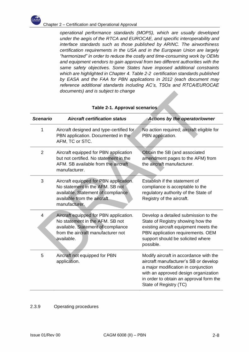
Table 2-1. Approval scenarios
Scenario Aircraft certification status Actions by the operator/owner
1 Aircraft designed and type-certified for
PBN application. Documented in the
AFM, TC or STC.
No action required; aircraft eligible for
PBN application.
2 Aircraft equipped for PBN application
but not certified. No statement in the
AFM. SB available from the aircraft
manufacturer.
Obtain the SB (and associated
amendment pages to the AFM) from
the aircraft manufacturer.
3 Aircraft equipped for PBN application.
No statement in the AFM. SB not
available. Statement of compliance
available from the aircraft
manufacturer.
Establish if the statement of
compliance is acceptable to the
regulatory authority of the State of
Registry of the aircraft.
4 Aircraft equipped for PBN application.
No statement in the AFM. SB not
available. Statement of compliance
from the aircraft manufacturer not
available.
Develop a detailed submission to the
State of Registry showing how the
existing aircraft equipment meets the
PBN application requirements. OEM
support should be solicited where
possible.
5 Aircraft not equipped for PBN
application.
Modify aircraft in accordance with the
aircraft manufacturer’s SB or develop
a major modification in conjunction
with an approved design organization
in order to obtain an approval form the
State of Registry (TC)
2.3.9 Operating procedures
Chapter 2 – Certification and Operational Approval
Issue 01/Rev 00 CAGM 6008 (II) – PBN 2-9
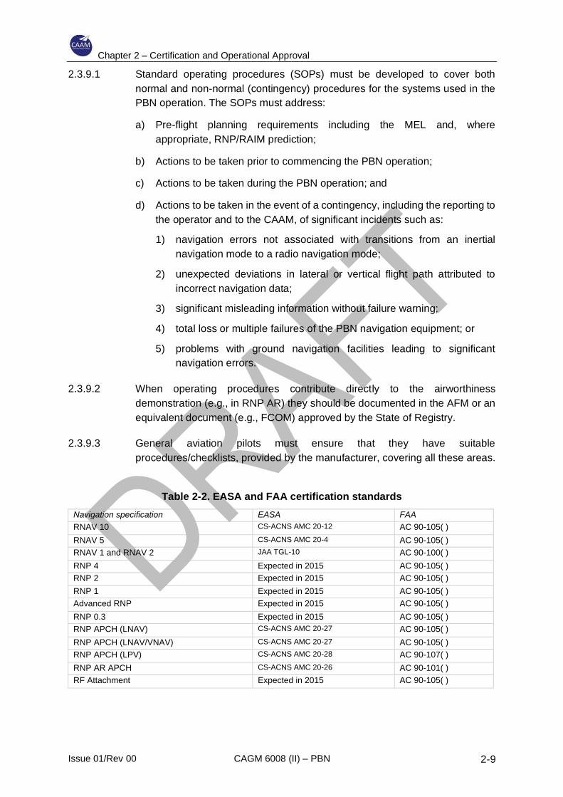
2.3.9.1 Standard operating procedures (SOPs) must be developed to cover both
normal and non-normal (contingency) procedures for the systems used in the
PBN operation. The SOPs must address:
a) Pre-flight planning requirements including the MEL and, where
appropriate, RNP/RAIM prediction;
b) Actions to be taken prior to commencing the PBN operation;
c) Actions to be taken during the PBN operation; and
d) Actions to be taken in the event of a contingency, including the reporting to
the operator and to the CAAM, of significant incidents such as:
1) navigation errors not associated with transitions from an inertial
navigation mode to a radio navigation mode;
2) unexpected deviations in lateral or vertical flight path attributed to
incorrect navigation data;
3) significant misleading information without failure warning;
4) total loss or multiple failures of the PBN navigation equipment; or
5) problems with ground navigation facilities leading to significant
navigation errors.
2.3.9.2 When operating procedures contribute directly to the airworthiness
demonstration (e.g., in RNP AR) they should be documented in the AFM or an
equivalent document (e.g., FCOM) approved by the State of Registry.
2.3.9.3 General aviation pilots must ensure that they have suitable
procedures/checklists, provided by the manufacturer, covering all these areas.
Table 2-2. EASA and FAA certification standards
Navigation specification EASA FAA RNAV 10 CS-ACNS AMC 20-12 AC 90-105( )
RNAV 5 CS-ACNS AMC 20-4 AC 90-105( ) RNAV 1 and RNAV 2 JAA TGL-10 AC 90-100( )
RNP 4 Expected in 2015 AC 90-105( ) RNP 2 Expected in 2015 AC 90-105( )
RNP 1 Expected in 2015 AC 90-105( ) Advanced RNP Expected in 2015 AC 90-105( )
RNP 0.3 Expected in 2015 AC 90-105( ) RNP APCH (LNAV) CS-ACNS AMC 20-27 AC 90-105( )
RNP APCH (LNAV/VNAV) CS-ACNS AMC 20-27 AC 90-105( ) RNP APCH (LPV) CS-ACNS AMC 20-28 AC 90-107( )
RNP AR APCH CS-ACNS AMC 20-26 AC 90-101( ) RF Attachment Expected in 2015 AC 90-105( )
Chapter 2 – Certification and Operational Approval
Issue 01/Rev 00 CAGM 6008 (II) – PBN 2-10
2.3.10 Control of operating procedures
2.3.10.1 The SOPs must be adequately documented in the operations manual (OM) for
commercial air operators and for general aviation operators of large or turbojet
aircraft. For general aviation operators where an OM is not required, the PBN
operating procedures must still be documented.
2.3.11 Flight crew and dispatch training and competency
2.3.11.1 A flight crew training programme and, if applicable, a dispatcher training
programme must cover all the tasks associated with the PBN operation as well
as provide sufficient background to ensure a comprehensive understanding of
all aspects of the operation.
2.3.12 Control of navigation database procedures
2.3.12.1 Navigation databases are required for all PBN navigation specifications except
RNAV 10 and RNAV 5. The procedures for maintaining currency, checking for
errors and reporting errors to the navigation database supplier must be
documented in the operations and maintenance manual. Moreover, the
suppliers of the navigation data are usually required to comply with FAA AC 20-
153 or to be issued with an LOA in accordance with EASA Opinion Nr. 01/2005.
2.3.13 Performance record
2.3.13.1 Navigation error reports should be recorded and analysed to determine the
need for any remedial action. Such action may involve the replacement of, or
modifications to, the navigation equipment or changes to the operational
procedures. All corrective action taken should be documented.
2.4 Documentation of operational approval
2.4.1 Operational approval may be documented through:
a) an amendment to the operations manual (OM), if it is required; and
b) an operations specification (Ops Spec), associated with the air operator
certificate (AOC); or
c) a letter of authorization (LOA) for general aviation aircraft.
Example of Ops Spec entries are provided in Appendix C.
2.4.2 During the validity of the operational approval, the CAAM should consider any
anomaly reports received from the operator or other interested party. Repeated
navigation error occurrences attributed to a specific piece of navigation equipment
may result in restrictions on use or cancellation of the approval for use of that
equipment. Information that indicates the potential for repeated errors may require
modification of an operator’s procedures and training programme. Information that
Chapter 2 – Certification and Operational Approval
Issue 01/Rev 00 CAGM 6008 (II) – PBN 2-11
attributes multiple errors to a particular pilot or crew may necessitate remedial
training and checking or a review of the operational approval.
2.5 CAAM PBN Operational Approval Process
2.5.1 General
2.5.1.1 In this CAGM, PBN operations mean all procedures applied for the purpose of
ensuring safe aircraft operations in PBN airspace.
2.5.1.2 CAAM certification procedures are outlined in this manual.
2.5.1.3 The PBN approval process consists of both, an airworthiness approval and an
operational approval.
2.5.1.4 The required information shall be provided to the CAAM by an air operator
applying for PBN approval at least 60 working days prior to the intended start
of PBN operations.
2.5.1.5 Any questions not covered herein, or any point of apparent conflict requiring
resolution, should be referred to the CAAM.
2.5.2 The approval process should consist of the following phases:
2.5.2.1 Step 1 — Pre-application phase: Prior to initiating the approval process, the
operator will review the requirements and guidelines outlined in the relevant
regulations, CADs, and CAGMs which are published by the CAAM.
A pre-application usually commences when a prospective applicant makes
his/her initial inquiries regarding application for an approval in the form of a
letter or a personal visit to the CAAM. If the proposed application is complex,
the operator may need to obtain advice and assistance from OEMs or other
design organisations, training establishments, data providers, etc.
2.5.2.2 Step 2 — Formal application phase: The operator submits to the CAAM a
formal, written application for approval, the CAAM will then appoint a FOI and
AWI to oversee the application
Note. – An example application form is contained in Attachment 1.
2.5.2.3 Step 3 — Document evaluation phase: The CAAM FOI and AWI evaluate the
formal written application for approval to determine if all the requirements are
being met. The FOI and AWI, may need to obtain advice and assistance from
other departments within CAAM or organisations such as regional agencies or
experts in other States.
2.5.2.4 Step 4 – Demonstration and inspection phase: During a formal inspection
by the FOI and AWI (assisted as necessary by a team from the CAAM), the
operator demonstrates how the requirements are being met.
Chapter 2 – Certification and Operational Approval
Issue 01/Rev 00 CAGM 6008 (II) – PBN 2-12
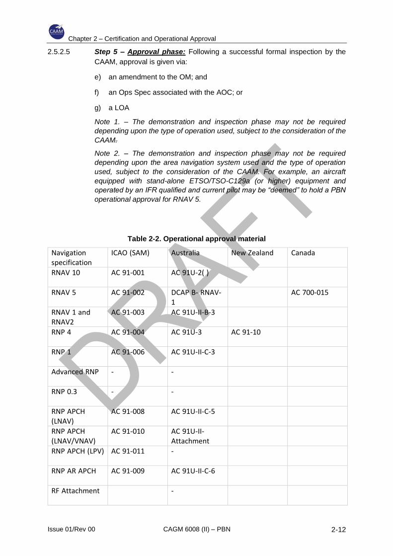
2.5.2.5 Step 5 – Approval phase: Following a successful formal inspection by the
CAAM, approval is given via:
e) an amendment to the OM; and
f) an Ops Spec associated with the AOC; or
g) a LOA
Note 1. – The demonstration and inspection phase may not be required
depending upon the type of operation used, subject to the consideration of the
CAAM.
Note 2. – The demonstration and inspection phase may not be required
depending upon the area navigation system used and the type of operation
used, subject to the consideration of the CAAM. For example, an aircraft
equipped with stand-alone ETSO/TSO-C129a (or higher) equipment and
operated by an IFR qualified and current pilot may be “deemed” to hold a PBN
operational approval for RNAV 5.
Table 2-2. Operational approval material
Navigation
specification
ICAO (SAM) Australia New Zealand Canada
RNAV 10 AC 91-001 AC 91U-2( )
RNAV 5 AC 91-002 DCAP B- RNAV-1
AC 700-015
RNAV 1 and
RNAV2
AC 91-003 AC 91U-II-B-3
RNP 4 AC 91-004 AC 91U-3 AC 91-10
RNP 1 AC 91-006 AC 91U-II-C-3
Advanced RNP - -
RNP 0.3 - -
RNP APCH
(LNAV) AC 91-008 AC 91U-II-C-5
RNP APCH
(LNAV/VNAV) AC 91-010 AC 91U-II-
Attachment
RNP APCH (LPV) AC 91-011 -
RNP AR APCH AC 91-009 AC 91U-II-C-6
RF Attachment
-

Chapter 2 – Certification and Operational Approval
Issue 01/Rev 00 CAGM 6008 (II) – PBN 2-13
2.6 International Operations
2.6.1 As stated in 2.2.1, the operator will need to make applications to each State into
or over which it intends to operate. The operator will also need to keep CAAM
informed of all applications to operate into other States. Applications should be
made direct to the CAAs of the States into which it is intended to operate. In some
cases, it will be possible to download information and both the instructions for
making an application and the necessary forms from a website maintained by the
CAA in question.

Chapter 2 – Certification and Operational Approval
Issue 01/Rev 00 CAGM 6008 (II) – PBN 2-14
INTENTIONALLY LEFT BLANK
Chapter 3 – Operational Approval Guidelines
Issue 01/Rev 00 CAGM 6008 (II) – PBN 3-1
3 Operational Approval Guidelines
3.1 Aircraft eligibility
3.1.1 The first step in assessing an application for PBN operational approval is to
establish that the aircraft and its systems are suitable for the specific operation.
3.1.2 The ICAO PBN manual have only recently been issued and this means that there
are many aircraft whose TC, STC and associated documentation (AFM) do not
include references to PBN.
3.1.3 However, a lack of specific airworthiness certification does not necessarily mean
a lack of PBN capability. If the aircraft is suitably equipped, it will be necessary to
demonstrate this and that the aircraft is capable of the specific PBN operation. It
is not meant to imply that additional certification is required to obtain approval,
although it is important that appropriate OEM input is obtained to support any
claims of capability that are is not part of the existing certification.
3.1.4 The aircraft eligibility assessment process needs to consider the capability,
functionality and performance characteristics of the navigation and other relevant
flight systems against the requirements of the particular PBN operation. In some
cases, operational mitigations and alternative means of meeting the PBN
requirements may need to be considered. Considerable additional evaluation may
be necessary before an aircraft is determined to be eligible for the issue of an
operational approval, particularly for advanced navigation specifications such as
RNP AR or A-RNP. While a large number of aircraft may never be considered to
be eligible for RNP operational approval, for engineering, economical or practical
reasons, many older aircraft have been certified to, or will be able to be approved
for, RNAV operational approvals such as RNAV 10, RNAV 5, and RNAV 1 and
RNAV 2.
3.1.5 Operating mitigations are normally required to address deficiencies in the required
aircraft qualification to undertake a particular operational procedure. These
deficiencies could be items related to aircraft performance or information displays
or availability.
3.1.6 Operators should discuss the proposed changes and mitigations with the CAAM
as early as possible.
3.1.7 In order to develop possible operational mitigations, operators should assess the:
a) qualification standard and fully understand the associated shortfall in the
qualification of the navigation specification;
b) procedures that have been established by the State with respect to the area
of operation. This review should identify the complexity of the proposed
operation and the hazards associated with that operation.
Chapter 3 – Operational Approval Guidelines
Issue 01/Rev 00 CAGM 6008 (II) – PBN 3-2
3.1.8 Following the identification of the above, operators should review their operational
procedures and identify possible changes or additional procedures/requirements
that could mitigate the identified deficiencies and hazards. The proposed changes
should then be presented to the CAAM for authorization/approval.
3.1.9 The operator should ensure that subsequent operations are conducted in
accordance with any restriction or limitation specified by the regulatory authority.
3.1.10 A number of manufacturers have obtained, or are in the process of obtaining,
airworthiness certification for specific PBN operations. In such cases the aircraft
eligibility assessment can be greatly simplified. It is anticipated that in the future
all manufacturers will seek appropriate PBN airworthiness certification for new
aircraft.
3.1.11 The AFM may include a statement of RNAV or RNP capability without any
reference to PBN. In many of these cases, the basis upon which a statement is
included in an AFM is not consistent with the PBN manual because many of the
terms, requirements, operating practices and other characteristics either differed
or did not exist at the time the AFM was issued. Consequently, unless the AFM
specifically references the relevant State regulatory documents consistent with
PBN, additional information will need to be obtained to evaluate the relevance of
the AFM statement.
3.1.12 In order to enable PBN operational approval, a number of OEMs provide additional
information to support claims of PBN compliance and capability. Such supporting
documentation may or may not be approved or endorsed by the State of
Manufacture, and it may be necessary to contact the relevant authority to validate
the manufacturer’s claims.
3.1.13 Where there is insufficient evidence of airworthiness certification, the aircraft
capability assessment must include an evaluation of the navigation functionality
as well as control, display and alerting functions. Area navigation systems that
were designed and installed before PBN implementation may not meet the
minimum requirements, and avionics upgrades may be necessary.
3.2 Standard Operating Procedures
3.2.1 Standard operating procedures (SOPs) must be developed to cover both normal
and non-normal (contingency) procedures for the systems used in the PBN
operation. Where possible, the practices and procedures should follow those laid
down by the manufacturer and the air navigation service provider (ANSP) in whose
airspace the PBN operations occur. The SOPs must be adequately documented
in the OM.
3.2.2 Pre-flight planning requirements
a) the flight plan should contain the appropriate statements of capability
applicable to the PBN operations anticipated during the flight;
Chapter 3 – Operational Approval Guidelines
Issue 01/Rev 00 CAGM 6008 (II) – PBN 3-3
b) the on-board navigation database, where applicable, must be current and
must contain the appropriate procedures, routes, waypoints and NAVAIDS;
c) a check must be carried out on the availability of appropriate NAVAIDS,
including, where appropriate, RNP or RAIM prediction. Any relevant NOTAMs
must be addressed;
d) an alternate approach must be identified in the event of loss of PBN capability;
e) the appropriate installed equipment must be serviceable.
3.2.3 Prior to commencing the PBN operation:
a) if all the criteria are not met, the PBN procedure must not be requested;
b) if offered a clearance for a procedure whose criteria cannot be met, ATC must
be advised “UNABLE ...”;
c) the loaded procedure must be checked against the chart;
d) it must be confirmed that the correct sensor has been selected and any
NAVAID de-selection is complete, if required;
e) it must be confirmed that a suitable RNP value has been selected, if
appropriate, and the navigation performance is adequate for the procedure;
f) the contingency procedures must be reviewed.
3.2.4 During the PBN operation the:
a) manufacturer’s instructions/procedures must be adhered to;
b) appropriate displays must have been selected;
c) lateral and, where appropriate, vertical deviation must not exceed prescribed
values;
d) altitude and speed constraints must be observed;
e) the procedure must be discontinued if there are integrity alerts, if the
navigation display is flagged as invalid or if the integrity alerting function is not
available.
3.2.5 In the event of a contingency:
a) ATC must be advised of any loss of PBN capability and a proposed course of
action;
b) where possible, documented procedures should be followed for:
1) navigation errors not associated with transitions from an inertial
navigation mode to a radio navigation mode;
2) unexpected deviations in lateral or vertical flight path attributed to
incorrect navigation data;
Chapter 3 – Operational Approval Guidelines
Issue 01/Rev 00 CAGM 6008 (II) – PBN 3-4
3) significant misleading information without failure warning;
4) total loss or multiple failures of the PBN navigation equipment;
5) problems with ground navigation facilities leading to significant navigation
errors; or
6) a communications failure.
3.2.6 After flight procedures
The required reporting of navigation errors or malfunctions should be completed
as applicable.
3.3 Training
3.3.1 General
3.3.1.1 The navigation specifications cover a wide range of operations, and training
needs to be appropriate to the particular circumstances. Moreover, although
each navigation specification includes guidance on flight crew training, the
guidance is not consistent, in detail or scope, across the range of navigation
specifications, and there is much duplication. The amount and type of training
required for flight crews will vary significantly depending upon a number of
factors including:
a) previous training and experience;
b) complexity of operations;
c) aircraft equipment.
It is therefore not possible to specify, for each of the navigation specifications,
the particular training that will be required.
3.3.1.2 For en-route operations, ground training is usually sufficient to provide crews
with the necessary knowledge. Delivery methods will vary, but classroom
training, computer-based training or, in some cases, desktop simulation training
is normally sufficient. Arrival and departure operations and approach
operations, in particular, also require the use of flight simulation training devices
in addition to ground training and briefings.
3.3.1.3 Dispatcher training, as applicable, should be implemented to achieve the
necessary competency in dispatch procedures related to PBN operations.
3.3.1.4 Consideration should also be given to the need for flight crews to demonstrate
that competency standards are achieved and maintained and the means by
which the operator documents the qualification.
3.3.2 Knowledge requirements
3.3.2.1 The following knowledge requirements apply to all PBN operations, although
the content and complexity will vary depending upon the particular operations.
Chapter 3 – Operational Approval Guidelines
Issue 01/Rev 00 CAGM 6008 (II) – PBN 3-5
3.3.2.2 Area navigation principles: Area navigation is the basis for all PBN operations,
and the same general knowledge is applicable to all navigation specifications.
Pilots with previous experience with area navigation operations may not be
familiar with some of the more advanced features such as radius to fix (RF)
legs, fixed radius transitions, required time of arrival or the application of vertical
navigation.
3.3.2.3 Navigation system principles: Flight crews should have a sound knowledge of
the navigation system to be used. The relevance of the navigation system to
the particular PBN operation should be clearly established. For example,
knowledge of inertial navigation and updating is relevant to requirements for
some oceanic and remote navigation specifications, as is knowledge of GNSS
for RNP APCH operations.
3.3.2.4 Equipment operation and functionality: Considerable variation exists in the
operation of navigation equipment, cockpit controls, displays and functionality.
Crews with experience on one type of installation or aircraft may require
additional training on another type of equipment. Special attention should be
paid to the differences between stand-alone GNSS equipment and flight
management systems with GNSS updating and degraded modes of operation
such as loss of integrity or loss of GNSS.
3.3.2.5 Flight planning: Knowledge of the relevant aspects of each of the navigation
specifications that relate to flight planning is required.
3.3.2.6 Operating procedures: The complexity of operating procedures varies
considerably between different PBN operations. RNP APCH and RNP AR
APCH require a detailed knowledge of standard operating procedures for both
normal and non-normal operations.
3.3.2.7 Performance monitoring and alerting: Flight crew responsibilities with respect
to performance monitoring and alerting provided by the navigation system must
be clearly understood.
3.3.2.8 Operating limitations: Operating limitations (e.g. time limits, minimum
equipment) vary both between and within the navigation specifications, and
flight crews need to be able to recognize this and plan accordingly. Alternative
means of navigation or other contingency procedures must be addressed.
Flight crews need to be aware of the ATC procedures that may be applicable
to the particular PBN operation.
3.3.3 Flight training requirements
3.3.3.1 Arrival, approach and departure operations require flight training and the
demonstration of flight crew competency. The amount of flight training required
varies with the anticipated operation, previous training and experience. In the
course of operational approval evaluation, all relevant circumstances need to
Chapter 3 – Operational Approval Guidelines
Issue 01/Rev 00 CAGM 6008 (II) – PBN 3-6
be considered and the training assessed for completeness and effectiveness.
Ongoing and recurrent training should also be considered.
3.3.3.2 The following guidelines are intended to aid the assessment of the extent of
training that might be required. These guidelines assume that flight crews have
previous relevant experience and have completed a knowledge training
curriculum.
3.3.3.3 En-route (oceanic, remote and continental): In general flight training is not
required for en-route operations.
3.3.3.4 Arrival and departure: Because arrival and departure operations require strict
adherence to track during periods of higher workload and may be associated
with minimum terrain clearance and reduced route spacing, crews need to be
fully conversant with the operation of the navigation system. Consequently,
unless crews have significant appropriate operational experience, simulator or
flight training must be provided. Particular care should be taken when this type
of operation is conducted with stand-alone GNSS equipment where functional
limitations require crew intervention.
3.3.3.5 RNP APCH: Flight training for RNP APCH can be considered under two
headings — stand-alone GNSS equipment and FMS equipment.
a) the training for RNP APCH operations using stand-alone GNSS
equipment, particularly in a single-pilot aircraft, normally requires multiple
in-flight exercises, each with pre-flight and post-flight briefing.
Considerable attention should be given to the programming and
management of the navigation system, including in-flight re-programming,
holding, multiple approaches, mode selection and recognition, human
factors and the navigation system functionality;
b) approaches conducted in FMS-equipped aircraft are generally much easier
to manage because the aircraft are usually equipped with map displays
which aid situational awareness. Additional training should be provided to
ensure familiarity and competency in operations which involve changes to
the planned approach, system alerting and missed approaches. Attention
should also be given to the method of vertical navigation to LNAV minima,
to LNAV/VNAV minima and to LPV minima.
3.3.3.6 RNP AR APCH: RNP AR APCH operations require that all aspects of the
operation are carefully addressed, and appropriate attention is given to training.
The safety of the RNP AR operation is often predicated upon the fact that the
crew procedures provide a significant mitigation for a number of the hazards
associated with the procedure. However, mitigations vary widely depending
upon the cockpit displays and the RNP system functionality. Accordingly,
training for RNP AR APCH operations has to be extremely thorough and ensure
that the crew are able to manage all operations, including non-normal
operations, safely. For example, crew without previous relevant experience
Chapter 3 – Operational Approval Guidelines
Issue 01/Rev 00 CAGM 6008 (II) – PBN 3-7
(e.g., RNP APCH with baro-VNAV) would require a course in ground training
plus simulator flight training in order to achieve competency.
3.4 Navigation databases
3.4.1 The packed navigation databases should be delivered to the operator at least one
week prior to the AIRAC effective date. The operator should have procedures in
place for ensuring that:
a) the correct version of the navigation database is loaded on the aircraft;
b) any database errors/omissions reported by the suppliers are addressed
expeditiously by flight crew briefing/removal of procedures, etc.;
c) any database errors/omissions reported by the flight crew are addressed
expeditiously by flight crew briefing/removal of procedures and reported back
to the database suppliers;
d) the version of the loaded navigation database is checked for validity by the
flight crew prior to departure;
e) prior to use after being loaded into the area navigation system, the procedure
is checked against the chart, by the flight crew, for waypoint sequence,
waypoint transition, leg length, magnetic bearing, altitude constraint and
speed constraint.

Chapter 3 – Operational Approval Guidelines
Issue 01/Rev 00 CAGM 6008 (II) – PBN 3-8
INTENTIONALLY LEFT BLANK
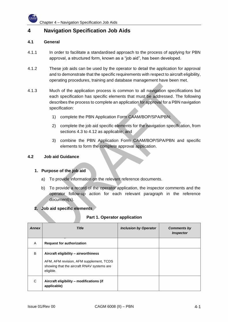
Chapter 4 – Navigation Specification Job Aids
Issue 01/Rev 00 CAGM 6008 (II) – PBN 4-1
4 Navigation Specification Job Aids
4.1 General
4.1.1 In order to facilitate a standardised approach to the process of applying for PBN
approval, a structured form, known as a “job aid”, has been developed.
4.1.2 These job aids can be used by the operator to detail the application for approval
and to demonstrate that the specific requirements with respect to aircraft eligibility,
operating procedures, training and database management have been met.
4.1.3 Much of the application process is common to all navigation specifications but
each specification has specific elements that must be addressed. The following
describes the process to complete an application for approval for a PBN navigation
specification:
1) complete the PBN Application Form CAAM/BOP/SPA/PBN;
2) complete the job aid specific elements for the navigation specification, from
sections 4.3 to 4.12 as applicable; and
3) combine the PBN Application Form CAAM/BOP/SPA/PBN and specific
elements to form the complete approval application.
4.2 Job aid Guidance
1. Purpose of the job aid
a) To provide information on the relevant reference documents.
b) To provide a record of the operator application, the inspector comments and the
operator follow-up action for each relevant paragraph in the reference
document(s).
2. Job aid specific elements
Part 1. Operator application
Annex Title Inclusion by Operator Comments by
Inspector
A Request for authorization
B Aircraft eligibility – airworthiness
AFM, AFM revision, AFM supplement, TCDS
showing that the aircraft RNAV systems are
eligible.
C Aircraft eligibility – modifications (if
applicable)

Chapter 4 – Navigation Specification Job Aids
Issue 01/Rev 00 CAGM 6008 (II) – PBN 4-2
Maintenance records documenting installation
or modification of aircraft systems to achieve
eligibility.
D Maintenance
For aircraft with established LRNS
maintenance practices, references to the
maintenance document/programme.
E Minimum equipment list
Showing provisions for LRNS.
F Training
Part 91/GA operators or equivalent:
• course completion records.
Part 121/Part135/CAT operators or
equivalent:
• training programmes for flight crew, flight
dispatchers and maintenance personnel.
G Operating policies and procedures
Part 91/GA operators or equivalent:
• extracts from the operations manual
corresponding to the application.
Part 121/Part135/CAT operators or
equivalent:
• operations manual and checklists.
H Validation flight plan
As required.
Contents of the application to be submitted by the operator
— compliance documentation for the aircraft/navigation systems;
— operating procedures and policies;
— sections of the maintenance manual related to LRNS (if not previously reviewed)
Note. – Documents may be grouped in a single binder or may be submitted as
individual documents.
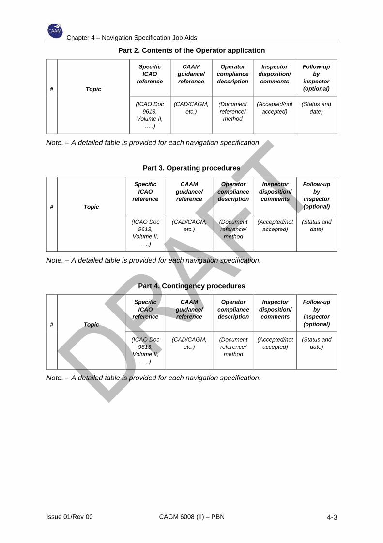
Chapter 4 – Navigation Specification Job Aids
Issue 01/Rev 00 CAGM 6008 (II) – PBN 4-3
Part 2. Contents of the Operator application
#
Topic
Specific
ICAO
reference
CAAM
guidance/
reference
Operator
compliance
description
Inspector
disposition/
comments
Follow-up
by
inspector
(optional)
(ICAO Doc
9613,
Volume II,
…..)
(CAD/CAGM,
etc.)
(Document
reference/
method
(Accepted/not
accepted)
(Status and
date)
Note. – A detailed table is provided for each navigation specification.
Part 3. Operating procedures
#
Topic
Specific
ICAO
reference
CAAM
guidance/
reference
Operator
compliance
description
Inspector
disposition/
comments
Follow-up
by
inspector
(optional)
(ICAO Doc
9613,
Volume II,
…..)
(CAD/CAGM,
etc.)
(Document
reference/
method
(Accepted/not
accepted)
(Status and
date)
Note. – A detailed table is provided for each navigation specification.
Part 4. Contingency procedures
#
Topic
Specific
ICAO
reference
CAAM
guidance/
reference
Operator
compliance
description
Inspector
disposition/
comments
Follow-up
by
inspector
(optional)
(ICAO Doc
9613,
Volume II,
…..)
(CAD/CAGM,
etc.)
(Document
reference/
method
(Accepted/not
accepted)
(Status and
date)
Note. – A detailed table is provided for each navigation specification.
Chapter 4 – Navigation Specification Job Aids
Issue 01/Rev 00 CAGM 6008 (II) – PBN 4-4
4.3 RNAV 10
4.3.1 General
4.3.1.1 RNAV 10 supports a 50 NM lateral and 50 NM longitudinal distance-based
separation minima in oceanic or remote area airspace. Prior to the development
of the PBN concept, RNAV 10 operations were authorized as RNP 10
operations. An RNAV 10 operational approval does not change any
requirement nor does it affect operators that have already obtained an RNP 10
approval.
4.3.1.2 RNP 10 was developed and implemented at a time when the delineation
between RNAV and RNP had not been clearly defined. Because the
requirements for RNP 10 did not include a requirement for on-board
performance monitoring and alerting, RNP 10 is more correctly described as an
RNAV operation and hence is included in this document as RNAV 10.
4.3.1.3 Recognizing that airspace, routes, airworthiness and operational approvals
have been designated as RNP 10, further declaration of airspace, routes, and
aircraft and operator approvals may continue to use the term RNP 10, while the
application in this document will be known as RNAV 10.
4.3.2 System requirements
4.3.2.1 RNAV 10 is intended for use in oceanic and remote areas, and the navigation
specification is based on the use of long-range navigation systems (LRNSs). A
minimum of two LRNSs is required for redundancy.
4.3.2.2 The most common combinations of dual LRNSs are:
a) dual INS;
b) dual IRS;
c) dual GNSS;
d) GNSS/IRS (IRS updated by GNSS).
4.3.2.3 Inertial systems (unless updated by GNSS) are subject to a gradual loss of
position accuracy with time (drift rate) and their use is time-limited in order to
meet the RNAV 10 accuracy requirement. The basic time limit is 6.2 hours, but
this may be extended by updating or by demonstration of reduced drift rate (less
than 2 NM per hour).
4.3.2.4 GNSS position is continuously updated and not subject to any time limit.
4.3.2.5 In order to be approved for oceanic and remote applications a GNSS receiver
must be capable of excluding a faulty satellite from the solution (fault detection
and exclusion (FDE)) so that continuity of navigation can be provided. FDE is
standard for TSO-C145( )/146( ) GNSS receivers and is available as an option
Chapter 4 – Navigation Specification Job Aids
Issue 01/Rev 00 CAGM 6008 (II) – PBN 4-5
or modification on some TSO-C129( ) receivers. Consequently, where a TSO-
C129( ) GNSS is used to satisfy the requirement for one or both of the LRNSs
it must be capable of FDE and approved for oceanic/remote operations.
4.3.2.6 The FDE requirement notwithstanding, the satellite constellation may be such
that there are not sufficient satellites for the FDE computation and in such
situations FDE is not available. In order to limit the exposure to the potential
loss of a navigation solution due to unavailability of FDE, a prediction of satellite
availability is required. The maximum period during which FDE may be
predicted to be unavailable is 34 minutes. The same time limit applies to an
IRS/GNSS system.
4.3.2.7 These time limitations mean that an RNAV 10 operational approval is not
universal for aircraft without GNSS where the operator must evaluate the
route(s) to be flown to determine if the RNAV 10 requirement can be satisfied.
Moreover, for aircraft with INS or IRS only, attention must be paid to radio
updating. Aircraft equipped with a flight management system normally provide
automatic radio updating of inertial position. Automatic updating is normally
considered adequate in such circumstances, provided the aircraft is within a
reasonable distance of the radio aids at the point at which the last update is
expected. If any doubt exists then the operator should be required to provide
an analysis of the accuracy of the update. Manual updating is less common,
and the operational approval needs to be based on a more detailed examination
of the circumstances.
4.3.3 Operating procedures
4.3.3.1 The standard operating procedures adopted by operators flying on oceanic and
remote routes should normally be generally consistent with RNAV 10
operations, although some additional provisions may need to be included. A
review of the operator’s procedure documentation against the requirements of
the PBN Manual and the requirements of the CAAM should be sufficient to
ensure compliance.
4.3.3.2 The essential elements to be evaluated are:
a) the aircraft is serviceable for RNAV 10 operations;
b) RNAV 10 capability is indicated on the flight plan;
c) route limitations are defined and observed (e.g. time limits);
d) en-route loss of capability is identified and reported;
e) procedures for alternative navigation are described.
4.3.3.3 GNSS-based operations also require the prediction of FDE availability. Many
stand-alone GNSS service prediction programmes are based on a prediction at
a destination and do not generally provide predictions over a route or large

Chapter 4 – Navigation Specification Job Aids
Issue 01/Rev 00 CAGM 6008 (II) – PBN 4-6
area. RNAV 10-specific route prediction services are available from commercial
sources.
4.3.4 Pilot knowledge and training
4.3.4.1 Unless the operator is inexperienced in the use of area navigation, flight crews
should possess the necessary skills to conduct RNAV 10 operations with
minimal additional training.
4.3.4.2 Where GNSS is used, flight crews must be familiar with GNSS principles related
to en-route navigation.
4.3.4.3 Where additional training is required, this can normally be achieved by bulletin,
computer-based training or classroom briefing. Flight training is not normally
required.

Chapter 4 – Navigation Specification Job Aids
Issue 01/Rev 00 CAGM 6008 (II) – PBN 4-7
4.3.5 Job Aid – RNAV 10 Specific Elements
Part 1. Operator application
Add following rows:
Annex Title Inclusion by Operator Comments by
Inspector
J
Aircraft group
A statement by the operator of the method
used to determine eligibility of the
aircraft/LRNS combination
K
RNP 10 time limit and area of operations (if
applicable)
For aircraft equipped with INS/IRU only,
details of time limit and area of
operations/routes for which the aircraft is
eligible.
L
Performance record
Evidence of previous problems, incidents or
path-keeping errors, together with corrective
action applied
M
Withdrawal of approval
The need for follow up action on navigation
error reports, with the possibility of removal of
approval.

Chapter 4 – Navigation Specification Job Aids
Issue 01/Rev 00 CAGM 6008 (II) – PBN 4-8
Part 2. Contents of the Operator application
#
Topic
Specific
ICAO
reference
CAAM
guidance/
reference
Operator
compliance
description
Inspector
disposition/
comments
Follow-up
by
inspector
(optional)
(ICAO Doc
9613,
Volume II,
Part B,
Chapter 1)
(CAD/CAGM,
etc.)
(Document
reference/
method
(Accepted/not
accepted)
(Status and
date)
1 Authorization request
Statement of intent to
obtain authorization.
1.3.3.2
2a Aircraft/navigation
system eligibility
Documents that establish
eligibility .
For RNP 10 the eligibility
method(s) used, and a list
of the airframes included
in each method.
1.3.3.1
1.3.3.2.1
2b Dual LRNS
At least 2 LRNSs with
displays and functions
suitable for oceanic
operations.
1.3.4
3 Time limit for aircraft
equipped with INS/IRU
and no GNSS.
1.3.4.2.2
1.3.9.6
4 Area of operation for
aircraft equipped with
INS/IRU and no GNSS
1.3.9.6
5 Training
Details of courses
completed (part 91
operators).
Details of training
programmes (part 121
and part 135 operators).
1.3.3.2.2.2
1.3.10
6 Operating policies and
procedures
Extracts from the
operations manual or
other documentation (Part
91 operators).
1.3.3.2.2.3
1.3.5

Chapter 4 – Navigation Specification Job Aids
Issue 01/Rev 00 CAGM 6008 (II) – PBN 4-9
Operations manual and
checklists (part 121 and
part 135 operators
7 Maintenance practices
Document references for
established LRNS
maintenance practices.
Complete copy of
appropriate maintenance
practices for new LRNS
installations.
1.3.3.2.2.5
8 MEL update
Applicable only to
operations requiring a
MEL
1.3.3.2.2.4
9 Past performance
Record of operating
history, including
problems, incidents,
track-keeping errors and
corrective actions.
1.3.3.2.2.6
10 Withdrawal of RNP 10
authority
1.3.12
11 Validation flight plan
If required
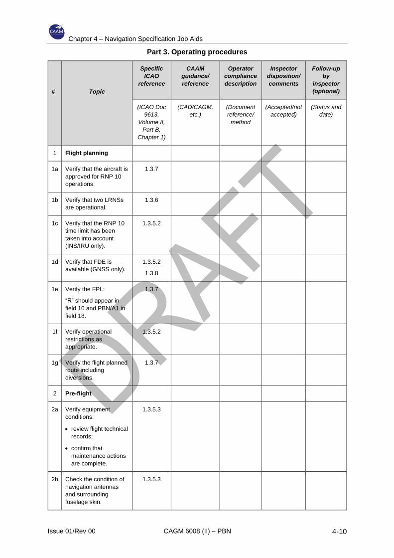
Chapter 4 – Navigation Specification Job Aids
Issue 01/Rev 00 CAGM 6008 (II) – PBN 4-10
Part 3. Operating procedures
#
Topic
Specific
ICAO
reference
CAAM
guidance/
reference
Operator
compliance
description
Inspector
disposition/
comments
Follow-up
by
inspector
(optional)
(ICAO Doc
9613,
Volume II,
Part B,
Chapter 1)
(CAD/CAGM,
etc.)
(Document
reference/
method
(Accepted/not
accepted)
(Status and
date)
1 Flight planning
1a Verify that the aircraft is
approved for RNP 10
operations.
1.3.7
1b Verify that two LRNSs
are operational.
1.3.6
1c Verify that the RNP 10
time limit has been
taken into account
(INS/IRU only).
1.3.5.2
1d Verify that FDE is
available (GNSS only).
1.3.5.2
1.3.8
1e Verify the FPL:
“R” should appear in
field 10 and PBN/A1 in
field 18.
1.3.7
1f Verify operational
restrictions as
appropriate.
1.3.5.2
1g Verify the flight planned
route including
diversions.
1.3.7
2 Pre-flight
2a Verify equipment
conditions:
• review flight technical
records;
• confirm that
maintenance actions
are complete.
1.3.5.3
2b Check the condition of
navigation antennas
and surrounding
fuselage skin.
1.3.5.3

Chapter 4 – Navigation Specification Job Aids
Issue 01/Rev 00 CAGM 6008 (II) – PBN 4-11
2c Review the emergency
procedures for RNP 10
operations.
1.3.5.3
3 En route
3a Verify that both LRNSs
are RNP 10 capable at
the oceanic point of
entry.
1.3.9.1
3b Prior to the oceanic
point of entry, the
aircraft position must be
independently checked
and updated if
necessary.
1.3.9.2
3c Other mandatory
navigation.
1.3.9.3
3d ATC to be notified if
unable to comply with
RNP 10 requirements or
of any deviation
required for contingency
procedures.
1.3.9.3
3e Follow route centre line
within 5 NM
1.3.9.5
4 Update LRNS position 1.3.9.7

Chapter 4 – Navigation Specification Job Aids
Issue 01/Rev 00 CAGM 6008 (II) – PBN 4-12
Part 4. Contingency procedures
#
Topic
Specific
ICAO
reference
CAAM
guidance/
reference
Operator
compliance
description
Inspector
disposition/
comments
Follow-up
by
inspector
(optional)
(Doc 4444,
Chapters 5
and 15)
(CAD/CAGM,
etc.)
(Document
reference/
method
(Accepted/not
accepted)
(Status and
date)
1 Contingencies 15.2.1 and
15.2.2
1a Inability to comply with
ATC clearance due to
meteorological
conditions, aircraft
performance or
pressurization failure.
15.2.1.1
1b Weather deviation. 15.2.3
1c Air-ground
communications failure
5.4.2.6.3.2
15.3
Chapter 4 – Navigation Specification Job Aids
Issue 01/Rev 00 CAGM 6008 (II) – PBN 4-13
4.4 RNAV 5
4.4.1 General
4.4.1.1 RNAV 5 supports continental en-route operations using a range of different
positioning sensors. Prior to the introduction of PBN, basic RNAV (B- RNAV)
was introduced in Europe and the Middle East. The RNAV 5 requirements are
based upon B-RNAV, and any B-RNAV approval meets the requirements of
RNAV 5 without further examination.
4.4.1.2 RNAV 5 is intended for en-route navigation where not all the airspace users are
equipped with GNSS and where there is adequate coverage of ground- based
radio navigation aids permitting DME/DME or VOR/DME area navigation
operations.
4.4.1.3 An RNAV 5 route is dependent upon an analysis of the supporting NAVAID
infrastructure. This analysis is the responsibility of the air navigation service
provider.
4.4.2 System requirements
4.4.2.1 The RNAV 5 system requirements are not complex, as follows:
a) one single area navigation system is required;
b) the following sensors may be used:
1) VOR/DME;
2) DME/DME;
3) INS/IRS — if automatic radio updating is not carried out, a time limit of
2 hours usually applies from the last on-ground position update;
4) GNSS — receivers must be approved in accordance with ETSO-
C129a, FAA TSO-C129a or later (ETSO-C129 or FAA TSO-C129 is
also applicable provided it includes pseudo-range step detection and
health word checking functions);
c) storage of a minimum of four waypoints is required. Manual data entry is
permitted, and a navigation database is not required;
d) an area navigation system failure indication is required;
e) continuous indication of aircraft position relative to track to be displayed to
the pilot flying (and the pilot not flying) on a navigation display situated in
the primary field of view;
f) display of distance and bearing to the active (To) waypoint;
g) display of ground speed or time to the active (To) waypoint;
Chapter 4 – Navigation Specification Job Aids
Issue 01/Rev 00 CAGM 6008 (II) – PBN 4-14
h) lateral deviation display must have scaling and FSD less than or equal to
±5 NM for RNAV 5 — the maximum FTE permitted is 2.5 NM (1⁄2 FSD).
4.4.3 Operating procedures
4.4.3.1 Normal area navigation operating procedures will usually meet the
requirements of RNAV 5. The essential elements to be evaluated are that the
operator’s procedures ensure that:
a) the aircraft is serviceable for RNAV 5;
b) RNAV 5 capability is indicated on the flight plan;
c) en-route loss of capability is identified and reported;
d) procedures for alternative navigation are addressed.
If the navigation system does not use a navigation database, manual waypoint
entry significantly increases the potential for navigation errors. Operating
procedures need to be robust to reduce the incidence of human error, including
cross-checking of entry, checking of tracks/distances/bearings against
published routes and general situational awareness and checking for
reasonableness.
4.4.3.2 Because RNAV 5 operations are typically conducted in areas of adequate
NAVAID coverage, contingency procedures will normally involve reversion to
conventional radio navigation using VOR/DMEs, VORs and NDBs.
4.4.3.3 GNSS-based operations also require the prediction of FDE availability. Many
stand-alone GNSS service prediction programmes are based on a prediction at
a destination and do not generally provide predictions over a route or large
area. RNAV 5 specific route prediction services are available from commercial
sources.
4.4.4 Pilot knowledge and training
4.4.4.1 Unless the operator is inexperienced in the use of area navigation, flight crews
should possess the necessary skills to conduct RNAV 5 operations with
minimal additional training.
4.4.4.2 Where GNSS is used, flight crews must be familiar with GNSS principles related
to en-route navigation. Where additional training is required, this can normally
be achieved by bulletin, computer-based training or classroom briefing. Flight
training is not normally required.
4.4.5 Operational approval
4.4.5.1 The operational approval process for RNAV 5 is generally straightforward,
given that most aircraft are equipped with area navigation systems which
exceed the minimum requirements for RNAV 5.

Chapter 4 – Navigation Specification Job Aids
Issue 01/Rev 00 CAGM 6008 (II) – PBN 4-15
4.4.5.2 In most cases the AFM will document RNAV 5 capability; failing that, many
OEMs have issued statements of compliance and only occasionally will it be
necessary to conduct an evaluation of aircraft capability.
4.4.5.3 With the exception of an amendment to the operations manual, CAAM may
decide that there is no further requirement for any additional documentation of
RNAV 5 approval.
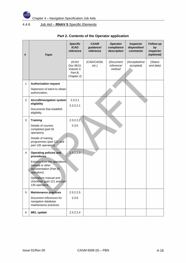
Chapter 4 – Navigation Specification Job Aids
Issue 01/Rev 00 CAGM 6008 (II) – PBN 4-16
4.4.6 Job Aid – RNAV 5 Specific Elements
Part 2. Contents of the Operator application
#
Topic
Specific
ICAO
reference
CAAM
guidance/
reference
Operator
compliance
description
Inspector
disposition/
comments
Follow-up
by
inspector
(optional)
(ICAO
Doc 9613,
Volume II,
Part B,
Chapter 2)
(CAD/CAGM,
etc.)
(Document
reference/
method
(Accepted/not
accepted)
(Status
and date)
1 Authorization request
Statement of intent to obtain
authorization.
2 Aircraft/navigation system
eligibility
Documents that establish
eligibility.
2.3.2.1
2.3.2.2.1
3 Training
Details of courses
completed (part 91
operators).
Details of training
programmes (part 121 and
part 135 operators).
2.3.2.2.2
2.3.5
4 Operating policies and
procedures
Extracts from the operations
manual or other
documentation (Part 91
operators).
Operations manual and
checklists (part 121 and part
135 operators.
2.3.2.2.3
5 Maintenance practices
Document references for
navigation database
maintenance practices.
2.3.2.2.5
2.3.6
6 MEL update 2.3.2.2.4
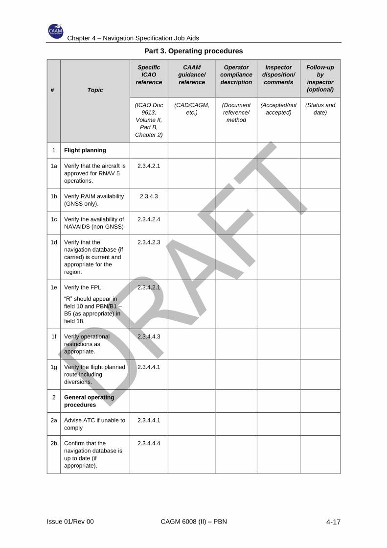
Chapter 4 – Navigation Specification Job Aids
Issue 01/Rev 00 CAGM 6008 (II) – PBN 4-17
Part 3. Operating procedures
#
Topic
Specific
ICAO
reference
CAAM
guidance/
reference
Operator
compliance
description
Inspector
disposition/
comments
Follow-up
by
inspector
(optional)
(ICAO Doc
9613,
Volume II,
Part B,
Chapter 2)
(CAD/CAGM,
etc.)
(Document
reference/
method
(Accepted/not
accepted)
(Status and
date)
1 Flight planning
1a Verify that the aircraft is
approved for RNAV 5
operations.
2.3.4.2.1
1b Verify RAIM availability
(GNSS only).
2.3.4.3
1c Verify the availability of
NAVAIDS (non-GNSS)
2.3.4.2.4
1d Verify that the
navigation database (if
carried) is current and
appropriate for the
region.
2.3.4.2.3
1e Verify the FPL:
“R” should appear in
field 10 and PBN/B1 –
B5 (as appropriate) in
field 18.
2.3.4.2.1
1f Verify operational
restrictions as
appropriate.
2.3.4.4.3
1g Verify the flight planned
route including
diversions.
2.3.4.4.1
2 General operating
procedures
2a Advise ATC if unable to
comply
2.3.4.4.1
2b Confirm that the
navigation database is
up to date (if
appropriate).
2.3.4.4.4

Chapter 4 – Navigation Specification Job Aids
Issue 01/Rev 00 CAGM 6008 (II) – PBN 4-18
2c Cross-check the chart
with the RNAV system
display.
2.3.4.4.5
2d Cross-check with
conventional NAVAIDS
to monitor for
navigational
reasonableness.
2.3.4.4.6
2e Follow route centre
lines within 2.5 NM.
2.3.4.4.8
2f Do not modify the flight
plan in the RNAV
system after ATC
heading assignment
until a clearance is
received to re-join the
route or a new
clearance is confirmed.
2.3.4.4.9
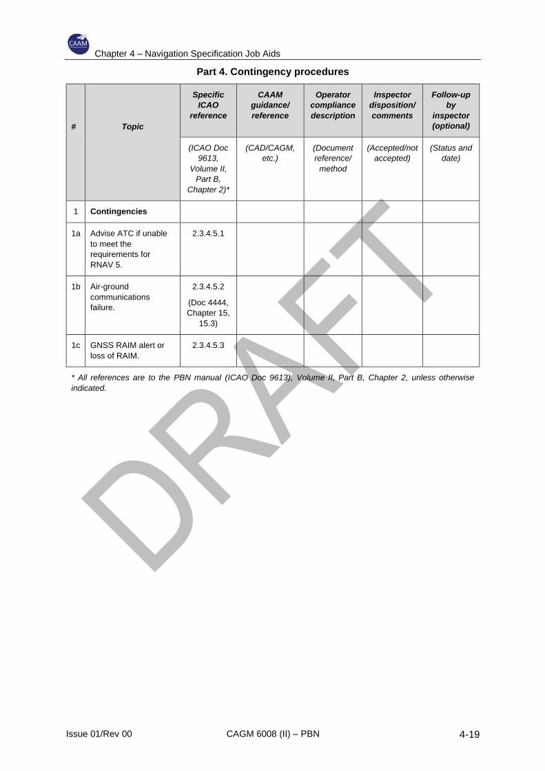
Chapter 4 – Navigation Specification Job Aids
Issue 01/Rev 00 CAGM 6008 (II) – PBN 4-19
Part 4. Contingency procedures
#
Topic
Specific
ICAO
reference
CAAM
guidance/
reference
Operator
compliance
description
Inspector
disposition/
comments
Follow-up
by
inspector
(optional)
(ICAO Doc
9613,
Volume II,
Part B,
Chapter 2)*
(CAD/CAGM,
etc.)
(Document
reference/
method
(Accepted/not
accepted)
(Status and
date)
1 Contingencies
1a Advise ATC if unable
to meet the
requirements for
RNAV 5.
2.3.4.5.1
1b Air-ground
communications
failure.
2.3.4.5.2
(Doc 4444,
Chapter 15,
15.3)
1c GNSS RAIM alert or
loss of RAIM.
2.3.4.5.3
* All references are to the PBN manual (ICAO Doc 9613), Volume II, Part B, Chapter 2, unless otherwise
indicated.

Chapter 4 – Navigation Specification Job Aids
Issue 01/Rev 00 CAGM 6008 (II) – PBN 4-20
INTENTIONALLY LEFT BLANK
Chapter 4 – Navigation Specification Job Aids
Issue 01/Rev 00 CAGM 6008 (II) – PBN 4-21
4.5 RNAV 1 and RNAV 2
4.5.1 General
4.5.1.1 RNAV 1 and RNAV 2 support operations in continental en-route, SIDs, STARs
and approach transitions using GNSS or DME/DME positioning. The RNAV 1
and RNAV 2 specifications represent an attempt at the harmonization of
European precision RNAV (P-RNAV) and United States RNAV (U.S.-RNAV)
requirements.
4.5.1.2 The RNAV 1 and RNAV 2 specifications apply to:
a) all ATS routes, including en-route;
b) standard instrument departures and arrivals (SIDs/STARs); and
c) instrument approach procedures up to the final approach fix (FAF)/final
approach point (FAP).
4.5.1.3 Because RNAV 1 and RNAV 2 operations can be based on DME/DME or
DME/DME IRU, the NAVAID infrastructure must be assessed to ensure
adequate DME coverage. This is the responsibility of the ANSP and is not part
of the operational approval.
4.5.1.4 A single RNAV 1 and RNAV 2 approval is issued. An operator with an RNAV 1
and RNAV 2 approval is qualified to operate on both RNAV 1 and RNAV 2
routes. RNAV 2 routes may be promulgated in cases where the NAVAID
infrastructure is unable to meet the accuracy requirements for RNAV 1.
4.5.2 Operational approval
4.5.2.1 For operators holding either a P-RNAV approval or a U.S.-RNAV approval, the
operational approval is relatively simple and minimal regulatory effort is
required. Operators holding both P-RNAV and U.S.-RNAV approvals should
qualify for an RNAV 1 and RNAV 2 operational approval without further
examination. There are some small differences between the P-RNAV and U.S.-
RNAV, and migration to RNAV 1 and RNAV 2 approval is not automatic unless
the operator holds both U.S. and European approvals.
4.5.2.2 For operators holding only a P-RNAV approval or a U.S.-RNAV approval, it is
necessary to ensure that any additional requirements for RNAV 1 and RNAV 2
are met as laid down in the PBN Manual (Part B, Chapter 3, 3.3.2.4).
4.5.2.3 Operators not holding a P-RNAV or U.S.-RNAV approval need to be evaluated
to determine that they meet the requirements for RNAV 1 and RNAV 2.
4.5.2.4 There is no obligation to obtain an RNAV 1 and RNAV 2 approval or to migrate
an existing approval to RNAV 1 and RNAV 2 if the existing approval is
applicable to the area of operation. Operators that operate only in P-RNAV
Chapter 4 – Navigation Specification Job Aids
Issue 01/Rev 00 CAGM 6008 (II) – PBN 4-22
airspace or only in U.S.-RNAV airspace can continue to do so in accordance
with a P-RNAV or U.S.-RNAV approval respectively.
4.5.3 System requirements
4.5.3.1 The RNAV 1 and RNAV 2 system requirements are as follows:
a) a single area navigation system;
b) the following sensors may be used:
1) DME/DME — accuracy is based upon TSO-C66c; the system must be
capable of auto-tuning multiple DME facilities, obtaining a position
update within 30 seconds of tuning, maintaining continuous updating
and performing reasonableness checks;
2) DME/DME/IRU — IRU performance in accordance with U.S. 14 CFR
Part 121, Appendix G, automatic position updating from the DME/DME
position and must not allow VOR inputs to affect position accuracy;
3) GNSS — receivers must be approved in accordance with ETSO-
C129a, FAA TSO-C129a or later (ETSO-C129 or FAA TSO-C129 are
also applicable provided they include pseudo-range step detection and
health word checking functions);
c) a navigation database containing the routes and procedures;
d) an area navigation system failure indication;
e) continuous indication of aircraft position relative to track to be displayed to
the pilot flying (and the pilot not flying) on a navigation display situated in
the primary field of view;
f) display of distance and bearing to the active (To) waypoint;
g) display of ground speed or time to the active (To) waypoint;
h) display of active navigation sensor type;
i) lateral deviation display must have scaling and FSD of less than or equal
to ±1 NM for RNAV 1 or less than or equal to ±2 NM for RNAV 2 — the
maximum FTE permitted is:
1) 0.5 NM for RNAV 1;
2) 1.0 NM for RNAV 2.
Note.— Some States have authorized TSO-C129( ) equipment with an FSD of
±5 NM on RNAV 2.
j) automatic leg sequencing and fly-by or flyover turn functionality;
k) execution of leg transitions and maintenance of tracks consistent with
ARINC 424:
1) CA;
Chapter 4 – Navigation Specification Job Aids
Issue 01/Rev 00 CAGM 6008 (II) – PBN 4-23
2) CF;
3) DF;
4) FM;
5) IF;
6) TF;
7) VA;
8) VI;
9) VM.
4.5.3.2 For the majority of air transport aircraft equipped with FMS, the required
functionalities, with the exception of the provision of a non-numeric lateral
deviation display, are normally available. For this category of aircraft lateral
deviation is displayed on a map display, usually with a numeric indication of
cross-track error in one-tenth of an NM. In some cases, a numeric indication of
cross-track error may be provided outside the primary field of view (e.g., CDU).
Acceptable lateral tracking accuracy for both RNAV 1 and RNAV 2 routes is
usually adequate provided the autopilot is engaged or the flight director is used.
4.5.3.3 Aircraft equipped with stand-alone GNSS navigation systems should have track
guidance provided via a CDI or HSI (a navigation map display may also be used
for RNAV 2 routes). A lateral deviation display is often incorporated in the unit
but is commonly not of sufficient size or suitable position to allow either pilot to
manoeuvre and adequately monitor cross-track deviation. Caution should be
exercised in regard to the limitations of stand- alone GNSS systems with
respect to ARINC 424 path terminators. Path terminators involving an altitude
termination are not normally supported due to a lack of integration of the lateral
navigation system and the altimetry system. For example, a departure
procedure commonly specifies a course after take-off until reaching a specified
altitude (CA path terminator). Using a basic GNSS navigation system it is
necessary for the flight crew to manually terminate the leg on reaching the
specified altitude and then navigate to the next waypoint, ensuring that the flight
path is consistent with the departure procedure. This type of limitation does not
preclude operational approval (as stated in the PBN Manual functional
requirements) provided the operator’s procedures and crew training are
adequate to ensure that the intended flight path and other requirements can be
met for all SID and STAR procedures.
4.5.4 Operating procedures
4.5.4.1 Operators with en-route area navigation experience will generally meet the
basic requirements of RNAV 1 and RNAV 2, and the operational approval
should focus on procedures associated with SIDs and STARs.
Chapter 4 – Navigation Specification Job Aids
Issue 01/Rev 00 CAGM 6008 (II) – PBN 4-24
4.5.4.2 4.3.4.2. Particular attention should be placed on the selection of the correct
procedure from the database, review of the procedures, connection with the en-
route phase of flight and the management of discontinuities. Similarly, an
evaluation should be made of procedures management, selection of a new
procedure, including change of runway, and any crew amendments such as
insertion or deletion of waypoints.
4.5.4.3 GNSS-based operations also require the prediction of fault detection (FD)
RAIM availability. Many stand- alone GNSS service prediction programmes are
based on a prediction at a destination and do not generally provide predictions
over a route or large area. RNAV 1 and RNAV 2 specific route prediction
services are available from commercial sources.
4.5.4.4 RNAV 1 and RNAV 2 operations are typically conducted in areas of adequate
NAVAID coverage; contingency procedures will normally involve reversion to
conventional ground-based radio navigation.
4.5.5 Pilot knowledge training
4.5.5.1 Most crews will already have some experience with area navigation operations,
and much of the knowledge and training will have been covered in past training.
Particular attention should be placed on the application of this knowledge to the
execution of RNAV 1 and RNAV 2 SIDs and STARs, including connection with
the en-route structure and transition to final approach. This requires a thorough
understanding of the airborne equipment and its functionality and management.
4.5.5.2 Particular attention should be placed on:
a) the ability of the airborne equipment to fly the designed flight path. This
may involve pilot intervention where the equipment functionality is limited;
b) management of changes;
c) turn management (turn indications, airspeed and bank angle, lack of
guidance in turns);
d) route modification (insertion/deletion of waypoints, direct to waypoint);
e) intercepting a route from radar vectors.
4.5.5.3 Flight training for RNAV 1 and RNAV 2 is not normally required, and the
required level of competence can normally be achieved by classroom briefing,
computer-based training, desktop simulator training, or a combination of these
methods. Computer-based simulator programmes are available from a number
of GPS manufacturers which provide a convenient method for familiarity with
programming and operation of stand-alone GNSS systems.

Chapter 4 – Navigation Specification Job Aids
Issue 01/Rev 00 CAGM 6008 (II) – PBN 4-25
4.5.5.4 Where VNAV is used for SIDs and STARs, attention should be given to the
management of VNAV and specifically the potential for altitude constraints to
be compromised in cases where the lateral flight path is changed or intercepted.

Chapter 4 – Navigation Specification Job Aids
Issue 01/Rev 00 CAGM 6008 (II) – PBN 4-26
4.5.6 Job Aid – RNAV 1 and RNAV 2 Specific Elements
Part 2. Contents of the Operator application
#
Topic
Specific
ICAO
reference
CAAM
guidance/
reference
Operator
compliance
description
Inspector
disposition/
comments
Follow-up
by
inspector
(optional)
(ICAO
Doc 9613,
Volume II,
Part B,
Chapter 3)
(CAD/CAGM,
etc.)
(Document
reference/
method
(Accepted/not
accepted)
(Status
and date)
1 Authorization request
Statement of intent to obtain
authorization.
3.3.2.1
2 Aircraft/navigation system
eligibility
Documents that establish
eligibility.
3.3.2.2
3.3.2.3.1
3 Training
Details of courses
completed (part 91
operators).
Details of training
programmes (part 121 and
part 135 operators).
3.3.2.3.2
3.3.5
4 Operating policies and
procedures
Extracts from the operations
manual or other
documentation (Part 91
operators).
Operations manual and
checklists (part 121 and part
135 operators.
3.3.2.3.3
5 Maintenance practices
Document references for
navigation database
maintenance practices.
3.3.2.3.5
3.3.6
6 MEL update 3.3.2.3.4
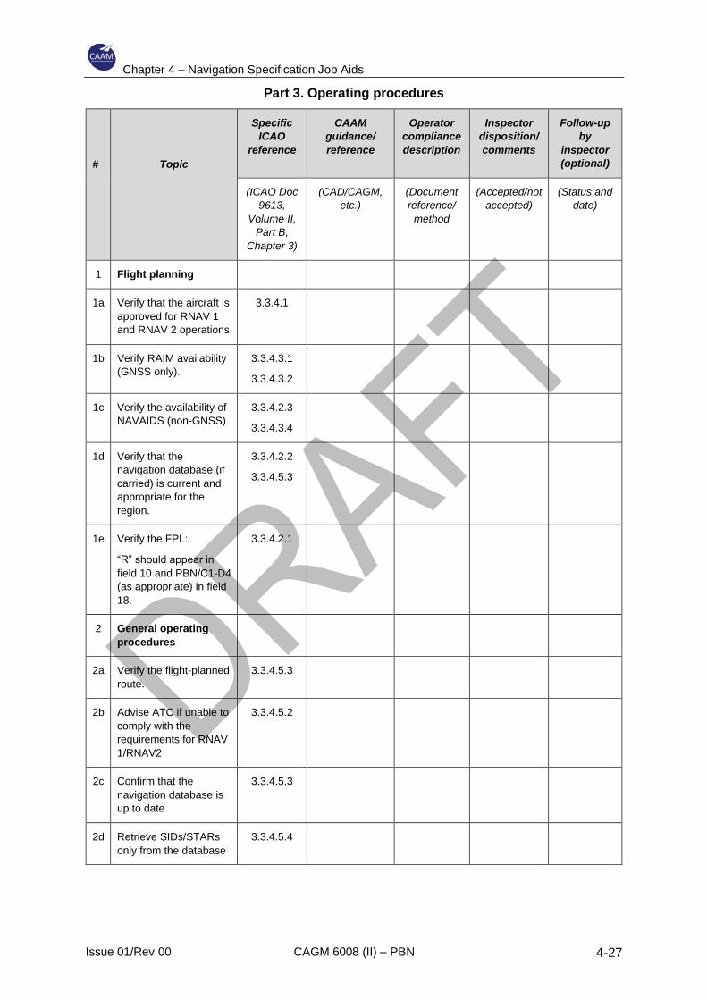
Chapter 4 – Navigation Specification Job Aids
Issue 01/Rev 00 CAGM 6008 (II) – PBN 4-27
Part 3. Operating procedures
#
Topic
Specific
ICAO
reference
CAAM
guidance/
reference
Operator
compliance
description
Inspector
disposition/
comments
Follow-up
by
inspector
(optional)
(ICAO Doc
9613,
Volume II,
Part B,
Chapter 3)
(CAD/CAGM,
etc.)
(Document
reference/
method
(Accepted/not
accepted)
(Status and
date)
1 Flight planning
1a Verify that the aircraft is
approved for RNAV 1
and RNAV 2 operations.
3.3.4.1
1b Verify RAIM availability
(GNSS only).
3.3.4.3.1
3.3.4.3.2
1c Verify the availability of
NAVAIDS (non-GNSS)
3.3.4.2.3
3.3.4.3.4
1d Verify that the
navigation database (if
carried) is current and
appropriate for the
region.
3.3.4.2.2
3.3.4.5.3
1e Verify the FPL:
“R” should appear in
field 10 and PBN/C1-D4
(as appropriate) in field
18.
3.3.4.2.1
2 General operating
procedures
2a Verify the flight-planned
route.
3.3.4.5.3
2b Advise ATC if unable to
comply with the
requirements for RNAV
1/RNAV2
3.3.4.5.2
2c Confirm that the
navigation database is
up to date
3.3.4.5.3
2d Retrieve SIDs/STARs
only from the database
3.3.4.5.4

Chapter 4 – Navigation Specification Job Aids
Issue 01/Rev 00 CAGM 6008 (II) – PBN 4-28
2e Cross-check the chart
with the RNAV system
display.
3.3.4.5.3
3.3.4.5.6
2f Cross-check with
conventional NAVAIDS
to monitor for
navigational
reasonableness.
3.3.4.5.7
2g Use an appropriate
display.
3.3.4.5.8
3.3.4.5.9
2h Use appropriate scaling. 3.3.4.5.10
2i Follow route centre line
within 1 or 0.5 NM
3.3.4.5.11
2j Do not modify the flight
plan in the RNAV
system after ATC
heading assignment
until a clearance is
received to re-join the
route or a new
clearance is confirmed.
3.3.4.5.12
3 RNAV SID
requirements
3a Prior to take-off, check
the RNAV system,
aerodrome and
procedure loaded and
the displayed position.
3.3.4.6.1
3b Engage LNAV no later
than 153 m (500 ft)
above aerodrome
elevation.
3.3.4.6.2
3c If DME/DME only, do
not use RNAV until
within adequate DME
coverage.
3.3.4.6.4
3d If DME/DME/IRU only,
confirm navigation
position within 0.17 NM
of the start of the take-
off roll.
3.3.4.6.5
3e If GNSS, acquire signal
before start of take-off
roll.
3.3.4.6.6
4 RNAV STAR
requirements

Chapter 4 – Navigation Specification Job Aids
Issue 01/Rev 00 CAGM 6008 (II) – PBN 4-29
4a Verify that the correct
STAR is loaded and
displayed.
3.3.4.7.1
4b Contingency
preparations
3.3.4.7.3
4c Procedure modification
in response to ATC
instructions.
3.3.4.7.4
4d Observance of speed
and altitude constraints.
3.3.4.7.6

Chapter 4 – Navigation Specification Job Aids
Issue 01/Rev 00 CAGM 6008 (II) – PBN 4-30
Part 4. Contingency procedures
#
Topic
Specific
ICAO
reference
CAAM
guidance/
reference
Operator
compliance
description
Inspector
disposition/
comments
Follow-up
by
inspector
(optional)
(ICAO Doc
9613,
Volume II,
Part B,
Chapter 3)*
(CAD/CAGM,
etc.)
(Document
reference/
method
(Accepted/not
accepted)
(Status and
date)
1 Contingencies
1a Advise ATC if unable
to meet the
requirements for
RNAV 1/RNAV 2.
3.3.4.8.1
1b Air-ground
communications
failure.
3.3.4.8.2
(Doc 4444,
Chapter 15,
15.3)
* All references are to the PBN manual (ICAO Doc 9613), Volume II, Part B, Chapter 3, unless otherwise
indicated.
Chapter 4 – Navigation Specification Job Aids
Issue 01/Rev 00 CAGM 6008 (II) – PBN 4-31
4.6 RNP 4
4.6.1 General
4.6.1.1 RNP 4 supports 30 NM lateral and 30 NM longitudinal distance-based
separation minima in oceanic or remote area airspace. Operators holding an
existing RNP 4 operational approval do not need to be re-examined because
the navigation specification is based upon U.S. FAA Order 8400.33.
4.6.2 System requirements
4.6.2.1 The RNP 4 system requirements are as follows:
a) two long-range navigation systems;
b) at least one GNSS receiver with FDE;
c) a navigation database containing the routes and procedures;
d) an area navigation system failure indication;
e) continuous indication of aircraft position relative to track to be displayed to
the pilot flying (and the pilot not flying) on a navigation display situated in
the primary field of view;
f) display of distance and bearing to the active (To) waypoint;
g) display of ground speed or time to the active (To) waypoint;
h) display of active navigation sensor type;
i) lateral deviation display must have scaling and FSD of ±4 NM — the
maximum FTE permitted is 2 NM;
j) automatic leg sequencing and fly-by turn functionality;
k) parallel off-set;
l) ability to fly direct to a fix;
m) ability to fly a course to a fix.
For the majority of air transport aircraft equipped with FMS, the required
functionalities, with the exception of the provision of a non-numeric lateral
deviation display, are normally available. For this category lateral deviation is
not normally displayed on a CDI or HSI, but is commonly available on a map
display, usually with a numeric indication of cross-track error in one-tenth of an
NM. In some cases, a numeric indication of cross-track error may be provided
outside the primary field of view (e.g., CDU).
4.6.2.2 Aircraft equipped with stand-alone GNSS navigation systems should provide
track guidance via a CDI, HSI, or a navigation map display. The CDI/HSI must
be coupled to the area navigation route providing a direct indication of lateral
Chapter 4 – Navigation Specification Job Aids
Issue 01/Rev 00 CAGM 6008 (II) – PBN 4-32
position with reference to the flight-planned track. This type of unit in en- route
mode (nominally outside 30 NM from departure and destination airports)
defaults to a CDI/HSI full-scale display of ±5 NM, with RAIM alerting defaulting
to 2 NM, which is adequate for RNP 4. A lateral deviation display is often
incorporated in the unit and may be suitable if of sufficient size and position, to
allow either pilot to manoeuvre and monitor cross-track deviation.
4.6.2.3 The default method for area navigation systems to manage turns at the
intersection of “straight” route segments is to compute, based on ground speed
and assumed angle of bank, a position at which the turn should commence so
that the resulting radius will turn inside the angle created by the two consecutive
segments. For aircraft fitted with a stand-alone GNSS system or an FMS, fly-
by transitions are a standard function and should not require specific
evaluation. However, a stand-alone GNSS receiver may require a pilot action
to initiate the turn. All turns are limited by the physical capability of the aircraft
to execute a turn of suitable radius. In normal cases where the angle between
track is small there is seldom a problem, but operators need to be aware that
large angle turns, particularly at high altitude where TAS is high and bank angle
is commonly limited, can be outside the aircraft capability. While this condition
is rare, flight crews need to be aware of the aircraft and avionics limitations.
4.6.3 Operating procedures
4.6.3.1 Some additional provisions may need to be added to the standard operating
procedures to specifically address RNP 4 operations.
4.6.3.2 The essential elements to be evaluated are that the operator’s procedures
ensure that:
a) the aircraft is serviceable for RNP 4 operations;
b) RNP 4 capability is indicated on the flight plan;
c) en-route loss of capability is identified and reported;
d) procedures for alternative navigation are described.
4.6.3.3 GNSS-based operations also require the prediction of FDE RAIM availability.
The maximum period during which FDE may be predicted to be unavailable is
25 minutes. Many stand-alone GNSS prediction programmes are based on a
prediction at a destination and do not generally provide predictions over a route
or large area. RNP 4- specific route prediction services are available from
commercial sources.
4.6.4 Pilot knowledge and training
4.6.4.1 Unless the operator is inexperienced in the use of area navigation, flight crews
should possess the necessary skills to conduct RNP 4 operations with minimal
additional training.

Chapter 4 – Navigation Specification Job Aids
Issue 01/Rev 00 CAGM 6008 (II) – PBN 4-33
4.6.4.2 Where additional training is required, this can normally be achieved by bulletin,
computer-based training or classroom briefing. Flight training is not normally
required.
4.6.5 Job Aid – RNP 4 Specific Elements
Part 1. Operator application
Add following rows:
Annex Title Inclusion by Operator Comments by
Inspector
J
Aircraft group
Statement by the operator as to which
eligibility group the aircraft/RNP system
combinations belong.
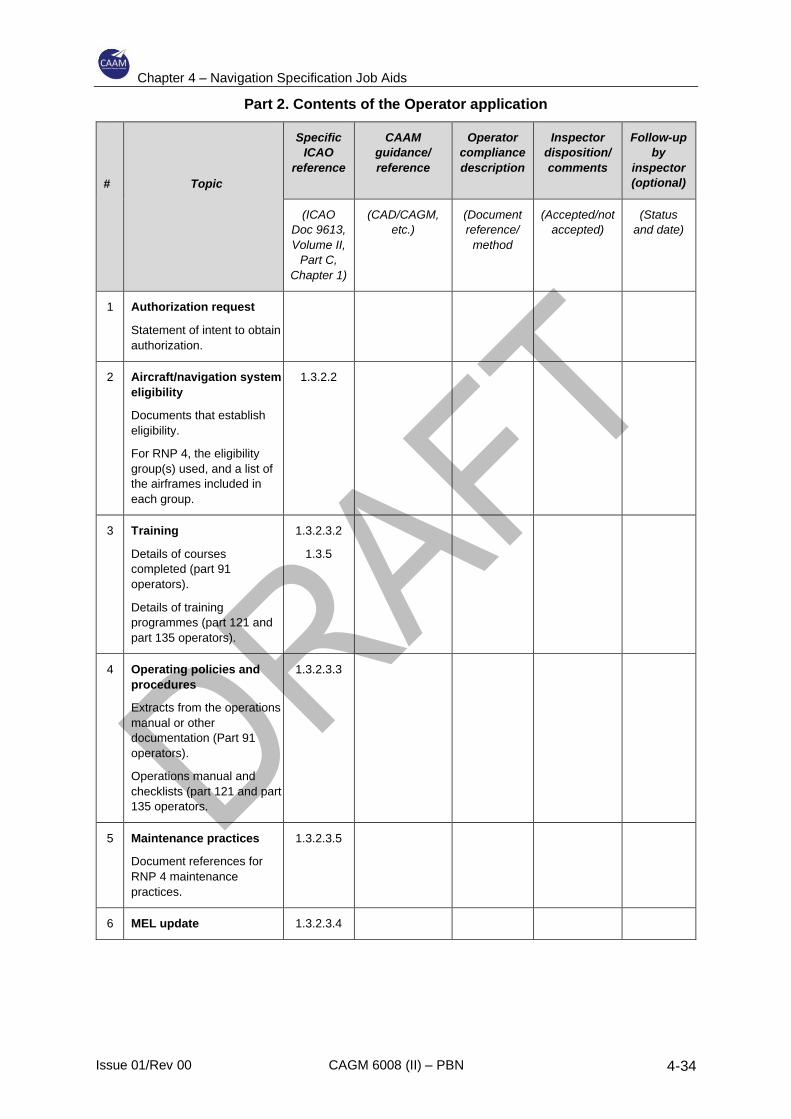
Chapter 4 – Navigation Specification Job Aids
Issue 01/Rev 00 CAGM 6008 (II) – PBN 4-34
Part 2. Contents of the Operator application
#
Topic
Specific
ICAO
reference
CAAM
guidance/
reference
Operator
compliance
description
Inspector
disposition/
comments
Follow-up
by
inspector
(optional)
(ICAO
Doc 9613,
Volume II,
Part C,
Chapter 1)
(CAD/CAGM,
etc.)
(Document
reference/
method
(Accepted/not
accepted)
(Status
and date)
1 Authorization request
Statement of intent to obtain
authorization.
2 Aircraft/navigation system
eligibility
Documents that establish
eligibility.
For RNP 4, the eligibility
group(s) used, and a list of
the airframes included in
each group.
1.3.2.2
3 Training
Details of courses
completed (part 91
operators).
Details of training
programmes (part 121 and
part 135 operators).
1.3.2.3.2
1.3.5
4 Operating policies and
procedures
Extracts from the operations
manual or other
documentation (Part 91
operators).
Operations manual and
checklists (part 121 and part
135 operators.
1.3.2.3.3
5 Maintenance practices
Document references for
RNP 4 maintenance
practices.
1.3.2.3.5
6 MEL update 1.3.2.3.4
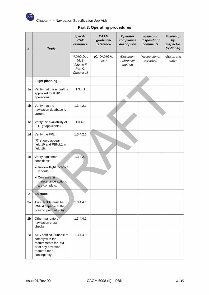
Chapter 4 – Navigation Specification Job Aids
Issue 01/Rev 00 CAGM 6008 (II) – PBN 4-35
Part 3. Operating procedures
#
Topic
Specific
ICAO
reference
CAAM
guidance/
reference
Operator
compliance
description
Inspector
disposition/
comments
Follow-up
by
inspector
(optional)
(ICAO Doc
9613,
Volume II,
Part C,
Chapter 1)
(CAD/CAGM,
etc.)
(Document
reference/
method
(Accepted/not
accepted)
(Status and
date)
1 Flight planning
1a Verify that the aircraft is
approved for RNP 4
operations.
1.3.4.1
1b Verify that the
navigation database is
current.
1.3.4.2.1
1c Verify the availability of
FDE (if applicable)
1.3.4.3
1d Verify the FPL:
“R” should appear in
field 10 and PBN/L1 in
field 18.
1.3.4.2.1
1e Verify equipment
conditions:
• Review flight technical
records;
• Confirm that
maintenance actions
are complete.
1.3.4.2.2
2 En-route
2a Two LRNSs must be
RNP 4 capable at the
oceanic point of entry.
1.3.4.4.1
2b Other mandatory
navigation cross-
checks.
1.3.4.4.2
2c ATC notified if unable to
comply with the
requirements for RNP
or of any deviation
required for a
contingency.
1.3.4.4.3
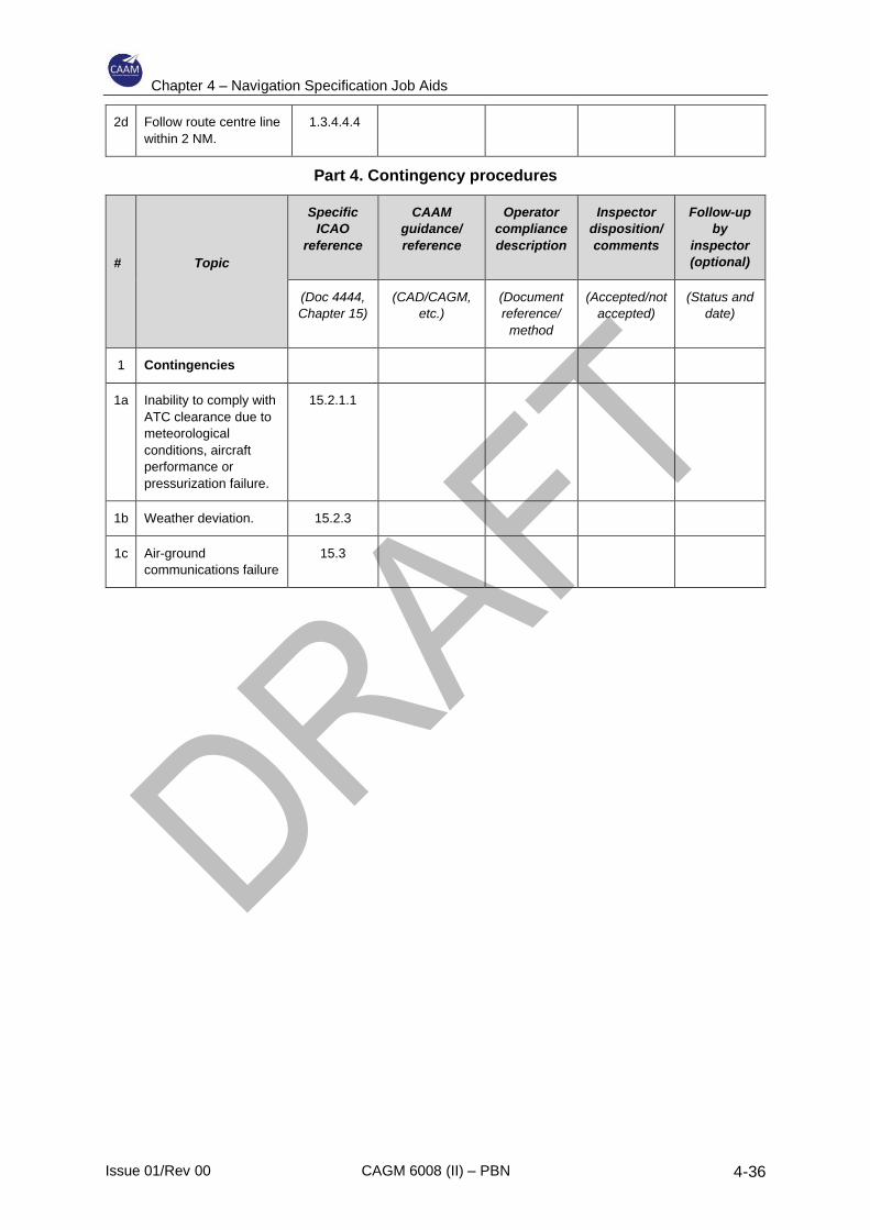
Chapter 4 – Navigation Specification Job Aids
Issue 01/Rev 00 CAGM 6008 (II) – PBN 4-36
2d Follow route centre line
within 2 NM.
1.3.4.4.4
Part 4. Contingency procedures
#
Topic
Specific
ICAO
reference
CAAM
guidance/
reference
Operator
compliance
description
Inspector
disposition/
comments
Follow-up
by
inspector
(optional)
(Doc 4444,
Chapter 15)
(CAD/CAGM,
etc.)
(Document
reference/
method
(Accepted/not
accepted)
(Status and
date)
1 Contingencies
1a Inability to comply with
ATC clearance due to
meteorological
conditions, aircraft
performance or
pressurization failure.
15.2.1.1
1b Weather deviation. 15.2.3
1c Air-ground
communications failure
15.3
Chapter 4 – Navigation Specification Job Aids
Issue 01/Rev 00 CAGM 6008 (II) – PBN 4-37
4.7 RNP 2
4.7.1 General
4.7.1.1 RNP 2 is a navigation specification primarily intended to provide a means to
develop routes in areas with little or no ground-based navigation aid (NAVAID)
infrastructure.
4.7.1.2 The RNP 2 navigation specification is applicable to fixed or flexible routes in
Continental En-route and Oceanic/Remote flight phases.
4.7.1.3 RNP 2 requires Global Navigation Satellite System (GNSS) as the primary
navigation sensor, either as a stand-alone aviation system or as part of a multi-
sensor system. Where multi-sensor systems incorporating GNSS are used,
positioning data from non-GNSS navigation sensors may be integrated with the
GNSS data provided the non-GNSS data do not cause position errors
exceeding the total system error budget. Otherwise, a means should be
provided to deselect the non-GNSS navigation sensor types.
4.7.1.4 RNP 2 operations in Oceanic and Remote airspace require dual independent
long-range navigation systems. RNP 2 operations in Continental En-route
airspace may use a single GNSS area navigation system providing an alternate
means of navigation is available if required by the category of operation.
4.7.1.5 The standards applicable to RNP 2 oceanic / remote also meet the
requirements for:
a) RNP 4; and
b) RNAV 5; and
c) RNAV 1 and RNAV 2.
Note. – RNP 2 is applicable to area navigation routes defined by straight
segments. Fixed Radius Transitions may be applied to RNP 2 routes.
4.7.2 Aircraft eligibility
4.7.2.1 An aircraft is eligible for a RNP 2 navigation authorization if:
a) The AFM, an AFM supplement, or OEM service letter states that the aircraft
navigation system is approved for RNP 2 operations; or
b) The aircraft is equipped with GNSS stand-alone system certified by the
manufacturer for en-route operations in accordance with AC 21-36(0)
(utilizing either TSO-C129 Class A1 or A2 or TSO-C146 / ETSO-C146
Class Gamma and Operational Class 1, 2 or 3) or equivalent;
c) The aircraft is equipped with a multi-sensor system (e.g. FMS) with GNSS
equipment certified by the manufacturer for en-route operations in
accordance with AC 21-37 (0) (utilizing either TSO/ETSO-C129(a) sensor
Chapter 4 – Navigation Specification Job Aids
Issue 01/Rev 00 CAGM 6008 (II) – PBN 4-38
Class B or C, TSO/ETSO-C145 Class 1, 2 or 3 or TSO-C196) and the
requirements of ETSO-C115b FMS or equivalent.
d) The aircraft is demonstrated to comply with the requirements for RNP 2
contained in ICAO ICAO Doc 9613 PBN Manual, Volume II, Part C,
Chapter 2, Implementing RNP 2.
4.7.3 System performance, monitoring and alerting
System performance, monitoring and alerting requirements for RNP 2 operations
are as stated in ICAO ICAO Doc 9613 PBN Manual, Volume II, Part C, Chapter 2,
Implementing RNP 2.
4.7.4 System functionality
System functionality requirements for RNP 2 operations are as stated in ICAO
ICAO Doc 9613 PBN Manual, Volume II, Part C, Chapter 2, Implementing RNP 2.
4.7.5 Operating standards
4.7.5.1 Flight planning
Prior to flight, consider conditions that may affect RNP 2 operations, including:
a) verifying that the aircraft and operating crew are approved for RNP 2;
b) confirming that the aircraft can be operated in accordance with the RNP 2
requirements for the planned route(s) including the route(s) to any alternate
aerodrome(s) and minimum equipment requirements;
c) checking availability of the NAVAID infrastructure required for the intended
routes, including any non-RNAV contingencies, for the period of the
intended operation;
d) confirming that the navigational database is current and appropriate for the
region of intended operation and includes the NAVAIDs and waypoints
required for the route; and
e) considering any operating restrictions, including time limits if applicable.
Insert the appropriate identifier in the flight plan to indicate RNP 2 as set
out in the Aeronautical Information Publication.
4.7.5.2 GNSS Integrity Availability
a) GNSS navigation systems are equipped with a means of monitoring the
integrity of the position solution. Integrity may be assured by a number of
methods including Receiver Autonomous Integrity Monitor and proprietary
hybrid inertial / GNSS systems.
b) The availability of the integrity monitoring function can be predicted and
can be obtained from a variety of sources such as Notice to Airmen
(NOTAM), and prediction services. Operators should be familiar with the
prediction information available for the intended route. Prediction services
Chapter 4 – Navigation Specification Job Aids
Issue 01/Rev 00 CAGM 6008 (II) – PBN 4-39
are available from Air Navigation Service Provider (ANSPs), avionic
manufacturers, other entities or through an on-board prediction capability.
c) Integrity availability prediction should take into account the latest satellite
constellation NOTAM and the integrity system used by the aircraft avionics.
d) In the event of a predicted, continuous loss of the integrity function more
than 5 minutes for any part of the RNP 2 operation, the flight plan should
be revised (i.e. delaying the departure or planning a different route).
Note. – Some RNP systems, typically multi-sensor systems with tightly coupled
GNSS/IRS, provide a global RNP capability based on a minimum number of
available GPS satellites and IRS coasting capability, for example “For
instrument approach procedures requiring GPS PRIMARY...GPS PRIMARY is
available worldwide if 24 satellites or more are operative. If the number of
satellites is 23 or less check GPS PRIMARY availability using an approved
ground based prediction software”. This equates to a global RNP capability of
RNP 0.3 provided there is a minimum number of 24 serviceable GPS satellites.
In such cases a prediction is not required unless operations below the stated
RNP value are planned or the minimum number of serviceable satellites is
reached.
e) Operators, pilots and ANSPs need to be aware, that a prediction of integrity
availability, an unplanned failure of GNSS elements can result in a loss of
integrity monitoring capability, and in some cases a complete loss of the
navigation function whilst airborne, which may require reversion to an
alternative means of navigation. Pilots should, therefore, assess their
capability to navigate (potentially to an alternate destination) in the case of
failure of GNSS navigation.
f) For aircraft navigating with Space Based Augmentation System (SBAS)
receivers (all TSO-C145/C146), check GPS INTEGRITY availability in
areas where SBAS is unavailable.
4.7.5.3 Flight procedures
a) Comply with any instructions or procedures identified by the manufacturer
as being necessary to comply with the performance requirements of the
navigation specification.
b) At system initialization, confirm the navigation database is current and
verify that the aircraft position has been entered correctly. Verify proper
entry of the Air Traffic Control (ATC) assigned route upon initial clearance
from ATC to conduct the relevant RNAV route. Ensure the waypoints
sequence, depicted by the navigation system, matches the route depicted
on the appropriate chart/s and the assigned route.
c) Cross-check the cleared flight plan by comparing charts or other applicable
resources with the navigation system textural display and the aircraft map
display, if applicable. If required, confirm the exclusion of specific
navigation aids.
Chapter 4 – Navigation Specification Job Aids
Issue 01/Rev 00 CAGM 6008 (II) – PBN 4-40
Note. – Small differences between charted navigation information and
displayed navigation data may be noted. Differences of 3 degrees or less due
to the equipment manufacturer’s application of magnetic variation and are
operationally acceptable.
d) During flight, where feasible, confirm navigation reasonableness by cross-
reference to available data from ground-based aids.
e) For RNP 2 routes, a lateral deviation indicator, navigation map display,
flight director or autopilot in the lateral navigation mode is recommended.
f) In lieu of a lateral deviation indicator, a navigation map display with
equivalent functionality to a lateral deviation indicator, as described in
ICAO ICAO Doc 9613, Volume II, Part C, Chapter 2, Implementing RNP 2
is acceptable for RNP 2 operations.
g) Select lateral deviation display scaling suitable for the navigation accuracy
associated with the route (e.g., full scale deflection ±2 NM for RNP 2 or ±
5 NM for TSO-C129 equipment).
h) Select navigation map scale to enable monitoring of tracking accuracy
applicable to RNP 2.
Note. – Map scaling selection is dependent upon a number of factors including
display size, resolution, any numeric cross-track indications and route
complexity. Typically, a 10 NM display scaling may be used.
i) Maintain route centrelines, as depicted by lateral deviation indicators
and/or flight guidance, unless authorized to deviate by ATC or under
emergency conditions.
j) The standard for limitation of cross-track error/deviation (the difference
between the computed path and the displayed aircraft position) is 1⁄2 the
navigation accuracy (i.e. 1 NM for RNP 2).
Note. – Brief deviations from this standard during and immediately after turns,
are normally considered acceptable. As accurate cross-track information may
not be provided during turns, crew procedures and training need to emphasize
observance of turn anticipation commands and management of rate of turn.
k) If ATC issues a heading assignment taking the aircraft off a route, do not
modify the flight plan until clearance is received to re-join the route or the
controller confirms a new clearance.
l) Manually selecting aircraft bank-limiting functions may reduce the aircraft’s
ability to maintain its desired track and is therefore not recommended.
Pilots should recognise that manually selectable aircraft bank-limiting
functions might reduce their ability to satisfy ATC flight path expectations,
especially when executing large angle turns. This should not be construed
as a requirement to deviate from approved aircraft flight manual
procedures; rather pilots should be encouraged to limit the selection of
such functions within accepted procedures.
Chapter 4 – Navigation Specification Job Aids
Issue 01/Rev 00 CAGM 6008 (II) – PBN 4-41
4.7.5.4 Contingency procedures
Notify ATC when the RNP performance ceases to meet RNP 2 requirements.
4.7.6 Flight crew knowledge and training
4.7.6.1.1 Flight crew knowledge elements include:
a) The meaning and proper use of aircraft equipment/navigation suffixes;
b) The capabilities and limitations of the RNP system installed;
c) The operations and airspace for which the RNP system is approved
to operate;
d) The NAVAID limitations with respect to the RNP system to be used for RNP
2 operations; Required navigation equipment for operation on RNP 2
routes;
e) The flight planning requirements for the RNP 2 operation;
f) The radio/telephony phraseology for the airspace, in accordance with
ICAO Doc 4444 - Procedures for Air Navigation Services – Air Traffic
Management (PANS/ATM) and Doc 7030 – Regional supplementary
procedures, as appropriate;
g) Contingency procedures for RNP system failures;
h) RNP system-specific information, including:
1) Levels of automation, mode annunciations, changes, alerts,
interactions, reversions and degradation;
2) Functional integration with other aircraft systems;
3) Types of navigation sensors (e.g. Distance Measuring Equipment,
Inertial Reference Unit and GNSS) utilized by the RNP system and
associated system prioritization/weighting/logic;
4) Aircraft configuration and operational conditions required to support
RNP2 operations i.e. appropriate selection of lateral deviation display
scaling;
5) Pilot procedures consistent with the operation;
6) The meaning and appropriateness of route discontinuities and related
flight crew procedures;
7) Monitoring procedures for each phase of the flight (e.g. monitor PROG
or LEGS page);
8) Turn anticipation with consideration to speed and altitude effects; and
9) Interpretation of electronic displays and symbols.
4.7.6.2 Flight crew training elements include:
Chapter 4 – Navigation Specification Job Aids
Issue 01/Rev 00 CAGM 6008 (II) – PBN 4-42
a) Verify that the aircraft navigation data is current and valid;
b) Verify the successful completion of RNP system self-tests;
c) Initialize RNP system position;
d) Perform a manual or automatic update (with take-off point shift, if
applicable);
e) Verify waypoints and flight plan programming;
f) Resolve route discontinuities;
g) Fly direct to waypoint;
h) Fly a course/track to waypoint;
i) Intercept a course/track;
j) Vector off track and re-join a procedure;
k) Fly radar vectors and re-joining an RNP 2 route from a ‘heading’ mode;
l) Determine cross-track error/deviation;
m) Determine allowable deviation limits and maintain flight within those limits;
n) Remove and reselect navigation sensor input;
o) Perform gross navigation error checks using conventional aids;
p) Confirm exclusion of a specific navigation aid or navigation aid type;
q) Change arrival airport and alternate airport;
r) Perform parallel offset function if capability exists. Advise ATC if this
functionality is not available; and
s) Contingency procedures for RNP 2 failures.
Note. – Where crews have the required standard of knowledge based on
previous training or experience a separate training course may not be
necessary, provided the applicant details the relevant knowledge and training
elements that are contained in other training programmes.
4.7.7 Minimum equipment list
The operator’s MEL must identify any unserviceability that affects the conduct of
a RNP 2 operation.
4.7.8 Navigation Data Base
4.7.8.1 A navigation database should be obtained from a supplier that complies with
Radio Technical Commission for Aeronautics DO-200A/ European
Organization for Civil Aircraft Equipment document ED-76, Standards for
Processing Aeronautical Data and should be compatible with the intended
function of the equipment (see ICAO Annex 6, Part 1, Chapter 7). A Letter of
Chapter 4 – Navigation Specification Job Aids
Issue 01/Rev 00 CAGM 6008 (II) – PBN 4-43
Acceptance (LOA), issued by an appropriate regulatory authority to each of the
participants in the data chain, demonstrates compliance with this requirement.
(e.g. Federal Aviation Administration (FAA) LOA issued in accordance with FAA
AC 20-153 or European Aviation Safety Agency (EASA) LOA issued in
accordance with EASA Implementing Rule 21 subpart G).
Note. – While a LOA provides assurance of minimum standards for the supply
of a navigation data, errors may still occur, and all operators should consider
the need to conduct periodic checks to ensure database integrity.
4.7.8.2 Any discrepancy in data is to be reported to the navigation database supplier
and resolved prior to operational use by:
a) re-issue of the navigation database;
b) prohibition of the route; or
c) instructions to flight crew.
4.7.9 Navigation errors
4.7.9.1 It is the responsibility of the operator to take immediate action to rectify any
condition that has led to navigation error.
4.7.9.2 A report to the CAAM, including an initial analysis of the causal factors and the
measures being taken to prevent a recurrence is due within 72 hours.
4.7.9.3 Navigation errors exceeding the following limits are reportable:
a) a lateral navigational error of at least 2 NM for RNP 2;
b) a longitudinal navigational error of at least 2 NM for RNP 2; or
c) a navigation system failure. A navigation system failure is defined as
meaning that the aircraft cannot meet the required performance for the
current route.
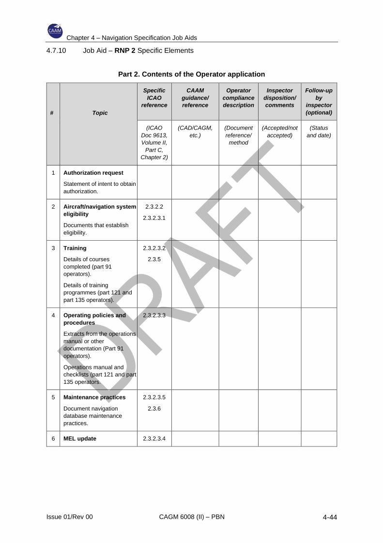
Chapter 4 – Navigation Specification Job Aids
Issue 01/Rev 00 CAGM 6008 (II) – PBN 4-44
4.7.10 Job Aid – RNP 2 Specific Elements
Part 2. Contents of the Operator application
#
Topic
Specific
ICAO
reference
CAAM
guidance/
reference
Operator
compliance
description
Inspector
disposition/
comments
Follow-up
by
inspector
(optional)
(ICAO
Doc 9613,
Volume II,
Part C,
Chapter 2)
(CAD/CAGM,
etc.)
(Document
reference/
method
(Accepted/not
accepted)
(Status
and date)
1 Authorization request
Statement of intent to obtain
authorization.
2 Aircraft/navigation system
eligibility
Documents that establish
eligibility.
2.3.2.2
2.3.2.3.1
3 Training
Details of courses
completed (part 91
operators).
Details of training
programmes (part 121 and
part 135 operators).
2.3.2.3.2
2.3.5
4 Operating policies and
procedures
Extracts from the operations
manual or other
documentation (Part 91
operators).
Operations manual and
checklists (part 121 and part
135 operators.
2.3.2.3.3
5 Maintenance practices
Document navigation
database maintenance
practices.
2.3.2.3.5
2.3.6
6 MEL update 2.3.2.3.4
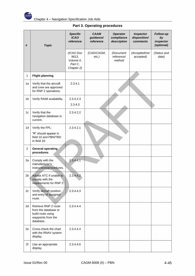
Chapter 4 – Navigation Specification Job Aids
Issue 01/Rev 00 CAGM 6008 (II) – PBN 4-45
Part 3. Operating procedures
#
Topic
Specific
ICAO
reference
CAAM
guidance/
reference
Operator
compliance
description
Inspector
disposition/
comments
Follow-up
by
inspector
(optional)
(ICAO Doc
9613,
Volume II,
Part C,
Chapter 2)
(CAD/CAGM,
etc.)
(Document
reference/
method
(Accepted/not
accepted)
(Status and
date)
1 Flight planning
1a Verify that the aircraft
and crew are approved
for RNP 2 operations.
2.3.4.1
1b Verify RAIM availability. 2.3.4.2.3
2.3.4.3
1c Verify that the
navigation database is
current.
2.3.4.2.2
1d Verify the FPL:
“R” should appear in
field 10 and PBN/TBD
in field 18.
2.3.4.2.1
2 General operating
procedures
2a Comply with the
manufacturer’s
instructions/procedures.
2.3.4.4.1
2b Advise ATC if unable to
comply with the
requirements for RNP 2.
2.3.4.4.2
2c Verify aircraft position
and entry of assigned
route.
2.3.4.4.3
2d Retrieve RNP 2 route
from the database or
build route using
waypoints from the
database.
2.3.4.4.4
2e Cross-check the chart
with the RNAV system
display.
2.3.4.4.4
2f Use an appropriate
display.
2.3.4.4.6

Chapter 4 – Navigation Specification Job Aids
Issue 01/Rev 00 CAGM 6008 (II) – PBN 4-46
2g Use appropriate scaling 2.3.4.4.6
2h Follow route centre line
within 1 NM.
2.3.4.4.7
2i Do not use bank limiting
functions.
2.3.4.4.8
2j Do not modify the fight
plan in the RNAV
system after ATC
heading assignment
until a clearance is
received to re-join the
route or a new
clearance is confirmed.
2.3.4.4.9
2k If RNP input is required,
select RNP 2 or lower.
2.3.4.4.10

Chapter 4 – Navigation Specification Job Aids
Issue 01/Rev 00 CAGM 6008 (II) – PBN 4-47
Part 4. Contingency procedures
#
Topic
Specific
ICAO
reference
CAAM
guidance/
reference
Operator
compliance
description
Inspector
disposition/
comments
Follow-up
by
inspector
(optional)
(ICAO Doc
9613,
Volume II,
Part C,
Chapter 2)*
(CAD/CAGM,
etc.)
(Document
reference/
method
(Accepted/not
accepted)
(Status and
date)
1 Contingencies
1a Advise ATC if unable
to meet the
requirements for RNP
2.
2.3.4.5
* All references are to the PBN manual (ICAO Doc 9613), Volume II, Part C, Chapter 2, unless otherwise
indicated.
Chapter 4 – Navigation Specification Job Aids
Issue 01/Rev 00 CAGM 6008 (II) – PBN 4-48
4.8 RNP 1
4.8.1 General
4.8.1.1 RNP 1 is intended to support arrival and departure procedures using GNSS
positioning only.
4.8.1.2 Other than the sole requirement for GNSS there is no significant difference
between the RNAV 1 and RNAV 2 specification and RNP 1.
4.8.2 Maintaining 1 NM scaling
4.8.2.1 Stand-alone basic GNSS receiver
4.8.2.1.1 The most basic qualifying system is a stand-alone GNSS receiver (TSO
C129(a) or equivalent) which should be coupled to a CDI or HSI display
providing course guidance and cross-track deviation indications. The
receiver normally incorporates a self-contained control and display unit, but
the interface may also be provided by a separate CDU.
4.8.2.1.2 In this arrangement the RNP 1 capability is provided when in terminal mode.
In terminal mode:
a) a cross-track deviation display scaling is automatically set at ±1 NM full-
scale deflection;
b) alert is automatically set to 1 NM (RAIM alert limit).
4.8.2.1.3 In the default mode (en-route) CDI scaling increases to ±5 NM and HAL
increases to 2 NM. Terminal mode cannot be manually selected but will be
system-selected provided certain conditions exist.
4.8.2.1.4 For departure, provided the current flight plan includes the departure airport
(usually the ARP), terminal mode will be active and annunciated. In the
general case terminal mode will automatically switch to en-route mode at 30
NM from the departure ARP. If the RNP 1 SID extends past 30 NM, the CDI
scaling will no longer be adequate to support the required FTE limit (±0.5
NM), and flight crew action will be necessary to manually select ±1 NM CDI
scaling.
4.8.2.1.5 On arrival, provided the current flight plan route includes the destination
airport (ARP), the receiver will automatically switch from en-route to terminal
mode at 30 NM from the ARP. If the STAR commences at a distance greater
than 30 NM radius from the destination, then en-route CDI scaling of ±5 NM
is inadequate for RNP 1 and must be manually selected to ±1 NM.
Note 1. – Manual selection of ±1 NM CDI scaling (terminal scaling) does not
change the mode, and en- route RAIM alert limits apply.
Chapter 4 – Navigation Specification Job Aids
Issue 01/Rev 00 CAGM 6008 (II) – PBN 4-49
Note 2.— If manual selection of ±1 NM is not available, crew procedures to
maintain FTE at ±0.5 NM may be considered an acceptable means of
compliance.
4.8.2.2 FMS systems
4.8.2.2.1 Aircraft equipped with FMS normally integrate positioning from a number of
sources (radio NAVAIDS and GNSS) with the IRS.
4.8.2.2.2 In such systems, the navigation capability, alerting and other functions are
based upon an RNP value, which may be a default value for a given
operation, a pilot selected value or a value extracted from the navigation
database.
4.8.2.2.3 There is normally no automatic mode switching (as in the case of a stand-
alone receiver), although the default RNP may vary with the phase of flight,
and numerical across-track deviation displays may be deemed acceptable.
4.8.3 De-selection of radio updating
There is a possibility of position errors caused by the integration of GNSS data
with other positioning data and the potential need for de-selection of other
navigation sensors. While it is unlikely that any reduction in positioning accuracy
will be significant in proportion to the required RNP 1 navigation accuracy, this
should be confirmed. Otherwise, a means to deselect other sensors should be
provided and the operating procedures should reflect this.

Chapter 4 – Navigation Specification Job Aids
Issue 01/Rev 00 CAGM 6008 (II) – PBN 4-50
4.8.4 Job Aid – RNP 1 Specific Elements
Part 2. Contents of the Operator application
#
Topic
Specific
ICAO
reference
CAAM
guidance/
reference
Operator
compliance
description
Inspector
disposition/
comments
Follow-up
by
inspector
(optional)
(ICAO
Doc 9613,
Volume II,
Part C,
Chapter 3)
(CAD/CAGM,
etc.)
(Document
reference/
method
(Accepted/not
accepted)
(Status
and date)
1 Authorization request
Statement of intent to obtain
authorization.
2 Aircraft/navigation system
eligibility
Documents that establish
eligibility.
3.3.2.2
3.3.2.3.1
3 Training
Details of courses
completed (part 91
operators).
Details of training
programmes (part 121 and
part 135 operators).
3.3.2.3.2
3.3.5
4 Operating policies and
procedures
Extracts from the operations
manual or other
documentation (Part 91
operators).
Operations manual and
checklists (part 121 and part
135 operators.
3.3.2.3.3
5 Maintenance practices
Document navigation
database maintenance
practices.
3.3.2.3.5
3.3.6
6 MEL update 3.3.2.3.4
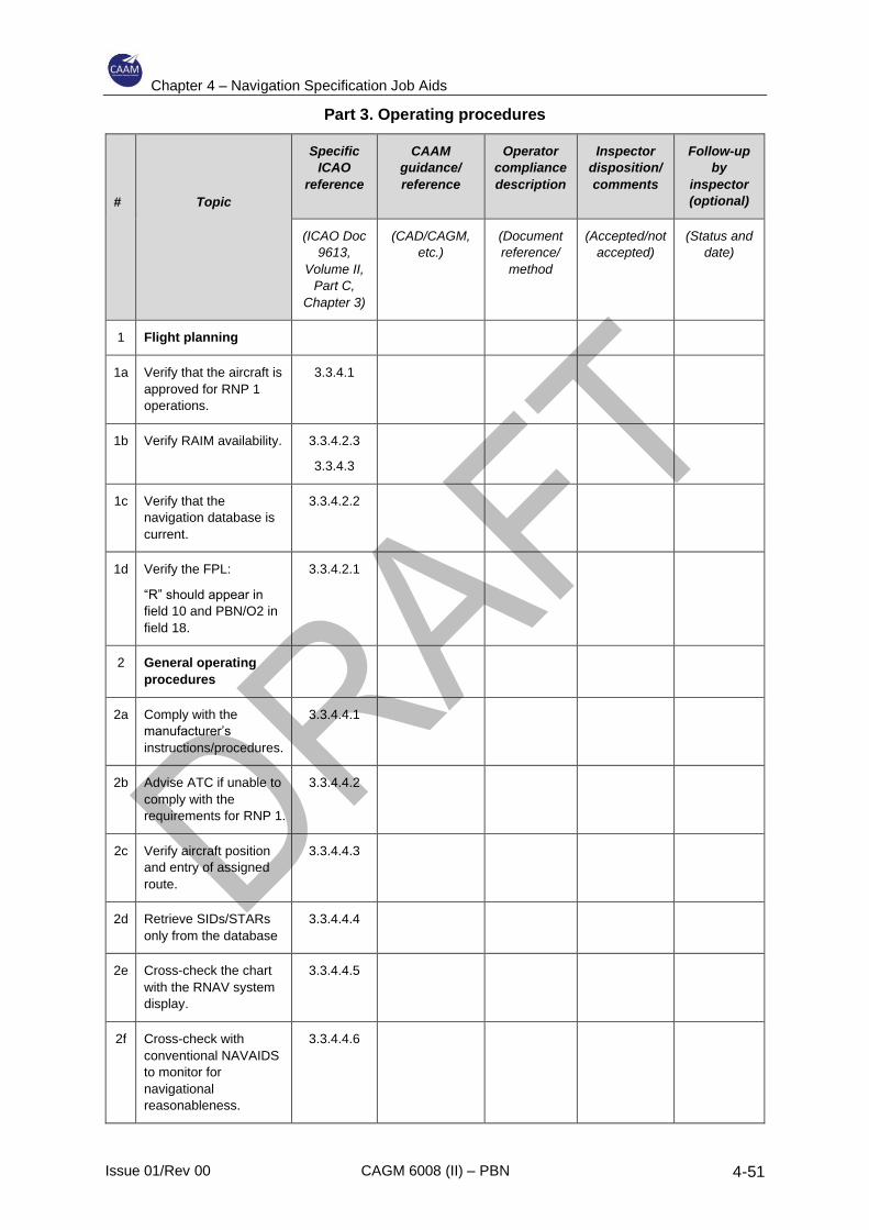
Chapter 4 – Navigation Specification Job Aids
Issue 01/Rev 00 CAGM 6008 (II) – PBN 4-51
Part 3. Operating procedures
#
Topic
Specific
ICAO
reference
CAAM
guidance/
reference
Operator
compliance
description
Inspector
disposition/
comments
Follow-up
by
inspector
(optional)
(ICAO Doc
9613,
Volume II,
Part C,
Chapter 3)
(CAD/CAGM,
etc.)
(Document
reference/
method
(Accepted/not
accepted)
(Status and
date)
1 Flight planning
1a Verify that the aircraft is
approved for RNP 1
operations.
3.3.4.1
1b Verify RAIM availability. 3.3.4.2.3
3.3.4.3
1c Verify that the
navigation database is
current.
3.3.4.2.2
1d Verify the FPL:
“R” should appear in
field 10 and PBN/O2 in
field 18.
3.3.4.2.1
2 General operating
procedures
2a Comply with the
manufacturer’s
instructions/procedures.
3.3.4.4.1
2b Advise ATC if unable to
comply with the
requirements for RNP 1.
3.3.4.4.2
2c Verify aircraft position
and entry of assigned
route.
3.3.4.4.3
2d Retrieve SIDs/STARs
only from the database
3.3.4.4.4
2e Cross-check the chart
with the RNAV system
display.
3.3.4.4.5
2f Cross-check with
conventional NAVAIDS
to monitor for
navigational
reasonableness.
3.3.4.4.6

Chapter 4 – Navigation Specification Job Aids
Issue 01/Rev 00 CAGM 6008 (II) – PBN 4-52
2g Use an appropriate
display.
3.3.4.4.7
2h Use appropriate scaling. 3.3.4.4.7
2i Follow route centre line
within 0.5 NM
3.3.4.4.8
2j Do not modify the flight
plan in the RNAV
system after ATC
heading assignment
until a clearance is
received to re-join the
route or a new
clearance is confirmed.
3.3.4.4.9
2k If RNP input is required,
select RNP 1 or lower.
3.3.4.5
3 RNP 1 SID
requirements
3a Prior to take-off, check
the RNAV system, the
aerodrome and
procedure loaded and
the displayed position.
3.3.4.6.1
3b Engage LNAV no later
than 153 m (500 ft)
above aerodrome
elevation.
3.3.4.6.2
3c Use an authorized
method to achieve RNP
1 (AP / FD / Map /
L/DEV indicator)
3.3.4.6.3
3.3.4.6.5
3d If GNSS, signal must be
acquired before start of
take-off roll.
3.3.4.6.4
4 RNP 1 STAR
requirements
4a Verify that the correct
STAR is loaded and
displayed.
3.3.4.7.1
4b Contingency
preparations
3.3.4.7.3
4c Procedure modification
in response to ATC
instructions.
3.3.4.7.4
4d Verify the correct
operation of the
3.3.4.7.5

Chapter 4 – Navigation Specification Job Aids
Issue 01/Rev 00 CAGM 6008 (II) – PBN 4-53
navigation system and
that the correct
procedure, transition
and runway are loaded.
4e Observance of speed
and altitude constraints.
3.3.4.7.6
4f If the procedure is more
than 30 NM from ARP
use FD/AP or set FSD
to 1 NM.
3.3.4.7.7
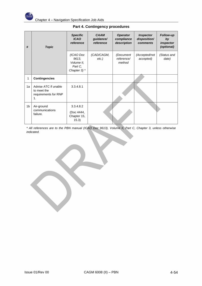
Chapter 4 – Navigation Specification Job Aids
Issue 01/Rev 00 CAGM 6008 (II) – PBN 4-54
Part 4. Contingency procedures
#
Topic
Specific
ICAO
reference
CAAM
guidance/
reference
Operator
compliance
description
Inspector
disposition/
comments
Follow-up
by
inspector
(optional)
(ICAO Doc
9613,
Volume II,
Part C,
Chapter 3) *
(CAD/CAGM,
etc.)
(Document
reference/
method
(Accepted/not
accepted)
(Status and
date)
1 Contingencies
1a Advise ATC if unable
to meet the
requirements for RNP
1.
3.3.4.8.1
1b Air-ground
communications
failure.
3.3.4.8.2
(Doc 4444,
Chapter 15,
15.3)
* All references are to the PBN manual (ICAO Doc 9613), Volume II, Part C, Chapter 3, unless otherwise
indicated.
Chapter 4 – Navigation Specification Job Aids
Issue 01/Rev 00 CAGM 6008 (II) – PBN 4-55
4.9 RNP APCH
4.9.1 General
4.9.1.1 RNP APCH is the general designator for PBN approach procedures that are
not authorization required operations
4.9.1.2 GNSS is used for all RNP APCH applications as follows:
a) RNP APCH – LNAV — lateral positioning with GNSS (basic constellation);
b) RNP APCH – LNAV/VNAV — lateral positioning with GNSS, vertical
positioning with barometric inputs;
c) RNP APCH – LPV — lateral and vertical positioning with SBAS;
d) RNP APCH – LP — lateral positioning with SBAS.
4.9.1.3 The published RNP APCH OCA/H are treated as:
a) MDA/H for LNAV and LP minima;
b) DA/H for LNAV/VNAV and LPV minima.
4.9.1.4 Operators currently approved to conduct RNAV(GNSS) approaches should
qualify for RNP APCH LNAV without further examination.
4.9.2 Aircraft requirements for RNP APCH to LNAV minima
4.9.2.1 On-board performance monitoring and alerting.
4.9.2.1.1 Accuracy: During operations on the initial and intermediate segments and
for the RNAV missed approach of an RNP APCH, the lateral TSE must be
within ± 1NM for at least 95% of the total flight time. The along-track error
must also be within ± 1NM for at least 95% of the total flight time.
4.9.2.1.2 During operations on the FAS of an RNP APCH down to LNAV or
LNAV/VNAV minima, the lateral TSE must be within ±0.3 NM for at least
95% of the total flight time. The along-track error must also be within ±0.3NM
for at least 95% of the total flight time.
4.9.2.1.3 To satisfy the accuracy requirement, the 95% FTE should not exceed 0.5
NM on the initial and intermediate segments, and for the RNAV missed
approach of an RNP APCH. The 95% FTE should not exceed 0.25 NM on
the FAS of an RNP APCH.
Note. – The use of a deviation indicator with 1 NM full-scale deflection on
the initial and intermediate segments, and for the RNAV missed approach
and 0.3 NM full-scale deflection on the FAS, is an acceptable means of
compliance. The use of an autopilot or flight director is an acceptable means
of compliance (roll stabilization systems do not qualify).
Chapter 4 – Navigation Specification Job Aids
Issue 01/Rev 00 CAGM 6008 (II) – PBN 4-56
4.9.2.1.4 Integrity: Malfunction of the aircraft navigation equipment is classified as a
major failure condition under airworthiness regulations (i.e. 10-5 per hour).
4.9.2.1.5 Continuity: Loss of function is classified as a minor failure condition if the
operator can revert to a different navigation system and proceed to a suitable
airport.
4.9.2.1.6 On-board performance monitoring and alerting: During operations on the
initial and intermediate segments and for the RNAV missed approach of an
RNP APCH, the RNP system, or the RNP system and pilot in combination,
shall provide an alert if the accuracy requirement is not met, or if the
probability that the lateral TSE exceeds 2 NM is greater than 10-5. During
operations on the FAS of an RNP APCH down to LNAV or LNAV/VNAV
minima, the RNP system, or the RNP system and pilot in combination, shall
provide an alert if the accuracy requirement is not met, or if the probability
that the lateral TSE exceeds 0.6 NM is greater than 10-5.
4.9.2.1.7 SIS: During operations on the initial and intermediate segments and for the
RNAV missed approach of an RNP APCH, the aircraft navigation equipment
shall provide an alert if the probability of SIS errors causing a lateral position
error greater than 2 NM exceeds 10-7 per hour. During operations on the
FAS of an RNP APCH down to LNAV or LNAV/VNAV minima, the aircraft
navigation equipment shall provide an alert of the probability of SIS errors
causing a lateral position error greater than 0.6 NM exceeds 10-7 per hour.
Notes:
1. There are no RNP APCH requirements for the missed approach if it is based on
conventional means (VOR, DME, NDB) or on dead reckoning.
2. Compliance with the on-board performance monitoring and alerting requirement does
not imply automatic monitoring of an FTE. The on-board monitoring and alerting
function should consist at least of a NSE monitoring and alerting algorithm and a
lateral deviation display enabling the crew to monitor the FTE. To the extent
operational procedures are used to monitor FTE, the crew procedure, equipment
characteristics, and installation are evaluated for their effectiveness and equivalence
as described in the functional requirements and operating procedures. PDE is
considered negligible due to the navigation database quality assurance process.
3. The following systems meet the accuracy, integrity and continuity requirements of
these criteria:
a) GNSS stand-alone systems, equipment should be approved in accordance with
TSO-C129a/ ETSO-C129a Class A, E/TSO-C146() Class Gamma and
operational class 1, 2 or 3, or TSO C-196();
b) GNSS sensors used in multi-sensor system (e.g. FMS) equipment should be
approved in accordance with TSO C129 ( )/ ETSO-C129 ( ) Class B1, C1, B3,
C3 or E/TSO C145() class 1, 2 or 3, or TSO C-196(). For GNSS receiver
Chapter 4 – Navigation Specification Job Aids
Issue 01/Rev 00 CAGM 6008 (II) – PBN 4-57
approved in accordance with E/TSO-C129(), capability for satellite FDE is
recommended to improve continuity of function; and
c) multi-sensor systems using GNSS should be approved in accordance with AC20-
130A or TSO-C115b, as well as having been demonstrated for RNP APCH
capability.
4. For RNP procedures, the RNP system may only use DME updating when authorized
by the State. The manufacturer should identify any operating constraints (e.g. manual
inhibit of DME) in order for a given aircraft to comply with this requirement. This is in
recognition of States where a DME infrastructure and capable equipped aircraft are
available. Those States may establish a basis for aircraft qualification and operational
approval to enable use of DME. It is not intended to imply a requirement for
implementation of DME infrastructure or the addition of RNP capability using DME
for RNP operations. This requirement does not imply an equipment capability must
exist providing a direct means of inhibiting DME updating. A procedural means for
the pilot to inhibit DME updating or executing a missed approach if reverting to DME
updating may meet this requirement.
4.9.2.2 Criteria for specific navigation systems
4.9.2.2.1 RNP APCH is based on GNSS positioning. Positioning data from other types
of navigation sensors may be integrated with the GNSS data provided the
other positioning data do not cause position errors exceeding the TSE
budget, or if means are provided to deselect the other navigation sensor
types.
4.9.2.3 Functional requirements
4.9.2.3.1 Navigation displays and required functions
4.9.2.3.1.1 Navigations data, including a to/from indication, and a failure indication,
must be displayed on a lateral deviation display (CDI, EHSI) and/or a
navigation map display. These must be used as primary flight instruments
for the navigation of the aircraft, for manoeuvre anticipation and for
failure/status/integrity indication:
a) the displays must be visible to the pilot and located in the primary
field of view (±15 degrees from the pilot’s normal line of sight) when
looking forward along the flight path;
b) the lateral deviation display scaling should agree with any alerting
and annunciation limits;
c) the lateral deviation display must also have a full-scale deflection
suitable for the current phase of flight and must be based on the TSE
requirement. Scaling is ±1 NM for the initial and intermediate
segments and ±0.3 NM for the final segment;
d) the display scaling may be set automatically by default logic or set to
a value obtained from a navigation database. The full-scale
Chapter 4 – Navigation Specification Job Aids
Issue 01/Rev 00 CAGM 6008 (II) – PBN 4-58
deflection value must be known or must be available for display to
the pilot commensurate with approach values;
e) as an alternate means, a navigation map display must give
equivalent functionality to a lateral deviation display with appropriate
map scales (scaling may be set manually by the pilot). To be
approved, the navigation map display must be shown to meet the
TSE requirements;
f) it is highly recommended that the course selector of the deviation
display is automatically slaved to the RNAV computed path;
Note. – This does not apply for installation where an electronic map
display contains graphical display of the flight path and path deviation.
g) a flight director and/or autopilot is not required for this type of
operation, however, if the lateral TSE cannot be demonstrated
without these systems, it becomes mandatory. In this case, coupling
to the flight director and/or automatic pilot from the RNP system must
be clearly indicated at the cockpit level; and
h) enhanced navigation display (e.g. electronic map display or
enhanced EHSI) to improve lateral situational awareness, navigation
monitoring and approach verification (flight plan verification) could
become mandatory if the RNAV installation doesn’t support the
display of information necessary for the accomplishment of these
crew tasks.
4.9.2.3.1.2 The following system functions are required as a minimum:
a) The capability to continuously display to the pilot flying, on the
primary flight instruments for navigation of the aircraft (primary
navigation display), the RNAV computed desired path and aircraft
position relative to the path. For aircraft where the minimum flight
crew is two pilots, the means for the pilot not flying to verify the
desired path and the aircraft position relative to the path must also
be provided;
b) A navigation database, containing current navigation data officially
promulgated for civil aviation, which can be updated in accordance
with the AIRAC cycle and from which approach procedures can be
retrieved and loaded into the RNP system. The stored resolution of
the data must be sufficient to achieve the required track-keeping
accuracy. The database must be protected against pilot modification
of the stored data;
c) The means to display the validity period of the navigation data to the
pilot;
Chapter 4 – Navigation Specification Job Aids
Issue 01/Rev 00 CAGM 6008 (II) – PBN 4-59
d) The means to retrieve and display data stored in the navigation
database relating to individual waypoints and NAVAIDs, to enable
the pilot to verify the procedure to be flown;
e) Capacity to load from the database into the RNP system the whole
approach to be flown. The approach must be loaded from the data
base, into the RNP system, by its name;
f) The means to display the following items, either in the pilot’s primary
field of view, or on a readily accessible display page:
1) the identification of the active (To) waypoint;
2) the distance and bearing to the active (To) waypoint; and
3) the ground speed or time to the active (To) waypoint;
g) The means to display the following items on a readily accessible
display page:
1) the display of distance between flight plan waypoints;
2) the display of distance to go;
3) the display of along-track distances; and
4) the active navigation sensor type, if there is another sensor in
addition to the GNSS sensor;
h) The capability to execute a “Direct to” function;
i) The capability for automatic leg sequencing with the display of
sequencing to the pilot;
j) The capability to execute procedures extracted from the on-board
database, including the capability to execute fly-over and fly-by turns;
k) The capability to automatically execure leg transition and maintain
tracks consistent with the following ARINC 424 path terminators, or
their equivalent:
1) ARINC 424 path terminators
2) IF
3) TF
4) DF
Note. – Path terminators are defined in ARINC 424, and their application
is described in more detail in RTCA/EUROCAE documents DO 236B/ED-
75B and DO-201A/ED-77.
l) The capability to display an indication of the RNP system failure,
including the associated sensors, in the pilot’s primary field of view;
Chapter 4 – Navigation Specification Job Aids
Issue 01/Rev 00 CAGM 6008 (II) – PBN 4-60
m) The capability to indicate to the crew when the NSE alert limit is
exceeded (alert provided by the “on-board performance monitoring
and alerting function”); and
n) The capability to automatically load numeric values for courses and
tracks from the RNP system database.
4.9.3 Aircraft requirements for RNP APCH to LNAV/VNAV minima
4.9.3.1 In addition to the requirements stated in 4.9.2, the following requirements need
to be met for the aircraft to be eligible to conduct RNP APCH down to VNAV
minima. Eligibility may be established by recognizing the qualities and
qualifications of the aircraft and equipment and determining the acceptability
for operations. The determination of eligibility for existing systems should
consider acceptance of manufacturer documentation of compliance.
4.9.3.2 This approach operation is based upon the use of RNAV equipment that
automatically determines aircraft position in the vertical plane using inputs from
equipment that can include:
a) FAA-TSO-C106, Air Data Computer;
b) air data system, ARINC 706, Mark 5 Air Data System;
c) barometric altimeter system, DO-88 Altimetry, ED-26 MPS for Airborne
Altitude Measurements and Coding Systems, ARP-942 Pressure Altimeter
Systems, ARP-920 Design and Installation of Pitot Static Systems for
Transport Aircraft; and
d) type certified integrated systems providing an air data system capability
comparable to item b)
Note. – Further information on these requirements are detailed in the PBN
manual ICAO Doc 9613 in Attachment A to Volume II.
4.9.4 Aircraft requirements for RNP APCH to LP and LPV minima
4.9.4.1 On-board performance monitoring and alerting
4.9.4.1.1 Accuracy: Along the FAS and the straight continuation of the final approach
in the missed approach, the lateral and vertical TSE is dependent on the
NSE, PDE and FTE:
a) NSE: the accuracy itself (the error bound with 95% probability) changes
due to different satellite geometries. Assessment based on
measurements within a sliding time window is not suitable for GNSS.
Therefore, GNSS accuracy is specified as a probability for each and
every sample. NSE requirements are fulfilled without any demonstration
of the equipment computes three dimensional positions using
linearized, weighted least square solution in accordance with RTCA DO
229C (or subsequent version) appendix J.
Chapter 4 – Navigation Specification Job Aids
Issue 01/Rev 00 CAGM 6008 (II) – PBN 4-61
b) FTE: FTE performance is considered acceptable if the lateral and
vertical display full-scale deflection is compliant with the non-numeric
lateral cross-track and vertical deviation requirements of RTCA DO 229
C (or subsequent version) and if the crew maintains the aircraft within
one-third the full scale deflection for the lateral deviation and within one-
half the full scale deflection for the vertical deviation.
c) PDE: PDE is considered negligible based upon the process of path
specification to data specification and associated quality assurance that
is included in the FAS data-block generation process which is a
standardized process. The responsibilities for FAS Data Block
generation lies with the ANSP.
Note.— FTE performance is considered acceptable if the approach mode of
the FGS is used during such approach.
4.9.4.1.2 Integrity: Simultaneously presenting misleading lateral and vertical guidance
with misleading distance data during an RNP APCH operation down to LPV
minima is considered a hazardous failure condition (extremely remote).
Simultaneously presenting misleading lateral guidance with misleading
distance data during an RNP APCH operation down to LP minima is
considered a hazardous failure condition (extremely remote).
4.9.4.1.3 Continuity: Loss of approach capability is considered a minor failure
condition if the operator can revert to a different navigation system and
proceed to a suitable airport. For RNP APCH operations down to LP or LPV
minima at least one system is required.
4.9.4.1.4 On-board performance monitoring and alerting: Operations on the FAS of
an RNP APCH operation down to LP and LPV minima, the on-board
performance monitoring and alerting function is fulfilled by:
a) NSE monitoring and alerting (see the SIS section below);
b) FTE monitoring and alerting: LPV approach guidance must be displayed
on a lateral and vertical deviation display (HIS, EHSI, CDI/VDI) including
a failure indicator. The deviation display must have a suitable full-scale
deflection based on the required track-keeping accuracy. The lateral
and vertical full scale deflection are angular and associated to the lateral
and vertical definitions of the FAS contained in the FAS Data Block; and
c) Navigation database: once the FAS Data Block has been decoded, the
equipment shall apply the CRC to the Data Block to determine whether
the data is valid. If the FAS Data Block does not pass the CRC test, the
equipment shall not allow activation of the LP or the LPV approach
operation.
4.9.4.1.5 SIS
Chapter 4 – Navigation Specification Job Aids
Issue 01/Rev 00 CAGM 6008 (II) – PBN 4-62
4.9.4.1.5.1 At a position between 2 NM from the FAP and the FAP, the aircraft
navigation equipment shall provide an alert within 10 seconds if the SIS
errors causing a lateral position error are greater than 0.6 NM, with a
probability of 1-10-7 per hour.
4.9.4.1.5.2 After sequencing the FAP and during operations on the FAS of an RNP
APCH operation down to LP or LPV minima:
a) the aircraft navigation equipment shall provide an alert within 6
seconds if the SIS errors causing a lateral position error are greater
than 40 m, with a probability of 1-2.10-7 in any approach; and
b) the aircraft navigation equipment shall provide an alert within 6
seconds if the SIS errors causing a vertical position error is greater
than 50 m (or 35 m for LPV minima down to 200 ft), with a probability
of 1-2.10-7 in any approach.
Notes:
1. There are no RNP APCH requirements for the missed approach if it is based on
conventional means (VOR, DME, NDB) or on dead reckoning. The requirements for the
straight continuation of the final approach, in the missed approach, are in accordance with
RTCA DO 229C (or subsequent version).
2. Compliance with the performance monitoring and alerting requirement does not imply an
automatic monitor of FTE. The on-board monitoring and alerting function should consist
at least of a NSE monitoring and alerting algorithm and a lateral and vertical deviation
display enabling the crew to monitor the FTE. To the extent operational procedures are
used to monitor FTE, the crew procedure, equipment characteristics, and installation are
evaluated for their effectiveness and equivalence as described in the functional
requirements and operating procedures. PDE is considered negligible due to the
navigation database quality assurance process and the operating procedures.
3. The following systems meet the accuracy, integrity and continuity requirements of these
criteria:
a) GNSS SBAS stand-alone equipment approved in accordance with E/TSO C146a (or
subsequent version). Application of this standard guarantees that the equipment is at
least compliant with RTCA DO 229C. The equipment should be a class gamma,
operational class 3;
b) for an integrated navigation system (e.g. FMS) incorporating a GNSS SBAS sensor,
E/TSO C115b and AC 20-130A provide an acceptable means of compliance for the
approval of this navigation system when augmented by the following guidelines:
i) the performance requirements of E/TSO-C146a (or subsequent version) that
apply to the functional class gamma, operational class 3 or delta 4 is
demonstrated; and
ii) The GNSS SBAS sensor is approved in accordance with E/TSO C145a class
beta, operational class 3;
Chapter 4 – Navigation Specification Job Aids
Issue 01/Rev 00 CAGM 6008 (II) – PBN 4-63
c) approach system incorporating a class delta GNSS SBAS equipment approved in
accordance with E/TSO C146a (or subsequent version). This standard guarantees
that the equipment is at least compliant with RTCA DO 229C. The equipment should
be a class delta 4; and
d) future augmented GNSS systems are also expected to meet these requirements.
4.9.4.2 Criteria for specific navigation systems
RNP APCH operations down to LP or LPV minima are based on augmented
GNSS positioning. Positioning data from other types of navigation sensors may
be integrated with the GNSS data provided it does not cause position errors
exceeding the TSE budget, or if means are provided to deselect the other
navigation sensor types.
4.9.4.3 Functional requirements
4.9.4.3.1 Navigation displays and required functions
4.9.4.3.1.1 Approach guidance must be displayed on a lateral and vertical deviation
display (HIS, EHSI, CDI/VDI) including a failure indicator and must meet
the following requirements:
a) this display must be used as primary flight instruments for the
approach;
b) the display must be visible to the pilot and located in the primary field
of view (± 15° from the pilot’s normal line of sight) when looking
forward along the flight path; and
c) the deviation display must have full-scale deflection based on the
required track-keeping accuracy.
The lateral and vertical full-scale deflection are angular and associated to
the lateral and vertical definitions of the FAS contained in the FAS Data
Block.
4.9.4.3.1.2 The following system functions are required as a minimum:
a) The capability to display the GNSS approach mode (e.g. LP, LPV,
LNAV/VNAV, lateral navigation) in the primary field of view. This
annunciation indicates to the crew the active approach mode in order
to correlate it to the corresponding line of minima on the approach
chart. It can also detect a level of service degradation (e.g.
downgrade from LPV to lateral navigation). The airborne system
should automatically provide the highest “level of service” available
for the annunciation of the GNSS approach mode when the approach
is selected;
b) The capability to continuously display the distance to the LTP/FTP;
Chapter 4 – Navigation Specification Job Aids
Issue 01/Rev 00 CAGM 6008 (II) – PBN 4-64
c) The navigation database must contain all the necessary
data/information to fly the published approach procedure (FAS).
Although data may be stored or transmitted in different ways, the
data has to be organized in Data Blocks for the purpose of computing
the CRC. This format provides integrity protection for the data it
contains. Consequently, each FAS is defined by a specific “FAS Data
Block” containing the necessary lateral and vertical parameters
depicting the approach to be flown. Once the FAS Data Block has
been decoded, the equipment shall apply the CRC to the Data Block
to determine whether the data is valid. If the FAS Data Block does
not pass the CRC test, the equipment shall not allow activation of the
approach operation;
d) The capacity to select from the database into the installed system the
whole approach procedure to be flown (SBAS channel number
and/or approach name);
e) The indication of the loss of navigation (e.g. system failure) in the
pilot’s primary field of view by means of a navigation warning flag or
equivalent indicator on the vertical and/or lateral navigation display);
f) The indication of the LOI function in the pilot’s normal field of view
(e.g. by means of an appropriately located annunciator); and
g) The capability to immediately provide track deviation indications
relative to the extended FAS, in order to facilitate the interception of
the extended FAS from a radar vector (e.g. VTF function).
Note. – There requirements are limited to the FAS, the straight
continuation of the final approach in the missed approach, and the
interception of the extended FAS. If the installed system is also able to fly
the initial, intermediate and missed approach segments of the approach,
the corresponding requirement applies.
4.9.5 Operating procedures
Most manufacturers have developed recommended procedures for
RNAV(GPS)/RNAV(GNSS) procedures. Although the manufacturer’s
recommendations should be followed, the operational approval should include an
independent evaluation of the operator’s proposed procedures. RNP APCH
operating procedures should be consistent with the operator’s normal procedures
where possible in order to minimize any human factors elements associated with
the introduction of PBN operations.
4.9.5.1 Pre-flight planning
4.9.5.1.1 Operators and pilots intending to conduct operations using an RNP APCH
procedure must file the appropriate flight plan suffixes and the on-board
navigation data must be current and include appropriate procedures.
Chapter 4 – Navigation Specification Job Aids
Issue 01/Rev 00 CAGM 6008 (II) – PBN 4-65
Note.— Navigation databases are expected to be current for the duration of the flight.
If the AIRAC cycle is due to change during flight, operators and pilots should establish
procedures to ensure the accuracy of navigation data, including the suitability of
navigation facilities used to define the routes and procedures for the flight.
4.9.5.1.2 In addition to the normal pre-flight planning checks, the following must be
included:
a) the pilot must ensure that approaches which may be used for the intended flight
(including alternate aerodromes) are selected from a valid navigation database
(current AIRAC cycle), have been verified by the appropriate process (navigation
database integrity process) and are not prohibited by a company instruction or
NOTAM;
b) subject to a State’s regulations, during the pre-flight phase, the pilot should
ensure sufficient means are available to navigate and land at the destination or
at an alternate aerodrome in the case of loss of RNP APCH airborne capability;
c) operators and pilots must take account of any NOTAMs or operator briefing
material that could adversely affect the aircraft system operation, or the
availability or suitability of the procedures at the airport of landing, or any
alternate airport; and
d) for missed approach procedures based on conventional means (VOR, NDB),
operators and pilots must ensure that the appropriate airborne equipment
required for this procedure is installed in the aircraft and is operational and that
the associated ground-based NAVAIDs are operational.
4.9.5.1.3 The availability of the NAVAID infrastructure, required for the intended
routes, including any non-RNAV contingencies, must be confirmed for the
period of intended operations using all available information. Since GNSS
integrity (RAIM or SBAS signal) is required by Annex 10, Volume I, the
availability of these should also be determined as appropriate. For aircraft
navigating with SBAS receivers (all TSO-C145()/C146()), operators should
check appropriate GPS RAIM availability in areas where the SBAS signal is
unavailable.
4.9.5.2 GNSS availability
4.9.5.2.1 ABAS availability
Chapter 4 – Navigation Specification Job Aids
Issue 01/Rev 00 CAGM 6008 (II) – PBN 4-66
4.9.5.2.1.1 RAIM levels required for RNP APCH down to LNAV or LNAV/VNAV
minima can be verified either through NOTAMs (where available) or
through prediction services. The operating authority may provide specific
guidance on how to comply with this requirement (e.g. if sufficient
satellites are available, a prediction may not be necessary). Operators
should be familiar with the prediction information available for the
intended route.
4.9.5.2.1.2 RAIM availability prediction should take into account the latest GPS
constellation NOTAMs and avionics model (when available). The service
may be provided by the ANSP, avionics manufacturer, and other entities,
or through an airborne receiver RAIM prediction capability.
4.9.5.2.1.3 In the event of a predicted, continuous loss of appropriate level of fault
detection of more than five minutes for any part of the RNP APCH
operation, the flight planning should be revised (e.g., delaying the
departure or planning a different departure procedure).
4.9.5.2.1.4 RAIM availability prediction software does not guarantee the service,
rather they are tools to assess the expected capability of meeting the
RNP. Because of unplanned failure of some GNSS elements,
pilots/ANSPs should realize that RAIM or GPS navigation altogether may
be lost while airborne which may require reversion to an alternative
means of navigation. Therefore, pilots should assess their capability to
navigate (potentially to an alternate destination) in case of failure of GPS
navigation.
4.9.5.2.2 SBAS and other augmented GNSS availability
4.9.5.2.2.1 Section B of this chapter contains criteria to assess GNSS SBAS vertical
guidance availability.
4.9.5.2.2.2 If the aircraft uses other GNSS augmentations, or enhancements to a
basic GNSS capability (i.e., use of multiple constellations, dual
frequency), the RNP APCH operation must be supported by a prediction
capability based on the specific characteristics of these other
augmentations.
4.9.5.3 Prior to commencing the procedure
4.9.5.3.1 In addition to the normal procedure prior to commencing the approach
(before the IAF and in compatibility with crew workload), the pilot must verify
the correct procedure was loaded by comparison with the approach charts.
This check must include:
Chapter 4 – Navigation Specification Job Aids
Issue 01/Rev 00 CAGM 6008 (II) – PBN 4-67
a) the waypoint sequence; and
b) reasonableness of the tracks and distances of the approach legs, and the
accuracy of the inbound course and length of the FAS.
Note.— As a minimum, this check could be a simple inspection of a suitable map
display that achieves the objectives of this paragraph.
4.9.5.3.2 The pilot must also check using the published charts, the map display or
CDU, which waypoints are fly-by, and which are fly-over.
4.9.5.3.3 For multi-sensor systems, the pilot must verify, during the approach, that the
GNSS sensor is used for position computation.
4.9.5.3.4 For an RNP system with ABAS requiring barometric corrected altitude, the
current airport barometric altimeter setting should be input at the appropriate
time and location, consistent with the performance of the flight operation.
4.9.5.3.5 When the operation is predicated on the availability of ABAS, the pilot should
perform a new RAIM availability check if ETA is more than 15 minutes
different from the ETA used during the pre-flight planning. This check is also
processed automatically 2 NM before the FAF for an E/TSO-C129a Class
A1 receiver.
4.9.5.3.6 ATC tactical interventions in the terminal area may include radar headings,
“direct to” clearances which bypass the initial legs of an approach,
interception of an initial or intermediate segment of an approach, or the
insertion of waypoints loaded from the database. In complying with ATC
instructions, the pilot should be aware of the implications for the RNP
system:
a) the manual entry of coordinates into the RNP system by the pilot for operation
within the terminal area is not permitted; and
b) “direct to” clearances may be accepted to the IF provided that the resulting track
change at the IF does not exceed 45 degrees.
Note.— “Direct to” clearance to FAF is not acceptable.
4.9.5.3.7 The lateral definition of the flight path between the FAF and the MAPt must
not be revised by the pilot under any circumstances.
4.9.5.4 During the procedure
4.9.5.4.1 The aircraft must be established on the final approach course no later than
the FAF before starting the descent (to ensure terrain and obstacle
clearance).
Chapter 4 – Navigation Specification Job Aids
Issue 01/Rev 00 CAGM 6008 (II) – PBN 4-68
4.9.5.4.2 The crew must check the approach mode annunciator (or equivalent) is
properly indicating approach mode integrity within 2 NM before the FAF.
Note.— This will not apply for certain RNP systems (e.g. aircraft already approved
with demonstrated RNP capability). For such systems, other means are available
including electronic map displays, flight guidance mode indications, etc., which clearly
indicate to the crew that the approach mode is activated.
4.9.5.4.3 The appropriate displays must be selected so that the following information
can be monitored:
a) the RNAV-computed desired path (DTK); and
b) the aircraft position relative to the path (cross-track deviation) for FTE monitoring.
4.9.5.4.4 The procedure must be discontinued:
a) if the navigation display is flagged invalid; or
b) in case of LOI alerting function; or
c) if integrity alerting function is annunciated not available before passing the FAF;
or
Note.— Discontinuing the procedure may not be necessary for a multi-sensor RNP
system that includes demonstrated RNP capability without GNSS. Manufacturer
documentation should be examined to determine the extent the system may be used
in such configuration.
d) if FTE is excessive.
4.9.5.4.5 The missed approach must be flown in accordance with the published
procedure. Use of the RNP system during the missed approach is
acceptable, provided:
a) the RNP system is operational (e.g. no loss of function, no NSE alert, no failure
indication); and
b) the whole procedure (including the missed approach) is loaded from the
navigation database.
4.9.5.4.6 During the RNP APCH procedure, pilots must use a lateral deviation
indicator, flight director and/or autopilot in lateral navigation mode. Pilots of
aircraft with a lateral deviation indicator (e.g. CDI) must ensure that lateral
deviation indicator scaling (full-scale deflection) is suitable for the navigation
Chapter 4 – Navigation Specification Job Aids
Issue 01/Rev 00 CAGM 6008 (II) – PBN 4-69
accuracy associated with the various segments of the procedure (i.e. ±1.0
NM for the initial and intermediate segments, ±0.3 NM for the FAS down to
LNAV or LNAV/VNAV minima, and ±1.0 NM for the missed approach
segment). All pilots are expected to maintain procedure centre lines, as
depicted by on-board lateral deviation indicators and/or flight guidance
during the whole approach procedure, unless authorized to deviate by ATC
or under emergency conditions. For normal operations, cross-track
error/deviation (the difference between the RNP system computed path and
the aircraft position relative to the path) should be limited to ±½ the
navigation accuracy associated with the procedure (i.e. 0.5 NM for the initial
and intermediate segments, 0.15 NM for the FAS, and 0.5 NM for the missed
approach segment). Brief deviations from this standard (e.g. overshoots or
undershoots) during and immediately after turns, up to a maximum of one-
times the navigation accuracy (i.e. 1.0 NM for the initial and intermediate
segments), are allowable.
Note.— Some aircraft do not display or compute a path during turns but are still
expected to satisfy the above standard during intercepts following turns and on
straight segments.
4.9.5.4.7 When Barometric VNAV is used for vertical path guidance during the FAS,
deviations above and below the Barometric VNAV path must not exceed +22
m/–22 m (+75 ft/–75 ft), respectively.
4.9.5.4.8 Pilots must execute a missed approach if the lateral deviations or vertical
deviations, if provided, exceed the criteria above, unless the pilot has in sight
the visual references required to continue the approach.
4.9.5.5 General operating procedures
4.9.5.5.1 Operators and pilots must not request an RNP APCH procedure unless they
satisfy all the criteria in the relevant State documents. If an aircraft not
meeting these criteria receives a clearance from ATC to conduct an RNP
APCH procedure, the pilot must advise ATC that he/she is unable to accept
the clearance and must request alternate instructions.
4.9.5.5.2 The pilot must comply with any instructions or procedures identified by the
manufacturer as necessary to comply with the performance requirements in
this navigation specification.
4.9.5.5.3 If the missed approach procedure is based on conventional means (e.g.
NDB, VOR, DME), related navigation equipment must be installed and be
serviceable.
4.9.5.5.4 Pilots are encouraged to use flight director and/or autopilot in lateral
navigation mode, if available.
4.9.5.6 Contingency procedures
Chapter 4 – Navigation Specification Job Aids
Issue 01/Rev 00 CAGM 6008 (II) – PBN 4-70
4.9.5.6.1 The pilot must notify ATC of any loss of the RNP APCH capability, together
with the proposed course of action. If unable to comply with the requirements
of an RNP APCH procedure, pilots must advise ATS as soon as possible.
The loss of RNP APCH capability includes any failure or event causing the
aircraft to no longer satisfy the RNP APCH requirements of the procedure.
The operator should develop contingency procedures in order to react safely
following the loss of the RNP APCH capability during the approach.
4.9.5.6.2 In the event of communications failure, the pilot must continue with the RNP
APCH in accordance with the published lost communications procedure.
4.9.6 Flight crew knowledge and training
Successful RNP APCH approach operations depend on sound flight crew
knowledge and training. The type of navigation system has a significant effect on
the conduct of this type of procedure, and flight training must take this factor into
account. Crews operating aircraft equipped with basic stand- alone systems
typically require significantly more flight training than crews operating FMS-
equipped aircraft. The amount of training will vary depending on the flight crew’s
previous area navigation experience. However, the following is provided as a
guide.
4.9.6.1 Ground training
Ground training, including computer-based training and classroom briefings,
should comprise all elements of the syllabus stated in this document.
4.9.6.2 Simulator training
Simulator training shall include all new elements required for the intended
operation. For FMS systems operated by crews with experience in the use of
the FMS for the conduct of conventional approach procedures, a pre-flight
briefing session and one simulator session of 2 to 4 hours per crew may be
sufficient. For operators of stand-alone systems, simulator or flight training may
require 2 or more training sessions. Proficiency may be achieved in normal
uncomplicated operations in a short period of time; however additional flight
time needs to be scheduled to ensure competency in the management of
approach changes, go-around, holding and other functions, including due
consideration of human factors. Where necessary, initial training should be
supplemented by operational experience in VMC or under supervision.
4.9.7 Navigation database
4.9.7.1 RNP APCH operations are critically dependent on valid data.
4.9.7.2 Although the navigation database should be obtained from a qualified source,
operators must also have procedures in place for the management of data.
Experienced area navigation operators who understand the importance of
reliable data will normally have such procedures established; however less
experienced operators may not fully understand the need for comprehensive
management procedures and may need to develop or improve existing
procedures.

Chapter 4 – Navigation Specification Job Aids
Issue 01/Rev 00 CAGM 6008 (II) – PBN 4-71
4.9.7.3 It should be noted that despite the requirement for the database supplier to
comply with RTCA DO- 200A/EUROCAE ED-76, data errors will still occur.
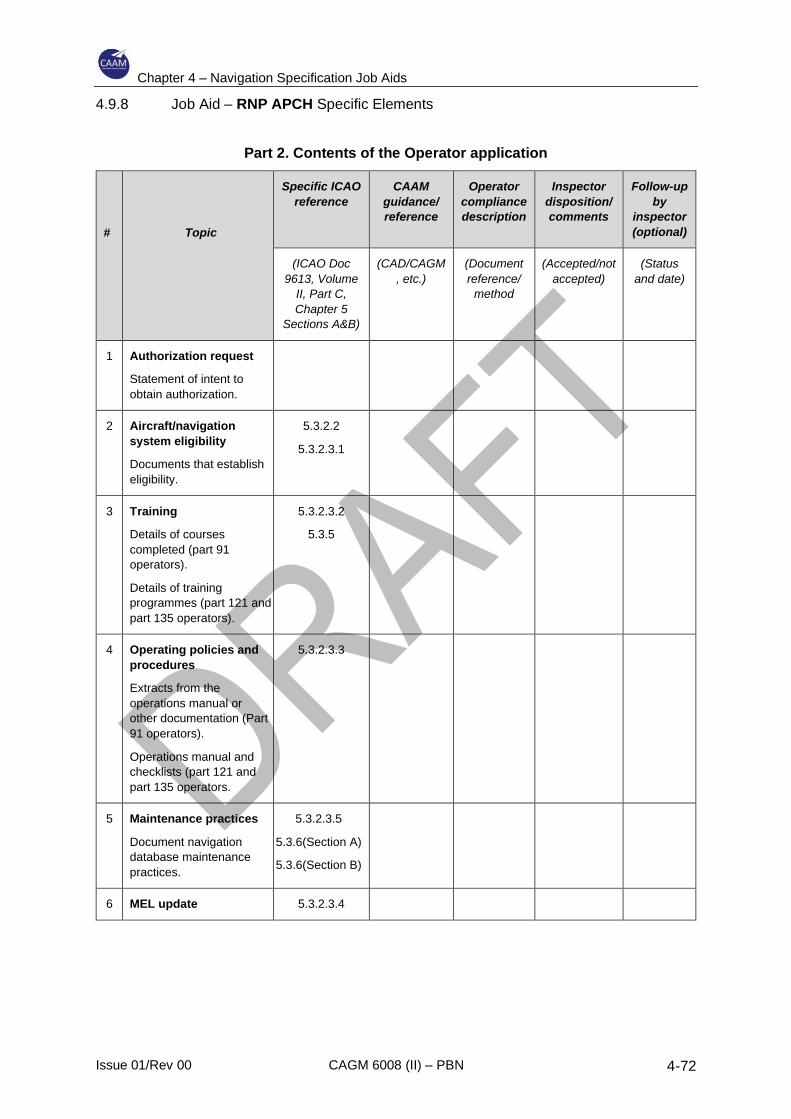
Chapter 4 – Navigation Specification Job Aids
Issue 01/Rev 00 CAGM 6008 (II) – PBN 4-72
4.9.8 Job Aid – RNP APCH Specific Elements
Part 2. Contents of the Operator application
#
Topic
Specific ICAO
reference
CAAM
guidance/
reference
Operator
compliance
description
Inspector
disposition/
comments
Follow-up
by
inspector
(optional)
(ICAO Doc
9613, Volume
II, Part C,
Chapter 5
Sections A&B)
(CAD/CAGM
, etc.)
(Document
reference/
method
(Accepted/not
accepted)
(Status
and date)
1 Authorization request
Statement of intent to
obtain authorization.
2 Aircraft/navigation
system eligibility
Documents that establish
eligibility.
5.3.2.2
5.3.2.3.1
3 Training
Details of courses
completed (part 91
operators).
Details of training
programmes (part 121 and
part 135 operators).
5.3.2.3.2
5.3.5
4 Operating policies and
procedures
Extracts from the
operations manual or
other documentation (Part
91 operators).
Operations manual and
checklists (part 121 and
part 135 operators.
5.3.2.3.3
5 Maintenance practices
Document navigation
database maintenance
practices.
5.3.2.3.5
5.3.6(Section A)
5.3.6(Section B)
6 MEL update 5.3.2.3.4
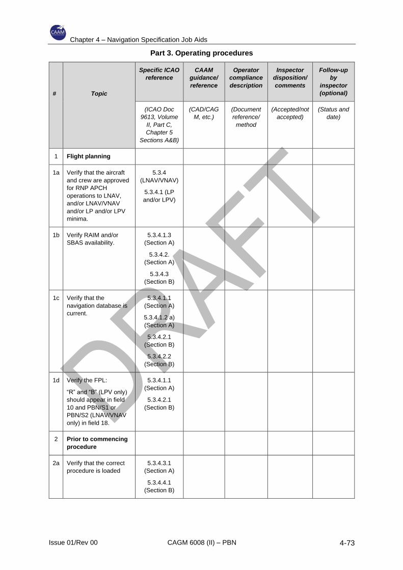
Chapter 4 – Navigation Specification Job Aids
Issue 01/Rev 00 CAGM 6008 (II) – PBN 4-73
Part 3. Operating procedures
#
Topic
Specific ICAO
reference
CAAM
guidance/
reference
Operator
compliance
description
Inspector
disposition/
comments
Follow-up
by
inspector
(optional)
(ICAO Doc
9613, Volume
II, Part C,
Chapter 5
Sections A&B)
(CAD/CAG
M, etc.)
(Document
reference/
method
(Accepted/not
accepted)
(Status and
date)
1 Flight planning
1a Verify that the aircraft
and crew are approved
for RNP APCH
operations to LNAV,
and/or LNAV/VNAV
and/or LP and/or LPV
minima.
5.3.4
(LNAV/VNAV)
5.3.4.1 (LP
and/or LPV)
1b Verify RAIM and/or
SBAS availability.
5.3.4.1.3
(Section A)
5.3.4.2.
(Section A)
5.3.4.3
(Section B)
1c Verify that the
navigation database is
current.
5.3.4.1.1
(Section A)
5.3.4.1.2 a)
(Section A)
5.3.4.2.1
(Section B)
5.3.4.2.2
(Section B)
1d Verify the FPL:
“R” and “B” (LPV only)
should appear in field
10 and PBN/S1 or
PBN/S2 (LNAV/VNAV
only) in field 18.
5.3.4.1.1
(Section A)
5.3.4.2.1
(Section B)
2 Prior to commencing
procedure
2a Verify that the correct
procedure is loaded
5.3.4.3.1
(Section A)
5.3.4.4.1
(Section B)
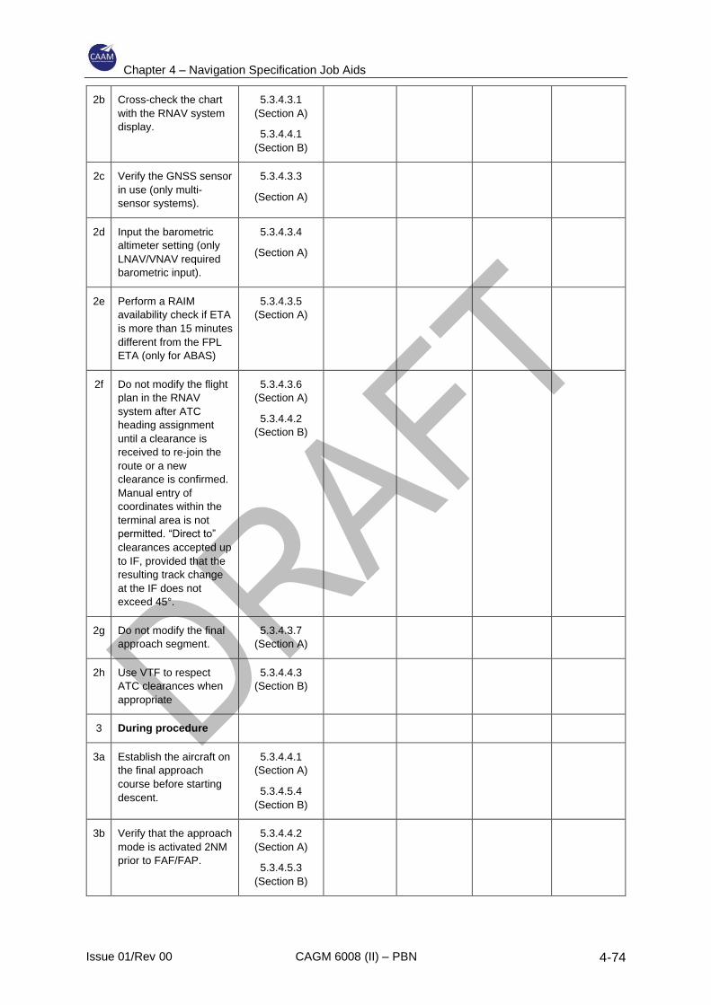
Chapter 4 – Navigation Specification Job Aids
Issue 01/Rev 00 CAGM 6008 (II) – PBN 4-74
2b Cross-check the chart
with the RNAV system
display.
5.3.4.3.1
(Section A)
5.3.4.4.1
(Section B)
2c Verify the GNSS sensor
in use (only multi-
sensor systems).
5.3.4.3.3
(Section A)
2d Input the barometric
altimeter setting (only
LNAV/VNAV required
barometric input).
5.3.4.3.4
(Section A)
2e Perform a RAIM
availability check if ETA
is more than 15 minutes
different from the FPL
ETA (only for ABAS)
5.3.4.3.5
(Section A)
2f Do not modify the flight
plan in the RNAV
system after ATC
heading assignment
until a clearance is
received to re-join the
route or a new
clearance is confirmed.
Manual entry of
coordinates within the
terminal area is not
permitted. “Direct to”
clearances accepted up
to IF, provided that the
resulting track change
at the IF does not
exceed 45°.
5.3.4.3.6
(Section A)
5.3.4.4.2
(Section B)
2g Do not modify the final
approach segment.
5.3.4.3.7
(Section A)
2h Use VTF to respect
ATC clearances when
appropriate
5.3.4.4.3
(Section B)
3 During procedure
3a Establish the aircraft on
the final approach
course before starting
descent.
5.3.4.4.1
(Section A)
5.3.4.5.4
(Section B)
3b Verify that the approach
mode is activated 2NM
prior to FAF/FAP.
5.3.4.4.2
(Section A)
5.3.4.5.3
(Section B)
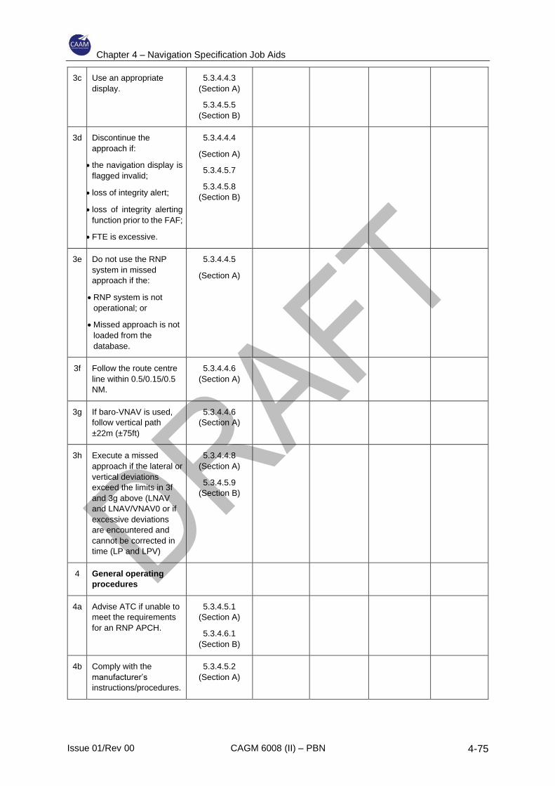
Chapter 4 – Navigation Specification Job Aids
Issue 01/Rev 00 CAGM 6008 (II) – PBN 4-75
3c Use an appropriate
display.
5.3.4.4.3
(Section A)
5.3.4.5.5
(Section B)
3d Discontinue the
approach if:
• the navigation display is
flagged invalid;
• loss of integrity alert;
• loss of integrity alerting
function prior to the FAF;
• FTE is excessive.
5.3.4.4.4
(Section A)
5.3.4.5.7
5.3.4.5.8
(Section B)
3e Do not use the RNP
system in missed
approach if the:
• RNP system is not
operational; or
• Missed approach is not
loaded from the
database.
5.3.4.4.5
(Section A)
3f Follow the route centre
line within 0.5/0.15/0.5
NM.
5.3.4.4.6
(Section A)
3g If baro-VNAV is used,
follow vertical path
±22m (±75ft)
5.3.4.4.6
(Section A)
3h Execute a missed
approach if the lateral or
vertical deviations
exceed the limits in 3f
and 3g above (LNAV
and LNAV/VNAV0 or if
excessive deviations
are encountered and
cannot be corrected in
time (LP and LPV)
5.3.4.4.8
(Section A)
5.3.4.5.9
(Section B)
4 General operating
procedures
4a Advise ATC if unable to
meet the requirements
for an RNP APCH.
5.3.4.5.1
(Section A)
5.3.4.6.1
(Section B)
4b Comply with the
manufacturer’s
instructions/procedures.
5.3.4.5.2
(Section A)

Chapter 4 – Navigation Specification Job Aids
Issue 01/Rev 00 CAGM 6008 (II) – PBN 4-76
4c If the missed approach
is based on
conventional means,
appropriate navigation
equipment must be
installed and
serviceable.
5.3.4.5.3
(Section A)
5.3.4.6.3
(Section B)
4d Use FD or AP if
available
5.3.4.5.4
(Section A)
5.3.4.6.4
(Section B)
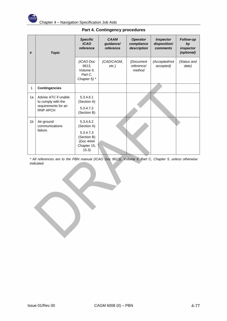
Chapter 4 – Navigation Specification Job Aids
Issue 01/Rev 00 CAGM 6008 (II) – PBN 4-77
Part 4. Contingency procedures
#
Topic
Specific
ICAO
reference
CAAM
guidance/
reference
Operator
compliance
description
Inspector
disposition/
comments
Follow-up
by
inspector
(optional)
(ICAO Doc
9613,
Volume II,
Part C,
Chapter 5) *
(CAD/CAGM,
etc.)
(Document
reference/
method
(Accepted/not
accepted)
(Status and
date)
1 Contingencies
1a Advise ATC if unable
to comply with the
requirements for an
RNP APCH
5.3.4.6.1
(Section A)
5.3.4.7.2
(Section B)
1b Air-ground
communications
failure.
5.3.4.6.2
(Section A)
5.3.4.7.3
(Section B)
(Doc 4444
Chapter 15,
15.3)
* All references are to the PBN manual (ICAO Doc 9613), Volume II, Part C, Chapter 5, unless otherwise
indicated.
Chapter 4 – Navigation Specification Job Aids
Issue 01/Rev 00 CAGM 6008 (II) – PBN 4-78
4.10 RNP 0.3
4.10.1 General
RNP 0.3 is primarily intended to support helicopter operations – en-route, arrivals,
departures and approaches. However, it does not exclude fixed wing operations
where the demonstrated performance is sufficient to meet the functional and
accuracy requirements for all phases of flight.
4.10.2 System requirements
4.10.2.1 The following systems meet the accuracy, integrity and continuity requirements
of these criteria;
a) Aircraft with E/TSO-C145a and the requirements of E/TSO-C115B FMS,
installed for IFR use in accordance with FAA AC 20-130A;
b) Aircraft with E/TSO-C146a equipment installed for IFR use in accordance
with FAA AC 20-138 or AC 20-138A; and
c) Aircraft with RNP 0.3 capability certified or approved to equivalent
standards (e.g. TSO-C193).
4.10.2.2 General
4.10.2.2.1 On-board performance monitoring and alerting is required. This section
provides the criteria for a TSE form of performance monitoring and alerting
that will ensure a consistent evaluation and assessment of compliance for
RNP 0.3 applications.
4.10.2.2.2 The aircraft navigation system, or aircraft navigation system and the pilot in
combination, is required to monitor the TSE, and to provide an alert if the
accuracy requirement is not met or if the probability that the lateral TSE
exceeds two times the accuracy value is larger than 10–5. To the extent
operational procedures are used to satisfy this requirement, the crew
procedure, equipment characteristics, and installation should be evaluated
for their effectiveness and equivalence. Examples of information provided to
the pilot for awareness of navigation system performance include “EPU”,
“ACTUAL”, “ANP” and “EPE”. Examples of indications and alerts provided
when the operational requirement is or can be determined as not being met
include “UNABLE RNP”, “Nav Accur Downgrade”, GNSS alert limit, loss of
GNSS integrity, TSE monitoring (real time monitoring of NSE and FTE
combined), etc. The navigation system is not required to provide both
performance and sensor-based alerts, e.g. if a TSE based alert is provided,
a GNSS alert may not be necessary.
4.10.2.3 On-board performance monitoring and alerting
4.10.2.3.1 Accuracy: During operations in airspace or on ATS routes designated as
RNP 0.3, the lateral TSE must be within ±0.3 NM for at least 95% of the total
Chapter 4 – Navigation Specification Job Aids
Issue 01/Rev 00 CAGM 6008 (II) – PBN 4-79
flight time. The along-track error must also be within ±0.3 NM for at least
95% of the total flight time. To meet this performance requirement, an FTE
of 0.25 NM (95%) may be assumed.
Note.— For all RNP 0.3 operations, the use of a coupled FGS is an
acceptable means of complying with this FTE assumption (see RTCA DO-
208, Appendix E, Table 1). Any alternative means of FTE bounding, other
than coupled FGS, may require FTE substantiation through an airworthiness
demonstration.
4.10.2.3.2 Integrity: Malfunction of the aircraft navigation equipment is classified as a
Major failure condition under airworthiness regulations (i.e. 1×10⁻⁵ per hour).
4.10.2.3.3 Continuity: For the purpose of this specification, loss of function is a major
failure condition for remote continental and offshore operations. The carriage
of dual independent long-range navigation systems may satisfy the
continuity requirement. Loss of function is classified as a minor failure
condition for other RNP 0.3 operations if the operator can revert to a different
available navigation system and proceed to a suitable airport.
4.10.2.3.4 SIS: The aircraft navigation equipment shall provide an alert if the probability
of SIS errors causing a lateral position error greater than 0.6 NM exceeds 1
× 10–7 per hour.
4.10.2.4 Bounding FTE for equipment not monitoring TSE performance.
4.10.2.4.1 RNP 0.3 operations require coupled FGS to meet the allowable FTE bound
unless the manufacturer demonstrates and obtains airworthiness approval
for an alternate means of meeting the FTE bound. The following may be
considered as one operational means to monitor the FGS FTE.
a) FTE should remain within half-scale deflection (unless there is other
substantiated FTE data);
b) Pilots must manually set systems without automatic CDI scaling to not
greater than 0.3 NM full-scale prior to commencing RNP 0.3 operations;
and
c) Aircraft with electronic map display, or another alternate means of flight
path deviation display, must select appropriate scaling for monitoring
FTE.
4.10.2.4.2 Automatic monitoring of FTE is not required if the necessary monitoring can
be achieved by the pilot using available displays without excessive workload
in all phases of flight. To the extent that compliance with this specification is
achieved through operational procedures to monitor FTE, an evaluation of
the pilot procedures, equipment characteristics, and installation must ensure
their effectiveness and equivalence, as described in the functional
requirements and operating procedures.
Chapter 4 – Navigation Specification Job Aids
Issue 01/Rev 00 CAGM 6008 (II) – PBN 4-80
4.10.2.4.3 PDE is considered negligible if the quality assurance process is applied at
the navigation database level and if operating procedures are applied.
4.10.2.5 Functional requirements
The following navigation displays and functions (installed per AC 20-130A and
AC 20-138A or equivalent airworthiness installation advisory material) are
required.
Paragraph Functional requirement Explanation
a) Navigation data, including a failure indicator, must be displayed on a lateral deviation display (CDI, EHSI) and/or a navigation map display. These must be used as primary flight instruments for the navigation of the aircraft, for manoeuvre anticipation and for failure/status/integrity indication.
Non-numeric lateral deviation display (e.g. CDI, EHSI), with a to/from indication and a failure annunciation, for use as primary flight instruments for navigation of the aircraft, for manoeuvre anticipation, and for failure/status/integrity indication, with the following six attributes: 1) The capability to continuously display to
the pilot flying, on the primary flight instruments for navigation of the aircraft (primary navigation display), the computed path and aircraft position relative to the path. For operations where the required minimum flight crew is two pilots, the means for the pilot not flying to verify the desired path and the aircraft position relative to the path must also be provided.
2) Each display must be visible to the pilot and located in the primary field of view (±15° from the pilot’s normal line of sight) when looking forward along the flight path.
3) The lateral deviation display scaling should agree with any implemented alerting and annunciation limits.
4) The lateral deviation display must also have a full-scale deflection suitable for the current phase of flight and must be based on the required track-keeping accuracy.
5) The display scaling may be set automatically by default logic: automatically to a value obtained from a navigation database, or manually by pilot procedures. The full-scale deflection value must be known or must be available for display to the pilot commensurate with the required track-keeping accuracy.
6) The lateral deviation display must be automatically slaved to the computed path. The course selector of the deviation display should be automatically slewed to the computed path.
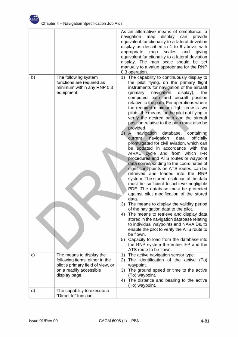
Chapter 4 – Navigation Specification Job Aids
Issue 01/Rev 00 CAGM 6008 (II) – PBN 4-81
As an alternative means of compliance, a navigation map display can provide equivalent functionality to a lateral deviation display as described in 1 to 6 above, with appropriate map scales and giving equivalent functionality to a lateral deviation display. The map scale should be set manually to a value appropriate for the RNP 0.3 operation.
b) The following system functions are required as minimum within any RNP 0.3 equipment.
1) The capability to continuously display to the pilot flying, on the primary flight instruments for navigation of the aircraft (primary navigation display), the computed path and aircraft position relative to the path. For operations where the required minimum flight crew is two pilots, the means for the pilot not flying to verify the desired path and the aircraft position relative to the path must also be provided.
2) A navigation database, containing current navigation data officially promulgated for civil aviation, which can be updated in accordance with the AIRAC cycle and from which IFR procedures and ATS routes or waypoint data corresponding to the coordinates of significant points on ATS routes, can be retrieved and loaded into the RNP system. The stored resolution of the data must be sufficient to achieve negligible PDE. The database must be protected against pilot modification of the stored data.
3) The means to display the validity period of the navigation data to the pilot.
4) The means to retrieve and display data stored in the navigation database relating to individual waypoints and NAVAIDs, to enable the pilot to verify the ATS route to be flown.
5) Capacity to load from the database into the RNP system the entire IFP and the ATS route to be flown.
c) The means to display the following items, either in the pilot’s primary field of view, or on a readily accessible display page.
1) The active navigation sensor type. 2) The identification of the active (To)
waypoint. 3) The ground speed or time to the active
(To) waypoint. 4) The distance and bearing to the active
(To) waypoint.
d) The capability to execute a “Direct to” function.
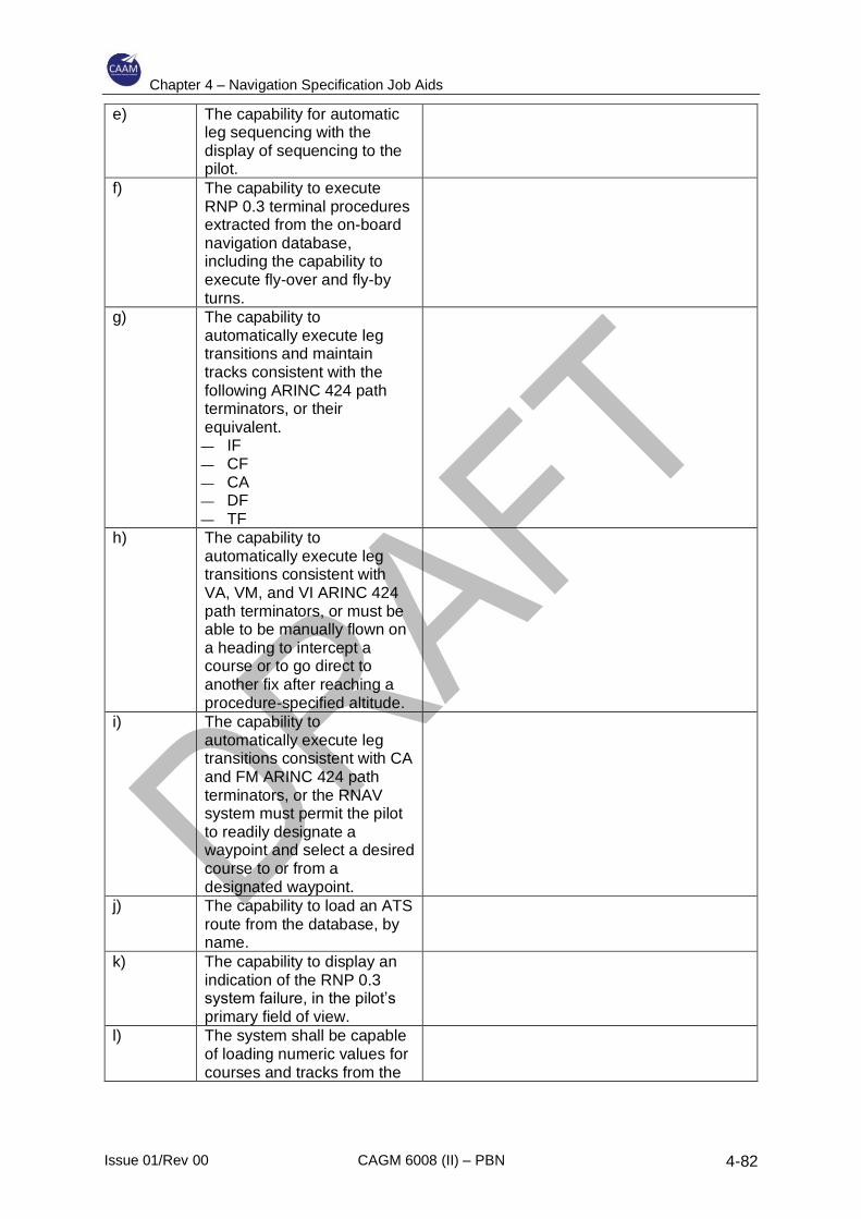
Chapter 4 – Navigation Specification Job Aids
Issue 01/Rev 00 CAGM 6008 (II) – PBN 4-82
e) The capability for automatic leg sequencing with the display of sequencing to the pilot.
f) The capability to execute RNP 0.3 terminal procedures extracted from the on-board navigation database, including the capability to execute fly-over and fly-by turns.
g) The capability to automatically execute leg transitions and maintain tracks consistent with the following ARINC 424 path terminators, or their equivalent. — IF — CF — CA — DF — TF
h) The capability to automatically execute leg transitions consistent with VA, VM, and VI ARINC 424 path terminators, or must be able to be manually flown on a heading to intercept a course or to go direct to another fix after reaching a procedure-specified altitude.
i) The capability to automatically execute leg transitions consistent with CA and FM ARINC 424 path terminators, or the RNAV system must permit the pilot to readily designate a waypoint and select a desired course to or from a designated waypoint.
j) The capability to load an ATS route from the database, by name.
k) The capability to display an indication of the RNP 0.3 system failure, in the pilot’s primary field of view.
l) The system shall be capable of loading numeric values for courses and tracks from the
Chapter 4 – Navigation Specification Job Aids
Issue 01/Rev 00 CAGM 6008 (II) – PBN 4-83
on-board navigation database.
4.10.3 Operating procedures
4.10.3.1 Airworthiness certification and recognition of RNP 0.3 aircraft qualification
alone does not authorize RNP 0.3 operations. Operational approval is also
required to confirm the adequacy of the operator’s normal and contingency
procedures for the particular equipment installation applied to an RNP 0.3
operation.
4.10.3.2 Pre-flight planning
Operators and pilots intending to conduct operations on RNP 0.3 ATS routes,
including SIDs and STARs, initial and intermediate approach, should file the
appropriate flight plan suffixes. The on-board navigation data must be current
and include appropriate procedures.
Note.— Navigation databases are expected to be current for the duration of the
flight. If the AIRAC cycle is due to change during flight, operators and pilots
should establish procedures to ensure the accuracy of navigation data,
including suitability of navigation facilities used to define the ATS routes.
4.10.3.3 RNP 0.3 availability prediction
4.10.3.3.1 RAIM prediction is not required where the equipment uses SBAS
augmentation and the planned operations are within the service volume of
the SBAS system. In areas and regions where SBAS is not usable or
available, RAIM availability for the intended route should be checked prior to
flight. Operators can verify the availability of RAIM to support RNP 0.3
operations via NOTAMs (where available) or through GNSS prediction
services. The operating authority may provide specific guidance on how to
comply with this requirement. Operators should be familiar with the
prediction information available for the intended ATS route. RAIM availability
prediction should take into account the latest GNSS constellation NOTAMs
and avionics model (when available). The ANSP, avionics manufacturer, or
the RNP system may provide this service. In the event of a predicted,
continuous loss of RNP 0.3 of more than 5 minutes for any part of the RNP
0.3 operation, the flight planning should be revised (e.g. delaying the
departure or planning a different ATS route). If the prediction service is
temporarily unavailable, ANSPs may still allow RNP 0.3 operations to be
conducted.
4.10.3.3.2 RAIM availability prediction software does not guarantee the availability of
GNSS. Rather, prediction tools simply assess the expected capability to
meet the RNP. Because of potential unplanned failures of some GNSS
elements, pilots/ANSPs must consider the loss of RAIM (or GNSS
navigation altogether) while airborne may require reversion to an alternative
Chapter 4 – Navigation Specification Job Aids
Issue 01/Rev 00 CAGM 6008 (II) – PBN 4-84
means of navigation. Therefore, pilots should assess their capability to
navigate in case of failure of GNSS navigation and consider the actions
necessary to successfully divert to an alternate destination.
4.10.3.4 General operating procedures
4.10.3.4.1 The pilot must comply with any instructions or procedures the manufacturer
identifies necessary to comply with the performance requirements in this
chapter.
Note.— Pilots are expected to adhere to all AFM/RFM limitations or
operating procedures required to maintain RNP 0.3 performance for the ATS
route. This shall include any speed restrictions needed to ensure
maintenance of RNP 0.3 navigation accuracy.
4.10.3.4.2 Operators and pilots should not request or file RNP 0.3 procedures unless
they satisfy all the criteria in the relevant CADs and documents. If an aircraft
not meeting these criteria receives a clearance from ATC to conduct an RNP
0.3 operation, the pilot must advise ATC that he/she is unable to accept the
clearance and must request alternate instructions.
4.10.3.4.3 The operator must confirm the availability of GNSS for the period of intended
operations along the intended ATS route using all available information and
the availability of NAVAID infrastructure required for any (non-RNAV)
contingencies.
4.10.3.4.4 At system initialization, the pilot must confirm the navigation database is
current and verify that initial position of the aircraft is entered correctly. The
pilot must also verify proper entry of their desired ATS route and any ATC
changes to that ATS route upon initial clearance and any subsequent
change of ATS route. The pilot must ensure the waypoints sequence
depicted by their navigation system matches the ATS route depicted on the
appropriate chart(s) and their assigned ATS route.
Note.— The pilot may notice a slight difference between the navigation
information portrayed on the chart and their primary navigation display.
Differences of 3° or less may result from the equipment manufacturer’s
application of magnetic variation and are operationally acceptable.
4.10.3.4.5 The pilot must not attempt to fly an RNP 0.3 Instrument Flight Procedure
unless it is retrievable by name from the on-board navigation database and
conforms to the charted procedure. However, the pilot may subsequently
modify a procedure by inserting or deleting specific waypoints in response
to ATC clearances. The pilot may select the ATS route to be flown for the
en-route section of the flight from the database or may construct the ATS
route by means of selection of individual en-route waypoints from the
database. The manual entry or creation of new waypoints, by manual entry
of latitude and longitude or rho/theta values is not permitted. Additionally,
Chapter 4 – Navigation Specification Job Aids
Issue 01/Rev 00 CAGM 6008 (II) – PBN 4-85
pilots must not change any SID or STAR database waypoint type from a fly-
by to a fly-over or vice versa.
4.10.3.4.6 The pilot should cross-check the flight plan clearance by comparing charts
or other applicable resources with the navigation system textual display and
the aircraft/rotorcraft map display, if applicable. If required, the pilot should
also confirm exclusion of specific NAVAIDs in compliance with NOTAMs or
other pilot procedures.
4.10.3.4.7 There is no pilot requirement to cross-check the navigation system’s
performance with conventional NAVAIDs as the absence of an integrity alert
is considered sufficient to meet the integrity requirements. However, the pilot
should monitor the reasonableness of the navigation solution and report any
loss of RNP 0.3 capability to ATC. In addition, the pilot must continuously
monitor the lateral deviation indicator (or equivalent navigation map display)
during all RNP 0.3 operations.
4.10.3.4.8 The pilot is expected to maintain centre line, as depicted by on-board lateral
deviation indicators, during all RNP operations unless authorized to deviate
by ATC or under emergency conditions. For normal operations on straight
segments or FRTs, cross-track error/deviation (the difference between the
RNP system computed path and the aircraft position relative to the path)
should be limited to ±½ the navigation accuracy associated with the
procedure (0.15 NM). Brief deviations from this standard (e.g., overshoots
or undershoots) during track changes (fly-by and fly-over turns), up to a
maximum of one times the navigation accuracy (i.e., 0.3 NM for RNP 0.3),
are allowable.
Note.— Some systems do not display or compute a path during track
changes (fly-by and fly-over turns). As such, the pilots of these aircraft may
not be able to adhere to the lateral navigation accuracy requirement (e.g.
0.15 NM) during these turns. However, the pilot is expected to satisfy the
operational requirement during intercepts following turns and on straight
segments.
4.10.3.4.9 If ATC issues a heading assignment taking the aircraft/rotorcraft off an ATS
route, the pilot should not modify the flight plan in the RNAV system until
receiving a new ATC clearance to re-join the ATS route or the controller
confirms a new ATS route clearance. When the aircraft is following an ATC
heading assignment, the specified accuracy requirement does not apply.
4.10.3.4.10 Manually selecting aircraft bank limiting functions may reduce the aircraft’s
ability to maintain its desired track and is not recommended. The pilot should
recognize manually selectable aircraft bank-limiting functions might reduce
their ability to satisfy path requirements of the procedure, especially when
executing large angle turns. This should not be construed as a requirement
to deviate from flight manual procedures; rather, pilots should be
Chapter 4 – Navigation Specification Job Aids
Issue 01/Rev 00 CAGM 6008 (II) – PBN 4-86
encouraged to avoid the selection of such functions except where needed
for flight safety reasons.
4.10.3.5 Aircraft/rotorcraft with RNP selection capability
The pilot of an aircraft/rotorcraft with a manual RNP input selection capability
should select RNP 0.3 for all RNP 0.3 ATS routes.
4.10.3.6 RNP 0.3 SID specific requirements
4.10.3.6.1 Prior to commencing take-off, the pilot must verify the aircraft RNP system
is available, operating correctly, and the correct airport/heliport and
departure data are loaded and properly depicted (including the aircraft’s
initial position). A pilot assigned an RNP 0.3 departure procedure and
subsequently issued a change to the procedure or a transition from the
procedure must verify that the appropriate changes are entered and
available for navigation prior to take-off. A final check of proper departure
entry and correct route depiction, shortly before take-off, is recommended.
Note.— As a minimum, the arrival checks can be a simple inspection of a
suitable map display that achieves the objectives of this paragraph.
4.10.3.6.2 The creation of new waypoints by manual entry into the RNP 0.3 system by
the pilot would not create a valid ATS route and is unacceptable at all times.
4.10.3.6.3 Where the contingency procedures require reversion to a conventional IFP,
the pilot must complete all necessary preparation for such reversion (e.g.
manual selection of NAVAID) before commencing any portion of the IFP.
4.10.3.6.4 Procedure modifications in the terminal area may take the form of ATC-
assigned radar headings or “direct to” clearances, and the pilot must be
capable of reacting in a timely fashion. This may include a requirement for
the pilot to insert tactical waypoints loaded from the on-board navigation
database. The pilot must not make manual entries or modify and create
temporary waypoints or fixes that are not provided in the on-board navigation
database.
4.10.3.6.5 The pilot must verify their aircraft navigation system is operating correctly,
and the correct arrival procedure (including any applicable transition) is
entered and properly depicted. Although a particular method is not
mandated, the pilot must adhere to any published altitude and speed
constraints associated with an RNP 0.3 operation.
4.10.3.7 Contingency procedures
The pilot must notify ATC of any loss of the RNP 0.3 capability (integrity alerts
or loss of navigation) together with the proposed course of action. If unable to
comply with the requirements of an RNP 0.3 ATS route for any reason, the pilot
must advise ATC as soon as possible. The loss of RNP 0.3 capability includes
any failure or event causing the aircraft to no longer satisfy the RNP 0.3
Chapter 4 – Navigation Specification Job Aids
Issue 01/Rev 00 CAGM 6008 (II) – PBN 4-87
requirements of the desired ATS route. In the event of communications failure,
the pilot should continue with the published lost communications procedure.
4.10.4 Pilot knowledge and training
The training programme should provide sufficient training (e.g. simulator, training
device, or aircraft) on the aircraft RNP system to the extent that the pilot is familiar
with the following:
a) The information in this chapter;
b) The meaning and proper use of aircraft/helicopter equipment/navigation
suffixes;
c) Procedure characteristics as determined from chart depiction and textual
description;
d) Depiction of waypoint types (fly-over and fly-by) and path terminators as well
as associated aircraft/helicopter flight paths;
e) Required navigation equipment and MEL for operation on RNP 0.3 ATS
routes;
f) RNP system-specific information:
1) Levels of automation, mode annunciations, changes, alerts, interactions,
reversions, and degradation;
2) Functional integration with other aircraft systems;
3) The meaning and appropriateness of route discontinuities as well as
related flight crew procedures;
4) Pilot procedures consistent with the operation (e.g. monitor PROG or
LEGS page);
5) Types of navigation sensors utilized by the RNP system and associated
system prioritization/weighting/logic/limitations;
6) Turn anticipation with consideration for airspeed and altitude effects;
7) Interpretation of electronic displays and symbols used to conduct an RNP
0.3 operation; and
8) Understanding of the aircraft configuration and operational conditions
required to support RNP 0.3 operations (i.e. appropriate selection of CDI
scaling/lateral deviation display scaling);
g) RNP equipment operating procedures, as applicable, including how to
perform the following actions:
1) Verifying currency and integrity of aircraft navigation data;
2) Verifying successful completion of RNP system self-tests;
3) Entry of and update to the aircraft navigation system initial position;
4) Retrieving and flying an IFP with appropriate transition;
5) Adhering to speed and/or altitude constraints associated with an RNP 0.3
IFP;
6) Impact of pilot selectable bank limitations on aircraft/rotorcraft ability to
achieve the required accuracy on the planned route;
Chapter 4 – Navigation Specification Job Aids
Issue 01/Rev 00 CAGM 6008 (II) – PBN 4-88
7) Selecting the appropriate STAR or SID for the active runway in use and
be familiar with flight crew procedures required to deal with a runway
change;
8) Verifying waypoint in the flight plan programming;
9) Flying direct to a waypoint;
10) Flying a course/track to a waypoint;
11) Intercepting a course/track;
12) Following vectors and re-joining an RNP ATS route from “heading” mode;
13) Determining cross-track error/deviation. More specifically, the maximum
deviations allowed to support RNP 0.3 must be understood and
respected;
14) Inserting and deleting route discontinuities;
15) Removing and reselecting navigation sensor inputs;
16) When required, confirming exclusion of a specific NAVAID or NAVAID
type;
17) Changing the arrival airport/heliport and the alternate airport;
18) Performing a parallel offset function, if the capability exists. The pilot
should know how to apply offsets within the functionality of their particular
RNP system and the need to advise ATC if this functionality is not
available; and
19) Performing a conventional holding pattern;
h) Operator-recommended levels of automation for phase of flight and workload,
including methods to minimize cross-track error to maintain route centre line;
i) R/T phraseology for RNAV/RNP applications; and
j) Contingency procedures for RNAV/RNP failures.
Note. – Where additional training is required, this can normally be achieved by
bulletin, computer-based training or classroom briefing. Flight training is not
normally required.
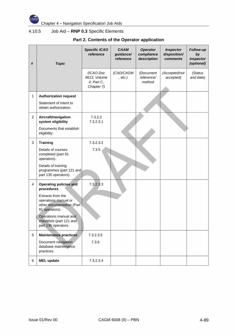
Chapter 4 – Navigation Specification Job Aids
Issue 01/Rev 00 CAGM 6008 (II) – PBN 4-89
4.10.5 Job Aid – RNP 0.3 Specific Elements
Part 2. Contents of the Operator application
#
Topic
Specific ICAO
reference
CAAM
guidance/
reference
Operator
compliance
description
Inspector
disposition/
comments
Follow-up
by
inspector
(optional)
(ICAO Doc
9613, Volume
II, Part C,
Chapter 7)
(CAD/CAGM
, etc.)
(Document
reference/
method
(Accepted/not
accepted)
(Status
and date)
1 Authorization request
Statement of intent to
obtain authorization.
2 Aircraft/navigation
system eligibility
Documents that establish
eligibility.
7.3.2.2
7.3.2.3.1
3 Training
Details of courses
completed (part 91
operators).
Details of training
programmes (part 121 and
part 135 operators).
7.3.2.3.2
7.3.5
4 Operating policies and
procedures
Extracts from the
operations manual or
other documentation (Part
91 operators).
Operations manual and
checklists (part 121 and
part 135 operators.
7.3.2.3.3
5 Maintenance practices
Document navigation
database maintenance
practices.
7.3.2.3.5
7.3.6
6 MEL update 7.3.2.3.4

Chapter 4 – Navigation Specification Job Aids
Issue 01/Rev 00 CAGM 6008 (II) – PBN 4-90
Part 3. Operating procedures
#
Topic
Specific ICAO
reference
CAAM
guidance/
reference
Operator
compliance
description
Inspector
disposition/
comments
Follow-up
by
inspector
(optional)
(ICAO Doc
9613, Volume
II, Part C,
Chapter 7)
(CAD/CAG
M, etc.)
(Document
reference/
method
(Accepted/not
accepted)
(Status and
date)
1 Flight planning
1a Verify that the aircraft
and crew are approved
for RNP 0.3 operations.
7.3.4.1
1b Verify RAIM and/or
SBAS availability.
7.3.4.3
7.3.4.4.3
1c Verify that the
navigation database is
current.
7.3.4.2
1d Verify the FPL:
“R” should appear in
field 10 and PBN/TBD
in field 18.
7.3.4.2
2 General operating
procedures
2a Comply with the
manufacturer’s
instructions/procedures.
7.3.4.4.1
2b Advise ATC if unable to
meet the requirements
for RNP 0.3.
7.3.4.4.2
2c Verify aircraft position
and entry of assigned
route.
7.3.4.4.4
2d Retrieve
SID/STAR/APP from
the database; retrieve
ATS route from
database or construct
route with waypoints
from database
7.3.4.4.5
2e Cross-check the chart
with the RNAV system
display.
7.3.4.4.6
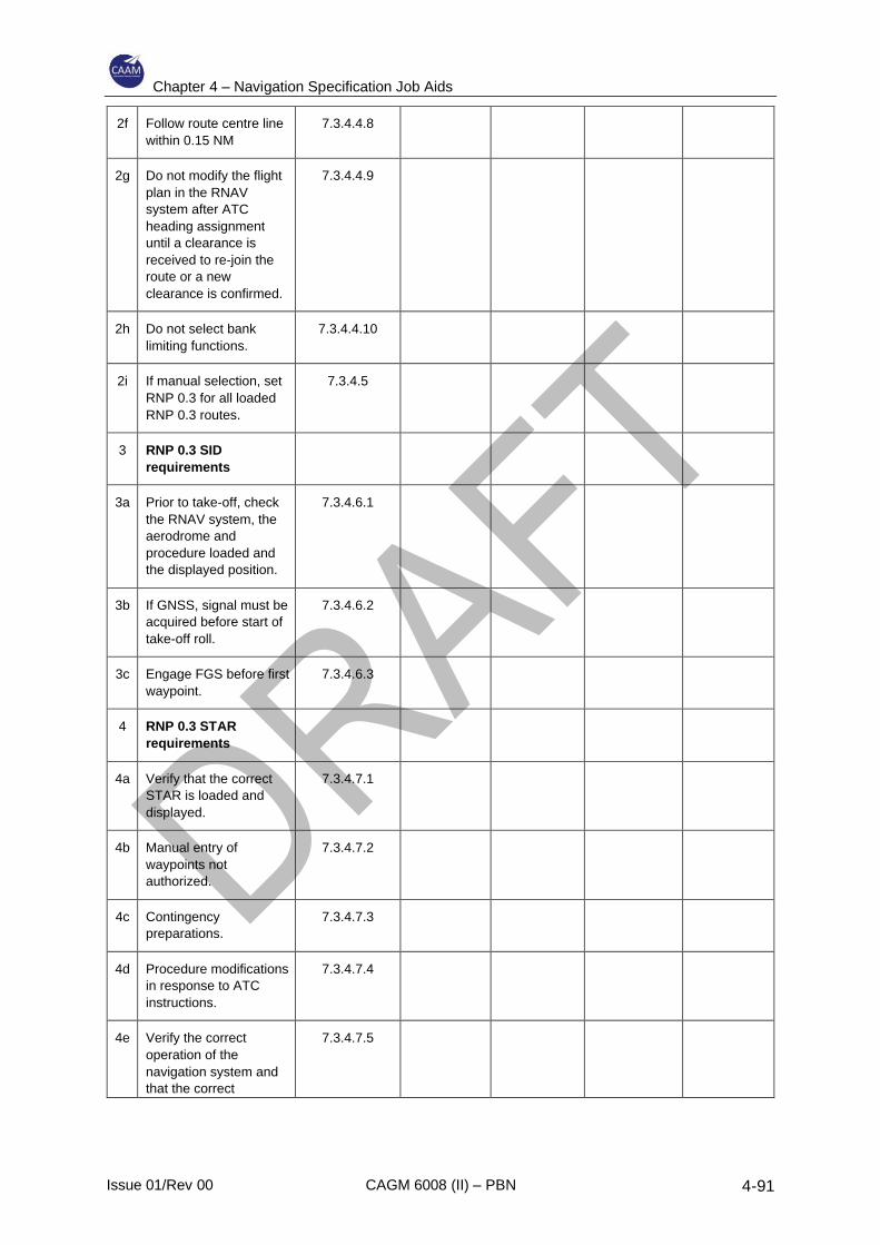
Chapter 4 – Navigation Specification Job Aids
Issue 01/Rev 00 CAGM 6008 (II) – PBN 4-91
2f Follow route centre line
within 0.15 NM
7.3.4.4.8
2g Do not modify the flight
plan in the RNAV
system after ATC
heading assignment
until a clearance is
received to re-join the
route or a new
clearance is confirmed.
7.3.4.4.9
2h Do not select bank
limiting functions.
7.3.4.4.10
2i If manual selection, set
RNP 0.3 for all loaded
RNP 0.3 routes.
7.3.4.5
3 RNP 0.3 SID
requirements
3a Prior to take-off, check
the RNAV system, the
aerodrome and
procedure loaded and
the displayed position.
7.3.4.6.1
3b If GNSS, signal must be
acquired before start of
take-off roll.
7.3.4.6.2
3c Engage FGS before first
waypoint.
7.3.4.6.3
4 RNP 0.3 STAR
requirements
4a Verify that the correct
STAR is loaded and
displayed.
7.3.4.7.1
4b Manual entry of
waypoints not
authorized.
7.3.4.7.2
4c Contingency
preparations.
7.3.4.7.3
4d Procedure modifications
in response to ATC
instructions.
7.3.4.7.4
4e Verify the correct
operation of the
navigation system and
that the correct
7.3.4.7.5
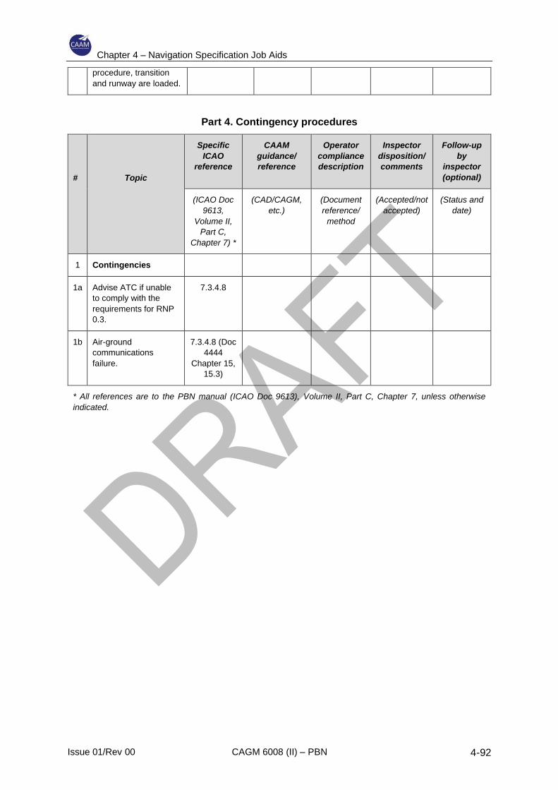
Chapter 4 – Navigation Specification Job Aids
Issue 01/Rev 00 CAGM 6008 (II) – PBN 4-92
procedure, transition
and runway are loaded.
Part 4. Contingency procedures
#
Topic
Specific
ICAO
reference
CAAM
guidance/
reference
Operator
compliance
description
Inspector
disposition/
comments
Follow-up
by
inspector
(optional)
(ICAO Doc
9613,
Volume II,
Part C,
Chapter 7) *
(CAD/CAGM,
etc.)
(Document
reference/
method
(Accepted/not
accepted)
(Status and
date)
1 Contingencies
1a Advise ATC if unable
to comply with the
requirements for RNP
0.3.
7.3.4.8
1b Air-ground
communications
failure.
7.3.4.8 (Doc
4444
Chapter 15,
15.3)
* All references are to the PBN manual (ICAO Doc 9613), Volume II, Part C, Chapter 7, unless otherwise
indicated.

Chapter 4 – Navigation Specification Job Aids
Issue 01/Rev 00 CAGM 6008 (II) – PBN 4-93
4.11 Advanced RNP (A-RNP)
4.11.1 General
A-RNP is intended to support operations in oceanic airspace and en-route
continental airspace, on SIDs, on STARs and on approaches. It is intended to
provide a single assessment of aircraft eligibility covering a range of accuracy
requirements across all phases of flight. It incorporated RNAV 5, RNAV 2, RNAV
1, RNP 2, RNP 1, and RNP APCH (A and/or B). Fixed radius turn functionality
within terminal airspace (RF) is a requirement while fixed radius turn functionalities
in the en-route (FRT) is an option. RNP scalability, time of arrival control (TOAC)
and Baro-VNAV functionalities are all optional. Higher continuity requirements are
applied for RNP 2 in oceanic/remote airspace. The navigation specification does
not specifically address the oceanic and remote applications RNAV 10 and RNP
4, and an operator would need to obtain separate approval before operating with
an A-RNP approved aircraft in such airspace. It is not anticipated that this
additional application will represent a significant burden to the operator particularly
if the aircraft already meets the RNP 2 oceanic criteria.
4.11.2 Aircraft requirements
4.11.2.1 This section describes the aircraft performance and functional criteria for
aircraft to qualify for applications requiring A-RNP. Aircraft eligible for A-RNP
operations must meet all of the requirements of this chapter. The significant
functional and performance requirements for A-RNP described herein are for
RF legs, parallel offsets, RNAV holding, and the options for scalability, higher
continuity, FRTs and TOAC.
4.11.2.2 Approved RNP AR systems are considered to meet the system performance
monitoring and alerting requirements without further examination. However,
this navigation specification contains additional functional requirements that are
not included with the RNP AR APCH navigation specification, e.g. RF, RNAV
holding, parallel offset and FRT. If such capabilities have been demonstrated
and are contained in an approved RNP AR system, documentation of
compliance may be all that is necessary. If such capabilities are added to an
RNP AR system or part of a new RNP system, they will be subject to typical
regulatory reviews, demonstrations, tests and approval.
4.11.2.3 Communications and ATS surveillance equipment must be appropriate for the
navigation application.
4.11.2.4 Some features/requirements may be required in one flight phase and optional
or unnecessary in another. No distinctions are made regarding this flight phase
association in providing a general set of criteria spanning all phases and
navigation applications. Where such differences are deemed important, or the
operational need is for one application, a more application-specific navigation
specification, e.g. RNP 1 should be used instead.
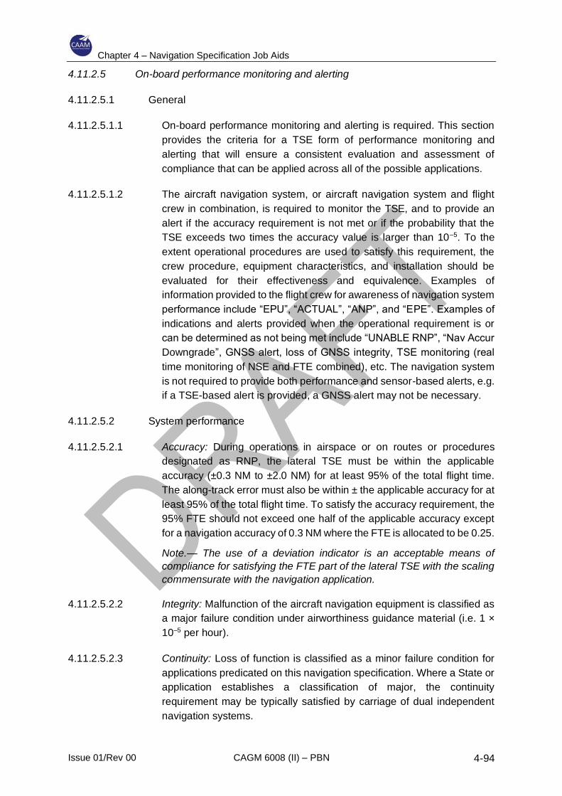
Chapter 4 – Navigation Specification Job Aids
Issue 01/Rev 00 CAGM 6008 (II) – PBN 4-94
4.11.2.5 On-board performance monitoring and alerting
4.11.2.5.1 General
4.11.2.5.1.1 On-board performance monitoring and alerting is required. This section
provides the criteria for a TSE form of performance monitoring and
alerting that will ensure a consistent evaluation and assessment of
compliance that can be applied across all of the possible applications.
4.11.2.5.1.2 The aircraft navigation system, or aircraft navigation system and flight
crew in combination, is required to monitor the TSE, and to provide an
alert if the accuracy requirement is not met or if the probability that the
TSE exceeds two times the accuracy value is larger than 10–5. To the
extent operational procedures are used to satisfy this requirement, the
crew procedure, equipment characteristics, and installation should be
evaluated for their effectiveness and equivalence. Examples of
information provided to the flight crew for awareness of navigation system
performance include “EPU”, “ACTUAL”, “ANP”, and “EPE”. Examples of
indications and alerts provided when the operational requirement is or
can be determined as not being met include “UNABLE RNP”, “Nav Accur
Downgrade”, GNSS alert, loss of GNSS integrity, TSE monitoring (real
time monitoring of NSE and FTE combined), etc. The navigation system
is not required to provide both performance and sensor-based alerts, e.g.
if a TSE-based alert is provided, a GNSS alert may not be necessary.
4.11.2.5.2 System performance
4.11.2.5.2.1 Accuracy: During operations in airspace or on routes or procedures
designated as RNP, the lateral TSE must be within the applicable
accuracy (±0.3 NM to ±2.0 NM) for at least 95% of the total flight time.
The along-track error must also be within ± the applicable accuracy for at
least 95% of the total flight time. To satisfy the accuracy requirement, the
95% FTE should not exceed one half of the applicable accuracy except
for a navigation accuracy of 0.3 NM where the FTE is allocated to be 0.25.
Note.— The use of a deviation indicator is an acceptable means of
compliance for satisfying the FTE part of the lateral TSE with the scaling
commensurate with the navigation application.
4.11.2.5.2.2 Integrity: Malfunction of the aircraft navigation equipment is classified as
a major failure condition under airworthiness guidance material (i.e. 1 ×
10–5 per hour).
4.11.2.5.2.3 Continuity: Loss of function is classified as a minor failure condition for
applications predicated on this navigation specification. Where a State or
application establishes a classification of major, the continuity
requirement may be typically satisfied by carriage of dual independent
navigation systems.
Chapter 4 – Navigation Specification Job Aids
Issue 01/Rev 00 CAGM 6008 (II) – PBN 4-95
4.11.2.5.2.4 SIS: For GNSS RNP system architectures, the aircraft navigation
equipment shall provide an alert if the probability of SIS errors causing a
lateral position error greater than two times the applicable accuracy (2 ×
RNP) exceeds 1 × 10⁻⁷ per hour.
Notes:
1. The lateral TSE includes positioning error, FTE, PDE and display error. For
procedures extracted from the on-board navigation database, PDE is considered
negligible due to the navigation database requirements, and pilot knowledge and
training.
2. For RNP systems where the architecture is an integrated, multi-sensor capability and
where GNSS integrity is incorporated into a 2 × RNP integrity alert consistent with
RTCA/EUROCAE DO-236/ED-75 when performance cannot be met, a separate
GNSS integrity alert is not required.
4.11.2.6 Criteria for specific navigation services
4.11.2.6.1 This section identifies unique issues for the navigation sensors.
4.11.2.6.2 GNSS: The sensor must comply with the guidelines in FAA AC 20-138() or
FAA AC 20-130A. For systems that comply with FAA AC 20-138(), the
following sensor accuracies can be used in the total system accuracy
analysis without additional substantiation: GNSS sensor accuracy is better
than 36 metres (95%), and augmented GNSS (GBAS or SBAS) sensor
accuracy is better than 2 metres (95%). In the event of a latent GNSS
satellite failure and marginal GNSS satellite geometry, the probability the
TSE remains within the procedure design obstacle clearance volume must
be greater than 95%.
Note.— GNSS-based sensors output a HIL, also known as a HPL (see FAA
AC 20-138() and RTCA/DO-229D for an explanation of these terms). The
HIL is a measure of the position estimation error assuming a latent failure is
present. In lieu of a detailed analysis of the effects of latent failures on the
TSE, an acceptable means of compliance for GNSS-based systems is to
ensure the HIL remains less than twice the navigation accuracy, minus the
95% of FTE, during the RNP operation.
4.11.2.6.3 IRS: An IRS must satisfy the criteria of US 14 CFR Part 121, Appendix G, or
equivalent. While Appendix G defines the requirement for a 2 NM per hour
drift rate (95%) for flights up to 10 hours, this rate may not apply to an RNP
system after loss of position updating. Systems that have demonstrated
compliance with Part 121, Appendix G, can be assumed to have an initial
drift rate of 8NM/hour for the first 30 minutes (95 minutes) without further
substantiation. Aircraft manufacturers and applicants can demonstrate
improved inertial performance in accordance with the methods described in
Appendix 1 or 2 of FAA Order 8400.12A.
Note. – Integrated GPS/INS position solutions reduce the rate of degradation
after loss of position updating. For “tightly coupled” GPS/IRUs, RTCA/DO-
229C, Appendix R, provides additional guidance.
Chapter 4 – Navigation Specification Job Aids
Issue 01/Rev 00 CAGM 6008 (II) – PBN 4-96
4.11.2.6.4 DME: For RNP procedures and routes, the RNP system may only use DME
updating when authorized by the State. The manufacturer should identify
any operating constraints (e.g. manual inhibit of DME) in order for a given
aircraft to comply with this requirement.
Notes:
1. This is in recognition of States where a DME infrastructure and capable equipped
aircraft are available, those States may establish a basis for aircraft qualification and
operational approval to enable use of DME. It is not intended to imply a requirement
for implementation of DME infrastructure or the addition of RNP capability using DME
for RNP operations.
2. This does not imply an equipment capability must exist providing a direct means of
inhibiting DME updating. A procedural means for the flight crew to inhibit DME
updating or executing a missed approach if reverting to DME updating may meet this
requirement.
4.11.2.6.5 VHF VOR station: For RNP procedures, the RNAV system must not use
VOR updating. The manufacturer should identify any operating constraints
(e.g. manual inhibit of VOR) in order for a given aircraft to comply with this
requirement.
Note.— This does not imply an equipment capability must exist providing a
direct means of inhibiting VOR updating. A procedural means for the flight
crew to inhibit VOR updating or executing a missed approach if reverting to
VOR updating may meet this requirement.
4.11.2.6.6 For multi-sensor systems, there must be automatic reversion to an alternate
RNAV sensor if the primary RNAV sensor fails. Automatic reversion from
one multi-sensor system to another multi-sensor system is not required.
4.11.2.7 Functional requirements
4.11.2.7.1 Displays – guidance, situation and status
Item Function/Feature Description
a) Continuous display of deviation. 1. The navigation system must provide the capability to continuously display to the pilot flying, on the primary flight instruments for navigation of the aircraft, the aircraft position relative to the RNP defined path.
2. For operations where the required minimum flight crew is two pilots, the means for the pilot not flying to verify the desired path and the aircraft position relative to the path must also be provided.
3. The display must allow the pilot to readily distinguish whether the cross-track deviation exceeds the navigation accuracy (or a smaller value).
Chapter 4 – Navigation Specification Job Aids
Issue 01/Rev 00 CAGM 6008 (II) – PBN 4-97
4. The numeric display of deviation on a map display with an appropriately scaled deviation indicator is generally considered acceptable for monitoring deviation.
5. Moving map displays without an appropriately scaled deviation indicator may be acceptable depending on the task, flight crew workload, display characteristics, flight crew procedures and training.
b) Identification of the active (To) waypoint.
The navigation system must provide a display identifying the active waypoint either in the pilot’s primary optimum field of view, or on a readily accessible and visible display to the flight crew.
c) Display of distance and bearing. The navigation system must provide a display of distance and bearing to the active (To) waypoint in the pilot’s primary optimum field of view. Where not viable, a readily accessible page on a control display unit, readily visible to the flight crew, may display the data.
d) Display of groundspeed and time.
The navigation system must provide the display of groundspeed and time to the active (To) waypoint in the pilot’s primary optimum field of view. Where not viable, a readily accessible page on a control display unit, readily visible to the flight crew, may display the data.
e) Desired track display. The navigation system must have the capability to continuously display to the pilot flying the aircraft desired track. This display must be on the primary flight instruments for navigation of the aircraft.
f) Display of aircraft track. The navigation system must provide a display of the actual aircraft track (or track angle error) either in the pilot’s primary optimum field of view, or on a readily accessible and visible display to the flight crew.
g) Failure annunciation. The aircraft must provide a means to annunciate failures of any aircraft component of the RNP system, including navigation sensors. The annunciation must be visible to the pilot and located in the primary optimum field of view.
h) Slaved course selector. The navigation system must provide a course selector automatically slaved to the RNP computed path.
i) Display of distance to go. The navigation system must provide the ability to display distance to go to any waypoint selected by the flight crew.
Chapter 4 – Navigation Specification Job Aids
Issue 01/Rev 00 CAGM 6008 (II) – PBN 4-98
j) Display of distance between flight plan waypoints.
The navigation system must provide the ability to display the distance between flight plan waypoints.
k) Display of deviation. The navigation system must provide a numeric display of the lateral deviation with a resolution of 0.1 NM or less.
l) Display of active sensors. The aircraft must display the current navigation sensor(s) in use. It is recommended that this display be provided in the primary optimum field of view. Note.— This display is used to support operational contingency procedures. If such a display is not provided in the primary optimum field of view, crew procedures may mitigate the need for this display if the workload is determined to be acceptable.
4.11.2.7.2 Path definition and flight planning
Item Function/Feature Description
a) Maintaining tracks and leg transitions.
The aircraft must have the capability to execute leg transitions and maintain tracks consistent with the following ARINC 424 path terminators:
ARINC 424 path terminators
IF
CF
DF
TF
RF
CA
course from an FA
VA
VM
VI
HM
Where approval is sought for FRT in association with this navigation specification, the RNP system must have the capability to create FRTs between route segments, based upon the data contained in the aircraft navigation system database. Notes: 1. Path terminators and the FRT are defined
in ARINC 424, and their application is described in more detail in RTCA/EUROCAE documents DO-236B/ED-75B and DO-201A/ED-77.
Chapter 4 – Navigation Specification Job Aids
Issue 01/Rev 00 CAGM 6008 (II) – PBN 4-99
2. The list of path terminators includes a number that introduce variability in the flight path to be flown by the aircraft. For all RNP applications, the preferred path terminators are IF, DF, TF, and RF. Other path terminators may be used on the understanding that they will introduce less repeatability, predictability and reliability of aircraft lateral path performance.
3. For the VA, VM and VI path terminators, if the aircraft is unable to automatically execute these leg transitions, they should be able to be manually flown on a heading to intercept a course or to go direct to another fix after reaching a procedure-specified altitude.
b) Leg transition. Fly-by and fly-over fixes. The aircraft must have the capability to execute fly-by and fly-over fixes. For fly-by turns, the navigation system must limit the path definition within the theoretical transition area defined in EUROCAE ED-75B/ RTCA DO-236B. The fly-over turn is not compatible with RNP flight tracks and will only be used when there is no requirement for repeatable paths. FRTs: Where approval is sought for FRTs, the aircraft must have the capability to execute the function.
c) Intercepts. The RNP system should provide the ability to intercept the final approach at or before the FAF. This functional capability must provide the pilot with the ability to re-join the published final approach track following a period when the aircraft has been flown manually, or in AFCS heading mode, following ATC vectors to support final approach sequencing. The implementation method and visual information (MCDU and primary displays (map display/EHSI)) shall be sufficient to enable the correct re-acquisition of the track with a minimum of manual intervention on the MCDU. Due account must be taken of the workload associated with the re-acquisition and the impact of errors in leg sequencing.
d) Holding. A holding procedure will only normally be required at defined holding points on entry to terminal airspace. However, holding may be required by ATC at any point. A hold shall be defined by a point, the turn direction, an inbound track and an outbound distance. This data may be extracted from
Chapter 4 – Navigation Specification Job Aids
Issue 01/Rev 00 CAGM 6008 (II) – PBN 4-100
the database for published holds or may be manually entered for ad hoc ATC holds. Note.— It is highly desirable that the RNP system provide a holding capability that includes the computation of the hold flight path, guidance and/or cues to track the holding entry and path. The system with the minimum of crew intervention must be capable of initiating, maintaining and discontinuing holding procedures at any point and at all altitudes.
e) Parallel offset Parallel offsets provide a capability to fly offset from the parent track, as defined by the series of waypoints. The turn defined for the parent track (fly-by or FRT) shall be applied in the offset track. Parallel offsets are applicable only for en-route segments and are not foreseen to be applied on SIDs, STARs or approach procedures. The activation of an offset shall be clearly displayed to the flight crew and the cross-track deviation indication during the operation of the offset will be to the offset track.
f) Offset execution The system should be capable of flying tracks offset by up to 20 NM from the parent track. The presence of an offset should be continuously indicated; Tracks offset from the parent track shall be continued for all ATS route segments and turns until either:
- Removed by the crew; or - Automatically cancelled following:
• Amendment of the active flight plan by executing a “Direct-To”;
• Commencement of a terminal procedure;
• Where a course change exceeds 90°, the RNP system may terminate the offset at the fix where the course change occurs. The offset may also be terminated if the route segment ends at a hold fix.
The flight crew shall be given advance notice of this cancellation.
Chapter 4 – Navigation Specification Job Aids
Issue 01/Rev 00 CAGM 6008 (II) – PBN 4-101
The cross-track offset distance should be manually entered into the RNP system to a resolution of 1 NM or better. Where parallel offsets are applied, the lateral track-keeping requirement of RNP must be maintained referenced to the offset track. Where FRTs are applied, the offset track must be flown with the same turn radius as the parent track.
g) Entry and recovery from offsets. Transitions to and from the offset track must maintain an intercept angle of between 30° and 45°.
h) Capability for a “direct-to” function.
The navigation system must have a “direct-to” function the flight crew can activate at any time. This function must be available to any fix. The navigation system must also be capable of generating a geodesic path to the designated “To” fix without “S-turning” and without undue delay.
i) Altitudes and/or speeds associated with published terminal procedures.
Altitudes and/or speeds associated with published terminal procedures must be extracted from the navigation database.
j) Capability to load procedures from the navigation database.
The navigation system must have the capability to load the entire procedure(s) to be flown into the RNP system from the on-board navigation database. This includes the approach (including vertical angle), the missed approach and the approach transitions for the selected airport and runway.
k) Means to retrieve and display navigation data.
The navigation system must provide the ability for the flight crew to verify the procedure to be flown through review of the data stored in the on-board navigation database. This includes the ability to review the data for individual waypoints and for NAVAIDs.
l) Magnetic variation. For paths defined by a course (e.g. CF and FA path terminators), the navigation system should use the appropriate magnetic variation value in the navigation database.
m) Changes in navigation accuracy. The RNP system should automatically retrieve and set the navigation accuracy for each leg segment of a route or procedure from the on-board navigation database. When a change occurs to a smaller navigation accuracy, e.g. from RNP 1.0 to RNP 0.3, the change must be complete by the first fix defining the leg with the smaller navigation accuracy requirement. The timing of this change must also consider any latency in alerting from the RNP system.
Chapter 4 – Navigation Specification Job Aids
Issue 01/Rev 00 CAGM 6008 (II) – PBN 4-102
When the RNP system cannot automatically set the navigation accuracy for each leg segment, any operational procedures necessary to accomplish this must be identified. Note.— One acceptable means to meet this requirement may be to require the flight crew to manually set the smallest navigation accuracy the route or procedure uses before commencing the route or procedure (i.e. prior to the ÍAF). If the navigation accuracy for the RNP system has been set manually by the flight crew and following an RNP system change to the navigation accuracy required (e.g. the next flight path segment contains a different navigation accuracy), the RNP system should provide an alert to the flight crew.
n) Automatic leg sequencing. The navigation system must provide the capability to automatically sequence to the next leg and display the sequencing to the flight crew in a readily visible manner.
4.11.2.7.3 System
Item Function/Feature Description
a) Design assurance The system design assurance must be consistent with at least a major failure condition for the display of misleading lateral or vertical guidance in RNP applications.
b) Navigation database. The aircraft navigation system must use an on-board navigation database, containing current navigation data officially promulgated for civil aviation, which can be updated in accordance with the AIRAC cycle; and allow retrieval and loading of procedures into the RNP system. The stored resolution of the data must be sufficient to achieve negligible PDE. The on-board navigation database must be protected against flight crew modification of the stored data. When a procedure is loaded from the database, the RNP system must fly the procedure as published. This does not preclude the flight crew from having the means to modify a procedure or route already loaded into the RNP system. However, the procedures stored in the navigation database must not be modified and must remain intact
Chapter 4 – Navigation Specification Job Aids
Issue 01/Rev 00 CAGM 6008 (II) – PBN 4-103
within the navigation database for future use and reference. The aircraft must provide a means to display the validity period for the on-board navigation database to the flight crew. The equipment should not permit the flight crew to either manually or automatically select a route that is not supported. A route is not supported if it incorporates an FRT and the equipment does not provide FRT capability. The RNP system should also restrict pilot access to routes requiring FRTs if the equipment can support the route, but the aircraft is not otherwise equipped (e.g. the aircraft does not have the required roll steering autopilot or flight director installed). Note. – An alternate means of satisfying this requirement is to remove such routes from the navigation database.
4.11.2.7.4 Optional capability
Item Function/Feature Description
a) RNP scalability The RNP system must be capable of manual or automatic entry and display of navigation accuracy requirements in tenths of NM between 0.3 and 1.0 NM. The RNP system must provide lateral deviation displays and alerting appropriate to the selected navigation accuracy and application. Notes: 1. One means by which this can be achieved
is as described in RTCA MOPS DO-283A. Another means is to develop lateral deviation displays and alerting as per RTCA/EUROCAE MASPS DO-236B/ED-75B.
2. It is recognized that aircraft and equipment that are based upon GNSS standards such as RTCA DO-208() and DO-229() have RNP capabilities for lateral deviation and alerting that are generally associated with navigation accuracies of 0.3, 1.0, and 2.0 NM only. Such capability exists in a large portion of the aircraft fleet but may not be extended to other navigation accuracies or the means of compliance specified herein. Additionally, some of this fleet does provide the capability to select other navigation accuracies. Therefore, before a manufacturer implements or an
Chapter 4 – Navigation Specification Job Aids
Issue 01/Rev 00 CAGM 6008 (II) – PBN 4-104
operator applies this functional capability, it is recommended that they determine the effects of the resolution of a number of issues including: a) How their aircraft and systems will be
affected or accommodated operationally when different navigation accuracy requirements are needed;
b) Is there a basis for implementing improved functionality or operating procedures; and
c) How such systems will need to be qualified, used by the flight crew and operationally approved.
4.11.3 Operating procedures
Airworthiness certification alone does not authorize RNP operations. Operational
approval is also required to confirm the adequacy of the operator's normal and
contingency procedures for the particular equipment installation.
4.11.3.1 Pre-flight planning
4.11.3.1.1 Operators and pilots intending to conduct RNP operations requiring A-RNP
capability should indicate appropriate application in the flight plan.
4.11.3.1.2 The on-board navigation data must be current and appropriate to the route
being flown and for potential diversions. Navigation databases are expected
to be current for the duration of the flight. If the AIRAC cycle is due to change
during flight, operators and pilots should establish procedures to ensure the
accuracy of navigation data, including suitability of navigation facilities used
to define the routes and procedures for flight.
4.11.3.1.3 Operators using GNSS equipment should confirm the availability of RAIM by
using RAIM availability prediction software taking account of the latest
GNSS NOTAMs. Operators using SBAS augmentation should also check
the relevant SBAS NOTAMs to determine the availability of SBAS.
Notwithstanding pre-flight analysis results, because of unplanned failure of
some GNSS or DME elements (or local interference), pilots must realize that
integrity availability (or GNSS/DME navigation altogether) may be lost while
airborne which may require reversion to an alternate means of navigation.
Therefore, pilots should assess their capability to navigate in case of failure
of the primary sensor or the RNP system.
4.11.3.2 General operating procedures
4.11.3.2.1 Operators and pilots should not request or file RNP routes, SIDs, STARs or
approaches unless they satisfy all the criteria in the relevant State
documents. The pilot should comply with any instructions or procedures
Chapter 4 – Navigation Specification Job Aids
Issue 01/Rev 00 CAGM 6008 (II) – PBN 4-105
identified by the manufacturer, as necessary, to comply with the
performance requirements.
Note.— Pilots are expected to adhere to any AFM limitations or operating
procedures required to maintain the RNP for the operation.
4.11.3.2.2 At system initialization, pilots must confirm the navigation database is
current and verify that the aircraft position has been entered correctly. Pilots
must not fly an RNP route, SID, STAR or approach unless it is retrievable by
name from the on-board navigation database and conforms to the chart. An
RNP route, SID, STAR or approach should not be used if doubt exists as to
the validity of the procedure in the navigation database.
Note.— Flight crew may notice a slight difference between the navigation
information portrayed on the chart and their primary navigation display.
Differences of 3° or less may result from equipment manufacturer's
application of magnetic variation and are operationally acceptable.
4.11.3.2.3 Cross-checking with conventional NAVAIDs is not required as the absence
of integrity alert is considered sufficient to meet the integrity requirements.
However, monitoring of navigation reasonableness is suggested, and any
loss of RNP capability shall be reported to ATC. While operating on RNP
Routes, SIDs, STARs or approaches, pilots are encouraged to use flight
director and/or autopilot in lateral navigation mode, if available. Flight crew
should be aware of possible lateral deviations when using raw path steering
data or Navigation Map Displays for lateral guidance in lieu of flight director.
When the dispatch of a flight into RNP operations is predicated on use of the
autopilot/flight director at the destination and/or alternate, the
dispatcher/flight crew must determine that the autopilot/flight director is
installed and operational.
4.11.3.3 Manual entry of RNP
If the navigation system does not automatically retrieve and set the navigation
accuracy from the on-board navigation database for each leg segment of a
route or procedure, the fight crew’s operating procedures should ensure the
smallest navigation accuracy for the route or procedure is manually entered into
the RNP system.
4.11.3.4 SID specific requirements
4.11.3.4.1 Prior to flight, pilots must verify their aircraft navigation system is operating
correctly and the correct runway and departure procedure (including any
applicable en-route transition) are entered and properly depicted. Pilots who
are assigned an RNP departure procedure and subsequently receive a
change of runway, procedure or transition must verify the appropriate
changes are entered and available for navigation prior to take-off. A final
check of proper runway entry and correct route depiction, shortly before
take-off, is recommended.
Chapter 4 – Navigation Specification Job Aids
Issue 01/Rev 00 CAGM 6008 (II) – PBN 4-106
4.11.3.4.2 Engagement altitude: The pilot must be able to use RNP equipment to follow
flight guidance for lateral navigation no later than 153 m (500 ft) above the
airport elevation. The altitude at which guidance begins on a given route may
be higher (e.g. climb to 304 m (1 000 ft) then direct to …).
4.11.3.4.3 Pilots must use an authorized method (lateral deviation indicator/navigation
map display/flight director/autopilot to achieve appropriate level of
performance.
4.11.3.4.4 GNSS aircraft: When using GNSS, the signal must be acquired before the
take-off roll commences. For aircraft using FAA TSO-C129a equipment, the
departure airport must be loaded into the flight plan in order to achieve the
appropriate navigation system monitoring and sensitivity. For aircraft using
FAA TSO-C145a/C146a equipment, if the departure begins at a runway
waypoint, then the departure airport does not need to be in the flight plan to
obtain appropriate monitoring and sensitivity.
4.11.3.5 STAR specific requirements
4.11.3.5.1 Prior to the arrival phase, the flight crew should verify that the correct
terminal route has been loaded. The active flight plan should be checked by
comparing the charts with the map display (if applicable) and the MCDU.
This includes confirmation of the waypoint sequence, reasonableness of
tracks and distances, any altitude or speed constraints, and, where possible,
which waypoints are fly-by, and which are fly-over. If required by a route, a
check will need to be made to confirm that updating will exclude a particular
NAVAID. A route must not be used if doubt exists as to the validity of the
route in the navigation database.
Note.— As a minimum, the arrival checks could be a simple inspection of a
suitable map display that achieves the objectives of 4.11.3.5.1.
4.11.3.5.2 The creation of new waypoints by manual entry into the RNP system by the
flight crew would invalidate the route and is not permitted.
4.11.3.5.3 Where the contingency procedure requires reversion to a conventional
arrival route, necessary preparations must be completed before
commencing the RNP route.
4.11.3.5.4 Route modifications in the terminal area may take the form of headings or
“direct to” clearances and the flight crew must be capable of reacting in a
timely fashion. This may include the insertion of tactical waypoints loaded
from the database. Manual entry or modification by the flight crew of the
loaded route, using temporary waypoints or fixes not provided in the
database, is not permitted.
Chapter 4 – Navigation Specification Job Aids
Issue 01/Rev 00 CAGM 6008 (II) – PBN 4-107
4.11.3.5.5 Pilots must verify their aircraft navigation system is operating correctly, and
the correct arrival procedure and runway (including any applicable transition)
are entered and properly depicted.
4.11.3.5.6 Although a particular method is not mandated, any published altitude and
speed constraints must be observed. Approaches using temporary
waypoints or fixes not provided in the navigation database are not permitted.
4.11.3.6 Contingency procedures
4.11.3.6.1 The pilot must notify ATC of any loss of the RNP capability (integrity alerts
or loss of navigation), together with the proposed course of action. If unable
to comply with the requirements of an RNP SID or STAR, pilots must advise
ATS as soon as possible. The loss of RNP capability includes any failure or
event causing the aircraft to no longer satisfy the A-RNP requirements of the
route.
4.11.3.6.2 In the event of communications failure, the flight crew should continue with
the A-RNP SID or STAR in accordance with the published lost
communications procedure.
4.11.4 Pilot knowledge and training
The training programme should provide sufficient training (e.g. simulator, training
device, or aircraft) on the aircraft’s RNP system to the extent that the pilots are
familiar with the following:
a) The meaning and proper use of aircraft equipment/navigation suffixes;
b) Procedure characteristics as determined from chart depiction and textual
description:
1) Depiction of waypoint types (fly-over, fly-by, RF and FRT), altitude and
speed restrictions and path terminators as well as associated aircraft
flight paths; and
2) Required navigation equipment for operation on RNP routes, SIDs, and
STARs;
c) RNP system-specific information:
1) Levels of automation, mode annunciations, changes, alerts, interactions,
reversions, and degradation;
2) Functional integration with other aircraft systems;
3) The meaning and appropriateness of route discontinuities as well as
related flight crew procedures;
4) Monitoring procedures for each phase of flight (for example, monitor
PROG or LEGS page);
5) Types of navigation sensors (GNSS) used by the RNP system and
associated system prioritization/weighting/logic;
6) Turn anticipation with consideration to speed and altitude effects;
Chapter 4 – Navigation Specification Job Aids
Issue 01/Rev 00 CAGM 6008 (II) – PBN 4-108
7) Interpretation of electronic displays and symbols; and
8) Automatic and/ or manual setting of the required navigation accuracy;
d) Understand the performance requirement to couple the autopilot/flight director
to the navigation system’s lateral guidance on RNP procedures, if required;
e) The equipment should not permit the flight crew to select a procedure or route
that is not supported by the equipment, either manually or automatically (e.g.
a procedure is not supported if it incorporates an RF leg and the equipment
does not provide RF leg capability). The system should also restrict pilot
access to procedures requiring RF leg capability or FRTs if the system can
select the procedure, but the aircraft is not otherwise equipped (e.g. the
aircraft does not have the required roll steering autopilot or flight director
installed);
f) RNP equipment operating procedures, as applicable, including how to
perform the following actions:
1) Verify currency and integrity of aircraft navigation data;
2) Verify successful completion of RNP system self-tests;
3) Initialize navigation system position;
4) Retrieve and fly a SID or a STAR with appropriate transition;
5) Adhere to speed and/or altitude constraints associated with a SID or
STAR;
6) Select the appropriate STAR or SID for the active runway in use and be
familiar with procedures to deal with a runway change;
7) Verify waypoints and flight plan programming;
8) Perform a manual or automatic runway update (with take-off point shift, if
applicable);
9) Fly direct to a waypoint;
10) Fly a course/track to a waypoint;
11) Intercept a course/track. (Fly vectors, and re-join an RNP route/procedure
from the “heading” mode);
12) Determine cross-track error/deviation. More specifically, the maximum
deviations allowed to support A-RNP must be understood and respected;
13) Where applicable, the importance of maintaining the published path and
maximum airspeeds while performing RNP operations with RF legs or
FRTs;
14) Insert and delete route discontinuity;
15) Remove and reselect navigation sensor input;
16) When required, confirm exclusion of a specific NAVAID or NAVAID type;
17) When required by the State aviation authority, perform gross navigation
error check using conventional NAVAIDs;
18) Change arrival airport and alternate airport;
19) Perform parallel offset function if capability exists. Pilots should know how
offsets are applied, the functionality of their particular RNP system and
the need to advise ATC if this functionality is not available;
20) Perform RNAV holding function;

Chapter 4 – Navigation Specification Job Aids
Issue 01/Rev 00 CAGM 6008 (II) – PBN 4-109
21) Flight crew contingency procedures for a loss of RNP capability; and
22) Manual setting of the required navigation accuracy;
Note. – Operators are strongly encouraged to use manufacturer recommended
training and operating procedures.
g) Operator-recommended levels of automation for phase of flight and workload,
including methods to minimize cross-track error to maintain route centre line;
and
h) R/T phraseology for RNAV/RNP applications.

Chapter 4 – Navigation Specification Job Aids
Issue 01/Rev 00 CAGM 6008 (II) – PBN 4-110
4.11.5 Job Aid – A-RNP Specific Elements
Part 2. Contents of the Operator application
#
Topic
Specific ICAO
reference
CAAM
guidance/
reference
Operator
compliance
description
Inspector
disposition/
comments
Follow-up
by
inspector
(optional)
(ICAO Doc
9613, Volume
II, Part C,
Chapter 4)
(CAD/CAGM
, etc.)
(Document
reference/
method
(Accepted/not
accepted)
(Status
and date)
1 Authorization request
Statement of intent to
obtain authorization.
2 Aircraft/navigation
system eligibility
Documents that establish
eligibility.
4.3.2.5
4.3.2.6.6
3 Training
Details of courses
completed (part 91
operators).
Details of training
programmes (part 121 and
part 135 operators).
4.3.2.6.2
4.3.6
4 Operating policies and
procedures
Extracts from the
operations manual or
other documentation (Part
91 operators).
Operations manual and
checklists (part 121 and
part 135 operators.
4.3.2.6.3
5 Maintenance practices
Document navigation
database maintenance
practices.
4.3.2.6.5
4.3.5
6 MEL update 4.3.2.6.4
Chapter 4 – Navigation Specification Job Aids
Issue 01/Rev 00 CAGM 6008 (II) – PBN 4-111
Part 3. Operating procedures
#
Topic
Specific ICAO
reference
CAAM
guidance/
reference
Operator
compliance
description
Inspector
disposition/
comments
Follow-up
by
inspector
(optional)
(ICAO Doc
9613, Volume
II, Part C,
Chapter 4)
(CAD/CAG
M, etc.)
(Document
reference/
method
(Accepted/not
accepted)
(Status and
date)
1 Flight planning
1a Verify that the aircraft
and crew are approved
for A-RNP operations.
4.3.4
1b Verify RAIM/SBAS
availability.
4.3.4.1.3
1c Verify that the
navigation database is
current.
4.3.4.2.2
1d If dispatch predicated
on procedure with RF
leg, verify AP/FD is
operational.
Appendix 1 to
Part C
5.5.3
1e Verify the FPL:
“R” should appear in
field 10 and PBN/TBD
in field 18.
4.3.4.1.1
2 General operating
procedures
2a If system does not set
RNP automatically,
smallest navigation
accuracy value must be
entered manually for
loaded route.
4.3.4.3
3 A-RNP SID
requirements
3a Prior to take-off, check
the RNAV system, the
runway and procedure
loaded and the
displayed position.
4.3.4.4.1
3b Engage LNAV no later
than 153 m (500 ft)
above aerodrome
elevation.
4.3.4.4.2

Chapter 4 – Navigation Specification Job Aids
Issue 01/Rev 00 CAGM 6008 (II) – PBN 4-112
3c Use an authorized
method to achieve
appropriate RNP
performance
(AP/FD/Map/ L/DEV
indicator.
4.3.4.4.3
3d If GNSS, signal must be
acquired before start of
take-off roll.
4.3.4.4.4
4 A-RNP STAR
requirements
4a Verify that the correct
STAR is loaded and
displayed.
4.3.4.5.1
4b Contingency
preparations.
4.3.4.5.3
4c Verify the correct
operation of the
navigation system and
that the correct
procedure, transition
and runway are loaded.
4.3.4.5.5
4d Route modification in
response to ATC
instructions.
4.3.4.5.4
4e Observance of speed
and altitude constraints.
4.3.4.5.6
5 RF requirements
5a Be established on
procedure prior to RF
leg.
Appendix 1 to
Part C
5.5.5
5b Cross-track deviation
not to exceed ½ RNP.
Appendix 1 to
Part C
5.5.6
5c Do not exceed
maximum airspeed
associated with design.
Appendix 1 to
Part C
5.5.7
Chapter 4 – Navigation Specification Job Aids
Issue 01/Rev 00 CAGM 6008 (II) – PBN 4-113
Part 4. Contingency procedures
#
Topic
Specific
ICAO
reference
CAAM
guidance/
reference
Operator
compliance
description
Inspector
disposition/
comments
Follow-up
by
inspector
(optional)
(ICAO Doc
9613,
Volume II,
Part C,
Chapter 4) *
(CAD/CAGM,
etc.)
(Document
reference/
method
(Accepted/not
accepted)
(Status and
date)
1 Contingencies
1a Advise ATC if unable
to comply with the
requirements for A-
RNP
4.3.4.6.1
1b Air-ground
communications
failure.
4.3.4.6.2
(Doc 4444
Chapter 15,
15.3)
1c If unable to follow RF
turn due to system
failure, maintain bank
and roll out on charted
exit course. Inform
ATC.
Appendix 1
to Part C
5.5.8
* All references are to the PBN manual (ICAO Doc 9613), Volume II, Part C, Chapter 4, unless otherwise
indicated.
Chapter 4 – Navigation Specification Job Aids
Issue 01/Rev 00 CAGM 6008 (II) – PBN 4-114
4.12 RNP AR
4.12.1 General
4.12.1.1 RNP AR APCH is the designator for PBN approach procedures that require
additional levels of scrutiny, control and authorization. RNP AR APCH
applications can range from simple straight-in approaches, with a minimum
track-keeping accuracy requirement of RNP 0.3 in final approach and RNP 1 at
all other times, to complex curved approaches with RF legs used in the final
and the missed approach and minimum track-keeping accuracies as low as
RNP 0.1. Moreover, in addition to the RNP AR APCH procedures designed
according to the Required Navigation Performance Authorization Required
(RNP AR) Procedure Design Manual (ICAO Doc 9905), there are a number of
RNP AR APCH procedures in commercial use which have been designed
according to private, proprietary criteria.
4.12.1.2 GNSS, an inertial reference system and a VNAV system are required for all
RNP AR APCH applications. DME/DME updating may be used as a
reversionary system if the required navigation accuracy can be maintained in a
specific operation, although explicit authorization is required. VOR updating
shall not be used.
4.12.2 System requirements
This section describes the aircraft performance and functional criteria for aircraft
to qualify for RNP AR APCH. In addition to the specific guidance in this chapter,
the aircraft must comply with FAA AC 20-129 and either FAA AC 20-130 or AC
20-138, or equivalent.
4.12.2.1 On-board performance monitoring and alerting
4.12.2.1.1 This section defines the general performance requirements for aircraft
qualification. The requirements for RNP AR APCH are unique due to the
reduced obstacle clearance and advanced functionality, therefore the
requirements in this section do not use the same structure as for other
navigation specifications, e.g. RNP 4, RNP 1 and RNP APCH.
4.12.2.1.2 Path definition: Aircraft performance is evaluated around the path defined by
the published procedure and RTCA/DO-236B Section 3.2; EUROCAE ED-
75B. All vertical paths used in conjunction with the FAS will be defined by a
flight path angle (RTCA/DO 236B, section 3.2.8.4.3) as a straight line
emanating to a fix and altitude.
4.12.2.1.3 Lateral accuracy: All aircraft operating on RNP AR APCH procedures must
have a cross-track navigation error no greater than the applicable accuracy
value (0.1 NM to 0.3 NM) for 95% of the flight time. This includes positioning
error, FTE, PDE and display error. Also, the aircraft along-track positioning
error must be no greater than the applicable accuracy value for 95% of the
flight time.
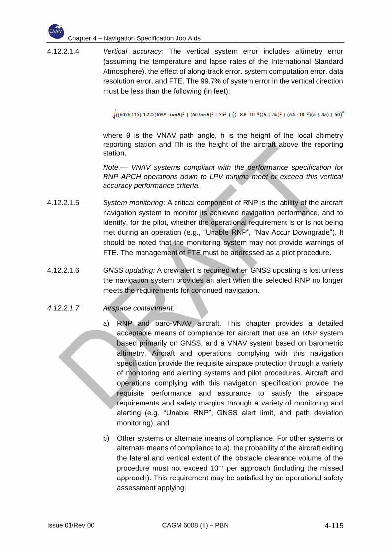
Chapter 4 – Navigation Specification Job Aids
Issue 01/Rev 00 CAGM 6008 (II) – PBN 4-115
4.12.2.1.4 Vertical accuracy: The vertical system error includes altimetry error
(assuming the temperature and lapse rates of the International Standard
Atmosphere), the effect of along-track error, system computation error, data
resolution error, and FTE. The 99.7% of system error in the vertical direction
must be less than the following (in feet):
where θ is the VNAV path angle, h is the height of the local altimetry
reporting station and h is the height of the aircraft above the reporting
station.
Note.— VNAV systems compliant with the performance specification for
RNP APCH operations down to LPV minima meet or exceed this vertical
accuracy performance criteria.
4.12.2.1.5 System monitoring: A critical component of RNP is the ability of the aircraft
navigation system to monitor its achieved navigation performance, and to
identify, for the pilot, whether the operational requirement is or is not being
met during an operation (e.g., “Unable RNP”, “Nav Accur Downgrade”). It
should be noted that the monitoring system may not provide warnings of
FTE. The management of FTE must be addressed as a pilot procedure.
4.12.2.1.6 GNSS updating: A crew alert is required when GNSS updating is lost unless
the navigation system provides an alert when the selected RNP no longer
meets the requirements for continued navigation.
4.12.2.1.7 Airspace containment:
a) RNP and baro-VNAV aircraft. This chapter provides a detailed
acceptable means of compliance for aircraft that use an RNP system
based primarily on GNSS, and a VNAV system based on barometric
altimetry. Aircraft and operations complying with this navigation
specification provide the requisite airspace protection through a variety
of monitoring and alerting systems and pilot procedures. Aircraft and
operations complying with this navigation specification provide the
requisite performance and assurance to satisfy the airspace
requirements and safety margins through a variety of monitoring and
alerting (e.g. “Unable RNP”, GNSS alert limit, and path deviation
monitoring); and
b) Other systems or alternate means of compliance. For other systems or
alternate means of compliance to a), the probability of the aircraft exiting
the lateral and vertical extent of the obstacle clearance volume of the
procedure must not exceed 10–7 per approach (including the missed
approach). This requirement may be satisfied by an operational safety
assessment applying:
Chapter 4 – Navigation Specification Job Aids
Issue 01/Rev 00 CAGM 6008 (II) – PBN 4-116
1) appropriate quantitative numerical methods;
2) qualitative operational and procedural considerations and
mitigations; or
3) an appropriate combination of both quantitative and qualitative
methods.
Notes:
1. This requirement applies to the total probability of excursion outside the obstacle
clearance volume, including events caused by latent conditions (integrity) and by detected
conditions (continuity) if the aircraft does not remain within the obstacle clearance volume
after the failure is annunciated (considering the aircraft wingspan). The monitor limit of
the alert, the latency of the alert, the crew reaction time, and the aircraft response should
all be considered when ensuring that the aircraft does not exit the obstacle clearance
volume. The requirement applies to a single approach, considering the exposure time of
the operation and the NAVAID geometry and navigation performance available for each
published approach.
2. This containment requirement is derived from the operational requirement which is
notably different than the containment requirement specified in RTCA/DO 236B
(EUROCAE ED-75B). The requirement in RTCA/DO-236B (EUROCAE ED-75B) was
developed to facilitate airspace design and does not directly equate to obstacle clearance.
4.12.2.2 Criteria for specific navigation services
4.12.2.2.1 This section identifies unique issues for the navigation sensors within the
context of RNP AR APCH operations.
4.12.2.2.2 ABAS and other GNSS augmentations based on GPS
a) The sensor must comply with the guidelines in AC 20-138() or AC 20-
130 A. For systems that comply with AC 20-138(), the following sensor
accuracies can be used in the total system accuracy analysis without
additional substantiation: GPS (ABAS) sensor lateral accuracy is better
than 36 m (119 ft) (95%), and augmented GPS (GBAS or SBAS) sensor
lateral accuracy is better than 2 m (7 ft) (95%).
b) In the event of a latent GPS satellite failure and marginal GPS satellite
geometry (e.g. HIL) equal to the horizontal alert limit), the probability
that the aircraft remains within the obstacle clearance volume used to
evaluate the procedure must be greater than 95% (both laterally and
vertically).
Notes:
1. Other GNSS systems meeting or exceeding the accuracy of GPS can use the criteria in
a) and b) above.
Chapter 4 – Navigation Specification Job Aids
Issue 01/Rev 00 CAGM 6008 (II) – PBN 4-117
2. GNSS-based sensors output a HIL, also known as a HPL (see AC 20-138A, Appendix 1
and RTCA/DO-229C for an explanation of these terms). The HIL is a measure of the
position estimation error assuming a latent failure is present. In lieu of a detailed analysis
of the effects of latent failures on the TSE, an acceptable means of compliance for GNSS-
based systems is to ensure the HIL remains less than twice the navigation accuracy,
minus the 95% of FTE, during the RNP AR APCH operation.
4.12.2.2.3 IRS: An IRS must satisfy the criteria of US 14 CFR part 121, Appendix G, or
equivalent. While Appendix G defines the requirement for a 2 NM per hour
drift rate (95%) for flights up to 10 hours, this rate may not apply to an RNP
system after loss of position updating. Systems that have demonstrated
compliance with Part 121, Appendix G, can be assumed to have an initial
drift rate of 8 NM/hour for the first 30 minutes (95%) without further
substantiation. Aircraft manufacturers and applicants can demonstrate
improved inertial performance in accordance with the methods described in
Appendix 1 or 2 of FAA Order 8400.12A.
Note.— Integrated GPS/INS position solutions reduce the rate of
degradation after loss of position updating. For “tightly coupled” GPS/IRUs,
RTCA/DO-229C, Appendix R, provides additional guidance.
4.12.2.2.4 DME: GNSS-updating is the basis for initiating all RNP AR APCH
procedures. When authorized by the State, the aircraft may use DME/DME-
updating as a reversionary navigation mode during an approach or during
the missed approach when the navigation system continues to comply with
the required navigation accuracy. The aircraft manufacturer should identify
any requirements for the DME infrastructure or any necessary operational
procedures and limitations when conducting a procedure through use of
DME/DME updating of the aircraft's position.
4.12.2.2.5 VHF omnidirectional range (VOR) station: The aircraft's RNP system may
not use VOR-updating when conducting RNP AR APCH procedures. The
aircraft manufacturer should identify any pilot procedures or techniques for
an aircraft to comply with this requirement.
Note.— This does not imply a requirement for a direct means of inhibiting
VOR updating. An operational procedure requiring the pilot to inhibit VOR
updating or a procedure requiring the pilot to execute a missed approach
when the navigation system reverts to VOR-updating may satisfy this
requirement.
4.12.2.2.6 For multi-sensor systems, there must be automatic reversion to an alternate
area navigation sensor if the primary area navigation sensor fails. Automatic
reversion from one multi-sensor system to another multi-sensor system is
not required.
4.12.2.2.7 The 99.7% aircraft ASE for each aircraft (assuming the temperature and
lapse rates of the International Standard Atmosphere) must be less than or
equal to the following with the aircraft in the approach configuration:
Chapter 4 – Navigation Specification Job Aids
Issue 01/Rev 00 CAGM 6008 (II) – PBN 4-118
Where H is the true altitude of the aircraft.
4.12.2.2.8 Temperature compensation systems: Systems that provide temperature-
based corrections to the barometric VNAV guidance must comply with
RTCA/DO-236B, Appendix H.2. This applies to the FAS. Manufacturers
should document compliance to this standard to allow the operator to
conduct RNP approaches when the actual temperature is below or above
the published procedure design limit. Appendix H also provides guidance on
operational issues associated with temperature compensated systems, such
as intercepting the compensated path from uncompensated procedure
altitudes.
4.12.2.3 Functional requirements
Note.— Additional guidance and information concerning many of the required
functions are provided in EUROCAE ED-75A/ RTCA DO-236B.
4.12.2.3.1 General requirements
4.12.2.3.1.1 Path definition and flight planning:
a) Maintaining track and leg transitions: The aircraft must have the
capability to execute leg transitions and maintain tracks consistent
with the following paths:
1) a geodesic line between two fixes;
2) a direct path to a fix;
3) a specified track to a fix, defined by a course; and
4) a specified track to an altitude.
Notes:
1. Industry standards for these paths can be found in EUROCAE ED-75A/ RTCA DO-236B
and ARINC 424, which refer to them as TF, DF, CF, and FA path terminators. Also, certain
procedures require RF legs. EUROCAE ED-75A/ RTCA DO-236B and ED 77/ DO-201A
describe the application of these paths in more detail.
2. The navigation system may accommodate other ARINC 424 path terminators (e.g.
heading to manual terminator (VM)), and the missed approach procedure may use these
types of paths when there is no requirement for RNP containment.
b) Fly-by and fly-over fixes: The aircraft must have the capability to
execute fly-by and fly-over fixes. For fly-by turns, the navigation
system must limit the path definition within the theoretical transition
area defined in EUROCAE ED-75B/ RTCA DO-236B and under the
wind conditions identified in Doc 9905. The fly-over turn is not
Chapter 4 – Navigation Specification Job Aids
Issue 01/Rev 00 CAGM 6008 (II) – PBN 4-119
compatible with RNP flight tracks and will only be used when there is
no requirement for repeatable paths.
c) Waypoint resolution error: The navigation database must provide
sufficient data resolution to ensure the navigation system achieves
the required accuracy. The waypoint resolution error must be less
than or equal to 60 ft, including both the data storage resolution and
the RNP system computational resolution used internally for
construction of flight plan waypoints. The navigation database must
contain vertical angles (flight path angles) stored to a resolution of
hundredths of a degree, with computational resolution such that the
system-defined path is within 1.5 m (5 ft) of the published path.
d) Capability for a “direct-to” function: The navigation system must have
a “direct-to” function that the pilot can activate at any time. This
function must be available to any fix. The navigation system must
also be capable of generating a geodesic path to the designated “To”
fix, without “S-turning” and without undue delay.
e) Capability to define a vertical path: The navigation system must be
capable of defining a vertical path by a flight path angle to a fix. The
system must also be capable of specifying a vertical path between
altitude constraints at two fixes in the flight plan. Fix altitude
constraints must be defined as one of the following:
1) an “AT” or “ABOVE” altitude constraint (e.g. 2400A may be
appropriate for situations where bounding the vertical path is
not required);
2) an “AT” or “BELOW” altitude constraint (e.g. 4800B may be
appropriate for situations where bounding the vertical path is
not required);
3) an “AT” altitude constraint (e.g. 5200); or
4) a “WINDOW” constraint (e.g. 2400A, 3400B).
Note.— For RNP AR APCH procedures, any segment with a published
vertical path will define that path based on an angle to the fix and the
altitude.
f) Altitudes and/or speeds associated with published terminal
procedures must be extracted from the navigation database.
g) The system must be able to construct a path to provide guidance
from the current position to a vertically constrained fix.
h) Capability to load procedures from the navigation database: The
navigation system must have the capability to load the entire
procedure(s) to be flown into the RNP system from the on-board
navigation database. This includes the approach (including vertical
Chapter 4 – Navigation Specification Job Aids
Issue 01/Rev 00 CAGM 6008 (II) – PBN 4-120
angle), the missed approach and the approach transitions for the
selected airport and runway.
i) Means to retrieve and display navigation data: The navigation system
must provide the ability for the pilot to verify the procedure to be flown
through review of the data stored in the on-board navigation
database. This includes the ability to review the data for individual
waypoints and for NAVAIDs.
j) Magnetic variation: For paths defined by a course (CF and FA path
terminators), the navigation system must use the magnetic variation
value for the procedure in the navigation database.
k) Changes in navigation accuracy: RNP changes to lower navigation
accuracy must be completed by the fix defining the leg with the lower
navigation accuracy, considering the alerting latency of the
navigation system. Any operational procedures necessary to
accomplish this must be identified.
l) Automatic leg sequencing: The navigation system must provide the
capability to automatically sequence to the next leg and display the
sequencing to the pilot in a readily visible manner.
m) A display of the altitude restrictions associated with flight plan fixes
must be available to the pilot. If there is a specified navigation
database procedure with a flight path angle associated with any flight
plan leg, the equipment must display the flight path angle for that leg.
4.12.2.3.1.2 Demonstration of path steering performance: The demonstration of path
steering performance (FTE) must be completed in a variety of operational
conditions, i.e. rare-normal conditions and non-normal conditions (e.g.
see FAA AC 120-29A, 5.19.2.2 and 5.19.3.1). Realistic and
representative procedures should be used (e.g. number of waypoints,
placement of waypoints, segment geometry, leg types, etc.). The non-
normal assessment should consider the following:
a) Criteria for assessing probable failures during the aircraft
qualification will demonstrate that the aircraft trajectory is maintained
within a 1 × RNP corridor, and 22 m (75 ft) vertical. Proper
documentation of this demonstration in the AFM, AFM extension, or
appropriate aircraft operational support document, alleviates the
operational evaluations;
b) RNP-significant improbable failure cases should be assessed to
show that, under these conditions, the aircraft can be safely extracted
from the procedure. Failure cases might include dual system resets,
flight control surface runaway and complete loss of flight guidance
function; and
Chapter 4 – Navigation Specification Job Aids
Issue 01/Rev 00 CAGM 6008 (II) – PBN 4-121
c) The aircraft performance demonstration during the operational
evaluations can be based on a mix of analyses and flight technical
evaluations using expert judgement.
Recommended operating procedures (relevant to sections 4.12.3 and 4.12.4) resulting from
the above demonstration (e.g. one engine inoperative performance) should be documented in
the AFM, AFM extension, or appropriate aircraft operational support document.
4.12.2.3.1.3 Displays
a) Continuous display of deviation: The navigation system must
provide the capability to continuously display to the pilot flying, on
the primary flight instruments for navigation of the aircraft, the
aircraft position relative to the RNP defined path (both lateral and
vertical deviation). The display must allow the pilot to readily
distinguish if the cross-track deviation exceeds the lateral
navigation accuracy (e.g. 1 × RNP) or a smaller value, and if the
vertical deviation exceeds 22 m (75 ft) (or a smaller value) during
RNP AR APCH operations.
Note.— The aircraft manufacturer may allocate a lateral deviation limit
smaller than 1 × RNP to ensure lateral containment during RNP AR
APCH operations. Likewise, the manufacturer may require a vertical
deviation limit smaller than 22 m (75 ft) to ensure compliance with the
vertical error budget in the procedure design.
It is recommended that an appropriately scaled non-numeric
deviation display (i.e. lateral deviation indicator and vertical
deviation indicator) be located in the pilot’s primary optimum field
of view. A fixed-scale CDI is acceptable as long as the CDI
demonstrates appropriate scaling and sensitivity for the intended
navigation accuracy and operation. With a scalable CDI, the scale
should be derived from the selection of the lateral navigation
accuracy, and not require the separate selection of a CDI scale.
Alerting and annunciation limits must also match the scaling
values. If the equipment uses default navigation accuracy to
describe the operational mode (e.g. en route, terminal area and
approach), then displaying the operational mode is an acceptable
means from which the pilot may derive the CDI scale sensitivity.
Numeric display of deviation or graphic depiction on a map
display, without an appropriately scaled deviation indicator, is
generally not considered acceptable for monitoring deviation. The
use of a numeric display or a map display may be feasible
depending on the pilot workload, the display characteristics, and
the pilot procedures and training. Additional initial and recurrent
pilot training (or line experience) may be necessary.
b) Identification of the active (To) waypoint: The navigation system must
provide a display identifying the active waypoint either in the pilot’s
Chapter 4 – Navigation Specification Job Aids
Issue 01/Rev 00 CAGM 6008 (II) – PBN 4-122
primary optimum field of view, or on a readily accessible and visible
display to the pilot.
c) Display of distance and bearing: The navigation system must provide
a display of distance and bearing to the active (To) waypoint in the
pilot’s primary optimum field of view. Where not viable, a readily
accessible page on a control display unit, readily visible to the pilot,
may display the data.
d) Display of ground speed and time to the active (To) waypoint: The
navigation system must provide the display of ground speed and time
to the active (To) waypoint in the pilot’s primary optimum field of view.
Where not viable, a readily accessible page on a control display unit,
readily visible to the pilot, may display the data.
e) Display of To the active fix: The navigation system must provide a To
display in the pilot’s primary optimum field of view.
f) Desired track display: The navigation system must have the
capability to continuously display to the pilot flying the desired aircraft
track. This display must be on the primary flight instruments for
navigation of the aircraft.
g) Display of aircraft track: The navigation system must provide a
display of the actual aircraft track (or track angle error) either in the
pilot’s primary optimum field of view, or on a readily accessible and
visible display to the pilot.
h) Failure annunciation: The aircraft must provide a means to
annunciate failures of any aircraft component of the RNP system,
including navigation sensors. The annunciation must be visible to the
pilot and located in the primary optimum field of view.
i) Slaved course selector: The navigation system must provide a
course selector automatically slaved to the RNP computed path.
j) RNP path display: The navigation system must provide a readily
visible means for the pilot monitoring to verify the aircraft’s RNP-
defined path and the aircraft’s position relative to the defined path.
k) Display of distance to go: The navigation system must provide the
ability to display distance to go to any waypoint selected by the pilot.
l) Display of distance between flight plan waypoints: The navigation
system must provide the ability to display the distance between flight
plan waypoints.
m) Display of deviation: The navigation system must provide a numeric
display of the vertical and lateral deviation. Vertical deviation must
have a resolution of 3 m (10 ft) or less for RNP AR APCH operations.
Lateral deviation resolution must be:
Chapter 4 – Navigation Specification Job Aids
Issue 01/Rev 00 CAGM 6008 (II) – PBN 4-123
1) 0.1NM or less for RNP operations not less than 0.3; or
2) 0.01 NM or less for RNP operations below 0.3.
n) Display of barometric altitude: The aircraft must display barometric
altitude from two independent altimetry sources, one in each of the
pilot’s primary optimum field of view.
Notes:
1. This display supports an operational cross-check (comparator monitor) of altitude
sources. If the aircraft altitude sources are automatically compared, the output of the
independent altimetry sources, including independent aircraft static air pressure systems,
is expected to be analysed to ensure that they can provide an alert in the pilot’s primary
optimum field of view when deviations between the sources exceed 30 m (±100 ft). This
comparator monitor function should be documented as it may eliminate the need for an
operational mitigation.
2. When barometric vertical guidance is used, the altimeter setting input is expected to be
used simultaneously by the aircraft altimetry system and by the RNP system. A single
input is necessary to prevent possible crew error. Separate altimeter settings for the RNP
system are prohibited.
o) Display of active sensors: The aircraft must either display the current
navigation sensor(s) in use or indicate sensor loss/degradation in
navigation system performance. It is recommended that this display
be provided in the primary optimum field of view.
Note.— This display is used to support operational contingency
procedures. If such a display is not in the primary optimum field of view,
pilot procedures may mitigate the requirement provided the workload is
acceptable.
4.12.2.3.1.4 Design assurance: The system design assurance must be consistent with
at least a major failure condition for the display of misleading lateral or
vertical guidance on an RNP AR APCH procedure.
Note.— The display of misleading lateral or vertical RNP guidance is considered
a hazardous (severe-major) failure condition for RNP AR APCHs with a
navigation accuracy less than RNP-0.3. Systems designed consistent with this
effect should be documented as it may eliminate the need for some operational
mitigations for the aircraft.
The system design assurance must be consistent with at least a major
failure condition for the loss of lateral guidance and a minor failure
condition for loss of vertical guidance on an RNP AR APCH procedure.
Note.— Loss of vertical guidance is considered a minor failure condition because
the pilot can take action to stop descending or climb when guidance is lost.
4.12.2.3.1.5 Navigation database: The aircraft navigation system must use an on-
board navigation database which can receive updates in accordance with
Chapter 4 – Navigation Specification Job Aids
Issue 01/Rev 00 CAGM 6008 (II) – PBN 4-124
the AIRAC cycle and allow retrieval and loading of RNP AR APCH
procedures into the RNP system. The RNP system must not allow the
pilot to modify the data stored in the on-board navigation database.
Note.— When a procedure is loaded from the on-board navigation database, the
RNP system is expected to execute the procedure as published. This does not
preclude the pilot from having the means to modify a procedure already loaded
into the navigation system.
4.12.2.3.1.6 The aircraft must provide a means to display the validity period of the on-
board navigation database to the pilot.
4.12.2.3.2 Requirements for RNP AR approaches with RF legs
4.12.2.3.2.1 The navigation system must have the capability to execute leg transitions
and maintain tracks consistent with an RF leg between two fixes/
4.12.2.3.2.2 The aircraft must have an electronic map display of the selected
procedure.
4.12.2.3.2.3 The RNP system, the flight director system and autopilot must be capable
of commanding a bank angle up to 25° above 121 m (400 ft) AGL and up
to 8° below 121 m (400 ft) AGL.
4.12.2.3.2.4 Upon initiating a go-around or missed approach (through activation of
TOGA or other means), the flight guidance mode should remain in lateral
navigation to enable continuous track guidance during an RF leg.
4.12.2.3.2.5 When evaluating an FTE on RF legs, the effect of rolling into and out of
the turn should be considered. The procedure is designed to provide a 5°
manoeuvrability margin, to enable the aircraft to get back on the desired
track after a slight overshoot at the start of the turn.
4.12.2.3.3 Requirements for RNP AR approaches to less than RNP 0.3
4.12.2.3.3.1 No single point of failure: No single point of failure can cause the loss of
guidance compliant with the navigation accuracy associated with the
approach. Typically, the aircraft must have at least the following
equipment: dual GNSS sensors, dual FMS, dual air data systems, dual
autopilots, and a single IRU.
Note.— For RNP AR APCH operations requiring less than 0.3 to avoid
obstacles or terrain, the loss of the display of lateral guidance is
considered a hazardous (severe-major) failure condition. The AFM
should document systems designed consistent with this effect. This
documentation should describe the specific aircraft configuration or mode
of operation that achieves navigation accuracy less than 0.3. Meeting this
requirement can substitute for the general requirement for dual
equipment described above.
Chapter 4 – Navigation Specification Job Aids
Issue 01/Rev 00 CAGM 6008 (II) – PBN 4-125
4.12.2.3.3.2 Design assurance: The system design assurance must be consistent with
at least a major failure condition for the loss of lateral or vertical guidance
on an RNP AR APCH where RNP less than 0.3 is required to avoid
obstacles or terrain while executing the procedure.
4.12.2.3.3.3 Go-around guidance: Upon initiating a go-around or missed approach
(through activation of TOGA or other means), the flight guidance mode
should remain in lateral navigation to enable continuous track guidance
during an RF leg. If the aircraft does not provide this capability, the
following requirements apply:
a) If the aircraft supports RF legs, the lateral path after initiating a go-
around (TOGA), (given a minimum 50-second straight segment
between the RF end point and the DA), must be within 1° of the track
defined by the straight segment through the DA point. The prior turn
can be of arbitrary angular extent and radius as small as 1 NM, with
speeds commensurate with the approach environment and the
radius of the turn.
b) The pilot must be able to couple the autopilot or flight director to the
RNP system (engage lateral navigation) by 121 m (400 ft) AGL.
4.12.2.3.3.4 Loss of GNSS: After initiating a go-around, or missed approach following
loss of GNSS, the aircraft must automatically revert to another means of
navigation that complies with the navigation accuracy.
4.12.2.3.4 Requirements for approaches with missed approach less than RNP 1.0
4.12.2.3.4.1 Single point failure: No single point of failure can cause the loss of
guidance compliant with the navigation accuracy associated with a
missed approach procedure. Typically, the aircraft must have at least the
following equipment: dual GNSS sensors, dual FMS, dual air data
systems, dual autopilots, and a single IRU.
4.12.2.3.4.2 Design assurance: The system design assurance must be consistent with
at least a major failure condition for the loss of lateral or vertical guidance
on an RNP AR APCH where RNP less than 1.0 is required to avoid
obstacles or terrain while executing a missed approach.
Note.— For RNP AR APCH missed approach operations requiring less
than 1.0 to avoid obstacles or terrain, the loss of the display of lateral
guidance is considered a hazardous (severe-major) failure condition. The
AFM should document systems designed consistent with this effect. This
documentation should describe the specific aircraft configuration or mode
of operation that achieves navigation accuracy less than 1.0. Meeting this
requirement can substitute for the general requirement for dual
equipment described above.
Chapter 4 – Navigation Specification Job Aids
Issue 01/Rev 00 CAGM 6008 (II) – PBN 4-126
4.12.2.3.4.3 Go-around guidance: Upon initiating a go-around or missed approach
(through activation of TOGA or other means), the flight guidance mode
should remain in lateral navigation to enable continuous track guidance
during an RF leg. If the aircraft does not provide this capability, the
following requirements apply:
a) If the aircraft supports RF legs, the lateral path after initiating a go-
around (TOGA) (given a minimum 50-second straight segment
between the RF end point and the DA) must be within 1° of the track
defined by the straight segment through the DA point. The prior turn
can be of arbitrary angular extent and the radius as small as 1 NM,
with speeds commensurate with the approach environment and the
radius of the turn.
b) The pilot must be able to couple the autopilot or flight director to the
RNP system (engage lateral navigation) by 121 m (400 ft) AGL.
4.12.2.3.4.4 Loss of GNSS: After initiating a go-around or missed approach following
loss of GNSS, the aircraft must automatically revert to another means of
navigation that complies with the navigation accuracy.
4.12.3 Operating Procedures
Most manufacturers have developed recommended procedures for RNP AR
APCH procedures. Although the manufacturer’s recommendations should be
followed, the operational approval should include an independent evaluation of the
operator’s proposed procedures. RNP AR APCH operating procedures should be
consistent with the operator’s normal procedures where possible in order to
minimize any human factors elements associated with the introduction of PBN
operations.
4.12.3.1 Pre-flight considerations
4.12.3.1.1 MEL: The operator’s MEL should be developed/revised to address the
equipment requirements for RNP AR instrument procedures. Guidance for
these equipment requirements is available from the aircraft manufacturer.
The required equipment may depend on the intended navigation accuracy
and whether the missed approach requires an RNP less than 1.0. For
example, GNSS and autopilot are typically required for high navigation
accuracy. Dual equipment is typically required for approaches when using a
line of minima less than RNP 0.3 and/or where the missed approach has an
RNP less than 1.0. An operable Class A TAWS is required for all RNP AR
APCH procedures. It is recommended that the TAWS use an altitude that
compensates for local pressure and temperature effects (e.g., corrected
barometric and GNSS altitude), and includes significant terrain and obstacle
data. The TAWS must not utilize the captain’s altimeter subscale setting as
the sole reference to help militate against a dual QNH setting error by the
pilot. The pilot must be cognizant of the required equipment.
Chapter 4 – Navigation Specification Job Aids
Issue 01/Rev 00 CAGM 6008 (II) – PBN 4-127
4.12.3.1.2 Autopilot and flight director: RNP AR APCH procedures with a lateral
navigation accuracy of less than RNP 0.3 or with RF legs require the use of
an autopilot or flight director driven by the RNP system in all cases. Thus,
the autopilot/flight director must be operable and able to track the lateral and
vertical paths defined by the procedure. When the dispatch of a flight is
predicated on flying an RNP AR APCH procedure requiring the autopilot at
the destination and/or alternate, the dispatcher must determine that the
autopilot is operational.
4.12.3.1.3 Dispatch RNP availability prediction: The operator must have a predictive
performance capability which can forecast whether or not the specified RNP
will be available at the time and location of a desired RNP AR APCH
procedure. This capability can be a ground service and need not be resident
in the aircraft’s avionics equipment. The operator must establish procedures
requiring use of this capability as both a pre-flight dispatch tool and as a
flight-following tool in the event of reported failures. The RNP assessment
must consider the specific combination of the aircraft capability (sensors and
integration).
a) RNP assessment when GNSS updating. This predictive capability must
account for known and predicted outages of GNSS satellites or other
impacts on the navigation system’s sensors. The prediction programme
should not use a mask angle below 5 degrees, as operational
experience indicates that satellite signals at low elevations are not
reliable. The prediction must use the actual GNSS constellation with the
integrity monitoring algorithm (RAIM, AAIM, etc.) identical to that used
in the actual equipment. For RNP AR APCH operations with high terrain,
use a mask angle appropriate to the terrain; and
b) RNP AR APCH operations must have GNSS updating available prior to
the commencement of the procedure.
4.12.3.1.4 NAVAID exclusion: The operator must establish procedures to exclude
NAVAID facilities in accordance with NOTAMs (e.g. DMEs, VORs,
localizers).
4.12.3.1.5 Navigation database currency: During system initialization, pilots of aircraft
equipped with an RNP capable system, must confirm that the navigation
database is current. Navigation databases are expected to be current for the
duration of the flight. If the AIRAC cycle changes during flight, operators and
pilots must establish procedures to ensure the accuracy of the navigation
data, including the suitability of the navigation facilities used to define the
routes and procedures for the flight. An outdated database must not be used
to conduct the RNP AR APCH operation unless it has been established that
any amendments to the database have no material impact on the procedure.
If an amended chart is published for the procedure, the database must not
be used to conduct the operation.
Chapter 4 – Navigation Specification Job Aids
Issue 01/Rev 00 CAGM 6008 (II) – PBN 4-128
4.12.3.2 In-flight considerations
4.12.3.2.1 Modification of the flight plan: Pilots are not authorized to fly a published
RNP AR APCH procedure unless it is retrievable by the procedure name
from the aircraft navigation database and conforms to the charted
procedure. The lateral path must not be modified, with the exception of:
a) Accepting a clearance to go direct to a fix in the approach procedure
that is before the FAF and that does not immediately precede an RF leg.
b) Changing the altitude and/or airspeed waypoint constraints on the initial,
intermediate, or missed approach segments of an approach (e.g. to
apply cold temperature corrections or comply with an ATC
clearance/instruction).
4.12.3.2.2 Required list of equipment: The pilot must have a required list of equipment
for conducting RNP AR APCH operations or alternate methods to address
in-flight equipment failures prohibiting RNP AR APCH procedures (e.g. a
quick reference handbook).
4.12.3.2.3 RNP management: The pilot’s operating procedures must ensure the
navigation system uses the appropriate navigation accuracy throughout the
approach. If multiple lines of minima associated with a different navigation
accuracy are shown on the approach chart, the crew must confirm that the
desired navigation accuracy is entered in the RNP system. If the navigation
system does not extract and set the navigation accuracy from the on-board
navigation database for each leg of the procedure, then the pilot’s operating
procedures must ensure that the smallest navigation accuracy required to
complete the approach or missed approach is selected before initiating the
procedure (e.g. before the IAF and before take-off roll). Different segments
may have a different navigation accuracy, which are annotated on the
approach chart.
4.12.3.2.4 GNSS updating: All RNP AR instrument procedures require GNSS updating
of the navigation position solution. The pilot must verify that GNSS updating
is available prior to commencing the RNP AR procedure. During an
approach, if at any time GNSS updating is lost and the navigation system
does not have the performance to continue the approach, the pilot must
abandon the RNP AR APCH unless the pilot has in sight the visual
references required to continue the approach.
4.12.3.2.5 Radio updating: Initiation of all RNP AR APCH procedures is based on the
availability of GNSS updating. Except where specifically designated on a
procedure as “Not Authorized”, DME/DME updating can be used as a
reversionary mode during the approach or missed approach when the
system complies with the navigation accuracy. VOR updating is not
authorized at this time. The pilot must comply with the operator’s procedures
for inhibiting specific facilities.
Chapter 4 – Navigation Specification Job Aids
Issue 01/Rev 00 CAGM 6008 (II) – PBN 4-129
4.12.3.2.6 Procedure confirmation: The pilot must confirm that the correct procedure
has been selected. This process includes confirmation of the waypoint
sequence, reasonableness of track angles and distances, and any other
parameters that can be altered by the pilot, such as altitude or speed
constraints. A procedure must not be used if the validity of the navigation
database is in doubt. A navigation system textual display or navigation map
display must be used.
4.12.3.2.7 Track deviation monitoring: Pilots must use a lateral deviation indicator
and/or flight director in lateral navigation mode on RNP AR APCH
procedures. Pilots of aircraft with a lateral deviation indicator must ensure
that lateral deviation indicator scaling (full-scale deflection) is suitable for the
navigation accuracy associated with the various segments of the RNP AR
APCH procedure. All pilots are expected to maintain procedure centre lines,
as depicted by on-board lateral deviation indicators and/or flight guidance
during all RNP operations described in this manual, unless authorized to
deviate by ATC or under emergency conditions. For normal operations,
cross-track error/deviation (the difference between the RNP system
computed path and the aircraft position relative to the path) should be limited
to ±½ the navigation accuracy associated with the procedure segment. Brief
lateral deviations from this standard (e.g., overshoots or undershoots) during
and immediately after turns, up to a maximum of one-times the navigation
accuracy of the procedure segment are tolerable.
4.12.3.2.8 The vertical deviation must be within 22 m (75 ft) during the FAS noting that
transients in excess of 75 ft above the vertical path are acceptable (e.g.
configuration changes or energy management actions). Vertical deviation
should be monitored above and below the vertical path; while being above
the vertical path provides margin against obstacles on the final approach,
continued intentional flight above the vertical path can result in a go-around
decision closer to the runway and reduce the margin against obstacles in
the missed approach.
4.12.3.2.9 Pilots must execute a missed approach if the lateral deviation exceeds 1 x
RNP or the vertical deviation exceeds -22m (-75 ft), unless the pilot has in
sight the visual references required to continue the approach.
a) Some aircraft navigation displays do not incorporate lateral and vertical
deviations scaled for each RNP AR APCH operation in the primary
optimum field of view. Where a moving map, low-resolution vertical
deviation indicator (VDI), or numeric display of deviations are to be
used, pilot training and procedures must ensure the effectiveness of
these displays. Typically, this involves the demonstration of the
procedure with a number of trained crews and inclusion of this
monitoring procedure in the recurrent RNP AR APCH training
programme.
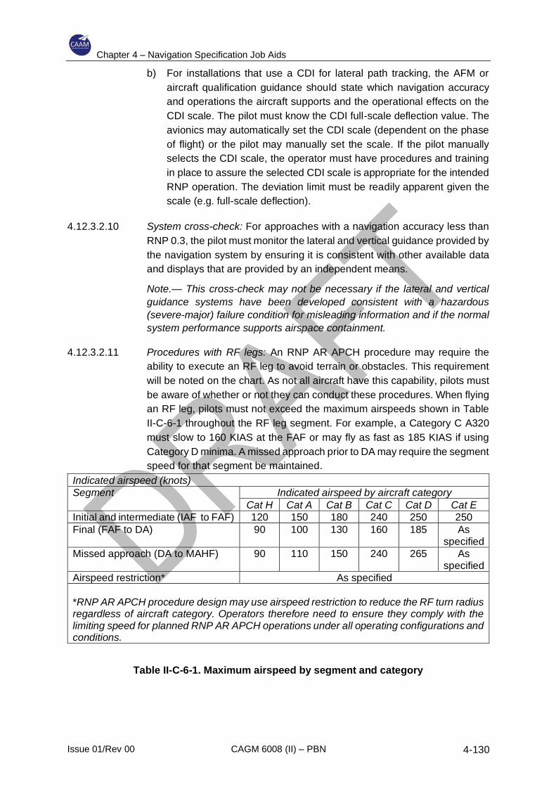
Chapter 4 – Navigation Specification Job Aids
Issue 01/Rev 00 CAGM 6008 (II) – PBN 4-130
b) For installations that use a CDI for lateral path tracking, the AFM or
aircraft qualification guidance should state which navigation accuracy
and operations the aircraft supports and the operational effects on the
CDI scale. The pilot must know the CDI full-scale deflection value. The
avionics may automatically set the CDI scale (dependent on the phase
of flight) or the pilot may manually set the scale. If the pilot manually
selects the CDI scale, the operator must have procedures and training
in place to assure the selected CDI scale is appropriate for the intended
RNP operation. The deviation limit must be readily apparent given the
scale (e.g. full-scale deflection).
4.12.3.2.10 System cross-check: For approaches with a navigation accuracy less than
RNP 0.3, the pilot must monitor the lateral and vertical guidance provided by
the navigation system by ensuring it is consistent with other available data
and displays that are provided by an independent means.
Note.— This cross-check may not be necessary if the lateral and vertical
guidance systems have been developed consistent with a hazardous
(severe-major) failure condition for misleading information and if the normal
system performance supports airspace containment.
4.12.3.2.11 Procedures with RF legs: An RNP AR APCH procedure may require the
ability to execute an RF leg to avoid terrain or obstacles. This requirement
will be noted on the chart. As not all aircraft have this capability, pilots must
be aware of whether or not they can conduct these procedures. When flying
an RF leg, pilots must not exceed the maximum airspeeds shown in Table
II-C-6-1 throughout the RF leg segment. For example, a Category C A320
must slow to 160 KIAS at the FAF or may fly as fast as 185 KIAS if using
Category D minima. A missed approach prior to DA may require the segment
speed for that segment be maintained.
Indicated airspeed (knots)
Segment Indicated airspeed by aircraft category
Cat H Cat A Cat B Cat C Cat D Cat E
Initial and intermediate (IAF to FAF) 120 150 180 240 250 250
Final (FAF to DA) 90 100 130 160 185 As specified
Missed approach (DA to MAHF) 90 110 150 240 265 As specified
Airspeed restriction* As specified
*RNP AR APCH procedure design may use airspeed restriction to reduce the RF turn radius regardless of aircraft category. Operators therefore need to ensure they comply with the limiting speed for planned RNP AR APCH operations under all operating configurations and conditions.
Table II-C-6-1. Maximum airspeed by segment and category
Chapter 4 – Navigation Specification Job Aids
Issue 01/Rev 00 CAGM 6008 (II) – PBN 4-131
4.12.3.2.12 Temperature compensation: For aircraft with temperature compensation
capabilities, approved operating procedures may allow pilots to disregard
the temperature limits on RNP AR APCH procedures if the operator provides
pilot training on the use of the temperature compensation function.
Temperature compensation by the system is applicable to the baro-VNAV
guidance and is not a substitute for the pilot compensating for the cold
temperature effects on minimum altitudes or the DA. Pilots should be familiar
with the effects of the temperature compensation on intercepting the
compensated path described in EUROCAE-ED075B/ RTCA DO-236B
Appendix H.
Note. – When using GNSS vertical guidance on RNP AR operations (e.g. SBAS
or GBAS), the temperature limits for the procedure do not apply. However, the
pilot may still need to compensate for the cold temperature effects on minimum
altitudes or the DA.
4.12.3.2.13 Altimeter setting: RNP AR APCH IAPs use barometric data to derive vertical
guidance. The pilot must ensure that the current local QNH is set prior to the
FAF. Remote altimeter settings are not permitted.
4.12.3.2.14 Altimeter cross-check: The pilot must complete an altimetry cross-check
ensuring both pilots’ altimeters agree within 30 m (±100 ft) prior to the FAF
but no earlier than the IAF on approach. If the altimetry cross-check fails
then the procedure must not be continued. If the avionics systems provide a
comparator warning system for the pilots’ altimeters, the pilot procedures
should address actions to take if a comparator warning for the pilots’
altimeters occurs while conducting an RNP AR APCH procedure.
Notes:
1. This operational cross-check is not necessary if the aircraft automatically compares
the altitudes to within 30 m (100 ft) (see also 4.12.2.3.1.3, Displays, (n) Display of
barometric altitude).
2. This operational check is not necessary when the aircraft uses GNSS vertical guidance
(e.g. SBAS or GBAS).
4.12.3.2.15 VNAV altitude transitions: The aircraft barometric VNAV system provides fly-
by vertical guidance and may result in a path that starts to intercept the
vertical path of the procedure prior to the FAF. The small vertical
displacement which may occur at a vertical constraint (e.g. the FAF is
considered operationally acceptable, providing a smooth transition to the
next flight path vertical segment. This momentary deviation below the
published minimum procedure altitude is acceptable provided the deviation
is limited to no more than 30 m (100 ft) and is a result of a normal VNAV
capture. This applies to both “level off” or “altitude acquire” segments
following a climb or descent, or vertical climb or descent segment initiation,
or joining of climb or descent paths with different gradients.
Chapter 4 – Navigation Specification Job Aids
Issue 01/Rev 00 CAGM 6008 (II) – PBN 4-132
4.12.3.2.16 Non-standard climb gradient: When an approach procedure specifies a non-
standard climb gradient, the operator must ensure the aircraft is capable of
complying with the published climb gradient at the aircraft landing weight
under ambient atmospheric conditions.
4.12.3.2.17 Go-around or missed approach: Where possible, the missed approach will
require a navigation accuracy of RNP 1.0. The missed approach portion of
these procedures is similar to a missed approach of an RNP APCH
approach. Where necessary, navigation accuracy less than RNP 1.0 will be
used in the missed approach. Approval to conduct these approaches,
equipage and procedures must meet criteria in 4.12.2.3.4 “Requirements for
approaches with missed approach less than RNP 1.0”.
4.12.3.2.18 In some aircraft, activating TOGA during the initiation of a go-around or
missed approach may cause a change in lateral navigation mode or
functionality, (i.e. TOGA disengages the autopilot and flight director from
lateral navigation guidance) and track guidance may revert to track-hold
derived from the inertial system. In such cases, lateral navigation guidance
to the autopilot and flight director should be re-engaged as quickly as
possible.
4.12.3.2.19 The pilot procedures and training must address the impact on navigation
capability and flight guidance if the pilot initiates a go-around while the
aircraft is in a turn. When initiating an early go-around, the pilot must ensure
adherence to the published track unless ATC has issued a different
clearance. The pilot should also be aware that RF legs are designed for a
maximum ground speed. Initiating an early go-around at speeds higher that
those considered in the design, may cause the aircraft to diverge throughout
the turn and require pilot intervention to maintain the path.
4.12.3.2.20 Contingency procedures — failure while en route: The aircraft RNP
capability is dependent on operational aircraft equipment and GNSS. The
pilot must be able to assess the impact of equipment failure on the
anticipated RNP AR APCH procedure and take appropriate action. As
described in 6.3.4.1.3, “Dispatch RNP availability prediction”, the pilot also
must be able to assess the impact of changes in the GNSS constellation and
take appropriate action.
4.12.3.2.21 Contingency procedures — failure on approach: The operator’s contingency
procedures need to address the following conditions: Failure of the RNP
system components, including those affecting lateral and vertical deviation
performance (e.g. failures of a GPS sensor, the flight director or automatic
pilot); and loss of navigation SIS (loss or degradation of external signal).
Chapter 4 – Navigation Specification Job Aids
Issue 01/Rev 00 CAGM 6008 (II) – PBN 4-133
4.12.4 Flight crew/dispatcher knowledge and training
4.12.4.1 The operator must provide training for key personnel (e.g. flight crew and
dispatchers) in the use and application of RNP AR APCH procedures. A
thorough understanding of the operational procedures and best practices is
critical to the safe operation of aircraft during RNP AR APCH operations. This
programme shall provide sufficient detail on the aircraft’s navigation and flight
control systems to enable the pilots to identify failures affecting the aircraft’s
RNP capability and the appropriate abnormal/emergency procedures. Training
shall include both knowledge and skill assessments of the crew members’ and
dispatchers’ duties. The amount of training will vary depending on the flight
crew’s previous area navigation experience; however, the following guidelines
are provided:
a) Ground training: Ground training including computer-based training and
classroom briefing shall include all required elements of the syllabus
detailed in 4.12.4.3
b) Simulator training: Briefings and simulator sessions should cover all
elements of the intended operation or the minimum number of approaches
stipulated in 4.12.4.4. Proficiency may be achieved in normal
uncomplicated operations in a short period of time; however, additional
flight time needs to be scheduled to ensure competency in the
management of approach changes, go-around, holding and other
functions, including due consideration of human factors. Where necessary,
initial training should be supplemented by operational experience in VMC
or under supervision. The minimum functionality of the flight simulation
training device used for RNP AR APCH simulator training is listed in
Appendix F.
4.12.4.2 Operator responsibilities
a) Each operator is responsible for the training of pilots for the specific RNP
AR APCH operations exercised by the operator. The operator must include
training on the different types of RNP AR APCH procedures and required
equipment. Training must include discussion of RNP AR APCH regulatory
requirements. The operator must include these requirements and
procedures in their flight operations and training manuals (as applicable).
This material must cover all aspects of the operator’s RNP AR APCH
operations including the applicable operational authorization. An individual
must have completed the appropriate ground and or flight training segment
before engaging in RNP AR APCH operations.
b) Flight training segments must include training and checking modules
representative of the type of RNP AR APCH procedures the operator
conducts during line-oriented flying activities. Many operators may train for
RNP AR APCH procedures under the established training standards and
provisions for advanced qualification programmes. They may conduct
Chapter 4 – Navigation Specification Job Aids
Issue 01/Rev 00 CAGM 6008 (II) – PBN 4-134
evaluations in LOFT scenarios, selected event training scenarios or in a
combination of both. The operator may conduct required flight training
modules in flight training devices, aircraft simulators, and other enhanced
training devices as long as these training devices accurately replicate the
operator’s equipment and RNP AR APCH operations.
c) Operators must address initial RNP AR APCH training and qualifications
during initial, transition, upgrade, recurrent, differences, or stand-alone
training and qualification programmes in the respective qualification
category. The qualification standards assess each pilot’s ability to properly
understand and use RNP AR procedures (RNP AR APCH initial
evaluation). The operator must also develop recurrent qualification
standards to ensure their pilots maintain appropriate RNP AR APCH
operations knowledge and skills (RNP AR APCH recurrent qualification).
d) Operators may address RNP AR APCH operation topics separately or
integrate them with other curriculum elements. For example, an RNP AR
APCH pilot qualification may focus on a specific aircraft during transition,
upgrade, or differences courses. General training may also address RNP
AR APCH qualification, e.g. during recurrent training or checking events
such as recurrent proficiency check/proficiency training, line-oriented
evaluation or special purpose operational training. A separate,
independent RNP AR APCH operations qualification programme may also
address RNP AR APCH training, e.g. by completion of an applicable RNP
AR APCH curriculum at an operator’s training centre or at designated crew
bases.
e) Operators intending to receive credit for RNP training, when their proposed
programme relies on previous training (e.g. special RNP IAPs), must
receive specific authorization from their principal operations inspector/flight
operations inspector. In addition to the current RNP training programme,
the air carrier will need to provide differences training between existing
training programme and the RNP AR APCH training requirements.
f) Training for flight dispatchers must include: the explanation of the different
types of RNP AR APCH procedures, the importance of specific navigation
equipment and other equipment during RNP AR APCH operations and the
RNP AR APCH regulatory requirements and procedures. Dispatcher
procedure and training manuals must include these requirements (as
applicable). This material must cover all aspects of the operator’s RNP AR
operations including the applicable authorizations (e.g. Operations
specifications, OM, MSpecs or LOA). An individual must have completed
the appropriate training course before engaging in RNP AR APCH
operations. Additionally, the dispatchers’ training must address how to
determine: RNP AR APCH availability (considering aircraft equipment
capabilities), MEL requirements, aircraft performance, and navigation
signal availability (e.g. GPS RAIM/predictive RNP capability tool) for
destination and alternate airports.
Chapter 4 – Navigation Specification Job Aids
Issue 01/Rev 00 CAGM 6008 (II) – PBN 4-135
4.12.4.3 Ground training segments content
4.12.4.3.1 Ground training segments must address the following subjects, as training
modules, in an approved RNP AR APCH training programme during the
initial introduction of a crew member to RNP AR APCH systems and
operations. For recurrent programmes, the curriculum need only review
initial curriculum requirements and address new, revised, or emphasized
items.
4.12.4.3.2 General concepts of RNP AR APCH operation. RNP AR APCH training must
cover RNP AR APCH systems theory to the extent appropriate to ensure
proper operational use. The pilot must understand basic concepts of RNP
AR APCH systems operation, classifications, and limitations. The training
must include general knowledge and operational application of RNP AR
procedures. This training module shall address the following specific
elements:
a) definition of RNP AR APCH;
b) the differences between RNAV and RNP;
c) the types of RNP AR APCH procedures and familiarity with the charting
of these procedures;
d) the programming and displaying of RNP and aircraft specific displays
(e.g. actual navigation performance (ANP display));
e) how to enable and disable the navigation updating modes related to
RNP;
f) the navigation accuracy appropriate for different phases of flight and
RNP AR APCH procedures and how to select the navigation accuracy,
if required;
g) the use of GPS RAIM (or equivalent) forecasts and the effects of RAIM
availability on RNP AR APCH procedures (pilot and dispatchers);
h) when and how to terminate RNP navigation and transfer to traditional
navigation due to loss of RNP and/or required equipment;
i) how to determine database currency and whether it contains the
navigational data required for use of GNSS waypoints;
j) explanation of the different components that contribute to the TSE and
their characteristics (e.g. effect of temperature on baro-VNAV and drift
characteristics when using IRU with no radio updating); and
k) temperature compensation — pilots operating avionics systems with
compensation for altimetry errors introduced by deviations from ISA
may disregard the temperature limits on RNP AR APCH procedures, if
pilot training on the use of the temperature compensation function is
Chapter 4 – Navigation Specification Job Aids
Issue 01/Rev 00 CAGM 6008 (II) – PBN 4-136
provided by the operator and the compensation function is utilized by
the crew. However, the training must also recognize the temperature
compensation by the system is applicable to the VNAV guidance and is
not a substitute for the pilot compensating for the cold temperature
effects on minimum altitudes or the DA.
4.12.4.3.3 ATC communications and coordination for use of RNP AR APCH: Ground
training must instruct the pilots on proper flight plan classifications and any
ATC procedures applicable to RNP AR APCH operations. The pilots must
receive instructions on the need to advise ATC immediately when the
performance of the aircraft’s navigation system is no longer suitable to
support continuation of an RNP AR APCH procedure. Pilots must also know
what navigation sensors form the basis for their RNP AR APCH compliance,
and they must be able to assess the impact of a failure of any avionics or a
known loss of ground systems on the remainder of the flight plan.
4.12.4.3.4 RNP AR APCH equipment components, controls, displays, and alerts:
Academic training must include a discussion of RNP terminology,
symbology, operation, optional controls, and display features including any
items unique to an operator’s implementation or systems. The training must
address applicable failure alerts and equipment limitations. The pilots and
dispatchers should achieve a thorough understanding of the equipment used
in RNP operations and any limitations on the use of the equipment during
those operations.
4.12.4.3.5 AFM information and operating procedures: The AFM or other aircraft
eligibility evidence must address normal and abnormal flight crew operating
procedures, responses to failure alerts, and any equipment limitations,
including related information on RNP modes of operation. Training must also
address contingency procedures for loss or degradation of RNP capability.
The flight operations manuals approved for use by the pilots (e.g. FOM or
POH) should contain this information.
4.12.4.3.6 MEL operating provisions: Pilots must have a thorough understanding of the
MEL requirements supporting RNP AR APCH operations.
4.12.4.4 Flight training segments – content
4.12.4.4.1 Training programmes must cover the proper execution of RNP AR APCH
procedures in concert with the OEM’s documentation. The operational
training must include: RNP AR APCH procedures and limitations;
standardization of the set-up of the cockpit’s electronic displays during an
RNP AR APCH procedure; recognition of the aural advisories, alerts and
other annunciations that can impact compliance with an RNP AR APCH
procedure; and the timely and correct responses to loss of RNP AR APCH
capability in a variety of scenarios, embracing the scope of the RNP AR
APCH procedures which the operator plans to complete. Such training may
Chapter 4 – Navigation Specification Job Aids
Issue 01/Rev 00 CAGM 6008 (II) – PBN 4-137
also use approved flight training devices or simulators. This training must
address the following specific elements:
a) Procedures for verifying that each pilot’s altimeter has the current
setting before beginning the final approach of an RNP AR APCH
procedure, including any operational limitations associated with the
source(s) for the altimeter setting and the latency of checking and
setting the altimeters approaching the FAF;
b) The use of aircraft radar, TAWS, GPWS, or other avionics systems to
support the pilot’s track monitoring and weather and obstacle
avoidance;
c) The effect of wind on aircraft performance during RNP AR APCH
procedures and the need to remain within RNP containment area,
including any operational wind limitation and aircraft configuration
essential to safely complete an RNP AR procedure;
d) The effect of ground speed on compliance with RNP AR APCH
procedures and bank angle restrictions impacting the ability to remain
on the course centre line. For RNP AR APCH procedures, aircraft are
expected to maintain the standard speeds associated with the
applicable category;
e) The relationship between RNP and the appropriate approach minima
line on an approved published RNP AR APCH procedure and any
operational limitations noted on the chart, e.g. temperature limits, RF
leg requirements or loss of GNSS updating on approach;
f) Concise and complete pilot briefings for all RNP AR APCH procedures
and the important role CRM plays in successfully completing an RNP
AR APCH procedure;
g) Alerts from the loading and use of improper navigation accuracy data
for a desired segment of an RNP AR procedure;
h) The performance requirement to couple the autopilot/flight director to
the navigation system’s lateral and vertical guidance on RNP AR APCH
procedures requiring an RNP of less than RNP 0.3;
i) The importance of aircraft configuration to ensure the aircraft maintains
any required speeds during RNP AR procedures;
j) The events triggering a missed approach when using the aircraft’s RNP
capability;
k) Any bank angle restrictions or limitations on RNP AR APCH procedures;
l) The potentially detrimental effect on the ability to comply with an RNP
AR APCH procedure when reducing the flap setting, reducing the bank
angle or increasing airspeed;
Chapter 4 – Navigation Specification Job Aids
Issue 01/Rev 00 CAGM 6008 (II) – PBN 4-138
m) Pilot knowledge and skills necessary to properly conduct RNP AR
APCH operations;
n) Programming and operating the FMC, autopilot, auto throttles, radar,
GPS, INS, EFIS (including the moving map), and TAWS in support of
RNP AR APCH procedures;
o) The effect of activating TOGA while in a turn;
p) FTE monitoring and impact on go-around decision and operation;
q) Loss of GNSS during a procedure;
r) Performance issues associated with reversion to radio updating and
limitations on the use of DME and VOR updating; and
s) Flight crew contingency procedures for a loss of RNP capability during
a missed approach. Due to the lack of navigation guidance, the training
should emphasize the flight crew contingency actions that achieve
separation from terrain and obstacles. The operator should tailor these
contingency procedures to their specific RNP AR APCH procedures.
4.12.4.5 Evaluation module
4.12.4.5.1 Initial evaluation of RNP AR APCH operations knowledge and procedures.
The operator must evaluate each individual pilot’s knowledge of RNP AR
APCH procedures prior to employing RNP AR APCH procedures as
appropriate. As a minimum, the review must include a thorough evaluation
of pilot procedures and specific aircraft performance requirements for RNP
AR APCH operations. An acceptable means for this initial assessment
includes one of the following:
a) an evaluation by an authorized instructor/evaluator or check-airman
using an approved simulator or training device;
b) an evaluation by an authorized instructor/evaluator or check-airman
during line operations, training flights, proficiency checks, practical tests
events, operating experience, route checks, and/or line checks; or
c) LOFT/LOE programmes using an approved simulator that incorporates
RNP operations that employ the unique RNP AR APCH characteristics
(i.e. RF legs, RNP missed approach) of the operator’s approved
procedures.
4.12.4.5.2 Evaluation content. Specific elements that must be addressed in this
evaluation module are:
a) demonstrate the use of any RNP limits that may impact various RNP
AR APCH procedures;
Chapter 4 – Navigation Specification Job Aids
Issue 01/Rev 00 CAGM 6008 (II) – PBN 4-139
b) demonstrate the application of radio-updating procedures, such as
enabling and disabling ground-based radio updating of the FMC (i.e.
DME/DME and VOR/DME updating) and knowledge of when to use this
feature. If the aircraft’s avionics do not include the capability to disable
radio updating, then the training must ensure the pilot is able to
accomplish the operational actions that mitigate the lack of this feature;
c) demonstrate the ability to monitor the actual lateral and vertical flight
paths relative to the programmed flight path and complete the
appropriate flight crew procedures when exceeding a lateral or vertical
FTE limit;
d) demonstrate the ability to read and adapt to a RAIM (or equivalent)
forecast, including forecasts predicting a lack of RAIM availability;
e) demonstrate the proper set-up of the FMC, the weather radar, TAWS,
and moving map for the various RNP AR APCH operations and
scenarios the operator plans to implement;
f) demonstrate the use of pilot briefings and checklists for RNP AR APCH
operations, as appropriate, with emphasis on CRM;
g) demonstrate knowledge of and ability to perform an RNP AR APCH
missed approach procedure in a variety of operational scenarios (e.g.
loss of navigation or failure to acquire visual conditions);
h) demonstrate speed control during segments requiring speed restrictions
to ensure compliance with an RNP AR APCH procedures;
i) demonstrate competent use of RNP AR APCH procedure plates,
briefing cards, and checklists;
j) demonstrate the ability to complete a stable RNP AR APCH operation
including bank angle, speed control, and remain on the procedure’s
centre line; and
k) knowledge of the operational limit for deviation below the desired flight
path on an RNP AR APCH procedure and how to accurately monitor the
aircraft’s position relative to the vertical flight path.
4.12.4.6 Recurrent training
4.12.4.6.1 The operator should incorporate recurrent RNP training that employs the
unique AR characteristics of the operator’s approved procedures as part of
the overall programme.
4.12.4.6.2 A minimum of two RNP AR APCHs, as applicable, must be flown by each
pilot for each duty position (pilot flying and pilot monitoring), with one
culminating in a landing and one culminating in a missed approach, and may
be substituted for any required “precision-like” approach.
Chapter 4 – Navigation Specification Job Aids
Issue 01/Rev 00 CAGM 6008 (II) – PBN 4-140
Note. – Equivalent RNP approaches may be credited toward this requirement.
4.12.5 Navigation database
4.12.5.1 RNP AR APCH operations are critically dependent on valid data.
4.12.5.2 Any RNP AR APCH in the database shall first be validated formally by the
operator by:
a) comparing the data in the database with the procedure published on the
chart;
b) flying the entire procedure either in a simulator or in the actual aircraft in
VMC to ensure that there is complete consistency and there are no
disconnects;
c) comparing subsequent database updates with the validated master to
ensure that there are no discrepancies.
4.12.5.3 The navigation database shall be obtained from a qualified source, and
operators must also have procedures in place for the management of data
4.12.5.4 Even qualified database suppliers who comply with RTCA DO-
200A/EUROCAE ED/76 cannot guarantee that the databases will be error-free.
Operators must have procedures in place to ensure, for every AIRAC, that the
RNP AR procedure in the database is exactly the same as the RNP AR
procedure that was initially validated.
4.12.5.5 The procedure stored in the navigation database defines the lateral and vertical
path. Navigation database updates occur every 28 days, and the navigation
data in every update are critical to the integrity of every RNP AR APCH
procedure. Given the reduced obstacle clearance associated with these
procedures, validation of navigation data warrants special consideration. This
section provides guidance for the operator’s procedures for validating the
navigation data associated with RNP AR APCH procedures.
4.12.5.5.1 Data process
4.12.5.5.1.1 The operator must identify the responsible manager for the data updating
process within their procedures.
4.12.5.5.1.2 The operator must document a process for accepting, verifying and
loading navigation data into the aircraft.
4.12.5.5.1.3 The operator must place their documented data process under
configuration control.
4.12.5.5.1.4 Initial data validation: The operator shall validate every RNP AR
procedure before flying the procedure in instrument meteorological
Chapter 4 – Navigation Specification Job Aids
Issue 01/Rev 00 CAGM 6008 (II) – PBN 4-141
conditions (IMC) to ensure compatibility with their aircraft and to ensure
the resulting path matches the published procedure. As a minimum, the
operator must:
a) compare the navigation data for the procedure(s) to be loaded into
the RNP system with the published procedure;
b) validate the loaded navigation data for the procedure, either in a
simulator or in the actual aircraft in visual meteorological conditions
(VMC). The depicted procedure on the map display must be
compared to the published procedure. The entire procedure must be
flown to ensure the path does not have any apparent lateral or
vertical path disconnects, and is consistent with the published
procedure; and
c) once the procedure is validated, retain and maintain a copy of the
validated navigation data for comparison to subsequent data
updates.
4.12.5.5.1.5 Data updates: Upon receipt of each navigation data update, and before
using the navigation data in the aircraft, the operator must compare the
update to the validated procedure. This comparison must identify and
resolve any discrepancies in the navigation data. If there are significant
changes (any change affecting the approach path or performance) to any
portion of a procedure and source data verifies the changes, the operator
must validate the amended procedure in accordance with initial data
validation.
4.12.5.5.1.6 Data suppliers: Data suppliers must have an LOA for processing
navigation data (e.g., FAA AC 20 153, EASA Conditions for the issuance
of Letters of Acceptance for navigation database Suppliers by the
Agency, or equivalent). An LOA recognizes the data supplier as one
whose data quality, integrity and quality management practices are
consistent with the criteria of DO-200A/ED-76. The operator’s supplier
(e.g. the FMS company) must have a Type 2 LOA, and their respective
suppliers must have a Type 1 or 2 LOA.
4.12.5.5.1.7 Aircraft modifications: If an aircraft system required for RNP AR APCH
operations is modified (e.g. software change), the operator is responsible
for validating of RNP AR APCH procedures using the navigation
database and the modified system. This may be accomplished without
any direct evaluation if the manufacturer verifies that the modification has
no effect on the navigation database or path computation. If no such
assurance from the manufacturer is available, the operator must conduct
an initial data validation using the modified system noting that flight
control computers, FMS OPS and display software changes are
particularly critical.
Chapter 4 – Navigation Specification Job Aids
Issue 01/Rev 00 CAGM 6008 (II) – PBN 4-142
4.12.6 TAWS database
The procedure validation process should include a compatibility check with the
installed TAWS. The TAWS data should only be obtained from a qualified source
and operators should have procedures in place for the management of the TAWS
data.
4.12.7 Safety assessments
4.12.7.1 The RNP AR procedure design criteria in assume that any event leading the
aircraft to exit the lateral (2 x RNP) or vertical (VEB) extent of the obstacle
clearance volume may have hazardous repercussions. In order to ensure that
the TLS of the intended operation is met, the acceptability of the repercussions
of aircraft failures with respect to the RNP AR application must be addressed
(refer section 4.12.2.1.7 and 4.12.2.3.1.2).
4.12.7.2 Demonstration of compliance with those requirements may be part of the
aircraft qualification criteria assessed during the airworthiness approval or may
be the subject of a demonstration as part of the operational approval.
4.12.7.3 Operators should ensure that the aircraft compliance documented in the
airworthiness approval or the demonstrated compliance performed during the
operational approval properly satisfies the 10–7 RNP AR lateral and vertical
airspace containment limits. The operator shall demonstrate that any
contingency procedures and operational limitations used to satisfy this
objective are well understood and are applied by the applicant’s flight crews.
Furthermore, when the CAAM decides to implement a “State-wide” RNP AR
operational approval process, stakeholders should ensure that any
demonstration is representative and is applicable to all public RNP AR
procedures, including the most challenging ones.
4.12.7.4 The operator shall provide a clear statement as to whether the aircraft State of
Design approval has included the demonstration of compliance in the
airworthiness approval of the aircraft or whether demonstration of compliance
will be the operator’s responsibility to be satisfied during the operational
approval.
a) If the published RNP AR value in the operator’s AFM includes the potential
degradation of performance under aircraft failures and if the RNP AR level
at which the aircraft has been qualified satisfies the RNP AR level required
by the intended application, no additional failure demonstration should be
required during the operational approval process, provided the operator is
able to give evidence through documentation obtained from the aircraft
manufacturer qualification dossier.
b) If the published RNP AR value in the operator’s AFM does not include the
potential degradation of performance under aircraft failures or if the RNP
AR level at which the aircraft has been qualified does not satisfy the RNP
Chapter 4 – Navigation Specification Job Aids
Issue 01/Rev 00 CAGM 6008 (II) – PBN 4-143
AR level required by the intended application, the CAAM requires a
demonstration from the operator, additional to the RNP AR aircraft
qualification, that the containment criteria are satisfied (including
consideration of engine failure in addition to system failures) for the
intended application. To do so, the applicant needs to obtain from the
aircraft manufacturer the detailed list of failures that may degrade the RNP
AR performance. The applicant then has to assess the effect of those
failures with respect to the intended operation using simulation means
qualified as representative of the aircraft configuration approved for RNP
AR.
In both cases, all contingency procedures and operational limitations required
to support the demonstration that the TLS of the intended application is satisfied
must be applied during the training programme.
4.12.8 Flight operational safety assessment (FOSA)
In certain circumstances, such as for RNP < 0.3 applications, approaches in areas
of high terrain and other difficult conditions, or approaches in complex high traffic
density environments, a flight operational safety assessment (FOSA) may need to
be completed. Further guidance on how to conduct a FOSA is provided at
Appendix E.
4.12.9 Documentation supporting the application for approval
4.12.9.1 Support data and information collated during the AR qualification and
compliance assessment may include inputs from one or all of the following:
aircraft manufacturer, avionics supplier and operator.
4.12.9.2 Support documentation will vary in form and location of content depending on
the governing regulations, business processes and procedures, and other
practices that may apply. Each is an acceptable means of compliance. The
result is there will not be a 1 for 1 correlation between one manufacturer’s
documentation and another’s, or one operator and another. However, what
should be clear from any documentation set is what is relevant and applicable
to the PBN application and the associated operational approval, e.g. this could
range from a single document whose content clearly addresses RNP AR
requirements only for regulatory approval, to a documentation set comprised of
multiple documents with clearly identified sections for RNP AR indexed to the
application requirements.
4.12.10 Oversight of operators
4.12.10.1 The CAAM considers any anomaly reports in determining remedial action.
Repeated navigation error occurrences attributed to a specific piece of
navigation equipment may result in the cancellation of the approval for use of
that equipment.
Chapter 4 – Navigation Specification Job Aids
Issue 01/Rev 00 CAGM 6008 (II) – PBN 4-144
4.12.10.2 Information that indicates the potential for repeated errors may require
modification of an operator’s training programme. Information that attributes
multiple errors to a particular pilot crew may necessitate remedial training or
licence review.
4.12.10.3 Operators must have an RNP monitoring programme to ensure continued
compliance with the guidance of this chapter and to identify any negative trends
in performance. At a minimum, this programme must address the following
information. During the interim approval, operators must submit the following
information every 30 days to the authority granting their authorization.
Thereafter, operators must continue to collect and periodically review these
data to identify potential safety concerns, as well as maintain summaries of
these data:
a) total number of RNP AR APCH procedures conducted;
b) number of satisfactory approaches by aircraft/system (satisfactory if
completed as planned without any navigation or guidance system
anomalies);
c) reasons for unsatisfactory approaches, such as:
1) UNABLE REQ NAV PERF, NAV ACCUR DOWNGRAD, or other RNP
messages during approaches;
2) excessive lateral or vertical deviation;
3) TAWS warning;
4) autopilot system disconnect;
5) navigation data errors; and
6) pilot report of any anomaly;
d) crew comments.

Chapter 4 – Navigation Specification Job Aids
Issue 01/Rev 00 CAGM 6008 (II) – PBN 4-145
4.12.11 Job Aid – RNP AR Specific Elements
Part 1. Operator application
Amend rows:
Annex Title Inclusion by Operator Comments by
Inspector
C Aircraft eligibility – modifications (if
applicable)
Maintenance records documenting installation
or modification of aircraft systems to achieve
eligibility. Note: If aircraft were not delivered in
an RNP AR operations compliant state,
provide details as to how each aircraft was
modified to become RNP AR compliant.
Where possible, reference should be made to
aircraft OEM documentation.
D Continuing Airworthiness
Navigation database and RNP AR APCH
system maintenance practices. Provide details
of procedures for:
— Revising the electrical load analysis for
each aircraft when it is modified, and the
electrical load is changed.
— Assessing modification documentation and
managing the aircraft configuration;
including procedures to modify any
affected synthetic training devices (aircraft
simulators or other training systems).
— Software configuration management to an
individual aircraft level.
Aircraft operational data updating procedures
e.g. navigation, terrain, SATCOM calling
databases.
I Navigation database
Validation programme and procedures
J Withdrawal of approval
Possibility of withdrawal of approval following
navigation error reports.
K Monitoring programme
Data collection plan

Chapter 4 – Navigation Specification Job Aids
Issue 01/Rev 00 CAGM 6008 (II) – PBN 4-146
L Flight operational safety assessment
(FOSA)
An established methodology for a formal
safety assessment of the proposed operation.
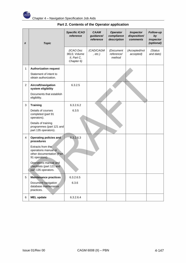
Chapter 4 – Navigation Specification Job Aids
Issue 01/Rev 00 CAGM 6008 (II) – PBN 4-147
Part 2. Contents of the Operator application
#
Topic
Specific ICAO
reference
CAAM
guidance/
reference
Operator
compliance
description
Inspector
disposition/
comments
Follow-up
by
inspector
(optional)
(ICAO Doc
9613, Volume
II, Part C,
Chapter 6)
(CAD/CAGM
, etc.)
(Document
reference/
method
(Accepted/not
accepted)
(Status
and date)
1 Authorization request
Statement of intent to
obtain authorization.
2 Aircraft/navigation
system eligibility
Documents that establish
eligibility.
6.3.2.5
3 Training
Details of courses
completed (part 91
operators).
Details of training
programmes (part 121 and
part 135 operators).
6.3.2.6.2
6.3.5
4 Operating policies and
procedures
Extracts from the
operations manual or
other documentation (Part
91 operators).
Operations manual and
checklists (part 121 and
part 135 operators.
6.3.2.6.3
5 Maintenance practices
Document navigation
database maintenance
practices.
6.3.2.6.5
6.3.6
6 MEL update 6.3.2.6.4
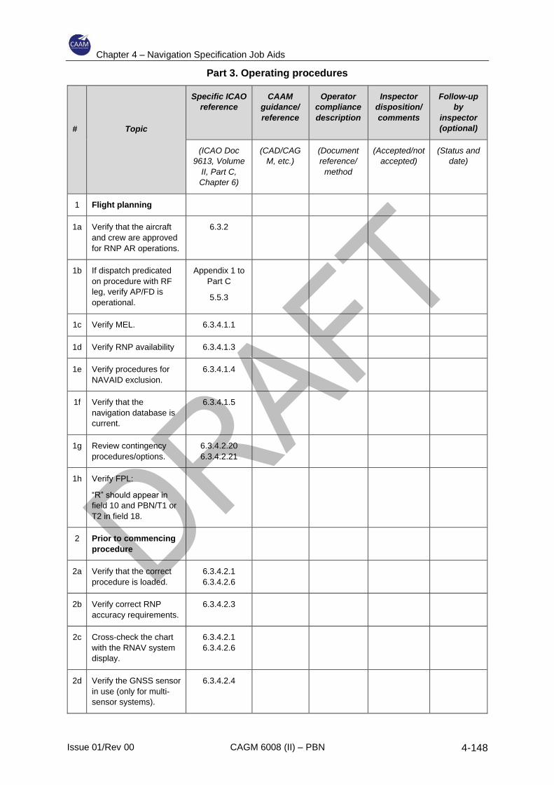
Chapter 4 – Navigation Specification Job Aids
Issue 01/Rev 00 CAGM 6008 (II) – PBN 4-148
Part 3. Operating procedures
#
Topic
Specific ICAO
reference
CAAM
guidance/
reference
Operator
compliance
description
Inspector
disposition/
comments
Follow-up
by
inspector
(optional)
(ICAO Doc
9613, Volume
II, Part C,
Chapter 6)
(CAD/CAG
M, etc.)
(Document
reference/
method
(Accepted/not
accepted)
(Status and
date)
1 Flight planning
1a Verify that the aircraft
and crew are approved
for RNP AR operations.
6.3.2
1b If dispatch predicated
on procedure with RF
leg, verify AP/FD is
operational.
Appendix 1 to
Part C
5.5.3
1c Verify MEL. 6.3.4.1.1
1d Verify RNP availability 6.3.4.1.3
1e Verify procedures for
NAVAID exclusion.
6.3.4.1.4
1f Verify that the
navigation database is
current.
6.3.4.1.5
1g Review contingency
procedures/options.
6.3.4.2.20
6.3.4.2.21
1h Verify FPL:
“R” should appear in
field 10 and PBN/T1 or
T2 in field 18.
2 Prior to commencing
procedure
2a Verify that the correct
procedure is loaded.
6.3.4.2.1
6.3.4.2.6
2b Verify correct RNP
accuracy requirements.
6.3.4.2.3
2c Cross-check the chart
with the RNAV system
display.
6.3.4.2.1
6.3.4.2.6
2d Verify the GNSS sensor
in use (only for multi-
sensor systems).
6.3.4.2.4
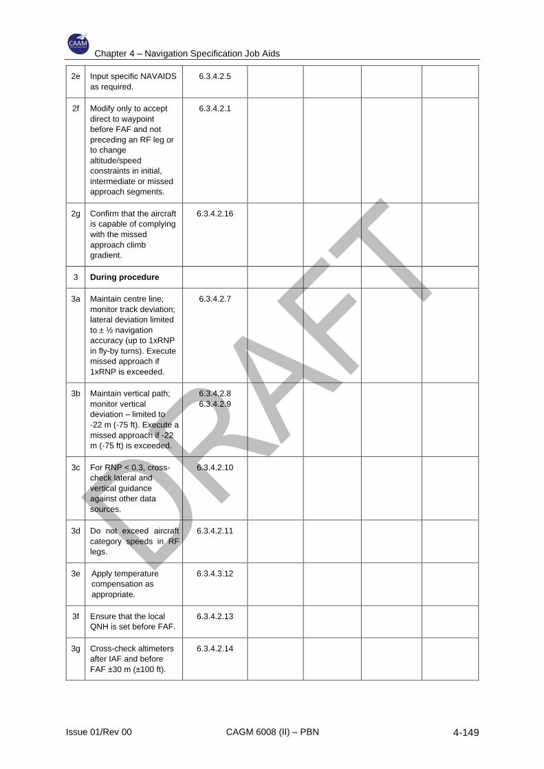
Chapter 4 – Navigation Specification Job Aids
Issue 01/Rev 00 CAGM 6008 (II) – PBN 4-149
2e Input specific NAVAIDS
as required.
6.3.4.2.5
2f Modify only to accept
direct to waypoint
before FAF and not
preceding an RF leg or
to change
altitude/speed
constraints in initial,
intermediate or missed
approach segments.
6.3.4.2.1
2g Confirm that the aircraft
is capable of complying
with the missed
approach climb
gradient.
6.3.4.2.16
3 During procedure
3a Maintain centre line;
monitor track deviation;
lateral deviation limited
to ± ½ navigation
accuracy (up to 1xRNP
in fly-by turns). Execute
missed approach if
1xRNP is exceeded.
6.3.4.2.7
3b Maintain vertical path;
monitor vertical
deviation – limited to
-22 m (-75 ft). Execute a
missed approach if -22
m (-75 ft) is exceeded.
6.3.4.2.8
6.3.4.2.9
3c For RNP < 0.3, cross-
check lateral and
vertical guidance
against other data
sources.
6.3.4.2.10
3d Do not exceed aircraft
category speeds in RF
legs.
6.3.4.2.11
3e Apply temperature
compensation as
appropriate.
6.3.4.3.12
3f Ensure that the local
QNH is set before FAF.
6.3.4.2.13
3g Cross-check altimeters
after IAF and before
FAF ±30 m (±100 ft).
6.3.4.2.14
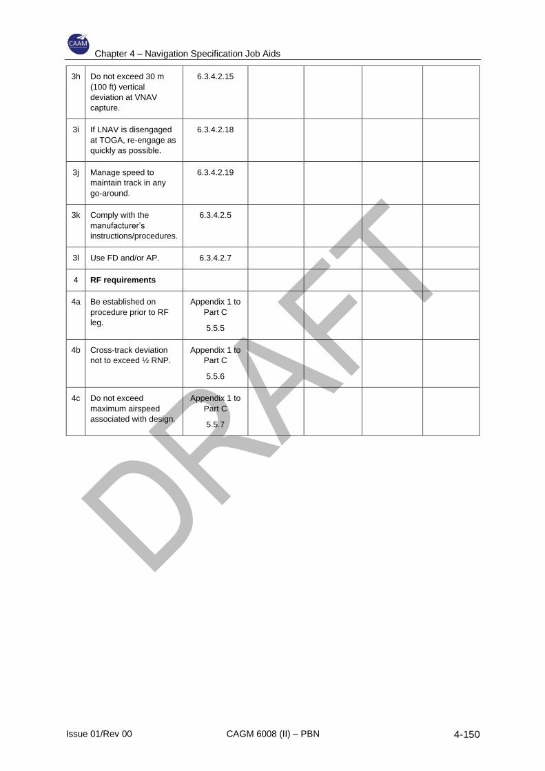
Chapter 4 – Navigation Specification Job Aids
Issue 01/Rev 00 CAGM 6008 (II) – PBN 4-150
3h Do not exceed 30 m
(100 ft) vertical
deviation at VNAV
capture.
6.3.4.2.15
3i If LNAV is disengaged
at TOGA, re-engage as
quickly as possible.
6.3.4.2.18
3j Manage speed to
maintain track in any
go-around.
6.3.4.2.19
3k Comply with the
manufacturer’s
instructions/procedures.
6.3.4.2.5
3l Use FD and/or AP. 6.3.4.2.7
4 RF requirements
4a Be established on
procedure prior to RF
leg.
Appendix 1 to
Part C
5.5.5
4b Cross-track deviation
not to exceed ½ RNP.
Appendix 1 to
Part C
5.5.6
4c Do not exceed
maximum airspeed
associated with design.
Appendix 1 to
Part C
5.5.7
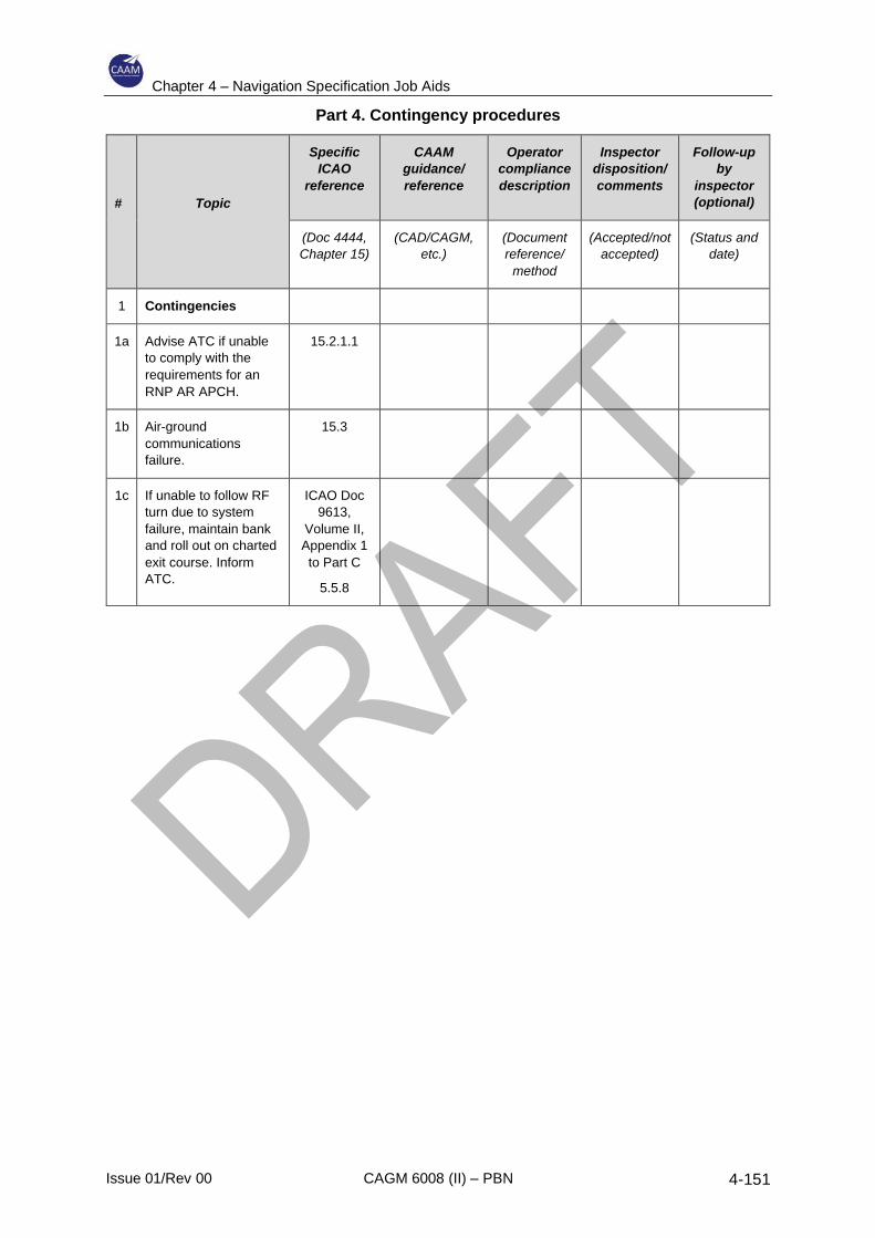
Chapter 4 – Navigation Specification Job Aids
Issue 01/Rev 00 CAGM 6008 (II) – PBN 4-151
Part 4. Contingency procedures
#
Topic
Specific
ICAO
reference
CAAM
guidance/
reference
Operator
compliance
description
Inspector
disposition/
comments
Follow-up
by
inspector
(optional)
(Doc 4444,
Chapter 15)
(CAD/CAGM,
etc.)
(Document
reference/
method
(Accepted/not
accepted)
(Status and
date)
1 Contingencies
1a Advise ATC if unable
to comply with the
requirements for an
RNP AR APCH.
15.2.1.1
1b Air-ground
communications
failure.
15.3
1c If unable to follow RF
turn due to system
failure, maintain bank
and roll out on charted
exit course. Inform
ATC.
ICAO Doc
9613,
Volume II,
Appendix 1
to Part C
5.5.8

Chapter 4 – Navigation Specification Job Aids
Issue 01/Rev 00 CAGM 6008 (II) – PBN 4-152
INTENTIONALLY LEFT BLANK
Chapter 5 – Appendices
Issue 01/Rev 00 CAGM 6008 (II) – PBN 5-1
5 Appendices
5.1 Appendix A – Area Navigation Systems
1 General
1.1 An area navigation system automatically accepts inputs from various positioning
sources. These can be ground-based NAVAIDS, satellite or airborne systems, e.g.
VOR, DME, INS or GNSS. The quality of the available NAVAID infrastructure has a
direct impact on the accuracy of the navigation solution. The area navigation system
computes aircraft position, velocity, track angle, vertical flight path angle, drift angle,
magnetic variation, barometric-corrected altitude, estimated time of arrival and wind
direction and magnitude. It may also perform automatic radio NAVAID tuning as well as
support manual tuning. While navigation can be based upon a single navigation signal
source (e.g. GNSS), most systems are multi-sensor area navigation systems. Such
systems use a variety of navigation sensors including GNSS, DME, VOR and IRS, or
AHRS, to compute the position and velocity of the aircraft. While the implementation
may vary, the system will typically base its calculations on the most accurate positioning
sensor available.
1.2 The area navigation system will confirm the validity of the individual sensor data and, in
most systems, will also confirm the consistency of the computed data before they are
used. GNSS data are subjected to rigorous integrity and accuracy checks prior to being
accepted for navigation position and velocity computation. DME and VOR data are
typically subjected to a series of reasonableness checks prior to being accepted for radio
updating. This difference in rigour is due to the capabilities and features designed into
the navigation sensor technology and equipment. For multi-sensor area navigation
systems, if GNSS is not available for calculating position/velocity, then the system may
automatically select a lower priority update mode such as DME/DME or VOR/DME. If
these radio update modes are not available or have been deselected, then the system
may automatically revert to inertial coasting (i.e. navigation with reference to INS
information or AHRS DR). For single-sensor systems, sensor failure may lead to a dead
reckoning mode of operation. If the area navigation system is using ground NAVAIDS,
it uses its current estimate of the aircraft’s position and its internal database to
automatically tune the ground stations in order to obtain the most accurate radio
position.
1.3 Area navigation enables the aircraft to fly a path, or “leg”, between points, called
“waypoints”, which are not necessarily co-located with ground-based navigation aids. If
a navigation database is included in the area navigation system then the data in the
database are specific to an operator’s requirements. These data are taken from the
States’ aeronautical information publications (AIPs) in the form of route structures,
instrument flight procedures, runways and NAVAIDS. The intended flight path is
programmed into the area navigation system by selection or input of a series of
waypoints, or by loading a complete route or procedure description from the navigation
database. If there is no database the pilot must insert all waypoint data.
1.4 The intended flight path is displayed to the pilot. Lateral and, where available, vertical
guidance are provided to the pilot on displays in the primary field of view. Area navigation
systems are generally coupled, or capable of being coupled, directly to the auto-flight
system (autopilot).
Chapter 5 – Appendices
Issue 01/Rev 00 CAGM 6008 (II) – PBN 5-2
1.5 More advanced area navigation systems include a capability for performance
management where aerodynamic and propulsion models are used to compute vertical
flight profiles matched to the aircraft and able to satisfy the constraints imposed by the
procedure. A performance management function can be complex, utilizing fuel flow, total
fuel, flap position, engine data and limits, altitude, airspeed, Mach, temperature, vertical
speed, progress along the flight plan and pilot inputs to determine the optimum path.
Area navigation systems routinely provide flight progress information for the waypoints
en-route, for terminal and approach procedures, and the origin and destination. The
information includes estimated time of arrival and distance-to-go, which are both useful
in tactical and planning coordination with ATC.
2 Guidance and control
2.1 An area navigation system provides lateral guidance and, in many cases, vertical
guidance. The lateral guidance function compares the aircraft’s position generated by
the navigation function with the desired lateral flight path and then generates steering
commands to fly the aircraft along the desired path. Geodesic or great circle paths join
the flight plan waypoints and circular transition arcs between these legs are calculated
by the area navigation system. The flight path error is computed by comparing the
aircraft’s present position and direction with the reference path. Roll steering commands
to track the reference path are based upon the path error. These steering commands
are output to a flight guidance system, which either controls the aircraft directly or
generates commands for the flight director. The vertical guidance function, where
included, is used to control the aircraft along the vertical profile within constraints
imposed by the flight plan. The outputs of the vertical guidance function are typically
pitch commands to a display and/or flight guidance system and thrust or speed
commands to displays and/or an auto-thrust function.
2.2 Display and system controls provide the means for system initialization, flight planning,
computation of path deviations, progress monitoring, active guidance control and
presentation of navigation data for flight crew situational awareness.
3 Navigation database
3.1 Operators purchase the navigation data from third-party companies, known as data
houses, which compile the navigation information from each State to support the
operator’s requirement. These data houses produce the datasets which are packaged
and shipped in ARINC 424 format to the original equipment (area navigation system)
manufacturers (OEMs). The OEMs, known as “data packers”, code the datasets for the
appropriate (target) area navigation systems. The databases are updated and validated
in accordance with the ICAO AIRAC. Each area navigation system uses its own
proprietary binary database format. Furthermore, each operator has a specific
requirement for navigation data.
3.2 If the data in the dataset are incorrect, the data in the database will be incorrect and the
pilot may not be aware of this. Each navigation specification includes requirements to
ensure that the navigation database integrity is maintained and to ensure that only valid
databases are used. The flight path extracted from the database should also be checked
for accuracy and consistency against the chart information before and during every area
navigation operation. When using an area navigation system with a database, the pilot
will select the route/procedure or the waypoints defining the flight planned route from
the database to create a route in the area navigation system. For area navigation
Chapter 5 – Appendices
Issue 01/Rev 00 CAGM 6008 (II) – PBN 5-3
systems without a database, the pilot will manually insert the waypoints (key in the
coordinates of each waypoint required) to define the route.
4 RNAV waypoints
4.1 A significant point is defined as a specified geographical location used to define an area
navigation route or the flight path of an aircraft employing area navigation. There are
three categories of significant points: ground-based navigation aid, intersection and
waypoint. An intersection is a significant point expressed as radials, bearings and/or
distances from ground-based navigation aids. Area navigation systems use only
significant points that are defined by geographic coordinates in WGS-84 and data
houses convert fixes into “computer navigation fixes” with associated coordinates. Fixes
are associated only with conventional navigation and are not used in PBN. All significant
points are treated as “waypoints” within the area navigation system. Significant points
are identified as follows:
a) by a five-letter unique name code, e.g. BARNA
b) by the three-letter ICAO identifier for the NAVAID, e.g. OTR
c) by an alphanumeric name code if used in terminal airspace only, e.g. DF410.
4.2 Area navigation routes/procedures can specify a path laterally, longitudinally and
vertically. The waypoints are used to indicate a change in direction (track), speed and/or
height. In SIDs and missed approaches, turns may be predicated on altitude rather than
waypoint location. The area navigation system will fly routes and procedures in a
consistent manner, but the actual track will depend upon the waypoint transition and, in
terminal procedures, on the leg types used to define the procedure. Waypoint transition
may be:
a) flyover;
b) fly-by;
c) fixed radius.
4.3 A flyover waypoint requires that the turn is initiated when the aircraft passes overhead
the waypoint. All area navigation systems are capable of a flyover turn followed by a
manoeuvre to recapture the next leg. A fly-by waypoint requires the area navigation
system to calculate a turn anticipation before the aircraft reaches the waypoint to allow
interception of the next segment without the aircraft passing overhead the waypoint. The
turn anticipation distance depends on aircraft ground speed and the angle of bank
applied in the turn. Turn anticipation does not provide track guidance during the turn,
and cross-track error cannot be monitored until the aircraft is established on the
subsequent leg. The effectiveness of the turn anticipation algorithm is limited by
variation in ground speed during the turn (e.g. headwind to tailwind) and the achieved
bank angle. Undershooting or overshooting of the turn can occur and crew intervention
may be required. Fly-by functionality is called up in many navigation specifications but
is not always available on older and less capable area navigation systems.
4.4 A fixed radius turn is defined differently in en-route and on terminal procedures. In the
former, which is known as a fixed radius transition (FRT), a fixed radius value is
associated with a waypoint, and the area navigation system is required to fly by that
waypoint using the same turn radius regardless of the aircraft ground speed. In the latter
case, the ground track is defined in the database with a waypoint at the start and end of
Chapter 5 – Appendices
Issue 01/Rev 00 CAGM 6008 (II) – PBN 5-4
the turn and the leg type specified as a radius to fix (RF) leg. In both cases the turn is a
fixed circular track over the ground with tangential inbound and outbound legs. The area
navigation system monitors cross-track error during the turn and provides guidance to
maintain the circular track. RF and FRT functionality are not available on many older
RNAV systems.
5 RNAV Performance
PBN requirements are specified in terms of lateral, vertical and 4-D accuracy; integrity;
continuity; availability and functionality. (Only one navigation specification to date
addresses “time of arrival” (4-D) requirements.)
5.1 Accuracy
5.1.1 The accuracy achieved by an area navigation system depends on the position and
timing sources, the RNAV system, the flight guidance and the navigation database.
The total system error (TSE) is usually computed as a root sum square of the
navigation system error (NSE), the flight technical error (FTE) and the position
definition error (PDE).
5.1.2 The lateral track accuracy is based upon the path that has been defined by the area
navigation system, the navigation sensor used to estimate the position, and the ability
of the pilot and aircraft guidance system to fly the defined path. Each navigation
specification identifies the 95% accuracy requirement and may place additional
constraints on certain of the error sources. For example, the FTE requirement is
usually set at one-half full-scale deflection (FSD), where, FSD = the 95 % accuracy
requirement. Positioning sources may be limited, for example to DME/DME and GNSS
only. Additional data integrity checks may be required to limit the potential for path
definition error.
5.1.3 Position estimation accuracy is related to the type of navigation sensor used and the
associated NSE. The NSE depends upon the signal-in-space and the dilution of
precision (DOP) resulting from the relative angle that the signals subtend at the
antenna.
5.1.4 Some sensors are better suited to PBN operations than others:
a) NDB is not suitable for any area navigation systems
b) VOR accuracy deteriorates with range and is appropriate only for RNAV 5
applications.
c) DME/DME requires there to be sufficient stations with appropriate geometry in
order to support some PBN applications in continental en-route and terminal
airspace. A position estimation accuracy sufficient for ± 1 NM accuracy requires
that the signals from a pair of DME stations subtend more than 30° but less than
150° at the aircraft antenna.
d) GNSS is the most accurate PBN positioning source and can be used in all PBN
applications.
5.1.5 Vertical profile accuracy is, similarly, based upon the vertical path defined by the area
navigation system, the sensor used to estimate the altitude, the vertical component of
Chapter 5 – Appendices
Issue 01/Rev 00 CAGM 6008 (II) – PBN 5-5
any along-track error and the ability of the pilot and aircraft guidance system to fly the
defined profile. At present there are two vertical sensor sources for area navigation
systems: barometric altimetry and SBAS.
5.2 Integrity
5.2.1 Integrity is the degree of confidence that can be placed in the guidance provided by
the area navigation system. Any malfunction of the area navigation system or
associated equipment (e.g. sensors) must not occur more than once in 100 000 flight
hours. The pilot must be alerted if the system malfunctions.
5.2.2 In RNP systems, the pilot must also be alerted if the probability that the total system
error (TSE) is greater than the 95% accuracy requirement exceeds 10–5. In GNSS-
equipped area navigation systems this is usually achieved using the receiver
autonomous integrity monitoring (RAIM) function or the aircraft autonomous integrity
monitoring (AAIM) function. SBAS also provides an integrity monitoring function.
5.2.3 The RAIM function in the GNSS receiver compares a series of position estimations
using the available satellite signals and generates an alert if one of the position
estimations exceeds a pre-set threshold value (horizontal alert limit (HAL)). This is
known as fault detection (FD) and requires a minimum of five satellites in view,
although a barometric input may be used instead of one satellite. More recent RAIM
versions detect the fault and exclude the faulty satellite from the positioning solution
without necessarily generating any alert. This is known as fault detection and exclusion
(FDE) and requires a minimum of six satellites in view. RAIM availability is determined
by calculating the radius of a circle, as a function of the RAIM threshold and the satellite
geometry at the time of the measurements, which is centred on the GPS position
solution and is guaranteed to contain the true position. If this radius is less than HAL,
RAIM is available. The AAIM function compares the GNSS position estimation with the
on-board inertial navigation position and generates an alert if the pre-set threshold
values are breached. SBAS detects GPS satellite signal errors and broadcasts
corrections to all users.
5.3 Availability and continuity
5.3.1 In order to perform a specific navigation application, both the signals-in-space and the
aircraft systems must meet the required accuracy and integrity for that operation.
Availability is a measure of the probability that this will be the case when the operation
is to be performed. Continuity is a measure of the probability that it will continue to be
the case for the duration of the operation. The service provider is responsible for
ensuring that the signal is available and continues to be available. However, the
navigation specifications do not specify a measure of availability, and operators are
required to check the availability prior to departure and again prior to commencing an
operation. The navigation specifications all require that the airborne systems meet a
continuity of 10–4 per flight hour. This is often achieved through redundancy (additional
capability to handle failures), or by the carriage of additional systems (e.g. IRS/IRU).
The probability of failure and therefore being unable to complete an operation must be
acceptably low.
5.3.2 On-board performance monitoring and alerting
RNP systems do not necessarily provide the pilot with a warning when the
lateral accuracy limits have been exceeded. Most RNP specifications require
Chapter 5 – Appendices
Issue 01/Rev 00 CAGM 6008 (II) – PBN 5-6
that the area navigation system, or the area navigation system and pilot in
combination, provide an alert if the accuracy requirement is not met or if the
probability that the lateral TSE exceeds a specified value is greater than 10–5.
RNP systems typically have an NSE monitoring and alerting algorithm, which
generates an alert, and displays FTE via a lateral deviation indicator, which is
monitored by the crew.
5.3.3 Functionality
5.3.3.1 The following functions are the minimum required to conduct area navigation
operations:
a) continuous indication of aircraft position relative to track to be displayed to the
pilot flying (and the pilot monitoring) on a navigation display situated in the
primary field of view;
b) display of distance and bearing to the active (To) waypoint;
c) display of ground speed or time to the active (To) waypoint;
d) navigation data storage (usually a navigation database);
e) appropriate failure indication of the area navigation system, including failed
sensors or degraded mode of performance.
5.3.3.2 Each navigation specification identifies additional functionalities which may include:
a) non-numeric lateral and vertical deviation displays in the primary field of view,
automatically saved to the area navigation computed path and with full-scale
deflection based upon the required TSE;
b) map displays with appropriate scales;
c) the means to retrieve and display data, including entire area navigation
routes/procedures, from a navigation database;
d) display active sensor type;
e) execute “direct to” function;
f) automatically sequence legs and display the sequencing (fly-by, flyover, turn at
altitude);
g) execute leg transitions and maintain tracks consistent with ARINC 4241 path
terminators (CA, CF, DF, FA, FM, HA, HF, HM, IF, RF, VA, VI and VM);
h) define a vertical path by altitude constraints at two waypoints or by vertical path
angle at a waypoint;
i) provide guidance to a vertically constrained waypoint;
j) display altitude restrictions and vertical path angles;
k) execute fixed-radius transitions;
l) automatic reversion to alternate sensor when primary sensor fails;
Chapter 5 – Appendices
Issue 01/Rev 00 CAGM 6008 (II) – PBN 5-7
m) execute parallel offset;
n) maintain continuous track guidance upon initiation of missed approach/go-
around;
o) ensure that lower navigation accuracy is achieved by the waypoint which marks
the start of the leg with the lower accuracy requirement;
p) appropriate alert when the NSE limit cannot be assured.
5.3.4 Deviation display
There are a number of different ways in which lateral deviation can be
displayed: the course deviation indicator (CDI) and the horizontal situation
indicator (HSI) are both avionic instruments that display deviation from track by
means of pointers; navigation performance scales (NPS) and also L/DEV and
V/DEV provide a graphical representation of the achieved lateral and vertical
performance, together with an indication of available flight technical error
remaining; numeric displays of achieved navigation performance and, finally,
the navigation map display. In general, a map display, or a numeric indicator is
considered to be adequate for RNP 2 and higher, while deviation indicators
such as CDI and HSI are required for lower RNP accuracy values, and NPS or
L/DEV and V/DEV, together with FD and/or AP, are required for low RNP
accuracy values.
Chapter 5 – Appendices
Issue 01/Rev 00 CAGM 6008 (II) – PBN 5-8
5.2 Appendix B – Example Regulatory text
XXX.001 APPLICATION FOR A SPECIFIC APPROVAL
a) An applicant for the initial issue of a specific approval shall provide the Civil Aviation
Authority of Malaysia with the documentation required, as detailed on the application form,
and the following information:
1) the official name, address and mailing address of the applicant; and
2) a description of the intended operation.
b) An applicant for a specific approval shall provide evidence to the Civil Aviation Authority
of Malaysia that:
1) the applicant complies with the requirements;
2) the aircraft and required equipment fulfil the applicable airworthiness requirements, are
maintained according to the approved maintenance programme and are approved
when required;
3) a training programme has been established for flight crew and, as applicable,
personnel involved in these operations; and
4) operating procedures in accordance with the requirements have been documented.
Operating procedures should be documented in the operations manual. If an
operations manual is not required, operating procedures may be described in a
procedure’s manual.
c) An operator shall retain records relating to the requirements of a) and b) above at least
for the duration of the operation requiring the specific approval.
XXX.002 PRIVILEGES OF AN OPERATOR HOLDING A SPECIFIC APPROVAL
The scope of the activity that the operator is approved to conduct shall be documented and
specified:
a) for commercial operators, in the operations specifications associated to the air
operator certificate; and
b) for non-commercial operators, in the list of specific approvals.
XXX.003 CHANGER TO OPERATIONS SUBJECT TO A SPECIFIC APPROVAL
In case of a change that affects the conditions of a specific approval, the operator shall provide
the relevant documentation to the Civil Aviation Authority of Malaysia and obtain prior approval
for the change to operation, documented by an amendment to the approval document
XXX.003.
XXX.004 CONTINUED VALIDITY OF A SPECIFIC APPROVAL
Specific approvals shall be issued for an unlimited duration. They shall remain valid subject to
the operator remaining in compliance.
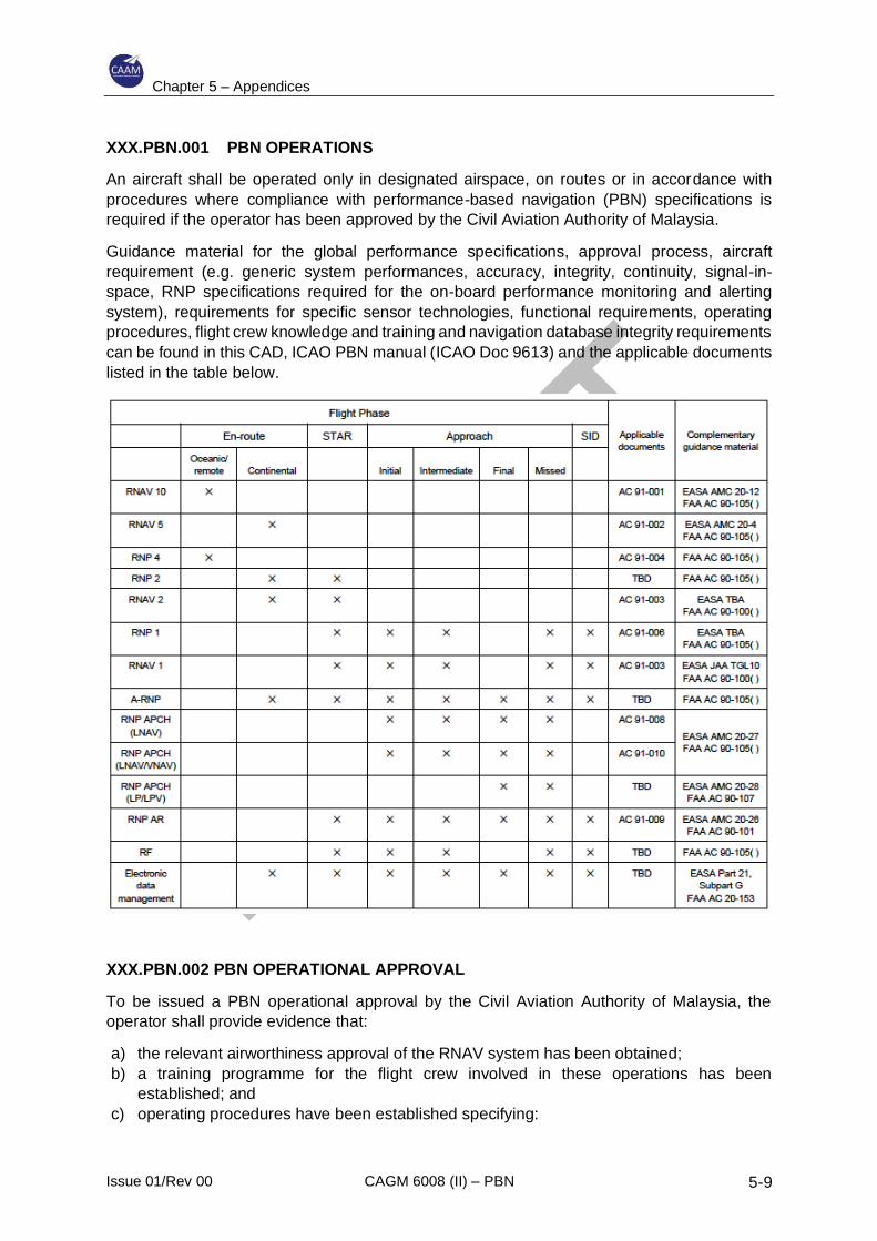
Chapter 5 – Appendices
Issue 01/Rev 00 CAGM 6008 (II) – PBN 5-9
XXX.PBN.001 PBN OPERATIONS
An aircraft shall be operated only in designated airspace, on routes or in accordance with
procedures where compliance with performance-based navigation (PBN) specifications is
required if the operator has been approved by the Civil Aviation Authority of Malaysia.
Guidance material for the global performance specifications, approval process, aircraft
requirement (e.g. generic system performances, accuracy, integrity, continuity, signal-in-
space, RNP specifications required for the on-board performance monitoring and alerting
system), requirements for specific sensor technologies, functional requirements, operating
procedures, flight crew knowledge and training and navigation database integrity requirements
can be found in this CAD, ICAO PBN manual (ICAO Doc 9613) and the applicable documents
listed in the table below.
XXX.PBN.002 PBN OPERATIONAL APPROVAL
To be issued a PBN operational approval by the Civil Aviation Authority of Malaysia, the
operator shall provide evidence that:
a) the relevant airworthiness approval of the RNAV system has been obtained;
b) a training programme for the flight crew involved in these operations has been
established; and
c) operating procedures have been established specifying:

Chapter 5 – Appendices
Issue 01/Rev 00 CAGM 6008 (II) – PBN 5-10
1) the equipment to be carried, including its operating limitations and appropriate
entries in the minimum equipment list (MEL);
2) flight crew composition and experience requirements;
3) normal procedures;
4) contingency procedures;
5) monitoring and incident reporting; and
6) electronic navigation data management.
XXX.PBN.003 ELECTRONIC NAVIGATION DATA MANAGEMENT
Electronic navigation data products that have been processed for application in the air and on
the ground shall be used only once the Civil Aviation Authority of Malaysia has approved the
operator’s procedure for:
a) ensuring acceptable standards of data integrity and compatibility with the intended
function;
b) continual monitoring of the related data processes and the products; and
c) ensuring the timely distribution and insertion of electronic navigation data.
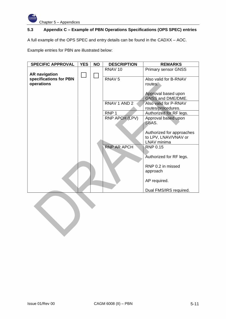
Chapter 5 – Appendices
Issue 01/Rev 00 CAGM 6008 (II) – PBN 5-11
5.3 Appendix C – Example of PBN Operations Specifications (OPS SPEC) entries
A full example of the OPS SPEC and entry details can be found in the CADXX – AOC.
Example entries for PBN are illustrated below:
SPECIFIC APPROVAL YES NO DESCRIPTION REMARKS
AR navigation specifications for PBN operations
RNAV 10 Primary sensor GNSS
RNAV 5 Also valid for B-RNAV routes. Approval based upon GNSS and DME/DME.
RNAV 1 AND 2 Also valid for P-RNAV routes/procedures.
RNP 1 Authorized for RF legs.
RNP APCH (LPV) Approval based upon SBAS. Authorized for approaches to LPV, LNAV/VNAV or LNAV minima
RNP AR APCH RNP 0.15 Authorized for RF legs. RNP 0.2 in missed approach AP required. Dual FMS/IRS required.
Chapter 5 – Appendices
Issue 01/Rev 00 CAGM 6008 (II) – PBN 5-12
5.4 Appendix E – Flight Operational Safety Assessments (FOSAs)
1 FOSA OVERVIEW
1.1 Why is FOSA needed?
1.1.1 In some cases, the operational needs of stakeholders lead to procedure designs which
may or may not comply with Required Navigation Performance Authorization Required
(RNP AR) Procedure Design Manual (ICAO Doc 9905) but which require the aircraft
to be operated in a manner that was not considered in its airworthiness approval.
1.1.2 A FOSA is intended to address this nominal mismatch.
1.1.3 When RNP AR APCH is being implemented it is for a specific reason, e.g. improved
access, safety, efficiency. The FOSA process helps to ensure that the operational
needs, the limits of safe and efficient aircraft performance, the means of assuring
repeatable and predictable flight operations, the means of safe flight operations when
faced with aircraft failures and hazardous conditions, etc., are understood by all
relevant stakeholders. As a result, the aircraft operations, procedure design,
contingency arrangements, training and maintenance will all be at the level necessary
for flight and operational safety.
1.2 When should a FOSA be conducted?
A FOSA should be conducted for each RNP AR approach procedure where the more
stringent aspects of the nominal procedure design criteria (as per Doc 9905) are
applied (i.e. RF legs after the FAF, RNP missed approaches less than 1.0, RNP final
approaches less than 0.3) or where the application of the default procedure design
criteria is in an operating environment with special challenges or demands.
1.3 How should a FOSA be carried out?
1.3.1 The FOSA should ensure that for each specific set of operating conditions, aircraft and
environment, all failure conditions are assessed and, where necessary, mitigations are
implemented to meet the safety criteria. The assessment should give proper attention
to the inter-dependence of the elements of procedure design, aircraft capability, crew
procedures and operating environment.
1.3.2 The functional areas presented in Figure E-1 have been identified as elements to
assess collectively in a typical FOSA. The FOSA should act as the “glue” to combine
and analyse the risks associated with the RNP AR system.
2 REQUIRED DEPTH OF A FOSA
2.1 The depth of a FOSA and the associated level of resources are very important issues
for stakeholders. Three factors that influence the required depth of a FOSA are:
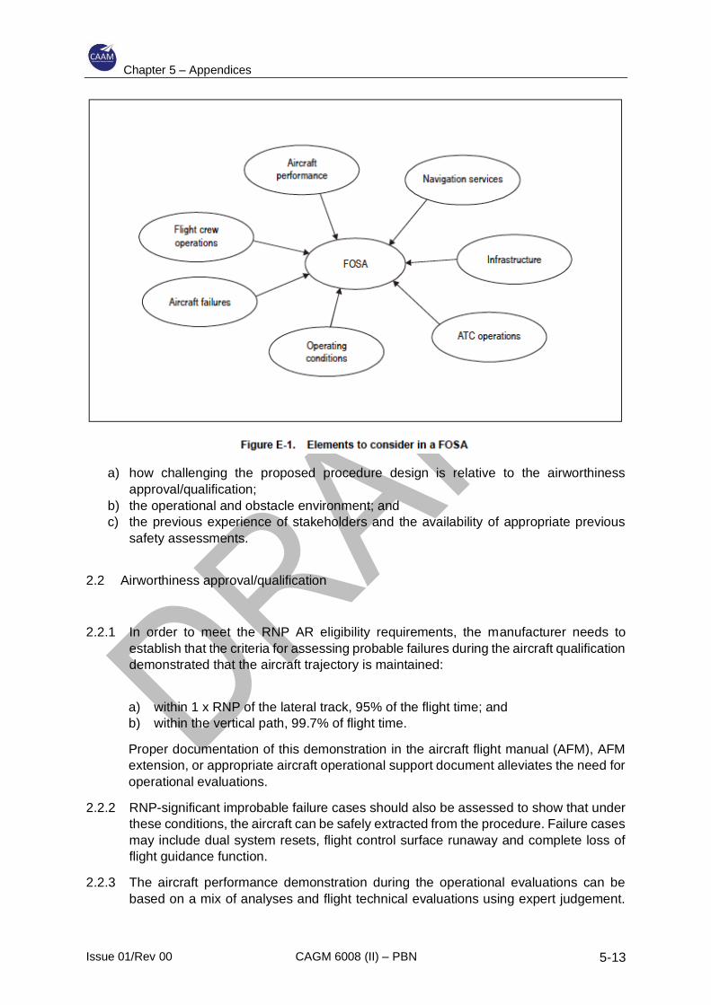
Chapter 5 – Appendices
Issue 01/Rev 00 CAGM 6008 (II) – PBN 5-13
a) how challenging the proposed procedure design is relative to the airworthiness
approval/qualification;
b) the operational and obstacle environment; and
c) the previous experience of stakeholders and the availability of appropriate previous
safety assessments.
2.2 Airworthiness approval/qualification
2.2.1 In order to meet the RNP AR eligibility requirements, the manufacturer needs to
establish that the criteria for assessing probable failures during the aircraft qualification
demonstrated that the aircraft trajectory is maintained:
a) within 1 x RNP of the lateral track, 95% of the flight time; and
b) within the vertical path, 99.7% of flight time.
Proper documentation of this demonstration in the aircraft flight manual (AFM), AFM
extension, or appropriate aircraft operational support document alleviates the need for
operational evaluations.
2.2.2 RNP-significant improbable failure cases should also be assessed to show that under
these conditions, the aircraft can be safely extracted from the procedure. Failure cases
may include dual system resets, flight control surface runaway and complete loss of
flight guidance function.
2.2.3 The aircraft performance demonstration during the operational evaluations can be
based on a mix of analyses and flight technical evaluations using expert judgement.
Chapter 5 – Appendices
Issue 01/Rev 00 CAGM 6008 (II) – PBN 5-14
Aircraft performance in the event of failures, as well as in normal conditions, should
therefore be available in the AFM or an equivalent document.
2.3 Operational and obstacle environment
2.3.1 If the procedure is being introduced for noise alleviation purposes and there are no
obstacles close to the route (within 2 × RNP), a less detailed FOSA may be
appropriate. No FOSA is required if the default RNP values of 1, 1, 0.3 and 1 are used
for the procedure.
2.3.2 If a very complex and challenging procedure is being introduced for better access to a
runway surrounded by challenging terrain/obstacles, a more detailed FOSA may be
considered advisable (if no prior examination/ assessment is found to be applicable —
see below).
2.4 Previous experience stakeholders and availability of appropriate previous FOSAs
2.4.1 The specific history and circumstances of the RNP AR APCH implementation and the
associated stakeholders will affect the depth of the FOSA. Important factors include
whether:
a) a new procedure is being developed, or one already exists, that is flown by other
carriers and/or by other aircraft types;
b) relevant FOSAs exist for the procedure or for other similar applications;
c) a carrier with an RNP-certified aircraft already has the manufacturer’s AFM,
operations manual, crew procedures, dispatch guidance, minimum equipment
criteria for RNP, compliance assessments, etc., that were considered valid from a
previous similar RNP AR application;
d) the ANSP and regulator(s) have previous experience with RNP AR approaches
and FOSA at this airport or similar locations.
2.4.2 When it is determined that no FOSA has to be performed, a rationale should be
provided, e.g. “not applicable as covered by basic aircraft certification and/or prior
operational approvals and FOSA”.
3 HOW TO CONDUCT A FOSA
3.1 Overview of the main steps
Within aviation a number of safety assessment methodologies are in use. There is
usually a large degree of commonality between them, and it is difficult to identify one
as clearly the best in all situations. The method illustrated in Figure E-2 was developed
to be consistent with previous FOSA material and more general safety assessment
material. It is likely that many organizations planning RNP AR approaches will already
have their own safety assessment processes in place. It is expected that the steps
below will be represented within these processes.
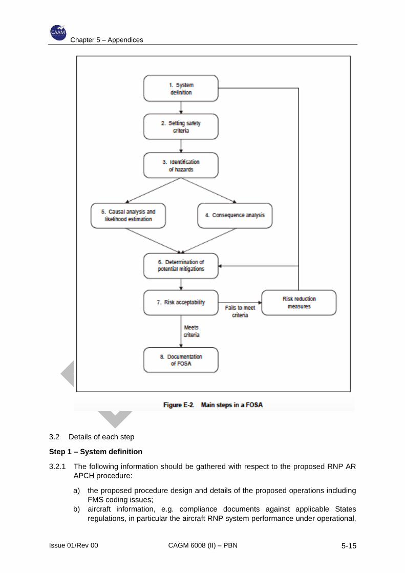
Chapter 5 – Appendices
Issue 01/Rev 00 CAGM 6008 (II) – PBN 5-15
3.2 Details of each step
Step 1 – System definition
3.2.1 The following information should be gathered with respect to the proposed RNP AR
APCH procedure:
a) the proposed procedure design and details of the proposed operations including
FMS coding issues;
b) aircraft information, e.g. compliance documents against applicable States
regulations, in particular the aircraft RNP system performance under operational,
Chapter 5 – Appendices
Issue 01/Rev 00 CAGM 6008 (II) – PBN 5-16
rare, normal and non-normal conditions which should be documented to support
the FOSA exercise;
c) flight crew procedures and training;
d) dispatch procedures and training;
e) proposed minimum equipment list (or RNP AR required equipment list);
f) any special maintenance requirements;
g) airport and airspace environment;
h) navigation infrastructure;
i) ATC facilities (including surveillance and communications), procedures and
intended training with respect to RNP AR operations; and
j) monitoring programme.
3.2.2 This should be used to put together a system description which is suitable and
sufficient to conduct the FOSA. It should be ensured that all relevant elements are
included, i.e. not just equipment hardware but human aspects, procedures, software,
firmware and environmental aspects. As part of this step, assumptions made in AR
guidance documents will need to be checked and validated.
3.2.3 With the system defined it is recommended that a small group of experts spend a short
amount of time to identify the difficult elements of the approach, any human factors
issues and any key hazards. This information will help to understand the exact
requirements and necessary outcomes of the FOSA process. Subsequently an
estimation of the depth of analysis required and the effort needed to complete the
FOSA can be made.
Step 2 — Setting safety criteria
3.2.4 Safety criteria can be quantitative or qualitative. This CAD and the ICAO PBN manual
notes that a FOSA is likely to use a mix of quantitative and qualitative analysis so it
would be expected that the safety criteria reflect this. The following criteria have been
found to be useful and practical:
a) Quantitative safety objective criteria: Quantitative criteria work best in the
airworthiness domain where relevant data on equipment failure rates are available
and where consequences can be precisely defined. It should be noted that
conversions between different units (e.g. per flight hour to per approach) need to
take account of exposure times. In the flight operations domain, human factors and
the influence of procedures and training make it much more difficult to derive
meaningful quantitative criteria. Hence qualitative criteria such as the following are
generally more useful.
b) Risk reduced as far as reasonably practicable (AFARP): This criterion is commonly
used in aviation. It is sometimes referred to as the ALARP criterion, reducing risk
as low as reasonably practicable. It is generally used in a qualitative manner
although it can be used quantitatively via cost-benefit analysis. In the context of the
FOSA it can be applied globally to the system, i.e. the system as a whole has
reduced the risk AFARP, and it can also be applied hazard by hazard.
Risk reduced AFARP/ALARP is a flexible criterion suited to the mixture of
techniques used in a FOSA. It has been found to be readily accepted by
Chapter 5 – Appendices
Issue 01/Rev 00 CAGM 6008 (II) – PBN 5-17
stakeholders in RNP AR case studies and has helped to define what extra risk
reduction measures were needed by the AO and ANSP.
c) Risk no greater than current operations: In a safety conscious industry such as
aviation, great care is taken to ensure that operations do not become riskier; rather
there is a drive to continue the downward trend in accident rates. This is potentially
a useful criterion to apply hazard by hazard to check that there are adequate
mitigations in place to ensure no risk increase. Potential difficulties with this relative
criterion are:
1) Sometimes it is very difficult even for aviation experts to compare the risks from
different approach types.
2) There is a range of risk associated with current approach operations
(historically non-precision approaches are significantly higher risk than
precision approaches). Hence the conclusions from use of this criterion will
depend on what is being compared.
3) Some regulations require that the ATM risk should decrease in the future as
traffic rises. Being as safe as today may not be good enough.
Therefore, some care needs to be taken with this “no risk increase” criterion. On its
own it will probably not be sufficient, but together with the other criteria above it can
be part of a practical package. If a relative criterion is used, the other approach type
for comparison needs to be defined in the same level of detail as described above
in Step 1 for the RNP AR approach.
The choice of safety criteria is very important. It is advisable for AOs to consult with
their regulators before undertaking a FOSA. Some regulators may be wary of an
RNP AR approach that increases risk compared to an existing PA, for example,
even if the new procedure meets an AO’s existing risk tolerability matrix. This could
prevent an operational approval from being granted. The AFARP/ALARP principle
is likely to be an important and possibly the most practical part of the criteria used
in a FOSA.
Step 3 – Identification of hazards
3.2.5 There are a range of techniques that have been used in aviation to identify hazards.
Some of these are based on analysis by a single person and others use a group of
experts working as a team. Given the need for a FOSA to make use of a mix of
disciplines, a group-based approach is likely to be the most successful.
3.2.6 The following points can help maximize the effectiveness of group-based hazard
identification:
a) ensure use of an experienced facilitator to guide the group;
b) gather the required mix of skills and knowledge, i.e.:
1) procedure designers;
2) aircraft and avionics manufacturers, if available;
3) technical support experts;
Chapter 5 – Appendices
Issue 01/Rev 00 CAGM 6008 (II) – PBN 5-18
4) pilots (from relevant aircraft operators and test pilots if available);
5) AIM experts;
6) ATCOs and ATC representatives with knowledge of airspace planning and
technical facilities; and
7) Regulators.
Representatives from other disciplines which could be useful in a FOSA include flight
operations, dispatch, maintenance and safety and quality. Running an effective group
session involves obtaining a balance of skills but also having a manageable size of
group.
Step 4 – Consequence analysis and severity evaluation
3.2.7 The manner in which the consequences of hazards are analysed will depend on the
hazards. Aircraft failures will use the failure condition effects and severity classification
detailed in the national advisory circulars/acceptable means of compliance and will
have to satisfy the quantitative safety objectives set forth in the PBN manual and
related documents. In this context, consequences are related to quantitative lateral
and vertical excursions and, in the case of excursion beyond the 2 x RNP lateral
corridor, whether or not the aircraft remains manoeuvrable and able to make a safe
extraction. To assess consequences in this manner will require simulations. Where
relevant analysis already exists from RNP certification activity this should be used and
not duplicated.
3.2.8 For hazards in many of the other FOSA functional areas, human failures and
procedural issues have a dominant effect. It is very difficult to assign a single severity
level or determine a quantified excursion for such hazards. Thus, the consequences
are better described qualitatively for most of these other hazards. This information can
then be used in the decision-making process concerning whether mitigations are
sufficient to control risk to an acceptable level.
Step 5 — Causal analysis and likelihood estimation
3.2.9 The likelihood of aircraft equipment failures will already have been analysed in the
existing aircraft system safety assessment (SSA) documents. These often employ
techniques that can model complex trees/chains linking multiple causes to the hazard.
Data generally exists to populate these models and enable robust quantification of the
hazard likelihood. This enables a check to be made that the safety objectives can be
met. This work will already have been done during RNP AR certification activities, and
it should not be necessary for the manufacturer to supply detailed technical analyses.
Details of the hazards considered, and their likelihood category should be sufficient for
the FOSA.
3.2.10 For most of the other functional areas, where human failures and procedural issues
have a dominant effect, such detailed quantification either may not be possible or may
not be useful. A possible qualitative method used in the case studies was:
a) identify and document the relevant causes of the hazard;
b) map the causal mitigations (see Step 6) to these causes;
Chapter 5 – Appendices
Issue 01/Rev 00 CAGM 6008 (II) – PBN 5-19
c) consider the likelihood of these causes implicitly when judging whether the
mitigations are sufficient.
3.2.11 At the end of Step 5, potential combinations and sequences of causes leading to
hazards and subsequent sequences of events to various consequences (from Step 4)
will be apparent. It is important that common cause failures (CCFs) within these
combinations and sequences are identified and their importance assessed. Critical
CCFs that can significantly increase risk levels will need additional mitigations.
Step 6 — Determination of mitigations
3.2.12 Mitigations that reduce the chance of a hazard occurring (causal mitigations) and
mitigations that reduce the severity of hazard consequences/effects should be
considered and documented. Splitting out the potential causes and consequences can
help this process.
3.2.13 As part of the analysis of consequential mitigations it would be expected that
contingency procedures would be fully worked out covering a range of challenging
hazards (e.g. double FMS loss, loss of GNSS) occurring at various critical locations
(e.g. in the RF leg, early in the procedure potentially requiring long extraction, at DA/
DH).
3.2.14 It is usually helpful to identify mitigations that are already in place or planned and then
to allow the FOSA group time to also identify potential extra mitigations. Some of these
potential extra mitigations may later be rejected as not needed or not practicable.
However, this part of the process is a key stage in demonstrating that risk has been
reduced AFARP.
Step 7 — Determination of risk acceptability
3.2.15 For aircraft failure hazards, the normal airworthiness criteria from 14 CFR 25.1309 will
be used along with section 4.12.2 of this CAD, i.e.:
a) Criteria for assessing probable failures during the aircraft qualification will
demonstrate that the aircraft trajectory is maintained within a 1 x RNP corridor,
and 22 m (75 ft) vertical. Proper documentation of this demonstration in the AFM,
AFM extension, or appropriate aircraft operational support document alleviates the
operational evaluations.
b) RNP-significant improbable failure cases should be assessed to show that, under
these conditions, the aircraft can be safely extracted from the procedure. Failure
cases might include dual system resets, flight control surface runaway and
complete loss of flight guidance function.
c) The aircraft performance demonstration during the operational evaluations can be
based on a mix of analyses and flight technical evaluations using expert
judgement.
3.2.16 For most of the other hazards the most direct way to determine risk acceptability is for
the expert group to look at the mitigations and decide if residual risk is acceptable. In
making this decision the group will be making sure that risk is not going to be higher
than current operations and that it has been reduced AFARP.
Chapter 5 – Appendices
Issue 01/Rev 00 CAGM 6008 (II) – PBN 5-20
5.5 Appendix F – Flight Simulation Training Device Functionality and Qualification
for RNP AR APCH
1. A statement of compliance is required that attests to the fact that the simulation
of the navigation systems (i.e., EGPWS, GPS, IRS, FMS) and flight guidance systems
accurately replicate the operator’s equipment and is based on original equipment
manufacturers (OEM) or aircraft manufacturer’s design data. A statement of compliance
template should be made available by the regulatory authority.
2. While there are no requirements for airport-specific models (e.g. FAA 14 CFR
Part 60, Class I or Class II models) to be used in the qualification of a flight simulation
training device (FTSD) for RNP AR APCH training, any visual model must employ real-
world terrain modelling. Furthermore, approved RNP AR APCH applications must be used.
Generic airport models may be approved for use in training where airport recognition in the
visual segment portion of the RNP/AR approach is not critical to completion of the training
task. In these cases, a generic airport with a real-world visual terrain model may be utilized.
In addition, any terrain awareness and warning system (TAWS/EGPWS) must provide
correct terrain feedback (Class A terrain display) and warnings consistent with the specific
approach being trained.
3. Evidence must be provided that the FSTD is equipped and operated in
accordance with a valid aircraft cockpit configuration and complies with all applicable
software versions or limitations. The operator should ensure that the simulator has the
capabilities to support the simulation of any manufacturer required, or operator adapted,
normal and non-normal procedures, including appropriate aircraft/system-specific failures
and relevant operating conditions (obtained from the appropriate OEM or vendor), for
inclusion in the flight training programme.
4. The following items should be addressed in the statement of compliance:
Simulator PBN RNP AR capability
— Airframe
• Model
• Engines
• Winglets
• Other airframe unique options
— Flight guidance and flight management system
• Part numbers for all software and hardware components
— Autoflight options
— Autothrust
— Air data system
— PFD
— Flight mode annunciation
— TAWS
• GPS position as a direct input to keep terrain on navigation display

Chapter 5 – Appendices
Issue 01/Rev 00 CAGM 6008 (II) – PBN 5-21
• Peaks and obstacle function
• Database currency
Operator and crew policies and procedures
— AFM or equivalent documentation providing all training assumptions taken
in the framework of RNP AR qualification of the aircraft
— FCOMs
— QRH
— Checklist
Ability to generate failures and degradation
— GPS faults
— CDU faults and failures
— Display unit failures
— Flight guidance system failures
— Loss of NAV or approach modes
— Loss of deviation or performance information
— Loss of TAWS data or display
— TAWS terrain discrepancies
— Dual loss of GPS sensors
— FMS/GPS position disagreements
— FMS failures or downgrades
Visuals
— Ability to add airports to the visual database
— Use of generic airport with TAWS (possibility to set a generic visual with
“flat terrain” in a way so as to avoid spurious GPWS warning or crash
simulator generated by an inaccurate generic visual terrain)
— Runway coordinates must match AIP
— Visual terrain is accurate and does not cause spurious TAWS alerts (or
flat terrain option in visual settings)
Navigation database considerations
— Procedure service provider/developer test databases and loading media
— Coordination required with multiple parties associated with process
• Aircraft OEM
• FMS/FGS vendor
• Operator
• FSTD vendor
• Navigation database packing service provider
• Flight training provider
Evaluation criteria
— Normal performance and functionality:
Chapter 5 – Appendices
Issue 01/Rev 00 CAGM 6008 (II) – PBN 5-22
• Up-to-date database with display of validity period
• Operable Class A TAWS identical to the aircraft
• Dual FMSs, dual GPSs, dual autopilots and at least a single IRU and all must be operable
• Statement of compliance with the OEM systems included in the
eligible configuration of RNP AR aircraft qualification
• Ability to load the entire RNP/AR approach procedure to be flown from
the on-board navigation database
• Ability to verify the RNP/AR procedure to be flown through a review of the individual waypoints
• Either an equipment capability or an operational procedure to provide a
direct means of inhibiting sensor updating (VOR/DME), if required
• FSTD autopilot/flight director able to fly an RF leg, comply with the
aircraft’s bank angle limits, able to maintain lateral track navigation
without exceeding the RNP value while encountering strong tailwinds
• Upon initiating a go-around or missed approach (through activation of
TOGA or other means), the lateral flight guidance mode should remain
in LNAV. If the aircraft cannot remain in LNAV after TOGA is selected,
then procedures to re-engage LNAV while remaining within 1 x RNP
must be demonstrated and verified in the FSTD. The FSTD must permit
re-engagement of LNAV by 400 ft AGL.
— Non-normal performance and functionality:
• The navigation system must have the ability to monitor the achieved
navigation performance and to alert the pilot when the RNP
requirements are not being met (i.e. “UNABLE RNP”)
• The instructor’s operating panel must have the capability to induce the
malfunction of an “UNABLE RNP” alert or other alert message that
would cause a missed approach during an RNP AR APCH (e.g. FMS
failure, GPS failure, AP failure, loss of guidance, loss of FD/FDE, engine
failure, extreme wind/turbulence). The malfunction must appear realistic
to the pilots.
— Demonstration mode:
• The ability to demonstrate cockpit effects induced by remote or very
remote failure combinations at a faster rate than real time would be
advantageous, the objective being to illustrate and consolidate the
theoretical knowledge received during the ground course. The FTSD
should clearly indicate that the training situation is not in real time
(“demo mode” displayed in front of the visual scene). Example effects
could include:
– FMS/GPS position disagree
– FMS 1/FMS 2 position disagree
– Inconsistency between the terrain display and one or both FMS FPL displays
– Effect of position radio navigation update
– High/low temperature impact on non-compensated baro-VNAV FPA

Chapter 5 – Appendices
Issue 01/Rev 00 CAGM 6008 (II) – PBN 5-23
– Loss of GPS, GPS primary lost, navigation accuracy downgraded
– IRS drift effect.

Chapter 5 – Appendices
Issue 01/Rev 00 CAGM 6008 (II) – PBN 5-24
INTENTIONALLY LEFT BLANK
Chapter 6 – Attachments
Issue 01/Rev 00 CAGM 6008 (II) – PBN 6-1
6 Attachments
6.1 Attachment A – PBN Application Form
About this Application Form:
This form is approved by the Civil Aviation Authority of Malaysia (CAAM) for the issuance of
specific approvals. The application form is made up of five sections as follows:
1) Section A- Details of the Applicant
2) Section B- Details of Proposed/ Approved Type of Operations
3) Section C- Applicant(s) Declaration
4) Section D- Flight Operations Section
5) Section E- Airworthiness Section
Abbreviations
AFM = Aircraft Flight Manual
AMMD = aircraft moving map display
AMO = Approved Maintenance Organisation
AOC = Air operator certificate
AWI = Airworthiness Inspector
CAAM = The Civil Aviation Authority of Malaysia
CAD = Civil Aviation Directives
CAGM = Civil Aviation guidance manual
CAMO = Continuing Airworthiness Management Organisation
DG = Dangerous goods
EDTO = Extended diversion time operations
EFB = Electronic. Flight bag
FOI = Flight Operations
HEMS (H) = Helicopter Emergency Medical Service
HHO (H) = Helicopter Hoist Operations
HOFO (H) = Helicopter Offshore Operations
IMC = Instrument meteorological conditions
LVO = Low Visibility Operations
MCAR = Malaysian Civil Aviation Regulations
MOE = Maintenance Organisation Exposition
NAT-HLA = North Atlantic High-Level Airspace

Chapter 6 – Attachments
Issue 01/Rev 00 CAGM 6008 (II) – PBN 6-2
NVIS (H) = Night Vision Imaging Systems
PMI = Principal Maintenance Inspector
POI = Principal Operations Inspector
PBN = Performance based navigation
RVSM = Reduced Vertical Separation Minimum
SET-IMC = Single - Engined Turbine Aeroplane Operations at night or in IMC
SPA = Specific approval
TSO = Technical Standard Order
Chapter 6 – Attachments
Issue 01/Rev 00 CAGM 6008 (II) – PBN 6-3
GUIDELINES FOR COMPLETING THIS APPLICATION FORM
All applicants shall fill all sections of this application form. If applying for multiple specific
approvals, only ONE section A to section C is required, followed with all the relevant section
D and section E as applicable to the SPA being applied for.
All information will be used to assess if the applicant is entitled to a Specific Approval. An
incomplete, poorly prepared or inaccurate application may:
• Result in rejection of the application
• Result in delays
• Result a refusal to issue the SPA.
Please remember it is an offence to make a false declaration in this form in accordance
with Regulation 164 of the Civil Aviation Regulations 2016 (MCAR 2016)
If the form is filled by hand, use block letters and either a black or blue ballpoint pen. Some
questions contain check boxes. Annotate with a where appropriate. This information is used
by the FOI/AWI when going through the application package.

Chapter 6 – Attachments
Issue 01/Rev 00 CAGM 6008 (II) – PBN 6-4
Section A – Details of the Applicant
Applicant type:
AOC Number:
Proposed Start Date:
Details of the Operator of the Aircraft:
Name of Operator
Trading name if different
Phone Fax
Registered Address
City
State Postcode
Details of the person that you wish CAAM to contact in relation to this application
Full Name
Phone Mobile
Section B – Details of Proposed/Approved Type of Operations
RVSM PBN LVO EDTO EFB
NAT HLA PBCS CPDLC ADS-C ADS-B OUT
ADS-B IN NVIS(H) HHO(H) HEMS(H) HOFO(H)
SET-IMC DG
Proposed/Approved Type of Operations
Schedule Non-Schedule Passenger Cargo
Initial issue of Specific Approval
Variation to existing Specific Approval
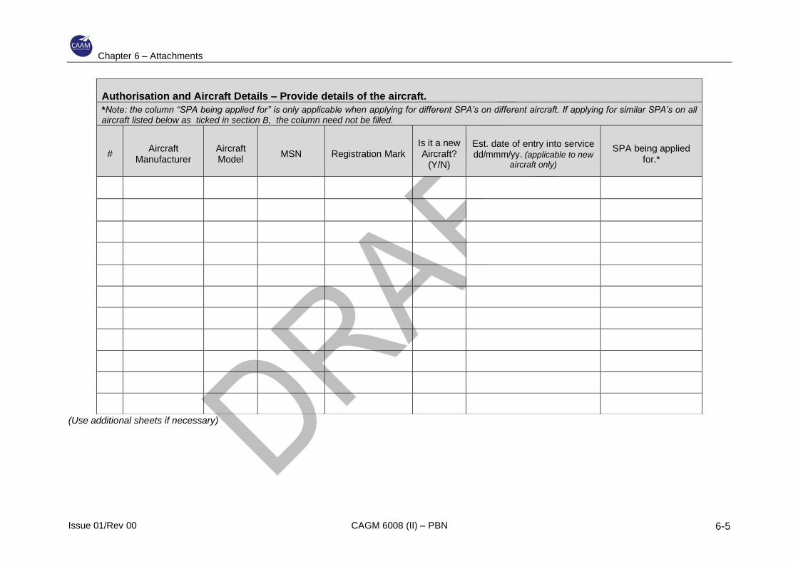
Chapter 6 – Attachments
Issue 01/Rev 00 CAGM 6008 (II) – PBN 6-5
(Use additional sheets if necessary)
Authorisation and Aircraft Details – Provide details of the aircraft.
*Note: the column “SPA being applied for” is only applicable when applying for different SPA’s on different aircraft. If applying for similar SPA’s on all aircraft listed below as ticked in section B, the column need not be filled.
# Aircraft
Manufacturer Aircraft Model
MSN Registration Mark Is it a new Aircraft?
(Y/N)
Est. date of entry into service dd/mmm/yy. (applicable to new
aircraft only)
SPA being applied for.*

Chapter 6 – Attachments
Issue 01/Rev 00 CAGM 6008 (II) – PBN 6-6
Section C- Applicants Declaration
DECLARATION
1. I declare and undersign below that the statements, answers and attachments provided in this application form is true and correct to the best of my knowledge in accordance with Civil Aviation Regulations 2016 (MCAR) and Civil Aviation Directives (CAD).
Giving false or misleading information is an offence under Regulation 164 of the Civil Aviation Regulations 2016 (MCAR)
2. I understand that processing the application may be delayed if:
• The application does not accurately and completely identify my/our requirements; or
• The details in this application are subsequently changed; or
• Adequate supporting documentation has not been provided.
3. I understand and agree that for CAAM to proceed with this application, I must:
• Accept the cost as per civil aviation (fees and charges) regulation; and
• Forward the prescribed payment; and
• Forward all supporting documentation as required by the specific approval being applied for.
Note. – CAAM may send materials/responses relating this application by email or by mail.
Name
Signature
Date
FOR CAAM USE ONLY
Date of Initial application Received by administrator
Fee payable
……………………………………………………… Name & Signature of CAAM Personnel
Cash / Credit Card
Receipt No.:
Subject Responsible division Date Name & Signature
Application Form and application package checked for completeness.
POI
Airworthiness Approval granted
PMI
Operational Approval granted (AOC, AOC Extract, or letter of Authorisation).
FOI
Approval process administratively completed (OPS Spec Update, Billing, and Exchange of Certificates).
Administrator
Approved (if no, state reasons below))
YES NO
Withdrawal of Approval reason.
Remarks:
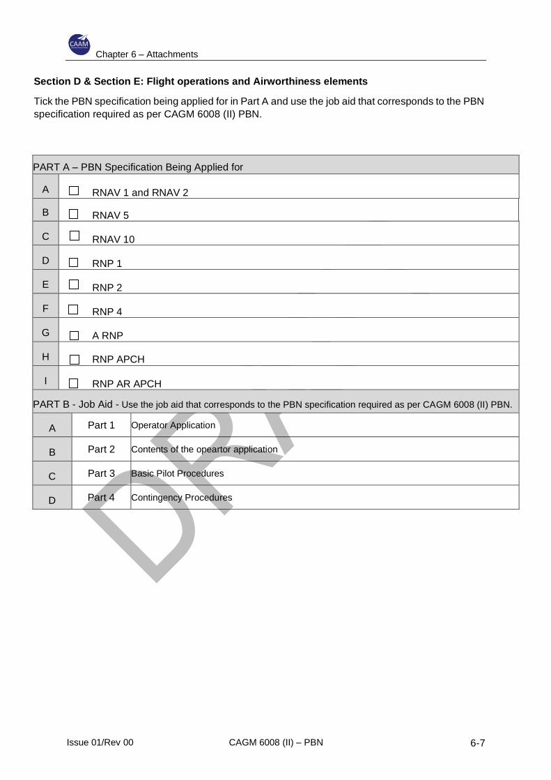
Chapter 6 – Attachments
Issue 01/Rev 00 CAGM 6008 (II) – PBN 6-7
Section D & Section E: Flight operations and Airworthiness elements
Tick the PBN specification being applied for in Part A and use the job aid that corresponds to the PBN
specification required as per CAGM 6008 (II) PBN.
PART A – PBN Specification Being Applied for
A RNAV 1 and RNAV 2
B RNAV 5
C RNAV 10
D RNP 1
E RNP 2
F RNP 4
G A RNP
H RNP APCH
I RNP AR APCH
PART B - Job Aid - Use the job aid that corresponds to the PBN specification required as per CAGM 6008 (II) PBN.
A Part 1 Operator Application
B Part 2 Contents of the opeartor application
C Part 3 Basic Pilot Procedures
D Part 4 Contingency Procedures
Related Documents