Performance Analysis of NACA2420 as Wind Turbine Propeller Blade Marine Hydrodynamics and Energy Laboratory Naval Architecture Department, Engineering Faculty, Hasanuddin University Uswah Pawara

Welcome message from author
This document is posted to help you gain knowledge. Please leave a comment to let me know what you think about it! Share it to your friends and learn new things together.
Transcript
Performance Analysis of NACA2420 as Wind Turbine Propeller Blade
Marine Hydrodynamics and Energy LaboratoryNaval Architecture Department, Engineering Faculty, Hasanuddin
University
Uswah Pawara
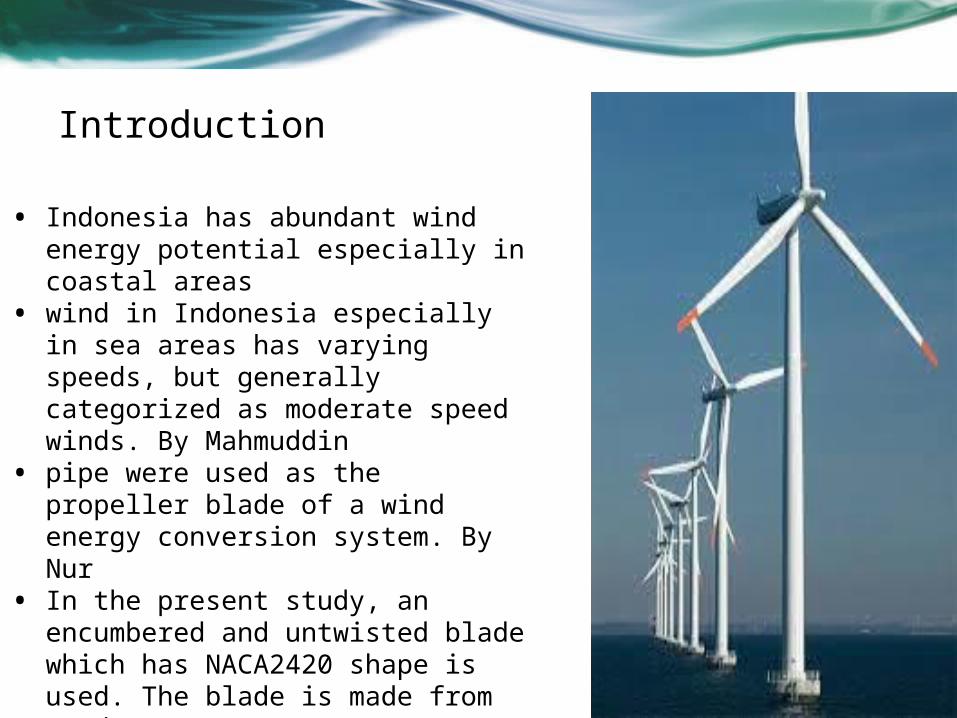
Introduction
• Indonesia has abundant wind energy potential especially in coastal areas
• wind in Indonesia especially in sea areas has varying speeds, but generally categorized as moderate speed winds. By Mahmuddin
• pipe were used as the propeller blade of a wind energy conversion system. By Nur
• In the present study, an encumbered and untwisted blade which has NACA2420 shape is used. The blade is made from wood
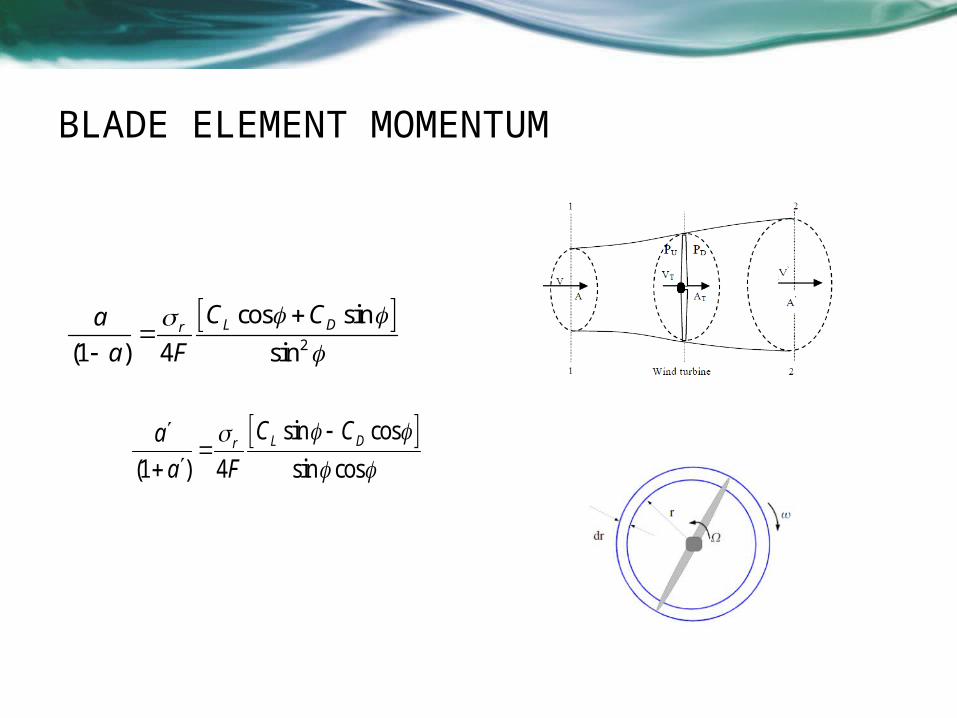
BLADE ELEMENT MOMENTUM
2
cos s
(1 ) 4
i
si
n
nL Dra C C
a F
(28)
sin
(1 ) 4
cos
sin cosL DrC Ca
a F
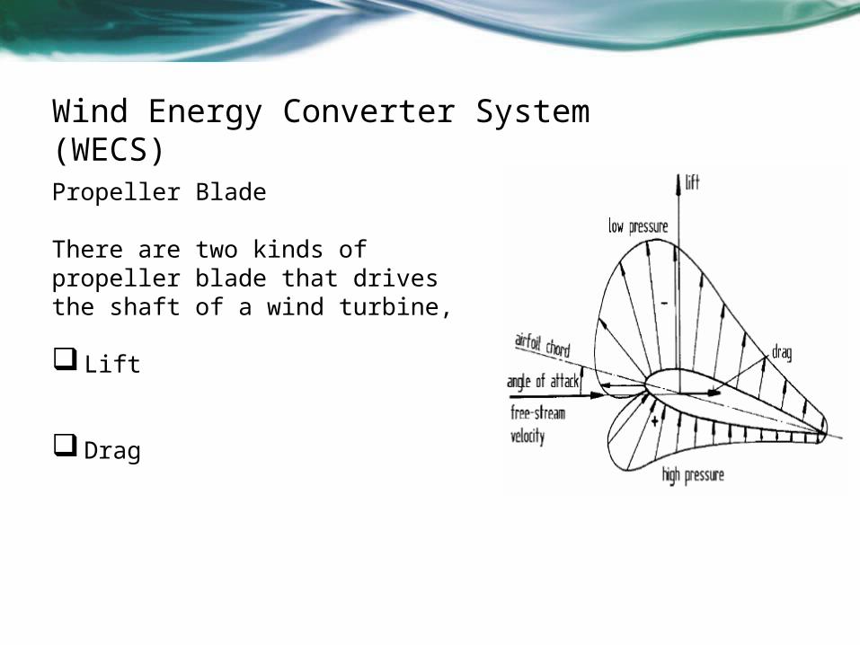
Wind Energy Converter System (WECS) Propeller Blade
There are two kinds of propeller blade that drives the shaft of a wind turbine,
Lift
Drag
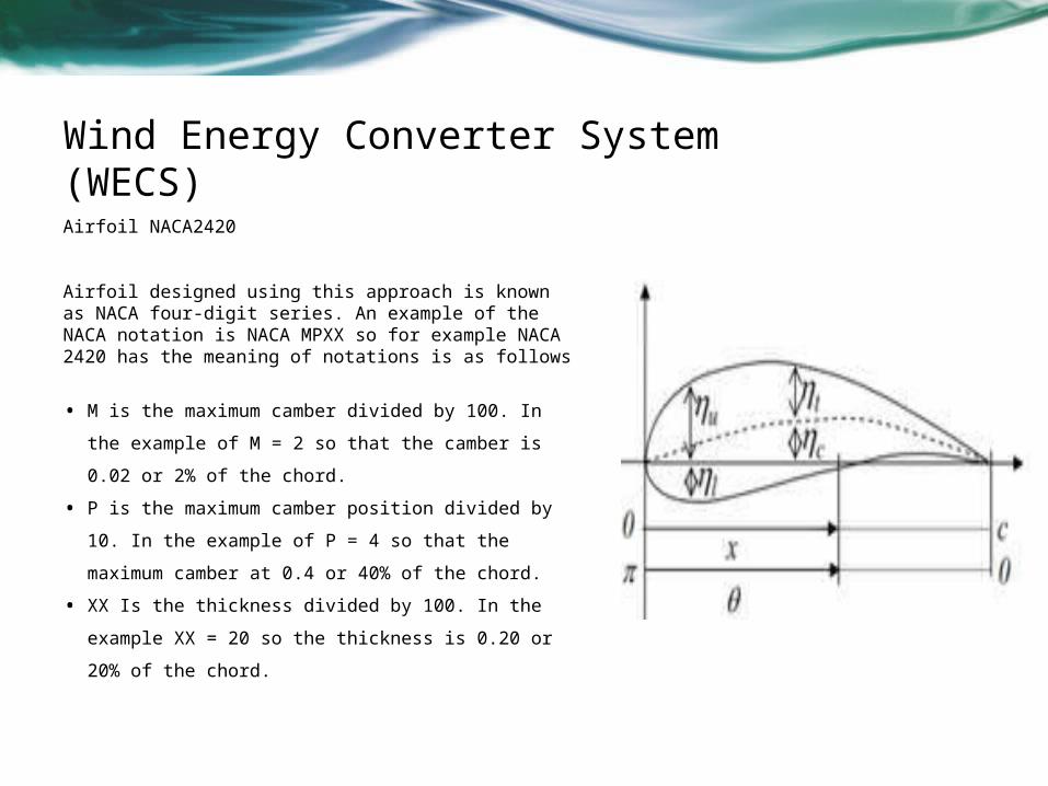
Wind Energy Converter System (WECS) Airfoil NACA2420
Airfoil designed using this approach is known as NACA four-digit series. An example of the NACA notation is NACA MPXX so for example NACA 2420 has the meaning of notations is as follows
• M is the maximum camber divided by 100. In
the example of M = 2 so that the camber is
0.02 or 2% of the chord.
• P is the maximum camber position divided by
10. In the example of P = 4 so that the
maximum camber at 0.4 or 40% of the chord.
• XX Is the thickness divided by 100. In the
example XX = 20 so the thickness is 0.20 or
20% of the chord.
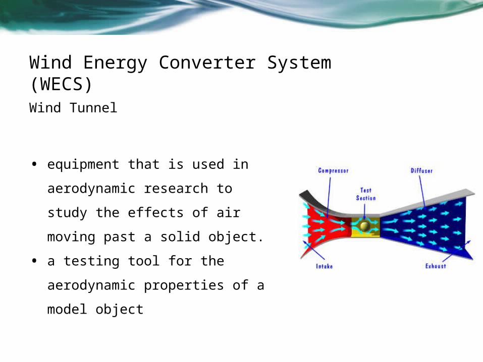
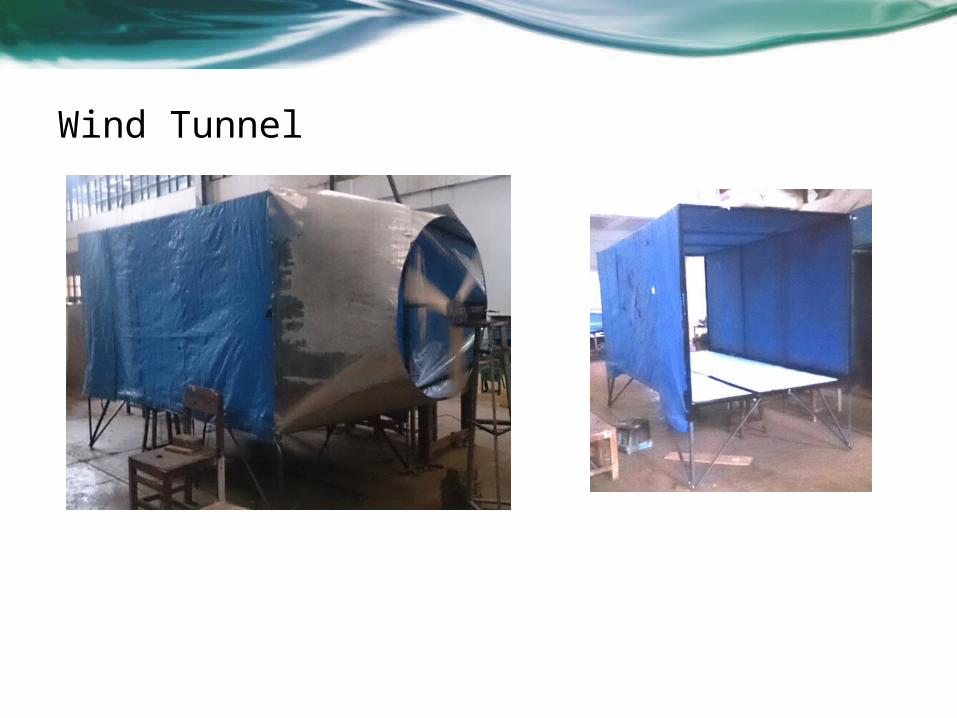
Wind Energy Converter System (WECS) Wind Tunnel
• equipment that is used in
aerodynamic research to study
the effects of air moving past a
solid object.
• a testing tool for the
aerodynamic properties of a
model object
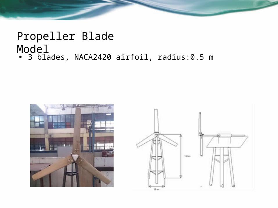
Propeller Blade Model
• 3 blades, NACA2420 airfoil, radius:0.5 m
Wind Tunnel

RESULTS AND DISCUSSIONEffect of Wind Tunnel to Wind Speed
To determine the effect of the use of wind tunnel to the increase of wind speed,
the wind speed is measured with and without the wind tunnel

RESULTS AND DISCUSSIONEffect of Pitch Angles to Turbine Performance
the performance of the airfoil for several pitch angles of the airfoil are
measured. The measured pitch angles are 0°, 5°, 8°, 15° and 30°.
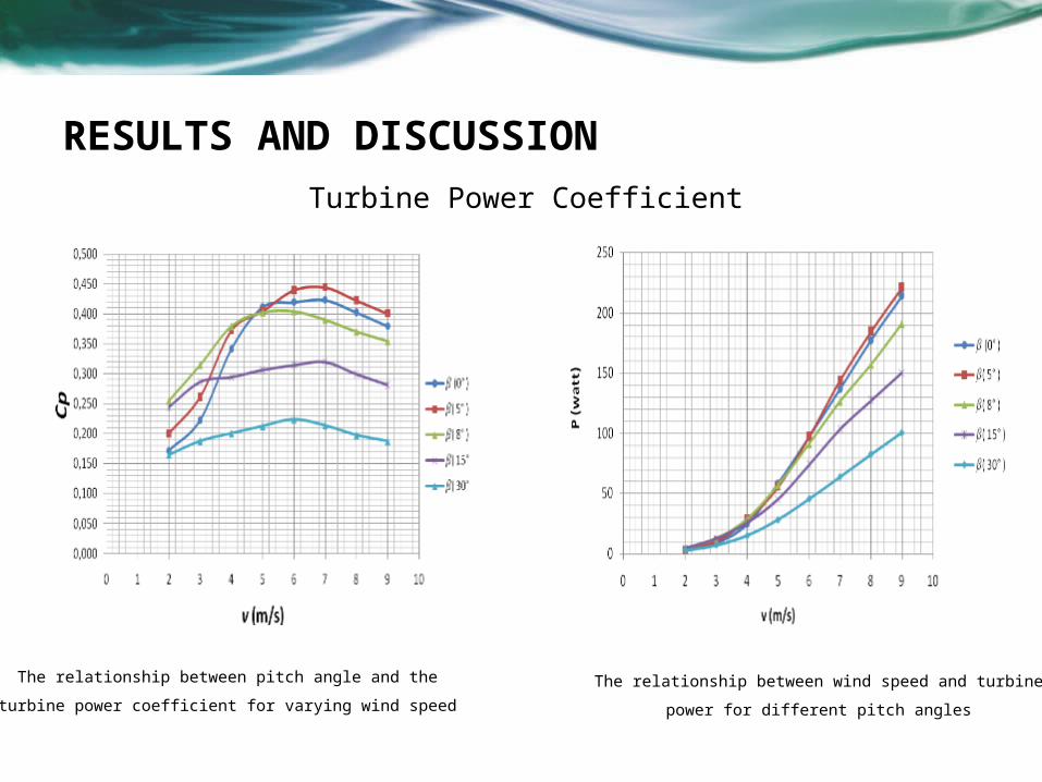
RESULTS AND DISCUSSIONTurbine Power Coefficient
The relationship between pitch angle and the turbine
power coefficient for varying wind speed
The relationship between wind speed and turbine power
for different pitch angles
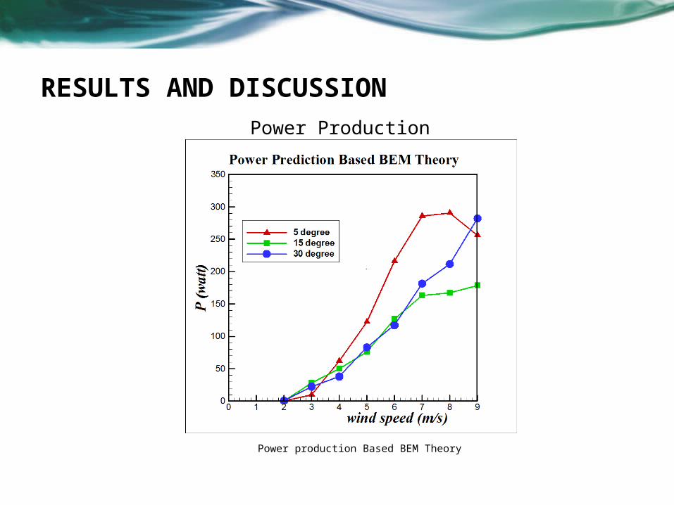
RESULTS AND DISCUSSIONPower Production
Power production Based BEM Theory
Conclusion
• Wind speed using a wind tunnel produces a higher speed which
can be used as a validation test compared the wind turbine
without the use of tunnels. This is because the winds were issued
by the fan is limited by the walls of the tunnel and focused
aheadDesign documents
• Results of experiments and analysis of wind turbine propeller
diameter is known performance and dimensions that can be used
to generate the optimal wind turbine rotation is pitch angle of 5o.
This is due to the influence of the larger lift force.Supplemental
documents
• Power obtained under optimal airfoil spin speed propeller blade
produced is 294.44 rpm and generates a power of 221.039 watts
which produced the maximum power efficiency of the experiment
was 40.1%
Related Documents