Captain Pressure Governor Universal Version With Trim Control Technology Leaders for Emergency Vehicles

Welcome message from author
This document is posted to help you gain knowledge. Please leave a comment to let me know what you think about it! Share it to your friends and learn new things together.
Transcript

Captain
Pressure Governor Universal Version
With
Trim Control
Technology Leaders for Emergency Vehicles

1C:\manuals\Uni-Gov-V6-107490
Installation and Technical ManualPressure Governor
for Electronic EnginesV6.0
Contents
Operation SectionOverview....................................................................................2-3v6.0 Features ............................................................................... 4Operation ..................................................................................5-8
Troubleshooting / DiagnosticsDiagnostics ..............................................................................9-17Self Test ..................................................................................... 18
Installation / WiringInstallation .................................................................................. 19-4 & -12 Connector ..................................................................... 20PSI Transducer .......................................................................... 21Wiring ....................................................................................22-23ISC Wiring .................................................................................. 24ISM Wiring .................................................................................. 25CAT Wiring ................................................................................. 26Navistar Wiring ........................................................................... 27DDEC Wiring .............................................................................. 28Mack Wiring ............................................................................... 29MBE900 Wiring .......................................................................... 30Engine ECM ............................................................................... 31Preset Programming .................................................................. 32Engine Type Programming ........................................................ 33Parameter Programming ............................................................ 34Miscellaneous ............................................................................ 35Notes .......................................................................................... 36
2
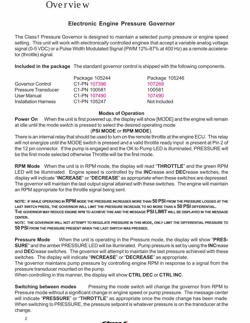
Electronic Engine Pressure Governor
The Class1 Pressure Governor is designed to maintain a selected pump pressure or engine speedsetting. This unit will work with electronically controlled engines that accept a variable analog voltagesignal (0-5 VDC) or a Pulse Width Modulated Signal (PWM 12%-87% at 400 Hz) as a remote accelera-tor (throttle) signal.
Included in the package The standard governor control is shipped with the following components.
Package 105244 Package 105246Governor Control C1-PN 107396 107269Pressure Transducer C1-PN 100581 100581User Manual C1-PN 107490 107490Installation Harness C1-PN 105247 Not Included
Modes of OperationPower On When the unit is first powered up, the display will show [MODE] and the engine will remainat idle until the mode switch is pressed to select the desired operating mode
(PSI MODE or RPM MODE).There is an internal relay that should be used to turn on the remote throttle at the engine ECU. This relaywill not energize until the MODE switch is pressed and a valid throttle ready input is present at Pin 2 ofthe 12 pin connector. If the pump is engaged and the OK to Pump LED is illuminated, PRESSURE willbe the first mode selected otherwise Throttle will be the first mode.
RPM Mode When the unit is in RPM mode, the display will read “THROTTLE” and the green RPMLED will be illuminated. Engine speed is controlled by the INCrease and DECrease switches, thedisplay will indicate “INCREASE” or “DECREASE” as appropriate when these switches are depressed.The governor will maintain the last output signal attained with these switches. The engine will maintainan RPM appropriate for the throttle signal being sent.
NOTE: IF WHILE OPERATING IN RPM MODE THE PRESSURE INCREASES MORE THAN 50 PSI FROM THE PRESSURE LOGGED AT THELAST SWITCH PRESS, THE GOVERNOR WILL LIMIT THE PRESSURE INCREASE TO NO MORE THAN A 50 PSI DIFFERENTIAL.THE GOVERNOR MAY REDUCE ENGINE RPM TO ACHIEVE THIS AND THE MESSAGE PSI LIMIT WILL BE DISPLAYED IN THE MESSAGECENTER.NOTE: THE GOVERNOR WILL NOT ATTEMPT TO REGULATE PRESSURE IN THIS MODE, ONLY LIMIT THE DIFFERENTIAL PRESSURE TO50 PSI FROM THE PRESSURE PRESENT WHEN THE LAST SWITCH WAS PRESSED.
Pressure Mode When the unit is operating in the Pressure mode, the display will show “PRES-SURE” and the amber PRESSURE LED will be illuminated. Pump pressure is set by using the INCreaseand DECrease switches. The governor will attempt to maintain the last pressure achieved with theseswitches. The display will indicate “INCREASE” or “DECREASE” as appropriate.The governor maintains pump pressure by controlling engine RPM in response to a signal from thepressure transducer mounted on the pump.When controlling in this manner, the display will show CTRL DEC or CTRL INC.
Switching between modes Pressing the mode switch will change the governor from RPM toPressure mode without a significant change in engine speed or pump pressure. The message centerwill indicate “PRESSURE” or “THROTTLE” as appropriate once the mode change has been made.When switching to PRESSURE, the pressure setpoint is whatever pressure is on the transducer at thechange.
Overview

3C:\manuals\Uni-Gov-V6-107490
Preset ModePressing the PRESET switch in either mode will control the engine to attain the preset RPM or pumppressure programmed in governor memory. If there is more than 10 PSI pressure on the pump, theRPM Preset is disabled and the Message Center will display DISABLED.
High Idle ModeAn input is available to bring the engine speed to a PRESET RPM (High Idle) from a remotely mountedswitch. While operating in this mode, the display will show HIGHIDLE. This function is inoperativewhen the pump engaged input is active, there is more than 10 PSI on the pressure transducer or if theMODE switch on the governor has been pressed. Pressing the IDLE switch causes the high idle todrop out and the high idle input must be toggled off and then on again to reinstate high idle. The INC andDEC switches are active in high idle mode and the engine speed can be adjusted, changing enginespeed in this manner will not change the preset RPM that is set in memory.Idle Mode Pressing the IDLE switch at any time returns the engine to idle speed.NOTE: A FIRM, POSITIVE SWITCH DEPRESSION IS NECESSARY TO ACTIVATE THIS FEATURE AND A QUICK PRESS MIGHT BE IGNORED.
SENSORWhenever the transducer signal is below 0.3 VDC or above 4.8 VDC, a sensor fault willbe logged and SENSOR will be displayed in the message center. ( SENSOR will flashif the failure occurs while operating in PSI Mode) Once a failure is detected, the governor can no longer maintain a pressure setting. It will hold the current engine RPM andonly operate as a throttle.
Once the SENSOR message is displayed, it will not clear until power to the governor is reset.It is extremely important that the cause for this message is investigated.The governor cannot control discharge pressure properly unless the sensor signal is reliable and cor-rect.
Switch Session Pressure IncreaseIf the INC switch is held the governor will not allow a change greater than 80 PSI without releasing theINC switch and pressing it again. This is only applicable when the discharge pressure is above 90 PSI.This function prevents high pressures from being introduced by a distracted operator.
Pressure / Water LossIf the discharge pressure drops below 30 PSI for any reason, engine speed will not be increased. Thegovernor output voltage will reduce to the last known value (engine RPM) where the pressure setpointwas obtained. The display will flash -INTAKE- during this low pressure condition. If the pressure in-creases above 30 PSI, OPERATOR will flash and the governor will not increase output unless theoperator presses the INC or PRESET switches. If pressure above 30 PSI is not regained within 5seconds, the governor will return the engine to idle and display LoSupply. The operator must makecertain that the water supply is adequate and then reinstate governing using the MODE, INC and/orPRESET switches.
Pressure Recovery / Cavitation (TRIM)The governor has a trim adjustment, this can be set between 5% and 20% of maximum throttle. Thisparameter limits the governor’s maximum increase in a pressure recovery attempt. The messagecenter will flash OPERATOR when this limit is reached and the RPM will not increase further. Theoperator must take positive action to restore discharge pressure. If pressure is not restored within 4seconds, the governor will reduce output to the last known output where pressure was maintained. Theoperator must input a new setpoint with the INC/DEC or PRESET switches. If the pressure rises abovethe original setpoint and the governor controls a decrease in engine speed, the governor will return tonormal operation and PSI MODE is displayed.
!
Overview
CAUTION
4
Version DisplayWhile the governor is at idle and [MODE] is being displayed, if the IDLE switch is depressed for 7seconds, the message center will scroll through the version number, governor settings and I/O voltage.When the sequence is complete, the display will return to [MODE] and normal operation is available.
PSI EnableThe pressure governor will not control pressure until a discharge pressure of 70 PSI is attained. It willact as a throttle until this pressure point is achieved.
Setting PRESETIf the PRESET switch is the held down for 10 seconds after a Power On Cycle (before pressing anyother switch), the governor will enter the PRESET programming mode.
Selecting Engine TypeOnly the INC and PRESET switches are active in the engine selection menu.Selecting the engine type is only necessary at first power on of a new governor.
RPM Preset DisableIf there is pressure on the pump transducer or the Pump Engaged Interlock is active, RPM Preset isdisabled and a DISABLED message will be displayed in the Message Center.
Pressure PresetWhile the governor is attempting to reach the preset PSI, the increase is tested at intervals and if thepressure is not increasing, the governor will maintain the engine speed at the point the pressure stopsincreasing and uses that as the pressure setpoint.
High IdleThe High Idle feature is disabled if there is > 10 PSI at the pump transducer.
Switch Session PressureIf the INC switch is held and the operating pressure is above 90 PSI, the governor will not allow a changegreater than 80 PSI without releasing the INC switch and pressing it again. This is to prevent highpressures from being introduced by a distracted operator.
New MessagesOPERATOR will be flash anytime the governor can’t achieve a desired pressure.This indicates that the governor will not increase engine speed until the pump operator intervenes.-INTAKE- will be displayed anytime the governor is operating in pressure mode and the dischargepressure drops below 30 PSI. If pressure remains below 30 PSI, the display will change to LoSupplyand engine speed will be reduced to idle. When LoSupply is displayed the governor is no longeractive and the operator must ensure an adequate water supply and reinstate governing using the MODESwitch and either INC or PRESET.
OPERATOR will be flashed anytime the governor can’t achieve a function or pressure.This indicates that the governor will not increase engine speed until the pump operator intervenes.CTRL INC will be flash in the display if the governor cannot regain the set pressure. It will changeto OPERATOR flashing if pressure cannot be regained within 4 seconds.During these periods, the governor will not command an increase in engine speed and will returnto the last known engine speed command where the setpoint was achieved.
v6.0 Features

5C:\manuals\Uni-Gov-V6-107490
I D L E R E Q
V 6 . 0 b 4 4 4
[ M O D E ]
When the governor is initially powered up, neither the RPMnor the PRESSURE LED will be illuminated. If the IDLESwitch is held on prior to power being applied, the informa-tion will remain in the message center as long the IDLE Switchis depressed.
At this point, the operator must select an operating modewith the MODE switch before the governor will operate.
The governor will check for a valid pressure transducer sig-nal at power up, if none is found SENSOR will be displayedin the message center. The governor will operate, but will notbe able to maintain a pump pressure.
S E N S O R
If no interlocks are established, NO-INTLK will be displayedin the message center when the MODE switch is pressedand the governor will not respond to an increase or decreaserequest.
N O - I N T L K
R P MIf only the OEM throttle interlock is active, you may selectRPM mode and RPM will be displayed.
Operation
6
Operation
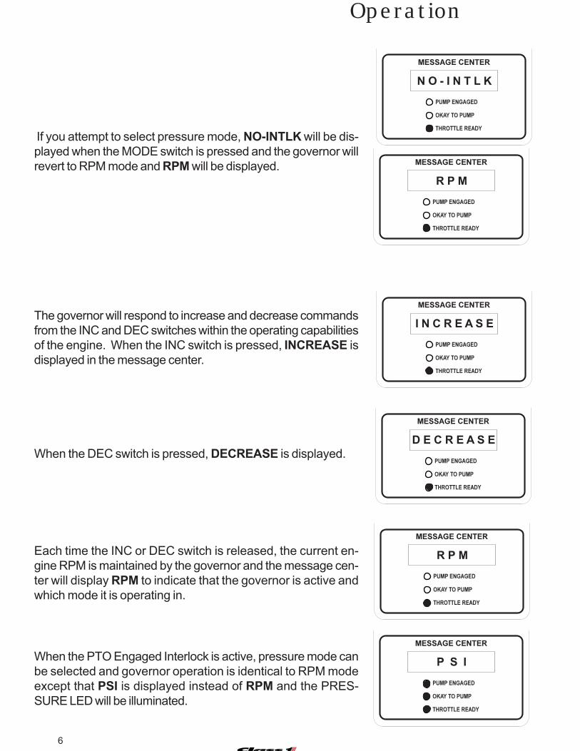
If you attempt to select pressure mode, NO-INTLK will be dis-played when the MODE switch is pressed and the governor willrevert to RPM mode and RPM will be displayed.
N O - I N T L K
When the PTO Engaged Interlock is active, pressure mode canbe selected and governor operation is identical to RPM modeexcept that PSI is displayed instead of RPM and the PRES-SURE LED will be illuminated.
When the DEC switch is pressed, DECREASE is displayed.
The governor will respond to increase and decrease commandsfrom the INC and DEC switches within the operating capabilitiesof the engine. When the INC switch is pressed, INCREASE isdisplayed in the message center.
Each time the INC or DEC switch is released, the current en-gine RPM is maintained by the governor and the message cen-ter will display RPM to indicate that the governor is active andwhich mode it is operating in.
R P M
I N C R E A S E
D E C R E A S E
R P M
P S I
7C:\manuals\Uni-Gov-V6-107490
Operation
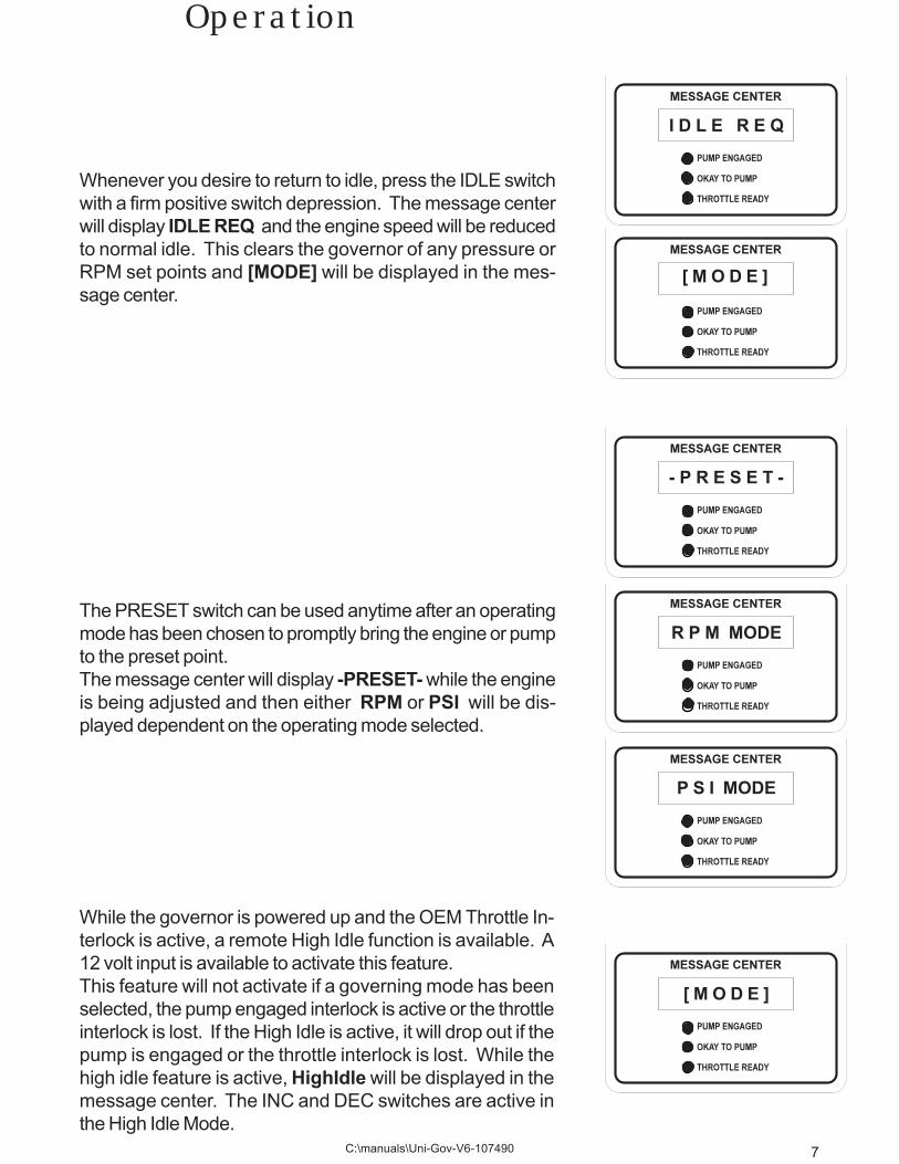
Whenever you desire to return to idle, press the IDLE switchwith a firm positive switch depression. The message centerwill display IDLE REQ and the engine speed will be reducedto normal idle. This clears the governor of any pressure orRPM set points and [MODE] will be displayed in the mes-sage center.
I D L E R E Q
[ M O D E ]
The PRESET switch can be used anytime after an operatingmode has been chosen to promptly bring the engine or pumpto the preset point.The message center will display -PRESET- while the engineis being adjusted and then either RPM or PSI will be dis-played dependent on the operating mode selected.
- P R E S E T -
R P M MODE
P S I MODE
[ M O D E ]
While the governor is powered up and the OEM Throttle In-terlock is active, a remote High Idle function is available. A12 volt input is available to activate this feature.This feature will not activate if a governing mode has beenselected, the pump engaged interlock is active or the throttleinterlock is lost. If the High Idle is active, it will drop out if thepump is engaged or the throttle interlock is lost. While thehigh idle feature is active, HighIdle will be displayed in themessage center. The INC and DEC switches are active inthe High Idle Mode.

8
NOTE: While the governor is determining cavitation, the dis-charge pressure drop will be treated normally. That is, the en-gine will be commanded to increase speed to compensate forthe pressure reduction within the Trim Limit. This could resultin the engine running at a speed that can cause a pressure“spike”.
P S I
- I N T A K E -
O P E R A T O R
- I N T A K E -
L O S U P P L Y
[ M O D E ]
If the pump discharge pressure drops below 30 PSI for morethan 5 seconds, the governor will return the engine to idle.LOSUPPLY will be displayed in the message center. The gov-ernor enters it’s initial power up state and a mode must be se-lected to enable governing again.
Operation
When operating in pressure mode, once the pump pressureexceeds 70 PSI, the governor will monitor the pump dischargepressure and respond to changes in pressure by modulatingengine/pump speed.
If the discharge pressure drops and the governor is unable toregain pressure within 4 seconds, the Message Center willflash -INTAKE- to indicate an insufficient water supply the gov-ernor will then reduce speed to the point that the pressure waslast achieved. At this time the Message Center will display OP-ERATOR and will no longer attempt to automatically regulate adecrease in pressure until the pump operator presses theDEC,INC or PRESET switches. The governor will respond toan increase in pressure if it occurs.
9C:\manuals\Uni-Gov-V6-107490
Class1 Uni-Governor Quick Tests
Operation description:
The governor is simply a Throttle Position Sensor (TPS) for the Engine Control Module (ECM). It sendsa varying voltage signal, or for Caterpillar Engines (CAT) a Pulse Width Modulated (PWM) signal to theECM at the remote throttle signal input. When operating in pressure (PSI) mode, the governor modu-lates the output signal to maintain a specific input voltage from its pressure transducer. This voltage is“set” into the governor’s memory by the use of the INC and DEC switches. A PRESET function isavailable that causes the governor to attain either a specific pre-programmed voltage or pressure.For Cummins, CAT and Navistar engines, once the ECM is programmed for remote throttle, the ECMcontinuously looks for the signal. If it is not present, the ECM will record a fault and illuminate the CEL orSEL dependent on the ECM. This is a quick check to see if a valid signal is present at the ECM. If thereis no Check Engine Light (CEL) or Stop Engine Light (SEL), then a valid signal from the governor ispresent.
For most engines the remote throttle must be ‘turned on’ in the ECM to use the remote throttle signal.For Cummins and CAT, this is performed by grounding a terminal at the ECM. Navistar ECM’s useswitched voltage.
The governor will not operate in any mode unless 12 VDC is applied at terminal 2 of the 12 pin connec-tor (THROTTLE READY Interlock). This is evidenced by the illumination of the THROTTLE READYLED. This will allow the governor to operate in RPM mode. 12 VDC applied to pin 10 of the 12 pinconnector (PUMP ENGAGED Interlock) illuminates the PUMP Engaged LED. If both the THROTTLEREADY and PUMP ENGAGED LED’s are lit, then the governor will illuminate the OKAY TO PUMP LEDand the governor will operate in either PRESSURE (PSI) or THROTTLE (RPM) mode.note: The THROTTLE READY and PUMP ENGAGED LED’s will illuminate if the governor has aground and the inputs are active (12 VDC). This is not dependent on the governor functioning or evenhaving power applied. The OKAY TO PUMP LED is turned on by governor software and usually indi-cates that the governor is operational.
Preliminary Diagnostic information:
To assist in governor diagnostics there is some preliminary information necessary. When power is firstapplied to the governor, a set of characters is displayed. These are referred to as the ‘V’ number. Ongovernors produced after January 2001, if the IDLE switch is held when power is applied, the ‘V’ num-ber will continue to be displayed until the IDLE switch is released. A typical number will look like thefollowing: V3.7b444. This contains the software version number, the engine type programmed into thegovernor and the parameter settings.
The other information necessary is a brief but accurate description of the problem trying to be resolved.What are you trying to correct? Provide a brief description of the operational anomaly.
____________________________________________________________________________________
____________________________________________________________________________________
____________________________________________________________________________________
See page 3 for a diagnostic guide relating to this problem
Diagnostics

10
Passwords:There are several diagnostic modes available in the governor. Access is provided by entering a pass-word that uses the INC and IDLE switches in a specific sequence.
The Message Center must display [MODE] prior to entering any password.
Governor Self Test:
The Self Test password is:IDLE INC IDLE INC IDLE INC IDLE INC
This test is capable of determining if there is a problem with the governor that replacement of the gover-nor display will correct.Results are displayed in the Message Center as a numeral matching its position in the display.
The Message Center (Test) positions are numbered left to right as follows:
0 1 2 3 4 5 6 7
When the self test starts, the governor checks for the type of output signal present, analog (ANA) orpulse width modulated (PWM). This is displayed along with the output voltage range if the signal isanalog (Make note of this range. It should vary from ~0.7 to 4.0 VDC). Once this output test is completethe Message Center will display a results screen. Any X indicates that a particular function has not beentested.
The Message Center will display X X X 3 - 5 X X for analog or X X X - 4 5 X X for PWM.Either a ‘3 -’ or a ‘- 4’ are in the 3 and 4 positions dependent on whether the governor is
configured for Analog or PWM output. The 5 in position 5 indicates that the pressure transducer istransmitting a no pressure signal (expected).If the pump is engaged, an H (high) will be shown. If the signal is too low, an F (fail) will be displayed.
0 The input to terminal 2 Throttle Ready changedRelease the Park Brake or shift the Transmission to change the interlock
1 The input to terminal 10 Pump Engaged changedShift the Pump
2 Each of the switches on the governor have been pressedThe switch pressed will be displayed i-IDLE p-PRESET m-MODE u-INC d-DEC
3 Analog Output, a (-) will be in position 4
4 PWM Output, a (-) will be in position 3
5 Transducer voltage is between 0.3 and 0.9an (H indicates voltage > 1.0) (F indicates voltage < 0.3)
6 The High Idle Input (terminal 3) has been toggledToggle the High Idle switch ON and then OFF if equipped
7 The internal relay has been activated
NOTE: THIS CHECK DOES NOT TEST FOR THE VALIDITY OF THE SIGNAL IN NOR IF THE SIGNAL IS TRULY SENT TO THE ECM. THAT TESTMUST BE DONE MANUALLY IF IT IS THOUGHT THAT THE REMOTE PTO ON SIGNAL THROUGH THE GOVERNOR IS THE PROBLEM.
11C:\manuals\Uni-Gov-V6-107490
Contents Page
Problem specific tests:
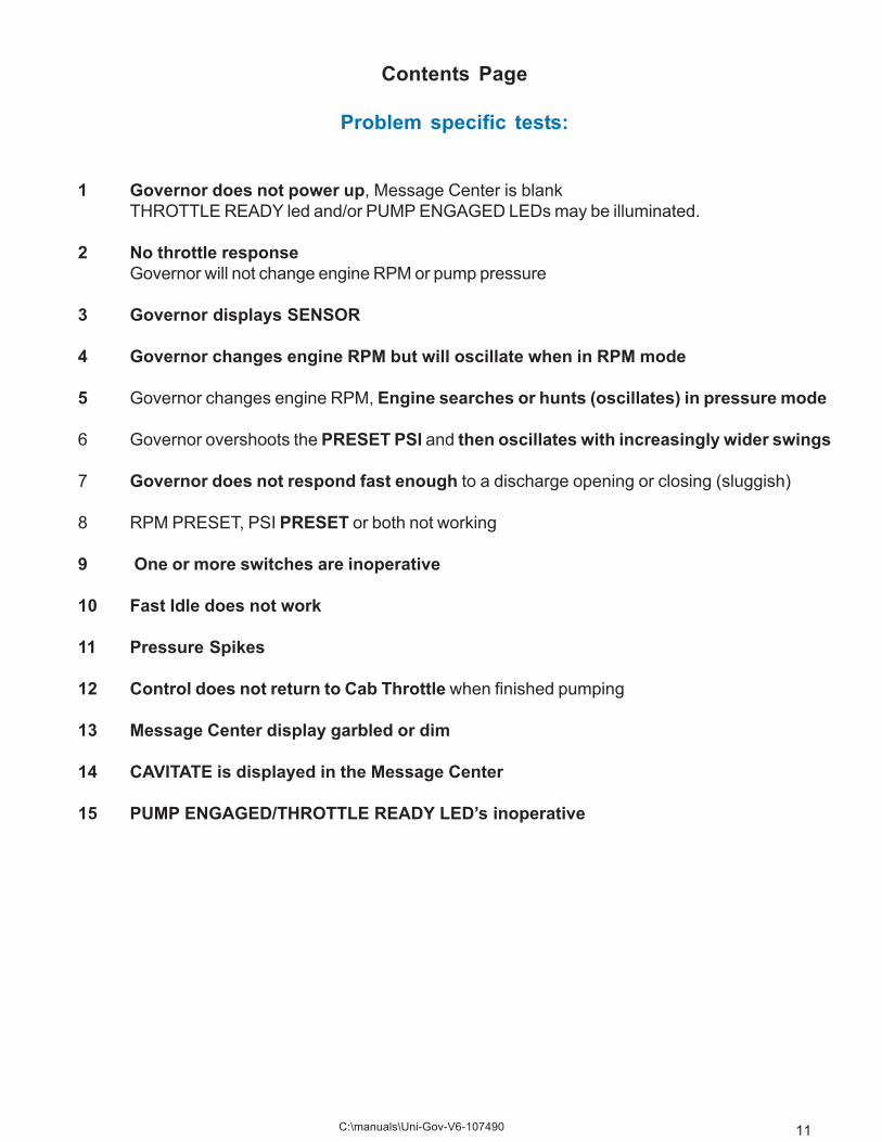
1 Governor does not power up, Message Center is blankTHROTTLE READY led and/or PUMP ENGAGED LEDs may be illuminated.
2 No throttle responseGovernor will not change engine RPM or pump pressure
3 Governor displays SENSOR
4 Governor changes engine RPM but will oscillate when in RPM mode
5 Governor changes engine RPM, Engine searches or hunts (oscillates) in pressure mode
6 Governor overshoots the PRESET PSI and then oscillates with increasingly wider swings
7 Governor does not respond fast enough to a discharge opening or closing (sluggish)
8 RPM PRESET, PSI PRESET or both not working
9 One or more switches are inoperative
10 Fast Idle does not work
11 Pressure Spikes
12 Control does not return to Cab Throttle when finished pumping
13 Message Center display garbled or dim
14 CAVITATE is displayed in the Message Center
15 PUMP ENGAGED/THROTTLE READY LED’s inoperative

12
1 Governor does not power up, Message Center is blank
Check for power at pin 1 of the 4 pin connector and ground at pin 2 with a voltmeter across pin 1 (redlead, power) and pin 2 (black lead, ground).Check that the terminals are fully inserted into the connector, the orange wedge lock is inserted properlyand the weather seal is in place and not distorted.
If Power and Ground are present and the governor Message Center is still blank then the problem isinternal and the governor should be replaced.
If either power or ground is missing, then the problem is in the vehicle wiring and that should be investi-gated. (contact OEM if necessary).Replacing the governor will not rectify this situation.
2 Governor will not change engine RPM or pump pressure
The THROTTLE READY Interlock must be present. A visual determination can be made by observingthe THROTTLE READY LED. If it isn’t on then check for a 12 V interlock to pin 2 of the governor’s 12 pinconnector. This is an OEM function and must be present for the governor to operate.If 12 VDC is not present at the wire installed at pin 2, then the governor is not the problem.
Contact the OEM for further assistance.
A MODE must be selected before the governor will control the engine. Make sure that either the RPM orPRESSURE LED is illuminated and the Message Center indicates THROTTLE or PRESSURE.The output signal will not change if a mode is not selected. Output will remain at hardware idle (approx.0.7 VDC or 12% PWM). Once a mode is selected, the governor idle output will increase to the appro-priate software idle signal.To monitor the governor output voltage, an internal voltmeter is included.With [MODE] showing in the display, enter the following Password:
INC IDLE IDLE IDLE IDLE IDLE IDLE INCThe Message Center becomes an output voltmeter
OUT=x.xVThe output voltage can be monitored to ensure that it increases and decreases with the INC and DECswitches.Check that the remote throttle switch is active at the ECM. Use a meter or diagnostic reader (DDR).Most engines require this input before they will utilize a remote throttle signal.The governor may or may not be used to satisfy this requirement. The OEM is best able to answer thisquestion. If the governor is being used, then the signal should be at pin 11 and the output to the enginefound at pin 12 after a MODE is selected. Check that the relay is switching and that terminal 11 and 12of the 12 pin connector have continuity. If a mode can be selected, the governor output is changing, andthe relay closes then the governor is not the problem.Contact the OEM for further assistance.

13C:\manuals\Uni-Gov-V6-107490
3 Governor Message Center displays SENSOR
The governor will display SENSOR whenever the transducer input is less than 0.3 VDC. This input is atpin 7 of the governor 12 pin connector. You can measure this voltage in either of two ways. A voltmeterback probing pin 7 or on the governor Message Center.Enter the password:
INC IDLE IDLE IDLE IDLE IDLE INC IDLEThe message center will display XDC=x.xV where x.x is the voltage to one decimal place that is read atpin 7.There are 2 main requirements for the transducer to operate correctly.1. Five volts supplied from the governor at pin 6 to the transducer pin B.2. Ground supplied from the governor at pin 5 to the transducer pin A.
If either of these are missing, check the output at the governor and if present, check the wiring.
If both are present at the transducer, then with power on and the connector installed, back probe terminalC of the transducer and check for 0.7 VDC. This is the zero pressure output of the transducer +- 0.1VDC. If present, check the signal wire to the governor.
Note: There have been many cases of moisture and corrosion in the transducer connections causingproblems. Use a bright light and inspect the transducer and connector for visible moisture, corrosionand/or mineral deposits. If present, this might be the reason for the SENSOR reading. There is aremovable seal on the round section of the transducer connector, ensure that it is still present. Checkunder the wire weather seal for corrosion and moisture as well. If moisture or corrosion is present, cleanthe contacts (the use of a moisture displacing chemical is recommended (WD40, CRC 5-56, etc.) andcheck for signal voltage again.Once SENSOR is displayed, the SENSOR message will not clear until power to the governor is re-moved and reapplied even if the error is corrected.
4 Governor changes engine RPM but will oscillate when in RPM mode
This is usually attributable to the governor sending out a PWM signal when the engine requires ananalog signal. Check the V number for an ‘a’ or an ‘F’. An F indicates the governor is programmed forCAT and an ‘a’ shows that there is a 12 VDC input on terminal 4 of the 12 pin connector. If this is not thecase then a poor ground at pin 9 or a fluctuating 5 volt supply at pin 1 needs to be investigated.
REMOVABLE SEAL
DIELECTRIC GREASE CAN BEADDED TO THE SEALING SUR-FACE TO ENSURE A BETTERMOISTURE BARRIER.
CHECK THAT THE HARNESS ISN’T PULLED TO ONE SIDE DISTORTING THE WIRE WEATHER SEAL. THIS IS ANOTHER SOURCE OF MOISTURE INTRUSION.

14
5 Governor changes engine RPM but will search or hunt (oscillate) when in pressuremode
There are three programmable parameters that can fine tune governor operation. These are RAMP,GAIN and SENSITIVITY.To enter the Menu System:With [MODE] showing in the Message Center,Press and hold the IDLE and PRESET switches. While still holding these, press MODE. This puts youinto the MENU system where the RAMP, GAIN and SENS settings can be changed. Scroll through the3 parameters using the MODE switch. Use the INC or DEC switch to enter that parameter and changethe values. Press PRESET before scrolling to the next parameter.The governor is shipped from Class1 with all 3 set to 5.
RateThis parameter controls how much voltage increase or decrease occurs with each press of the
INC or DEC switch. The nominal value of 5 will work on every engine and normally doesn’t need t obe changed.
GAINThis parameter controls how fast the voltage will change automatically in response to a pressure
change or when using the PRESET switch. The lower the value, the slower the response. Avalue of 5 on some engine-pump combinations will exacerbate the hunt condition.
(The governor is commanding changes faster than the apparatus can follow)Try a value of 4 first and don’t change any other setting. If this slows the oscillations but they are stillpresent, then change the SENSitivity setting (described below). The effect of decreasing the GAIN is toslow down the governor reaction to change. If it becomes too slow, then the governor will not be able todecrease RPM fast enough when a discharge is closed. Usually 4 is slow enough but in extreme casesa 3 might be necessary. Do not go to 3 until you have tried a sensitivity change first.
SENS-itivity
This parameter controls how much pressure deviation is allowed before the governor responds.A setting of 5 allows approximately 5 PSI swings before the governor attempts to restore the set
pressure. The higher the number, the “looser’” the “window”. After setting the GAIN to a 4, set the SENSto 6 if necessary. Normally this value should never be higher than 7. A setting of 10 allows up to 30 PSIswings.
Randomly changing values can be counterproductive. Lower the GAIN first, try it and then the SENSand back to GAIN if necessary. Change by a value of 1 only. If you go too far, it might solve the oscillationproblem but create a response problem. There is no magic set of numbers that will optimize yourinstallation. Each installation is unique to Engine Torque, Transmission Gearing, Transfer Gear ratioand pump capacity and design. The parameters are used to match the governor to the apparatus.
A note about two-stage pumps:In pressure mode, engine RPM is relatively low compared to a single stage pump or the two-
stage in volume mode. This places the engine outside of it’s optimal torque range and small changes inRPM equate to substantial changes in pressure. This can create two problems.1 The engine is slow to respond to commands and the governor starts a lead lag situation thatcan result in oscillations. The setup cannot be “tweaked” for best performance in both volumeand pressure.2 Snapping a nozzle closed will result in a pressure “spike” that is too fast to be controlled by agovernor or a discharge relief valve. This could also result in an uncontrollable oscillation.
Discretion should be used whenever operating in Pressure Mode, this mode allows for governor opera-tion in which the governor and engine have the least ability to compensate for pressure changes.
15C:\manuals\Uni-Gov-V6-107490
6 Governor overshoots the PRESET PSI and then oscillates with increasingly wider swings
This can be caused by GAIN being set too high or SENSitivity set too low. In a few cases, the PRESETis just set too high. PRESET is intended to allow very fast initial response to get up and pumping and anormal setting would be around 125 PSI. Once the apparatus is pumping water, the pressure setpointshould be manually invoked with the INC or DEC switches. A two stage pump in pressure mode and aPRESET PSI of 150 PSI or greater could easily result in oscillations.Check the GAIN and SENS settings. A lower GAIN will have the biggest impact on this condition.Do not compensate for operating procedures that can create problems by substituting less than opti-mum governor operation.
7 Governor does not respond fast enough to a discharge opening or closing (sluggish)
This is normally the result of the GAIN being set too low. Check the GAIN setting and if less than 4,change it to a 4 and reevaluate operation. In a rare case, it could be caused by the SENS being set to7 or greater. Check this and bring it back to a 6 or 7 if necessary. Potentially, this could be caused bytorque loading of the engine being excessive and the apparatus does not have enough “muscle” toadequately control the pump. If after setting the governor parameters to the best values for response, trya different pump loading scenario to evaluate power-train efficiency.
8 RPM PRESET, PSI PRESET or both not working
The governor must have 12 VDC on pin 2 to operate in RPM mode and THROTTLE MODE must beselected.If the RPM PRESET doesn’t work, then verify that there is an RPM PRESET. Enter the Password:INC IDLE IDLE INC IDLE INC IDLE INC This will place the governor in it’s view settingsmode. The parameter settings will be shown RAMP GAIN SENS is the sequence displayed as XX X.This will be followed by the Idle CNTS and then the Pressure Preset PXXX and this is followed by theRPM preset as a CNT value.
The RPM Preset CNT should be higher than the Idle CNT value by at least 15.The CNT value is the number of steps on the digital potentiometer used by the governor.low CNTS=low output and high CNTS=high output. Operational CNTS can be viewed using thePasswordINC IDLE IDLE INC IDLE INC IDLE IDLEThe values seen can be used to identify how many counts relate to engine RPM values.If the governor works in THROTTLE mode, then the RPM PRESET should work. It is most likely thatthe RPM PRESET is not set.
To set PRESET values, enter the following Password:INC IDLE IDLE INC IDLE INC INC IDLEThe Message Center should display PRESET, select a mode with the MODE switch. You must viewthe RPM/PRESSURE LED’s to know which mode you are operating in. Use the INC/DEC switchesto attain the RPM or Pressure you want as a PRESET and then press the PRESET switch to storethe value. Select the other MODE if desired, adjust the setpoint and then store that value with thePRESET switch. You must then press the IDLE switch to save these settings to memory and exit thePRESET mode.
If the PSI PRESET does not work, it will be most likely because the transducer signal is not changing.Operate the apparatus with the pump engaged and water available. Enter one of the following twopasswords dependent on which is easier for you to correlate to operating conditions.
INC IDLE IDLE IDLE IDLE IDLE INC IDLE places you in the transducer voltmeter mode. Thevoltage should increase with pressure.
INC IDLE IDLE INC IDLE IDLE INC INC places you in the PSI display mode. The pressure dis-played should be reasonably close to the master discharge Gauge reading. (+- 25 PSI)If the values appear not to change with pressure then you will have to diagnose the transducer system.see Section Three (3).

16
9 One or more switches are inoperative
This condition can be diagnosed with the self test IDLE INC IDLE INC IDLE INC IDLE INCIf you cannot enter the selftest, then one of the switches is shorted to ground and the governor must bereplaced. If you can enter the selftest, when the Message Center displays X X X 3 - 5 X X Each timeyou press a switch a letter will be displayed in position 2, just before the 3.i=IDLEp=PRESETu=INC (i is used for idle)d=DECm=MODEIf there is a letter constantly displayed in position 2 then that switch is shorted and the governor shouldbe replaced. If one of the switches does not display it’s letter, then that is the switch that is bad andagain the governor should be replaced. If all of the switches display, then the governor is OK and oneof the functions is not set properly. PRESET would be the most likely one, however if the governor isconfigured for the wrong engine type it could show up as the INC switch not seeming to operate.note: The IDLE switch has a longer ‘debounce’ time than the rest. It must be held for a half second toadequately be read. This is to prevent an accidental drop to idle when operating.
10 Fast Idle does not work
An RPM PRESET must be configured. Refer to section 812 VDC must be present on pin 2 (Throttle Ready)12 VDC must NOT be present on pin 10 (Pump Engaged)12 VDC must be actively toggled at pin 3 once the governor has been powered on. If it is present atgovernor power on, it will be ignored until it is turned off and then back on. Automatic Fast Idle activationcan cause this to occur.
11 Pressure Spikes
This can usually be traced to the GAIN setting. Set GAIN to a higher number if it is at 3 or below. Theother possibility is that the discharge is being closed too fast. The governor can maintain pressurewithin 30 PSI as long as the change is not faster than 3 seconds. The governor can actually managefaster changes than this, but the NFPA specification is 3-10 seconds. The governor operates best inthis range.Snapping a nozzle closed could result in a pressure spike that the governor cannot handle fast enoughto protect other Firefighters.
12 Control does not return to Cab Throttle when finished pumping
This condition is the result of the PTO ON switch not being released. The governor drops out its internalrelay whenever the IDLE switch is pressed. (The governor has no Mode selected.) This can be testedwith a voltmeter at terminals 11 and 12 of the governor 12 pin connector. The PTO ON switch can betested at the engine ECM or with a Diagnostic Data Reader (DDR) with the appropriate software. Thegovernor is not necessarily used to control the PTO ON switch.
Consult your OEM for additional trouble shooting assistance in this area.

17C:\manuals\Uni-Gov-V6-107490
13 Message Center display garbled or dim
This is an internal component of the governor and there is no field repair to correct a dim display. Thegovernor should be replaced.Contact Class1 at 1 800 533 3569
14 CAVITATE is displayed in the Message Center
This indicates that the governor has performed a cavitation check and the transducer signal remainedbelow 25 psi for at least 5 seconds. If the apparatus was run away from water then this is the case. If not,the transducer circuit needs to be checked.
15 PUMP ENGAGED/THROTTLE READY LED’s inoperative
These LED’s are connected directly to their associated interlock. If 12 VDC is present at pin 2, then theTHROTTLE READY LED should be on. If 12 VDC is present at pin 10, then the PUMP ENGAGED LEDshould be on.If 12 VDC is present and the LED is not on, the governor will need to be replaced. The LED’s can bedamaged by electrical “spikes” from the chassis and this condition may or may not be covered by theClass1 warranty. In any event, this condition is most likely the result of external conditions and theyshould be investigated before replacing the governor to prevent a recurrence.
18
Self Test
PO
S-0
PO
S-1
PO
S-2
PO
S-3
PO
S-4
PO
S-5
PO
S-6
PO
S-7
x x x x x x x x
TEST SETUP
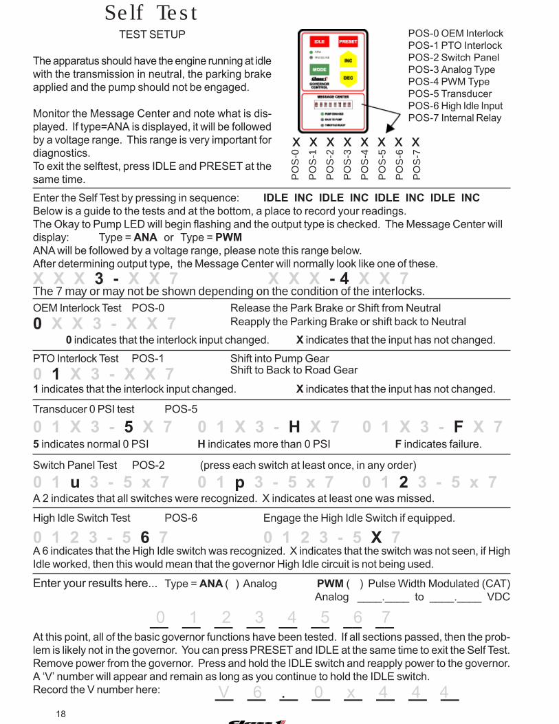
The apparatus should have the engine running at idlewith the transmission in neutral, the parking brakeapplied and the pump should not be engaged.
Monitor the Message Center and note what is dis-played. If type=ANA is displayed, it will be followedby a voltage range. This range is very important fordiagnostics.To exit the selftest, press IDLE and PRESET at thesame time.
POS-0 OEM InterlockPOS-1 PTO InterlockPOS-2 Switch PanelPOS-3 Analog TypePOS-4 PWM TypePOS-5 TransducerPOS-6 High Idle InputPOS-7 Internal Relay
Enter the Self Test by pressing in sequence: IDLE INC IDLE INC IDLE INC IDLE INCBelow is a guide to the tests and at the bottom, a place to record your readings.The Okay to Pump LED will begin flashing and the output type is checked. The Message Center willdisplay: Type = ANA or Type = PWMANA will be followed by a voltage range, please note this range below.After determining output type, the Message Center will normally look like one of these.X X X 3 - X X 7 X X X - 4 X X 7OEM Interlock Test POS-0 Release the Park Brake or Shift from Neutral
PTO Interlock Test POS-1 Shift into Pump GearShift to Back to Road Gear
Reapply the Parking Brake or shift back to Neutral0 X X 3 - X X 7
0 1 X 3 - X X 7
Transducer 0 PSI test POS-5
0 1 X 3 - 5 X 7 0 1 X 3 - H X 7 0 1 X 3 - F X 75 indicates normal 0 PSI H indicates more than 0 PSI F indicates failure.
Switch Panel Test POS-2 (press each switch at least once, in any order)
0 1 u 3 - 5 x 7 0 1 p 3 - 5 x 7 0 1 2 3 - 5 x 7
High Idle Switch Test POS-6 Engage the High Idle Switch if equipped.
0 1 2 3 - 5 6 7 0 1 2 3 - 5 X 7A 6 indicates that the High Idle switch was recognized. X indicates that the switch was not seen, if HighIdle worked, then this would mean that the governor High Idle circuit is not being used.
1 indicates that the interlock input changed. X indicates that the input has not changed.
0 indicates that the interlock input changed. X indicates that the input has not changed.
At this point, all of the basic governor functions have been tested. If all sections passed, then the prob-lem is likely not in the governor. You can press PRESET and IDLE at the same time to exit the Self Test.Remove power from the governor. Press and hold the IDLE switch and reapply power to the governor.A ‘V’ number will appear and remain as long as you continue to hold the IDLE switch.Record the V number here:
A 2 indicates that all switches were recognized. X indicates at least one was missed.
__ __ __ __ __ __ __ __ 0 1 2 3 4 5 6 7
Type = ANA ( ) Analog PWM ( ) Pulse Width Modulated (CAT)Analog ____.____ to ____.____ VDC
Enter your results here...
The 7 may or may not be shown depending on the condition of the interlocks.
__ __ __ __ __ __ __ __ V 6 . 0 x 4 4 4
19C:\manuals\Uni-Gov-V6-107490
Installation
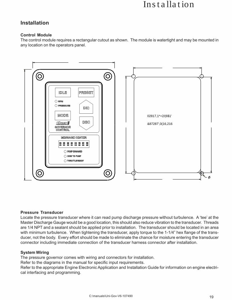
Control ModuleThe control module requires a rectangular cutout as shown. The module is watertight and may be mounted inany location on the operators panel.
Pressure TransducerLocate the pressure transducer where it can read pump discharge pressure without turbulence. A ‘tee’ at theMaster Discharge Gauge would be a good location, this should also reduce vibration to the transducer. Threadsare 1/4 NPT and a sealant should be applied prior to installation. The transducer should be located in an areawith minimum turbulence. When tightening the transducer, apply torque to the 1-1/4” hex flange of the trans-ducer, not the body. Every effort should be made to eliminate the chance for moisture entering the transducerconnector including immediate connection of the transducer harness connector after installation.
System WiringThe pressure governor comes with wiring and connectors for installation.Refer to the diagrams in the manual for specific input requirements.Refer to the appropriate Engine Electronic Application and Installation Guide for information on engine electri-cal interfacing and programming.
Installation
02817,1*�+2/(6�$1'
&87�287�',0(16,216����� �����
�����
���������
�����

20
-4 & -12 Connector
Connector A DT06-4S
1 System Power 12 VDC INPUT 2 System Ground Ground INPUT 3 Plug NC --------- 4 Plug NC ---------
Connector B DT06-12S
1 5 VDC input 5 VDC INPUT 2 Throttle Interlock 12VDC INPUT 3 High Idle 12 VDC INPUT 4 CAT ID Input 12 VDC INPUT 5 Transducer Ground XDucer Ground OUTPUT 6 Transducer Voltage XDucer 5 VDC OUTPUT 7 Transducer IN Xducer Signal INPUT 8 Analog Out Control Signal OUTPUT 9 Signal Ground Ground INPUT10 Pump Engaged Interlock 12 VDC INPUT11 Delay Relay Common (30) Enable Input INPUT12 Delay Relay NO (87) Enable Output OUTPUT
Governor Connectors
���������� ����������
����������������������������������� ��������������������������������
A
B
21C:\manuals\Uni-Gov-V6-107490
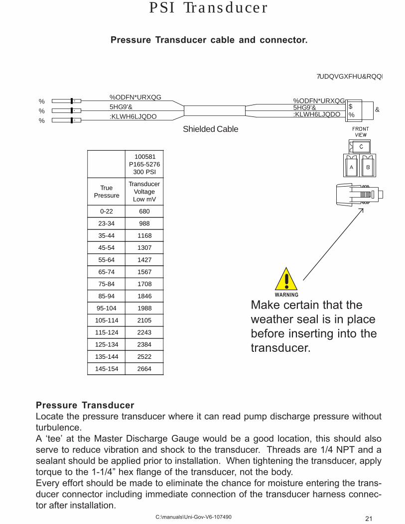
PSI Transducer
%ODFN�*URXQG5HG����9'&:KLWH�6LJQDO
%��%��%��
%ODFN����*URXQG5HG���������9'&:KLWH����6LJQDO
$%
&
7UDQVGXFHU�&RQQH
Shielded Cable
Pressure Transducer cable and connector.
100581P165-5276
300 PSI
TruePressure
TransducerVoltageLow mV
0-22 680
23-34 988
35-44 1168
45-54 1307
55-64 1427
65-74 1567
75-84 1708
85-94 1846
95-104 1988
105-114 2105
115-124 2243
125-134 2384
135-144 2522
145-154 2664
Make certain that theweather seal is in placebefore inserting into thetransducer.
!WARNING
Pressure TransducerLocate the pressure transducer where it can read pump discharge pressure withoutturbulence.A ‘tee’ at the Master Discharge Gauge would be a good location, this should alsoserve to reduce vibration and shock to the transducer. Threads are 1/4 NPT and asealant should be applied prior to installation. When tightening the transducer, applytorque to the 1-1/4” hex flange of the transducer, not the body.Every effort should be made to eliminate the chance for moisture entering the trans-ducer connector including immediate connection of the transducer harness connec-tor after installation.
22
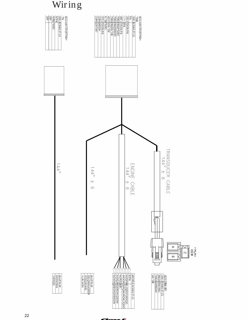
Wiring
&211(&
725��'(876&+
������������'7����6326���:,5(�'(6&
5,37,21����������5('�����9'&����������%
/$&.�*5281'
����������3/8*����������3/8*
&211(&
725��'(876&+
������������'7�����6$326���:,5(�'(6&
5,37,21��������������9'&����������2(0�,17(5/2&
.�����9'&�
����������+,*+
�,'/(�����9'&�
����������&$7�,17(5/2&
.�����9'&�
����������75$16'8&(5�*5281'
����������75$16'8&(5�6833/<
����������75$16'8&(5�6,*1$/
����������&21752/�6,*1$/
����������6,*1$/�*5281'���������372�,17(5/2&
.�����9'&�
���������(1$%/(�6833/<
���������(1$%/(�287387
&211��3$&
.$5'���������326���:,5(�'(6&
5,37,21���$������6(1625�5(7851���%
������6(1625�6833/<���&
������6,*1$/
&R
OR
U������:,5(�'(6&
5,37,215('�����������9'&%
OD
FN
�����6LJQD
O�*U
RX
QG
<HO
OR
Z����&
RQ
WU
RO
�6LJQD
O%
UR
ZQ
����&$7�,'
2UD
QJH
��(QD
EO
H�,Q
SX
W%
OX
H�������(Q
DE
OH
�2XW
SX
W
������&LU
FX
LW2(0�,Q
WH
UO
RF
N372�(Q
JDJH
G+
LJK�,G
OH
������&LU
FX
LW6X
SS
O\����9'&
*UR
XQ
G

23C:\manuals\Uni-Gov-V6-107490
Wiring
Power and GroundIt is imperative that the Class1 Pressure Governor be supplied power and ground from the samesource as the engine Electronic Control Module.
This is the only configuration that will assure reliable operation.
Terminal A-1 This is the Governor power input 12/24 VDC.
Terminal A-2 This is the Governor ground input.
InterlocksThere are two (2) 12 VDC interlocks that must be supplied to the governor for operation.
Terminal B-2The Throttle Ready or OEM Interlock must be continuously maintained once it is established. Thisinput allows the governor to operate in RPM mode and accept a High Idle input.
Terminal B-10The Pump Engaged Interlock is necessary to initiate pressure governing and it must not cause theOEM interlock to dropout when it is established or erratic operation of the governor could ensue.When the pump engaged interlock is active, the high idle function is precluded.
If a CAT Engine is installed, provide 12 VDC to terminal 12-4. This will ensure that the governorwill always output a PWM signal and ignore any engine type programming. This engine type willshow up as an ’a‘ during the power on sequence.
High IdleTerminal B-3
This 12 volt signal input causes the governor to bring the engine to a preset RPM.
Throttle Enable RelayTerminals B-11 and B-12
There is a governor controlled relay available to switch signal voltage or ground to the remotethrottle enable signal. This is the recommended configuration to handle the throttle source switch-ing function from the cab throttle to the remote throttle. Since it is controlled by the governor, itdisables remote throttle operation whenever [MODE] is shown in the display.
Transducer ConnectionTerminals B-5, B-6 & B-7
Sensor ground is provided at terminal B-5.Sensor voltage (5VDC) for the pressure transducer is at terminal B-6.Sensor signal is input at terminal B-7.Wiring should be straight from the transducer for at least 2 inches before being bent.
Engine ECM ConnectionsTerminal B-1, B-8 and B-9
The engine control signal output (B-8) is sent to the engine ECM. It should be connected to theremote throttle input terminal. B-1 is ECM 5 VDC and B-9 is ECM signal ground.
24
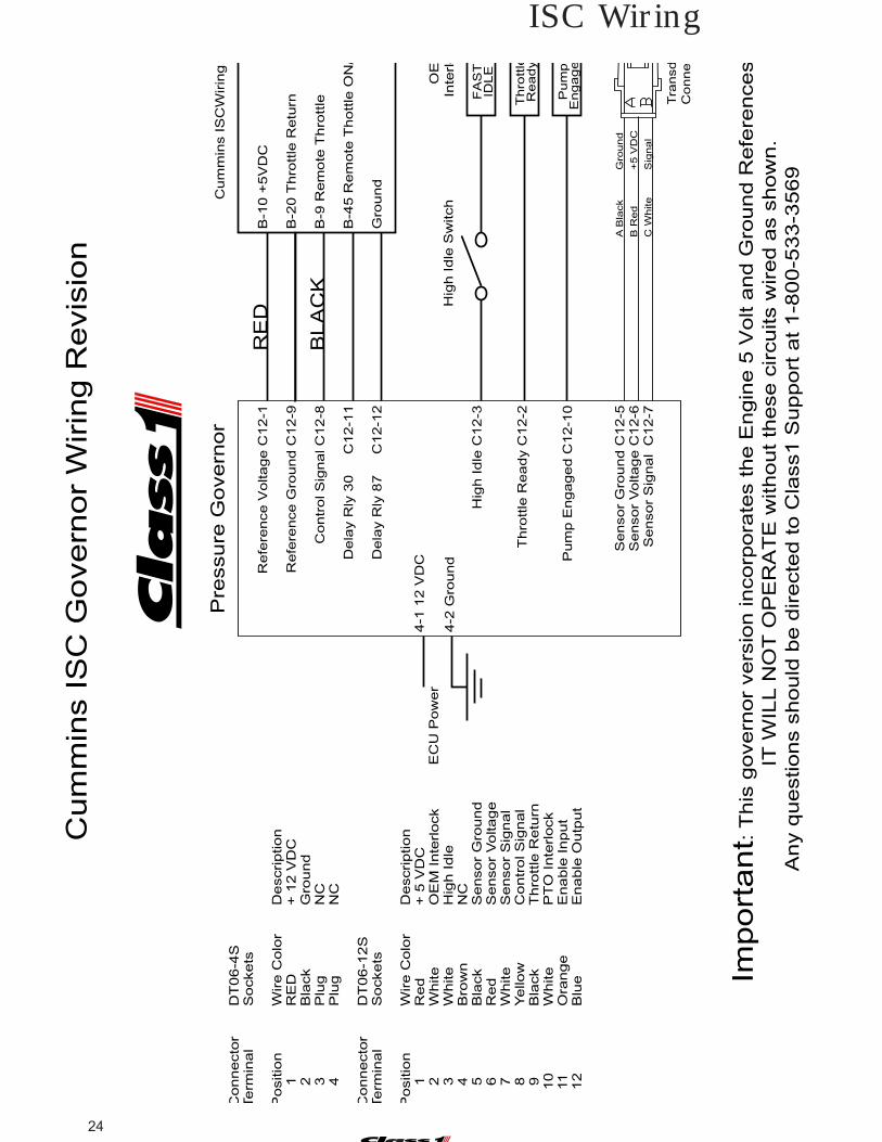
ISC Wiring
Re
fere
nce
Vo
lta
ge
C1
2-1
Re
fere
nce
Gro
un
d C
12
-9
Co
ntr
ol S
ign
al C
12
-8
De
lay R
ly 3
0
C
12
-11
De
lay R
ly 8
7
C
12
-12
Cu
mm
ins I
SC
Wirin
g
B-1
0 +
5V
DC
B-2
0 T
hro
ttle
Re
turn
B-9
Re
mo
te T
hro
ttle
B-4
5 R
em
ote
Th
ott
le O
N/
Gro
un
d
Import
ant:
This
govern
or
vers
ion incorp
ora
tes the E
ngin
e 5
Volt a
nd G
round R
efe
rences
IT
WIL
L N
OT
OP
ER
AT
E w
ithout th
ese c
ircuits w
ired a
s s
how
n.
Any q
uestions s
hould
be d
irecte
d to C
lass1 S
upport
at 1-8
00-5
33-3
569
Cum
min
s IS
C G
overn
or
Wirin
g R
evis
ion
Co
nn
ecto
rD
T0
6-4
STe
rmin
al
So
cke
ts
Po
sitio
nW
ire
Co
lor
De
scrip
tio
n
1
RE
D+
12
VD
C
2
Bla
ck
Gro
un
d
3
Plu
gN
C
4
Plu
gN
C
Co
nn
ecto
rD
T0
6-1
2S
Te
rmin
al
So
cke
ts
Po
sitio
nW
ire
Co
lor
De
scrip
tio
n
1
Re
d+
5 V
DC
2W
hite
OE
M I
nte
rlo
ck
3W
hite
Hig
h I
dle
4B
row
nN
C
5
Bla
ck
Se
nso
r G
rou
nd
6R
ed
Se
nso
r V
olta
ge
7W
hite
Se
nso
r S
ign
al
8Y
ello
wC
on
tro
l S
ign
al
9B
lack
Th
rott
le R
etu
rn
10
Wh
ite
PT
O I
nte
rlo
ck
1
1O
ran
ge
En
ab
le I
np
ut
1
2B
lue
En
ab
le O
utp
ut
4-1
12
VD
C
4-2
Gro
un
d
Pu
mp
En
ga
ge
OE
Inte
rlo
FA
ST
IDL
EH
igh
Id
le C
12
-3
Th
rott
le R
ea
dy C
12
-2
Pu
mp
En
ga
ge
d C
12
-10
Th
rott
leR
ea
dy
EC
U P
ow
er
Hig
h I
dle
Sw
itch
Se
nso
r G
rou
nd
C1
2-5
S
en
so
r V
olta
ge
C1
2-6
S
en
so
r S
ign
al C
12
-7
A B
lack
Gro
und
B R
ed
+5 V
DC
C W
hite
Sig
nal
Tra
nsd
Co
nn
e
Pre
ssure
Govern
or
RE
D
BLA
CK
25C:\manuals\Uni-Gov-V6-107490
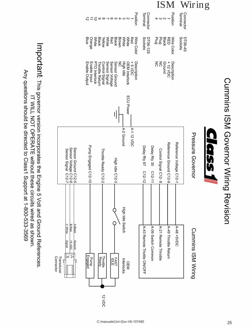
ISM Wiring
Reference V
oltage C12-1
Reference G
round C12-9
Control S
ignal C12- 8
Delay R
ly 30 C12-11
Delay R
ly 87 C12-12
Cum
mins IS
M W
iring
A-48 +
5VD
C
A-49 T
hrottle Return
A-21 R
emote T
hrottle
A-09 S
witch C
omm
on
A-43 R
emote T
hottle ON
/OF
F
Cum
mins IS
M G
overnor Wiring R
evision
Important: T
his governor version incorporates the Engine 5 V
olt and Ground R
eferences. IT
WILL N
OT
OP
ER
AT
E w
ithout these circuits wired as show
n.A
ny questions should be directed to Class1 S
upport at 1-800-533-3569
Connector
DT
06-4STerm
inalS
ockets
Position
Wire C
olorD
escription 1
RE
D+
12 VD
C 2
Black
Ground
3P
lugN
C 4
Plug
NC
Connector
DT
06-12STerm
inalS
ockets
Position
Wire C
olorD
escription 1
Red
+ 5 V
DC
2W
hiteO
EM
Interlock 3
White
High Idle
4B
rown
NC
5B
lackS
ensor Ground
6R
edS
ensor Voltage
7W
hiteS
ensor Signal
8Yellow
Control S
ignal 9
Black
Throttle R
eturn 10
White
PT
O Interlock
11O
rangeE
nable Input 12
Blue
Enable O
utput
4-1 12 VD
C
4-2 Ground
12 VD
C
Pum
pE
ngaged
OE
M
Interlocks
FA
ST
IDLE
High Idle C
12-3
Throttle R
eady C12-2
Pum
p Engaged C
12-10
Throttle
Ready
EC
U P
ower
High Idle S
witch
Sensor G
round C12-5
Sensor V
oltage C12-6
Sensor S
ignal C12-7
A B
lackG
round
B R
ed+
5 VD
C
C W
hiteS
ignal
TransducerC
onnector
Pressure G
overnor
26
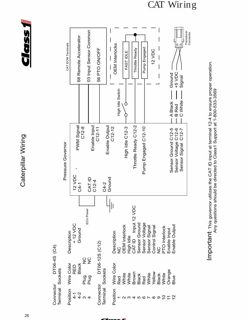
CAT Wiring
Connect
or
DT
06-4
S(C
4)
Term
inal
Sock
ets
Posi
tion
Wire C
olo
rD
esc
riptio
n 4
-1R
ED
+ 1
2 V
DC
4
-2B
lack
Gro
und
3
Plu
gN
C 4
Plu
gN
C
Connect
or
DT
06-1
2S
(C
12)
Term
inal
Sock
ets
Posi
tion
Wire C
olo
rD
esc
riptio
n 1
Red
NC
2
White
OE
M Inte
rlock
3
White
Hig
h Idle
4
Bro
wn
CA
T ID
Input 12 V
DC
5
Bla
ckS
enso
r G
round
6
Red
Senso
r V
olta
ge
7
White
Senso
r S
ignal
8
Yello
wC
ontr
ol S
ignal
9
Bla
ckN
C 10
White
PT
O Inte
rlock
11
Ora
nge
Enable
Input
12
Blu
eE
nable
Outp
ut
Pre
ssure
Gove
rnor
12 V
DC
C4-1
CA
T ID
C12-4
C4-2
Gro
und
PW
M S
ignal
C12-8
E
nable
Input
C12-1
1
Enable
Outp
ut
C12-1
2
12 V
DC
Pu
mp
En
ga
ge
d
OE
M Inte
rlock
s
FA
ST
ID
LE
Hig
h Idle
C12-3
Thro
ttle
Ready
C12-2
P
um
p E
ngaged C
12-1
0
CA
T E
CM
Term
inals
68 R
em
ote
Acc
ele
rato
r 0
3 Input S
enso
r C
om
mon
56 P
TO
ON
/OF
F
Th
rott
le R
ea
dy
EC
U P
ow
er
Hig
h I
dle
Sw
itch
Senso
r G
round C
12-5
S
enso
r V
olta
ge C
12-6
S
enso
r S
ignal
C12-7
A B
lack
Gro
und
B R
ed
+5 V
DC
C W
hite
Sig
nal
Tra
nsd
uce
rC
onnect
or
Imp
ort
an
t: T
his
gove
rnor
util
izes
the C
AT
ID
input at te
rmin
al 1
2-4
to e
nsu
re p
roper
opera
tion.
Any
quest
ions
should
be d
irect
ed to C
lass
1 S
upport
at 1-8
00-5
33-3
569
Ca
terp
illa
r W
irin
g

27C:\manuals\Uni-Gov-V6-107490
Navistar Wiring
Na
vistar C
ircuit
EC
M P
in9
7D
F S
witch
Vo
ltag
e1
2 V
DC
1 A
mp
97
CC
Va
riab
le E
na
ble
36
99
F R
em
ote
Se
nso
r Ou
tpu
t 30
97
DD
5 V
olt re
fere
nce
05
97
HM
Re
fere
nce
Gro
un
d 0
6
Pre
ssure
Go
vern
or
Re
fere
nce
Vo
ltag
e C
12
-1
Re
fere
nce
Gro
un
d C
12
-9
Co
ntro
l Sig
na
l C1
2- 8
De
lay R
ly 30
C1
2-1
1
De
lay R
ly 87
C1
2-1
2
Na
vistar W
iring
97
DD
Vo
ltag
e R
ef 5
V
97
HM
Re
m A
cc. Re
turn
99
F R
em
ote
Se
nso
r
97
DF
Sw
itch V
olta
ge
97
CC
Va
riab
le E
na
ble
Importa
nt:
Th
is go
vern
or ve
rsion
inco
rpo
rate
s the
En
gin
e 5
Vo
lt an
d G
rou
nd
Re
fere
nce
s. IT
WIL
L N
OT
OP
ER
AT
E w
itho
ut th
ese
circuits w
ired
as sh
ow
n.
An
y qu
estio
ns sh
ou
ld b
e d
irecte
d to
Cla
ss1 S
up
po
rt at 1
-80
0-5
33
-35
69
Na
vistar G
ove
rno
r Wirin
g
Co
nn
ecto
rD
T0
6-4
STe
rmin
al
So
ckets
Po
sition
Wire
Co
lor
De
scriptio
n 1
RE
D+
12
VD
C 2
Bla
ckG
rou
nd
3P
lug
NC
4P
lug
NC
Co
nn
ecto
rD
T0
6-1
2S
Term
ina
lS
ocke
ts
Po
sition
Wire
Co
lor
De
scriptio
n 1
Re
d9
7 D
D 2
Wh
iteO
EM
Inte
rlock
3W
hite
Hig
h Id
le 4
Bro
wn
CA
T ID
5B
lack
Se
nso
r Gro
un
d 6
Re
dS
en
sor V
olta
ge
7W
hite
Se
nso
r Sig
na
l 8
Ye
llow
Co
ntro
l Sig
na
l 9
Bla
ck9
7 H
M 1
0W
hite
PT
O In
terlo
ck 11
Ora
ng
eE
na
ble
Inp
ut
12
Blu
eE
na
ble
Ou
tpu
t
4-1
12 V
DC
4-2
Gro
und
12 V
DC
Pum
pE
ngaged
OE
M
Inte
rlocks
FA
ST
IDLE
Hig
h Id
le C
12
-3
Th
rottle
Re
ad
y C1
2-2
Pu
mp
En
ga
ge
d C
12
-10
Thro
ttleR
eady
EC
U P
ow
er
Hig
h Id
le S
witch
Se
nso
r Gro
un
d C
12
-5
Se
nso
r Vo
ltag
e C
12
-6
Se
nso
r Sig
na
l C1
2-7
A B
lack
Gro
und
B R
ed
+5 V
DC
C W
hite
Sig
nal
Tra
nsd
uce
rC
onnecto
r
Re
d W
ire
Bla
ck Wire
Inp
ut 1
2 V
DC
28
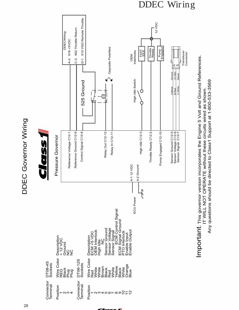
DDEC Wiring
Pre
ssure
Govern
or
Refe
rence V
oltage C
12-1
Refe
rence G
round C
12-9
Contr
ol S
ignal C
12-8
DD
EC
Wirin
g
A-3
9
16 +
5V
DC
C-3
9
52 T
hro
ttle
Retu
rn
D-1
5
10 V
SG
Rem
ote
Thro
ttle
Import
ant:
Th
is g
overn
or
vers
ion incorp
ora
tes the E
ngin
e 5
Volt a
nd G
round R
efe
rences.
IT
WIL
L N
OT
OP
ER
AT
E w
ithout th
ese c
ircuits w
ired a
s s
how
n.
An
y q
ue
stio
ns s
hould
be d
irecte
d to C
lass1 S
upport
at 1-8
00-5
33-3
569
DD
EC
Govern
or
Wirin
g
Connecto
rD
T06-4
STerm
inal
Sockets
Positio
nW
ire C
olo
rD
escription
1
RE
D+
12 V
DC
2
Bla
ck
Gro
und
3
Plu
gN
C 4
Plu
gN
C
Connecto
rD
T06-1
2S
Term
inal
Sockets
Positio
nW
ire C
olo
rD
escription
1
Red
EC
M +
5 V
DC
2
White
OE
M Inte
rlock
3
White
Hig
h Idle
4
Bro
wn
NC
5
Bla
ck
Sensor
Gro
und
6
Red
Sensor
Voltage
7
White
Sensor
Sig
nal
8
Yello
wE
CM
Contr
ol S
ignal
9
Bla
ck
EC
M S
ignal G
round
10
White
PT
O Inte
rlock
11
Ora
nge
Enable
Input
12
Blu
eE
nable
Outp
ut
4-1
12 V
DC
4-2
Gro
und
12 V
DC
Pu
mp
En
ga
ge
d
OE
M
Inte
rlocks
FA
ST
ID
LE
Hig
h Idle
C12-3
Thro
ttle
Ready C
12-2
Pum
p E
ngaged C
12-1
0
Th
rott
le R
ea
dy
EC
U P
ow
er
Hig
h I
dle
Sw
itch
Sensor
Gro
und C
12-5
S
ensor
Voltage C
12-6
S
ensor
Sig
nal C
12-7
A B
lack
Gro
und
B R
ed
+5 V
DC
C W
hite
Sig
nal
Tra
nsd
uce
rC
on
ne
cto
r
525 G
round
Rela
y O
ut C
12-1
2
Rela
y In C
12-1
1
Opposite P
ola
rities

29C:\manuals\Uni-Gov-V6-107490
Reference V
oltage C12-1
Reference G
round C12-9
Control S
ignal C12- 8
Delay R
elay 30
Delay R
elay 87
Mack E
CM
Wiring
VJ3-4 +
5VD
C
VJ3-6 T
hrottle Return
VJ3-5 R
emote T
hrottle
Mack G
overnor Wiring
Important: T
his governor version incorporates the Engine 5 V
olt and Ground R
eferences. IT
WILL N
OT
OP
ER
AT
E w
ithout these circuits wired as show
n.A
ny questions should be directed to Class1 S
upport at 1-800-533-3569
Connector
DT
06-4STerm
inalS
ockets
Position
Wire C
olorD
escription 1
RE
D+
12 VD
C 2
Black
Ground
3P
lugN
C 4
Plug
NC
Connector
DT
06-12STerm
inalS
ockets
Position
Wire C
olorD
escription 1
Red
+ 5 V
DC
2W
hiteO
EM
Interlock 3
White
High Idle
4B
rown
NC
5B
lackS
ensor Ground
6R
edS
ensor Voltage
7W
hiteS
ensor Signal
8Yellow
Control S
ignal 9
Black
Throttle R
eturn 10
White
PT
O Interlock
11O
rangeE
nable Input 12
Blue
Enable O
utput
4-1 12 VD
C
4-2 Ground
12 VD
C
Pum
pE
ngaged
OE
M
Interlocks
FA
ST
IDLE
High Idle C
12-3
Throttle R
eady C12-2
Pum
p Engaged C
12-10
Throttle
Ready
EC
U P
ower
High Idle S
witch
Sensor G
round C12-5
Sensor V
oltage C12-6
Sensor S
ignal C12-7
A B
lackG
round
B R
ed+
5 VD
C
C W
hiteS
ignal
TransducerC
onnector
Pressure G
overnor
Cab T
hrottle Signal
Method to
control changingthe throttle source
using thegovernor
delay relay
Mack Wiring

30
Ref
eren
ce V
olta
ge C
12-1
Ref
eren
ce G
roun
d C
12-9
Con
trol
Sig
nal C
12-8
D
elay
Rly
30
C
12-1
1
Del
ay R
ly 8
7
C12
-12
Mer
cede
s M
BE
900
VC
U W
iring
VC
U3-
17 +
5VD
C
VC
U1-
14 S
enso
r C
omm
on
VC
U3-
18 R
emot
e T
hrot
tle S
igna
l
VC
U3-
7
Thr
ottle
Sel
ect
Gro
und
Impo
rtan
t: T
his
gove
rnor
ver
sion
inco
rpor
ates
the
Eng
ine
5 V
olt a
nd G
roun
d R
efer
ence
s.
IT W
ILL
NO
T O
PE
RA
TE
with
out t
hese
circ
uits
wire
d as
sho
wn.
Any
que
stio
ns s
houl
d be
dire
cted
to C
lass
1 S
uppo
rt a
t 1-8
00-5
33-3
569
Mer
cede
s M
BE
900
Gov
erno
r W
iring
Pos
ition
Wire
Col
orD
escr
iptio
n
1R
ED
+ 1
2 V
DC
2
Bla
ckG
roun
d
3P
lug
NC
4
Plu
gN
C
Con
nect
orD
T06
-12S
Term
inal
Soc
kets
Pos
ition
Wire
Col
orD
escr
iptio
n
1R
ed+
5 V
DC
2
Whi
teO
EM
Inte
rlock
3
Whi
teH
igh
Idle
4
Bro
wn
NC
5
Bla
ckS
enso
r G
roun
d
6R
edS
enso
r V
olta
ge
7W
hite
Sen
sor
Sig
nal
8
Yello
wC
ontr
ol S
igna
l
9B
lack
Thr
ottle
Ret
urn
1
0W
hite
PT
O In
terlo
ck
11
Ora
nge
Ena
ble
Inpu
t
12
Blu
eE
nabl
e O
utpu
t
4-1
12
VD
C
4-2
Gro
und
12 V
DC
Pum
p E
ngag
ed
OE
M
Inte
rlock
s
FA
ST
IDLE
Hig
h Id
le C
12-3
Thr
ottle
Rea
dy C
12-2
Pum
p E
ngag
ed C
12-1
0
Thr
ottle
Rea
dy
EC
U P
ower
Hig
h Id
le S
witc
h
Sen
sor
Gro
und
C12
-5
Sen
sor
Vol
tage
C12
-6
Sen
sor
Sig
nal
C12
-7
A B
lack
Gro
und
B R
ed+
5 V
DC
C W
hite
Sig
nal
Tran
sduc
erC
onne
ctor
Pre
ssur
e G
over
nor
Con
nect
orD
T06
-4S
Term
inal
Soc
kets
MBE900 Wiring
31C:\manuals\Uni-Gov-V6-107490
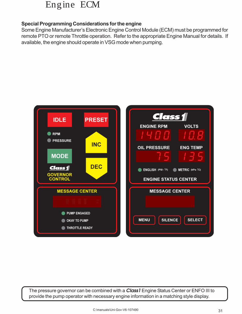
Special Programming Considerations for the engineSome Engine Manufacturer’s Electronic Engine Control Module (ECM) must be programmed forremote PTO or remote Throttle operation. Refer to the appropriate Engine Manual for details. Ifavailable, the engine should operate in VSG mode when pumping.
Engine ECM
The pressure governor can be combined with a Class1 Engine Status Center or ENFO III toprovide the pump operator with necessary engine information in a matching style display.
32
Preset ProgrammingChanging the preset RPM or PressureHolding the PRESET switch as the first function after the governor Power On Cycle accesses the gover-nor PRESET programming function.Apply power to the controller and hold the preset switch until the display indicates PRESET, then re-lease the switch (approx. 10 seconds).
Typically , the RPM Preset is an engine speed that either enhances alternator output or provides goodpump priming ability. Once set to department specification, it should not need to be changed.The Preset Pressure is normally one that is set by the department for initial attack operation or a safepressure for pre-connects. If set too high, it could present a hazard to operators. The design intent is toget the apparatus up and pumping in a minimal amount of time. Once the truck is operating, the pres-sure should be adjusted to the operation being performed.
The display will show PRESET while in the PRESET programming mode.The apparatus must be operating (engine running) to preset an RPM and the pump must be engaged topreset a Pressure. The only indication of mode will be the two LED’s at the top left of the controller.The green RPM LED will be illuminated in the Throttle Mode and the amber PRESSURE LED is illumi-nated when operating in Pressure Mode.
Operate the controller using the INC and DEC switches until you attain the desired RPM or pressure.
Press the PRESET switch to store this value.
STORING will be displayed in the Message Center.
Change the operating mode and operate the controller to achieve the desired value for that mode.Press the PRESET switch to store this value.
STORING will be displayed in the Message Center.
Press IDLE to return to normal operation and save the settings to memory.
UPDATING will be displayed in the Message Center.
The controller is now in operational condition with [MODE] showing in the Message Center.
To test the presets, select a mode and press the PRESET Switch. The governor should operate theengine to the correct Preset Point for the mode you selected.
Presets can be set individually if desired.
33C:\manuals\Uni-Gov-V6-107490
Engine Type Programming
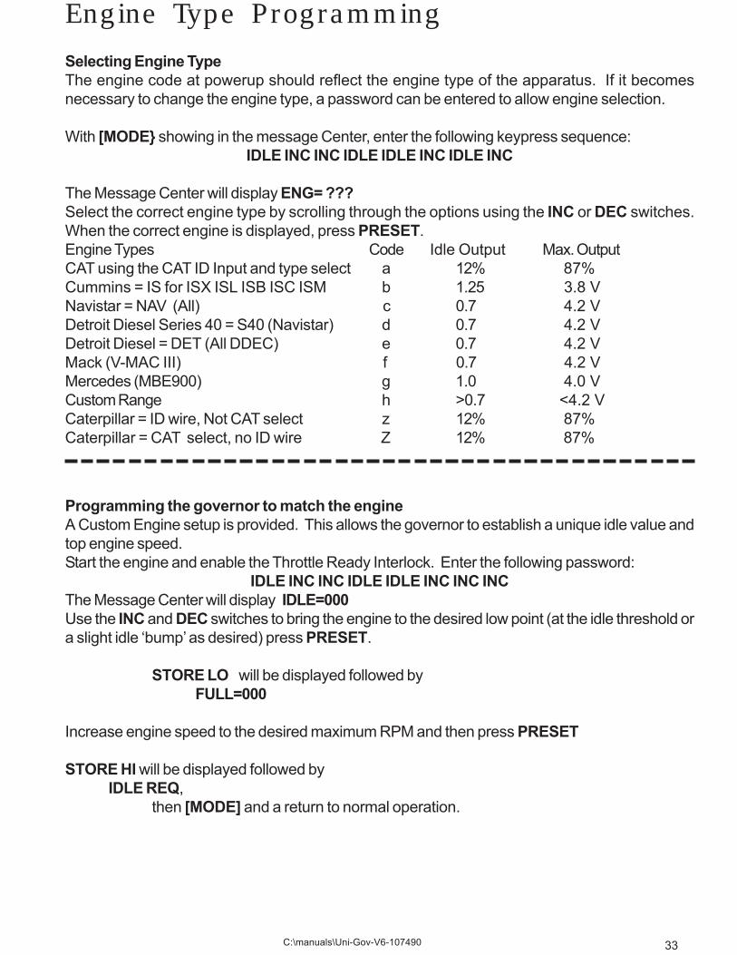
Programming the governor to match the engineA Custom Engine setup is provided. This allows the governor to establish a unique idle value andtop engine speed.Start the engine and enable the Throttle Ready Interlock. Enter the following password:
IDLE INC INC IDLE IDLE INC INC INCThe Message Center will display IDLE=000Use the INC and DEC switches to bring the engine to the desired low point (at the idle threshold ora slight idle ‘bump’ as desired) press PRESET.
STORE LO will be displayed followed byFULL=000
Increase engine speed to the desired maximum RPM and then press PRESET
STORE HI will be displayed followed byIDLE REQ,
then [MODE] and a return to normal operation.
Selecting Engine TypeThe engine code at powerup should reflect the engine type of the apparatus. If it becomesnecessary to change the engine type, a password can be entered to allow engine selection.
With [MODE} showing in the message Center, enter the following keypress sequence:IDLE INC INC IDLE IDLE INC IDLE INC
The Message Center will display ENG= ???Select the correct engine type by scrolling through the options using the INC or DEC switches.When the correct engine is displayed, press PRESET.Engine Types Code Idle Output Max. OutputCAT using the CAT ID Input and type select a 12% 87%Cummins = IS for ISX ISL ISB ISC ISM b 1.25 3.8 VNavistar = NAV (All) c 0.7 4.2 VDetroit Diesel Series 40 = S40 (Navistar) d 0.7 4.2 VDetroit Diesel = DET (All DDEC) e 0.7 4.2 VMack (V-MAC III) f 0.7 4.2 VMercedes (MBE900) g 1.0 4.0 VCustom Range h >0.7 <4.2 VCaterpillar = ID wire, Not CAT select z 12% 87%Caterpillar = CAT select, no ID wire Z 12% 87%
34
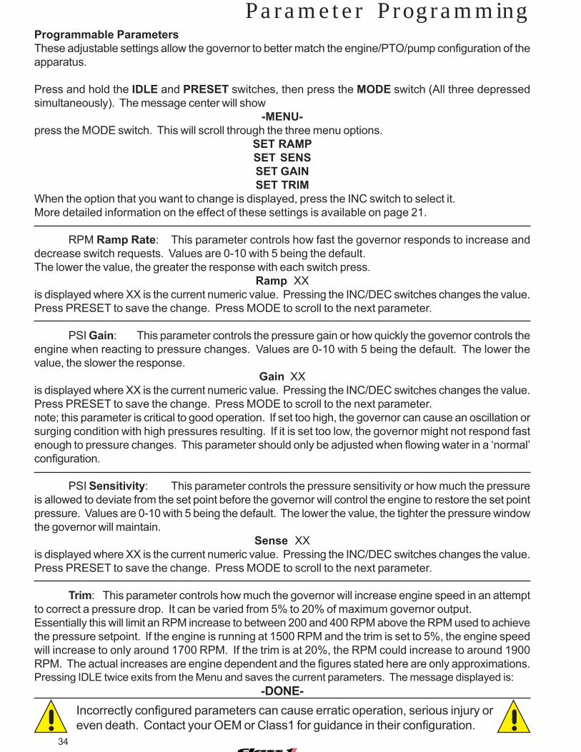
Programmable ParametersThese adjustable settings allow the governor to better match the engine/PTO/pump configuration of theapparatus.
Press and hold the IDLE and PRESET switches, then press the MODE switch (All three depressedsimultaneously). The message center will show
-MENU-press the MODE switch. This will scroll through the three menu options.
SET RAMPSET SENSSET GAINSET TRIM
When the option that you want to change is displayed, press the INC switch to select it.More detailed information on the effect of these settings is available on page 21.
RPM Ramp Rate: This parameter controls how fast the governor responds to increase anddecrease switch requests. Values are 0-10 with 5 being the default.The lower the value, the greater the response with each switch press.
Ramp XXis displayed where XX is the current numeric value. Pressing the INC/DEC switches changes the value.Press PRESET to save the change. Press MODE to scroll to the next parameter.
PSI Gain: This parameter controls the pressure gain or how quickly the governor controls theengine when reacting to pressure changes. Values are 0-10 with 5 being the default. The lower thevalue, the slower the response.
Gain XXis displayed where XX is the current numeric value. Pressing the INC/DEC switches changes the value.Press PRESET to save the change. Press MODE to scroll to the next parameter.note; this parameter is critical to good operation. If set too high, the governor can cause an oscillation orsurging condition with high pressures resulting. If it is set too low, the governor might not respond fastenough to pressure changes. This parameter should only be adjusted when flowing water in a ‘normal’configuration.
PSI Sensitivity: This parameter controls the pressure sensitivity or how much the pressureis allowed to deviate from the set point before the governor will control the engine to restore the set pointpressure. Values are 0-10 with 5 being the default. The lower the value, the tighter the pressure windowthe governor will maintain.
Sense XXis displayed where XX is the current numeric value. Pressing the INC/DEC switches changes the value.Press PRESET to save the change. Press MODE to scroll to the next parameter.
Trim: This parameter controls how much the governor will increase engine speed in an attemptto correct a pressure drop. It can be varied from 5% to 20% of maximum governor output.Essentially this will limit an RPM increase to between 200 and 400 RPM above the RPM used to achievethe pressure setpoint. If the engine is running at 1500 RPM and the trim is set to 5%, the engine speedwill increase to only around 1700 RPM. If the trim is at 20%, the RPM could increase to around 1900RPM. The actual increases are engine dependent and the figures stated here are only approximations.Pressing IDLE twice exits from the Menu and saves the current parameters. The message displayed is:
-DONE-
Parameter Programming
Incorrectly configured parameters can cause erratic operation, serious injury oreven death. Contact your OEM or Class1 for guidance in their configuration.! !

35C:\manuals\Uni-Gov-V6-107490
MiscellaneousIt is essential that the governor be powered at the same time as the engine ECM and that thecontrol signal does not drop out when the engine is started. This signal can be checked at the 12way connector terminal 8 with a voltmeter. Valid signals for idle are 0.6• VDC and higher, formaximum throttle 3.6 to 4.2 VDC.
The governor must have a throttle interlock (12 VDC) signal at terminal 12-2 in order to operate asa throttle or to act on a fast idle input (12 VDC) at terminal 12-3. Additionally, a pump engaged (12VDC) signal must be present at terminal 12-10 before it can operate in the pressure governingmode.If the governor is powered with the OEM Throttle interlock and the High Idle request active, it willignore the High Idle request. High Idle requires an active toggle.
The governor does not default to an operating mode, this means that the operator must selectwhich mode to operate in before the unit will respond. If the interlocks exist for pressure mode,the first selection will be PRESSURE. Once a mode is selected, it remains in effect until the modeswitch is pressed, the idle switch is pressed, the unit is powered off, the OEM Throttle interlock islost or cavitation is detected.
The PRESET function is very useful to expedite initial pumping operations. It can also be veryuseful to have both a THROTTLE and a PRESSURE preset. Any time that the PRESET switch ispressed, the engine will go to that point either from a higher pressure/RPM or a lower one. You donot have to be at idle for PRESET to function.
When increasing engine RPM from idle using the INCrease switch, the governor output must gofrom its base idle output and cross the idle threshold of the engine being governed. This is verysimilar to “taking up the slack” in a mechanical engine throttle cable. By using the PRESETfunction, the “slack” is taken care of automatically and the engine will increase to a knownparameter eliminating the guesswork.Note: A custom engine configuration can be programmed that will tailor the minimum idle outputfor an application.
Cavitation (running away from water). The governor will react to a pressure drop below 30 PSI forfive seconds or more by dropping the engine to idle speed and showing LoSupply in the MessageCenter. If the pressure climbs above 30 PSI before water loss is recognized, the 5 second timerresets. This means that if the pump has some water, the governor may never “see” a continuouspressure drop below 30 PSI and the engine could run at an advanced speed until it is manuallydecreased. The maximum speed will be restricted to the last value plus the trim parameter, usuallyless than a 300 RPM increase. If water is introduced during the period that engine speed isadvanced, a pressure spike could result.
Pump operators should be trained in all aspectsof governor operation and have knowledgeof all powertrain operating characteristics.
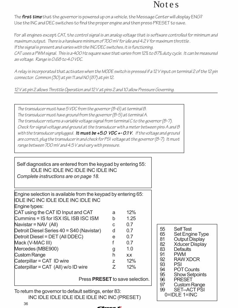
36
Notes
55 Self Test65 Set Engine Type81 Output Display82 Xducer Display83 Defaults91 PWM92 RAW XDCR93 PSI94 POT Counts95 Show Setpoints96 PRESET97 Custom Range99 SET--ACT PSI 0=IDLE 1=INC
The fffffirst timeirst timeirst timeirst timeirst time that the governor is powered up on a vehicle, the Message Center will display ENG?
Use the INC and DEC switches to find the proper engine and then press PRESET to save.
For all engines except CAT, the control signal is an analog voltage that is software controlled for minimum and
maximum output. There is a hardware minimum of 700 mV for idle and 4.2 V for maximum throttle .
If the signal is present and varies with the INC/DEC switches, it is functioning.
CAT uses a PWM signal. This is a 400 Hz square wave that varies from 12% to 87% duty cycle. It can be measured
as voltage. Range is 0.68 to 4.0 VDC.
A relay is incorporated that activates when the MODE switch is pressed if a 12 V input on terminal 2 of the 12 pin
connector. Common (30) at pin 11 and NO (87) at pin 12.
12 V at pin 2 allows Throttle Operation and 12 V at pins 2 and 10 allow Pressure Governing.
The transducer must have 5 VDC from the governor (B-6) at terminal B.
The transducer must have ground from the governor (B-5) at terminal A.
The transducer returns a variable voltage signal from terminal C to the governor (B-7).
Check for signal voltage and ground at the transducer with a meter between pins A and B
with the transducer unplugged. It must bIt must bIt must bIt must bIt must be +5e +5e +5e +5e +5.0 VDC.0 VDC.0 VDC.0 VDC.0 VDC +- 0+- 0+- 0+- 0+- 0.1 V.1 V.1 V.1 V.1 V. If the voltage and ground
are correct, plug the transducer in and check for PSI voltage at the governor (B-7). It must
range between 700 mV and 4.5 V and vary with pressure.
Engine selection is available from the keypad by entering 65:IDLE INC INC IDLE IDLE INC IDLE INCEngine types:CAT using the CAT ID Input and CAT a 12%Cummins = IS for ISX ISL ISB ISC ISM b 1.25Navistar = NAV (All) c 0.7Detroit Diesel Series 40 = S40 (Navistar) d 0.7Detroit Diesel = DET (All DDEC) e 0.7Mack (V-MAC III) f 0.7Mercedes (MBE900) g 1.0Custom Range h x.xCaterpillar = CAT ID wire z 12%Caterpillar = CAT (All) w/o ID wire Z 12%
Press PRESET to save selection.
To return the governor to default settings, enter 83:INC IDLE IDLE IDLE IDLE IDLE INC INC (PRESET)
Self diagnostics are entered from the keypad by entering 55:IDLE INC IDLE INC IDLE INC IDLE INC
Complete instructions are on page 18.

Gauges
Flowmeters
Electronic Controls
Plumbing Components
…And More
607 N.W. 27th Avenue
Ocala, Florida 34475
Phone 352‐629‐5020
FAX 352‐629‐2902
http://www.class1.com
rleonard
Typewritten Text
rleonard
Typewritten Text
rleonard
Typewritten Text
rleonard
Typewritten Text
Related Documents