Interoperability Specification for ICCs and Personal Computer Systems Part 3. Requirements for PC-Connected Interface Devices Bull CP8, a Bull Company Gemplus SA Hewlett-Packard Company IBM Corporation Microsoft Corporation Schlumberger SA Siemens Nixdorf Informationssysteme AG Sun Microsystems Inc. Toshiba Corporation VeriFone Inc. Revision 1.0 December 1997

Welcome message from author
This document is posted to help you gain knowledge. Please leave a comment to let me know what you think about it! Share it to your friends and learn new things together.
Transcript
Interoperability Specification for ICCs and Personal Computer Systems
Part 3. Requirements for PC-Connected Interface Devices Bull CP8, a Bull Company
Gemplus SA
Hewlett-Packard Company
IBM Corporation
Microsoft Corporation
Schlumberger SA
Siemens Nixdorf Informationssysteme AG
Sun Microsystems Inc.
Toshiba Corporation
VeriFone Inc.
Revision 1.0 December 1997

Copyright © 1996, 1997, Bull CP8, Gemplus, Hewlett-Packard, IBM, Microsoft, Schlumberger, Siemens Nixdorf, Sun Microsystems, Toshiba and VeriFone.
All rights reserved.
INTELLECTUAL PROPERTY DISCLAIMER THIS SPECIFICATION IS PROVIDED “AS IS” WITH NO WARRANTIES WHATSOEVER INCLUDING ANY WARRANTY OF MERCHANTABILITY, FITNESS FOR ANY PARTICULAR PURPOSE, OR ANY WARRANTY OTHERWISE ARISING OUT OF ANY PROPOSAL, SPECIFICATION, OR SAMPLE. NO LICENSE, EXPRESS OR IMPLIED, BY ESTOPPEL OR OTHERWISE, TO ANY INTELLECTUAL PROPERTY RIGHTS IS GRANTED OR INTENDED HEREBY. BULL CP8, GEMPLUS, HEWLETT-PACKARD, IBM, MICROSOFT, SCHLUMBERGER, SIEMENS NIXDORF, SUN MICROSYSTEMS, TOSHIBA AND VERIFONE DISCLAIM ALL LIABILITY, INCLUDING LIABILITY FOR INFRINGEMENT OF PROPRIETARY RIGHTS, RELATING TO IMPLEMENTATION OF INFORMATION IN THIS SPECIFICATION. BULL CP8, GEMPLUS, HEWLETT PACKARD, IBM, MICROSOFT, SCHLUMBERGER, SIEMENS NIXDORF, SUN MICROSYSTEMS, TOSHIBA AND VERIFONE DO NOT WARRANT OR REPRESENT THAT SUCH IMPLEMENTATION(S) WILL NOT INFRINGE SUCH RIGHTS. Windows and Windows NT are trademarks and Microsoft and Win32 are registered trademarks of Microsoft Corporation. PS/2 is a registered trademark of IBM Corp. JAVA is a registered trademark of Sun Microsystems, Inc. All other product names are trademarks, registered trademarks, or servicemarks of their respective owners.
Interoperability Specification for ICCs and Personal Computer Systems December 1997 Part 3. Requirements for PC-Connected Interface Devices
1996, 1997 – Bull CP8, Gemplus, Hewlett-Packard, IBM, Microsoft, Schlumberger, Siemens Nixdorf, Sun Microsystems, Toshiba, VeriFone. All Rights Reserved. Page i
Contents
1. SCOPE 1
2. IFD SUBSYSTEM COMPONENTS 2
2.1 Interface Device 2
2.2 I/O Channel 3
2.3 IFD Handler 4
3. FUNCTIONALITY REQUIREMENTS 5
3.1 Mandatory Functionality 5 3.1.1 Operational characteristics 5 3.1.2 Enumeration of Device Capabilities 6 3.1.3 ICC Events 11 3.1.4 ICC Interface Management 11 3.1.5. Protocol Support 13
3.1.5.1 Protocol Negotiation 14 3.1.5.2 T=0 Protocol Support 15 3.1.5.3 T=1 Protocol Support 16 3.1.5.4 Synchronous Protocols 17
3.1.6 Channel mechanism support 17
3.2 Optional Functionality 18 3.2.1 ICC Power Management 18 3.2.2 Mechanical Characteristics 18 3.2.3 Security Assurance Devices 18 3.2.4 Vendor-Specific Features 19
APPENDIX A: IFD HANDLER INTERFACE REFERENCE 20
3.3 Syntax 20
3.4 Administrative Services 20 3.4.1 Retrieving an IFD Capability 20 3.4.2 Setting an IFD Capability 21 3.4.3 Protocol Information and Negotiation 21 3.4.4 ICC Power Management 22 3.4.5 Mechanical Characteristics 23
Interoperability Specification for ICCs and Personal Computer Systems December 1997 Part 3. Requirements for PC-Connected Interface Devices
1996, 1997 – Bull CP8, Gemplus, Hewlett-Packard, IBM, Microsoft, Schlumberger, Siemens Nixdorf, Sun Microsystems, Toshiba, VeriFone. All Rights Reserved. Page ii
3.5 Communication Services 24 3.5.1 Data Exchange with the ICC 24 3.5.2 ICC Insertion and Removal 26

Interoperability Specification for ICCs and Personal Computer Systems December 1997 Part 3. Requirements for PC-Connected Interface Devices
1996, 1997 – Bull CP8, Gemplus, Hewlett-Packard, IBM, Microsoft, Schlumberger, Siemens Nixdorf, Sun Microsystems, Toshiba, VeriFone. All Rights Reserved. Page iii
Interoperability Specification for ICCs and Personal Computer Systems December 1997 Part 3. Requirements for PC-Connected Interface Devices
1996, 1997 – Bull CP8, Gemplus, Hewlett-Packard, IBM, Microsoft, Schlumberger, Siemens Nixdorf, Sun Microsystems, Toshiba, VeriFone. All Rights Reserved. Page 1
1. Scope
This document discusses requirements for Interface Devices compliant with the Interoperability Specification for ICCs and Personal Computer Systems. For the purposes of this discussion, Interface Devices are PC-connected peripherals designed to interface to ISO/IEC 7816–compatible ICCs. Such devices are also commonly called ICC smart card “Readers” or “Terminals”. However, other specifications may describe IFD or ICC Terminal functionality that differs in scope from the Interface Devices requirements herein.
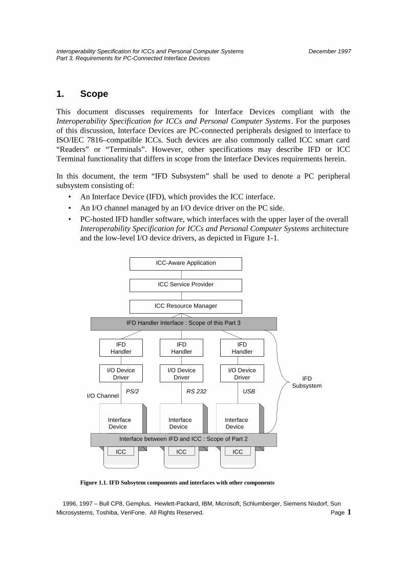
In this document, the term “IFD Subsystem” shall be used to denote a PC peripheral subsystem consisting of:
• An Interface Device (IFD), which provides the ICC interface. • An I/O channel managed by an I/O device driver on the PC side. • PC-hosted IFD handler software, which interfaces with the upper layer of the overall
Interoperability Specification for ICCs and Personal Computer Systems architecture and the low-level I/O device drivers, as depicted in Figure 1-1.
ICC-Aware Application
ICC Service Provider
ICC Resource Manager
IFDHandler
IFDHandler
IFDHandler
InterfaceDevice
ICC
InterfaceDevice
ICC
InterfaceDevice
ICC
IFD Handler Interface : Scope of this Part 3
Interface between IFD and ICC : Scope of Part 2
I/O Channel
I/O DeviceDriver
I/O DeviceDriver
I/O DeviceDriver IFD
SubsystemPS/2 RS 232 USB
Figure 1.1. IFD Subsytem components and interfaces with other components

Interoperability Specification for ICCs and Personal Computer Systems December 1997 Part 3. Requirements for PC-Connected Interface Devices
1996, 1997 – Bull CP8, Gemplus, Hewlett-Packard, IBM, Microsoft, Schlumberger, Siemens Nixdorf, Sun Microsystems, Toshiba, VeriFone. All Rights Reserved. Page 2
A vendor must fully implement the IFD Subsystem. In doing so, they may create the entire subsystem or take advantage of standard device drivers, I/O channels, and/or default IFD Handlers, which may be provided by other vendors. In order to claim compliance however, they must insure that the entire subsystem functions in accordance with this specification. In particular, this means they must support:
• An ICC interface as described in Part 2, “Interface Requirements for Compatible IC Cards and Interface Devices.”
• A PC software interface and associated functionality, as described in this document.
This document identifies specific requirements for compliant Interface Devices. Reference designs for specific types of Interface Devices, and especially a PS/2 keyboard–based compliant Interface Device, can be found in Part 4 of these specifications “Interface Device Design Considerations and reference design information”.
2. IFD Subsystem Components
The IFD Subsystem is a PC peripheral subsystem consisting of the components identified in Section 1. It is the intent of this specification to define requirements that are supportable across a wide variety of Interface Device designs and that encourage continued innovation by Interface Device vendors. In order to achieve this, the IFD Subsystem employs a layered architecture, which allows for design variations and supports a variety of data communications interfaces between the Interface Device and PC. Requirements on compliant devices are specified at the interface to the ICC and at the programming interface (IFD Handler Interface) exposed on the PC.
2.1 Interface Device
The Interface Device is a PC peripheral that: • Interfaces to an ICC as described in Part 2, “Interface Requirements for Compatible
IC Cards and Interface Devices.” • Supports bidirectional data communications between an ICC and PC. • Incorporates functionality required to support the interface exposed by the IFD
Handler
There are limited physical design requirements imposed on compliant Interface Devices, primarily those dictated by compatibility with the ICC physical interface.
In the interest of reliability, it is strongly recommended that these devices employ: • A landing card or landing contact design. • A microswitch for card detection.
The Interface Device should employ a tamper-evident design if it incorporates any of the optional security assurance features discussed in chapter 3.2.3. These features should provide reasonable assurance to the end user that attempts to access or modify the Interface
Interoperability Specification for ICCs and Personal Computer Systems December 1997 Part 3. Requirements for PC-Connected Interface Devices
1996, 1997 – Bull CP8, Gemplus, Hewlett-Packard, IBM, Microsoft, Schlumberger, Siemens Nixdorf, Sun Microsystems, Toshiba, VeriFone. All Rights Reserved. Page 3
Device are detectable. See ISO 13491:1995 for information regarding tamper-evident devices.
2.2 I/O Channel
This specification is compatible with IFD Subsystems using any available PC I/O channel to communicate with the Interface Device. It is the responsibility of the vendor to create an IFD Handler and device drivers, as necessary to insure that the ICC Service Providers can communicate with the ICC through the Interface Device. It is also the responsibility of the Interface Device vendor to provide appropriate management services and error handling related to the PC I/O channel to insure reliable, error free communication.
Interoperability Specification for ICCs and Personal Computer Systems December 1997 Part 3. Requirements for PC-Connected Interface Devices
1996, 1997 – Bull CP8, Gemplus, Hewlett-Packard, IBM, Microsoft, Schlumberger, Siemens Nixdorf, Sun Microsystems, Toshiba, VeriFone. All Rights Reserved. Page 4
The following indicates possible design options and discusses the primary strengths and/or weaknesses of the associated PC I/O channel:
• PS/2 Keyboard Integrated Interface Device. Can be implemented at very low incremental cost beyond basic keyboard. This is likely to be the preferred near term solution for desktop PCs due to the ubiquitous availability of PS/2® keyboard interfaces, the efficient use of desktop space, and the fact such designs don’t use other, scarce, I/O resources. Drawbacks include the maximum data rate limit of 9600 bps and potential impact in responsiveness to keyboard input.
• Serial Port (RS-232C) interface. It’s possible to build low-cost Interface Devices using standard serial ports. Such devices can easily support multiple data rates, including support for rates in excess of 30 kbps, and are suitable for use with desktop and laptop PCs. Biggest drawback is reliance on serial port, which is a scarce resource on most PCs.
• Interface Devices employing custom interface boards. Such devices offer the designer the greatest flexibility, but solutions are fairly high cost and space for add-on interface boards is a scarce commodity on many PCs.
• Parallel Port interfaces. It’s possible to build such devices at relatively low cost, but not all PCs include parallel I/O ports and when present these tend to be an overloaded resource. Design complications include de-facto requirements to support pass-through for printers, and the need to convert between the ICC serial interface and a parallel interface.
• PC Card–based Interface Devices. Such devices are moderately high cost, but may be the best approach to addressing the needs of existing laptop PCs. Such devices offer growth potential to very high effective data rates, but the design makes ICC insertion/removal somewhat difficult and it is difficult to support any of the optional Security Assurance features identified in Chapter 3.2.3.
• SCSI interfaces. SCSI- based Interface Devices can support a variety of effective data rates. This may also be an attractive option in situations where there is a need to support multiple Interface Devices from a single PC. The downside is the fairly high cost associated with SCSI-compatible devices.
• USB interface. Efforts are underway to establish USB as a standard for connection of peripheral devices to the PC. It offers a great deal of flexibility, a clean model for handling of multiple devices, and supports data rates up to 10 Mbps. The major drawback is the absence of USB interfaces on most of the PC’s built before 1997. It is believed that USB-based Interface Devices will eventually supplant PS/2 Keyboard and serial port Interface Devices as the preferred designs.
2.3 IFD Handler
The IFD Handler is software running on the PC that implements a standard, hardware-independent and I/O channel–independent interface into the IFD subsystem for PC-based software. It is the responsibility of this IFD Handler to interface to the I/O channel used by
Interoperability Specification for ICCs and Personal Computer Systems December 1997 Part 3. Requirements for PC-Connected Interface Devices
1996, 1997 – Bull CP8, Gemplus, Hewlett-Packard, IBM, Microsoft, Schlumberger, Siemens Nixdorf, Sun Microsystems, Toshiba, VeriFone. All Rights Reserved. Page 5
the Interface Device, either via standard device drivers or by implementing appropriate functionality. It is also required to map Interface Device functionality onto these interfaces.
Depending on the vendor-implemented Interface Device functionality, the complexity of the IFD Handler can vary dramatically. For example, given an Interface Device with limited intelligence and support for only the ISO/IEC 7816 physical data link layer, the IFD Handler will need to implement the T=0 and T=1 data link layers, provide associated error handling, and so on. In contrast, a vendor could implement a sophisticated Interface Device that internally supports the T=0 and T=1 data link layers. In this case, the IFD Handler will be significantly simpler in design.
These specifications do not mandate a specific implementation for IFD Handlers. Compatible IFD Handlers may be implemented as statically linked libraries, dynamically linked libraries (sometimes called shared libraries), or device drivers. Recommended implementations for a specific environment should be specified by the Operating System vendor. This allows each OS vendor to optimize the implementation in consideration of the OS services, device driver model, and supported hardware.
3. Functionality Requirements
This Section presents information on functional requirements for the IFD Subsystem visible at the PC-software interface implemented by the IFD Handler. It discusses both mandatory and optional functionality.
3.1 Mandatory Functionality
The following subsections identify mandatory functionality for compliant IFD subsystems.
3.1.1 Operational characteristics
The IFD Handler shall present a uniform set of services to the ICC Service Provider software. An IFD Handler shall only support a single, active, logical connection between a PC-based application and the associated Interface Device at any given time. That is, the IFD Handler is not required to support multiple active connections to PC software programs nor is it required to provide any services related to the management of multiple logical connections and associated command streams.
This does not preclude use of the “session” management features defined in ISO/IEC 7816 such as the “channel” mechanisms defined in 7816-4 or the Node Addressing functionality associated with the T=1 protocol. However, implementation of these features is the responsibility of the ICC and associated ICC Service Provider(s).
From the perspective of PC-based software, the IFD Handler implements a number of administrative and asynchronous communications services. The administrative functions should appear to act as simple function calls and may block the calling application until completed. The communications functions shall be implemented such that the calling
Interoperability Specification for ICCs and Personal Computer Systems December 1997 Part 3. Requirements for PC-Connected Interface Devices
1996, 1997 – Bull CP8, Gemplus, Hewlett-Packard, IBM, Microsoft, Schlumberger, Siemens Nixdorf, Sun Microsystems, Toshiba, VeriFone. All Rights Reserved. Page 6
process may initiate a command and then continue independent processing while the command is transmitted to the ICC and ICC response retrieved. The IFD Handler shall then notify the calling process using an appropriate inter-process signaling mechanism. The specific signaling mechanism to be implemented is OS dependent and is beyond the scope of this specification.
It is acceptable to implement an IFD Handler that supports multiple Interface Devices. This may be desirable to improve efficiency and/or reduce vendor development and support costs. In the event an IFD Handler supports multiple Interface Devices, it must present an independent logical connection to the calling ICC Service Provider(s) for each Device. In addition, it must support the ability for the calling software to determine which physical Device is associated with a given logical connection.
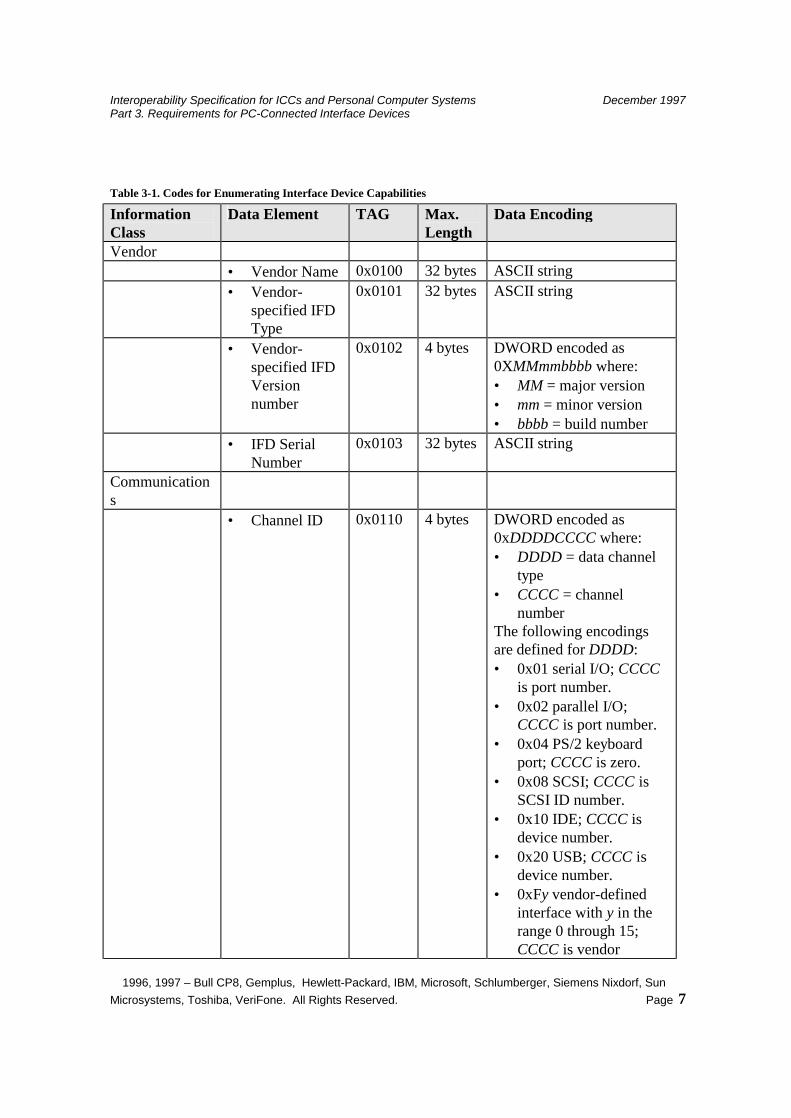
3.1.2 Enumeration of Device Capabilities
The IFD Handler shall provide an interface that supports enumeration of the functionality, both mandatory and optional, that is implemented by the IFD subsystem. An ICC Service Provider shall be able to query this interface at any time. Information will be returned using a TLV (tag-length-value) structure. At a minimum, the following information shall be retrievable.
Interoperability Specification for ICCs and Personal Computer Systems December 1997 Part 3. Requirements for PC-Connected Interface Devices
1996, 1997 – Bull CP8, Gemplus, Hewlett-Packard, IBM, Microsoft, Schlumberger, Siemens Nixdorf, Sun Microsystems, Toshiba, VeriFone. All Rights Reserved. Page 7
Table 3-1. Codes for Enumerating Interface Device Capabilities
Information Class
Data Element TAG Max. Length
Data Encoding
Vendor • Vendor Name 0x0100 32 bytes ASCII string • Vendor-
specified IFD Type
0x0101 32 bytes ASCII string
• Vendor-specified IFD Version number
0x0102 4 bytes DWORD encoded as 0XMMmmbbbb where: • MM = major version • mm = minor version • bbbb = build number
• IFD Serial Number
0x0103 32 bytes ASCII string
Communications
• Channel ID 0x0110 4 bytes DWORD encoded as 0xDDDDCCCC where: • DDDD = data channel
type • CCCC = channel
number The following encodings are defined for DDDD: • 0x01 serial I/O; CCCC
is port number. • 0x02 parallel I/O;
CCCC is port number. • 0x04 PS/2 keyboard
port; CCCC is zero. • 0x08 SCSI; CCCC is
SCSI ID number. • 0x10 IDE; CCCC is
device number. • 0x20 USB; CCCC is
device number. • 0xFy vendor-defined
interface with y in the range 0 through 15; CCCC is vendor
Interoperability Specification for ICCs and Personal Computer Systems December 1997 Part 3. Requirements for PC-Connected Interface Devices
1996, 1997 – Bull CP8, Gemplus, Hewlett-Packard, IBM, Microsoft, Schlumberger, Siemens Nixdorf, Sun Microsystems, Toshiba, VeriFone. All Rights Reserved. Page 8
Information Class
Data Element TAG Max. Length
Data Encoding
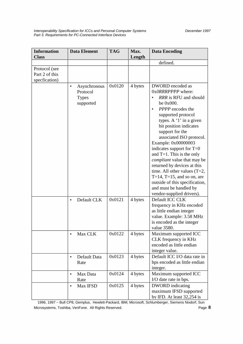
defined. Protocol (see Part 2 of this specfication)
• Asynchronous Protocol Types supported
0x0120 4 bytes DWORD encoded as 0x0RRRPPPP where: • RRR is RFU and should
be 0x000. • PPPP encodes the
supported protocol types. A ‘1’ in a given bit position indicates support for the associated ISO protocol.
Example: 0x00000003 indicates support for T=0 and T=1. This is the only compliant value that may be returned by devices at this time. All other values (T=2, T=14, T=15, and so on, are outside of this specification, and must be handled by vendor-supplied drivers).
• Default CLK 0x0121 4 bytes Default ICC CLK frequency in KHz encoded as little endian integer value. Example: 3.58 MHz is encoded as the integer value 3580.
• Max CLK 0x0122 4 bytes Maximum supported ICC CLK frequency in KHz encoded as little endian integer value.
• Default Data Rate
0x0123 4 bytes Default ICC I/O data rate in bps encoded as little endian integer.
• Max Data Rate
0x0124 4 bytes Maximum supported ICC I/O date rate in bps.
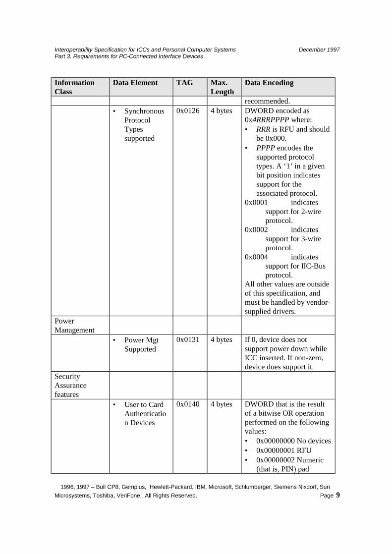
• Max IFSD 0x0125 4 bytes DWORD indicating maximum IFSD supported by IFD. At least 32,254 is
Interoperability Specification for ICCs and Personal Computer Systems December 1997 Part 3. Requirements for PC-Connected Interface Devices
1996, 1997 – Bull CP8, Gemplus, Hewlett-Packard, IBM, Microsoft, Schlumberger, Siemens Nixdorf, Sun Microsystems, Toshiba, VeriFone. All Rights Reserved. Page 9
Information Class
Data Element TAG Max. Length
Data Encoding
recommended. • Synchronous
Protocol Types supported
0x0126 4 bytes DWORD encoded as 0x4RRRPPPP where: • RRR is RFU and should
be 0x000. • PPPP encodes the
supported protocol types. A ‘1’ in a given bit position indicates support for the associated protocol.
0x0001 indicates support for 2-wire protocol.
0x0002 indicates support for 3-wire protocol.
0x0004 indicates support for IІC-Bus protocol.
All other values are outside of this specification, and must be handled by vendor-supplied drivers.
Power Management
• Power Mgt Supported
0x0131 4 bytes If 0, device does not support power down while ICC inserted. If non-zero, device does support it.
Security Assurance features
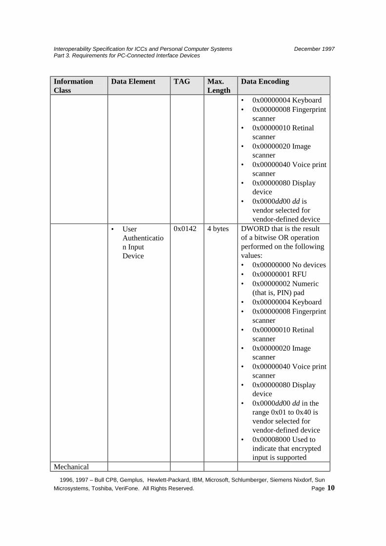
• User to Card Authentication Devices
0x0140 4 bytes DWORD that is the result of a bitwise OR operation performed on the following values: • 0x00000000 No devices • 0x00000001 RFU • 0x00000002 Numeric
(that is, PIN) pad
Interoperability Specification for ICCs and Personal Computer Systems December 1997 Part 3. Requirements for PC-Connected Interface Devices
1996, 1997 – Bull CP8, Gemplus, Hewlett-Packard, IBM, Microsoft, Schlumberger, Siemens Nixdorf, Sun Microsystems, Toshiba, VeriFone. All Rights Reserved. Page 10
Information Class
Data Element TAG Max. Length
Data Encoding
• 0x00000004 Keyboard • 0x00000008 Fingerprint
scanner • 0x00000010 Retinal
scanner • 0x00000020 Image
scanner • 0x00000040 Voice print
scanner • 0x00000080 Display
device • 0x0000dd00 dd is
vendor selected for vendor-defined device
• User Authentication Input Device
0x0142 4 bytes DWORD that is the result of a bitwise OR operation performed on the following values: • 0x00000000 No devices • 0x00000001 RFU • 0x00000002 Numeric
(that is, PIN) pad • 0x00000004 Keyboard • 0x00000008 Fingerprint
scanner • 0x00000010 Retinal
scanner • 0x00000020 Image
scanner • 0x00000040 Voice print
scanner • 0x00000080 Display
device • 0x0000dd00 dd in the
range 0x01 to 0x40 is vendor selected for vendor-defined device
• 0x00008000 Used to indicate that encrypted input is supported
Mechanical
Interoperability Specification for ICCs and Personal Computer Systems December 1997 Part 3. Requirements for PC-Connected Interface Devices
1996, 1997 – Bull CP8, Gemplus, Hewlett-Packard, IBM, Microsoft, Schlumberger, Siemens Nixdorf, Sun Microsystems, Toshiba, VeriFone. All Rights Reserved. Page 11
Information Class
Data Element TAG Max. Length
Data Encoding
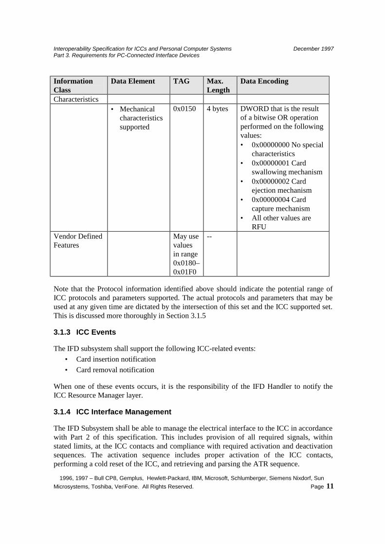
Characteristics • Mechanical
characteristics supported
0x0150 4 bytes DWORD that is the result of a bitwise OR operation performed on the following values: • 0x00000000 No special
characteristics • 0x00000001 Card
swallowing mechanism • 0x00000002 Card
ejection mechanism • 0x00000004 Card
capture mechanism • All other values are
RFU Vendor Defined Features
May use values in range 0x0180–0x01F0
--
Note that the Protocol information identified above should indicate the potential range of ICC protocols and parameters supported. The actual protocols and parameters that may be used at any given time are dictated by the intersection of this set and the ICC supported set. This is discussed more thoroughly in Section 3.1.5
3.1.3 ICC Events
The IFD subsystem shall support the following ICC-related events: • Card insertion notification • Card removal notification
When one of these events occurs, it is the responsibility of the IFD Handler to notify the ICC Resource Manager layer.
3.1.4 ICC Interface Management
The IFD Subsystem shall be able to manage the electrical interface to the ICC in accordance with Part 2 of this specification. This includes provision of all required signals, within stated limits, at the ICC contacts and compliance with required activation and deactivation sequences. The activation sequence includes proper activation of the ICC contacts, performing a cold reset of the ICC, and retrieving and parsing the ATR sequence.

Interoperability Specification for ICCs and Personal Computer Systems December 1997 Part 3. Requirements for PC-Connected Interface Devices
1996, 1997 – Bull CP8, Gemplus, Hewlett-Packard, IBM, Microsoft, Schlumberger, Siemens Nixdorf, Sun Microsystems, Toshiba, VeriFone. All Rights Reserved. Page 12
As stated in Part 2, the IFD Subsystem should notify to the ICC Resource Manager in the event that a valid ATR is not transmitted by the ICC. It is up to the ICC Resource Manager either to deactivate the card or to proceed with the default parameters. If a valid ATR is transmitted, and the Interface Device supports programmable protocol parameters (that is, selection of frequency, IFS, and so on) the IFD subsystem shall parse the ATR and determine all supported protocol and associated parameter options. The supported options for a given ICC are determined by the intersection of the options supported by the Interface Device and the ICC (as specified in the ATR). Note that an Interface Device is required to support T=0 and T=1 only at a default clock frequency.
To insure that the PC software can determine the state of the ICC at any time, the IFD Handler shall expose an interface which allows the ICC state to be queried. This will include the ability to determine the following information, through the following TLV structure.
Table 3-2. Codes for Enumerating ICC State
Information TAG Maximum Length
Responses (return as integer)
ICC presence 0x0300 1 byte • 0 = not present • 1 = card present but not
swallowed (applies only if the IFD supports ICC swallowing)
• 2 = card present (and swallowed if the IFD supports ICC swallowing)
• 4 = card confiscated ICC interface status 0x0301 1 byte BOOLEAN, 0 = contact inactive
1 = contact active ATR string 0x0303 32 bytes Contains the ATR string as
returned by the ICC. ICC type, based on ATR sequence
0x0304 1 byte ISO/IEC 7816 or unknown • 0 = unknown ICC type • 1 = 7816 Asynchronous • 2 = 7816 Synchronous • Other values RFU
In addition, to enable a PC application to insure that an ICC is in a known state, the IFD Subsystem will provide a means to reinitialize an ICC using a warm reset on demand.
Interoperability Specification for ICCs and Personal Computer Systems December 1997 Part 3. Requirements for PC-Connected Interface Devices
1996, 1997 – Bull CP8, Gemplus, Hewlett-Packard, IBM, Microsoft, Schlumberger, Siemens Nixdorf, Sun Microsystems, Toshiba, VeriFone. All Rights Reserved. Page 13
The IFD Subsystem is responsible for determining when unrecoverable data communications errors have occurred and informing the logically connected ICC Service Provider, if any. At a minimum, the IFD Subsystem shall be able to distinguish between an unresponsive ICC and unrecoverable communications errors, indicated by repeated parity and/or checksum errors, and make this information available to a connected ICC Service Provider. Those error codes can be defined by the operating system vendor either as new error codes or mapped onto standard operating system error codes, provided the previous stated requirements are met.
3.1.5. Protocol Support
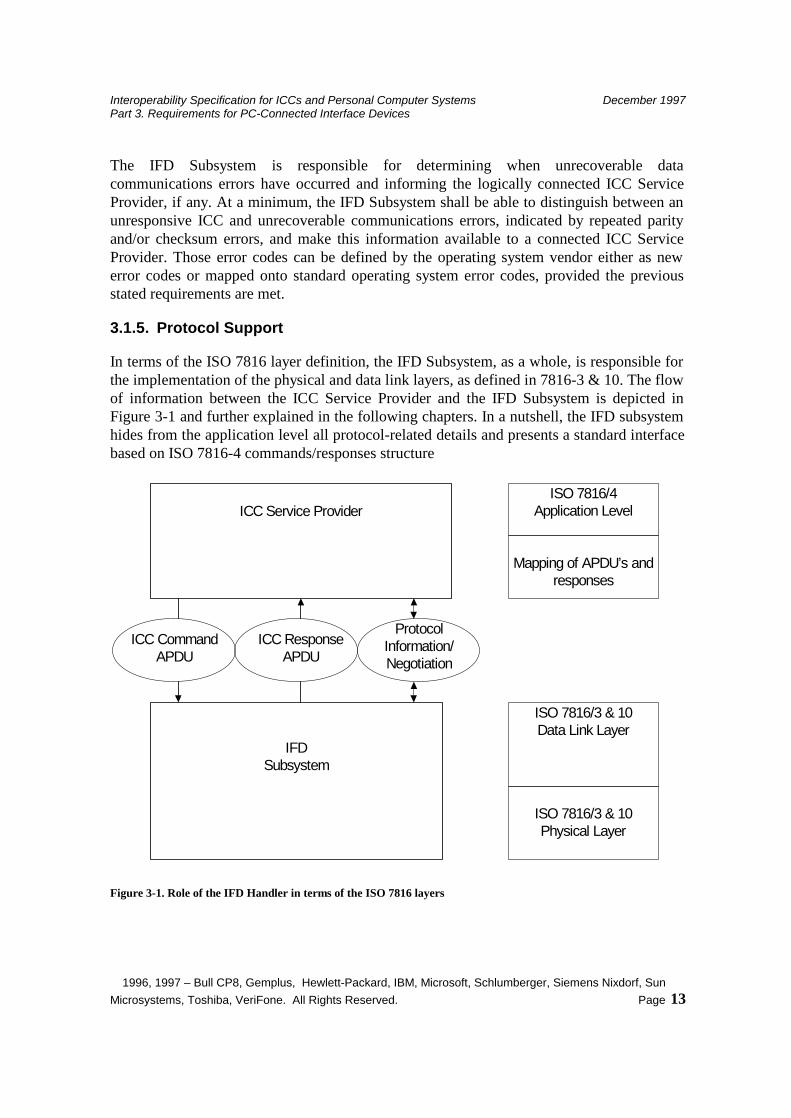
In terms of the ISO 7816 layer definition, the IFD Subsystem, as a whole, is responsible for the implementation of the physical and data link layers, as defined in 7816-3 & 10. The flow of information between the ICC Service Provider and the IFD Subsystem is depicted in Figure 3-1 and further explained in the following chapters. In a nutshell, the IFD subsystem hides from the application level all protocol-related details and presents a standard interface based on ISO 7816-4 commands/responses structure
ICC Service Provider
IFDSubsystem
ISO 7816/4Application Level
ISO 7816/3 & 10Data Link Layer
ProtocolInformation/Negotiation
ISO 7816/3 & 10Physical Layer
ICC CommandAPDU
ICC ResponseAPDU
Mapping of APDU’s andresponses
Figure 3-1. Role of the IFD Handler in terms of the ISO 7816 layers
Interoperability Specification for ICCs and Personal Computer Systems December 1997 Part 3. Requirements for PC-Connected Interface Devices
1996, 1997 – Bull CP8, Gemplus, Hewlett-Packard, IBM, Microsoft, Schlumberger, Siemens Nixdorf, Sun Microsystems, Toshiba, VeriFone. All Rights Reserved. Page 14
3.1.5.1 Protocol Negotiation
A compliant Interface Device is required to support both the T=0 and T=1 protocols. It must support the default global parameters and a default CLK frequency in the range of 1 to 5 MHz. It is not, however, required to support flexible protocol and parameter selection. That is, an IFD Subsystem need only parse an ATR to determine the default protocol and parameters.
It is recommended that Interface Devices provide support for protocol selection and setting of associated parameters in order to maximize performance. Interface Devices providing this ability must parse the ATR and determine the intersection of the ICC-supported options with those supported by the Interface Device. In general, an IFD should wait until the first application connects to the device prior to negotiating the protocol settings (using PTS). Connection requests contain hints indicating the protocol desired and an indication of whether timing parameters should be optimized or left at the default value.
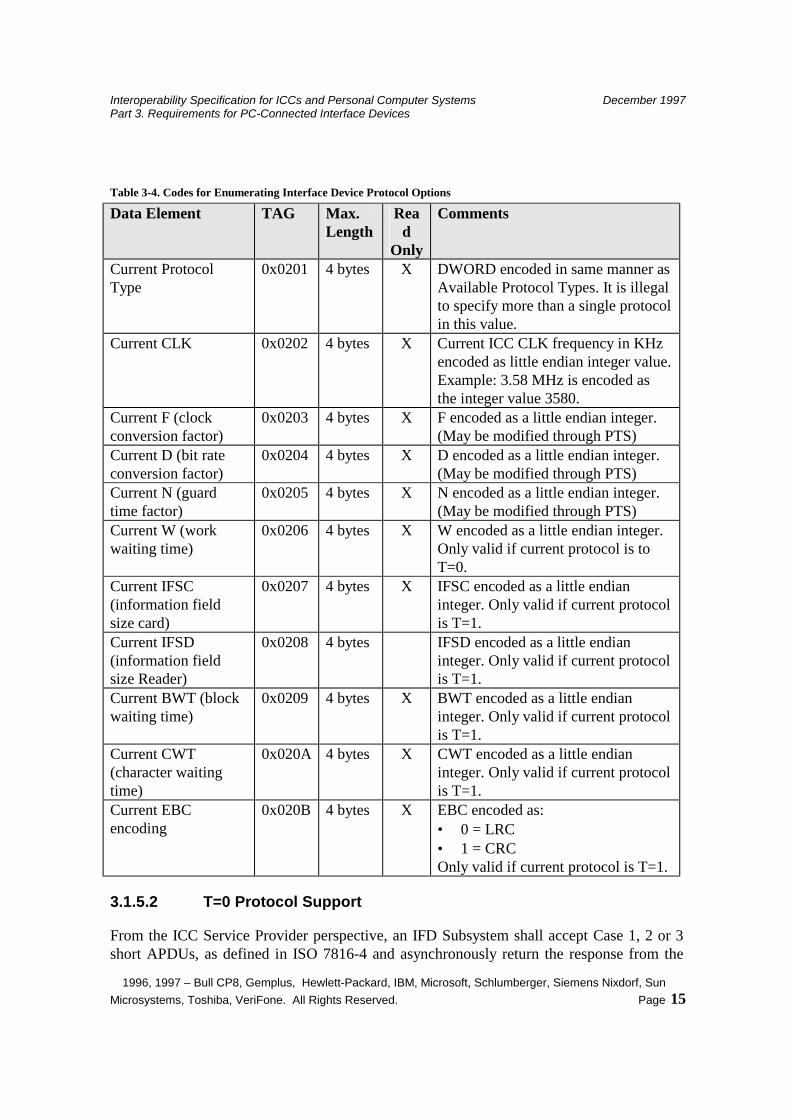
The IFD Handler will expose an interface that allows a Service Provider to enumerate current protocol setting and parameter options. The following table indicates the available information and which of these may be set explicitly. Explicit setting of the protocol basic timing parameters is not allowed because the IFD will automatically negotiate these settings based on its capabilities and the ICC capabilities. Other parameters may not be settable based on T=0 and T=1 protocol definitions.
Interoperability Specification for ICCs and Personal Computer Systems December 1997 Part 3. Requirements for PC-Connected Interface Devices
1996, 1997 – Bull CP8, Gemplus, Hewlett-Packard, IBM, Microsoft, Schlumberger, Siemens Nixdorf, Sun Microsystems, Toshiba, VeriFone. All Rights Reserved. Page 15
Table 3-4. Codes for Enumerating Interface Device Protocol Options
Data Element TAG Max. Length
Read
Only
Comments
Current Protocol Type
0x0201 4 bytes X DWORD encoded in same manner as Available Protocol Types. It is illegal to specify more than a single protocol in this value.
Current CLK 0x0202 4 bytes X Current ICC CLK frequency in KHz encoded as little endian integer value. Example: 3.58 MHz is encoded as the integer value 3580.
Current F (clock conversion factor)
0x0203 4 bytes X F encoded as a little endian integer. (May be modified through PTS)
Current D (bit rate conversion factor)
0x0204 4 bytes X D encoded as a little endian integer. (May be modified through PTS)
Current N (guard time factor)
0x0205 4 bytes X N encoded as a little endian integer. (May be modified through PTS)
Current W (work waiting time)
0x0206 4 bytes X W encoded as a little endian integer. Only valid if current protocol is to T=0.
Current IFSC (information field size card)
0x0207 4 bytes X IFSC encoded as a little endian integer. Only valid if current protocol is T=1.
Current IFSD (information field size Reader)
0x0208 4 bytes IFSD encoded as a little endian integer. Only valid if current protocol is T=1.
Current BWT (block waiting time)
0x0209 4 bytes X BWT encoded as a little endian integer. Only valid if current protocol is T=1.
Current CWT (character waiting time)
0x020A 4 bytes X CWT encoded as a little endian integer. Only valid if current protocol is T=1.
Current EBC encoding
0x020B 4 bytes X EBC encoded as: • 0 = LRC • 1 = CRC Only valid if current protocol is T=1.
3.1.5.2 T=0 Protocol Support
From the ICC Service Provider perspective, an IFD Subsystem shall accept Case 1, 2 or 3 short APDUs, as defined in ISO 7816-4 and asynchronously return the response from the
Interoperability Specification for ICCs and Personal Computer Systems December 1997 Part 3. Requirements for PC-Connected Interface Devices
1996, 1997 – Bull CP8, Gemplus, Hewlett-Packard, IBM, Microsoft, Schlumberger, Siemens Nixdorf, Sun Microsystems, Toshiba, VeriFone. All Rights Reserved. Page 16
ICC. Direct Case 4 APDU support is not required. The IFD Subsystem shall change this APDU to TPDU for T=0 command. Especially it is mandatory to change APDU case1 format (CLA INS P1 P2) to TPDU with P3='00' (CLA INS P1 P2 '00').
The IFD Subsystem is responsible for detecting and responding to physical link errors (bit parity errors) as required by ISO/IEC 7816. In terms of processing ICC response bytes, the IFD Subsystem is only required to correctly process an ICC ACK response. It will then either send remaining data associated with the last command header or retrieve remaining data from the ICC. In this case, the IFD Subsystem does not return the ACK byte to the ICC Service Provider.
It is not required to interpret or respond to other ICC response bytes, as these are generally application specific, and shall return them to the ICC Service Provider.
3.1.5.3 T=1 Protocol Support
From the ICC Service Provider perspective, an IFD Subsystem shall accept APDU’s, construct the necessary T=1 blocks to convey those APDU’s and asynchronously return the response from the ICC. It is implicit that the ICC Service Provider has the right to transmit the first such block. The IFD Subsystem must at all times track whether it, or the ICC, has the right to transmit. If the ICC has the right to transmit, an IFD Subsystem may return an error if an ICC Service Provider attempts to initiate a block transmission request.
The IFD Subsystem is responsible for detecting the following errors: • Transmission error (incorrect parity or an EDC error) denoted by the least significant
nibble of the PCB of the R-Block sent by the ICC • BWT time-out • Loss of synchronization (wrong number of characters received)
In the event such an error is detected, the IFD Subsystem shall interpret it to mean that the associated block is invalid.
The IFD Subsystem is generally responsible for automatic retransmission of the last block sent, in the event of a protocol error. A maximum of three such attempts will be made, after which the ICC shall be deactivated and the ICC Service Provider informed that an unrecoverable error has occurred. All other errors are the responsibility of the ICC Service Provider and/or ICC. The following lists the specific procedures to be implemented by the IFD Subsystem:
1. If there is no response from the ICC to a block sent by the IFD within BWT, the IFD Subsystem shall follow the scenario 33 or 35 defined in the ISO 7816-3 Annex A document, in order to try to recover the communication. If it fails, the IFD Subsystem shall deactivate the ICC and inform the ICC Service Provider that an unrecoverable error has occurred.
Interoperability Specification for ICCs and Personal Computer Systems December 1997 Part 3. Requirements for PC-Connected Interface Devices
1996, 1997 – Bull CP8, Gemplus, Hewlett-Packard, IBM, Microsoft, Schlumberger, Siemens Nixdorf, Sun Microsystems, Toshiba, VeriFone. All Rights Reserved. Page 17
2. If an invalid block is received in response to an R-block, the sender shall retransmit the R-block.
3. If an S(response) is not received in response to an S(request), the sender shall retransmit the S(request).
4. If an invalid block is received in response to an S(response) block, the IFD Subsystem shall transmit an R-block with bit 5 = sequence number of the next expected I-block.
5. If the IFD Subsystem detects an underrun or overrun condition, it will wait the greater of CWT or BWT before transmitting the last block.
6. When the ICC sends an S(IFS request) and receives an invalid response, it will retransmit the block only one time to elicit an S(IFS response) and then remain in receive mode.
The only time an IFD Subsystem is expected to initiate a block is for the purpose of establishing an IFSD larger than the default size of 32 bytes. The IFD Subsystem should do this only as the first block following negotiation of the T=1 protocol. In other words, the IFD Subsystem may send an S(IFS request) and then process an S(IFS response) prior to transmitting the first ICC Service Provider block.
The ICC Service Provider should assume this will be done if the Interface Device capabilities indicate it supports a maximum IFSD greater than 32 bytes. As such, it should wait until after the first block has been transmitted to determine the effective IFSD setting.
Compliant IFD Subsystems provide implicit support for the chaining function, as described in ISO 7816-3, so as to enable the IFD (the ICC) to transmit information longer than IFSC (IFSD).
Compliant IFD Subsystems may provide support for the logical sessions using the Node Addressing mechanisms associated with T=1. If logical sessions are not supported, DAD and SAD should be set to 0 (zero).
3.1.5.4 Synchronous Protocols
Synchronous cards will be clearly specified in the 1.1 release of these specifications (in early 1998). It is expected that synchronous card hardware must comply with ISO 7816-10.
3.1.6 Channel mechanism support
Compliant IFD Subsystems provide implicit support for the logical sessions using the ‘channel’ mechanisms of ISO/IEC 7816-4. It is the responsibility of the ICC Service Provider, and associated ICC, to implement and manage such channels.
Interoperability Specification for ICCs and Personal Computer Systems December 1997 Part 3. Requirements for PC-Connected Interface Devices
1996, 1997 – Bull CP8, Gemplus, Hewlett-Packard, IBM, Microsoft, Schlumberger, Siemens Nixdorf, Sun Microsystems, Toshiba, VeriFone. All Rights Reserved. Page 18
3.2 Optional Functionality
3.2.1 ICC Power Management
An Interface Device may optionally support the ability to activate and deactivate an inserted ICC under control of an ICC Service Provider. This may be desirable to minimize power consumption in certain environments when the ICC is expected to be inserted for long periods of time, but used infrequently. If implemented, a request to activate an ICC shall result in activation of the ICC contacts, generation of a cold reset, and processing of the ATR sequence as specified above.
3.2.2 Mechanical Characteristics
Interface Devices may optionally support different mechanical characteristics such as ICC swallowing and ejection. Some Interface Devices may also offer the possibility of confiscating the card (this would typically be the case for PC-based ATM’s).
The IFD Handler Interface will expose the necessary entry points enabling an ICC Service Provider to trigger those mechanisms.
3.2.3 Security Assurance Devices
The IFD subsystem may optionally implement various Security Assurance features. This may include:
• Isolated numeric keypad (that is, PIN pad) for entry of numeric user authentication data presented to the ICC.
• Isolated keyboard for entry of alphanumeric authentication data presented to the ICC.
• Isolated biometric measurement device for user authentication to the ICC. • Isolated display for presentation of ICC-generated security-critical data.
The IFD subsystem may also implement user authentication devices designed to deliver authenticating data to the PC and associated applications. These could include:
• Isolated numeric keypad (that is, PIN pad) for entry of numeric user authentication data presented to the ICC.
• Isolated keyboard for entry of alphanumeric authentication data presented to the ICC.
• Isolated biometric measurement device for user authentication to the ICC.
Note that the same type of data collection devices may be used to deliver authentication data to PC applications and to an ICC. Hence, compliant Interface Devices implementing such devices may support both functions. The routing of this data must be under the control of logic contained in the Interface Device such that security-critical operations cannot be circumvented by software running on the PC.
Interoperability Specification for ICCs and Personal Computer Systems December 1997 Part 3. Requirements for PC-Connected Interface Devices
1996, 1997 – Bull CP8, Gemplus, Hewlett-Packard, IBM, Microsoft, Schlumberger, Siemens Nixdorf, Sun Microsystems, Toshiba, VeriFone. All Rights Reserved. Page 19
3.2.4 Vendor-Specific Features
Compliant Interface Devices may implement vendor-specific features and functionality not identified in this specification. Such features must be isolated so that they do not impact required functionality identified herein nor allow such functionality to be circumvented.
If such features are implemented, they shall be accessible through a general purpose “escape” interface, where “escape” is used to indicate a data exchange that is outside the normal ICC Service Provider to ICC data exchange. The escape interface shall provide a means for an ICC Service Provider or an application to request a specific Service by supplying a Command Code parameter, and an optional variable-length data structure. The response to an escape request shall be an escape response specifying a completion code and optional variable-length data structure. The implementation of such a mechanism is clearly Operating System dependent and will not be discussed any further in this document.
Interoperability Specification for ICCs and Personal Computer Systems December 1997 Part 3. Requirements for PC-Connected Interface Devices
1996, 1997 – Bull CP8, Gemplus, Hewlett-Packard, IBM, Microsoft, Schlumberger, Siemens Nixdorf, Sun Microsystems, Toshiba, VeriFone. All Rights Reserved. Page 20
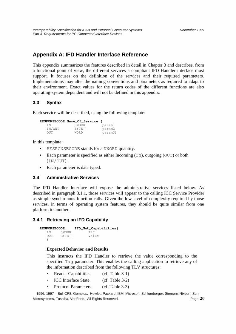
Appendix A: IFD Handler Interface Reference
This appendix summarizes the features described in detail in Chapter 3 and describes, from a functional point of view, the different services a compliant IFD Handler interface must support. It focuses on the definition of the services and their required parameters. Implementations may alter the naming conventions and parameters as required to adapt to their environment. Exact values for the return codes of the different functions are also operating-system dependent and will not be defined in this appendix.
3.3 Syntax
Each service will be described, using the following template: RESPONSECODE Name_Of_Service ( IN DWORD param1 IN/OUT BYTE[] param2 OUT WORD param3)
In this template: • RESPONSECODE stands for a DWORD quantity. • Each parameter is specified as either Incoming (IN), outgoing (OUT) or both
(IN/OUT). • Each parameter is data typed.
3.4 Administrative Services
The IFD Handler Interface will expose the administrative services listed below. As described in paragraph 3.1.1, those services will appear to the calling ICC Service Provider as simple synchronous function calls. Given the low level of complexity required by those services, in terms of operating system features, they should be quite similar from one platform to another.
3.4.1 Retrieving an IFD Capability RESPONSECODE IFD_Get_Capabilities( IN DWORD Tag OUT BYTE[] Value )
Expected Behavior and Results This instructs the IFD Handler to retrieve the value corresponding to the specified Tag parameter. This enables the calling application to retrieve any of the information described from the following TLV structures: • Reader Capabilities (cf. Table 3-1) • ICC Interface State (cf. Table 3-2) • Protocol Parameters (cf. Table 3-3)

Interoperability Specification for ICCs and Personal Computer Systems December 1997 Part 3. Requirements for PC-Connected Interface Devices
1996, 1997 – Bull CP8, Gemplus, Hewlett-Packard, IBM, Microsoft, Schlumberger, Siemens Nixdorf, Sun Microsystems, Toshiba, VeriFone. All Rights Reserved. Page 21
ResponseCode can be one of the following: IFD_Success : Value was successfully retrieved. IFD_Error_Tag : Tag does not exist.
Support Mandatory
3.4.2 Setting an IFD Capability RESPONSECODE IFD_Set_Capabilities( IN DWORD Tag OUT BYTE[] Value )
Expected Behavior and Results The IFD Handler will attempt to set the parameter specified by Tag to Value. This function can be used by a calling service provider to set parameters such as the current IFSD, or to request an extension of the Block Waiting Time.
ResponseCode can be one of the following: IFD_Success : Parameter was successfully Set. IFD_Error_Set_Failure : Operation failed. IFD_Error_Tag : Tag does not exist. IFD_Error_Value_Read_Only : The value cannot be modified.
Support Mandatory
3.4.3 Protocol Information and Negotiation
RESPONSECODE IFD_Set_Protocol_Parameters( IN DWORD ProtocolType IN BYTE SelectionFlags IN BYTE PTS1 // Encodes Clock Conversion and bit // duration factors IN BYTE PTS2 IN BYTE PTS3 )
Expected Behavior and Results This function should only be called by the ICC Resource Manager layer. A Service Provider simply specifies its preferred protocols and protocol parameters, if any, when connecting to an ICC, and lets the ICC Resource Manager check if it is able to negotiate one of the preferred protocols based on the ATR received from the ICC, and the IFD capabilities. The protocol type parameter can be
Interoperability Specification for ICCs and Personal Computer Systems December 1997 Part 3. Requirements for PC-Connected Interface Devices
1996, 1997 – Bull CP8, Gemplus, Hewlett-Packard, IBM, Microsoft, Schlumberger, Siemens Nixdorf, Sun Microsystems, Toshiba, VeriFone. All Rights Reserved. Page 22
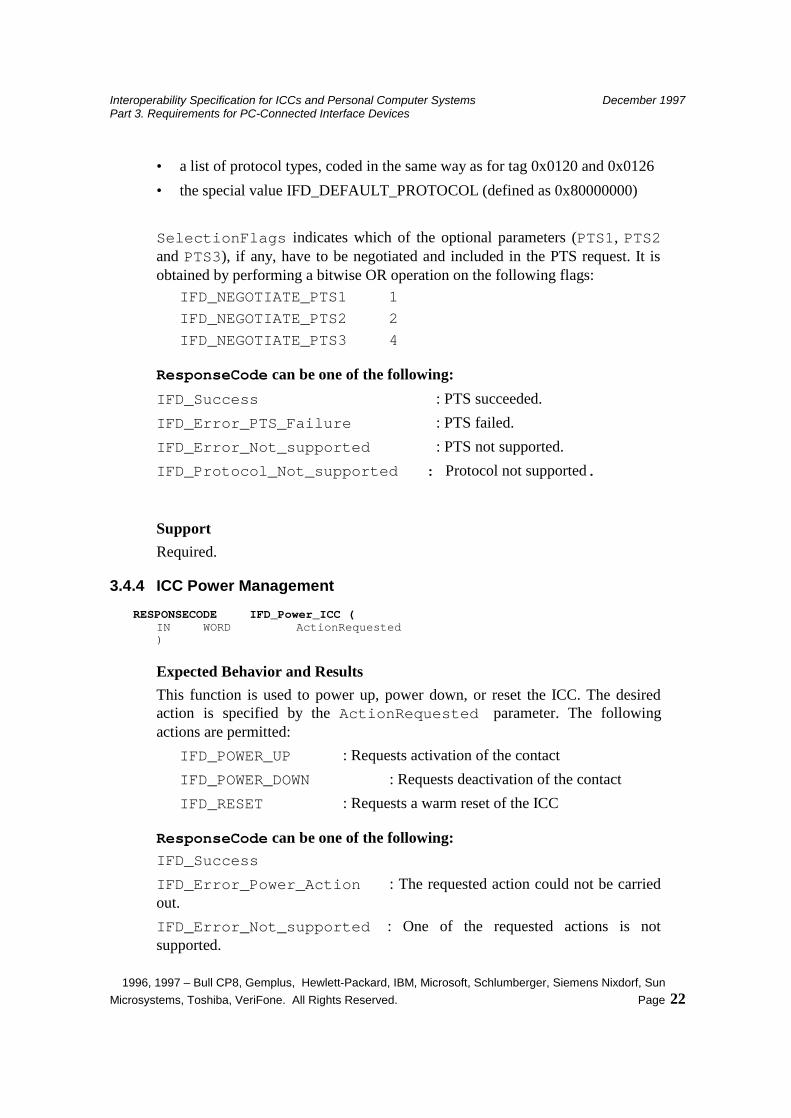
• a list of protocol types, coded in the same way as for tag 0x0120 and 0x0126 • the special value IFD_DEFAULT_PROTOCOL (defined as 0x80000000) SelectionFlags indicates which of the optional parameters (PTS1, PTS2 and PTS3), if any, have to be negotiated and included in the PTS request. It is obtained by performing a bitwise OR operation on the following flags:
IFD_NEGOTIATE_PTS1 1 IFD_NEGOTIATE_PTS2 2 IFD_NEGOTIATE_PTS3 4
ResponseCode can be one of the following: IFD_Success : PTS succeeded. IFD_Error_PTS_Failure : PTS failed. IFD_Error_Not_supported : PTS not supported. IFD_Protocol_Not_supported : Protocol not supported.
Support Required.
3.4.4 ICC Power Management RESPONSECODE IFD_Power_ICC ( IN WORD ActionRequested )
Expected Behavior and Results This function is used to power up, power down, or reset the ICC. The desired action is specified by the ActionRequested parameter. The following actions are permitted:
IFD_POWER_UP : Requests activation of the contact IFD_POWER_DOWN : Requests deactivation of the contact IFD_RESET : Requests a warm reset of the ICC
ResponseCode can be one of the following: IFD_Success IFD_Error_Power_Action : The requested action could not be carried out. IFD_Error_Not_supported : One of the requested actions is not supported.
Interoperability Specification for ICCs and Personal Computer Systems December 1997 Part 3. Requirements for PC-Connected Interface Devices
1996, 1997 – Bull CP8, Gemplus, Hewlett-Packard, IBM, Microsoft, Schlumberger, Siemens Nixdorf, Sun Microsystems, Toshiba, VeriFone. All Rights Reserved. Page 23
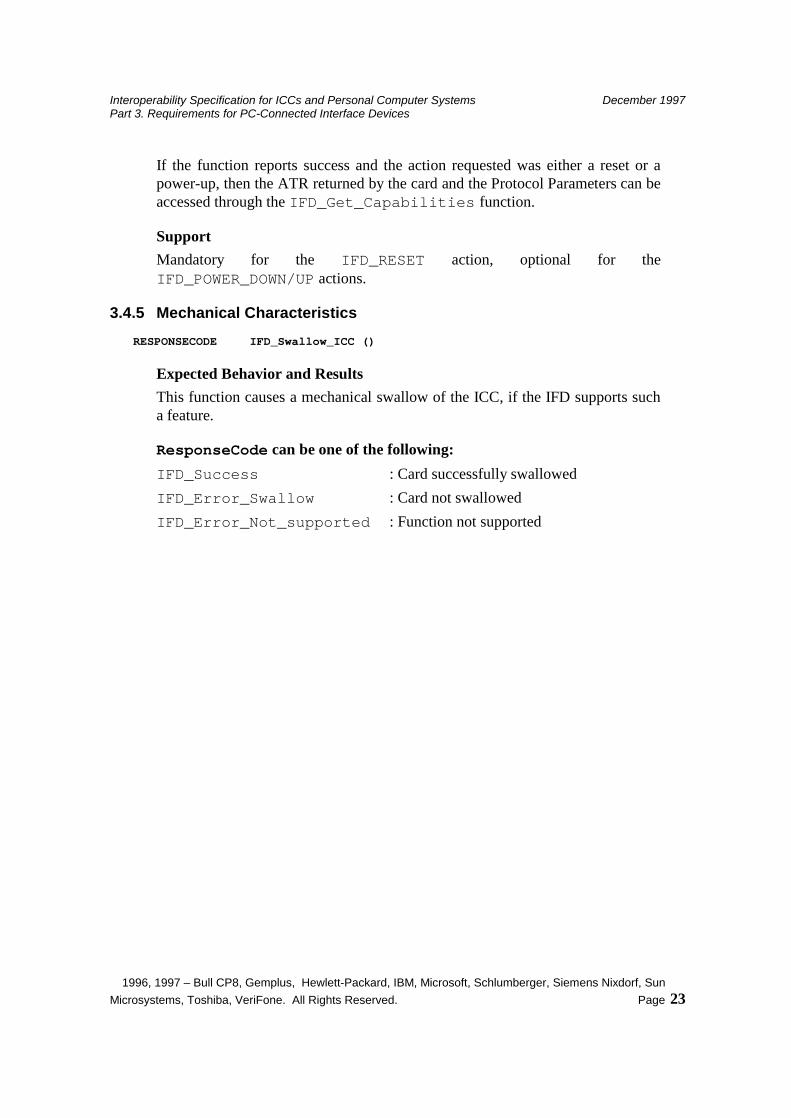
If the function reports success and the action requested was either a reset or a power-up, then the ATR returned by the card and the Protocol Parameters can be accessed through the IFD_Get_Capabilities function.
Support Mandatory for the IFD_RESET action, optional for the IFD_POWER_DOWN/UP actions.
3.4.5 Mechanical Characteristics RESPONSECODE IFD_Swallow_ICC ()
Expected Behavior and Results This function causes a mechanical swallow of the ICC, if the IFD supports such a feature.
ResponseCode can be one of the following: IFD_Success : Card successfully swallowed IFD_Error_Swallow : Card not swallowed IFD_Error_Not_supported : Function not supported
Interoperability Specification for ICCs and Personal Computer Systems December 1997 Part 3. Requirements for PC-Connected Interface Devices
1996, 1997 – Bull CP8, Gemplus, Hewlett-Packard, IBM, Microsoft, Schlumberger, Siemens Nixdorf, Sun Microsystems, Toshiba, VeriFone. All Rights Reserved. Page 24
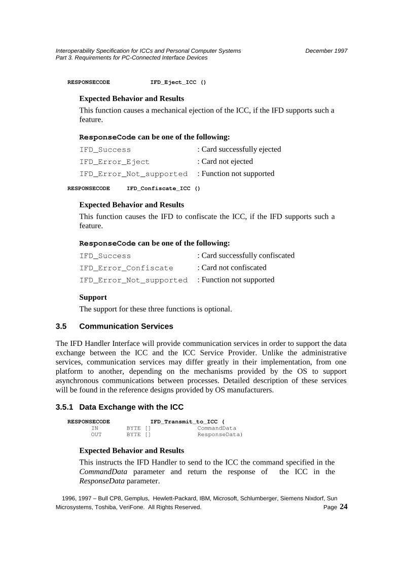
RESPONSECODE IFD_Eject_ICC ()
Expected Behavior and Results This function causes a mechanical ejection of the ICC, if the IFD supports such a feature.
ResponseCode can be one of the following: IFD_Success : Card successfully ejected IFD_Error_Eject : Card not ejected IFD_Error_Not_supported : Function not supported
RESPONSECODE IFD_Confiscate_ICC ()
Expected Behavior and Results This function causes the IFD to confiscate the ICC, if the IFD supports such a feature.
ResponseCode can be one of the following: IFD_Success : Card successfully confiscated IFD_Error_Confiscate : Card not confiscated IFD_Error_Not_supported : Function not supported
Support The support for these three functions is optional.
3.5 Communication Services
The IFD Handler Interface will provide communication services in order to support the data exchange between the ICC and the ICC Service Provider. Unlike the administrative services, communication services may differ greatly in their implementation, from one platform to another, depending on the mechanisms provided by the OS to support asynchronous communications between processes. Detailed description of these services will be found in the reference designs provided by OS manufacturers.
3.5.1 Data Exchange with the ICC RESPONSECODE IFD_Transmit_to_ICC (
IN BYTE [] CommandData OUT BYTE [] ResponseData)
Expected Behavior and Results This instructs the IFD Handler to send to the ICC the command specified in the CommandData parameter and return the response of the ICC in the ResponseData parameter.
Interoperability Specification for ICCs and Personal Computer Systems December 1997 Part 3. Requirements for PC-Connected Interface Devices
1996, 1997 – Bull CP8, Gemplus, Hewlett-Packard, IBM, Microsoft, Schlumberger, Siemens Nixdorf, Sun Microsystems, Toshiba, VeriFone. All Rights Reserved. Page 25
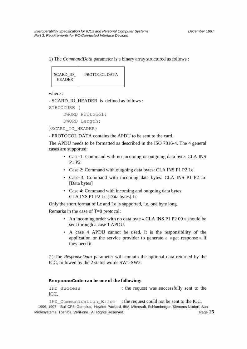
1) The CommandData parameter is a binary array structured as follows :
SCARD_IO_HEADER
PROTOCOL DATA
where : - SCARD_IO_HEADER is defined as follows : STRUCTURE {
DWORD Protocol; DWORD Length;
}SCARD_IO_HEADER; - PROTOCOL DATA contains the APDU to be sent to the card. The APDU needs to be formatted as described in the ISO 7816-4. The 4 general cases are supported:
• Case 1: Command with no incoming or outgoing data byte: CLA INS P1 P2
• Case 2: Command with outgoing data bytes: CLA INS P1 P2 Le • Case 3: Command with incoming data bytes: CLA INS P1 P2 Lc
[Data bytes] • Case 4: Command with incoming and outgoing data bytes:
CLA INS P1 P2 Lc [Data bytes] Le Only the short format of Lc and Le is supported, i.e. one byte long. Remarks in the case of T=0 protocol:
• An incoming order with no data byte « CLA INS P1 P2 00 » should be sent through a case 1 APDU.
• A case 4 APDU cannot be used. It is the responsibility of the application or the service provider to generate a « get response » if they need it.
2)The ResponseData parameter will contain the optional data returned by the ICC, followed by the 2 status words SW1-SW2.
ResponseCode can be one of the following: IFD_Success : the request was successfully sent to the ICC, IFD_Communication_Error : the request could not be sent to the ICC.
Interoperability Specification for ICCs and Personal Computer Systems December 1997 Part 3. Requirements for PC-Connected Interface Devices
1996, 1997 – Bull CP8, Gemplus, Hewlett-Packard, IBM, Microsoft, Schlumberger, Siemens Nixdorf, Sun Microsystems, Toshiba, VeriFone. All Rights Reserved. Page 26
IFD_Response_TimeOut : the IFD timed-out waiting the response from the ICC.
3.5.2 ICC Insertion and Removal RESPONSECODE IFD_Is_ICC_Present ()
Expected Behavior and Results Asynchronously signals the insertion of an ICC in the Interface Device.
RESPONSECODE IFD_Is_ICC_Absent ()
Expected Behavior and Results Asynchronously signals the removal of the ICC from the Interface Device.
Related Documents