Parameter Tolerance Evaluation when Laser Cutting in Decommissioning Applications Paper 501 Paul Hilton TWI Ltd, Granta Park, Abington, Cambridge, CB21 6AL, UK Abstract In conventional laser cutting it is well known that in order to maintain high quality edges, low heat affected zones and high cutting speeds, high tolerances have to be maintained on many of the parameters used. In particular, nozzle stand-off distances have to be small and kept constant, if good cut quality is to be maintained in plate and tube cutting. Recently, a potential application of laser cutting has arisen in a sector where the resulting cut quality is not important; that of decommissioning. In nuclear environments all over the world, there are extensive amounts of contaminated pipework and vessels of different types, which simply need to be size reduced, so that their constituent parts can be placed in containers for long term storage. This paper addresses the capability of a 5kW fibre delivered laser beam to cut plate material, in stainless and CMn steels, up to 25mm thickness, if the requirement for good cut quality is removed. It will be shown that even when cutting 25mm thickness material, separation speeds of up to 0.15m/min can be maintained, with nozzle to workpiece stand-off distances up to 75mm. This very wide tolerance to nozzle tip position is important for potential decommissioning applications which must be performed remotely. Such tolerances provide relaxed positional accuracy on any selected deployment method of the cutting head. Introduction The major reason for the limited use of lasers in decommissioning is that historically, industrial lasers have been considered unreliable and not suited to on-site nuclear decommissioning environments. However, the advent of robust, solid state, high power (4+kW) lasers, whose beams can be transmitted down optical fibres, has provided a more realistic opportunity for use of lasers in decommissioning applications. Power from fibre, diode or disc lasers can be transmitted via several hundred metres of fibre optic cable, hence the laser unit can be located some distance from the active area of operations. As a result there is no risk of contamination of this high value asset, which can therefore be reused on a number of decommissioning tasks so spreading the capital cost of the equipment. Laser cutting is just one of a set of tools which may be useful in aspects of decommissioning, particularly that of size reduction for long term storage. Laser cutting can be compared to both mechanical cutting and also other thermal cutting processes used in decommissioning such as plasma cutting. Some of the benefits of laser cutting, when compared to mechanical cutting, include the lack of a reaction force between the cutting head and the material being cut, which means that lightweight deployment systems can be employed and as a result the mass/volume of secondary waste produced can be kept much smaller. Compared to other thermal cutting processes, laser cutting generally produces less cutting debris (due to the small kerfs possible) [1] and less fume, thus reducing the load on ventilation systems. Laser cutting also allows for single sided cutting of tubular structures and pipework [2] which is a major advantage compared to processes which must rotate around a tube in order to be able to cut it. In laser cutting where the capability to simply sever the material is more important than maintaining cut quality, the tolerance to cutting head stand-off can be arranged to be high by employing high brightness lasers and long focal length cutting optics. In addition, with some thermal cutting processes, stand-off constraints and the physical geometry of the cutting heads reduce the flexibility of applied cutting paths. The large stand-off tolerance and cut path flexibility offered by laser cutting is highly beneficial for remote cutting operations. There are also some current disadvantages to laser cutting for nuclear applications, which are still being addressed. These include the generic development of a safety case for use of laser cutting and within this, some of the important issues include management of the laser beam energy transmitted through the part being cut and the temperatures generated in the process. This paper will describe additional laser cutting information on plate materials, particularly with respect to the tolerance to stand-off position and the choice of diameter of optical fibre. The information it provides should be of use to anyone considering the application of laser cutting in a decommissioning environment. Any real application of laser cutting in decommissioning will require the minimum of components from the cutting system becoming contaminated and therefore subsequently unusable. One of these components is the optical fibre which brings the laser light from the laser to the cutting head. A 50m long fibre of this type is

Welcome message from author
This document is posted to help you gain knowledge. Please leave a comment to let me know what you think about it! Share it to your friends and learn new things together.
Transcript

Parameter Tolerance Evaluation when Laser Cutting in Decommissioning Applications
Paper 501
Paul Hilton
TWI Ltd, Granta Park, Abington, Cambridge, CB21 6AL, UK
Abstract
In conventional laser cutting it is well known that in order to maintain high quality edges, low heat affected zones and high cutting speeds, high tolerances have to be maintained on many of the parameters used. In particular, nozzle stand-off distances have to be small and kept constant, if good cut quality is to be maintained in plate and tube cutting. Recently, a potential application of laser cutting has arisen in a sector where the resulting cut quality is not important; that of decommissioning. In nuclear environments all over the world, there are extensive amounts of contaminated pipework and vessels of different types, which simply need to be size reduced, so that their constituent parts can be placed in containers for long term storage. This paper addresses the capability of a 5kW fibre delivered laser beam to cut plate material, in stainless and CMn steels, up to 25mm thickness, if the requirement for good cut quality is removed. It will be shown that even when cutting 25mm thickness material, separation speeds of up to 0.15m/min can be maintained, with nozzle to workpiece stand-off distances up to 75mm. This very wide tolerance to nozzle tip position is important for potential decommissioning applications which must be performed remotely. Such tolerances provide relaxed positional accuracy on any selected deployment method of the cutting head.
Introduction
The major reason for the limited use of lasers in decommissioning is that historically, industrial lasers have been considered unreliable and not suited to on-site nuclear decommissioning environments. However, the advent of robust, solid state, high power (4+kW) lasers, whose beams can be transmitted down optical fibres, has provided a more realistic opportunity for use of lasers in decommissioning applications. Power from fibre, diode or disc lasers can be transmitted via several hundred metres of fibre optic cable, hence the laser unit can be located some distance from the active area of operations. As a result there is no risk of contamination of this high value asset, which can therefore be reused on a number of decommissioning tasks so spreading the capital cost of the equipment.
Laser cutting is just one of a set of tools which may be useful in aspects of decommissioning, particularly that of
size reduction for long term storage. Laser cutting can be compared to both mechanical cutting and also other thermal cutting processes used in decommissioning such as plasma cutting. Some of the benefits of laser cutting, when compared to mechanical cutting, include the lack of a reaction force between the cutting head and the material being cut, which means that lightweight deployment systems can be employed and as a result the mass/volume of secondary waste produced can be kept much smaller. Compared to other thermal cutting processes, laser cutting generally produces less cutting debris (due to the small kerfs possible) [1] and less fume, thus reducing the load on ventilation systems. Laser cutting also allows for single sided cutting of tubular structures and pipework [2] which is a major advantage compared to processes which must rotate around a tube in order to be able to cut it. In laser cutting where the capability to simply sever the material is more important than maintaining cut quality, the tolerance to cutting head stand-off can be arranged to be high by employing high brightness lasers and long focal length cutting optics. In addition, with some thermal cutting processes, stand-off constraints and the physical geometry of the cutting heads reduce the flexibility of applied cutting paths. The large stand-off tolerance and cut path flexibility offered by laser cutting is highly beneficial for remote cutting operations.
There are also some current disadvantages to laser cutting for nuclear applications, which are still being addressed. These include the generic development of a safety case for use of laser cutting and within this, some of the important issues include management of the laser beam energy transmitted through the part being cut and the temperatures generated in the process. This paper will describe additional laser cutting information on plate materials, particularly with respect to the tolerance to stand-off position and the choice of diameter of optical fibre. The information it provides should be of use to anyone considering the application of laser cutting in a decommissioning environment.
Any real application of laser cutting in decommissioning will require the minimum of components from the cutting system becoming contaminated and therefore subsequently unusable. One of these components is the optical fibre which brings the laser light from the laser to the cutting head. A 50m long fibre of this type is

expensive. To reduce the cost of replacing a long fibre, it is possible to introduce a ‘fibre to fibre coupler’ at a position just outside an active area or cell, whereby a fibre of the minimum required length can be introduced into the active area. Using such an arrangement, only this latter fibre might need to be changed.
Because of the expansion, collimation and subsequent re-focussing of the beam in such a device, the output fibre has to be a larger diameter than the input fibre, in order to be sure that as the beam focusses into the output fibre, the latter is large enough to include the entire incident beam. In practice there could be a difference of two in the fibre diameters. This is important, as the diameter of the final beam focus after the cutting head, is related to the exit diameter of the fibre feeding into the cutting head. The resulting focussed ‘spot’ size also relates to the combination of lenses used in the cutting head, such that the ratio of the collimating and focussing lengths and the diameter of the fibre, determine the focussed spot size.
As a result of the possibility of using such a coupler unit in active decommissioning it is necessary to quantify the effect on laser cutting (if any) of using different diameter optical fibres as input to the cutting head. This report details an experiment which has been conducted using TWI’s 5kW laser, and feeding fibres of 150microns diameter (the smallest possible with this laser) and 300microns diameter. In the series of experiments, the same collimating lens was used, but two different focussing lenses were used. The effect of these optical variables on the speed of cutting stainless steel and CMn steel was assessed, as a function of the stand-off distance between the tip of the cutting nozzle and the material being cut.
Materials Used
6 and 25mm thickness 304 stainless and S275JR C-Mn steels were used in the trials. These were obtained as bar stock, 50mm wide. These are referred to as simply stainless and C-Mn steel, for the remainder of the paper
Equipment and Procedures
For all the trials, a 5kW multimode laser was used. The beam from the laser was transmitted to the cutting head using either a 150 or 300micron diameter optical fibre. In conventional laser cutting systems, the laser light arriving at the cutting head from the optical fibre first expands as it leaves the fibre and is then made parallel by a lens (the collimating lens). Below this lens, a second lens (the focussing lens) then focusses the laser light to a small spot to create the power density needed for cutting. In this work two cutting heads were used. Both used the same 120mm focal length collimating lens. Focussing lenses of 250 and 500mm focal length were used. Both
cutting heads used the same nozzle exit design, with a clear central hole of 6mm diameter. Table 1 below provides details of the focussed spot diameters for the various combinations of optics used.
Fibre diameter (microns)
Collimating lens focal
length (mm)
Focussing lens focal
length (mm)
Approximate spot diameter
(mm) 150
120
250 0.3 150 500 0.6 300 250 0.6 300 500 1.2
Table 1. Calculated spot diameters used in the cutting trials
The cutting nozzles were arranged to produce a 15mm distance between the end of the nozzle and the position of the beam focus. The cutting head included a quartz ‘coverslide’ to provide the cutting lens with some protection from scattered debris and dust during the trials. Compressed air from a bottle bank was used as the cutting assist gas. This could be turned on and off, in the program of the robot which held the cutting head. The cutting head was mounted on the arm of a Kawasaki JS30 articulated robot and configured with its optical axis vertical. The steel bars used in the trials were held in a simple vice type clamp for cutting. During the trials the laser beam was simply moved from one side of the sample to the other, at a constant speed. During the experiments the following parameters remained fixed:
The collimating lens focal length was 120mm.
The laser power was 5kW.
The cutting assist gas pressure, measured at the process head was 8bar.
The diameter of the exit hole in the nozzle tip was 6mm. (At 8bar this corresponds to an estimated air flow of 1.3m3/min.)
The distance between the laser beam focus position and tip of the cutting nozzle was 15mm.
On the various materials and thicknesses investigated, to optimise a particular cut or cutting sequence, the procedure involved setting the stand-off distance between the nozzle tip and the material surface and then adjusting the cutting speed until the material could be comfortably cut in a single-pass.
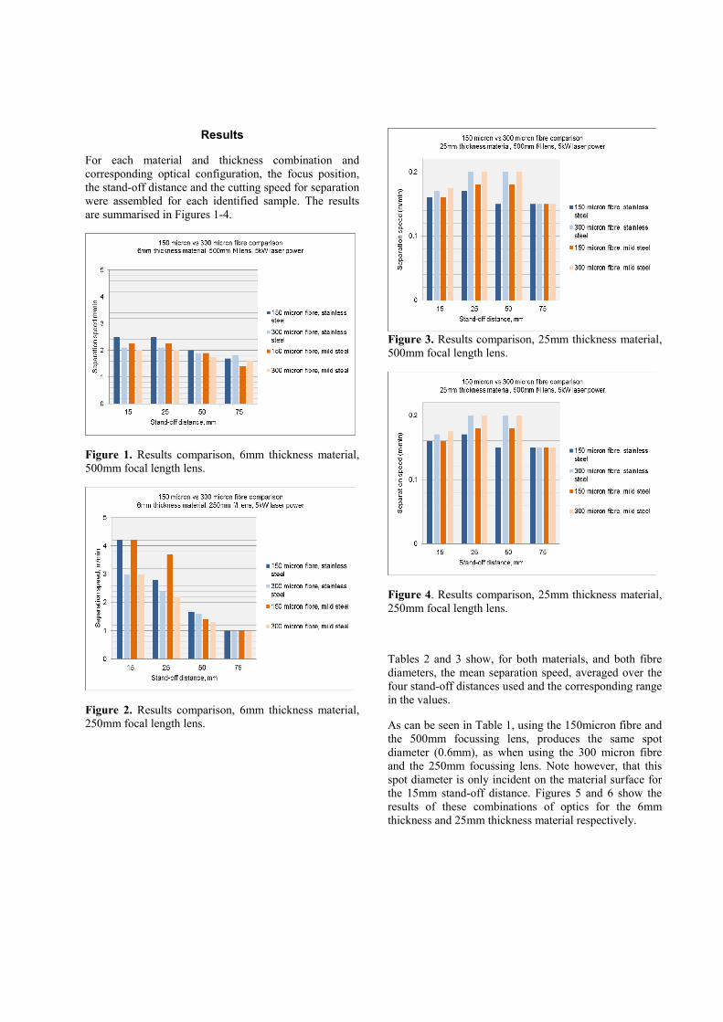
Results
For each material and thickness combination and corresponding optical configuration, the focus position, the stand-off distance and the cutting speed for separation were assembled for each identified sample. The results are summarised in Figures 1-4.
Figure 1. Results comparison, 6mm thickness material, 500mm focal length lens.
Figure 2. Results comparison, 6mm thickness material, 250mm focal length lens.
Figure 3. Results comparison, 25mm thickness material, 500mm focal length lens.
Figure 4. Results comparison, 25mm thickness material, 250mm focal length lens.
Tables 2 and 3 show, for both materials, and both fibre diameters, the mean separation speed, averaged over the four stand-off distances used and the corresponding range in the values.
As can be seen in Table 1, using the 150micron fibre and the 500mm focussing lens, produces the same spot diameter (0.6mm), as when using the 300 micron fibre and the 250mm focussing lens. Note however, that this spot diameter is only incident on the material surface for the 15mm stand-off distance. Figures 5 and 6 show the results of these combinations of optics for the 6mm thickness and 25mm thickness material respectively.

Figure 5. Separation speed data for 6mm thickness material using optics producing a spot size of 0.6mm. Top mild steel, bottom stainless steel.
150micron fibre
300micron fibre
6mm stainless 500mm lens Mean separation speed, m/min 2.2 1.98 Range 0.75 0.3 Expressed as a % 34 15 6mm stainless 250mm lens Mean separation speed, m/min 2.4 2 Range 3.2 2 Expressed as a % 130 100 6mm mild 500mm lens Mean separation speed, m/min 1.9 1.8 Range 0.8 0.3 Expressed as a % 42 17 6mm mild 250mm lens Mean separation speed, m/min 2.5 1.9 Range 3 2 Expressed as a % 120 105
Table 2.
Figure 6. Separation speed data for 25mm thickness material using optics producing a spot size of 0.6mm. Top mild steel, bottom stainless steel.
150micron fibre
300micron fibre
25mm stainless 500mm lens Mean separation speed, m/min 0.16 0.18 Range 0.02 0.05 Expressed as a % 13 27 25mm stainless 250mm lens Mean separation speed, m/min 0.15 0.14 Range 0.05 0.1 Expressed as a % 33 71 25mm mild 500mm lens Mean separation speed, m/min 0.17 0.18 Range 0.03 0.05 Expressed as a % 18 27 25mm mild 250mm lens Mean separation speed, m/min 0.16 0.14 Range 0.12 0.1 Expressed as a % 75 71
Table 3.

Figure 7. Photographic images of the cut surfaces corresponding to the 6mm thickness results shown in Figures 1 and 2, at the 4 different stand-off values used, (smallest top). Left-hand side, stainless steel. Right-hand side, mild steel.
300micron fibre
500mm lens
300micron fibre
250mm lens
150micron fibre
500mm lens
150micron fibre
250mm lens
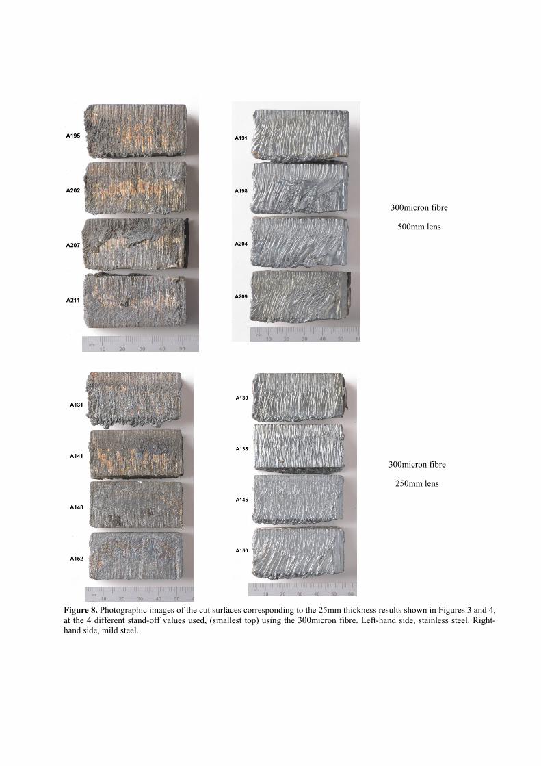
Figure 8. Photographic images of the cut surfaces corresponding to the 25mm thickness results shown in Figures 3 and 4, at the 4 different stand-off values used, (smallest top) using the 300micron fibre. Left-hand side, stainless steel. Right-hand side, mild steel.
300micron fibre
500mm lens
300micron fibre
250mm lens

Figure 9. Photographic images of the cut surfaces corresponding to the 25mm thickness results shown in Figures 3 and 4, at the 4 different stand-off values used, (smallest top) using the 150micron fibre. Left-hand side, stainless steel. Right-hand side, mild steel.
A240
150micron fibre
500mm lens
150micron fibre
250mm lens

Discussion
As can be seen from Figures 1 and 3 (both materials, both material thicknesses and the 500mm lens), there was little difference in any of the cutting results in terms of separation speed, for both optical fibre diameters. As expected, the corresponding edge photographs in Figures 7 and 8, show that the cut quality decreases with increasing stand-off distance. Slightly different results were recorded using the 250mm focal length lens, as can be seen in Figures 2 and 4, where there are small differences between the 150 and the 300micron fibres. Also evident, is that when using the 250mm lens (with either fibre), the separation speed dropped significantly as the stand-off distance increased (and the diameter of the focal spot incident on the material surface increased), which correspondingly reduced the available incident power density. However, it must be stated that for a wide range of stand-off distance, both materials at both thicknesses could be cut using two different focussing lenses, irrespective of the diameter of the optical fibre delivering the laser power.
A more detailed look at the results and referring to the mean and range data for the separation speeds in Tables 2 and 3 reveals the following:
For the 6mm thickness material:
For all stand-off distances, the range in the separation speed results for the 300micron fibre was consistently smaller.
For all stand-off distances, the range in the separation speed results using the 500mm lens was significantly smaller than when using the 250mm lens.
For all stand-off distances, for each lens and fibre, range and average separation speeds were similar for both materials.
The most tolerant performance was when using the 300micron fibre and the 500mm lens, for both materials.
For the 25mm thickness material:
For all stand-off distances, the range in the separation speed results for the 150micron fibre was slightly lower than when using the 300micron diameter fibre. (But equal for the 250mm lens and mild steel)
For all stand-off distances, the range in the separation speed results using the 500mm lens was significantly smaller than when using the 250mm lens.
For all stand-off distances, for each lens and fibre, average separation speeds were similar for both materials.
The most tolerant performance was when using the 150micron fibre and the 500mm lens, for both materials, but with the stand-off limited to less than 75mm for the mild steel.
As can be seen in Table 1, the optical combinations 150micron fibre/500mm lens and 300micron fibre/250mm lens, both produced a minimum focussed spot size of 0.6mm. The difference between these two laser beams is in the divergence angle of the beam below the focus point. The 500mm lens diverges less than the 250mm lens. Figure 5 shows the separation speed against stand-off distance for 6mm thickness mild steel (top) and 6mm thickness stainless steel (bottom), for the optical combinations producing the same focal spot size. What can be seen from these graphs, is that for plates positioned close to the nozzle, the 250mm lens (and 300micron fibre), produced the highest cutting speeds. However, at larger stand-off distances, the 500mm lens (and 150micron fibre), performed better, in terms of achievable cutting speed. This graph also shows that the 500mm lens/150micron fibre combination outperforms the 250mm lens/300micron fibre combination. These findings are reflected for both 6mm thickness materials and also, but to a lesser extent, for the 25mm thickness materials, as presented in Figure 6.
Conclusions
This work, conducted using 5kW of laser power, delivered down 150 and 300micron diameter optical fibres has allowed the following conclusions to be drawn:
Only small differences in cutting speed and cut quality were seen for both focussing lenses, both plate materials and both thicknesses, when varying the stand-off distance or changing fibre diameter from 150 to 300micron. This result indicates the high tolerance offered by laser cutting when edge quality is not the deciding factor.
For the 6mm thickness, the most tolerant performance was obtained using the 300micron fibre and the 500mm lens, for both materials. However, this lens also has the smallest divergence below the cut and therefore poses the larger impact on whatever is positioned behind the material being cut.

For the 25mm thickness, the most tolerant performance was using the 150micron fibre and the 500mm lens, for both materials, but with the stand-off limited to less than 75mm for the mild steel.
Acknowledgements
The author would like to thank Matthew Spinks who conducted the cutting trials. LaserSnake2 is co-funded by the UK’s Technology Strategy Board, the Department of Energy and Climate Change, and the Nuclear Decommissioning Authority, under grant number 110128. The LaserSnake2 project includes OC Robotics, Laser Optical Engineering, ULO Ltd and the UK’s national Nuclear Laboratory, as well as TWI.
References
[1] Pilot Guy et al., 2008: ‘Measurement of secondary emissions during laser cutting of steel equipment’, Nuclear Engineering and Design. Vol. 238, no. 8, pp2124-2134, August.
[2] Hilton P et al., 2010: ‘The laser alternative in nuclear decommissioning - tube cutting and concrete scabbling using the latest technology’, Nuclear Engineering International, Vol. 55, no. 672, July.
Meet the Author
Dr Paul Hilton is the Technology Fellow for Laser Materials Processing at TWI Ltd and has over twenty years of laser processing experience. He has previously been conference chair for LMP at ICALEO and is the current Chairman of the governing body of ELI, the European Laser Institute.
Related Documents