Part 6 Drainage, Hygiene and Water Storage The Building Bye-Laws (Jersey) 1997. Code of Practice TECHNICAL GUIDANCE DOCUMENT States of Jersey Planning and Environment Committee

Welcome message from author
This document is posted to help you gain knowledge. Please leave a comment to let me know what you think about it! Share it to your friends and learn new things together.
Transcript

Part 6Drainage, Hygiene and Water Storage
The Building Bye-Laws (Jersey) 1997. Code of Practice
TECHNICAL GUIDANCE DOCUMENT
States of JerseyPlanning and Environment Committee

PAGEUSE OF GUIDANCE 2
DRAINAGE, HYGIENE AND WATERSTORAGETHE REQUIREMENTS 3
GUIDANCE 4Performance 4Introduction to provisions 4Provisions meeting the requirement 4
Sanitary pipework 4Traps 4Branch discharge pipes 4Discharge stacks 7Materials for pipes, fittings and joints 8Airtightness 8Alternative approach 8
Foul drainage 9Layout 9Depth of pipe cover 9Pipe gradients and sizes 9Materials for pipes and jointing 10Bedding and backfilling 10Clearance of blockages 11Watertightness 13Alternative approach 13
PAGE
Appendix 14Additional guidance for large buildings 14
Cesspools and septic tanks 17Performance 17Introduction to Provisions 17
Rainwater drainage 20Performance 20Introduction to Provisions 20
Sanitary conveniences andwashing facilities 23Performance 23
Wells and water tanks 26Performance 26
Hot water storage 27Guidance 27Performance 27
Technical Guidance Document Drainage, Hygiene and Water Storage1
Contents

THE TECHNICAL GUIDANCEDOCUMENTSThe Building Bye-Laws (Jersey) 1997, which comeinto operation on the twentieth day of February1997, replace the Building Bye-Laws (Jersey) 1960and consolidate all subsequent revisions to thoseBye-Laws. This document is one of a series that has been approved by the Committee as practicalguidance on meeting the requirements of the secondschedule and Bye-Law 7 of the Building Bye-Laws(Jersey) 1997.
At the back of this document is a list of thosedocuments currently published which have beenapproved for the purpose of the Building Bye-Laws.The detailed provisions contained in the TechnicalGuidance Documents are intended to provide guidance for some of the more common building situations. In other circumstances, alternative waysof demonstrating compliance with the requirementsmay be appropriate.
Evidence supporting compliance
The is no obligation to adopt any particular solution contained in a Technical GuidanceDocument if you prefer to meet the relevantrequirement in some other way. However, shoulda contravention of a requirement be alleged then, ifyou have followed the guidance in the relevantTechnical Guidance Documents, that will be evidence tending to show that you have compliedwith the Bye-Laws. If you have not followed the guidance then that will be evidence tending to showthat you have not complied. It will then be for you todemonstrate by other means that you have satisfiedthe requirement.
Other requirements
The guidance contained in a Technical GuidanceDocuments relates only to the particular requirementsof the Bye-Laws which that document addresses.The building work will also have to comply with therequirements of any other relevant paragraphs in thesecond schedule to the Bye-Laws. There areTechnical Guidance Documents which give guidanceon each of the other requirements in the secondschedule and on Bye-Law 7.
LIMITATION ON REQUIREMENTSIn accordance with Bye-Law 8, the requirements inparts 1, 2, 3, 4, 5, 6, 7, 9 and 10 of the secondschedule to the Building Bye-Laws do not requireanything to be done except for the purpose of securing reasonable standards of health and safetyfor persons in or about the building.
MATERIALS AND WORKMANSHIPAny building work which is subject to requirementsimposed by the second schedule to the BuildingBye-Laws should, in accordance with Bye-Law 7, be carried out with proper materials and in a workmanlike manner.You may show that you have complied with Bye-Law7 in a number of ways, for example, by the appropriate use of a product bearing an EC mark inaccordance with the Construction Products Directive(89.106/EEC), or by following an appropriate technical specification (as defined in that Directive),a British Standard, a British Board of Agr�mentCertificate, or an alternative national technical specification of any member state of the EuropeanCommunity which, in use, is equivalent. You will findfurther guidance in the Technical GuidanceDocuments supporting Bye-Law 7 on materials andworkmanship.
Technical specificationsBuilding Bye-Laws are made for specific purposes;health and safety, energy conservation and the welfare and convenience of disabled people.Standards and technical approvals are relevant guidance to the extent that they relate to these considerations. However, they may also addressother aspects of performance such as serviceabilityor aspects which although they relate to health andsafety are not covered by the Bye-Laws.
When a Technical Guidance Document makes reference to a named standard, the relevant versionof the standard is the one listed at the end of thepublication. However, if this version of the standardhas been revised or updated by the issuing standards body, the new version may be used as asource of guidance provided it continues to addressthe relevant requirements of the Bye-Laws.
Drainage, Hygiene and Water Storage Technical Guidance Document2
Use of GuidanceTHE BUILDING BYE-LAWS (JERSEY) 1997

This Technical Guidance Document which takeseffect on 20 February 1997, deals with the followingrequirements from part 6 of the second schedule tothe Building Bye-Laws (Jersey) 1997.
Technical Guidance Document Drainage, Hygiene and Water Storage3
The RequirementsDRAINAGE, HYGIENE AND WATER STORAGE
Requirements Limits on application
Foul Water Drainage(17) (1) Any system which carries foul water from a building shall—
(a) connect to a public sewer where such sewer is available; or(b) connect to a cesspool or septic tank connected to a sub-surface irrigation system where a public sewer is not available, and any such system shall be adequate.
(2) In sub-paragraph (1) ‘foul water’ means waste water whichcomprises or includes—(a) waste from a sanitary convenience or other soil appliance; or(b) water which has been used for cooking or washing; or(c) trade effluent.
Cesspools, septic tanks and sub-surface irrigation(18) (1) Any cesspool or septic tank and sub-surface irrigation shall
be so sited and constructed that it is not prejudicial to the health of any person and will not contaminate any well, borehole, reservoir or stream of water, used or likely to be used by persons for drinking or domestic purposes, or forthe manufacture or preparation of food or drink for humanconsumption.
(2) Any cesspool or septic tank shall be—(a) of adequate capacity and so constructed that it isimpermeable to liquids;(b) adequately ventilated; and(c) provided with adequate means of access for emptying.
Rainwater drainage(19) Every building shall be provided with a system which carries
rainwater from the roof to a sewer, soakaway , watercourse orsome other suitable rainwater outfall, and any such systemshall be adequate.
Sanitary facilities(20) Every building shall have adequate sanitary facilities in rooms
provided for that purpose.
Wells and water tanks(21) A well, borehole, water tank or cistern in connection with a
building and intended to supply water for human consumptionshall be constructed and installed so as to prevent pollution ofthe water.
Hot water storage(22) A hot water storage system with a storage vessel which does
not incorporate a vent pipe to the atmosphere shall beinstalled so as to operate safely, and there shall be precautionsto prevent the temperature of stored water at any timeexceeding 100°C.
Requirement (22) does not apply to—(a) a hot water storage system thathas a storage vessel with a capacityof 15 litres or less;(b) a system providing space heatingonly; or(c) a system which heats or storeswater for the purposes only of anindustrial process.

PerformanceIn the view of the Committee requirement (17)of part 6 will be met if a foul water drainagesystem:
(a) conveys the flow of foul water to a foulwater outfall (a foul of combined sewer, acesspool, or septic tank connected to a sub-surfacesystem),
(b) minimises the risk of blockage or leakage,
(c) prevents foul air from the drainage systemfrom entering the building under workingconditions,
(d) is ventilated, and
(e) is accessible for clearing blockages.
Introduction to provisions0.1 The capacity of the system should be largeenough to carry the expected flow at any point.
0.2 The capacity depends on the size andgradient of the pipes. Minimum sizes andgradient limits are given in the text.
0.3 The flow depends on the type, number andgrouping of appliances.
0.4 Appliances are seldom in usesimultaneously and the minimum stack and drainsizes in normal use are capable of carrying theflow from quite large numbers of appliances.Table 1 shows approximate flow rates resultingfrom the typical household group of 1 wc, 1 bath,1 or 2 washbasins and 1 sink for designpurposes in BS 5572.
PIPE SIZES0.5 The pipe sizes quoted in this document are nominal sizes used as a numerical designation in convenient round numbers approximatelyequal to a manufacturersÕ size. Equivalent pipesizes for individual pipe standards will be foundin BS 5572 for sanitary pipework and BS 8301for building drainage.
Provisions meeting therequirement
Section 1Sanitary Pipework
TRAPS1.1 All points of discharge into the systemshould be fitted with a water seal (trap) toprevent foul air from the system entering thebuilding. Under working and test conditions trapsshould retain a minimum seal of 25mm.
1.2 Table 2 gives minimum trap sizes and sealdepths for the appliances which are most used(for other appliances see Appendix paragraph A2).
1.3 Ventilation Ð To prevent the water sealfrom being broken by the pressures whichcan develop in the system the branch dischargepipes should be designed as described inparagraphs 1.5 to 1.21.
1.4 Access for clearing blockages Ð If a trapforms part of an appliance the appliance shouldbe removable. All other traps should be fitteddirectly after the appliance and should beremovable or be fitted with a cleaning eye.
BRANCH DISCHARGE PIPES1.5 Branch pipes should be discharged into anotherbranch pipe or a discharge stack unless theappliances are on the ground floor.
Drainage, Hygiene and Water Storage Technical Guidance Document4
Guidance
Table 1 Flow rates from dwellings
No of dwellings Flow rate (litres/sec)
1 2.55 3.510 4.115 4.620 5.125 5.430 5.8
Table 2 Minimum trap sizes and sealdepths
washbasinbidet 32 75
sink*bath*shower* 40 75food waste disposal uniturinal bowl
(siphonic only)wc pan 75 50
* Where these appliances are installed on a ground floor and discharge to a gully, the depth of seal may be reduced to not less than 38mm.
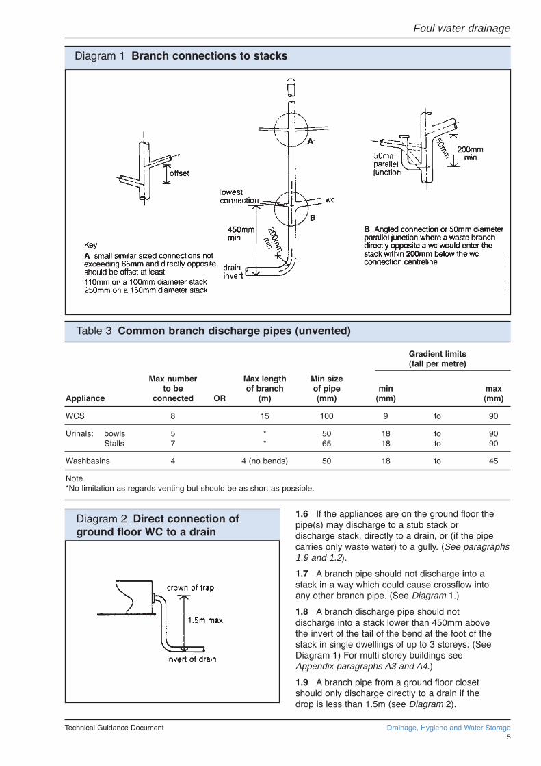
1.6 If the appliances are on the ground floor thepipe(s) may discharge to a stub stack ordischarge stack, directly to a drain, or (if the pipecarries only waste water) to a gully. (See paragraphs1.9 and 1.2).
1.7 A branch pipe should not discharge into astack in a way which could cause crossflow intoany other branch pipe. (See Diagram 1.)
1.8 A branch discharge pipe should notdischarge into a stack lower than 450mm abovethe invert of the tail of the bend at the foot of thestack in single dwellings of up to 3 storeys. (SeeDiagram 1) For multi storey buildings seeAppendix paragraphs A3 and A4.)
1.9 A branch pipe from a ground floor closetshould only discharge directly to a drain if thedrop is less than 1.5m (see Diagram 2).
Technical Guidance Document Drainage, Hygiene and Water Storage5
Diagram 1 Branch connections to stacks
Table 3 Common branch discharge pipes (unvented)
Gradient limits(fall per metre)
Max number Max length Min sizeto be of branch of pipe min max
Appliance connected OR (m) (mm) (mm) (mm)
WCS 8 15 100 9 to 90
Urinals: bowls 5 * 50 18 to 90Stalls 7 * 65 18 to 90
Washbasins 4 4 (no bends) 50 18 to 45
Note*No limitation as regards venting but should be as short as possible.
Diagram 2 Direct connection ofground floor WC to a drain
Foul water drainage
1.10 Branch pipes from more than one ground floor appliance may discharge into a stub stack.(See paragraph 1.26.)
1.11 A branch pipe discharging to a gully shouldterminate between the grating or sealing plateand the top of the water seal.
1.12 Sizes of branch pipes Ð Pipes serving a single appliance should have at least the samediameter as the appliance trap (see Table 2). If apipe serves more than one appliance and is unventilated the diameter should be at least the size shown in Table 3.
1.13 Bends in branch pipes should be avoided ifpossible. Where they cannot they should have as large a radius as possible. Pipes of 65mm or less should have a centre line radius of at least75mm.
1.14 Junctions on branch pipes should be madewith a sweep of 25mm radius or at 45¡. Connectionof branch pipes of 75mm diameter or more to thestack should be made with a sweep of 50mm minimum radius or at 45¡.
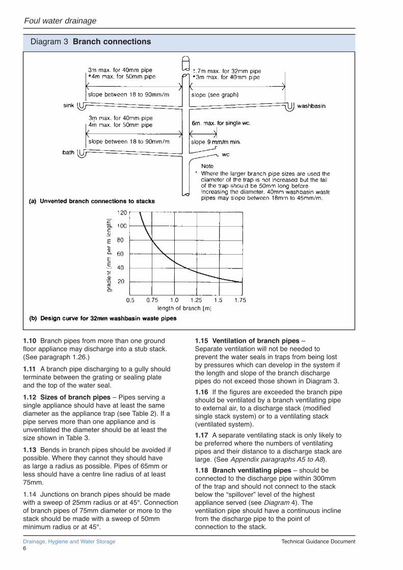
1.15 Ventilation of branch pipes ÐSeparate ventilation will not be needed toprevent the water seals in traps from being lostby pressures which can develop in the system if the length and slope of the branch discharge pipes do not exceed those shown in Diagram 3.
1.16 If the figures are exceeded the branch pipeshould be ventilated by a branch ventilating pipeto external air, to a discharge stack (modifiedsingle stack system) or to a ventilating stack(ventilated system).
1.17 A separate ventilating stack is only likely to be preferred where the numbers of ventilating pipes and their distance to a discharge stack arelarge. (See Appendix paragraphs A5 to A8).
1.18 Branch ventilating pipes Ð should beconnected to the discharge pipe within 300mmof the trap and should not connect to the stackbelow the ÒspilloverÓ level of the highestappliance served (see Diagram 4). Theventilation pipe should have a continuous inclinefrom the discharge pipe to the point ofconnection to the stack.
Drainage, Hygiene and Water Storage Technical Guidance Document6
Diagram 3 Branch connections
Foul water drainage

1.19 Branch ventilation pipes which run direct tooutside air should finish at least 900mm aboveany opening into the building nearer than 3m (seeDiagram 6 and paragraph 1.27).
1.20 Branch ventilating pipes to branch pipesserving one appliance should be at least 25mmdiameter or where the branch is longer than 15mor has more than 5 bends, should be at least32mm.
1.21 Rodding points should be provided to giveaccess to any lengths of discharge pipes whichcannot be reached by removing traps orappliances with integral traps (see paragraph 1.4).
DISCHARGE STACKS1.22 All stacks should discharge to a drain. Thebend at the food of the stack should have as largea radius as possible and at least 200mm at thecentre line.
1.23 Offsets in the ÔwetÕ portion of a dischargestack should be avoided. If they are unavoidablethen in a building of not more than 3 storeys thereshould be no branch connection within 750mm ofthe offset. In a building over 3 storeys a ventilationstack may be needed with connections aboveand below the offset. In buildings over 3 storeysdischarge stacks should be located inside thebuilding.
1.24 Sizes of stacks Ð Stacks should have atleast the diameter shown in Table 4 and shouldnot reduce in the direction of flow.
Stacks serving urinals should be not less than50mm, stacks serving siphonic closets not lessthan 75mm and stacks serving washdown closetsnot less than 100mm.
1.25 Ventilation of discharge stacks Ð Toprevent water seals in the traps from being lost bypressures which can develop in the system,discharge stacks should be ventilated. Dischargestacks connected to drains liable to surchargingor near an intercepting trap require ventilationpipes of not less than 50mm diameter connectedto the base of the stack above the likely floodlevel.
Stack size Max capacity(mm) (litres/sec)
50* 1.265* 2.175 3.490 5.3100 7.2
Notes* No wcs Not more than 1 siphonic wc with 75mm outlet.
1.26 Stub stacks Ð An unventilated stub stack may be used if it connects above ground into a ventilated discharge stack or into a drain not subject to surcharging and no branch into the sub stack is more than 2m above the invert of the connection or drain and no branch serving acloset is more than 1.5m from the crown of the
Technical Guidance Document Drainage, Hygiene and Water Storage7
Foul water drainage
Diagram 4 Branch ventilation pipes Table 4 Minimum diameters fordischarge stacks
Diagram 5 Stub stack
Diagram 6 Termination of ventilationstacks or ventilating part of dischargestacks

closet trap to the invert of the connection or drain(see Diagram 5). The length of branch drain from an unventilated sub stack should not be more than 6m where a single appliance is connected and 12m where a group of appliances is connected. (See also Table 10 and paragraph 2.21.)
1.27 Ventilating pipes open to outside air shouldfinish at least 900mm above any opening into thebuilding within 3m and should be finished with acage or other perforated corer which does notrestrict the flow of air (see Diagram 6).
1.28 Sizes of stack ventilation pipes Ð Thesize of the part of a discharge stack which servesonly for ventilation (the dry part above thehighest branch) may be reduced in one and twostorey houses, but should be at least 75mm.
1.29 Discharge stacks may terminate inside a building when fitted with air admittance valves.Where these valves are used they should notadversely affect the amount of ventilation necessary for the below ground system which is normally provided by the open stacks of the sanitary pipework. Only an air admittance valvewhich is the subject of a current British Board ofAgrément Certificate should be used and the conditions of use should be in accordance with the terms of the Certificate.
1.30 Access for clearing blockagesRodding points should be provided to give access to any lengths of pipe which cannot bereached from any other part of the system. All pipes should be reasonably accessible for repair.
MATERIALS FOR PIPES, FITTINGSAND JOINTS1.31 Any of the materials shown in Table 5 may be used (the references are to British StandardSpecifications). Where necessary different metalsshould be separated by non-metallic material to prevent electrolytic corrosion. Pipes should be firmly supported without restricting thermal movement.
AIRTIGHTNESS1.32 The pipes, fittings and joints should be capable of withstanding an air or smoke test of positive pressure of at least 38mm water gauge for at least 3 minutes. Every trap should maintain a water seal of at least 25mm. Smoke testing is not recommended for uPVC pipes.
Alternative approach
1.33 The requirement can also be met byfollowing the relevant recommendations ofBS 5572: 1978 Code of practice for sanitarypipework, Clauses 3, 4 and 7 to 12 are relevant.
Drainage, Hygiene and Water Storage Technical Guidance Document8
Foul water drainage
Table 5 Materials for sanitary pipework
Material British Standard
Pipescast iron BS 416, BS 6087copper BS 864, BS 2871galvanised steel BS 3868uPVC BS 4514polypropylene BS 5254plastics
ABSMUPVCpolyethylenepolypropylene
Trapscopper BS 1184plastics BS 3943
NoteSome of these materials may not be suitable forconveying trade effluent.

Section 2Foul Drainage
2.1 Some public sewers may carry foul waterand rainwater in the same pipe. However, the onsite drainage system should be designed to keepthe rainwater and foul drainage separate up to apoint near the site boundary. Systems whichdischarge to a cesspool or septic tank should onlycarry foul water.
2.2 Where a gravity connection to the sewer isimpracticable, sewage lifting equipment will beneeded. Any pump chamber should be capable ofproviding 24 hours storage in the event of powerfailure of other breakdown and be fitted with dualpumps and alarm system. Guidance on sewagelifting installations is contained in BS 8301 Code ofpractice for building drainage.
LAYOUT2.3 The layout of the drainage system should bekept simple. Changes of direction and gradientshould be minimised and as easy as practicable.Access points should be provided only ifblockages could not be cleared without them.Connection of drains to other drains or private orpublic sewers, and of private sewers to publicsewers should be made obliquely, or in thedirection of flow.
2.4 The system should be ventilated by a flow ofair. A ventilating pipe should be provided at ornear the head of each main drain, any branchlonger than 6m serving a single appliance or12m serving a group of appliances, or on a drainfitted with an intercepting trap (particularly on asealed system). Ventilated discharge stacksmay be used (see paragraphs 1.27 and 1.28).
2.5 Pipes should be laid to even gradients andany change of gradient should be combined withan access point (see paragraph 2.21).
2.6 Pipes should be laid in straight lineswhere practicable but may be laid to slightcurves if these can still be cleared of blockages.Any bends should be limited to positions in orclose to inspection chambers of manholes (seeparagraph 2.21) and to the foot of discharge andventilating stacks. Bends should have as large aradius as practicable (see paragraph 1.22)
2.7 Special precautions should also be taken toaccommodate the effects of settlement wherepipes run under or near a building, on piles orbeams, in common trenches or in unstableground. Precautions may also be necessary insituations involving surcharging of drains, orwhere control of rodents from sewers is aproblem (see Appendix paragraphs A9 to A14).
DEPTH OF PIPE COVER2.8 The depth of cover will usually depend onthe levels of the connections to the system, thegradients at which the pipes should be laid andthe ground levels.
2.9 Pipes also need to be protected fromdamage and if the proposed bedding class givestoo little cover (or too much, when the pipescould be damaged by the weight of backfilling)for one combination of cover, pipe strength andpipe bedding it may be possible to chooseanother combination. Alternatively specialprotection can be provided (see Appendixparagraphs A15 and A17).
PIPE GRADIENTS AND SIZES2.10 Drains should have enough capacity tocarry the flow and be laid to falls. The flowdepends on the appliances connected (seeparagraphs 0.1 to 0.4 and Table 1) and thecapacity depends on the size and gradient of thepipes (see Diagram 7).
2.11 A drain carrying only waste water shouldhave a diameter of at least 75mm and a draincarrying soil water or waste water containingtrade effluent a diameter of at least 100mm.
2.12 Table 6 shows the flattest gradients atwhich drains should be laid, (depending on theflow and the appliances connected to them) andthe capacity they will then have (see alsoparagraphs 0.1 to 0.4).
Technical Guidance Document Drainage, Hygiene and Water Storage9
Foul water drainage
Diagram 7 Discharge capacities offoul drains running 0.75 proportionaldepth

2.13 Combined systems Ð The capacity ofsystems carrying foul water and rainwatershould take account of the combined peak flow.
MATERIALS FOR PIPES ANDJOINTING2.14 Any of the materials shown in Table 7 may be used (the references are to British StandardSpecifications). Joints should be appropriate to the material to the pipes. To minimise the effects of any differential settlement pipes should have flexible joints. All joints should remain watertightunder working and test conditions and nothing in the pipes., joints or fittings should project into thepipe line or cause an obstruction. Different metalsshould be separated by non-metallic materials toprevent electrolytic corrosion where necessary.
BEDDING AND BACKFILLING2.15 The choice of bedding and backfilling depends on the depth at which the pipes are to be laid and the size and strength of the pipes.
2.16 Rigid pipes Ð The types of bedding andbackfilling which should be used for rigid pipes ofstandard strength laid in a trench of any widthare shown in Diagram 8 and Table 8. Minimumand maximum depths of cover are also shownfor each type. For special protection where pipesare laid with less cover see Appendix paragraphA15.
2.17 Flexible pipes Ð These will become deformed under load and require support to limitthe deformation to 5 per cent of the diameter ofthe pipe. The bedding and backfilling should beas shown in Diagram 9. The minimum depthshould be 0.9m under any road and 0.6m in
Drainage, Hygiene and Water Storage Technical Guidance Document10
Table 6 Recommended minimumgradients for foul drainsPeak Pipe Minimum Maximumflow size gradient capacity
(litres/sec) (mm) (1 in ...) (litres/sec)
<1 75 1:40 4.1100 1:40 9.2
>1 75 1:80 2.8100 1:80* 6.3150 1:150 15.0
Notes* Minimum of 1 wc. Minimum of 5 wcs.
Table 7 Materials for below groundgravity drainage
Material British Standard
Rigid pipesasbestos BS 3656vitrified clay BS 65, BSEN 295concrete BS 5911grey iron BS 437, BS 6087
Flexible pipesuPVC BS 4660
BS 5481
NoteSome of these materials may not be suitable forconveying trade effluent.
Diagram 8 Bedding for rigid pipes
Foul water drainage

fields and gardens. The maximum depth shouldbe 10m. For special protection where pipes arelaid with less cover see Appendix paragraph A16to A17.
CLEARANCE OF BLOCKAGES2.18 Sufficient and suitable access points should be provided for clearing blockages from drain runs which cannot be reached by any othermeans. The siting, spacing and type of the access points will depend on the layout, depth and size of the runs.
2.19 The provisions described below are fornormal methods of rodding (which need not be inthe direction of flow) and not mechanical meansof clearing.
2.20 Access points should be one of four types.Table 9 shows the depth at which each typeshould be used and the recommendeddimensions it should have. The dimensionsshould be increased at junctions if they do notallow enough space for branches. The types are:
(a) rodding eyes Ð capped extensions of thepipes;
(b) access fittings Ð small chambers on (or anextension of) the pipes but not with an openchannel;
(c) inspection chambers Ð chambers withworking space at ground level;
(d) manholes Ð large chambers with workingspace at drain level.
Technical Guidance Document Drainage, Hygiene and Water Storage11
Diagram 9 Bedding for flexible pipes
Foul water drainage
Table 8 Limits of cover for standard strength rigid pipes in any width of trench
Fields and Light traffic Heavy trafficgardens roads roads
Pipe bore Bedding class Min Max Min Max Min Max
D or N 0.4 4.2 0.7 4.1 0.7 3.7100 F 0.3 5.8 0.5 5.8 0.5 5.5
B 0.3 7.4 0.4 7.4 0.4 7.2
D or N 0.6 2.7 1.1 2.5 Ð Ð150 F 0.6 3.9 0.7 3.8 0.7 3.3
B 0.6 5.0 0.6 5.0 0.6 4.6

2.21 Siting of access points Ð Accessshould be provided at the following points:
(a) on or near the head of each drain run, and
(b) at a bend and at a change or gradient, and
(c) at a change of pipe size (but see below if it isat a junction), and
(d) at a junction unless each run can be clearedfrom an access point (some junctions can only berodded through from one direction).
2.22 Access should be provided to long runs.The distances between access points depend onthe types of access used but should not be morethan shown in Table 10 for drains up to andincluding 300mm.
2.23 Construction of access points ÐThese should contain the foul water underworking and test conditions and resist the entryof ground water and rainwater. Any of thematerials shown in Table 11 may be used.
2.4 Where half round channels are used ininspection chambers and manholes thebranches should discharge into the channel at orabove the level of the horizontal diameter.Where the angle of the branch is more than 45¡ athree quarter section branch should be used.Channels and branches should be benched upat least to the top of the outgoing pipe and at a slope of 1 in 12. The benching should berounded at the channel with a radius of at least25mm.
Drainage, Hygiene and Water Storage Technical Guidance Document12
Table 9 Minimum dimensions for access fittings and chambers
Internal sizes Cover sizes
Type Depth to Length × width Circular Length × width Circular(m) (mm × mm) (mm) (mm × mm) (mm)
Rodding eye As drain but min 100
Access fittingsmall 0.6 or less 150 × 100 150 150 × 100 150large 225 × 100 Ð 225 × 100 Ð
Inspection chamber 0.6 or less Ð 190* Ð 190*1.0 or less 450 × 450 450 450 × 450 450
Manhole 1.5 or less 1200 × 750 1050 600 × 600 600over 1.5 1200 × 750 1200 600 × 600 600over 2.7 1200 × 840 1200 600 × 600 600
Shaft over 2.7 900 × 840 900 600 × 600 600
Notes* Drains up to 150mm. For clayware or plastics may be reduced to 430mm in order to provide support for cover and frame.
Table 10 Maximum spacing of access points in metres
Access FittingInspection
From To Small Large Junction chamber Manhole
Start of external drain* 12 12 - 22 45
Rodding eye 22 22 22 45 45
Access fittingsmall 150 diam
150 × 100 - - 12 22 22large 225 × 100 - - 22 45 45
Inspection chamber 22 45 22 45 45
Manhole 22 45 45 45 90
Note*See paragraphs 1.9 and 1.26
Foul water drainage

2.25 Inspection chambers and manholes shouldhave removable non-ventilating covers ofdurable material (such as cast iron, cast orpressed steel, precast concrete or uPVC) and beof suitable strength. Inspection chambers andmanholes in buildings should have mechanicallyfixed airtight covers unless the drain itself haswatertight access covers. Manholes deeper than1m should have metal step irons or fixedladders.
WATERTIGHTNESS2.26 After laying, including any necessaryconcrete or other haunching or surrounding andbackfilling gravity drains and private sewers up
to 300mm should be capable of withstanding a final water test to a pressure equal to 1.5m head of water measured above the invert at the head of the drain, or an air test to ensure a maximum loss of head on a monometer of 25mm in a period of 5 minutes for 100mm gauge or 12mm for a 50mm gauge.
2.27 Where the drain is water tested using a stand pipe of the same diameter as the drain, thesection of drain should be filled and left to stand for 2 hours and topped up. The leakage over 30 minutes should then be measured and should not be more than 0.5 litres for each metre run ofdrain for a 100mm drain Ð a drop in water level of6.4mm/m, and 0.08 litres for a 150mm drain Ð a drop in water level of 4.5mm/m.
2.28 To prevent damage to the drain the head ofwater at the lower end of the section should notbe more than 4m and it may be necessary to test a drain in several sections.
Alternative approach
2.29 The requirement can also be met byfollowing the relevant recommendations of BS 8301: 1985 Code of practice for buildingdrainage. The relevant clauses are in Sectionone, Section two, Section three (except Clause10), Section four (except Clause 23), Section five (Clause 25 only) and Apendices. The Code contains additional detailed information about design and construction and describes the discharge unit method of determining pipe sizes.
Technical Guidance Document Drainage, Hygiene and Water Storage13
Table 11 Materials for access points
Material British Standards
1. Inspection chambers and manholesClaybricks and blocks BS 3921vitrified BS 65
Concreteprecast BS 5911in situ BS 8110
Plastics BS 7158
2 Rodding eyes and access fittings as pipes(excluding frames and covers) see Table 7
BBA Certificates
Foul water drainage

AppendixAdditional guidance for largebuildingsCAPACITY OF PIPES(see paragraphs 0.1 to 0.4)
A1 Flow rates for other commonly usedappliances not covered in Table 1 are shown in Table A1.
TRAPS(see paragraph 1.2)
A2 Minimum trap sizes and seal depths forappliances not listed in Table 1 are shown inTable A2
BRANCH DISCHARGE PIPES(see paragraph 1.5)A3 A branch pipe should not discharge into astack less than 750mm above the invert of the tail of the bend at the foot of the stack in a multistorey building up to 5 storeys. Alternatively a branch pipe serving any ground floor appliance may discharge direct to a drain or into its own stack.
A4 If the building has more than 5 storeys ground floor appliances, unless discharging to agully or drain, should discharge into their own stack. If the building has more than 20 storeysground floor appliances, unless discharging to agully or drain, and first floor appliances should discharge into their own stack.
VENTILATING STACKS(see paragraph 1.17)A5 A dry stack may provide ventilation forbranch ventilating pipes as an alternative tocarrying them to outside air or to a ventilateddischarge stack (ventilated system).
A6 Ventilation stacks serving buildings with notmore than 10 storeys and containing onlydwellings should be at least 32mm diameter (forall other buildings see paragraph 2.29).
A7 The lower end of a stack may be connecteddirectly to a bend (see paragraph 1.22) or it may be connected to a ventilated discharge stack when the connection should be below the lowestbranch discharge pipe.
A8 The upper end of a stack may be carried tooutside air (when it should finish as described inparagraph 1.19) or it may be connected to a ventilated discharge stack when the connectionshould be above the spill-over level of the highest appliance.
SPECIAL PROTECTION ÐSETTLEMENT(see paragraph 2.7)A9 A drain may run under a building if at least100mm of granular or other flexible filling is provided round the pipe. On sites where excessive subsidence is possible additional flexible joints may be advisable or other solutions such as suspended drainage. Where the crown of the pipe is within 300mm of the underside of the slab, concrete encasement shouldbe used integral with the slab.
A10 A drain may run through a wall orfoundation and depending on whether it isnecessary to build the pipe into the wall eitherÑ
(a) an opening formed to give at least 50mmclearance all round the pipe and the openingmasked with rigid sheet material to prevent theingress of fill or vermin or
(b) a length of pipe (as short as possible) built inwith its joints as close as possible to the wallfaces within at most 150mm) and connected oneach side to rocker pipes with a length of at most600mm and flexible joints (see Diagram A1).
A11 A drain trench should not be excavatedlower than the foundations of any buildingnearby (see Diagram A2) unless either:
(a) where the trench is within 1m of the buildingthe trench is filled with concrete up to the lowestlevel of the building, or
Drainage, Hygiene and Water Storage Technical Guidance Document14
Foul water drainage
Table A1 Flow rates from appliances
Appliance Flow rate(litres per sec)
Spray tap basin 0.06Washing machine 0.70
Table A2 Minimum trap sizes and sealdepths additional to Table 2
Diam of trap Depth of sealAppliance (mm) (mm)
sanitary towel macerator 40 75
Food waste disposal unit 50 75(industrial type)
urinal stall (1 to 7 person 65 50position)

(b) where the trench is further than 1m from thebuilding, the trench is filled with concrete to a level below the lowest level for the building equal to the distance from the building, less 150mm.
SPECIAL PROTECTION ÐSURCHARGING OF DRAINS
A12 Where a drain is liable to surcharge, measures should be taken to protect the building. All drainage unaffected by surcharge should by-pass the protective measures and discharge by gravity either to a surcharge free outlet or if unavoidable into the surcharged part of the system. The measures taken depend on the particular circumstances and the Public ServicesDepartment may be able to provide information, and in some cases give guidance, on sites where surcharging could be a problem. Protective measures are described in BS 8301.Where any type of anti-flood device is used additional ventilation may be needed to maintain trap seals (see paragraph 1.25).
SPECIAL PROTECTION Ð RODENTCONTROL
A13 The department of health may be able to provide information on locations where infestation of drains and private sewers by rodents is a problem, and on the measures found most effective in that area. Measures mayinclude ÔsealedÕ drainage, i.e. drainage havingaccess covers to the pipework in the inspectionchamber instead of an open channel which giveseffective protection. Protection can also be derived from intercepting traps although their liability to blockage can affect the efficiency of the drainage system unless they are regularly maintained. In some situations a combination of both measures may be advisable.
SPECIAL PROTECTION Ð GROUNDLOADS
A14 Where rigid pipes have less than the recommended cover in Table 8 the pipes should,where necessary, be protected from damage by concrete encasement not less than 100mm thick and having movement joints formed with compressible board at each socket or sleeve joint face (see Diagram A3 and paragraphs 2.9 and2.16).
Technical Guidance Document Drainage, Hygiene and Water Storage15
Diagram A1 Pipes penetrating walls
Diagram A2 Pipe runs near buildings

A15 Where flexible pipes are not under a road and have less than 0.6m cover they should, where necessary have concrete paving slabs laid as bridging above the pipes with at least 75mm of granular material between the top of the pipe and the underside of the slabs (seeDiagram A4 and paragraphs 2.9 and 2.18).
A16 Where flexible pipes are under a road andhave less than 0.9m cover reinforced concretebridging should be used instead of paving slabs,or a reinforced concrete surround (seeparagraphs 2.9 and 2.14).
Drainage, Hygiene and Water Storage Technical Guidance Document16
Diagram A3 Concrete encasement forrigid pipes (minimum sizes)
Diagram A4 Protection for flexiblepipes (minimum sizes)
Foul water drainage
Section 3PERFORMANCE
In the view of the Committee requirement (18) ofpart 6 will be met if:
(a) cesspools have sufficient capacity to store the foul water from the building until they are emptied;
(b) septic tanks have sufficient capacity to enablebreakdown and settlement of solid matter in the foulwater from the buildings;
(c) cesspools and septic tanks are constructed soas to prevent leakage of the contents and ingress ofsubsoil water, and with adequate ventilation;
(d) cesspools and septic tanks are sited so as notto be prejudicial to health, not to contaminate watersupplies and so as to permit satisfactory access foremptying;
(e) cesspools are fitted with a warning devicewhich operates automatically when the cesspoolis 75% full.
Introduction to provisions0.1 Paragraphs 1.1 to 1.10 of this documentgive guidance only on the general principles relating to capacity, siting and ventilation ofcesspools and septic tanks.
0.2 Specialist knowledge is advisable in thedetailed design and installation of small sewagetreatment works and guidance is given in BS 6297: 1983 Code of practice for design andinstallation of small sewage treatment works andcesspools (see also paragraph 1.11).
CAPACITY1.1 Cesspools should have a capacity below thelevel of the inlet of at least 18,000 litres (18m3).
1.2 Septic tanks should have a capacity below thelevel of the inlet of at least 2,700 litres (2.7m3).
SITING1.3 Cesspools, septic tanks and sub-surface irrigation systems should be sited:
(a) As far as is practicable (a distance of 15m isdesirable) from any dwelling, public building or anybuilding in which any person is employed in anymanufactured, trade or business, and,
(b) Within 30m of a vehicle access and at suchlevels that they can be emptied or desludged andcleaned without hazard to the building occupants ofthe contents being taken through a dwelling or placeof work. Access may be through an open coveredspace.
DESIGN AND CONSTRUCTION1.4 Cesspools and septic tanks should preventleakage of the contents and to ingress of subsoilwater. Septic tanks should incorporate at least twochambers or compartments operating in series.Cesspools and septic tanks may be constructed inbrickwork, concrete, or glass reinforced concrete.Brickwork should be of engineering bricks and be at least 220mm thick. The mortar should be a mixof 1:3 cement and ratio. In-situ concrete should beat least 150mm thick of C/25/P mix (see BS 5328).
1.5 Factory made cesspools and septic tanks are available in glass reinforced plastics, polyethylene or steel and a way of demonstrating compliance is for these to be the subject of a British Board of Agr�ment (BBA)Certificate, and to be installed in accordance with the certificate and the manufacturerÕs instructions. Particular care is necessary in ensuring stability of these tanks.
1.6 Cesspools and septic tanks should be coveredand ventilated.
1.7 Cesspools, and septic tanks, should be providedwith access for emptying or desludging and cleaning.The access should not have any dimension less than600mm where entry is required. Access coversshould be of durable quality having regard to the corrosive nature of the tank contents, and be lockable.
1.8 The inlet of a cesspool and the inlet and outlet of a septic tank should be provided withaccess for inspection.
1.9 Cesspools should have no openings exceptfor the inlet, access for emptying and ventilation.
1.10 The inlet and outlet of a septic tank should be designed to prevent disturbance to the surface scum or settled sludge. Where the width of the tank does not exceed 1200mm the inletshould be via a dip pipe. To minimise turbulence,provision should be made to limit the flow rate of the incoming foul water. For steeply laid drains up to 150mm the velocity may be limited by laying the last 12m of the incoming drain at a gradient of 1 in 50 or flatter.
Alternative approach
1.11 The requirement can also be met by following the relevant recommendations of BS 6297: 1983 Code of practice for design andinstallation of small sewage treatment works andcesspools. The relevant clauses are in Sectionone, Section two, Section three (clauses 6-11),Section four and Appendices.
Technical Guidance Document Drainage, Hygiene and Water Storage17
Cesspools and septic tanks
Guidance

DISPOSAL OF SEPTIC TANKEFFLUENTDisposal of septic tank effluent should be to underground strata using a sub-surface irrigationsystem installed in accordance with BS 6297: 1983, Section 3 (Clause 5.3).
A sub-surface irrigation system should be so sitedthat no part is within 30m of any well, borehole,reservoir or stream of water, used or likely to beused by people for drinking or domestic purposes or for the manufacture of preparation of articles offood or drink for human consumption.
Note: Permission in respect of the Island Planning(Jersey) Law will not normally be given for newdevelopment which relies on septic tanks and soakaways or private sewage treatment plants.
Drainage, Hygiene and Water Storage Technical Guidance Document18
Cesspools and septic tanks

A BRIEF OUTLINE OF BS 6297:1983 SECTION 15.3
If the winter water-table is within one metre of theinvert of the proposed irrigation system, it is notadvisable to use this method of disposal.
Specification
A system of field drains should be carefully designedfrom the septic tank, using porous or perforatedpipes, laid in trenches with a uniform gradient.
(a) The pipes must be carefully laid to a fall of1:200 with the perforations downwards.
(b) The trenches should be from 300mmÐ900mm
wide and 150mm deeper than invert level, with 2metres of undisturbed ground between the pipelines.
(c) The trenches are then lined with chippings ofsingle size 20mm to a minimum depth of 150mm.
(d) The porous or perforated pipe is then laid onthe middle of the trench and side filled to the crownof the pipe.
(e) To prevent ingress of soil and fines a polythenesheet or similar material is laid on top of the pipe tothe width of the trench.
(f) Further chippings are then added to a depth of150mm taking care not to puncture the material andthe trench is then back-filled in the normal way usingas dug material.
Technical Guidance Document Drainage, Hygiene and Water Storage19
Cesspools and septic tanks
Septic tank installation showing herringbone layout of pipes
Calculating area of drainage trenchThe formula and method for calculating the area ofa sub-surface irrigation trench is as follows:
Trench area in m2 = P × Vp × 0.25
Where P = the number of persons served by the tank.Vp = the percolation value.
The percolation value is determined as follows:
(i) Excavate a hole 300mm square at the proposedinvert level.
(ii) Fill with water to a minimum depth of 250mmand allow the water to seep away overnight.
(iii) Re-fill the test hole the following day to a depthof 250mm and note in seconds the time taken for thewater to seep away.
(iv) Divide this time by the initial depth of water inmillimetres.
(v) The result of this calculation is the percolationvalue or the average time for the water to drop 1mm.The percolation value should be the average from atleast three test holes over the drainage area.
(vi) If the percolation value exceeds 140 s the soil isnot suitable. For values ranging from 100 sÐ140 sunderdrains should be provided in accordance withBS 6297: 1983: Section: 15.3.3.

Section 4PERFORMANCE
In the view of the Committee requirement (19) ofpart 6 will be met if a rainwater drainage system:
(a) carried the flow of rainwater from the roof to an outfall (a surface water or combined sewer, asoakaway, or a watercourse),
(b) minimises the risk of blockage or leakage,
(c) is accessible for clearing blockages.
Introduction to provisions0.1 There are no provisions in this document fordraining the rainfall on overall areas of 6m2 or less including small roofs and balconies unless they receive a flow from a rainwater pipe or frompaved and other hard surfaces.
0.2 The capacity of the drainage system should be large enough to carry the expected flow at any point in the system.
0.3 The flow depends on the area to be drainedand the intensity of the rainfall which should beassumed to be 75mm an hour for roof drainage design.
0.4 The capacity depends on the size and gradient of the gutters and pipes. Capacities andminimum sizes are given in the test.
0.5 Rainwater or surface water should not bedischarged to a cesspool or septic tank.
0.6 Rainwater or surface water soakaways shouldbe positioned at least 5m from any building.
Drainage, Hygiene and Water Storage Technical Guidance Document20
Rainwater drainage
Guidance

Gutters and rainwater pipes
GUTTERS1.1 The flow into a gutter depends on the area of surface being drained and whether the surface is flat or pitched (and, if it is pitched, on the angle of pitch). Table 1 shows a way of allowing for the pitch by working out an effectivearea.
1.2 Table 2 shows the largest effective area which should be drained into the gutter sizes which are most often used. These sizes are for agutter which is laid level, half round in section with a sharp edged outlet at only one end and where the distance from a stop end to the outlet is not more than 50 times the water depth. At greater distances the capacity of the gutter should be reduced. The Table shows the smallest size of outlet which should be used with the gutter.
1.3 Where the outlet is not at the end of the guttershould be of the size appropriate to the larger ofthe areas draining into it. Where there are twoend outlets they may be up to 100 times thedepth of flow apart.
1.4 Gutters should be laid with any fall towards the nearest outlet. Where there is a fall or the gutter has a section which gives it large capacitythan a half-round gutter or the outlet is round edged it may be possible to reduce the size of the gutter and pipe. Paragraph 1.8 gives a reference to some detailed recommendations which makes reductions possible. Gutters should also be laid so that any overflow in excess of the design capacity, caused by conditions such as above normal rainfall, will be discharged clear of the building.
RAINWATER PIPES1.5 Rainwater pipes should discharge into a drain or gully but may discharge to another gutter or onto another surface if it is drained. Anyrainwater pipe which discharges into a combinedsystem should do so through a trap.
1.6 The size of a rainwater pipe should be at least the size of the outlet from the gutter. Adown pipe which serves more than one gutter should have an area at least as large as the combined areas of the outlets.
MATERIALS FOR GUTTERS,RAINWATER PIPES AND JOINTS1.7 The materials used should be of adequatestrength and durability and,
(a) all gutter joints should remain watertight under working conditions. Pipes inside a buildingshould be capable of withstanding the airtightness test described in paragraph 1.32 of section one to this Technical Guidance Document.
(b) Gutters and rainwater pipes should be firmlysupported without restricting thermal movement, and
(c) Different metals should be separated by non-metallic material to prevent electrolytic corrosion.
Alternative approach
1.8 The performance can also be met by following the relevant recommendations of BS 6367: 1983 Code of practice for drainage of roofs and paved areas. The relevant clauses are in Section one, Section two, Section three(except Clause 9), Section four, Section five(except Clause 18) and Appendices. The Codecontains additional detailed information aboutdesign and construction.
Technical Guidance Document Drainage, Hygiene and Water Storage21
Table 1 Calculation of area drained
Type of surface Effective design area (m2)
1 flat roof plan area of relevant portion
2 pitched roof at 30¡ plan area of portion x 1.15pitched roof at 45¡ plan area of portion x 1.40pitched roof at 60¡ plan area of portion x 2.00
3 pitched roof over 70¡or any wall elevation area x 0.5
Table 2 Gutter sizes and outlet sizes
Max effective Flowroof area Gutter size Outlet size capacity
(m2) (mm dia) (mm dia) (litres/sec)
6.0 Ð Ð Ð18.0 75 50 0.3837.0 100 63 0.7853.0 115 63 1.1165.0 125 75 1.37
103.0 150 89 2.16
NoteRefers to nominal half round eaves gutters laid level withoutlets at one end sharp edged. Round edged outletsallow smaller downpipe sizes.
Rainwater drainage

Rainwater drainage
DESIGN2.1 The following provisions apply if thedrainage system is to carry only rainwater.
2.2 Where there is evidence of a liability to surcharging from sewers, or levels in the building or on the site make gravity connection impracticable, surface water lifting equipment will be needed. Guidance on surface water liftinginstallations is contained in BS 8301 Code of practice for building drainage.
LAYOUT2.3 Refer to paragraphs 2.3 to 2.7 in Section 2.
DEPTH OF PIPES2.4 Refer to paragraphs 2.8 and 2.9 in Section 2.
PIPE GRADIENTS AND SIZES2.5 Drains should have enough capacity tocarry the flow, which may include the run off frompaved or other hard surfacesÑalthough the run off from these surfaces is not covered by buildingbye laws. A rainfall intensity of 50mm per hourshould be assumed for these areas (see paragraph 0.3). The capacity depends on thesize and gradients of the pipes.
2.6 Drains should be at least 75mm diameter.Diagram 1 shows the capacities of drains ofvarious sizes at different gradients. 75mm and100mm rainwater drains should be laid at notless than 1:100. However the capacity can beincreased by increasing the gradient, or by usinglarger pipes.
MATERIALS FOR PIPES ANDJOINTING2.7 See paragraph 2.14 in Section 2.
BEDDING AND BACKFILLING2.8 See paragraphs 2.15 to 2.17 in Section 2.
CLEARANCE OF BLOCKAGES2.9 See paragraphs 2.18 to 2.25 in Section 2.
WATERTIGHTNESS2.10 See paragraphs 2.26 to 2.28 in Section 2.
Alternative approach
2.11 The requirement can also be met by following the relevant recommendations of BS 8301: 1985 Code of practice for buildingdrainage. The relevant causes are in Section one, Section two, Section three (except Clauses 7 and 10), Section four (except Clause 23), Section five (Clause 25 only) and Appendices. The Code contains additional detailed information about design and construction.
Drainage, Hygiene and Water Storage Technical Guidance Document22
Rainwater drainage
Diagram 1 Discharge capacities ofrainwater drains running full

Section 5
PERFORMANCE
In the view of the Committee requirement (20) of part6 will be met if there are provided:
a. sanitary conveniences in sufficient numbers of the appropriate type for the sex and age of the persons using the building; and
b. washbasins, with hot and cold water, in roomscontaining water closets; sited, designed andinstalled so as not to be prejudicial to health, inaccordance with paragraphs 1.1 to 1.11 below, and
c. in dwellings a bathroom containing a fixed bath or shower having supplies of hot and cold water with a connection to a foul water drainage system.
Meaning of termsThe following meanings apply to terms in Section 5.
Sanitary conveniences means closets and urinals.
Sanitary accommodation means a room containing closets or urinals whether or not it also contains other sanitary appliances. Sanitary accommodation containing one or more cubicles counts as a single space if there is free circulation of air throughout the space.
SANITARY FACILITIESNumber, type and siting of appliances1.1 Any dwelling should have at least one closetand one wash-basin.
1.2 Restaurants, public houses, cafes and fastfood outlets should have sanitary facilities as setout in tables 1, 2 and 3.
1.3 A space containing a closet or urinal should be separated by a door from a space used for the preparation of food (including a kitchen and any space in which washing up is done).
1.4 Washbasins should be located in the roomcontaining the closet.
Design1.5 A closet, urinal or washbasin should have
a surface which is smooth and non-absorbent and capable of being easily cleaned.
1.6 Any flushing apparatus should be capable of cleansing the receptacle effectively. No part of the receptacle should be connected to any pipe other than a flush pipe or discharge pipe.
1.7 A wash-basin provided in sanitary accommodation containing a water closet shouldhave a supply of hot water, which may be from acentral source or from a unit water heater, and apiped supply of cold water.
Installation1.8 A closet fitted with flushing apparatusshould discharge through a trap and dischargepipe into a discharge stack or a drain.
1.9 A urinal fitted with flushing apparatus should discharge through a grating, a trap and a branch pipe to a discharge stack or a drain.
1.10 A closet fitted with a macerator and pump may be connected to a small bore branch discharge pipe discharging to a discharge stack if:
a. there is also access to a closet dischargingdirectly to a gravity system, and
b. the macerator and pump small bore drainage system is the subject of a current European Technical Approval issued by a member body of the European Organisation forTechnical Approvals eg the British Board ofAgr�ment and the conditions of use are in accordance with the terms of that document.
1.11 A washbasin should discharge through a grating, a trap and a branch discharge pipe to a discharge stack or may, where the washbasin is located on the ground floor, discharge into a gully or direct to a drain.
Alternative approach1.12 The requirement can also be met, subject to other legislation, by following the relevant recommendations of clauses 2, 3 and 6 to 8 of BS 6465 Sanitary installations, Part 1: 1984 Code of practice for scale of provision, selection and installation of sanitary appliances.
Technical Guidance Document Drainage, Hygiene and Water Storage23
Sanitary facilities
Guidance

Drainage, Hygiene and Water Storage Technical Guidance Document24
Sanitary facilities
Table 1 Sanitary facilities for public houses
Maximum Minimum requirementsnumber
of patrons For female patrons For male patrons
W.CÕs Washbasins W.CÕs Urinals Washbasins
Up to 50 2 1 2 251 to 100 3 2 1 2 2
101 to 150 4 2 1 3 2151 to 200 5 3 1 3 2201 to 250 6 3 2 3 3251 to 300 7 4 2 4 3301 to 350 8 4 2 5 3351 to 400 9 5 2 6 4401 to 450 10 5 3 6 5451 to 500 11 6 3 7 5501 to 550 12 6 3 7 5551 to 600 13 7 3 8 5601 to 650 14 7 3 9 5651 to 700 15 8 4 9 6
Table 2 Sanitary facilities for restaurants
Maximum Minimum requirementsnumber
of patrons For female patrons For male patrons
W.CÕs Washbasins W.CÕs Urinals Washbasins
Up to 60 2 1 1 Nil 161 to 100 3 2 1 1 2
101 to 150 3 2 1 2 2151 to 200 4 2 1 3 2201 to 250 4 2 2 5 3251 to 300 4 2 2 6 4301 to 350 4 2 2 7 4351 to 400 4 2 2 8 4401 to 450 5 3 3 9 5451 to 500 5 3 3 10 5
Table 3 Sanitary facilities for cafes, canteens and fast food outlets
Maximum Minimum requirementsnumber
of patrons For female patrons For male patrons For staff
W.CÕs Washbasins W.CÕs Urinals Washbasins W.CÕs Washbasins
Up to 15 Nil Nil Nil Nil Nil 1 116 to 60 1 1 1 Nil 1 - -
61 and over See Table 2
BATHROOM1.13 Any dwelling should have at least onebathroom with a fixed bath or shower.
1.14 A bath or shower should have a supply ofhot water, which may be from a central sourceor from a unit water heater, and a piped supplyof cold water.
1.15 A bath or shower should dischargethrough a grating, a trap and branch dischargepipe to a discharge stack, or may, if it is on theground floor, discharge into a gully or directly to a foul drain.
1.16 A bath or shower may be connected to a macerator and pump small bore drainage system which is the subject of a current European Technical Approval issued by a member body of the European Organisation forTechnical Approvals, eg the British Board ofAgr�ment, and the conditions of use are in accordance with the terms of that document.
Technical Guidance Document Drainage, Hygiene and Water Storage25
Sanitary facilities

Section 6PERFORMANCE
In the view of the Committee requirement (21) ofpart 6 will be met if a well or borehole intended tosupply water for human consumption is sited aminimum of 30m from any part of a sewagetreatment system.
If the water supply serving the building is connectedvia a storage tank or cistern, the tank or cisternshould be covered by a non-airtight cover capable ofexcluding light and insects.
Drainage, Hygiene and Water Storage Technical Guidance Document26
GuidanceWells and water tanks

Sections 7 and 8PERFORMANCE
In the view of the Committee requirement (22) ofpart 6 will be met if a hot water storage system thathas a storage vessel with no vent pipe to the atmosphere.
a. has been installed by a competent person;
b. has safety devices that prevent the temperature of the stored water at any time exceeding 100¡C;
c. has pipework that safely conveys the discharge of hot water from safety devices to where it is visible but will cause no danger to persons, in or about the building.
Meaning of termsThe following meanings apply to terms inSections 7 and 8.
Unvented hot water storage system meansan unvented vessel for either:
a. storing domestic hot water for subsequentuse; or
b. heating domestic water that passes throughan integral pipe or coil (eg water jacketed tubeheater/combi boiler)
and fitted with safety devices to prevent water temperatures exceeding 100¡C and other applicable operating devices to control primary flow, prevent backflow, control working pressure and accommodate expansion.
Unit means an unvented hot water storage system having the safety devices described in paragraph 7.3 or 7.4 and all operating devices factory-fitted by the manufacturer.
Package means an unvented hot water storage system having the safety devices described in paragraph 7.3 or 7.4 factory-fittedtogether with a kit containing other applicabledevices, supplied by the package manufacturer, to be fitted by the installer.
Domestic hot water means water that has been heated for ablution, culinary and cleansing purposes. The term is used irrespective of the type of building in which anunvented hot water storage system is installed.
Technical Guidance Document Drainage, Hygiene and Water Storage27
GuidanceHot water storage

SYSTEMS UP TO 500 LITRESAND 45kW7.1 This section describes the provisions for an unvented hot water storage system having a storage vessel of not more than 500 litres capacity and a power input not exceeding 45kW heated directly or indirectly and requirements related to its installation.
Design7.2 Any unvented hot water storage system should be in the form of a proprietary unit or package which is:
a. approved by a member body of the European Organisation for Technical Approvals(EOTA) operating a technical approvals scheme e.g. the British Board of Agr�ment (BBA) as meeting the relevant requirement of the BuildingRegulations of England and Wales or
b. approved by a certification body havingNational Accreditation Council for CertificationBodies� (NACCB) accreditation and testing to the requirements of an appropriate standard that will ensure requirement (22) of part 6 will be met eg BS 7206 Specification for unvented hot water storage units and packages; or
c. the subject of a proven independent assessment that will clearly demonstrate an equivalent level of verification and performanceto a. or b. above.
Direct heating7.3 To meet the requirement a directly heated unit or package should have a minimum of two temperature activated safety devices operating in sequence:
a. a non self-resetting thermal cut-out to BS 3955: 1986 Specification for electrical controls for household and similar general purposes, or to BS 4201: 1976 (1984) Specification for thermostatsfor gas burning appliances and
b. one or more temperature relief valves to BS 6283 Safety and control devices for use in hotwater systems Part 2: 1991 Specification for temperature relief valves for pressures from 1 bar to 10 bar, or Part 3: 1991 Specification for combined temperature and pressure relief valves for pressures from 1 bar to 10 bar. These devices are additional to anythermostatic control which is fitted to maintainthe temperature of the stored water.
7.4 Other safety devices providing at least anequivalent degree of safety in preventing thetemperature of stored water at any timeexceeding 100¡C which are:
a. approved by a member of EOTA eg BBA; or
b. approved by a body having NACCB accreditation eg Kitemarked to an appropriate BS; or
c. the subject of a proven independent assessment that will clearly demonstrate an equivalent level of verification and safety to a. and b. above.
7.5 In both units and packages, the temperaturerelief valve(s) specified in paragraph 7.3 (see also7.4) should be located directly on the storage vessel,such that the stored water does not exceed 100¡C.The valve(s) should be sized to give a discharge rating measured in accordance with Appendix F of BS 6283 Part 2: 1991 or Appendix G of BS 6283Part 3: 1991 at least equal to the power input to thewater. The valve(s) should not be disconnected other than for replacement or relocated in any otherdevice or fitting. Each valve should discharge via ashort length of metal pipe (D1) of a size not lessthan the nominal outlet size of the temperature reliefvalve either directly or by way of a manifold sized toaccept the total discharge from the discharge pipesconnected to it, through an air break over a tundishlocated vertically as near as possible to the valve(s).
Indirect heating7.6 Safety devices listed in paragraph 7.3 (seealso 7.4) for direct heating are also required for indirectly heated units and packages but the non self-resetting thermal cut-out should be wired up to a motorised valve or some other suitabledevice to shut off the flow to the primary heater, that is:
a. approved by a member of EOTA eg BBA; or
b. approved by a body having NACCB accreditation eg Kitemarked to an appropriate BS; or
c. the subject of a proven independent assessment that will clearly demonstrate and equivalent level of verification and performance to a. and b. above.
If the unit incorporates a boiler the thermal cut-outmay be on the boiler. The temperature relief valve should be sized and located and the discharge pipe (D1) provided all in accordance with paragraph 7.5.
7.7 Where an indirect unit or package has anyalternative direct-method of water heating fitted, a non self-resetting thermal cut-out device will also be needed on the direct source(s).
Installation7.8 The unit or package should be installed by a competent person ie one holding a currentRegistered Operative identity card for the installation of unvented domestic hot water storage systems issued by:
Drainage, Hygiene and Water Storage Technical Guidance Document28
Section 7Hot water storage

a. the Construction Industry Training Board(CITB); or
b. the Institute of Plumbing; or
c. the Association of Installers of Unvented Hot Water Systems (Scotland and Northern Ireland); or
d. individuals who are designated RegisteredOperatives and employed by companies included on the list of Approved Installers published by the BBA up to the 31 December 1991; or
e. an equivalent body.
Discharge pipes7.9 The discharge pipe (D1) from the vessel up to and including the tundish is generally supplied by the manufacturer of the hot water storage system (see paragraph 7.5). Where otherwise, the installation should include the discharge pipe(s) (D1) from the safety device(s). In either case the tundish should be vertical, located in the same space as the unvented hot water storage system and be fitted as close as possible and within 500mm of the safety device eg the temperature relief valve.
The discharge pipe (D2) from the tundish should terminate in a safe place where there is no risk to persons in the vicinity of the discharge, be of metal and:
a. be at least one pipe size larger than the nominal outlet size of the safety device unless its total equivalent hydraulic resistance exceeds that of a straight pipe 9m long ie discharge pipes between 9m and 18m equivalent resistance length should be at least two sizes larger than the nominal outlet size of the safety device, between 18 and 27m at least 3 sizes larger, and so on. Bends must be taken into account in calculating the flow resistance. Refer to Diagram 1, Table 1 and the worked example.
An alternative approach for sizing discharge pipes would be to follow BS 6700: 1987Specification for design installation, testing andmaintenance of services supplying water for domestic use within buildings and their curtilages, Appendix E, section E2 and Table 21.
b. have a vertical section of pipe at least 300mm long, below the tundish before any elbows or bends in the pipework,
c. be installed with a continuous fall,
d. have discharges visible at both the tundish and the final point of discharge but where this is not possible or is practically difficult there should be clear visibility at one or other of these locations. Examples of acceptable discharge arrangements are:
i. ideally below a fixed grating and above the water seal in a trapped gully.
ii. Downward discharges at low level; ie up to 100mm above external surfaces such as car parks, hard standings, grassed areas etc. are acceptable providing that where children may play or otherwise come into contact with discharges a wire cage or similar guard is positioned to prevent contact, whilst maintaining visibility.
iii. discharges at high level; eg into a metal hopper and metal down pipe with the end of the discharge pipe clearly visible (tundish visible or not) or onto a roof capable of withstanding high temperature discharges of water and 3m from any plastics guttering system that would collect such discharged (tundish visible).
iv. Where a single pipe serves a number of discharges, such as in blocks of flats, the number served should be limited to not more than 6 systems so that any installation discharging can be traced reasonably easily. The single common discharge pipe should be at least one pipe size larger than the largest individual discharge pipe (D2) to be connected. If unvented hot water storage systems are installed where discharges from safety devices may not be apparent ie in dwellings occupied by blind, infirm or disabled people, consideration should be given to the installation of an electronically operated device to warn when discharge takes place.
Note: The discharge will consist of scalding water and steam. Asphalt, roofing felt and non-metallic rainwater goods may be damaged by such discharges.
7.10 Electrical non self-resetting thermal cut-outs should be connected to the direct heat source or indirect primary flow control device in accordance with the current Regulations forElectrical Installations of the Institution of Electrical Engineers.
Technical Guidance Document Drainage, Hygiene and Water Storage29
Hot water storage

Worked example:-The example below is for a G1/2 temperature relief valve witha discharge pi[e (D2) having 4 No. elbows and length of 7m from the tundish to the point of discharge.
From Table 1:Maximum resistance allowed for a straight length of 22mm copper discharge pipe (D2) from a G1/2temperature relief valve is: 9.0mSubtract the resistance for 4 No. 22mm elbows at 0.8m each = 3.2m
Therefore the maximum permitted length equates to:5.8m
5.8m is less than the actual length of 7m therefore calculate the next largest size.
Maximum resistance allowed for a straight length of 28mm pipe (D2) from a G1/2 temperature relief valve equates to: 18m
Subtract the resistance for 4 No. 28mm elbows at 1.0m each = 4m
Therefore the maximum permitted length equates to: 14mAs the actual length is 7m, a 28mm (D2) copper pipe will besatisfactory.
Drainage, Hygiene and Water Storage Technical Guidance Document30
Diagram 1 Typical discharge pipe arrangement
Table 1 Sizing of copper discharge pipe ÔD2Õ for common temperature reliefvalve outlet sizes
Minimum Maximum resistanceMinimum size of allowed, expressed Resistance
Valve size of discharge as a length of created byoutlet discharge pipe D2* straight pipe (i.e. each elbowsize pipe D1* from tundish no elbows or bends) or bend
22mm up to 9m 0.8mG1/2 15mm 28mm up to 18m 1.0m
35mm up to 27m 1.4m
28mm up to 9m 1.0mG3/4 22mm 35mm up to 18m 1.4m
42mm up to 27m 1.7m
35mm up to 9m 1.4mG 1 28mm 42mm up to 18m 1.7m
54mm up to 27m 2.3m*see 7.5, 7.9, 7.9(a) and Diagram 1

SYSTEMS OVER 500 LITRES OR OVER 45KW
8.1 This section describes the provisions for an unvented hot water storage system having a storage vessel providing a capacity of more than 500 litres or having a power input of more than 45kW.
8.2 Unvented hot water storage systems within the scope of Section 8 will generally be individual designs for specific projects and inappropriate for EOTA or NACCB approval. Where this is the case the unvented hot water storage system should be designed to the same safety requirements by an appropriately qualified engineer and the system should beinstalled by a competent person (see paragraph 7.8).
8.3 An unvented hot water storage system with a storage vessel of more than 500 litres capacity and a power input of not more than 45kW should have safety devices in accordance with the relevant recommendations in BS 6700: 1987 Specification for design, installation, testing and maintenance of services supplying water for domestic use within buildings and their curtilages (the relevant Clause is Section 2 Clause 7) or otherequivalent practice specifications that recommend a similar operating sequence for safety devices to prevent the temperature of stored water at any time exceeding 100¡C.
8.4 Any unvented hot water storage vessel with a power input of more than 45kW should have the appropriate number of temperature relief valves either to BS 6283 Parts 2 and 3 (seeparagraph 7.3) or equivalent (see paragraph 7.4) to give a combined discharge rating at least equal to the power input, or equally suitable temperature relief valves market with the set temperature in ¡C and the discharge rating marked in kW, measured in accordance with Appendix F of BS 6283 Part 2: 1991 orAppendix G of BS 6283 Part 3: 1991 or equivalent (see paragraph 7.4) by a member ofEOTA eg BBA or another recognised testing body such as the Associated Offices TechnicalCommittee (AOTC). The valves should be factory fitted to the storage vessel and the sensing element located as described in paragraph 7.5.
8.5 Non self-resetting thermal cut-outs appropriate to the heat source should be incorporated and installed in a similar manner to that described in paragraphs 7.6, 7.7 and7.10.
8.6 Discharge pipes to convey any dischargesfrom safety devices should be installed as described in paragraph 7.9.
Technical Guidance Document Drainage, Hygiene and Water Storage31
Section 8

BS 65: 1991 Specification for vitrified clay pipes, fittings and ducts, also flexible mechanical joints for use solely with surface water pipes and fittings.
BSEN 295: Vitrified clay pipes and fittings and pipe joints for drains and sewers
Part 1: 1991 Test requirementsPart 2: 1991 Quality control and samplingPart 3: 1991 Test methods.
BS 416 Discharge and ventilating pipes and fittings, sand-cast or spun in cast iron,
Part 1: 1990 Specification for spigot and socket systems.Part 2: 1990 Specification for socketless systems.
BS 437: 1978 Specification for cast iron spigot and socket drain pipes and fittings.Amendment slip number 1: AMD 5877.
BS 864 Capillary and compression tube fittings of copper and copper alloy.
Part 2: 1983 Specification for capillary and compression fittings for copper tubes.Amendment slip number 1: AMD 5097
2: AMD 5651.
BS 882: 1983 Specification for aggregates from natural sources for concrete.Amendment slip number 1: AMD 5150
BS 2871 Specification for copper and copper alloys. Tubes
Part 1: 1971 Copper tubes for water, gas and sanitation.Amendment slip number 1: AMD 1422
2: AMD 2203.
BS 3656: 1981 (1990) Specification for asbestos-cement pipes, joints and fittings for sewerage and drainage.Amendment slip number 1: AMD 5531.
BS 3868: 1973 (1980) Specification for prefabricated drainage stack units: galvanised steel.
BS 3921: 1985 Specification for clay bricks.
BS 3943: 1979 (1988) Specification for plasticswaste traps.Amendment slip number 1: AMD 3206
2: AMD 41913: AMD 4692.
BS 4514: 1983 Specification for unplasticized PVC soil and ventilating pipes, fittings and accessories.Amendment slip number 1: AMD 4517
2: AMD 5584.
BS 4660: 1989 Specification for unplasticizedpolyvinyl chloride (PVC-U) pipes and plastics fittings of nominal sizes 110 and 160 for belowground drainage and sewerage.
BS 5254: 1976 Specification for polypropylenewaste pipe and fittings (external diameter 34.6mm, 41.0mm and 54.1mm)Amendment slip number 1: AMD 3588
2: AMD 4438.
BS 5255: 1989 Specification for thermoplasticswaste pipe and fittings.
BS 5481: 1977 (1989) Specification for unplasticized PBC pipe and fittings for gravity sewers.Amendment slip number 1: AMD 3631
2: AMD 4436.
BS 5572: 1978 Code of practice for sanitarypipework.Amendment slip number 1: AMD 3613
2: AMD 4202.
BS 5911 Precast concrete pipes fittings and ancillary products.
Part 2: 1982 Specification for inspection chambers and street gullies.Amendment slip number 1: AMD 5146.
Part 100: 1988 Specification for unreinforced andreinforced pipes and fittings with flexible joints.Amendment slip number 1: AMD 6269.
Part 101: 1988 Specification for glass compositeconcrete (GCC) pipes and fittings with flexible joints.
Part 120: 1989 Specification for reinforced jacking pipes with flexible joints.
Part 200: 1989 Specification for unreinforced andreinforced manholes and soakways of circular cross section.
BS 6087: 1990 Specification for flexible joints forgrey or ductile cast iron drain pipes and fittings (BS 437) and for discharge and ventilating pipes and fittings (BS 416).Amendment slip number 1: AMD 6357.
BS 7158: 1989 Specification for plastics inspection chambers for drains.
Drainage, Hygiene and Water Storage Technical Guidance Document32
Standards referred to

BS 8110 Structural use of concrete.
Part 1: 1985 Code of practice for design and constructionAmendment slip number 1: AMD 5917
2: AMD 6276.
BS 8301: 1985 Code of practice for building drainage.Amendment slip number 1: AMD 5904.
BS 5328: Concrete.
Part 1: 1991 Guide to specifying concrete.
Part 2: 1991 Methods for specifying concrete mixes.
Part 3: 1990 Specification for the procedures to beused in producing and transporting concrete.Amendment slip number 1: AMD 6927.
Part 4: 1990 Specification for the procedures to beused in sampling, testing and assessing complianceof concrete.Amendment slip number 1: AMD 6928.
BS 6297: 1983 Code of practice for design andinstallation of small sewage treatment works andcesspools.
BS 6367: 1983 Code of practice for drainage of roofsand paved areas.Amendment slip number 1: AMD 4444.
BS 8301: 1985 Code of practice for building drainage.Amendment slip number 1: AMD 5904
2: AMD 6580.
BS 5906: 1980 (1987) Code of practice for the storage and on-site treatment of solid waste frombuildings.
BS 3955: 1986 Specification for electrical controls for household and similar general purposes.Amendment slip number 1: AMD 5940.
BS 4201: 1979 (1984) Specification for thermostats for gas-burning appliances.Amendment slip number 1: AMD 4531
2: AMD 6268.
BS 6283 Safety and control devices for use in hot water systems:
Part 2: 1991 Specification for temperature reliefvalves for pressures from 1 bar to 10 bar.
Part 3: 1991 Specification for combined temperature and pressure relief valves for pressures from 1 bar to 10 bar.
BS 6700: 1987 Specification for design, installation, testing and maintenance of services supplying water for domestic use within buildings and their curtilages.
BS 7206: 1960 Specification for unvented hot water storage units and packages.
BS 6465 Sanitary installations.
Part 1: 1984 Code of practice for scale of provision, selection and installation of sanitary appliances.
Technical Guidance Document Drainage, Hygiene and Water Storage33

List of codes of practice currently issued or approvedby the Planning and Environment Committee for thepurpose of showing compliance with the BuildingBye-Laws (Jersey) 1997.
Drainage, Hygiene and Water Storage Technical Guidance Document34
Technical Guidance Document. Part 1 StructureTechnical Guidance Document. Part 2 Fire SafetyTechnical Guidance Document. Part 3 Heat Producing Appliances and Storage of FuelsTechnical Guidance Document. Part 4 Site Preparation and Resistance to MoistureTechnical Guidance Document. Part 5 VentilationTechnical Guidance Document. Part 6 Drainage, Hygiene and Water StorageTechnical Guidance Document. Part 7 Stairs, Tamps and Protective BarriersTechnical Guidance Document. Part 8 Access and Facilities for Disabled PeopleTechnical Guidance Document. Part 10 GlazingÑSafety and ProtectionTechnical Guidance Document. Part 11 Conservation of Fuel and PowerTechnical Guidance Document. Supporting Bye-Law 7. Materials and Workmanship
Related Documents