Motherboard P5WDG2 WS Professional

Welcome message from author
This document is posted to help you gain knowledge. Please leave a comment to let me know what you think about it! Share it to your friends and learn new things together.
Transcript

Mot
herb
oard
P5WDG2 WSProfessional

i ii ii ii ii i
E2703E2703E2703E2703E2703
First Edit ion V1First Edit ion V1First Edit ion V1First Edit ion V1First Edit ion V1July 2006July 2006July 2006July 2006July 2006
Copyr ight © 2006 ASUSTeK COMPUTER INC . A l l R i ghts Rese rved .Copy r ight © 2006 ASUSTeK COMPUTER INC . A l l R i ghts Rese rved .Copy r ight © 2006 ASUSTeK COMPUTER INC . A l l R i ghts Rese rved .Copy r ight © 2006 ASUSTeK COMPUTER INC . A l l R i ghts Rese rved .Copy r ight © 2006 ASUSTeK COMPUTER INC . A l l R i ghts Rese rved .No part of this manual, including the products and software described in it, may be reproduced,transmitted, transcribed, stored in a retrieval system, or translated into any language in any formor by any means, except documentation kept by the purchaser for backup purposes, without theexpress written permission of ASUSTeK COMPUTER INC. (“ASUS”).Product warranty or service will not be extended if: (1) the product is repaired, modified oraltered, unless such repair, modification of alteration is authorized in writing by ASUS; or (2) theserial number of the product is defaced or missing.ASUS PROVIDES THIS MANUAL “AS IS” WITHOUT WARRANTY OF ANY KIND, EITHER EXPRESS ORIMPLIED, INCLUDING BUT NOT LIMITED TO THE IMPLIED WARRANTIES OR CONDITIONS OFMERCHANTABILITY OR FITNESS FOR A PARTICULAR PURPOSE. IN NO EVENT SHALL ASUS, ITSDIRECTORS, OFFICERS, EMPLOYEES OR AGENTS BE LIABLE FOR ANY INDIRECT, SPECIAL,INCIDENTAL, OR CONSEQUENTIAL DAMAGES (INCLUDING DAMAGES FOR LOSS OF PROFITS, LOSSOF BUSINESS, LOSS OF USE OR DATA, INTERRUPTION OF BUSINESS AND THE LIKE), EVEN IF ASUSHAS BEEN ADVISED OF THE POSSIBILITY OF SUCH DAMAGES ARISING FROM ANY DEFECT ORERROR IN THIS MANUAL OR PRODUCT.SPECIFICATIONS AND INFORMATION CONTAINED IN THIS MANUAL ARE FURNISHED FORINFORMATIONAL USE ONLY, AND ARE SUBJECT TO CHANGE AT ANY TIME WITHOUT NOTICE, ANDSHOULD NOT BE CONSTRUED AS A COMMITMENT BY ASUS. ASUS ASSUMES NO RESPONSIBILITYOR LIABILITY FOR ANY ERRORS OR INACCURACIES THAT MAY APPEAR IN THIS MANUAL,INCLUDING THE PRODUCTS AND SOFTWARE DESCRIBED IN IT.Products and corporate names appearing in this manual may or may not be registeredtrademarks or copyrights of their respective companies, and are used only for identification orexplanation and to the owners’ benefit, without intent to infringe.
i i ii i ii i ii i ii i i
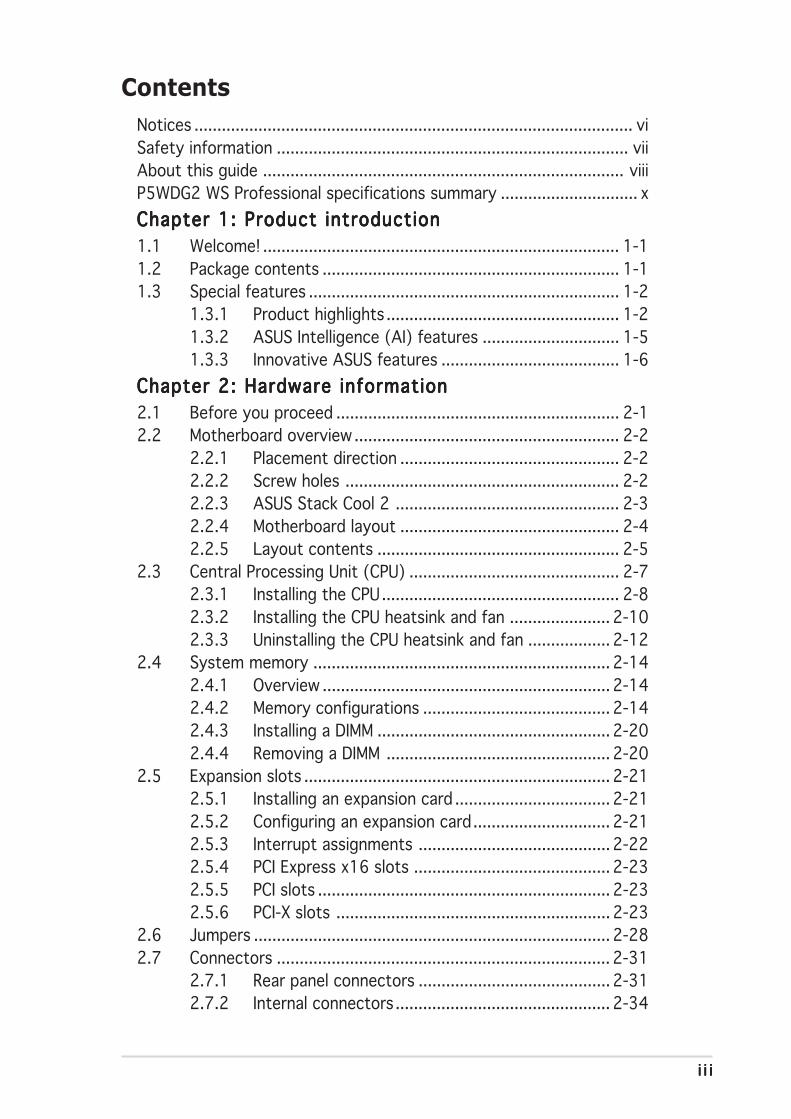
ContentsNotices ................................................................................................ viSafety information ............................................................................. viiAbout this guide ............................................................................... viiiP5WDG2 WS Professional specifications summary .............................. xChapter 1: Product introductionChapter 1: Product introductionChapter 1: Product introductionChapter 1: Product introductionChapter 1: Product introduction1.1 Welcome! .............................................................................. 1-11.2 Package contents ................................................................. 1-11.3 Special features .................................................................... 1-2
1.3.1 Product highlights ................................................... 1-21.3.2 ASUS Intelligence (AI) features .............................. 1-51.3.3 Innovative ASUS features ....................................... 1-6
Chapter 2: Hardware informationChapter 2: Hardware informationChapter 2: Hardware informationChapter 2: Hardware informationChapter 2: Hardware information2.1 Before you proceed .............................................................. 2-12.2 Motherboard overview .......................................................... 2-2
2.2.1 Placement direction ................................................ 2-22.2.2 Screw holes ............................................................ 2-22.2.3 ASUS Stack Cool 2 ................................................. 2-32.2.4 Motherboard layout ................................................ 2-42.2.5 Layout contents ..................................................... 2-5
2.3 Central Processing Unit (CPU) .............................................. 2-72.3.1 Installing the CPU.................................................... 2-82.3.2 Installing the CPU heatsink and fan ...................... 2-102.3.3 Uninstalling the CPU heatsink and fan .................. 2-12
2.4 System memory ................................................................. 2-142.4.1 Overview ............................................................... 2-142.4.2 Memory configurations ......................................... 2-142.4.3 Installing a DIMM ................................................... 2-202.4.4 Removing a DIMM ................................................. 2-20
2.5 Expansion slots ................................................................... 2-212.5.1 Installing an expansion card .................................. 2-212.5.2 Configuring an expansion card.............................. 2-212.5.3 Interrupt assignments .......................................... 2-222.5.4 PCI Express x16 slots ........................................... 2-232.5.5 PCI slots ................................................................ 2-232.5.6 PCI-X slots ............................................................ 2-23
2.6 Jumpers .............................................................................. 2-282.7 Connectors ......................................................................... 2-31
2.7.1 Rear panel connectors .......................................... 2-312.7.2 Internal connectors............................................... 2-34

i vi vi vi vi v
Contents
Chapter 3: Powering upChapter 3: Powering upChapter 3: Powering upChapter 3: Powering upChapter 3: Powering up3.1 Starting up for the first time ................................................ 3-13.2 Turning off the computer ..................................................... 3-2
3.2.1 Using the OS shut down function ........................... 3-23.2.2 Using the dual function power switch .................... 3-2
Chapter 4: BIOS setupChapter 4: BIOS setupChapter 4: BIOS setupChapter 4: BIOS setupChapter 4: BIOS setup4.1 Managing and updating your BIOS ........................................ 4-1
4.1.1 ASUS Update utility ................................................ 4-14.1.2 Creating a bootable floppy disk .............................. 4-44.1.3 ASUS EZ Flash 2 utility ........................................... 4-54.1.4 AFUDOS utility ........................................................ 4-64.1.5 ASUS CrashFree BIOS 2 utility ................................ 4-9
4.2 BIOS setup program ........................................................... 4-114.2.1 BIOS menu screen ................................................. 4-124.2.2 Menu bar ............................................................... 4-124.2.3 Navigation keys .................................................... 4-124.2.4 Menu items ........................................................... 4-134.2.5 Sub-menu items ................................................... 4-134.2.6 Configuration fields .............................................. 4-134.2.7 Pop-up window ..................................................... 4-134.2.8 Scroll bar .............................................................. 4-134.2.9 General help .......................................................... 4-13
4.3 Main menu .......................................................................... 4-144.3.1 System Time......................................................... 4-144.3.2 System Date ......................................................... 4-144.3.3 Legacy Diskette A ................................................ 4-144.3.4 Language .............................................................. 4-144.3.5 Primary, Third, and Fourth IDE Master/Slave ........ 4-154.3.6 IDE Configuration .................................................. 4-164.3.7 System Information .............................................. 4-18
4.4 Advanced menu .................................................................. 4-194.4.1 JumperFree Configuration .................................... 4-194.4.2 LAN Cable Status ................................................. 4-234.4.3 USB Configuration ................................................. 4-244.4.4 CPU Configuration ................................................. 4-264.4.5 Chipset ................................................................. 4-284.4.6 Onboard Devices Configuration ............................ 4-304.4.7 PCI PnP ................................................................. 4-32

vvvvv
Contents4.5 Power menu ........................................................................ 4-32
4.5.1 Suspend Mode ...................................................... 4-334.5.2 Repost Video on S3 Resume ................................ 4-334.5.3 ACPI 2.0 Support .................................................. 4-334.5.4 ACPI APIC Support ................................................ 4-344.5.5 APM Configuration ................................................ 4-344.5.6 Hardware Monitor ................................................. 4-36
4.6 Boot menu .......................................................................... 4-374.6.1 Boot Device Priority .............................................. 4-384.6.2 Removable Drives ................................................. 4-394.6.3 Boot Settings Configuration ................................. 4-394.6.4 Security ................................................................ 4-41
4.7 Tools ................................................................................... 4-444.7.1 EZ Flash 2 ............................................................. 4-444.7.2 ASUS O.C. Profile .................................................. 4-45
4.8 Exit menu ........................................................................... 4-47Chapter 5: Software supportChapter 5: Software supportChapter 5: Software supportChapter 5: Software supportChapter 5: Software support5.1 Installing an operating system ............................................. 5-15.2 Support CD information ........................................................ 5-1
5.2.1 Running the support CD ......................................... 5-15.2.2 Drivers menu .......................................................... 5-25.2.3 Utilities menu .......................................................... 5-35.2.4 Make Disk menu ...................................................... 5-55.2.5 Manuals menu ......................................................... 5-65.2.6 Contact information ............................................... 5-65.2.7 Other information ................................................... 5-7
5.3 Software information ......................................................... 5-115.3.1 ASUS MyLogo2™ .................................................. 5-115.3.2 AI NET2 ................................................................ 5-135.3.3 AI Gear .................................................................. 5-145.3.4 AI Nap ................................................................... 5-165.3.5 AI Booster ............................................................. 5-175.3.6 ASUS PC Probe II ................................................... 5-185.3.7 SoundMAX® High Definition Audio utility .............. 5-24
5.4 RAID configurations ............................................................ 5-295.4.1 Installing Serial ATA hard disks ............................. 5-305.4.2 Intel® RAID configurations ................................... 5-30
5.5 Creating a RAID driver disk ................................................. 5-41

v iv iv iv iv i
Appendix: CPU featuresAppendix: CPU featuresAppendix: CPU featuresAppendix: CPU featuresAppendix: CPU featuresA.1 Intel® EM64T ........................................................................ A-1A.2 Enhanced Intel SpeedStep® Technology (EIST) .................... A-1A.3 Intel® Hyper-Threading Technology ...................................... A-3
v i iv i iv i iv i iv i i
Notices
Federal Communications Commission StatementFederal Communications Commission StatementFederal Communications Commission StatementFederal Communications Commission StatementFederal Communications Commission Statement
This device complies with Part 15 of the FCC Rules. Operation is subject tothe following two conditions:• This device may not cause harmful interference, and• This device must accept any interference received including interference
that may cause undesired operation.
This equipment has been tested and found to comply with the limits for aClass B digital device, pursuant to Part 15 of the FCC Rules. These limits aredesigned to provide reasonable protection against harmful interference in aresidential installation. This equipment generates, uses and can radiate radiofrequency energy and, if not installed and used in accordance withmanufacturer’s instructions, may cause harmful interference to radiocommunications. However, there is no guarantee that interference will notoccur in a particular installation. If this equipment does cause harmfulinterference to radio or television reception, which can be determined byturning the equipment off and on, the user is encouraged to try to correctthe interference by one or more of the following measures:• Reorient or relocate the receiving antenna.• Increase the separation between the equipment and receiver.• Connect the equipment to an outlet on a circuit different from that to
which the receiver is connected.• Consult the dealer or an experienced radio/TV technician for help.
Canadian Department of Communications StatementCanadian Department of Communications StatementCanadian Department of Communications StatementCanadian Department of Communications StatementCanadian Department of Communications Statement
This digital apparatus does not exceed the Class B limits for radio noiseemissions from digital apparatus set out in the Radio InterferenceRegulations of the Canadian Department of Communications.
This class B digital apparatus complies with CanadianThis class B digital apparatus complies with CanadianThis class B digital apparatus complies with CanadianThis class B digital apparatus complies with CanadianThis class B digital apparatus complies with CanadianICES-003.ICES-003.ICES-003.ICES-003.ICES-003.
The use of shielded cables for connection of the monitor to the graphicscard is required to assure compliance with FCC regulations. Changes ormodifications to this unit not expressly approved by the partyresponsible for compliance could void the user’s authority to operatethis equipment.

v i i iv i i iv i i iv i i iv i i i
Safety information
Electrical safetyElectrical safetyElectrical safetyElectrical safetyElectrical safety• To prevent electrical shock hazard, disconnect the power cable from the
electrical outlet before relocating the system.• When adding or removing devices to or from the system, ensure that the
power cables for the devices are unplugged before the signal cables areconnected. If possible, disconnect all power cables from the existingsystem before you add a device.
• Before connecting or removing signal cables from the motherboard,ensure that all power cables are unplugged.
• Seek professional assistance before using an adpater or extension cord.These devices could interrupt the grounding circuit.
• Make sure that your power supply is set to the correct voltage in yourarea. If you are not sure about the voltage of the electrical outlet you areusing, contact your local power company.
• If the power supply is broken, do not try to fix it by yourself. Contact aqualified service technician or your retailer.
Operation safetyOperation safetyOperation safetyOperation safetyOperation safety• Before installing the motherboard and adding devices on it, carefully read
all the manuals that came with the package.• Before using the product, make sure all cables are correctly connected
and the power cables are not damaged. If you detect any damage,contact your dealer immediately.
• To avoid short circuits, keep paper clips, screws, and staples away fromconnectors, slots, sockets and circuitry.
• Avoid dust, humidity, and temperature extremes. Do not place theproduct in any area where it may become wet.
• Place the product on a stable surface.• If you encounter technical problems with the product, contact a qualified
service technician or your retailer.
The symbol of the crossed out wheeled bin indicates that the product(electrical and electronic equipment) should not be placed in municipalwaste. Please check local regulations for disposal of electronic products.

i xi xi xi xi x
About this guideThis user guide contains the information you need when installing andconfiguring the motherboard.
How this guide is organizedHow this guide is organizedHow this guide is organizedHow this guide is organizedHow this guide is organizedThis user guide contains the following parts:
••••• Chapter 1: Product introduct ionChapter 1: Product introduct ionChapter 1: Product introduct ionChapter 1: Product introduct ionChapter 1: Product introduct ionThis chapter describes the features of the motherboard and the newtechnology it supports.
••••• Chapter 2: Hardware informat ionChapter 2: Hardware informat ionChapter 2: Hardware informat ionChapter 2: Hardware informat ionChapter 2: Hardware informat ionThis chapter lists the hardware setup procedures that you have toperform when installing system components. It includes description ofthe switches, jumpers, and connectors on the motherboard.
••••• Chapter 3: Power ing upChapter 3: Power ing upChapter 3: Power ing upChapter 3: Power ing upChapter 3: Power ing upThis chapter describes the power up sequence and ways of shuttingdown the system.
••••• Chapter 4: B IOS setupChapter 4: B IOS setupChapter 4: B IOS setupChapter 4: B IOS setupChapter 4: B IOS setupThis chapter tells how to change system settings through the BIOSSetup menus. Detailed descriptions of the BIOS parameters are alsoprovided.
••••• Chapter 5: Software supportChapter 5: Software supportChapter 5: Software supportChapter 5: Software supportChapter 5: Software supportThis chapter describes the contents of the support CD that comeswith the motherboard package.
••••• Appendix: CPU featuresAppendix: CPU featuresAppendix: CPU featuresAppendix: CPU featuresAppendix: CPU featuresThe Appendix describes the CPU features and technologies that themotherboard supports.
Where to find more informationWhere to find more informationWhere to find more informationWhere to find more informationWhere to find more informationRefer to the following sources for additional information and for productand software updates.
1 .1 .1 .1 .1 . ASUS webs itesASUS webs itesASUS webs itesASUS webs itesASUS webs itesThe ASUS website provides updated information on ASUS hardwareand software products. Refer to the ASUS contact information.
2 .2 .2 .2 .2 . Opt ional documentat ionOpt ional documentat ionOpt ional documentat ionOpt ional documentat ionOpt ional documentat ionYour product package may include optional documentation, such aswarranty flyers, that may have been added by your dealer. Thesedocuments are not part of the standard package.

xxxxx
Conventions used in this guideConventions used in this guideConventions used in this guideConventions used in this guideConventions used in this guideTo make sure that you perform certain tasks properly, take note of thefollowing symbols used throughout this manual.
DANGER/WARNING: DANGER/WARNING: DANGER/WARNING: DANGER/WARNING: DANGER/WARNING: Information to prevent injury to yourselfwhen trying to complete a task.
CAUTION:CAUTION:CAUTION:CAUTION:CAUTION: Information to prevent damage to the componentswhen trying to complete a task.
NOTE: NOTE: NOTE: NOTE: NOTE: Tips and additional information to help you complete atask.
IMPORTANT: IMPORTANT: IMPORTANT: IMPORTANT: IMPORTANT: Instructions that you MUST follow to complete atask.
TypographyTypographyTypographyTypographyTypographyBold textBo ld textBo ld textBo ld textBo ld text Indicates a menu or an item to select.
Italics Used to emphasize a word or a phrase.
<Key> Keys enclosed in the less-than and greater-thansign means that you must press the enclosed key.
Example: <Enter> means that you must pressthe Enter or Return key.
<Key1+Key2+Key3> If you must press two or more keyssimultaneously, the key names are linked with aplus sign (+).
Example: <Ctrl+Alt+D>
CommandCommandCommandCommandCommand Means that you must type the command exactlyas shown, then supply the required item or valueenclosed in brackets.
Example: At the DOS prompt, type the commandline:
afudos /i[filename]afudos /iWDG2WSP.ROM
x ix ix ix ix i
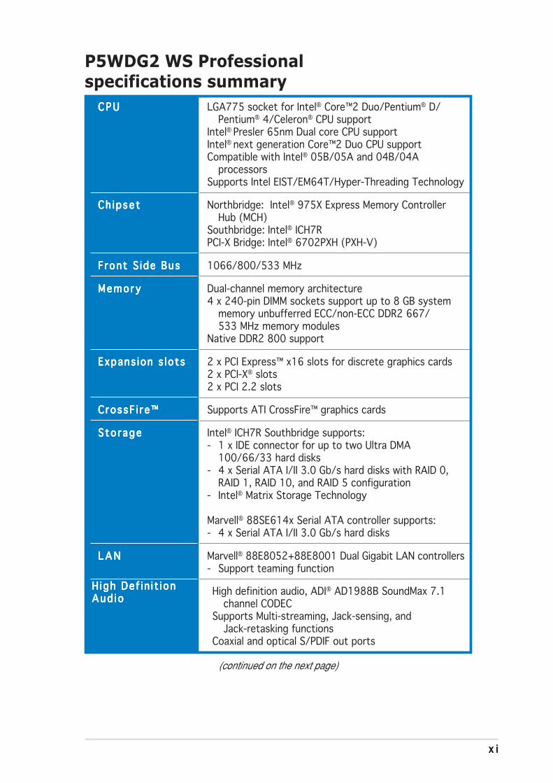
P5WDG2 WS Professionalspecifications summary
(continued on the next page)
C P UC P UC P UC P UC P U
Ch ipsetCh ipsetCh ipsetCh ipsetCh ipset
Front S ide BusFront S ide BusFront S ide BusFront S ide BusFront S ide Bus
MemoryMemoryMemoryMemoryMemory
Expans ion s lotsExpans ion s lotsExpans ion s lotsExpans ion s lotsExpans ion s lots
CrossF i re™CrossF i re™CrossF i re™CrossF i re™CrossF i re™
Sto rageSto rageSto rageSto rageSto rage
L A NL A NL A NL A NL A N
LGA775 socket for Intel® Core™2 Duo/Pentium® D/Pentium® 4/Celeron® CPU support
Intel® Presler 65nm Dual core CPU supportIntel® next generation Core™2 Duo CPU supportCompatible with Intel® 05B/05A and 04B/04A
processorsSupports Intel EIST/EM64T/Hyper-Threading Technology
Northbridge: Intel® 975X Express Memory ControllerHub (MCH)
Southbridge: Intel® ICH7RPCI-X Bridge: Intel® 6702PXH (PXH-V)
1066/800/533 MHz
Dual-channel memory architecture4 x 240-pin DIMM sockets support up to 8 GB system
memory unbufferred ECC/non-ECC DDR2 667/533 MHz memory modules
Native DDR2 800 support
2 x PCI Express™ x16 slots for discrete graphics cards2 x PCI-X® slots2 x PCI 2.2 slots
Supports ATI CrossFire™ graphics cards
Intel® ICH7R Southbridge supports:- 1 x IDE connector for up to two Ultra DMA
100/66/33 hard disks- 4 x Serial ATA I/II 3.0 Gb/s hard disks with RAID 0,
RAID 1, RAID 10, and RAID 5 configuration- Intel® Matrix Storage Technology
Marvell® 88SE614x Serial ATA controller supports:- 4 x Serial ATA I/II 3.0 Gb/s hard disks
Marvell® 88E8052+88E8001 Dual Gigabit LAN controllers- Support teaming function
H igh Def in i t ionH igh Def in i t ionH igh Def in i t ionH igh Def in i t ionH igh Def in i t ionAud i oAud i oAud i oAud i oAud i o High definition audio, ADI® AD1988B SoundMax 7.1
channel CODECSupports Multi-streaming, Jack-sensing, and
Jack-retasking functionsCoaxial and optical S/PDIF out ports

x i ix i ix i ix i ix i i
P5WDG2 WS Professionalspecifications summary
T1 1394a controller supports:- 2 x IEEE 1394a ports
Supports up to 8 USB 2.0 ports
ASUS AI NET2ASUS AI Overclocking (intelligent CPU frequency tuner)ASUS MyLogo2ASUS Q-Fan2ASUS Multi-language BIOSASUS CrashFree BIOS 2ASUS EZ Flash 2ASUS C.P.R. (CPU Parameter Recall)ASUS CPU Lock FreeAI QuietASUS PEG Link 2 (automatic performance tuning for
single/dual graphics cards)Precision TweakerStack Cool 2 patented fanless cooling technology8-Phase Power DesignStepless Frequency Selection (SFS) allows FSB
tuning from 200 MHz up to 450 MHz at 1 MHzincrement
Adjustable CPU, memory, and PCI Express x16 voltage
8 Mb Flash ROM, AMI BIOS, Green PnP, DMI2.0, WfM2.0,ACPI 2.0a, SM BIOS 2.3
WOL by PME, WOR by PME, chassis intrusion, PXE,AI NET2
ATX power supply (with 24-pin and 2 x 4-pin 12 V plugs)ATX 12V 2.0 or later standard compliant
ATX form factor: 12 in x 9.6 in (30.5 cm x 24.5 cm)
IEEE 1394aIEEE 1394aIEEE 1394aIEEE 1394aIEEE 1394a
U S BU S BU S BU S BU S B
ASUS spec ia lASUS spec ia lASUS spec ia lASUS spec ia lASUS spec ia lfeatu resfeatu resfeatu resfeatu resfeatu res
B IOS featuresB IOS featuresB IOS featuresB IOS featuresB IOS features
Manageab i l i tyManageab i l i tyManageab i l i tyManageab i l i tyManageab i l i ty
P o wP o wP o wP o wP o we re re re re rRequirementRequirementRequirementRequirementRequirement
Form FactorForm FactorForm FactorForm FactorForm Factor
(continued on the next page)

x i i ix i i ix i i ix i i ix i i i
P5WDG2 WS Professionalspecifications summary
1 x PS/2 mouse port1 x PS/2 keyboard port1 x Parallel port2 x LAN (RJ-45) ports1 x Coaxial S/PDIF Out port1 x Optical S/PDIF Out port1 x eSATA port4 x USB 2.0 ports (5 x USB ports for optional Wi-Fi
edition)8-Channel audio ports
1 x Floppy disk drive connector1 x Primary IDE connector4 x ICH7R Serial ATA connectors4 x Marvell® 88SE61x Serial ATA RAID connectors1 x Optical drive audio connector1 x Front panel audio connector2 x USB connectors for four additional USB 2.0 ports2 x IEEE 1394a port connector1 x Chassis intrusion connector1 x CPU fan connector2 x Chassis fan connectors1 x Power fan connector1 x Serial port (COM1) connectorEATX power connectors (24-pin and 2 x 4-pin)System panel connector
Device driversBIOS Flash Utility under DOSASUS AI BoosterASUS UpdateASUS PC Probe 2Symantec NIS 2006Microsoft® DirectX 9.0cAdobe® Acrobat Reader®
RAID Utility
*Specifications are subject to change without notice.
Rea r pane lRear pane lRear pane lRear pane lRear pane l
I n te rna lI n te rna lI n te rna lI n te rna lI n te rna lconnectorsconnectorsconnectorsconnectorsconnectors
Support CDSupport CDSupport CDSupport CDSupport CDcontentscontentscontentscontentscontents

x i vx i vx i vx i vx i v
1Productintroduction
This chapter describes the motherboardfeatures and the new technologiesit supports.
ASUS P5WDG2 WS Profess iona lASUS P5WDG2 WS Profess iona lASUS P5WDG2 WS Profess iona lASUS P5WDG2 WS Profess iona lASUS P5WDG2 WS Profess iona l
Chapter summary 11.1 Welcome! .............................................................................. 1-11.2 Package contents ................................................................. 1-11.3 Special features .................................................................... 1-2

ASUS P5WDG2 WS Profess iona lASUS P5WDG2 WS Profess iona lASUS P5WDG2 WS Profess iona lASUS P5WDG2 WS Profess iona lASUS P5WDG2 WS Profess iona l 1 - 11 - 11 - 11 - 11 - 1
1.1 Welcome!Thank you for buying an ASUSThank you for buying an ASUSThank you for buying an ASUSThank you for buying an ASUSThank you for buying an ASUS®®®®® P5WDG2 WS Profess ionalP5WDG2 WS Profess ionalP5WDG2 WS Profess ionalP5WDG2 WS Profess ionalP5WDG2 WS Profess ionalWorkstat ion Workstat ion Workstat ion Workstat ion Workstat ion motherboard!motherboard!motherboard!motherboard!motherboard!
The motherboard delivers a host of new features and latest technologies,making it another standout in the long line of ASUS quality motherboards!
Before you start installing the motherboard, and hardware devices on it,check the items in your package with the list below.
1.2 Package contentsCheck your motherboard package for the following items.
MotherboardMotherboardMotherboardMotherboardMotherboard ASUS P5WDG2 WS Professional motherboard
I/O modulesI/O modulesI/O modulesI/O modulesI/O modules 1 x IEEE 1394a module1 x 2-port USB 2.0/GAME module1 x COM1 module
Cab lesCab lesCab lesCab lesCab les 1 x 2-in-1 FDD/ATA/Logo+Pull cable8 x Serial ATA signal cables4 x Serial ATA power cables for up to 8 devices
Accessor iesAccessor iesAccessor iesAccessor iesAccessor ies I/O shield1 x Wi-Fi antenna (optional)
Appl icat ion CDAppl icat ion CDAppl icat ion CDAppl icat ion CDAppl icat ion CD ASUS motherboard support CDDocumentat ionDocumentat ionDocumentat ionDocumentat ionDocumentat ion User guide
If any of the above items is damaged or missing, contact your retailer.

1 - 21 - 21 - 21 - 21 - 2 Chapter 1 : Product int roduct ionChapter 1 : Product int roduct ionChapter 1 : Product int roduct ionChapter 1 : Product int roduct ionChapter 1 : Product int roduct ion
1.3 Special features
1.3.11.3.11.3.11.3.11.3.1 Product highlightsProduct highlightsProduct highlightsProduct highlightsProduct highlights
Latest processor technology Latest processor technology Latest processor technology Latest processor technology Latest processor technology
The motherboard comes with a 775-pin surface mount Land Grid Array(LGA) socket designed for the Intel® Pentium® 4/Celeron®/Pentium® D/Pentium® Processor Extreme Edition in the 775-land package with 1066/800/533 MHz Front Side Bus (FSB). The motherboard also supports theIntel® Hyper-Threading Technology and is fully compatible with Intel® 05B/05A and 04B/04A processors. See page 2-7 for details.
IntelIntelIntelIntelIntel®®®®® 65nm Dual-Core CPU support 65nm Dual-Core CPU support 65nm Dual-Core CPU support 65nm Dual-Core CPU support 65nm Dual-Core CPU support
This motherboard supports Intel® Pentium® D/Pentium® 4/Celeron®
dual-core processors built on the 65-nanometer (nm) process technologywith copper interconnect. Dual-core processors contain two physicalCPU cores with dedicated L2 caches to meet demands for more powerfulprocessing. Intel®’s 65nm process is the most advanced chip manufacturingtechnology, delivering breakthrough performance, enhanced mediaexperience, and low power consumption. Intel® 65nm dual-core processorsutilize the latest package technologies for a thinner, lighter design withoutcompromising performance. This motherboard also supports Intel® nextgeneration Core™2 Duo CPU. This motherboard supports the latest Intel®Core™2 processors in LGA775 package. With new Intel® Core™microarchitecture technology and 1066/800 MHz FSB, Intel® Core™2processor is one of the most powerful and enrgy-efficient CPUs in theworld.
IntelIntelIntelIntelIntel® 975X Express/ICH7R chipset 975X Express/ICH7R chipset 975X Express/ICH7R chipset 975X Express/ICH7R chipset 975X Express/ICH7R chipsetThe Intel® 975X Express Memory Controller Hub (MCH) and the ICH7R I/Ocontroller hub provide the vital interfaces for the motherboard. The Intel®975X Express is the latest chipset designed to support Dual PCI Expressgraphics, along with the maximum 8 GB dual-channel DDR2 800/667/533MHz, 1066/800/533 FSB, and dual-core CPU. The MCH also supports theIntel® Memory Pipeline Technology (MPT) that boosts system performance.
The Intel® ICH7R Southbridge integrates four Serial ATA I/II connectorsenabled through the Serial ATA 3 Gb/s RAID controller to ensure datasecurity and enable powerful multi-task processing.

ASUS P5WDG2 WS Profess iona lASUS P5WDG2 WS Profess iona lASUS P5WDG2 WS Profess iona lASUS P5WDG2 WS Profess iona lASUS P5WDG2 WS Profess iona l 1 - 31 - 31 - 31 - 31 - 3
Enhanced Intel SpeedStepEnhanced Intel SpeedStepEnhanced Intel SpeedStepEnhanced Intel SpeedStepEnhanced Intel SpeedStep® Technology (EIST) Technology (EIST) Technology (EIST) Technology (EIST) Technology (EIST)The Enhanced Intel SpeedStep® Technology (EIST) intelligently managesthe CPU resources by automatically adjusting the CPU voltage and corefrequency depending on the CPU loading and system speed or powerrequirement. See page 4-26 and the Appendix for details.
DDR2 memory support DDR2 memory support DDR2 memory support DDR2 memory support DDR2 memory support
The motherboard supports DDR2 memory, which features data transferrates of 800/667/533 MHz to meet the higher bandwidth requirements ofthe latest 3D graphics, multimedia, and Internet applications. Thedual-channel DDR2 architecture doubles the bandwidth of your systemmemory to boost system performance, eliminating bottlenecks with peakbandwidths of up to 10.7 GB/s. See page 2-14 for details.
PCI-XPCI-XPCI-XPCI-XPCI-X®®®®® interface interface interface interface interface
The motherboard supports PCI-X, the new and improved version of theprevious PCI standard. PCI-X offers faster data transfers and enhanced systemreliability with ECC automatic single-bit error recovery and double-bit errordetection. PCI-X, which is backward-compatible with PCI-based hardware andsoftware, enables users to keep pace with upcoming advances inhigh-bandwidth, business-critical applications such as Fiber Channel, RAID,InfiniBrand™ Architecture, and iSCSI. See page 2-23 for details.
IntelIntelIntelIntelIntel®®®®® EM64T EM64T EM64T EM64T EM64T The motherboard supports Intel® Pentium® 4 CPUs with the Intel® EM64T(Extended Memory 64 Technology). The Intel® EM64T feature allows yourcomputer to run on 64-bit operating systems and access larger amounts ofsystem memory for faster and more efficient computing. See the Appendixfor details.
IntelIntelIntelIntelIntel®®®®® Memory Pipeline Technology (MPT) Memory Pipeline Technology (MPT) Memory Pipeline Technology (MPT) Memory Pipeline Technology (MPT) Memory Pipeline Technology (MPT)
The Intel® MPT increases system-level and standard operating performanceby optimizing memory access between CPU and system memory.

1 - 41 - 41 - 41 - 41 - 4 Chapter 1 : Product int roduct ionChapter 1 : Product int roduct ionChapter 1 : Product int roduct ionChapter 1 : Product int roduct ionChapter 1 : Product int roduct ion
8-channel high definition audio 8-channel high definition audio 8-channel high definition audio 8-channel high definition audio 8-channel high definition audio
Onboard is the ADI AD1988B High Definition Audio 8-channel audio CODEC.This CODEC is fully-compliant with Intel® High Definition Audio standard(192 KHz, 24-bit audio). With the CODEC, 8-channel audio ports, and S/PDIF interfaces, you can connect your computer to home theater decodersto produce crystal-clear digital audio.
IEEE 1394a support IEEE 1394a support IEEE 1394a support IEEE 1394a support IEEE 1394a support The motherboard supports the IEEE 1394a interface that provideshigh-speed and flexible PC connectivity to a wide range of peripherals anddevices compliant to IEEE 1394a standards. The IEEE 1394a interfaceallows up to 400 Mbps transfer rates through simple , low-cost,high-bandwidth asynchronous (real-time) data interfacing betweencomputers, peripherals, and consumer electronic devices such ascamcorders, VCRs, printers, TVs, and digital cameras. See pages 2-33 and2-38 for details.
S/PDIF digital sound ready S/PDIF digital sound ready S/PDIF digital sound ready S/PDIF digital sound ready S/PDIF digital sound ready The motherboard supports the S/PDIF technology through the S/PDIFinterfaces on the rear panel. The S/PDIF technology turns your computer intoa high-end entertainment system with digital connectivity to powerful audioand speaker systems. See page 2-33 for details.
PCI Express™ interface PCI Express™ interface PCI Express™ interface PCI Express™ interface PCI Express™ interface
The motherboard fully supports PCI Express, the latest I/O interconnecttechnology that speeds up the PCI bus. PCI Express features point-to-pointserial interconnections between devices and allows higher clockspeeds bycarrying data in packets. This high speed interface is software compatible withexisting PCI specifications. See page 2-23 for details.
USB 2.0 technology USB 2.0 technology USB 2.0 technology USB 2.0 technology USB 2.0 technology The motherboard implements the Universal Serial Bus (USB) 2.0specification, dramatically increasing the connection speed from the12 Mbps bandwidth on USB 1.1 to a fast 480 Mbps on USB 2.0. USB 2.0 isbackward compatible with USB 1.1. See pages 2-33 and 2-38 for details.

ASUS P5WDG2 WS Profess iona lASUS P5WDG2 WS Profess iona lASUS P5WDG2 WS Profess iona lASUS P5WDG2 WS Profess iona lASUS P5WDG2 WS Profess iona l 1 - 51 - 51 - 51 - 51 - 5
Dual Gigabit LAN solution Dual Gigabit LAN solution Dual Gigabit LAN solution Dual Gigabit LAN solution Dual Gigabit LAN solution
The motherboard comes with dual Gigabit LAN controllers to provide thetotal solution for your networking needs. These network controllers use thePCI Express segment to provide faster data bandwidth for your wired orwireless Internet, LAN, and file sharing requirements. See page 2-32 fordetails.
1.3.21.3.21.3.21.3.21.3.2 ASUS Intelligence (AI) featuresASUS Intelligence (AI) featuresASUS Intelligence (AI) featuresASUS Intelligence (AI) featuresASUS Intelligence (AI) features
Serial ATA I/II technology Serial ATA I/II technology Serial ATA I/II technology Serial ATA I/II technology Serial ATA I/II technology
The motherboard supports the Serial ATA 3 Gb/s technology through theSerial ATA interfaces and the Intel® 975X Express MCH chipset. The SerialATA 3 Gb/s specification provides twice the bandwidth of the current SerialATA products with a host of new features, including Native CommandQueuing (NCQ), Power Management (PM) Implementation Algorithm, and HotSwap. Serial ATA allows thinner, more flexible cables with lower pin countand reduced voltage requirements. See pages 2-35 and 2-36 for details.
ASUS Stack Cool 2 ASUS Stack Cool 2 ASUS Stack Cool 2 ASUS Stack Cool 2 ASUS Stack Cool 2 ASUS Stack Cool 2 is a fan-less and zero-noise cooling solution that lowersthe temperature of critical heat generating components by 20ºC. Themotherboard uses a special design on the printed circuit board (PCB) todissipate heat that critical components generate. See page 2-3 for details.
Trusted Platform Module (TPM)Trusted Platform Module (TPM)Trusted Platform Module (TPM)Trusted Platform Module (TPM)Trusted Platform Module (TPM) [optional] [optional] [optional] [optional] [optional]The Trusted Platform Module (TPM) is a secure microcontroller hardwarecomponent with embedded software. The motherboard implements theoptional module to provide the first link in the chain of trust, providingconvenient single sign-on to systems and enable digital signatures forsecure transactions.See page 2-43 for details.
AI Quiet AI Quiet AI Quiet AI Quiet AI Quiet
The ASUS AI Quiet function dynamically controls CPU speed and reducestemperature and fan speeds, thus minimizing noise and ensuring quietoperation. See page 4-35 for details.

1 - 61 - 61 - 61 - 61 - 6 Chapter 1 : Product int roduct ionChapter 1 : Product int roduct ionChapter 1 : Product int roduct ionChapter 1 : Product int roduct ionChapter 1 : Product int roduct ion
CPU Lock FreeCPU Lock FreeCPU Lock FreeCPU Lock FreeCPU Lock FreeThis feature allows you to adjust the CPU multiplier to 14x. Setting theappropriate BIOS setting automatically reduces the CPU multiplier value formore flexibility when increasing external FSB. See page 4-20 for details.
1.3.31.3.31.3.31.3.31.3.3 Innovative ASUS featuresInnovative ASUS featuresInnovative ASUS featuresInnovative ASUS featuresInnovative ASUS features
Native DDR2-800 memory support Native DDR2-800 memory support Native DDR2-800 memory support Native DDR2-800 memory support Native DDR2-800 memory support
Native DDR2-800 eliminates the bottleneck when overclocking both theCPU and the memory, thus maximizing performance for 3D graphics andother system-intensive applications. See pages 2-16 and 4-20 for details.
AI Overclocking AI Overclocking AI Overclocking AI Overclocking AI Overclocking This feature allows convenient overclocking up to 30 percent (dependingon the installed CPU and DRAM) to enhance system performance while stillmaintaining system stability. See page 4-19 to set the BIOS items foroverclocking.
AI NET2 AI NET2 AI NET2 AI NET2 AI NET2
AI NET2 is a BIOS-based diagnostic tool that detects and reports Ethernetcable faults and shorts. With this utility, you can easily monitor thecondition of the Ethernet cable connected to the LAN (RJ-45) port. Duringthe bootup process, AI NET2 immediately diagnoses the LAN cable andreports shorts and faults up to 100 meters at 1 meter accuracy. See pages4-23 and 5-13 for details.
PEG Link Mode PEG Link Mode PEG Link Mode PEG Link Mode PEG Link Mode
This feature enhances your PCI Express graphics card performance byallowing the motherboard to automatically adjust the PCI Express graphicslink mode to the correct frequency based on the system configuration.Four additional settings are available for overclocking the PEG Link Mode.See page 4-28 for details.
ASUS P5WDG2 WS Profess iona lASUS P5WDG2 WS Profess iona lASUS P5WDG2 WS Profess iona lASUS P5WDG2 WS Profess iona lASUS P5WDG2 WS Profess iona l 1 - 71 - 71 - 71 - 71 - 7
ASUS Q-Fan 2 technology ASUS Q-Fan 2 technology ASUS Q-Fan 2 technology ASUS Q-Fan 2 technology ASUS Q-Fan 2 technology The ASUS Q-Fan 2 technology smartly adjusts the fan speeds according tothe system loading to ensure quiet, cool, and efficient operation.See page 4-35 for details.
ASUS Multi-language BIOS ASUS Multi-language BIOS ASUS Multi-language BIOS ASUS Multi-language BIOS ASUS Multi-language BIOS The multi-language BIOS allows you to select the language of your choicefrom the available options. The localized BIOS menus allow easier and fasterconfiguration. See page 4-14 for details.
ASUS MyLogo2™ ASUS MyLogo2™ ASUS MyLogo2™ ASUS MyLogo2™ ASUS MyLogo2™ This new feature present in the motherboard allows you to personalize andadd style to your system with customizable boot logos. See pages 4-38and 5-11 for details.
ASUS CrashFree BIOS 2 ASUS CrashFree BIOS 2 ASUS CrashFree BIOS 2 ASUS CrashFree BIOS 2 ASUS CrashFree BIOS 2 This feature allows you to restore the original BIOS data from the support CDin case when the BIOS codes and data are corrupted. This protectioneliminates the need to buy a replacement ROM chip. See page 4-9 for details.
ASUS EZ Flash 2 BIOS ASUS EZ Flash 2 BIOS ASUS EZ Flash 2 BIOS ASUS EZ Flash 2 BIOS ASUS EZ Flash 2 BIOS
With the ASUS EZ Flash 2, you can easily update the system BIOS evenbefore loading the operating system. No need to use a DOS-based utility orboot from a floppy disk. See page 4-5 for details.

1 - 81 - 81 - 81 - 81 - 8 Chapter 1 : Product int roduct ionChapter 1 : Product int roduct ionChapter 1 : Product int roduct ionChapter 1 : Product int roduct ionChapter 1 : Product int roduct ion

2Hardwareinformation
This chapter lists the hardware setupprocedures that you have to performwhen installing system components. Itincludes description of the jumpers andconnectors on the motherboard.

ASUS P5WDG2 WS Profess iona lASUS P5WDG2 WS Profess iona lASUS P5WDG2 WS Profess iona lASUS P5WDG2 WS Profess iona lASUS P5WDG2 WS Profess iona l
Chapter summary 22.1 Before you proceed .............................................................. 2-12.2 Motherboard overview .......................................................... 2-22.3 Central Processing Unit (CPU) .............................................. 2-72.4 System memory ................................................................. 2-142.5 Expansion slots ................................................................... 2-212.6 Jumpers .............................................................................. 2-282.7 Connectors ......................................................................... 2-30

ASUS P5WDG2 WS Profess iona lASUS P5WDG2 WS Profess iona lASUS P5WDG2 WS Profess iona lASUS P5WDG2 WS Profess iona lASUS P5WDG2 WS Profess iona l 2 - 12 - 12 - 12 - 12 - 1
Onboard LEDOnboard LEDOnboard LEDOnboard LEDOnboard LEDThe motherboard comes with a standby power LED. The green LED lightsup to indicate that the system is ON, in sleep mode, or in soft-off mode.This is a reminder that you should shut down the system and unplug thepower cable before removing or plugging in any motherboard component.The illustration below shows the location of the onboard LED.
2.1 Before you proceedTake note of the following precautions before you install motherboardcomponents or change any motherboard settings.
• Unplug the power cord from the wall socket before touching anycomponent.
• Use a grounded wrist strap or touch a safely grounded object ora metal object, such as the power supply case, before handlingcomponents to avoid damaging them due to static electricity.
• Hold components by the edges to avoid touching the ICs on them.
• Whenever you uninstall any component, place it on a groundedantistatic pad or in the bag that came with the component.
• Before you insta l l o r remove any component , ensureBefore you insta l l o r remove any component , ensureBefore you insta l l o r remove any component , ensureBefore you insta l l o r remove any component , ensureBefore you insta l l o r remove any component , ensurethat the ATX power supp ly i s sw itched of f or thethat the ATX power supp ly i s sw itched of f or thethat the ATX power supp ly i s sw itched of f or thethat the ATX power supp ly i s sw itched of f or thethat the ATX power supp ly i s sw itched of f or thepower cord i s detached f rom the power supp ly . power cord i s detached f rom the power supp ly . power cord i s detached f rom the power supp ly . power cord i s detached f rom the power supp ly . power cord i s detached f rom the power supp ly . Failureto do so may cause severe damage to the motherboard, peripherals,and/or components.
P5W
DG
2-W
S P
RO
®
P5WDG2-WS PRO Onboard LED
SB_PWR
ONStandbyPower
OFFPowered
Off

2 - 22 - 22 - 22 - 22 - 2 Chapter 2 : Hardware in format ionChapter 2 : Hardware in format ionChapter 2 : Hardware in format ionChapter 2 : Hardware in format ionChapter 2 : Hardware in format ion
P5W
DG
2-W
S P
RO
®
2.2 Motherboard overviewBefore you install the motherboard, study the configuration of your chassisto ensure that the motherboard fits into it.
Make sure to unplug the power cord before installing or removing themotherboard. Failure to do so can cause you physical injury and damagemotherboard components.
Do not overtighten the screws! Doing so can damage the motherboard.
2.2.12.2.12.2.12.2.12.2.1 Placement directionPlacement directionPlacement directionPlacement directionPlacement directionWhen installing the motherboard, make sure that you place it into thechassis in the correct orientation. The edge with external ports goes to therear part of the chassis as indicated in the image below.
P l ace th i s s i de towa rdsP l ace th i s s i de towa rdsP l ace th i s s i de towa rdsP l ace th i s s i de towa rdsP l ace th i s s i de towa rdsthe r ea r o f the chass i sthe r ea r o f the chass i sthe r ea r o f the chass i sthe r ea r o f the chass i sthe r ea r o f the chass i s
2.2.22.2.22.2.22.2.22.2.2 Screw holesScrew holesScrew holesScrew holesScrew holesPlace nine (9) screws into the holes indicated by circles to secure themotherboard to the chassis.

ASUS P5WDG2 WS Profess iona lASUS P5WDG2 WS Profess iona lASUS P5WDG2 WS Profess iona lASUS P5WDG2 WS Profess iona lASUS P5WDG2 WS Profess iona l 2 - 32 - 32 - 32 - 32 - 3
2.2.32.2.32.2.32.2.32.2.3 ASUS Stack Cool 2ASUS Stack Cool 2ASUS Stack Cool 2ASUS Stack Cool 2ASUS Stack Cool 2The motherboard comes with the ASUS Stack Cool 2 cooling solution thatlowers the temperature of critical heat generating components by 20ºC.The motherboard uses a special design on the printed circuit board (PCB)to dissipate heat that critical components generate.

2 - 42 - 42 - 42 - 42 - 4 Chapter 2 : Hardware in format ionChapter 2 : Hardware in format ionChapter 2 : Hardware in format ionChapter 2 : Hardware in format ionChapter 2 : Hardware in format ion
2.2.42.2.42.2.42.2.42.2.4 Motherboard layoutMotherboard layoutMotherboard layoutMotherboard layoutMotherboard layout
The Wireless LAN module and the USB port on the module are optionalitems and are grayed out in the above illustration.
PANEL
P5W
DG
2-W
S P
RO
®
AAFP
CHASSIS
24.5cm (9.6in)
30.5
cm (
12.0
in)
CPU_FAN
DD
R2
DIM
M_B
1 (6
4 bi
t,240
-pin
mod
ule)
DD
R2
DIM
M_A
1 (6
4 bi
t,240
-pin
mod
ule)
DD
R2
DIM
M_A
2 (6
4 bi
t,240
-pin
mod
ule)
DD
R2
DIM
M_B
2 (6
4 bi
t,184
-pin
mod
ule)
LAN1_USB12
CHA_FAN1
FLO
PP
YS
uper
I/O
8MbBIOS
TSB43AB22A
PS/2KBMST: MouseB: Keyboard
PAR
AL
LE
L P
OR
T
SPDIF_O1
SPDIF_O2
LAN2_USB34
CD
PCIEX16_1
PCIEX16_2
PCI1
PCI2 CLRTC
USB56
SATA1
ES
ATA
SB_PWR
EAT
XP
WR
PR
I_ID
E
CR2032 3VLithium Cell
CMOS Power
CHA_FAN2
AUDIO
Mar
vell®
88E8
001
COM1
EATX12V
LGA775
Intel®975XMCH
IE1394_1
PWR_FAN
USB78
PCIX_1
PCIX_2 SATA3
SATA2
SATA4
EXT_SATA3
Marvell®
88SE614x
Intel®ICH7R
Intel®6702PXH(PXH-V) PCIX_SPEED
TPM
EXT_SATA2 EXT_SATA1IE1394_2
AD1988B
Marvell®
88E8052

ASUS P5WDG2 WS Profess iona lASUS P5WDG2 WS Profess iona lASUS P5WDG2 WS Profess iona lASUS P5WDG2 WS Profess iona lASUS P5WDG2 WS Profess iona l 2 - 52 - 52 - 52 - 52 - 5
2.2.52.2.52.2.52.2.52.2.5 Layout contentsLayout contentsLayout contentsLayout contentsLayout contents
S l o t sS l o t sS l o t sS l o t sS l o t s P a g eP a g eP a g eP a g eP a g e
1. DDR2 DIMM slots 2-142. PCI Express x16 slots 2-233. PCI slots 2-234. PCI -X slots 2-23
J u m p e rJ u m p e rJ u m p e rJ u m p e rJ u m p e r P a g eP a g eP a g eP a g eP a g e
1. Clear RTC RAM (3-pin CLRTC) 2-282. PCIX speed setting (6-pin PCIX_SPEED) 2-29
Rea r pane l connec to r sRea r pane l connec to r sRea r pane l connec to r sRea r pane l connec to r sRea r pane l connec to r s P a g eP a g eP a g eP a g eP a g e
1. PS/2 mouse port (green) 2-302. Parallel port 2-303. LAN1 (RJ-45) port 2-304. LAN2 (RJ-45) port 2-305. Rear Speaker Out port (black) 2-316. Center/Subwoofer port (orange) 2-317. Line In port (light blue) 2-318. Line Out port (lime) 2-319. Microphone port (pink) 2-31
10. Side Speaker Out port (gray) 2-3111. USB 2.0 ports 3 and 4 2-3112. USB 2.0 ports 1 and 2 2-3113. External ATA port 2-3214. Optical S/PDIF Out port 2-3215. Coaxial S/PDIF Out port 2-3216. PS/2 keyboard port (purple) 2-32

2 - 62 - 62 - 62 - 62 - 6 Chapter 2 : Hardware in format ionChapter 2 : Hardware in format ionChapter 2 : Hardware in format ionChapter 2 : Hardware in format ionChapter 2 : Hardware in format ion
In te rna l connec to r sI n te rna l connec to r sI n te rna l connec to r sI n te rna l connec to r sI n te rna l connec to r s P a g eP a g eP a g eP a g eP a g e
1. Floppy disk drive connector (34-1 pin FLOPPY) 2-332. Primary IDE connector (40-1 pin PRI_IDE) 2-333. ICH7R Serial ATA connectors (7-pin SATA1 [red], 2-34
SATA2 [red], SATA3 [black], SATA4 [black])4. Marvell® 88SE614x Serial ATA connectors 2-35
(7-pin EXT_SATA1, EXT_SATA2, EXT_SATA3)5. Optical drive audio connector (4-pin CD) 2-366. Front panel audio connector (10-1 pin AAFP) 2-367. USB connectors (10-1 pin USB56, USB78 [optional]) 2-378. IEEE 1394a port connectors (10-1 pin IE1394_1[Red];
10-1 pin IE1394_2 [Red]) 2-379. Chassis intrusion connector (4-1 pin CHASSIS) 2-3810. CPU, Chassis, and Power Fan connectors (4-pin CPU_FAN, 2-39
3-pin PWR_FAN, 3-pin CHA_FAN1, 3-pin CHA_FAN2)11. Serial port connector (10-1 pin COM1) 2-4012. ATX power connectors (24-pin EATXPWR, 2x4-pin EATX12V) 2-4013. TPM connector (20-1 pin TPM) 2-4214. System panel connector (12-pin PANEL) 2-43
• System power LED• Hard disk drive activity LED• System warning speaker• ATX power button/soft-off button• Reset button
ASUS P5WDG2 WS Profess iona lASUS P5WDG2 WS Profess iona lASUS P5WDG2 WS Profess iona lASUS P5WDG2 WS Profess iona lASUS P5WDG2 WS Profess iona l 2 - 72 - 72 - 72 - 72 - 7
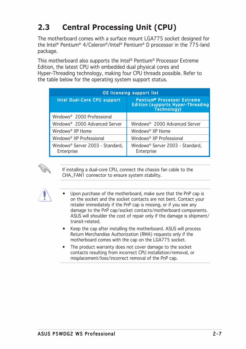
2.3 Central Processing Unit (CPU)The motherboard comes with a surface mount LGA775 socket designed forthe Intel® Pentium® 4/Celeron®/Intel® Pentium® D processor in the 775-landpackage.
This motherboard also supports the Intel® Pentium® Processor ExtremeEdition, the latest CPU with embedded dual physical cores andHyper-Threading technology, making four CPU threads possible. Refer tothe table below for the operating system support status.
• Upon purchase of the motherboard, make sure that the PnP cap ison the socket and the socket contacts are not bent. Contact yourretailer immediately if the PnP cap is missing, or if you see anydamage to the PnP cap/socket contacts/motherboard components.ASUS will shoulder the cost of repair only if the damage is shipment/transit-related.
• Keep the cap after installing the motherboard. ASUS will processReturn Merchandise Authorization (RMA) requests only if themotherboard comes with the cap on the LGA775 socket.
• The product warranty does not cover damage to the socketcontacts resulting from incorrect CPU installation/removal, ormisplacement/loss/incorrect removal of the PnP cap.
OS l i cens i ng suppo r t l i s tOS l i cens i ng suppo r t l i s tOS l i cens i ng suppo r t l i s tOS l i cens i ng suppo r t l i s tOS l i cens i ng suppo r t l i s tI n te l Dua l -Co re CPU suppo r tI n te l Dua l -Co re CPU suppo r tI n te l Dua l -Co re CPU suppo r tI n te l Dua l -Co re CPU suppo r tI n te l Dua l -Co re CPU suppo r t P e n t i u mP e n t i u mP e n t i u mP e n t i u mP e n t i u m®®®®® P rocesso r Ex t reme P rocesso r Ex t reme P rocesso r Ex t reme P rocesso r Ex t reme P rocesso r Ex t reme
Ed i t i onEd i t i onEd i t i onEd i t i onEd i t i on (supports Hyper -Thread ing (supports Hyper -Thread ing (supports Hyper -Thread ing (supports Hyper -Thread ing (supports Hyper -Thread ingTechno logyTechno logyTechno logyTechno logyTechno logy)))))
Windows® 2000 ProfessionalWindows® 2000 Advanced Server Windows® 2000 Advanced ServerWindows® XP Home Windows® XP HomeWindows® XP Professional Windows® XP ProfessionalWindows® Server 2003 - Standard, Windows® Server 2003 - Standard,
Enterprise Enterprise
If installing a dual-core CPU, connect the chassis fan cable to theCHA_FAN1 connector to ensure system stability.

2 - 82 - 82 - 82 - 82 - 8 Chapter 2 : Hardware in format ionChapter 2 : Hardware in format ionChapter 2 : Hardware in format ionChapter 2 : Hardware in format ionChapter 2 : Hardware in format ion
3. Lift the load lever in thedirection of the arrow to a 135ºangle.
2. Press the load lever with your thumb (A), then move it to the left (B)until it is released from the retention tab.
Re ten t i on t abRe ten t i on t abRe ten t i on t abRe ten t i on t abRe ten t i on t ab
Load l e ve rLoad l e ve rLoad l e ve rLoad l e ve rLoad l e ve r
Th i s s i de o f t heTh i s s i de o f t heTh i s s i de o f t heTh i s s i de o f t heTh i s s i de o f t hesocke t box shou l dsocke t box shou l dsocke t box shou l dsocke t box shou l dsocke t box shou l df a ce you .f a ce you .f a ce you .f a ce you .f a ce you .
P n P c a pP n P c a pP n P c a pP n P c a pP n P c a pA
B
To prevent damage to the socket pins, do not remove the PnP capunless you are installing a CPU.
2.3.12.3.12.3.12.3.12.3.1 Installing the CPUInstalling the CPUInstalling the CPUInstalling the CPUInstalling the CPUTo install a CPU:
1. Locate the CPU socket on the motherboard.
Before installing the CPU, make sure that the socket box is facingtowards you and the load lever is on your left.
P5W
DG
2-W
S P
RO
®
P5WDG2-WS PRO CPU Socket 775

ASUS P5WDG2 WS Profess iona lASUS P5WDG2 WS Profess iona lASUS P5WDG2 WS Profess iona lASUS P5WDG2 WS Profess iona lASUS P5WDG2 WS Profess iona l 2 - 92 - 92 - 92 - 92 - 9
5. Position the CPU overthe socket, making surethat the gold triangle ison the bottom-leftcorner of the socket.The socket alignmentkey should fit into theCPU notch.
A l i gnment keyA l i gnment keyA l i gnment keyA l i gnment keyA l i gnment key
Go ld t r i ang l e ma rkGo ld t r i ang l e ma rkGo ld t r i ang l e ma rkGo ld t r i ang l e ma rkGo ld t r i ang l e ma rk
6. Close the load plate (A), thenpush the load lever (B) untilit snaps into the retentiontab.
7. If installing a dual-core CPU,connect the chassis fan cableto the CHA_FAN1 connectorto ensure system stability.
A
B
The CPU fits in only one correct orientation. DO NOT force the CPU intothe socket to prevent bending the connectors on the socket anddamaging the CPU!
The motherboard supports Intel® Pentium® 4 LGA775 processors withthe Intel® Enhanced Memory 64 Technology (EM64T), Enhanced IntelSpeedStep® Technology (EIST), and Hyper-Threading Technology. Referto the Appendix for more information on these CPU features.
4. Lift the load plate with yourthumb and forefinger to a 100ºangle (A), then push the PnP capfrom the load plate window toremove (B).
Load p l a t eLoad p l a t eLoad p l a t eLoad p l a t eLoad p l a t e
A
B

2 -102 -102 -102 -102 -10 Chapter 2 : Hardware in format ionChapter 2 : Hardware in format ionChapter 2 : Hardware in format ionChapter 2 : Hardware in format ionChapter 2 : Hardware in format ion
Fa s t ene rF a s t ene rF a s t ene rF a s t ene rF a s t ene r
Mothe rboa rd ho l eMothe rboa rd ho l eMothe rboa rd ho l eMothe rboa rd ho l eMothe rboa rd ho l e
2.3.22.3.22.3.22.3.22.3.2 Installing the CPU heatsink and fanInstalling the CPU heatsink and fanInstalling the CPU heatsink and fanInstalling the CPU heatsink and fanInstalling the CPU heatsink and fanThe Intel® Pentium® 4 LGA775 processor requires a specially designedheatsink and fan assembly to ensure optimum thermal condition andperformance.
To install the CPU heatsink and fan:
1. Place the heatsink on top ofthe installed CPU, making surethat the four fasteners matchthe holes on the motherboard.
• When you buy a boxed Intel® Pentium® 4 processor, the packageincludes the CPU fan and heatsink assembly. If you buy a CPUseparately, make sure that you use only Intel®-certifiedmulti-directional heatsink and fan.
• Your Intel® Pentium® 4 LGA775 heatsink and fan assembly comes ina push-pin design and requires no tool to install.
• If you purchased a separate CPU heatsink and fan assembly, makesure that you have properly applied Thermal Interface Material to theCPU heatsink or CPU before you install the heatsink and fanassembly.
Make sure that you have installed the motherboard to the chassis beforeyou install the CPU fan and heatsink assembly.
Make sure to orient each fastener with the narrow end of the groovepointing outward. (The photo shows the groove shaded for emphasis.)
Orient the heatsink and fanassembly such that the CPUfan cable is closest to theCPU fan connector.
Na r r ow endNa r r ow endNa r r ow endNa r r ow endNa r r ow endo f t he g rooveo f t he g rooveo f t he g rooveo f t he g rooveo f t he g roove

ASUS P5WDG2 WS Profess iona lASUS P5WDG2 WS Profess iona lASUS P5WDG2 WS Profess iona lASUS P5WDG2 WS Profess iona lASUS P5WDG2 WS Profess iona l 2 -112 -112 -112 -112 -11
2. Push down two fasteners at atime in a diagonal sequence tosecure the heatsink and fanassembly in place.
B
B
AA
A
A B
B
3. Connect the CPU fan cable to the connector on the motherboardlabeled CPU_FAN.
Do not forget to connect the CPU fan connector! Hardware monitoringerrors can occur if you fail to plug this connector.
P5W
DG
2-W
S P
RO
®
P5WDG2-WS PRO CPU fan connector
GN
DC
PU
FA
N P
WR
CP
U F
AN
INC
PU
FA
N P
WM
CPU_FAN

2 -122 -122 -122 -122 -12 Chapter 2 : Hardware in format ionChapter 2 : Hardware in format ionChapter 2 : Hardware in format ionChapter 2 : Hardware in format ionChapter 2 : Hardware in format ion
2.3.32.3.32.3.32.3.32.3.3 Uninstalling the CPU heatsink and fanUninstalling the CPU heatsink and fanUninstalling the CPU heatsink and fanUninstalling the CPU heatsink and fanUninstalling the CPU heatsink and fanTo uninstall the CPU heatsink and fan:
1. Disconnect the CPU fan cablefrom the connector on themotherboard.
2. Rotate each fastenercounterclockwise.
3. Pull up two fasteners at a timein a diagonal sequence todisengage the heatsink and fanassembly from themotherboard.
B
B
AA
A
A B
B
4. Carefully remove the heatsinkand fan assembly from themotherboard.

ASUS P5WDG2 WS Profess iona lASUS P5WDG2 WS Profess iona lASUS P5WDG2 WS Profess iona lASUS P5WDG2 WS Profess iona lASUS P5WDG2 WS Profess iona l 2 -132 -132 -132 -132 -13
5. Rotate each fastener clockwiseto ensure correct orientationwhen reinstalling.
The narrow end of thegroove should point outwardafter resetting. (The photoshows the groove shaded foremphasis.)
Na r row end o f the g rooveNa r row end o f the g rooveNa r row end o f the g rooveNa r row end o f the g rooveNa r row end o f the g roove
Refer to the documentation in the boxed or stand-alone CPU fanpackage for detailed information on CPU fan installation.
2 -142 -142 -142 -142 -14 Chapter 2 : Hardware in format ionChapter 2 : Hardware in format ionChapter 2 : Hardware in format ionChapter 2 : Hardware in format ionChapter 2 : Hardware in format ion
2.4 System memory
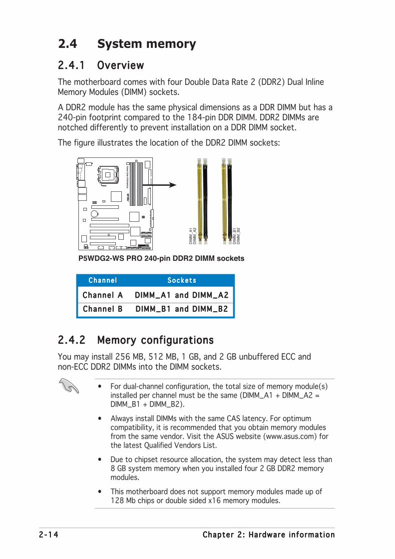
2.4.12.4.12.4.12.4.12.4.1 OverviewOverviewOverviewOverviewOverviewThe motherboard comes with four Double Data Rate 2 (DDR2) Dual InlineMemory Modules (DIMM) sockets.
A DDR2 module has the same physical dimensions as a DDR DIMM but has a240-pin footprint compared to the 184-pin DDR DIMM. DDR2 DIMMs arenotched differently to prevent installation on a DDR DIMM socket.
The figure illustrates the location of the DDR2 DIMM sockets:
• For dual-channel configuration, the total size of memory module(s)installed per channel must be the same (DIMM_A1 + DIMM_A2 =DIMM_B1 + DIMM_B2).
• Always install DIMMs with the same CAS latency. For optimumcompatibility, it is recommended that you obtain memory modulesfrom the same vendor. Visit the ASUS website (www.asus.com) forthe latest Qualified Vendors List.
• Due to chipset resource allocation, the system may detect less than8 GB system memory when you installed four 2 GB DDR2 memorymodules.
• This motherboard does not support memory modules made up of128 Mb chips or double sided x16 memory modules.
Channe lChanne lChanne lChanne lChanne l S o c k e t sS o c k e t sS o c k e t sS o c k e t sS o c k e t s
Channe l AChanne l AChanne l AChanne l AChanne l A D IMM_A1 and D IMM_A2DIMM_A1 and D IMM_A2DIMM_A1 and D IMM_A2DIMM_A1 and D IMM_A2DIMM_A1 and D IMM_A2
Channe l BChanne l BChanne l BChanne l BChanne l B D IMM_B1 and D IMM_B2DIMM_B1 and D IMM_B2DIMM_B1 and D IMM_B2DIMM_B1 and D IMM_B2DIMM_B1 and D IMM_B2
2.4.22.4.22.4.22.4.22.4.2 Memory configurationsMemory configurationsMemory configurationsMemory configurationsMemory configurationsYou may install 256 MB, 512 MB, 1 GB, and 2 GB unbuffered ECC andnon-ECC DDR2 DIMMs into the DIMM sockets.
P5W
DG
2-W
S P
RO
®
P5WDG2-WS PRO 240-pin DDR2 DIMM sockets
DIM
M_A
2D
IMM
_A1
DIM
M_B
2D
IMM
_B1

ASUS P5WDG2 WS Profess iona lASUS P5WDG2 WS Profess iona lASUS P5WDG2 WS Profess iona lASUS P5WDG2 WS Profess iona lASUS P5WDG2 WS Profess iona l 2 -152 -152 -152 -152 -15
• Some old-version DDR2-667 DIMMs may not match Intel®’sOn-Die-Termination (ODT) requirement and will automaticallydowngrade to run at DDR2-533. If this happens, contact yourmemory vendor to check the ODT value.
• Due to chipset limitation, DDR2-667 with CL=4 will be downgradedto run at DDR2-533 by default setting. If you want to operate withlower latency, adjust the memory timing manually.
• Due to chipset limitation, DDR2-533 with CL=3 will be downgradedto run at DDR2-400 by default setting. If you want to operate withlower latency, adjust the memory timing manually.
Important not ice on insta l l i ng WindowsImportant not ice on insta l l i ng WindowsImportant not ice on insta l l i ng WindowsImportant not ice on insta l l i ng WindowsImportant not ice on insta l l i ng Windows®®®®® XP 32-b i t vers ion XP 32-b i t vers ion XP 32-b i t vers ion XP 32-b i t vers ion XP 32-b i t vers ion
If you install Windows® XP 32-bit version Operating System (OS), thelimitation of this OS version is that it may reserve a certain amount ofmemory space for system devices. We recommend that you install lessthan 3 GB system memory if you would like to work under Windows® XP32-bit version OS. The excess memory installation will not cause anyusage problem, but it will not give users the benefit of manipulating thisexcess memory space.
Visit the ASUS FAQ site for further explanation:http://support.asus.com/faq/faq.aspx?SLanguage=en-usUnder Genera l searchGenera l searchGenera l searchGenera l searchGenera l search, make theselections as shown, then clickSea rchSea rchSea rchSea rchSea rch. Click the article titled“4GB memory insta l led but4GB memory insta l led but4GB memory insta l led but4GB memory insta l led but4GB memory insta l led butless memory s ize detectedless memory s ize detectedless memory s ize detectedless memory s ize detectedless memory s ize detected.”
You also may check the URLs below for third party comments on thisissue:http://dlsvr01.asus.com/pub/ASUS/mb/4GB_Rev1.pdfhttp://www.intel.com/support/motherboards/server/sb/cs-016594.htm
Notes on memory l im i tat ionsNotes on memory l im i tat ionsNotes on memory l im i tat ionsNotes on memory l im i tat ionsNotes on memory l im i tat ions
• Due to chipset limitation, this motherboard can only support up to8 GB on the operating systems listed below. You may install amaximum of 2 GB DIMMs on each slot, but only DDR2-533 2 GBdensity modules are available for this configuration.
32-bit 64-bitWindows® 2000 Advanced Windows® Server 2003 Standard
Server x64 EditionWindows® Server 2003 Windows® XP Professional x64
Enterprise Edition EditionWindows® Server 2003
Enterprise x64 Edition
2 -162 -162 -162 -162 -16 Chapter 2 : Hardware in format ionChapter 2 : Hardware in format ionChapter 2 : Hardware in format ionChapter 2 : Hardware in format ionChapter 2 : Hardware in format ion
S i z eS i z eS i z eS i z eS i z e V e n d o rV e n d o rV e n d o rV e n d o rV e n d o r C h i p N o .C h i p N o .C h i p N o .C h i p N o .C h i p N o . B r a n dB r a n dB r a n dB r a n dB r a n d Side(s)Side(s)Side(s)Side(s)Side(s) P a r t N o . P a r t N o . P a r t N o . P a r t N o . P a r t N o . C LC LC LC LC L A A A A A B B B B B C C C C CD IMM supportD IMM supportD IMM supportD IMM supportD IMM support
DDR2-800 MHz capability
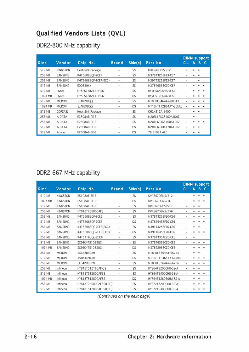
Qualif ied Vendors Lists (QVL)Qualified Vendors Lists (QVL)Qualified Vendors Lists (QVL)Qualified Vendors Lists (QVL)Qualified Vendors Lists (QVL)
(Continued on the next page)
512 MB KINGSTON Heat-Sink Package – SS KHX6400D2/512 – • •256 MB SAMSUNG K4T56083QF-ZCE7 – SS M378T3253FZ3-CE7 – • •256 MB SAMSUNG K4T56083QF-ZCE7(ECC) – SS M391T3253FZ3-CE7 – •512 MB SAMSUNG EDD339XX – SS M378T6553CZ0-CE7 – • • •512 MB Hynix HY5PS12821AFP-S6 – SS HYMP564U64AP8-S6 – • • •1024 MB Hynix HY5PS12821AFP-S6 – DS HYMP512U64AP8-S6 – • • •512 MB MICRON 5JAIIZ9DQQ – SS MT8HTF6464AY-80EA3 – • • •1024 MB MICRON 5JAIIZ9DQQ – DS MT16HTF12864AY-80EA3 – • • •512 MB CORSAIR Heat-Sink Package – SS CM2X512A-6400 – • •256 MB A-DATA E2508AB-GE-E – SS M20EL6F3G3160A1D0Z – •256 MB A-DATA E2508AB-GE-E – SS M2OEL6F3G3160A1D0Z – • • •512 MB A-DATA E2508AB-GE-E – DS M2OEL6F3H4170A1D0Z – • •512 MB Apacer E2508AB-GE-E – DS 78.91091.420 – • •
S i z eS i z eS i z eS i z eS i z e V e n d o rV e n d o rV e n d o rV e n d o rV e n d o r C h i p N o .C h i p N o .C h i p N o .C h i p N o .C h i p N o . B r a n dB r a n dB r a n dB r a n dB r a n d Side(s)Side(s)Side(s)Side(s)Side(s) P a r t N o . P a r t N o . P a r t N o . P a r t N o . P a r t N o . C LC LC LC LC L A A A A A B B B B B C C C C CD IMM supportD IMM supportD IMM supportD IMM supportD IMM support
DDR2-667 MHz capability
512 MB KINGSTON E5108AE-6E-E – SS KVR667D2N5/512 – • • •1024 MB KINGSTON E5108AE-6E-E – DS KVR667D2N5/1G – • • •512 MB KINGSTON E5108AE-6E-E – SS KVR667D2E5/512 – • •256 MB KINGSTON HYB18T256800AF3 – SS KVR667D2N5/256 – • • •256 MB SAMSUNG K4T56083QF-ZCE6 – SS M378T3253FZ0-CE6 – • • •512 MB SAMSUNG K4T56083QF-ZCE6 – DS M378T6453FZ0-CE6 – • • •256 MB SAMSUNG K4T56083QF-ZCE6(ECC) – SS M391T3253FZ0-CE6 – • •512 MB SAMSUNG K4T56083QF-ZCE6(ECC) – DS M391T6453FZ0-CE6 – • • •256 MB SAMSUNG K4T51163QC-ZCE6 – SS M378T3354CZ0-CE6 – •512 MB SAMSUNG ZCE6K4T51083QC – SS M378T6553CZ0-CE6 – • • •1024 MB SAMSUNG ZCE6K4T51083QC – DS M378T2953CZ0-CE6 – • • •256 MB MICRON 4SB42D9CZM – SS MT8HTF3264AY-667B5 – • •512 MB MICRON 4VB41D9CZM – DS MT16HTF6464AY-667B4 – • • •256 MB MICRON 5FB42D9DPN – SS MT8HTF3264AY-667B6 – • • •256 MB Infineon HYB18T512160AF-3S – SS HYS64T32000HU-3S-A – • •512 MB Infineon HYB18T512800AF3S – SS HYS64T64000HU-3S-A – • • •1024 MB Infineon HYB18T512800AF3S – DS HYS64T128020HU-3S-A – • •256 MB Infineon HYB18T256800AF3S(ECC) – SS HYS72T32000HU-3S-A – • • •512 MB Infineon HYB18T512800AF3S(ECC) – SS HYS72T64000HU-3S-A – • • •

ASUS P5WDG2 WS Profess iona lASUS P5WDG2 WS Profess iona lASUS P5WDG2 WS Profess iona lASUS P5WDG2 WS Profess iona lASUS P5WDG2 WS Profess iona l 2 -172 -172 -172 -172 -17
S i z eS i z eS i z eS i z eS i z e V e n d o rV e n d o rV e n d o rV e n d o rV e n d o r C h i p N o .C h i p N o .C h i p N o .C h i p N o .C h i p N o . B r a n dB r a n dB r a n dB r a n dB r a n d Side(s)Side(s)Side(s)Side(s)Side(s) P a r t N o . P a r t N o . P a r t N o . P a r t N o . P a r t N o . C LC LC LC LC L A A A A A B B B B B C C C C CD IMM supportD IMM supportD IMM supportD IMM supportD IMM support
DDR2-667 MHz capability
1024 MB Infineon HYB18T512800AF3S(ECC) – DS HYS72T128020HU-3S-A – • • •512 MB Hynix HY5PS12821AFP-Y5 – SS HYMP564U64AP8-Y5 – • •1024 MB Hynix HY5PS12821AFP-Y5 – DS HYMP512U64AP8-Y5 – • • •1024 MB Hynix HY5PS1G831FP-Y5(ECC) – SS HYMP112U72P8-Y5 – • • •512 MB Hynix HY5PS12821AFP-Y5(ECC) – SS HYMP564U72AP8-Y5 – • • •1024 MB Hynix HY5PS12821AFP-Y5(ECC) – DS HYMP512U72AP8-Y5 – • • •512 MB Hynix HY5PS12821AFP-Y4 – SS HYMP564U64AP8-Y4 – • • •1024 MB Hynix HY5PS12821AFP-Y4 – DS HYMP512U64AP8-Y4 – • •512 MB Hynix HY5PS12821AFP-Y4(ECC) – SS HYMP564U72AP8-Y4 – • • •1024 MB Hynix HY5PS12821AFP-Y4(ECC) – DS HYMP512U72AP8-Y4 – • • •256 MB ELPIDA E2508AB-GE-E – SS EBE25UC8ABFA-6E-E – • • 512 MB ELPIDA E5108AE-GE-E – SS EBE51UD8AEFA-6E-E – •256 MB crucial Heat-Sink Package – SS BL3264AA664.8FB – • • •512 MB crucial Heat-Sink Package – DS BL6464AA664.16FB – • •1024 MB crucial Heat-Sink Package – DS BL12864AA664.16FA – • • •1024 MB crucial Heat-Sink Package – DS BL12864AL664.16FA – •512 MB Kingmax E5108AE-6E-E – SS KLCC28F-A8EB5 – •1024 MB Kingmax E5108AE-6E-E – DS KLCD48F-A8EB5 – • • •512 MB Apacer E5108AE-6E-E – SS 78.91092.420 – • •1024 MB Apacer E5108AE-6E-E – DS 78.01092.420 – • • •512 MB A-DATA E5108AE-6E-E – SS M20EL5G3H3160B1C0Z – • •
S i d e ( s )S i d e ( s )S i d e ( s )S i d e ( s )S i d e ( s ): S SS SS SS SS S - Single-sided D SD SD SD SD S - Double-sided
D IMM suppo r tD IMM suppo r tD IMM suppo r tD IMM suppo r tD IMM suppo r t:AAAAA - Supports one module inserted into either slot, in Single-channel memory configuration.BBBBB - Supports one pair of modules inserted into either Channel A or Channel B as one pair of
Dual-channel memory configuration.CCCCC - Supports four modules inserted into the yellow and black slots as two pairs of
Dual-channel memory configuration.
Visit the ASUS website for the latest DDR2-800/667 MHz QVL.
2 -182 -182 -182 -182 -18 Chapter 2 : Hardware in format ionChapter 2 : Hardware in format ionChapter 2 : Hardware in format ionChapter 2 : Hardware in format ionChapter 2 : Hardware in format ion
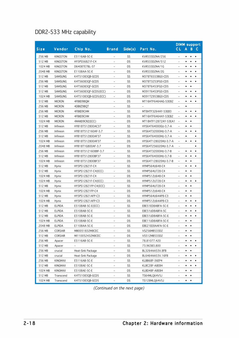
DDR2-533 MHz capability
S i z eS i z eS i z eS i z eS i z e V e n d o rV e n d o rV e n d o rV e n d o rV e n d o r C h i p N o .C h i p N o .C h i p N o .C h i p N o .C h i p N o . B r a n dB r a n dB r a n dB r a n dB r a n d Side(s)Side(s)Side(s)Side(s)Side(s) P a r t N o . P a r t N o . P a r t N o . P a r t N o . P a r t N o . C LC LC LC LC L A A A A A B B B B B C C C C CD IMM supportD IMM supportD IMM supportD IMM supportD IMM support
256 MB KINGSTON E5116AB-5C-E – SS KVR533D2N4/256 – • • •512 MB KINGSTON HY5PS56821F-C4 – DS KVR533D2N4/512 – • • •1024 MB KINGSTON D6408TE7BL-37 – DS KVR533D2N4/1G – • • •2048 MB KINGSTON E1108AA-5C-E – DS KVR533D2N4/2G – • • •512 MB SAMSUNG K4T51083QB-GCD5 – SS M378T6553BG0-CD5 – • • •256 MB SAMSUNG K4T56083QF-GCD5 – SS M378T3253FG0-CD5 – • • •512 MB SAMSUNG K4T56083QF-GCD5 – DS M378T6453FG0-CD5 – • •512 MB SAMSUNG K4T56083QF-GCD5(ECC) – DS M391T6453FG0-CD5 – • • •1024 MB SAMSUNG K4T51083QB-GCD5(ECC) – DS M391T2953BG0-CD5 – • • •512 MB MICRON 4FBIID9BQM – DS MT16HTF6464AG-53EB2 – • • •256 MB MICRON 4DBIIZ9BQT – SS – – •256 MB MICRON 4FBIID9CHM – SS MT8HTF3264AY-53EB3 – • • •512 MB MICRON 4FBIID9CHM – DS MT16HTF6464AY-53EB2 – • • •1024 MB MICRON 4MAIID9CRZ(ECC) – DS MT18HTF12872AY-53EA1 – • •512 MB Infineon HYB18T512800AC37 – SS HYS64T64000GU-3.7-A – • •256 MB Infineon HYB18T512160AF-3.7 – SS HYS64T32000HU-3.7-A – • • •512 MB Infineon HYB18T512800AF37 – SS HYS64T64000HU-3.7-A – • •1024 MB Infineon HYB18T512800AF37 – DS HYS64T128020HU-3.7-A – • • •2048 MB Infineon HYB18T1G800AF-3.7 – DS HYS64T256020HU-3.7-A – •256 MB Infineon HYB18T5121608BF-3.7 – SS HYS64T32000HU-3.7-B – • • •512 MB Infineon HYB18T512800BF37 – SS HYS64T64000HU-3.7-B – • • •1024 MB Infineon HYB18T512800BF37 – DS HYS64T128020HU-3.7-B – • •512 MB Hynix HY5PS12821F-C4 – SS HYMP564U648-C4 – • • •512 MB Hynix HY5PS12821F-C4(ECC) – SS HYMP564U728-C4 – • •1024 MB Hynix HY5PS12821F-C4 – DS HYMP512U648-C4 – • •1024 MB Hynix HY5PS12821F-C4(ECC) – DS HYMP512U728-C4 – • • •512 MB Hynix HY5PS12821FP-C4(ECC) – SS HYMP564U728-C4 – • •1024 MB Hynix HY5PS12821FP-C4 – DS HYMP512U648-C4 – • •512 MB Hynix HY5PS12821AFP-C3 – SS HYMP564U64AP8-C3 – • •1024 MB Hynix HY5PS12821AFP-C3 – DS HYMP512U64AP8-C3 – • • •512 MB ELPIDA E5108AB-5C-E(ECC) – SS EBE51ED8ABFA-5C-E – • • •512 MB ELPIDA E5108AB-5C-E – SS EBE51UD8ABFA-5C – • • •512 MB ELPIDA E5108AB-5C-E – SS EBE51UD8ABFA-5C-E – • • •1024 MB ELPIDA E5108AB-5C-E – DS EBE11UD8ABFA-5C-E – • •2048 MB ELPIDA E1108AA-5C-E – DS EBE21EE8AAFA-5C-E – • •256 MB CORSAIR MIII0051832M8CEC – SS VS256MB533D2 – • •512 MB CORSAIR MI110052432M8CEC – DS VS512MB533D2 – • •256 MB Apacer E5116AB-5C-E – SS 78.81077.420 – • • •512 MB Apacer – – SS 73.963B3.800 – • • •256 MB crucial Heat-Sink Package – SS BL3264AA53V.8FB – • •512 MB crucial Heat-Sink Package – DS BL6464AA53V.16FB – • • •256 MB KINGMAX E5116AB-5C-E – SS KLBB68F-36EP4 – • • •512 MB KINGMAX E5108AE-5C-E – SS KLBC28F-A8EB4 – • • •1024 MB KINGMAX E5108AE-5C-E – DS KLBD48F-A8EB4 – • •512 MB Transcend K4T51083QB-GCD5 – SS TS64MLQ64V5J – • •1024 MB Transcend K4T51083QB-GCD5 – DS TS128MLQ64V5J – • •
(Continued on the next page)

ASUS P5WDG2 WS Profess iona lASUS P5WDG2 WS Profess iona lASUS P5WDG2 WS Profess iona lASUS P5WDG2 WS Profess iona lASUS P5WDG2 WS Profess iona l 2 -192 -192 -192 -192 -19
S i d e ( s )S i d e ( s )S i d e ( s )S i d e ( s )S i d e ( s ): S SS SS SS SS S - Single-sided D SD SD SD SD S - Double-sided
D IMM suppo r tD IMM suppo r tD IMM suppo r tD IMM suppo r tD IMM suppo r t:AAAAA - Supports one module inserted into either slot, in Single-channel memory configuration.BBBBB - Supports one pair of modules inserted into either Channel A or Channel B as one pair of
Dual-channel memory configuration.CCCCC - Supports four modules inserted into the yellow and black slots as two pairs of
Dual-channel memory configuration.
Visit the ASUS website for the latest DDR2-533 MHz QVL.

2 -202 -202 -202 -202 -20 Chapter 2 : Hardware in format ionChapter 2 : Hardware in format ionChapter 2 : Hardware in format ionChapter 2 : Hardware in format ionChapter 2 : Hardware in format ion
2.4.32.4.32.4.32.4.32.4.3 Installing a DIMMInstalling a DIMMInstalling a DIMMInstalling a DIMMInstalling a DIMM
Unplug the power supply before adding or removing DIMMs or othersystem components. Failure to do so can cause severe damage to boththe motherboard and the components.
To install a DIMM:
1. Unlock a DIMM socket bypressing the retaining clipsoutward.
2. Align a DIMM on the socketsuch that the notch on theDIMM matches the break onthe socket.
3. Firmly insert the DIMM into thesocket until the retaining clipssnap back in place and theDIMM is properly seated.
2.4.42.4.42.4.42.4.42.4.4 Removing a DIMMRemoving a DIMMRemoving a DIMMRemoving a DIMMRemoving a DIMMTo remove a DIMM:
1. Simultaneously press the retainingclips outward to unlock the DIMM.
2. Remove the DIMM from the socket.
• A DDR2 DIMM is keyed with a notch so that it fits in only onedirection. Do not force a DIMM into a socket to avoid damaging theDIMM.
• The DDR2 DIMM sockets do not support DDR DIMMs. Do not installDDR DIMMs to the DDR2 DIMM sockets.
Un locked re ta i n i ng c l i pUn locked re ta i n i ng c l i pUn locked re ta i n i ng c l i pUn locked re ta i n i ng c l i pUn locked re ta i n i ng c l i p
DDR2 D IMM no tchDDR2 D IMM no tchDDR2 D IMM no tchDDR2 D IMM no tchDDR2 D IMM no tch
Support the DIMM lightlywith your fingers whenpressing the retainingclips. The DIMM might getdamaged when it flips outwith extra force.
DDR2 D IMM no tchDDR2 D IMM no tchDDR2 D IMM no tchDDR2 D IMM no tchDDR2 D IMM no tch
1
2
3
1
2
1

ASUS P5WDG2 WS Profess iona lASUS P5WDG2 WS Profess iona lASUS P5WDG2 WS Profess iona lASUS P5WDG2 WS Profess iona lASUS P5WDG2 WS Profess iona l 2 -212 -212 -212 -212 -21
2.5 Expansion slotsIn the future, you may need to install expansion cards. The followingsub-sections describe the slots and the expansion cards that they support.
2.5.12.5.12.5.12.5.12.5.1 Installing an expansion cardInstalling an expansion cardInstalling an expansion cardInstalling an expansion cardInstalling an expansion cardTo install an expansion card:
1. Before installing the expansion card, read the documentation thatcame with it and make the necessary hardware settings for the card.
2. Remove the system unit cover (if your motherboard is alreadyinstalled in a chassis).
3. Remove the bracket opposite the slot that you intend to use. Keepthe screw for later use.
4. Align the card connector with the slot and press firmly until the card iscompletely seated on the slot.
5. Secure the card to the chassis with the screw you removed earlier.6. Replace the system cover.
2.5.22.5.22.5.22.5.22.5.2 Configuring an expansion cardConfiguring an expansion cardConfiguring an expansion cardConfiguring an expansion cardConfiguring an expansion cardAfter installing the expansion card, configure the it by adjusting thesoftware settings.
1. Turn on the system and change the necessary BIOS settings, if any.See Chapter 4 for information on BIOS setup.
2. Assign an IRQ to the card. Refer to the tables on the next page.3. Install the software drivers for the expansion card.
Make sure to unplug the power cord before adding or removingexpansion cards. Failure to do so may cause you physical injury anddamage motherboard components.
When using PCI cards on shared slots, ensure that the drivers support“Share IRQ” or that the cards do not need IRQ assignments. Otherwise,conflicts will arise between the two PCI groups, making the systemunstable and the card inoperable. Refer to the table on the next page fordetails.
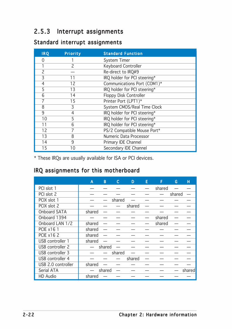
2 -222 -222 -222 -222 -22 Chapter 2 : Hardware in format ionChapter 2 : Hardware in format ionChapter 2 : Hardware in format ionChapter 2 : Hardware in format ionChapter 2 : Hardware in format ion
2.5.32.5.32.5.32.5.32.5.3 Interrupt assignmentsInterrupt assignmentsInterrupt assignmentsInterrupt assignmentsInterrupt assignmentsStandard interrupt assignmentsStandard interrupt assignmentsStandard interrupt assignmentsStandard interrupt assignmentsStandard interrupt assignments
I R QI R QI R QI R QI R Q P r i o r i t yP r i o r i t yP r i o r i t yP r i o r i t yP r i o r i t y S tanda rd Func t i onStanda rd Func t i onStanda rd Func t i onStanda rd Func t i onStanda rd Func t i on
0 1 System Timer1 2 Keyboard Controller2 — Re-direct to IRQ#93 11 IRQ holder for PCI steering*4 12 Communications Port (COM1)*5 13 IRQ holder for PCI steering*6 14 Floppy Disk Controller7 15 Printer Port (LPT1)*8 3 System CMOS/Real Time Clock9 4 IRQ holder for PCI steering*10 5 IRQ holder for PCI steering*11 6 IRQ holder for PCI steering*12 7 PS/2 Compatible Mouse Port*13 8 Numeric Data Processor14 9 Primary IDE Channel15 10 Secondary IDE Channel
* These IRQs are usually available for ISA or PCI devices.
IRQ assignments for this motherboardIRQ assignments for this motherboardIRQ assignments for this motherboardIRQ assignments for this motherboardIRQ assignments for this motherboard
AAAAA BBBBB CCCCC DDDDD EEEEE FFFFF GGGGG HHHHHPCI slot 1 — — — — — shared — —PCI slot 2 — — — — — — shared —PCIX slot 1 — — shared — — — — —PCIX slot 2 — — — shared — — — —Onboard SATA shared — — — — — — —Onboard 1394 — — — — — shared — —Onboard LAN 1/2 shared — — — — shared — —PCIE x16 1 shared — — — — — — —PCIE x16 2 shared — — — — — — —USB controller 1 shared — — — — — — —USB controller 2 — shared — — — — — —USB controller 3 — — shared — — — — —USB controller 4 — — — shared — — — —USB 2.0 controller shared — — — — — — —Serial ATA — shared — — — — — sharedHD Audio shared — — — — — — —

ASUS P5WDG2 WS Profess iona lASUS P5WDG2 WS Profess iona lASUS P5WDG2 WS Profess iona lASUS P5WDG2 WS Profess iona lASUS P5WDG2 WS Profess iona l 2 -232 -232 -232 -232 -23
2.5.42.5.42.5.42.5.42.5.4 PCI Express x16 slotsPCI Express x16 slotsPCI Express x16 slotsPCI Express x16 slotsPCI Express x16 slotsThis motherboard supports two ATICrossFire™ PCI Express x16 graphicscards that comply with the PCIExpress specifications. The figureshows two graphics cards installed onthe PCI Express x16 slots.
Refer to the next page for the list ofqualified PCI Express x16 graphicscards for this motherboard.
• In CrossF i re™ modeIn CrossF i re™ modeIn CrossF i re™ modeIn CrossF i re™ modeIn CrossF i re™ mode, install the master card in PCIEX16_1 (blueslot). Each PCI Express x16 slot works at x8 bandwidth.
• In s ing le card modeIn s ing le card modeIn s ing le card modeIn s ing le card modeIn s ing le card mode, install the VGA card in PCIEX16_1 (blueslot) to avail of full x16 bandwidth. Installing in PCIEX16_2 (blackslot) will cause the card to run at x8 bandwidth only.
• Connect the EZ Plug™ when using two graphics cards and a 20-pinATX power supply, or if the cards do not have auxiliary power plugs.
2.5.52.5.52.5.52.5.52.5.5 PCI slotsPCI slotsPCI slotsPCI slotsPCI slotsThe PCI slots support cards such as aLAN card, SCSI card, USB card, andother cards that comply with PCIspecifications. The figure shows aLAN card installed on a PCI slot.
2.5.62.5.62.5.62.5.62.5.6 PCI-X slotsPCI-X slotsPCI-X slotsPCI-X slotsPCI-X slotsThe PCI-X slots support cards such asa LAN card, SCSI card, USB card, andother cards that comply with PCI-X1.0 specifications. The figure shows aRAID card installed on a PCI-X slot.

2 -242 -242 -242 -242 -24 Chapter 2 : Hardware in format ionChapter 2 : Hardware in format ionChapter 2 : Hardware in format ionChapter 2 : Hardware in format ionChapter 2 : Hardware in format ion
Qualified PCI Express x16 graphics cardsQualified PCI Express x16 graphics cardsQualified PCI Express x16 graphics cardsQualified PCI Express x16 graphics cardsQualified PCI Express x16 graphics cards
Abit RX600XT-PCIE V6.14.10.7801 Windows® 2000 Pro Pass ATI Radeon X600XTRev. B(BIOS: V008.015)Albatron PCX5750 V6.14.10.7801 Windows® XP Pro Pass nVIDIA GeForce PCX5750(BIOS: V4.36.20.38)Albatron PC6200 V6.14.10.7801 Windows® 2000 Pro Pass nVIDIA GeForce 6200BIOS: V5.43.02.27)Albatron PC6600GT V6.14.10.7801 Windows® 2000 Pro Pass nVIDIA GeForce 6600GT(BIOS: V5.43.02.16)ASUS EAX300 V6.14.10.6525 Windows® XP Pro Pass ATI Radeon X300Rev: V1.00(BIOS: V5b60.8.15.117.0)ASUS EAX300SE V8.172.0.0 Windows® XP Pro Pass ATI Radeon X300SERev: V1.00 (Chinese-Traditional)(BIOS: V5b60.8.15.117.0)ASUS EAX300SE-HM128 V6.14.10.6546 Windows® XP Home Pass ATI Radeon X300SERev: V1.00 (Hyper Memory)(BIOS: V008.015.128.000)ASUS EAX300SE-X V6.14.10.6553 Windows® 2003 Standard Pass ATI Radeon X300SERev: V1.00(BIOS: V008.015.117.000)ASUS EAX550GE 256M V6.14.10.6546 Windows® XP Pro Pass ATI Radeon X550(BIOS: V5B60.8.15.139. AS01)ASUS EAX600XT V6.14.10.6546 Windows® XP Pro Pass ATI Radeon X600XTRev. V1.02(BIOS:V113-AA20306-100-AS)ASUS EAX700 V6.14.10.6525 Windows® XP Pro Pass ATI Radeon X700(BIOS: V5E4D.9.7.1.3. A901)ASUS EAX700-X 128M V6.14.10.6546 Windows® XP Pro Pass ATI Radeon X700LERev. V1.00a(BIOS: V009.008.001.004)ASUS EAX700LE 128M V6.14.10.6546 Windows® XP Home Pass ATI Radeon X700LE(BIOS: V5E4D.9.8.1.4. AS13)ASUS EAX700PRO V6.14.10.6546 Windows® XP Pro Pass ATI Radeon X700PRORev. V1.00 (Chinese-Traditional)(BIOS: V113-AA.30602-100)ASUS EAX800 V8.172.0.0 Windows® XP Pro Pass ATI Radeon X800(BIOS: V554F.9.7.1.AS02)ASUS EAX800PRO V8.172.0.0 Windows® 2000 Pro Pass ATI Radeon X800PRORev. V1.00(BIOS: V5549.9.4.1.10.AS)ASUS EAX800XL V8.172.0.0 Windows® XP Pro Pass ATI Radeon X800XLRev. V1.00(BIOS: V554D.9.7.1.AS02)ASUS EAX800XT V6.14.10.6553 Windows® 2003 Standard Pass ATI Radeon X800XTRev. V1.00(BIOS: V5D57.9.4.1.8.AS)ASUS EAX850PRO V8.172.0.0 Windows® XP Pro Pass ATI Radeon X850PRO(BIOS: V5D4F.9.7.1.4.AS02)ASUS EAX850XT 256MB V6.14.10.6553 Windows® 2003 Standard Pass ATI Radeon X850XTRev. PN: 109-A47401-10(BIOS: V009.007.001.004)ASUS EAX850XT PE V6.14.10.6546 Windows® XP Pro Pass ATI Radeon X850XT PERev. PN: 109-A47401-10(BIOS: V009.007.001.004)ASUS EN5750/128 V6.14.10.7801 Windows® 2000 Pro Pass nVIDIA GeForce PCX5750Rev. 1.01(BIOS: V04.32.20.38.00)
(Continued on the next page)
M o d e lM o d e lM o d e lM o d e lM o d e l D r i v e r V e r s i o nD r i v e r V e r s i o nD r i v e r V e r s i o nD r i v e r V e r s i o nD r i v e r V e r s i o n O S E n v i r o n m e n tO S E n v i r o n m e n tO S E n v i r o n m e n tO S E n v i r o n m e n tO S E n v i r o n m e n t S t a t u sS t a t u sS t a t u sS t a t u sS t a t u s C h i p s e tC h i p s e tC h i p s e tC h i p s e tC h i p s e t
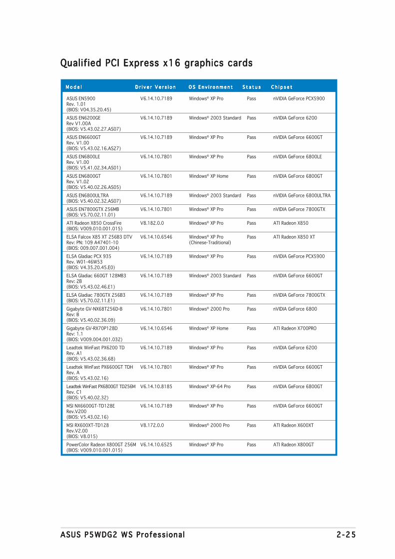
ASUS P5WDG2 WS Profess iona lASUS P5WDG2 WS Profess iona lASUS P5WDG2 WS Profess iona lASUS P5WDG2 WS Profess iona lASUS P5WDG2 WS Profess iona l 2 -252 -252 -252 -252 -25
Qualified PCI Express x16 graphics cardsQualified PCI Express x16 graphics cardsQualified PCI Express x16 graphics cardsQualified PCI Express x16 graphics cardsQualified PCI Express x16 graphics cards
ASUS EN5900 V6.14.10.7189 Windows® XP Pro Pass nVIDIA GeForce PCX5900Rev. 1.01(BIOS: V04.35.20.45)ASUS EN6200GE V6.14.10.7189 Windows® 2003 Standard Pass nVIDIA GeForce 6200Rev V1.00A(BIOS: V5.43.02.27.AS07)ASUS EN6600GT V6.14.10.7189 Windows® XP Pro Pass nVIDIA GeForce 6600GTRev. V1.00(BIOS: V5.43.02.16.AS27)ASUS EN6800LE V6.14.10.7801 Windows® XP Pro Pass nVIDIA GeForce 6800LERev. V1.00(BIOS: V5.41.02.34.AS01)ASUS EN6800GT V6.14.10.7801 Windows® XP Home Pass nVIDIA GeForce 6800GTRev. V1.02(BIOS: V5.40.02.26.AS05)ASUS EN6800ULTRA V6.14.10.7189 Windows® 2003 Standard Pass nVIDIA GeForce 6800ULTRA(BIOS: V5.40.02.32.AS07)ASUS EN7800GTX 256MB V6.14.10.7801 Windows® XP Pro Pass nVIDIA GeForce 7800GTX(BIOS: V5.70.02.11.01)ATI Radeon X850 CrossFire V8.182.0.0 Windows® XP Pro Pass ATI Radeon X850(BIOS: V009.010.001.015)ELSA Falcox X85 XT 256B3 DTV V6.14.10.6546 Windows® XP Pro Pass ATI Radeon X850 XTRev: PN: 109 A47401-10 (Chinese-Traditional)(BIOS: 009.007.001.004)ELSA Gladiac PCX 935 V6.14.10.7189 Windows® XP Pro Pass nVIDIA GeForce PCX5900Rev. W01-46W53(BIOS: V4.35.20.45.E0)ELSA Gladiac 660GT 128MB3 V6.14.10.7189 Windows® 2003 Standard Pass nVIDIA GeForce 6600GTRev: 2B(BIOS: V5.43.02.46.E1)ELSA Gladiac 780GTX 256B3 V6.14.10.7189 Windows® XP Pro Pass nVIDIA GeForce 7800GTX(BIOS: V5.70.02.11.E1)Gigabyte GV-NX68T256D-B V6.14.10.7801 Windows® 2000 Pro Pass nVIDIA GeForce 6800Rev: B(BIOS: V5.40.02.36.09)Gigabyte GV-RX70P128D V6.14.10.6546 Windows® XP Home Pass ATI Radeon X700PRORev: 1.1(BIOS: V009.004.001.032)Leadtek WinFast PX6200 TD V6.14.10.7189 Windows® XP Pro Pass nVIDIA GeForce 6200Rev. A1(BIOS: V5.43.02.36.68)Leadtek WinFast PX6600GT TDH V6.14.10.7801 Windows® XP Pro Pass nVIDIA GeForce 6600GTRev. A(BIOS: V5.43.02.16)Leadtek WinFast PX6800GT TD256M V6.14.10.8185 Windows® XP-64 Pro Pass nVIDIA GeForce 6800GTRev. C1(BIOS: V5.40.02.32)MSI NX6600GT-TD128E V6.14.10.7189 Windows® XP Pro Pass nVIDIA GeForce 6600GTRev.V200(BIOS: V5.43.02.16)MSI RX600XT-TD128 V8.172.0.0 Windows® 2000 Pro Pass ATI Radeon X600XTRev.V2.00(BIOS: V8.015)PowerColor Radeon X800GT 256M V6.14.10.6525 Windows® XP Pro Pass ATI Radeon X800GT(BIOS: V009.010.001.015)
M o d e lM o d e lM o d e lM o d e lM o d e l D r i v e r V e r s i o nD r i v e r V e r s i o nD r i v e r V e r s i o nD r i v e r V e r s i o nD r i v e r V e r s i o n O S E n v i r o n m e n tO S E n v i r o n m e n tO S E n v i r o n m e n tO S E n v i r o n m e n tO S E n v i r o n m e n t S t a t u sS t a t u sS t a t u sS t a t u sS t a t u s C h i p s e tC h i p s e tC h i p s e tC h i p s e tC h i p s e t
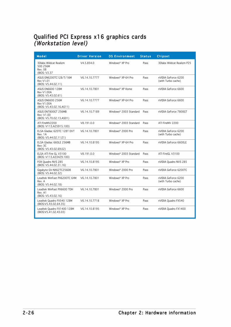
2 -262 -262 -262 -262 -26 Chapter 2 : Hardware in format ionChapter 2 : Hardware in format ionChapter 2 : Hardware in format ionChapter 2 : Hardware in format ionChapter 2 : Hardware in format ion
Qualified PCI Express x16 graphics cardsQualified PCI Express x16 graphics cardsQualified PCI Express x16 graphics cardsQualified PCI Express x16 graphics cardsQualified PCI Express x16 graphics cards(Workstation level)(Workstation level)(Workstation level)(Workstation level)(Workstation level)
3Dlabs Wildcat Realizm V4.5.854.0 Windows® XP Pro Pass 3Dlabs Wildcat Realizm P25500 256MRev. 08(BIOS: V3.37ASUS EN6200TC128/T/16M V6.14.10.7777 Windows® XP-64 Pro Pass nVIDIA GeForce 6200Rev V1.01 (with Turbo cache)(BIOS: V5.44.02.11)ASUS EN6600 128M V6.14.10.7801 Windows® XP Home Pass nVIDIA GeForce 6600Rev V1.00A(BIOS: V5.43.02.61)ASUS EN6600 256M V6.14.10.7777 Windows® XP-64 Pro Pass nVIDIA GeForce 6600Rev V1.00A(BIOS: V5.43.02.16.AS11)ASUS EN7800GT 256MB V6.14.10.7189 Windows® 2003 Standard Pass nVIDIA GeForce 7800GTRev: V1.00(BIOS: V5.70.02.13.AS01)ATI FireMV2200 V8.191.0.0 Windows® 2003 Standard Pass ATI FireMV 2200(BIOS: V113.A25915.100)ELSA Gladiac 620TC 128T DVT V6.14.10.7801 Windows® 2000 Pro Pass nVIDIA GeForce 6200Rev. 1A (with Turbo cache)(BIOS: V5.44.02.11.E1)ELSA Gladiac 660LE 256MB V6.14.10.8195 Windows® XP-64 Pro Pass nVIDIA GeForce 6600LERev: 3C(BIOS: V5.43.02.69.E2)ELSA ATI Fire GL V3100 V8.191.0.0 Windows® 2003 Standard Pass ATI FireGL V3100(BIOS: V113.A33429.100)FOX Quadro NVS 285 V6.14.10.8195 Windows® XP Pro Pass nVIDIA Quadro NVS 285(BIOS: V5.44.02.31.16)Gigabyte GV-NX62TC256D8 V6.14.10.7801 Windows® 2000 Pro Pass nVIDIA GeForce 6200TC(BIOS: V5.44.02.32)Leadtek WinFast PX6200TC 64M V6.14.10.7801 Windows® XP Pro Pass nVIDIA GeForce 6200Rev. A (with Turbo cache)(BIOS: V5.44.02.18)Leadtek WinFast PX6600 TDH V6.14.10.7801 Windows® 2000 Pro Pass nVIDIA GeForce 6600Rev. A1(BIOS: V5.43.02.16)Leadtek Quadro FX540 128M V6.14.10.7718 Windows® XP Pro Pass nVIDIA Quadro FX540(BIOS:V5.43.02.64.35)Leadtek Quadro FX1400 128M V6.14.10.8195 Windows® XP Pro Pass nVIDIA Quadro FX1400(BIOS:V5.41.02.43.03)
M o d e lM o d e lM o d e lM o d e lM o d e l D r i v e r V e r s i o nD r i v e r V e r s i o nD r i v e r V e r s i o nD r i v e r V e r s i o nD r i v e r V e r s i o n O S E n v i r o n m e n tO S E n v i r o n m e n tO S E n v i r o n m e n tO S E n v i r o n m e n tO S E n v i r o n m e n t S t a t u sS t a t u sS t a t u sS t a t u sS t a t u s C h i p s e tC h i p s e tC h i p s e tC h i p s e tC h i p s e t
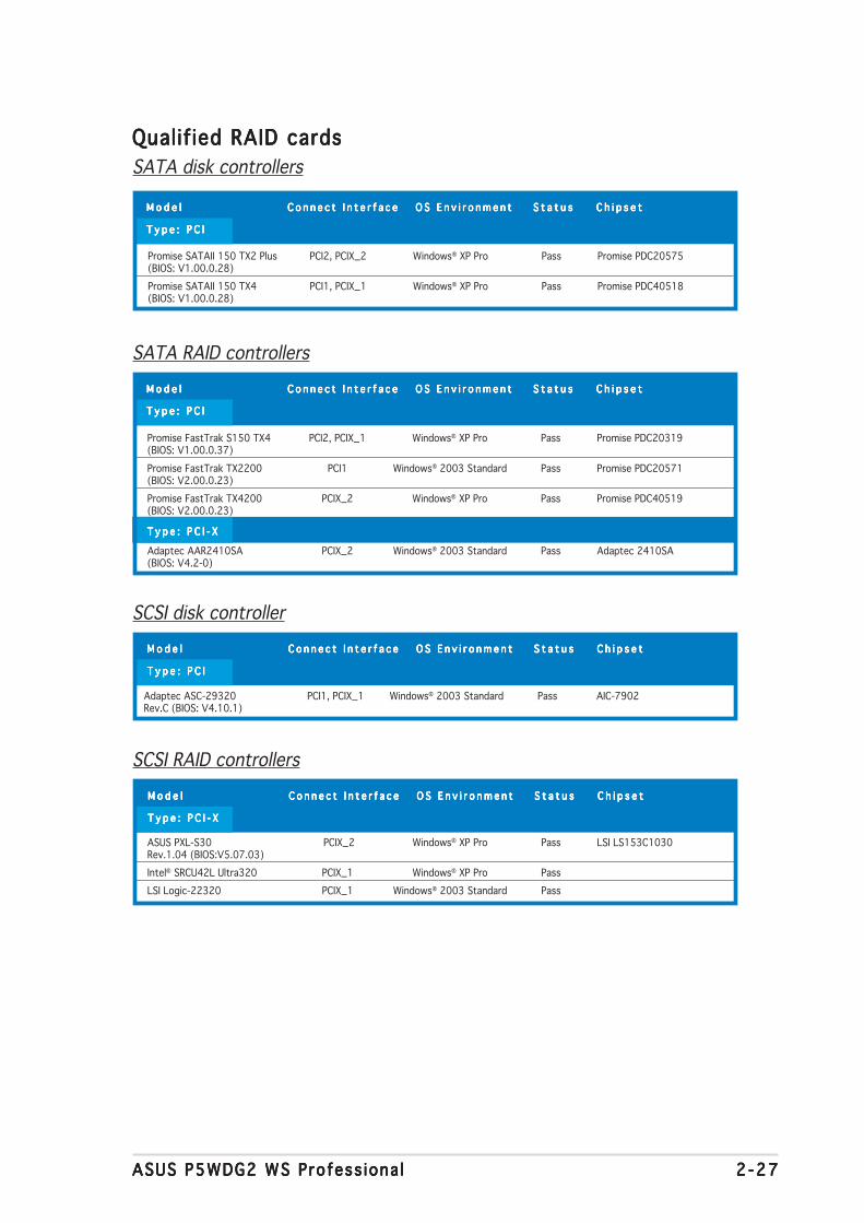
ASUS P5WDG2 WS Profess iona lASUS P5WDG2 WS Profess iona lASUS P5WDG2 WS Profess iona lASUS P5WDG2 WS Profess iona lASUS P5WDG2 WS Profess iona l 2 -272 -272 -272 -272 -27
Qualif ied RAID cardsQualif ied RAID cardsQualif ied RAID cardsQualif ied RAID cardsQualif ied RAID cardsSATA disk controllers
SATA RAID controllers
SCSI disk controller
SCSI RAID controllers
M o d e lM o d e lM o d e lM o d e lM o d e l C o n n e c t I n t e r f a c eC o n n e c t I n t e r f a c eC o n n e c t I n t e r f a c eC o n n e c t I n t e r f a c eC o n n e c t I n t e r f a c e O S E n v i r o n m e n tO S E n v i r o n m e n tO S E n v i r o n m e n tO S E n v i r o n m e n tO S E n v i r o n m e n t S t a t u sS t a t u sS t a t u sS t a t u sS t a t u s C h i p s e tC h i p s e tC h i p s e tC h i p s e tC h i p s e t
T y p e : P C IT y p e : P C IT y p e : P C IT y p e : P C IT y p e : P C I
Promise SATAII 150 TX2 Plus PCI2, PCIX_2 Windows® XP Pro Pass Promise PDC20575(BIOS: V1.00.0.28)Promise SATAII 150 TX4 PCI1, PCIX_1 Windows® XP Pro Pass Promise PDC40518(BIOS: V1.00.0.28)
M o d e lM o d e lM o d e lM o d e lM o d e l C o n n e c t I n t e r f a c eC o n n e c t I n t e r f a c eC o n n e c t I n t e r f a c eC o n n e c t I n t e r f a c eC o n n e c t I n t e r f a c e O S E n v i r o n m e n tO S E n v i r o n m e n tO S E n v i r o n m e n tO S E n v i r o n m e n tO S E n v i r o n m e n t S t a t u sS t a t u sS t a t u sS t a t u sS t a t u s C h i p s e tC h i p s e tC h i p s e tC h i p s e tC h i p s e t
T y p e : P C IT y p e : P C IT y p e : P C IT y p e : P C IT y p e : P C I
Promise FastTrak S150 TX4 PCI2, PCIX_1 Windows® XP Pro Pass Promise PDC20319(BIOS: V1.00.0.37)Promise FastTrak TX2200 PCI1 Windows® 2003 Standard Pass Promise PDC20571(BIOS: V2.00.0.23)Promise FastTrak TX4200 PCIX_2 Windows® XP Pro Pass Promise PDC40519(BIOS: V2.00.0.23)
T y p e : P C I - XT y p e : P C I - XT y p e : P C I - XT y p e : P C I - XT y p e : P C I - X
Adaptec AAR2410SA PCIX_2 Windows® 2003 Standard Pass Adaptec 2410SA(BIOS: V4.2-0)
M o d e lM o d e lM o d e lM o d e lM o d e l C o n n e c t I n t e r f a c eC o n n e c t I n t e r f a c eC o n n e c t I n t e r f a c eC o n n e c t I n t e r f a c eC o n n e c t I n t e r f a c e O S E n v i r o n m e n tO S E n v i r o n m e n tO S E n v i r o n m e n tO S E n v i r o n m e n tO S E n v i r o n m e n t S t a t u sS t a t u sS t a t u sS t a t u sS t a t u s C h i p s e tC h i p s e tC h i p s e tC h i p s e tC h i p s e t
T y p e : P C IT y p e : P C IT y p e : P C IT y p e : P C IT y p e : P C I
Adaptec ASC-29320 PCI1, PCIX_1 Windows® 2003 Standard Pass AIC-7902Rev.C (BIOS: V4.10.1)
M o d e lM o d e lM o d e lM o d e lM o d e l C o n n e c t I n t e r f a c eC o n n e c t I n t e r f a c eC o n n e c t I n t e r f a c eC o n n e c t I n t e r f a c eC o n n e c t I n t e r f a c e O S E n v i r o n m e n tO S E n v i r o n m e n tO S E n v i r o n m e n tO S E n v i r o n m e n tO S E n v i r o n m e n t S t a t u sS t a t u sS t a t u sS t a t u sS t a t u s C h i p s e tC h i p s e tC h i p s e tC h i p s e tC h i p s e t
T y p e : P C I - XT y p e : P C I - XT y p e : P C I - XT y p e : P C I - XT y p e : P C I - X
ASUS PXL-S30 PCIX_2 Windows® XP Pro Pass LSI LS153C1030Rev.1.04 (BIOS:V5.07.03)Intel® SRCU42L Ultra320 PCIX_1 Windows® XP Pro PassLSI Logic-22320 PCIX_1 Windows® 2003 Standard Pass

2 -282 -282 -282 -282 -28 Chapter 2 : Hardware in format ionChapter 2 : Hardware in format ionChapter 2 : Hardware in format ionChapter 2 : Hardware in format ionChapter 2 : Hardware in format ion
2.6 Jumpers1 .1 .1 .1 .1 . C lear RTC RAM (CLRTC)Clear RTC RAM (CLRTC)Clear RTC RAM (CLRTC)Clear RTC RAM (CLRTC)Clear RTC RAM (CLRTC)
This jumper allows you to clear the Real Time Clock (RTC) RAM inCMOS. You can clear the CMOS memory of date, time, and systemsetup parameters by erasing the CMOS RTC RAM data. The onboardbutton cell battery powers the RAM data in CMOS, which includesystem setup information such as system passwords.
To erase the RTC RAM:1. Turn OFF the computer and unplug the power cord.
2. Remove the onboard battery.
3. Move the jumper cap from pins 1-2 (default) to pins 2-3. Keep thecap on pins 2-3 for about 5~10 seconds, then move the cap backto pins 1-2.
4. Reinstall the battery.
5. Plug the power cord and turn ON the computer.
6. Hold down the <Del> key during the boot process and enter BIOSsetup to re-enter data.
You do not need to clear the RTC when the system hangs due tooverclocking. For system failure due to overclocking, use the C.P.R. (CPUParameter Recall) feature. Shut down and reboot the system so the BIOScan automatically reset parameter settings to default values.
Except when clearing the RTC RAM, never remove the cap on CLRTCjumper default position. Removing the cap will cause system boot failure!
P5W
DG
2-W
S P
RO
®
P5WDG2-WS PRO Clear RTC RAM
CLRTC
Normal Clear RTC(Default)
1 2 2 3
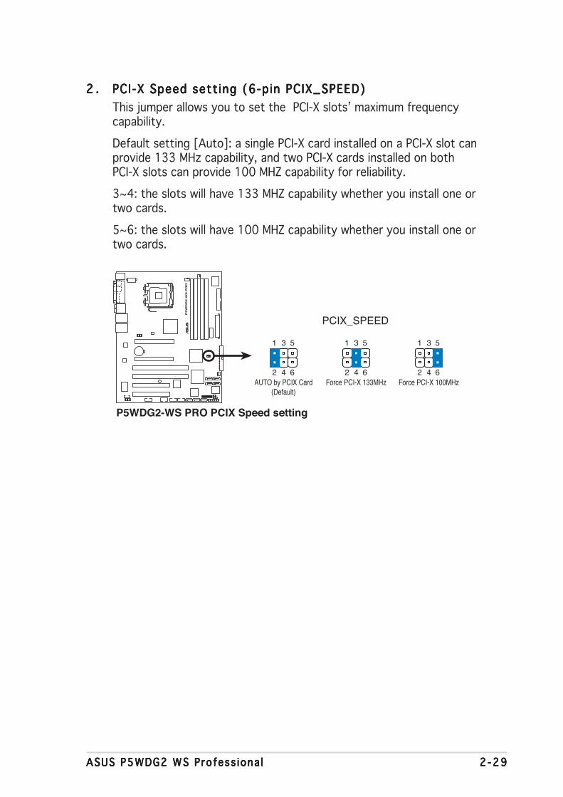
ASUS P5WDG2 WS Profess iona lASUS P5WDG2 WS Profess iona lASUS P5WDG2 WS Profess iona lASUS P5WDG2 WS Profess iona lASUS P5WDG2 WS Profess iona l 2 -292 -292 -292 -292 -29
2 .2 .2 .2 .2 . PCI-X Speed sett ing (6-pin PCIX_SPEED)PCI-X Speed sett ing (6-pin PCIX_SPEED)PCI-X Speed sett ing (6-pin PCIX_SPEED)PCI-X Speed sett ing (6-pin PCIX_SPEED)PCI-X Speed sett ing (6-pin PCIX_SPEED)This jumper allows you to set the PCI-X slots’ maximum frequencycapability.
Default setting [Auto]: a single PCI-X card installed on a PCI-X slot canprovide 133 MHz capability, and two PCI-X cards installed on bothPCI-X slots can provide 100 MHZ capability for reliability.
3~4: the slots will have 133 MHZ capability whether you install one ortwo cards.
5~6: the slots will have 100 MHZ capability whether you install one ortwo cards.
1 3 5
2 4 6
1 3 5
2 4 6
1 3 5
2 4 6
P5W
DG
2-W
S P
RO
®
P5WDG2-WS PRO PCIX Speed setting
PCIX_SPEED
AUTO by PCIX Card(Default)
Force PCI-X 133MHz Force PCI-X 100MHz

2 -302 -302 -302 -302 -30 Chapter 2 : Hardware in format ionChapter 2 : Hardware in format ionChapter 2 : Hardware in format ionChapter 2 : Hardware in format ionChapter 2 : Hardware in format ion
D N RD N RD N RD N RD N R - Driver Not Ready
2.7 Connectors
2.7.12.7.12.7.12.7.12.7.1 Rear panel connectorsRear panel connectorsRear panel connectorsRear panel connectorsRear panel connectors
1 .1 .1 .1 .1 . PS/2 mouse port (green).PS/2 mouse port (green).PS/2 mouse port (green).PS/2 mouse port (green).PS/2 mouse port (green). This port is for a PS/2 mouse.2 .2 .2 .2 .2 . Para l le l port .Para l le l port .Para l le l port .Para l le l port .Para l le l port . This 25-pin port connects a parallel printer, a scanner,
or other devices.
11
4 6
13
1
16
2
15 14 12
3 5 7 8
910
32-bit OS LAN port LED indications32-bit OS LAN port LED indications32-bit OS LAN port LED indications32-bit OS LAN port LED indications32-bit OS LAN port LED indications
A c t i v i t y / L i n kA c t i v i t y / L i n kA c t i v i t y / L i n kA c t i v i t y / L i n kA c t i v i t y / L i n k S p e e d L E DS p e e d L E DS p e e d L E DS p e e d L E DS p e e d L E D D e s c r i p t i o nD e s c r i p t i o nD e s c r i p t i o nD e s c r i p t i o nD e s c r i p t i o n
OFF OFF Soft-off Mode
YELLOW* OFF 10 Mbps connection
YELLOW* ORANGE 100 Mbps connection
YELLOW* GREEN 1 Gbps connection
64-bit OS LAN port LED indications64-bit OS LAN port LED indications64-bit OS LAN port LED indications64-bit OS LAN port LED indications64-bit OS LAN port LED indications
* Blinking
A c t i v i t y / L i n kA c t i v i t y / L i n kA c t i v i t y / L i n kA c t i v i t y / L i n kA c t i v i t y / L i n k S p e e d L E DS p e e d L E DS p e e d L E DS p e e d L E DS p e e d L E D D e s c r i p t i o nD e s c r i p t i o nD e s c r i p t i o nD e s c r i p t i o nD e s c r i p t i o n
DNR DNR Soft-off Mode
DNR DNR 10 Mbps connection
DNR DNR 100 Mbps connection
DNR DNR 1 Gbps connection
3 .3 .3 .3 .3 . LAN1 (RJ-45) port .LAN1 (RJ-45) port .LAN1 (RJ-45) port .LAN1 (RJ-45) port .LAN1 (RJ-45) port . This Marvell® LAN port allows Gigabitconnection to a Local Area Network (LAN) through a network hub.Refer to the table below for the LAN port LED indications.
4 .4 .4 .4 .4 . LAN2 (RJ-45) port .LAN2 (RJ-45) port .LAN2 (RJ-45) port .LAN2 (RJ-45) port .LAN2 (RJ-45) port . This Marvell® LAN port allows Gigabitconnection to a Local Area Network (LAN) through a network hub.Refer to the table below for the LAN port LED indications.
Item numbers 9, 10, and 11 are only for the optional Wireless LANmodule.

ASUS P5WDG2 WS Profess iona lASUS P5WDG2 WS Profess iona lASUS P5WDG2 WS Profess iona lASUS P5WDG2 WS Profess iona lASUS P5WDG2 WS Profess iona l 2 -312 -312 -312 -312 -31
5 .5 .5 .5 .5 . Rear Speaker Out port (b lack).Rear Speaker Out port (b lack).Rear Speaker Out port (b lack).Rear Speaker Out port (b lack).Rear Speaker Out port (b lack). This port connects the rearspeakers on a 4-channel, 6-channel, or 8-channel audio configuration.
6 .6 .6 .6 .6 . Center/Subwoofer port (orange).Center/Subwoofer port (orange).Center/Subwoofer port (orange).Center/Subwoofer port (orange).Center/Subwoofer port (orange). This port connects thecenter/subwoofer speakers.
7 .7 .7 .7 .7 . L ine In port ( l ight b lue).L ine In port ( l ight b lue).L ine In port ( l ight b lue).L ine In port ( l ight b lue).L ine In port ( l ight b lue). This port connects a tape, CD, DVDplayer, or other audio sources.
8 .8 .8 .8 .8 . L ine Out port ( l ime).L ine Out port ( l ime).L ine Out port ( l ime).L ine Out port ( l ime).L ine Out port ( l ime). This port connects a headphone or aspeaker. In 4-channel, 6-channel, and 8-channel configuration, thefunction of this port becomes Front Speaker Out.
Audio 2, 4, 6, or 8-channel configurationAudio 2, 4, 6, or 8-channel configurationAudio 2, 4, 6, or 8-channel configurationAudio 2, 4, 6, or 8-channel configurationAudio 2, 4, 6, or 8-channel configuration
Light Blue Line In Line In Line In Line InLime Line Out Front Speaker Out Front Speaker Out Front Speaker OutPink Mic In Mic In Mic In Mic InBlack – Rear Speaker Out Rear Speaker Out Rear Speaker OutGray – – – Side Speaker OutOrange – – Center/Subwoofer Center/Subwoofer
P o r tP o r tP o r tP o r tP o r t H e a d s e tH e a d s e tH e a d s e tH e a d s e tH e a d s e t 4 - channe l4 - channe l4 - channe l4 - channe l4 - channe l 6 - channe l6 - channe l6 - channe l6 - channe l6 - channe l 8 - channe l8 - channe l8 - channe l8 - channe l8 - channe l2-channel2-channel2-channel2-channel2-channel
Refer to the audio configuration table below for the function of theaudio ports in 2, 4, 6, or 8-channel configuration.
9 .9 .9 .9 .9 . Microphone port (p ink). Microphone port (p ink). Microphone port (p ink). Microphone port (p ink). Microphone port (p ink). This port connects a microphone.10 .10 .10 .10 .10 .S ide Speaker Out port (gray).S ide Speaker Out port (gray).S ide Speaker Out port (gray).S ide Speaker Out port (gray).S ide Speaker Out port (gray). This port connects the side
speakers in an 8-channel audio configuration.11 .11 .11 .11 .11 . USB 2.0 ports 3 and 4.USB 2.0 ports 3 and 4.USB 2.0 ports 3 and 4.USB 2.0 ports 3 and 4.USB 2.0 ports 3 and 4. These two 4-pin Universal Serial Bus
(USB) ports are available for connecting USB 2.0 devices.12 .12 .12 .12 .12 . USB 2.0 ports 1 and 2.USB 2.0 ports 1 and 2.USB 2.0 ports 1 and 2.USB 2.0 ports 1 and 2.USB 2.0 ports 1 and 2. These two 4-pin Universal Serial Bus
(USB) ports are available for connecting USB 2.0 devices.

2 -322 -322 -322 -322 -32 Chapter 2 : Hardware in format ionChapter 2 : Hardware in format ionChapter 2 : Hardware in format ionChapter 2 : Hardware in format ionChapter 2 : Hardware in format ion
14 .14 .14 .14 .14 . Opt ica l S/PDIF Out portOpt ica l S/PDIF Out portOpt ica l S/PDIF Out portOpt ica l S/PDIF Out portOpt ica l S/PDIF Out port. This port connects an external audiooutput device via an optical S/PDIF cable.
15 .15 .15 .15 .15 . Coaxia l S/PDIF Out port .Coaxia l S/PDIF Out port .Coaxia l S/PDIF Out port .Coaxia l S/PDIF Out port .Coaxia l S/PDIF Out port . This port connects an external audiooutput device via a coaxial S/PDIF cable.
16 .16 .16 .16 .16 . PS/2 keyboard port (purple) .PS/2 keyboard port (purple) .PS/2 keyboard port (purple) .PS/2 keyboard port (purple) .PS/2 keyboard port (purple) . This port is for a PS/2 keyboard.
13 .13 .13 .13 .13 . Externa l SATA port . Externa l SATA port . Externa l SATA port . Externa l SATA port . Externa l SATA port . This port connects to an external SATA boxor a Serial ATA port multiplier.
The external SATA portsupports external Serial ATA1.5 and 3 Gb/s devices. Longercables support higher powerrequirements to deliver signalup to two meters away, andenables improved hot-swapfunction.
Do not insert a differentconnector to this port.
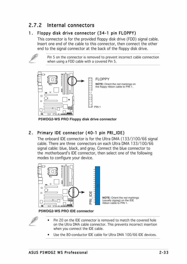
ASUS P5WDG2 WS Profess iona lASUS P5WDG2 WS Profess iona lASUS P5WDG2 WS Profess iona lASUS P5WDG2 WS Profess iona lASUS P5WDG2 WS Profess iona l 2 -332 -332 -332 -332 -33
2.7.22.7.22.7.22.7.22.7.2 Internal connectorsInternal connectorsInternal connectorsInternal connectorsInternal connectors1 .1 .1 .1 .1 . F loppy disk dr ive connector (34-1 pin FLOPPY)Floppy disk dr ive connector (34-1 pin FLOPPY)Floppy disk dr ive connector (34-1 pin FLOPPY)Floppy disk dr ive connector (34-1 pin FLOPPY)Floppy disk dr ive connector (34-1 pin FLOPPY)
This connector is for the provided floppy disk drive (FDD) signal cable.Insert one end of the cable to this connector, then connect the otherend to the signal connector at the back of the floppy disk drive.
Pin 5 on the connector is removed to prevent incorrect cable connectionwhen using a FDD cable with a covered Pin 5.
P5W
DG
2-W
S P
RO
®
P5WDG2-WS PRO Floppy disk drive connector
NOTE: Orient the red markings onthe floppy ribbon cable to PIN 1.
PIN 1
FLOPPY
2 .2 .2 .2 .2 . Pr imary IDE connector (40-1 pin PRI_IDE)Pr imary IDE connector (40-1 pin PRI_IDE)Pr imary IDE connector (40-1 pin PRI_IDE)Pr imary IDE connector (40-1 pin PRI_IDE)Pr imary IDE connector (40-1 pin PRI_IDE)The onboard IDE connector is for the Ultra DMA (133/)100/66 signalcable. There are three connectors on each Ultra DMA 133/100/66signal cable: blue, black, and gray. Connect the blue connector tothe motherboard's IDE connector, then select one of the followingmodes to configure your device.
• Pin 20 on the IDE connector is removed to match the covered holeon the Ultra DMA cable connector. This prevents incorrect insertionwhen you connect the IDE cable.
• Use the 80-conductor IDE cable for Ultra DMA 100/66 IDE devices.
P5W
DG
2-W
S P
RO
®
P5WDG2-WS PRO IDE connector
NOTE: Orient the red markings(usually zigzag) on the IDEribbon cable to PIN 1.P
RI_
IDE

2 -342 -342 -342 -342 -34 Chapter 2 : Hardware in format ionChapter 2 : Hardware in format ionChapter 2 : Hardware in format ionChapter 2 : Hardware in format ionChapter 2 : Hardware in format ion
• These connectors are set to Standard IDE Standard IDE Standard IDE Standard IDE Standard IDE mode by default. InSSSSStandard IDE tandard IDE tandard IDE tandard IDE tandard IDE mode, you can connect Serial ATA boot/data harddisk drives to these connectors. If you intend to create a Serial ATARAID set using these connectors, set the Conf igure SATA AsConf igure SATA AsConf igure SATA AsConf igure SATA AsConf igure SATA Asitem in the BIOS to [RAID]. See section “4.3.6 IDE Configuration” fordetails.
• For RAID 5, use at least three hard disk drives. For RAID 10, use atleast four hard disk drives. Use two to four Serial ATA hard diskdrives for each RAID 0 or RAID 1 set.
3 .3 .3 .3 .3 . ICH7R Ser ia l ATA connectors (7-pin SATA1 [red],ICH7R Ser ia l ATA connectors (7-pin SATA1 [red],ICH7R Ser ia l ATA connectors (7-pin SATA1 [red],ICH7R Ser ia l ATA connectors (7-pin SATA1 [red],ICH7R Ser ia l ATA connectors (7-pin SATA1 [red],SATA2 [red], SATA3 [black], SATA4 [black])SATA2 [red], SATA3 [black], SATA4 [black])SATA2 [red], SATA3 [black], SATA4 [black])SATA2 [red], SATA3 [black], SATA4 [black])SATA2 [red], SATA3 [black], SATA4 [black])These connectors are for Serial ATA signal cables for Serial ATA harddisk drives.
If you installed Serial ATA hard disk drives, you can create a RAID 0,RAID 1, RAID 10, and RAID 5 configuration with the Intel® MatrixStorage Technology through the onboard Intel® ICH7R RAID controller.
P5W
DG
2-W
S P
RO
®
P5WDG2-WS PRO SATA connectorsSATA1
SATA4 SATA3
SATA2
GN
DS
ATA
_TX
P0
SA
TA_T
XN
0G
ND
SA
TA_R
XN
0S
ATA
_RX
P0
GN
D
GN
DS
ATA
_TX
P1
SA
TA_T
XN
1G
ND
SA
TA_R
XN
1S
ATA
_RX
P1
GN
D
GN
DS
ATA
_TX
P2
SA
TA_T
XN
2G
ND
SA
TA_R
XN
2S
ATA
_RX
P2
GN
D
GN
DS
ATA
_TX
P3
SA
TA_T
XN
3G
ND
SA
TA_R
XN
3S
ATA
_RX
P3
GN
D
If any device jumper is set as "Cable-Select," make sure all other devicejumpers have the same setting.
Black or gray
D r i v e j u m p e rD r i v e j u m p e rD r i v e j u m p e rD r i v e j u m p e rD r i v e j u m p e r M o d eM o d eM o d eM o d eM o d e C a b l eC a b l eC a b l eC a b l eC a b l es e t t i n gs e t t i n gs e t t i n gs e t t i n gs e t t i n g o f dev i ce ( s )o f dev i ce ( s )o f dev i ce ( s )o f dev i ce ( s )o f dev i ce ( s ) connec to rconnec to rconnec to rconnec to rconnec to r
Single device Cable-Select or Master - BlackTwo devices Cable-Select Master Black
Slave GrayMaster MasterSlave Slave

ASUS P5WDG2 WS Profess iona lASUS P5WDG2 WS Profess iona lASUS P5WDG2 WS Profess iona lASUS P5WDG2 WS Profess iona lASUS P5WDG2 WS Profess iona l 2 -352 -352 -352 -352 -35
Important notes on Ser ia l ATAImportant notes on Ser ia l ATAImportant notes on Ser ia l ATAImportant notes on Ser ia l ATAImportant notes on Ser ia l ATA
• You must install Windows® 2000 Service Pack 4 or the Windows® XPService Pack 1 before using Serial ATA hard disk drives. The SerialATA RAID feature (RAID 0/RAID 1/RAID 5/RAID 10) is available onlyif you are using Windows® 2000/XP/Server 2003 or later version.
• When using the connectors in SSSSStandard IDE tandard IDE tandard IDE tandard IDE tandard IDE mode, connect theprimary (boot) hard disk drive to the SATA1 or SATA2 connector.Refer to the table below for the recommended SATA hard disk driveconnections.
Serial ATA hard disk drive connectionSerial ATA hard disk drive connectionSerial ATA hard disk drive connectionSerial ATA hard disk drive connectionSerial ATA hard disk drive connectionConnec to rConnec to rConnec to rConnec to rConnec to r C o l o rC o l o rC o l o rC o l o rC o l o r S e t t i n gS e t t i n gS e t t i n gS e t t i n gS e t t i n g U s eU s eU s eU s eU s e
SATA1/SATA2SATA1/SATA2SATA1/SATA2SATA1/SATA2SATA1/SATA2 R e dR e dR e dR e dR e d Maste rMas te rMas te rMas te rMas te r Boot d i skBoot d i skBoot d i skBoot d i skBoot d i sk
SATA3/SATA4SATA3/SATA4SATA3/SATA4SATA3/SATA4SATA3/SATA4 B l ackB l a ckB l a ckB l a ckB l a ck S l aveS l aveS l aveS l aveS l ave Data d i skData d i skData d i skData d i skData d i sk
4 .4 .4 .4 .4 . Marve l lMarve l lMarve l lMarve l lMarve l l®®®®® 88SE614x 88SE614x 88SE614x 88SE614x 88SE614x Ser ia l ATA connectorsSer ia l ATA connectorsSer ia l ATA connectorsSer ia l ATA connectorsSer ia l ATA connectors(7-pin EXT_SATA1, EXT_SATA2, EXT_SATA3)(7-pin EXT_SATA1, EXT_SATA2, EXT_SATA3)(7-pin EXT_SATA1, EXT_SATA2, EXT_SATA3)(7-pin EXT_SATA1, EXT_SATA2, EXT_SATA3)(7-pin EXT_SATA1, EXT_SATA2, EXT_SATA3)These connectors are for Serial ATA signal cables. These connectorssupport Serial ATA hard disk drives.
Set the Marve l l SATA Contro l le r Marve l l SATA Contro l le r Marve l l SATA Contro l le r Marve l l SATA Contro l le r Marve l l SATA Contro l le r and Marve l l SATA BOOTROMMarve l l SATA BOOTROMMarve l l SATA BOOTROMMarve l l SATA BOOTROMMarve l l SATA BOOTROMitems in the BIOS to [Enabled] to use the connectors to build a RAIDset. See section “4.4.6 Onboard Devices Configuration” for details.
Before creating a RAID set using Serial ATA hard disks, make sure thatyou have connected the Serial ATA signal cables and installed Serial ATAhard disk drives; otherwise, you cannot enter the Marvell® 88SE6141RAID utility.
P5W
DG
2-W
S P
RO
®
P5WDG2-WS PRO SATA 3 Gbps connector
EXT_SATA3 EXT_SATA2 EXT_SATA1
GN
DR
SA
TA_T
X_0_D
PR
SA
TA_T
X_0_D
NG
ND
RS
ATA
_RX
_0_DN
RS
ATA
_RX
_0_DP
GN
D
GN
DR
SA
TA_T
X_1_D
PR
SA
TA_T
X_1_D
NG
ND
RS
ATA
_RX
_1_DN
RS
ATA
_RX
_1_DP
GN
D
GN
DR
SA
TA_T
X_2_D
PR
SA
TA_T
X_2_D
NG
ND
RS
ATA
_RX
_2_DN
RS
ATA
_RX
_2_DP
GN
D
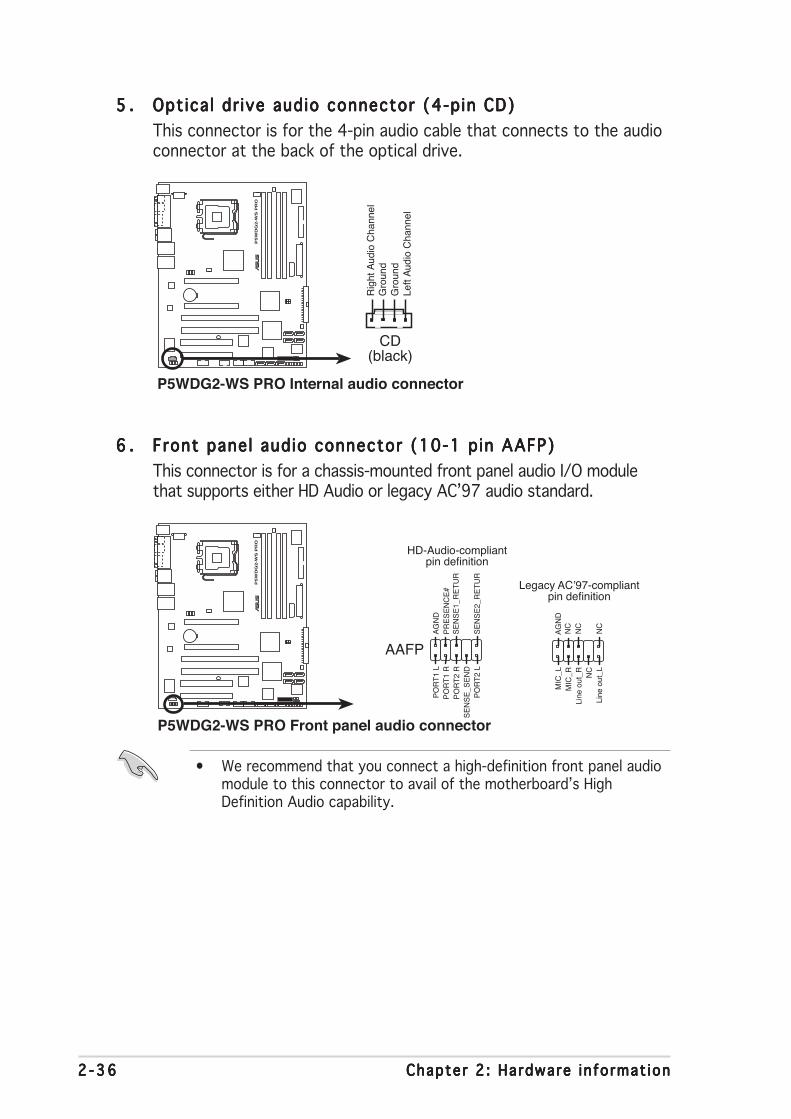
2 -362 -362 -362 -362 -36 Chapter 2 : Hardware in format ionChapter 2 : Hardware in format ionChapter 2 : Hardware in format ionChapter 2 : Hardware in format ionChapter 2 : Hardware in format ion
6 .6 .6 .6 .6 . Front panel audio connector (10-1 pin AAFP)Front panel audio connector (10-1 pin AAFP)Front panel audio connector (10-1 pin AAFP)Front panel audio connector (10-1 pin AAFP)Front panel audio connector (10-1 pin AAFP)This connector is for a chassis-mounted front panel audio I/O modulethat supports either HD Audio or legacy AC’97 audio standard.
• We recommend that you connect a high-definition front panel audiomodule to this connector to avail of the motherboard’s HighDefinition Audio capability.
5 .5 .5 .5 .5 . Opt ica l dr ive audio connector (4-pin CD)Optica l dr ive audio connector (4-pin CD)Optica l dr ive audio connector (4-pin CD)Optica l dr ive audio connector (4-pin CD)Optica l dr ive audio connector (4-pin CD)This connector is for the 4-pin audio cable that connects to the audioconnector at the back of the optical drive.
P5W
DG
2-W
S P
RO
®
P5WDG2-WS PRO Internal audio connector
CD(black)
Rig
ht A
udio
Cha
nnel
Left
Aud
io C
hann
elG
roun
dG
roun
d
P5W
DG
2-W
S P
RO
®
P5WDG2-WS PRO Front panel audio connector
AAFP
Legacy AC’97-compliantpin definition
HD-Audio-compliantpin definition
SE
NS
E2_
RE
TU
R
PO
RT
1 L
PO
RT
2 R
PO
RT
2 L
SE
NS
E1_
RE
TU
RS
EN
SE
_SE
ND
PO
RT
1 R
PR
ES
EN
CE
#A
GN
D
NC
MIC
_L
Line
out
_R
Line
out
_L
NC
NC
MIC
_RN
CA
GN
D

ASUS P5WDG2 WS Profess iona lASUS P5WDG2 WS Profess iona lASUS P5WDG2 WS Profess iona lASUS P5WDG2 WS Profess iona lASUS P5WDG2 WS Profess iona l 2 -372 -372 -372 -372 -37
7 .7 .7 .7 .7 . USB connectors (10-1 pin USB56, USB78 USB connectors (10-1 pin USB56, USB78 USB connectors (10-1 pin USB56, USB78 USB connectors (10-1 pin USB56, USB78 USB connectors (10-1 pin USB56, USB78 [opt iona l[opt iona l[opt iona l[opt iona l[opt iona l]]]]])))))These connectors are for USB 2.0 ports. Connect the USB/GAMEmodule cable to any of these connectors, then install the module to aslot opening at the back of the system chassis. These USB connectorscomply with USB 2.0 specification that supports up to 480 Mbpsconnection speed.
USB78 is for the optional Wireless LAN module and the fifth USB porton the rear panel for the Wi-Fi add-on configuration.
Never connect a 1394 cab le1394 cab le1394 cab le1394 cab le1394 cab le to the USB connectors. Doing so willdamage the motherboard!
8 .8 .8 .8 .8 . IEEE 1394IEEE 1394IEEE 1394IEEE 1394IEEE 1394aaaaa port connector port connector port connector port connector port connectorsssss (10-1 pin IE1394_ (10-1 pin IE1394_ (10-1 pin IE1394_ (10-1 pin IE1394_ (10-1 pin IE1394_1 ; 1 ; 1 ; 1 ; 1 ; 10-1 p in10-1 p in10-1 p in10-1 p in10-1 p inIE1394_2)IE1394_2)IE1394_2)IE1394_2)IE1394_2)These connectors are for additional IEEE 1394a ports. Connect theIEEE 1394a module cables to any of these connectors, then install themodule to a slot opening at the back of the system chassis.
Never connect a USB port modu le cab le USB port modu le cab le USB port modu le cab le USB port modu le cab le USB port modu le cab le to the IEEE 1394connector. Doing so will damage the motherboard!
P5W
DG
2-W
S P
RO
®
P5WDG2-WS PRO USB 2.0 connectors
USB56 USB78
US
B+
5VU
SB
_P8-
US
B_P
8+G
ND
NC
US
B+
5VU
SB
_P7-
US
B_P
7+G
ND
1
US
B+
5VU
SB
_P6-
US
B_P
6+G
ND
NC
US
B+
5VU
SB
_P5-
US
B_P
5+G
ND
P5W
DG
2-W
S P
RO
®
P5WDG2-WS PRO IEEE 1394 connectors
IE1394_1
TP
A1-
GN
DT
PB
1-+
12VG
ND
TP
A1+
GN
DT
PB
1++
12V
IE1394_2
TP
A2-
GN
DT
PB
2-+
12VG
ND
TP
A2+
GN
DT
PB
2++
12V
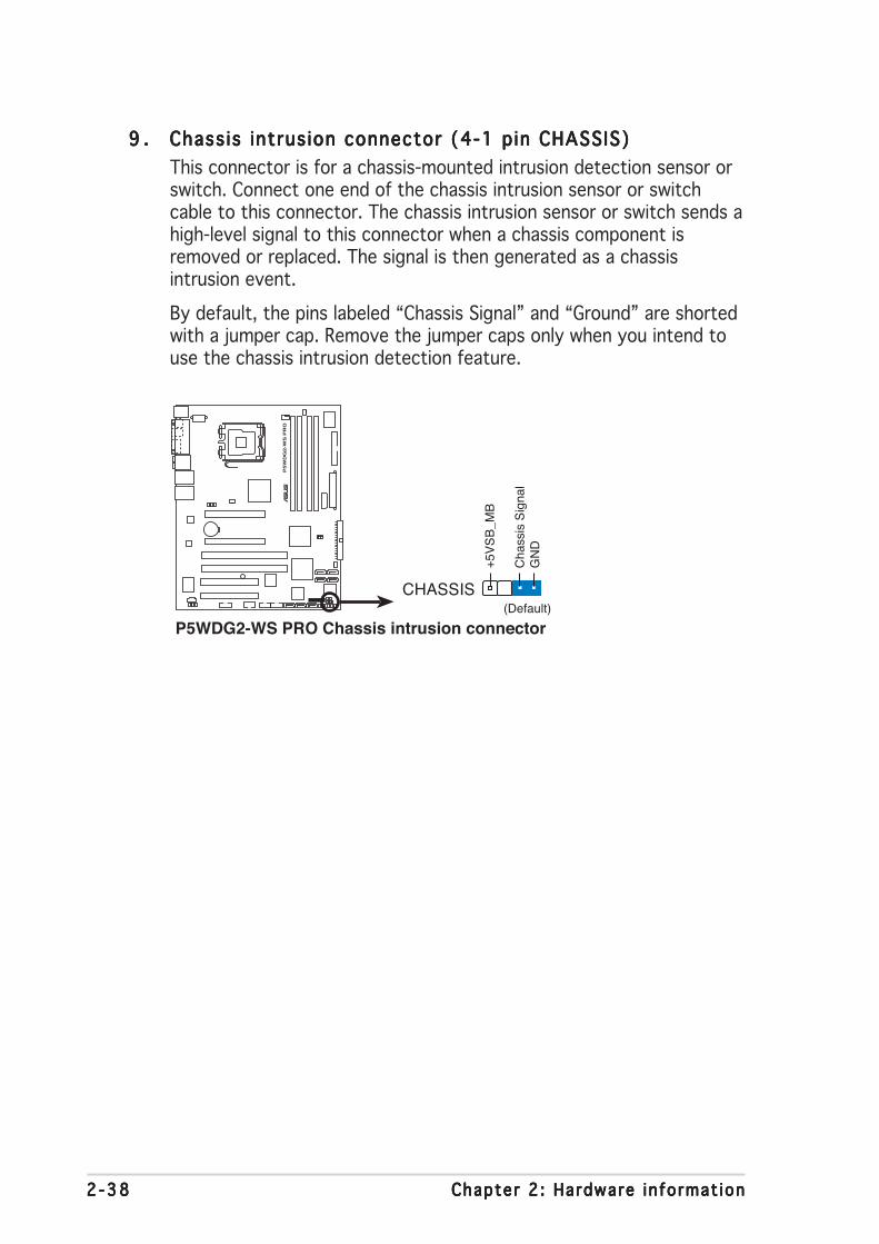
2 -382 -382 -382 -382 -38 Chapter 2 : Hardware in format ionChapter 2 : Hardware in format ionChapter 2 : Hardware in format ionChapter 2 : Hardware in format ionChapter 2 : Hardware in format ion
9 .9 .9 .9 .9 . Chass is intrus ion connector (4-1 pin CHASSIS)Chass is intrus ion connector (4-1 pin CHASSIS)Chass is intrus ion connector (4-1 pin CHASSIS)Chass is intrus ion connector (4-1 pin CHASSIS)Chass is intrus ion connector (4-1 pin CHASSIS)This connector is for a chassis-mounted intrusion detection sensor orswitch. Connect one end of the chassis intrusion sensor or switchcable to this connector. The chassis intrusion sensor or switch sends ahigh-level signal to this connector when a chassis component isremoved or replaced. The signal is then generated as a chassisintrusion event.
By default, the pins labeled “Chassis Signal” and “Ground” are shortedwith a jumper cap. Remove the jumper caps only when you intend touse the chassis intrusion detection feature.
P5W
DG
2-W
S P
RO
®
P5WDG2-WS PRO Chassis intrusion connector
CHASSIS
+5V
SB
_MB
Cha
ssis
Sig
nal
GN
D
(Default)

ASUS P5WDG2 WS Profess iona lASUS P5WDG2 WS Profess iona lASUS P5WDG2 WS Profess iona lASUS P5WDG2 WS Profess iona lASUS P5WDG2 WS Profess iona l 2 -392 -392 -392 -392 -39
10 .10 .10 .10 .10 . CPU, Chassis , and Power Fan connectors (4-pin CPU_FAN,CPU, Chassis , and Power Fan connectors (4-pin CPU_FAN,CPU, Chassis , and Power Fan connectors (4-pin CPU_FAN,CPU, Chassis , and Power Fan connectors (4-pin CPU_FAN,CPU, Chassis , and Power Fan connectors (4-pin CPU_FAN,3-pin PWR_FAN, 3-pin CHA_FAN1, 3-pin CHA_FAN2)3-pin PWR_FAN, 3-pin CHA_FAN1, 3-pin CHA_FAN2)3-pin PWR_FAN, 3-pin CHA_FAN1, 3-pin CHA_FAN2)3-pin PWR_FAN, 3-pin CHA_FAN1, 3-pin CHA_FAN2)3-pin PWR_FAN, 3-pin CHA_FAN1, 3-pin CHA_FAN2)The fan connectors support cooling fans of 350 mA ~ 2000 mA (24 Wmax.) or a total of 1 A ~ 3.48 A (41.76 W max.) at +12V. Connect thefan cables to the fan connectors on the motherboard, making sure thatthe black wire of each cable matches the ground pin of the connector.
Only the CPU_FAN and CHA_FAN1 connectors support theASUS Q-Fan 2 feature.
Do not forget to connect the fan cables to the fan connectors.Insufficient air flow inside the system may damage the motherboardcomponents. These are not jumpers! Do not place jumper caps on thefan connectors!
If you install two VGA cards, we recommend that you plug the rearchassis fan cable to the motherboard connector labeled CHA_FAN1 forbetter thermal environment.
P5W
DG
2-W
S P
RO
®
P5WDG2-WS PRO Fan connectors
CPU_FAN
CHA_FAN2 PWR_FAN
CHA_FAN1
GND
Rotation+12V
GN
D
SP
EE
DC
HA
SS
IS F
AN
PO
WE
R
CPU_FANPWR_FAN
CHA_FAN1
GND
Rotation+12V
GN
DC
PU
FA
N P
WR
CP
U F
AN
INC
PU
FA
N P
WM
CHA_FAN2

2 -402 -402 -402 -402 -40 Chapter 2 : Hardware in format ionChapter 2 : Hardware in format ionChapter 2 : Hardware in format ionChapter 2 : Hardware in format ionChapter 2 : Hardware in format ion
12 .12 .12 .12 .12 . ATX power connectors (24-pin EATXPWR, ATX power connectors (24-pin EATXPWR, ATX power connectors (24-pin EATXPWR, ATX power connectors (24-pin EATXPWR, ATX power connectors (24-pin EATXPWR, 2 x 42 x 42 x 42 x 42 x 4-p in-p in-p in-p in-p inEEEEEATX12V)ATX12V)ATX12V)ATX12V)ATX12V)These connectors are for ATX power supply plugs. The power supplyplugs are designed to fit these connectors in only one orientation.Find the proper orientation and push down firmly until the connectorscompletely fit.
11 .11 .11 .11 .11 . Ser ia l port connector (10-1 pin COM1)Ser ia l port connector (10-1 pin COM1)Ser ia l port connector (10-1 pin COM1)Ser ia l port connector (10-1 pin COM1)Ser ia l port connector (10-1 pin COM1)This connector is for a serial (COM) port. Connect the serial portmodule cable to this connector, then install the module to a slotopening at the back of the system chassis.
P5W
DG
2-W
S P
RO
®
P5WDG2-WS PRO COM port connector
PIN 1
COM1
P5W
DG
2-W
S P
RO
®
P5WDG2-WS PRO ATX power connectors
EATXPWR
EATX12V
+3 Volts+3 VoltsGround+5 Volts
+5 VoltsGround
GroundPower OK
+5V Standby+12 Volts
-5 Volts
+5 Volts
+3 Volts-12 VoltsGround
GroundGroundPSON#
Ground
+5 Volts
+12 Volts+3 Volts
+5 VoltsGround
GN
D+
12V
DC
GN
D+
12V
DC
GN
D+
12V
DC
GN
D+
12V
DC

ASUS P5WDG2 WS Profess iona lASUS P5WDG2 WS Profess iona lASUS P5WDG2 WS Profess iona lASUS P5WDG2 WS Profess iona lASUS P5WDG2 WS Profess iona l 2 -412 -412 -412 -412 -41
• You may use a 4-pin ATX12Vpower plug for this connector.
• Make sure to remove the cap onthe connector before connectingan 8-pin EPS +12V power plug.
• Use only either a 4-pin ATX12V oran 8-pin EPS +12V power plug.Connecting other power plug typesmay cause serious damage to thesystem.
Important notes on motherboard power requ i rementsImportant notes on motherboard power requ i rementsImportant notes on motherboard power requ i rementsImportant notes on motherboard power requ i rementsImportant notes on motherboard power requ i rements
• For a fully configured system, we recommend that you use a powersupply unit (PSU) that complies with ATX 12 V Specification 2.0 (orlater version) and provides a minimum power of 400 W.
• Do not forget to connect the 8-pin/4-pin EATX12 V power plug;otherwise, the system will not boot up.
• Make sure that the PSU can support at least 8 A on the +12V_1lead and 13 A on the +12V_2 lead.
• Use of a PSU with a higher power output is recommended whenconfiguring a system with more power consuming devices. Thesystem may become unstable or may not boot up if the power isinadequate.
• If you want to use two high-end PCI Express x16 graphics cards, usea PSU with 450 to 500 W power to ensure system stability.
• To support an Intel® Dual-Core CPU up to 840 Extreme Edition, makesure that the PSU can provide at least DC 16A (peak 22A) on the+12V_2 lead.
Connec t aConnec t aConnec t aConnec t aConnec t a4 -p i n powe r4 -p i n powe r4 -p i n powe r4 -p i n powe r4 -p i n powe r
p l ug he r ep l ug he r ep l ug he r ep l ug he r ep l ug he r e
Remove the capRemove the capRemove the capRemove the capRemove the capbe fo re u s i ng anbe fo re u s i ng anbe fo re u s i ng anbe fo re u s i ng anbe fo re u s i ng an
8 -p i n powe r p l ug8 -p i n powe r p l ug8 -p i n powe r p l ug8 -p i n powe r p l ug8 -p i n powe r p l ug
2x4-pin EATX12V

2 -422 -422 -422 -422 -42 Chapter 2 : Hardware in format ionChapter 2 : Hardware in format ionChapter 2 : Hardware in format ionChapter 2 : Hardware in format ionChapter 2 : Hardware in format ion
13 .13 .13 .13 .13 . TPM connector (20-1 p in TPM)TPM connector (20-1 p in TPM)TPM connector (20-1 p in TPM)TPM connector (20-1 p in TPM)TPM connector (20-1 p in TPM)
This connector supports a Trusted Platform Module (TPM) system,which can securely store keys, digital certificates, passwords, anddata. A TPM system also helps enhance network security, protectsdigital identities, and ensures platform integrity.
The TPM module is purchased separately.
P5W
DG
2-W
S P
RO
®
P5WDG2-WS PRO TPM connector
CK
_33M
_TP
MLF
RA
ME
nLR
ES
ET
nLA
D3
+3.
3VLA
D0
+3.
3VX G
ND
LPC
_PD
#
GN
Dsm
b_cl
k_m
ain
smb_
data
_mai
nLA
D2
LAD
1G
ND X
SE
RIR
Q X X
TPM1

ASUS P5WDG2 WS Profess iona lASUS P5WDG2 WS Profess iona lASUS P5WDG2 WS Profess iona lASUS P5WDG2 WS Profess iona lASUS P5WDG2 WS Profess iona l 2 -432 -432 -432 -432 -43
• System power LEDSystem power LEDSystem power LEDSystem power LEDSystem power LEDThis 3-pin connector is for the system power LED. Connect thechassis power LED cable to this connector. The system power LEDlights up when you turn on the system power, and blinks when thesystem is in sleep mode.
• Hard d isk dr ive act iv ity LEDHard d isk dr ive act iv ity LEDHard d isk dr ive act iv ity LEDHard d isk dr ive act iv ity LEDHard d isk dr ive act iv ity LEDThis 2-pin connector is for the HDD Activity LED. Connect the HDDActivity LED cable to this connector. The IDE LED lights up or flasheswhen data is read from or written to the HDD.
• System warn ing speakerSystem warn ing speakerSystem warn ing speakerSystem warn ing speakerSystem warn ing speakerThis 4-pin connector is for the chassis-mounted system warningspeaker. The speaker allows you to hear system beeps and warnings.
• ATX power button/soft-off buttonATX power button/soft-off buttonATX power button/soft-off buttonATX power button/soft-off buttonATX power button/soft-off buttonThis connector is for the system power button. Pressing the powerbutton turns the system on or puts the system in sleep or soft-offmode depending on the BIOS settings. Pressing the power switch formore than four seconds while the system is ON turns the system OFF.
• Reset buttonReset buttonReset buttonReset buttonReset buttonThis 2-pin connector is for the chassis-mounted reset button forsystem reboot without turning off the system power.
14 .14 .14 .14 .14 . System panel connector (12-pin PANEL)System panel connector (12-pin PANEL)System panel connector (12-pin PANEL)System panel connector (12-pin PANEL)System panel connector (12-pin PANEL)
This connector supports several chassis-mounted functions.
The sytem panel connector is color-coded for easy connection. Refer tothe connector description below for details.
P5W
DG
2-W
S P
RO
®
P5WDG2-WS PRO System panel connector
* Requires an ATX power supply.
PANEL
PLE
D-
PW
R+
5V Spe
aker
Gro
und
RESET
Gro
und
Res
etG
roun
dG
roun
d
PWRSW
PLE
D+
IDE
_LE
D-
IDE
_LE
D+
IDE_LED
PLED SPEAKER

2 -442 -442 -442 -442 -44 Chapter 2 : Hardware in format ionChapter 2 : Hardware in format ionChapter 2 : Hardware in format ionChapter 2 : Hardware in format ionChapter 2 : Hardware in format ion

3Powering up
This chapter describes the power upsequence, the vocal POST messages,and ways of shutting down thesystem.

ASUS P5WDG2 WS Profess iona lASUS P5WDG2 WS Profess iona lASUS P5WDG2 WS Profess iona lASUS P5WDG2 WS Profess iona lASUS P5WDG2 WS Profess iona l
Chapter summary 33.1 Starting up for the first time ................................................ 3-13.2 Turning off the computer ..................................................... 3-2

ASUS P5WDG2-WSASUS P5WDG2-WSASUS P5WDG2-WSASUS P5WDG2-WSASUS P5WDG2-WS 3 - 13 - 13 - 13 - 13 - 1
3.1 Starting up for the first time
1. After making all the connections, replace the system case cover.2. Be sure that all switches are off.3. Connect the power cord to the power connector at the back of the
system chassis.4. Connect the power cord to a power outlet that is equipped with a
surge protector.5. Turn on the devices in the following order:
a. Monitorb.External SCSI devices (starting with the last device on the chain)c. System power
6. After applying power, the system power LED on the system frontpanel case lights up. For systems with ATX power supplies, the systemLED lights up when you press the ATX power button. If your monitorcomplies with “green” standards or if it has a “power standby”feature, the monitor LED may light up or switch between orange andgreen after the system LED turns on.The system then runs the power-on self tests or POST. While thetests are running, the BIOS beeps (see BIOS beep codes table below)or additional messages appear on the screen. If you do not seeanything within 30 seconds from the time you turned on the power,the system may have failed a power-on test. Check the jumpersettings and connections or call your retailer for assistance.
AMI BIOS beep codesAMI BIOS beep codesAMI BIOS beep codesAMI BIOS beep codesAMI BIOS beep codes
Beep Desc r i p t i onBeep Desc r i p t i onBeep Desc r i p t i onBeep Desc r i p t i onBeep Desc r i p t i on E r r o rE r r o rE r r o rE r r o rE r r o rOne beep Keyboard controller error
Refresh Time errorNo master drive detected
Two continuous beeps followed by Floppy controller failuretwo short beepsTwo continuous beeps followed by Hardware component failurefour short beeps
7. At power on, hold down the <Delete> key to enter the BIOS Setup.Follow the instructions in Chapter 4.

3 - 23 - 23 - 23 - 23 - 2 Chapter 3 : Power ing upChapter 3 : Power ing upChapter 3 : Power ing upChapter 3 : Power ing upChapter 3 : Power ing up
3.2 Turning off the computer
3.2.13.2.13.2.13.2.13.2.1 Using the OS shut down functionUsing the OS shut down functionUsing the OS shut down functionUsing the OS shut down functionUsing the OS shut down functionIf you are using Windows® 2000:
1. Click the Start Start Start Start Start button then click Shut Down. . .Shut Down. . .Shut Down. . .Shut Down. . .Shut Down. . .2. Make sure that the Shut DownShut DownShut DownShut DownShut Down option button is selected, then click
the OK OK OK OK OK button to shut down the computer.3. The power supply should turn off after Windows® shuts down.
If you are using Windows® XP or later version:
1. Click the Start Start Start Start Start button then select Turn Off Computer .Turn Off Computer .Turn Off Computer .Turn Off Computer .Turn Off Computer .2. Click the Turn Off Turn Off Turn Off Turn Off Turn Off button to shut down the computer.3. The power supply should turn off after Windows® shuts down.
3.2.23.2.23.2.23.2.23.2.2 Using the dual function power switchUsing the dual function power switchUsing the dual function power switchUsing the dual function power switchUsing the dual function power switchWhile the system is ON, pressing the power switch for less than fourseconds puts the system to sleep mode or to soft-off mode, depending onthe BIOS setting. Pressing the power switch for more than four secondslets the system enter the soft-off mode regardless of the BIOS setting.Refer to section “4.5 Power Menu” in Chapter 4 for details.

4BIOS setup
This chapter tells how to changethe system settings through the BIOSSetup menus. Detailed descriptionsof the BIOS parameters are alsoprovided.

ASUS P5WDG2 WS Profess iona lASUS P5WDG2 WS Profess iona lASUS P5WDG2 WS Profess iona lASUS P5WDG2 WS Profess iona lASUS P5WDG2 WS Profess iona l
Chapter summary 44.1 Managing and updating your BIOS ........................................ 4-14.2 BIOS setup program ........................................................... 4-114.3 Main menu .......................................................................... 4-144.4 Advanced menu .................................................................. 4-194.5 Power menu ........................................................................ 4-324.6 Boot menu .......................................................................... 4-374.7 Tools menu ......................................................................... 4-444.8 Exit menu ........................................................................... 4-47

ASUS P5WDG2 WS Profess iona lASUS P5WDG2 WS Profess iona lASUS P5WDG2 WS Profess iona lASUS P5WDG2 WS Profess iona lASUS P5WDG2 WS Profess iona l 4 - 14 - 14 - 14 - 14 - 1
4.1 Managing and updating your BIOSThe following utilities allow you to manage and update the motherboardBasic Input/Output System (BIOS) setup.
1. ASUS Update ASUS Update ASUS Update ASUS Update ASUS Update (Updates the BIOS in Windows® environment.)2. ASUS EZ F lash 2 ASUS EZ F lash 2 ASUS EZ F lash 2 ASUS EZ F lash 2 ASUS EZ F lash 2 (Updates the BIOS in DOS mode using a floppy
disk or the motherboard support CD.)3. ASUS AFUDOS ASUS AFUDOS ASUS AFUDOS ASUS AFUDOS ASUS AFUDOS (Updates the BIOS in DOS mode using a bootable
floppy disk.)4. ASUS CrashFree BIOS 2 ASUS CrashFree BIOS 2 ASUS CrashFree BIOS 2 ASUS CrashFree BIOS 2 ASUS CrashFree BIOS 2 (Updates the BIOS using a floppy disk or
the motherboard support CD when the BIOS file fails or getscorrupted.)
Refer to the corresponding sections for details on these utilities.
Save a copy of the original motherboard BIOS file to a bootable floppydisk in case you need to restore the BIOS in the future. Copy the originalmotherboard BIOS using the ASUS Update or AFUDOS utilities.
Install ing ASUS UpdateInstall ing ASUS UpdateInstall ing ASUS UpdateInstall ing ASUS UpdateInstall ing ASUS UpdateTo install ASUS Update:
1. Place the support CD in the optical drive. The Dr ivers Dr ivers Dr ivers Dr ivers Dr ivers menu appears.2. Click the Ut i l i t ies Ut i l i t ies Ut i l i t ies Ut i l i t ies Ut i l i t ies tab, then click ASUS UpdateASUS UpdateASUS UpdateASUS UpdateASUS Update. See page 5-3 for
the Ut i l i t ies Ut i l i t ies Ut i l i t ies Ut i l i t ies Ut i l i t ies screen menu.3. The ASUS Update utility is copied to your system.
4.1.14.1.14.1.14.1.14.1.1 ASUS Update utilityASUS Update utilityASUS Update utilityASUS Update utilityASUS Update utilityThe ASUS Update is a utility that allows you to manage, save, and updatethe motherboard BIOS in Windows® environment. The ASUS Update utilityallows you to:
• Save the current BIOS file• Download the latest BIOS file from the Internet• Update the BIOS from an updated BIOS file• Update the BIOS directly from the Internet, and• View the BIOS version information.
This utility is available in the support CD that comes with the motherboardpackage.
ASUS Update requires an Internet connection either through a networkor an Internet Service Provider (ISP).
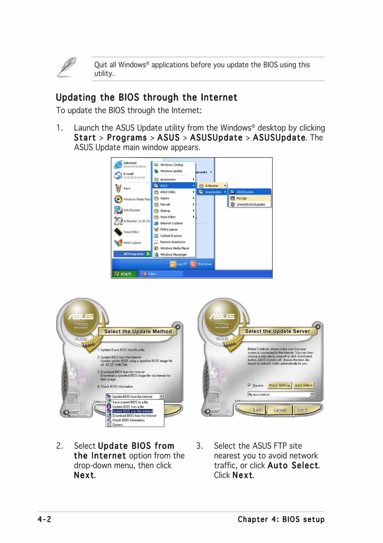
4 - 24 - 24 - 24 - 24 - 2 Chapter 4 : B IOS setupChapter 4 : B IOS setupChapter 4 : B IOS setupChapter 4 : B IOS setupChapter 4 : B IOS setup
3. Select the ASUS FTP sitenearest you to avoid networktraffic, or click Auto Se lectAuto Se lectAuto Se lectAuto Se lectAuto Se lect.Click NextNextNextNextNext.
Updating the BIOS through the InternetUpdating the BIOS through the InternetUpdating the BIOS through the InternetUpdating the BIOS through the InternetUpdating the BIOS through the InternetTo update the BIOS through the Internet:
1. Launch the ASUS Update utility from the Windows® desktop by clickingStart Start Start Start Start > Programs Programs Programs Programs Programs > ASUS ASUS ASUS ASUS ASUS > ASUSUpdate ASUSUpdate ASUSUpdate ASUSUpdate ASUSUpdate > ASUSUpdateASUSUpdateASUSUpdateASUSUpdateASUSUpdate. TheASUS Update main window appears.
2. Select Update B IOS fromUpdate B IOS fromUpdate B IOS fromUpdate B IOS fromUpdate B IOS fromthe Internet the Internet the Internet the Internet the Internet option from thedrop-down menu, then clickNextNextNextNextNext.
Quit all Windows® applications before you update the BIOS using thisutility.

ASUS P5WDG2 WS Profess iona lASUS P5WDG2 WS Profess iona lASUS P5WDG2 WS Profess iona lASUS P5WDG2 WS Profess iona lASUS P5WDG2 WS Profess iona l 4 - 34 - 34 - 34 - 34 - 3
Updating the BIOS through a BIOS fi leUpdating the BIOS through a BIOS fi leUpdating the BIOS through a BIOS fi leUpdating the BIOS through a BIOS fi leUpdating the BIOS through a BIOS fi leTo update the BIOS through a BIOS file:
1. Launch the ASUS Update utility from the Windows® desktop byclicking Start Start Start Start Start > Programs Programs Programs Programs Programs > ASUS ASUS ASUS ASUS ASUS > ASUSUpdate ASUSUpdate ASUSUpdate ASUSUpdate ASUSUpdate >ASUSUpdateASUSUpdateASUSUpdateASUSUpdateASUSUpdate. The ASUS Update main window appears.
2. Select Update B IOS from aUpdate B IOS from aUpdate B IOS from aUpdate B IOS from aUpdate B IOS from af i l e f i l e f i l e f i l e f i l e option from the drop-downmenu, then click NextNextNextNextNext.
4. From the FTP site, select theBIOS version that you wish todownload. Click Next.
5. Follow the screen instructions tocomplete the update process.
The ASUS Update utility iscapable of updating itselfthrough the Internet. Alwaysupdate the utility to avail ofall its features.
3. Locate the BIOS file from theOpen Open Open Open Open window, then click SaveSaveSaveSaveSave.
4. Follow the screen instructions tocomplete the update process.

4 - 44 - 44 - 44 - 44 - 4 Chapter 4 : B IOS setupChapter 4 : B IOS setupChapter 4 : B IOS setupChapter 4 : B IOS setupChapter 4 : B IOS setup
4.1.24.1.24.1.24.1.24.1.2 Creating a bootable floppy diskCreating a bootable floppy diskCreating a bootable floppy diskCreating a bootable floppy diskCreating a bootable floppy disk
1. Do either one of the following to create a bootable floppy disk.
DOS environment
a. Insert a 1.44MB floppy disk into the drive.b. At the DOS prompt, type format A:/S then press <Enter>.
Windows® XP environment
a. Insert a 1.44 MB floppy disk to the floppy disk drive.b. Click Start Start Start Start Start from the Windows® desktop, then select M yM yM yM yM y
ComputerComputerComputerComputerComputer.c. Select the 3 1/2 Floppy Drive icon.d. Click F i l e F i l e F i l e F i l e F i l e from the menu, then select FormatFormatFormatFormatFormat. A Format 3 1/2Format 3 1/2Format 3 1/2Format 3 1/2Format 3 1/2
Floppy D iskF loppy D iskF loppy D iskF loppy D iskF loppy D isk window appears.e. WindowsWindowsWindowsWindowsWindows®®®®® XP users : XP users : XP users : XP users : XP users : Select Create an MS-DOS startupCreate an MS-DOS startupCreate an MS-DOS startupCreate an MS-DOS startupCreate an MS-DOS startup
d i sk d i sk d i sk d i sk d i sk from the format options field, then click Sta r tSta r tSta r tSta r tSta r t.
Windows® 2000 environment
To create a set of boot disks for Windows® 2000:a. Insert a formatted, high density 1.44 MB floppy disk into the drive.b. Insert the Windows® 2000 CD to the optical drive.c. Click Sta r tSta r tSta r tSta r tSta r t, then select R unRunRunRunRun.d. In the Open Open Open Open Open field, type D:\bootdisk\makeboot a:
assuming that D is your optical drive letter.e. Press <Enter>, then follow screen instructions to continue.
2. Copy the original or the latest motherboard BIOS file to the bootablefloppy disk.

ASUS P5WDG2 WS Profess iona lASUS P5WDG2 WS Profess iona lASUS P5WDG2 WS Profess iona lASUS P5WDG2 WS Profess iona lASUS P5WDG2 WS Profess iona l 4 - 54 - 54 - 54 - 54 - 5
4.1.34.1.34.1.34.1.34.1.3 ASUS EZ Flash 2 utilityASUS EZ Flash 2 utilityASUS EZ Flash 2 utilityASUS EZ Flash 2 utilityASUS EZ Flash 2 utilityThe ASUS EZ Flash 2 feature allows you to update the BIOS without havingto go through the long process of booting from a floppy disk and using aDOS-based utility. The EZ Flash 2 utility is built in the BIOS chip so it isaccessible by pressing <Alt> + <F2> during the Power-On Self Tests(POST).
To update the BIOS using EZ Flash 2:
1. Visit the ASUS website (www.asus.com) to download the latest BIOSfile for the motherboard and rename the same to WDG2WSP.ROMWDG2WSP.ROMWDG2WSP.ROMWDG2WSP.ROMWDG2WSP.ROM.
2. Save the BIOS file to a floppy disk or a USB flash disk, then restart thesystem.
3. You can launch the EZ Flash 2 by two methods.(1) Insert the floppy disk / USB flash disk that contains the BIOS file
to the floppy disk drive or the USB port.Press <Alt> + <F2> during POST to display the following.
• This function can supp ort devices such as USB flash disk, or floppydisk with FAT 32/16 format and single partition only.
• Do not shutdown or reset the system while updating the BIOS toprevent system boot failure!
4. When the correct BIOS file is found, EZ Flash 2 performs the BIOSupdate process and automatically reboots the system when done.
(2) Enter BIOS setup program. Go th the Tools menu to select EZFlash 2 and press <Enter> to enable it.You can switch between drives by pressing <Tab> before thecorrect file is found. Then press <Enter>.
ASUSTek EZ Flash 2 BIOS ROM Utility V3.00
Current ROM Update ROMBOARD: P5WDG2-WS ProVER: 0204DATE: 07/04/2006
BOARD: UnknownVER: UnknownDATE: Unknown
A:
[Enter] Select [S] Save [ESC]Exit[Tab] Switch [Up/Down/Home/End] Move
Note
FLASH TYPE: Winbond W39V080A 8Mb LPC
PATH: A:\

4 - 64 - 64 - 64 - 64 - 6 Chapter 4 : B IOS setupChapter 4 : B IOS setupChapter 4 : B IOS setupChapter 4 : B IOS setupChapter 4 : B IOS setup
The utility returns to the DOS prompt after copying the current BIOSfile.
3. Press <Enter>. The utility copies the current BIOS file to the floppydisk.
A:\>afudos /oOLDBIOS1.rom
AMI Firmware Update Utility - Version 1.19(ASUS V2.07(03.11.24BB))
Copyright (C) 2002 American Megatrends, Inc. All rights reserved.
Reading flash ..... done
Write to file...... ok
A:\>
4.1.44.1.44.1.44.1.44.1.4 AFUDOS utilityAFUDOS utilityAFUDOS utilityAFUDOS utilityAFUDOS utilityThe AFUDOS utility allows you to update the BIOS file in DOS environmentusing a bootable floppy disk with the updated BIOS file. This utility alsoallows you to copy the current BIOS file that you can use as backup whenthe BIOS fails or gets corrupted during the updating process.
Copying the current BIOSCopying the current BIOSCopying the current BIOSCopying the current BIOSCopying the current BIOSTo copy the current BIOS file using the AFUDOS utility:
Ma i n f i l e nameMa i n f i l e nameMa i n f i l e nameMa i n f i l e nameMa i n f i l e name Ex tens i on nameEx tens i on nameEx tens i on nameEx tens i on nameEx tens i on name
1. Copy the AFUDOS utility (afudos.exe) from the motherboard supportCD to the bootable floppy disk you created earlier.
2. Boot the system in DOS mode, then at the prompt type:afudos /o[filename]
where the [filename] is any user-assigned filename not more thaneight alphanumeric characters for the main filename and threealphanumeric characters for the extension name.
A:\>afudos /oOLDBIOS1.rom
• Make sure that the floppy disk is not write-protected and has atleast 1.2 MB free space to save the file.
• The succeeding BIOS screens are for reference only. The actual BIOSscreen displays may not be same as shown.

ASUS P5WDG2 WS Profess iona lASUS P5WDG2 WS Profess iona lASUS P5WDG2 WS Profess iona lASUS P5WDG2 WS Profess iona lASUS P5WDG2 WS Profess iona l 4 - 74 - 74 - 74 - 74 - 7
2. Copy the AFUDOS utility (afudos.exe) from the motherboard supportCD to the bootable floppy disk you created earlier.
3. Boot the system in DOS mode, then at the prompt type:
afudos /i[filename]
where [filename] is the latest or the original BIOS file on the bootablefloppy disk.
Updating the BIOS fi leUpdating the BIOS fi leUpdating the BIOS fi leUpdating the BIOS fi leUpdating the BIOS fi leTo update the BIOS file using the AFUDOS utility:
1. Visit the ASUS website (www.asus.com) and download the latest BIOSfile for the motherboard. Save the BIOS file to a bootable floppy disk.
A:\>afudos /iWDG2WSP.rom
Write the BIOS filename on a piece of paper. You need to type the exactBIOS filename at the DOS prompt.
A:\>afudos /iWDG2WSP.rom
AMI Firmware Update Utility - Version 1.19(ASUS V2.07(03.11.24BB))
Copyright (C) 2002 American Megatrends, Inc. All rights reserved.
WARNING!! Do not turn off power during flash BIOSReading file ....... doneReading flash ...... done
Advance Check ......Erasing flash ...... doneWriting flash ...... 0x0008CC00 (9%)
4. The utility verifies the file and starts updating the BIOS.
Do not shut down or reset the system while updating the BIOS toprevent system boot failure!

4 - 84 - 84 - 84 - 84 - 8 Chapter 4 : B IOS setupChapter 4 : B IOS setupChapter 4 : B IOS setupChapter 4 : B IOS setupChapter 4 : B IOS setup
5. The utility returns to the DOS prompt after the BIOS update process iscompleted. Reboot the system from the hard disk drive.
A:\>afudos /iWDG2WSP.rom
AMI Firmware Update Utility - Version 1.19(ASUS V2.07(03.11.24BB))
Copyright (C) 2002 American Megatrends, Inc. All rights reserved.
WARNING!! Do not turn off power during flash BIOSReading file ....... doneReading flash ...... done
Advance Check ......Erasing flash ...... doneWriting flash ...... doneVerifying flash .... done
Please restart your computer
A:\>
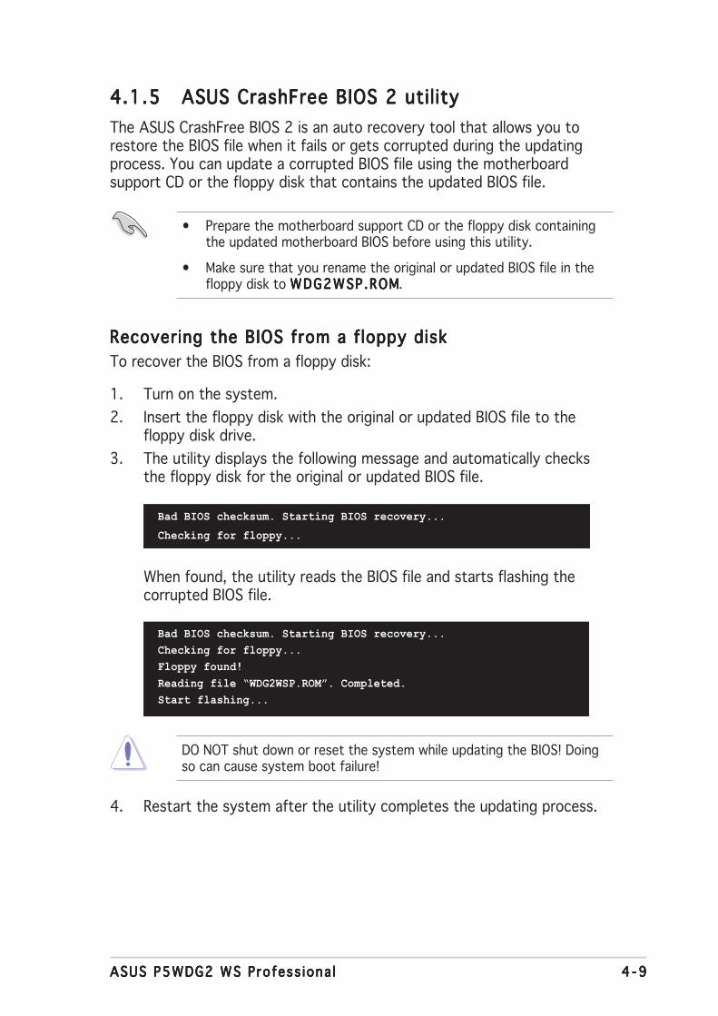
ASUS P5WDG2 WS Profess iona lASUS P5WDG2 WS Profess iona lASUS P5WDG2 WS Profess iona lASUS P5WDG2 WS Profess iona lASUS P5WDG2 WS Profess iona l 4 - 94 - 94 - 94 - 94 - 9
4.1.54.1.54.1.54.1.54.1.5 ASUS CrashFree BIOS 2 utilityASUS CrashFree BIOS 2 utilityASUS CrashFree BIOS 2 utilityASUS CrashFree BIOS 2 utilityASUS CrashFree BIOS 2 utilityThe ASUS CrashFree BIOS 2 is an auto recovery tool that allows you torestore the BIOS file when it fails or gets corrupted during the updatingprocess. You can update a corrupted BIOS file using the motherboardsupport CD or the floppy disk that contains the updated BIOS file.
Recovering the BIOS from a floppy diskRecovering the BIOS from a floppy diskRecovering the BIOS from a floppy diskRecovering the BIOS from a floppy diskRecovering the BIOS from a floppy diskTo recover the BIOS from a floppy disk:
1. Turn on the system.2. Insert the floppy disk with the original or updated BIOS file to the
floppy disk drive.3. The utility displays the following message and automatically checks
the floppy disk for the original or updated BIOS file.
Bad BIOS checksum. Starting BIOS recovery...
Checking for floppy...
4. Restart the system after the utility completes the updating process.
Bad BIOS checksum. Starting BIOS recovery...Checking for floppy...Floppy found!Reading file “WDG2WSP.ROM”. Completed.Start flashing...
When found, the utility reads the BIOS file and starts flashing thecorrupted BIOS file.
DO NOT shut down or reset the system while updating the BIOS! Doingso can cause system boot failure!
• Prepare the motherboard support CD or the floppy disk containingthe updated motherboard BIOS before using this utility.
• Make sure that you rename the original or updated BIOS file in thefloppy disk to WDG2WSP.ROMWDG2WSP.ROMWDG2WSP.ROMWDG2WSP.ROMWDG2WSP.ROM.

4 -104 -104 -104 -104 -10 Chapter 4 : B IOS setupChapter 4 : B IOS setupChapter 4 : B IOS setupChapter 4 : B IOS setupChapter 4 : B IOS setup
The recovered BIOS may not be the latest BIOS version for thismotherboard. Visit the ASUS website (www.asus.com) to download thelatest BIOS file.
Recovering the BIOS from the support CDRecovering the BIOS from the support CDRecovering the BIOS from the support CDRecovering the BIOS from the support CDRecovering the BIOS from the support CDTo recover the BIOS from the support CD:
1. Remove any floppy disk from the floppy disk drive, then turn on thesystem.
2. Insert the support CD to the optical drive.3. The utility displays the following message and automatically checks
the floppy disk for the original or updated BIOS file.
4. Restart the system after the utility completes the updating process.
DO NOT shut down or reset the system while updating the BIOS! Doingso can cause system boot failure!
Bad BIOS checksum. Starting BIOS recovery...Checking for floppy...Floppy not found!Checking for CD-ROM...CD-ROM found!Reading file “WDG2WSP.ROM”. Completed.Start flashing...
When no floppy disk is found, the utility automatically checks theoptical drive for the original or updated BIOS file. The utility thenupdates the corrupted BIOS file.
Bad BIOS checksum. Starting BIOS recovery...Checking for floppy...

ASUS P5WDG2 WS Profess iona lASUS P5WDG2 WS Profess iona lASUS P5WDG2 WS Profess iona lASUS P5WDG2 WS Profess iona lASUS P5WDG2 WS Profess iona l 4 -114 -114 -114 -114 -11
4.2 BIOS setup programThis motherboard supports a programmable firmware chip that you canupdate using the provided utility described in section “4.1 Managing andupdating your BIOS.”
Use the BIOS Setup program when you are installing a motherboard,reconfiguring your system, or prompted to “Run Setup.” This sectionexplains how to configure your system using this utility.
Even if you are not prompted to use the Setup program, you can changethe configuration of your computer in the future. For example, you canenable the security password feature or change the power managementsettings. This requires you to reconfigure your system using the BIOSSetup program so that the computer can recognize these changes andrecord them in the CMOS RAM or the firmware hub.
The firmware hub on the motherboard stores the Setup utility. When youstart up the computer, the system provides you with the opportunity torun this program. Press <Del> during the Power-On-Self-Test (POST) toenter the Setup utility; otherwise, POST continues with its test routines.
If you wish to enter Setup after POST, restart the system by pressing<Ctrl+Alt+Delete>, or by pressing the reset button on the system chassis.You can also restart by turning the system off and then back on. Do thislast option only if the first two failed.
The Setup program is designed to make it as easy to use as possible. Beinga menu-driven program, it lets you scroll through the various sub-menusand make your selections from the available options using the navigationkeys.
• The default BIOS settings for this motherboard apply for mostconditions to ensure optimum performance. If the system becomesunstable after changing any BIOS settings, load the default settingsto ensure system compatibility and stability. Select the L o a dL o a dL o a dL o a dL o a dDefau l t Sett ingsDefau l t Sett ingsDefau l t Sett ingsDefau l t Sett ingsDefau l t Sett ings item under the Exit Menu. See section “4.7 ExitMenu.”
• The BIOS setup screens shown in this section are for referencepurposes only, and may not exactly match what you see on yourscreen.
• Visit the ASUS website (www.asus.com) to download the latest BIOSfile for this motherboard.

4 -124 -124 -124 -124 -12 Chapter 4 : B IOS setupChapter 4 : B IOS setupChapter 4 : B IOS setupChapter 4 : B IOS setupChapter 4 : B IOS setup
4.2.24.2.24.2.24.2.24.2.2 Menu barMenu barMenu barMenu barMenu barThe menu bar on top of the screen has the following main items:
Ma inMa inMa inMa inMa in For changing the basic system configurationAdvancedAdvancedAdvancedAdvancedAdvanced For changing the advanced system settingsPowerPowerPowerPowerPower For changing the advanced power management (APM)
configurationBootBootBootBootBoot For changing the system boot configurationToo l sToo l sToo l sToo l sToo l s For configuring options for special functionsEx i tEx i tEx i tEx i tEx i t For selecting the exit options and loading default
settings
To select an item on the menu bar, press the right or left arrow key on thekeyboard until the desired item is highlighted.
4.2.34.2.34.2.34.2.34.2.3 Navigation keysNavigation keysNavigation keysNavigation keysNavigation keysAt the bottom right corner of a menu screen are the navigation keys forthat particular menu. Use the navigation keys to select items in the menuand change the settings.
4.2.14.2.14.2.14.2.14.2.1 BIOS menu screenBIOS menu screenBIOS menu screenBIOS menu screenBIOS menu screen
Some of the navigation keys differ from one screen to another.
Select Screen Select Item
+- Change FieldTab Select FieldF1 General HelpF10 Save and ExitESC Exit
v02.58 (C)Copyright 1985-2005, American Megatrends, Inc.
BIOS SETUP UTILITYMain Advanced Power Boot Exit
System Time [10:55:25]System Date [Mon 07/05/2006]Legacy Diskette A [1.44M, 3.5 in]
Primary IDE Master [ST320410A]Primary IDE Slave [ASUS CD-S520/A]Third IDE Master [Not Detected]Third IDE Slave [Not Detected]Fourth IDE Master [Not Detected]Fourth IDE Slave [Not Detected]IDE Configuration
System Information
Use [ENTER], [TAB] or[SHIFT-TAB] to selecta field.
Use [+] or [-] toconfigure the SystemTime.
Nav iga t i on keysNav i ga t i on keysNav i ga t i on keysNav i ga t i on keysNav i ga t i on keys
Gene r a l he l pGene r a l he l pGene r a l he l pGene r a l he l pGene r a l he l pMenu ba rMenu ba rMenu ba rMenu ba rMenu ba r
Sub -menu i t emsSub -menu i t emsSub -menu i t emsSub -menu i t emsSub -menu i t ems
Con f i gu ra t i on f i e l d sCon f i gu ra t i on f i e l d sCon f i gu ra t i on f i e l d sCon f i gu ra t i on f i e l d sCon f i gu ra t i on f i e l d sMenu i t emsMenu i t emsMenu i t emsMenu i t emsMenu i t ems

ASUS P5WDG2 WS Profess iona lASUS P5WDG2 WS Profess iona lASUS P5WDG2 WS Profess iona lASUS P5WDG2 WS Profess iona lASUS P5WDG2 WS Profess iona l 4 -134 -134 -134 -134 -13
4.2.44.2.44.2.44.2.44.2.4 Menu itemsMenu itemsMenu itemsMenu itemsMenu itemsThe highlighted item on the menu bardisplays the specific items for thatmenu. For example, selecting Ma inMa inMa inMa inMa inshows the Main menu items.
The other items (Advanced, Power,Boot, and Exit) on the menu bar havetheir respective menu items.
4.2.54.2.54.2.54.2.54.2.5 Sub-menu itemsSub-menu itemsSub-menu itemsSub-menu itemsSub-menu itemsA solid triangle before each item on any menu screen means that the iteamhas a sub-menu. To display the sub-menu, select the item and press<Enter>.
4.2.64.2.64.2.64.2.64.2.6 Configuration fieldsConfiguration fieldsConfiguration fieldsConfiguration fieldsConfiguration fieldsThese fields show the values for the menu items. If an item is user-configurable, you can change the value of the field opposite the item. Youcannot select an item that is not user-configurable.
A configurable field is enclosed in brackets, and is highlighted whenselected. To change the value of a field, select it then press <Enter> todisplay a list of options. Refer to “4.2.7 Pop-up window.”
4.2.74.2.74.2.74.2.74.2.7 Pop-up windowPop-up windowPop-up windowPop-up windowPop-up windowSelect a menu item then press <Enter> to display a pop-up window withthe configuration options for that item.
4.2.84.2.84.2.84.2.84.2.8 Scroll barScroll barScroll barScroll barScroll barA scroll bar appears on the right sideof a menu screen when there are itemsthat do not fit on the screen. Press theUp/Down arrow keys or <Page Up> /<Page Down> keys to display the otheritems on the screen.
4.2.94.2.94.2.94.2.94.2.9 General helpGeneral helpGeneral helpGeneral helpGeneral helpAt the top right corner of the menuscreen is a brief description of theselected item.
Ma i n menu i t emsMa i n menu i t emsMa i n menu i t emsMa i n menu i t emsMa i n menu i t ems
Sc ro l l b a rSc ro l l b a rSc ro l l b a rSc ro l l b a rSc ro l l b a r
Select Screen Select Item+- Change OptionF1 General HelpF10 Save and ExitESC Exit
Advanced Chipset settings
WARNING: Setting wrong values in the sections below may cause system to malfunction.
Configure DRAM Timing by SPD [Enabled]Memory Acceleration Mode [Auto]DRAM Idle Timer [Auto]DRAm Refresh Rate [Auto]
Graphic Adapter Priority [AGP/PCI]Graphics Aperture Size [ 64 MB]Spread Spectrum [Enabled]
ICH Delayed Transaction [Enabled]
MPS Revision [1.4]
Pop -up w i ndowPop -up w i ndowPop -up w i ndowPop -up w i ndowPop -up w i ndow
System Time [11:51:19]System Date [Wed 11/02/2005]Legacy Diskette A [1.44M, 3.5 in]Language [English]
Primary IDE Master [ST320413A] Primary IDE Slave [ASUS CD-S520/A] Third IDE Master [Not Detected] Third IDE Slave [Not Detected] Fourth IDE Master [Not Detected] Fourth IDE Slave [Not Detected] IDE Configuration System Information
Use [ENTER],[TAB], or[SHIFT-TAB] toselect a field.
Use [+] or [-]to configure
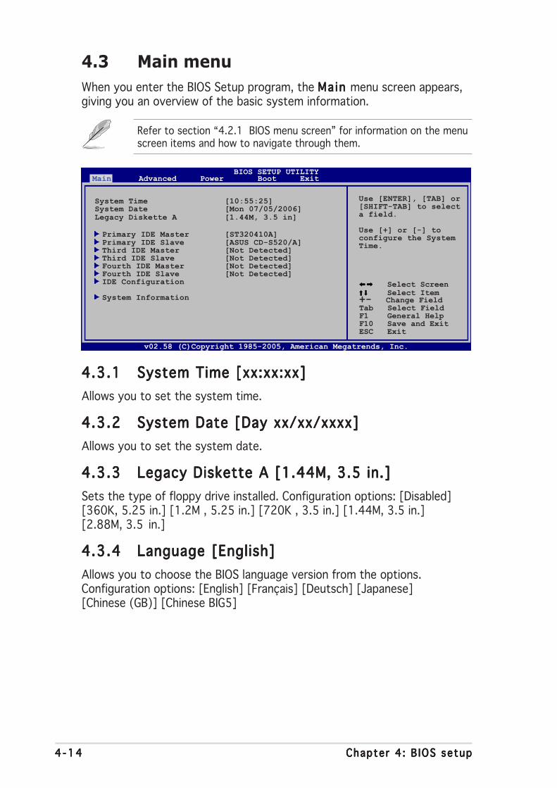
4 -144 -144 -144 -144 -14 Chapter 4 : B IOS setupChapter 4 : B IOS setupChapter 4 : B IOS setupChapter 4 : B IOS setupChapter 4 : B IOS setup
4.3 Main menuWhen you enter the BIOS Setup program, the Ma in Ma in Ma in Ma in Ma in menu screen appears,giving you an overview of the basic system information.
4.3.14.3.14.3.14.3.14.3.1 System Time [xx:xx:xx]System Time [xx:xx:xx]System Time [xx:xx:xx]System Time [xx:xx:xx]System Time [xx:xx:xx]Allows you to set the system time.
4.3.24.3.24.3.24.3.24.3.2 System Date [Day xx/xx/xxxx]System Date [Day xx/xx/xxxx]System Date [Day xx/xx/xxxx]System Date [Day xx/xx/xxxx]System Date [Day xx/xx/xxxx]Allows you to set the system date.
4.3.34.3.34.3.34.3.34.3.3 Legacy Diskette A [1.44M, 3.5 in.]Legacy Diskette A [1.44M, 3.5 in.]Legacy Diskette A [1.44M, 3.5 in.]Legacy Diskette A [1.44M, 3.5 in.]Legacy Diskette A [1.44M, 3.5 in.]Sets the type of floppy drive installed. Configuration options: [Disabled][360K, 5.25 in.] [1.2M , 5.25 in.] [720K , 3.5 in.] [1.44M, 3.5 in.][2.88M, 3.5 in.]
4.3.44.3.44.3.44.3.44.3.4 Language [English]Language [English]Language [English]Language [English]Language [English]Allows you to choose the BIOS language version from the options.Configuration options: [English] [Français] [Deutsch] [Japanese][Chinese (GB)] [Chinese BIG5]
Refer to section “4.2.1 BIOS menu screen” for information on the menuscreen items and how to navigate through them.
Select Screen Select Item
+- Change FieldTab Select FieldF1 General HelpF10 Save and ExitESC Exit
v02.58 (C)Copyright 1985-2005, American Megatrends, Inc.
BIOS SETUP UTILITYMain Advanced Power Boot Exit
System Time [10:55:25]System Date [Mon 07/05/2006]Legacy Diskette A [1.44M, 3.5 in]
Primary IDE Master [ST320410A]Primary IDE Slave [ASUS CD-S520/A]Third IDE Master [Not Detected]Third IDE Slave [Not Detected]Fourth IDE Master [Not Detected]Fourth IDE Slave [Not Detected]IDE Configuration
System Information
Use [ENTER], [TAB] or[SHIFT-TAB] to selecta field.
Use [+] or [-] toconfigure the SystemTime.

ASUS P5WDG2 WS Profess iona lASUS P5WDG2 WS Profess iona lASUS P5WDG2 WS Profess iona lASUS P5WDG2 WS Profess iona lASUS P5WDG2 WS Profess iona l 4 -154 -154 -154 -154 -15
4.3.54.3.54.3.54.3.54.3.5 Primary, Third, and Fourth IDE Master/SlavePrimary, Third, and Fourth IDE Master/SlavePrimary, Third, and Fourth IDE Master/SlavePrimary, Third, and Fourth IDE Master/SlavePrimary, Third, and Fourth IDE Master/SlaveThe BIOS automatically detects the connected IDE devices. There is aseparate sub-menu for each IDE device. Select a device item, then press<Enter> to display the IDE device information.
The BIOS automatically detects the values opposite the dimmed items(Device, Vendor, Size, LBA Mode, Block Mode, PIO Mode, Async DMA, UltraDMA, and SMART monitoring). These values are not user-configurable.These items show N/A if no IDE device is installed in the system.
Type [Auto]Type [Auto]Type [Auto]Type [Auto]Type [Auto]Selects the type of IDE drive. Setting to [Auto] allows automatic selectionof the appropriate IDE device type. Select [CDROM] if you are specificallyconfiguring a CD-ROM drive. Select [ARMD] (ATAPI Removable MediaDevice) if your device is either a ZIP, LS-120, or MO drive.Configuration options: [Not Installed] [Auto] [CDROM] [ARMD]
LBA/Large Mode [Auto]LBA/Large Mode [Auto]LBA/Large Mode [Auto]LBA/Large Mode [Auto]LBA/Large Mode [Auto]Enables or disables the LBA mode. Setting to [Auto] enables the LBA modeif the device supports this mode, and if the device was not previouslyformatted with LBA mode disabled. Configuration options: [Disabled][Auto]
Block (Multi-sector Transfer) M [Auto]Block (Multi-sector Transfer) M [Auto]Block (Multi-sector Transfer) M [Auto]Block (Multi-sector Transfer) M [Auto]Block (Multi-sector Transfer) M [Auto]Enables or disables data multi-sector transfer mode. When set to [Auto],the data transfer from and to the device occurs multiple sectors at a timeif the device supports multi-sector transfer feature. When set to[Disabled], the data transfer from and to the device occurs one sector at atime. Configuration options: [Disabled] [Auto]
Primary IDE MasterDevice : Hard DiskVendor : ST320413ASize : 20.0GBLBA Mode : SupportedBlock Mode : 16 SectorsPIO Mode : SupportedAsync DMA : MultiWord DMA-2Ultra DMA : Ultra DMA-5SMART Monitoring: Supported
Type [Auto]LBA/Large Mode [Auto]Block(Multi-sector Transfer) M [Auto]PIO Mode [Auto]DMA Mode [Auto]SMART Monitoring [Auto]32Bit Data Transfer [Enabled]

4 -164 -164 -164 -164 -16 Chapter 4 : B IOS setupChapter 4 : B IOS setupChapter 4 : B IOS setupChapter 4 : B IOS setupChapter 4 : B IOS setup
PIO Mode [Auto]PIO Mode [Auto]PIO Mode [Auto]PIO Mode [Auto]PIO Mode [Auto]Selects the PIO mode.Configuration options: [Auto] [0] [1] [2] [3] [4]
DMA Mode [Auto]DMA Mode [Auto]DMA Mode [Auto]DMA Mode [Auto]DMA Mode [Auto]Selects the DMA mode. Configuration options: [Auto]
SMART Monitoring [Auto]SMART Monitoring [Auto]SMART Monitoring [Auto]SMART Monitoring [Auto]SMART Monitoring [Auto]Sets the Smart Monitoring, Analysis, and Reporting Technology.Configuration options: [Auto] [Disabled] [Enabled]
32Bit Data Transfer [Enabled]32Bit Data Transfer [Enabled]32Bit Data Transfer [Enabled]32Bit Data Transfer [Enabled]32Bit Data Transfer [Enabled]Enables or disables 32-bit data transfer.Configuration options: [Disabled] [Enabled]
Configure SATA As [Standard IDE]Configure SATA As [Standard IDE]Configure SATA As [Standard IDE]Configure SATA As [Standard IDE]Configure SATA As [Standard IDE]Sets the configuration for the Serial ATA connectors supported by theSouthbridge chip.
The AHCI allows the onboard storage driver to enable advanced Serial ATAfeatures that increases storage performance on random workloads byallowing the drive to internally optimize the order of commands.
If you want to create a RAID 0, RAID 1, RAID 10, and RAID 5, or the Intel®Matrix Storage Technology configuration from the Serial ATA hard diskdrives, set this item to [RAID].
If you want to use the Serial ATA hard disk drives as Parallel ATA physicalstorage devices, keep the defaul setting [Standard IDE].
IDE Configuration
Configure SATA As [Standard IDE]Onboard IDE Operate Mode [Enhanced Mode]
Enhanced Mode Support On [S-ATA]
IDE Detect Time Out (Sec) [35]
When in AHCI/RAIDmode SATAcontroller isforced to Nativemode.
4.3.64.3.64.3.64.3.64.3.6 IDE ConfigurationIDE ConfigurationIDE ConfigurationIDE ConfigurationIDE ConfigurationThe items in this menu allow you to set or change the configurations forthe IDE devices installed in the system. Select an item then press <Enter>if you want to configure the item.

ASUS P5WDG2 WS Profess iona lASUS P5WDG2 WS Profess iona lASUS P5WDG2 WS Profess iona lASUS P5WDG2 WS Profess iona lASUS P5WDG2 WS Profess iona l 4 -174 -174 -174 -174 -17
If you want the Serial ATA hard disk drives to use the Advanced HostController Interface (AHCI), set this item to [AHCI]. For details on AHCI, go to:
www.intel.com/support/chipsets/imst/sb/CS-012304.htmwww.intel.com/support/chipsets/imst/sb/CS-012305.htm
The SATA controller is set to Native mode when this item is set to [RAID]or [AHCI]
The Onboard IDE Operate Mode Onboard IDE Operate Mode Onboard IDE Operate Mode Onboard IDE Operate Mode Onboard IDE Operate Mode and its sub-menu items appearonly when the Conf igure SATA As Conf igure SATA As Conf igure SATA As Conf igure SATA As Conf igure SATA As item is set to [Standard IDE].
Onboard IDE Operate Mode [Enhanced Mode]Onboard IDE Operate Mode [Enhanced Mode]Onboard IDE Operate Mode [Enhanced Mode]Onboard IDE Operate Mode [Enhanced Mode]Onboard IDE Operate Mode [Enhanced Mode]Allows selection of the IDE operation mode depending on the installedoperating system (OS). Set to [Enhanced Mode] if you are using OSsupporting native mode, including Windows® 2000/XP. Configurationoptions: [Disabled] [Compatible Mode] [Enhanced Mode]
If you are using a Serial ATA optical drive, set this item to [CompatibleMode] before creating a boot disk using the support CD.
Enhanced Mode Support On [S-ATA]Allows you to use OS support ing nat ive mode OS support ing nat ive mode OS support ing nat ive mode OS support ing nat ive mode OS support ing nat ive mode on Serial ATA andParallel ATA ports. It is recommend that you do not change thedefault setting for better OS compatibility. In this setting, you mayuse legacy OS on the Parallel ATA ports only if you do not install anySerial ATA device.
The P-ATA+S-ATA and P-ATA options are for advanced users only. Ifyou set to any of these options and encountered problems, revert tothe default setting S -ATAS-ATAS-ATAS-ATAS-ATA. Configuration options: [S-ATA+P-ATA][S-ATA] [P-ATA]
Combined Mode Option [Primary P-ATA +S-ATA]Allows you to choose the IDE ports to be used.Configuration options: [Primary P-ATA +S-ATA] [S-ATA only][P-ATA only]
The [S-ATA only] and [P-ATA only] options are for advanced usersonly. If you set to any of these options and encounter problems,revert to the default setting [Primary P-ATA+S-ATA].
The Combined Mode Opt ionCombined Mode Opt ionCombined Mode Opt ionCombined Mode Opt ionCombined Mode Opt ion item appears when you set theOnboard IDE Operate ModeOnboard IDE Operate ModeOnboard IDE Operate ModeOnboard IDE Operate ModeOnboard IDE Operate Mode to [Compatible Mode].

4 -184 -184 -184 -184 -18 Chapter 4 : B IOS setupChapter 4 : B IOS setupChapter 4 : B IOS setupChapter 4 : B IOS setupChapter 4 : B IOS setup
4.3.74.3.74.3.74.3.74.3.7 System InformationSystem InformationSystem InformationSystem InformationSystem InformationThis menu gives you an overview of the general system specifications. TheBIOS automatically detects the items in this menu.
AMI BIOSAMI BIOSAMI BIOSAMI BIOSAMI BIOSDisplays the auto-detected BIOS information.
ProcessorProcessorProcessorProcessorProcessorDisplays the auto-detected CPU specification.
System MemorySystem MemorySystem MemorySystem MemorySystem MemoryDisplays the auto-detected system memory.
AMIBIOSVersion : 0201Build Date : 07/03/06
ProcessorType : Genuine Intel(R) CPU 2.80GHzSpeed : 2800 MHzCount : 2
System MemoryTotal : 512MBAppropritated : 0MBAvailable : 512MB
Onboard Serial-ATA BOOTROOM [Enabled]Enables or disables the onboard Serial ATA boot ROM.Configuration options: [Disabled] [Enabled]
The Onboard Ser ia l -ATA BOOTROM Onboard Ser ia l -ATA BOOTROM Onboard Ser ia l -ATA BOOTROM Onboard Ser ia l -ATA BOOTROM Onboard Ser ia l -ATA BOOTROM appears only when theConf igure SATA As Conf igure SATA As Conf igure SATA As Conf igure SATA As Conf igure SATA As item is set to [RAID].
ALPE and ASP [Disabled]ALPE and ASP [Disabled]ALPE and ASP [Disabled]ALPE and ASP [Disabled]ALPE and ASP [Disabled]Allows you to enable or disable the Agressive Link Power Management(ALPE) and Aggressive Slumber/Partial (ASP) management features.Configuration options: [Disabled] [Enabled]
The ALPE and ASP ALPE and ASP ALPE and ASP ALPE and ASP ALPE and ASP and its sub-menu item appear only when theConf igure SATA As Conf igure SATA As Conf igure SATA As Conf igure SATA As Conf igure SATA As item is set to [AHCI].
IDE Detect Time Out(Sec) [35]IDE Detect Time Out(Sec) [35]IDE Detect Time Out(Sec) [35]IDE Detect Time Out(Sec) [35]IDE Detect Time Out(Sec) [35]Selects the time out value for detecting ATA/ATAPI devices.Configuration options: [0] [5] [10] [15] [20] [25] [30] [35]
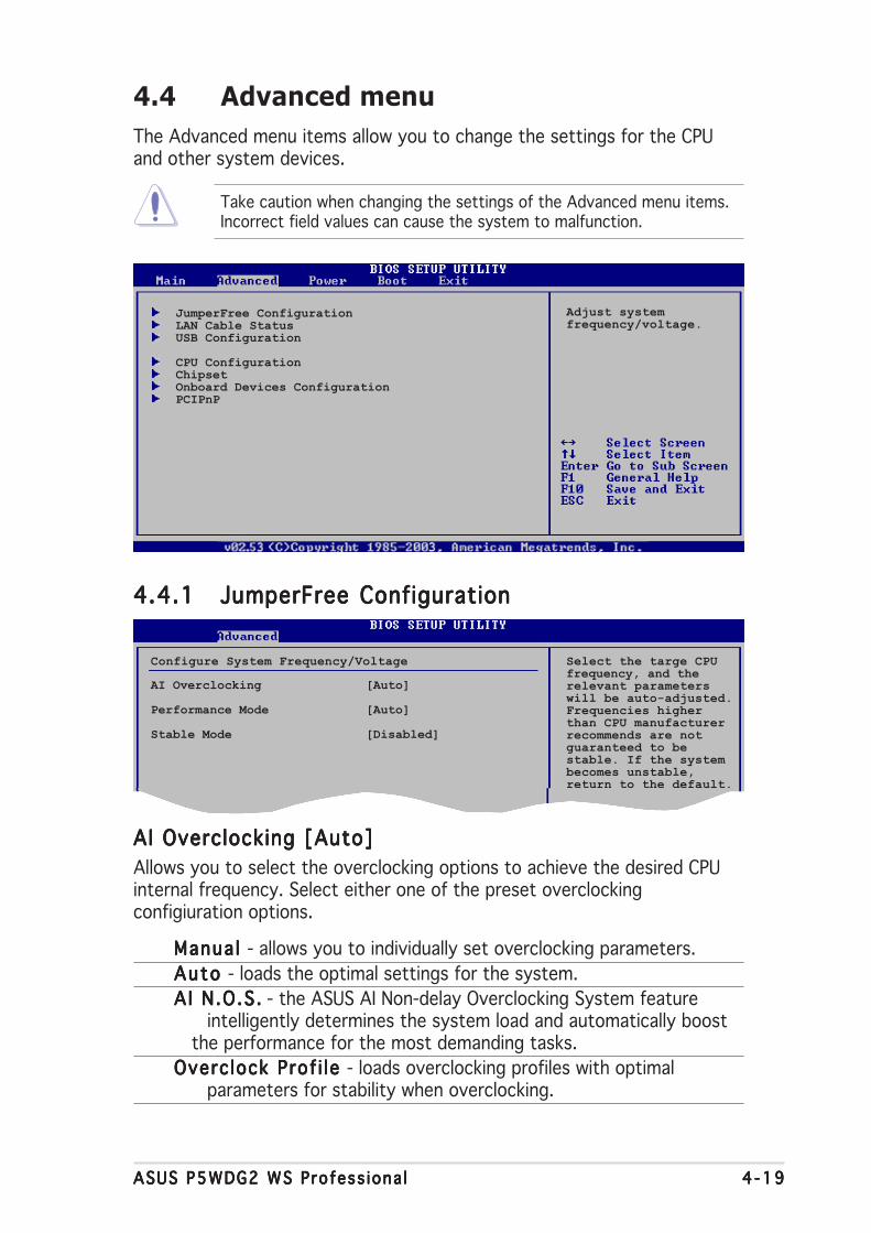
ASUS P5WDG2 WS Profess iona lASUS P5WDG2 WS Profess iona lASUS P5WDG2 WS Profess iona lASUS P5WDG2 WS Profess iona lASUS P5WDG2 WS Profess iona l 4 -194 -194 -194 -194 -19
4.4 Advanced menuThe Advanced menu items allow you to change the settings for the CPUand other system devices.
JumperFree ConfigurationLAN Cable StatusUSB Configuration
CPU ConfigurationChipsetOnboard Devices ConfigurationPCIPnP
4.4.14.4.14.4.14.4.14.4.1 JumperFree ConfigurationJumperFree ConfigurationJumperFree ConfigurationJumperFree ConfigurationJumperFree Configuration
AI Overclocking [Auto]AI Overclocking [Auto]AI Overclocking [Auto]AI Overclocking [Auto]AI Overclocking [Auto]Allows you to select the overclocking options to achieve the desired CPUinternal frequency. Select either one of the preset overclockingconfigiuration options.
Manua l Manua l Manua l Manua l Manua l - allows you to individually set overclocking parameters.Auto Auto Auto Auto Auto - loads the optimal settings for the system.AI N.O.S .A I N.O.S .A I N.O.S .A I N.O.S .A I N.O.S . - the ASUS AI Non-delay Overclocking System feature
intelligently determines the system load and automatically boostthe performance for the most demanding tasks.
Overc lock Prof i le Overc lock Prof i le Overc lock Prof i le Overc lock Prof i le Overc lock Prof i le - loads overclocking profiles with optimalparameters for stability when overclocking.
Take caution when changing the settings of the Advanced menu items.Incorrect field values can cause the system to malfunction.
Adjust systemfrequency/voltage.
Configure System Frequency/Voltage
AI Overclocking [Auto]
Performance Mode [Auto]
Stable Mode [Disabled]
Select the targe CPUfrequency, and therelevant parameterswill be auto-adjusted.Frequencies higherthan CPU manufacturerrecommends are notguaranteed to bestable. If the systembecomes unstable,return to the default.

4 -204 -204 -204 -204 -20 Chapter 4 : B IOS setupChapter 4 : B IOS setupChapter 4 : B IOS setupChapter 4 : B IOS setupChapter 4 : B IOS setup
The following item appears only when you install a CPU that supports thelock free feature. Only some latest CPUs support this feature
CPU Lock Free [Auto]CPU Lock Free [Auto]CPU Lock Free [Auto]CPU Lock Free [Auto]CPU Lock Free [Auto]This feature allows you to adjust the CPU multiplier to 14x. Setting thisitem to [Auto] allows the motherboard to automatically reduce the CPUmultiplier value for more flexibility when increasing external FSB.Configuration options: [Auto] [Disabled] [Enabled]
The following item appears only when you set the A I Overc lock ingA I Overc lock ingA I Overc lock ingA I Overc lock ingA I Overc lock ingitem to [Manual].
CPU Frequency [XXX]CPU Frequency [XXX]CPU Frequency [XXX]CPU Frequency [XXX]CPU Frequency [XXX]Displays the frequency sent by the clock generator to the system bus andPCI bus. The value of this item is auto-detected by the BIOS. Use the <+><+><+><+><+>and < ->< ->< ->< ->< -> keys to adjust the CPU frequency. You can also type the desiredCPU frequency using the numeric keypad. The values range from 100 to450.
DRAM Frequency [Auto]DRAM Frequency [Auto]DRAM Frequency [Auto]DRAM Frequency [Auto]DRAM Frequency [Auto]Allows you to set the DDR operating frequency.Configuration options: [Auto] [DDR2-400MHz] [DDR2-533MHz][DDR2-600MHz] [DDR2-667MHz] [DDR2-800MHz] [DDR2-889MHz][DDR2-1066MHz]
Selecting a very high DRAM frequency may cause the system to becomeunstable! If this happens, revert to the default setting.

ASUS P5WDG2 WS Profess iona lASUS P5WDG2 WS Profess iona lASUS P5WDG2 WS Profess iona lASUS P5WDG2 WS Profess iona lASUS P5WDG2 WS Profess iona l 4 -214 -214 -214 -214 -21
Performance Mode [Auto]Performance Mode [Auto]Performance Mode [Auto]Performance Mode [Auto]Performance Mode [Auto]Allows enhanced system performance. Setting to [Turbo] may cause thesystem to become unstable. If this happens, revert to the default setting[Auto]. Configuration options: [Auto] [Standard] [Turbo]
PCI Express Frequency [Auto]PCI Express Frequency [Auto]PCI Express Frequency [Auto]PCI Express Frequency [Auto]PCI Express Frequency [Auto]Allows you to set the PCI Express frequency. This item is set to [Auto] bydefault. Configuration options: [Auto] [90] ~ [150]
PCI Clock Synchronization Mode [Auto]PCI Clock Synchronization Mode [Auto]PCI Clock Synchronization Mode [Auto]PCI Clock Synchronization Mode [Auto]PCI Clock Synchronization Mode [Auto]Allows you to synchronize the PCI frequency with the PCI Express or CPUfrequency. Configuration options: [To CPU] [33.33MHz] [Auto]
CPU Clock Spread Spectrum [Enabled]CPU Clock Spread Spectrum [Enabled]CPU Clock Spread Spectrum [Enabled]CPU Clock Spread Spectrum [Enabled]CPU Clock Spread Spectrum [Enabled]Allows you to enable or disable the CPU clock spread spectrum.Configuration options: [Disabled] [Enabled]
PCIE Clock Spread Spectrum [Disaabled]PCIE Clock Spread Spectrum [Disaabled]PCIE Clock Spread Spectrum [Disaabled]PCIE Clock Spread Spectrum [Disaabled]PCIE Clock Spread Spectrum [Disaabled]Allows you to enable or disable the PCI Express clock spread spectrum.Configuration options: [Disabled] [Enabled]
The following items also appear when the A I Overc lock ing A I Overc lock ing A I Overc lock ing A I Overc lock ing A I Overc lock ing item is setto [AI NOS].
Memory Voltage [Auto]Memory Voltage [Auto]Memory Voltage [Auto]Memory Voltage [Auto]Memory Voltage [Auto]Allows you to select the DDR2 reference voltage.Configuration options: [Auto] [1.80V] [1.90V] [1.95V] [2.00V] [2.05V][2.10V] [2.15V] [2.20V] [2.25V] [2.30V] [2.35V] [2.40V]
Refer to the DDR2 documentation before adjusting the memory voltage.Setting a very high memory voltage may damage the memory module(s)!
CPU VCore Voltage [Auto]CPU VCore Voltage [Auto]CPU VCore Voltage [Auto]CPU VCore Voltage [Auto]CPU VCore Voltage [Auto]Allows you to select the CPU VCore voltage. Configuration options: [Auto][1.7000V] [1.6875V] [1.6750V] [1.6625V] [1.6500V] [1.6375V][1.6250V] [1.6125V] [1.6000V] [1.5875V] [1.5750V] [1.5625V][1.5500V] [1.5375V] [1.5250V] [1.5125V] [1.5000V] [1.4875V][1.4750V] [1.4625V] [1.4500V] [1.4375V] [1.4250V] [1.4125V][1.4000V] [1.3875V] [1.3750V] [1.3625V] [1.3500V] [1.3375V][1.3250V] [1.3125V] [1.3000V] [1.2875V] [1.2750V] [1.2625V][1.2500V] [1.2375V] [1.2250V] [1.2125V] [1.2000V]
Refer to the CPU documentation before setting the CPU Vcore voltage.Setting a high Vcore voltage may damage the CPU!

4 -224 -224 -224 -224 -22 Chapter 4 : B IOS setupChapter 4 : B IOS setupChapter 4 : B IOS setupChapter 4 : B IOS setupChapter 4 : B IOS setup
FSB Termination Voltage [Auto]FSB Termination Voltage [Auto]FSB Termination Voltage [Auto]FSB Termination Voltage [Auto]FSB Termination Voltage [Auto]Allows you to select the front side bus termination voltage.Configuration options: [Auto] [1.20V] [1.30V] [1.40V] [1.50V]
Setting a high FSB termination voltage may damage the chipset andCPU.
MCH Chipset Voltage [Auto]MCH Chipset Voltage [Auto]MCH Chipset Voltage [Auto]MCH Chipset Voltage [Auto]MCH Chipset Voltage [Auto]Allows you to select the chipset voltage of the memory controller hub(MCH). Configuration options: [Auto] [1.50V] [1.60V] [1.70V] [1.80V]
Setting a high MCH chipset voltage may damage the chipset!
ICH Chipset Voltage [Auto]ICH Chipset Voltage [Auto]ICH Chipset Voltage [Auto]ICH Chipset Voltage [Auto]ICH Chipset Voltage [Auto]Allows you to select the chipset voltage of the I/O controller hub (ICH).Configuration options: [Auto] [1.05V] [1.20V]
Setting a high ICH chipset voltage may damage the chipset!
The following item appears only when the A I Overc lock ing A I Overc lock ing A I Overc lock ing A I Overc lock ing A I Overc lock ing item is setto [Overclock Profile].
Overclock Options [Overclock 5%]Overclock Options [Overclock 5%]Overclock Options [Overclock 5%]Overclock Options [Overclock 5%]Overclock Options [Overclock 5%]Allows you to overclock the CPU speed through the available preset values.Configuration options: [Overclock 5%] [FSB888/DDR2-667]
[Overclock 10%] [FSB960/DDR2-800][Overclock 15%] [FSB1200/DDR2-800][Overclock 20%] [FSB1280/DDR2-800][Overclock 30%] [FSB1333/DDR2-667]
[FSB1333/DDR2-834]
The following item appears only when the A I Overc lock ing A I Overc lock ing A I Overc lock ing A I Overc lock ing A I Overc lock ing item is setto [AI NOS].
NOS Mode [Auto]NOS Mode [Auto]NOS Mode [Auto]NOS Mode [Auto]NOS Mode [Auto]Sets the Non-Delay Overclocking System mode. Select either of thefollowing configuration options:
AutoAutoAutoAutoAuto - loads the optimum sensitivity and overclocking percentagesetting.
Manua l Manua l Manua l Manua l Manua l - allows you to manually set overclocking configurations.

ASUS P5WDG2 WS Profess iona lASUS P5WDG2 WS Profess iona lASUS P5WDG2 WS Profess iona lASUS P5WDG2 WS Profess iona lASUS P5WDG2 WS Profess iona l 4 -234 -234 -234 -234 -23
4.4.24.4.24.4.24.4.24.4.2 LAN Cable StatusLAN Cable StatusLAN Cable StatusLAN Cable StatusLAN Cable StatusThis menu displays the status of the Local Area Network (LAN) cableconnected to the LAN (RJ-45) port.
POST Check LAN Cable [Disabled]POST Check LAN Cable [Disabled]POST Check LAN Cable [Disabled]POST Check LAN Cable [Disabled]POST Check LAN Cable [Disabled]Allows you to enable or disable LAN cable check during POST. Whenenabled, the menu reports the cable faults or shorts, and displays the point(length) where the fault or short is detected.Configuration options: [Disabled] [Enabled]
This function is available only on Marvell LAN (LAN2).
POST Check LAN Cable [Disabled]
LAN Cable StatusPair Status Length
1-2 N/A3-6 N/A4-5 N/A7-8 N/A
Check LAN cableduring POST.
The following items appear if the NOS Mode NOS Mode NOS Mode NOS Mode NOS Mode item is set to [Manual]
Sensitivity [Sensitive]Sensitivity [Sensitive]Sensitivity [Sensitive]Sensitivity [Sensitive]Sensitivity [Sensitive]Allows you to choose the sensitivity of the AI NOS sensor. Setting this itemto [Sensitive] will trigger AI NOS with less CPU loading. Configurationoptions: [Normal] [Sensitive] [Less-Sensitive]
Target Frequency [Overclock XX%]Target Frequency [Overclock XX%]Target Frequency [Overclock XX%]Target Frequency [Overclock XX%]Target Frequency [Overclock XX%]Allows you to set the maximum overclock percentage for the selected NOSMode. Configuration options: [Overclock 3%] [Overclock 5%] [Overclock7%] [Overclock 10%] [Overclock 15%] [Overclock 20%] [Overclock 30%]
Selecting a very high frequency may cause the system to becomeunstable. If this happens, revert to the default setting.
1-2 N/A3-6 N/A4-5 N/A7-8 N/A

4 -244 -244 -244 -244 -24 Chapter 4 : B IOS setupChapter 4 : B IOS setupChapter 4 : B IOS setupChapter 4 : B IOS setupChapter 4 : B IOS setup
4.4.34.4.34.4.34.4.34.4.3 USB ConfigurationUSB ConfigurationUSB ConfigurationUSB ConfigurationUSB ConfigurationThe items in this menu allows you to change the USB-related features.Select an item then press <Enter> to display the configuration options.
The Modu le Vers ionModu le Vers ionModu le Vers ionModu le Vers ionModu le Vers ion and USB Dev ices Enab led USB Dev ices Enab led USB Dev ices Enab led USB Dev ices Enab led USB Dev ices Enab led items show theauto-detected values. If no USB device is detected, the item showsN o n eN o n eN o n eN o n eN o n e.
USB Function [Enabled]USB Function [Enabled]USB Function [Enabled]USB Function [Enabled]USB Function [Enabled]Enables or disables the USB host controllers.Configuration options: [Disabled] [Enabled]
Legacy USB Support [Auto]Legacy USB Support [Auto]Legacy USB Support [Auto]Legacy USB Support [Auto]Legacy USB Support [Auto]Allows you to enable or disable support for legacy USB devices. Setting to[Auto] allows the system to detect the presence of USB devices atstartup. If detected, the USB controller legacy mode is enabled. If no USBdevice is detected, the legacy USB support is disabled.Configuration options: [Disabled] [Enabled] [Auto]
USB 2.0 Controller [Enabled]USB 2.0 Controller [Enabled]USB 2.0 Controller [Enabled]USB 2.0 Controller [Enabled]USB 2.0 Controller [Enabled]Allows you to enable or disable the USB 2.0 controller.Configuration options: [Enabled] [Disabled]
The following items appear only when the USB 2 .0 Contro l le r USB 2 .0 Contro l le r USB 2 .0 Contro l le r USB 2 .0 Contro l le r USB 2 .0 Contro l le r is setto [Enabled].
USB 2.0 Controller Mode [HiSpeed]USB 2.0 Controller Mode [HiSpeed]USB 2.0 Controller Mode [HiSpeed]USB 2.0 Controller Mode [HiSpeed]USB 2.0 Controller Mode [HiSpeed]Allows you to set the USB 2.0 controller mode to HiSpeed (480 Mbps) orFullSpeed (12 Mbps). Configuration options: [HiSpeed ] [FullSpeed ]
USB ConfigurationModule Version - 2.24.0-F.4
USB Devices Enabled: None
USB Function [Enabled]Legacy USB Support [Auto]USB 2.0 Controller [Enabled]USB 2.0 Controller Mode [HiSpeed]BIOS EHCI Hand-off [Enabled] USB Mass Storage Device Configuration
Enables USB hostcontrollers.

ASUS P5WDG2 WS Profess iona lASUS P5WDG2 WS Profess iona lASUS P5WDG2 WS Profess iona lASUS P5WDG2 WS Profess iona lASUS P5WDG2 WS Profess iona l 4 -254 -254 -254 -254 -25
BIOS EHCI Hand-off [Enabled]BIOS EHCI Hand-off [Enabled]BIOS EHCI Hand-off [Enabled]BIOS EHCI Hand-off [Enabled]BIOS EHCI Hand-off [Enabled]Allows you to enable support for operating systems without an EHCIhand-off feature. Configuration options: [Disabled] [Enabled]
Mass Storage Device ConfigurationMass Storage Device ConfigurationMass Storage Device ConfigurationMass Storage Device ConfigurationMass Storage Device Configuration
USB Mass Storage Reset Delay [20 Sec]Configuration options: [10 Sec] [20 Sec] [30 Sec] [40 Sec]
Emulation Type [Floppy]Sets the emulation type for the USB device. When set to Auto, USBdevices less than 530 MB will be emulated as Floppy and theremaining as hard drive. Forced FDD option can be used to force aHDD formatted drive to boot as FDD (Ex. ZIP drive)Configuration options: [Auto] [Floppy] [Forced FDD] [Hard Disk][CDROM]
USB Mass Storage Device ConfigurationUSB Mass Storage Reset Delay [20 Sec]
Device #1 ASUS Ai Flash-5Emulation Type [Floppy]Device #1 ASUS Ai Flash-5Emulation Type [Auto]
If Auto, USB devicesless than 530MB willbe emulated as Floppyand remaining as harddrive. Forced FDDoption can be used toforce a HDD formatteddrive to boot as FDD(Ex.ZIP drive)

4 -264 -264 -264 -264 -26 Chapter 4 : B IOS setupChapter 4 : B IOS setupChapter 4 : B IOS setupChapter 4 : B IOS setupChapter 4 : B IOS setup
4.4.44.4.44.4.44.4.44.4.4 CPU ConfigurationCPU ConfigurationCPU ConfigurationCPU ConfigurationCPU ConfigurationThe items in this menu show the CPU-related information that the BIOSautomatically detects.
Configure Advanced CPU settingsManufacturer: IntelBrand String: Genuine Intel(R) CPU 2.80GHzFrequency : 2800 MHzFSB Speed : 800 MHz
Cache L1 : 32 KBCache L2 : 2048 KBCache L3 : 0 KB
Ratio Status: Unlocked (Max:08, Min:06)Ratio Actual Value : 8
Ratio CMOS Setting: [8]Max CPUID Value Limit: [Disabled]Execute Disable Function [Disabled]Enhanced C1 Control [Auto]Virtulization Technology [Enabled]Hardware Prefetcher [Enabled]Adjacent Cache Line Prefetch [Enabled]CPU Internal Thermal Control [Auto]
Sets the ratiobetween CPU CoreClock and the FSBFrequency.NOTE: If an invalidratio is set in CMOSthen actual andsetpoint values maydiffer.
Ratio CMOS Setting [8]Ratio CMOS Setting [8]Ratio CMOS Setting [8]Ratio CMOS Setting [8]Ratio CMOS Setting [8]Sets the ratio between the CPU core clock and the Front Side Busfrequency. The BIOS auto-detects the default value of this item. Use the<+><+><+><+><+> or < ->< ->< ->< ->< -> keys to adjust the values.
You can only adjust the Rat io CMOS Rat io CMOS Rat io CMOS Rat io CMOS Rat io CMOS if you installed an unlocked CPU.Refer to the CPU documentation for details.
Max CPUID Value Limit [Disabled]Max CPUID Value Limit [Disabled]Max CPUID Value Limit [Disabled]Max CPUID Value Limit [Disabled]Max CPUID Value Limit [Disabled]Setting this item to [Enabled] allows legacy operating systems to booteven without support for CPUs with extended CPUID functions.Configuration options: [Disabled] [Enabled]
Execute Disable Function [Disabled]Execute Disable Function [Disabled]Execute Disable Function [Disabled]Execute Disable Function [Disabled]Execute Disable Function [Disabled]Allows you to enable or disable the No-Execution Page ProtectionTechnology. Setting this item to [Enabled] forces the XD feature flag toalways return to zero (0). Configuration options: [Disabled] [Enabled]
Enhanced C1 Control [Auto]Enhanced C1 Control [Auto]Enhanced C1 Control [Auto]Enhanced C1 Control [Auto]Enhanced C1 Control [Auto]Allows you to disable or set to auto the Enhanced C1 Control function.Configuration options: [Auto] [Disabled]
Virtualization Technology [Enabled]Virtualization Technology [Enabled]Virtualization Technology [Enabled]Virtualization Technology [Enabled]Virtualization Technology [Enabled]Allows you to disable or enable the virtualization technology.Configuration options: [Enabled] [Disabled]

ASUS P5WDG2 WS Profess iona lASUS P5WDG2 WS Profess iona lASUS P5WDG2 WS Profess iona lASUS P5WDG2 WS Profess iona lASUS P5WDG2 WS Profess iona l 4 -274 -274 -274 -274 -27
Scrol l down the screen to d isplay the fo l lowing item.Scrol l down the screen to d isplay the fo l lowing item.Scrol l down the screen to d isplay the fo l lowing item.Scrol l down the screen to d isplay the fo l lowing item.Scrol l down the screen to d isplay the fo l lowing item.
The following item appears only when you installed an Intel® Pentium® 4CPU that supports the Enhanced Intel SpeedStep® Technology (EIST).
Intel(R) SpeedStep Technology [Disabled]Intel(R) SpeedStep Technology [Disabled]Intel(R) SpeedStep Technology [Disabled]Intel(R) SpeedStep Technology [Disabled]Intel(R) SpeedStep Technology [Disabled]Allows you to use the Enhanced Intel SpeedStep® Technology. When set to[Automatic], you can adjust the system power settings in the operatingsystem to use the EIST feature.
Set this item to [Disabled] if you do not want to use the EIST.
Configuration options: [Minimum Speed] [Automatic] [Disabled]
• Refer to the Appendix for details on how to use the EIST feature.• The motherboard comes with a BIOS file that supports EIST.
CPU Internal Thermal Control [Auto]CPU Internal Thermal Control [Auto]CPU Internal Thermal Control [Auto]CPU Internal Thermal Control [Auto]CPU Internal Thermal Control [Auto]Allows you to disable or set to auto the CPU Internal Thermal Controlfunction. When set to [Auto], the BIOS automatically checks the CPU’scapability to enable TM or TM2 support. In TM mode, the CPU powerconsumption is reduced. In TM2 mode, the CPU core and VID are reduced.Configuration options: [Auto] [Disabled]
Hardware Prefetcher [Enabled]Hardware Prefetcher [Enabled]Hardware Prefetcher [Enabled]Hardware Prefetcher [Enabled]Hardware Prefetcher [Enabled]Allows you to disable or enabled the hardward prefetcher function.Configuration options: [Enabled] [Disabled]
Adjacent Cache Line Prefetch [Enabled]Adjacent Cache Line Prefetch [Enabled]Adjacent Cache Line Prefetch [Enabled]Adjacent Cache Line Prefetch [Enabled]Adjacent Cache Line Prefetch [Enabled]Allows you to disable or enabled the Adjacent Cache Line Prefetchfunction. Configuration options: [Enabled] [Disabled]

4 -284 -284 -284 -284 -28 Chapter 4 : B IOS setupChapter 4 : B IOS setupChapter 4 : B IOS setupChapter 4 : B IOS setupChapter 4 : B IOS setup
Configure DRAM Timing by SPD [Enabled]Configure DRAM Timing by SPD [Enabled]Configure DRAM Timing by SPD [Enabled]Configure DRAM Timing by SPD [Enabled]Configure DRAM Timing by SPD [Enabled]When this item is enabled, the DRAM timing parameters are set accordingto the DRAM SPD (Serial Presence Detect). When disabled, you canmanually set the DRAM timing parameters through the DRAM sub-items.The following sub-items appear when this item is Disabled.Configuration options: [Disabled] [Enabled]
DRAM CAS# Latency [5 Clocks]Controls the latency between the SDRAM read command and the timethe data actually becomes available. Configuration options: [6 Clocks][5 Clocks] [4 Clocks] [3 Clocks]DRAM RAS# Precharge [4 Clocks]Controls the idle clocks after issuing a precharge command to the DDRSDRAM. Configuration options: [2 Clocks] ~ [6 Clocks]
DRAM RAS# to CAS# Delay [4 Clocks]Controls the latency between the DDR SDRAM active command and theread/write command. Configuration options: [2 Clocks] ~ [6 Clocks]
DRAM RAS# Activate to Precharge Delay [15 Clocks]Configuration options: [4 Clocks] ~ [18 Clocks]
DRAM Write Recovery Time [4 Clocks]Configuration options: [2 Clocks] ~ [6 Clocks]
DRAM ECC Mode [Disabled]DRAM ECC Mode [Disabled]DRAM ECC Mode [Disabled]DRAM ECC Mode [Disabled]DRAM ECC Mode [Disabled]Allows you to disable or set to [Auto] the DRAM ECC mode.Configuration options: [Disabled] [Auto]
4.4.54.4.54.4.54.4.54.4.5 ChipsetChipsetChipsetChipsetChipsetThe Chipset menu allows you to change the advanced chipset settings.Select an item then press <Enter> to display the sub-menu.
Advanced Chipset SettingsConfigure DRAM Timing by SPD [Enabled]DRAM ECC Mode [Disabled]Hyper Path 3 [Auto]DRAM Throttling Threshold [Auto
Boot Graphic Adapter Priority [PCI Express/PCI]
PEG Buffer Length [Auto]Link Latency [Auto]PEG Root Control [Auto]PEG Link Mode [Auto]Slot Power [Auto]High Priority Port Select [Disabled]
Enable or DisableConfigure DRAMTiming by SPD
ASUS P5WDG2 WS Profess iona lASUS P5WDG2 WS Profess iona lASUS P5WDG2 WS Profess iona lASUS P5WDG2 WS Profess iona lASUS P5WDG2 WS Profess iona l 4 -294 -294 -294 -294 -29
Hyper Path 3 [Auto]Hyper Path 3 [Auto]Hyper Path 3 [Auto]Hyper Path 3 [Auto]Hyper Path 3 [Auto]Allows you to enable or disable the ASUS Hyper Path 3 feature.Configuration options: [Disabled] [Enabled] [Auto]
DRAM Throttl ing Threshold [Auto]DRAM Throttl ing Threshold [Auto]DRAM Throttl ing Threshold [Auto]DRAM Throttl ing Threshold [Auto]DRAM Throttl ing Threshold [Auto]Configuration options: [Disabled] [Auto]
Boot Graphic Adapter Priority [PCI Express/PCI]Boot Graphic Adapter Priority [PCI Express/PCI]Boot Graphic Adapter Priority [PCI Express/PCI]Boot Graphic Adapter Priority [PCI Express/PCI]Boot Graphic Adapter Priority [PCI Express/PCI]Allows selection of the graphics controller to use as primary boot device.Configuration options: [PCI Express/PCI] [PCI/PCI Express]
PEG Buffer Length [Auto]PEG Buffer Length [Auto]PEG Buffer Length [Auto]PEG Buffer Length [Auto]PEG Buffer Length [Auto]Sets the length of the PCI Express graphics card buffer.Configuration options: [Auto] [Long] [Short]
Link Latency [Auto]Link Latency [Auto]Link Latency [Auto]Link Latency [Auto]Link Latency [Auto]Sets the PCI Express graphics card link latency.Configuration options: [Auto] [Slow] [Normal]
PEG Root Control [Auto]PEG Root Control [Auto]PEG Root Control [Auto]PEG Root Control [Auto]PEG Root Control [Auto]Allows you to enable, disable, or set to automatic the PCI Express graphicscard root control. Configuration options: [Auto] [Disabled] [Enabled]
PEG Link Mode [Auto]PEG Link Mode [Auto]PEG Link Mode [Auto]PEG Link Mode [Auto]PEG Link Mode [Auto]Sets the PCI Express graphics link mode. Setting this item to [Auto] allowsthe motherboard to automatically adjust the PCI Express graphics link modeto the correct frequency based on the system configuration. Fouradditional settings are available for overclocking the PEG Link Mode.Configuration options: [Auto] [Slow] [Normal] [Fast] [Faster]
Slot Power [Auto]Slot Power [Auto]Slot Power [Auto]Slot Power [Auto]Slot Power [Auto]Sets the PCI Express graphics card slot power.Configuration options: [Auto] [Light] [Normal] [Heavy] [Heavier]
High Priority Port Select [Disabled]High Priority Port Select [Disabled]High Priority Port Select [Disabled]High Priority Port Select [Disabled]High Priority Port Select [Disabled]Allows you to disable or select the high priority port. The specified highpriority port will be given arbitration above VC0 but below VC1.Configuration options: [Disabled] [PCI Express Port 1] [PCI Express Port 5][PCI Express Port 6]

4 -304 -304 -304 -304 -30 Chapter 4 : B IOS setupChapter 4 : B IOS setupChapter 4 : B IOS setupChapter 4 : B IOS setupChapter 4 : B IOS setup
4.4.64.4.64.4.64.4.64.4.6 Onboard Devices ConfigurationOnboard Devices ConfigurationOnboard Devices ConfigurationOnboard Devices ConfigurationOnboard Devices Configuration
HD Audio Controller [Enabled]HD Audio Controller [Enabled]HD Audio Controller [Enabled]HD Audio Controller [Enabled]HD Audio Controller [Enabled]Allows you to enable or disable the high-definition audio CODEC.Configuration options: [Enabled] [Disabled]
PCI-E Lan [Enabled]PCI-E Lan [Enabled]PCI-E Lan [Enabled]PCI-E Lan [Enabled]PCI-E Lan [Enabled]Allows you to enable or disable the PCI-E Lan.Configuration options: [Enabled] [Disabled]
PCI-E LAN BOOTROM [Disabled]Allows you to enable or disable the PCI-E boot ROM. Configurationoptions: [Disabled] [Enabled]
PCI Lan [Enabled]PCI Lan [Enabled]PCI Lan [Enabled]PCI Lan [Enabled]PCI Lan [Enabled]Allows you to enable or disable the PCI Lan.Configuration options: [Enabled] [Disabled]
PCI LAN BOOTROM [Disabled]Allows you to enable or disable the PCI LAN boot ROM. Configurationoptions: [Disabled] [Enabled]
Marvell SATA Controller [Enabled]Marvell SATA Controller [Enabled]Marvell SATA Controller [Enabled]Marvell SATA Controller [Enabled]Marvell SATA Controller [Enabled]Allows you to enable or disable the onboard Marvell® 88SE6141 Serial ATAcontroller. Configuration options: [Enabled] [Disabled]
Marvell SATA BOOTROM [Disabled]Allows you to enable or disable the Marvell® 88SE6141 Serial ATAboot ROM. Configuration options: [Disabled] [Enabled]
Configure Win627EHG Super IO ChipsetHD Audio Controller [Enabled]PCI-E Lan [Enabled] PCI-E LAN PCI LAN BOOTROM [Disabled]PCI Lan [Enabled] PCI LAN BOOTROM [Disabled]Marvell SATA Controller [Enabled]
Marvell SATA BOOTROM [Disabled]Onboard 1394 Controller [Enabled]
Serial Port1 Address [3F8/IRQ4]Parallel Port Address [378]Parallel Port Mode [ECP]
ECP Mode DMA Channel [DMA3] Parallel Port IRQ [IRQ7]
Enable or disableHigh Definition AudioController.
ASUS P5WDG2 WS Profess iona lASUS P5WDG2 WS Profess iona lASUS P5WDG2 WS Profess iona lASUS P5WDG2 WS Profess iona lASUS P5WDG2 WS Profess iona l 4 -314 -314 -314 -314 -31
Onboard 1394 Controller [Enabled]Onboard 1394 Controller [Enabled]Onboard 1394 Controller [Enabled]Onboard 1394 Controller [Enabled]Onboard 1394 Controller [Enabled]Allows you to enable or disable the onboard IEEE 1394a controller.Configuration options: [Enabled] [Disabled]
Serial Port1 Address [3F8/IRQ4]Serial Port1 Address [3F8/IRQ4]Serial Port1 Address [3F8/IRQ4]Serial Port1 Address [3F8/IRQ4]Serial Port1 Address [3F8/IRQ4]Allows you to select the Serial Port1 base address.Configuration options: [Disabled] [3F8/IRQ4] [2F8/IRQ3] [3E8/IRQ4][2E8/IRQ3]
Parallel Port Address [378]Parallel Port Address [378]Parallel Port Address [378]Parallel Port Address [378]Parallel Port Address [378]Allows you to select the Parallel Port base addresses.Configuration options: [Disabled] [378] [278] [3BC]
Parallel Port Mode [ECP]Parallel Port Mode [ECP]Parallel Port Mode [ECP]Parallel Port Mode [ECP]Parallel Port Mode [ECP]Allows you to select the Parallel Port mode.Configuration options: [Normal] [Bi-directional] [EPP] [ECP]
ECP Mode DMA Channe l [DMA3]ECP Mode DMA Channe l [DMA3]ECP Mode DMA Channe l [DMA3]ECP Mode DMA Channe l [DMA3]ECP Mode DMA Channe l [DMA3]
Appears only when the Parallel Port Mode is set to [ECP]. This itemallows you to set the Parallel Port ECP DMA.Configuration options: [DMA0] [DMA1] [DMA3]
EPP Ve r s i on [1 .9 ]EPP Ve r s i on [1 .9 ]EPP Ve r s i on [1 .9 ]EPP Ve r s i on [1 .9 ]EPP Ve r s i on [1 .9 ]
Appears only when the Parallel Port Mode is set to [EPP]. This itemallows the BIOS to select the parallel port EPP version.Configuration options: [DMA0] [DMA1] [DMA3]
Parallel Port IRQ [IRQ7]Allows you to select the parallel port IRQ.Configuration options: [IRQ5] [IRQ7]

4 -324 -324 -324 -324 -32 Chapter 4 : B IOS setupChapter 4 : B IOS setupChapter 4 : B IOS setupChapter 4 : B IOS setupChapter 4 : B IOS setup
4.4.74.4.74.4.74.4.74.4.7 PCI PnPPCI PnPPCI PnPPCI PnPPCI PnPThe PCI PnP menu items allow you to change the advanced settings forPCI/PnP devices. The menu includes setting IRQ and DMA channel resourcesfor either PCI/PnP or legacy ISA devices, and setting the memory size blockfor legacy ISA devices.
Advanced PCI/PnP SettingsWARNING: Setting wrong values in below sections
may cause system to malfunction.Plug And Play O/S [No]PCI Latency Timer [64]Allocate IRQ to PCI VGA [Yes]Palette Snooping [Disabled]
IRQ-3 assigned to [PCI Device]IRQ-4 assigned to [PCI Device]IRQ-5 assigned to [PCI Device]IRQ-7 assigned to [PCI Device]IRQ-9 assigned to [PCI Device]IRQ-10 assigned to [PCI Device]IRQ-11 assigned to [PCI Device]IRQ-14 assigned to [PCI Device]IRQ-15 assigned to [PCI Device]
Plug And Play O/S [No]Plug And Play O/S [No]Plug And Play O/S [No]Plug And Play O/S [No]Plug And Play O/S [No]When set to [No], BIOS configures all the devices in the system. When setto [Yes] and if you install a Plug and Play operating system, the operatingsystem configures the Plug and Play devices not required for boot.Configuration options: [No] [Yes]
PCI Latency Timer [64]PCI Latency Timer [64]PCI Latency Timer [64]PCI Latency Timer [64]PCI Latency Timer [64]Allows you to select the value in units of PCI clocks for the PCI devicelatency timer register. Configuration options: [32] [64] [96] [128] [160][192] [224] [248]
Allocate IRQ to PCI VGA [Yes]Allocate IRQ to PCI VGA [Yes]Allocate IRQ to PCI VGA [Yes]Allocate IRQ to PCI VGA [Yes]Allocate IRQ to PCI VGA [Yes]When set to [Yes], BIOS assigns an IRQ to PCI VGA card if the cardrequests for an IRQ. When set to [No], BIOS does not assign an IRQ to thePCI VGA card even if requested. Configuration options: [No] [Yes]
Palette Snooping [Disabled]Palette Snooping [Disabled]Palette Snooping [Disabled]Palette Snooping [Disabled]Palette Snooping [Disabled]When set to [Enabled], the palette snooping feature informs the PCIdevices that an ISA graphics device is installed in the system so that thelatter can function correctly. Configuration options: [Disabled] [Enabled]
Take caution when changing the settings of the PCI PnP menu items.Incorrect field values can cause the system to malfunction.
NO: Lets the BIOSconfigue all thedevices in the system.YES: Lets theoperating systemconfigure Plug andPlay (PnP) devices notrequired for boot ifyour system has a Plugand Play operatingsystem.
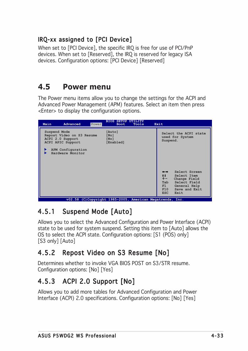
ASUS P5WDG2 WS Profess iona lASUS P5WDG2 WS Profess iona lASUS P5WDG2 WS Profess iona lASUS P5WDG2 WS Profess iona lASUS P5WDG2 WS Profess iona l 4 -334 -334 -334 -334 -33
4.5 Power menuThe Power menu items allow you to change the settings for the ACPI andAdvanced Power Management (APM) features. Select an item then press<Enter> to display the configuration options.
4.5.14.5.14.5.14.5.14.5.1 Suspend Mode [Auto]Suspend Mode [Auto]Suspend Mode [Auto]Suspend Mode [Auto]Suspend Mode [Auto]Allows you to select the Advanced Configuration and Power Interface (ACPI)state to be used for system suspend. Setting this item to [Auto] allows theOS to select the ACPI state. Configuration options: [S1 (POS) only][S3 only] [Auto]
4.5.24.5.24.5.24.5.24.5.2 Repost Video on S3 Resume [No]Repost Video on S3 Resume [No]Repost Video on S3 Resume [No]Repost Video on S3 Resume [No]Repost Video on S3 Resume [No]Determines whether to invoke VGA BIOS POST on S3/STR resume.Configuration options: [No] [Yes]
4.5.34.5.34.5.34.5.34.5.3 ACPI 2.0 Support [No]ACPI 2.0 Support [No]ACPI 2.0 Support [No]ACPI 2.0 Support [No]ACPI 2.0 Support [No]Allows you to add more tables for Advanced Configuration and PowerInterface (ACPI) 2.0 specifications. Configuration options: [No] [Yes]
IRQ-xx assigned to [PCI Device]IRQ-xx assigned to [PCI Device]IRQ-xx assigned to [PCI Device]IRQ-xx assigned to [PCI Device]IRQ-xx assigned to [PCI Device]When set to [PCI Device], the specific IRQ is free for use of PCI/PnPdevices. When set to [Reserved], the IRQ is reserved for legacy ISAdevices. Configuration options: [PCI Device] [Reserved]
Select the ACPI stateused for SystemSuspend.
Suspend Mode [Auto]Repost Video on S3 Resume [No]ACPI 2.0 Support [No]ACPI APIC Support [Enabled]
APM ConfigurationHardware Monitor
Select Screen Select Item
+- Change FieldTab Select FieldF1 General HelpF10 Save and ExitESC Exit
v02.58 (C)Copyright 1985-2005, American Megatrends, Inc.
BIOS SETUP UTILITYMain Advanced Power Boot Tools Exit

4 -344 -344 -344 -344 -34 Chapter 4 : B IOS setupChapter 4 : B IOS setupChapter 4 : B IOS setupChapter 4 : B IOS setupChapter 4 : B IOS setup
4.5.44.5.44.5.44.5.44.5.4 ACPI APIC Support [Enabled]ACPI APIC Support [Enabled]ACPI APIC Support [Enabled]ACPI APIC Support [Enabled]ACPI APIC Support [Enabled]Allows you to enable or disable the Advanced Configuration and PowerInterface (ACPI) support in the Advanced Programmable InterruptController (APIC). When set to Enabled, the ACPI APIC table pointer isincluded in the RSDT pointer list. Configuration options: [Disabled][Enabled]
4.5.54.5.54.5.54.5.54.5.5 APM ConfigurationAPM ConfigurationAPM ConfigurationAPM ConfigurationAPM Configuration
APM ConfigurationPower Button Mode [On/Off]
Restore on AC Power Loss [Power Off]Power On By RTC Alarm [Disabled]Power On By External Modems [Disabled]Power On By PCI Devices [Disabled]Power On By PCIE Devices [Disabled]Power On By PS/2 Keyboard [Disabled]Power On By PS/2 Mouse [Disabled]
Go into On/Off orSuspend when Powerbutton is pressed.
Power Button Mode [On/Off]Power Button Mode [On/Off]Power Button Mode [On/Off]Power Button Mode [On/Off]Power Button Mode [On/Off]Allows the system to go into On/Off mode or suspend mode when thepower button is pressed. Configuration options: [On/Off] [Suspend]
Restore on AC Power Loss [Power Off]Restore on AC Power Loss [Power Off]Restore on AC Power Loss [Power Off]Restore on AC Power Loss [Power Off]Restore on AC Power Loss [Power Off]When set to Power Off, the system goes into off state after an AC powerloss. When set to Power On, the system goes on after an AC power loss.When set to Last State, the system goes into either off or on state,whatever the system state was before the AC power loss.Configuration options: [Power Off] [Power On] [Last State]
Power On By RTC Alarm [Disabled]Power On By RTC Alarm [Disabled]Power On By RTC Alarm [Disabled]Power On By RTC Alarm [Disabled]Power On By RTC Alarm [Disabled]Allows you to enable or disable RTC to generate a wake event.Configuration options: [Disabled] [Enabled]
The succeeding items appear when the Power On By RTC A la rmPower On By RTC A la rmPower On By RTC A la rmPower On By RTC A la rmPower On By RTC A la rmitem is set to [Enabled].
RTC Alarm Date [XX]To set the alarm date, highlight this item and press the <+> or <->key to make the selection. Configuration options: [Everyday] [1] [2][3]... ~ [31]

ASUS P5WDG2 WS Profess iona lASUS P5WDG2 WS Profess iona lASUS P5WDG2 WS Profess iona lASUS P5WDG2 WS Profess iona lASUS P5WDG2 WS Profess iona l 4 -354 -354 -354 -354 -35
RTC Alarm HourTo set the alarm hour, highlight this item and press the <+> or <->key to make the selection. Configuration options: [00] [1]... ~ [23]
RTC Alarm MinuteTo set the alarm minute, highlight this item and press the <+> or <->key to make the selection. Configuration options: [00] [1]... ~ [59]
RTC Alarm SecondTo set the alarm second, highlight this item and press the <+> or <->key to make the selection. Configuration options: [00] [1]... ~ [59]
Power On By External Modems [Disabled]Power On By External Modems [Disabled]Power On By External Modems [Disabled]Power On By External Modems [Disabled]Power On By External Modems [Disabled]Allows either settings of [Enabled] or [Disabled] for powering up thecomputer when the external modem receives a call while the computer is inSoft-off mode. Configuration options: [Disabled] [Enabled]
The computer cannot receive or transmit data until the computer andapplications are fully running. Thus, connection cannot be made on thefirst try. Turning an external modem off and then back on while thecomputer is off causes an initialization string that turns the systempower on.
Power On By PCI Devices [Disabled]Power On By PCI Devices [Disabled]Power On By PCI Devices [Disabled]Power On By PCI Devices [Disabled]Power On By PCI Devices [Disabled]When set to [Enabled], this parameter allows you to turn on the systemthrough a PCI LAN or modem card. This feature requires an ATX powersupply that provides at least 1A on the +5VSB lead.Configuration options: [Disabled] [Enabled]
Power On By PCIE Devices [Disabled]Power On By PCIE Devices [Disabled]Power On By PCIE Devices [Disabled]Power On By PCIE Devices [Disabled]Power On By PCIE Devices [Disabled]When set to [Enabled], this parameter allows you to turn on the systemthrough a PCI Express device. Configuration options: [Disabled] [Enabled]
Power On By PS/2 Keyboard [Disabled]Power On By PS/2 Keyboard [Disabled]Power On By PS/2 Keyboard [Disabled]Power On By PS/2 Keyboard [Disabled]Power On By PS/2 Keyboard [Disabled]Allows you to use specific keys on the keyboard to turn on the system.This feature requires an ATX power supply that provides at least 1A on the+5VSB lead. Configuration options: [Disabled] [Space Bar] [Ctrl-Esc][Power Key]
Power On By PS/2 Mouse [Disabled]Power On By PS/2 Mouse [Disabled]Power On By PS/2 Mouse [Disabled]Power On By PS/2 Mouse [Disabled]Power On By PS/2 Mouse [Disabled]When set to [Enabled], this parameter allows you to use the PS/2 mouseto turn on the system. This feature requires an ATX power supply thatprovides at least 1A on the +5VSB lead. Configuration options: [Disabled][Enabled]
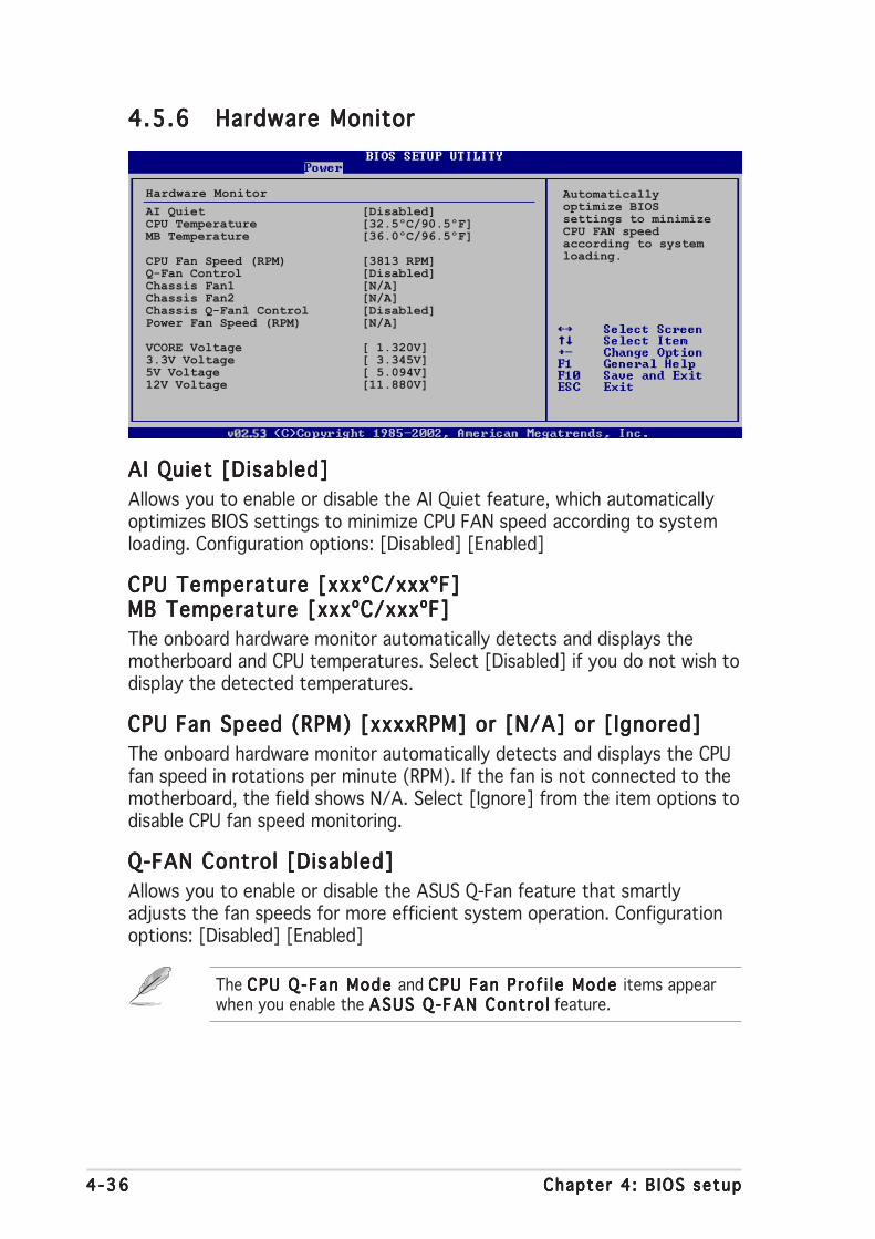
4 -364 -364 -364 -364 -36 Chapter 4 : B IOS setupChapter 4 : B IOS setupChapter 4 : B IOS setupChapter 4 : B IOS setupChapter 4 : B IOS setup
4.5.64.5.64.5.64.5.64.5.6 Hardware MonitorHardware MonitorHardware MonitorHardware MonitorHardware Monitor
Hardware MonitorAI Quiet [Disabled]CPU Temperature [32.5ºC/90.5ºF]MB Temperature [36.0ºC/96.5ºF]
CPU Fan Speed (RPM) [3813 RPM]Q-Fan Control [Disabled]Chassis Fan1 [N/A]Chassis Fan2 [N/A]Chassis Q-Fan1 Control [Disabled]Power Fan Speed (RPM) [N/A]
VCORE Voltage [ 1.320V]3.3V Voltage [ 3.345V]5V Voltage [ 5.094V]12V Voltage [11.880V]
AI Quiet [Disabled]AI Quiet [Disabled]AI Quiet [Disabled]AI Quiet [Disabled]AI Quiet [Disabled]Allows you to enable or disable the AI Quiet feature, which automaticallyoptimizes BIOS settings to minimize CPU FAN speed according to systemloading. Configuration options: [Disabled] [Enabled]
CPU Temperature [xxxºC/xxxºF]CPU Temperature [xxxºC/xxxºF]CPU Temperature [xxxºC/xxxºF]CPU Temperature [xxxºC/xxxºF]CPU Temperature [xxxºC/xxxºF]MB Temperature [xxxºC/xxxºF]MB Temperature [xxxºC/xxxºF]MB Temperature [xxxºC/xxxºF]MB Temperature [xxxºC/xxxºF]MB Temperature [xxxºC/xxxºF]The onboard hardware monitor automatically detects and displays themotherboard and CPU temperatures. Select [Disabled] if you do not wish todisplay the detected temperatures.
CPU Fan Speed (RPM) [xxxxRPM] or [N/A] or [Ignored]CPU Fan Speed (RPM) [xxxxRPM] or [N/A] or [Ignored]CPU Fan Speed (RPM) [xxxxRPM] or [N/A] or [Ignored]CPU Fan Speed (RPM) [xxxxRPM] or [N/A] or [Ignored]CPU Fan Speed (RPM) [xxxxRPM] or [N/A] or [Ignored]The onboard hardware monitor automatically detects and displays the CPUfan speed in rotations per minute (RPM). If the fan is not connected to themotherboard, the field shows N/A. Select [Ignore] from the item options todisable CPU fan speed monitoring.
Q-FAN Control [Disabled]Q-FAN Control [Disabled]Q-FAN Control [Disabled]Q-FAN Control [Disabled]Q-FAN Control [Disabled]Allows you to enable or disable the ASUS Q-Fan feature that smartlyadjusts the fan speeds for more efficient system operation. Configurationoptions: [Disabled] [Enabled]
The CPU Q-Fan Mode CPU Q-Fan Mode CPU Q-Fan Mode CPU Q-Fan Mode CPU Q-Fan Mode and CPU Fan Prof i l e Mode CPU Fan Prof i l e Mode CPU Fan Prof i l e Mode CPU Fan Prof i l e Mode CPU Fan Prof i l e Mode items appearwhen you enable the ASUS Q-FAN Contro lASUS Q-FAN Contro lASUS Q-FAN Contro lASUS Q-FAN Contro lASUS Q-FAN Contro l feature.
Automaticallyoptimize BIOSsettings to minimizeCPU FAN speedaccording to systemloading.

ASUS P5WDG2 WS Profess iona lASUS P5WDG2 WS Profess iona lASUS P5WDG2 WS Profess iona lASUS P5WDG2 WS Profess iona lASUS P5WDG2 WS Profess iona l 4 -374 -374 -374 -374 -37
CPU Q-Fan Mode [PWM]CPU Q-Fan Mode [PWM]CPU Q-Fan Mode [PWM]CPU Q-Fan Mode [PWM]CPU Q-Fan Mode [PWM]Allows you to select the type of CPU fan cable connected to the CPU fanconnector. Set to [PWM] when using a 4-pin CPU fan cable. Set to [DC]when using a 3-pin CPU fan cable. Configuration options: [PWM] [DC]
Some CPU fans with a 4-pin cable do not comply with Intel®’s PWM fanspecification. When using this type of CPU fan, you can not reduce theCPU fan speed even if you set the CPU Q-Fan Mode to [PWM].
CPU Fan Profi le [Optimal]CPU Fan Profi le [Optimal]CPU Fan Profi le [Optimal]CPU Fan Profi le [Optimal]CPU Fan Profi le [Optimal]Allows you to set the appropriate CPU fan performance. When set to[Optimal], the CPU fan automatically adjusts depending on the CPUtemperature. Set this item to [Silent] to minimize fan speed for quiet CPUfan operation, or [Performance] to achieve maximum CPU fan speed.Configuration options: [Optimal] [Performance Mode] [Silent]
Chassis Fan1/2 or [N/A]/[Ignored]Chassis Fan1/2 or [N/A]/[Ignored]Chassis Fan1/2 or [N/A]/[Ignored]Chassis Fan1/2 or [N/A]/[Ignored]Chassis Fan1/2 or [N/A]/[Ignored]The onboard hardware monitor automatically detects and displays thechassis fan speed in rotations per minute (RPM). If the fan is not connectedto the chassis, the specific field shows N/A. Select [Ignore] from the itemoptions to disable chassis fan speed monitoring.
Chassis Q-Fan1 Control [Disabled]Chassis Q-Fan1 Control [Disabled]Chassis Q-Fan1 Control [Disabled]Chassis Q-Fan1 Control [Disabled]Chassis Q-Fan1 Control [Disabled]Allows you to enable or disable the ASUS Q-Fan feature that smartlyadjusts the chassis fan speeds for more efficient system operation.Configuration options: [Disabled] [Enabled]
• The Chassis Q-Fan function is available only on CHA_FAN1.
• The Chass is Fan Prof i l e ModeChass is Fan Prof i l e ModeChass is Fan Prof i l e ModeChass is Fan Prof i l e ModeChass is Fan Prof i l e Mode item appears when you enablethe Chass is Q-Fan Contro l Chass is Q-Fan Contro l Chass is Q-Fan Contro l Chass is Q-Fan Contro l Chass is Q-Fan Contro l feature.
Chassis Fan Profi le [Optimal]Chassis Fan Profi le [Optimal]Chassis Fan Profi le [Optimal]Chassis Fan Profi le [Optimal]Chassis Fan Profi le [Optimal]Allows you to set the appropriate performance level of the chassis Q-Fan.Configuration options: [Optimal] [Performance Mode] [Silent Mode]
Power Fan Speed (RPM) [xxxxRPM] or [N/A]/ [Ignored]Power Fan Speed (RPM) [xxxxRPM] or [N/A]/ [Ignored]Power Fan Speed (RPM) [xxxxRPM] or [N/A]/ [Ignored]Power Fan Speed (RPM) [xxxxRPM] or [N/A]/ [Ignored]Power Fan Speed (RPM) [xxxxRPM] or [N/A]/ [Ignored]The onboard hardware monitor automatically detects and displays thepower fan speed in rotations per minute (RPM). If the fan is not connectedto the power fan connector, the specific field shows N/A.
VCORE Voltage, 3.3V Voltage, 5V Voltage, 12V VoltageVCORE Voltage, 3.3V Voltage, 5V Voltage, 12V VoltageVCORE Voltage, 3.3V Voltage, 5V Voltage, 12V VoltageVCORE Voltage, 3.3V Voltage, 5V Voltage, 12V VoltageVCORE Voltage, 3.3V Voltage, 5V Voltage, 12V VoltageThe onboard hardware monitor automatically detects the voltage outputthrough the onboard voltage regulators.

4 -384 -384 -384 -384 -38 Chapter 4 : B IOS setupChapter 4 : B IOS setupChapter 4 : B IOS setupChapter 4 : B IOS setupChapter 4 : B IOS setup
4.6 Boot menuThe Boot menu items allow you to change the system boot options. Selectan item then press <Enter> to display the sub-menu.
Boot SettingsBoot Device PriorityRemovable DrivesBoot Settings ConfigurationSecurity
Specifies the BootDevice Prioritysequence.
A virtual floppy diskdrive (Floppy DriveB:) may appear whenyou set the CD-ROMdrive as the firstboot device.
4.6.14.6.14.6.14.6.14.6.1 Boot Device PriorityBoot Device PriorityBoot Device PriorityBoot Device PriorityBoot Device Priority
1st ~ xxth Boot Device [1st 1st ~ xxth Boot Device [1st 1st ~ xxth Boot Device [1st 1st ~ xxth Boot Device [1st 1st ~ xxth Boot Device [1st FLOPPY DRIVEFLOPPY DRIVEFLOPPY DRIVEFLOPPY DRIVEFLOPPY DRIVE]]]]]These items specify the boot device priority sequence from the availabledevices. The number of device items that appears on the screen dependson the number of devices installed in the system.Configuration options: [1st FLOPPY DRIVE] [Hard Drive] [ATAPI CD-ROM][Disabled]
Boot Device Priority1st Boot Device [1st FLOPPY DRIVE]2nd Boot Device [HDD: PM-ST330620A]3rd Boot Device [CDROM:ATAPI CD-ROM]
Specifies the bootsequence from theavailable devices.
A device enclosed inparenthesis has beendisable din thecorresponding typemenu.
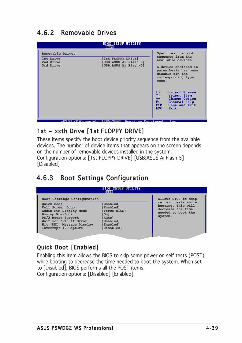
ASUS P5WDG2 WS Profess iona lASUS P5WDG2 WS Profess iona lASUS P5WDG2 WS Profess iona lASUS P5WDG2 WS Profess iona lASUS P5WDG2 WS Profess iona l 4 -394 -394 -394 -394 -39
4.6.24.6.24.6.24.6.24.6.2 Removable DrivesRemovable DrivesRemovable DrivesRemovable DrivesRemovable Drives
1st ~ xxth Drive [1st 1st ~ xxth Drive [1st 1st ~ xxth Drive [1st 1st ~ xxth Drive [1st 1st ~ xxth Drive [1st FLOPPY DRIVEFLOPPY DRIVEFLOPPY DRIVEFLOPPY DRIVEFLOPPY DRIVE]]]]]These items specify the boot device priority sequence from the availabledevices. The number of device items that appears on the screen dependson the number of removable devices installed in the system.Configuration options: [1st FLOPPY DRIVE] [USB:ASUS Ai Flash-5][Disabled]
Removable Drives1st Drive [1st FLOPPY DRIVE]2nd Drive [USB:ASUS Ai Flash-5]3rd Drive [USB:ASUS Ai Flash-5]
Specifies the bootsequence from theavailable devices.
A device enclosed inparenthesis has beendisable din thecorresponding typemenu.
4.6.34.6.34.6.34.6.34.6.3 Boot Settings ConfigurationBoot Settings ConfigurationBoot Settings ConfigurationBoot Settings ConfigurationBoot Settings Configuration
Boot Settings Configuration
Quick Boot [Enabled]Full Screen Logo [Enabled]AddOn ROM Display Mode [Force BIOS]Bootup Num-Lock [On]PS/2 Mouse Support [Auto]Wait For ‘F1’ If Error [Enabled]Hit ‘DEL’ Message Display [Enabled]Interrupt 19 Capture [Disabled]
Allows BIOS to skipcertain tests whilebooting. This willdecrease the timeneeded to boot thesystem.
Quick Boot [Enabled]Quick Boot [Enabled]Quick Boot [Enabled]Quick Boot [Enabled]Quick Boot [Enabled]Enabling this item allows the BIOS to skip some power on self tests (POST)while booting to decrease the time needed to boot the system. When setto [Disabled], BIOS performs all the POST items.Configuration options: [Disabled] [Enabled]

4 -404 -404 -404 -404 -40 Chapter 4 : B IOS setupChapter 4 : B IOS setupChapter 4 : B IOS setupChapter 4 : B IOS setupChapter 4 : B IOS setup
Interrupt 19 Capture [Disabled]Interrupt 19 Capture [Disabled]Interrupt 19 Capture [Disabled]Interrupt 19 Capture [Disabled]Interrupt 19 Capture [Disabled]When set to [Enabled], this function allows the option ROMs to trapInterrupt 19. Configuration options: [Disabled] [Enabled]
Add On ROM Display Mode [Force BIOS]Add On ROM Display Mode [Force BIOS]Add On ROM Display Mode [Force BIOS]Add On ROM Display Mode [Force BIOS]Add On ROM Display Mode [Force BIOS]Sets the display mode for option ROM.Configuration options: [Force BIOS] [Keep Current]
Bootup Num-Lock [On]Bootup Num-Lock [On]Bootup Num-Lock [On]Bootup Num-Lock [On]Bootup Num-Lock [On]Allows you to select the power-on state for the NumLock.Configuration options: [Off] [On]
PS/2 Mouse Support [Auto]PS/2 Mouse Support [Auto]PS/2 Mouse Support [Auto]PS/2 Mouse Support [Auto]PS/2 Mouse Support [Auto]Allows you to enable or disable support for PS/2 mouse.Configuration options: [Disabled] [Enabled] [Auto]
Wait for ‘F1’ If Error [Enabled]Wait for ‘F1’ If Error [Enabled]Wait for ‘F1’ If Error [Enabled]Wait for ‘F1’ If Error [Enabled]Wait for ‘F1’ If Error [Enabled]When set to Enabled, the system waits for the F1 key to be pressed whenerror occurs. Configuration options: [Disabled] [Enabled]
Hit ‘DEL’ Message Display [Enabled]Hit ‘DEL’ Message Display [Enabled]Hit ‘DEL’ Message Display [Enabled]Hit ‘DEL’ Message Display [Enabled]Hit ‘DEL’ Message Display [Enabled]When set to Enabled, the system displays the message “Press DEL to runSetup” during POST. Configuration options: [Disabled] [Enabled]
Full Screen Logo [Enabled]Full Screen Logo [Enabled]Full Screen Logo [Enabled]Full Screen Logo [Enabled]Full Screen Logo [Enabled]Allows you to enable or disable the full screen logo display feature.Configuration options: [Disabled] [Enabled]
Set this item to [Enabled] to use the ASUS MyLogo2™ feature.
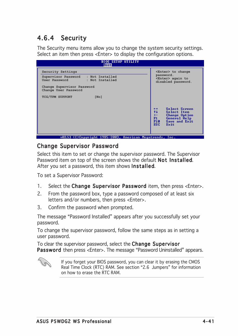
ASUS P5WDG2 WS Profess iona lASUS P5WDG2 WS Profess iona lASUS P5WDG2 WS Profess iona lASUS P5WDG2 WS Profess iona lASUS P5WDG2 WS Profess iona l 4 -414 -414 -414 -414 -41
4.6.44.6.44.6.44.6.44.6.4 SecuritySecuritySecuritySecuritySecurityThe Security menu items allow you to change the system security settings.Select an item then press <Enter> to display the configuration options.
Security Settings
Supervisor Password : Not InstalledUser Password : Not Installed
Change Supervisor PasswordChange User Password
TCG/TPM SUPPORT [No]
<Enter> to changepassword.<Enter> again todisabled password.
Change Supervisor PasswordChange Supervisor PasswordChange Supervisor PasswordChange Supervisor PasswordChange Supervisor PasswordSelect this item to set or change the supervisor password. The SupervisorPassword item on top of the screen shows the default Not Insta l ledNot Insta l ledNot Insta l ledNot Insta l ledNot Insta l led.After you set a password, this item shows Insta l ledInsta l ledInsta l ledInsta l ledInsta l led.
To set a Supervisor Password:
1. Select the Change Supervisor Password Change Supervisor Password Change Supervisor Password Change Supervisor Password Change Supervisor Password item, then press <Enter>.2. From the password box, type a password composed of at least six
letters and/or numbers, then press <Enter>.3. Confirm the password when prompted.
The message “Password Installed” appears after you successfully set yourpassword.To change the supervisor password, follow the same steps as in setting auser password.To clear the supervisor password, select the Change SupervisorChange SupervisorChange SupervisorChange SupervisorChange SupervisorPassword Password Password Password Password then press <Enter>. The message “Password Uninstalled” appears.
If you forget your BIOS password, you can clear it by erasing the CMOSReal Time Clock (RTC) RAM. See section “2.6 Jumpers” for informationon how to erase the RTC RAM.

4 -424 -424 -424 -424 -42 Chapter 4 : B IOS setupChapter 4 : B IOS setupChapter 4 : B IOS setupChapter 4 : B IOS setupChapter 4 : B IOS setup
After you have set a supervisor password, the other items appear to allowyou to change other security settings.
User Access Level [Full Access]User Access Level [Full Access]User Access Level [Full Access]User Access Level [Full Access]User Access Level [Full Access]This item allows you to select the access restriction to the Setup items.Configuration options: [No Access] [View Only] [Limited] [Full Access]
No AccessNo AccessNo AccessNo AccessNo Access prevents user access to the Setup utility.
V iew Only V iew Only V iew Only V iew Only V iew Only allows access but does not allow change to any field.
L imited L imited L imited L imited L imited allows changes only to selected fields, such as Date andTime.
Fu l l AccessFu l l AccessFu l l AccessFu l l AccessFu l l Access allows viewing and changing all the fields in the Setuputility.
Change User PasswordChange User PasswordChange User PasswordChange User PasswordChange User PasswordSelect this item to set or change the user password. The User PasswordUser PasswordUser PasswordUser PasswordUser Passworditem on top of the screen shows the default Not Insta l ledNot Insta l ledNot Insta l ledNot Insta l ledNot Insta l led. After you seta password, this item shows Insta l ledInsta l ledInsta l ledInsta l ledInsta l led.
To set a User Password:
1. Select the Change User Password item and press <Enter>.2. On the password box that appears, type a password composed of at
least six letters and/or numbers, then press <Enter>.3. Confirm the password when prompted.
The message “Password Installed” appears after you set your passwordsuccessfully.
To change the user password, follow the same steps as in setting a userpassword.
Security SettingsSupervisor Password : Not InstalledUser Password : Not Installed
Change Supervisor PasswordUser Access Level [Full Access]Change User PasswordClear User PasswordPassword Check [Setup]
ASUS P5WDG2 WS Profess iona lASUS P5WDG2 WS Profess iona lASUS P5WDG2 WS Profess iona lASUS P5WDG2 WS Profess iona lASUS P5WDG2 WS Profess iona l 4 -434 -434 -434 -434 -43
Clear User PasswordClear User PasswordClear User PasswordClear User PasswordClear User PasswordSelect this item to clear the user password.
Password Check [Setup]Password Check [Setup]Password Check [Setup]Password Check [Setup]Password Check [Setup]When set to [Setup], BIOS checks for user password when accessing theSetup utility. When set to [Always], BIOS checks for user password bothwhen accessing Setup and booting the system.Configuration options: [Setup] [Always]
TCG/TPM SUPPORT [No]TCG/TPM SUPPORT [No]TCG/TPM SUPPORT [No]TCG/TPM SUPPORT [No]TCG/TPM SUPPORT [No]Enables or disables TPM/TCG (TPM1.1/1.2) support in BIOS.Configuration options: [Yes] [No]

4 -444 -444 -444 -444 -44 Chapter 4 : B IOS setupChapter 4 : B IOS setupChapter 4 : B IOS setupChapter 4 : B IOS setupChapter 4 : B IOS setup
4.7 Tools menuThe Tools menu items allow you to configure options for special functions.Select an item then press <Enter> to display the sub-menu.
Select Screen Select Item
+- Change FieldTab Select FieldF1 General HelpF10 Save and ExitESC Exit
v02.58 (C)Copyright 1985-2005, American Megatrends, Inc.
BIOS SETUP UTILITYMain Advanced Power Boot Tools Exit
EZ Flash 2ASUS O.C. Profile
4.7.14.7.14.7.14.7.14.7.1 ASUS EZ Flash 2ASUS EZ Flash 2ASUS EZ Flash 2ASUS EZ Flash 2ASUS EZ Flash 2Allows you to run ASUS EZ Flash 2. When you press <Enter>, aconfirmation message appears. Use the left/right arrow key to selectbetween [Yes] or [No], then press <Enter> to confirm your choice. Pleasesee page 4-5, section 4.1.3 for details.
ASUSTek EZ Flash 2 BIOS ROM Utility V3.00
Current ROM Update ROMBOARD: P5WDG2-WS ProVER: 0204DATE: 07/04/2006
BOARD: UnknownVER: UnknownDATE: Unknown
PATH: C:\P5WDG2OC
A:C:
[Enter] Select [S] Save [ESC]Exit
[Tab] Switch [Up/Down/Home/End] Move
Note
WIN98SE <DIR>NETTERM <DIR>DRIVERS <DIR>RECYCLED <DIR>WUTEMP <DIR>NEWFOL~1 <DIR>INSTALL <DIR>TEST-REB <DIR>MSDOWNLD.TMP <DIR>
FLASH TYPE: Winbond W39V080A 8Mb LPC
WIN98E <DIR>

ASUS P5WDG2 WS Profess iona lASUS P5WDG2 WS Profess iona lASUS P5WDG2 WS Profess iona lASUS P5WDG2 WS Profess iona lASUS P5WDG2 WS Profess iona l 4 -454 -454 -454 -454 -45
Save to Profi le 1/2Save to Profi le 1/2Save to Profi le 1/2Save to Profi le 1/2Save to Profi le 1/2Allows you to save the current BIOS file to the BIOS Flash. Press <Enter> tosave the file.
Load from Profi le 1/2Load from Profi le 1/2Load from Profi le 1/2Load from Profi le 1/2Load from Profi le 1/2Allows you to load the previous BIOS settings saved in the BIOS Flash.Press <Enter> to load the file.
Start O.C. Profi leStart O.C. Profi leStart O.C. Profi leStart O.C. Profi leStart O.C. Profi leAllows you to run the utility to save and load CMOS. Press <Enter> to runthe utility.
4.7.24.7.24.7.24.7.24.7.2 ASUS O.C. ProfileASUS O.C. ProfileASUS O.C. ProfileASUS O.C. ProfileASUS O.C. Profile
O.C. PROFILE Configuration
O.C. Profile 1 Status: Not InstalledO.C. Profile 2 Status: Not Installed
Save to Profile 1Load from Profile 1
Save to Profile 2Load from Profile 2
Start O.C. Profile
Save to Profile 1
BIOS SETUP UTILITYMain Advanced Power Boot Tools Exit
Select Screen Select Item
+- Change FieldTab Select FieldF1 General HelpF10 Save and ExitESC Exit
ASUSTek O.C. Profile Utility B311
Current CMOS Update CMOSBOARD: P5WDG2 WS ProVER: 0204.romDATE: 07/03/2006
BOARD: UnknownVER: UnknownDATE: Unknown
PATH: C:\P5WDG2OC
A:C:
WIN98SE <DIR>NETTERM <DIR>DOCUME”1 <DIR>PROGRA”1 <DIR>SYSTEM”1 <DIR>M2NPVVM <DIR>RECYCLED <DIR>TEST-REB <DIR>BOOTFONT.BIN 213830 2001-09-05 20:00:00
[Enter] Select [Y] Yes [N/Esc] No [Left/Right]: Switch
Note
CMOS backup is done! Press any key to Exit.

4 -464 -464 -464 -464 -46 Chapter 4 : B IOS setupChapter 4 : B IOS setupChapter 4 : B IOS setupChapter 4 : B IOS setupChapter 4 : B IOS setup
• This function can supp ort devices such as USB flash disk, or floppydisk with FAT 32/16 format and single partition only.
• Do not shutdown or reset the system while updating the BIOS toprevent system boot failure!

ASUS P5WDG2 WS Profess iona lASUS P5WDG2 WS Profess iona lASUS P5WDG2 WS Profess iona lASUS P5WDG2 WS Profess iona lASUS P5WDG2 WS Profess iona l 4 -474 -474 -474 -474 -47
If you attempt to exit the Setup program without saving your changes,the program prompts you with a message asking if you want to saveyour changes before exiting. Press <Enter> to save the changes whileexiting.
Exit & Discard ChangesExit & Discard ChangesExit & Discard ChangesExit & Discard ChangesExit & Discard ChangesSelect this option only if you do not want to save the changes that youmade to the Setup program. If you made changes to fields other thanSystem Date, System Time, and Password, the BIOS asks for a confirmationbefore exiting.
Discard ChangesDiscard ChangesDiscard ChangesDiscard ChangesDiscard ChangesAllows you to discard the selections you made and restore the previouslysaved values. After selecting this option, a confirmation appears. Select O kO kO kO kO kto discard any changes and load the previously saved values.
Exit Options
Exit & Save ChangesExit & Discard ChangesDiscard Changes
Load Setup Defaults
Pressing <Esc> does not immediately exit this menu. Select one of theoptions from this menu or <F10> from the legend bar to exit.
Exit & Save ChangesExit & Save ChangesExit & Save ChangesExit & Save ChangesExit & Save ChangesOnce you are finished making your selections, choose this option from theExit menu to ensure the values you selected are saved to the CMOS RAM.An onboard backup battery sustains the CMOS RAM so it stays on evenwhen the computer is turned off. When you select this option, aconfirmation window appears. Select OK OK OK OK OK to save the changes and exit.
4.8 Exit menuThe Exit menu items allow you to load the optimal or failsafe default valuesfor the BIOS items, and save or discard your changes to the BIOS items.

4 -484 -484 -484 -484 -48 Chapter 4 : B IOS setupChapter 4 : B IOS setupChapter 4 : B IOS setupChapter 4 : B IOS setupChapter 4 : B IOS setup
Load Setup DefaultsLoad Setup DefaultsLoad Setup DefaultsLoad Setup DefaultsLoad Setup DefaultsAllows you to load the default values for each of the parameters on theSetup menus. When you select this option or if you press <F5>, aconfirmation window appears. Select Ok Ok Ok Ok Ok to load default values. SelectEx it & Save ChangesEx it & Save ChangesEx it & Save ChangesEx it & Save ChangesEx it & Save Changes or make other changes before saving the valuesto the non-volatile RAM.

5Softwaresupport
This chapter describes the contentsof the support CD that comes withthe motherboard package.

ASUS P5WDG2 WS Profess iona lASUS P5WDG2 WS Profess iona lASUS P5WDG2 WS Profess iona lASUS P5WDG2 WS Profess iona lASUS P5WDG2 WS Profess iona l
Chapter summary 55.1 Installing an operating system ............................................. 5-15.2 Support CD information ........................................................ 5-15.3 Software information ......................................................... 5-115.4 RAID configurations ............................................................ 5-295.5 Creating a RAID driver disk ................................................. 5-41

ASUS P5WDG2 WS Profess iona lASUS P5WDG2 WS Profess iona lASUS P5WDG2 WS Profess iona lASUS P5WDG2 WS Profess iona lASUS P5WDG2 WS Profess iona l 5 - 15 - 15 - 15 - 15 - 1
5.1 Installing an operating systemThis motherboard supports Windows® 2000/2003 Server/XP operatingsystems (OS). Always install the latest OS version and correspondingupdates to maximize the features of your hardware.
5.2 Support CD informationThe support CD that came with the motherboard package contains thedrivers, software applications, and utilities that you can install to avail allmotherboard features.
5.2.15.2.15.2.15.2.15.2.1 Running the support CDRunning the support CDRunning the support CDRunning the support CDRunning the support CDPlace the support CD to the optical drive. The CD automatically displays theDr ivers Dr ivers Dr ivers Dr ivers Dr ivers menu if Autorun is enabled in your computer.
C l i c k an i con toC l i c k an i con toC l i c k an i con toC l i c k an i con toC l i c k an i con tod i sp l ay suppo r td i sp l ay suppo r td i sp l ay suppo r td i sp l ay suppo r td i sp l ay suppo r tCD/mothe rboa rdCD/mothe rboa rdCD/mothe rboa rdCD/mothe rboa rdCD/mothe rboa rdi n f o rmat i oni n f o rmat i oni n f o rmat i oni n f o rmat i oni n f o rmat i on
C l i c k an i t em to i n s ta l lC l i c k an i t em to i n s ta l lC l i c k an i t em to i n s ta l lC l i c k an i t em to i n s ta l lC l i c k an i t em to i n s ta l l
• Motherboard settings and hardware options vary. Use the setupprocedures presented in this chapter for reference only. Refer toyour OS documentation for detailed information.
• Make sure that you install Windows® 2000 Service Pack 4 or theWindows® XP Service Pack1 or later versions before installing thedrivers for better compatibility and system stability.
If Auto run Auto run Auto run Auto run Auto run is NOT enabled in your computer, browse the contents ofthe support CD to locate the file ASSETUP.EXE from the BIN folder.Double-click the ASSETUP .EXEASSETUP .EXEASSETUP .EXEASSETUP .EXEASSETUP .EXE to run the CD.
The contents of the support CD are subject to change at any timewithout notice. Visit the ASUS website (www.asus.com) for updates.

5 - 25 - 25 - 25 - 25 - 2 Chapter 5 : Software supportChapter 5 : Software supportChapter 5 : Software supportChapter 5 : Software supportChapter 5 : Software support
5.2.25.2.25.2.25.2.25.2.2 Drivers menuDrivers menuDrivers menuDrivers menuDrivers menuThe drivers menu shows the available device drivers if the system detectsinstalled devices. Install the necessary drivers to activate the devices.
The screen display and driver options vary under different operatingsystem versions.
ASUS InstAll - Installation Wizard for DriversASUS InstAll - Installation Wizard for DriversASUS InstAll - Installation Wizard for DriversASUS InstAll - Installation Wizard for DriversASUS InstAll - Installation Wizard for DriversLaunches the ASUS InstAll driver installation wizard.
Intel Chipset Inf Update ProgramIntel Chipset Inf Update ProgramIntel Chipset Inf Update ProgramIntel Chipset Inf Update ProgramIntel Chipset Inf Update ProgramInstalls the Intel® Chipset INF Update Program. This driver enablesPlug-n-Play INF support for the Intel® chipset components on themotherboard. When installed to the target system, this driver provides themethod for configuring the chipset components.
You can install this utility using three different modes: interactive, silent orunattended preload. Installing the driver in interactive mode requires userinput during installation. User input is not required when installing the driverin silent or unattended preload modes. Refer to the online help or readmefile that came with the utility for details.
SoundMAX ADI1988B Audio DriverSoundMAX ADI1988B Audio DriverSoundMAX ADI1988B Audio DriverSoundMAX ADI1988B Audio DriverSoundMAX ADI1988B Audio DriverInstalls the SoundMAX® ADI1988B audio driver and application.
Marvell 61xx SATA controller DriverMarvell 61xx SATA controller DriverMarvell 61xx SATA controller DriverMarvell 61xx SATA controller DriverMarvell 61xx SATA controller DriverInstalls the Marvell® 61xx SATA controller driver.
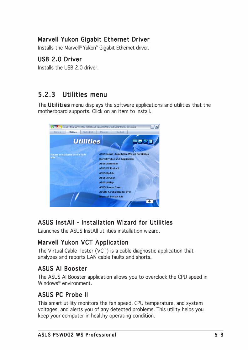
ASUS P5WDG2 WS Profess iona lASUS P5WDG2 WS Profess iona lASUS P5WDG2 WS Profess iona lASUS P5WDG2 WS Profess iona lASUS P5WDG2 WS Profess iona l 5 - 35 - 35 - 35 - 35 - 3
Marvell Yukon Gigabit Ethernet DriverMarvell Yukon Gigabit Ethernet DriverMarvell Yukon Gigabit Ethernet DriverMarvell Yukon Gigabit Ethernet DriverMarvell Yukon Gigabit Ethernet DriverInstalls the Marvell® Yukon™ Gigabit Ethernet driver.
USB 2.0 DriverUSB 2.0 DriverUSB 2.0 DriverUSB 2.0 DriverUSB 2.0 DriverInstalls the USB 2.0 driver.
5.2.35.2.35.2.35.2.35.2.3 Utilities menuUtilities menuUtilities menuUtilities menuUtilities menuThe Ut i l i t iesUt i l i t iesUt i l i t iesUt i l i t iesUt i l i t ies menu displays the software applications and utilities that themotherboard supports. Click on an item to install.
ASUS InstAll - Installation Wizard for Util itiesASUS InstAll - Installation Wizard for Util itiesASUS InstAll - Installation Wizard for Util itiesASUS InstAll - Installation Wizard for Util itiesASUS InstAll - Installation Wizard for Util itiesLaunches the ASUS InstAll utilities installation wizard.
Marvell Yukon VCT ApplicationMarvell Yukon VCT ApplicationMarvell Yukon VCT ApplicationMarvell Yukon VCT ApplicationMarvell Yukon VCT ApplicationThe Virtual Cable Tester (VCT) is a cable diagnostic application thatanalyzes and reports LAN cable faults and shorts.
ASUS AI BoosterASUS AI BoosterASUS AI BoosterASUS AI BoosterASUS AI BoosterThe ASUS AI Booster application allows you to overclock the CPU speed inWindows® environment.
ASUS PC Probe I IASUS PC Probe I IASUS PC Probe I IASUS PC Probe I IASUS PC Probe I IThis smart utility monitors the fan speed, CPU temperature, and systemvoltages, and alerts you of any detected problems. This utility helps youkeep your computer in healthy operating condition.

5 - 45 - 45 - 45 - 45 - 4 Chapter 5 : Software supportChapter 5 : Software supportChapter 5 : Software supportChapter 5 : Software supportChapter 5 : Software support
ASUS UpdateASUS UpdateASUS UpdateASUS UpdateASUS UpdateThe ASUS Update utility that allows you to update the motherboard BIOS inWindows® environment. This utility requires an Internet connection eitherthrough a network or an Internet Service Provider (ISP).
ASUS AI GearASUS AI GearASUS AI GearASUS AI GearASUS AI GearInstalls the ASUS AI Gear application.
ASUS AI NapASUS AI NapASUS AI NapASUS AI NapASUS AI NapInstalls the ASUS AI Nap application.
ASUS Screen SaverASUS Screen SaverASUS Screen SaverASUS Screen SaverASUS Screen SaverBring life to your idle screen by installing the ASUS screen saver.
ADOBE Acrobat Reader V7.0ADOBE Acrobat Reader V7.0ADOBE Acrobat Reader V7.0ADOBE Acrobat Reader V7.0ADOBE Acrobat Reader V7.0The Adobe Acrobat® Reader V7.0 is for opening, viewing, and printingdocuments in Portable Document Format (PDF).
Microsoft DirectX 9.0cMicrosoft DirectX 9.0cMicrosoft DirectX 9.0cMicrosoft DirectX 9.0cMicrosoft DirectX 9.0cThe Microsoft DirectX® 9.0c is a multimedia technology that enhancescomputer graphics and sounds. DirectX® improves the multimedia featuresof your computer so you can enjoy watching TV and movies, capturingvideos, or playing games in your computer.
Click to open the next screen.
Anti-virus Uti l ityAnti-virus Uti l ityAnti-virus Uti l ityAnti-virus Uti l ityAnti-virus Uti l ityThe anti-virus utility scans, identifies, and removes computer viruses.View the online help for detailed information.
Click to view the previous screen.
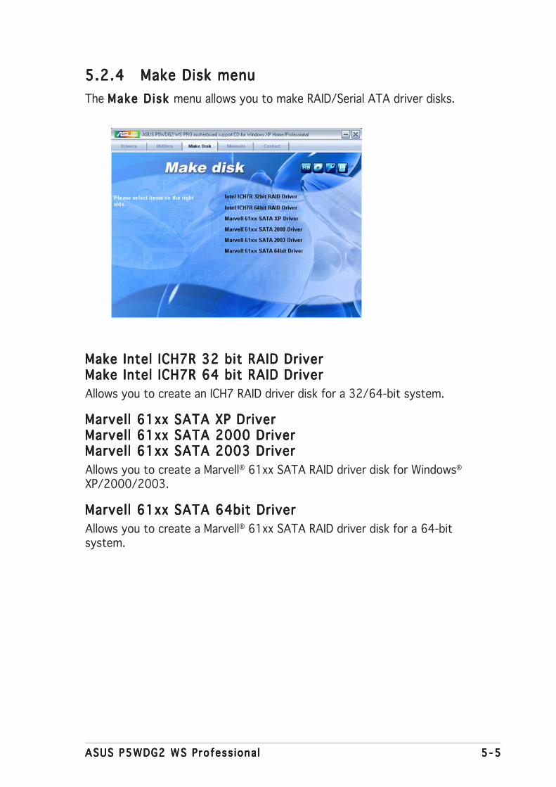
ASUS P5WDG2 WS Profess iona lASUS P5WDG2 WS Profess iona lASUS P5WDG2 WS Profess iona lASUS P5WDG2 WS Profess iona lASUS P5WDG2 WS Profess iona l 5 - 55 - 55 - 55 - 55 - 5
5.2.45.2.45.2.45.2.45.2.4 Make Disk menuMake Disk menuMake Disk menuMake Disk menuMake Disk menuThe Make D isk Make D isk Make D isk Make D isk Make D isk menu allows you to make RAID/Serial ATA driver disks.
Make Intel ICH7R 32 bit RAID DriverMake Intel ICH7R 32 bit RAID DriverMake Intel ICH7R 32 bit RAID DriverMake Intel ICH7R 32 bit RAID DriverMake Intel ICH7R 32 bit RAID DriverMake Intel ICH7R 64 bit RAID DriverMake Intel ICH7R 64 bit RAID DriverMake Intel ICH7R 64 bit RAID DriverMake Intel ICH7R 64 bit RAID DriverMake Intel ICH7R 64 bit RAID DriverAllows you to create an ICH7 RAID driver disk for a 32/64-bit system.
Marvell 61xx SATA XP DriverMarvell 61xx SATA XP DriverMarvell 61xx SATA XP DriverMarvell 61xx SATA XP DriverMarvell 61xx SATA XP DriverMarvell 61xx SATA 2000 DriverMarvell 61xx SATA 2000 DriverMarvell 61xx SATA 2000 DriverMarvell 61xx SATA 2000 DriverMarvell 61xx SATA 2000 DriverMarvell 61xx SATA 2003 DriverMarvell 61xx SATA 2003 DriverMarvell 61xx SATA 2003 DriverMarvell 61xx SATA 2003 DriverMarvell 61xx SATA 2003 DriverAllows you to create a Marvell® 61xx SATA RAID driver disk for Windows®
XP/2000/2003.
Marvell 61xx SATA 64bit DriverMarvell 61xx SATA 64bit DriverMarvell 61xx SATA 64bit DriverMarvell 61xx SATA 64bit DriverMarvell 61xx SATA 64bit DriverAllows you to create a Marvell® 61xx SATA RAID driver disk for a 64-bitsystem.

5 - 65 - 65 - 65 - 65 - 6 Chapter 5 : Software supportChapter 5 : Software supportChapter 5 : Software supportChapter 5 : Software supportChapter 5 : Software support
5.2.65.2.65.2.65.2.65.2.6 Contact informationContact informationContact informationContact informationContact informationClick the Contact Contact Contact Contact Contact tab to display the ASUS contact information. You canalso find this information on the inside front cover of this user guide.
5.2.55.2.55.2.55.2.55.2.5 Manuals menuManuals menuManuals menuManuals menuManuals menuThe Manua lsManua lsManua lsManua lsManua ls menu contains the user manuals for third party componentsand applications.
Most user manual files are in Portable Document Format (PDF). Installthe Adobe Acrobat Reader application from the Ut i l i t i es Ut i l i t i es Ut i l i t i es Ut i l i t i es Ut i l i t i es tab beforeopening a user manual file.

ASUS P5WDG2 WS Profess iona lASUS P5WDG2 WS Profess iona lASUS P5WDG2 WS Profess iona lASUS P5WDG2 WS Profess iona lASUS P5WDG2 WS Profess iona l 5 - 75 - 75 - 75 - 75 - 7
5.2.75.2.75.2.75.2.75.2.7 Other informationOther informationOther informationOther informationOther informationThe icons on the top right corner of the screen provide additionalinformation on the motherboard and the contents of the support CD. Clickan icon to display the specified information.
Motherboard InfoMotherboard InfoMotherboard InfoMotherboard InfoMotherboard InfoDisplays the general specifications of the motherboard.
Browse this CDBrowse this CDBrowse this CDBrowse this CDBrowse this CDDisplays the contents of the support CD in graphical format.

5 - 85 - 85 - 85 - 85 - 8 Chapter 5 : Software supportChapter 5 : Software supportChapter 5 : Software supportChapter 5 : Software supportChapter 5 : Software support
Technical Support FormTechnical Support FormTechnical Support FormTechnical Support FormTechnical Support FormDisplays the ASUS Technical Support Request Form that you have to fill outwhen requesting technical support.
Fi le l istFi lel istFi lel istFi lel istFi lel istDisplays the contents of the support CD in text format.

ASUS P5WDG2 WS Profess iona lASUS P5WDG2 WS Profess iona lASUS P5WDG2 WS Profess iona lASUS P5WDG2 WS Profess iona lASUS P5WDG2 WS Profess iona l 5 -115 -115 -115 -115 -11
5.3 Software informationMost of the applications in the support CD have wizards that willconveniently guide you through the installation. View the online help orreadme file that came with the software application for more information.
5.3.15.3.15.3.15.3.15.3.1 ASUS MyLogo2™ASUS MyLogo2™ASUS MyLogo2™ASUS MyLogo2™ASUS MyLogo2™The ASUS MyLogo2™ utility lets you customize the boot logo. The bootlogo is the image that appears on screen during the Power-On-Self-Tests(POST). The ASUS MyLogo2™ is automatically installed when you install theASUS Update ASUS Update ASUS Update ASUS Update ASUS Update utility from the support CD. See section “5.2.3 Utilitiesmenu” for details.
To launch the ASUS MyLogo2™:
1. Launch the ASUS Update utility. Refer to section “4.1.1 ASUS Updateutility” for details.
2. Select Opt ions Opt ions Opt ions Opt ions Opt ions from the drop down menu, then click NextNextNextNextNext.3. Check the option Launch MyLogo to replace system bootLaunch MyLogo to replace system bootLaunch MyLogo to replace system bootLaunch MyLogo to replace system bootLaunch MyLogo to replace system boot
logo before f lash ing BIOSlogo before f lash ing BIOSlogo before f lash ing BIOSlogo before f lash ing BIOSlogo before f lash ing BIOS, then click NextNextNextNextNext.4. Select Update BIOS from a f i leUpdate BIOS from a f i leUpdate BIOS from a f i leUpdate BIOS from a f i leUpdate BIOS from a f i le from the drop down menu, then
click NextNextNextNextNext.5. When prompted, locate the new
BIOS file, then click NextNextNextNextNext. TheASUS MyLogo2 window appears.
6. From the left window pane, selectthe folder that contains the imageyou intend to use as your bootlogo.
• Before using the ASUS MyLogo2™, use the AFUDOS utility to make acopy of your original BIOS file, or obtain the latest BIOS version fromthe ASUS website. See section “4.1.4 AFUDOS utility.”
• Make sure that the BIOS item Fu l l Screen Logo Fu l l Screen Logo Fu l l Screen Logo Fu l l Screen Logo Fu l l Screen Logo is set to[Enabled] if you wish to use ASUS MyLogo3. See section “4.6.2Boot Settings Configuration.”
• You can create your own boot logo image in GIF, JPG, or BMP fileformats.

5 -125 -125 -125 -125 -12 Chapter 5 : Software supportChapter 5 : Software supportChapter 5 : Software supportChapter 5 : Software supportChapter 5 : Software support
9. When the screen returns to the ASUS Update utility, flash the originalBIOS to load the new boot logo.
10. After flashing the BIOS, restart the computer to display the new bootlogo during POST.
8. Adjust the boot image to yourdesired size by selecting a valueon the Rat io Rat io Rat io Rat io Rat io box.
7. When the logo images appear onthe right window pane, select animage to enlarge by clicking on it.

ASUS P5WDG2 WS Profess iona lASUS P5WDG2 WS Profess iona lASUS P5WDG2 WS Profess iona lASUS P5WDG2 WS Profess iona lASUS P5WDG2 WS Profess iona l 5 -135 -135 -135 -135 -13
3. Click the R unRunRunRunRun button to perform a cable test.
5.3.25.3.25.3.25.3.25.3.2 AI NET2AI NET2AI NET2AI NET2AI NET2The AI NET2 features the Marvell® Virtual Cable Tester™ (VCT). VCT is acable diagnostic utility that reports LAN cable faults and shorts using theTime Domain Reflectometry (TDR) technology. The VCT detects andreports open and shorted cables, impedance mismatches, pair swaps, pairpolarity problems, and pair skew problems of up to 64 ns at one meteraccuracy.
The VCT feature reduces networking and support costs through a highlymanageable and controlled network system. This utility can be incorporatedin the network systems sofware for ideal field support as well asdevelopment diagnostics.
Using the Virtual Cable Tester™Using the Virtual Cable Tester™Using the Virtual Cable Tester™Using the Virtual Cable Tester™Using the Virtual Cable Tester™To use the the Marvell® Virtual Cable Tester™ utility:
1. Launch the VCT utility from the Windows® desktop by clickingStart > Al l Programs > Marvel l > Virtua l Cable TesterStart > Al l Programs > Marvel l > Virtua l Cable TesterStart > Al l Programs > Marvel l > Virtua l Cable TesterStart > Al l Programs > Marvel l > Virtua l Cable TesterStart > Al l Programs > Marvel l > Virtua l Cable Tester.
2. Click Virtua l Cable Tester Virtua l Cable Tester Virtua l Cable Tester Virtua l Cable Tester Virtua l Cable Tester from the menu to display the screenbelow.
• The VCT only runs on systems with Windows® XP or Windows® 2000operating systems.
• The VCT utility only tests Ethernet cables connected to Gigabit LANport(s).
• The R u nR u nR u nR u nR u n button on the Virtual Cable Tester™ main window isdisabled if no problem is detected on the LAN cable(s) connected tothe LAN port(s).
• If you want the system to check the status of the LAN cable beforeentering the OS, enable the item Post Check LAN Cab le Post Check LAN Cab le Post Check LAN Cab le Post Check LAN Cab le Post Check LAN Cab le in theBIOS Setup.
• AI NET2 is available only on LAN2.

5 -145 -145 -145 -145 -14 Chapter 5 : Software supportChapter 5 : Software supportChapter 5 : Software supportChapter 5 : Software supportChapter 5 : Software support
5.3.35.3.35.3.35.3.35.3.3 AI GearAI GearAI GearAI GearAI GearASUS AI Gear provides four system performance options that allows you toselect the best performance setting for your computing needs. This easy-to-use utility adjusts the processor frequency and VCore voltage tominimize system noise and power consumption.
After installing AI Gear from the bundled support CD, you can launch AIGear by double-clicking the AI Gear icon on your Windows OS taskbar.
Shift the gear to the performance setting that you like.
Max imumMax imumMax imumMax imumMax imumPe r fo rmancePe r f o rmancePe r f o rmancePe r f o rmancePe r f o rmance
M e d i u mM e d i u mM e d i u mM e d i u mM e d i u mPe r fo rmancePe r f o rmancePe r f o rmancePe r f o rmancePe r f o rmance
H i g hH i g hH i g hH i g hH i g hPe r f o rmancePe r f o rmancePe r f o rmancePe r f o rmancePe r f o rmance
Max imumMax imumMax imumMax imumMax imumPowe r Sav i ngPowe r Sav i ngPowe r Sav i ngPowe r Sav i ngPowe r Sav i ng

ASUS P5WDG2 WS Profess iona lASUS P5WDG2 WS Profess iona lASUS P5WDG2 WS Profess iona lASUS P5WDG2 WS Profess iona lASUS P5WDG2 WS Profess iona l 5 -155 -155 -155 -155 -15
You can also set the AI Gear modes by clicking the AI Gear icon on theWindows taskbar.
• When AI Gear is enabled, the system will automatically optimize theCPU and chassis fan speed according to the system loading.
• The AI Booster (AI NOS) and AI Gear functions cannot be enabledsimutaneously.

5 -165 -165 -165 -165 -16 Chapter 5 : Software supportChapter 5 : Software supportChapter 5 : Software supportChapter 5 : Software supportChapter 5 : Software support
5.3.45.3.45.3.45.3.45.3.4 AI NapAI NapAI NapAI NapAI NapThis feature allows you to minimize the power consumption of yourcomputer whenever you are away. Enable this feature for minimum powerconsumption and a more quiet system operation.
After installing AI Nap from the bundled support CD, you can launch theutility by double-clicking the AI Nap icon on the Windows OS taskbar. ClickYes Yes Yes Yes Yes on the confirmation screen.
To exit AI Nap mode, press the system power or mouse button then clickY e sY e sY e sY e sY e s on the confirmation screen.

ASUS P5WDG2 WS Profess iona lASUS P5WDG2 WS Profess iona lASUS P5WDG2 WS Profess iona lASUS P5WDG2 WS Profess iona lASUS P5WDG2 WS Profess iona l 5 -175 -175 -175 -175 -17
5.3.55.3.55.3.55.3.55.3.5 AI BoosterAI BoosterAI BoosterAI BoosterAI BoosterThe ASUS Ai Booster application allows you to overclock the CPU speed inWIndows® environment without the hassle of booting the BIOS.
After installing AI Booster from the bundled support CD, you can launch theutility by double-clicking the AI Booster icon on the Windows® OS taskbar.
The options on the task bar allow you to use the default settings, adjustCPU/Memory/PCI-E frequency manually, or create and apply your personaloverclocking configurations.
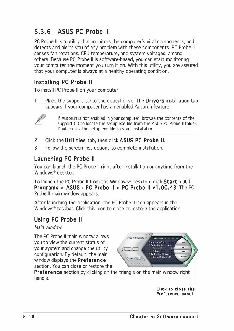
5 -185 -185 -185 -185 -18 Chapter 5 : Software supportChapter 5 : Software supportChapter 5 : Software supportChapter 5 : Software supportChapter 5 : Software support
5.3.65.3.65.3.65.3.65.3.6 ASUS PC Probe IIASUS PC Probe IIASUS PC Probe IIASUS PC Probe IIASUS PC Probe IIPC Probe II is a utility that monitors the computer’s vital components, anddetects and alerts you of any problem with these components. PC Probe IIsenses fan rotations, CPU temperature, and system voltages, amongothers. Because PC Probe II is software-based, you can start monitoringyour computer the moment you turn it on. With this utility, you are assuredthat your computer is always at a healthy operating condition.
Install ing PC Probe I IInstall ing PC Probe I IInstall ing PC Probe I IInstall ing PC Probe I IInstall ing PC Probe I ITo install PC Probe II on your computer:
1. Place the support CD to the optical drive. The Dr ivers Dr ivers Dr ivers Dr ivers Dr ivers installation tabappears if your computer has an enabled Autorun feature.
If Autorun is not enabled in your computer, browse the contents of thesupport CD to locate the setup.exe file from the ASUS PC Probe II folder.Double-click the setup.exe file to start installation.
2. Click the Ut i l i t ies Ut i l i t ies Ut i l i t ies Ut i l i t ies Ut i l i t ies tab, then click ASUS PC Probe I IASUS PC Probe I IASUS PC Probe I IASUS PC Probe I IASUS PC Probe I I.3. Follow the screen instructions to complete installation.
Launching PC Probe I ILaunching PC Probe I ILaunching PC Probe I ILaunching PC Probe I ILaunching PC Probe I IYou can launch the PC Probe II right after installation or anytime from theWindows® desktop.
To launch the PC Probe II from the Windows® desktop, click Start Start Start Start Start > A l lA l lA l lA l lA l lPrograms > ASUS Programs > ASUS Programs > ASUS Programs > ASUS Programs > ASUS > PC Probe I I > PC Probe I I v1.00.43PC Probe I I > PC Probe I I v1.00.43PC Probe I I > PC Probe I I v1.00.43PC Probe I I > PC Probe I I v1.00.43PC Probe I I > PC Probe I I v1.00.43. The PCProbe II main window appears.
After launching the application, the PC Probe II icon appears in theWindows® taskbar. Click this icon to close or restore the application.
Using PC Probe I IUsing PC Probe I IUsing PC Probe I IUsing PC Probe I IUsing PC Probe I IMain window
The PC Probe II main window allowsyou to view the current status ofyour system and change the utilityconfiguration. By default, the mainwindow displays the PreferencePreferencePreferencePreferencePreferencesection. You can close or restore thePreference Preference Preference Preference Preference section by clicking on the triangle on the main window righthandle.
C l i c k to c l o se theC l i c k to c l o se theC l i c k to c l o se theC l i c k to c l o se theC l i c k to c l o se theP re fe rence pane lP r e fe rence pane lP r e fe rence pane lP r e fe rence pane lP r e fe rence pane l
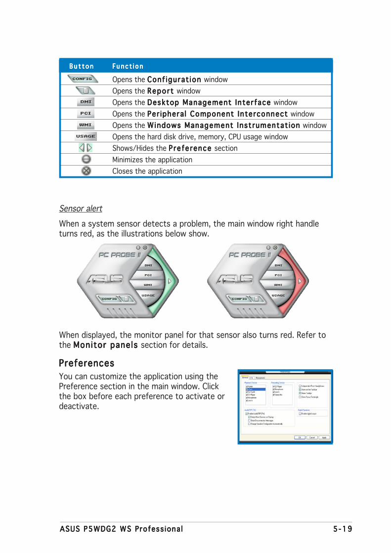
ASUS P5WDG2 WS Profess iona lASUS P5WDG2 WS Profess iona lASUS P5WDG2 WS Profess iona lASUS P5WDG2 WS Profess iona lASUS P5WDG2 WS Profess iona l 5 -195 -195 -195 -195 -19
B u t t o nB u t t o nB u t t o nB u t t o nB u t t o n Func t i o nFunc t i o nFunc t i o nFunc t i o nFunc t i o n
Opens the Conf igurat ion Conf igurat ion Conf igurat ion Conf igurat ion Conf igurat ion windowOpens the Repor t Repor t Repor t Repor t Repor t windowOpens the Desktop Management Inter face Desktop Management Inter face Desktop Management Inter face Desktop Management Inter face Desktop Management Inter face windowOpens the Per iphera l Component Interconnect Per iphera l Component Interconnect Per iphera l Component Interconnect Per iphera l Component Interconnect Per iphera l Component Interconnect windowOpens the Windows Management Inst rumentat ion Windows Management Inst rumentat ion Windows Management Inst rumentat ion Windows Management Inst rumentat ion Windows Management Inst rumentat ion windowOpens the hard disk drive, memory, CPU usage windowShows/Hides the P re fe rence P re fe rence P re fe rence P re fe rence P re fe rence sectionMinimizes the applicationCloses the application
Sensor alert
When a system sensor detects a problem, the main window right handleturns red, as the illustrations below show.
When displayed, the monitor panel for that sensor also turns red. Refer tothe Monitor panels Monitor panels Monitor panels Monitor panels Monitor panels section for details.
PreferencesPreferencesPreferencesPreferencesPreferencesYou can customize the application using thePreference section in the main window. Clickthe box before each preference to activate ordeactivate.

5 -205 -205 -205 -205 -20 Chapter 5 : Software supportChapter 5 : Software supportChapter 5 : Software supportChapter 5 : Software supportChapter 5 : Software support
Hardware monitor panelsHardware monitor panelsHardware monitor panelsHardware monitor panelsHardware monitor panelsThe hardware monitor panels display the current value of a system sensorsuch as fan rotation, CPU temperature, and voltages.
The hardware monitor panels come in two display modes: hexagonal (large)and rectangular (small). When you check the Enable Monitor ing PanelEnable Monitor ing PanelEnable Monitor ing PanelEnable Monitor ing PanelEnable Monitor ing Paneloption from the PreferencePreferencePreferencePreferencePreference section, the monitor panels appear on yourcomputer’s desktop.
Changing the monitor panels position
To change the position of the monitor panels in the desktop,click the arrow down button of the Scheme Scheme Scheme Scheme Scheme options, thenselect another position from the list box. Click OK OK OK OK OK whenfinished.
Moving the monitor panels
All monitor panels move together using amagnetic effect. If you want to detach amonitor panel from the group, click thehorseshoe magnet icon. You can now moveor reposition the panel independently.
Adjusting the sensor threshold value
You can adjust the sensor thresholdvalue in the monitor panel by clickingthe or buttons. You can also adjustthe threshold values using theConf ig Conf ig Conf ig Conf ig Conf ig window.
You cannot adjust the sensor thresholdvalues in a small monitoring panel.
La rge d i sp l ayLa rge d i sp l ayLa rge d i sp l ayLa rge d i sp l ayLa rge d i sp l ay
Sma l l d i s p l aySma l l d i s p l aySma l l d i s p l aySma l l d i s p l aySma l l d i s p l ay
C l i c k t oC l i c k t oC l i c k t oC l i c k t oC l i c k t oi n c r e a sei n c r e a sei n c r e a sei n c r e a sei n c r e a se
v a l u ev a l u ev a l u ev a l u ev a l u e
C l i c k t oC l i c k t oC l i c k t oC l i c k t oC l i c k t odec r e a sedec r e a sedec r e a sedec r e a sedec r e a se
v a l u ev a l u ev a l u ev a l u ev a l u e

ASUS P5WDG2 WS Profess iona lASUS P5WDG2 WS Profess iona lASUS P5WDG2 WS Profess iona lASUS P5WDG2 WS Profess iona lASUS P5WDG2 WS Profess iona l 5 -215 -215 -215 -215 -21
Monitoring sensor alert
The monitor panel turns red when a component value exceeds or is lowerthan the threshold value. Refer to the illustrations below.
La rge d i sp l ayLa rge d i sp l ayLa rge d i sp l ayLa rge d i sp l ayLa rge d i sp l ay
Sma l l d i s p l aySma l l d i s p l aySma l l d i s p l aySma l l d i s p l aySma l l d i s p l ay
WMI browserWMI browserWMI browserWMI browserWMI browserClick to display the WMI(Windows ManagementInstrumentation) browser. Thisbrowser displays various Windows®
management information. Click anitem from the left panel to displayon the right panel. Click the plussign (+) before WMI Informat ionWMI Informat ionWMI Informat ionWMI Informat ionWMI Informat ionto display the available information.
You can enlarge or reduce the browser size by dragging the bottom rightcorner of the browser.
DMI browserDMI browserDMI browserDMI browserDMI browserClick to display the DMI(Desktop Management Interface)browser. This browser displaysvarious desktop and systeminformation. Click the plus sign (+)before DMI Informat ion DMI Informat ion DMI Informat ion DMI Informat ion DMI Informat ion todisplay the available information.

5 -225 -225 -225 -225 -22 Chapter 5 : Software supportChapter 5 : Software supportChapter 5 : Software supportChapter 5 : Software supportChapter 5 : Software support
PCI browserPCI browserPCI browserPCI browserPCI browserClick to display the PCI(Peripheral ComponentInterconnect) browser. This browserprovides information on the PCIdevices installed on your system.Click the plus sign (+) before thePCI Informat ion PCI Informat ion PCI Informat ion PCI Informat ion PCI Informat ion item to displayavailable information.
UsageUsageUsageUsageUsageThe Usage Usage Usage Usage Usage browser displays real-time information on the CPU, hard diskdrive space, and memory usage. Click to display the Usage browser.
CPU usage
The CPUCPUCPUCPUCPU tab displays real-time CPUusage in line graph representation.If the CPU has an enabledHyper-Threading, two separate linegraphs display the operation of thetwo logical processors.
Hard disk drive space usage
The Hard D isk Hard D isk Hard D isk Hard D isk Hard D isk tab displays theused and available hard disk drivespace. The left panel of the tablists all logical drives. Click a harddisk drive to display the informationon the right panel. The pie chart atthe bottom of the windowrepresents the used (blue) and theavailable HDD space.

ASUS P5WDG2 WS Profess iona lASUS P5WDG2 WS Profess iona lASUS P5WDG2 WS Profess iona lASUS P5WDG2 WS Profess iona lASUS P5WDG2 WS Profess iona l 5 -235 -235 -235 -235 -23
Memory usage
The Memory tab shows both usedand available physical memory. Thepie chart at the bottom of thewindow represents the used (blue)and the available physical memory.
Configuring PC Probe I IConfiguring PC Probe I IConfiguring PC Probe I IConfiguring PC Probe I IConfiguring PC Probe I IClick to view and adjust the sensor threshold values.
The Conf ig Conf ig Conf ig Conf ig Conf ig window has two tabs: Sensor/Threshold Sensor/Threshold Sensor/Threshold Sensor/Threshold Sensor/Threshold and PreferencePreferencePreferencePreferencePreference.The Sensor/Threshold Sensor/Threshold Sensor/Threshold Sensor/Threshold Sensor/Threshold tab enables you to activate the sensors or toadjust the sensor threshold values. The Preference Preference Preference Preference Preference tab allows you tocustomize sensor alerts, or change the temperature scale.
Loads the de fau l tLoads the de fau l tLoads the de fau l tLoads the de fau l tLoads the de fau l tt h resho l d va l uesth resho l d va l uesth resho l d va l uesth resho l d va l uesth resho l d va l uesfo r each senso rfo r each senso rfo r each senso rfo r each senso rfo r each senso r
App l i e s you rApp l i e s you rApp l i e s you rApp l i e s you rApp l i e s you rc h a n g e sc h a n g e sc h a n g e sc h a n g e sc h a n g e s
Cance l s o rCance l s o rCance l s o rCance l s o rCance l s o ri gno re s you ri gno re s you ri gno re s you ri gno re s you ri gno re s you r
c h a n g e sc h a n g e sc h a n g e sc h a n g e sc h a n g e s
Loads your savedLoads your savedLoads your savedLoads your savedLoads your savedconf igurat ionconf igurat ionconf igurat ionconf igurat ionconf igurat ionSaves you rSaves you rSaves you rSaves you rSaves you rcon f i gu r a t i oncon f i gu r a t i oncon f i gu r a t i oncon f i gu r a t i oncon f i gu r a t i on

5 -245 -245 -245 -245 -24 Chapter 5 : Software supportChapter 5 : Software supportChapter 5 : Software supportChapter 5 : Software supportChapter 5 : Software support
5.3.75.3.75.3.75.3.75.3.7 SoundMAXSoundMAXSoundMAXSoundMAXSoundMAX®®®®® High Definition Audio utility High Definition Audio utility High Definition Audio utility High Definition Audio utility High Definition Audio utilityThe ADI AD1988B High Definition Audio CODEC provides 8-channel audiocapability through the SoundMAX® audio utility with AudioESP™ software todeliver the ultimate audio experience on your PC. The software implementshigh quality audio synthesis/rendering, 3D sound positioning, and advancedvoice-input technologies.
Follow the installation wizard to install the ADI AD1988B Audio Driver fromthe support CD that came with the motherboard package to activate theSoundMAX® audio utility.
• You must use 4-channel, 6-channel or 8-channel speakers for thissetup.
• SoundMAX® requires Microsoft® Windows® 2000/XP or later version.Make sure that one of these operating systems is installed beforeinstalling SoundMAX®.
• Jack Retasking function works on High Definition front panel audioports only.
If the SoundMAX® audio utility is correctly installed,you will find the SoundMAX® icon on the taskbar.

ASUS P5WDG2 WS Profess iona lASUS P5WDG2 WS Profess iona lASUS P5WDG2 WS Profess iona lASUS P5WDG2 WS Profess iona lASUS P5WDG2 WS Profess iona l 5 -255 -255 -255 -255 -25
From the taskbar, double-click on the SoundMAX® icon to display theSoundMAX® Control Panel.
Audio Setup WizardAudio Setup WizardAudio Setup WizardAudio Setup WizardAudio Setup Wizard
By clicking the icon from the SoundMAX® control panel, you can easilyconfigure your audio settings. Simply follow succeeding screen instructionsand begin enjoying High Definition Audio.

5 -265 -265 -265 -265 -26 Chapter 5 : Software supportChapter 5 : Software supportChapter 5 : Software supportChapter 5 : Software supportChapter 5 : Software support
Jack configurationJack configurationJack configurationJack configurationJack configurationThis screen helps you configureyour computer’s audio ports,depending on the audio devicesyou have installed.
Adjust speaker volumeAdjust speaker volumeAdjust speaker volumeAdjust speaker volumeAdjust speaker volumeThis screen helps you adjustspeaker volume. Click the Tes tTes tTes tTes tTes tbutton to hear the changes youhave made.
Adjust microphone volumeAdjust microphone volumeAdjust microphone volumeAdjust microphone volumeAdjust microphone volumeThis screen helps you adjust microphone volume. You will be asked to readpre-written text to allow the AudioWizard to adjust the volume as youspeak.

ASUS P5WDG2 WS Profess iona lASUS P5WDG2 WS Profess iona lASUS P5WDG2 WS Profess iona lASUS P5WDG2 WS Profess iona lASUS P5WDG2 WS Profess iona l 5 -275 -275 -275 -275 -27
Audio preferencesAudio preferencesAudio preferencesAudio preferencesAudio preferences
Click the icon to go to the Preferences page. This page allows you tochange various audio settings.
General optionsGeneral optionsGeneral optionsGeneral optionsGeneral optionsClick the General tab to choose your playback and recording devices, enable/disable the AudioESP™ feature, and enable/disable digital output.
DTS.DTS.DTS.DTS.DTS.This feature is consists of two elements: DTS interactive and DTS NEO:PC.DTS interactive re-encodes your stereo or multi-channel sound into a DTSaudio signal and send it out from your PC to any DTS enabled system.
While DTS NEO:PC turns your stereo audio such as MP3, WMA, CD, and othersound format into a convincing multi-channel audio experience.

5 -285 -285 -285 -285 -28 Chapter 5 : Software supportChapter 5 : Software supportChapter 5 : Software supportChapter 5 : Software supportChapter 5 : Software support
Microphone optionsMicrophone optionsMicrophone optionsMicrophone optionsMicrophone optionsClick the Listening Environment tab allows you to optimize your microphoneinput settings.
Enhanced Microphone FeaturesEnhanced Microphone FeaturesEnhanced Microphone FeaturesEnhanced Microphone FeaturesEnhanced Microphone FeaturesVoice recording
Enables Noise Filter function. Detects repetitive and stationary noiseslike computer fans, air conditioners, and other background noises theneliminates it in the incoming sudio stream while recording. You can enableit for a better recording quality.
Directional Array
Receives only the sound coming from the reception cone and eliminatesinterferences including neighboring speakers and reverberations. You canenable it to transit clearer sound during on-line games, MSN, or Skype.
Speaker Phone
Advanced de-reverberation techniques can help to reduce echo andminimize its effect on the speech engine. You can enable it when youhave conference call to reduce echoes in the other side.
The directional Array and Speaker Phonefunction only when working with the ASUSArray Mic.

ASUS P5WDG2 WS Profess iona lASUS P5WDG2 WS Profess iona lASUS P5WDG2 WS Profess iona lASUS P5WDG2 WS Profess iona lASUS P5WDG2 WS Profess iona l 5 -295 -295 -295 -295 -29
If you want to boot the system from a hard disk drive included in acreated RAID set, copy first the RAID driver from the support CD to afloppy disk before you install an operating system to the selected harddisk drive. Refer to section “5.6 Creating a RAID driver disk” for details.
5.4 RAID configurationsThe motherboard comes with the Intel® ICH7R Southbridge RAID controllersthat allow you to configure Serial ATA hard disk drives as RAID sets. Themotherboard supports the following RAID configurations.
RA ID 0RAID 0RAID 0RAID 0RAID 0 (Data striping) optimizes two identical hard disk drives to read andwrite data in parallel, interleaved stacks. Two hard disks perform the samework as a single drive but at a sustained data transfer rate, double that ofa single disk alone, thus improving data access and storage. Use of twonew identical hard disk drives is required for this setup.
RA ID 1RAID 1RAID 1RAID 1RAID 1 (Data mirroring) copies and maintains an identical image of datafrom one drive to a second drive. If one drive fails, the disk arraymanagement software directs all applications to the surviving drive as itcontains a complete copy of the data in the other drive. This RAIDconfiguration provides data protection and increases fault tolerance to theentire system. Use two new drives or use an existing drive and a new drivefor this setup. The new drive must be of the same size or larger than theexisting drive.
RAID 10 RAID 10 RAID 10 RAID 10 RAID 10 is data striping and data mirroring combined without parity(redundancy data) having to be calculated and written. With the RAID 10configuration you get all the benefits of both RAID 0 and RAID 1configurations. Use four new hard disk drives or use an existing drive andthree new drives for this setup.
RA ID 5RAID 5RAID 5RAID 5RAID 5 stripes both data and parity information across three or more harddisk drives. Among the advantages of RAID 5 configuration include betterHDD performance, fault tolerance, and higher storage capacity. The RAID 5configuration is best suited for transaction processing, relational databaseapplications, enterprise resource planning, and other business systems.Use a minimum of three identical hard disk drives for this setup.
I n te lI n te lI n te lI n te lI n te l® Matr ix Storage Matr ix Storage Matr ix Storage Matr ix Storage Matr ix Storage. The Intel® Matrix Storage technology supportedby the ICH7R chip allows you to create a RAID 0 and a RAID 1 set usingonly two identical hard disk drives. The Intel® Matrix Storage technologycreates two partitions on each hard disk drive to create a virtual RAID 0and RAID 1 sets. This technology also allows you to change the hard diskdrive partition size without losing any data.
5 -305 -305 -305 -305 -30 Chapter 5 : Software supportChapter 5 : Software supportChapter 5 : Software supportChapter 5 : Software supportChapter 5 : Software support
5.4.25.4.25.4.25.4.25.4.2 IntelIntelIntelIntelIntel®®®®® RAID configurations RAID configurations RAID configurations RAID configurations RAID configurationsThis motherboard supports RAID 0, RAID 1, RAID 5, RAID 10 (0+1), andIntel® Matrix Storage configurations for Serial ATA hard disks drivesthrough the Intel® ICH7R Southbridge chip.
Setting the RAID item in BIOSSetting the RAID item in BIOSSetting the RAID item in BIOSSetting the RAID item in BIOSSetting the RAID item in BIOSYou must set the RAID item in the BIOS Setup before you can create a RAIDset(s). To do this:1. Enter the BIOS Setup during POST.2. Go to the Main MenuMain MenuMain MenuMain MenuMain Menu, select IDE ConfigurationIDE ConfigurationIDE ConfigurationIDE ConfigurationIDE Configuration, then press <Enter>.3. Select the item Conf igure SATA AsConf igure SATA AsConf igure SATA AsConf igure SATA AsConf igure SATA As, then press <Enter> to display
the configuration options.4. Select RA ID RA ID RA ID RA ID RA ID from the Conf igure SATA As Conf igure SATA As Conf igure SATA As Conf igure SATA As Conf igure SATA As item options, then
press <Enter>.5. Save your changes, then exit the BIOS Setup.
Refer to the system or the motherboard user guide for details onentering and navigating through the BIOS Setup.
5.4.15.4.15.4.15.4.15.4.1 Installing Serial ATA hard disksInstalling Serial ATA hard disksInstalling Serial ATA hard disksInstalling Serial ATA hard disksInstalling Serial ATA hard disksThe motherboard supports Serial ATA hard disk drives. For optimalperformance, install identical drives of the same model and capacity whencreating a disk array.To install the SATA hard disks for a RAID configuration:
1. Install the SATA hard disks into the drive bays.2. Connect the SATA signal cables.3. Connect a SATA power cable to the power connector on each drive.

ASUS P5WDG2 WS Profess iona lASUS P5WDG2 WS Profess iona lASUS P5WDG2 WS Profess iona lASUS P5WDG2 WS Profess iona lASUS P5WDG2 WS Profess iona l 5 -315 -315 -315 -315 -31
IntelIntelIntelIntelIntel®®®®® Matrix Storage Manager Option ROM Util ity Matrix Storage Manager Option ROM Util ity Matrix Storage Manager Option ROM Util ity Matrix Storage Manager Option ROM Util ity Matrix Storage Manager Option ROM Util ityThe Intel® Matrix Storage Manager Option ROM utility allows you to createRAID 0, RAID 1, RAID 10 (RAID 0+1), and RAID 5 set(s) from Serial ATAhard disk drives that are connected to the Serial ATA connectorssupported by the Southbridge.
To enter the Intel® Application Accelerator RAID Option ROM utility:
1. Install all the Serial ATA hard disk drives.2. Turn on the system.3. During POST, press <Ctrl+I> to display the utility main menu.
Intel(R) Matrix Storage Manager Option ROM v5.0.0.1032 ICH7R wRAID5Copyright(C) 2003-05 Intel Corporation. All Rights Reserved.
[ MAIN MENU ]1. Create RAID Volume2. Delete RAID Volume3. Reset Disks to Non-RAID4. Exit
[ DISK/VOLUME INFORMATION ]RAID Volumes:None defined.
Physical Disks:Port Drive Model Serial # Size Type/Status(Vol ID)0 XXXXXXXXXXX XXXXXXXX XX.XXGB Non-RAID Disk1 XXXXXXXXXXX XXXXXXXX XX.XXGB Non-RAID Disk2 XXXXXXXXXXX XXXXXXXX XX.XXGB Non-RAID Disk3 XXXXXXXXXXX XXXXXXXX XX.XXGB Non-RAID Disk
[↑↓↑↓↑↓↑↓↑↓]-Select [ESC]-Exit [ENTER]-Select Menu
The navigation keys at the bottom of the screen allow you to movethrough the menus and select the menu options.
The RAID BIOS setup screens shown in this section are for reference onlyand may not exactly match the items on your screen.

5 -325 -325 -325 -325 -32 Chapter 5 : Software supportChapter 5 : Software supportChapter 5 : Software supportChapter 5 : Software supportChapter 5 : Software support
Creating a RAID 0 set (striped)Creating a RAID 0 set (striped)Creating a RAID 0 set (striped)Creating a RAID 0 set (striped)Creating a RAID 0 set (striped)To create a RAID 0 set:
1. From the utility main menu, select 1. Create RAID Volume1. Create RAID Volume1. Create RAID Volume1. Create RAID Volume1. Create RAID Volume, thenpress <Enter>. This screen appears.
2. Enter a name for the RAID 0 set, then press <Enter>.3. When the RAID Leve l RAID Leve l RAID Leve l RAID Leve l RAID Leve l item is highlighted, press the up/down arrow
key to select RAID 0(Str ipe)RAID 0(Str ipe)RAID 0(Str ipe)RAID 0(Str ipe)RAID 0(Str ipe), then press <Enter>.4. When the D isks D isks D isks D isks D isks item is highlighted, press <Enter> to select the hard
disk drives to configure as RAID. This pop-up screen appears.
Intel(R) Matrix Storage Manager Option ROM v5.0.0.1032 ICH7R wRAID5Copyright(C) 2003-05 Intel Corporation. All Rights Reserved.
[ CREATE ARRAY MENU ]
[ DISK/VOLUME INFORMATION ]
Enter a string between 1 and 16 characters in length that can be usedto uniquely identify the RAID volume. This name is case sensitive and
cannot contain special characters.
[↑↓↑↓↑↓↑↓↑↓]-Change [TAB]-Next [ESC]-Previous Menu [Enter]-Select
Name:RAID Level:
Disks:Strip Size:
Capacity:
Volume0RAID0(Stripe)Select Disks128KB0.0 GB
Create Volume
[ SELECT DISKS ]
[↑↓↑↓↑↓↑↓↑↓]-Previous/Next [SPACE]-Selects [ENTER]-Selection Complete
Port Drive Model Serial # Size Status 0 XXXXXXXXXXXX XXXXXXXX XX.XGB Non-RAID Disk 1 XXXXXXXXXXXX XXXXXXXX XX.XGB Non-RAID Disk 2 XXXXXXXXXXXX XXXXXXXX XX.XGB Non-RAID Disk 3 XXXXXXXXXXXX XXXXXXXX XX.XGB Non-RAID Disk
Select 2 to 4 disks to use in creating the volume.
5. Use the up/down arrow key to highlight a drive, then press <Space>to select. A small triangle marks the selected drive. Press <Enter>after completing your selection.

ASUS P5WDG2 WS Profess iona lASUS P5WDG2 WS Profess iona lASUS P5WDG2 WS Profess iona lASUS P5WDG2 WS Profess iona lASUS P5WDG2 WS Profess iona l 5 -335 -335 -335 -335 -33
6. Use the up/down arrow key to select the stripe size for the RAID 0array, then press <Enter>. The available stripe size values range from4 KB to 128 KB. The default stripe size is 128 KB.
T I P : T I P : T I P : T I P : T I P : We recommend a lower stripe size for server systems, and a higherstripe size for multimedia computer systems used mainly for audio andvideo editing.
7. Key in the RAID volume capacity that you want, then press <Enter>.The default value indicates the maximum allowed capacity.
8. Press <Enter> when the Create VolumeCreate VolumeCreate VolumeCreate VolumeCreate Volume item is highlighted. Thiswarning message appears.
WARNING: ALL DATA ON SELECTED DISKS WILL BE LOST.
Are you sure you want to create this volume? (Y/N):
9. Press <Y> to create the RAID volume and return to the main menu, or<N> to go back to the Create Volume menu.

5 -345 -345 -345 -345 -34 Chapter 5 : Software supportChapter 5 : Software supportChapter 5 : Software supportChapter 5 : Software supportChapter 5 : Software support
Creating a RAID 1 set (mirrored)Creating a RAID 1 set (mirrored)Creating a RAID 1 set (mirrored)Creating a RAID 1 set (mirrored)Creating a RAID 1 set (mirrored)To create a RAID 1 set:
1. From the utility main menu, select 1. Create RAID Volume1. Create RAID Volume1. Create RAID Volume1. Create RAID Volume1. Create RAID Volume, thenpress <Enter>. This screen appears.
2. Enter a name for the RAID 1 set, then press <Enter>.3. When the RAID Leve l RAID Leve l RAID Leve l RAID Leve l RAID Leve l item is highlighted, press the up/down arrow
key to select RAID 1(Mirror)RAID 1(Mirror)RAID 1(Mirror)RAID 1(Mirror)RAID 1(Mirror), then press <Enter>.4. When the Capac ity Capac ity Capac ity Capac ity Capac ity item is highlighted, key in the RAID volume
capacity that you want, then press <Enter>. The default valueindicates the maximum allowed capacity.
5. Press <Enter> when the Create VolumeCreate VolumeCreate VolumeCreate VolumeCreate Volume item is highlighted. Thiswarning message appears.
Intel(R) Matrix Storage Manager Option ROM v5.0.0.1032 ICH7R wRAID5Copyright(C) 2003-05 Intel Corporation. All Rights Reserved.
[ CREATE ARRAY MENU ]
[ DISK/VOLUME INFORMATION ]
Enter a string between 1 and 16 characters in length that can be usedto uniquely identify the RAID volume. This name is case sensitive and
cannot contain special characters.
[↑↓↑↓↑↓↑↓↑↓]-Change [TAB]-Next [ESC]-Previous Menu [Enter]-Select
Name:RAID Level:
Disks:Strip Size:
Capacity:
Volume1RAID1(Mirror)Select DisksN/AXX.X GB
Create Volume
WARNING: ALL DATA ON SELECTED DISKS WILL BE LOST.
Are you sure you want to create this volume? (Y/N):
6. Press <Y> to create the RAID volume and return to main menu or <N>to go back to Create Volume menu.
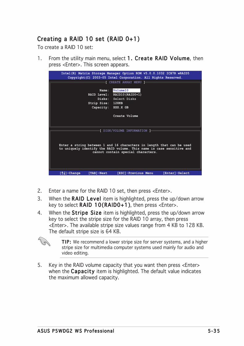
ASUS P5WDG2 WS Profess iona lASUS P5WDG2 WS Profess iona lASUS P5WDG2 WS Profess iona lASUS P5WDG2 WS Profess iona lASUS P5WDG2 WS Profess iona l 5 -355 -355 -355 -355 -35
Creating a RAID 10 set (RAID 0+1)Creating a RAID 10 set (RAID 0+1)Creating a RAID 10 set (RAID 0+1)Creating a RAID 10 set (RAID 0+1)Creating a RAID 10 set (RAID 0+1)To create a RAID 10 set:
1. From the utility main menu, select 1. Create RAID Volume1. Create RAID Volume1. Create RAID Volume1. Create RAID Volume1. Create RAID Volume, thenpress <Enter>. This screen appears.
Intel(R) Matrix Storage Manager Option ROM v5.0.0.1032 ICH7R wRAID5Copyright(C) 2003-05 Intel Corporation. All Rights Reserved.
[ CREATE ARRAY MENU ]
[ DISK/VOLUME INFORMATION ]
Enter a string between 1 and 16 characters in length that can be usedto uniquely identify the RAID volume. This name is case sensitive and
cannot contain special characters.
Name:RAID Level:
Disks:Strip Size:
Capacity:
Volume10RAID10(RAID0+1)Select Disks128KBXXX.X GB
Create Volume
2. Enter a name for the RAID 10 set, then press <Enter>.3. When the RAID Leve l RAID Leve l RAID Leve l RAID Leve l RAID Leve l item is highlighted, press the up/down arrow
key to select RAID 10(RAID0+1)RAID 10(RAID0+1)RAID 10(RAID0+1)RAID 10(RAID0+1)RAID 10(RAID0+1), then press <Enter>.4. When the Str ipe S ize Str ipe S ize Str ipe S ize Str ipe S ize Str ipe S ize item is highlighted, press the up/down arrow
key to select the stripe size for the RAID 10 array, then press<Enter>. The available stripe size values range from 4 KB to 128 KB.The default stripe size is 64 KB.
T I P : T I P : T I P : T I P : T I P : We recommend a lower stripe size for server systems, and a higherstripe size for multimedia computer systems used mainly for audio andvideo editing.
5. Key in the RAID volume capacity that you want then press <Enter>when the Capac ity Capac ity Capac ity Capac ity Capac ity item is highlighted. The default value indicatesthe maximum allowed capacity.
[↑↓↑↓↑↓↑↓↑↓]-Change [TAB]-Next [ESC]-Previous Menu [Enter]-Select

5 -365 -365 -365 -365 -36 Chapter 5 : Software supportChapter 5 : Software supportChapter 5 : Software supportChapter 5 : Software supportChapter 5 : Software support
Creating a RAID 5 set (parity)Creating a RAID 5 set (parity)Creating a RAID 5 set (parity)Creating a RAID 5 set (parity)Creating a RAID 5 set (parity)To create a RAID 5 set:
1. From the utility main menu, select 1. Create RAID Volume1. Create RAID Volume1. Create RAID Volume1. Create RAID Volume1. Create RAID Volume, thenpress <Enter>. This screen appears.
Intel(R) Matrix Storage Manager Option ROM v5.0.0.1032 ICH7R wRAID5Copyright(C) 2003-05 Intel Corporation. All Rights Reserved.
[ CREATE ARRAY MENU ]
[ DISK/VOLUME INFORMATION ]
Enter a string between 1 and 16 characters in length that can be usedto uniquely identify the RAID volume. This name is case sensitive and
cannot contain special characters.
Name:RAID Level:
Disks:Strip Size:
Capacity:
Volume5RAID5(Parity)Select Disks64KB0.0 GB
Create Volume
WARNING: ALL DATA ON SELECTED DISKS WILL BE LOST.
Are you sure you want to create this volume? (Y/N):
7. Press <Y> to create the RAID volume and return to the main menu or<N> to go back to the Create Volume menu.
[↑↓↑↓↑↓↑↓↑↓]-Change [TAB]-Next [ESC]-Previous Menu [Enter]-Select
6. Press <Enter> when the Create VolumeCreate VolumeCreate VolumeCreate VolumeCreate Volume item is highlighted. Thiswarning message appears.
2. Enter a name for the RAID 5 set, then press <Enter>.3. When the RAID Leve l RAID Leve l RAID Leve l RAID Leve l RAID Leve l item is highlighted, press the up/down arrow
key to select RAID 5(Par i ty)RAID 5(Par i ty)RAID 5(Par i ty)RAID 5(Par i ty)RAID 5(Par i ty), then press <Enter>.

ASUS P5WDG2 WS Profess iona lASUS P5WDG2 WS Profess iona lASUS P5WDG2 WS Profess iona lASUS P5WDG2 WS Profess iona lASUS P5WDG2 WS Profess iona l 5 -375 -375 -375 -375 -37
4. The Disks item is highlighted, press <Enter> to select the hard diskdrives to configure as RAID. The following pop-up screen appears.
[ SELECT DISKS ]
[↑↓↑↓↑↓↑↓↑↓]-Previous/Next [SPACE]-Selects [ENTER]-Selection Complete
Port Drive Model Serial # Size Status 0 XXXXXXXXXXXX XXXXXXXX XX.XGB Non-RAID Disk 1 XXXXXXXXXXXX XXXXXXXX XX.XGB Non-RAID Disk 2 XXXXXXXXXXXX XXXXXXXX XX.XGB Non-RAID Disk 3 XXXXXXXXXXXX XXXXXXXX XX.XGB Non-RAID Disk
Select 2 to 4 disks to use in creating the volume.
5. Use the up/down arrow key to highlight the drive you want to set,then press <Space> to select. A small triangle marks the selecteddrive. Press <Enter> after completing your selection.
6. When the Str ipe S ize Str ipe S ize Str ipe S ize Str ipe S ize Str ipe S ize item is highlighted, press the up/down arrowkey to select the stripe size for the RAID 5 array, then press <Enter>.The available stripe size values range from 4 KB to 128 KB. Thedefault stripe size is 64 KB.
T I P : T I P : T I P : T I P : T I P : We recommend a lower stripe size for server systems, and a higherstripe size for multimedia computer systems used mainly for audio andvideo editing.
7. Key in the RAID volume capacity that you want, then press <Enter>when the Capac ity Capac ity Capac ity Capac ity Capac ity item is highlighted. The default value indicatesthe maximum allowed capacity.
8. Press <Enter> when the Create VolumeCreate VolumeCreate VolumeCreate VolumeCreate Volume item is highlighted. Thiswarning message appears.
WARNING: ALL DATA ON SELECTED DISKS WILL BE LOST.
Are you sure you want to create this volume? (Y/N):
9. Press <Y> to create the RAID volume and return to the main menu or<N> to go back to the Create Volume menu.

5 -385 -385 -385 -385 -38 Chapter 5 : Software supportChapter 5 : Software supportChapter 5 : Software supportChapter 5 : Software supportChapter 5 : Software support
Deleting a RAID setDeleting a RAID setDeleting a RAID setDeleting a RAID setDeleting a RAID set
Take caution when deleting a RAID set. You will lose all data on the harddisk drives when you delete a RAID set.
To delete a RAID set:
1. From the utility main menu, select 2. Delete RAID Volume2. Delete RAID Volume2. Delete RAID Volume2. Delete RAID Volume2. Delete RAID Volume, thenpress <Enter> to display this screen.
2. Use the up/down arrow key to select the RAID set you want to delete,then press <Del>. This window appears.
Intel(R) Matrix Storage Manager Option ROM v5.0.0.1032 ICH7R wRAID5Copyright(C) 2003-05 Intel Corporation. All Rights Reserved.
[ DELETE VOLUME MENU ]Name Level Drives Capacity Status BootableVolume0 RAIDX(xxxxx) X XXX.XGB Normal Yes
[ HELP ]
Deleting a volume will destroy the volume data on the drive(s) andcause any member disks to become available as non-RAID disks.
WARNING: EXISTING DATA WITHIN THIS VOLUME WILL BE LOST AND NON-RECOVERABLE.
[↑↓↑↓↑↓↑↓↑↓]-Select [<ESC>]-Previous Menu [<Del>]-Delete Volume
3. Press <Y> to delete the RAID set and return to the utility main menu;otherwise, press <N> to return to the Delete Volume menu.
ALL DATA IN THE VOLUME WILL BE LOST!
Are you sure you want to delete volume “VolumeX”? (Y/N):
[ DELETE VOLUME VERIFICATION ]

ASUS P5WDG2 WS Profess iona lASUS P5WDG2 WS Profess iona lASUS P5WDG2 WS Profess iona lASUS P5WDG2 WS Profess iona lASUS P5WDG2 WS Profess iona l 5 -395 -395 -395 -395 -39
Exiting the IntelExiting the IntelExiting the IntelExiting the IntelExiting the Intel®®®®® Matrix Storage Manager uti l ity Matrix Storage Manager uti l ity Matrix Storage Manager uti l ity Matrix Storage Manager uti l ity Matrix Storage Manager uti l ityTo exit the utility:
1. From the utility main menu, select 4 . Ex i t4 . Ex i t4 . Ex i t4 . Ex i t4 . Ex i t, then press <Enter>. Thiswindow appears.
Are you sure you want to exit? (Y/N):
[ CONFIRM EXIT ]
2. Press <Y> to exit or press <N> to return to the utility main menu.
Resetting Disks to Non-RAIDResetting Disks to Non-RAIDResetting Disks to Non-RAIDResetting Disks to Non-RAIDResetting Disks to Non-RAID
Take caution before you reset a RAID volume HDD to non-RAID. Resettinga RAID volume HDD deletes all internal RAID structure on the drive.
To reset a RAID set hard disk drive:
1. From the utility main menu, select 3. Reset Disks to Non-RAID3. Reset Disks to Non-RAID3. Reset Disks to Non-RAID3. Reset Disks to Non-RAID3. Reset Disks to Non-RAID,then press <Enter> to display this screen.
2. Use the up/down arrow key to highlight the RAID set drive you wantto reset, then press <Space> to select.
3. Press <Enter> to reset the RAID set drive. A confirmation messageappears.
4. Press <Y> to reset the drive or press <N> to return to the utility mainmenu.
[ RESET RAID DATA ]
Resetting RAID data will remove internal RAID structuresfrom the selected RAID disks. By removing these structures,the drive will revert back to a non-RAID disk.
WARNING: Resetting a disk causes all data on the disk to be lost.
Port Drive Model Serial # Size Status 0 XXXXXXXXXXXX XXXXXXXX XX.XGB Member Disk 1 XXXXXXXXXXXX XXXXXXXX XX.XGB Member Disk
Select the disks that should be reset.
[↑↓↑↓↑↓↑↓↑↓]-Previous/Next [SPACE]-Selects [ENTER]-Selection Complete

5 -405 -405 -405 -405 -40 Chapter 5 : Software supportChapter 5 : Software supportChapter 5 : Software supportChapter 5 : Software supportChapter 5 : Software support
Resetting a RAID set hard disks driveResetting a RAID set hard disks driveResetting a RAID set hard disks driveResetting a RAID set hard disks driveResetting a RAID set hard disks drive
Take caution before you reset a RAID volume HDD to non-RAID. Resettinga RAID volume HDD deletes all internal RAID structure on the drive.
To reset a RAID set hard disk drive:
1. From the utility main menu, select [3. Reset Disks to Non-RAID][3. Reset Disks to Non-RAID][3. Reset Disks to Non-RAID][3. Reset Disks to Non-RAID][3. Reset Disks to Non-RAID],then press <Enter> to display the following screen.
Resetting RAID data will remove the internal RAID structuresfrom the selected RAID disks. By removing these structuresthe drive will revert back to a Non-RAID disk.
[ RESET RAID DATA ]
WARNING: Resetting a disk causes all data on the disk to be lost.
Port Drive Model Serial # Size Status 0 STXXXXXXXXX XXXXXXXX XX.0GB Member Disk 1 STXXXXXXXXX XXXXXXXX XX.0GB Member Disk
Select the disk that should be reset
[ ]-Previous/Next[ ]-Previous/Next [Space]-Selects [Space]-Selects [Enter]-Selection Complete[Enter]-Selection Complete
2. Use the up or down arrow keys to highlight the RAID set drive youwant to reset, then press <Space> to select.
3. Press <Enter> to reset the RAID set drive. A confirmation windowappears.
4. Press <Y> to reset the drive; otherwise, press <N> to return to theutility main menu.
5. Follow steps 2 to 4 to select and reset other RAID set drives.

ASUS P5WDG2 WS Profess iona lASUS P5WDG2 WS Profess iona lASUS P5WDG2 WS Profess iona lASUS P5WDG2 WS Profess iona lASUS P5WDG2 WS Profess iona l 5 -415 -415 -415 -415 -41
5.5 Creating a RAID driver diskA floppy disk with the RAID driver is required when installing Windows®
2000/XP operating system on a hard disk drive that is included in a RAIDset. You can create a RAID driver disk in DOS (using the Makediskapplication in the support CD) or in Windows® environment.
To create a RAID driver disk in DOS environment:
1. Place the motherboard support CD in the optical drive.2. Restart the computer, then enter the BIOS Setup.3. Select the optical drive as the first boot priority to boot from the
support CD. Save your changes, then exit the BIOS Setup.4. Restart the computer.5. Press any key when prompted to boot from CD.
The Makedisk menu appears.
6. Place a blank, high-density floppy disk to the floppy disk drive, thenpress the corresponding number to format the floppy disk. Thefollowing message displays on screen.
Loading FreeDOS FAT KERNEL GO!
Press any key to boot from CDROM...
1) Make ICH7R 32-bit RAID driver disk2) Make ICH7R 64-bit RAID driver disk
3) Make Marvell 88SE6140 SATA2 RAID driver disk4) Format floppy disk5) FreeDOS command prompt
Please choose 1 ~ 6
7. Press <Enter> to format the floppy disk.8. When finished, select the type of RAID driver disk you want to create
by typing the number preceding the option, then press <Enter>. Thefollowing message appears on screen.
Insert new diskette for drive B:\
and press ENTER when ready...
Please insert your formatted floppy to drive B:\
Press a key to continue.
The screens shown in this section are for reference only, and may notexactly match the items on your screen.

5 -425 -425 -425 -425 -42 Chapter 5 : Software supportChapter 5 : Software supportChapter 5 : Software supportChapter 5 : Software supportChapter 5 : Software support
3. Insert a formatted high-density floppy disk to the floppy disk drive.4. Follow screen instructions to complete the process.5. After creating a RAID driver disk, eject the floppy disk, then
write-protect it to prevent computer virus infection.
To install the RAID driver:
1. Install an operating system to the selected hard disk drive. Duringinstallation, the computer prompts you to press the F 6F 6F 6F 6F 6 key if you areinstalling a third-party SCSI or RAID driver.
2. Press <F6>, then insert the RAID driver disk to the floppy disk drive.3. Follow screen instructions to install the RAID drivers.
To create a RAID driver disk in Windows® environment:
1. Place the motherboard support CD in the optical drive.2. Click the Make D isk Make D isk Make D isk Make D isk Make D isk menu tab, then select the RAID driver disk you
wish to create:• Click Make ICH7R 32 bit RAID Driver DiskMake ICH7R 32 bit RAID Driver DiskMake ICH7R 32 bit RAID Driver DiskMake ICH7R 32 bit RAID Driver DiskMake ICH7R 32 bit RAID Driver Disk to create an Intel®
ICH7R RAID driver disk for a 32-bit system.• Click Make ICH7R 64 bit RAID Driver DiskMake ICH7R 64 bit RAID Driver DiskMake ICH7R 64 bit RAID Driver DiskMake ICH7R 64 bit RAID Driver DiskMake ICH7R 64 bit RAID Driver Disk to create an Intel®
ICH7R RAID driver disk for a 64-bit system.
• Click Make Marvel l 88SE6141 SATA2 RAID Dr iver DiskMake Marvel l 88SE6141 SATA2 RAID Dr iver DiskMake Marvel l 88SE6141 SATA2 RAID Dr iver DiskMake Marvel l 88SE6141 SATA2 RAID Dr iver DiskMake Marvel l 88SE6141 SATA2 RAID Dr iver Disk tocreate a Marvell® 88SE6141 SATA2 RAID driver disk for a 32-bitsystem.O rO rO rO rO r
Browse the contents of the support CD to locate the driver diskutility.
9. The RAID drivers are copied to the floppy disk. After creating a RAIDdriver disk, eject the floppy disk, then write-protect it to preventcomputer virus infection.
10. Press any key to return to the Makedisk menu.
Refer to section “5.2.4 Make Disk menu” for details.

ACPU features
The Appendix describes the CPUfeatures and technologies that themotherboard supports.
ASUS P5WDG2 WS Profess iona lASUS P5WDG2 WS Profess iona lASUS P5WDG2 WS Profess iona lASUS P5WDG2 WS Profess iona lASUS P5WDG2 WS Profess iona l
Chapter summary AA.1 Intel® EM64T ........................................................................ A-1A.2 Enhanced Intel SpeedStep® Technology (EIST) .................... A-1A.3 Intel® Hyper-Threading Technology ...................................... A-3

ASUS P5WDG2 WS Profess iona lASUS P5WDG2 WS Profess iona lASUS P5WDG2 WS Profess iona lASUS P5WDG2 WS Profess iona lASUS P5WDG2 WS Profess iona l
A.1 Intel® EM64T
The motherboard supports Intel® Pentium® 4 CPUs with the Intel® EM64T(Extended Memory 64 Technology). The Intel® EM64T feature allows yourcomputer to run on 64-bit operating systems and access larger amounts ofsystem memory for faster and more efficient computing.
The motherboard is fully compatible with Intel® LGA 775 processorsrunning on 32-bit operating systems.
Using the IntelUsing the IntelUsing the IntelUsing the IntelUsing the Intel®®®®® EM64T feature EM64T feature EM64T feature EM64T feature EM64T featureTo use the Intel® EM64T feature:
1. Install an Intel® Pentium® 4 CPU that supports the Intel® EM64T.
2. Install a 64-bit operating system (Windows® XP Professional x64Edition or Windows® Server 2003 x64 Edition).
3. Install the 64-bit drivers for the motherboard components and devicesfrom the support CD.
4. Install the 64-bit drivers for expansion cards or add-on devices, if any.
Refer to the expansion card or add-on device(s) documentation, or visitthe related website, to verify if the card/device supports a 64-bit system.
A.2 Enhanced Intel SpeedStep®
Technology (EIST)The Enhanced Intel SpeedStep® Technology (EIST) intelligently manages theCPU resources by automatically adjusting the CPU voltage and core frequencydepending on the CPU loading and system speed/power requirement.
System requirementsSystem requirementsSystem requirementsSystem requirementsSystem requirements• Intel® Pentium® 4 processor with EIST support• BIOS file with EIST support• Operating system with EIST support (Windows® XP SP2/Windows®
Server 2003 SP1/Linux 2.6 kernel or later versions)
Using the EISTUsing the EISTUsing the EISTUsing the EISTUsing the EISTTo use the EIST feature:
1. Turn on the computer, then enter the BIOS Setup.2. Go to the Advanced MenuAdvanced MenuAdvanced MenuAdvanced MenuAdvanced Menu, highlight CPU Conf igurat ionCPU Conf igurat ionCPU Conf igurat ionCPU Conf igurat ionCPU Conf igurat ion, then
press <Enter>.3. Scroll down the options, select the Inte l(R) SpeedStepInte l(R) SpeedStepInte l(R) SpeedStepInte l(R) SpeedStepInte l(R) SpeedStep
TechnologyTechnologyTechnologyTechnologyTechnology item, then press <Enter>. Refer to the BIOS screen onthe next page.

A - 2A - 2A - 2A - 2A - 2 Append ix : CPU featuresAppend ix : CPU featuresAppend ix : CPU featuresAppend ix : CPU featuresAppend ix : CPU features
4. Select Automat ic Automat ic Automat ic Automat ic Automat ic (default) from the options, then press <Enter>.
Set this item to [Maximum] or [Disabled] if you do not want to use theEIST feature. The CPU constantly operates at a lower internal frequencyif you set this item to [Minimum].
5. Press <F10> to save your changes and exit the BIOS setup.6. After the computer restarts, right click on a blank space on the
desktop, then select Propert ies Propert ies Propert ies Propert ies Propert ies from the pop-up menu.7. When the Disp lay Propert ies Disp lay Propert ies Disp lay Propert ies Disp lay Propert ies Disp lay Propert ies window appears, click the ScreenScreenScreenScreenScreen
Saver Saver Saver Saver Saver tab.8. Click the Power Power Power Power Power button on the Monitor
power section to open the PowerPowerPowerPowerPowerOpt ions Propert ies Opt ions Propert ies Opt ions Propert ies Opt ions Propert ies Opt ions Propert ies window.
9. On the Power schemes Power schemes Power schemes Power schemes Power schemes section, click ,then select any option exceptHome/Office DesktopHome/Office DesktopHome/Office DesktopHome/Office DesktopHome/Office Desktop or Always OnAlways OnAlways OnAlways OnAlways On.
10. Click App lyApp lyApp lyApp lyApp ly, then click O KO KO KO KO K.11. Close the Display PropertiesDisplay PropertiesDisplay PropertiesDisplay PropertiesDisplay Properties window.
After you adjust the power scheme,the CPU internal frequency slightlydecreases when the CPU loading is low.
Select Screen Select Item+- Change OptionF1 General HelpF10 Save and ExitESC Exit
Configure Advanced CPU settingsFrequency : 2800 MHzFSB Speed : 800 MHz
Cache L1 : 32 KBCache L2 : 2048 KBCache L3 : 0 KBRatio Status: Unlocked (Max:14, Min:14)Ratio Actual Value : 14
Ratio CMOS Setting: [ 28]VID CMOS Setting: [ 62]
Microcode Updation [Enabled]Max CPUID Value Limit: [Disabled]Execute Disable Function [Disabled]CPU Internal Thermal Control [Auto]Hyper Threading Technology [Enabled]Intel(R) SpeedStep Technology [Automatic]
Maximum: CPU speed isset to maximum.Minimum: CPU speed isset to minimum.Automatic: CPU speedis controlled by theoperating system.Disabled: Default CPUspeed.
• The motherboard comes with a BIOS file that supports EM64T and EIST.You can download the latest BIOS file from the ASUS website(www.asus.com/support/download/) if you need to update the BIOS file.
• The screen displays and procedures may vary depending on theoperating system.
• Visit www.intel.com for more information on the EM64T and EIST features.• Visit www.microsoft.com for more information on Windows® 64-bit OS.
ASUS P5WDG2 WS Profess iona lASUS P5WDG2 WS Profess iona lASUS P5WDG2 WS Profess iona lASUS P5WDG2 WS Profess iona lASUS P5WDG2 WS Profess iona l
A.3 Intel® Hyper-Threading Technology
• The motherboard supports Intel® Pentium® 4 LGA775 processorswith Hyper-Threading Technology.
• Hyper-Threading Technology is supported under Windows® XP/2003Server and Linux 2.4.x (kernel) and later versions only. Under Linux, usethe Hyper-Threading compiler to compile the code. If you are using anyother operating systems, disable the Hyper-Threading Technology itemin the BIOS to ensure system stability and performance.
• Installing Windows® XP Service Pack 1 or later version is recommended.
• Make sure to enable the Hyper-Threading Technology item in BIOSbefore installing a supported operating system.
• For more information on Hyper-Threading Technology, visitwww.intel.com/info/hyperthreading.
Using the Hyper-Threading TechnologyUsing the Hyper-Threading TechnologyUsing the Hyper-Threading TechnologyUsing the Hyper-Threading TechnologyUsing the Hyper-Threading Technology
To use the Hyper-Threading Technology:
1. Install an Intel® Pentium® 4 CPU that supports Hyper-ThreadingTechnology.
2. Power up the system and enter the BIOS Setup. Under the AdvancedAdvancedAdvancedAdvancedAdvancedMenuMenuMenuMenuMenu, make sure that the item Hyper-Threading Technology Hyper-Threading Technology Hyper-Threading Technology Hyper-Threading Technology Hyper-Threading Technology isset to Enab ledEnab ledEnab ledEnab ledEnab led. See page 4-26 for details.The BIOS item appears only if you installed a CPU that supportsHyper-Threading Technology.
3. Restart the computer.

A - 4A - 4A - 4A - 4A - 4 Append ix : CPU featuresAppend ix : CPU featuresAppend ix : CPU featuresAppend ix : CPU featuresAppend ix : CPU features
Related Documents