1 Project Report On OVERVIEW ON PLANNING AND CONSTRUCTION OF A COMMERCIAL BUILDING A project report submitted in the partial fulfillment of Requirement for the award of the degree of Bachelor Of Technology In Civil Engineering By SIRIPURAM ANUSHA (09241A0157) KATYADA KALPANA (09241A0168) GUGULOTHU SHRAVANI (09241A01A3) Under the guidance of Mr.A.VENKATA SUBRAMANYAM QA/QC INCHARGE,ECCIL HYD Mr.B.H.MAHESH CHANDRA KANTH ASSISTANT PROFESSOR, DEPARTMENT OF CIVIL ENGINEERING. GOKARAJU RANGARAJU INSTITUTE OF ENGINEERING AND TECHNOLOGY BACHUPALLY,KUKATPALLY,HYDERABAD-500090

Welcome message from author
This document is posted to help you gain knowledge. Please leave a comment to let me know what you think about it! Share it to your friends and learn new things together.
Transcript
1
Project Report
On
OVERVIEW ON PLANNING AND CONSTRUCTION OF A
COMMERCIAL BUILDING
A project report submitted in the partial fulfillment of
Requirement for the award of the degree of
Bachelor Of Technology
In
Civil Engineering
By
SIRIPURAM ANUSHA (09241A0157)
KATYADA KALPANA (09241A0168)
GUGULOTHU SHRAVANI (09241A01A3)
Under the guidance of
Mr.A.VENKATA SUBRAMANYAM
QA/QC INCHARGE,ECCIL HYD
Mr.B.H.MAHESH CHANDRA KANTH
ASSISTANT PROFESSOR, DEPARTMENT OF CIVIL ENGINEERING.
GOKARAJU RANGARAJU INSTITUTE OF ENGINEERING AND TECHNOLOGY
BACHUPALLY,KUKATPALLY,HYDERABAD-500090

2
GOKARAJU RANGARAJU
INSTITUTE OF ENGINEERING AND TECHNOLOGY
HYDERABAD
CERTIFICATE
This is to certify that the dissertation entitled “OVERVIEW ON PLANNING AND
CONSTRUCTION OF A COMMERCIAL BUILDING” is a bonafide project work done under
the guidance of Mr. A.VENKATA SUBRAMANYAM (QA/QC INCHARGE,ECCIL HYD)
and Mr.B.H.MAHESH CHANDRAKANTH ,ASSISTANT PROFESSOR IN THE
DEPARTMENT OF CIVIL ENGINEERING,GRIET.
GRIET,Hyderabad.
Project by
SIRIPURAM ANUSHA (09241A0157)
KATYADA KALPANA (09241A0168)
GUGULOTHU SHRAVANI (09241A01A3)
B.H.Mahesh Chandrakanth Prof.Dr.G.Venkata Ramana
Internal guide HOD Civil Engineering External Examiner

3
STUDENT DECLARATION
We hereby declare that the project entitled “Overview on Planning and Construction of a
Commercial Building” is the work done by us during this summer vacation with Madhucon
heights under ECCI.ltd.The site is situated beside JNTU.The building proposed is on a site with
an area of 5200sq.mts and is a 4 basement+G+14.This was taken up by “East Coast
Constructions and Industries Limited”for Madhucon Constructions.The name of the building is
“Madhucon Heights”and it is a commercial corporate office.This project report is submitted in
partial fulfillment of the requirements for the award of Mini Project.
SIRIPURAM ANUSHA (09241A0157)
KATYADA KALPANA (09241AO168)
GUGULOTHU SHRAVANI(09241A01A3)

4
ACKNOWLEDGEMENT
Salutations to our beloved and highly esteemed institute “Gokaraju Rangaraju Institute of
Engineering and Technology” for having well qualified staff and labs furnished with necessary
equipment and computers.
Firstly we would like to express our deep sense of gratitude towards Dr.G.Venkata
Ramana,Head of the Department,Civil Engineering for giving us the opportunity to do an
industrial oriented project work.
We are grateful to M.Ramana Rao the honourable Deputy Project Manager,ECCIL
Hyderabad,for his greatest support,help,guidance,precious time and standing behind us from the
commencement of the project work till the end.
We express our sincere thanks to each and every members of Madhucon Projects ltd.,for
supporting us to complete the Project in their company.
Our greatest vote of thanks again goes to each and every members of ECCIL namely
A.Venkata Subramanyam,QA/QC Incharge,S.Selvam,Project Engineer who has guided and
explained every detail concerned with the project wok.
Finally,we would like to thank our project guide ,Mr.B.H.Mahesh
Chandrakanth,Asst.Professor,Department of Civil Engineering at Gokaraju Rangaraju Institute
of Engineering and Technology for always being available when we required his guidance.
Special thanks to all our team members for the team work and other friends for their
support wherever necessary.

5
CONTENTS PAGE.NO.
• Abstract
1) Introduction 1
2) Basic details of Construction 2
3) Machinery Equipment 3
4) Project Planning,Sheduling and Controlling 7
5) Execution Work 17
5.1) Surveying 17
5.2) Building Column line Staking 19
5.3) Excavation 23
5.4) PCC 24
5.5) Footings 24
5.6) Columns 25
5.7) Beams 28
5.8) Slabs 29
5.9) Waterproofing 38
6) Concrete Mix Design 41
7) Steel Work 49
7.1) Methods of Tying 50
7.2) Reinforcement laying method 51
8) Formwork or Shuttering 57
8.1) Materials of formwork 58
8.2) Use of formwork in construction 59
9) Quality control 63
10) Safety 72
11) Conclusion 76
12) Bibilography 77
6
ABSTRACT
This project deals with basic knowledge required for the Planning and Construction of a
Commercial Building.It deals wih the different equipments required for the construction.
It deals with the structural drawings necessary for the reinforcement details.This project deals
with the project planning,scheduling and controlling.Firstly it dealt with what are the basic
parameters required for the construction planning.
It aiso involves the major part of the construction like quality control and its related tests.It
involves the testing of materials like cement,fine aggregate,coarse aggregate,steel.One of the
important parts our project is the construction of post tension slabs and capital slabs.We have
seen and studied in brief some works on the site related to post tensioned slabs like method of
reinforcement laid,laying of tendons.In this project we have seen the capital slabs instead of
beams and their advantages.
It tells about the materials used for the shuttering process,steel work and concrete work.
It facilitates the ideas that are required for the safety purposes in any project.It also carries the
knowledge about how safety can be attained
7
1.INTRODUCTION
In this we are trying to put up all the basic necessary details for the construction of a commercial
building.The name of the building is “MADHUCON HEIGHTS” and it is a commercial
corporate office.
In this Project we worked out for describing all the process that is needed for the construction of
commercial buildings.It gives the basic knowledge about the planning management,scheduling
of the project process,its duty during the work.It also covers the Quality Control Process,Quality
Assurance procedure according to the Indian Standard Codes(IS-Codes) and all the tests that
should be followed to achieve the best quality products for the constrution work.
We focused mainly on the ongoing works of the project like laying of reinforcement for Post
tensioned slabs and Conventional Slabs and their basic difference.We also noticed the location of
position of Capital Slabs instead of beams and their advantages.We have also gone through the
Concrete Pouring on Slabs.
We have gone through the idea of location of additional reinforcement laid in the weak zones in
the beams and slabs called top extras and bottom extras and also noticed the postion of laps in
them.This project also tells about the formwork and its necessity and the materials of shuttering
equipment used for it.
In this era of rapid developing infrastructure,the role of civil engineers in the field of early stage
development in constructional work is vital.As development of nation begins with the
construction work that requires the best CIVIL engineers ideas and methods of working than
only follows the other department for its further development,so this development is under the
control in the hand of every civil engineers which needed to be as best as possible.

8
2. BASIC DETAILS OF CONSTRUCTION
(MADHUCON HEIGHTS)
In this project we are trying to provide the basic necessary details about Madhucon Heights;its
location,the construction details etc.so that the readers could get easily the basic ideas and
valuation of the project.
Location of the Project :Opposite to JNTU
Area of the Project :5200sq.mts
Purpose of the Project :Commercial Corporate Office
Site Details of the Project :4b+G+14(Four Basements,Ground Floor,Fourteen Floors)
Cost of the Project :29Cr.
Start time of the project :10th June 2010
Estimated time of Completion of the Project: By 2013
9
3.MACHINERY EQUIPMENT
a) Earth Moving Equipments
• Dozer
• Wheel Loader
• Hydraulic Excavator
• Vibratory Compactor
b) Hauling Equipments
• Tractors Trailers
• Trucks
• Tipper
c ) Concreting Equipments
• Batching Plants
• Mixers
• Concrete Pumps
• Transit Mixers
d) Miscellaneous Equipments
• Dewatering Pumps
• Compressors
• Blasting Gun
• Tower Cranes
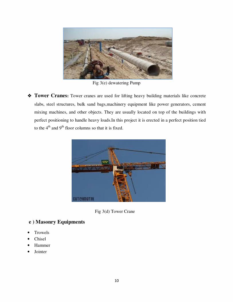
���� Dewatering Pumps:Dewatering is the removal of water from solid material or soil by
wet classification, centrifugation, filtration, or similar solid-liquid separation processes, such
as removal of residual liquid from a filter cake by a filter press as part of various industrial
process.Construction dewatering, unwatering, or water control are common terms used to
describe removal or draining groundwater or surface water from a riverbed,construction site.
10
Fig 3(e) dewatering Pump
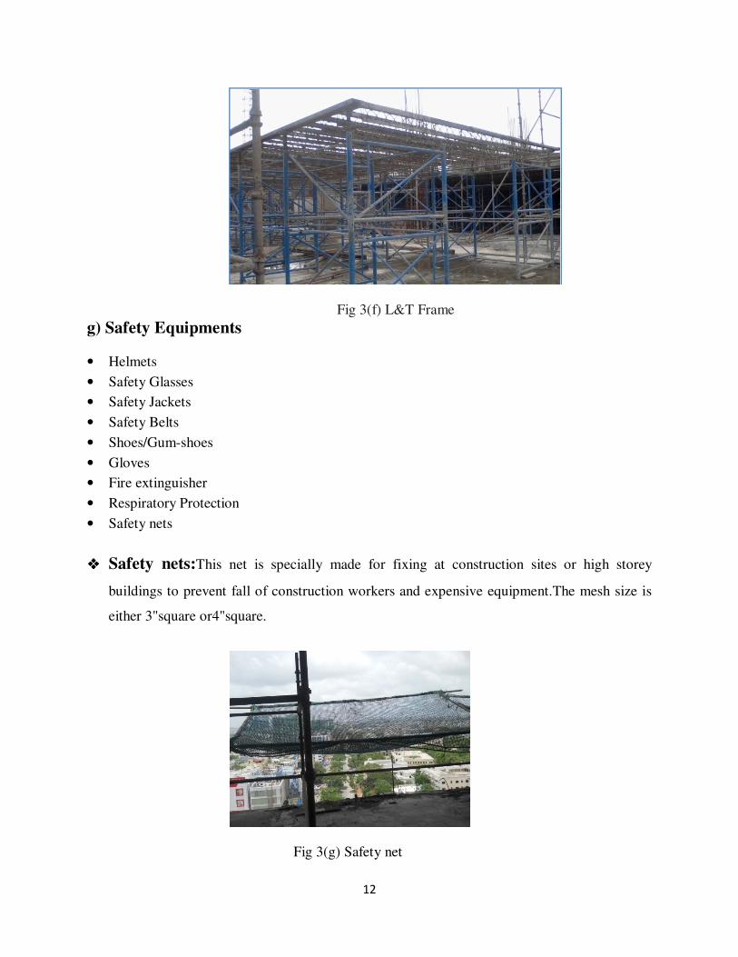
���� Tower Cranes: Tower cranes are used for lifting heavy building materials like concrete
slabs, steel structures, bulk sand bags,machinery equipment like power generators, cement
mixing machines, and other objects. They are usually located on top of the buildings with
perfect positioning to handle heavy loads.In this project it is erected in a perfect position tied
to the 4th and 9
th floor columns so that it is fixed.
Fig 3(d) Tower Crane
e ) Masonry Equipments
• Trowels
• Chisel
• Hammer
• Jointer

11
f) Shuttering Equipments
• Plywood
• Props
• Adjustable Span
• Cup Lock
• L&T-Frame
• Adjustable U-Jack
� Plywood: Shuttering Plywood is BWP grade plywood treated with preservatives mainly
used for concrete purpose.Manufactured with select hardwood, it withstands the loads and
forces encountered during the pouring of concrete and vibrations. Shuttering Plywood is a
superfinisher, since it helps in saving over 40 percent in finishing costs, which is highly
beneficial in the construction industry. Re-usability up to many times on either side depends
on careful handling in storage,fixing,removal and oiling.All this reflects on the RCC
construction that in turn results in leads to a huge 40 percent cost saving.
Fig 3(f) Plywood
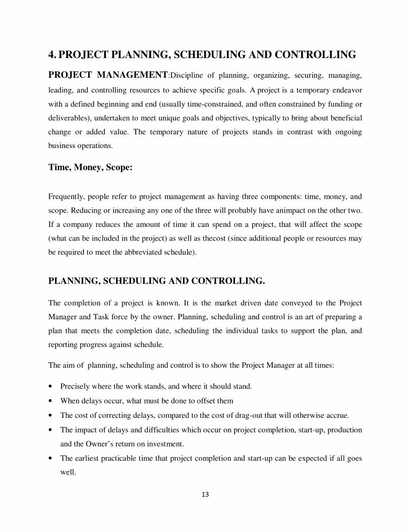
���� L&T Frame:L&T Formwork offers comprehensive solutions for meeting every
construction challenge Being an engineered product, it is fully compatible with different
components having optimal number of individual elements.This makes it highly flexible and
versatile enabling contractors to achieve stringent time schedules with safety and quality.
12
Fig 3(f) L&T Frame
g) Safety Equipments
• Helmets
• Safety Glasses
• Safety Jackets
• Safety Belts
• Shoes/Gum-shoes
• Gloves
• Fire extinguisher
• Respiratory Protection
• Safety nets
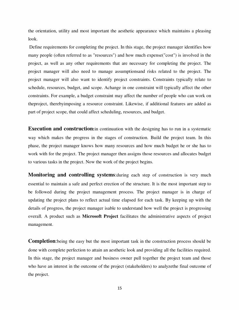
���� Safety nets:This net is specially made for fixing at construction sites or high storey
buildings to prevent fall of construction workers and expensive equipment.The mesh size is
either 3"square or4"square.
Fig 3(g) Safety net
13
4. PROJECT PLANNING, SCHEDULING AND CONTROLLING
PROJECT MANAGEMENT:Discipline of planning, organizing, securing, managing,
leading, and controlling resources to achieve specific goals. A project is a temporary endeavor
with a defined beginning and end (usually time-constrained, and often constrained by funding or
deliverables), undertaken to meet unique goals and objectives, typically to bring about beneficial
change or added value. The temporary nature of projects stands in contrast with ongoing
business operations.
Time, Money, Scope:
Frequently, people refer to project management as having three components: time, money, and
scope. Reducing or increasing any one of the three will probably have animpact on the other two.
If a company reduces the amount of time it can spend on a project, that will affect the scope
(what can be included in the project) as well as thecost (since additional people or resources may
be required to meet the abbreviated schedule).
PLANNING, SCHEDULING AND CONTROLLING.
The completion of a project is known. It is the market driven date conveyed to the Project
Manager and Task force by the owner. Planning, scheduling and control is an art of preparing a
plan that meets the completion date, scheduling the individual tasks to support the plan, and
reporting progress against schedule.
The aim of planning, scheduling and control is to show the Project Manager at all times:
• Precisely where the work stands, and where it should stand.
• When delays occur, what must be done to offset them
• The cost of correcting delays, compared to the cost of drag-out that will otherwise accrue.
• The impact of delays and difficulties which occur on project completion, start-up, production
and the Owner’s return on investment.
• The earliest practicable time that project completion and start-up can be expected if all goes
well.

14
The terms “planning”, “scheduling” will be encountered frequently. As applied to Engineering
and Construction aspects:
• “Planning” means determining what work must be done to achieve the project objective and
relationship between various activities.
• “Scheduling” means deciding when the various activities will be carried out.
• “Control” means making full use of the tools provided by the scheduling and monitoring
operations and refers to the process of analyzing data, investigating cause of backlog,
determining solutions, comparing the cost of these drag-outs costs and preparing specific
recommendations to the Project Manager.
PROJECT MANAGEMENT PROCESS – It is the management process of planning
and controlling the performance or execution of a project. Typical phase of project planning
includes:
1. Initiation
2. Planning
3. Execution and construction
4. Monitoring and controlling systems
5. Completion
Initiation:involves the study of the site of construction, its location, characteristics of the
surface (if it is a rocky stratum or a loose soil stratum), the surroundings of the site, purpose of
construction etc.
The surroundings of the site should be studied for performing further construction works without
creating any kind of disturbance.
Planning:is one of the main stages of construction wherein the site is properly studied and then
planning of the structure is done with sufficient architectural aspects. The planning and design
must also involve maintaining the principles of building-by-laws. The design principles includes
15
the orientation, utility and most important the aesthetic appearance which maintains a pleasing
look.
Define requirements for completing the project. In this stage, the project manager identifies how
many people (often referred to as "resources") and how much expense("cost") is involved in the
project, as well as any other requirements that are necessary for completing the project. The
project manager will also need to manage assumptionsand risks related to the project. The
project manager will also want to identify project constraints. Constraints typically relate to
schedule, resources, budget, and scope. Achange in one constraint will typically affect the other
constraints. For example, a budget constraint may affect the number of people who can work on
theproject, therebyimposing a resource constraint. Likewise, if additional features are added as
part of project scope, that could affect scheduling, resources, and budget.
Execution and construction:in continuation with the designing has to run in a systematic
way which makes the progress in the stages of construction. Build the project team. In this
phase, the project manager knows how many resources and how much budget he or she has to
work with for the project. The project manager then assigns those resources and allocates budget
to various tasks in the project. Now the work of the project begins.
Monitoring and controlling systems:during each step of construction is very much
essential to maintain a safe and perfect erection of the structure. It is the most important step to
be followed during the project management process. The project manager is in charge of
updating the project plans to reflect actual time elapsed for each task. By keeping up with the
details of progress, the project manager isable to understand how well the project is progressing
overall. A product such as Microsoft Project facilitates the administrative aspects of project
management.
Completion:being the easy but the most important task in the construction process should be
done with complete perfection to attain an aesthetic look and providing all the facilities required.
In this stage, the project manager and business owner pull together the project team and those
who have an interest in the outcome of the project (stakeholders) to analyzethe final outcome of
the project.

16
PROJECT SCHEDULING:
Project scheduling refers to the finishing of the work within a specified period. In this stage the
project is scheduled to perform a given task in its estimated time. The scheduling is done in such
a way that each task in the construction process is assigned with time limit for its completion.
This process involves the management of time, performing the task in coordination with other
works simultaneously without any delay in the further progress.
The project should be managed such there is no delay, but in case of any such delay it should be
done to complete it within the estimated time.
COMMON SCHEDULING TECHNIQUES
a. Bar Charts and Linked Bar Charts:
Bar Charts are the easiest and most widely used form of scheduling in construction
management,Even with otherscheduling techniques the eventual schedule is presented the form
of a bar chart. A typical Bar chart is a list of activitieswith the start, duration and finish of each
activity shown as a bar plotted to a time scale. The level of detail of the activitiesdepends on the
intended use of the schedule.
The linked bar chart shows the links between an activity and its preceding activities which have
to be complete before thisactivity can start.The bar charts are also useful for calculating the
resources required for the project. To add the resources to each activityand total them vertically
is called a resource aggregation. Bar charts and resource aggregation charts are useful for
estimating the work content in terms of man-hours and machine hours.
b. Network Analysis and Critical Path Method:
Practically network analysis offers little more than a linked bar chart, though its protagonists
claim, with some justification, that the self contained steps of a network are more applicable to
complex operations than the bar chart, and that the greater rigor imposed by the logic diagram
produces more realistic models of the proposedwork. The steps in producing a network are:
17
- Listing of activities
- Producing a network showing the logical relationship between activities.
- Assessing the duration of each activity, producing a schedule, and determining the start and
finish times of each activity and the available float
- Assessing the required resources.
There are now two popular forms of network analysis in construction management practice,
activity on the arrow and activity on the node, the latter now usually called aprecedence diagram.
Each of these approaches offers virtually the same facilities and it seems largely a matter of
preference which is used.
c.Line of Balance
The line of Balance is a planning technique for repetitive work.The basis of the technique is to
find the required resources for each stage or operation so that the following stages are not
interfered withand the target output can be achieved. The line of balance technique has been
applied in construction work mainly to house building.

18
SCHEDULING SOFTWARE
MS PROJECT
Software used in this project sheduling is MS PROJECT.
MS Project is a strong tool that is built around the PERT and CPM basics.
Microsoft Project is a leading, if not the leading scheduling software in the construction industry.
While there are others that may do a good job of scheduling – they are not as easy to learn,
customize, view and share information.Most importantly Microsoft Project is designed to
streamline and integrate with all your other everyday Microsoft Office Programs. Microsoft has
committed to providing the most universal and powerfulscheduling systems for us to use.
The Basis of MS Project
• A highly visual, yet checklist-intensive program
– Balances visual approach (charts, graphs, etc) with logical structured approach (task
and resources lists).
• The most widely used PM program because:
– It is fairly generic in its approach.
– Highly automated once configured; requires relatively low amount of user
manipulation.
– Scalable – can be used for small to enormous projects.
– A cost-effective choice for casual users.
• Easy to use core techniques
– Advanced techniques are complex, however.
Benefits of Using Microsoft Project
• User friendly and has the common interface as other Microsoft Office Programs.
• Good step-by-step tutorial for beginners.
• Good searchable keyword help function.
19
• Based on data entry – once configured, user enters data and Project automatically.
• Computes all times and cost(Optimistic, Pessimistic, Likely and PERT- expected).
• Identifies Critical Path, computes late & early start dates, slack.
• Computes % complete on a task and project level.
• Identifies areas of over-tasking of resources.
• Draws a wide ranges of charts and graphs specific to the project.
• Creates a wide range of reports specific to the project.
• VERY customizable to meet individual user needs.
• Easily share information between Excel, Outlook, Word, SharePoint and other
softwareprograms.
• Simple enough for a beginner and robust enough for the most advanced scheduler.
• Easy customization for integration with your particular needs and requirements.
• Easy and Effective communication via email and the internet.
• Filter and View for any information required.
• Automation of the processes of organizing, scheduling, recording, calculating, tracking,
reporting, and analyzing schedule data for any project.
Microsoft Project is specified and recognized as a leading scheduling software,designed by
Microsoft – the leading software developer in the world.Regular software upgrades providing
state of the art technology.
PROJECT CONTROLLING:
The project due to any reason being delayed should be suitably controlled making the task
complete. For this maintenance project controlling is very necessary. Project controlling is done
with a compensation to the delayed work/works.Project control is the formal mechanism
established to determine deviations from he basic plan,to determine the precise effect of these
deviations on the plan, and to replan and reschedule to compensate for the deviations.
The project management term action of monitoring and controlling processes refers specifically
to thoseparticular processes that are implemented by the project team and/or the project team
leader for the sole andexplicit purposes of taking a careful and thorough measurement of and to
20
complete a through monitoring of theteam’s project execution to date. The purposes of the
project team’s implementation of monitoring and controlling processes include a retrospective
view in hopes of potentially implementing corrective action in theevent that any action of this
type is deemed necessary. This can be the case when any particular phase of theproject has taken
a wrong turn or has possibly fallen behind schedule in regards to the execution elements. Theact
of monitoring and controlling project processes is essential to maintaining an efficient and
effective workflowthroughout the project. At the onset of the project, the project team leader
may assign one or more project team members to be responsible for this activity.
STEPS IN CONTROL PROCESS :
Establish:standards or targets.These targets are generally expressed in terms of time.
Measure:Performance against the standards set down in the first step.
Identify:the deviation from the standards.
Suggest and Select:Correcting measures.This will involve all the problems-
identifying,decision making and organizing and leadership skill of the decision mak
21
CONSTRUCTION DRAWINGS
CONSTRUCTION:
In the fields of Engineering,construction is a process that consists of the building or assembling
of infrastructure.Normally the job is managed by a Project Manager,and supervised by a
construction manager,design engineer or project engineer.
DRAWINGS
It is the vital part of construction of a project which is referred as a tool for execution of the
work.
DIFFERENT DRAWINGS USED IN CONSTRUCTION
Architectural Drawings
• Site plan showing existing and proposed buildings and road networks,land levels etc.
• All floor plans,elevations and sections.
• Details of toilets,staircases,flooring pattern and false-ceiling.
• Sch edules for doors and windows and flooring pattern in different rooms.
• Integrated service drawings showing electrical,air-conditioning.
• Fire-detection systems.
• Details of built-in furniture.
• Any other detail required for proper completion of works.
Structural Drawings
• Design basis report including Soil test report.
• Detailed design with calculations.
• All detailed drawings like floor plans,structural profiles,column schedule,beam
elevations,reinforcement details or others as required.
In each and every construction site,there exists the following department which is listed below to
run any project.They are

22
• Project Management
• Quantity Surveying
• Quality Control(QA/QC)and preparation of documents in ISO
• Land Surveying
• Engineers Department
• Safety Department

23
5. EXECUTION WORK
5.1 Surveying
Construction surveying is generally performed by specialised technicians. Unlike land surveyors,
the resulting plan does not have legal status. Construction surveyors perform the following tasks:
• Survey existing conditions of the future work site, including topography, existing buildings
and infrastructure, and even including underground infrastructure whenever possible;
• Construction surveying (otherwise "lay-out" or "setting-out"): to stake out reference
points and markers that will guide the construction of new structures such as roads or
buildings for subsequent construction;
• Verify the location of structures during construction;
• As-Built surveying: a survey conducted at the end of the construction project to verify that
the work authorized was completed to the specifications set on plans.
Setting out Process:
Setting out involves marking out the site to indicate where the foundation trenches are to be dug,
and the position of the walls on the concrete foundations.
Wooden profiles are firmly placed into the ground, on which strings can be fixed, the position of
which can be transferred to the ground to indicate thetrench and wall positions.
Once the profiles are in, the string lines for the outer edge of the trench are checked to ensure
that the diagonals are equal - showing that the house will be built “square”.If the diagonals are
not equal, then reposition some profiles and check.
Total station
A total station is an electronic/optical instrument used in modern surveying.The total station is an
electronic theodolite (transit) integrated with an electronic distance meter (EDM) to read slope
distances from the instrument to a particular point. Total station can perform the following
measurements
24
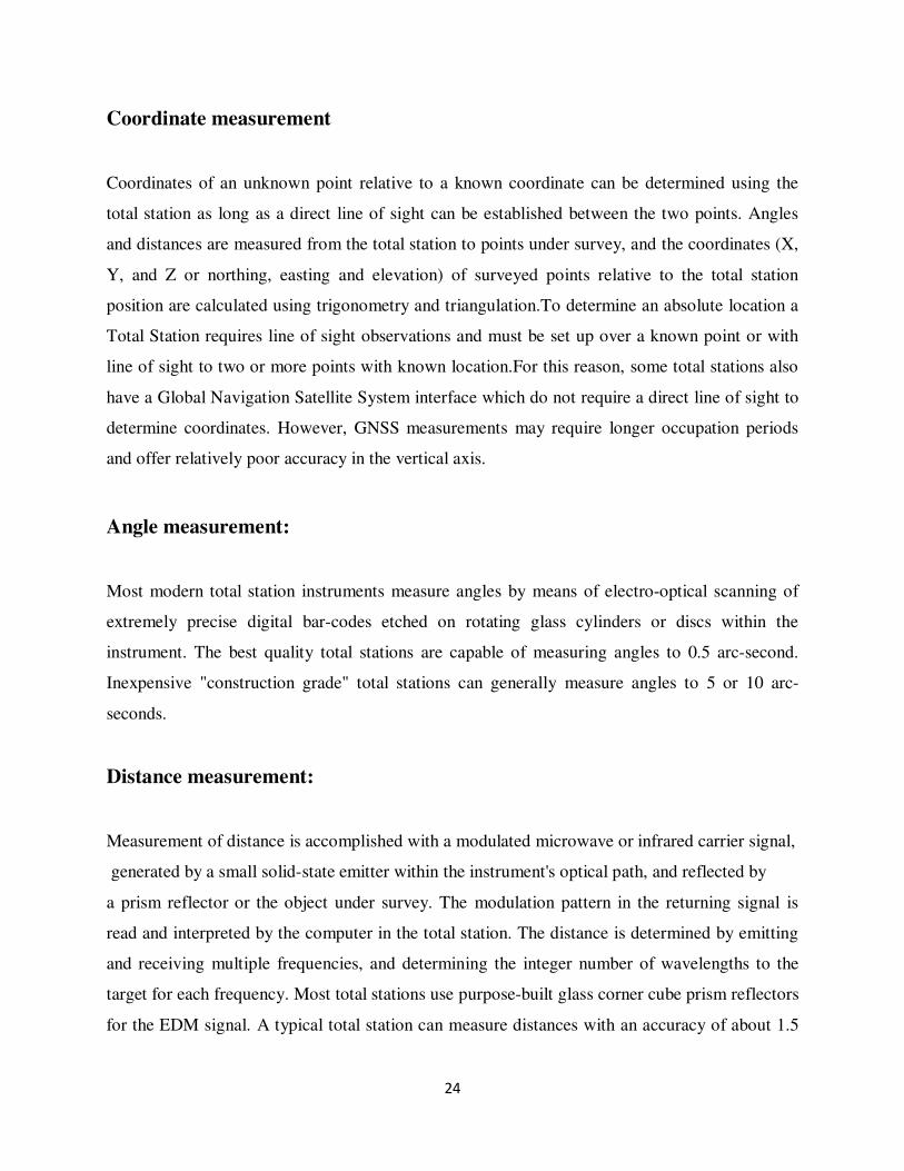
Coordinate measurement
Coordinates of an unknown point relative to a known coordinate can be determined using the
total station as long as a direct line of sight can be established between the two points. Angles
and distances are measured from the total station to points under survey, and the coordinates (X,
Y, and Z or northing, easting and elevation) of surveyed points relative to the total station
position are calculated using trigonometry and triangulation.To determine an absolute location a
Total Station requires line of sight observations and must be set up over a known point or with
line of sight to two or more points with known location.For this reason, some total stations also
have a Global Navigation Satellite System interface which do not require a direct line of sight to
determine coordinates. However, GNSS measurements may require longer occupation periods
and offer relatively poor accuracy in the vertical axis.
Angle measurement:
Most modern total station instruments measure angles by means of electro-optical scanning of
extremely precise digital bar-codes etched on rotating glass cylinders or discs within the
instrument. The best quality total stations are capable of measuring angles to 0.5 arc-second.
Inexpensive "construction grade" total stations can generally measure angles to 5 or 10 arc-
seconds.
Distance measurement:
Measurement of distance is accomplished with a modulated microwave or infrared carrier signal,
generated by a small solid-state emitter within the instrument's optical path, and reflected by
a prism reflector or the object under survey. The modulation pattern in the returning signal is
read and interpreted by the computer in the total station. The distance is determined by emitting
and receiving multiple frequencies, and determining the integer number of wavelengths to the
target for each frequency. Most total stations use purpose-built glass corner cube prism reflectors
for the EDM signal. A typical total station can measure distances with an accuracy of about 1.5

25
millimetres (0.0049 ft) + 2 parts per million over a distance of up to 1,500 metres (4,900
ft).Reflectorless total stations can measure distances to any object that is reasonably light in
color, up to a few hundred meters.
Data processing:
Some models include internal electronic data storage to record distance, horizontal angle, and
vertical angle measured, while other models are equipped to write these measurements to an
external data collector, such as a hand-held computer.When data is downloaded from a total
station onto a computer, application software can be used to compute results and generate a map
of the surveyed area. The new generation of total stations (e.g. Hilti POS 15/18)can also show
the map on the touch-sceen of the instrument right after measuring the points.
Applications:
• Total stations are mainly used by land surveyors and Civil Engineers, either to record
features as in Topographic Surveying or to set out features (such as roads, houses or
boundaries).
• They are also used by archaeologists to record excavations and by private accident
reconstructionists and insurance companies to take measurements of scenes.
5.2 Building Column line staking: Building column line staking is an integral part of
constructing a building. It ensures that the structure that is to be constructed is built in the correct
place and that the columns are placed exactly where they were designed to be placed. Any type
of construction staking is done specifically by professional land surveyors to make sure that
improvements are built in the right area based on the site plan and engineering plans. What
happens is that the surveyor uses structural or architectural plans to mark where the columns and
other features will be built, ,marks the dimensions and sizes and then allows the construction
crew to build the improvements at the location without worry of whether things will be in the
right place or not.
26
Surveyors do a lot of different projects on a construction job, but building column line staking is
critical since columns are typically a support structure for the property. Being able to mark an
entire line that is level and straight for the construction of the columns will allow the builder to
ensure that everything is right where it needs to be base on the site plan and for the sake of
structural integrity, which is critical in the building and construction process. It is always in the
best interest of the Construction Company or builder to rely on a professional land surveyor for
the staking process.
A qualified professional land surveyor has an advantage because they can interpret the plans and
then layout the site with temporary markers to fit the goals of the builder, engineers or architect.
The builder will be able to trust that the building column line staking is correct and that
everything can continue to be built accurately and reliably because the land surveyor has taken
the time to mark everything for the construction crew. Staking is critical because it requires a
boundary and topographic survey to make sure that the site plan matches the actual property
built.
Building column line staking is not the only type of staking done. While this will ensure that
columns are constructed evenly and at the right distances, there are other types of staking in a
construction build. For example, mass grading, curb, fences, storm drains, sanitary sewer lines
utilities, building offsets, sidewalks, roads and even parking lots require staking to ensure that
they are all in the right places and that the construction crew can work around them or perform
their job correctly. All land staking is done first and then building staking will begin with a
survey that will utilize the dimensions and controls of their property to find the exact locations
for staking that aids the building process.
Stages and Measurement:
Design Stage: Topographical surveying and site maps
Construction Stage : Setting out and positioning works involves establishing lines and grades by
means of stakes and string lines to guide the contractor.
During & After Construction: As built drawings, a record and a check.
Measurements Involved: Horizontal & vertical angles, elevations, horizontal distances.
27
Equipment: Most of the cases Laser Instruments are used. The reasons are
1) To create a visible line or plane of known elevation or tilt.
2) Line or plane could be horizontal, vertical or tilted
3) Single beam lasers will project visible string lines or plumb lines.
4) A rotating single beam to create a plane.
Ex: A level or a Theodolite. A total station may also be used. The ones designed for construction
staking are of lower angular resolution (10” or 20”) and shorter range (500m).
Horizontal & Vertical Control:
Before construction: New control points around the site must be established with high accuracy.
Additional points inside the site are then established. All points must be ‘tied out’ for
repositioning. These should:
1) Meet certain accuracy standards.
2) Be clearly marked, referenced and recorded.
3) Be far enough to be safe during construction.
During Construction: Additional control is extended by the contractor as needed around or inside
the structure. These additional points should be close enough to the structure so that workers
with suitable equipment can use them.
Steps for Building staking:
1) First step is to locate the building by boundary surveying. Stakes are placed temporarily
at the corners as a check.
2) A set of batter boards and reference stakes are first set. The boards are around the
building corners and nailed are a full number of feet above the footing base or at 1st floor
elevation.
3) Nails are driven into the batter board tops so that a string connecting them will define an
outside wall.

28
Fig 5.2.Building Staking
Steps for Column Staking:
1) The location of the line is determined after a profile leveling is done.
2) The centre line and an offset reference line are established.
3) Precise alignment and grade are guided by laser beams.
4) The centre line and an offset line are marked and stationed. The actual profile and staking
are on the offset line, not the centre line.
5) The two ends of the offset line, on either side of the building outside the boundary are
joined with strings.
6) At the required locations, the plumb bob is dropped on to the ground to mark the position
of the column.

29
5.3 EXCAVATION
Excavation is the process by which a part of land is cleared for the construction process after the
surveying work has been done.It can be done on the ground level or below the ground level or
below the ground level surface by means of machines like excavators,bulldozers and sometimes
blasting process is also carried out wherever hard rock is formed.
Excavation process was carried out by means of blasting for the land clearance in this project as
it was rocky area.
Excavation should be done after the marking of land has been completed with expert
surveyor,then at least minimum of 2m extra land should be excavated from all corners for easier
convenience of the constructional work.The depth of excavation should be as such that it should
reach to the hard soil which can bear the structural load.
Excavation of land is always carried out in the multiples of m3 of land by the concerned
contractors.Length x Breadth xdepth of the land that must be excavated is taken for estimation of
billing after the completion of work.
Fig 5.3 Excavation
30
Hazards associated with excavation
With careful planning and management,an excavation site can be hazardous to all persons in the
viscinity of the construction work.Particular hazards identified in relation to excavation work
include:
• The depth of excavation
• Nature of the strata
• Fractures or faults
• The presence of water
• Exposure to wet weather
• Any load close to the edge of the zoned of influence
• The exposure time
• Any previous disturbance
• Adjoining buildings
• Adjacent excavations
• Vibration which may increase the potential to collapse
• The presence of existing underground services
• Chemical gases
5.4 PCC
Plain Cement Concrete is a mixture of sand,coarse aggregate,and cement.It is used below the
footings of any constructional structure,to make the structure stronger and to resist designed
load.The main function of PCC is not to allow grond water to enter the footings.It saves the
structure from corrosion.PCC helps the structure to increase its durability.The grade of concrete
used in PCC is M20.The thickness of the PCC used in this project is 75mm.To calculate the
quantity of concrete we multiply length,breadth and depth of concrete used.
5.5 FOOTINGS
The structural unit constructed in masonry or concrete under the base of a wall or a column
which distributes the structure load over a large area of ground.Footings in any structure are
31
constructed just above the PCC.The main function of footings is to transfer the structural load of
the building to the ground.In this project there are 77 no’s of isolated footings are constructed
where one column rests on each footing and 11no’s of combined footings are constructed where
two or more column rests.Raft or strip footings are used for retaining walls.Raft footings ara
continous footings.
The concrete used in footing are RCC where steel bars are also added to make the structure
stronger.The grade of concrete used for footings is M30.For steel to be placed inside the footings
so the clear cover of 50mm is provided.
To calculate the concrete quantity of footings we take footings of depth,length and breadth and
multiply all the dimensions to get the individual concrete quantity.
To calculate the BBS the steel bars quantity we simply take the length of steel bars used and then
its diameter and multiply the length with its unit weight to get the quantity of steel required in
kg’s.
5.6 COLUMNS
A column is an element used primarily to support axial compressive loads and with a height of at
least three times its least lateral dimension. The strength of a column depends on the strength of
the materials, shape and size of the cross section, length and the degree of positional and
directional restrains and its ends.
Columns are directly erected from the base of the footings i.e. below the ground surface in such a
way that the projections on all sides of the column should be equal so as to resist, transfer and
support the axial compressive loads in the structure.
For stirrups to be used in the columns; the spacing are less in top and bottom of the columns as
compared with middle. In this project 100mm of spacing’s are used in both top and bottom side
of the column at a distance of 1m from both the sides, and 200mm at the middle.
32
The types of columns used in this project are square columns and circular columns.
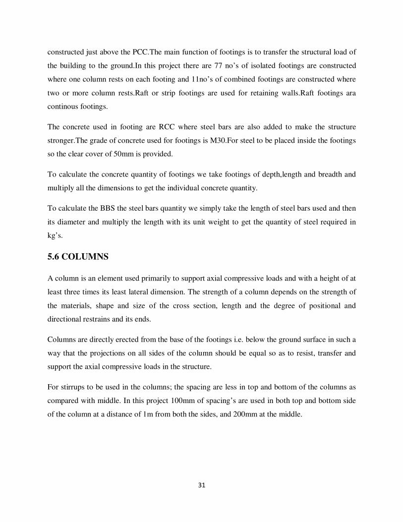
a) Square column:
Columns are designed for all types of decorative and load-bearing installations and
are a long-standing element of architecture, both structurally and decoratively. They support and
enhance the existing architecture. Square columns can be can be used on the exterior to frame a
porch or entryway or accent balustrades. They can also create elegant outdoor living areas. Used
in spaced groupings they can also serve to define a fountain. Interior square columns enhance
any interior space. Columns can be used to encase doorways and windows, frame fireplace
mantels. For ease of installation and longevity consider square fiber-reinforced polymer
columns.
Fig 5.6(a) Square column
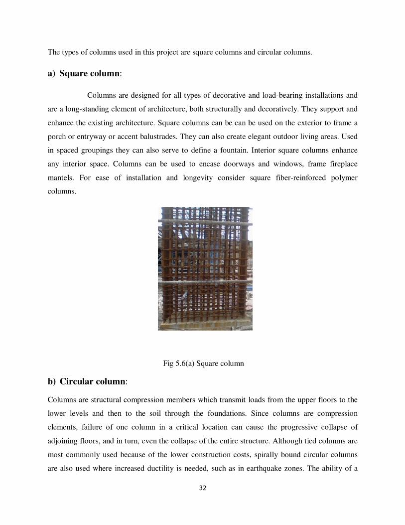
b) Circular column:
Columns are structural compression members which transmit loads from the upper floors to the
lower levels and then to the soil through the foundations. Since columns are compression
elements, failure of one column in a critical location can cause the progressive collapse of
adjoining floors, and in turn, even the collapse of the entire structure. Although tied columns are
most commonly used because of the lower construction costs, spirally bound circular columns
are also used where increased ductility is needed, such as in earthquake zones. The ability of a
33
spirally reinforced column to sustain the maximum load at excessive deformation prevents the
complete collapse of the structure before total redistribution of moments and stresses
complete.Failure in columns could occur as a result of material failure or by loss of lateral
structural stability. If a column fails due to material failure, it is classified as a short column, as
opposed to the slender column whose failure is by buckling.
Fig 5.6(b) Circular column
The grades of concrete used in the columns of MADHUCON HEIGHTS are:
1. M50 upto ground floor and
2. M40 above the ground floor.
The concrete quality can be simply calculated from the product of length, breadth and height of
the individual columns of different dimensions or by multiplying the individual quality if more
number of columns has been constructed with the same sizes.
To calculate the BBS(bar bending schedule) i.e. the steel bars quantity we simply take the length
of the steel bars used and then its diameter and multiply it with its unit weight to get the quantity
of steel required and stirrups are calculated differently.
34
For stirrups (of 8mm dia bars) the clear cover of column (40mm) from each side is deducted and
for the bend length 10 times the dia of bars (i.e.10 x 8) are considered.
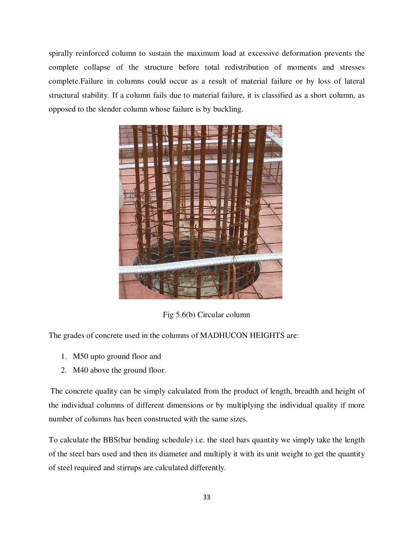
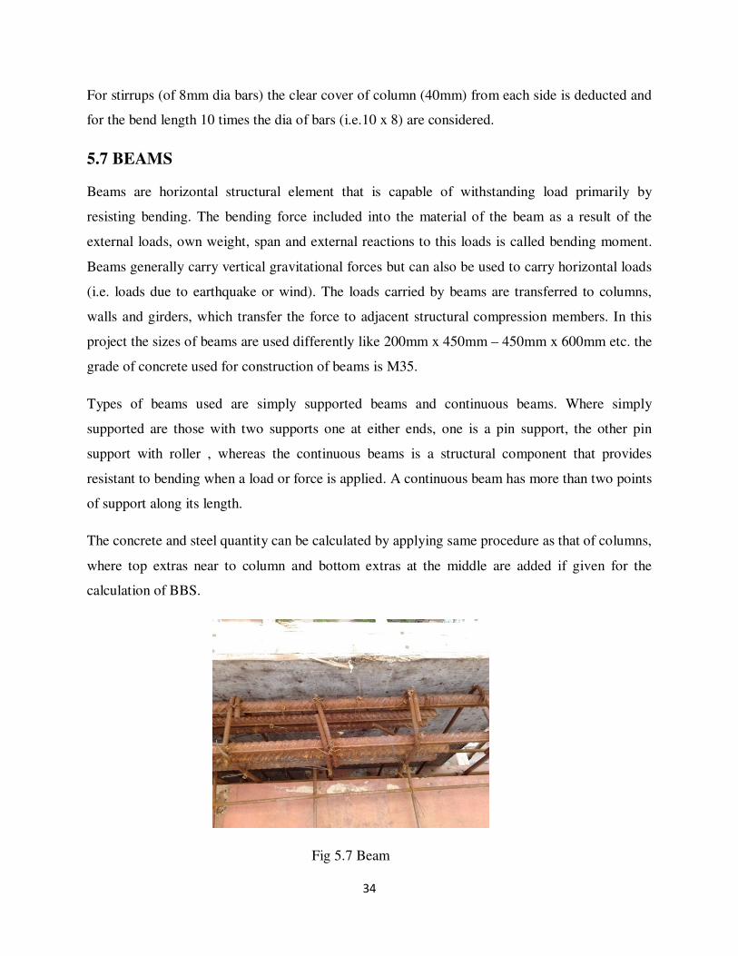
5.7 BEAMS
Beams are horizontal structural element that is capable of withstanding load primarily by
resisting bending. The bending force included into the material of the beam as a result of the
external loads, own weight, span and external reactions to this loads is called bending moment.
Beams generally carry vertical gravitational forces but can also be used to carry horizontal loads
(i.e. loads due to earthquake or wind). The loads carried by beams are transferred to columns,
walls and girders, which transfer the force to adjacent structural compression members. In this
project the sizes of beams are used differently like 200mm x 450mm – 450mm x 600mm etc. the
grade of concrete used for construction of beams is M35.
Types of beams used are simply supported beams and continuous beams. Where simply
supported are those with two supports one at either ends, one is a pin support, the other pin
support with roller , whereas the continuous beams is a structural component that provides
resistant to bending when a load or force is applied. A continuous beam has more than two points
of support along its length.
The concrete and steel quantity can be calculated by applying same procedure as that of columns,
where top extras near to column and bottom extras at the middle are added if given for the
calculation of BBS.
Fig 5.7 Beam
35
5.8 SLABS
A shallow reinforced concrete structural member, relatively sizable in length and width, but
shallow in depth spanning between beams, girders or columns. Slabs are used for floors, roofs
and bridge decks. If they cast integrally with beams, they may be considering the top flange of
those members and act with them as T-beam.
Slabs are of two types:
One way slabs: it is supported on four sides and has a much larger span in one direction than
in the other may be assumed to be supported only along its longer sides. It may be designed as
beam spacing in the short direction. For this purpose a one ft. width can be chosen and the depth
of slab and reinforcing for this unit. Some steel is also placed in the long direction to resist
temperature stresses and distribute concentrated load.
Two way slabs: a supported on four sides and with reinforcing steel perpendicular to all the
sides is called two way slabs.
The thickness of slab is taken as 150mm – 200mm. The grade of concrete used is M35. Concrete
can be calculated by taking breadth, length and depth of the slabs then by deducting the pre
calculated quantities from beams and columns. For calculating steel quantity; length of top main,
top distribution roads are calculated separately for separate diameter of roads and same
procedure can be followed for the bottom reinforcement.
Based on the type of reinforcement, the slabs are again classified into two types. They are post
tensioned slabs and conventional slabs.
5.8.1 Types of prestressing:
1)Pre tensioning:
A method of prestressing concrete in which the tendons are tensioned before the
concrete is placed. In this method, the prestress is imparted to concrete by bond between steel
and concrete. The concrete is cast around already tensioned tendons. This method produces good
bond between the tendon and the concrete, which both protects the tendon from corrosion and

36
allows for direct transfer of tension. The cured concrete adheres and bonds to the bars and when
the tension is released, it is transferred to the concrete as compression by static friction.
However, it requires stout anchoring points between which the tendon is to be stretched and the
tendons are usually in a straight line. Thus, most pretensioned concrete elements are
prefabricated in a factory and must be transported to the construction site, which limits their size.
Pre-tensioned elements are mostly balcony elements, lintels, floor slabs, beams or foundation
piles. An innovative bridge construction method using prestressing is the stressed ribbon bridge
design.
2) Post tensioning:
It is a method of prestressing concrete by tensioning the tendons against hardened
concrete.
Post-tensioning is a method of reinforcing (strengthening) concrete or other materials with high-
strength steel strands or bars, typically referred to as tendons. Post-tensioning applications
include office and apartment buildings, parking structures, slabs-on-ground, bridges, sports
stadiums, rock and soil anchors, and water-tanks. In many cases, post tensioning allows
construction that would otherwise be impossible due to either site constraints or architectural
requirements. Although post-tensioning systems require specialized knowledge and expertise to
fabricate, assemble and install, the concept is easy to explain. Imagine a series of wooden blocks
with holes drilled through them, into which a rubber band is threaded. If one holds the ends of
the rubber band, the blocks will sag. Post-tensioning can be demonstrated by placing wing nuts
on either end of the rubber band and winding the rubber band so that the blocks are pushed
tightly together. If one holds the wing nuts after winding, the blocks will remain straight. The
tightened rubber band is comparable to a post-tensioning tendon that has been stretched by
hydraulic jacks and is held in place by wedge-type anchoring devices.
Concrete is very strong in compression but weak in tension, i.e. it will crack when forces act to
pull it apart. Deflections will cause the bottom of the beam to elongate slightly. Even a slight
elongation is usually enough to cause cracking. Steel reinforcing bars (“rebar”) are typically
embedded in the concrete as tensile reinforcement to limit the crack widths. Rebar is what is
called “passive” reinforcement however; it does not carry any force until the concrete has already
37
deflected enough to crack. Post-tensioning tendons, on the other hand, are considered “active”
reinforcing. Because it is prestressed, the steel is effective as reinforcement even though the
concrete may not be cracked. Post-tensioned structures can be designed to have minimal
deflection and cracking, even under full load.
ADVANTAGES/APPLICATIONS:
There are post-tensioning applications in almost all facets of construction. In building
construction, post-tensioning allows longer clear spans, thinner slabs, fewer beams and more
slender, dramatic elements. Thinner slabs mean less concrete is required. In addition, it means a
lower overall building height for the same floor-to-floor height. Posttensioning can thus allow a
significant reduction in building weight versus a conventional concrete building with the same
number of floors. This reduces the foundation load and can be a major advantage in seismic
areas. A lower building height can also translate to considerable savings in mechanical systems.
Another advantage of post-tensioning is that beams and slabs can be continuous, i.e. a single
beam can run continuously from one end of the building to the other. Structurally, this is much
more efficient than having a beam that just goes from one column to the next. Post-tensioning is
the system of choice for parking structures since it allows a high degree of flexibility in the
column layout, span lengths and ramp configurations. Post-tensioned parking garages can be
either stand-alone structures or one or more floors in an office or residential building. In areas
where there are expansive clays or soils with low bearing capacity, post-tensioned slabs-on-
ground and mat foundations reduce problems with cracking and differential settlement. Post-
tensioning allows bridges to be built to very demanding geometry requirements, including
complex curves, variable super elevation and significant grade changes. Post-tensioning also
allows extremely long span bridges to be constructed without the use of temporary intermediate
supports. This minimizes the impact on the environment and avoids disruption to water or road
traffic below. Post-tensioned rock and soil anchors are used in tunneling and slope stabilization
and as tie-backs for excavations. Post-tensioning can also be used to produce virtually crack-free
concrete for water-tanks.
38
CRITICAL ELEMENTS:
There are several critical elements in a post-tensioning system. In un bonded construction, the
plastic sheathing acts as a bond breaker between the concrete and the prestressing strands. It also
provides protection against damage by mechanical handling and serves as a barrier that prevents
moisture and chemicals from reaching the strand. The strand coating material reduces friction
between the strand and the sheathing and provides additional corrosion protection. Anchorages
are another critical element, particularly in un bonded systems. After the concrete has cured and
obtained the necessary strength, the wedges are inserted inside the anchor casting and the strand
is stressed. When the jack releases the strand, the strand retracts slightly and pulls the wedges
into the anchor. This creates a tight lock on the strand. The wedges thus maintain the applied
force in the tendon and transfer it to the surrounding concrete. In corrosive environments, the
anchorages and exposed strand tails are usually covered with a housing and cap for added
protection.
5.8.2 Terminology:
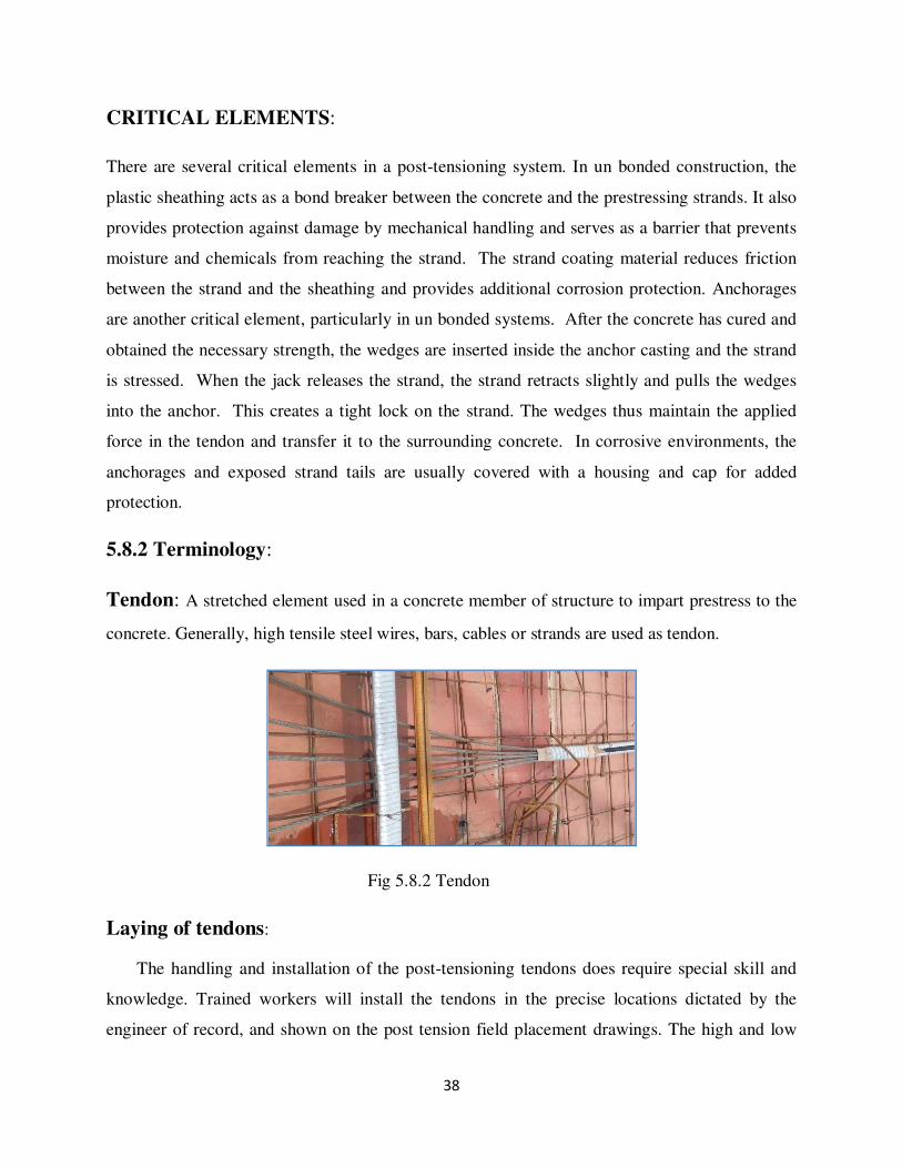
Tendon: A stretched element used in a concrete member of structure to impart prestress to the
concrete. Generally, high tensile steel wires, bars, cables or strands are used as tendon.
Fig 5.8.2 Tendon
Laying of tendons:
The handling and installation of the post-tensioning tendons does require special skill and
knowledge. Trained workers will install the tendons in the precise locations dictated by the
engineer of record, and shown on the post tension field placement drawings. The high and low
39
points of the draped profile are critical to maintain and the tolerance for the placement drawings.
The high and low points of the draped profile are critical to maintain and the tolerance for the
placement in these locations can be as tight as +1/4 or -1/4 inch. In elevated slab construction,
the tendons typically are grouped in bundles in order to increase the spacing between tendons
and improve the constructability of the slab.
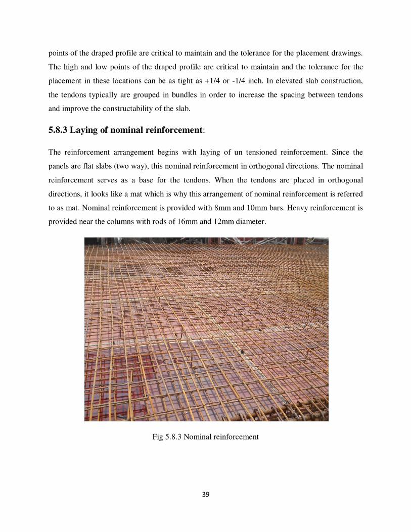
5.8.3 Laying of nominal reinforcement:
The reinforcement arrangement begins with laying of un tensioned reinforcement. Since the
panels are flat slabs (two way), this nominal reinforcement in orthogonal directions. The nominal
reinforcement serves as a base for the tendons. When the tendons are placed in orthogonal
directions, it looks like a mat which is why this arrangement of nominal reinforcement is referred
to as mat. Nominal reinforcement is provided with 8mm and 10mm bars. Heavy reinforcement is
provided near the columns with rods of 16mm and 12mm diameter.
Fig 5.8.3 Nominal reinforcement

40
Tendon laying:
Tendons are bound together in different numbers. Stand is a bunch of seven rods. They may be
singly placed or in a group of three or in a group of five. The three stand or five strand tendons
are placed in aluminium ducts where as the mono strand tendons are placed in HDPE pipes.
These are placed according to the drawings updated. Tendon profile is achieved at the site
according to the elevation details given in the drawing. At about 0.7m from the anchorage end,
grouting pipe is provided for every tendon. They are supported with chairs on both sides with the
help of chairs made from 8mm diameter.
Materials:
All the materials used should be ready at the site. Everything will be brought on day one of
execution except concrete. Concrete will come in ready mix trucks on the day of pouring
concrete into the reinforcement.
The main materials are
1. High grade concrete
2. Steel Fe 450,Fe 415
3. Ducts for tendons (aluminum, HDPE pipe)
4. Tendons (mono strand, 3 strand, 5 strands)
The chairs must be prepared for profiling the tendons and supporting them. After this, the
anchorage markings are made. These are done at every end of a tendon span. The dead end and
live ends are chosen for every tendon profile. Any undulations on the formwork base may be
hammered and must be cleaned thoroughly to remove any kind of dust particles that may have
come upon during the course of execution in the initial stages.
Machinery used in post tensioning slabs:
Machinery used in post tensioning can be classified into two categories:-
1. Installation equipments
2. Pumping equipments
41
Installation equipments are used to induce prestressing force. They are further classified as:-
1. Mono strand stressing jacks.
2. Multi strand stressing jacks.
In this method, the prestress is imparted to concrete by bearing. Post tensioned concrete may be
bonded or unbounded.
Bonded post tensioned concrete:
The term used for a method of applying compression after pouring concrete and the
curing process. The concrete is cast around plastic, steel or aluminum curved duct to follow the
area where otherwise tension would occur in the concrete element. A set of tendons are fished
through the duct to follow the area where otherwise tension would occur in the concrete element,
and then concrete is poured. Once the concrete is hardened, the tendons are tensioned by
hydraulic jacks that react (push) against the concrete member itself.
When the tendons have stretched sufficiently, according to the designed specifications, they are
wedged in position and maintain tension after the jack is removed, transferring pressure to the
concrete. The duct is then grouted to protect the tendons from corrosion. The method is
commonly used to create monolithic slabs for house constructions in locations where expansive
soils (such as adobe clay) create problems for the typical perimeter foundation. All stresses from
seasonal expansion and contraction of the underlying soil are taken into the entire tensioned slab,
which supports the building without supports without the building significance flexure. Post
tensioning is also used in the construction of various bridges, both after concrete is cured,
support by false work and by the assembly of prefabricated sections.
Grouting:
Grouting can be defined as the filling of duct with the material that provides an anti-
corrosive alkaline environment to the prestressing steel and also a strong bond between the
tendon and the surrounding grout. The major part of grout comprises of water and cement, with a
42
w/c ratio of about 0.5 together with some water-reducing admixtures, expansion agent and
pozzolonas.
After two days of the completed prestressing process, grouting is done for the
tendons. The primary and most important reason for grouting to be done is to retain the prestress.
Another important reason is to protect from corrosion by filling all the spaces in the providing
duct.
1. Grouting is done with the help of grout pump. The mixture of cement, admixture, water must
be done under a strict mixing time and velocity control and must not contain lumps nor any
air bubbles during injection into the ducts.
2. Grouting machines include the mixing the injecting operation in a single piece of equipment,
easily handled, with pressures of to 25 bar i.e. 5kg/cm, without the presence of air bubbles,
using any type of cement and admixtures.
3. The grout slurry used in the site contained the following ingredients:
Cement= 50kg
Water=22.5kg
w/c=0.45
Admixture cebex 100 may be added proportionately.
When cubes of 70mm x 70mm x 70mm were tested in the laboratory, the compressive strength
of these cubes was found to be 17KN.
4. This completes the process of laying of the post tensioned slab. The slab is then subjected to
curing for about 5-6 days and then left to harden. At the end of 28days, its compressive
strength may be checked with may be checked with any suitable equipment (rebound
hammer). Other properties may as well be checked.
Ducts:
The hollow materials made out of HDPE (high density poly ethylene) or aluminium that holds
the tendons within and is responsible for protecting the tendons, which impart prestress to the
slab are called ducts.

43
Duct made from galvanized steel strip may be prefabricated or fabricated on site as necessary.
Plastic duct may be shipped in coils or in bundles of straight lengths. In order to avoid
inadvertent introduction of contaminants or debris, it is recommended that the ends of duct coils
or bundles be protected and covered during shipping and storage. Special temporary end caps
may be used to seal the ends of individual ducts. The plastic ducts should be protected from
sunlight, ultraviolet degradation, crushing and excessive bending until installed in the bridge. All
ducts and pipes should be stored in a dry location, on a raised platform, protected from weather
and contamination.
Advantages:
• Large reduction in traditional reinforcement requirements such as tendons cannot distress in
accidents.
• Tendons can be easily “woven” allowing a more efficient design approach.
• Higher ultimate strength due to bond generated between the strand and the concrete.
• No long term issues in maintaining the integrity of the anchor end.
Un bonded post tensioned concrete:
It differs from bonded post tensioning by providing each individual cable
permanent freedom of movement relative to the concrete. To achieve this, each individual tendon
is coated with grease (generally lithium base) and covered by a plastic sheathing formed in an
extrusion process. The transfer of tension is to the concrete is achieved by the steel cable acting
against steel anchors embedded in the perimeter of the slab. The main disadvantage over bonded
post tensioning is the fact that a cable can distress itself and burst out of the slab if damaged
(such as during repairing the slab)
Advantages:
• The ability to individually adjust cables based on poor field conditions (for ex: shifting a
group of four cables around an opening by placing two to either side).
• The procedure of post stress grouting is eliminated.
• The ability to distress the tendons before attempting the repair work.
44
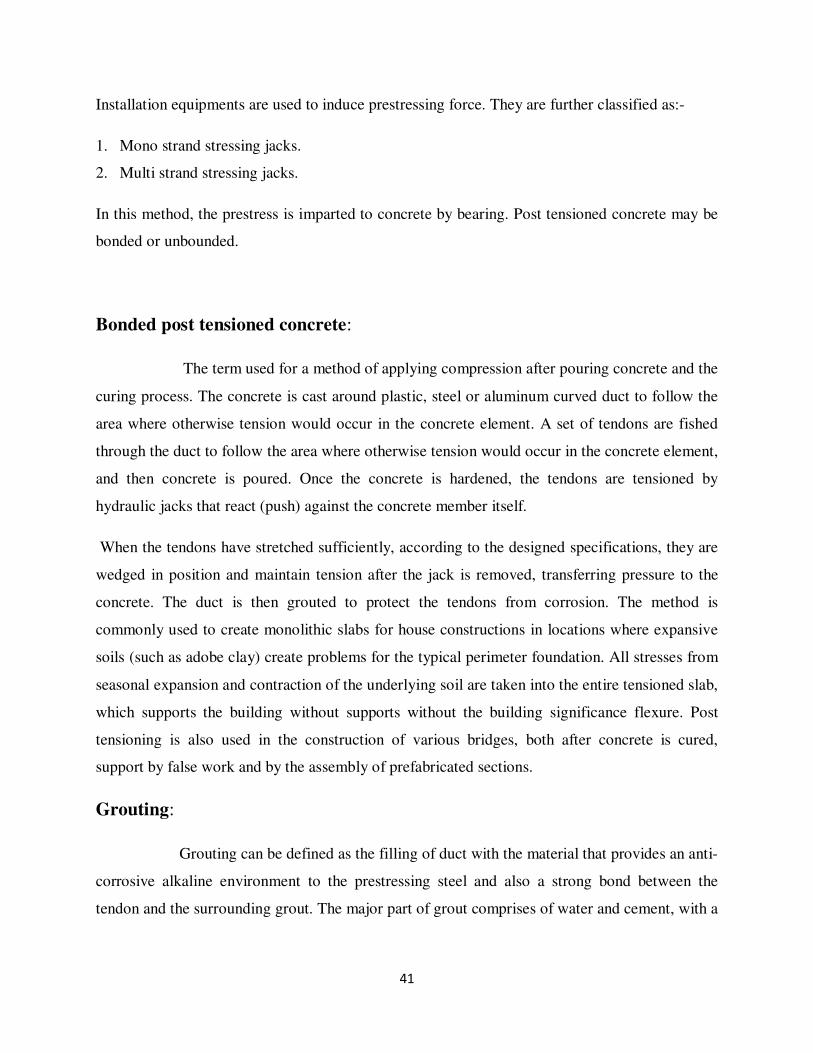
CAPITAL SLABS: Capital slab is provided where the number of beams required is to be
reduced. The depth of capital slabs are kept in such a way that the vehicles can directly pass
through the ramp to the mid-way be parking area inside the floor.
Fig 5.8.4 Capital Slab
RETAINING WALL
Placement of steel in walls is the same as for columns except that the steel is erected in place and
not preassembled. Horizontal steel is tied to vertical steel at least three in any bar length. The
wood block is removed when the form has been filled up to the level of the block. For high
walls, ties in between the top and bottom should be used.
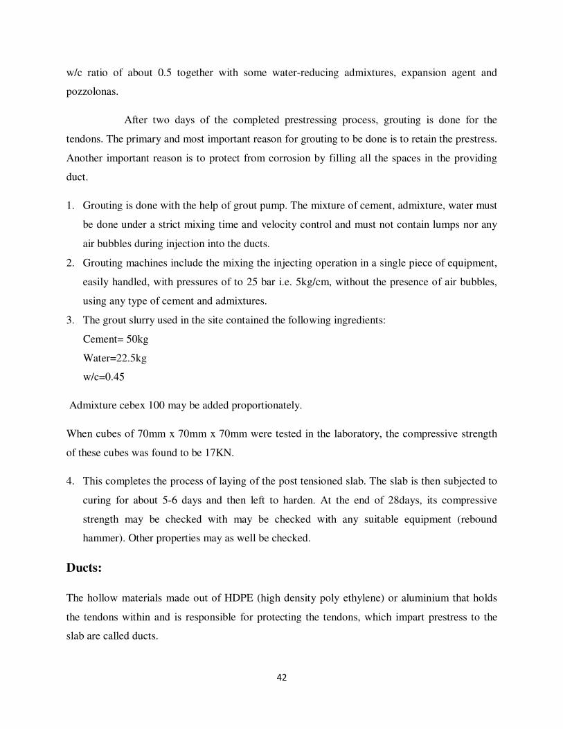
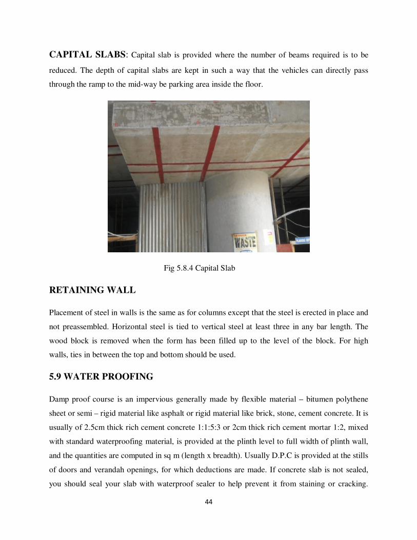
5.9 WATER PROOFING
Damp proof course is an impervious generally made by flexible material – bitumen polythene
sheet or semi – rigid material like asphalt or rigid material like brick, stone, cement concrete. It is
usually of 2.5cm thick rich cement concrete 1:1:5:3 or 2cm thick rich cement mortar 1:2, mixed
with standard waterproofing material, is provided at the plinth level to full width of plinth wall,
and the quantities are computed in sq m (length x breadth). Usually D.P.C is provided at the stills
of doors and verandah openings, for which deductions are made. If concrete slab is not sealed,
you should seal your slab with waterproof sealer to help prevent it from staining or cracking.
45
Repairing a concrete slab can be very expensive and time consuming, so you should waterproof
your concrete to maintain it and prevent future problems. Waterproofing concrete is very simple
and can be done in a day.
Fig 5.9(a) Water proofing material Fig 5.9(b) water proofing in buildings
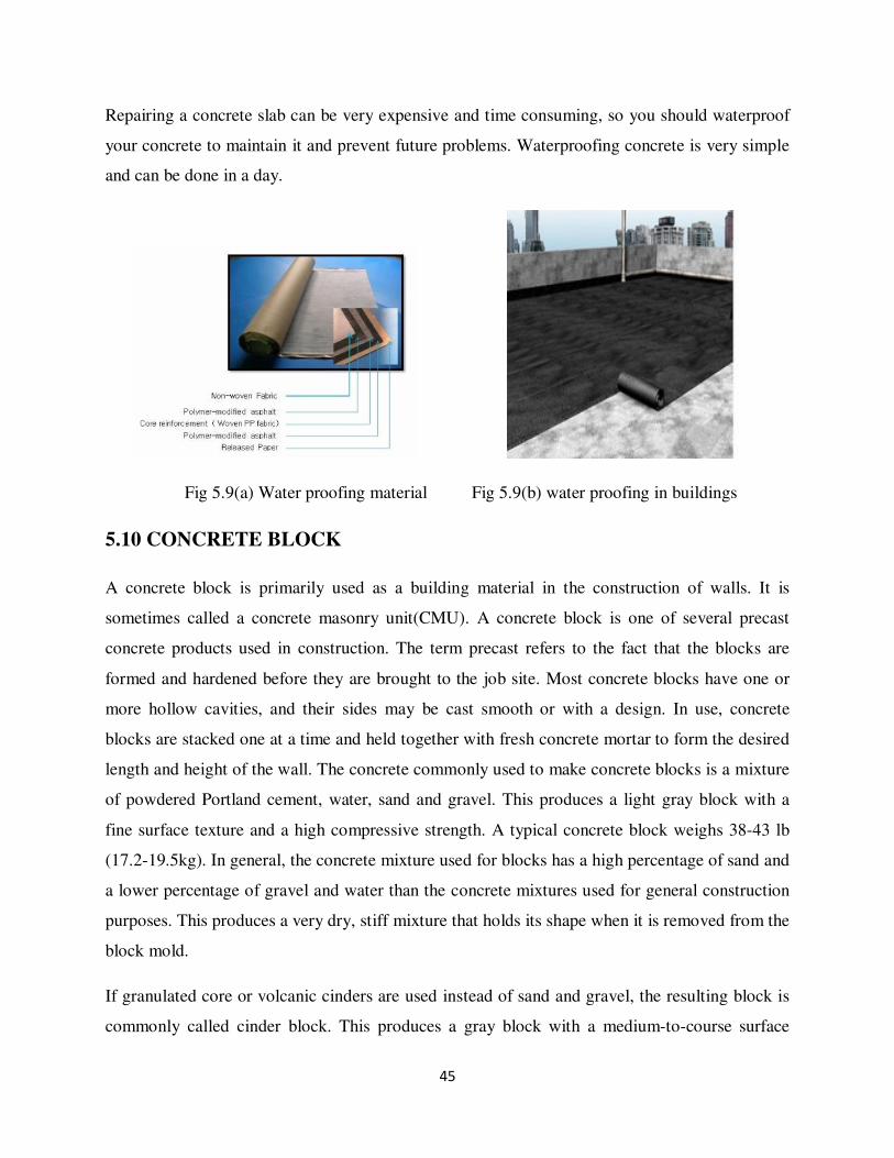
5.10 CONCRETE BLOCK
A concrete block is primarily used as a building material in the construction of walls. It is
sometimes called a concrete masonry unit(CMU). A concrete block is one of several precast
concrete products used in construction. The term precast refers to the fact that the blocks are
formed and hardened before they are brought to the job site. Most concrete blocks have one or
more hollow cavities, and their sides may be cast smooth or with a design. In use, concrete
blocks are stacked one at a time and held together with fresh concrete mortar to form the desired
length and height of the wall. The concrete commonly used to make concrete blocks is a mixture
of powdered Portland cement, water, sand and gravel. This produces a light gray block with a
fine surface texture and a high compressive strength. A typical concrete block weighs 38-43 lb
(17.2-19.5kg). In general, the concrete mixture used for blocks has a high percentage of sand and
a lower percentage of gravel and water than the concrete mixtures used for general construction
purposes. This produces a very dry, stiff mixture that holds its shape when it is removed from the
block mold.
If granulated core or volcanic cinders are used instead of sand and gravel, the resulting block is
commonly called cinder block. This produces a gray block with a medium-to-course surface
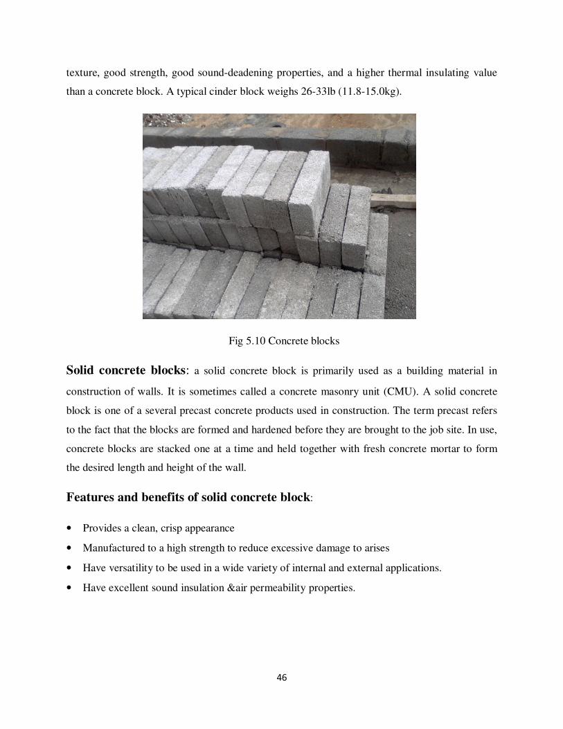
46
texture, good strength, good sound-deadening properties, and a higher thermal insulating value
than a concrete block. A typical cinder block weighs 26-33lb (11.8-15.0kg).
Fig 5.10 Concrete blocks
Solid concrete blocks: a solid concrete block is primarily used as a building material in
construction of walls. It is sometimes called a concrete masonry unit (CMU). A solid concrete
block is one of a several precast concrete products used in construction. The term precast refers
to the fact that the blocks are formed and hardened before they are brought to the job site. In use,
concrete blocks are stacked one at a time and held together with fresh concrete mortar to form
the desired length and height of the wall.
Features and benefits of solid concrete block:
• Provides a clean, crisp appearance
• Manufactured to a high strength to reduce excessive damage to arises
• Have versatility to be used in a wide variety of internal and external applications.
• Have excellent sound insulation &air permeability properties.
47
6.CONCRETE MIX DESIGN
The process of selecting suitable ingredients of concrete and determining their relative amounts
with the objective of producing a concrete of required strength,durability,and workability as
economically as possible is termed as concrete mix design.The proportioning of ingredient of
concrete is governed by the required performance of concrete in two states,namely plastic and
hardened states.If the plastic concrete is not workable,it cannot be properly placed and
compacted.The property of workability,therefore,becomes of vital importance.
The compressive strength of concrete which is generally considered to be an index of its other
properties,depends upon many factors,e.g quality and quantity of cement,water and
aggregates;batching and mixing;placing,compaction and curing.From technical point of view the
rich mixes may lead to high shrinkage and cracking in the structural concrete,and to evolution of
high heat of hydration in mass concrete which may cause cracking.
REQUIREMENTS OF CONCRETE MIX DESIGN:
The requirements which form the basis of selection and proportioning of mix ingredients are:
• The minimum compressive strength required from structural consideration.
• The adequate workability necessary for full compaction with the compacting equipment
available.
• Maximum water-cement ratio and or maximum cement content to give adequate durability
for the particular site conditions.
• Maximum cement content to avoid shrinkage cracking due to temperature cycle in mass
concrete.
The selection and proportioning of materials depends on:
• The structural requirements of the concrete.
• The environment to which the structure will be exposed.
• The characteristics of the available raw materials

48
TYPES OF MIXES
a. Nominal Mixes:
In the specifications for concrete prescribed the proportions of cement,fine and coarse
aggregates.These mixes of fixed cement-aggregate ratio which ensures adequate strength are
termed nominal mixes.These offer simplicity and under normal circumstances,have a margin of
strength above that specified.However,due to the variability of mix ingredients the nominal
concrete for a given workability varies widely in strength.
b.Standard Mixes:
The nominal mixes of fixed cement-aggregate ratio (by volume)vary widely in strength and may
result in under or over-rich mixes.For this reason,the minimum compressive strength has been
included in many specifications.These mixes are termed as standard mixes.
IS456-2000 has designed the concrete mixes into a number of grades as
M10,M15,M20,M25,M30,M35,M40.In this designation the letter M refers to the mix and the
number to the specified 28 day cube strength of mix in N/mm2.The mixes of grades
M10,M15,M20andM25 correspond approximately to the mix proportions(1:3:6),(1:2:4),(1:1.5:3)
and(1:1:2) respectively.
c.Designed Mixes:
In these mixes the performance of the concrete is specified by the designer but the mix
proportions are determined by the producer of concrete,except that the minimum cement content
can be laid down.The approach results in the production of concrete with the appropriate
properties most economically.However the designed mix does not serve as a guide since this
does not guarantee the correct mix proportions for the prescribed performance.
49
FACTORS AFFECTING THE CHOICE OF MIX PROPORTIONS
1.Compressive Strength:
It is one of the most important properties of concrete and influences many other describable
properties of the hardened concrete.The mean compressive strength required at a specific
age,usually 28 days,determines the nominal water-cement ratio of the mix.
2.Workability:
The degree of workability required depends on the three factors.These are the size of the section
to be concreted,the amount of reinforcement,and the method of compaction to be used.For the
narrow and complicated section with numerous corners or inaccessible parts,the concrete must
have a high workability so that full compaction can be achieved with a reasonable amount of
effort.
3.Durability:
The durability of concrete is its resistance to the aggressive environmental conditions.High
strength concrete is generally more durable than low strength concrete.In the situations when the
high strength is not necessary but the conditions of exposures are such that high durability is
vital,the durability requirement will determine the water-cement ratio to be used.
4.Max.Nominal Size of Aggregate:
In general,larger the max size of aggregate,smaller is the cement requirement for a particular
water-cement ratio,because the workability of concrete increases with increase in maximum size
of the aggregrate.However,the compressive strength tends to increase with the decrease in size of
aggregate.IS456:2000 and IS43:1980 recommend that the nominal size of aggregate should be as
large as possible.
5.Quality Control:

50
The degree of control can be estimated statistically by the variations in test results.The variation
in strength results from the variations in the properties of the mix ingredients and lack of control
of accuracy in batching,mixing,placing,curing and testing.The difference between the mean and
minimum strengths of the mix lower will be the cement-content required.The factor controlling
this difference is termed as quality control.
DESIGN MIX FOR M40
a)STIPULATION FOR PROPORTIONING
Grade designation : M40
Type of cement : OPC 43 grade conforming to IS8112
Maximum nominal size of aggregate : 20mm
Minimum cement content : 320kg/m3
Maximum water cement ratio : 0.45
Workability : 100mm
Method of concrete placing : pumping
Type of aggregate : crushed angular aggregate
Maximum cement content : 450kg/m3
Chemical admixture type : superplasticizer
b)TEST DATA FOR MATERIALS
Cement used : OPC43 grade conforming to I8112
Specific gravity of cement : 3.15
Specific gravity of coarse aggregate : 2.74

51
Specific gravity of fine aggregate : 2.74
Water absorption(Coarse aggregate) : 0.5%
Water absorption(Fine aggregate) : 1.0%
Fine aggregate : Zone 1 table 4 IS 383
c)TARGET STENGTH FOR MIX PROPORTIONING
f’ck=fck+1.65*S
Where,
f’ck=target average compressive strength at 28 days.
fck=characteristic compressive strength at 28 days.
S=standard deviation.
From table1,IS10262:2009,S=5N/mm2.
f’ck=40+1.65*5=48.25N/mm2
d)SELECTION OF WATER-CEMENT RATIO
From table 5 IS 456,maximum water cement ratio is 0.4
Adopt 0.4 based on experience0.4<0.45,hence OK.
e)SELECTION OF WATER CONTENT
From table 2,IS 10262 maximum water content =186litres(for 20-50mm slump)
For 20mm aggregate
Estimated water content for 100mm slump=186+(6/100)*186
=197litres
52
Where 6 is free water content of coarse and fine aggregate (0.5+1.0+4=5.5=6)
As superplasticizer is used,the water content can be reduced upto 20% and above.Based on trial
with superplasticizer water content reduction of 20% has been achieved.Hence,the arrived water
content=197*0.71=140litres.
f)CALCULATION OF CEMENT CONTENT
Water cement ratio=0.40
Cement content=140/0.4=350kg/m3
350kg/m3>320kg/m
3 hence OK.
g)PROPORTION OF VOL.OF COARSE AGGREGATE AND FINE
AGGREGATE AND AGGRAGATE CONTENT
From table 3,IS 10262 volume of coarse aggregate corresponding to 20mm size aggregate and
fine aggregate(zone1)for water cement ratio of 0.5=60
In the present case w/c ratio is 0.4.Therefore,volume of coarse aggregate is required to be
increased to decrease the fine aggregate content.As the w/c ratio is lower by 0.10,the proportion
of volume of coarse aggregate is increased by 0.02%(at the rate of -/+0.01for every +/-0.05
change in water cement ratio).Therefore,corrected proportion of volume of coarse aggregate for
the w/c ratio of 0.40=0.62.
For plumpable concrete these value should be reduced by 10%.
Therefore volume of coarse aggregate=0.62*0.9=0.56
Volume of fine aggregate content=1-0.56=0.44
h)MIX CALCULATION
The mix calcuation per unit volume of concrete shall be follows

53
Volume of concrete = 1m3
Volume of cement = ( mass of cement/sp.gr of cement)*(1/1000)
= (350/3.15)*(1/1000)
= 0.111m3
Volume of water = (mass of water/sp.gr of water)*(1/1000)
= (140)*(1/1000)
= 0.140m3
Volume of chemical admixtures = (7/1.145)*(1/1000)
(2% by mass of cementitious material) = 0.006m3
Volume of all in aggregate = [1-(0.111+0.14+0.006)]
= 0.743m3
Mass of coarse aggregate = 0.743*0.56*2.74*1000
= 1140kg.
Mass of fine aggregate = 0.743*0.44*2.74*1000
= 896kg.
i)MIX PROPORTION FOR M40
Cement = 350kg
Water = 140kg
Fine aggregate = 869kg/m3
Coarse aggregate = 1140kg/m3
54
Chemical admixture = 7kg/m3
Water-cement ratio = 0.4.
PROPERTIES OF GOOD CONCRETE:
1.It has to satisfy performance requirements in the plastic or green state and also the hardened
state.In the plastic state the concrete should be workable and free from segregation and
bleeding.Segregation is the separation of coarse aggregate and Bleeding is the separation of the
main mass.
2.In its hardened state concrete should be strong,durable,and impermeable;and it should have
minimum dimensional changes.
3.Compressive strength is the important property of a concrete.It should have good workability.
4.Concrete should fulfill durability requirements to resist environment in which the structure is
expected to serve.
5.Be mixed,transported and compacted as efficiently as possible.
6.Will be as economic as possible.
55
7.STEEL WORK
Steel is an alloy made by combining iron and another element,usually carbon.
Steel bars are used in concrete along with the mix.
There are two types of steel bars
Mild steel bars:These are used for tensilestress of RCC (reinforced cementconcrete) slab
beams etc. in reinforced cement concrete work.These steel bars are plain in surface and are round
sections of diameter from 6 to 50 mm. These rods are manufactured in long lengths and can be
cut quickly and be bent easily without damage.
Deformed steel bars(HYSD):As deformed bars are rods of steels provided with lugs,ribs
or deformation on the surface of bar ,these bars minimize slippage in concrete and increases the
bond between the two materials. Deformed bars have more tensile stresses then that of mild steel
plain bars.These bars can be used without end hooks. The deformation should be spaced along
the bar at substantial uniform distances.
To limit cracks that may be developed in reinforced concrete around mild steel bars due to
stretching of bars and some loss of bond load it is common to use deformed bars that have
projecting ribs or are twisted to improve the bond with concrete. These bars are produced in
sections from 6 mm to 50 mm, dia. In addition the strength of deformed bars calculated should
be 40 to 80 % higher than that of plain round bars of same nominal size. And it has more tensile
stress than that of plain round bars of same nominal size. Cold twisted deformed (Ribbed or Tor
Steel Bars)bars are recommended as best quality steel bars for construction work By structural
Engineer.
GRADES OF STEEL
Mild Steel Bars: Mild steel bars can be supplied in two grades
a) Mild steel bars grade-1 designated as Fe 415
b) Mild steel bars grade-2 designated as Fe-500

56
7.1 METHODS OF TYING STEEL BARS
Several types of ties can be used with rebar. Some are more effective than others. The views in
figures illustrate than others. The views in figure illustrated the six types used by the Seabees:(A)
snap, or simple, tie,(B) wall tie, (C)double-strand tie, (D) saddle tie (E) saddle tie with twist and
(F) cross, or figure-eight, tie. As a builder, you will probably, as a professional, you should be
familiar with the snap and saddle ties. However, as a professional, you be familiar with all six
types.
(A) SNAP, OR SIMPLE, TIE- the snap, or simple, tie (view A of figure) is simply
wrapped once around the two crossing bars in a diagonal manner with the two ends on top.
The ends are then twisted together with a pair of side cutters until they are very tight against
the bars. Finally, the loose ends are cut off. This tie is used mostly on floor slabs.
(B) WALL TIE-the wall tie (view B of figure)is made by taking one and one-half turns
around the vertical bars, then one turn diagonally around the intersection. The two ends are
twisted together until the connection is tight, then the excess is cut off. The wall tie is issued
on light vertical mats of steel.
(C) DOUBLE –STRAND SINGLE TIE-The double-strand tie (view C) is a for heavy
work.
(D) SADDLE TIE- the wires of the saddle tie (view D) pass half way around one of the bars
on either side of the crossing bar brought squarely or diagonally around crossing bar. The
ends are then twisted together and cut off.
(E) SADDLE TIE WITH TWIST- the saddle tie with twist (view E) is a variation of the
saddle tie.
(F) CROSS, OR FIGURE-EIGHT TIE- the cross, or figure-eight, tie (view F) has the
advantage of causing little or no twist in the bar

57
Fig 7.1 Methods of tying
7.2 REINFORCEMENT LAYING METHOD
Footing and other principle structural members that are against the ground should have at least
75 mm of concrete between steel and ground. If the concrete surface is to be in contact with
concrete over the steel should be at least 50 mm for bar. The protective covering may be reduced
to 20 mm for beams and 10 mm for columns and 25 mm for slabs and interior wall surfaces, but
it should be 50 mm for all exterior wall surfaces. The clear distance between parallel bars in
beams, footings, walls, and floor slabs should be a minimum of 25 mm, or one-third times the
largest size aggregates particle in the concrete. In columns ,the clear distance between parallel
bars should be a minimum of one and one-half times the bar diameter, one and one-half times the
maximum size of coarse aggregates, or not less than 40 mm.
(a)COLUMN
Steel for column ties can be assembled into cages by laying the vertical bars for one side of the
column horizontally across a couple of sawhorses. The proper number of ties is slipped over the
bars, the remaining vertical bars are added, and then the ties are sufficient number of
intersections arewired together to make the assembly rigid. This allows it to hoisted and set as a
unit.After the column form is raised, it is tied to the dowels or reinforcing steel carried up from
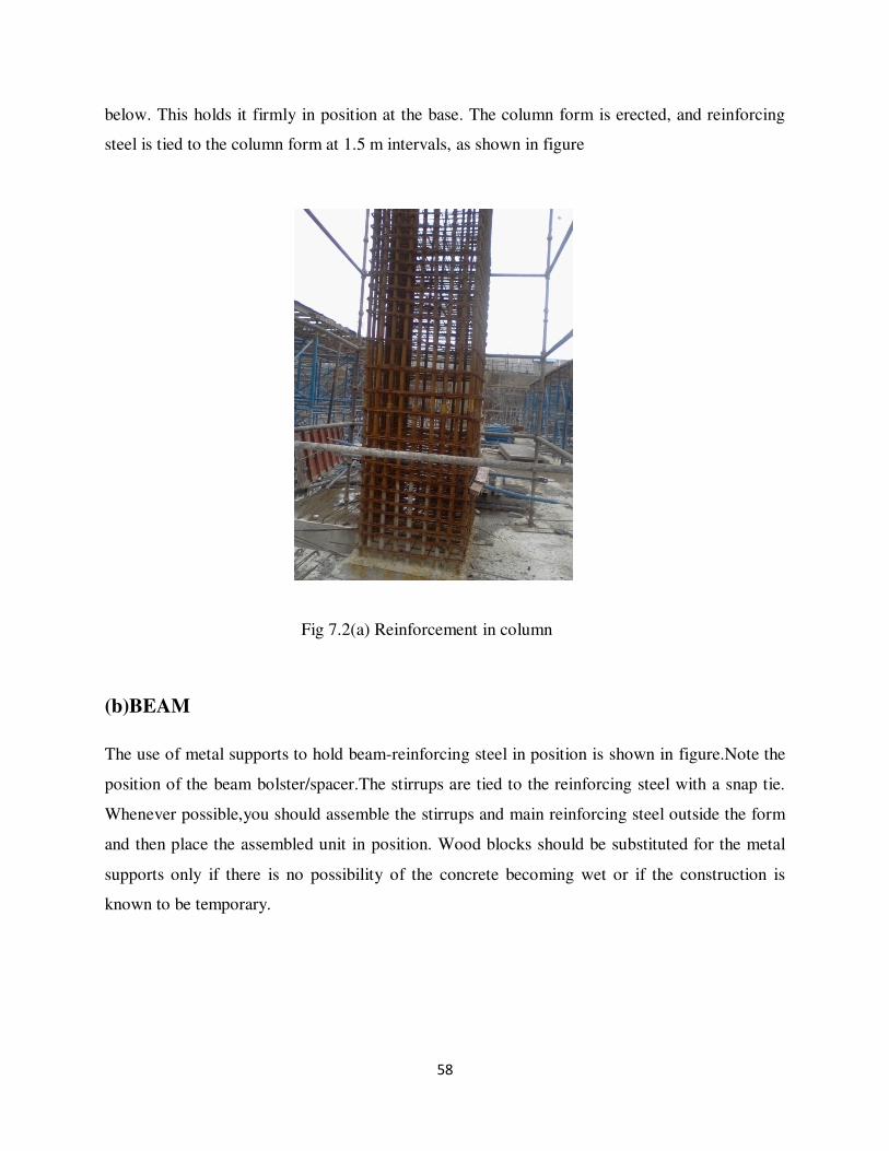
58
below. This holds it firmly in position at the base. The column form is erected, and reinforcing
steel is tied to the column form at 1.5 m intervals, as shown in figure
Fig 7.2(a) Reinforcement in column
(b)BEAM
The use of metal supports to hold beam-reinforcing steel in position is shown in figure.Note the
position of the beam bolster/spacer.The stirrups are tied to the reinforcing steel with a snap tie.
Whenever possible,you should assemble the stirrups and main reinforcing steel outside the form
and then place the assembled unit in position. Wood blocks should be substituted for the metal
supports only if there is no possibility of the concrete becoming wet or if the construction is
known to be temporary.

59
Fig 7.2(b) Reinforcement in beam
(c)FOOTING
Steel is placed in footings very much as it is placed in floor slabs. Stones, rather then steel
supports, may be used to support the steel at the proper distance above the subgrade. Steel mats
are generally preassembled and placed in small footings after the forms have been set. A typical
arrangement is shown in figure.Steel mats in large footings are generally constructed in place.
Fig 7.2(c) Reinforcement in footing

60
(d)RETAINING WALL
Placement of steel in walls is the same as for columns except that the steel is erected in place
and not preassembled. Horizontal steel is tied to vertical steel at least 3 times in any bar length.
Steel in place in a wall is shown in figure.The wood block is removed when the form has been
filled upto the level of the block. For high walls, ties in between the top and bottom should be
used.
Fig 7.2(d) Reinforcement in retaining wall
GENERAL PRECAUTION FOR STEEL BARS INREINFORCEMENT
• Steel bars are clear, freefrom loose mil scales, dust and loose rust coats of paints,oil or other
coatings which may destroy or reduce bond strength.
• Steel bars should be stored in such a way as to avoid distortion and to prevent deterioration
and corrosion.
• Steel bars should not be clean by oily substances to remove the rust.
• The bar is bent correctly and accurately to the size and shape as shown in drawings.
• If possible, the bar of full length is used.
• Overlapping bars do not touch each other and tease should be kept a part with concrete.
• The overlap if given should be staggered.
• The cranks in the bar at the end should be kept in position by using spots.

61
• The steel bars should not be disturbed while lying cements concrete.
• Required cover under steel bars should be given before laying the cement concrete.
• No overlap is given in the bar having a diameter more than 36 mm, if required, the bar
should be welded.
WEIGHT OF DIFFERENT STEEL BARS PER METER
M S Steel round & square Bar
S.No. Dia of steel bar Round bar Square bar
1 6 mm 0.22 Kg. 0.28 Kg.
2 8 mm 0.39 Kg. 0.50 Kg.
3 10 mm 0.62 Kg. 0.78 Kg.
4 12 mm 0.89 Kg. 1.13 Kg.
5 16 mm 1.58 Kg. 2.01 Kg.
6 20 mm 2.46 Kg. 3.14 Kg.
7 25 mm 3.85 Kg. 4.91 Kg.
8 28 mm 4.83 Kg. 6.15 Kg.
9 32 mm 6.31 Kg. 8.04 Kg.
10 36 mm 7.99 Kg. 10.17 Kg.
11 40 mm 9.86 Kg. 12.56 Kg.
12 45 mm 12.49 Kg. 15.90 Kg.
13 50 mm 15.41 Kg. 19.62 Kg.
CONVERSIONS OF STEEL FROM m3 OF LENGTH TO KG
We generally use the formula as
Are of steel bars * 7850(density of steel)
Table for conversions:
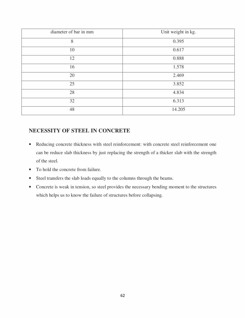
62
diameter of bar in mm Unit weight in kg.
8 0.395
10 0.617
12 0.888
16 1.578
20 2.469
25 3.852
28 4.834
32 6.313
48 14.205
NECESSITY OF STEEL IN CONCRETE
• Reducing concrete thickness with steel reinforcement: with concrete steel reinforcement one
can be reduce slab thickness by just replacing the strength of a thicker slab with the strength
of the steel.
• To hold the concrete from failure.
• Steel transfers the slab loads equally to the columns through the beams.
• Concrete is weak in tension, so steel provides the necessary bending moment to the structures
which helps us to know the failure of structures before collapsing.

63
8.FORMWORK OR SHUTTERING
The structure of boards that make up a form for pouring a concrete mix in a liquid form casting it
into a definite and different shape, to keep concrete from following all over the place a formwork
needs to be put in place to hold the concrete while it cures.Improperly installed formwork will
cause the concrete to cure improperly, looked crooked and ruin the jobs.
Things needed in making FORMWORK
• Measuring tape
• 2-inch by 122-inch boards
• 2inch by 4 inch stakes
• Builder’s level
• Nail
• Hammer
INSTRUCTIONS
• Measure of length and width of concerned concrete slab area.
• Cut a 2-inch by 12-inch board that is equal to the length of one side of intended concrete
area.
• Pound 2-inches by 4-inch stakes into the ground in the corner of the intended slab area. Nail
it be 2 by 12 to the two stakes.
• Set up a builder’s level and use it to level the 2-by-12.
• Place 2 by 4 stakes every 2 feet along the board to the brace the 2 -by -12.
• Cut a second 2- by-12 to the width of concrete slab. Nail one end to the other 2-by-12 end.
Calculate the diagonal for 90 degrees and run a measuring tape from one end to both 2- by -
12s to make sure that the form is straight.
• Add the other two sides of formwork in the same manner.

64
NECESSITY OF FORMWORK
Forms for all concrete structures must be tight, rigid, and strong. If the forms are not tight, there
will be excessive leakage at the time the concrete is placed. This leakage can result in unsightly
surface ridges, honeycombing, and sand streaks after the concrete has set. The forms must be
able to safely withstand the pressure of the concrete at the time of placement. No shortcuts
should be taken. Proper form construction material adequate bracing in place prevent the forms
from collapsing or shifting during the placement of the concrete. Forms or form part are often
omitted when a firm earth surface exists that is capable of supporting or molding the concrete. in
most footings, the bottom of the footing is cast directly against the earth and only the sides are
molded informs. Many footings are cast with both the bottom and sides against the natural earth.
In the cases, however, the specifications usually call for larger footings. A foundation wall is
often cast between a form on the inner side and natural earth surface on the outer side.
8.1 MATERIALS OF FORMWORK
a) Earth
b) Metal
c) Wood
a) EARTH:
Earthen forms are used in subsurface construction where the soil is stable enough to retain
the desired shape of the concrete. The advantages of earthen forms are tat less excavation
is required and there is better settling resistance. The obvious disadvantage is a rough surface
finish, so the use of earthen forms is generally restricted to footings and foundations.
Precautions must be taken to avoid collapse of sides of trenches.
b) METAL:
Metal forms are used where high strength is required or where the construction is duplicated
at more than one location. They are initially more expensive than wood forms, but may be
more economical if they can be reused repeatedly. Originally, all prefabricated metal forms

65
were made of steel. These forms were heavy and to handle. Currently, aluminum forms,
which are lightweight and easier to handle, are replacing steel.
c) WOOD:
Wooden forms are by far the most common type used in building construction. They have the
advantage of economy, ease in handling, ease of production, and adaptability to many desired
shapes. Added economy may result from reusing form lumber later for roofing, bracing, or
similar purposes. Lumber should be straight, structurally sound, strong, and only partially
seasoned. Kiln-dried timber has a tendency to swell when soaked with water from the
concrete. If the boards are tight-jointed, the swelling will cause bulging and distortion. When
green lumber is used, an allowance should be made for shrinkage, or the forms should be
kept wet until the concrete is in place. Soft wood, such as pine, fir, and spruce, make the best
and most economical form lumber since they are light, easy to work with, and available in
almost every region. Lumber that comes in contact with concrete should be surface at least
on one side and both edges. The surface side is turned toward the concrete. The edges of the
lumber may be square, shiplap, or tongue and groove. The latter makes a more watertight
joint and tends to prevent warping.
8.2 USE OF FORM IN CONSTRUCTION
FOUNDATION:-
Whenever possible, excavate the earth and use it as a mold for concrete footings. You should
thoroughly moisten the earth before placing the concrete. If this is not possible, you must
construct a form. Because most footings are rectangular or square, you can build and erect the
four sides of the form in panels.
COULMN:-
Square column forms are made of wood. Round column forms are made of steel, or cardboard
impregnated with waterproofing compound. Figure shows an assembled column and footing
form. After constructing the footing forms, build the column form sides, and then nail the yokes
to them. Figure shows a column from with two styles of yokes. View A shows a commercial
type, and view B shows yokes made of all-thread bolts and 2-by material. Since the rate of

66
placing concrete in a column form is very high and bursting pressure exerted on the form by the
concrete increases directly with the rate of placing, a column form must be securely braced, as
shown by the yokes in the figure. Because the bursting pressure is greater at bottom of the form
than it is at the top, yokes are placed closer together at the bottom.
Fig 8.2(a) Formwork in Column
WALL:-
Wall forms may be built in place or prefabricated, depending on shape and desirability of form
reuse. Some of the elements that make up wooden forms are sheathing, studs, wales, braces,
shoes plates, spreads, and tie wires.
STAIR FORMS:-
Concrete stairway forms require accurate layout to ensure accurate finish dimensions for the
stairway. Stairways should always be reinforced with rebar’s (reinforcing bars) that tie into the
floor and landing. They are formed monolithically or formed after the concrete for the floor slab
has set. Stairways formed after the slab has set must be anchored to a wall or beam by tying the
stairway rebar’s projecting from the walls or beams, or by providing a keyway in the beam in

67
beam or wall. You can use various stair forms, including prefabricated forms. For moderate-
width stairs joining typical floors, a design based on strength considerations not necessary.
Fig 8.2(b) .Reinforcement in staircase
BEAMS:-
The types of construction used for beam depends upon whether the forms are to be removed in
one piece or whether the sides are to be stripped and the bottom left in place until the concrete
has hardened enough to permit removal of the shoring. The letter type of form is preferred, and
details for this type little bursting pressure, they must be shored up at frequent intervals to
prevent sagging under the weight of fresh concrete. The bottom of the form should be same
width as the beam and should be in one piece for the full width. The sides of the form should be
25-thick tongue-and-groove sheathing and should lap over the bottom.
STRIPPING TIME FOR-STRUCTURAL CONCRETE
Sr. No. ELEMENT STRIPPING TIME
1 Walls, columns and vertical
faces of all structural
12 hrs
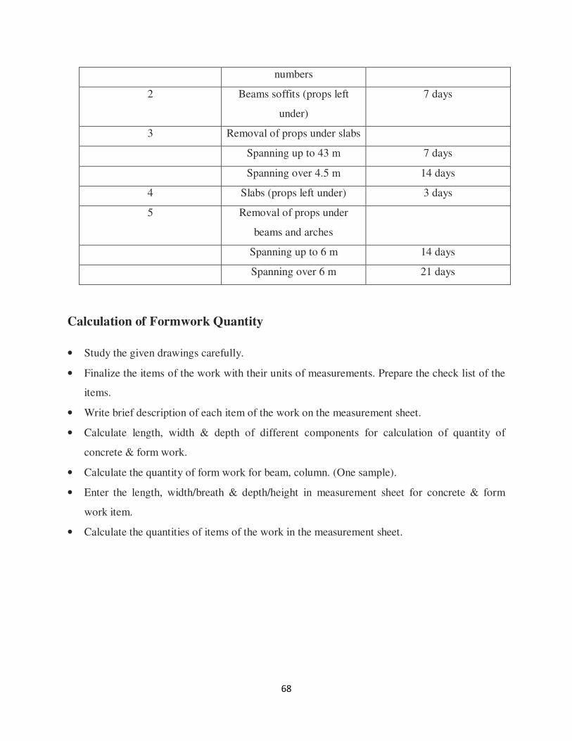
68
numbers
2 Beams soffits (props left
under)
7 days
3 Removal of props under slabs
Spanning up to 43 m 7 days
Spanning over 4.5 m 14 days
4 Slabs (props left under) 3 days
5 Removal of props under
beams and arches
Spanning up to 6 m 14 days
Spanning over 6 m 21 days
Calculation of Formwork Quantity
• Study the given drawings carefully.
• Finalize the items of the work with their units of measurements. Prepare the check list of the
items.
• Write brief description of each item of the work on the measurement sheet.
• Calculate length, width & depth of different components for calculation of quantity of
concrete & form work.
• Calculate the quantity of form work for beam, column. (One sample).
• Enter the length, width/breath & depth/height in measurement sheet for concrete & form
work item.
• Calculate the quantities of items of the work in the measurement sheet.
69
9.QUALITY CONTROL
Quality Control:-defined as the operational techniques and the activities used to keep the
quality of inputs or outputs to specifications;to fulfill and verify requirements of quality.
Objectives:The main objective of the quality control process for design projects is to provide a
mechanism by which all construction plans can be subject to a systematic and consistent
review.The outcome of the review should create a set of quality project plans,which should be
substantially error free.A secondary objective of Quality Control Process is to provide for a well-
documented “trail” of the design process.The QC system is designed to:
• Provide routine and consistent checks to ensure data integrity,correctness,and completeness.
• Identify and address errors and omissions.
• Doccument and archive inventory material and record all QC activities.
TESTS CONDUCTED IN CONSTRUCTION
1. WATER: Stability for construction/concreting purpose as per IS 456-2000.
2. SAND:
Test to be conducted
• Bulking of sand-field
• particle size
• Percentage of deleterious material/organic impurities-lab
IS code for materials-IS 383-1970
IS code for testing-IS 2386(part-I) to IS-2386(part-VIII)
Remarks: Silt content should not exceed 5%.
3. SAND(FOR PLASTERING)
Test to be conducted
• Particle size-lab

70
• Silt content-field
• Percentage of deleterious material/organic impurities-lab
IS code for materials-IS 1542
IS code for testing-IS 1727content
Remarks: Silt should not exceed 8%.
4. COARSE AGGREGATE
Test to be conducted
a. Percentage of soft deleterious materials-field(visual)
b. Particle size distribution-lab
c. Aggregate impact value-lab
1. crushing test-lab
2. impact value-lab
3. elongation index & flakiness index
IS code for material-IS 383-1970
IS code for testing –IS 2386(part-1) toIS-2386(part-)
5. CEMENT
Manufacturer batch test certificate shall be submitted to company prior to use. Sample shall
be drawn from each lot/batch of cement supplied to site by contractor &all the test required
as per BIS specifications to be conducted at an approved lap.
Remarks: Cement to be tested if stored for more than 3 months.
6. CEMENT CONCRETE
Test to be conducted
a. Slump test-field
b. Cube test-lab

71
7. REINFORCEMENT STEEL
Test to be conducted
1. Free from defects-field(visual)
2. Weight-lab
3. Size-lab
4. Ultimate tensile stress –lab
5. Yield stress – lab
6. Elongation percentage-lab
7. Bend re-bend test-lab
8. Chemical analysis-lab
IS code for materials
IS-432 for mild steel
IS-1786 for tor steel
8. BRICKS
Test to be conducted
a) Compressive test-Lab
b) Water absorption-Lab
c) Efflorescence-Lab
d) Percentage of deleterious materials-Lab
e) Dimension test-Lab
IS codes for materials-IS: 1077-1986
IS code for testing-IS:3495(part 1) to IS: 3495(part3)
9. STRUCTURAL STEEL
a) Weight –Lab
b) Size-Lab
c) Ultimate tensile stress-Lab
72
d) Yield stress-Lab
e) Elongation percentage-Lab
f) Bend Re-bend Test-Lab
g) Chemical analysis-Lab
MATERIAL SPECIFICATION
1. CEMENT
• Cement is a fine powder, which when mixed with water and allowed to set and harden can
join different components of members together to give a mechanically strong structure.
• Although the percentage of cement in concrete is around 15%, the role of cement is very
important in strength and durability of concrete.
Normallyconsistency: generally taken as 27, 28, and 29 in the project work.
Initial setting time: not less than 30 minutes
Final setting time: not more than 600 minutes.
Fineness:as per Indian Standard Specification, the residue of cement should not exceed 10
percent when sieved on 90-micron sieve.
Specification: the specific gravity of Portland cement is taken ass 3.15.
2.COARSE AGGREGATE
Refer IS 10262 for limits
PROPERTIES
Sizes: 20 mm for residential and 40 mm for footing, basement, PCC and retaining walls.
Specific gravity: 2.7
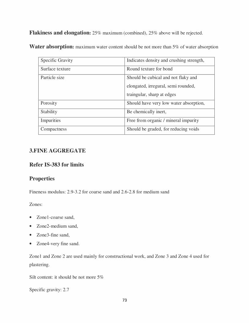
73
Flakiness and elongation: 25% maximum (combined), 25% above will be rejected.
Water absorption: maximum water content should be not more than 5% of water absorption
Specific Gravity Indicates density and crushing strength,
Surface texture Round texture for bond
Particle size Should be cubical and not flaky and
elongated, irregural, semi rounded,
traingular, sharp at edges
Porosity Should have very low water absorption,
Stability Be chemically inert,
Impurities Free from organic / mineral impurity
Compactness Should be graded, for reducing voids
3.FINE AGGREGATE
Refer IS-383 for limits
Properties
Fineness modulus: 2.9-3.2 for coarse sand and 2.6-2.8 for medium sand
Zones:
• Zone1-coarse sand,
• Zone2-medium sand,
• Zone3-fine sand,
• Zone4-very fine sand.
Zone1 and Zone 2 are used mainly for constructional work, and Zone 3 and Zone 4 used for
plastering.
Silt content: it should be not more 5%
Specific gravity: 2.7

74
4.WATER
Refer IS 456-2000 and IS: 3025 for limits;
Water is the most important and least expensive ingredient of concrete. A part of mixing water is
utilized in the hydration of cement to form the binding matrix in which the inert aggregates are
held in suspension until the matrix has hardened. The remaining water serves a lubricant the fine
and coarse aggregates and makes concrete workable i.e. readily placeable in forms.
Generally, cement requires about three-tenth of its weight of water for hydration.
Hence the minimum water cement ratio is 0.3. But the concrete containing water in this
proportion will be very harsh and difficult to place. Additional water is required to the mix,
which makes the concrete workable. This additional water must be kept to minimum, since too
much of water reduces the strength of a concrete.
EFFECT OF IMPURITIES IN WATER ON PROPERTIES OF
CONCRETE:
Percentage of salt in water Percentage reduction in compressive
strength
0.5 SO4 4
5.0 NaCl 30
1.0 SO4 10
CO2 20
LIMIT OF IMPURITIES IN WATER
The PH value of water suitable for concrete constructions shall generally be between 6 and 8 i.e.
the water which is fit for drinking purposes are used for construction.
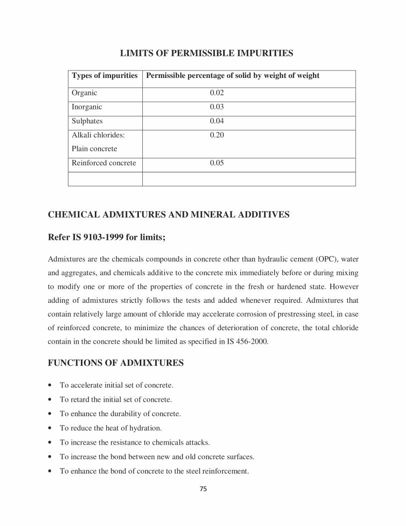
75
LIMITS OF PERMISSIBLE IMPURITIES
Types of impurities Permissible percentage of solid by weight of weight
Organic 0.02
Inorganic 0.03
Sulphates 0.04
Alkali chlorides:
Plain concrete
0.20
Reinforced concrete 0.05
CHEMICAL ADMIXTURES AND MINERAL ADDITIVES
Refer IS 9103-1999 for limits;
Admixtures are the chemicals compounds in concrete other than hydraulic cement (OPC), water
and aggregates, and chemicals additive to the concrete mix immediately before or during mixing
to modify one or more of the properties of concrete in the fresh or hardened state. However
adding of admixtures strictly follows the tests and added whenever required. Admixtures that
contain relatively large amount of chloride may accelerate corrosion of prestressing steel, in case
of reinforced concrete, to minimize the chances of deterioration of concrete, the total chloride
contain in the concrete should be limited as specified in IS 456-2000.
FUNCTIONS OF ADMIXTURES
• To accelerate initial set of concrete.
• To retard the initial set of concrete.
• To enhance the durability of concrete.
• To reduce the heat of hydration.
• To increase the resistance to chemicals attacks.
• To increase the bond between new and old concrete surfaces.
• To enhance the bond of concrete to the steel reinforcement.
76
• To decrease the weight of concrete per cubic meter.
• To increase the strength of a concrete by reducing water content.
CLASSIFICATION OF ADMIXTURES
Accelerating admixtures
These are used to spend up the initial set of concrete. The use of 2 percent calcium chloride by
mass of cement can be reduce the setting time by one third and raise the one to seventh day
compressive strength by 3 to 8 MPa. An increase in flexure strength of 40 to 80 percent of one
day and upto 12 percent at 28 days is obtained. Other used admixture are, Ca (NO3)2 and NaNO3.
Retarding admixtures
These are used to slow down the initial rate of hydration of cement or prolong the setting of the
cement paste in concrete. Adding sugar by 0.05 percent of mass of cement can delay the initial
setting time by 4 hours.
Air-entraining admixtures
Add and entrain any bubbles in the concrete, which will reduce damage during freeze-thaw
cycles, there by increasing the concrete’s durability. However, entrained air entails a trade off
with strength, as each 1% of may result in 5% decrease in compressive strength.
Air-entraining admixtures help to incorporate a controlled amount of air, in the of millions of
minute non-coalescing bubbles distributed through the body of concrete, during mixing, without
significantly altering the setting or the rate of hardening of concrete. The compounds used for air
entraining are number of natural woods resins containing pimeric acid salts, some animal and
vegetable oil such as tallow, olive oil.
Water-reducing admixtures
Water reducing admixtures enable a given fresh concrete mix have higher flowability
(workability) without increasing the water content which result in rate of concrete placement,
easy placement,in relatively poorly accessible locations without vibration,true shutter finish for

77
highly reinforced concrete member,and reduction in cement mortar.The compound used mostly
in this case is fly ash.
Grouting admixtures
The commonly used grouting admixtures are gels,clays etc.These are used to grout below the
base plate or machine foundations,grouting of foundation bolt holes in industrial
structures,grouting of prestressed concrete ducts.
Shrinkage reducing admixtures
The shrinkage reducing also called as expansion producing admixtures either expand themselves
or react with other constituents of concrete resulting in expansion.This expansion may be of
about the same magnitude as the drying shrinkage at later ages or may be little greater.The
compounds used in this type are granulated iron and chemicals,and anhydrous sulphoaluminate.
Gas forming admixtures
These admixtures when added to mortar or concrete mixture react chemically with hydroxides
present in the cement and form minute bubbles of hydrogen gas size ranging from 0.1 to 1mm
throughout the cement-water mix.This action when properly controlled causes a slight expansion
in plastic concrete or mortar and thus reduces or eliminates voids caused by norml settlement
that occurs during the placement of concrete.Aluminium powder may be used as the gas forming
admixtures.The amount of powder added usually varies from 0.005 to 0.02 percent by mass of
cement.Zinc and Magnesium are also used for the same purpose.
Air-detraining admixtures
These are used to dissipate excess air or other gases and remove a part of the entrained air from a
concrete mixture.The compounds used are tributyl-phosphate,dibutyl-phathalate,water insoluble
alcohols and silicon.

78
10. SAFETY
Safety:The word safety refers to your freedom from danger,injury and damage,and to your
personal security.The word safety has been used so often that many of you may think of it as a
“preaching word”,or a word that forces you to alter your ways or change bad habits.
General Safety Rules
1.Housekeeping
• Work place and surrounding area shall be kept clean and free from obstructions.
• On job completion all tools,equipments and left over material shall be collected at designated
storage place.
• Waste oily material and other intermediate material shall be removed and kept in covered
metallic containers.
Approval
• Wearing apron,no person working on or near moving machinery shall be loose.
• All persons engaged in oily or cleaning of machinery shall put on tight fitting
clothes,shoes,boots must be properly lashed.
• The safety apparel to be warned shall be specified in the work permit by the department
person.
2.Personnel Protective Equipment
Personnel protective equipments like goggles,faceshields,shoes,helmet,respiratory gas musk are
issued for personnel protection for jobs where special hazard exhaust and there usage as
specified in the clearance certificate is mandatory by the personnel while engaged on such work.
3.Stacking Materials
a)All materials shall be stacked tightly and upto safe height to prevent them from falling or
causing some other piles to fall.

79
b)No material shall be stacked in passages and emergency exit.
4.Eye Protections
Goggles or face shields must be used by all personnel engaged in operations involving hazards to
eyes.These operations shall be identified by the respective department head.Every individual
who are available at sites should follow all the rules issued by the safety department.This safety
comes into act to the people working on the electrical tasks and welding works.
5.Safety Belts
All employees in elevated places who are not adequately protected by railing on suitable
enclosure should wear safety helmet and safety belt with lifeline tide nicely to firm structure or
other support independent of equipment on which they are working.
6.Defective Tools
All defective tools like chisels with irregular heads,spanners with worn jaws,broken hammers
shall be brought to the notice of the supervisor and discard it.
7.Guards
Machine guard and other safety devices shall not be removed except for making repairs
lubricating or cleaning by authorized person.These must be replaced before starting machines.
8.Electricity
• No works should be done in close proximity to electric supply line and operations without
the approval of components authority.
• The use of defective plugs,sockets and flexible cable should be avoided.
• No one except a person duly authorized by electrical section shall operate any switch gear or
other electric equipment except for routine starting and stopping motors and switching on or
switching off lights,fans etc.
9.First-aid boxes
80
First-aid boxes shall be provided in suitable places in every department.
10.Welding and Gas cutting
Welding and gas cutting operations,soldering shall be prohibited in proximity to material sand
plant where inflammable liquids,gases etc.are likely to be present or given off,except with
special precautions after obtaining hot work permit.
EMERGENCY INSRUCTIONS
In the case of an emergency like fire,gas leak etc.
a)Switch on the nearest Fire alarm.
b)Contain the emergency appropriately.
c)All officers,supervisors and other members of core group to rush to the site of emergency.
d)If required on the instructions of shift-in –charge shut down operations in an orderly manner.
In the event of a fire general rules should be followed:
Do not panic.
•••• Cut off electrical supply to the affected area.
•••• Remove any flammable materials from the area.
•••• Extinguish the fire using appropriate extinguishing equipments.
•••• Cool the surrounding equipments with water spray.
•••• No undue crowding around the area of fire.
Fire protection
Fire remains a threat to the plant and property,particularly as we use a number of flammable
chemicals.All big fires are initially small and are best prevented if detected & extinguished in the
incipient stage.Hence each of us should be alert about fire and know how to extinguish it.
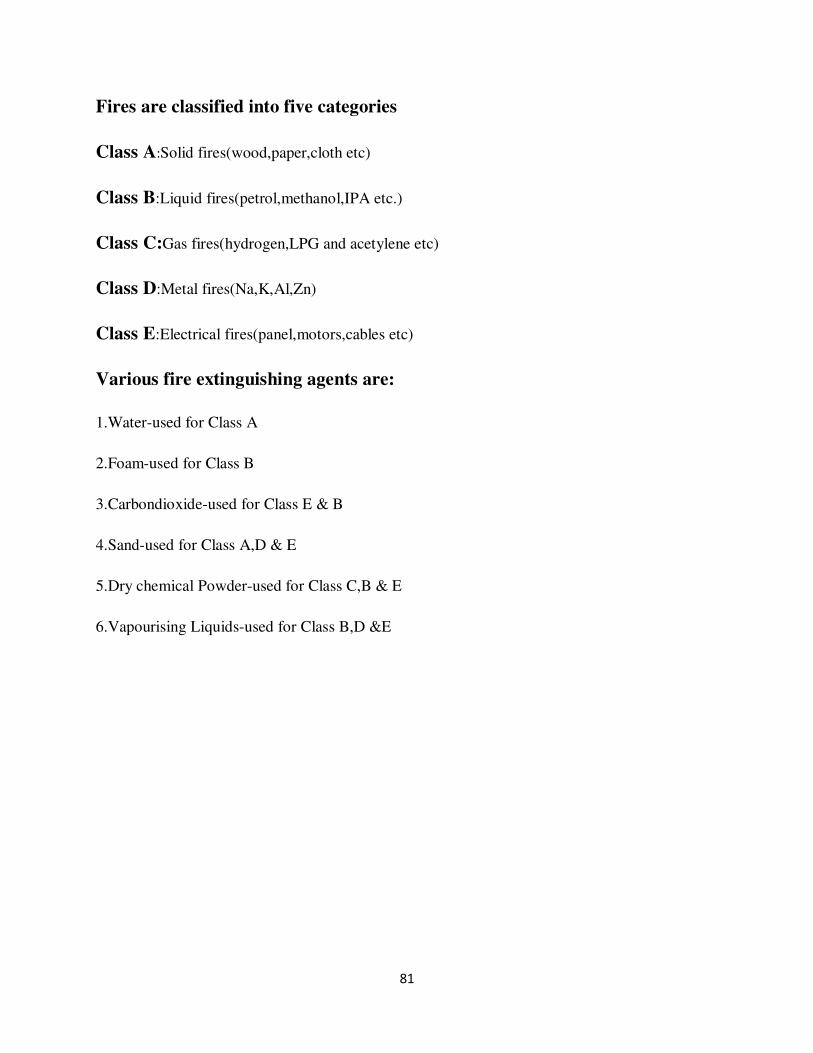
81
Fires are classified into five categories
Class A:Solid fires(wood,paper,cloth etc)
Class B:Liquid fires(petrol,methanol,IPA etc.)
Class C:Gas fires(hydrogen,LPG and acetylene etc)
Class D:Metal fires(Na,K,Al,Zn)
Class E:Electrical fires(panel,motors,cables etc)
Various fire extinguishing agents are:
1.Water-used for Class A
2.Foam-used for Class B
3.Carbondioxide-used for Class E & B
4.Sand-used for Class A,D & E
5.Dry chemical Powder-used for Class C,B & E
6.Vapourising Liquids-used for Class B,D &E
82
11.CONCLUSION
In this project we came to know the prerequisites required for the construction of any
commercial building in which Planning and Scheduling and the whole project management
process plays a vital role in achieving good progress of construction.Different project scheduling
softwares are available now a days and the most efficient software is found to be MS
Project.These stages are given primary importance and then the execution work starts.
Execution work starts from surveying followed by many construction activities like
excavation,PCC,footings,columns,slabs,retainingwalls,staircase,formwork,type of reinforcement.
etc.All the necessary reinforcement details and proper alignment is the most important task to be
done for the strength of the structure.Different types of formwork materials and their utilities and
advantages are known through this project.Here in this project we have gone through the
construction of post-tension slabs and capital slabs and their advantages.
Prestressed concrete offers great advantages in comparison with other forms of construction such
as reinforced concrete and steel.They possess improved resistance to shearing forces,due to the
effect of compressive prestress,which reduces the principle stress.The savings in steel are even
higher.However,there is an overall economy in using prestressed concrete,as the decrease in dead
weight reduces the design loads and the cost of foundations.No need of beams,which means an
even surface and easier construction.Instead of beams capital slabs are used which gives an
aesthetic appearance and the height of the roofing also will be at the required level to the actual
height.
The most important part of construction is Quality Control and Safety. Quality control process
for projects is to provide a mechanism by which all construction plans can be subjected to a
systematic and consistent review.The outcome of the review should create a set of quality project
plans,which should be substantially error free. It facilitates the ideas that are required for the
safety purposes in any project.It also carries the knowledge about how safety can be attained.

83
12.BIBILOGRAPHY
1.Building Materials by “S.K.Duggal”
2.Building Planning,Designing & Scheduling by “Gurucharansingh”
3.N.Krishnaraju,”Prestressed concrete”,Tata Mc.Graw Hill Company Limited.
4.www.wikipedia.com.
5.www.google.com.
Related Documents