DISPLAY TECHNOLOGIES RASTER SCAN SYSTEM RANDOM SCAN SYSTEM HARD COPY DEVICES GRAPHICS SOFTWARE Overview of the Graphics System

Overview of the graphics system
Aug 19, 2015
Welcome message from author
This document is posted to help you gain knowledge. Please leave a comment to let me know what you think about it! Share it to your friends and learn new things together.
Transcript
DISPLAY TECHNOLOGIESRASTER SCAN SYSTEMRANDOM SCAN SYSTEMHARD COPY DEVICESGRAPHICS SOFTWARE
Overview of the Graphics System
Video Display Devices
The primary output device in a graphics system is a video monitor.
The operation of most video monitor is based on the standard Cathode Ray Tube(CRT)

Refresh Cathode Ray Tubes
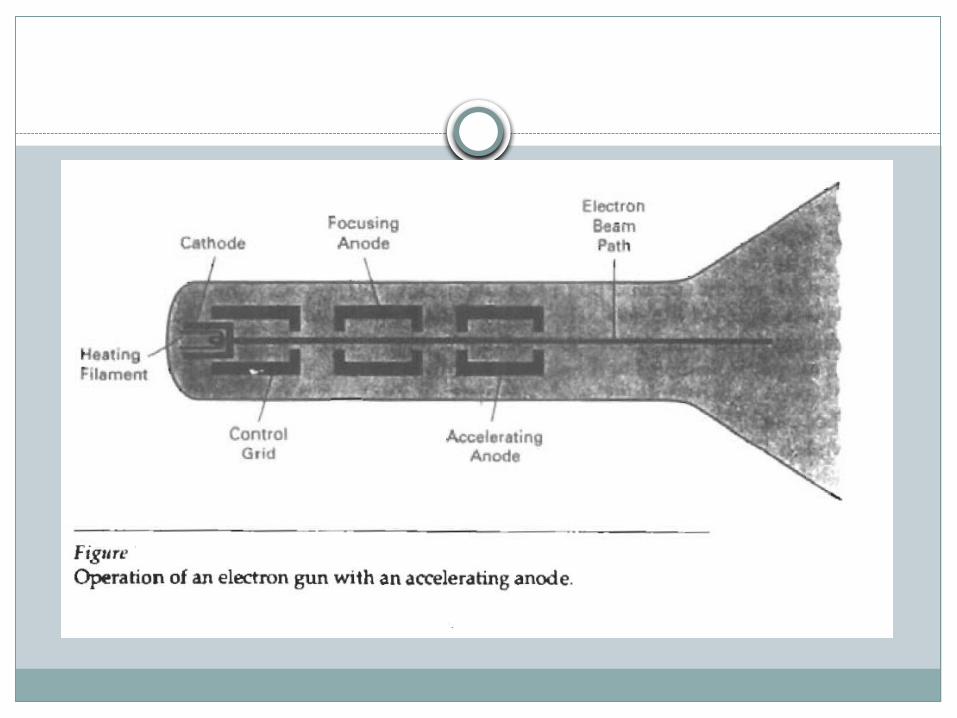
Electron are “boiled off” the surface of cathode by heating it with the help of the heating filament.
The accelerating voltage is generated with the help of positively charged metal coating on the inside of CRT envelope or an accelerating anode can be used.
The intensity of the electron beam is controlled by setting the negative voltage of the control grid.
Focusing system is needed to force the electron beam to converge into small spot as it strikes the phosphorous.
Focusing can be implemented with the help of electric field or the magnetic field.
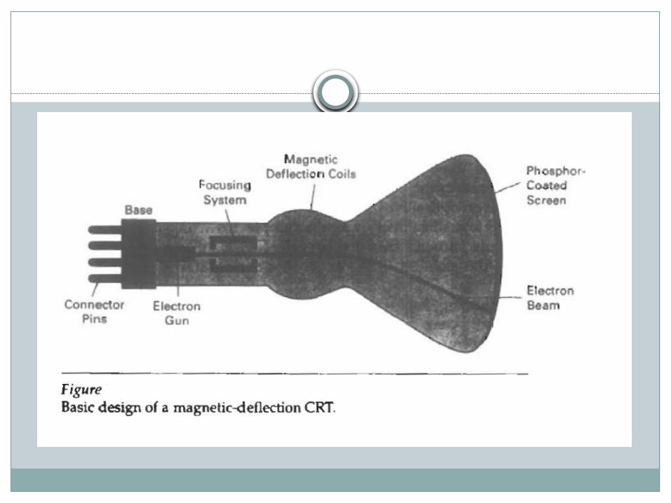
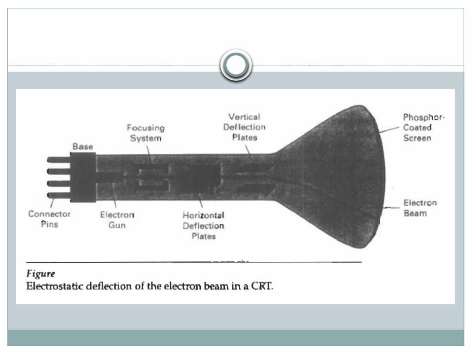
As in the case of focusing of the electron, the deflection of the electron can be controlled by using either magnetic or the electric field.
Different kind of Phosphors are available for use in CRT. Beside color major difference between phosphors is their persistence.
Persistence is defined as the time it takes for the emitted light on the screen to decay one-tenth of its original intensity.
A phosphors with low persistence is used in animation while the other one is useful in displaying highly complex, static pictures.
The maximum number of points that can be displayed on the screen without overlap is referred to as the resolution.
High resolution system are referred to as high-definition system.
The physical size of the graphical monitor is given as the length of the screen diagonal.
Aspect ratio is the ratio of vertical points to horizontal points required to produce equal length lines in both direction on the screen.
Raster Scan Display
The electron beam is swept across the screen one row at a time top to bottom.
As the electron beam moves across each row, beam intensity is turned ON and OFF to create the pattern of illuminated spots.
Picture definition is stored in the memory area called refresh buffer or frame buffer.
Each screen point is referred to as pixel or pel(picture element)
On a black white system with one bit per pixel, the frame buffer is commonly called bitmap.
For a system with multiple bits per pixel, the frame buffer is often referred to as pixmap.
Refreshing on raster scan display is carried out at the rate of 60 to 80 frames per second.
On some rater scan system, each frame is displayed in two passes using an interlaced refresh procedure.

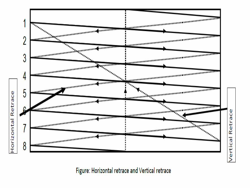
Interlaced vs Non-Interlaced Scan
In interlaced scan, each frame is displayed in two passes. First pass for odd scan lines and second for the even.
In non-interlaced scan, electron beam sweep over all the scan lines.
Question
Consider a RGB raster system is to be designed using 8 inch by 10 inch screen with a resolution of 100 pixels per inch in each direction. If we want to store 8 bits per pixel in the frame buffer, how much storage (in bytes) do we need for the frame buffer?

Question
Consider 512 pixels X 512 scan lines image with 24-bit true color. If 5 minutes video is required to capture, calculate the total memory required?

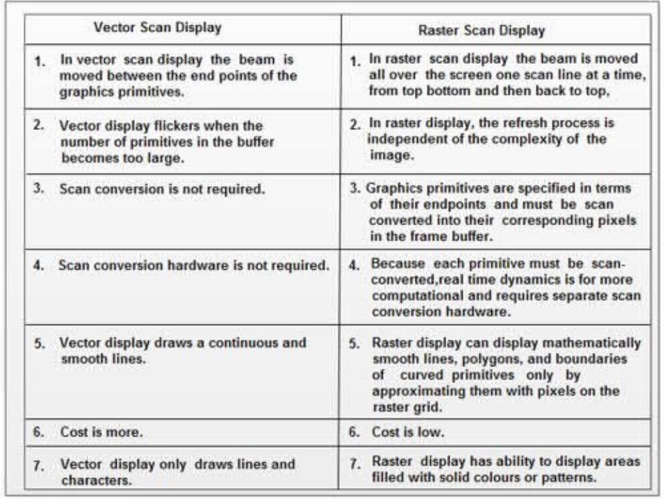
Random scan display
Electron beam is directed only to part of the screen where a picture is to be drawn.
It is also referred to as vector display or stroke-writing or calligraphic displays.
The components lines of a picture can be drawn and refreshed in any specified order.
Refresh rate depends on the number of lines to be displayed.
Picture set is stored as the line drawing commands in memory called refresh display file or display list or display program or simply refresh buffer.
It is suited for line drawing application and cannot display realistic shaded scenes.
Vector display has higher resolution than raster scan display.
Vector display produce smooth line drawing as beam directly follow the line path.

Color CRT Monitors
Color pictures can be displayed by using a combination of phosphors that emit different colored light.
By combining these different light, range of colors can be generated.
Two basic techniques used are: Beam Penetration Shadow Mask
Beam Penetration
This method is used with random scan monitors.
Two layers of phosphors, usually red and green are coated inside CRT.
The colors are displayed depending on how far the electron beam penetrates the phosphors layers.
Beam of slow electrons excite only outer red layer, fast beam can penetrated deep to excite both layer.
Only four colors are possible and quality of pictures is not as good as with other methods.
Shadow Mask
It is used on raster scan system(including color TV).
It produces much wider range of colors than beam penetration method.
It has three phosphor color dots(red, green, blue) at each pixel position.
It has three electron gun one for each color dot and shadow mask grid just behind the phosphors coated screen.
The three electron beams are deflected and focused as group onto shadow mask, which contain series of holes aligned with phosphors dot pattern.

There are two primary variations Stripe Pattern Delta Pattern
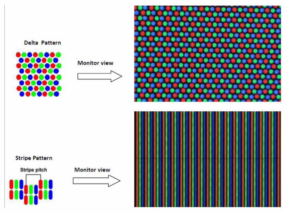
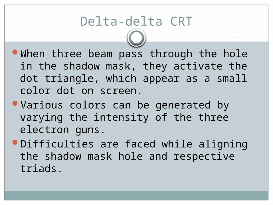
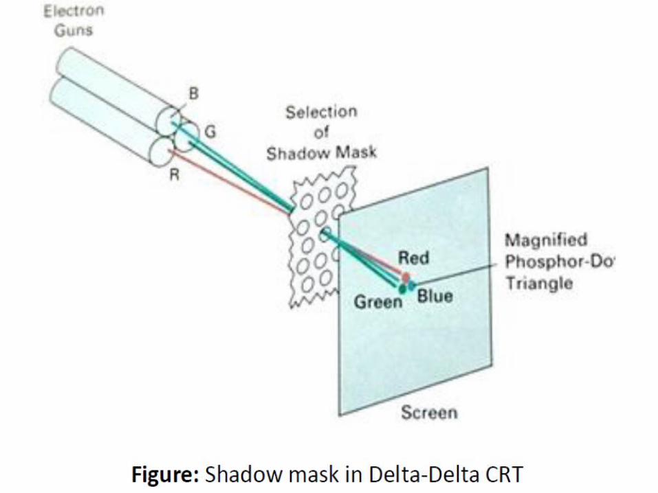
Delta-delta CRT
When three beam pass through the hole in the shadow mask, they activate the dot triangle, which appear as a small color dot on screen.
Various colors can be generated by varying the intensity of the three electron guns.
Difficulties are faced while aligning the shadow mask hole and respective triads.
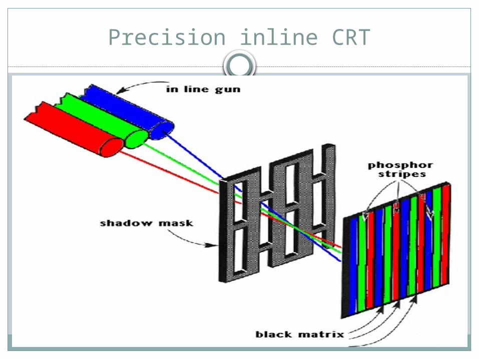
Precision inline CRT

Direct View Storage Tubes(DVST)
It store the picture information as a charge distribution just behind the phosphors coated screen.
Two electrons gun are used. Primary gun to store picture pattern and the second flood gun, maintains the picture display.
Because no refreshing is needed, very complex pictures can be displayed at very high resolution without any flicker.

Disadvantage is that they ordinarily do not display color and selected part of the pictures can not be displayed.
To eliminate the picture section, the entire screen must be erased and modified picture is redrawn.
Flat Panel display
Flat panel display refers to class of video devices that have reduced volume, weight and power requirements compared to CRT.
They are used in calculators, pocket video games, laptops, Tv monitors etc.
We can separate flat panel displays into two categories: Emissive displays Non-emissive displays
Emissive display are the devices that convert the electrical energy into light. Examples are plasma panel, LED etc.
Non-emissive display use optical effects to convert sunlight or light from some other source into graphical patterns. Example LCD
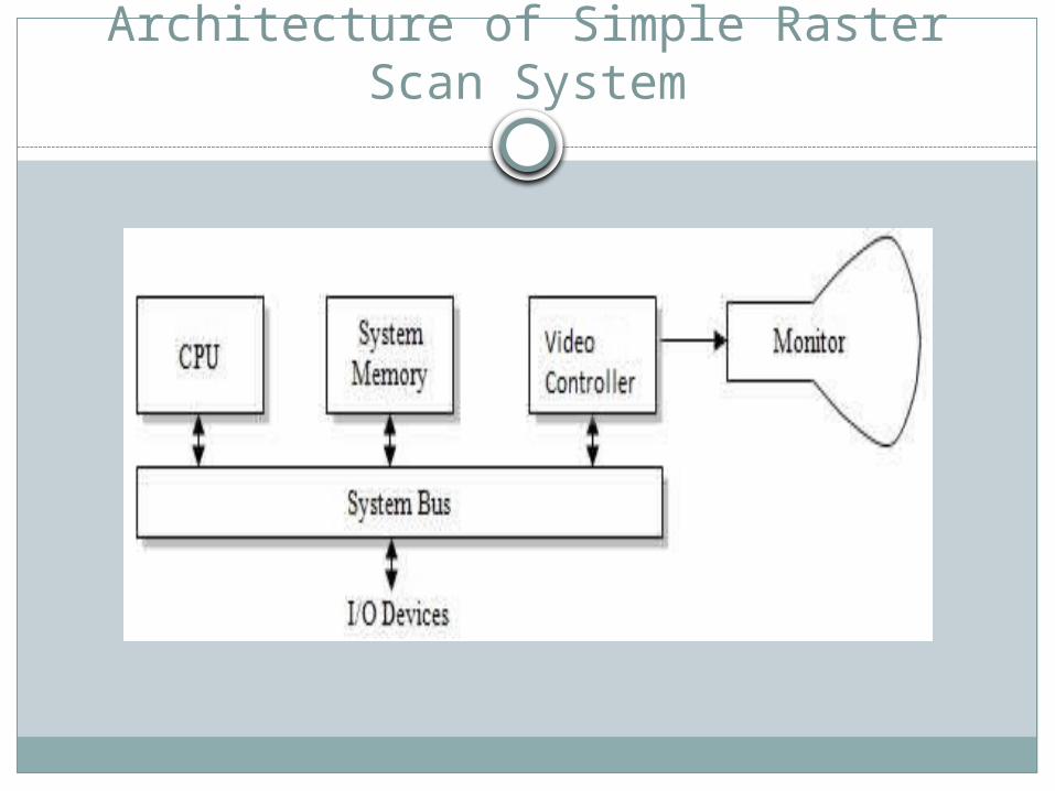
Architecture of Simple Raster Scan System


Raster Scan display processor
Display processor is also called graphics controller or display coprocessor.
Its purpose is to free the CPU from the graphics part.
In addition to the system memory separate display processor memory can also be provided.
The major task is to digitize the picture definition into set of pixel-intensity values for storage in the frame buffer.
The digitization process is called scan conversion.
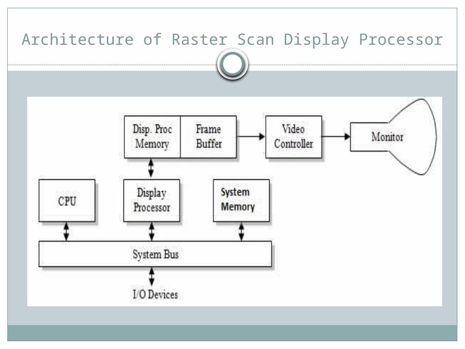
Architecture of Raster Scan Display Processor

Random Scan System
An application program is input and store in the system memory along with graphics package.
Graphics command in application program are translated by graphics package and stored in the display file in the system memory.
This display file is accessed by the processor to refresh screen.
Graphics pattern are drawn by directing electron beam along components line of the picture.

Architecture of Random Scan System
Hard-copy devices
We can obtain hard copy output of the images using various hard copy devices.
The quality of the pictures obtain from the device depends on the dot size and the number of dots per inch.
These can be of two types: Impact Non-Impact

Impact printer pressed the formed character against the ribbon on to the paper.
Non-impact system uses the laser technology. Examples laser printer, plotters etc.

Graphics Software
Two general classification of graphics software: General Programming Package Special Purpose application package.
General programming package provides an extensive set of graphics function that can be used in high level programming such C or Fortran. Example GL(Graphics library)
Special purpose application package is designed for the non-programmer. Example CAD system
Related Documents
![Wdr2010 Graphics Ch0 Overview[1]](https://static.cupdf.com/doc/110x72/55a1f8821a28ab826d8b468c/wdr2010-graphics-ch0-overview1.jpg)