Generation, Fuels, and Environment, June 15, 2010 Overview of DOE’s Gasification Program Jenny B. Tennant Technology Manager - Gasification

Welcome message from author
This document is posted to help you gain knowledge. Please leave a comment to let me know what you think about it! Share it to your friends and learn new things together.
Transcript

Generation, Fuels, and Environment, June 15, 2010
Overview of DOE’s Gasification ProgramJenny B. TennantTechnology Manager - Gasification
2
Gasification Program Goal
"Coal is an abundant resource in the world ... It is imperative that we figure out a way to use coal as cleanly as possible.“
Dr. Steven Chu, Secretary of Energy
The goal of the Gasification Program is to reduce the cost of electricity, while increasing power plant availability and efficiency, and maintaining the highest environmental standards
3
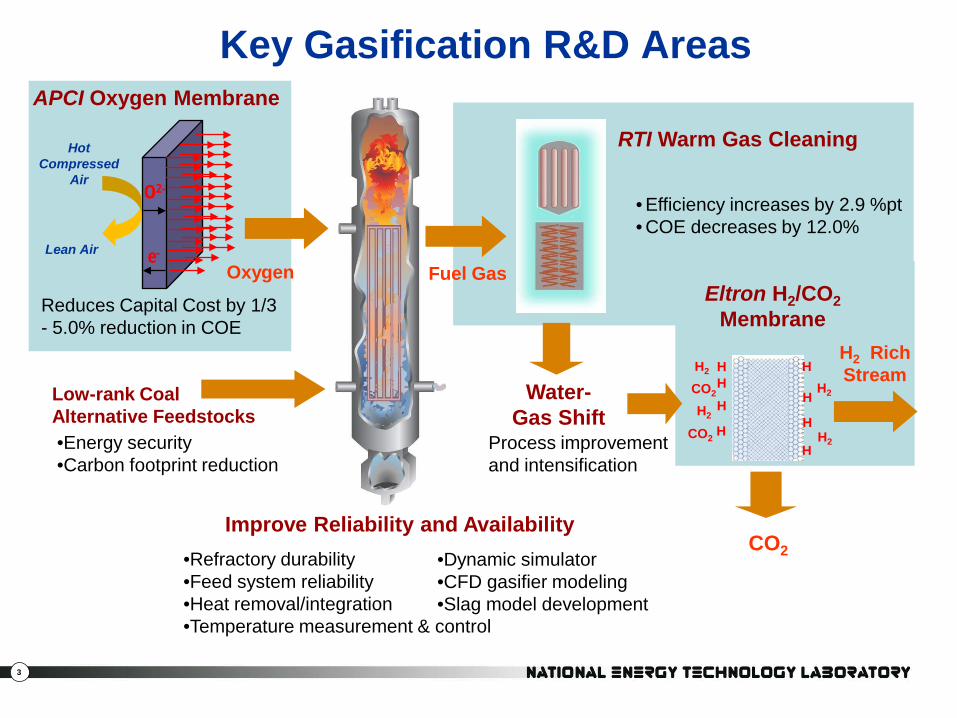
APCI Oxygen Membrane
Fuel Gas
RTI Warm Gas Cleaning
Reduces Capital Cost by 1/3 - 5.0% reduction in COE
Oxygen
CO2
H2 Rich Stream
• Efficiency increases by 2.9 %pt • COE decreases by 12.0%
Water-Gas Shift
Key Gasification R&D Areas
O2-
e-
Hot Compressed
Air
Lean Air
HH
H
H2
CO2
H2
H2
H
H
H
H
CO2
H
H2
Process improvementand intensification
Eltron H2/CO2Membrane
Low-rank Coal Alternative Feedstocks•Energy security•Carbon footprint reduction
Improve Reliability and Availability •Refractory durability •Feed system reliability•Heat removal/integration•Temperature measurement & control
•Dynamic simulator•CFD gasifier modeling•Slag model development
4
NCCC Facility
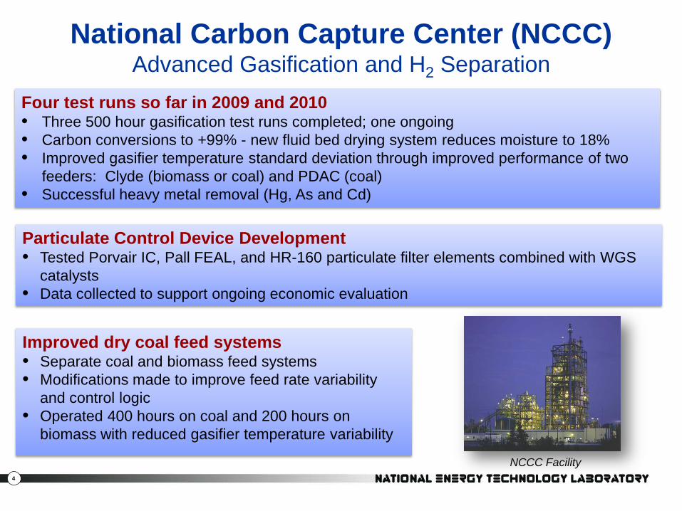
National Carbon Capture Center (NCCC)Advanced Gasification and H2 Separation
Four test runs so far in 2009 and 2010 • Three 500 hour gasification test runs completed; one ongoing• Carbon conversions to +99% - new fluid bed drying system reduces moisture to 18% • Improved gasifier temperature standard deviation through improved performance of two
feeders: Clyde (biomass or coal) and PDAC (coal)• Successful heavy metal removal (Hg, As and Cd)
Particulate Control Device Development• Tested Porvair IC, Pall FEAL, and HR-160 particulate filter elements combined with WGS
catalysts• Data collected to support ongoing economic evaluation
Improved dry coal feed systems • Separate coal and biomass feed systems• Modifications made to improve feed rate variability
and control logic• Operated 400 hours on coal and 200 hours on
biomass with reduced gasifier temperature variability
5
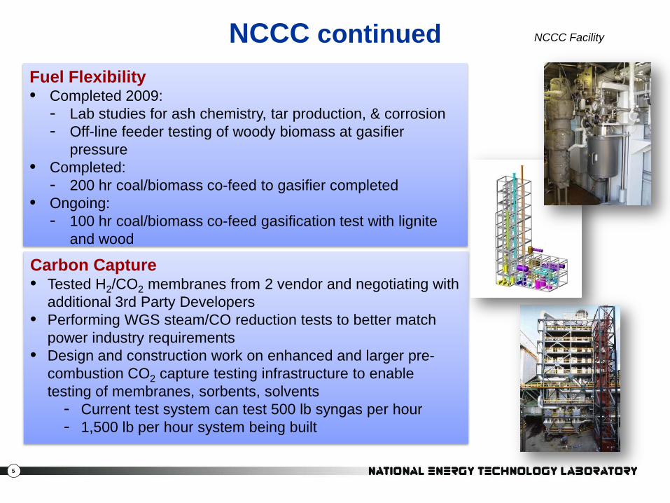
Fuel Flexibility• Completed 2009:
- Lab studies for ash chemistry, tar production, & corrosion- Off-line feeder testing of woody biomass at gasifier
pressure• Completed:
- 200 hr coal/biomass co-feed to gasifier completed• Ongoing:
- 100 hr coal/biomass co-feed gasification test with lignite and wood
NCCC continued
Carbon Capture• Tested H2/CO2 membranes from 2 vendor and negotiating with
additional 3rd Party Developers• Performing WGS steam/CO reduction tests to better match
power industry requirements • Design and construction work on enhanced and larger pre-
combustion CO2 capture testing infrastructure to enable testing of membranes, sorbents, solvents
- Current test system can test 500 lb syngas per hour - 1,500 lb per hour system being built
NCCC Facility
6
Advanced Gas Separation
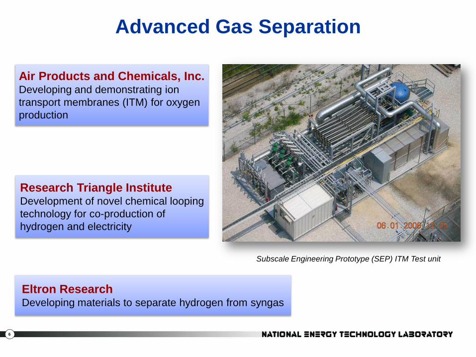
Air Products and Chemicals, Inc.Developing and demonstrating ion transport membranes (ITM) for oxygen production
Research Triangle InstituteDevelopment of novel chemical looping technology for co-production of hydrogen and electricity
Eltron ResearchDeveloping materials to separate hydrogen from syngas
Subscale Engineering Prototype (SEP) ITM Test unit

7
APCI Air Separation ITM ModulesStatus:• Ongoing Tests of 5 TPD Subscale
Engineering Prototype (SEP) ITM Test unit‒ Operated under full driving force
conditions‒ Met/exceeded wafer performance for
flux and purity‒ Cycled modules from idle to operating
conditions w/o loss of performance‒ 0.5 and 1 TPD module tested;
optimization ongoing
• 100 TPD Intermediate Scale Test Unit (ISTU)‒ Detailed design almost complete‒ Will test 1 TPD modules
Plans: • ISTU tests complete FY14 - 15• Next Phase planned: 2,000 TPD
© Air Products and Chemicals, Inc. 2009. All Rights Reserved 1.0 TPD Stack
0.5 TPD StackBenefit:• Low-cost oxygen would provide cost-effective emission
reduction and carbon management opportunities
2005
2008
Presenter
Presentation Notes
Gas separations projects in Gasification Program make significant progress: ITM separation of O2 from air expect to reduce cost substantially and reduce auxiliary power required Steady and successful development of materials, fabrication technology, and performance for ITM at 1 tpd and 5 tpd levels led to successful field test of commercial scale modules with good performance in January ’06 Phase III activity underway, which will culminate in the design, construction, and operation of a 100-TPD Intermediate Scale Test Unit (ISTU) facility. Planned ISTU operations include producing high-purity oxygen at targeted production flux and qualifying process schemes for turbo machinery-integrated operation. The use of low-cost oxygen in combustion processes would provide cost-effective emission reduction and carbon management opportunities.
8
ELTRON Hydrogen Membrane
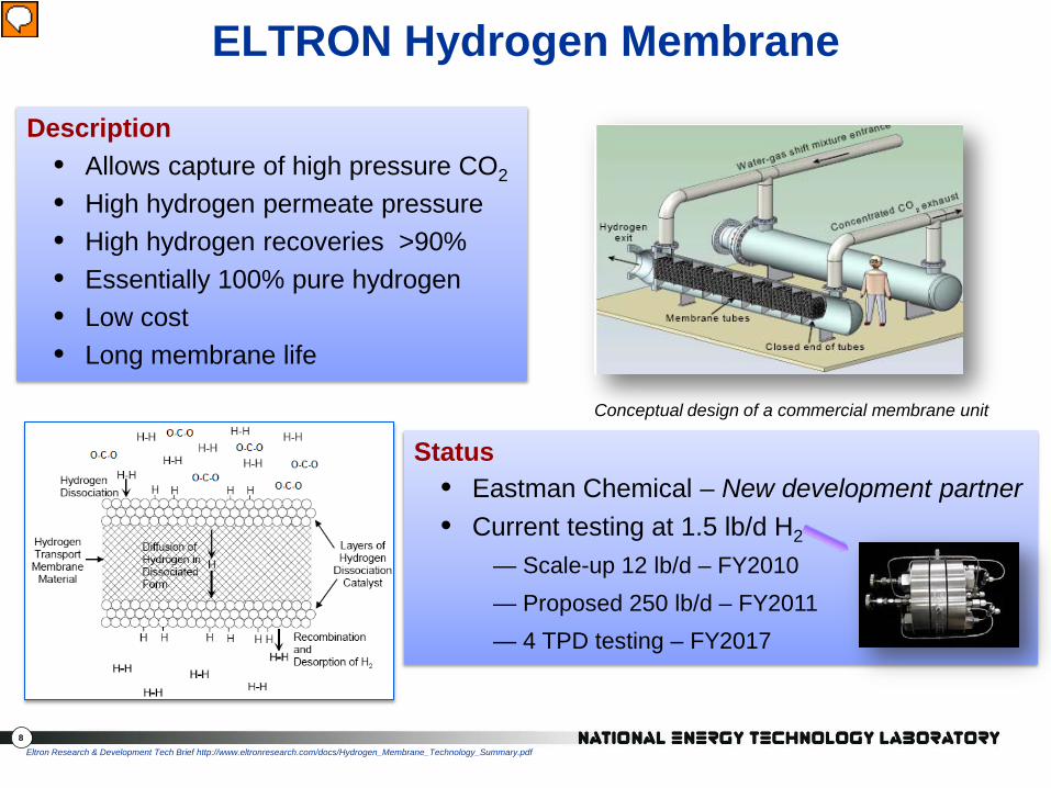
Conceptual design of a commercial membrane unit
Eltron Research & Development Tech Brief http://www.eltronresearch.com/docs/Hydrogen_Membrane_Technology_Summary.pdf
Description• Allows capture of high pressure CO2
• High hydrogen permeate pressure • High hydrogen recoveries >90%• Essentially 100% pure hydrogen• Low cost • Long membrane life
Status• Eastman Chemical – New development partner• Current testing at 1.5 lb/d H2
— Scale-up 12 lb/d – FY2010 — Proposed 250 lb/d – FY2011— 4 TPD testing – FY2017
Presenter
Presentation Notes

9
Benefits:• DOE-funded system study predicts a 2 to 3 percentage point increase in overall
IGCC thermal efficiency and a 6% reduction in the cost of electricity by using the RTI contaminant removal process for an IGCC plant
• Coupling this technology with a high-temperature CO2 separation technology has the potential to minimize the impact of carbon capture on the cost of electricity to the consumer
High Temperature Syngas Cleanup Technology Scale-Up and Demonstration (50 MWe)
Polk Power Station Unit 1
Description:Project to design, build, and test a 50-MWe warm gas cleanup system to:• Remove more than 99.9 percent of the sulfur• Remove multiple trace contaminants, and• Capture CO2 from coal-derived syngas
Complete 5,000 hours of operation of warm syngas cleaning technologies
Presenter
Presentation Notes
Research Triangle Institute (RTI) International is to design, build, and test a 50-MWe warm gas cleanup system to remove more than 99.9 percent of the sulfur from coal-derived syngas. The project will also test a novel process for the conversion of this sulfur to a pure elemental sulfur product, removal of multiple trace contaminants (e.g., mercury and arsenic) from coal syngas, and an advanced technology to capture the greenhouse gas carbon dioxide (CO2). � RTI's syngas cleanup technologies will be tested at Tampa Electric Company's 250 MW IGCC power plant, using up to 20 percent of the syngas produced by the coal gasifier. Data on thermal efficiency, emissions, and cost benefits will be gathered during more than 5,000 hours of testing the warm syngas cleaning system. This information will help refine the integration strategy in an IGCC plant and mitigate technical risks associated with commercial deployment of this technology. �

10
Status:• Pump component testing nearly complete• Final design of prototype pump complete• Lab scale tests complete and analysis ongoing of
coal/biomass blends to:- Predict transport behavior- Estimate economic impact of using biomass- Select most promising blend for further testing
Plans (to be completed by 2013):• 600 TPD pump testing at EERC• 400 TPD life cycle testing• Conduct gasification economic analysis• Complete pump model and analyze economic
potential using test data
High Pressure Solids Pump
PWR Pump
Benefit:• Reduce heat penalties with slurry feed and high-moisture (western) low-rank coals
Presenter
Presentation Notes
From PI Alan Darby’s presentation at 2009 GTC Dry Solids Pump Component Tests Complete to Support Pump Design Pump Design Activity Pump Component Testing Nearly Complete Developed Dry Solids Pump Design Criteria Final Design of Prototype Pump Underway Testing begins 4Q 2010 at EERC Initiated Project to Determine Effects of Biomass/Coal Blends on Solid Feed Systems Analyze Coal/Biomass Blends To Predict Transport Behavior Void Fraction, Permeability, Internal Friction Angle and Cohesion Coefficient Ultimate Analysis, Heating Value and True Solids Density Conduct Gasification Economic Analysis Biomass Milling – Energy Consumption Used To Grind Samples Model Feed System and Pump Using Test Data Determine Extrusion Pump Size, Efficiency & Costs Select Most Promising Blend for Further Testing Pump Component Test Rig Validation 600-tpd Pump Testing at EERC

11
Link:
PWR Presentation
High Pressure Solids Pump
PWR Pump
Presenter
Presentation Notes
From PI Alan Darby’s presentation at 2009 GTC Dry Solids Pump Component Tests Complete to Support Pump Design Pump Design Activity Pump Component Testing Nearly Complete Developed Dry Solids Pump Design Criteria Final Design of Prototype Pump Underway Testing begins 4Q 2010 at EERC Initiated Project to Determine Effects of Biomass/Coal Blends on Solid Feed Systems Analyze Coal/Biomass Blends To Predict Transport Behavior Void Fraction, Permeability, Internal Friction Angle and Cohesion Coefficient Ultimate Analysis, Heating Value and True Solids Density Conduct Gasification Economic Analysis Biomass Milling – Energy Consumption Used To Grind Samples Model Feed System and Pump Using Test Data Determine Extrusion Pump Size, Efficiency & Costs Select Most Promising Blend for Further Testing Pump Component Test Rig Validation 600-tpd Pump Testing at EERC

12
Improving RAM(Reliability Availability Maintainability)
Virginia Polytechnic InstituteDevelopment of a single crystal sapphire optical fiber sensor for reliable temperature measurements in slaggingcoal gasifiers
NETLOffice of Research and Development• Development of new refractory
materials and slag behavior model• Development of an IGCC Dynamic
Simulator• Computational Fluid Dynamics (CFD)
modeling of advanced gasifiers• Biomass characteristics database
Gas Technology Institute (GTI)Development of an optical sensor for monitoring coal gasifier flame characteristics
Dynamic Simulator and Immersive Training System

13
Systems Analysis(Improving Overall Process)
NETLOffice of Systems Analysis and Planning• Assessments of individual and cumulative value of
technologies under development• Optimization studies on project variables, and technology
integration with IGCC plant• Sensitivity analyses on external factors, such as carbon tax• Many analyses are open to the public and posted on NETL
website, for example:Current and Future Technologies for Gasification-Based Power Generation Volume 2: A Pathway Study Focused on Carbon Capture Advanced Power Systems R&D Using Bituminous Coal

14
Research & DevelopmentGasification Projects
NETLOffice of Research and Development• Modeling
– IGCC Dynamic Simulator Research & Training Center
– Co-gasification Kinetics and Product Characterization
– Development of Carbonaceous Chemistry for Computational Modeling
– Absorption/regeneration Transport DesulfurizerModeling for a 50 MWe plant
– Slagging Gasifier Model Development and validate using commercial experience
• Biomass/ coal prep. for gasification systems– Database of biomass materials characterization, and
feed and gasifier operations impact• Evaluating
– Refractories for slagging gasifiers including low and no chrome refractory materials

15
Advanced IGCC Technologies Pathway
20
25
30
35
40
45
50
55
60Re
fere
nce
Adv
. F T
urbi
neCo
al P
ump
85%
CF
WG
CUH
2 M
embr
ane
Adv
Tur
bine
-1IT
MA
dv T
urbi
ne-2
90%
CF
Adv
. IG
FC
1600
1800
2000
2200
2400
2600
2800
3000
3200
3400
3600
3800
Refe
renc
eA
dv. F
Tur
bine
Coal
Pum
p85
% C
FW
GCU
H2
Mem
bran
eA
dv T
urbi
ne-1
ITM
Adv
Tur
bine
-290
% C
FA
dv. I
GFC
7
8
9
10
11
12
13
14
15
16
17
18
Refe
renc
eA
dv. F
Tur
bine
Coal
Pum
p85
% C
FW
GCU
H2
Mem
bran
eA
dv T
urbi
ne-1
ITM
Adv
Tur
bine
-290
% C
FA
dv. I
GFC
Advanced IGCC Pathway: Cumulative incorporation of advanced technologiesCarbon Capture Non-capture
Advanced IGFC Alternate Pathway: High efficiency, near-100% capture solution Carbon Capture Non-capture
Efficiency(% HHV)
Total Overnight Cost($/kW)
Cost of Electricity(¢/kW-hr)
CF = capacity factor WGCU = warm gas cleanup ITM = ion transport membrane IGFC = integrated gasification fuel cellSource: “Current and Future Technologies for Gasification-Based Power Generation” (Nov 2009); modified to include owner’s costs; 30-yr current dollar levelized cost of electricity
Presenter
Presentation Notes
COE and TOC for IGCC pathway cases are based on draft results of Rev 2 of the Bituminous Baseline Report costing methodology. Capture Cases: IGCC cases represent cumulative implementation of technologies; IGFC case incorporates some, but not all of the technology advancements Nominal 600 MW net power output but will vary +/- 200 MW 90% CO2 capture for IGCC, ~99% for IGFC; compression to 2,200 Psi 50 Mile Pipeline transport (flat terrain), 4,500 feet storage in saline formation 100 years of MVA Reference: Represents 2002 vintage IGCC technology (7FA-based turbine, 75% capacity factor) Adv F Turbine: Represents today’s “conventional” IGCC with CCS technology (Case 2 from NETL “Baseline” Study). Two-stage water gas shift converts syngas to H2-rich fuel. Two-stage Selexol provides H2S and CO2 separation. Advance F turbine powered by H2-rich fuel. 80% capacity factor Coal Pump: Eliminates need for slurry feed improving the gasifier cold gas efficiency. Benefit of elimination of slurry water is somewhat dampened because additional steam injection is now required downstream of gasifier for water gas shift relative to reference. Adv. Materials/Sensors: Benefit of advancement materials occurs through reliability, availability and maintainability, modeled here as an increase in the capacity factor from 80% to 85%. Warm Gas Cleanup: RTI transport desulfurizer (zinc oxide sorbent) and direct sulfur reduction processes replace Selexol H2S removal and Claus plant. Still requires low temperature CO2 removal with Selexol. Elimination of sour water stripper, improved heat recovery and reduced cost are primary benefits. Hydrogen Membrane: Coupling warm gas cleanup with a CO2 separation process at temperature and pressure (such as a H2 membrane) improves process efficiency primarily due to reduced CO2 compression auxiliary load and improved heat recovery. Target costs of the H2 membrane are significantly lower than that of Selexol, resulting in a significant reduction in COE. 1st Generation Advanced H2 Turbine: Improved process efficiency achieved through higher firing temperature and improved materials to handle high H2 fuel content. This step also allows air integration with ASU, reducing the main air compressor parasitic load. Increase in power rating of the turbine results in economies of scale, adding further to the cost reduction. ITM for O2 separation: Minimal impact on process efficiency. Most of the COE benefit is associated with projected costs below that of cryogenic ASU. Next Generation Advanced H2 Turbine: Improved process efficiency achieved through higher firing temperature, improved turbine efficiency. Increase in power rating of the turbine results in economies of scale, adding further to the cost reduction. Because of the significant increase in power rating, these results show a decrease to a single-train system (from a 2-train system). If a 2-train system were maintained, the result would be a 1GW unit that has a COE 8% above that of the reference PC non-capture case. Adv. Process Control/Operating Experience: The benefits of advanced process control and operating experience gained from demonstrations is modeled as a capacity factor improvement from 85% to 90%. Pressurized SOFC/Catalytic Gasifier: Catalytic gasifier provides a high methane content (17%) fuel to a pressurized SOFC. Other technologies incorporated include warm gas cleanup and high pressure oxycombustion. The efficiency of the IGFC system nears 60% (compared to 40% for the best IGCC case with capture) and CO2 capture is nearly 100%.

16
Edwardsport 630 MW IGCC ProjectDuke Energy
• 2 x GE Gasifier – delivered 12/09• 2 x GE 7 FB combustion turbines
‒ 232 MWe each‒Delivered 4/10
• GE steam turbine‒ 320 MWe
• 1.5 million tons of coal per year • Operational - 2012• Total project cost:
– $2.88 billion (4/10 increase from $2.35B)– $133.5 million Federal investment tax credit
award– $460 million in local, state and federal tax
incentiveshttp://www.duke-energy.com/about-us/edwardsport-overview.asp
Rendering of the proposed IGCC power plant located at Duke Energy’s Edwardsport Station near Vincennes, Indiana
Presenter
Presentation Notes
On April 16th Duke announced the addition of ~$530 million to the estimated cost of this project, taking it from $2.35 billion to $2.88 billion One of the first plants to be announced under the GE and Bechtel IGCC alliance 630 MW IGCC plant The retirement of the current circa 1940's 160 MW Edwardsport power plant A Clauss process sulfur removal system An activated carbon bed for the absorption of mercury on each of the two gasifier trains Two heat recovery steam generators, each of which will be equipped with selective catalytic reduction (SCR) for nitrogen oxide control A multiple cell cooling tower No thermal discharge into the White River Potential for the capture and geologic storage of CO2 An alliance between Duke Energy Indiana, GE, and Bechtel to support the project Certificates of Public Convenience and Necessity Duke Energy Indiana filed an application and supporting testimony in the fall of 2006 with the Indiana Utility Regulatory Commission for Certificates of Public Convenience and Necessity (CPCN) to construct the Edwardsport IGCC Plant in Edwardsport, Indiana. The hearing took place in June 2007 and the IURC approved the plant in November 2007. Air Quality Electric utilities continue to face increasingly stringent emission reduction requirements. The Edwardsport IGCC Plant will reduce sulfur dioxide, nitrogen oxide, mercury and particulate emissions (PM-10) well below all federal standards. Water Quality The Edwardsport IGCC Plant will use less than one tenth of the water per day as compared to the current plant. Project Support Knox County has also granted the project substantial financial incentives. In addition, the project received the maximum amount of $133.5 in federal tax credits under the Clean Coal Facilities Investment of the Energy Policy Act of 2005 demonstrating the support for and interest in this type of clean coal technology at the national level. The project will receive a total of approximately $460 million in federal, state, and local tax incentives
17
Edwardsport IGCC ProjectProject Cost Increase
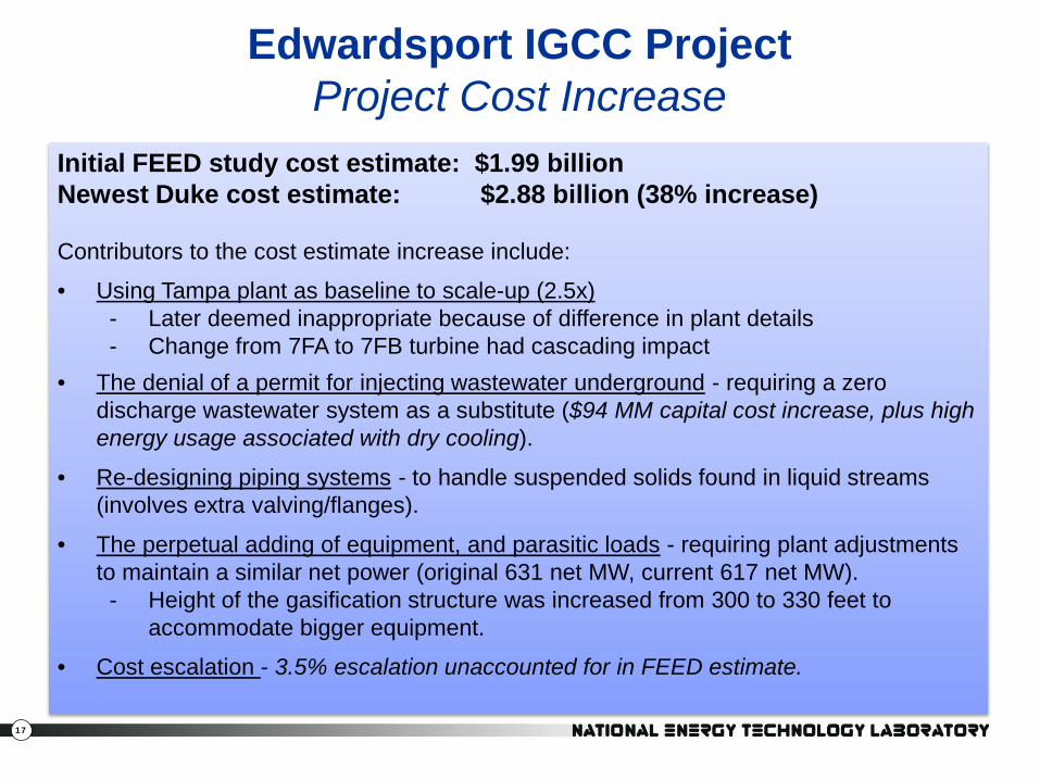
Initial FEED study cost estimate: $1.99 billion Newest Duke cost estimate: $2.88 billion (38% increase)
Contributors to the cost estimate increase include:
• Using Tampa plant as baseline to scale-up (2.5x)- Later deemed inappropriate because of difference in plant details- Change from 7FA to 7FB turbine had cascading impact
• The denial of a permit for injecting wastewater underground - requiring a zero discharge wastewater system as a substitute ($94 MM capital cost increase, plus high energy usage associated with dry cooling).
• Re-designing piping systems - to handle suspended solids found in liquid streams (involves extra valving/flanges).
• The perpetual adding of equipment, and parasitic loads - requiring plant adjustments to maintain a similar net power (original 631 net MW, current 617 net MW).
- Height of the gasification structure was increased from 300 to 330 feet to accommodate bigger equipment.
• Cost escalation - 3.5% escalation unaccounted for in FEED estimate.
18
Visit NETL Gasification Websitewww.netl.doe.gov/technologies/coalpower/gasification/index.html
Related Documents