IA OIF-OFP-01.0 f OTN Over Packet Fabric Protocol (OFP) Implementation Agreement IA # OIF-OFP-01.0 November 2011 Implementation Agreement created and approved by the Optical Internetworking Forum www.oiforum.com

Welcome message from author
This document is posted to help you gain knowledge. Please leave a comment to let me know what you think about it! Share it to your friends and learn new things together.
Transcript

IA OIF-OFP-01.0
f
OTN Over Packet Fabric Protocol (OFP) Implementation Agreement
IA # OIF-OFP-01.0
November 2011
Implementation Agreement created and approved by the Optical Internetworking Forum
www.oiforum.com

IA OIF-OFP-01.0
www.oiforum.com 2
The OIF is an international non profit organization with over 90 member companies, including the world’s leading carriers and vendors. Being an industry group uniting representatives of the data and optical worlds, OIF’s purpose is to accelerate the deployment of interoperable, cost-effective and robust optical internetworks and their associated technologies. Optical internetworks are data networks composed of routers and data switches interconnected by optical networking elements.
With the goal of promoting worldwide compatibility of optical internetworking products, the OIF actively supports and extends the work of national and international standards bodies. Working relationships or formal liaisons have been established with IEEE 802.1, IEEE 802.3ba, IETF, IP-MPLS Forum, IPv6 Forum, ITU-T SG13, ITU-T SG15, MEF, ATIS-OPTXS,ATIS-TMOC, TMF and the XFP MSA Group.
For additional information contact: The Optical Internetworking Forum, 48377 Fremont Blvd.,
Suite 117, Fremont, CA 94538 510-492-4040 [email protected]
www.oiforum.com
IA OIF-OFP-01.0
www.oiforum.com 3
Working Group: Physical and Link Layer
Title: OTN Over Packet Fabric Protocol (OFP) Implementation Agreement
Source: Technical Editor PLL Vice-Chair
Winston Mok Karl Gass
PMC-Sierra Sandia National Laboratories
8555 Baxter Place PO Box 5800 MS 0874
Burnaby, BC, Canada Albuquerque, NM, USA
V5A 4V7 87185
Phone : +1 604 415 6121 Phone : +1 505 844 8849
Email : [email protected] Email : [email protected]
Abstract :: The OTN Over Packet Fabric Protocol Implementation Agreement defines the protocol that enables the switching of Optical Data Unit (ODUk/ODUflex) of the Optical Transport Network (OTN) hierarchy over a packet fabric within a Network Equipment (NE). This IA provides the segmentation and re-assembly functions required for timing transfer, packet loss detection and replacement, and packet delay variation compensation for the ODUk/ODUflex clients.
Notice : : This Technical Document has been created by the Optical Internetworking Forum (OIF). This document is offered to the OIF Membership solely as a basis for agreement and is not a binding proposal on the companies listed as resources above. The OIF reserves the rights to at any time to add, amend, or withdraw statements contained herein. Nothing in this document is in any way binding on the OIF or any of its members.
The user's attention is called to the possibility that implementation of the OIF implementation agreement contained herein may require the use of inventions covered by the patent rights held by third parties. By publication of this OIF implementation agreement, the OIF makes no representation or warranty whatsoever, whether expressed or implied, that implementation of the specification will not infringe any third party rights, nor does the OIF make any representation or warranty whatsoever, whether expressed or implied, with respect to any claim that has been or may be asserted by any third party, the validity of any patent rights related to any such claim, or the extent to which a license to use any such rights may or may not be available or the terms hereof.
For additional information contact: The Optical Internetworking Forum, 39355 California Street, Suite 307, Fremont, CA 94538 510-608-5928 phone [email protected]

IA OIF-OFP-01.0
www.oiforum.com 4
Notice: This Technical Document has been created by the Optical Internetworking Forum (OIF). This document is offered to the OIF Membership solely as a basis for agreement and is not a binding proposal on the companies listed as resources above. The OIF reserves the rights to at any time to add, amend, or withdraw statements contained herein. Nothing in this document is in any way binding on the OIF or any of its members.
The user's attention is called to the possibility that implementation of the OIF implementation agreement contained herein may require the use of inventions covered by the patent rights held by third parties. By publication of this OIF implementation agreement, the OIF makes no representation or warranty whatsoever, whether expressed or implied, that implementation of the specification will not infringe any third party rights, nor does the OIF make any representation or warranty whatsoever, whether expressed or implied, with respect to any claim that has been or may be asserted by any third party, the validity of any patent rights related to any such claim, or the extent to which a license to use any such rights may or may not be available or the terms hereof.
© 2011 Optical Internetworking Forum
This document and translations of it may be copied and furnished to others, and derivative works that comment on or otherwise explain it or assist in its implementation may be prepared, copied, published and distributed, in whole or in part, without restriction other than the following, (1) the above copyright notice and this paragraph must be included on all such copies and derivative works, and (2) this document itself may not be modified in any way, such as by removing the copyright notice or references to the OIF, except as needed for the purpose of developing OIF Implementation Agreements.
By downloading, copying, or using this document in any manner, the user consents to the terms and conditions of this notice. Unless the terms and conditions of this notice are breached by the user, the limited permissions granted above are perpetual and will not be revoked by the OIF or its successors or assigns.
This document and the information contained herein is provided on an “AS IS” basis and THE OIF DISCLAIMS ALL WARRANTIES, EXPRESS OR IMPLIED, INCLUDING BUT NOT LIMITED TO ANY WARRANTY THAT THE USE OF THE INFORMATION HEREIN WILL NOT INFRINGE ANY RIGHTS OR ANY IMPLIED WARRANTIES OF
MERCHANTABILITY, TITLE OR FITNESS FOR A PARTICULAR PURPOSE.

IA OIF-OFP-01-0
www.oiforum.com 5
1 Table of Contents
1 Table of Contents .................................................................................................................... 5
2 List of Figures .......................................................................................................................... 6
3 List of Tables ........................................................................................................................... 7
4 Document Revision History ..................................................................................................... 8
5 Introduction ............................................................................................................................. 9
5.1 OTN Over Packet Fabric Protocol Requirements ....................................................... 10
5.2 Objectives .................................................................................................................... 11
6 Segmentation and Reassembly Models ............................................................................... 12
6.1 Introduction .................................................................................................................. 12
6.1.1 Ingress SAR Functions ............................................................................... 13
6.1.2 Egress SAR Functions ................................................................................ 17
7 Packet Format ....................................................................................................................... 20
8 Ingress Noise Shaping and Egress Filtering Functions ........................................................ 22
8.1 Packet Size Decision Model ........................................................................................ 22
8.2 Ingress Noise Shaping ................................................................................................ 23
8.3 Egress Filtering ........................................................................................................... 24
9 ODUflex Resizing .................................................................................................................. 26
10 Summary ............................................................................................................................... 27
11 Glossary ................................................................................................................................ 28
12 References ............................................................................................................................ 29
12.1 Normative references .................................................................................................. 29
12.2 Informative references ................................................................................................. 29
13 Appendix A: List of Variables ................................................................................................. 30
14 Appendix B: Noise Shaping Performance Validation ............................................................ 31
15 Appendix C: Mapping of OTN Over Packet Fabric Protocol Packets into Interlaken .............................................................................................................................. 32
16 Appendix D: Results of the PSD Governing Equations in Table 3 ........................................ 33
17 Appendix E: Examples of Converting Rate Decision (D) to a sequence of N packets of sizes Bnom ± 1. ...................................................................................................... 35
18 Appendix F: Noise Shaping Transfer Function Derivation .................................................... 36
19 Appendix G: List of companies belonging to OIF when document is approved ................... 39
IA OIF-OFP-01-0
www.oiforum.com 6
2 List of Figures
Figure 1 Converged Packet and OTN Network ........................................................................... 9
Figure 2 Converged Optical Transport Platform Network Element ........................................... 10
Figure 3 OTN Over Packet Fabric Network Element Model ..................................................... 12
Figure 4 Ingress Functional Blocks (Regenerator) .................................................................... 13
Figure 5 Ingress Functional Blocks (ODUk to ODUj/ODUflex Demultiplexing) ......................... 14
Figure 6 Egress Functional Blocks (Regenerator) .................................................................... 18
Figure 7 Egress Functional Blocks (ODUj/ODUflex to ODUk Multiplexing) .............................. 18
Figure 8 Packet Format .............................................................................................................. 20
Figure 9 Bit Ordering Relationship to OTN Octets .................................................................... 21
Figure 10 Packet Size Decision Variance High Level Diagram ................................................. 22
Figure 11 Shaping Components and Model ............................................................................... 23
Figure 12 Noise Transfer Function Mask ................................................................................... 24
Figure 13 Egress Filter Function Mask ....................................................................................... 25
Figure 14 Interlaken Burst Format ............................................................................................. 32
Figure 15 Noise Shaping Model ................................................................................................ 36
Figure 16 B+/-1 Noise Transfer Function .................................................................................. 38

IA OIF-OFP-01-0
www.oiforum.com 7
3 List of Tables
Table 1 Global Signals .............................................................................................................. 12
Table 2 Segmentation Ratio (N) for Various ODUk/ODUflex Rates and Packet Fabric Classes ...................................................................................................................... 15
Table 3 Governing Equations of PSD ....................................................................................... 16
Table 4 Supported Bmax Limits ................................................................................................... 17
Table 5 Packet Fields ................................................................................................................ 20
Table 6 Parameters for Sample ODUk and ODUflex(CBR) streams ........................................ 33
Table 7 Parameters for Sample ODUflex(GFP) Streams ......................................................... 34

IA OIF-OFP-01-0
www.oiforum.com 8
4 Document Revision History SOURCE: Winston Mok Karl Gass Technical Editor PLL Vice Chair PMC-Sierra Sandia National Laboratories 8555 Baxter Place PO Box 5800 MS 0874 Burnaby, BC, Canada Albuquerque, NM, USA V5A 4V7 87185 Phone: +1 604 415 6121 Phone: +1 505 844 8849 Email: [email protected] Email: [email protected] DATE: November 2011 Issue No. Issue Date Details of Change
OIF2011.052.00 January 2011 Draft inherited from OIF2010.348.05 with Editor’s notes added
OIF2011.052.01 April 2011 Incorporated Editor’s notes Updated ODUk/ODUflex rates breakpoints for Segmentation from ODU4.ts to Gbps. Added equations for generating Dnom, D∆, Tadj, T, Bnom
Added Section on ODUflex resizing
OIF2011.052.02 July 2011 Incorporated OIF2011.131.01 into Section 4 Updated section on ODUflex resizing from OIF2011.232.00 to reflect decisions at the May 2011 ITU meeting. Fixed typos.
OIF2011.052.03 July 2011 Incorporated editorial comments provided by Ciena.
OIF2011.052.04 July 2011 Incorporated editorial comments provided by Ciena.
OIF2011.052.05 July 2011 Incorporated text from OIF2011.299.00.
Straw ballot revision
OIF2011.052.06 October 2011 Incorporated straw ballot comment changes from OIF2011.334.00.
Fixed typos : - Word order in Figure 3 to match text
OIF2011.052.07 October 2011 Incorporated comments from Beijing Plenary.

IA OIF-OFP-01-0
www.oiforum.com 9
5 Introduction
The optical communications network is evolving from a pure TDM (SONET/SDH) oriented network to a converged Packet (Ethernet) and TDM (OTN) network. Historically, Network Elements used separate fabrics, one for packet and another for TDM traffic. A single converged fabric is expected to be simpler, and consume less power and shelf real estate. As packet traffic is expected to form a significant portion, and in some cases the majority, of the traffic, it will be economically advantageous to build Network Elements using packet oriented switching fabrics and employ circuit emulation techniques to convert OTN client streams into packet format for switching by the packet fabric. Figure 1 shows a converged network with packet and OTN capable Optical Transport Platform (OTP) Network Elements.
Figure 1 Converged Packet and OTN Network
The OTN Over Packet Fabric Protocol (OFP) Implementation Agreement defines the protocols that enables the switching of ODUk/ODUflex streams arriving at an ingress linecard of a Network Element to an egress linecard over a packet oriented switching fabric. Protocols such as OIF SPI-S and Interlaken, already exist for connecting packet PHY devices to Packet fabric devices. This IA addresses the segmentation and re-assembly of ODUk/ODUflex stream such that frequency and phase of the ODUk/ODUflex stream is preserved. The ODUk/ODUflex segments can be switched over existing and future packet fabrics. Figure 2 shows the points within an OTP NE where the OTN Over Packet Fabric Protocol Implementation Agreement is applicable.

IA OIF-OFP-01-0
www.oiforum.com 10
Figure 2 Converged Optical Transport Platform Network Element
Packet-switched platformLinecard
Vendor C
Linecard
Vendor A
FabricInt’fc*
OTN Over Packet Fabric Protocol
Packetswitchfabric
FabricInt’fc*
ODUkto PktSAR
ODUk ODUkODUkto PktSAR
OTN Ports OTN Ports
The OTN Over Packet Fabric Protocol is based on the mapping of CBR clients into an ODUk and the multiplexing of Low Order ODUj into a High Order ODUk, as defined in ITU G.709. In those definitions, a variable amount of CBR client or ODUj data is mapped into each ODUk frame, which has a fixed period. The variation in the amount of data encodes the rate of the CBR client or the ODUj stream carried within the ODUk. This technique, commonly referred to in OTN standards, is called justification and is re-used here as the technique for encoding the timing information of the ODUk/ODUflex switched across the packet fabric. The rate of the ODUk client is encoded by varying the amount of data in each packet, where the packets are constructed over a fixed time period.
5.1 OTN Over Packet Fabric Protocol Requirements
The following are the set of requirements that must be met by the OTN Over Packet Fabric Protocol in order to support the transport of ODUk/ODUflex clients across network elements and packet switching fabrics with a variety of implementation characteristics. The OTN Over Packet Fabric Protocol shall
Provide a mechanism for transferring the timing information of ODUk/ODUflex client signals across a packet fabric such that ITU-T Recommendation G..8251 ODCr and ODCp timing specifications are still met without reduction in the maximum number of NEs allowed by the G.8251 Hypothetical Reference Model,
Provide a mechanism for transferring the timing information of ODUk/ODUflex client signals across a packet fabric that is agnostic to fabric latency and latency variations,
o Support packet fabric implementations with a maximum fabric latency of up to 100µs and a maximum latency variation of up to 50µs.
o Provides a mechanism to compensate the packet fabric latency to a configurable value (max fabric latency <= config value <= 100µs) with a resolution of better than 5ns.
Provide a mechanism to signal the status of the ODUk/ODUflex client (Status = No Defect, Signal Degrade, Signal Fail),

IA OIF-OFP-01-0
www.oiforum.com 11
Provide a mechanism to protect against a re-frame of the ODUk/ODUflex stream in the event of single packet loss by the packet fabric
Support the use of a common reference 311.04MHz clock, that is phase-locked to a common timestamp synchronization pulse of 8kHz,
Support packet fabrics with a variety of internal packet sizes from 128 to 512 bytes and ODUk/ODUflex packetization that allows optimal use of the packet fabric bandwidth, and
Support for interoperable receiver and transmitter implementations.
Support of packet fabrics that deliver packets out of order is NOT required. Ordered delivery of packets across the packet fabric is the responsibility of the packet fabric itself.
5.2 Objectives
The following are additional objectives that may be met by the OTN Over Packet Fabric Protocol in order to support the transport of ODUk/ODUflex clients across network elements and packet switching fabrics with a variety of implementation characteristics. The OTN Over Packet Fabric Protocol may
Provide a mechanism to protect against a re-frame of the ODUk/ODUflex stream in the event of double (consecutive) packet loss by the packet fabric.

IA OIF-OFP-01-0
www.oiforum.com 12
6 Segmentation and Reassembly Models
6.1 Introduction
In the context of the OTN Over Packet Fabric Protocol, a Network Element (See Figure 3 below) consists of ingress OTN functions, ingress SAR functions, a packet fabric, egress SAR functions and egress OTN functions. A common reference clock (REFCLK) and a synchronization pulse (SYNC) must be distributed to all ingress and egress SAR functions. REFCLK and SYNC must be derived from a common timing reference and are phase locked to each other. The ingress OTN functions consist of an OTUk framer, which terminates the OTUk overhead, performs Forward Error Correction (FEC) and outputs the corresponding High-Order ODUk stream. There may also be one or more ODTUjk De-multiplexer stages, which extract Low-Order ODUj/ODUflex clients from the High-Order ODUk carrier stream. The High-Order or Low-Order streams are segmented into packets by the ingress SAR functions and forwarded to a packet fabric. The packet fabric switches the traffic, which is then reassembled by the egress SAR functions back into ODU data streams that are processed by the OTN egress functions. In the OTN egress functions, High-Order ODUk streams can be adapted to become an OTUk stream with the addition of OTUk overhead and FEC checksum bytes. Low-Order ODUj/ODUflex streams are multiplexed into a High-Order ODUk streams. The entire system must preserve the timing integrity of the ODU streams from ingress to egress.
Figure 3 OTN Over Packet Fabric Network Element Model
Table 1 Global Signals
Signal Description
REFCLK 311.04MHz SAR reference clock. Used by ingress SAR functions to measure the rate of the incoming ODUk/ODUflex. Used by egress SAR functions as reference to generate outgoing ODUk/ODUflex streams. The SAR reference clock may be derived from other system reference rates, such as a 155.52MHz clock, which must remain phase-locked with the SYNC signal.
SYNC 8kHz synchronization pulse. Used by ingress and egress SAR functions to synchronize timestamping used to compensate for packet latency variation.

IA OIF-OFP-01-0
www.oiforum.com 13
SYNC is phase-locked to REFCLK. The SAR synchronization pulse may be derived from other system level synchronization pulse reference rates, such as 2kHz or 4kHz signals.
6.1.1 Ingress SAR Functions
Figure 4 and Figure 5 below shows the functional blocks of the Ingress SAR functions in conjunction with a representative set of ingress OTN functions for cases of with and without ODTU multiplexing. These are logical representations only and are not intended to limit implementation. Blocks directly related to OTN Over Packet Fabric are high-lighted in blue.
Figure 4 Ingress Functional Blocks (Regenerator)
Clock & Data
Recovery PLL
OTUkOTUk Rx Framer
ODUk Clock Low-Pass Filter
FilteredODUk Clock Packet Size
Decision
REFCLK
T / N
Packet Formatter
SYNC
FIC
To:Packet Fabric
ODUk Data

IA OIF-OFP-01-0
www.oiforum.com 14
Figure 5 Ingress Functional Blocks (ODUk to ODUj/ODUflex Demultiplexing)
For either of the two cases shown in Figure 4 and Figure 5 above, the OTUk is recovered and processed. In the regenerator case, the ODUk clock is low-pass filtered, while in the multiplexed case, the ODUj/ODUflex is extracted and low pass-filtered, before being forwarded to the Packet Size Decision (PSD) function. The low-pass filter represents the standard 300Hz bandwidth desynchronizer filter specified by the OTN standards. The ODUk or ODUj/ODUflex data is forwarded to the Packet Formatter (PF) function.
The PSD function makes packet size decisions related to the rate of the filtered ODUk or ODUj/ODUflex clock. Packet size decisions are generated at a rate of N decisions every T cycles of the SAR reference clock, (e.g., 1 decision every 237 cycles or 32 decisions every 943 cycles). The Packet Formatter (PF) constructs packets with sizes as directed by the PSD. Therefore, packets are constructed at an average rate of one packet every T/N cycles of the SAR reference clock and would have an average size of (ODUk/ODUflex Rate * T) / (8 * REFCLK * N) bytes. Generating a packet size decision every T/N cycles may be impractical for some implementations. Thus, it may be desirable to generate an aggregate packet size decision every T cycles, and subsequently segment it into N individual packet size decisions. Table 2 below lists the recommended Segmentation Ratio (N) values for various ODUk/ODUflex (FODU) rates.

IA OIF-OFP-01-0
www.oiforum.com 15
Table 2 Segmentation Ratio (N) for Various ODUk/ODUflex Rates and Packet Fabric Classes
ODUk/ODUflex Rate N
128-byte fabric 256-byte fabric 512-byte fabric
ODU0, ODU1 1 1 1
ODU2, ODU1e, ODU2e, ODU1f, ODU2f
1 1 1
ODU3, ODU3e1, ODU3e2 8 4 2
ODU4 16 8 4
FODU <= 11.0 Gbps 1 1 1
FODU <= 42.0 Gbps 8 4 2
FODU <= 105.0 Gbps 16 8 4
FODU <= 225.0 Gbps (informative) (32) (16) (8)
FODU <= 425.0 Gbps (informative) (64) (32) (16)
FODU <= 1100.0 Gbps (informative) (128) (64) (32)
Packet size decisions are equivalent to a common transport function known as justification. Traditional justification mechanisms can produce very low frequency phase discontinuities in the client signal timing that are difficult to filter. A well known technique for generating justification (or packet size) decisions that minimizes this problem is a Sigma-Delta Modulator, which makes justification decisions very frequently in order to provide frequency shaping of the phase discontinuities. This technique shall be utilized in the PSD function for generating aggregate packet size decisions to improve timing transfer performance. The individual packet size decisions are written into a size decision FIFO.
The Packet Formatter, under the control of the individual packet size decisions read from the size decision FIFO, produces data packets of the proper size. It then adds the appropriate packet overhead required by the OTN Over Packet Fabric Protocol. This overhead includes a timestamp which is determined by a counter that increments by one at each REFCLK cycle and resets to zero on the rising edge of the SYNC pulse. This counter has a modulo of 38880. The timestamp is used by the egress SAR function to compensate for packet latency variations. Other overhead includes bits assigned for error resilience, particularly packet loss, and reporting of client signal status from ingress to egress functions.
The PSD function is governed by the equations in Table 3 below. A list of variable with a brief description is available in Appendix A. A compliant device shall support N, T, D and B generated from Table 2 and Table 3. A device may optionally support T, D and B resulting from a Tadj that is 1 higher than the value given by Eqn 8.

IA OIF-OFP-01-0
www.oiforum.com 16
Table 3 Governing Equations of PSD
Equation # Equation
Eqn 1 Dmax = Bmax * N
Eqn 2 BpRC = FODU / (8 * FREF)
Eqn Tmax = INT(Dmax / BpRC)
Eqn 4 DTmax = Round(Tmax * BpRC)
Eqn 5 εwc = 0.5
Eqn 6 εppm = Dmax * (PPMref + PPMODU) * 10-6
Eqn 7 D∆ = 1, when N < 4 D∆ = RoundUp ( 2*(Ɛwc+Ɛppm) ), when N >= 4
Eqn 8 Tadj = RoundUp ( [DTmax + D∆ – Dmax] / BpRC ), when [DTmax + D∆ – Dmax] > 0
Tadj = 0, when [DTmax + D∆ – Dmax] <= 0
Eqn 9 T = Tmax - Tadj
Eqn 10 Davg = T * BpRC
Eqn 11 Dnom = Round (Davg)
Eqn 12 εnom = Davg - Dnom
Eqn 13 D = {Dnom-D∆, Dnom, Dnom+D∆}
Eqn 14 Bnom = Min [Round (Davg /N), Bmax-1]
Eqn 15 B = {Bnom-1, Bnom, Bnom+1}
An aggregate packet size decision (D) is generated every T cycles of the 311.04MHz reference clock (REFCLK). During the period of (T/311.04MHz), the incoming ODUk/ODUflex stream is expected to deliver an average of Davg = (FODU * T) / (311.04MHz*8) = Dnom+εnom bytes, where Dnom is the nearest integer, and εnom is a fractional offset. Note that εnom can have a positive or a negative value. The actual epsilon (εact) is the sum of εnom, the current ppm offset of the ODUk/ODUflex stream (εppm), and jitter/wander (εj). εact = εnom + εppm + εj The nominal aggregate packet size decision (Dnom) of the ODUk is the integer nearest to Davg. εact is encoded by varying the size decision by +D∆, 0, or -D∆. For example, if Dnom =1280 and εact=0.33, the PSD may generate size decisions D = 1280, 1281, 1280, 1279, 1281, 1281, 1280, 1280, 1279, … such that the sequence averages to 1280.33. Given the very high rate of decision generation, the amount of phase contribution by jitter/wander is negligibly small. Thus, εj can be treated as being 0.
An incoming ODUflex stream may have a frequency offset of up to ±100ppm. When coupled with the local reference clock offset of ±20ppm, the total effective offset is ±120ppm. At higher ODUflex rates, the large εppm can cause εact to be larger than 1. The variance in D must be sufficiently large to span the range of εact. For good Sigma-Delta performance, the decision variance (D∆) is set to 2*(εppm + εwc), rounded up to the next integer for N>=4. For N<4, it is set to 1 so that every decision can be expressed in exactly N packets with payloads of Bnom ±1 bytes. εwc is the worst case fractional portion of εnom, measured from the nearest integer. Thus, εwc = 0.5.

IA OIF-OFP-01-0
www.oiforum.com 17
Finally, the PSD segments the aggregate packet size decisions into N individual packet size decisions. Each packet shall have a size of Bnom ± 1 bytes. The sum of the individual packet sizes shall encode the aggregate packet size decision (D) losslessly. Packets shall be generated at an average rate of T/N cycles of the 311.04MHz system reference clock.
The ODUk data is sent to the Packet Formatter (PF). The Packet Formatter reads individual packet size decisions (B) from the Size Decision FIFO and formats the ODUk data into packets of the directed size. The Packet Formatter maintains a timestamp counter which increments at every cycle of the 311.04MHz reference clock (REFCLK). The counter modulo is 38800. Thus, the counter period is 125µs. The timestamp counter is initialized to 0 by the 8kHz frame pulse (SYNC). In order to allow for small phase variances between the 311.04MHz reference clock and the 8kHz frame pulse, the counter will not re-initialize to 0 if the current count value is within ±8 of 0, at the time the frame pulse is detected. The value of the timestamp counter at the time of creation of each packet is captured in the overhead bytes of the packet.
Table 4 below shows the supported range of Bmax for 128-byte, 256-byte and 512-byte class of packet fabrics. The range of supported Bmax provides a range of 0 to 12 bytes of user specific and fabric overhead and 4 bytes of OFP overhead.
Table 4 Supported Bmax Limits
Packet Fabric Class Minimum Bmax Maximum Bmax
128-byte 112 124
256-byte 240 252
512-byte 496 508
The Fabric Interface Chip (FIC) takes in packets constructed by the Packet Formatter over an industry standard packet bus, such as OIF SPI-S, or Interlaken, and adds fabric specific overhead bytes. The packets are sent to the Core Fabric for switching to destination egress line cards. In the case of hybrid ingress line cards serving both OTN and packet (eg., Ethernet) clients, the FIC may segment the packet traffic into smaller segments for transfer over the fabric.
6.1.2 Egress SAR Functions
Figure 6 and Figure 7 below show the functional blocks of two kinds of egress functions, a regenerator configuration and an ODUj/ODUflex to ODUk multiplexing configuration. They are logical representations only and are not intended to limit implementation. Blocks directly related to OTN Over Packet Fabric are high-lighted in blue.

IA OIF-OFP-01-0
www.oiforum.com 18
Figure 6 Egress Functional Blocks (Regenerator)
ODUk Data
Read Enable
OTUk
FilteredODUk Clock
Packet Size Extraction
REFCLK
Packet Re-assembly
SYNC
From:Packet Fabric OTUk Tx
FramerFIC
Low-Pass Filter
T / N
Packet Delay Variation
FIFO
Figure 7 Egress Functional Blocks (ODUj/ODUflex to ODUk Multiplexing)
ODUj Data
Read Enable
OTUk
ODUk Clock
FilteredODUj Clock
Packet Size Extraction
REFCLK
Packet Re-assembly
SYNC
From:Packet Fabric OTUk Tx
FramerFIC
ODTUjk MUX
Low-Pass Filter
T / N
Packet Delay Variation
FIFO
ODUk packets are delivered by the packet fabric. The Packet Re-assembly (PR) function removes the OTN Over Packet Fabric Protocol header bytes and converts the packet stream into a contiguous serial ODUk/ODUflex stream. The Packet Size Extraction (PSE) function extracts the size of each packet. The packet sizes are loaded into a FIFO and read out at an average rate of once every T/N cycles of the reference clock. The resulting clock information is low-pass filtered, removing the noise generated by the ingress noise shaper. By metering the rate of packet size updates to the filter at a precise period, fabric packet delay variations have no impact on jitter and wander of the transmitter ODUk/ODUflex.

IA OIF-OFP-01-0
www.oiforum.com 19
The egress SAR function maintains a timestamp counter which increments at every cycle of the reference clock. The timestamp counter is initialized by the SYNC pulse. The egress SAR function also provides a packet delay variation FIFO for each ODUk/ODUflex stream. This FIFO buffers some amount of data so that the transmit ODUk/ODUflex stream is not interrupted by packet delay variations in the fabric. After reset, the depth of the FIFO is initialized by suspending the read operation until the packet at the head of the FIFO is of a configured age, i.e., suspend reading until (timestamp counter – packet timestamp) > configured value. The FIFO initialization process may be used to ensure that all ODUk/ODUflex streams have the same latency through the Network Element regardless of the packet delay variations in the fabric.
The output data stream and its filtered clock are then processed by the OTN functions. For a regenerator application this information is passed to the egress OTN framer. If ODUj/ODUflex multiplexing is provided, then the information is utilized by the multiplexer and then the multiplexed signal is processed by the OTN framer.

IA OIF-OFP-01-0
www.oiforum.com 20
7 Packet Format
The packet format of the OTN Over Packet Fabric Protocol is shown in Figure 8 below. Each packet contains an optional 0 to 12 byte User Specific and Fabric Overhead field, 4 bytes of OTN Over Packet Fabric overhead field, and an ODUk/ODUflex Payload field that is Bnom±1 byte. Bnom is software configurable to best match the packet size characteristics of the packet switching fabric. The definitions of the fields are listed in Table 5. The definition of the User Specific and Fabric Overhead field is outside the scope of this IA.
Figure 8 Packet Format
Table 5 Packet Fields
Field Description
Timestamp Timestamp is a 16-bit count that records the time of creation of the packet relative to the system 8kHz frame pulse (SYNC), in steps of 311.04MHz system reference clock (REFCLK) cycles. The range of Timestamp is 0 to 38879.
RSV 1 RSV 1 is a 6-bit field that is reserved for future standardization. Eg., RSV 1 can be combined with SQ to form a larger sequence number field to support packet fabrics that may deliver packets out of order.
SQ SQ is a 2-bit sequence number used to detect packets dropped by the switching fabric due to, for example, congestion or bit errors. SQ is a binary counting number that increments with every packet, per ODUk/ODUflex.
PPSI 1 PPSI 1 is a 2-bit field that records the size of the previous packet. When the previous packet is dropped by the switching fabric, the egress linecard can use PPSI 1 to construct a replacement packet of the indicated size to avoid changing the frame alignment of the ODUk/ODUflex stream.
PPSI 1 = ‘b00 : Previous packet size is Bnom bytes PPSI 1 = ‘b01 : Previous packet size is Bnom+1 bytes PPSI 1 = ‘b10 : Reserved PPSI 1 = ‘b11 : Previous packet size is Bnom-1 bytes
PPSI 1 is a 2’s-complement encoding of (-1, 0, +1).
CSI CSI is an optional 3-bit Client Status Indication field that may be used for fast APS applications. CSI carries the status of the ODUk/ODUflex stream.
CSI = ‘b000 : Forces the switching fabric to select this ODUk/ODUflex even if the alternate stream is in the No Defects state. CSI = ‘b001 : No Defects detected
IA OIF-OFP-01-0
www.oiforum.com 21
CSI = ‘b010 : Signal Degrade detected CSI = ‘b011 : Signal Fail detected CSI = ‘b100 : Server Signal Fail detected CSI = ‘b111 : Forces the switching fabric to not select this ODUk/ODUflex regardless of the state of the alternate stream. CSI = ‘b101 and ‘b110 : Reserved
Implementation of CSI is optional. When not used, the CSI field is set to ‘b001.
PPSI 2 PPSI 2 is an optional 2-bit field that records the size of the previous-previous packet. When two consecutive packets are dropped by the switching fabric, the egress linecard can use PPSI 1 and PPSI 2 to construct two replacement packets of the indicated sizes to avoid changing the frame alignment of the ODUk/ODUflex stream.
PPSI 2 = ‘b00 : Previous-previous packet size is Bnom bytes PPSI 2 = ‘b01 : Previous-previous packet size is Bnom+1 bytes PPSI 2 = ‘b10 : Reserved PPSI 2 = ‘b11 : Previous-previous packet size is Bnom-1 bytes
PPSI 2 is a 2’s-complement encoding of (-1, 0, +1). Implementation of PPSI 2 is optional. When not used, the PPSI 2 field is set to ‘b00.
P P is a 1-bit odd parity field computed over the entire OTN Over Packet Fabric Header (from Timestamp to P)
User Specific and Fabirc
OH
User Specific and Fabric Overhead is an optional 0-12 byte field reserved for user proprietary data and fabric overhead. The specification of this field is outside the scope of this IA.
Payload The Payload field carries Bnom-1, Bnom, or Bnom+1 bytes of an ODUk/ODUflex stream.
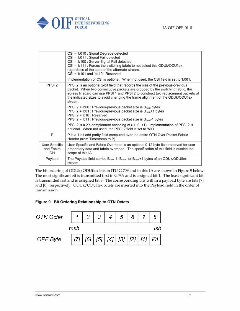
The bit ordering of ODUk/ODUflex bits in ITU G.709 and in this IA are shown in Figure 9 below. The most significant bit is transmitted first in G.709 and is assigned bit 1. The least significant bit is transmitted last and is assigned bit 8. The corresponding bits within a payload byte are bits [7] and [0], respectively. ODUk/ODUflex octets are inserted into the Payload field in the order of transmission.
Figure 9 Bit Ordering Relationship to OTN Octets
IA OIF-OFP-01-0
www.oiforum.com 22
8 Ingress Noise Shaping and Egress Filtering Functions
The required noise performance of the SAR implementation is achieved through noise shaping of aggregate packet size decisions generated by the ingress SAR function (Figure 4 and Figure 5) coupled with the appropriate filtering of those decisions by the egress SAR function (Figure 6 and Figure 7).
8.1 Packet Size Decision Model
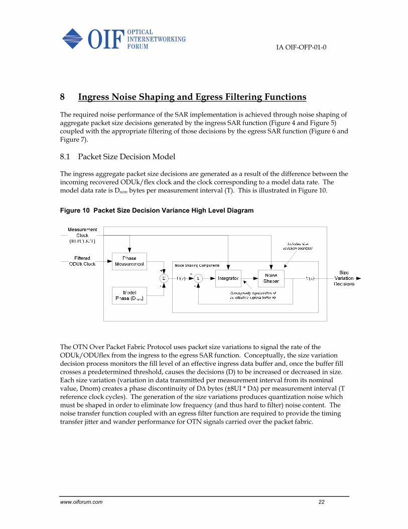
The ingress aggregate packet size decisions are generated as a result of the difference between the incoming recovered ODUk/flex clock and the clock corresponding to a model data rate. The model data rate is Dnom bytes per measurement interval (T). This is illustrated in Figure 10.
Figure 10 Packet Size Decision Variance High Level Diagram
The OTN Over Packet Fabric Protocol uses packet size variations to signal the rate of the ODUk/ODUflex from the ingress to the egress SAR function. Conceptually, the size variation decision process monitors the fill level of an effective ingress data buffer and, once the buffer fill crosses a predetermined threshold, causes the decisions (D) to be increased or decreased in size. Each size variation (variation in data transmitted per measurement interval from its nominal value, Dnom) creates a phase discontinuity of D∆ bytes (±8UI * D∆) per measurement interval (T reference clock cycles). The generation of the size variations produces quantization noise which must be shaped in order to eliminate low frequency (and thus hard to filter) noise content. The noise transfer function coupled with an egress filter function are required to provide the timing transfer jitter and wander performance for OTN signals carried over the packet fabric.

IA OIF-OFP-01-0
www.oiforum.com 23
8.2 Ingress Noise Shaping
To minimize the effect of the noise generated by the decisions (D), noise shaping at the ingress SAR function shall be provided. The characteristics of the noise shaping are determined by the noise shaping components of the packet size decision model illustrated in Figure 10 above. The derivation of the required noise shaping transfer function is based on the noise shaping components shown in Figure 11a.
Figure 11 Shaping Components and Model
1z
Σ+
+
2/
2/2/
2/
0)(
x
x
xD
xQ
D = Variance in decision (bytes)
1zΣ2
1Σ
11
1 z 11
1 z
U(z) Y(z)+
-
+
-
1z
Σ+
+
E(z)
(d)
1zΣ2
1Σ
11
1 z 11
1 z
U(z) Y(z)+
-
+
-
1z
)(Q
(a)
1st-Order Noise ShaperIntegrator
11
1 z
Equivalent Circuit
(c)(b)
D
D D
D D
The noise shaping components consist of an integrator, which is represented in Figure 11b, and a 1st-order noise shaper that includes the packet size decision quantizer. The quantizer function is defined by the relationship given in Figure 11c. For the purposes of determining the noise transfer function the quantizer is replaced with an error input and summation node, where the error is equivalent to the function Q(x)-x. This is shown in Figure 11d.
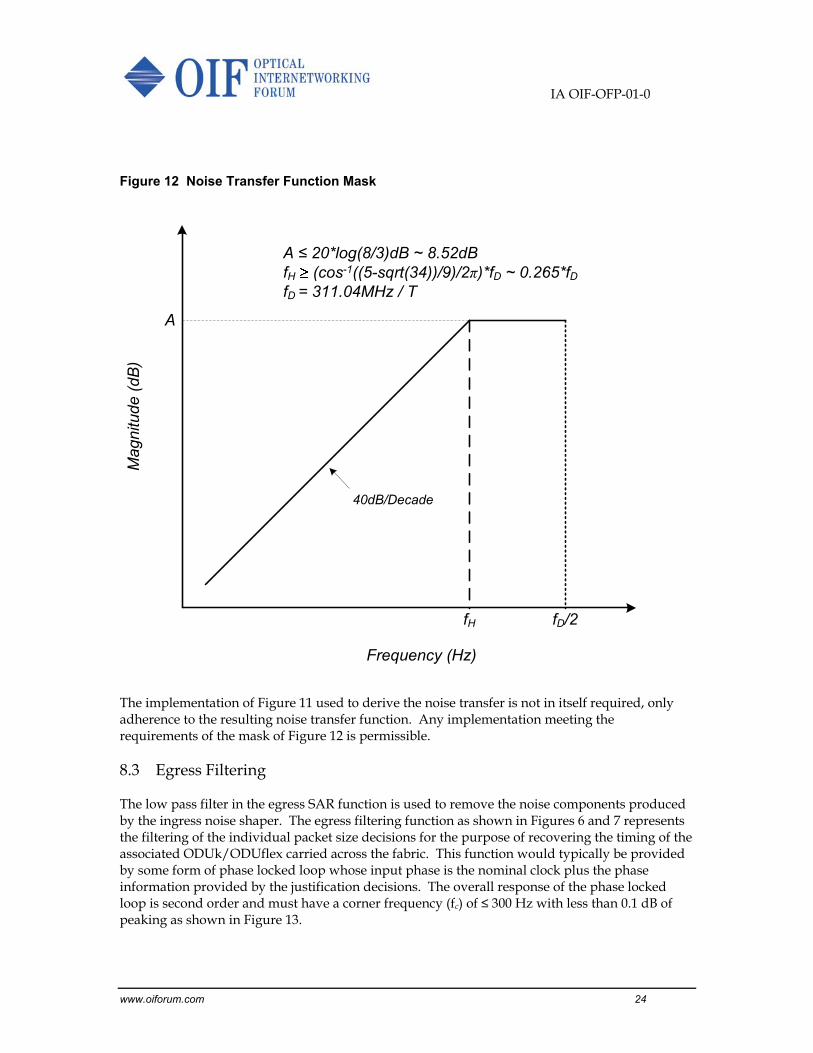
The packet size decision noise transfer function, as derived from Figure 11d, shall be a second order high-pass filter. (Note: The second order response results from the closing of the feedback loop prior to the integrator.) The response of the noise shaper for justifications (-D∆, 0, +D∆) shall lie below the mask provided in Figure 12.
IA OIF-OFP-01-0
www.oiforum.com 24
Figure 12 Noise Transfer Function Mask
40dB/Decade
fD/2
A
fH
Mag
nitu
de (
dB)
Frequency (Hz)
A ≤ 20*log(8/3)dB ~ 8.52dBfH (cos-1((5-sqrt(34))/9)/2π)*fD ~ 0.265*fDfD = 311.04MHz / T
The implementation of Figure 11 used to derive the noise transfer is not in itself required, only adherence to the resulting noise transfer function. Any implementation meeting the requirements of the mask of Figure 12 is permissible.
8.3 Egress Filtering
The low pass filter in the egress SAR function is used to remove the noise components produced by the ingress noise shaper. The egress filtering function as shown in Figures 6 and 7 represents the filtering of the individual packet size decisions for the purpose of recovering the timing of the associated ODUk/ODUflex carried across the fabric. This function would typically be provided by some form of phase locked loop whose input phase is the nominal clock plus the phase information provided by the justification decisions. The overall response of the phase locked loop is second order and must have a corner frequency (fc) of ≤ 300 Hz with less than 0.1 dB of peaking as shown in Figure 13.

IA OIF-OFP-01-0
www.oiforum.com 25
Figure 13 Egress Filter Function Mask
-20dB/Decade
fc
A
Frequency (Hz)
Mag
nitu
de (
dB)
A ≤ 0.1dBfc ≤ 300Hz

IA OIF-OFP-01-0
www.oiforum.com 26
9 ODUflex Resizing
The resizing of ODUflex(GFP) streams is specified in ITU G.7044. When the ODUflex is being resized, the rate of the ODUflex may change by a factor of up to 80X. This amount of change is outside the range addressable by Dnom ± D∆. However, ODUflex(GFP) streams are not used to carry timing, especially during the resizing operation. Thus, the precise rate and phase signaling capability of variable packet sizing is not required. The ramp in the speed of the ODUflex is specified to be at a fixed rate of 512Mbps/s. The following scheme is used to signal the ODUflex rate during resizing :
1. During “GMP Special Mode” the Ingress SAR function does not need to generate packet size decisions that tracks the rate of the ODUflex, as they will be ignored by the Egress SAR function. Although the individual packet sizes are arbitrary, they must still fall within the range of Bnom±1.
2. During “GMP Special Mode” the Egress SAR function does not use packet size variations to determine the rate of the ODUflex. Instead, the Egress SAR function compares the Timestamp field in the OFP Header to the current Timestamp counter value to determine the age of the packet. The rate of the ODUflex is increased if the filtered age is older than the configurable target and decreased if the filtered age is younger.
3. Upon being signaled by BWR_IND field in the OPUflex overhead to begin, the Egress SAR function changes the rate of the ODUflex at the nominal rate of 512Mbps/s, subject to biasing by filtered packet age. Ramping stops when so signaled by BWR_IND or when the ODUflex has reached the configured final rate. During the ramp, the age-based adjustment process depicted above remains in effect to compensate for ppm offsets between the reference clock of the upstream Network Elements and the local reference clock.
4. At any time during “GMP Special Mode”, the Ingress and Egress SAR functions can be re-configured to the final ODUflex rate. The Network Element exits “GMP Special Mode” when the upstream node has exited “GMP Special Mode”, the SAR functions have been re-configured and both the Ingress and Egress SAR functions have stabilized to the final ODUflex rate.
5. Upon exiting “GMP Special Mode”, variable packet size is again used to signal the rate of the ODUflex between the Ingress and Egress SAR functions.

IA OIF-OFP-01-0
www.oiforum.com 27
10 Summary
The OTN Over Packet Fabric Protocol Implementation Agreement defines the protocol that enables the switching of Optical Data Unit (ODUk/ODUflex) of the Optical Transport Network (OTN) hierarchy over a packet fabric within a Network Equipment (NE). This IA provides the segmentation and re-assembly functions required for timing transfer, packet loss detection and replacement, and packet delay variation compensation for the ODUk/ODUflex clients.

IA OIF-OFP-01-0
www.oiforum.com 28
11 Glossary
IA OIF-OFP-01-0
www.oiforum.com 29
12 References
12.1 Normative references
[1] International Telecommunication Union, ITU-T G.709, “Interfaces for Optical transport Network”, December 2009.
[2] International Telecommunication Union, ITU-T G.7044, Q11, SG15, WP3, “WD33r6, Hitless Adjustment of ODUflex(GFP) (HAO)”, September 2011
12.2 Informative references

IA OIF-OFP-01-0
www.oiforum.com 30
13 Appendix A: List of Variables
This informative appendix lists the variables used in this Implementation Agreement.
Variable Description Value
Fref SAR reference clock frequency 311.04 MHz
Fsync Timestamp synchronization pulse frequency 8 kHz
FODU Rate of ODUk/ODUflex client in bits/sec (bps)
PPMref PPM offset of REFCLK 20
PPMODU PPM offset of ODUk/ODUflex 20 .. 100
BpRC Number of ODUk/ODUflex bytes received in 1 SAR reference clock period.
Bnom Nominal number of ODUk/ODUflex client bytes per packet
Bmax Maximum number of ODUk/ODUflex client bytes per packet supported by the fabric. Bmax = Fabric cell size – Overhead bytes
N Segmentation Ratio. Number of Bnom±1 packets generated by each Decision.
Tmax Integer portion of the number of REFCLK cycles needed to receive N* Bmax bytes from a nominal ODUk/ODUflex client.
Tadj A reduction in Tmax to ensure Decision is at or below Dmax.
T Decision period, in integer number of REFCLK cycles. T = Tmax - Tadj
Davg Average number of ODUk/ODUflex client bytes in a decision period (T). Davg is a floating point value.
Dnom Nominal number of ODUk/ODUflex client bytes per decision
D∆ Variance in Decision, in number of ODUk/ODUflex client bytes per decision.
D Decision, in number of ODUk/ODUflex client bytes. D has value [Dnom- D∆, Dnom, Dmax+ D∆]. Each decision is segmented into N packets, each carrying Bnom±1 ODUk/ODUflex client bytes.
εnom Nominal Epsilon of an ODUk/ODUflex client. εnom = Davg – Round(Davg)
εwc Worst Case nominal Epsilon 0.5
εppm Variance in the number of ODUk/ODUflex client bytes in each decision period due to clock offsets. εppm = Dnom * (Max ppm offset of ODUk/ODUflex client rate + Max ppm offset of REFCLK)
εj Variance in the number of ODUk/ODUflex client bytes in each decision period due to phase noise. εj is negligibly small.
0.0
εact Actual Epsilon. εact = εnom + εppm + εj

IA OIF-OFP-01-0
www.oiforum.com 31
14 Appendix B: Noise Shaping Performance Validation
The operation of the noise shaping functions defined in Section 8 is an important consideration for interoperability. Since the ingress and egress functions may exist on different devices, potentially from different vendors, it is important to be able to validate the noise shaping independent of other factors. It is important to consider methods by which this might be accomplished.
The noise transfer information is incorporated in the outgoing packet size decisions.
)]([)( zEfzY noise
However, the outgoing decisions also encode the information regarding the ingress clock rate.
)]([)( zUgzY input
Applying superposition, Y(z) is a function of U(z) plus E(z) (see Figure 11d).
)]([)]([)()()( zUgzEfzYzYzY inputnoise
The transfer function Y(z)input/U(z) is a lowpass response (derived from Figure 11d). For a constant U(z) value, which is the case for a stable fixed incoming ODUk/flex clock, Y(z)input would produce a constant or DC output. Therefore, the total Y(z) output contains the error transferred to the output, Y(z)noise, plus a DC value. If the output stream of the justification decisions is high-pass filtered to remove the DC component, the remaining signal represents the noise component. If the noise shaping implementation is compliant with the requirements of this standard, the spectrum of that noise component, normalized to unit amplitude justifications (+1,0,-1), should lie at or below the mask provided in Figure 12. To avoid removing too much low frequency content and since it has been determined that the noise shaping function essentially eliminates wander effects, the DC blocking low-pass function should not have a corner frequency above 10Hz (the wander limit).
The above approach can be applied in a number of ways. One might be to provide a real-time analog output representing the normalized justification decisions (+1,0,-1), measure the stream through an AC-coupled input of a spectrum analyzer (the AC-coupled high-pass response shall not have a corner frequency above 10Hz), and compare the result against the mask of Figure 12. A second might be to provide a digital stream of justification decisions and process the stream using FFT techniques. This could be performed real-time or performed off-line by storing the digital justification stream. In either case the DC component would be ignored and the result would be compared against the mask of Figure 12.
To support the validation mechanism described above it is recommended that each ingress packet size decision circuit implementation provide the ability to access the stream of justification decisions.

IA OIF-OFP-01-0
www.oiforum.com 32
15 Appendix C: Mapping of OTN Over Packet Fabric Protocol Packets into Interlaken
This informative appendix describes the mapping of OTN Over Packet Fabric Protocol packets into Interlaken.
Interlaken is a packet oriented protocol. The basic unit is an 8-byte word. Payload data is carried in Data Words, while control information is carried in Control Words. An OFP packet can be transferred in one or more Interlaken bursts. Each burst consists of a leading Burst Control Word, a number of Data Words, and trailing Burst Control Word. The leading Burst Control Word contains a Channel Number field to identify the ODUk/ODUflex stream. The entire OFP packet, including the optional User the Fabric OH, the OFP OH and the ODUk/ODUflex payload bytes, is padded out to a multiple of 8 bytes. The Trailing Burst Control Word contains an EOP Format field that identifies the last byte of an OFP packet, so that the sink device can remove the pad bytes.
Figure 14 Interlaken Burst Format
Burst Control Word (8 bytes)
Data Word (8 bytes)
Data Word (8 bytes)
Data Word (8 bytes)
Data Word (8 bytes)
Data Word (8 bytes)
Burst Control Word (8 bytes)
Order of T
ransmission
Channel Number field to identify ODUk/ODUflex stream
Optional User and Fabric OH+
OPF OH+
OPF ODUk/ODUflex Payload+
1..7 Pad bytes
EOF Format field to identify location of the EOP byte in the last Data Word

IA OIF-OFP-01-0
www.oiforum.com 33
16 Appendix D: Results of the PSD Governing Equations in Table 3
This informative appendix shows the recommended values of T, Dnom, D∆, and Bnom for various ODUk and ODUflex streams. In this example, the maximum payload size (Bmax) is set to 120 bytes. Note that references to ODU rates above ODU4 are shown to illustrate scalability of the algorithms only, as the ITU has yet to define ODU5 and ODU6. Table 6 and Table 7 are taken from OIF2011.115.02.
Table 6 Parameters for Sample ODUk and ODUflex(CBR) streams
ODUk ODU0 1.24416 1 120 0.5 240 120 2 238 119 119 0 0.0048 0.0048 1 119 119ODU1 2.498775 1 120 1.0042 119 119 0 119 119.5 119 0.5 0.0048 0.5048 1 119.5 119ODU2 10.037274 1 120 4.0338 29 117 0 29 116.9789 117 -0.021 0.0048 -0.0259 1 116.979 117ODU2e 10.399525 1 120 4.1793 28 117 0 28 117.0214 117 0.0214 0.0144 0.0358 1 117.021 117ODU3 40.319219 8 960 16.203 59 956 0 59 956 956 4E-07 0.0384 0.0384 2 119.5 119ODU3e1 41.774364 8 960 16.788 57 957 0 57 956.9263 957 -0.074 0.0384 -0.1121 2 119.616 119ODU3e2 41.785969 8 960 16.793 57 957 0 57 957.1921 957 0.1921 0.0384 0.2305 2 119.649 119ODU4 104.794446 16 1920 42.115 45 1895 0 45 1895.154 1895 0.1542 0.0768 0.231 2 118.447 118ODU5? 420 64 7680 168.79 45 7595 0 45 7595.486 7595 0.4861 0.3072 0.7933 2 118.679 119ODU6? 1051 128 15360 422.37 36 15205 0 36 15205.44 15205 0.4398 0.6144 1.0542 3 118.792 119
ODUflex(CBR)FC400 4.26785714 1 120 1.7152 69 118 0 69 118.3458 118 0.3458 0.0144 0.3602 1 118.346 118FC800 8.53571429 1 120 3.4303 34 117 0 34 116.6306 117 -0.369 0.0144 -0.3838 1 116.631 117IB SDR 2.5 1 120 1.0047 119 120 1 118 118.5539 119 -0.446 0.0144 -0.4605 1 118.554 119IB DDR 5 1 120 2.0094 59 119 0 59 118.5539 119 -0.446 0.0144 -0.4605 1 118.554 119IB QDR 10 1 120 4.0188 29 117 0 29 116.5445 117 -0.456 0.0144 -0.4699 1 116.544 117
εnom (bytes)
εppm (bytes)
εact (bytes)
D∆ (bytes)
Bavg (bytes)
Bnom (bytes)
Dmax (bytes)
Tmax (ref clks)
Tadj (ref clks)
T (ref clks)
Davg (bytes)
Dnom (bytes)
Dnom in Tmax (bytes)
Bytes per ref clock tick
ODU type
ODU bit rate Fodu (Gbps)
Scale FactorN

IA OIF-OFP-01-0
www.oiforum.com 34
Table 7 Parameters for Sample ODUflex(GFP) Streams
ODUflex(GFP) n=1 1.24917723 1 120 0.502 239 120 2 237 118.9779 119 -0.022 0.0144 -0.0365 1 118.978 119n=2 2.49835446 1 120 1.004 119 119 0 119 119.4799 119 0.4799 0.0144 0.4943 1 119.48 119n=3 3.74753169 1 120 1.506 79 119 0 79 118.9779 119 -0.022 0.0144 -0.0365 1 118.978 119n=4 4.99670892 1 120 2.0081 59 118 0 59 118.4758 118 0.4758 0.0144 0.4902 1 118.476 118n=5 6.24588615 1 120 2.5101 47 118 0 47 117.9738 118 -0.026 0.0144 -0.0406 1 117.974 118n=6 7.49506338 1 120 3.0121 39 117 0 39 117.4718 117 0.4718 0.0144 0.4862 1 117.472 117n=7 8.74424061 1 120 3.5141 34 119 0 34 119.4799 119 0.4799 0.0144 0.4943 1 119.48 119n=8 9.99341784 1 120 4.0161 29 116 0 29 116.4678 116 0.4678 0.0144 0.4822 1 116.468 116
n=9 11.2902332 8 960 4.5373 211 957 0 211 957.3685 957 0.3685 0.1152 0.4837 2 119.671 119n=10 12.5447035 8 960 5.0414 190 958 0 190 957.8727 958 -0.127 0.1152 -0.2425 2 119.734 119n=11 13.7991739 8 960 5.5456 173 959 1 172 953.8395 954 -0.16 0.1152 -0.2757 2 119.23 119n=12 15.0536442 8 960 6.0497 158 956 0 158 955.8561 956 -0.144 0.1152 -0.2591 2 119.482 119n=13 16.3081146 8 960 6.5539 146 957 0 146 956.8644 957 -0.136 0.1152 -0.2508 2 119.608 119n=14 17.562585 8 960 7.058 136 960 1 135 952.8312 953 -0.169 0.1152 -0.284 2 119.104 119n=15 18.8170553 8 960 7.5622 126 953 0 126 952.8312 953 -0.169 0.1152 -0.284 2 119.104 119n=16 20.0715257 8 960 8.0663 119 960 1 118 951.8229 952 -0.177 0.1152 -0.2923 2 118.978 119n=17 21.325996 8 960 8.5704 112 960 1 111 951.3188 951 0.3188 0.1152 0.434 2 118.915 119n=18 22.5804664 8 960 9.0746 105 953 0 105 952.8312 953 -0.169 0.1152 -0.284 2 119.104 119n=19 23.8349367 8 960 9.5787 100 958 0 100 957.8727 958 -0.127 0.1152 -0.2425 2 119.734 119n=20 25.0894071 8 960 10.083 95 958 0 95 957.8727 958 -0.127 0.1152 -0.2425 2 119.734 119n=21 26.3438774 8 960 10.587 90 953 0 90 952.8312 953 -0.169 0.1152 -0.284 2 119.104 119n=22 27.5983478 8 960 11.091 86 954 0 86 953.8395 954 -0.16 0.1152 -0.2757 2 119.23 119n=23 28.8528181 8 960 11.595 82 951 0 82 950.8146 951 -0.185 0.1152 -0.3006 2 118.852 119n=24 30.1072885 8 960 12.099 79 956 0 79 955.8561 956 -0.144 0.1152 -0.2591 2 119.482 119n=25 31.3617589 8 960 12.604 76 958 0 76 957.8727 958 -0.127 0.1152 -0.2425 2 119.734 119n=26 32.6162292 8 960 13.108 73 957 0 73 956.8644 957 -0.136 0.1152 -0.2508 2 119.608 119n=27 33.8706996 8 960 13.612 70 953 0 70 952.8312 953 -0.169 0.1152 -0.284 2 119.104 119n=28 35.1251699 8 960 14.116 68 960 1 67 945.7732 946 -0.227 0.1152 -0.342 2 118.222 118n=29 36.3796403 8 960 14.62 65 950 0 65 950.3105 950 0.3105 0.1152 0.4257 2 118.789 119n=30 37.6341106 8 960 15.124 63 953 0 63 952.8312 953 -0.169 0.1152 -0.284 2 119.104 119n=31 38.888581 8 960 15.628 61 953 0 61 953.3354 953 0.3354 0.1152 0.4506 2 119.167 119n=32 40.1430513 8 960 16.133 59 952 0 59 951.8229 952 -0.177 0.1152 -0.2923 2 118.978 119n=33 42.9484154 16 1920 17.26 111 1916 0 111 1915.861 1916 -0.139 0.2304 -0.3699 2 119.741 119n=34 44.2498825 16 1920 17.783 107 1903 0 107 1902.785 1903 -0.215 0.2304 -0.4456 2 118.924 119n=35 45.5513497 16 1920 18.306 104 1904 0 104 1903.831 1904 -0.169 0.2304 -0.3996 2 118.989 119n=36 46.8528168 16 1920 18.829 101 1902 0 101 1901.739 1902 -0.261 0.2304 -0.4917 2 118.859 119n=37 48.1542839 16 1920 19.352 99 1916 0 99 1915.861 1916 -0.139 0.2304 -0.3699 2 119.741 119n=38 49.4557511 16 1920 19.875 96 1908 0 96 1908.015 1908 0.0151 0.2304 0.2455 2 119.251 119n=39 50.7572182 16 1920 20.398 94 1917 0 94 1917.43 1917 0.4296 0.2304 0.66 2 119.839 119n=40 52.0586853 16 1920 20.921 91 1904 0 91 1903.831 1904 -0.169 0.2304 -0.3996 2 118.989 119n=41 53.3601525 16 1920 21.444 89 1909 0 89 1908.538 1909 -0.462 0.2304 -0.6923 2 119.284 119n=42 54.6616196 16 1920 21.967 87 1911 0 87 1911.153 1911 0.1533 0.2304 0.3837 2 119.447 119n=43 55.9630867 16 1920 22.49 85 1912 0 85 1911.676 1912 -0.324 0.2304 -0.5541 2 119.48 119n=44 57.2645539 16 1920 23.013 83 1910 0 83 1910.107 1910 0.1072 0.2304 0.3376 2 119.382 119n=45 58.566021 16 1920 23.536 81 1906 0 81 1906.446 1906 0.446 0.2304 0.6764 2 119.153 119n=46 59.8674881 16 1920 24.059 79 1901 0 79 1900.693 1901 -0.307 0.2304 -0.5377 2 118.793 119n=47 61.1689553 16 1920 24.582 78 1917 0 78 1917.43 1917 0.4296 0.2304 0.66 2 119.839 119n=48 62.4704224 16 1920 25.105 76 1908 0 76 1908.015 1908 0.0151 0.2304 0.2455 2 119.251 119n=49 63.7718895 16 1920 25.628 74 1897 0 74 1896.508 1897 -0.492 0.2304 -0.722 2 118.532 119n=50 65.0733567 16 1920 26.152 73 1909 0 73 1909.061 1909 0.0611 0.2304 0.2915 2 119.316 119n=51 66.3748238 16 1920 26.675 71 1894 0 71 1893.893 1894 -0.107 0.2304 -0.3371 2 118.368 118n=52 67.6762909 16 1920 27.198 70 1904 0 70 1903.831 1904 -0.169 0.2304 -0.3996 2 118.989 119n=53 68.977758 16 1920 27.721 69 1913 0 69 1912.722 1913 -0.278 0.2304 -0.508 2 119.545 119n=54 70.2792252 16 1920 28.244 67 1892 0 67 1892.324 1892 0.3242 0.2304 0.5546 2 118.27 118n=55 71.5806923 16 1920 28.767 66 1899 0 66 1898.601 1899 -0.399 0.2304 -0.6299 2 118.663 119n=56 72.8821594 16 1920 29.29 65 1904 0 65 1903.831 1904 -0.169 0.2304 -0.3996 2 118.989 119n=57 74.1836266 16 1920 29.813 64 1908 0 64 1908.015 1908 0.0151 0.2304 0.2455 2 119.251 119n=58 75.4850937 16 1920 30.336 63 1911 0 63 1911.153 1911 0.1533 0.2304 0.3837 2 119.447 119n=59 76.7865608 16 1920 30.859 62 1913 0 62 1913.245 1913 0.2454 0.2304 0.4758 2 119.578 119n=60 78.088028 16 1920 31.382 61 1914 0 61 1914.291 1914 0.2915 0.2304 0.5219 2 119.643 119n=61 79.3894951 16 1920 31.905 60 1914 0 60 1914.291 1914 0.2915 0.2304 0.5219 2 119.643 119n=62 80.6909622 16 1920 32.428 59 1913 0 59 1913.245 1913 0.2454 0.2304 0.4758 2 119.578 119n=63 81.9924294 16 1920 32.951 58 1911 0 58 1911.153 1911 0.1533 0.2304 0.3837 2 119.447 119n=64 83.2938965 16 1920 33.474 57 1908 0 57 1908.015 1908 0.0151 0.2304 0.2455 2 119.251 119n=65 84.5953636 16 1920 33.997 56 1904 0 56 1903.831 1904 -0.169 0.2304 -0.3996 2 118.989 119n=66 85.8968308 16 1920 34.52 55 1899 0 55 1898.601 1899 -0.399 0.2304 -0.6299 2 118.663 119n=67 87.1982979 16 1920 35.043 54 1892 0 54 1892.324 1892 0.3242 0.2304 0.5546 2 118.27 118n=68 88.499765 16 1920 35.566 53 1885 0 53 1885.002 1885 0.0017 0.2304 0.2321 2 117.813 118n=69 89.8012322 16 1920 36.089 53 1913 0 53 1912.722 1913 -0.278 0.2304 -0.508 2 119.545 119n=70 91.1026993 16 1920 36.612 52 1904 0 52 1903.831 1904 -0.169 0.2304 -0.3996 2 118.989 119n=71 92.4041664 16 1920 37.135 51 1894 0 51 1893.893 1894 -0.107 0.2304 -0.3371 2 118.368 118n=72 93.7056336 16 1920 37.658 50 1883 0 50 1882.91 1883 -0.09 0.2304 -0.3208 2 117.682 118n=73 95.0071007 16 1920 38.181 50 1909 0 50 1909.061 1909 0.0611 0.2304 0.2915 2 119.316 119n=74 96.3085678 16 1920 38.704 49 1897 0 49 1896.508 1897 -0.492 0.2304 -0.722 2 118.532 119n=75 97.610035 16 1920 39.227 48 1883 0 48 1882.91 1883 -0.09 0.2304 -0.3208 2 117.682 118n=76 98.9115021 16 1920 39.75 48 1908 0 48 1908.015 1908 0.0151 0.2304 0.2455 2 119.251 119n=77 100.212969 16 1920 40.273 47 1893 0 47 1892.847 1893 -0.153 0.2304 -0.3832 2 118.303 118n=78 101.514436 16 1920 40.796 47 1917 0 47 1917.43 1917 0.4296 0.2304 0.66 2 119.839 119n=79 102.815904 16 1920 41.319 46 1901 0 46 1900.693 1901 -0.307 0.2304 -0.5377 2 118.793 119n=80 104.117371 16 1920 41.842 45 1883 0 45 1882.91 1883 -0.09 0.2304 -0.3208 2 117.682 118
εnom (bytes)
εppm (bytes)
εact (bytes)
D∆ (bytes)
Bavg (bytes)
Bnom (bytes)
Dmax (bytes)
Tmax (ref clks)
Tadj (ref clks)
T (ref clks)
Davg (bytes)
Dnom (bytes)
Dnom in Tmax (bytes)
Bytes per ref clock tick
ODU type
ODU bit rate Fodu (Gbps)
Scale FactorN

IA OIF-OFP-01-0
www.oiforum.com 35
17 Appendix E: Examples of Converting Rate Decision (D) to a sequence of N packets of sizes Bnom ± 1.
Two examples of PSD and PF implementations are given below for illustrative purposes. They are not intended to limit nor define compliant designs. In the first example, a packet size decision (D) is generated every T cycles of the 311.04MHz reference clock (REFCLK). The decision is segmented into N packet sizes using simple modulo arithmetic. Of the N packets, (D mod N) of those would have a size of Bnom+1 bytes and the rest would have a size of Bnom bytes. The sum of the N packet sizes is D. In this second example implementation, the PSD generates the size decision (D) of each packet directly, once every T/N cycles of the 311.04MHz system reference clock. Each decision sets the size of a single packet.
IA OIF-OFP-01-0
www.oiforum.com 36
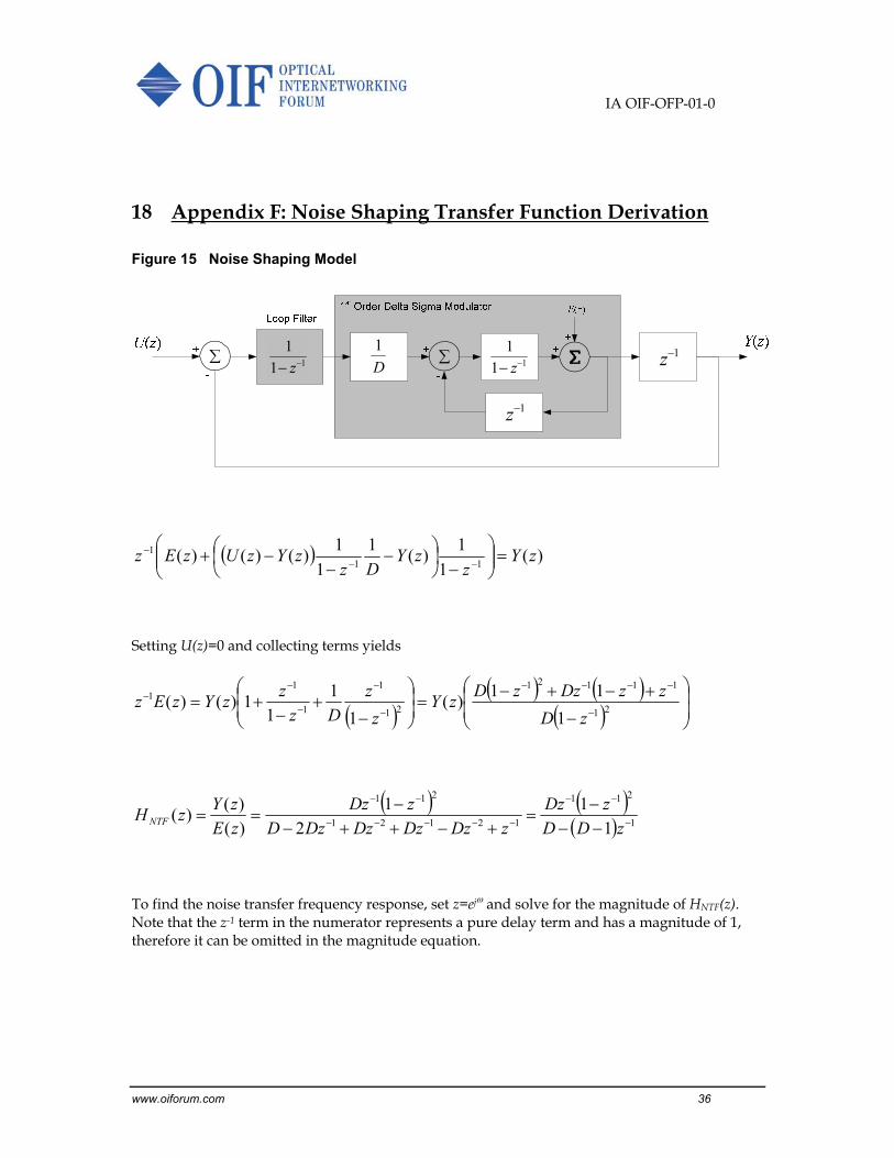
18 Appendix F: Noise Shaping Transfer Function Derivation
Figure 15 Noise Shaping Model
)(1
1)(
1
1
1)()()(
111 zY
zzY
DzzYzUzEz
Setting U(z)=0 and collecting terms yields
21
11121
21
1
1
11
1
11)(
1
1
11)()(
zD
zzDzzDzY
z
z
Dz
zzYzEz
1
211
12121
211
1
1
2
1
)(
)()(
zDD
zDz
zDzDzDzDzD
zDz
zE
zYzHNTF
To find the noise transfer frequency response, set z=ej and solve for the magnitude of HNTF(z). Note that the z-1 term in the numerator represents a pure delay term and has a magnitude of 1, therefore it can be omitted in the magnitude equation.
D
1
1z
1z11
1 z11
1 z
IA OIF-OFP-01-0
www.oiforum.com 37
cos121
)cos1(2
sin1cos1
)cos1(2
sin1cos1
)cos1(2
sin1cos1
sincos1
sin1cos1
sincos1
1
)1()()(
2222
22
22
DDDD
D
DDD
D
DjDD
D
DjDD
D
DjDD
jD
eDD
eDeHzH
j
jj
NTFNTF
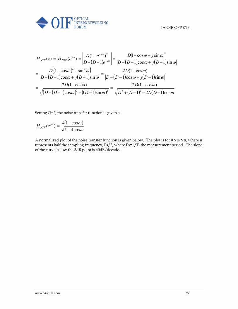
Setting D=2, the noise transfer function is given as
cos45
cos14)(
jNTF eH
A normalized plot of the noise transfer function is given below. The plot is for 0 ≤ ≤ π, where π represents half the sampling frequency, Fs/2, where Fs=1/T, the measurement period. The slope of the curve below the 3dB point is 40dB/decade.

IA OIF-OFP-01-0
www.oiforum.com 38
Figure 16 B+/-1 Noise Transfer Function
B+/-1 Noise Transfer Function
-160
-140
-120
-100
-80
-60
-40
-20
0
20
0 0.1 0.2 0.3 0.4 0.5 0.6 0.7 0.8 0.9 1
Frequency (x Fs/2, Fs=1/T)
Mig
nit
ud
e (d
B)

IA OIF-OFP-01-0
www.oiforum.com 39
19 Appendix G: List of companies belonging to OIF when document is approved
Acacia Communications Finisar Corporation MoSys, Inc.
ADVA Optical Networking Force 10 Networks NEC
Alcatel‐Lucent France Telecom Group/Orange NeoPhotonics
Altera Fujitsu Nokia Siemens Networks
AMCC Furukawa Electric Japan NTT Corporation
Amphenol Corp. Gennum Corporation Oclaro
Anritsu GigOptix Inc. Opnext
AT&T Hewlett Packard Picometrix
Avago Technologies Inc. Hitachi PMC Sierra
Broadcom Hittite Microwave Corp QLogic Corporation
Brocade Huawei Technologies Reflex Photonics
Centellax, Inc. IBM Corporation Semtech
China Telecom Infinera SHF Communication Technologies
Ciena Corporation Inphi Sumitomo Electric Industries
Cisco Systems IP Infusion Sumitomo Osaka Cement
ClariPhy Communications JDSU TE Connectivity
Cogo Optronics Juniper Networks Tektronix
Comcast KDDI R&D Laboratories Telcordia Technologies
Cortina Systems Kotura, Inc. Tellabs
CyOptics LeCroy TeraXion
Department of Defense Lightwire Texas Instruments
Deutsche Telekom LSI Corporation Time Warner Cable
ECI Telecom Ltd. Luxtera TriQuint Semiconductor
Emcore Macom Technology Solutions u2t Photonics AG
Emulex Marben Products Verizon
Ericsson Maxim Integrated Products Vitesse Semiconductor
ETRI Mayo Clinic Xilinx
EXFO Metaswitch Xtera Communications
FCI USA LLC Mitsubishi Electric Corporation Yamaichi Electronics Ltd.
Fiberhome Technologies Group Molex ZTE Corporation

IA OIF-OFP-01-0
www.oiforum.com 40
Notes
Related Documents