Service Manual Steering OSPM www.danfoss.com

Welcome message from author
This document is posted to help you gain knowledge. Please leave a comment to let me know what you think about it! Share it to your friends and learn new things together.
Transcript
Revision history Table of revisions
Date Changed Rev
October 2019 Minor adjustments throughout, especially reflecting tool numbers 0202
Mar 2014 Converted to Danfoss layout - DITA CMS BA
Feb 1998 First edition AA
Service ManualSteering, OSPM
2 | © Danfoss | October 2019 520L0454 | en-0202
Exploded ViewExploded view OSPM...................................................................................................................................................................... 4
Part List, OSPMOSPM main parts list....................................................................................................................................................................... 5
ToolsTools for OSPM.................................................................................................................................................................................. 7
DismantlingDismantling the OSPM................................................................................................................................................................... 8Cleaning, inspection, replacement, and lubrication............................................................................................................8
AssemblingAssemby of the OSPM.....................................................................................................................................................................9
Service ManualSteering, OSPM
Contents
© Danfoss | October 2019 520L0454 | en-0202 | 3
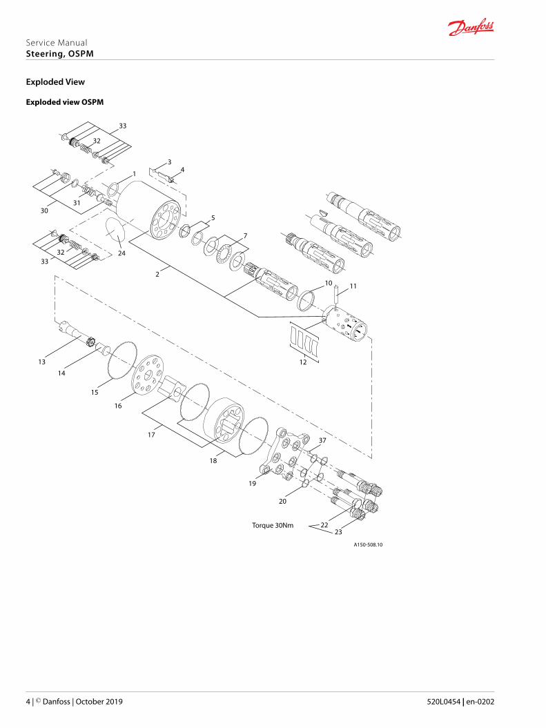
Exploded view OSPM
3031
24
2
1
34
5
7
10 11
12
37
2322
20
19
18
17
16
15
14
13
A150-508.10
Torque 30Nm
32
33
3233
Service ManualSteering, OSPM
Exploded View
4 | © Danfoss | October 2019 520L0454 | en-0202
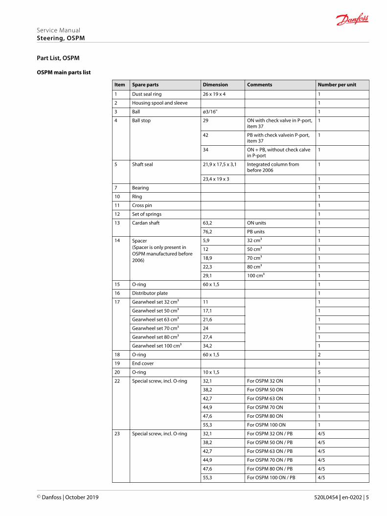
OSPM main parts list
Item Spare parts Dimension Comments Number per unit
1 Dust seal ring 26 x 19 x 4 1
2 Housing spool and sleeve 1
3 Ball ø3/16" 1
4 Ball stop 29 ON with check valve in P-port,item 37
1
42 PB with check valvein P-port,item 37
1
34 ON + PB, without check calvein P-port
1
5 Shaft seal 21,9 x 17,5 x 3,1 Integrated column frombefore 2006
1
23,4 x 19 x 3 1
7 Bearing 1
10 RIng 1
11 Cross pin 1
12 Set of springs 1
13 Cardan shaft 63,2 ON units 1
76,2 PB units 1
14 Spacer(Spacer is only present inOSPM manufactured before2006)
5,9 32 cm³ 1
12 50 cm³ 1
18,9 70 cm³ 1
22,3 80 cm³ 1
29,1 100 cm³ 1
15 O-ring 60 x 1,5 1
16 Distributor plate 1
17 Gearwheel set 32 cm³ 11 1
Gearwheel set 50 cm³ 17,1 1
Gearwheel set 63 cm³ 21,6 1
Gearwheel set 70 cm³ 24 1
Gearwheel set 80 cm³ 27,4 1
Gearwheel set 100 cm³ 34,2 1
18 O-ring 60 x 1,5 2
19 End cover 1
20 O-ring 10 x 1,5 5
22 Special screw, incl. O-ring 32,1 For OSPM 32 ON 1
38,2 For OSPM 50 ON 1
42,7 For OSPM 63 ON 1
44,9 For OSPM 70 ON 1
47,6 For OSPM 80 ON 1
55,3 For OSPM 100 ON 1
23 Special screw, incl. O-ring 32,1 For OSPM 32 ON / PB 4/5
38,2 For OSPM 50 ON / PB 4/5
42,7 For OSPM 63 ON / PB 4/5
44,9 For OSPM 70 ON / PB 4/5
47,6 For OSPM 80 ON / PB 4/5
55,3 For OSPM 100 ON / PB 4/5
Service ManualSteering, OSPM
Part List, OSPM
© Danfoss | October 2019 520L0454 | en-0202 | 5
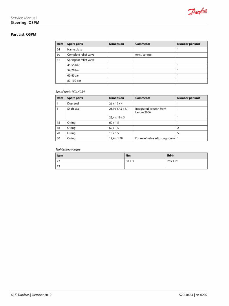
Item Spare parts Dimension Comments Number per unit
24 Name plate 1
30 Complete relief valve (excl. spring) 1
31 Spring for relief valve
45-55 bar 1
54-70 bar 1
65-85bar 1
80-100 bar 1
Set of seals 150L4054
Item Spare parts Dimension Comments Number per unit
1 Dust seal 26 x 19 x 4 1
5 Shaft seal 21,9x 17,5 x 3,1 Integrated column frombefore 2006
1
23,4 x 19 x 3 1
15 O-ring 60 x 1,5 1
18 O-ring 60 x 1,5 2
20 O-ring 10 x 1,5 5
30 O-ring 12,4 x 1,78 For relief valve adjusting screw 1
Tightening torque
Item Nm lbf·in
22 30 ± 3 265 ± 25
23
Service ManualSteering, OSPM
Part List, OSPM
6 | © Danfoss | October 2019 520L0454 | en-0202
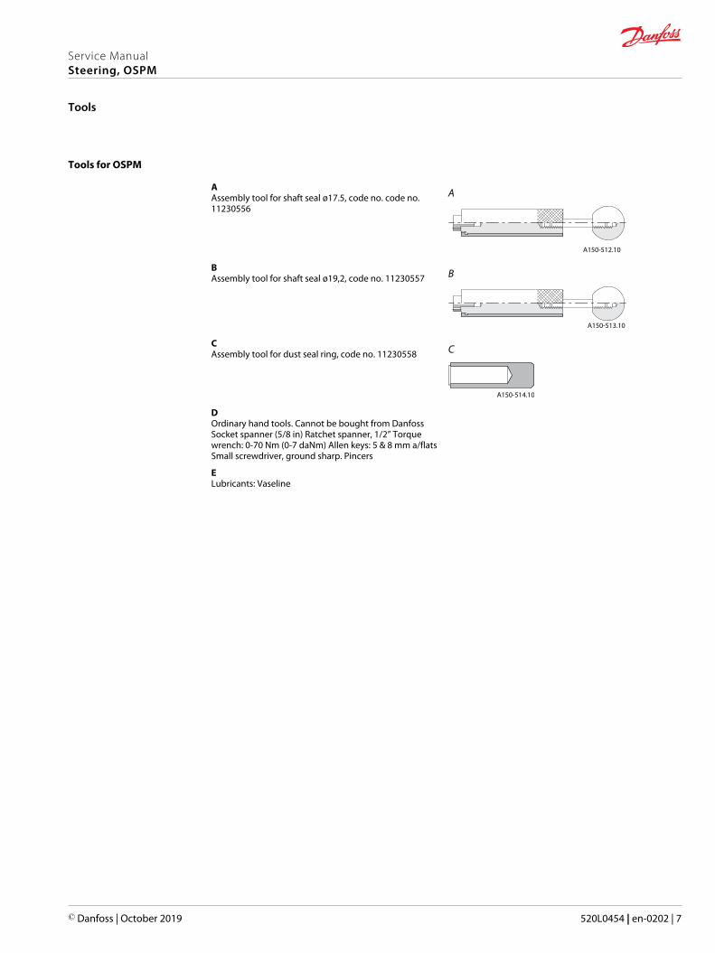
Tools for OSPM
AAssembly tool for shaft seal ø17.5, code no. code no.11230556
A
A150-512.10
BAssembly tool for shaft seal ø19,2, code no. 11230557 B
A150-513.10
CAssembly tool for dust seal ring, code no. 11230558 C
A150-514.10
DOrdinary hand tools. Cannot be bought from DanfossSocket spanner (5/8 in) Ratchet spanner, 1/2” Torquewrench: 0-70 Nm (0-7 daNm) Allen keys: 5 & 8 mm a/flatsSmall screwdriver, ground sharp. Pincers
ELubricants: Vaseline
Service ManualSteering, OSPM
Tools
© Danfoss | October 2019 520L0454 | en-0202 | 7
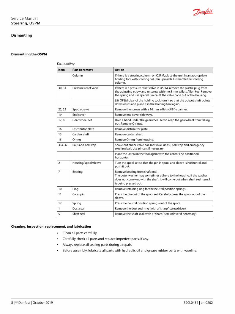
Dismantling the OSPM
Dismantling
Item Part to remove Action
Column If there is a steering column on OSPM, place the unit in an appropriateholding tool with steering column upwards. Dismantle the steeringcolumn.
30, 31 Pressure relief valve If there is a pressure relief valve in OSPM, remove the plastic plug fromthe adjusting screw and unscrew with the 5 mm a/flats Allen key. Removethe spring and use special pliers-lift the valve cone out of the housing.
Lift OPSM clear of the holding tool, turn it so that the output shaft pointsdownwards and place it in the holding tool again.
22, 23 Spec. screws Remove the screws with a 16 mm a/flats (5/8”) spanner.
19 End cover Remove end cover sideways.
17, 18 Gear wheel set Hold a hand under the gearwheel set to keep the gearwheel from fallingout. Remove O-rings.
16 Distributor plate Remove distributor plate.
13 Cardan shaft Remove cardan shaft.
15 O-ring Remove O-ring from housing.
3, 4, 37 Balls and ball stop Shake out check valve ball (not in all units), ball stop and emergencysteering ball. Use pincers if necessary.
Place the OSPM in the tool again with the center line positionedhorizontal.
2 Housing/spool/sleeve Turn the spool set so that the pin in spool and sleeve is horizontal andpush it out.
7 Bearing Remove bearing from shaft end.The outer washer may sometimes adhere to the housing. If the washerdoes not come out with the shaft, it will come out when shaft seal item 5is being pressed out.
10 Ring Remove retaining ring for the neutral position springs.
11 Cross pin Press the pin out of the spool set. Carefully press the spool out of thesleeve.
12 Spring Press the neutral position springs out of the spool.
1 Dust seal Remove the dust seal ring (with a “sharp” screwdriver).
5 Shaft seal Remove the shaft seal (with a “sharp” screwdriver if necessary).
Cleaning, inspection, replacement, and lubrication
• Clean all parts carefully.
• Carefully check all parts and replace imperfect parts, if any.
• Always replace all sealing parts during a repair.
• Before assembly, lubricate all parts with hydraulic oil and grease rubber parts with vaseline.
Service ManualSteering, OSPM
Dismantling
8 | © Danfoss | October 2019 520L0454 | en-0202
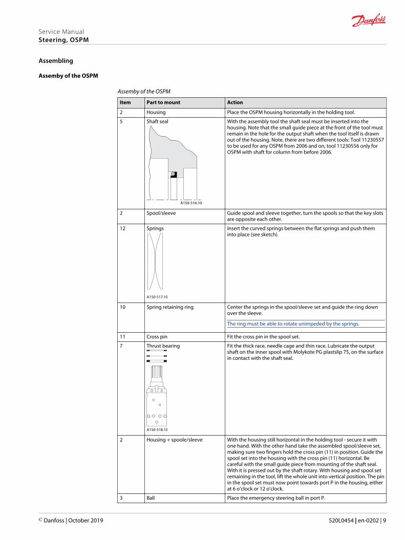
Assemby of the OSPM
Assemby of the OSPM
Item Part to mount Action
2 Housing Place the OSPM housing horizontally in the holding tool.
5 Shaft seal
A150-516.10
With the assembly tool the shaft seal must be inserted into thehousing. Note that the small guide piece at the front of the tool mustremain in the hole for the output shaft when the tool itself is drawnout of the housing. Note, there are two different tools: Tool 11230557to be used for any OSPM from 2006 and on, tool 11230556 only forOSPM with shaft for column from before 2006.
2 Spool/sleeve Guide spool and sleeve together, turn the spools so that the key slotsare opposite each other.
12 Springs
A150-517.10
Insert the curved springs between the flat springs and push theminto place (see sketch).
10 Spring retaining ring Center the springs in the spool/sleeve set and guide the ring downover the sleeve.
The ring must be able to rotate unimpeded by the springs.
11 Cross pin Fit the cross pin in the spool set.
7 Thrust bearing
A150-518.10
Fit the thick race, needle cage and thin race. Lubricate the outputshaft on the inner spool with Molykote PG plastslip 75, on the surfacein contact with the shaft seal.
2 Housing + spoole/sleeve With the housing still horizontal in the holding tool - secure it withone hand. With the other hand take the assembled spool/sleeve set,making sure two fingers hold the cross pin (11) in position. Guide thespool set into the housing with the cross pin (11) horizontal. Becareful with the small guide piece from mounting of the shaft seal.With it is pressed out by the shaft rotary. With housing and spool setremaining in the tool, lift the whole unit into vertical position. The pinin the spool set must now point towards port P in the housing, eitherat 6 o’clock or 12 o’clock.
3 Ball Place the emergency steering ball in port P.
Service ManualSteering, OSPM
Assembling
© Danfoss | October 2019 520L0454 | en-0202 | 9
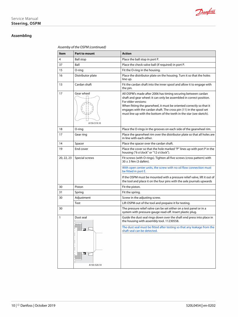
Assemby of the OSPM (continued)
Item Part to mount Action
4 Ball stop Place the ball stop in port P.
37 Ball Place the check valve ball (if required) in port P.
15 O-ring Fit the O-ring in the housing.
16 Distributor plate Place the distributor plate on the housing. Turn it so that the holesline up.
13 Cardan shaft Fit the cardan shaft into the inner spool and allow it to engage withthe pin.
17 Gear wheel
A150-519.10
All OSPM's made after 2006 has timing securing between cardanshaft and gear wheel: it can only be assembled in correct position.For elder versions:When fitting the gearwheel, it must be oriented correctly so that itengages with the cardan shaft. The cross pin (11) in the spool setmust line up with the bottom of the teeth in the star (see sketch).
18 O-ring Place the O-rings in the grooves on each side of the gearwheel rim.
17 Gear ring Place the gearwheel rim over the distributor plate so that all holes arein line with each other.
14 Spacer Place the spacer over the cardan shaft.
19 End cover Place the cover so that the hole marked “P” lines up with port P in thehousing (“6 o’clock” or “12 o’clock”).
20, 22, 23 Special screws Fit screws (with O-rings). Tighten all five screws (cross pattern) with30 ± 3 Nm (3 daNm).
With open center units, the screw with no oil flow connection mustbe fitted in port E.
If the OSPM must be mounted with a pressure relief valve, lift it out ofthe tool and place it on the four pins with the axle journals upwards
30 Piston Fit the piston.
31 Spring Fit the spring.
30 Adjustment Screw in the adjusting screw.
Test Lift OSPM out of the tool and prepaire it for testing.
30 The pressure relief valve can be set either on a test panel or in asystem with pressure-gauge read-off. Insert plastic plug.
1 Dust seal
A150-520.10
Guide the dust seal rings down over the shaft end press into place inthe housing with assembly tool. 11230558.
The dust seal must be fitted after testing so that any leakage from theshaft seal can be detected.
Service ManualSteering, OSPM
Assembling
10 | © Danfoss | October 2019 520L0454 | en-0202
Danfoss Power Solutions is a global manufacturer and supplier of high-quality hydraulic andelectric components. We specialize in providing state-of-the-art technology and solutionsthat excel in the harsh operating conditions of the mobile off-highway market as well as themarine sector. Building on our extensive applications expertise, we work closely with you toensure exceptional performance for a broad range of applications. We help you and othercustomers around the world speed up system development, reduce costs and bring vehiclesand vessels to market faster.
Danfoss Power Solutions – your strongest partner in mobile hydraulics and mobileelectrification.
Go to www.danfoss.com for further product information.
We offer you expert worldwide support for ensuring the best possible solutions foroutstanding performance. And with an extensive network of Global Service Partners, we alsoprovide you with comprehensive global service for all of our components.
Local address:
Danfoss Power Solutions GmbH & Co. OHGKrokamp 35D-24539 Neumünster, GermanyPhone: +49 4321 871 0
Danfoss Power Solutions ApSNordborgvej 81DK-6430 Nordborg, DenmarkPhone: +45 7488 2222
Danfoss Power Solutions (US) Company2800 East 13th StreetAmes, IA 50010, USAPhone: +1 515 239 6000
Danfoss Power Solutions Trading(Shanghai) Co., Ltd.Building #22, No. 1000 Jin Hai RdJin Qiao, Pudong New DistrictShanghai, China 201206Phone: +86 21 2080 6201
Danfoss can accept no responsibility for possible errors in catalogues, brochures and other printed material. Danfoss reserves the right to alter its products without notice. This also applies to productsalready on order provided that such alterations can be made without subsequent changes being necessary in specifications already agreed.All trademarks in this material are property of the respective companies. Danfoss and the Danfoss logotype are trademarks of Danfoss A/S. All rights reserved.
© Danfoss | October 2019 520L0454 | en-0202
Products we offer:
• DCV directional controlvalves
• Electric converters
• Electric machines
• Electric motors
• Gear motors
• Gear pumps
• Hydrostatic motors
• Hydrostatic pumps
• Orbital motors
• PLUS+1® controllers
• PLUS+1® displays
• PLUS+1® joysticks andpedals
• PLUS+1® operatorinterfaces
• PLUS+1® sensors
• PLUS+1® software
• PLUS+1® software services,support and training
• Position controls andsensors
• PVG proportional valves
• Steering components andsystems
• Telematics
Hydro-Gearwww.hydro-gear.com
Daikin-Sauer-Danfosswww.daikin-sauer-danfoss.com
Related Documents