www.ReadyLIFT.com - Phone: (800) 549-4620 Installation Instructions 6.5” GM 1500 Lift 4-25-16 MMC A NEW REPLACEMENT PART WILL BE SENT TO YOU IMMEDIATELY (800)549-4620 MON-FRI 7AM-5PM PST OR EMAIL: [email protected] WEBSITE: www. ReadyLIFT.COM **Please retain this document in your vehicle at all times** IF YOUR ReadyLIFT® OFF ROAD SUSPENSION PRODUCT IS MISSING A PART OR HAS A DAMAGED PART, PLEASE CONTACT CUSTOMER SERVICE DIRECTLY. Limited Warranty details for ReadyLIFT® Off Road Suspension. The ReadyLIFT® Off Road Suspension Limited Lifetime Warranty covers defective materials or defective work- manship for the life of the product to the original purchaser and only on the original vehicle which the product was installed. The ReadyLIFT® Off Road Suspension Limited Lifetime Warranty excludes the following wearable items: bushings, bushing sleeves, bump stops, top-out stops, spherical bearings (uniballs), heim joints (rod ends), and misalignment spacers (upper control arm and steering). These items are considered wear items and are cov- ered for 90 days from the original purchase date, therefore these items will not be considered defective because of wear. Wear is subject to use of product, use of vehicle, driving conditions, weather conditions, cleanliness of product/components, and maintenance/up-keep. The degree of wear and overall lifetime of each wear item is subject to afore mentioned conditions and circumstances. ReadyLIFT® Off Road Suspension will only warranty wear items in the case of workmanship and defects for the period of 90 days following the date of purchase. Please note that all products should be inspected by a professional technician before installing any part/kit onto the vehicle. In addition, all products should be installed by a qualified technician. Please contact ReadyLIFT® Off Road Suspension if there is any question as to the quality of workmanship of each component or its installation procedure. Contact ReadyLIFT® Off Road Suspension directly about any potentially defective parts prior to re- moving any parts from the vehicle. If it appears that the part is warrantable, you will be given an RGA number and asked to return the part freight prepaid. If the part is found to be warrantable, at the sole discretion of ReadyLIFT® Off Road Suspension, it will be repaired or replaced and returned to you. The limited warranty ex- pressed by ReadyLIFT® Off Road Suspension supersedes that of any claims made by authorized and unauthor- ized dealers of ReadyLIFT® Off Road Suspension products. www.ReadyLIFT.com ReadyLIFT® Off Road Suspension Limited Warranty

Welcome message from author
This document is posted to help you gain knowledge. Please leave a comment to let me know what you think about it! Share it to your friends and learn new things together.
Transcript

www.ReadyLIFT.com - Phone: (800) 549-4620
Installation Instructions 6.5” GM 1500 Lift
4-25-16 MMC
A NEW REPLACEMENT PART WILL BE SENT TO YOU IMMEDIATELY
(800)549-4620 MON-FRI 7AM-5PM PST
OR EMAIL: [email protected]
WEBSITE: www. ReadyLIFT.COM **Please retain this document in your vehicle at all times**
IF YOUR ReadyLIFT® OFF ROAD SUSPENSION PRODUCT IS MISSING A PART OR HAS A DAMAGED PART,
PLEASE CONTACT CUSTOMER SERVICE DIRECTLY.
Limited Warranty details for ReadyLIFT® Off Road Suspension.
The ReadyLIFT® Off Road Suspension Limited Lifetime Warranty covers defective materials or defective work-manship for the life of the product to the original purchaser and only on the original vehicle which the product was installed. The ReadyLIFT® Off Road Suspension Limited Lifetime Warranty excludes the following wearable items: bushings, bushing sleeves, bump stops, top-out stops, spherical bearings (uniballs), heim joints (rod ends), and misalignment spacers (upper control arm and steering). These items are considered wear items and are cov-ered for 90 days from the original purchase date, therefore these items will not be considered defective because of wear. Wear is subject to use of product, use of vehicle, driving conditions, weather conditions, cleanliness of product/components, and maintenance/up-keep. The degree of wear and overall lifetime of each wear item is subject to afore mentioned conditions and circumstances. ReadyLIFT® Off Road Suspension will only warranty wear items in the case of workmanship and defects for the period of 90 days following the date of purchase. Please note that all products should be inspected by a professional technician before installing any part/kit onto the vehicle. In addition, all products should be installed by a qualified technician. Please contact ReadyLIFT® Off Road Suspension if there is any question as to the quality of workmanship of each component or its installation procedure. Contact ReadyLIFT® Off Road Suspension directly about any potentially defective parts prior to re-moving any parts from the vehicle. If it appears that the part is warrantable, you will be given an RGA number and asked to return the part freight prepaid. If the part is found to be warrantable, at the sole discretion of ReadyLIFT® Off Road Suspension, it will be repaired or replaced and returned to you. The limited warranty ex-pressed by ReadyLIFT® Off Road Suspension supersedes that of any claims made by authorized and unauthor-ized dealers of ReadyLIFT® Off Road Suspension products.
www.ReadyLIFT.com
ReadyLIFT® Off Road Suspension Limited Warranty

www.ReadyLIFT.com - Phone: (800) 549-4620
Installation Instructions 6.5” GM 1500 Lift
2 4-25-16 MMC
Please read Instructions thoroughly and completely before beginning installation. Installation by a certified mechanic is recommended.
ReadyLIFT® Suspension is NOT responsible for any damage or failure resulting from
improper installation.
Safety Warning: Suspension systems or components that enhance the on and off-road per-formance of your vehicle may cause it to handle differently than it did from the factory. Ex-treme care must be used to prevent loss of control or vehicle rollover during abrupt maneuvers. Always operate your vehicle at reduced speeds to ensure your ability to control your vehicle under all driving conditions. Failure to drive safely may result in serious injury or death to driver and passengers. Driver and passengers must ALWAYS wear your seat belts, avoid quick sharp turns and other sudden maneuvers. ReadyLIFT® Suspension does not recommend the combined use of suspension lifts, body lifts, or other lifting devices. You should never operate your vehicle under the influence of alcohol or drugs. Constant maintenance is required to keep your vehicle safe. Thoroughly inspect your vehicle before and after every off-road use. It is the responsibility of the retailer and/or the installer to review all state and local laws, with the end user of this product, related to bumper height laws and the lifting of their vehicle before the purchase and installation of any ReadyLIFT® products. It is the responsibility of the driver/s to check their surrounding area for obstructions, people, and animals before moving the vehicle. All raised vehicles have increased blind spots and damage, injury and/or death can occur if these instructions are not followed.
Driver Front: Driver Rear: Pass. Front: Pass. Rear:
VEHICLE HEIGHT MEASURMENTS
This suspension system was developed using a 35 - 12.50 r20 tire with 20” x 9” wheel and a offset of 0. If wider tires are used, offset wheels may be necessary and trimming may be re-quired. Factory wheels can be used but are not recommended with tires over 11” wide. The stock spare rim can be run in an emergency. Please note that if running the spare factory tire, it is done for short distances and a speed not to exceed 45mph or damage to differentials may oc-cur.

www.ReadyLIFT.com - Phone: (800) 549-4620
Installation Instructions 6.5” GM 1500 Lift
3 4-25-16 MMC
BILL OF MATERIALS
Safety Warning Before you start installation: ReadyLIFT® Suspension highly recommends that the installation of this product be performed by a professional mechanic with experience working on and installing suspension products. Professional knowledge and skill will typically yield the best installation results. If you need an installer in your area, please contact ReadyLIFT® Suspension customer service to find one of our “Pro-Grade” Dealers. Notes:
Installation by a professional mechanic is highly recommended.
A Factory Service Manual for your specific Year / Make / Model is highly recommended for reference during installa-tion.
Vehicles with a two piece rear driveline may require a carrier bearing drop support bracket, call technical assistance for details.
All lifted vehicles may require additional driveline modifications and or balancing.
A four wheel vehicle alignment will need to be performed after installation of this product.
Speedometer / Computer recalibration is required if changing +/- 10% from factory tire diameter.
Use of a Vehicle Hoist will greatly reduce installation time.
Vehicle must be in excellent operating condition. Repair or replace any and all worn or damaged components prior to installation.
Front Cross Member 1 Rear Cross Member 1 5/8" x 5.5" Bolt 4 5/8” X 5” Bolt 2 5/8" x 4.5" Bolt 2 5/8" Flat Washer 16 5/8" Lock Nut 8 Driver Side Control Arm Drop 1 Passenger Side Control Arm Drop 1 M14 x 80mm Bolt 4 M14 Flat Washer 6 M14 Lock Nut 4 Driver Side Differential Drop 1 Differential Drop, Passenger Side 1 1/2" x 1.75" Bolt 2 1/2” Washer 4 1/2-13 Lock Nut 2 9/16" x 1.75" Bolt 2 9/16" Flat Washer 2
9/16" Fender Washer 2 9/16" Lock Nut 2 Steering Extension Bracket 1 Steering Extension Shaft 1 Universal Joint 1 3/4" Rod End 1 Passenger Side R&P Bracket 1 1/2" x 1" Bolt 1 1/2" Flat Washer 2 1/2” Lock Nut 1 M16 x 160mm Bolt 6 M16 Thick Washer 1 M16 Flat Washer 1 M16 Lock Nut 1 M12 x 140mm Bolt 1 M12 Thick Washer 1 Sway Bar Brackets 2 7/16" x 1.5" Bolt 4 7/16" Flat Washer 8
7/16" Lock Nut 4 Front Differential Skid Plate 1 3/8 x 1" Bolt 6 3/8" Flat Washer 6 Bump Stop Extension 2 M10 x 100mm Allen Bolt 2 M10 Flat Washer 2 Driver Side Strut Spacer 1 Passenger Side Strut Spacer 1 M10 Flange Nut 6 U-Bolt 4 U-Bolt Flange Nuts 8 Front Brake Line Bracket 1 Rear Brake Line Bracket 1 1/4" x 3/4" Bolt 3 1/4" Flat Washer 6 1/4" Lock Nut 3 Shock 2 2WD Only Transmission Spacer 1
*** If your kit came with add-a-leafs, install for a leveled stance on the 6.5” lift.***

www.ReadyLIFT.com - Phone: (800) 549-4620
Installation Instructions 6.5” GM 1500 Lift
4 4-25-16 MMC
Park vehicle on a clean flat surface and block the rear wheels for safety. Engage the parking brake. Record the stock vehicle measurements on both the front and the rear, this will provide a guideline on vehicle rake and lift height. Measure from the center of the wheel up to the bottom edge of the fender well opening and record on the chart provided on page 2. Disconnect the vehicle power source at the ground terminal on the battery. Lock the steering wheel in the straight forward position with the col-umn lock or steering wheel locking device. Raise the front of the vehicle and support with jack stands at each frame rail behind the lower control arms.
If installing on a 2WD, Ignore any steps pertaining to front differential removal and install.
Remove the front wheels. Remove all factory skid plate and hardware.
Remove the brake line bracket from the frame, the upper control arm, and steering knuckle. Unclip the abs wire from the brake line bracket. Disconnect the ABS electrical connection. (Fig 1) Remove the brake caliper/bracket assembly from the knuckle. Hang the caliper out of the way using a S-Hook or suitable strap. Do not let the caliper hang by the brake hose. (Fig 2) Remove the brake rotor bolt and then remove rotor from hub. (Fig 3) Remove the tie rod ends from the steering knuckles. Strike the tie rod boss with a dead blow hammer to break the taper loose. (Fig 4) Remove the sway bar end links from the sway bar and the lower con-trol arms. (Fig 5)
FIG 2
FIG 3
FIG 4
FIG 5
FIG 6
FIG 1

www.ReadyLIFT.com - Phone: (800) 549-4620
Installation Instructions 6.5” GM 1500 Lift
5 4-25-16 MMC
Remove the sway bar from the vehicle noting direction of sway bar in relationship to the vehicle. Remove the bolts from the strut to lower control arm. (Fig 6) Remove the upper strut nuts and remove strut from vehicle. (Fig 7) Remove the hub dust cap if applicable to expose the axle shaft nut. Remove the axle shaft nut. Remove the CV shaft flange bolts. Re-move CV axle assembly from the vehicle. If 2WD, ignore this step. (Fig 8) Loosen but do not remove the upper and lower ball joint nuts. Strike the ball joint boss on the knuckle with a dead blow hammer to dis-lodge the taper. Remove knuckle. (Fig 9) Remove the upper control arm cam bolts from the frame and remove the upper control arms from the vehicle. Mark cam bolt and hard-ware for install later. (Fig 10) Remove the lower control arm mounting bolts and remove the lower control arms from the frame. Remove the pinch bolt that connects the intermediate shaft to the rack and pinion. Remove the intermediate shaft from the rack and pinion unit. (Fig 11) Disconnect the wiring harness and plugs from the front cross mem-ber. Support the rack and pinion unit with a jack or suitable device, remove the four mounting bolts that attach the rack and pinion to the frame. Remove the rack and pinion assembly from the vehicle. (Fig 12) Remove the four bolts that attach the OEM cross member to the frame at the rear lower control arm pocket. Remove the cross mem-ber from the vehicle and discard all. If 2WD, loosen but do not re-move the cross member. (Fig 13) Disconnect the actuator connector, harness, and vent tube from the front differential. If 2WD, ignore this step.
FIG 10
FIG 7
FIG 8
FIG 9
FIG 11
FIG 12
FIG 10
www.ReadyLIFT.com - Phone: (800) 549-4620
Installation Instructions 6.5” GM 1500 Lift
6 4-25-16 MMC
Remove the driveshaft mounting bolts and disconnect the driveshaft from the differential. Allow the driveshaft to rest out of the way. If 2WD, ignore this step. (Fig 14) Support the differential and remove the front differential mounting bolts and nuts from the driver and passenger side. Remove differen-tial from the vehicle. If 2WD, ignore this step. Locate the rear control arm pocket on drivers and passenger sides and measure 3 3/8” from the inner edge of the pockets out towards the frame / outside of truck. Mark a vertical cut line on both sides of the frame pocket and connect these lines up and over the top side. If 2WD, ignore this step. (Fig 15) Using a cutting tool, cut along the line to remove this section of cross member support from the control arm pocket. Round off the bottom corners and sand any sharp edges. Paint any exposed metal surface with quality rust preventative paint. If 2WD, ignore this step. Using a cutting tool, cut the frame on the upper front driver side dif-ferential mount as marked. This is cut for clearance of the steering shaft extension u-joint. If 2WD, ignore this step. (Fig 16) Using a cutting tool, cut the factory skid plate mounting bracket from the frame. (Fig 17, 18) Using a cutting tool, trim the droop limiter and lower plates out of the factory upper control arm pockets. Sand and smooth all cut areas flush with the upper control arm pockets. (Fig 19, 20)
FIG 13
FIG 14
FIG 15
FIG 16
FIG 17
FIG 20 FIG 18 FIG 19

www.ReadyLIFT.com - Phone: (800) 549-4620
Installation Instructions 6.5” GM 1500 Lift
7 4-25-16 MMC
Front Cross Member Fitment. It may be necessary to slightly re-move some material at the corners of the control arm pockets front and back in order to fit the new front cross member into the frame. It may also be necessary to “spread” open the pockets. Check the front cross member for fitment. Use a suitable cutting tool to remove ma-terial for fitment. Use a large hammer to strike the factory frame pocket tabs to “spread” them open to aid in cross member installa-tion. (Fig 21) You will need to Drill / Cut a hole to make clearance for lowering the Rack and Pinion. Measure from the lower mounting hole for the rack and pinion on the driver side 3 3/4” from the center of the mounting hole to the left side of the frame and mark a vertical line. Now meas-ure from the same lower mounting hole up 7/8” and make a horizon-tal line. Where these two lines intersect will be the center of the 3” hole. Use an appropriate metal cutting 3” hole saw to drill out the hole in the frame. (Fig 22, 23) Install the upper control arm drop brackets into the upper control arm frame pockets using M14 bolts, washers, brake line bracket and lock nuts. The brake line bracket is being used as a washer on the outside of the rear mount. Do not tighten at this time. (Fig 24) Attach the factory brake line bracket assembly to drop bracket using 1/4” x 3/4” bolt, washers and lock nut. Do not tighten at this time. (Fig 25) Install the front cross member using 5/8” x 5.5” bolts, washers, anti-crush sleeves, and lock nuts from the inside out passing through the upper control arm drop brackets. Bolt shown holding crush sleeve in place while components are lined up. Bolt is turned around for final install. (Fig 26, 27)
FIG 21
FIG 22
FIG 23
FIG 24
FIG 25
FIG 26 FIG 27
www.ReadyLIFT.com - Phone: (800) 549-4620
Installation Instructions 6.5” GM 1500 Lift
8 4-25-16 MMC
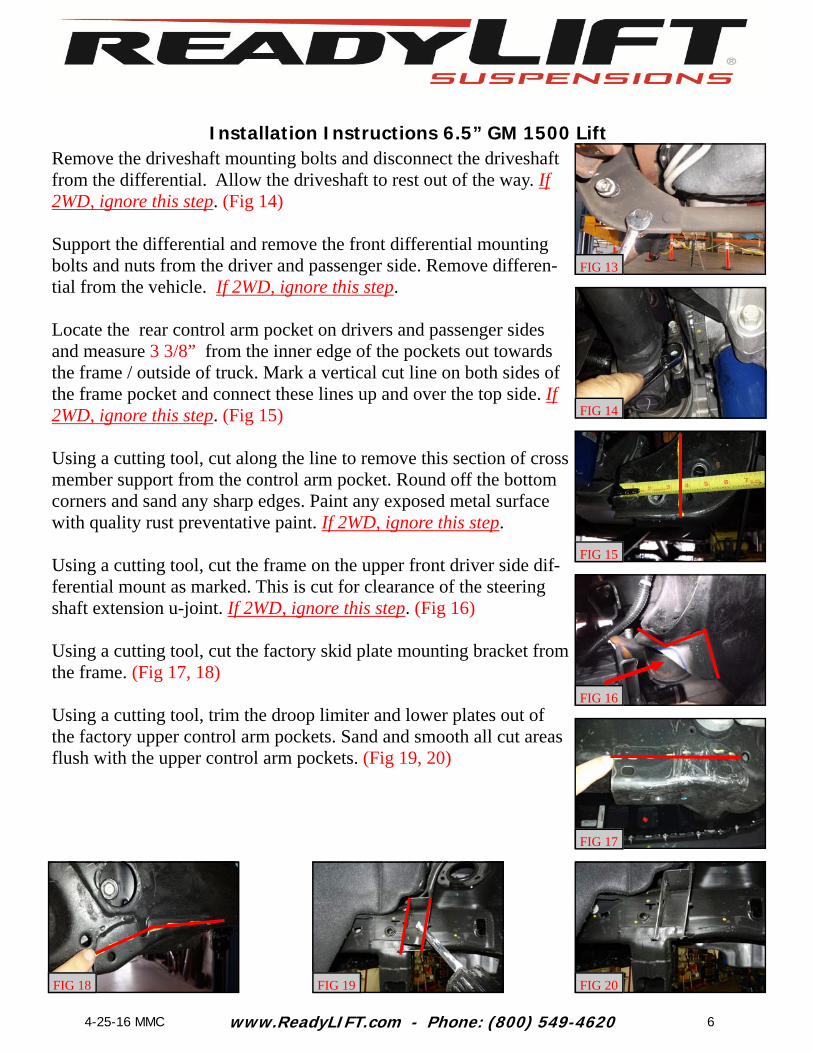
Locate the steering extension support bracket. Install ¾” rod end into extension 1 1/4” from the face of threaded insert to center of the bearing. Secure in the horizontal position with set screw. (Fig 28 ) Install steering extension drop bracket assembly onto the frame using the factory bolts from the rack and pinion and the supplied M16 flat washer and M16 lock nut in the original upper hole. Do not tighten at this time. (Fig 29) Locate the steering u-joint and steering extension shaft. Install steer-ing shaft extension onto the factory rack and pinion shaft noting the location of the set screws for the new u-joint. Make sure the notch is in the same line as the factory notch on the rack and pinion shaft. Lube the shaft extension and hiem joint with a coating of anti-seize before installation into vehicle. (Fig 30) Install the factory rack and pinion unit lower mounting points to the front cross member using M16 bolt, and M16 thick washer in the ReadyLift cross member driver side , factory hardware in the factory lower mounting hole, and the M12 bolt, and M12 thick washer in the ReadyLift cross member. As you raise the rack and pinion unit, slide the steering extension shaft and u-joint assembly through the ¾ rod end attached to the support bracket. Do not tighten at this time. (Fig 31) Install passenger side rack and pinion drop bracket using factory hardware on the backside of the rack and pinion mounting point and 1/2” x 1” bolt, washers, and lock nut to the original upper passenger side front cross member mount. Do not tighten at this time. (Fig 32) Install factory intermediate shaft onto the Readylift steering exten-sion using factory pinch bolt. Torque to165 in-lbs. (Fig 33) Reconnect the electrical connectors and harness to their respective points on the frame. Install both the driver and passenger side differential drop brackets onto the existing factory mounts using the factory hardware. Do not tighten at this time. If 2WD, ignore this step.
1 1/4”
Set Screw Attachment Points
FIG 28
FIG 29
FIG 30
FIG 31
FIG 32
FIG 33

www.ReadyLIFT.com - Phone: (800) 549-4620
Installation Instructions 6.5” GM 1500 Lift
9 4-25-16 MMC
Install the differential onto differential drop brackets using 1/2” x 1 3/4” bolts, washers and lock nuts on the drivers drop bracket and 9/16” x 1 3/4” bolts, fender washers, regular washers, and lock nuts on the passenger drop bracket. ***Make sure to install bolts from the bottom facing up.*** Torque factory and 1/2” hardware to 50 ft-lbs. Torque 9/16” hardware to 70 ft-lbs. Connect electrical connector and vent tube to the differential. If 2WD, ignore this step. (Fig 31, 32) Re-attach the front drive shaft to the front differential using factory hardware, and a drop of thread locker. Torque to 18 ft-lbs. If 2WD, ignore this step. Install the rear cross member into the frame pockets using the 5/8” x 5” bolts, flat washers, and lock nuts from the inside facing out. Do not tighten at this time. (Fig 33) Install the factory lower control arms into the front and rear cross members using 5/8” x 4.5” and 5/8” x 5.5 bolts, washers and lock nuts. Do not tighten at this time. (Fig 40) Torque the cross members to 150 ft-lbs, upper control arm drops to 100 ft-lbs, (make sure the brake line brackets face straight down after this procedure), the differential hangers to 70 ft-lbs, the driver side rack and pinion and steering extension bracket bolts to 100 ft-lbs, and passenger side bolts to 70 ft-lbs. Install the factory upper control arms into the upper control arm drop down brackets using the factory cam eccentrics and bolts. Do not tighten at this time. (Fig 35) Locate and install the strut spacer onto their corresponding struts us-ing supplied factory hardware. D is driver and P is passenger side. (Fig 36) Install the strut assembly onto the frame using supplied 10mm flange nuts. Install the lower control arm to lower strut mount using factory hardware. Torque upper hardware to 25 ft-lbs and lower hardware to 50 ft-lbs.
FIG 31
FIG 32
FIG 33
FIG 34
FIG 35
FIG 36

www.ReadyLIFT.com - Phone: (800) 549-4620
Installation Instructions 6.5” GM 1500 Lift
10 4-25-16 MMC
Install the CV Axles to the front differential using factory hardware and a drop of thread locker. Torque to 60 ft-lbs. If 2WD, ignore this step. Install sway bar drop brackets onto the frame using the factory hard-ware. Torque to 35 ft-lbs. Attach the sway bar to the bottom of the drop down brackets using the 7/16” x 1 1/2” bolt, washers and c-lock nuts. Torque to 45 ft-lbs. (Fig 37) Install the factory end links onto the sway bar and lower control arm using the factory hardware. Torque to 40 ft-lbs. Install the factory knuckle to the lower ball joint (while sliding the axle into the hub assembly) using factory hardware. Torque to 110 ft-lbs. Install axle nut and washer. Torque to 150 ft-lbs. If 2WD, ignore the steps for cv axle. (Fig 38) Install upper control arm to knuckle using factory hardware. Torque to 85 ft-lbs. (Fig 39) Attach ABS wire to hub assembly using factory hardware. Torque to 5 ft-lbs. Install the factory brake rotor using the factory hardware. Torque to 5 ft-lbs. Install the factory caliper using the factory hardware and a drop of thread locker. Torque to 100 ft-lbs. (Fig 46) Install brake line brackets onto knuckles and control arms using fac-tory hardware. Clip abs wire back into brake line bracket. Torque to 5 ft-lbs. Install tie rod end onto knuckle using factory hardware. Torque to 85 ft-lbs. (Fig 47) Cut the front ear off the differential as shown for skid plate clearance. (Fig 48)
FIG 37
FIG 38
FIG 39
FIG 40
FIG 41
FIG 42

www.ReadyLIFT.com - Phone: (800) 549-4620
Installation Instructions 6.5” GM 1500 Lift
11 4-25-16 MMC
Install skid plate using 3/8” x 1” hardware. Torque to 25 ft-lbs. (Fig 43) Double check all upper control drop brackets, differential drop brack-ets, and steering bolts at this time for tightness and proper torque. Install the wheels and lower vehicle to the ground. Torque the lug nuts to the wheel manufactures specs. Jounce the vehicle to settle the suspension. Torque the lower control arm bolts to 150 ft-lbs. Center the upper control arm cam bolts and torque to 120 ft-lbs.
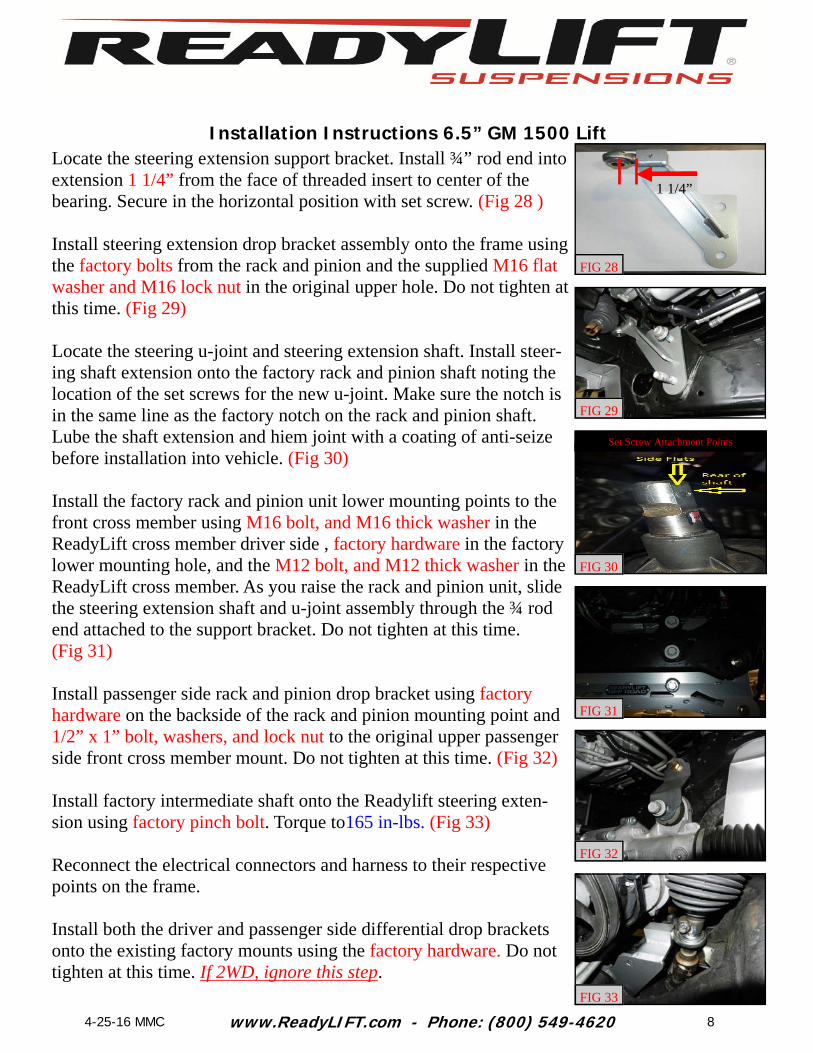
Rear Installation: Block the front wheels and raise the rear of the vehicle. Place jack stands under the frame rails ahead of the spring hangers. Remove the wheels. Remove the brake line bracket on the differential. Gently bend the metal brake lines until the rubber lines point up. Install the ReadyLift bracket using factory hardware, 1/4” x 1” bolt, washers, and lock nuts. Torque to 10 ft-lbs. (Fig 44) Remove the parking brake bracket from the outer frame rail. Remove the 2 cables from the bracket. Leave the driver side out of the bracket and reinstall the passenger side into the lower location of the bracket. Reinstall to the frame rail using factory hardware. Torque to 10 ft-lbs. (Fig 45) Remove the ABS wires from their points on top of the frame under the bed and bottom of the frame. Disconnect the electrical connectors and let hang out of the way. Support rear axle with a suitable jack and remove the shocks. Dis-card shocks as they will not be reused. Remove the factory bump stops from the frame. Install bump stop onto extension and frame using M10 x 100mm Allen bolt and wash-ers. Torque to 25 ft-lbs. (Fig 46, 47)
FIG 43
FIG 45
FIG 46
FIG 47
FIG 48
FIG 44
www.ReadyLIFT.com - Phone: (800) 549-4620
Installation Instructions 6.5” GM 1500 Lift
12 4-25-16 MMC
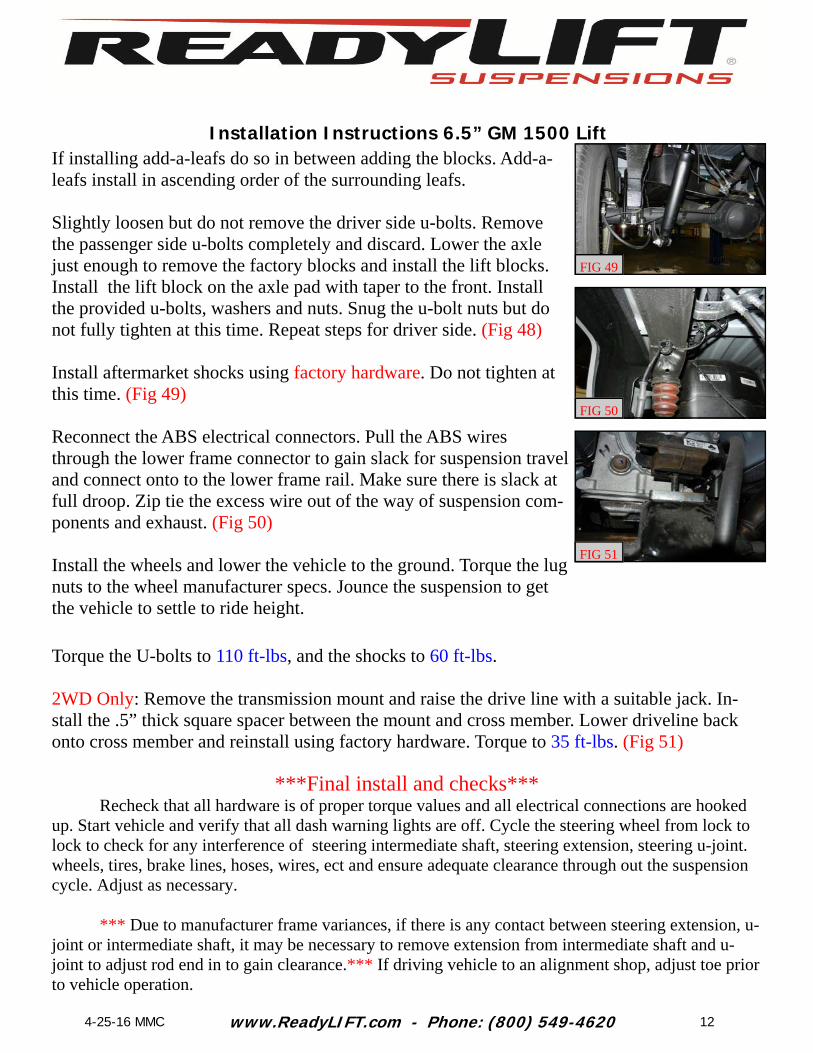
If installing add-a-leafs do so in between adding the blocks. Add-a-leafs install in ascending order of the surrounding leafs. Slightly loosen but do not remove the driver side u-bolts. Remove the passenger side u-bolts completely and discard. Lower the axle just enough to remove the factory blocks and install the lift blocks. Install the lift block on the axle pad with taper to the front. Install the provided u-bolts, washers and nuts. Snug the u-bolt nuts but do not fully tighten at this time. Repeat steps for driver side. (Fig 48) Install aftermarket shocks using factory hardware. Do not tighten at this time. (Fig 49) Reconnect the ABS electrical connectors. Pull the ABS wires through the lower frame connector to gain slack for suspension travel and connect onto to the lower frame rail. Make sure there is slack at full droop. Zip tie the excess wire out of the way of suspension com-ponents and exhaust. (Fig 50) Install the wheels and lower the vehicle to the ground. Torque the lug nuts to the wheel manufacturer specs. Jounce the suspension to get the vehicle to settle to ride height.
***Final install and checks*** Recheck that all hardware is of proper torque values and all electrical connections are hooked up. Start vehicle and verify that all dash warning lights are off. Cycle the steering wheel from lock to lock to check for any interference of steering intermediate shaft, steering extension, steering u-joint. wheels, tires, brake lines, hoses, wires, ect and ensure adequate clearance through out the suspension cycle. Adjust as necessary. *** Due to manufacturer frame variances, if there is any contact between steering extension, u-joint or intermediate shaft, it may be necessary to remove extension from intermediate shaft and u-joint to adjust rod end in to gain clearance.*** If driving vehicle to an alignment shop, adjust toe prior to vehicle operation.
FIG 49
FIG 50
FIG 51
Torque the U-bolts to 110 ft-lbs, and the shocks to 60 ft-lbs. 2WD Only: Remove the transmission mount and raise the drive line with a suitable jack. In-stall the .5” thick square spacer between the mount and cross member. Lower driveline back onto cross member and reinstall using factory hardware. Torque to 35 ft-lbs. (Fig 51)
FIG 51
www.ReadyLIFT.com - Phone: (800) 549-4620
Installation Instructions 6.5” GM 1500 Lift
13 4-25-16 MMC
Place your message here. F or maximum i mpact, use two or thr ee sentences.
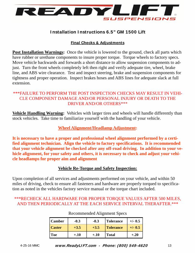
Final Checks & Adjustments
Post Installation Warnings: Once the vehicle is lowered to the ground, check all parts which have rubber or urethane components to insure proper torque. Torque wheels to factory specs. Move vehicle backwards and forwards a short distance to allow suspension components to ad-just. Turn the front wheels completely left then right and verify adequate tire, wheel, brake line, and ABS wire clearance. Test and inspect steering, brake and suspension components for tightness and proper operation. Inspect brakes hoses and ABS lines for adequate slack at full extension. ***FAILURE TO PERFORM THE POST INSPECTION CHECKS MAY RESULT IN VEHI-
CLE COMPONENT DAMAGE AND/OR PERSONAL INJURY OR DEATH TO THE DRIVER AND/OR OTHERS***
Vehicle Handling Warning: Vehicles with larger tires and wheels will handle differently than stock vehicles. Take time to familiarize yourself with the handling of your vehicle.
Wheel Alignment/Headlamp Adjustment:
It is necessary to have a proper and professional wheel alignment performed by a certi-fied alignment technician. Align the vehicle to factory specifications. It is recommended that your vehicle alignment be checked after any off-road driving. In addition to your ve-hicle alignment, for your safety and others, it is necessary to check and adjust your vehi-cle headlamps for proper aim and alignment
Vehicle Re-Torque and Safety Inspection:
Upon completion of all services and adjustments performed on your vehicle, and within 50 miles of driving, check to ensure all fasteners and hardware are properly torqued to specifica-tion as noted in the vehicles factory service manual or the torque chart included.
***RECHECK ALL HARDWARE FOR PROPER TORQUE VALUES AFTER 500 MILES,
AND THEN PERIODICALLY AT THE EACH SERVICE INTERVAL THERAFTER.***
Recommended Alignment Specs
Camber -0.3 -0.3 Tolerance +/- 0.5
Caster +3.5 +3.5 Tolerance +/- 0.5
Toe +.10 +.10 Total +.20
Related Documents