ORP-11242 Revision 3A RETRIEVE AND TREAT HANFORD'S TANK WASTE AND CLOSE THE TANK FARMS TO PROTECT THE COLUMBIA RIVER

Welcome message from author
This document is posted to help you gain knowledge. Please leave a comment to let me know what you think about it! Share it to your friends and learn new things together.
Transcript

ORP-11242Revision 3A
RETRIEVE AND TREAT HANFORD'S TANKWASTE AND CLOSE THE TANK FARMS TO
PROTECT THE COLUMBIA RIVER
ORP-11242Revision 3A
River Protection Project System Plan
P. J. CertaCH2M HILL Hanford Group. Inc.
Date Published
July 2008
Prepared for the U.S. Department of EnergyAssistant Secretary for Environmental Management
P.O. Box 450Richland, Washington 99352
Approved for PUblic Release:Further Dissemination tmfimited
ORP-1l242, Rev 3A
DISCLAIMER
Some of the activities describe herein may be subject toand/or undergoing the analysis required by the NationalEnvironmental Policy Act (NEPA), 42 USC §4321, et seqThey are included within this document for planning purposesonly, not for decisional purposes which will be conductedfollowing the NEPA process.
TRADEMARK DISCLAIMER
Reference herein to any specific commercial product, process,or service by trade name, trademark, manufacturer, orotherwise, does not necessarily constitute or imply itsendorsement, recommendation, or favoring by the UnitedStates Government or any agency thereof or its contractors orsubcontractors.
Scientific or technical information is available to U.S. Government and U.S. Governmentcontractor personnel through the Office of Scientific and Technical Information (OSTI). Itis available to others through the National Technical Information Service (NTIS).
This report has been reproduced from the best available copy.
Printed in the United States of America
ORP-1l242, Rev 3A
Office of River Protection
River Protection Project System Plan - Revision 3A
Prepared by:P. J. CertaT. M. HohlR. L. Lytle
G. K. AllenK. N. Jordan
T. W. CrawfordR. A. Kirkbride
Approval of this System Plan indicates that the scenario evaluated and presented in thisdocument is suitable for strategic planning purposes only. This document is not intended as abudget request, nor does it represent contractual commitments on behalf of any party.
Some of the activities describe herein may be subject to and/or undergoing the analysis requiredby the National Environmental Policy Act (NEPA), 42 U.S.C. §4321, et seq. They are includedwithin this document for planning purposes only, not for decisional purposes which will beconducted following the NEPA process.
U1.!JI ~'-----_s.J.~n~ManagerU. S. Department of EngeryOffice of River Protection

ORP-1l242, Rev 3A
History Sheet
Revision Date Reason for revision Revised by
0 August 2002 Initial Issuance K. R. Wells
April 2003 Reflect proposed changes and additions to the Waste K. R. WellsTreatment Processes & Facilities to accelerate missioncompletion
2 September 2003 Reflect a Target Case which depicts the mission based P. 1. CeIlaon how ORP expects the VVTP to perform and a StretchCase which depicts the mission if significant increasesin both VVTP and Non-VVTP LAWtreatrnentperformance are realized.
3 May 2008 Reflects a Reference Case which depicts a mission P. 1. CeIlascenario based on beginning full VVTP operations in2019, in conjllllction with Supplemental LAWTreatment and Supplemental TRU packaging.Generally aligued witb key features oftbe FY 2007baseline.
3A July 2008 Incorporate comments from The Office ofManagernent P. 1. CeIlaand Budget
11
ORP-11242, Rev 3
EXECUTIVE SUMMARY
The U.S. Department of Energy (DOE), Office of River Protection (ORP) manages the River
Protection Project (RPP). The RPP mission is to retrieve and treat Hanford's tank waste and
close the tank farms to protect the Columbia River. As a result, the ORP is responsible for the
retrieval, treatment, and disposal of the approximately si million gallons of radioactive waste
contained in the Hanford Site waste tanks and closure of all the tanks and associated facilities.
The previous revision of the System Plan was issued in September 2003. ORP has approved a
number of changes to the tank waste treatment strategy and plans since the last revision of this
document, and additional changes are under consideration.
The ORP has established contracts to implement this strategy to establish a basic capability to
complete the overall mission. The current strategy for completion of the mission uses a number
of interrelated activities. The ORP will reduce risk to the environment posed by tank wastes by:
• Retrieving the waste from the single-shell tanks (SST) to double-shell tanks (DST)
for treatment and disposal;
• Constructing and operating the WTP, which will safely treat all of the high-level
waste2 (HLW) and about half of the low-activity waste2 (LAW) contained in the tank
farms, and maximizing its capability and capacity;
• Developing and deploying supplemental treatment capability or a second WTP LAW
Facility that can safely treat about half of the LAW contained in the tank farms;
• Developing and deploying treatment and packaging capability for transuranic (TRU)
tank waste for shipment to and disposal at the Waste Isolation Pilot Plant (WIPP);
• Deploying interim storage capacity for the immobilized HLW and shipping that waste
to Yucca Mountain for disposal;
1 This is the total volume of waste in the tanks as January 2007. The volume varies depending on how much wateris added during waste retrieval and how much of that water has been removed by the waste evaporator.
2 Tank waste has not yet been classified. Until such classification has been made, the tank waste is managed as if itwere high-level waste. As used in this System Plan, the term HLW refers to the faction of the tank wastecontaining most of the radioactivity that will be immobilized into glass and disposed at an off-site repository; theterm LAW refers to the fraction of the tank waste that will be immobilized into glass and disposed on-site.
ES-I
ORP-1l242, Rev 3A
• Operating the Integrated Disposal Facility for the disposal of immobilized LAW,
along with the associated secondary waste,
• Closing the SST and DST tank famls, ancil1ary facilities, and al1 waste management
and treatment facilities,
• Developing and implementing technical solutions to mitigate the impact from
substantial1y increascd cstimatcs ofNa added during thc pretreatment ofthe tank
waste solids, This involves a combination of: 1) refining or modifying the f10wsheet
to reduce the required amount of additional sodium, 2) increasing the overall LAW
vitritlcation capacity, 3) increasing the incorporation of sodium into the LAW glass,
or 4) accepting an increase in mission duration,
ORP has made and continues to make modifications to the WTP contract as needed to improve
projected plant performance and address known or emerging risks, Key elements ofthe
implementation of this strategy are included within the scope of the Tank Operations Contract,
cun'ently in procurement
Since 2003, the ORP ha, conducted over 30 design oversight assessments 3 ofthe Wa,te
Treatment and Immobilization Plant (WTP), The estimated cost at completion has increased and
the schedule for constmction and commissioning of the WTP has extended, 111e DOE, OtIice of
Environmental Management (EM), sanctioned a comprehensive review4 of the WTP f1owsheet,
fixusing on throughput In 2005, the TFC completed interim stabilization ofthe SSTs and as of
March 2007, has completed the retrieval of seven selected SSTs, Demonstration of supplemental
treatmcnt technologies continues,
Ihe ongoing tank waste retrieval experience, progress with supplemental treatment technologies,
and changes in WTP schedule led to the FY 2007 TFC baseline submittal in November 2006,5
TIle TFC baseline submittal wa, developed befiJre the WTP schedule was lul1y understood and
3 One of the key assessments deals "'lith the high-level waste pretreatment capacity of the \VTP PretreatmentFacility, See D-03-DESIGN-OOS, 2004, "HLW Feed Preparation System: Ultra-Filtration Process System," ORP"VIP Engineering Division, for more details. Nota bene - this document number was also used for a differentreport issued in 2003.
4 "Comprehensive Review of the Hanford \Vaste Treatment Plant Flowsheet and Throughput, AssessmentConducted by an Independent Team of External Experts," J\/1arch 2006, transmitted under cover ofletterCCN 132846.
5 Baseline Change Request RPP-06-003, Rev. 1, "Alignment ofT.FC Lifecyc1e Baseline," November 2006.
ES-2
ORP-1l242, Rev 3A
approved by ORP, and therefore reflects an earlier start date for the WTP facilities. This System
Plan is aligned with the current WTP schedule with hot commissioning beginning in 2018 and
full operations beginning in 2019.
Major decisions regarding the use of supplemental treatment and the associated technology, the
ultimate needed capacity, and its relationship to the WTP have not yet been finalized. This
System Plan assumes that the outcome of this decision will be to provide a supplemental LAW
treatment system using in-container vitrification (ICV™) as the enabling technology. No final
implementation decisions regarding supplemental technology can be made until the Tank
Closure and Waste Management Environmental Impact Statement is completed and a Record of
Decision is issued by the DOE.
Purpose
This version of the System Plan establishes a Reference Case that will be used to provide a
description of how the mission could play out, and communicate the potential mission impacts of
key issues and uncertainties on the mission. The Reference Case demonstrates how ORP could
use the WTP with supplemental LAW and supplemental TRU treatment to complete the
treatment and disposal of Hanford tank waste in a reasonable time frame. This case assumes that
the WTP being constructed by Bechtel National, Inc. (BNI) will perform better than the
minimum contractual performance requirements. Key assumptions have been adjusted to result
in a more realistic scenario for this System Plan revision, without undue optimism or pessimism.
The Reference Case approximates the key features of the current baseline and underlying
technical basis; it not an exact depiction of the current baseline, a budget request, nor contractual
or regulatory commitment on behalf of any party.
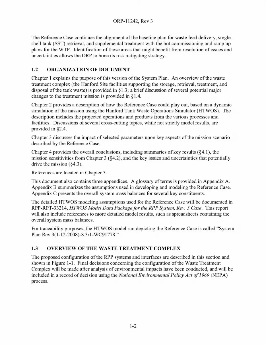
The Reference Case continues the alignment of the baseline plan for waste feed delivery, SST
retrieval, and supplemental treatment with the hot commissioning and ramp-up plans for the
WTP. Identification of those areas that might benefit from resolution of issues and uncertainties
allows the ORP to hone its risk mitigating strategy.
Results (Life-cycle Mission Scenario)
The Reference Case shows that the WTP, together with supplemental LAW and TRU treatment,
can treat the Hanford tank waste by 2049, with approximately 30 years ofWTP operations.
ES-3
ORP-11242, Rev 3
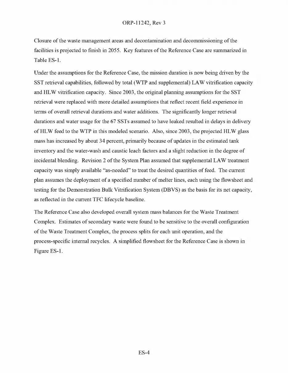
Closure of the waste management areas and decontamination and decommissioning of the
facilities is projected to finish in 2055. Key features of the Reference Case are summarized in
Table ES-l.
Under the assumptions for the Reference Case, the mission duration is now being driven by the
SST retrieval capabilities, followed by total (WTP and supplemental) LAW vitrification capacity
and HLW vitrification capacity. Since 2003, the original planning assumptions for the SST
retrieval were replaced with more detailed assumptions that reflect recent field experience in
terms of overall retrieval durations and water additions. The significantly longer retrieval
durations and water usage for the 67 SSTs assumed to have leaked resulted in delays in delivery
ofHLW feed to the WTP in this modeled scenario. Also, since 2003, the projected HLW glass
mass has increased by about 34 percent, primarily because of updates in the estimated tank
inventory and the water-wash and caustic leach factors and a slight reduction in the degree of
incidental blending. Revision 2 of the System Plan assumed that supplemental LAW treatment
capacity was simply available "as-needed" to treat the desired quantities of feed. The current
plan assumes the deployment of a specified number of melter lines, each using the flowsheet and
testing for the Demonstration Bulk Vitrification System (DBVS) as the basis for its net capacity,
as reflected in the current TFC lifecycle baseline.
The Reference Case also developed overall system mass balances for the Waste Treatment
Complex. Estimates of secondary waste were found to be sensitive to the overall configuration
of the Waste Treatment Complex, the process splits for each unit operation, and the
process-specific internal recycles. A simplified flowsheet for the Reference Case is shown in
Figure ES-l.
ES-4
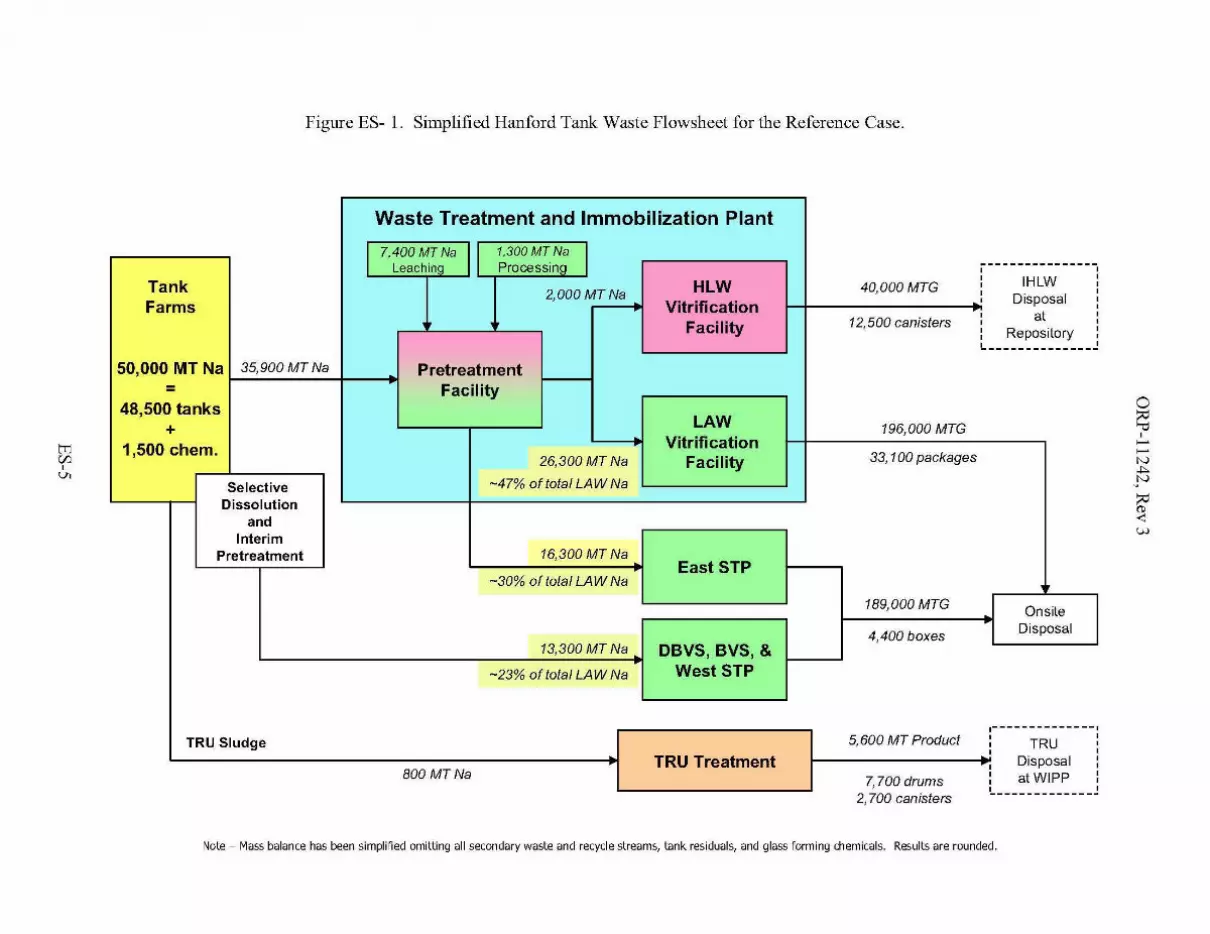
Figure ES- 1. Simplified Hanford Tank Waste Flowsheet for the Reference Case.
2,700 camsters
Waste Treatment and Immobilization Plant
I 7,400 MT Na I 1.300MT Na ILeaching Processing j--------------.,
IHLW,
Tank HLW 40,000MTG , ,2,000MTNa , ,
Farms Vitrification, Disposal ,,
at ,Facility 12,500 canisters ,
Repository,,,
---------------50,000 MT Na 35,900 MT Na Pretreatment
= Facility48,500 tanks
LAW+ 196,000 MTG
1,500 chern. Vitrification26,300MTNa Facility 33, 100 packages
Selective -47% oftotat LAW Na
Dissolutionand
InterimPretreatment 16,300 MT Na
East STP-30% oftotat LAW Na
189,000 MTG Onsite
4,400 boxes Disposal
13,300 MT Na DBVS,BVS,&-23% oftotat LAW Na WestSTP
.- -- - - - - - - - - - --I
TRU Sludge 5,600 MT Product , ,, TRU ,, ,TRU Treatment Disposal ,, ,
800 MTNa ,atWIPP
,7,700 drums , ,
!.._------------~
Note - Mass balance has been simplified omitting all secondary waste and recycle streams, tank residuals, and glass forming chemicals. Results are rounded.
ORP-11242, Rev 3
Opportunities
Under the assumptions for the Reference Case, the mission duration is being driven by the SST
retrieval capabilities, followed by total (WTP and supplemental) LAW vitrification capacity and
HLW vitrification capacity. Since 2003, the SST retrieval capabilities were updated to reflect
recent field experience in terms of overall retrieval durations and water additions. Key efforts
being pursued by ORP to address issues with the underlying assumptions and shorten the
treatment mission duration include:
• Continued testing and refinement of SST retrieval technologies, their interface with
the DST System, and balancing of logistical and resource constraints to reduce the
overall time needed to retrieve the SSTs.
• Continued glass formulation work to improve waste loading to decrease the proj ected
amount of LAW and HLW glass.
• Implementation of oxidative leaching in the WTP to reduce the impacts of chromium.
• Reduction of the total amount of HLW glass to be produced by treating the TRU
separately from the HLW and disposal at WIPP.
• Exploring the early startup of the WTP LAW Vitrification Facility in conjunction
with an Interim Pretreatment System (IPS) to begin treating tank waste before startup
of the rest of the WTP, freeing DST space for continued retrieval of the SSTs;
• Development of second generation LAW and HLW melters to increase net
production rates.
• Development of supplemental LAW treatment technologies.
• Exploring technologies to reduce the amount of sodium hydroxide that is expected to
be added during pretreatment of the HLW to reduce the needed LAW treatment
capacity. This may include process changes or new unit operations to recycle sodium
hydroxide.
• Implementing flowsheet, equipment, and operating mode improvements at the WTP
Pretreatment (PT) facility to increase pretreatment capacity.
ES-6
ORP-11242, Rev 3
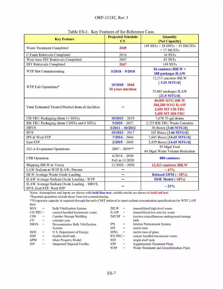
Table ES-l Key Features of the Reference Case
Key FeatureProjected Schedule Quautity
CY [Net Capacity]
Waste Treatment Completed 2049149 SSTs + 28 DSTs + 43 !MUSTs
+ 17 MUSTsC-Farm Retrievals Completed 2016 16 SSTsWest Area SST Retrievals Completed 2047 83 SSTsSST Retrievals Completed 2047 149 SSTs
WTP Hot Commissioning 5/2018 - 9/201856 canisters IHLW +188 packaees ILAW
12,513 canisters lHLW
10/2018 - 2048[ 5.25 MTG/d]
WTP Full Operations*30 years duration
33,065 packages lLAW[21.0 MTG/d]
40,000 MTG IHLW
Total Estimated Treated Product from all facilities - 384,200 MTG ILAW2,200 MT CH-TRU3,400 MT RH-TRU
CH-TRUPackaging(from 11 SSTs) 10/2013 - 2019 7,678 55-gal drumsRH-TRU Packaging (from 3 DSTs and 6 SSTs) 5/2025 - 2037 2,723 RH-TRU Waste CanistersDBVS 3/2011 - 1012012 36 Boxes [3.66 MTG/d]BVS 10/2013 - 2017 103 Boxes [3.66 MTG/d]IPS & West STP 7/2014 - 2046 1,845 Boxes [14.65 MTG/d]East STP 2/2019 - 2049 2,439 Boxes [14.65 MTG/d]
242-A Evaporator Operations 2007 - 2039**93 Mgal Feed
64 Mgal Waste Volume Reduction
CSB Operation612018 - 2050
880 canistersFull in 1112020
Shipping lHLW to Yucca 1112020 - 2050 12,513 canisters IHLWLAW Sodium to WTP lLAW, Percent - -47%HLW Average Waste Oxide Loading - Relaxed GPM (- 28%)lLAW Average Sodium Oxide Loading - WTP - DOE Model (-18%)lLAW Average Sodium Oxide Loading - DBVS, - -21%BVS, East STP, West STP
immobilized high-level waste.immobilized low-activity waste.inactive miscellaneous underground storagetank.Interim Pretreatment Systemmetric tonsmetric tons of glass.remote handled transuranic waste.single-shell tank.Supplemental Treatment Plant.Waste Treatment and Immobilization Plant.
IPSMTMTGRH-TRU~
SSTSTPWTP
IHLW!LAW!MUST
Bulk Vitrification System.contact handled transuranic waste.Canister Storage Building.calendar year.Demonstration Bulk VitrificationSystem.U. S. Department ofEnergy.double-shell tank.Glass Property Model.Integrated Disposal Facility.
DOEDSTGPMIDF
Notes: AssmnptIons and mputs are Shm.Vll wIth bold blue text; notable results are Shm.Vll III bold red text.*Reported quantities include those from hot commissioning.**Evaporator capacity is required through the end of SST retrieval to meet sodium concentration specifications for WTP LAWfeed.BVSCH-TRU~
CSBCYDBVS
ES-7

ORP-1l242, Rev 3A
Key Issues and Uncertainties
The Reference Case projects single value estimates for key mission metrics such as the treatment
end date and the quantity of glass produced. A number of sensitivity studies were performed to
evaluate how these projected results might be impacted by differing assumptions. These
estimates are shown in Table 4-1, Ranges on Key Mission Parameters. An abridged version of
those results is presented in Table ES-2, Ranges on Key Mission Parameters, Abridged. Note
that these ranges are not necessarily bounding and do not address the likelihood of any particular
result. The three variables with the greatest overall impact on the treatment mission are the need
to add additional sodium hydroxide during pretreatment, the need for supplemental LAW
treatment capacity beyond that which is provided by a single WTP LAW Vitrification Facility,
and the ability to retrieve the SSTs quickly while minimizing the amounts of water needed.
Some of the assumptions used for the Reference Case present issues and uncertainties that need
to be successfully addressed to further reduce ORP's risk of achieving the desired performance
for the mission. These challenges are discussed in more detail together with potential mitigating
actions in Table 4-2, Key Issues and Uncertainties for the Reference Case, located in §4.3. The
issues and uncertainties identified for the Reference Case will assist ORP in the management of
the programmatic and technical risks associated with the waste treatment mission.
ES-8
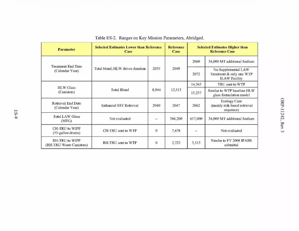
Table ES-2. Ranges on Key Mission Parameters, Abridged.
ParameterSelected Estimates Lower than Reference Reference Selected Estimates Hi~her than
Case Case Reference Case
2060 34,000 MT additional SodiumTreatment End Date f----- ------
(Calendar Year)Total blend; HLW drives duration 2035 2049 No Supplemental LAW
2072 Treatment & only one WTPILAW Facility
14,363 TRU sent to WTPHLWGlass ----- ------------(Canisters)
Total Blend 8,944 12,513 Similar to WTP baseline HLW15,237
glass formulation model
Retrieval End DateEcology Case
(Calendar Year)Enlianced SST Retrieval 2040 2047 2062 (mainly risk-based retrieval
sequence)
Total LAW GlassNot evaluated 384,200 617,000 34,000 MT additional Sodium
(MTG)--
CH-TRUtoWIPPCH-TRU sent to WTP 0 7,678 Not evaluated
(55-gallon drums)--
RH-TRUtoWIPPRH-TRU sent to WTP 0 2,723 3,513
Similar to FY 2008 IPABS(RH-TRU Waste Canisters) submittal

ORP-1l242, Rev 3
This page intentionally left blank.
E8-10
ORP-11242, Rev 3
CONTENTS
1.0 INTRODUCTION 1-1
1.1 PURPOSE 1-1
1.2 ORGANIZATION OF DOCUMENT 1-2
1.3 OVERVIEW OF THE WASTE TREATMENT COMPLEX 1-21.3.1 Tank Farms 1-5
1.3.1.1 Single-Shell Tanks 1-51.3.1.2 Double-Shell Tanks 1-61.3.1.3 Miscellaneous Underground Storage Tanks 1-111.3.104 Waste Retrieval from Single-Shell Tanks 1-121.3.1.5 Waste Retrieval from Double-Shell Tanks 1-161.3.1.6 Waste Transfer Lines 1-171.3.1.7 Tank Farm Waste Evaporator (242-A) 1-17
1.3.2 Waste Treatment and Immobilization Plan!... 1-181.3.2.1 Pretreatment 1-181.3.2.2 High-Level Waste Vitrification 1-191.3.2.3 Low-Level Waste Vitrification 1-201.3.204 Waste Treatment and Immobilization Plant Analytical Laboratory 1-211.3.2.5 Balance of Facilities 1-21
1.3.3 Supplemental Treatment 1-211.3.3.1 Demonstration Bulk Vitrification System 1-221.3.3.2 Bulk Vitrification System 1-241.3.3.3 East Supplemental LAW Treatment Plant 1-241.3.3 A Interim Pretreatment System 1-241.3.3.5 West Supplemental Treatment Facility 1-251.3.3.6 Supplemental Transuranic Waste Treatment System 1-25
1.304 Interfacing Facilities 1-261.304.1 Liquid Effluent Retention Facility and Effluent Treatment Facility 1-261.304.2 Central Waste Complex 1-271.304.3 Canister Storage Building I Hanford Shipping Facility 1-281.3 0404 Integrated Disposal Facility 1-281.304.5 222-S Laboratory 1-281.304.6 Other Hanford Site Facilities 1-291.304.7 Waste Encapsulation and Storage Facility 1-291.304.8 State Approved Land Disposal Site 1-301.304.9 200 Area Treated Effluent Disposal Facility 1-301.304.10 Offsite Geologic Repository 1-301.304.11 Waste Isolation Pilot Plan!... 1-31
1.4 OPTIONS UNDER CONSIDERATION 1-31104.1 Start Low-Activity Waste Treatment Firs!... 1-31104.2 Caustic Recycle 1-32104.3 Single-Shell Tank Retrieval Sequence 1-331.404 Supplemental Treatment vs. Second Waste Treatment and Immobilization Plant
Immobilized Low-Activity Waste Facility 1-33104.5 Interim Pretreatment System 1-34
2.0 RESULTS AND DISCUSSION OF REFERENCE CASE 2-1
2.1 METHODOLOGY 2-1
2.2 KEY FEATURES AND RESULTS 2-2
ORP-11242, Rev 3
2.3 DISCUSSION 2-42.3.1 Tank Farms 2-4
2.3.1.1 Single-Shell Tanks 2-42.3.1.2 Double-Shell Tank Operation 2-52.3 .1.3 Inactive Miscellaneous Underground Storage Tanks 2-72.3 .1.4 Waste Retrieval from Single-Shell Tanks 2-72.3 .1.5 Waste Retrieval from Double-Shell Tanks 2-132.3.1.6 Waste Transfers 2-132.3.1.7 242-A Evaporator Operation 2-17
2.3.2 Waste Treatment and Immobilization Plan!... 2-192.3.2.1 Pretreatment 2-192.3.2.2 High-Level Waste Vitrification 2-242.3 .2.3 Low-Activity Waste Vitrification 2-252.3 .2.4 Waste Treatment and Immobilization Plant Analytical Laboratory 2-252.3.2.5 Balance of Facilities 2-25
2.3.3 Supplemental Treatment 2-262.3.3.1 Demonstration Bulk Vitrification System 2-262.3.3.2 Bulk Vitrification System 2-272.3.3.3 East Supplemental Treatment Plant 2-272.3.3.4 Interim Pretreatment System 2-282.3.3.5 West Supplemental Treatment Plant 2-282.3.3.6 Supplemental Transuranic Waste Treatment System 2-29
2.3.4 Interfacing Facilities 2-322.3.4.1 Liquid Effluent Retention Facility and Effluent Treatment Facility 2-322.3.4.2 Central Waste Complex 2-322.3.4.3 Canister Storage Building I Hanford Shipping Facility 2-332.3.4.4 Integrated Disposal Facility 2-342.3.4.5 222-S Laboratory 2-352.3.4.6 Other Hanford Site Facilities 2-352.3.4.7 Waste Encapsulation and Storage Facility 2-352.3.4.8 State Approved Land Disposal Site 2-352.3.4.9 200 Area Treated Effluent Disposal Facility 2-352.3.4.10 Offsite Geologic Repository 2-352.3.4.11 Waste Isolation Pilot Plan!... 2-35
2.4 CROSS-CUTTING DISCUSSIONS 2-362.4.1 High-Level Waste Glass Volume 2-36
2.4.1.1 Waste Composition and Quantity 2-362.4.1.2 Solubility During Retrieval and Staging 2-372.4.1.3 Degree of Blending 2-382.4.1.4 Partitioning During Pretreatment 2-382.4.1.5 Glass Formulation Model 2-39
2.4.2 Low-Activity Waste Glass Volume 2-422.4.3 Secondary Waste 2-42
2.5 SCHEDULE 2-43
3.0 SENSITIVITY STUDIES 3-1
3.1 BLENDING - GENERAL 3-1
3.2 BLENDING - RETRIEVAL CONSTRAINTS 3-3
3.3 TRANSURANIC WASTE DISPOSITION 3-4
3.4 DEGREE OF PRETREATMENT 3-5
3.5 LEACH CAUSTIC 3-6
11

ORP-11242, Rev 3
3.6 HIGH-LEVEL WASTE GLASS MODELS 3-7
3.7 SUPPLEMENTAL LOW-ACTIVITY WASTE TREATMENT 3-8
3.8 ENHANCED SINGLE-SHELL TANK RETRIEVAL 3-10
3.9 RISK-BASED RETRIEVAL SEqUENCE 3-12
4.0 CONCLUSIONS 4-1
4.1 SUMMARY RESULTS 4-1
4.2 MISSION SENSITIVITIES 4-2
4.3 KEY ISSUES AND UNCERTAINTIES 4-4
4.4 FUTURE WORK 4-14
5.0 REFERENCES 5-1
APPENDICES
A GLOSSARy A-l
B KEY ENABLING ASSUMPTIONS B-l
C OVERALL SYSTEM MASS BALANCE C-l
FIGURES
Figure 1-1. River Protection Project Simplified Process Flow Diagram 1-3
Figure 1-2. Waste Transfer System Overview 1-7
Figure 1-3. Waste Type by Tank. 1-9
Figure 2-1. Projected Single-Shell Tank Retrieval Progress 2-4
Figure 2-2. Cumulative Volume Transferred to the Double-Shell Tanks from the Single-ShellTanks 2-5
Figure 2-3. Total Double-Shell Tank Space Utilization 2-7
Figure 2-4. Projected Single-Shell Tank Retrieval Sequence and Schedule 2-9
Figure 2-5. Approach Used to Sequence Single-Shell Tank Retrievals 2-11
Figure 2-6. Double-Shell Tank Transfers 2-14
Figure 2-7. 242-A Evaporator Operation 2-17
111

ORP-11242, Rev 3
Figure 2-8. Sodium Concentration in Delivered Waste Treatment and Immobilization PlantFeed 2-18
Figure 2-9. Cumulative Volume of the Feed Delivered to the Waste Treatment andImmobilization Plant 2-19
Figure 2-10. Cumulative Sodium in the Feed Delivered to the Waste Treatment andImmobilization Plant 2-20
Figure 2-11. Solids Concentration Distribution in Feed Delivered to theWaste Treatment and Immobilization Plant 2-21
Figure 2-12. Waste Treatment and Immobilization Plant High-Level Waste GlassProduction 2-24
Figure 2-13. Waste Treatment Plant Low-Activity Waste Glass Production 2-25
Figure 2-14. Demonstration Bulk Vitrification System and Bulk Vitrification System Low-Activity Waste Glass Production 2-26
Figure 2-15. East Supplemental Treatment Plant Low-Activity Waste Glass Production 2-27
Figure 2-16. West Supplemental Treatment Plant Low-Activity Waste Glass Production 2-28
Figure 2-17. Contact-Handled Transuranic Packaged Waste Production 2-29
Figure 2-18. Remote-Handled Transuranic Packaged Waste Production 2-30
Figure 2-19. Projected Demand on the Liquid Effluent Retention Facility and EffluentTreatment Facility 2-32
Figure 2-20. High-Level Waste Glass Interim Storage and Shipping 2-33
Figure 2-21. Conceptual Model for Estimating High-Level Waste Glass Mass 2-36
Figure 2-22. RPP Operating Schedule for the Reference Case 2-44
Figure 3-1. Comparison of High-Level Waste Glass Mass Ranges for Selected Cases 3-2
Figure 3-2. High-Level Waste Glass Production for the Enhanced Single-Shell Tank RetrievalSensitivity Case 3-11
TABLES
Table 2-1. Key Features of the Reference Case 2-3
Table 2-2. Feed Controls Assumed for the Reference Case 2-16
Table 2-3. Supplemental Transuranic Waste Product Inventory for Selected Constituents 2-31
Table 2-4. Integrated Disposal Facility Inventory for Selected Constituents 2-34
Table 2-5. Summary of Reference Case High-Level Waste Glass Drivers 2-41
Table 3-1. Effects of Constraining Blend Pairs 3-3
IV

ORP-11242, Rev 3
Table 3-2. Sensitivity of Mission to Transuranic Waste Disposition 3-5
Table 3-3. Sensitivity of Mission to Degree-of-Pretreatrnent.. 3-6
Table 3-4. High-Level Waste Glass Formulation Constraints and Limits 3-9
Table 4-1. Ranges on Key Mission Parameters 4-3
Table 4-2. Key Issues and Uncertainties for the Reference Case 4-5
v
ORP-11242, Rev 3
This page intentionally left blank.
VI
200 E200WBBIBDGREBNIBOFBVSCCCHCH-TRU
CH2MHILLCIDCSSCSBCWCDBVSDCRTDOEDSSDSSFDSTEast STPEFRTEISEMERPETFFYGFMGPMHDWHEPAHGRHLWHSFHTWOSICV™IDFIHLWILAWIMUSTIPABSIPS
ORP-11242, Rev 3
TERMS
200 East Area200 West AreaBest-Basis InventoryBuoyant-Displacement Gas Release EventBechtel National, Inc.balance offacilitiesBulk Vitrification Systemconcentrated-complexed (waste)contact handledcontact-handled transuranic mixed waste (sometimes calledCH-TRUM)CH2M HILL Hanford Group, Inc.Central Internet Databasecentral storage and shippingCanister Storage BuildingCentral Waste ComplexDemonstration Bulk Vitrification Systemdouble-contained receiver tankU.S. Department of Energydouble-shell slurrydouble-shell slurry feeddouble-shell tankEast Supplemental Treatment PlantExternal Flowsheet Review TeamEnvironmental Impact StatementU.S. Department of Energy, Office of Environmental ManagementExpert Review PanelEffluent Treatment Facilityfiscal yearglass-forming mineralGlass Property ModelHanford Defined Waste (Model)high-efficiency particulate airhydrogen generation ratehigh-level wasteHanford Shipping FacilityHanford Tank Waste Operations SimulatorIn-Container VitrificationTM
Integrated Disposal Facilityimmobilized high-level wasteimmobilized low-activity wasteinactive miscellaneous underground storage tankIntegrated Planning, Accountability and Budgeting SystemInterim Pretreatment System
Vll
ISlTVLAWLERFLLWMMRSMSMTGMUSTNEPANRCNWPAORPPNNLPTPUREXREDOXRCRARHRH-TRU
RLRODRPPSALDSSNFSSTSWPTC&WMTEDFTFCTFCOUPTPA
TRUTRUPACT-IITWINSUFPVRSWACWESFWest STPWIPPWIPP-WACWRFWTP
ORP-11242, Rev 3
Interim Storage (Facility)in-tank vehiclelow-activity wasteLiquid Effluent Retention Facilitylow-level wastemolarity (moles per liter)Mobile Retrieval Systemmodified sluicingmetric tons of glassmiscellaneous underground storage tankNational Environmental Policy Act of1969U. S. Nuclear Regulatory CommissionNuclear Waste Policy Amendments Act of1987U.S. Department of Energy, Office of River ProtectionPacific Northwest National LaboratoryPretreatment (Facility)Plutonium-Uranium Extraction (Plant)Reduction and Oxidation Facility (S-Plant)Resource Conservation and Recovery Actremote handledremote-handled transuranic mixed waste (sometimes calledRH-TRUM)U.S. Department of Energy, Richland Operations OfficeRecord of DecisionRiver Protection Proj ectState Approved Land Disposal SiteSpent Nuclear Fuelsingle-shell tankspecial work permit (protective clothing)Tank Closure and Waste ManagementTreated Effluent Disposal FacilityTank Farm Contractor (also Tank Farm Contract)Tank Farm Contractor Operation and Utilization PlanTri-Party Agreement (Hanford Federal Facility Agreement andConsent Order)transuranicTransuranic Package Transporter-IITank Waste Information Network Systemultrafiltration processVacuum Retrieval SystemWaste Acceptance CriteriaWaste Encapsulation and Storage FacilityWest Supplemental Treatment PlantWaste Isolation Pilot PlantWaste Isolation Pilot Plant - Waste Acceptance CriteriaWaste Retrieval FacilityWaste Treatment and Immobilization Plant
V111

ORP-11242, Rev 3
This page intentionally left blank.
IX

ORP-11242, Rev 3
1.0 INTRODUCTION
1.1 PURPOSE
The U.S. Department of Energy, Office of River Protection (ORP) manages the River ProtectionProject (RPP). The RPP mission is to retrieve and treat the Hanford Site's tank waste and closethe tank farms to protect the Columbia River. As a result, the ORP is responsible for theretrieval, treatment, and disposal of approximately 576 million gallons (Mgal) of highlyradioactive and hazardous waste contained in 177 Hanford Site waste tanks and closure of all thetanks and associated facilities. The tanks contain materials from years of World-War-II andpost-war weapons material production, accounting for 60% by volume of the nation's storedradioactive tank waste. These tanks contain both high-level and transuranic (TRU) wastes andare approximately 10 miles from the Columbia River and within a 50-mile radius of more than200,000 people.
There have been a number of changes to the tank waste treatment plans since the last revision ofthis document. Since 2003, the ORP has conducted over 30 design oversight assessments7 of theWaste Treatment and Immobilization Plant (WTP). The estimated cost at completion hasincreased and the schedule for construction and commissioning of the WTP has been extended.The U.S. Department of Energy, Office of Environmental Management (EM), directed acomprehensive review8 of the WTP fIowsheet, focusing on throughput.
In addition to the WTP-specific changes, there have been compensatory changes in the tankfarms' strategy and plans, affecting both near-term retrieval plans and the assumedimplementation of Supplemental Low-Activity Waste (LAW) Treatment and Supplemental TRUwaste Treatment.
This version of the System Plan establishes a Reference Case that will be used to provide adescription of how the mission could play out, and communicate the potential mission impacts ofkey issues and uncertainties on the mission. The Reference Case demonstrates how ORP coulduse the WTP with supplemental LAW and supplemental TRU treatment to complete thetreatment and disposal of Hanford tank waste in a reasonable time frame. This case assumes thatthe WTP being constructed by Bechtel National, Inc. (BNI) will perform better than theminimum contractual performance requirements. Key assumptions have been adjusted to resultin a more realistic scenario for this System Plan revision, without undue optimism or pessimism.
The Reference Case approximates the key features of the current baseline and underlyingtechnical basis; it not an exact depiction of the current baseline, a budget request, nor contractualor regulatory commitment on behalf of any party.
6 This is the total volume of waste in the tanks as January 2007. The volume varies depending on how much wateris added during waste retrieval and how much of that water has been removed by the waste evaporator.
7 One of the key assessments deals with the HLW pretreatment capacity of the WTP Pretreatment Facility. SeeD-03-DESIGN-005, 2004, HLW Feed Preparation System: Ultra-Filtration Process System, ORP WTPEngineering Division, for more details. Nota bene - this document number was also used for a different reportissued in 2003.
8 "Comprehensive Review of the Hanford Waste Treatment Plant Flowsheet and Throughput, AssessmentConducted by an Independent Team of Extemal Experts," March 2006, transmitted under cover ofletterCCN: 132846.
1-1
ORP-11242, Rev 3
The Reference Case continues the alignment of the baseline plan for waste feed delivery, singleshell tank (SST) retrieval, and supplemental treatment with the hot commissioning and ramp upplans for the WTP. Identification of those areas that might benefit from resolution of issues anduncertainties allows the ORP to hone its risk mitigating strategy.
1.2 ORGANIZATION OF DOCUMENT
Chapter 1 explains the purpose of this version of the System Plan. An overview of the wastetreatment complex (the Hanford Site facilities supporting the storage, retrieval, treatment, anddisposal of the tank waste) is provided in §1.3; a brief discussion of several potential majorchanges to the treatment mission is provided in §lA.
Chapter 2 provides a description of how the Reference Case could play out, based on a dynamicsimulation of the mission using the Hanford Tank Waste Operations Simulator (HTWOS). Thedescription includes the projected operations and products from the various processes andfacilities. Discussions of several cross-cutting topics, while not strictly model results, areprovided in §2A.
Chapter 3 discusses the impact of selected parameters upon key aspects of the mission scenariodescribed by the Reference Case.
Chapter 4 provides the overall conclusions, including summaries of key results (§4.1), themission sensitivities from Chapter 3 (§4.2), and the key issues and uncertainties that potentiallydrive the mission (§4.3).
References are located in Chapter 5.
This document also contains three appendices. A glossary of terms is provided in Appendix A.Appendix B summarizes the assumptions used in developing and modeling the Reference Case.Appendix C presents the overall system mass balances for several key constituents.
The detailed HTWOS modeling assumptions used for the Reference Case will be documented inRPP-RPT-332 14, HTWOS Model Data Package for the RPP System, Rev. 3 Case. This reportwill also include references to more detailed model results, such as spreadsheets containing theoverall system mass balances.
For traceability purposes, the HTWOS model run depicting the Reference Case is called "SystemPlan Rev 3(1-12-2008)-8.3rl-WC91778."
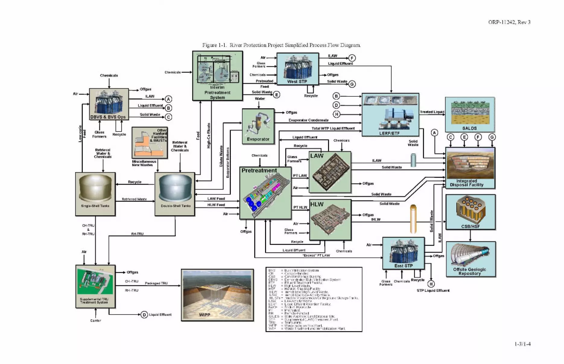
1.3 OVERVIEW OF THE WASTE TREATMENT COMPLEX
The proposed configuration of the RPP systems and interfaces are described in this section andshown in Figure 1-1. Final decisions concerning the configuration of the Waste TreatmentComplex will be made after analysis of environmental impacts have been conducted, and will beincluded in a record of decision using the National Environmental Policy Act of1969 (NEPA)process.
1-2
ORP-11242, Rev 3
Figure 1-1. River Protection Project Simplified Process Flow Diagram.
SALOS
Offslte GeologicRepository
A
ITreated Liquid
SolidWaste
East STP
, ..f~;~~~;'~~I .
~
STP liqUid Effluent
Glass Chemicals RecycleFormers H
Solid Waste
Solid Waste
Solid Waste
ILAW
Air
Offgas
••-+OffgasIHLW
Hl---1
II uid Emuent
1-_"iL",A",W,-....,oI F
Recycle
Air
PTHLW
Recycle
LERF/ETFII uid Effluent
Total WTP II uld Effluent
Evaporator Condensate
Offgas
GlassFonners
Bulk Vitrification SystemContact-HandledCanister Storage BuildingDemonstration Bulk Vltn,fication SystemEffluent Treatment FaalltyHigh-level WasteHanford, Shipping FacilityImmobilized High-Level WasteImmobilized Low-ActlvltyWasteInactive ,Miscellaneous Underground Storage TanksLow~Actlvlty WasteLiquid Effluent Retention FacilitySodium HydroxidePretreatedRemote-HandledState-A.pproved Land Disposal SiteSupplemental (LAW) Treatment PlantTransuranicWaste Isolation Pilot PlantWaste Treatment and Immobilization Plant
;~~~~;~ .., ':.
Recycle
Liquid Effluent Chemicals"Excess" PT LAW
BVSCHCSBDBVSETFHLWHSFIHLWILAWIMUSTsLAWLERFNaOHPTRHSALDSeTPTRUWIPPWTP
Air
GlassFonners
Chemicals
Chemicals
Evaporator
Offgas
Air
HLW Feed
LAW Feed
.Im",
:E:.Offgas
"~-"""C"IIit~I;;:;' t-_-,P~re~F~t:~:~:~el!d-ol,_"':W~e~s~t~S~T~P~.".J._":S~O~i!!id~W!!!!.st~e<G
Pretreatment 1-_,::S:::O::lId::,::W:,:'::st~ E1","'J!""_~s~s~t:e~m':" 1 Water
Packaged TRU
Offgas
1-__-'i=LA.;;Wc........,~I®
liquid Emuent B
Double-Shell Tanks
RH-TRU
CH ·TRU
Offgas
RH ·TRU
Retrieved Waste
Carrier
L .....@ Liquid ElI'luent
ChemicalsChemicals
CH·TRU&
RH-TRU
Air
Slngle·Shell Tanks
Supplemental TRUTreatment System
OBVS & BVS 0Solid Waste @S
• ~.~,~
,9 g: Glass
Recycle~ W
h. Fonners t •0 ... y~ Retrieval ~..,
Water & :I: •Retrieval
~ •Chemicals • EWater & •;: 0
Chemicals ~
• 0
Miscellaneous ~m"
New Wastes0
Q l'0~•>w
Rec ie
Air
1-311-4
ORP-11242, Rev 3
1.3.1 Tank Farms
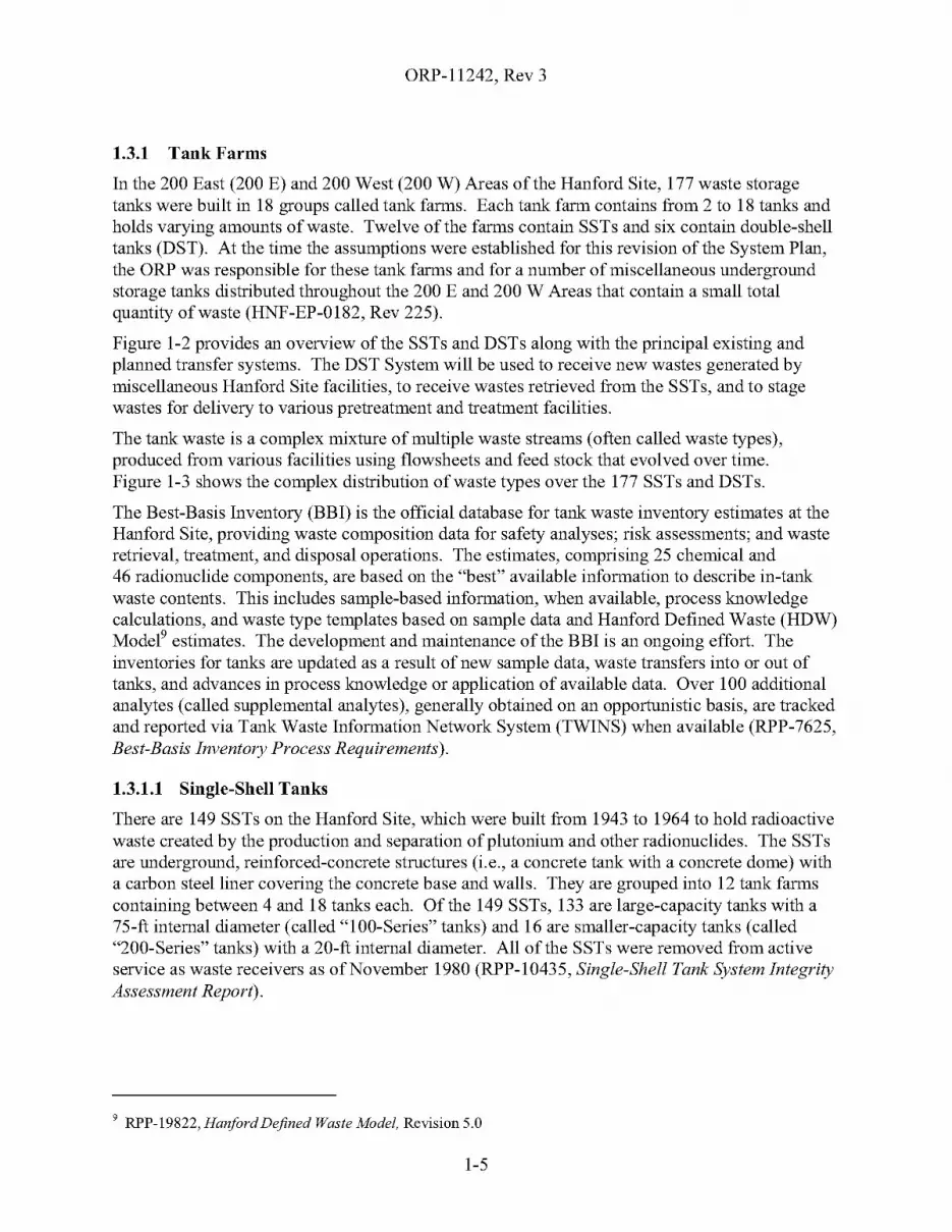
In the 200 East (200 E) and 200 West (200 W) Areas of the Hanford Site, 177 waste storagetanks were built in 18 groups called tank farms. Each tank farm contains from 2 to 18 tanks andholds varying amounts of waste. Twelve of the farms contain SSTs and six contain double-shelltanks (DST). At the time the assumptions were established for this revision of the System Plan,the ORP was responsible for these tank farms and for a number of miscellaneous undergroundstorage tanks distributed throughout the 200 E and 200 W Areas that contain a small totalquantity of waste (HNF-EP-0182, Rev 225).
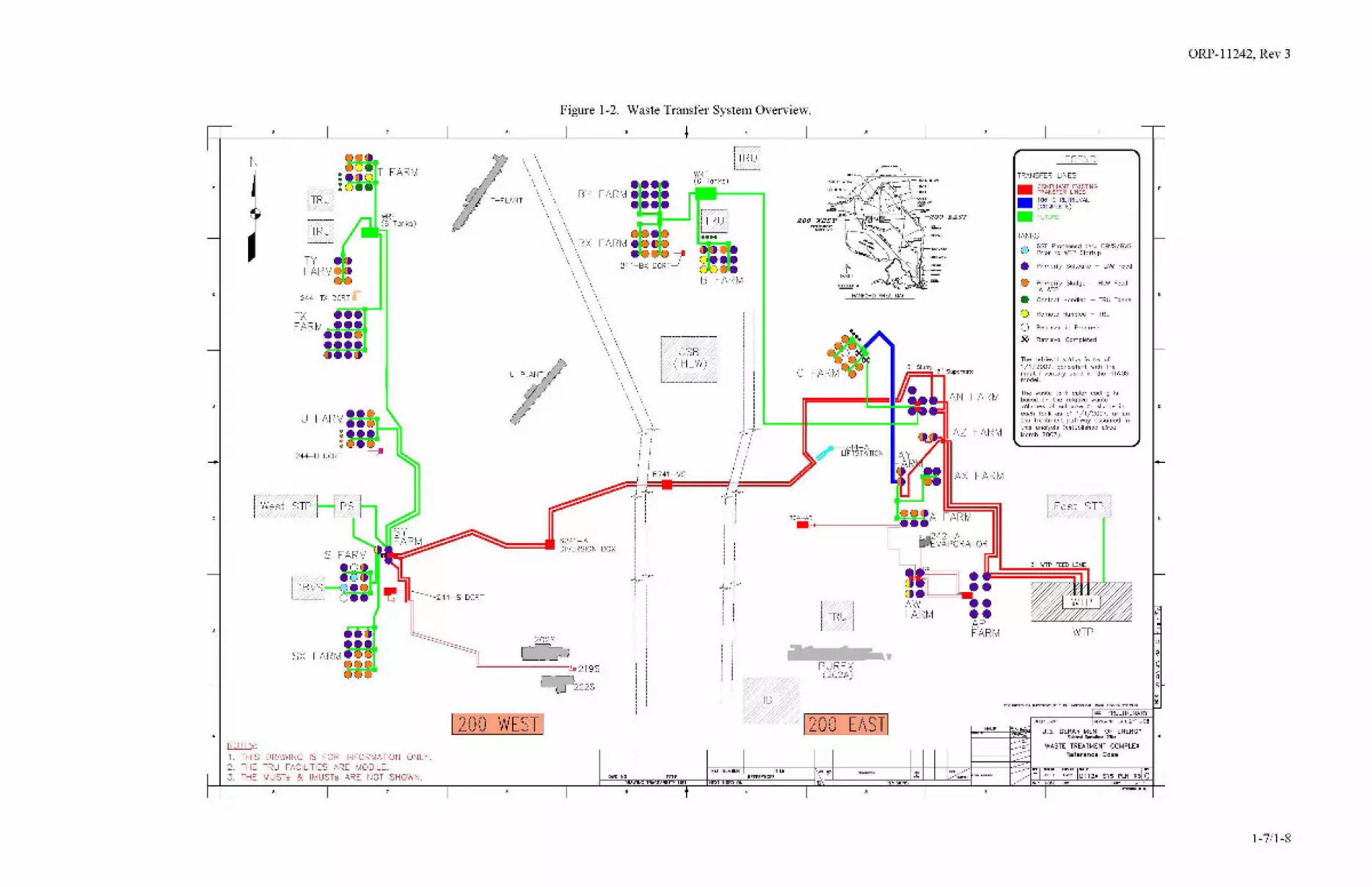
Figure 1-2 provides an overview of the SSTs and DSTs along with the principal existing andplanned transfer systems. The DST System will be used to receive new wastes generated bymiscellaneous Hanford Site facilities, to receive wastes retrieved from the SSTs, and to stagewastes for delivery to various pretreatment and treatment facilities.
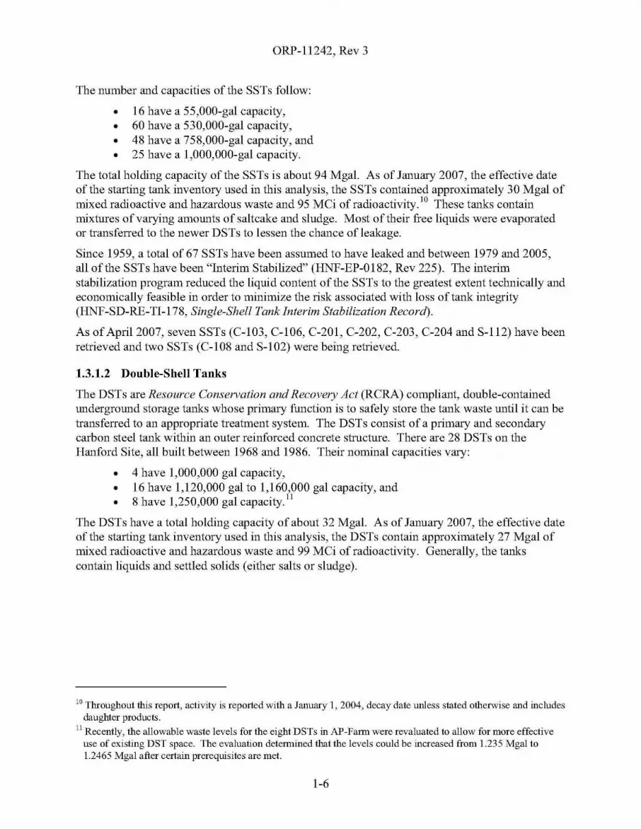
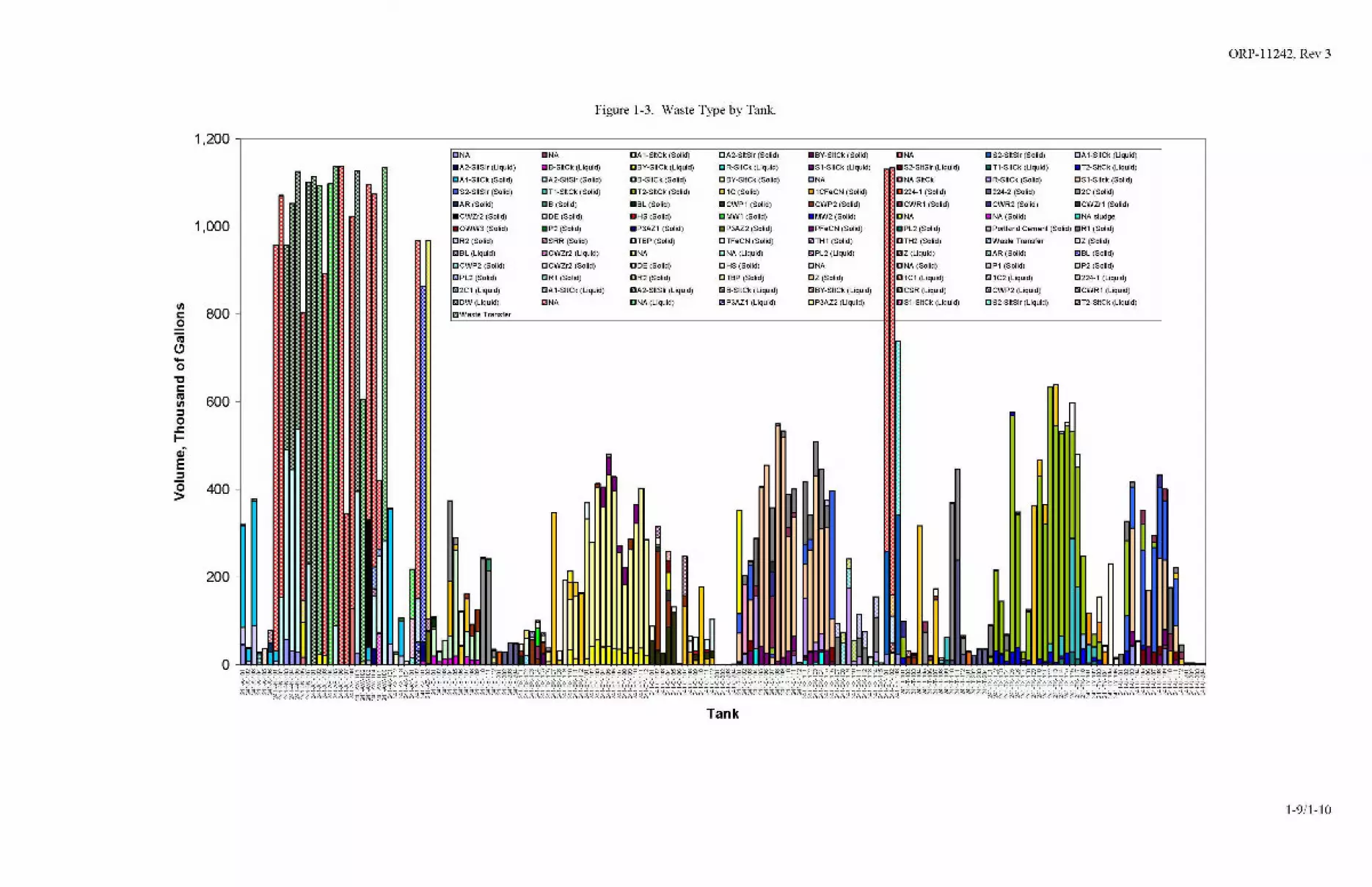
The tank waste is a complex mixture of multiple waste streams (often called waste types),produced from various facilities using flowsheets and feed stock that evolved over time.Figure 1-3 shows the complex distribution of waste types over the 177 SSTs and DSTs.
The Best-Basis Inventory (BBI) is the official database for tank waste inventory estimates at theHanford Site, providing waste composition data for safety analyses; risk assessments; and wasteretrieval, treatment, and disposal operations. The estimates, comprising 25 chemical and46 radionuclide components, are based on the "best" available information to describe in-tankwaste contents. This includes sample-based information, when available, process knowledgecalculations, and waste type templates based on sample data and Hanford Defined Waste (HDW)Modee estimates. The development and maintenance of the BBI is an ongoing effort. Theinventories for tanks are updated as a result of new sample data, waste transfers into or out oftanks, and advances in process knowledge or application of available data. Over 100 additionalanalytes (called supplemental analytes), generally obtained on an opportunistic basis, are trackedand reported via Tank Waste Information Network System (TWINS) when available (RPP-7625,Best-Basis Inventory Process Requirements).
1.3.1.1 Single-Shell Tanks
There are 149 SSTs on the Hanford Site, which were built from 1943 to 1964 to hold radioactivewaste created by the production and separation of plutonium and other radionuclides. The SSTsare underground, reinforced-concrete structures (i.e., a concrete tank with a concrete dome) witha carbon steel liner covering the concrete base and walls. They are grouped into 12 tank farmscontaining between 4 and 18 tanks each. Of the 149 SSTs, 133 are large-capacity tanks with a75-ft internal diameter (called "IOO-Series" tanks) and 16 are smaller-capacity tanks (called"200-Series" tanks) with a 20-ft internal diameter. All of the SSTs were removed from activeservice as waste receivers as of November 1980 (RPP-I0435, Single-Shell Tank System IntegrityAssessment Report).
9 RPP-19822, Hanford Defined Waste Model. Revision 5.0
1-5
ORP-11242, Rev 3
The number and capacities of the SSTs follow:
• 16 have a 55,000-gal capacity,• 60 have a 530,000-gal capacity,• 48 have a 758,000-gal capacity, and• 25 have a 1,000,000-gal capacity.
The total holding capacity of the SSTs is about 94 Mgal. As of January 2007, the effective dateof the starting tank inventory used in this analysis, the SSTs contained approximately 30 Mga1 ofmixed radioactive and hazardous waste and 95 MCi of radioactivity. 10 These tanks containmixtures of varying amounts of saltcake and sludge. Most of their free liquids were evaporatedor transferred to the newer DSTs to lessen the chance ofleakage.
Since 1959, a total of 67 SSTs have been assumed to have leaked and between 1979 and 2005,all of the SSTs have been "Interim Stabilized" (HNF-EP-0182, Rev 225). The interimstabilization program reduced the liquid content of the SSTs to the greatest extent technically andeconomically feasible in order to minimize the risk associated with loss of tank integrity(HNF-SD-RE-TI-l78, Single-Shell Tank Interim Stabilization Record).
As of Apri12007, seven SSTs (C-103, C-106, C-201, C-202, C-203, C-204 and S-112) have beenretrieved and two SSTs (C-108 and S-102) were being retrieved.
1.3.1.2 Double-Shell Tanks
The DSTs are Resource Conservation and Recovery Act (RCRA) compliant, double-containedunderground storage tanks whose primary function is to safely store the tank waste until it can betransferred to an appropriate treatment system. The DSTs consist of a primary and secondarycarbon steel tank within an outer reinforced concrete structure. There are 28 DSTs on theHanford Site, all built between 1968 and 1986. Their nominal capacities vary:
• 4 have 1,000,000 gal capacity,• 16 have 1,120,000 gal to 1,160,000 gal capacity, and• 8 have 1,250,000 gal capacity.11
The DSTs have a total holding capacity of about 32 Mgal. As of January 2007, the effective dateof the starting tank inventory used in this analysis, the DSTs contain approximately 27 Mga1 ofmixed radioactive and hazardous waste and 99 MCi of radioactivity. Generally, the tankscontain liquids and settled solids (either salts or sludge).
10 Throughout this report, activity is reported with a January 1, 2004, decay date unless stated otherwise and includesdaughter products.
11 Recently, the allowable waste levels for the eight DSTs in AP-Farm were revaluated to allow for more effectiveuse of existing DST space. The evaluation determined that the levels could be increased from 1.235 Mgal to1.2465 Mgal after certain prerequisites are met.
1-6
ORP-11242, Rev 3
Figure 1-2. Waste Transfer System Overview.
•,
·•
Dl12A_SYS_PLN_R3 C_1 .. 1~-~.,
C~PU!'J'jT EXlSTlNGTRAASFER LINES106-C RETRIEVAL(COMPLETE)
F1JTlJf<E
The wasle lank color coding isbased on the relative wastevolumes of soltcoke Or ~Iudge ineach tank as of 1/1/2007, or Onthe treatment pathway assumed inthis analysis (established circa~arch 2007).
Reference Case
WTP
LEGEND
U.S. DEPARTMENT OF ENERGY"""""'Opccot_OI'f"",
"'" PRELI~INARY
REI'!'" flO ""TE 2111/DB
WASTE TREATMENT COMPLEX
0 SST Processed thru D8VS/8VSPrior to WTP Startup
• Primarily 30ltcake - LAW Feed
() Primarily Sludge - HLW Feedto WT1'
• Contact Handled - TRU Tanks
() Remote Handled - TRU
0 Rdrieval"
Progress
® Retrieval Completed
The rdrieval statu~ is a~ of1/1/2007, consistent wilh theinput inventory used in the HTWOSmodel.
TRANSFER LINES
TANKS
•••
FARM
FARM
EAST
1i=9t-"",' Supern~te
REYISIQHS
---------1
~~~J
-.•
~244-A4' L1FTSTATION
-~~~r200 WEST~
c
204-AR
~.PUREX(202A)
L:J1200 EASTI
R[~ NU~BER TITLE
REFEREi'lCESNEXT USED ON
~ .0.•••O:.J©".B FARM
OW~ NO TlTLEDRAWING TRACEAIiILJIT UST
,,
,..----~~~- !
\,: I:
\" C5B
\, (~:_~_~~__ i'ii,
\\",!). _-"". L..---ff--------;.---'
',f" 10, ,
~"':~-'f ~!=6=21.1'-I=V=S=====;&! j(='=====,
1," rr, ,
i, i ::, ,
-t,:'" : :) -'r~'-r"'- I
!, i i, ,
i, II, ,
!, i' i'
"'
i
6241-ADIVERSION BOX
2025
~
T-PLANT
~~~~~~~~~,""219S
Q222S
1200 WEST 1
T FARM
rTRU]
ITRUlL~_JJ
TYFARM
U
244- TX DCRT
244-U
5X
N
1. THIS DRAWING IS FOR INFORMATION ONLY.2. THE TRU FACILITIES ARE MOBILE.3. THE MUSTs & IMUSTs ARE NOT SHOWN.
1-7/1-8
ORP-11242, Rev 3
Figure 1-3. Waste Type by Tank.
1,200CNA .NA CA 1-SIICk (Solid) CA2-SIISlr (Solid) .BY-SIICk (Solid) CNA .S2-SIISlr (Solid) CA1-SIICk (liquid)
.A2-SIISlr (liquid) .S-SIICk (Liquid) CBY-SIICk (liquid) DR-SliCk (Liquid) .51-SIICk (liquid) .S2-SIISlr (Liquid) .T1-SIICk (liquid) .T2-SIICk (liquid)
CA 1-SIICk (Solid) DA2-SIISlr (Solid) DB-SliCk (Solid) DBY-SIICk (Solid) CNA DNA SliCk DR-SliCk (Solid) DS1-Sllck (Solid)
.S2-SIISlr (Solid) CT1-SIICk (Solid) DT2-SIICk (Solid) D1C (Solid) C1CFeCN (Solid) 0224-1 (Solid) .224-2 (Solid) C2C (Solid)
.AR (Solid) .8 (Solid) .SL (Solid) .CWP1 (Solid) .CWP2 (Solid) • CWR1 (Solid) • CWR2 (Solid) .CWZr1 (Solid)
• CWZr2 (Solid) DOE (Solid) .HS (Solid) DMW1 (Solid) .MW2 (Solid) CNA .NA (Solid) DNA sludge
1,000 .OWW3 (Solid) .P2 (Solid) .P3AZ1 (Solid) .P3AZ2 (Solid) .PFeCN (Solid) .PL2 (Solid) CPortland Cement (Solid) DR1 (Solid)
CR2 (Solid) EJSRR (Solid) CTBP (Solid) CTFeCN (Solid) ElJTH1 (Solid) DTH2 (Solid) DWaste Transfer CZ (Solid)
mBL (liquid) C CWZr2 (liquid) CNA DNA (liquid) a PL2 (liquid) mz (liquid) CAR (Solid) aBL (Solid)
C CWP2 (Solid) C CWZr2 (Solid) DDE (Solid) DHS (Solid) CNA DNA (Solid) CP1 (Solid) CP2 (Solid)
ElPL2 (Solid) CR1 (Solid) DR2 (Solid) DTBP (Solid) CZ (Solid) [] 1C1 (liquid) m 1C2 (liquid) C224-1 (liquid)
m2C1 (liquid) CA 1-SltCk (liquid) mA2-SltSlr (liquid) DB-SKCk (liquid) a BY-SliCk (liquid) D CSR (liquid) aCWP2 (liquid) aCWR1 (liquid)
mDW (liquid) "NA DNA (liquid) ElJP3AZ1 (liquid) CP3AZ2 (liquid) DS1-SltCk (liquid) CS2-SltSlr (Liquid) ElJT2-SltCk (liquid)
800 DWaste Transfer
200
a
VIs:::oCll~
'0"Cs::::Jl 600::::so
..s:::I-ai'E::::s
g 400
Tank
1-9/1-10

ORP-11242, Rev 3
One of the considerations in operating the DSTs is managing the solids and liquids in the DSTsto avoid buoyant-displacement gas release events (BDGRE) and to avoid tank bumps(RPP-RPT-24887, The Long-Term Management ofTank Waste at Hanford). A BDGRE is therapid release of gas12 that may be retained in a settled solids layer resulting in temporary creationof a flammable mixture in the headspace of the tank (RPP-7771 ,Flammable Gas Safety IssueResolution). A tank bump is the rapid release of gas, mostly water vapor, causing the tankheadspace to pressurize as a result oflocal superheated liquid vaporization (RPP-6213, HanfordWaste Tank Bump Accident and Consequence Analysis). The controls to prevent each of theseevents directly or indirectly limit the depth of the solids in the tank, the depth of the supernate,and/or the heat load from radioactive decay. This requires careful coordination with SSTretrieval plans to allow effective use of the DSTs before waste treatment processes are on-line.
Another consideration in operating the DSTs is managing waste containing high concentrationsof phosphates. Wastes containing phosphates pose a high risk of solids precipitation and/orgelling during transfer, after evaporation and cooling, or during mixing with the waste in thereceiver tank. This could (and has in the past) lead to formation of plugs in waste transfer linesor could cause significant difficulties during evaporator operations. It is asserted that a tankcontaining phosphate gel might retain flammable gases leading to a gas release event of adifferent mechanism than a BDGRE (RPP-23584). Because of these issues, controls for thetransfer of phosphate wastes are provided by HNF-SD-WM-OCD-015, Tank Farms WasteTransfer Compatibility Program. These phosphate waste transfer controls are not currentlyexplicitly modeled for life-cycle mission modeling purposes.
The current baseline assumes that all DSTs will remain in service without failure until thetreatment mission has been completed and that no new DSTs will be built. While none of theDSTs have leaked, many are approaching their design lifetimes. The continued integrity of theDSTs is maintained by an ongoing Double-Shell Tank Integrity Program, described inRPP-7574, Double-Shell Integrity Program Plan. This program consists of visual and ultrasonicinspections of the DSTs, corrosion monitoring probes installed in tanks of particular interest,well-defined waste chemistry limits, and structural analysis (RPP-RPT-24887).
1.3.1.3 Miscellaneous Underground Storage Tanks
The ORP is currently responsible for 70 miscellaneous underground storage tanks that comprise42 inactive miscellaneous underground storage tanks (IMUST) and 28 miscellaneousunderground storage tanks (MUST). The distinction between IMUSTs and MUSTs isregulatory: the IMUSTs were removed from service before RCRA permitting and therefore notincluded in the RCRA operating permit for the tank farm facilities, while the MUSTs arepermitted under either RCRA SST Part A or RCRA DST Part A. All will be closed underRCRA provisions per the Hanford Federal Facility Agreement and Consent Order (Tri-PartyAgreement or TPA) (Ecology et al. 1989).
The number of miscellaneous underground storage tanks under ORP management changes overtime as the status of waste sites and operable units is better understood and as memorandum ofagreements between ORP and RL are adjusted. The Reference Case assumed that ORP was
12 Tank waste generates flammable gases through the radiolysis afwater and organic compounds, thermolyticdecomposition of organic compounds, and corrosion of a tank's carbon steel walls.
1-11

ORP-11242, Rev 3
responsible for 60 miscellaneous underground storage tanks that comprise 43 IMUSTs and17 MUSTs. The list of these tanks, their waste volumes, and their status assumed by theReference Case is provided by HNF-EP-0182, Rev. 215 13 while the FY 2007 Tank FarmContract (TFC) Baseline14 identified 63 (45 IMUSTs and 18 MUSTs).
In any case, decisions regarding the retrieval of any remaining liquid or sludge from these tankshave not yet been made. Therefore, for the purposes of this System Plan, it was assumed that thewaste from the IMUSTs and MUSTs would be retrieved circa 2020 - 2030 into the DST Systemand treated with the rest of the waste. The combined inventory of the IMUSTs and MUSTs isnot well known and was estimated from an engineering study circa 1994 (WHC-SD-EN-ES-040,Engineering Study of50 Miscellaneous Inactive Underground Radioactive Waste Tanks Locatedat the Hanford Site, Washington). This should be acceptable for mission modeling purposesbecause the waste in the IMUSTs and MUSTs comprises only a small fraction of the total tankwaste.
1.3.1.4 Waste Retrieval from Single-Shell Tanks
Waste from the SSTs is retrieved to reduce the risk to the public and environment. Although thetank waste is currently managed as high-level waste, the disposition of the waste depends onwhether it satisfies criteria as LAW feed, low-curie LAW feed, contact-handled transuranic(CH-TRU) sludge, remote-handled transuranic (RH-TRU) sludge, or high-level waste (HLW).
• Most of the tank waste is candidate LAW feed and is comprised primarily of solublesalts. LAW feed15 is material that will require pretreatment to remove some of theisotopes (primarily 137Cs) and entrained solids so that it can be treated and disposed asimmobilized low-activity waste (ILAW) by either the WTP or by SupplementalTreatment. The type of pretreatment depends upon the specific waste - for example,the feed to the Demonstration Bulk Vitrification System (DBVS) and BulkVitrification System (BVS) may only require selective dissolution and solid/liquidseparation, while the bulk of the waste will require solid/liquid separation and cesiumremoval.
• Some of the sludge in the SSTs may meet the criteria for definition as CH-TRUwaste. The CH-TRU sludge is candidate material for drying, packaging, and disposalat the Waste Isolation Pilot Plant (WIPP). This waste can be retrieved directly to theSupplemental TRU Treatment System.
• Some sludge in SSTs and DSTs may meet the criteria for definition as RH-TRUwaste. The RH-TRU sludge is candidate material for drying, packaging, and disposalat WIPP after water-washing to remove soluble salts and to reduce the dose rate byremoval of soluble radionuclides. Even after water-washing, the dose rate of thismaterial is expected to exceed allowable limits for CH-TRU.
13 Tables 5.1, 5.2 and 5.3 ofHNF-EP-0182, Rev 215.14 Baseline Change Request, RPP-06-003, Rev 1, Appendix A, WBS 5.08.05.10, MUST/IMUST Retrieval and
Closure.15 The terms "LAW Feed" and "HLW Feed" refer to liquid feed (containuig mostly soluble salts and a small amount
of entrained solids) and slurry feed (containuig mostly uisoluble solids mixed with liquid feed), respectively. Inthis context, they are used without regulatory connotation.
1-12
ORP-11242, Rev 3
• Most of the sludge in the SSTs and DSTs is likely to be classified as HLW, whichwill be transferred to the WTP for pretreatment and immobilization as HLW glass.The resulting HLW glass is planned for disposal in the geologic repository at YuccaMountain.
Wastes are planned to be retrieved from the SSTs by using one of three primary retrievaltechnologies: modified sluicing (MS), a Mobile Retrieval System (MRS), or a Vacuum RetrievalSystem (VRS). The choice of retrieval system depends on the nature of the waste retrieved andthe condition of the SSTs (i.e., whether the SST is a sound tank or assumed to have leakedpreviously). The selected retrieval techniques for each SST, along with the associated minimumretrieval durations and as-retrieved volumes, are part of the key enabling assumptions (SeeAppendix B, §B2.2.3.3). Special retrieval systems may be developed to deal with specific wasteretrieval issues (e.g., the removal of hard heels).
Note that the minimum retrieval durations and as-retrieved volumes assumed for the ReferenceCase reflect our current understanding of retrieval system performance based on very limitedfield experience and do not take credit for possible improvements in how a given technology isactually applied, or other improvements resulting from the deployment of other newtechnologies. See §2.3.1.4, Waste Retrieval from Single-Shell Tanks, for a discussion on thesensitivity of the treatment end date to these assumptions.
Retrieval of each SST requires a pathway or route to a DST, a Waste Retrieval Facility (WRF),or a processing facility. The route is typically provided by a combination of underground andabove ground transfer lines (See §1.3.1.6). Because of the distance of tanks in the northwest(T-, TX-, and TY-Farms) and northeast (B-, BX-, and BY-Farms) quadrants from the DSTsystem, waste will be initially retrieved into WRFs. WRFs will provide the necessary tanks 16
and pumps to support retrieval and conditioning of the waste before transfer to the DST System.The B-Complex WRF is assumed to be available for use in June 2018; the T-Complex WRF oneyear later. The eleven B- and T-Farm SSTs containing CH-TRU waste are assumed to beretrieved directly to the Supplemental TRU Treatment System without requiring a WRF orimpacting the DST system.
A small amount of "residual" tank waste may remain in each SST after retrieval has beencompleted. TPA Milestone M-045-00 requires" ...retrieval of as much tank waste as technicallypossible, with tank waste residues not to exceed 360 cubic feet (cu. ft.) in each of the 100 seriestanks, 30 cu. ft. in each of the 200 series tanks, or the limit of waste retrieval technologycapability, whichever is less."
After retrieval of an SST is completed, the tank residuals are established and reported in the BBI.For the six17 of the seven SSTs that had been retrieved, the Reference Case used the BBIinventory for the amount and composition of the tank residuals. For the tanks that have not yetbeen retrieved, the Reference Case assumed that the residuals would be no better than themaximum allowable volume to attempt to provide a conservative estimate of the tank residualsfor potential use in risk assessments. The detailed residual assumptions are provided inAppendix B, §B2.2.3.9 .
16 Each WRF was assumed to contain 6 tanks, each with a working volume of 150 Kgal.
17 Only six of the seven SSTs were retrieved in time to have their residual inventory reported in the dmvnload of theBBI used as input to the Reference Case.
1-13

ORP-11242, Rev 3
1.3.1.4.1 Modified Sluicing
The MS technology uses a liquid spray to dissolve, dislodge, and mobilize SST wastes forretrieval. The sluicing system typically consists of two sluicers, a slurry pump, and one or morecameras installed in the tank, and a control trailer located near the tank. Water is added to a SSTto dissolve and mobilize the waste, or recycled supernate from a DST or a WRF may be used asthe motive fluid. The mobilized waste solutions and slurries will be pumped from the SST to aDST receiver, or to a WRF tank and then to a DST. The system is referred to as MS because ofdesign improvements that improve or maintain waste retrieval efficiencies (compared to pastretrieval efforts using sluicing) while reducing the amount of water or recycled liquid required toretrieve the waste (HNF-SD-WM-SP-012, Tank Farm Contractor Operation and UtilizationPlan).
1.3.1.4.2 Mobile Retrieval System
The MRS is a vacuum-based waste retrieval system that consists of an articulated mast installednear the center of a tank along with an in-tank vehicle (lTV) designed to move waste toward thecenter of the tank where it can be removed with the mast. The articulating arm on the mast has avacuum head that can be moved around the central region of the tank with an effective horizontalreach of approximately 16 ft. Air or water can be injected at the vacuum head to assist inmobilizing the waste. If needed, a series of five scarifying, high-pressure, low-volume water jetslocated around the outside of the vacuum head can be used to dislodge the waste. Both thecentral mast and the lTV have the ability to use low-pressure water (approximately 125 psi) andhigh-pressure water (approximately 1,500 psi) to mobilize waste. The waste is moved to a batchvessel located above grade in the vesseVpump skid where load cells and a level gauge indicatethe waste batch volume. The batch vessel has a working volume of about 400 gal(HNF-SD-WM-SP-012).
The lTV is an adaptation of a commercially available tracked vehicle. The lTV has the ability topush waste via a low-pressure water cannon to wash down tank walls and equipment and athree-nozzle scarifier system that can be used to dislodge and mobilize waste, if necessary. ThelTV may be deployed at any time during waste retrieval operations to push or jet waste to thecenter of the tank where it can be removed with the vacuum system. Water and hydraulic linesare routed to the lTV through an umbilical line (HNF-SD-WM-SP-012).
During retrieval operations, the batch vessel is placed under a vacuum (created by the vacuumskid), which draws waste from the SST into the batch vessel. The waste is separated from thegas stream, which continues to the vacuum skid. When the batch vessel is full (-400 gal), thevacuum is broken and the waste is combined with supernate before transfer to the pump skid.A booster pump located on the pump skid draws waste from the batch tank through an ultrasonicde-agglomeration unit to reduce the particle size before transfer to the DST(HNF-SD-WM-SP-012).
The MRS technology was developed to retrieve waste from those SSTs assumed to have leaked.As such, the volume of liquid added to the SST at any point in time is kept to a minimum.Additionally, water is used as a motive fluid rather than recycled supernate to avoid increasingthe source term that could leak from the tank during retrieval.
1-14

ORP-11242, Rev 3
1.3.1.4.3 Vacuum Retrieval System
The VRS uses the same articulated mast described in the MRS system above installed near thecenter of a 200-Series tank. The articulated mast has a vacuum head, which can be moved alongthe bottom of the tank with an effective horizontal reach of approximately 16 ft, which issufficient to retrieve waste from the 12 remaining small-volume 200-Series tanks, avoiding theneed to deploy an lTV. Air or water can be injected at the vacuum head to assist in mobilizingthe waste. If needed, a series of five scarifying, high-pressure, low-volume water jets locatedaround the outside of the vacuum head can be used to dislodge the waste. The central mast hasthe ability to use low-pressure water (approximately 125 psi) or high-pressure water(approximately 1,500 psi) to mobilize waste. The waste is moved to a batch vessel located abovegrade in the vessel/pump skid where load cells and a level gauge indicate the waste batchvolume. The batch vessel has a working volume of about 400 gal.
During retrieval operations, the batch vessel is placed under a vacuum (created by the vacuumskid), which draws waste from the SST into the batch vessel. The waste is separated from thegas stream, which continues to the vacuum skid. When the batch vessel is full (-400 gal), thevacuum is broken, and the waste is combined with supernatant before transfer to the pump skid.A booster pump located on the pump skid draws waste from the batch tank through an ultrasonicde-agglomeration unit to reduce the particle size before transfer to the DST.
1.3.1.4.4 Secondary Retrieval Technologies
A number of secondary retrieval technologies also have been developed to help with the removalof heels projected to remain after the retrieval of certain SSTs using one of the primary retrievaltechnologies. These include:
• A remote water lance (a.k.a. Salt Mantis), which directs a thin stream ofhigh-pressure (30,000 psi), low-volume (6 gpm) water to break up and mobilizehardened material;
• A mobile retrieval tool (a.k.a. Sand Mantis), which combines a remote water lancewith a VRS;
• A high-pressure water mixer (a.k.a. Rotary Viper), which allows a focused stream ofwater to be directed at problematic waste in the tank to assist with mobilization anddissolution;
• A remotely-controlled in-tank tracked vehicle (a.k.a. Foldtrack®) capable of beingdeployed through a 12 in. riser that can be fitted with several tools, including a watercannon and scarifying bars, to aid retrieval operations.
1.3.1.4.5 Chemical Addition
Varying amounts of recycled supernate, water, or other chemicals may be added to the waste tosupport retrieval depending on the nature of the waste, the selected retrieval technology, and thedestination tank.
Recycled supernate can be used to mobilize the waste and to transport the waste throughpipelines as slurry.
1-15
ORP-11242, Rev 3
Water can also be used to mobilize waste and has the added benefit of dissolving a portion of thewater soluble fraction of the waste. Water may also be added during installation and startup ofretrieval equipment and for flushing equipment or pipelines.
Chemicals such as sodium hydroxide may be added to the waste to facilitate dissolution ofaluminum compounds (similar to caustic leaching) or to ensure that the composition of theretrieved waste remains within the DST chemistry controls to limit corrosion of the tame Oxalicacid was added to C-l 06 to break down the large clumps of solids which could not be retrievedby the installed sluicing system. Generally, it is desired to minimize the use of oxalic acid to thetank waste due to the limited solubility of its sodium salt.
In the modeling of the retrieval and feed staging processes, sufficient water is assumed to beadded during retrieval to dissolve salts and other material in the waste to the extent defined bythe water wash factors (see §2.4.1.2). This assumption is important in estimating the fraction ofthe soluble salts that dissolve prior to delivery to the WTP. If they are not dissolved duringretrieval and feed staging, they will need to be dissolved in the WTP Pretreatment (PT) Facilityduring the caustic and oxidative leaching process, potentially reducing the facility's throughput.The applicability of this assumption may require revisiting for future modeling efforts due to theincreasing use of recycled supernate rather than water during retrievals to limit demands on DSTtank space.
1.3.1.5 Waste Retrieval from Double-Shell Tanks
DST waste retrieval uses combinations of 300-hp mixer pumps, fixed or variable inlet heighttransfer pumps, and the ability to add diluent to the waste. The transfer pumps are used to pumpwaste from one DST to another DST, to the 242-A Evaporator, and to deliver feed to the varioustreatment facilities. Variable inlet height transfer pumps provide the capability to decantsupernate from above a layer of settled solids. The mixer pumps will be used to mobilize sludgefor transfer between DSTs, to the WTP, or to the RH-TRU system and for blending of solids; fordissolution of settled salts in the DSTs; and for mixing staged feed before sampling and delivery.
In 2000, a full-scale mixer pump test using actual tank waste demonstrated that mixer pumpscould be used to mobilize essentially all of the settled solids in DST AZ-IOI. This test wasperformed with a solids depth of about 18 in. (RPP-6548, Test Report, 241-AZ-101 Mixer PumpTest). However, the baseline requires that up to 200-in. deep layers of sludge be mobilized. Theability to mobilize, maintain in suspension, and transfer such quantities of sludge has not yetbeen demonstrated at Hanford. 18 As a risk mitigating measure, the baseline includes theperformance of related engineering research and studies, small-scale demonstration tests, andlimited full-scale demonstration tests, starting in fiscal year (FY) 2012. The baseline alsocontains risk mitigating measures to improve the ability to sample the staged feed.
The retrieval of waste from the DSTs containing double-shell slurry feed (DSSF) or double-shellslurry (DSS) is complicated by the settled salts and retained gas in those tanks. Each of thesetanks contains a large layer of settled salts with retained gas and a layer of saturated supernatewith a floating crust on the surface. These tanks (AN-I03, AN-I04, AN-I05, and AW-IOl) areall designated as "Waste Group A" tanks because of their potential for BDGREs. The strategy
18 Both the West Valley Demonstration Project and the Savannah River Site have successfully used mixer pumps torecover waste sludge for feed to their respective vitrification facilities.
1-16
ORP-11242, Rev 3
selected for retrieving this waste comprises the following key operational steps (HNF-4669,Decision Documentfor the Low-Activity Waste Retrieval Strategy for Tanks 241-AN-I03,241-AN-I04, 241-AN-I05, and 241-AW-IOl):
• Slowly decant the supernate from the source tank to another DST while adding waterto the pump inlet to dissolve any entrained salts and dilute the waste. This step mayneed to be performed gradually because it will likely induce BDGREs as thehydrostatic head in the tank is reduced. The decant transfer may be paused ifflammable gas concentrations in the vapor space exceed allowable limits.
• Add dilution water to the source tank and install and operate a mixer-pump todissolve the majority of the settled salts and release any remaining gas.
• Stage, sample, and deliver the diluted supernate and the dissolved salts to the WTP asLAW feed.
There are several issues related to the retrieval and staging of the DSSF/DSS tanks. First, theauthorization basis for the tank farms will need to be amended before this waste can be retrieved.Second, the retrieval of each of these tanks temporarily ties up two DSTs because of the largevolumes of dilution water required to dissolve the solids. Third, Tank AN-104 needs to beretrieved early in the mission to open up the route for cross-site transfer of solids from 200 W to200 E because this slurry pipeline is hard piped into AN-104; alternatively, the slurry pipelinecould be rerouted to allow the transfer of waste cross-site into any 200 E Area DST.
1.3.1.6 Waste Transfer Lines
The tank farms contain underground piping so the waste can be pumped between tanks, betweentank farms, to and from the different facilities, and between the 200 E and 200 W Areas. Thesefarms also contain equipment, such as diversion boxes and valve pits, that are used to route thewaste. For safety and environmental protection, the pipelines generally have a double-walldesign with sensors to monitor for leaks. Above-ground hose-in-hose transfer lines will also beused directly or in combination with existing transfer routes to permit more rapid deployment,reduce costs, and provide additional flexibility. See Figure 1-2 for an overview of the wastetransfer system.
1.3.1.7 Tank Farm Waste Evaporator (242-A)
The 242-A Evaporator, located in the 200 E Area just north of the AW-Tank Farm, wasconstructed from 1974 through 1977 and began operating in 1977. The design life of the242-A Evaporator as originally constructed was 10 years. Portions of the 242-A Evaporatorwere expanded and upgraded in 1983, and life-extension upgrades were made between 1989 and1993 to extend its life through 2000. Since then, additional upgrades have either been made orare planned to extend the life of the 242-A Evaporator through 2019. This System Plan assumesthat the 242-A Evaporator will be available as needed, except during a series of maintenanceoutages planned for FYs 2008 - 2012 (HNF-14755, Documented Safety Analysisfor the242-A Evaporator).
The purpose of the 242-A Evaporator is to reduce waste volume so that waste, primarily fromretrieval of the SSTs, can be stored within the existing DST system. The process uses aconventional, forced circulation, vacuum evaporator operating at low pressure (approximately
1-17
ORP-11242, Rev 3
60 torr) and low temperature (approximately 50°C [122 OF]) to concentrate the waste and reduceits volume by removing some of the water (HNF-14755).
The waste feed is pumped from feed Tank AW-102, through an underground encased transferline to the 242-A Evaporator and subsequently into the recirculation loop. The waste feed passedthrough the tube of the reboiler and heated with steam on the shell side. A portion of the waterin the waste flashes in the main vessel, creating product slurry and water vapor. The slurry isgenerally transferred from the 242-A Evaporator through underground encased piping to TankAW-106, but can be routed to other DSTs in the 200 E Area. Process off-gas and the watervapor are passed through one primary and two secondary condensers, creating processcondensate and a gaseous effluent. Gaseous effluents are filtered and released to theenvironment from the vessel ventilation exhaust system. Process condensate is collected in thecondensate collection tank and pumped directly to the Liquid Effluent Retention Facility (LERF)or is used in the process condensate recycle system. Cooling water from the process vaporcondensers and the steam condensate stream is discharged to the 200 Area Treated EffluentDisposal Facility (TEDF) Pump Station 3 (HNF-14755).
1.3.2 Waste Treatment and Immobilization Plant
The WTP will pretreat and immobilize by vitrification to borosilicate glass about half of thewaste now stored in underground tanks at the Hanford Site. The WTP consists of threeindividual waste treatment facilities (Pretreatment, HLW Vitrification, and LAW Vitrification), astand-alone analytical and radiochemical laboratory, and the balance of facilities (BOF). Thesefacilities are described in the following subsections.
1.3.2.1 Pretreatment
The WTP PT separates waste feed from the tank farms into an HLW fraction and LAW fractionfor subsequent treatment by either vitrification or a separate supplemental process. The WTP PTFacility consists of a series of process vessels located in process cells and a hot cell. The PTFacility includes systems to support the following activities:
• Receive and store waste feed from the tank farm DST System;
• Concentrate waste feed, recycle streams, and treated LAW product to facilitate WTPprocessmg;
• Precipitate strontium and TRU from selected waste for incorporation into HLWfeed' 19,
• Mix appropriate amounts of HLW feed with LAW feed for use as feed to theultrafilter process (UFP) system;
• Use the UFP system to concentrate solids, caustic and oxidative leach solids, andwater wash solids;
• Store pretreated HLW solids for HLW vitrification feed;
19 This capability is not used in this mission scenario since this is assumed to be performed in the Tank Farms for thewaste currently in tanks AN-I02 and AN-I07.
1-18
ORP-11242, Rev 3
• After removal of solids, strontium, TRU, and cesium, transfer the remaining processstream to the LAW Vitrification Facility and/or the East Supplemental TreatmentPlant (East STP); and
• Blend pretreated HLW feed with the separated cesium, strontium, and TRU materialand then transfer it to the HLW Vitrification Facility.
The technical and programmatic assumptions for the PT Facility are included in Appendix B,§B2.3.1 and §B2.3.2.
Between 2003 and 2006, the ORP and an Expert Flowsheet Review Team20 extensively reviewedthe WTP flowsheet, focusing on sustaining plant throughput. Collectively, these reviewsidentified a number of issues requiring optimization of the WTP Pretreatment Facility flowsheet.These optimizations will result in future evolution of the ultrafiltration process system andassociated leaching process and minor changes to the ion exchange system. Testing to addressthese issues is well underway and is scheduled to be completed in 2009. It is anticipated thatafter resolution of these issues the WTP Pretreatment Facility performance will be reasonablyaligned with that assumed by the Reference Case presented in this report with one exception: thequantity of caustic that will be required to leach alumina from HLW solids and keep the resultingaluminate in solution will be significantly higher than the Reference Case. The potential impactfrom the additional sodium added with the caustic addition is addressed as a sensitivity study in§3.5, Leach Caustic.
1.3.2.2 High-Level Waste Vitrification
The HLW Vitrification Facility provides the final treatment for the HLW portion of the tankwaste comprising the pretreated HLW feed (sludge) and the separated cesium, strontium, andTRU. The waste is blended with various glass-forming materials and is fed into two ceramiclinedjoule-heated melters where the mixture is processed into molten borosilicate glass. Thisglass contains and is called immobilized high-level waste (IHLW). The glass is poured intolarge canisters [0.61 m (24 in.) diameter x 4.5 m (177 in.) long], cooled, sealed, decontaminated,and staged for interim storage at the Canister Storage Building (CSB) for final disposal at anoffsite geologic repository.
The HLW Vitrification Facility also provides temporary storage for up to 48 canisters of IHLW,allocated equally between canister cooling and buffer capacity.
The Reference Case assumes that the two HLW melters will each support a 3 metric tons of glassper day (MTG/d) nameplate capacity, with 70% availability, yielding a net 4.2 MTG/dvitrification capacity. This is consistent with the contract capacity of 480 canisters per year forthe HLW Vitrification Facility which equates to 4.2 MTG/d net production capacity and with theBasis afDesign (24590-WTP-DB-ENG-OI-00l). 21
20 "Comprehensive Review of the Hanford Waste Treatment Plant Flowsheet and Throughput, AssessmentConducted by an Independent Team of Extemal Experts," March 2006, transmitted under cover ofletterCCN: 132846.
21The Basis of Design provides a couple of capacity calculations, keeping only two significant figures:
Calculation 1 - (480 canisters I year) * (1.16 m3 I canister) * (2.7 MTG I m3) 1(365 d I year) ~ 4.1 MTG/d
Calculation 2 - (480 canisters I year) * (3.2 MTG/canister) 1(365 d1year) ~ 4.2 MTG/d.
1-19
ORP-11242, Rev 3
The Reference Case also assumes that after about 5 years of operation, these melters are replacedwith second generation melters, each supporting a 3.75 MTG/d nameplate capacity, with a 70%availability, yielding a net 5.25 MTG/d vitrification capacity. This is consistent with the Basis ofDesign which requires the HLW Vitrification Facility to be capable of supporting a productioncapacity of up to 7.5 MTG/d. The High Level Waste Vitrification Plant Capacity EnhancementStudy (24590-HLW-RPT-PE-07-001) concluded that the HLW Vitrification Facility should becapable of supporting production of 7.5 MTG/d with relatively minor design changes.Modification M083 to the WTP Contract (DE-AC27-01RVI4136) now requires that the HLWVitrification Facility be designed to support this increased capacity.
The technical and programmatic assumptions for the HLW Vitrification Facility are included inAppendix B, §B2.3.1 and §B2.3.3.
1.3.2.3 Low-Level Waste Vitrification
The LAW Vitrification Facility provides the final treatment for the LAW portion of the tankwaste comprising the pretreated LAW feed (supernate) and leachate from pretreatment of theHLW sludge after removal of the cesium, strontium, and TRU. The waste is blended withvarious glass-forming materials and is fed into two ceramic-lined j oule-heated melters where themixture is processed into molten borosilicate glass. This glass contains and is called ILAW. Theglass is poured into large packages [1.22 m (48 in.) diameter by 2.286 m (90 in.) height], cooled,sealed, decontaminated, and staged for onsite disposal at the Integrated Disposal Facility (IDF).
The Reference Case assumes that the two LAW melter lines will each support 15 MTG/dnameplate capacity, with 70% availability, yielding a net 21 MTG/d vitrification capacity. Thisis consistent with the contract capacity to treat (vitrify) an average of 733 units of sodium peryear, yielding a net 20 MTG/d vitrification capacity22 Design oversight report,D-03-DESIGN-002, Waste Treatment Plant LAW Melter Support System Capacities, concludedthat the LAW Vitrification Facility would support up to 32 MTG/d nameplate capacity (23MTG/d net). If the most limiting systems were upgraded, the LAW Vitrification Facility wouldsupport about 45 MTG/d nameplate capacity (32 MTG/d net).
The contract requires that the design of the LAW vitrification facility allow for future expansionto support treatment of 1100 units of sodium per year, equivalent to a net 30 MTG/d vitrificationcapacity. The expanded capacity could be provided by either installation of a melter in the thirdmelter cell for a total of three melters, or the use of two second generation melters. In eithercase, changes to the LAW Vitrification Facility would be required to take advantage of thisexpansion capability (D-03-DESIGN-002, 24590-WTP-DB-ENG-OI-00l). These changeswould likely require a one-year outage of the LAW Vitrification Facility to implement.Assumptions established for the Reference Case did not take credit for this potential futureexpanded LAW vitrification capacity. Instead, additional LAW vitrification capacity wasprovided through the supplemental LAW treatment facilities.
22 The conversion of units of sodium per year to net MTG/d assumes Envelope A waste, non-waste sodium additionsof 3.5%, and a 14-wt% sodium oxide loading in the glass:
(733 units/year)*(1 MT Nalunit)*(1.035) I (0.7419 kg Na I kg Na20) I (0.14) I (365 d I year) ~ 20 MTG/d net.
1-20
ORP-11242, Rev 3
The technical and programmatic assumptions for the LAW Vitrification Facility are included inAppendix B, §B2.3.1 and §B2.3.4.
1.3.2.4 Waste Treatment and Immobilization Plant Analytical Laboratory
A stand-alone analytical and radiochemical laboratory will support efficient WTP operations andmeet permitting, process control, authorization basis, and waste form qualification requirements.The laboratory will also support the investigation of operational anomalies or process upsets,process improvements, analytical methods optimization, and qualification of new instruments.
1.3.2.5 Balance of Facilities
The WTP includes 20 support facilities, collectively referred to as the BOF, which consist ofseven functional groups (D-05-DESIGN-019, Design Oversight Report, Review ofBalance ofFacilities (BOF) Equipment, System and Facility Preservation Lay-Up and Turnover):
• Power Group - three switch gear buildings and a diesel generator facility.
• Steam Group - a steam plant and a fuel oil facility.
• Water Group - cooling towers, water treatment facility, chiller/compressor facility,and firewater facility.
• Air Group - chiller/compressor facility.
• Process Support Group - glass former storage facility, wet chemical storage facility,and anhydrous ammonia storage and supply facility.
• Waste Facility Group - spent melter staging pad and the non-dangerousnon-radioactive effluent facility.
• Miscellaneous Support Facility Group - administration building, simulator facility,warehouse, and Site infrastructure (roads, grading, lights, sanitary waste, stormdrains, etc.).
1.3.3 Supplemental Treatment
The WTP, as currently scoped, was not intended to process all of the tank waste. TheU.S. Department of Energy (DOE) has pursued a variety of strategies to obtain the neededtreatment capacity, either by parallel plant construction by two private vendors, or phasedapproach in which a smaller plant is followed by the construction of a second, larger plant. Asthe development and design of WTP has progressed, DOE has been able to increase the capacityof the HLW system to support completion of the HLW treatment mission in 25-35 years.However, the capacity improvements implemented on the LAW side provide only about 50% ofthe capacity needed to complete the mission in a similar timeframe. As a result, using only theWTP, the mission duration is driven by the available LAW treatment capacity and the amount ofLAW that would need to be treated. The current strategy is to shorten the overall treatmentschedule by roughly balancing the overall HLW and LAW treatment durations. This is done bybasing the mission duration on the available HLW treatment capacity and the amount of HLWthat would need to be treated. Then the WTP will be augmented with additional LAW treatmentcapacity so that LAW treatment completes about the same time as the HLW treatmentcompletes.
1-21
ORP-11242, Rev 3
Therefore, the baseline assumes that the treatment capability being provided by the WTP will beaugmented in order to reduce the overall duration of the treatment mission. This augmentedcapability, collectively called "Supplemental Treatment," refers to any primary waste treatmentcapabilities beyond those provided by the WTP. Supplemental Treatment includes bothSupplemental LAW Treatment and Supplemental TRU Treatment. Supplemental LAWTreatment includes the DBVS, the BVS, the East STP, the Interim Pretreatment System (IPS),and the West Supplemental Treatment Plant (West STP). Each of these will be discussed in theremainder of this section.
Previous technology evaluations have recommended that bulk vitrification, steam reforming, anda cementatious waste form called cast stone be developed as potential alternative technologies tothe LAW vitrification process used at the WTP (CH2M-0303565, "CH2M HILL Hanford Group,Inc. Recommendation for Further Testing of Supplemental Technologies"). While asupplemental treatment technology has not been selected, the DBVS is planned to demonstratethe viability of one of these proposed supplemental treatment technologies to treat actualHanford Site waste.
The decision as to which technologies (bulk vitrification, steam reformer, cast stone, or a secondWTP LAW facility) will be used to provide supplemental LAW treatment capability will bemade as part ofTPAMilestonesM-62-08 and M-62-11. Key information supporting thatdecision will be obtained by the DBVS project at the Hanford Site and the Steam Reformertesting being performed at the Idaho National Laboratory and at Hazen Research in Golden,Colorado. Meanwhile, the System Plan assumes that the eventual outcome of those decisionswill be to provide supplemental LAW treatment capability using bulk vitrification instead ofbuilding a second WTP LAW vitrification facility. Final decisions concerning the use ofsupplemental treatment will be made after analysis of environmental impacts have beenconducted, and will be included in a record of decision using the National Environmental PolicyAct of1969 (NEPA) process.
A new concept under consideration for supporting the M-62-08 and M-62-11 Milestones and forproviding the needed supplemental treatment capacity is discussed in §1.4.4, SupplementalTreatment vs. Second Waste Treatment and Immobilization Plant Immobilized Low-ActivityWaste Facility.
1.3.3.1 Demonstration Bulk Vitrification System
The DBVS, to be located in 200 W Area west of S-Farm, is a single-line, full-scale test facilitythat will treat LAW from Tank S-l 09 in order to support a decision as to how to providesupplemental LAW treatment capacity. A portion of the waste from S-109 is selectivelydissolved and the low-curie fraction is used as feed for DBVS after separation of any entrainedsolids. The Tank S-109 waste retrieval will be controlled to ensure that the feed meets theU.S. Nuclear Regulatory Commission (NRC) definition of LAW and to limit the total activity inthe retrieved waste to reduce the dose rate and allow the use of a partially shielded demonstrationfacility.
The retrieved LAW is mixed with glass-forming minerals (GFM) in a rotary mixer-dryer andheated to about 60°C (140°F) under a vacuum of about 26 in. mercury (660 torr) to remove mostof the water. The resulting mixture (dried waste and GFMs with 1 - 3 wt% residual moisture) isfed in several batches to a large, refractory-lined, steel box, similar to a roll-off container, andmelted by application of an electric current between two electrodes using the In-Container
1-22

ORP-11242, Rev 3
Yitrification™ (ICy™) technology available from AMEC Earth and Environmental, Inc. Themaximum melt temperatures will range from 1300 to 1500 °c. When the ICy™ container isnearly full, it is topped off with clean GFMs (no waste) or gypsum from the Off-gas TreatmentSystem, allowed to cool, and interim stored until they are transferred to the IDF for disposalonsite.
Off-gases from the melt are vented from the container and directed to the Off-gas TreatmentSystem. The Off-gas Treatment System consists of multiple stages of particulate filtration, NOxremoval, scrubbing, and high-efficiency particulate air (HEPA) filtration systems and off-gassampling and monitoring systems. Liquid secondary wastes (condensate from the mixer-dryerand liquid effluent from the Off-gas Treatment System) are sent to the LERF for treatment at theEffluent Treatment Facility (ETF).
The DBYS is constructed using process modules, comprised of process equipment mounted onmobile skids, and associated process structures (the buildings, skids, and trailers that house theprocessing equipment). The process systems include:
• Clean Soil System (supplies the GFM);
• Waste Receipt System;
• Waste Mixer-Dryer and Condensate Recovery Systems;
• Dried Waste Handling System;
• In-Container VitrificationTM System;
• Off-Gas Treatment System; and
• Secondary Waste Storage System.
The technical and programmatic assumptions for the DBYS are included in Appendix B,§B2.4.1.
An Expert Review Panel (ERP) was chartered to review the current status of the DBYS project,focusing on mission integration; the overall process flowsheet; vitrification and productqualification; equipment design, including operations and maintenance; and safety. The ERPidentified a number of technical issues, concerns, and suggestions (RPP-31314, AComprehensive Technical Review ofthe Demonstration Bulk Vitrification System, TechnicalAssessment Conducted by an Independent and External Team ofExperts, September 28, 2006,)which are being resolved as described in RPP-PLAN-32249, Demonstration Bulk VitrificationSystem Project Implementation Plan, Response to the Demonstration Bulk Vitrification SystemExpert Review Panel Final Report.
Recently, a full-scale integrated dryer melter test called FS-38D (AMEC07.02, "RE: Test andAnalytical Results from IDMT"; 30686-RT-0003, Demonstration Bulk Vitrification System,Series 38 Full-Scale Testing) was conducted using cold feed at the Horn Rapids Test Site. Thetest results demonstrated that the three primary test objectives to (1) demonstrate integrated dryerand melt system operations, (2) demonstrate resolution to the molten ionic salt issue, and(3) demonstrate acceptable glass product were successfully met. The average Na20 loading inthe glass from the full-scale test was 17.7 wt% (the test targeted 18.18 wt%).
An earlier engineering scale test called ES-30K (30686-RT-000l) demonstrated successful glassformulation using GFMs at 20.80 wt% Na20 loading as compared to the 21.24 wt% Na20
1-23

ORP-11242, Rev 3
loading assumed by the Reference Case and targeted by that test. The slightly lower Na20loading was due to formulating the glass using approximate compositions for the GFMs and isnot believed to reflect a real constraint.
1.3.3.2 Bulk Vitrification System
After it completes its initial mission, the DBVS is assumed to be shut down, refurbished,re-permitted, and operated to process additional low-curie feed. In this new role, the refurbishedsystem is called the BVS. The feed will comprise the portion oflow-curie waste fromTank S-l 09 that was not treated by the DBVS, plus low-curie feed obtained by selectivedissolution and solid-liquid separation of the waste in Tank S-105. The BVS will operate as longas low-curie feed is available from tanks S-109 and S-105.
The technical and programmatic assumptions for the BVS are included in Appendix B, §B2A.2.
1.3.3.3 East Supplemental LAW Treatment Plant
The underlying capacity requirements for the WTP PT Facility are to provide enough pretreatedHLW feed to support the HLW Vitrification Facility and enough pretreated LAW feed to supportabout twice the capacity of the LAW Vitrification Facility. The East STP is designed and sizedto process the "excess" pretreated LAW feed beyond that which the LAW Vitrification Facilitycan process.
The East STP is a production scale supplemental LAW treatment facility, located in 200 E,northeast of the WTP PT Facility, on the plot ofland originally reserved for the second LAWVitrification Facility. For planning purposes, the East STP is assumed to be a four-line bulkvitrification facility using the same technology and process flowsheet as the DBVS and BVS.
The technical and programmatic assumptions for the East STP are included in Appendix B,§B2A.3.
1.3.3.4 Interim Pretreatment System
The term "Interim Pretreatment System" is used in two different contexts in this System Plan:
• The Reference Case uses the term "Interim Pretreatment System" to refer to the WestSupplemental Pretreatment Facility provided by the baseline, and is discussed in thissection.
• The term "Interim Pretreatment System" also refers to a new project that mayeventually supplant the "West Supplemental Pretreatment" and is discussed as anoption under consideration in §lA.5.
The Reference Case assumes that the IPS will be used to pretreat a portion of the supernategenerated from retrieval of 200 W Area SSTs to provided pretreated LAW for treatment in theWest STP.
For the Reference Case, the IPS is assumed to be installed in two new vaults located nearSY-Farm consistent with the current approved baseline for the West Supplemental Pretreatmentsystem. Rotary micro-filtration units located in Tank SY-IOI are assumed to remove entrainedsolids, and a regenerable ion exchange system located in one of the vaults will remove cesium
1-24
ORP-11242, Rev 3
from the supernate. Pretreated supernate will be temporarily stored in a pair of double-containedreceiver tanks (DCRT) located in the second vault. After sampling, the staged pretreatedsupernate from the DCRTs will be transferred to the West STP for vitrification.
The technical and programmatic assumptions for the IPS are included in Appendix B, §B2.4.4.
1.3.3.5 West Supplemental Treatment Facility
The West STP, to be located near SY-Farm and the IPS, is assumed to be functionally identicalto the East STP. However, it will treat pretreated supernate from the IPS rather than from theWTP PT Facility.
One of the features of the current TFC baseline is that the total supplemental LAW treatmentcapacity is split between 200 E Area and 200 W Area to reduce the demand on the WTP PTFacility to prepare pretreated LAW feed, to reduce the volume of waste that must be transferredcross site from the 200 W to 200 E Areas, and to partially decouple West Area SST retrievalsfrom the WTP schedule.
The technical and programmatic assumptions for the West STP are included in Appendix B,§B2.4.5.
1.3.3.6 Supplemental Transuranic Waste Treatment System
As many as 20 tanks (17 SSTs and 3 DSTs) contain waste that is classified as TRU and mightqualify for disposal at the WIPP. However, questions remain as to how much, if any, of thewaste will meet all of the conditions23 for disposal at WIPP, and the outcome of the TankClosure and Waste Management (TC&WM) Environmental Impact Statement (EIS) Record ofDecision (ROD). If the decision is to not dispose of this waste as TRU, then this TRU wastewould probably be processed in the WTP along with the HLW.
The purpose of the Supplemental TRU Treatment System is to prepare the TRU tank waste forshipment and disposal at WIPP. Doing so will avoid the increase in HLW glass mass, andtreatment and disposal costs that would result if this TRU waste were immobilized in the WTPalong with the HLW.
Supplemental TRU treatment comprises both contact-handled transuranic mixed waste(CH-TRU) and remote-handled transuranic mixed waste (RH-TRU) processes. Eleven of thetanks are projected to yield a low-dose, contact-handled product meeting WIPP waste acceptancecriteria (WAC); the remaining nine tanks are projected to yield a higher-dose, remote-handledproduct. WIPP has recently received a RH-TRU permit and has established waste acceptancecriteria for remote-handled waste. A Class 3 RCRA permit modification would be required as aprecursor to acceptance of the Hanford TRU tank waste at WIPP.
The CH-TRU process will use mobile, skid-mounted process equipment. The facility will befirst located adjacent to B-Farm, the tank farm supplying the initial CH-TRU waste feed, andthen be relocated to T-Farm, which supplies the remaining CH-TRU feed.
23 A decision for disposal at the Waste Isolation Pilot Plant (WIPP) will not be made until (I) the waste meets theWIPP Waste Acceptance Criteria, with special emphasis on the waste detennination as delineated in the WIPPrecertification decision by the Environmental Protection Agency in March 2006; and (2) it meets the regulatoryeligibility requirements for disposal as described in the WIPP Hazardous Waste Facility Permit.
1-25

ORP-11242, Rev 3
The TRU treatment system uses a rotary dryer-mixer similar in design to that being used for thebulk vitrification processes to remove water from the TRU sludge. A flowability agent(vermiculite) is added during startup of the dryer, and a scouring agent (sand) is added duringsteady-state operation. The dried product, consisting of approximately 10 wt% water, 10 wt%sand, with the remainder dried TRU sludge, is packaged in 55-gal drums for eventual disposal atWIPP. Condensate from the mixer-dryer is filtered and then discharged to LERF/ETF via a tanktruck or reused to retrieve and transport additional TRU sludge. Off-gas is HEPA filtered andthen discharged to the atmosphere.
The RH-TRU process is assumed to be the same as the CH-TRU process; however, the RH-TRUsludge will be water washed to remove soluble high-level waste components before drying. TheRH-TRU from the DSTs will be water-washed in AW-Farm; the RH-TRU from B-Farm andT-Farm will be water-washed in the adjacent WRF. The facility will also include provisionssuch as shielding to handle the higher dose rate expected from the RH-TRU sludge. TheRH-TRU is assumed to be directly packaged into a RH-TRU waste canister.
The RH-TRU Facility will be located adjacent to AW-Farm, which will supply the initialwater-washed RH-TRU waste feed, and then be relocated near the B-Complex WRF to treatsludge from B-Farm, and finally near the T-Complex WRF to treat sludge from T-Farm.
An Interim Storage (IS) Facility will be provided adjacent to each CH-TRU or RH-TRU facilitysite to enable packaged wastes to be staged pending accumulation of sufficient quantity forshipment to a central storage and shipping (CSS) facility or the Central Waste Complex (CWC)for CH-TRU waste or direct to WIPP for RH-TRU waste (WBS 5.09.02.02.04.04, CH-TRU CSSWIPP Waste Facilities Cost Estimating Input Sheet; WBS 5.09.02.02.05.04. RH-TRU CSS WIPPWaste Facilities Cost Estimating Input Sheet).
Shipping is discussed in §1.3.4.11, Waste Isolation Pilot Plant.
The technical and programmatic assumptions for the Supplemental TRU Treatment System areincluded in Appendix B, §B2.4.6.
1.3.4 Interfacing Facilities
1.3.4.1 Liquid Effluent Retention Facility and Effluent Treatment Facility
The LERF is designed to store 242-A Evaporator process condensate and other dilute liquidwaste streams for treatment at the 200 E Area ETF. 24 The LERF is located in 200 E Area,approximately 1.2 km (0.75 mile) north of the 242-A Evaporator. The LERF consists of three7.8 Mgal basins, each equipped with primary and secondary liners, leachate detection, collectionand removal systems, and a floating cover, capable of storing up to 23.4 Mgal of waste. TheLERF also includes transfer piping and pumps connecting it to the 242-A Evaporator and theETF. A life extension upgrade is planned for the LERF in FY 2015 to extend its 20-year designlife (HNF-SD-WM-SAD-040, LERF Final Hazard Category Determination).
The ETF provides for the collection, treatment and storage oflow-level mixed wastes as well asthe disposal of the treated wastes meeting applicable state and federal permit requirements. TheETF is located in the northeast corner of200 East Area, near the LERF, approximately 1.6 km
24 Throughout this document, ETF refers specifically to the 200 Area ETF.
1-26
ORP-11242, Rev 3
(1 mile) north of the 242-A Evaporator (HNF-SD-ETF-ASA-OOl, 200 Area E.fJluent TreatmentFacility Auditable Safety Analysis Report). The ETF began operation in 1995 and has anoperating design life of 30 years (HNF-26914, Conceptual Design Report for E.fJluent TreatmentFacility Solidification Treatment Unit).
Together, the LERF and ETF are assumed to provide the necessary storage and treatmentcapability for the radioactive liquid effluents generated by the Waste Treatment Complex overthe waste treatment mission. An engineering study was conducted to ensure that the ETF hassufficient capacity and produces a secondary waste product that would meet future disposalrequirements. Due to uncertainties in the projected inventory of mobile radionuclides to bedisposed in this stream, and potential issues with the performance of the existing powder wasteform, the study recommended that the secondary waste from ETF be stabilized in acement-based waste form. The cement-based waste form can be tailored to meet the final WACfor the disposal of waste at the IDF once they have been defined (HNF-23 142). Project W-601,Effluent Treatment Facility Solidification Treatment Unit (HNF-26914), is assumed to providethe ETF with the recommended cement-based stabilization method.
This Plan assumes that the LERF and ETF will support the needs of the waste treatment mission.
The technical and programmatic assumptions for the LERF and ETF are included inAppendix B, §B2.5.1.
The DOE Richland Operations Office (RL) is currently responsible for the management of theLERF and the ETF. These facilities will be transitioned to the ORP as part of the newcontracting scheme for the Hanford Site. Under the solicitation for the Tank Operations Contract(DE-RP27-07RVI4800), the Tank Operations Contractor will assume responsibility for the ETFand LERF, and complete upgrade designs and permitting, perform facility upgrades, and operatethe ETF and LERF.
1.3.4.2 Central Waste Complex
The CWC in the 200 W Area provides compliant interim storage for containerized low-levelwaste (LLW) and mixed LLW on the Hanford Site, and TRU waste awaiting treatment and finaldisposal at the WIPP. The CWC began waste management operations in August 1988.Treatment available at the CWC includes the absorption and solidification of free liquids,neutralization of corrosive materials, and stabilization and encapsulation of solid waste matrices(WA7890008967, "Dangerous Waste Permit Application, Central Waste Complex").
The CWC receives, stores, and distributes solid radioactive and non-radioactive waste in a safeand environmentally compliant manner. The CWC consists of multiple storage structures thatprovide interim storage for solid waste awaiting appropriate treatment and final disposal. Thesolid waste is received from both onsite and offsite generators. Low level, mixed low level, andmixed TRU waste are all stored at the CWC (SWIFT-CWC 2007, Solid Waste IntegratedForecast Technical [SWIFT) Report).
The CWC is not modeled. It is assumed to provide, to the extent practical, permitted wastestorage and characterization for the CH-TRU waste packaged by the Supplemental TRUTreatment System (WBS 5.09.02.02.04.07, CH-TRU CSS Onsite Waste Storage Cost EstimatingInput Sheet).
1-27
ORP-11242, Rev 3
1.3.4.3 Canister Storage Building / Hanford Shipping Facility
The CSB, also known as Building 212H, is located in the 200 E Area. The CSB consists of threebelow-grade concrete vaults along with common superstructure, operating deck, utilities and asupport building. Project W-379, Spent Nuclear Fuel (SNF) Canister Storage Building,completed construction of the CSB and outfitted Vault 1. Vault 1 is being used by the SNFProgram managed by RL. Vaults 2 and 3 will be transitioned to the ORP and retrofitted underProject W-464 for the interim storage of up to 880 IHLW glass canisters before shipping to theOffsite Geologic Repository. Project W-464 will also provide for the onsite transportation ofIHLW canisters from the WTP to the CSB and then to the Hanford Shipping Facility (HSF)(RPP-7507, Design Requirements Document for Immobilized High-Level Waste Interim StorageFacility, Project W-464).
The HSF will receive, package, and stage the IHLW canisters from the ORP and SNFmulti-canister overpacks and SNF standard canisters from RL; load the canisters and overpacksinto casks, and dispatch the loaded casks to transport to the Offsite Geologic Repository forpermanent disposal. The HSF will have a 40-year design life; its location has not yet beendetermined. The HSF is specified to receive up to two canisters per day. The System Planassumes that this entire capacity will be available for the ORP mission (RPP-20270, HanfordShipping Facility System Specification).
The technical and programmatic assumptions for the CSB and HSF are included in Appendix B,§B2.5.3.
1.3.4.4 Integrated Disposal Facility
The IDF will provide onsite disposal ofILAW from the WTP; mixed waste generated throughwaste operations; other LLW; offsite generated mixed and LLW; alternative ILAW forms suchas those generated from bulk vitrification or the ETF; and spent or failed LAW and HLW meltersfrom the WTP. The IDF also provides for the transport of spent or failed melters and ILAWpackages from the WTP to the IDF. The initial phase of the IDF has been constructed(RPP-15833, System Specification for the Integrated Disposal Facility).
The IDF is located in the 200 E Area, southwest of the Plutonium-Uranium Extraction Plant(PUREX). The IDF consists of a single landfill with two separate, expandable cells that will beexpanded if and when the additional capacity is needed. One cell (Celli) is permitted as anRCRA Subtitle C landfill system and designed in accordance with Washington Dangerous WasteRegulations; this cell may receive dangerous and/or hazardous waste, specifically mixed LLW.This includes the ILAW from WTP and bulk vitrification, the spent or failed melters, and ETFsecondary waste. The other cell (Cell 2) will not receive dangerous and/or hazardous waste, itwill receive only LLW. Both cells include a double liner system, leachate collection andremoval systems, and a leak-detection system (RPP-15479, Project Definition Criteria for theIntegrated Disposal Facility).
The technical and programmatic assumptions for the IDF are included in Appendix B, §B2.5.5.
1.3.4.5 222-S Laboratory
The 222-S Laboratory provides key analytical support for the operation (primarily wastecompatibility analysis, 242-A Evaporator campaign planning, and SST retrieval) of the tankfarms. Approximately 10 Kgal/year of liquid waste is returned to the tank farms.
1-28

ORP-11242, Rev 3
The 222-S Laboratory is not shown on the Simplified Process Flow Diagram or explicitlymodeled. However, the detailed modeling assumptions account for the waste stream from the222-S Laboratory to the tank farms.
The programmatic assumptions for the 222-S Laboratory are included in Appendix B, §B2.5.6.
1.3.4.6 Other Hanford Site Facilities
Radioactive waste receipts from other Hanford Site facilities are largely completed, and this planassumes that they will handle their own deactivation waste, except for a small volume of liquidwaste from T-Plant (18 Kgal) and the -PUREX Plant (17 Kgal) that is assumed to be transferredto the tank farms circa 2025. T-Plant and PUREX are managed by RL.
1.3.4.7 Waste Encapsulation and Storage Facility
The Waste Encapsulation and Storage Facility (WESF), adjacent to the west end ofB-Plant, wasconstructed in 1974 to encapsulate and store cesium and strontium that were separated from theHanford Site's tank waste (DOE/RL-2006-35, Hanford Facility Dangerous Waste PermitApplication, Waste Encapsulation and Storage Facility). The cesium waste is stored as achloride salt in double-contained 316L stainless steel capsules with maximum outer dimensionsof about 53 cm (21 in.) long by about 8 cm (3 in.) in diameter. The strontium waste is stored as afluoride salt in double contained HastelloyTM C-276 capsules with maximum outer dimensions ofabout 51 cm (20.1 in.) long by about 6.7 cm (2.625 in.) in diameter (HNF-22687, WESF CapsuleData Book).
Approximately one third of the cesium and strontium contained in the original tank waste waspreviously removed and incorporated into capsules that are now stored in water pools located inWESF pending final disposition. WESF provides safe storage and monitoring of the capsules,which contain radioactive cesium chloride salt and strontium fluoride powder. The currentinventory consists of 1,335 cesium capsules and 601 strontium capsules. The capsules containsome 130 MCi ofradioactivitl5 (HNF-SD-WM-TI-733, Supporting Calculations andAssumptions for Use in WESF Safety Analysis).
The management of the WESF and the disposition of the cesium and strontium capsules is theresponsibility ofRL and, therefore, is not a part of this plan. Current plans assume that thecapsules will be transferred for direct disposal at the Offsite Geological Repository starting inFY 2018 and that WESF will be deactivated by FY 2022. However, the current WTP contractprovides for the ability to receive and vitrify the contents of the capsules, after appropriateconditioning, as HLW if direct disposal is determined to be infeasible.
A recent study (EDF-NSNF-072, Hanford Cs-Sr Repository Disposal Performance AnalysisUsing the TSPA-FEIS Model) has shown that direct disposal of the capsules at the OffsiteGeologic Repository at Yucca Mountain appears viable. A decision as to the continuing viabilityof direct disposal will be made under TPA Milestone M-092-05 circa 2017. This allowssufficient time for ORP to make the necessary changes to the WTP to receive and vitrify thecontents of the capsules (M-92-07-01, Modification ofHanford Federal Facility Agreement andConsent Order (Tri-Party Agreement) M-92-05).
25 Nota bene - the decay date for this activity is January 1, 2002.
1-29

ORP-11242, Rev 3
The WESF is not shown on the Simplified Process Flow Diagram nor is the treatment of thecapsule contents modeled.
The programmatic assumptions for the WESF are included in Appendix B, §B2.5.7.
1.3.4.8 State Approved Land Disposal Site
The State Approved Land Disposal Site (SALDS) is located north of the 200 W Area. Treatedeffluent from the ETF is transferred via pipeline to the SALDS where it is discharged to theground (HNF-SD-ETF-ASA-OOl).
The SALDS is not explicitly modeled, although the predicted demand on the SALDS from theETF resulting from the retrieval and treatment of tank waste is calculated.
The programmatic assumptions for the SALDS are included in Appendix B, §B2.5.1.
1.3.4.9 200 Area Treated Effluent Disposal Facility
The 200 Area TEDF began operations in 1995 and collects, transports, and disposes of treated orunregulated liquid effluents from facilities and systems in the 200 E and 200 W Areas. TheTEDF consists of about 11 miles of pipeline, three pumping stations, one disposal samplingstation (Building 6653) and two five-acre disposal ponds (HNF-SD-W049H-ICD-00l, 200 AreaTreated E.fJluent Disposal Facility Interface Control Document).
Project W-519-Pl provided a pipeline for future WTP non-radioactive, non-dangerous liquideffluents from the WTP site boundary to the 200 Area TEDF (24590-WTP-ICD-MG-OI-005,ICD 05 - Interface Control Document for Nonradioactive, Nondangerous Liquid E.fJluents).
The 200 Area TEDF is not modeled or shown on the Simplified Process Flow Diagram.
The technical and programmatic assumptions for the 200 Area TEDF are included inAppendix B, §B2.5.1.
1.3.4.10 Offsite Geologic Repository
The IHLW glass canisters are assumed to be disposed at an Offsite Geologic Repository,designed to isolate the IHLW from the environment for tens or hundreds of thousands of years.The Nuclear Waste Policy Amendments Act of1987 (NWPA) lists Yucca Mountain, Nevada, asthe only site to be studied as a candidate for a deep geologic repository (42 USC 10172). In2002, President Bush signed House Joint Resolution 87, designating the Yucca Mountain site fordevelopment as a repository for the disposal of SNF and HLW.
The final decision on whether DOE is allowed to construct the repository and given a license forits operation is under the jurisdiction of the NRC as the licensing and enforcement agency(DOEYMPO 1111, Regulatory Licensing Overview - Fact Sheet). As ofJuly 2006, the earliestdate that the Yucca Mountain Repository could begin receiving waste was projected as March2017, based solely on factors within DOE's control (DOE OCRM, 2007, "Yucca MountainRepository -- About the Project").
This System Plan assumes that the Yucca Mountain Repository will be ready to accept IHLWfrom Hanford in April 2019. However, until such a repository is ready for receipt of the IHLWcanisters, they will have to be stored and monitored on an interim basis at the CSB, and ifnecessary, additional storage facilities of similar design would be constructed.
1-30
ORP-11242, Rev 3
1.3.4.11 Waste Isolation Pilot Plant
The WIPP, located in the Chihuahuan Desert, 26 miles southeast of Carlsbad, New Mexico, isthe world's first underground repository that is licensed to safely and permanently dispose ofTRU radioactive waste left from the research and production of nuclear weapons. The WIPP isdesignated to receive and safely dispose of this defense-related TRU waste from the DOEcomplex in an ancient salt bed approximately 2,150 ft underground (WIPP 2007a, "WhyWIPP?")
The WIPP began accepting CH-TRU waste in March 1999 and RH-TRU waste in January 2007(WIPP 2007b, "WIPP Chronology"). The baseline described in DOE/NTP-96-1204, NationalTRU Waste Management Plan, (shows that disposal phase activities are currently scheduledthrough FY 2034. WIPP acceleration initiatives26 show the completion of shipping to WIPPfrom Hanford ofCH-TRUby FY 2015 and RH-TRU by FY 2028.
CH-TRU sludge from the tank farms is assumed to be retrieved, packaged to meet WIPP WAC,and transported to the WIPP for disposal. A shipment comprises up to fourteen 55-gal drums ofpackaged CH-TRU in a Transuranic Package Transporter-II (TRUPACT-II) shipping container,three TRUPACT-lls in a shipment, for a maximum of 42 drums per shipment. However, actualshipments will contain approximately 30 drums each due to a variety of shipping-relatedconstraints (RPP-36870, Rough Estimate ofTRUDrums per Shipment to WIPP). The drums areplanned to be disposed of in the WIPP; the TRUPACT-II shipping containers will be reused.
RH-TRU sludge from the tank farms is assumed to be water-washed, retrieved, packaged to meetWIPP WAC, and transported to the WIPP for disposal. The plans are to directly package theRH-TRU into an RH-TRU waste canister which will be shipped to WIPP in an RH-72B shippingpackage, one RH-72B per shipment. The RH-TRU waste canister will be emplaced at WIPPwith its contents; the RH-72B shipping package is reused.
1.4 OPTIONS UNDER CONSIDERATION
There are a number of major options under consideration that may significantly change theoverall mission. These are briefly discussed in the following subsections.
1.4.1 Start Low-Activity Waste Treatment First
One change under consideration is to allow the WTP LAW Facility to begin vitrifying pretreatedtank waste before the projected completion ofWTP hot startup. This would require early startupof the WTP LAW, BOF, and Laboratory facilities and implementation of a tank farm basedpretreatment system. Additional modifications to the WTP LAW Facility or the 200 Area ETFmay also be necessary to accommodate secondary waste streams that would otherwise berecycled back to the WTP PT Facility. The operational WTP facilities would need to be isolatedfrom the WTP facilities still under construction, namely the WTP PT and WTP HLW Facilities(RPP-29981, Evaluation ofStarting the Waste Treatment and Immobilization Plant (WTP) LowActivity Waste (LAW) Facility First).
26 Per Tables 5.0-1 and 5.0-2 of "Transuranic Waste Performance Management Plan," U.S. Department of Energy,Carlsbad Field Office, August 2002.
1-31

ORP-1l242, Rev 3A
The ORP has made provisions for the Start LAW First option in its recent request [llr proposalIllr the Tank Operating Contract (DE-RP27-07RVl 4800).
At ORP's request, a potential scenario for implementing the Start LAW First option wasdeveloped and evaluated (RPP-29981). The option includes a new PT Facility located in thetank farms tailored to pretreat selected tank waste to the extent necessary to directly feed theWTP I,AW Facility. The study suggests that LAW treatment could begin a, early ~lS mid-201 4with WTP LAW treatment running Illr about Jive years in advance ofthe 2019 operational datelor the entire WTP complex. Some of the more impOl1ant benefIts and programmatic risksinclude:
• BeneJits:
Treats a portion ofthc tank waste, producing approximately 32,000 MTG thatincorporates approximately 4,600 MT Na.
Frees up about 4.7 Mgal ofDST space to support accelerated SST retrieval.
Lessons leamed during the WTP LAW stat1up could be applied to the startup ofthe WTP PT and WTP HLW Facilities.
Experience lrom the operation of the WTP LAW Facility could be considered insupporting supplemental LAW treatment decisions.
• Programmatic Risks:
Ine Tank Farm and WTP baselines do not address the additional operational andInterim Pretreatment System costs associated with stat1ing the LAW facilityearlier than assumed in the Reference Case.
Ihe tank fann PT Facility would need to be covered under either the TC&WMEIS or a separate NEPA analysis.
The potential shift of some ofthe 99Tc and 1291from the LAW glilss to thesolidiJied secondary waste form from ETF would need to be evaluated andmitigated, if necessary.
Operation ofthe WTP LAW Facility, the WTP Laboratory, and the BOF withinan active construction site will result in complex logistical and security issues.
Ihe technology sclected for solid-liquid separation has not been tested at fullscale, nor ha, the assumed cesium ion exchange technology been operatedrecently in the tank farms.
1.4.2 Caustic Recycle
One of the emerging changes to the WTP flowsheet is the need to add hydroxide ion (fromsodium hydroxide) to the waste, beyond that assumed in this System Plan, to maintain aluminumthat has been leached or otherwise predicted to report to the liquid phase, in solution. 111is isdiscussed more detail in §3.5, Leach Caustic. Most of the sodium added to the wasteeventually reports to the LAW glass, significantly increasing the mass of LAW glass andpotentially driving the mission duration.
1-32
ORP-1l242, Rev 3A
One of the options to mitigate this increase in I,AW glass volume is the recycle of caustic fromthe pretreated LAW stream back to either the WTP PT Facility or the tank farms. ORP isexploring potential caustic management techniques, such as caustic recycle, in conjunction withtechnology development effOlts under the DOE Environmental Management (EM) program.
1.4.3 SIngle-Shell Tank Retrieval Sequence
The SST retrieval sequence needs to balance a number of competing, interdependentconsiderations. The primary considerations include:
• Maximizing the reduction of short-term and long-ternl risk to human health and theenvironment: and
• Optimizing waste feed27 to maintain efficient WTP operations.
Additional considerations include:
• Worker safety;
• Supporting the completion of waste management area closures;
• Optimization of DST space utilization considering resource leveling and wastetransfer infrastmeture; and
• Waste retrieval and closure requirements fi)r associated ancillary equipment
While this version ofthe System Plan focuses optimizing the waste feed and DST spaceutilization, the SST retrieval sequence will continue to change as the treatment mission evolves.
1.4.4 Supplemental Treatment vs. Second 'Vaste Treatment amIImmobilization Plant Immobilized Low-ActI-vity Waste I<'acility
i\S discussed in §L33, Supplemental Treatment, the WTP as currently scoped was not intendedto process all ofthe tank waste; additional capacity, to be constructed at a later date, was alwaysplanned. Using only the WTP, the mission duration is driven by the available LAW treatmentcapacity and the amount of LAW that would need to be treated. Alternatives for providing someor all of the needed supplemental treatment capacity include the addition of a third LAW melterto the existing WTP LAW Facility or thc replaccment ofthc LAW melters with higher-capacitysecond-generationmelters. Final decisions concerning the use of supplemental treatment,including which technologies (bulk vitrification, steam reformer, cast stone, or a second WTPLAW facility) will be used to provide supplemental LAW treatment capability, will be madeafter analysis of environmental impacts have been conducted, and will be included in a record ofdecision using the National Environmental Policy Act of1969 (NEPA) process.
A new concept is being considered for supporting the supplemental treatment decision thatwould avoid the need f()r the DRVS facility This "Cold Test" concept would continue thedevelopment of integrated tests perfomled at the Horn Rapids Test Site by incorporating a
27 This comprises feed to DBVS/BVS, West STP, East STP, CH-TRU and RH-TRU packaging, and the WTI) Twoof the key challenges are to alIov'/ for reasonable degree of incidental and/or intentional blending to reduce theresulting volume ofHLW glass and to maintain the appropriate balance ofHLW feed (primarily solids) and LAWfeed (primarily liquids) to the \VTP to minimize the overall treatment mission duration.
] -33
ORP-1l242, Rev 3A
prototypical off gas treatment system. Additional full scale testing that extends the latest systemperformance tests over the range of expected LAW feed compositions would provide sufficientinformation to select a supplemental treatment technology, avoiding the need to build and testthe DBVS on a narrow range of selected hot feed from a single source.
A production-scale STP using BV technology would probably be located in 200 E Area to treatboth the "excess" pretreated LAW from the WTP Pretreatment Facility and the pretreated LAWfrom the IPS. This STP would be constructed in phases to manage risk. The phasedconstruction and operation would first focus on demonstrating the performance of a single-lineBV facility based largely on an optimized version of the existing DBVS design. The facilitywould then be expanded to include multiple BV lines as needed to support the RPP missionthroughput objectives. This concept would be a more cost effective method of obtainingsufficient information to support the supplemental treatment decision and ensures that thelocation and capability of a future STP is integrated with and supportive of the overall RPPmission objectives.
1.4.5 Interim Pretreatment System
As discussed in §1.3.3.4, the term IPS is used in two different contexts in this System Plan. Inthat context, IPS was assumed to be the West Supplemental Pretreatment system. For the othercontext, discussed in the remainder of this section, it refers to a recently chartered proj ect onwhich ORP has directed the TFC (CORR-2008-0024, "Contract No. DE-AC27-99RLl4047Prepare Baseline Change Requests (BCR) to: 1) Develop an Integrity Program for Single-ShellTanks (SST), and 2) Support Mission Analysis and Preliminary Conceptual Design for InterimPretreatment System") to initiate work.
ORP's goal for the IPS is to begin providing pretreated waste to the WTP LAW Vitrificationfacility about 5 years before the WTP Pretreatment Facility is hot commissioned (see §1.4.1,Start Low-Activity Waste Treatment First). After the WTP Pretreatment Facility beginsoperation, the IPS would provide back-up or supplemental pretreatment capacity and could beused to feed the WTP LAW Vitrification Facility and/or a STP. The IPS is targeted for start-upin FY 2014.
A mission analysis will evaluate alternatives for siting, technology selection, feed selection,system size, preliminary mass balances, cost estimate, and strategies for secondary wastemanagement. Conceptual design development activities include detailed siting study andgeophysical survey, development of the process flowsheet, development of functions andrequirements and safety design strategy, plus a number of related activities (CORR-2008-0024).
The IPS is time-sensitive since its initial goal is to provide pretreated LAW feed for LAWtreatment (either Early LAW or STP) before the WTP Pretreatment Facility has completed hotcommlsslomng.
1-34

ORP-11242, Rev 3
2.0 RESULTS AND DISCUSSION OF REFERENCE CASE
This chapter provides a description of the Reference Case based on a dynamic simulation of themission using the HTWOS:
• §2.1 briefly discusses the modeling methodology;
• §2.2 summarizes the key features and results for the Reference Case;
• §2.3 is a more detailed discussion of the projected operations and products from thevarious processes and facilities;
• A discussion of several cross-cutting topics, while not strictly model results, isprovided in §2.4; and
• A summary level schedule depicting key operational activities is provided in §2.5.
2.1 METHODOLOGY
This revision of the System Plan uses the most recent release of the HTWOS model to simulatethe waste storage, retrieval, feed staging, and treatment processes to provide a Reference Casefor implementing the RPP mission. The HTWOS model is a dynamic flowsheet mass balancethat tracks and predicts the movement of waste over the full RPP mission. It establishes thetiming of key process steps and the life-cycle system mass balance using a well-defined set ofassumptions. The various processes are modeled in sufficient detail to estimate the overalltiming of each process and the quantities and composition of the primary and secondary wastestreams, taking into account the interactions, including recycle, between the various processesand unit operations.
The assumptions used to establish the Reference Case were developed after reviewing existingassumptions from the previous RPP System Plan, the WTP contract,28 and the HTWOS modelrun29 supporting the TFC baseline submittal,30 along with considerations of the findings of tworelatively recent reviews31 , 32 of the WTP. These assumptions, documented in Appendix B, werethen used in conjunction with lower-level technical and programmatic assumptions to prepare themore detailed modeling assumptions that were used to configure the HTWOS model. Thesemore detailed HTWOS modeling assumptions are documented in RPP-RPT-332 14.
In simulating the waste treatment mission, the HTWOS model addresses mixing of wastestreams, partitioning of streams (evaporators, ion exchange, solid-liquid separation, wash andleach factors or decontamination factors, and a strontium solubility correlation) and certain
28 DE-AC27-0IRVI4136, Through Modification Number MOSI, 2006, WTP Contract.
29 HNF-SD-WM-SP-012, 2007, Tank Farm Contractor Operation and Utilization Plan, Rev. 6, CH2M HILLHanford Group, Inc., Richland, Washington.
30 Baseline Change Request RPP-06-003, Rev. I, "Alignment ofTFC Lifecycle Baseline," November 2006.31 "Comprehensive Review of the Hanford Waste Treatment Plant Flowsheet and Throughput, Assessment
Conducted by an Independent Team of Extemal Experts," March 2006, transmitted under cover ofletter CCN:132846.
32 D-03-DESIGN-OOS, 2004, "HLW Feed Preparation System: Ultra-Filtration Process System", ORP WTPEngineering Division. NB - this document number was also used for a different report issued in 2003.
2-1

ORP-11242, Rev 3
chemical reactions. The simulation proceeds subject to a variety of constraints such as tankspace, vessel volume, production rates, dwell time, and simultaneous retrieval limitations. Themodel doesn't explicitly address reaction kinetics, waste speciation, solid-liquid equilibria, heattransfer, equipment reliability, and certain flowsheet details.
2.2 KEY FEATURES AND RESULTS
The key distinguishing features and summary level results of the Reference Case are presented inTable 2-1. The mission scenario depicted in this version of the System Plan is not compliantwith several key TPA milestone dates. This non-compliance results primarily from a series ofmission delays. The scenario depicted by this Reference Case is not intended to be used as thebasis for renegotiated milestone dates.
2-2
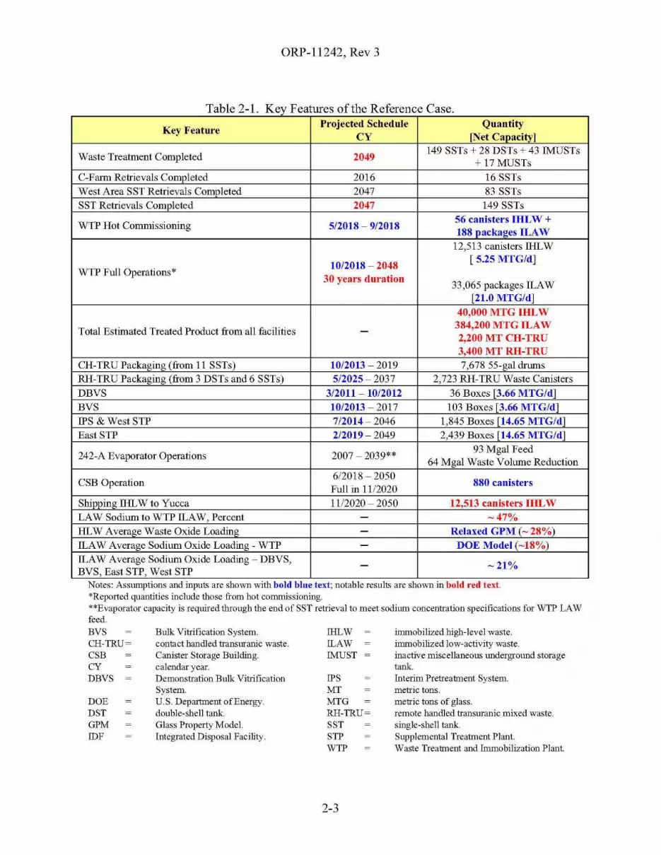
ORP-11242, Rev 3
Table 2-1 Key Features of the Reference Case
Key FeatureProjected Schedule Quautity
CY [Net Capacity]
Waste Treatment Completed 2049149 SSTs + 28 DSTs + 43 !MUSTs
+ 17 MUSTsC-Farm Retrievals Completed 2016 16 SSTsWest Area SST Retrievals Completed 2047 83 SSTsSST Retrievals Completed 2047 149 SSTs
WTP Hot Commissioning 5/2018 - 9/201856 canisters IHLW +188 packages ILAW
12,513 canisters lliLW
10/2018 - 2048[ 5.25 MTG/d]
WTP Full Operations*30 years duration
33,065 packages [LAW[21.0 MTG/d]
40,000 MTG IHLW
Total Estimated Treated Product from all facilities - 384,200 MTG ILAW2,200 MT CH-TRU3,400 MT RH-TRU
CH-TRUPackaging(from 11 SSTs) 10/2013 - 2019 7,678 55-gal drumsRH-TRU Packaging (from 3 DSTs and 6 SSTs) 5/2025 - 2037 2,723 RH-TRU Waste CanistersDBVS 3/2011 - 1012012 36 Boxes [3.66 MTG/d]BVS 10/2013 - 2017 103 Boxes r3.66 MTG/dlIPS & West STP 7/2014 - 2046 1,845 Boxes [14.65 MTG/d]East STP 2/2019 - 2049 2,439 Boxes [14.65 MTG/dl
242-A Evaporator Operations 2007 - 2039**93 Mgal Feed
64 Mgal Waste Volume Reduction
CSB Operation612018 - 2050
880 canistersFull in 1112020
Shipping lliLW to Yucca 1112020 - 2050 12,513 canisters IHLWLAW Sodium to WTP [LAW, Percent - -47%HLW Average Waste Oxide Loading - Relaxed GPM (- 28%)[LAW Average Sodium Oxide Loading - WTP - DOE Model (-18%)[LAW Average Sodium Oxide Loading - DBVS, - -21%BVS, East STP, West STP
immobilized high-level waste.immobilized low-activity waste.inactive miscellaneous underground storagetank.Interim Pretreatment System.metric tons.metric tons of glass.remote handled transuranic mixed waste.single-shell tank.Supplemental Treatment Plant.Waste Treatment and Immobilization Plant.
IPSMTMTGRH-TRU~
SSTSTPWTP
IHLW!LAW!MUST
Bulk Vitrification System.contact handled transuranic waste.Canister Storage Building.calendar year.Demonstration Bulk VitrificationSystem.U.S. Department ofEnergy.double-shell tank.Glass Property Model.Integrated Disposal Facility.
DOEDSTGPMIDF
Notes: AsslUllptIons and mputs are shmvn wIth bold blue text; notable results are shmvn III bold red text.*Reported quantities include those from hot commissioning.**Evaporator capacity is required through the end of SST retrieval to meet sodimn concentration specifications for WTP LAWfeed.BVSCH-TRU~
CSBCYDBVS
2-3

ORP-11242, Rev 3
2.3 DISCUSSION
The discussion of the mission scenario depicted by the Reference Case is generally organizedaccording to Figure 1-1, River Protection Project Simplified Process Flow Diagram.
The overall mass balance for the Reference Case for selected constituents is provided inAppendix C; the full mass balance is provided as a spreadsheet in SVF-1431,Balance_Graphic_System Plan Rev 3{l-12-2008}-8.3r1-WC91778_M4.xls.
2.3.1 Tank Farms
2.3.1.1 Single-Shell Tanks
The SSTs are projected to be retrieved by March 2047, with the C-Farm retrievals completing inNovember 2016. Figure 2-1 shows the projected SST retrieval progress as measured by theapproximate volume of waste remaining in the SSTs as a function of time (SVF-1360,SST_Retrieval_File_System Plan Rev 3{l-12-2008}-8.3r2- WC91778_M3.xls).
Figure 2-1. Projected Single-Shell Tank Retrieval Progress.
40 r-----.g-----.r------;;---;r---:r--n-----.g-----.r----;;---,
SST RetrievalCompletoo,March 2047
2045 2050
36.1 million gallol16 (M;Jalj,SST Inventor)' as of
December 1994.
2040203520302025
HlWOS Case: Systam Plan Rav 3Run Data: 1/12/2008
202020152005 2010
historical • projected
-+-- :------.
2000
5
!0+---+----+----.:-+---+----+--+---+----+--+----..::::::;=",6"""'"1995
mE 15~
~
~." 10S
35
rDBVS StartMarch 2011
~BVS Start
rn
rOctober 2013
~ 30 C-l06 RetrievalStarted WTPFul1
'" Opefations Start~ N(I\/emb!ll" 1998c October 2018rof- 25'jj Interim IPS & Woot STP
~ Stabilization Startif) Completed July 2014
d> March 2003
~ 20 C-f'arm RetrievalCompletes
Uj November 2016.~
Calendar Year
Approximately 300,000 gal of residual waste are projected to remain in the SSTs, comprisingapproximately 3 MCi of total activity or 1.6% of the total starting tank inventory. As discussedin §1.3.1.4, Waste Retrieval from Single-Shell Tanks, this is intentionally based on assumptionsthat provide a conservative (high) estimate of the tank residuals for potential use in riskassessments and therefore does not represent the most-likely estimate of these residuals.
2-4

ORP-11242, Rev 3
The volume of waste transferred into the DST System as a result of SST retrievals is shown inFigure 2-2. The volumes are on an "as-retrieved" basis - this is the net increase in waste in theDST System for the retrievals after accounting for any supernate recycle and water additions, butbefore the waste is re-concentrated through the 242-A Evaporator. The average retrieval rate onan as-retrieved basis is shown between each pair of black points (SVF-1360).
Figure 2-2. Cumulative Volume Transferred to the Double-Shell Tanks from the Single-ShellTanks.
200 ,----r--........---...----------------------,
" 150~
"oiE0"5>'c•>• 100~
'""'1•~"3E
500u
0.3 Mgal/yr
HTWOS Case: System Plan Rev 3Run Date: 1/1212008
205020452040203520302025202020152010o+----.......""""=q..--+---+-----t----+---+---+-----!2005
Calendar Year
More details on the timing and sequence of individual retrievals are presented in §2.3.1.4, WasteRetrieval from Single-Shell Tanks.
2.3.1.2 Double-Shell Tank Operation
The 28 DSTs are used to support a number of different functions, which include:
• Storing of waste currently in the DST System, including segregation of the RH-TRU,concentrated-complexed (CC) wastes, and DSSF/DSS wastes;
• Receiving and storing waste to be retrieved from the SSTs, especially near-termretrievals;
• Sending and receiving waste (both slurry and supernate) cross-site from 200 West to200 East Area;
• Staging slurry for delivery as HLW feed for WTP;• Staging supernate for delivery as LAW feed for WTP;• Staging supernate for LAW feed for IPS and West STP;
2-5
ORP-11242, Rev 3
• Receiving high-cesium eluate from the IPS;• Water washing of some of the RH-TRU waste;• Staging dilute waste for 242-A Evaporator feed;• Storing concentrated waste from 242-A Evaporator operation;• Precipitating the strontium and TRU in the CC waste currently stored in AN-102 and
AN-IO?;• Reserving storage space for emergency purposes; and• Incidental and intentional waste blending, including segregation of incompatible
wastes.
The allocation of specific DSTs to each of these functions varies as the mission progresses andinvolves a number of implicit and explicit trade-offs that are dependent on the overallconfiguration of the Waste Treatment Complex and the associated mission scenario. Thespecific assignments used for the Reference Case should be considered as placeholders that canserve as a starting point for further analysis as the configuration of the Waste TreatmentComplex evolves.
Figure 2-3 shows the overall utilization of the DSTs over time. Both the volume of actual wasteprojected to be stored in the DSTs and a series of head-space allocations for designated purposesare shown. The head-space allocations reflect that portion of the DST space that is not useablefor storing waste for the indicated reasons. One example is "Safety-Basis Tank Headspace,"which refers to those tanks into which additional waste may not be transferred because ofBDGRE concerns - this restriction is removed once the underlying concern is resolved as part ofthe feed staging activities. Another example is "WTP Feed Tank Headspace," which refers tothose tanks containing staged and sampled LAW or HLW for the WTP. Until this waste hasbeen completely delivered to the WTP, no additional waste may be transferred into the tank ofstaged feed. The total waste inventory plus the allocated DST space should remain less than orequal to the maximum total DST capacity. Both the allocation ofDSTs to functions and thehead-space allocations vary with time. Keep in mind that as the maximum total DST capacity isapproached, the operation of the DST System becomes more and more difficult because of thelarge number of constraints and lack of free space for the transfer of waste.
A number of specific waste blending activities are assumed to take place in the DST Systembeyond incidental blending. These specific blending activities originate from the Feed ControlList discussed in §2.3.1.6, Waste Transfers, and listed in Table 2-2, Feed Controls Assumed forthe Reference Case. The current baseline includes the blending of the solids from three pairs oftanks as a placeholder for potential future intentional blending activities - these placeholderswere not included in the Reference Case since they were speculative.
2-6
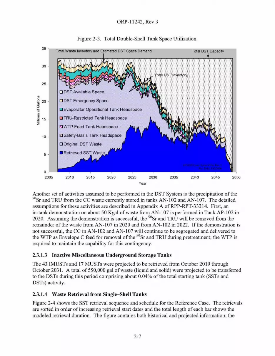
ORP-11242, Rev 3
Figure 2-3. Total Double-Shell Tank Space Utilization.
35 l---O;C=============~==--------:=====--"Total Waste Inventory and Estimated DST Space Demand Total DST Capacity
2050204520402035
H•••••••
20302025202020152010
o TRU-Restricted Tank Headspace
5lWTP Feed Tank Headspace
ill DST Emergency Space
o Evaporator Operational Tank Headspace
5
o -!----"-2005
30
10 I1.lSafety-Basis Tank Headspace
o Original DST Waste
25
00cg 20ro
(9
'500c.Q 15~
Year
Another set of activities assumed to be performed in the DST System is the precipitation of the90Sr and TRU from the CC waste currently stored in tanks AN-102 and AN-107. The detailedassumptions for these activities are described in Appendix A of RPP-RPT-33214. First, anin-tank demonstration on about 50 Kgal of waste from AN-I07 is performed in Tank AP-I02 in2020. Assuming the demonstration is successful, the 90Sr and TRU will be removed from theremainder of the waste from AN-I07 in 2020 and fromAN-I02 in 2022. If the demonstration isnot successful, the CC in AN-l 02 and AN-IO? will continue to be segregated and delivered tothe WTP as Envelope C feed for removal of the 90Sr and TRU during pretreatment; the WTP isrequired to maintain the capability for this contingency.
2.3.1.3 Inactive Miscellaneous Underground Storage Tanks
The 43 IMUSTs and 17 MUSTs were projected to be retrieved from October 2019 throughOctober 2031. A total of 550,000 gal of waste (liquid and solid) were projected to be transferredto the DSTs during this period comprising about 0.04% of the total starting tank (SSTs andDSTs) activity.
2.3.1.4 Waste Retrieval from Single-Shell Tanks
Figure 2-4 shows the SST retrieval sequence and schedule for the Reference Case. The retrievalsare sorted in order of increasing retrieval start dates and the total length of each bar shows themodeled retrieval duration. The figure contains both historical and projected information; the
2-7

ORP-11242, Rev 3
date which demarcates the historical from the projected retrievals is April 1, 2007. As of thatdate, CH2M HILL Hanford Group, Inc. (CH2M HILL) has completed retrievals of seven SSTs(shown with green bars), namely C-I06, C-203, C-202, C-201, C-I03, C-204 and S-112.
The projected retrievals are shown with black and yellow bars. The black portion of the barshows the assumed minimum retrieval duration. The yellow portion of the bar shows theincrease in projected retrieval duration beyond the minimum duration due to bottlenecks in theDST System.
The retrieval sequence projected for the Reference Case was established using methodologydescribed in Section 2.1 of "Single-Shell Tank Retrieval Selection and Sequence" (RPP-21216,Single-Shell Tank Retrieval Selection and Sequence). The basic approach was to group the SSTsin four subsets of tanks, with each subset addressing different retrieval drivers. As the HTWOSmodel simulates the mission, it attempts to honor each of these retrieval drivers, subj ect to DSTspace and logistical considerations, simultaneous retrieval constraints, and programmaticassumptions related to the timing and sequencing of tanks within some of the subsets33
Figure 2-5 shows the overall timing of the retrievals supporting each of these drivers and howthey are consolidated into the overall projected sequence. The four groups of drivers, CommittedTanks, TRU Treatment, West Area LAW Feed, and Balance WTP Feed, are summarized below:
• Committed Tanks: The Committed Tanks group is comprised of S-l 02, S-112 and allof the C-Farm SSTs - these tanks are referred to as "committed" because theirretrieval directly supports near term TPA milestones. The projected timing of theIn-Progress and Planned tanks is determined by near-term DST space availability,operation of the 242-A Evaporator, operational logistics, and the programmaticassumptions for the relative order and destination DST for the retrievals.
33 Section 2.3, "Single-Shell Tank Retrieval Sequence Development" ofRPP-21216 describes this in more detail.
2-8
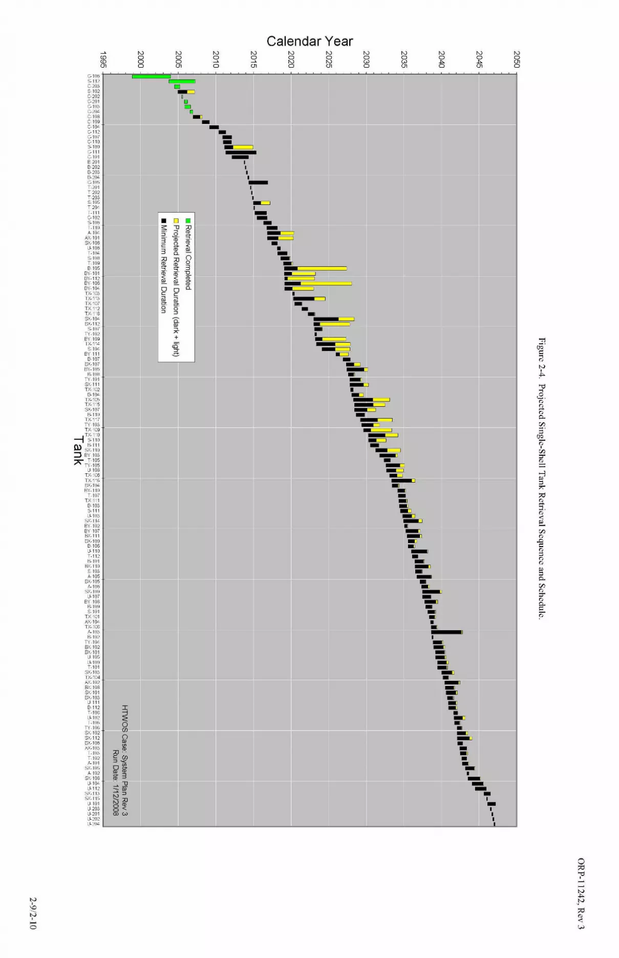
N,'0N,-o
~
CDCD(Jl
C-106 -I i iS-112 ,C-203S-102C-202C-201C-103G204C-108C-109G104C-112
S-109C-111C-1018-2018-2028-203"204C-105T-201T-202T-203S-105T-204T-111C-102S-106T-110~104
AX-101SX-106
U-106T-104S-108T-1098-105
BY-101BY-112BY-106BY-104TX-103TX-113TX-107TX-112TX-118SX-104BX-112
S-107TY-102BY-109TX-114
G104BY-111
8-107BX-107BY-105
8-108TY-101SX-111TX-102
" 104TX-105TX-115SX-107
8-110TX-117TY-103TX-1CB
----I TX-110--, S-110
Q) s~ii6:::J BY-103A T-105
TY-105Ll-108
TX-100TX-116BX-104BY-110
T-107TX-111
8-103S-111U-103
SX-114BY-102BY-107BX-111BX-109
8-106U-110T-1128-101
BX-110S-103A-105
BX-105A-106
SX-109Ll-107
BY-1088-109S-101
TX-101N<-104TX-108
A-1038-102
TY-104BX-102BX-101
U-105U-109T-101
SX-103TX-104M-102BX-108SX-101BX-103
Ll-1118-112T-108U-102T-106
TY-106SX-102SX-112BX-106N<-103
T-103T-102A-101
SX-105A-102
SX-108~104
U-112SX-113SX-115
U-101U-203U-201U-202U-204 I ... 'I' ,.p ... ~ , I
o?O"0,--N.."N
?O~w

ORP-11242, Rev 3
Figure 2-5. Approach Used to Sequence Single-Shell Tank Retrievals.
e uence rivers
Committed TanksTRU
TreatmentWest Area LAW
Food Balance WTP Feed
ConsolidatedSequence
.-
2-11
SeIo<:t next~ from.,""" beolbolllnCM _.,
m.
-, -,'" '"- -~.. _..- ~- ~W_
"""",~"'00'00''00''00''00''00'"'''"."
"''''00'201020112012201320142015201620172018
2020
""2022202320242025202620272028
""2030203120322033
''''20352036203720382039,~o
'''''""'''''"",~,"",~,,~,
ORP-11242, Rev 3
• TRU Treatment: The TRU Treatment group is comprised of both CH-TRU andRH-TRU drivers (see Appendix B, §B2.4.6, Supplemental TRU Sludge Treatment,for details):
The desired start date and general sequence of the retrieval of the CH-TRU tanksis established by the baseline, while the projected timing of the individualretrievals is established by the interplay of the SST retrieval durations andvolumes and the assumed TRU Packaging System slurry treatment rate. 34 Thereis a 10-day outage between tanks and a 60-day outage between farms. DST tankspace is not a factor because these tanks are retrieved directly to the CH-TRUTreatment System.
The early availability date for the RH-TRU Treatment System and the sequenceof SSTs to be used for its feed was established by the baseline. The projectedavailability date of the RH-TRU Treatment System for packaging SST waste wasdetermined from when the packaging of the RH-TRU from DSTs AW-I03,AW-I05, and SY-I02 was completed. The projected timing of the individualretrievals is established by the interplay of the SST retrieval durations andvolumes, the time needed to water-wash the retrieved sludge in the WRFs, theavailability of space in the DST System to receive the wash water, and theassumed TRU Packaging System slurry treatment rate.
• West Area LAW Feed: The West Area LAW Feed group is comprised of bothDBVS / BVS Feed and IPS / West STP Feed drivers:
The desired start date and sequence of the retrieval of S-109 and S-105 to feedDBVS and BVS is set by the baseline. The pace of these retrievals is limited bythe assumed treatment (vitrification rate) and the one-year outage to allow for therefurbishment and re-permitting of the DBVS facility as the BVS facility.
The start date for the operation of the IPS and West STP and the treatment(vitrification) capacity were established by the baseline. Forty-two SSTs,containing mostly salt-cake, were selected to provide feed to the IPS and WestSTP facilities. Before the T-Complex WRF was assumed to be available(June 2019), retrievals were further restricted to a twenty-three SST subset of thatforty-two tank group. The timing of the individual retrievals was determined bythe interplay of the SST retrieval durations and volumes, simultaneous retrievalconstraints, the assumed West STP treatment rate, and the availability of DSTspace for receipt of the high-cesium eluent from the IPS and for settled solidsfrom the retrieved waste.
• Balance WTP Feed: The SSTs in this subset comprise the seventy SSTs notexplicitly included in the other three groups. The early start date for retrieving tanksfrom this group is set by the projected completion date of the Committed Tanks. Thesubgroup is sorted two different ways - "Sort 1" is by decreasing mass of solublesodium in each SST and "Sort 2" is by decreasing mass of "no-blend" HLW glass
34 The current baseline assumes tliat TRU treatment is limited by the shipping rate of packaged TRU wastes, whiletliis system plan is limited by the capacity of the treatment.
2-12
ORP-11242, Rev 3
that would be made after pretreating the waste in each SST. The HTWOS modeldetermines which SST to retrieve next by keeping track of the relative balance ofsodium and solids retrieved from all of the SSTs to date. Starting from the top ofboth lists, the model finds the first SST that best maintains the balance of retrievedsodium (provides LAW feed) and solids (provides HLW feed) and that satisfies thesimultaneous retrieval constraints. The selection is biased toward retrievingadditional HLW feed whenever the number of DSTs containing staged HLW feeddrops below three.
Using the Reference Case assumptions, the SST retrieval assumptions are now the primary driverin the overall mission duration. The outages on the production plots for West STP (see §2.3.3.5)and HLW vitrification (see §2.3.2.2) suggest that feed is not being retrieved and/or staged fastenough to keep up with the assumed capacity of these facilities.
A simple sensitivity study was performed to confirm that the outages on the production plotswere caused by the assumed SST retrieval performance. See §3.8, Enhanced Single-Shell TankRetrieval, for more details.
2.3.1.5 Waste Retrieval from Double-Shell Tanks
As discussed in §1.3.1.5, Waste Retrieval from Double-Shell Tanks, the timing of the initialretrieval of the DSSF in AN-I04 is key to enabling cross-site transfers of solids from West Areato East Area. In the Reference Case, Tank AN-I04 was decanted to AY_I0235 in 2019,immediately after all of the hot commissioning feed was delivered from AY-102. After retrievalof AN-I04 was completed, the initial cross-site transfer of solids from West to East Area wasprojected to occur.
It may be prudent to revisit the decision to hard-pipe the slurry cross-site transfer line directlyinto AN-I04 and provide multiple destinations (receivers) for the cross-site transfers of slurryfrom West to East Area. This would eliminate potential bottlenecks through AN-104 and theadditional flexibility might also simplify the operation of the DST System as a whole. Theoriginal rationale behind having a single, hard-piped, receiver was to avoid potential problemswith exceeding the transfer line pressure ratings for the interconnected portions of the transfersystem.
2.3.1.6 Waste Transfers
The detailed list of all waste transfers that are projected to occur in the tank farms has beencaptured from the model results and is available for further analysis (SVF-1292,Transfer_File_Formatted_System Plan Rev 3(l-12-2008)-8.3rl-WC91778_Ml.xls). Cursoryanalysis of this list has shown that the dynamic allocation of individual DSTs to processfunctions (early SST waste storage, SST receivers, HLW staging, LAW staging, cross-sitereceivers, RH-TRU washing, evaporator feed staging and bottoms receivers, AN-102/107Sr/TRU precipitation, etc.) can likely be improved.
35 To simply programming of the HTWOS model, AY-I02 was used to receive and stage the decanted supernatefrom the DSSFiDSS-containing tanks. However, since AY-I02 will be configured as a HLW staging tank, it maybe beneficial to use another DST with fewer equipment upgrades for staging the supernate from the DSSFiDSScontaining tanks.
2-13
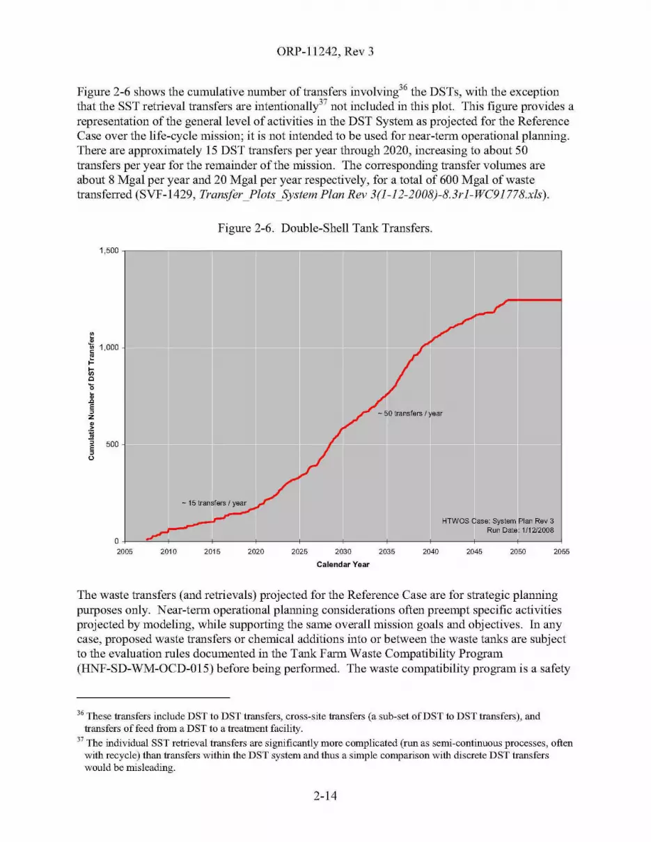
ORP-11242, Rev 3
Figure 2-6 shows the cumulative number of transfers involving36 the DSTs, with the exceptionthat the SST retrieval transfers are intentionally37 not included in this plot. This figure provides arepresentation of the general level of activities in the DST System as projected for the ReferenceCase over the life-cycle mission; it is not intended to be used for near-term operational planning.There are approximately 15 DST transfers per year through 2020, increasing to about 50transfers per year for the remainder of the mission. The corresponding transfer volumes areabout 8 Mgal per year and 20 Mgal per year respectively, for a total of 600 Mgal of wastetransferred (SVF-1429, Transfer_Plots_System Plan Rev 3(l-12-2008)-8.3rl-WC91778.xls).
Figure 2-6. Double-Shell Tank Transfers.
1,500,-----,;:-----------------------------:=----,
~.~1,000
~l;;c'0•.cE,z.~~
"5 500E,u
- 50 transfers I year
HTWOS Casa: Systam Plan Rav 3Run Data: 1/1212008
205520502045204020352030
Calendar Year
2025202020152010
O+-~~--+----f_--_+_--__+_---f_--_+_--__+---+_--_+_--_1
2005
The waste transfers (and retrievals) projected for the Reference Case are for strategic planningpurposes only. Near-term operational planning considerations often preempt specific activitiesprojected by modeling, while supporting the same overall mission goals and objectives. In anycase, proposed waste transfers or chemical additions into or between the waste tanks are subjectto the evaluation rules documented in the Tank Farm Waste Compatibility Program(HNF-SD-WM-OCD-015) before being performed. The waste compatibility program is a safety
36 These transfers include DST to DST transfers, cross-site transfers (a sub-set ofDST to DST transfers), andtransfers of feed from a DST to a treatment facility.
37 The individual SST retrieval transfers are significantly more complicated (run as semi-continuous processes, oftenwith recycle) than transfers within the DST system and thus a simple comparison with discrete DST transferswould be misleading.
2-14
ORP-11242, Rev 3
management program whose primary purpose is to prevent the formation of incompatiblemixtures as a result of waster transfer operations.
The compatibility program also includes programmatic controls over the feed planned for thevarious treatment facilities. These programmatic controls are called the "Feed Control List."A summary of these feed controls, incorporating the revisions assumed by Appendix B,§B2.2.2.6 , are presented in Table 2-2. These assumed revisions include both housekeepingchanges and changes needed to align the controls with the other Reference Case assumptions.
2-15
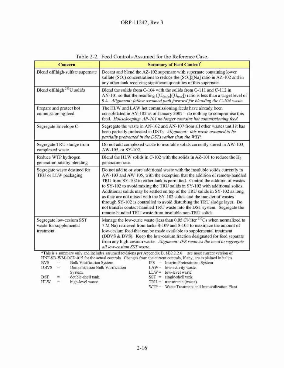
DSTHLW
ORP-11242, Rev 3
Table 2-2. Feed Controls Assumed for the Reference Case.
Concern Summary of Feed Coutro(
Blend off high-sulfate supernate Decant and blend the AZ-l 02 supernate with supernate containing lowersulfate (S04) concentrations to reduce the [S04]:[Na] ratio ni AZ-l02 and inany other tank receiving significant quantities of this supernate.
Blend off high 233U solids Blend the solids from Col 04 with the solids from C-lll and C-112 niAN-lOl so that the resulting ([Ufi""il,]/[UtctelD ratio is less than a target level of9.4. Alignment:follow assumedpathforwardfor blending the C-I04 waste.
Prepare and protect hot The HLW and LAW hot commissioning feeds have already beencommissioning feed consolidated ni AY-l02 as ofJanuary 2007 - do nothnig to compromise this
feed. Housekeeping: AP-IOI no longer contains hot commissioningfeed.
Segregate Envelope C Segregate the waste ni AN-l02 and AN-l07 from all other wastes until it hasbeen partially pretreated in DSTs. Alignment: this waste assumed to bepartially pretreated in the DSTs rather than the WTP.
Segregate TRU sludge from Do not add complexed waste to insoluble solids currently stored in AW-l03,complexed waste AW-l05, or SY-l02.
Reduce WTP hydrogen Blend the HLW solids in C-l02 with the solids in AZ-lOl to reduce the H,generation rate by blending generation rate.
Segregate waste destined for Do not add to or store additional waste with the insoluble solids currently niTRU or LLW packagnig AW-l03 and AW 105, with the exception that the addition of remote-handled
TRU from SY-l02 to either tank is permitted. Control the addition of wastesto SY-l02 to avoid mixing the TRU solids ni SY-l02 with additional solids.Additional solids may be settled on top of the TRU solids in SY-l02 as longas they are not mixed with the SY-l02 solids and the transfer of wastesthrough SY-l02 is controlled to avoid disturbing the TRU sludge layer. Donot transfer contact-handled TRU waste into the DST system. Segregate theremote-handled TRU waste from nisoluble non-TRU solids.
Segregate low-cesium SST Manage the low-curie waste (less than 0.05 Ci/liter 137Cs when normalized towaste for supplemental 7 M Na) retrieved from tanks S-109 and S-105 to maximize the amount oftreatment low-cesium feed that can be made available to supplemental treatment
(DBVS & BVS). Keep the low-cesium fraction designated for feed separatefrom any high-cesium waste. Alignment: IPS removes the need to segregateall low-cesium SST waste.
*11118 IS a summary only and mcludes assmnedrevIslons per Appendix B, §B2.2.2.6 see most current verSIon ofHNF-SD-WM-OCD-015 for the actual controls. Changes from the current controls, ifany, are explained in italics.BVS Bulk Vitrification System. IPS = Interim Pretreatment SystemDBVS Demonstration Bulk Vitrification LAW= low-activity waste.
System. LLW= low-level waste.double-shell tank. SST = single-shell tank.high-level waste. TRU = transuranic (waste).
WTP = Waste Treatment and Immobilization Plant
2-16
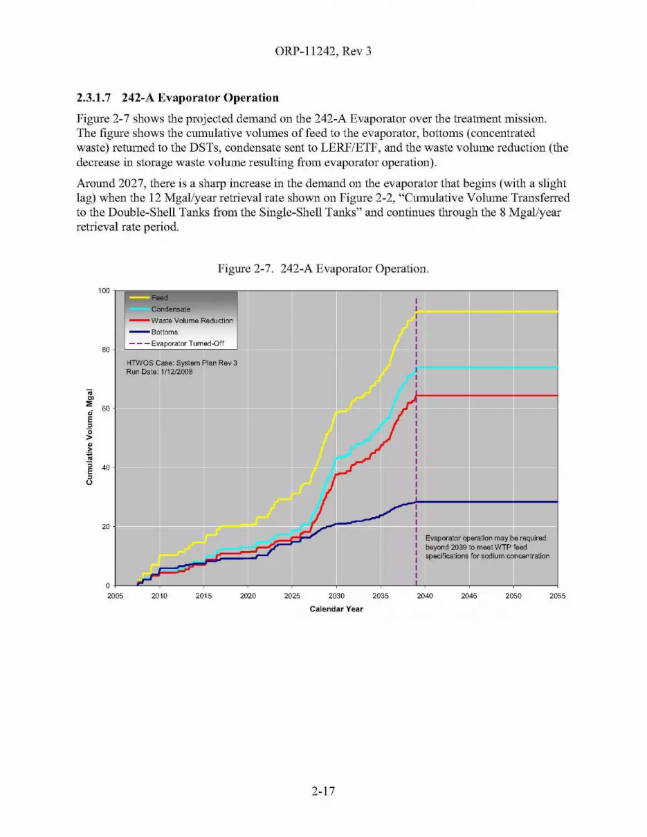
ORP-11242, Rev 3
2.3.1.7 242-A Evaporator Operation
Figure 2-7 shows the projected demand on the 242-A Evaporator over the treatment mission.The figure shows the cumulative volumes of feed to the evaporator, bottoms (concentratedwaste) returned to the DSTs, condensate sent to LERF/ETF, and the waste volume reduction (thedecrease in storage waste volume resulting from evaporator operation).
Around 2027, there is a sharp increase in the demand on the evaporator that begins (with a slightlag) when the 12 MgaVyear retrieval rate shown on Figure 2-2, "Cumulative Volume Transferredto the Double-Shell Tanks from the Single-Shell Tanks" and continues through the 8 Mgal/yearretrieval rate period.
Figure 2-7. 242-A Evaporator Operation.
100 n!!!!!!!!!iiiiiiiiiijiiiiiiiiiiiiiiii~T--,--r-"---;lr-T-II----'
80
Condensate--Waste Volume Reduction
--Bottoms
- - - Evaporator Turned-Off
..'":;; 60ofE,~•••IiE 40,U
20
HlWOS Case: Systam Plan Rev 3Run Date: 1/1212008
Evaporator oparation may be raquiradbeyond 2039 to maat WTP faMspecifications for sodium concentration
205520502045204020352030
Calendar Year
20252020201520100+-----''"-~---~--~--~---~--~--...J....~--~--~--___4
2005
2-17
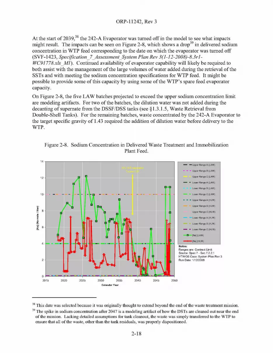
ORP-11242, Rev 3
At the start of 2039,38 the 242-A Evaporator was turned off in the model to see what impactsmight result. The impacts can be seen on Figure 2-8, which shows a drop39 in delivered sodiumconcentration in WTP feed corresponding to the date on which the evaporator was turned off(SVF-1423, SpecificationJ _Assessment_System Plan Rev 3(l-12-2008)-8.3rl-WC91778.xls_Ml). Continued availability of evaporator capability will likely be required toboth assist with the management of the large volumes of water added during the retrieval of theSSTs and with meeting the sodium concentration specifications for WTP feed. It might bepossible to provide some of this capacity by using some of the WTP's spare feed evaporatorcapacity.
On Figure 2-8, the five LAW batches projected to exceed the upper sodium concentration limitare modeling artifacts. For two of the batches, the dilution water was not added during thedecanting of supernate from the DSSF/DSS tanks (see §1.3.1.5, Waste Retrieval fromDouble-Shell Tanks). For the remaining batches, waste concentrated by the 242-A Evaporator tothe target specific gravity of 1.43 required the addition of dilution water before delivery to theWTP.
Figure 2-8. Sodiurn Concentration in Delivered Waste Treatment and ImmobilizationPlant Feed.
14,.....---------------------:::------,- -Upper RartgeA (LAW)
• - - Upper Range B (LAW)
Upper Range C (LAW)
Lower Range 8 (LAW)
Lo"",r Range C (LAW)
Upper Rartg8 B (HLW)
Upper Range C (HLW)
La""" Rang!! A (HLW)
Lowsr Rartg!l B (HLW)
D [Na] (LAW)
- • Lower Range C (HLW)
_[Na] (HLW)
- - Lowsr Rartgl A fJ.-AW)
• • • Upper Rartg8 A (HLW)
Notes:Ranges are: Contract LimitSource: Spec 7 - Sec 7.2.2.1HTWOS Case: System Plan Rev 3Run Date: 1/12/2008
2050
""
2045
~ ..,...-..
"
20402035203020252020
"[]
[]
--[] -[]
" "" ,,[]
"" ,,~
1 "" "[]
2
O~~~....."~=~'_,=~~_......=~""""~~=,,....,""""--'_=""""2015
4
12
10 -
,~ 8."'E.~
Calendar Year
38 This date was selected because it was originally thought to extend beyond the end of the waste treatment mission.
39 The spike in sodium concentration after 2047 is a modeling artifact of how the DSTs are cleaned out near the endof the mission. Lacking detailed assumptions for tank cleanout, the waste was simply transferred to the WTP toensure that all of the waste, other than the tank residuals, was properly dispositioned.
2-18
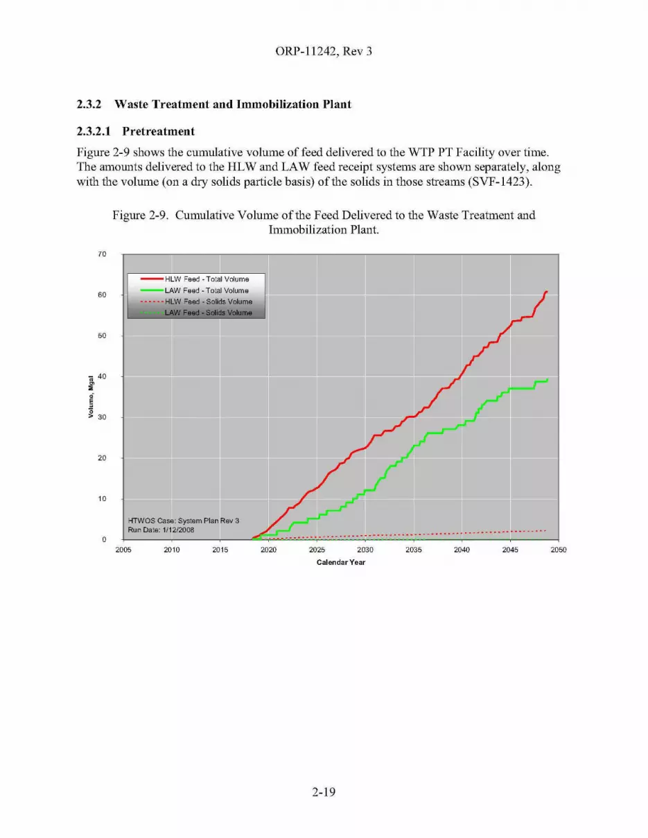
ORP-11242, Rev 3
2.3.2 Waste Treatment and Immobilization Plant
2.3.2.1 Pretreatment
Figure 2-9 shows the cumulative volume of feed delivered to the WTP PT Facility over time.The amounts delivered to the HLW and LAW feed receipt systems are shown separately, alongwith the volume (on a dry solids particle basis) of the solids in those streams (SVF-1423).
Figure 2-9. Cumulative Volume of the Feed Delivered to the Waste Treatment andImmobilization Plant.
KTWOS Case: System Plan Rev 3Run Date: 1/12/2008
-- HLW Feed - Total Volume
--LAW Feed - Total Volume
...... HLW Feed - Solids Volume
205020452040203520302025
..... --_ ........... - ................ -.-_ ........... - - .
2020201520102005o
20
10
60
70
50
iii 40~
~.E,;;> 30
Calendar Year
2-19
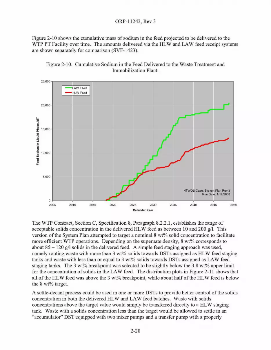
ORP-11242, Rev 3
Figure 2-10 shows the cumulative mass of sodium in the feed projected to be delivered to theWTP PT Facility over time. The amounts delivered via the HLW and LAW feed receipt systemsare shown separately for comparison (SVF-1423).
Figure 2-10. Cumulative Sodium in the Feed Delivered to the Waste Treatment andImmobilization Plant.
25,000 1~;:::::==:::i!::::~=;----lf------lIl--T------II--l-LAW Feed
-HLW Feed
205020452040
HTWOS Case: Systam Plan Rev 3Run Date: 1/12/2008
2035203020252020201520100+---~--~----~--~--~---~--~--~-----1
2005
20,000
5,000
I
"51~ 15,000~
'5~
:J.==,'g 10,000
'"~~u.
Calendar Year
The WTP Contract, Section C, Specification 8, Paragraph 8.2.2.1, establishes the range ofacceptable solids concentration in the delivered HLW feed as between 10 and 200 gil. Thisversion of the System Plan attempted to target a nominal 8 wt% solid concentration to facilitatemore efficient WTP operations. Depending on the supernate density, 8 wt% corresponds toabout 85 - 120 gil solids in the delivered feed. A simple feed staging approach was used,namely routing waste with more than 3 wt% solids towards DSTs assigned as HLW feed stagingtanks and waste with less than or equal to 3 wt% solids towards DSTs assigned as LAW feedstaging tanks. The 3 wt% breakpoint was selected to be slightly below the 3.8 wt% upper limitfor the concentration of solids in the LAW feed. The distribution plots in Figure 2-11 shows thatall of the HLW feed was above the 3 wt% breakpoint, while about half of the HLW feed is belowthe 8 wt% target.
A settle-decant process could be used in one or more DSTs to provide better control of the solidsconcentration in both the delivered HLW and LAW feed batches. Waste with solidsconcentrations above the target value would simply be transferred directly to a HLW stagingtank. Waste with a solids concentration less than the target would be allowed to settle in an"accumulator" DST equipped with two mixer pumps and a transfer pump with a properly
2-20

ORP-11242, Rev 3
positioned inlet (either variable height or a fixed, raised height). The clarified supernate wouldbe decanted and transferred towards DSTs assigned as LAW feed staging tanks. Additionalwaste would be transferred into the "accumulator" DST and the settle-decant process repeateduntil the desired solids concentration was reached. The waste in the "accumulator" DST wouldthen be transferred to a HLW staging tank, sampled, and delivered to the WTP. Additionalmodeling would be needed to determine in which DSTs to conduct the settle-decant operationand if those DSTs could also serve as the HLW staging tanks.
Figure 2-11. Solids Concentration Distribution in Feed Delivered to theWaste Treatment and Immobilization Plant.
20
18
16
,.12
;j1_ 10:E"0!!l.
8
6
•2
00% 20% 40% 60% 80%
.......... [Solid] (HlW)
D [Solid] (LAW)
- -UpperRangeA(LAW}
- - - Upper Range 8 (LAW)
Upper Rarlg!l C (LAW)
Notes:Ranges are: Contract LimitSource: Spec 7 - Sec 7.2.2.1HTWOS Case: System Plan Rev3Run Date: 1/12/2008Weighted by: Total Vol
100%
Percent offeed less than stated value
The waste projected to be delivered to the WTP PT Facility was screened against the WTPcontract feed specifications (Specifications 7 and 8),40 and the directed hydrogen generation rate(HGR) limits. The detailed results of these screenings are documented in SVF-1423; SVF-1422,Specification_8_Assessment_System Plan Rev 3(l-12-2008)-8.3rl-WC91778.xls; and SVF-1420,HGR_Feed_Assessment_System Plan Rev 3(l-12-2008)-8.3rl-WC91778.xls, respectively, onboth batch-by-batch and mission aggregate basis. While a full assessment of the results of this
40 Specification 7 primarily applies to the feed delivered to the WTP LAW feed receipt tanks, plus the liquid phaseof the feed delivered to the WTP HLW feed receipt tanks. Specification 8 primarily applies to the solids in thefeed delivered to the WTP HLW feed receipt tanks.
2-21
ORP-11242, Rev 3
screening is beyond the scope of the System Plan and typically is handled as follow-on work,some of the major observations follow:
• All of the waste was projected to meet the HGR screening criteria, with the exceptionof a batch group of HLW feed that exceeded the upper limit by less than 10%. Thewaste in this batch group includes a mix of waste originally from AN-I02 andAN-I07. This waste may benefit from intentional blending with other waste after theremoval of the 90Sr and TRU and before delivery to the WTP to mitigate the highHGR.
• Most of the feed was projected to satisfy Specification 7; however, four limits wereprojected to be exceeded in the Reference Case by more than 1% of the deliveredwaste, weighted by mass of delivered sodium. These were sodium concentration,bulk density, mercury to sodium ratio, and TRU to sodium ratio.
The batches with high sodium concentration and bulk density result from themodeling artifacts discussed in §2.3.1.7, 242-A Evaporator Operation.
The high TRU batches result from an unrealistically high (75%) wash factorfor Tank C-I05 for 24lAm. The 75% value is based on experimental resultsfrom 1986, too old to investigate further. Newer experimental data from 1997suggests a more realistic upper bound of about 0.3%. The basis for this factorhas been reviewed and the factor has since been updated.
The cause of the high mercury batches has been traced to the inventory andwash factor (unity) for A-I06. The basis for the A-I06 inventory and washfactor were evaluated to determine that the current mercury wash factor is toohigh. The current wash factor was derived using a much smaller mercuryinventory for A-I06 and mercury is not expected to be soluble in high pHsolutions. The A-I 06 mercury wash factor was revised in the BBI to a valueof 0.293 based on the behavior of cadmium as a chemical analog. Applicationof the revised wash factor would resolve the out-of-specification batches.
• Specification 8 includes feed component concentration limits that will be used toprovide the basis for certification that the HLW feed is within specification limits(certification limits) and component concentration limits that will be used to supportproduct and process qualification but will not be used as a basis for determining if thefeed meets specification requirements (qualification limits). Of the certificationlimits, four limits were proj ected to be exceeded in the Reference Case by more than1% of the delivered waste, weighted by mass of delivered solids. These include thestrontium, vanadium, total organic carbon and 233U, all as ratios to mass ofnon-volatile oxides. The causes (modeling artifacts, data issues, or real) and potentialimpacts of these have not been evaluated. Also, about one-third of the qualificationlimits are projected to be exceeded by more than I% of the delivered waste.
A comprehensive evaluation of the processability of the tank waste through the WTP wasperformed as part of the follow-on actions from the External Flowsheet Review Team(24590-WTP-RPT-PE-07-001, WTP Waste Feed Analysis and Definition - EFRT M4 FinalReport). This review was based upon the feed projected to be delivered to the WTP according tothen current tank farm technical baseline documented in the Tank Farm Contractor Operationsand Utilization Plan (HNF-SD-WM-SP-012). From an overall mission perspective, this feed
2-22
ORP-11242, Rev 3
should be similar in composition to the Reference Case, although the distribution of componentsamong the individual feed batches will vary. The evaluation found that "All of the TFCOUP{Tank Farm Contractor Operation and Utilization Plan} Rev. 6 batches appear processable bythe WTP. However, some batches will hamper WTP operations and result in reduce {sic}production rates and/or require reduction in waste loading to accommodate."
The "feed vector" is a data file that contains a listing of all of the feed batches projected to bedelivered to the WTP for a specific mission scenario, including the type (HLW or LAW) of feed;the projected delivery date; liquid and solid volumes and density; weight percent solids; liquidand solid phase composition; residual water wash factors (if any); and the caustic leach factors.The water wash factors and caustic leach factors are zero-order approximations of the complexsolid-liquid equilibrium that occurs in the waste. They assume that process conditions willsupport the stated factors and that sufficient reactants are present to support the assumedstoichiometry. The waste composition data input to the HTWOS model are not fully speciated.Currently, leach factors for only ten analytes (plus their isotopes) are being tracked. These wereselected because of their potential impact on the mass of HLW glass.
The feed vector41 specific to the underlying technical and programmatic assumptions used by theReference Case is available for further analysis. However, because of the limitations describedabove, the feed vector may require adjustments for charge balance, solid-liquid equilibrium, freeand bound hydroxide, speciation of key analytes such as aluminum, and other parametersimportant to the end user. These considerations are important in understanding the performanceof the UFP system and the caustic and oxidative leach operations.
The WTP PT assumptions (namely, the ultrafilter permeate rate and associated operating cycles)did not appear to drive the mission duration for the Reference Case based on cursoryexamination of the model execution and its results.
41 The feed vector for this Reference Case is named "batches-to-wtp-fully-water-washed.csv" and is kept with theraw data from the Reference Case: "System Plan Rev 3(1-12-2008)-8.3rl-WC91778."
2-23

ORP-11242, Rev 3
2.3.2.2 High-Level Waste Vitrification
In the Reference Case, about 12,513 canisters of HLWare projected to be produced by the WTPHLW Vitrification Facility by November 2048. The average waste oxide loading of the HLWglass was approximately 28.4 wt% and ranged from 10- to 55 wt% for most of the projectedmelter batches.
Figure 2-12 is a plot of cumulative WTP HLW glass production versus time, overlaid with thecumulative production capacity based on the assumed ramp-up ofHLW Vitrification Facility.The production closely follows the assumed capacity through 2032, at which time production islimited by the ability to retrieve SSTs fast enough to provide a continual supply of HLW feed tothe WTP pretreatment facility. The cumulative outage represents an increase in treatmentmission length of about 8 years beyond the date at which the 12,513 canisters would have beenproduced had there been a continual supply of feed. Had there been no outages, the HLWvitrification could have completed by 2041. As discussed in §2.3.1.4, most of this cumulativeoutage results from not being able to retrieve waste from the SSTs fast enough.
Figure 2-12. Waste Treatment and Immobilization PlantHigh-Level Waste Glass Production.
14,000 1(=============;--------------------,
205520502045
HTWOS Casa: System Plan Rev 3Run Date: 1/1212008
204020352030202520202015
O+---+--<lC-+---+---+---+---+---+---+-----j2010
~~
~ 10,000~
~
U~.
1;j~
8,000;;:a;>~
..J
.r.
.2' 6,000:I:'C~
.~
:c 4,0000E.E
- Projected WTP IHLW Production
- Assumed Capacity
2,000
12,000
Calendar Year
2-24
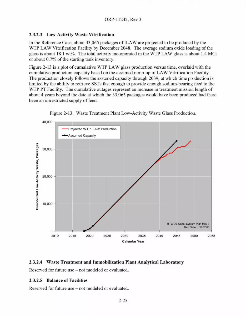
ORP-11242, Rev 3
2.3.2.3 Low-Activity Waste Vitrification
In the Reference Case, about 33,065 packages ofILAW are projected to be produced by theWTP LAW Vitrification Facility by December 2048. The average sodium oxide loading of theglass is about 18.1 wt%. The total activity incorporated in the WTP LAW glass is about 1.4 MCior about 0.7% of the starting tank inventory.
Figure 2-13 is a plot of cumulative WTP LAW glass production versus time, overlaid with thecumulative production capacity based on the assumed ramp-up of LAW Vitrification Facility.The production closely follows the assumed capacity through 2039, at which time production islimited by the ability to retrieve SSTs fast enough to provide enough sodium-bearing feed to theWTP PT Facility. The cumulative outages represent an increase in treatment mission length ofabout 4 years beyond the date at which the 33,065 packages would have been produced had therebeen an unrestricted supply offeed.
Figure 2-13. Waste Treatment Plant Low-Activity Waste Glass Production.
40,000 r;==:Jl===J::==:JlC=::::-lf--li--lf--ir--lf----,- Projected WTP ILAW Production
-Assumed Capacity
~~ 30,000"u~
0-
.;~
~~.~ 20,000
1..J'C
~:c~ 10,000.E
HTWOS Case: System Plan Rev 3Run Date: 1/1212008
2055205020452040203520302025202020150+----+-----4""-+---+----+------\---+----+------\-----12010
Calendar Year
2.3.2.4 Waste Treatment and Immobilization Plant Analytical Laboratory
Reserved for future use - not modeled or evaluated.
2.3.2.5 Balance of Facilities
Reserved for future use - not modeled or evaluated.
2-25

ORP-11242, Rev 3
2.3.3 Supplemental Treatment
The following subsections provide projected production metrics for each of the SupplementalLAW Treatment processes and for the Supplemental TRU Treatment processes.
2.3.3.1 Demonstration Bulk Vitrification System
The DBVS was projected to produce about 36 ICV™ containers (a.k.a., boxes) of vitrified LAWby October 2012, treating approximately 242 MT of LAW sodium, at the assumed sodium oxideloading of 21.24 wt%. This is slightly less than the 260 MT of LAW sodium (39 boxes) in thekey enabling assumptions because of modeling artifacts42 Figure 2-14 shows the projectedproduction over time.
Together, the total activity incorporated in to the DBVS and BVS glass is about 0.09 MCi orabout 0.05% of the starting tank inventory.
Figure 2-14. Demonstration Bulk Vitrification System and Bulk Vitrification System LowActivity Waste Glass Production.
150 ,----------:,,------------,,-----------,,------------,
II _ pr:;ected DBVS/BVS Box Production
- Assumed Capacity
~
~'"af 100
~s:~.s; +-BVS
I..J
al.!::! 50~:c~ r:l +-Refurbish
-DBVS
o J2010 2015 2020 2025 2030 2035 2040
HTWOSlfase: System Plan Rev 31,1 Run Date: 1/1212008
2045 2050 2055
Calendar Year
42 These artifacts were (1) the last partially full box and the waste present in the DBVS at the end date for the DBVSoperation was attributed to BVS, and (2) the holdup in the DBVS feed tank and dryer was not addressed whenselecting the melter production rate.
2-26
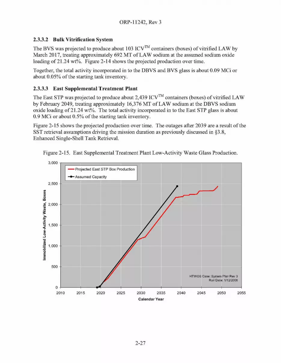
ORP-11242, Rev 3
2.3.3.2 Bulk Vitrification System
The BYS was projected to produce about 103 ICy™ containers (boxes) of vitrified LAW byMarch 2017, treating approximately 692 MT of LAW sodium at the assumed sodium oxideloading of 21.24 wt%. Figure 2-14 shows the projected production over time.
Together, the total activity incorporated in to the DBYS and BYS glass is about 0.09 MCi orabout 0.05% of the starting tank inventory.
2.3.3.3 East Supplemental Treatment Plant
The East STP was projected to produce about 2,439 ICy™ containers (boxes) of vitrified LAWby February 2049, treating approximately 16,376 MT of LAW sodium at the DBYS sodiumoxide loading of21.24 wt%. The total activity incorporated in to the East STP glass is about0.9 MCi or about 0.5% of the starting tank inventory.
Figure 2-15 shows the projected production over time. The outages after 2039 are a result of theSST retrieval assumptions driving the mission duration as previously discussed in §3.8,Enhanced Single-Shell Tank Retrieval.
Figure 2-15. East Supplemental Treatment Plant Low-Activity Waste Glass Production.
3,000 G==========:::::;-------.-----.--I- Projected East STP Box Production
- Assumed Capacity
2,500
~~
~
'"S~ 2,000~
~~.~
U 1,500
1..J'C
.~ 1,000:coE.E
500
HTWOS Case: System Plan Rev 3Run Date: 1/1212008
205520502045204020352030202520202015
o+---+--_~---+---_+_--_+_--_+_--_+_--_+_--__l
2010
Calendar Year
2-27
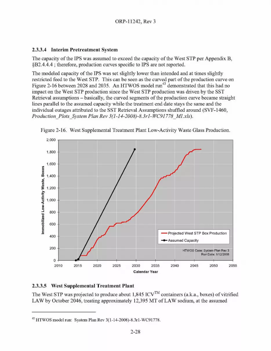
ORP-11242, Rev 3
2.3.3.4 Interim Pretreatment System
The capacity of the IPS was assumed to exceed the capacity of the West STP per Appendix B,§B2.4.4.4 ; therefore, production curves specific to IPS are not reported.
The modeled capacity of the IPS was set slightly lower than intended and at times slightlyrestricted feed to the West STP. This can be seen as the curved part of the production curve onFigure 2-16 between 2028 and 2035. An HTWOS model run43 demonstrated that this had noimpact on the West STP production since the West STP production was driven by the SSTRetrieval assumptions - basically, the curved segments of the production curve became straightlines parallel to the assumed capacity while the treatment end date stays the same and theindividual outages attributed to the SST Retrieval Assumptions shuffled around (SYF-1460,Production_Plots_System Plan Rev 3(l-14-2008)-8.3rl- WC91778_Ml.xls).
Figure 2-16. West Supplemental Treatment Plant Low-Activity Waste Glass Production.
2,000,---------------------------------,
HTWOS Case: System Plan Rev 3Run Date: 1/1212008
- Projected West STP Box Production
_ Assumed Capacity
1,800
1,600~~
x0
'" 1,400
400
200
.;~
~
;;: 1,200
~.~
U 1,000
1...J 800'C
~:c 600oE.E
205520502045204020352030202520202015
O+---....---f-----+-----+---+----+------.,---+-----l2010
Calendar Year
2.3.3.5 West Supplemental Treatment Plant
The West STP was projected to produce about 1,845 ICy™ containers (a.k.a., boxes) of vitrifiedLAW by October 2046, treating approximately 12,395 MT of LAW sodium, at the assumed
43 HTWOS model run: System Plan Rev 3(1-14-2008)-8.3rl-WC91778.
2-28

ORP-11242, Rev 3
sodium oxide loading of 21.24 wt%. The total activity incorporated in to the West STP glass isabout 0.7 MCi or about 0.4% of the starting tank inventory.
Figure 2-16 shows the projected production over time. The pervasive cumulative outages are aresult of the SST retrieval assumptions driving the mission duration as previously discussed in§3.8, Enhanced Single-Shell Tank Retrieval.
2.3.3.6 Supplemental Transuranic Waste Treatment System
The Supplemental TRU Treatment System is comprised of both CH-TRU and RH-TRUprocesses.
Between October 2013 and June 2019, the contact-handled portion of Supplemental TRUTreatment System was projected to produce about 7,678 55-gal drums, each containing about620 lb of dried CH-TRU waste. The projected production over time is shown in Figure 2-17.The outage in 2014 is the assumed 60-day outage needed to relocate the contact-handled systemfrom B-Farm to T-Farm. The ten-day outages assumed between tanks in a given farm are notvisible.
Figure 2-17. Contact-Handled Transuranic Packaged Waste Production.
- Projected CH-TRU Drum Production
HTWOS Case: System Plan Rav 3Run Date: 1/12/2008
205520502045204020352030
9,000
8,000
7,000
6,000
~
E~ 5,000C~
.Q
~ 4,000,;,'"
3,000
2,000
1,000
a2010 2015 2020 2025
Calendar Year
2-29
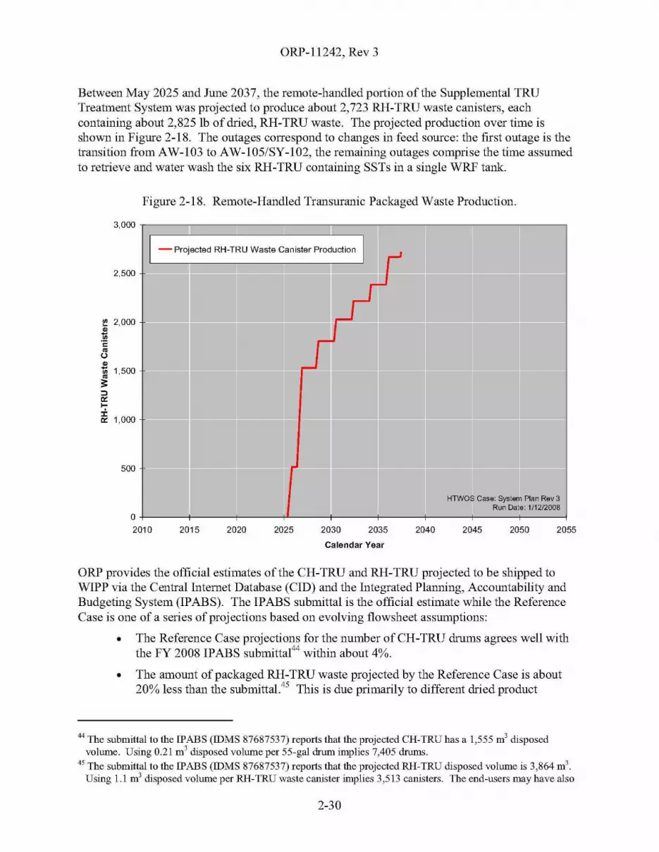
ORP-11242, Rev 3
Between May 2025 and June 2037, the remote-handled portion of the Supplemental TRUTreatment System was proj ected to produce about 2,723 RH-TRU waste canisters, eachcontaining about 2,825 Ib of dried, RH-TRU waste. The projected production over time isshown in Figure 2-18. The outages correspond to changes in feed source: the first outage is thetransition from AW-I03 to AW-I05/SY-I02, the remaining outages comprise the time assumedto retrieve and water wash the six RH-TRU containing SSTs in a single WRF tarue
Figure 2-18. Remote-Handled Transuranic Packaged Waste Production.
•• II
1-Projected RH-TRU Waste Canister Production 1=
;;;;;;;;;; 'I
,....
lIIIlIIII =1-"'"
= =
;;;;;;;;;; =HTWOS Case: System Plan Rev 3
Run Date: 1/12/2008
3,000
2,500
~ 2,000~
~~
~
U~
1;; 1,500~s:
OJ
'">-:i:.
'" 1,000
500
o2010 2015 2020 2025 2030 2035 2040 2045 2050 2055
Calendar Year
ORP provides the official estimates of the CH-TRU and RH-TRU projected to be shipped toWIPP via the Central Internet Database (Cm) and the Integrated Planning, Accountability andBudgeting System (IPABS). The IPABS submittal is the official estimate while the ReferenceCase is one of a series of projections based on evolving fIowsheet assumptions:
• The Reference Case projections for the number of CH-TRU drums agrees well withthe FY 2008 IPABS submittal44 within about 4%.
• The amount of packaged RH-TRU waste projected by the Reference Case is about20% less than the submittal45 This is due primarily to different dried product
44 The submittal to the IPABS (IDMS 87687537) reports that the projected CR-TRU has a 1,555 m3 disposedvolume. Using 0.21 m' disposed volume per 55-gal drum implies 7,405 drums.
45 The submittal to the IPABS (IDMS 87687537) reports that the projected RH-TRU disposed volume is 3,864 m3
Using 1.1 m3 disposed volume per RH-TRU waste canister implies 3,513 canisters. The end-users may have also
2-30
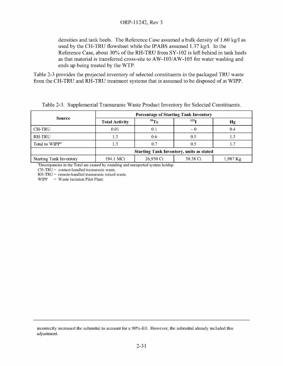
ORP-11242, Rev 3
densities and tank heels. The Reference Case assumed a bulk density of 1.60 kg/I asused by the CH-TRU flowsheet while the IPABS assumed 1.37 kg/I. In theReference Case, about 30% of the RH-TRU from SY-I02 is left behind in tank heelsas that material is transferred cross-site to AW-I03/AW-I05 for water washing andends up being treated by the WTP.
Table 2-3 provides the projected inventory of selected constituents in the packaged TRU wastefrom the CH-TRU and RH-TRU treatment systems that is assumed to be disposed of at WIPP.
Table 2-3. Supplemental Transuranic Waste Product Inventory for Selected Constituents.
DIscrepanCIes III the Total are caused by roundmg and umeported system holdup.CH-TRU = contact-handled transuranic waste.RH-TRU = remote-handled transuranic mixed waste.WIPP = Waste Isolation Pilot Plant.
SourcePercentage of Starting Tank Inventory
Total Activity 99Tc 1291 Hg
CH-TRU 0.01 0.1 ~O 0.4
RH-TRU 1.3 0.6 0.5 1.3
Total to WIPP' 1.3 0.7 0.5 1.7
Starting Tank Inventory, units as stated
Starting Tank Inventory 194.1 MCi 26,930 Ci 30.38 Ci 1,987 Kg,
incorrectly increased the submittal to account for a 90%-fill. However, the submittal already included thisadjustment.
2-31
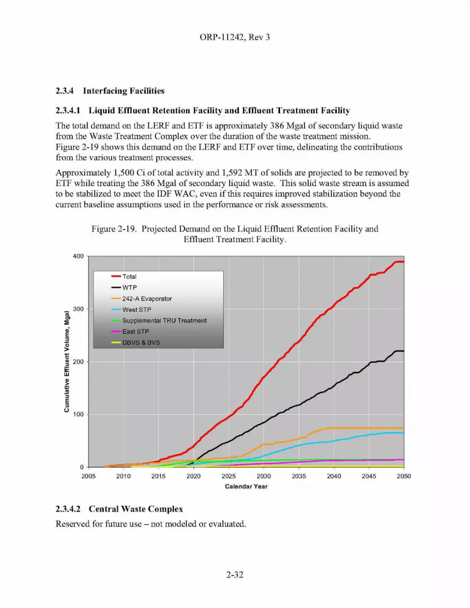
ORP-11242, Rev 3
2.3.4 Interfacing Facilities
2.3.4.1 Liquid Effluent Retention Facility and Effluent Treatment Facility
The total demand on the LERF and ETF is approximately 386 Mgal of secondary liquid wastefrom the Waste Treatment Complex over the duration of the waste treatment mission.Figure 2-19 shows this demand on the LERF and ETF over time, delineating the contributionsfrom the various treatment processes.
Approximately 1,500 Ci of total activity and 1,592 MTofsolids are projected to be removed byETF while treating the 386 Mgal of secondary liquid waste. This solid waste stream is assumedto be stabilized to meet the IDF WAC, even if this requires improved stabilization beyond thecurrent baseline assumptions used in the performance or risk assessments.
Figure 2-19. Projected Demand on the Liquid Effluent Retention Facility andEffluent Treatment Facility.
400 ~--------------------------=-------.....,
205020452040203520302025202020152010
o-l-=~~~C---=~~::::::==:::==~==:==:j2005
-Total
-WTP
- 242-A Evaporator
WestSTP
Supplemental TRU Treatment
-EaolSTP
~~ 200
ill~
~~
E~
u 100
Calendar Year
2.3.4.2 Central Waste Complex
Reserved for future use - not modeled or evaluated.
2-32
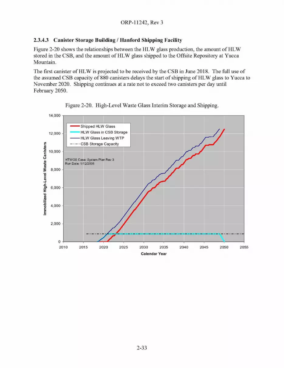
ORP-11242, Rev 3
2.3.4.3 Canister Storage Building / Hanford Shipping Facility
Figure 2-20 shows the relationships between the HLW glass production, the amount ofHLWstored in the CSB, and the amount ofHLW glass shipped to the Offsite Repository at YuccaMountain.
The first canister ofHLW is projected to be received by the CSB in June 2018. The full use ofthe assumed CSB capacity of880 canisters delays the start of shipping ofHLW glass to Yucca toNovember 2020. Shipping continues at a rate not to exceed two canisters per day untilFebruary 2050.
Figure 2-20. High-Level Waste Glass Interim Storage and Shipping.
14,000 r----------------------------------,
205520502045204020352030202520202015
-Shipped HLW Glass
- HLW Glass in CSB Storage
--HLW Glass Leaving WTP
- - - - CSB Storage Capacity
HTWOS Case: Systam Plan Rev 3Run Date: 1/1212008
0+----r---""'-.,......'------r----r----r----,----,----,------12010
12,000
2,000
~
-.:-~ 10,000~
u~
gjs: 8,000a;~
..J
.r.
.2' 6,000:I:'C
.~:co 4,000E.E
Calendar Year
2-33
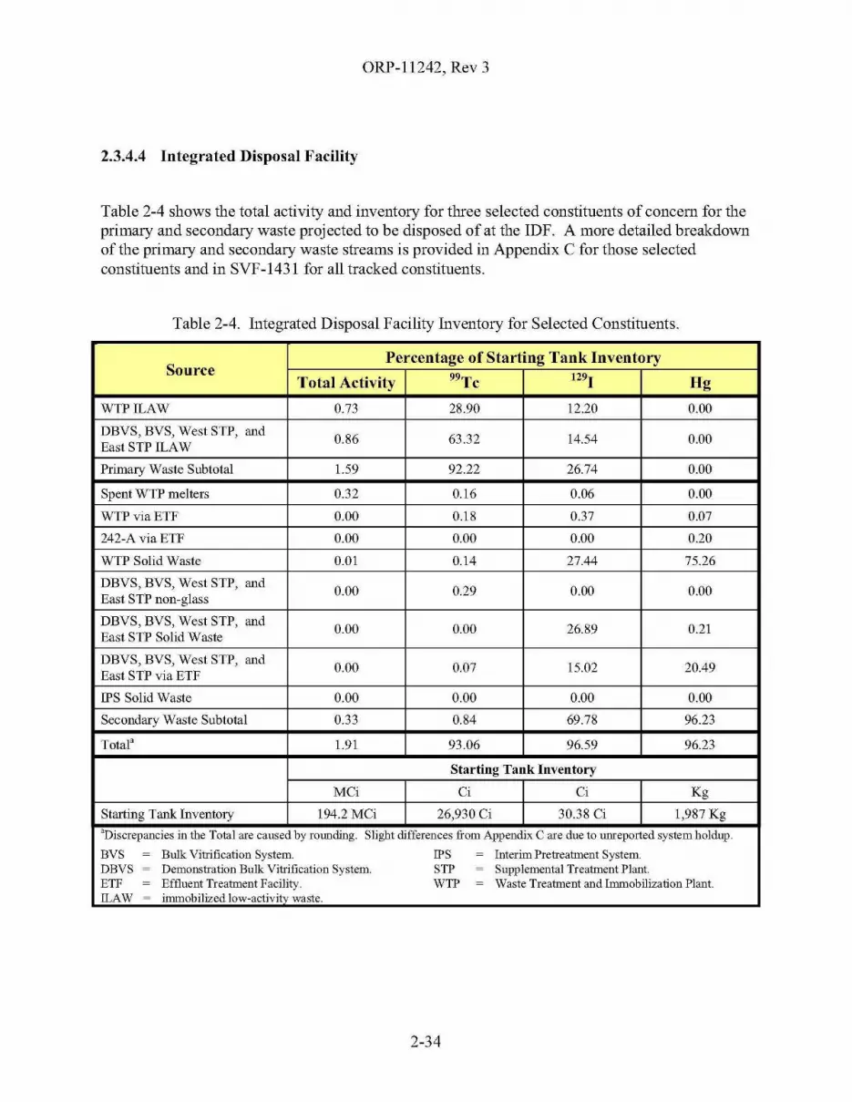
ORP-11242, Rev 3
2.3.4.4 Integrated Disposal Facility
Table 2-4 shows the total activity and inventory for three selected constituents of concern for theprimary and secondary waste projected to be disposed of at the IDF. A more detailed breakdownof the primary and secondary waste streams is provided in Appendix C for those selectedconstituents and in SVF-1431 for all tracked constituents.
Table 2-4. Integrated Disposal Facility Inventory for Selected Constituents.
SourcePercentage of Starting Tank Inventory
Total Activity 99Tc t291 Hg
WTPILAW 0.73 28.90 12.20 0.00
DBVS, BVS, West STP, and0.86 63.32 14.54 0.00
East STP ILAW
Primary Waste Subtotal 1.59 92.22 26.74 0.00
Spent WTP melters 0.32 0.16 0.06 0.00
WTPviaETF 0.00 0.18 0.37 0.07
242-A via ETF 0.00 0.00 0.00 0.20
WTP Solid Waste 0.01 0.14 27.44 75.26
DBVS, BVS, West STP, and0.00 0.29 0.00 0.00
East STP non-glass
DBVS, BVS, West STP, and0.00 0.00 26.89 0.21
East STP Solid Waste
DBVS, BVS, West STP, and0.00 0.07 15.02 20.49
East STP via ETF
IPS Solid Waste 0.00 0.00 0.00 0.00
Secondary Waste Subtotal 0.33 0.84 69.78 96.23
Tota13 1.91 93.06 96.59 96.23
Starting Tank Inventory
MCi Ci Ci Kg
Starting Tank Inventory 194.2 MCi 26,930 Ci 30.38 Ci 1,987 Kg
aDiscrepancies in the Total are caused by roooding. Slight differences from Appendix C are due to umeported system holdup.
BVS ~ Bulk Vitrification System. IPS ~ Interim Pretreatment System.DBVS ~ Demonstration Bulk Vitrification System. STP ~ Supplemental Treatment Plant.ETF ~ Effluent Treatment Facility. WTP ~ Waste Treatment and Immobilization Plant.!LAW ~ immobilized low-activity waste.
2-34
ORP-11242, Rev 3
2.3.4.5 222-S Laboratory
A small volume of dilute waste is assumed to be transferred each year to the DSTs from theoperation of the 222-S Laboratory through the end of the waste treatment mission. For modelingpurposes, these were assumed to be 6.1 KgaVyear before FY 2018 and 12.2 KgaVyear thereafter.
2.3.4.6 Other Hanford Site Facilities
A small volume of dilute waste was assumed to be transferred to the DSTs from thedecommissioning of T-Plant (18.3 Kgal) and PUREX (16.5 Kgal). For modeling purposes, thesetwo transfers were assumed to occur in 2025.
2.3.4.7 Waste Encapsulation and Storage Facility
The cesium and strontium capsules are assumed to be dispositioned outside of the WasteTreatment Complex and therefore are not modeled or evaluated.
2.3.4.8 State Approved Land Disposal Site
The total volume of treated effluent from the Waste Treatment Complex projected to be disposedat the SALDS is 386 Mgal.
2.3.4.9 200 Area Treated Effluent Disposal Facility
Reserved for future use - not modeled.
2.3.4.10 Offsite Geologic Repository
The Offsite Geologic Repository is assumed to be located at Yucca Mountain. The first canisterof IHLW is projected to be shipped to Yucca by November 2020. Shipping continues at a ratenot to exceed two canisters per day until February 2050. The number of canisters projected to beshipped to Yucca Mountain over time is shown in Figure 2-20, High-Level Waste Glass InterimStorage and Shipping.
2.3.4.11 Waste Isolation Pilot Plant
The projected production and therefore the earliest shipping schedules for the CH-TRU(2013 - 2019) and RH-TRU (2025 - 2037) are not fully aligned with the WIPP Baseline andinitiatives. The baseline described in DOE/NTP-96-1204, National TRU Waste ManagementPlan, Corporate Board Annual Report shows that disposal phase activities are currentlyscheduled through FY 2034. WIPP acceleration initiatives46 show the completion of shipping toWIPP from Hanford ofCH-TRU by FY 2015 and RH-TRU by FY 2028. These schedulemismatches will continue to be monitored and resolved.
The schedule for shipping packaged TRU waste from the Supplemental TRU Treatment Systemto WIPP may be slightly delayed from the production schedule depending upon the size of thetwo IS Facilities discussed in §1.3.3.6, Supplemental Transuranic Waste Treatment System. Inany case, the schedule can be no earlier than the projected production for packaged CH-TRU
46 Per Tables 5.0-1 and 5.0-2 of "Transuranic Waste Performance Management Plan," U.S. Department of Energy,Carlsbad Field Office, August 2002.
2-35
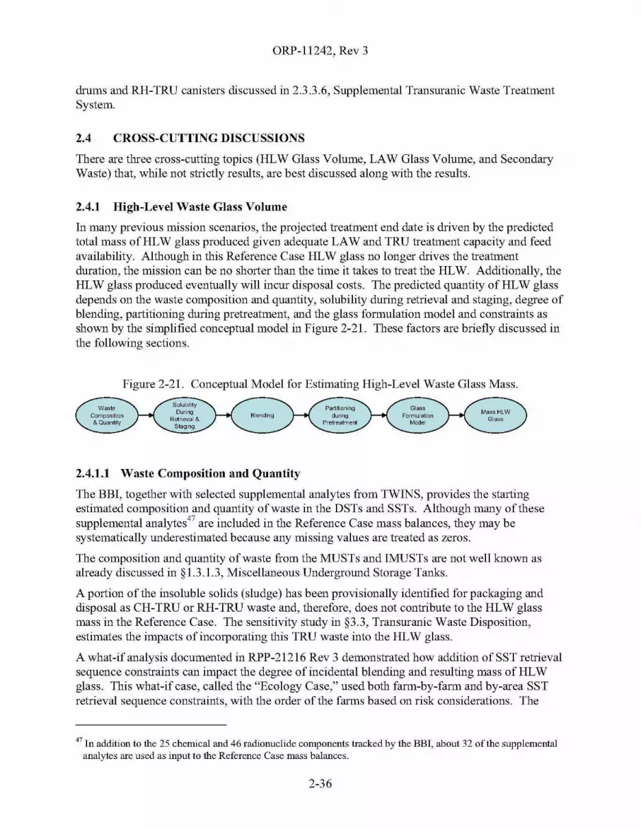
ORP-11242, Rev 3
drums and RH-TRU canisters discussed in 2.3.3.6, Supplemental Transuranic Waste TreatmentSystem.
2.4 CROSS-CUTTING DISCUSSIONS
There are three cross-cutting topics (HLW Glass Volume, LAW Glass Volume, and SecondaryWaste) that, while not strictly results, are best discussed along with the results.
2.4.1 High-Level Waste Glass Volume
In many previous mission scenarios, the projected treatment end date is driven by the predictedtotal mass of HLW glass produced given adequate LAW and TRU treatment capacity and feedavailability. Although in this Reference Case HLW glass no longer drives the treatmentduration, the mission can be no shorter than the time it takes to treat the HLW. Additionally, theHLW glass produced eventually will incur disposal costs. The predicted quantity of HLW glassdepends on the waste composition and quantity, solubility during retrieval and staging, degree ofblending, partitioning during pretreatment, and the glass formulation model and constraints asshown by the simplified conceptual model in Figure 2-21. These factors are briefly discussed inthe following sections.
Figure 2-21. Conceptual Model for Estimating High-Level Waste Glass Mass.
2.4.1.1 Waste Composition and Quantity
The BBI, together with selected supplemental analytes from TWINS, provides the startingestimated composition and quantity of waste in the DSTs and SSTs. Although many of thesesupplemental analytes47 are included in the Reference Case mass balances, they may besystematically underestimated because any missing values are treated as zeros.
The composition and quantity of waste from the MUSTs and lMUSTs are not well known asalready discussed in §1.3.1.3, Miscellaneous Underground Storage Tanks.
A portion of the insoluble solids (sludge) has been provisionally identified for packaging anddisposal as CH-TRU or RH-TRU waste and, therefore, does not contribute to the HLW glassmass in the Reference Case. The sensitivity study in §3.3, Transuranic Waste Disposition,estimates the impacts of incorporating this TRU waste into the HLW glass.
A what-if analysis documented in RPP-21216 Rev 3 demonstrated how addition of SST retrievalsequence constraints can impact the degree of incidental blending and resulting mass of HLWglass. This what-if case, called the "Ecology Case," used both farm-by-farm and by-area SSTretrieval sequence constraints, with the order of the farms based on risk considerations. The
47 In addition to the 25 chemical and 46 radionuclide components tracked by the BBI, about 32 of the supplementalanalytes are used as input to the Reference Case mass balances.
2-36

ORP-1l242, Rev 3A
resulting HLW glass mass was about II % greater than the Reference Case, after backing-out theTRU waste from the Ecology Case estimates, corresponding to about 88 percent-of-span. Asdiscussed in §3.1, Blending - General, the Reference Case achieved a HLW glass masscorresponding to 64 percent-of-span.
Uncertainty estimates associated with the standard BEl analytes for all 177 SSTs and DSTs arequantified and summarized in PNNL-12003, Summary ofUncertainty Estimation Results forHanford Tank Chemical and Radionuclide Inventories.
Qualitatively, there are known uncertainties in and limitations of the BEl that may affect theHLW (and LAW) glass estimates. For example, the composition of certain waste in TX-Farm isbased on only a few samples, increasing the uncertainty in the sulfate inventory. Also, there areonly a few samples of REDOX (Reduction and Oxidation Facility (S-Plant)) sludge that havebeen analyzed, which increases the uncertainty about aluminum dissolution (wash and leachfactors). Another limitation of the BEl is that the inventory is not fully speciated48 nor is thebound hydroxide (mostly associated with aluminum) measured. This causes difficulties in bothestimating the total hydroxide and in reconciling and maintaining the charge balance of thewaste. Uncertainties in the accounting of hydroxide (both free and bound) in the feed deliveredto the WTP will result in uncertainties in determining the amount of sodium hydroxide that needsto be added to the waste during pretreatment.
2.4.1.2 Solubility During Retrieval and Staging
The solubility of tank waste during retrieval and staging is an important factor in determiningboth the quantity of solids and overall composition of the feed delivered to the WTP forpretreatment. This chemistry is approximated using water wash factors which describe thesolubility of the tank waste when contacted with large quantities of water. They define both howmuch saltcake is predicted to dissolve during retrieval and staging and how much slightly solublematerial is predicted to be removed from sludge when water-washed in the PT Facility.
One limitation of water wash factors is that they are a zero-order approximation that applies onlyto the specific set of conditions used when they were developed; they cannot accurately reflectcomplex changes in solid-liquid equilibrium that occur as varying amounts of water are usedduring retrieval, that occur when mixing different wastes, or that occur from concentration(removal of water) in the 242-A Evaporator or in the WTP. This solubility approximation allowsthe simulation of the retrieval and staging of all the tank waste in reasonable amount of computertime.
The water wash factors were originally developed to help estimate the quantity of HLW glassthat would result from treating all of the Hanford tank waste before the decision was madeinclude caustic and oxidative leaching as one of the pretreatment processes. The factors weregenerally estimated by contacting solids with large quantities of water and measuring thecomposition of the liquid phase. Engineering judgment was used to estimate the wash factors forwaste that lacked direct measurements.
48 The phrase "not fully speciated" means that not all of the chemical compounds or their constituent species havebeen identified.
2-37

ORP-11242, Rev 3
Over the past several years, the water wash factors for Cr, AI, S04, P04, 99Tc were reviewed andupdated because previous analysis suggested there were biases or errors that required correction.The factors actually used in the Reference Case are cited in Appendix B, §B2.6.3.
2.4.1.3 Degree of Blending
One of the major drivers for predicting the HLW glass mass is the degree of blending that occursbefore vitrification of the waste. Blending (or its intentional absence, called segregation)influences the HLW glass mass by influencing the composition and variability of the pretreatedHLW feed batches, thus increasing or decreasing the overall amount of glass formers that mustbe added to the waste during vitrification.
Previous work (RPP-20003, Sensitivity ofHanford Immobilized High-level Waste Glass Mass toChromium and Aluminum Partitioning Assumptions, and RPP-RPT-26040, Pairwise Blending ofHigh-Level Waste) has shown that the degree of blending can change the predicted mass ofHLWby about a factor of two between two bounding cases, the Total-Blend and the No-Blend cases.Under current assumptions for the Reference Case, the HLW glass mass for the No-Blend caseis nominally twice that of the Total-Blend case; see the sensitivity study discussed in§3.1, Blending - General, for more details.
Like many previous mission scenarios, the Reference Case relies primarily on "IncidentalBlending" - that which occurs during the retrieval, staging, storage, and delivery of feed withoutany special effort other than SST sequencing. The degree of incidental blending in recentmission scenarios has typically resulted in a projected HLW glass mass about half-way betweenthe Total-Blend and No-Blend cases, with the exception of the TFCOUP Rev 6, whichoverestimated the degree of incidental blending. The degree of incidental blending is sensitive tothe configuration (most notably how tank systems are connected) of the retrieval, transfer, andstaging systems; the amount of solids that are allowed to accumulate in the DST System; and theSST retrieval sequence.
In addition to incidental blending, the Reference Case incorporates several intentional blendssupporting WTP safety and operational considerations; these were discussed in the Feed ControlList discussion in §2.3.1.6, Waste Transfers.
Intentional blending can also be used to reduce the mass of HLW glass. However, there aremany operational and logistical considerations that constrain the degree of blending that can beachieved and the difficulty and cost thereof. Section 2.4 of the RPP-RPT-26040 discusses someof the ways in which intentional blending could be implemented.
2.4.1.4 Partitioning During Pretreatment
The purpose of the WTP PT Facility is to partition (separate) the tank waste into two streams.One stream, containing the LAW fraction of the waste, will be sent to either the WTP LAWVitrification Facility or to the East STP for treatment (immobilization in glass) and on-sitedisposal in the IDF. The other stream, containing the HLW faction of the waste and separatedfission products, will be sent to the WTP HLW Vitrification Facility for treatment(immobilization in glass) and eventual disposal at the HLW Geologic Repository.
The WTP PT Facility contains several unit operations that influence the partitioning of wasteinto pretreated LAW and HLW. These are briefly discussed below and include feedconcentration, caustic leaching, oxidative leaching, post-leach wash, Sr/TRU precipitation, and
2-38
ORP-11242, Rev 3
cesium removal. The sensitivity study in §3.4, Degree of Pretreatment, demonstrates theimportance of both caustic and oxidative leaching on the resulting mass of HLW glass.
A vacuum evaporator is used to concentrate liquid feed to a target sodium concentration(nominally 5 M) when needed. The solid liquid equilibrium that takes place during thisconcentration step has not been defined in the WTP Dynamic (G2) Model Design Document(24590-WTP-MDD-PR-OI-002) nor modeled in HTWOS.
The UFP system is used to remove any remaining water-soluble components, caustic-soluble(primarily aluminum and chromium) components, and additional removal of chromium(oxidative leaching) from the solids. The water wash factors have already been "applied" duringthe retrieval and staging of the feed to the WTP PT Facility; little or no additional dissolutionfrom washing is assumed here.
The caustic-soluble components are removed by contacting the solids with hydroxide ion from asodium hydroxide solution. The amount of material removed from the solids is approximatedusing the caustic leach factors, which, like water wash factors, are a zero-order approximation.Sufficient excess hydroxide must remain to keep the removed material (mostly aluminum) insolution in the subsequent processing steps. The caustic leach factors used by the ReferenceCase are cited in Appendix B, §B2.6.4. The Reference Case assumes that the amount of causticneeded to achieve a 3 M free OK concentration after caustic leaching will be sufficient to keepthe aluminum in solution. However, recent WTP flowsheet calculations predict that additionalcaustic will be required. See the sensitivity study in §3.5, Leach Caustic, for more details.
It has been assumed that additional chromium can be removed during the ultrafilter operatingcycles by oxidizing the chromium to a soluble valance by adding sodium permanganate to thewaste after caustic leaching and water rinsing is completed.
The final step in the pretreatment of solids in the UFP system is a post-leach wash in which theinterstitial liquid containing the leached (dissolved) solids is physically diluted and removedfrom the insoluble solids. The post-leach wash effectiveness depends primarily on the operatingmodes and parameters selected for the operation of the UFP system.
Envelope C waste from tanks AN-102 and AN-107 requires the removal of complexed strontiumand TRU from the liquid phase in order for the resulting ILAW to be disposed on site. Althoughthe Reference Case assumes that this removal will occur in the tank farms, the WTP is retainingthat capability. If performed in the WTP, the UFP system is used to effect this separation byprecipitating the TRU with sodium permanganate and precipitating the strontium using isotopicdilution with Sr(N03h. This potential operation has little impact on the total HLW glass massbut reduces the rate at which waste can be pretreated and introduces some process inefficienciesin the management and blending of the precipitate, both of which in tum impacts the overallglass production.
2.4.1.5 Glass Formulation Model
A glass formulation model is a mathematical model that estimates the composition of the glassresulting from the vitrification of a specified (in this case pretreated HLW) feed. It is generallystated as a non-linear programming problem in which the object (the objective function) is tominimize the mass or volume of the resulting glass subject to a set of constraints on acceptableglass properties and allowable glass composition. In theory, and depending on the goal, differentobjective functions or constraints could be used to account for uncertainties in properties,
2-39
ORP-11242, Rev 3
composition or limits; maximize rate of incorporation of feed into the glass; increase melterlifespan; or increase the robustness of the formulation.
The method currently used to formulate the HLW glass in both the WTP's G2 model and theHTWOS model directly bases the glass formulation on the composition of the pretreated HLW.The pretreated HLW is comprised of the water- and caustic-insoluble solids, the separatedcesium, the precipitated strontium and TRU, and any dissolved solids remaining in the liquidphase, less any chromium removed by oxidative leaching. In the WTP HLW VitrificationFacility, the pretreated HLW is combined with glass forming chemicals, converted to oxides, andincorporated into glass in the HLW melters. The mass and composition of the glass-formingchemicals is adjusted to produce the minimum mass of HLW for that specific batch of pretreatedHLW, and is subject to a number of constraints on glass properties and composition. Theresulting mass of HLW glass depends on the specific glass properties models (i.e., empiricalproperty-composition correlations) being used, the allowable ranges for each property, the modeldomain (region of model validity), allowances for uncertainties, and any other limits on glasscomposition. One of the main objectives of blending is to level out the various glass-limitingcomponents to reduce the total quantity of glass formers needed to produce an acceptable glassand thus minimize the total mass of HLW glass produced.
The Reference Case uses a glass formulation model often referred to as the "Relaxed GlassProperty Model (GPM)," which was developed using experimental data available before 1996.The details of the model are restated in Appendix B, §B2.3.3.6, for convenience. While thismodel is more aggressive than the WTP's baseline model, it is thought to estimate improvementsexpected in HLW loading after additional technology development. Pacific Northwest NationalLaboratory (PNNL) is developing an updated glass formulation model for the ORP using dataavailable through 2007 to improve the accuracy and expand the region of validity of the model.The sensitivity study in 2.4.1.5, Glass Formulation Model, compares the HLW glass massprojected by the Reference Case to that projected by a model similar to WTP's current baselinemodel.
The 2,000-plus projected melter feed batches (individual melter feed preparation vessel batchesof pretreated HLW sent to the HLW melters) for the Reference Case were reviewed and thelimiting constraints were identified. Table 2-5 summarizes the glass drivers; three constraints(S03, Ah03, and Spinel liquidus temperature) determine about 94% of the glass mass. Thisassumes that water washing and caustic leaching removes much of the aluminum; that oxidativeleaching is effective in removing the chromium; that the components removed by leaching do notre-precipitate; and that the relaxed glass properties model applies. For similar technicalassumptions, but different degrees of blending and older tank inventory, a previous analysis(RPP-RPT-26040) identified Fe203 and P20 S as limiting constraints in addition to thoseidentified for the Reference Case.
2-40

Table 2-5. Summary of Reference Case High-Level Waste Glass Drivers.
Number of waste Waste oxideGlass
Average waste Percent of waste Percent ofConstraints!reed batches mass' (Ml)
massloading in glass3 oxide mass glass mass
(Ml)
S03 960 5,738 22,645 0.253 46.8% 56.1%
PzOs 0 0 0 n/a 0.0% 0.0%Solubilitylimited
CrZ03 0 0 0 n/a 0.0% 0.0%
Subtotal 960 5,738 22,645 0.253 46.8% 56.1%
Glass Alz°3 298 1,829 5,871 0.312 14.9% 14.5%
compositionconstraints FeZ03 57 362 933 0.388 3.0% 2.3%
Modelvalidity NazO 81 449 1,291 0.348 3.7% 3.2%limited
SiOz 0 0 0 n/a 0.0% 0.0%
Subtotal 436 2,640 8,096 0.326 21.5% 20.1%
Glass composition constraints1,396 8,378 30,740 0.273 68.4% 76.2%
subtotal
Spinel TL involved 615 3,712 9,289 0.400 30.3% 23.0%
Glass property Spinel TL NOT involved 33 164 336 0.488 1.3% 0.8%constraints
Glass property constraints648 3,876 9,626 0.403 31.6% 23.8%
subtotal
Reference Case Realized Blend total 2,044 12,254 40,366 0.304 100.0% 100.0%
Notes.lThe shaded cells indicate the major constraints that drive the HLW glass mass. This analysis of glass drivers is performed for glass formulated before the application ofmelter DFs. No credit is taken for volatility of constraining components.2In this table, waste oxides refer to the fully pretreated HLW, on an oxide basis.3Represents the weighted average waste loading from the glasses produced from melter feed batches that are limited by the same (or same group) of constraints. Units aremass fraction.
ORP-11242, Rev 3
2.4.2 Low-Activity Waste Glass Volume
The main factors that control the mass of LAW glass are the total mass of LAW sodium and theachievable sodium oxide loading.
The total mass of soluble sodium comprises the soluble portion of the tank waste, the sodiumpresent in the sodium hydroxide and sodium nitrite added for DST corrosion control, and thesodium from sodium hydroxide added by the WTP PT process. In the Reference Case, about55,900 MT of LAW sodium are incorporated into LAW glass from the WTP, DBYS, BYS, WestSTP, and East STP. Of that amount, approximately 1,500 MT were added for tank corrosionchemistry controls and 8,770 MT were added by the WTP for caustic leaching and other processreasons. The sensitivity study in §3.5, Leach Caustic, explains that up to 34,000 MT additionalleach caustic might be required to be added by the WTP fIowsheet.
The achievable sodium oxide loading is driven primarily by the amount of S04 from the LAWsupernate that can be incorporated into the glass as S03.
• For the facilities using the ICy™ process (DBYS, BYS, West STP and East STP), afixed sodium oxide loading of 21.24 wt% is used pending fIowsheet revision aftercompletion of the crucible-scale glass formulation work and the full scale tests.
• For the WTP, the DOE Model is used to estimate the sodium oxide loading. In thismodel, the LAW glass is formulated around two constraints: [Na20] :s 20 wt% and[S03] :s 0.8 wt%. For the Reference Case, this results in about an 18.1 wt% sodiumoxide loading.
• The DOE Model assumes that LAW glass can be formulated to incorporate more S03than the baseline LAW glass formulation model (24590-LAW-RTP-RT-04-0003,"Preliminary ILAW Formulation Algorithm Description") currently in use at theWTP. Use of the baseline model with the other Reference Case assumptions wouldreduce the sodium oxide loading to around 13 wt%. Use of the WTP baseline modelwith the addition of 34,000 MT of additional caustic would likely dilute the S03sufficiently so that the sodium oxide loading would be similar to that achieved by theDOE Model.
2.4.3 Secondary Waste
Table 2-4 shows the total activity and inventory for three selected constituents of concern for thesecondary waste streams projected to be disposed of at the IDF. A more detailed breakdown ofthe secondary waste streams is provided in Appendix C for those selected constituents and inSYF-1431 for all tracked constituents. As discussed in §2.3.4.4, Integrated Disposal Facility,only process-related waste streams generated by the Waste Treatment Complex are reported, notthe overall mass and volume (e.g., the total waste inventory on the HEPA filters is estimated, butnot the number of filters or their mass and volume). Miscellaneous LLW such as shoe coversand SWPs (protective clothing requiring special work permits) are not estimated or reported, noris waste that will be generated from the decommissioning of the various facilities addressed.
The secondary waste estimates are strongly affected by the overall system configuration (i.e.,how the various facilities are interconnected); the assumptions impacting the internal recycleswithin each facility, particularly the phase of the recycled material; and the numerous split factor
2-42

ORP-11242, Rev 3
assumptions used to partition the mass at each unit operation. Like wash and leach factors, splitfactors (and decontamination factors) are a zero-order approximation to the partitioning that isexpected to occur in each unit operation. The basis for each of the individual split factors run thegamut from engineering estimates to partial- and full-scale testing of simulants, analogs, oractual waste.
An implicit assumption is that whatever inventory is projected to report to IDF as secondarywaste, it will meet IDF performance goals through either better stabilization at ETF, or bettercontrol at the treatment facility (West STP, East STP, or WTP), more optimal system design(e.g., recycle management, interfaces between WTP and supplemental pretreatment and/orsupplemental treatment), or through refined estimates of the behaviors of each unit operation.
Because of the importance of the secondary waste in the successful treatment of the tank waste,the ORP is developing a secondary waste management strategy that focuses on the keyconstituents of concern and addresses the basis for the secondary waste estimates, theacceptability of those estimates to their ultimate disposal at the IDF, and the ability of the ETF tosupport the treatment mission.
2.5 SCHEDULE
Figure 2-22 depicts the schedule for the key operational activities for the RPP Mission asestimated by the Reference Case. The overall mission, including closure and decontaminationand decommissioning activities, extends to FY 2055. Only key operational activities are shown activities such as design, construction, permitting and testing are not shown. The schedule foractivities not addressed by the HTWOS model, such as closure and decontamination anddecommissioning, were estimated by shifting the baseline schedule to be consistent with theprojected dates for the modeled activities.
2-43
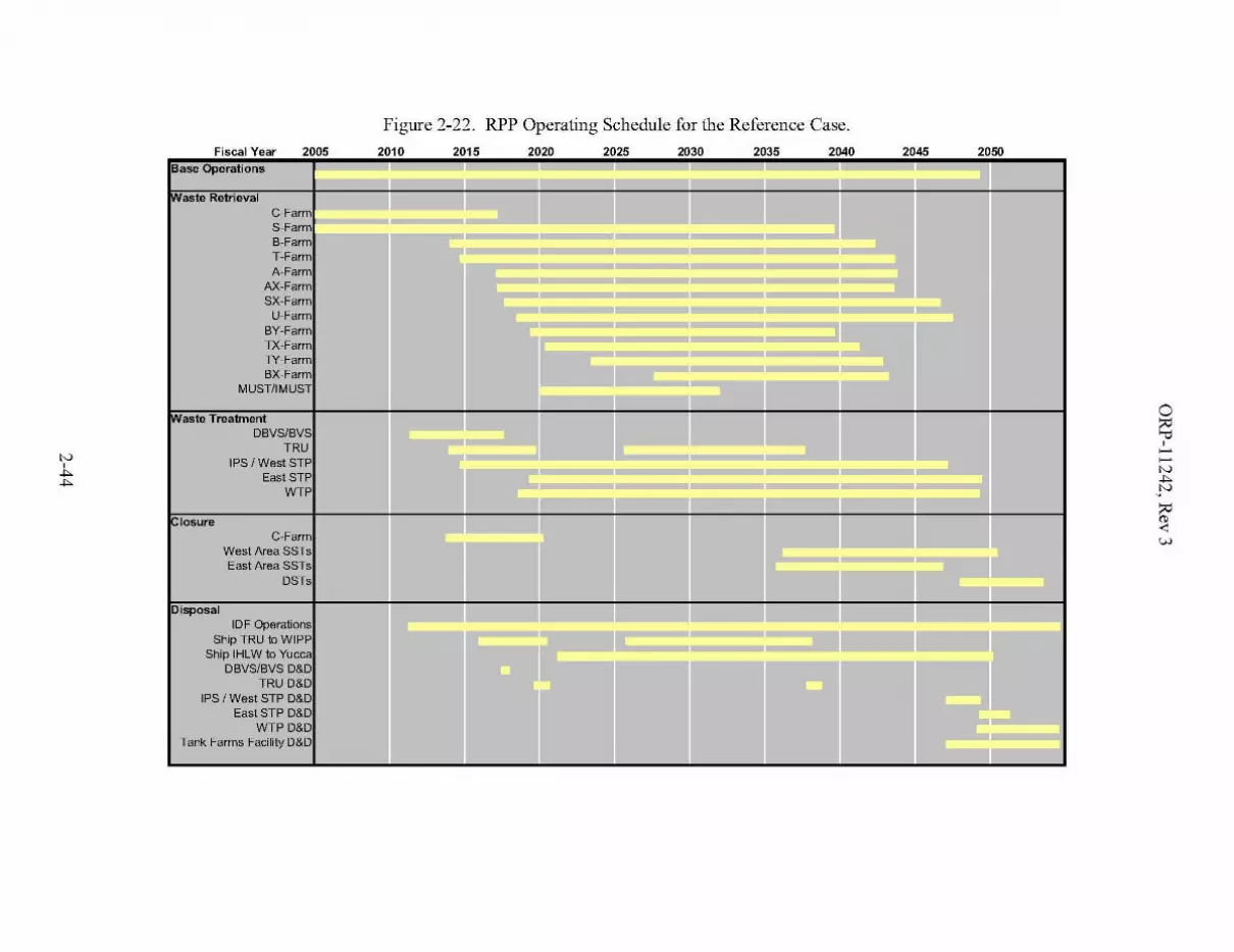
Figure 2-22. RPP Operating Schedule for the Reference Case.
Fiscal Year 2005 2010 2015 2020 2025 2030 2035 2040 2045 2050Base Operations .- _. .- _.
.....- .....-rvvaste Retrieval Jl II
C-FarrnS-FarmB-FarrnT-FarrnA-Farm
AX-FarmSX-Farrn
U-FarmBY-Farm L JL,TX-Farrn iiii-=:--,TY-FarrnBX-Farrn
MUSTIIMUST
rvvaste TreatmentDBVS/BVS
TRUIPS / West STP
JEast STPWTP
!ClosureC-Farrn
West Area SSTs
JIIrEast Area SSTsDSTs
"Disposal JIIOF Operations
~~"'IShip TRU to WIPP :::::::.
Ship IHLW to YuccaoBVS/BVS 0&0
TRU 0&0IPS I West STP 0&0
East STP 0&0WTP 0&0
Tank Farms Facility 0&01r

ORP-11242, Rev 3
3.0 SENSITIVITY STUDIES
This section discusses the impact of selected parameters upon key aspects of the Reference Casemission scenario. This section is organized according to study and each study is independent ofthe others. These studies are meant to provide a representation of the key sensitivities; they arenot meant to be comprehensive, rigorous, sensitivity analyses that capture all uncertainties andinteractions.
§4.2, Mission Sensitivities, will summarize the results by providing projected ranges on keymission parameters.
3.1 BLENDING - GENERAL
As discussed in §2.4.1.3, one of the factors that influences the mass ofHLW glass is the degreeof blending. The impact that blending may have upon the mass of HLW glass can be assessedby comparing the mass of glass that would result if all of the tank waste solids were mixedtogether before treatment versus that which would result if the solids from each tank were treatedseparately and the resulting glass totaled. This analysis uses many of the same assumptions asthe Reference Case, namely, the tank inventory, disposition ofTRU tanks, water wash andcaustic leach factors, oxidative leaching, and the glass formulation model and associated limits.
For the Reference Case assumptions, the mass of HLW glass could range from 28,620 MTG(8,944 canisters) to 46,514 MTG (14,536 canisters). The mass ofHLW glass resulting from thedegree of blending realized in the mission scenario underpinning the Reference Case was40,042 MTG (12,513 canisters). This is 64 percent-of-span between the Total-Blend and theNo-Blend. The percent-of-span is the percent of the way the projected glass mass falls betweenthe Total Blend and the No Blend glass mass. For example, 0 percent of span corresponds to theTotal Blend, while 50 percent of span corresponds to halfway between the Total Blend and NoBlend." These glass masses are shown on Figure 3-1 as "Case 16 (SP3 Ref).',49 (SVF-1397,SP3_Total-Blend_No-Blend_vj.xls).
The potential change in mission duration relative to the Realized Blend can be estimated for theTotal-Blend and No-Blend by assuming that HLW drives the mission at the assumed net HLWvitrification rate of 5.25 MTG/d. If the Total-Blend were achieved, the length of the missionwould be reduced by about 6 years; if the N0-Blend were achieved, the length would increase byabout 3 years. In practice, other constraints such as SST retrieval durations or LAW treatmentcapacity may limit reductions in mission length.
The Realized Blend for the Reference Case is about 34% larger50 than the System PlanRevision 2 (SP2). Most of this increase is due to increases in the Total Blend and No Blend inresponse to updated waste inventories and wash and leach factors. So of the increase is due to alesser degree of incidental blending as evidenced by an increased percent-of-span for theReference Case.
49 The case numbering on Figure 3-1 begins at Case 16 in order to maintain continuity with the nLUllbering used inRPP-RTP-26040 and RPP-20003.
50 The 24% increase shown on Figure 3-1 applies to the average increase in the Total Blend and No Blend. The 34%increase applies to the increase in the Realized Blend.
3-1

Figure 3-1. Comparison of High-Level Waste Glass Mass Ranges for Selected Cases.
120,.----------------------------------------------...,Neither caustic nor oxidative leaching ------------------,. 119%
100
No caustic leaching + 84%
R - Realized Blend
No Blend
Nominal %change in glassmass for thechange shownby the alTow.
Total Blend
Legend
+38%
15%
All TRU to WTP instead cfWIPP
No oxidative leacl1ing
RH-TRU to WTP ir;stead cfWIPP
CH-TRUtoWTPinsl8ad j 4%ofWIPP20
40
80
60
;=-::;;~
0~
"~~~
~
0
'".,.~~
w .!!!, Cltv :s:
..J:I:~
0~~
~
::;;
oL --======::::::JSP2 Case 16
(SP3 Ref)Case 17 Case 18 Case 19 Case 20 Case 21 Case 22
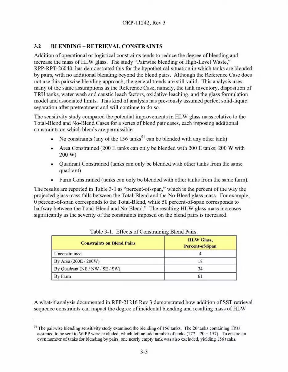
ORP-11242, Rev 3
3.2 BLENDING - RETRIEVAL CONSTRAINTS
Addition of operational or logistical constraints tends to reduce the degree of blending andincrease the mass ofHLW glass. The study "Pairwise blending of High-Level Waste,"RPP-RPT-26040, has demonstrated this for the hypothetical situation in which tanks are blendedby pairs, with no additional blending beyond the blend pairs. Although the Reference Case doesnot use this pairwise blending approach, the general trends are still valid. This analysis usesmany of the same assumptions as the Reference Case, namely, the tank inventory, disposition ofTRU tanks, water wash and caustic leach factors, oxidative leaching, and the glass formulationmodel and associated limits. This kind of analysis has previously assumed perfect solid-liquidseparation after pretreatment and will continue to do so.
The sensitivity study compared the potential improvements in HLW glass mass relative to theTotal-Blend and No-Blend Cases for a series of blend pair cases, each imposing additionalconstraints on which blends are permissible:
• No constraints (any of the 156 tanks51 can be blended with any other tank)
• Area Constrained (200 E tanks can only be blended with 200 E tanks; 200 W with200W)
• Quadrant Constrained (tanks can only be blended with other tanks from the samequadrant)
• Farm Constrained (tanks can only be blended with other tanks from the same farm).
The results are reported in Table 3-1 as "percent-of-span," which is the percent of the way theprojected glass mass falls between the Total-Blend and the No-Blend glass mass. For example,opercent-of-span corresponds to the Total-Blend, while 50 percent-of-span corresponds tohalfway between the Total-Blend and N0-Blend." The resulting HLW glass mass increasessignificantly as the severity of the constraints imposed on the blend pairs is increased.
Table 3-1. Effects of Constraining Blend Pairs.
Constraints on Blend PairsHLWGlass,
Percent-of-Span
Unconstrained 4
By Area (200E /200W) 18
By Quadrant (NE / NW / SE / SW) 34
By Farm 61
A what-if analysis documented in RPP-21216 Rev 3 demonstrated how addition of SST retrievalsequence constraints can impact the degree of incidental blending and resulting mass of HLW
51 The pairwise blending sensitivity study examined the blending of 156 tanks. The 20 tanks containing TRUassumed to be sent to WIPP were excluded, which left an odd number of tanks (177 - 20 ~ 157). To ensure aneven number of tanks for blending by pairs, one nearly empty tank was also excluded, yielding 156 tanks.
3-3
ORP-11242, Rev 3
glass. This what-if case, called the "Ecology Case," used both farm-by-farm and by-area SSTretrieval sequence constraints, with the order of the farms based on risk considerations. Theresulting HLW glass mass was about 11% greater than the Reference Case, after backing-out52
the TRU waste from the Ecology Case estimates, corresponding to about 88 percent-of-span. Asdiscussed in §3.1, Blending - General, the Reference Case achieved a HLW glass masscorresponding to 64 percent-of-span.
3.3 TRANSURANIC WASTE DISPOSITION
The Reference Case assumes that the TRU sludge present in 20 tanks will be packaged andshipped to WIPP for disposal. The impact to HLW glass mass from treating this TRU sludge inthe WTP instead disposal at WIPP was estimated by comparing the Total-Blend / No-Blend forthe Reference Case against those for three different dispositions. This analysis uses many of thesame assumptions as the Reference Case, namely, the tank inventory, water wash and causticleach factors, oxidative leaching, and the glass formulation model and associated limits. Thiskind of analysis has previously assumed perfect solid-liquid separation after pretreatment andwill continue to do so.
Case 17 on Figure 3-1 shows that the impact of treating the CH-TRU in the WTP rather thandisposal at WIPP is an increase in the Total-Blend and No-Blend HLW glass of about 4%relative to the Reference Case - Case 16 (Reference Case). Case 18 shows about a 10% increasefor RH-TRU. Case 19 shows about a 15% increase for both CH-TRU and RH-TRU(SVF-1397).
52 In the Ecology Case, the TRU waste was assumed to be treated at the WTP. The Ecology Case HLW glass masswas therefore adjusted by a factor of 1/1.15 to account for the increase in glass mass due solely to the TRUdisposition. This adjusted glass mass can then be directly compared to that from the Reference Case - thedifference is due to changes in blending as a result of the changed SST retrieval sequence.
3-4
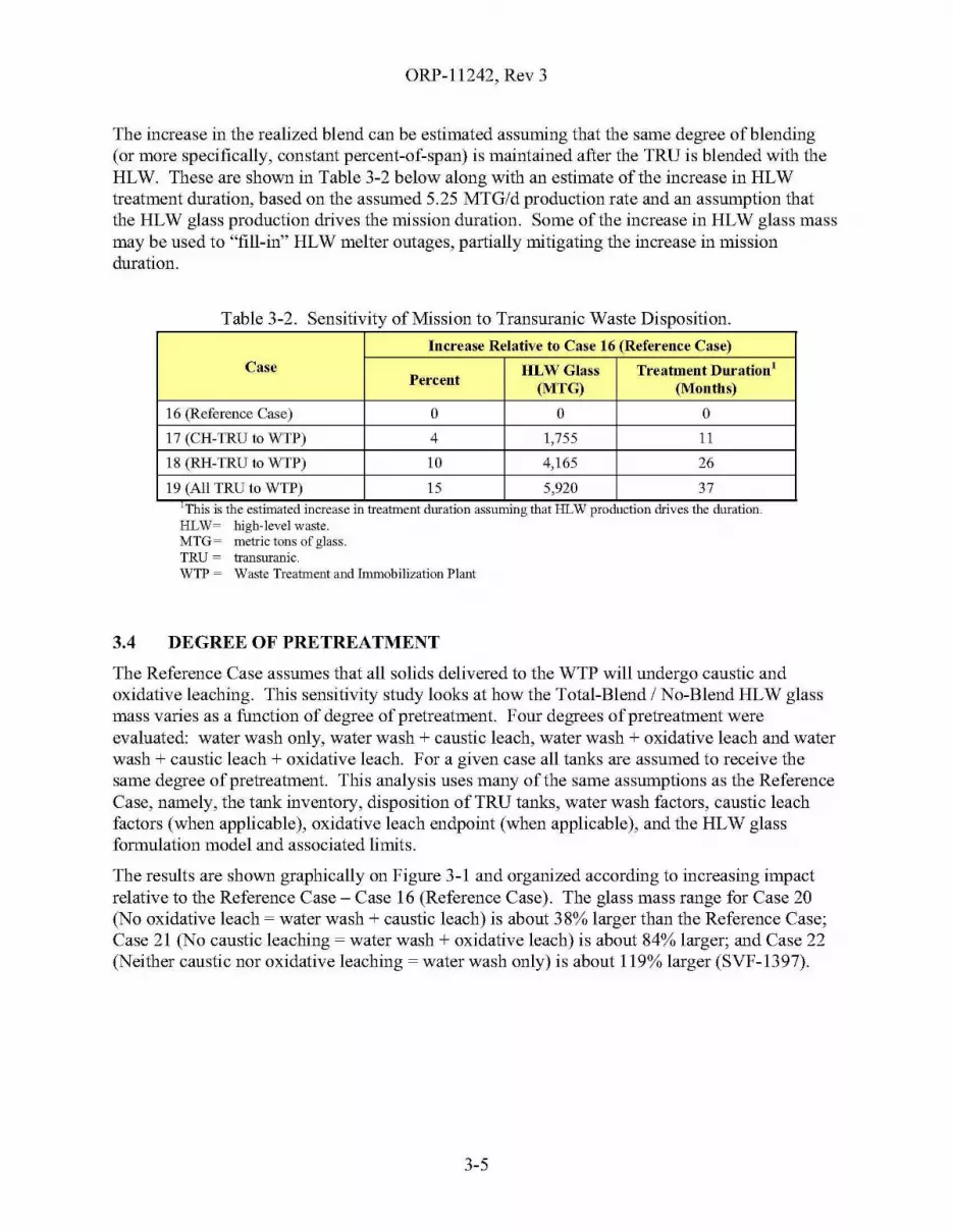
ORP-11242, Rev 3
The increase in the realized blend can be estimated assuming that the same degree of blending(or more specifically, constant percent-of-span) is maintained after the TRU is blended with theHLW. These are shown in Table 3-2 below along with an estimate of the increase in HLWtreatment duration, based on the assumed 5.25 MTG/d production rate and an assumption thatthe HLW glass production drives the mission duration. Some of the increase in HLW glass massmay be used to "fill-in" HLW melter outages, partially mitigating the increase in missionduration.
Table 3-2. Sensitivity of Mission to Transuranic Waste Disposition.
Increase Relative to Case 16 (Reference Case)
Case ULWGlass Treatment Duration!Percent
(MTG) (Months)
16 (Reference Case) 0 0 0
17 (CU-TRU to WTP) 4 1,755 11
18 (RH-TRU to WTP) 10 4,165 26
19 (All TRU to WTP) 15 5,920 37uThIS IS the estllnated Increase III treatment duratIon assummg that HLW productIon drIves the duratIon.HLW= high-level waste.MTG= metric tons of glass.TRU = transuranic.WTP = Waste Treatment and Immobilization Plant
3.4 DEGREE OF PRETREATMENT
The Reference Case assumes that all solids delivered to the WTP will undergo caustic andoxidative leaching. This sensitivity study looks at how the Total-Blend / No-Blend HLW glassmass varies as a function of degree of pretreatment. Four degrees of pretreatment wereevaluated: water wash only, water wash + caustic leach, water wash + oxidative leach and waterwash + caustic leach + oxidative leach. Fora given case all tanks are assumed to receive thesame degree of pretreatment. This analysis uses many of the same assumptions as the ReferenceCase, namely, the tank inventory, disposition ofTRU tanks, water wash factors, caustic leachfactors (when applicable), oxidative leach endpoint (when applicable), and the HLW glassformulation model and associated limits.
The results are shown graphically on Figure 3-1 and organized according to increasing impactrelative to the Reference Case - Case 16 (Reference Case). The glass mass range for Case 20(No oxidative leach ~ water wash + caustic leach) is about 38% larger than the Reference Case;Case 21 (No caustic leaching ~ water wash + oxidative leach) is about 84% larger; and Case 22(Neither caustic nor oxidative leaching ~ water wash only) is about 119% larger (SVF-1397).
3-5
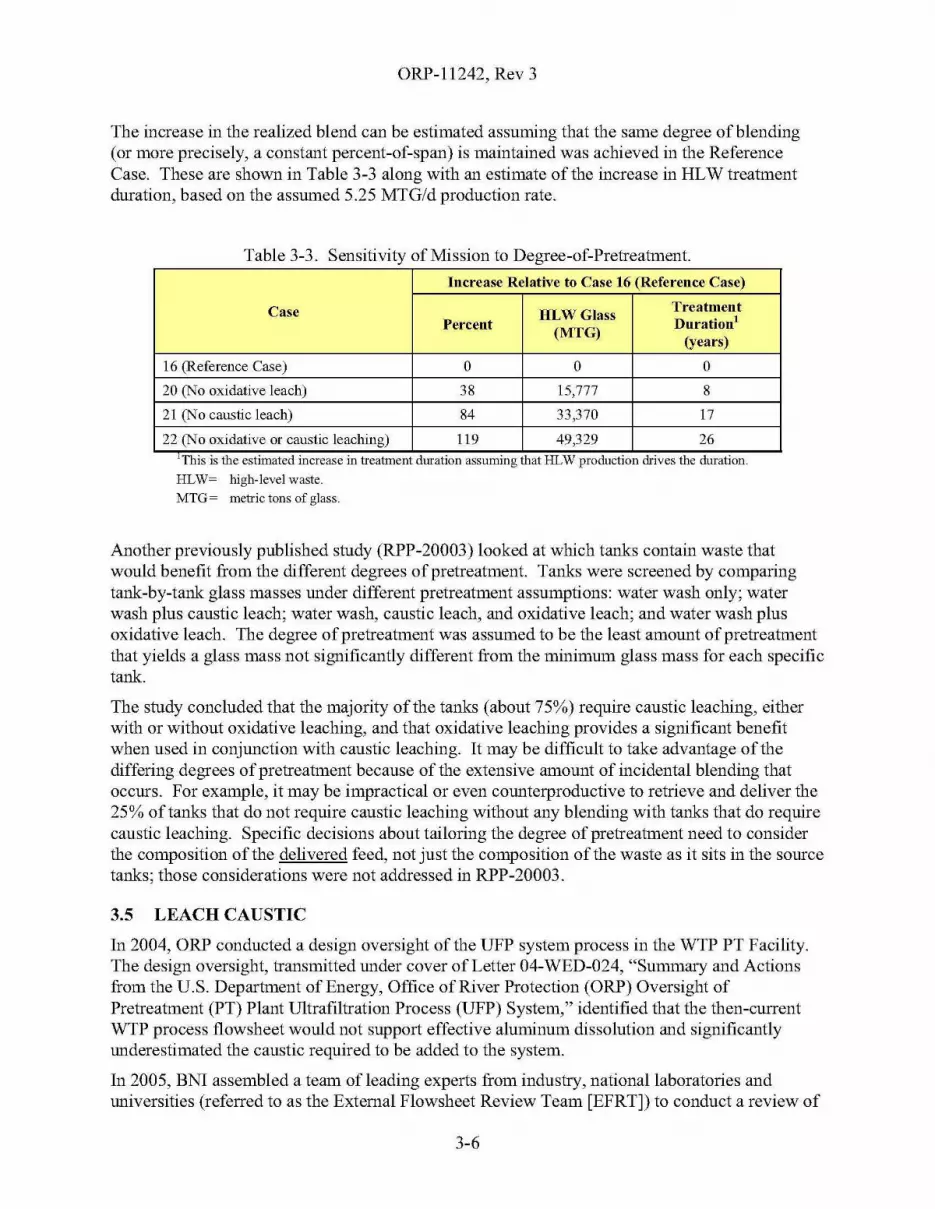
ORP-11242, Rev 3
The increase in the realized blend can be estimated assuming that the same degree of blending(or more precisely, a constant percent-of-span) is maintained was achieved in the ReferenceCase. These are shown in Table 3-3 along with an estimate of the increase in HLW treatmentduration, based on the assumed 5.25 MTG/d production rate.
Table 3-3. Sensitivity of Mission to Degree-of-Pretreatment.
Increase Relative to Case 16 (Reference Case)
Case HLWGlassTreatment
Percent(MTG)
Duration!(years)
16 (Reference Case) 0 0 0
20 (No oxidative leach) 38 15,777 8
21 (No caustic leach) 84 33,370 17
22 (No oxidative or caustic leaching) 119 49,329 26,.ThIS IS the estllnated Increase III treatment duratIon assummg that HLW productIon drIves the duratIon.
HLW= high-level waste.
MTG= metric tons of glass.
Another previously published study (RPP-20003) looked at which tanks contain waste thatwould benefit from the different degrees of pretreatment. Tanks were screened by comparingtank-by-tank glass masses under different pretreatment assumptions: water wash only; waterwash plus caustic leach; water wash, caustic leach, and oxidative leach; and water wash plusoxidative leach. The degree of pretreatment was assumed to be the least amount of pretreatmentthat yields a glass mass not significantly different from the minimum glass mass for each specifictank.
The study concluded that the majority of the tanks (about 75%) require caustic leaching, eitherwith or without oxidative leaching, and that oxidative leaching provides a significant benefitwhen used in conjunction with caustic leaching. It may be difficult to take advantage of thediffering degrees of pretreatment because of the extensive amount of incidental blending thatoccurs. For example, it may be impractical or even counterproductive to retrieve and deliver the25% of tanks that do not require caustic leaching without any blending with tanks that do requirecaustic leaching. Specific decisions about tailoring the degree of pretreatment need to considerthe composition of the delivered feed, not just the composition of the waste as it sits in the sourcetanks; those considerations were not addressed in RPP-20003.
3.5 LEACH CAUSTIC
In 2004, ORP conducted a design oversight of the UFP system process in the WTP PT Facility.The design oversight, transmitted under cover of Letter 04-WED-024, "Summary and Actionsfrom the U.S. Department of Energy, Office of River Protection (ORP) Oversight ofPretreatment (PT) Plant Ultrafiltration Process (UFP) System," identified that the then-currentWTP process fIowsheet would not support effective aluminum dissolution and significantlyunderestimated the caustic required to be added to the system.
In 2005, BNI assembled a team of leading experts from industry, national laboratories anduniversities (referred to as the External Flowsheet Review Team [EFRTJ) to conduct a review of
3-6
ORP-11242, Rev 3
the process flowsheet. In response to this review, BNI performed a study to determine theimpact of eight proposed modifications to the WTP PT processes. This study included theprocess flowsheet changes (aluminum solubility relationships) needed to complete the causticleaching process and maintain the aluminum in solution through the cesium ion-exchangeprocess. Based on the recommended modifications and updated aluminum solubilityrelationships from this study, up to 34,000 MT of additional sodium53 may be required to beadded during caustic leaching. (24590-WTP-RPT-PO-07-002, Dynamic (G2) FlowsheetAssessment ofthe Effect ofM-12 Modifications on Pretreatment Capacity)
The sensitivity study in this section estimates the impact upon the mission if the additional34,000 MT of sodium were incorporated into the WTP PT flowsheet. The impacts wereestimated in two ways:
• Given a fixed LAW treatment capacity (WTP LAW Vitrification + East STP),estimate the increase in mission duration.
• Given a fixed mission duration, estimate the needed East STP capacity.
In both of the above cases, the West Area LAW treatment (DBVS, BVS, and West STP)production was held constant. The production of the WTP LAW Vitrification facility and theEast STP were assumed to follow their ramp-up curves in the key enabling assumptions (i.e., anyproduction outages were removed to decouple this study from SST retrieval limitations). Theresults of the study (SVF-1412, Caustic_Sensitivity_vl.xls) are discussed below; the missiondurations and end dates have been adjusted to remove production outages in the Reference Case.
• Given a fixed LAW treatment capacity (WTP LAW Vitrification + East STP),estimate the increase in mission duration: An additional 15 years would be requiredto treat the additional sodium resulting in a treatment end date of about 2060 ascompared to the no-outage date of 2045 for the Reference Case.
• Given a fixed mission duration, estimate the needed East STP capacity: The EastSTP would require approximately 35 MTG/d net production capacity to maintain thetreatment end date as compared to about 14.65 MTG/d for the Reference Case. Thisis over twice the Reference Case capacity for East STP.
In either of the above cases, the total mass of projected LAW glass will be about 617,000 MTGas compared to 384,200 MTG for the Reference Case, an increase of about 61 percent, assumingthe average Na20 loadings discussion in §2.4.2, Low-Activity Waste Glass Volume, aremaintained.
3.6 HIGH-LEVEL WASTE GLASS MODELS
As discussed in §2.4.1.5, one of the factors that influences the mass ofHLW glass is the glassformulation model. This sensitivity study estimated the impact of using a different glassformulation model. The study compares the glass mass projected by the Reference Case versusthat projected by a Sensitivity Case that is generally aligned with the glass formulation
53 The cited study estimated 40,600 MT sodium for leaching and maintaining aluminum solubility when usingrecommended modifications and updated aluminum solubility relationships. The base case for the cited studyused only 6,600 MT sodium. The difference (40,600 - 6,600 ~ 34,000) is the incremental or additional sodiumassumed by the Leach Caustic sensitivity study.
3-7
ORP-11242, Rev 3
constraints and limits implicit in the WTP flowsheet. In this study, the composition of each ofthe two thousand plus batches of pretreated HLW is kept constant between the two cases toeliminate blending or pretreatment related influences. Table 3-4 compares the constraints andlimits for both cases used in this study.
The impact of changing from the Reference Case to the Sensitivity Case HLW glass constraintsand limits is an increase in HLW glass mass of about 21 % (SVF-1427,SP3_HLW_Glass_Limit_Sensitivity. xis). A sub-study changed only the Ah03 limit to theSensitivity Case value, leaving the other constraints and limits at the Reference Case values.This sub-study found that over half of this glass mass increase is solely a result of the reductionof the Ah03 upper limit from 17 wt% to 11 wt%.
3.7 SUPPLEMENTAL LOW-ACTIVITY WASTE TREATMENT
As discussed in §1.3.3 and §1.4.4, the WTP as currently scoped was not intended to treat all ofthe tank waste; the Reference Case assumes additional (supplemental) LAW treatment capabilitywill be provided in order to maintain a reasonable duration for the treatment mission. This studydemonstrates the need for supplemental LAW treatment by estimating the treatment missionduration and end date ifthere were no supplemental LAW treatment other than the small amountprovided by DBVS and BVS. In this study, the WTP LAW Vitrification capacity is heldconstant at the Reference Case assumptions and all production outages are removed to decouplethis study from the SST retrieval limitations.
The results of this study (SVF-1412) indicate that the treatment mission would end around 2072without the treatment capacity provided by East STP and West STP, for approximately 54 yearsofWTP full operations. This simple calculation assumes that the 18.1 wt% average Na20loading for the WTP LAW Facility projected for the Reference Case is maintained. However,since the overall S04:Na ratio for the combined feed (East STP, West STP, and WTP LAW) isslightly higher54 than the Reference Case's WTP LAW ratio, the resulting Na20 loading may besmaller and the treatment end date later than estimated here.
A sub-study examined this same question, but added in the 34,000 MT of additional sodium thatmight be required for leaching solids and maintaining aluminum in solution, as discussed in §3.5.If this additional sodium were treated with the WTP LAW Vitrification Facility, withoutEast STP or West STP, the treatment mission would end around 2105, for approximately87 years of full WTP operations.
54 The "excess pretreated LAW" from the WTP is emiched in S04 because there is more excess pretreated wastewhenever the Na,O loading in the LAW glass is lower.
3-8
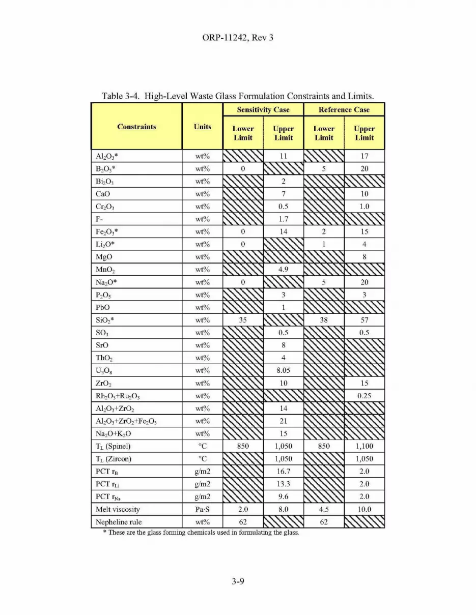
ORP-11242, Rev 3
Table 3-4. High-Level Waste Glass Formulation Constraints and Limits.
Sensitivity Case Reference Case
Constraints Units LowerLimit
UpperLimit
LowerLimit
UpperLimit
Al,03'
CaO
Cr,03
F-
MgO
MnO,
P,O,
PbO
SrO
ThO,
ZrO,
Na,O+K,O
Tc (Spinel)
Tc (Zircon)
PCTrE
peT ILi
Melt viscosity
Nepheline rule
wt% ~ ,~~ 0.5 ~"'-"'-"0 LO
wt% 0 14 2 15
°C 850 1,050 850 1,100
°C ~"'-"'-"'0'\ 1,050 ~"'-"'-"'-~ 1,050
Pa'S 2.0 8.0 4.5 10.0
* These are the glass fonnmg chellllcals used III forrnulatmg the glass.
3-9
ORP-11242, Rev 3
3.8 ENHANCED SINGLE-SHELL TANK RETRIEVAL
As mentioned in §2.3.l.4, Waste Retrieval from Single-Shell Tanks, the outages in theproduction plots for West STP and HLW Vitrification suggest that feed is not being retrievedand/or staged fast enough to keep up with the assumed capacities of these facilities. Examinationof the detailed model results for the Reference case revealed:
• The SSTs providing West Area LAW Feed are first retrieved into Tank SY-l03. Theliquids in Tank SY-l03 are decanted into Tank SY-lOl, which then provides feed tothe IPS. The IPS returns the separated cesium to SY-l02 and sends the pretreatedfeed to the West STP. Tank utilization data (SVF-136l, DST_Space_File_SystemPlan Rev 3(l-12-2008)-8.3rl-WC91778_M3.xls) shows that SY-lOl is emptied bythe IPS faster than SY-l03 is refilled with retrieved SST waste. Although themajority of the seventeen-year cumulative West STP outage was related to the SSTretrieval assumptions, a couple of years was due to waiting for the high-solidscross-site receiver (AN-l04) to be available so that it could receive the settled solidsaccumulated in SY-l03.
• Around the time that the HLW production curve begins to deviate from the assumedcapacity (2031), the volume of waste in the DSTs begins to decrease. This suggeststhat the SSTs are not being retrieved fast enough to replenish the supply ofHLWfeed.
This was confirmed by performing a simple sensitivity study55 in which the SST retrievalvolumes and durations of the SSTs assumed to be retrieved using the MRS technology (thesetend to be the tanks with high as-retrieved volumes and long ruinimum retrieval durations) werereplaced with volumes and durations similar to using MS technology, which is generally muchmore efficient. The rationale behind selecting this more optiruistic assumption is that theretrieval systems supporting the MRS tanks ruight be reconfigured to include both "at-tank"recycle of supernate to reduce the addition of water to the SST during retrieval and recycle ofsupernate from the DST System to reduce the addition of water to slurry the retrieved waste tothe DST System.
The results of this simple study show (SVF-1437, Transfer_File_Formatted_System Plan Rev3(l-30-2008)-8.3rl-WC91778_Ml.xls SVF-1438, DST_Space_File_System Plan Rev 3(l-30-2008)-8.3rl-WC91 778_Ml.xls; SVF-1439, Production_Plots_System PlanRev 3(l-30-2008)-8.3rl-WC91778_Ml.xls):
• The cumulative outage in the HLW production curve (Figure 3-2) is reduced to about3 years versus the 8 years seen in the Reference Case. Much of this remaining outageis now a result of the East Area LAW treatment capacity (WTP LAW Vitrification +East STP) driving the treatment end date.
• There are no outages in the WTP LAW Vitrification and only a 3-year cumulativeoutage in East STP. The cause of this residual outage had not been positivelyidentified, but may be related to the balance of HLW and LAW feed projected to bedelivered to the WTP around 2025 - 2027 and the assumed WTP ultrafilter permeaterate.
55 HTWOS Model Run: "System Plan Rev 3(1-30-2008)-8.3rl-WC91778".
3-10
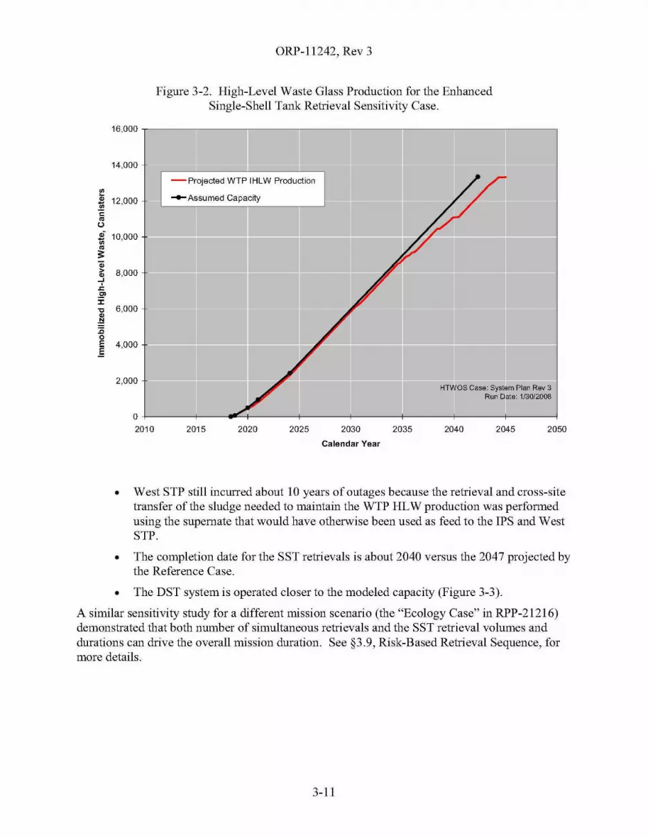
ORP-11242, Rev 3
Figure 3-2. High-Level Waste Glass Production for the EnhancedSingle-Shell Tank Retrieval Sensitivity Case.
-Projected WTP IHLW Production
-Assumed Capacity
HTWOS Case: System Plan Rev 3Run Date: 1/30/2008
16,000
14,000
~~ 12,000~~
~
u~.
10,0001;;~s:a;> 8,000~..J
.r.
.2':I:'C 6,000~
.~
:c0E 4,000.E
2,000
0
2010 2015 2020 2025 2030
Calendar Year
2035 2040 2045 2050
• West STP still incurred about 10 years of outages because the retrieval and cross-sitetransfer of the sludge needed to maintain the WTP HLW production was performedusing the supernate that would have otherwise been used as feed to the IPS and WestSTP.
• The completion date for the SST retrievals is about 2040 versus the 2047 projected bythe Reference Case.
• The DST system is operated closer to the modeled capacity (Figure 3-3).
A similar sensitivity study for a different mission scenario (the "Ecology Case" in RPP-21216)demonstrated that both number of simultaneous retrievals and the SST retrieval volumes anddurations can drive the overall mission duration. See §3.9, Risk-Based Retrieval Sequence, formore details.
3-11
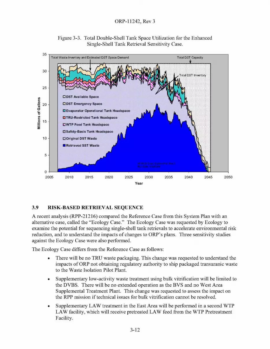
ORP-11242, Rev 3
Figure 3-3. Total Double-Shell Tank Space Utilization for the EnhancedSingle-Shell Tank Retrieval Sensitivity Case.
35,---------------------------------.,Total Wastalnvantory and Estimated DST Space Damand Total DST Capacity
205020452040203520302025202020152010
0+----"-2005
30
25
~E:l DST Available Space
~
.Q20 [] CST Emergency Space
<iiCl [J Evaporator Operational Tank Headspace'li~ DTRU-Restricted Tank Headspace~
~ 15E;JWTP Feed Tank Headspace
:;;IZI Safety-Basis Tank Headspace
10 o Original DST Waste
• Retrieved SST Waste
5
Year
3.9 RISK-BASED RETRIEVAL SEQUENCE
A recent analysis (RPP-21216) compared the Reference Case from this System Plan with analternative case, called the "Ecology Case." The Ecology Case was requested by Ecology toexamine the potential for sequencing single-shell tank retrievals to accelerate environmental riskreduction, and to understand the impacts of changes to ORP's plans. Three sensitivity studiesagainst the Ecology Case were also performed.
The Ecology Case differs from the Reference Case as follows:
• There will be no TRU waste packaging. This change was requested to understand theimpacts of ORP not obtaining regulatory authority to ship packaged transuranic wasteto the Waste Isolation Pilot Plant.
• Supplementary low-activity waste treatment using bulk vitrification will be limited tothe DVBS. There will be no extended operation as the BVS and no West AreaSupplemental Treatment Plant. This change was requested to assess the impact onthe RPP mission if technical issues for bulk vitrification cannot be resolved.
• Supplementary LAW treatment in the East Area will be performed in a second WTPLAW facility, which will receive pretreated LAW feed from the WTP PretreatmentFacility.
3-12

ORP-11242, Rev 3
• The maximum WTP HLW melter capacity was reduced from 5.25 MTG/d to4.2 MTG/d. This change was requested to understand the impact if ORP is not ableto achieve higher HLW melter production rates than those currently specified in theDangerous Waste Permit.
• The near-term schedule for the retrieval of SST wastes from C-Farm, from tanks S102, S-109, and S-112, and from the A and AX Farms will be accelerated.
• Risk reduction, including a desire for early closure of waste management areas, wasthe primary consideration used to prioritize the sequencing of the remaining SSTs forretrieval. This was implemented by sequencing the remaining retrievals first by area(200 West before 200 East) and then by farm within each area. Retrievals fromdifferent areas and different farms were allowed a reasonable overlap. Within eachfarm, the tanks were ordered to attempt to provide balanced feed to the WTP withinthe few remaining degrees of freedom. The order of the farms was selected byEcology based on risk considerations described in RPP-21216.
The Ecology Case projected that the treatment mission would be completed in 2066 (2049 forReference Case), SST Retrievals would be completed in 2062 (2047 for Reference Case), andapproximately 15,921 canisters ofHLW glass (12,513 for Reference Case) would be produced.
The increase in HLW glass mass had two drivers. First, treating the TRU waste at the WTPaccounted for a 15% increase in HLW glass as compared to the Reference Case. This isconsistent with the results in §3.3, Transuranic Waste Disposition. Second, the reduction inincidental blending increased the HLW glass mass by an additional 11%. In the Ecology Case,the degree of incidental blending is reduced because the retrieved waste did not have anopportunity to be accumulated and blended in the DSTs before delivery to the WTP and becausethe tanks in a given tank farms often contain waste that would produce HLW glass limited by thesame components.
A sensitivity case around the Ecology Case increased the net HLW and LAW vitrificationcapacity so that waste treatment could be finished by 2047 if vitrification capacity were the onlyconstraint. The treatment end date (2065) and SST retrieval end date (2062) were about the sameas the Ecology Case. Increasing the vitrification capacities did not significantly reduce themission length because the SST retrieval assumptions constrain the mission and not theprocessing rates through the WTP.
Two other sensitivity studies around the Ecology Case explored how improvements in SSTretrieval could affect the mission. One study, similar to that discussed in §3.8, Enhanced SingleShell Tank Retrieval, demonstrated that the mission could be shortened by about 8 years if theperformance of SST Retrieval could be increased. The other study demonstrated that an increasein the number of simultaneous retrievals that could be supported in the south-west quadrant(S, SX, and U-Farms) would provide a similar benefit.
3-13
ORP-11242, Rev 3
This page intentionally left blank.
3-14
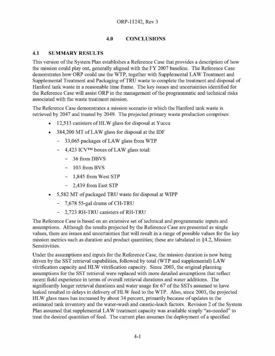
ORP-11242, Rev 3
4.0 CONCLUSIONS
4.1 SUMMARY RESULTS
This version of the System Plan establishes a Reference Case that provides a description of howthe mission could play out, generally aligned with the FY 2007 baseline. The Reference Casedemonstrates how ORP could use the WTP, together with Supplemental LAW Treatment andSupplemental Treatment and Packaging of TRU waste to complete the treatment and disposal ofHanford tank waste in a reasonable time frame. The key issues and uncertainties identified forthe Reference Case will assist ORP in the management of the programmatic and technical risksassociated with the waste treatment mission.
The Reference Case demonstrates a mission scenario in which the Hanford tank waste isretrieved by 2047 and treated by 2049. The projected primary waste production comprises:
• 12,513 canisters ofHLW glass for disposal at Yucca
• 384,200 MT of LAW glass for disposal at the IDF
33,065 packages of LAW glass from WTP
4,423 ICVTM boxes of LAW glass total:
36 fromDBVS
103 fromBVS
1,845 from West STP
2,439 from East STP
• 5,582 MT of packaged TRU waste for disposal at WIPP
7,678 55-gal drums ofCH-TRU
2,723 RH-TRU canisters ofRH-TRU
The Reference Case is based on an extensive set of technical and programmatic inputs andassumptions. Although the results projected by the Reference Case are presented as singlevalues, there are issues and uncertainties that will result in a range of possible values for the keymission metrics such as duration and product quantities; these are tabulated in §4.2, MissionSensitivities.
Under the assumptions and inputs for the Reference Case, the mission duration is now beingdriven by the SST retrieval capabilities, followed by total (WTP and supplemental) LAWvitrification capacity and HLW vitrification capacity. Since 2003, the original planningassumptions for the SST retrieval were replaced with more detailed assumptions that reflectrecent field experience in terms of overall retrieval durations and water additions. Thesignificantly longer retrieval durations and water usage for 67 of the SSTs assumed to haveleaked resulted in delays in delivery of HLW feed to the WTP. Also, since 2003, the projectedHLW glass mass has increased by about 34 percent, primarily because of updates in theestimated tank inventory and the water-wash and caustic-leach factors. Revision 2 of the SystemPlan assumed that supplemental LAW treatment capacity was available simply "as-needed" totreat the desired quantities of feed. The current plan assumes the deployment of a specified
4-1

ORP-11242, Rev 3
number of melter-lines, each using the flowsheet and testing for the DBVS as the basis for itsavailable capacity.
The Reference Case also developed overall system mass balances for the Waste TreatmentComplex. Estimates of secondary waste were found to be sensitive to the overall configurationof the Waste Treatment Complex, the process splits for each unit operation, and theprocess-specific internal recycles.
4.2 MISSION SENSITIVITIES
Based on the discussions in §1.3, Overview of the Waste Treatment Complex, the ReferenceCase Results presented in §2.0, Results and Discussion of Reference Case, and the sensitivitiesstudies in §3.0, Sensitivity Studies, the waste retrieval and treatment mission is sensitive to thefollowing broad categories of process assumptions:
• Leach caustic requirements;
• SST retrieval capabilities;
• STP capacity;
• WTP capacity (pretreatment, LAW vitrification, and HLW vitrification);
• Overall configuration of the Waste Treatment Complex;
• Glass formulation models and limits;
• Degree of blending;
• TRU disposition;
• Process splits and recycle configuration;
• Tank waste inventory.
In order to help understand some of the technical and programmatic uncertainty in the ReferenceCase, Table 4-1 presents multiple estimates of several key mission parameters. The estimatesinclude values lower and higher than the point estimate for the Reference Case when availableand a brief explaination of the source of the estimates. A more comprehensive analysis, such asa Monte Carlo-based sensitivity analysis with input distributions provided by a Delphi study, orperhaps a series of well-crafted parametric studies, would be required to provide more definitiveranges.
4-2
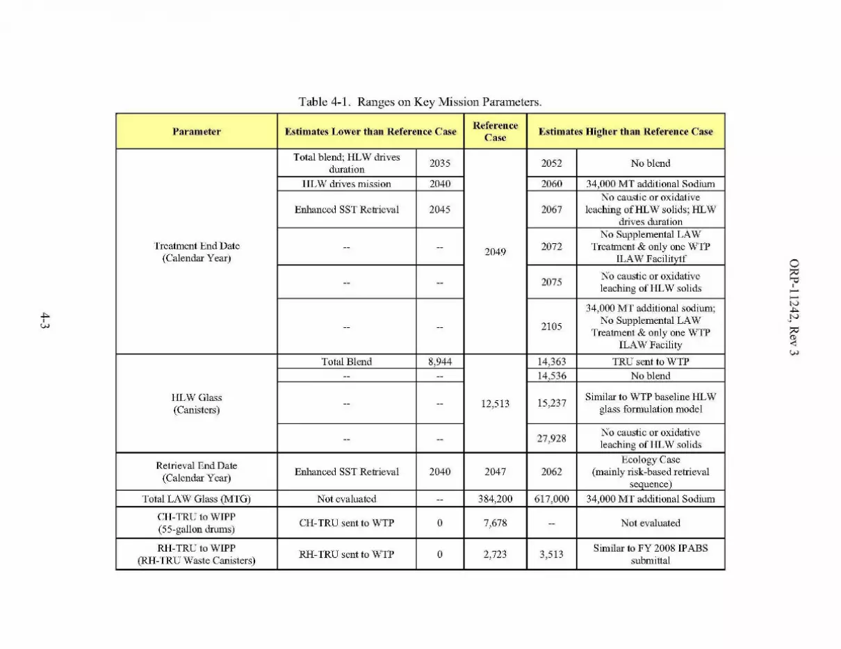
.4,w
Table 4-1. Ranges on Key Mission Parameters.
Parameter Estimates Lower than Reference CaseReference
Estimates Higher than Reference CaseCase
Total blend; HLW drives2035 2052 No blend
durationHLW drives mission 2040 2060 34,000 MT additional Sodium
No caustic or oxidativeEnhanced SST Retrieval 2045 2067 leaching ofHLW solids; HLW
drives durationNo Supplemental LAW
Treatment End Date -- --2049 2072 Treatment & only one WTP
(Calendar Year) ILAW Facilitvtf
2075No caustic or oxidative
-- --leaching of HLW solids
34,000 MT additional sodium;
-- -- 2105No Supplemental LAW
Treatment & only one WTPILAW Facility
Total Blend 8,944 14,363 TRU sent to WTP-- -- 14,536 No blend
HLWGlass12,513 15,237
Similar to WTP baseline HLW(Canisters)
-- --glass formulation model
27,928No caustic or oxidative
-- --leaching of HLW solids
Retrieval End DateEcology Case
(Calendar Year)Enhanced SST Retrieval 2040 2047 2062 (mainly risk-based retrieval
sequence)
Total LAW Glass (MTG) Not evaluated -- 384,200 617,000 34,000 MT additional Sodium
CH-TRU to WIPPCH-TRU sent to WTP 0 7,678 Not evaluated
(55-gallon drums)--
RH-TRU to WIPPRH-TRU sent to WTP 0 2,723 3,513
Similar to FY 2008 IPABS(RH-TRU Waste Canisters) submittal
ORP-1l242, Rev 3A
4.3 KEY ISSUES AND UNCERTAINTIES
The mission scenario depicted by the Reference Case includes a number of challenges that needto be successfully addressed to reach the desired performance for the mission. These challengesare summarized along with potential mitigating actions in Table 4-2, "Key Issues andUncertainties for the Reference Case."
The key issues and uncertainties were developed using a top-down, qualitative, approach thatexamined the challenges presented by the key enabling assumptions or other assertions or fromthe key features or other observations from the simulation of the Reference Case. The key issuesand uncertainties identified in Table 4-2 are grouped by summary-level assumptions and areintended to reflect mission driving issues and uncertainties only. Programmatic risks, such aslabor shortfalls, and lower-level issues and uncertainties are addressed in RPP risk managementplans and associated data.
Information sources included the RPP System Plan Key Enabling Assumptions (Appendix B) ofORP M 413.3-1d, River Protection Project Federal RiskManagement Plan; TFC-PLN-39, RiskManagement Plan; ( and 24590-WTP-RPT-PR-OI-006, Risk Assessment Report, supporting theWTP Technical and Programmatic Risk Analysis.
The baseline has evolved and continues to evolve since the assumptions for the Reference Casewere established. Therefore, some of the assumptions and key features of the Reference Caseare different than the current baseline and the associated issues and uncertainties may not befully consistent with the critical risks addressed in current ORP and contractor critical risk lists.An overall update of RPP risk data has been initiated and is targeted for completion in 2008.
4-4
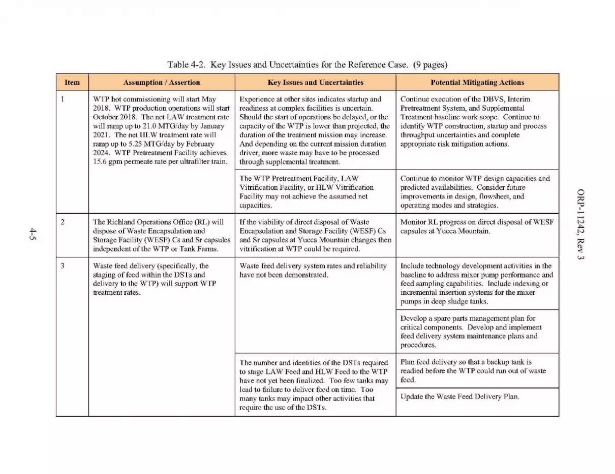
Table 4-2. Key Issues and Uncertainties for the Reference Case. (9 pages)
Item Assumption / Assertion Key Issues and Uncertainties Potential Mitigating Actions
1 WTP hot commissioning will start May Experience at other sites indicates startup and Continue execution of the DBVS, Interim2018. WTP production operations will start readiness at complex facilities is uncertain. Pretreatment System, and SupplementalOctober 2018. The net LAW treatment rate Should the start of operations be delayed, or the Treatment baseline work scope. Continue towill ramp up to 21.0 MTG/day by January capacity of the WTP is lower than projected, the identify WTP construction, startup and process2021. The net HLW treatment rate will duration of the treatment mission may increase. throughput uncertainties and completeramp up to 5.25 MTG/day by February And depending on the current mission duration appropriate risk mitigation actions.2024. WTP Pretreatment Facility achieves driver, more waste may have to be processed15.6 gpm permeate rate per ultrafilter train. through supplemental treatment.
The WTP Pretreatment Facility, LAW Continue to monitor WTP design capacities andVitrification Facility, or HLW Vitrification predicted availabilities. Consider futureFacility may not achieve the assumed net improvements in design, flowsheet, andcapacities. operating modes and strategies.
2 The Richland Operations Office (RL) will [fthe viability of direct disposal of Waste Monitor RL progress on direct disposal of WESFdispose of Waste Encapsulation and Encapsulation and Storage Facility (WESF) Cs capsules at Yucca Mountain.Storage Facility (WESF) Cs and Sr capsules and Sr capsules at Yucca Mountain changes thenindependent of the WTP or Tank Farms. vitrification at WTP could be reqinred.
3 Waste feed delivery (specifically, the Waste feed delivery system rates and reliability Include technology development activities in thestaging offeed within the DSTs and have not been demonstrated. baseline to address mixer pump perfOlmance anddelivery to the WTP) will support WTP feed sampling capabilities. Include indexing ortreatment rates. incremental insertion systems for the mixer
pumps in deep sludge tanks.
Develop a spare parts management plan forcritical components. Develop and implementfeed delivery system maintenance plans andprocedures.
The number and identities of the DSTs required Plan feed delivery so that a backup tank isto stage LAW Feed and HLW Feed to the WTP readied before the WTP could run out of wastehave not yet been finalized. Too few tanks may feed.lead to failure to deliver feed on time. Toomany tanks may impact other activities that Update the Waste Feed Delivery Plan.
require the use of the DSTs.
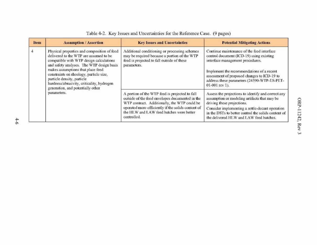
Table 4-2. Key Issues and Uncertainties for the Reference Case. (9 pages)
Item Assumption / Assertion Key Issues and Uncertainties Potential Mitigating Actions
4 Physical properties and composition of feed Additional conditioning or processing schemes Continue maintenance of the feed interfacedelivered to the WTP are assumed to be may be required because a portion of the WTP control document (ICD-I9) using existingcompatible with WTP design calculations feed is projected to fall outside of these interface management procedures.and safety analyses. The WTP design basis parameters.makes assumptions that place feed Implement the recommendations of a recentconstraints on rheology, particle size, assessment of proposed changes to ICD-I9 toparticle density, particle address these parameters (24590-WTP-ES-PET-hardness/abrasivity, criticality, hydrogen 01-001 rev 1).generation, and potentially otherparameters. A portion of the WTP feed is projected to fall Assess the projections to identify and correct any
outside of the feed envelopes documented in the assumption or modeling artifacts that may beWTP contract. Additionally, the WTP could be driving these projections.operated more efficiently if the solids content of Consider implementing a settle-decant operationthe HLW and LAW feed batches were better in the DSTs to belter control the solids content ofcontrolled. the delivered HLW and LAW feed batches.

Table 4-2. Key Issues and Uncertainties for the Reference Case. (9 pages)
Item Assumption / Assertion Key Issues and Uncertainties Potential Mitigating Actions
5 Composition and waste oxide loading of HLW glass formulation assumptions have not Further HLW glass development is underway atHLW glass will be as estimated by the been demonstrated for all Hanford waste the Vitreous State Laboratory (CatholicPNNL Relaxed 1996 Glass Properties compositions. Incorrect assumptions could University, Maryland) with DOE (EM-21)Model for HLW. Three glass property impact expected waste loading per unit of glass, funding.model constraints, glass viscosity, number of lliLW canisters and mission An effort to update the HLW glass formulationchromium oxide (Cr,03) glass solubility, duration. model using currently available glass data isand spinel liquidus temperature were underway at PNNL.relaxed. The maximum allowable viscositywas increased from 5.5 Pascal-seconds Projected number of lliLW canisters generated Continue to evaluate options for blending,(pa's) to 10 Pa·s. The maximum allowable is uncertain. HLW glass mass is sensitive to the caustic and oxidative leaching, and improvingchrome oxide loading was increased from degree-of-blending (both incidental and the HLW glass formulations. Evaluate impact0.5 wt% to 1.0 wt%. The maximum spinel intentional) achieved during the retrieval, that other assumption changes and operationalliquidus temperature (Te) was increased storage and delivery offeed. constraints have upon blending and the resultingfrom 1050"C to 1100"C (see Appendix B, HLW glass mass.Key Enabling Assumption B2.3.3.6). Sample, characterize, and test leaching
performance ofDSTs containing SST waste afterComposition and sodium oxide loading of near-telTIl SST retrievals are complete to reduceWTP LAW glass will be as estimated by uncertainty.the DOE glass model (see Appendix B, Key If the disposition of the TRU waste is notEnabling Assumption B2.3.4.6). disposal at WIPP, then evaluate the need for
blending with HLW before treatment at the
Projections oflHLW and lLAW from the WTP.
WTP are based on starting tank inventory,Projected number of lLAW packages from the Adopt the recently updated lLAW glasswash and leach factors, oxidative leach
assumptions, and the assumed disposition WTP is uncertain. formulation model for future planinng in lieu of
of the TRU waste. the DOE glass model.
Continue to evaluate options for filtering and ion
Glass produced by the various bulkexchange at higher temperature, caustic recycle,potential segregation of high Al batches and
vitrification facilities (DBVSiBVS, East special treatment to minimize caustic additions.STP, West STP) will achieve a 21.24 wt%sodium oxide loading. Projected number of lLAW boxes from Continue the testing and development effort
Supplemental LAW treatment is uncertain. supporting the DBVS.
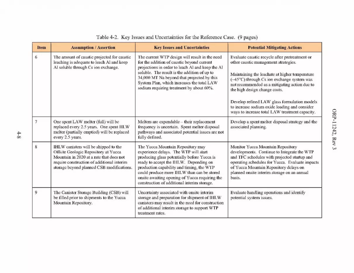
.4,00
Table 4-2. Key Issues and Uncertainties for the Reference Case. (9 pages)
Item Assumption / Assertion Key Issues and Uncertainties Potential Mitigating Actions
6 The amount of caustic projected for caustic The current WTP design will result in the need Evaluate caustic recycle after pretreatment orleaching is adequate to leach Al and keep for the addition of caustic beyond current other caustic management strategies.Al soluble through Cs ion exchange. projections in order to leach Al and keep the Al
soluble. The result is the addition of up to Maintaining the leachate at higher temperature34,000 MT Na beyond that proj ected by this
(~45°C) through Cs ion exchange system wasSystem Plan, which increases the total LAW not recommended as a mitigating action due tosodium requiring treatment by about 60%. the high design change costs.
Develop refined LAW glass formulation modelsto increase sodium oxide loading and considerways to increase total LAW treatment capacity.
7 One spent LAW melter (full) will be Melters are expendable - their replacement Develop a spent melter disposal strategy and thereplaced every 2.5 years. One spent HLW frequency is uncertain. Spent melter disposal associated planning.melter (partially emptied) will be replaced pathways and associated potential issues are notevery 2.5 years. fully defined.
8 lliLW canisters will be shipped to the The Yucca Mountain Repository may Monitor Yucca Mountain RepositoryOffsite Geologic Repository at Yucca experience delays. The WTP will start developments. Continue to Integrate the WTPMountain in 2020 at a rate that does not producing glass potentially before Yucca is and TFC schedules with projected startup andrequire construction of additional interim ready to accept the lliLW. Depending on operating schedules for Yucca. Evaluate impactsstorage beyond planned CSB modifications. production capability and timing, the WTP of Yucca Mountain Repository delays on
could produce more lliLW than can be stored plarmed onsite interim storage on an armualonsite awaiting opening of Yucca requiring the basis.construction of additional interim storage.
9 The Canister Storage Building (CSB) will Uncertainty associated with onsite interim Evaluate handling operations and identifybe filled prior to shipments to the Yucca storage and preparation for shipment of IHLW potential system issues.Mountain Repository. canisters may result in the need for construction
of additional interim storage to support WTPtreatment rates.
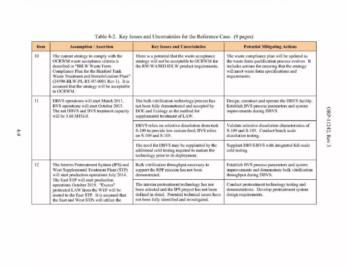
Table 4-2. Key Issues and Uncertainties for the Reference Case. (9 pages)
Item Assumption / Assertion Key Issues and Uncertainties Potential Mitigating Actions
10 The current strategy to comply with the There is a potential that the waste acceptance The waste compliance plan will be updated asOCRWM waste acceptance criteria is strategy will not be acceptable to OCRWM for the waste fOlTIl qualification process evolves. Itdescribed in "iliLW Waste Form the RW!WASRD IHLW product requirements. includes actions for ensuring that the strategyCompliance Plan for the Hanford Tank will meet waste form specifications andWaste Treatment and Immobilization Plant" requirements.(24590-HLW-PL-RT-07-0001 Rev 1). !tisassumed that the strategy will be acceptabletoOCRWM.
11 DBVS operations will start March 2011. The bulk vitrification technology/process has Design, construct and operate the DBVS facility.BVS operations will start October 2013. not been fully demonstrated and accepted by Establish BVS process parameters and systemThe net DBVS and BVS treatment capacity DOE and Ecology as the method for improvements during DBVS.will be 3.66 MTG/d. supplemental treatment of LAW.
DBVS relies on selective dissolution from tank Validate selective dissolution characteristics ofS-109 to provide low cesium feed; BVS relies S-109 and S-105. Conduct bench scaleon S-109 and S-105. dissolution testing.
The need for DBVS may be supplanted by the Supplant DBVSIBVS with integrated full-scaleadditional cold testing required to mature the cold testing.technology prior to its deployment.
12 The Interim Pretreatment System (IPS) and Bulk vitrification throughput necessary to Establish BVS process parameters and systemWest Supplemental Treatment Plant (STP) support the RPP mission has not been improvements and demonstrate bulk vitrificationwill start production operations July 2014. demonstrated. throughput during DBVS.The East STP will start productionoperations October 2019. llExcess ll The interim pretreatment technology has not Conduct pretreatment technology testing andpretreated LAW from the WTP will be been selected and the IPS project has not been demonstrations. Develop pretreatment systemrouted to the East STP. !t is assumed that defined in detail. Potential technical issues have design requirements.the East and West STPs will utilize the not been fully identified and investigated.

.4,-o
Table 4-2. Key Issues and Uncertainties for the Reference Case. (9 pages)
Item Assumption / Assertion Key Issues and Uncertainties Potential Mitigating Actions
same technology and process flowsheet as The deployment of half of the STP capacity in Revisit the deployment strategy and capacity ofthe DBVS. The net supplemental LAW West Area along with the necessary the supplemental LAW treatment plants andtreatment capacity for the West and East pretreatment capability appears to result in less supporting pretreatment system. This shouldSTP will be 14.65 MTG/d each. than optimal configuration of the waste consider the potential early startup of the WTP
treatment complex. lLAW Facility and impacts from additional leachcaustic.
13 Packaged CH-TRU waste and washed and The Class III Permit modification to enable the Develop bases for TRU classification. Pursuepackaged RH-TRU waste will be acceptable WIPP disposal pathway is uncertain. agreement with regulators and stakeholders.for disposal at the WlPP. Agreement on TRU waste classification is Secure Class III permit modification.
uncertain.
WIPP is projected to close before Hanford TRU Monitor WIPP developments. Work withtank waste is immobilized. DOE-EM to align schedules.
Some tank waste assumed to be dispositioned as Assess existing characterization data and ifCH-TRU may not meet CH-TRU dose needed obtain additional waste samples beforelimitations. waste retrieval.
Final criteria for Hanford CH-TRU and Develop and test new technologies that willRH-TRU may be more stringent than current support TRU waste retrieval and packaging.standards. TRU packaging may requireadditional technology development and testing.
14 The DSTs will remain fully operational for The likelihood of a major failure of a tank or Execute DST Integrity, Field Projects, and DSTthe duration of the waste treatment mission. infrastructure component increases with time Life Extension work scope.
due to the age of the tank farm facilities. Asfound tank, equipment, and facility conditionsmay lead to significant new scope.
15 The 242-A Evaporator will continue to Management of the water content of the tank Execute 242-A evaporator upgrades andoperate as needed through the life of the waste is one of the keys to effective utilization maintain evaporator readiness to support missionmISSIOn. of the DSTs. The likelihood of a major failure needs. Evaluate evaporator replacement if
of a 242-A Evaporator component increases necessary.with time due to the age of the facility.
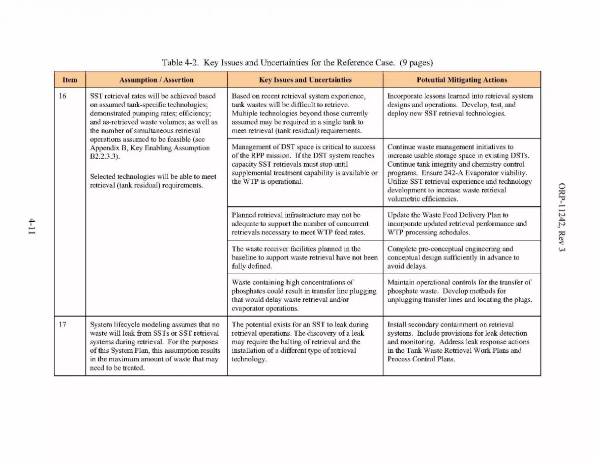
Table 4-2. Key Issues and Uncertainties for the Reference Case. (9 pages)
Item Assumption / Assertion Key Issues and Uncertainties Potential Mitigating Actions
16 SST retrieval rates will be achieved based Based on recent retrieval system experience, Incorporate lessons learned into retrieval systemon assumed tank-specific technologies; tank wastes will be difficult to retrieve. designs and operations. Develop, test, anddemonstrated pumping rates; efficiency; Multiple technologies beyond those currently deploy new SST retrieval technologies.and as-retrieved waste volumes; as well as assumed may be required in a single tank tothe number of simultaneous retrieval meet retrieval (tank residual) requirements.operations assumed to be feasible (seeAppendix B, Key Enabling Assumption Management ofDST space is critical to success Continue waste management initiatives toB2.2.3.3). of the RPP mission. If the DST system reaches increase usable storage space in existing DSTs.
capacity SST retrievals must stop until Continue tank integrity and chemistry control
Selected technologies will be able to meet supplemental treatment capability is available or programs. Ensure 242-A Evaporator viability.
retrieval (tank residual) requirements. the WTP is operational. Utilize SST retrieval experience and technologydevelopment to increase waste retrievalvolumetric efficiencies.
Planned retrieval infrastructure may not be Update the Waste Feed Delivery Plan toadequate to support the number of concurrent incorporate updated retrieval performance andretrievals necessary to meet WTP feed rates. WTP processing schedules.
The waste receiver facilities planned in the Complete pre-conceptual engineering andbaseline to support waste retrieval have not been conceptual design sufficiently in advance tofully defined. avoid delays.
Waste containing high concentrations of Maintain operational controls for the transfer ofphosphates could result in transfer line plugging phosphate waste. Develop methods forthat would delay waste retrieval and/or unplugging transfer lines and locating the plugs.evaporator operations.
17 System lifecycle modeling assumes that no The potential exists for an SST to leak during Install secondary containment on retrievalwaste will leak from SSTs or SST retrieval retrieval operations. The discovery of a leak systems. Include provisions for leak detectionsystems during retrieval. For the purposes may require the halting of retrieval and tlie and monitoring. Address leak response actionsof this System Plan, this assumption results installation of a different type of retrieval in tlie Tank Waste Retrieval Work Plans andin the maximum amount of waste that may technology. Process Control Plans.need to be treated.

Table 4-2. Key Issues and Uncertainties for the Reference Case. (9 pages)
Item Assumption / Assertion Key Issues and Uncertainties Potential Mitigating Actions
18 Closure activities for each tank faIm can Delays in completing the Tank Closure and Monitor EIS progress and if necessary revisebegin after all tanks in that fann are interim Waste Management EIS will impact progress in planning to incorporate ROD provisions. Planclosed. developing closure plans and initiating field and demonstrate closure technologies.
closure activities. EIS alternatives and RODmay not align with the baseline assumptions.Assumed closure technologies have been testedbut not deployed.
19 The timing, capacities, and capability of the The current Effluent Treatment Facility (ETF) is Plan and execute upgrades to the ETF facility toETF, LERF, SALDS, and TEDF will be inadequate to treat the projected liquid insure that the ETF can handle the quantity anddriven by the needs of the waste treatment secondary waste stream that will be generated compositions of liquid secondary wastemission and assumed to be available when by the WTP and BVS. Currently planned ETF generated by the Waste Treatment Complexneeded. If the treatment mission requires upgrades may also not be adequate to treat (WTP, DBVSffiVS, West STP, East STP,that changes be made to the ETF, LERF, secondary waste streams for the Waste CR-TRU and RH-TRU packaging, and theSALDS, or TEDF or their operating plans, Treatment Complex. 242-A evaporator). Of particular importance isthe required changes will be made. the ability to safely dispose of the ETF solid
product in the IDF.
20 Laboratory services required to support 222-S and associated support systems such as Include high-priority system upgrades in thewaste characterization for tank farm core sampling trucks, are aging and prone to baseline. PerfOlTIl critical and routineprojects and operations as well as WTP increased failure rates and increased maintenance on sampling systems andproduction operations are available and maintenance attention. components to ensure readiness of these systems.provided in a timely marmer. Ensure appropriate integration with WTP
laboratory needs.
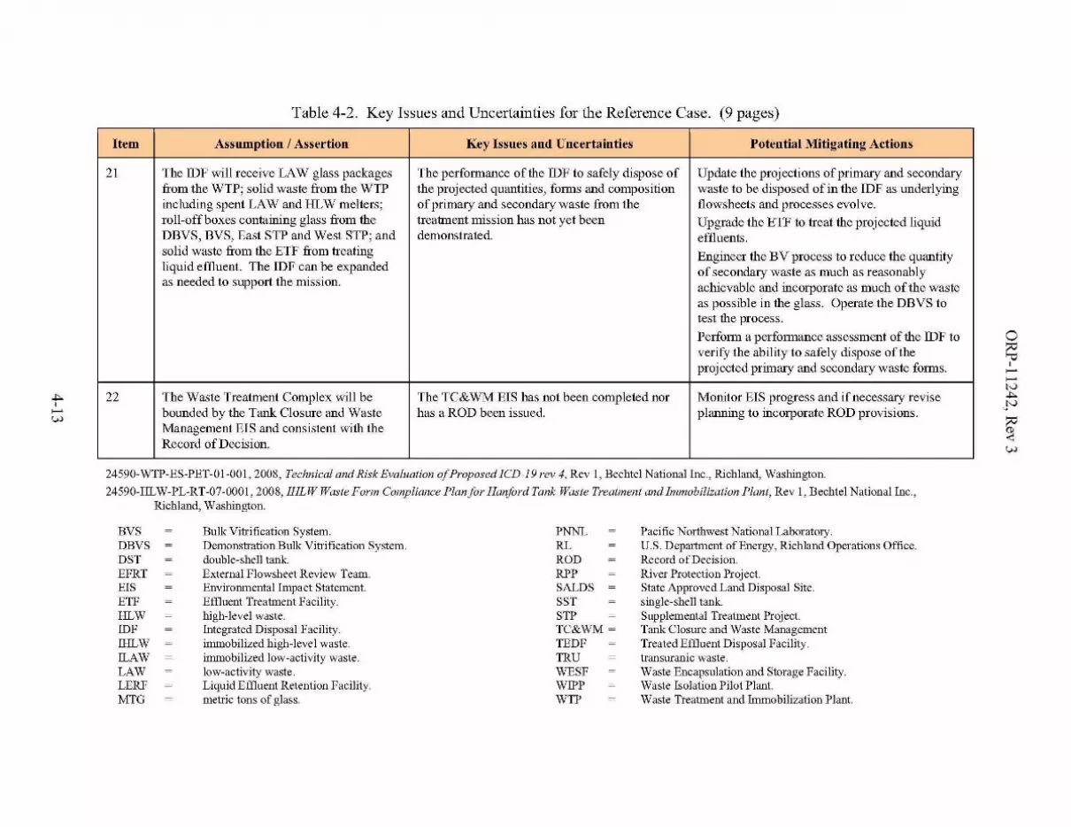
Table 4-2. Key Issues and Uncertainties for the Reference Case. (9 pages)
Item Assumption / Assertion Key Issues and Uncertainties Potential Mitigating Actions
21 The IDF will receive LAW glass packages The performance of the IDF to safely dispose of Update the projections of primary and secondaryfrom the WTP; solid waste from the WTP the projected quantities, fOlliS and composition waste to be disposed of in the IDF as underlyingincluding spent LAW and HLW melters; of primary and secondary waste from the flowsheets and processes evolve.roll-off boxes containing glass from the treatment mission has not yet been Upgrade the ETF to treat the projected liquidDBVS, BVS, East STP and West STP; and demonstrated. effluents.solid waste from the ETF from treating Engineer the BV process to reduce the quantityliquid effluent. The IDF can be expanded of secondary waste as much as reasonablyas needed to support the mission. achievable and incorporate as much of the waste
as possible in the glass. Operate the DBVS totest the process.
PerfOlTIl a perfOlmance assessment of the IDF toverify the ability to safely dispose of theprojected primary and secondary waste forms.
22 The Waste Treatment Complex will be The TC&WM EIS has not been completed nor Monitor EIS progress and if necessary revisebounded by the Tank Closure and Waste has a ROD been issued. planning to incorporate ROD provisions.Management EIS and consistent with theRecord of Decision.
24590-WTP-ES-PET-OI-OOl, 2008, Technical and Risk Evaluation a/Proposed ICD-19 rev 4, Rev 1, Bechtel National Inc., Richland, Washington.
24590-HLW-PL-RT-07-0001, 2008, IHLW Waste Form Compliance Plan for Hanford Tank Waste Treatment and Immobilization Plant, Rev 1, Bechtel National Inc.,Richland, Washington.
BVSDBVSDSTEFRTEISETFHLWIDFIHLW!LAWLAWLERFMTG
Bulk Vitrification System.Demonstration Bulk Vitrification System.double-shell tank.External Flowsheet Review Team.Environmental Impact Statement.Effluent Treatment Facility.high-level waste.Integrated Disposal Facility.immobilized high-level waste.immobilized low-activity waste.low-activity waste.Liquid Effluent Retention Facility.metric tons of glass.
PNNLRLRODRPPSALDSSSTSTPTC&WM ~
TEDFTRUWESFWIPPWTP
Pacific Northwest National Laboratory.U.S. Department of Energy, Richland Operations Office.Record ofDecision.River Protection Project.State Approved Land Disposal Site.single-shell tank.Supplemental Treatment Project.Tank Closure and Waste ManagementTreated Effluent Disposal Facility.transuranic waste.Waste Encapsulation and Storage Facility.Waste Isolation Pilot Plant.Waste Treatment and Immobilization Plant.
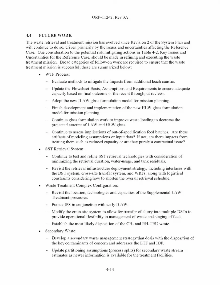
ORP-1l242, Rev 3A
4.4 FUTURE WORK
The waste retrieval and treatment mission has evolved since Revision 2 of the System Plan andwill continue to do so, dri ven primarily by the issues and uncertainties affecting the ReferenceCase. Due consideration to the potential risk mitigating actions in Table 4-2, Key Issues andUncertainties for the Reference Case, should be made in refining and executing the wastetreatment mission. Broad categories of follow-on work arc required to ensure that the wastetreatment mission is successful; these are summarized below:
• WTP Process:
Evaluate methods to mitigate the impacts from additional leach caustic.
Update the Flowsheet Basis, Assumptions and Requirements to ensure adequatecapacity based on final outcome of the recent tln'oughput reviews.
Adopt the new ILAW glass ftmnulation model for mission planning.
Finish development and implementation of the new HLW glass formulationmodel for mission plalllling.
Continue glass Itmnulation work to improve waste loading to decrease theprojected amount of LAW and HLW glass.
Continue to assess implications of out-of-specification feed batches. Are theseartifacts of modeling assumptions or input data? Ifnot, are there impacts fromtreating them such as reduced capacity or are they purely a contractual issue?
• SST Retrieval System:
Continue to test and refine SST retrieval technologies with consideration ofminimizing the retrieval duration, water-usage, and tank residuals.
Revisit the retrieval infrastructure deployment strategy, including interfaces withthe DST system, cross-site transfer system, and WRFs, along with logisticalconstraints considering how to shorten the overall retrieval schedule.
• Waste Treatment Complex Configuration:
Revisit the location, technologies and capacities of the Supplemental LAWTreatment processes.
Pursue IPS in conjunction with early ILAW.
Modify the cross-site system to allow for transfer of slurry into multiple DSTs toprovide operational flexibility in management of waste and staging onced.
Establish the most likely disposition of the CH- and RH-TRU W~lste.
• Secondary Waste:
Develop a secondary waste management strategy that deals with the disposition ofthe key contaminants of concern and addresses the ETF and IDF.
Update partitioning assumptions (process splits) for secondary waste streamestimates as newer infonnation is available It)r the treatment facilities.
4-]4

ORP-11242, Rev 3
• DST System:
Ensure continued availability of evaporator capability to manage waste volumethrough the end of SST retrieval.
Revisit the allocation of the DSTs to support functions (early SST waste storage,SST receivers, HLW staging, LAW staging, cross-site receivers, RH-TRUwashing, Evaporator feed staging and bottoms receivers, AN-102/l07 Sr/TRUprecipitation, etc).
Seek opportunities to improve blending within the degrees of freedom afforded byother mission constraints.
Explore the use of settle-decant operations in staging WTP feed to better controlthe solids concentration.
Explore alternative methodologies that may improve upon the accuracy and utilityof the solubility approximations (water wash factors) currently used in theretrieval and staging of the tank waste.
4-15
ORP-11242, Rev 3
This page intentionally left blank.
4-16
ORP-11242, Rev 3
5.0 REFERENCES
04-WED-024, 2004, "Contract No. DE-AC27-0lRV14136 - Summary and Actions from theU.S. Department of Energy, Office of River Protection (ORP) Oversight of Pretreatment(PT) Plant Ultrafiltration Process (UFP) System," (External letter from R. J. Schepens, toJ. P. Henschel, Bechtel National, Inc., June 6, 2004) U.S. Department of Energy, Officeof River Protection.
24590-HLW-PL-RT-07-000l, 2008, IHLW Waste Form Compliance Plan for Hanford TankWaste Treatment and Immobilization Plant, Rev 1, Bechtel National Inc., Richland,Washington.
24590-HLW-RPT-PE-07-00l, 2007, High Level Waste Vitrification Plant CapacityEnhancement Study, Rev 0, Bechtel National Inc., Richland, Washington.
24590-LAW-RTP-RT-04-0003, 2005, "Preliminary ILAW Formulation Algorithm Description,"Rev 0, Bechtel National Inc., Richland, Washington.
24590-WTP-DB-ENG-Ol-00l, 2007, Basis ofDesign, Rev. 11, Bechtel National Inc., Richland,Washington.
24590-WTP-ES-PET-01-001, 2008, Technical and Risk Evaluation ofProposed ICD- I 9 rev 4,Rev 1, Bechtel National Inc., Richland, Washington.
24590-WTP-ICD-MG-Ol-005, 2003, ICD 05 - Interface Control Document for Nonradioactive,Nondangerous Liquid E.fJluents, Rev. 3, Bechtel National Inc., Richland, Washington.
24590-WTP-RPT-PE-07-00l, 2007, WTP Waste FeedAnalysis and Definition - EFRT M4 FinalReport, Rev 1, Bechtel National Inc., Richland, Washington.
24590-WTP-RPT-PO-07-002, 2007, Dynamic (G2) Flowsheet Assessment ofthe Effect ofM- I 2Modifications on Pretreatment Capacity, Rev 0, Bechtel National Inc., Richland,Washington.
24590-WTP-RPT-PR-Ol-006, 2006, Risk Assessment Report, Rev 13, Bechtel National Inc.,Richland, Washington.
30686-RT-000l, 2007, Demonstration Bulk Vitrification System (DBVS), Series 30 and 31Testing, ES-30J, ES-30K, and ES-3IF Test Report, Rev. 0, AMEC GeoMelt Divisionprepared for CH2M HILL, Hanford Group, Inc., Richland, Washington.
30686-RT-0003, 2007, Demonstration Bulk Vitrification System, Series 38 Full-Scale Testing,FS-38D Test Report, Rev. 0, AMEC GeoMelt Division, prepared for CH2M HILLHanford Group, Inc., Richland, Washington.
AMEC07.02, 2007, "RE: Test and Analytical Results from IDMT" (external letter fromT. M. Brouns to K. Witwer, AMEC, GeoMelt Division, November 9, 2007) PacificNorthwest National Laboratory, Richland, Washington
CH2M-0303565, 2003, "CH2M HILL Hanford Group, Inc. Recommendation for Further Testingof Supplemental Technologies, " (external letter from E. S. Aromi to R. J. Schepens,U.S. Department of Energy, Office of River Protection, September 12), CH2M HILLHanford Group, Inc., Richland, Washington.
5-1

ORP-11242, Rev 3
CORR-2008-0024, 2008, "Contract No. DE-AC27-99RL14047 - Prepare Baseline ChangeRequests (BCR) to: 1) Develop an Integrity Program for Single-Shell Tanks (SST), and2) Support Mission Analysis and Preliminary Conceptual Design for Interim PretreatmentSystem," ,(external letter from C. B. Reid to D. B. Cartmell, CH2M HILL HanfordGroup, Inc., February 11,2008) U.S. Department of Energy, Office of River Protection,Richland, Washington.
D-03-DESIGN-002, 2003, Design Oversight Report, Waste Treatment Plant LAW MelterSupport System Capacities, Office of River Protection, Richland, Washington.
D-05-DESIGN-019, 2006, Design Oversight Report, Review ofBalance ofFacilities (BOF)Equipment, System and Facility Preservation Lay-Up and Turnover, Office of RiverProtection, Richland, Washington.
DE-RP27-07RV14800, Solicitation: Tank Operations Contract, U. S. Department of Energy,Washington, D.C.
DOE OCRM, 2007, "Yucca Mountain Repository -- About the Project" Web site,http://www.ocrwm.doe.gov/ym repository/about project/index.shtrnl, OCRWM - Aboutthe Project, accessed 8/31/2007 at 11:36 am PDT, U.S. Department of Energy, Office ofCivilian Radioactive Waste Management, Las Vegas, Nevada.
DOE/NTP-96-l204, 2002, National TRU Waste Management Plan, Corporate Board AnnualReport, Rev 3, U.S. Department of Energy, Carlsbad Field Office, Carlsbad,New Mexico.
DOE/RL-2006-35, 2006, Hanford Facility Dangerous Waste Permit Application, WasteEncapsulation and Storage Facility, Rev. 0 Reissue, U.S. Department of Energy,Richland, Washington.
DOE/RL-2006-35, 2007, Hanford Facility Dangerous Waste Permit Application, WasteEncapsulation and Storage Facility, Rev. 1 Reissue, U.S. Department of Energy,Richland, Washington.
DOEYMPO 1111, 2007, Regulatory Licensing Overview - Fact Sheet, accessed 8/31/2007 at11:40 am PDT, U.S. Department of Energy, Office of Civilian Radioactive WasteManagement, Las Vegas, Nevada,http://www.ocrwm.doe. gov/factsheets/doevrnpO111.shtml.
Ecology et aI., 1989, Hanford Federal Facility Agreement and Consent Order, 2 vols.,Washington State Department of Ecology, U.S. Environmental Protection Agency, andU.S. Department of Energy, Olympia, Washington, as amended.
EDF-NSNF-On, 2007, Hanford Cs-Sr Repository Disposal Performance Analysis Using theTSPA-FEIS Model, Rev 0, National Spent Nuclear Fuel Program Engineering DesignFile, U.S. Department of Energy, Richland Operations Office, Richland, Washington.
HNF-14755, 2007, Documented Safety Analysisfor the 242-A Evaporator, Rev. lG,CH2M HILL Hanford Group, Inc., Richland, Washington.
HNF-22687,2004, WESF Capsule Data Book, Rev 0, Fluor Hanford, Inc., Richland,Washington.
5-2
ORP-11242, Rev 3
HNF-269l4, 2005, Conceptual Design Report for Ejjluent Treatment Facility SolidificationTreatment Unit, Rev. 0, Fluor Hanford, Inc., Richland, Washington.
HNF-4669, 2000, Decision Document for the Low-Activity Waste Retrieval Strategy for Tanks241-AN-103, 241-AN-104, 241-AN-105, and 241-AW-101, Rev 0, CH2M HILL HanfordGroup, Inc., Richland, Washington.
HNF-EP-0182, 2006, Waste Tank Summary Report For Month Ending 02/28/2006, Rev. 215,CH2M HILL Hanford Group, Inc., Richland, Washington.
HNF-EP-0182, 2007, Waste Tank Summary Report For Month Ending 12/31/2006, Rev. 225,CH2M HILL Hanford Group, Inc., Richland, Washington.
HNF-SD-ETF-ASA-OOl, 2000, 200 Area Ejjluent Treatment Facility Auditable Safety AnalysisReport, Rev. 4, Fluor Hanford, Inc., Richland, Washington.
HNF-SD-RE-TI-178, 2007, Single-Shell Tank Interim Stabilization Record, Rev. 9A,CH2M HILL Hanford Group, Inc., Richland, Washington.
HNF-SD-W049H-ICD-00l, 2004, 200 Area Treated Ejjluent Disposal Facility Interface ControlDocument, Rev. 9, Fluor Hanford, Inc., Richland, Washington.
HNF-SD-WM-OCD-015, 2007, Tank Farm Waste Transfer Compatibility Program, Rev 17,CH2M HILL Hanford Group, Inc., Richland, Washington.
HNF-SD-WM-SAD-040, 2001, LERF Final Hazard Category Determination, Rev. 2,Fluor Hanford, Inc., Richland, Washington.
HNF-SD-WM-SP-012, 2007, Tank Farm Contractor Operation and Utilization Plan, Rev. 6,CH2M HILL Hanford Group, Inc., Richland, Washington.
HNF-SD-WM-TI-733, 2007, Supporting Calculations and Assumptions for Use in WESF SafetyAnalysis, Rev. 2B, Fluor Hanford, Inc., Richland, Washington.
IDMS 87687537, 2007, "RE: ORP IPABS FORECAST," (email to Y. M. Shehadeh, et aI.,Office of River Protection, December 11, 2007), from J. G. Kristofzski, CH2M HILLHanford Group, Inc., Richland, Washington.
M-92-07-0l, 2007, Modification ofHanford Federal Facility Agreement and Consent Order(Tri-Party Agreement) M-92-05, "Determine disposition path and determine interimagreement milestones for Hanford Site Cs/Sr capsules," State of Washington Departmentof Ecology, Richland, Washington.
National Environmental Policy Act of1969,42 USC 4321, et seq.
Nuclear Waste Policy Amendments Act of1987, "Selection of Yucca Mountain Site,"42 USC 10172, et seq.
ORP M 413.3-ld, 2006, River Protection Project Federal Risk Management Plan, U.S.Department of Energy, Office of River Protection, Richland, Washington.
PNNL-12003, 1998, Summary ofUncertainty Estimation Results for Hanford Tank Chemicaland Radionuclide Inventories, Rev 0, Pacific Northwest National Laboratory, Richland,Washington.
Resource Conservation and Recovery Act of1976,42 USC 6901, et seq.
5-3
ORP-11242, Rev 3
RPP-10435, 2002, Single-Shell Tank System Integrity Assessment Report, Rev. 0, CH2M HILLHanford Group, Inc., Richland, Washington.
RPP-15479, 2004, Project Definition Criteriafor the Integrated Disposal Facility, Rev. OA,CH2M HILL Hanford Group, Inc., Richland, Washington.
RPP-15833, 2004, System Specification for the Integrated Disposal Facility, Rev. OB,CH2M HILL Hanford Group, Inc., Richland, Washington.
RPP-19822, 2005, Hanford Defined Waste Model Revision 5.0, Rev. OA, CH2M HILL HanfordGroup, Inc., Richland, Washington.
RPP-20003, 2005, Sensitivity ofHanford Immobilized High-level Waste Glass Mass toChromium and Aluminum Partitioning Assumptions, Rev 1, CH2M HILL HanfordGroup, Inc., Richland, Washington.
RPP-20270, 2005 Hanford Shipping Facility System Specification, Rev. 0, CH2M HILL HanfordGroup, Inc., Richland, Washington.
RPP-21216, 2008, Single-Shell Tank Retrieval Selection and Sequence, Rev. 3, CH2M HILLHanford Group, Inc., Richland, Washington.
RPP-23584, 2004, Safety Evaluation ofWaste Gel in the Tank Farms, Rev 0, CH2M HILLHanford Group, Inc., Richland, Washington.
RPP-29981, 2007, Evaluation ofStarting the Waste Treatment and Immobilization Plant (WTP)Low Activity Waste (LAW) Facility First, Rev. 1, CH2M HILL Hanford Group, Inc.,Richland, Washington.
RPP-31314, 2006, A Comprehensive Technical Review ofthe Demonstration Bulk VitrificationSystem, Technical Assessment Conducted by an Independent and External Team ofExperts, September 28, 2006, Volume 1, Rev. 0, CH2M HILL Hanford Group, Inc.,Richland, Washington.
RPP-36870, 2008, Rough Estimate ofTRUDrums per Shipment to WIPP, Rev 0, CH2M HILLHanford Group, Inc., Richland, Washington.
RPP-6213, 2005, Hanford Waste Tank Bump Accident and Consequence Analysis, Rev. 4,CH2M HILL Hanford Group, Inc., Richland, Washington.
RPP-6548, 2001, Test Report, 241-AZ-IOl Mixer Pump Test, Rev. 1, CH2M HILL HanfordGroup, Inc., Richland, Washington.
RPP-7507, 2004, Design Requirements Document for Immobilized High-Level Waste InterimStorage Facility, Project W-464, Rev. 1B, CH2M HILL Hanford Group, Inc., Richland,Washington.
RPP-7574, 2007, Double-Shell Tank Integrity Program Plan, Rev 2, CH2M HILL HanfordGroup, Inc., Richland, Washington.
RPP-7625, 2007, Best-Basis Inventory Process Requirements, Rev 7, CH2M HILL HanfordGroup, Inc., Richland, Washington.
RPP-7771, 2001, Flammable Gas Safety Issue Resolution, Rev. OA, CH2M HILL HanfordGroup, Inc., Richland, Washington.
5-4

ORP-11242, Rev 3
RPP-PLAN-32249, 2007, Demonstration Bulk Vitrification System Project Implementation Plan,Response to the Demonstration Bulk Vitrification System Expert Review Panel FinalReport, Rev. 0, CH2M HILL Hanford Group, Inc., Richland, Washington.
RPP-RPT-24887, 2005, The Long-Term Management ofTank Waste at Hanford, Rev. 0,CH2M HILL Hanford Group, Inc., Richland, Washington.
RPP-RPT-26040, 2006, Pairwise Blending ofHigh-Level Waste, Rev. 0, CH2M HILL HanfordGroup, Inc., Richland, Washington.
RPP-RPT-332 14, 2008, HTWOS Model Data Package for the RPP System, Rev. 3 Case, Rev. 0,CH2M HILL Hanford Group, Inc., Richland, Washington.
SVF-1292, 2008, Transfer_File_Formatted_System Plan Rev3(1-I2-2008}-8.3rI-WC91778_MI.xls, Rev 0, CH2M HILL Hanford Group, Inc.,Richland, Washington.
SVF-1360, 2008, SST_Retrieval_File_System Plan Rev 3(1-12-2008}-8.3r2-WC91778_M3.xls,Rev 1, CH2M HILL Hanford Group, Inc., Richland, Washington.
SVF-1361, 2008, DST_Space_File_System Plan Rev 3(1-12-2008}-8.3rI-WC91778_M3.xls,Rev 0, CH2M HILL Hanford Group, Inc., Richland, Washington.
SVF-1397, 2008, SP3_Total-Blend_No-Blend_vj.xls, Rev. 0, CH2M HILL HanfordGroup, Inc., Richland, Washington.
SVF-1412, 2008, SP3_Caustic_Sensitivity_vI.xls, Rev 0, CH2M HILL Hanford Group, Inc.,Richland, Washington.
SVF-1420, 2008, HGR_Feed_Assessment_System Plan Rev 3(1-I2-2008}-8.3rI-WC9I778.xls,CH2M HILL Hanford Group, Inc., Richland, Washington.
SVF-1422, 2008, Specification_8_Assessment_System Plan Rev 3(1-12-2008}-8. 3r1WC91778.xls, CH2M HILL Hanford Group, Inc., Richland, Washington.
SVF-1423, 2008, SpecificationJ _Assessment_System Plan Rev 3(1-12-2008}-8. 3r1WC91778_MI.xls, Rev 1, CH2M HILL Hanford Group, Inc., Richland, Washington.
SVF-1427, 2008, SP3_HLW_Glass_Limit_Sensitivity.xls, Rev 0, CH2M HILL Hanford Group,Inc., Richland, Washington.
SVF-1429, 2008, Transfer_Plots_System Plan Rev 3(1-12-2008}-8.3rI -WC91778.xls, Rev 0,CH2M HILL Hanford Group, Inc., Richland, Washington.
SVF-1431, 2008, Balance_Graphic_System Plan Rev 3(1-12-2008}-8.3r1-WC91778_M4.xls,Rev 2, CH2M HILL Hanford Group, Inc., Richland, Washington.
SVF-1437, 2008, Transfer_File_Formatted_System Plan Rev 3(1-30-2008}-8. 3r1WC91778_MI.xls, CH2M HILL Hanford Group, Inc., Richland, Washington.
SVF-1438, 2008, DST_Space]ile_System Plan Rev 3(1-30-2008)-8.3rl-WC91778_Ml.xls,Rev 0, CH2M HILL Hanford Group, Inc., Richland, Washington.
SVF-1439, 2008, Production_Plots_System Plan Rev 3(1-30-2008}-8.3rI-WC9I778_MI.xls,Rev 0, CH2M HILL Hanford Group, Inc., Richland, Washington.
5-5

ORP-11242, Rev 3
SVF-1460, 2008, Production_Plots_System Plan Rev 3{l-14-2008)-8.3rl-WC91778_Ml.xls,Rev 0, CH2M HILL Hanford Group, Inc., Richland, Washington.
SWIFT-CWC, 2007, Web site, http://www.hanford.gov/swift/onsite/cwc.htm. SWIFT 2007.0Central Waste Complex, accessed 9/6/2007 at 11:01 am PDT, Solid Waste IntegratedForecast Technical (SWIFT) Report, U.S. Department of Energy, Richland OperationsOffice/Fluor Hanford, Richland, Washington.
TFC-PLN-39, 2006, Risk Management Plan, Rev B, CH2M HILL Hanford Group, Inc.,Richland, Washington.
WA7890008967, 2003, "Dangerous Waste Permit Application, Central Waste Complex," Rev. 7,07/16/2003, Approved 4/28/2004, Fluor Hanford, Inc., and U.S. Department of Energy,Richland Operations Office, Richland, Washington.
WBS 5.09.02.02.04.04,2006, CH-TRU CSS WIPP Waste Facilities Cost Estimating Input Sheet,Revision Date 6/1/2006, CH2M HILL Hanford Group, Inc., Richland, Washington.
WBS 5.09.02.02.04.07,2006, CH-TRU CSS Onsite Waste Storage Cost Estimating Input Sheet,CH2M HILL Hanford Group, Inc., Richland, Washington.
WBS 5.09.02.02.05.04,2006, RH-TRU CSS WIPP Waste Facilities Cost Estimating Input Sheet,CH2M HILL Hanford Group, Inc., Richland, Washington.
WHC-SD-EN-ES-040, 1994, Engineering Study of50 Miscellaneous Inactive UndergroundRadioactive Waste Tanks Located at the Hanford Site, Washington, Rev. 0,Westinghouse Hanford Company, Richland, Washington.
WIPP, 2007a, "Why WIPP?" (Fact sheet, updated February 5, 2007), WIPP Information Center,U. S. Department of Energy, Carlsbad Field Office, Carlsbad, New Mexico.
WIPP, 2007b, "WIPP Chronology," (Fact sheet, updated February 5, 2007), WIPP InformationCenter, U. S. Department of Energy, Carlsbad Field Office, Carlsbad, New Mexico.
5-6

ORP-11242, Rev 3
APPENDIX A
GLOSSARY
A-i

ORP-11242, Rev 3
This page intentionally left blank.
A-ii
Term or Abbreviation
Buoyant-Displacement GasRelease Events (BDGREs)
Caustic Leach Factor
Cross-site Transfer
Feed Vector
No-Blend
Percent-of-span
Realized-Blend
Saltcake
ORP-11242, Rev 3
APPENDIX A
GLOSSARY
Definition or Expansion
Tank waste generates flammable gasses through the radiolysis of water andorganic compounds, thelTIlolytic decomposition of organic compounds, andcorrosion of a tank's carbon steel walls. Under certain conditions, this gasmay accumulate in a settled solids layer until the waste becomeshydrodynamically unstable (less dense waste near the bottom of the tank).A BDGRE is the rapid release of this gas, partially restoring hydrodynamicequilibrium. The release may result in the temporary creation of flammablemixture in the headspace of the tank, depending on the size of the releaserelative to the capacity of the ventilation system.
The fraction of an analyte in previously washed solids that will go intosolution by caustic leaching. N. B. - The telTIl, Caustic Leach Factor, asused in this System Plan, is technically a Differential Caustic Leach Factor.
The Hanford waste tanks are located in two physically separated areas,called "East Area" and "West" area - about five miles apart. The cross-sitetransfer system is a pair of transfer pipelines and ancillary equipment that isused to transfer supernate and slurry from West Area to East Area.
The "feed vector" is a list of the individual feed batches projected to bedelivered to a facility (such as the Waste Treatment and ImmobilizationPlant) and includes the associated waste composition and caustic leachfactors.
The hypothetical case in which the waste from each individual tank isretrieved, pretreated, and the HLW fraction vitrified as a separate batch. Noblending of waste between tanks is permitted.
This is the percent of the way the projected glass mass falls between theTotal-Blend and the No-Blend glass mass. For example, 0 percent of spancorresponds to the Total Blend, while 50 percent of span corresponds tohalfway between the Total-Blend and No-Blend."
This refers to the actual blending that is predicted to occur during theevolution of a specific mission scenario.
Saltcake is a mixture of crystalline sodium salts that originally precipitatedwhen alkaline liquid waste from the various processing facilities wasevaporated to reduce waste volume. Saltcakes are comprised primary ofthe sodium salts of nitrate, nitrite, carbonate, phosphate and sulfate.Transition metals such as iron, manganese and lanthanum and heavy metalssuch as uranium and lead are generally absent. Saltcake typically contains asmall amount of interstitial liquid. The bulk of the saltcake will generallydissolve if contacted with sufficient water.
A-I
Term or Abbreviation
Sludge
Slurry
Supernate
Tank Bump
Total-Blend
Waste Treatment Complex
Water Wash Factor
ORP-11242, Rev 3
Definition or Expansion
Sludge is a mixture of metal hydroxides and oxyhydroxides that originallyprecipitated when acid liquid waste from the various reprocessing facilitieswas made alkaline with sodium hydroxide. Sludge is comprised primary ofthe hydroxides and oxyhydroxides of aluminum, iron, chromium, silicon,zirconium and uranium, plus the majority of the insoluble radionuclidessuch as 90Sr and the plutonium isotopes. Sludge typically contains asignificant amount of interstitial liquid (up to nomnial40 wt% water).Sludge is mostly insoluble in water, however a significant amount ofaluminum and chromium will dissolve if leached with sufficient quantitiesof sodium hydroxide.
The telTIl slurry is used in two different contexts:
Slurry is a mixture of solids, such as sludge or un-dissolved saltcake,suspended in a liquid. For example, a slurry results when the sludge andsupernate in a tank is mixed together. Slurries can be used to transfersolids by pumping though a pipelnie.
Slurry also refers to a waste produced at Hanford that results fromevaporating supernate originally removed from tanks containing saltcake sothat aluminum salts begin to precipitate in addition to the sodium salts.This material, called "Double-Shell Slurry" or "Double-Shell Slurry Feed"is present in the DSTs (specifically, AN-103, AN-104, AN-lOS andAW-1 01). For simplicity, this System Plan will use the term "settled salts"or "salt cake" instead of slurry in this context.
Supernate is technically the liquid floating above a settled solids layer. AtHanford, it is typically used to refer to any non-interstitial liquid in thetanks, even if no solids are present. Supernate is similar to saltcake incomposition and contains many of the soluble radionuclides such as 137Csand 99Tc.
A tank bump is a postulated event in which gases, primarily water vapor,are suddenly emitted from the waste causing the tank headspace topressurize due to vaporization of locally superheated liquid.
The Total-Blend represents the hypothetical case in which all of the wasteis blended together, pretreated, and the HLW fraction vitrified as a singlebatch ofunifolTIl composition.
Comprises all of the existing and future facilities, pipelines andinfrastructure needed for the storage, retrieval and treatment of the HanfordTank Waste.
The fraction of an analyte in a solid waste phase that reports to solutionupon contact with water.
A-2

ORP-11242, Rev 3
APPENDIXB
KEY ENABLING ASSUMPTIONS
B-i

ORP-11242, Rev 3
This page intentionally left blank.
B-ii
ORP-11242, Rev 3
APPENDIXB
KEY ENABLING ASSUMPTIONS
The scope of this version of the System Plan is defined primarily by the Key EnablingAssumptions. For clarity, several important limitations on the scope are listed below:
• Only one case, the "Reference Case," will be addressed.
• There will be no analysis or discussion of cost.
• The System Plan will align itself with the Tank Farm Contractor planningassumptions to the extent agreed to in the Key Enabling Assumptions.
• The System Plan will align itself with the Waste Treatment Plant flowsheetassumptions to the extent agreed to in the Key Enabling Assumptions.
• The System Plan will communicate the potential impacts on the mission of key issuesand uncertainties. This will be done using a qualitative discussion of the potentialnumerical range of impacts due to selected key issues and uncertainties, primarily thefactors influencing the mass of HLW glass, the mission duration, and the mass ofLAW glass from either WTP or the STPs. Full HTWOS runs will not be performedto evaluate the impacts.
During the modeling effort, several assumptions were updated or clarified. The signatures belowindicate concurrence with the final set of assumptions. 1
ORP Concurrence-~f+--'-.c...;rL.-_-----
Date
Date
1 Signature indicates concurrence with the Key Enabling Assumptions and the limitations on scope. PelTIlission isgiven in advance to make editorial and formatting changes to these signed assumptions during the documentpreparation and review cycle without the need to obtain a second set of signatures.
B-1
ORP-11242, Rev 3
This page intentionally left blank.
B-2
ORP-11242, Rev 3
Bl.O GENERAL INFORMATION
The key enabling assumptions listed in this section document the initial input for modeling andmission planning purposes as of February 2007 with updates made in October 2007. These weredeveloped after reviewing existing assumptions from the previous River Protection Project(RPP) System Plan, the Waste Treatment and Immobilization Plant (WTP) contracr, theHanford Tank Waste Operations Simulator (HTWOS) model run3 supporting the Tank FarmContract (TFC) baseline submittal,4 and with considerations of the findings of two recentreviews5
,6 of the WTP. They represent the major planning bases needed to develop an integrateddynamic flowsheet for the new System Plan case. They are not intended to address design-basisdecisions or detailed equipment operating plans.
The scenario was not constrained to match current contracts, regulatory permits, performancebased initiatives, funding, interface control documents, or other planning guidance except ascaptured by the key enabling assumptions. Changes in those areas may be required to implementa scenario built upon these modeling assumptions.
This version of the System Plan establishes a Reference Case that will be used to provide adescription of how the mission could play out, and communicate the potential impacts on themission of key issues and uncertainties.
The approach used in selecting assumptions for this Reference Case was to generally follow thesubmitted baseline, except for new production schedule and capacity assumptions, and routineupdates of other modeling assumptions. Little or no attempt was made to second-guess the finaloutcome of the findings identified in the two reviews. Therefore, some of the assumptions usedfor this Reference Case are expected to change as those findings are resolved. The affectedassumptions will be considered while preparing the Key Issues and Uncertainties.
2 DE-AC27-0lRVl4136, Through Modification Number MOSl, 2006, WTP Contract.
3 HNF-SD-WM-SP-Ol2, 2007, Tank Farm Contractor Operation and Utilization Plan, Rev. 6, CH2M HILLHanford Group, Inc., Richland, Washington.
4 Baseline Change Request RPP-06-003, Rev. l, "Alignment of TFC Lifecycle Baseline," November 2006.5 "Comprehensive Review of the Hanford Waste Treatment Plant Flowsheet and Throughput, Assessment
Conducted by an Independent Team of Extemal Experts," March 2006, transmitted under cover ofletter CCN:132846.
6 D-03-DESIGN-OOS, 2004, "HLW Feed Preparation System: Ultra-Filtration Process System", ORP WTPEngineering Division. NB - this document number was also used for a different report issued in 2003.
B-3
ORP-11242, Rev 3
B2.0 KEY ENABLING ASSUMPTIONS
B2.1 WASTE TREATMENT COMPLEX
B2.1.1 The overall configuration and process flow assumed for the waste treatment complex isshown in Figure I-I, River Protection Project Simplified Process Flow Diagram.,located in the body of this document.
B2.2 TANK FARMS
B2.2.1 Single-Shell Tanks
B2.2.1.1 The integrity and status of the 149 single-shell tanks (SST) is as described in the"Waste Tank Summary Report for Month Ending 12/3112006.,,7
B2.2.1.2 For mission modeling purposes, interim closure8 of the SSTs will not be addressed.
B2.2.1.3 Closure activities for each tank farm can begin after all tanks in that farm are interimclosed9
B2.2.2 Double-Shell Tanks
B2.2.2.1 The integrity and status of the 28 double-shell tanks (DST) is as described in the"Waste Tank Summary Report for Month Ending 07/3112006.,,7 Furthermore, it is assumed thatthe DSTs will remain fully operational for the duration of the waste treatment mission.
B2.2.2.2 The maximum operating liquid levels for the DSTs are given in OSD-T-151-00007,Rev. I, "Operating Specifications for the Double Shell Storage Tanks", March 2007. In thisrevision of the operating specifications, the maximum operating level for AP-Farm tanks wasincreased from 449 in. (1.235 Mgal) to 454 in. (1.2465 Mgal).IO It is assumed that eachAP-Farm tank will successfully pass the in-service leak testing required to utilize this increasedoperating level.
B2.2.2.3 The volume ofDST space allocated for tank farm emergencies and emergency returnsfrom the WTP is 1.265 Mgal. 11 No space will be reserved for non-emergency retums ofpretreated LAW or liquid effluents to the DST system.
B2.2.2.4 Solids are assumed to settle to approximately 40 wt% solids in the DSTs within30 days. Solids from C-Farm retrieval are assumed to settle within 2 days to a solids loadingcomparable to that in the source SST. 12
7 HNF-EP-0182, Rev. 225.
8 Interim closure comprises tank isolation and tank fill per Baseline Change Request RPP-06-003, Rev. 1.
9 Baseline Change Request RPP-06-003, Rev. 1.
10 NB - At liquid levels above 426 in., the nominal 2750 gal per in. of tank level begins to decrease, dropping to2603 gal per in. at 454 in.
11 HNF-3484, Rev 8.
B-4

ORP-11242, Rev 3
B2.2.2.5 The solids management strategy for the DSTs assumes that l2:
• DSTs supporting C-Farm retrieval will be operated with a minimal supernatant layerso that they do not become Group A tanks even though they will be filled withsignificant quantities of solids.
• DSTs not supporting C-Farm retrieval are assumed to hold up to 10 wt% bulk solidsbased on the maximum operating level of each DST.
B2.2.2.6 The waste blending and segregation controls in the feed control list(HNF-SD-WM-OCD-015, Rev. 17, Table A-I) will be followed, with the following exceptionsand clarifications:
• "Blend off high 233U solids": It is assumed that blending solids from tanks C-llland C-112 with the solids from C-104 in Tank AN-IOI will successfully mitigate theuranium enrichment issues with the C-l 04 solids.
• "Prepare and protect hot commissioning feed": The HLW and LAW hotcommissioning feeds have already been consolidated in AY-102 as of January 2007.
• "Segregate Envelope C": It is assumed that the strontium and transuranic (TRU) willbe removed from the Envelope C waste currently stored in AN-102 and AN-107 inthe DST system rather than in the WTP.
• "Segregate low-cesium SST waste for non-WTP supplemental treatment": Onlywaste from S-105 and S-109 need to be segregated for delivery to non-WTPsupplemental treatment.
B2.2.3 Waste Retrieval and Transfers
B2.2.3.1 The SSTs to be retrieved in the near-term is provided by the eighteen "committedtanks" identified in the Single-Shell Tank Retrieval Selection and Sequence document. 13, 14
These tanks are S-102, S-112 and all ofC-Farm.
B2.2.3.2 The life-cycle priorities15 for sequencing the retrieval of SST waste are to minimize. . d . 16 bllllsslOn uratlOn, y:
• Balancing feed to WTP, STP, and TRU;
• Balancing high-level waste (HLW) WTP feed and low-activity waste (LAW) WTPfeed;
12 HNF-SD-WM-SP-OI2, Rev. 6, Assumption A4.2.5.
13 RPP-21216, Rev. 3, Single-Shell Tank Retrieval Selection and Sequence.
14 The telTIl "committed tanks" is used to indicate tanks with near-telTIl Hanford Federal Facility Agreement andConsent Order (Ecology, EPA, and DOE, 1996) retrieval milestones.
15 In the future, additional priorities may need to be considered such as risk or hazard based metrics, logistics, andtank closure strategy. The challenge will be to incorporate such considerations without adversely impacting theoverall mission, particularly the amount ofHLW glass produced and the mission duration.
16 Minimizing treatment mission duration was used as placeholder goal due to lack of a practical metric fordetelTIlining how well the entire retrieval sequence and associated timing impacts the risk to human health and theenvironment.
B-5
ORP-11242, Rev 3
• Providing for incidental blending; and
• Implementing designated intentional blends.
B2.2.3.3 Updated SST retrieval assumptions (assumed technology, minimum retrieval duration,and as-retrieved waste volumes) will be provided by SVF-1283, Rev. 2, "Single-Shell TankRetrieval Assumptions for Mission Modeling."
B2.2.3.4 During retrieval of waste from SSTs to the DST system, sodium hydroxide and sodiumnitrite will be added as needed so that the as-retrieved liquid phase composition satisfies the DSTwaste chemistry limits given in Table 3-4 of HNF-SD-WM-OCD-O 15, Rev. 17.
B2.2.3.5 Allow 210 days 17 to sample the staged feed and verify compliance with permits and thesafety authorization basis before delivery to the WTP, starting from when each staging tank(DST) is first filled with feed.
B2.2.3.6 The feed for LAW hot commissioning will be delivered by decanting a portion of thesupernate from AY-I02 and transferring it to the WTP; the feed for HLW hot commissioningwill be delivered by remobilizing the solids in AY-I02 with the remaining supernate andadditional dilution water and then transferring them to the WTP.
B2.2.3.7 Subsequent deliveries of feed to the WTP will be timed and sequenced to balance theproduction of HLW glass, LAW glass and excess pretreated LAW supernate.
B2.2.3.8 All HLW batches delivered to the WTP should be at least 130 Kgal total volumewhenever possible18 and contain between 10 and 200 grams of unwashed solids per liter ofslurry. 19
B2.2.3.9 The residual waste remaining in the SSTs and DSTs after retrieval is complete will beestimated as follows:
• The residual inventory in a 200 Series SST will be best-basis inventory (BBI) data forSSTs where waste retrieval actions have been completed, when that information areavailable, or will be estimated as 30 ft3 of "selected phase", calculated for the BBIused as input to the model run20
• The residual waste inventory in a 100 Series SST will be BBI data for SSTs wherewaste retrieval actions have been completed, when that information are available, orwill be estimated as 360 ft3 of slurry containing 35 % water-washed solids withliquids at Yz the concentration of the bulk as-retrieved supernate20
• DSTs: 100 gal with composition of the last waste contained in the tank21
17 The 210 days comprises the 180 days required by ICD-19 (24590-WTP-ICD-MG-OI-019) with an additional30 days allocated for the TFC to sample the staged waste.
18 This operational consideration reduces the number of transfers needed to deliver a DST of staged HLW to theWTP.
19 The WTP Contract (DE-AC27-01RVI4136), Section C, Specification 8, Paragraph 8.2.2.1, establishes the rangeof acceptable solids concentration in the delivered HLW feed. This version of the System Plan will attempt totarget a nominal 8 wt% solid concentration to facilitate more efficient WTP operations.
20 HNF-SD-WM-SP-012, Rev. 6, Assumption A3.10, "Single-Shell Tank Waste Residuals."
21 HNF-SD-WM-SP-012, Rev. 6, Assumption A4.2.12, "Waste Transfer Rates and Timing."
B-6
ORP-11242, Rev 3
B2.2.3.10 No waste is assumed to leak from the SSTs during retrieval.22, 23
B2.2.4 Tank Farm Waste Evaporator (242-A)
B2.2.4.1 The 242-A Evaporator will be available, as needed, to support SST retrieval. Theevaporator will not be available during scheduled maintenance outages24
B2.2.4.2 Ifthere are periods greater than 11 months during which the 242-A Evaporator is notused to concentrate waste, a "cold run" of 82,000 gal of water will be performed to maintainpersonnel qualifications and avoid the need for a full readiness review25
B2.2.4.3 A 3-month period is allocated for the sampling and analysis of dilute feed staged in oneor more DSTs, and preparation of the process control plan before that feed can be run throughthe evaporator25
B2.2.4.4 When processing waste, the evaporator is assumed to run at the lesser of 50 gpmboil-off or 140 gpm feed25
B2.2.4.5 Dilute waste will be concentrated until it reaches a bulk concentration of1.43 g/mL25,26
B2.2.4.6 The composition of process condensate from the 242-A Evaporator will be estimatedusing the formulas and partition factors given in RPP-I7239. The volume of process condensatewill be 1.15 times the waste volume reduction to account for the vacuum system steamjets.27
B2.2.4.7 The releases from the condenser to the atmosphere will be estimated using the releasefactors given in Table D-6 of RPP-I7239.27
22 While PerfOlmance Assessments assume nominal leakage during retrieval operations, the System Plan assumes noleakage occurs to ensure that maximum waste inventory is modeled through the Waste Treatment Complex.
23 HNF-SD-WM-SP-012, Rev. 6, Assumption A3.11, "SST Waste Leaks."
24 HNF-SD-WM-SP-012, Rev. 6, Assumption A4.3.1, "Evaporator Availability."25 HNF-SD-WM-SP-012, Rev. 6, Assumptions A4.3.2, "Evaporator Operation."26 This density is expected to be the average density selected for future evaporator campaigns - it is not an inherent
limitation of the evaporator. The feed for each evaporator campaign will be evaluated and a target density forspecific for that feed will be determined considering the ability of the transfer system to maintain solids insuspension and the DSTs ability to stay within buoyant displacement gas release event (BDGRE) controls. In thefuture, a lower value may be used for waste containing high concentrations of phosphates.
27 HNF-SD-WM-SP-012, Rev. 6, Assumption A4.3.3, "Evaporator Process Chemistry."
B-7
ORP-11242, Rev 3
B2.3 WASTE TREATMENT PLANT
The assumptions for the performance of the WTP used in this System Plan are consistent withthe U.S. Department of Energy, Office of River Protection (ORP) assessment of the potentialperformance of the WTP after specific enhancements in design, flowsheet, or operating modeshave been made. The technical issues identified in two specific reviews (a design oversightreview28 of the ultra-filters and a comprehensive independent review29
) are assumed to besuccessfully resolved without adverse impact to the assumed performance.
B2.3.1 ~neral
B2.3.1.1 The WTP will be operable for 40 years, from the start of hot commissioningthrough 2058.
B2.3.1.2 The Balance of Facilities (BOF), the Laboratory, and other support facilities areassumed to be capable of supporting the WTP. WTP sampling and analysis times will supportproduction.
B2.3.1.3 Hot commissioning will begin on May I, 2018 and end on September 30, 201830
B2.3.1.4 Delivery of the first batch of LAW feed will begin on May 1,201831
B2.3.1.5 Delivery of the first batch ofHLW feed will begin on May 15,201832
B2.3.1.6 Full WTP operations will begin on October 1,201833 and continue until the end of thetreatment mission.
B2.3.1.7 The WTP is assumed to not return any waste streams or wastewater back to the tankfarms.
B2.3.1.8 It is assumed that the delivered feed and internal WTP material flows andaccumulations will be consistent with the WTP authorization basis34
28 D-03-DESIGN-005, 2004, "HLW Feed Preparation System: Ultra-Filtration Process System," ORP WTPEngineering Division. NB - this document number was also used for a different report issued in 2003.
29 "Comprehensive Review of the Hanford Waste Treatment Plant Flowsheet and Throughput, AssessmentConducted by an Independent Team of Extemal Experts," March 2006, transmitted under cover ofletter CCN:132846.
30 This is more aggressive than BN!,s schedule which shows hot commissioning ending on May 20, 2019.
31 Date is set to match the start of hot commissioning (see Assumption B2.3. 1.3 ).
32 Date is set to match the start ofHLW vitrification (see Assumption B2.3.3. I).
33 There may be a contractor transition once hot commissioning has been completed - the effects of which areassumed to be consistent with the various facility ramp-ups.
34 This assumption is not necessarily true for all feed to the WTP. It is assumed that the integrated managementprocess for ICD-I9 (24590-WTP-ICD-MG-OI-OI9), as described in 24590-WTP-PL-MG-OI-OOI will be used tosuccessfully address any feed not consistent with this assumption. For example, the Feed Control List (seeHNF-SD-WM-OCD-OI5, Rev. 17, Table A-I) requires blending of the solids in AZ-IOI to reduce the hydrogengeneration rate and blending of solids in C-I04 to reduce the concentration of 233U.
B-8
ORP-11242, Rev 3
B2.3.1.9 Key features of the WTP that will be modeled for purposes of mission planning andestimation of secondary waste streams include:
• Feed Receipt Tanks (simplified and LAW tanks lumped)
• Front End Evaporator (simplified - no feed tanks)
• Ultrafilter System (with modified [OH-] endpoint and oxidative leach)
• Pretreated HLW Lag Storage and Blend Tanks (simplified - only take credit for the81 Kgal capacity of the Blend Tank)
• Cesium Ion-Exchange (as a black-box)
• Back-End Evaporator and Pretreated LAW Storage (simplified and product routingmodified to interface with the East Supplemental Treatment Plant [East STPJ)
• HLW Melter Feed Preparation (simplified)
• HLW Melter (model total capacity, not individual melters)
• LAW Melter Feed Preparation (simplified)
• LAW Melter (model total capacity, not individual melters)
• Off-Gas Treatment Systems (except for Pretreatment Facility off-gas system)
• Recycle of both LAW submerged bed scrubber (SBS) and wet electrostaticprecipitator (WESP) Condensate to the Back-End Evaporator.
• Recycle ofHLW Condensate (from SBS, WESP, and high-efficiency mist eliminator(HEME) - neglect canister wash water) to the HLW Feed Receipt Tank
• Discharge of LAW Caustic Scrubber effluent and evaporator condensate to the LiquidEffluent Retention Facility (LERF)/ Effluent Treatment Facility (ETF) viaPretreatment.
B2.3.1.10 The basis for modeled chemical reactions and extents for estimating primary streamsand secondary waste streams will be the 24590-WTP-MDD-PR-OI-002, Rev. 6, with flowsheetand operating mode modifications as needed to implement the other assumptions in this SystemPlan. Off-gas system configuration and updated split factors for all unit operations will beobtained from 24590-WTP-MDD-PR-OI-002, Rev. 8, with additional clarification provided by24590-WTP-RPT-PT-02-005, Rev. 3, "Flowsheet Bases, Assumptions, and Requirements.,,35
35 The last major revision of the HTWOS model aligned the model with 24590-WTP-MDD-PR-OI-002, Rev. 6, perORP direction. A subset of the changes that have occurred since that alignment are being addressed in thisassumption set to better reflect the WTP flowsheet, with the focus on providing reasonable estimates of thesecondary waste streams. The specific clarifications that were needed comprise the use of split factors from24590-WTP-RPT-PT-02-005, Rev. 3, for Feed Evaporator ('291), Feed Evaporator Condenser ('291, 99Tc, Hg),LAW Melter ('291), LAW SBS ('291, 99Tc), HLW Melter ('291) and HLW WESP ('291, 99Tc, Hg) and the use of anupdated 99Tc split factor for the LAW Melter per CCN 150375.
B-9

ORP-11242, Rev 3
B2.3.1.11 One LAW Melter is assumed to be replaced every 2.5 years and containsapproximately 6900 gal of glass36
B2.3.1.12 One HLW Melter is assumed to be replaced every 2.5 years and containsapproximately 823 gal of glass. 37
B2.3.2 Pretreatment
B2.3.2.1 For planning purposes, all solids delivered with the HLW feed and entrained solidsdelivered with the LAW feed will undergo caustic and oxidative leaching with the insolublefraction incorporated into HLW glass.
B2.3.2.2 When the WTP requests delivery of HLW feed, the HLW feed receipt tanks at theWTP will have sufficient space to receive 160,000 gal (600 m3
) of HLW feed without. . 38mterruptlOn.
B2.3.2.3 When the WTP requests delivery of LAW feed, the LAW feed receipt tanks at theWTP will have sufficient space to receive 1 Mgal of feed without interruption. 38
B2.3.2.4 The WTP pretreatment facility will be configured so that a portion of concentratedpretreated LAW from the Treated LAW Concentrate Tank can be transferred to the East STP asfeed. This is downstream of the point to which LAW SBS condensate is recycled, so the STPfeed will include a proportional fraction of SBS condensate.
B2.3.2.5 Any "excess" pretreated LAW beyond that which the LAW Vitrification Facility canprocess will be routed to the East STP.
B2.3.2.6 Sufficient caustic will be added to the waste during caustic leaching so that 3.0 M[OK] remains in solution after the leach reactions are complete.
B2.3.2.7 An oxidative leach process that removes chromium from the HLW sludge withoutimpact on cycle time39 or other species will be implemented in the ultrafilters. Reactionstoichiometry and endpoint (5,000 ~lg Cr/g dried solids) are described in RPP-15552.
B2.3.2.8 The technical issues surrounding the capacity and flowsheet of WTP PretreatmentFacility, as identified in an ORP Design Oversight Report (D-03-DESIGN-005), are assumed to
36 Replacement of spent melters is already accounted for in the assumed net production capacity assumptions.Assumes two melters, each with a 5-year minimum design life per 24590-LAW-3PS-AEOO-TOOO!. Volume ofglass in the melter does not include an allowance for increased volume due to corrosion of refractory and reflectsthe set point of 6891 gals per 24590-WTP-MDD-PR-OI-002, Appendix D; other contributions to source term areneglected. No credit taken for purging melter with "cold" glass, nor draining the melter, prior to removal fromservIce.
37 Replacement of spent melters is already accounted for in the assumed net production capacity assumptions.Assumes two melters, each with a 5-year minimum design life per 24590-HLW-3PS-AEOO-TOOO!. Volume ofglass in the melter is assumed to reflect the 25-inch heel remaining after the maximum pour and includes anallowance for increased volume due corrosion of refractory (CCN: 102476); other contributions to source telTIl areneglected. No credit taken for purging melter with "cold" glass, prior to removal from service.
38 These are operational considerations.
39 This is an optimistic assumption - the emerging oxidative leach process may increase cycle time on the order of10 percent.
B-IO

ORP-1l242, Rev 3
be successfully resolved. For modeling purposes, the UF permeate rate is assumed to be15.6 gpm per ultrafilter train40
B2.3.2.9 There will be approximately 300 gal (2005 Ibm air-dried) of spent cesium ion exchangeresin generated for every 300,000 gal of supernate treated through the cesium ion exchangesystem41
B2.3.2.10 An estimate of the constituents that remain on the spent cesium ion exchange resinwill be obtained by averaging the values reported in Table 2.5-8a "Summary of Spent ResinMetals and Radionuclide Concentrations after Processing a Sequence of Actual Waste Samplesin Column Tests", ignoring the "less-than" values42
B2.3.3 High-Level Waste Vitrification
B2.3.3.1 HLW Vitrification at the WTP will begin on May 15,2018.
B2.3.3.2 During hot commissioning, the WTP will produce 56 Canisters43 of HLW glass.
B2.3.3.3 During full operations, the net WTP HLW vitrification capacity will be ramped asfollows:
Starting OnRate
MTG/d
Al.O 10/112018 A2.0 3.0
A3.0 11112020 A4.0 4.0
A5.0 111121 A6.0 4.244
A7.0 2/6/2024 A8.0 5.2545
40 This assumes that the effective surface area of each ultrafilter train has been increased to 1162 fe, operates at25°C, and is representative of concentrating a 5M [Na] feed from 5 wt% to 20 wt% undissolved solids(RPP-35320). Also, it is assumed that the cesium ion-exchange system will support this permeate rate.
41 This assumes that all supernate is Envelope A and is based on operating the system as four colunm carousel (lead,lag, polish, regeneration), with the colunms swapping function every 100 colunm volumes, 300 gal per colunmvolume, resin change-out after the lOth regeneration cycle (24590-WTP-MDD-PR-01-002, Section 4.7.4). Usingthe air-dried bulk density of SuperLig resin from Flow Properties Test Report Sodium Form Resin Samples,4716-1, Jenike & Johanson, 2003, sunnnary page 2, the bulk density is about 50 Ib per cubic foot of resin.Note - recent testing has sho\Vll that a new spherical resorcinol fOlmaldehyde resin will last at least 25 cycles.
42 24590-WTP-RPT-PT-02-005, Rev. 3.
43 The BN! Contract, Standard 5, Table C.6-5.2, requires that 56 canisters ofHLW glass be produced during hotcommissioning. For modeling purposes, the average WTP glass production rate during hot commissioning is set(about 1.3 MTG/d) so that the contract goal is just met by the end date for hot commissioning.
44 Assumes two HLW melters, each 3 MTG/d design at a 0.7 total operating efficiency (TOE).
45 Assumes two second generationHLW melters, each 3.75 MTG/d design at a 0.70 TOE.
B-ll

ORP-11242, Rev 3
B2.3.3.4 Average density of immobilized high-level waste (IHLW) glass will be 2.7 Kg/L.
B2.3.3.5 Each thin-walled canister of IHLW will contain 3.2 MT of HLW glass on theaverage46
B2.3.3.6 The composition and waste oxide loading of HLW glass will be estimated using thesame mathematical model and computer code that was used for the RPP System Plan(ORP-11242, Rev. 2,) and the Tank Farm Contractor Operation and Utilization Plan (TFCOUP)(HNF-SD-WM-SP-012, Rev. 6). The references for the various property models and constraintsare taken from a variety of sources and are consolidated in RPP-18592. They are restated herefor convenience.
The physical property constraints are summarized in Table B-1. The terms "default" and"relaxed," identified in Table B-1, refer to two levels of parameters. The "relaxed" levels,discussed in Section 2.3.6.4 of the System Plan (ORP-11242, Rev. 2) incorporate potentialimprovements in the HLW waste oxide loading by relaxing the glass viscosity, Cr203 solubility,and the spinel liquidus temperature constraints. The "default" levels are the more conservativelevels that had been used for HLW glass projections up until 2002 and are shown forcomparison. This revision (Revision 3) of the System Plan will continue to use the "relaxed"limits. The melter was assumed to operate at a nominal temperature of 1150 °C.
Table B-1. Glass Property Constraints.
Property Lower Limit Upper Limit
Liquidus Temperature (Spinel) 850 "e1100 "e (relaxed)
1050 "e (default)
Liquidus Temperature (Zircon) None 1050 "e
Melt Viscosity at 1150 "e 4.5 Pa's10 Pa's (relaxed)5.5 Pa's (default)
peT (E, Li, Na) None 2 g/m'
Nepheline precipitation rule
[Si0 2 ] 0.62 None
[Si0 2 ] + [AlP3] + [Na2O]
46 This is based on an average fill of 1.185 m} per canister.
B-12
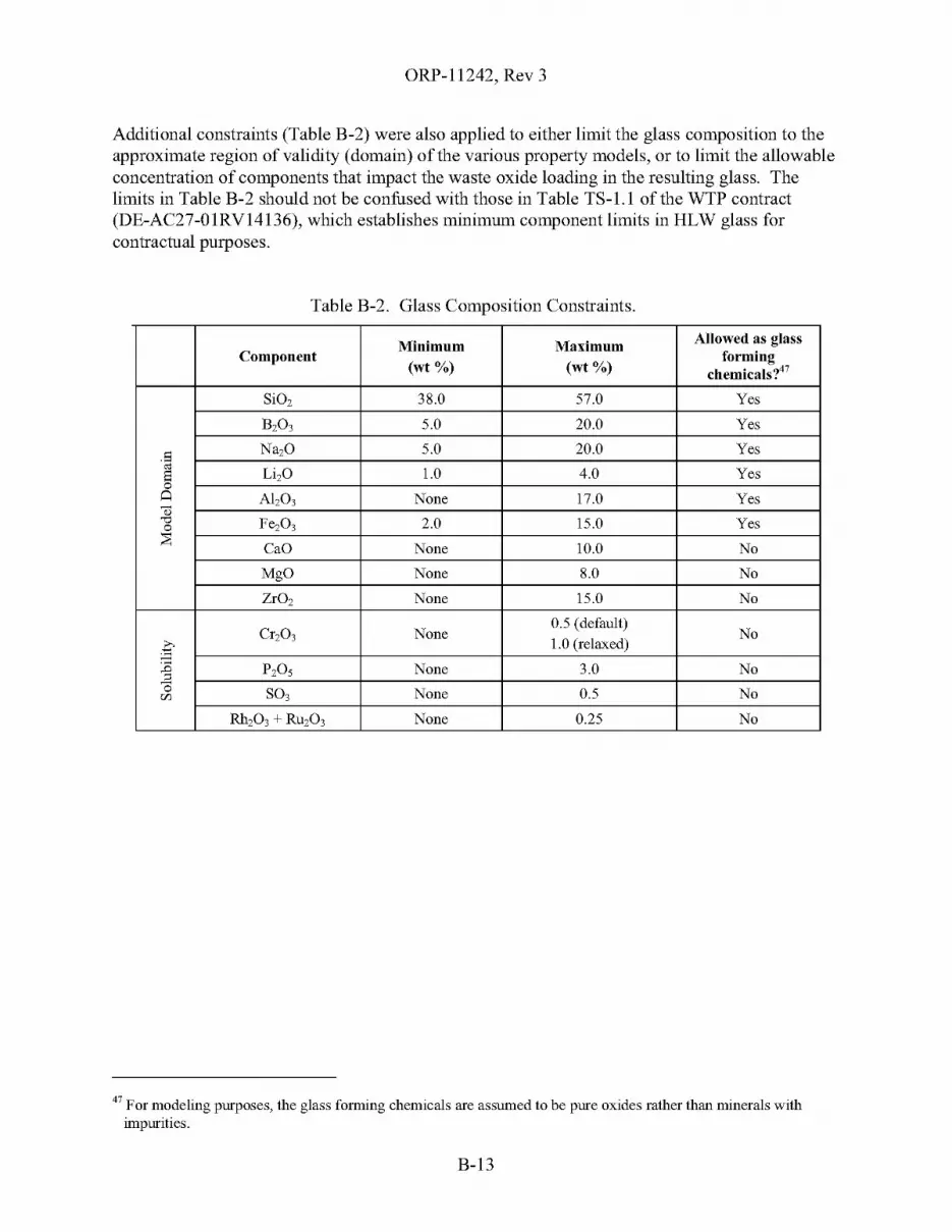
ORP-11242, Rev 3
Additional constraints (Table B-2) were also applied to either limit the glass composition to theapproximate region of validity (domain) of the various property models, or to limit the allowableconcentration of components that impact the waste oxide loading in the resulting glass. Thelimits in Table B-2 should not be confused with those in Table TS-l.l of the WTP contract(DE-AC27-0IRVI4136), which establishes minimum component limits in HLW glass forcontractual purposes.
Table B-2. Glass Composition Constraints.
Minimum Maximum Allowed as glassComponent
(wI %) (wI %)forming
chemicals?47
SiO, 38.0 57.0 Yes
B,03 5.0 20.0 Yes
S Na,O 5.0 20.0 Yesoj
Li,O 1.0 4.0 YesS0~ Al,03 None 17.0 Yes<l
"'" Fe,03 2.0 15.0 Yes0;;:CaO None 10.0 No
MgO None 8.0 No
ZrO, None 15.0 No
Cr,03 None0.5 (default)
No
~1.0 (relaxed)
~ P,O, None 3.0 No0 S03 None 0.5 Nor/J
Rh,03 + RU,03 None 0.25 No
47 For modeling purposes, the glass fmming chemicals are assumed to be pure oxides rather than minerals withimpurities.
B-13
ORP-11242, Rev 3
B2.3.4 Low-Level Waste Vitrification
B2.3.4.1 LAW Vitrification at the WTP will begin on May 15, 201848
B2.3.4.2 During hot commissioning, the WTP will produce 188 Packages49 of LAW glass.
B2.3.4.3 During full operations, the net WTP LAW vitrification capacity will be ramped asfollows:
Starting OnRate
MTG/d
101112018 9.0
1/112020 18.0
1/112021 21.050,51
B2.3.4.4 The average density of immobilized low-activity waste (ILAW) glass will be2.6 Kg/liter.
B2.3.4.5 Each package ofILAW will contain 5.92 MT of LAW glass on the average52
B2.3.4.6 The total sodium loading of LAW glass from pretreated feed will be determined usingthe DOE Model (D-03-DESIGN-004), which maximizes the sodium oxide loading in the LAWglass subject to the following constraints:
[Na20] ~ 20wt%
[S03] ~ 0.8wt%
B2.3.4.7 The composition of the LAW glass will be estimated using a glass recipe model similarto that described in 24590-WTP-MRQ-PO-04-0065 (DRAFT). Sulfate volatilization will beestimated using Equation 3.1-5f of 24590-WTP-RPT-PT-02-005.
48 ORP may direct BNI to begin commissioning oftbe LAW Vitrification Facility by 2013, which would requiresignificant changes in the TFC baseline.
49 The BNI Contract, Standard 5, Table C.6-5.2, requires tbat 188 packages of LAW glass be produced during hotcommissioning. For modeling purposes, the average WTP glass production rate during hot commissioning is setso that tbe contract goal is just met by the end date for hot commissioning. The average LAW vitrification rateduring hot commissioning is about 8.1 MTG/d.
50 Assumes two LAW melters, each 15 MTG/d design at a 0.7 TOE.51 No credit is taken for expanded LAW vitrification capacity in this version of the System Plan.
52 This is based on a 601 gal (2.275 m3) container per 24590-WTP-MDD-PR-OI-002, Section 4.7.14.
B-14
ORP-11242, Rev 3
B2.4 SUPPLEMENTAL TREATMENT
B2.4.1 Demonstration Bulk Vitrification System IDBVS)
B2.4.1.1 The DBVS will be located in 200 West Area adjacent to S-Farm.
B2.4.1.2 The DBVS will begin operation on 3/1/2011 and treat low-curie waste containing260 MT Na by October 23, 2012, not to exceed its net treatment rate of 3.66 MTG/d53,54
B2.4.1.3 The DBVS will be modeled using a simplified continuous flowsheet that implementsthe overall mass balances for the primary and secondary waste streams as shown in Figures 8-1and 8-4 of the process flowsheet (RPP-20528, Rev. 1) and described in the rest of the document.The mass balance spreadsheet developed for the flowsheet and documented in SVF-1102,Rev. 0, consolidates and elaborates on many of the underlying technical assumptions, mostnotably, the basis for many of the process splits. Any parameters not specifically addressed bythose two documents may be obtained from the process design criteria provided in145579-A-DC-002, Rev. OF. However, the mixture of glass-forming minerals specified inTable 1 of ST07.004 will be used instead of Hanford soil.
B2.4.1.4 The feed for the DBVS will be supplied from S-109 using the selective dissolutionassumptions described in Table A-14, "Selective Dissolution Separation Assumptions." TheS-109 retrieval will be controlled to limit the total activity in the retrieved waste to 0.0062 Ci perliter at a 5 M [Na] feed concentration and to prevent entrainment of solids in the feed55
B2.4.1.5 For modeling purposes, the density of the bulk vitrification product (glass) is2.65 MT/m355,56
B2.4.1.6 The Na20 loading in the product will be a nominal 21.24 wt% based on wastesodium55, 57, 58
B2.4.1.7 The product is packaged in 35_m3roll-off boxes, each filled with 42.6 MT radioactiveglass. 55, 56 The mass of clean fill glass used to top off each box will be neglected.
B2.4.1.8 The roll-off boxes will be temporarily stored on a cooling pad located near the DBVSuntil the IDF is ready to accept them for disposal.
53 HNF-SD-WM-SP-012, Rev. 6, Assumption A2.4.1, "Supplemental LAW Processing." This is based on a targetdesign rate of 1.09 gpm of 5 M [Na] nominal feed, a 17.6-wt% waste sodium oxide loading, and a 0.70 TOE (see145579-A-DC-002, Rev. OF, "Process Design Criteria").
54 For modeling purposes, the average DBVS glass production rate is set so that the treatment goal is just met by theend date. The average vitrification rate is about 2.74 MTG/d.
55 HNF-SD-WM-SP-012, Rev. 6, Assumption A2.4.1, "Supplemental LAW Processing."
56 145579-A-DC-002, Rev. OF, "Process Design Criteria," Section 3.5.1.57 145579-A-DC-002, Rev. OF, "Process Design Criteria," Section 3.4.1.
58 The assumed Na20 loading takes into consideration the recent decision to replace Hanford soil with a mixture ofglass forming minerals. See ST07.004 for details.
B-15

ORP-11242, Rev 3
B2.4.2 Bulk Vitrification System (BVS)
B2.4.2.1 The DBVS facility will be refurbished and re-permitted for extended operation as theBulk Vitrification Facility (BVS) after a one_year59 outage.
B2.4.2.2 The BVS starts operating on 10/23/201359 at a net rate of 3.66 MTG/d and operates aslong as low-curie feed is available.60
B2.4.2.3 The feed for the DBVS will be supplied from S-109 and S-105 using the selectivedissolution assumptions described in Table A-14, "Selective Dissolution SeparationAssumptions." The retrievals will be controlled to prevent entrainment of solids in the feed. 60
B2.4.2.4 For planning purposes, it is assumed that the BVS will utilize the same technology andprocess flowsheet as the DBVS61 See assumptions 2.4.1.3, 2.4.1.5, 2.4.1.6, and 2.4.1.7.
B2.4.3 East Supplemental Treatment Plant (East STP)
B2.4.3.1 A production scale supplemental LAW treatment facility, East STP, will be located in200E, northeast of the WTP pretreatment facility, on the plot of land originally reserved for thesecond LAW Vitrification Facility.
B2.4.3.2 For planning purposes, it is assumed that the East STP will utilize the same technologyand process flowsheet as the DBVS61 See assumptions 2.4.1.3, 2.4.1.5, 2.4.1.6, and 2.4.1.7.
B2.4.3.3 The East STP will start hot testing on 2/1/201962 and operate at 3.66 MTG/d for eightmonths.60, 63
B2.4.3.4 The East STP will start production operations on 10/1/2019 at a net capacity of14.65 MTG/d60, 64, 65
B2.4.3.5 The "excess" pretreated LAW from the WTP will be used to feed the East STP.60
59 Personal communication with P. K. Brockman, March 8, 2007.
60 HNF-SD-WM-SP-012, Rev. 6, Assumption A2A.I, "Supplemental LAW Processing."61 The process flowsheet will be revisited after evaluating the operation of the DBVS. It is anticipated that changes
will be required to control the amount and distribution of key constituents of concern such as 129r in the secondarywaste streams.
62 Maintained same relationship with start ofWTP full operations.
63 This assumes that the four melter lines will be tested one at a time.64 This assumes four melter lines, each with a design capacity of 5.24 MTG/d, with a 0.70 TOE.
65 The capacity of the East STP may be adjusted by even numbers of melters to bring the LAW treatmentcompletion date closer to the HLW treatment completion date if there is a gross mismatch.
B-16
ORP-11242, Rev 3
B2.4.4 Interim Pretreatment System
B2.4.4.1 The Interim Pretreatment System is assumed to pretreat liquid waste using rotarymicro-filtration units66 to remove entrained solids and a regenerable ion exchange to removecesium as described in HNF-SD-WM-SP-012, Rev. 6, Assumption A2.4.1, "Supplemental LAWProcessing."
B2.4.4.2 For planning purposes, the rotary micro-filtration units are assumed to removeessentially all entrained solids from the feed.
B2.4.4.3 For planning purposes, the regenerable ion exchange system is assumed to performsimilarly to the WTP Pretreatment Facility ion exchange system, except that the average 137Csconcentration in the pretreated waste is assumed to be 1.5E-5 Ci per mole of sodium. 67
B2.4.4.4 For planning purposes, the capacity of the Interim Pretreatment System is assumed toexceed the capacity of the West Supplemental Treatment Plant.
B2.4.5 West Supplemental Treatment Plant (West STP)
B2.4.5.1 A production scale supplemental LAW treatment facility, West STP, will be located in200W, near the SY-Farm and the Interim Pretreatment Facility.
B2.4.5.2 For planning purposes, it is assumed that the West STP will utilize the sametechnology and process flowsheet as the DBVS61 See assumptions 2.4.1.3, 2.4.1.5, 2.4.1.6, and2.4.1.7.
B2.4.5.3 The West STP will start hot testing on 7/2/2014 and operate at 3.66 MTG/d for eightmonths.68, 69
B2.4.5.4 The West STP will start production operations on 3/2/2015 at a net capacity of14.65 MTG/d and will be operated to process as much liquid waste from West Area aspractical.68,70,71
66 These are assumed to be similar to the rotary micro-filtration unit jointly designed and tested by Savarmah RiverSite (SRS) and Oak Ridge National Laboratory (ORNL) personnel for separating entrained solids from SRS wastesolutions. See WSRC-MS-2005-00147, 2005, "Small Column Ion Exchange Alternative Overview," D. McCabeet aI, Westinghouse Savannah River Company, Aiken South Carolina."
67 RPP-RPT-30160, Rev. 0, "Supporting Information for the Evaluation of Waste Treatment and ImmobilizationPlant (WTP) Low Activity Waste (LAW) Startup First Scenarios", Appendix A, Section A.2, "Cesium Removal."This report evaluates a cesium ion-exchange system similar in function to the Supplemental Pretreatment System.
68 HNF-SD-WM-SP-012, Rev. 6, Assumption A2A.I, "Supplemental LAW Processing."
69 This assumes that the four melter lines will be tested one at a time.70 This assumes four melter lines, each with a design capacity of 5.24 MTG/d, with a 0.70 TOE.
71 The capacity of the West STP maybe adjusted by even numbers ofmelters to bring the LAW treatmentcompletion date closer to the HLW treatment completion date if there is a gross mismatch.
B-17
ORP-1l242, Rev 3
B2.4.6 Supplemental TRU Sludge Treatment
B2.4.6.1 The contact-handledSupplemental TRU (transuranic) Treatment and Packaging processwill be available on October 1, 201372 and treat a maximum of 8,040 gal of slurry from retrievedTRU tank waste per day73
B2.4.6.2 The SSTs assumed to provide contact-handled sludge are [B-201, B-202, B-203,B-204], [T-201, T-202, T-203, T-204], T-lll, T-llO, and T-I04, in the stated order except thatthe tank order within the [brackets] can be changed. 74, 75, 76
B2.4.6.3 The contact-handled Supplemental TRU Treatment and Packaging system will first belocated near B-Farm and then moved to T-Farm. There will be a 10-day outage between tanksand 60-day outage to move equipment between farms. 74
B2.4.6.4 The remote-handled Supplemental TRU Treatment and Packaging process will beavailable on 5/9/202577 and treat a maximum of 8,040 gal of slurry from retrieved TRU tankwaste per day78
B2.4.6.5 The SSTs assumed to provide remote-handled sludge are T-I05, T-I07, T-112, B-I07,B-llO, and B-lll; the DSTs assumed to provide remote-handled sludge are SY-I02, AW-I03,and AW_I05 74
B2.4.6.6 All remote-handled sludge will be water-washed before treatment to remove solublewaste constituents. The SSTs will be retrieved, transferred to the nearest WRF and thenwater-washed. The sludge in SY-I02 will be consolidated with the sludge in AW-I03 and/orAW-I05, and then the sludge will be water washed in their respective tanks74
,77
B2.4.6.7 The remote-handled Supplemental TRU Treatment and Packaging process is initiallyassumed to be located near AW-Farm for treating water washed TRU tank waste from SY-102,AW-I03 and AW-I05; then near B-Farm for tanks B-I07, B-llO, and B-lll; and finally nearT-Farm for T-I05, T-I07, and T-11277
72 Baseline Change Request RPP-06-003, Rev. 1.
73 The assumed rate is based on 1:1 dilution of solids with water during retrieval and a 0.67 TOE per RPP-21970,Rev. 0, "CR-TRUM WPU&SE II-Tank Material Balance," Section 3.0.
74 HNF-SD-WM-SP-012, Rev. 6, Assumption A2.3.1, "TRU Sludge Processing."
75 These are operational considerations.76 RPP-21970, Rev. 0, "CR-TRUM WPU&SE II-Tank Material Balance," Section 3.0 and Section 5.0,
Assumption 2.77 The timing of all activities tliat depend upon the water washing of the RH-TRU DST solids may be adjusted based
on available DST space and operational logistics.78 The assumed rate is based on 1:1 dilution of solids with water during retrieval and a 0.67 TOE per RPP-21970,
Rev. 0, "CR-TRUMWPU&SE II-Tank Material Balance," Section 3.0.
B-18
ORP-11242, Rev 3
B2.4.6.8 The process flowsheet for the contact-handled TRU (CH-TRU) sludge treatment isdescribed in the material balance for the CH-TRU tanks and is assumed to use the "dry batchmode."79 For modeling purposes, the two dryers may be lumped into one dryer of equivalenttreatment capacity. For planning purposes, the same flowsheet will be used for processing thewater-washed sludge from the RH-TRU tanks80
B2.4.6.9 The dried waste product from the CH-TRU process is assumed to be packaged in55-gal drums containing 620 Ibm product per drum. 81 Although not explicitly modeled, theCH-TRU drums are loaded up to fourteen drums to into a Transuranic Package Transporter-II(TRUPACT-II) shipping container, three TRUPACT-IIs in a shipment, for a maximum of42 drums per shipment.
B2.4.6.10 The dried waste product from the RH-TRU process is assumed to be packaged in anRH-TRU Waste Canister containing about 2825 Ibm product per canister82 Each canister will beshipped to Waste Isolation Pilot Plant (WIPP) in an RH-TRU 72-B Shipping Package.
B2.4.6.11 Liquid effluent will either be transferred to the LERF via Tank Truck or recycled tothe Retrieval project. For planning purposes, it will be assumed that the liquid effluent istransferred only to LERF (no recycle) and will be modeled as a continuous transfer.
79 RPP-21970, Rev. 0, CH-TRUMWPU&SE ll-Tank Material Balance.
80 HNF-SD-WM-SP-012, Rev. 6, Assumption A2.3.1, "TRU Sludge Processing."81 RPP-21970, Rev. 0, CH-TRUMWPU&SE ll-Tank Material Balance, Section 5.0, Assumption 4.
82 This assumes an inner canister volume ofO.89 m3 per DOE/CAO 95-1095 Appendix I, a 90% fill, and a bulk driedwaste product density of 1.60 Kg/L. The density of1l1e dried RH-TRU product is assumed to be the same as thedried CH-TRU product as stated in RPP-21970 Rev 0, Assumption 3.
B-19
ORP-11242, Rev 3
B2.5 INTERFACING FACILITIES
B2.5.1 Liquid Effluents
B2.5.1.1 The timing, capacities, and capability of the ETF, LERF, State Approved LandDisposal Site (SALDS), and TEDF will be driven by the needs of the waste treatment missionand assumed to be available when needed83 If the treatment mission requires that changes bemade to the ETF, LERF, SALDS, or TEDF or their operating plans, the ORP is assumed tosuccessfully drive the changes.
B2.5.1.2 The LERF consists of three basins, each with an operating volume of7.8 Mgal(HNF-SD-WM-SAD-040, LERF Final Hazard Category Determination), which are used toprovide lag-storage ofliquid effluent. For planning purposes, only two of the basins will beallocated to supporting the waste treatment mission; the third basin will be reserved forCERCLA effluents83
B2.5.1.3 The ETF will be modeled as a black-box. Overall partitioning offeed into solid wasteand treated effluent will be approximated per HNF-4573, Appendix A83
B2.5.1.4 The SALDS will not be modeled; however, the demand on the SALDS from ETF willbe estimated.
B2.5.1.5 The TEDF will not be modeled.
B2.5.2 Central Waste Complex
B2.5.2.1 The Central Waste Complex (CWC) is assumed to support the needs of the wastetreatment mission and is assumed to be available when needed; the demand on the CWC will notbe modeled.
B2.5.3 Canister Storage Building and Hanford Shipping Facility
B2.5.3.1 The IHLW interim storage facility (the Canister Storage Building), being upgraded byProject W-464, will be operational on 9/29/201584 and provide interim storage for up to880 IHLW canisters85
B2.5.3.2 The need date for the Canister Storage Building will be the date on which the firstradioactive HLW canister is produced (estimated to be May 17, 2018).86
B2.5.3.3 For planning purposes, the first 880 IHLW canisters will be stored in the CSB. Nocredit will be taken for the 24 canisters of WTP-provided storage for cooling IHLW canisters,nor for the 24 canisters ofWTP-provided buffer capacity87
83 HNF-SD-WM-SP-012, Rev. 6, Assumption A4.3.4, "ETF and LERF."84 Baseline Change Request RPP-06-003, Rev. I, "Alignment ofTFC Lifecycle Baseline," November 2006.
85 RPP-12364, Rev. 0, "Project W-464, liumobilized High-Level Waste Interim Storage Facility, Preliminary DesignReport," November 2002.
86 HNF-SD-WM-SP-012, Rev. 6, Assumption A2.6 "Waste Disposal Sites," with adjustments for WTP schedule.
87 Cooling and buffer capacity obtained from 24590-HLW-3YD-HPH-0000I, Rev.!.
B-20
ORP-11242, Rev 3
B2.5.3.4 The Hanford Shipping Facility (HSF) for IHLW will be located in the 200 Area andwill be operational on 4/5/201988 If this date is later than the date determined by the model run,it will be accelerated to match that date.
B2.5.3.5 The shipping rate is up to 2 canisters of IHLW per dal9- first priority given to
shipping newly created IHLW canisters beyond the 880 stored at the CSB - second priority isgiven to emptying the CSB after HLW vitrification is finished.
B2.5.4 Yucca Mountain (Offsite Repository)
B2.5.4.1 Yucca will be ready to accept IHLW from Hanford on 4/8/201988
B2.5.4.2 IHLW canisters will be shipped to Yucca starting when the Canister Storage Buildingis full (880 canisters).
B2.5.4.3 It is assumed that the WTP-prepared deli sting petition for the IHLW is accepted byEcology before shipping the waste to Yucca.
B2.5.5 Integrated Disposal Facility
B2.5.5.1 The Integrated Disposal Facility (IDF) will be operational on 10/1/2010 and willprovide permanent disposal for the ILAW, other mixed low-level waste, and low-level waste(LLW). It is assumed that the ILAW produced by the DBVS can be safely stored until the IDF isavailable90
B2.5.5.2 The IDF will receive LAW glass packages from the WTP; solid waste from the WTPincluding spent LAW and HLW melters; roll-off boxes containing glass from the DBVS, BVS,East STP and West STP; and solid waste from the ETF from treating liquid effluent. Only thatportion of the primary and secondary waste streams directly related to treatment of the tankwaste will be modeled91
B2.5.5.3 For planning purposes, the IDF can be expanded as needed to support the missionwithout interference from other users.
B2.5.6 222-S Laboratory
B2.5.6.1 It is assumed that the laboratory services required to support waste characterization forTFC projects and operations are available and provided in a timely manner.
88 Baseline Change Request RPP-06-003, Rev. 1, "Alignment of TFC Lifecycle Baseline," November 2006.
89 RPP-20270, Rev. 0, Section 3.2.1.1.1, "Canister Receipt Rate Requirements."90 HNF-SD-WM-SP-012, Rev. 6, Assumption A2.6 "WASTE DISPOSAL SITES."
91 For example, the inventory that is retained on a disposable filter will be modeled, but the mass, composition andoverall volume oftbe filter itself will not be tracked.
B-21
ORP-11242, Rev 3
B2.5.7 Waste Encapsulation and Storage Facility
B2.5.7.1 Cesium and strontium capsules are assumed to be dispositioned outside of the WTPand tank farm facilities by DOE-RL92
B2.5.8 Waste Isolation Pilot Plant
B2.5.8.1 It is assumed that WIPP will be ready to accept contact-handled TRU waste starting on10/1/201388
B2.5.8.2 It is assumed that WIPP will be ready to accept remote-handled TRU (RH-TRU) wasteone year before the modeled need date (per Assumption B2.4.6.4 ), but no earlier than the currentbaseline date of 6/18/2022.
B2.5.9 Other Hanford Site Facilities
(No unique assumptions)
92 Pretreatment can connect to a potential new facility designed to receive and treat the Hanford Cs and Sf capsulesprior to incorporation into the HLW feed for immobilization in !lie HLW Vitrification Facility (Section C.7(c)(2)ofDE-AC27-01RV14136).
B-22
ORP-11242, Rev 3
B2.6 CROSS-CUTTING ASSUMPTIONS
B2.6.1 The starting tank inventory reflects the contents of the tanks as of January 2007. This iscalled the "FY 2007" inventory and is based on BBI downloaded from Tank WasteInformation Network System (TWINS) circa May 2007 as documented in RPP-33715.Adjustments will be made in the Hanford Tank Waste Operations Simulator (HTWOS)model for historical transfers as needed.
B2.6.2 Assumed addition of "new" waste into the DSTs from retrieval of the IMUSTs andfrom deactivation of other Hanford Site facilities is described in HNF-SD-WM-SP-012,Tank Farm Contractor Operation and Utilization Plan, Rev. 6, Assumption A2.1.1,"New Waste Introduced Via Deactivation." Waste added due to other TFC activities isdescribed in HNF-SD-WM-SP-012, Rev. 6, Assumption A2.1.2, "New WasteIntroduced via Operations."
B2.6.3 The water wash factors93 in TWINS circa March 2007 will be used to partition wasteinto solid and liquid phases during retrieval and staging; strontium partitioning will bemodeled per RPP-21807. The feed vector will be reported on a fully water-washedbasis.
B2.6.4 The caustic leach factors93 in the TWINS circa March 2007 will be used as the basis forcomputing the caustic leach factors associated with each delivered batch of HLWsolids.
B2.6.5 For modeling purposes, the approximations to waste chemistry in the tank farms aredescribed in HNF-SD-WM-SP-012, Rev. 6, Assumption A6.6, "Waste Chemistry andMass Balances."
B2.6.6 Total organic carbon (TOC) will not be speciated94 However, for modeling purposes,all TOC will be treated as oxalate once it enters the WTP or STP to allow for reactionstoichiometry.
B2.6.7 The composition waste retrievals from SSTs and DSTs will be homogeneous95
Tanks S-105 and S-109 are exceptions in that they use selective dissolution assumptions(see B2.4.1.4 and B2.4.2.3).
93 Uncertainties and biases in the water wash and caustic leach factors can significantly influence the canister countsand end dates; some of these have been addressed in TWINS since the last revision of the System Plan (forexample, Cr ,AI, P04 and S04 wash and leach factors; S-complex 99Tc wash factors; 90Sr wash factors; andmiscellaneous corrections).
94 An enabling assumption for speciating TOe into its constituent organic compounds is not available. Therefore,the organic content of the various secondary waste streams will not be estimated.
95 HNF-SD-WM-SP-012, Rev. 6, Assumption A6.1, "Estimating Waste Compositions."
B-23

ORP-11242, Rev 3
B2.6.8 The design, flowsheet, operating modes, and operating plans of all facilities orprocesses will drive the permit conditions, and the permits will be modified as theprocesses evolve.
B-24

ORP-11242, Rev 3
B3.0 REFERENCES
145579-A-DC-002, 2005, Bulk Vitrification Process Improvement Design Criteria -Full DBVS,Rev. OF, Apri18, 2005, AMEC Earth & Environmental and Geomelt, Richland,Washington.
24590-HLW-3PS-AEOO-T0001, 2003, Engineering Specification for High Level Waste Melters,Rev. 2, Bechtel National, Inc., Richland, Washington.
24590-HLW-3YD-HPH-00001, System Descriptionfor HLW System HPH Canister PourHandling, Rev. 1, Bechtel National, Inc., Richland, Washington.
24590-LAW-3PS-AEOO-T0001, 2003, Engineering Specification for Low Activity WasteMelters, Rev. 2, Bechtel National, Inc., Richland, Washington.
24590-WTP-ICD-MG-01-019, 2003, ICD 19 -Interface Control Documentfor Waste Feed,Rev. 3, Bechtel National, Inc., Richland, Washington.
24590-WTP-MDD-PR-01-002, 2003, Dynamic (G2) Model Design Document, Rev. 6,Bechtel National Inc., Richland, Washington.
24590-WTP-MDD-PR-01-002, 2005, Dynamic (G2) Model Design Document, Rev. 8,Bechtel National Inc., Richland, Washington.
24590-WTP-MRQ-PO-04-0065, 2004, Model Run Request, Supplemental LAWData Collection,8/16 Rev. 0 DRAFT, Bechtel National, Inc., Richland, Washington.
24590-WTP-PL-MG-01-001, 2003, Interface Management Plan, Rev. 1, Bechtel National, Inc.,Richland, Washington.
24590-WTP-RPT-PT-02-005, 2005, Flowsheet Bases, Assumptions, and Requirements, Rev. 3,Bechtel National, Inc., Richland, Washington.
Baseline Change Request RPP-06-003, 2006, Alignment ofTFC Lifecycle Baseline, Rev. 1,CH2M HILL Hanford Group, Inc., Richland, Washington.
CCN: 102476, "HLW Melter Glass Inventory", October 14, 2004, Mark Hall to Distribution,Bechtel National, Inc., Richland, Washington.
CCN: 132846, "Comprehensive Review ofthe Hanford Waste Treatment Plant Flowsheet andThroughput, Assessment Conducted by an Independent Team ofExternal Experts,"March 2006, transmitted under cover ofletter CCN: 132846, Bechtel National, Inc.,Richland, Washington.
CCN: 150375, "Justification to Revise the LAW Vitrification Technetium (Tc+4 & 99Tc)Decontamination Factors in the Flowsheet Bases, Assumptions, and RequirementsDocument, "March 19,2007, Joe Perez to Scott Saunders, Bechtel National, Inc.,Richland, Washington.
D-03-DESIGN-004, 2003, An Assessment ofthe Factors Affecting the Ability to Increase theNa20 Loading in the Waste Treatment and Immobilization Plant (WTP) Low ActivityWaste (LAW) Glass, ORP WTP Engineering Division, U.S. Department of Energy,Office of River Protection, Richland, Washington.
B-25
ORP-11242, Rev 3
D-03-DESIGN-005, 2004, HLW Feed Preparation System: Ultra-Filtration Process System,ORP WTP Engineering Division, U.S. Department of Energy, Office of River Protection,Richland, Washington.
DE-AC27-0IRVI4136, 2000, WTP Contract, U.S. Department of Energy, Office of RiverProtection, Richland, Washington, as modified and amended through M051, dated 2006.
DOE/CAO 95-1095, 1995, Remote-Handled Transuranic Waste Study, U.S. Department ofEnergy, Carlsbad Area Office, Carlsbad, New Mexico.
Ecology, EPA, and DOE, 1996, Hanford Federal Facility Agreement and Consent Order, asamended, State of Washington Department of Ecology, U.S. Environmental ProtectionAgency, and U.S. Department of Energy, Olympia, Washington.
HNF-3484, 2007, Double-Shell Tank Emergency Pumping Guide, Rev. 8, CH2M HILL HanfordGroup, Inc., Richland, Washington.
HNF-4573, 1999, Liquid E.fJluent "Retention Facility Basin 44 Process Test Post-Report,Rev. OA, Waste Management Federal Services of Hanford, Inc., Richland, WA.
HNF-EP-0182, 2007, Waste Tank Summary Report For Month Ending 12/31/2006, Rev. 225,CH2M HILL Hanford Group, Inc., Richland, Washington.
HNF-SD-WM-OCD-015, 2007, Tank Waste Transfer Compatibility Program, Rev. 17,CH2M HILL Hanford Group, Inc., Richland, Washington.
HNF-SD-WM-SAD-040, 2001, Liquid E.fJluent Retention Facility Final Hazard CategoryDetermination, Rev. 2, Fluor Hanford, Inc., Richland, Washington.
HNF-SD-WM-SP-012, 2007, Tank Farm Contractor Operation and Utilization Plan, Rev. 6,CH2M HILL Hanford Group, Inc., Richland, Washington.
ORP-11242, 2003, River Protection Project System Plan, Rev. 2, U.S. Department of Energy,Office of River Protection, Richland, Washington.
OSD-T-151-00007, 2007, Operating Specifications for the Double Shell Storage Tanks, Rev. I,CH2M HILL Hanford Group, Inc., Richland, Washington.
RPP-12364, 2002, Project W-464, Immobilized High-Level Waste Interim Storage Facility,Preliminary Design Report, Rev. 0, CH2M HILL Hanford Group, Inc., Richland,Washington.
RPP-15552, 2003, Hanford Tank Waste Oxidative Leach Behavior Analysis, Rev. 0,CH2M HILL Hanford Group, Inc., Richland, Washington.
RPP-I7239, 2004, Process Control Plan for 242-A Evaporator Campaign 04-01, Rev. 0,CH2M HILL Hanford Group, Inc., Richland, Washington.
RPP-18592, 2005, Software Verification & Validation Plan & Results for Hanford Tank WasteOperations Simulator Model Reference Version 1.1, Rev. 2, CH2M HILL HanfordGroup, Inc., Richland, Washington.
RPP-20270, 2005, Hanford Shipping Facility System Specification, Rev. 0, CH2M HILLHanford Group, Inc., Richland, Washington.
B-26
ORP-11242, Rev 3
RPP-20528, 2006, Demonstration Bulk Vitrification System Flowsheet, Rev. 1, CH2M HILLHanford Group, Inc., Richland, Washington.
RPP-2l2l6, 2006, Single Shell Tank Retrieval Selection and Sequence, Rev. 2, CH2M HILLHanford Group, Inc., Richland, Washington.
RPP-2l807, 2004, Strontium-90 Liquid Concentration Solubility Correlation in The HanfordTank Waste Operations Simulator, Rev. 0, CH2M HILL Hanford Group, Inc., Richland,Washington.
RPP-2l970, 2005, CH-TRUM WPU&SE ll-Tank Material Balance, Rev. 0, CH2M HILLHanford Group, Inc., Richland, Washington.
RPP-337l5, 2007, Double & Single-Shell Tank Inventory Input To the HTWOS Model- 2007Update, Rev. 0, CH2M HILL Hanford Group, Inc., Richland, Washington.
RPP-35320, 2007, WTP Ultra-Filter Permeate Assumptionfor System Modeling, Rev 0,CH2M HILL Hanford Group, Inc., Richland, Washington.
RPP-RPT-30l60, Supporting Informationfor the Evaluation ofWaste Treatment andImmobilization Plant (WTP) Low Activity Waste (LA TV) Startup First Scenarios, Rev. 0,CH2M HILL Hanford Group, Inc., Richland, Washington.
ST07.004, 2007, "RE: Bulk Vitrification Baseline Glass Formulation for FY07 System Plan,"(Letter to J. E. Van Beek, March 19,2007, from L. M. Bagaasen), Pacific NorthwestNational Laboratory, Richland, Washington.
SVF-1283, 2008, "Single-Shell Tank Retrieval Assumptions for Mission Modeling, SVF-1283Rev1.xls," Rev 2, CH2M HILL Hanford Group, Inc., Richland, Washington.
WSRC-MS-2005-00l47, 2005, "Small Column Ion Exchange Alternative Overview,"D. McCabe et aI, Westinghouse Savannah River Company, Aiken, South Carolina.
B-27

ORP-11242, Rev 3
This page intentionally left blank.
B-28

ORP-11242, Rev 3
APPENDIXC
OVERALL SYSTEM MASS BALANCE
C-i

ORP-11242, Rev 3
This page intentionally left blank.
C-ii
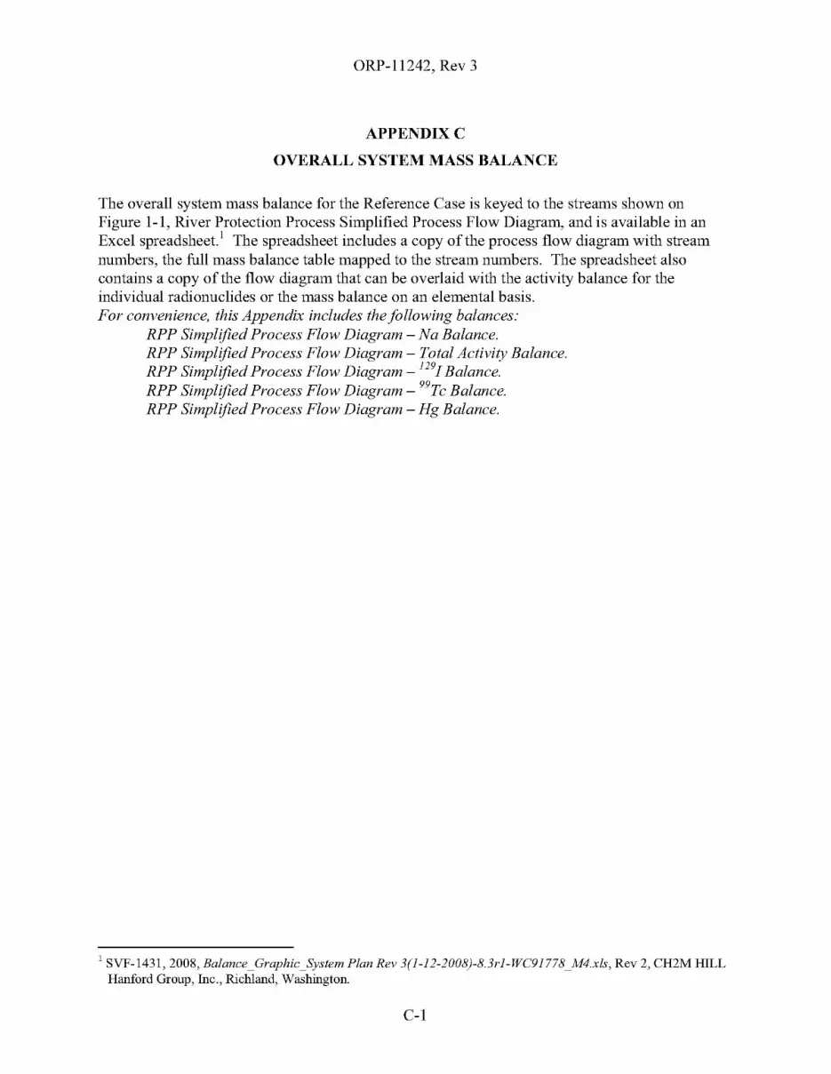
ORP-11242, Rev 3
APPENDIXC
OVERALL SYSTEM MASS BALANCE
The overall system mass balance for the Reference Case is keyed to the streams shown onFigure 1-1, River Protection Process Simplified Process Flow Diagram, and is available in anExcel spreadsheet.! The spreadsheet includes a copy of the process flow diagram with streamnumbers, the full mass balance table mapped to the stream numbers. The spreadsheet alsocontains a copy of the flow diagram that can be overlaid with the activity balance for theindividual radionuclides or the mass balance on an elemental basis.For convenience, this Appendix includes the following balances:
RPP Simplified Process Flow Diagram - Na Balance.RPP Simplified Process Flow Diagram - Total Activity Balance.RPP Simplified Process Flow Diagram - 1291Balance.RPP Simplified Process Flow Diagram - 99Tc Balance.RPP Simplified Process Flow Diagram - Hg Balance.
1 SVF-1431, 2008, Balance_Graphic_System Plan Rev 3(1-12-2008)-8.3rl-WC91778_M4.xls, Rev 2, CH2M HILLHanford Group, Inc., Richland, Washington.
C-l

ORP-11242, Rev 3
This page intentionally left blank.
C-2
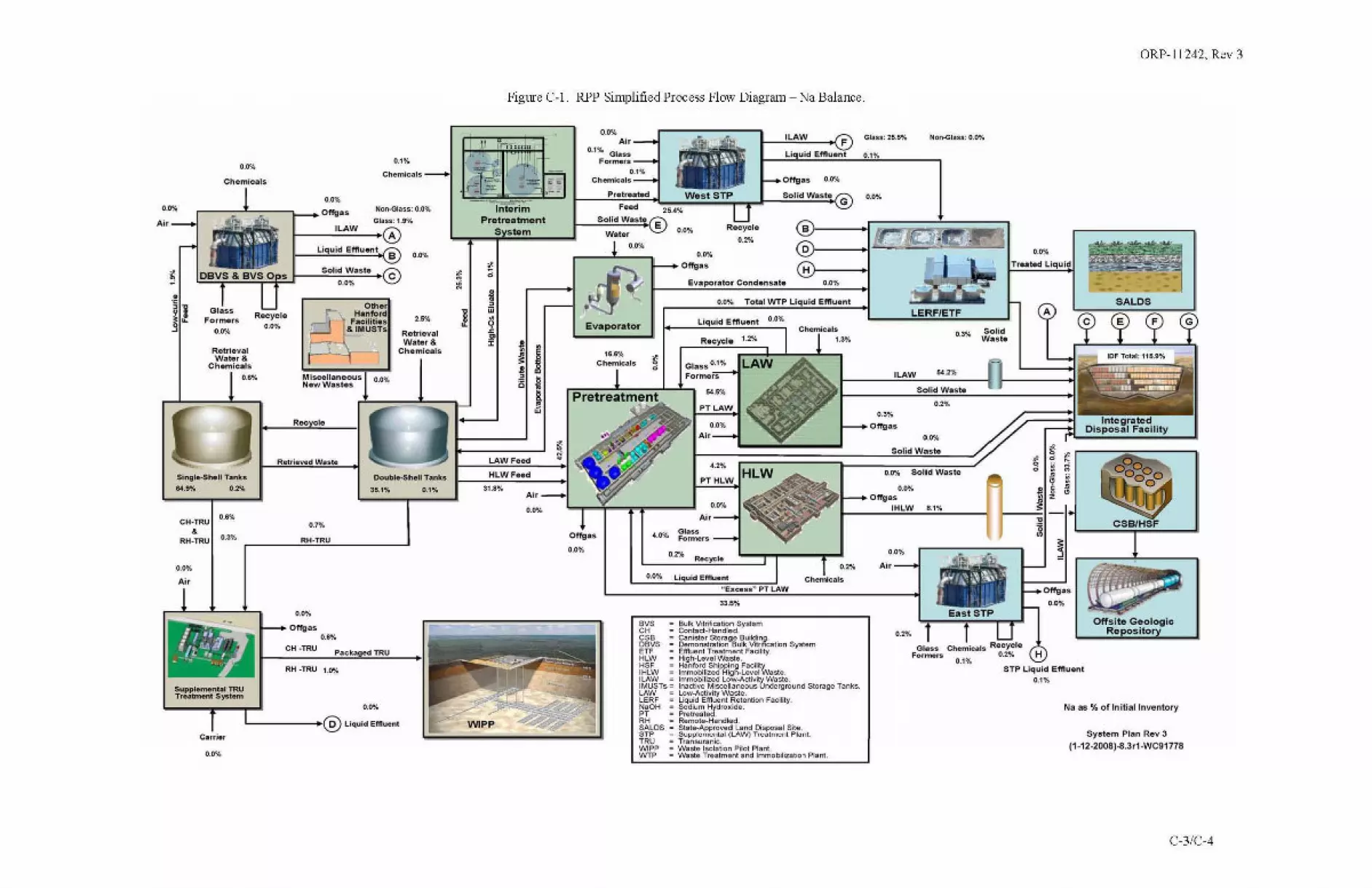
ORP-11242, Rev 3
Figure C-l. RPP Simplified Process Flow Diagram - Na Balance.
ott'site GeologicRepository
A
System Plan Rev 3
(1-12-200S)-8.3r1-WC91ns
Na as % of In itiallnventory
0.0%
Treated Liquid
STP Liquid Etl'Iuent
0.1%
SolidWaste
L.ERFJETF
0,,",
Solid Waste
0.3%
lLAW 50%
Solid Waste
0.0% Solid Waste
0.0%
Air
0,'"
0.3%
Otrgas
Glass: 25.5%
0.1%
0'"'~1-~01Tgas
IHL.W 8.1%
Hr---1
Of1gas OJ)'!.
Solid Wilsie G
l.i uid Effluent
0'"'
Recycle
0,'"
0.0% Toul WTP l.iquid Effluent
Recycle 1.2%
,,'"PTHL.W
0.0%
AI,
Liquid Emuent
Evaporator Condensate D.O%
West STP
GlusFormers
0.0%
BUlk Vijrification SySlemContact-Handled.Canister Storage Building.Demon5l:mtion Bulk Vijrification SyslemEm....nt Treatment FaciHly.High·Level Wasle.Hanford Shipping FacilitYImmobilized High-Level Wasle.Immobilized Low-Activity Wasle.Inactive Miscellana<>us (Jnder\lfOund Storage TanksLow_Activity W",sle.Liquid Effluent Retention Facility.Sodium Hydroxide.Prelrealed.Remole_Handled.Slale.App«Ived Land Disposal Sil....s"f'I"Iu",,,,,t,,1 (LAW) T,,,,,lrn,,,,t Pl,,,,l.
• Tranwranlc.• Wasle Isolation Pilot Plant.• WaSle Trutment and Immobilization Plan\.
2U%
r-__;r;~~r;=-lf--'~LA!:!!.W!!""-..(iF
.,,.
33.5%
0.0% Liquid Effluent
"Excess" PT LAW
L__:O':"'::"_R~·~·~",~,·,----':::::rr---T-:0,'"
'voCHCOBO,VOHFHLWHOFIHLW,LAWIMUSTs ..LAWLERFNaOHPTRHSALOS."TRU,,"PPWTP
Solid Waste E
Water0,,",
16.S%Chemicals
0.0%Air
0.1% GlassForme'5
0.1%ChemlCllls
Pretreated,....
01Tg:llS
0,,",
LAW Feed
HL.W Feed
31.8%Air
0,",
--~-
InterimPretreatment
S 10m
I 'J ,,"
'~. ~I
"~:~
0,,",
RetrievalWalllr&
Chemicals
2.5%
0,,",
NOfl-Glns: 0.0%
Glass: 1.9%
DoubteoShell Tanks
36.1% 0.1%
OtherHanford
F.eUlties&IMUSTs
MisceHaneousNewWasles
0,"
RH-TRU
0,",
RK ele
,-_"L"iq,"ei"dcE"tlI::::""~",.o(I B
RH -TRU 1.0%
o""*s0.6%
CH -TRU
Retrieved Waste
Recycle
0'"'
0.3%
0,,",
0,"
'''I'''{\~'U',. " ...'1 .....'
I '
RetrievalW;,ter&
Chemicals0,"
Carrier
0,,",
Chemicals
0,",
r---,--'---,-----,~_Offgas
f-_---"L:::A::W~_0
0,"
L-----_@LiqUidEfI'I"ent
0.1%
~~!'y;~~~~!!j~j__OS"O"Ii~d~W~'"'~"=-@OBVS &BVSO s "'.
CH-TRU&
RH_TRU
0,,",
Air
SingleoShell Tanks
&U% 0.2%
s...ppl.....nt.1 TRUTr.atment System
Air
C-3/C-4

ORP-11242, Rev 3
Figure C-2. RPP Simplified Process Flow Diagram - Total Activity Balance.
SALDS
Offsit. GeologicRe sito
System Plan Rev 3(1·12·200SI-8.3r1·WC91ns
Total Activity as % of InitialInventory
A
0.0""
Treated LIquid
STP Liquid Emuent0.0%
SolidWute
'.0%
...
LERF/ETF
'.0%
'.0%
lLAW 0.7'%
'.0%Solid Waste
'.0%
Olu-.:O"'''iIo
'.0%
'.0%
O.~'t. Solid Waste....'._.OfTgIlSIHL.W 95.0%
H)---t
D
U uid Effluent
LAW
0.0"1. Total WTP liquid EfftuII"'
.....PTHLW
....AI<
Recycle 0.0%
Liquid effluent 0.0'1.
Evaporator Conden••t. 0.0%
Glass 0.0%
Formers
'.0%Ofl'g1S
Bulk Vitribtion SySlllm• ContDct-Kandllld.• Cllrllsrllr Sto~e Building.• C/emrmslt'1llion Bulk V~rifio;atiorl System• Em""nt TrllD!mlInt Fecilily.• High-level Waste.• Hanford Shipping Facili!y
Immobil~e<fRiQfl·level Waste.Immoblhzed low·Activity Waste.I~ctive "b<>e"neous Underground Slollll!" Tenk".low·Activity WaSlll.liquid Em""nt RlItllniion Facility.Sodium Hydro";"",Pretreated.Remote·Hendled.Stete.Appr&Hod lend Disposel Site.
• Supplemel'ltDl (LAW) Treatment Plant.• Tt'1Irl..... ranic.• Waste Isolation Pilot Plant.• Weste Treatment eOO Immobil~ation Plant.
r--~;-:::~~-l_...J'~LA~W"-__(F
L--':·"'~...J~~~~~=TT---l"'~. •...Recycle0.0% Air
0,0% Liquid Emuen1
"Exce.." PT LAW
evsCHCSBOSVSETFHLWH5'IHlW,lAWIMUSTs·lAWLmN.OH •eTRHSAlOS5T''RU"OP'wrP
Solid Washo E
W.ter'.0%
....
0.0%AI,
0.0'4 GI...Formers
'.0%Ch....ic.l.
OffgllS
'.0%
""
Air
'.0%
LAWhed
HLWF..d
~
In.rimp,.t,...tment
S 10m
,~ '"
i,! "•
~•~ • j•
~•~ !
'.0%
'.0%
Retrlev.;,1Water It
Chemicals
'.0%
Ott",Hllnford
Facilities& IMUSTs
Miscellaneous 0N_Wast41s .v""'
Ooub!oe-$n.1I Tanh
50.9% 0.0"4
•.'"RH-TRU
'.0%
,-_"U=·,q="";dCE='"""""~::::'-e• B
OffgllS ...eH-TRU
RH -TRU u%
'.0%
•.'"'.0%
'.0%
'.0%
'------_'@UquidEMusnt
'.0%
Carris.
'.0%r--..,....-;---...._.Offglls Non-G~ss:0.0%GIISI: a.CWo
I-_--";:;LA"W'-_@
RetrievalWahlr &
Chemicals
'.0%
CH·TRU
•RH-TRU
Air
'.0%
Sfngle.shell Tames
'*9.1% 1.",
AI,
C-S/C-6

ORP-11242, Rev 3
Figure C-3. RPP Simplified Process Flow Diagram - 1291 Balance.
Offsit.e GeologicRe sito
A
,.,.Treated Uquid
STP L.iquid Efftuent10.0"Jl,
1291 as % of Initial Inventory
System Plan Rev 3(1-12-2008)-8.3r1-WC91778
East STP
. -r;;l~~~~~ ,I __
Solid15.6% Waste
Non-Gl...: 0.0%
Solid Waste
21.9%
Glass Chemicals RecycleFormers 0.1%,.,.
LERF/ETF
ILAW 12.2'llo
.,.
,,.Solid Waste
S.W SOlid WillSle
,.,.Air
,.,.OfTgas
IHLW u""
8.6'4
.....F
,.,.
Li uid Emu."!
,LAW
,.,.
LAW
Recycle,....
61.2%
'"
OA"Il. Total WTP Liquid EMu."t
Recycle 26.9"10
PTHLW
0.0"10
Air
Liquid EflIuent
Evaporator Condensate 0.0%
,.,.Otrgas
GinsFOllNlrs
,....
Sulk V~rificabon System• Contact_Handled.• Ganl!;ler Slo",ge Building.
Oemonst"'tion Bulk V~rificationSyslemEfftuent T",atment Facility.High-Le~elWaste_Hanford Shippjng FacilityImmobilized High-Level Waste.ImmobHized Low-Acti~iIy WaSl8.lnaclive Miscella~Undergro.."j Sto",ge Tanks.Low-ActMty waSle.liquid Effluent Retentkln Facility.
• Sodium HvdroJ<ide.• Pretreated.
Remote_Handled_• State-Appro~ed Land Disposal Site.• Suppklm"mtal (LAW) Treatment Plant.• Transuranic.• Waste Isolation Pilot Plant.• Waste Treatment and Immobilization Plant.
,.,.
0.0% Liquid Effluent
~E"cessHPT LAW
l__~'="~_·~2"',-~~=:rl----l-~.",eeye e ,.,.
'"C"C..OBVSEn'"OW
""IHLW'<AWIMUSTs_<AWLERFNaOH
"'"SALDS,"pTeo"'''WTP
,,.Chemic.ds
Solid Waste E
Waler,.,.
0.0%Air
0.0"1. GlassFormers
OffgaS,.,.
AJ,,.,.
HLWFoed
LAW Feed
(0
~•"•~<£ ! I~
•• •;;I,w
30.1%
" r;n..l"'r
J I,
• ••-=
,.,..
,.,.RetrievalWater &
Chemicals
Non-Glau; 0.0%
GIUs:O.2"lIo
,.~
Miscellaneous 0.0%NewW.stes
RH·TRU
,.,.
Roc 0;:10
RH _TRU 0.5%
Of'l'gas ,.,.CH·TRU
Recycle,,.
'.0%
,.,.
,.,.
,.,..L------_'@LiquidEffluent
,.,.Chemic.'s_
0.0'4
,.,.Chemicals
Carrier
~l!!~~.!.2l!:~~~J--_CSo","';;d~Wi""'~"'-o(DBVS&BVSO 5 C0."'"
,.,.,----=--'---=:--"'l-__ Otrua~
ILAWf---==---I A
RetrievalWa~r&
Chemic..ls,.,.
CH·TRU
•RH_TRU
Air
,.,.
Si"lillle-SheH Tanks
.&.3% 0.2%
Air
C-7/C-8

ORP-11242, Rev 3
Figure C-4. RPP Simplified Process Flow Diagram - 99Tc Balance.
Offsi~ G.ologicR. sito
System Plan Rev 3(1-12-200S)-8.3r1-WC91ns
99Tc as % of Initial Inventory
A
.,..Treated Liquid
STP Liquid Effluent0.0%
SolidWaste
, .
""
""
Non-Glns: 0.1%
Solid Waste
LERF/ETF
lLAW Z8.",
..,.
0.1%
So'idWaste
0.0'4 Solid Waste
.,..Air
""Ol'fgas
Glau: 20.9%
""
...
""
"",._+ Ol'fga5IHLW 5.6'10
0.0%
B
0»------1 '-=-~
H!}----1
LI uid Effluent
""
Recycle
1.3%
0.2% Total WTP Liquid Effluent
Recycle 47.5%
PTHLW
0.0'10
Air
15.1%
Liquid Effluent
Evaporator Condensate
.,.Offgas
GinsFomw,s
""
Sulk Vitrification SY!lIem• Contact_Handled._ canister Stofllge BUilding.
Demonslration Bull< Vltrificat;on Sy!lIemEflIuem Trealment Facility.Higt>.Level Waste.Hanbrd Shi . FacililvImmobilize:rti~LevelWaste.ImmOO~iz&dLow-ACI'vily Waste.Inactive Mscellaneous (Jndergrolnd Slo<age Tanks..Low-Aalvlty WaSle.Liquid EflIlIlInl Retention Facility.SodUn Hvdroxide.Prell'eated.Remole_Handled.Slate_Approved Land Disposal S<te.Supplemental (LAW) Trealment Plant.Transuranlc.
_ Waste Isolation Pilot Plam.- Waste Treatmem and Immobilization Plant
.,,.
0.0'4 Liquid Effluent"EJlcess~PT LAW
L--·~'·~·~.1R~·~·~~"~·'--~=:Jl:----r-:""
,VSCHCS8O'VSEn'HewH"IHlW'lAWIMUSTs_lAW
CE"'NaOl-l _
'TRKSALDS _mTRU,..",WTI'
""Chemicals
0.0"4
."D.O'llo Glass
Formers
""ClMImlcals
Evaporator
Offgn 0.0%
1__--""'~·~"~·~·....:"''-oIl.::_::::~W::.~s~t~S~TP;- ...J---'So~'~''!!W~.~'~':.\GFeed 21.0%
Solid Waste E
Water
""
0fl'BiiS
0.0%
""A;,
HL.WFeed
LAW Fe-.:l
~0
!,"••<~ ! i~
•, •, •l•~
25.S'4
--Jnt8'ri,;;P,..t,...tment
S tom
""
""
RetrievalWater &
Chemicals
""
NoI\-Glass: O.O'Jl.
G~ss;l.O"lI.
""'.,Hanford
Facilities& IMUSTs
Packaged TRU
Miscellaneous G.O'lloNewW.st.s
Roc clo
RH-'mU
OOUble.s...... Tank.
156."" 0.0%
Offgas0.1%
eH ·TRU
""
RH _TRU 0.6%
RatrieVfll Waste
Recycle0.1%
....Chemicals
0.1%
0.1%
""RetrievalWahor &
Chemicals
""
""L-----_'@LiqUidEMu.nl
0.0'10
Curier
""'---=--"---::--"'__ Otrg35
fLAWI--"';::=-~-<A
CH·TRU&
RH_TRU
Air""
Si"'llle-Shell Tanks
.3.1"4 0.3%
Air
C-9/C-1O
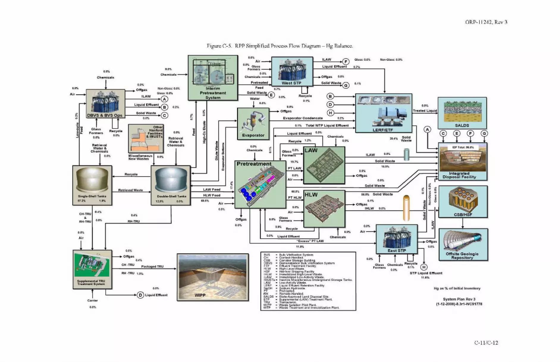
ORP-11242, Rev 3
Figure C-5. RPP Simplified Process Flow Diagram - Hg Balance.
CSBlHSF
A
0.0'10
Troatocl L.iquid
2OA'I\. SolidWaste
East STP
.rt;(~...~~\\I.
Non.(>lns; 0.0%
Hg 115 % of lnitilllinventory
System Plan Rev 3
(1-12-2008)-8.3r1-WC91n8
STP Liquid Emu.nt11.6"10
Glass Chemiuls RecycleFormer. 0.1'10....
LERF/ETF
Oft'site Geologic0.0% Repository
56.8'10 Solid Waste
lLAW 0.0%
SolidWasle
18.6'10
...Solid Wast.
..".AI,
0.1'10Offgas
IHLW 0.0'10
....Ol'fgas
Glus:O.O*!o
0.1'10
..".
....
0)---1
Hl)-----I
LI uid Emuent
LAW
Roeycre
0.1'10
0.1% TotaiINTP Liquid Emu.nt
Recycle 1.7%
Liquid Ef'llu.n! 0.0%
Evaporator Condensate 0.2%
Glass 0.0'10
Formers
....Otfgas
BUlk Vitrification Sy~emContact_Handled.Cani$l:nrStora~e BuHding.Domonslratkm Bulk Vdri1ic:atlon SystemEfIluent Treatment Flldlity.High_Le~1I1Waste.Hanford Shipping Facil;tyImmobiltzed High_Level Waste.ImmobHtzed Low·ActivitY Waste.Inaclive Miscellaneous Underground Storage Tanks.Low_Adi~ityWa:sln.Liquid EfIluent Retention Facility.~~~~~I~J.droxide.
• Remote.HancHed.• State.Approved Land o;spo5ll1 Site.• Supplemental (LAW) Treatment Plant.• Transuranlc.• Waste I$olation Pilot Plant.- Waste Treatment aN:! Immobilization Plant.
11.8'10
,;;
0.0% Liquid Effluent
'·Ex.,.ss" PT LAW
'"SCHC.,OBVSmHewHS'IHLW'CAWIMUSTs_LAWLERFNaOH
"RHSALDSmT"
"'''WTP
....
0.0%Air
0.1)% GlassFormers
Evaporator
Ol'fgas
0.0%
Air....
LAW Feed
HLW FHd
69.8'10
1J , j,,1.
• j '11r~;, J~-.~lt _-:m:: Ot'fgas 0.0%
L.,.-;;'~:i",';;';;;;1'-...J t __"PC'~·~";;·;;·f''':::'o\,,,,,,..w:::.~s::.t:';:S~Tl':::'_ ..J.__So,,,'~id,-,W,.,,",~.G---=intiri;; F_d 8.'"
p ...t....tn'lent Solid Waste ES tem Water
..,.
....RetrievalWater &
Chemicals
Non-Glns: 0.0%
Glass: 0.ll'4
Packaged TRU
Miscellaneous 0.0%Now Wastes
'A%
RH·TRU
Dou~-5henTank.
12.8'10 0.0%
Rec: c:le
...
I-_--".::LA:;W"-_@
I-_CL~I,'"'"id,-"E"m","~,,",~ B
Ol'fgas0.4%
CH ·TRU
RH _TRU 1.3%
R.t';e~d Wnte
Recycle...
...
....RetrievalWater &
Chemicals....
Chemicals_
....L-------+,@L1quidEffluent
0.0%
.... ....
Carrier
Chemicals ....,--_---,J'--,,..--_-..._. Offgas
~!2!i!l!,~!.!!!l!~2jp..t--"SOO"';~d~W;=·~""·,-""CDBVS&BVSO 5 ~....
CH·TRU&
RH_TRU
Slngle-5helt Tank.
87.2'10 1.9%
....Air
....Air
C-lliC-12
Related Documents