Original MINI Accessories Installation Instructions. © BMW AG, Munich 01 29 0 304 014 4/2007 (Z/Z) 1 Illuminated Door Sill Strips Retrofit MINI ONE (R 50, R 56) MINI COOPER (R 50, R 56) MINI Convertible (R 52) MINI COOPER S (R 53, R 56) Retrofit kit No. 51 47 0 302 686 “MINI Cooper S” illuminated door sill strips retrofit kit 51 47 0 302 683 “MINI” illuminated door sill strips retrofit kit 51 47 0 404 911 “John Cooper Works” illuminated door sill strip retrofit kit 51 47 0 416 145 “MINI Cooper” illuminated door sill strips retrofit kit 51 47 0 417 011 “Union Jack” illuminated door sill strips retrofit kit 51 47 0 417 015 “Union Jack” illuminated door sill strips retrofit kit 51 47 0 417 112 Personalized illuminated door sill strips retrofit kit 51 47 0 417 118 Personalized illuminated door sill strips retrofit kit 51 47 0 417 688 “MINI” illuminated door sill strips retrofit kit 51 47 0 417 692 “MINI Cooper S” illuminated door sill strips retrofit kit 51 47 0 417 695 “John Cooper Works” illuminated door sill strip retrofit kit 51 47 0 417 690 “Chequered” illuminated door sill strips retrofit kit" 51 47 0 417 693 “Chequered” illuminated door sill strips retrofit kit" 51 47 0 431 500 “Union Jack” illuminated door sill strips retrofit kit 51 47 0 431 501 “Union Jack” illuminated door sill strips retrofit kit 51 47 0 431 502 “Chequered” stainless steel door sill strips retrofit kit" 51 47 0 431 503 “Chequered” stainless steel door sill strips retrofit kit" Installation time The installation time is approx. 2.5 hours. This may vary depending on the condition of the car and the equipment in it. Important information These installation instructions are primarily designed for use within the MINI dealership organisation and by authorised MINI service companies. In any event the target group for these installation instructions is specialist personnel trained on MINI cars with the appropriate specialist knowledge. All work must be completed using the latest MINI repair manuals, circuit diagrams, servicing manuals and work instructions in a rational order using the prescribed tools (special tools) and observing current health and safety regulations. In the event of any installation or function problems, restrict the troubleshooting session to about 0.5 hours for mechanical work or 1 hour for electrical work. In order to reduce costs and avoid any additional expense, send a query immediately to the Technical Parts Support via the Aftersales Assistance Portal (ASAP). Please provide the following information: - Chassis number - Part number of the retrofit kit - A precise description of the problem - Work steps already carried out Do not archive the hard copy of these installation instructions since daily updates are made by ASAP.

Welcome message from author
This document is posted to help you gain knowledge. Please leave a comment to let me know what you think about it! Share it to your friends and learn new things together.
Transcript

Original MINI AccessoriesInstallation Instructions.
©
Illuminated Door Sill Strips RetrofitMINI ONE (R 50, R 56)MINI COOPER (R 50, R 56)MINI Convertible (R 52)MINI COOPER S (R 53, R 56)
Retrofit kit No. 51 47 0 302 686 “MINI Cooper S” illuminated door sill strips retrofit kit51 47 0 302 683 “MINI” illuminated door sill strips retrofit kit51 47 0 404 911 “John Cooper Works” illuminated door sill strip retrofit kit 51 47 0 416 145 “MINI Cooper” illuminated door sill strips retrofit kit51 47 0 417 011 “Union Jack” illuminated door sill strips retrofit kit51 47 0 417 015 “Union Jack” illuminated door sill strips retrofit kit51 47 0 417 112 Personalized illuminated door sill strips retrofit kit51 47 0 417 118 Personalized illuminated door sill strips retrofit kit51 47 0 417 688 “MINI” illuminated door sill strips retrofit kit51 47 0 417 692 “MINI Cooper S” illuminated door sill strips retrofit kit51 47 0 417 695 “John Cooper Works” illuminated door sill strip retrofit kit 51 47 0 417 690 “Chequered” illuminated door sill strips retrofit kit"51 47 0 417 693 “Chequered” illuminated door sill strips retrofit kit"51 47 0 431 500 “Union Jack” illuminated door sill strips retrofit kit51 47 0 431 501 “Union Jack” illuminated door sill strips retrofit kit51 47 0 431 502 “Chequered” stainless steel door sill strips retrofit kit"51 47 0 431 503 “Chequered” stainless steel door sill strips retrofit kit"
Installation timeThe installation time is approx. 2.5 hours. This may vary depending on the condition of the car and the equipment in it.
Important information These installation instructions are primarily designed for use within the MINI dealership organisation and by authorised MINI service companies.
In any event the target group for these installation instructions is specialist personnel trained on MINI cars with the appropriate specialist knowledge.
All work must be completed using the latest MINI repair manuals, circuit diagrams, servicing manuals and work instructions in a rational order using the prescribed tools (special tools) and observing current health and safety regulations.
In the event of any installation or function problems, restrict the troubleshooting session to about 0.5 hours for mechanical work or 1 hour for electrical work.In order to reduce costs and avoid any additional expense, send a query immediately to the Technical Parts Support via the Aftersales Assistance Portal (ASAP).Please provide the following information:- Chassis number- Part number of the retrofit kit- A precise description of the problem- Work steps already carried out
Do not archive the hard copy of these installation instructions since daily updates are made by ASAP.
BMW AG, Munich 01 29 0 304 014 4/2007 (Z/Z) 1

©
PictogramsDenotes instructions that draw your attention to special features.
Denotes the end of the instruction or other text.
Installation informationAll pictures show LHD cars; proceed accordingly on RHD cars.
All the figures show the right-hand side of the card. Proceed in exactly the same way on the left-hand side.
Ensure that the cables and/or lines are not kinked or damaged as you install them in the car. Costs incurred as a result of this will not be reimbursed by BMW AG.
Auxiliary cables/lines that you install must be secured with cable ties.
If the specified PIN chambers are already used, bridges, double crimps or twin-lead terminals must be used.
Deburr holes and treat them with anti-corrosive coatings as set out in MINI directives to protect them from corrosion.
Special tools requiredNone
BMW AG, Munich 01 29 0 304 014 4/2007 (Z/Z) 2

©
Contents
Section Page
1. Parts list . . . . . . . . . . . . . . . . . . . . . . . . . . . . . . . . . . . . . . . . . . . . . . . . . . . . . . . . . . . . . . . . . . . . . . . 4
2. Preparatory work . . . . . . . . . . . . . . . . . . . . . . . . . . . . . . . . . . . . . . . . . . . . . . . . . . . . . . . . . . . . . . . 5
3. Overview of connections for R50, R52 and R53 cars. . . . . . . . . . . . . . . . . . . . . . . . . . . . . . . . . . . 6
4. Overview of connections for R56 cars . . . . . . . . . . . . . . . . . . . . . . . . . . . . . . . . . . . . . . . . . . . . . . . 7
5. Installation and cabling diagram for R50, R52 and R53 cars . . . . . . . . . . . . . . . . . . . . . . . . . . . . 8
6. Installation and cabling diagram for R56 cars . . . . . . . . . . . . . . . . . . . . . . . . . . . . . . . . . . . . . . . . 9
7. Installing the illuminated door sill strip . . . . . . . . . . . . . . . . . . . . . . . . . . . . . . . . . . . . . . . . . . . . . 10
8. Concluding work . . . . . . . . . . . . . . . . . . . . . . . . . . . . . . . . . . . . . . . . . . . . . . . . . . . . . . . . . . . . . . . . 13
9. Circuit diagram for R50, R52 and R53 cars . . . . . . . . . . . . . . . . . . . . . . . . . . . . . . . . . . . . . . . . . . . 14
10. Circuit diagram for R56 cars . . . . . . . . . . . . . . . . . . . . . . . . . . . . . . . . . . . . . . . . . . . . . . . . . . . . . . 15
BMW AG, Munich 01 29 0 304 014 4/2007 (Z/Z) 3

©
1. Parts list
Legend
A Adapter cableB Illuminated door sill strip (2x)C Inverter
D Protective coverE Plug casing (2x)F Rubber grommet (4x)
G Cable tie (x 10)H Blade terminal fuse, 5 AI Insulation-piercing connector (2x)
J Mini blade terminal fuse, 5 A (not required)
A
B
C
HG JI
D EF
R50 1463 Z
BMW AG, Munich 01 29 0 304 014 4/2007 (Z/Z) 4
©
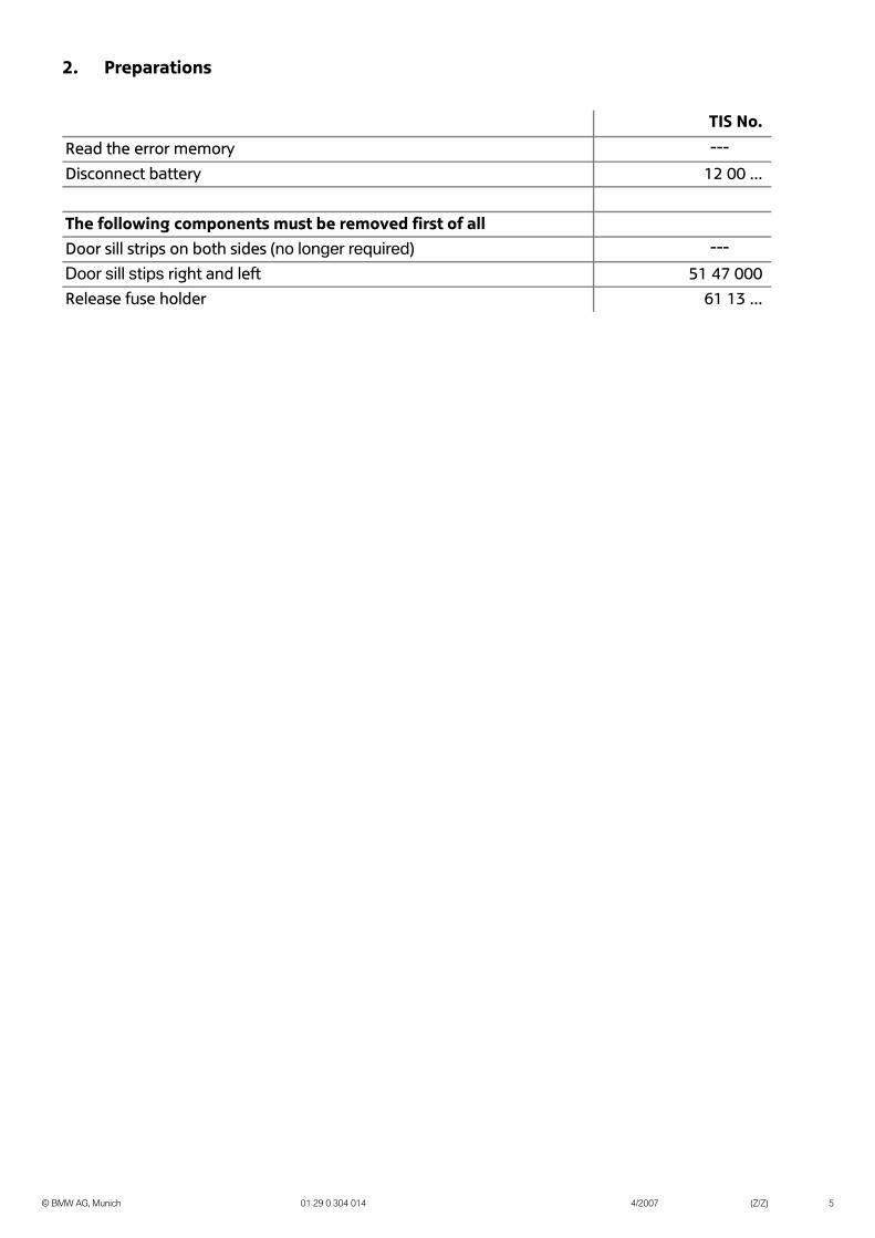
2. Preparations
TIS No.
Read the error memory ---
Disconnect battery 12 00 ...
The following components must be removed first of allDoor sill strips on both sides (no longer required) ---
Door sill stips right and left 51 47 000Release fuse holder 61 13 ...
BMW AG, Munich 01 29 0 304 014 4/2007 (Z/Z) 5
©
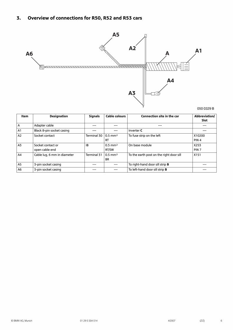
3. Overview of connections for R50, R52 and R53 cars
Item Designation Signals Cable colours Connection site in the car Abbreviation/Slot
A Adapter cable --- --- --- ---
A1 Black 8-pin socket casing --- --- Inverter C ---
A2 Socket contact Terminal 30 0.5 mm²RT
To fuse strip on the left X10200PIN 4
A3 Socket contact or open cable end
IB 0.5 mm²RT/SW
On base module X253PIN 7
A4 Cable lug, 6 mm in diameter Terminal 31 0.5 mm²BR
To the earth post on the right door sill X151
A5 3-pin socket casing --- --- To right-hand door sill strip B ---
A6 3-pin socket casing --- --- To left-hand door sill strip B ---
A A1
A4
A3
A2
A5
A6
��� ���� �
BMW AG, Munich 01 29 0 304 014 4/2007 (Z/Z) 6

©
4. Overview of connections for R56 cars
Item Designation Signals Cable colours Connection site in the car Abbreviation/Slot
A Adapter cable --- --- --- ---
A1 Black 8-pin socket casing --- --- Inverter C ---
A2 Socket contact Terminal VA 0.5 mm²RT
On fuse holder in passenger footwell X11007PIN 8
A3 Socket contact IB 0.5 mm²RT/SW
On footwell module in driver’s footwell X14260PIN 35
A4 Cable lug, 6 mm in diameter Terminal 31 0.5 mm²BR
To the earth post on the right door sill X151
A5 3-pin socket casing --- --- To right-hand door sill strip B ---
A6 3-pin socket casing --- --- To left-hand door sill strip B ---
A A1
A4
A3
A2
A5
A6
056 0004 B
BMW AG, Munich 01 29 0 304 014 4/2007 (Z/Z) 7

©
5. Installation and cabling diagram for R50, R52 and R53 cars
Legend
Tie back any excess lengths.
A1 To inverter CA2 To X10200, PIN 4
A3 To X253, PIN 7A4 To X151
A5/A6 To door sill strips B
050 0328 B
A1 A3 A5
A6
A4
A2
BMW AG, Munich 01 29 0 304 014 4/2007 (Z/Z) 8

©
6. Installation and cabling diagram for R56 cars
Legend
Tie back any excess lengths.
A1 To inverter CA2 To X11007, PIN 8
A3 To X14260, PIN 35A4 To X151
A5/A6 To door sill strips B
R56 0005 Z
A1 A2 A5
A6
A4
A3
BMW AG, Munich 01 29 0 304 014 4/2007 (Z/Z) 9

©
7. Installing the illuminated door sill strip
R50, R52 and R53 cars only
Figure A shows the front right A pillar.
Push the protective cover D over the inverter C.Connect branch A1 to the inverter C.
Position the inverter C with the protective sheath D behind the carpet between the base module and earth post.
Then secure the inverter C with a cable tie G to the side of the top section of the main wiring harness.
Route branches A2 and A6 under the carpet into the driver’s footwell.
If there is a socket contact on branch A3, disconnect it.
Connect branch A3 to the base module (A pillar at the front right) X253 (black 54-pin), PIN 7 (brown/yellow cable) using an insulation-piercing connector I.
Figure A shows the front left A pillar.
Connect branch A2 to X10200 (black 12-pin), PIN 4 (1).
If PIN 4 is occupied, cut the plug off branch A2 and connect it to X10200, PIN 4, (red/green cable) using an insulation-piercing connector I.
If there is no fuse in slot 3, insert fuse H.
R56 cars only
If Pin 8 on plug X11007 is already occupied, connect branch A2 to violet/green cable from Pin 8 using insulation piercing
connector I.
Connect branch A2 to PIN 8 of plug X11007.
If there is no fuse in slot 14, insert fuse H.
X255
X332X254
X253
A3
D
C
A1A2
A6 A4-A5
I
G
050 1227 Z
050 0474 B
A6
A2
I
1
H
X11007
IH
A2
R56 0002 Z
BMW AG, Munich 01 29 0 304 014 4/2007 (Z/Z) 10

©
7. Installing the illuminated door sill strip
Push the protective cover D over the inverter C.Connect branch A1 to the inverter C.
Position the inverter C with the protective sheath D behind the carpet underneath the fuse holder.
Use cable tie G to attach inverter C to the standard wiring harness.
Route branches A3 and A6 under the carpet into the driver’s footwell.
If Pin 35 on plug X14260 is already occupied, connect branch A3 to brown/yellow cable from Pin 35 using insulation
piercing connector I.
Connect branch A3 to PIN 35 of plug X14260.
All cars
Connect branch A4 on the adapter cable A to earth post X151 on the front right door sill.
Drill a 8 mm hole at the point shown on the side skirt fold at the front and drill a hole in the interior in the same place.
a = 750 mmb = 45 mm
Drill only the plastic doorsill with a wider 12 mm hole.
Deburr holes and treat them with anti-corrosive coatings as set out in MINI directives to protect them from corrosion.
D
A1A3
A6
G
C
R56 0003 Z
X14260
I
A3
R56 0336 Z
X151
A4
A
R56 0006 Z
��� ���� �
ab
BMW AG, Munich 01 29 0 304 014 4/2007 (Z/Z) 11

©
7. Installing the illuminated door sill strip
Insert rubber grommets F into the holes.
On cars with the aerodynamics package ensure that the door sill strip B is positioned
in the center.
Check part numbers of the door sill strips B. Left side: Right side:51 47 0 302 684 51 47 0 302 68551 47 0 302 687 51 47 0 302 68851 47 0 404 912 51 47 0 404 91351 47 0 416 146 51 47 0 416 14751 47 0 417 012 51 47 0 417 01351 47 0 417 016 51 47 0 417 01751 47 0 417 113 51 47 0 417 11751 47 0 417 119 51 47 0 417 12051 47 0 417 690 51 47 0 417 69151 47 0 417 693 51 47 0 417 69451 47 0 417 696 51 47 0 417 69751 47 0 417 012 51 47 0 417 01351 47 0 417 119 51 47 0 417 120
Route the 2-core cable from the door sill strip B through the rubber grommets into the interior.
Connect the plug contacts on door sill strip B into plug casing E, chambers 1 and 2 and connect this to branch A5 on the adapter wiring harness.
Remove the backing foil from the adhesive strips on the reverse of the illuminated door sill strip B and affix the door sill strip B.
FF
050 0333 B
A5
EB
050 0334 B
B
BMW AG, Munich 01 29 0 304 014 4/2007 (Z/Z) 12

©
8. Concluding work
This retrofit system does not require coding.
- Connect the battery
- Conduct a function test
- Conduct a brief test
- Re-assemble the car
BMW AG, Munich 01 29 0 304 014 4/2007 (Z/Z) 13

©
9. Circuit diagram for R50, R52 and R53 cars
Legend
The components marked with an asterisk (*) are only valid for this circuit diagram.
Cable colors
A1* 8-pin socket casing, to inverter CA2*/X10200 Socket contact, in fuse strip on the left, PIN 4A3*/X253 Socket contact/open cable end, signal IB, in base module, PIN 7A4*/X151 Cable lug, 6 mm in diameter, to earth post connection on right door sill
A5* 3-pin socket casing, to right-hand door sill stripA6* 3-pin socket casing, to left-hand door sill strip
BR Brown
GE YellowRT redSW Black
0,5 SW
0,5 SW/G
E
0,5 RT/SW
0,5 RT
0,5 BR
A4*/X151A5*
A3*/X253A2*/X10200
A6*
A1*
0,5 SW
0,5 SW/G
E
1
8 3 451
2 21
R50 1464 Z
BMW AG, Munich 01 29 0 304 014 4/2007 (Z/Z) 14

©
10. Circuit diagram for R56 cars
Legend
The components marked with an asterisk (*) are only valid for this circuit diagram.
Cable colors
A1* 8-pin socket casing, to inverter CA2*/X11007 Socket contact, on fuse holder in passenger footwell, PIN 8A3*/X14260 Socket contact signal IB, on footwell module, PIN 35A4*/X151 Cable lug, 6 mm in diameter, to earth post connection on right door sill
A5* 3-pin socket casing, to right-hand door sill stripA6* 3-pin socket casing, to left-hand door sill strip
BR BrownGE Yellow
RT redSW Black
0,5 SW
0,5 SW/G
E
0,5 RT/SW
0,5 RT
0,5 BR
A4*/X151A5*
A3*/X14260A2*/X11007
A6*
A1*
0,5 SW
0,5 SW/G
E
1
8 3 451
2 21
R56 0007 Z
BMW AG, Munich 01 29 0 304 014 4/2007 (Z/Z) 15
Related Documents