I r r r r r . ‘I c‘ -1 ” ,- * -1 ~ . . - ORGAN . UISIANA PIPELINE LLC KINDER August 2,2006 Ms. Stacey Gerard Acting Assistant Administratorand Chief Safety Officer Pipeline and Hazardous Materials Safety Administration US. Department of Transportation 400 Seventh Streel SW, Room 2103 Washington, D.C. 20590 Re: Petition of Kinder Morgan Louisiana Pipeline for Waiver of 49 C.F.R. $51 92.1 1 1 and 192.201 To Allow Use of A 0.80 Design Factor in Claw 1 1,ocations For 3 New Interstate Pipeline Project and Request for Expediled Considerdlion Ms. Gerard: Kinder Morgan Louisiana Pipeline (“KMLP”) has comtnenced obtaining regulatory approvals to construct a new 137-mile interstate natural gas pipeline project that will deliver imported liquefied natural gas (“LNG’’) received from the Sabine Pass LNG Terminal in Cameron Parish, Louisiana, to various interconnections with interstate and intrastate pipelines in Louisiana. Eiicloscd for filing and considcration by tlic Pipclinc and Hazardous Matcrials Safety Administration is KMLP’s petition for a waiver of the regulations of the Office of Pipeline Safety (“OPS”) at 49 C.F.R. $9192.1 11 and 192.201(a)( 2), in order to allow KMLP to utilize a 0.80 design factor so as to design, construct, and operate a portion of the new pipeline at hoop stress levels up to 80 percent SMYS in Class 1 locations and to grant KMLP relief from equipment requirements for pressure relieving and limiting stations. KMLP does not request a waiver for its pipelines that will opcratc in othcr class localions, and will comply wilh all othcr applicablc OPS rcgulations. In addition, KMLP respectfblly requests expedited consideration of its petition. Communications regarding this application may be addressed to me as indicated below. Thank you for your consideration. Vice President Gas Pipeline Operations and Engineering Kinder Morgan, Inc. cc: Dr. ’I’licodore L. Wilke, Deputy Associatc Administrator (with enclosure) Joy Kadnar, Director, Office of Pipeline Safety Engineering and Emergency Support (with James Reynolds, General Engineer (with enclosure) enclosuc e)

Welcome message from author
This document is posted to help you gain knowledge. Please leave a comment to let me know what you think about it! Share it to your friends and learn new things together.
Transcript
I
r
r r
r r
. ‘ I c‘ -1 ” ,- * - 1 ~
. . - ORGAN . UISIANA PIPELINE LLC
KINDER August 2,2006
Ms. Stacey Gerard Acting Assistant Administrator and Chief Safety Officer Pipeline and Hazardous Materials Safety Administration US. Department of Transportation 400 Seventh Streel SW, Room 2103 Washington, D.C. 20590
Re: Petition of Kinder Morgan Louisiana Pipeline for Waiver of 49 C.F.R. $51 92.1 1 1 and 192.201 To Allow Use o f A 0.80 Design Factor in Claw 1 1,ocations For 3 New Interstate Pipeline Project and Request for Expedi led Considerdlion
Ms. Gerard:
Kinder Morgan Louisiana Pipeline (“KMLP”) has comtnenced obtaining regulatory approvals to construct a new 137-mile interstate natural gas pipeline project that will deliver imported liquefied natural gas (“LNG’’) received from the Sabine Pass LNG Terminal in Cameron Parish, Louisiana, to various interconnections with interstate and intrastate pipelines in Louisiana.
Eiicloscd for filing and considcration by tlic Pipclinc and Hazardous Matcrials Safety Administration is KMLP’s petition for a waiver of the regulations of the Office of Pipeline Safety (“OPS”) at 49 C.F.R. $9192.1 11 and 192.201(a)( 2), in order to allow KMLP to utilize a 0.80 design factor so as to design, construct, and operate a portion of the new pipeline at hoop stress levels up to 80 percent S M Y S in Class 1 locations and to grant KMLP relief from equipment requirements for pressure relieving and limiting stations. KMLP does not request a waiver for its pipelines that will opcratc in othcr class localions, and will comply wilh all othcr applicablc OPS rcgulations. In addition, KMLP respectfblly requests expedited consideration of its petition.
Communications regarding this application may be addressed to me as indicated below. Thank you for your consideration.
Vice President Gas Pipeline Operations and Engineering Kinder Morgan, Inc.
cc: Dr. ’I’licodore L. Wilke, Deputy Associatc Administrator (with enclosure) Joy Kadnar, Director, Office of Pipeline Safety Engineering and Emergency Support (with
James Reynolds, General Engineer (with enclosure) encl osuc e)
f
PETITION OF KINDER MORGAN LOUISIANA PIPELINE LLC FOR WAIVER OF 49 C.F.R. 88 192.111 AND 192.201(a)(2)(i)
TO ALLOW USE OF A 0.80 DESIGN FACTOR IN CLASS 1 LOCATIONS FOR A NEW INTERSTATE GAS PIPELINE PROJECT AND REQUEST FOR EXPEDITED CONSIDERATION
August 2,2006
TABLE OF CONTENTS
I . KINDER MORGAN LOUISIANA PIPELINE PROJECT .............................................. 2
A . Project Overview ................................................................................................................ 2
B . Pipeline Design and Material Quality ................................................................................. 5
Fracture Control Plan ....................................................................................................... 9 1 . 2 . 3 . 4 . 5 .
Pipe Specification ............................................................................................................ 6
Inspection of High Quality Line Pipe ............................................................................ 10 ExternalAnternal Pipe Coating ....................................................................................... 12 Supplemental Pipeline Design and Material Quality Criteria ........................................ 13
C . Construction ...................................................................................................................... 16 1 . Unloading. Hauling. and StringinglStaging Materials ................................................... 16 2 . Lowering-In of Pipe ....................................................................................................... 17 3 . Depth of Cover ............................................................................................................... 17 4 . Welding and Non-Destructive Testing .......................................................................... 17 5 . Smart Tool Capability .................................................................................................... 18 6 . Hydrostatic Testing ........................................................................................................ 18 7 . Geometry and Smart Tool In-line Inspection Survey .................................................... 19 8 . Local Line Break Equipment ......................................................................................... 20 9 . Cathodic Protection Interference ................................................................................... 20 10 . Contractor Operator Qualification ................................................................................. 20 1 1 . Construction Reviews .................................................................................................... 21 12 . Supplemental Construction Cntena ............................................................................... 21
. .
. .
D . Pipeline Operation and Maintenance ................................................................................ 22 1 . External Corrosion Control ............................................................................................ 23 2 . Internal Corrosion Control ............................................................................................. 24 3 . Integrity Management Program ..................................................................................... 25 4 . Damage Prevention Program ......................................................................................... 26 5 . Operator Qualification ................................................................................................... 26 6 . Pipeline Facilities Security ............................................................................................ 26 7 . Supplemental Operation and Maintenance Criteria ....................................................... 27
E . Risk Analysis .................................................................................................................... 30
F . Reporting ........................................................................................................................... 33
I1 . PETITION FOR WAIVER OF REGULATIONS ........................................................... 34
I11 . PUBLIC POLICY BENEFITS .......................................................................................... 36
IV . REQUEST FOR EXPEDITED CONSIDERATION ...................................................... 39
r
r
V. CONCLUSION ................................................................................................................... 41
APPENDIX A
APPENDIX B
APPENDIX C
APPENDIX D
APPENDIX E
APPENDIX F
APPENDIX G
APPENDIX H
APPENDIX I
APPENDIX J
APPENDIX K
Map of Project
M8270; X-70 and X-80 Grade High Strength, High Toughness Welded Steel Line Pipe for High-pressure Gas Transmission Service
M8910; Procedure for Conducting Underbead Crack Sensitivity Tests
Fracture Control Plan for KMLP
M8370; Plant Application of Fusion-Bonded Epoxy Coating
C1040; Unloading, Hauling, and Stringing Materials
C1090; Lowering-In Pipe
C1070; Non-Destructive Examination Requirements
O&M 1600/C1135; Strength and Leak Testing
Risk Comparison Matrix
Form of Notice for Federal Register
.. 11
PETITION OF KINDER MORGAN LOUISIANA PIPELINE LLC FOR WAIVER OF 49 C.F.R. 05 192.111 AND 192.201(a)(2)(i)
TO ALLOW USE OF A 0.80 DESIGN FACTOR IN CLASS 1 LOCATIONS FOR A NEW INTERSTATE GAS PIPELINE PROJECT
AND REQUEST FOR EXPEDITED CONSIDERATION
Pursuant to Section 601 18(c) of the Pipeline Safety Act, 49 U.S.C. 0 601 18(c) (2000),
Kinder Morgan Louisiana Pipeline LLC (“KMLP”) asks the Pipeline and Hazardous Materials
Safety Administration (“PHMSA”) for a waiver of the provision of 49 C.F.R. 0 192.1 1 1
requiring a design factor of 0.72 for steel pipe that will be constructed and operated in Class 1
locations. KMLP seeks a waiver of Section 192.1 1 1 so that it can utilize a 0.80 design factor for
Class 1 locations in the design formula for steel pipe specified in Section 192.105, thus allowing
KMLP to design, construct, and operate the proposed new Kinder Morgan Louisiana Pipeline at
hoop stresses up to 80% specified minimum yield strength (“SMYS”). In addition, because a
waiver of Section 192.1 1 1 necessarily requires a commensurate modification in the required
capacity of pressure relieving and limiting stations installed to protect a pipeline, KMLP also
requests a waiver of Section 192.201(a)(2)(i) to permit each pressure relieving station or pressure
limiting station installed to protect pipelines in Class 1 locations to have enough capacity and to
be set to operate such that the pressure may not exceed the maximum allowable operating
pressure (“MAOP”), plus 4%, or the pressure that produces a hoop stress of 83% of SMYS,
whichever is lower.
No waivers are requested for the pipelines that will operate in other class locations.
1
I. KINDER MORGAN LOUISIANA PIPELINE PROJECT
A. Project Overview
The Kinder Morgan Louisiana Pipeline Project (“Project”) is a new interstate natural gas
pipeline system being developed by KMLP, a wholly-owned subsidiary of Kinder Morgan
Energy Partners, L.P. (“KMP”). KMP owns or operates more than 25,000 miles of pipelines that
transport up to 8.4 billion cubic feet per day of natural gas and more than 2 million barrels per
day of gasoline and other petroleum products. KMLP is a new company, formed for the purpose
of constructing and operating the Project.
When constructed, the Project will deliver almost 3,395,000 DtWd of imported liquefied
natural gas (“LNG”) supplies from the new Sabine Pass LNG Terminal (“Terminal”) under
development by Sabine Pass LNG, L.P., in Cameron Parish, Louisiana, to consuming markets
throughout the Gulf Coast, midwestern, northeastern, mid-Atlantic, and southeastern United
States via numerous major interstate and intrastate pipeline systems. The Project’s total
estimated cost is approximately $500 million. As currently designed, the Project will consist of
several operationally integrated segments. A map of the Project is included in Appendix A.
Leg 1: Leg 1 of the Project will consist of approximately 137 miles of 42-inch diameter
pipeline extending from within the LNG Terminal in a northeasterly direction to an
interconnection with the existing pipeline system of Columbia Gulf Transmission
Company in Evangeline Parish, Louisiana. Along its route, the line will interconnect
with at least ten interstate and intrastate pipeline systems in Louisiana. These
interconnecting systems will deliver LNG supplies to consuming markets throughout the
eastern United States. Leg 1 will have a firm, peak day capacity of approximately
2,130,000 DtWd. The line will receive gas from the Terminal at a pressure of 1,440 psig.
2
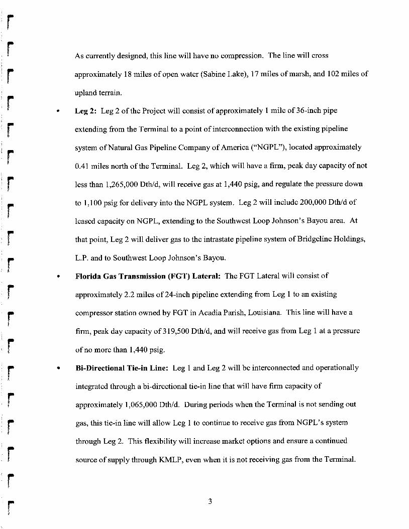
As currently designed, this line will have no compression. The line will cross
approximately 18 miles of open water (Sabine Lake), 17 miles of marsh, and 102 miles of
upland terrain.
Leg 2: Leg 2 of the Project will consist of approximately 1 mile of 36-inch pipe
extending from the Terminal to a point of interconnection with the existing pipeline
system of Natural Gas Pipeline Company of America (“NGPL”), located approximately
0.41 miles north of the Terminal. Leg 2, which will have a firm, peak day capacity of not
less than 1,265,000 DtWd, will receive gas at 1,440 psig, and regulate the pressure down
to 1,100 psig for delivery into the NGPL system. Leg 2 will include 200,000 DtWd of
leased capacity on NGPL, extending to the Southwest Loop Johnson’s Bayou area. At
that point, Leg 2 will deliver gas to the intrastate pipeline system of Bridgeline Holdings,
L.P. and to Southwest Loop Johnson’s Bayou.
Florida Gas Transmission (FGT) Lateral: The FGT Lateral will consist of
approximately 2.2 miles of 24-inch pipeline extending from Leg 1 to an existing
compressor station owned by FGT in Acadia Parish, Louisiana. This line will have a
firm, peak day capacity of 3 19,500 DtWd, and will receive gas from Leg 1 at a pressure
of no more than 1,440 psig.
Bi-Directional Tie-in Line: Leg 1 and Leg 2 will be interconnected and operationally
integrated through a bi-directional tie-in line that will have firm capacity of
approximately 1,065,000 DtWd. During periods when the Terminal is not sending out
gas, this tie-in line will allow Leg 1 to continue to receive gas from NGPL’s system
through Leg 2. This flexibility will increase market options and ensure a continued
source of supply through KMLP, even when it is not receiving gas from the Terminal.
3
The regulatory approval process at the Federal Energy Regulatory Commission
(“FERC”) for the Project is underway. On February 17,2006, FERC granted KMLP’s request to
use FERC’s National Environmental Policy Act (“NEPA”) pre-filing process to expedite
regulatory authorizations required for the Project. On March 24,2006, FERC initiated the
NEPA review of the Project under the pre-filing process. KMLP anticipates filing an application
at FERC requesting a certificate of public convenience and necessity authorizing construction
and operation of the Project no later than October 2006. KMLP expects to obtain final
authorization from FERC to begin construction on or about September 1,2007, with a targeted
in-service date of January 2008.
Sabine Pass LNG, L.P., has received authorization from FERC for the construction and
operation of the LNG Terminal, and has commenced construction. FERC authorized the siting,
construction and operation of the Terminal in 2004, and authorized its expansion in June 2006.’
When completed and operational, the Terminal will receive, store, and vaporize foreign source
LNG, and will have a send-out capacity of 4 Bcf/d. Sabine Pass anticipates that the Terminal
will be placed into service in time for the 2008 heating season.
The waiver requested in this petition would apply only to Leg 1 pipe located in Class 1
locations. The majority of the route for Leg 1 - approximately 92% - traverses Class 1
locations. Approximately 5% will be in Class 2 locations, and approximately 3% will traverse
Class 3 locations. KMLP is not requesting a waiver for Leg 2, the FGT Lateral, or the bi-
directional tie-in line. As currently designed, Leg 1 will have no compression. If compression is
SabinePass LNG, L.P., 109 FERC 7 61,324 (2004); Sabine Pass LNG, L.P., 115 FERC 7 61,330 I
(2006).
4
constructed in the future, it will be designed using a design factor of 0.50, in accordance with
Section 192.1 1 1.
B. Pipeline Design and Material Quality
The KMLP Pipeline project is being designed and constructed in conformance with
Kinder Morgan Engineering and Construction Standards (“KMEC Standards”). As discussed in
more detail below, each of these standards is designed to meet or exceed the requirements of 49
C.F.R. Part 192 and the industry standards as referenced in 49 C.F.R. 5 192.7. The design for the
pipeline will take into account and ensure that all pressure rated fittings and components
(including flanges, valves, gaskets, pressure vessels, and compressors) are rated for a pressure
rating commensurate with the MAOP and class location of the pipeline. In addition, the design
will ensure that fittings (including tees, elbows and caps) have the same design factors as the
adjacent pipe class location. Further, the KMEC Standards for pipeline design and material
quality incorporate, or are consistent with, the supplemental safety criteria contained in
PHMSA’s orders granting waivers to Rockies Express Pipeline LLC (“Rockies Express”),
Alliance Pipeline L.P. (“Alliance”), and Maritimes and Northeast Pipeline, L.L.C. (“Maritimes”)
on July 11, 2006.2
The following discussion describes the principal features of the proposed design and
construction of the pipeline.
Pipeline Safety: Grant of Waiver; Rockies Express Pipeline, 71 Fed. Reg. 39,141 (July 11,2006) (“Rockies Express”); Pipeline Safety: Grant of Waiver; Alliance Pipeline L.P., 71 Fed. Reg. 39,145 (July 11,2006) (“Alliance”); and Pipeline Safety: Grant of Waiver; Maritimes & Northeast Pipeline, L.L.C., 71 Fed. Reg. 39,148 (July 11, 2006) (“Maritimes”).
2
5
1. Pipe Specification
KMLP will purchase various grades of pipe from qualified vendors with the majority
being high grade pipe utilizing Material Standard M8270, X-70 and X-80 Grade High Strength,
High Toughness Welded Line Pipe for High Pressure Transmission Service (“M8270”). A copy
of M8270 is attached hereto as Appendix B. This specification exceeds the requirements of 49
C.F.R. Part 192, Subparts B and C, which incorporate American Petroleum Institute (“API”)
Standard 5L as the minimum requirement for pipe to be used in gas service. Kinder Morgan,
Inc. (“Kinder Morgan”) engineering has specifically designed the steel chemistry for use in line
pipe in order to maximize the steel’s toughness, thus reducing the pipeline’s susceptibility to
third party damage by having puncture resistance to 35 tons, and having properties to arrest long
running failures. This standard incorporates quality assurance requirements to ensure that the
pipe is manufactured in a consistent and uniform fashion. The standard includes fracture
toughness criteria consistent with the American Society of Mechanical Engineers (“ASME”)
Standard B3 1.8.
KMLP will obtain the pipe for Leg 1 from various steel mills. Before any production run
begins, KMLP will review the manufacturing procedure specifications and quality plans for plate
rolling and pipe forming. The pipe will be manufactured according to API Standard 5L, product
specification level (“PSL”) 2, and supplementary requirements (“SR”) for maximum operating
pressures and minimum operating temperatures. The plate will employ continuous casting,
micro-alloyed, fine grain, and fully killed steel, with calcium treatment for desulphurization and
inclusion shape control. The plate will be ultrasonically tested to detect laminations and other
flaws at the pipe mill after pipe forming. The minimum wall thickness tolerance for the
plate/pipe will be -8%, as required by API Standard 5L. The diameter/thickness ratio for NPS 42
6
f x 0.540” WT API 5L Grade X70 is 78 and for NPS 42 x 0.473” WT API 5L X80 pipe is 89.
These ratios and the pipe metallurgy provide high strength and resistance, minimizing sensitivity
to egging or denting.
With respect to maximum carbon equivalent, the Kinder Morgan line pipe specification
M8270 restricts the carbon content for pipe, fittings, flanges and ells. For low carbon contents,
the appropriate carbon equivalent formula uses the material chemistry parameter (“Pcm”)
formula; the pipe carbon equivalent will be at or below 0.25 based on the Pcm formula. All
bends, flanges, and fittings will have carbon equivalents (“CE”) below 0.42, otherwise a pre-heat
procedure prior to welding for CE above 0.42 will be implemented.
The following analysis demonstrates where Kinder Morgan’s Material Standard M8270
exceeds the requirements of API Standard 5L:
The specification requires an API monogram and API Q1 quality system certification for
pipe mills. (M8270 Section 2.0). This requirement restricts the vendor pool to only those
pipe mills that can demonstrate they have passed Q1 quality systems audit and conform
to the API requirements.
The pipe specification includes special controls on submerged arc welding flux. (M8270
Section 5.1.3). The intent of this requirement is to control excess moisture content in the
welding flux and thereby prevent cracking due to the presence of hydrogen.
A project-specific Manufacturing Procedure Specification and Quality Plan will be
required from each pipe manufacturer. (M8270 Section 5.1.3). Requiring the pipe mill
to write a quality plan specific to Kinder Morgan’s pipe requirements provides audit
inspection points that are specific to the mill run for KMLP pipe, and not generic to the
API Standard 5L specification.
Chemical analysis limitations are more restrictive than API Standard 5L. Deviations
fiom these restrictions require underbead crack sensitivity testing per Kinder Morgan
Material Specification M8910. (M8270 Section 6.1). A copy of M8910 is included as
Appendix C. The pipe chemistry required by M8270 has been designed with the intent to
7
control underbead cracking more precisely in the intended service than the standard API
5L specifications. If the pipe mill requests a deviation from the specification limits, the
mill will be required to perform specific tests to demonstrate that the potential for
underbead cracking has not increased.
The specification requires more stringent lot test acceptance criteria for transverse pipe
body tensile tests. (M8270 Section 6.2.1).
The specification requires centerline segregation evaluation using slab macro-etching to
check for inclusions that may form as the steel slab cools after it has been cast. (M8270
Section 5.3).
The specification requires supplementary fracture toughness tests including pipe body
Charpy tests and drop weight tear tests in conformance with ASME Standard B3 1.8.
(M8270 Section 6.2.5.3).
Additional seam welding qualification tests are required including Vickers macro
hardness tests. (M8270 Section 6.2.6). These tests will assess the potential for hard
microstructures that cause the pipe to be susceptible to underbead cracking.
The pipe specification requires more restrictive roundness requirements within 4 inches
of pipe ends to improve field weldability. (M8270 Section 7.2). Kinder Morgan
specifies a greater degree of roundness to aid in the line-up for welding during the
construction process.
Straight-beam ultrasonic inspection is required at pipe ends to ensure freedom from
laminations or inclusions that could affect field welding. (M8270 Section 7.9). API
Standard 5L does not require this test.
The specification requires specific qualifications for mill nondestructive testing (“NDT”)
personnel and NDT procedures. (M8270 Section 9.8.3). Kinder Morgan requires the
NDT technicians be trained to a specific level and qualified to a recognized standard to
ensure that the consistency of Quality Assurance/Quality Control is maintained
throughout the pipe manufacturing process.
The specification has x-ray film density requirements that are not included in API
Standard 5L and includes special qualification requirements for substitution of non-film
8
r
f
r I
b t
radiological inspection methods. (M8270 Section 9.8.4). The density requirement
ensures that the proper level of film sensitivity is utilized. The radiological criteria
ensure that spatial resolution and contrast are equivalent to film x-ray.
0 The specification includes numerous repair weld restrictions that are not included in API
Standard 5L. (M8270 Section 9.8.5.6). Kinder Morgan requires a tighter weld repair
specification and restricts certain types of repairs in order to better control the
workmanship in the mill and produce better quality seam welds.
0 The mill is required to subject the pipe to a mill hydrostatic test pressure of 95% SMYS
or greater for 10 seconds (M8270 Section 9.4).
0 The specification includes special traceability requirements including unique pipe
numbers that are traceable to the rolling parameters for individual plates or coils, (M8270
Section lO.O), that are not required in API Standard 5L. This is important for tracing the
root cause of any material property deficiencies back to the plate rolling process and then
tracing any material that was produced during that rolling process in order to identify all
potentially affected pipe. Certification records of factory induction bends and/or factory
weld bends will be obtained and retained for the life of the asset.
2. Fracture Control Plan
Class 1 line pipe for KMLP will be primarily NPS 42 API 5L Grade X70 and X80 PSL2
longitudinal-seam submerged arc welded pipe or helical seam welded pipe. The fracture control
plan to be implemented on the pipeline is described in more detail in Appendix D. The
following discussion highlights major aspects of this plan.
The first aspect of the fracture control plan is to ensure that the pipe has adequate
ductility to prevent brittle fractures. Kinder Morgan Specification M8270 addresses this issue
with requirements more stringent that ASME Standard B3 1.8. The most stringent test for
controlling brittle fractures in gas pipelines is the drop weight tear test, which is conducted in
accordance with API 5L Supplementary Requirement SR6. Kinder Morgan specifies drop
9
weight tear tests per API 5L Supplementary Requirement SR6 at a test temperature of +32" F
(the lowest anticipated operating temperature). The specification incorporates acceptance
criteria of 60% minimum average shear per each set of two specimens representing a heat of
steel and a minimum all-heat average shear of 80%. In comparison, ASME B3 1.8 incorporates
less stringent acceptance criteria in which 80% of the heats must exhibit a shear area of 40% or
more.
The second aspect of the fracture control plan is to ensure that the pipe has adequate
toughness to arrest a ductile fracture. Kinder Morgan Specification M8270 addresses this issue
with Charpy value requirements in conformance with ASME Standard B3 1.8, also incorporating
a correction factor for high-toughness steel based on research and technical paper by Brian Leis
and Robert Eiber.
3. Inspection of High Quality Line Pipe
Kinder Morgan employs third-party inspection to ensure that each joint is inspected for
conformance to Kinder Morgan pipe specifications. The result of this inspection process will be
retained for the life of the pipeline.
Pipe weld seams will be inspected using automatic ultrasonic scanning and X-ray
radiography in accordance with API Standard 5L and Specification M8270. The full length of
the longitudinal weld seam will be inspected for longitudinal and transverse defects by ultrasonic
methods supplemented with radiographic methods within 8 inches of the pipe ends. The
ultrasonic inspection of the submerged arc weld is conducted by shear wave ultrasonic inspection
with multiple single-element piezoelectric transducers with angles between 45 degrees and 70
degrees using water as an acoustic couplant. Multiple probes are positioned on each side of the
weld. The sound path of the transducers is aimed at the inside weld toe, outside weld toe and
10
11
weld centerline. A calibration pipe sample is fabricated with API Standard N5 notches (depth
equal to 5% of pipe thickness) and 1/16” radial drilled holes. The ultrasonic unit is set to alarm
on signals equal in amplitude to the N5 notches or 1/16” drilled holes.
With respect to acceptance and rejection criteria for seam defects, a calibration pipe
sample is fabricated with API N5 notches (depth equal to 5% of pipe thickness) and 1/16” radial
drilled holes. The ultrasonic unit is set to alarm on signals equal in amplitude to the N5 notches
or 1/16” drilled holes. Indications verified to exceed the amplitudes are considered defects
unless it can be demonstrated that they do not exceed other API limits for workmanship and
defects. Specification M8270 requires the more restrictive N5 and 1/16” drilled holes to
establish amplitude acceptance limits for ultrasonic inspection outlined in API 5L.
Weld repairs will be conducted by either shielded metal arc welding or submerged arc
welding. API Standard 5L requires tensile tests, guided bend tests and nick-break tests for repair
weld procedure qualification. Kinder Morgan pipe specification M8270 contains more
restrictive requirements for repair of submerged arc weld seams than API 5L Appendix B. The
Kinder Morgan pipe specification also requires Charpy impact tests meeting the requirements for
the original submerged arc weld and Vickers macrohardness tests to ensure hardness does not
exceed 280 HVl 0. The Kinder Morgan pipe specification also includes additional hydrogen
control requirements for repair welding. Further, the only dimensional restriction in API 5L
Appendix B restricts the minimum length of a repair weld to 2 inches. The Kinder Morgan pipe
specification adds the following additional restrictions:
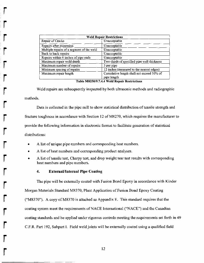
Repair of Cracks Repairs after expansion Multiple repairs of a segment of the weld Back to back repairs Repairs within 6 inches of pipe ends Maximum repair weld depth Maximum number of repairs Minimum spacing of repairs Maximum repair length
Weld repairs are subsequently inspected by both ultrasonic methods and radiographic
Unacceptable Unacceptable Unacceptable Unacceptable Unacceptable Two-thirds of specified pipe wall thickness 3 per pipe 12 inches (measured to the nearest edges) Cumulative length shall not exceed 10% of pipe length
methods.
Data is collected in the pipe mill to show statistical distribution of tensile strength and
fracture toughness in accordance with Section 12 of M8270, which requires the manufacturer to
provide the following information in electronic format to facilitate generation of statistical
distributions:
0
0
0
A list of unique pipe numbers and corresponding heat numbers.
A list of heat numbers and corresponding product analyses.
A list of tensile test, Charpy test, and drop weight tear test results with corresponding heat numbers and pipe numbers.
4. ExternaYInternal Pipe Coating
The pipe will be externally coated with Fusion Bond Epoxy in accordance with Kinder
Morgan Materials Standard M8370, Plant Application of Fusion Bond Epoxy Coating
(“M8370”). A copy of M8370 is attached as Appendix E. This standard requires that the
coating system meet the requirements of NACE International (“NACE”) and the Canadian
coating standards and be applied under rigorous controls meeting the requirements set forth in 49
C.F.R. Part 192, Subpart I. Field weld joints will be externally coated using a qualified field
12
applied Epoxy coating. The pipeline will also be internally coated with epoxy for flow
efficiency.
Kinder Morgan will have qualified coating inspectors in the pipe coating mills to confirm
strict adherence to Specification M8370. Chloride contamination levels above
2 milligrams/m2, will require additional sampling and an appropriate acid solution wasWrinse.
5. Supplemental Pipeline Design and Material Quality Criteria
PHMSA recently issued orders granting Rockies Express, Alliance, and Maritimes
waivers of certain pipeline safety regulations pertaining to pipe design factor and MAOP
requirement^.^ The waiver granted to Rockies Express allows the pipeline to operate at hoop
stresses up to 80% of SMYS in Class 1 locations and grants relief from equipment requirements
for pressure relieving and limiting stations. The waivers granted to Maritimes and Alliance
permit those pipelines to, among other things, increase the MAOP for their respective pipelines.
The waivers granted to Alliance and Maritimes also permit an increase in design factor for
compressor station facilities and, like the waiver granted to Rockies Express, grant relief from
equipment requirements for pressure relieving and limiting stations. In these orders, PHMSA
recognized the benefit of granting such waivers where appropriate, and where measures can be
designed and implemented to ensure safe operations. In this regard, PHMSA adopted
supplemental safety criteria designed to address life cycle management issues relating to
pipelines subject to such waivers.
PHMSA’s supplemental criteria require adherence to maintenance, inspection,
monitoring, control, and reporting standards exceeding the requirements applicable to pipeline
otherwise subject to Section 192.1 1 1 including several measures addressing pipe and material
See supra note 2. 3
13
quality. The KMEC Standards described above are designed to satisfy each of the supplemental
Pipe and Material Quality requirements set forth in the waiver riter ria.^ The criteria include:
Steel Properties: The skelp/plate must be micro alloyed, fine grain, fully killed steel with calcium treatment and continuous casting.
Manufacturing Standards: The pipe must be manufactured according to API Standard 5L PSL 2, and SR for maximum operating pressures and minimum operating temperatures. Pipe carbon equivalents must be at or below 0.25 based on the Pcm formula.
Fracture Control: The API Standard 5L and other standards address steel pipe toughness properties needed to resist initiation and propagation, and arrest (stop) a pipeline failure caused by a fracture. An overall fracture control plan addressing steel pipe properties necessary to resist and arrest this condition within 6 pipe joints must be instituted. The plan will include acceptable Charpy Impact and Drop Weight Tear Test values, which are measures of a steel pipeline’s toughness and resistance to fracture.
The fracture control plan also will comply with API Standard 5L, Appendix F and include the following tests:
0 SR 5A- Fracture Toughness Testing for Shear Area: Test results must be at least 80% of the minimum average shear area for all heats with a minimum result of 80% shear area for any single test; SR 5B - Fracture Toughness Testing for Absorbed Energy; and SR 6 - Fracture Toughness Testing by Drop Weight Tear Test: Test results must be at least 80% of the average shear area for all heats with a minimum result of 60% of the shear area for any single test.
The above fracture initiation, propagation and arrest plan will account for the entire range of pipeline operating temperatures, pressures and gas compositions planned for the pipeline diameter, grade, and operating stress level associated with any wavier.
Steel Plate Quality Control: The steel mill and/or pipe rolling mill must incorporate a comprehensive plate/coil mill and pipe mill inspection program to check for defects and inclusions that could affect the pipe quality. This program must include a plate (body and all ends) ultrasonic testing (UT) inspection program to check for imperfections such as laminations. An inspection protocol for centerline segregation evaluation using a test method referred to as slab macro-etching must be employed to check for inclusions that may form as the steel plate cools after it has been cast. A minimum of one macroetch test must be performed from the first heat (manufacturing run) of each sequence
0 0
Supplemental safety criteria addressing welding procedures and depth of cover are addressed 4
below in Section C. 12, Supplemental Construction Criteria. Supplemental safety criteria addressing temperature control are addressed below in Section D.7, Supplemental Operation and Maintenance Criteria. One of these supplemental criteria includes the installation of filter separators at all receipt points. As explained herein at Section D.2, Internal Corrosion Control, and Section D.7, Supplemental Operation and Maintenance Criteria, KMLP will determine whether to employ filter separators at its receipt point at the LNG Terminal based on an evaluation of the quality of gas leaving the regasification plant.
14
(approximately 4 heats) and graded on the Mannesmann scale or equivalent. Test results with a Mannesmann scale rating of one or two out of a possible five are acceptable.
Pipe Seam Quality Control: A quality assurance program must be instituted for pipe weld seams. The pipe weld seam tests must meet the minimum requirements for tensile strength in API Standard 5L for the appropriate pipe grade properties. A pipe weld seam hardness test using the Vickers hardness testing of a cross-section from the weld seam must be performed on one length of pipe from each heat. The maximum weld seam and heat affected zone hardness must be a maximum of 280 Vickers hardness. The hardness tests must include a minimum of 3 readings for each heat affected zone, 3 readings in the weld metal, and 2 readings in each section of pipe base metal for a total of 13 readings. The pipe weld seam must be 100% ultrasonically tested after expansion and hydrostatic testing per APL Standard 5L.
Puncture Resistance: Steel pipe must be puncture resistant to 35 tons. Puncture resistance must be calculated based on industry established calculations such as the Pipeline Research Council International’s “Reliability Based Prevention of Mechanical Damage to Pipelines” calculation method.
Mill Hydrostatic Test: The pipe must be subjected to a mill hydrostatic test pressure of 95% SMYS or greater for 10 seconds.
Pipe Coating: The application of a corrosion resistant coating to the steel pipe must be subject to a coating application quality control program. The program must address pipe surface cleanliness standards, blast cleaning, application temperature control, adhesion, cathodic disbondment, moisture permeation, bending, minimum coating thickness, coating imperfections, and coating repair.
Field Coating: A field girth weld joint coating application specification and quality standards to ensure pipe surface cleanliness, application temperature control, adhesion quality, cathodic disbondment, moisture permeation, bending, minimum coating thickness, holiday detection, and repair quality must be implemented in field conditions. Field joint coatings must be non-shielding to CP. Field coating applicators must use valid coating procedures and be trained to use these procedures.
Coatings for Trenchless Installation: Coatings used for directional bore, slick bore, and other trenchless installation methods must resist abrasions and other damages that may occur due to rocks and other obstructions encountered in this installation technique.
Bends Quality: Certification records of factory induction bends and/or factory weld bends must be obtained and retained. All bends, flanges, and fittings must have CE below 0.42 or a pre-heat procedure prior to welding for CE above 0.42.
Fittings: All pressure rated fittings and components (including flanges, valves, gaskets, pressure vessels, and compressors) must be rated for a pressure rating commensurate with the MAOP and class location of the pipeline. Designed fittings (including tees, elbows and caps) must have the same design factors as the adjacent pipe class location.
Desinn Factor - Stations: Compressor and meter stations must be designed using a design factor of 0.50 in accordance with Section 192.1 1 1.
15
0 Ovemressure Protection Control: Mainline pipeline overpressure protection must be limited to a maximum of 104% MAOP.
C. Construction
1. Unloading, Hauling, and StringingBtaging Materials
Pipe that may be obtained from mills in North America and overseas will be transported
using multiple modes of transport including railroad, truck, barge, and marine vessels. The
loading and transportation of the pipe will be conducted in accordance with industry standards
such as API Standard RP 5L1, Recommended Practice for Railroad Transportation of Line Pipe,
and API RP 5W, Recommended Practice for Transportation of Line Pipe on Barges and Marine
Vessels. These recommended practices give consideration for load stresses, blocking, tie-down,
and stacking.
Pipe installed in upland locations will be strung in accordance with Kinder Morgan
Construction Standards C 1040, Unloading, Hauling, and Stringing Materials, included with this
petition as Appendix F. Pipe installation in lake and marsh areas is dependent on saturation
levels and will vary based on the amount of water. During construction in these areas, Kinder
Morgan may use typical unloading and stringing methods, or it may unload, stage and string
using a variety of techniques which may include: a) lay barge flotation pusWpul1 string, b)
bottom pusWpul1 string from land, c) string directly from a barge(s) into or over the ditch line, or
d) use of a combination of the techniques mentioned and/or a variety of other available
techniques. To achieve negative buoyancy on the pipe in marsh and lake areas, Kinder Morgan
will apply either a concrete weight overcoat or a combination of a concrete weight overcoat and
additional clamp-odset-odbolt on concrete weights.
16
2. Lowering-In of Pipe
f
In upland areas, the pipe will be lowered into the trench in accordance with Kinder
Morgan Construction Standard C1090, Lowering-In Pipe, included with this petition as
Appendix G. Pipe used in marsh or lake construction may be lowered into the ditch by a variety
of techniques that may include: a) the removal of temporary flotation devices used during the
push/pull stringing to allow the concrete weight overcoat to sink the pipe to the ditch bottom, b)
lowering the pipe directly from a barge using mechanical means to sink the pipe to the ditch
bottom and anchoring in place, or c) a combination of the techniques mentioned or a variety of
other available techniques. Throughout the construction phase, coating inspectors will ensure
coating integrity is maintained as outlined in Construction Standard C 1090.
3. Depth of Cover
Kinder Morgan will comply in all respects with the depth of cover requirements of 49
C.F.R. 6 192.327. In particular, as required by Section 192.327, the soil cover over the Project’s
buried transmission line pipe will be at least 36 inches. In areas where threats from chisel
plowing or other activities require deeper burial, the top of the pipeline will be installed one foot
below the deepest penetration.
4. Welding and Non-Destructive Testing
Kinder Morgan will perform all of the welding applications with qualified welding
procedures and employ qualified and tested welders. The welding process on the KMLP Project
will be 100% nondestructively tested by qualified technicians and procedures and in
conformance with Kinder Morgan’s Construction Standard C1070 (“C1070”). A copy of C1070
is attached as Appendix H.
17
Nondestructive testing of 100% of the welds on the Project exceeds the nondestructive
testing requirements specified in 49 C.F.R. Part 192, Subpart E. Section 192.243(d)(l) requires
that 10% of the welds performed in a Class 1 location be nondestructively tested. By
nondestructively testing 100% of the welds, imperfections that do not meet the standards set
forth in the regulations will be discovered, repaired, or removed prior to placing the line into
service.
5. Smart Tool Capability
The Project will be designed to accommodate in-line inspection (“ILI”) (i. e., pigging)
tools and in conformance with the requirements set forth in 49 C.F.R. Part 192, Subpart D for the
purposes of cleaning and running ILI tools. The technology surrounding ILI has evolved at a
very rapid rate over the past decade, increasing the quality and sophistication of the data that
pipeline operators are able to gather on the condition of their pipelines. However, one of the
results related to the increase in tool sophistication is that the length of inspection tools has
continually increased to accommodate the added electronic packages. As the length of the tools
increase, the length of the launchers and receivers used in the process of pigging must increase as
well. To keep pace with this fluid environment, Kinder Morgan will utilize a design feature that
allows for the installation of launchers and receivers that are adaptable in length and specific to
the newest generation of tools.
6. Hydrostatic Testing
Prior to putting the pipeline into service, it will be hydrostatically tested in conformance
with 49 C.F.R. Part 192, Subpart J, and to no less than 100% of SMYS, utilizing Kinder
18
Morgan’s Strength and Leak Testing Procedure O&M 1600/C 1 1 3 5 (“C 1 13 5”). A copy of C 1 1 35
is attached as Appendix I.
C1135 meets or exceeds the requirements stated in 49 C.F.R. 68 192.505, 192.619, and
ASME B3 1.8. Section 192.505(a) of the Office of Pipeline Safety’s (“OPS”) regulations
requires the hydrostatic testing to 125% of MAOP of any pipeline segment passing within 300
feet of a building meant for human occupancy. The testing requirements stated in ASME B3 1.8
Table 841.322(f) for steel pipelines in Class 1 locations with a 0.8 design factor is 125% of
MAOP. By testing the Project pipeline to a minimum of 100% of the SMYS, Kinder Morgan
has designed a hydrostatic test that both meets regulations and provides the maximum assurance
that all manufacturing defects have been discovered prior to putting the pipeline in service. Any
pipe that fails during a pre in-service hydrostatic test will be subjected to a failure analysis to
determine root cause.
7. Geometry and Smart Tool In-line Inspection Survey
Prior to commissioning the pipeline for gas service, the pipeline will be surveyed with a
multi-channel geometry tool to confirm compliance with construction specifications for dents,
buckles, etc. Kinder Morgan utilizes this means of final inspection of the construction process to
ensure that damage that may have occurred during the backfilling process is discovered and
repaired in conformance with Kinder Morgan’s Construction and Engineering Design Standards
prior to putting the line into service. Thus, in addition to meeting the requirements of 49 C.F.R.
Part 192, Subpart G, which specifies that inspection be conducted during the construction
process, Kinder Morgan also conducts a post-construction inspection.
Additionally, an initial ILI will be performed using a high resolution Magnetic Flux
Leakage (“MFL”) tool as soon after commissioning as practicable, not exceeding three (3) years,
19
to establish a baseline and further verify that the pipe is free of construction damage and other
anomalies.
8. Local Line Break Equipment
Local line break detection equipment will be installed on each mainline valve to close the
valve in the event of rapid pressure decline. Line break sensing and valve actuation equipment is
not a requirement set forth by 49 C.F.R. Part 192.
9. Cathodic Protection Interference
Kinder Morgan will comply with the corrosion control requirements set forth in 49
C.F.R. Part 192, Subpart I in the design, construction and operation of the Project, and employ
other cathodic protection measures to address electrical interference. To eliminate the risk of
electrical interference with cathodic protection systems with other pipelines or underground
metallic structures, at the time of construction, Kinder Morgan will coordinate with the other
pipeline company owners/operators to install variable resistance bonds between the various
pipelines/structures to eliminate stray electrical currents, and to equalize the voltage potentials
between the pipeline and other pipelines and underground metallic structures. After pipeline
installation, Kinder Morgan will conduct cathodic protection electrical surveys to detect
unresolved interference problems.
10. Contractor Operator Qualification
All contractors utilized to construct and install OPS-regulated facilities on the Project will
be required to work in compliance with a qualified Operator Qualification plan. All third party
and company inspectors will be qualified in their respective discipline(s).
20
11. Construction Reviews
When the Project is completed, Kinder Morgan will complete the necessary Process
Hazard Reviews (“PHR’) and Pre-Startup Safety Reviews (“PSSR’) before the pipeline is placed
into operation. The purpose of these reviews is to provide an additional level of quality
assurance with respect to design and construction standards/specifications implementation. The
PHR and PSSR provide for an enhanced transition fi-om the builder to operator. These reviews
are based on Occupational Safety and Health Administration process management practices that
have been incorporated into the Kinder Morgan O&M Procedures.
12. Supplemental Construction Criteria
The KMEC Construction Standards described above are designed to satisfy each of the
supplemental Construction, Pre-In Service Hydrostatic Pressure Test, and Supervisory Control
and Data Acquisition (“SCADA”) requirements adopted by PHMSA in its orders granting
waivers to Rockies Express, Alliance, and Maritimes.’ Those supplemental requirements
include:
Welding Procedures: Automated or manual welding procedure documentation must be submitted to the appropriate PHMSA regional office. The PHMSA’s regional office must be notified within 14 days before welding procedure qualification activities.
Depth of Cover: The soil cover must be a minimum of 36 inches except in areas where threats fi-om chisel plowing or other activities require the top of the pipeline to be installed one foot below the deepest penetration.
Pipeline Inspection: The pipeline must be capable of passing ILI. All headers and other segments covered under this waiver that do not allow the passage of an ILI device must have a corrosion mitigation plan.
Construction Quality: A construction quality assurance plan to ensure quality standards and controls must be maintained throughout the construction phase with respect to: inspection, pipe hauling and stringing, field bending, welding, nondestructive examination of girth welds, field joint coating, pipeline coating integrity tests, lowering
See discussion accompanying note 3, supra. 5
21
r r r
8
8
8
8
8
8
D.
of the pipeline in the ditch, padding materials to protect the pipeline, backfilling, alternating current (“A,”) interference mitigation and CP systems. All girth welds must be non-destructively examined by radiography or alternative means. The examiner must have all required certifications that are current.
Interference Currents Control: Control of induced AC from parallel electric transmission lines and other interference issues that may affect the pipeline must be incorporated into the design of the pipeline and addressed during the construction phase. Issues identified and not originally addressed in the design phase must be brought to PHMSA’s attention. An induced AC program to protect the pipeline from corrosion caused by stray currents must be in place within six months after placing the pipeline in service.
Pre-In-Service Hydrostatic Pressure Test Level: The pre-in service hydrostatic test must be to a pressure producing a hoop stress on 0.8 designed Class 1 pipe of at least 100% SMYS and 1.25 x MAOP.
Pre-In-Service Assessment of Hydrostatic Test Failures: Any pipe failure occurring during the pre-in service hydrostatic test must undergo a root cause failure analysis to include a metallurgical examination of the failed pipe. The results of this examination must preclude a systemic pipeline material issue and the results must be reported to PHMSA headquarters and the appropriate PHMSA regional office.
SCADA System Capabilities: A SCADA system to provide remote monitoring and control of the entire pipeline system must be employed.
Mainline Valve Control: Mainline valves that reside on either side of pipeline segment containing a High Consequence Area where personnel response time to the valve exceeds one (1) hour must be remotely controlled by the SCADA system. The SCADA system must be capable of opening and closing the valve and monitoring the valve position, upstream pressure and downstream pressure. As an alternative, a leak detection system for mainline valve control is acceptable.
SCADA Procedures: A detailed procedure for establishing and maintaining accurate SCADA set points must be established to ensure the pipeline operates within acceptable design limits at all times.
Pipeline Operation and Maintenance
The KMLP Project will be operated by Kinder Morgan’s gas pipeline group in
conformance with Kinder Morgan’s Operations and Maintenance (“O&M”) Procedures. These
procedures are intended to ensure continuous safe operation over the life of the pipeline, and they
meet or exceed the requirements of OPS’s Part 192 requirements. In addition, O&M procedures
22

for KMLP will satisfy the supplemental criteria adopted in PHMSA’s recent waiver orders. Key
features of Kinder Morgan’s O&M procedures are set forth below.
1. External Corrosion Control
Kinder Morgan’s external corrosion control consists of several components including
protection of coating design limitations, coating inspection and maintenance, cathodic protection,
and maintenance of cathodic protection interference bonds (i. e., variable resistance bonds).
Coating. Kinder Morgan O&M procedures require that gas temperatures on the discharge
side of compressor facilities be monitored, controlled, and limited. Gas temperatures are
monitored to ensure that the temperature of the gas is within the design limitations of the pipe’s
external coating and is below the maximum long-term operating temperature for the pipe
coating.
When pipe is unearthed or uncovered for any reason, the O&M procedures require that
the pipeline coating be inspected and repaired. The condition of pipeline coating will be
documented, and buried pipeline inspection reports will be completed, filed, and archived in the
JSMLP Pipeline Operational Data System (“PODS”). This provides historical information on the
pipeline coating that is useful in tracking the overall condition of coating over large geographic
areas. Under the Kinder Morgan O&M procedures, inspection and repair of pipe coating is
performed:
0 During any pipeline excavation that occurs as a result of normal maintenance activities
As a result of any pipeline Integrity Management Plan action
As a result of piping changes, revisions, or additions
Pipe coating repairs will be completed in conformance with Kinder Morgan’s O&M Procedures.
23
Cathodic Protection. Kinder Morgan will design and install cathodic protection systems
within one year of the pipeline’s in-service date. The design will be based on actual pipe-to-soil
data, as well as soil and geological conditions assessed during the first several months of service.
The cathodic protection systems will be inspected and maintained in accordance with 49 C.F.R.
Part 192, Subpart I.
Interference Elimination. Kinder Morgan will design and install resistor bonds to
eliminate interference of the cathodic protection system at the time of pipeline construction, and
will coordinate operation of its cathodic protection systems with owners/operators of nearby
underground pipelines and/or structures. Kinder Morgan’s inspection and maintenance of the
resistor bonds and normal cathodic protection systems will be in conformance with 49 C.F.R.
6 192.465(c).
2. Internal Corrosion Control
The primary preventive action to mitigate the risk of internal corrosion control is to
eliminate the introduction of free water and gas contaminants into the pipeline. The KMLP
FERC tariff will provide for the receipt and delivery of pipeline quality gas (no free liquids,
solids or constituents that under normal pipeline conditions will drop out of the gas stream). In
addition, all delivery and receipt points will employ state-of-the-art gas measurement and quality
monitoring equipment with continuous alarming and SCADA capabilities. Depending on the
levels of water and/or contaminates detected in the gas received into the system, reducing or
shutting off gas flow will be accomplished automatically, via SCADA gas control dispatch, or
manually by a local operator.
KMLP gas receipts into the pipeline will be filtered through full-flow, high efficiency
filter separator(s) to ensure the gas quality specifications are met. The full-flow, high efficiency
24
F
Y
F t
k 8
filter separators are designed to capture any free liquids andor solid Contaminants. The need for
filtration of gas received from process (LNG regasification) plants will be evaluated, and, when
necessary, will be designed based on the process and gas quality leaving the plant.
KMLP recognizes that PHMSA’s grant of waiver to Rockies Express was conditioned on
the requirement that filtersheparators must be installed at all gas receipt points in order to
minimize the entry of contaminants and to promote the integrity of downstream pipeline
segments. KMLP, however, believes that this condition is not necessary under the present
circumstances to prevent entry of contaminants and to ensure downstream pipeline integrity.
Unlike the Rockies Express system, which will receive unprocessed gas directly from production
fields, gas leaving an LNG regasification plant is subject to several processes that remove
contaminants from the gas. Moreover, future supply connections will be required to employ a
similar filter separator design concept.
In addition, Kinder Morgan will develop schedules for performing maintenance pigging
based on the level of contaminants captured in the respective filter separators and flow
efficiency. Materials collected in the mainline filter separators will be analyzed to detect the
presence of internal corrosion constituents and to determine the need for additional internal
corrosion mitigation measures.
3. Integrity Management Program
KMLP will comply with Part 192, Subpart 0 requirements, including baseline
assessment and re-assessment requirements. The combination of Kinder Morgan’s design and
construction practices, which include a hydrostatic test at a minimum of 100% SMYS and a
robust Fusion Bond Epoxy coating system, minimizes the potential for future formation of stress
corrosion cracking.
25
r 4. Damage Prevention Program
Kinder Morgan’s damage prevention program meets the requirements of Part 192
including operator monitoring of excavations (6 192.935(b)(l)(i-i~)), line marking (6 192.707),
line surveillance (0 192.705), and public awareness ($8 192.614 & 192.616). In addition, Kinder
Morgan utilizes a state-of-the-art, one-call management system that is integrated with the
Geographic Information Systems (“GIs”) mapping and PODS systems. As-built, detailed GIS
survey data for the KMLP facilities will be entered into the mapping system data base as the
facilities are constructed.
5. Operator Qualification
KMLP will maintain an Operator Qualification program that is consistent with 49 C.F.R.
Part 192, Subpart N. It will provide for employee/operator training intended to ensure that
employees performing covered tasks are trained and qualified to do so, and to ensure that
contractors performing covered tasks are properly supervised. Kinder Morgan’s O&M
Procedures also incorporate a Management of Change process for all work processes and
procedures. Further, Kinder Morgan’s O&M Procedures are audited on an annual basis, and
proposed changes are managed through a company user group committee (Action Decision
Committee).
6. Pipeline Facilities Security
KMLP will implement the Kinder Morgan corporate security plan, which includes
specific threat level preparation, response, recovery and training related to actions and
documentation requirements. Further, a specific security and emergency response plan will be
maintained at each of the respective KMLP operating geographical offices.
26
7. Supplemental Operation and Maintenance Criteria
O&M procedures for the Project will satisfy the supplemental O&M criteria adopted by
PHMSA in its recent orders granting waivers to Rockies Express, Alliance, and Maritimes, with
one exception.6 As discussed in Section D.2 above, KMLP does not believe that the installation
of filter separators at the receipt point from the LNG terminal is necessary ensure that
contaminants do not enter the system, and to ensure downstream pipeline integrity. Otherwise,
the O&M procedures for the Project will satisfy PHMSA's supplemental O&M criteria, which
include:
Temperature Control: The compressor station discharge temperature must be limited to 120" Fahrenheit or a temperature below the maximum long-term operating temperature for the pipe coating.
Gas Oualitv Monitoring and Control: An acceptable gas quality monitoring and mitigation program must be instituted to not exceed the following limits:
o Hydrogen Sulfide (H2S) (4 grains maximum); o Carbon Dioxide (COv (3% maximum); o Water (H20) (less than or equal to 7 pounds per million standard cubic feet
and no free water); and other deleterious constituents that may impact the integrity of the pipeline must be instituted.
The need for filtration of gas received from process (LNG regasification) plants will be evaluated, and, when necessary, will be designed based on the process and gas quality leaving the plant. Gas leaving the regasification plant has gone through several process that remove contaminants. Otherwise, filters/separators will be installed at locations where gas is received into the pipeline to minimize the entry of contaminants and to protect the integrity of downstream pipeline segments.
Gas quality monitoring equipment must be installed to permit the operator to manage the introduction of contaminants and free liquids into the pipeline.
Cathodic Protection: The initial CP system must be operational within 12 months of placing the pipeline in service.
See discussion accompanying note 3, supra. Pipeline inspection is address above in Section C.12, 6
Supplemental Construction Criteria. Leak and annual reporting requirements and criteria completion reporting provisions are addressed below in Section F, Reporting.
27
e
e
e
e
e
a
e
e
e
e
e
a
Interference Current Surveys: Interference surveys must be performed within six months of placing the pipeline in service to ensure compliance with applicable NACE standards (Recommended Practice (“RP”) 0169 and RP 0177) for interference current levels.
Corrosion Surveys: Corrosion surveys of the affected pipeline must be completed within six months of placing the respective CP system(s) in operation to ensure CP (in accordance with the NACE standard RP 0169, paragraphs 6.2 and 6.3), test stations, AC interference mitigation, and AC grounding programs (NACE standard RP 01 77) are being implemented along the pipeline.
Verification of Cathodic Protection: A close interval survey (“CIS”) must be performed in concert with ILI in accordance with subpart 0 reassessment intervals for all HCA pipeline mileage. If any annual test point readings fall below subpart I requirements, remediation must be performed and must include a CIS on either side of the affected test point to ensure corrosion control.
Pipeline Markers: Line-of-sight markings on the pipeline must be used in the waiver area except in agricultural areas, subject to FERC permits or environmental permits and local restrictions.
Pipeline Patrolling: Pipeline patrolling must be conducted at least monthly to inspect for excavation activities, ground movement, wash-outs, leakage, and/or other activities and conditions affecting the safe operation of the pipeline.
Monitoring of Ground Movement: An effective monitoring/mitigation plan must be in place to monitor and mitigate issues of unstable soil and ground movement.
Review of Risk Assessment Calculations: A copy of the C-FER PIRAMID risk analysis report regarding the pipe subject to this waiver must be submitted to PHMSA Headquarters.
Initial ILI: A baseline ILI must be performed in association with the construction of the pipeline using a high-resolution MFL tool within three years of placing a pipeline segment in service. A geometry tool must be launched either prior to placing the pipeline in service, or no later than six months after placing the pipeline in service.
Future ILI: A second high-resolution MFL inspection must be performed and completed on the pipe subject to this waiver within the first reassessment interval required by subpart 0, regardless of HCA classification. Future ILI must be performed on a frequency consistent with subpart 0 for the entire pipeline covered by this waiver.
Direct Assessment Plan: Headers, mainline valve bypasses, and other sections covered by this waiver that cannot accommodate ILI tools must be part of a Direct Assessment plan or other acceptable integrity monitoring method.
Initial CIS: A CIS must be performed on the pipeline within one year of completion of the installation of CP systems. The CIS results must be integrated with the baseline ILI to determine whether further action is needed.
Damage Prevention Program: Common Ground Alliance’s damage prevention best practices must be incorporated into damage prevention program.
28
0 Class 2 and 3 Pipe: Pipe installed in Class 2 and Class 3 locations must use stress factors of 0.60 and 0.50 as required in Section 192.1 11. Pipe in road and railroad crossings must meet the requirements of Section 192.1 1 1.
Anomalv Evaluation and Repair: Anomaly evaluations and repairs must be performed based upon the following:
0
Anomaly Response Time o Any anomaly with a failure pressure ratio (“FPR”) equal to or less than 1.1
must be treated as an “immediate” per subpart 0. o Any anomaly with an FPR equal to or less than 1.25 must be remediated
within 12 months per subpart 0. o Any anomaly with an FPR greater than 1.25 must have a remediation schedule
per subpart 0.
Anomaly Repair Criteria o Segments operating at MAOP equal to 80% stress level - any anomaly
evaluated and found to have an FPR equal to or less than 1.25 must be repaired.
o Segments operating at MAOP equal to 66% stress level - any anomaly evaluated and found to have an FPR equal to or less than 1.50 must be repaired.
o Segments operating at MAOP equal to 56% stress level - any anomaly evaluated and found to have an FPR equal to or less than 1.80 must be repaired.
All other pipe segments with anomalies not repaired must be reassessed according to subpart 0 and the ASME Standard B3 1.8s requirements. Each anomaly not repaired must have a corrosion growth rate and ILI tool tolerance assigned to it per the Gas Integrity Management Program to determine the maximum re-inspection interval.
Confirmation that the remaining strength (R-STRENG) effective area method, R- STRENG - 0.85dL, and ASME Standard B3 1G assessment methods are valid for their pipe diameter, wall thickness, grade, operating pressure, operating stress level, and operating temperature. If it is not valid, a valid evaluation method must be confirmed to PHMSA. Until confirmation of the previously mentioned anomaly assessment calculations has been performed, the most conservative of the calculations for anomaly evaluation must be used.
Dents must be evaluated and repaired per Section 192.3090>)(3)($ and Section 192.933(d)(l)(ii).
Potential Impact Radius Calculation Updates: If the pipeline operating pressures and gas quality are determined to be outside the parameters of the C-FER Study, a new study with the uprated parameters must be incorporated into the integrity management plan.
0
29
E. Risk Analysis
Kinder Morgan conducted a risk analysis for the Project using the C-FER PIRAMID
program to compare the risk associated with using 0.80 design criteria versus the 0.72 design
criteria required by 49 C.F.R. 0 192.1 1 1 for pipeline in Class 1 locations. All risk results were
based on a seven-year evaluation period extending from the projected in-service date. A review
of the risk analysis comparing the two design criteria for Class 1 pipe shows that there is no
significant increase in risk from using the 0.80 design criteria for this type of pipe. A risk
analysis matrix comparing the risks of operating at 72% and 80% SMYS in Class 1 locations is
included as Appendix J.
The risk analysis considered the following nine risk areas: (1) stress corrosion cracking,
(2) manufacturing defects, (3) weathedoutside factors, (4) welding and fabrication defects, (5)
equipment failure, (6 ) equipment impact (third party damage), (7) external corrosion, (8) internal
corrosion, and (9) incorrect operation. For the first five of these risk areas, the analysis showed
zero or a negligible increase in the risk of failure between 0.72 and 0.80 design factor pipeline.
Importantly, the PIRAMID program uses the minimum safety requirements specified in OPS’s
Part 192 regulations as a baseline for the comparative analysis. Because Kinder Morgan’s
pipeline design and construction program exceeds the requirements of the regulations in specific
areas (see discussion above) and will incorporate additional safety waiver criteria, that program
will reduce the risk of using a 0.80 design factor for the Project. For example, with respect to
equipment impact (third party damage), when consideration of the metallurgical composition of
the pipe and the fracture control plan that Kinder Morgan will use (as described above) is added
to these results, the 0.80 design factor pipe will improve pipe toughness and its resistance to
external damage and pipeline fracture.
30
With respect to external corrosion, internal corrosion, and incorrect operation, the risk
analysis showed a slightly higher risk associated with 0.80 design factor pipeline. The effect of
these slightly higher risk factor categories will be mitigated, in part, by Kinder Morgan’s
proposed design, construction, and O&M measures for the Project, as discussed above.
External Corrosion. Because pipe wall designed with a 0.80 design factor is less thick
than 0.72 pipe, the risk analysis indicates a slightly higher risk factor for 0.80 design factor pipe.
Several control and prevention programs employed by Kinder Morgan will mitigate this
increased risk.
As described in Section I.B.4 above, Kinder Morgan will apply Fusion Bond Epoxy coating on all line pipe and field weld joints. Fusion Bond Epoxy is recognized as the best available coating material, and will provide an effective barrier protecting the pipe surface from corrosive environments.
As described in Section I.C.9, during construction, Kinder Morgan will install variable resistor bonds designed to eliminate stray electrical currents that may otherwise interfere with the impressed current cathodic protection system and to equalize the voltage potentials between the KMLP pipeline and nearby underground pipelines and other metallic structures.
As described in Section I.D. 1, Kinder Morgan will install impressed current cathodic protection systems. These systems use sacrificial anodes that will counter the effects of corrosion along the pipe where damage to the coating and loss of the protective barrier may have occurred. KMLP also will monitor the cathodic protection and resistor bond performance in conformance to 49 C.F.R. 6 192.465(c). Cathodic protection systems and interference bond connections are designed to maintain specific voltage and current limits. These readings indicate the condition of the coating and identify stray currents. Readings outside of the specified range trigger investigation and remedial action.
As described in Section I.C.5, the KMLP pipeline will be designed with the capability to use state-of-the-art in-line inspection tools that measure and identi@ pipe wall metal loss. KMLP will run these tools at intervals based on the results of a risk assessment analysis, as well as otherwise required by OPS’s regulations. The data from the tools will be used to detect any external anomalies more quickly and to facilitate prompt repairs.
Internal Corrosion. Because pipe wall on 0.80 pipe is less thick than 0.72 pipe, the risk
analysis indicates internal corrosion as a slightly higher risk factor. KMLP will employ several
control and prevention programs that will mitigate this increased risk.
31
As described in Section I.D.2, Kinder Morgan will install gas quality monitoring equipment on the Project to enable Kinder Morgan to reduce the introduction of potentially corrosive contaminants and free liquids into the pipeline. Information obtained through monitoring will ensure enforcement of gas quality specifications and facilitate cleanliness of the pipe. Kinder Morgan also will install in-line filters on gas receipt points to minimize the entry of potentially corrosive contaminants into the pipe to protect the integrity of the pipeline’s downstream segments.
Kinder Morgan will develop and implement an internal cleaning program that will be tailored based on results of gas quality monitoring program to minimize the potential for accumulation of liquids and corrosive contaminants on the pipe wall.
As described in Section I.C.5, the Project will be designed with the capability to use state-of-the-art in-line inspection tools that measure and identify pipe wall metal loss. KMLP will run these tools at intervals based on the results of a risk assessment analysis, as well as otherwise required by OPS’s regulations. The data from these tools will be used to identify internal anomalies and to facilitate more prompt repairs.
Improper Operation. Improper operation occurs when pipeline parameters, such as
pressure, exceed established limits. A pipe designed with a 0.80 design factor operates at higher
stress levels. Consequently, the margin between the MAOP and SMYS is smaller. If a pressure
excursion occurs and exceeds the MAOP, SMYS of the pipe is reached more quickly than if
operating at a 0.72 design factor, resulting in a greater risk factor for pipe operating at an 0.80
design factor. KMLP will employ several control and prevention programs to mitigate this
increased risk.
As described in Section I.D.5, KMLP will maintain an operator qualification program that is consistent with 49 C.F.R. Part 192, Subpart N. The program provides for employee/operator training intended to prevent improper operations.
As described in Section I.D.5, Kinder Morgan’s O&M Procedures incorporate a Management of Change process for all processes and procedures. O&M Procedures are audited on an annual basis and proposed changes are managed through an Action Decision Committee.
KMLP’s gas control center will be equipped with state-of-the-art SCADA interface equipment, various forms of telephonic equipment (land lines, cell phones and satellite phones) and multimedidinformation connections. The gas controllers will attend regular training and provide continuous emergency notification service to operating and management personnel. Gas controllers for the Project will be able to monitor remote system warnings and alarms, as well as control gas supply receipts and market deliveries at every meter site on the system, and will have the ability to start, stop and control all compressor stations by remote control. The gas controllers will not be able to override
32
P r
r
local safety systems such as Over Pressure Protection, station lock outs, or mainline valve “line break” protection.
Accordingly, the procedures and programs that KMLP will utilize in the design,
construction, and operation and maintenance of the Project will mitigate the slightly higher risk
of external corrosion, internal corrosion, and improper operation on 0.80 design factor pipeline in
Class 1 locations.
F. Reporting
PHMSA’s recent orders granting waivers to other pipelines adopted a number of
additional reporting requirements applicable to pipe subject to the waiver. KMLP incorporates
those supplemental reporting requirements in its application for waiver.
Hvdrostatic Test Failure: The results of any root cause analysis performed following any pre-in-service hydrostatic test must be reported to PHMSA headquarters and the appropriate PHMSA regional office.
Criteria Completion Reporting: A report describing results, completion dates and status of the outstanding supplemental requirements must be submitted to PHMSA Headquarters and the appropriate regional office within 180 days after completion of the Project. A follow-up report must be submitted after the baseline ILI run has been performed with assessment and integration of the results. The report must be submitted to PHMSA Headquarters and the appropriate PHMSA regional office.
Leak Reporting: Any non-reportable leaks occurring on the pipeline must be reported to the appropriate PHMSA regional office within 24 hours.
Annual Reporting: After approval of the waiver, the following must be reported annually:
0
0
0
0
0
The results of any ILI or direct assessment results performed within the waiver area during the previous year; Any new integrity threats identified within the waiver area during the previous year; Any encroachment in the waiver area, including the number of new residences or public gathering areas; Any reportable incidents associated with the waiver area that occurred during the previous year; Any leaks on the pipeline in the waiver area that occurred during the previous year;
33
r
f I”
0
0
0
A list of all repairs on the pipeline in the waiver area made during the previous year; On-going damage prevention initiatives on the pipeline in the waiver area and a discussion of their success; and Any company mergers, acquisitions, transfers of assets, or other events affecting the regulatory responsibility of the company operating the pipeline to which this waiver applies.
11. PETITION FOR WAIVER OF REGULATIONS
KMLP requests a waiver of the provision of OPS’s regulations in 49 C.F.R. 5 192.1 11,
which requires a design factor of 0.72 for steel pipe in Class 1 locations. KMLP seeks a waiver
of Section 192.1 1 1 so that it can utilize a 0.80 design factor in the design formula for steel pipe
specified in Section 192.105, thus allowing KMLP to design, construct, and operate the proposed
new Kinder Morgan Louisiana Pipeline Project at hoop stresses up to 80% SMYS, rather than
72% SMYS, for Class 1 locations. In addition, because a waiver of Section 192.1 11 necessarily
requires a commensurate modification in the required capacity of pressure relieving and limiting
stations installed to protect a pipeline, KMLP also requests a waiver of Section 192.201(a)(2)(i)
to permit each pressure relieving station or pressure limiting station installed to protect pipelines
in Class 1 locations to have enough capacity and to be set to operate such that the pressure may
not exceed MAOP, plus 4%, or the pressure that produces a hoop stress of 83% of SMYS,
whichever is lower. KMLP is requesting a waiver for pipelines that will operate in Class 1
locations on the Leg 1 segment of the Project.
Under Section 601 18 of the Pipeline Safety Act, PHMSA may grant a waiver of any
regulatory requirement if granting the waiver is “not inconsistent with pipeline safety.”
49 U.S.C. 5 601 18. The waiver of 49 C.F.R. $5 192.1 11 and 192.201(a)(2)(i) that KMLP seeks
in this petition is not inconsistent with pipeline safety and is otherwise consistent with the public
interest.
34
In January 2006, PHMSA issued a notice of Reconsideration of Natural Gas Pipeline
Maximum Allowable Operating Pressure for Class Locations (“Notice”). 71 Fed. Reg. 977 (Jan.
6,2006). In the Notice, PHMSA correctly stated: “Over the past 20 years, there has been a
drastic improvement in technology pertaining to materials, metallurgy, controls, operations, and
maintenance of the pipeline network.” Id. These same technological improvements allow the
safe operation of pipelines at hoop stress levels up to 80% SMYS in Class 1 locations.
PHMSA’s recent order granting Rockies Express a waiver of Sections 192.11 1 and
192.201, as well as its orders granting Alliance and Maritimes waivers of certain MAOP-related
requirements for their existing pipeline systems, recognize the safety enhancements inherent in
these technological advancements. These waivers reflect PHMSA’s determination that, under
certain circumstances, and subject to conditions designed to address a pipeline’s life cycle
management, pipelines can be operated safely at design factors and operating pressures different
from those specified in OPS’s regulations, and that granting waivers of existing regulations is not
inconsistent with pipeline safety.
Allowing KMLP to design pipe for the Project at a 0.80 design factor will result in pipe
wall thickness less than required by Section 192.1 1 1 and relief pressure settings different from
those required under Section 192.201. However, as discussed in detail above, KMLP will
construct the Project utilizing state of the art materials, manufacturing technologies, and testing
and inspection technologies and practices, and operation and maintenance procedures and
practices that will result in a pipeline system that will meet or exceed recommended industry
standards and the safety requirements of OPS’s regulations. In addition, the standards KMLP
will use are consistent with the supplemental safety criteria adopted by PHMSA in its orders
granting waivers to Rockies Express, Alliance, and Maritimes. The chart included in Appendix
35
f
b r
J, demonstrates how the standards KMLP will use to design and construct the Project will meet
or exceed the requirements of OPS’s regulations, satis@ the supplemental safety criteria
contained in recent waiver orders, and result in a higher degree of pipeline and public safety than
required by the minimum safety standards provided in existing regulations. KMLP’s standards
allow the Project to operate reliably and safely at higher stress levels than allowed under OPS’s
regulations.
Accordingly, KMLP respectfully requests that PHMSA approve the waiver of the
requirements of 49 C.F.R. $0 192.1 11 and 192.20l(a)(2)(i) so as to allow the design,
construction, and operation of the Kinder Morgan Louisiana Pipeline Project at hoop stresses up
to 80% SMYS for Class 1 locations and to permit each pressure relieving station or pressure
limiting station installed to protect pipelines in Class 1 locations to have enough capacity and to
be set to operate such that the pressure may not exceed MAOP, plus 4%, or the pressure that
produces a hoop stress of 83% of SMYS, whichever is lower. KMLP does not seek a waiver of,
and will comply with, all other applicable requirements of 49 C.F.R. Part 192.
111. PUBLIC POLICY BENEFITS
The timely construction of the Kinder Morgan Louisiana Pipeline Project will facilitate
the integration of much needed LNG supplies into the nation’s natural gas supply portfolio,
thereby enhancing energy security and helping to fill the anticipated long-term gap between
domestic production and demand for natural gas. Demand for natural gas in the United States is
projected to continue to grow, particularly in the eastern half of the country. The U.S. Energy
Information Administration (“EIA”) forecasts that demand for natural gas in the United States
will increase from 22.4 trillion cubic feet (“Tcf”) in 2004 to 26.9 Tcf in 2030. Annual Energy
Outlook 2006 at 85.
36
At the same time, domestic natural gas production from conventional sources is projected
to decline over the long term. World natural gas resources, however, are extensive, and LNG
imports are expected to become increasingly important in meeting the shortfall between
declining domestic supply and growing demand in the United States. Annual Energy Outlook
2006 at 86. EIA forecasts that net annual LNG imports will increase to 4.4 Tcf by 2030, id. at
86, and could be even higher in a scenario characterized by lower domestic production and
higher consumption. Id. at 90. In its 2006 International Energy Outlook (“EO ’y, EIA forecasts
that after 2010, LNG imports will replace Canadian natural gas as the primary source of natural
gas imports. IEO at 41 (June 2006). Noting that new LNG terminals currently under
construction in the Gulf of Mexico region will more than double current LNG in the United
States, EIA states that “LNG is expected to be a significant contributor to supply in the United
States, indicative of the country’s growing dependence on imports and the increasing
globalization of natural gas markets.” IEO at 42.
FERC also has acknowledged the importance of LNG imports in augmenting the nation’s
natural gas supply over the long term. Specifically, when authorizing the construction and
operation of the Sabine Pass LNG Terminal, FERC stated that it “recognizes the important role
that LNG will play in meeting future demand for natural gas in the United States and has noted
that the public interest is served through encouraging gas-on-gas competition by introducing new
imported ~upplies.”~
anticipated widening supply gap between domestic production and demand.8
FERC also has recognized the importance of LNG in filling the
New pipeline take-away capacity, such as that provided by the KMLP Project, is needed
to transport these increased LNG supplies to markets expected to experience demand growth.
Sabine Pass LNG, L. P., 109 FERC 7 6 1,324, at P 24 (2004). Id. at P 30.
7
8
37
FERC has recognized the need for timely addition of new pipeline infrastructure and
implemented measures, such as a “pre-filing” process, designed to reduce the time for analyzing
and considering infrastructure projects. 18 C.F.R. 5 157.22 (2005). See Testimony of the
Honorable Joseph T. Kelliher, FERC Chairman, before the Subcommittee on Energy and Air
Quality, House Committee on Energy and Commerce at 7 (Nov. 2,2005). As FERC Chairman
Kelliher has stated: “Inability to strengthen the energy infrastructure will likely result in higher
prices and greater price volatility.” Id. at 9.
Kh4LP’s Project will help ensure that LNG supplies reach the nation’s consuming
markets, particularly in the eastern United States, via connections with numerous interstate and
intrastate pipelines. The Project also will provide direct access to end-use markets, including
local distribution companies, electric utilities, and industrial customers. The need for KMLP’s
Project is further demonstrated by the fact that two of the three customers at the LNG Terminal
have fully contracted for all of the Project’s capacity on a firm basis.
Allowing KMLP to design, construct, and operate the Project at a higher design factor in
Class 1 locations will increase the public benefits that will result from the Project. PHMSA
already has recognized the many benefits of an increase in design factor for natural gas pipelines
- particularly for new pipelines - in circumstances in which such an increase ensures reliable and
safe operation. In the Notice, for example, PHMSA stated:
Pipeline operators continually explore ways to reduce the cost of new pipelines, or increase the efficiency of existing pipelines, without affecting reliability or safety. One way to achieve cost reductions is to use high-grade line pipe and employ new welding methods. Another method to increase cost-effectiveness and to make the pipeline more efficient is to operate pipelines at higher stress levels.
Notice, 71 Fed. Reg. at 977. KMLP agrees and, based on initial design parameters, estimates
that allowing KMLP to design its pipelines in Class 1 locations at pressures up to 80% SMYS
38

will reduce the overall cost of construction of the Project by millions of dollars, ultimately
resulting in significant cost savings to KMLP’s customer^.^ Most importantly, as demonstrated
above, allowing KMLP to operate at a higher design factor as proposed in this petition will result
in a safer pipeline than currently required under the OPS’s regulations, in addition to lowering
costs to KMLP’s customers. Granting the requested waiver of 49 C.F.R. $ 5 192.1 1 1 and
192.201(a)(2)(i) therefore not only meets the requirements of 49 U.S.C. $ 601 18 for waivers of
OPS’s regulations, it is also consistent with the public interest.
IV. REQUEST FOR EXPEDITED CONSIDERATION
KMLP respectfully requests expedited consideration and approval by PHMSA of this
request for waiver of OPS regulations to allow KMLP to design, construct, and operate the
Kinder Morgan Louisiana Pipeline in Class 1 locations at hoop stresses up to 80% SMYS.
As demonstrated earlier in this request, Kinder Morgan has designed the pipe steel
required to build this project to very specific chemistries and toughness characteristics. These
chemistries and toughness characteristics are necessary to build this project to a 0.8 design
factor. These characteristics must be communicated to the mill at the time that the order is placed
to allow the mills the necessary time to respond to Kinder Morgan’s requirements. Another
factor that must be communicated at the time the order is placed is dimensional size of the
finished product. The determination of whether to design the KMLP pipeline to a 0.80 design
factor or a 0.72 design factor greatly influences the wall thickness of the pipe, which in turn
greatly influences the dimensional size of the plate or coil used to make the pipe.
The timing of key elements in the execution of the Project is essential to its overall
Because the Kinder Morgan Louisiana Pipeline will be a FERC-certificated pipeline with FERC- 9
approved cost-based rates to its customers, those customers will benefit fiom reduced construction and operating costs.
39
success. Placing the pipe order represents one of the largest expenditures related to the Project
and, as such, the timely placement of the purchase order for the pipe required for this Project is
of critical importance.
Accordingly, KMLP respectfully requests expedited consideration and approval by
PHMSA of this request for waiver of OPS regulations to allow KMLP to design, construct, and
operate the Kinder Morgan Louisiana Pipeline in Class 1 locations at hoop stresses up to 80%
SMYS. Consistent with this request, KMLP is attaching a Form of Notice of its petition for
waiver suitable for publication in the Federal Register. lo
The Form of Notice is provided for PHMSA’s convenience. KMLP notes that under FERC 10
regulations, applicants seeking certificates of public convenience and necessity to construct facilities are required to submit such forms of notice for FERC’s convenience in preparing a public notice of such applications for publication in the Federal Register. See 18 C.F.R. 6 157.6(b)(7) (2005).
40

V, CONCLUSION
For the reasons set forth above, KMLP's requested waiver orOPS rcgulations is not
inconsistent with pipeline safety and, in h l , cnhanccs pipclinc and public safety. KMLP
therefore respectfully rquesls:
(1) PHMSA to approve Che waiver of OPS regulations in 49 C.F.R. 56 192.1 1 1 and 192.201(a)(2)(i), so as to permit KMLP to utilize a 0.80 design factor in the dcsign formtila for steel pipe in Class 1 locations on the new interstate Kinder Morgan Louisiana Pipeline Project, and make a commensurate modification in the rcquircd capacity of pressure relieving and limiting stations installed to protect the pipeline in Class 1 locations. Expedite its consideration ofthis petition for waiver and issue an order approving KMLP's petition by Octvbcr 3,2006.
(2)
Rcspectlully subrnittcd,
M, Dwaync $\rtdn Vice President'of Gas Pipeline Operatioils
Kinder Morgan, Inc. Onc Allcii Ccntcr 500 Dallas Street Suilc 1000 IIouston, TX 77002 Tclcphonc: (713) 369-9356 E- Mail : D w a y n e - B u r t o n ~ k i n d e ~ ~ r ~ ~ n .corn
and Enginccririg
Datcd: August 2,2006
41
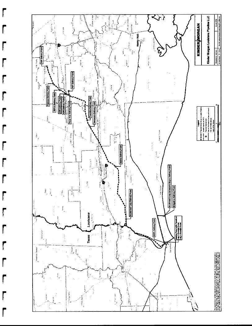
r I
f
f
APPENDIX B
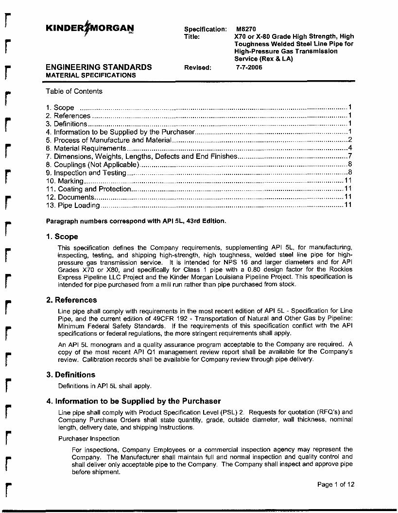
Specification: M8270 Title: X70 or X-80 Grade High Strength, High
Toughness Welded Steel Line Pipe for H ig h-Pressure Gas Transmission Service (Rex & LA)
ENGINEERING STANDARDS Revised: 7-7-2006 MATERIAL SPECIFICATIONS
Table of Contents
1. Scope ................................................................................................................................... I 2. References ............................................................................................................................. 1 3. Definitions ............................................................................................................................... 1 4. Information to be Supplied by the Purchaser ........................................................................... 1 5. Process of Manufacture and Material ..................................................................................... .2 6. Material Requirements ............................................................................................................ 4 7. Dimensions, Weights, Lengths, Defects and End Finishes ...................................................... 7 8. Couplings (Not Applicable) ...................................................................................................... 8 9. Inspection and Testing ............................................................................................................ 8 I O . Marking ............................................................................................................................... 1 1 11. Coating and Protection ........................................................................................................ 11 12. Documents .......................................................................................................................... 1 1 13. Pipe Loading ....................................................................................................................... 1 1
Paragraph numbers correspond with API 5L, 43rd Edition.
I. Scope This specification defines the Company requirements, supplementing API 5L, for manufacturing, inspecting, testing, and shipping high-strength, high toughness, welded steel line pipe for high- pressure gas transmission service. It is intended for NPS 16 and larger diameters and for API Grades X70 or X80, and specifically for Class 1 pipe with a 0.80 design factor for the Rockies Express Pipeline LLC Project and the Kinder Morgan Louisiana Pipeline Project. This specification is intended for pipe purchased from a mill run rather than pipe purchased from stock.
2. References Line pipe shall comply with requirements in the most recent edition of API 5L - Specification for Line Pipe, and the current edition of 49CFR 192 - Transportation of Natural and Other Gas by Pipeline: Minimum Federal Safety Standards. If the requirements of this specification conflict with the API specifications or federal regulations, the more stringent requirements shall apply.
An API 5L monogram and a quality assurance program acceptable to the Company are required. A copy of the most recent API Q1 management review report shall be available for the Company’s review. Calibration records shall be available for Company review through pipe delivery.
3. Definitions Definitions in API 5L shall apply.
4. Information to be Supplied by the Purchaser Line pipe shall comply with Product Specification Level (PSL) 2. Requests for quotation (RFQ’s) and Company Purchase Orders shall state quantity, grade, outside diameter, wall thickness, nominal length, delivery date, and shipping instructions.
Purchaser Inspection
For inspections, Company Employees or a commercial inspection agency may represent the Company. The Manufacturer shall maintain full and normal inspection and quality control and shall deliver only acceptable pipe to the Company. The Company shall inspect and approve pipe before shipment.
Page 1 of 12
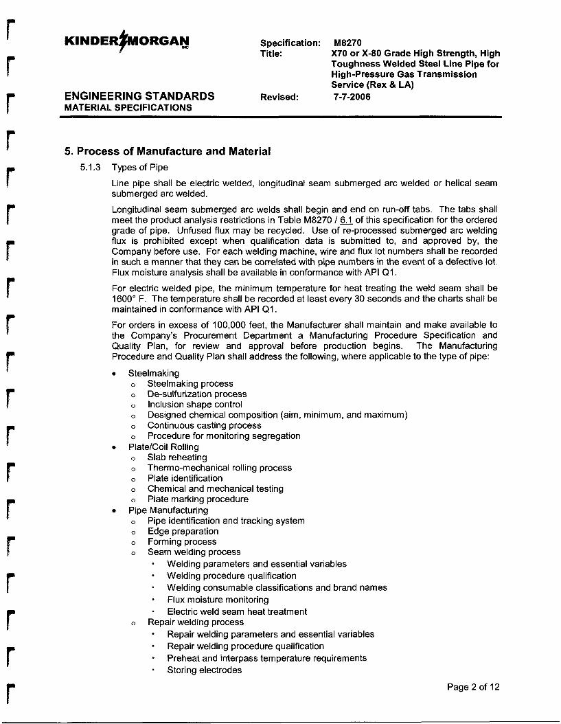
KINDER~ORGAN DIC Specification: Title:
ENGINEERING STANDARDS Revised: MATERIAL SPECIFICATIONS
M8270 X70 or X-80 Grade High Strength, High Toughness Welded Steel Line Pipe for High-pressure Gas Transmission Service (Rex & LA) 7-7-2006
5. Process of Manufacture and Material 5.1.3 Types of Pipe
Line pipe shall be electric welded, longitudinal seam submerged arc welded or helical seam submerged arc welded.
Longitudinal seam submerged arc welds shall begin and end on run-off tabs. The tabs shall meet the product analysis restrictions in Table M8270 / 6.1 of this specification for the ordered grade of pipe. Unfused flux may be recycled. Use of re-processed submerged arc welding flux is prohibited except when qualification data is submitted to, and approved by, the Company before use. For each welding machine, wire and flux lot numbers shall be recorded in such a manner that they can be correlated with pipe numbers in the event of a defective lot. Flux moisture analysis shall be available in conformance with API QI .
For electric welded pipe, the minimum temperature for heat treating the weld seam shall be 1600" F. The temperature shall be recorded at least every 30 seconds and the charts shall be maintained in conformance with API QI .
For orders in excess of 100,000 feet, the Manufacturer shall maintain and make available to the Company's Procurement Department a Manufacturing Procedure Specification and Quality Plan, for review and approval before production begins. The Manufacturing Procedure and Quality Plan shall address the following, where applicable to the type of pipe:
Steelmaking o Steelmaking process o De-sulfurization process o Inclusion shape control o
o Continuous casting process o Procedure for monitoring segregation
o Slab reheating o Thermo-mechanical rolling process o Plate identification o Chemical and mechanical testing o Plate marking procedure
o
o Edge preparation o Forming process o Seam welding process
Designed chemical composition (aim, minimum, and maximum)
0 Plate/Coil Rolling
Pipe Manufacturing Pipe identification and tracking system
Welding parameters and essential variables
Welding consumable classifications and brand names
Electric weld seam heat treatment
Repair welding parameters and essential variables
Preheat and interpass temperature requirements Storing electrodes
Welding procedure qualification
Flux moisture monitoring
o Repair welding process
Repair welding procedure qualification - Page 2 of 12
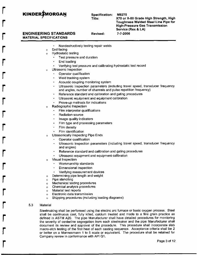
Specification: Title:
ENGINEERING STANDARDS Revised: MATERIAL SPECIFICATIONS
M8270 X70 or X-80 Grade High Strength, High Toughness Welded Steel Line Pipe for High-pressure Gas Transmission Service (Rex & LA) 7-7-2006
0
0
0
0
0
0
0
0
0
0
0
0
0
- Nondestructively testing repair welds End facing Hydrostatic testing
Test pressure and duration End loading
- Operator qualification Weld tracking system Acoustic coupling monitoring system
Verifying test pressure and calibrating hydrostatic test record Ultrasonic Inspection
Ultrasonic inspection parameters (including travel speed, transducer frequency and angles, number of channels and pulse repetition frequency) Reference standard and calibration and gating procedures Ultrasonic equipment and equipment calibration Prove-up methods for indications
Radiographic Inspection Film interpreter qualifications Radiation source Image quality indicators Film type and processing parameters Film density Film identification
Ultrasonically Inspecting Pipe Ends Operator qualification Ultrasonic inspection parameters (including travel speed, transducer frequency and angles) Reference standard and calibration and gating procedures Ultrasonic equipment and equipment calibration
- Workmanship standards
Verifying measurement devices Determining pipe length and weight Pipe stenciling Mechanical testing procedures Chemical analysis procedures Material test reports Electronic data transmission Shipping procedures (including loading diagrams)
Visual Inspection
Dimensional inspection
5.3 Material
Steelmaking shall be performed using the electric arc furnace or basic oxygen process. Steel shall be continuous cast, fully killed, calcium treated and made to a fine grain practice as defined in ASTM A20. The pipe Manufacturer shall have detailed procedures for monitoring the severity of centerline segregation from each steelmaker and the pipe Manufacturer shall document its review and approval of the procedure. This procedure shall incorporate slab macro-etch testing of the first heat of each casting sequence. Acceptance criteria shall be 2 or better on a Mannesmann 1 to 5 scale or equivalent. The procedure shall be retained for Company review in conformance with API Q I .
Page 3 of 12
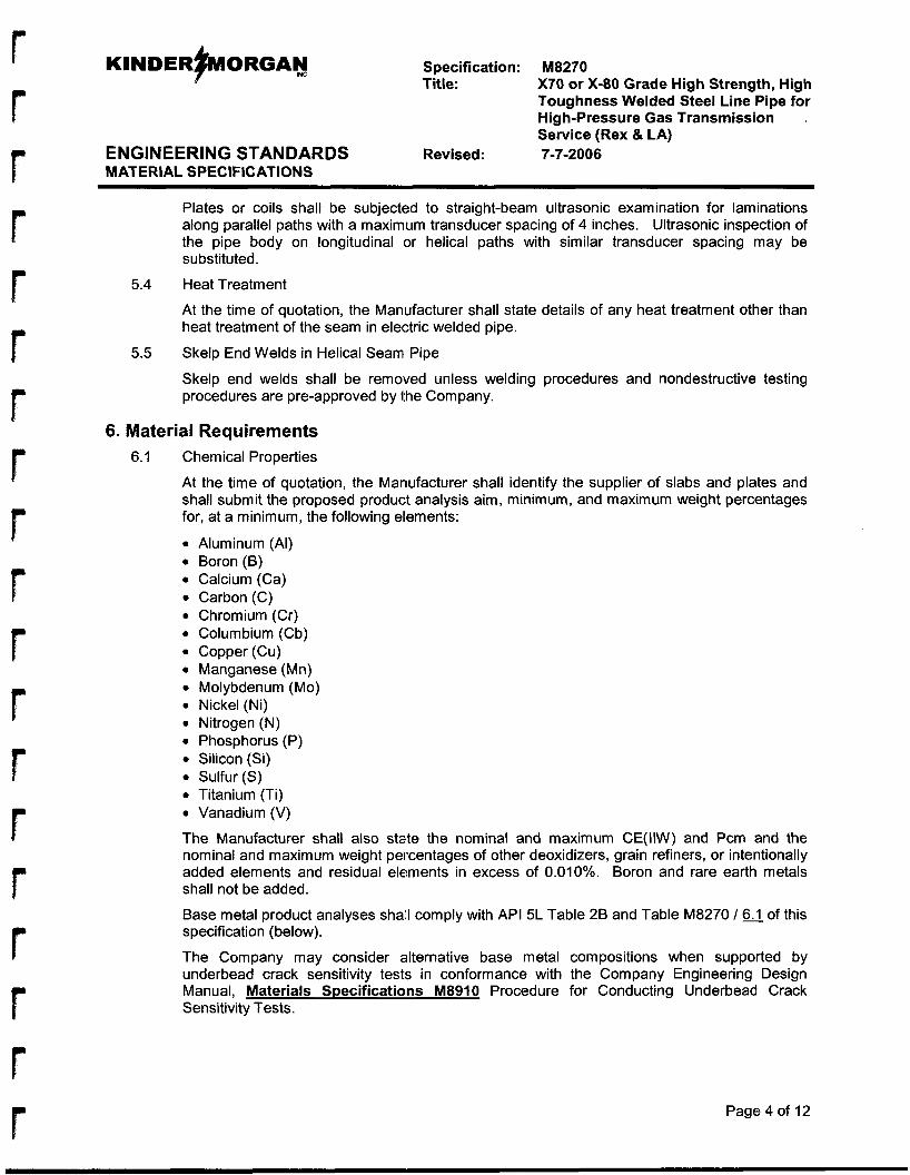
KINDER~ORGAN mc Specification: M8270 Title: X70 or X-80 Grade High Strength, High
Toughness Welded Steel Line Pipe for High-pressure Gas Transmission Service (Rex & LA)
ENGINEERING STANDARDS Revised: 7-7-20 0 6 MATERIAL SPECIFICATIONS
Plates or coils shall be subjected to straight-beam ultrasonic examination for laminations along parallel paths with a maximum transducer spacing of 4 inches. Ultrasonic inspection of the pipe body on longitudinal or helical paths with similar transducer spacing may be substituted.
5.4 Heat Treatment
At the time of quotation, the Manufacturer shall state details of any heat treatment other than heat treatment of the seam in electric welded pipe.
Skelp End Welds in Helical Seam Pipe
Skelp end welds shall be removed unless welding procedures and nondestructive testing procedures are pre-approved by the Company.
5.5
6. Material Requirements 6.1 Chemical Properties
At the time of quotation, the Manufacturer shall identify the supplier of slabs and plates and shall submit the proposed product analysis aim, minimum, and maximum weight percentages for, at a minimum, the following elements:
Aluminum (AI) Boron (B) Calcium (Ca) Carbon (C) Chromium (Cr) Columbium (Cb) Copper (Cu) Manganese (Mn) Molybdenum (Mo) Nickel (Ni) Nitrogen (N) Phosphorus (P) Silicon (Si) Sulfur ( S ) Titanium (Ti) Vanadium (V)
The Manufacturer shall also state the nominal and maximum CE(IIW) and Pcm and the nominal and maximum weight percentages of other deoxidizers, grain refiners, or intentionally added elements and residual elements in excess of 0.010%. Boron and rare earth metals shall not be added.
Base metal product analyses shall comply with API 5L Table 28 and Table M8270 / 6.1 of this specification (below).
The Company may consider alternative base metal compositions when supported by underbead crack sensitivity tests in conformance with the Company Engineering Design Manual, Materials Specifications M8910 Procedure for Conducting Underbead Crack Sensitivity Tests.
Page 4 of 12
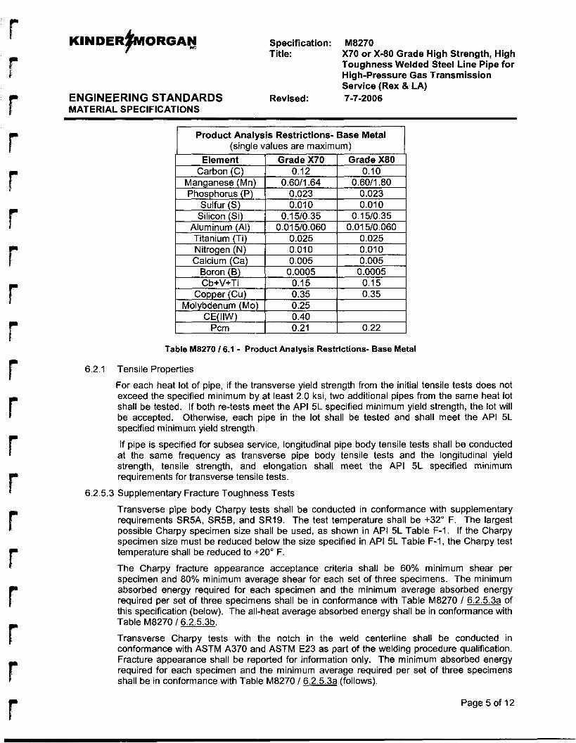
r r
Pcm
KINDER~ORGAN INC
0.21 0.22
Specification: Title:
ENGINEERING STANDARDS Revised: MATERIAL SPECIFICATIONS
M8270 X70 or X-80 Grade High Strength, High Toughness Welded Steel Line Pipe for High-pressure Gas Transmission Service (Rex & LA) 7-7-2006
Product Analysis Restrictions- Base Metal
Page 5 of 12
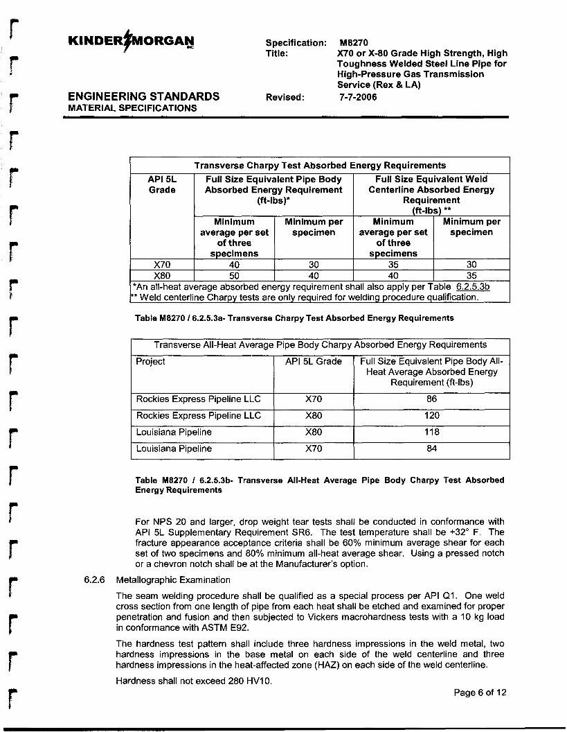
KINDER~ORGAN mc
API 5L Full Size Equivalent Pipe Body Grade Absorbed Energy Requirement
(ft-l bS)*
Minimum Minimum per
of three specimens
X70 40 30 X80 50 40
average per set specimen
Specification: Title:
Full Size Equivalent Weld Centerline Absorbed Energy
Requirement (ft-lbs) **
Minimum Minimum per
of three specimens
average per set specimen
35 30 40 35
ENGINEERING STANDARDS Revised: MATERIAL SPECIFICATIONS
Project API 5L Grade
Rockies Express Pipeline LLC X70
M8270 X70 or X-80 Grade High Strength, High Toughness Welded Steel Line Pipe for High-pressure Gas Transmission Service (Rex & LA) 7-7-2006
Full Size Equivalent Pipe Body All- Heat Average Absorbed Energy
Requirement (ft-lbs)
86
6.2.6
X80
X80
120
118
Louisiana Pipeline X70 84
Table M8270 I 6.2.5.3b- Transverse All-Heat Average Pipe Body Charpy Test Absorbed Energy Requirements
For NPS 20 and larger, drop weight tear tests shall be conducted in conformance with API 5L Supplementary Requirement SR6. The test temperature shall be +32" F. The fracture appearance acceptance criteria shall be 60% minimum average shear for each set of two specimens and 80% minimum all-heat average shear. Using a pressed notch or a chevron notch shall be at the Manufacturer's option.
Metallographic Examination
The seam welding procedure shall be qualified as a special process per API QI . One weld cross section from one length of pipe from each heat shall be etched and examined for proper penetration and fusion and then subjected to Vickers macrohardness tests with a 10 kg load in conformance with ASTM E92.
The hardness test pattern shall include three hardness impressions in the weld metal, two hardness impressions in the base metal on each side of the weld centerline and three hardness impressions in the heat-affected zone (HAZ) on each side of the weld centerline.
Hardness shall not exceed 280 HVI 0. Page 6 of 12
KINDERFORGAY Specification: M8270 Title: X70 or X-80 Grade High Strength, High
Toughness Welded Steel Line Pipe for High-pressure Gas Transmission Service (Rex & LA)
ENGINEERING STANDARDS Revised: 7-7-2006 MATERIAL SPECIFICATIONS
7.2
7.7
7.8
7.8.1
7.9
For submerged arc welded pipe, the welding procedure qualification shall include chemical analysis of the weld metal. The Rcm for the weld metal shall not exceed 0.25.
7. Dimensions, Weights, Lengths, Defects and End Finishes Diameter and Roundness
Within 4-inches of pipe ends, out of roundness shall not exceed:
0 3/8-inch for diameters greater than NPS 24 with wall thickness of 0.500-inch or more 0 II2-inch for diameters greater than NPS 24 with wall thickness less than 0.500-inch
Longitudinal seam submerged arc welded line pipe shall be checked for out of roundness at the position of the longitudinal weld. Templates with a minimum chord length of 25% of nominal diameter shall be used to measure the local irregularity in profile. The template shall have a radius equal to the external diameter of the pipe and may have a cutout to accommodate the weld. Any local irregularities shall be measured with a taper gauge inserted in the gap between the template and the pipe surface. The local irregularity shall not exceed 1 / I 6-inch.
Diameter tapes used for accepting and rejecting shall be verified against a standard at least once per 8-hour operating shift.
Jointers
Mill-welded jointers can be provided only with prior Company approval of jointer welding facilities and techniques. Joint welding shall conform to API 5L Appendix A and API 1104. Pipe weld seams shall be staggered between 3-inches and 6-inches.
Workmanship and Repair of Defects
Defects shall be repaired before final mill hydrostatic testing. Surface imperfections, such as scabs, slivers, and scratches shall be ground to vanishing. If scratches, dents, deep or rough grinds, gouges, and other surface imperfections are not scattered but appear over a large area in excess of what the Company representative considers a workmanlike finish, the surface imperfections shall be cause for rejecting the pipe, even if the individual imperfections would be permissible. Weld spatter shall be removed from pipe surfaces. The surface quality must be compatible for application of 14 mils nominal thickness fusion bonded epoxy coating in accordance with company specification C1080 - Pipe Coatinns. Where less than 50% of the footage formed from a heat or coil complies with this pipe specification, the Company reserves the right to reject all pipes from the affected heat or coil.
Dents
Dents l/&inch or deeper with sharp bottom gouges and dents extending into the weld or heat- affected zone shall be removed as a cylinder. Jacking to remove dents is unacceptable.
Pipe Ends
For pipe processed from discrete plate or cut-to-length plate, one inch of the complete pipe circumference at each end of the pipe shall be inspected for laminar discontinuities by the straight-beam pulse echo method.
For pipe processed from coils, one inch of the complete pipe circumference of at least one end of each pipe shall be inspected for laminar discontinuities by the straight-beam pulse echo method. The inspection shall include the pipe ends corresponding to the front and back of each coil.
Page 7 of 12
Specification: Title:
ENGINEERING STANDARDS Revised: MATERIAL SPECIFICATIONS
M8270 X70 or X-80 Grade High Strength, High Toughness Welded Steel Line Pipe for High-pressure Gas Transmission Service (Rex & LA) 7-7-2006
For pipe processed from Steckel-rolled coils, one inch of the complete pipe circumference of the pipe ends corresponding to the front and back of each coil shall be examined for longitudinal linear indications. The reference standard shall consist of API N5 internal and external longitudinal notches (primary reference level). Discontinuities exceeding the primary reference level are unacceptable.
For straight-beam inspection, the reference standard shall consist of a 1/4-inch, flat-bottom hole drilled to a depth of approximately one-half the wall thickness (primary reference level). Discontinuities exceeding the primary reference level or areas with total loss of back reflection are unacceptable.
8. Couplings (Not Applicable)
9. Inspection and Testing 9.2.1
9.2.2
9.3
9.4
9.8
Heat Analyses
The Manufacturer shall provide the Company’s Procurement Department with a material test report, including heat analyses for each heat of steel. For orders over 100,000 feet, heat analyses shall also be supplied in electronic format before production begins.
Product Analyses
The Manufacturer shall provide the Company’s Procurement Department with a material test report that includes two product analyses for each heat of steel.
Testing of Mechanical Properties
The Manufacturer shall provide the Company’s Procurement Department with a material test report of all mechanical tests required by this specification and API 5L.
Hydrostatic Tests
The highest possible mill test pressure is desired. The minimum test pressure shall be at least 95% of specified minimum yield strength.
Nondestructive Inspection
9.8.3 Inspection Methods
Electric welded pipe weld seams shall be inspected full-length by ultrasonic methods for longitudinal defects. Submerged arc welded pipe weld seams shall be inspected full- length for longitudinal and transverse defects by a combination of ultrasonic methods supplemented with film radiographic methods within 8-inches of pipe ends. Technicians performing film interpretation shall have RT Level II certifications per ASNT SNT-TC-1A or IS0 9712. Technicians performing ultrasonic inspection of the weld seam shall have UT Level II certifications per ASNT SNT-TC-1A or IS0 9712. A Level I l l individual, nationally certified by ASNT SNT-TC-1A or IS0 9712 in the specific NDE test method, shall write the inspection procedures. Technicians shall conduct inspections in conformance with these written procedures.
9.8.4 Radiological Inspection
The reference standard for film radiographic inspection shall be API standard 2% penetrameters per API 5L Table 16 or IS0 wire 2% penetrameters per API 5L Table 18. Radiographic film shall meet ASTM E1815-96 Class 1 or Class 2 requirements. The developed radiographs shall have a density between 2.0 and 3.8 in the weld.
Page 8 of 12
KINDERFORGAY Specification: M8270 Title: X70 or X-80 Grade High Strength, High
Toughness Welded Steel Line Pipe for High-pressure Gas Transmission Service (Rex & LA)
ENGINEERING STANDARDS Revised: 7-7-2006 MATERIAL SPECIFICATIONS
Substituting non-film radioscopic methods requires prior Company approval of radioscopic facilities and techniques. The submittal shall include a written practice in conformance with ASME SE-1255 - Standard Practice for Radioscopy, including evaluating spatial resolution and contrast sensitivity with a calibrated line pair test pattern and step wedge.
9.8.5 Ultrasonic Inspection
Automatic ultrasonic equipment shall incorporate a device that monitors acoustic coupling effectiveness and shall include a record of the inspection made without operator intervention. For submerged arc welded pipe, the ultrasonic reference standard shall include a 1/16-inch radial drilled hole at the weld centerline and API N5 ID and OD notches in the base metal parallel to the weld approximately 1/16-inch from the weld toe. In addition, for longitudinal seam submerged arc welded pipe, the end of the reference standard shall contain a 1 /8-inch side-drilled hole along the weld centerline at mid-wall. For transverse inspection, a 1/16-inch radial drilled hole at the weld centerline or API 5L N5 ID and OD transverse notches may be used as reference reflectors. For transverse notches, the weld crown may be ground to a flatter contour to facilitate notching. Each reflector shall be considered a reference standard with acceptance limit signal heights of 100% and shall produce alarms when scanned in the dynamic mode.
For electric welded pipe, the ultrasonic reference shall include a l/8-inch radial drilled hole and API N10 ID and OD notches at the weld centerline and two additional 1/8-inch radial drilled holes straddling the centerline. Each of these reflectors shall be considered a reference standard with acceptance limit signal heights of 100% and shall produce alarms when scanned in the dynamic mode.
Indications above the acceptance level signal height found by automated ultrasonic inspection may be reevaluated by manual ultrasonic inspection using the same reference reflectors.
9.8.5.6 Weld Repair
In conformance with PSL 2, weld repairs in the pipe body and weld repairs in electric weld seams are not permitted.
Stops and starts in submerged arc welds shall be examined with film radiography.
Weld repairs to submerged arc weld seams are permitted subject to the following restrictions:
Repair welding procedures shall be qualified in conformance with API 5L Appendix C using automatic submerged arc welding or manual shielded metal arc welding with low-hydrogen electrodes. Repair welding shall be conducted in the flat position. The procedure qualification record shall include weld metal Charpy results meeting requirements of Table M8270 / 6.2.5.3a - Transverse Charpy Test Absorbed Energy Requirements (above) and Vickers macrohardness tests in the weld metal and heat-affected zone not to exceed 280 HVIO. The pipe shall be preheated to 200" F minimum unless data to support a lower preheat temperature is presented and approved by the Company. Low hydrogen shielded metal arc electrodes shall be purchased in hermetically-sealed containers. When containers are opened, electrodes not immediately used shall be placed in a cabinet at 250" F to 300" F unless data to support other ranges is presented and approved by the Company. Low hydrogen shielded metal arc electrodes that are exposed to the atmosphere for more than four hours shall be discarded or re-dried according to a written procedure approved by the Company.
Page 9 of 12

f I
Repair of cracks Repairs after expansion Multiple repairs of a segment of the weld Back to back repairs Repairs within 6-inches of pipe ends Maximum repair weld depth Maximum number of repairs Minimum spacing of repairs Maximum repair length
KINDER~ORGAN wc
Unacceptable Unacceptable Unacceptable Unacceptable Unacceptable Two-thirds of specified pipe wall thickness 3 per pipe 12-inches (measured to the near edges) Cumulative length shall not exceed 10% of pipe lenoth
Specification: M8270 Title: X70 or X-80 Grade High Strength, High
Toughness Welded Steel Line Pipe for High-pressure Gas Transmission Service (Rex & LA)
ENGINEERING STANDARDS Revised: 7-7-2006 MATERIAL SPECIFICATIONS
0 Completed weld repairs shall be subject to hydrostatic testing, film radiographic examination, and ultrasonic examination. Film coverage shall extend at least 2-inches beyond each end of the repair.
0 Table M8270 / 9.8.5.6 (follows) specifies additional weld repair restrictions.
Carbon (C) Manganese (Mn) Phosphorus (P)
Silicon (Si) Aluminum (AI) Copper (CU)~ Nickel (Ni)2
Sulfur (S)
Weld Repair Restrictions
Tolerance’ Tolerance’ 0.01 % Chromium (Cr)2 0.01 % 0.01 Yo Molybdenum (MO)~ 0.01 % 0.001 % Vanadium (V)O 0.001 %
0.001 % 0.01 % Titanium (Ti)3 0.001 % 0.001 % Nitrogen (N) 0.0001 % 0.01 % Calcium (Ca)‘ 0.0001 Yo 0.01 Yo Boron (B)’ 0.0001 %
0.001 % Columbium (Cb)3
Table M8270 19.8.5.6 - Weld Repair Restrictions 9.10 Test Methods
9.10.1 Methods of Chemical Analysis
Table M8270 / 9.10.1 lists those elements that shall be reported and the related reporting tolerances.
I Chemical Analyses Required and Reporting Tolerances
I Element 1 Reporting- I Element I Reporting-
Table M8270 I9.10.1 - Chemical Analyses Required and Repotting Tolerances
Page 10 of 12
r ii
r
KINDER#MORGARJ Specification: Title:
E NGI N EERl NG STANDARDS MATERIAL SPECIFICATIONS
Revised:
M8270 X70 or X-80 Grade High Strength, High Toughness Welded Steel Line Pipe for High-pressure Gas Transmission Service (Rex & LA) 7-7-2006
9.10.2 Tensile Test
Extensometers shall meet ASTM E83 Class B-I requirements.
I O . Marking Line pipe shall be marked in conformance with API 5L Appendix I. Cold die-stamping the pipe or skelp is unacceptable. Markings shall be in U.S. customary units. Stencils shall be coated with varnish unless the pipe is purchased with internal coating.
Markings shall include a heat number traceable to steelmaking and casting and a unique pipe number traceable to rolling parameters for the individual plate or coil. For line pipe manufactured from coils, the pipe number shall be traceable to the wrap position in the coil. For line pipe manufactured from Steckel-rolled plates, the pipe number shall be traceable to the wrap position in the coil box.
For electric welded pipe, the location of the weld seam shall be marked on the inside surface with a one-inch wide, six-inch long stripe centered on the weld, one inch back from the bevel at both pipe ends.
Color-coding with a paint band may be used to distinguish different pipe wall thicknesses or grades or to distinguish a heavy land pipe end.
1 I, Coating and Protection Surfaces of pipe provided without a specified external mill coating shall be free of loose mill scale, dirt, grease, oil, paint, crayon, or any other substances that could interfere with subsequent coating application. Only greaseless crayon or chalk shall be used for mill control purposes.
When specified on a Company Purchase Order, internal coating shall be supplied in conformance with API RP 5L2, most recent edition and the Company Engineering Design Manual, Material Specification M8360, Internally Cleaning and Coatina Welded Line Pipe for Flow Efficiency.
12. Documents The Manufacturer shall provide a material test report and certificate of compliance in conformance with API 5L Supplementary Requirement SR15. Documents shall be in English with U.S. customary units. For submerged arc welded pipe, the certificate shall state whether the pipe was cold-expanded or non-expanded. For drop weight tear tests, the notch type shall be stated.
For orders over 100,000 feet, the Manufacturer shall also supply the following information in electronic format:
0 A list of unique pipe numbers and corresponding heat numbers 0 A list of heat numbers and corresponding product analyses 0 A list of tensile test, Charpy test, and drop weight tear test results with corresponding heat numbers
and pipe numbers
13. Pipe Loading Line pipe shall be loaded in conformance with the most recent editions of API RP 5L1 - Recommended Practice for Railroad Transportation of Line pipe, or API RP 5LW - Recommended Practice for Transportation of Line Pipe on Barges and Marine Vessels.
Handling pipe with copper or copper alloy hooks is unacceptable.
Page 11 of 12
r
r
Specification: M8270 Title: X70 or X-80 Grade High Strength, High
Toughness Welded Steel Line Pipe for High-pressure Gas Transmission Service (Rex & LA)
ENGINEERING STANDARDS Revised: 7-7-2006 MATERIAL SPECIFICATIONS
Before loading, rail cars, trucks, ships, or barges shall be cleaned of debris or any substance that could damage pipe during loading or transit. Timber or other dunnage shall be used to protect pipe from damage in transit. For truck loading, non-metallic hold-down straps are required and chains are prohibited. For marine vessels, deck loading and/or loading of other commodities on top of pipe is prohibited. A loading diagram shall be provided to the Company’s Procurement Department. Shipping damage due to loading shall be considered mill damage.
When line pipe is temporarily stored or stockpiled for the Company, the following requirements shall
0 Pipes shall be segregated by diameter, wall, grade, and coating. 0 Pipes shall be stored at a height to prevent groundwater entering the pipe.
apply:
r F k ? Page 12 of ‘I2

KINDER#~UIORGAN Specification: M8910
ENGINEERING STANDARDS Crack Sensitivity Tests Title: Procedure For Conducting Underbead
MATERIAL SPECIFICATIONS Revised: 9-1 -2005
F
P
P
APPENDIX C
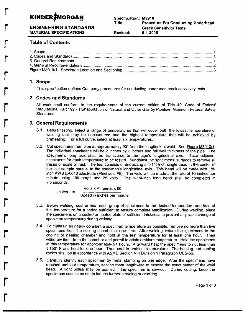
r r
KINDER~ORGAN Im Specification: M8910
ENGINEERING STANDARDS Crack Sensitivity Tests Title: Procedure For Conducting Underbead
MATERIAL SPECIFICATIONS Revised : 9-1-2005
Table of Contents
1. Scope ........................................................................................................................................................ I 2. Codes and Standards ................................................................................................................................ 1 3. General Requirements .............................................................................................................................. 1 4. General Recommendations.. ..................................................................................................................... 2 Figure M8910/1 - Specimen Location and Sectioning .................................................................................. 3
I. Scope This specification defines Company procedures for conducting underbead crack sensitivity tests.
2. Codes and Standards All work shall conform to the requirements of the current edition of Title 49, Code of Federal Regulations, Part 192 - Transportation of Natural and Other Gas by Pipeline: Minimum Federal Safety Standards.
3. General Requirements 3.1. Before testing, select a range of temperatures that will cover both the lowest temperature of
welding that may be encountered and the highest temperature that will be achieved by preheating. For a full curve, select at least six temperatures.
3.2. Cut specimens from pipe at approximately 90" from the longitudinal weld. See Fiqure M8910/1. The individual specimens will be 2 inches by 3 inches and full wall thickness of the pipe. The specimen's long axis shall be transverse to the pipe's longitudinal axis. Take adjacent specimens for each temperature to be tested. Sandblast the specimens' surfaces to remove all traces of scale or rust. The test consists of depositing a l-1/4-inch single bead in the center of the test sample parallel to the specimen's longitudinal axis. This bead will be made with 1/8- inch AWS E-6010 Electrode (Fleetweld #5). The weld will be made at the rate of 10 inches per minute using 100 amps and 25 volts. The 1-1/4-inch long bead shall be completed in 7.5 seconds.
Volts x Amperes x 60 Joules =
Speed in inches per minute
3.3. Before welding, cool or heat each group of specimens to the desired temperature and hold at this temperature for a period sufficient to ensure complete stabilization. During welding, place the specimens on a cooled or heated plate of sufficient thickness to prevent any rapid change of specimen temperature during weldiiig.
3.4. To maintain as nearly constant a specimen temperature as possible, remove no more than five specimens from the cooling chamber at one time. After welding, return the specimens to the cooling or heating chamber and hold at the test temperature for at least one hour. Then withdraw them from the chamber arid permit to attain ambient temperature. Hold the specimens at this temperature for approximately 24 hours. Afterward heat the specimens to not less than 1,150' F and hold for one hour. Then cool to ambient temperature. The heating and cooling cycles shall be in accordance with ASME Section Vlll Division 1 Paragraph UCS-56.
3.5. Carefully identify each specimen by metal stamping on one edge. After the specimens have reached ambient temperature, section them lengthwise to expose the exact center of the weld bead. A light polish may be applied if the specimen is saw-cut. During cutting, keep the specimens cool so as not to induce further straining or cracking. r Page 1 of 3
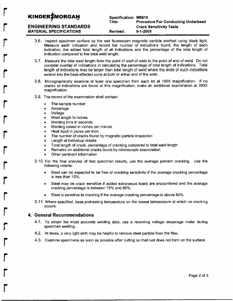
Specification: M8910 Title: Procedure For Conducting Underbead
ENGINEERING STANDARDS Crack Sensitivity Tests MATERIAL SPECIFICATIONS Revised: 9-1-2005
3.6. Inspect specimen surface by the wet fluorescent magnetic particle method using black light. Measure each indication and record the number of indications found, the length of each indication, the added total length of all indications and the percentage of the total length of indication compared to the total weld length.
3.7. Measure the total weld length from the point of start of weld to the point of end of weld. Do not consider overlap of indications in calculating the percentage of total length of indications. Total length of indications may be larger than total length of weld where the ends of such indications extend into the heat-affected zone at both or either end of the weld.
3.8. Micrographically examine at least one specimen from each lot at IOOX magnification. If no cracks or indications are found at this magnification, make an additional examination at 200X magnification.
3.9. The record of the examination shall contain:
The sample number Amperage Voltage Weld length in inches Welding time in seconds Welding speed in inches per minute Heat input in joules per inch The number of cracks found by magnetic particle inspection Length of individual cracks Total length of crack, percentage of cracking compared to total weld length Remarks on additional cracks found by microscopic examination Other pertinent information
3.10. For the final analysis of test specimen results, use the average percent cracking. Use the
Steel can be expected to be free of cracking sensitivity if the average cracking percentage is less than 15%.
Steel may be crack sensitive if added extraneous loads are encountered and the average cracking percentage is between 15% and 80%.
Steel is sensitive to cracking if the average cracking percentage is above 80%.
following criteria:
3.1 1. Where specified, base preheating temperature on the lowest temperature at which no cracking occurs.
4. General Recommendations 4.1. To obtain the most accurate welding data, use a recording voltage amperage meter during
specimen welding.
4.2. At times, a very light etch may be helpful to remove steel particle from the flaw.
4.3. Examine specimens as soon as possible after cutting so that rust does not form on the surface.
Page 2 of 3
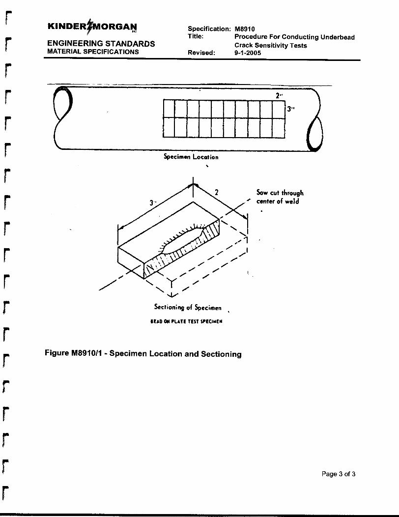
Specification: M8910 Title: Procedure For Conducting Underbead
ENGINEERING STANDARDS Crack Sensitivity Tests MATERIAL SPECIFICATIONS Revised: 9-1 -2005
I
I 3- - I
Sow cut through center of weld
1
Figure M8910/1 - Specimen Location and Sectioning
Page 3 of 3
APPENDIX D
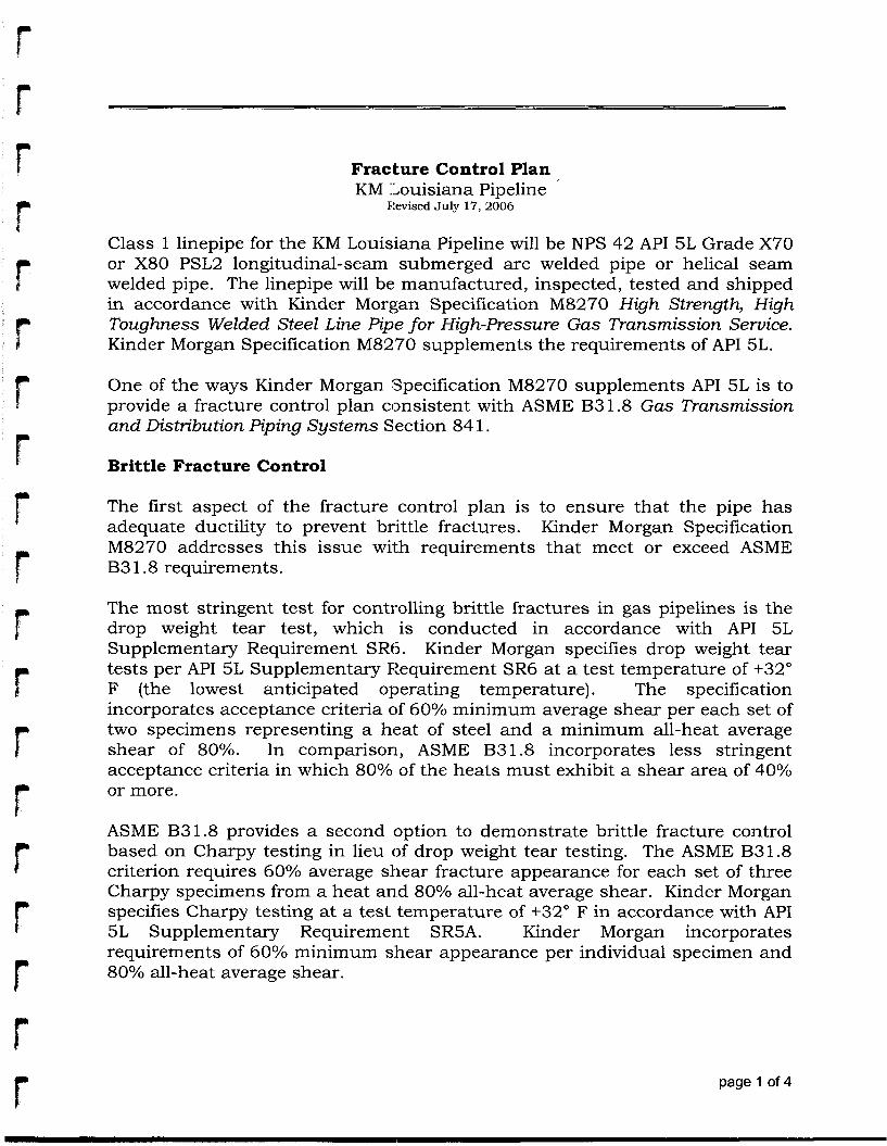
P
Fracture Control Plan KM ]Louisiana Pipeline
Ftevised July 17, 2006
r r
Class 1 linepipe for the KM Louisiana Pipeline will be NPS 42 API 5 L Grade X70 or X80 PSL2 longitudinal-seam submerged arc welded pipe or helical seam welded pipe. The linepipe will be: manufactured, inspected, tested and shipped in accordance with Kinder Morgan Specification M8270 High Strength, High Toughness Welded Steel Line Pipe for High-pressure Gas Transmission Service. Kinder Morgan Specification M8270 supplements the requirements of API 5L.
One of the ways Kinder Morgan Specification M8270 supplements API 5L is to provide a fracture control plan consistent with ASME B31.8 Gas Transmission and Distribution Piping Systems Section 84 1.
Brittle Fracture Control
The first aspect of the fracture control plan is to ensure that the pipe has adequate ductility to prevent brittle fractures. Kinder Morgan Specification M8270 addresses this issue with requirements that meet or exceed ASME B3 1.8 requirements.
The most stringent test for controlling brittle fractures in gas pipelines is the drop weight tear test, which is conducted in accordance with API 5 L Supplementary Requirement SRIS. Kinder Morgan specifies drop weight tear tests per API 5 L Supplementary Fzequirement SR6 at a test temperature of +32" F (the lowest anticipated operating temperature). The specification incorporates acceptance criteria of 60% minimum average shear per each set of two specimens representing a heat of steel and a minimum all-heat average shear of 80%. In Comparison, ASME B31.8 incorporates less stringent acceptance criteria in which 80% of the heats must exhibit a shear area of 40% or more.
ASME B3 1.8 provides a second option to demonstrate brittle fracture control based on Charpy testing in lieu of drop weight tear testing. The ASME B31.8 criterion requires 60% average shear fracture appearance for each set of three Charpy specimens from a heat an.d 80% all-heat average shear. Kinder Morgan specifies Charpy testing at a test temperature of +32" F in accordance with API 5 L Supplementary Requirement SR5A. Kinder Morgan incorporates requirements of 60% minimum s:hear appearance per individual specimen and 80% all-heat average shear.
page 1 of 4
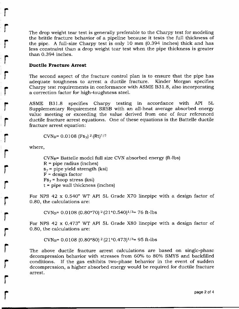
h r
The drop weight tear test is generally preferable to the Charpy test for modeling the brittle fracture behavior of a pipeline because it tests the full thickness of the pipe. A full-size Charpy test is only 10 mm (0.394 inches) thick and has less constraint than a drop weight tear test when the pipe thickness is greater than 0.394 inches.
Ductile Fracture Arrest
The second aspect of the fracture control plan is to ensure that the pipe has adequate toughness to arrest a ductile fracture. Kinder Morgan specifies Charpy test requirements in conformance with ASME B3 1.8, also incorporating a correction factor for high-toughness steel.
ASME B31.8 specifies Charpy testing in accordance with API 5 L Supplementary Requirement SR5B with an all-heat average absorbed energy value meeting or exceeding the: value derived from one of four referenced ductile fracture arrest equations. One of these equations is the Battelle ductile fracture arrest equation:
CVNB= 0.0108 (Fs~) (Rt)1/3
where,
CVNB= Battelle model full size CVN absorbed energy (ft-lbs) R = pipe radius (inches) sy = pipe yield strength (ksi) F = design factor Fs,= hoop stress (ksi) t = pipe wall thickness (inches)
For NPS 42 x 0.540” WT API 51, Grade X70 linepipe with a design factor of 0.80, the calculations are:
CVNF 0.0108 (0.80*70) 2 (2 1*0.540)1/3= 76 ft-lbs
For NPS 42 x 0.473” WT API 51, Grade X80 linepipe with a design factor of 0.80, the calculations are:
CVNF 0.0108 (0.80*80) 2 (5!1*0.473)1/3= 95 ft-lbs
The above ductile fracture arrest calculations are based on single-phase decompression behavior with stresses from 60% to 80% SMYS and backfilled conditions. If the gas exhibits two-phase behavior in the event of sudden decompression, a higher absorbed energy would be required for ductile fracture arrest.
page 2 of 4
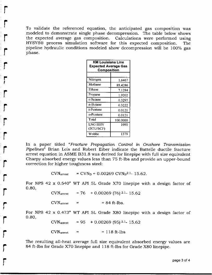
h E
To validate the referenced equation, the anticipated gas composition was modeled to demonstrate single phase decompression. The table below shows the expected average gas complosition. Calculations were performed using HYSYSB process simulation solftware for this expected composition. The pipeline hydraulic conditions modeled show decompression will be 100% gas phase.
Expected Average Gas
n-Pentane
LNG HHV (BT U/SCF)
Wobbe
In a paper titled “Fracture Propagation Control in Onshore Transmission Pipelines” Brian Leis and Robert Eiber indicate the Battelle ductile fracture arrest equation in ASME B31.8 was derived for linepipe with full size equivalent Charpy absorbed energy values less than 75 ft-lbs and provide an upper-bound correction for higher toughness steel:
CVNmest = CVNB -I- 0.00269 cVN~2.1- 15.62.
For NPS 42 x 0.540” WT API 51L Grade X70 linepipe with a design factor of 0.80,
CVNmest = 76 + 0.00269 (76) 2.1- 15.62
For NPS 42 x 0.473” WT API 5 L Grade X80 linepipe with a design factor of 0.80,
CVNmest = 95 + 0.00269 (95) 2.1- 15.62
The resulting all-heat average fu.11 size equivalent absorbed energy values are 84 ft-lbs for Grade X70 linepipe and 118 ft-lbs for Grade X80 linepipe.
page 3 of 4 r
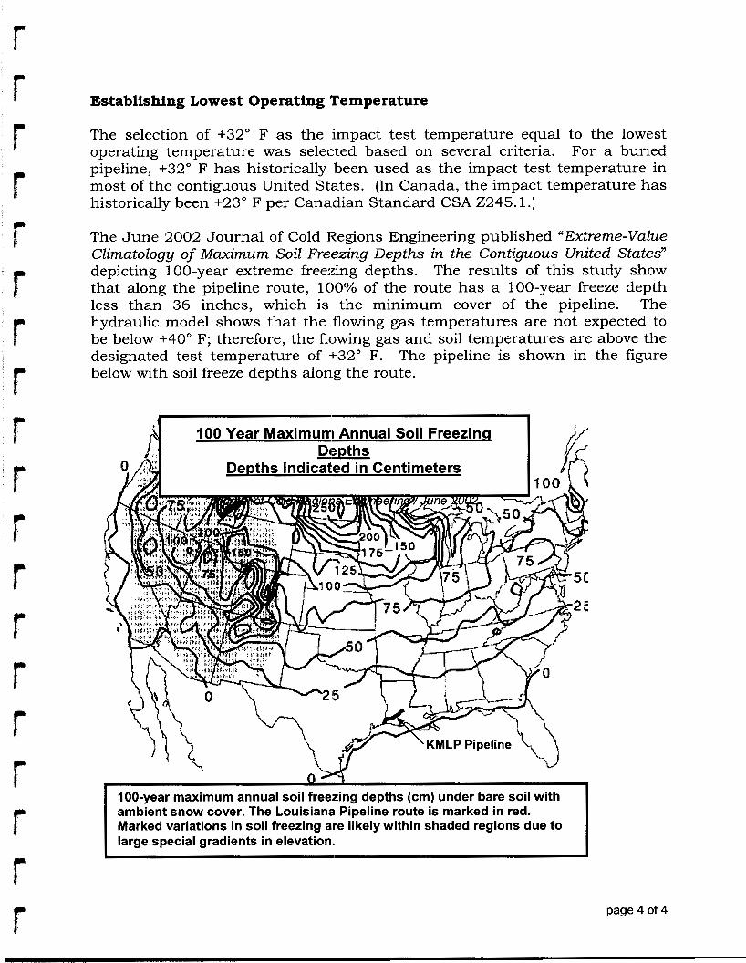
Establishing Lowest Operating Temperature
The selection of +32" F as the impact test temperature equal to the lowest operating temperature was selected based on several criteria. For a buried pipeline, +32" F has historically been used as the impact test temperature in most of the contiguous United States. (In Canada, the impact temperature has historically been +23" F per Cana.dian Standard CSA 2245.1 .)
The June 2002 Journal of Cold Regions Engineering published "Extreme-Value Climatology of Maximum Soil Freezing Depths in the Contiguous United States" depicting 100-year extreme freezing depths. The results of this study show that along the pipeline route, 100% of the route has a 100-year freeze depth less than 36 inches, which is the minimum cover of the pipeline. The hydraulic model shows that the flowing gas temperatures are not expected to be below +40" F; therefore, the flowing gas and soil temperatures are above the designated test temperature of +32" F. The pipeline is shown in the figure below with soil freeze depths along the route.
100-year maximum annual soil freezing depths (cm) under bare soil with ambient snow cover. The Louisiana1 Pipeline route is marked in red. Marked variations in soil freezing are likely within shaded regions due to large special gradients in elevation,.
page 4 of 4
t
APPENDIX E
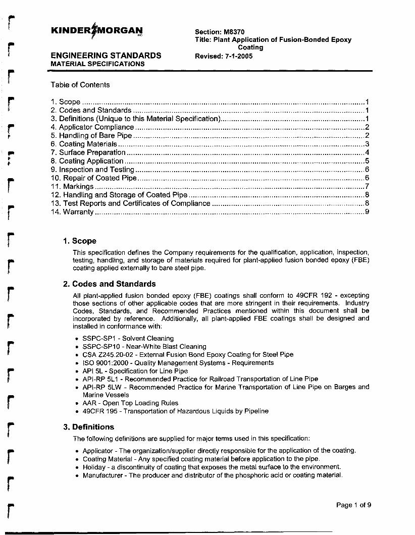
Section: M8370 Title: Plant Application of Fusion-Bonded Epoxy
Coating ENGINEERING STANDARDS Revised: 7-1-2005 MATERIAL SPECIFICATIONS
Table of Contents
1. Scope ...................................................................................................................................... I 2. Codes and Standards .............................................................................................................. 1 3. Definitions (Unique to this Material Specification) .................................................................... 1 4. Applicator Compliance ............................................................................................................ 2 5. Handling of Bare Pipe ............................................................................................................. 2 6. Coating Materials .................................................................................................................. ..3 7. Surface Preparation ............................................................................................................... .4 8. Coating Application ............................................................................................................... ..5 9. Inspection and Testing ........................................................................................................... .6 IO. Repair of Coated Pipe.. ........................................................................................................ .6 1 1. Markings ............................................................................................................................... 7 12. Handling and Storage of Coated Pipe ................................................................................... 8 13. Test Reports and Certificates of Compliance ........................................................................ 8 14. Warranty ............................................................................................................................... 9
I. Scope This specification defines the Company requirements for the qualification, application, inspection, testing, handling, and storage of materials required for plant-applied fusion bonded epoxy (FBE) coating applied externally to bare steel pipe.
2. Codes and Standards All plant-applied fusion bonded epoxy (FBE) coatings shall conform to 49CFR 192 - excepting those sections of other applicable codes that are more stringent in their requirements. Industry Codes, Standards, and Recommended Practices mentioned within this document shall be incorporated by reference. Additionally, all plant-applied FBE coatings shall be designed and installed in conformance with:
0 SSPC-SP1 - Solvent Cleaning 0 SSPC-SPIO - Near-White Blast Cleaning 0 CSA 2245.20-02 - External Fusion Bond Epoxy Coating for Steel Pipe 0 IS0 9001 :2000 - Quality Management Systems - Requirements 0 API 5L - Specification for Line Pipe 0 API-RP 5L1 - Recommended Practice for Railroad Transportation of Line Pipe 0 API-RP 5LW - Recommended Practice for Marine Transportation of Line Pipe on Barges and
0 AAR - Open Top Loading Rules 0 49CFR 195 - Transportation of Hazardous Liquids by Pipeline
Marine Vessels
3. Definitions The following definitions are supplied for major terms used in this specification:
0 Applicator - The organizationlsupplier directly responsible for the application of the coating. 0 Coating Material - Any specified coating material before application to the pipe. 0 Holiday - a discontinuity of coating that exposes the metal surface to the environment. 0 Manufacturer - The producer and distributor of the phosphoric acid or coating material.
Page 1 of 9
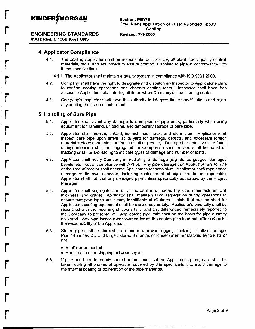
r Section: M8370 Title: Plant Application of Fusion-Bonded Epoxy
Coating ENGINEERING STANDARDS Revised: 7-1-2005 MATERIAL SPECIFICATIONS
r g
r t
r
4. Applicator Compliance
5. Handling of Bare Pipe
4.1.
4.1
4.2.
4.3.
The coating Applicator shall1 be responsible for furnishing all plant labor, quality control, materials, tools, and equipment to ensure coating is applied to pipe in conformance with these specifications.
1. The Applicator shall maintain a quality system in compliance with IS0 9001 :2000.
Company shall have the riglit to designate and dispatch an Inspector to Applicator's plant to confirm coating operations and observe coating tests. Inspector shall have free access to Applicator's plant during all times when Company's pipe is being coated.
Company's Inspector shall have the authority to interpret these specifications and reject any coating that is non-conformant.
5.1.
5.2.
5.3.
5.4.
5.5.
5.6.
Applicator shall avoid any (damage to bare pipe or pipe ends, particularly when using equipment for handling, unloading, and temporary storage of bare pipe.
Applicator shall receive, unload, inspect, haul, rack, and store pipe. Applicator shall inspect bare pipe upon arrival at its yard for damage, defects, and excessive foreign material surface contamination (such as oil or grease). Damaged or defective pipe found during unloading shall be segregated for Company inspection and shall be noted on trucking or rail bills-of-lading to indicate types of damage and number of joints.
Applicator shall notify Company immediately of damage (e.9. dents, gouges, damaged bevels, etc.) out of compliance with API 5L. Any pipe damage that Applicator fails to note at the time of receipt shall become Applicator's responsibility. Applicator shall repair such damage at its own expense, including replacement of pipe that is not repairable. Applicator shall not coat any damaged pipe unless specifically authorized by the Project Manager.
Applicator shall segregate and tally pipe as it is unloaded (by size, manufacturer, wall thickness, and grade). Applicator shall maintain such segregation during operations to ensure that pipe types are (clearly identifiable at all times. Joints that are too short for Applicator's coating equipment shall be racked separately. Applicator's pipe tally shall be reconciled with the incoming shipper's tally, and any differences immediately reported to the Company Representative. Applicator's pipe tally shall be the basis for pipe quantity delivered. Any pipe losses (unaccounted for on the coated pipe load-out tallies) shall be the responsibility of the Applicator.
Stored pipe shall be stacked in a manner to prevent egging, buckling, or other damage. Pipe 14-inches OD and larger, stored 3 months or longer (whether stacked by forklifts or not):
0 Shall not be nested. 0 Requires lumber stripping between layers.
If pipe has been internally coated before receipt at the Applicator's plant, care shall be taken, during all phases of operation covered by this specification, to avoid damage to the internal coating or obliter<ation of the pipe markings.
P
Page 2 of 9
Section: M8370 Title: Plant Application of Fusion-Bonded Epoxy
Coating ENGINEERING STANDARDS Revised: 7-1-2005 MATERIAL SPECIFICATIONS
6. Coating Materials 6.1. Powdered epoxy resin and repair materials shall be packaged in containers adequate to
keep contents clean and dry during handling, shipping, and storing. Handling and storing conditions, as well as temperature-time limitations on coating and repair materials, shall be in conformance with Manufacturer’s recommendations. Precautions shall be taken during handling, shipping, and storage to prevent damage to containers that could result in contamination of coating materials.
Epoxy resin powder shall be delivered in clearly labeled containers that identify the properties of the epoxy powider.
The Applicator shall use epoxy powder that meets the following requirements:
6.2.
6.3.
6.3.1. All epoxy powder shall be certified by the powder Manufacturer to be in conformance with the requirements of CSA 2245.20-02, Table 1 - Epoxy Powder Properties. At least once per year, the epoxy powder Manufacturer shall conduct tests and provide the Applicator with a test report for the epoxy powder properties given in Table 1 - Epoxy Powder Properties.
6.3.2. All epoxy powder shall be certified by the powder Manufacturer to be in conformance with the requirements of CSA 2245.20-02, Table 2 - Coating Qualification Test Requirements. At least once per year, the epoxy powder Manufacturer shall conduct tests and provide the Applicator with a test report for the coating properties given in Table 2 - Coating Qualification Test Requirements.
6.3.3. All epoxy powder shall be certified with the requirements of CSA 2245.20-02, Tables 3 - Laboratory-Coating Tjest Requirements, and 4 - Production Coating Test Requirements, using test equipment at the application facility or a Company-approved off-site facility.
6.3.4. All epoxy powder shall be identified with the following:
6.4.
6.5.
6.6.
6.7.
0 Name of the powder Manufacturer 0 Product description 0 Mass of material 0 Batch number 0 Location of powder Manufacturer 0 Manufacturing identification number 0 Temperature requirements for transportation and storage 0 Year and month of manufacture
The Applicator shall conduct the sample preparation, testing, and evaluation of the epoxy powder and coating in conformance with the requirements of Tables 3 and 4, CSA 2245.20-02, using test equipment at the application facility or a Company-approved off- site facility.
The minimum testing frequency shall be one sample on every vehicle shipment of epoxy powder received. The acceptance criteria and the tests to be conducted shall be in conformance with the requirements of CSA 2245.20-02 Clause 7.3.1.
The Company reserves the right to inspect and verify the Applicator‘s epoxy powder testingkertifications at any time.
Use of reclaimed or reconditiloned powder (previously-used material) is not allowed.
Page 3 of 9
KINDERFORGAY Section: M8370
ENGINEERING STANDARDS Revised: 7-1 -2005 MATERIAL SPECIFICATIONS
Title: Plant Application of Fusion-Bonded Epoxy Coating
7. Surface Preparation 7.1.
7.2.
7.3.
7.4.
7.5.
Applicator shall notify the Company 7 calendar days prior to commencement of coating activities. Applicator shall siubmit detailed surface preparation procedures for review and approval of the Project Manager. Required procedures include:
0 Inspection and detection of soluble ferrous salt or chloride contamination on pipe surfaces.
0 Removal of soluble ferrous salt or chloride contaminations before pipe coating. 0 Measurement of pipe surface profiles. 0 Inspection and detection of chloride contamination in blast unit abrasives.
Applicator shall inspect the pipe surface and clean it according to SSPC Specification SSPC-SP 1 to remove oil, grease, and loosely adhering deposits. All foreign materials remaining on the external surface of the pipe shall be removed by use of a non-oily solvent. Only Company-approved solvents that do not leave a residue shall be used. Gasoline and/or kerosene' shall not be used for surface cleaning.
If pipe inspection demonstrates chloride levels above 2 milligrams/m2, pipe shall be cleaned usin a phosphoric acid solution to remove all chloride or to bring it below 2 milligrams/m . Before blast cleaning, piping shall be preheated to remove moisture. During blast cleaning and inspection, pipe surface shall be maintained at a temperature at least 3°C (5°F) above the dew point, blut less than 150°C (300"F),
Before coating, external pipe surfaces shall be blast cleaned to at least SSPC-SP 10 specification. The surface profile, measured from peak to trough, shall be 40pm (1.6 mils) to 11Op-n (4.4 mils) inclusive, and in conformance with the powder Manufacturer's recommendations. Surface profiles shall be measured using the Applicator's approved procedures per paranraph 7 . 1 (above).
9
7.5.1. Surface finishes shall be monitored a minimum of every 2 hours during production to determine cleanliness. External surface profiles shall be tested at least once every 4 hours of production. The external surface profile on two pipes shall be measured using a profilometer, replicating film, or Company-approved equivalent method.
7.5.2. Bevel lands and pipe ends, shall be protected from blast-cleaning and impact damage.
7.6.
7.7.
Abrasives removed from the blast unit shall be inspected for chloride at a minimum of one test per 8-hour shift.
After cleaning, each pipe shall be visually inspected for surface defects and surface imperfections that could cause holidays in the coating. (Note: Typical surface defects and imperfections include slivers, scabs, burrs, and weld spatter.) Such surface imperfections shall be removed by abrasive disc grinding, provided that the remaining pipe wall thickness is within specified limits provided by the Company. A grind area will have a profile reading of at least 1.5 to 2.0 mils measured by 'Press-0-Film Repli%a Tape' or a Company-approved alt'ernate method. For grind areas exceeding 13 cm (2 in2) square inches, the anchor pattern shall be restored before coating application. No more than 1 % of the surface area shall have disturbed anchor profile. Pipe (containing surface defects) which does not conform with API 5L shall be rejected and replaced or repaired as required by the Company Representative.
Residual blast products froim the interior and exterior surfaces of the pipe shall be removed before heating. Shot, grit, sand, dust or other foreign matter remaining on the external and internal surfaces of the pipe shall be removed. When removing said materials, Contractor shall utilize dust collection equipment to prevent contamination of the plant and/or other pipe in close proximity.
Page 4 of 9
7.8.
Section: M8370 Title: Plant Application of Fusion-Bonded Epoxy
Coating ENGINEERING STANDARDS Revised: 7-1 -2005 MATERIAL SPECIFICATIONS
7.8.1. If it is determined by the Applicator/Company Inspector that pipe requires phosphoric acid washing, Applicator shall follow acid Manufacturer's recommendations for concentration, application, dwell time, rinse water quality, and disposal.
Blast-cleaned pipe surfaces shall be protected from conditions of high humidity, rainfall, or surface moisture. No pipe shall be allowed to flash rust before coating.
7.9.
8. Coating Application 8.1. Coating qualification testing shall be in conformance with CSA 2245.20-02, Clause 6.1
Coating Qualification. The coating system shall be qualified for production by testing laboratory-coated test specimens. The coating shall be re-qualified when there is a change in one or more of the following:
0 Manufacturpr 0 Coating formulation 0 Location of powder manufacture
Coatings applied during production shall be pre-qualified in conformance with the coating qualification.
The Applicator shall selecl application and curing temperatures of the external pipe surface not to exceed 275°C (527°F). Such temperatures shall be in conformance with the powder Manufacturer's recommendations. Applicator shall submit a temperature testing procedure to the Project Manager for review and approval 7 days prior to production application. The minimum recording frequency shall be at start-up and once every hour of production thereafter.
The nominal thickness of the coating and the maximum permissible thickness of the coating shall be a uniform rriinimum thickness of 12 mils (300 pm), with 14 mils (350 pm) minimum average and 25 mils (625 pm) maximum. The minimum permissible thickness of the coating shall be 300 pm. The Company purchase order will specify if other thickness ranges are required.
8.3.1. The coating thickness Shidl be measured at three random locations along each pipe length. Coating thickness shall be measured using a coating thickness gauge that has been calibrated at least once every working shift (to a maximum of 12 hours) against a thickness standard traceable to NlST (or other national equivalent) of the nominal coating thickness specified in the purchase order. Such measured thickness values shall be recorded by Applicator and provided in writing to Project Manager.
8.3.2. Where individual measured thickness values are less than 300 pm, the coating thickness of the affected pipes shall be measured along the pipe length at intervals not exceeding 1 m. The average of such measured values for each pipe shall be at least 300 pm, and no individual value shall be less than 250 pm ( I O mils).
8.3.3. Coated pipe that does not meet the requirements for coating thickness shall be stripped and re-coated in conformance with these specifications.
The cutback length for both ends of the pipe shall be 37.5 to 75 mm (1.5- to 3-inches) unless otherwise specified in the purchase order. The cutback area shall be free of coating.
8.5. The post-application temperature and the time interval between application and quenching shall be measured, recorded, and controlled to ensure that the coating is being cured. The minimum recording frequency shall be at start-up and once every hour of production thereafter.
Care shall be taken in handling the pipe during curing and cooling operations to prevent damage to the coating.
Page 5 of 9
8.2.
8.3.
8.4.
8.6.
Section: M8370 Title: Plant Application of Fusion-Bonded Epoxy
Coating ENGINEERING STANDARDS Revised: 7-1 -2005 MATERIAL SPECIFICATIONS
8.7.
8.8.
After coating is completely cured, pipe may be force-cooled to facilitate coating inspection and repairs.
The Company reserves the right to reject cold-expanded pipe that has been heat treated above 316°C (600°F) for niore than one hour, or heated above 482°C (900°F) for any length of time. Any pipe rejected on these grounds shall be the responsibility of the Applicator.
9. Inspection and Testing 9.1. The Applicator shall have full responsibility for the coating application quality in
conformance with this specification. The Applicator and/or Company Representative shall suspend coating operations when any conditions arise which jeopardize the quality of the completed work.
The entire coated surface of each length of pipe shall be inspected with a holiday detector that has a search electrode made of conducting rubber or phosphor bronze wire. A ’mustache’ of phosphor bronze wire shall be attached to the holiday detecting wand for inspecting the toe of DSAW pipe.
9.2.1. For inspection, the direct lcurrent potential of the detector shall be set to exceed 5 V for each micrometer (pm) (125 Vlmil) of nominal coating thickness. The detector shall be calibrated at least once every working shift (to a maximum of 12 hours) against a standard traceable to NlST (or other national equivalent).
9.2.2. Inspection shall be performed when the temperature of the coating is less than 100°C (21 2°F).
No holidays shall be permittled in the finished coating. Coated pipe with holidays shall be repaired by patching in conformance with these specifications, provided that the number of holidays does not exceed the following:
0 For pipe smaller than 355.6 mm (14-inch) OD, =1.0 average per meter length, determined by dividing the total number of holidays by the total pipe length for the individual pipe tested.
0 For pipe 355.6 mm (14-inlch) OD or larger, 0.7 per m2, determined by dividing the total number of holidays by the total outside surface area for the individual pipe tested.
9.3.1. Where the quantity of holidays exceeds the applicable limit specified, or where the area of an individual holiday is equal to or greater than 250 cmZ (40 in2), the affected pipe shall be stripped and re-coated in conformance with the requirements of these specifications.
The Applicator shall have facilities available at the application plant for the preparation, testing, and evaluation of test ring samples. Testing and subsequent test failures resulting in corrective actions shall conform to CSA 2245.20-02, Clause 7.3.3. The minimum test frequency shall be one test ring per pipe diameter and specified wall thickness every working shift (to a maximum of 12 hours). Applicator shall re-bevel the pipe end (at its own expense) in conformance with applicable API 5L Specifications.
Residual magnetism levels shall be in conformance with limits specified in API 5L. If pipe is heated with an induction coil, residual magnetism shall be measured at the frequency specified in API 5L.
9.2.
9.3.
9.4.
9.5.
10. Repair of Coated Pipe 10.1.
10.2.
Where required by these specifications, coated pipe shall be repaired by patching or by stripping and re-coating, whichever is applicable.
The repair of holidays by patching shall conform to the following requirements: Page 6 of 9
c
KINDER+ORGA~ Section: M8370
ENGINEERING STANDARDS Revised: 7-1 -2005 MATERIAL SPECIFICATIONS
Title: Plant Application of Fusion-Bonded Epoxy Coating
10.2.1. Areas around the holidays shall be cleaned by removing rust, scale, dirt, other foreign
10.2.2. Repair areas shall be roughened in conformance with the patching Manufacturer's
10.2.3. Dust shall be removed with a clean, dry cloth or brush.
10.2.4. Areas 1 mm in diameter or smaller shall be patched with the powder Manufacturer's recommended hot-melt stick, two-part epoxy, or Company-approved equivalent.
10.2.5. Areas greater that Imm in diameter and less than 250 cm2 (40 in2) area shall be patched with the powder Manufacturer's recommended two-part epoxy or Company- approved equivalent.
10.2.6. Patching material shall be applied in conformance with the patching Manufacturer's recommendations.
10.2.7. The minimum thickness of repaired coating shall be in conformance with the requirements of paranraph8.3 (above).
10.2.8. Patch repairs and patches shall be electrically tested in conformance with the requirements of pa ran rap lw (above).
10.2.9. Applicator shall record thle number of patch repairs per length of pipe.
material, and loose coating.
recommendations.
10.3. Stripping and Re-coating
The pipe surface shall be cleaned by a combination of:
0 Heating to a temperature not to exceed 275°C (527°F) Scraping
0 Abrasive blasting
Coating shall be removed blefore the re-coating process. Re-coating shall be performed in conformance with the requirements of Sub-section 8 - Coatinq Application of this specification.
11. Markings 11.1. Coated pipe shall be marked in conformance with the requirements of paraqraph 11.2
(below) of this specification and with any additional markings specified in the Company purchase order. Additional markings, when desired by the Applicator, are acceptable.
The following required markings shall be placed on the coating:
0 Applicator's name, plant location, and mark 0 Name of Company on purchase order 0 Pipe Manufacturer 0 Pipe OD, grade, and wall thickness 0 API Specification and markings required by the applicable pipe specification or
standard 0 Month and year of coating application 0 Coating Manufacturer, product, and batch number (or traceable daily sequence
number) 0 Flexibility test temperature
11.2.
11.2.1. The flexibility test temperature shall be marked using the designation 'FM30C' for the -30°C test, 'FM 18C' for the -1 8°C test, or 'FOC' for the 0" C test.
Page 7 of 9
KINDER~ORGAN mc Section: M8370 Title: Plant Application of Fusion-Bonded Epoxy
Coating ENGINEERING STANDARDS Revised: 7-1-2005 MATERIAL SPECIFICATIONS
11.2.2. Pipe orders that contain more than one wall thickness or grade with the same outside diameter shall be marked individually with a discrete external circumferential color band for each wall thicknless or grade.
12. Handling and Storage of Coated Pipe 12.1. Coated pipe shall be handled in a manner that prevents damage to the pipe and coating.
The Applicator shall submit a coated-pipe handling procedure, to the Project Manager, for review and approval. If the Applicator is responsible for loading, handling procedures shall include loading requirements.
12.1.1. For rail shipping, Applicator shall comply with the requirements of API RP 5L1,
12.1.2. For barge shipping, Applicator shall comply with provisions of API RP 5LW.
12.1.3. Truck shipments shall be made on trailers configured for pipe hauling. Trailers shall be of sufficient length to eliminate excessive overhang. Trucks and trailers used for hauling coated pipe shall be equipped with fenders and gravel guards to prevent road gravel or slag from causing damage to pipe coating.
Pipe shipped by truck shall be loaded in conformance with existing highway shipping standards and regulations.
Sills, skids, bolsters, standards, separators and tie-down buckles shall be padded with minimum 1/4-inch thick rubber pads or equivalent, with securing nails placed outside the pipe contact area.
Each single-length pipe spool shall be separated from each adjacent spool by a minimum of three 1/2-inch thick non-compressible rubber pads or four 518- to 3/4-inch thick nylon ropes to prevent damage to the pipe or coating during shipment, placed on each end and proportionally spaced along the length of the pipe. A minimum of 6 separators shall be used for each double-jointed pipe section.
Pipe that is damaged during handling and storage shall be repaired in conformance with the requirements of the applicable pipe specification or standard. All costs of damage repair shall be the responsibility of the Applicator.
Coating that is damaged after the holiday inspection shall be repaired by patching in conformance with the requirements of paraqraDh 10.2 of these specifications or by stripping and re-coating in conformance with the requirements of paragraph 10.3 of this specification.
Coated pipe shall have full encirclement separators around each length. Separators shall be sized and located on the pipe in order to prevent damage to the coating before and during loading operations or yard storage.
Applicator shall submit details of facilities and the methods of yard storage for Company approval. Coated pipe shall be stored on pipe racks (not directly on the ground). Pipe racks shall be of sufficient height to prevent surface water from contaminating pipe interiors or exteriors and shall be constructed to allow water to drain from each joint of racked pipe.
applicable parts of 49CFR 192, and AAR Open Top Loading Rules.
12.1.3.1.
12.1.3.2.
12.1.3.3.
12.2.
12.3.
12.4.
12.5.
13. Test Reports and Certificates of Compliance 13.1. Unless requirements for test reports are specifically waived in the Company purchase
order, the Applicator shall furnish test reports to the Company for the tests required by these specifications.
Page 8 of 9
r r r
Section: M8370 Title: Plant Application of Fusion-Bonded Epoxy
Coating ENGINEERING STANDARDS Revised: 7-1-2005 MATERIAL SPECIFICATIONS
13.2.
13.3.
The Applicator shall provide certificates of compliance stating that:
All coatings have been manufactured, applied, inspected, and tested in conformance with the requirements of this specification and any other requirements specified in the purchase order. The results of the coating tests and other required tests conform to the requirements of this specification and any other requirements specified in the Company purchase order.
The following performed test procedures and reporting requirements shall conform to CSA 2245.20-02, Clause 12:
0 Cure Time of the Epoxy Powder Gel Time of the Epoxy Powder Moisture Content of the Epoxy Powder - Titration Moisture Content of the Epoxy Powder - Mass Loss Particle Size of the Epoxy Powder Density of the Epoxy Powder Thermal Characteristics alf the Epoxy Powder and Coating Cathodic Disbondment of the Coating Interface Contamination a4 the Coating
0 Porosity of the Coating 0 Flexibility of the Coating 0 Resistance to Impact of the Coating 0 Cathodic Disbondment of Strained Coating 0 Adhesion of the Coating
14. Warranty 14.1. Applicator represents and warrants that it comprehends the work to be performed under
this specification. Applicator shall be liable to the Company for theft or loss of pipe from the time pipe is received until coated pipe is received and accepted by Company's carrier or pipeline contractor.
14.2. Applicator guarantees that material and workmanship are in conformance with this specification and the Company purchase order.
14.3. Applicator guarantees thait coating was applied in conformance with coating Manufacturer's specifications.
14.4. Coating applied on the pipe that fails to meet requirements of this specification shall be repaired or replaced at no additional cost to the Company. Applicator is responsible for any costs associated with repairing, removing, or re-applying coating (in Applicator's plant or in the field) resulting frorn faults or deficiencies in coating application. Applicator's costs shall include: replacing coating material, freight, labor, equipment rental, and any charges associated with reclaiming the pipe as the result of defective coating application.
Page 9 of 9
r P
APPENDIX F
Section: C1040 Title: Unloading, Hauling, and Stringing Materials
CONSTRUCTION STANDARDS Revised: 7-1 -2005
Table of Contents
1. Scope ..................................................................................................................................... I 2. Unloading Material .................................................................................................................. 1 3. Equipment Handling and Storage ........................................................................................... 2 4. Unloading and Stringing Pipe .................................................................................................. 2 5. Storing and Stacking Pipe ....................................................................................................... 3
7. Unloading and Shipping Delays .............................................................................................. 4 6. Damaged Pipe ....................................................................................................................... .4
8. Surplus ................................................................................................................................... 4
I. Scope This document defines Company requirements for Unloading, Hauling, and Stringing Material. For Projects subject to FERC regulation, additional requirements may apply, and shall supercede the basic requirements contained herein.
2.1.
2.2.
2.3.
2.4.
2.5.
2.6.
2. Unloading Material Component parts and miscellaneous material required for construction shall be delivered to the job site or Company’s storage yard as designated in the Scope of Work. Contractor shall perform all work necessary to prepare sites for unloading, stockpiling, hauling, and stringing pipe and material. Contractor shall provide all necessary equipment and personnel to unload and store all incoming materials and/or transfer necessary materials from Company’s storage yard. Contractor shall also provide all necessary equipment and personnel to load and haul material from storage sites to construction site. Contractor shall store all materials (of any description) used in or near facility construction to relieve Company from all claims for demurrage and/or storage. A Company Representative shall be present during all material unloading unless prior approval is obtained from Company.
Contractor is responsible ifor verifying, retaining, and transferring (to a designated Company Representative) all documentation related to the receiving and unloading of material (by Contractor). On a daily basis, delivery receipts, packing slips, tally sheets, etc. shall be collected, stored, and delivered to Company Representative as directed.
Company requires 48 hour advance notice by Contractor to arrange pick-up or delivery of pipe or material from Company storage location(s). Contractor shall off-load all pipe delivered directly to construction sites after work has commenced.
Unless Company Representative specifies otherwise, Contractor shall be responsible for selecting unloading and storage sites. Contractor shall be responsible for unloading from railroad cars and arranging any stored material in a manner that will not interfere with railroad operations.
Contractor shall visually inspect all joints of pipe, elbows, fittings, valves, flanges, bolts and nuts, and other Company-supplied material for any apparent damage that may impair serviceability. Contractor shall set aside any item with apparent damage and advise the Company Representative immediately. Damaged material shall be segregated and stacked with damage areas clearly visible for subsequent inspection and/or repair.
Contractor shall remain responsible for the condition of all materials until Company provides for removal and replacement. Contractor shall be entirely responsible for storing and handling all materials after initial receipt and inspection. Contractor shall be held responsible for all Contractor-caused damage or loss due to negligence or improper handling or storage.
Page 1 of 4
I (I
Section: C1040 Title: Unloading, Hauling, and Stringing Materials
CONSTRUCTION STANDARDS Revised: 7-1 -2005
2.7.
2.8.
2.9.
2.10.
To avoid damage to materials or equipment during stockpiling, hauling, stringing, or loading and unloading frorri trucks or railroad cars, Contractor shall provide material- handling equipment and tools to avoid damage of any kind. Equipment used in handling, transporting, storing, and laying pipe shall be padded effectively to prevent damage to pipe or coating.
Valves, fittings and all materials having machined surfaces shall be placed on skids or pallets and stored to protect them from damage.
Ball and plug valves shall be stored in the open position; gate valves in the closed position. If specified by the Scope of Work or by the Company Representative, Contractor shall coat seats, stems, and other exposed machined surfaces with Company- specified or supplied protectorant. Company Representative may periodically inspect valves to ensure they remain rust free. When feasible Contractor shall keep small fittings, bolts, and other supplies in covered areas to avoid weather damage and loss.
Scrap material and debris rlelating to Contractor's work shall be removed from the work site and disposed of by Contractor.
3. Equipment Handling and Storage 3.1. Due to the unusual hazar'ds present when working near power lines, workers and
equipment shall maintain a minimum distance of 10 feet from power lines, or as required per OSHA 29CFR 1926.550. Contractor shall use non-conductive chokers or slings, and/or install insulating devilces between the crane (or side boom cable) and the load (to ensure the safety of all personnel on the ground should the boom contact a power line). In addition, when tailing or handling materials or equipment lifted by cranes (or other equipment), workers shall b'e required to use non-conductive rope or tag lines. Workers shall not be permitted to use: their hands to guide materials or lift equipment. If requested by Company Representative, Contractor shall also supply and install signs warning workers of overhead power lines.
3.2. When compressor units or auxiliary equipment cannot be immediately installed, Contractor shall set units on crib beds made of solid timbers (stacked to a convenient unloading height). A crib bed shall be continuous beneath the unit. Regardless of size, the unit shall be protected from any hazard and kept level while in temporary storage.
4. Unloading and Stringing Pipe 4.1.
4.2.
4.3.
4.4.
No pipe or other material shall be strung within 300 feet of active blasting and/or rock excavating. Contractor shall string pipe to avoid interference with normal use of any land that is crossed by right-of-way (ROW). Gaps shall be left in stringing at appropriate locations to allow regular land use and the passage of farm stock and equipment across the ROW.
Pipe shall be strung to avoid damage to coating and to prevent pipe from contacting the ground. During periods of extreme wet weather or unstable ground conditions (when continued stringing operations could cause irreparable damage to ROW soil structure or access roads), the Compainy Representative may suspend activities of stringing pipe and/or other heavy materials. Company shall consider use of low ground pressure vehicles for stringing under i3dverse ground conditions.
Contractor shall provide necessary trucks and equipment for hauling and stringing all pipe and materials to the ROW. Contractor shall perform all such work in a manner to avoid damaging line pipe, internal and external coatings, casing pipe, valves, and all other materials.
Pipe shall not be rolled off the transporting conveyance.
Page 2 of 4
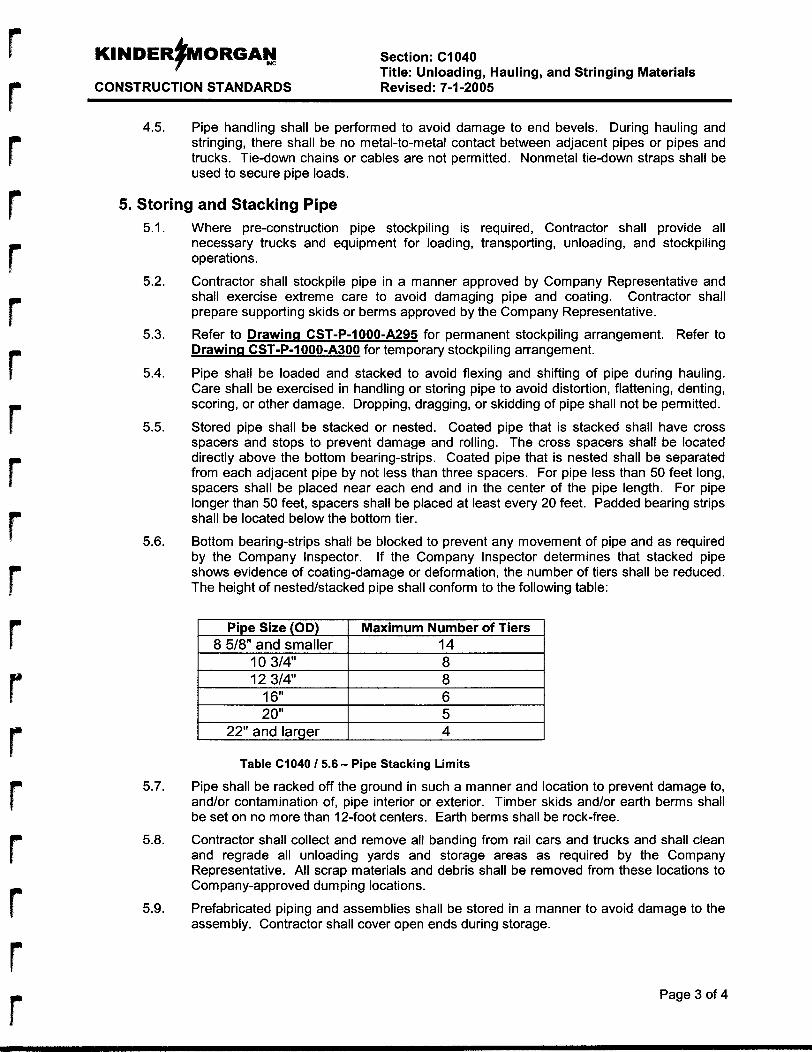
r
r r
KINDER#MORGAN INC Section: C1040
CONSTRUCTION STANDARDS Revised: 7-1-2005 Title: Unloading, Hauling, and Stringing Materials
4.5. Pipe handling shall be performed to avoid damage to end bevels. During hauling and stringing, there shall be no metal-to-metal contact between adjacent pipes or pipes and trucks. Tie-down chains or cables are not permitted. Nonmetal tie-down straps shall be used to secure pipe loads.
5. Storing and Stacking Pipe 5.1.
5.2.
5.3.
5.4.
5.5.
5.6.
5.7.
5.8.
5.9.
Where pre-construction pipe stockpiling is required, Contractor shall provide all necessary trucks and equipment for loading, transporting, unloading, and stockpiling operations.
Contractor shall stockpile pipe in a manner approved by Company Representative and shall exercise extreme care to avoid damaging pipe and coating. Contractor shall prepare supporting skids or berms approved by the Company Representative.
Refer to Drawinn CST-P-1 OOO-A295 for permanent stockpiling arrangement. Refer to Drawinn CST-P-1000-A300 for temporary stockpiling arrangement.
Pipe shall be loaded and stacked to avoid flexing and shifting of pipe during hauling. Care shall be exercised in handling or storing pipe to avoid distortion, flattening, denting, scoring, or other damage. Dropping, dragging, or skidding of pipe shall not be permitted.
Stored pipe shall be stacked or nested. Coated pipe that is stacked shall have cross spacers and stops to prevent damage and rolling. The cross spacers shall be located directly above the bottom bearing-strips. Coated pipe that is nested shall be separated from each adjacent pipe by not less than three spacers. For pipe less than 50 feet long, spacers shall be placed near each end and in the center of the pipe length. For pipe longer than 50 feet, spacers shall be placed at least every 20 feet. Padded bearing strips shall be located below the bottom tier.
Bottom bearing-strips shall be blocked to prevent any movement of pipe and as required by the Company Inspector. If the Company Inspector determines that stacked pipe shows evidence of coating-clamage or deformation, the number of tiers shall be reduced. The height of nested/stacked pipe shall conform to the following table:
I 12 3/4" I 8 I 6 5
22" and larger 4
Table C1040 / 5.6 - Piipe Stacking Limits
Pipe shall be racked off the ground in such a manner and location to prevent damage to, and/or contamination of, pipe interior or exterior. Timber skids and/or earth berms shall be set on no more than 12-foot centers. Earth berms shall be rock-free.
Contractor shall collect and remove all banding from rail cars and trucks and shall clean and regrade all unloading yards and storage areas as required by the Company Representative. All scrap mlaterials and debris shall be removed from these locations to Company-approved dumping locations.
Prefabricated piping and assemblies shall be stored in a manner to avoid damage to the assembly. Contractor shall cover open ends during storage.
Page 3 of 4
Section: C1040 Title: Unloading, Hauling, and Stringing Materials
CONSTRUCTION STANDARDS Revised: 7-1-2005
6. Damaged Pipe Any dents, gouges, scratches, or other similar defects found in pipe shall be brought to the attention of the Company Representative as soon as detected. Detrimental defects identified by the Company Representative shall not be accepted and shall be repaired or cut out of the line as directed, regardless or when or how they occurred. Grinding and/or hammering to remove defects within dented areas shall not be permitted.
7. Unloading and Shipping Delays 7.1. Contractor shall protect and indemnify the Company against any charge of demurrage,
storage or other charges inlcident to Contractor’s failure to promptly unload Company- supplied materials upon arrival at delivery points.
The Company shall not be liiable for costs due to shipping delays except as provided in the Scope of Work.
7.2.
8. Surplus At completion of work, Contractor shall collect all (new or used) surplus Company-furnished pipe, valves, fittings, appurtenances, and/or any other material. Contractor shall load, haul, transport, unload, and place all such surplus materials in storage areas designated by the Scope of Work or approved by the Company Representative.
Page 4 of 4
APPENDIX G
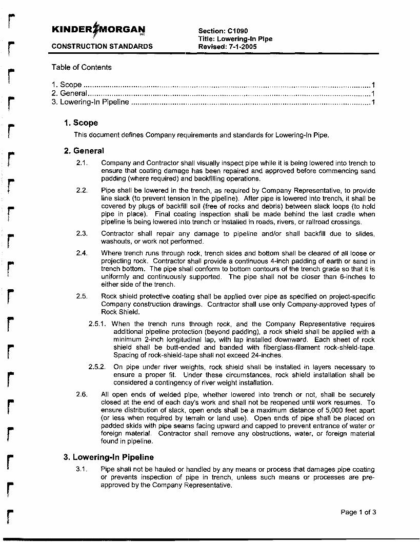
r Section: C1090 Title: Lowering-In Pipe
CONSTRUCTION STANDARDS Revised: 7-1-2005
Table of Contents
1. Scope ..................................................................................................................................... I 2. General ................................................................................................................................... 1 3. Lowering-In Pipeline ............................................................................................................... 1
I. Scope This document defines Company requirements and standards for Lowering-In Pipe.
2. General 2.1. Company and Contractor shall visually inspect pipe while it is being lowered into trench to
ensure that coating damage has been repaired and approved before commencing sand padding (where required) and backfilling operations.
Pipe shall be lowered in the trench, as required by Company Representative, to provide line slack (to prevent tension in the pipeline). After pipe is lowered into trench, it shall be covered by plugs of backfill soil (free of rocks and debris) between slack loops (to hold pipe in place). Final coaling inspection shall be made behind the last cradle when pipeline is being lowered into trench or installed in roads, rivers, or railroad crossings.
2.3. Contractor shall repair any damage to pipeline and/or shall backfill due to slides, washouts, or work not performed.
2.4. Where trench runs through rock, trench sides and bottom shall be cleared of all loose or projecting rock. Contractor shall provide a continuous 4-inch padding of earth or sand in trench bottom. The pipe sh,all conform to bottom contours of the trench grade so that it is uniformly and continuously supported. The pipe shall not be closer than 6-inches to either side of the trench.
Rock shield protective coating shall be applied over pipe as specified on project-specific Company construction drawings. Contractor shall use only Company-approved types of Rock Shield.
2.5.1. When the trench runs through rock, and the Company Representative requires additional pipeline protection (beyond padding), a rock shield shall be applied with a minimum 2-inch longitudinal lap, with lap installed downward. Each sheet of rock shield shall be butt-enlded and banded with fiberglass-filament rock-shield-tape. Spacing of rock-shield-tape shall not exceed 24-inches.
On pipe under river weights, rock shield shall be installed in layers necessary to ensure a proper fit. Ulnder these circumstances, rock shield installation shall be considered a contingency of river weight installation.
All open ends of welded pipe, whether lowered into trench or not, shall be securely closed at the end of each di3y’s work and shall not be reopened until work resumes. To ensure distribution of slack, open ends shall be a maximum distance of 5,000 feet apart (or less when required by terrain or land use). Open ends of pipe shall be placed on padded skids with pipe seanis facing upward and capped to prevent entrance of water or foreign material. Contractalr shall remove any obstructions, water, or foreign material found in pipeline.
2.2.
2.5.
2.5.2.
2.6.
3. Lowering-In Pipeline 3.1. Pipe shall not be hauled or handled by any means or process that damages pipe coating
or prevents inspection of pipe in trench, unless such means or processes are pre- approved by the Company Representative.
Page 1 of 3
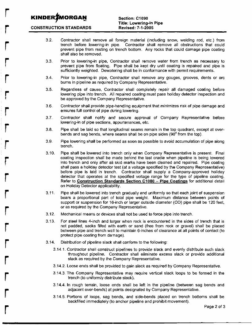
KINDER~ORGAN Mc Section: ClO90
CONSTRUCTION STANDARDS Revised: 7-1-2005 Title: Lowering-In Pipe
3.2.
3.3.
3.4.
3.5.
3.6.
3.7.
3.8.
3.9.
3.10.
3.1 1.
3.12.
3.1 3.
3.14.
Contractor shall remove ad foreign material (including snow, welding rod, etc.) from trench before lowering-in pipe. Contractor shall remove all obstructions that could prevent pipe from resting on trench bottom. Any rocks that could damage pipe coating shall also be removed.
Prior to lowering-in pipe, Contractor shall remove water from trench as necessary to prevent pipe from floating. Pipe shall be kept dry until coating is repaired and pipe is sufficiently weighted. Dewatering shall be in conformance with permit requirements.
Prior to lowering-in pipe, Contractor shall remove any gouges, grooves, dents or arc burns in pipeline as required by Company Representative.
Regardless of cause, Contractor shall completely repair all damaged coating before lowering pipe into trench. 1\11 repaired coating must pass holiday detector inspection and be approved by the Company Representative.
Contractor shall provide pipe-handling equipment that minimizes risk of pipe damage and ensures full control of pipe during lowering.
Contractor shall notify and secure approval of Company Representative before lowering-in of pipe sections, appurtenances, etc.
Pipe shall be laid so that longitudinal seams remain in the top quadrant, except at over- bends and sag bends, where seams shall be on pipe sides (90' from the top).
Pipe lowering shall be performed as soon as possible to avoid accumulation of pipe along trench.
Pipe shall be lowered into trench only when Company Representative is present. Final coating inspection shall be made behind the last cradle when pipeline is being lowered into trench and only after all skid marks have been cleaned and repaired. Pipe coating shall pass a holiday detector test (at a voltage specified by the Company Representative) before pipe is laid in trench. Contractor shall supply a Company-approved holiday detector that operates at the specified voltage range for the type of pipeline coating. Refer to Construction Standards Section C1080 - Pipe Coatinas for additional detail on Holiday Detector applicability.
Pipe shall be lowered into trench gradually and uniformly so that each joint of suspension bears a proportional part of total pipe weight. Maximum distance between points of support or suspension for 16-inch or larger outside diameter (OD) pipe shall be 120 feet, or as required by the Company Representative.
Mechanical means or devices shall not be used to force pipe into trench.
For steel lines 4-inch and larger when rock is encountered in the sides of trench that is not padded, sacks filled with earth or sand (free from rock or gravel) shall be placed between pipe and trench wad to maintain 6-inches of clearance at all points of contact (to protect pipe coating from daimage).
Distribution of pipeline slack shall conform to the following:
3.14.1. Contractor shall construct pipelines to provide slack and evenly distribute such slack throughout pipeline. Clontractor shall eliminate excess slack or provide additional slack as required by the Company Representative.
3.14.2. Loose ends shall be provided to gain slack as required by Company Representative.
3.14.3. The Company Representative may require vertical slack loops to be formed in the
3.14.4. In rough terrain, loose ends shall be left in the pipeline (between sag bends and
3.14.5. Portions of loops, sag bends, and side-bends placed on trench bottoms shall be
Page 2 of 3
trench (to uniformly distribute slack).
adjacent over-bends) at points designated by Company Representative.
backfilled immediately (to anchor pipeline and prohibit movement).
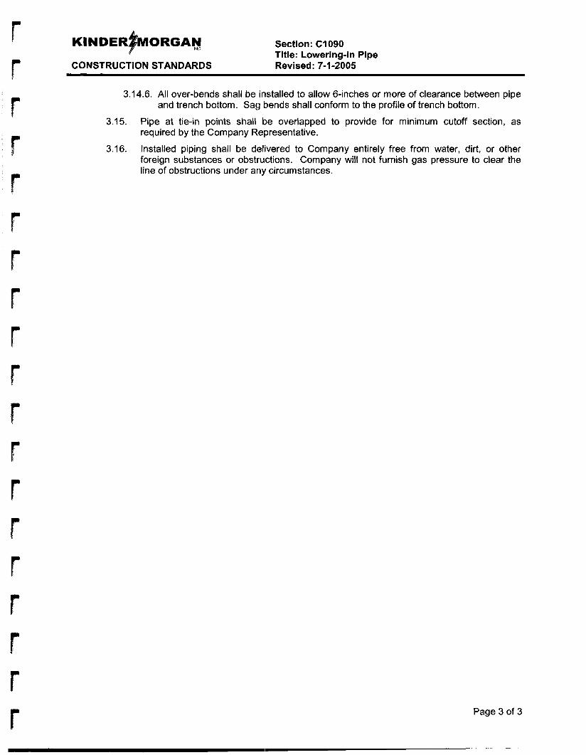
Section: C1090 Title: Lowering-In Pipe
CONSTRUCTION STANDARDS Revised: 7-1-2005
3.14.6. All over-bends shall be installed to allow 6-inches or more of clearance between pipe and trench bottom. Sag bends shall conform to the profile of trench bottom.
Pipe at tie-in points shall be overlapped to provide for minimum cutoff section, as required by the Company Representative.
Installed piping shall be delivered to Company entirely free from water, dirt, or other foreign substances or obstructions. Company will not furnish gas pressure to clear the line of obstructions under any circumstances.
3.15.
3.16.
Page 3 of 3
b
r r
APPENDIX H
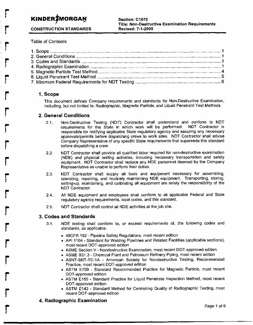
Section: C1070 Title: Non-Destructive Examination Requirements
CONSTRUCTION STANDARDS Revised: 7-1-2005
Table of Contents
1. Scope ...................................................................................................................................... 2. General Conditions ................................................................................................................. 1 3. Codes and Standards ............................................................................................................. 1 4. Radiographic Examination ...................................................................................................... 1 5. Magnetic Particle Test Method ................................................................................................ 4 6. Liquid Penetrant Test Method ................................................................................................. 5 7. Minimum Federal Requirements for NDT Testing ................................................................... 6
1.
2.
3.
Scope This document defines Company requirements and standards for Non-Destructive Examination, including, but not limited to: Radiograiphic, Magnetic Particle, and Liquid Penetrant Test Methods.
General Conditions 2.1.
2.2.
2.3.
2.4.
2.5.
Non-Destructive Testing (IVDT) Contractor shall understand and conform to NDT requirements for the State in which work will be performed. NDT Contractor is responsible for notifying applicable State regulatory agency and securing any necessary approvals/permits before dispatching crews to work sites. NDT Contractor shall advise Company Representative of any specific State requirements that supersede this standard before dispatching a crew.
NDT Contractor shall providle all qualified labor required for non-destructive examination (NDE) and physical testing activities, including necessary transportation and safety equipment. NDT Contractor shall replace any NDE personnel deemed by the Company Representative as unable to perform their duties.
NDT Contractor shall supply all tools and equipment necessary for assembling, operating, repairing, and routinely maintaining NDE equipment. Transporting, storing, setting-up, maintaining, and calibrating all equipment are solely the responsibility of the NDT Contractor.
All NDE equipment and employees shall conform to all applicable Federal and State regulatory agency requirements, local codes, and this standard.
NDT Contractor shall control all NDE activities at the job site.
Codes and Standards 3.1. NDE testing shall conform to, or exceed requirements of, the following codes and
standards, as applicable:
49CFR 192 - Pipeline Safety Regulations, most recent edition API 1 104 - Standard for Welding Pipelines and Related Facilities (applicable sections), most recent DOT-approved edition ASME Section V - Nondestructive Examination, most recent DOT-approved edition ASME B31.3 - Chemical Flant and Petroleum Refinery Piping, most recent edition ASNT-SNT-TC-1 A - American Society for Nondestructive Testing, Recommended Practice, most recent DOT-approved edition ASTM E709 - Standard Recommended Practice for Magnetic Particle, most recent DOT-approved edition ASTM E165 - Standard Practice for Liquid Penetrate Inspection Method, most recent DOT-a p proved edition ASTM E142 - Standard Method for Controlling Quality of Radiographic Testing, most recent DOT-approved edition
4. Radiographic Examination Page 1 of 6
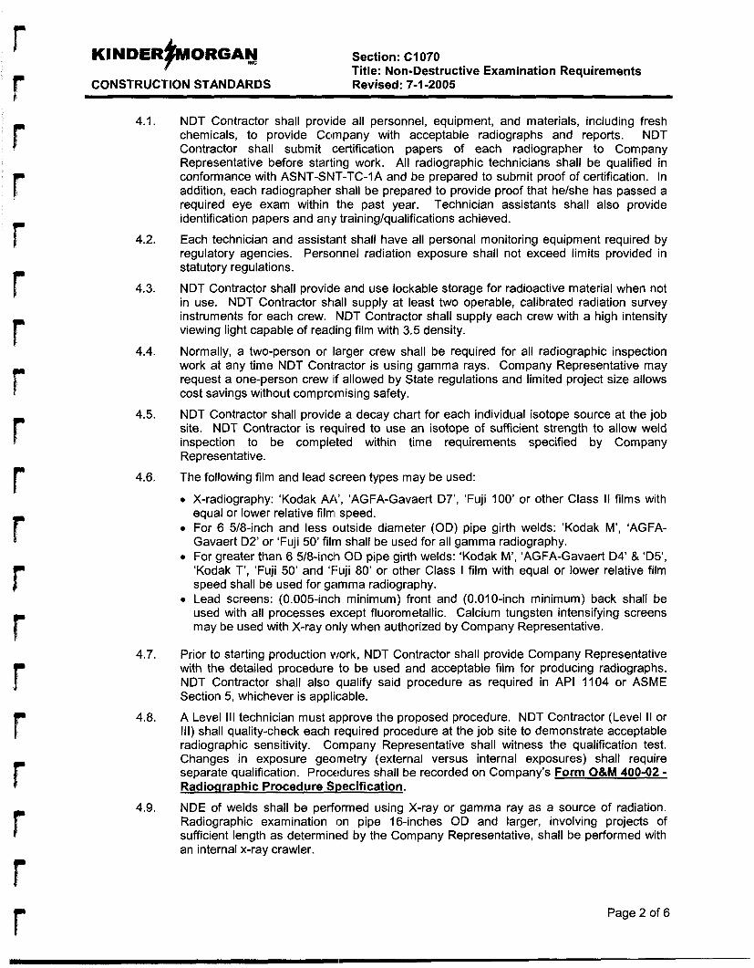
I
r
r
r
KINDER#MORGA~ Section: C1070
CONSTRUCTION STANDARDS Revised: 7-1-2005 Title: Non-Destructive Examination Requirements
4.1.
4.2.
4.3.
4.4.
4.5.
4.6.
4.7.
4.8.
4.9.
NDT Contractor shall provide all personnel, equipment, and materials, including fresh chemicals, to provide Cclmpany with acceptable radiographs and reports. NDT Contractor shall submit certification papers of each radiographer to Company Representative before starting work. All radiographic technicians shall be qualified in conformance with ASNT-SNT-TC-1A and be prepared to submit proof of certification. In addition, each radiographer shall be prepared to provide proof that helshe has passed a required eye exam within the past year. Technician assistants shall also provide identification papers and any training/qualifications achieved.
Each technician and assistant shall have all personal monitoring equipment required by regulatory agencies. Personnel radiation exposure shall not exceed limits provided in statutory regulations.
NDT Contractor shall providle and use lockable storage for radioactive material when not in use. NDT Contractor shall supply at least two operable, calibrated radiation survey instruments for each crew. NDT Contractor shall supply each crew with a high intensity viewing light capable of reading film with 3.5 density.
Normally, a two-person or larger crew shall be required for all radiographic inspection work at any time NDT Contractor is using gamma rays. Company Representative may request a one-person crew if allowed by State regulations and limited project size allows cost savings without compralmising safety.
NDT Contractor shall provide a decay chart for each individual isotope source at the job site. NDT Contractor is required to use an isotope of sufficient strength to allow weld inspection to be completed within time requirements specified by Company Representative.
The following film and lead screen types may be used:
X-radiography: ‘Kodak AA’, ‘AGFA-Gavaert D7’, ’Fuji 100’ or other Class II films with equal or lower relative film1 speed. For 6 5/8-inch and less outside diameter (OD) pipe girth welds: ‘Kodak M’, ‘AGFA- Gavaert D2’ or ‘Fuji 50’ filrn shall be used for all gamma radiography. For greater than 6 518-inch OD pipe girth welds: ‘Kodak M’, ‘AGFA-Gavaert D4’ & ‘D5’, ‘Kodak T’, ‘Fuji 50’ and ‘Fuji 80’ or other Class I film with equal or lower relative film speed shall be used for gamma radiography. Lead screens: (0.005-inch minimum) front and (0.01 0-inch minimum) back shall be used with all processes except fluorometallic. Calcium tungsten intensifying screens may be used with X-ray only when authorized by Company Representative.
Prior to starting production work, NDT Contractor shall provide Company Representative with the detailed procedure to be used and acceptable film for producing radiographs. NDT Contractor shall also qualify said procedure as required in API 1104 or ASME Section 5, whichever is applilcable.
A Level Ill technician must alpprove the proposed procedure. NDT Contractor (Level It or Ill) shall quality-check each required procedure at the job site to demonstrate acceptable radiographic sensitivity. Company Representative shall witness the qualification test. Changes in exposure geometry (external versus internal exposures) shall require separate qualification. Procedures shall be recorded on Company’s Form O&M 400-02 - Radiographic Procedure Siaecification.
NDE of welds shall be performed using X-ray or gamma ray as a source of radiation. Radiographic examination on pipe 16-inches OD and larger, involving projects of sufficient length as determined by the Company Representative, shall be performed with an internal x-ray crawler.
Page 2 of 6
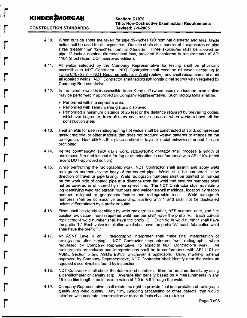
KINDERFORGAY Section: C1070
CONSTRUCTION STANDARDS Revised: 7-1 -2005 Title: Non-Destructive Examination Requirements
4.10.
4.1 1.
4.12.
4.13.
4.14.
4.15.
4.16.
4.1 7.
4.18.
4.19.
When outside shots are taken for pipe 12-inches OD nominal diameter and less, single belts shall be used for all exposures. Outside shots shall consist of 4 exposures on pipe sizes greater than 12-inches nominal diameter. Three exposures shall be allowed on pipe 12-inches nominal diaimeter and less, provided it conforms to requirements of API 11 04 (most recent DOT-approved edition).
All welds selected by the Company Representative for testing shall be physically accessible to NDT Contractor. NDT Contractor shall examine all welds according to Table C1070 / 7. - NDT Rewirements for a Weld (below), and shall reexamine and mark all repaired welds. NDT Contractor shall radiograph longitudinal seams when required by Com pan y Representative.
In the event a weld is inacclessible to an X-ray unit (when used), an isotope examination may be performed if approved by Company Representative. Such radiographs shall be:
0 Performed within a separate area. 0 Performed with safety warning signs displayed. 0 Performed a minimum dis.tance of 25 feet or the distance required by prevailing codes,
whichever is greater, from all other construction areas or when workers have left the construction area.
Heat shields for use in radiographing hot welds shall be constructed of solid, compressed gasket material or other material that does not produce weave patterns or images on the radiograph. Heat shields that place a sheet or layer of metal between pipe and film are prohibited.
Before commencing each clay’s work, radiographic operator shall process a length of unexposed film and inspect lit for fog or deterioration in conformance with API 11 04 (most recent DOT-approved edition).
While performing the radiographic work, NDT Contractor shall assign and apply weld radiograph numbers to the body of the coated pipe. Welds shall be numbered in the direction of travel or pipe laying. Weld radiograph numbers shall be painted or marked on the work side of coated pipe at a distance from the weld that ensures numbers shall not be covered or obscured by other operations. The NDT Contractor shall maintain a log identifying weld radiograph numbers and welder stencil markings, location by station number, milepost or geographic feature and radiographic result. Weld radiograph numbers shall be consecutive ascending, starting with 1 and shall not be duplicated unless differentiated by a prefix or suffix.
Films shall be clearly identified by weld radiograph number, AFE number, date, and film position indication. Each repaired weld number shall have the prefix ‘R.’ Each cut-out replacement weld number shall have the prefix ‘C.’ Each tie-in weld number shall have the prefix IT.’ Each valve installation weld shall have the prefix ‘V.’ Each fabrication weld shall have the prefix ‘F.’
An ASNT Level II or Ill radiographic interpreter shall make final interpretation of radiographs after ‘drying’. NDT Contractor may interpret ‘wet‘ radiographs, when requested by Company Representative, to expedite NDT Contractor’s work. All radiographic procedures and interpretations shall be in conformance with API 1 104 or ASME Section 5 and ASME 831.3, whichever is applicable. Using marking material approved by Company Representative, NDT Contractor shall identify near the welds all rejected discontinuities found by inspection.
NDT Contractor shall check Ithe determined number of films for required density by using a densitometer or density stirip. Average film density based on 4 measurements in any 18-inch film length should have a value of 2.0 to 3.5 through the weld.
Company Representative Shidl retain the right to provide final interpretation of radiograph quality and weld quality. Any film, including processing or other defects, that would interfere with accurate interpretation or mask defects shall be re-taken.
Page 3 of 6

r
r
r
Section: C1070 Title: Non-Destructive Examination Requirements
CONSTRUCTION STANDARDS Revised: 7-1-2005
4.20.
4.21.
4.22.
4.23.
NDT Contractor shall provide Company Representative with weld examination reports as required on forms supplied by NDT Contractor. Daily reports shall summarize number of girth welds made (daily and project total), number of girth welds radiographed (daily and project total), number of welds rejected (daily and project total) and disposition of rejects (daily only). By start of the next workday, NDT Contractor shall provide Company Representative with original daily radiographic reports on NDT Contractor-supplied forms.
Film processed in connection with all radiographic examination shall be available to Company Representative at all times for inspection and examination. NDT Contractor shall retain title to all radiographs during the project.
NDT Contractor shall have facilities for processing and interpreting film at the job site, unless approved otherwise by the Company Representative. NDT Contractor shall roll and box film daily, identified (with job name, AFE number, and date), and deliver film to Company Representative ai the location where work is performed.
NDT Contractor shall remove from work site all refuse and debris relating to its work and dispose of at locations approved by Company Representative.
5. Magnetic Particle Test Methold 5.1.
5.2.
5.3.
5.4.
5.5.
5.6.
5.7.
NDT Contractor shall submit a copy of the magnetic particle testing procedure for the ‘yoke’ method for review anld approval of the Company Representative. Prior to the start of work, NDT Contractor shall submit certification papers - that all personnel performing testing are qualified and certified in conformance with SNT-TC-1 A, to Company Representative.
Magnetization equipment may only be an AC/DC yoke. The current induction method is not allowed. Only dry, contrasting color powder ferromagnetic particles shall be used. Company Representative shall approve equipment for powder application during the practical demonstration. NDT Contractor shall provide a magnetic field indicator (ASTM E709) during procedure qualification and while performing the work.
Each procedure shall be qualified at the job site by NDT Contractor demonstrating procedure’s ability to detect known defect indications. A Company Representative shall witness qualification tests.
Poles shall be placed in direct contact with the surface being examined. The continuous magnetization method shall be used. Two separate examinations shall be made on each area. When length of the area being examined exceeds pole spacing, successive examinations shall be overl,apped by I-inch. Broad areas of particle accumulation that may mask indications of discontinuities shall be removed and the area cleaned and reexamined . Any areas suspected of having ‘near surface’ discontinuities shall be tested using the AC yoke method.
Discontinuities in excess of those allowed by the referenced Codes and Standards shall not be accepted. Examinations to determine complete removal of defects during welding or grinding repairs shall show that the entire defect was removed. Any repairs shall be reexamined.
NDT Contractor shall complete and provide Company Representative with daily reports. NDT Contractor’s test repoirt shall reference the magnetic particle procedure used for testing .
Page 4 of 6
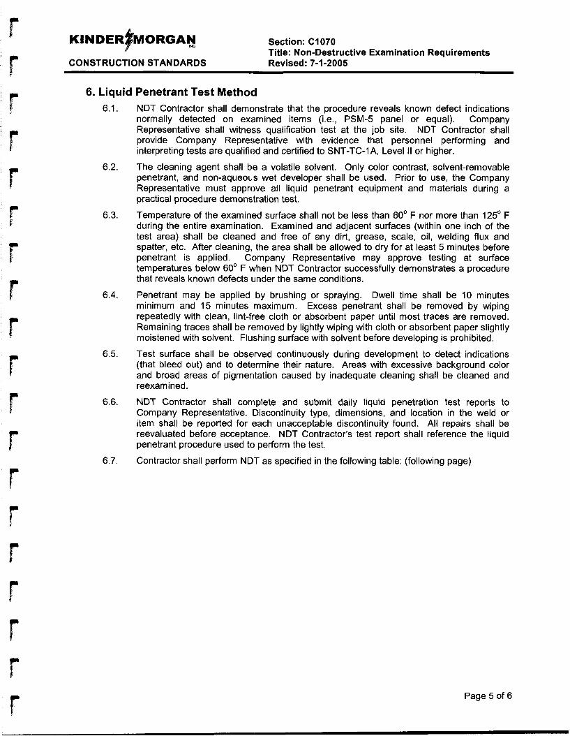
Section: C1070 Title: Non-Destructive Examination Requirements
CONSTRUCTION STANDARDS Revised: 7-1-2005
6. Liquid Penetrant Test Metho(d 6.1.
6.2.
6.3.
6.4.
6.5.
6.6.
6.7.
NDT Contractor shall demonstrate that the procedure reveals known defect indications normally detected on examined items (i.e., PSM-5 panel or equal). Company Representative shall witness qualification test at the job site. NDT Contractor shall provide Company Representative with evidence that personnel performing and interpreting tests are qualified and certified to SNT-TC-IA, Level II or higher.
The cleaning agent shall be a volatile solvent. Only color contrast, solvent-removable penetrant, and non-aqueouls wet developer shall be used. Prior to use, the Company Representative must approve all liquid penetrant equipment and materials during a practical procedure demonstration test.
Temperature of the examinled surface shall not be less than 60' F nor more than 125' F during the entire examination. Examined and adjacent surfaces (within one inch of the test area) shall be cleaned and free of any dirt, grease, scale, oil, welding flux and spatter, etc. After cleaning, the area shall be allowed to dry for at least 5 minutes before penetrant is applied. Clompany Representative may approve testing at surface temperatures below 60' F when NDT Contractor successfully demonstrates a procedure that reveals known defects under the same conditions.
Penetrant may be applied by brushing or spraying. Dwell time shall be 10 minutes minimum and 15 minutes maximum. Excess penetrant shall be removed by wiping repeatedly with clean, lint-free cloth or absorbent paper until most traces are removed. Remaining traces shall be removed by lightly wiping with cloth or absorbent paper slightly moistened with solvent. Flushing surface with solvent before developing is prohibited.
Test surface shall be observed continuously during development to detect indications (that bleed out) and to determine their nature. Areas with excessive background color and broad areas of pigmentation caused by inadequate cleaning shall be cleaned and reexamined.
NDT Contractor shall complete and submit daily liquid penetration test reports to Company Representative. IDiscontinuity type, dimensions, and location in the weld or item shall be reported for each unacceptable discontinuity found. All repairs shall be reevaluated before acceptance. NDT Contractor's test report shall reference the liquid penetrant procedure used to perform the test.
Contractor shall perform NDT as specified in the following table: (following page)
Page 5 of 6
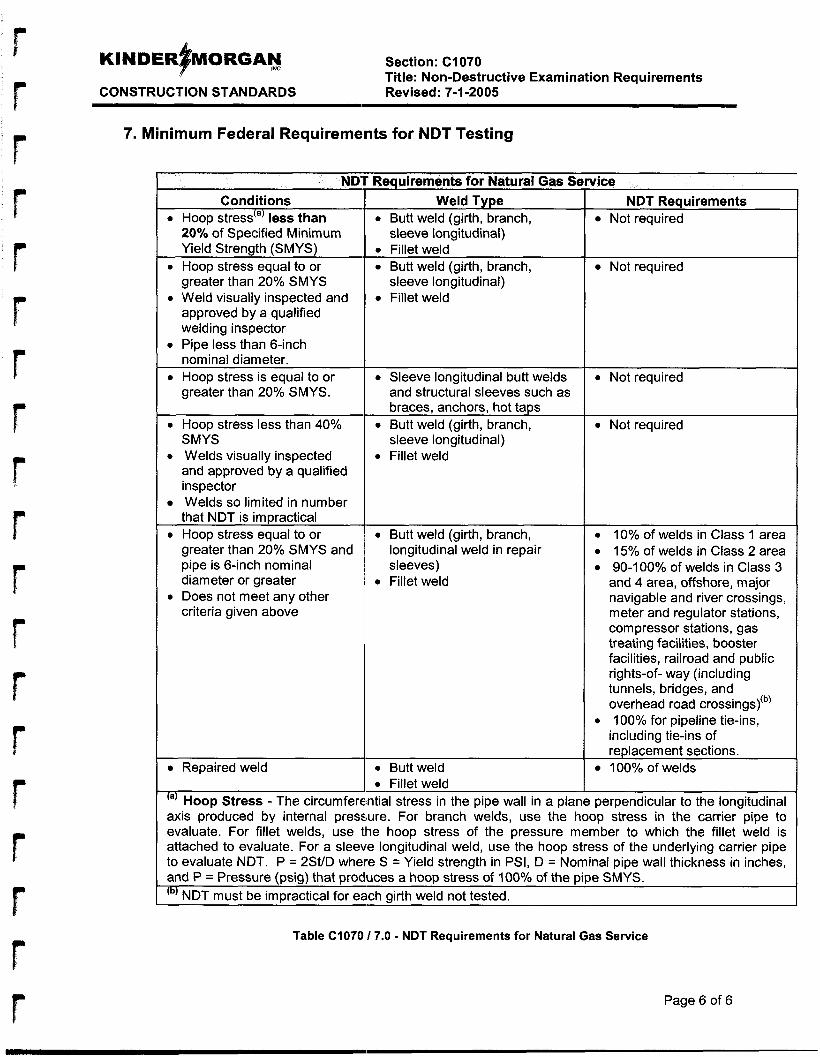
Section: C1070 Title: Non-Destructive Examination Requirements
CONSTRUCTION STANDARDS Revised: 7-1 -2005
7. Minimum Federal Requirements for NDT Testing
NDT Requirements for Natural Gas Sc Conditions
0 Hoop stress(a) less than 20% of Specified Minimum Yield Strength (SMYS)
0 Hoop stress equal to or greater than 20% SMYS
0 Weld visually inspected and approved by a qualified welding inspector
0 Pipe less than 6-inch nominal diameter.
0 Hoop stress is equal to or greater than 20% SMYS.
0 Hoop stress less than 40% SMYS
0 Welds visually inspected and approved by a qualified inspector Welds so limited in number that NDT is impractical
0 Hoop stress equal to or greater than 20% SMYS and pipe is 6-inch nominal diameter or greater
0 Does not meet any other criteria given above
Repaired weld
Weld Type
sleeve longitudinal) 0 Butt weld (girth, branch,
0 Fillet weld 0 Butt weld (girth, branch,
0 Fillet weld sleeve longitudinal)
0 Sleeve longitudinal butt welds and structural sleeves such as braces, anchors, hot taps
sleeve longitudinal) 0 Butt weld (girth, branch,
0 Fillet weld
0 Butt weld (girth, branch, longitudinal weld in repair sleeves)
0 Fillet weld
0 Butt weld 0 Fillet weld
vice NDT Reauirements
Not required
Not required
0 Not required
0 Not required
0 10% of welds in Class 1 area 0 15% of welds in Class 2 area 0 90-100% of welds in Class 3
and 4 area, offshore, major navigable and river crossings, meter and regulator stations, compressor stations, gas treating facilities, booster facilities, railroad and public rights-of- way (including tunnels, bridges, and overhead road crossings)@)
0 100% for pipeline tie-ins, including tie-ins of replacement sections. 100% of welds
‘a) Hoop Stress - The circumferential stress in the pipe wall in a plane perpendicular to the longitudinal axis produced by internal pressure. For branch welds, use the hoop stress in the carrier pipe to evaluate. For fillet welds, use tlhe hoop stress of the pressure member to which the fillet weld is attached to evaluate. For a sleeve longitudinal weld, use the hoop stress of the underlying carrier pipe to evaluate NDT. P = 2St/D where S = Yield strength in PSI, D = Nominal pipe wall thickness in inches, and P = Pressure (psig) that produces a hoop stress of 100°/~ of the pipe SMYS.
NDT must be impractical for each girth weld not tested. (b)
Table C1070 17.0 - NDT Requirements for Natural Gas Service
Page 6 of 6

APPENDIX I
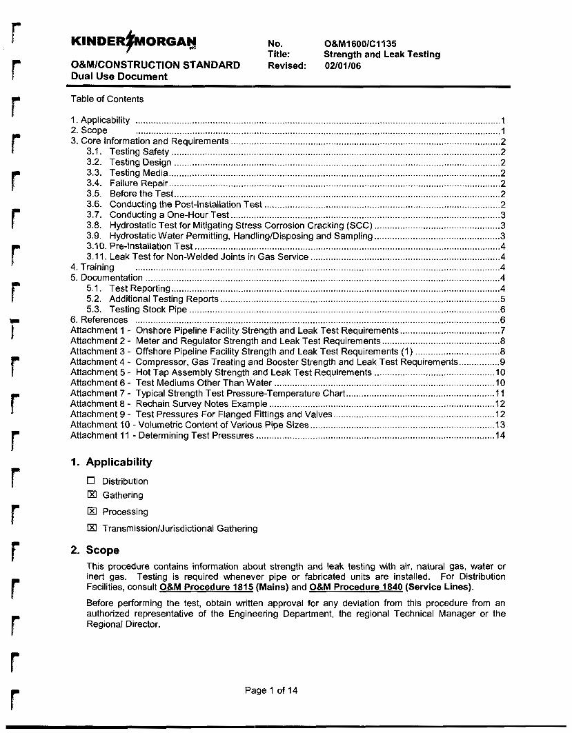
KINDER~ORGABJ No . O&M1600/C1135
O&M/CONSTRUCTION STANDARD Revised: 02/01/06 Dual Use Document
Title: Strength and Leak Testing
Table of Contents
1 . Applicability .............................................................................................................................................. 1 2 . Scope .............................................................................................................................................. 1
Testing Safety ................................................................................................................................ 2 3 . Core Information and Requirements ......................................................................................................... 2
3.1 . 3.2. Testing Design ............................................................................................................................... 2 3.3. 3.4. 3.5. 3.6. 3.7. 3.8. 3.9. 3.10. 3.1 1 .
Testing Media ................................................................................................................................. 2 Failure Repair ................................................................................................................................. 2 Before the Test ............................................................................................................................... 2 Conducting the Post-Installation Test ............................................................................................ 2 Conducting a One-Hour Test ......................................................................................................... 3 Hydrostatic Test for Mitigating Stre:ss Corrosion Cracking (SCC) ................................................. 3 Hydrostatic Water Permitting, Hancfling/Disposing and Sampling ................................................. 3 Pre-Installation Test ....................................................................................................................... 4 Leak Test for Non-Welded Joints in Gas Service .......................................................................... 4
4 . Training .............................................................................................................................................. 4 5 . Documentation .......................................................................................................................................... 4
5.1. Test Reporting ................................................................................................................................ 4 5.2. Additional Testing Reports ............................................................................................................. 5 5.3. Testing Stock Pipe ......................................................................................................................... 6
Attachment 1 . Onshore Pipeline Facility Strength and Leak Test Requirements ....................................... 7 Attachment 2 . Meter and Regulator Strength and Leak Test Requirements .............................................. 8
6 . References .............................................................................................................................................. 6
Attachment 3 . Offshore Pipeline Facility Strength and Leak Test Requirements (1) ................................. 8 Attachment 4 . Compressor, Gas Treating and Booster Strength and Leak Test Requirements ................ 9
Attachment 7 . Typical Strength Test Pressure-Temperature Chart .......................................................... 11 Attachment 8 . Rechain Survey Notes Example ........................................................................................ 12
Attachment 5 . Hot Tap Assembly Strength ;and Leak Test Requirements ............................................... 10 Attachment 6 . Test Mediums Other Than Water ...................................................................................... 10
Attachment 9 . Test Pressures For Flanged Fittings and Valves ............................................................... 12 Attachment 10 . Volumetric Content of Various Pipe Sizes ........................................................................ 13 Attachment 1 1 . Determining Test Pressures ............................................................................................. 14
1 . Applicability
0 Distribution El Gathering
El Processing
El TransmissionlJurisdictional Gathering
2 . Scope This procedure contains information about strength and leak testing with air. natural gas. water or inert gas . Testing is required whenever pipe or fabricated units are installed . For Distribution Facilities. consult 0&M Procedure 1815 (Mains) and O&M Procedure 1840 (Service Lines) . Before performing the test. obtain written approval for any deviation from this procedure from an authorized representative of the Engineering Department. the regional Technical Manager or the Regional Director .
Page 1 of 14
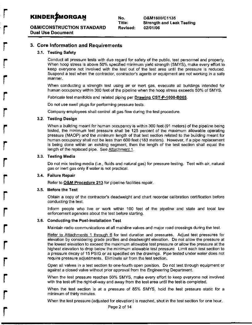
KINDER~ORGAN IxC No. O&M160O/CI 135
O&M/CONSTRUCTION STANDARD Revised: 02/01/06 Dual Use Document
Title: Strength and Leak Testing
3. Core Information and Requiremlents 3.1.
3.2.
3.3.
3.4.
3.5.
3.6.
Testing Safety
Conduct all pressure tests with due regard for safety of the public, test personnel and property. When hoop stress is above 50% specified minimum yield strength (SMYS), make every effort to keep everyone not involved with the test out of the test area until the pressure is reduced. Suspend a test when the contractor, contractor's agents or equipment are not working in a safe manner.
When conducting a strength test using air or inert gas, evacuate all buildings intended for human occupancy within 300 feet of the pipeline when the hoop stress exceeds 50% of SMYS.
Fabricate test manifolds and related piping per Drawinci CST-P-1000-BO65.
Do not use swell plugs for performing pressure tests.
Company employees shall control (all gas flow during the test procedure.
Testing Design
When a building meant for human {occupancy is within 300 feet (91 meters) of the pipeline being tested, the minimum test pressure shall be 125 percent of the maximum allowable operating pressure (MAOP) and the minimurn length of that test section related to the building meant for human occupancy shall not be less than 600 feet (183 meters). However, if a pipe replacement is being done within an existing segment, then the length of the test section shall equal the length of the replaced pipe. See Bltachment 1.
Testing Media
Do not mix testing media (Le., fluids and natural gas) for pressure testing. Test with air, natural gas or inert gas only if water is not practical.
Failure Repair
Refer to O&M Procedure 213 for pipeline facilities repair.
Before the Test
Obtain a copy of the contractor's deadweight and chart recorder calibration certification before conducting the test.
Inform people who live or work within 100 feet of the pipeline and state and local law enforcement agencies about the test before starting.
Conducting the Post-Installation Test
Maintain radio communications at all mainline valves and major road crossings during the test.
Refer to Attachments 1 throuqh 6 for test duration and pressures. Adjust test pressures for elevation by considering grade profiles and deadweight elevation. Do not allow the pressure at the lowest elevation to exceed the maximum allowable test pressure or allow the pressure at the highest elevation to drop below the minimum allowable test pressure. Limit each test section to a pressure decay of 15 PSlG or as specified on the drawings. Pipe tested under water does not require pressure adjustments. Eliminate air from the test section.
Open all valves in a test section to one-fourth open position. Do not test through equipment or against a closed valve without prior approval from the Engineering Department.
When the test pressure reaches 50% SMYS, make every effort to keep everyone not involved with the test off the right-of-way and away from the test area until the test is completed.
When the test section is at a pressure of 85% SMYS, hold the test pressure static for a minimum of thirty minutes.
When the test pressure (adjusted for elevation) is reached, shut in the test section for one hour. Page 2 of 14
KINDERFORGAY No. O&M1600/C1135
O&M/CONSTRUCTION STANDARD Revised: 02/01/06 Dual Use Document
Title: Strength and Leak Testing
Record the deadweight readings every ten minutes during this hour Do not re-pressure the test during this hour Pressure can be bled off during this hour so the maximum pressure (adjusted for elevation) is not exceeded
If the pressure drops below the minimum pressure during this hour, repair the leaks and begin the hour-long test again until the pressure holds between the limits.
After a successful one-hour shut-in period, re-pressure the test section to the required test pressure (adjusted for elevation).
During the next seven hours, maintain the pressure between the maximum and minimum allowable test pressures. Record deadweight pressures every thirty minutes and before and after each re-pressuring or bleed-down period.
Once the test is completed, run a squeegee, ball or polyethylene pig to dewater the pipeline. Run the pig as many times as necessary.
Report all gas lost as a result of testing on OMl000-05, Gas Lost Report.
3.7. Conducting a One-Hour Test
Steel lines with MAOPs that prodluces hoop stresses less than 30% SMYS may be strength- tested for one hour (see Attachmentu).
When testing, apply the pressure in the test segment in increments equal to 25% of the total test pressure. At the end of each increment, maintain the pressure while checking the test segment for leaks.
When the test pressure (adjusted for elevation) is reached, maintain the pressure in the test segment at or above the test pressure for at least one hour.
3.8. Hydrostatic Test for Mitigating Stress Corrosion Cracking (SCC)
The spike test is an assessment method for SCC conducted during the initial hour of an eight- hour hydrostatic test. The highest possible spike test pressure is desired (up to 110% SMYS), provided the pipe is not permanently bulged. In a high consequence area (HCA), a one-hour spike test by itself cannot be used as an assessment method for SCC unless the Office of Pipeline Safety (OPS) is notified 180 days in advance (see the Pipeline lnteqrity Management Proqram, Section Eight).
When conducting a hydrostatic test for mitigating SCC as prescribed in O&M Procedure 917, the following special eight-hour tesl. requirements apply:
0 For the first hour, keep the minimum test pressure at least 100% SMYS of the lowest strength pipe and the maximum test pressure at less than or equal to 110% SMYS of the lowest strength pipe (adjusted for elevation). Do not re-pressure during the one-hour spike test. Pressure can be bled off during this hour so the maximum pressure is not exceeded. Maintain the minimum test pressure at a minimum of 93% SMYS of the lowest strength pipe and the maximum test pressure at less than or equal to 100% SMYS of the lowest strength pipe for seven hours. See further details in this procedure.
0
0
3.9. Hydrostatic Water Permitting, HandIinglDisposing and Sampling
When conducting a hydrostatic test, consider:
0 The suitability of fill water 0 Compliance with all fill and discharge permit requirements 0 Handling and disposing of any pre-pig fluids
Page 3 of 14
KINDERFORGAN mc No. O&MI 600/C1135
O&M/CONSTRUCTION STANDARD Revised: 02/01/06 Dual Use Document
Title: Strength and Leak Testing
Contact the Environmental, Health and Safety Department (EHS) well in advance of any hydrotesting. EHS will help securse the necessary uptake and discharge permits and determine if any water testing and erosion control is required. Requirements vary by state.
Submit the hydrostatic discharge water lab analyses to EHS, which will submit them to the appropriate state agency.
Collect and test any pre-hydrostatic fluids found during hydrostatic test activity to determine disposal options. Contact EHS for help in disposing of the fluid.
3.10. Pre-Installation Test
Contact the Engineering Department or Regional Technical Manager to obtain prior approval before conducting a four-hour pre-installation test on fabricated units, short pipe sections or when a post-installation test is impractical.
3.1 I. Leak Test for Non-Welded Joints in Gas Service
At installation, leak-test non-weldeld (above or below grade) gas piping joints that have not been part of a previous strength test. Test the system at operating pressure for ten minutes or until the non-welded joints have been checked for leaks, whichever is longer. The test medium may be the gas in the system. OM1600-01, Pressure Test Report is not required for leak tests for non-welded joints.
4. Training Review this information as necessary before performing the procedure. Document all reviews in employee's training file.
5. Documentation 5.1. Test Reporting
Prepare a test report for every pressure or weld joint leak test using OM1600-01, Pressure Test Report. This report will be a permanent record and may be used to satisfy regulatory agencies. Be sure that the data is complete and self-explanatory.
For contract work, prepare OM1600-01, Pressure Test Report with a pressure test log and pressure-temperature chart. For testing work that company personnel perform, prepare OM1600-01. Pressure Test Report with a pressure test log. The pressure-temperature chart may be substituted for the pressure test log.
The region or district in which the tested facility will be placed in service or stock will assign test report numbers. For the NGPL system, test report numbers have three parts. Example: 8-93- 109.
0 The first number, 8 is the sequential number of the test performed in the location during the calendar year
0 The second number, 93 is the last two digits of the calendar year 0 The third number, 109 is the location number
Complete all sections of OM16001-01, Pressure Test Report. If a part of the form is not applicable, insert N/A (not applicable) so every section is completed. A company agent must sign all reports.
On every pressure-temperature chart submitted, write all important information on the chart as shown in Attachment 7. Stamp each chart with the following stamps:
Page 4 of 14
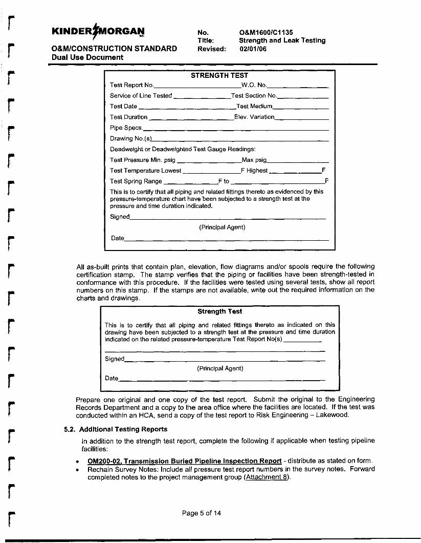
KINDER~ORGAN No. O&Ml600/C1135
O&M/CONSTRUCTION STANDARD Revised: 02/01/06 Dual Use Document
Title: Strength and Leak Testing
r
STRENGTH TEST Test Report No. W.O. No.
Service of Line Tested - Test Date Test Medium
Test Duration Elev. Variation
Pipe Specs.
Drawing No.(s)
Deadweight or Deadweighted Test Gauge Readings:
Test Pressure Min. psig -
Test Section No.
Max psig
Test Temperature Lowest - F Highest F
Test Spring Range F to F
This is to certify that all piping and related fittings thereto as evidenced by this pressure-temperature chart have been subjected to a strength test at the pressure and time duration indicated.
Signed
(Principal Agent)
Date
All as-built prints that contain plan, elevation, flow diagrams and/or spools require the following certification stamp. The stamp verifies that the piping or facilities have been strength-tested in conformance with this procedure. If the facilities were tested using several tests, show all report numbers on this stamp. If the stamps are not available, write out the required information on the charts and drawings.
Strength Test
This is to certify that all piping and related fittings thereto as indicated on this drawing have been subjected to a strength test at the pressure and time duration indicated on the related pressure-temperature Test Report No(s)
Signed
Date
I
(Principal Agent)
Prepare one original and one copy of the test report. Submit the original to the Engineering Records Department and a copy to tl?e area office where the facilities are located. If the test was conducted within an HCA, send a copy of the test report to Risk Engineering - Lakewood.
5.2. Additional Testing Reports
In addition to the strength test report, complete the following if applicable when testing pipeline facilities:
OM200-02. Transmission Burieid Pipeline Inspection Report - distribute as stated on form. Rechain Survey Notes: Include all pressure test report numbers in the survey notes. Forward completed notes to the project management group (Attachment 8).
0
0
Pa.ge 5 of 14
r r
F b
r r
KINDER~ORGAN mc No. O&M16OO/C1135
O&M/CONSTRUCTION STANDARD Revised: 02/01/06 Dual Use Document
Title: Strength and Leak Testing
5.3. Testing Stock Pipe
Test stock pipe per the preceding procedure for eight hours. Send test records and pipe mill test reports to the area Materials Management Specialist. If tested pipe is transferred to another location, send a copy of the test report with the pipe.
6. References e
e
e
0
0
0
e
e
e
e
e
e
e
e
0
e
e
49 CFR Part 192 O&M Procedure 208 O&M Procedure 213 O&M Procedure 228 O&M Procedure 229 O&M Procedure 230 0&M Procedure 231 O&M Procedure 403 O&M Procedure 917 O&M Procedures 1815 O&M Procedure 1840 OM200-02. Transmission Buried Pipeline Inspection Report OM1000-05, Gas Lost Report OM1600-01, Pressure Test Report Drawina CST-P-1000-BO65 Pipeline Integrity Manaaement PronraiE Unmeasured Gas Reporting
Page 6 of 14
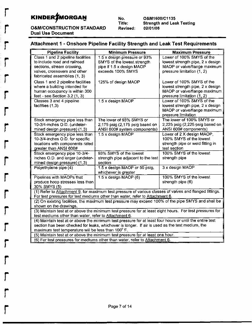
KINDER#WORGAN No. O&M1600/C1135
O&M/CONSTRUCTION STANDARD Revised: 02/01/06 Dual Use Document
Title: Strength and Leak Testing
Attachment 1 - Onshore Pipeline Facility Strength and Leak Test Requirements
Pipeline Facility Class 1 and 2 pipeline facilities to include road and railroad sections, stream crossing, valves, crossovers and other fabricated assemblies (1, 3) Class 1 and 2 pipeline facilities where a building intended for human occupancy is within 300 feet - see Section 3.2 (1, 3) Classes 3 and 4 pipeline facilities (1,3)
Stock emergency pipe less than 10-3/4-inches O.D. (undeter- mined design pressure) (1,3) Stock emergency pipe less than 10-3/4-inches O.D. for specific locations with components rated
inches O.D. and larger (undeter- mined design pressure) (1,3) Polyethylene pipe (4)
Pipelines with MAOPs that produce hoop stresses less than 30% SMYS (5) (1) Refer to Attachment 9, for mE
Minimum Pressure 1.5 x design pressure or 93% SMYS of the lowest strength pipe if ‘I .5 x design MAOP exceeds 100% SMYS
125% of design MAOP
1.5 x design MAOP
The lower of 93% SMYS or 2,175 psig (2,175 psig based on ANSI 600# system components) 1.5 x design MAOP
93% ShAYS of the lowest strength pipe adjacent to the test section 1.5 x design MAOP or 50 psig, whichever is greater I .5 x design MAOP (6)
Maximum Pressure Lower of 100% SMYS of the lowest strength pipe, 2 x design MAOP or valve/flange maximum pressure limitation (1, 2)
Lower of 100% SMYS of the lowest strength pipe, 2 x design MAOP or valve/flange maximum pressure limitation (1, 2) Lower of 100% SMYS of the lowest strength pipe, 2 x design MAOP or valve/flange maximum pressure limitation The lower of 100% SMYS or 2,225 psig (2,225 psig based on ANSI 600# components) Lower of 2 X design MAOP, 100% SMYS of the lowest strength pipe or weld fitting in test section 100% SMYS of the lowest strength pipe
3 x design MAOP
100% SMYS of the lowest strength pipe (6)
imum test pressure of various classesof valves and flanged fittings. For test pressures for test mediums other tlhan water, refer to Attachment 6. (2) On existing facilities, the maximum test pressure may exceed 100% of the pipe SMYS and shall be
est pressure for at least four hours or until the entire test
Page 7 of 14
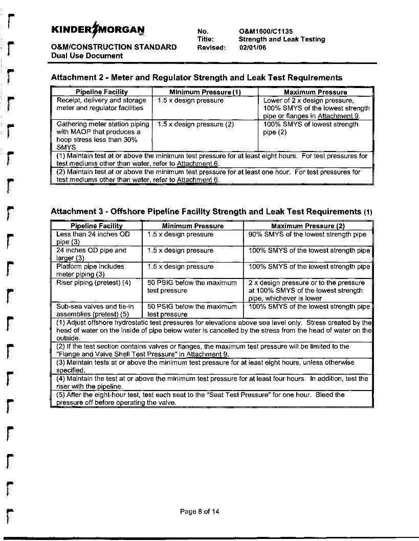
KINDERFORGAY No. O&M1600/C1135
O&M/CONSTRUCTION STANDARD Revised: 02/01/06 Dual Use Document
Title: Strength and Leak Testing
meter piping (3) Riser piping (pretest) (4)
r
50 PSlG below the maximum test pressure
2 x design pressure or to the pressure at 100% SMYS of the lowest strength
Attachment 2 - Meter and Regulator Strength and Leak Test Requirements
num Pressure (1) Maximum Pressure Lower of 2 x design pressure, 100% SMYS of the lowest strength pipe or flanges in Attachment 9. 100% SMYS of lowest strength Pipe (2)
ra t least eight hours. For test pressures for
ra t least one hour. For test pressures for - Attachment 3 - Offshore Pipeline Facility Strength and Leak Test Requirements (I)
Minimum Pressure
1.5 x design pressure 100% SMYS of the lowest strength pipe
ipe, whichever is lower 1 Sub-sea valves and tie-in 1 50 PSlG below the maximum 1 :00?40 SMYS of the lowest strenath-riDeI - . . assemblies (pretest) (5) (1) Adjust offshore hydrostatic test pressurles for elevations above sea level only. Stress created by the head of water on the inside of pipe below water is cancelled by the stress from the head of water on the outside. (2) If the test section contains valves or flanges, the maximum test pressure will be limited to the "Flange and Valve Shell Test Pressure" in ,Attachment 9. (3) Maintain tests at or above the minimum test pressure for at least eight hours, unless otherwise specified. (4) Maintain the test at or above the minimum test pressure for at least four hours. In addition, test the riser with the pipeline. (5) After the eight-hour test, test each seat to the "Seat Test Pressure" for one hour. Bleed the Dressure off before or>eratina the valve.
I test pressure
b
r Page 8 of 14
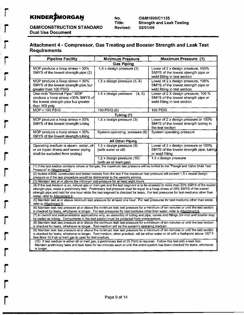
KINDER+ORGA~ No. O&M16OO/C1135
O&M/CONSTRUCTION STANDARD Revised: 02/01/06 Dual Use Document
Title: Strength and Leak Testing
MOP produce a hoop stress = 30% SMYS of the lowest strength pipe (2)
MOP produce a hoop stress < 30% SMYS of the lowest strength pipe but greater than 100 PSlG One-inch "Nominal Pipe:" MOP produce a hoop stress <30% SMYS of the lowest strength pipe but greater
Attachment 4 - Compressor, Gas Treating and Booster Strength and Leak Test Require men ts
1.5 x #design pressure (3) Lower of 2 x design pressure, 100% SMYS of the lowest strength pipe or weld fitting in test section Lower of 2 x design pressure, 100% SMYS of the lowest strength pipe or weld fitting in test section Lower of 2 X design pressure, 100 % SMYS of the lowest strength pipe or weld fitting in test section
1.5 x design pressure (3, 4)
1.5 x design pressure (4, 5)
shall be excluded from testing) I or weld fitting I 1.5 x design pressure l m e s i g n pressure (10) . . I (with air 0; inert gas) I
(1) If the test section contains valves or flanges, the maximum test pressure will be limited to the "Flange and Valve Shell Test Pressure" in Attachment 9. (2) Isolate ASME constructed and tested vessels from the test if the maximum test pressure will exceed 1.5 x vessel design pressure or if the test procedure would be detrimental to the vessel's service. (3) Maintain test at or above the minimum test pressure for at least eight hours. (4) If the test medium is air, natural gas or inert gas and the test segment is to be stressed to more than 20% SMYS of the lowest strength pipe, make a preliminary test. Preliminary test pressure shall be equal to a hoop stress of 20% SMYS of the lowest strength pipe and held for one hour while the test segment is checked for leaks. For test pressures for test mediums other than water, refer to Attachment 6. (5) Maintain test at or above minimum test pressure for at least one hour. For test pressures for test mediums other than water, refer to Attachment 6. (6) Maintain leak test pressure at or above the minimum leak test pressure for a minimum of ten minutes or until the test section is checked for leaks, whichever is longer. For test pressures for test mediums other than water, refer to Attachment 6. (7) In control and instrumentation applications only, an assembly of tubing and pipe, valves and fittings 3/4-inch and smaller may be tested as tubing. Components in the test section must be protected from overpressure. (8) Maintain leak test pressure at or above the minimum leak test pressure for a minimum of ten minutes or until the test section is checked for leaks, whichever is longer. Test medium will be the system's operating medium. (9) Maintain leak test pressure at or above the minimum leak test pressure for a minimum of ten minutes or until the test section is checked for leaks, whichever is longer. Test mediuim, when practical, will be either water or oil with a flashpoint above 120' F. See Note 10 if air or inert gas is used for test medium.
( I O ) If test medium is either air or inert gas, a preliminary test of 25 PSIG is required. Follow this test with a leak test. Maintain preliminary tests and leak tests for ten minutes each or until the entire system has been checked for leaks, whichever
Page 9 of 14
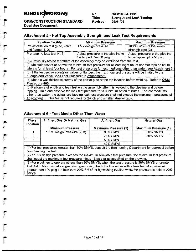
KINDERFORGAY No. O&M1600/C1135
O&M/CONSTRUCTION STANDARD Revised: 02/01/06 Dual Use Document
Title: Strength and Leak Testing
r
Attachment 5 - Hot Tap Assembly Strength and Leak Test Requirements
I ~~
Pipeline Facilit Minimum Pressure Maxi mum Pressure I 100% SMYS of the lowest 11 Pre-installation test (pi:, valve I 1.5 x design pressure .. . - .
and flange (1, 2) Pre-tapping leak test (4, 5)
(1) Previously-tested members of the assembly may be excluded from the test. (2) Maintain test at or above the minimum test pressure for at least eight hours and hot taps on liquid laterals for at least four hours. For test pressures for test mediums other than water, see Attachment 6 (3) If the test section contains valves or flanaes, the maximum test pressure will be limited to the
strength pipe (3) Actual pressure in the pipeline to be tapped plus 50 psig
Actual pressure in the pipeline to be tapped plus 50 psig
I
. . "Flange and Valve Shell Test Pressure" in kachment 9. (4) Make a wall thickness survey of the carrier pipe at the tap location before welding. Refer to O&M Procedure 403. (5) Perform a strength and leak test on the assembly after it is welded to the pipeline and before tapping. Hold and observe the leak test pressure for a minimum of ten minutes. For test mediums other than water, the actual pre-tapping leak test pressure shall not exceed the maximum pressures of
Attachment 6 - Test Media Other Than Water
Class Airllnert Gas Or Natural Gas Airllnert Gas Natural Gas Location
Minimum Pressure Maximum Pressure (1) Maximum Pressure (1) 1 1.5 x Design Pressure (2, 3) 80% SMYS 80% SMYS 2 75% SMYS 30% SMYS 3 50% SMYS 4 40% SMYS
(1) For test pressures greater than 50% SMYS, consult the Engineering Department for approval befort commencing the test.
1 (2) If 1.5 x design pressure exceeds the maximum allowable test pressure, the minimum test pressure shall equal the maximum test pressure minus 15 psig or as specified on the drawing. (3) For pipelines to operate at less than 30'Y0 SMYS, when the test pressure is 20% SMYS or greater and test medium is natural gas, inert gas oir air, check the line either with a leak test at a pressure
, greater than 100 psig but less than 20% SMYS or by walking the line while the pressure is held at 20%
Page 10 of 14
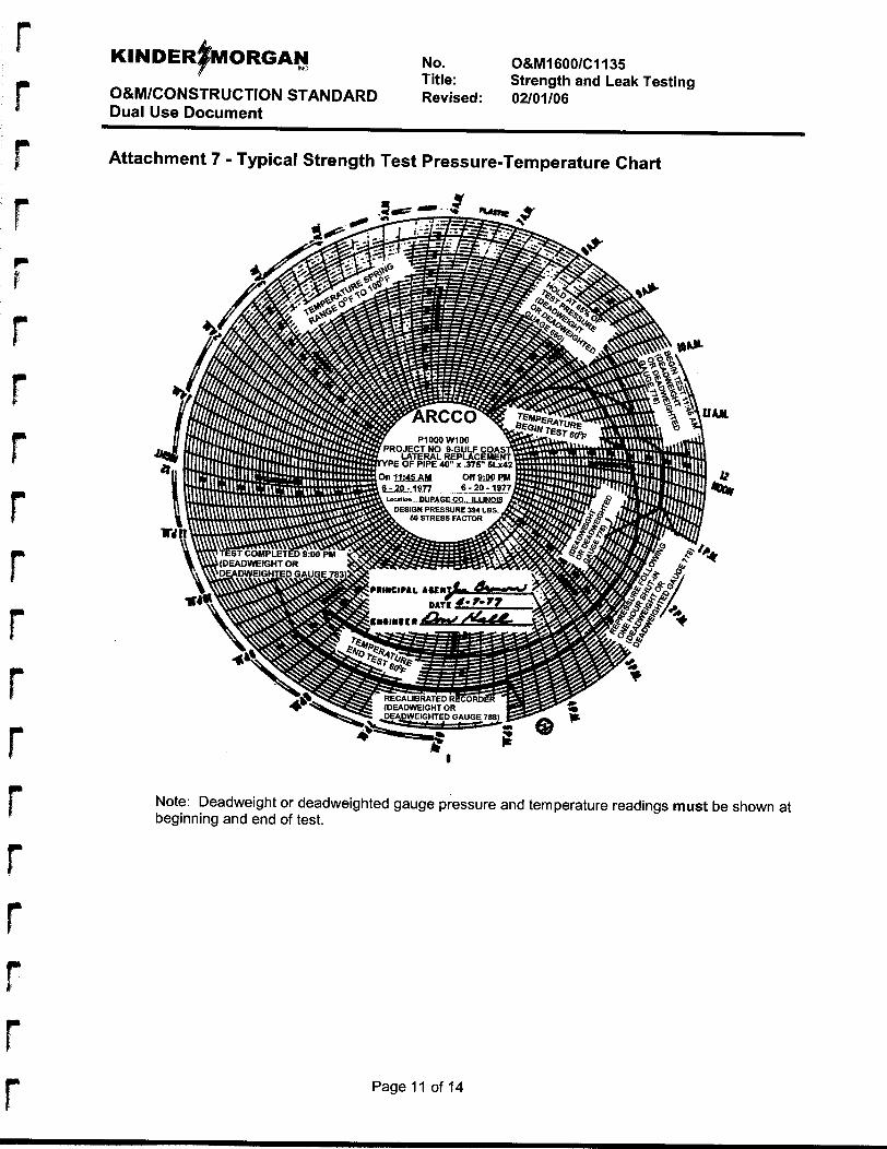
No. O&M1600/C1135 Title: Strength and Leak Testing
O&M/CONSTRUCTION STANDARD Revised: 02/01/06 Dual Use Document
Attachment 7 - Typical Strength Test Pressure-Temperature Chart
Note: Deadweight or deadweighted gauge pressure and temperature readings must be shown at beginning and end of test.
Page 11 of 14
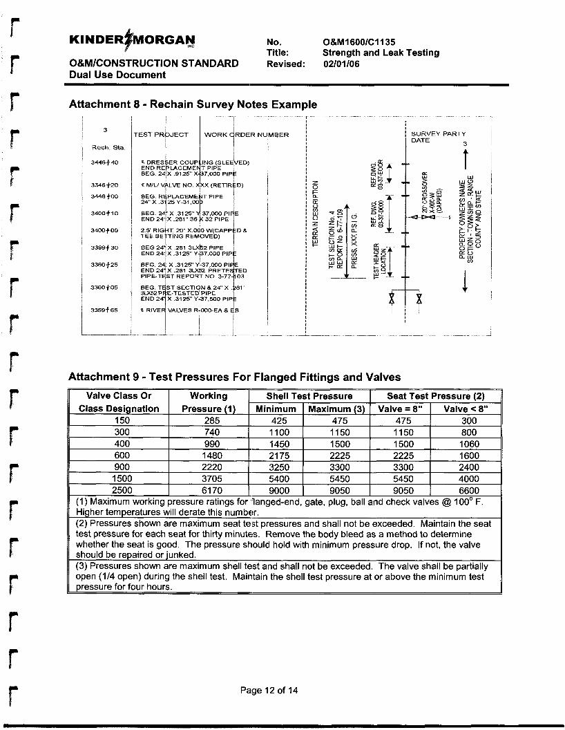
f
300
r
740 1100 1150 1150 I 800
No. 0&MI 600/C1135 Title: Strength and Leak Testing
O&M/CONSTRUCTION STANDARD Revised: 02/01/06 Dual Use Document
400 990 1450
Attachment 8 - Rechain Survey Notes Example
1500 1500 I 1060
3
Rech. Sta.
3446540
3346 f-20
3446 $.OD
3400f10
3400t00
3399-f 30
3360f25
3360505
3359t 65
1
rESTPR JECT WORK RDERNt l " i 1
600 1480 21 75 2225 2225 900 2220 3250 3300 3300 1500 3705 5400 5450 5450 4000
BEG. 24 X .3125" 437,000 PI
PIPE-T ST REPOR~T NO. END24 X 2-31 3M52 i
IBER
I I
I SURVEY PARTY
3 1 DATE
f m Attachment 9 - Test Pressures For Flanged Fittings and Valves
Valve Class Or Working
2500 I 61 70 I 9000 I 9050 I 9050 I 6600 (1) Maximum working pressure ratings for flanged-end, gate, plug, ball and check valves @ 100' F. Hiaher temDeratures will derate this number. (2) Pressures shown are maximum seat telst pressures and shall not be exceeded. Maintain the seat test pressure for each seat for thirty minutes. Remove the body bleed as a method to determine whether the seat is good. The pressure should hold with minimum pressure drop. If not, the valve should be reDaired or iunked. (3) Pressures shown are maximum shell test and shall not be exceeded. The valve shall be partially open (114 open) during the shell test. Maintain the shell test pressure at or above the minimum test pressure for four hours.
Page 12 of 14
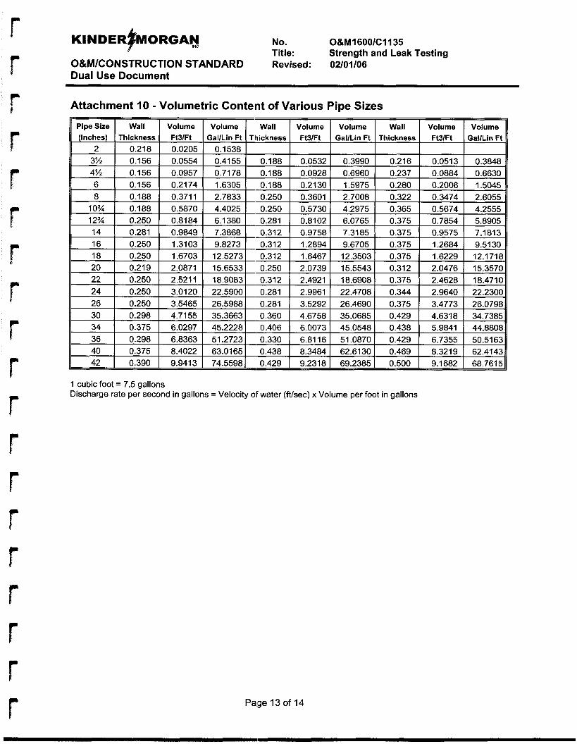
r
No. O&M1600/C1135 Title: Strength and Leak Testing
O&M/CONSTRUCTION STANDARD Revised: 02101106 Dual Use Document
Attachment 10 - Volumetric Content of Various Pipe Sizes
(Inches) Thickness Ft3lFt GaVLin Ft Pipe Size Wall Volume Volume
2 1 0.218 I
2.7008 I 0.322 I 1.5975 I 0.280 I
1 cubic foot = 7.5 gallons Discharge rate per second in gallons = Velocity OF water (Wsec) x Volume per foot in gallons
Page 13 of 14
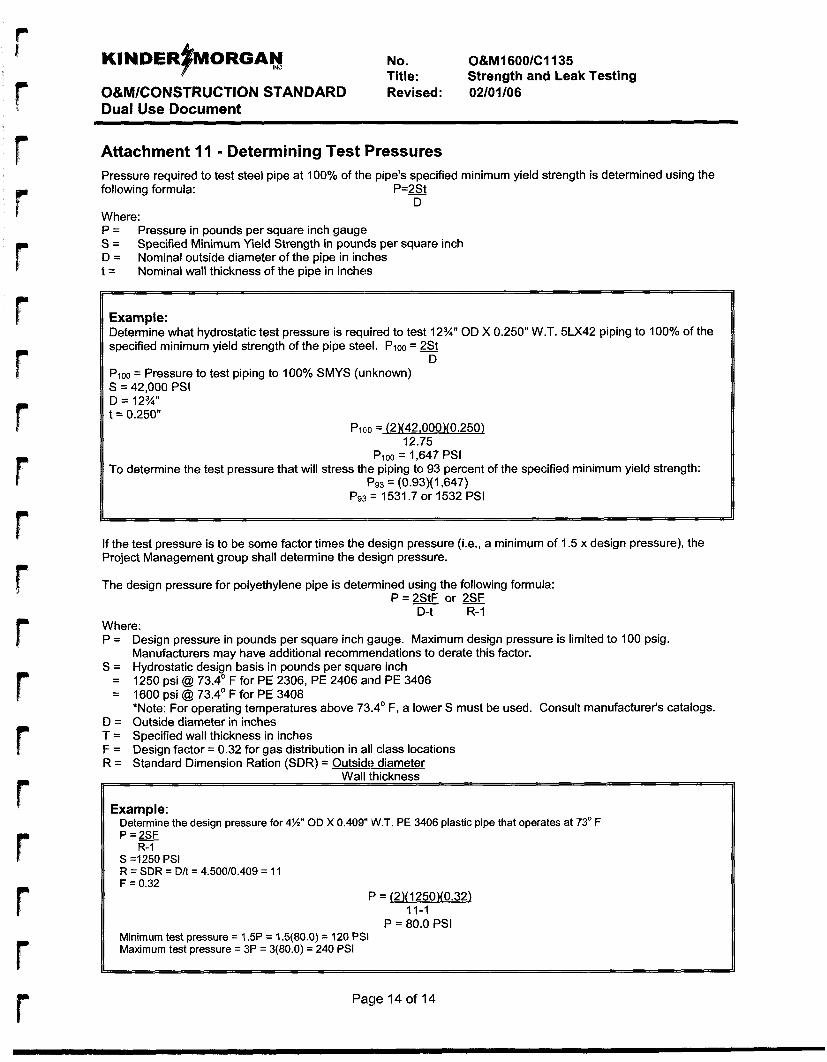
No. O&M16OO/C1135 Title: Strength and Leak Testing
O&M/CONSTRUCTION STANDARD Revised: 02/01/06 Dual Use Document
Attachment I I - Determining Test Pressures
following formula: P = B Pressure required to test steel pipe at 100% of the pipe's specified minimum yield strength is determined using the
D Where: P = S = D = t =
Pressure in pounds per square inch gauge Specified Minimum Yield Strength in pounds per square inch Nominal outside diameter of the pipe in inches Nominal wall thickness of the pipe in inches
Example: Determine what hydrostatic test pressure is required to test 12%" OD X 0.250" W.T. 5LX42 piping to 100% of the specified minimum yield strength of the pipe steel. PIOO = 2&t
D PIOO = Pressure to test piping to 100% SMYS (unknown) S = 42,000 PSI D = 12%" t = 0.250"
Piclo = (2)(42,000X0.250)
Pi00 = 1,647 PSI
Pg3 = (0.93)(1,647)
12.75
To determine the test pressure that will stress the piping to 93 percent of the specified minimum yield strength:
P93 = 1531.7 or 1532 PSI
If the test pressure is to be some factor times the design pressure (i.e., a minimum of 1.5 x design pressure), the Project Management group shall determine the design pressure.
The design pressure for polyethylene pipe is determined using the following formula: - .
P = = or D-t R- 1
Where: P = Design pressure in pounds per square inch gauge. Maximum design pressure is limited to 100 psig.
Manufacturers may have additional recommendations to derate this factor. S = Hydrostatic design basis in pounds per square inch
= 1250 psi @ 73.4' F for PE 2306, PE 2406 and PE 3406 = 1600 psi @ 73.4' F for PE 3408
*Note: For operating temperatures above 73.4' F, a lower S must be used. Consult manufacturer's catalogs. D = Outside diameter in inches T = Specified wall thickness in inches F = Design factor = 0.32 for gas distribution in all class locations R = Standard Dimension Ration (SDR) = Outside diameter
rl Wall thickness
Example:
P=2SJ Determine the design pressure for 4%" OD X 0.409 'W.T. PE 3406 plastic pipe that operates at 73" F
S =I250 PSI R = SDR = D/t = 4.500/0.409 = 11 F = 0.32
R- 1
F' = [2)(1250X0.32) 11-1
P = 80.0 PSI Minimum test pressure = 1.5P = 1.5(80.0) = 120 PSI Maximum test pressure = 3P = 3(80.0) = 240 PSI
Page 14 of 14
APPENDIX J
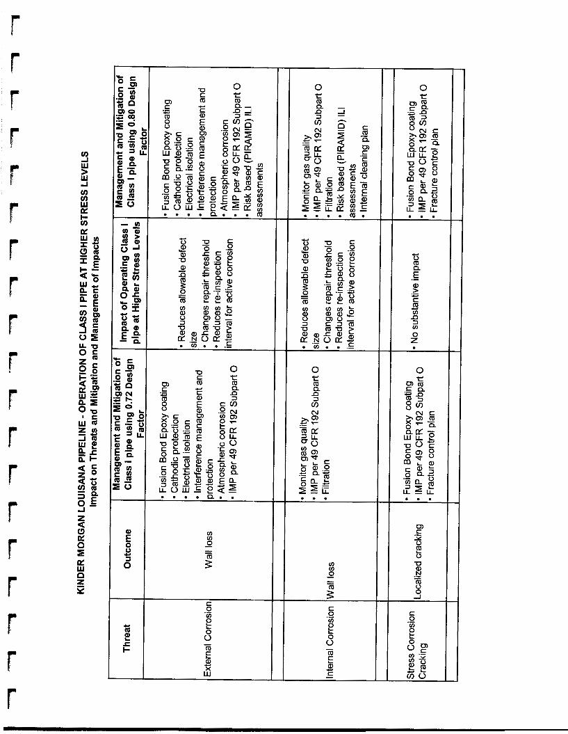
5- c - m
I- L
1 k e X w
0 r ([I Q d 3 a
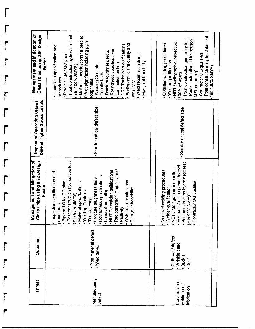
I-. .
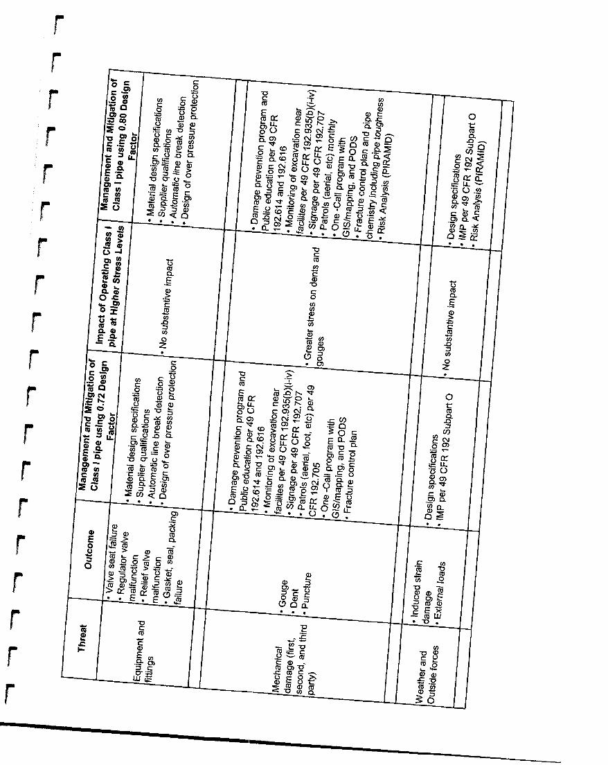
I P
b
f r

CI c 0 0 m m .- E" .- E"
9 a, > t C m m u) u) n n 3 3 u) u) 0 0 z z
.- .- c CI
CI C
APPENDIX K

Proposed Notice of Intent to Consider Waiver
r t
DEPARTMENT OF TRANSPORTATION Pipeline and Hazardous Materials Safety Administration
Docket No.
Pipeline Safety: Petition for Waiver; Kinder Morgan Louisiana Pipeline LLC
Summary: Kinder Morgan Louisiana Pipeline LLC (KMLP) petitioned the Pipeline and Hazardous Materials Safety Administration’s (PHMSA) Office of Pipeline Safety (OPS) for a waiver of the provision of 49 C.F.R. 5 192.1 1 1 requiring a design factor of 0.72 for steel pipe that will be constructed and operated in Class 1 locations. KMLP seeks a waiver of section 192.1 11 so that it can utilize a 0.80 desigp factor for Class 1 locations in the design formula for steel pipe specified in Section 192.105, thus allowing KMLP to design, construct, and operate the proposed new Kinder Morgan Louisiana Pipeline Project at hoop stresses up to 80 percent specified minimum yield strength (SMY,S), rather than 72 percent SMYS for Class 1 locations. KMLP also requests a waiver of 49 C.F.R. 3 192.201(a)(2)(i) to permit each pressure relief and limiting station installed to protect pipelines in Class 1 locations to have enough capacity and to be set to operate such that the pressure may not exceed the maximum allowable operating pressure (MAOP), plus 4%, or the pressure that produces a hoop stress of 83% of SMYS, whichever is lower. KMLP is not seeking a waiver for lines that will operate in other class locations and will comply with all other applicable OPS regulations.
Dates: Persons interested in submitting written comments on the waiver proposed in this notice must do so by . Late-filed comments will be considered so far as practicable.
Addresses:
For Further Information Contact:
Supplementary Information:
1. Background
Part 192, Subpart C of the Federal :pipeline safety regulations sets forth the minimum requirements for the design of pipe use to transport natural gas. Section 1 92.105 sets forth the formula for the design pressure used for steel pipe, and Section 192.1 1 1 sets forth the design factor (F) to be used in the design formula for each class location. For Class 1 locations, section 192.1 1 1 provides that, except as otherwise provided in that section, the design factor (F) for steel pipe is to be 0.72.
I
On August 2,2006, KMLP petitioned PHMSA for a waiver of section 192.1 1 1 that would permit KMLP to utilize a 0.80 design factor for Class 1 locations in the design formula for steel pipe specified in section 192.105, thus allowing KMLP to design, construct, and operate the proposed new Kinder Morgan Louisiana Pipeline Project at hoop stresses up to 80 percent SMYS, rather than 72 percent SMYS for Class 1 locations.
KMLP also requests a waiver of 49 C.F.R. tj 192.201(a)(2)(i), which provides, in relevant part, the following:
[elach pressure relief station or pressure limiting station or group of those stations installed to protect a pipeline must have enough capacity, and must be set to operate, to insure . . .[that] the pressure may not exceed the maximum allowable operating pressure plus 10 percent, or the pressure that produces a hoop stress of 75 percent of SMYS, whichever is lower
49 C.F.R 6 201(a)(2)(i)(2005). Because a waiver of Section 192.1 11 necessarily requires a commensurate modification in the required capacity of pressure relieving and limiting stations installed to protect a pipeline, KMLP also requests a waiver of Section 192.201(a)(2)(i) to permit each pressure relief station or pressure liimiting station installed to protect pipelines in Class 1 locations to have enough capacity and to be set to operate such that the pressure may not exceed MAOP, plus 4%, or the pressure that promduces a hoop stress of 83% of SMYS, whichever is lower.
KMLP is not seeking a waiver for pipelines that will operate in other class locations, and will otherwise comply with all applicable OPS regulations.
2. System Description
KMLP states that the Kinder Morgan Louisiana Pipeline Project is a multi-segment interstate natural gas pipeline project being developed by KMLP, a wholly-owned subsidiary of Kinder Morgan Energy Partners, L.P. When complete, the pipeline system will deliver almost 3,395,000 Dth/d of imported liquefied natural gas (LNG) per day from the new Sabine Pass LNG Terminal (Terminal) under development by Sabine Pass LNG, L.P., in Cameron Parish, Louisiana, to consuming markets in the Gulf Coast, midwestern, northeastern, mid-Atlantic and southeastern regions of the United States via numerous interstate and intrastate pipeline systems. The pipeline will be designed to operate iat pressures up to 1,440 psig.
The Kinder Morgan Louisiana Pipeline Project is comprised of four operationally integrated segments: Leg I, Leg 2, the Florida Gas Transmission (FGT) Lateral, and the Bi- directional Tie-in Line. Leg 1 of the project will consist of approximately 137 miles of 42-inch diameter pipeline carrying regasified LNG from the Terminal in a northeasterly direction to an interconnection with the pipeline system of Columbia Gulf Transmission Co. Along this route, Leg 1 will interconnect with at least ten interstate and intrastate pipeline systems and will provide firm, peak day capacity of approximately 2,130,000 Dth/d.
I 2
r
r
Leg 2 of the Kinder Morgan Louisiana Pipeline Project consists of approximately one mile of 35-inch diameter pipe between tlhe Terminal and the existing pipeline system of Natural Gas Pipeline Company of America (NGPL). Leg 2 will have a firm, peak day capacity of approximately 1,265,000 Dtldd.
The FGT Lateral is a 2.2 mile, 24-inch diameter pipeline, which will extend from Leg 1 to an existing compressor station owned by FGT in Acadia Parish, Louisiana. The FGT Lateral will have a firm, peak day capacity of approximately 3 19,500 DtWd.
Finally, the Kinder Morgan Loui,siana Pipeline Project will include a Bi-directional Tie-in Line, which will connect Leg 1 arid Leg 2. The Bi-directional Tie-in Line will have firm capacity of approximately 1,065,000 Dtldd, and will allow gas originating from NGPL’s system to flow from Leg 2 to Leg 1 during periods where no regasified LNG is flowing from the Terminal. This segment will provide flexibility to enable KMLP to continue serving markets when it is not receiving gas from the Terminal.
3. KMLP’s Proposed Waiver
KMLP seeks a waiver of section 192.1 1 1 for those sections of the Kinder Morgan Louisiana Pipeline Project that will be located in Class 1 locations. KMLP explains that the design of the pipe at a 0.80 design factor will result in pipe wall thickness less than required by Section 192.1 1 1. KMLP states, however, that it will utilize state of the art materials, manufacturing technologies, and testing imd inspection technologies and practices that will result in a pipeline system that will meet or exceed recommended industry standards and the safety requirements of OPS’s regulations. KMLP explains that the Kinder Morgan Louisiana Pipeline Project is being designed and constructed in conformance with Kinder Morgan, Inc. (Kinder Morgan) Engineering and Construction Standards (KMEC Standards), and states that each of these standards is designed to meet or exceed the requirements of 49 C.F.R. Part 192 and the industry standards as referenced in 49 C.F.R. 0 192.7. KMLP asserts that these standards increase the reliability and safety of pipeline operations and allow pipelines to operate reliably and safely at higher stress levels than allowed under OPS’s current regulations.
In addition, KMLP explains that the pipeline will be operated pursuant to the Kinder Morgan Operations and Maintenance (O&M) Procedures. These procedures meet or exceed Part 192 requirements and are designed to ensure continuous safe operations over the life of the pipeline. Finally, KMLP states that Kinder Morgan’s risk analysis demonstrates that there is no significant increase in risk from using the: 0.80 design criteria for this type of pipe.
a. Pipeline Design and Matterial Quality
In its petition, KMLP describes the principal features of the proposed design and construction of the proposed Kinder Morgan Louisiana Pipeline Project that will ensure safe operation of the pipeline as designed and constructed using a design factor of 0.80 in the calculation of the design pressure required under 49 C.F.R. 6 192.105 for steel pipe in Class 1 locations, as follows:
3
r
i. Pipe Specification
KMLP states that it will purchase various grades of pipe from qualified vendors primarily utilizing Material Standard M8270, X-70 and X-80 Grade High Strength, High Toughness Welded Line Pipe for High Pressure Transmission Service (M8270). KMLP states that specification exceeds the requirements of 49 C.F.R. Part 192, Subparts B and C, which incorporate American Petroleum Institute (API) standard 5L as the minimum requirement for pipe to be used in gas service. KMLP states that Kinder Morgan engineering has specifically designed the steel chemistry for use in line pipe in order to maximize the steel’s toughness, thus reducing the pipeline’s susceptibility to third-party damage and long running failures. KMLP states that the standard incorporates quality assurance requirements to ensure that the pipe is manufactured in a consistent and unifornn fashion, and that the standard includes fracture toughness criteria consistent with American Society of Mechanical Engineers (ASME) Standard B3 1.8.
ii. Fracture Control Plan
KMLP states that Class 1 line pipe for the Kinder Morgan Louisiana Pipeline Project will be NPS 42 API 5L Grade X70 or X80 PSL2 longitudinal-seam submerged arc welded pipe or helical seam welded pipe. KMLP will implement a detailed fracture control plan. KMLP states that the first aspect of the fracture control plan is to ensure that the pipe has adequate ductility to prevent brittle fractures, and states that Kinder Morgan Specification M8270 addresses this issue with requirements more stringent that ASME Standard B3 1.8. KMLP states that the second aspect of the fi-acture control plan is to ensure that the pipe has adequate toughness to arrest a ductile fracture, and explains that Kinder Morgan Specification M8270 addresses this issue with test requirements in conformance with ASME Standard B3 1.8.
iii. Inspection of High Quality Line Pipe
KMLP states that Kinder Morgan employs third-party inspection to ensure that each joint is inspected for conformance to Kinder Morgan pipe specifications. KMLP states that the result of this inspection process will remain in the company’s records for the life of the pipeline.
iv. External / Internal Pipe Coating
KMLP states that the pipe will be externally coated with fusion bonded epoxy in accordance with Kinder Morgan Materials Standard M8370, Plant Application of Fusion Bond Epoxy Coating (M8370). KMLP states that this standard requires that the coating system meet the requirements of NACE and the Canadian coating standards and that it be applied under very rigorous controls meeting the requirements set forth in 49 C.F.R. Part 192, Subpart I. KMLP states that field weld joints will be externally coated with field applied Fusion Bond Epoxy coating, and that the pipeline will be internally coated with epoxy for flow efficiency.
4

v. Supplemental Pipeline Design and Material Quality Criteria
In its recent orders granting Rockies Express Pipeline LLC, Alliance Pipeline L.P., and Maritimes & Northeast Pipeline, L.L.C. waivers of certain pipeline safety regulations pertaining to pipe design factor and MAOP requirements, PHMSA imposed supplemental safety criteria. See Pipeline Safety: Grant of Waiver; Rockies Express Pipeline, 71 Fed. Reg. 39,141 (July 1 1, 2006); Pipeline Safety: Grant of Waiver.; Alliance Pipeline L.P., 71 Fed. Reg. 39,145 (July 11, 2006); and Pipeline Safety: Grant of Waiver; Maritimes & Northeast Pipeline, L.L.C., 71 Fed. Reg. 39,148 (July 11,2006). These supplemental criteria exceed the standards applicable to pipelines otherwise subject to Section 192.1 1 1 , and include pipe and material quality requirements. KMLP states that the KM:EC standards are designed to satisfy each of the supplemental pipe and material quality requirements set forth in the waiver criteria.
b. Construction
i. Unloading, Handling, and Stringing Materials
KMLP states that the loading andl transportation of the pipe will be conducted in accordance with API Standard RP 5L1, Recommended Practice for Railroad Transportation of Line Pipe, and API Rp SW, Recommend.ed Practice for Transportation of Line Pipe on Barges and Marine Vessels. KMLP avers that these recommended practices give consideration for load stresses, blocking, tie-down, and stacking. Pipe for the Project will be strung in accordance with Kinder Morgan Construction Standards C 1040, Unloading, Hauling, and Stringing Materials, included with KMLP’s Petition.
ii. Lowering-In of Pipe
KMLP states that pipe will be lowered into the trench in accordance with Kinder Morgan Construction Standard C 1090, Lowering-In Pipe, included with its Petition. In addition, throughout the construction phase, KMLlP asserts that coating inspectors will ensure coating integrity as outlined in Construction Standard C1090.
iii. Depth of Cover
KMLP avers that it will comply in all respects with the depth of cover requirements of 49 C.F.R. 0 192.327. In particular, as required by Section 192.327, the soil cover over buried transmission line pipe will be at least 36 inches. In areas where threats from chisel plowing or other activities require deeper burial, the top of the pipeline will be installed one foot below the deepest penetration.
iv. Welding and Non-Destructive Testing
KMLP states that Kinder Morgan will perform all of the welding applications with fully qualified welding procedures and will employ fully qualified and tested welders. KMLP states that the welding process on the Kinder Mlorgan Louisiana Pipeline Project will be 100 percent nondestructively tested by qualified technicians and procedures and in conformance with Kinder
5
I
Morgan’s Construction Standard C1070 (C1070). KMLP asserts that nondestructive testing of 100 percent of the welds on this project exceeds the nondestructive testing requirements specified in 49 C.F.R. Part 192, Subpart E. Section 192.243(d)( 1) requires that 10 percent of the welds performed in a Class 1 location be nondestructively tested. KMLP states that by nondestructively testing 100 percent of the welds in the project, any imperfections that do not meet the standards set forth in the regulakions will be discovered, repaired, or removed prior to putting the line in service.
v. Smart Tool Caparbility
KMLP states that the proposed project will be designed to be piggable and in conformance with the requirements set hrth in 49 C.F.R. Part 192, Subpart D for the purposes of cleaning and running in-line inspection tlools. KMLP states that the technology surrounding in- line inspection has evolved rapidly over the past decade, increasing the quality and sophistication of the data that pipeline operators can gather on the condition of their pipelines. Thus, KMLP states that to keep pace with this evolving technology, Kinder Morgan will utilize a design feature that allows for the installation of launchers and receivers that are adaptable in length and specific to the newest generation of tools.
vi. Hydrostatic Testing
KMLP states that, prior to placing the pipeline into service, it will be hydrostatically tested in conformance with 49 C.F.R. Part 192, Subpart J and to no less than 100 percent of SMYS, utilizing Kinder Morgan’s Strength and Leak Testing Procedure O&M 1600 / C1135 (C1135).
KMLP states that C1135 meets or exceeds the requirements stated in 49 C.F.R. $ 5 192.505, 192.619, and ASME Standard B31.8. Section 192.505(a) of OPS’s regulations requires the hydrostatic testing to 125 percent of MAOP of any pipeline segment passing within 300 feet of a building meant for human occupancy. The testing requirements stated in ASME B3 1.8 Table 841.322(0 for steel pipelineis in Class 1 locations with a 0.8 design factor is 125 percent of MAOP. By testing the Kinder Morgan Louisiana Pipeline Project to a minimum of 100 percent of the MAOP, KMLP states that Kinder Morgan has designed a hydrostatic test that both meets regulations and provides the maximum assurance that all manufacturing defects have been discovered prior to putting the pipeline in service.
vii. Geometry Smart Tool In-Line Inspection Survey
Prior to commissioning the pipeline for gas service, KMLP states that the pipeline will be surveyed with a multi-channel geometry smart tool to confirm compliance to construction specifications for dents, buckles, etc. KMLP states that Kinder Morgan utilizes this means of final inspection of the construction process to ensure that damage that may have occurred during the backfilling process is discovered and repaired in conformance with Kinder Morgan’s Construction and Engineering Design Standards prior to putting the line into service. Thus, in addition to meeting the requirements of 49 C.F.R. Part 192, Subpart G, which specifies that
r 6
inspection is done during the construction process, KMLP states that Kinder Morgan conducts a post-construction inspection.
viii. Local Line Break Equipment
KMLP states that local line break equipment will be installed on each mainline valve to close the valve in the event of rapid pressure decline. Line break sensing and valve actuation equipment is not a requirement set forth by 49 C.F.R. Part 192.
ix. Cathodic Protection Interference
KMLP states that Kinder Morgan will comply with the corrosion control requirements set forth in 49 C.F.R. Part 192, Subpart I in the design, construction and operation of the Kinder Morgan Louisiana Pipeline Project, and .that Kinder Morgan will employ other cathodic protection measures to address electrical interference. In particular, KMLP states that, at the time of construction, it will coordinate with other pipeline company owner/operators to eliminate the risk of electrical interference with cathodic protection systems of other nearby pipelines or underground metallic structures. After pipeline installation, KMLP states that Kinder Morgan will conduct cathodic protection electrical surveys to detect unresolved interference problems.
x. Contractor Operiator Qualification
KMLP states that all contractors utilized to construct and install OPS regulated facilities on the new pipeline will be required to work in compliance with a qualified Operator Qualification (OQ) plan, and that all third party and company inspectors will be OQ qualified in their respective discipline(s).
xi. Construction Reviews
KMLP states that, as the construction of each pipeline segment is completed, and before the segment is placed into operation, KMLP will complete the necessary Process Hazard Reviews (PHR) and Pre-Startup Safety Reviews (PSSR). KMLP states that the purpose of these reviews is to provide an additional level of quality assurance with respect to design and construction standards/specifications implementation. Designed to provide for an enhanced transition from the builder to operator, KlLlLP states that these reviews are based on Occupational Safety & Health Administration process management practices that have been incorporated into the Kinder Morgan O&M Procedures.
xii. Supplemental Coiistruction Criteria
KMLP states that the KMEC construction standards described in its Petition are designed to satisfy each of the supplemental Construction, Pre-In-Service Hydrostatic Pressure Test, and Supervisory Control and Data Acquisition (SCADA) standards contained in PHMSA’s recent orders granting pipeline safety waivers to Rockies Express Pipeline LLC, Alliance Pipeline L.P., and Maritimes & Northeast Pipeline, L.L.C. See Id.
7
6 t
r I r
f
f
C. Pipeline Operation and Maintenance
KMLP states that the pipeline will be operated in conformance with the Kinder Morgan O&M Procedures. KMLP states that these procedures are intended to ensure continuous safe operation over the life of the pipeline, arid that they meet or exceed the requirements of OPS’s Part 192 requirements in many respects. KMLP states that Kinder Morgan’s O&M procedures include several key features, including the following:
i. External Corrosion Control
KMLP states that Kinder Morgan’s external corrosion control procedures address coating inspection and maintenance, cathodic protection, and maintenance of cathodic protection interference bonds. KMLP states that thle Kinder Morgan O&M procedures regarding coating require the inspection and maintenance of pipeline coating in several circumstances, including during any pipeline excavation that occurs as a result of normal maintenance activities, any pipeline Integrity Management Plan action, and piping changes, revisions, or additions.
KMLP explains that pipe coating repairs will be completed in conformance with the Kinder Morgan O&M Procedures, and that buried pipeline inspection reports will be completed and filed/archived any time the pipeline is uncoveredhnearthed.
With respect to cathodic protection, KMLP states that Kinder Morgan will design and install cathodic protection systems within one year of the pipeline’s in-service date, and that the design will be based on actual pipe-to-soil data, as well as soil and geological conditions assessed during the first several months of service. KMLP states that the cathodic protection systems will be inspected and maintained in accordance with 49 C.F.R. Part 192, Subpart I.
KMLP also states that, at the time: of construction, Kinder Morgan will coordinate with owners / operators of nearby underground pipelines and/or other metallic structures to design and install resistor bonds to eliminate the risk of electrical interference with other cathodic protection systems. KMLP states also that it will coordinate operation of its cathodic protection systems with owners/operators of nearby underground pipelines and/or structures. KMLP explains that Kinder Morgan’s inspection and maintenance of the electrical interference bonds and normal cathodic protection systems will be conducted in conformance with 49 C.F.R. tj 192.465(c).
ii. Internal Corrosioin Control
KMLP states that the primary preventive action to mitigate the risk of internal corrosion control is to eliminate the introduction of free water and gas contaminants into the pipeline. KMLP asserts that its FERC tariff will provide for the receipt and delivery of pipeline quality gas (no free liquids, solids or constituents that under normal pipeline conditions will drop out of the gas stream). In addition, KMLP states that all delivery and receipt points will employ state-of- the-art gas measurement and quality monitoring equipment with continuous alarming and SCADA capabilities. KMLP states that, depending on the levels of water and/or contaminates detected in the gas received into the system, reducing or shutting off gas flow will be
8
t I
I I
r
r I r
accomplished either automatically, via SCADA gas control dispatch, or manually by a local operator.
The need for filtration of gas received from process (LNG regasification) plants will be evaluated, and, when necessary, will be designed based on the process and gas quality leaving the plant. With respect to other sources of supply, KMLP states also that gas supply will be filtered through full-flow, high efficiency filter separator(s) designed to capture any free liquids and/or solid contaminants. KMLP states that future supply connections will be required to employ the same filter separator design concept.
KMLP, states that Kinder Morgan will develop schedules for performing maintenance pigging based on the level of contaminants captured in the respective filter separators and to maximize flow efficiency. KMLP explains that materials collected in the mainline filter separators will be analyzed to detect the presence of internal corrosion constituents and to determine the need for additional internal corrosion mitigation measures.
iii. Integrity Management Program
KMLP states that it will comply with Part 192, Subpart 0 requirements, including baseline assessment and re-assessment requirements. KMLP states that the combination of its design and construction practices, which include a hydrostatic test at a minimum of 100% SMYS and a robust Fusion Bond Epoxy coating system, minimize the potential for future formation of stress corrosion cracking (SCC).
iv. Damage Prevention Program
KMLP explains that Kinder Morgan’s damage prevention program meets the requirements of Part 192 in all respects, including operator monitoring of excavations (0 192.935(b)(i-iv)), line marking (0 192.707), line surveillance (8 192.705), and public awareness (0 8 192.6 14 & 192.6 16). In addition, KMLP explains that Kinder Morgan utilizes a state-of-the-art, one-call management system that is integrated with the GIS mapping and Pipeline Operational Data System (PODS) systems. KMLP states that as-built, detailed Geographic Information Systems (GIS) survey data for its pipeline facilities will be entered into the mapping system data base as they are constructed.
v. Operator Qualification
KMLP states that it will maintain an OQ program that is consistent with 49 C.F.R. Part 192, Subpart N. KMLP states that its OQ program will provide for employee/operator training intended to ensure that employees perforniing covered tasks are trained and qualified to do so, and to ensure that contractors performing covered tasks are properly supervised. KMLP states that the Kinder Morgan O&M Procedures also incorporate a Management of Change process for all work processes and procedures, and th,at the Procedures are audited on an annual basis, with proposed changes managed through a company user group committee (Action Decision Committee).
9
vi. Pipeline Facilities Security
KMLP states that it will implement the Kinder Morgan corporate security plan, which includes specific threat level preparation, response, recovery and training related to actions and documentation requirements. Further, KMLP states that a specific security and emergency response plan will be maintained at each. of the respective KMLP operating geographical offices.
vii. Supplemental Operation and Maintenance Criteria
With the one exception, KMLP states that the O&M standards described in its Petition are designed to satisfy each of the supplemental O&M criteria contained in PHMSA’s recent orders granting pipeline safety waivers to Rockies Express Pipeline LLC, Alliance Pipeline L.P., and Maritimes & Northeast Pipeline, L.L.C. See Id. This sole exception relates to the use of filter separators at points where gas is received from process (LNG regasification) plants at the Terminal. KMLP states that gas processing at the Terminal will ensure that contaminates do not enter the system and, thus, filtration is not necessary at these receipt points. Gas supply from other sourced will be subject to filter separators. Moreover, the need for filtration of gas received fiom process (LNG regasification) plants will be evaluated, and, when necessary, will be designed based on the process and gas quality leaving the plant.
d. Risk Analysis
KMLP states that a risk analysis was conducted for the Kinder Morgan Louisiana Pipeline Project using the C-FER PIRAMID program to compare the risk associated with using a 0.80 design criteria for Class 1 pipe versus the 0.72 design criteria required by 49 C.F.R. 6 192.1 11. In addition, scenarios were created to determine the risk reduction associated with an in-line inspection conducted on the pipeline seven years after installation for both design criteria. KMLP has reviewed the risk analysis comparing the two design criteria for Class 1 pipe and states that it shows that there is no significant increase in risk from using the 0.80 design criteria for this type of pipe. KMLP states that external and internal corrosion are the primary threats to the proposed pipeline, and that these threilts can be effectively mitigated by conducting an in-line inspection to confirm the integrity of the pipeline and assure that the risk is minimized.
e. Reporting
KMLP states that its Petition includes the additional reporting requirements adopted by PHMSA in its recent orders granting waivers to Rockies Express, Alliance Pipeline L.P., and Maritimes & Northeast Pipeline, L.L.C. See Id.
4. Request for Expedited Consideration
KMLP is requesting expedited consideration and approval by PHMSA of its petition for waiver of sections 192.1 11 and 192.201(a)(2)(i). KMLP states that time is of the essence for obtaining PHMSA authorization in order for KMLP to meet the construction schedule that is
10
r consistent with the FERC’s expected schedule for conducting an environmental review of the proposed pipeline and for considering KMLP’s submission to FERC of an application for a certificate of public convenience and necessity. In addition, KMLP states that it must release steelmaking so that steel slabs of the appropriate size for the ordered pipe thickness can be produced and delivered to the plate rolling mills. Accordingly, KMLP asks OPS for consideration and approval of its petition for waiver within that time frame.
5. Opportunity for Public Comments
This notice provides an opportunity for public comment on KMLP’s petition for waiver. Comments should address . After the comment period has ended, PHMSNOPS will evaluate the KMLP’s petition and will consider all comments received by the deadline. PHMSNOPS will publish a subsequent Federal Register notice granting or denying KMLP’s petition for waiver.
Persons interested in submitting written comments on the waiver proposed in this notice must do so by copy of the petition is available in Docket No. at http ://dms. dot. gov .
. Late-filed comments will be considered so far as practicable. A
11
Related Documents