HEATING & COOLING Copyright 1994 Carrier Corporation Product Data CCSA, CDSA, CDSB Heating/Cooling Coil ltPi Sizes A018 thru A070 The CDSA/ CDSB are cased coils designed to fit BDP furnaces of the same width or the next smaller size. The CDSA/ CDSB are available in sizes 018 through 070 (1 . J/ 2- 6 tons). The CDSA has a prepalnted wrapper while the CDSB has an unpainted embossed galvanized steel wrapper. The CCSA is an uncased A•coll requiring a field-fabricated enclosure, It is available In sizes 0 18 through 060 (1-J /2 -5 tons). FEATURES Coil Design- Our advanced manufacturing methods give a better bond of the fin to the grooved tubing. Contaminants are not introduced into the coll during manufacturing and all coils are shipped with a holding charge. This helps to prevent galvanic action. The coils are approved for air conditioning or heat pump application in the vertical configuration, both upnow and downnow. Metering Device- The CDSA/CDSB and CCSA Coils Include a Check -Flo-Rater® metering device which eliminates the potential serviceability requirements of check valves and expansion devices used in conventional coils. Condensate Pan- Each coil Is equipped with a corrosion-resistant condensate drain pan with two 3/ 4, in. female threaded brass Insert connections. The thermoplastic drain pan is designed with a slope to help ensure proper drainage. Refrigerant Connections- Sweat-type connections are furnished for Installation of the refrigerant tubes to ensure leak-free operation. Casing - The coil casing Is fully Insulated to minimize heating or cooling transfer, while maintaining quiet operation. FOATI No. CCSA,3PD

Welcome message from author
This document is posted to help you gain knowledge. Please leave a comment to let me know what you think about it! Share it to your friends and learn new things together.
Transcript
HEATING & COOLING
Copyright 1994 Carrier Corporation
Product Data
CCSA, CDSA, CDSB Heating/Cooling Coil
ltPi
Sizes A018 thru A070
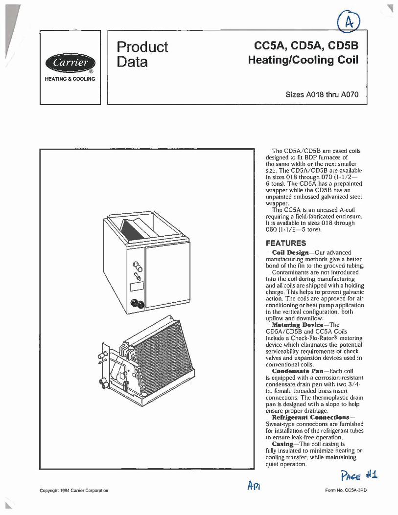
The CDSA/ CDSB are cased coils designed to fit BDP furnaces of the same width or the next smaller size. The CDSA/ CDSB are available in sizes 018 through 070 (1 . J/ 2-6 tons). The CDSA has a prepalnted wrapper while the CDSB has an unpainted embossed galvanized steel wrapper.
The CCSA is an uncased A•coll requiring a field-fabricated enclosure , It is available In sizes 0 18 through 060 (1-J /2- 5 tons).
FEATURES Coil Design- Our advanced
manufacturing methods give a better bond of the fin to the grooved tubing.
Contaminants are not introduced into the coll during manufacturing and all coils are shipped with a holding charge. This helps to prevent galvanic action. The coils are approved for air conditioning or heat pump application in the vertical configuration, both upnow and downnow.
Metering Device- The CDSA/CDSB and CCSA Coils Include a Check-Flo-Rater® metering device which eliminates the potential serviceability requirements of check valves and expansion devices used in conventional coils.
Condensate Pan- Each coil Is equipped with a corrosion-resistant condensate drain pan with two 3 / 4, in. female threaded brass Insert connections. The thermoplastic drain pan is designed with a slope to help ensure proper drainage.
Refrigerant ConnectionsSweat-type connections are furnished for Installation of the refrigerant tubes to ensure leak-free operation.
Casing- The coil casing Is fully Insulated to minimize heating or cooling transfer, while maintaining quiet operation.
FOATI No. CCSA,3PD
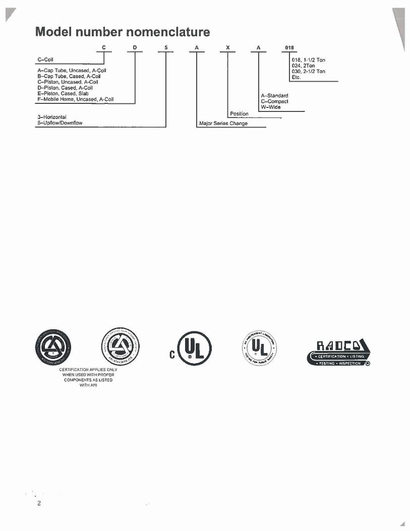
Model number nomenclature C
C-Coil T A-Cap Tube, Uncased, A-Coil B-Cap Tube, Cased, A-Coil C-Plslon, Uncased, A-Coil D-Pislon, Cased, A-Coil E-Piston, Cased, Slab F-Mobile Home, Uncased, A-Coil
3-Horizontal 5-Upflow/Downflow
2
CERTIFICATION APPLIES ONLY WHEN USED WITH PROPER COMPONENTS AS LISTED
WITH ARI
D 5 A X
Position
Major Series Change
A 018
A-Standard C-Compact W-Wide
018, 1-1/2 Ton 024,2Ton 030, 2-1/2 Ton Etc.
,
I C
LEFT SIDE
A
UNIT SERIES In. mm CDS XA018 A 14-3/16 360.4
CDS_XA024 A 14-3/16 3604
CO5_XW024 A 17-1/2 444,5
CD5_XA030 A 14-3/16 360.4
CO5_XW030 A 17-1/2 444.5
CD5_XA038 A 17-1/2 444.5
CD5_XW036 A 21 533.4
CDS XA042 A 21 533.4
CDS_XA048 A 21 533.4
CO5_XC048 A 21 533.4
cos_xw042 A 24-1/2 622.3
CDS_XW048 A 24-1/2 622.3
CDS_XA0&O A 24-1/2 622.3
CDS_XW0&0 A 31-1/2 800.1
CD5_XA070 A 31-1/2 800.1
21 ,,,,e,'"7-l} 2>i,,_4-__ _ __ ,~ ----
,,,,... i-----D----120.e)7
(5U► (•&2<11 ,,
r (,081
,__ ___ ,. ___ _ E.8Qfil
(127>
t2-(!,C Bl 2 l,9-(603)
-----------------~ <> I
RIGHT SIDE
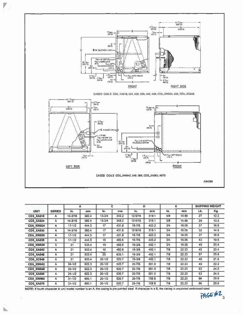
CASED COILS C05..)(A01 B, 024, 030, 036, 042, 048, CDS..)(W024, 036, C05-.XC048
,,,, 1209)
-----D------
2 (SOB) r
--------~-~· 101/e-1257.2)
~------~({>! 31•-119.l)NPT
PLUGGE:> ORIIIH
14i"2,L 2 ,, ("4U)
l,"...- ,.PT0AAtN (Ii.II
I 3/ (3-1.9)
'-------A------' FRONT
CASED COILS CDS..XW042, 048 060, CD5-XA060, A070
A94090
C D E SHIPPING WEIGHT
In. mm ln. mm In. mm Lb. Kg,
13-3/4 349.2 12-9/16 319.1 5/8 15 88 27 12 2
13-3/4 349.2 12-9/16 319.1 5/8 15.88 29 13.2
17 431.8 15-7/8 403 2 314 19.05 37 16 8
17 431.8 12-9/16 319.1 314 19 05 32 14 5
17 431.8 15-7/8 403 2 314 19.05 37 16.8
19 482.6 15-7/8 403.2 314 19.05 43 19.5
19 482.6 19-3/8 492.1 314 19.05 45 204
19 482.6 19-3/8 492.1 7/8 22 23 45 204
25 635.1 19-3/8 492.1 716 22 23 57 25.9
20-1/2 520.7 19-3/8 492.1 718 22.23 48 21.8
20-1/2 520.7 22-7/8 581.0 718 22 23 49 22.2
20-1/2 520.7 22-7/8 581.0 718 22.23 53 24 0
20-1/2 520.7 22-7/8 581.0 7/8 22.23 53 24.0
20-1/2 520.7 29-7/8 7588 7/8 22.23 66 29.9
20-1/2 520.7 29-7/8 7588 7/8 22.23 66 29.9
NOTE: If fourth character in unit model number Is an A. the casing is pre-painted steel If character is a B, the casing is unpainted embossed steel
~~z.3
,
UNIT
CC5AXA018
CC5AXA024
CC5AXW024
CC5AXA030
CC5AXW030
CC5AXA036
CC5AXA042
CC5AXW042
CC5AXWD48
CC5AXC048
CC5AXA060
CC5AXW060
4
,a,:.,,,• (210)
7
1>u•· (44.4) ,r -------
lC'l
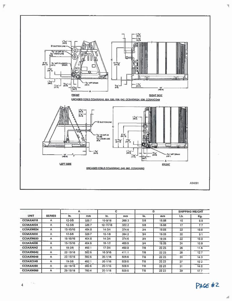
BJGHTSJPE UNCASED COllS CCSAXAQ18 02• 03Q 036. 042 CC5AXW024 Q3Q CC5AXC048
2,, •. (9031 2•1a· 1$4.01
,_ _____ ,r --'\.,-.-.-<•eui
C
911,::,t 114•~
1G11f1&" t27d)
'------ A-----..., EfillliI
UNCASED COJLS CCMXWP:f? Q48 ll6Q CC!IAXAO§O
A94091
A C D SHIPPING WEIGHT SERIES ln. mm In. mm In. mm Lb. Kg.
A 12•5/8 320,7 10.9/16 268.3 518 15.88 15 68
A 12-5/8 320.7 12-11'16 322.2 5/B 15.88 17 7.7
A 15-15/16 404.8 14,3f4 374.6 314 19.05 22 10.0
A 12-5/8 320.7 15. 1/8 384.2 314 19.05 20 9.1
A 15-15/16 404.8 14-314 374.6 314 19.05 22 10.0
A 15-15/16 404 8 18, 112 469.9 314 19.05 24 10.9
A 19-318 492.1 17-314 450 8 7/8 22.23 26 11.8
A 22-15/16 582.6 16-3116 411.1 718 2223 28 12.7
A 22-15/16 582.6 20-1/16 509.6 718 2223 31 14 0
A 19-318 492.1 20-1116 5096 718 22 23 27 12 2
A 22, 15116 582.6 20-1/16 509.6 718 22 23 31 14.0
A 29•15116 760.4 20-1/16 509.6 7/8 22 23 39 17.7
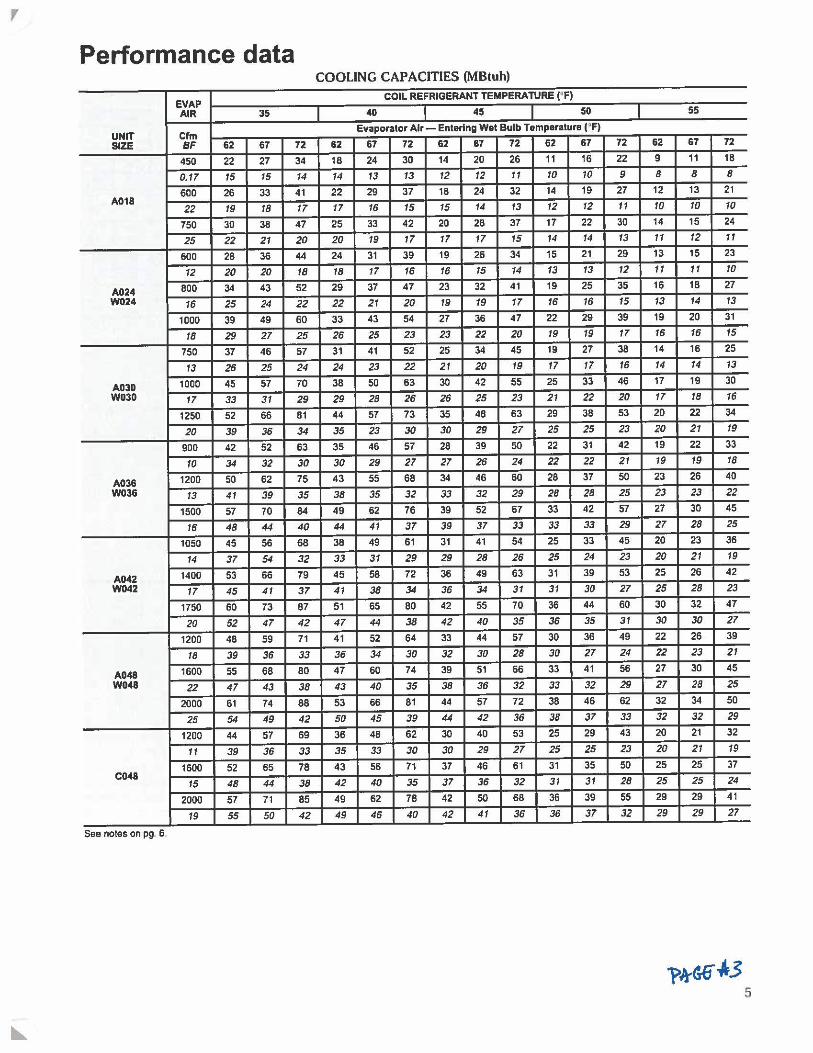
, Performance data
COOLING CAPACITIES (MBtuh)
EVAP COIL REFRIGERANT TEMPERATURE ('Fl
AIR 35 40 45 50 55
UNIT Cfm Evaporator Air- Entering Wet Bulb Temperature ('F)
SIZE BF 62 67 72 62 67 72 62 67 72 62 67 72 62 67 72
450 22 27 34 18 24 30 14 20 26 11 16 22 9 11 1B
0.17 15 15 14 14 13 13 12 12 11 10 10 9 8 8 8
600 26 33 41 22 29 37 1B 24 32 14 19 27 12 13 21 A018
22 19 18 17 17 16 15 15 14 13 12 12 11 10 10 10
750 30 38 47 25 33 42 20 28 37 17 22 30 14 15 24
25 22 21 20 20 19 17 17 17 15 14 14 13 11 12 11
600 2B 36 44 24 31 39 19 26 34 15 21 29 13 15 23
12 20 20 18 18 17 16 16 15 14 13 13 12 11 11 10
A024 800 34 43 52 29 37 47 23 32 41 19 25 35 16 18 27
W024 16 25 24 22 22 21 20 19 19 17 16 16 15 13 14 13
1000 39 49 60 33 43 54 27 36 47 22 29 39 19 20 31
18 29 27 25 26 25 23 23 22 20 19 19 17 16 16 15
750 37 46 57 31 41 52 25 34 45 19 27 38 14 16 25
13 26 25 24 24 23 22 21 20 19 17 17 16 14 14 13
A03D 1000 45 57 70 38 50 63 30 42 55 25 33 46 17 19 30
W030 17 33 31 29 29 28 26 26 25 23 21 22 20 17 18 16
1250 52 66 81 44 57 73 35 48 63 29 3B 53 20 22 34
20 39 36 34 35 23 30 30 29 27 25 25 23 20 21 19
900 42 52 63 35 46 57 28 39 50 22 31 42 19 22 33
10 34 32 30 30 29 27 27 26 24 22 22 21 19 19 18
A036 1200 50 62 75 43 55 68 34 46 60 28 37 50 23 26 40
W036 13 41 39 35 38 35 32 33 32 29 28 28 25 23 23 22
1500 57 70 84 49 62 76 39 52 67 33 42 57 27 30 45
16 48 44 40 44 41 37 39 37 33 33 33 29 27 28 25
1050 45 56 68 38 49 61 31 41 54 25 33 45 20 23 36
14 37 54 32 33 31 29 29 28 26 25 24 23 20 21 19
AD42 1400 53 66 79 45 58 72 36 49 63 31 39 53 25 26 42
W042 17 45 41 37 41 38 34 36 34 31 31 30 27 25 28 23
1750 60 73 87 51 65 80 42 55 70 36 44 60 30 32 47
20 52 47 42 47 44 38 42 40 35 36 35 31 30 30 27
1200 48 59 71 41 52 64 33 44 57 30 36 49 22 26 39
18 39 36 33 36 34 30 32 30 28 30 27 24 22 23 21
A048 1600 55 68 80 47 60 74 39 51 66 33 41 56 27 30 45
W048 22 47 43 38 43 40 35 38 36 32 33 32 29 27 28 25
2000 61 74 88 53 66 81 44 57 72 38 46 62 32 34 50
25 54 49 42 50 45 39 44 42 36 38 37 33 32 32 29
1200 44 57 69 36 48 62 30 40 53 25 29 43 20 21 32
11 39 36 33 35 33 30 30 29 27 25 25 23 20 21 19
1600 52 65 78 43 56 71 37 46 61 31 35 50 25 25 37 C048
15 48 44 38 42 40 35 37 36 32 31 31 28 25 25 24
2000 57 71 85 49 62 78 42 50 68 36 39 55 29 29 41
19 55 50 42 49 46 40 42 41 36 36 37 32 29 29 27
See notes on pg. 6.
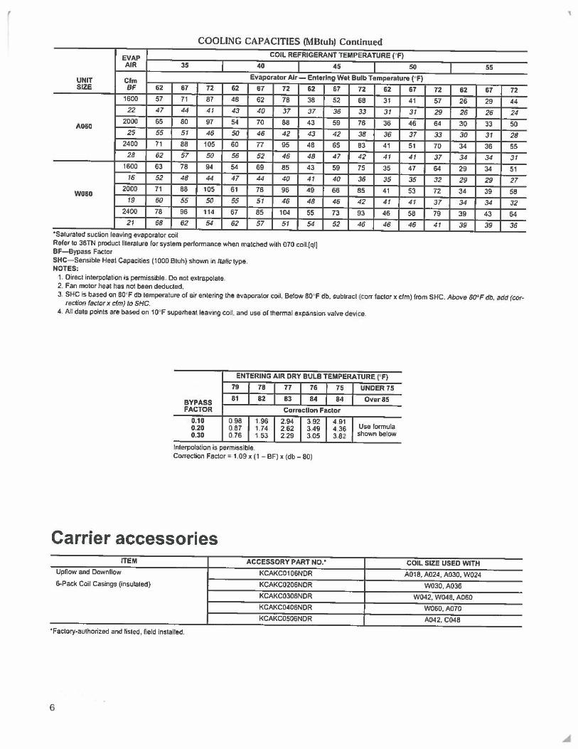
r COOLING CAPACITIES (MBtuh) Continued
EVAP COIL REFRIGERANT TEMPERATURE ('F)
AIR 35 40 45 50
UNIT Cfm Evaporator Air- Entering Wet Bulb Temperature ( ' F)
SIZE BF 62 67 72 62 67 72 62 1600 57 71 87 48 62 78 38
22 47 44 41 43 40 37 37
A060 2000 65 80 97 54 70 88 43
25 55 51 46 50 46 42 43 2400 71 88 105 60 77 95 48
28 62 57 50 56 52 46 48 1600 63 78 94 54 69 85 43
16 52 48 44 47 44 40 41
W060 2000 71 88 105 61 78 96 49
19 60 55 50 55 51 46 48 2400 78 96 114 67 85 104 55 21 68 62 54 62 57 51 54
•saturated suction leaving evaporator coif Refer to 38TN product literature lor system perfonnance when matched with 070 coil.[ql) BF-Bypass Factor SHC- Sensible Heat Capacities (1000 Btuh) shown in Italic type. NOTES:
1, Direct interpolation is permissible, Do not extrapolate. 2. Fan motor heat has nol been deducted.
67 72 62 67
52 68 31 41
36 33 31 31 59 76 36 46
42 38 36 37
65 83 41 51
47 42 41 41 59 75 35 47
40 36 35 35 66 85 41 53
46 42 41 41
73 93 46 58
52 46 46 46
55
72 62 67 72
57 26 29 44
29 26 26 24
64 30 33 50
33 30 31 28 70 34 36 55
37 34 34 31 64 29 34 51
32 29 29 27 72 34 39 58
37 34 34 32 79 39 43 64
41 39 39 36
3. SHC is based on 80' F db lemperalure or air entering the evaporator coil. Below 80' F db, subtracl (corr factor x elm) from SHC. Above B<J>F db, add (correction factor x cfm) to 5HC.
4. An data points are based on 10' F superheat leav:ng colt and use or thenna! expansion valve device.
ENTERING AIR ORY BULB TEMPERATURE ('F)
79 78 77 76 75 UNDER 75
BYPASS 81 82 83 84 84 Over BS
FACTOR Correction Factor
0.10 0.98 1.96 2.94 3.92 4 91 Use formula 0.20 0.87 1.74 2.62 3.49 4 36
0.30 0.76 1 53 2.29 3.05 382 shown below
Interpolation is permissible. Correction Factor " 1.09 x (1 - BF) x (db- 80)
Carrier accessories ITEM ACCESSORY PART No.• COIL SIZE USED WITH
Upflow and Downflow KCAKC0106NDR A018,A024,A030,W024
6-Pack Coil Casings (insulated) KCAKC0206NDR W030,A036
KCAKC0306NDR W042,W048,A060
KCAKC0406NDR W060, A070
KCAKC0506NDR A042, C048
•Factory-authorized and listed, field installed.
6
'
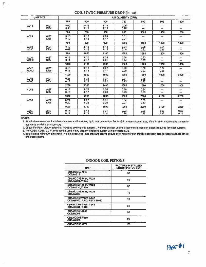
, COIL STATIC PRESSURE DROP (in. we)
UNIT SIZE AIR QUANTITY (CFM)
400 500 600 700 800 900 1000
A018 WET 0.09 0.13 0.19 0,26 - - -DRY 0.08 0.11 0.13 0.20 - - -
600 700 800 900 1000 1100 1200
A024 WET 0.13 0.18 0.24 0.31 - - -DRY 0.10 0.13 0.17 0.21 - - -
700 800 900 1000 1100 1200 1300
A030 WET 0.12 0.16 0.19 0.24 0.28 0 34 -W030 DRY 0.09 0.12 0.15 0.18 0.22 026 -900 1000 1100 1200 1300 1400 1500
A036 WET 0,16 0.20 0.24 0 28 0.33 - -W036 DRY 0.14 0.17 0.21 0 24 0.28 - -
1000 1100 1200 1300 1400 1500 1600
A042 WET 0.15 0.18 0.22 0 26 0 30 0 34 -W042 DRY 0.13 0.15 0.17 0.20 023 026 -
1400 1500 1600 1700 1800 1900 2000
A048 WET 0.21 0.24 0.27 0.31 0 35 - -W048 DRY 0.17 0.19 0.22 0.25 0,27 - -
1200 1300 1400 1500 1600 1700 1800
C048 WET 0.18 0.22 0.26 0.30 034 - -DRY 0.15 0.17 0.20 0.23 026 - -
1600 1700 1800 1900 2000 2100 2200
A060 WET 0,24 0.27 0.31 0.34 038 - -DRY 0.20 0.22 0.25 0.27 030 - -
1600 1700 1800 1900 2000 2100 2200
W060 WET 0.17 0.19 0.21 0.23 0.25 0,27 030 A070 DRY 0.11 0.13 0.14 0.16 0.17 0.18 0.2 1
NOTES: 1. All units have sweat suction lube connection and Hare filling liquid tube connection. For 1-1/8-in. system suction tube, 3/4- x 1-1/8-ln. suction lube c:onneclion
adapter Is available as accessory. 2. Check-Flo-Rater pistons (sized for matched cooling-only systems). Refer to outdoor unit installation instructions for pistons required for olher systems 3. The CD5A, CD58, CCSA coils can be used in any properly designed system using relrigerant 22. 4. Before using maximum cfm shown in table, check coil static pressure drop to ensure system blower can provide necessary static pressure needed for coil
and duel syslems
INDOOR COIL PISTONS FACTORY-INSTALLED
UNIT INDOOR PISTON SIZE
CD5A/CDSBA018 52 CC5AA018
CD5A/CD5BA024, W024 59 CC5AA024, W024
CD5A/CDSBA030, W030 CC5AA030, W030 67
C05A/C05BA036, W036 70 CCSAA036
CD5A/CD5BW042, A042 CCSAW042, A042, A043, W043
78
CD5A/CD5BW048, C048 84 CCSAW048, C048
CD5A/CD5BA060 90 CC5AA060
CD5A/CDSBW060 90 CC5AW060
CD5A/CDSBA070 109
7

* Print.cl on ft!CYt:llld pa~r. Carrier Corporation • Syracuse, New York 13221 5-94 mUNITED TECHNOLOGIES CARRJER
Manufacturer raserves Iha righl to discontinue, or change at any time, specifications or designs without notice and without lm:urrlng obligations.
Book 1 1 t 4 Page B Catalog No .. 92-32CC-5AJC Printed In U.S.A. PC 101 Form CC5A-3PD -t-- -Tab I Jc 2c Replaces: CC5A-2PD
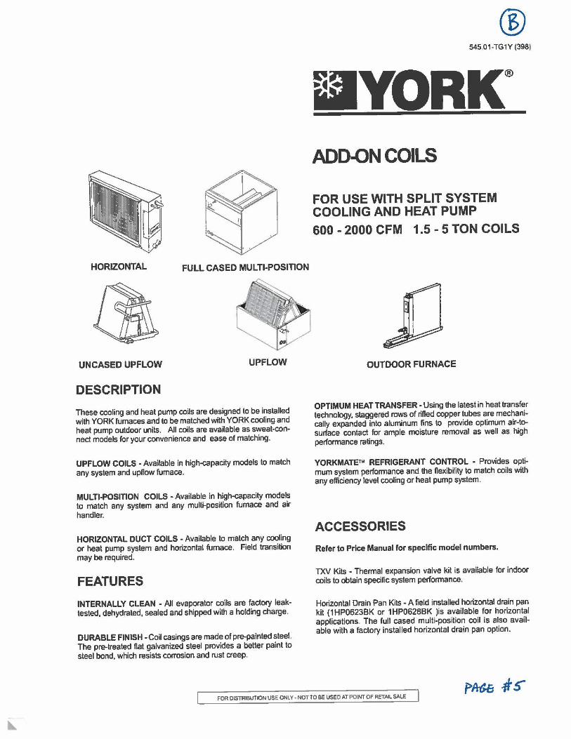
HORIZONTAL FULL CASED MULTI-POSITION
UNCASED UPFLOW UPFLOW
DESCRIPTION
These cooling and heat pump coils are designed to be installed with YORK furnaces and to be matched with YORK cooling and heat pump outdoor units. All coils are available as sweat-connect models for your convenience and ease of matching.
UPFLOW COILS , Available in high-capacity models to match any system and upflow furnace.
MULTI.POSITION COILS -Available in high-capacity models to match any system and any multi-position furnace and air handler.
HORIZONTAL DUCT COILS - Available to match any cooling or heat pump system and horizontal furnace. Field transition may be required.
FEATURES
INTERNALLY CLEAN - All evaporator coils are factory leaktested, dehydrated, sealed and shipped with a holding charge.
DURABLE FINISH -Coil casings are made of pre-painted steel. The pre-treated flat galvanized steel provides a better paint to steel bond, which resists corrosion and rust creep.
® 545.01 -TG1Y (3981
■YORK® ADD-ON COILS
FOR USE WITH SPLIT SYSTEM COOLING AND HEAT PUMP
600 - 2000 CFM 1.5 - 5 TON COILS
OUTDOOR FURNACE
OPTIMUM HEAT TRANSFER • Using the latest in heat transfer technology, staggered rows of rifled copper tubes are mechanically expanded into aluminum fins to provide optimum air-tosurface contact for ample moisture removal as well as high performance ratings.
YORKMATEtu REFRIGERANT CONTROL • Provides opfi. mum system performance and the flexibi~ty to match coils with any efficiency level cooling or heat pump system.
ACCESSORIES
Refer to Price Manual for specific model numbers.
TXV Kits - Thermal expansion valve kit is available for indoor coils to obtain specific system performance.
Horizontal Drain Pan Kits - A field installed horizontal drain pan kit (1HP0623BK or 1HP0628BK )is available for horizontal applications. The full cased multi-posftion coil is also available with a factory installed horizontal drain pan option.
FOR OISTRIBUTION USE ONLY• NOTTO BE USED AT POINT OF RETAIL SAU:
545.01-TG1Y
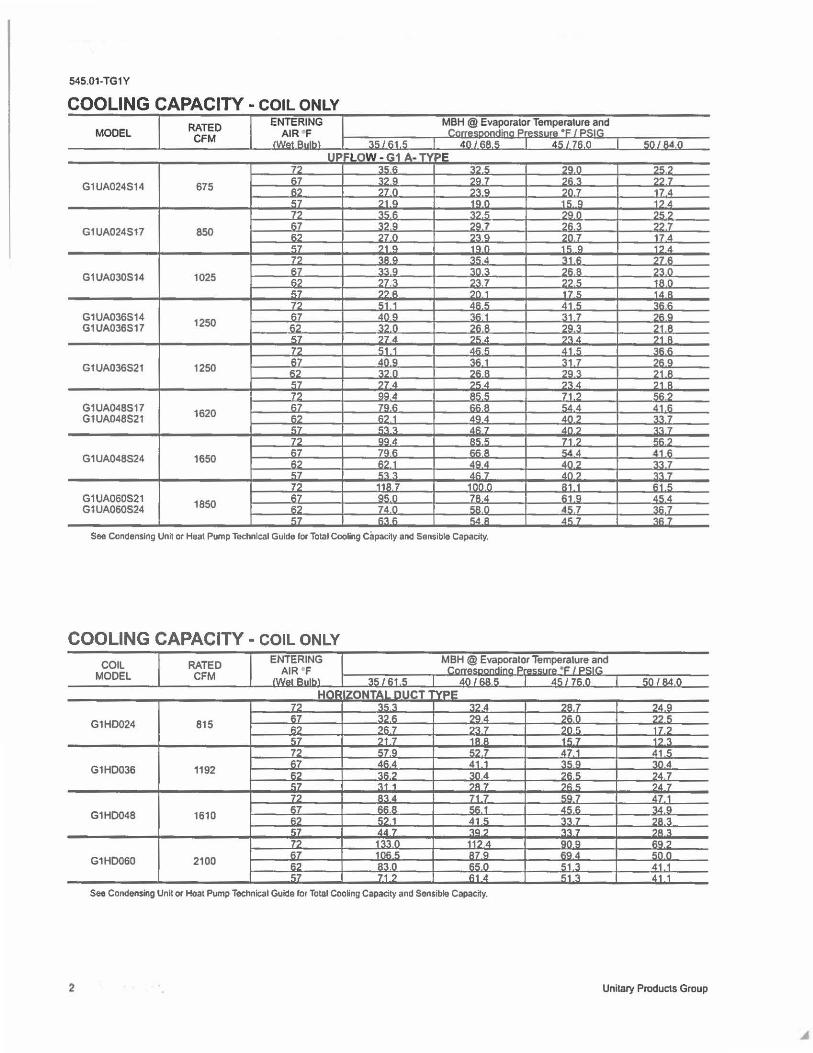
COOLING CAPACITY - COIL ONLY
MODEL
G1UA024S14
G1UA024S17
G1UA030514
G1UA036514 G1UA036517
G1UA036521
G1UA048517 G1UA048S21
G1UA048524
G1UA060521 G1UA060524
RATED CFM
675
850
1025
1250
1250
1620
1650
1850
UP 77 67 fl7 ,;7 72 F,7 I.? ,;7 ,~ 67 .,., ,;;7 77 67
"' 57 72 fl7 62 ,;7 n. l':7 ,:::7 .. , 77 67 I':? 57 72 67 I.?
"'
l=LOW - G1 A. TV PE .,, .. " ::17,; .,,, a 7Q 7 770 7::1.9 71 Q 1a n 351': "1? .5 ':I? a 7g 7 270 239 ?1 Q 1<1 n ':1119 ,ic::4 ,, Q ::in, 273 ?':17 ?? ., ?n 1 ,;1 1 "" o; 40 <1 361 ::17 n 7fl.B 274 ?C::.4 51.1 .4fl .. Ang ':\<': 1 ,, n 26.8 774 7,; d QQ .4 11,;; c;
79.1': flfl A <':? 1 AQ4 '-'l 'l dfl 7 QQ A AC:: c; 79,::: ,:::,::: A
fl7.1 d.Q.4 C::'l"I.
"" 7 118.7 100.0 ac::n 7A4 74.0 AAn .,.,, F, 'id A
See Condensing Unit or Heat Pump Technical Gulde for Total Cooling Capacity and Sensible Capacity.
COOLING CAPACITY - COIL ONLY
2
COIL MODEL
G1HD024
G1HD036
G1HD048
G1HD060
RATED CFM
815
1192
1610
2100
See Condensing Unit or Heat Pump Technical Gulde for Total Cooling Capacity and Sensible Capacity.
7qn 7"- 7 71\.,, 777 7n 17 1 c:: 17 ?Q 7c; 71i 77 7
?n7 17 4 1 o; <I 1? .4 31 F, 77 6 ?I. R ,-:in ?? " 1A n 17 c; 1.4 A
.41,; ::lfl fl 31 7 7,::Q 7Q ::I 21.B 7':\4 '1R 41.5 ':!fl fl '.-11 7 71. Q
?Q "I. 21 R 7'l4 71 R 71? ""' c;.4 .4 41.6 An? ':I':\ 7 dn? 'l':17 71? <;fl ,
54d 41 6 .407 33.7 ,1n7 ,0,07
81.1 61.5 fl1 Q AC:: d. 4c; 7 'l,i; _7 ,t,;7 "IR7
Unitary Products Group
545.01-TG1Y
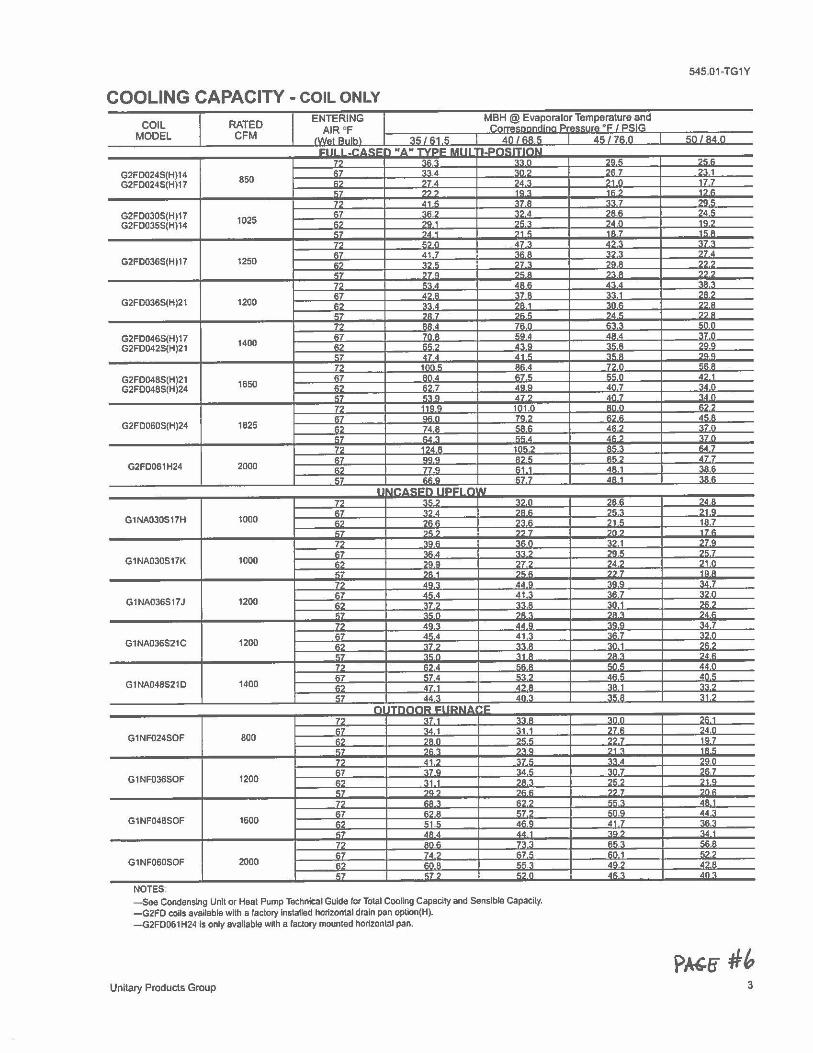
COOLING CAPACITY - COIL ONLY
COIL RATED ENTERING MBH @ Evaporator Temperature and
AIR "F - '· - °F I cc::1r., MODEL CFM /WAI R11lh\ "I.&:: I R1 !'i 4n I &;A&; A&; J 71:. n &;n/R40
1e1i1 I .rAc:i: 'I ".6."TVPF UIII rl.PO!.IITlnN 7" ""., .,_,n -.n • ._,.,.,
G2FD024S(H)14 87 .... 4 .,,,_., .,., .. ?'l.1
G2FD024S{H)17 850 " ?7 4 ., . ., ?1 n 17.7 C .,.,., 10., ... ., . ., "
.111 !I ~7A .,., 7 """ G2FD0305(H)17 "
.,_.,., '>'>4 .,. " 24.5 G2FD0355{H)14 1025 "
.,.,,. .,,,., .,. n . .,, ., .. .,. ")A 1 .,. " .n7 .. , . 7'> .,., n .117 .. ... ., 37 'l
11.7 41 7 .,., . .,.,., 27.4 G2FD036S(Hl17 1250
"" .,., .. '7'> '>'1 D .,, ? .. ., 770 ?CD = .,., .,
7'> "'IA ARI< . ., . ...,.,_ .,7 • ., a .,.,. a .,., 1 ?A?
G2FD036S(H)21 1200 .,., -,-, A .,. 1 ,n., .,., . C'7 ., . ., .,.,., ?A,: .,., . 72 AAA .,..,,. .,., ., "n n
G2FD046S(H)17 07 7nA C<>. ... '1.7 n
G2FD042S(H)21 1400 . ., """ A'2"' .,., . ?QQ
"" 47 A d1,; ... ,. ?QQ
7? 11111 C """ 7? n '"' A
G2FD048S(H)21 S7 .,, . ,::7" ~., ... A
G2F0048S(H)24 1650 . ., C'> 7 4"" An '7 .. . ., CH> A7 '> An 7 ,. 1'2 ,u Q 1n1 n an n " ,:7 ""n 70" .,.,., A
G2FD060S(H)24 1825 ,., 74.8 co" 4"., ,. ,., ,....,. ,c,c A ... ., 170 ,., . ., .. 1ft" '> . . ., l:.d 7
F.7 QQ" . ., . = d7.7
G2FD061H24 2000 "" 77 Q 1::1 1 4" 1 'lAI:: ,;7 ,,., " &;7 7 •• 1 """ I ~·"' "ct:f'\ I IP'lr'I n AJ
.,., .,., ., .,., n --.,-.,---,, ?4A F.7 -,., A .,. ""., ,1 Q
G1NA030517H 1000 "" """
,,., .,, " 1A 7 C,7 ?C:? .,., .,,. ., 171::
72 ""'" .... .,., 1 27.9 F:7 ..... .... .,,,., .,.,.,.
G1NA030517K 1000 .,., ?DD '27 "4" ,1 n ... ?A 1 .,c., ...... 10A
7? An'> .... -.,,---,,- ti 7 .,., A"-A Al 'l
.,.,., ,.,n G1NA036S17J 1200 .,., 'l7? .,., a '1ft 1 .,.,.,
"7 ""n ?A.,_ .,.·., .,.,. 7? AQ'l AA n .,. n ti 7
,::7 d.1;4 41 .. ... 7 i.?n G1NA036S21C 1200 s, 'l7, .,., a .,, 1 .,.,.,
"" "'"' .,, a ., ., ?A"-
7'J "'· ""a "·" ,,.n
"7 574 c-,-, = Aft 0:
G1NA048521D 1400 .,., 471 .... .,. 1 ,. .. ., ,;7 44 'l An'> ., ... 31.2
n ,;-,,- S:l'..,._IA "'C 77 .,., . .. ., . -.,,.-,,- ?11..1 :7 .,. 1 'l1 1 ?7 F. .,. n
G1NF024SOF 800 .. ., "" n
., .... ~ 107
<7 .,.,., ?'lQ -.,. IA S,
r2 41.2 'l7S, 10 ?On <7 37.9 "4,; 1ft .,,. 7
G1NF0365OF 1200 <? 31 1 ., . ., .... ?1 Q
07 """ .,., .. M ')ftC:
77 .... ., fl?, rr AA 1
0.7 """ 572 """ 44'.I G1NF048SOF 1600 ,., 51.5 4"" 41 7 ...... ·~ .IA 4 .,,,., ... 1
72 onc: ""., <;fl A F.7 ., . ., en 1 ,_,,
G1NF060SOF 2000 s, ..nA AO? 4"" "" .... ., = An'l
NOTES - See Condensing Unit or Heal Pump Technical Gulde lor Total Cooling Capacity and Sensible Capacity. -G2FD coils available with a factory Installed horizontal drain pan optlon(H). -G2FD061H24 ls only available with a factory mounted horizontal pan.
Unitary Products Group 3
545.o1-TG1Y
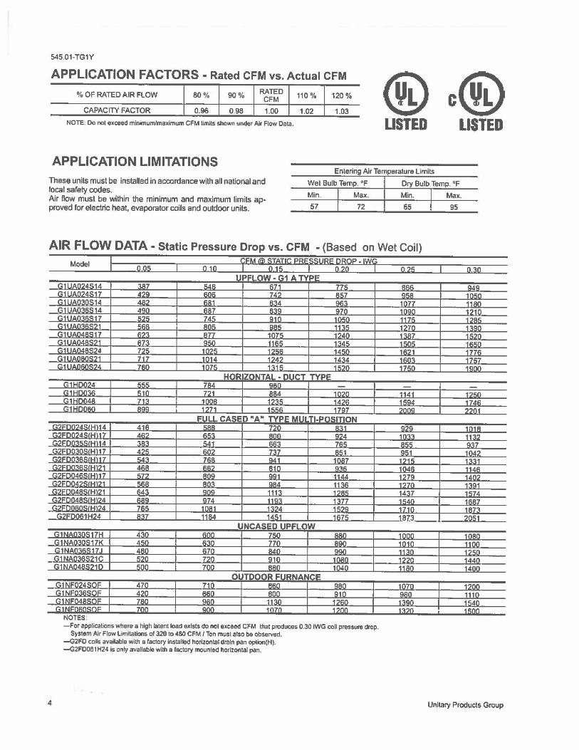
APPLICATION FACTORS - Rated CFM vs. Actual CFM
@c@ % OF RATED AIR FLOW 80 9/4 90% RATED CFM
CAPACITY FACTOR 0.96 0.98 1.00
NOTE. Do not exceed minimum/maximum CFM Umlts shown under />Jr Flow Oala.
APPLICATION LIMITATIONS
These units must be installed in accordance with all national and local safety codes. Air flow must be within the minimum and maximum limits approved for electric heat, evaporator coils and outdoor units.
110 % 120%
1.02 1.03
LISTED LISTED
Entering Air Temperature Limits
Wei Bulb Temp. °F Dry Bulb Temp. °F
Min. I Max. Min. I Max.
AIR FLOW DATA - Static Pressure Drop vs. CFM - (Based on Wet Coil)
4
irnil Ii I
1111 I I II i J i i NOTES: - For applications where a high latent load exists do not exceed CFM that produces 0.30 IWG coil pressure drop.
System />Jr Flow Limitations of 320 to 480 CFM / Ton must also be observed. -G2FD coils available with a factory Installed horizontal drain pan option(H). -G2FD061H24 Is only available with a factory mounted horizontal pan.
0,30
II I !ffl
Unitary Products Group
545.01•TG1Y
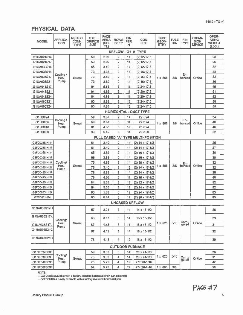
PHYSICAL DATA
REFRIG. STD. FACE FIN TUBE EXPAN• OPER·
MODEL APPLICA- CONN. ORIFICE AREA ROWS PER COIL GEOM- TUBE FIN SION ATING TION TYPE SIZE (SQ, DEEP IN. SIZE ETRY DIA. TYPE DEVICE WEIGHT
FT.) (LBS.)
UPFLOW • G1 A TYPE
G1UA024S14 59 2.92 2 14 (2)12x17.5 26
G1UA024S17 59 2.92 2 14 (2)12x17,5 26
G1UA030S14 65 3.40 2 14 (2)12x17.5 32
G1UA036S14 73 4.38 2 14 (2)18x17.5 32
G1UA036S17 Cooling/
73 3.89 2 14 (2)16x17.5 En-
32 Heat Sweat 1 X .866 3/8 hanced Orifice G1UA036S21 Pump 73 3.89 2 14 (2)16x17.5 36
G1UA048S17 84 5.83 3 11 (2)24x17.5 49
G1UA048S21 84 4.86 3 11 (2)20x17.5 51
G1UA048S24 84 4.86 3 11 (2)20x17.5 52
G1UA060S21 90 5.83 3 12 (2)24x17.5 SB
G1UA060S24 90 5.83 3 12 (2)24x17.5 58
HORIZONTAL • DUCT TYPE
G1HD024 59 3.67 2 14 22x24 34
G1H0036 Cooling/
69 3.67 3 11 22x24 En•
40 Heat Sweat 1 X .866 3/8 rianced Orifice G1HD048 Pump 81 4.33 3 12 26x24 46
G1HD060 93 5.42 3 11 26x30 52
FULL CASED "A" TYPE MULTI-POSITION
G2FD024S(H)14 61 3.40 2 14 (2) 14 X 17-1/2 25
G2FD024S(H)17 61 3.40 2 14 (2) 14 X 17-1/2 27
G2FD035S(H)14 65 3.89 2 14 (2) 16 X 17-1/2 30
G2FD030S(H)17 65 3.88 2 14 (2) 16 X 17-1/2 30
G2FD036S(H)17 Cooling/ 75 4.86 3 14 (2) 20 X 17-1/2 En- 32
G2FD036S(H)21 Heat Sweal 75 3.40 3 12 (2) 14 X 17-1/2 1 X .886 3/8 hanced Orifice 32 Pump G2F0046S(H)17 78 5.83 2 14 (2) 24 X 17-1/2 36
G2FD042S(H)21 78 4.86 3 11 (2) 16 X 17•1/2 40
G2FD048S(H)21 84 5.35 3 12 (2) 22 X 17-1/2 52
G2FD048S(H)24 84 5.35 3 12 (2) 24 X 17-1/2 52
G2FD060S(H)24 90 5.83 3 12 (2) 24 X 17-1/2 63
G2FD061H24 90 6.81 3 12 (2) 28 X 17-1/2 85
UNCASED UPFLOW
G1NA030S17H 57 3.21 3 14 14 X 16-1/2 26
G1NA030S17K 63 3.67 3 14 16 X 16-1/2 29 Cooling/ COWc·
G1NA036S17J Heat Sweat 67 4.13 3 14 18 X 16-1/2 1 x .625 5/16 gaed Orifice 31 Pump G1NA036S21C 67 4.13 3 14 18 X 16-1/2 32
G1NA048S21D 78 4.13 4 12 18 X 16-1/2 39
OUTDOOR FURNACE
G1NF024SOF 59 3.33 3 14 20 X 24-1/8 26
G1NF036SOF Cooling/
73 3.33 4 14 20 X 24-1/8 1 x .625 5/16 CoWc• 31 Heat Sweat gaed Orifice G1NF048SOF Pump 73 5.25 4 12 27x 28-1/16 42
G1NF060SOF 84 5.25 4 12 27x 28·1-16 1 X .886 3/8 50
NOTE: -G2FD coils available with a factory installed horizontal drain pan optlon(H). -G2FD061 H24 Is only available with a factory mounted horizontal pan.
Unitary Products Group 5
545 01-TGtY
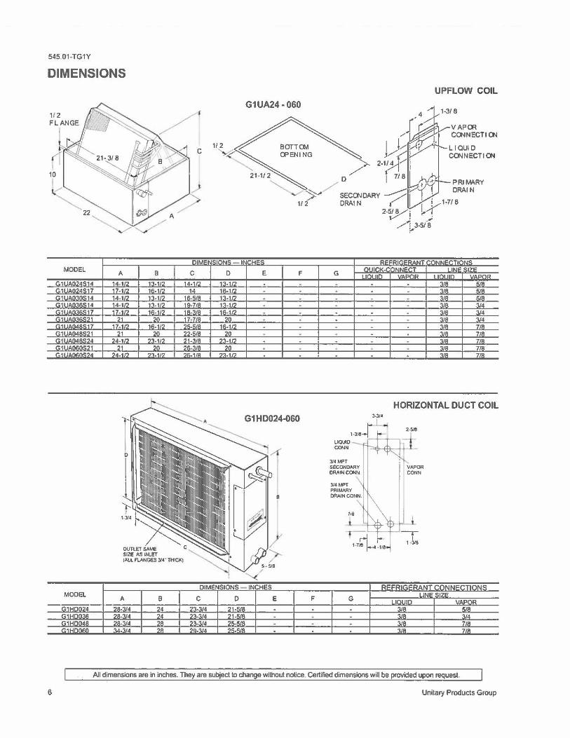
DIMENSIONS
10 I l.(_
MODEL
r.11 IAn?A".14 G1UA024S17 G1 -~ r.11 '""~"C:14 G11JA036S17 G1UAinn'<71 r.11 ,,.nAac;17 r. 1 I lt,,n4A<:'l 1 G11 OAn•u~~•
C::1 oAn~n~~,
r.11 OAMnr~•
A B 14-10 1:\.1/:> 17- 1/2 16-1/2 1'1-1/2 13-1/2 14. 1n n.11:> 11.1n 16-1/2
21 20 17. 11' 1s.1n
,1 ,o 24- 1/2 73.1,2
21 20 ::>4.11' ?'\.11?
OUTlETSAME SIZE AS INLET
C
C 1..s.1n
14 16--.tR Hl.7/R 1R-~'" 17•7/R 25.l;IR ,::>.!;/R 2, •. ., ..
26-'UR 'Jf;..1/A
IAlL FLANGES J/4" THICK)
MODEL I A I lii5 j H
B
" 0
1:l-11::> 11:.112 13-1/2 1'.l-11::> '"-112
20 1R.1n
::>n 2'.l-1/7
20 n.11::>
G1UA24-060
D
/ ~ SECOJDARY
1,{- ORAi N I 2-~J
_,,.,-·p-s,a
-~~
t"lt rn~K.r "'l"'N"rT E F G
"""' "AD,, ..
. . - . .
. . . . . . . . . . . .
. . . .
. . . . .
. . . -. . .
. . . . . - . . . . . . .
UPFLOW COIL
VAPCR CONNECTIOJ
LIQUID CONNECTIOI
PRIMARY DRAIN
''"'" "'7" I .,..,,. nr ,,. ,,.,~
:UK "/K
'.l/R /;/R "UA ',/A
:UR "lid
'"" '.l/4 . ., .. 3/4 '\IA 718 '.\JR 718 ~, .. 7/R 'UA 718 ,OD ,,,.
HORIZONTAL DUCT COIL
G1HD024-060
G
-.-1
1 -318
All dimensions are in inches. They are subject to change wi1hout notice, Certified dimensions will be provided upon request.
6 Unitary Products Group
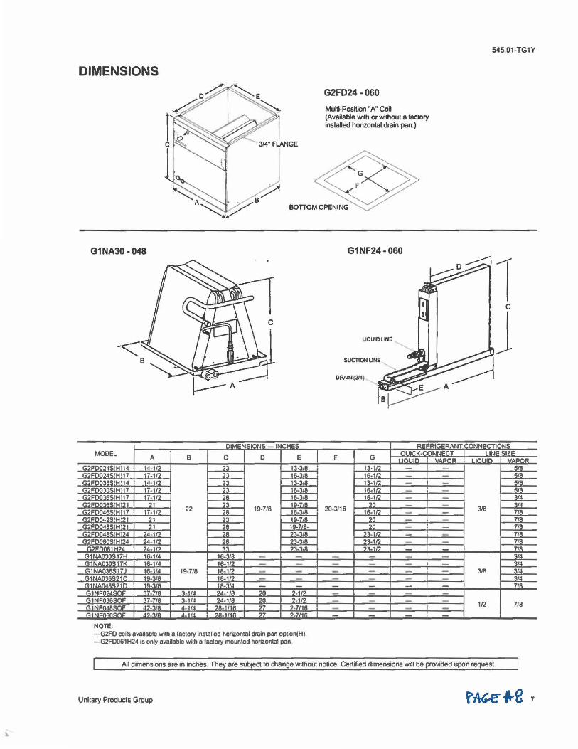
DIMENSIONS
G1NA30-048
,. .. ~N~ .. ,~~ 1Nr"'""' MODEL A B C D E
GZFDOZ4SIHl14 14-11? 23 13-~JR r.-,i:nn7451Hl17 17-1/2 23 1R.'UA
~, ··14 .... ,,., ?'.I 1'.\.'UR :·,.7 11. ,n n 1i; ... , ..
r.7F -.n-." ilHl17 17. 112 2R 16-3/8 .. U\ ,, 21 23 19-7/8
19-718 ,. ·~, " 7 17.11? 22 28 IR.'UA .. ·~, ,, n n IQ.7/R r.,:,i;nn4i,, '1Hl?1 71 7R 1Cl. 7/R. ,.
"LM ?4,1M :>R n.-., .. Hl24 24-11' 28 23-3/8
=IM?.4 ?.,4.◄ I-, .,..,. 11 ~ ,u
r. nm, :17H 1R.1/4 1R.'\/8 -- ;HK 11> HA 11\.11, -C::1fJAn'>.:<:17J 11;. 114 19-7/8 1A. 1/7 -C 19.-., .. 1R. 1.'7
'" ~ '"·"''" , ..... 37-718 3.1 ... 24-1 8 20 2,1/2 37•1/H 3 ,1 4 24,1 A ,n 2.11?
"'·""' 4, 1 'd ?A. '" ,1 7-7111\
" ~ .. , . .. /R 4 . 1 , .. 7A.1/1fi 77 7.7/lll
NOTE· -G2FD coils available with a factory installed horiZontal drain pan option(H). -G2F0061H24 ls only available with a fado,y mounted horizontal pan
G2FO24-060
Multi-Position "A" Coil (Available with or without a factory instaled horizontal drain pan.)
G1NF24-060
ORAIN tJ/4)
nlJICK• F G 11nr11n
13•l/Z IR.1/? 1'.l.•I'> 1i;.1n 1R.1/2
20-3!16 20 -
1ft.112 ,n :;,n
?'l,1/2 23-1/2 -?'>.11? --
545 01-TG1Y
N I Ill.II: <:17<: ,..,,,., 11r,■ 11n ,,. ,,, ..
""' Ii/A
'"" "'" .. , ..
- . ., .. 3/8 718
7/R 7/R /R
- /8 , u
,/4 IIA
3/8 ,,, .. :l/4 7 / A
1/2 7/8 -
All dimensions are in inches. They are subject to change without notice. Certified dimensions will be provided upon request
Unitary Products Group

Heating and Air Conditioning
Unita,y ProduclS Groui> P.O Box 1592, York, Pann1ylvania USA 17405-1592 Subjec1 to dlange wiU,oul nollee. Prinled in U.S.A. Copyright e by Yori< lntomatlonal Corporabon 1998. All RighlS Reserved
USA Q5(5) -saf ... ltM
U S ~Tum
"" 545.01-TGIY
Supersedes 545 01-TGIY (997)
. '
HEATING & COOLING
Copyright 2003 Carner Corporation
Product Data
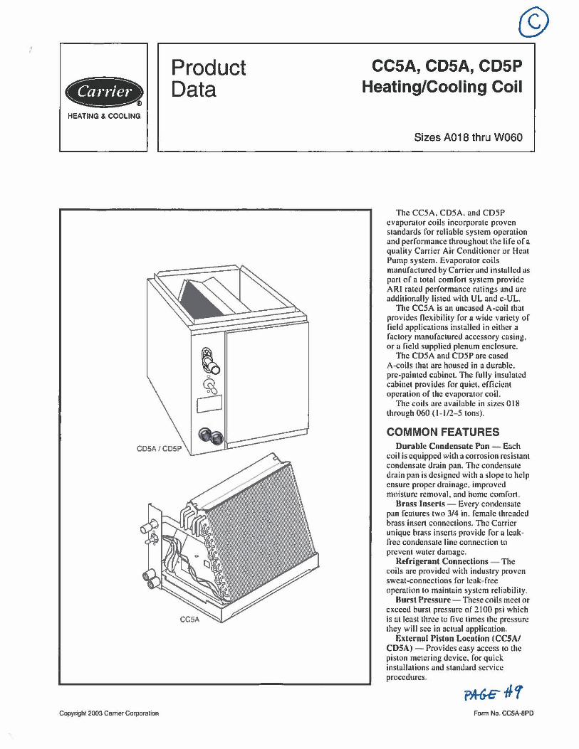
@) CC5A, CDSA, CDSP
Heating/Cooling Coil
Sizes A018 thru W060
The CC5A, CD5A, and CD5P cvaporalor coils incorporalc proven standards for reliable system operation and performance throughout lhe Ii fe of a qualily Carrier Air Conditioner or Heal Pump system. Evaporator coils manufactured by Carrier and installed as part of a total comfort system provide ARI rated performance ratings and are additionally listed with UL and c-UL.
The CC5A is an uncased A-coil thal provides flexibility for a wide variety of field applications installed in either a faclory manufaclured accessory casing, or a field supplied plenum enclosure.
The CD5A and CD5P arc cased A-coils lhat arc housed in a durable, pre-painted cabinet. The fully insulated cabinel provides for quiet, cfficicnl opcralion of the evaporator coil.
The coils arc available in sizes 0 18 through 060 ( 1- 1/2- 5 tons).
COMMON FEATURES Durable Condcnsalc Pan - Each
coil is equipped wi1h a corrosion resistant condensate drain pan. The condensale drain pan is designed with a slope lo help ensure proper drainage, improved moisture removal, and home comfort.
Brass lnscrls - Every condensate pan features 1wo 3/4 in. female threaded brass inserl connections. The Carrier unique brass inserts provide for a leakfree condensate line connection lo prcvenl water damage.
Refrigerant Connections - The coils arc provided with industry proven sweat-connections for leak-free operation lo maintain system reliability.
Burst Pressure - These coils meet or exceed burst pressure of 2100 psi which is al least lhrcc lo five times the pressure they will sec in aclual applicalion.
External Piston Location (CCSA/ CDSA) - Provides easy access 10 1he piston mclcring device, for quick ins1alla1ions and slandard service procedures.
Fomi No, CCSA•BPD
Liquid Linc Bracket- Holds the piston body in place for quick. safe piston access without needing a back-up wrench.
Tenon Ring - The ring, installed inside the liquid line connection, is the best option for preventing refrigerant leaks and future service calls. Tenon works with Puron® and R-22 refrigerants.
Protective Tube Sheets - Protect the durable copper tubing from being damaged during the manufacturing and installation process.
Warranty - All Carrier coils feature a limited 5-year warranty on parts, with
additional extended warranties on the system available.
CC5A FEATURES Coil Support - Carrier provides a
standard factory :;upport for the uncased coil. This provides precise, durable support in the plenum for easier installations.
Face Plate - A unique Carrier feature that provides for a more professional installa1ion and prevents air leaks at the refrigerant line connections.
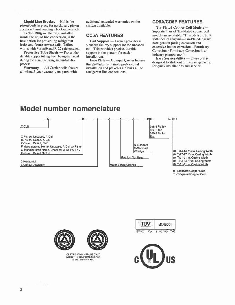
Model number nomenclature
C-Cojl J C-P•ston, Uncased, A-Coil O-Piston, Cased, A•Coil E-Pislon, Cased, Slab F•Manufaclured Home, Uncased, A•Coil w/ Piston G-Manufactured Home, Uncased, A•Coil w/ TXV K-Piston Cased N-Coil
3-Honzontal 5-U flowtDowntlow
A-Standard C-Compact W-Wide
Ma'or Series Chan e
CDSA/CDSP FEATURES Tin-Plated Copper Coil Models -
Separate lines of Tin-Plated copper coil modcb arc available. "T' models arc built wilh special hairpins- Tin-Plated to resist both general pitting corrosion and excessive indoor corrosion- Formicary Corrosion. (Formicary Corrosion is an industry phenomenon).
Easy Serviceability - Every coil is designed 10 slide out of the casing easily. for quick installations and service.
018·1 1JzTon 024•2Ton 030·2 ½ Ton Etc.
(0, T)14-14 3/16 In, Casing Width (0, T)17•17 ½ In. Casing Width (0, T)21 ·21 In. Casing Width (0, T)24·24 lf2 In. Casing Width O 31·31 In. Casin Width
0 - Standard Copper Coils T • nn-plaled Copper Coils
•• I ~ 1SO 9001
2
CERTIFICATION APPLIES ONLY WHEN THE COMPLETE SYSTEM
IS LISTED WITH ARI
IS09001 Ccn. 12 100 7854 TMS
C us
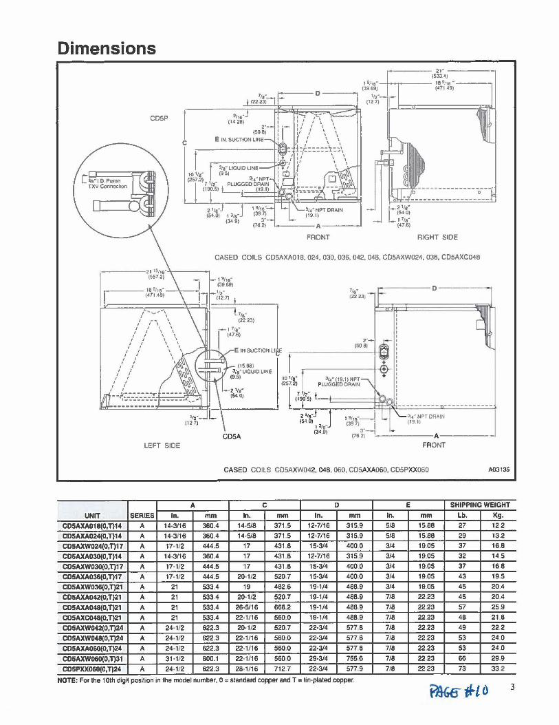
Dimensions
CD5P
C
LEFT SIDE
A
UNIT SERIES In.
CDSAXA018(0,n14 A 14•3/16
CDSAXA024(0,n14 A 14•3/16
CDSAXW024(0,n11 A 17-112
CD5AXA030(0,n14 A 14-3/16
CD5AXW030(0,n17 A 17• 112
CD5AXA036(0,n17 A 17-1/2
CD5AXW036(0,n21 A 21
CD5AXA042(0,n21 A 21
CD5AXA048(0,n21 A 21
CD5AXC048(0,n21 A 21
CD5AXW042(0,n24 A 24-112
CD5AXW048{0,n24 A 24-112
CDSAXA0&O(o,n24 A 24· 112
CD5AXW060(0,n31 A 31-112
CD5PXX060(0,T)24 A 24-112
------------------0
2 ,,,· (54.0) 13/a"
(34 9) '-A_ 1- t2 11s· (54 0) 1 71e· (47.6)
FRONT RIGHT SIDE
CASED COILS CD5AXA018, 024, 030, 036, 042, 048, C05AXW024, 036, CD5AXC048
mm 360.4
360.4
444.5
360.4
444.5
444.5
533.4
533.4
533.4
533.4
622.3
622.3
622.3
800.1
622.3
E IN SUCTION Lt
(1588) 'la" llOUIO LINE
(9 5) IO 1/e" (257.2)
l/4" (19.1) NPT PLUGGED DRAIN
' ' ' ' ' ' ' ' ' ' ' ' ' ' ' ' ' ' ' (;9~·~) L_'-=====11:$;1.nl:
l.,__J2[_1,-•• --~-1-.,-,.-. -~Q ~ ~ :,. :~;T_O_R~IN ____________ I
(54 .0) , , ,.. 139 7) (19. 11
P 4-9> (76~; !-------A • CD5A
FRONT
CASED COILS C05AXW042, 048, 060, CD5AXA060, CD5PXX060 A03135
C D E SHIPPING WEIGHT
In. mm In. mm In. mm Lb. Kg.
14-5/8 371 .5 12•7/16 315.9 5/8 15.88 27 12.2
14,5/8 371 ,5 12-7/16 315.9 5/8 15.88 29 13.2
17 431 .8 15-3/4 400 0 3/4 19.05 37 16.8
17 431. 8 12-7/16 315 9 3/4 19.05 32 14.5
17 431 .8 15-3/4 400 0 3/4 19.05 37 16.8
20-1/2 520.7 15-3/4 4000 3/4 19.05 43 19.5
19 482.6 19-1/4 488.9 3/4 19,05 45 20.4
20-1/2 520.7 19-1/4 488.9 7/8 22.23 45 20.4
26-5/16 668.2 19-1/4 488 9 7/8 22.23 57 25.9
22-1/16 560,0 19-1/4 488 9 7/8 22.23 48 21.8
20-1/2 520.7 22-3/4 577 8 7/8 22.23 49 222
22•1/1 6 560,0 22•3/4 577.8 718 22.23 53 24.0
22· 1/ 16 560.0 22•3/4 577 8 7/8 22.23 53 24.0
22-1/16 560.0 29-3/4 7556 7/8 2223 66 29.9
28-1/16 712.7 22-3/4 577.9 718 2223 73 332
NOTE: For the 10th digit pos,Hon in the model number, O = standard copper and T = tin-plated copper. 3
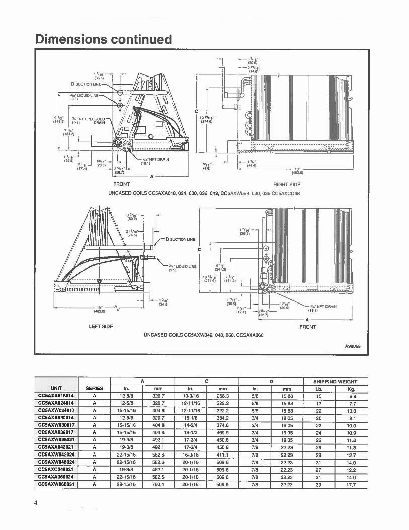
Dimensions continued
4
3/9' UOUID llNE (9S)
7 1,,.. (184.2)
, ,,, •. J J (36.5)
11/11( (17.41
FRONT
7 331,.· (80.9) 2 15/,e" (74.6)
.----ir+--+--=:r
C 10 13/11"' (274.6>
3,,..J J (4.8)
l:=13/4" (44.4) 19• _______ _,
(4112.6)
RIGHT SIDE
UNCASED COILS CC5AXA018, 024, 030, 036, 042, CC5AXW024, 030, 036 CC5AXCO48
I.
UNIT CC5AXA018014
CC5AXA024014
CCSAXW024017 CCSAXA030014
CCSAXW030017
CCSAXA036017
CCSAXW036021 CCSAXA042021 CCSAXW042024
CCSAXW048024 CC5AXC048021
CC5AXA060024 CCSAXW060031
3 3,, • • (80.91
19• _j (4112.6)----v---l
r 'rD><'°""" C '-~•.· uou D LINE
f9.S)
L 13,.• (34,9)
10 131,9... 7 , , .... (274.6) (184.2)
- ------ A------"" LEFT SIDE FRONT
UNCASED COILS CC5AXW042, 048, 060, CC5AXA060
A98068
A C 0 SHIPPING WEIGHT SERIES In. mm In. mm In. mm Lb, Kg.
A 12-5/8 320.7 10,9/16 268.3 5/8 15.88 15 68 A 12-5/8 320.7 12-11/16 322.2 5/8 15.88 17 7.7
A 15•15/16 404.8 12-11/16 322.2 5/8 15.88 22 10,0 A 12-5/8 320.7 15-1/8 384.2 3/4 19.05 20 9.1 A 15-15/16 404.8 14-3/4 374.6 3/4 19.05 22 10,0
A 15·15/16 404.8 18-1/2 469.9 314 19.05 24 10.9
A 19-3/8 492.1 17-3/4 450.8 3/4 19.05 26 11 .8
A 19-3/8 492.1 17·3/4 450.8 7/8 22.23 26 11.8 A 22-15/16 582.6 16·3/16 411.1 7/8 22.23 28 12.7 A 22•15/16 582.6 20-1/16 509.6 7/8 22.23 31 14.0 A 19·3/8 492.1 20-1/16 509.6 7/8 22.23 27 12.2
A 22-15/16 582.6 20-1/16 509.6 7/8 22.23 31 14.0 A 29-15/16 760.4 20·1/16 509.6 7/8 22.23 39 17.7
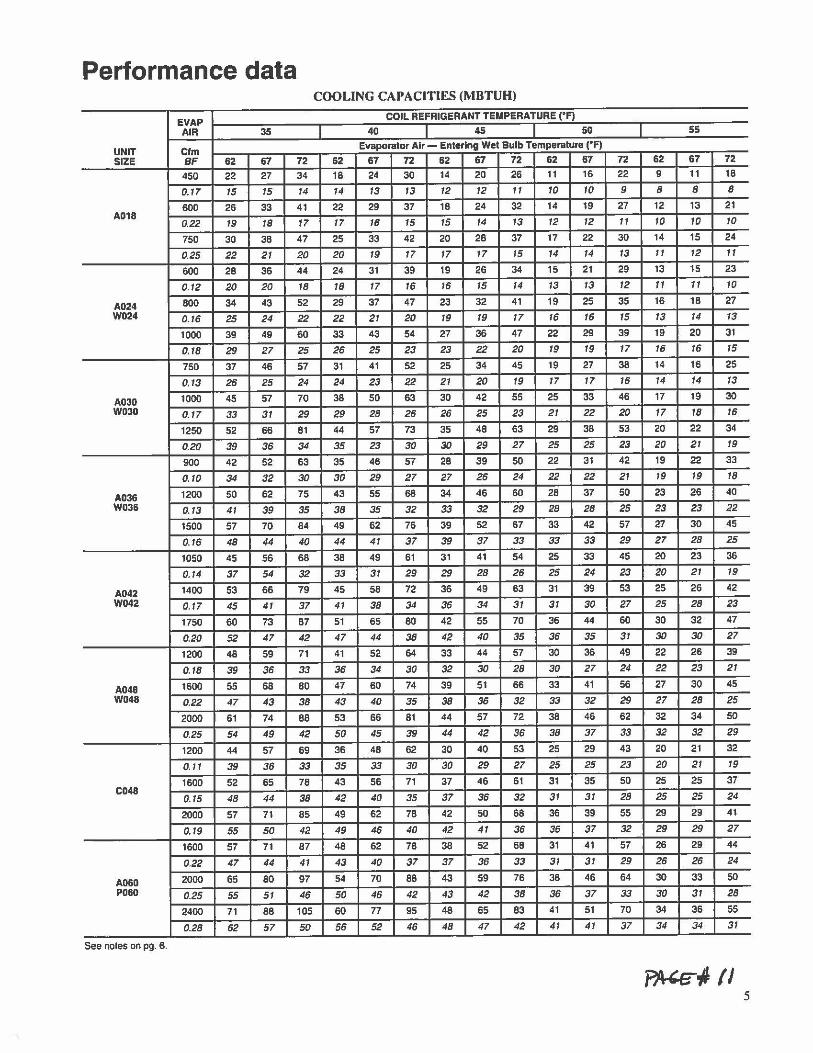
Performance data COOLING CAPACITIES (MBTUH)
EVAP COIL REFRIGERANT TEMPERATURE ("F)
AIR 35 I 40 45 so 55
UNIT Cfm Evaporator Air - Entering Wet Bulb Temperature ("F)
SIZE BF 62 67 72 62 67 72 62 67 72 62 67 72 62 67 72
450 22 27 34 18 24 30 14 20 26 11 16 22 9 11 18
0.17 15 15 14 14 13 13 12 12 11 10 10 9 8 8 8
600 26 33 41 22 29 37 18 24 32 14 19 27 12 13 21 A018
0.22 19 18 17 17 16 15 15 14 13 12 12 11 10 10 10
750 30 38 47 25 33 42 20 28 37 17 22 30 14 15 24
0.25 22 21 20 20 19 17 17 17 15 14 14 13 11 12 11
600 28 36 44 24 31 39 19 26 34 15 21 29 13 15 23
0.12 20 20 18 18 17 16 16 15 14 13 13 12 11 11 10
A024 800 34 43 52 29 37 47 23 32 41 19 25 35 16 18 27 W024 0.16 25 24 22 22 21 20 19 19 17 16 16 15 13 14 13
1000 39 49 60 33 43 54 27 36 47 22 29 39 19 20 31
0.18 29 27 25 26 25 23 23 22 20 19 19 17 16 16 15
750 37 46 57 31 41 52 25 34 45 19 27 38 14 16 25
0.13 26 25 24 24 23 22 21 20 19 17 17 16 14 14 13
A030 1000 45 57 70 38 50 63 30 42 55 25 33 46 17 19 30
W030 0.17 33 31 29 29 28 26 26 25 23 21 22 20 17 18 16
1250 52 66 81 44 57 73 35 48 63 29 38 53 20 22 34
0.20 39 36 34 35 23 30 30 29 27 25 25 23 20 21 19
900 42 52 63 35 46 57 28 39 50 22 31 42 19 22 33
0.10 34 32 30 30 29 27 27 26 24 22 22 21 19 19 18
A036 1200 50 62 75 43 55 68 34 46 60 28 37 50 23 26 40
W036 0.13 41 39 35 38 35 32 33 32 29 28 28 25 23 23 22
1500 57 70 84 49 62 76 39 52 67 33 42 57 27 30 45
0.16 48 44 40 44 41 37 39 37 33 33 33 29 27 28 25
1050 45 56 68 38 49 61 31 41 54 25 33 45 20 23 36
0.14 37 54 32 33 31 29 29 28 26 25 24 23 20 21 19
A042 1400 53 66 79 45 58 72 36 49 63 31 39 53 25 26 42 W042 0.17 45 41 37 41 38 34 36 34 31 31 30 27 25 28 23
1750 60 73 87 51 65 80 42 55 70 36 44 60 30 32 47
0.20 52 47 42 47 44 38 42 40 35 36 35 31 30 30 27
1200 48 59 71 41 52 64 33 44 57 30 36 49 22 26 39
0. 18 39 36 33 36 34 30 32 30 28 30 27 24 22 23 21
A048 1600 55 68 80 47 60 74 39 51 66 33 41 56 27 30 45
W048 0.22 47 43 38 43 40 35 38 36 32 33 32 29 27 28 25
2000 61 74 88 53 66 81 44 57 72 38 46 62 32 34 50
0.25 54 49 42 50 45 39 44 42 36 38 37 33 32 32 29
1200 44 57 69 36 48 62 30 40 53 25 29 43 20 21 32
0.11 39 36 33 35 33 30 30 29 27 25 25 23 20 21 19
1600 52 65 78 43 56 71 37 46 61 31 35 50 25 25 37 C048
0.15 48 44 38 42 40 35 37 36 32 3 1 31 28 25 25 24
2000 57 71 85 49 62 78 42 50 68 36 39 55 29 29 41
0.19 55 50 42 49 46 40 42 41 36 36 37 32 29 29 27
1600 57 71 87 48 62 78 38 52 68 31 41 57 26 29 44
0.22 47 44 41 43 40 37 37 36 33 31 31 29 26 26 24
AO&O 2000 65 80 97 54 70 88 43 59 76 36 46 64 30 33 50 PO&O 0.25 55 51 46 50 46 42 43 42 38 36 37 33 30 31 28
2400 71 88 105 60 77 95 48 65 83 41 51 70 34 36 55
0.28 62 57 50 56 52 46 48 47 42 41 41 37 34 34 31
See noles on pg. 6.
5
EVAP AIR 35
UNIT Cfm SIZE BF 62 67
1600 63 78
0, 16 52 48
WO&D 2000 71 88
0. 19 60 55 2400 78 96
0.21 68 62
• Saturated suet on teaving evaporator coil CFM - Cubic Ft. per Minute EWB - Entering Wet Bulb (•F) LWB - Leav.ng Wet Bulb ('F) TC - Total Cool ng Capacity 1000 Btuh BF - Bypass Factor MBH - 1000 Btuh
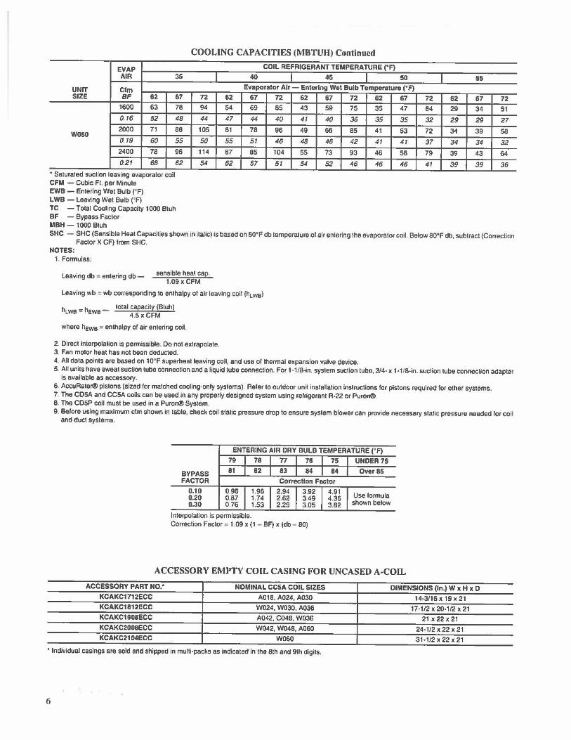
COOLING CAPACITIES (MBTUH) Continued
COIL REFRIGERANT TEMPERATURE (•F)
40 45 SD 55 Evaporator Air - Entering Wet Bulb Temperature (°F)
72 62 67 72 62 67 72 62 67 72 62 67 72 94 54 69 85 43 59 75 35 47 64 29 34 51
44 47 44 40 41 40 36 35 35 32 29 29 27 105 61 78 96 49 66 85 41 53 72 34 39 58
50 55 51 46 48 46 42 41 41 37 34 34 32 114 67 85 104 55 73 93 46 58 79 39 43 64
54 62 57 51 54 52 46 46 46 41 39 39 36
SHC - SHC (Sensible Heat Capac.I es shown In Ita!ic) is based on 80'F db temperature of air entering the evaporator coil. Below 80'F db, subtract (Correction Factor X CF) from SHC.
NOTES: 1. Formulas:
Leaving db = entering db - sensible heat cap 1.09x CFM
Leaving wb ,. wb corresponding to enthalpy or air leaving coil (hl we)
h _ h _ total capacity (Btuh) t WB - EWB 4.5 x CFM
where hews a enthalpy of air entering coil.
2 . Direct interpolation is permissible. Do not extrapo,ate. 3. Fan motor heat has not been deducted. 4. All data points are based on 10' F superheat leaving coil, and use of thermal expansion valve device. 5. Al units have sweat suction tube connection and a liquid tube connect:on. For 1 • 1/8-in. system suction tube, 3/4- x 1 -1/8-in. suction tube connection adapter
is available as accessory.
6 AccuRater® pistons (sized for matched cooling-only systems) Refer to outdoor unit installation instructions for pistons required for other systems. 7. The CDSA and CCSA coils can be used in any properly designed system using refrigerant R-22 or Puron®. 8. The CD5P coil must be used in a Puron® System.
9. Before using maximum elm shown in table, check coil stalic pressure drop to ensure system blower can provide necessary statie pressure needed for coil and duct systems.
ENTERING AIR DRY BULB TEMPERATURE ("F)
79 78 n 76 75 UNDER75
BYPASS 81 82 83 84 84 Over 85 FACTOR Correction Factor
0.10 098 1.96 2.94 3.92 4.91 Use formula 0.20 0.87 1.74 2.62 349 4.36
0.30 076 1.53 2.29 305 3.82 shown below
Interpolation Is permissible. Correction Factor ■ 1 09 x (1 - BF) x (db - 80)
ACCESSORY EMPTY COIL CASING FOR UNCASED A-COIL
ACCESSORY PART NO.' NOMINAL CCSA COIL SIZES DIMENSIONS (In.) W x H x D KCAKC1712ECC A018, A024, A030 14•3/16 X 19 X 21 KCAKC1812ECC W024,W030, A036 17-1/2 X 20-1/2 X 21 KCAKC1908ECC A042, C048, W036 21 X 22 X 21 KCAKC2008ECC W042, W048, A0GO 24-1/2 X 22 X 21 KCAKC2104ECC W060 31•1/2 X 22 X 21
• Individual casings are sold and shipped in multi-packs as Indicated in the 8th and 9th digits.
6
UNIT SIZE BULB
A018 WET DRY
A024 WET DRY
W024 WET DRY
A030 WET DRY
W030 WET DRY
A036 WET DRY
W036 WET DRY
A042 WET DRY
W042 WET DAY
1400 A048 WET 0.21
ORY 0,17 1400
W048 WET 0.19 ORY 0.15
C048 WET DRY
1600 A060 WET 0.24 P060 DRY 020
1600 W060 WET 0.17
DRY 0.11
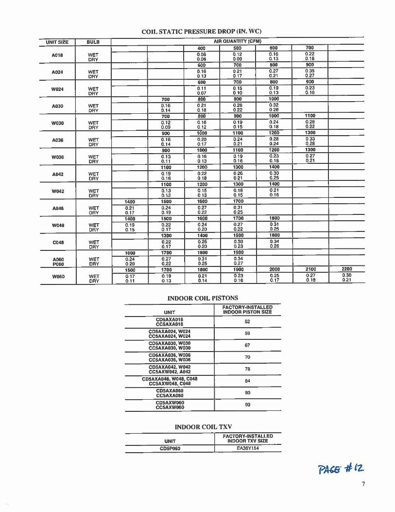
COIL STATIC PRESSURE DROP (IN. WC)
AIR QUANTITY (CFM)
400 500 600 0.08 0,12 0.16 0 .06 0.09 0.13 600 700 800 0,16 0 21 0.27 0.13 0 17 0.21 600 700 800 0.11 0.15 0.19 0.07 0.10 0.13
700 800 900 1000 0.16 0 21 0.26 032 0.14 0.18 0.22 028 700 800 900 1000 0.12 0.16 0.19 0.24 0.09 0.12 0.15 0.18 900 1000 1100 1200 0.16 0.20 0,24 0.28 0.14 0,17 0.21 0.24 900 1000 1100 1200 0.13 0 .16 0.19 0.23 0.11 0.13 0.16 0.18 1100 1200 1300 1400 0.19 0.22 026 0.30 0.16 018 021 0.25 1100 1200 1300 1400 0.13 015 0.18 0.21 0.12 0.13 0.15 0.16 1500 1600 1700 0.24 027 0.31 0.19 022 0.25 1500 1600 1700 1800 0.22 024 0.27 0 31 0.17 0.20 0.22 0.25 1300 1400 1500 1600 0.22 0,26 0.30 0.34 0.17 0.20 0.23 0.26 1700 1800 1900 0.27 0.31 0.34 0.22 025 0.27 1700 1800 1900 2000 0.19 0.21 023 0.25 0.13 0.14 0.16 0.17
INDOOR COIL PISTONS FACTORY-INSTALLED
UNIT INDOOR PISTON SIZE
C05AXA018 52 CC5AXA018
CD5AXA024, W024 CC5AXA024, W024 59
CD5AXA030, W030 CC5AXA030, W030 67
CD5AXA036, W036 70 CC5AXA036, W036
CD5AXA042, W042 78 CC5AXW042, A042
CD5AXA048, W048, C048 84 CC5AXW048, C048
CD5AXA060 90 CC5AXA060
CD5AXW060 90 CC5AXW060
INDOOR COIL TXV
UNIT
CDSP060
FACTORY-INSTALLED INDOOR TXV SIZE
EA36Y154
700 0.22 0.18 900 0.35 0.27 900 0.23 0,16
1100 0.28 0.22 1300 033 028 1300 0.27 0.21
2100 2200 0.27 0.30 0.18 0.21
7

Copyright 2003 Carrier Corporalion • Indianapolis, IN 46231 8·03
A Carrier V A Unlled Technologies Company
Manufacturer reserves the right to discontinue, or change at any tlme, epeclRcatlons or deelgns without notice and without Incurring obllgalfons.
_B_oo_k__._1 __ 4_ Pa9e B Catalog No, 02CC-5A3 Printed in U S.A. PC 101 Form CCSA•BPD
Tab 3d 2d Replaces: CCSA-7PD
LENNOX) ENGINEERING DATA
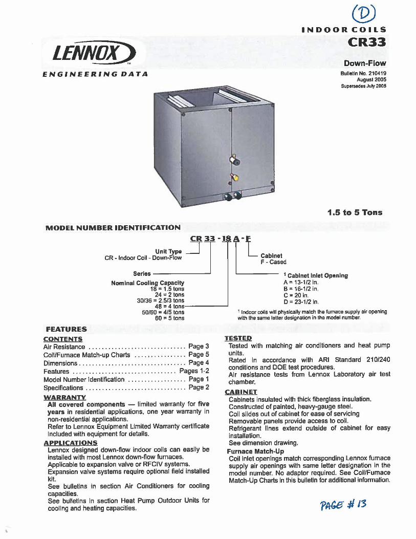
MODEL NUMBER IDENTIFICATION
Unit Type CR - Indoor Coll - Down-Flow
CR 33 -1
~ Serles ______ __.
Nominal Cooling Capacity 18 = 1.5 tons
24 = 2 tons 30/36 = 2.5/3 tons
48 = 4 tons-------' 50/60 = 4/5 tons
60 = 5 tons
A·F
L Cabinet
(p) INDOOR COILS
CR33
Down-Flow Bulletin No. 210419
August 2005 Supersedes July 2005
1.5 to 5 Tons
F-Cased
1 Cabinet Inlet Opening A= 13-1/2 In. B = 16-1/2 in. C = 20 in. D = 23-1/2 In.
1 Indoor coils wlll physically match the furnace supply air opening with the same letter designation In the model number.
FEATURES CONTENTS TESTED Air Resistance . . . . . . . . . . . . . . . . . . . . . . . . . . . . . . Page 3 Coll/Furnace Match-up Charts . . . . . . • . . . . . . . . . Page 5 Dimensions . . . . . . . . . . . . . . . . . . . . . . . . . . . . . . . . . Page 4 Features . . • . . . . . . . . . . . . . . . . . . . . . . . . . . . . . Pages 1-2 Model Number Identification ................. • Page 1 Specifications . . . . . . . . . . . . . . . . . . . . . . . . . . . . . . . Page 2
WARRANTY All covered components - limited warranty for five years in resfdentlal applications, one year warranty in non-residential applications. Refer to Lennox Equipment Limited Warranty certificate Included with equipment for details.
APPLICATIONS Lennox designed down-flow indoor coils can easily be installed with most Lennox down-flow furnaces. Applicable to expansion valve or RFCIV systems. Expansion valve systems require optional field installed kit. See bulletins in section Air Conditioners for cooling capacities. See bulletins In section Heat Pump Outdoor Units for cooling and heating capacities.
Tested with matching air conditioners and heat pump units. Rated In accordance with ARI Standard 210/240 conditions and DOE test procedures. Afr resistance tests from Lennox Laboratory air test chamber.
CABINET Cabinets insulated with thick fiberglass insulation. Constructed of painted, heavy-gauge steel. Coll slides out of cabinet for ease of servicing Removable panels provide access to coil. Refrigerant lines extend outside of cabinet for easy installation. See dimension drawing. Furnace Match-Up Coil Inlet openings match corresponding Lennox furnace supply air openings with same letter designation In the model number. No adaptor required. See Coil/Furnace Match-Up Charts In this bulletin for additional information.
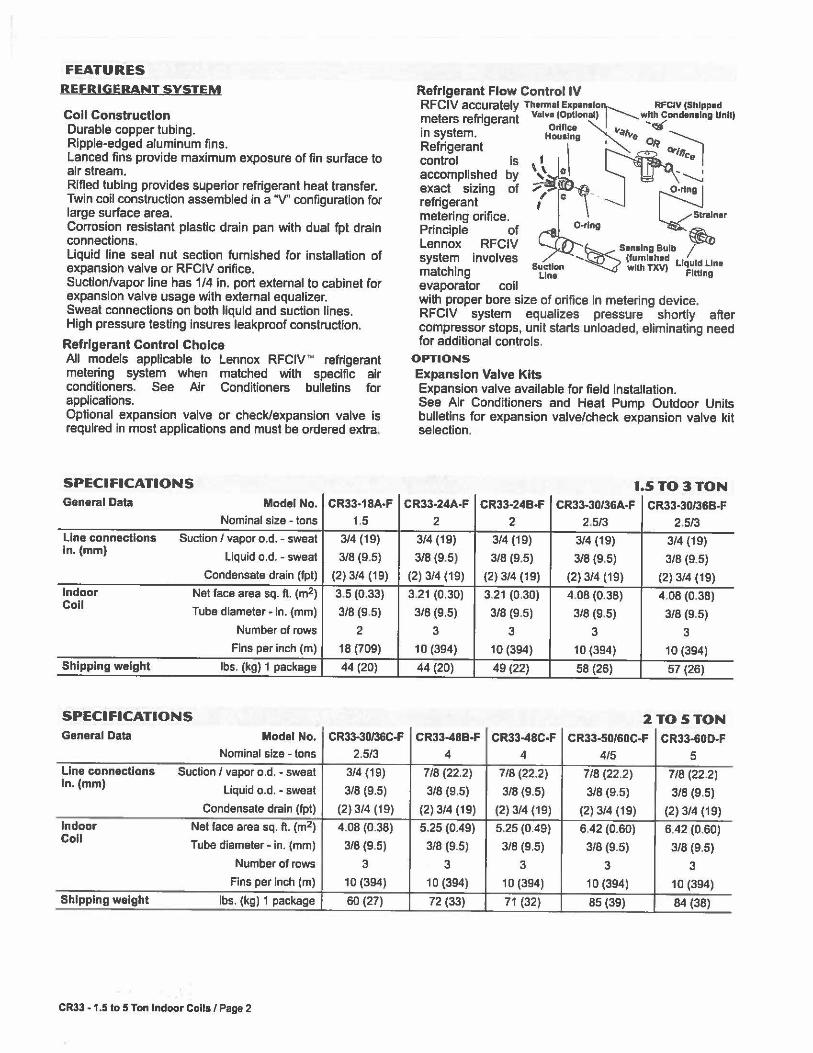
FEATURES
REFRIGERANT SYSTEM
Coll Construction Durable copper tubing. Ripple-edged aluminum fins. Lanced fins provide maximum exposure of fin surface to air stream. Rifled tubing provides superior refrigerant heat transfer. Twin coil construction assembled in a "V" configuration for large surface area. Corrosion resistant plastic drain pan with dual fpt drain connections. Liquid line seal nut section furnished for Installation of expansion valve or RFCIV orifice. Suction/vapor line has 1/4 in. port external to cabinet for expansion valve usage with external equalizer. Sweat connections on both liquid and suction lines. High pressure testing Insures leakproof construction.
Refrigerant Control Choice All models applicable to Lennox RFCIV"' refrigerant metering system when matched with specific air conditioners. See Alr Conditioners bulletins for applications. Optional expansion valve or check/expansion valve is required in most applications and must be ordered extra.
SPECIFICATIONS General Data Model No. CR33-18A-F
Nominal size - tons 1.5
Line connections Suction/ vapor o.d. - sweat 314 (19) In. (mm)
Liquid o.d. - sweat 3/8 (9.5)
Condensate drain (fpt) (2) 3/4 (19)
Indoor Net face area sq. ft. (m2) 3.5 (0.33) Coll Tube diameter - In. (mm) 3/8 (9.5)
Number of rows 2
Fins per Inch (m) 18 (709)
Shipping weight lbs. (kg) 1 package 44 (20)
SPECIFICATIONS General Data Model No. CR33-30/36C-F
Nominal size - tons 2.5/3
Line connections Suction / vapor o.d. - sweat 3/4 (19) In. (mm)
Liquid o.d. - sweat 3/8 (9.5)
Condensate drain (fpt) (2) 3/4 (19)
Indoor Net face area sq. ft. (m2) 4.08 (0.38) Coll Tube diameter - in. (mm) 3/8 (9.5)
Number of rows 3
Fins per Inch (m) 10 (394)
Shipping weight lbs. (kg) 1 package 60 (27)
CR33 • 1.5 lo 5 Ton Indoor Coils / Page 2
Refrigerant Flow Control IV RFCIV accurately Thermal Expan•lo'r-----... RFc1v IShlppad meters refrigerant Valve (Optlon■II I . --.. w!th conden■lng UnH)
. t Oriflc■ ~ ~ m sys em. Housing ,.,.,,, ~ ~
control Is \ I cc, Refrigerant \ ~• 0r111.
accomplished by ,\ 0 - --...__;
exact sizing of O _ _ ~-ring refrigerant metering orifice. /Strainer Principle of O-rlng ~ Lennox RFCIV ~S•n•lng Bulb / system Involves -... (tuml■hed Liquid Lin■ matching 5!f:.~" wllh TI(V) Fitting
evaporator coil with proper bore size of orifice In metering device. RFCIV system equalizes pressure shortly after compressor stops, unit starts unloaded, elimlnating need for additional controls.
OPTIONS
Expansion Valve Kits Expansion valve available for field Installation. See Air Conditioners and Heat Pump Outdoor Units bulletins for expansion valve/check expansion valve kit selection.
1.5TO3TON CR33-24A-F CR33-24B-F CR33-30/36A-F CR33-30/36B-F
2 2 2.5/3 2,5/3
3/4 (19) 3/4 (19) 3/4 (19) 3/4 (19)
3/8 (9.5) 3/8 (9.5) 3/8 (9,5) 3/8 (9.5)
(2) 3/4 (19) (2) 3/4 (19) (2) 3/4 (19) (2) 3/4 (19)
3.21 (0.30) 3.21 (0.30) 4 .08 (0.38) 4 .08 (0.38)
3/8 (9.5) 3/8 (9.5) 3/8 (9.5) 3/8 (9.5)
3 3 3 3
10 (394) 10 (394) 10 (394) 10 (394)
44 (20) 49 (22) 58 (26) 57 (26)
2TO5TON CR33-48B-F CR33-48C-F CR33-50160C-F CR33-60D-F
4 4 4/5 5
7/8 (22.2) 7/8 (22.2) 7/8 (22.2) 7/8 (22.2)
3/8 (9.5) 3/8 (9.5) 3/8 (9.5) 3/8 (9.5)
(2) 3/4 (19) (2) 3/4 (19) (2) 3/4 (19) (2) 3/4 (19)
5.25 (0.49) 5.25 (0.49) 6.42 (0.60) 6.42 (0.60)
3/8 (9.5) 3/8 (9.5) 3/8 (9.5) 3/8 (9.5)
3 3 3 3
10 (394) 1 D (394) 10 (394) 10 (394)
72 (33) 71 (32) 85 (39) 84 (38)
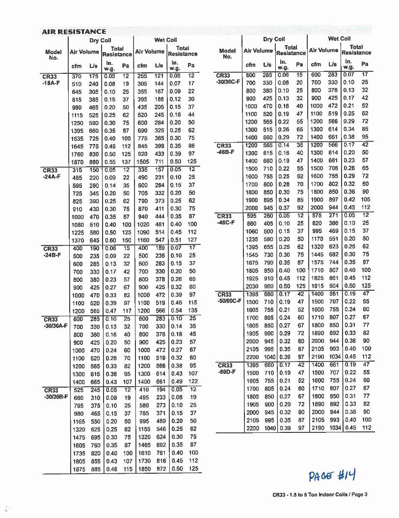
AIR RESISTANCE Dry Coll Wet Coll Dry Coll Wet Coll
Model Air Volume Total Air Volume Total
No. Resistance Resistance
cfm Us In. Pa cfm Us In. Pa w.g. w.g.
Model Air Volume Total Air Volume Total
No. Resistance Resistance
cfm Us In. Pa cfm Us In. Pa w.g. w.g.
CR33 370 175 0.05 12 255 121 0.05 12 CR33 600 285 0.06 15 600 283 0.07 17 -18A-F 510 240 0.08 19 305 144 0.07 17 -30/36C-F 700 330 0.08 20 700 330 0.10 25
645 305 0.10 25 355 167 0.09 22 800 380 0.10 25 800 378 0.13 32
815 385 0.15 37 395 186 0.12 30 900 425 0.13 32 900 425 0.17 42
980 465 0.20 50 435 205 0.15 37 1000 470 0.16 40 1000 472 0.21 52
1115 525 0.25 62 520 245 0.18 44 1100 520 0.19 47 1100 519 0.25 62
1250 590 0.30 75 600 284 0.20 50 1200 565 0.22 55 1200 566 0.29 72
1395 660 0.35 87 690 325 0.25 62 1300 615 0.26 65 1300 614 0.34 85
1535 725 0.40 100 775 365 0.30 75 1400 660 0.29 72 1400 661 0.38 95
1645 775 0.45 112 845 399 0.35 86 CR33 1200 565 0.14 35 1200 566 0.17 42
1760 830 0.50 125 920 433 0.39 97 -48B-F 1300 615 0.16 40 1300 614 0.20 50
1870 880 0.55 137 1505 711 0.50 125 1400 660 0.19 47 1400 661 0.23 57
CR33 315 150 0.05 12 335 157 0.05 12 1500 710 0.22 55 1500 708 0.26 65 -24A•F 465 220 0.09 22 490 231 0.10 25 1600 755 0.25 62 1600 755 0.29 72
595 280 0.14 35 600 284 0.15 37 1700 800 0.28 70 1700 802 0.32 80
725 345 0.20 50 705 332 0.20 50 1800 850 0.30 75 1800 850 0.36 90
825 390 0.25 62 790 373 0.25 62 1900 895 0.34 85 1900 897 0.42 105
910 430 0.30 75 870 411 0.30 75 2000 945 0.37 92 2000 944 0.45 112
1000 470 0.35 87 940 444 0.35 87 CR33 595 280 0.05 12 575 271 0.05 12
1080 510 0.40 100 1020 481 0.40 100 -48C-F 860 405 0.10 25 820 386 0.10 25
1225 580 0.50 125 1090 514 0.45 112 1060 500 0.15 37 995 469 0.15 37
1370 645 0.60 150 1160 547 0.51 127 1235 580 0.20 50 1170 551 0.20 50
CR33 400 190 0.06 15 400 189 0.07 17 1395 655 0.25 62 1320 623 0.25 62 •24B•F 500 235 0.09 22 500 236 0.10 25 1545 730 0.30 75 1445 682 0.30 75
600 285 0.13 32 600 283 0.15 37 1675 790 0.35 87 1575 744 0.35 87
700 330 0.17 42 700 330 0.20 50 1805 850 0.40 100 1710 807 0.40 100
800 380 0.23 57 800 378 0.26 65 1925 910 0.45 112 1825 861 0.45 112
900 425 0.27 67 900 425 0.32 80 2030 960 0.50 125 1915 904 0.50 125
1000 470 0.33 82 1000 472 0.39 97 CR33 1395 660 0.17 42 1400 661 0.19 47
1100 520 0.39 97 1100 519 0.46 115 -50/60C•F 1500 710 0.19 47 1500 707 0.22 55
1200 565 0.47 117 1200 566 0.54 135 1605 755 0.21 52 1600 755 0.24 60
CR33 600 285 0.10 25 600 283 0.10 25 1700 805 0.24 60 1710 807 0.27 67 -30/36A·F 700 330 0.13 32 700 330 0.14 35 1805 850 0.27 67 1800 850 0.31 77
BOO 380 0.16 40 800 378 0.18 45 1905 900 0.29 72 1890 892 0.33 82
900 425 0.20 50 900 425 0.23 57 2000 945 0.32 80 2000 944 0.36 90
1000 470 0.24 60 1000 472 0.27 67 2105 995 0.35 87 2105 993 0.40 100
1100 520 0.28 70 1100 519 0.32 80 2200 1040 0.39 97 2190 1034 0.45 112
1200 565 0.33 82 1200 566 0.38 95 CR33 1395 660 0.17 42 1400 661 0.19 47
1300 615 0.38 95 1300 614 0.43 107 -60D-F 1500 710 0.19 47 1500 707 0.22 55
1400 665 0.43 107 1400 661 0.49 122 1605 755 0.21 52 1600 755 0.24 60
CR33 525 245 0.05 12 410 194 0.05 12 1700 805 0.24 60 1710 807 0,27 67 -30/36B·F 660 310 0.08 19 495 233 0.08 19 1805 850 0.27 67 1800 850 0.31 77
795 375 0.10 25 580 273 0.10 25 1905 900 0.29 72 1890 892 0.33 82
980 465 0.15 37 785 371 0.15 37 2000 945 0.32 80 2000 944 0.36 90
1165 550 0.20 50 995 469 0.20 50 2105 995 0.35 87 2105 993 0.40 100
1320 625 0.25 62 1155 546 0.25 62 2200 1040 0.39 97 2190 1034 0.45 112
1475 695 0.30 75 1320 624 0.30 75 1605 760 0.35 87 1465 692 0.35 87 1735 820 0.40 100 1610 761 0.40 100 1805 855 0.43 107 1730 816 0.45 112 1875 885 0.46 115 1850 872 0.50 125
CR33 • 1.5 to 5 Ton Indoor Coils / Page 3
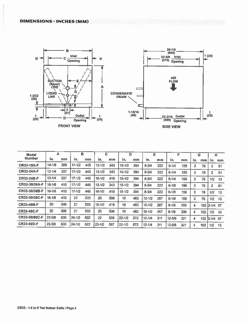
DIMENSIONS - INCHES (MM)
-rr=· ~ 28·1l8 (664) Inlet -518 Inlet 1 (25)
H C Opening H 751 Opening
"\ /') l ,\ /1 AIR
~~TION E/ / FLOW ( rr)" __t, I A ~ t.: E _
LIQUID~ c; I
J ;fl CONDENSATE 1-3/32 LINE \ \ DRAIN~ (28) \ F
,,~,J L,2\, 1-15/16j L,215, Outlet (49) 23-3/16 Outlet
Opening (589) Opening
FRONT VIEW SIDE VIEW
Model A B C D E F G H Number In. mm In. mm In. mm In. mm In. mm In. mm In. mm In. mm
CR33-18A-F 14.1/8 359 17-1/2 445 13-1/2 343 15-1/2 394 8-3/4 222 6-1/4 159 3 76 2 51 CR33-24A°F 13-1/4 337 17-1/2 445 13-1/2 343 15-1/2 394 8-3/4 222 6-1/4 159 3 76 2 51
CR33-24B-F 13-1/4 337 17-1/2 445 16-1/2 419 15-1/2 394 8-3/4 222 6-1/4 159 3 76 1/2 13
CR33-30/36A-F 16-1/8 410 17-1/2 445 13-1/2 343 15-1/2 394 8-3/4 222 6-1/8 156 3 76 2 51
CR33-30/36B-F 16-1/8 410 17-1/2 445 16-1/2 419 15-1/2 394 8-3/4 222 6-1/8 156 3 76 1/2 13 CR33-30/36C-F 16-1/8 410 21 533 20 508 19 483 10-1/2 267 6-1/8 156 3 76 1/2 13
CR33-48B-F 20 508 21 533 16-1/2 419 19 483 10-1/2 267 8-1/8 206 4 102 12-1/4 57
CR33-48C-F 20 508 21 533 20 508 19 483 10-1/2 267 8-1/8 206 4 102 1/2 13
CR33-50/60C-F 23-5/8 600 24.1/2 622 20 508 22-1/2 572 12-1/4 311 12-5/8 321 4 102 2-1/4 57
CR33-60D-F 23-5/8 600 24.1/2 622 23-1/2 597 22-1/2 572 12-1/4 311 12-5/8 321 4 102 1/2 13
CR33 -1.5 to 5 Ton Indoor Colls / Page 4
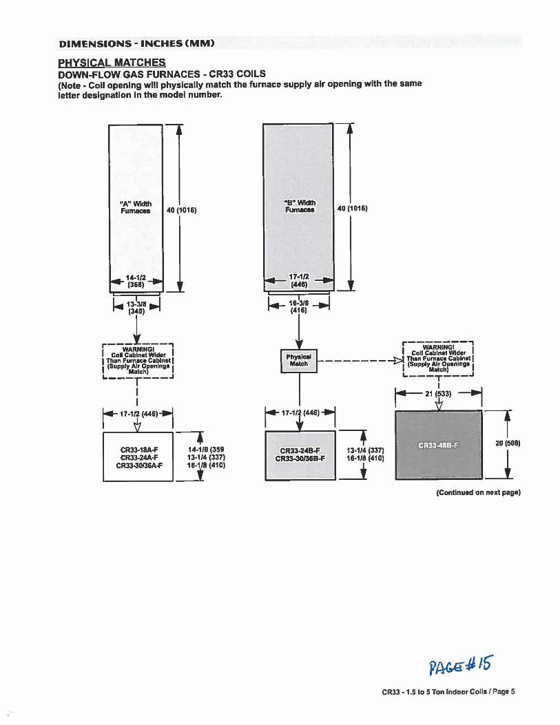
DIMENSIONS - INCHES (MM)
PHYSICAL MATCHES DOWN-FLOW GAS FURNACES - CR33 COILS (Note - Coll opening will physically match the furnace supply air opening with the same letter designation In the model number.
"A"Wldth Fumac:es 40 (1016)
14-t/2 (368)
I - 13-318 - I
r~~I~~ I co11~!:i~~~Wider I I Than Furnace Cabinet I I (Supply Air orenln11• I
Match '----r---.J I I r- 17-1/2 (44611
• 14-1/8 (359 13-1/4 (337) 16-1/8 (410)
L...---------1 __t
CR33·1BA.f CR33-24A.f
CR33-30/36A.f
"B"Wldth Furnaces
I - 16-3/8 -..I ~ (416)
40 (1016)
Pfl~lc:al Match
1,---WARNINGI-,,
Coll Cabinet Wider _ _ _ _ _ _ _ ......t Than Fumaca Cabinet I
~, (Supply Air Or•nlng• I Match
i+ 17-1/ (446)1
CR33-24B-F CR33-30/31B-F
7 13-1/4 (337) 16·1/8 (410)
~-----1 _j
._ ___ T ___ .J I
14-21 (533)
7 20 (508)
~ --1 (Continued on next pagal
CR33 - 1.5 to 5 Ton Indoor Coils / Page 5
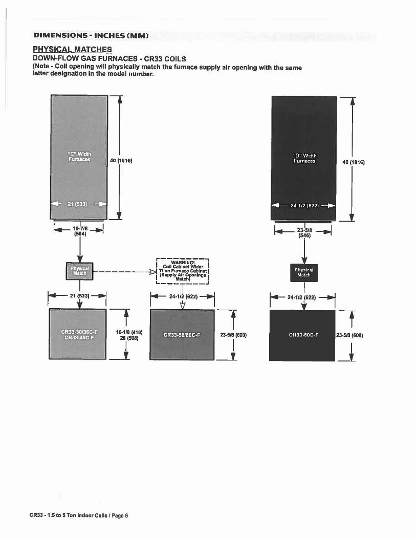
DIMENSIONS - INCHES (MM)
PHYSICAL MATCHES DOWN-FLOW GAS FURNACES - CR33 COILS (Note - Coll opening wlll physically match the furnace supply air opening with the same letter designation In the model number.
i.---19-7/8-.i (504)
I 40 (1016)
1,---wiRNiiroi'"-,
1 Call Cabinet Wider ______ --¼>I Than Fumac:e Cabinet I I (Supply Air Or•nln11• J
Match L---T ___ .,
I j4"- 24.1n (6221 -,
16-118 (410)
................. ___ _._]~
CR33 • 1.5 to 5 Ton Indoor Colls / Page 6
7 23-5/8 (600)
_j
"D" Width Furnaces
,.__ 24-112 (622) ___.
Physical Match
r-- 24-1/2 (622) -,
40 (1016)
t 23-518 (6001
_l


LENNOX) Visit us at www.lannoJt.com For Iha latest technical Information, www.lennoJtdavenel.com Contact us at 1-800-4-LENNOX
NOTE - Due to Lennox· ongo'ng commlHment to quality, Specifications, Ratings and Dimensions subjec1 to change without notice and without Incurring Dabill!y. Improper lnstalla!lon, adjustment, alteratlon, service or maintenance can cause property damage or personal rn;uiy. Installation and service must ba performed by a qualified Installer and servicing agency. C2D05 Lennox Industries Inc.
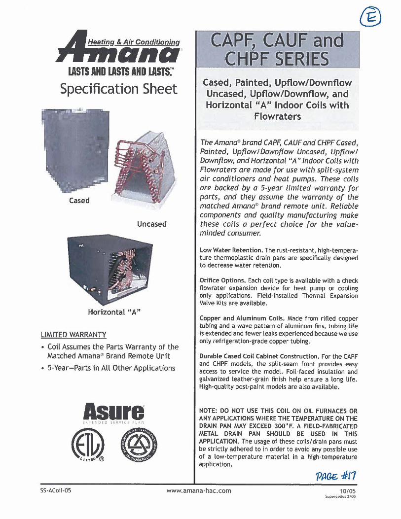
Heating & Air Conditioning
ono IASTS AND lASTS AND lASTS:"
Specification Sheet
Cased
Uncased
Horizontal "A"
LIMITED WARRANTY
• Coil Assumes the Parts Warranty of the Matched Amana~ Brand Remote Unit
• 5-Year-Parts in All Other Applications
Asure € \ l E ti DE D ~ E RV I ( E PL AN
~@)
CCA.P-~ CAUJF and CMP-r $1t'ltl~S
Cased, Painted, Upflow/Downflow Uncased, Upflow/Downflow, and Horizontal "A" Indoor Coils with
Flowraters
The Amanas brand CAPF, CAUF and CHPF Cased, Painted, Upflow/Downflow Uncased, Upflowl Downflow, and Horizontal "A" Indoor CoHs with Flowraters are made for use with split-system air conditioners and heat pumps. These coils are backed by a 5-year limited warranty for parts, and they assume the warranty of the matched Aman~ brand remote unit. Reliable components and quality manufacturing make these coils a perfect choice for the valueminded consumer.
Low Water Retention. The rust-resistant, high-temperature thermoplastic drain pans are specifically designed to decrease water retention.
Orifice Options. Each coil type is available with a check flowrater expansion device for heat pump or cooling only applications. Field-installed Thermal Expansion Valve Kits are available.
Copper and Aluminum Coils. Made from rifled copper tubing and a wave pattern of aluminum fins, tubing life is extended and fewer leaks experienced because we use only refrigeration-grade copper tubing.
Durable Cased Coil Cabinet Construction. For the CAPF and CHPF models, the split-seam front provides easy access to service the model. Foil-faced insulation and galvanized leather-grain finish help ensure a long life. High-quality post-paint models are also available.
NOTE: DO NOT USE THIS COIL ON OIL FURNACES OR ANY APPLICATIONS WHERE THE TEMPERATURE ON THE DRAIN PAN MAY EXCEED 300°F. A FIELD-FABRICATED METAL DRAIN PAN SHOULD BE USED IN THIS APPLICATION. The usage of these coils/drain pans must be strictly adhered to in order to avoid any possible use of a low-temperature material in a high-temperature application.
SS·ACoil-05 www.amana-hac.com 10/ 05 Supercc<h:$ 2/05
®
Specification Sheet
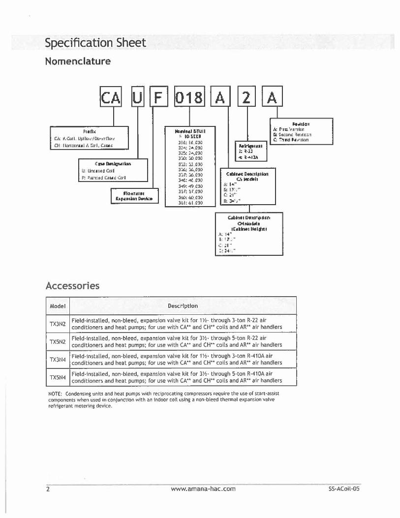
Nomenclature
CA u F 018 -
A 2 A -- I 1111(1( ~NI r.TUU
~ IO!ittl lit: ti t1il li~ ~ ... c->J l~:.a.,m l:il:t :.Ot:Ja ~:U;::.. uo l:.t.: :..\.,ffi
1c r·, Jt.,OJa•
u. '- ■ "ricf' 6alN: :W.tr:., r.: ~ Ck "-Gclll i)plk>o•J~,rtb;
01 I lon:x-ru l I, !:a I, C..u ,c
CIH~IW U. lh:t i..t Gcll l
~ '.1n: 1:I C..s,u: .:0-I
n:i ... , ••• , hp,111bl~
nr: ~-'"" ><:-c ffi
:M""r. ~ ''" l~T: ~r ffi )6£~~, ffi llol: ./al £10
C:-, .......... i: ~-lJ 1: i•tlA
C 11111 MC r-tlptkwl C.\w.dlh
,',;. 1 ... -r.: ff.'" C: ~.-D:. JI,\,.
1 ~1 0.u:r41icr.
otNo»II• lt .. Nllltl~I
A. 1'4" I ' ? . . '~· .. :: H .•
Accessories
Model Descrfptfon
TX3N2 Field-installed, non-bleed, expansion valve kit for 1½- through 3-ton R-22 air conditioners and heat pumps; for use with CA .. and CH*' coils and AR'* air handlers
TX5N2 Field-installed, non-bleed, expansion valve kit for 3½- through 5-ton R-22 air conditioners and heat pumps; for use with CA" and CH*' coils and AR'* air handlers
TX3~14 Field-installed, non-bleed, expansion valve kit for 1½· through 3-ton R-410A air conditioners and heat pumps; for use with CA .. and CH .. coils and AR'* air handlers
TX5N4 Field-installed, non-bleed, expansion valve kit for 3½· through 5-ton R-410A air conditioners and heat pumps; for use with CA .. and CH .. coils and AR'* air handlers
NOTE: Condensing units and heat pumps with reciprocating compressors require the use of start-assist components when used in conjunction with an indoor coil using a non-bleed thermal expansion valve refrigerant metering device.
2 www.amana-hac.com
r.dh,a.Yi
SS·ACoil·OS
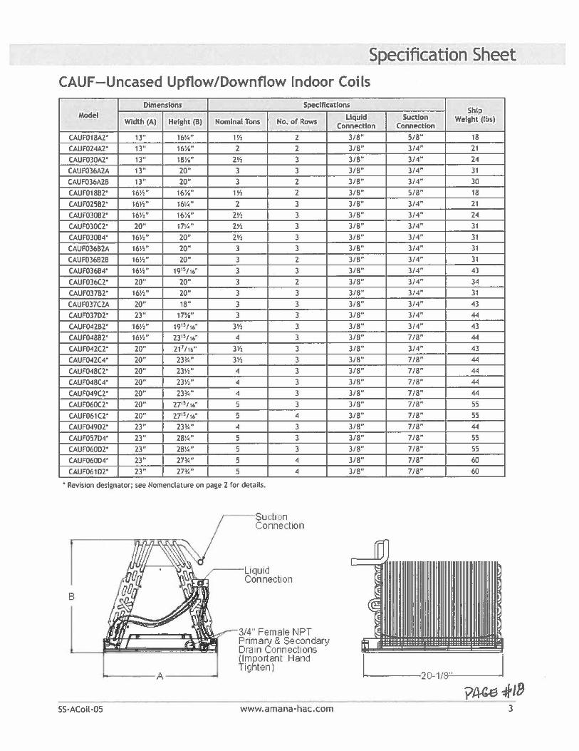
Specification Sheet CALIF-Uncased Upflow/Downflow Indoor Coils
Dimensions Specifications Ship
Model Width (A) Helsht (B) Nominal Tons No. of Rows
CAUF018A2' 13" 16¼" 1½ 2
CAUF024A2' 13" 16¼" 2 2
CAUF030A2' 13" 18¼" 2½ 3
CAUF036A2A 13" 20" 3 3 CAUF036A2B 13'' 20" 3 2
CAUF018B2' 16½" 16¼" 1½ 2
CAUF025B2' 16½" 16¼" 2 3
CAUF030B2' 16½" 16¼" 2½ 3 CAUF030C2' 20" 17¼" 2Yi 3
CAUF030B4' 16½" 20" 2½ 3
CAUF036B2A 16½" 20" 3 3
CAUF036B2B 16½" 20" 3 2
CAUF036B4' 16Yz" 1915'16" 3 3
CAUF036C2' 20" 20" 3 2
CAUF037B2' 16½" 20" 3 3
CAUF037C2A 20" 18" 3 3
CAUF037D2' 23" 17¾" 3 3
CAUF042B2' 16Yi'' 1915'16" 3½ 3
CAUF048B2' 16Y," 2315'16" 4 3
CAUF042C2" 20" 21 7 /16" 3Y, 3
CAUF042C4' 20" 23¼" 3Y, 3
CAUF048C2" 20" 23½" 4 3
CAUF048C4" 20" 23½" 4 3
CAUF049C2' 20" 23¼" 4 3
CAUF060C2' 20" 2715/16" 5 3
CAUF061C2' 20" 2715/16" 5 4
CAUF049D2' 23" 23¼" 4 3
CAUF057D4' 23" 28¼" 5 3
CAUF060D2' 23" 28¼" 5 3
CAUF060D4' 23" 27¼" 5 4
CAUF061D2' 23" 27¼" 5 4
• Revision designator; see Nomenclature on page 2 for details.
B
SS·ACoil·OS
Suction Connection
~--Uqu1d Connection
- ----A-----
3/4" Female NPT Primary & Secondary Oran Connections (Important Hand Tighten)
www.amana-hac.com
Liquid Suction ConnKtlon Connection
Welaht (lbs)
3/8" 518" 18
3/8" 3/4" 21
3/8" 3/4" 24
3/8" 3/4" 31
3/8" 3/4" 30
3/8" 5/8" 18
3/8" 3/4" 21
3/8" 3/4" 24
318" 3/4" 31
3/8" 3/4" 31
3/8" 3/4" 31
3/8" 3/4" 31
3/8" 3/4" 43
3/8" 3/4" 34
3/8" 3/4" 31
3/8" 3/4" 43
3/8" 3/4" 44
3/8" 3/4" 43
3/8" 718" 44
3/8" 3/4" 43
3/8" 7/8" 44 3/8" 7/8" 44
3/8" 7/8" 44
3/8" 7/8" 44
3/8" 7/8" 55 3/8" 7/8" 55
3/8" 7/8" 44
3/8" 7/8" 55 3/8" 7/8" 55 3/8" 7/8" 60
3/8" 7/8" 60
----20-1/:-;;.8';_' ___ J y~f/8
3
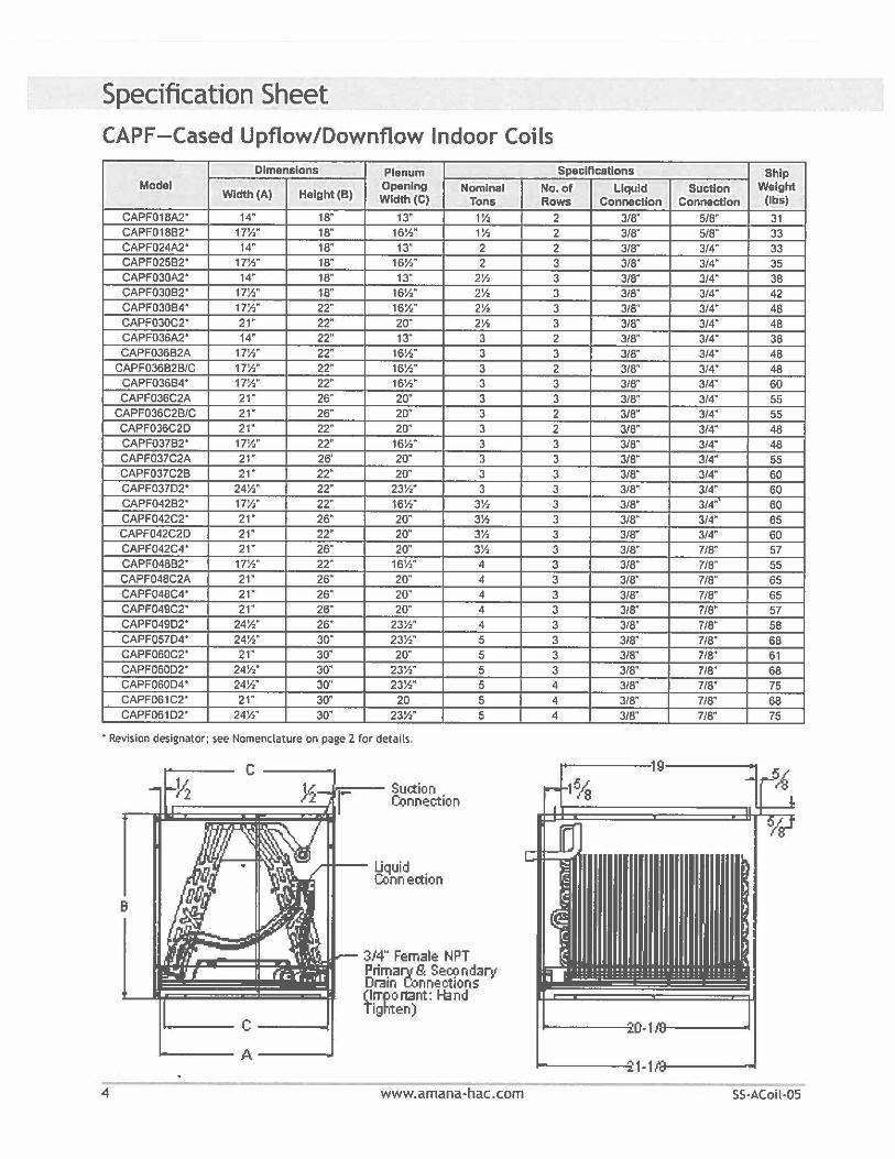
Specification Sheet CAPF-Cased Upflow/Downflow Indoor Coils
Dimensions Plenum Model
Wldth(A) Height (B) Opening Nominal Wldth(C) Tons
CAPF018A2• 14" 18" 13" 1½ CAPF01882' 17½" 18" 16½" 1½ CAPF024A2' 14" 18" 13" 2 CAPF02582' 17½" 18" 16½" 2 CAPF030A2• 14" 18" 13" 2½ CAPF030B2• 17½" 18" 16½" 2½ CAPF03084' 17½" 22" 16½" 2½ CAPF030C2' 21" 22" 20" 2½ CAPF036A2' 14" 22" 13" 3 CAPF036B2A 17½" 22" 16½" 3
CAPF036B2B/C 17½" 22" 16½" 3 CAPF03684' 17½" 22· 16½" 3 CAPF036C2A 21" 26" 20· 3
CAPF036C2B/C 21" 26" 20" 3 CAPF036C20 21· 22" 20" 3 CAPF03782' 17½" 22" 16½" 3 CAPF037C2A 21· 26' 20· 3 CAPF037C2B 21· 22· 20· 3 CAPF037D2• 24½" 22" 23½" 3 CAPF042B2' 17½" 22· 16½" 3½ CAPF042C2' 21· 26" 20· 3½ CAPF042C2D 21· 22" 20" 3½ CAPF042C4" 21" 26" 20" 3½ CAPF048B2' 17½" 22" 16½" 4 CAPF048C2A 21· 26" 20· 4 CAPF048C4• 21" 26" 20· 4 CAPF049C2' 21" 26" 20" 4 CAPF04902' 24½" 26" 23½" 4 CAPF057D4' 24½" 30" 23½" 5 CAPF060C2' 21· 30" 20" 5 CAPF060D2' 24½" 30" 23½" 5 CAPF060D4' 24½" 30" 23½" 5 CAPF061C2' 21· 30" 20 5 CAPF06102' 24½" 30" 23½" 5
• Revision designator; see Nomenclature on page 2 for details.
9
4
C----_11=--- Suction
Connection
,..... __ Liquid Conn ec.tion
----- A ____ ..,
3/4" Female NPT Prin;iary G SeC9 ndary Drain Connec11ons (l!'fPOl"Gnt: Hand lighten)
www.amana-hac.com
Specifications Ship No.of Liquid Suction Weight Rows Connection Connection (lbs)
2 3/8" 5/8" 31 2 3/8" 5/8" 33 2 3/8" 3/4" 33 3 3/8" 3/4" 35 3 3/8" 3/4" 38 3 3/8" 3/4" 42 3 3/8" 3/4" 48 3 3/8" 3/4" 48 2 3/8" 3/4" 38 3 3/8" 3/4" 48 2 3/8" 3/4" 48 3 3/8" 3/4" 60 3 3/8" 3/4" 55 2 3/8" 3/4" 55 2 3/8" 3/4" 48 3 3/8" 3/4" 48 3 3/8" 3/4" 55 3 3/8" 3/4" 60 3 3/8" 3/4" 60 3 3/8" 3/4" 60 3 3/8" 3/4" 65 3 3/8" 3/4" 60 3 3/8" 7/8" 57 3 3/8" 7/8" 55 3 3/8" 7/8" 65 3 3/8" 7/8" 65 3 3/8" 7/8" 57 3 3/8" 7/8" 58 3 3/8" 7/8" 68 3 3/8" 7/8" 61 3 3/8" 7/8" 68 4 3/8" 7/8" 75 4 3/8" 7/8" 68 4 3/8" 7/8" 75
--------1-1.ra-----
SS·ACoil-05
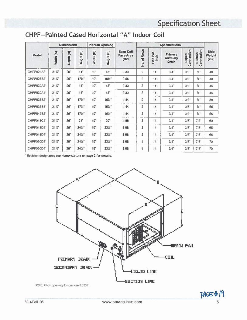
Specification Sheet CHPF-Painted Cased Horizontal "A" Indoor Coil
Dimensions Plenum Opening Specifications
g ~ §: e i[ EvapCoU I C C Ship ; Primary 0 g .2 Modal FacaAraa "0 - Waight
= ~ = a: a.~ -'ti ~i fi ~ Ill ~ Auxiliary i! a .21 ;; .21 (ft2) 'o (lbs)
i C- Drain :::i 8 :IC
i Cit :! Cit 0 ii: (I) 0 0 :c z 0 0
CHPF024A2· 21Y. 26" 14" 19" 13" 3 33 2 14 314" 318" ¾" 40
CHPF025B2• 211/o" 26" 17½" 19" 16½" 3 56 2 14 3/4" 3/8" ¾" 48
CHPF030A2' 21¼" 26" 14" 19" 13" 3 33 3 14 3/4" 3/8" ¾" 45
CHPF030A4• 21Yo" 26" 14" 19" 13" 3 33 3 14 3/4" 3/8" ¾" 45
CHPF036B2" 21¼" 26" 17½" 19" 16½" 444 2 14 3/4" 3/8" ¾" 50
CHPF036B4' 21¼" 26" 17½" 19" 16½" 444 3 14 3/4" 3/8" ¾" 55
CHPF042B2' 21¼" 26" 17½" 19" 16½" 444 3 14 3/4" 3/8'' ¾ .. 55
CHPF048C2• 21 ¼" 26" 21" 19" 20" 488 3 14 3/4" 3/8" 7/8" 60
CHPF048D2• 21¼" 26" 241/z" 19" 23½" 596 3 14 3/4" 3/8" 718" 65
CHPF048D4• 21¼" 26" 24½" 19" 23½" 596 3 14 3/4" 3/8" 7/8" 65
CHPF060D2• 21 ¼" 26" 24½" 19" 23½" 596 4 14 3/4" 3/8" 718" 70
CHPF060D4• 21¼" 26" 24½" 19" 23½" 5.96 4 14 3/4" 3/8'' 7/8" 70
• Revision designator; see Nomenclature on page 2 for details.
NOTE: All oi, opening ftonges ore O 6250'".
SS-ACoil-05 www.amana-hac.com
Specification Sheet
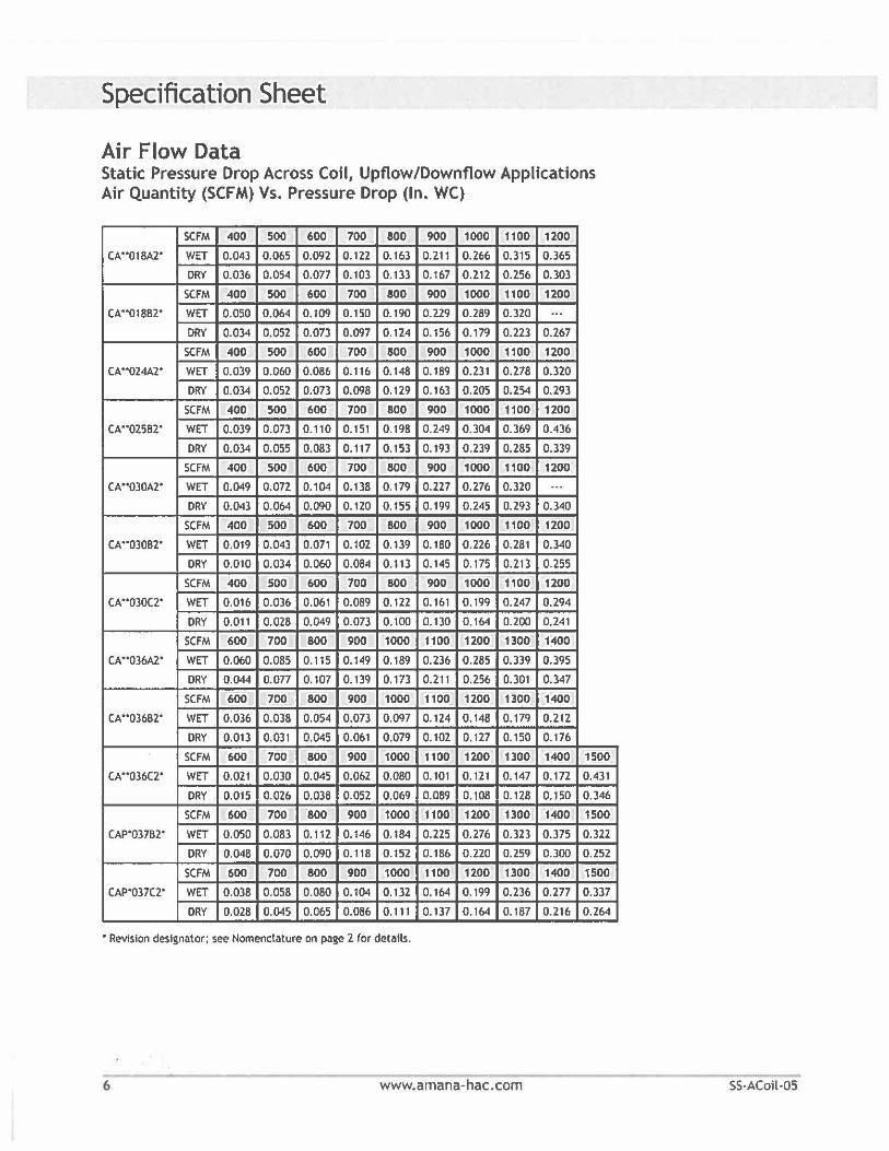
Air Flow Data Static Pressure Drop Across Coil, Upflow/Downflow Applications Air Quantity (SCFM) Vs. Pressure Drop (In. WC)
SCFM 400 500 600 700 800 900 1000 1100 1200
CA .. 018A2" WET 0.043 0.065 0.092 0.122 0.163 0.211 0.266 0.315 0.365
ORY 0.036 0.054 0.077 0.103 0.133 0. 167 0.212 0.256 0.303
SCFM 400 500 600 700 800 900 1000 1100 1200
CA"01882' WET 0.050 0.064 0. 109 0. 150 0.190 0.229 0.289 0.320 ... ORY 0.034 0.052 0.073 0.097 0.124 0.156 0.179 0.223 0.267
SCFM 400 500 600 700 800 900 1000 1100 1200
CA"024A2" WET 0.039 0.060 0.086 0.116 0.148 0.189 0.231 0.278 0.320
DRY 0.034 0.052 0.073 0.098 0.129 0.163 0.205 0.254 0.293
SCFM 400 500 600 700 800 900 1000 1100 1200
(A"02582' WET 0.039 0,073 0.110 0.151 0.198 0.249 0.304 0.369 0.436
DRY 0.034 0.055 0.083 0.117 0.153 0.193 0.239 0.285 0.339
SCFM 400 500 600 700 800 900 1000 1100 1200
CA"030A2' WET 0.049 0.072 0.104 0.138 0.179 0.227 0.276 0.320 ... DRY 0.043 0.064 0.090 0.120 0.155 0.199 0.245 0.293 0.340
SCFM 400 500 600 700 800 900 1000 1100 1200
CA'"03082" WET 0.019 0.043 0.071 0.102 0.139 0.180 0.226 0.281 0.340
DRY 0.010 0.034 0.060 0.084 0.113 0.145 0.175 0.213 0.255
SCFM 400 500 600 700 800 900 1000 1100 1200
CA"030C2' WET 0.016 0.036 0.061 0.089 0.122 0, 161 0.199 0.247 0.294
DRY 0.011 0.028 0.049 0.073 0.100 0.130 0.164 0.200 0.241
SCFM 600 700 800 900 1000 1100 1200 1300 1400
CA .. 036A2' WET 0.060 0.085 0.115 0.149 0.189 0.236 0.285 0.339 0.395
DRY 0.044 0.077 0.107 0.139 0.173 0.211 0.256 0.301 0.347
SCFM 600 700 800 900 1000 1100 1200 1300 1400
CA"03682' WET 0.036 0.038 0.054 0.073 0.097 0.124 0.148 0.179 0.212
DRY 0.013 0.031 0.045 0.061 0.079 0.102 0.127 0. 150 0.176
SCFM 600 700 800 900 1000 1100 1200 1300 1400 1500
CA"036C2' WET 0.021 0.030 0.045 0.062 0.080 0.101 0.121 0.147 0.172 0.431
DRY 0.015 0.026 0.038 0.052 0.069 0.089 0.108 0.128 0.150 0.346
SCFM 600 700 800 900 1000 1100 1200 1300 1400 1500
CAP'03782' WET 0.050 0.083 0.112 0.146 0.184 0.225 0.276 0.323 0.375 0.322
DRY 0.048 0.070 0.090 0.118 0.152 0. 186 0.220 0.259 0.300 0.252
SCFM 600 700 800 900 1000 1100 1200 1300 1400 1500
CAP'037C2' WET 0.D38 0.058 0.080 0.104 0.132 0.164 0.199 0.236 0.277 0.337
DRY 0.028 0.045 0.065 0.086 0. 111 0.137 0, 164 0.187 0.216 0.264
• Revision designator; see Nomenclature on page 2 for details.
6 www.amana-hac.com SS·ACoil-05
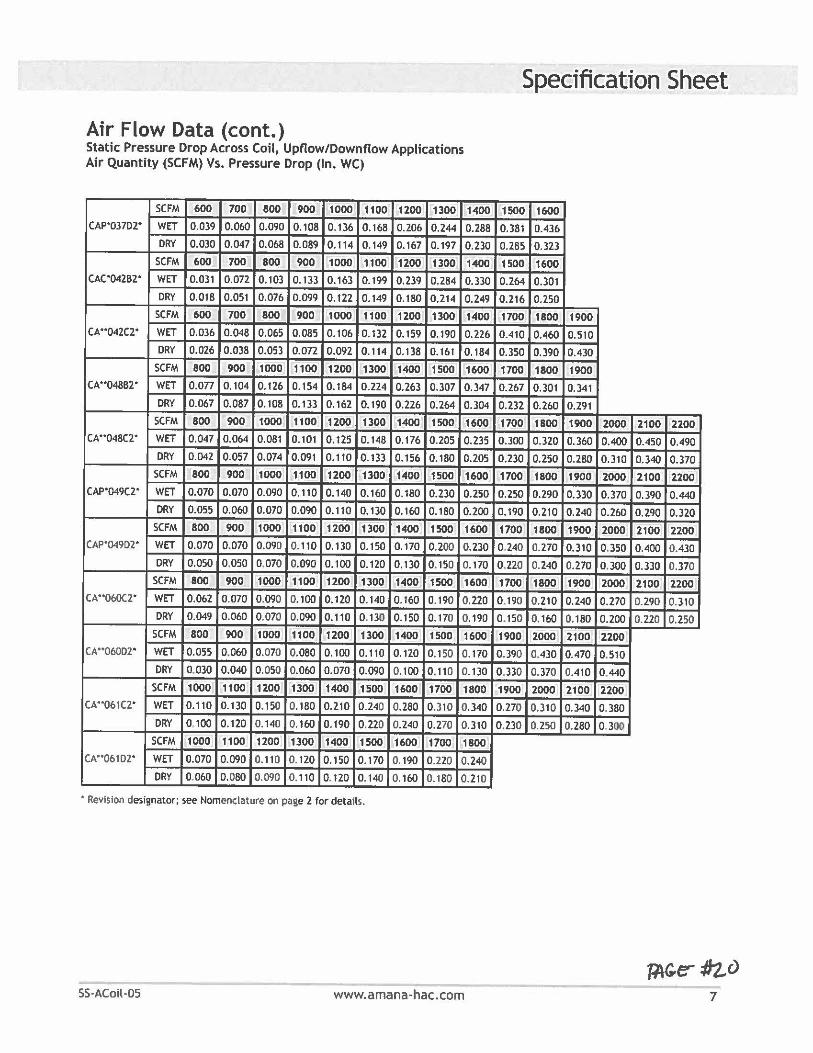
Air Flow Data (cont.) Static Pressure Drop Across Coil, Upflow/Downflow Applications Air Quantity (SCFM) Vs. Pressure Drop (In. WC)
SCFM 600 700 800 900 1000 1100 1200 1300 1400 CAP'037D2' WET 0.039 0.060 0.090 0.108 0.136 0.168 0.206 0.244 0.288
DRY 0.030 0.047 0.068 0.089 0.114 0.149 0.167 0.197 0.230
SCFM 600 700 800 900 1000 1100 1200 1300 1400 CAC'042B2' WET 0.031 0.072 0.103 0.133 0.163 0.199 0.239 0.284 0.330
DRY 0.018 0.051 0.076 0.099 0.122 0.149 0.180 0.214 0.249 SCFM 600 700 800 900 1000 1100 1200 1300 1400
CA"042C2" WET 0.036 0.048 0.065 0.085 0.106 0.132 0.159 0.190 0.226
DRY 0.026 0.038 0.053 0.072 0.092 0.114 0.138 0.161 0. 184
SCFM 800 900 1000 1100 1200 1300 1400 1500 1600 CA"048B2' WET 0.077 0.104 0.126 0.154 0.184 0.224 0.263 0.307 0.347
DRY 0.067 0.087 0.108 0.133 0.162 0.190 0.226 0.264 0.304 SCFM 800 900 1000 1100 1200 1300 1400 1500 1600
CA"'048C2" WET 0.047 0.064 0.081 0.101 0.125 0.148 0.176 0.205 0.235
DRY 0.042 0.057 0.074 0.091 0.110 0.133 0.156 0.180 0.205
SCFM 800 900 1000 1100 1200 1300 1400 1500 1600 CAP'049C2' WET 0.070 0.070 0.090 0.110 0.140 0.160 0.180 0.230 0.250
ORY 0.055 0.060 0.070 0.090 0.110 0.130 0.160 0.180 0.200
SCFM 800 900 1000 1100 1200 1300 1400 1500 1600 CAP'049D2' WET 0.070 0.070 0.090 0.110 0.130 0.150 0.170 0.200 0 .230
ORY 0.050 0.050 0.070 0.090 0.100 0.120 0.130 0. 150 0 .170
SCFM 800 900 1000 1100 1200 1300 1400 1500 1600 CA'"060C2' WET 0.062 0.070 0.090 0.100 0.120 0.140 0.160 0. 190 0.220
DRY 0.049 0.060 0.070 0.090 0.110 0.130 0.150 0. 170 0.190
SCFM 800 900 1000 1100 1200 1300 1400 1500 1600 CA"060D2" WET 0.055 0.060 0.070 0.080 0.100 0.110 0.120 0.150 0.170
DRY 0 .030 0.040 0.050 0.060 0.070 0.090 0.100 0. 110 0.130
SCFM 1000 1100 1200 1300 1400 1500 1600 1700 1800 CA"061C2' WET 0.110 0. 130 0.150 0.180 0.210 0 .240 0.280 0.310 0.340
DRY 0 .100 0. 120 0. 140 0. 160 0.190 0 .220 0.240 0.270 0.310
SCFM 1000 1100 1200 1300 1400 1500 1600 1700 1800 CA"061D2" WET 0.070 0.090 0. 110 0. 120 0.150 0. 170 0. 190 0,220 0.240
DRY 0.060 0.080 0.090 0.110 0. 120 0. 140 0. 160 0.1 80 0.210
• Revision designator; see Nomenclature on page 2 for details.
SS·ACoil-05 www.amana-hac.com
Specification Sheet
1500 1600
0.381 0.436
0.285 0.323
1500 1600
0.264 0.301
0.216 0.250
1700 1800 1900
0.410 0.460 0.510
0.350 0.390 0.430
1700 1800 1900
0.267 0.301 0.341
0.232 0.260 0.291
1700 1800 1900 2000 2100 2200 0.300 0.320 0.360 0.400 0.450 0.490
0.230 0.250 0.280 0.310 0.340 0.370
1700 1800 1900 2000 2100 2200 0.250 0.290 0.330 0.370 0.390 0.440
0,190 0.210 0.240 0.260 0.290 0.320
1700 1800 1900 2000 2100 2200
0.240 0.270 0.310 0.350 0 .400 0.430
0.220 0. 240 0.270 0.300 0.330 0.370
1700 1800 1900 2000 2100 2200
0 , 190 0.210 0.240 0.270 0.290 0.310
0 . 150 0. 160 0. 180 0.200 0.220 0.250
1900 2000 2100 2200
0 .390 0 .430 0.470 0.510
0.330 0.370 0.410 0 .440
1900 2000 2100 2200
0.270 0.310 0.340 0.380
0.230 0.250 0.280 0.300
Specification Sheet
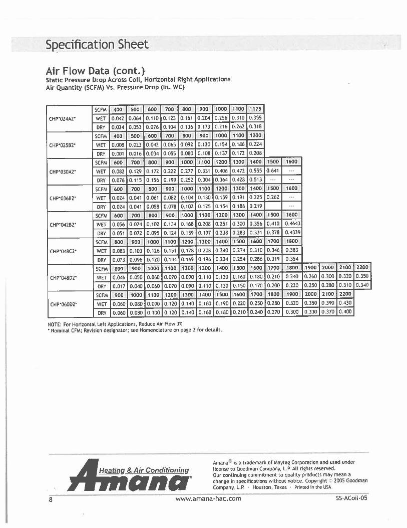
Air Flow Data (cont.) Static Pressure Drop Across Coil, Horizontal Right Applications Air Quantity (SCFM) Vs. Pressure Drop (In. WC)
SCFM 400 500 600 700 800 900 1000 1100 1175
CHP'024A2' WET 0.042 0.064 0 .110 0.123 0.161 0.204 0.256 0.310 0.355
DRY 0.034 0.053 0 .076 0.104 0.136 0.173 0.216 0.262 0.318
SCFM 400 500 600 700 800 900 1000 1100 1200
CHP'OZ582" WET 0.008 0.023 0.042 0.065 0.092 0.120 0.154 0.186 0.224
DRY 0.001 0.016 0.034 0.055 0.080 0.108 0.137 0.172 0.208
SCFM 600 700 800 900 1000 1100 1200 1300 1400 1500 1600
CHP'030A2" WET 0.082 0. 129 0 .172 0.222 0.2n 0.331 0.406 0.472 0.555 0,641 ... DRY 0.076 0.115 0.156 0.199 0.252 0.304 0.364 0.428 0.513 ... ··-
SCFM 600 700 800 900 1000 1100 1200 1300 1400 1500 1600
CHP'03682' WET 0.024 0.041 0.061 0.082 0.104 0.130 0.159 0.191 0.225 0.262 ... ORY 0.024 0.041 0.058 0.078 0.102 0.125 0.154 0. 186 0.219 ...
SCFM 600 700 800 900 1000 1100 1200 1300 1400 1500 1600
CHP.04282' WET 0.056 0.074 0. 102 0.134 0.168 0.208 0.251 0.300 0.356 0.410 0.4643
DRY 0.051 0.072 0 .095 0.124 0.159 0.197 0.238 0.283 0.331 0.378 0.4339
SCFM 800 900 1000 1100 1200 1300 1400 1500 1600 1700 1800
CHP.048(2' WET 0.083 0.103 0.126 0.151 0.178 0.208 0.240 0.274 0.310 0.346 0.383
DRY 0.073 0.096 0.120 0.144 0.169 0.196 0.224 0.254 0.286 0.319 0.354
SCFM 800 900 1000 1100 1200 1300 1400 1500 1600 1700 1800 1900 2000 2100 2200
CHP'048D2' WET 0.046 0.050 0.060 0.070 0.090 0.110 0.130 0. 160 0, 180 0.210 0.240 0.260 0.300 0.320 0.350
ORY 0.017 0.040 0.060 0.070 0.090 0.110 0, 130 0 .150 0. 170 0.200 0.220 0.250 0.280 0.310 0.340
SCFM 900 1000 1100 1200 1300 1400 1500 1600 1700 1800 1900 2000 2100 2200
CHP'060D2' WET 0.060 0.080 0.090 0.120 0.140 0 .160 0. 190 0.220 0.250 0.280 0.320 0.350 0.390 0.430
ORY 0.060 0.080 0.100 0.120 0.140 0 . 160 0. 180 0.210 0.240 0.270 0.300 0.330 D.370 0.400
NOTE: For Horizontal Left Applications, Reduce Air Row 3% • Nominal CFM; Revision designator; see Nomenclature on page 2 for details.
8
Heating & Air Conditioning
ono· Amana;!il is a trademark or Maytag Corporation and used under license to Goodman Company, L. P. All rights reserved. Our continuing commitment to quality products may mean a change in specifications without notice. Copyright <P 2005 Goodman Company, LP. • Houston, Texas • Printed In the USA.
www.amana-hac.com SS-ACoil-05
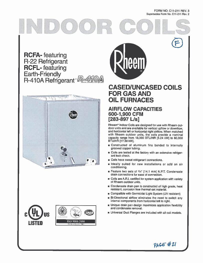
I RCFA- featuring R-22 Refrigerant RCFL- featuring Earth-Friend~y ,5i
0 ~1: : , -~
R-41 OA Refngerant .... ~'ii .....
c@us LISTED ISO 9001:ZOOO
FORM NO. C11-211 REV. 3 Supersedes Form No. C11-211 Rev. 2
CASED/UNCASED COILS FOR GAS AND OIL FURNACES AIRFLOW CAPACITIES 600-1,900 CFM [283-897 L/s] Rheem• Indoor Coils are designed for use with Rheem outdoor units and are available for vertical upflow or downflow, and horizontal left or horizontal right airflow. When matched with Rheem outdoor units, the coils provide a nominal capacity range from 18,000 BTU/HR [5.24 kW] to 60,000 BTU/HR (17.58 kW].
■ Constructed of aluminum fins bonded to internally grooved copper tubing.
■ Coils are tested at the factory with an extensive refrigerant leak check.
■ Coils have sweat refrigerant connections.
■ Ideally suited for new installations or add on air conditloni ng.
■ Feature two sets of 3/4" [14.1 mm] N.P.T. Condensate drain connections for ease of connection.
■ Coils are A.A.I. certified for system application with variety of Rheem outdoor units.
■ Condensate drain pan is constructed of high grade, heat resistant, corrosion free thermal-set material.
■ Compatible with Germicidal Light System (UV resistant)
■ Bi-Directional airflow eliminates the need to switch any internal components from horizontal left to right.
■ Unique drain pan design maximizes application flexibility and condensate removal.
■ Universal Duct Flanges are included with all coil models.
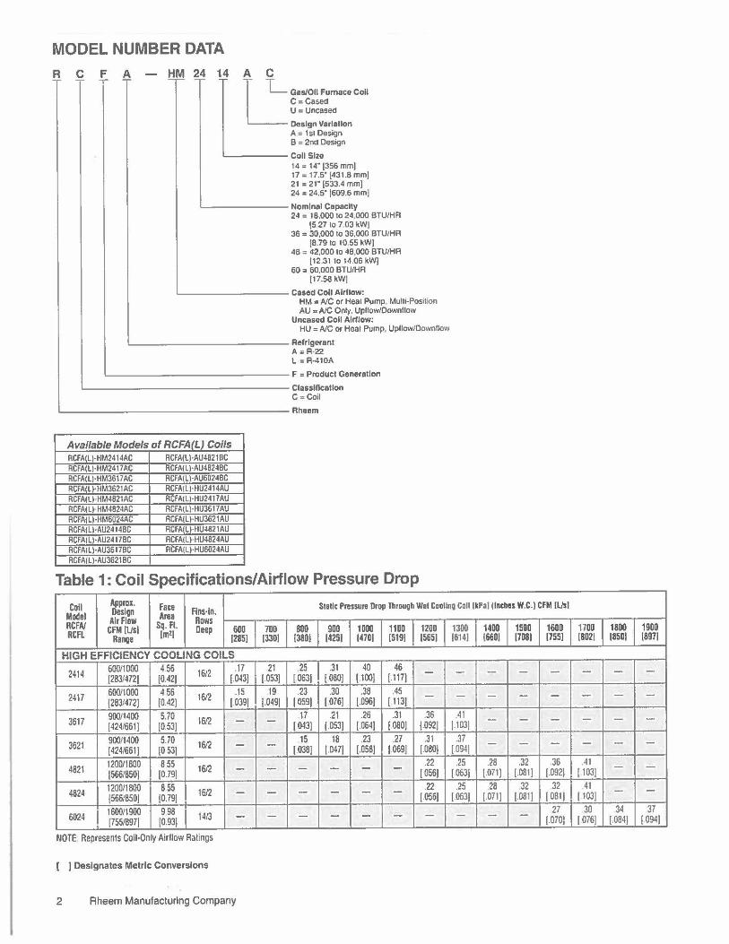
MODEL NUMBER DATA
R £ f. A A C
L Gas/011 Furnace Coll C : Ca5ed U " Unca5ed
Design Variation A : Isl De5ign B = 21\d Design
'------Call Size 14 = 14" (356 mm) 17 "17.5" [431.8 mm) 21 = 21· [533.4 mm) 24 = 24.5" (609.6 mmJ
'-------- Nominal Capacity 24 = 18,000 to 24,000 BTU/HA
{5.27 lo 7.03 kW] 36 = 30,000 to 36,000 BTU/HA
[8.79 lo 10.55 kW) 48 " 42,000 10 48,000 BTU/HA
[12.3110 14.06 kW) 60 = 60,000 BTU/HA
[17.58 kW)
'--------- Cased Call Airflow: HM "'A/C or Heal Pump Multi-Position AU " A/C Only, Upflow/Oownllow
Uncased Coll Airflow: HU = A/C or Heat Pump, Upflaw/Downflow
'------------- Relrlgerant A= A·22 L = R-410A
L-------------- F = Product Generation
'---------------- Classlflcatlan C = Coil
'------------------Rheem
Available Models of RCFAfLJ Coils RCFA(L)·HM2414AC RCFA(L)·AU4821BC RCFA(L)·HM2417AC RCFA(L)·AU4B24BC RCFA(L)·HM3617AC RCFA(L)-AU6024BC RCFA(L)·HM3621AC RCFA(L)·HU2414AU RCFA(Ll HM4B21AC RCFA(Ll·HU2417AU RCFA(L)•HM4824AC RCFA(Ll·HU36f7AU RCFAiL)·HM6024AC RCFA(L)-HU3621AU RCFAiLJ·AU24 f4BC RCFA(l)·HU4821AU RCFA(ll·AU2417BC RCFAIU·HU4824AU RCFA(l)·AU36f7BC RCFA(L)·HU6024AU RCFA(ll·AU3621BC
Table 1: Coil Specifications/Airflow Pressure Drop
Coll Appm. Design Face Fins-In.
Static Pn1ssuie Drop Through Wei Coollng Coll (kPa) (Inches W.C.) CFM II.hi Model Area RCFA/ Airflow Sq. ft. Rows
CFM (l/s) Deep 600 700 BOD 900 1000 1100 1200 1300 1400 1500 1600 RCFL Range (mZ) (285) (330) (380] 1425( (470( (5191 (565) (6141 16601 (708) (755)
HIGH EFFICIENCY COOLING COILS
2414 600/1000 4.56 16/2 .17 21 .25 .31 40 46 - -(283/472] (0.421 [.043] (.053] I 0631 I 0801 11001 [.117] - - -
2417 60011000 456 1612 .15 19 23 .30 .38 .45 -(283/472] [0.421 (.0391 j,0491 l.059] I 0761 1.096] [ 113] - - - -
3617 900/1400 5.70 16/2 - - 17 21 .26 .31 .36 .41 -(4241661I (0.531 (.043] f.053] (.064] (.080] (.092] (.103I - -
3621 900/1400 5.70 16/2 - - 15 18 .23 .27 .31 .37 -(424/6611 (0.53] (.038] (.0471 (.058] (.069] (.080] (0941 - -4821 1200/1800 855 16/2 - - - - - - .22 .25 .28 .32 .36
(566/850] (0.79] I 0561 (.063] (.071] (.081] (.0921
4824 1200/1800 855 1612 - - - - - - .22 .25 .28 32 32 (5661850] f0.791 (.056] (.063] (.0711 (.081] I os11
6024 1600/1900 998 14/3 - - - - - - - - - - 27 [755/8971 (0.931 (.070)
NOTE Represen1s Coil-Only Airflow Ratings
] Designates Metric Conversions
2 Rheem Manufacturing Company
1700 1800 1900 (8D21 (850( 18971
- - -- - -- - -- - -.41
[ 103] - -41
( 103] - -30 34 37
I 0761 (.0841 (.094I
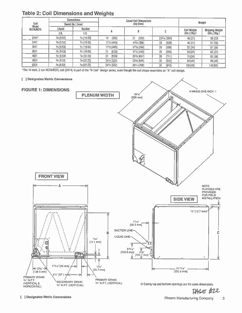
Table 2: Coil Dimensions and Weights Connections Cased Coll Dimensions Weight Coll Sweal (In.I Imm! fin) Imm]
Model liquid Sucllon RCFNRCFL A 8 C Coll Welghl Shipping Weight I.D. I.D. (lbs.) (Kg.I (lbs.) (Kg.I
2414' l/a (9.53] l/4 (19 05] 14 1356] 21 15331 233/16 [584] 46 [21] 50(23] 2417 3/s (9.53] l/4 (19 05] 17112(445] 141h[368( 20 [508] 46 [21] 51 (23] 3617 J/a (9.53] l/1 (19 05] 171'2 [445] 177/a [454] 20 [508] 521241 57 [26] 3621 l/8 (9.53] ¼[19.05] 21 [533] 17th [445] 20 (508] 54 (241 60 [27] 4821 l/1 [9.53] 7/a [22 23] 21 [5331 257/a [6571 28 [711] 76(341 83 (38] 4824 J/a [9.531 7/a (22.23] 24112 (6221 253/a [6451 32 [812] 89 (40] 99 [45] 6024 J/a (9.531 7/1 [22.231 24112 (6221 30th {7681 32 [812] 108(49] 118 (SSJ
·The 14 inch, 2 ton RCFA/RCFL coil (2414) is part of the "N·Coil" design series, even though the coil shape resembles an "A" coil design.
( J Designates Metric Conversions
FIGURE 1: DIMENSIONS PLENUM WIDTH
FRONT VIEW
, --~-~ I
/ !I \ / J ' \ ' , t I \ \ I
t t \ \ I I I \ \ I t
I I \ \ I , , I \ \ I I
I I \ \ I I ' , ' ' , , ,' ,' \ \ ,' ,' B , , ' ' , '
, \ \ ,' / 7/Jg"
', ', ,' ,' [11.1 mm) ' ' , ,
\ ', ' \ \' ,
·--------~--1! - j
SECONDARY DRAIN l/•' N.P.T. (VERTICAL)
[ J Designates Metric Conversions
PRIMARY DRAIN 3/•" N.P.T. {VERTICAL)
NOTE. FLANGES ARE PROVIDED FOR FIELD
SIDE VIEW INSTALLATION
,J.J::;::=.=========~ _j_
14!:------2111/,e" [550.Bmm(
112" (12.7 mm)
<D Casing top and bottom openings are lhe same dimensions.
C
~nz Rheem Manufacturing Company 3
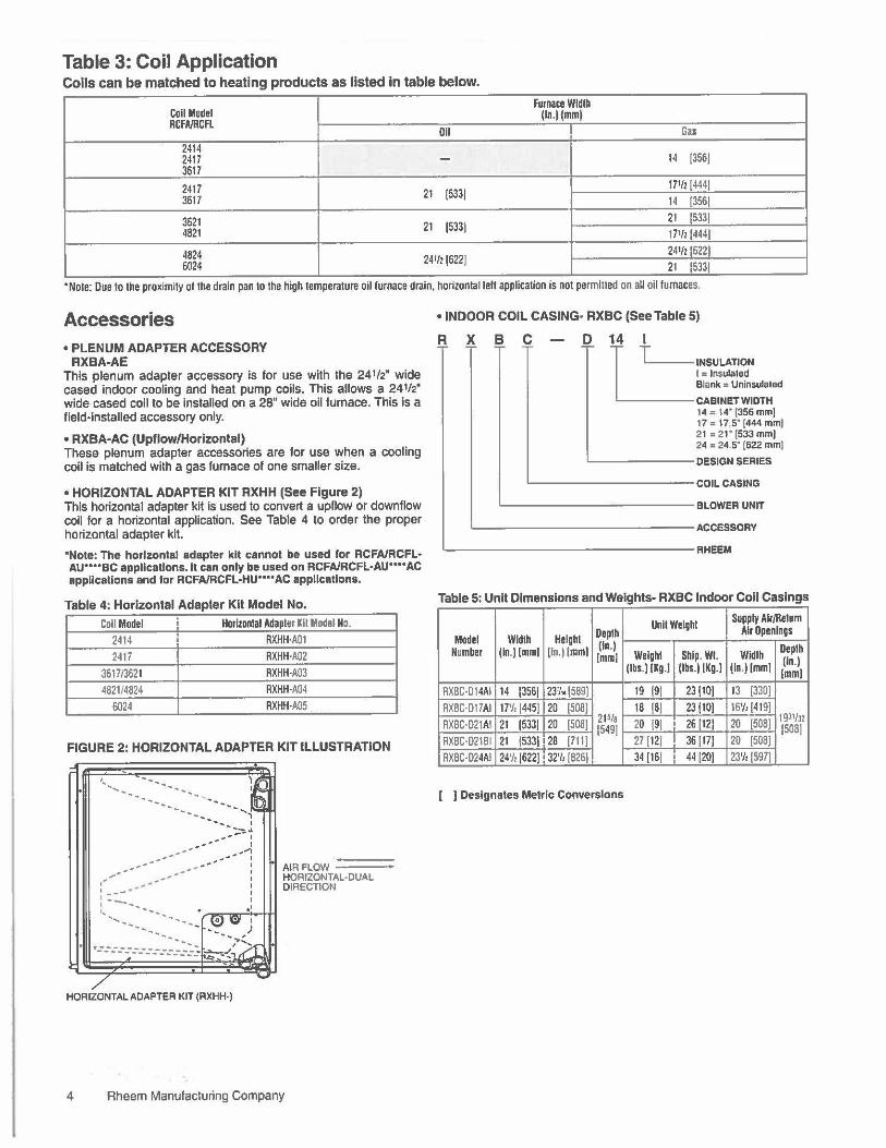
Table 3: Coil Application Coils can be matched to heating products as listed In table below.
Furnace Width Coll Model RCFA/RCFL
(la.l{mml
011 Gas 2414 2417 - 14 13561 3617
2417 21 [5331 171/2 [4441
3617 14 [3561
3621 21 (5331 21 (5331
4821 171/2 (444)
4824 241h (622) 24•12 (622)
6024 21 (533)
• Note: Due to the proximity ol 1he drain pan to the high 1empera1ure oil furnace drain, horizon1al tell application is not permitted on all oil furnaces.
Accessories • PLENUM ADAPTER ACCESSORY
RXBA-AE This plenum adapter accessory is for use with the 24½" wide cased indoor cooling and heat pump coils. This allows a 24½" wide cased coil to be installed on a 28" wide oil furnace. This is a field-installed accessory only.
• RXBA-AC (Upflow/Horlzontal) These plenum adapter accessories are for use when a cooling coil is matched with a gas furnace of one smaller size.
• HORIZONTAL ADAPTER KIT RXHH (See Figure 2) This horizontal adapter kit is used to convert a upllow or downflow coil for a horizontal application. See Table 4 to order the proper horizontal adapter kit.
"Note: The horizontal adapter kit cannot be used for RCFA/RCFL· AU*' .. BC appllcatlons. lt can only be used on RCFA/RCFL•AU .... AC applications and for RCFA/RCFL-HU'"'AC appllcatlons.
Table 4: Horizontal Adapter Kit Model No.
Coll Model Horizontal Adapter KIi Model No. 2414 RXHH·A01
2417 RXHH·A02
361713621 RXHH-A03
482114824 RXHH·A04
6024 RXHH·A05
FIGURE 2: HORIZONTAL ADAPTER KIT ILLUSTRATION
' ..........
,, -..... --------
-------::.~l I
--I _..., I
' ' I ' ' I
•' I
-·- _; - .,..._ 1:;~-------_ .. ,. __ :: ~~I ..,
HORIZONTAL ADAPTER KIT (RXHH·)
A1R FLOW =-====::::::; HORIZONTAL-DUAL DIRECTION
4 Rheem Manufacturing Company
• INDOOR COIL CASING• RXBC (See Table 5)
R X B C D 14 I
L INSULATION I = lnsula1ed Blank = Uninsule1ed
CABINET WIDTH 14 = 14' 1356 mm] 17 = 17.5" (444 mm) 21 = 21 • 1533 mm( 24 = 24.5" [622 mml
'--------DESIGN SERIES
~---------COIL CASING
'-------------BLOWER UNIT
'--------------ACCESSORY
'---------------RHEEM
Table 5: Unit Dimensions and Weights- RXBC Indoor Coll Casings
Unll Weigh! Supply Air/Return
Model Width Height Depth Air Openings
Number (ln,l(mml (ln.l(mml (la.I Welghl Ship. WI. Width Depth
lmml (In.) (lbs.I [Kg.] (lbs.I [Kg.] (ln.)[mml !mml
RXBC·D14AI 14 (3561 23'/,. (589) 19 (91 231101 13 (330)
RXBC·D17AI 17'1, 1445] 20 (5081 18 (Bl 231101 16'/, (4191
RXBC·D21AI 21 (5331 20 (5081 215/e 20 (91 261121 20 (508] 1931/Jz (5491 (5081
RXBC·D21B1 21 {5331 28 (7111 27 (121 361171 20 [5081
RXBC·D24AI 24'/, [6221 32'/, 1826) 34 (161 44 1201 23'/, (597)
[ ) Designates Metric Conversions
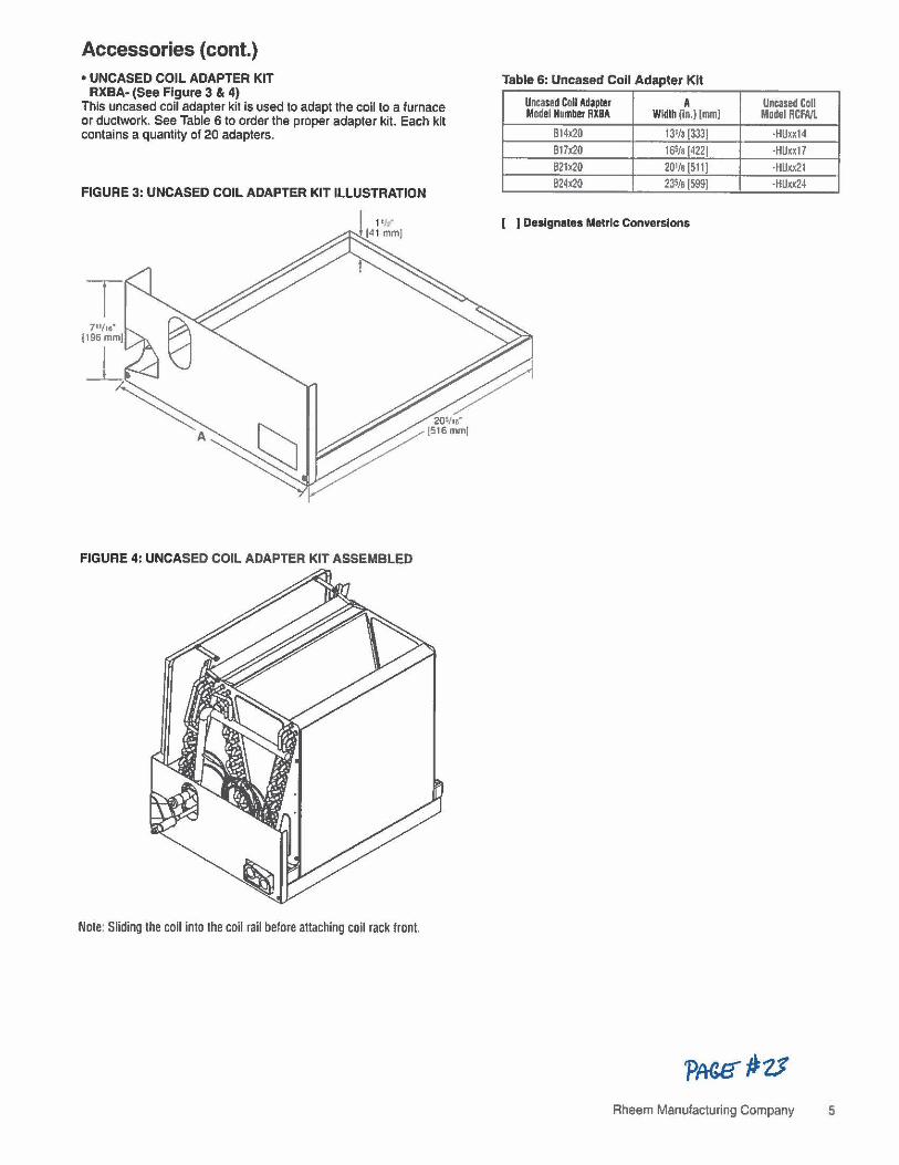
Accessories {cont.) • UNCASED COIL ADAPTER KIT
RXBA- (See Figure 3 & 4) This uncased coil adapter kit is used to adapt the coil to a furnace or ductwork. See Table 6 to order the proper adapter kit. Each kit contains a quantity of 20 adapters.
FIGURE 3: UNCASED COIL ADAPTER KIT ILLUSTRATION
7111,,· {196mm)
FIGURE 4: UNCASED COIL ADAPTER KIT ASSEMBLED
Note: Sliding the coil into the coil rail before attaching coil rack front.
Table 6: Uncased Coll Adapter Kit
Uncased Coll Adapter A Uncased Coll Model Number RXBA Width (In.) (mml Model RCFA/L
B14x20 131/g (333! •HUxx14 B17x20 16S/g (4221 ·HUxx17 B21x20 201/g (5111 ·HUxx21 B24x20 23S/g (5991 ·HUxx24
[ J Designates Metric Conversions
Rheem Manulacturing Company 5

NOTES
6 Rheem Manufacluring Company

NOTES
Rheem Manufacturing Company 7

Before proceeding with Installation, refer to Installation Instructions packaged with each model, as well as complying with all Federal, Stale, Provlnclal, and Local codes, regulations, and practices.
RHEEM AIR CONDITIONING DIVISION
5600 Old Greenwood Road, Fort Smith, Arkansas 72908 • "In keeping with its policy of continuous progress and product improvement, Rheem reserves the right to make changes without notice."
PAINTE0 IN U S A 4,07 DC FORM NO C11 •211 REV 3 !Sup••11dH Form No CU-211 Aev. 2
© Cased and Uncased Heat Pump/ Cooling Coils 1 /2-STon
2/4CXC,2/4CXA,2/4TXC 2/4TXFH 13 SEER Heat Pump /Cooling Coils for R-22 and R-410A
PUB. NO. 22-1773-01

Heat Pump/ Cooling Coil Nomenclature
2 T X C
Refrigerant Type 2-R22
T 4 • R410A
Product Family _____ __, T-Premium (Heat Pump or Convertible Coil) C - Standard (Cooling Only)
Coll Design _________ _,
X • Direct Expansion Evaporator Coil
Product Family-----------' C • Cased A Coil A • Uncased A Coil F • Cased Horizontal Flat Coil
Coll Width (Cased/Uncased) A· 14.5" / 13.3" B - 17.5'' / 16.3" C - 21.0• / 19.8" D • 24.5" / 23.3" H • 10.5"
B 0
Refrigerant Line Coupling------------' O· Brazed
3
Nominal Capacity In OOO's of BTU's -----------'
6 A
MajorDeslgnChange ___________________ ...,
C
Efficiency--- ------------------------' C - Standard S - Hi Efficiency
3
Refrigerant Control-------------------------' 3-TXV • Non-Bleed
H
Coll Circuitry------------------------------' H - HeatPump C - Cooling Only
C A A
AlrflowConflguratlon----------------------------...J A • Upflow Only U • Upflow / Downflow H • Horizontal Only C •Convertible• Upflow, Downflow, Left Airflow M - Convertible• Upflow, Downflow, Left or Right Airflow
Minor Design Change ----- --------------------------'
Unit Parts Identifier ----------------------------------1
0 2006 Amcncan S1,mlanl Inc All n&hts n:scr-c,J 2 Pub. No. 22,1n3-01
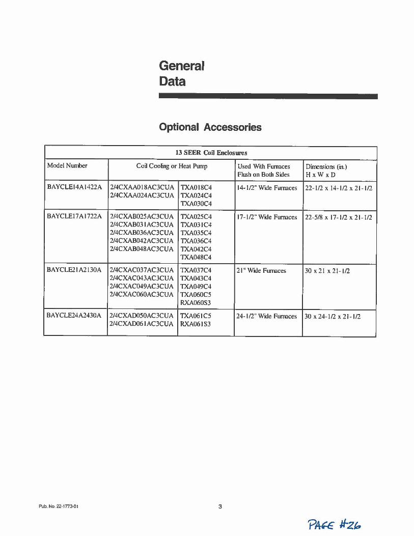
Model Number
BAYCLEl4A1422A
BAYCLE17A1722A
BA YCLE2 I A2 I 30A
BAYCLE24A2430A
Pub. No. 22•1773-01
General Data
Optional Accessories
13 SEER Coil Enclosures
Coil Cooling or Heal Pump Used With Furnaces Flush on Both Sides
2/4CXAA018AC3CUA TXA018C4 14-1/2" Wtde Furnaces 2/4CXAA024AC3CUA TXA024C4
TXA030C4
2/4CXAB025AC3CU A TXA025C4 17- 1 /2" WK.le Furnaces 2/4CXAB03 I AC3CUA TXA03IC4 2/4CXAB036AC3CUA TXA035C4 2/4CXAB042AC3CUA TXA036C4 2/4CXAB048AC3CUA TXA042C4
TXA048C4
2/4CXAC037 AC3CUA TXA037C4 21" Wide Furnaces 2/4CXAC043AC3CUA TXA043C4 2/4CXAC049AC3CUA TXA049C4 2/4CXAC060AC3CUA TXA060C5
RXA060S3
2/4CXAD050AC3CUA TXA061C5 24- 1/2" Wide Furnaces 2/4CXAD06 I AC3CUA RXA061S3
3
Dimensiom (in.) HxW xD
22- 1/2 X (4+ 1/2 X 21 - 1/2
22-5/8 X 17• 1/2 X 21 -1/2
30x21 x 21- l/2
30 X 24- 1 /2 X 21 - I /2
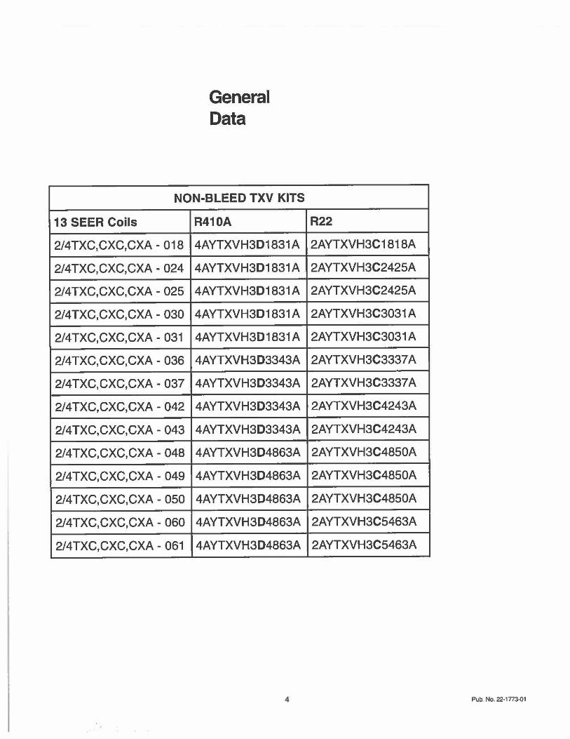
General Data
NON-BLEED TXV KITS
13 SEER Coils R410A
2/4TXC,CXC,CXA - 018 4AYTXVH3D1831A
2/4TXC,CXC,CXA - 024 4AYTXVH3D1831 A
2/4TXC,CXC,CXA- 025 4AYTXVH3D1831 A
2/4TXC,CXC,CXA - 030 4AYTXVH3D1831A
2/4TXC,CXC,CXA - 031 4AYTXVH3D1831A
2/4TXC,CXC,CXA - 036 4AYTXVH3D3343A
2/4TXC,CXC,CXA - 037 4AYTXVH3D3343A
2/4TXC,CXC,CXA - 042 4AYTXVH3D3343A
2/4TXC,CXC,CXA - 043 4AYTXVH3D3343A
2/4TXC,CXC,CXA - 048 4AYTXVH3D4863A
2/4TXC,CXC,CXA - 049 4AYTXVH3D4863A
2/4TXC,CXC,CXA - 050 4AYTXVH3D4863A
2/4TXC,CXC,CXA - 060 4AYTXVH3D4863A
2/4TXC,CXC,CXA - 061 4AYTXVH3D4863A
R22
2AYTXVH3C1818A
2AYTXVH3C2425A
2AYTXVH3C2425A
2AYTXVH3C3031 A
2AYTXVH3C3031 A
2AYTXVH3C3337 A
2AYTXVH3C3337 A
2AYTXVH3C4243A
2AYTXVH3C4243A
2AYTXVH3C4850A
2AYTXVH3C4850A
2AYTXVH3C4850A
2AYTXVH3C5463A
2AYTXVH3C5463A
Pub. No. 22-1n3-01
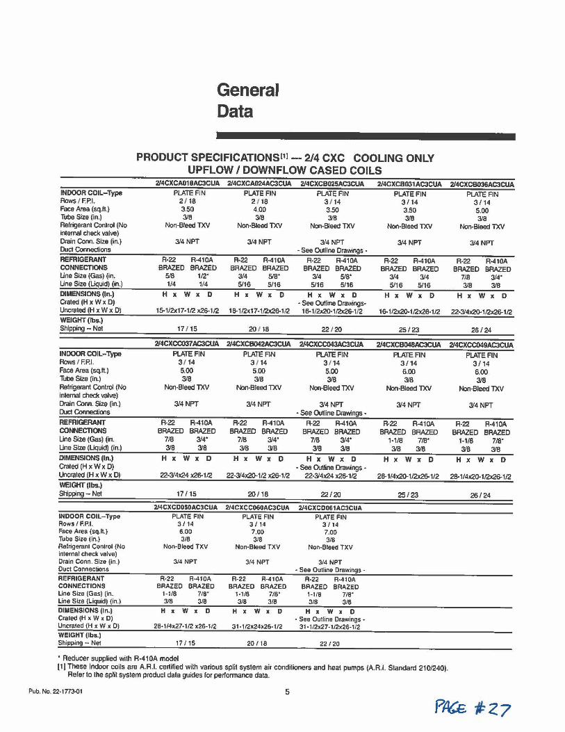
General Data
PRODUCT SPECIFICATIONSl11 ---2/4 CXC COOLING ONLY UPFLOW / DOWNFLOW CASED COILS
INDOOR COIL-Type Rows I F.P.I. Face Area (sq.ft.) Tube Size (In.) Refrigerant Control (No internal check valve) Drain Conn. Size (in.) Duct Connections
REFRIGERANT CONNECTIONS Una Size (Gas) (in. Una Size (Liquid) (in.)
DIMENSIONS (In.) Crated (H x W x D) Uncraled (H X w X D)
WEIGHT (tbs.) Shipping - Net
214CXCA018AC3CUA 214CXCA024AC3CUA PLATE FIN
2 / 18 3.50 3/8
Non-Bleed TXV
3/4NPT
R-22 A-410A BRAZED BRAZED
5/8 1/2' 1/4 114
H X w X D
15-1/2x17·1/2 x26-1/2
17/ 15
PLATE FIN 2 / 18 4.00 3/8
Non-Bleed TXV
3/4 NPT
R•22 R-410A BRAZED BRAZED
314 518' 5/16 5/16
H X w X D
18-1/2x17• 1/2x26-1I2
20 118
2/4CXCB025AC3CUA PLATE FIN
3 / 14 3 .. 50 3/8
Non-Bleed TXV
3/4 NPT • S88 Oullill8 Drawings •
R·22 R-410A BRAZED BRAZED
3/4 5/8' 5/16 5/16
H x W X 0 • S88 Outline Drawings•
16-1/2x20· 1/2x26-1/2
22 / 20
2/4CXCC037 AC3CUA 2/4CXCB042AC3CUA 2/4CXCC043AC3CUA INDOOR COIL-Type Rows I F.P.L Face Area (sq.It.) Tube Size (in.) Refrigerant Control (No internal ched< valve) Drain Conn. Size (in.) Duct Connections
REFRIGERANT CONNECTIONS Line Size (Gas) (in. Line Size (Liquid) (in.) DIMENSIONS (In.) Crated (H X w X D) Uncraled (H x W x 0)
WEIGHT (lbs.) Shipping - Net
PLATE FIN 3 / 14 5.00 3/8
Non-Bleed TXV
3/4 NPT
R-22 BRAZED
7/8 3/8
R-410A BRAZED
314• 3/8
H x W X 0
22-3/4x24 x26-1/2
17 / 15
PLATE AN 3 114 5.00 3/8
Non-Bleed TXV
3/4NPT
R-22 BRAZED
7/8 3/8
R-41DA BRAZED
3'4' 3/8
H X W X D
22-3/4x20-1/2 x26-1/2
20/ 18
2/4CXCDOSOAC3CUA 2/4CXCC060AC3CUA INDOOR COIL-T!(pe Rows /F.P.I. Face Area (sq.It) Tube Size (in.) Refrigerant Control (No internal check valve) Drain Conn. Size (in.) Duct ConMctions REFRIGERANT CONNECTIONS Line Size (Gas) (in. Line Size (Liquid) (in.) DIMENSIONS (In.) Crated (H x W x 0) Uncrated (H X w X D) WEIGHT (lbs.) Shipping •• Net
PLATE FIN 3 / 14 6.00 3/8
Non-Bleed TXV
3/4 NPT
R·22 R-410A BRAZED BRAZED
1-1/8 7/8' 3/8 3/8
H X W X 0
28·1/4•27•1/2 x26-1/2
17 / 15
• Reducer supplied with R-41 OA model
PLATE FIN 3 / 14 7.00 3/8
Non-Bleed TXV
3/4 NPT
R-22 R-410A BRAZED BRAZED
1-1/8 7/8' 3/8 3/8
H X W X 0
31-1/2x24x26-1/2
20/ 18
PLATE AN 3 / 14 5.00 3/8
Non-Bleed TXV
3/4 NPT • See Outline DraY.1ngs •
R-22 R-410A BRAZED BRAZED
7/8 314• 3/8 3/8
H X W X D • See Outline Drav,;ngs •
22·3/4x24 X26-1/2
22/20
2/4CXC0061 AC3CUA PLATE FIN
3 / 14 7.00 3/8
Non-Bleed TXV
3/4 NPT • See Outline Drawings -
R-22 R-410A BRAZED BRAZED
1·1/8 7/8' 3/8 3/8
H x W x 0 - See Outline Drawings •
31 • 1/2x27-1/2x26-1/2
22 /20
2/4CXCB031AC3CUA PLATE FIN
3/ 14 3.50 3/8
Non-Bleed TXV
3/4 NPT
R-22 R-410A BRAZED BRAZED
314 3/4 5/16 5/16
H x W x 0
16-1/2x20-1/2x26-1 /2
25/23
2/4CXCB036AC3CUA PLATE FIN
3/ 14 5.00 3/8
Non-Bleed TXV
3/4 NPT
R-22 R-410A BRAZED BRAZED
7/8 314' 3/8 318
H X W X D
22•3/4x20-1/2x26-1/2
26 /24
2/4CXCB048AC3CUA 2/4CXCC049AC3CUA PLATE FIN
3/ 14 6.00 3/8
Non-Bleed TXV
3/4 NPT
A-22 BRAZED
1-1/8 3/8
R-410A BRAZED
7/8' 3/8
PLATE AN 3/ 14 6.00 3/8
Non-Bleed TXV
3/4NPT
R-22 BRAZED
1-1/8 3/8
R-410A BRAZED
7/8' 3/8
HxWxD HxWxD
28-1/4x20-1/2x26-1/2 28-1/4X20-1/2x26-1/2
25/23 26/24
(1) These indoor coils are A.A.I. certified with various split system air condilioners and heal pumps (AR.I. Standard 210/240). Refer to lhe split system product data guides for performance data.
Pub. No. 22-1n3-01 5
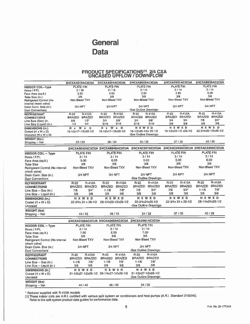
INDOOR COIL-Type Rows I FP.I. Face Area (sq.ft.) Tube Size (in ) Refrigerant Control (No internal check valve) Drain Conn. Size (in.) Duct Connections
REFRIGERANT CONNECTIONS Line Size (Gas) (in. Line Size (Liquid) (in.)
DIMENSIONS (In.) Crated (H x W x 0) Uncrated (H x W x 0)
WEIGHT (Iba.) Shipping - Net
General Data
PRODUCT SPECIFICATIONSl11 2/4 CXA UNCASED UPFLOW / DOWNFLOW
2/4CXAA018AC3CUA PLATE FIN
2 I 18 3.50 318
Non-Bleed TXV
314 NPT
R·22 R-410A BRAZED BRAZED
5/8 112· 1/4 1/4
H x W x 0 15• 1/2x17•1/2x26-1/2
25 /23
2/4CXAA024AC3CUA PLATE FIN
2118 4.00 3/8
Non-Bleed TXV
3/4 NPT
R-22 R•410A BRAZED BRAZED
3/4 519• 5/16 5/16
H X W X D 1 B•1/2x17·1/2x26-112
26/ 24
2/4CXAB025AC3CUA
PLATE FIN 3 f 14 3.50 3/B
Non-Bleed TXV
314 NPT ·See Outline Drawings•
R-22 R-410A BRAZED BRAZED
3/4 519• 5/16 5(16
HXWXD 16•1/2x20·1/2x 26-1/2
-See Outline Drawings•
34 /32
2/4CXAB031AC3CUA
PLATE FIN 3 f 14 3.50 3(8
Non-Bleed TXV
3/4 NPT
R·22 R-410A BRAZED BRAZED
3/4 3/4 318 3/8
H X W X D 16·1/2x20·1/2 x26-1/2
37 / 35
2/4CXAB036AC3CUA
PLATE FIN 3 / 14 5.00 3(8
Non-Bleed TXV
314 NPT
R·22 R-410A BRAZED BRAZED
7/8 314• 3/8 3/8
H X W X D 22•3/4x20· 112x26· 112
42 /39
2/4CXAB042AC3CUA 2/4CXAB048AC3CUA 2/4CXAC037AC3CUA 2/4CXAC043AC3CUA 2/4CXAC049AC3CUA
INDOOR COIL - Type Rows/ F.P.I. Face Area (sq.fl.) Tube Size Relrigeranl Control (No inlernal check valve) Drain Conn. Size (in.) Duct Connections
REFRIGERANT CONNECTIONS Line Size •· Gas (in.) Line Size•· Liquid (in.)
DIMENSIONS (In.) Crated (H x W x D) Uncraled
WEIGHT (lbs) Shipping ·- Net
INDOOR COIL-Type Rows/ F.P.I. Face Area (sq.fl.) Tube Size Refrigerant Control (No inlernal check valve) Drain Conn. Size (in.) Duel Connections
REFRIGERANT CONNECTIONS Line Size •• Gas (in.) Line Size •• Liquid (in.I
DIMENSIONS (In.) Crated (H x W x D) Uncrated WEIGHT (lbs) Shipping •• Net
PLATE FIN 3/ 14 5.00 3/8
Non-Bleed TXV
3/4 NPT
R·22 BRAZED
7/8 3/8
R-410A BRAZED
314• 3/8
PLATE FIN 3 / 14 6.00 3/8
Non-Bleed TXV
3/4 NPT
R-22 BRAZED
1-118 3/8
R-410A BRAZED
7/8' 3/8
HXWXD HXWXD 22-3/4x 24 x 26-1/2 28·1/4x20-1/2x26-1/2
44 / 42 46 / 43
2/4CXAC060AC3CUA 2/4CXA0050AC3CUA
PLATE FIN PLATE FIN 3/14 3/14 7.00 6.00 3/8 3/8
Non-Bleed TXV Non-Bleed TXV
3/4NPT
R-22 R·410A BRAZED BRAZED
1-1/8 7/B" 3/B 3/8
HXWXD 31 ·1/2x27· 1/2x26· 1/2
44/42
3/4 NPT
R•22 BRAZED
1-1/8 318
R-410A BRAZED
718" 3/8
HXWXD 28·1/4x27· 1/2x26-1/2
46/ 43
PLATE FIN 3 / 14 5.00 3/8
Non-Bleed TXV
3/4 NPT •See Outline Drawings•
R•22 R-410A BRAZED BRAZED
7/8 3/4' 3/8 3/8
HXWXD 22•3/4x24x26·1/2
•See Outline Drawings·
34/32
2/4CXAD061 AC3CUA
PLATE FIN 3 / 14 7.00 3/8
Non-Bleed TXV
3/4 NPT -See Outline Drawings-
R-22 R·410A BRAZED BRAZED
1-110 110· 3/B 3/8
HXWXD 31 ·112x27·1/2x26· 1/2
-See Outline Drawings-
34 /32
PLATE FIN 3 / 14 5.00 3/B
Non-Bleed TXV
3/4 NPT
R-22 R-410A BRAZED BRAZED
7/B 3/4' 3/8 3/8
HXWXD 22•3/4x 24 X 26-1/2
37 / 35
PLATE FIN 3 / 14 6.00 3/B
Non-Bleed TXV
3/4 NPT
R•22 R·410A BRAZED BRAZED
1·1/8 7/8' 3/8 3/8
HXWXD 28· 1/4x24x26· 1/2
42/ 39
• Reducer supplied wilh R-41 OA models (1) These indoor coifs are A.A.I. certilied wilh various split system air conditioners and heal pumps (A.A.I. Standard 210/240).
Refer lo the split system product data guides for performance dala.
6 Pub. No. 22· 1 n3-01
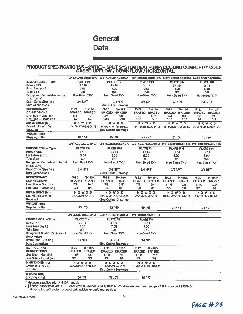
General Data
PRODUCT SPECIRCATIONSl11-2J4TXC- SPLIT SYSTEM HEAT PUMP /COOLING COMFOR'fl'M COILS CASED UPFLOW / DOWNFLOW / HORIZONTAL
INDOOR COIL - Type Rows/ F.P.I. Face Area (sq.ft.) Tube Size Refrigerant Control {No inlernal check valve) Drain Conn. Size (in.) Duel Conneclions
REFRIGERANT CONNECTIONS Line Size •· Gas (in.) Line Size •· Liquid (in.)
DIMENSIONS (In.) Crated (H x W x D) Uncraled
WEIGHT (Iba) Shipping •• Net
2/4TXCA018AC3HCA
PLATE FIN 2 / 18 3.50 3/8
Non-Bleed TXV
3/4 NPT
R-22 R-410A BRAZED BRAZED
5/B 112• 1/4 1/4
HXWXD 15·1/2x17•1/2x26·1 /2
37 /34
2/4TXCAD24AC3HCA
PLATE FIN 2 / 18 4.00 3/8
Non-Bleed TXV
3/4 NPT •See Outline Drawings-
R·22 R•410A BRAZED BRAZED
3/4 s1e· 5/16 5/16
HXWXD 18·1/2x17•1/2x26-1/2
•See Outline Drawings-
40 /37
2/4TXCBD25AC3HCA
PLATE FIN 3 / 14 350 3/8
Non-Bleed TXV
3/4 NPT
R•22 R-410A BRAZED BRAZED
3/4 5/8· 5/16 5/16
HXWXD 16-1/2x20·1/2x26·1 /2
44 / 42
2/4TXCBD31AC3HCA 2/4TXCBD36AC3HCA
PLATE FIN PLATE FIN 3 / 124 3 / 1
3 50 5 00 3/8 3;'8
Non-Bleed TXV Non-Bleed TXV
3/4 NPT
R•22 R-410A BRAZED BRAZED
3/4 3/4 5/16 5116
HXWXD 16· 1 /2x20· 112x26· 112
57 / 54
3/4 NPT
R·22 R•410A BRAZED BRAZED
718 3/4· 3/8 3i'8 H X W X D
2:2•3/4x20 • 1'2x26• 1/2
70 / 67
2/4TXCC037AC3HCA 2/4TXCB042AC3HCA 2/4TXCC043AC3HCA 2/4TXCB048AC3HCA 2/4TXCC049AC3HCA
INDOOR COIL - Type Rows / F.P.I. Face Area (sq.fl.) Tube Size Refrigerant Control (No internal check valve) Drain Conn. Size (in.) Duct Conneclion&
REFRIGERANT CONNECTIONS Line Size - Gas {in.) Line Size - Liquid (in.)
DIMENSIONS (In.) Crated (H x W x D) Uncraled
WEIGHT (lb&) Shipping •• Net
PLATE FIN 3 / 14 5.00 3/8
Non-Bleed TXV
3/4 NPT
R-22 BRAZED
7/8 3/8
R-410A BRAZED
314· 3/8
HXWXD 22-3/4x24x26• 1/2
73 / 70
PLATE FIN 3/ 14 5.00 3/8
Non-Bleed TXV
3/4 NPT •Seit Outline Drawings•
R·22 A•410A BRAZED BRAZED
7/8 314° 3/8 3/8 HXWXD
22-3/4x20· 1/2x26-1/2 -See Outline Drawings-
62/59
PLATE FIN 3 / 14 5.00 3/8
Non-Bleed TXV
3/4 NPT
R-22 BRAZED
7/8 3/8
R-410A BRAZED
3/4' 3/8
HXWXD 22-3/4x24x26•1/2
59/ 56
2/4TXCD050AC3HCA 2/4TXCC060AC3HCA 2/4TXCD061 AC3HCA
INDOOR COIL - Type Rows/ F.P.I Face Area (sq.fl) Tube Size Refrigerant ConlrOI (No internal check valve) Drain Conn. Size (in.) Duel Connections
REFRIGERANT CONNECTIONS Line Size -- Gas (In.) Line Size •· Liquid (in.)
DIMENSIONS (In.) Crated (H X w X D) Uncrated
WEIGHT (lbs)
PLATE FIN 3 I 14 6.00 3/8
Non-Bleed TXV
3/4 NPT
R-22 R-410A BRAZED BRAZED
1-118 7/8" 3/8 3/8
HXWXD 28-1/4x27-1/2x26-11'2
Shipping •· Nel 80 / 77
• Reducer supplied wilh R-41 OA models
PLATE FIN 3 / 14 7.00 3/8
Non-Bleed TXV
314 NPT -See Oumne Drawings-
R-22 R·410A BRAZED BRAZED
1-1/8 7/8' 3/8 3/8
HXWXD 31-1/2x24x26· 1I2
•See Ou11ine Drawings-
77174
PLATE FIN 3 / 14 7.00 3/B
Non-Bleed TXV
3/4 NPT
R-22 R-410A BRAZED BRAZED
1-118 118· 3/8 3/8
HXWXD 31-1/2x27-1/2x26· 1/2
80/ 77
PLATE FIN 3/ 14 6.00 3/8
Non-Bleed TXV
3/4 NPT
A·22 BRAZED
1-1/8 3/8
R-410A BRAZED
7/8' 3/8
HXWXD 28-1 /4x20· 1 /2x26· 1/2
74 /71
(1) These indoor coils are A.A.I. certified with various split system air conditioners and heat pumps (A.R.I. Standard 210/240). Reier to the split system product data guides for performance data.
Pub. No. 22-1n3-01 7
PLATE FIN 3 / 14 6,00 3/8
Non-Bleed TXV
3/4 NPT
R·22 R•410A BRAZED BRAZED
1-1/8 7/8' 3/8 3/8
H X W X D 28· 1 /4x24x26-1 /2
70/ 67
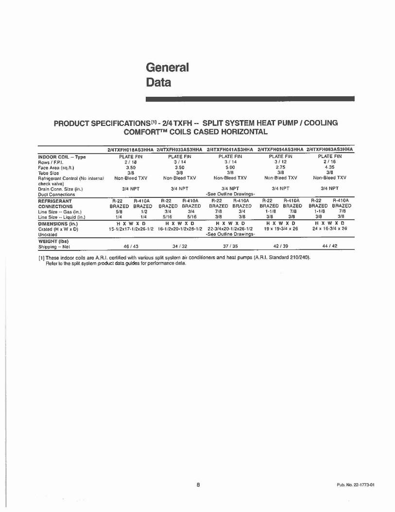
General Data
PRODUCT SPECIFICATIONSl11 - 2/4 TXFH - SPLIT SYSTEM HEAT PUMP/ COOLING COMFORTTM COILS CASED HORIZONTAL
INDOOR COIL - Type Rows/ F.P. I. Face Area (sq.ft.) Tube Size Refrigerant Control (No lntarna l check valve) Drain Conn. Size (in.J, Duct Connections REFRIGERANT CONNECTIONS Line Size • • Gas (in.) Line Size " Liquid (ill.) DIMENSIONS (In.) Crated (H x W x D) Uncrated WEIGHT (lbs) Sh,ipping - Net
2/4TXFH018AS3HHA 2/4TXFH033AS3HHA PLATE FIN PLATE FIN
21 18 3 / 14 3.50 3.50 3/8 3/8
Non-Steed TXV Non•Bleed TXV
3/4 NPT
R-22 R-410A BRAZED BRAZED
5.re 112 1/4 1/4
HXWXD 15-1/2x17• 112x26-112
46 143
314 NPT
R·22 R-410A BRAZED BRAZED
314 3/4 5(16 5/16
HXWXD 16· 1 /2x20· 1/2x26-112
34 / 32
2/4TXFH041AS3HHA
PLATE FIN 3 / 14 5 00 3/B
Non-Bleed TXV
314 NPT -See Oull ne Drawings•
R-22 R-410A BRAZED BRAZED
7/8 3,14 3/8 3i8
H X W X 0 22·314x20· 112x26-1/2
-See Outllne Drawings•
37 I 35
2/4TXFH054AS3HHA 2/4TX FHD63AS3HHA
PLATE FIN PLATE FIN 3/12 2/16 2.75 4 35 3/8 3/8
Nein-Breed TXV Non-Bleed TXV
314 NPT
R-22 R-41 DA BRAZED BRAZED
1-1'8 7/8 318 3/8
H X W X D 19 X 19•3/4 X 26
42 / 39
3/4 NPT
R-22 R-410A BRAZED BRAZED
1-1/8 7/8 3/8 3/8
H X W X D 24 X 16-3/4 X 26
44 / 42
[1) These indoor coils are A.R.l. certified with various split syslem air conditioners and heat pumps (A.A.I. Standard 210/240). Reier to the split syslem product dala guides for performance dala.
8 Pub. No. 22-1n3-01
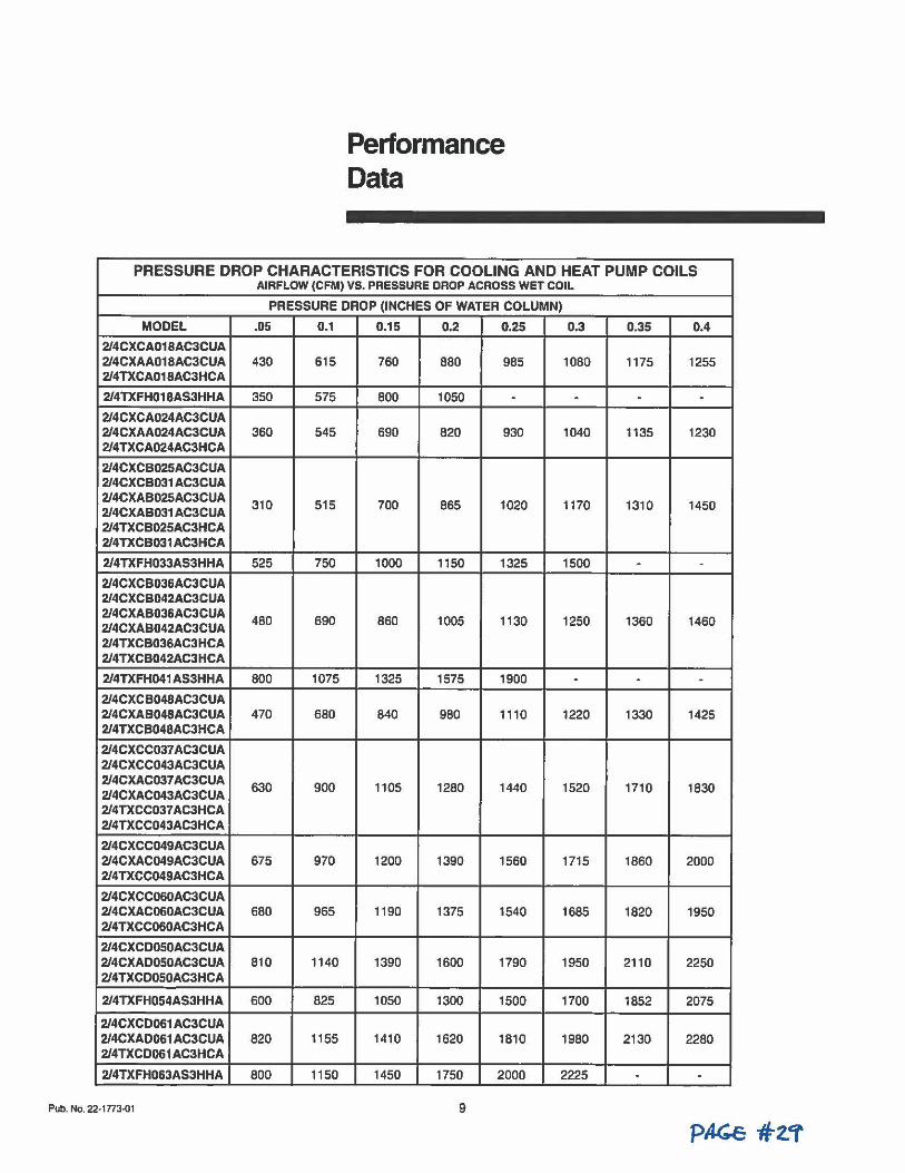
Performance Data
------------------
PRESSURE DROP CHARACTERISTICS FOR COOLING AND HEAT PUMP COILS AIRFLOW (CFM) VS. PRESSURE DROP ACROSS WET COIL
PRESSURE DROP (INCHES OF WATER COLUMN)
MODEL .05 0.1 0.15 0.2 0.25 0.3 0.35 0.4
2/4CXCA01 BAC3CUA 2/4CXAA01 BAC3CUA 430 615 760 880 985 1080 1175 1255 2/4TXCA018AC3HCA
2/4TXFH018AS3HHA 350 575 800 1050 . . . . 2/4CXCA024AC3CUA 2/4CXAA024AC3CUA 360 545 690 820 930 1040 1135 1230 2/4TXCA024AC3HCA
2/4CXCB025AC3CUA 2/4CXCB031 AC3CUA 2/4CXAB025AC3CUA 310 515 700 865 1020 1170 1310 1450 2/4CXAB031 AC3CUA 2/4TXCB025AC3HCA 2/4TXCB031AC3HCA
2/4TXFH033AS3HHA 525 750 1000 1150 1325 1500 . . 2/4CXCB036AC3CUA 2/4CXCB042AC3CUA 2/4CXAB036AC3CUA
480 690 860 1005 1130 1250 1360 1460 2/4CXAB042AC3CUA 2/4TXCB036AC3HCA 2/4TXCB042AC3HCA
2/4TXFH041 AS3HHA 800 1075 1325 1575 1900 . . .
2/4CXCB048AC3CUA 2/4CXAB048AC3CUA 470 680 840 980 1110 1220 1330 1425 2/4TXCB048AC3HCA
2/4CXCC037 AC3CUA 2/4CXCC043AC3CUA 2/4CXAC037AC3CUA
630 900 1105 1280 1440 1520 1710 1830 2/4CXAC043AC3CUA 2/4TXCC037AC3HCA 2/4TXCC043AC3HCA
2/4CXCC049AC3CUA 2/4CXAC049AC3CUA 675 970 1200 1390 1560 1715 1860 2000 2/4TXCC049AC3HCA
2/4CXCC060AC3CUA 2/4CXAC060AC3CUA 680 965 1190 1375 1540 1685 1820 1950 2/4TXCC060AC3HCA
2/4CXCD050AC3CUA 2/4CXAD0S0AC3CUA 810 1140 1390 1600 1790 1950 2110 2250 2/4TXCD050AC3HCA
2/4TXFH054AS3HHA 600 825 1050 1300 1500 1700 1852 2075
2/4CXCD061AC3CUA 2/4CXAD061AC3CUA 820 1155 1410 1620 1810 1980 2130 2280 2/4TXCD061AC3HCA
2/4TXFH063AS3HHA 800 1150 1450 1750 2000 2225 . .
Pub. No. 22• 1773-01 9
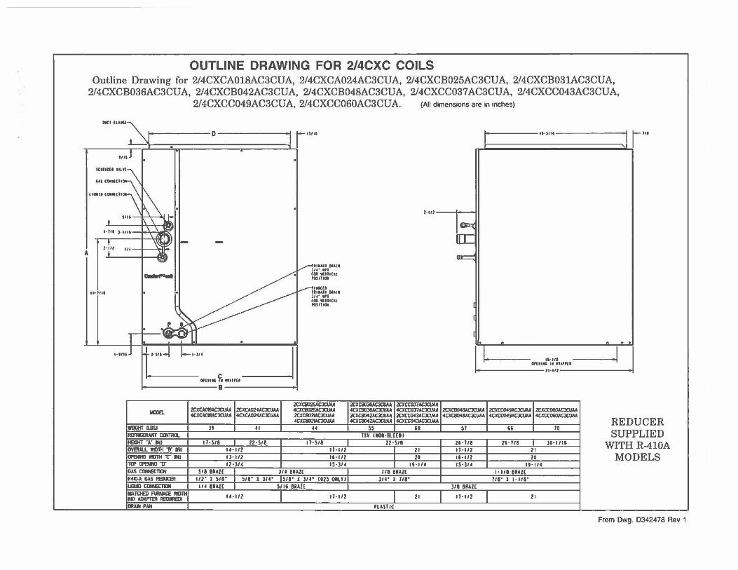
OUTLINE DRAWING FOR 2/4CXC COILS Outline Drawing for 2/4CXCA018AC3CUA, 2/4CXCA024AC3CUA, 2/4CXCB025AC3CUA, 2/4CXCB031AC3CUA,
2/4CXCB036AC3CUA, 2/4CXCB042AC3CUA, 2/4CXCB048AC3CUA, 2/4CXCC037 AC3CUA, 2/4CXCC043AC3CUA,
A
2/4CXCC049AC3CUA, 2/4CXCC060AC3CUA. (All dimensions are in inches)
IICI n,a1
T l• Ill j
u-i11t
~• • D 1 111
111
:J
"'
lo
i!I.: 't::11
Clllllll'l"'II
"
11-
~ lo
, .. ..-
I _,-ffll.lH DHII V Ju· ••t
fGI tUtlCll IOSIIIOI
I --11NU ~ ..... , 01&11 u•· .,,
IOI tflflClt POSlflOI
:j -~
,____i=_ ... ,. _J 1+:::J
r-------....:°':..:':::"=" f, , .. m• a-----_J
IQE.
lmfT 11.11$1
REFMBAIITCtMIICl. IEOIT "A" IN/ OVE!W.l. Wlll'H T WI Ol'ENINOlll:ll'H"C"'WJ TIPlftNl«JV GAS CINEC1lCN
~ 12CXCA02•ACXUAA 4CXCADIIIACJCI/AA 4CXCA~CJCI/AA
tt 41
11· Sii I 22•5/8 U·l/2 1l·H2 12•)14
2txt802SACXUAA ~cxtl,IA 2CXClm!ACXUAA 4CXC803IACXIIAA
u
1 l•S/8 ll · 1/2 11· l/2 l!·l/4
s,8 Bill£ I l/4 BUI[
I
I R411-A GAS RSD:81 112· 1 s,e· 1 SIi" I 3,.- 511" I l/4" C025 OIILTII UIDJ C1HETDI IIATOEII FIJWACE lllllH NI AOAPT8I flB1ffDI 11!.u.l PAN
114 Bill( I
U•l/2
SI II Bill[ I
11-112
I !MIit t- '" >I I Ii I
1·111-----i---t
1~ [C
~
I
I
I . . . .
I -'· - ..... .t•;:•:. ..... -·I I t---• --ll•Ul--•
2tXC8036ACX1MA 2tXCC037ACXUAA 4CXC803IAC3CIIAA 4CXC0ll7ACXU.U I 2CXC8048ACXIW, I 2CXCC049ACXUM I 2txa:o&OACJCUAA 2tXC804ZACXIIAA 20ttX>43ACXUAA 4CXt8048ACJCI/AA 4CJttll49ACXUM 4CXtt060ACJCI/AA 4CXC8042ACXUAA 4CXCC043ACXIIM
tt I " I u I " I ~ UV CIOl·BLCCD I
22•5/I 2'•118 2••Tt8 I JO• l/li I 21 ll· 112 21 I 2G 16• 112 20 I 19·114 15·)/4 It • 1/4
111 Bill£ I •Ill 9Rl l[ J,.- I 118" 1/1" I 1•111"
J/1 BRAU
I 21 If· 112 I 21
Pl&SIIC
REDUCER SUPPLIED
WITH R-410A MODELS
From Dwg. D342478 Rev 1
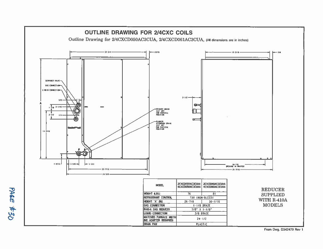
~ r;, ~ ~ Cl
A
,-in
u-J,u
l•t/U
OUTLINE DRAWING FOR 2/4CXC COILS Outline Drawing for 2/4CXCD050AC3CUA, 2/4CXCD061AC3CUA, (All dimensions are in inches)
..........
l•l,.
ll·Jtl IUIII
.'t°"U HCOIIAlt OIII. )U• IPI ,,. ,ur,c.u ,cs,11011
i----------U·Jm------------i t-----------l•·SII------------
t.«UJ.
WEIGHT n.BS.I REFRIGERANT CCMRIX. t£IGKT "A" (M GAS CON'ECTION R41D-A GAS REDUCER LlOOO CONECTION MA TOED MNACE WllTH 1W ADAPTER RE0W1ED1 DRAIN PAN
1 • lt•)II. 1111
■ I >I I
l·IIJ I •II
ll• UI 0PU115 II HA"ll ~
l""---------11-111•-----------t
2CXCD050ACJCUAA I 2CXC0061AC3CUAA -4CXC0050ACJCIJAA -4CXC0061ACJCUAA
1& I st U Y INON-llltUI
26·1/8 I JO·l/16 I · I /8 BRAZ[
1/8° X l·l/8° J/8 BRAZ[
2H l2
PLASHC
REDUCER SUPPLIED
WITH R-410A MODELS
From Dwg. D342479 Rev 1
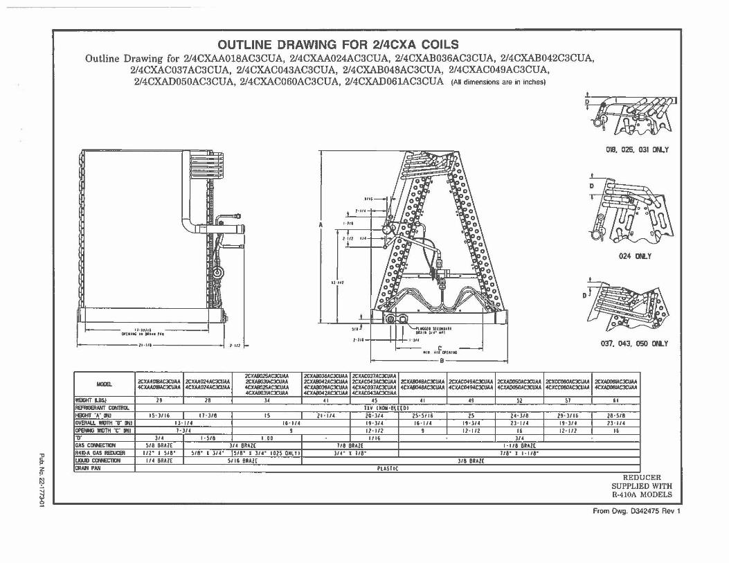
"ti
~ ~ ~
!
OUTLINE DRAWING FOR 2/4CXA COILS Outline Drawing for 2/4CXAA018AC3CUA, 2/4CXAA024AC3CUA, 2/4CXAB036AC3CUA, 2/4CXAB042C3CUA,
2/4CXAC037 AC3CUA, 2/4CXAC043AC3CUA, 2/4CXAB048AC3CUA, 2/4CXAC049AC3CUA, 2/4CXAD050AC3CUA, 2/4CXAC060AC3CUA, 2/4CXAD061AC3CUA (All dimensions are in inches)
1lB
lt·tllU on••• 11 •••• , ..
i---------11,111---------...i ' .,,
2CXAII02SACJCIIAA IIOOEI.. 2CJCAAOBACXUAA 2CXAA02◄ACXUAA 2CXABOJIM:JCUAA
◄CXMOIIAC3CIIAA 4CXAA024AC3CUAA 4C.IIAllll25ACJCUAA ◄CXAll031ACJCUAA
1181iKTUSJ 2' 28 34 REAIIGERANTCIWTRU. leGHT "A" IIIJ IS·J/16 tl·J/8 15 OV8IAU. IIIJTH T IIIJ I l· 114 16· l/4 CftNING IIIJTH ""C'" IIIJ l·J/4 9 ,,. 314 1 ·Sl8 I 00 GAS ctfHClDI S/8 BRAlE JI 4 BRAZE R◄l>-A GAS AEU::91 112· 1 s,a· s,a· 1 314• 1518" I J/4" I 025 ONl Tl I..DJll IXHE1DI 1/4 BRAl[ S/16 BRAZE IIWl PAN
I
A ,.,,. -. l t11
u ·,,,
Ill
NII I I J I
•n ,,f o,unc
i----------8--------
2CXABOJ6ACJCUAA 2CXAC037ACJCIIAA 2CXAIDl2ACJCIIAA 2CXAC04JACJCUAA 2CXAIIO◄IIACJCUIA 2CXAC049ACJCIIAA 2CXAIXl50ACJCUAA ◄CXAIIDJ6ACJCUAA ◄CXACOJ7ACXUAA ◄CXAliO◄aACJCUAA ◄CXAC049ACJCUAA 4CXAIJOSOACJCIIAA 4CXAB0◄2ACXU.U. 4CXAC04JACJCUAA
41 4S 41 49 Sl 11¥ CNON·BlUOI
ll·IH 20·)/4 25·5116 I 25 24 • ) 18 19•)/4 15 • 1/4 I 19 • l/4 ll•l/4 12-112 9 12· l/2 16
1116 J/4 118 BRAZE 1 ·1/8 &RAZE
11◄• J 1/8" 11a· 1 1-11a· J/8 BRAU
PLASTIC
D
2CXCCO&OACJCUAA ◄CXCC060ACJCUAA
SI
2'·)116 I 19· ]14 I 12 · 112
018, 025, 031 otl.Y
024 otl.Y
037. 043, 050 otl.Y
2CXAIXJ8LICJCUAA 4CXAIJ061ACXUAA
" 28· 518 ll· 1/4
16
REDUCER SUPPLIED WITH R-410A MODELS
From Dwg. D342475 Rev 1
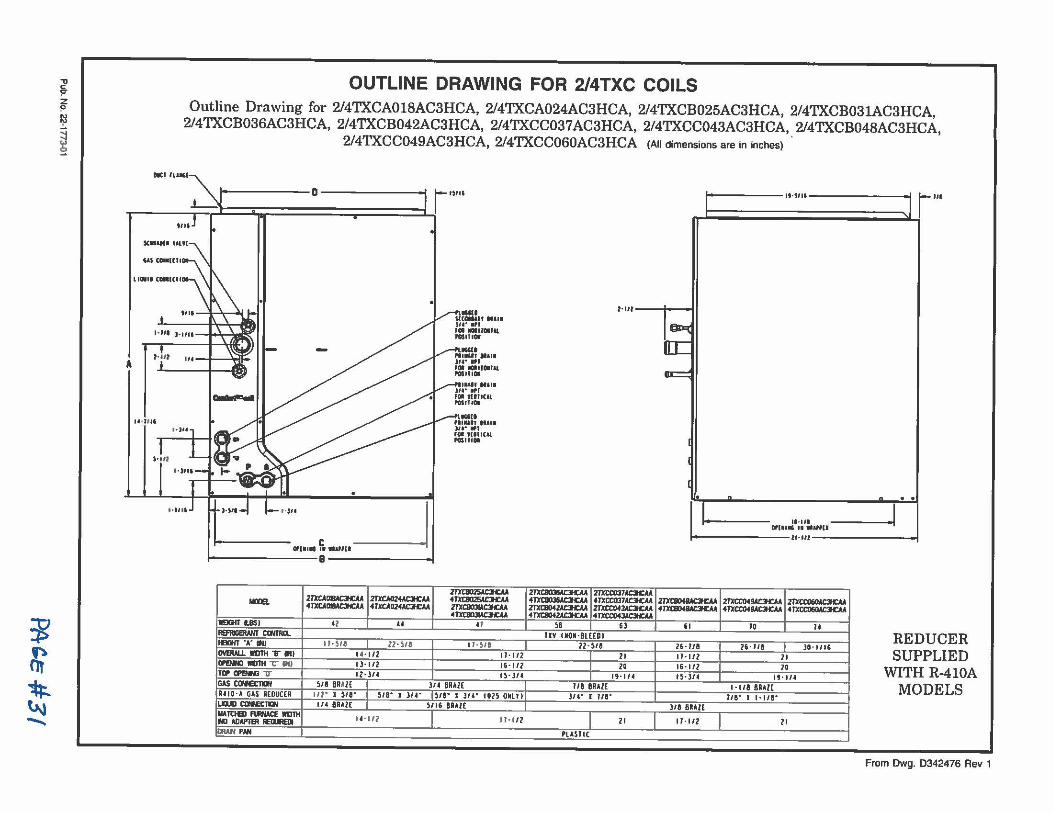
~ ln ~ ~ ~
'Jl !'"
~ ~ ~ !
A
OUTLINE DRAWING FOR 2/4TXC COILS Outline Drawing for 2/4TXCA018AC3HCA, 2/4TXCA024AC3HCA, 2/4TXCB025AC3HCA, 2/4TXCB031AC3HCA,
2/4TXCB036AC3HCA, 2/4TXCB042AC3HCA, 2/4TXCC037AC3HCA, 2/4TXCC043AC3HCA, 2/4TXCB048AC3HCA, 2/4TXCC049AC3HCA, 2/4TXCC060AC3HCA (All dimensions are in inches)
*'''°" ~
814 D ; 1 r•llll
• .,.,
"' co .. ,o, ua,, contcu
MIi J•IIII
N il " ' I ~
u 4 Jn,
l•i '1
t------ .... f. _.., __J a-------'
M0ll8. 2TXCAD18AC3HCAA 2TXCAG24ACH:AA 4lltAIIIMCH:AA 4TXC.\~ACJICM
191l11TUSI l l u REfllGaWff CIMR(l. IBJfT.A.N 11 · 518 I ll•SI& IMIW..L llllllt T .. , 11· l/2 CPEIRI IIOlH 'C" N ll•l/2 Til'll'E!Wl V ll·l/1
.• "511 ..... , .. , .. Jt•• •1 JCII r&:11 l(&l POSIIIOI
27XCII025AC3ICM 4l'XClll25ACJICA 2fXl:IICIJIADCAA 4llrCIIIIJW3DA
IT
1 l · S/8 11· 112 16 • 112 ll·l/1
GAS CCNe:T1tW SI& BRAZE I l/1 BRAI[
I
I RIIO·A GAS A[DUCCI 112· 1 s,a· , s,a· I l/1" u,a· I l/1" 1015 ONll li IJ0UD CllN£11CN 1/1 BAA1£ I S/16 BAAi[ I IIATtlBl F111NAa 1111TH
11· 112 11-112 NIADAl'IBIIIE0IHDI IJWI PAN
I ,..,,,, :l 1 ... i I ■
l•lll I II
21'XClmlAc:ICAA 2TXCC037AOC.U 4JXtBIJUOt;M 41XCCOJ7AOC.U ZIXCB042AOQA .m:taHlAOCAA 4 fll'C8042AOQA 41xa:o43AC31CAA
sa 6l IIV UON · BLHD I
ll·SI& I 21 I 2D I 19·114
II& BRAZE )/1° I 11& "
2 I
Pl AS I IC
••••_:•i~':..,,u-------i ·1 .,._ _________ ,, . .,, .
.zm:lll4&ICKAA ·~ "
16· 118 II• Ill 16·112 IS·l/1
l /8 BRAl[
ll·lll
.m:taHMOCAA 2TXCC060ACH:AA 41XCC04SAC:KAA ·~
JD II
16· 118 I JO· • 116 21 10
"' "' 1 • 118 BAAi[ 1,a· 1 1. 11a·
2 I
REDUCER SUPPLIED
WITH R-410A MODELS
From Dwg. 0342476 Rev 1
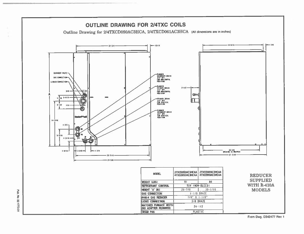
"ll
~ z !"
l;l
~ ~
,.
OUTLINE DRAWING FOR 2/4TXC COILS Outline Drawing for 2/4TXCD050AC3HCA, 2/4TXCD061AC3HCA (All dimensions a,e in inches)
I O
ll·Jlt I r- 11111
iii ii I
"I (IIOOICII
UOIII Cal(Cfl
l•ill J•UII
1-i11 .,, I ~.
u-iu1
1-i111
1-1,,-1 ..... l•Jlt -I 1----------Z,•JIII I•
i----------1•-1••------------t
ii=:., NII• :,u• ■Pl FOi Wllll(J\, P0$1tlOI
MOOE!.
WEIGHT ll.BSl REFRIGERANT CONTIIOL t£JGHT "A" IIN.I GAS CCNECTION R410-A GAS REDUCER UOUD COPIECTION MATCIEI FUINACE WIDTH INO ADAPTER REOUREDI DRAW PAN
I ,,.,,,. i-- , .. ,t J
1,111--+---
1~ rr::
(
I
I -" ft
J 1
1 Cll'IOI~· i:·:. .. ,11 • I fl •llll----------.1
2TXC0050AC3HCAA I 2TXCD061ACHAA 4TXCOOSOACJHCAA 4TXCD061ACJHCAA
8 1 I 86
TXV INON·HLHD I 26 -1ts I 30 - 1116
I· 118 BRAZ[ l/8" X I · 118"
3/ 8 BR4ZE
24 • I /2
PLASTIC
REDUCER SUPPLIED
WITH R-410A MODELS
From Dwg. D3424n Rev 1
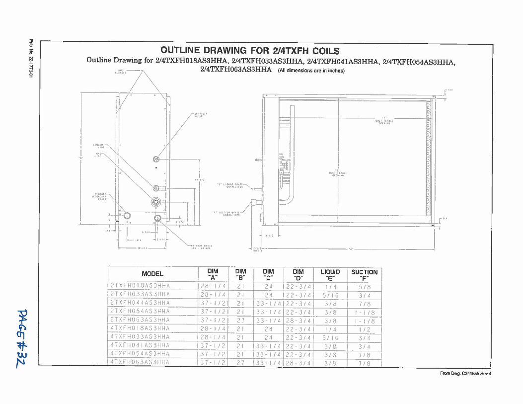
1 ~
~
i ~ ~
~
OUTLINE DRAWING FOR 2/4TXFH COILS Outline Drawing for 2/4TXFH018AS3HHA, 2/4TXFH033AS3HHA, 2/4TXFH041AS3HHA, 2/4TXFH054AS3HHA, ,.i."\:,7\ 2/4TXFH063AS3HHA (All dimensions are in inches)
~~-----------------~-1''· / .. \ . ----,
~ -• • ~=!-+--------t----- ~
/
I\~:,"' r- ·c· ~ !~ 0'-< l flO(i( t= Ol'UllloG- tJ I=='= <
~ "";';:,"""" • )11 ~
... .~:/~ e>- ~ ~ \ . ---r I-- "";•;,.... ~
" 0 I ~ OH•"""' .._ U·IIZ ~ )
,< ...._ C.0n{Cl10• -~ , ~
.. i~:m\'"'.. -- [ [IC l ;;,...../ j ~ ,..;. "~ °' .... _r . / ·~ ~ ~ . . blJ .,. ""'""' ..... ../ <
j_ r-9. 1~• ___J_ ' ,0 .. 1<1,c, !U-t-~=================~[JI' : J-~- .j , . .,, -i' . . ' .. -;.
114~ t•JJ•- ~ t·lll I+-
..-•·>" ◄ , . ., ....
, 10.iu - J1t~•:,•:;:• .. /:1111l'/f-----------·•·-------------'
MODEL ~1~ ~~~ ~b~ ~b~ u~~10 su~;~oN 2TXFH0l8AS3HHA 28-1/4 21 24 22-3/4 1/4 5/8
2TXFH033AS3HHA 28-1/4 21 24 22-3/4 5/IG 3/4
2TXFH041AS3HHA 37-1/2 21 33-1/4 22-3/4 3/8 7/8
2TXFH054AS3HHA 37-1/2 21 33-1/4 22 - 3/4 3/8 1-1/8
2TXFH063AS3HHA 37-112 27 33- 1/4 28-3/4 3/8 1-1/8
4TXFH018AS3HHA 28 - 1/4 21 2 4 22-3/4 1/4 1/2
4TXFH033AS3HHA 28-1/4 21 24 22-3/4 5/IG 3/4
4TXFH041AS3HHA 37-1/2 21 33-1/4 22-3/4 3/8 3/4
4TXFH054AS3HHA 37-1/2 21 33-1/4 22-3/4 3/8 7/8
4TXFH063AS3HHA 37-1/2 27 33-1/4 28-3/4 3/8 7/8
From Dwg. C341655 Rev 4

Amert~ sranc1arr1 Inc. 62001>Dup Highway fylclr, TX 75707
For more information contact your local dealer (distributor)
Literature Order Number
File Number
Supersedes New
Stocking Location Pl Louisville & lnland•LaCrosse
Since American Standard has a policy of cont•nuous product improvement. i1 reserves lhe righ1 lo change design and specificalions without notice.
P.I.
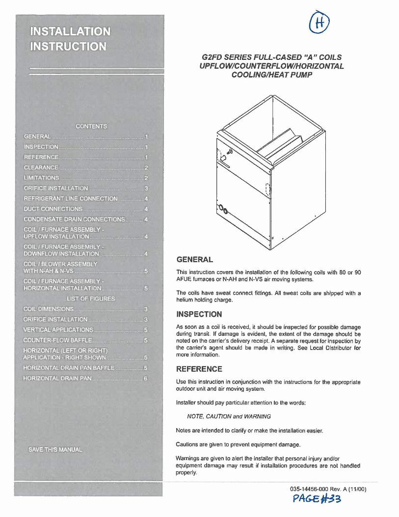
CONDENSATE DRAJN CONNECTIONS
COIL·/ F.URN'ACE ASSEMBLY, -UP.F.I..OW 1NSTAL!.:ATlON
_COIL. j FURNiCE ASSE:MBL Y. -DOWNF.LOW INSTALLA ON ,.
• : . : WITH N•AH & N•VS
COIi!.: I FURNACE ASSEMBLY, -HORIZONTAL INSTALLATION.,.. . .. . . . . 5
................ ,.... 3
VERi lCA~ AP.PUCATIONS .. . .......... ......... 5
COUNTER•FLlOW BAF.F.LE .. . ............... 5
HORIZONTAL!(LEFJ1ORRIGHT) APP.LIOOiON. RIGH1i SHOWN .. ............. 5
HORIZONTAL DRAIN PAN HORIZONTAL DRAIN PAN BAFFLE. , ........... 5
HORl2ONTAL' DRAlN PAN ...... 6
@ G2FD SERIES FULL-CASED "A" COILS
UPFLOW/COUNTERFLOW/HORIZONTAL COOLING/HEAT PUMP
GENERAL This instruction covers the installation of the following coils with 80 or 90 AFUE furnaces or N-AH and N-VS air moving systems.
The coils have sweat connect fittings. All sweat coils are shipped with a helium holding charge.
INSPECTION As soon as a coil is received, it should be inspected for possible damage during transit. If damage is evident, the extent or the damage should be noted on the carrier's delivery receipt. A separate request for inspection by the carrier's agent should be made in writing. See Local Distributor for more information.
REFERENCE Use this instruction in conjunction with the instructions for the appropriate outdoor unit and air moving system.
Installer should pay particular attention to the words:
NOTE, CAUTION and WARNING
Notes are intended to clarify or make the installation easier.
Cautions are given to prevent equipment damage.
Warnings are given to alert the installer that personal injury and/or equipment damage may result if installation procedures are not handled properly.
035-14456-000 Rev. A (11/00)
PA6-E~3
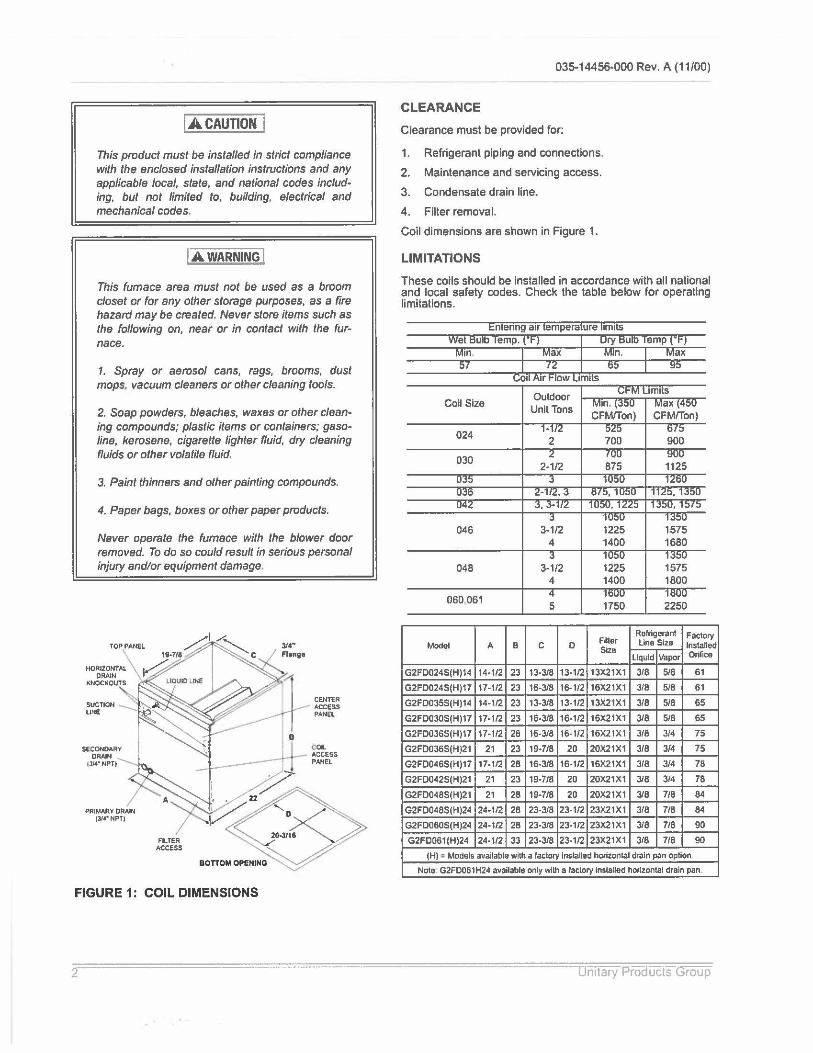
IA CAUTION I This product must be instafled in strict compliance with the enclosed installation instructions and any applicable local, state, and national codes including, but not limited lo, building, electrical and mechanical codes.
I A WARNING I This furnace area must not be used as a broom closet or for any other storage purposes, as a fire hazard may be created. Never store items such as the following on, near or in contact with the furnace.
1. Spray or aerosol cans, rags, brooms, dust mops. vacuum cleaners or other cleaning tools.
2. Soap powders, bleaches, waxes or other cleaning compounds; plastic items or containers; gasoline, kerosene, cigarette lighter fluid, dry cleaning fluids or other volatile fluid.
3. Paint thinners and other painting compounds.
4. Paper bags, boxes or other paper products.
Never operate the furnace with the blower door removed. To do so could result in serious personal injury and/or equipment damage.
TOP PANEL
SECONDARY OAAJM
tll4. NPT)
FILTER ACCESS
FIGURE 1: COIL DIMENSIONS
:114" Fling,
CENTER ACCESS PANEL
035-14456-000 Rev. A (11/00)
CLEARANCE
Clearance must be provided for:
1. Refrigerant piping and connections.
2. Maintenance and servicing access.
3. Condensate drain line.
4. Filter removal.
Coil dimensions are shown in Figure 1.
LIMITATIONS
These coils should be installed in accordance with all national and local safety codes. Check the table below for operating limitations.
Entenng air temperature limits
~in [ Max
Coil Size
024
030
046
048
060 061
Model A B
G2FD024S(H)14 14-1/2 23
G2FO024S(H)17 17-1/2 23
G2FO035S(H)14 14-1/2 23
G2FO030S(H)17 17-1/2 23
G2FO036S(H)17 17-1/2 28
G2FD036S(H)21 21 23
G2FO046S(H)17 17-1/2 28
G2FD042S(H)21 21 23
G2FO048S(H)21 21 28
G2FO048S(H)24 24-1/2 28
G2FO060S(H)24 24-1/2 28
G2FO061(H)24 24-1/2 33
Outdoor Unit Tons
2
3-1/2 4
3-1/2 4
5
C D
13-3/8 13- 1/2
16-3/8 16-1/2
13-3/8 13-1/2
16-3/8 16-1/2
16-3/8 16-1/2
19-7/8 20
16-3/8 16-1/2
19-7/8 20
19-7/8 20
23-3/8 23-1/2
23-3/8 23-1/2
23-3/8 23-1/2
700
1225 1400
1225 1400
1750
Filler Size
13X21X1
16X21X1
13X21X1
16X21X1
16X21XI
20X21X1
16X21X1
20X21X1
20X21X1
23X21X1
23X21X1
23X21X1
900
1575 1680
1575 1600
2250
Refrigerant Factory Line Size Installed
liquid Vapor Orifice
318 5/8 61
318 518 61
3/8 5/8 65
3/8 5/8 65
318 3/4 75
318 3/4 75
3/8 3/4 78
3/8 3/4 78
3/8 7/8 84
3/8 7/8 84
3/8 7/8 90
318 7/8 90
(HI : Models available with a faclory lnslalled horizontal drain pan opUon
Note G2FD061H24 available only with a factory lnslaUed horizontal drain pan.
nitary Proaucts Group
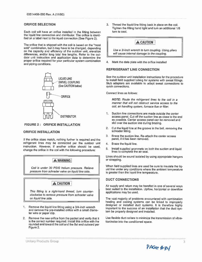
03514456-000 Rev. A (11/00)
ORIFICE SELECTION
Each coil will have an orifice installed in the fitting between the liquid line connection and distributor. The orifice is identi• fled on a label next to the liquid connection (See Figure 2).
The orifice that is shipped with the coil is based on the "most sold" combination, but it may have to be changed, depending on the capacity and efficiency of the outdoor unit, elevation differences, and/or long total line lengths. Refer lo the outdoor unit instruction and application data lo determine the proper orifice required for your particular system combination and piping conditions.
LIQUID LINE / SWIVEL COUPLING
(See CAUTION below)
~ ---ORIFICE
~ DISTRJBUTOO
FIGURE 2: ORIFICE INSTALLATION
ORIFICE INSTALLATION
If the orifice sizes match, nothing further is required and the refrigerant lines may be connected per the outdoor unit instruction. However, if another orifice should be used, change the orifice in the coil with the following procedure:
I.A WARNING I Coil is under 30 PSIG helium pressure. Relieve
pressure from schrader valve on liquid line side.
I .A CAUTION I This fitting is a right-hand thread, tum counterclockwise to remove pressure from schrader valve on liquid line side.
1. Remove the liquid line fitting using a 3/4-inch wrench and remove the pre-installed orifice with a small diameter wire or paper clip.
2. Remove the new orifice from the packet and verify that it is the correct number required. Install this orifice with the rounded end toward the coil and the Hat end outward per Figure 2.
Unitary Products Group
3. Thread the liquid line fitting back in place on the coil. Tighten the fitting hand tight and tum an additional 1/8 turn to seal.
I .A CAUTION I Use a 3/.inch wrench to tum coupling. Using pliers will cause internal damage to the coupling.
4. Mark the data plate with the orifice installed
REFRIGERANT LINE CONNECTION
See the outdoor unit installation instructions for the procedure to install field supplied tubing for systems with sweat fittings. Stub adapters are available to adapt sweat connections to quick connections.
Connect lines as follows:
NOTE: Route the refrigerant lines to the coil in a manner that will not obstruct service access to the coil, air handling system, furnace flue or filter.
1. Suction line connections are made outside the center access panel. Cut off the suction line as close to the end as possible. Center access panel can be removed and slid over the suction line during brazing.
2. Cut the liquid line at the groove in the bell, removing the schrader fitting.
3. Braze the suction line. Re-attach the center access panel, if it has been removed.
4. Braze the liquid line.
5. Install supplied grommets on both the suction and liquid lines to complete the air seal.
Lines should be sound isolated by using appropriate hangers or strapping.
When field supplied lines are used be sure to insulate the liq• uid line under any conditions where the ambient temperature is greater than the liquid line temperature.
DUCT CONNECTIONS
Air supply and return may be handled in one or several ways best suited to the installation. Upflow, horizontal or downflow applications may be used.
The vast majority of problems encountered with combination healing and cooling systems can be linked to improperly designed or installed duct systems. It is therefore highly important to the success of an installation that the duct system be properly designed and installed.
Use nexible duct collars to minimize the transmission of vibration/noise into the conditioned space.
3
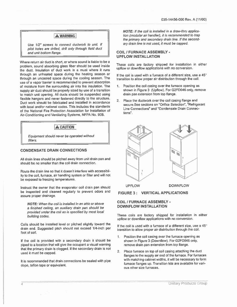
jAWARNING I
Use 112" screws to connect ductwork to unit. If pilot holes are drilled, drill only through field duct and unit bottom flange.
Where return air duct is short, or where sound is liable to be a problem, sound absorbing glass fiber should be used inside the duct. Insulation of duct work is a must where it runs through an unheated space during the heating season or through an uncooled space during the cooling season. The use of a vapor barrier is recommended to prevent absorption of moisture from the surrounding air into the insulation. The supply air duct should be properly sized by use of a transition to match unit opening. All ducts should be suspended using flexible hangers and never fastened directly to the structure. Duct work should be fabricated and installed in accordance with local and/or national codes. This includes the standards of the National Fire Protection Association for Installation of Air-Conditioning and Ventilating Systems, NFPA No. 908.
IACAUTION
Equipment should never be operated without filters.
CONDENSATE DRAIN CONNECTIONS
All drain lines should be pitched away from unit drain pan and should be no smaller than the coil drain connection.
Route the drain line so that it doesn't interfere with accessibility to the coil, furnace, air handling system or filter and will not be exposed to freezing temperatures.
Instruct the owner that the evaporator coil drain pan should be inspected and cleaned regularly to prevent odors and assure proper drainage.
NOTE: When the coil is installed in an attic or above a finished ceiling, an auxiliary drain pan should be provided under the coil as is specified by most local building codes.
Coils should be installed level or pitched slightly toward the drain end. Suggested pitch should not exceed 1/4-inch per foot of coil.
If the coil is provided with a secondary drain it should be piped to a location that will give the occupant a visual warning that the primary drain is clogged. If the secondary drain is not used it must be capped.
It is recommended that drain connections be sealed with pipe dope, teflon tape or equivalent.
4
035-14456-000 Rev. A (11/00)
NOTE: If the coil is installed in a draw-thru applicalion (modular air handler), it is recommended to trap the primary and secondary drain line. ff the secondary drain line is not used, it must be capped.
COIL / FURNACE ASSEMBLY -UPFLOW INSTALLATION
These coils are factory shipped for installation in either upflow or downflow applications with no conversion.
If the coil is used with a furnace of a different size, use a 45• transition to allow proper air distribution through the coil.
1. Position the coil casing over the furnace opening as shown in Figure 3 (Upflow). For G2FD046 only, remove drain pan extension from top flange.
2. Place the ductwork over the coil casing flange and secure.See sections on "Orifice Selection", "Refrigerant Line Connections" and "Condensate Drain Connections".
UP FLOW DOWN FLOW
FIGURE 3 : VERTICAL APPLICATIONS
COIL/ FURNACE ASSEMBLY· DOWNFLOW INSTALLATION
These coils are factory shipped for installation in either upflow or downflow applications with no conversion.
lf the coil is used with a furnace of a different size, use a 45° transition to allow proper air distribution through the coil.
1. Position the coil casing over the furnace opening as shown in Figure 3 (Downflow). For G2FD046 only, remove drain pan extension from top flange.
2. Place furnace on top of coil casing attaching the duct flanges to the supply air end of the furnace. For furnaces with matching cabinet widths, it will be necessary to form furnace flanges up. Transition kits are available for various other size furnaces.
Unitary Products roup
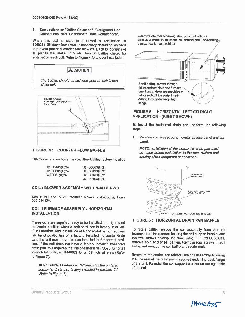
03514456-000 Rev. A (11/00)
3. See sections on "Orifice Selection", "Refrigerant Line Connections" and "Condensate Drain Connections".
When this coil is used in a downnow application, a 1DB0311BK downnow baffle kit accessory should be installed to prevent potential condensate blow off. Each kit consists of 10 pieces that make up 5 kits. Two (2) baffles should be installed on each coil. Refer to Figure 4 for proper installation.
IA.CAUTION I The baffles should be installed prior to installation of the coil.
COUNTER,FLOW BAFFLE (EACH SIDE OF -DRAIN PAN)
lll·a•#ldti5f-j:.;;u:.;;.:;.;µ.::;..:.;:u~1mu.a.u:,
FIGURE 4 : COUNTER-FLOW BAFFLE
The following coils have the downnow baffles factory installed
G2FD048S(H)24 G2FD060S(H)24 G2F0061(H)24
G2FD036S(H)21 G2FD042S(H)21 G2FO048S(H)21 G2 FD046S(H) 17
COIL/ BLOWER ASSEMBLY WITH N-AH & N-VS
See N-AH and N-VS modular blower instructions Form 535.01-NSV. '
COIL/ FURNACE ASSEMBLY- HORIZONTAL INSTALLATION
These coils are supplied ready to be installed in a right hand horizontal position when a horizontal pan is factory installed. If unit requires field instatlalion of a horizontal pan or requires left hand positioning of a factory installed horizontal drain pan, the unit must have the pan installed in the correct position. If the coil does not have a factory installed horizontal drain pan, this requires the use of either a 1 HP0623 Kit for all 23-inch tall units, or 1 HP0628 for all 28-inch tall units (Refer to Figure 7).
NOTE: Models bearing an "H" indicates the unit has horizontal drain pan factory installed in position ':4" (Refer to Figure 7).
Unitary Products Group
6 screws into rear mounting plate provided with coll. 3 holes provided in full-cased coil cabinet and 3 self•drillin screws into rumace cabinet
==;;;;::¼:=~WUL---= 3 self-drilling screws through @ full,cased toe plate and furnace ~ duct flange . Holes are provided In I full-cased coil toe plate & self- .,, drilling through furnace duct flange
FIGURE 5: HORIZONTAL LEFT OR RIGHT APPLICATION - (RIGHT SHOWN)
To install the horizontal drain pan, perform the rollowing steps:
1. Remove coil access panel, center access panel and top panel.
NOTE: Installation of the horizontal drain pan must be made before installation to the duct system and brazing of the refrigerant connections.
SUPPORT BRACKET
FIGURE 6 : HORIZONTAL DRAIN PAN BAFFLE
To rotate baffle, remove the coil assembly from the unit (remove front two screws holding the coil support bracket and the two screws holding the drain pan). For G2FD060/061, remove both end sheet baffles. Remove four screws in coil baffle and remove the coil baffle and rotate ends.
Resecure the baffles and reinstall the coil assembly ensuring that the rear of the drain pan is secured under the back flange or the unit. Reinstall the coil support bracket on the right side of the coil.
5
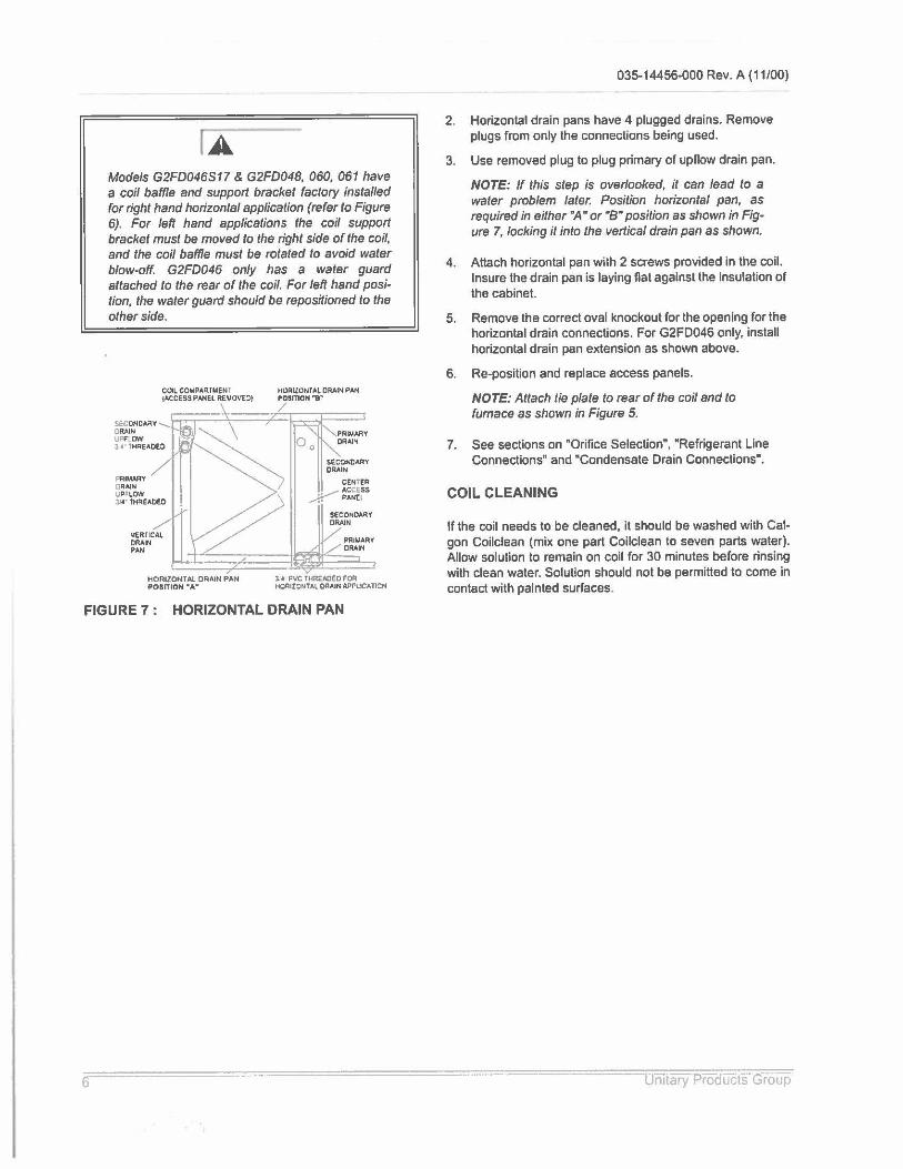
Models G2FD046S17 & G2FD048, 060, 061 have a coil baffle and support bracket factory installed for right hand horizontal application (refer to Figure 6). For left hand applications the coil support bracket must be moved to the right side of the coil, and the coil baffle must be rotated to avoid water blow-off. G2FD046 only has a water guard attached to the rear of the coil. For left hand position, the water guard should be repositioned to the other side.
SECONOA.tY DRAIN UPf l.OW
COILCOMPAqfMENI (ACCESS PANEL REVOV£~)
3_·4' THREAOEO
PRIM~Y DRAIN UPFLOW ll4' tH~EAOEO
vt;RTICAI,. ORA.IN PAN
HORIZONTAL DRAIN PAN POSrtlON_A_
HORIZONTAL OR.Al~ PAN P0SmON'"I-
/
PRIJJ.,t.RY CRAIN
];4 PVC THRl:AOED ro~ HORIZONTAL DRAIN AP PUCA TIC:N
FIGURE 7: HORIZONTAL DRAIN PAN
035-14456-000 Rev. A (11/00)
2. Horizontal drain pans have 4 plugged drains. Remove plugs from only the connections being used.
3. Use removed plug to plug primary of upnow drain pan.
NOTE: If this step is overlooked, it can lead to a water problem later. Position horizontal pan, as required in either •A• or ·a" position as shown in Figure 7, locking it into the vertical drain pan as shown.
4. Attach horizontal pan with 2 screws provided in the coil. Insure the drain pan is laying nat against the insulation of the cabinet.
5. Remove the correct oval knockout for the opening for the horizontal drain connections. For G2FD046 only, install horizontal drain pan extension as shown above.
6. Re-position and replace access panels.
NOTE: Attach tie plate to rear of the coil and to furnace as shown in Figure 5.
7. See sections on "Orifice Selection", "Refrigerant Line Connections" and "Condensate Drain Connections".
COIL CLEANING
If the coil needs to be cleaned, ii should be washed with Calgon Coilclean (mix one part Coilclean to seven parts water). Allow solution to remain on coil for 30 minutes before rinsing with clean water. Solution should not be permitted to come in contact with painted surfaces.
· rntary ·Proaueis Group
03514456-000 Rev. A (11/00)
NOTES
Unitary Products Group 7
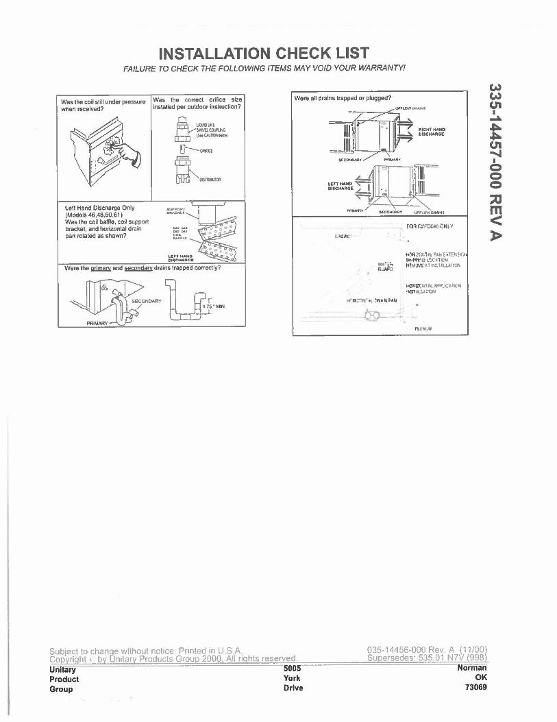
INSTALLATION CHECK LIST FAILURE TO CHECK THE FOLLOWING ITEMS MAY VOID YOUR WARRANTY!
Was lhe coll still under pressure when received?
Left Hand Discharge Only (Models 46,48,60,61) Was the coil baffle, coil support bracket, and horizontal drain pan rotated as shown?
Was the correct orifice size Installed per outdoor lnslrucUon?
tJO\lllLM !\',ML CIXl'lflG tS..Cll.'Tlllt ...
'1"-0Rn:E
~as-
Ooll•--· ..... , co~ &••Lr::......__
L.IFfMAND DI.CHARDI!'
Were the IWl!liO£ and ~ drains trapped correctly?
SECONDARY H (JT y5 "MIN
Subject lo change without notice, Printed in U.S.A. Co ri ht l b Unitar Products Grou 2000. All ri Unitary Product Group
Were all drains trapped or plugged?
hts reserved. 5005 York Drive
t<:<l zrr.1 II 'W, [ , U:,.;1',1 !-ttfW~ 1'..(1TC<4 ft!,rJ,,: ll ~11.1.UIY.Pi
Kl"ll':41lll. ~.i;~,11;~ •1151.IUl~llU
035-144 56-000 Rev. A ( 11 /00 Su ersedes: 535.01 N7V 998
Nomian OK
73069
w w u, I
...a.
t u, ~ I
0 C C
::0 m < )>
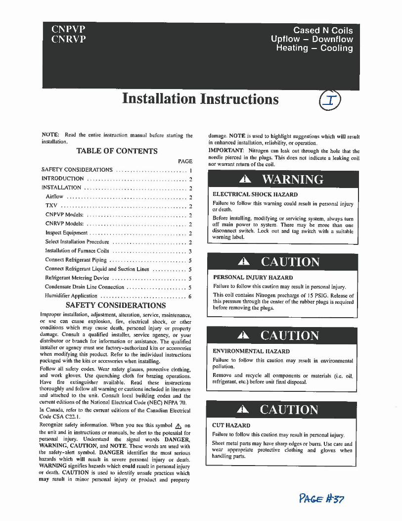
CNPVP CNRVP
Cased N Coils Upflow - Downflow
Heating - Cooling
Installation Instructions
NOTE: Read the entire instn11:1ion manual before starting thll installation.
TABLE OF CONTENTS PAGE
SAFETY CONSIDERATIONS ... ... . ..••........ . .... . I
INTRODUCTION . . • . . . . . . . . . . . . . . . . . . . • • . . . . . . . . . . . 2
INSTALLATION .. •• ..... .. ... ... ..... . •.... .. . .... . 2
Airflow ........ ... .... ..... ... ... .. ,. . • . . . . . . . . . . . 2
TXV .......... ... .... ..... ... ..... . ...•••.. ..... 2
CNPVP Models: . . . . . . . . . . . . . . . . . . . . . . . . . . . . . . . . . . . :?
CNRVP Models: . . .. .... . •. . . ... .....•. .. ..... . ... . 2
Inspect Equipment ... ..... . .. . ... •.. , . • . . . . . . . . . . . . . 2
Select Installation Proocdure . . .. . .. . .. •. , ......... .... 2
Installation of Furnace Coils . ... . .. .......•....... .... 3
Connect Refrigerant Piping . . . . . . . . . . . . . . . . . . . . . . . . . . . 5
Connect Refrigerant Liquid and Suction Lint:s ............ 5
Refrigerant Metering Device . . . . . . . . . . . . . . . . . . . . . . . . . . 5
Condensate Drain Line Connection ..................... 5
Humidifier Application .............................. 6
SAFETY CONSIDERATIONS Improper installation, adjustment, alteration, service, maintenance, or use can cause explosion, lire, electrical shock, or other conditions which may cause death, personal injury or property damage. Consult a qualified installer, service agency, or your distributor or branch for information or assistance. The qualified installer or agency must use factory-authorized kits or accessories when modifying this product. Refer to the individual instructions packaged with the kits or accessorfos when installing.
Follow all safety codes. Wear safety glasses, protectivt: clothing, and work gloves. Use quenching cloth for brazing operations. Have fire extinguisher available. Read these instructions thoroughly and follow all warning or cautions included in literature and attached to the unit. Consult local building codes and the cummt editions of the National Electrical Code (NEC) NFPA 70.
In Canada, reft:r lo the currt:nt editions of the Canadian Electrical Codt: CSA C22. I.
Rt:cognize safety information. Wht:n you see this symbol &, on
the unit and in instructions or manuals, be alert to the potential for personal injury. Understand the signal words DANGER, WARNING, CAUTION, and NOTE. These words are used with tht: safety-alert symbol. DANGER identifies the most serious hazards which will result in severe personal injury or death. WARNING signifies hazards which could resull in personal injury or death. CAUTION is uSt:d to identiry unsafe practices which muy result in minor personal injury or product and propt:rty
damage. NOTE is u.wd to highlight suggestions which will result in enhanced installation, reliability, or operation.
IMPORTANT: Nitrogen can leak out through the hole that the needle pierced in th1: plugs. This does not indicate a leaking coil nor warrant re.turn or the coil.
A WARNING ELECTRICAL SHOCK HAZARD
Failure to follow this warning could result in personal injury or death.
Before installing, modifying or servicing system, always turn off main power to system. There may be more than one disconnect switch. Lock out and tag switch with a suitable warning label.
A CAUTION PERSONAL INJURY HAZARD
Failure lo follow this caution may result in personal injury.
This coil contains Nitrogen precharge of 15 PSIG. ReleaSt: of this pressure through the center of the rubber plugs is required before removing the plugs.
A CAUTION ENVIRONMENTAL HAZARD
Failure to follow this caution may result in environmental pollution.
Remove and recycle all components or materials (i.e. oit refrigerant, etc.) before unir final disposal.
A CAUTION CUT HAZARD
Failure to follow this caution may result in personal injury.
Sheet metal pans may have sharp edges or burrs. Use earn and wear appropriate protective clothing and gloves when handling parts.
INTRODUCTION Use this instnu.1ion manual 10 install indoor coils on upflow or downflow furnaces. Do nol install coil in horizontal posilion. Models CNPVP/CNRVP are enclosed in a painted cnsing and both coils have faciory-installed TXV's. CNPVP models an: used wilh Puron® refrigerant (R-410A) systems and CNRVP models are used with R-22 sys1ems.
NOTE: Models with tin-plated copper coils, "T'' in lhe I Ith position of the model number, are inslalled the same as slandartl copper coils.
INSTALLATION These units can be installed in multiple configuralions. Before installalion, there are several performance requiremenls that must be considered because poor inslallation can negalively aller performance. This seclion will briefly discuss those factors.
Airflow Airflow amount and dislribution are vital lo adequale system performance. Problems that can be experienced wilh incorrecl airflow include: • low syslt:m performance
• reslricted TXV
• frosted coil
• poor humidity conlrol
• waterblow-off
When altaching the roil and building lhe plenum, pay special attention to lhe effeel these details will have on airflow. After syslem slart- up, check lhe cfm to insure lhat it is correct (Generally, the cfm should be 350 to 400 cfmiton during normal cooling operulion.)
TXV A thermal expansion valve is utilized in this coil design lo optimize performance and comfort throughout the entire operaling range of lhe system. Special attenlion needs 10 be laken to lhe TXV when installing the coil • Do not overheat valve. Tempernluresthat exceed 212"F (IOO•C)
can harm valve performance. Use a wet cloth or heal sink when
brazing.
• Place liquid filler dryer near ID unit to reduce the risk of debris
clogging the valve.
• Make sun: TXV bulb is securely fastened and wrapped in the
indentation on vapor line lube.
CNPVP Models: These coils have a factory-installed hard-shutoff TXV designed only for use with R- 410A refrigerant. Use only with outdoor units designed for R- 410A.
CNRVP Models: These roils have a factory-installed hard-shutoff TXV designed only for use wilh R-22 refrigeranl. Use only wilh ou1door units designed for R- 22.
NOTE: All TXV'S have preset superheat seltings and are nol fit!ld• adjustable.
Cahim:l Sweating If this unit is installed in a garage, attic, or other uncondilioned space. special auention needs to be given to the polenlial of cabinet sweating. A 6- in (152 mm) wide piece of insulalion should be wrapped around the roil casing and supply duct conneclion point.
Inspect Equipment File claim with shipper if equipment is damaged.
Select Installation Procedure
A. CAUTION PROPERTY DAMAGE HAZARD
Failure to follow this caution may result in property damage.
Installing coils rolated 90° from the fronl of the furnace, in upnow or downnow applications, may cause water blow-off or coil freeze- up due to lhe concentration of air on one slab of the coil or lack of air 10 a slab in the coil. )I is recommended thal on lhis type of application, a field-supplied adapter be placed belween the coil and furnace to allow air to distribule properly between all slabs of the coil.
NOTE: Furnace coils are nol approved to be used in fan coil or "draw-through" type applicalions.
To install cased coils in upnow applications, follow the instructions below, Upnnw Cosed Cnil lnstollotion, To install cased coils in downnow applicalions, follow the instructions below, Downnow CaSL-d Coil Installation. See Table I for dimensions and overhang options. Refor to instructions for placement of coil casing on furnace.
2
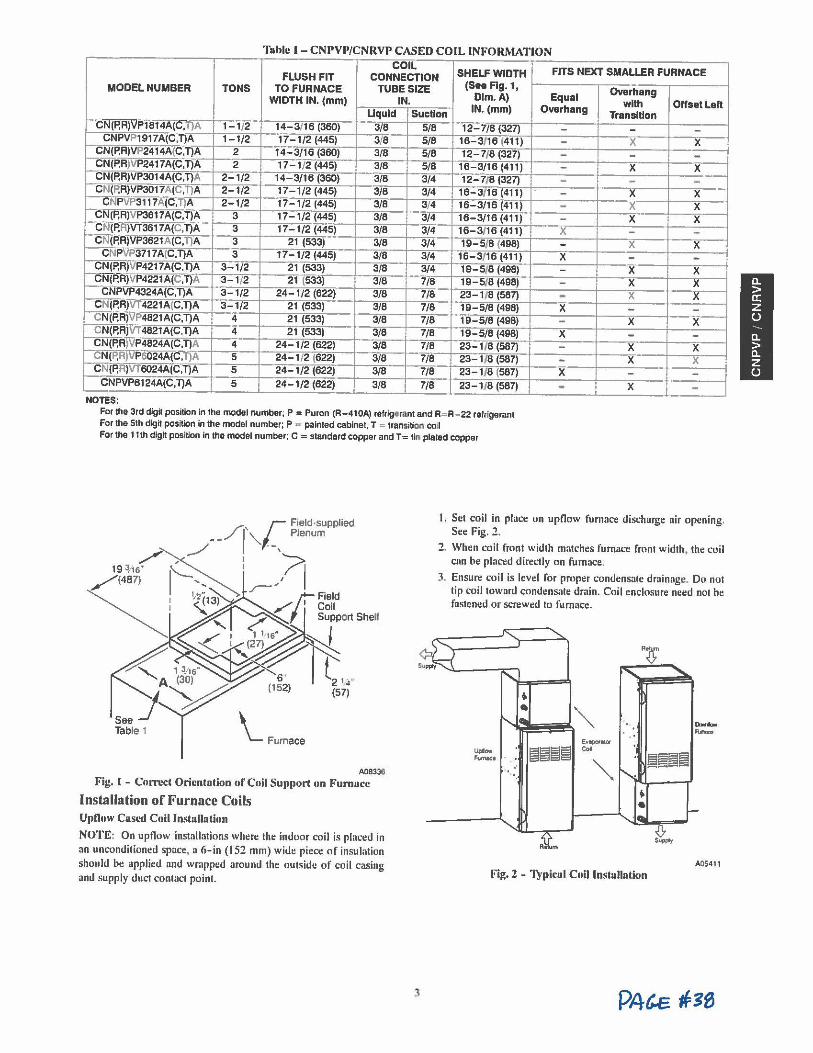
Tublc 1-CNPVP/CNRVP CASED COIL INFORMATION COIL
FLUSH FIT CONNECTION SHELF WIDTH FITS NEXT SMALLER FURNACE (Saa Ag.1, MODEL NUMBER TONS TO FURNACE TUBE SIZE Overhang
WIDTH IN. (mm) IN. Dim.A) Equal with Offset Left
Liquid Suction IN. (mm) Overhang Transition ,-.CN(P.R)VP1814A(C,T}A 1-1/2 14-3/16 (360) 3/8 5/8 12-7/8 (327) - - -CNPVP1917 A(C,T)A 1-1/2 17-1/2 (445) 3/8 5/8 16-3/16 (411) - X X
CN(P.R)VP2414A(C,T)A 2 14-3/16 (360) 3/8 5/8 12-7/8 (327) - - -CN(P.R)VP2417A(C,T)A 2 17-1/2 (445) 3/8 5/8 16-3/16 (411) - X X CN(P, RJVP3014A(C,T)A 2-1/2 14-3/16 (360) 3/8 3/4 12-7/8 (327) - - -CN(P,R)VP3017A(C,T}A 2-1/2 17-1/2 (445) 3/8 3/4 16-3/16 (411) - X X
CNPVP3117A(C,T)A 2-1/2 17-1/2 (445) 3/8 3/4 16-3/16 (411) - X X CN(P,R)VP3617A(C,T)A 3 17-1/2 (445) 3/6 3/4 16-3/16 (411) - X X CN(P,R)VT3617A(C,T)A 3 17-1/2 (445) 3/8 3/4 16-3/16 (411) X - -CN(P,R)VP3621A(C,T)A 3 21 (533) 3/8 3/4 19-5/8 (496) - X X
CNPVP3717A(C,T)A 3 17-1/2 (445) 3/8 3/4 16-3/16 (411 I X - . CN(P.R)VP4217A(C.T)A 3-1/2 21 (533) 3/8 3/4 19-5/ 8 (498) - X X
,-CN(P,R)VP4221 A(C,T}A 3-1/2 21 (533) 3/8 7/8 19-518 (496) - X X CNPVP4324A(C,T)A 3-1/2 24-1 /2 (622) 3/8 7/8 23-1/8 (587) - X X
CN(P,R)VT4221A(C.T)A 3-1/2 21 (533) 3/6 7/8 19-5/8 (498) X - -CN(P,RJVP4821 A(C,T)A 4 21 (533) 3/8 7/8 19-5/6 (498) - X X CN(P,R)VT 4821 A(C.T)A 4 21 (533) 3/8 7/6 19-5/8 (498) X - -CN(P,R)VP4824A(C,T)A 4 24-1/2 (622) 3/8 7/8 23-1 /8 (587) - X X CN(P,R)VP6024A(C,T)A 5 24-1/2 (622) 3/8 7/6 23-1/8 (587) - X X CN(P,R)VT6024A(C,T)A 5 24-1/2 (622) 3/8 7/6 23-1/8 (587) X - -
CNPVP6124A(C ,T)A 5 24-1/2 (622) 3/8 7/8 23-1/8 (587) - X -NOTES:
For the 3rd digit position in 1he model number; P = Puron (R-410A) refr.lgar:an1 and R= R - 22 refrigerant For the 51h digit positlon in the model number; P a paln1ed cabinet, T = transitiOrl co~ For !he 11th dlgh posi1ion In !he model number; C = standard copper and T= 1in pla1ed copper
Table 1 \_ Furnace
A0833$
Fig. l - Cnrn!ct Oricntution or Coil Support on Fumucc
Installation of Furnace Coils Up011w Cusl-d Coil lnstullution
NOTE: On upnow installations where the indoor coil is placi:d in an unconditioned space, a 6-in (152 mm) wide piece of insulation should be applied and wrapped around the outside of coil casing and supply duct contact point.
3
I. Set coil in placi: on upnow furnace discharge air opening. See Fig. 2 ,
2. When coil front width ma1ches fumaci: front width, the coil can be placi:d directly on furnace.
3. Ensure coil is level for proper condensate drainage. Do not lip coil toward condensate drain. Coil enclosure need not he fastened or screwed to fu mace.
"" --E~apo,-101
Uplow ~~~~ c., -· "'
~§~~ .. '•
.. •
-0, Su...,
A05411
Fig. 2 - Typicul Coil lnstullution

NOTE: When CNPVT/CNRVT (transition coils) are applied lo same width furnace, remove block- off plates al casing base by removing 2 screws per plate from side of casing. See Fig. 3.
.. -- - -
.,
Bloc.,0~ Plate:t
Fig. 3 - Ulock-OITPlotc Rcmuvul A05◄12
TRANSITION MODEL COILS APPLIED CENTERED OVER NARROW FURNACE
I . There is no transition required for this applicalion.
2. Remove coil from packaging and place on to p of furnace with 1 5/8- in (41 mm) overhang on both sides. See Fig. 4, Alternative A.
3. Continue with normal installation practices. See Connect Refrigerant Piping.
0
Cb
-ALTERNATIVE
A
MOOELS T036. T042, T048 AND T060 ONLY
0 0
....
Field _j Fabucated Block-oft Plale -
ALTERNATIVE C
L 2 I •4" (571
t
0 0
IA
-ALTERNATIVE
B
Fii:. 4 - Altcmnlive Coil Mounting rosititms A08337
STANDARD MODEL COIL APPLIED CENTERED OVER NARROW FURNACE REQUIRE A MINIMUM TRANSITION AS SPECIFIED IN FIG. 5.
I. Prepare transition, following recommended transition drawing. See Fig. 5.
2. Place transition on top of gas furnace. See Fig. 4, Alternal• ive B. Secure with sheet metal screws. Place coil on top of transition. Make sure coil rests evenly on top of transition and gas furnace.
3. Secure coil to transition using sheet metal screws.
4. Continue with normal installation practices. See Connect Refrigerant Piping.
NOTE: If coil is not being installed in the standard orientation (front of coil matching front of furnace) then coil must be raised above furnace as specified in Fig. 5.
STANDARD MODEL COIL APPLIED DIRECTLY ON TOP AND OFFSET TO THE LEFT ON NARROW FURNACE
I. Notch support rail on underside of coil cabinet lo provide clearances for gas furnace 0ange. This rail is not visible from front of coil. To locate position of notch, place coil directly on top of gas furnace with overhanging portion entirely on left side as in Fig. 4, Alternative C. Mark loca1ion of gas furnace flange on coil casing. Remove coil from top of furnace. Using tin snips, make a notch in rail large enough to allow clearance for gas flow furnace flange.
2. Place coil on top of gas furnace. Make sure coil is shifted completely 10 left side, and notch is suffici1ml so coil n:sts on top of furnace cabinet .
3. Prepare and install block-off plate. See Fig. 4, Alternative C. Using field-supplied sheel metal, cut a block-off plate 10
be allached lo botlom left side of coil casing. This plale prevents air leakage from overhanging portion of coil. Attach plale using sheet metal screws.
4. Continue with normal ins1alla1ion practices. See Connect Refrigerant Piping.
DownRow C11scd Coil lnslallution I. Place N- coil on supply duct opening.
2. When coil width matches furnace width, furnace can be placed directly on the cased co il.
NOTE: In downflow installation with a 4- way multipoise furnace, break off perforated duct flanges on furnace. See Furnace
Installation Instructions.
4
3. Coils lhat under- hang (narrower than furnace) musl have a field-fabricated transition between furnace and N• coil cas• ing as specified in Fig. 5 .
4. Coils that overhang (wider than furnace) do not require a transition in downflow application. However, a field- sup• plied furnace shelf should be constructed to fit furnace to coil opening.
5. Place furnace on lop of N- coil casing, or field- supplied furnace shelf.
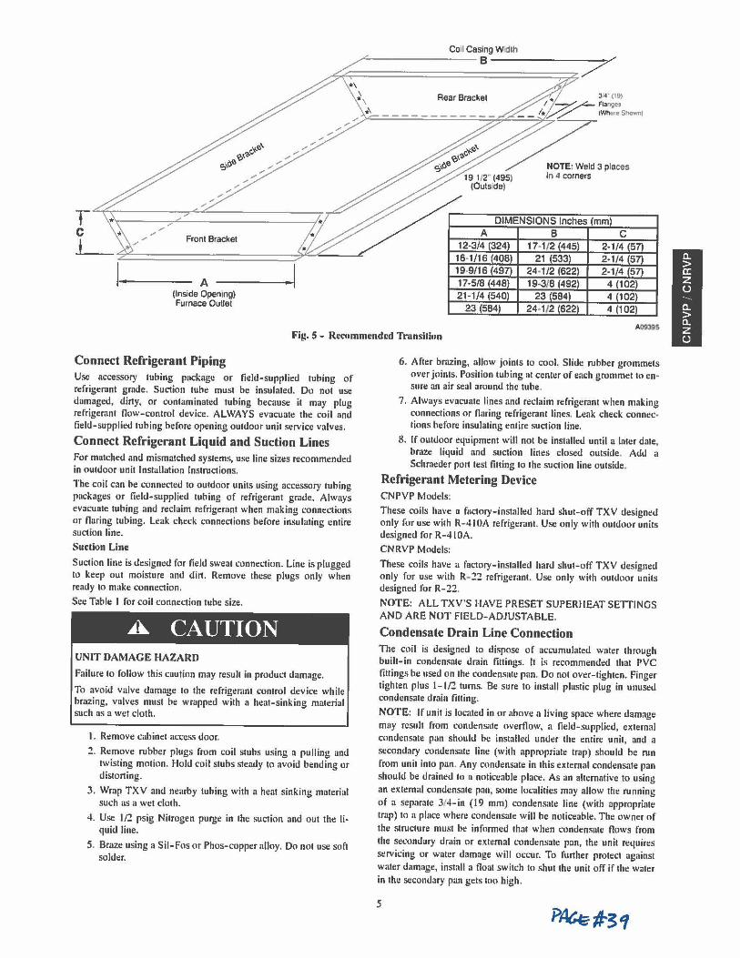
Coil Casing W:ijlh
~~,,,.=.;..=_=_=_=_=_=_=_=_=_=_=_=B= -=-=-=-= _= _= _= _;; _; 7-.,,.-'
T C
t l I
Front Bracket
A (Inside Opening) Furnace Outlet
Rear Bracket
DIMENSIONS Inches mm
. I
Fig. 5 - Recommended Transition
Connect Refrigerant Piping Use accessory tubing package or field-supplied tubing of refrigerant grade. Suction tube must be insulated. Do not use damaged, dirty, or contaminated tubing because it may plug refrigerant flow-control device. ALWAYS evacuate the coil and field-supplied tubing before opening outdoor unit service valves.
Connect Refrigerant Liquid and Suction Lines For matched and mismatched systems, use line sizes recommended in outdoor unit Installation Instructions.
The coil can be connected to outdoor units using acct:ssory tubing packages or field-supplied tubing of refrigerant grade. Always evacuate tubing and reclaim refrigerant when making L"Onnections or flaring tubing. Leak check connections before insulating entire suction line.
Suction Line
Suction line is designlld for field sweat connection. Line is plugged lo keep out moisture and din. Remove these plugs only when ready to make connection.
Set: Table I for coil connection tube: size.
A CAUTION UNIT DAMAGE HAZARD
Failure lo follow this caution may result in product damage.
To avoid valve damage: to the refrigerant control device while brazing, valves must be wrapped with a heat-sinking material such as a wet cloth.
I. Remove cabinet access door.
2. Remove: rubber plugs from coil stubs using a pulling and twisting motion. Hold coil stubs steady to avoid bending or distorting.
3. Wrap TXV and nearby tubing with a heat sinking material such as a wet cloth.
4. Use If.! psig Nitrogen purge in the suction and out the Ii• quid line.
5. Braze using a Sil-Fos or Phos-copper alloy. Do not use soft solder.
6. After brazing, allow joints to cool. Slide rubber grommets over joints. Position tubing at centt:r of each grommet to en• sure an air seal around the tube,
7. Always evacuate lines and reclaim refrigerant when making connections or flaring refrigerant lines. Leak check connt:c• tions bt:fore insulating entire suction line.
8. If outdoor equipment will not be installed until a later date, braze liquid and suction lines closed outside. Add a Schraeder port lest fitting to the suclion line outside.
Refrigerant Metering Device CNPVP Models:
These coils have a factory-installed hard shut-off TXV designed only for use with R- 410A refrigerant. Use only with outdoor units designed for R-4 IOA.
CNRVP Models:
These coils have a factory-installed hard shut-off TXV designed only for use with R- 22 refrigerant. Use only with outdoor units designed for R- 22.
NOTE: ALL TXV'S HAVE PRESET SUPERHEAT SETTINGS AND ARE NOT FIELD-ADJUSTABLE.
Condensate Drain Linc Connection The coil is designed to dispose of accumulated water lhrough built-in condensate drain fittings. It is recommended that PVC fillings be used on the condensate pan. Do nol over-tighten. Finger tighten plus 1-1/2 turns. Be sure to install plastic plug in unused condensate drain fitting.
NOTE: If unit is located in or above a living space where damage may result from condensate overflow, a field-supplied, external condensate pan should be installed under the entire unit, and a secondary condensate line (with appropriate trap) should be run from unit into pan. Any condensate in this exlemal condensate pan should be drained lo a noticeable place:. As an altt:mative to using
an external condensate pan, some localities may allow the running of a separate 3/4-in (19 mm) condensate line (with appropriate trap) to a place where condensate will be noticeable. The owner of
the: structure must be informed that when condensate flows from the secondary drain or external condensate pan, the unit requires servicing or watt:r damage will occur. To further protect against water damage, install a float switch to shut the unit off if the water in the second:1ry pan gets too high.
5
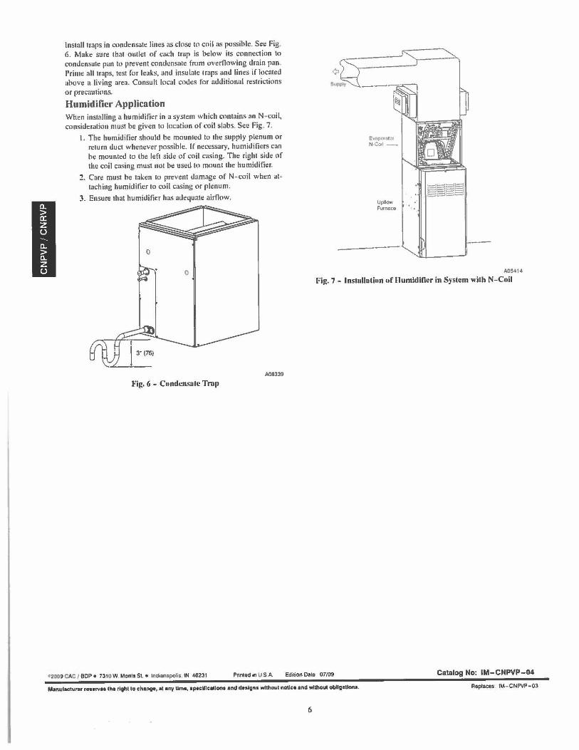
Install traps in condensate lines as close lo coil as possible. Sec Fig. 6. Make sure that outlet of each trap is below its conne<.1ion to condensate pan to prevent condensate from overflowing drain pan. Prime all traps, test for leaks, and insulate traps and lines if located above a living area. Consult local codes for additional restrictions or precautions.
Humidifier Application When installing a humidifier in a system which contains an N-coil, consideration must he given to location of coil slabs. See Fig. 7.
I. The humidifier should he mounted to the supply plenum or return duel whenever possible. If ne<.-essary, humidifiers can be mounted to the left side of coil casing. The right side of the coil casing must not be used to mount the humidifier.
2. Care must he taken to prevent damage of N- 1."0il when at• taching humidifier to coil casing or plenum.
3. Ensure that humidifier has adequate airOow.
A08339
Fig. 6 - Condensate Tnip
- 9 CAC I BOP• 7310,W. Monis S1. • Indianapolis. IN 46231 Pnmedin USA.
¢,
Evnpaotor N-Coil-
Upllow Furncace
A05414
Fig. 7 - lnstullutinn or Humidifier in System with N-Coil
Edition Date 07/09 Catalog No: IM-CNPVP-04
Manulac1urer rnorve1 tho right to chanoe, at ony Umo, lptelftcaUon1 and dnlgn1 without node• and without ob1lg1Uona. Roplaces !M- CNPVP- 03
6
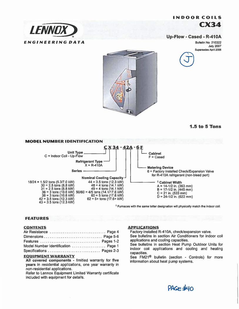
LENNOX) •
ENGINEERING DATA
MODEL NUMBER IDENTIFICATION
INDOOR COILS
CX34
Up-Flow -Cased - R-410A Bulletin No. 210322
July2007 Supersedes AprU 2006
@
1.5 to 5 Tons
~X34-42A-L Unit Type L Cabinet
C = Indoor Coil· Up-Flow ----J F = Cased Refrigerant Type
X = R-410A Metering Device
Serles ______ _, 6 = Factory installed Check/Expansion Valve
Nominal Cooling Capacity 18/24 = 1.5/2 tons (5.3n .0 kW) 44 = 3.5 tons i12.3 kW)
30 = 2.5 tons (8.8 kW) 48 = 4 tons 14.1 kW) 31 = 2.5 tons (8.8 kW 49 = 4 tons 14.1 kWI 36 = 3 tons (10.6 kW 50/60 = 4/5 tons (14.1/17.6 kW 38 = 3 tons (10.6 kW 60 = 5 tons (17.6 kW
42 = 3.5 tons (12.3 kW 62 = 5+ tons (17.6+ kW) 43 = 3.5 tons (12.3 kW
for R-41 0A refrigerant (non-bleed port)
...__ ____ 1 Cabinet Width
A= 14-1/2 in. (363 mm) B = 17-1/2 In. (445 mm) C = 21 in. (533 mm) D = 24-1/2 In. (622 mm)
1 Furnaces with the same letter designation will physically malch the Indoor coll.
FEATURES
CONTENTS Air Resistance .. •.•..•.. . ...... , . . . . . . . . . . . . Page 4 Dimensions . . . . . . . . . . . . • . . . . . . . . . . . • . . . . . . Page 5-6 Features . . • . . . . . . . . . . . . . • . . . . . . . . . . . • • . . Pages 1 ·2 Model Number Identification . . . . . . . . . . . . . . . . . . Page 1 Specifications . • ..... .. .... .. . . . .. .. . . . . .. Pages 2-3
EQUIPMENT WARRANTY All covered components - llmitied warranty for five years In residential applications, one year warranty in non-residential applications. Refer to Lennox Equipment Limited Warranty certificate Included with equipment for details.
APPLICATIONS Factory installed R-41 0A, check/expansion valve. See bulletins in section Air Conditioners for Indoor coil applications and cooling capacities. See bulletins In section Heat Pump Outdoor Units for Indoor coil applications and cooling and heating capacities. See FM21® bulletin (section - Controls) for more information about heat pump systems.
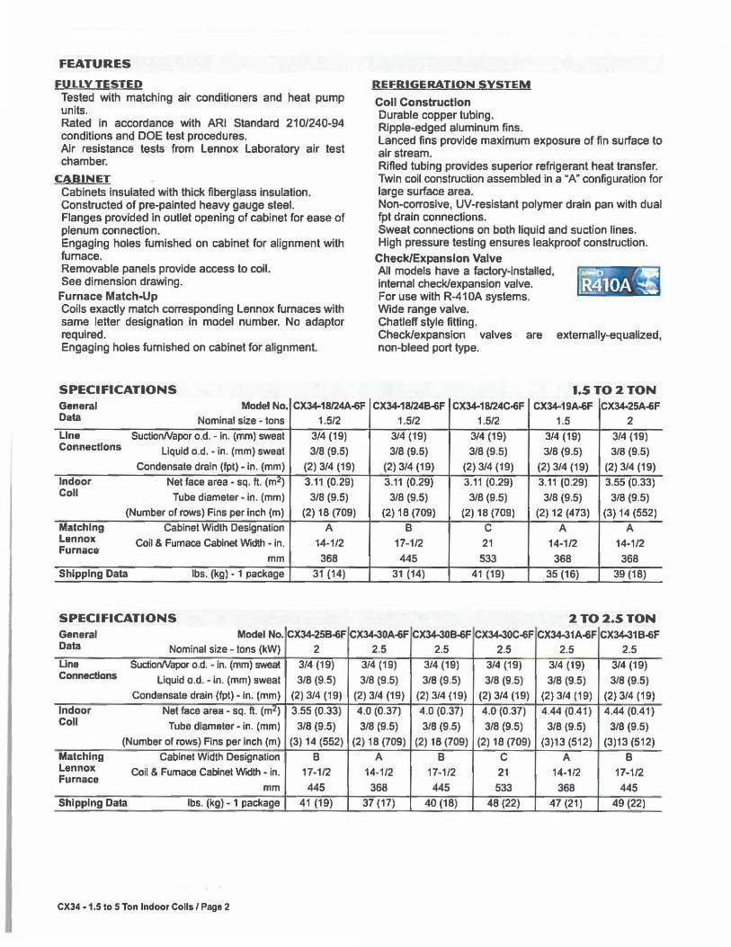
FEATURES
FULLY TESTED Tested with matching air conditioners and heat pump units. Rated in accordance with ARI Standard 210/240-94 conditions and DOE test procedures. Air resistance tests from Lennox Laboratory air test chamber.
CABINET Cabinets insulated with thick fiberglass insulation. Constructed of pre-painted heavy gauge steel. Flanges provided in outlet opening of cabinet for ease of plenum connection. Engaging holes furnished on cabinet for alignment with furnace. Removable panels provide access to coll. See dimension drawing.
Furnace Match-Up Coils exactly match corresponding Lennox furnaces with same letter designation In model number. No adaptor required. Engaging holes furnished on cabinet for alignment.
SPECIFICATIONS
REFRIGERATION SYSTEM
Coll Construction Durable copper tubing. Ripple-edged aluminum fins. Lanced fins provide maximum exposure of fin surface to air stream. Rifled tubing provides superior refrigerant heat transfer. Twin coil construction assembled in a "A" configuration for large surface area. Non-corrosive, UV-resistant polymer drain pan with dual fpt drain connections. Sweat connections on both liquid and suction lines. High pressure testing ensures leakproof construction.
Check/Expansion Valve All models have a factory-Installed, internal check/expansion valve. For use with R-41 0A systems. Wide range valve. Chatleff style fitting. Check/expansion valves are externally-equalized, non-bleed port type.
l.5TO2 TON General Model No. CX34-18/24A-6F CX34-18/24B-6F CX34-18/24C-6F CX34-19A-6F CX34-25A-6F Data Nominal size - tons 1.5/2 1.5/2 1.5/2 1.5 2
Lina SuctionNapor o.d. - in. (mm) sweat 3/4 (19) 3/4 (19) 3/4 (19) 3/4 (19) 3/4 (19) Connections Liquid o.d. - in. (mm) sweat 3/8 (9.5) 3/8 (9.5) 3/8 (9.5) 3/8 (9.5) 3/8 (9.5)
Condensate drain (fpt) • in. (mm) (2) 3/4 (19) (2) 3/4 (19) (2) 3/4 (19) (2) 3/4 (19) (2) 3/4 (19)
Indoor Net face area - sq. fl. (m2) 3.11 (0.29) 3.11 (0.29) 3.11 (0.29) 3.11 (0.29) 3.55 (0.33) Coll Tube diameter - in. (mm) 3/8 (9.5) 3/8 (9.5) 3/8 (9.5) 3/8 (9.5) 3/8 (9.5)
(Number of rows) Fins per inch (m) (2) 18 (709) (2) 18 (709) (2) 18 (709) (2) 12 (473) (3) 14 (552)
Matching Cabinet Width Designation A B C A A Lennox Coil & Fumace Cabinet Width - In. 14-1/2 17-1/2 21 14-1/2 14-1/2 Furnace
mm 368 445 533 368 368
Shipping Data lbs. (kg) - 1 package 31 (14) 31 (14) 41 (19) 35 (16) 39 (18)
SPECIFICATIONS 2TO2.5TON General Model No. CX34-25B-6F CX34-30A-6F CX34-308-6F CX34-30C-6F CX34-31A-6F CX34-318-oF Data Nominal size - tons (kW) 2 2.5 2.5 2.5 2.5 2.5
Una SudionNapor o.d. - In. (mm) sweat 3/4 (19) 3/4 (19) 3/4 (19) 3/4 (19) 3/4 (19) 3/4 (19) Connections Liquid o.d. - in. (mm) sweat 3/8 (9.5) 3/8 (9.5) 3/8 (9.5) 3/8 (9.5) 3/8 (9.5) 3/8 (9.5)
Condensate drain (fpt) - In. (mm) (2) 3/4 (19) (2) 3/4 (19) (2) 3/4 (19) (2) 3/4 (19) (2)3/4(19) (2) 3/4 (19)
Indoor Net face area - sq. ft. (m2) 3.55 (0.33) 4.0 (0.37) 4.0 (0.37) 4.0 (0.37) 4 .44 (0.41) 4.44 (0.41) Coll Tube diameter - In. (mm) 3/8 (9.5) 3/8 (9.5) 3/8 (9.5) 3/8 (9.5) 3/8 (9.5) 3/8 (9.5)
(Number of rows) Fins per Inch (m) (3) 14 (552) (2) 18 (709) (2) 18 (709) (2) 18 (709) (3)13 (512) (3)13 (512)
Matching Cabinet Width Designation • B A B C A B Lennox Coil & Furnace Cabinet Width • in. 17-1/2 14-1/2 17-1/2 21 14-1/2 17-1/2 Furnace
mm 445 368 445 533 368 445
Shipping Data lbs. (kg) • 1 package 41 (19) 37 (17) 40 (18) 48 (22) 47 (21) 49 (22)
CX34 • 1.5 to 5 Ton Indoor Coils / Page 2
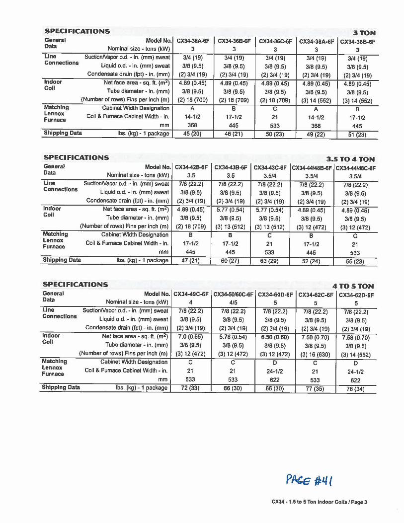
SPECIFICATIONS 3TON General Model No. CX34-36A-6F CX34-36B-6F CX34-36C-6F CX34-38A-&F CX34-38B-6F Data Nominal size - tons (kW) 3 3 3 3 3 Line SuctionNapor o.d. - In. (mm) sweat 3/4 (19) 3/4 (19) 3/4 (19) 3/4 (19) 3/4 (19) Connections liquid o.d. - In. (mm) sweat 3/8 (9.5) 3/8 (9.5) 3/8 (9.5) 3/8 (9.5) 3/8 (9.5)
Condensate drain (fpt) - In. (mm) (2) 3/4 (19) (2) 3/4 (19) (2) 3/4 (19) (2) 3/4 (19) (2) 3/4 (19) Indoor Net face area - sq. ft. (m2) 4.89 (0.45) 4.89 (0.45) 4.89 (0.45) 4.89 (0.45) 4.89 (0.45) Coll Tube diameter - In. (mm) 3/8 (9.5) 3/8 (9.5) 3/8 (9.5) 3/8 (9.5) 3/8 (9.5)
(Number of rows) Fins per Inch (m) (2) 18 (709) (2) 18 (709) (2) 18 (709) (3) 14 (552) (3) 14 (552) Matching Cabinet Width Designation A B C A B Lennox Coil & Furnace Cabinet Width - In. 14-1/2 17-1/2 21 14-1/2 17-1/2 Furnace
mm 368 445 533 368 445 Shipping Data lbs. (kg) - 1 package 45 (20) 46 (21) 50 (23) 49 (22) 51 (23)
SPECIFICATIONS 3.5TO4TON General Model No. CX34-428-6F CX34-438-6F CX34-43C-6F CX3444/48B-6F CX3444/48C-6F Data Nominal size - tons (kW) 3.5 3.5 3.5/4 3.5/4 3.5/4 Line SuctionNapor o.d. - in. (mm) sweat 7/8 (22.2) 7/8 (22.2) 7/8 (22.2) 7/8 (22.2) 7/8 (22.2) Connections Liquid o.d. - in. (mm) sweat 3/8 (9.5) 3/8 (9.5) 3/8 (9.5) 3/8 (9.5) 3/8 (9.5)
Condensate drain (fpt) - in. (mm) (2) 3/4 (19) (2) 3/4 (19) (2) 3/4 (19) (2) 3/4 (19) (2) 3/4 (19) Indoor Net face area - sq. ft. (m2) 4.89 (0.45) 5.77 (0.54) 5.77 (0.54) 4.89 (0.45) 4.89 (0.45) Coll Tube diameter - in. (mm) 3/8 (9.5) 3/8 (9.5) 3/8 (9.5) 3/8 (9.5) 3/8 (9.5)
(Number of rows) Fins per inch (m) (2) 18 (709) (3) 13 (512) (3) 13 (512) (3) 12 (472) (3) 12 (472) Matching Cabinet Width Designation B B C B C Lennox Coil & Furnace Cabinet Width - In. 17-1/2 17-1/2 21 17-1/2 21 Furnace
mm 445 445 533 445 533 Shipping Data lbs. (kg) - 1 package 47 (21) 60 (27) 63 (29) 52 (24) 55 (23)
SPECIFICATIONS 4TO5TON General Model No. CX34-49C•6F CX34-50/60C-6F CX34-60D-6F CX34-62C-6F CX34-62D-6F Data Nominal size - tons (kW) 4 4/5 5 5 5 Line SuctionNapor o.d. - In. (mm) sweat 7/8 (22.2) 7/8 (22.2) 7/8 (22.2) 7/8 (22.2) 7/8 (22.2) Connections
Liquid o.d. - In. (mm) sweat 3/8 (9.5) 3/8 (9.5) 3/8 (9.5) 3/8 (9.5) 3/8 (9.5) Condensate drain (fpt) - in. (mm) (2) 3/4 (19) (2) 3/4 (19) (2) 3/4 (19) (2) 3/4 (19) (2) 3/4 (19)
Indoor Net face area - sq. ft. (m2 ) 7.0 (0.65) 5.78 (0.54) 6.50 (0.60) 7.50 (0.70) 7.58 (0.70) Coll Tube diameter - in. (mm) 3/8 (9.5) 3/8 (9.5) 3/8 (9.5) 3/8 (9.5) 3/8 (9.5)
(Number of rows) Fins per inch (m) (3) 12 (472) (3) 12 (472) (3) 12 (472) (3) 16 (630) (3) 14 (552) Matching Cabinet Width Designation C C D C D Lennox Coil & Furnace Cabinet Width - in. 21 21 24-1/2 21 24-1/2 Furnace
mm 533 533 622 533 622 Shipping Data lbs. (kg) - 1 package 72 (33) 66 (30) 66 (30) 77 (35) 76 (34)
p~ #'-I(
CX34 -1.5 lo 5 Ton Indoor Coils/ Page 3
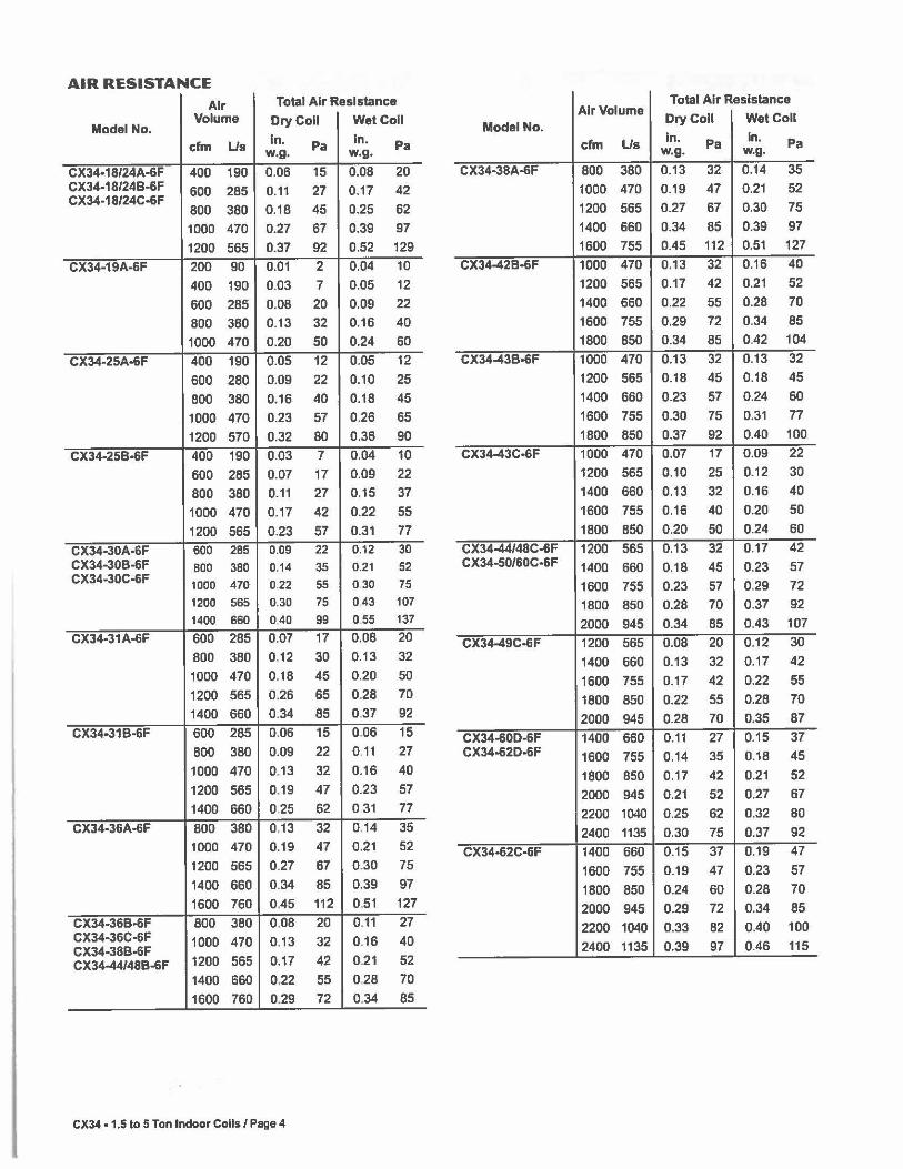
AIR RESISTANCE
Air Total Air Resistance Volume Dry Coll Wet Coll
Model No. cfm Us In. Pa In. Pa w.g. w.g.
Total Air Resistance Air Volume
Dry Coll Wet Coll Model No.
cfm Us In. Pa In. Pa w.g. w.g.
CX34-18/24A-6F 400 190 0.06 15 0.08 20 CX34-38A-6F 800 380 0.13 32 0.14 35 CX34-18/24B-6F 600 285 0.11 27 0.17 42 CX34-18/24C-6F
800 380 0.18 45 0.25 62 1000 470 0.19 47 0.21 52 1200 565 0.27 67 0.30 75
1000 470 0.27 67 0.39 97 1400 660 0.34 85 0.39 97
1200 565 0.37 92 0.52 129 1600 755 0.45 112 0.51 127
CX34-19A-6F 200 90 0.01 2 0.04 10 CX34-428-6F 1000 470 0.13 32 0.16 40
400 190 0.03 7 0.05 12 1200 565 0.17 42 0.21 52
600 285 0.08 20 0.09 22 1400 660 0.22 55 0.28 70
800 380 0.13 32 0.16 40 1600 755 0.29 72 0.34 85
1000 470 0.20 50 0.24 60 1800 850 0.34 85 0.42 104
CX34-25A-6F 400 190 0.05 12 0.05 12 CX34-43B-6F 1000 470 0.13 32 0.13 32
600 280 0.09 22 0.10 25 1200 565 0.18 45 0.18 45
800 380 0.16 40 0.18 45 1400 660 0.23 57 0.24 60
1000 470 0.23 57 0.26 65 1600 755 0.30 75 0.31 77
1200 570 0.32 80 0.36 90 1800 850 0.37 92 0.40 100
CX34-25B-6F 400 190 0.03 7 0.04 10 CX34-43C-6F 1000 470 0.07 17 0.09 22
600 285 0.07 17 0.09 22 1200 565 0.10 25 0.12 30
BOO 380 0.11 27 0.15 37 1400 660 0.13 32 0.16 40
1000 470 0.17 42 0.22 55 1600 755 0.16 40 0.20 50
1200 565 0.23 57 0.31 77 1800 850 0.20 50 0.24 60
CX34-30A-6F 600 285 0.09 22 0.12 30 CX34-44/48C-6F 1200 565 0.13 32 0.17 42 CX34-30B-6F 800 380 0.14 35 0.21 52 CX34-50/6DC-6F 1400 660 0.18 45 0.23 57 CX34-30C-6F 1000 470 0.22 55 0 30 75 1600 755 0.23 57 0.29 72
1200 565 0.30 75 043 107 1800 850 0.28 70 0.37 92 1400 660 040 99 055 137 2000 945 0.34 85 0.43 107
CX34-31A-6F 600 285 0.07 17 0.08 20 CX34-49C-6F 1200 565 0.08 20 0.12 30 BOO 380 0.12 30 0.13 32 1400 660 0.13 32 0.17 42 1000 470 0.18 45 0.20 50 1600 755 0.17 42 0.22 55 1200 565 0.26 65 0.28 70 1800 850 0.22 55 0.28 70 1400 660 0.34 85 0.37 92 2000 945 0.28 70 0.35 87
CX34-31B-6F 600 285 0.06 15 0.06 15 CX34-60D-6F 1400 660 0.11 27 0.15 37 800 380 0.09 22 0.11 27 CX34-62D-6F 1600 755 0.14 35 0.18 45 1000 470 0.13 32 0.16 40 1800 850 0.17 42 0.21 52 1200 565 0.19 47 0.23 57 2000 945 0.21 52 0.27 67 1400 660 0,25 62 0 31 77 2200 1040 0.25 62 0.32 80
CX34-36A-6F 800 380 0.13 32 0.14 35 2400 1135 0.30 75 0.37 92 1000 470 0.19 47 0.21 52 CX34-62C-6F 1400 660 0.15 37 0.19 47 1200 565 0.27 67 0.30 75 1600 755 0.19 47 0.23 57 1400 660 0.34 85 0.39 97 1800 850 0.24 60 0.28 70 1600 760 0.45 112 0.51 127 2000 945 0.29 72 0.34 85
CX34-36B-6F 800 380 0.08 20 0.11 27 CX34-36C-6F 1000 470 0.13 32 0.16 40 CX34-38B-6F CX34-44/488-6F 1200 565 0.17 42 0.21 52
2200 1040 0.33 82 0.40 100 2400 1135 0.39 97 0.46 115
1400 660 0,22 55 0.28 70 1600 760 0.29 72 0.34 85
CX34 • 1,5 to 5 Ton Indoor Coils/ Page 4
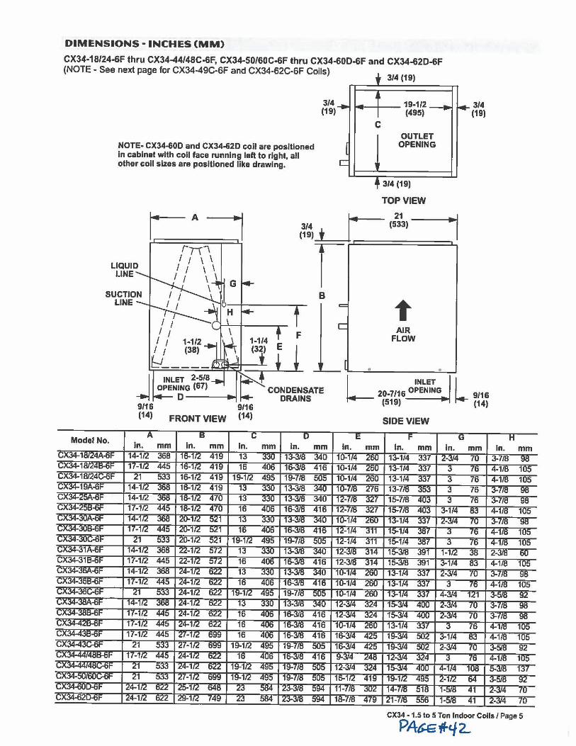
DIMENSIONS - INCHES (MM)
CX34-18/24-6F thru CX34-44/48C-6F, CX34-50/60C-6F thru CX34-60D-6F and CX34-62D-6F (NOTE - See next page for CX34-49C-6F and CX34-62C-6F Coils)
NOTE- CX34-60D and CX34-62D coll are positioned In cabinet with coll face running left to right, all other coll sizes are positioned Ilka drawing.
LIQUID LINE
3/4 (19)
B = C
C
3/4 (19)
OUTLET OPENING
3/4 (19)
TOP VIEW
AIR FLOW
3/4 (19)
L INLET l 20-7116 OPENING 9/16 (519) · (14)
SIDE VIEW
CX34 • 1.5 to 5 Ton Indoor Coils / Page 5
PA&etf-'/2..
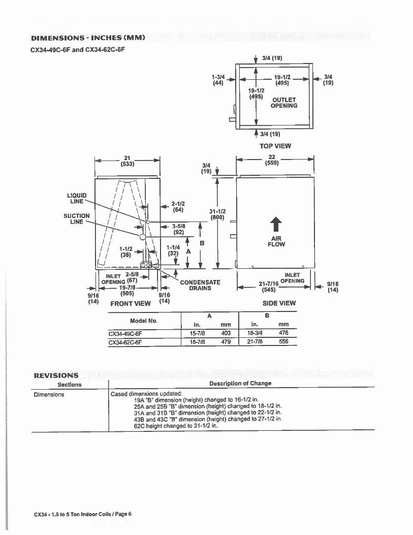
DIMENSIONS - INCHES (MM)
CX34-49C-6F and CX34-62C-6F
LIQUID LINE
REVISIONS Sections
Dimensions
9/16 (14)
1-3/4 (44)
C
3/4 (19)
19-1/2 (495)
19-1/2 (495)
OUTLET OPENING
3/4 (19)
TOP VIEW
t AIR
FLOW
3/4 (19)
L INLET l 21-7/16 OPENING_ 9/16
(545) " (14)
FRONT VIEW SIDE VIEW
A B Model No.
In. In. mm mm
CX34-49C-6F 15-7/8 403 18-3/4 476
CX34-62C-6F 18-7/8 479 21-7/8 556
Description of Change
Cased dimensions updated: 19A "B" dimension (height) changed to 16-1/2 in. 25A and 258 "8" dimension (height) changed to 18-1/2 in. 31A and 318 ·e• dimension (height) changed to 22-1/2 In. 438 and 43C ·e· dimension (height) changed to 27-1/2 in. 62C height changed to 31-1/2 in.
CX34 • 1,5 to 5 Ton Indoor Coils/ Page 6

LENNOX") ,l
Visit us at www.lannox.com
For the latest tachnlcal Information, www.lannoxdavanat.com Contact us at 1-800-4-LENNOX
NOTE - Due to Lenn01• 0ng0lng e0mmittment lo quallty, Specificat10ns, Ratings and Dimensions subject 10 change without notice and wilh0ut Incurring liability. Improper lnstallatlon. adjustment. alteration, service or maintenance can cause property damage or personal Injury. Installation and service must be performed by a qualiHed Installer and servicing agency. C2007 Lennox Industries Inc.

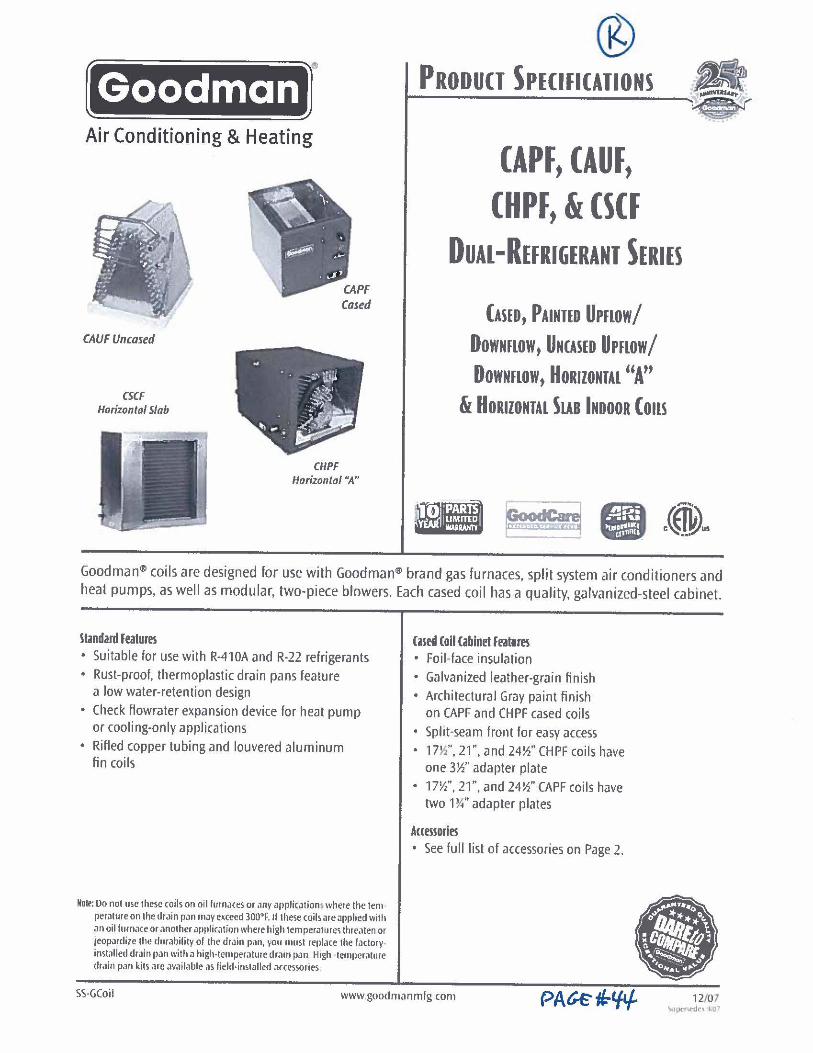
Goodman ~-Air Conditioning & Heating
CAUF Uncased
CSCF Horizontal Slab
CHPF Horizontal "A"
® PRODUCT SPECIFICATIONS • t-------------~
CAPF, CAUF, CHPF, & CSCF
0UAL-REFRl6ERANT §ERIES
CASED, PAINTED u,now/ DowNnow, UNCASED U,now/ DowNnow, HORIZONTAL "A"
& HoRIZONTAL SLAB INDOOR Cons
Goodman® coils are designed for use with Goodman® brand gas furnaces, split system air conditioners and heat pumps, as well as modular, two-piece blowers. Each cased coil has a quality, galvanized-steel cabinet.
Standard Features • Suitable for use with R-410A and R-22 refrigerants • Rust-proof, thermoplastic drain pans feature
a low water-retention design • Check flowrater expansion device for heat pump
or cooling-only applications • Rifled copper tubing and louvered aluminum
fin coils
Nolt! Do not use these coils on oil furnaces or ,1ny applicatiom where the tern peratureon the dr.iin p,1n may exceed 300°F. If these coilsareapphed with an oil furnace or another am>lication where high temperatures thre,1ten or 1eo1wdize the durability of the drain pan, you must rcf)lace the factoryinstalled drain pan with a high-ternµcra1ure dr.1111 pan High temperature dr,1in p,1n kits are ,wailable as field-installed accessories.
Cased Coil Cabinet Features • Foil-face insulation • Galvanized leather-grain finish • Architectural Gray paint finish
on CAPF and CHPF cased coils • Split-seam front for easy access • 17½", 21", and 24½" CHPF coils have
one 3½" adapter plate • 17½", 2r, and 24½" CAPF coils have
two 1¾" adapter plates
Auessorles • See full list of accessories on Page 2 .
SS·GCoil www.goodmanmfg com • i
' .
12/07 '- I xt q-;:lr1- 1,(1".'
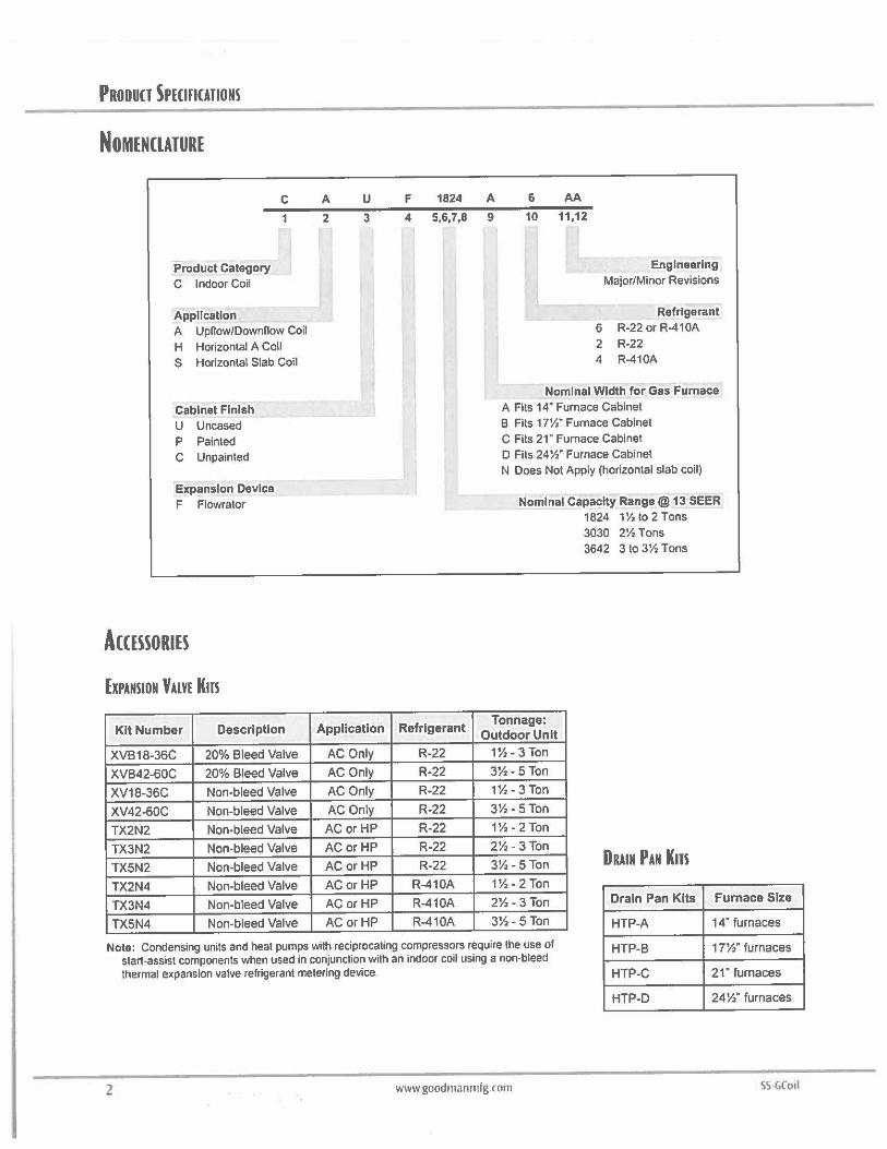
PRODUCT SPECIFICATIONS
NOMENCLATURE
Product Category C Indoor Coil
Application
C
A UpRow/Downnow Coil H Horizontal A Coil S Horizontal Slab Coil
Cabinet Finish U Uncased P Painted C Unpainted
Expansion Device F Flowrator
ACCESSORIES
ExPANSION VALVE Km
Kit Number Description
XVB18-36C 20% Bleed Valve
XVB42-60C 20% Bleed Valve
XV18-36C Non-bleed Valve
XV42-60C Non-bleed Valve
TX2N2 Non-bleed Valve
TX3N2 Non-bleed Valve
TXSN2 Non-bleed Valve
TX2N4 Non-bleed Valve
TX3N4 Non-bleed Valve
TX5N4 Non-bleed Valve
A u 2 3
Application
AC Only
AC Only
AC Only
AC Only
AC or HP
AC or HP
AC or HP
AC or HP
AC or HP
AC or HP
F 1824 A 6 AA
4 5,6,7,8 9 10 11,12
Refrigerant
R-22
R-22
R-22
R-22
R-22
R-22
R-22
R-410A
R-410A
R-410A
Engineering Major/Minor Revisions
Refrigerant 6 R-22 or R-410A 2 R-22 4 R-410A
Nominal Width for Gas Furnace A Fits 14" Furnace Cabinet B Fils 17½" Furnace Cabinet C Fils 21" Furnace Cabinet D Fits 24½" Furnace Cabinet N Does Not Apply (horizontal slab coil)
Nominal Capacity Range@ 13 SEER 1824 1½ to 2 Tons 3030 2½ Tons 3642 3 to 3½ Tons
Tonnage: Outdoor Unit
1½ • 3 Ton
3½- 5 Ton
1½- 3 Ton
3½ • 5Ton
1½ • 2 Ton
2½- 3 Ton
3½-5 Ton DRAIN PAN Kns 1½ -2 Ton
2½- 3 Ton Drain Pan Kits Furnace Size
3½- 5 Ton HTP-A 14" furnaces
Note: Condensing units and heat pumps with reciprocating compressors require the use of start-assist components when used in conjunction with an indoor coil using a non-bleed thermal expansion valve refrigerant metering device
HTP-B
HTP-C
17½" furnaces
21 • furnaces
HTP-D 24½" furnaces
2 www goodmanrnfg.com SS-GCotf
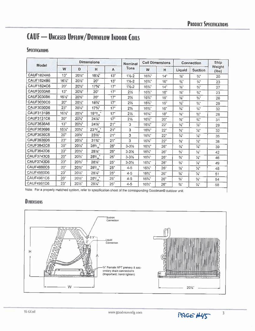
(AUF- UNCASED u,now/DOWNHOW INDOOR (mu SPECIHCATIONS
Dimensions Nominal Model Tons w D H A
CAUF1824A6 13" 20½" 18¼" 13" 1½-2 CAUF1824B6 16½" 20½" 20" 13" 1½-2 CAUF1824C6 20· 20½" 17¾" 17" 1½-2 CAUF3030A6 13" 20½" 20" 17" 2½ CAUF303086 16½" 20½" 20" 17' 2½ CAUF3030C6 20" 20½" 18¼" 17" 2½ CAUF3030D6 23" 20½" 17¾" 17" 2½ CAUF313186 16½" 20½" 191sI,; 17" 2½ CAUF3131C6 20· 20½" 24¼" 17· 2½ CAUF3636A6 13" 20½" 24¼" 21" 3 CAUF363686 16½" 20½" 23151,; 21" 3 CAUF3636C6 20" 20½" 23¼" 21 · 3 CAUF3636D6 23" 20½" 31¼" 21" 3 CAUF3642C6 20· 20½" 285/ ,; 25" 3-3½ CAUF364206 23" 20½" 28¼" 25" 3-3½ CAUF3743C6 20" 20½" 285
/ ,.- 25" 3-3½ CAUF3743D6 23" 20½" 28¼" 25" 3-3½ CAUF4860C6 20" 20½" 285t,; 25" 4.5
CAUF4860D6 23" 20½" 28¼" 25" 4-5 CAUF4961C6 20· 20½" 285
/,; 25" 4-5 CAUF4961D6 23" 20½" 28¼" 25" 4-5
PRODUCT SPECIFICATIONS
Coll Dimensions Connection Ship Weight w H Liquid Suction (lbs)
16¾" 14" ¾" ¼" 20 16¼" 16" ¾" ¾" 23 16¼" 14" ¾" ¼" 27 16¾" 16" ¾. ¼" 23 16¾" 16" ¼~ ¾" 26 16¾" 16" ¾" ¾" 29 16¾" 16" ¾" ¼" 32 16¾" 18" ¾" ¼" 28 16¾" 20" ¾" ¼" 31 16¼" 22" ¾~ ¼" 29 16¾" 22" ¾· ¼" 32 16¾" 22· ¾. ¼" 35 16¾" 22· ¾" ¼" 38 16¾" 26" ¼" ¼" 39 16¾" 26" w ¼" 42 16¼" 26" ¾" ¼" 46 16¾" 26" ¾. ¼" 49 16¾" 26" ¼" ¼" 48 16¼" 26" ¾" ¼" 51 16¾" 26" ¾" ¼" 54 16¾" 26" ¾" ¼" 58
Note For a properly matched system, refer to specification sheet of the corresponding Goodman® outdoor unit.
DIMENSIONS
H
uchon Connec11on
•2~ 1qui<1
3 ,.,
1
Coonec1Jon
A
W----
¼" Female NPT primary & sec• ondary drain connections (Important: hand-tighten)
www goodman rnfg corn
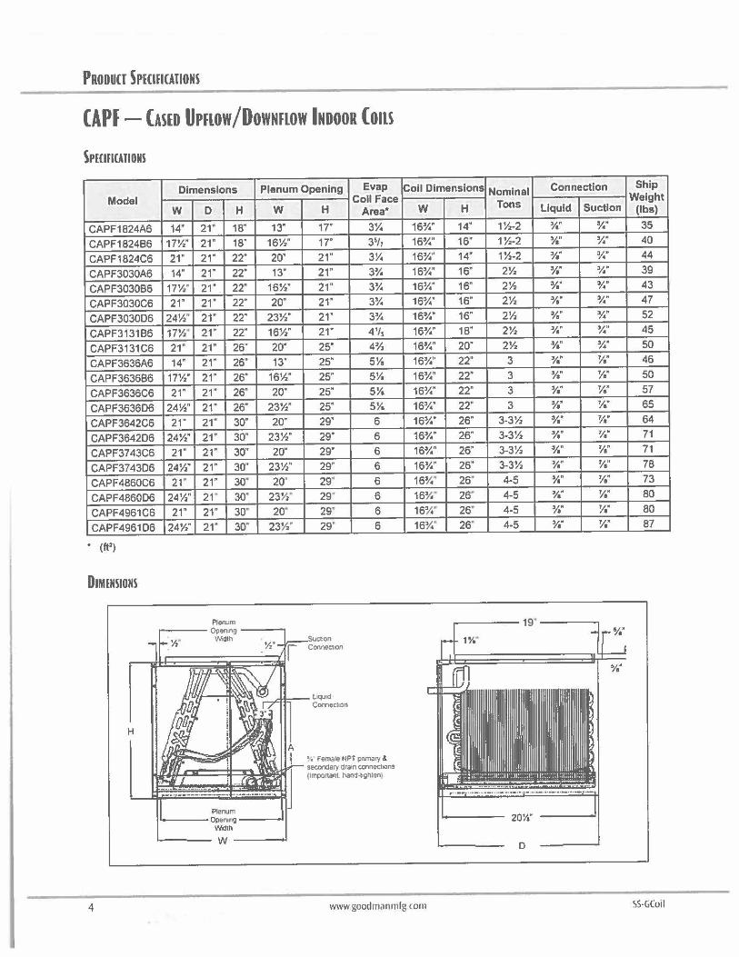
PRODUCT 5PICIHCATIONS
CAPF- CASED UPHOW/OOWNFLOW INDOOR (OILS
SPHIHCATIONS
Model
CAPF1824A6
CAPF1824B6
CAPF1824C6
CAPF3030A6
CAPF3030B6
CAPF3030C6
CAPF3030D6
CAPF3131B6
CAPF3131C6
CAPF3636A6
CAPF3636B6
CAPF3636C6
CAPF3636D6
CAPF3642C6
CAPF3642D6
CAPF3743C6
CAPF3743D6
CAPF4860C6
CAPF4860D6
CAPF4961C6
CAPF4961D6
DIMENSIONS
H
Dimensions Plenum Opening Evap Coll Face
w D H w 14" 21" 18" 13"
17½" 21· 18" 16½"
21" 21" 22" 20"
14" 21" 22· 13"
17½" 21" 22" 16½"
21" 21" 22" 20·
24½~ 21" 22" 23½"
17½" 21· 22" 16½"
21" 21· 26" 20·
14" 21" 26" 13"
17½" 21" 26" 16½"
21" 21" 26" 20'
24½" 21" 26" 23½"
21" 21" 30" 20"
24½" 21· 30" 23½"
21" 21" 30" 20·
24½" 21" 30" 23½"
21 · 21" 30· 20'
24½" 21 · 30" 23½'
21" 21" 30" 20·
24½" 21" 30· 23½"
Plenum .---- Open,ng ----.
½" 'Mdlh
Plenum ---Opening __ __,
Width
'-----w----i
H
17"
17"
21"
21"
21"
21"
21"
21·
25"
25"
25"
25"
25"
29"
29"
29"
29"
29•
29•
29' 29•
Suction Connection
Area*
3¼
3~/7
3¼
3¾
3¾
3¾
3¼
4'/s
4½
5¼
5¼
5¼
5¼
6
6
6
6
6
6
6
6
! , Female NPT pnmary & secondary drain connections (lmportanl hand-tighten)
Coll Dimensions
w H
16¾" 14"
16¾" 16"
16¾" 14"
16¾" 16"
16¾" 16"
16¾" 16"
16¼" 16"
16¾" 18"
16¼" 20"
16¼'' 22"
16¾" 22"
16¼" 22"
16¼" 22"
16¾" 26"
16¼" 26"
16¾" 26"
16¾" 26"
16¾" 26"
16¾" 26'
16¾" 26"
16¾" 26"
4 www goodmanmfg.com
Nominal Connection Ship
Tons Weight
Liquid Suction (lbs)
1½-2 ¾" ¾" 35
1½-2 ¾" ¾" 40
1½-2 ¼" ¾" 44 2½ ¾" ¾" 39
2½ ¾" ¾' 43
2½ ¼" ¾" 47
2½ ¼" ¼" 52
2½ ¼" ¼" 45
2½ ¼" ¼" 50
3 ¾" ¼" 46
3 ¾" ¼" 50
3 ¼" ¼" 57
3 ¾" ¼" 65
3-3½ ¾" ¼" 64
3-3½ ¾" ¼" 71
3-3½ ¾" 1/. 71
3-3½ ¾" ¼" 78
4-5 ¾" ¼" 73
4 .. 5 ¾" ¼" 80
4-5 ¾" 1/. 80
4-5 ¾" ¼" 87
D
SS-GCoil
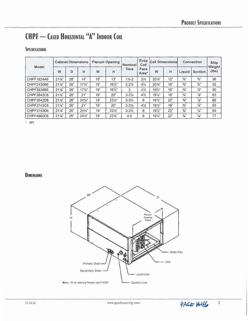
CHPF- CASED HORIZONTAL "Au INDOOR Con
SPECIFICATIONS
Model
CHPF1824A6
CHPF243086
CHPF363686
CHPF3642C6
CHPF3642D6
CHPF3743C6
CHPF3743D6
CHPF4860D6
• (It')
DIMENSIONS
SSGCoil
Cabinet Dimensions Plenum Opening Evap Coll Dimensions Coll
w 21¼"
21¼"
21¼"
21¼"
21¼"
21¼·
21¼"
21¼"
Nominal Tons Face
D H w H Area* w 26" 14" 19" 13" 1½-2 3½ 20¼"
26" 17½" 19· 16½" 2-2½ 4½ 20¼"
26" 17½" 19" 16½" 3 4½ 19½"
25· 21 " 19" 20· 3-3½ 4½ 19½"
26" 24½" 19" 23½" 3-3½ 6 19½"
26" 21 · 19" 20· 3-3½ 4½ 19½"
26" 24½" 19· 23½" 3-3½ 6 19½"
26" 24½" 19" 23½" 4-5 6 19½"
w~~ r< . . 0
H
~ Primary Drain
Secondary Drain Liqu d Line
Nole; All air opening nonges are O 6250"
www.goodmanmlg com
H
12·
16"
16"
16"
22·
16"
22"
22·
Coil
PRODUCT SPECIFICATIONS
Connection Ship Weight
Liquid Suction (lbs)
¾" ,/4. 36
¾" ¾" 55 ¾" ¼" 50 ¾" ¼" 63
¾" ¼" 66
¾" ¼" 63
¾" ¼" 63
¾" ¼" 77
s
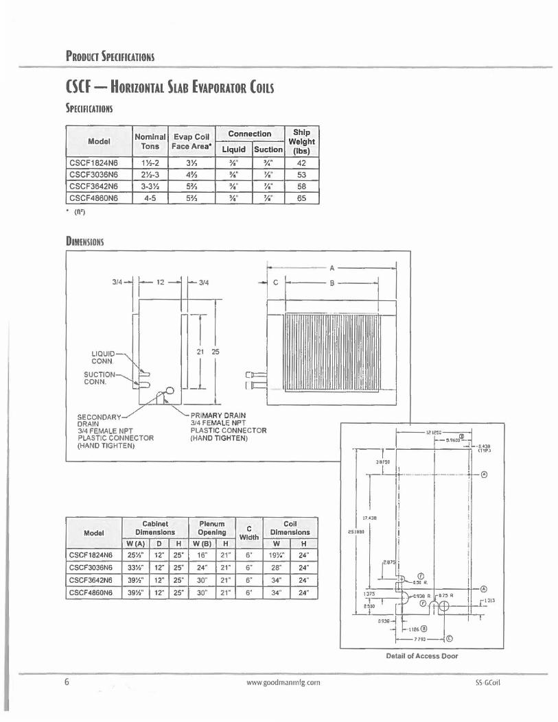
PRODUCT SPECIFICATIONS
CSCF - HORIZONTAL SLAB EVAPORATOR Cons SPECIFICATIONS
Model
CSCF1824N6
CSCF3036N6
CSCF3642N6
CSCF4860N6
• {fl')
DIMENSIONS
LIQUID CONN
SUCTION CONN.
SECONDARY DRAIN
Nominal Tons
11/.-2
2½-3
3-3½
4.5
3/4 FEMALE NPT PLASTIC CONNECTOR {HAND TIGHTEN)
Cabinet
Evap Coll Connection
Face Area* Liquid SucUon
3½ ¾" ¼"
4½ ¾" ¼" 5½ ¾" ¼"
5½ ¾" ¼"
3/4 -
ox:= IIC
PRIMARY DRAIN 3/4 FEMALE NPT PLASTIC CONNECTOR (HAND TIGHTEN)
Plenum
C
Ship Weight
(lbs)
42
53
58
65
Coll C
Model Dimensions Opening Width
Dimensions
W(A) 0 H W(B) H w H
CSCF1824N6 25½" 12" 25· 16" 21· 5• 19¼" 24"
CSCF3036N6 33½" 12· 25" 24" 21" 6" 28" 24"
CSCF3642N6 39½" 12· 25" 30" 21" 6" 34• 24"
CSCF4860N6 39½" 12· 25" 30" 21· 6" 34" 24"
6 www goodmanrnfg com
A
B
I
1 1z1e:~~ !1.9600
-l 0.038 -r----.--------- <lYP.l
0
17.•38
~SIBBO
Detail of Access Door
SS GC01I
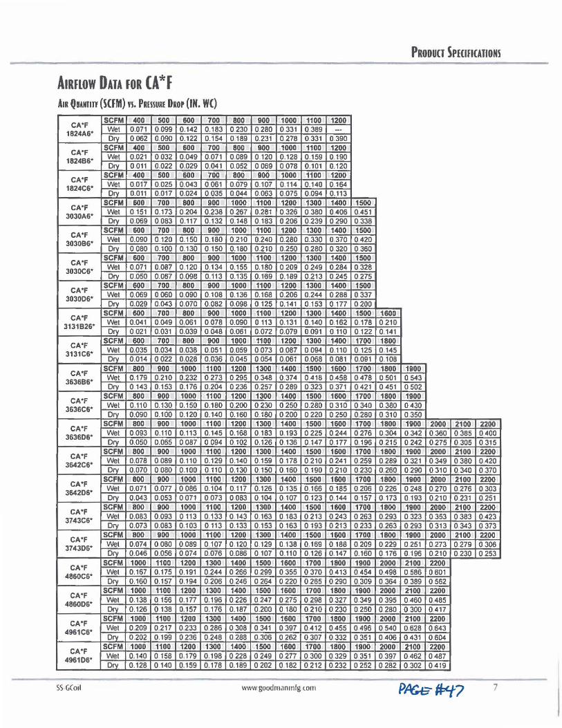
PRODUCT SPECIFICATIONS
AIRFLOW DATA JOR CA*F A1R Qmmr (SCFM) vs. P1muRE DROP (IN. WC)
CA•F SCFM 400 500 800 700 800 900 1000 1100 1200
1824A6* Wet 0.071 0.099 0.142 0.183 0230 0.280 0 331 0389 --Orv 0062 0.090 0.122 0.154 0 189 0.231 0278 0 331 0.390
CA•F SCFM 400 500 800 700 800 900 1000 1100 1200 Wet 0.021 0032 0.049 0.071 0.089 0 120 0.128 0.159 0190 1824B6* Drv 0 011 0.022 0.029 0.041 0.052 0069 0078 0.101 0.120
CA•F SCFM 400 500 600 700 800 900 1000 1100 1200 Wei 0.017 0.025 0.043 0 061 0.079 0.107 0 114 0.140 0164 1824C6* Drv 0.011 0.017 0.024 0035 0044 0.063 0.075 0.094 0.113
CA•F SCFM 600 700 800 900 1000 1100 1200 1300 1400 1500 Wet 0 151 0.173 0204 0.238 0267 0.281 0326 0 380 0406 0.451 3030A6* Orv 0.069 0083 0.117 0 .132 0.148 0183 0206 0 .239 0290 0.338
CA•F SCFM 600 700 800 900 1000 1100 1200 1300 1400 1500 Wet 0.090 0 120 0.150 0.180 0 210 0.240 0.280 0.330 0 370 0420 3030B6* Orv 0080 0.100 0.130 0 150 0.180 0.210 0.250 0.280 0 320 0360
CA•F SCFM 600 700 800 900 1000 1100 1200 1300 1400 1500 Wei 0.071 0.087 0.120 0.134 0.155 0.180 0209 0249 0284 0.328 3030C6* Drv 0.050 0.067 0.098 0.113 0.135 0.169 0.189 0.213 0.245 0275
CA*F SCFM 600 700 800 900 1000 1100 1200 1300 1400 1500 Wet 0.069 0060 0.090 0.108 0.136 0.168 0.206 0.244 0288 0337 3030D6* Drv 0.029 0.043 0.070 0.082 0.098 0 125 0.141 0.153 0.177 0 200
CA*F SCFM 600 700 800 900 1000 1100 1200 1300 1400 1500 1600 Wet 0.041 0.049 0 .061 0078 0.090 0 113 0.131 0.140 0.162 0.178 0 210 3131B26* Orv 0 021 0.031 0.039 0048 0.061 0.072 0.079 0091 0110 0122 0 141
CA*F SCFM 600 700 800 900 1000 1100 1200 1300 1400 1700 1800 Wei 0.035 0.034 0.038 0.051 0.059 0073 0087 0094 0.110 0 125 0 145 3131C6* Orv 0.014 0022 0.028 0.036 0.045 0054 0.061 0.068 0 081 0,091 0.108
CA*F SCFM 800 900 1000 1100 1200 1300 1400 1500 1600 1700 1800 1900 Wei 0,179 0.210 0.232 0273 0295 0348 0 374 0418 0.458 0478 0 501 0 543 3636B6* Drv 0 143 0.153 0.176 0.204 0236 0.257 0289 0323 0.371 0421 0451 0502
CA*F SCFM 800 900 1000 1100 1200 1300 1400 1500 1600 1700 1800 1900 Wet 0.110 0.130 0.150 0.180 0.200 0230 0 250 0.280 0 310 0340 0.380 0430 3636C6* Orv 0.090 0.100 0.120 0.140 0.160 0180 0200 0220 0250 0.280 0 310 0350
CA*F SCFM 800 900 1000 1100 1200 1300 1400 1500 1600 1700 1800 1900 2000 2100 2200 Wet 0093 0.110 0.113 0.145 0.168 0.183 0.193 0225 0244 0276 0304 0342 0.360 0385 0400 363606* Orv 0.050 0.065 0087 0 094 0102 0.126 0.136 0147 0.177 0.196 0 215 0242 0.275 0305 0 315
CA*F SCFM 800 900 1000 1100 1200 1300 1400 1500 1600 1700 1800 1900 2000 2100 2200 Wet 0.078 0089 0.110 0.129 0.140 0159 0178 0 210 0 241 0259 0,289 0.321 0349 0380 0,420 3642C6* Drv 0.070 0080 0.100 0 110 0.130 0150 0 160 0190 0 210 0230 0.260 0.290 0 310 0.340 0 370
CA*F SCFM 800 900 1000 1100 1200 1300 1400 1500 1600 1700 1800 1900 2000 2100 2200 Wet 0.071 0.077 0086 0.104 0.117 0.126 0 135 0166 0185 0206 0226 0248 0270 0276 0303 364206* Drv 0.043 0.053 0071 0073 0083 0 104 0 107 0 123 0.144 0157 0173 0 193 0.210 0 231 0 251
CA*F SCFM 800 900 1000 1100 1200 1300 1400 1500 1600 1700 1800 1900 2000 2100 2200 Wet 0.083 0.093 0113 0.133 0 143 0 163 0 183 0 213 0243 0263 0.293 0323 0353 0383 0.423 3743C6* Dry 0.073 0.083 0.103 0113 0.133 0 153 0163 0193 0213 0233 0.263 0.293 0313 0 343 0 373
CA*F SCFM 800 900 1000 1100 1200 1300 1400 1500 1600 1700 1800 1900 2000 2100 2200 Wei 0.074 0080 0089 0.107 0 120 0.129 0.138 0.169 0 188 0209 0 229 0 251 0.273 0 279 0 306 374306* Drv 0 .046 0.056 0074 0.076 0.086 0107 0 110 0126 0.147 0.160 0176 0 196 0210 0230 0253
CA*F SCFM 1000 1100 1200 1300 1400 1500 1600 1700 1800 1900 2000 2100 2200 Wet 0.167 0.175 0.191 0244 0 266 0299 0355 0370 0413 0454 0.498 0 586 0 601 4860C6* Dry 0 .160 0.157 0.194 0.206 0246 0264 0220 0.265 0290 0.309 0 364 0389 0562
CA*F SCFM 1000 1100 1200 1300 1400 1500 1600 1700 1800 1900 2000 2100 2200 Wet 0.138 0 156 0.177 0.196 0226 0247 0275 0298 0327 0 349 0395 0460 0.485 486006* Orv 0.126 0 138 0.157 0.176 0.187 0.200 0 180 0 210 0230 0250 0 280 0300 0 417
CA*F SCFM 1000 1100 1200 1300 1400 1500 1600 1700 1800 1900 2000 2100 2200 Wei 0.209 0.217 0233 0.286 0308 0 341 0397 0.412 0455 0496 0 540 0.628 0.643 4961C6* Dry 0.202 0.199 0236 0.248 0.288 0.306 0262 0307 0332 0 351 0406 0 431 0.604
CA*F SCFM 1000 1100 1200 1300 1400 1500 1600 1700 1800 1900 2000 2100 2200 Wei 0.140 0 158 0.179 0.198 0228 0249 0277 0 300 0329 0 351 0397 0462 0487 496106* Orv 0.128 0 140 0.159 0.178 0.189 0202 0 182 0 212 0232 0 252 0 282 0 302 0419
-- ----------SS·GC01I www good111,1nmfg com 7
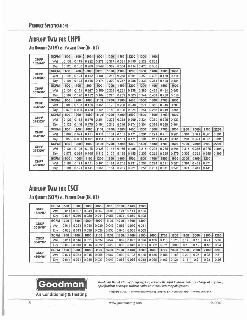
PRODUCT SPECIHCATIONS
AIRFLOW DATA FOR (ff PF Ala Qumnr (SUM) n. PmsuRE D10P (IN. WC)
SCFM 600 700 BOO 900 1000 1100 1200 1300 1400 CHPF
Wei 0 132 0 179 0222 0272 0 327 0 381 0456 0522 0605 1824A&• Dry 0 126 0 165 0206 0249 0302 0354 0414 0478 0 563
SCFM 600 700 800 900 1000 1100 1200 1300 1400 1500 1600 CHPF
Wet 0 106 0 124 0152 0184 0 218 0258 0 301 0350 0406 0460 0.514 2430B&• Dry 0 101 0 122 0 145 0174 0209 0247 0288 0333 0381 0428 0.484
SCFM 600 700 BOO 900 1000 1100 1200 1300 1400 1500 1600 CHPF
Wet 0107 0 131 0167 0199 0239 0 291 0338 0389 0439 0494 0 552 363686* Dry 0 102 0126 0 152 0184 0220 0259 0303 0349 0401 0.458 0 516
SCFM BOO 900 1000 1100 1200 1300 1400 1500 1600 1700 1800 CHPF
Wet 0083 0 103 0126 0 151 0178 0208 0240 0274 0 310 0346 0.383 3642C6* Dry 0073 0096 0120 0144 0169 0 196 0224 0254 0286 0 319 0 354
SCFM 800 900 1000 1100 1200 1300 1400 1500 1600 1700 1800 CHPF
Wet 0 133 0 153 0176 0 201 0 228 0 258 0290 0 324 0 360 0396 0 433 3743C6* Dry 0123 0 146 0170 0194 0 219 0246 0274 0 304 0 336 0 369 0404
SCFM 800 900 1000 1100 1200 1300 1400 1500 1600 1700 1800 1900 2000 2100 2200 CHPF
Wet 0087 0 091 0101 0 111 0 131 0 151 0 171 0201 0 221 0.251 0.281 0 301 0 341 0 361 0 391 3642D6* Dry 0058 0 081 0 101 0 111 0 131 0 151 0 171 0 191 0 211 0 241 0 261 0.291 0 321 0 351 0 381
SCFM BOO 900 1000 1100 1200 1300 1400 1500 1600 1700 1800 1900 2000 2100 2200 CHPF
Wet 0101 0 105 0 115 0 125 0145 0 165 0185 0 215 0 235 0265 0295 0 315 0.355 0375 0405 3743D6° Dry 0072 0095 0105 0 115 0 135 0 155 0185 0205 0225 0255 0275 0305 0335 0365 0395
SCFM 900 1000 1100 1200 1300 1400 1500 1600 1700 1800 1900 2000 2100 2200 CHPF
Wet 0101 0121 0131 0 161 0 181 0 201 0 231 0 261 0 291 0321 0.361 0 391 0431 0.471 4860D6* Dry 0 101 0121 0 141 0 161 0 181 0 201 0 221 0 251 0 281 0 311 0.341 0 371 0 411 0441
AIRFLOW DATA FOR (§Cf AIR Quumn (SCFM) vs. Pamm DRor (IN. WC)
SCFM 500 600 700 800 900 1000 1100 1200 CSCF
Wei 0011 0027 0049 0067 0 095 0.121 0.141 0153 1824N6° Ory 0007 0 016 0029 0041 0.056 0071 0089 0 108
SCFM 700 800 900 1000 1100 1200 1300 1400 CSCF
Wet 0019 0023 0030 0.039 0 049 0 052 0070 0 081 3036N6* Dry 0060 0013 0020 0028 0036 0045 0053 0063
SCFM BOO 900 1000 1100 1200 1300 1400 1500 1600 1700 1800 1900 2000 2100 2200 CSCF
Wei 0 011 0.016 0 021 0034 0 044 0062 0073 0096 0 106 0.113 0123 0 14 015 0.21 026 3642N6* Ory 0005 0010 0 016 0022 0.029 0.035 0043 0051 0062 0.071 0080 0 1 012 0 18 024
SCFM BOO 900 1000 1100 1200 1300 1400 1500 1600 1700 1800 1900 2000 2100 2200 CSCF
Wet 0021 0033 0045 0055 0067 0090 0103 0 125 0.135 0.156 0 188 023 025 0.28 0 31 4860N6° Dry 0014 0021 0030 0.037 0047 0055 0065 0088 0095 0.103 0 121 0 18 0.2 023 025
Goodman Goodmon Man11/acturing Company, LP., r~rves the right to discontinue, or cJionge at any time, specifications or designs without notiu or without incurring obligations.
Air Conditioning & Heating (optr11,11 < 1007 " Goodman M1Jttufo,tur,n1 Compony, t P • llou1ton, rrx111 • PrintNI III rlk- tJSA.
8 www goodmanrnlg com SS GCo.,
© Cased and Uncased
ea IP mp I Coo ing Coils 1 /2-5 on
2/4CXC,2/4CXA,2/4TXC 2/4TXFH 13 SEER Heat Pump /Cooling Coils for R-22 and R-410A
PUB. NO. 22-1773-02
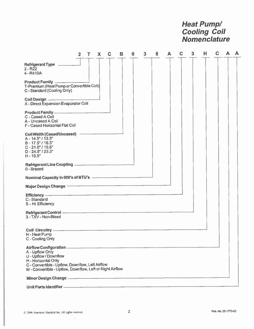
2 T X C
Refrigerant Type 2 - R22 4 - R410A
T
Product Family _____ __, T-Premium (Heat Pump or Convertible Coil C- Standard (Cooling Only)
Coll Design _________ ___.
X - Direct Expansion Evaporator Coil
Product FamilY----------...J C - Cased A Coil A - Uncased A Coil
tCoil F - Cased Horizontal Fla
Coll Width (Cased/Unc A - 14.5" / 13.3"
ased)
B - 17.5" / 16.3" C- 21.0" / 19.8" D - 24.5" / 23.3" H-10.5"
Refrigerant Line Coup ling 0- Brazed
Nominal Capacity In 00
Major Design Change
Efflclency---C-Standard S - Hi Efficiency
Refrigerant Control -3 - TXV - Non-Bleed
Coll Circuitry --H -Heat Pump C - Cooling Only
Airflow Configuration A - Upflow Only U - Upflow / Downflow H - Horizontal Only
0'sofBTU's
C- Convertible- Upflow, Downflow, Left Airflow
B
M - Convertible - Upflow, Downflow, Left or Right Airflow
0 3 6 A
I
'
Heat Pump/ Cooling Coil Nomenclature
C 3 H C A A
I I
I I
i
Minor Design Change - - ---- ---------------------------l Unit Parts ldentlfler--------------------------------...J
0 21NJ6 American S1and:ml Inc ,\II nsht• reserved 2 Pub. No. 22-1773-02
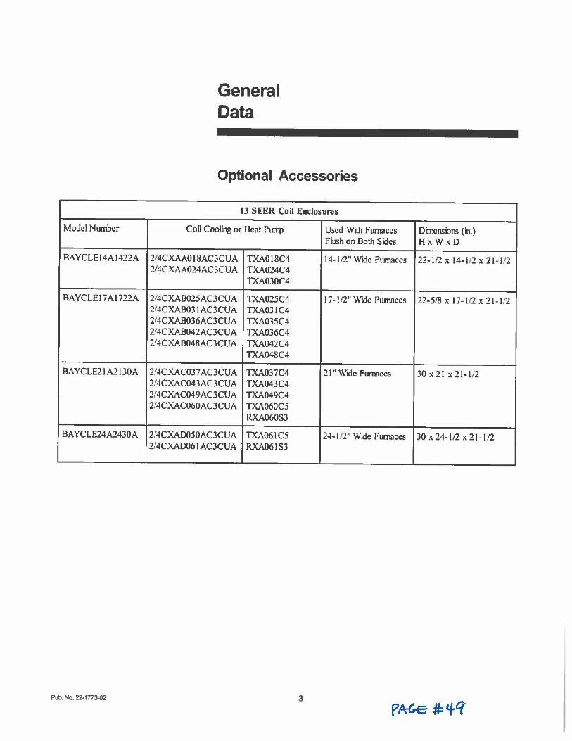
Model Number
BAYCLE14A1422A
BAYCLE17Al722A
BAYCLE21A2130A
BAYCLE24A2430A
Pub. No. 22-1773-02
General Data
Optional Accessories
13 SEER Coil Enclosures
Coil Cooling or Heat Plllll> Used With Furnaces Flush on Both Sides
2/4CXAA0 I 8AC3CUA TXA0l8C4 14-1/2" Wide Furnaces 2/4CXAA024AC3CUA TXA024C4
TXA030C4
2/4CXAB025AC3CUA TXA025C4 17- 1/2" Wide Furnaces 2/4CXAB03 I AC3CUA TXA031C4 2/4CXAB036AC3CUA TXA035C4 2/4CXAB042AC3CUA TXA036C4 2/4CXAB048AC3CUA TXA042C4
TXA048C4
2/4CXAC03 7 AC3CUA TXA037C4 21" Wide Furnaces 2/4CXAC043AC3CUA TXA043C4 2/4CXAC049AC3CUA TXA049C4 2/4CXAC060AC3CUA TXA060C5
RXA060S3
2/4CXAD050AC3CUA TXA061C5 24-1/2" Wide Furnaces 2/4CXAD06 IAC3CUA RXA061S3
3
Oirreru;ioru; (in.) HxWxD
22-)/2 X 14- l/2 X 2} -1/2
22-5/8 X 17-1/2 X 21 -1/2
30 X 21 X 21-1/2
30 x24-l/2 x21-l/2
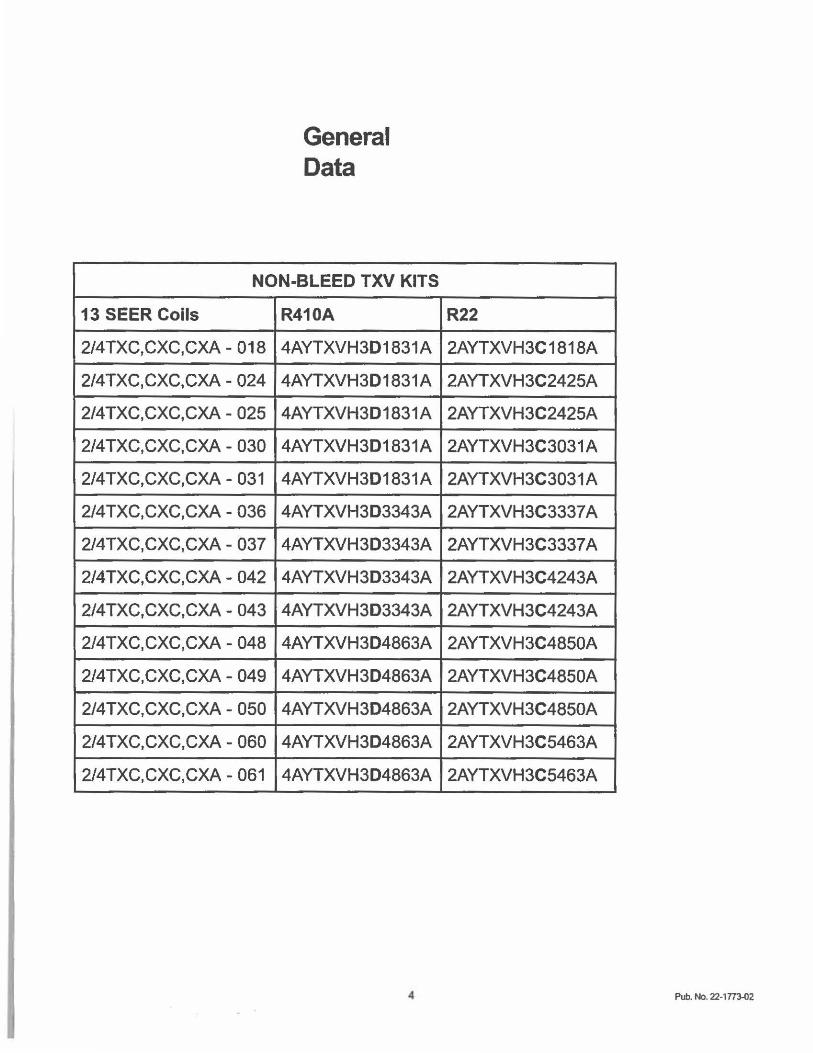
General Data
NON-BLEED TXV KITS
13 SEER Coils R410A
2/4TXC,CXC,CXA - 018 4AYTXVH3D1831A
2/4TXC,CXC,CXA - 024 4AYTXVH3D1831A
2/4TXC,CXC,CXA - 025 4AYTXVH3D1831A
2/4TXC,CXC,CXA- 030 4AYTXVH3D1831A
2/4TXC,CXC,CXA- 031 4AYTXVH3D1831A
2/4TXC,CXC,CXA- 036 4AYTXVH3D3343A
2/4TXC,CXC,CXA - 037 4AYTXVH3D3343A
2/4TXC,CXC,CXA - 042 4AYTXVH3D3343A
2/4TXC,CXC,CXA- 043 4AYTXVH3D3343A
2/4TXC,CXC,CXA - 048 4AYTXVH3D4863A
2/4TXC,CXC,CXA - 049 4AYTXVH3D4863A
2/4TXC,CXC,CXA - 050 4AYTXVH3D4863A
2/4TXC,CXC,CXA- 060 4AYTXVH3D4863A
2/4TXC,CXC,CXA - 061 4AYTXVH3D4863A
4
R22
2AYTXVH3C1818A
2AYTXVH3C2425A
2AYTXVH3C2425A
2AYTXVH3C3031 A
2AYTXVH3C3031 A
2AYTXVH3C3337 A
2AYTXVH3C3337 A
2AYTXVH3C4243A
2AYTXVH3C4243A
2AYTXVH3C4850A
2AYTXVH3C4850A
2AYTXVH3C4850A
2AYTXVH3C5463A
2AYTXVH3C5463A
Pub. No. 22-1773-02
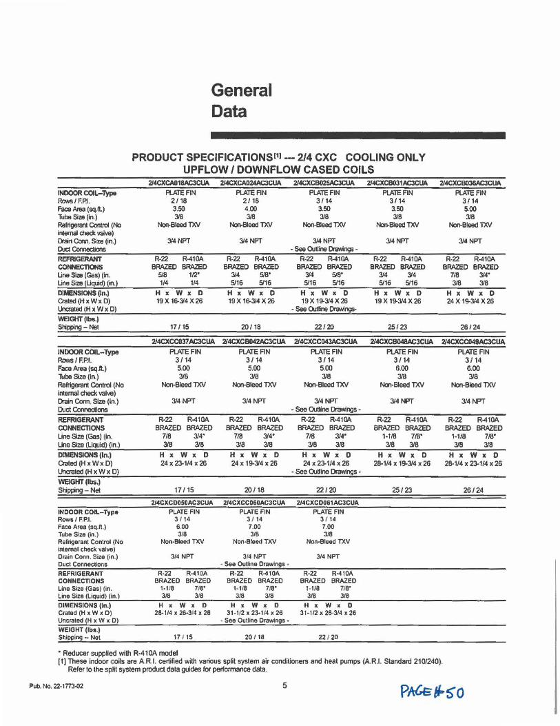
INDOOR COIL-'type Rows / F.P.I. Face /J,Jea (sq.ft.) Tube Size (In.) Refrigelcn Control (No internal dl8d( valve) Drain cain. Size (in.) Duct Comectioos REFRIGERANT CONNECTIONS Line Size (Gas) (in. Line Size (Liquid) (in.)
DIIENSIONS (In.) Crated (H x W x D) lklc:rated (H x W x 0)
'M:IGKT (lbs.I Stippir,g - Net
INDOOR COIL-Type RaMI I F.P.I. Face Area (sq.ft.) Tube Size (in,) Refrlgercn Qnrol (No internal check valve) Drain Com. Size (In.) Duel Connections
REFRIGERANT CONNECTIONS Line Size (Gas) l]n. Line Size (Liquid) (In.)
DIMENSIONS (In.) Crated (H x W X D) Uncrated (H x W X D)
WEIGHT (lbs.) Shipping - Net
INDOOR COIL-Type Rows/ FP.I. Face Area (sq.ft.) Tube Size (in.) Refrigerant Control (No internal check valve) Crain Coon. Size (in.) Duci Connections
REFRIGERANT CONNECTIONS Line Size (Gas) (in . Line Size (Liquid) (In.)
DIMENSIONS (In.) Craled (H X w X D ) Uncraled (H X w X D)
WEIGHT (lbs.) Shipping - Net
General Data
PRODUCT SPECIFICATIONSl1l -- 2/4 CXC COOLING ONLY UPFLOW / DOWNFLOW CASED COILS
2/4CXCA018AC3CUA 2/4CXCA024AC3CUA 2/4CXCS025AC3CUA 2/4CXC8031AC3CUA 2/4CXCB036AC3CUA Pl.ATEFIN
2/ 18 3.50 3/8
Nori-Bleed TXV
3/4NPT
R•22 R-410A BRAZED BRAZED
5/8 112· 1/4 1/4
H x W X D 19 X 16-3/4 X 26
17 / 15
2/4CXCC037 AC3CUA PI.ATEFIN
3/ 14 5.00 318
Non-Bleed TXV
3/4NPT
R-22 BRAZED
718 3/8
R-410A BRAZED
314• 3/8
H x W x 0 24 X 2J.1/4 X 26
17 / 15
PLATE AN 2/ 18 4.00 3/8
Non-Bleed TXV
3/4NPT
R-22 R-410A BRAZED BRAZED
314 518· 5116 5/16
H X w X D 19 X 16-3/4 X 26
20/ 18
2/4CXCB042AC3CUA PI.ATEFIN
3/ 14 5.00 3/8
Non-Bleed TXV
3/4 NPT
R•22 R-410A BRAZED BRAZED
7/8 314• 3/8 3/8
H x W x 0 24 X 19-3/4 )( 26
20/ 18
PLATE FIN 3/ 14 3.50 3/8
Nori-Bleed TXV
3/4NFT • See Outline OnMings •
R-22 R-410A BRAZED BRAZED
3/4 5,15• 5116 5/16
H X w X D 19X 19-J.14X26
- See OutUne OraY.ings-
22/20
2/4CXCCD43AC3CUA
PI.ATEFIN 3/14 5.00 318
Non-Bleed TXV
3/4 NPT - See OUtline OraMngs -
R•22 R-410A BRAZED BRAZED
7/8 314• 318 3/8
H X W x 0 24 X 23-1/4 X 26
• See OJUine Drawings •
22/20
2/4CXCD050ACJCUA 2/4CXCCO&OACJCUA 2/4CXC0061AC3CUA
PLATE FIN 3 / 14 6.00 318
Non-Bleed TXV
3/4 NPT
R-22 R-410A BRAZED BRAZED
t-118 115• 3/8 318
H X W X 0 28• 1/4 X 26-3(4 X 26
171 15
PLATE FIN 3 / 14 7.00 3/8
Non-Bleed TXV
314 NPT - See Outline Drawings •
R-22 R-410A BRAZED BRAZED
1-1/8 7,e• 3/8 3/8
H x W X 0 31-1/2 X 23-1/4 X 26
• See Outline Drawings •
20 / 18
PLATE FIN 3 / 14 7.00 318
Non-Bleed TXV
3/4 NPT
R-22 R-410A BRAZED BRAZED
1-118 119• 318 3/8
H X W x 0 31 -1/2 X 26•3/4 X 26
22 / 20
PLATE FIN 3/ 14 3.50 3/8
Non-Bleed TXV
3/4 NPT
R-22 R-410A BRAZED BRAZED
3/4 3/4 5/16 5/16
H X W X D 19 X 19-3/4 X 26
25/23
PLATE FIN 3/ 14 5.00 318
Nori-Bleed TXV
3/4 NFT
R-22 R-410A BRAZED BRAZED
7/8 314• 318 318
H X W x 0 24 X 19-314 X 26
26/24
2/4CXCB048AC3CUA 2/4CXCC049AC3CUA
PI.ATEFIN 3/ 14 6.00 318
Non-Bleed TXV
314 NPT
R-22 BRAZED
1-1/8 3/8
R-410A BRAZED
718· 3/8
PI..ATEFIN 3/ 14 6.00 318
Non-Bleed TXV
3/4 NPT
R-22 BRAZED
1-1/8 3/8
R-410A BRAZED
718· 318
HxWxD HxWxO 28-1/4 X 19-3/4 X 26 28-1/4 X 23-1/4 X 26
25/23 26/24
• Reducer supplied wilh R-41 OA model (1) These indoor coils are A.R.I. certified with various split system air conditioners and heat pumps (A.R.1. Standard 210/240).
Refer to the split syslem product dala guides ror performance data.
Pub. No. 22-1773-02 5
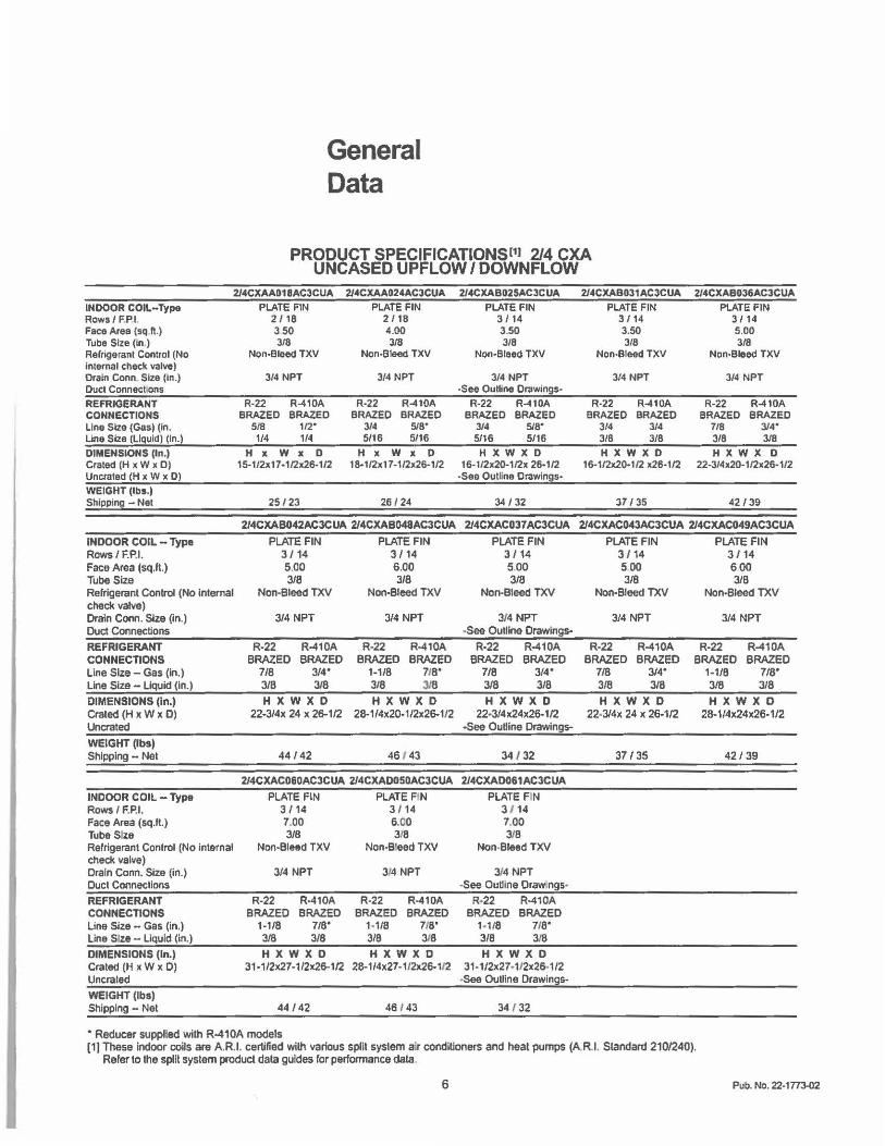
INDOOR COIL-Type Rows/ F,Pl. Face Area (sq.ft.) Tube Size (In.) Relrigerant Control (No Internal check valve) Drain Conn. Size (In.) Duct Connect.ons
REFRIGERANT CONNECTIONS Line Size (Gas) (In. Line Size (Liquid) (In.)
DIMENSIONS (In.} Crated (H x W x 0) Uncraled (H X w X D)
WEIGHT (Iba.) Shipping - Net
General Data
PRODUCT SPECIFICATIONS111 2/4 CXA UNCASED UPFLOW / DOWNFLOW
2/4CXAA018AC3CUA
PLATE FIN 2 / 18 350 3/8
Non-Bloed TXV
3/4 NPT
R-22 R-410A BRAZED BRAZED
518 112· 1/4 114
H X W X D 15· 1I2x 17 • 1/2x26-1/2
25/ 23
2/4CXAA024AC3CUA
PLATE FIN 2 / 18 4.00 3/8
Non-Bleed TXV
3/4 NPT
R-22 R-410A BRAZED BRAZED
314 515• 5116 5116
H IC w I( D 18·1/2x17-1/2x26-112
26 / 24
2/4CXAB025ACJCUA
PLATE FIN 3 / 14 3.50 318
Non-Bleed TXV
3/4 NPT -See Outline Drawings-
R-22 R-410A BRAZED BRAZED
3/4 515• 5/16 5/16
H X W X D 16-1/2x20-1/2x 26-1/2
-Sea Outline Drawings•
34 / 32
2/4CXAB031AC3CUA
PLATE FIN 3114 3.50 3/8
Non-Bleed TXV
314 NPT
R-22 R-410A BRAZED BRAZED
3/4 314 318 318
HXWXD 16-112x20•1/2 x26·1/2
37 / 35
2/4CXAB036AC3CUA
PLATE FIN 3 / 14 5.00 3/8
Non-Bleed TXV
3/4 NPT
R-22 R-410A BRAZED BRAZED
718 314• 3/8 318
H X W X D 22•3/4x20-1/2x26-112
42/ 39
214CXAB042AC3CUA 214CXAB048AC3CUA 2/4CXAC037 AC3CUA 2/4CXAC043AC3CUA 214CXAC049AC3CUA
INDOOR COIL - Type Rows/F.P.1. Face Area (sq.ft.) Tube Size Refrigerant Control (No Internal check valve) Drain Conn. Size (In.) Duct Connections
REFRIGERANT CONNECTIONS Line Size - Gas (in.) Line Size - Liquid (in.)
DIMENSIONS (In.) Craled (H x W x D) Uncrated
WEIGHT (lbs) Shipping - Net
INDOOR COIL - Type Rows/ F.P.I. Face Area (sq.It.) Tube Size Refrigerant Control (No internal check valve) Drain Conn. Size (in.) Duct Connections
REFRIGERANT CONNECTIONS Line Size - Gas (in.) Line Size - Liquid (in.)
DIMENSIONS (In.) Crated (H x W x 0) Uncrated
WEIGHT (lbs) Shipping - Net
PLATE FIN 3/ 14 5.00 3/8
Non-Bleed TXV
3/4 NPT
R-22 BRAZED
7/8 3/8
R-410A BRAZED
3/4° 3/8
PLATE FIN 3/ 14 6.00 3/8
Non-Bleed TXV
3/4 NPT
R-22 BRAZED
1-1/8 3/8
R-410A BRAZED
110· 318
HXWXD HXWXD 22-3/4x 24 x 26-1/2 28-1/4x20-1/2x26-1J2
44 /42 46 1 43
2/4CXAC0&0AC3CUA 2/4CXAOOS0AC3CUA
PLATE FIN PLATE FIN 3/14 3 1 14 7.00 6.00 3/8 318
Non-Bleed TXV Non-B!eed TXV
3/4 NPT
R-22 R-410A BRAZED BRAZED
1-110 110· 3/8 3/8
HXWXD 31-1 /2x27-1 /2x26-1 /2
44 / 42
3/4 NPT
R-22 BRAZED
1-118 3/8
R-410A BRAZED
115• 318
HXWXD 28-1 /4x27 -112x26-1/2
46 143
• Reducer supplied with R-410A models
PLATE FIN 3/ 14 5.00 3/8
Non-Bleed TXV
314 NPT -See Outline Drawings-
R-22 R-410A BRAZED BRAZED
7/8 3/4° 318 3/8
H X W X D 22•3/4x24x26-1/2
-See OuUlne Drawings-
34 / 32
2/4CXA0061AC3CUA
PLATE FIN 3 1 14 7.00 3/8
Non-Bleed TXV
3/4 NPT -See OuUine Draw ngs•
R•22 R-410A BRAZED BRAZED
1+118 718° 3/8 3!8
HXWXD 31-1/2x27-112x26-1 /2
-See Outline Drawings-
34 I 32
PLATE FIN 3 / 14 5 00 3/8
Non-Bleed TXV
3/4 NPT
R-22 BRAZED
7/8 3/8
R-410A BRAZED
3/4" 3/8
HXWXD 22-3/4x 24 X 26-1/2
37 / 35
PLATE FIN 3/ 14 600 3/8
Non-Bleed TXV
3/4 NPT
R-22 BRAZED
1-1/8 3/8
R-410A BRAZED
110· 318
HXWXD 28-1/4x24x26-1 /2
42 / 39
(1) These indoor coils are A.R.I. certified with various split system a,r conditioners and heat pumps (A.R.I. Standard 210/240). Refer to the split system product data guides for performance data,
6 Pub. No. 22-1773-02
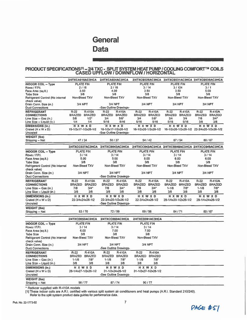
General Data
PRODUCT SPECIFICAT10NSl11 -2/4 nee - SPLIT SYSTEM HEAT PUMP/ COOLING COMFORT™ COILS CASED UPFLOW / DOWNFLOW / HORIZONTAL
INDOOR COIL - Type Rows/ F.P.I. Face Area (sq.fl.) Tube Size Refrigerant Control (No internal check valve) Drain Conn. Size (In.) Duct Connections
REFRIGERANT CONNECTIONS Line Size - Gas (In.) Line Size - Liquid (In .)
DIMENSIONS (In.) Crated (H x W x D) Uncrated
WEIGHT (lbs) Shipping - Net
214TXCA018AC3HCA
PLATE FIN 2 / 18 3.50 3/8
Non-Bleed TXV
3/4 NPT
R-22 R-410A BRAZED BRAZED
5/8 112· 1/4 1/4
HXWXD 15-1/2x17-1/2x26·1/2
47 / 34
2/4TXCA024AC3HCA
PLATE FIN 2 / 18 4.00 3/8
Non-Bleed TXV
3/4 NPT •See Outline Drawings•
R-22 R-410A BRAZED BRAZED
3/4 5/8° 5/16 5/16
HXWXD 18·1/2x17-1/2x26·1/2
-See Oulline Drawings-
50 /37
214TXCB025AC3HCA 2J4TXCB031AC3HCA 2/4TXCB036AC3HCA
PLATE FIN 3 1 14 3.50 3f8
Non•Bleed TXV
3/4 NPT
R-22 R-410A BRAZED BRAZED
3/4 519• 5/16 5116
H X W X D 16· 1/2x20·1I2x26•1/2
54 / 42
PLATE FIN 3 / 124
3.50 3/8
Non-Bleed TXV
3/4 NPT
PLATE FIN 3 / 1 5.00 3/8
Non-Bleed TXV
3/4 NPT
R-22 R-410A R-22 R-410A BRAZED BRAZED BRAZED BRAZED
3/4 3/4 7/8 3/4" 5/16 5/16 3/8 3/8
HXWXD HXWXD 16·1/2x20-1/2x26-1/2 22•3/4x20-112x26-112
67 /54 80161
2/4TXCC037AC3HCA 214TXCB042AC3HCA 2/4TXCC043ACJHCA 2/4TXCB048AC3HCA 2/4TXCC049AC3HCA
INDOOR COIL - Type Rows/ F.P.I. Face Area (sq.ft.) Tube Size Refrigerant Control (No Internal check valve) Drain Conn. Size (In.) Duct Connections
REFRIGERANT CONNECTIONS Line Size - Gas (in.) Line Size - Liquid (in.)
DIMENSIONS (In.) Crated (H x W x D) Uncrated
WEIGHT (lbsl Shipping - Net
INDOOR COIL - Type Rows/ F.P.I. Face Area (sq.ft.) Tube Size Refrigerant Control (No internal check valve) Drain Conn. Size (in.) Duct Connections
REFRIGERANT CONNECTIONS Line Size - Gas (in.) Line Size - Liquid (in.)
DIMENSIONS (In.) Crated (H x W x D) Uncrated
WEIGHT (lbs) Shipping - Net
PLATE FIN 3 / 14 5.00 3/8
Non-Bleed TXV
3/4 NPT
R-22 BRAZED
7/8 3/8
R-410A BRAZED
314• 3/8
HXWXD 22-3/4x24x26-1/2
83 / 70
2/4TXCD05DAC3HCA
PLATE FIN 3 / 14 6.00 3/8
Non-Bleed TXV
3/4 NPT
R•22 R-410A BRAZED BRAZED
1-1/8 7/8° 3/8 318 HXWXD
28-1/4x27-1/2x26-1/2
90 /77
• Reducer supplied with R-410A models
PLATE FIN 3 / 14 500 3/8
Non-Breed TXV
3/4t,FT -See Outline Drawings•
R-22 R-410A BRAZED BRAZED
718 314• 318 318 HXWXD
22-3/4x20•1/2x26-1/2 -See OUtllne Drawings-
72/ 59
2/4TXCC060AC3HCA
PLATE FIN 3 / 14 7.00 3/8
Non-Bleed TXV
3/4 NPT -See OUUine Drawings•
R·22 R-410A BRAZED BRAZED
1-1/8 7/8° 3/8 318 HXWXD
31-1/2x24x26-1/2 •See outline Drawings•
87 / 74
PLATE FIN 3/ 14 5.00 3/8
Non-Bleed TXV
3/4 NPT
R-22 BRAZED
718 3/8
R-410A BRAZED
3/4° 3/8
H X W X D 22•3/4x24x26-1/2
69/ 56
2/4TXCD061AC3HCA
PLATE FJN 3/ 14 7.00 3/8
Non-Bleed TXV
3/4 NPT
R-22 R-410A BRAZED BRAZED
1-1/8 7/8° 318 3/8
HXWXD 31 -1/2x27-1/2x26·1/2
90 / 77
PLATE FIN 3 / 14 6.00 3/8
Non-Bleed TXV
3/4 NPT
R-22 BRAZED
1-118 3/8
R-410A BRAZED
718" 3/8
HXWXD 28·1/4x20-1/2x26-1/2
84 / 71
PLATE FIN 3/ 14 6.00 3/8
Non-Bleed TXV
314 NPT
R-22 BRAZED
1-1/8 3/8
R-410A BRAZED
7/8° 3/8
H X W X D 28-1/4x24x26-1/2
80/67
[1) These indOOI' coils are A.R.I. certified with various split system air conditioners and heat pumps (A.R.1. Standard 210/240). Refer to the split system product data guides for performance data.
Pub. No. 22-1773-02 7
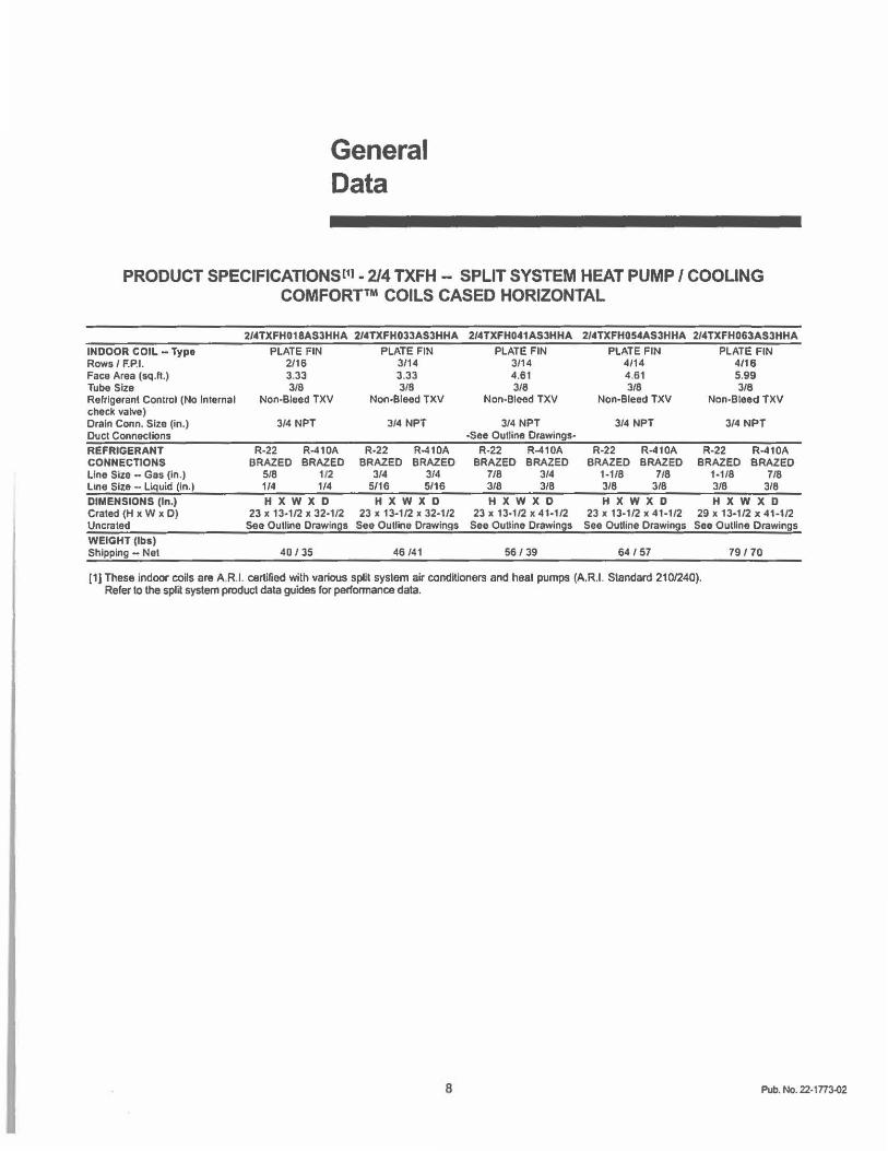
General Data
PRODUCT SPECIFICATIONSl11 - 2/4 TXFH - SPLIT SYSTEM HEAT PUMP/ COOLING COMFORT™ COILS CASED HORIZONTAL
INDOOR COIL - Type Rows/ F.P.1. Face Area (sq.ft.) Tube Size Refrigerant Control (No Internal check valve) Drain Conn. Size (in.) Duct Connections
REFRIGERANT CONNECTIONS Line Size - Gas (In.) Line Size - Liquid (in.I
DIMENSIONS (In.I Crated (H x W x 0) Uncrated WEIGHT (Iba) Shipping - Net
2/ .. TXFH018ASJHHA 2/.tTXFH0JJASJHHA
PLATE FIN PLATE FIN 2/16 3/14 3.33 3.33 318 3/8
Non-Bleed TXV Non-Bleed TXV
3/4 NPT
R-22 R-410A BRAZED BRAZED
5/8 112 114 1/4
H X W X D 23 X 13•1/2 X 32•1/2
See Outline Drawings
4D / 35
3/4 NPT
R-22 R-410A BRAZED BRAZED
3/4 3/4 5/16 5/16
HXWXD 23 X 13-1/2 X 32-1/2
See Outline Drawings
46 /41
2/ .. TXFH0 .. 1ASJHHA 2/ .. TXFH05 .. ASJHHA 2/ .. TXFH063ASJHHA
PLATE FIN 3114 4.61 3/8
Non-Bleed TXV
314 NPT -See Oulline Drawings-
PLATE FIN 4114 4.61 3/8
Non-Bleed TXV
3/4 NPT
PLATE FIN 4/16 5.99 3/8
Non-Bleed TXV
3/4 NPT
R-22 R-410A R-22 R-410A R-22 R-410A BRAZED BRAZED BRAZED BRAZED BRAZED BRAZED
7/8 3/4 1-1/8 7/8 1-1/8 7/8 3/8 3/8 3/8 318 3/8 3/8 HXWXD HXWXD HXWXD
23 X 13°1/2 X 41-1/2 23 X 13-1/2 X 41-1/2 29 X 13•1/2 X 41-1/2 See Outline Drawings See Outline Drawings See Outline Drawings
56 / 39 64157 79 / 70
[1J These indoor coils are AR.I. certified with various splil system air conditioners and heal pumps (A.R.I. Standard 210/240). Refer lo the split syslem product data guides for perfonnance dala.
8 Pub. No. 22-1TT3-02
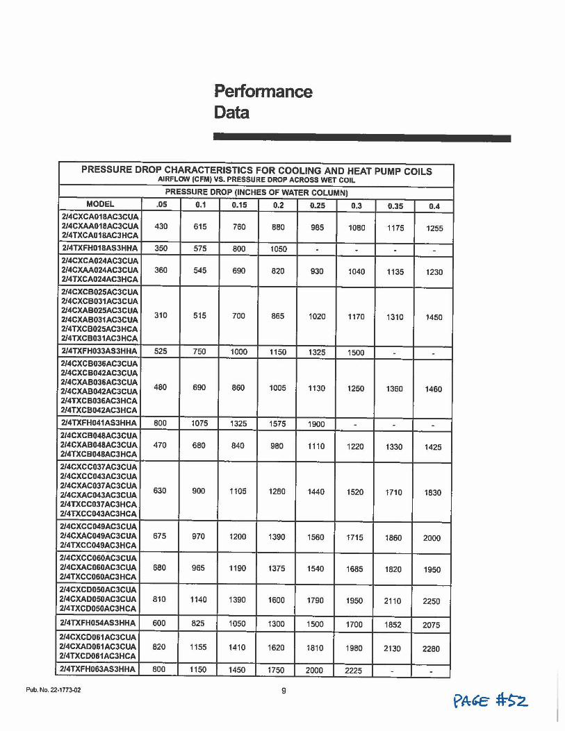
Perfonnance Data
PRESSURE DROP CHARACTERISTICS FOR COOLING AND HEAT PUMP COILS AIRFLOW (CFM) VS. PRESSURE DROP ACROSS WET COIL
PRESSURE DROP (INCHES OF WATER COLUMN)
MODEL .05 0.1 0.15 0.2 0.25 0.3 0 .35 0.4 2/4CXCA018AC3CUA 2/4CXAA018AC3CUA 430 615 760 2/4TXCA018AC3HCA
880 985 1080 1175 1255
2/4TXFH018AS3HHA 350 575 800 1050 . . . .
2/4CXCA024AC3CUA 2/4CXAA024AC3CUA 360 545 690 820 930 1040 1135 1230 2/4TXCA024AC3HCA
2/4CXCB025AC3CUA 2/4CXCB031AC3CUA 2/4CXAB025AC3CUA 310 515 700 865 2/4CXAB031AC3CUA 1020 1170 1310 1450 2/4TXCB025AC3HCA 2/4TXCB031AC3HCA
2/4TXFH033AS3HHA 525 750 1000 1150 1325 1500 . .
2/4CXCB036AC3CUA 2/4CXCB042AC3CUA 2/4CXAB036AC3CUA 480 690 860 1005 2/4CXAB042AC3CUA 1130 1250 1360 1460 2/4TXCB036AC3HCA 2/4TXCB042AC3HCA
2/4TXFH041AS3HHA 800 1075 1325 1575 1900 . . .
2/4CXCB048AC3CUA 2/4CXAB048AC3CUA 470 680 840 2/4TXCB048AC3HCA
980 1110 1220 1330 1425
2/4CXCC037 AC3CUA 2/4CXCC043AC3CUA 2/4CXAC037 AC3CUA 630 900 1105 1280 1440 1520 1710 1830 2/4CXAC043AC3CUA 2/4TXCC037 AC3HCA 2/4TXCC043AC3HCA
2/4CXCC049AC3CUA 2/4CXAC049AC3CUA 675 970 1200 1390 1560 1715 1860 2000 2/4TXCC049AC3HCA
2/4CXCC060AC3CUA 2/4CXAC060AC3CUA 680 965 1190 1375 2/4TXCC060AC3HCA
1540 1685 1820 1950
2/4CXCD050AC3CUA 2/4CXADOS0AC3CUA 810 1140 1390 1600 1790 1950 2110 2250 2/4TXCDOS0AC3HCA
2/4TXFH054AS3HHA 600 825 1050 1300 1500 1700 1852 2075 2/4CXCD061AC3CUA 2/4CXAD061AC3CUA 820 1155 1410 1620 1810 1980 2130 2280 2/4TXCD061AC3HCA
2/4TXFH063AS3HHA 800 1150 1450 1750 2000 2225 . .
Pub. No. 22-1773-02 9
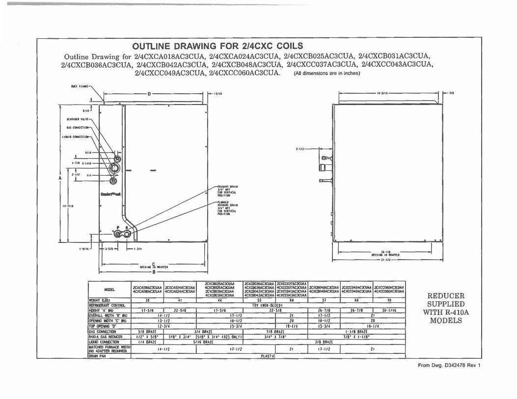
OUTLINE DRAWING FOR 2/4CXC COILS Outline Drawing for 2/4CXCA018AC3CUA, 2/4CXCA024AC3CUA, 2/4CXCB025AC3CUA, 2/4CXCB031AC3CUA,
2/4CXCB036AC3CUA, 2/4CXCB042AC3CUA, 2/4CXCB048AC3CUA, 2/4CXCC037AC3CUA, 2/4CXCC043AC3CUA, 2/4CXCC049AC3CUA, 2/4CXCC060AC3CUA. (All dimensions are in inches)
MIil-
i· D W'"' t ,,,.] rl I I
A
SC1UNIHUI~
t.&SC-CII
l lOIII <Ol,IU I
1•111
I t-oir
.... , .. l~ '<
r-t--#tl
-t --••un Nill V .,, . .,,
let tllll(At POSIIIOI
I ~,-• ~NIIUII DI.Ill
Ju• 11ft JOI 1(IIIC,.l ,as,,,.
l·tllJ :::r i----i=_. )It _J
,-----___:_°':.:::::"='" f;, """" B-----__J
IDIEL
lll9GIITUSJ IIUIURANTcama. IIEJOHT-.- IN! IIMRAU. mm v IN! ll'ENN3 111TH ,:- Ill ITIP Ol'ENNO "D" IG"5 aJfEll0N
2CXCAOIUC3CUAA I 2CXCA02fAC3CIIM 4CXCAOllloCJa/A 4CXCI024AC3CIIM
" 41
IJ• $11 I 22·SII U·l/l ll· 112 tl•l/4
2CXC802SACXUAA .Cml025•CXl!U 2CllClll3lloCXUM 4ClCC:8031•CXU ..
•• ll•SII
11-1/l U•lll U •JU
SIi BRAZ£ I l/4 8UI[
I
I '1141>" 0"5 REb.aR 112· I SIi' I SIi' I l/4· IS/1° I 314• con OIILTII lJUl CON£TDI 111,\TtltB) FIIWACE IIIITll HJ ADAl'Tfll IBIHDI IDIW'I PNI
114 IIAZC I Slli Bill[ I
U • lll 11• 1/l
1
,o-s .. , t- ,,. >I l .. '
t·lll---f--..
~
[C
m:::::=:
~- . [I .•.. ,. ""IIIG II nu,11
it •Ul
2CXcaooe.\CXIIU 2CXCtlmAC3CUlul 4Cl(C8031AC3CUAA 4CXIX037AC3CUM I 2CXC804&lC3CUIA 12CXCCOfv•c:x:uu.12CXCCOIQAC:X:UU. 2CXC80f2AC3CIIAA .21CXCC043"CXUM 4CX&l41•CX11u 40CCOftAC3CUlul «m:oeo•cxn .. olCJa:Bl42"CXIIAA 4IXCIUJACJCUAA
" I " I ~ I u I ~ TIY 1101•8LC£DI
22· Sii 25· JII Zi· 1/1 I l0·1116 I 21 11-1/l 21 I 20 ... .,z 21 I lt•lf• IHU IHU
l/18Ul£ 1-111 8aAZ£ J/4" I J/t• J/1' I H/1'
J/1 Bill£
I 21 I I 1·112 I 21
PLASTIC
.. .I I .I
REDUCER SUPPLIED
WITH R-410A MODELS
From Dwg. 0342478 Rev 1
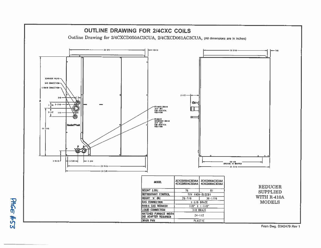
,.
!•ill
.... ,,,
l·tlll
l ~
~
OUTLINE DRAWING FOR 2/4CXC COILS Outline Drawing for 2/4CXCD050AC3CUA, 2/4CXCD061AC3CUA, (All dimensions are in inches)
I ll·ll< r ,sm
• I I M h I
a.Gd"'IIII
MIi l•JU
.'IVGGID $ltclltAII OIAII u,· .,. IOI 1t111Ul IOSIIIOI
i-----------11-111,-----------..i i-----------1o-1,1-------------f
MOOE1.
WEIGHT l8SJ REFRIGERANT CONTRIX. [IEGKf "A" !NJ [GAS COPH:CTION IR40-A GAS REDUC£R 'UWO COtlECTION MATCtED NINACE WDTH !Ml ADAPTER RE0UREDI DRAIN PAN
I" IMlll :1 1111
I I ■
1-111 I I
11·111 - -, 0,(1111 11 d&III~
i----------1,-11,, ■•
2CXC0050ACJCVAA I 2CXC0061ACJCIIAA 4CXC0050AC3CtJAA 4CXCD061ACJCIJAA
16 - - 1 81 TXV INON · BLH0I
26·118 I Jo-1116 I· 1/8 BRAZE
J/8" X I · 118" 318 BRAZ(
24 • l/2
PLASTIC
REDUCER SUPPLIED
WITH R-410A MODELS
From Dwg. D342479 Rev 1
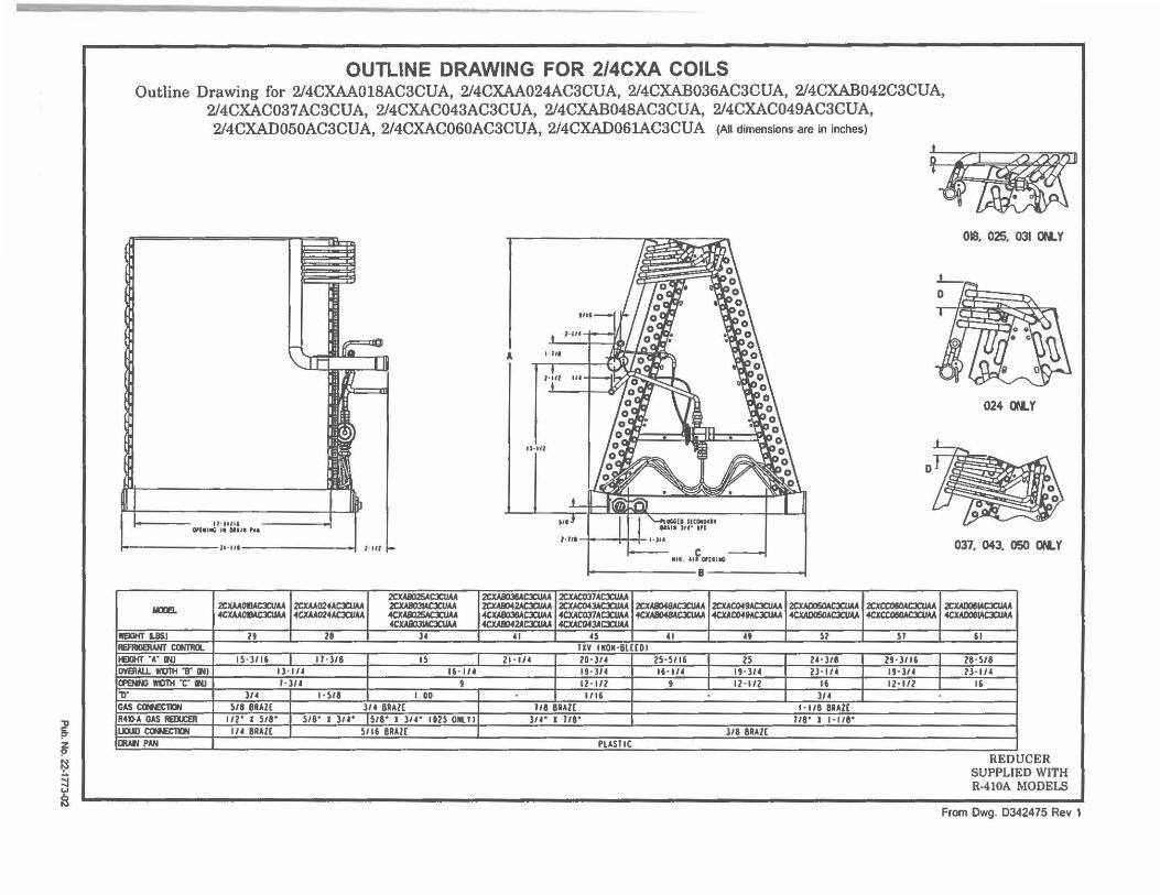
1 ~ ~
~
OUTLINE DRAWING FOR 2/4CXA COILS Outline Drawing for 2/4CXAA018AC3CUA, 2/4CXAA024AC3CUA, 2/4CXAB036AC3CUA, 2/4CXAB042C3CUA,
2/4CXAC037AC3CUA, 2/4CXAC043AC3CUA, 2/4CXABD48AC3CUA, 2/4CXAC049AC3CUA, 2/4CXAD050AC3CUA, 2/4CXAC060AC3CUA, 2/4CXAD061AC3CUA (AH dimensions are in inches)
11•111ll 0,l■laG , ■ Dtlll PII
1--------11•11•----------1 l •Ul
2CXAI025ACJCIIAA
MCIE. 2CXMOIIACXUAA 2CXM024AC3CIIM .2CXA803MCJCII.U .fCXAAOIIMC3CIIM 4CW024AC3CIIM 4tXA8:l25AC3CUM
4CXAa131ACXUAA IIEIOlfT L8lJ lt 21 )4
IIEflllDAHT IXMllll. IEIGHf .A • ..i 15•)/16 I ll•l/8 IS IIVEIIAU. Wl1TH T INI I)· 1/4 16· 114 11'ENNi wont ·c- 1N1 1· )/4 ' ,r J/4 1 ·5/8 I 00 GAScate;lD,I 511 BRAZ£ J/4 BRA!( A41)A GAS AelU:EII I /2' I 518' 518' I J/4' 518" J J/4' 1825 ONLT I U0ll) ctNE10I IH BRAZ£ 5116 BRAZ( DRAW PAN
A I ,,.
-r-
,.,u
,.;,, "' -+--I~
ll•tft
'" 1-1r• I• I I I
•.•. ,,f o,011G
--------8 --------,
2CXA8036ACJCI IAA .2CXACll37ACJCIIM 2CXA8>42AC3CUAA 2CXAC04JAC3CIIM lCXA8048ACJCIIAA 2CXAC049ACJCIIM 2CXMllJ!iOACJCIIAA 4CXAIID3SACJCIIAA 4CXAC037AC3CIIM 4CXAII048ACJCIJM 4CXAC049ACJCUM 4CICAD050ACJCIIAA 4CXAll>f1ACJCUAA -4CXAC043ACICUU
" 0 " 0 Sl IIV tllO~·BlCCOI
21·11' ZO· )l4 25· 5116 25 24·JII 19• )/4 16·11' I 19•)/4 2J · IH 12 · l/2 ' I 12 · 112 16 I/IS J/4
118 BRAZ£ 1 • 118 BRAZE l/4" I J/8' J/8 ' I 1-118'
J/8 BRAZ£ PlASIIC
'JB
2CXCCO&OACXUM «xccoeoACJa MA
Sl
29·3116 U•)/4 I 12· 1/2 I
018, 025. 031 ON.Y
024 ON.Y
037, 043, 050 ON. Y
2C.1WlO&IAC3CIIM 4CXA008w:3CUAA
" 28• 5/8 lJ· l/4
1,
REDUCER SUPPLIED WITH R-410A MODELS
From Dwg. 0342475 Rev 1
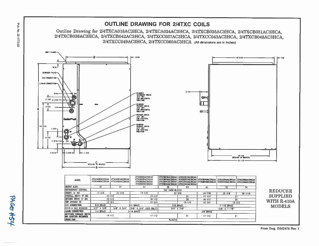
~ Pq
1
,i
~ t ~
~
OUTLINE DRAWING FOR 2/4TXC COILS Outline Drawing for 2/4TXCA018AC3HCA, 2/4TXCA024AC3HCA, 2/4TXCB025AC3HCA, 2/4TXCB031AC3HCA,
2/4TXCB036AC3HCA, 2/4TXCB042AC3HCA, 2/4TXCC037AC3HCA, 2/4TXCC043AC3HCA, 2/4TXCB048AC3HCA, 2/4TXCC049AC3HCA, 2/4TXCC060AC3HCA (All dimensions are in inches)
., """" , D ----------i r 1111, I' 11-111, :1 r "' 1 ii I , I l"I •
1111
KIWIII "1'1·
iU(-CII
1·111 8"11
iu•o•~CII ~
SICGll'lf ... 11 !.r..!t!-.u, .. ,,,
' ,.,,, .,.
A .
H • illl
,._,,,
-..8"11 n1au, 11i1.111 ,, ..• , fOI rtHIUl fOSUIOI
i-------,.i_._J , _____ _J
2TlCC8D2SACH:AA 11m. ZJXCAOIIIAQCAA ZDCA024ACJICAA 4TmlllSAC3ICAA
4TXrAOIIACl'GU 4 l'l!Clll24AC3CU 2mllOllAC3ICM 4TXC111131AQCAA
WBllHTLIISJ 42 u 0 RERlllEIW(I QJ/TIQ. l£DIT"A'IN.I 11· )11 I 22 •)11 11·)11 I OVEIW..1. IIIJTl1 T IN.I 14· l/l 11• l/2 CffNNl IIIJlH -C- IN.I ll· 112 Ii· 112 T1J' tfeftl ,,. 12·l14 tS•l14 GAS aHl;CTIW s,, 6•411 I lit BRAZ( I R410•4 GAS RCOUCCR 111" I SIi" I SIi" I 314° SIi" I )14" (02S OUTII L.D.m CllllECTl(N 114 BRAU I S/1 6 8Ul£ I IIATOEI f\ffW:E IID1lt U ·l/1 11·1/l t«IAIW'TEIIAEIUEDI IIUoNPNI
~ 21XCC037AC3CU ·~ 4l'Xa:037AC3CU 21XC8042AOC.U 21'Xtt'IHJAC:H:AA 4m:&Of:IAaCM 4JJICCDfJAC:ICAA
sa n UV IMON· BLHDI
2l·SII I 21 I 20 I 19· 114
Ill BRAl( l/4" I Ill"
11
PlASIIC
.•. ,,, Of(11• II •IIP(I
i----------11•111-----------
2l"Xl:al4MC3c:M ·~ 61
l& •lla II· 112 16 • 112 IS·ll(
318 BRAZ£
11 · 111
2JJICCDfllAOCAA 2'1lllX060AC3HC 4JJICCDfllAOCAA 4l'X1X06CW:Jfc:A
10 u
26·111 I l0· 1116 2 1 20
1!·114 1· 118 BRAZ[
If&" I 1 • 118"
2 1
REDUCER SUPPLIED
WITH R-410A MODELS
From Dwg. 0342476 Rev 1
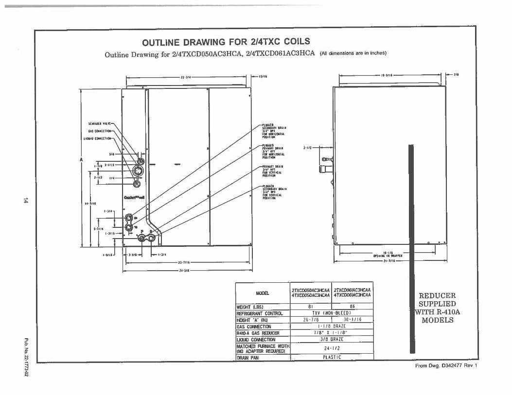
..... ~
i i ~ ;:I 2
A
OUTLINE DRAWING FOR 2/4TXC COILS Outline Drawing for 2/4TXCD050AC3HCA, 2/4TXCD061AC3HCA (All dimensions are in inches)
'6S COl■ICII
IICIIII COHICTI
,.;,, )-1111
1 · • ,1-1,. l r-., ... • * A I
1-i,1 ,,. I ';n:;.
••· i, .,
,.,-,.,
M••-f 1--1•)11 I .... --------JJ·flll r,
i-----------lM••-------------1
,.IGG(t SICOlldl IUII ,,...,, IOI ,tlllCU POSlllOI
MOOEI.
WBGHT ILBSI REFRIGERANT CONTROL tEIGHT "A" l1Nl GAS Cor.\\ECTION R4IO-A GAS REOOCER UlllD CINECTION MATCtE> FlllNACE WIDTH 1NO ADAPTER REOllREOI DRAIN PAN
1-111
.
I
IAC3/CAA 2TXC0050A 4TXCOOSOA
2TXC0061AC:H:AA JACJHCAA 4TXC0061ACJHCAA
81 I 86 TXV INON · BLHOI
26·7 118 30 • 1116 1 • I /8 BRAZC
11 8" X 1·118" 3/8 llRAZ[
24· 112
PL4ST IC
... ,,.,
11·111 O,t1111, II • .,PII
11 -t11•
r···
..
REDUC SUPPL]
THR~ MODE
ER ED lOA s
From Dwg. 0342477 Rev 1
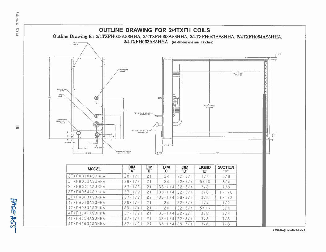
'l! !""
~ ~ :::j
~
-U'I
l ~
OUTLINE DRAWING FOR 2/4TXFH COILS Outline Drawing for 2/4TXFH018AS3HHA, 2/4TXFH033AS3HHA, 2/4TXFH041AS3HHA, 2/4TXFH054AS3HHA,
.. 1~1,~ 2/4TXFH063AS3HHA (All dimensions are in inches)
I '\ _['" v • . \ 1r•==·=r;~~~;;;;;;;;;;;;;;;;;;j;;;;;;;;;;;;;;;;;;;;;;;;;;;;;;;~Defl-,-
~ . /""""' : unl l=>=::::=:t+-----l-----~uc1 ~7;0:;.t------1;.+1 I= ~- s I== <
)
s UOUID[~ ,:, i::lj <
.~;;~ ~-/ ~ "' ... ~~:- I al>= ~ •oc,.~: .... 0 0 == 01'(111..C,
""""'"' ~ .. ,,, .,. '~"'""''= ~, ou~! "' ;JBH----,- I [JC ~
' '1>- • ! . ., . '"' 1o0, ... ,. _/ ..._ :?. - , , 1
ce-11o,,r,¢11 ' !!¼-iH--'- LI I"
1 ;c.,._ J•Hl tb--.......t============================== ( I tl· ·, ~ ]. . ~. Sf4.._ f•)l4--~ 1-
)· Ill ...
• JII l I,. ..,_
lllldt D••u ,o,u.- J1' .... ,, ◄ 11111----------···----------~ t ■U 1
MODEL 91~ '?~~ 9b~ '?b~ u~10 su~;~oN 2TXFH0I8AS3HHA 28-1/4 2! 24 22-3/4 1/4 5/8
2TXFH033AS3HHA 28-1/4 21 24 22-3/4 5/16 3/4
2TXFH041AS3HHA 37-1/2 21 33-1/4 22-3/4 3/8 7/8
2TXFH054AS3HHA 37-1/2 21 33-1/4 22-3/4 3/8 1-1/8
2TXFH063AS3HHA 37-1/2 27 33-1/4 28-3/4 3/8 1-1/8
4TXFH0l8AS3HHA 28-1/4 21 24 22-3/4 1/4 1/2
4TXFH033AS3HHA 28-1/4 21 24 22-3/4 5/16 3/4
4TXFH04IAS3HHA 37-1/2 21 33-1/4 22-3/4 3/8 3/4
4TXFH054AS3HHA 37 - 1/2 21 33-1/4 22-3/4 3/8 718 4TXFH063AS3HHA 37-1/2 27 33-1/4 28-3/4 3/8 718
From Dwg. C341655 Rev 4
Amencan Sbndard In~ 6200 Troup Highway Tyler, TX 75707
For mom information contact your local dftslftr (disllibu/or)
Literature Order Number
File Number 22•1773-02
Supersedes 22-1773-01
Stocking Location Pl Louisville & lnlanct_LaCrosse
Since American Standard has a pol icy of continuous produel improvement, it reserves Iha righl to change design and specifications wilhout notice.
P.I.
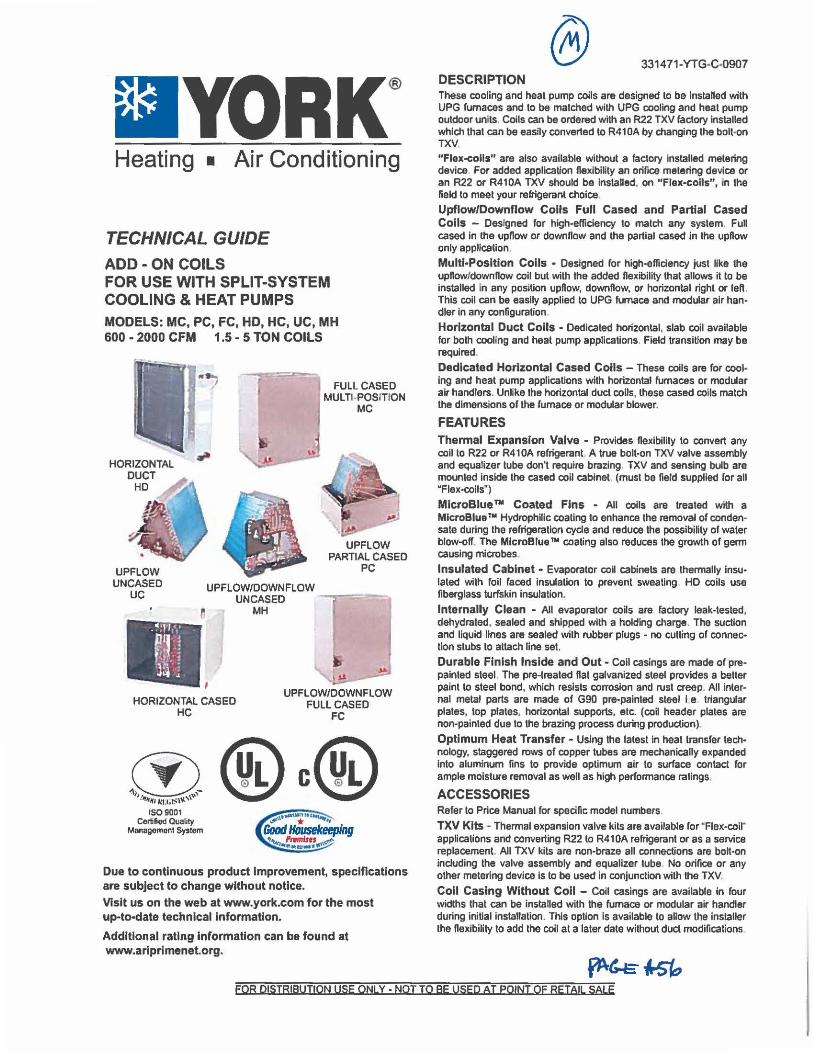
■YORK® Heating ■ Air Conditioning
TECHNICAL GUIDE ADD - ON COILS FOR USE WITH SPLIT-SYSTEM COOLING & HEAT PUMPS MODELS:MC,PC,FC,HD,HC,UC,MH 600 • 2000 CFM 1.5 - 5 TON COILS
HORIZONTAL DUCT
HD
-I FULL CASED MULTI-POSITION
MC
UPFLOW PARTIAL CASED
PC UPFLOW UNCASED
UC UPFLOW/DOWNFLOW
UNCASED --,1,--,=-~ 0 MH
HORIZONTAL CASED HC
Ii
UPFLOW/DOWNFLOW FULL CASED
FC
OO@®L c@®L '1;J 111"1'1 kl:t ir.;\\t.'\"'"'°'
1S09001 Certified Quality
Management System
Due to continuous product Improvement, specifications are subject to change without notice. Visit us on the web at www.york.com for the most up-to-date technical Information.
Additional rating Information can be found at www.arlprlmenet.org.
331471-YTG-C-0907 DESCRIPTION These cooling and heat pump coils are designed to be inslalled with UPG furnaces and to be matched with UPG cooling and heat pump outdoor units Coils can be ordered with an R22 TXV factory installed which that can be easily converted to R41 DA by changing the bolt-on TXV.
"Flex-coils" are also available without a factory Installed metering device For added applicaUon flexibility an orifice metering device or an R22 or R410A TXV should be Installed, on "Flex-coils", in the field to meet your refrigerant choice.
Upflow/Downflow Coils Full Cased and Partial Cased Colls - Designed for high•efficiency to match any system. Full cased In the upflow or downflow and the partial cased in the upflow only applJcalion.
Multi-Position Colls • Designed for high-efficiency just like the upftow/downflow coil but with the added flexibility that allows ii to be installed in any position upftow, downflow, or horizontal right or left. This coil can be easily applied lo UPG furnace and modular air handler in any configuration
Horizontal Duct Coils • Dedicated horizontal, slab coil avanable for both cooling and heat pump applications. Field transition may be required.
Dedicated Horizontal Cased Coils - These coils are for cool• Ing and heat pump applications with horizontal fumaces or modular air handlers. Unlike the horizontal duct coils, these cased coils match the dimensions of the fumace or modular blower.
FEATURES Thermal Expansion Valve • Provides flexibility to convert any coll to R22 or R410A refrigerant. A true bolt-on TXV valve assembly and equalizer tube don't require brazing. TXV and sensing bulb are mounted Inside the cased coil cabinet. (must be field supplied ror all "Flex•coils' )
MlcroBlue ™ Coated Fins - All coils are treated with a MlcroBlue no Hydrophilic coating to enhance the removal of conden• sate during the refrigeration cycle and reduce the possibility of water blow-off. The MlcroBlua™ coating also reduces the growth of germ causing microbes.
Insulated Cabinet • Evaporator coil cabinets are thermally lnsu• lated with foll raced insulation to prevent sweating HD coils use fiberglass turfskin Insulation.
Internally Clean • All evaporator coils are factory leak-tested, dehydrated, sealed and shipped with a holding charge. The suction and liquid lines are sealed with rubber plugs - no cutting of connection stubs to attach line set.
Durable Finish Inside and Out • Coil casings are made of prepainted steel. The pre-treated flat galvanized steel provides a better paint to steel bond, which resists corrosion and rust creep. All internal metal parts are made of G90 pre•palnted steel i.e triangular plates, top plates. horizontal supports, etc. (coil header plates are non-painted due to the brazing process during production).
Optimum Heat Transfer • Using the latest in heat transfer technology, staggered rows of copper tubes are mechanically expanded Into aluminum fins to provide optimum air to surface contact for ample moisture removal as well as high performance ratings.
ACCESSORIES Refer to Price Manual for specific model numbers
TXV Kits • Thermal expansion valve kits are available for · Flex-coir applications and converting R22 to R410A refrigerant or as a service replacement. All TXV kits are non-braze all connections are bolt-on including the valve assembly and equalizer tube. No orifice or any other metering device Is to be used in conjunction with the TXV.
Coll Casing Without Coll - Coil casings are available in four widths that can be instaned with the furnace or modular air handler during initial installation. This option is available to allow the Installer the fle1dbility to add the coil at a later date without duct modifications
FOR DISTRIBUTION USE ONLY ·NOTTO BE USED AT POINT OF RETAIL SALE
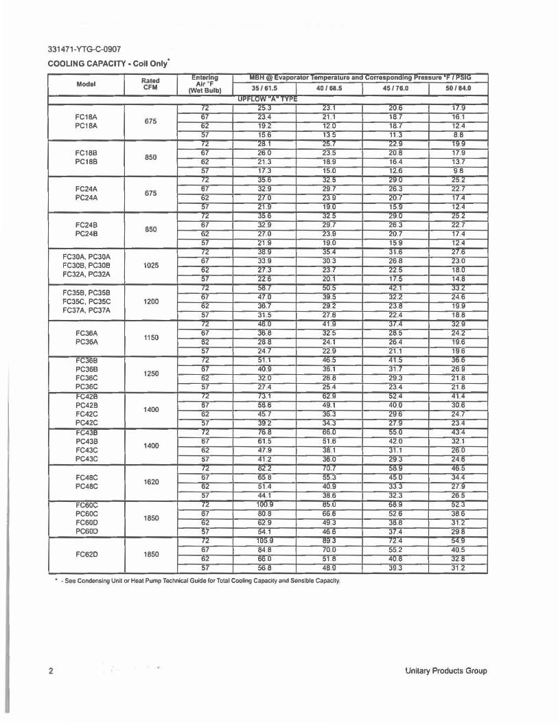
331471-YTG-C-0907
COOLING CAPACITY • Coll Only'
Rated 1:ntanng Man @I 1:vaporator 1amperatura ana {;OrT&1ponaIng l'rassure -1- 1 .-.nu Modal CFM Alr ' F
35/61.5 40 / 68.5 45 /76.0 50 / 84.0 (Wat Bulb) Ul'l"LUff A 1 1 ,-,;
72 25.3 23.1 ..:u.6 H .9 FC18A
675 67 23.4 21.1 18 7 16.1
PC18A o..: 19 2 12 u 18.7 12,4 57 15.6 13 5 11 .3 8.8 (2 .:o l 2':,. ( .:.:.9 l!:f9
FC18B 850
67 260 23.5 20.8 179 PC188 62 21.3 18.9 16.4 13 7
57 17 3 15.0 12.6 98
'" .>.J.b 3.:.:, "" u z:,.: FC24A
675 67 32.9 297 263 22,7
PC24A 62 27,0 23 9 .:u.7 17.4 57 21 .9 19.0 15,9 12.4 I.I: ;,:,6 ;,.;:.5 ;i:::,u .;::,2
FC24B 850 67 32 9 29.7 26.3
"" 7 PC24B 62 270 23.9 .:u.7 174
57 21 9 19,0 15 9 12.4
FC30A,PC30A ,.: ;,o.9 J5.4 Jl.b .:1.b
FC308, PC30B 1025 67 33.9 30 3 268 23.0
FC32A,PC32A 62 27.3 23.7 225 18.0 57 226 20,1 17.5 14.8
FC35B, PC35B rL ::,0. ( :,v.:, 42,l .,.,;,:
FC35C, PC35C 1200 67 470 39.5 32.2 246
FC37A, PC37A b.l: 3b.7 <:9,2 23.ts 19,9 57 31.5 27.6 22.4 18.8
'"" 4b.0 41 .9 3/.4 3<:l:I FC36A 1150
67 36.8 32 5 285 24.2 PC36A 62 288 24.1 264 19.6
57 24.7 22.9 21.1 196 i-c.;368 IL 51.1 465 41 .5 ;,06
PC36B 1250
67 40.9 J6.1 31 ,7 269 FC36C o.: 32.U 26.8 29.J 21 8 PC36C 57 27.4 254 23.4 21 8 FC42B I.;: (J.l o.:9 ':,24 41.4 PC42B
1400 67 586 49.1 400 J0,6
FC42C o.: 4:, 7 Jb.J 29ti 24.f PC42C 57 392 34.3 27.9 23.4 FC438 '"" /b,11 DD,U ;;,;;,,U 434 PC43B 1400
67 61.5 51.6 42.0 32.1 FC43C 62 47.9 Jll.1 J1.1 ,ou PC43C 57 41 2 36.0 293 24.6
fl. ts.: " tU.t .>09 4ti,5 FC48C
1620 67 65 8 55,3 450 34.4
PC48C IU 51.4 40.9 JJJ u .9 57 44.1 38.6 32.3 265
FC60C '" lUU.9 115.U bts,9 :,.: J PC60C 1850
67 80 8 66,6 52,6 386 FC60D O.! b.!.9 49.3 38.8 31.2 PC60D 57 54.1 466 37.4 298
'" 1u::,,9 Ol:13 ,.: 4 ::,4_9
FC62D 1850 67 84 B 70.0 552 405 O.! tib 0 51 8 408 J.1:.8 57 568 48.9 39.3 31 .2
• - See Condensing Unit or Heal Pump Technical Guide for Total Cooling Capacl1y and Sensible Capacity,
2 Unitary Products Group
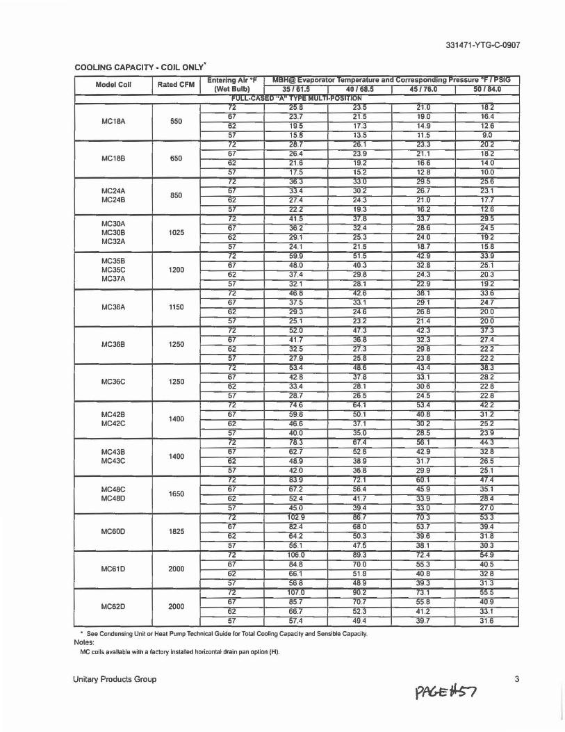
331471 -YTG-C-0907
COOLING CAPACITY • COIL ONLY•
Model Coll Rated CFM 1:nt1r1ng Atr °F '"'"""I!!! ~vaporator 1emperature ana 1.,orraspona1n9 t'ressure ·t-, r-.>1u
(Wet Bulb) 35 I 61.5 40/ 68.5 45/76.0 50 / 84.0 FULL• ... A,>l:U .. A .. 1 Tl"I: MULII• . ..,.,,1 ,..,,.
'" L0,8 LJ.5 Ll.U 18 2
MC18A 550 67 L"J.7 21 5 190 16,4 62 19 5 17.3 14.9 12.6 57 15 8 13.5 11.5 9,0 IL .:of .:o.l 23."J .:u 2
MC18B 650 67 .:o 4 23,9 21 .1 18 2 62 21 .6 19,2 11> ti 14 0 57 17.5 15.2 12 8 10,0
'" "J0,3 JJ.0 29.5 .::, ti MC24A
850 67 33 4 J02 26.7
""'· 1 MC24B 62 274 24,3 21.0 17.7
57 222 19,3 16,2 12 6
MC30A 72 415 ..,, .8 "J3,/ 2!!:>
MC30B 1025 67 JI> 2 32,4 286 24 5
MC32A 62 29.1 2:,,3 24U 19.2 57 24,1 21 5 11:17 15,8
MC35B 72 59.9 51 5 42.9 3J,9
MC35C 1200 67 480 403 32,8 25.1
MC37A 62 37,4 29,8 24,3 203 57 32 1 L8.1 22.9 19 2 12 4t, 8 42.t> 38.1 330
MC36A 1150 67 3/,5 33,1 291 24.7 62 29,3 246 268 20.0 57 .£:>.1 232 21,4 20.0 72 520 47.J 42,J ..,,.J
MC368 1250 67 41.7 36,8 32,3 27.4 62 "J25 27.3 298 222 57 27.9 25,8 23 8 222 /2 ::>.l.4 411.0 434 .l0.3
MC36C 1250 67 42,8 .,, 8 33.1 28.2 62 J3,4 28.1 30,6 228 57 L8.7 265 24,5 22.8 fL 746 04,1 0"J.4 422
MC428 1400
67 59.8 :iu.1 408 31.2 MC42C 62 46.6 3/.1 302 252
57 40,0 35,0 28,5 23,9 fL ,o.J o, 4 56, 1 44,J
MC438 1400 67 62 7 526 42,9 32.8
MC43C 62 48.9 389 31 7 265 57 420 36.8 29.9 25.1
'" 0.l9 ( " · 1 OU 1 41.4
MC48C 1650
67 67.2 ::,o.4 459 35.1 MC48D 62 52,4 41.7 "JJ.9 28.4
57 45,0 394 33,0 27.0 (" 1U2.9 OD I ,v.3 0,)3
MC60D 1825 67 82.4 680 53.7 394 62 ti4 2 :,v,3 396 31.8 57 55.1 47.5 38 1 30,3 ,2 1Ut>.0 tl!!,3 12.4 04,!!
MC61D 2000 67 84.8 700 55.3 40,5 62 66.1 51 8 40.8 328 57 56 8 489 39.J 31 3 ,2 1u,.o !!U.2 /3 1 :,:, :,
MC62D 2000 67 85 7 /0.7 55 8 409 62 66.7 52,3 41 ,2 33,1 57 57.4 49.4 "J!!. 7 31.6
• See Condenslng Unit or Heat Pump Technical Guide (or Total Cooling Capacity and Sensible Capacity. Notes:
MC colls available with a (actory Installed horizontal drain pan oplion (HJ.
Unitary Products Group 3
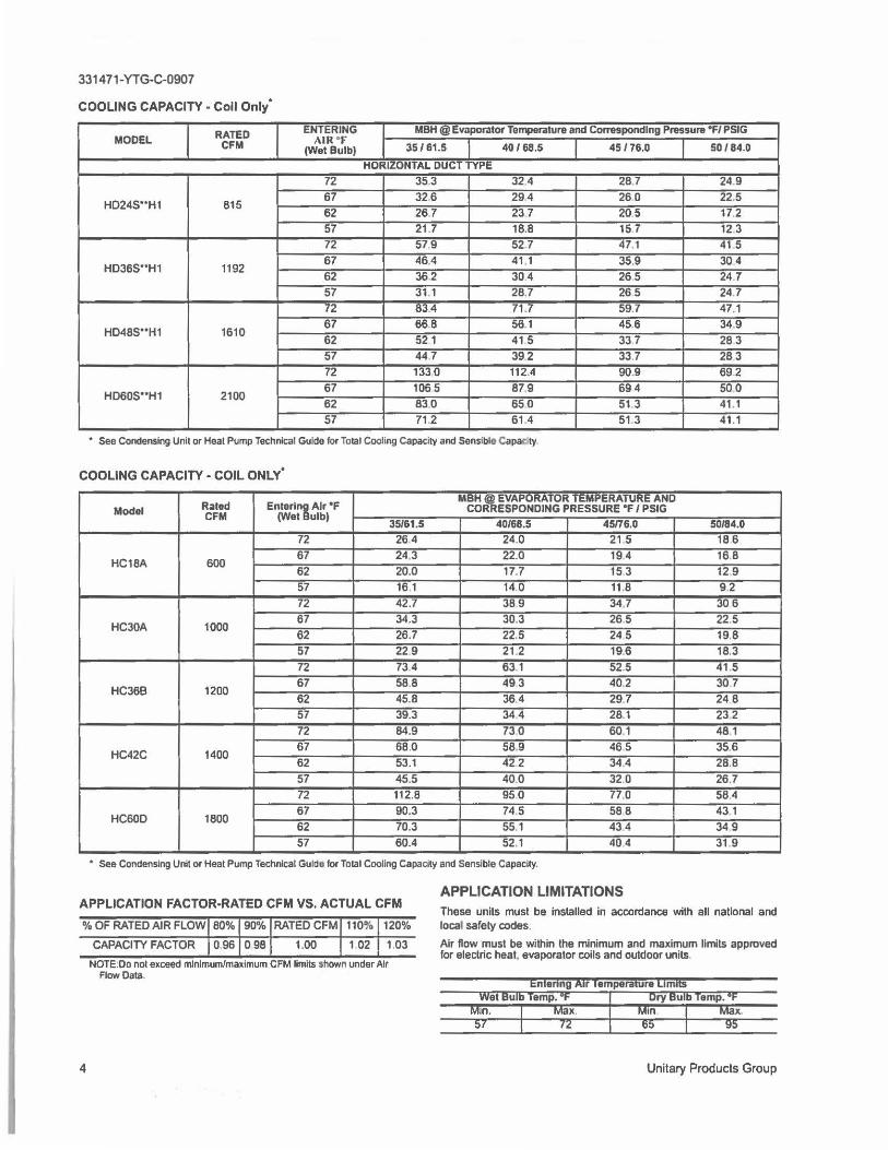
331471-YTG-C-0907
COOLING CAPACITY • Coll Only•
RATED ENTERING MBH@ ~v:ipor.,to, Te~ture and COfTHpondlng Pressure "f/ PSIG MODEL CFM AIR •r
35 / 61.5 40 / 68.5 45 / 76.D 5D / 84.D (Wet Bulb) HOR1LuNTAL OU~ 1 1 TPE
72 35.3 32.4 28.7 24.9
HD245 .. H1 815 67 32.6 29.4 260 22.5 62 267 23 7 20.5 17.2 57 21.7 18.8 15.7 12 3 72 57.9 52.7 47.1 41 5
HD365 .. H1 1192 67 464 41 .1 35.9 30.4 62 36.2 304 265 24.7 57 31.1 28.7 265 24.7 72 83.4 71 .7 59.7 47.1
HD485"'H1 1610 67 66.8 56.1 456 34.9 62 521 41 5 337 28 3 57 44 7 392 33.7 283 72 1330 112.4 90.9 69.2
HD605 .. H1 2100 67 1065 87.9 694 500 62 83.0 650 51 3 41.1 57 71.2 61 .4 51 3 41.1
• See Condensing Unit or Heat Pump Technical Gulde for Total Cooling Capacity and Sensible Capac.ty
COOLING CAPACITY· COIL ONLY•
Rated Enter1:, Air •F MBH I EVAPORATOR TEMPERATURE AND
Model COR ESPONDING PRESSURE "f / PSIG CFM (Wet ulbl
35/61.5 4D/68.5 45/76.D 5D/84.0
72 264 24.0 21 .5 18 6
HC1BA 600 67 24.3 22.0 19.4 16.8 62 20.0 17.7 15 3 12 9 57 16.1 14.0 11.8 9.2 72 42.7 389 34.7 306
HC30A 1000 67 34.3 30.3 26 5 22 5 62 26.7 22.5 24 5 19,8 57 22 9 21.2 19,6 18.3 72 734 63.1 52.5 41 .5
HC36B 1200 67 58.8 493 40.2 30 7 62 45.8 36.4 297 24 8 57 39.3 344 28 1 23 2 72 84.9 730 60.1 48.1
HC42C 1400 67 68.0 58.9 465 35.6 62 53.1 42 2 34.4 28.8 57 45.5 40.0 32.0 26.7 72 112.8 950 77.0 58.4
HC60O 1800 67 90.3 74.5 588 43.1 62 70.3 55.1 434 349 57 60.4 52.1 404 31 9
• See Condensing Unit or Heat Pump Technical Gulde for Total Cooling Capacity and Sensible Capacity,
APPLICATION FACTOR-RATED CFM VS. ACTUAL CFM
% OF RATED AIR FLOW 80% 90% RATED CFM 110% 120%
4
CAPACITY FACTOR O 96 0 98 1.00 1.02 1.03
NOTE:0o not exceed minimum/maximum CFM limits shown under Air Flow Data
APPLICATION LIMITATIONS These units must be installed in accordance with all national and local safety codes.
Air flow must be within the minimum and maximum llmits approved for electric heat. evaporator calls and outdoor units
Entering Xlr Temperature limits
Unitary Products Group
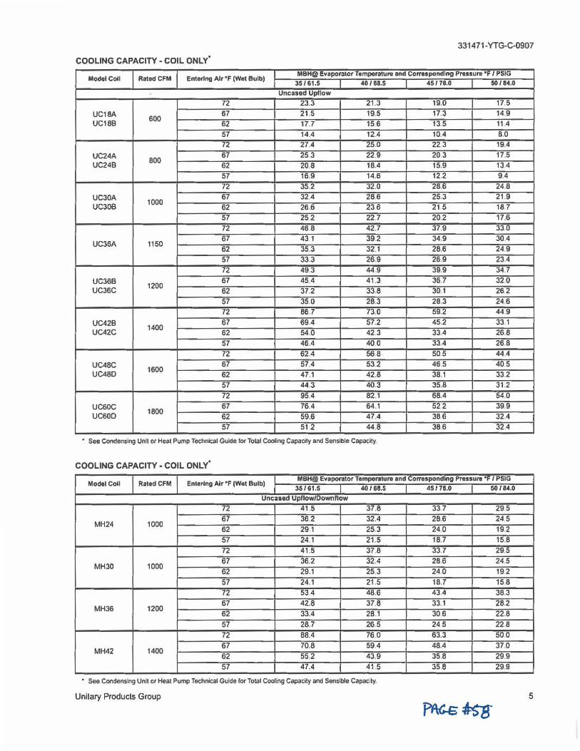
331471-YTG-C-0907
COOLING CAPACITY - COIL ONLY0
Model Coll Rated CFM Entering Air •F (Wet Bulb) MBH@ 1:vaporator Temparatun1 and Corresponding Pressure •F I PSIG
35161.5 40188.5 45176.0 50184.0 Uncased Upflow
72 23.3 21.3 19.0 17,5
UC18A 600 67 21.5 19.5 17.3 14.9
UC188 62 17.7 15 6 13.5 11.4 57 14.4 12.4 10.4 8.0 (,f, 27.4 ..:~.o 22.3 19.4
UC24A 800 67 25 3 22,9 20 3 17.5
UC248 62 20.8 18.4 15.9 13 4 57 16.9 14.6 12.2 9.4 72 35,2 32.0 28.6 24.8
UC30A 1000 67 32,4 286 25.3 21 .9
UC30B 62 26.6 236 21 5 18.7 57 252 22.7 202 17,6 72 46 8 42.7 37.9 330
UC36A 1150 67 43 1 39,2 34,9 304 62 35.3 32.1 28.6 249 57 33.3 26.9 26.9 23.4
72 49.3 44.9 39.9 34,7
UC36B 1200 67 45.4 41.3 36.7 32.0
UC36C 62 372 33.8 30.1 262 57 35 0 28.3 28.3 246 72 86 7 73.0 59,2 449
UC42B 1400 67 69.4 57.2 45.2 33 1
UC42C 62 54,0 42 3 33.4 26.8 57 46.4 400 33,4 26.8 72 62.4 56 8 505 44.4
UC48C 67 57,4 53.2 46 5 405 UC480 1600
62 47.1 42.8 38,1 332 57 44 3 40.3 35.8 31.2 72 95.4 82,1 68.4 54,0
UC60C 1800 67 76.4 64.1 522 39,9
UC60O 62 59.6 47.4 386 32.4 57 51 .2 44,8 386 324
• See Condensing Unit or Heat Pump Technical Gulde for Tolal Cooling Capacity and Sensible Capacity.
COOLING CAPACITY - COIL ONLY•
Modal Coll RatadCFM Entering Air •F (Wat Bulb) MBH@ Evaporator Temperature and Corresponding Pressure "F I PSIG
35161.5 40 /68.5 451711.0 50/84.0
Uncased Upflow/Oownflow
f ,f, 41 5 37,8 33.7 295
MH24 1000 67 36 2 32.4 28.6 24.5 62 291 25.3 24.0 19.2 57 24.1 21.5 18,7 15,8
72 41 ,5 37.8 33.7 29.5
MH30 1000 67 36.2 32.4 286 24.5
62 29.1 25.3 24.0 19 2 57 24.1 21 .5 18.7 15 8 ,, 534 48.6 43.4 38,3
MH36 1200 67 42,8 37 8 33.1 28.2 62 33.4 28.1 306 22.8 57 28.7 26.5 245 22.8 72 88.4 76.0 63.3 500
MH42 1400 67 70.8 594 48,4 37.0 62 55.2 43.9 35.8 29.9 57 47.4 41 5 358 29.9
• See Condensing Unit or Heat Pump Technical Guide lor Tolal Cooling Capacily and Sensible Capac ty.
Unitary Products Group 5
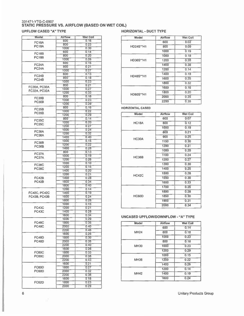
331471-YTG-C-0907 STATIC PRESSURE VS. AIRFLOW (BASED ON WET COIL)
UPFLOW CASED "A" TYPE HORIZONTAL - DUCT TYPE
Model Airflow Wet Coll
600 0.02 HD245 .. H1 800 0.09
FC18B PC188
1000 0 19
1000 0.19 HD36S••H1 1200 0.28
FC24A 1400 0.38 PC24A 1200 0.14
FC24B PC24B
HD48S .. H1 1400 0.19
1600 0.25
1800 0.32 FC30A, PC30A 1600 0.16 FC32A, PC32A
FC30B HD60S••H1
1800 0.20
2000 025
PC30B 2200 0.30
FC35B HORIZONTAL CASED
PC35B Model Airflow Wet Coll
FC35C PC35C
600 0.07
HC18A 800 0.12
1000 0.19 FC36A 800 0.21 PC36A
FC36B HC30A
900 0.25
1150 0.30
PC36B 1200 0.31
1000 0.20 FC37A PC37A HC36B
1100 0.24
1200 0.27
FC36C 1300 0.30
PC36C 1400 0.25
FC42B HC42C
1500 0.28
1550 0.30 PC42B 1600 0.33
1700 0.25
FC42C, PC42C 1800 0.28
FC43B, PC43B HC60D 1850 0.30
1900 0.31
FC43C 2000 0.34
PC43C
UNCASED UPFLOW/DOWNFLOW • "A" TYPE
FC48C Model Airflow Wet Coll PC48C 600 0.14
MH24 800 0.18
FC48D 1000 0.23
PC480 800 0.18
MH30 1000 0.23
FC60C 1200 0.29
PC60C 1000 0.15
MH36 1200 0.22
1400 0.28 FC60D PC60D
1200 0.14
MH42 1400 0.19
1600 0.24 FC620
6 Unitary Products Group
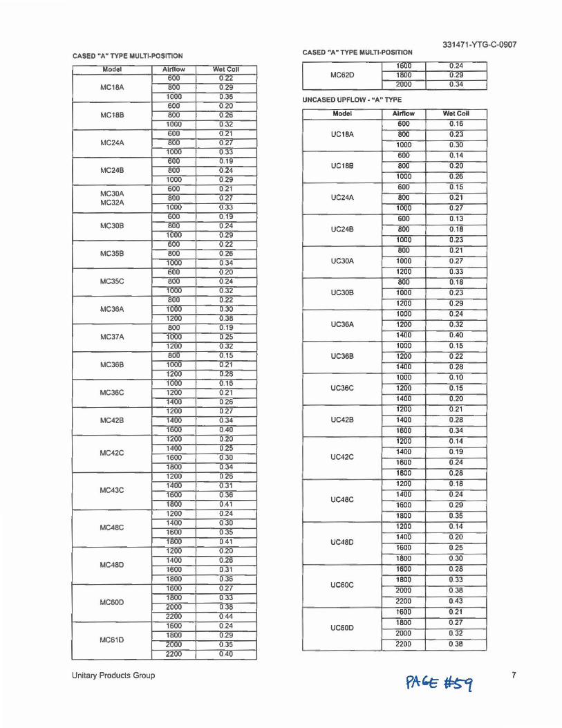
331471•YTG-C-0907
CASED "A" TYPE MULTI-POSITION CASED "A" TYPE MULTI-POSITION
Model Airflow Wet Coll 600 0.22
MC18A 8w 0.29
1600 0.24 MC620 1800 0.29
2000 0 .34
1000 0.36 UNCASED UPFLOW. "A" TYPE 600 020
MC18B 800 026 Model Airflow Wet Coll
1000 0 32 600 0.16 600 0.21 UC1BA 800 0.23
MC24A 800 0.27 1000 0.30 1000 033 600 0.19
MC24B 800 0.24
600 0.14
UC188 BOO 0.20
1000 029 1000 0.26
MC30A 600 021
MC32A 800 0.27 1000 0.33
600 0.15
UC24A 800 0.21
1000 0.27 600 0.19 600 0.13
MC30B BOO 0.24 1000 0.29 600 022
MC35B BOO 026
UC24B BOO 0.18
1000 0.23
BOO 0.21
1000 034 UC30A 1000 0.27
600 0.20 1200 0.33 MC35C BOO 0.24 800 0.18
1000 0.32 UC308 1000 0.23 800 0.22
MC36A 1000 0.30 1200 0.38
1200 0.29
1000 0.24
BOO 0.19 UC36A 1200 0.32
MC37A 1000 025 1400 0.40
1200 0.32 1000 0.15 800 0.15 UC36B 1200 0.22
MC36B 1000 0.21 1400 0.28 1200 0.28 1000 0.16
MC36C 1200 021 1400 026
1000 0.10
UC36C 1200 0.15
1400 0.20
1200 0 27 1200 0.21
MC42B 14UO 0.34 UC42B 1400 0.28 1600 0.40 1600 0.34 1200 0.20 1200 0.14
MC42C 1400 0.25 1600 030 1800 034 1200 026
UC42C 1400 0.19
1600 0.24
1800 0.28
MC43C 1400 0.31 1600 036 1800 0.41
1200 0.18
UC48C 1400 0.24
1600 0.29 1200 0.24 1800 0.35
MC48C 1400 030 1600 035 1800 0 41 1200 0.20
1200 0.14
UC48D 1400 0.20
1600 0.25
MC48D 1400 0.26 1600 0,31
1800 0.30
1600 0.28 1800 0.36 1600 027 UC60C
1800 0.33 '
2000 0.38
MC60D 1800 033 2000 0 38 2200 044
2200 0.43
1600 0.21
1600 024
MC610 1800 0.29 2000 0.35
UC60D 1800 0.27
2000 0.32
2200 0.38
2200 040
Unitary Products Group 7
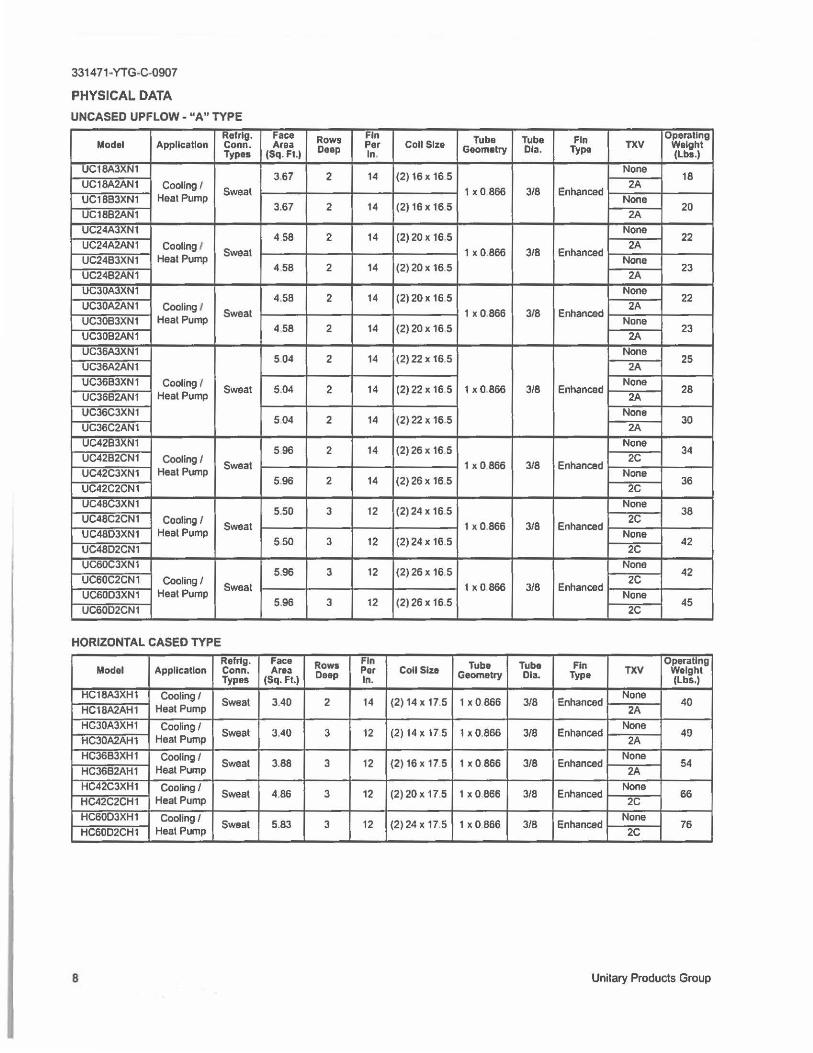
331471-YTG-C.0907
PHYSICAL DATA
UNCASED UPFLOW - "A" TYPE
Model App Ilea ti on Refrlg. Conn. Types
UC18A3XN1
UC18A2AN1 Cooling f Sweat
UC1883XN1 Heat Pump
UC1882AN1
UC24AJXN1
UC24A2AN1 Cooling / Sweat
UC2483XN1 Heat Pump
UC24B2AN1
UC30AJXN1
UC30A2AN1 Cooling / Sweat
UC30B3XN1 Heat Pump
UC3082AN1
UC36A3XN1
UC36A2AN1
UC3683XN1 Cooling I UC3682AN1 Heat Pump
Sweat
UC36C3XN1
UC36C2AN1
UC428JAN1
UC42B2CN1 Cooling I Sweat
UC42C3XN1 Heat Pump
UC42C2CN1
UC48C3XN1
UC48C2CN1 Cooling I Sweat
UC4803XN1 Heat Pump
UC4802CN1
UC60C3XN1
UC60C2CN1 Cooling/ Sweat
UC6003XN1 Heat Pump
UC6002CN1
HORIZONTAL CASED TYPE
Model Appllcatlon Rafrlg. Conn. Types
HC18A3XH1 Cooling/
HC18A2AH1 Heat Pump Sweat
HC30A3XH1 Cooling/ HC30A2AH1 Heat Pump
Sweat
HC36B3XH1 Cooling/ HC36B2AH1 Heat Pump
Sweat
HC42C3XH1 Cooling/
HC42C2CH1 Heat Pump Sweat
HC6003XH1 Cooling I HC6002CH1 Heat Pump
Sweat
B
Face Rows Fin Area Per
(Sq. Ft.I Deep In.
3.67 2 14
3.67 2 14
4 58 2 14
4.58 2 14
4,58 2 14
4 58 2 14
504 2 14
5.04 2 14
504 2 14
596 2 14
5.96 2 14
5.50 3 12
550 3 12
5.96 3 12
5.96 3 12
Face Rows Fin Area Per
(Sq. Ft.) Deep In.
3.40 2 14
3.40 3 12
3.88 3 12
4.86 3 12
5.83 3 12
Coll Size Tuba Tube Fin Operating Geometry Dia. Type TXV Weight
(Lbs.)
(2) 16 X 16 5 None
2A 18
1x0866 3/8 Enhanced
(2)16x165 None
20 2A
(2) 20 x 16,5 None
2A 22
1 X 0.866 3/8 Enhanced
(2) 20 x 16.5 None
23 2A
(2)20x 16 5 None
2A 22
1 X 0,866 3/8 Enhanced
(2) 20 X 16.5 None
23 2A
(2)22 X 16.5 None
2A 25
(2) 22 X 16 5 1x0866 3/8 Enhanced None
28 2A
(2) 22 X 16.5 None
2A 30
(2) 26 X 16.5 None
2C 34
1 X 0,866 3/8 Enhanced
(2) 26 x 16.5 None
36 2C
(2)24 X 16 5 None
2C 38
1 X 0.866 3/8 Enhanced
(2) 24 X 16.5 None
42 2C
(2) 26 X 16.5 None
2C 42
1x O 866 3/8 Enhanced
(2) 26 x 16.5 None
2C 45
Coll Size Tube Tube Fin Operating
Geometry Dia. Type TXV Weight (Lbs,)
(2) 14 x 17.5 1 XO 866 3/8 Enhanced None
40 2A
(2)14xl75 1 X 0 ,866 3/8 Enhanced None
4!) 2A
(2) 16 X 17.5 1 XO 866 318 Enhanced None
54 2A
(2) 20 X 17.5 1x O 866 3/8 Enhanced None
66 2C
(2) 24 x 17,5 1 x0866 318 Enhanced None
2C 76
Unitary Products Group
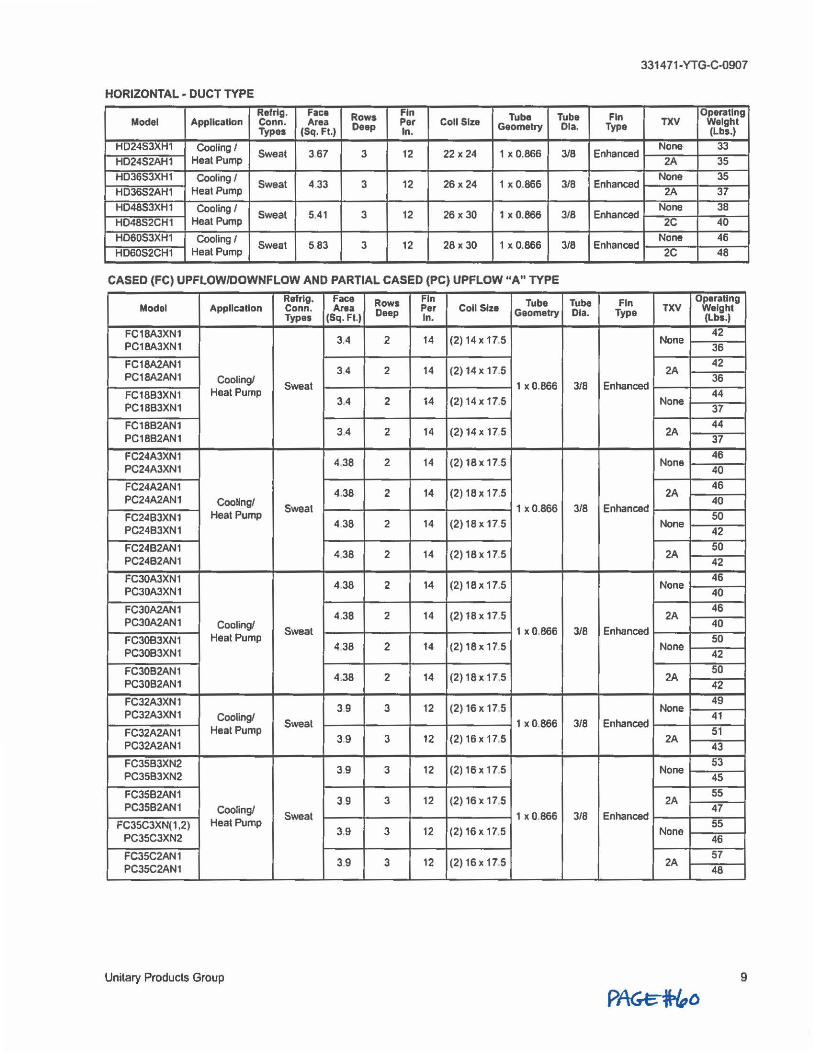
331471-YTG-C-0907
HORIZONTAL DUCT TYPE -Reing. Face Fin Tube Tube Fin Operating Rows TXV Weight Model Applk:atlon Conn. Area Deep Per Coll Size Geometry Dia. Type (lbs.) Types (Sq. Ft.) In.
None 33 HLJ24S3XH1 Cooling/ Sweat 367 3 12 22 X 24 1 X 0.866 3/8 Enhanced
2A 35 HD24S2AH1 Heat Pump
None 35 HD36S3XH1 Cooling I Sweat 4 33 3 12 26x24 1 X 0.866 3/8 Enhanced
2A 37 HD36S2AH1 Heat Pump
None 38 H048S3XH1 Cooling I Sweat 5.41 3 12 26 x30 1 X 0.866 3/8 Enhanced
2C 40 HD4852CH1 Heat Pump
None 46 HD60S3XH1 Cooling I Sweat 5 83 3 12 28x 30 1 X 0.866 3/8 Enhanced
2C 48 HD60S2CH1 Heat Pump
CASED (FC) UPFLOW/DOWNFLOW AND PARTIAL CASED (PC) UPFLOW "A" TYPE
Refrlg. Face Fin Tube Tube Fin Operating Rows TXV Weight Model Appllcatton Conn. Area Deep Per Coll Size Geometry Ota. Type (lbs.) Types (Sq. Ft.) In. 42 FC18A3XN1
3.4 2 14 (2) 14 X 17.5 None 36 PC18A3XN1
42 FC18A2AN1 14 (2) 14 X 17.5 2A 3,4 2
36 PC18A2AN1 Cooling! Sweat 1 x O.B66 3IB Enhanced
44 FC1883XN1 Heat Pump 3,4 2 14 (2) 14 X 17.5 None
37 PC1BB3XN1
44 FC1BB2AN1 (2) 14 X 17 5 2A 34 2 14
37 PC1BB2AN1
46 FC24A3XN1 14 (2) 18 X 17.5 None 4.38 2
40 PC24A3XN1
46 FC24A2AN1 14 (2) 1B x 17,5 2A 4.38 2
40 PC24A2AN1 Cooling/ Sweat 1 x0.866 3/8 Enhanced
50 FC2483XN1 Heat Pump 4 38 2 14 (2)18x175 None
42 PC24B3XN1
50 FC24B2AN1 4.38 2 14 (2) 18 X 17.5 2A
42 PC24B2AN1
46 FC30A3XN1 (2) 18 X 17.5 None 4.38 2 14
40 PC30A3XN1
46 FC30A2AN1 14 (2) 1B X 17.5 2A 4.38 2
40 PC30A2AN1 Cooling! Sweat 1 X 0,866 3IB Enhanced
50 FC30B3XN1 Heal Pump 14 (2) 18 X 17.5 None 4.38 2
42 PC3083XN1
50 FC30B2AN1 4.38 2 14 (2) 18 x 17,5 2A
42 PC30B2AN1
49 FC32A3XN1 12 (2) 16 X 17 5 None 39 3
41 PC32A3XN1 Cooling! Sweat 1 X 0.866 3IB Enhanced
51 FC32A2AN1 Heal Pump 12 (2) 16x 17,5 2A 3.9 3
43 PC32A2AN1
53 FC35B3XN2 3,9 3 12 (2) 16 X 17.5 None
45 PC35B3XN2
55 FC35B2AN1 12 (2) 16 X 17 5 2A 39 3
47 PC35B2AN1 Cooling/ Sweat 1 x 0.866 318 Enhanced
55 FC35C3XN(1 .2) Heat Pump 12 (2) 16 x 17.5 None 3.9 3
46 PC35C3XN2
57 FC35C2AN1 12 (2) 16 X 17.5 2A 3,9 3
48 PC35C2AN1
Unitary Products Group 9
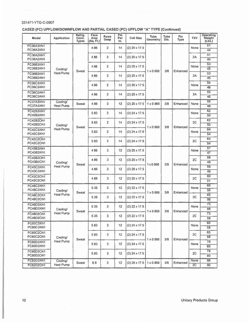
331471-YTG-C-0907
CASED (FC} UPFLOW/DOWNFLOW AND PARTIAL CASED (PC} UPFLOW "A" TYPE (Continued)
uperatlng Refrtg. Face Rows Fin Tube Tube Fin TXV Weight Model Application Conn. Area Deep Per Coll Siu Geometry Dia. Type (Lbs.) Types (Sq. Ft.) In.
51 FC36A3XN1 4.86 2 14 (2) 20 X 17.5 None
44 PC36A3XN1
51 FC36A2AN1 4 86 2 14 (2) 20 X 17,5 2A
44 PC36A2AN1
53 FC36B3XN1 486 2 14 (2)20x 17 5 None
45 PC36B3XN1 Coo~ng/ Sweat 1 X 0 .866 3/8 Enhanced
53 FC36B2AN1 Heat Pump 4.86 2 14 (2)20x 17,5 2A
45 PC36B2AN1
55 FC36C3XN1 4.86 2 14 (2) 20 X 17.5 None
46 PC36C3XN1
55 FC36C2AN1 486 2 14 (2)20 X 17 5 2A
46 PC36C2AN1
56 FC37A3XN1 Cooling/ Sweat 4.86 3 12 (2) 20 X 17 5 1 x0866 3/8 Enhanced None
48 PC37A3XN1 Heat Pump
62 FC42B3XN1 5.83 2 14 (2) 24 X 17,5 None
50 PC42B3XN1
62 FC42B2CN1 583 2 14 (2)24 X 17 5 2C
50 PC42B2CN1 Coo~ng/ Sweat 1 xO 866 3/8 Enhanced
64 FC42C3XN1 Heat Pump 5.83 2 14 (2) 24 X 17.5 None
54 PC42C3XN1
64 FC42C2CN1 583 2 14 (2) 24 X 17.5 2C
54 PC42C2CN1
57 FC4383XN1 486 3 12 (3)20x175 None
47 PC43B3XN1
58 FC4382CN1 4.86 3 12 (3) 20 X 17 5 2C
49 PC43B2CN1 Cooling/ Sweat 1x0 866 3/8 Enhanced
58 FC43C3XN1 Heat Pump (2)20 X 17.5 None 486 3 12
49 PC43C3XN1
60 FC43C2CN1 12 (2) 20 X 17.5 2C 486 3
51 PC43C2CN1
65 FC48C3XN1 5.35 3 12 (2) 22 X 17 5 None
56 PC48C3XN1 Cooling/ Sweat 1 X 0.866 3/8 Enhanced
65 FC48C2CN1 Heat Pump (2)22 X 17,5 2C 535 3 12
56 PC48C2CN1
73 FC4803XN1 535 3 12 (2) 22 X 17,5 None
58 PC48D3XN1 Cooling/ Sweat 1 x0866 3/8 Enhanced
73 Heal Pump FC48D2CN1 5.35 3 12 (2) 22 X 17 5 2C
58 PC48D2CN1
65 FC60C3XN1 583 3 12 (2) 24 X 17.5 None
58 PC60C3XN1
65 FC60C2CN1 5 83 3 12 (2) 24 X 17.5 2C
58 PC60C2CN1 Cooling/ Sweat 1 X 0.866 3/8 Enhanced
78 FC6003XN1 Heat Pump 583 3 12 (2)24 X 17.5 None
60 PC60D3XN1
78 FC6002CN1 12 (2) 24 X 17 5 2C 5.83 3
60 PC60D2CN1
None 88 FC6203XN1 Cooling/ Sweat 68 3 12 (2)28 X 17.5 1x0866 3/8 Enhanced
2C 90 FC6202CN1 Heat Pump
10 Unitary Products Group
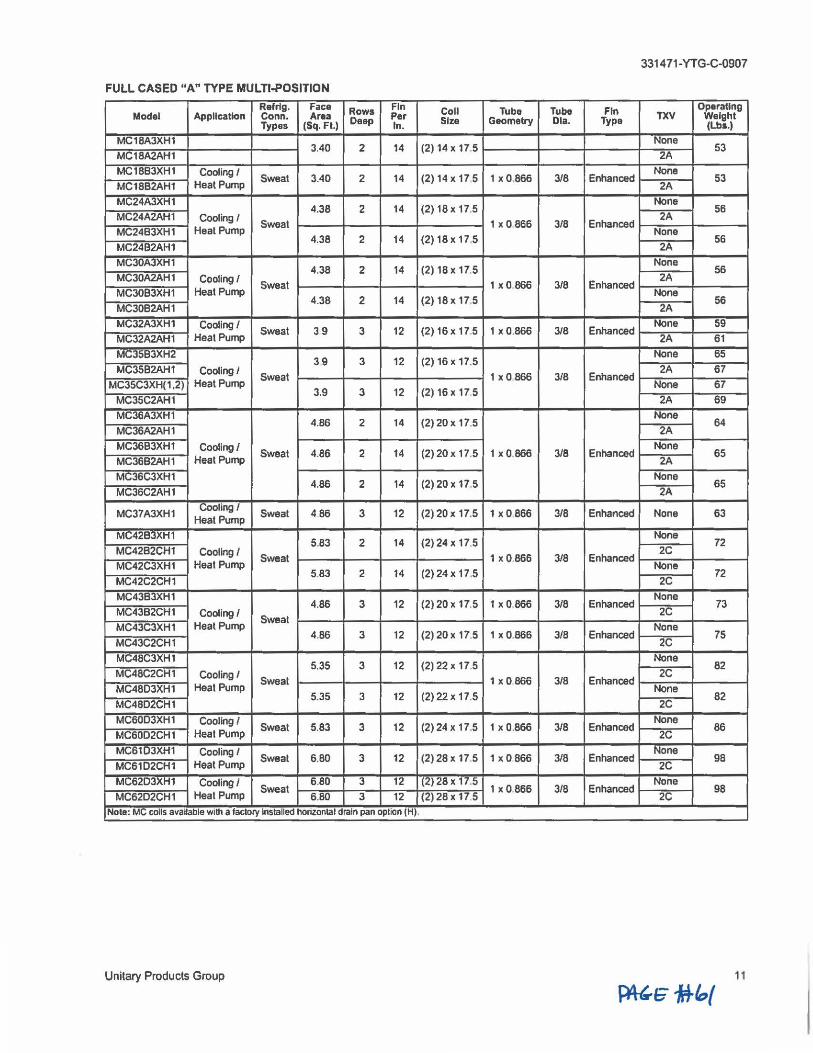
3314 71-YTG-C-0907
FULL CASED "A" TYPE MULTl•POSITION
Model Appllcatlon Refrtg. Face Rows Fin Conn. Area Per Coll Tube Tube Fin Operating
Types (Sq.Ft.) Deep In. Size G■omelry Dia. Type TXV Weight (Lb11.J
MC18A3XH1
MC18A2AH1 3.40 2 14 (2) 14 X 17.5
None 53
2A
MC1883XH1 Cooling I MC1882AH1 Heat Pump
Sweat 3.40 2 14 (2) 14 X 17 5 1 X 0,866 318 Enhanced None
53 2A
MC24A3XH1
MC24A2AH1 Cooling I 4.38 2 14 (2) 18 X 17.5
None
Sweat 2A
56
MC2483XH1 Heat Pump 1 X 0.866 3/8 Enhanced
MC2482AH1 4.38 2 14 (2) 18x 17.5
None 56
2A
MC30A3XH1
MC30A2AH1 Cooling I 4.38 2 14 (2) 18 X 17,5
None
Sweal 2A
56
MC3083XH1 Heat Pump 1x0866 3/8 Enhanced
MC3082AH1 4.38 2 14 (2) 18x 17,5
None 56
2A
MC32A3XH1 Cooling/ MC32A2AH1 Heat Pump
Sweat 39 3 12 (2) 16 X 17.5 1 X 0 .866 3/8 Enhanced None 59
2A 61
MC3583XH2
MC35B2AH1 Cooling/ 39 3 12 (2) 16 X 17.5
None 65
Sweat 2A 67
MC35C3XH(1 ,2) Heat Pump 1 X 0.866 3/8 Enhanced
MC35C2AH1 3,9 3 12 (2) 16 X 17.5
None 67
2A 69
MC36A3XH1
MC36A2AH1 4.86 2 14 (2)20x 17.5
None
2A 64
MC36B3XH1 Cooling/ MC3682AH1 Heat Pump
Sweat 4.86 2 14 (2)20x 17.5 1 X 0.866 3/8 Enhanced None
65 2A
MC36C3XH1
MC36C2AH1 4.86 2 14 (2) 20 X 17.5
None 65
2A
Cooling/ MC37A3XH1 Sweat 486 3
Heat Pump 12 (2) 20 X 17,5 1 x0866 3/8 Enhanced None 63
MC42B3XH1
MC42B2CH1 Cooling I 5.83 2 14 (2)24 X 17,5
None
Sweat 2C
72
MC42C3XH1 Heal Pump 1 X 0.866 3/8 Enhanced
MC42C2CH1 5.83 2 14 (2) 24 X 17,5
None 72
2C
MC4383XH1
MC4382CH1 Cooling/ 4.86 3 12 (2) 20 X 17.5 1x0866 3/8 Enhanced
None 73
MC43C3XH1 Heat Pump Sweat
2C
MC43C2CH1 4.86 3 12 (2) 20 X 17.5 1 X 0,866 3/8 Enhanced
None 75
2C
MC48C3XH1
MC48C2CH1 Cooling I 5.35 3 12 (2) 22 X 17.5
None
Sweat 2C
82
MC4803XH1 Heat Pump 1x0866 3/8 Enhanced
MC48D2CH1 5.35 3 12 (2)22x 17.5
None 82
2C
MC6003XH1 Cooling/ MC60D2CH1 Heal Pump
Sweat 5.83 3 12 (2) 24 X 17.5 1 X 0,866 3/8 Enhanced None
86 2C
MC6103XH1 Cooling I MC61D2CH1 Heat Pump
Sweat 6.80 3 12 (2) 28 X 17 5 1 x0866 3/8 Enhanced None
98 2C
MC6203XH1 Cooling/ 6.80 3 12 (2) 28 X 17.5
MC62D2CH1 Heat Pump Sweat 1 x0.866 3/8 Enhanced
None
6.80 3 12 (2) 28 X 17.5 98
2C
Nol■: MC coils available with a factory Installed horizontal drain pan option (H).
Unilary Products Group 11
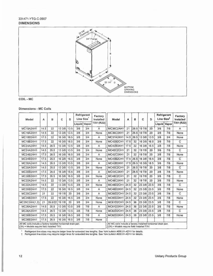
331471-YTG-C-0907
DIMENSIONS
COIL•MC
Dimensions - MC Coils
Model A B
MC18A2AH1 14.5 22
MC18A3XH1 14 5 22 MC18B2AH1 17.5 22
MC18B3XH1 17.5 22
MC24A2AH1 14.5 26.5
MC24A3XH1 14.5 26.5
MC2482AH1 17.5 26.5
MC2483XH1 17.5 26.5
MC30A2AH1 14.5 26.5
MC30A3XH1 14.5 26.5
MC3082AH1 17.5 26.5
MC3083XH1 17.5 26.5
MC32A2AH1 14.5 22
MC32A3XH1 14.5 22 MC35B2AH1 17.5 22
MC35C2AH1 21 22
MC3583XH1 17.5 22
MC3SC3XH( 1,2) 21 26.5/22
MC36A2AH1 14.5 26.S
MC36A3XH1 14.5 26.5
MC3682AH1 17.S 26.5
MC36B3XH1 17.5 26.5
C
13 3/8
13 3/8
16 3/8
16 3/8
13 3/8
13 3/8
16 3/8
16 318
13 3/8
13 3/8
16 3/8
16 3/8
13 3/8
13 3/8
16 3/8
19 7/8
16 3/8
19 7/8
13 3/8
13 3/8
16 3/8
16 3/8
Refrigerant Factory . D Line Size Installed
Liquid Vapor TXV(R22)
13 5 3/8 3/4 A
13 5 3/8 3/4 None 16.5 3/8 3/4 A
16.5 3/8 3/4 None 13.5 3/8 3/4 A
13.5 3/8 3/4 None 16.5 3/8 3/4 A
16.5 3/8 3/4 None 13.5 3/8 3/4 A
13.5 3/8 3/4 None 16.5 3/8 3/4 A
16.5 3/8 3/4 None 13.5 3/8 3/4 A
13.S 3/8 3/4 None 16.5 3/8 3/4 A
20 318 3/4 A
16.5 3/8 3/4 None 20 3/8 3/4 None
13.5 3/8 7/8 A
13.5 3/8 718 None 16.5 3/8 7/8 A
16.5 3/8 7/8 None
Refrigerant Factory Line Slzat Model A B C D Installed
Liquid Vapor TXV(R22)
MC36C2AH1 21 26.5 19 7/8 20 3/8 7/8 A
MC36C3XH1 21 26.5 19 7/8 20 3/8 7/8 None MC37A3XH1 14.5 26.5 13 3/8 13.5 3/8 3/4 None MC42B2CH1 17.5 32 16 3/8 16.5 3/8 7/8 C
MC4283XH1 17.5 32 16 3/8 16.5 3/8 7/8 None MC42C2CH1 21 32 19 7/8 20 3/8 7/8 C
MC42C3XH1 21 32 19 7/8 20 3/8 7/8 None MC43B2CH1 17.5 26.5 16 3/8 16.5 3/8 7/8 C
MC43B3XH1 17.5 26.5 16 3/8 16.5 3/8 7/8 None MC43C2CH1 21 26.5 197/8 20 3/8 7/8 C
MC43C3XH1 21 26.5 19 7/8 20 3/8 7/8 None MC48C2CH1 21 32 19 7/8 20 3/8 7/8 C
MC4BC3XH1 21 32 19 7/8 20 3/8 7/8 None MC48D2CH1 24.5 32 23 3/8 23.5 3/8 7/8 C
MC48D3XH1 24.S 32 23 3/8 23.S 3/8 7/8 None MC60D2CH1 24.5 32 23 3/8 23.5 3/8 7/8 C
MC6003XH1 24.5 32 23 3/8 23.5 3/8 7/8 None MC61D2CH1 24.S 36 23 3/8 23.S 3/8 7/8 C
MC61D3XH1 24.5 36 23 3/8 23.5 3/8 7/8 None MC62D2CH1 24.5 36 23 3/8 23.5 3/8 7/8 C
MC62D3XH1 24.5 36 233/8 23.5 3/8 718 None
All MC coils Include a factory Installed horizontal drain pan. All MC coils Include a factory Installed horizontal drain pan. (3X) = Models require field installed TXV. (3X) = Models require fleld Installed TXV.
• Relrtgerant line sizes may require larger lines for extended hne lengths. See York bulletin 11690.01-AO1V for details. t Relrtgerant line sizes may require larger lines for extended line lengths. See York bulletin #690 01-AO1V for details.
12 Unitary Products Group
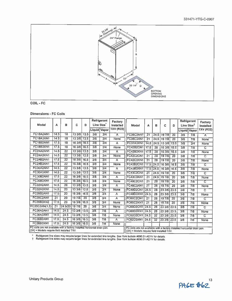
COIL-FC
Dimensions - FC Coils
Refrigerant Factory . Model A B C D Line Size Installed
Liquid Vapor TXV(R22)
FC18A2AN1 14.5 18 13 3/8 13.5 3/8 3/4 A FC18A3XN1 14 5 18 13 3/8 13.5 3/8 3/4 None FC1882AN1 17.5 18 16 318 16.5 318 3/4 A FC1883XN1 17.5 18 16 318 16.5 3/8 314 None FC24A2AN1 14.5 22 13 3/8 13.5 3/8 3/4 A FC24A3XN1 14.5 22 13 318 13.5 3/8 3/4 None FC2482AN1 17.5 22 16 3/8 16.5 318 3/4 A FC24B3XN1 17.5 22 16 3/8 16.5 318 3/4 None FC30A2AN1 14.5 22 13 318 13.5 3/8 3/4 A FC30A3XN1 14.5 22 13 3/8 13.5 3/8 3/4 None FC3082AN1 17.5 22 16 3/8 16 5 318 314 A FC3083XN1 17.5 22 16 3/8 16 5 3/8 314 None FC32A2AN1 14.5 20 13 3/8 13.5 318 314 A FC32A3XN1 14.5 20 13 3/8 13.5 3/8 3/4 None FC35B2AN1 17.5 20 16 3/8 16.5 3/8 3/4 A FC35C2AN1 21 20 19 7/8 20 3/8 3/4 A FC35B3XN2 17.5 20 16 3/8 16.5 3/8 3/4 None
FC35C3XN(1,2} 21 24.5120 19 7/8 20 3/8 3/4 None FC36A2AN1 14.5 245 13 318 13.5 3/8 7/8 A FC36A3XN1 14.5 245 13 3/8 13 5 3/8 7/8 None FC36B2AN1 17.5 24 5 16 318 16 5 3/8 718 A FC36B3XN1 17.5 245 16 318 16.5 3/8 718 None
Model
FC36C2AN1
FC36C3XN1
FC37A3XN1
FC4282CN1
FC4283XN1
FC42C2CN1
FC42C3XN1
FC43B2CN1
FC43B3XN1
FC43C2CN1
FC43C3XN1
FC48C2CN1
FC48C3XN1
FC48D2CN1
FC4803XN1
FC60C2CN1
FC60C3XN1
FC6002CN1
FC6003XN1
FC6202CN1
FC62D3XN1
BOTTOM OPENING DIMENSIONS
A B C
21 24.5 19 7/8
21 24.5 19 7/8
14.5 24.5 13 3/8
17.5 28 16 318
17.5 28 16 3/8
21 28 19 718
21 28 19 7/8
17.5 24.5 16 3/8
17.5 24.5 16 3/8
21 24.5 19 7/8
21 24.5 19 7/8
21 28 19 7/8
21 28 19 7/8
24.5 28 23 318
24.5 28 23 3/8
21 28 19 7/8
21 28 19 718
24.5 28 23 318
24.5 28 23 3/8
24.5 32 23 3/8
24.5 32 23 3/8
D
20
20
13.5
16.5
16.5
20
20
16 5
16.5
20
20
20
20 23.5
23,5
20
20 23 5
23 5
23.5
23.5
331471-YTG-C-0907
Refrigerant Factory Line Slzet Installed
Liquid Vapor TXV(R22)
3/8 7/8 A 3/8 7/8 None 3/8 3/4 None 318 718 C 318 7/8 None
318 7/8 C
318 7/8 None
318 7/8 C
318 7/8 None
3/8 718 C 3/8 7/8 None
318 7/8 C
318 7/8 None
3/8 7/8 C
3/8 718 None
3/8 7/8 C
3/8 7/8 None
318 7/8 C
318 7/8 None
3/8 7/8 C
3/8 718 None
FC coils are not available with a factory Installed horizontal drain pan. (JX) = Models require field installed TXV,
FC calls are not available with a factory Installed horizontal drain pan, (JX) = Models require field Installed TXV.
Refrigerant line sizes may require larger lines for extended line lengths, See York bulletin #690.01·AO1V for details, t Refrigerant line sizes may require larger lines for extended line lengths. See York bulletin #690,01•AD1V for details,
Unitary Products Group
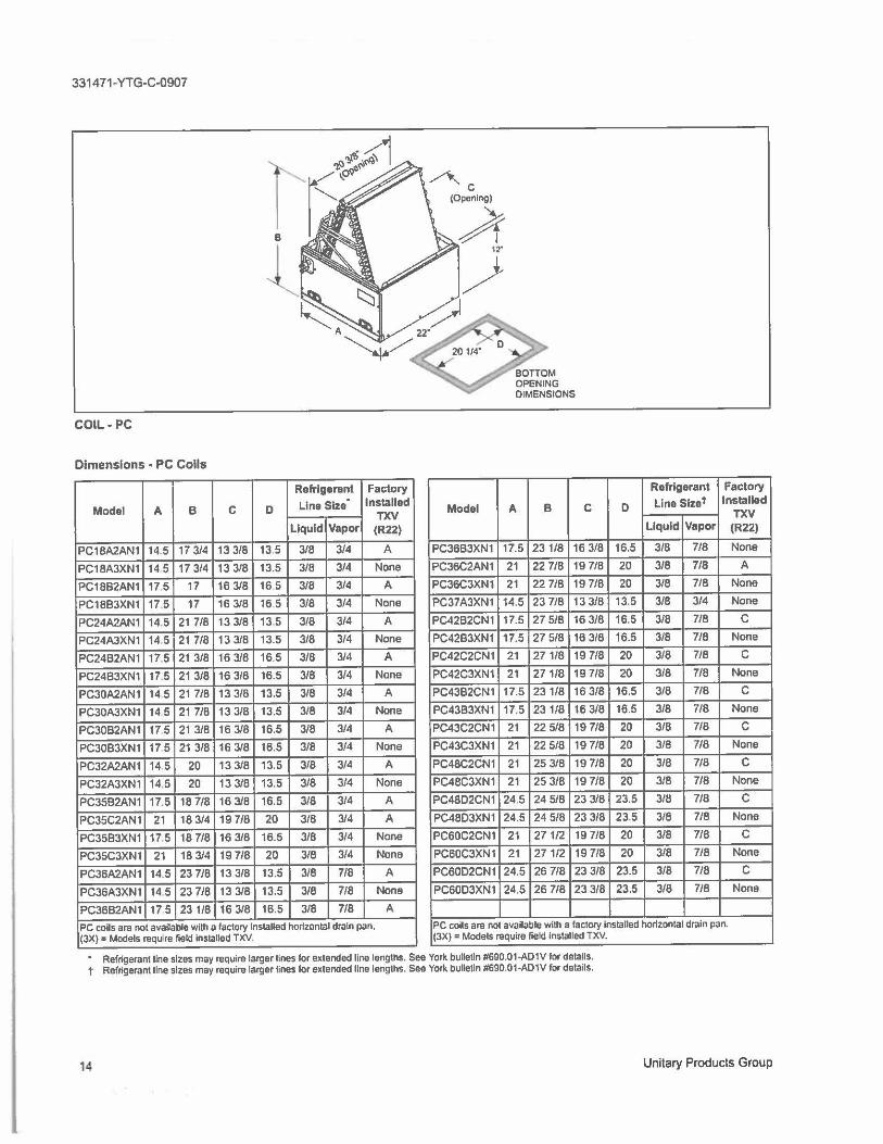
331471-YTG-C-0907
COIL-PC
Dimensions - PC Coils
Refrigerant Factory
Llne Size . Installed
Model A B C D TXV
Refrigerant Factory
Model A B C D Line Slzet Installed TXV
Liquid Vapor (R22) Liquid Vapor (R22)
PC18A2AN1 14.5 17 3/4 13 3/8 13.5 3/8 3/4 A PC3683XN1 17.5 23 1/8 16 3/8 16.5 3/8 718 None
PC18A3XN1 14 5 17 3/4 13 3/8 13.5 3/8 3/4 None PC36C2AN1 21 22 7/8 19 7/8 20 3/8 7/8 A
PC1882AN1 17.5 17 16 3/8 16 5 3/8 3/4 A PC36C3XN1 21 22 7/8 19 7/8 20 3/8 7/8 None
PC1883XN1 17.5 17 16 3/8 16 5 3/8 3/4 None PC37A3XN1 14.5 23 7/8 13 3/8 13.5 3/8 3/4 None
PC24A2AN1 14.5 21 7/8 13 3/8 13 5 3/8 3/4 A PC4282CN1 17.5 27 5/8 16 3/8 16.5 3/8 7/8 C
PC24A3XN1 14,5 21 7/8 13 3/8 13.5 3/8 3/4 None PC42B3XN1 17.5 27 5/8 16 3/8 16.5 3/8 7/8 None
PC24B2AN1 17.5 21 3/8 16 3/8 16.5 3/8 3/4 A PC42C2CN1 21 271/8 19 7/8 20 3/8 7/8 C
PC24B3XN1 17.5 21 3/8 16 3/8 16.5 3/8 3/4 None PC42C3XN1 21 271/8 19 7/8 20 3/8 7/8 None
PC30A2AN1 14 5 21 7/8 13 3/8 13.5 3/8 3/4 A PC4382CN1 17.5 231/8 16 3/8 16.5 3/8 7/8 C
PC30A3XN1 14 5 21 7/8 13 3/8 13.5 3/8 3/4 None PC4383XN1 17.5 23 1/8 16 3/8 16.5 3/8 7/8 None
PC30B2AN1 17 5 21 3/8 16 3/8 16.5 3/8 3/4 A PC43C2CN1 21 22 5/8 19 7/8 20 3/8 718 C
PC3083XN1 17 5 21 3/8 16 3/8 16.5 3/8 3/4 None PC43C3XN1 21 22 5/8 19 7/8 20 3/8 718 None
PC32A2AN1 14.5 20 13 3/8 13.5 3/8 3/4 A PC48C2CN1 21 25 3/8 19 7/8 20 3/8 7/8 C
PC32A3XN1 14.5 20 13 3/8 13.5 3/8 3/4 None PC48C3XN1 21 25 3/8 19 7/8 20 3/8 7/8 None
PC35B2AN1 17.5 18 7/8 16 3/8 16.5 3/8 3/4 A PC48O2CN1 24.5 24 5/8 23 3/8 23.5 3/8 7/8 C
PC35C2AN1 21 18 3/4 19 7/8 20 3/8 3/4 A PC48O3XN1 24.5 24 5/8 23 3/8 23.5 3/8 7/8 None
PC3583XN1 17,5 18 7/8 16 3/8 16.5 3/8 3/4 None PC60C2CN1 21 271/2 19 7/8 20 3/8 7/8 C
PC35C3XN1 21 18 3/4 19 7/8 20 3/8 3/4 None PC60C3XN1 21 271/2 19 7/8 20 3/8 7/8 None
PC36A2AN1 14.5 23 7/8 13 3/8 13.5 3/8 7/8 A PC60O2CN1 24.5 26 7/8 23 3/8 23.5 3/8 7/8 C
PC36A3XN1 14 5 23 7/8 13 3/8 13.5 3/8 7/8 None PC60O3XN1 24.5 26 7/8 23 3/8 23.5 3/8 7/8 None
PC3682AN1 17 5 23 1/8 16 3/8 16.5 3/8 7/8 A
PC coils are not available with a factory Installed horizontal drain pan. PC coils are not available with a factory installed horizontal drain pan. (3X) = Models requ re field insta11ed TXV. (JX) = Models require field installed TXV.
• Refrigerant line sizes may require larger lines for extended line lengths. See York bulletin #690.01-ADW for details. t Refrigerant line sizes may require larger lines for extended line lengths. See York bulletin #690.01-ADW for details.
14 Unitary Products Group
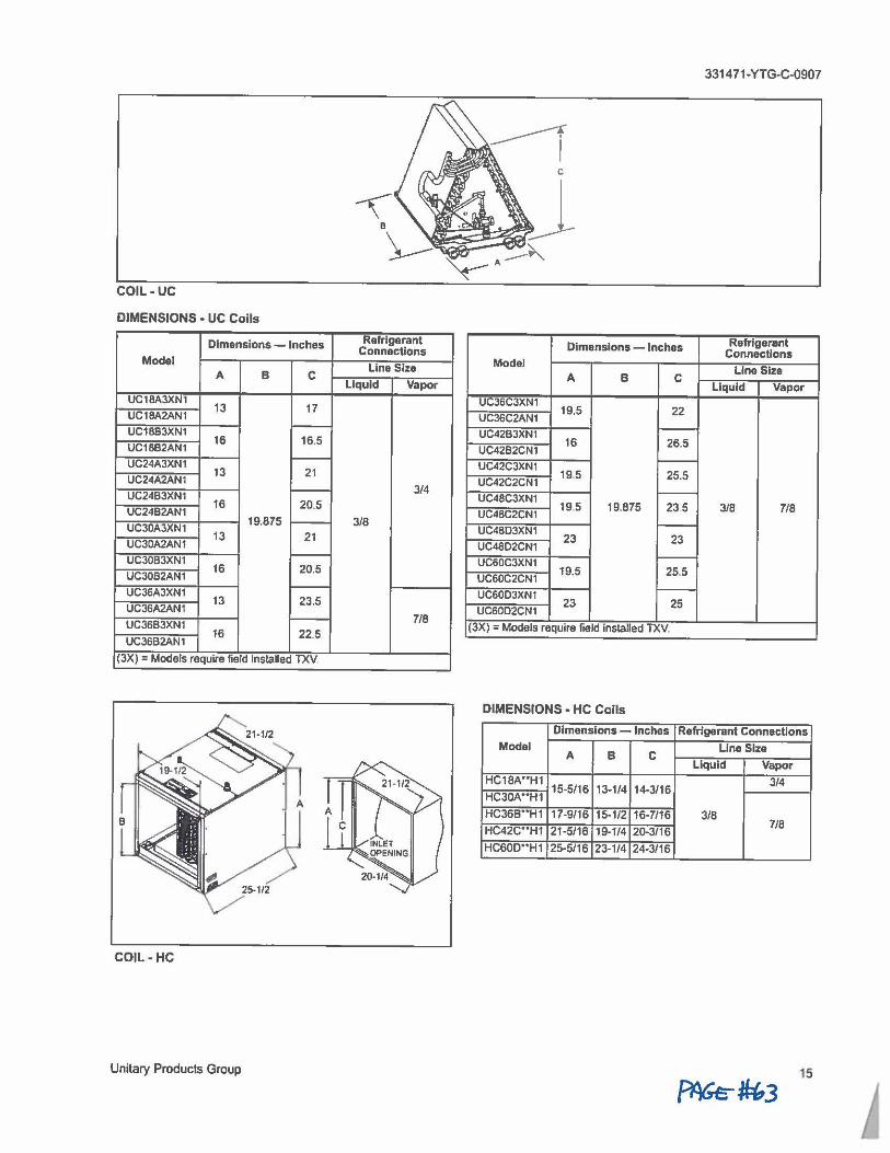
331471-YTG-C-0907
COIL-UC
DIMENSIONS • UC Coils
Dimensions - Inches Refrigerant Connections
Model Line Size
A B C Liquid Vapor
Dimensions - Inches Refrigerant Connections
Model Line Size A B C
Liquid Vapor UC18A3XN1
13 17 UC18A2AN1
UC36C3XN1 19.5 22 UC36C2AN1
UC18B3XN1 -UC18B2AN1
16 16.5 UC42B3XN1 -UC4282CN1
16 26.5
UC24A3XN1 ,___
13 21 UC24A2AN1
3/4 -UC2483XN1 16 20.5
UC24B2AN1 19.875 3/8 UC30A3XN1 .----
UC30A2AN1 13 21
UC42C3XN1 -UC42C2CN1
19.5 25.5
UC48C3XN1 ,___
19 5 19.875 235 3/8 7/8 UC48C2CN1
UC48O3XN1 t----
23 23 UC48D2CN1
UC30B3XN1 16 20.5
UC30B2AN1 UC60C3XN1 ~
UC60C2CN1 19.5 25.5
UC36A3XN1 -13 23.5
UC36A2AN1 7/8
UC3683XN1 i---
16 22.5 UC36B2AN1
UC60D3XN1 -UC60D2CN1
23 25
(3X) = Models require field Installed TXV.
(JX) = Models require field Installed TXV
DIMENSIONS - HC Coils
Dimensions - Inches Refrigerant Connections Model
B C Line Size
A Liquid Vapor
HC18A*'H1 15-5/16 13-1/4 14-3/16
3/4 HC30A .. H1
HC36B' *H1 17-9/16 15-1/2 16-7116 3/8 7/8
HC42C**H1 21-5/16 19-1/4 20-3/16
HC60D'*H1 25-5/16 23-1/4 24-3/16
COIL-HC
Unitary Products Group 15
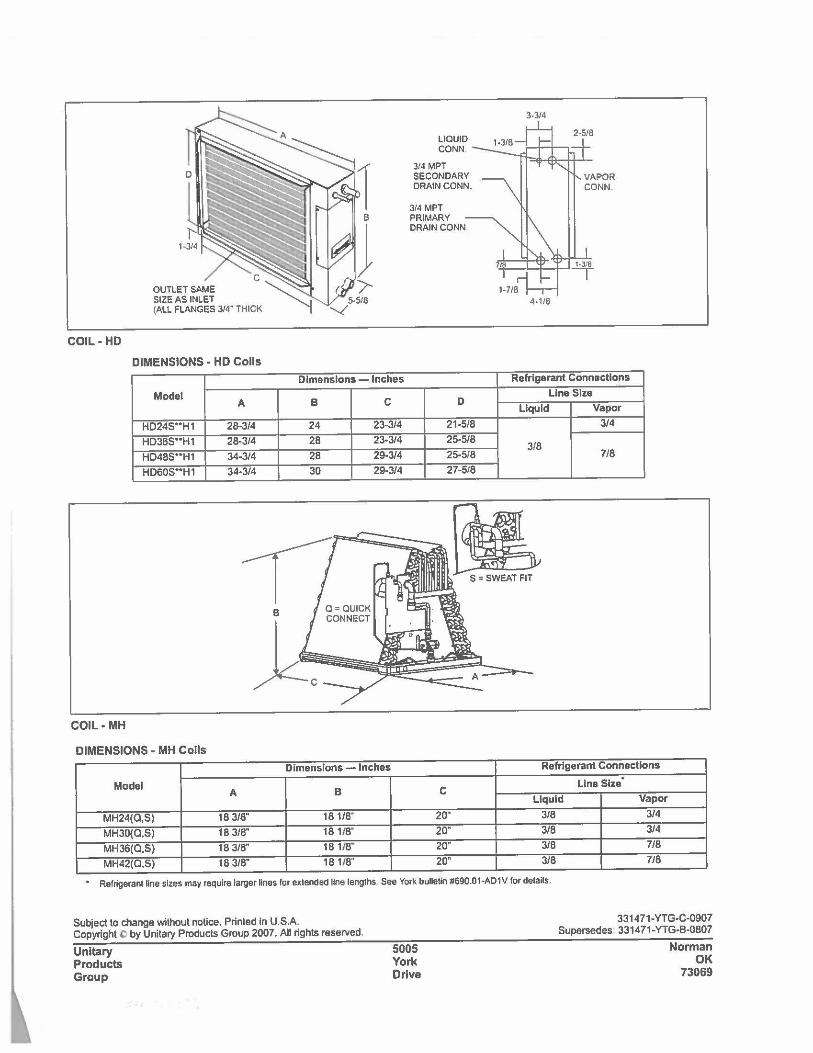
3-3/4
LIQUID CONN.
3/4 MPT SECONDARY DRAIN CONN.
314 MPT PRIMARY DRAIN CONN
l•J/8
I 4-1/8
COIL-HD
DIMENSIONS· HD Coils
Dimensions - Inches Refrigerant Connections
Model A B C D
Lina Slze
Liquid Vapor
HD245 .. H1 28-3/4 24 23-3/4 21•5/B 3/4
HD365 .. H1 28-3/4 28 23-314 25-5/B 3/8
HD4BS .. H1 34-314 28 29-314 25-518 7/B
HD60S**H1 34-314 30 29-3/4 27-518
COIL•MH
DIMENSIONS - MH Coils Dimensions - Inches Rafrlgarant Connections
Model Line Size .
A B C Liquid Vapor
MH24(0,S) 18 318" 18 110· 20" 318 3/4
MH30(0,S) 18 3/8" 18 1/8" 20" 3/8 3/4
MH36(Q,S) 18 3/8" 18 110· 20" 3/8 718
MH42(0,S) 18 3/8" 18 1/8" 20" 318 718
• Refrigerant line sites may require larger lines for extended llne lengths. See York bulletin #690.01-A01V for details,
Subject to change without notice. Printed in U.S.A. Copyright Q by Unitary Products Group 2007. All rights reserved.
Unitary Products Group
5005 York Drive
331471-YTG-C-0907 Supersedes 331471-YTG-B-0807
Norman OK
73069
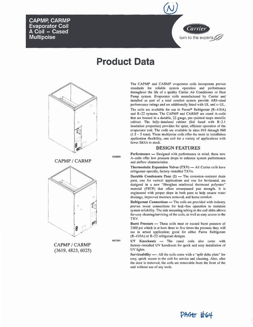
CAPMP, CARMP Evaporator Coil A Coil - Cased Multi poise
CAPMP / CARMP
I , B r
,i·
CAPMP / CARMP (3619,4823,6025)
,,
♦i&-turn to the expe~
Product Data
A07904
The CAPMP and CARMP evaporator coils incorporate proven standards for reliable system operation and performance throughout the lire of a quality Carrier Air Conditioner or Heat Pump system. Evaporator coils manufactured hy Carrier and installed as part of a total comfort system provide ARI-rated performance ratings and are additionally listed with UL and c-UL.
The coils are available for use in Puron® Refrigerant (R-410A) and R-22 systems. The CAPMP and CARMP are cased A-coils that are housed in a durable, 22 gauge, pre-painted taupe metallic cabinet. The fully-insulated cabinet (foil faced with R-2.1 insulation properties) provides for quiet, efficient operation of the evaporator coil. The coils are available in sizes 018 through 060 ( 1.5 - 5 tons). These multipoise coils offer the most in installation application nexibility, one coil for a variety of applications with fower SKUs to stock.
DESIGN FEATURES Perfonnnnce - Designed with performance in mind, these new A-coils offer low pressure drops to enhance system performance and airflow characteristics.
Thermostalic Expansion Valves (TXV) - All Carrier coils have refrigerant-specific, factory-installed TXVs.
Durable Condcnsnle Pans (?) - The corrosion-resistant dmin pans, one for vertical applications and one for horizontal, are designed in a new "fiberglass reinforced thermoset polyeslt:r" material (FRTP) that offt:rs unsurpassed pan strength. It is t:ngineered with proper slope in both pans lo help ensure water drainage, improved moisture removal, and home comfort.
Refrigerunt Conm.'Clions - The coils are provided with industry proven sweat connections for leak-free operation to maintain system reliability. The side mounting tubing to the coil slabs allows for easy cleaning/servicing of the coils, as well as easy access to the TXV.
Burst Pressure - These coils meet or exceed burst pressure of :?100 psi which is at least three to five times the pressure they will see in actual application; good for either Puron Refrigerant (R-4 IOA) or R-22 refrigerant designs.
UV Knockouls - The cased coils also come with factory-installed UV knockouts for quick and easy installation of UV lights.
Scrviceabilily -- All the coils come with a "split delta plate" for easy, quick at-cess to the coil for service and cleaning. Also, after the door is removed, the coils are removable from the front of the unit without use of any tools.
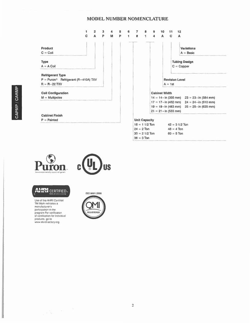
MODEL NUMBER NOMENCLATURE
1 2 3
C A p
Product C "' Coil
Type
A • ACoil
Refrigerant Type
P ., Puron' Refrigerant (R-410A) TX~ A • R- 22TXV -- --Coll Configuration
M "' Multipoise
Cabinet Finish P .. Painted
4
M
J
~ Puron .. c@us /&UDI -. •••• CERTIFIED-
c •-- ~~ .H ,,,q
Use of tho AHAi Certified TM Marl< md cales a manufacturers partlc1pa110n in lhe program For vorificat1on of cortd,c:ation for individual products go to www nh11directo,y.org
ISO 9001 2000
s p
6
1 7
8
8
1 9 10 11 12 4 A C A
J Variations A • Basic
I Tubing Design C • Copper
l
I Revision Level l A ,. 1st
Cabinet Width 14 = 14- ln (356 mm) 23 : 23- in (584 mm)
1 17 .,. 17- ln (432 mml 24 ,. 24- in (610 mml 19 • 19- ln (483 mm) 25 • 25- in (635 nvn)
L2t • 21 - in (533 mm)
I Unit Capacity
18 • 11/2Ton 24 ~ 2Ton
42 -. 3 1(2 Ton
48 = 4 Ton 30 = 21/2Ton
36 • 3Ton 60 • 5Ton
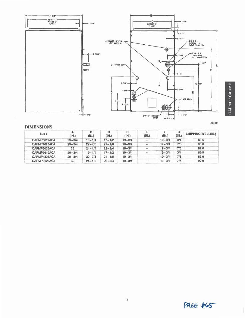
rE.~;:',:·. OIIISIK <I
llt.lGII
-------..... •
l )IW
----------------· ::,_,, ..
DIMENSIONS
I UNIT --(1:.)
r-CAPMP3619ACA 29-3/4 CAPMP4823ACA 29-3/4-~PMP6025ACA 35 CARMP3619ACA 29-3/'i CARMP4823ACA --¼ 29-3/4 CARMP6025AC=-A __ ...__3_5_
t
B (IN.)
19-1/4 22-7/8 24-1/4 19-1/4 22-7/8 24-1/2 ----
D
C l (IN.)
21-1/8 22-3/4
- 17-1/2 -21-1/8 22-3/4 -
-----c-----1
D l (IN.)
OIIISIK (I IUIIGII
E (IN.)
I 0 IUCIIO• Ll■l IIIAT co■•[CIIOI
IJ u•
E
A
F
A07811
,.~.) (I~.) I SHIPPING WT. (LBS.)
W-3/4 19-3/4 ~--- --ii-~-i-l:_
4
_ r~ r~i-~ ... 19-3/4 1 19-3/4 19-3/4 19-3/4 -
-t-t==-----=~--1,,,9_- -=-3/,...4 7/8 83.0 -j ~ 9-3/4 7/6 97 0
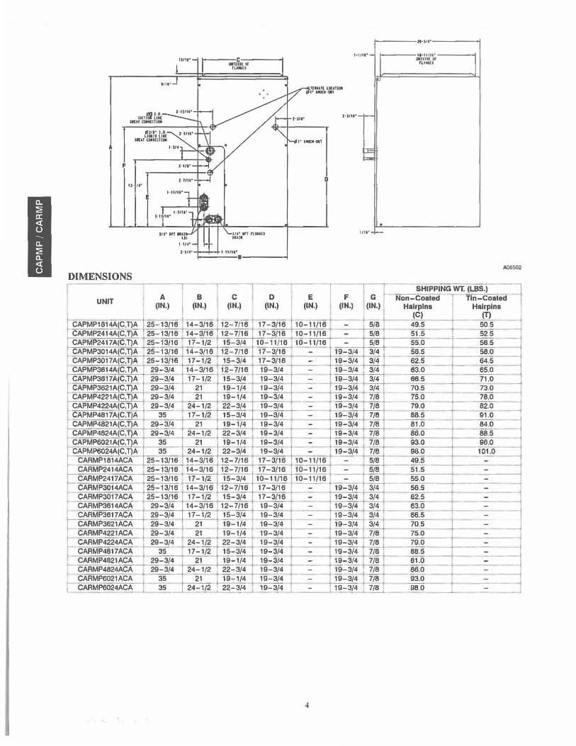
F
E
I I"'
DIMENSIONS
---c----OlfllN W ,u11n
'"' ,,r n••• ... 1,
... , ...
____ ,..,,.•-----! 1-111•· - 1-----ll•tl lll'----t
0,111K d I fLHtU
,.,,,. .. __
UH'•~
I ---r - l l :-T SHIPPING WT. (LBS.) ~ UNIT A B C D E F G Non-Coated - Tin-Coated
(IN.) I (IN.) (IN.) (IN.) I (IN.) l (IN.) (IN.) I Ha:i,;n• Ha~lns PMP181-4A~(~C~,T}~A.,-+---,2-,-5- 13/16 14-3/16 12- 7/16 1 17- 3/16 ~ 10-11/16 5/8 49.5 - ~ --! PMP2414A(C.T)A · 25- 13/16 14-3/16 , 12- 7/16 17- 3/16 110-11/16 - 5/8 si':5 525
PMP2417A(C,TJA • 25-13/16 ' 11-112 ' 15- 31• 10-W,o 1 10-11110 I - 5/0 55.o E SB 5 ~ CAPMP3014A(C,T}A 25- 13/16 14-3/16 12- 7116 17- 3/16 - 19-3/4 3/4 · 56.5 58.0 CAPMP3017A(CJ)~ 25_::13/16 17-1/2 . 15- 3/4 , 17- 3/16 - 19-3/4 3/4 62.5 64.5 CAPMP3614AC,T}A 1 29-3/4 14~ 12-7/16 19-3/4 1
- 19-3/4 3/4 ~ O ----+=-- 65.0 CAPMP3617A(C,T}~ 29-3/4 17-1/2 15-3/4 ~ 19-3/4 -..=_ 1~ 3/4 66.5 ---+ l_ 71 .0 CAPMP3621A(C,T}A 29-3/4 ~ 19-1/4 19-3/4 " 19-3/4 3/4 70.5 _J_ 73.0 i CAPMP4221A(C,T)A 29-3/4 21 19-1/4 19-3/4 19-3/4 ija 75.0 I 78.0 -1 CAPMP4224A(C,T}~ ! ~ 24-1/2 22-3/4 19-3/4 19-3/4 7/8 79.0 == 82.o ~
, CAPMP4817A(C,l)A 4 35 11-112 I 15-3/4 19-3/4 19-3/4 7/8 t 88.5 I 91.0 --1 CAPMP4821A(C,T)A 29-3/4 21 19-1/4 19-3/4 19-3/4 7/8 81 .0 84.0
CAPMP4824A(C,!l.A 29-3/4 24-1/2 22-3/4 1 19-3/4 19-3/4 7/8 1" 86.0 - 88.5 CAPMP6021A(C,T}A 35 _ 2_1 _ ' 19-1/4 , 19-3/4 ' Th'=3!4 t 7/8 93.0 _ _
19061.o_O ~
MP6024A(C,T}A 35 24-1/2 22-3/4 ' 19-3/4 19-3/4 7/8 98.0 ARMP1814ACA ~ 2~-~~-3/16 12-7/16 17-3/16 10-11/16 , =- ~ 5/8 49.5 ; _j ARMP2414ACA l 25-l 3/16 14-3/16 ~--7/16. 17-3/16 ~ 1/16 ♦ _ -_ , 5/8 ,i. 51.5 ~--------ARMP2417ACA 25-13/16 ~ 17-1/2 15-3/4 10-11/16 10-11/16 - 5/8 . 55.0 1
CARMP3014ACA : 25-13/16 • 14-3/16 • 12-7/16 17-3/16 ,--_- • 19-3/4 ~ 56.5 I ,- CARMP3017ACA 25-13/16 17-1/2 15-3/4 17-3/16 • - 19-3/4 3/4 62.5 -~---=:----_-_-_..
CARMP3614ACA 29-3/4 14-3/16 12-7/16 19-3/4 19-3/4 3/4 63.0 --t CARMP3617ACA 29-3/4 17-1/2 15-3/4 I 19-3/4 - 19-3/4 3/4 ~ -~ 1 g-
~ ARMP3621ACA _ 29-3/4 21 19-1/4 • 19-3/4 +--- 19-3/4 j 3 /4 70.5 ---=- -=-
r CARMP4221ACA ~ 29-3/i 21 19-1/4 19-3/4 - 19-3/4 7/8 75.0 CARMP4224ACA . 29-3/4 ; 24-1/2 22-3/4 19-3/4 - _-
1 19-3/4 - 7/8 79.0
CCAARRMMPP48482
171
AACCAA--; 29
: 5314
! 17-1/2 1~-3/4 19-~ 4 - I 19-3/4 7/8 t- 88.5 - ---_=-1
21 I 19-1/4 19-3/4 1 ~ -- 19-3/4 7/8 81.0 ~ RMP4824ACA 29...:314 24-1/2 22-3/4 19-3/4 19-3/4 I 7/8 86.0 I
CARMP6021ACA j_ 35 -21 . 19-1/4 19-3/4 19-3/4 ~ 93.0 t-----1 CARMP6024ACA 35 24-1/2 ._. 22-~ 4 _. 19-~ -= j 19-3/4 7/8 t- 98.0 ____.__ _ _;_~ _ _j
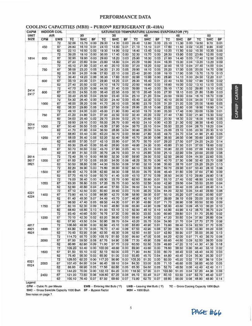
PERFORMANCE DATA
COOLING CAPACITIES (MBH) - PURON® REFRIGERANT (R-410A) ~===== ~PM j-lNDOOR COIL ---- --SATURATED TEMPERATURE LEAVING EVAPORATOR l~ _ - --,
I UNIT AIR 30 3S 40 45 ____J ~ ~ SIZE c"Fii EWB TC sHc BF TC SHC BF ~"fi:: -sifc- BF tc -.slfc , BF 1'c - sHc- BF
12 32.00 15.10 o.oo 29.30 14.30 o.oo 26.40 12.80 o.oo 23.10 ··1T i.30 ' ooo
119.50 9.7o ' oo~
1814
t ~ 7
3014 3017
3614 3617 3621
450 fi 26.80 16.10 0,01 24.10 14.60 0 .01 21 .10 13.10 0.01 17.80 11-:-50 cfo2 14.20 9.90 ·0:02 2 22.10 16.50 0 .02 19.30 14.90 0 .02 16.40 13.40 0 .02 13.20 11.80 0.02 10.30 10.30 0.05 2 39.20 19.10 0.00 36,00 17.40 0.00 32.30 15.70 0.00 28.30 13.90 0.02 23.80 12.00 0.02
600 1-66
21 32.90 10.90 o.o3 29.60 18.20 o.o3 25.90 16.30 o.o3 21.eo 14.40 0:.03 11.40 12.scr o.o3 :
27.20 20.60 0 .04 23.80 18.80 0.04 20.20 16.90 0 .04 16.30 15.00 0.04 13.20 13.20 0.09 i - --=t2 45.10 21.90 0 .00 41.40 20.10 0 .00 37.20 18.20 0 .02 32.60 16.10 0 .04 27.40 14.00 004 1
750 . 67 38.00 23.20 0.05 34.20 21.20 0.05 29.90 19.10 0.05 25.20 17.00 0.05 20.00 14.70 006
t- 62 31 .50 24.20 0.06 27.60 22.10 0 .06 23.40 20.00 0.08 19.10 17.90 0.06 15.70 15.70 0.13 72 39.40 19.20 0 .00 36.30 17.60 0 ,00 32.80 15.90 0 .00 28,90 1 4.10 0.00 24.50 12.20 0.01
600 -W- 33.10 20.00 0 .01 29.90 18.20 0.01 26.30 16.40 0 .01 22.40 14.50 0.02 17.90 12.60 0.02 62 27.40 20.50 0 .02 24.10 18.70 0.02 20.50 16:90 0.02 16.60 15.oo 0.02 13.10 13.10 o.o5
-, - 72 47.70 23.20 0,00 44.00 21.40 0 .00 39.80 19.40 0.00 35.10 17.30 0.02 29.80 15.10 0.02 800 t-"e7 40.30 24.50 0 .03 36.40 22.50 0.03 32.10 20.40 0.03 27.30 18.10 0.03 21.80 15.80 0.03
62 33.40 25.50 0 .04 29.50 23.40 0.04 25.10 21 .20 0 .04 20.50 19.00 0.04 16.70 16.70 0.09 72 54.30 26.40 0 .00 50.20 24.40 0 .00 45.40 22.30 0.02 40.10 20.00 0.04 34.00 17.50 0.04
000 67 46,00 28.20 0 .05 41 .70 26.10 0 .05 36.80 23.70 0.05 31.20 21.20 0.05 25.00 18.60 0.05 62 38.30 29.80 0 .05 33.80 27.50 0.08 28.90 25.10 0 .06 23.80 22.60 0.06 19.90 19.90 0.14 72 49.10 24.00 0 .00 45.00 21 .90 0.00 40.50 19.70 0 .00 35.50 17.40 0.00 30.00 15.00 0.01
750 87 41 .20 24.80 0.01 37.00 22.50 0 .02 32.40 20.20 0.02 27.40 17.80 0.02 21 .90 15.30 0.02 62 34.00 25.40 0.02 29.70 23.00 0.02 25.10 20.60 0 .02 20.30 18.30 0.02 16.00 16.00 0.06 ~ 59.90 29.10 0 .00 55.00 26.70 0.00 49.50 24.10 0.00 43.30 21.30 0.02 36.50 18.40 0.03
000 67 50.40 30.50 0 .03 45.30 27.90 0.04 39.70 25.10 0 .04 33.50 22.20 0.04 26.70 19.20 0.04 62 41 .70 31.60 0.04 36.50 28.80 0.04 30.90 26.00 0.04 25.00 23.10 0.05 20.30 20.30 0 .10 72 68.80 33.40 0.00 63.20 30.70 0.00 56.80 27.80 0.03 49.70 24.70 0.04 41.90 21.40 0.05
250 67 58.00 35.40 0 .06 52.20 32.40 0.06 45.70 29.30 0.06 38.50 26.00 0.06 30.60 22.60 0.07 62 48.00 37.00 0.07 42.10 33.90 0 .07 35.70 30.70 0 .07 29.20 27.50 0.07 24.20 24.20 0.14 72 60.30 29.40 0.00 55.40 26.90 0.00 49.90 24.30 0.00 43.80 21.50 0.01 37.00 18.60 0 .02
900 67 50.70 30.60 0.02 45.70 27.90 0.03 40.10 25.10 0.03 33.90 22.20 0.03 27.00 19.20 0,03 62 41.90 31.50 0 .03 36.70 28.70 0,03 31.10 25.80 0.03 25.10 22.90 0.04 20.00 20.00 0.08 72 72.40 35.10 0 .00 66.50 32.30 0 .00 59.90 29,30 0.02 52.50 26.00 0.04 44.30 22.60 0 .05
200 67 61.00 37.10 0.05 55.00 34.00 0.06 48.20 30.70 0.08 40.70 27.30 0 .06 32.40 23.70 0 .06 62 50.50 38.80 0.06 44.30 35.50 0.06 37.60 32.10 0.06 30.60 28.70 0.07 25.20 25.20 0.13
' ·+-500 I 1050
72 82.20 39.90 0 .00 75.60 36.90 0 .02 68.10 33,50 0 05 59.70 29.90 0.07 50.40 26.10 0.08 67 69.40 42.70 0.08 62.60 39.30 0.08 55.00 35.70 0 .08 46.40 31.80 0.09 37.00 27.80 0 .09 62 57.70 45.10 0.09 50.70 41 .40 0.09 43.10 37.70 0.09 35.50 34.00 0 .10 29.80 29.80 0 .18 72 75.00 36.40 0.00 69.30 33.70 0 .00 62.60 30.60 0:01 55.10 27.40 0.02 46.90 24.00 0.03 67 63.30 38.80 0.03 57.20 35.70 0 ,03 50.50 32.50 0.03 42.90 29.00 0.04 33.50 25.00 0 .04
E 4817 4821 4824
400
750
200
f- 62 52.60 40.80 0 .04 46.40 37.60 0 .04 39.50 34.10 0.04 32.00 30.40 0.05 26.40 26.40 0 .14 72 87.10 42.50 0.00 80.60 39.50 0.03 73.00 36.20 0.04 64.20 32.50 0 .05 54.40 28.60 0.08 67 73.80 48.10 0.06 66.90 42.70 0.08 58.90 39.00 0.07 50.10 35.20 0.07 40.00 3090 0.07 62 61 .40 49,30 0.07 54.40 45.70 0.07 46.90 42.10 007 39,00 38.10 0.09 33.00 3300 0.19 72 96.50 47.40 0.05 89.50 44.30 0 .07 81.30 40.80 0-:-01 71.70 36.90 0.08 60.50 32.60- 0 .09 67 82.10 52.30 0.09 74.60 48 80 0 .09 65.90 44.90 0 ,09 t 55.90 40,60 0 .09 45.10 36.20 0.10 62 68.60 56.80 0.10 61.00 5310 0.10 52.90 49.10 0.10 -44.90 44.90 0.12 38.70 38.70 1J:24° ~ 83.40 40.60 o.oo 76 10 ,....31.20 o.oo 69.30 33.60 o.oo ·50:90 29.80 0.01 51.10 25.80 o.ii2'
67 70.10 42.30 0.02 63.20 38.60 0.03 55.60 34.80 0.03 47,20 30.80 0.04 37.80 26.60 0 .04 62 57.90 43.50 0.04 50.90 39,70 0 .04 43.20 35.70 0.04 - 34.90 31 .70 0.04 27.70 27.70 0.08 72 100,80 48.90 0.00 92.80 45.10 0.00 83.80 40,90 0.01 "73.80 36.40 0.04 62.50 31.70 0.05
1600 ~ 84.90 51 .70 0.05 76.70 47.40 0.06 67.50 42.90 0.06 57.30 38.10 0,06 45.90 33.20 0 .08 - ~ 70.40 53.90 0.06 62.00 49.30 0 ,06 52.60 44.60 0:01 l 42.80 39.90 0.07 35.00 · 35.(Xf ~ , _E_ t 114.70 I 55.70 0.00 105.70 51.60 0,00 95.60 47.00 0.05 84,20 42,00 0.07 71 .40 36,70 ~
r 2000 67 97,00 59,50 0.08 87.70 "54,90 0.08 I 77.30 49.90 0,09 65.60 44.60 0.09 52.50 39.00 0,09 · ~ 80.60 · 62.80 o.o9 11 .00 57:io o .o9 60.50 52.50 o.o9 49.60 47.20 0.10 41.30 41.30 0.18°
t 12 i 100.20 5MO o.oo 100.00 48C60 ~ es.eo '3.60 o.oo t 78.60 -..:00 T oo 66.40 33.10 0:0.-1600 67 91.50 55.10 0.02 82,10 50.00 0 ,03 I 71.90 44.80 0.03 60,70 39,40
10,03 48.40 34,00 0 .03
I 62 75.40 56.30 0.03 65.90 51.00 0.03 55.60 45.70 0.04 44.80 , 40.40
11004 35.30 35.30 0 .07
I 6021 t 72 + 128.00 62.20 0.00 117.20 5 690 0.00 105.20 51 .20 O:.~ . 92.00-. 45.2~ 002 77.50 39":10-~ 6024 2000 - 67 110~40 64,90 0,04 96 40 59 10 0.04 I 84,30 53,00 0,05 ~ -t 46,80 0,05 56.60 40,50 ~
I ~ 88.60 66.90 0.05 77.50 60.80 mo.OS ' ~-5.30 54.60 0 .05 ~ 48.50 0:.06 142.40 42.40 2.:.!.!... I E... 144._20 70.00 0.00J.132.10 ! 64.20 0.00 118,50 57,90 0.01 B 03,60 I 51 ,20 0.0_'.' 87.20 1' 44.30 ~
2400 ~ 121 20 73,60 0.06 108.80 f 67.20 0.06 95.10 60.40 0 .07 80.10 53.50 -t0,07~ 46.40 O.:.OI._ E 100.10 ~~1 , 81.~ ...i..60.eo ~ 1 13.~ .... 6~ 0 .01 59.80 56.oo 008 48.90 48.~ 0.14 c___._
Legend CFM - Cubic Ft. per Minute EWB - Entering Wei Bulb ('F)
SHC - Gross Sensible Capacity 1000 Bluh BF - Bypass Fae1or
See notes on page 7
LWB - Leaving Wei Bulb (' F) MBH - 1000 Btuh
s
TC - Gross Coohng Capacity 1000 Btuh
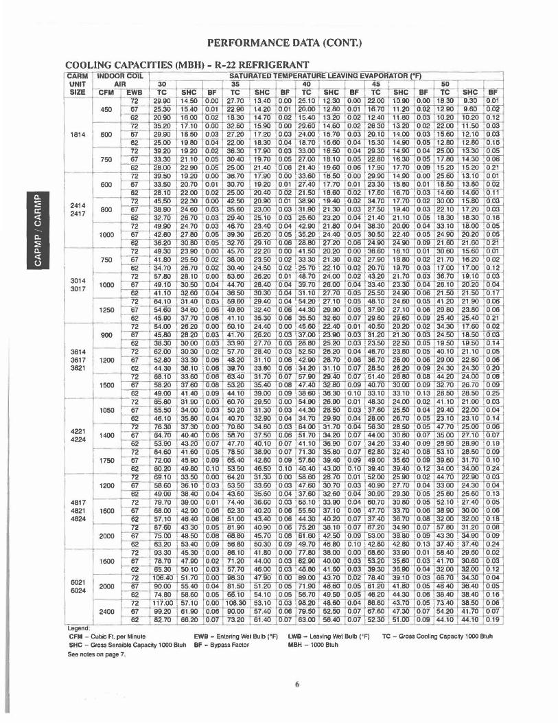
PERFORMANCE DATA (CONT.)
COOLING CAPACITIES (MBH) - R-22 REFRIGERANT ' CARM - INDOOR COIL r. SATURATEDTEMPERATURE-LEAVING EVAPORATOR ("F} UNITf AIR 30 -~~~m 40
45 -r ----so , -SHC4 BF SIZE CFM R'B
- TC- SHC BF TC SHC BF- - TC SHC BF- re i sHc--.,-..eF - re - ~ 0.00 22.00 1830 9.30 : a.of 29.90 14.50 0 .00 27.70 1_£3.40 . 0.00 25.10 12.30 10.90 0.00 450 67 25.30 15.40 0.01 22.90 14.20 0.01 20.00 12.80 0 .01 1670 11 .20 0.02 1290 9.60 0.02
14 70 0 .02 , 15.40 -~
10.20 0-:-12 "
I 1814
62 20.90 18.00 0.02 18.30 13.20 0 .02 1240 11.80 0.03 10.20 ..-72 35.20 17.10 0 .00 32.60 15.90 0.00 29.60 14.60 0.02 2830 13 20 0.02 22.00 1 11.50 ' 0.03 ◄
600 -e1- 29.90 18,50 0.03 27.20 - t 24.00 15.70 0.03 20.10 14.00 - ~ 17.20 0.03 O.O~+J5,60 12.10 0.03 ~ 25,00 19.80 0.04 22.00 18.30 0.04 18.70 16,60 0 ,04 15.30 14.90 0 ,05 12.80 12.80 0.18 - 72 39.20 19,20 0.02 36.30 17.90 0.03 33.00 16.50 0 .04 29.30 14.90 004 25.00 13.30 0.05
) 750 67 33.30 21.10 0 .05 30,40 19.70 0,05 27.00 18.10 0.05 22.80 16.30 005 17.80 14,30 0.06
62 28.00 22.90 0,05 25.00 21 .40 0.08 21 .40 19.60 0.06 17.90 17.70 0.09 15.20 15.20 0 .21 - 72 39.50 19.20 0.00 38.70 17.90 0.00 33.60 18.50 0 .00 29.90 14.90 0.00 25.60 13.10 0.01
~ 67 33.50 20.70 0.01 30.70 19.20 0.01 27.40 17.70 0.01 23.30 15.80 0.01 18.50 13.80 0.02 62 28.10 22.00 0,02 25.00 20.40 0.02 21 .50 18.60 0.02 17.60 16.70 0.03 14.60 14.60 0.11
2414 72 45.50 22.30 0.00 42.50 20.90 0.01 38.90 19.40 0.02 34.70 17.70 0.02 30.00 15.80 0.03 87 38.90 24.60 0.03 35.60 23,00 0.03 31 .90 21.30 0 .03 27.50 19.40 0.03 22.10 17.20 0.03
2417 62 32.70 28.70 0.03 29.40 25.10 0.03 25.60 23.20 0.04 21.40 21.10 0.05 18.30 18.30 0.18
I '1000 72 49.90 24.70 0.03 46.70 23.40 0.04 42.90 21 .80 0.04 38.30 20.00 0.04 33.10 18.00 0.05 67 42.80 27.80 0.05 39.30 26.20 0.05 35.20 24.40 0.05 30.50 22.40 0.05 24.90 20.20 0 .05
H 62 36.20 30.80 0 .05 32.70 29.10 0.06 28.80 27.20 0 ,08 24.90 24.90 0.09 21 .60 21.60 0.21 72 49.30 23.90 0.00 45.70 22.20 0.00 41 .50 20.20 0.00 36.60 18.10 0.01 30.60 15.60 0.01
750 67 41 .80 25.50 0.02 38.00 23.50 0.02 33.30 21.30 0.02 27.90 18.80 0.02 21 .70 16.20 0.02 62 34.70 26.70 0.02 30.40 24.50 0.02 25.70 22.10 0.02 20.70 19.70 0.03 17.00 17.00 0.12 72 57.80 28.10 0.00 53.60 26.20 0.01 46.70 24.00 0.02 43.20 21.70 0.03 36.70 19.10 0.03
3014 1000 67 49.10 30.50 0.04 44.70 28.40 0.04 39.70 28.00 0.04 33.40 23.30 0.04 26.10 20.20 0.04 3017 62 41.10 32.60 0.04 36.50 30.30 0.04 31.10 27.70 0.05 25.50 24.90 0.06 21 .50 21.50 0.17
1-- 72 84.10 31 .40 0.03 59.60 29.40 0.04 54.20 27.10 0 .05 48.10 24.60 0.05 41 .20 21 .90 0.06
I 1250 67 54.60 34.60 0,08 49.80 32.40 0.06 44.30 29.90 0.08 37.90 27.10 0.06 29.80 23.80 0.08
t.oo 62 45.90 37.70 0.08 41 .10 35.30 0.08 35.50 32.60 0.07 29.60 29.60 0.09 25.40 25.40 0.21
~
72 54.00 26.20 0.00 50.10 24.40 0.00 45.60 22,40 0 .01 40,50 20.20 0.02 34.30 17.60 0.02 87 45.80 28.20 0.03 41 .70 26.20 0.03 37.00 23.90 0.03 31.20 21 .30 0.03 24.50 18.50 0.03 62 38.30 30.00 0,03 33.90 27.70 0.03 28.80 25.20 0.03 23.50 22.50 0,05 19.50 19.50 0.14 -3614 72 62.00 30.30 0.02 57.70 28.40 0.03 52.50 28.20 0.04 46.70 23.80 0.05 40.10 21.10 0.05
3617
t 1200 67 52.80 33.30 0.06 48.20 31 .10 0.06 42.90 28.70 0.06 38.70 26.00 0.06 29.00 22.80 0.08
3621 62 44.30 38.10 0.06 39.70 33.80 0 ,06 34.20 31.10 0.07 28,50 28,20 0.09 24.30 24.30 0 ,20 72 68.10 33,60 0.08 63.40 31 .70 0.07 57.90 29.40 0.07 51 .40 26.80 0.08 44.20 24.00 0.08
~-1500 67 58.20 37.60 0.08 53.20 35.40 0.08 47.40 32.80 0.09 40.70 30.00 0.09 32.70 26.70 0.09 I
I 62 49.00 41 .40 0.09 44.10 39.00 0.09 38.60 38.30 0 .10 33.10 33.10 0.13 28.50 28.50 0.25 72 65.80 31 .90 0.00 60.70 29.50 0.00 54.90 26.90 0 .01 48.30 24.00 0.02 41.10 21 .00 0.03
I 1050 67 55.50 34.00 0.03 50.20 31 .30 0.03 44.30 28,50 0.03 37.60 25.50 0.04 29.40 22.00 0 .04 62 46.10 35.80 0.04 40.70 32.90 0.04 34.70 29.90 0.04 28.00 26.70 0.05 23.10 23.10 0.14
4221 [ ,:, 72 76.30 37.30 0.00 70.60 34.60 0.03 64.00 31.70 0 .04 56,30 28.50 0.05 47.70 25.00 0.06 67 64.70 40.40 0.06 58.70 37.50 0.06 51 .70 34.20 0.07 44.00 30.80 0.07 35.00 27.10 0.07
4224 62 53.90 43.20 0.07 47.70 40.10 0,07 41 .10 36.90 0,07 34,20 33.40 0.09 28.90 28.90 0 ,19 ,- 72 84.60 41.60 0.05 78.50 38.90 0,07 71 .30 35.80 0.07 62.80 32.40 0.08 53.10 28.50 0.09
l-- ~ 50
~..,- 72.00 45.90 0.09 65.40 42.80 0.09 57.80 39.40 0.09 49.00 35.60 0.09 39.60 31.70 0.10 ,__._62 60.20 49.80 0.10 53.50 46.50 0.10 46.40 43.00 0 .10 39.40 39.40 0.12 34.00 34.00 0.24
i 72 69.10 33.50 0.00 64.20 31 .30 0.00 58.60 28.70 0.01 52.00 25.90 0.02 44.70 22.90 0 .03
1200 67 58.60 36.10 0.03 53.50 33.60 0.03 47.60 30.70 0.03 40.90 27.70 0.04 33.00 24.30 0 .04
r -er 49.00 38.40 0.04 43.60 35.60 0.04 37.60 32.60 0 .04 30.90 29.30 0.05 25.60 25.60 0.13
4817 --,2 79.70 39.00 0.01 74.40 36.60 0.03 66.10 33.90 0 .04 60.70 30.80 0.05 52.10 27.40 0 ,05 l
4621 1600 67 68.00 42.90 0.06 62.30 40.20 0.06 55.50 37.10 0.06 47.70 33.70 0.06 38.90 30.00 0 .06 4824 62 57.10 46.40 0.06 51.00 43.40 0.06 44.30 40.20 0.07 37.40 36.70 0.08 32.00 32.00 0 .18 --~ 87.60 43.30 0.05 81 .90 40.90 0.06 75.20 38.10 0.07 67.20 34.90 0.07 57.80 31 .20 0 .08
l 2000 >- -67 75.00 48.50 0.08 68,80 45.70 0.08 61.60 42.50 0.09 53.00 38.80 0.09 43.30 34.90 0.09 62 63.20 53.40 0.09 56.80 50.30 0 ,09 49.70 46.80 0.10 42.80 42.80 0.13 37.40 37.40 0 .24
I - 72 93.30 45.30 0.00 88.10 41.80 0.00 77.80 38.00 0.00 68.60 33.90 0.01 58.40 29.60 0 .02 1600 "717- 78.70 47.90 0.02 71.20 44.00 0.03 62.90 40.00 0.03 53.20 35.60 0.03 41 .70 30.60 0 .03
- 82 65.30 50.10 0.03 57.70 46.00 0.03 48.80 t 41,60 I 0.03 39.30 36.90 0.04 32.00 32.00 0.12 .,___ 72 106.40 51.70 0.00 98.30 47.90 0,00 78,40 39.10 0.03 66.70 34.30 0 .04
6021 89.00 43.70 0.02
2000 67 90.00 55.40 0.04 81.50 51.20 0.05 71.90 46.60 0.05 61.20 41.80- 0.05 48.40 36.40 0 .05 6024 "72 74.80 58.60 0.05 66.10 54.10 0.05 56.70 49.50 0.05 46.20 44.30 0.06 38.40 38~Me ~ --72 117.00 57.10 0.00 108.30 53.10 0.03 98:.20 ~ 48.60 0.04 86.60 43.70 0.05 73.40 38.50 0 .06
2400 - 67 99.20 61.90 0.06 90.00 57.40 0.06 79.50 . ~ 0.07 67.60 47.30 · 0.07 54.20 41.7~~ I 62 ; 82.70 66.20 0.07 L 73.20 61.40 0.07 63.00 56.40 0~07 52.30 1 51.00 I 0.09 44.10 44.10 0 .19 I -----legend;
CFM - Cubic Ft. per Minute EWB - Entering Wet Bulb ['F) lWB - leaving Wet Bulb ('F) TC - Gross Cooling Capacity 1000 Btuh SHC - Gross Sensible Capac~y 1000 Btuh BF - Bypass Factor MBH - 1000 Btuh
See notes on page 7.
6
NOTES: I. Contacl manufactun:r for cooling capacilies at conditions other than shown in tahle.
2. Formulas: Leaving db = enlering db _ sensible heal cap.
1.()9 x CFM
Leaving wb = wb corresponding to enthalpy of air leaving coil (hLwe)
hLwe = hewo _ total caracity (Bluh)
-'.S x CFM
Where hewo = enlhalpy of air entering coil
3. SHC is based on 80°F db 1empern1ure of air entering the evaporalor coil. Below 80°F db, subtracl (Corre1.1ion Factor x CFM) from SHC. Above 80°F db, add (Correction Factor x CFM) to SHC.
4. Direct interpolation is pennissible. Do not exlrnpolate.
5. Fan motor heat has not been deducted.
6. All data points are based on I 0°F superheat leaving coil and use of thennostatic expansion valve (fXV) device.
7. All unics have sweal suction-tube connection and a liquid-tube connection. For 1- 11'8- in. system suclion tube, 3/4 x 1- 1/8- in. suction tube connection adapter is available as accessory.
8. The CAPMP coils can be used in any properly designed system using Puron Refrigerant (R-4 IOA).
9. The CARMP coils can be used in any properly designed system using R-22 refrigerant.
10. Before using maximum cfm shown in lable, check coil static pressure drop to ensure system blower can provide necessary slatic pressure needed for coil and duct systems.
I I. Bypass Factor= 0 indicales no psychometric solution. Use hypass factor of nexl lower EWB for approximation.
Interpolation is permissible.
BYPASS FACTOR
0.TO 0.20 0.30
Correciion Factor "' 1.09 x (1 - BF) x (db - 80)
I--;;:_ ENTERING AIR DRY ~B TEMPERATURE ( ' F) I 79 T-78 Rr I 76 75 Under 751 BT 82 ~ - 84
1~ ~e!S__j
0.98 0.87 0.76
Correction Factor T.96 2.94 T.74 2.62
~~9
7
3.92 3.49 3.05
4 91 I 4.36 3.82
Use formul~. I shownbelo~
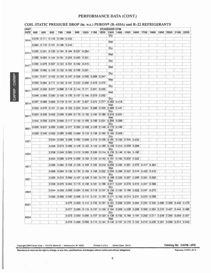
PERFORMANCE DATA (CONT.)
COIL STATIC PRESSURE DROP (in. w.c.) PURON® (R-410A) and R-22 REFRIGERANTS ,UNITk - - -- STANDARDCFM ~~-==--SIZE* 400 I soo eoo l 700 J aoo T 900 1000 ~ 1200-~ 1300 14oo f 1s~o ; 1eoo !1100 _1soo -' 1900 12000 J2100 T220~
Dry
j1BH ;oo19 [0.111 j0.145 ·~ J=l __i::_ ] Wet [ 7 l_ -1 _r_--r_ :I -_j__~
f- o.083 o 116 I 0.151 Jo.196 jo.2'!:!J I ~ =r_ C I --6--~-~ r I l=:L -!2414 0.065 Jo:o9Do.120 ]0.154 Jo.194 0.231 10.284 L ~ - Dr}'. i_:--l._J-~ '_ I 1
, -
Wet --,,.-- -.---.. ----.-- I o.066 o.oe4 @Ff o.~03 10.2so ~ =r_:__ _ r=-r= I C: I . I I --=l
2411 0.0560.016 10.091 [0.123 10.151 :@.182 )0.215 - -r- 1 ° '}' ===r_---i-r-r--1--r-r-1 j 1-----+-o._060 o.~ 10.105 !0.132 10.153 o.195 T0.231 ~ ~ Wet 1 =-_[ -~ i ft }_ 3014 0.054 0.011 _0.102 ro.133 10.1s1 jo.200 10.248 10.296J o.341 -=:T:::-c7= I .J 7 1 ! -
Wet 0059 o.084 10.111 ~0.142 ,o.1a1 J-02ID0~269@ l9@:375J _=r _r __ r=i _r _r_r_-1 __
Dty 3017 0,043 0.059 0.01110.096 i0.119 :0.144 10.111 . 0.201 ,0.232 J - - 1 _! _ __._ ____ 1-·c:r= r=r j
Wet f-- f 046 jo.063 :o.083 }0 .105 j0 .130 :o.1571_o.'feifl0 .219 0.252r:;;:=r _ _ r .1-. __i -T I _!--1 13614 10041 :o.ose )o.oe3 o.11e ~o.151Jo.1af 0221 Jo.21Q 10.311 10.3~2 10.418 I =r - .L r :r_:_ -- :r: --C ~j
h ~ ---~--- ~ ~ - ~- W~e_t ~-~-~-~-------~-1
o.0~~101 10.129 ;0.162 10.200 10.241 10.286.,;_o.332,Jo.388 ;o.441 J I I _ __,_ _ _... _ __,,_--1
~,,.,,,..~ ·"T"~ =-r=-=~~Dry 3617 0.023J0.036 0.052 @:oo!I0.089 0.110 j0.135 I0,160 :o.1s9 10.2wro.2s1 -,- -r -r
Wet o.042 o.058 o.076 o.095 10.111 ' 0.142 jo.169 jo.1es ;-o.231 0.265 jo.2991 _J,_:_-_-_-,.-:_-_-~·-_-__ , __ .,___....__-~T--i
Dry
3621 o 025To.~1 [o.oso ~0.062 [0 .011 !0.092 Jo.1oe Jo.128 10.148 10.110 10.193 i : ] Wet
0.029 o.040 o.053 ~ o.oaf ro:099]0.11e jo.138 10.160 jo.1as o.~ ~ __
14221 1 ~ 44 10.ose j0.068 j0.082 10.099 ~ 0.138 ro~~ 10.1a3 10.205 lo.233 T _r_ J _ ...... T _ _._ Wet
~ }Mss ,0.013 ~0.089 jo.106 :0.125 10.143 10.165 0.189 fo.21~@9 ]0.268- T --..--- C _
1422• _ _lfo3e 10.049 10.oso ~ o.oa5 10.099 10.114 ~ 03 64 ro.102 1 __i _I --.--~ -,- ~ 0.079~.103 ;0.125 j0.142 10.161 !0.182 :0.202 ~ -=r_:: • ~__,__ ____ .:..__._ -i
4817 1 _ L --1£.065 10.oa2 jo.105 _ 0.128 10.156 10.1as10.21s '.o~13 10.200] 0--:331 10.372 1~.417 l o 464 : __. __ [ -; 1 Wet
t t I fo."'6 ,o.084 0.100 [0.1,0 ;0.159 [0.188 [0.222 ;o.256 [o.290 [0.337]0.379 ;o,,s Jo.476 ; r -,-----,
821 =-: :o.oss [0 .012 o.OS9Jo.107To.128Jo.1soJ o:-115 :o~]g 10.22a 10.251 10.288 10.321 o.356 l :===::1 Wet =r= :o.oss 10.015 :o .094 fo.11s [0.136 -0.151 ~.~ -0.241 ~ . o.313 [0.347 :o.3861 _ r.:: 1 ~
4824 '---=:I - ~ 44 0.056 ™-fp.o84 io.100 10.11s _0.131 :o~~e 10.1eo j o.198 0.222 :0.247 jo.215 t j J~_l 1 Wet --, r I 1 0.os2 10.065 '.0 .080 j0.095 0.112 [0.131 I0.150 ;o.!_?1} 0.193J0.214 [0.241 ~0.2701~ -r ~
6021 ~ :T f r_ j0.075 (0.093JD!2)0.133 j0.157 fo~ITT.200 Jo.234 J0.264 j0.294 ~ 0.360 I0,396] 0.43.g_~
Wet "'=""="'"T=-"==-- . t t _L___L_~==r:0.011 o.095 [0.115 _o.131 Jo.1se !0.184 ' o.~ Topa ;o.268 10.300 10.334 [0.370 o.40J o.444 Jo.488 1
6024 _CI_-: To.013 10.083 10.oes Jo.101 o.12o· [email protected] .o.16s 10.154 10.203 10.211 10.238 10.2so 10.2s~ Jo.3o?°'1 Wet ._,J ___ J __ -y- 0 .016 :@>86 :o.09a 10.110 Jo.124 · 0.140 [0.157 Jo.175~ 0":'21510.238 ;0.261 10.286 ~.342 ;
Copyright 2009 C41<fier COfJI • 7310 w. Moms St • Indianapolis. IN 46231 Printed In US A. Edi~on Dalo: 09/10 Catalog No: CAPM-3PD
M■nulaclur■r r■- ■rY■a the right to change, al any lime, ap■clllcall- and -igfl• without natl co and without abMgaUona. Replaces: CAPM-2P 0
8
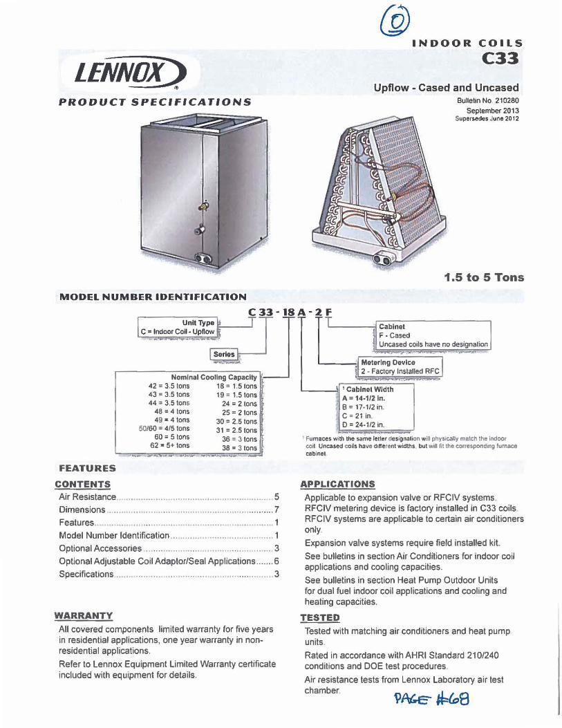
LENNOX) "
PRODUCT SPECIFICATIONS
MODEL NUMBER IDENTIFICATION
@ INDOOR COILS
C33
Upflow - Cased and Uncased Bulletin No 210280
September 2013 Supersedes June 2012
1.5 to 5 Tons
Mdoo, Co~~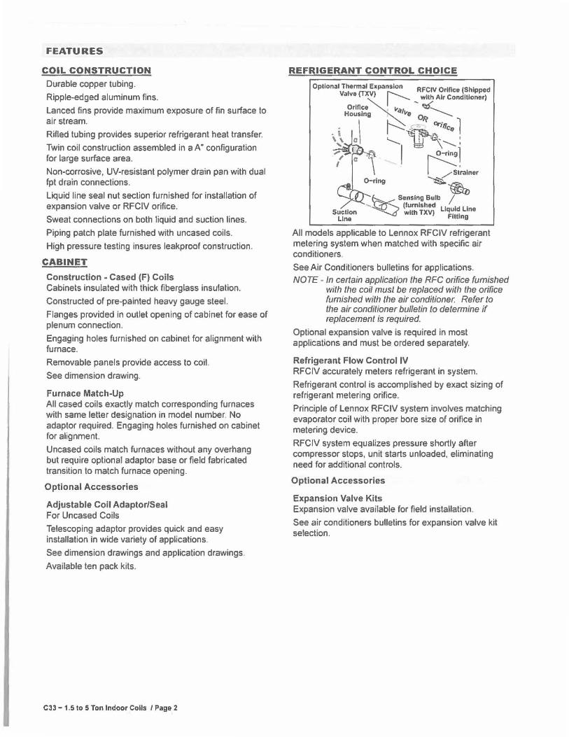
FEATURES
COIL CONSTRUCTION Durable copper tubing.
Ripple-edged aluminum fins.
Lanced fins provide maximum exposure of fin surface to air stream.
Rifled tubing provides superior refrigerant heat transfer.
Twin coil construction assembled in a A" configuration for large surface area.
Non-corrosive, UV-resistant polymer drain pan with dual fpt drain connections.
Liquid line seal nut section furnished for installation of expansion valve or RFCIV orifice.
Sweat connections on both liquid and suction lines.
Piping patch plate furnished with uncased coils.
High pressure testing insures leakproof construction.
CABINET
Construction - Cased (F) Coils Cabinets insulated with thick fiberglass insulation.
Constructed of pre-painted heavy gauge steel.
Flanges provided in outlet opening of cabinet for ease of plenum connection.
Engaging holes furnished on cabinet for alignment with furnace.
Removable panels provide access to coil.
See dimension drawing.
Furnace Match-Up All cased coils exactly match corresponding furnaces with same letter designation in model number. No adaptor required. Engaging holes furnished on cabinet for alignment.
Uncased coils match furnaces without any overhang but require optional adaptor base or field fabricated transition to match furnace opening.
Optional Accessories
Adjustable Coil Adaptor/Seal For Uncased Coils
Telescoping adaptor provides quick and easy installation in wide variety of applications.
See dimension drawings and application drawings.
Available ten pack kits.
C33 - 1.5 to 5 Ton Indoor Coils / Page 2
REFRIGERANT CONTROL CHOICE
Optional Thermal Expansion RFCIV Orifice (Shipped Valve (TXVI r----...__ wllh Air Conditioner)
Orlflce~I Ila,:~ ' 'II{" Housing ~e 0~ ~
. i \ ~~ Ori,;c,, l \,'\ ll '--...... bkJ \~:
· , ..._ I 0-rlng l \ '5i'ralner
~ ~
Sensing Bulb / - (furnished Liquid Line St~~I:' wllh TXV) Fitting
All models applicable to Lennox RFCIV refrigerant metering system when matched with specific air conditioners.
See Air Conditioners bulletins for applications.
NOTE - In certain application the RFC orifice furnished with the coil must be replaced with the orifice furnished with the air conditioner. Refer to the air conditioner bulletin to determine if replacement is required.
Optional expansion valve is required in most applications and must be ordered separately.
Refrigerant Flow Control IV RFCIV accurately meters refrigerant in system.
Refrigerant control is accomplished by exact sizing of refrigerant metering orifice.
Principle of Lennox RFCIV system involves matching evaporator coil with proper bore size of orifice in metering device.
RFClV system equalizes pressure shortly after compressor stops, unit starts unloaded, eliminating need for additional controls.
Optional Accessories
Expansion Valve Kits Expansion valve available for field installation.
See air conditioners bulletins for expansion valve kit selection.
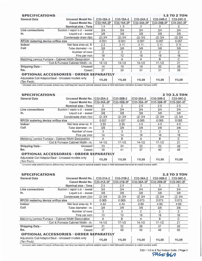
SPECIFICATIONS General Data Uncased Model No. C33-18A-2 C33-19A-2
Cased Model No. C33-18A-2F C33-19A-2F Nominal size • Tons 1.5 1..5
Line connections Suction I vapor o .d. • sweat 3/4 3/4 In. liquid o.d. - sweat 3/8 3/8
Condensate drain !fol) (2) 3/4 (2) 3/4 RFCIV metering device orifice size 0 051 0.051 Indoor Net face area sq ft 22 3 11 Coll Tube diameter• in 3/8 3/8
Number of rows 2 3 Fins per inch 18 12
Malchino Lennox Furnace • Cabinet Width Desionation A A 1 Coil & Furnace Cabinet Width • in 14-1/2 14-1/2
Shipping Data • Uncased 14 19 lbs. Cased 27 35
OPTIONAL ACCESSORIES - ORDER SEPARATELY Adjustable Coil Adaptor/Seal • Uncased models only Ten Pack
11L09 11L09
1.5TO 2 TON C33-24A-2 C33-24B-2 C33-24C-2
C33-24A-2F C33-24B-2F C33-24C-2F 2 2 2
3/4 3/4 3/4 3/8 3/8 3/8
(2) 3/4 (2) 3/4 (2} 3/4 0057 0.057 0057 3 11 3 11 3 11 3/8 3/8 3/8 2 2 2 18 18 18 A B C
14-1/2 17-1/2 21 18 20 25 31 31 39
11L09 11L09 11L09
' Uncased coils match furnaces without any overhang but require optional adaptor base or field fabricated transition to match furnace width
SPECIFICATIONS General Data Uncased Model No. C33-25A-2 CJJ-25B-2
Cased Model No. C33-25A-2F C33-25B-2F Nominal size • Tons 2 2
Line connections Suction/ vapor o.d. - sweat 3/4 3/4 In. Liquid o.d. • sweat 3/8 3/8
Condensate drain lfot) (2) 3/4 (2) 3/4 RFCIV meterlna device orifice size 0057 0.057 Indoor Net face area sq ft. 3.55 355 Coll Tube diameter • in 3/8 3/8
Number of rows 3 3 Fins per inch 14 14
Matchina Lennox Furnace. Cabinet Width Desionation A B 1 Coil & Furnace Cabinet Width - in. 14-1/2 17-1/2
Shipping Data - Uncased 23 24 lbs. Cased 39 41
OPTIONAL ACCESSORIES - ORDER SEPARATELY Adjustable Coil Adaptor/Seal - Uncased models only Ten Pack
11L09 11L09
2 TO 2.5TON C33-30A-2 C33-30B-2 CJJ.J0C-2 C33-30A-2F C33-30B-2F C33-30C-2F
25 25 25 3/4 3/4 3/4 3/8 3/8 3/8
(2) 3/4 (2) 3/4 (2) 3/4 0.065 0 065 0065 40 40 40 3/8 3/8 3/8 3 2 2 18 18 18 A B C
14-1/2 17-1/2 21 22 23 28 37 40 46
11L09 11L09 11L09
' Uncased coils match furnaces without any overhang but require optional adaptor base or fi!!ld fabricated transition to match furnace width
SPECIFICATIONS General Data Uncased Model No. C33-31A-2 C33-31B-2
Cased Model No. C33-31A-2F C33-31B-2F Nominal size - Tons 25 25
Line connections Suction I vapor o.d. • sweat 3/4 3/4 In. liquid o.d. • sweat 3/8 3/8
Condensate drain lfot) (2) 3/4 (2) 3/4 RFCIV meterlnQ device orifice size 0.065 0 065 Indoor Net face area sq ft. 4 44 4 44 Coll Tube diameter • in. 318 3/8
Number of rows 3 3 Fins oer inch 13 13
Matching Lennox Furnace - Cabinet Width Designation A 8 ' Coil & Furnace Cabinet Width • in. 14-1/2 17-1/2
Shipping Data • Uncased 31 32 lbs. Cased 47 49
OPTIONAL ACCESSORIES - ORDER SEPARATELY Adjustable Coil Adaptor/Seal • Uncased models only Ten Pack
11L09 11L09
2.5TO3TON C33-36A-2 CJJ-36B-2 C33-36C-2
C33-36A-2F C33-36B-2F CJJ.J6C-2F 3 3 3
3/4 3/4 3/4 3/8 3/8 3/8
(2) 3/4 (2) 3/4 (2) 3/4 0.073 0 073 0 073 4 89 489 489 3/8 3/8 3/8 2 2 2 18 18 18 A B C
14-1/2 17-1/2 21 26 27 29 45 46 50
11L09 11L09 11L09
' Uncased coil s match furnaces without any overhang but require optional adaptor base or field fabncated transition to match furnace width
C33 -1.5 to 5 Ton Indoor Coils / Page 3
'\?AG-e-~q
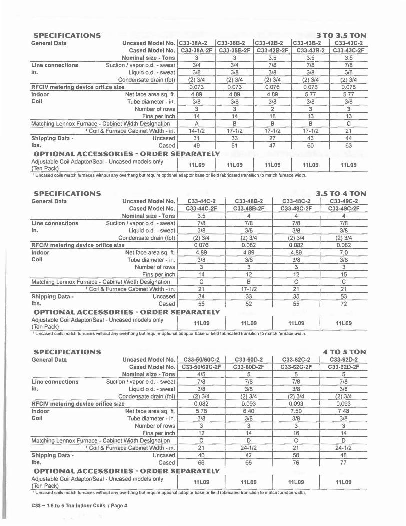
SPECI Fl CATIONS 3TO 3.5TON General Data Uncased Model No. CJJ.J8A-2 CJJ-388-2 CJJ-428·2 CJJ-438·2 C33-43C-2
Cased Model No. C33-38A-2F C33-388-2F C33-42B-2F CJJ-438-2 C33-43C-2F Nominal size • Tons 3
Line connections Suction / vapor o.d • sweat 3/4 In. Liquid o.d • sweat 3/8
Condensate drain tfot) (2) 3/4 RFCIV metering device orifice size 0.073 Indoor Net face area sq. ft. 4.89 Coil Tube diameter • in. 3/8
Number of rows 3 Fins oer inch 14
Matchina Lennox Furnace• Cabinet Width Desianation A ' Coil & Furnace Cabinet Width • in. 14-1/2
Shipping Data • Uncased 31 lbs. Cased 49
OPTIONAL ACCESSORIES - ORDER SEPARATELY Adjustable Coil Adaptor/Seal - Uncased models only Ten Pack
11L09
3 3.5 3.5 3/4 7/8 7/8 3/8 3/8 3/8
(2) 3/4 (2) 3/4 (2) 3/4 0.073 0.076 0.076 4.89 4.89 5,77 3/8 3/8 3/8 3 2 3 14 18 13 B B B
17-1/2 17-1/2 17-1/2 33 27 43 51 47 60
11L09 11L09 11L09
' Uncased coils match lumaces without any overhang but require optional adaptor base or field labricaled transition to match furnace width.
3.5 7/8 3/8
(2) 3/4 0.076 5.77 3/8 3 13 C 21 44 63
11L09
SPECIFICATIONS 3.5 TO 4 TON General Data Uncased Model No. C33-44C-2
Cased Model No. C33-44C-2F Nominal size • Tons 3.5
Line connections Suction I vapor o d. • sweat 7/8 in. Liquid o d • sweat 3/8
Condensate drain lfntl (2) 3/4 RFCIV metering device orifice size 0.076 Indoor Net face area sq. ft. 4.89 Coil Tube diameter. in. 3/8
Number of rows 3 Fins per inch 14
MatchinQ Lennox Furnace - Cabinet Width DesiQnation C ' Coil & Furnace Cabinet Width • in. 21
Shipping Data • Uncased 34 lbs. Cased 55
OPTIONAL ACCESSORIES - ORDER SEPARATELY Adjustable Coil Adaptor/Seal • Uncased models only Ten Pack
11L09
C33-48B-2 C33-4BC-2 C33-48B-2F C33-48C-2F
4 4 7/8 718 3/8 3/8
(2) 3/4 (2) 3/4 0,082 0.082 4.89 4.89 3/8 3/8 3 3
12 12 B C
17-1/2 21 33 35 52 55
11L09 11L09
' Uncased coil, match lumaces wilh04Jt any overhang but require optional adaptor base or field labricated transition to match furnace width,
SPECIFICATIONS General Data Uncased Model No. C33•50/60C-2
Cased Model No. C33-50/60C-2F Nominal size • Tons 4/5
Line connections Suction/ vapor o d. • sweat 718 In. Liquid o d. • sweat 3/8
Condensate drain lfotl (2) 3/4 RFCIV meterina device orifice size 0.082 Indoor Net face area sq. ft. 5.78 Coil Tube diameter • in. 3/8
Number of rows 3 Fins oer inch 12
Matchino Lennox Furnace • Cabinet Width Desionalion C ' Coil & Furnace Cabinet Width • in. 21
Shipping Data • Uncased 40 lbs. Cased 66
OPTIONAL ACCESSORIES - ORDER SEPARATELY Adjustable Coil Adaptor/Seal - Uncased models only Ten Pack
11L09
CJJ-60O-2 C33-62C·2 C33-60D-2F C33-62C-2F
5 5 718 7/8 3/8 3/8
(2) 3/4 (2) 3/4 0.093 0.093 6.40 7.50 3/8 3/8 3 3
14 16 D C
24-1/2 21 42 58 66 76
11L09 11L09
' Uncased coUs match furnaces without any overhang but require optional adapt~, base or field labricated transition to match furnace width,
C33 - 1.5 to 5 Ton Indoor Coils I Page 4
C33-49C-2 C33-49C-2F
4 7/8 3/8
(2) 3/4 0.082
7.0 3/8 3 15 C 21 53 72
11L09
4TO5TON C33-62D·2
C33-62D-2F 5
718 3/8
(2) 3/4 0.093 7.48 3/8 3
14 D
24-1/2 48 77
11L09
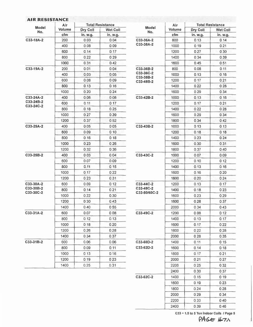
AIR RESISTANCE
Model Air Total Resistance
No. Volume Ory Coll Wet Coll
cfm In. w.g. In. w.g 1.
Air Total Resistance Model Volume Ory Coll Wet Coll
No. cfm ln.w.g. ln.w.g.
C33-18A-2 200 003 0.04 C33-36A-2 800 0.13 0 14
400 0.08 0.09 C33-38A-2 1000 0.19 021
600 0.14 0.17 1200 0.27 030
800 0.22 029 1400 0.34 0.39
1000 0 31 0.42 I 1600 0.45 0 51
C33-19A-2 200 0.01 0.04 C33-36B-2 800 0.08 0 11
400 0.03 0.05
600 0.08 0.09
C33-36C-2 1000 0.13 0 16 C33-38B-2 C33-48B-2 1200 0 17 0 .21
800 0.13 0.16 1400 0.22 0.28
1000 0.20 024 1600 0.29 034
C33-24A•2 400 0,06 0.08 C33-42B-2 1000 0.13 0 16 C33-24B-2 600 0.11 0.17 C33-24C-2
800 0.18 0.25
1200 0.17 021
1400 0.22 0.28
1000 0.27 0.39 1600 0.29 034
1200 0.37 0 52 1800 034 042
C33-25A-2 400 0.05 005 C33-43B-2 1000 0.13 0 .13
600 0.09 0 10 1200 0.18 0 18
800 0.16 0.18 1400 0.23 024
1000 0.23 026 1600 0.30 0 31
1200 0.32 036 1800 0.37 0 .40
C33-25B-2 400 003 0.04 C33-43C-2 1000 0.07 0 .09
600 0.07 0.09 1200 0.10 012
800 0.11 0 15 1400 0.13 0 16
1000 0.17 0.22 1600 0.16 0.20
1200 023 0.31 1800 0.20 0 24
C33-30A-2 600 0.09 0 12 C33-44C-2 1200 0.13 017 C33-308-2 800 0.14 0 21 C33-30C-2
1000 0.22 0.30
C33-48C-2 1400 018 0 23 C33-50/60C-2
1600 0.23 0.29
1200 0.30 0.43 1800 0.28 0 37
1400 0.40 055 2000 0 34 043
C33-31A-2 600 0.07 0 08 C33-49C-2 1200 0.08 012
800 0.12 013 1400 0.13 017
1000 0.18 0.20 1600 0.17 022
1200 0.26 028 1800 022 0 28
1400 0.34 0.37 2000 0.28 0.35
C33-31B-2 600 0.06 0.06 C33-60O-2 1400 0.11 0 15
800 009 011 C33-62O-2 1600 0.14 018
1000 0.13 0 16 1800 0.17 0 21
1200 0.19 023 2000 0 .21 0.27
1400 0.25 0.31 2200 0.25 032
2400 0.30 0 37
C33-62C-2 1400 0.15 0 19
1600 0 19 023
1800 0.24 028
2000 029 0 34
2200 0.33 040
2400 0.39 046
C33 - 1.5 to 5 Ton Indoor Coils / Page 5
p,4~ J,/.7,A
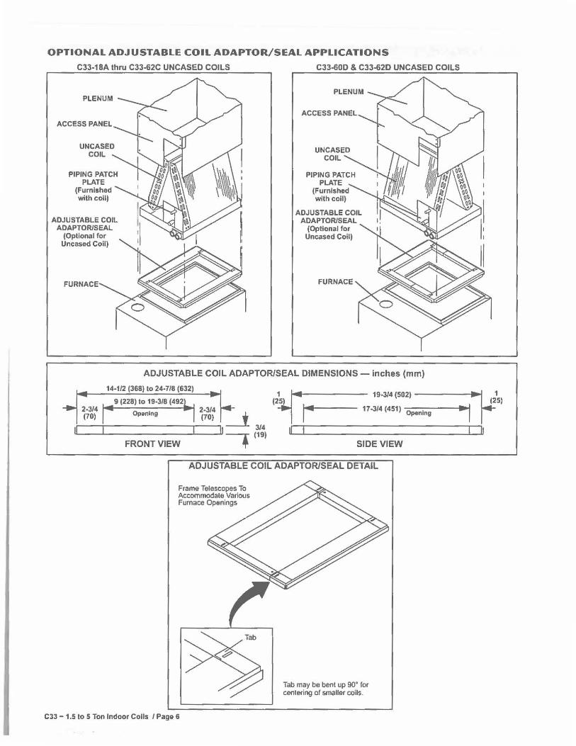
OPTIONAL ADJUSTABLE COIL ADAPTOR/SEAL APPLICATIONS
C33-18A thru C33-62C UNCASED COILS C33-60D & C33-62D UNCASED COILS
ACCESS PANEL
PIPING PATCH PLATE
(Furnished with coil)
ADJUSTABLE COIL ADAPTOR/SEAL
(Optional for Uncased Coil)
FURNACE
ADJUSTABLE COIL ADAPTOR/SEAL
(Optional for Uncased Coil)
ADJUSTABLE COIL ADAPTOR/SEAL DIMENSIONS - inches (mm)
14-1/2 (368) to 24-7/8 (632)
~◄ 19-3/4 (502)
9 (228) to 19-3/8 (492 ,~ 2-3/4 Opening 2-3/4 17-3/4 (451 I Opening (25)
(70) (70) __i II n 7 ,3/:,
FRONT VIEW SIDE VIEW
ADJUSTABLE COIL ADAPTOR/SEAL DETAIL
Frame Telescopes To Accommodate Various Furnace Openings
C33 - 1.5 to 5 Ton Indoor Coils / Page 6
Tab may be bent up 90° for cenlering of smaller coils.
~, (25) ►~1
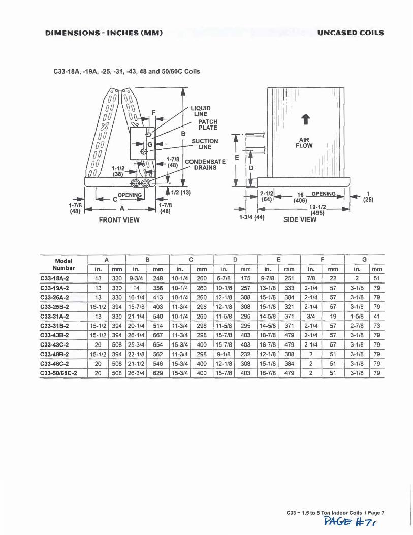
DIMENSIONS - INCHES (MM)
C33-18A, -19A, -25, -31, -43, 48 and 50/60C Coils
LIQUID LINE
PATCH PLATE
UNCASED COILS
II I
I 11· ,I' l
I I ~ t SUCTION
LINE T·:< Ep I AIR
I 11! FLOW
Model A Number In. mm In.
CJJ-18A-2 13 330 9-3/4
C33-19A-2 13 330 14
C33-25A-2 13 330 16-1/4
C33-25B-2 15-1/2 394 15-7/8
C33-31A·2 13 330 21-1/4
CJJ-31B-2 15-1/2 394 20-1/4
C33-4JB-2 15-1/2 394 26-1/4
C33-43C-2 20 508 25-3/4
CJJ-48B-2 15-1/2 394 22-1/8
C33-48C-2 20 508 21-1/2
C33-50/60C-2 20 508 26-3/4
B
mm 248
356
413
403
540
514
667
654
562
546
629
CONDENSATE DRAINS
C
In. mm In.
10-1/4 260 6-7/8
10-1/4 260 10-1/8
10-1/4 260 12-1/8
11-3/4 298 12-1/8
10-1/4 260 11-5/8
11-3/4 298 11-5/8
11 -3/4 298 15-7/8
15-3/4 400 15-7/8
11-3/4 298 9-1/8
15-3/4 400 12-1/8
15-3/4 400 15-7/8
' .
D
I II di; 'D I I rtl _)
2-ml •• OPENING► .I 1◄ 1 (64) r+- (406) (25) ~-----19-1/2
(495) 1•314 (44) SIDE VIEW
E F G
mm In. mm In. mm In. mm 175 9-7/8 251 7/8 22 2 51
257 13-1/8 333 2-1/4 57 3-1/8 79
308 15-1/8 384 2-1/4 57 3-1/8 79
308 15-1/8 321 2-1/4 57 3-1/8 79
295 14-5/8 371 3/4 19 1-5/8 41
295 14-5/8 371 2-1/4 57 2-7/8 73
403 18-7/8 479 2-1/4 57 3-1/8 79
403 18-7/8 479 2-1/4 57 3-1/8 79
232 12-1/8 308 2 51 3-1/8 79
308 15-1/8 384 2 51 3-1/8 79
403 18-7/8 479 2 51 3-1/8 79
C33 - 1.5 to 5 Ton Indoor Colls / Page 7
PAG-e- 11=7,
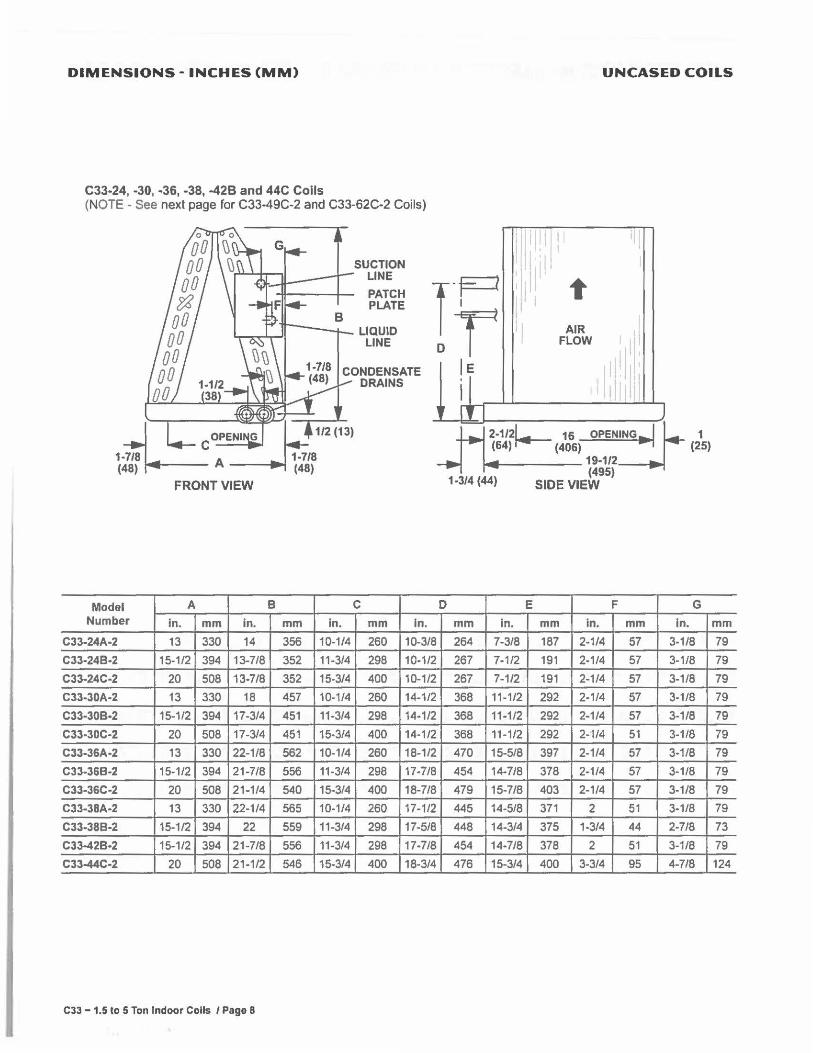
DIMENSIONS - INCHES (MM) UNCASED COILS
C33-24, -30, -36, -38, -42B and 44C Coils (NOTE - See next page for C33-49C-2 and C33-62C-2 Coils)
SUCTION "Ii} LINE lP 1" PATCH I I PLATE I
LIQUID Dr I AIR Ill LINE FLOW
CONDENSATE le 1,1
11 DRAINS
I I I
2-1121 16 OPENING► ►I ,◄ 1 (64) ~ (406) (25) 1-4------19-1/2
(495) 1•314 (44) SIDE VIEW
Model A B C D E F G Number In. mm in. mm in. mm in. mm in. mm In. mm In. mm
C33-24A-2 13 330 14 356 10-1/4 260 10-3/8 264 7-3/8 187 2-1/4 57 3-1/8 79
C33-24B•2 15-1/2 394 13-7/8 352 11-3/4 298 10-1/2 267 7-1/2 191 2-1/4 57 3-1/8 79
C33-24C-2 20 508 13-7/8 352 15-3/4 400 10-1/2 267 7-1/2 191 2-1/4 57 3-1/8 79
C33-30A-2 13 330 18 457 10-1/4 260 14-1/2 368 11-1/2 292 2-1/4 57 3-1/8 79
C33-30B-2 15-1/2 394 17-3/4 451 11-3/4 298 14-1/2 368 11-1/2 292 2-1/4 57 3-1/8 79
C33-30C-2 20 508 17-3/4 451 15-3/4 400 14-1/2 368 11-1/2 292 2-1/4 51 3-1/8 79
C33-36A-2 13 330 22-1/8 562 10-1/4 260 18-1/2 470 15-5/8 397 2-1/4 57 3-1/8 79
C33-36B-2 15-1/2 394 21-7/8 556 11-3/4 298 17-7/8 454 14-7/8 378 2-1/4 57 3-1/8 79
C33-36C·2 20 508 21-1/4 540 15-3/4 400 18-7/8 479 15-7/8 403 2-1/4 57 3-1/8 79
C33-38A-2 13 330 22-1/4 565 10-1/4 260 17-1/2 445 14-5/8 371 2 51 3-1/8 79
C33-38B-2 15-1/2 394 22 559 11-3/4 298 17-5/8 448 14-3/4 375 1-3/4 44 2-7/8 73
C33-42B-2 15-1/2 394 21-7/8 556 11-3/4 298 17-7/8 454 14-7/8 378 2 51 3-1/8 79
C33-44C-2 20 508 21-1/2 546 15-3/4 400 18-3/4 476 15-3/4 400 3-3/4 95 4-718 124
C33 - 1.5 to 5 Ton Indoor Coils I Page 8
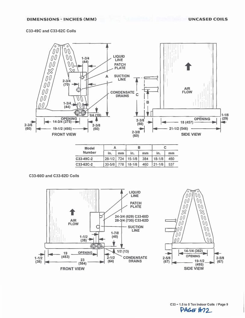
DIMENSIONS - INCHES (MM)
C33-49C and C33-62C Coils
Model Number
C33-49C-2
C33-62C-2
C33·60D and C33-62D Coils
I I ·11 Tl I ,;
I ~ jl I AIR
1lli1 FLOW
I :11 111: I 1-1/2 !II (38)
l,.-19 OPENING ... 1 1-1/2 (483)
23 (38) (584)
FRONT VIEW
In.
LIQUID LINE PATCH PLATE
A
mm
UNCASED COILS
AIR FLOW
I I I
I ~ . I I I I ..
_._--+_._U--__________ ___,1-1/8
2-3/8 ~ OPENING I f(29) (60) 4 18 (457) ... .
;', 21-1/2 (546) ...
~trif SIDE VIEW
B C
In. mm In. mm
28-1/2 724 15-1/8 384 18-1/8 460
30-5/8 778 18-1/8 460 21-1/8 537
LIQUID LINE
PATCH PLATE
24-3/4 (629) C33-60D 28-3/4 (730) C33-62D
SUCTION LINE
,◄ 14-1/4 (362)~
CONDENSATE OPENING 2
_518
DRAINS 19-1/2 (67) (495)
SIDE VIEW
CJJ - 1.5 to 5 Ton Indoor Coils I Page 9
PA66° .72....
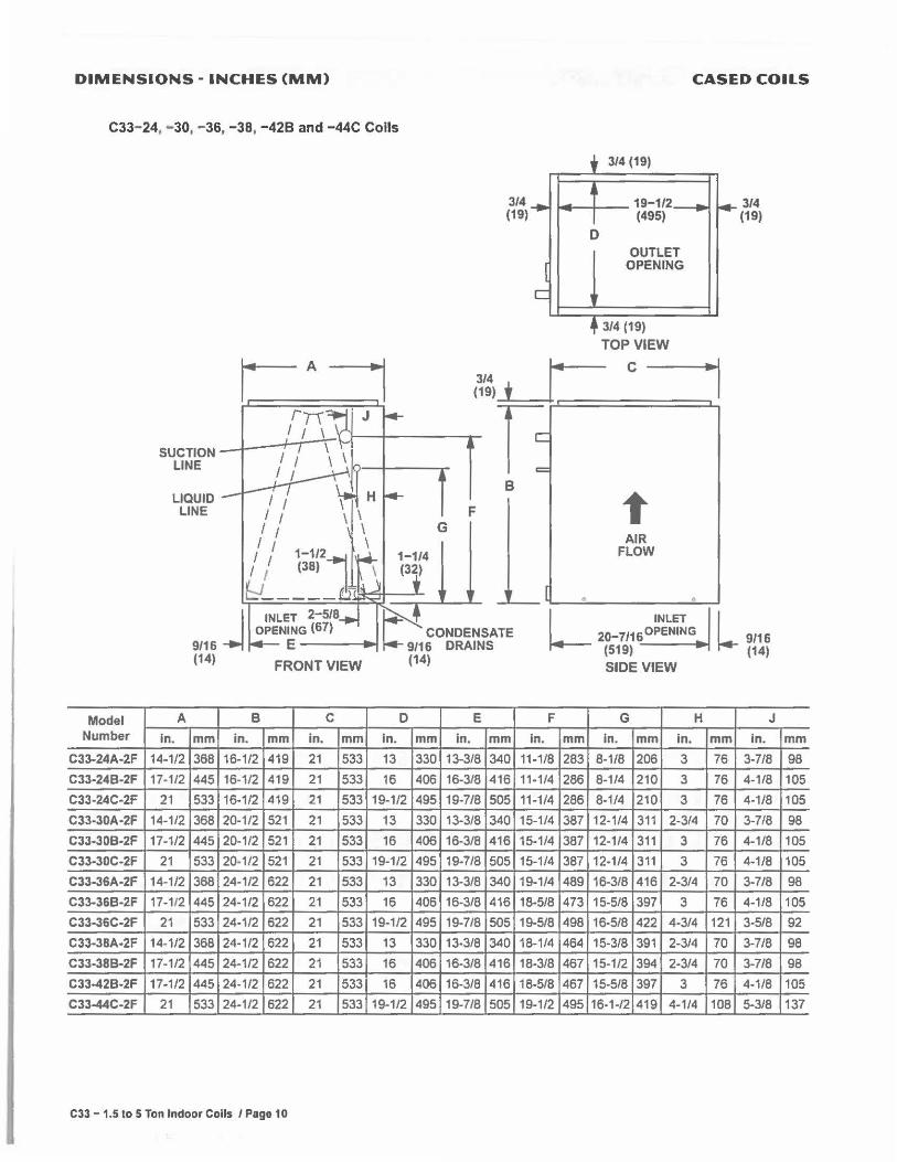
DIMENSIONS - INCHES (MM)
C33-24,. - 30, - 36, -38, -428 and -44C Coils
SUCTION LINE
LIQUID LINE
_j INLET 2-5/8 OPENING (67)
9/16 E----(14)
FRONT VIEW
Model A B C D Number In. mm in. mm in. mm In.
C33-24A-2F 14-1/2 368 16-1/2 419 21 533 13
C33-24B-2F 17-1/2 445 16-1/2 419 21 533 16
C33-24C-2F 21 533 16-1/2 419 21 533 19-1/2
C33-30A-2F 14-1/2 368 20-1/2 521 21 533 13
C33-30B-2F 17-1/2 445 20-1/2 521 21 533 16
C33-30C-2F 21 533 20-1/2 521 21 533 19-1/2
C33-36A-2F 14-1/2 368 24-1/2 622 21 533 13
CJJ.J6B-2F 17-112 445 24-1/2 622 21 533 16
C33-36C-2F 21 533 24-1/2 622 21 533 19-1/2
C33-3BA-2F 14-1/2 368 24-1/2 622 21 533 13
C33-38B-2F 17-1/2 445 24-1/2 622 21 533 16
C33-42B-2F 17-1/2 445 24-1/2 622 21 533 16
C33-44C-2F 21 533 24-1/2 622 21 533 19-1/2
C33 - 1.5 to 5 Ton Indoor Coils I Page 10
CASED COILS
3/4 (19)
3/4 (19)
i.---+-- 19-1/2 (495)
0 OUTLET
OPENING
3/4 (19)
TOP VIEW
3/4 I.. c-----, (19) + _ I ~===-;.c:=======~
f: B
F
3/4 (19)
G t
E
mm in.
330 13-3/8
406 16-3/8
495 19-7/8
330 13-3/8
406 16-3/8
495 19-7/8
330 13-3/8
406 16-3/8
495 19-7/8
330 13-3/8
406 16-3/8
406 16-3/8
495 19-7/8
AIR FLOW
_.,___ I __ __,; _______ __,
mm 340
416
505
340
416
505
340
416
505
340
416
416
505
L INLET
20_
7116 OPENING
(519)
SIDE VIEW
F G H
In. mm in. mm In.
11-1/8 283 8-1/8 206 3
11-1/4 286 8-1/4 210 3
11-1/4 286 8-1/4 210 3
15-1/4 387 12-1/4 311 2-3/4
15-1/4 387 12-1/4 311 3
15-1/4 387 12-1/4 311 3
19-1/4 489 16-3/8 416 2-3/4
18-5/8 473 15-5/8 397 3
19-5/8 498 16-5/8 422 4-3/4
18-114 464 15-3/8 391 2-3/4
18-3/8 467 15-1/2 394 2-3/4
18-5/8 467 15-5/8 397 3
19-1/2 495 16-1-/2 419 4-1/4
l 9/16 (14)
J
mm in.
76 3-7/8
76 4-1/8
76 4-1/8
70 3-7/8
76 4-1/8
76 4-1/8
70 3-7/8
76 4-1/8
121 3-5/8
70 3-7/8
70 3-7/8
76 4-1/8
108 5-3/8
mm
98
105
105
98
105
105
98
105
92
98
98
105
137
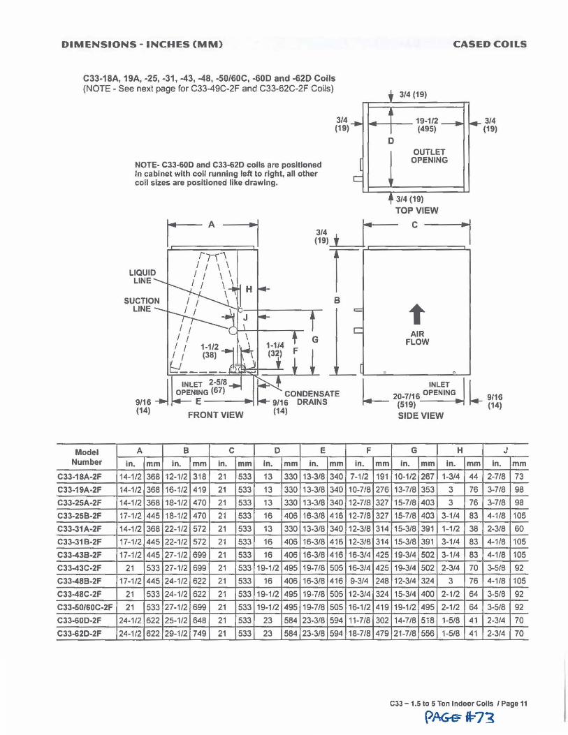
DIMENSIONS - INCHES (MM) CASED COILS
C33-18A, 19A, -25, -31, -43, -48, -50/60C, -600 and -62D Coils (NOTE - See next page for C33-49C-2F and C33-62C-2F Coils)
NOTE- C33-60D and C33-62D coils are positioned In cabinet with coll running left to right, all other coll sizes are positioned like drawing.
3/4 (19)
3/4 (19)
14--+--19-1/2 (495)
D OUTLET OPENING
3/4 (19)
TOP VIEW
3/4 1~ C -----+i 119> + _ I ~r ==:::,_,
LIQUID LINE
B = C
t AIR
FLOW
__ I...___ .. ______ --'-__.
3/4 (19)
9/16 j (14)
INLET 2-5/8 OPENING (67)
E----- L INLET
20_7116 OPENING
(519) l 9/16 (14)
FRONTVIEW SIDE VIEW
Model A B C D E F G H J Number in. mm in. mm In. mm in. mm in. mm in. mm In. mm in. mm In.
C33-18A-2F 14-1/2 368 12-1/2 318 21 533 13 330 13-3/8 340 7-1/2 191 10-1/2 267 1-3/4 44 2-7/8
C33-19A-2F 14-1/2 368 16-1/2 419 21 533 13 330 13-3/8 340 10-7/8 276 13-7/8 353 3 76 3-7/8
C33-25A-2F 14-1/2 368 18-1/2 470 21 533 13 330 13-3/8 340 12-7/8 327 15-7/8 403 3 76 3-7/8
C33-25B-2F 17-1/2 445 18-1/2 470 21 533 16 406 16-3/8 416 12-7/8 327 15-7/8 403 3-1/4 83 4-1/8
C33-31A-2F 14-1/2 368 22-1/2 572 21 533 13 330 13-3/8 340 12-3/8 314 15-3/8 391 1-1/2 38 2-3/8
C33-31B-2F 17-1/2 445 22-1/2 572 21 533 16 406 16-3/8 416 12-3/8 314 15-3/8 391 3-1/4 83 4-1/8
C33-43B-2F 17-1/2 445 27-1/2 699 21 533 16 406 16-3/8 416 16-3/4 425 19-3/4 502 3-1/4 83 4-1/8
C33-43C-2F 21 533 27-1/2 699 21 533 19-1/2 495 19-7/8 505 16-3/4 425 19-3/4 502 2-3/4 70 3-5/8
C33-48B-2F 17-1/2 445 24-1/2 622 21 533 16 406 16-3/8 416 9-3/4 248 12-3/4 324 3 76 4-1/8
C33-4BC-2F 21 533 24-1/2 622 21 533 19-1/2 495 19-7/8 505 12-3/4 324 15-3/4 400 2-1/2 64 3-5/8
C33-50/60C-2F 21 533 27-1/2 699 21 533 19-1/2 495 19-7/8 505 16-1/2 419 19-1/2 495 2-1/2 64 3-5/8
C33-60D-2F 24-1/2 622 25-1/2 648 21 533 23 584 23-3/8 594 11-7/8 302 14-7/8 518 1-5/8 41 2-3/4
C33-62D-2F 24-1/2 622 29-1/2 749 21 533 23 584 23-3/8 594 18-7/8 479 21-7/8 556 1-5/8 41 2-3/4
mm 73
98
98
105
60
105
105
92
105
92
92
70
70
C33 - 1.5 to 5 Ton Indoor Colls / Page 11
PAG-e-- A:-73
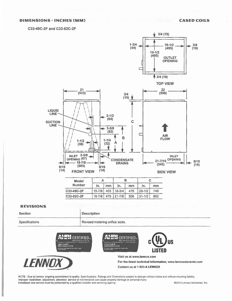
DIMENSIONS - INCHES (MM)
C33-49C-2F and C33-62C-2F
LIQUID LINE
Model Number
C33-49C-2F
C33·62C-2F
A
in.
15-7/8
18-7/8
REVISIONS
Section Description
1-3/4 (44)
B
mm In. mm 403 18-3/4 476
479 21-7/8 556
CASED COILS
3/4 (19)
19-1/2 (495)
19-1/2 (495)
OUTLET OPENING
3/4 (19)
TOP VIEW
t AIR
FLOW
L INLET
21 •7116 OPENING
(545)
SIDE VIEW
C
in. mm 29-1/2 749
31-1/2 800
3/4 (19)
l 9/16 (14)
Specifications Revised metering orifice sizes.
/ll.lDI ,... • •• CERTIFIED .•
C .... ,~ c:i • 1. , : 11 - ------U11ur,~&.:: AAN~:.lnC..•tt:•::21.J __ .. , ___ .. ,r.- - ,_,..
LENNOX) .
/lLIDI ,... ••• CERTIFIED-c ...... ,~ ., , 1.,,:,~ -------l :'L'll'J S.~11f' AA~ :,~~.ir:I :1:.::J t~ .......... . ... - .......... ...... ... _ ... _
c@us LISTED
Visit us at www.lennow..com
For the latest technical Information, www.lennoxdavenet.com
Contact us at 1-800-4-LENNOX
NOTE • Due to Lennox ongoing camm1tmenl to quality Speoficabons Ratings and D mensions sub,ect ta change without notice and without ,ncutring liability. Improper rnstallat10n adjustment, alteration. service or ma ntenance can cause property damage or pe~onal injury lnstallat,an and service must be performed by a qualified ,nslaller and servicing agency C2013 Lennox lndustnes Inc.
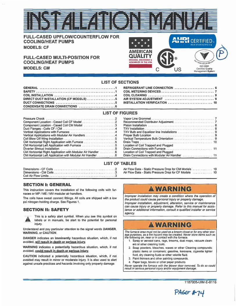
----~ - ..... .._.. • -------■ nns t 11111 ldJrl 1~11111
- ,. - .._ ..,..._ ------ -. _______ ., ___ _ ·------·----~-.:===-=:= ====== : -.=======~--=~= ____ ___. . .._.__.. ... --·
FULL-CASED UPFLOW/COUNTERFLOW FOR COOLING/HEAT PUMPS MODELS: CF
FULL-CASED MULTI-POSITION FOR COOLING/HEAT PUMPS MODELS: CM
- /II.IDI ,.. •••ii CERTIFIED,"
AMERICAN (I 9Y.~N~~.!! ~ ~ ® ASUMILID IN THE UU ~ I!
C US
www :1h1 111rrcc1or y e ra
©® 1509001
Carllfie~ Quality Managamenl Syslem
LIST OF SECTIONS GENERAL • •••••••• • •••••••••••.••••• • •••••••• •• •••.•• • • 1 SAFETY ••. . • •• ••• ..•••• , •• ..•• • ••• • ..•• .••. ••.•• ••• •..• 1 COIL INSTALLATION •...••• • •...• • .• • ••. •• ...•••.••• •••• • 4 DIRECT DUCT INSTALLATION (CF MODELS) • • •••• • ••••••• , .. 5 DUCT CONNECTIONS •••••••••••.• •• •••••••• •• • ••• • • •• .• • 5 CONDENSATE DRAIN CONNECTIONS ..................... • 6
REFRIGERANT LINE CONNECTION ••.•••• • •••.••• • •..••• • • 6 COIL METERING DEVICES • •• •.•••• •• •..••• ••• ... • •• ••• •.• 7 COIL CLEANING •••••.•••••• • •.•• •• ••••••• • • •• ••••••• •• • 9 AIR SYSTEM ADJUSTMENT •••••••••••.•• • ••.••• •• • • ••.•• 9 INSTALLATION VERIFICATION .............. .. ........... 10
LIST OF FIGURES Pressure Check . . . . . . . . . . . . • • . • . • . . . . . . . . . . . . . • . . . . ..•. 2 Component Location • Cased Coil CF Model •.... • ..•.....•. .. .. 2 Component Location • Cased Coll CM Model .......•.........•. 3 Duct Flanges - Coils CF I CM .... ... ....................••.. 4 Vertical Applications with Furnaces ....................•..... . 4 Vertical Applications with Modular Air Handlers ...........•...... 4 Coil Blow Off Wing Installation .....•....................... . . 5 CM Horizontal Right Application with Furnace . ....•••..•.......• 5 CM Horizontal Lell Application with Furnace ••.......••.•.•.••.. 5 Diverter Shroud lnstallatlon ...•••.••........... . ••...•....•. 5 CM Horizontal Right Application with Modular Air Handler .......•. 6 CM Horizontal Lell Application with Modular Air Handler .......••.. 6
Vapor Line Grommet . . • • • • • • . . • • • . . . . . . . . • • . . . . • . . • . . . • • . 7 Recommended Distributor Adjustment ......•................• 7 Piston Installation . . • • . . . . . . . . . . . . . . . . . • . . . . . • . . . . . . . . . . . . 8 TXV Installation . . . . . . . . . . . . . . . . . . . . • . . . . . . . . . . . . • • . . . . . . 8 TXV Bulb and Equalizer line Installations . . . . . . . . . . . . • . . . . . • . • . 9 Proper Bulb Location . . . . . . . . . . . . • . . . . . . . • . . . . . . . . . . . . . • • 9 Vertical Temperature Bulb Orientation . . . . . . . . . . • . . . . . . . . . . . • 9 Drain Traps .. .•..............••... . .........••.... .••.. 10 Location or Coll Trapped and Plugged Drain CoMectlons with Furnace . • . . . . . . . . . . . . • . . . . . . . . . . . . . 11 Location of coa Trapped and Plugged Drain Conneclions with Modular Air Handler • . . . . • • . . . . . . . . • • . 11
LIST OF TABLES Dimensions • CF Coils . . . . . . . . . . . . . . . . . . . . . . . . . . . . . . . . .••. 2 Dimensions • CM Coils .. ................ ....... ... .. ....•.. 3 Coil Air Flow Limits .................................. ..... . 3
SECTION I: GENERAL This Instruction covers the Installation of the following coils with fur• naces or MP / ME / MV modular air handlers.
The coils have sweat connect fittings. All coils are shipped with a low psi nitrogen holding charge. See Figures 1.
SECTION II: SAFETY
A This is a safety alert symbol. When you see this symbol on a. labels or in manuals. be alert to the potential for personal
injury.
Understand and pay partiC\Jlar attention to the signal words DANGER. WARNING, or CAUTION.
DANGER indicates an Imminently hazardous situation, which. if not avoided. wl(I result lo death or serious Injury WARNING Indicates a potentially hazardous situation, which, if not avoided. couJd rasyH In death oe sarjous injury CAUTION Indicated a potentlally hazardous situation, which, if not avoided may result in minor or moderate injury. It Is also used to alert against unsafe practices and hazards involving only property damage.
Air Flow Data ♦ Static Pressure Drop for CM Models ....... ... .• 10 Air Flow Data ♦ Static Pressure Drop for CF Models . . . . . . . . . . . . 10
AWARNING Improper installation may create a condition where the operation of the product could cause personal injury or property damage. Improper lnstallalion, adjustment, alteration, service or maintenance can cause injury or property damage. Refer to this manual for assis• lance or additional information, consult a qualified installer or service agency.
AWARNING The furnace area must not be used as a broom closet or for any other stor• age purposes, as a fire hazard may be created. Never store items such as the following on, near or in contact with the furnace.
1. Spray or aerosol cans, rags, brooms. dust mops, vacuum cleaners or other cleaning tools.
2. Soap powders, bleaches, waxes or other Cleaning compounds: plastic items or containers; gasoline, kerosene, cigarette lighter nuid, dry cleaning nuids or other volatile nuid.
3. Paint thinners and other painting compounds. 4. Paper bags, boxes or olher paper products
Never operate the furnace with the blower door removed. To do so could result in serious personal injury and/or equipment damage.
1187005-UIM·E-0116
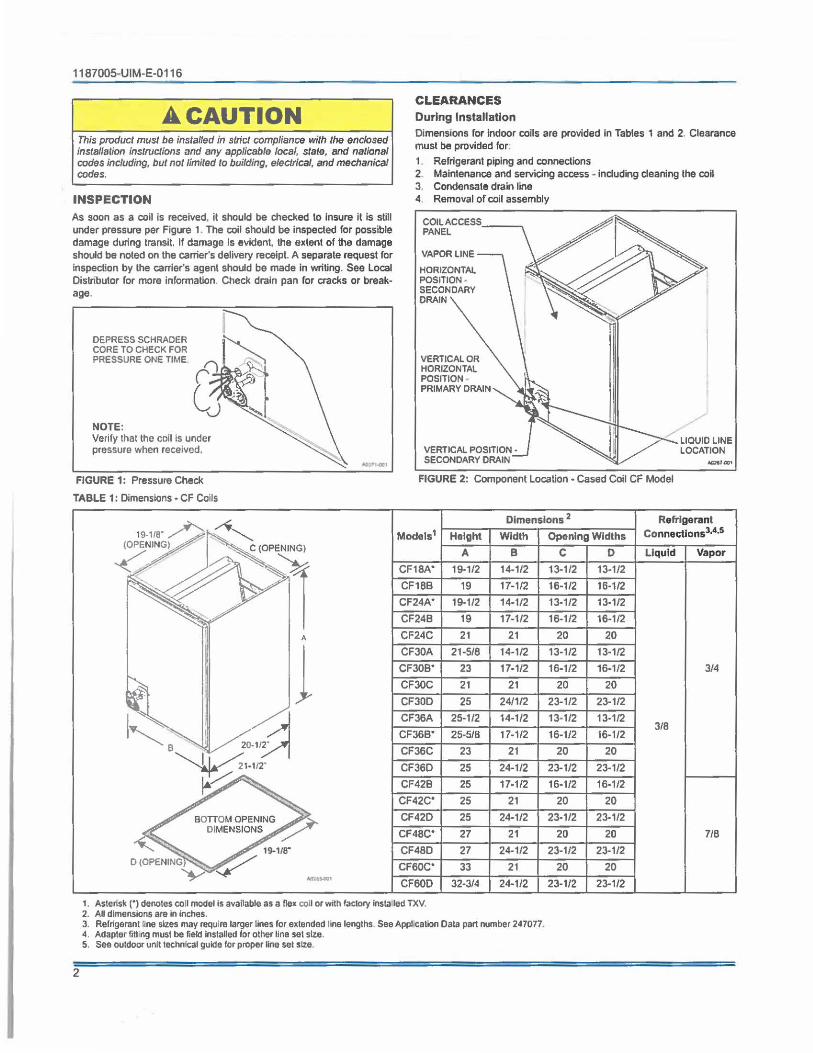
1187005-UIM·E-0116
A CAUTION This product must be installed in strict compliance with the enclosed installation ins/roe/ions and any applicable local, state, and national codes including, but not limited to building, electrical, and mechanical codes.
INSPECTION As soon as a coil is received, it should be checked lo insure it is still under pressure per Figure 1. The coil should be Inspected for possible damage during transit. If damage Is evident, the extent of the damage should be noted on the carrier's delivery receipt. A separate request for inspection by the carrier's agent should be made In writing. See Local Distributor for more information. Check drain pan for cracks or breakage,
DEPRESS SCHRADER CORE TO CHECK FOR PRESSURE ONE TIME
NOTE: Verify that the coll is under pressure when received,
FIGURE 1: Pressure Check
TABLE 1: Dimensions • CF Coils
19-118" ~ ~
~ , A
I l ~ jV,~
~1-112·
~ BOTTOM OPENING
DIMENSIONS
19-1/8"
D (OPENINGV ~ ~,-,;iv,
CLEARANCES During Installation Dimensions for indoor coils are provided In Tables 1 and 2. Clearance must be provided for.
1. Refrigerant piping and coMections 2 Maintenance and servicing access • induding deaning the coU 3. Condensate drain line 4 Removal of coil assembly
COIL ACCESS __ ~ PANEL
VAPOR LINE
HORIZONTAL POSITION SECONDARY DRAIN
VERTICAL OR HORIZONTAL POSITION PRIMARY DRAIN
VERTICAL POSITION • SECONDARY DRAIN
LIQUID LINE LOCATION
FIGURE 2: Component Location • Cased Coil CF Model
Dimensions 2 Refrigerant
Models1 Height Width Opening Widths Connectlons3•4•5
A B C 0 Liquid Vapor
CF18A" 19-1/2 14-1/2 13-1/2 13-1/2
CF18B 19 17-1/2 16-1/2 16-112
CF24A' 19-1/2 14-1/2 13-1/2 13-1/2
CF24B 19 17.1/2 16-1/2 16-1/2
CF24C 21 21 20 20
CF30A 21-5/8 14-1/2 13-1/2 13-1/2
CF30B' 23 17-1/2 16-1/2 16-1/2 3/4
CF30C 21 21 20 20
CF30D 25 24/1/2 23-1/2 23-1/2
CF36A 25-1/2 14-1/2 13-1/2 13-1/2 318
CF36B' 25-518 17-1/2 16-1/2 16-1/2
CF36C 23 21 20 20
CF36O 25 24-1/2 23-1/2 23-1/2
CF42B 25 17-1/2 16-1/2 16-1/2
CF42C' 25 21 20 20
CF42D 25 24-1/2 23-1/2 23-1/2
CF48C* 27 21 20 20 7/8
CF48D 27 24-1/2 23-1/2 23-1/2
CF60C' 33 21 20 20
CF60D 32-3/4 24-1/2 23-1/2 23-1/2
1. Asterisk (') denotes coll model Is available as a flex coil or with factOI)' lnsta led TXV. 2. AU dimensions are In Inches. J . Refrigerant line sizes may require larger lines for extended line lengths. See Appl cation Data part number 247077. 4. Adapter fitting must be field Installed for other line set sl?e. 5. See outdoor unit technical guide for proper line set size.
2
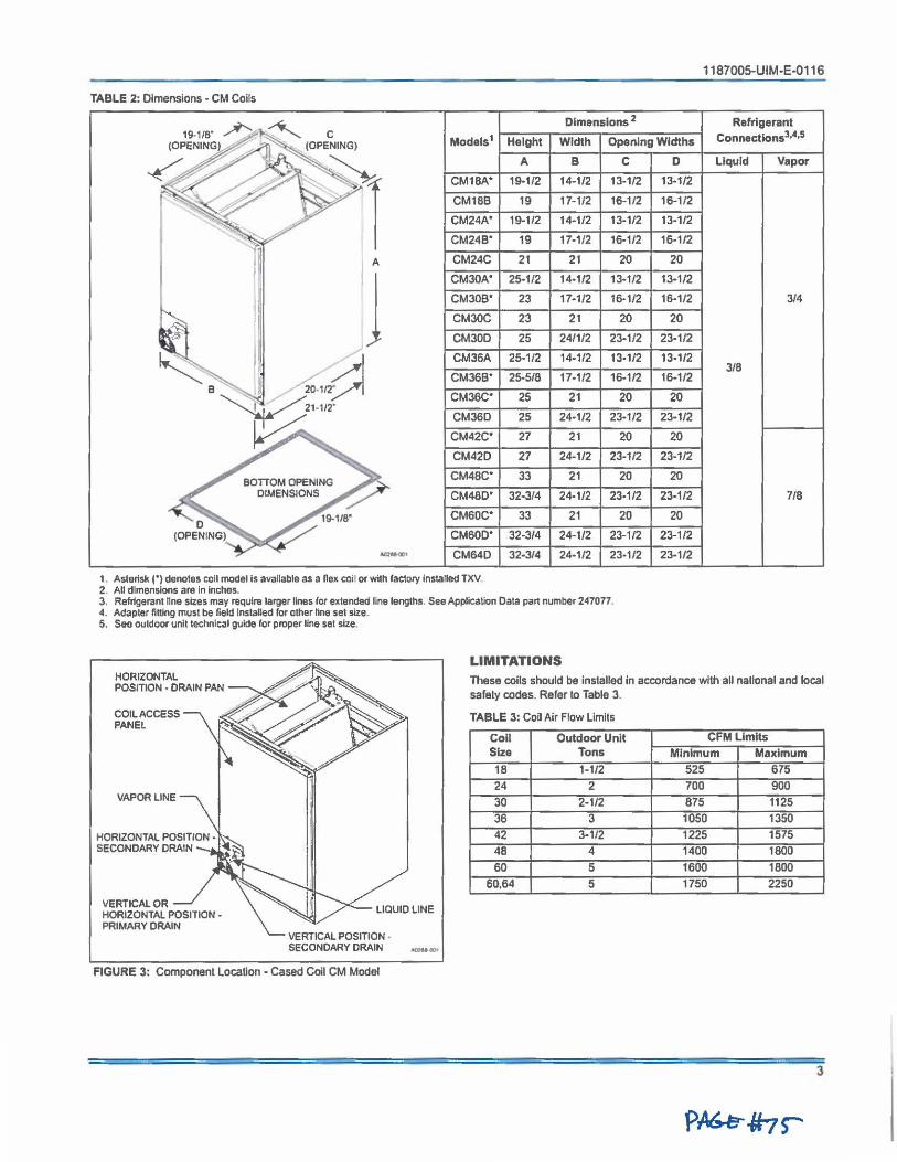
1187005-UIM-E-0116
TABLE 2: Dimensions • CM Coils
19.115· A -~ Dimensions 2 Refrigerant
C Models1 Height Width Openlng Widths Connectlons3•4•5
(0~
(OPENING)
~ ~7,~· . '
7 A 8 C D Liquid Vapor
~v ✓-~ '; ·' CM18A• 19-112 14-1/2 13-1/2 13-1/2 .
CM18B 19 17-1/2 16-1/2 16-1/2
~.
CM24A• 19-1/2 14-1/2 13-1/2 13-1/2 ..
" CM24B• 19 17-1/2 16-1/2 16-1/2
II A CM24C 21 21 20 20
l CM30A• 25-1/2 14-1/2 13-1/2 13-1/2
11 CM30B• 23 17-1/2 16-1/2 16-1/2 3/4
tt CM30C 23 21 20 20
CM30D 25 24/1/2 23-1/2 23-1/2
~ . I, d CM36A 25-1/2 14-1/2 13-1/2 13-1/2 3/8
B "'·· , , _ ,1 20-112" CM36B• 25-5/8 17-1/2 16-1/2 16-1/2
~21-112· CM36C' 25 21 20 20
CM36D 25 24-1/2 23-1/2 23-1/2
~ CM42C• 27 21 20 20
CM42D 27 24-1/2 23-1/2 23-1/2
BOTTOM OPENING CM4ac· 33 21 20 20
DIMENSIONS CM48D' 32-3/4 24-1/2 23-1/2 23-1/2 7/8
0 19-1/8" CMsoc· 33 21 20 20
(OPENING) CM60D' 32-3/4 24-1/2 23-1/2 23-1/2 - CM64D 32-3/4 24-1/2 23-1/2 23-1/2
1. Asterisk(') denotes coll model Is available as a nex coil or with factory Installed TXV 2. All dimensions are In Inches. 3. Refrigerant line sizes may require larger lines for extended tine lengths. See Application Data part number 247077. 4. Adapter titting must be field lnstaned for other line set size. 5. See outdoor unit lechnical guide for proper line set size.
HORIZONTAL POSITION • DRAIN PAN
COIL ACCESS PANEL
VAPOR LINE
VERTICAL OR HORIZONTAL POSITION -PRIMARY DRAIN
LIQUID LINE
---FIGURE 3: Component Location - Cased Coil CM Model
LIMITATIONS These coils should be installed in accordance with all national and local safely codes. Refer to Table 3.
TABLE 3: Coil Air Flow Limils
CoU Outdoor Unit CFM Limits Size Tons Minimum Maximum
18 1-1/2 525 675
24 2 700 900
30 2-1/2 875 1125
36 3 1050 1350
42 3-1/2 1225 1575
48 4 1400 1800
60 5 1600 1800
60,64 5 1750 2250
3
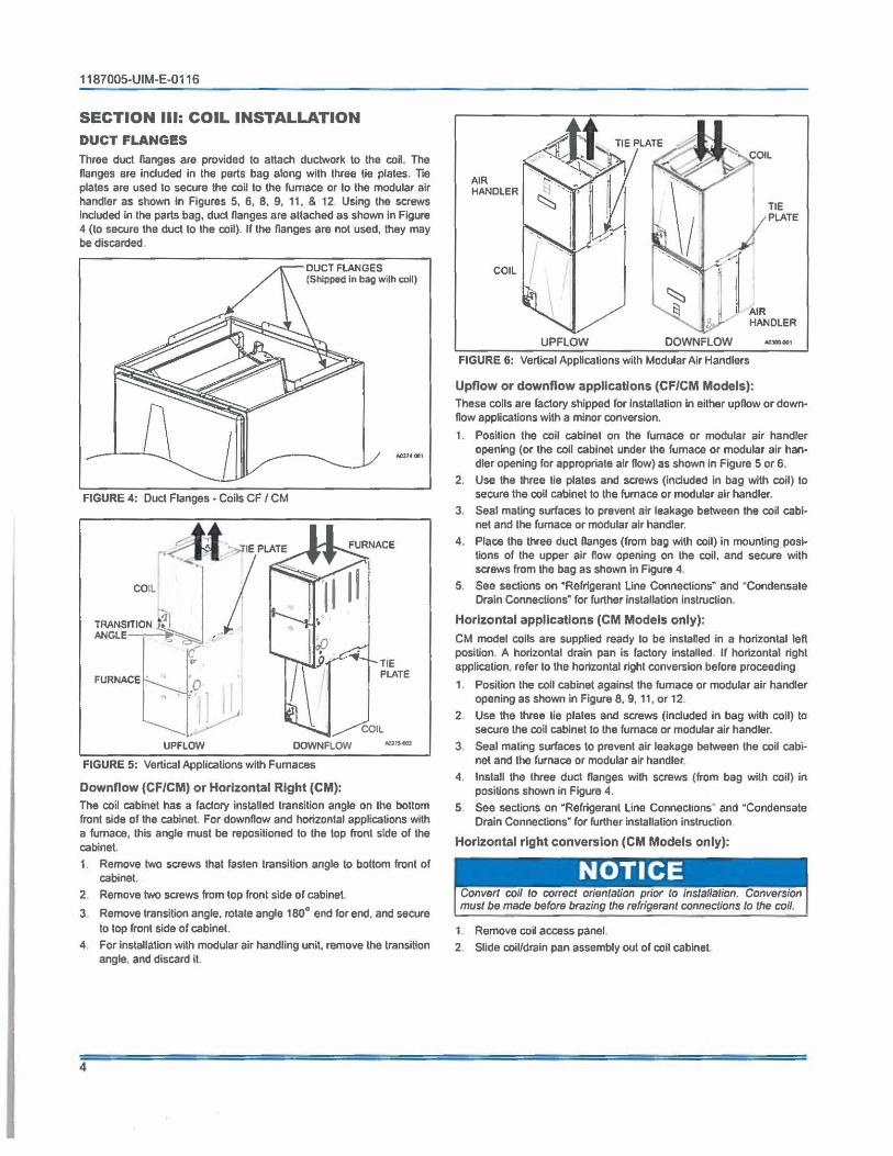
1187005-UIM-E-0116
SECTION Ill: COIL INSTALLATION DUCT FLANGES
Three duct flanges are provided to attach ductwork lo the coil. The flanges are included in the parts bag along with three lie plates. lie plates are used to secure the coU to lhe furnace or to the modular air handler as shown in Figures 5, 6, 8, 9, 11, & 12 Using the screws Included in lhe parts bag, duct flanges are attached as shown in Figure 4 (lo secure the duct to the coil). If the flanges are not used, they may be discarded.
DUCT FLANGES (Shipped In bag wilh coll)
FIGURE 4: Duct Flanges • Coils CF / CM
,..,,M ··,,J"tE PLATE
I · ; COIL
'1 TRANSITION •?1 ANGLE-~~=::::,,~ ~
UPFLOW
j
DOWNFLOW
FIGURE 5: Vertical Applicalions with Furnaces
Downflow (CF/CM) or Horizontal Right (CM):
TIE PL.ATE
""""""
The coil cabinet has a factory installed transition angle on the boltom front side of the cabinet. For downflow and horizontal appHcations with a furnace, this angle must be repositioned to the top front side of the cabinet.
1. Remove two screws that fasten transition angle to bottom front of cabinet.
2. Remove two screws from top front side of cabinet.
3 Remove transition angle, rotate angle 180° end for end, and secure lo top front side of cabinet.
4. For Installation with modular air handling unit, remove the transition angle, and discard it.
4
AIR HANDLER
COIL
UPFLOW DOWNFLOW
TIE PL.ATE
AIR HANDLER
FIGURE 6: Vertical Applications with Modular Air Handlers
Upflow or downflow applications (CF/CM Models): These colls are factory shipped for Installation In either upflow or downflow applications with a minor conversion.
1. Position the coil cabinet on the furnace or modular air handler opening (or the coil cabinet under the furnace or modular air handler opening for appropriate air flow) as shown in Figure 5 or 6.
2. Use the three lie plates and screws (included in bag with coil) to secure the coll cabinet to the furnace or modular air handler.
3. Seal mating surfaces lo prevent air leakage between the co~ cabi· net and the furnace or modular air handler.
4. Place the three duct flanges (from bag wilh coil) in mounting positions of the upper air flow opening on the coil, and secure with screws from lhe bag as shown in Figure 4.
5. See seclions on "Refrigerant Line Connections• and · condensate Drain Connections" for further installation instruction.
Horizontal applications (CM Models only):
CM model coils are supplied ready lo be installed in a horizontal left position A horizontal drain pan is factory installed. If horizontal right application. refer to lhe horizontal right conversion before proceeding
1 Position the coil cabinet against the furnace or modular air handler opening as shown in Figure 8, 9, 11 , or 12
2. Use the three lie plales and screws (Included in bag wilh coil) to secure the coil cabinel to the furnace or modular air handler.
3 Seal mating surfaces lo prevent air leakage between the coil cabinet and the furnace or modular air handler
4. Install the three duel Hanges with screws (from bag with coil) in positions shown in Figure 4.
5 See sections on "Refrigerant Line Connections• and "Condensate Drain Connections" ror further installation instruction
Horizontal right conversion (CM Models only):
Convert coil to correct oriental/on prior to installation. Conversion must be made before brazing the refrigerant connections to the coil.
1 Remove coil access panel.
2 Slide coil/drain pan assembly out of coil cabinet.
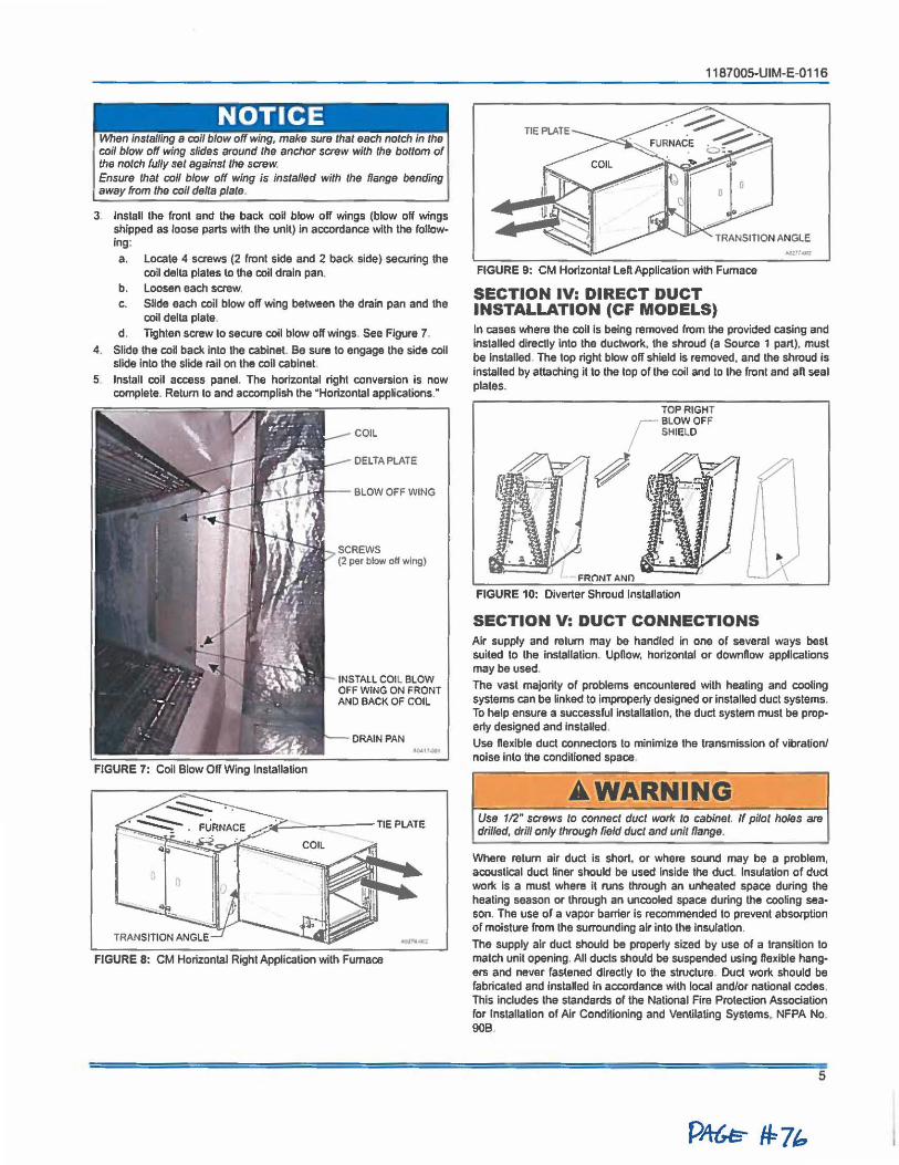
- - - -- -
NOTICE !Mien installing a coll blow off wing, make sure that each notch In the coil blow off wing slides around the anchor screw with the bottom of the notch fully set against the screw. Ensure that coll blow off wing is installed with the flange bending away from the coil delta plate.
3 Install the front and the back coil blow off wings (blow off wings shipped as loose parts with the unit) in accordance with the following:
a . Locate 4 screws (2 front side and 2 back side) securing lhe coil delta plates lo lhe coil drain pan.
b. Loosen each screw. c. Slide each coil blow olf wing between the drain pan and lhe
coil delta plate.
d . Tighlen screw to secure coll blow off wings. See Figure 7.
4. Slide lhe coll back inlo the cabinet. Be sure to engage the side coil slide into the slide rail on the coll cabinet.
5 Install coil access panel. The horizontal right conversion is now complete. Relum lo and accomplish the "Horizontal applications."
FIGURE 7: Coll Blow Off Wing Installation
COIL
DELTA PLATE
INSTALL COIL BLOW OFF WING ON FRONT AND BACK OF COIL
DRAIN PAN ~,, ....
FIGURE 8: CM Horizontal Righi Application with Furnace
1187005-UIM-E-0116
FIGURE 9: CM Horizontal Left Application with Furnace
SECTION IV: DIRECT DUCT INSTALLATION (CF MODELS) In cases where lhe coil Is being removed from the provided casing and installed directly into Iha duclwork, the shroud (a Source 1 part). must be Installed. The top right blow off shield Is removed, and lhe shroud is Installed by attaching it to the lop of the coil and to the front and aft seal plates.
TOP RIGHT
r BLOWOFF SHIELD
~
FRONTANn
FIGURE 10: Diverter Shroud Installation
SECTION V: DUCT CONNECTIONS Air supply and return may be handled in one of several ways best suited lo the installation. Upflow, horizontal or downflow applications maybe used.
The vast majority of problems encounlered with heating and cooling systems can be linked to improperly designed or Installed duel systems. To help ensure a successful installation, lhe duct system must be properly designed and installed
Use flexible duct connectors to minimize the transmission of vibration/ noise Into the conditioned space.
•WARNING Use 112" screws to connect duct work to cabinet. If pilot holes are drilled, drill only through field duet and unit flange.
Where return air duct is short, or where sound may be a problem, acoustical duct liner should be used Inside the duel. Insulation of duct work Is a must where it runs through an unheated space during the heating season or through an uncooled space during the cooling sea• son. The use of a vapor barrier Is recommended to prevent absorption of moisture from the surrounding air into the insulation.
The supply air duct should be properly sized by use of a transition to match unit opening. All ducts should be suspended using ffexlble hang• ers and never fastened directly to the structure. Duct work should be fabricated and installed in accordance with local and/or national codes. This includes the standards of the National Fire Protection Association ror Installation or Air Conditioning and Ventilating Systems, NFPA No. 90B.
5
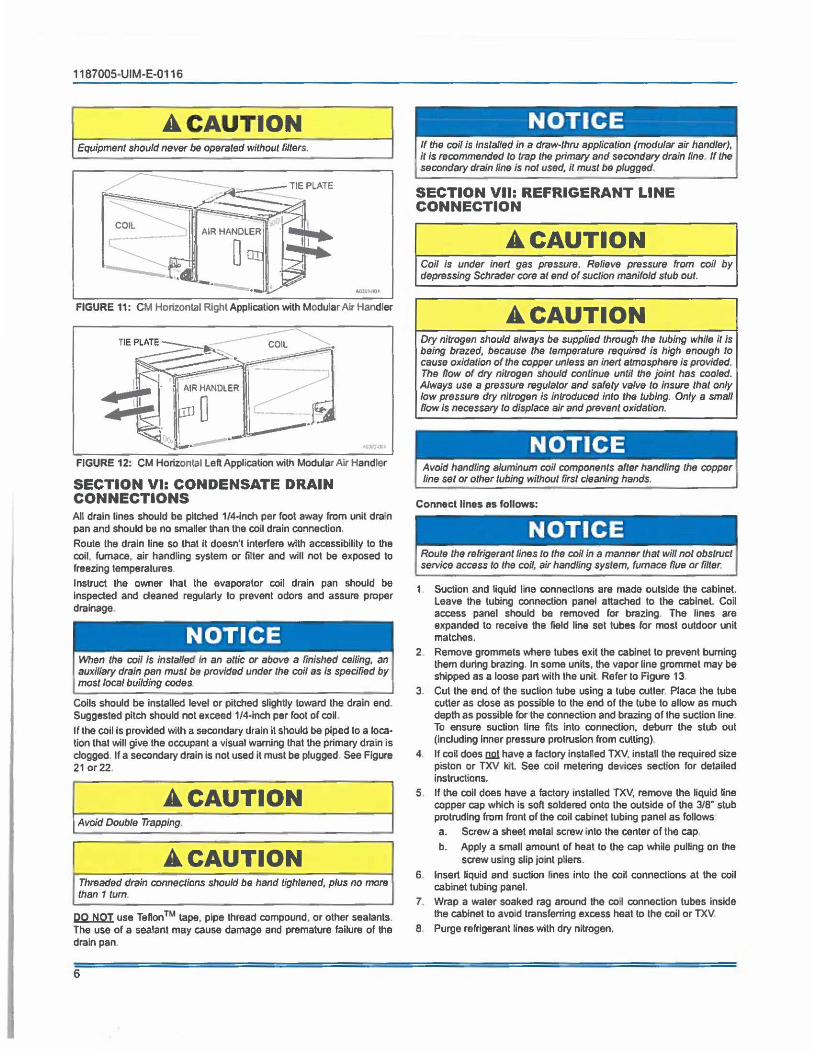
1187005-UIM-E-0116
A CAUTION Equipment should never be operated without filters.
COIL
..,.,...,. FIGURE 11: CM Horizontal Rlghl Application with Modular Air Handler
FIGURE 12: CM Horizontal Left Application with Modular Air Handler
SECTION VI: CONDENSATE DRAIN CONNECTIONS An drain lines should be pitched 1/4-inch per fool away from unit dra'n pan and should be no smaller than the coil drain connection.
Route the drain line so that ii doesn't interfere with accessibility to the coil, fumace, air handling system or filter and will not be exposed to freezing temperatures.
Instruct the owner that the evaporator coil drain pan should be Inspected and deaned regularly to prevent odors and assure proper drainage.
- - -
NOTICE When the coil Is installed In an attic or above a finished ceiling, an auxiliary drain pan must be provided under the coil as Is specified by most local building codes
Calls should be installed level or pitched slighUy toward the drain end. Suggested pitch should not exceed 1/4-lnch per fool of coil.
Ir the coil ls provided with a secondary drain ii should be piped to a location that will give the occupant a visual wamlng that the primary drain is clogged. If a secondary drain ls not used it must be plugged. See Figure 21 or 22.
A CAUTION Avoid Double Trapping.
A CAUTION Threaded drain connections should be hand lightened, plus no more than 1 tum.
12.Q.J:iQI. use Teflon TM tape, pipe thread compound, or other sealants. The use of a sealant may cause damage and premature failure of the drain pan.
6
NOTICE If the cci/ Is Installed in a draw-lhru application (modular air handler),
, II is recommended lo trap the primary and secondary drain line. If the secondary drain line is not used, ii must be plugged.
SECTION VII: REFRIGERANT LINE CONNECTION
A CAUTION Coll Is under inert gas prassure. Relieve pressure from coil by depressing Schrader core at end of suction manifold stub out .
A CAUTION Dry nitrogen should always be supplied through the tubing while ii Is being brazed, because the temperature required is high enough to cause oxidation of the copper unless an inert atmosphere is provided. The now of dry nitrogen should continue until the joint has cooled. Always use a pressure regulator and safety valve lo Insure that only low pressure dry nitrogen is introduced into the tubing. Only a small flow Is necessary lo displace air and prevent oxidation.
Avoid handling aluminum coil components after handling the copper line set or other tubing witho_ul first cleaning hands.
Connect llnes as follows:
Route the refrigerant lines to the coil in a manner that will no/ obstruct service access to the coil, air handling system, fumace flue or filter.
1. Suction and liquid llne connections are made outside the cabinet. leave the tubing connection panel attached to the cabinet. Coil access panel should be removed for brazing. The lines are expanded to receive the field line set tubes for most outdoor unit matches.
2 Remove grommets where lubes exit the cabinet to prevent burning them during brazing. In some units, the vapor line grommet may be shipped as a loose part with the unit Refer to Figure 13.
3. Cul the end or the suction tube using a tube culler Place the tube cutter as dose as possible to the end of the tube to allow as much depth as possible for the connection and brazing or the suction line. To ensure suction line fits into connection, deburr the stub out (induding inner pressure protrusion from culling).
4 If coil does om have a factory Installed TXV, instaU the required size piston or TXV kll. See coil metering devices section for detailed instructions.
5 If the coil does have a factory installed TXV, remove the liquid line copper cap which is soft soldered onto the outside of the 3/8" stub protruding from front of the coil cabinet tubing panel as follows
a. Screw a sheet metal screw into the center of the cap.
b. Apply a small amount of heat to the cap while pulling on the screw using slip joint pliers.
6. Insert liquid and suction lines into the coil connections at the coil cabinet tubing panel.
7. Wrap a water soaked rag around the coi connection tubes inside the cabinet lo avoid transferring excess heat to the coil or TXV
8 . Purge refrigerant lines with dry nitrogen.
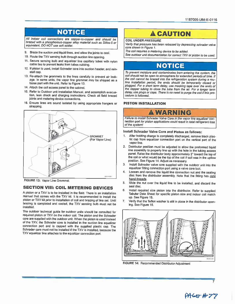
I NOTICE All indoor coil connections are copper-lo-copper and should be
, brazed with a phosphorous-copper alloy material such as Silfos-5 or equivalent. DO NOT use soft solder.
9. Braze the suction and liquid lines, and allow the joints to cool. 10. Route the TXV sensing bulb through suction line opening. 11. Secure sensing bulb and equalizer line capillary tubes with nylon
cable ties lo prevent leaks from tubes rubbing.
12. If piston Is used. install Schrader core into suction header, and reinstall cap.
13. Re-attach the grommets to the lines carefully to prevent air leakage. In some units. the vapor line grommet may be shipped as a loose part with the unit. Refer lo Figure 13.
14. Attach the coll access panel to the cabinet.
15. Refer to Outdoor unit Installation Manual, and accompllsh evacua• tion, leak check and charging instructions. Check all field brazed joints and metering device connections.
16. Ensure lines are sound isolated by using appropriate hangers or strapping. ---~- I '
\ '
GROMMET (For Vapor line)
FIGURE 13: Vapor Line Grommet
SECTION VIII: COIL METERING DEVICES A piston or a TXV is to be Installed in the field. There is an installation manual that comes with the TXV kit. It Is recommended to install the piston or TXV kit prior to installation of coil and brazing of line set. Until brazing is completed and cooled, the TXV sensing bulb must not be installed.
The outdoor technical guide for outdoor units should be consulted for required piston or TXV on the indoor coil. The piston and the Schrader core are supplied with the outdoor unit. When the piston is used instead of the TXV, the Schrader core is installed in the suction line equalizer connection port and is capped with the supplied plastic cap. The Schrader core must not be installed if the TXV is installed, because the TXV equalizer line attaches to the equalizer connection port
1187005~UIM•E-0116
A.CAUTION COIL UNDER PRESSURE. Verify that pressure has been released by depressing Schrader valve core shown in Figure 1. The coil requires a metering device to be added. Sae outdoor unit documentation for con-eel TXV or piston lo be used.
NOTICE To prevent moisture and contaminates from entering the system, the coil should not be open to atmosphere for extended periods of time. If the coil cannot be brazed into the refrigeration system during a routine installation period, the ends should be temporarily closed or plugged. For a short term delay, use masking tape over Iha ends of the copper tubing to close the tuba from the air. For a longer term delay, use plugs or caps, There is no need to purge the coil if this procedure is followed.
PISTON INSTALLATION
A.WARNING Failure lo install Schrader Valve Core in the vapor 1/ne equalizer connection port for piston applications could result in total refrigerant loss of the system/
Install Schrader Valve Core and Piston as follows: 1. Alter holding charge is completely discharged, remove btack plas
lic cap from equalizer connection port on the vertical part of the vapor line.
2. Distributor position must be adjusted to allow the preformed liquid line assembly to properly line up with the hole In the tubing access panel. Raise the distributor body approximalely 2· toward the top of the coil or what would be the lop of the coll if coil was In the upnow position. See Figure 14. Adjust as necessary.
3 Install Schrader valve core supplied with the outdoor unit into the equalizer fitting connection port using a valve core tool.
4. Loosen and remove lhe liquid line connection nut and the sealing disc from the distributor assembly, Nole that the fitting has li9b.l hand threads.
5. Slide the nut over the liquid line lo be installed, and discard the seal disc.
6 Install required size piston into the distributor. Refer to supplied Tabular Data Sheet for specific piston size and indoor coil match up See Figure 15.
7. Verify that the Teflon washer is still in place in the distributor opening. See Flgure 15.
.......... FIGURE 14: Recommended Distributor Adjustment
7
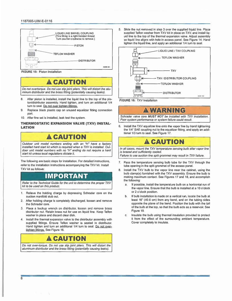
1187005-UIM-E-0116
(1 LIQUID LINE SWIVEL COUPLING n ~ (This fining Is a rlgtll•handed thread Tum c:oun1er-<:lockwise lo remove.)
Q'1------P1STON
lrl~TEFLON WASHER
G-::J:?~---------DISTRIBUTOR
FIGURE 15: Piston Installation
A CAUTION Do not overtorque Do not use slip joint pliers. This will dislort the aluminum distributor and the brass filling (potentially causing leaks).
8. After piston is Installed, install the liquid line to the top of the piston/distributor assembly. Hand tighten, and tum an additional 1/4 tum to seat Do not over lighten fillings.
9. Replace black plastic cap on unused equalizer lilting connection port.
10 After ffne set is lnstaUed, leak lest the system.
THERMOSTATIC EXPANSION VALVE (TXV) INSTAL· LATION
A CAUTION Outdoor unit model numbers ending with an "H" have a factory installed hard start kit which is required when a TXV is installed Outdoor uni/ model numbers with no "H" ending do no/ require a hard start kit unless local regulations dictate it.
The following are basic steps for Installation. For detailed Instructions, refer to the Installation lnstruclions accompanying the TXV kit. Install TXV kit as follows:
Refer lo the Technical Guide for the unit to determine the proper TXV kit to be used on this product.
1. Relieve the holding charge by depressing Schrader core on the suction manifold stub out.
2 After holding charge is completely discharged, loosen and remove the Schrader core.
3. Place a backup wrench on distributor, loosen and remove brass distributor nut. Retain brass nut for use on liquid line. Keep Tefton washer in place and discard dear disk.
4. Install the lhennal expansion valve to the distributor assembly with supplied fillings. Ensure Tenon washer is sealed in distributor. Hand tighten and lum an additional 1/4 tum to seal. Po not oyerlightan fittings See Figure 16.
A CAUTION Do not over-torque. Do not use slip joint pliers. This will distort the aluminum distributor and the brass fitting (potentially causing leaks).
8
5. Slide the nut removed In step 3 over the supplied liquid line Place supplied Tenon washer from TXV kit In place on TXV, and lnstan liquid line to the top of the thennal expansion valve. Adjust assembly so liquid line al.gns with hole In access panel See Figure 14. Hand lighten the liquid line, and apply an additional 1/4 tum to seal.
~ LIQUID LINE /TXV COUPLING
-4------TEFLON WASHER
----TXV I DISTRIBUTOR COUPLING
-4-----TEFLON WASHER
ii ~ DISTRIBUTOR
FIGURE 16: TXV Installation
•WARNING
---
Schrader valve core MUST NOT be installed with TXV installation. Poor system performance or system failure could result.
6. Install !he TXV equalizer line onto lhe vapor line by hand tightening the 1/4" SAE coupling nul lo the equalizer fitting, and apply an additional 1/3 tum to seal. See Figure 17.
A CAUTION In all cases, mount the TXV temperature sensing bulb after vapor line is brazed and sufficiently cooled. Failure to use suction line split grommet may result In TXV failure.
7. Pass the temperature sensing bulb lube ror lhe TXV through lhe tube opening in the split grommet of the access panel.
8. Install lhe TXV bulb to lhe vapor line near lhe cabinet. using the bulb clamp(s) furnished wilh the TXV assembly. Ensure the bulb is making maidmum contact. See Figures 17 and 18, and accomplish the following
a. If possible, Install the lemperature bulb on a horizontal run of the vapor line. Ensure thal the bulb is installed al a 10 o'clock or 2 o'dock position.
b. If bulb inslalialion is made on a vertical run, locate the bulb at least 16" (40.6 cm) from any bend, and on lhe tubing sides opposite the plane or the bend. Position the bulb with the tail of lhe bulb al lhe top, so lhal lhe bulb acts as a reservoir. See Figure 19.
c Insulate lhe bulb using lhennal insulation provided to protect it from lhe effect of the surrounding ambient temperature. Cover completely to insulate.
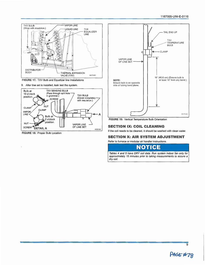
TVX EQUALIZER LINE
-,
THERMAL EXPANSION VALVE (TXV) ..,,.,,.,
FIGURE 17: TXV Bulb and Equalizer line Installations
9. After line set Is Installed, leak test the system.
Bulb al 10 o'clock position.
TXV SENSING BULB (Pass through split hole In grommet.)
,_......__,...,...SCREW
TXV BULB (Cover completely with Insulation.)
Bulb at --.--dllµ.-.L--...L...,..JL.,..J 2 o'clock position.
FIGURE 1 B: Proper Bulb Location
VAPOR LtNE OF LINE SET ..,. ... ,
1187005-UIM-E-0116
/TAIL END UP
✓ TXV ___- TEMPERATURE
---- BULB
CLAMP
VAPOR LINE OF LINE SET ---.i
1s- (40.6 cm) (Ensure bulb is NOTE: at least 1 s· from any bend I Ensure bulb is on opposite side of tubing bend plane.
FIGURE 19: Vertical Temperature Bulb Orientation
SECTION IX: COIL CLEANING If the coll needs lo be cleaned. II should be washed with clean water.
SECTION X: AIR SYSTEM ADJUSTMENT Rarer to furnace or modular air handler instructions.
NOTICE Tables 4 and 5 have DRY coil data. Run system indoor fan only for approximately 15 minutes prior to taking measurements to assure a dry coil.
9
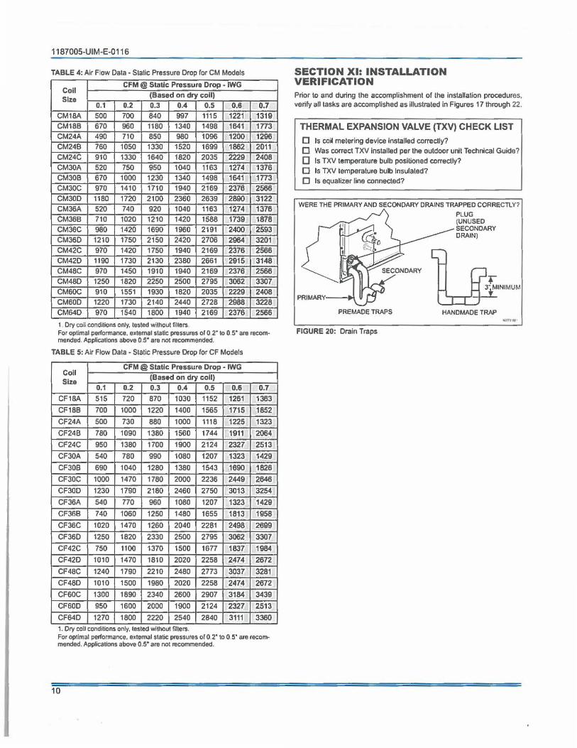
1187005-UIM-E-0116
TABLE 4: Air F ow Data - Static Pressure Drop for CM Models
Coil CFM @ Static Pressure Drop - IWG
Size (Based on dry coll) 0.1 0.2 0.3 0.4 0.5 0,8 0.7
CM18A 500 700 840 997 1115 1221 1319 CM18B 670 960 1180 1340 1498 1641 1n3 CM24A 490 710 850 980 1096 1200 1296 CM24B 760 1050 1330 1520 1699 1862 2011 CM24C 910 1330 1640 1820 2035 2229 2408 CM30A 520 750 950 1040 1163 1274 1376 CM30B 670 1000 1230 1340 1498 1641 1n3 CM30C 970 1410 1710 1940 2169 2376 2566 CM30D 1180 1720 2100 2360 2639 2890 3122 CM36A 520 740 920 1040 1163 1274 1376 CM36B 710 1020 1210 1420 1588 1739 1878 CM36C 980 1420 1690 1960 2191 2400 2593 CM360 1210 1750 2150 2420 2706 2964 3201 CM42C 970 1420 1750 1940 2169 2376 2566 CM42D 1190 1730 2130 2380 2661 2915 3148 CM48C 970 1450 1910 1940 2169 2376 2566 CM48D 1250 1820 2250 2500 2795 3062 3307 CM60C 910 1551 1930 1820 2035 2229 2408 CM600 1220 1730 2140 2440 2728 2988 3228 CM64D 970 1540 1800 1940 2169 2376 2566 1. Dry eoil conditions only, tested without filters For optimal performance. external static pn,ssures or o 2- to 0 s· are recommended, Applicallons above Os· are not recommended.
TABLE 5: Air Flow Data - Static Pressure Drop for CF Models
Coll CFM @ Static Pressure Drop • IWG
Size (Based on dry coll)
0.1 0.2 0.3 0.4 0.5 0.6 0.7 CF18A 515 720 870 1030 1152 1261 1363 CF18B 700 1000 1220 1400 1565 1715 1852 CF24A 500 730 880 1000 1118 1225 1323 CF24B 780 1090 1380 1560 1744 1911 2064 CF24C 950 1380 1700 1900 2124 2327 2513 CF30A 540 780 990 1080 1207 1323 1429 CFJOB 690 1040 1280 1380 1543 1690 1826 CF30C 1000 1470 1780 2000 2236 2449 2646
CF300 1230 1790 2180 2460 2750 3013 3254 CF36A 540 770 960 1080 1207 1323 1429 CF368 740 1060 1250 1480 1655 1813 1958
CF36C 1020 1470 1260 2040 2281 2498 2699 CF360 1250 1820 2330 2500 2795 3062 3307 CF42C 750 1100 1370 1500 1677 1837 1984 CF420 1010 1470 1810 2020 2258 2474 2672 CF48C 1240 1790 2210 2480 2773 3037 3281 CF48D 1010 1500 1980 2020 2258 2474 2672 CF60C 1300 1890 2340 2600 2907 3184 3439 CF600 950 1600 2000 1900 2124 2327 2513 CF64D 1270 1800 2220 2540 2840 3111 3360
1. Dry coil condillons only, tested without filters. For optimal performance, external stallc pressures or O 2' to o 5' are recom• mended. Applications above o.s• are not recommended.
10
SECTION XI: INSTALLATION VERIFICATION Prior to and during lhe accomplishment or the instaUalion procedures, verify all tasks are accomplished as illustrated in Figures 17 through 22.
THERMAL EXPANSION VALVE (TXV) CHECK LIST
D Is coil metering device installed correctly? D Was correct TXV Installed per the outdoor unit Technical Guide? 0 Is TXV temperature bulb positioned correctly? D ts TXV temperature bulb Insulated? D Is equalizer line connected?
WERE THE PRIMARY AND SECONDARY DRAINS TRAPPED CORRECTLY?
PREMAOE TRAPS
FIGURE 20: Drain Traps
PLUG (UNUSED SECONDARY ORAINI
♦ 3" MtNIMUM
HANDMADE TRAP
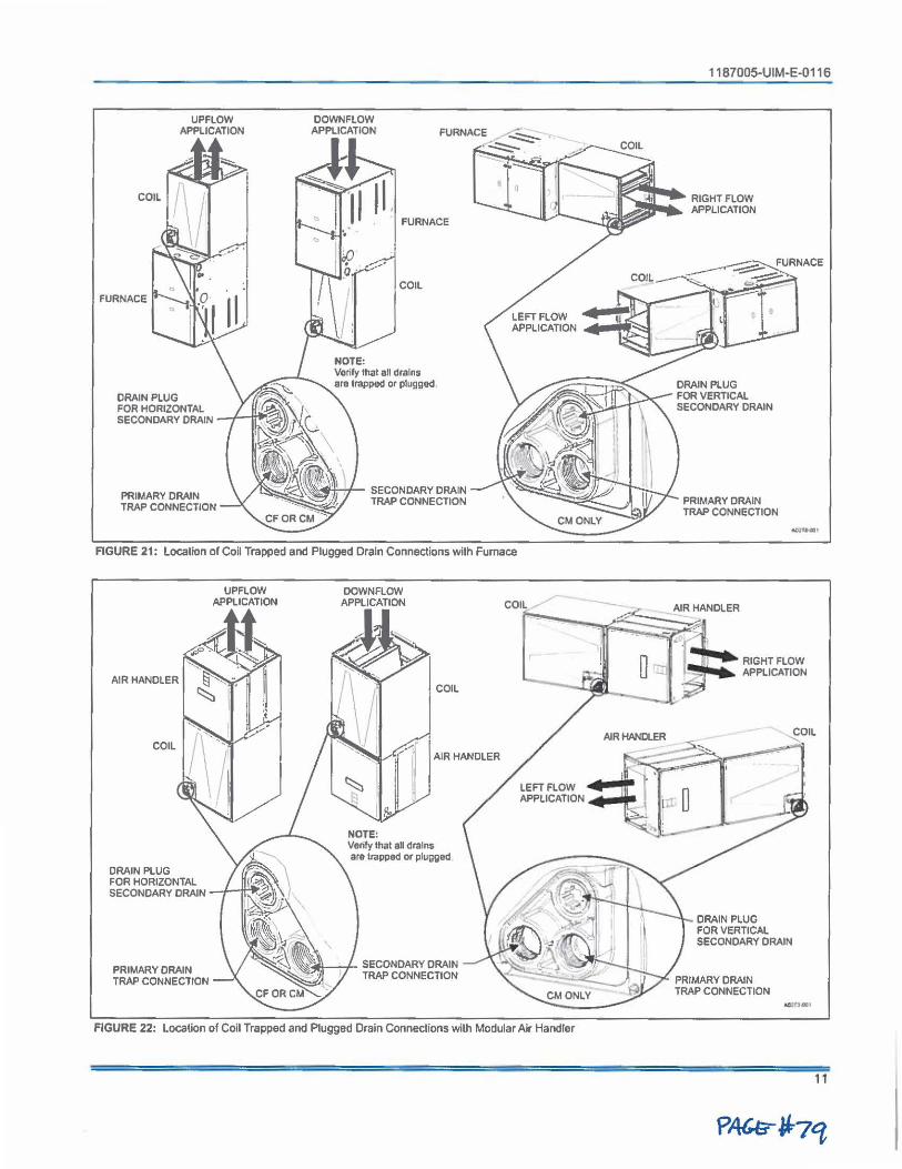
FURNACE
DRAIN PLUG
UPFLOW APPLICATION
FOR HORIZONTAL SECONDARY DRAIN ~-tn
PRIMARY DRAIN TRAP CONNECTION
OOWNFLOW APPLICATION
FURNACE
COIL
, \~4'Hf-- SECONDARY DRAIN TRAP CONNECTION
FIGURE 21: location of Coll Trapped and Plugged Drain Connections with Fu mace
AIR HANDLER
COIL
DRAIN PLUG FOR HORIZONTAL SECONDARY DRAIN
PRIMARY DRAIN TRAP CONNECTION
UPFLOW APPLICATION
DOWNFLOW APPLICATION
NOTE:
COIL
AIR HANDLER
Verify that au drains ara trapped or plugged
SECONDARY DRAIN TRAP CONNECTION
CM ONLY
FIGURE 22: Location of Coil Trapped and Plugged Drain Connections with Modular Air Handler
1187005-UIM-E-0116
PRIMARY DRAIN TRAP CONNECTION --·
~ANDLER
- --□ ~ • ~ : •'"HHLOW ....,7 I-' . APPLICATION
'
DRAIN PLUG FOR VERTICAL SECONDARY DRAIN
PRIMARY DRAIN TRAP CONNECTION
11
Subject lo change without notice. Published in U,SA Copyright -0 2016 by Johnson Controls, Inc, All rights reserved,
NOTES
York International Corp. 5005 York Drive
Norman, OK 73069
1187005-UIM-E-0116 Supersedes: 1187005-UIM-D-1115
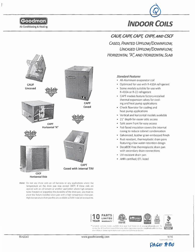
Goodman Air Conditioning & Heating
CAUF Uncased •
Horizontal "A"
• CSCF
Horizontal Slab
CAPF Cased
•
CAPT Cased with Internal TXV
INDOOR COILS
CAUF, CAPF, CAPT; CHPF, AND CSCF
CA.sED, PAINTED UPFLOW/DOWNFLOW,
UNCASED UPFLOW/DOWNFLOW,
HORIZONTAL ''A'; ANO HORIZONTAL SLAB
Standilrd Features • All-Aluminum evaporator coil
• Optimized for use with R-410A refrigerant
• Some models suitable for use with R-4 lOA or R-22 refrigerant
• CAPT models feature factory-installed thermal expansmn valves for cool• mg and heat pump applications
• Check nowrator for cooling and heat pump applications
• Vertical and horizontal models available
• 21 ' depth for easier attic access
• Split seam front for easy access • Foil-faced insulation covers the internal
casmg to reduce cabinet condensallon • Galvanized, leather gram-embossed finish
• Rust resistant, thermoplastic dram pans featuring a low water-retention design
• DecaBDE•free thermoplastic dram pan with secondary drain connections
• UV-resistant drain pan • AHRI cernhed; ETL listed
Norr:: 00 not us: tt;:s~ co,ls on c,I furnJtes or any a~plica~ons v..here tloe temper.1ture on the drain pan may exceed 300'F. If these mils are ~PP' ed with an " 'I furnace or another ,)ppl"cation ,vti.?re t; gh t~mpera tures threaten or jropard,ze the durability of the drain pan, you must rcpla~e the fal"tory installed dr,1in pan w th a hir,h tempcr:itu1e drain pJn. High-1emperature drain pan kits arc avJdable as fold- r.sta: cd acccsson°s.
SS-GCoil
110 PARTS I LIMITED
YEAR WARRANTY' .(@. m+H I lntert~k ---
• •·.4,m~ ..:tr w.1rrJnt, ,ku1h JVJt!J bk- t,;;,m yuur fJ,Jl ,t-:.11~, or ;n wv,wi•Y.,cltuJomft.lOnl to lt't .. r.,,• tilt' fl' ·u-.w P.uu I 1r111t\•t.l \ViltYJ l',IV. mJ:t.,.. 1r,t:\\l:111e,1 JQU\f l'"" , •r,n ril,,11;:1! \'l,thiu to Cil)'\ 111 •~•1.Jltltl(I~ f"W'IC t l'g,tl l,lnCt\ r, 1,vt ll t'IW0."l w1(.-lfott'!l.t Of Q1r:l►·t
www.goodmanmfg.com
~ ---BBB 25B
9/16
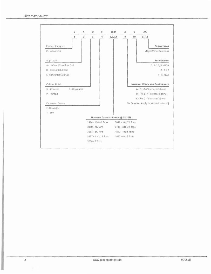
NOMENCLATVRE'
2
Product CJt~g~ry
C Indoor Coil
A- Upf'ow/Dcwr.tlow Coil
H Horiwntal A Coil
S- Hor irnntal Slab Coil
Cabinet Finish
U Uncased
P Painted
E~pansion DeVJCC
F- F!owrator
T TXV
C A
1 2 -u F 1824
3 4 5,6,7,8 - - --A
9 -6
10 -AA
11,12
~ Major/M nor Revisirms
REFRIGERANT
6 • P.•21 / R-410A
2 • R-22
4 • P.••110,\
NOMINAL WIDTH FOR GAS FURNACE
A• F,ts 14" furnace Catiinet
B • Fits l 7Vi" Furnac.? C.1bine1
C • F ls 2 I' Furnace Cabinet
N • Does Not Apply lhomontal slab coll)
NOMINAL CAPACITY RANGE @ 13 SEER
ll!2-l 1 '1 to 2 Tons
3030 • 2 l~ Toni.
3131 • 2►i Tons
3137 • 2 !1, to 3 Tons
3636 • 3 Tons
3642 • 3 to 3½ Tons
3743 • 3 lo 3Vi Tons
4360 • 4 to 5 Tons
4%1 • J to 5 Tons
www goodmanmlg.com SS·GCoil
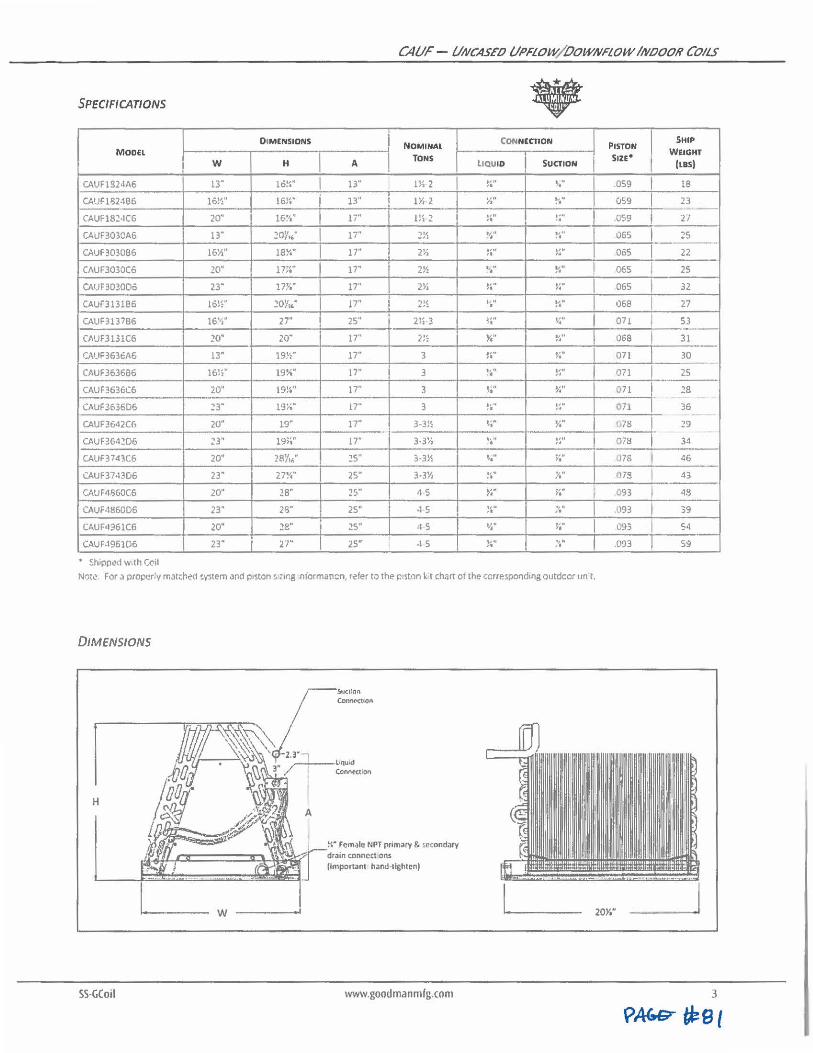
CA Ur - UNCASED UPFLOW/ OOWNFLOW INOOOH COILS
SPECIFICATIONS • DIMENSIONS NOMINAL
CONNECTION PISTON
SHIP
Moon TONS s,n• WEIGHT
w H A LIQUID SUCTION [LBS)
CAUF1S24A6 13· lb!~" I 13" Hl 2 ,,. ,, ~.· .059 I 18
CAUF1132466 16!':" 16!~ .. j 13" l½ 2 ¼ .. ., .. .. 059 I 23 - -CAUF18~•1C6 20· 16~.I ... li" l '' ., ,1 •
.,. .. !4" .059 j 27
CAUF303CA6 13· 1DY1' .. I n· :!!': •✓, .. ,,., .. 065 I 25 --CAUF3030B6 Hi½" 18¾" I 17" 2'' "
,, .. .. ~~ .. 065 I 22
CAUF3030C6 20· 11;~· I 17" 2½ ''." .,. .. 065 l 25
CAIJF303006 23" 17~;- 17" 2►,
~-·· , ... ,. I 065 I 32
CAUF313186 lb!~" 20Y,." !7'' 2!~ •. ,i . ., . .. 068 I 27
CAUF313786 16'1" 27" 25" 2lt3 ,,. ·• , .. ,. I 071 I 53
CAUF3131C6 20· 20· 17" 2!: ¾" ., .. ,. 068 I 31
CAIJF363cA6 13" 19!':" 17" 3 ,,. ,. , ..
" I 071 30 -CAUF363686 16!i .. 19½" 17· 3 ,," .,. ,, 071 I 25
CAUF3636C6 20" 19!~•1 17" 3 ~i'" ¾" 071 I 18
CAUF363606 23" l9ii'" 17" 3 !a" w· 071 1· 36
CAUF3642C6 20· 19" 17" 3-3½ ~ ... ¼. f.78 29
CAUF3642D6 ~3" 19~." 17" 3.3~; , ... :~" '}78 I 34
CAUF3743C6 20· 281/16" lS" 3-3½ ,, ... ,. I .J7S I 46
CAUF3743D6 23• 27¼" I 25" 3-3½ , .. .. y.• 073 I -13
CAUF4-'>60C6 20" 28" 25" 45 ¼" v.· I I .093 i 48
CAUF4860D6 23' 2l3" 25" .1 5 .,. ·•
., . ,, I 093 I 39
CAUF4961C6 20· 2e· 25" 45 'I," , .. " I G93 I 54
CAUF,1961D6 23" 27" 25" 45 !~·· .,. ., .093 59
• ~hipped w,th Ceil
Note: For a properly matched ~ystem and pistons ,,ng niormanon, r.?fer to the p ston kt chart ot the corresponding outdoor unit.
DIMENSIONS
H
w
SS-GCoil
!~• Female NPT primary & ~e,ondary dralll coMcct ons (Important h•nd·llghtonl
www.goodmanmfg.com 3
p,4w;r ~e,
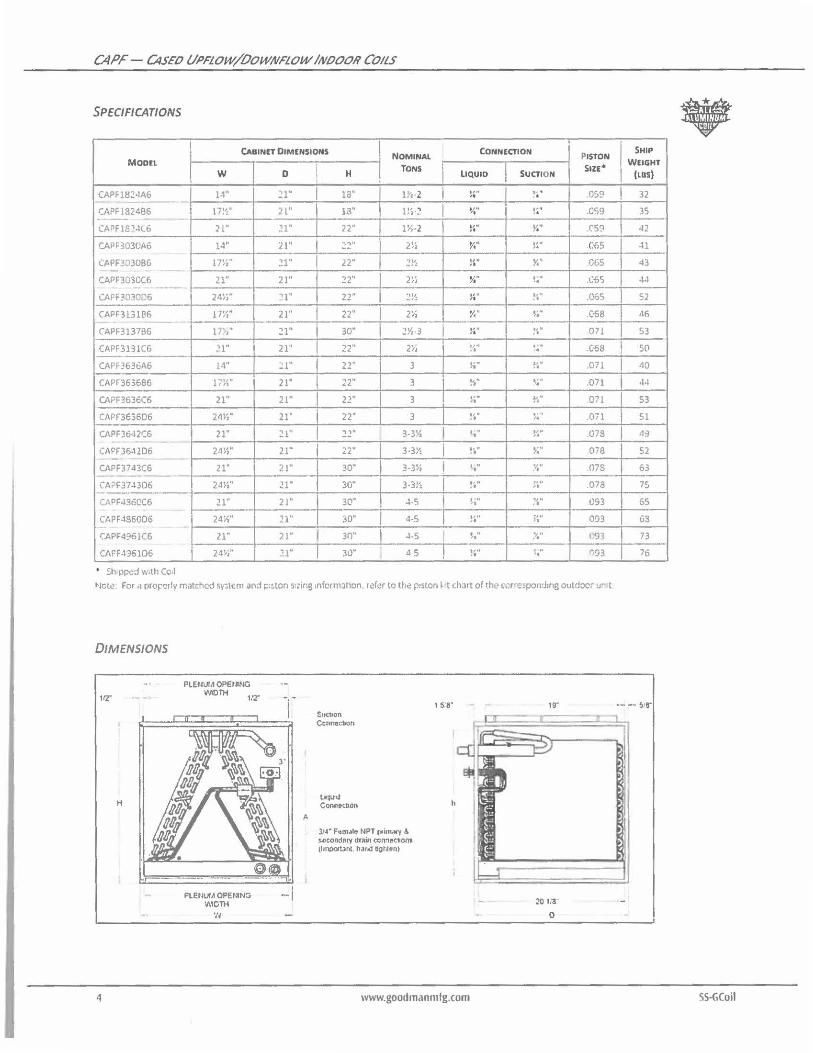
CAPF - CASEIJ tll'FLOW/OOWNFLOW IN/JOOR COILS
SPECIFICATIONS
CABINET DIMENSIONS NOMINAL
CONNECTION PISTON MODEL
TONS I s,u• w 0 H LIQUID SUCTION
CAPFl8Z4A6 l-1" ~l • I 1a· ll',-2 I ,,. ! ... .GS!? ,. ~
I CAPF1324B6 17Vi. ;, L" 13" 11, .., ,;. .. ! 4" .059 ,1-... ----CAPF18'-ll6 21" ~1· 22· 1½-2 I ,,. ,, Y." .CS!?
CAPF303CA6 1-1" 21"' 2:!" 2" " ½" ~~·· 065
CAPF303086 17½" ll" 22· :!½ !~· x· GGS - -CAPF3030C6 21" 21" ~2· 2'' " ~;" !~" .C6S
·- ---I CAFF3030D6 24ViH :'l" 22" :!!':
,,. ~·., .06S ,. CAPF3131B6 l 7Vi" 2 L" I 22" I 2'' II ¾" , ..
" .068 -CAPF3137B6 l .~'., .. 21 .. I 30" l 1½-3 I ,,. ,. .,. .. 071
CAPF3131C6 .'l" 21" I 22" 2}i ~1.•i .. , .. ,. .C58
CAPF3636A6 14" ~1· I 22· 3 , .. ,, !~" .071
CAPF3636B6 l .,,, ,, ,,, 21" I 22" 3 ,.,.., ., ~,~ .. .071
CAPF3636C6 21" 21" 22· 3 ,,. ,. ,.,. ., 071
CAPF363606 241,'' 21" 22· 3 "' .. ... , I• .Oil
CAPF36•12C6 21· ~ l" "' 3-3½ I '' ·• ~~·· G73 -
CAPF36-12D6 24~S" 21"' I 22 .. 3-3!~ I ?'.'' };" Oi8 --CAPF3743C6 21· 21· 30" 3-3Vi I ' . . , •1.• .. .07S -CAPF37-1306 24½"1 Zl" 30" 3-3l', I ,, . ,, 1"" ,, .073
CAPF4360C6 21" 2 J" 30" -l-S I I•• ,, .,. .. 093
CAPF-186006 24½" 11" 30• 4-5 ,~" ,, i4 .. 093
CAPF4961C6 21· 21· I 3()" I -l-5 h'• :'I," C9"1
CAPF-136106 24h .. 21· 30" 45 , ... l • . r,93
' $h pped w,th Cc,I
Nctc: For a pro~'!rly matc-7-ed sy,tem and piston s,,ing 1nfcrmat1on. refer to lhc piston f t chlrt of th, .-cm,~pondmg outdocr u~ t
DIMENSIONS
H
4
PlENUIA Of'ElflNG INIOlH l/2'
PLEtlUIA Of'El~NG INIO'IH
'II
A
Suc:uon Ccrmectton
loqu,~ Conr1,e110n
l/4" F•m•i<, NPT f'i•nMY .\ 5ocondFtry ct~ln ccnnec:t1om (hnocrtani. haud dgt~•n>
, s:e·
www.goodmanmfg.com
20 "11
0
• SHIP
WEIGHf
(LBS)
I 32
35
42
-11
43
4-1
52
,16
53
I so I 110
I •1-I
I S3
I 51
119
52
63
7S
65
G3
73
76
SS·GCoil
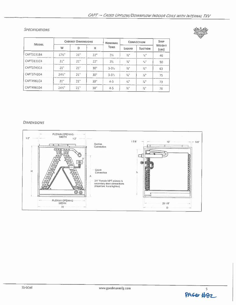
SPECIFICATIONS
MODEL
CAPT3131B4 --CAPT3131C4 --
CAPT3743C4
CAPT3743D4
CAPT4961C4
CAPT4961D4
DIMENSIONS
H
SS-(jCoil
CAPT - C4SE0 UPFLOW/OOWNFLOW IN000N COILS WITH IIVTENNAL TX//
• CABINET DIMENSIONS NOMINAL CONNECTION SHIP
w D
17½" 21"
21" 21·
21" 21'
24Vi'' 21"
21" 21"
24½'' 21"
PLENUM OPENING 'MOTH
1'2"
PLENUM OPENING 'MOTH
w
A
H TONS LIQUID
22" I 22"
30"
30"
30" I 30" I
Soo,on Connec1icn
Liquid Connec1ion
,,, ~-• )
2}S I
3-3~1
3-3~ I 4 •S I 4.5 l
31◄" Female NPT p,i,nary ,t. secondary drain conneehons jlm1101tanl hand lighto11)
~·tt ,,11 ,. ~ ... ''" ,. J, .. ,
'• ,,,, ,.
www.goodmanmlg.com
I
1 511
h
SUCTION
~" .. ; ., ,. ,,., ,. ,,11 /I
7, II ,. 1111 ,.
WEIGHT
(LBSJ
46
50
63
75
73
76
19·
201,8·
0
- - S,(!"
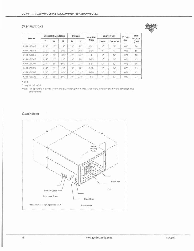
CHPF - PAINTEIJ CASEIJ HORIZONTAL ':4"' INOOOR COIL
SPECIFICATIONS
CABINET DIMENSIONS PlENUM CONNECTION SHIP NOMINAl PISTON Moon
TONS SIZE2 WEIGHT 0 w H 0 H LIQUID SUCTION
CHPF1824A6 21}&"4 26" 1,1" 19" 13" l',·2 !f' ~:- .059
CHPF2•13006 2l}i*' 26" 17Vi" 19" 16!':. ~-2Vi ,,. , I
, .... 065
CHPF3636!l6 ..:L·t" 26" l T1i1' l!:'" l6Vi" 3 , .. ,, .,. ,. .074
CHPF36•1~C6 21}t" 26'' 21" 19" 20" 3-31/, ,, . .. ~:·· .076
CHPF364206 21¼" 26" 24'," 19· 23:;· 3-3½ ,,. "
~; .. .076
CHPF.3743C6 21!~" 26" 21" 19" 20" ?-3Vi ,.,,. i','' 076
CHPF3743D6 21h" 21'," 24';" 19" 23!~· 3-3Vi ,,. " ;·· 078
CHPF,16€,006 ~ l!i .. 26" 2 ◄ '" .. ' 19" 23!," ,1.5 !It"' .,. ... 1, 0'?3
I (ft'} 2 Shipped with Co:I
Note: Fer J properly matched sv~tem an::l p,~ton s1,,ng information. referto the r,,~t::m kit chart c,i the correspond,ng outdoor unit
DIMENSIONS
Secondary Drain
Note: All alr octmng n.:rni~s arf! O 6-'.!S\)4'
G
Liquid line
Suction line
,/
'·•. ,,,,,.,,-✓
Drain Pan
Coil
www.goodm,1nmlg.com
(LBS)
36
ss
so 63
f.6
63
63
Ti
•
SS-G(o1I
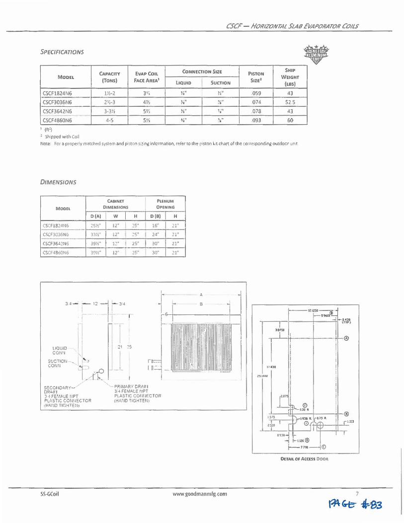
CSCr - flORIZOIVTAL SLAB EVAPORATOR COILS
SPEC/Ff CATIONS • CAPACITY EVAP COIL CONNECTION SIZE PISTON SHIP
MODEL (TONS) fACEAREA1 s1u2 WEIGHT
LIQUID SUCTION (LBS)
CSCF1824 N6 ll,·2 3~, 1' •• ,. )llf ,. .059 43
CSCF3036N6 21,.3 4% , " 7• 11 ° ,I 074 52 5
CSCF3642N6 3.31; SVi V " ,. , ,, • 078 43 -
CSCF4860N6 4-5 S½ J l l1 ,. 1,, •• 093 60
, (ft')
~ Shipped w ith Coil
Mote: Fer a proper y m~tched s·tstem and p·~tc;1 i • ng informal'ion, refer to the p•~ton ~ t chart of the co rft',pond,ng outdoor UI\ t
DIMENSIONS
CABINET I Pl£NUM
MOOEl DIMENSIONS OPENING
O(AJ w I H I D(B)
CSCF1S24N6 25!':" I 12" .s· I 16"
CSCF3036N6 33~~ .. I ,2" I ~s- I 2-1·
CSC:F36ol2N6 39½" I 1~- I J!," I 30''
CSCF4Se0N6 39½" I !2' ~!•" 30"
I
34 - 1 1:? 7 - 3.4
. ' I! {
LIQUID CON'l
SUCilOIJ , corm
$ECOIIOARYDRl.lll
, .,
l_
3 -1 FE1k1LE tlPi PL~STIC COWJECTOR tH4TIO TIGHTEN,
-...0 n ..
I I
'.!1 ?S
PRIMARY DRAlll 3;4 FEMAL:: tlPT PLASTIC COrHlECTOR {HAIIO TIGHTEN!
H
Jl"
21"
ll"
~1·
A
B
l 1 ,,r.nrlr--1
I
l:
SS•CiCoil www goodmanmfg com
~\181
1 1z1~•aj 596CD
i i i i I i i
i jJI
©
0£TAIL OF AC:C£5S DOOR
14311 Ul',-.>
@
lJl'
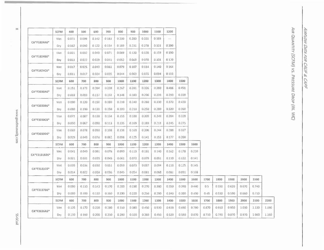
cc
I °d 0 :::,. 3 ~ ::i 3 OQ ;.., 0
3
"" ""
~
CA*F18Z4A6*
CA•F1824B6•
CA*F1824C6•
CA*F3030A6*
CA• F303086*
CA*F3030C6°
CA *F3030D6°
CA*F3131826*
CA*f3131C6•
CA*F313786"
CA*f3636A6"
SCFM
Wet
Dr,
Wet
Ory
Wet
Ory
SCFM
Wet
Dry
Wet
Ory
\V(/(
Ory
Wei
Dr1
SCFM
Wet
Ory
Wet
Dry
SCFM
Wet
Ory
SCFM
Wet
Dr;
400 500
0.071 0099
0.062 0.090
0.021 0 .031
0011 0.022
0017 0025
0.011 0.017
600 700
0.151 0.173
0.069 0.033
0090 0.120
0.080 0.100
0.071 0.087
o.oso 0067
0069 0078
0.029 0.043
600 700
0041 0049
0.021 0.031
0.035 0.036
0.014 0.022
600 700
0.090 0.110
0.080 0.100
600 700
0135 0.170
0 .130 0160
6D0 700 800 900 1000
0.1'12 0183 0230 0.280 0 .331
0.122 0.154 0 189 0.231 0.278
0.049 0071 0089 0120 0.128
0.029 a.cm 0.052 0.069 O.D78
0.0-H 0.061 0.079 0.107 0.114
0.024 0.035 0.0-14 0 .063 0.075
800 900 1000 1100 1200
0.20.1 0.238 0.267 0.281 0.326
O.Ui 0.132 0.148 0.183 0.206
0.lSC: 0.160 0.210 0.240 0280
0.130 0.150 0.180 0.210 0.250
0.120 0 .134 0.155 0180 0.209
0.098 0.113 0.135 0.169 0.189
0090 0108 0.136 0.168 0206
0.070 0.082 0.098 0.125 0.141
800 900 1000 1100 1200
0061 007!! 0.090 0 l 13 0.131
0.039 0.048 0 .061 0072 0.079
0.038 0 .051 0.059 0.073 0.087
0.028 0.036 0.045 0054 0.061
800 900 1000 1100 1200
0.14J 0.170 0.200 0.230 0 .270
0.130 0.160 O.l!lO 0.220 0 .250
800 900 1000 1100 1200
0.220 0.280 0 310 0380 0.450
0.200 0.230 0.280 0.320 0350
1100 1200
0 389
0.331 0390
0.159 0190
0.101 0120
0 .140 0164
0 .094 0.113
1300 1400 1500
0.380 0.406 0.451
)::.. ~ :ii ~ 0 "' ~
(:)
~ ~ ~ ~ ~ ~ ~ ~ ~ ~
~ ~ ~ ~ ~ ~
Cl ~ I,\
~ c::: :,;, r.,
0.239 0.290 0.338
0.330 0.370 0420
C, :,;, 0 "l)
0.280 0.320 0.360 ~ 0.249 0.284 0 .328 ~ ---0.213 0.245 0.275
0.244 0.288 0 337
0.153 0.177 0 .200
1300 1400 1500 1600
0 140 0.162 0 .178 0.210
0.091 0 .110 0.122 0.141
0.09~ 0110 0.125 0.145
0.068 0.081 0.091 0.108
1300 1400 1500 1600 1700 1800 1900 2000 2100
0.300 0 .350 0.390 0440 0 .5 0 550 0.620 0.670 0.740
0.290 0.340 0.380 0430 04S 0.530 0.590 0 .660 0.710
130D 1400 1500 1600 1700 1800 190D 2000 2100 2200
0.530 0610 0.690 0790 0 .870 0.910 0 .950 l .030 1.130 1.190
0 450 0520 0.590 0.670 0710 0.790 0.870 0 .970 l 060 1.160

f
~ C'\
~
::: =, ::: ~ &. 3 ~ :::,
3 ~
8 3
~ .::
$
CA"F3636B6•
CA •f3636C6•
CA• F3636D6•
CA•F3642C6•
CA°F364206"
CA°F3743C6°
CA•F374306•
CA°F4860C&•
CA•F4860D6•
CA"F4961C6°
CA°F49li1D1i•
Wet
Ory
Wet
Ory
\'Vet
Dry
SCFM
Wet
Ory
Wet
Ory
SCFM
W!!I
Dry
Wet
Ory
SCFM
Wet
Ory
\Vet
Ory
SCFM
Wet
Ory
Wet
Dry
0115 0.135
0.110 0.130
0.100 0.120
0.090 0.110
0.095 0.115
0.090 0.110
600 700
0.o75 0.090
0.070 0.080
0.070 0.090
0.060 0.080
800 900
0.083 0.093
0073 0.083
0.074 o.oso
0.046 0.056
1000 1100
0167 0.191
0.160 0.177
0.138 0.156
0.126 0.138
1000 1100
0.209 0.233
0202 0.219
0.140 0.158
0.128 0 140
0.170 0.180 0.220 0.260 0.300
0.160 0.170 0.210 0.240 0270
0.160 0.170 0.210 0.250 0.290
0.130 0.140 0.160 0.130 0.220
0.140 0.150 0.170 0.200 0.230
0.130 0.140 0.160 0.190 0.220
800 900 1000 1100 1200
0.110 0.120 0.140 0.170 0.200
0100 0.110 0.130 0.150 0.170
0.110 0.124 0.1,;o 0.160 0.190
0.090 0.100 0.110 0.130 0 150
1000 1100 1200 1300 1400
0.113 0.133 0.143 0.163 0,183
0.!03 0.113 0.133 0.1S3 0.163
0.089 0.107 0.120 0.129 0.138
0.074 0.076 0.086 0.!07 0.110
1200 1300 1400 1S00 1600
0.219 0.244 0.266 0.299 0.355
0.194 0.206 0.246 0.264 0.264
0.177 0.196 0.226 0.247 0275
0.157 0.176 0.187 0.200 0.205
1200 1300 1400 1500 1600
0.255 0.:!86 0.308 0.341 0.397
0.236 0.248 0.288 0.306 0.306
0.179 0.198 0.228 0.149 0.277
0159 0178 0189 0.202 0 206
0.350 0.400 0.460 0.520 0570
0.330 0.370 0.420 0.470 0.520
0.340 0.380 0 .430 o . .:80 0.540
0.250 0.280 0 320 0.350 0 370
0.270 0.310 0350 0.390 0.430
0.240 0.270 0.300 0.340 0.380
1300 1400 1500 1600 1700
0.230 0.260 0.290 0.330 0.360
0.200 0.230 0 250 0.280 0.310
0.210 0.240 0.270 0.300 0.330
0.170 0.190 0.120 0.240 0.260
1500 1600 1700 1800 1900
0.213 0.243 0.263 0.293 0.323
0.193 0.213 0.233 0.263 0.293
0.169 0.188 0.209 0.229 0.251
0.126 01•17 0160 0176 0 196
1700 1800 1900 2000 2100
0.370 0.413 0.454 0 498 0586
0.265 0.290 0309 0 364 0.389
0.:!98 0.327 0.349 0.395 0460
0.210 0.230 0.250 0.280 0.300
1700 1800 1900 2000 2100
0.412 0.455 0.496 O.S•IO 0.628
0.307 0.332 0.351 0.406 0.431
0.3DO 0,329 0.351 0.397 0.462
0.212 0.232 0.252 0.282 0.302
0.600 0.660 0.720
0.550 0.610 0.660
0 .550 0.610 0 .670
0.410 0.450 0.490
0..160 0.500 0.560
0 .410 0.440 0.490
1800 1900 2000
0.380 0420 0.460
0.330 0.370 0.400
0.350 0.380 0.420
0.280 0.300 0.330
2000 2100 2200
0.353 0.383 0.423
0.313 0.343 0.373
0 273 0 279 0306
0 210 0 230 0.253
2200
0.601
0S62
0.485
0.417
zzoo
0.6•13
0.604
0.487
0.419
0.790 0.850
0.720 0.770
0.710 0.780
0.530 0.570
0.620 0.660
0.530 0.560
2100 2200
0.500 0.540
0.430 0.470
0.460 0.480
0360 0.390
):,.
ii 0 § < ::! ~ 'Vi ~ ~ ~ ~ Cl ,.,.. c:: :a ~
i Q ,, ~ ~
~ ..._,
~ ~
~ t> ~
~ :i:j
~ ~ ~ ~ ~ ~ ~
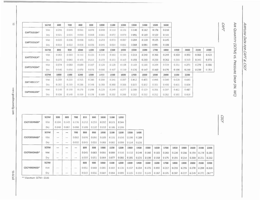
..... 0
I ~ C C. 3 :, :, 3
O<i" ;... C 3
~ C\ I"'\
~
SCFM
Wet CAPT3131B4*
Ory
Wet CAPT3131C4*
Ory
SCFM
Wet CAPT3743C4•
Dry
Wet CAPT3743D4•
Ory
SCFM
\/let CAPT4961C4*
Dry
Wet CAPT496104•
Ory
SCFM
CSCF1824N60" Wet
Dry
SCFM
CSCF3036N60• Wet
Ory
SCFM
CSCF3642N60• Wet
Ory
SCFM
CSCF4860N60* Wet
Ory
• • Maximum SCFM ~ 2146
600 700
0.041 0.049
0021 0031
0.035 0.036
0.014 0.022
800 900
0083 0.093
0.073 0.083
0.074 0080
0.046 O.OSG
1000 1100
0.209 0.233
0.202 0.219
0.140 0.158
0.128 0.140
500 600
0.104 0.143
0.048 0.067
- --- --
-- --- --- --
--· --
--·-
BOO 90D 1000 1100
0.061 0.076 0.090 0.113
0.039 0.048 O.Ool oon
0.038 0.051 1l059 0.073
0028 0.036 0.045 0.054
1000 1100 12D0 1300
0.113 0.133 0.143 0.163
0103 0.113 0.133 0.153
0.039 0.107 0.120 I 0129
0070 0,076 0086 0 107
12DO 1300 14D0 15DO
0.255 0.286 0.308 0.341
0.236 0248 0.288 0.300
0.179 0.198 o.n8 0.249
0.159 0 178 0.189 0.202
700 800 9D0 1000 1100
0.176 0.212 0.255 0 .292 0.321
0.086 0.J0S 0.132 0.159 0.186
700 800 900 1D00 1100
0.062 0.076 0 .092 0.109 0.131
0.032 0.0.13 0055 0068 0082
- 800 9DO 1D00 11DO
-- 0.045 0 .063 0.081 0099
-- 0.039 0 .051 0.064 0.077
800 9DO 1000 1100
-· 0.051 0.068 0.085 0.103
- 0043 0.056 0.069 0084
12DO 1300 1400 15D0 16D0
0.131 0.140 0162 0178 0 210
0.Oi9 0 091 0110 0122 0 141
0087 0.094 0 .110 0.125 0.145
0061 0.068 0.081 0 .091 0.108
14DO 1500 1600 17DO 1800
0183 0 213 0 243 0 .263 0.293
0.163 0.193 0 .213 0 .233 0.263
0.138 0 169 0.168 0.209 0129
0.110 0.126 0 147 0 .160 0176
1600 17DO 1800 1900 2000
0.397 0.412 0 .J55 0.496 0540
0 306 0.315 0 332 0 351 0406
0 277 0.300 0 329 0.351 0.397
0206 0.212 0 232 0 252 0282
120D
0.344
0.206
1200 1300 1400
0156 0.186 0.209
0 .099 O.lJ,t 0.131
12DO 1300 14D0 150D 1600 1700
0116 0.132 0.l-18 0 .166 0 183 0.202
0092 0.105 0 .121 0.138 0150 0175
1200 1300 1400 1500 1600 1700
0.120 0.137 0 .154 0.173 0 .192 0 .~12
0099 0.115 0132 0.149 0.167 0.185
1900 2000 21DO
0.323 0 .353 0 .383
0.293 0.313 0.3·13
0.251 0.273 0.279
0196 0 .210 0.230
21DO 2200
0628 0 .643
0 .431 0.604
0.462 0 487
0 302 0-119
1800 19DO 2000 2100
0 .220 0 236 0.259 0.178
0 191 0 .214 0 .230 0.251
1800 1900 2000 2100
0.233 0.255 0.278 0.299
0.207 0 .227 0 .2-19 0.272
22DO
0.423
0.373
0.306
0.253
2200
0.291
0.262
2200
0 .319
.;s2··
~ '1
Q ~
):. ~ :ii C ~
"' § ~
;/! ~ ::! ~ ... "< ~ ~ sS ~ ::i'j
~ ~ ~ -,:, ~ ::0 Q ~ '-" ~ C: ::0 "1 CJ ::0 0 ,, ~ ~ -...a
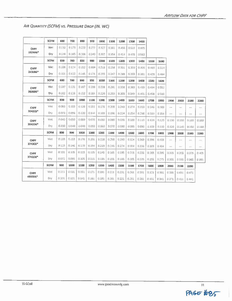
AIRFLOW 0ATA FOH CIIPF
AIR QUANTITY (SCFM) VS. PRESSURE DROP (IN. WC)
SCFM 600 700 800 900 1000 1100 1200 1300 1400
CHPF Wet 0.132 0179 0.222 0.272 0.327 0.3ol 0.456 0.522 0.605
1824A6" Ory 0.126 0.165 0.~06 0.249 0.30:! 0.354 0.414 0.473 0563
SCFM 600 700 800 900 1000 1100 1200 1300 1400 1500 1600
CHPF Wet 0.106 0.124 0.1S2 0.18,1 0.219 0.258 0.301 0.350 0.-106 0.460 0.514
243086" Ory 0.101 0.12:! 0.145 0.174 0.:!09 0247 0.288 0.333 0.381 0.423 0.484
SCFM 600 700 800 900 1000 1100 1200 1300 1400 1500 1600
CHPF Wet 0.107 0.131 0.167 0.199 0.239 0.291 0.333 0.389 0,.)39 0.494 O.S52
363686° Dry 0.102 0.126 0.152 0.184 0.220 0.259 0.303 0.349 0.401 0.4S8 0.516
SCFM 800 900 1000 1100 1200 1300 1400 1500 1600 1700 1800 1900 2000 2100 2200
CHPf Wet 0.083 0.103 0126 0.151 0.17S 0.208 0240 0.274 0.310 0 .3.16 0.383 ·- ... -· ... 3642C6" Ory 0.073 0.0':16 0.120 0.144 0.169 0.196 0 .22<1 0.254 0.~36 0.319 0 3S4 ... ... -· -·
CHPF Wet 0.040 0.050 0060 1).070 O.C80 0.080 00?0 0.100 0.110 0.120 0.1"0 0.130 0.150 0.160 0.180
364206° Ory 0.030 0040 0.040 0.050 0.060 0.070 0.030 1)085 0.090 0.100 0.110 0.120 0.140 0150 0.160
SCFM 800 900 1000 1100 1200 1300 1400 1500 1600 1700 1800 1900 2000 2100 2200
CHPF W~t 0.133 0.153 0.176 0.201 0.228 0.2SS 0.290 0.3~•• 0.360 0.396 0.433 ·- ... ... ... 3743C6°
Dry 0.123 0.146 0.170 0.194 0.219 0.2•16 0.274 0 304 0.336 0.369 0.404 ·- ... ... ...
CHPF Wet 0.101 0.105 0.115 0.125 0.145 0165 0.195 0.215 0.235 0 265 0 .295 0.315 O 355 0 375 (1,105
3743D6• Dry 0.072 0.095 0.105 0.115 0.135 0.155 0.185 0.205 0 225 0 255 0.275 0 305 0 335 0.365 0 395
SCFM 900 1000 1100 1200 1300 1400 1500 1600 1700 1800 1900 2000 2100 2200
CHPF Wet 0.111 0.131 0.151 0.171 0.191 0.211 0 .231 0~61 0291 0 321 0361 0 391 0 431 0471
4860D6' Ory 0.101 0.121 0.1-11 0.161 0.181 O.Wl 0.221 0.251 0.2S1 0 311 0 341 0 371 0 411 0 441
SS-GCoil www.goodm;inmfg.com 11
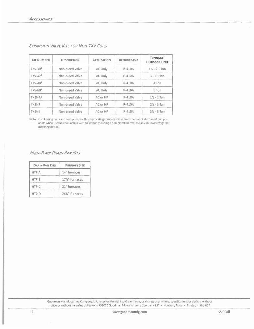
ACCESS OH/ES
EXPANSION VALVE KITS FOR NON-TXV COILS
KIT NUMBER I DESCRIPTION APPLICATION REFRIGERANT TONNAGE:
OUTDOOR UNIT
TXV-301 Non-bleed Valve AC Only R-410A rn - 21; Ton
TXV•421 Non-bleed Va ve AC Only R-410A 3 • 3li Ton
TXV·481 Non-bleed Valve AC Only R·410A 4 Ton
TXV-601 Non bleed Valve AC Only R·410A STon
TX2N4A Non bleed Valve AC or HP R·410A 1!', • 2 Ton
TX3N4 Non-bleed Valve AC or HP R·410A 2!. · 3 Ton
TXSN4 Non bleed Valve AC or HP R•410A 3!, · S Ton
Note; .ondcnsing units Jnd heat pumps with r,-::,pnxatirg compressors r<?qulr~ .he use of start-assist cornpo• nr1nts when used m t0n1unc11,n w,th an ir:joor co l• ! ne a non-bl•~ed thermal e~pans,on valve r~frig•1rant met<?r ng dev:ce
HIGH-~MP 0RAIN PAN KITS
DRAIN PAN KITS FURNACE SIZE
HTP•A
HTP-6
HTP-C
HTP•O
12
14" furnaces
171'.'' furnaces
21" furnaces
24!," furnaces
ljocdman Manu/Jcturini, CompJny, L.P, reserv~s th~ right to d1sc:onnnue, •Jr chang<? at ~ny tome. ,pecrfications or designs without nonce or w,thtJut incurring obligations. <\:>2016 Goodman Manufacturing Co,r.pany, LP. • Houston, T,:.,ca; • Pr intcd in th.;, LISA.
www.goodm,1nmlg.com SS-GCoil
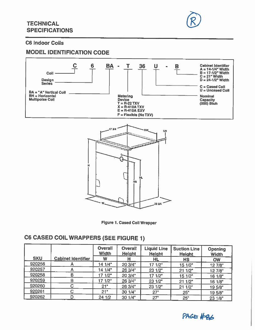
TECHNICAL SPECIFICATIONS
CS Indoor Coils
MODEL IDENTIFICATION CODE
C 6 Coll __ __.T J
Design _ Serles _____ _..
BA = "A" Vertical Coll BH = Horizontal Multlpoise Coll
BA M -- T
T 36 -,--
U B Cabinet Identifier
T T A= 14•1/4"Wldth =---- B = 17-1/2" Width C=21"Wldth D = 24-1/2" Width
'-------- C = Cased Coll U = Uncased Coll
Metering Device
.._ ___ _____ Nominal
T: R•22TXV X = R-410A TXV E = R-410A EXV F = Flexible (No TXV)
Figure 1. Cased Coll Wrapper
Capacity (000) Btuh
C6 CASED COIL WRAPPERS (SEE FIGURE 1)
Overall Overall Liquid Line Suction Line Opening Width Hetaht Helaht Helaht Width
SKU Cabinet Identifier w H HL HS ow 920256 A 141/4" 20 3/4" 171/2" 15 1/2" 12 7/8" 920257 A 14 1/4" 26 3/4" 23 1/2" 211/2" 12 7/8" 920258 B 17 1/2" 20 3;4• 17 1/2" 15 1/2" 16 1/8" 920259 B 171/2" 26 3/4" 231/2" 21 1/2" 16 1/8" 920260 C 21" 26 3/4" 23 1/2" 21 1/2" 19 5/8" 920261 C 21" 301/4" 27" 25" 19 5/8" 920262 D 241/2 30 1/4" 27" 25" 23 1/8"
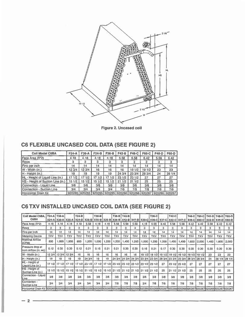
Figure 2. Uncased coll
CS FLEXIBLE UNCASED COIL DATA (SEE FIGURE 2)
Coll Model C6BA F24·A F36·A F24-B F36-B F42-B F48-C F60-C F48·0 F60-0
Face Area lft"21 4.18 4.18 4.18 4.18 5.58 5.58 6.42 5.58 6.42 Rows 3 3 3 3 3 3 3 3 3 Fins per inch 14 14 14 14 14 14 14 14 14 W • Widlh (in.) 12 3/4 12 3/4 16 16 16 19 1/2 19 1/2 23 23 H • Heiaht (in.I 19 19 19 19 24 3/4 233/4 28 3/4 24 281/4 HL • Heiaht of Liauid Line !in.I 171/2 171/2 17 1/2 171/2 231/2 231/2 27 27 27 HS • Heiaht of Suction Line lin.l 151/2 151/2 15 1/2 151/2 211/2 211/2 25 25 25 Connection - LiatJid Line 3/8 3/8 3/8 3/8 3/8 3/8 3/8 3/8 3/8 Connection• Suction Line 3/4 3/4 3/4 3/4 7/8 7/8 7/8 7/8 7/8 Horizonlal Drain Kil 920265 920265 920265 920265 920266 920266 920267 920266 920267
CS TXV INSTALLED UNCASED COIL DATA (SEE FIGURE 2)
Coll Model C68A, 1'24-A TJO-A T24•8 T30-8 T36-B T42•8 T36-C T42-C T48-C T60-C T42-D T48-D T60-D C&BH X24•A X30-A X3S-A X24·8 X26-8 X30-B XJS·B X36·8 X42·8 X47•B X30-C X36-C X37•C X42-C X47•C X48-C X&O·C X42-D X4B•D X&O-D
Face Area (11"21 4.18 4.18 4.18 4.18 5.58 4.18 4.18 5.58 5.58 5.58 4.18 5.58 6.42 5.58 5.58 6.42 6.42 5.58 6.42 6.42 Rows 3 3 3 3 3 3 3 3 3 3 3 3 3 3 3 3 3 3 3 3 Fins per Inch 14 14 14 14 14 14 14 14 14 14 14 14 14 14 14 14 14 14 14 14 Metering Device TXV TXV TXV TXV TXV TXV TXV TXV TXV TXV TXV TXV TXV TXV TXV TXV TXV TXV TXV TXV Nominal Alr11ow 800 1,000 1,000 BOO 1,200 1,000 1,200 1,200 1,400 1,200 1,000 1,200 1,200 1,400 1,400 1,600 2,000 1,400 1,600 2,000 ll'FMI
Pressure drop at 0.12 0.30 0.30 0.12 0.21 0. 15 0.21 0.21 0.30 0.30 0.16 0.21 0.17 0.30 0.30 0.30 0.30 0.30 0.30 0.30 nom alr1tow (in. wcl
W - Width (In.) 12 3/4 12 3/4 12 3/4 16 16 16 16 16 16 16 191/2 19 1/2 19 1/2 19 1/2 19 1/2 19 112 19 1/2 23 23 23 H • Height (in.) 19 19 19 19 243/4 19 19 24 3/4 24 3/4 24 3/4 233/4 233/4 283/4 23 3/4 233/4 28314 28314 24 28114 28 1/4 HL. Height of
17112 17112 171/2 17 1/2 231/2 17 1/2 17 112 23 112 23 112 23112 23 1/2 231/2 27 23 1/2 23 112 27 27 27 27 27 Liouid Line lin. l HS • Haight of 15 112 15 112 15 112 15 1/2 21 1/2 15 112 15 1/2 211/2 21 1/2 21 112 21 112 21 112 25 21112 21 112 25 25 25 25 25 Suction Line fin. l Connection • Liquid
3/8 3/8 3/8 3/8 3/8 318 318 318 3/8 3/8 318 318 3/8 318 3/8 3/8 3/8 3/8 318 3/8 Line Connection • 314 314 3/4 314 314 314 314 718 718 7/8 3/4 7/8 718 718 718 718 718 718 718 718 Suction Line Horizontal Drain Kil 1920265 92026 2026~ 1920266 92026.!i 920265 920261 92026E 920266 !120266 92026E 920267 920266 ~20266 920267 920267 920266 ~20267 920267
-2
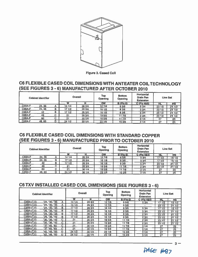
Figure 3. Cased Coll
C6 FLEXIBLE CASED COIL DIMENSIONS WITH ANTEATER COIL TECHNOLOGY (SEE FIGURES 3 • 6) MANUFACTURED AFTER OCTOBER 2010
Top Bottom Horizontal Overall Drain Pan Line Set Cabinet Identifier Opening Opening
Extension w H ow BIAn61 C IRn 4.11.i;:1 HL H!':;
C6BA•F 24 36 A 141/4 263/4 12 7/8 6 5/8 5 3/4 231/2 211/2 C6BA•F 24 36 B 171/2 263/4 161/8 8 3/B 5 3/4 231/2 211/2 C6BA•F 42 B 17 1/2 263/4 16 1/8 8 3/8 53/4 23 1/2 211/2 C6BA·F 48 C 21 263/4 19 5/8 11 7/8 2 3/4 231/2 21 1/2 C6BA·F 60 C 21 301/4 19 5/8 11 7/8 3 1/4 27 25 C6BA·F 48 60 D 241/2 301/4 231/8 153/8 31/4 27 25
C6 FLEXIBLE CASED COIL DIMENSIONS WITH STANDARD COPPER (SEE FIGURES 3 - 6) MANUFACTURED PRIOR TO OCTOBER 2010
Top Bottom Horizontal Overall Drain Pan UneSet Cabinet Identifier Opening Opening
Extension w H n.., A•~•- ~I C ,..,.,,.._,a UI HS
C6BA·F 24 36 A 141/4 203/4 12 7/8 6 518 53/4 171/2 151/2 C6BA-F 24 36 B 171/2 203/4 161/8 8 3/8 53/4 171/2 151/2 C6BA·F 42 B 17 1/2 263/4 161/8 8 3/8 5 3/4 231/2 211/2 C6BA·F 48 C 21 263/4 195/8 11 7/8 2 3/4 231/2 211/2 C6BA-F 60 C 21 30 1/4 195/8 11 7/8 31/4 27 25 C6BA·F 48 60 D 24 1/2 301/4 231/8 15 3/8 31/4 27 25
C6 TXV INSTALLED CASED COIL DIMENSIONS (SEE FIGURES 3 • 6) Top Bottom Horizontal
Overall Drain Pan Line Set Cabinet Identifier Opening Opening Extension
w H ,.. .. , B !Fin 61 C •~•" "-~ WI UC
C6BA·ITXI ·24 '30 '35 A 141/4 203/4 12 7/8 6 5/8 5 3/4 171/2 151/2 C6BH-ITX '24 '30 •35 A 14 1/4 26 3/4 12 7/8 6 5/8 . 231/2 211/2 C6BA-!TX '24 '30 ·35 B 171/2 203/4 16 1/8 83/8 5 3/4 17 1/2 151/2 C6BA-ITX '26 "36 '42 B 171/2 263/4 161/8 8 3/8 5 3/4 23 1/2 21 1/2 C6BH•ITX1 '24 "30 '35 B 171/2 263/4 161/8 8 3/8 23/4 231/2 211/2 C6BH-IT.XI '26 "36 '42 B 171/2 26 3/4 161/8 8 3/8 2 3/4 23 1/2 211/2 C6BA-TX) '30 '36 '42 C 21 26 3/4 19 5/8 11 7/8 2 3/4 231/2 211/2 C6BH· TX '30 '36 '42 C 21 26 3/4 19 5/8 11 7/8 2 3/4 231/2 211/2 C6BA· TX •37 '48 ·so C 21 301/4 19 5/8 11 7/8 31/4 27 25 C6BH•I TX •37 "48 ·so C 21 30 1/4 19 5/8 11 7/8 31/4 27 25 C6BA-tTX •42 •40 ·so D 241/2 301/4 231/8 15 3/8 31/4 27 25 CSBH•ITX •42 ·49 ·so D 241/2 301/4 231/8 15 3/8 31/4 27 25
3-
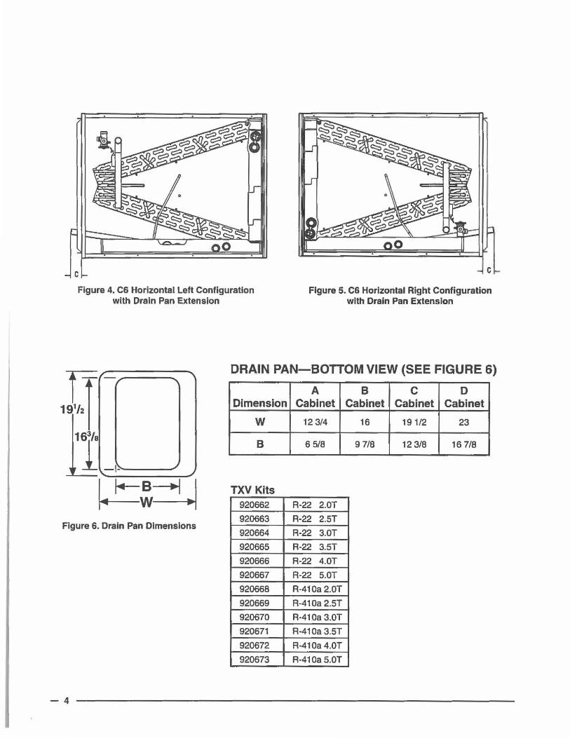
C
Figure 4. C& Horizontal Left Configuration with Drain Pan Extension
C
Figure 5. C6 Horizontal Right Configuration with Drain Pan Extension
DRAIN PAN-BOTTOM VIEW (SEE FIGURE 6)
A B C D Dimension Cabinet Cabinet Cabinet Cabinet
w 12 3/4 16 191/2 23
B 6 5/8 9 7/8 12 3/8 16 7/8
TXV Kits 920662 R·22 2.0T
Figure 6. Drain Pan Dimensions 920663 R-22 2.5T
920664 R-22 3.0T
920665 R-22 3.5T
920666 R-22 4.0T
920667 R-22 5.0T
920668 R·410a2.0T
920669 A-410a 2.5T
920670 R-410a 3.0T
920671 R·410a3.5T
920672 R-410a 4.0T
920673 R-410a 5.0T
-4
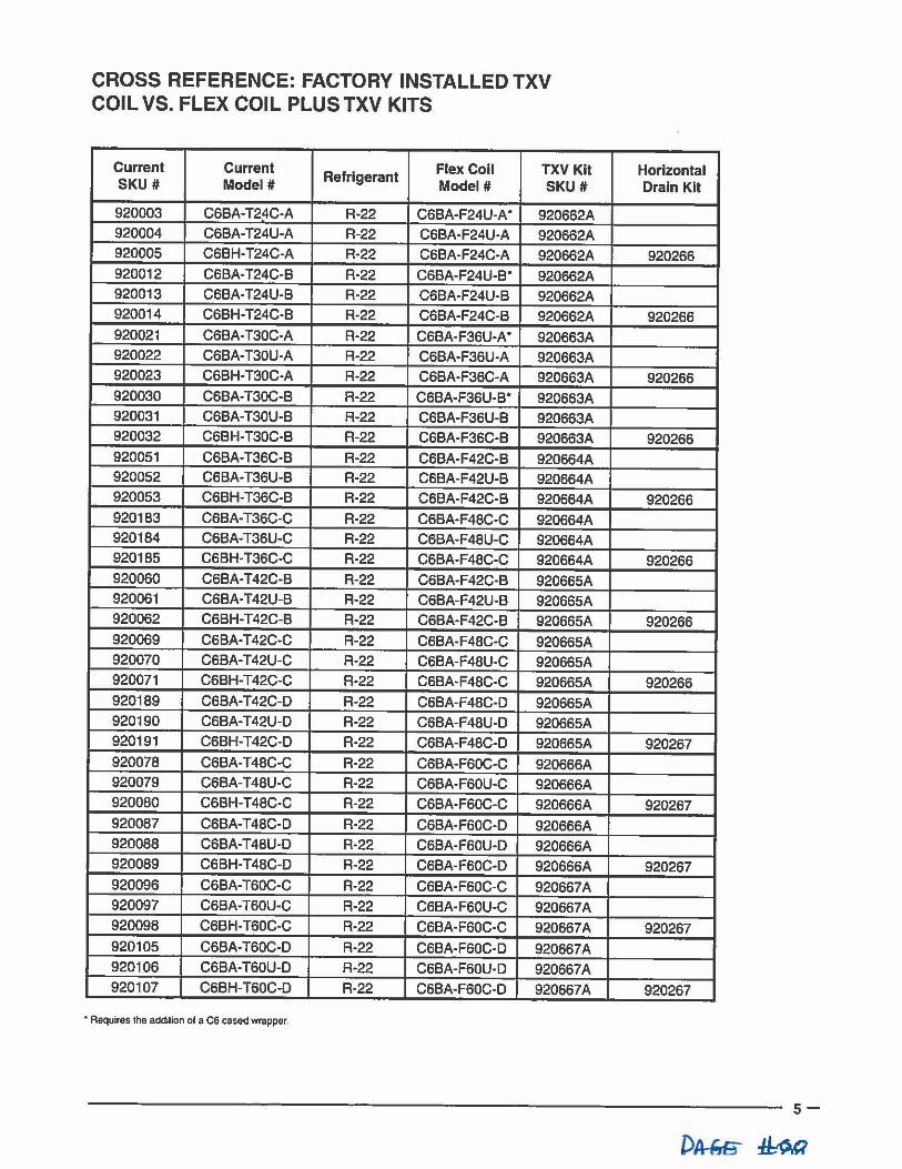
CROSS REFERENCE: FACTORY INSTALLED TXV COIL VS. FLEX COIL PLUSTXV KITS
Current Current Refrigerant Flex Coll TXV Kit
SKU# Model# Model# SKU#
920003 C6BA-T24C-A R-22 C6BA-F24U-A • 920662A 920004 C6BA-T24U-A R-22 C6BA-F24U-A 920662A 920005 C6BH· T24C-A R-22 C6BA-F24C-A 920662A 920012 C6BA-T24C-B R-22 C6BA-F24U·B• 920662A 920013 C6BA·T24U·B R-22 C6BA-F24U-B 920662A 920014 C6BH-T24C-B R-22 C6BA·F24C-B 920662A 920021 C6BA-T30C-A R-22 C6BA-F36U·A • 920663A 920022 C6BA-T30U·A R-22 C6BA-F36U·A 920663A 920023 C6BH-T30C-A R-22 C6BA-F36C-A 920663A 920030 C6BA-T30C-B R-22 C6BA·F36U-B• 920663A 920031 C6BA-T30U-B R-22 C6BA·F36U-B 920663A 920032 C6BH·T30C-B A-22 C6BA-F36C-B 920663A 920051 C6BA-T36C-B R-22 C6BA-F42C-B 920664A 920052 C6BA-T36U-B A-22 C6BA-F42U-B 920664A 920053 C6BH-T36C-B R-22 C6BA-F42C-B 920664A 920183 C6BA-T36C-C A-22 C6BA-F48C-C 920664A 920184 C6BA-T36U-C R-22 C6BA-F48U-C 920664A 920185 C6BH-T36C-C A-22 C6BA-F48C-C 920664A 920060 C6BA-T 42C-B A-22 C6BA-F42C-B 920665A 920061 C6BA-T42U-8 R-22 C6BA-F42U·B 920665A 920062 C6BH-T 42C-B R-22 C6BA-F42C-B 920665A 920069 C6BA-T 42C-C A-22 C6BA-F48C-C 920665A 920070 C6BA-T42U-C A-22 C6BA-F48U-C 920665A 920071 C6BH-T42C-C R-22 C6BA-F48C-C 920665A 920189 C6BA-T 42C-D R-22 C6BA-F48C-D 920665A 920190 C6BA-T42U-O R-22 C6BA-F48U-D 920665A 920191 C6BH-T 42C-D A-22 C6BA-F48C-D 920665A 920078 C6BA-T48C-C R-22 C6BA-F60C-C 920666A 920079 C6BA-T48U-C A-22 C6BA-F60U-C 920666A 920080 C68H-T48C-C A-22 C6BA-F60C-C 920666A 920087 C6BA-T48C-D R-22 C6BA-F60C-D 920666A 920088 C6BA-T48U-O R-22 C6BA-F60U-D 920666A 920089 C6BH-T48C-D R-22 C6BA-F60C-D 920666A 920096 C6BA-T60C-C R-22 C6BA-F60C-C 920667A 920097 C6BA-T60U-C R-22 C6BA-F60U-C 920667A 920098 C6BH-T60C-C R-22 C6BA-F60C-C 920667A 920105 C6BA-T60C-D R-22 C6BA-F60C-D 920667A 920106 C6BA-T60U-D A-22 C6BA-F60U-D 920667A 920107 C6BH-T60C-D A-22 C6BA-F60C-D 920667A
• Requires lhe addilion of a C6 cased wrapper.
Horizontal Drain Kit
920266
920266
920266
920266
920266
920266
920266
920266
920267
920267
920267
920267
920267
s-
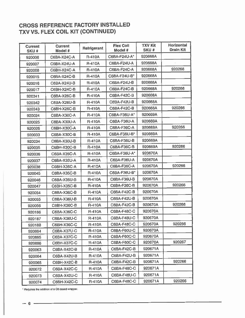
CROSS REFERENCE FACTORY INSTALLED TXV VS. FLEX COIL KIT (CONTINUED)
Current Current Refrigerant Flex Coll
SKU # Model# Model#
920006 C68A-X24C·A R-410A C6BA·F24U-A •
920007 C68A-X24U·A R-410A C68A-F24U·A
920008 C68H-X24C-A R·410A C68A-F24C-A
920015 C6BA-X24C·B R-410A C6BA·F24U·B•
920016 C6BA-X24U·B R-410A C6BA-F24U-B
920017 C6BH-X24C-B A·410A C6BA-F24C·B
920341 C6BA-X26C-B R-410A C6BA-F42C-B
920342 C68A-X26U-B R-410A C6BA-F42U-B
920343 C6BH-X26C-B R-410A C6BA-F42C-B
920024 C6BA-X30C·A R-410A C6BA·F36U-A •
920025 C6BA-X30U·A R-410A C6BA-F36U·A
920026 C6BH-X30C·A R-410A C68A-F36C·A
920033 C6BA-X30C-B R-410A C68A-F36U-B*
920034 C6BA·X30U-B R-410A C6BA-F36U-B
920035 C6BH-X30C·B R-410A C6BA-F36C-B
920036 C6BA-X35C-A R-410A C6BA-F36U-A •
920037 C6BA·X35U-A R-410A C6BA-F36U-A
920038 C6BH-X35C-A R-410A C6BA·F36C-A
920045 C6BA-X35C-B R-410A C6BA-F36U·B"
920046 C6BA-X35U-B R-410A C6BA-F36U-B
920047 C6BH-X35C-B A-410A C6BA-F36C-B
920054 C6BA·X36C·B R-410A C6BA-F42C-B
920055 C6BA-X36U-B R-410A C6BA-F42U·B
920056 C6BH-X36C-B R·410A C6BA-F42C-B
920186 C6BA-X36C-C R-410A C6BA-F48C-C
920187 C6BA-X36U-C R-410A C6BA-F48U-C
920188 C6BH-X36C-C R-410A C6BA-F48C-C
920884 C6BA-X37U-C A-410A C6BA-F60U-C
920885 C6BA-X37C-C R-410A C6BA-F60C-C
920886 C6BH-X37C-C R-410A C6BA-F60C-C
920063 C6BA-X42C-B R-410A C68A-F42C-B
920064 C6BA-X42U-8 A·410A C6BA-F42U·B
920065 C6BH-X42C-B R-410A C6BA-F42C-B
920072 C6BA-X42C-C A·410A C6BA-F48C-C
920073 C6BA-X42U-C R-410A C6BA-F48U-C
920074 C6BH-X42C-C R-410A C6BA-F48C-C
• Requires 1he addition or a C6 cased wrapper.
-6
TXV Kit Horizontal SKU# Drain Kit
920668A
920668A
920668A 920266
920668A
920668A
920668A 920266
920668A
920668A
920668A 920266
920669A
920669A
920669A 920266
920669A
920669A
920669A 920266
920670A
920670A
920670A 920266
920670A
920670A
920670A 920266
920670A
920670A
920670A 920266
920670A
920670A
920670A 920266
920670A
920670A
920670A 920267
920671A
920671A
920671A 920266
920671A
920671A
920671A 920266
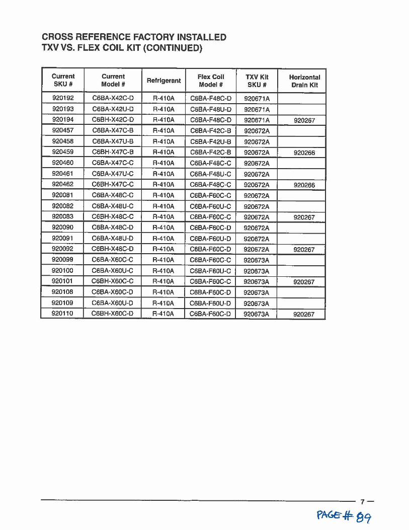
CROSS REFERENCE FACTORY INSTALLED TXVVS. FLEX COIL KIT (CONTINUED)
Current Current Refrigerant
Flex Coll SKU # Model# Model#
920192 C6BA-X42C-D R-410A C6BA-F48C-D
920193 C6BA-X42U-D R-410A C6BA·F48U-O
920194 C6BH-X42C-O R·410A C6BA-F48C·D
920457 C6BA·X47C·B R-410A C6BA-F42C-B
920458 C6BA-X47U-B R-410A C6BA·F42U-B
920459 C6BH-X47C-B R-410A C6BA·F42C-8
920460 C6BA-X47C-C R-410A C6BA-F48C-C
920461 C6BA·X47U·C R-410A C6BA-F48U-C
920462 C6BH-X47C-C R·410A C6BA-F48C-C
920081 C6BA-X48C-C R·410A C6BA-F60C·C
920082 C6BA-X48U-C R-410A C6BA-F60U·C
920083 C6BH-X48C-C R·410A C6BA-F60C-C
920090 C6BA-X48C-D R-410A C6BA-F60C·D
920091 C6BA-X48U-D R-410A C6BA-F60U-D
920092 C6BH-X48C-O R-410A C6BA-F60C-O
920099 C6BA-X60C-C R-410A C6BA·F60C-C
920100 C6BA·X60U·C R-410A C6BA-F60U-C
920101 C6BH-X60C-C R-410A C6BA-F60C-C
920108 C6BA-X60C-D R·410A C6BA-F60C-D
920109 C6BA-X60U-D R-410A C6BA-F60U-D
920110 C6BH-X60C-D R-410A C6BA-F60C-D
TXV Kit Horizontal SKU# Drain Kit
920671A
920671A
920671A 920267
920672A
920672A
920672A 920266
920672A
920672A
920672A 920266
920672A
920672A
920672A 920267
920672A
920672A
920672A 920267
920673A
920673A
920673A 920267
920673A
920673A
920673A 920267

A. ~I CERTIFIED- A.~I CERTIFIED. .... .. c .. ,, ... . , , ·-· .. . " . ---------- --·---u.,.,~ .... 4A(
. ... _ .. J,l' " «i ~~:; :. ., ---~----·-··- ... - .. -- ..... . - - -·- lntertek
-~·-··-.. . ' f -. :-
, ... , ...• Throu9h T•chnldan
CffllflcJl!oftll!NATE ~~3 ASSEMBLED
~c~~~! 8000 Phoenix Parkway I O'Fallon, MO 63368-3827
•~♦HRAI . , ........•.... , .. ,. ,, .. ,.,,., ✓llllllll elll1'M1
Specifications and illustrations subject lo change without notice and without incurring obligations. Printed In U.S.A (07/2011)
71 SC-0711 (Replaces 71 SC-0111)
e TRANE'
Cased A~uminum edica ed Upflow / Downfiow co·1s Convertible to Horizontal with Kit
4PXC Heat Pump /Cooling Coils for R-41 OA 2- 5Ton
•
•
PUB. NO. 22-1902-2
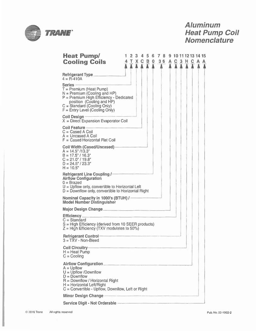
Aluminum Heat Pump Coil Nomenclature
Heat Pump/ Cooling Coils
12345678 4TXCB0 36
Refrigerant Type _____ _. i I I 11111 r 4 = R-410A Serles - --~I T = Premium (Heat Pump) N = Premium (Cooling and HP) P = Premium High Efficiency - Dedicated
position (Cooling and HP) C = Standard (Cooling Only) F = Entry Level (Cooling Only) j Coil Design --- ---X = Direct Expansion Evaporator Coil Coil Feature _________ _, C = Cased A Coil A = Uncased A Coil F = Cased Horizontal Flat Coil
Coll Width (Cased/Uncased)------J A = 14.5" /13.3" B = 17.5" / 16.3" C = 21.0" I 19.8" D = 24.5" / 23.3" H=10.5"
Refrigerant Line Coupling/------Airflow Configuration O = Brazed U = Upflow only, convertible to Horizontal Left D = Downflow only, convertible to Horizontal Right
Nominal Capacity in 1 000's (BTUH) / -------Model Number Distinguisher
9 10111213 14 15 A C 3 H C A A Ill I -
Major Design Change ___________ _, Efficiency _______ ____ _ C = Standard S = High Efficiency (derived from 10 SEER products) Z = High Efficiency (TXV modulates to 50%)
Refrigerant Control--3 = TXV • Non-Bleed
-----·- --· ---
Coll Circuitry------------ ____ _, H = Heat Pump C = Cooling
Airflow Configuration _______________ __. A= Upflow U = Upflow /Downflow D = Downflow R = Downflow / Horizontal Right H = Horizontal Left/Right C = Convertible - Upflow, Downllow, Left or Right
Minor Design Change Service Digit• Not Orderable _______________ _,
C 2016 Trane All nghts reserved Pub. No. 22· 1902·2
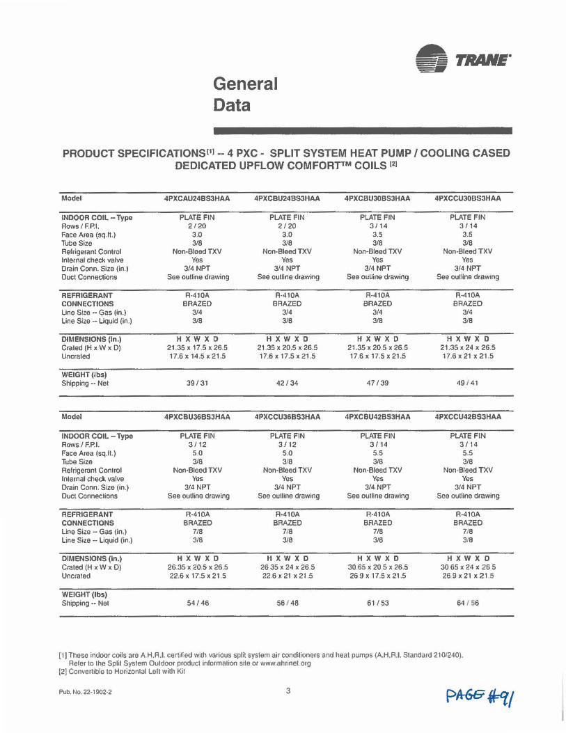
General Data
PRODUCT SPECIFICATIONSC11 -- 4 PXC - SPLIT SYSTEM HEAT PUMP/ COOLING CASED DEDICATED UPFLOW COMFORT™ COILS 121
Model 4PXCAU24BS3HAA 4PXCBU24BS3HAA 4PXCBU30BS3HAA 4PXCCU30B53HAA
INDOOR COIL -Type PLATE FIN PLATE FIN PLATE FIN PLATE FIN Rows / F.P.I. 2/20 2 / 20 3 / 14 3/ 14 Face Area {sq.H.) 3.0 3.0 3.5 3.5 Tube Size 3/8 318 3/8 3/8 Refrigerant Control Non-Bleed TXV Non-Bleed TXV Non-Bleed TXV Non-Bleed TXV lnlernal check valve Yes Yes Yes Yes Drain Conn. Size (in.) 3/4 NPT 3/4 NPT 3/4 NPT 3/4 NPT Duct Connections See outline drawing See outline drawing See ouUine drawing See outline drawing
REFRIGERANT R-410A R·410A R•410A R•410A CONNECTIONS BRAZED BRAZED BRAZED BRAZED Line Size •· Gas (in.) 3/4 3/4 3/4 3/4 Line Size •· Liquid (in.) 3/8 3/8 3/8 3/8
DIMENSIONS (In.) HXWXD HXWXD HXWXD HXWXD Craled (H X w X D) 21 .35x 17.5x26.5 21.35 X 20,5 X 26.5 21.35 X 20.5 X 26.5 21.35 X 24 X 26.5 Uncraled 17.6 X 14.5 X 21.5 17.6x 17.5x21.5 17 6 x 17.5 x 21.5 17.6 X 21 X 21 .5
WEIGHT (lbs) Shipping •• Net 39/31 42/ 34 47 /39 49 / 41
Model 4PXCBU36BSJHAA 4PXCCU36BS3HAA 4PXC BU42BS3HAA 4PXCCU42BS3HAA
INDOOR COIL - Type PLATE FIN PLATE FIN PLATE FIN PLATE FIN Rows/ F.P.I. 3 / 12 3 / 12 3 / 14 3 / 14 Face Area (sq.It.) so 5.0 5.5 5.5 Tube Size 3/8 3/8 3/8 3/8 Refrigerant Control Non-Bleed TXV Non-Bleed TXV Non-Bleed TXV Non-Bleed TXV lnlernal check valve Yes Yes Yes Yes Drain Conn. Size {in.) 3/4 NPT 3/4 NPT 3/4 NPT 3/4 NPT Duct Connections See outline drawing See outline drawing See outline drawing See outline drawing
REFRIGERANT R-410A A·410A R-410A A-410A CONNECTIONS BRAZED BRAZED BRAZED BRAZED Line Size •· Gas (in.) 7/8 718 7/8 7/8 Line Size •· Liquid {in.) 3/8 3/8 3/8 3f8
DIMENSIONS (In.) HXWXD HXWXD HXWXD H X W X D Crated (H x w x D) 26.35 X 20.5 X 26.5 26 35 X 24 X 26.5 30 65 X 20 5 X 26.5 30 65 X 24 X 26 5 Uncrated 22.6 X 17.5 X 21 ,5 22.6 X 21 X 21 .5 26 9 X 17.5 X 21.5 26 9 X 21 X 21 .5
WEIGHT (lbs) Shipping •• Net 54/46 56 / 48 61 / 53 64 / 56
(1 J These indoor coils are A H.R.I. certifed with various split system air conditioners and heat pumps (A.H.A.I. Standard 210/240). Refer to lhe Split System Outdoor product information site or www.ahrinel org
(2] Convertible to Horizontal Left with Kit
Pub. No. 22· 1902·2 3
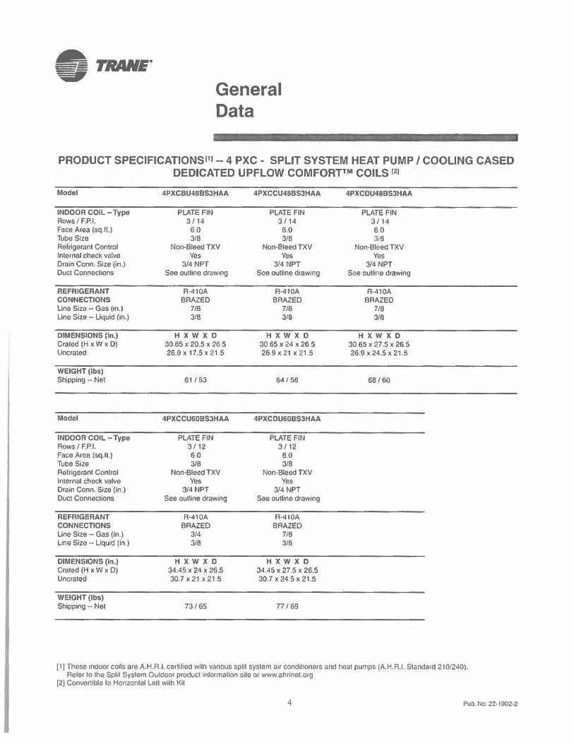
• TRANE" ., General Data
PRODUCT SPECIFICATIONSl11 -- 4 PXC - SPLIT SYSTEM HEAT PUMP/ COOLING CASED DEDICATED UPFLOW COMFORT™ COILS 121
Model 4PXCBU488S3HAA 4PXCCU488S3HAA 4PXCDU48BS3HAA
INDOOR COIL - Type PLATE FIN PLATE FIN PLATE FIN Rows/ F.P.I. 3 / 14 3 f 14 3/ 14 Face Area (sq.It.) 6.0 6.0 6.0 Tube Sizo 3/8 3/8 3J8 Refrigerant Control Non-Bleed TXV Non-Bleed TXV Non-Bleed TXV Internal check valvo Yes Yes Yes Drain Conn. Size (in.) 3/4 NPT 3/4 NPT 3/4 NPT Duct Connections See outline drawing See outline draw,rg See oulline drawing
REFRIGERANT R-410A R-410A A·410A CONNECTIONS BRAZED BRAZED BRAZED Line Size -· Gas (in.) 7/8 7/8 7/8 Line Size •· Liquid (in.) 3/8 3/8 3/8
DIMENSIONS (In.) HXWXO H X W X 0 HXWXD Crated (H x W x D) 30.65 X 20.5 X 26 5 30 65 X 24 X 26 5 30 65 X 27.5 X 26.5 Uncrated 26.9 X 17.5 X 21 5 269x21 x21 .5 26.9 X 24.5 X 21.5
WEIGHT (lbs) Shipping •• Net 61/53 64/ 56 68/60
Model 4PXCCU608S3HAA 4PXCDU608S3HAA
INDOOR COIL -Type PLATE FIN PLATE FIN Rows/ F.P.I. 3/ 12 3 / 12 Face Area (sq.fl.) 6.0 6.0 Tube Size 3/8 3/8 Refrigerant Control Non-Bleed TXV Non-Bleed TXV Internal check valve Yes Yes Drain Conn. Size (in.) 3/4 NPT 3/4 NPT Duct Connections See outline drawing See outline drawing
REFRIGERANT R·410A R-410A CONNECTIONS BRAZED BRAZED Line Size - Gas (in.) 3/4 716 Line Size •· Liquid (in.) 3/8 3/8
DIMENSIONS (In.) HXWXD HXWXO Crated (H X w X D) 34.45 X 24 X 26.5 34.45 X 27.5 X 26.5 Uncraled 30. 7 X 21 X 21 5 30.7 X 24.5 X 21.5
WEIGHT (lbs) Shipping •• Net 73/65 77 I 69
[1) These indoor coils are A.H.R.1. certified with various split system air conditioners and heat pumps (A.H.R.I. Standard 210/240). Refer to the Split System Outdoor product inlormalion silo or www.ahrinel.org
[2] Convertible to Horizontal Lall wilh Kil
4 Pub. No. 22· 1902·2
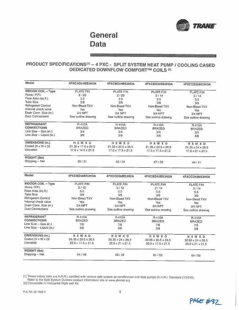
General Data
~ TRAIIE. V
PRODUCT SPECIFICATIONSl11--4 PXC- SPLIT SYSTEM HEAT PUMP/ COOLING CASED DEDICATED DOWNFLOW COMFORT™ COILS 121
Model 4PXCAD24BS3HDA 4PXCBD24BS3HDA 4PXCBD3OBS3HDA 4PXCCD308S3HDA
INDOOR COIL -Type PLATE FIN PLATE FIN PLATE FIN PLATE FIN Rows I F.P.I. 2 / 20 2 120 3/14 3 I 14 Face Area (sq.It) 30 30 3.5 3.5 Tube Size 3/8 3/8 3/8 3/8 Relrigeranl Control Non•Bleed TXV Non-B'eed TXV Non-Bleed TXV Non•Bleed TXV Internal check valve Yes Yes Yes Yes Drain Conn. Size (in ) 3/4 NPT 3/4 NPT 3/4 NPT 3/4 NPT Duel Connections See outline drawing See outline drawing See ouUine drawing See outline drawing
REFRIGERANT R-410A R-410A A-410A A-410A CONNECTIONS BRAZED BRAZED BRAZED BRAZED Line Size •· Gas (in ) 3/4 3/4 3/4 3/4 Line Size •· Liquid (in.) 3/8 318 3/8 3/8
DIMENSIONS (In.) HXWXD HXWXD HXWXD HXWXD Crated (H x W x D) 21.35 x 17 5 x 26 5 21 ,35 X 20,5 X 26,5 21 .35 X 20,5 X 26.5 21.35 x 24 x 26 5 Uncrated 17.6 X 14.5 X 21 5 17.6x 17.5><21 .5 17.6 X 17.5 X 21.5 17.6 X 21 X 21.5
WEIGHT (lbs) Shipping •• Net 39 / 31 42 / 34 47 / 39 49 / 41
Model 4PXCBD36BS3HDA 4PXCCD368S3HDA 4PXCBD42BS3HDA 4PXCCD42BS3HDA
INDOOR COIL -Type PLATE FIN PLATE FIN PLATE FIN PLATE FIN Rows/ F.P.I. 3 / 12 3/ 12 3/14 3 I 14 Face Area (sq.ft.) 5.0 5.0 5.5 5.5 Tube Size 3/8 3/8 3/8 3/8 Refrigerant Control Non-Bleed TXV Non-Bleed TXV Non-Bleed TXV Non-Bleed TXV lnlernal check valve Yes Yes Yes Yes Drain Conn. Size (in.) 3/4 NPT 3/4 NPT 3/4 NPT 3/4 NPT Duct Connections See outline drawing See outline drawing See outline drawing See outline drawing
REFRIGERANT R-410A R-410A R-410A R•410A CONNECTIONS BRAZED BRAZED BRAZED BRAZED Line Size •· Gas (in.) 7/8 7/8 7/8 7/8 Line Size -· Liquid (in.) 3/8 3/8 3/8 3/8
DIMENSIONS (In.) H X W X D H X W X D HXWXD HXWXD Crated (H x W x 0) 26.35 X 20.5 X 26.5 26.35 X 24 X 26.5 30.65 x 20.5 >< 26.5 30 65 X 24 X 26 5 Uncrated 22.6 X 17.5 X 21.5 22.6x21x21 .5 26.9 X 17.5 X 21 .5 26 .9 X 21 X 21 .5
WEIGHT (lbs) Shipping •• Net 54/ 46 56 / 48 61 / 53 64 /56
[1] These indoor coils are A.H.R.I. cerlilied with various split system air condilloners and heat pumps (AH.A.I. Standard 210/240). Reier to lhe Splil System Outdoor product informahon site or www.ahnnet.org
[2] Convertible to Horizontal Right w1lh KIi
Pub, No. 22• 1902-2 5
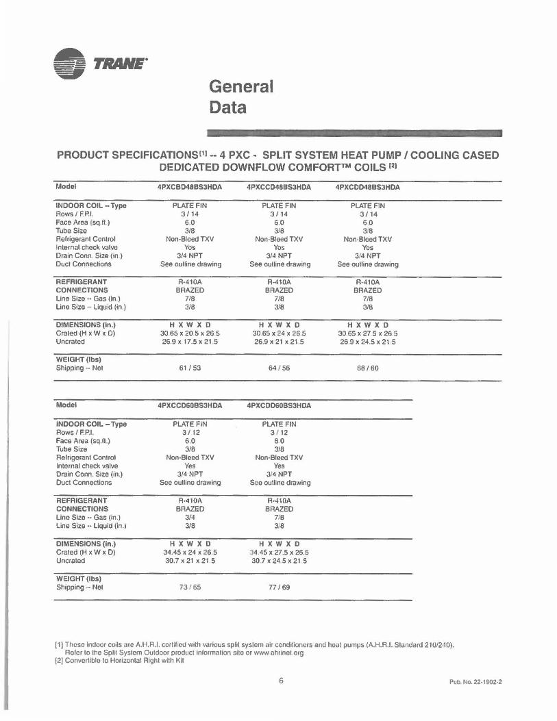
General Data
PRODUCT SPECIFICATIONSl11 -- 4 PXC - SPLIT SYSTEM HEAT PUMP/ COOLING CASED DEDICATED DOWNFLOW COMFORT™ COILS 121
Model 4PXCB048B53HDA 4PXCCD48BS3HOA 4PXCOD48BS3HOA
INDOOR COIL - Type PLATE FIN PLATE FIN PLATE FIN Rows/ F.P.I. 3/ 14 3 / 14 3/ 14 Face Area (sq.It.) 6.0 6.0 6.0 Tube Size 3/8 3/8 3!8 Refrigerant Control Non-Bleed TXV Non-Bleed TXV Non-Bleed TXV Internal chock valve Yes Yes Yes Drain Conn. Size (in ) 3/4 NPT 3/4 NPT 3/4 NPT Duct Connections See oulline drawing See outline drawing See outline drawing
REFRIGERANT R•410A A-410A R-410A CONNECTIONS BRAZED BRAZED BRAZED Line Size•· Gas (in.) 7/8 7/8 7/8 Line Size - Liqu d (in ) 3/8 3/8 3/8
DIMENSIONS (In.) HXWXD HXWXD HXWXD Craled (H X w X D) 30 65 X 20 5 X 26 5 30 65 X 24 X 26,5 30.65 X 27 5 X 26 5 Uncrated 26.9 x 17.5 x 21 5 26,9 X 21 X 21.5 26.9 X 24.5 X 21.5
WEIGHT (lbs) Shipping •• Net 61 / 53 64 156 68/60
Model 4PXCC060BS3HDA 4PXCD060BS3HDA
INDOOR COIL -Type PLATE FIN PLATE FIN Rows / F.P.I. 3 / 12 3 112 Face Area (sq.ft.) 6.0 60 Tube Size 3/8 3/8 Aelrigerant C011trol Non-Bleed TXV Non-Bleed TXV Internal check valve Yes Yes Drain Conn. Size (in.) 3/4 NPT 3/4 NPT Duct Connections See ouUine drawing See outl ne drawing
REFRIGERANT R•410A A·410A CONNECTIONS BRAZED BRAZED Line Size - Gas (in.) 3/4 7/8 Line Size •· Liquid (in.) 3/8 3,,'8
DIMENSIONS (In.) HXWXD HXWXD Crated (H x W x D) 34.45 X 24 X 26 5 34 45 X 27.5 X 26.5 Uncrated 30.7 X 21 X 21 5 30 7 X 24 5 X 21 5
WEIGHT (lbs) Shipping ·• Net 73165 77 /69
(1) These indoor coils are A.H.R.I. cortifcd with various split system air conditioners and heat pumps (A.H.R.I. Standard 210/240). Refer to the Splil System Outdoor product information site or www ahnnet.org
{2) Convertible to Horizontal Righi with Kil
6 Pub. No.22-1902-2
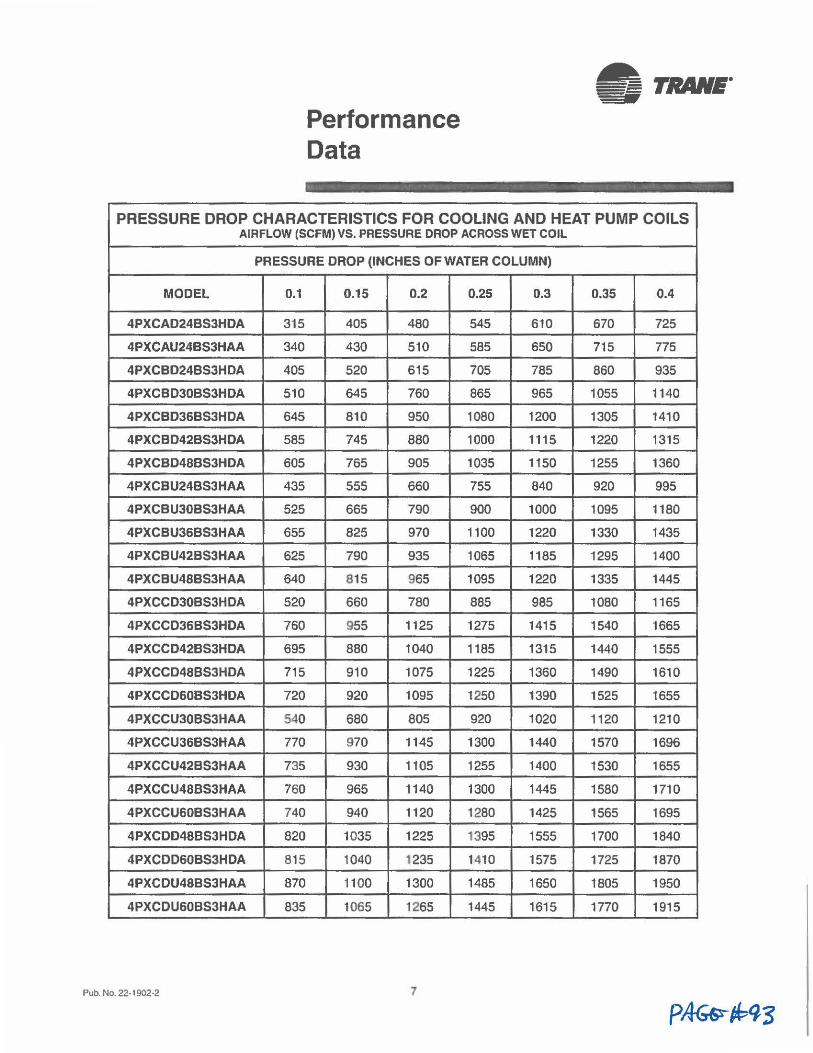
Performance Data
~ TRANE. -PRESSURE DROP CHARACTERISTICS FOR COOLING AND HEAT PUMP COILS
AIRFLOW (SCFM) VS, PRESSURE DROP ACROSS WET COIL
PRESSURE DROP (INCHES OF WATER COLUMN)
MODEL 0.1 0.15 0.2 0.25 0.3 0.35 0.4
4PXCAD24BS3HDA 315 405 480 545 610 670 725
4PXCAU24BS3HAA 340 430 510 585 650 715 775
4PXCBD24BS3HDA 405 520 615 705 785 860 935
4PXCBD30BS3HDA 510 645 760 865 965 1055 1140
4PXCBD36BS3HDA 645 810 950 1080 1200 1305 1410
4PXCBD42BS3HDA 585 745 880 1000 1115 1220 1315
4PXCBD48BS3HDA 605 765 905 1035 1150 1255 1360
4PXCBU248S3HAA 435 555 660 755 840 920 995
4PXCBU30BS3HAA 525 665 790 900 1000 1095 1180
4PXCBU368S3HAA 655 825 970 1100 1220 1330 1435
4PXCBU428S3HAA 625 790 935 1065 1185 1295 1400
4PXCBU488S3HAA 640 815 965 1095 1220 1335 1445
4PXCCD30BS3HDA 520 660 780 885 985 1080 1165
4PXCCD36BS3HDA 760 955 1125 1275 1415 1540 1665
4PXCCD428S3HDA 695 880 1040 1185 1315 1440 1555
4PXCCD48BS3HDA 715 910 1075 1225 1360 1490 1610
4PXCCO60BS3HOA 720 920 1095 1250 1390 1525 1655
4PXCCU308S3HAA 540 680 805 920 1020 1120 1210
4PXCCU368S3HAA 770 970 1145 1300 1440 1570 1696
4PXCCU42BS3HAA 735 930 1105 1255 1400 1530 1655
4PXCCU488S3HAA 760 965 1140 1300 1445 1580 1710
4PXCCU608S3HAA 740 940 1120 1280 1425 1565 1695
4PXCDD488S3HDA 820 1035 1225 1395 1555 1700 1840
4PXCDD608S3HDA 815 1040 1235 1410 1575 1725 1870
4PXCOU48BS3HAA 870 1100 1300 1485 1650 1805 1950
4PXCDU608S3HAA 835 1065 1265 1445 1615 1770 1915
Pub. No. 22-1902·2 7
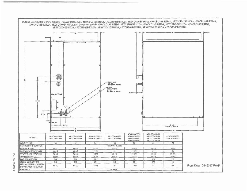
~ !'" z !"
~ g N
"'
Outline Drawing for Upflow model:.. 4P~CAU24BS3HAA. 4PXCBt.::?4BS3HAA, 4PXCBU36B53HAA, -IPXCCU36BS3HAA, 4PXC81A2BS3HAA. 4PXCCU42BS3HAA, 4PXCBl'46BSJHAA, 4PXCCU48BS31-l-\A, 4PXCCU60BS3IIAA. and Downllow models: 4PXCAD18BS311DA. 4PXCBDI6BSJIIDA, 4PXCAD2-1BS3IIDA, 4PXCBD:!4BS3HDA, 4PXCBD36BS3IIDA,
4PXCCD36BS:11-1DA. 4PXCBD42US3HDA, 4PXCCD42DS3HDA, 4PXCDD48BS3IIDA, 4PXCCD4SBS3UDA, 4PXCCD60BS3HDA
D l--1 - l· ,,. L- lt·Slt ~,,.
,- i-
& O " ... , 0 0
0 p 0
• [C I A l•lll
"' on-. ~- o:::i: V --~-.... ... __ l ·4 U
Coafart'"coil
0 :>
lt• ltl - -.. I /.~ ~ a l ;u I ~ "' - ft n n
I
~d I I
I I Sit - -1,1 _,,,,- l ·JU- ti tll
o,(Ul(ji II .. &1,(I
11 Ill
4PXCBU428SJ JPXCCU428S3
MODEL JPXCAU248SJ 4PXCBU24BSJ 4PXCBU366SJ 4PXCCUJ68S3 4PXCB0428S3 JPXCC042BSJ 4PXCCUf:OBSJ JPXCAD24BSJ 4PXCBD24BSJ 4PXCBD368SJ 4PXCCOJ6BSJ JPXCBU48BS3 4PXCCU48BSJ JPXCCD606S3
JPXCBn.t•BSJ 4PXCrOJ6"S3
WEIGHT ILBS I 39 42 5J 56 61 64 73
Rtr RIGERANT CONTROL TXV INON·BLEEO)
HEIGHT "A" IIN.) 17 1/~ 17·112 n-n ~ - 11'2 2{;.7/8 26-7;8 30.314
OVERALL WIDTH •a• tlN ) 14-1/2 17•112 17•112 21 17•112 21 21
OPENING WIDTH •c• ON I 13·5.'8 16-518 16·5.'8 20•118 16-518 20-1/8 20·118
TOP OPENING •o• 12-:~•4 15-J.'4 15-3/4 19-1;4 15·3'4 19-114 19-1!4
GAS cormECTION J.'4 1'4 iiB 1/8 718 718 7/8
LIQUID CONNECTION J.1! 3!8 J/8 l:8 J.-1! 3 '1! J.-1!
MATCHED FURNACE WIDTH U -1/2 17-112 17-1.'2 21 17-1/2 21 21 From Dwg. 0345397 RevD
I tNO ADAPTER REOUIREOl
DRAIN PAN PLASTIC
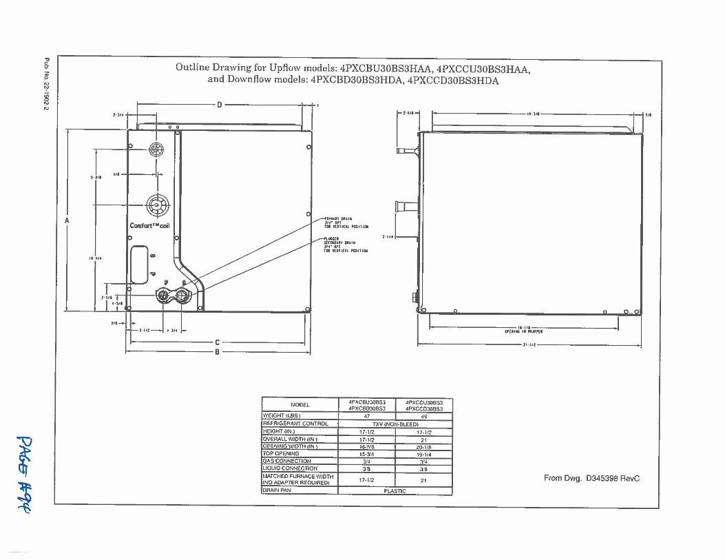
1 l
'J' c; z p
"' ':->
i "'
A
Outline Drawing for Upflow models: 4PXCBU30BS3HAA, 4PXCCU30BS3HAA, and Downflow models: 4PXCBD30BS3HDA, 4PXCCD30BS3HDA
l·JU I I I
D
0 0 j I
~ I I
r···1 ,.J
!------------- lt •Jta-------------11-illl
,.,, . ,,.-1-J r l •• Conifort"'coil
- LI _,,.-,/ I · · -
"""u ~~:' HIii
"j"'~--
t·IIIT "ill
- roa l(llt(it f'OSIIIOI
•-i,a ....L
,,. I I
Jf1J~1J11 1------------11-111-------------
0,(UIG II nu,u
C 1---------------11-u,----------------1 B
f.lOOEL 4PXCBUJ0853 4PXCCU30BS3 4PXCBOJOBS3 4PXCCDJOBS3
WEIGHT <LBS.I 47 I 49 REFRIGERANT CONTROL TXV (NON-BLEED) HEIGHT ON.) 17-1/2 17-112 OVERALL WlDTH UN.I 17-1/2 21 OPENING WIDTH <IN 1 16-518 20-118 TOP OPENING 15-314 19.1;4 GAS CONNECTION 1'4 3.'4 UOU10 CONNECTIO~I 3.'8 318 MATCHED FURNACE WIDTH
17-112 21 (NO ADAPTER REQUIRED) From Dwg. D345398 AevC
DRAIN PAN PLASTIC
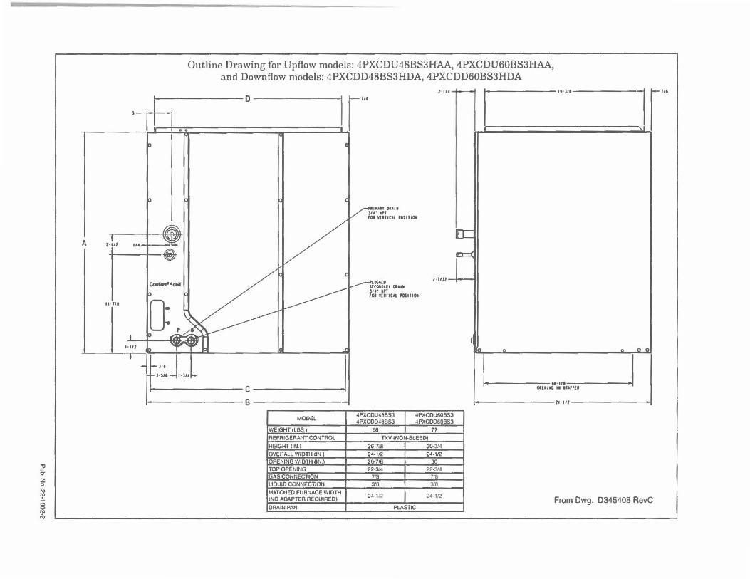
~ z p
~ 8 I\)
N
A 1-lit
Outline Drawing for Upflow models: 4PXCDU48BS3HAA, 4PXCDU60BS3HAA, and Downflow models: 4PXCDD48BS3HDA, 4PXCDD60BS3HDA
l II ·-_ _ D I r·
[C
..... I ,1
r· ..
,,, --t----.:it;;;:
I I ♦ o::::i:
" ,,.
I. HI
C-,ort •• CDil
)If
J-s,a~•-•u
--------c-------i --------e-------
MODEL
WEIGHT (LBS I
REFRIGERANT CONTROL
HEIGHT Utl.l
OVERALL WIDTH IIN l OPENING WIDTH IIN.l TOP OPENING GAS CONNECTION
UOUID CONNECTION
MATCHED FURNACE WIDTH (NO ADAPTER REOUIREOI
ORA!NPAN
}lUGCi[O $l(0-0Ut 01.UI .,, ... ,. 1·11)/
JOI YUflCAt f0$1HOI
4PXCOU488S3 4PXCOU60BSJ 4PXCOD488SJ 4PXC0060BSJ
68 I r, TXV INON-BLEEDI
26-7;8 JO.:l'4
24-112 24-112 26-718 JO 22-3/4 22-3/4
7!B 7/8
318 :l'8
24•1~ 24-112
PLASTIC
---
[
" ~ " ,. ,,
11• 111 0,(119' II IIUPH I
lt Ill
From Dwg. 0345408 RevC
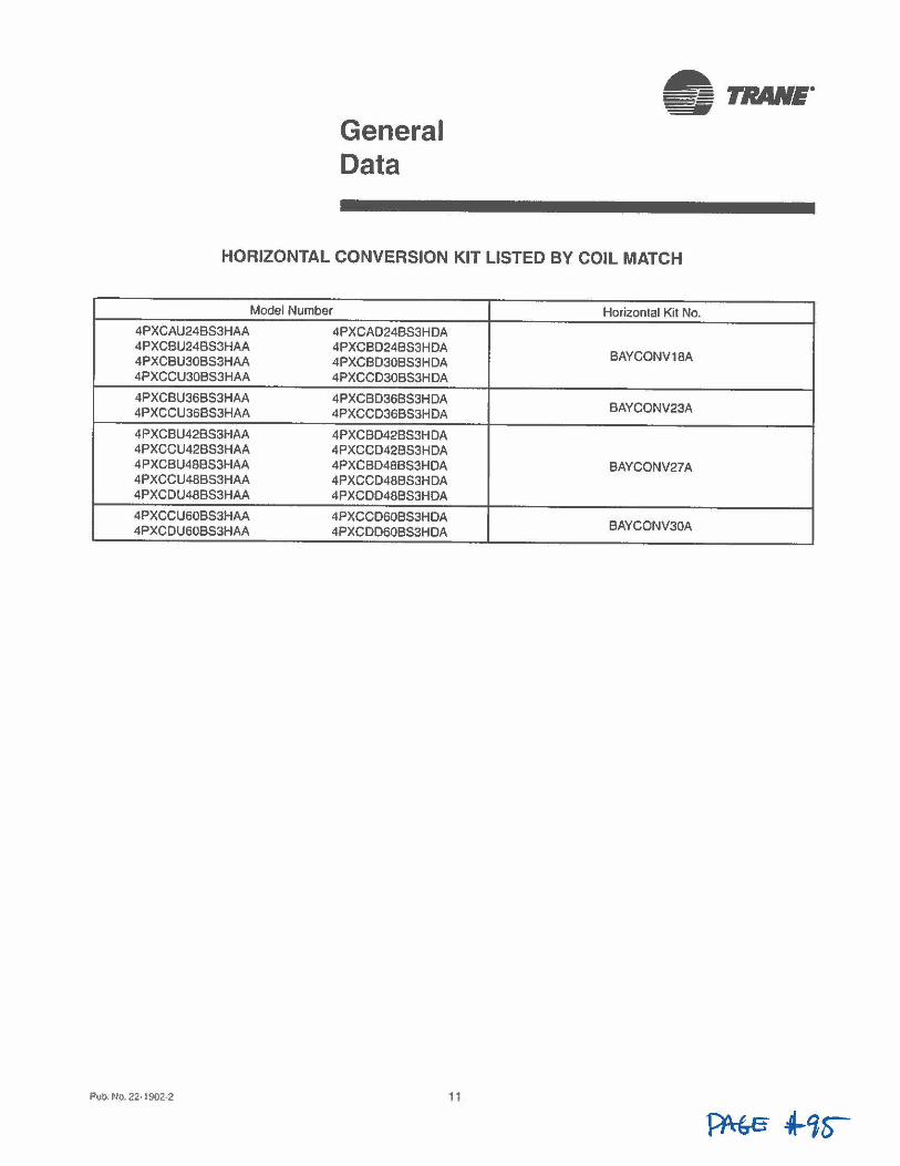
General Data
• TRANE"
HORIZONTAL CONVERSION KIT LISTED BY COIL MATCH
Model Number Horizontal Kit No.
4PXCAU248S3HAA 4PXCAD248S3HDA 4PXCBU248S3HAA 4PXC8O248S3HDA
BAYCONV18A 4PXCBU30B53HAA 4PXC8D30B53HDA 4PXCCU308S3HAA 4PXCCD308S3HDA
4PXCBU368S3HAA 4PXCBD368S3HDA BAYCONV23A 4PXCCU36B53HAA 4PXCCD368S3HDA
4PXCBU42BS3HAA 4PXCBD428S3HDA 4PXCCU428S3HAA 4PXCCD42BS3HDA 4PXCBU488S3HAA 4PXCBD48BS3HDA BAYCONV27A 4PXCCU488S3HAA 4PXCCD488S3HDA 4PXCDU488S3HAA 4PXCDD48BS3HDA
4PXCCU608S3HAA 4PXCCD608S3HDA BAYCONV30A 4PXCOU608S3HAA 4PXCDD608S3HDA
Pub. No. 22-1902-2 11
Trane 6200 Troup Highway Tyler, TX 75707 www.trane.com
For morn inlorm,11ion contact your local dealer (dislrit,ulor)
lntertek
Literature Order Number 22-1902·2
File Number 22·1902·2
Supersedes 22·1902-1
0~18 02/16
Since Trane has a policy of continuous product improvement, It reserves the right to change design and speci/1~//ons without notice.
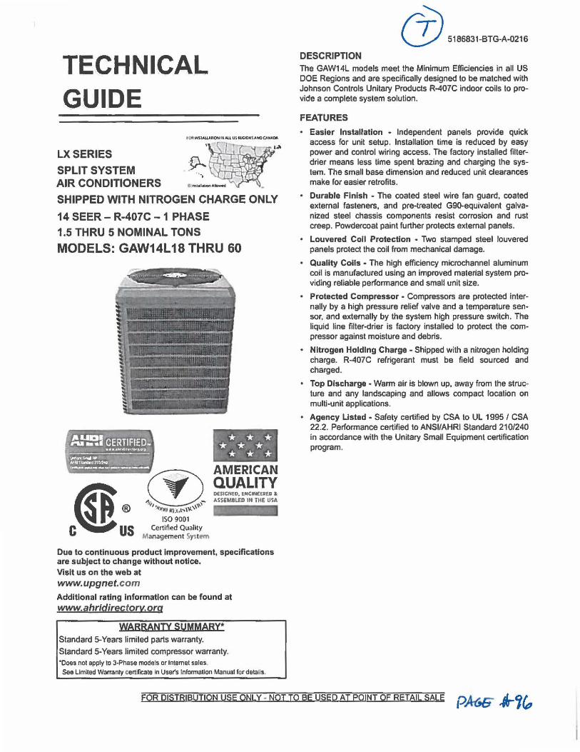
TECHNICAL GUIDE
LXSERIES
SPLIT SYSTEM AIR CONDITIONERS
SHIPPED WITH NITROGEN CHARGE ONLY
14 SEER - R-407C - 1 PHASE 1.5 THRU 5 NOMINAL TONS
MODELS: GAW14L18 THRU 60
--
l~~-ICERTIFIED~ ~ • ·;;..,. t 11•• ,.,,◄,1t~ltty..c:r:1 ,
. * * * :* * * . * * * -------\.WINY~ .. .,\ • NHV!tnwd2t~ol0 • J., . . ~ .
,......_ ..... --.. ·---------
Due to continuous product Improvement, specifications are subject to change without notice. Visit us on the web at www.upgnet.com Additional rating Information can be found at www.ahridirectory.org
WARRANTY SUMMARY* Standard 5-Years limited parts warranty.
Standard 5-Years limited compressor warranty. "Does not apply to 3-Phase models or Internet sales. See Limited Warranty cert.llcate In User's Information Manual for details.
6) 5186a31-BTG-A-<Y.116
DESCRIPTION The GAW14L models meet the Minimum Efficiencies in all US DOE Regions and are specifically designed to be matched with Johnson Controls Unitary Products R-407C indoor coils to provide a complete system solution.
FEATURES
• Easler Installation • Independent panels provide quick access for unit setup. Installation time is reduced by easy power and control wiring access. The factory installed filterdrier means less time spent brazing and charging the system. The small base dimension and reduced unit clearances make for easier retrofits.
• Durable Finish - The coated steel wire fan guard, coated external fasteners, and pre-treated G90-equivalent galvanized steel chassis components resist corrosion and rust creep. Powdercoat paint further protects external panels.
• Louvered Coll Protection • Two stamped steel louvered panels protect the coil from mechanical damage.
• Quality Coils - The high efficiency microchannel aluminum coil is manufactured using an Improved material system providing reliable performance and small unit size.
• Protected Compressor • Compressors are protected internally by a high pressure relief valve and a temperature sensor, and externally by the system high pressure switch. The liquid line filter-drier is factory installed to protect the compressor against moisture and debris.
• Nitrogen Holding Charge - Shipped with a nitrogen holding charge. R-407C refrigerant must be field sourced and charged.
• Top Discharge - Wanm air is blown up, away from the struc• ture and any landscaping and allows compact location on multi-unit applications.
• Agency Listed • Safety certified by CSA to UL 1995 / CSA 22.2. Performance certified toANSI/AHRI Standard 210/240 in accordance with the Unitary Small Equipment certification program.
FOR DISTRIBUTION USE ONLY - NOT TO BE USED AT POINT OF RETAIL SALE p~ ,t-'jft,
5186831-BTG-A-0216
LIST OF SECTIONS DESCRIPTION •••••• ••• •••• •••• • •• • • ••• ••••• •••• •••• •••• 1 FEATURES •••••••••••••••••••••••••••••••••••••••••••• 1 NOMENCLATURE ....................................... 2 PHYSICAL AND ELECTRICAL DATA ..... . ......... ... .. .. . 3 DIMENSIONS •••••.••••••.••••••••••••••••••.•••••.•••• 3 SYSTEM CHARGE FOR VARIOUS MATCHED SYSTEMS •• ••• •• 4 COOLING CAPACITY· Upflow, Downflow & Horizontal Furnaces and Coils (Coll Only Ratings) ••••••••••••••. •• •••••• • ••••• 4 ACCESSORIES •••••• ••••• •• ••••• •• •• ••••••••• • ••• •••• •• 5 SOUND POWER RATINGS ••• •• •••••• • • ••••••• •• ••••• • •• • 5 TYPICAL INSTALLATION •• ••• ••••• • .••••••••••••• • .••••• 6 TYPICAL FIELD WIRING ••• ••••• •••• • •••• •••• •••••• • •• ••. 7 ALTERNATIVE INSTALLATION CLEARANCES .•••••••••••••• 7 PERFORMANCE DATA· 1.5 TON •••• •. •••• •.• ••••• ••• •••• • 8 PERFORMANCE DATA· 2 TON •••••••••••••••••••••••••• • 9 PERFORMANCE DATA· 2.5 TON • • •••••.••• ••••••••• ••••• 10 PERFORMANCE DATA• 3 TON .......................... 11 PERFORMANCE DATA· 3.5 TON ......................... 12 PERFORMANCE DATA. 4 TON ••• •• ••• .••• .••••• . • •• . • •• 13 PERFORMANCE DATA. 5 TON •.•••••••••••••••••••.•••• 14
2
NOMENCLATURE
BRAND
PRODUCT TYPE
NOMINAL SERIES EFFICIENCY AND STAGING
CABINET AND CONNECTION TYPE
NOMINAL UNIT CAPACITY (MBH)
REFRIGERANT
VOLTAGE (Voltage-Phase-Hertz)
GENERATION (MAJOR REVISION)
FACTORY OPTION
STYLE LETTER (MINOR REVISION) NOT USED FOR ORDERING
G G = Guardian
AW AW = Southwest Region Air Conditioner
14 • 14 SEER/ 1-Stage 14 (US Southeast or Southwest Region)
L L = New Chassis Louvered / Sweat Connect
18 = 1.5 Ton 42 • 3.5 Ton
36 24 = 2 Ton 48 = 4 Ton
30 = 2.5 Ton 60 = 5 Ton
36 • 3 Ton
C C =R-407C
2 2 = 208/230-1-60
1=1stGen
1 2 = 2nd Gen
etc
s S = Standard (No Options)
A =Style A
A B = Style 8
etc
Johnson Controls Unitary Products
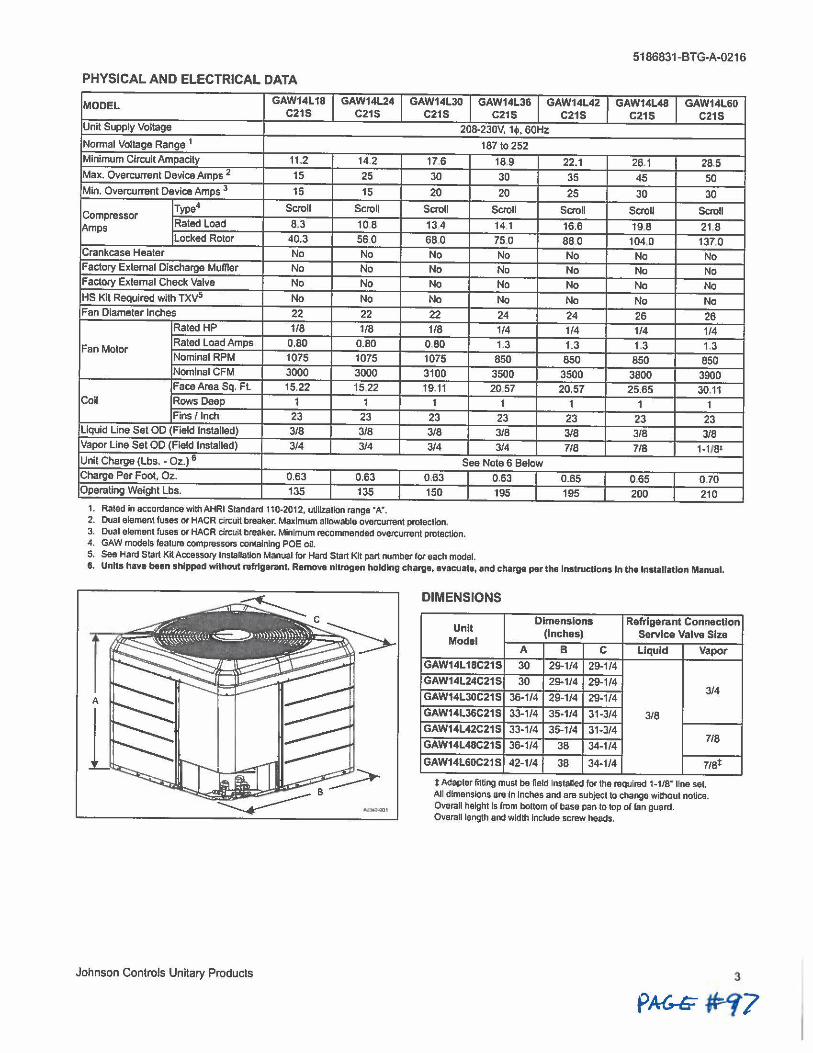
5186831-BTG-A-0216
PHYSICAL AND ELECTRICAL DATA
MODEL GAW14L18 GAW14L24 GAW14L30 GAW14L36 GAW14L42 GAW14L48 GAW14L60 C215 C21S C21S C21S C21S C21S C21S
Unit Supply Voltage 208-2J0V, 1♦, 60Hz
Normal Voltage Range 1 187 to 252 Minimum Circuit Ampaclty 11.2 14.2 17.6 18.9 22.1 26.1 28,5 Max. Overcurrenl Device Amps 2 15 25 JO 30 35 45 50 Min. Overcurrent Device Amps 3 15 15 20 20 25 30 30
Type4 Scroll Scroll Scroll Scroll Scroll Scroll Scroll Compressor Rated Load 8.3 10 8 13.4 14 1 16.6 19.8 21.8 Amps Locked Rotor 40.3 560 680 75.0 880 104,0 137,0
Crankcase Heater No No No No No No No Factory External Discharge Muffler No No No No No No No Factory External Check Valve No No No No No No No HS Kit Required with TXV5 No No No No No No No Fan Diameter Inches 22 22 22 24 24 26 26
Rated HP 1/8 1/8 1/8 1/4 1/4 1/4 1/4
Fan Motor Rated Load Amps 0.80 0.80 080 1.3 1.3 1.3 1.3 Nominal RPM 1075 1075 1075 850 850 850 850 NomlnalCFM 3000 3000 3100 3500 3500 3800 3900 Face Area Sq, Fl 15.22 15 22 19.11 20.57 20.57 25.65 30.11
Coll Rows Deep 1 1 1 1 1 1 1 Fins/ Inch 23 23 23 23 23 23 23
Liquid Line Set OD (Field Installed} 3/8 3/8 3/8 3/8 3/8 3/8 3/8 Vapor Line Set OD (Field Installed) 3/4 3/4 3/4 3/4 718 7/8 1-1181
Unit Charge (Lbs .• Oz.) 6 See Note 6 Below
Charge Per Foot, Oz. 0.63 0.63 0 .63 0.63 0.65 0.65 0.70 OperaUng Weight Lbs. 135 135 150 195 195 200 210
1. Rated in accordance withAHRI Standard 110-2012, uUlizaticn range ·A·. 2. Dual element fuses er HACR circuit breaker. Maximum allowable overcurrent protection. 3. Dual element fuses or HACR circuit breaker. Minimum recommended overcurrent protection. 4. GAW models feature compressors containing POE oil. 5. See Hard Start Kit Accesso,y lnstallaUon Manual for Hard Start Kit part number lcr each model. 6. Units have bean shipped without rafrlgarant. Remove nitrogen holding charge, evacuate, and charge par the Instructions In the Installation Manual.
DIMENSIONS
Unit Dimensions Refrigerant Connection
Johnson Controls Unitary Products
(Inches) Service Valve Size Model A B C Liquid Vapor
GAW14L 1BC21S 30 29-1/4 29-1/4
GAW14L24C21S 30 29-1/4 29-1/4 3/4 GAW14L30C21S 36-1/4 29-1/4 29-1/4
GAW14L36C21S 33-1/4 35-1/4 31-3/4 3/8 GAW14L42C21S 33-1/4 35-1/4 31-3/4
718 GAW14L48C21S 36-1/4 38 34-1/4
GAW14L60C21 S 42-1/4 38 34-1/4 115t
i Adapter fltUng must be field Installed for the required 1-11e• line set All dimensions are In Inches and are subject to change without notice. Overall height Is from bottom of base pan to top of fan guard. Overall length and width Include screw heads.
3
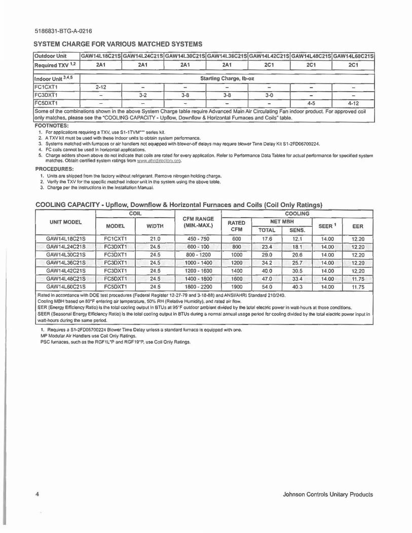
5186831-BTG-A-0216
SYSTEM CHARGE FOR VARIOUS MATCHED SYSTEMS
Outdoor Unit GAW14L18C21S GAW14L24C21S GAW14L30C21S GAW14L36C21 S GAW14L42C21S GAW14L48C21S GAW14L60C21S
Required TXV 1•2 2A1 2A1 2A1 2A1 2C1 2C1 2C1
Indoor Unit 3.0 Starting Charge, lb-oz
FC1CXT1 2-12 - - - - - -FC3DXT1 - 3-2 3-8 3-8 3-0 - -FC5DXT1 - - - - - 4-5 4-12
Some or the combinations shown in the above System Charge table require Advanced Main Air Circulating Fan indoor product For approved cow only matches, please see lhe "COOLING CAPACITY• UpHow, Downnow & Horizontal Furnaces and Coils" table.
FOOTNOTES: 1. For applications requiring a TXV, use S1-1TVM··· series kit 2. A TXV kit must be used wllll these Indoor units to obtain system performance. 3. Systems matched with furnaces or air handlers not equipped with blower-off delays may require blower Time Delay Kit S 1-2FD06700224. 4. FC coUs cannot be used In horizontal applications. 5. Charge adders shown above do not indicate that colts are rated for every applicaUon. Reier to Performance Data Tables for actual performance for specif,ed system
matches. Obtain certified system ratings from WWt/ ahrjdj1ec1orv.org,
PROCEDURES: 1. Units are shipped from the factory without refrigerant Remove nitrogen holding charge. 2. Verify the TXV for the specific matched Indoor unit In the system using the above table. 3. Charge per the Instructions In the lnstallallon Manual
COOLING CAPACITY• Upflow, Downflow & Horizontal Furnaces and Coils (Coil Only Ratings) COIL COOLING
UNIT MODEL CFMRANGE RATED NETMBH
MODEL WIDTH (MIN.-MAX.) CFM TOTAL SENS.
SEER 1 EER
GAW14L18C21S FC1CXT1 21 0 450- 750 600 17.6 12.1 14.00 12.20
GAW14L24C21S FC3OXT1 24.5 600-100 BOO 23.4 18.1 14.00 12.20
GAW14L30C21S FC3DXT1 24.5 BOO- 1200 1000 29.0 20.6 14.00 12.20
GAW14L36C21S FC3DXT1 24.5 1000-1400 1200 342 25.7 14.00 12.20
GAW14L42C21S FC3DXT1 24.5 1200 - 1600 1400 40.0 30.5 14.00 12.20
GAW14L48C21S FC5OXT1 24.5 1400-1800 1600 47.0 334 14.00 11.75
GAW14L60C21S FC5OXT1 24,5 1800 - 2200 1900 540 403 14,00 11 .75
Rated In accordance with DOE test procedures (Federal Register 12-27-79 and 3·18-88) and ANSI/AHRI Standard 210/240. Cooling MBH based on eo•F entering air temperature, 50% RH (RelaUve Humidity), and rated air now. EER (Energy Efficiency RaUo) Is the total cooling output in BTUs at 95"F outdoor ambient divided by Ule total electric power in watt-hours at those condlUon5, SEER (Seasonal Energy Elficlency Ratio) is the total cooling output In BTUs during a normal annual usage period for cooling divided by the total electric power Input In watt-hours during the same period.
4
1. Requires a S1-2F006700224 Blower Time Delay unless a standard furnace Is equipped with one. MP Modular Air Handlers use Coil Only RaUngs. PSC lumaces, such as the RGF1 L •p and RGF19"P, use Con Only Ratings.
Johnson Controls Unitary Products
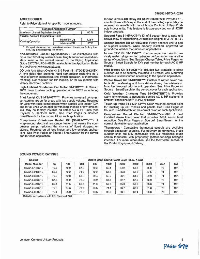
ACCESSORIES Refer to Price Manual for specific model numbers.
Standard Application Limits•
Maximum Llneset Equivalent Length I 80 Fl Outdoor Ambient Temperature Limits
CooUng Operation I Maximum DB I 125•F
I Minimum DB I 55•F
• For applications such as Low Ambient, reduced linesets, and/or long line• sets, see the accessories listed below.
Non-Standard Llneset Applications • For installations with more than 80' of equivalent lineset length and/or reduced diameters, refer to the current version of the Piping Application Guide 24 7077-UAD-H-0209, available in the Application Bulletins section on www.upgnet.com. OD Unit Anti Short Cycle Kit (10 Pack) S1-2TD08700124BK: A time delay that prevents rapid compressor restarting as a result of power interruption, limit switch operation, or thermostat resetting. Not required for HP models, or for AC models with factory electronic controls.
High Ambient Condenser Fan Motor S1-FHM**-HT: Class F 70°C motor to allow cooling operation up to 160°F air entering the condenser. Start Assist Kit S1-2SA0&7-: Provides increased compressor starting torque for areas with low supply voltage. Required for units with recip compressors when applied with indoor TXV, and for all units when applied with long linesets or low ambient kits. May be factory installed on select AC & HP units (see Physical & Electrical Table). See Price Pages or Source1 SmartSearch for the correct kit for each application. Compressor Crankcase Heater Kit (S1-025-•-...... ,: A wrap-around electrical resistance heater that warms the compressor sump, reducing the chance of liquid slugging on startup. Required on all long lineset and low ambient applications. See Price Pages or Source1 SmartSearch for the correct part for each application.
SOUND POWER RATINGS
5186831-BTG-A-0216
Indoor Blower-Off Delay Kit S1-2FD06700224: Provides a 1-minute blower-off delay at the end of the cooling cycle. May be required for retrofits with non-Johnson Controls Unitary Products indoor units. This feature is factory-provided on all JCUP indoor products.
Support Feet S1-HPRKIT-**: Kit of 5 support feet to raise unit above snow or landscaping. Available in heights of 3", 6" or 12".
Anchor Bracket Kit S1•1HK0401: Firmly anchors unit to pad or support structure. When property installed, approved for ground-mounted or roof-mounted applications. Indoor TXV Kit S1-1TVM ..... : Thermal expansion valves precisely meter refrigerant for optimum performance over a wide range of conditions. See System Charge Table, Price Pages, or Source1 Smart Search for TXV part number for each AC & HP model.
Wall Mount Kit (S1-ACB-**): Includes two brackets to allow outdoor unit to be securely mounted to a vertical wall. Mounting hardware is field sourced according to the specific application.
Winter Cover Kit 51-CCVRE-•: Custom fit winter cover protects AC condensing unit from debris during the off-season. Must be removed prior to unit operation. See Price Pages or Source1 SmartSearch for the correct cover for each application.
Cold Weather Charging Tent S1-CHGTENT01: Provides warm environment to accurately service AC & HP systems in ambient conditions 55°F (13°C) or colder.
Touch-up Paint S1-5130153****: Color matched aerosol paint for touching up unit chassis and panels. See Price Pages or Source1 SmartSearch for the correct color for each application.
Compressor Sound Blanket S1-010-07xxx-OO0: A field installed dense foam cover that provides 2dBA sound level reduction. See Price Pages or Source1 SmartSearch for the correct blanket for each application.
Thermostat - Compatible thermostat controls are available through accessory sourcing. For optimum performance, these outdoor units are fully compatible with our residential touch screen thermostat with proprietary (patent-pending) hexagon interface. For more information, see the thermostat section of the Product Equipment Catalog.
Coollng Octave Band Sound Power Leval (db re. 1-pW)
Model Number 63 125 250 500 1000 2000 4000 8000 dBA SQI
GAW14L18C21S 70.3 70.9 67.9 70.3 68.1 64.2 58.6 55.0 72 19.1
GAW14L24C21S 69.5 70.2 71.0 72.2 67.5 66.3 59.9 57.5 74 19.1
GAW14L30C21S 70.0 70.8 68.8 70.4 69.2 66.1 61.3 59.9 74 19.1
GAW14L36C21S 67.8 75.0 72.2 69.9 67.6 62.7 57.9 56.9 72 19.1
GAW14L42C21S 68,4 71 .5 69.9 71 .3 69.6 65.3 59.9 58.8 74 19.1
GAW14L48C21S 72.6 74,3 70.7 73.5 71 .1 66.7 63.7 61 .8 76 19.1
GAW14L60C21S 70.4 75.9 70.2 73.5 69.8 68.1 63.4 60.6 75 19.1
Rated in accordance w ith ARI Standard 270.
Johnson Controls Unitary Products 5
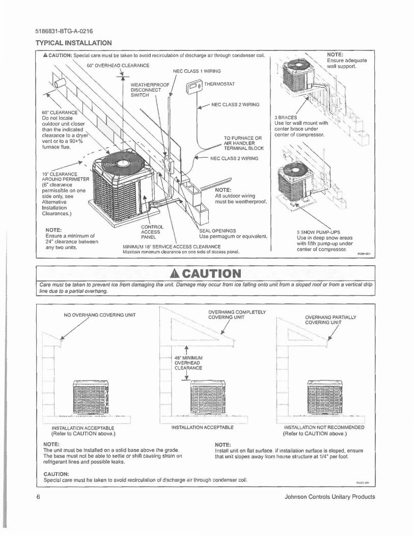
5186831-BTG-A-0216
TYPICAL INSTALLATION
A CAUTION: Special care musl be laken lo avoid rec rculalton of discharge a,r lhrough condenser coil.
60" OVERHEAD CLEARANCE
60" CLEARANCE Do not locale outdoor unit closer than lhe indicated clearance to a dryer vent or to a 90+% furnace flue.
______. ' ' 10• CLEARANCE AROUND PERIMETER cs· clearance permissible on one side only, see Alternative Installation Clearances.)
NOTE: Ensure a minimum of 24" clearance between any two units.
~ NEC CLASS 1 WIRING
T WEATHERPROOF/ j:? "' THERMOSTAT DISCONNECT
17
SWITCH
~ NEC CLASS 2 WIRING
TO FURNACE OR AIR HANDLER TERMINAL BLOCK
NEC CLASS 2 WIRING
SEAL OPENINGS Use permagum or equivalent.
MINIMUM 18" SERVICE ACCESS CLEARANCE Ma.intnin minimum clearance on one s,de al access panel.
A CAUTION
5 SNOW PUMP-UPS Use in deep snow areas with fifth pump-up under center of compressor. ,.._,
Care must be taken to prevent ice from damaging the unit. Damage may occur from ice falling onto unit from a sloped roof or from a vertical drip line due to a partial overhang.
6
7""° COVEroNG UN,r
~, I
INSTALLATION ACCEPTABLE (Refer to CAUTION above.)
NOTE:
t I I
l
OVERHANG COMPLETELY
..._ -.. COVEiG UNIT
j 48.JNIMUM
._ _.J'
OVERHEAD CLEARANCE
.1
INSTALLATION ACCEPTABLE
NOTE:
-,
OVERHANG PARTIALLY
' ~OVERINGiT
INSTAI.LATION NOT RECOMMENDED (Refer lo CAUTION above )
The unit must be Installed on a solid base above Iha grade. The base must not be able to settle or shin causing strain on refrigerant lines and possible leaks.
lr,stall unit on Rat surface. If insta lalion surface Is sloped, ensure that un,t slopes away from house structure at 1/4" per foot.
CAUTION; Special care must be laken lo avoid recirculat•on of d·scharge a•r through condenser coil.
Johnson Controls Unitary Products
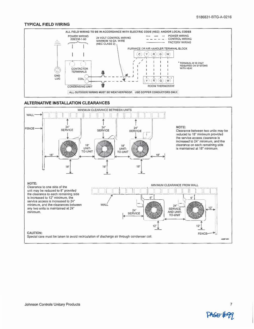
5186831-BTG-A-0216
TYPICAL FIELD WIRING
ALL FIELD WIRING TO BE IN ACCORDANCE WITH ELECTRIC CODE (NEC) AND/OR LOCAL CODES
POWER WIRING - - - POWER WIRING 2081230-1 _60 24 VOlT CONTROL WIRING _ _ _ _ _ CONTROL WIRING
----, I MINIMUM 18 GA. WIRE ---- FACTORY WIRING ,-- _______,_ (NEC CLASS 2)
FURNACE OR AIR HANDLER TERMINAL BLOCK
GND LUG
1 I i' c ~ y' R '- : o 1 ,w , I , I I I I
: ( :~NTA~TO~JR : (_, I I TmMINA~ l I I
L - - - - ~- J : I ~ I I -,71 _ _ _ _ _ _ ~ LY.a.'._~ G > , w) I
CONDENS,NGUNIT ROOM THERMOSTAT
• TERMINAL WIS ONLY REQUIRED ON SYSTEMS Wlflt HEAT
I ALL OUTDOOR WIRING MUST BE WEATHERPROOF. use coPPER CONDUCTORS ONLY.
ALTERNATIVE INSTALLATION CLEARANCES
WALL_. --i .•
FENCE
18"
NOTE: Clearance ta one side ar the unit may be reduced lo s· provided the clearance to each remaining side Is Increased to 12• minimum. the service access is increased to 24" minimum, and the clearances between any two units is maintained at 24· minimum.
CAUTION: Special care must be taken to avoid recirculallon or discharge air through condenser coll.
Johnson Controls Unitary Products
NOTE: Clearance between two units may be reduced to 1e· minimum provided the service access clearance Is increased lo 24" minimum. and the dearance on each remaining side Is maintained at 1 e• minimum.
FENC~ ..
7

5186831-BTG-A-0216
PERFORMANCE DATA-1.5 TON
CONDENSER-ONLY DATA (OUTDOOR UNIT}
SATURATED SUCTION Outdoor Ambient Temperature
MODEL @ COMPRESSOR 55°F 65 "F 75 "F 85°F
T (°F) P (PSIG) MBH KW MBH KW MBH KW MBH KW
35 107.4 13 67 0.97 12.98 1.11 12.30 1.25 11.62 1.39
40 118.6 15.91 0.94 15.14 1.08 14.37 1.22 13.60 1.36
45 130.4 18.15 0.92 17.29 1.06 16.44 1.20 15.58 1.34 GAW14L 18C21S
50 1430 20.39 0.90 19.44 1.04 18.50 1.18 17.56 1.32
55 156.3 22.62 0.88 21.60 1.02 20.57 1.16 19.54 1.30 60 170.3 24.86 0.86 23.75 1.00 22.64 1.14 21.53 1.28
Notes:
1. For Outdoor Unit (Condenser) performance only. Data does not Include the effects of air handler power or heat.
2. Performance based on 15' F subcoollng and 15' F superheat at the Outdoor Unit base valves.
a. Increase capacity by 1 % for each 2"F Increase In subcooling.
b. Decrease capacity by 1% for each 2'F decnlase In subcoollng.
3. Maximum recommended condensing temperature Is 140•F.
COOLING PERFORMANCE DATA
AIR CONDITIONER MODEL NO. GAW14L18C21S
INDOOR COIL MODEL NO. FC1CXT1
AIR TEMP. IDCFM 450
ENTERING ID DB (°F) 80 80 75 OUTDOOR UNIT (°F) IDWB (°F) 57 62 62
T.C. 17.2 19.2 19.0
55 s.c. 16 4 14.4 12.2
KW 1.05 1.05 1.05
T.C. 16.5 18.3 18 2 65 s.c. 15.6 13.9 11.7
KW 1.16 1.14 1.15
T.C. 15.8 17.3 17,4
75 s.c. 14.9 13,4 11 .3
KW 1.27 1.23 1.24 T.C. 15.5 16.9 16.8
85 s.c. 14.8 13.3 11.0
KW 1.38 1.36 1.37
T.C. 15.2 16.6 16.3 95 s.c. 14.7 13.2 10.8
KW 1.49 1.49 1.50
T.C. 14.0 15.4 15 .. 2 105 s.c. 13.6 12.6 102
KW 1 75 1 75 1.75
T.C. 12.8 14.2 14.2
115 s.c. 12.5 12.1 96 KW 2.01 2.01 2 00
T.C. 11 .5 12.9 13.2 125 s.c. 11.4 11 .6 8.9
KW 2.01 2.01 2.00
80 80 80 80 67 72 57 62
21.4 24.0 18.9 20.3 12.4 10.0 18.2 16.9 1.04 1.03 1.10 1.10 20.6 23.1 18.2 19.4 12.0 9.8 17.5 16.5 1,13 1.13 1 20 1.19 19.7 22.1 17.6 18.6 11.6 9.5 16.9 16.0 1.23 1.22 1.30 1.28
192 21.2 17.1 18.0 11 .3 9.0 16 5 15.7 1.36 1.35 1.42 1.41 18.7 203 16.7 17.3 11 .0 8.4 16.2 15.4 1 49 1.48 1.54 1.54 17,5 19.1 15.1 16.0 10,7 85 14.7 14.4 1.75 1.74 1 89 1.80 16 4 17.8 13.5 14.7
10.4 8.6 13.1 13.5 2,00 200 2.23 2.06
152 16 5 11 .9 13.4
10 1 8.7 11.6 12.6 2.00 2.00 2.44 2.19
600 75 80 62 67
20.1 22.5 14.1 14.2 1.10 1.09
19.2 21.6 136 13.9 1.20 1.19 18.3 20.6 13.0 13.6 1.29 1.28 17.6 20.0 12.8 13.3 1.42 1.41 16,9 19.3 12.5 13.0 1.55 1.54 15.6 17.8 11.9 12.4 1.80 1.80 14.2 16.3 11.3 11,9
2.06 2.05 12.9 14.8 10.6 11.3 2.18 2.18
95"F
MBH KW
10.93 1.53 12.83 1.50
14.72 1.48 16.62 1.46
18.52 1.44 20.41 1.42
80 80
72 57 24.7 20.6 11.2 20.0 1.09 1.15 23.8 20.0 10.9 19.5 1.18 1.24 23.0 19.4 10.6 18.9 1.27 1.34
22.1 18.8 10.3 18.3 1.40 1.47 21 .2 18.2 9.9 17.7 1.53 1.60 19.9 16.2 9.7 15.8 1.80 2,02
18.6 14.2
9.5 13.8 2.06 2.45 17.3 12.2 9.2 11.9 2.19 2.88
NOTE: All CAPACITIES INCLUDE INDOOR FAN HEAT. KW VALUES ARE FOR THE SYSTEM (OUTDOOR + INDOOR).
Green shaded cells are ACCA (TVA) condlllons,
Blue shaded cells ere AHRI conditions.
Multipliers for determining the performance with other Indoor sections.
105"F 115 °F
MBH KW MBH KW
10.25 1.67 9.56 1.81 12.06 1.64 11 .29 1.78 13.87 1.62 13.01 1.76 15.68 1.60 14.74 1.74 17.49 1.58 16.46 1.72
19.30 1.56 18.19 1.70
750 80 75 80 80 62 62 67 72
21.3 21.3 23.6 25.3 19.5 16.0 16.1 12.3 1.15 1.15 1.15 1.14 20.6 20.2 22.6 24.6 19.1 15.4 15.8 12,0 1.24 1.24 1.24 1.24 20.0 19.1 21.5 23.8 18.6 14.8 15.6 11 .7 1.34 1.34 1.33 1.33 19.0 18.4 20.8 23.0 18.1 145 15.2 11 .5 1.46 1.47 1.46 1.46 18.1 17.6 20.0 22.1
17.6 14.3 14.9 11.4 1.59 1.60 1.60 1.59 16.7 15.9 18.1 20.8
16.2 13.6 14.1 10.9 1.85 1.86 1.85 1.85 15.3 14.2 16.3 19.4 14.9 13.0 13,3 10.3 2.11 2.11 2.11 2.12 13.9 12.6 14.5 18.1
13.5 12.4 12.5 9.8 2.37 2.36 2.37 2.38
NOTE: For dry bulb temperatures different than those listed (between 73-87 ' F), sensible capacity Increases by 1060 BTUH per 1000 CFM per degree above the listed temperatunl and decreases by 1060 BTUH per 1000 CFM per degree below the listed temperature.
8 Johnson Controls Unitary Products

PERFORMANCE DATA - 2 TON
CONDENSER-ONLY DATA (OUTDOOR UNIT)
SATURATED SUCTION Outdoor Ambient Temperature MODEL @ COMPRESSOR 55 "F 65°F 75 "F 85 "F
T ("F) P (PSIG) MBH KW MBH KW MBH KW MBH KW 35 107.4 19.63 1.01 18.14 1.25 16.65 1 50 15.16 1.74 40 118.6 22.62 1.03 21.01 1.27 19.40 1 50 17.79 1.74 45 130.4 25.61 1.06 23.88 1.28 22.16 1.51 2043 1.73
GAW14L24C21S 50 143.0 28.60 1.08 26.76 1.30 24.91 1.51 2307 1.73 55 156.3 31.59 1.11 29.63 1.31 27.66 152 25.70 1.73
60 170.3 34.58 1.13 32.50 1.33 30.42 1.53 28.34 1.72
Notes:
1. For Outdoor Unit (Condenser) pemrmanc;e only. Data does not Include the elfacts or air handler power or heat.
2. Perfonnance based on 15"F subcoollng and 15'F supemeat at the Outdoor Unit base valves.
a. Increase capacity by 1% ror each 2'F Increase In subcooling.
b. Decrease capacity by 1% for each 2'F decrease In subcoollng.
3. Maximum recommended condensing temperature Is 140"F.
COOLING PERFORMANCE DATA AIR CONDJTIONER MODEL NO. GAW14L24C21S INDOOR COIL MODEL NO. FC3CXT1
AIR TEMP. IDCFM 600
ENTERING ID DB 1°F) 80 80 75 OUTDOOR UNIT ("F) ID WB (°F) 57 62 62
T.C. 23.5 26.3 26.9
55 s.c. 23.5 20.5 18.1
KW 1.30 1.30 1.30 T.C. 22.4 24.5 26.0
65 s.c. 22.4 19.1 17.7
KW 1.44 1.45 1.44 T.C. 21.2 22.8 25.2
75 s.c. 21.2 17.7 17.4 KW 1.59 1.59 1.57 T.C. 20.4 21.7 23.4
85 s.c. 20.4 17.3 16.2 KW 1.78 1.79 1.79 T,C. 19.6 20.7 21.6
95 s.c. 19.6 16.9 15.0 KW 1.98 1.99 2.00 T.C. 18.0 19.5 20.1
105 s.c. 18.0 17.0 14.6
KW 2.44 2.40 2.40 T.C. 16.5 18.4 18.5
115 s.c. 16.5 17.0 14.2
KW 2.89 2.81 2.80 T.C. 15.0 17.2 17.0
125 s.c. 15.0 17.1 13.7
KW 2.89 2.81 2.80
80 80 BO 80
67 72 57 62 28.8 32.1 26.6 28.2 18.0 13.9 26.6 24.2 1.30 1.29 1.37 1.37 27.9 31 .1 25.6 26.4 17.4 13.6 25.6 22.6 1.43 1.43 1.51 1.51 27.0 30.2 24.6 24.6 16.8 13.3 24.6 21.0
1.56 1.56 1.64 1.65 25.7 28.8 23.2 23.3 16.2 12.8 23.2 20.2 1.75 1.74 1.84 1.85 24.4 27.4 21.9 22.1 15.6 12.3 21 .9 19.3 1.94 1.92 2.04 2.05
22.3 25.1 20.2 20.7
14.5 11.6 20.2 18.9 2.41 2.34 2.48 2.47 20.2 22.9 18.4 19.4 13.4 11.0 18.4 18.5 2.88 2.76 2.93 2.88 18.0 20.6 16.7 18.1
12.3 10.3 16.7 18.1 2.88 2.76 3.14 3.09
800
75 BO
62 67 28.7 30.4 20.3 20.2 1.37 1.37 277 29.6
20.0 19.7
1.50 1.50 268 28.7 19.8 19.3 1.64 1.63 25.1 27.3 18.9 18.7 1.84 1.82 234 25.9 18.1 18.1 2.04 2.01 21 .0 23.1 16.7 16.1 2.47 2.47 18.7 20.3 15 4 14.0
2 91 2.94 16.3 17.5 14.0 12.0 3.14 3.17
95 •f MBH KW 13.67 1.98 16.19 1.97 18.70 1.96
21.22 1.94 23.74 1.93
26.26 1.92
BO BO
72 57 33.7 29.7 15.5 29.7 1.36 1.43 32.7 28.8
15.3 28.8
1.50 1.57 31.8 27.9 15.1 27.9 163 1.70 30.4 26.0 14.5 26.0 1.81 1.90 29.0 24.2 13.9 24.2 1.99 2.10 26.1 22.3 13.3 22.3
2.40 2.53 23.3 20.4 12.7 20.4
2.81 2.96
20.4 18.5
12.2 18.5 3 01 3.39
NOTE: ALL CAPACITIES INCLUDE INDOOR FAN HEAT. KW VALUES ARE FOR THE SYSTEM (OUTDOOR + INOOORI,
Green shaded eels aie ACCA {TVA) conditions.
Blue shaded cells aie AHR! conditions.
Multipliers for determining the performance with other Indoor sections.
5186831-BTG-A-0216
105 °F 115 °F MBH KW MBH KW 12.18 2.23 10.69 247 14.58 2.21 12.97 2.44 16.98 2.18 15.25 2.41
19.38 2.16 17.53 2.38 21 .78 2.14 19.81 2.34
24.18 2.11 22.10 2.31
1000
BO 75 80 80
62 62 67 72 30.2 30.4 32.0 35.2 27.8 22.5 22.4 17.2 1.44 1.43 1.44 1.43 28.3 29.5 31.2 34.3 26.1 22.3 22.0 17.0
1.57 1.57 1.57 1.57
26.4 28.5 30.3 33.4 24.3 22.1 21.7 16,8
1.71 1.70 1.70 1.70 24.9 26.8 28.8 32.0 23.0 21.7 21 .2 162
1.91 1.89 1.88 1.88 23.4 25.2 27.3 30.6
21 .8 21.2 20.6 15.5 2.12 2.08 2.07 2.06
21 .9 220 23.9 27.1 20.8 189 17.6 150 2.53 2.55 2.53 2.46
20.5 18.8 20.4 23.7 19.9 16.6 14.7 14.5
2.95 3.02 2.99 2.86 19.0 15 6 17.0 20.2 19.0 14 3 11 .7 140
3.36 3 49 3.45 327
NOTE: For dry bulb temperature5 different than those listed (between 73•87 'F), sensible capacity Increases by 1060 BTUH per 1000 CFM per degree above the listed temperature and decreases by 1060 BTUH per 1000 CFM per degree below the listed temperature.
Johnson Controls Unitary Products 9
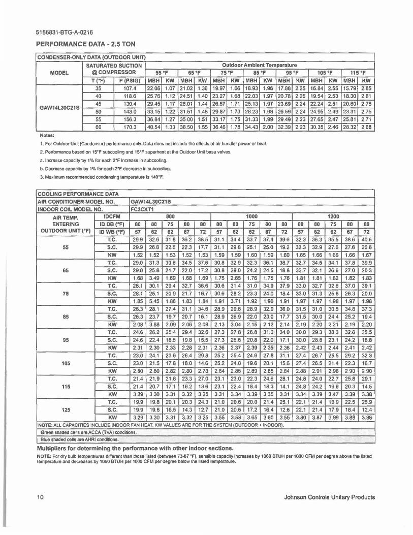
5186831-BTG-A-0216
PERFORMANCE DATA - 2.5 TON
CONDENSER-ONLY DATA (OUTDOOR UNIT}
SATURATED SUCTION Outdoor Ambient Temperature
MODEL @ COMPRESSOR 55 °F 65 "F 75°F 85°F T ("F) P (PSIG) MBH KW MBH KW MBH KW MBH KW
35 107.4 22.06 1.07 21 .02 1.36 19.97 1.66 18.93 1.96
40 118.6 25 76 1.12 24.51 1.40 23.27 1.68 22.03 1.97
GAW14L30C21S 45 130.4 29.45 1.17 28.01 1.44 26.57 1.71 25.13 1.97
50 143.0 33.15 1.22 31.51 1.48 29.87 1.73 28.23 1.98
55 156.3 36.84 1.27 35.00 1.51 33.17 1.75 31 .33 1.99 60 170.3 40.54 1.33 38.50 1.55 36.46 1.78 34.43 2.00
Notes:
1. For Ouldoor Unll (Condenser) performance only. Dala does no! Include lhe effects of air handler power or heat.
2. Pefformance based on 15'F subcooUng and 15'F supe,heat at the Outdoor Unit base valves.
a. Increase capacity by 1% for each 2'F Increase In subcoollng.
b. Decrease capacity by 1% lor each 2'F decrease In subcoollng.
3. Maximum recommended condensing temperature Is 140'F.
COOLING PERFORMANCE DATA AIR CONDITIONER MODEL NO. GAW14L30C21 S INDOOR COIL MODEL NO. FC3CXT1
AIR TEMP. IDCFM 800 ENTERING ID DB {°F) 80 80 75
OUTDOOR UNIT {°F) ID we ("F) 57 62 62 T.C. 29.9 326 31.8
55 s.c. 29.9 266 22.5
KW 1.52 1.52 1.53
T.C. 29.0 31.3 30.6 65 s.c. 29.0 25.8 21 .7
KW 1 68 3.49 1.69
T.C. 28.1 30.1 29.4 75 s.c. 28.1 25.1 20.9
KW 1.85 5.45 1.86 T.C. 26.3 28.1 27.4
85 s.c. 26.3 23.7 19.7
KW 2.08 3.88 2.09
T.C. 24.6 26.2 25.4
95 s.c. 24.6 22.4 18.5 KW 2 31 2.30 2.33
T.C. 23.0 24.1 23.6 105 s.c. 23.0 21.5 17.8
KW 2.80 2.80 2.82
T.C. 21.4 21.9 21 .8
115 s.c. 21 .4 20.7 17.1 KW 329 3.30 3.31
T.C. 19.9 19.8 20.1 125 s.c. 19.9 19.8 16.5
KW 329 3.30 3.31
80 80 80 80 67 72 57 62
36.2 38.5 31.1 34.4 22.3 17.7 31.1 29.8
1.52 1.53 1.59 1.59 34.5 37.6 30.8 32.9 22.0 17.2 30.8 29.0 1.68 1.69 1.75 2.65 32.7 36.6 30.6 31 .4 21 .7 16.7 30.6 28.2 1.83 1.84 1.91 3.71 31 .1 34.6 28.9 29.6 20.7 16.1 28.9 26.9 2.06 2.08 2.13 3.04 29.4 32.6 27.3 27.8 19.B 15.5 27.3 25.6 2.28 2.31 2.36 2.37 26.4 29.8 25.2 25.4
18.0 14.6 252 24.0 2.80 2.70 2.84 2.85 23.3 27.0 23.1 23.0 16.2 13.6 23.1 22.4 3.32 3.25 3.31 3.34
20.3 24.3 21.0 20.6 14.3 12.7 21.0 20.6 3.32 3.25 3.55 3.58
1000 75 80 62 67
33.7 37.4 25.1 25.0 1.60 1.59 32.3 36.1 24.2 24.5 1.76 1.75 31.0 34.9
23.3 24.0 1.92 1.90 28.9 32.9 22.0 23.0 2.15 2.12 26.8 31.0
20.8 22.0 2.39 2.35 24.8 27.8 19.6 20.1 2.89 2.85 22.3 24.6
18.4 18.3 3.39 3.35
20.0 21.4 17.2 16.4 3.65 3.60
95 "F
MBH KW 17.88 2.25 20.78 2.25 23.69 2.24 26.59 2.24
29.49 2.23 32.39 2.23
80 80 72 57
39.6 32.3 19.2 32.3
1.60 1.65 38.7 32.7 18.8 32.7 1.76 1.81 37.9 33.0 18.4 33.0 1.91 1.97
36.0 31.5 17.7 31 .5 2.14 2.19 34.0 30.0 17.1 30.0 2.36 2.42 31.1 27.4 15.6 27.4 2.84 2.88 28.1 24.8 14.1 24.8 3.31 3.34 25.1 22.1 12.6 22.1 3.55 3.80
NOTE: ALL CAPACITIES INCLUDE INDOOR FAN HEAT. KW VALUES ARE FOR THE SYSTEM (OUTDOOR + INDOOR).
Green shaded cells are ACCA (TVAI condiUons.
Blue shaded cells era AHRI conditions.
Multipliers for determining the performance with other Indoor sections.
1os°F 115 "F
MBH KW MBH KW 16.84 2.55 15.79 2.85 19.54 2.53 18.30 2.81 22.24 2.51 20.80 2.78 24.95 2.49 23.31 2.75
27.65 2.47 25.81 2.71 30.35 2.46 28.32 2.68
1200 80 75 80 80 62 62 67 72
36.3 35.5 38.6 40.6 32.9 27.6 27.6 20.6 1.66 1.66 1.66 1.67 34.5 34.1 37.8 39.9 32.1 26.6 27.0 20.3 1.81 1.82 1.82 1.83 32.7 32.6 37.0 39.1 31 .3 25.6 26.3 20.0 1.97 1.98 1.97 1.98 31 .0 30.5 34.8 37.3 30.0 24.4 25.2 19.4 2.20 2.21 2.19 2.20 29.3 28.3 32.6 35.5 28.8 23.1 24.2 18.8 2.43 2.44 2.41 2.42 26.7 25.5 29.2 32.3 26.5 21.4 22.3 16.7 2.91 2.96 2 90 2 90
24.0 22.7 25.8 29.1 24.2 19.6 20.3 14.5 3.39 3.47 3.39 3.38 21 .4 19.9 22.5 25.9 21 .4 17.9 18.4 12.4 3.87 3.99 3.88 3.86
NOTE: For dry bulb temperatures different than lhose l.sted (between 73-87 'F). sensible capacity Increases by 1060 BTUH per 1000 CFM per degree above lhe listed temperature and decreases by 1060 BTUH per 1000 CFM per degree below lhe Hsted temperature.
10 Johnson Controls Unitary Products
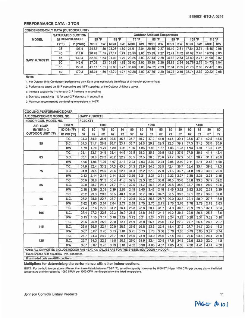
PERFORMANCE DATA· 3 TON
CONDENSER-ONLY DATA (OUTDOOR UNIT)
SATURATED SUCTION OutdOOf Ambient Temperature
MODEL @ COMPRESSOR 55 "F 65 •F 75°F 85 °F T {°F) P (PSIG) MBH KW MBH KW MBH KW MBH KW
35 107.4 24.62 1.56 23.26 1.80 21.91 2.04 20.55 2.27
40 118.6 28.76 1.55 27.17 1.79 2558 2.03 23.99 2.27 45 130.4 32.89 1.54 31.08 1.79 29.26 2.03 27.44 2.28
GAW14L36C21S 50 143.0 37.03 1.53 3498 1.78 32.93 2.03 3088 2.28 55 156.3 41.17 1.51 38.89 1.77 36.60 2.03 34.32 2.29
60 170.3 45.31 1.50 42.79 1 77 4028 2.03 37.76 2.29
Notes:
1. For Outdoor Unit (Condenser) perlonnance only. Data does not Include the effects of a.r handler power or heal
2. Performance based on 15'F subcOoling and 15"F superheat at the Ou1door Unit base valves.
a. Increase capacity by 1% for each 2'F Increase In subeoollng.
b. Decrease capacity by 1% for each 2'F decrease In subcooling.
3. Maximum recommended condensing temperature Is 140'F.
COOLING PERFORMANCE DATA
AIR CONDITIONER MODEL NO. GAW14L36C21S
INDOOR COIL MODEL NO. FC3CXT1
AIR TEMP. IDCFM 1000
ENTERING ID DB ("Fl 80 80 75 OUTDOOR UNIT ("F) IDWB ("F) 57 62 62
T.C. 34.3 34.9 36.6
55 s.c. 34.3 31 .7 26.8 KW 1.79 1.78 1.79 T.C. 33.1 33.7 34,9
65 s.c. 33.1 30.6 26.2 KW 1.96 1.96 1.96 T.C. 31.9 32.4 33.2
75 s.c. 31 .9 29.5 25.6 KW 2.13 2.14 2.14 T.C. 30.0 30.8 31.3
85 s.c. 30.0 28.7 24.1 KW 2.38 2.39 2.39 T.C. 28.2 29.3 29.3
95 s.c. 28.2 28.0 22.7 KW 2.62 2.63 2.64 T.C. 27.4 27.6 27.6
105 s.c. 27.4 27.2 22.5
KW 3.15 3.15 3.17 T.C. 26.5 25.9 25.9
115 s.c. 26.5 26.5 22.4
KW 367 3.67 3.70
T.C. 25.7 24.3 24.2
125 s.c. 25.7 24.3 22,3
KW 3.67 3.67 3.70
80 80 80 80 67 72 57 62
39.5 45.7 36.7 36.7 26.7 231 36.7 34.5 1.80 1.96 1 86 1.86 38.4 44.6 35.5 35.3
262 22.9 35.5 33.3 1.97 2.13 2.03 2.03 37.3 43.5 34.3 33.9 25.6 22.7 34.3 32.2 2.14 2.29 2.20 2.21 35.4 41.8 32.5 32.3 24.7 21 .9 32.5 31 .2 2 39 2.53 2.45 2.45 33,5 40.1 30.8 30.7 23.7 21.2 30.8 30.3 2.64 2.78 2.69 2.70 31.2 36.4 28.8 28.8
22.3 20.9 28.8 28.8 3 19 3.29 3.22 3.21 29.0 32.7 28.9 26.8 20.9 20.6 26.9 26.8
3.73 3.81 3.75 3.73 26.7 29.1 25.0 24 9 19.5 20.3 25.0 24.9 3.73 3.81 4.02 3.98
1200
75 80 62 67
37.2 41.0
29.2 29.3 1.86 1.87 35.8 39.8
285 28.6 2.03 2.04 34.3 38.5 27.8 27.9 2.21 2.21 32.5 36.6
26.8 26.8 2.45 2.46
30.7 34.7 25.8 25.7 2.70 2.71
28.4 31.7 24.7 24.1 3.24 3.25 26.1 28.6 23.5 22.4
3.78 3.80 23.9 25.6 22.4 20.8 4.06 4.07
95 "F MBH KW
19.19 2.51 22.41 2.52 25.62 2.53 28.83 2.54 32.04 2.55 35.25 2.56
80 80
72 57 44.6 39.1 22.0 39.1 1.88 1.93 43.5 37.9 21.7 37.9 2.05 2.10 42.4 36.7 21 .5 36.7 2.22 2.27 40.5 35.0
20.8 35.0 2.46 2.52
38.5 33.3 20.0 33.3 2.70 2.76
34.9 30.3 19.2 30.3 3.24 3.29 31 .2 27.2 18.4 27.2 3.78 3.83 27.5 24.2 17.6 24.2 4.05 4.36
NOTE: ALL CAPACITIES INCLUDE INDOOR FAN HEAT. KW VALUES ARE FOR THE SYSTEM (OUTOOOR + INDOOR).
Graen shaded cells are ACCA (TVA) conditions.
Blue shaded cells are AHRI conditions.
Multipliers for determining the performance with other Indoor sections.
5186831-BTG-A-0216
105"F 115 "F MBH KW MBH KW 17.84 2.74 16.48 298 20.82 2.76 19.23 3.00 23.80 2.77 21.98 3.02 26.78 2.79 24.73 3.04 29.76 2.80 27.47 3.06
32.74 2.82 30.22 3.08
1400
80 75 80 80
62 62 67 72 38.5 378 42.5 43.5 37.3 31.5 32.0 20.9 1.94 1.94 1.95 1.81 37.0 36.6 41.1 42.4
36.1 30.7 31.1 20.6 2.11 2.11 2.12 1.98 35.4 35.4 39.8 41.3 34.8 29.9 30.2 20.3
2.28 2.28 2.28 2.15 33.8 33.8 37.9 39.2 33.7 29.4 28.9 19.6 2.52 2.52 2.53 2.39 32.1 32.2 36.0 37.0 32.1 28.9 27.7 18.9 2.76 2.76 2.78 2.63
29.9 29.3 32.1 33.3 29.9 26.8 25.8 17.5 328 3.31 3.32 3.18 27.7 26.4 28.3 29.7 27.7 24.7 23.9 16.2
3.79 3.86 3.87 3.74 25.6 23.5 24.4 26.0 25.6 22.6 22.0 14 8 4.30 4.41 4.41 4 30
NOTE: For dry bulb temperatures different than those listed (between 73-87 ' F), sensible capacity Increases by 1060 BTUH per 1000 CFM Pflt' degree above the Usted temperature and decreases by 1060 BTUH per 1000 CFM per degree below the Isled temperature
Johnson Controls Unitary Products 11
PAt;.sr ~ to I
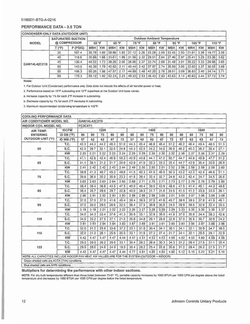
5186831-BTG-A-0216
PERFORMANCE DATA - 3.5 TON
CONDENSER-ONLY DATA (OUTDOOR UNITI
SATURATED SUCTION Outdoor Ambient Temperature
MODEL @ COMPRESSOR 55"F 65 "F 75"F 85 °F T ("F) P(PSIG) MBH KW MBH KW MBH KW MBH KW
35 107.4 30.79 1.60 28.96 1.93 27.12 2.26 25.28 2.59 40 118.6 35.66 1.66 33.61 1.99 31.56 2.32 29.51 2.64
GAW14L42C21S 45 130.4 40.52 1.73 38.26 2.05 36.00 2.37 33.74 2.69 50 143.0 45.39 1.79 42.92 2.11 40.44 2.42 37.97 2.74 55 156.3 50.26 1.86 47.57 2.17 44.89 2.48 42.20 2.78 60 170.3 55.12 1.92 52.23 2.23 49.33 2.53 46.43 2.83
Noln:
1. For Outdoor Unit (Condenser) performance only. Data does not Include the effects of air handler power or heal
2. Performance based on 15'F subcooffng and 15'F superheat al the Outdoor Unit base valves.
a. Increase capacity by 1 % for each 2'F Increase In subcooling.
b. Decrease capacity by 1% for each 2"F decrease In subcootlng.
3. Maximum recommended condensing temperature Is 140'F.
COOLING PERFORMANCE DATA AIR CONDITIONER MODEL NO. GAW14L42C21 S INDOOR COIL MODEL NO. FC3CXT1
AIR TEMP. IDCFM 1200
ENTERING ID DB ("F) 80 80 75 OUTDOOR UNIT ("F) ID WB (°F) 57 62 62
T.C. 42.3 44.3 44.2 55 s.c. 42.3 39.7 32.1
KW 2.20 2.21 2.22 T.C. 41.1 42.8 42.4
65 s.c. 41.1 38.1 31.2
KW 2.41 2.42 2.42 T.C. 39.8 41.3 40.7
75 s.c. 39.8 36.5 302 KW 2.62 2.63 2.63 T.C. 38.4 39.4 38.8
85 s.c. 38.4 35.7 29.6 KW 2.90 2.91 2 92 T.C. 37.0 37.5 37.0
95 s.c. 37.0 350 29.0 KW 3.19 3.19 3 21
T.C. 34,5 34.3 334 105 s.c. 34.5 33.2 275
KW 3.81 3 83 3.84 T.C. 32.0 31 2 29.8
115 s.c. 32.0 31.2 261 KW 4.42 447 4.47
T.C. 29.5 280 26.2 125 s.c. 29.5 28.0 24.6
KW 4.42 4 47 447
80 80 80 80 67 72 57 62
48.3 51.0 44.3 45.4 32.5 24.8 44.3 42.5 2.23 2.24 2.28 2.29 46.8 50.3 42.9 43.8 31 .7 24.0 42.9 41 .0 243 2.44 2.49 2.50 45.3 49.6 41.5 42.3
30.8 232 41.5 39.4 264 2.65 2.69 2.71 43 5 47.5 40.0 40.4 29.7 22.8 40.0 38.5 2.93 2.93 2.98 2.99
41.6 45.4 384 38.5
286 22.5 38.4 37.5 322 3.22 3.26 327 37.6 41.3 35.8 35.1 27.1 21.5 35.8 34.8 3 84 3.83 3.87 3.89
336 37.2 33.1 31 .6
25.6 20.5 33 1 31.6 4.47 4.44 4.47 4.51
295 33.1 304 28.2 240 19.5 30.4 28.2 447 4.44 4 77 4.81
1400 75 80 62 67
46.8 48.4 34.2 34.0 2.30 2.30 44.1 47.2 33.3 333 2.50 2.51 41.5 460 32.4 32.7 2.70 2.71 39.5 43.9 31.7 31 .6 2.99 3.00 37.5 41.8
30.9 30.5 3.28 3.29 33.9 380 29.1 28.9 3.91 3.91
30.4 34.1 27.3 27 4 4.53 4.53 26.8 30,3
25.4 25.8 4.85 4.84
95 °F MBH KW 23.45 2.93 27.46 2.97 31.48 3.01 35.50 3.05
39.51 3.09 43.53 3.14
80 80 72 57
51.2 46.2 26.0 46.2 2.32 2.36 50.7 44.7 25.4 44.7 252 2.56 503 43.2 24.9 43.2 2.73 2.77 48.0 41 .5 24.5 41.5 3 01 3.05 45.7 39.9 24.0 39.9 329 3.33 41.9 37.0 22.9 37.0 3.90 3.93 38.1 34.1
21.7 34 1 4.50 4.52 34.3 31 .2 20.6 31 .2 480 5.12
NOTE; ALL CAPACITIES INCLUDE INDOOR FAN HEAT, KW VALUES ARE FOR THE SYSTEM (OUTDOOR + INDOOR).
Green shaded ceUs are ACCA (TVA) candltlons.
Blue shaded ceHs are AHRI condltloos.
Multipliers for determining the performance with other Indoor sections.
105°F 115 "F MBH KW MBH KW 21.61 3.26 19.77 3.59 25.41 3.29 23.36 3.62 29.22 3.33 26.96 3.65 33.02 3.37 30.55 3.68 36.83 3.40 34.14 3.71 40.63 3.44 37.73 3.74
1600 80 75 80 80 62 62 67 72
46.4 49.4 48.5 51.3 45.3 36.2 35.4 27.1 2.37 2.38 2.37 2.39 44.9 45.9 47.7 51.2 43.9 35.4 35.0 26.9 2,58 2.58 2.58 2.60 43.3 42.4 46.8 51.1 42.4 34.7 34.5 26.6 2.79 2.78 2.79 2.80 41.4 40.1 44.3 48.6 41 2 33.8 33.5 26.1 307 3.06 3.08 3.08
395 37.9 41 9 46.1 39.5 32.9 32.4 25.5 3.35 3.35 3.36 3.37
35.8 34.4 38.3 42.6 35 8 30.7 308 24.2 3.95 3.97 3.98 3.96 32.1 30.9 34.7 39.0 32.1 28.5 29.1 22.9 4.55 4.60 4.59 4.55 28.4 27.5 31.1 35.4 28.4 26.2 27.5 21.7 5.15 5.22 5.21 5.15
NOTE: For dry bulb tempera1ures dllferent than those listed (between 73•87 ' F), sensible capacity Increases by 1060 BTUH per 1000 CFM per degree above the listed temperature and decreases by 1060 BTUH per 1000 CFM per degree below the listed lemperature.
12 Johnson Controls Unitary Products
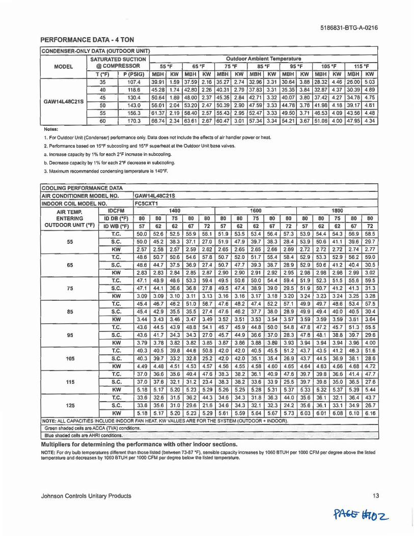
PERFORMANCE DATA • 4 TON
CONDENSER-ONLY DATA (OUTDOOR UNITI
SATURATED SUCTION Outdoor Ambient Temperature
MODEL @ COMPRESSOR 55 "F 65°F 75 "F 85 "F
T ("F) P (PSIG) MBH KW MBH KW MBH KW MBH KW 35 107.4 39.91 1.59 37.59 2.16 35.27 2.74 32.96 3.31 40 118.6 45.28 1.74 42.80 2.26 40.31 2.79 37.83 3.31
45 130.4 50.64 1.89 48.00 2.37 45.35 2.84 42.71 3.32 GAW14L48C21S
50 143.0 56.01 2.04 53.20 2.47 50.39 2.90 4759 3.33 55 156.3 61 .37 2.19 58.40 2.57 55.43 2.95 52.47 3.33
60 170.3 66.74 2.34 6361 2.67 60.47 3.01 57.34 3.34
Noles:
1. FOf Outdoor Unit (Condenser) perfcnnance Ollly. Data does not Include the elfects of air handler power or heat.
2. Perfonnance based on 15'F subcoollng and 15'F superheat at the Ouldoor Unll base valves.
a. Increase capacity by 1% fOf each 2'F lncmase In subcoollng.
b. Decrease capacily by 1 % for each 2'F decrease In subcooling.
3. Maximum rea>mmended condensing lemperatUAI ls 140'F.
COOLING PERFORMANCE DATA AIR CONDITIONER MODEL NO. GAW14L48C21S INDOOR COIL MODEL NO. FC5CXT1
AIR TEMP. IDCFM 1400 ENTERING ID DB ("F) 80 80 75
OUTDOOR UNIT ("F) IDWB("F) 57 62 62 T.C. 50.0 52.6 52.5
55 s.c. 50.0 45.2 38.3 KW 2.57 2.58 2.57 T.C. 48.6 50.7 50.6
65 s.c. 48.6 44.7 37.5 KW 2.83 2.83 2.84 T.C. 47.1 48.9 48.6
75 s.c. 47.1 44.1 36.6 KW 3.09 3.09 3.10 T.C. 45.4 46.7 46.2
85 s.c. 45.4 42.9 35.5 KW 3.44 3.43 3.46 T.C. 43.6 44.5 43.9
95 s.c. 43.6 41.7 34.3 KW 3.79 3.78 3.82 T.C. 40.3 40.5 39.8
105 s.c. 40.3 39.7 33.2
KW 4.49 4.48 4.51 T.C. 37.0 36.6 35.6
115 s.c. 37.0 37.6 32.1
KW 5.18 5.17 5.20 T.C. 33.6 32.6 31.5
125 s.c. 33.6 35.6 31.0 KW 5.18 5.17 5.20
80 80 80 80 67 72 57 62
55.9 56.1 51.9 53.5 37.1 27.0 51.9 47.9 2.59 2.62 2.65 2.65 54.6 57.8 50.7 52.0
36.9 27.4 50.7 47.7
2.85 2.87 2.90 2.90 53.3 59.4 49,5 50.6 36.8 27.8 49.5 47.4
3.11 3.13 3.16 3.16 51.0 56.7 47.6 48.2
35.5 27.4 47.6 46.2 3.47 3.49 3.52 3.51 48.8 54.1 45.7 45.9 34.3 27.0 45.7 44.9 3.82 3.85 3.87 3.86 44.6 50.8 42.0 42.0 32.8 25.2 42.0 42.0 4.53 4.57 4.56 4.55 40.4 47.6 38.3 38.2 31.2 23.4 38.3 38.2 5.23 5.29 5.26 5.25
36.2 44.3 34.6 34.3 29.6 21.6 34.6 34.3 5.23 5.29 5.61 5.59
1600
75 80 62 67
53.4 56.4 39.7 38.3 2.65 2.66 51.7 55.4 39.3 38.7
2.91 2.92 50.0 54.4 38.9 39.0 3.17 3.18 47.4 52.2 37.7 38.0 3.53 3.54 44.8 50.0 36.6 37.0 3.88 3.89 40.5 45.5 3S.1 35.4 4.58 4.60 36.1 40.9 33.6 339
5.28 5.31 31.8 36.3 32.1 32.3 5.64 5.67
95 "F MBH KW 30.64 3.88 35.35 3.84 40.07 3.80 44.78 3.76 49.50 3.71
54.21 3.67
80 80
72 57 57.3 53.9 28.4 53.9 2.69 2.72 58.4 52.9 28.9 52.9 2.95 2.98 59,4 51 .9 29.5 51 .9 3.20 324 57.1 499 28.9 49,9
357 359 54.8 47.8 28.3 476 3.93 3,94
51 .2 43.7 26.9 43.7 4.65 4.64 47.6 39.7 25.5 39.7
5.37 5 33 44.0 35.6 24.2 35.6 5 73 6.03
NOTE: ALL CAPACITIES INCLUDE INDOOR FAN HEAT. KW VALUES ARE FOR THE SYSTEM (OUTDOOR • INDOOR),
Green shaded cells are ACCA (TVA) conditions.
Blue shaded cells are AHRI conditions.
Multipliers for determining the performance with other Indoor sections.
5186831-BTG-A-0216
105°F 115 "F MBH KW MBH KW 28.32 4.46 26.00 503 32.87 4.37 30.39 4.89
37.42 4.27 34.78 4.75
41.98 4.18 39.17 4.61 46.53 409 4356 4.48 51.08 4 00 47,95 4 34
1800 80 75 80 80
62 62 67 72 54.4 54.3 56.9 58.5 50.6 41.1 39,6 297 2,72 2.72 2.74 2.n 53.3 52.9 56.2 59.0
506 41 .2 40.4 30,5
2.98 2.98 2.99 3,02
52.3 51.5 55.6 59.5 50.7 41.2 41.3 31.3
3.23 324 3.25 3.28 49.7 48.6 53.4 57.5 49.4 40.0 40.5 30.4 3.59 3.59 3.61 3.64 47.2 45.7 S1.3 5S.5 48.1 38.8 39.7 296 3.94 3.94 3.96 4.00
43.5 41.2 46.3 51.6 44.5 36.9 38.1 28.6 4.63 4.66 4.68 4.72
39.8 36.6 41.4 47.7 39.8 35.0 36.5 27,6
5 32 5.37 5.39 5.44
36 1 32.1 36.4 43.7 36.1 33.1 34.9 26.7 6.01 6.08 6.10 6.16
NOTE: For dry bulb temperatures different than those listed (between 73•87 'F), sensible capacity Increases by 1060 8TUH per 1000 CFM per degree above the listed temperalure and decreases by 1060 BTUH per 1000 CFM per degree below lhe listed temperature.
Johnson Controls Unitary Products 13
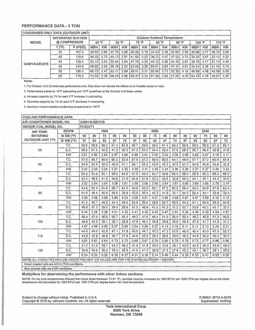
PERFORMANCE DATA - 5 TON
CONDENSER-ONLY DATA (OUTDOOR UNIT}
SATURATED SUCTION Outdoor Amblont Temperature MODEL @ COMPRESSOR 55 "F 65°F 75°F 8S°F
T ("F) P(PSIG) MBH KW MBH KW MBH KW MBH KW 35 107.4 39.52 2.80 37.79 3.00 36.06 3.19 34 33 3.38
40 118.6 46.32 2.72 44.12 2.97 41 .92 3 .22 39.73 347
GAW14L60C21S 45 130.4 53.12 2.63 5045 294 47.78 3.25 45.12 3.56 50 143.0 59.92 2.55 56,78 2.92 53 65 3.28 50.51 365
55 156.3 66.72 2.47 63.11 2.89 59 51 3.31 5590 3.73
60 170.3 73.52 2.38 6944 2.86 65.37 3.34 61.30 382
Notu:
1. For Outdoor Unll (Condenser) performance only, Cata does not Include the effects of a,r handler power or heat.
2. Perfonnance based on 15"F subcoollng and 15"F superheat at the Outdoor Unit base valves.
a. Increase capacity by 1% for each 2"F Increase In subcoollng.
b. Decrease capacity by 1% for each 2•F decrease In subcoollng.
3. Ma~lmum recommended condensing temperature Is 140"F.
COOLING PERFORMANCE DATA
AIR CONDITIONER MODEL NO. GAW14L60C21S INDOOR COIL MODEL NO. FC5CXT1
AIR TEMP. IDCFM 1800 ENTERING ID OB ("F) 80 80 75
OUTDOOR UNIT (°F) IDWB ("F) 57 62 62 T.C. 58.6 58.6 58.0
55 s.c. 56.5 51.3 42.5 KW 2.91 2.95 2.94
T.C. 57.0 56.7 56.0 65 s.c. 54.9 50.4 42.0
KW 3.22 3.25 3 .24 TC. 55.5 54.8 54.1
75 s.c. 53.4 495 41.5
KW 3.52 3.54 3.54 T.C. 53.5 52.4 51.6
85 s.c. 51 .6 48.4 40.5
KW 3.93 395 3.95
T.C. 51.4 50.1 49.2
95 s.c. 49.8 47.3 39.5
KW 4.34 4.35 4.36 T.C. 48.0 47.0 46.0
105 S.C. 46,8 450 38.1 KW 4.97 4.98 5.00
T.C. 44.6 44.0 42.9
115 s.c. 43.8 42 8 36.6
KW 5.61 561 564
T.C. 41.2 41 .0 39.7
125 s.c. 40.8 40.5 35.2
KW 6.24 625 6.28
80 80 80 80 67 72 57 62
61 .4 63.8 58 7 59.0
41 .3 30.3 57 3 53.2 2 97 300 2.99 3 01
60.2 63.9 578 572 40,9 31.1 56.1 52.5 3.27 3.30 3.29 3.31
59.0 64.0 57.0 55.4
40.6 31 9 54.8 51.8 3.58 3.61 3.59 3.60 56.7 61 .5 54.9 53.0
40.0 30.9 52.9 50.4
3.99 4.03 4.00 4.01
54 4 59.0 52.8 50.6
394 29.9 51.0 48.9
4.41 4.45 4.41 4.42 50.7 554 49,2 47.6
38.1 28.8 47.8 46.4
5.07 5.09 5.04 5.05
471 51 ,8 455 44.7
36.7 27.6 44.6 43.9
5.73 5.73 5.68 567 43.4 48.2 41 9 41.8
35 4 26.5 41 5 41.3
639 6.37 6.31 6 30
2000 75 80 62 67
58.5 61 .4
44.4 42,0
300 3.03
56.6 605 43.9 42.3 3.30 3.34
54.7 59.6
43.3 42.5 3.60 3.64
52.1 57.2 42.3 41 .9
4.01 4.06
49.6 54.7
41 .3 41.3
4.43 4.47 46.4 51 .0
39.9 399 5.07 5.14
43.2 47.3
38.4 386
5.70 5.80
40.0 436
36.9 37.2
6.34 6.46
95 "F
MBH KW 32.60 3 58
37.53 3.72
42.45 3.87 47.37 4.01
5230 416
57.22 430
80 80 72 57
64.4 58.8
31.0 582 3.06 306
64.7 58.6 32.0 57.2
336 3.36
65.0 585
32.9 56 2 367 3.66
62.5 56.4
32.1 54 2 4.09 4.07
60.0 54.2
31.2 52.1
4.51 4.48 56.0 50.4
30.0 48.8 5.15 5.11
52.0 46.5
28.9 455
5.79 5.75 48.1 42.6
278 42.2
6.44 6.38 NOTE: ALL CAPACITIES INCLUDE INDOOR FAN HEAT KW VALUES ARE FOR THE SYSTEM {OUTOOOR + INDOOR).
Green shaded cells are ACCA (TVA) conditions.
Blue shaded cens are AHRI conditions.
Multipliers for determining the performance with other Indoor sections.
105 •f 115 °F
MBH KW MBH KW 30.88 3.77 29.15 3.96
35.33 3.97 33.13 4.22
39.78 4.17 37.12 4.48 44 24 4.38 41.10 4.74
48.69 4.58 45.09 5.00
53.15 4.78 49.07 5 .26
2200
80 75 80 80 62 62 67 72
59.5 59.0 61 .5 65.1
55.1 46.4 42.8 31.6
3.08 3.07 3.10 3.11
57.7 57.2 60.9 65 5 54,6 45,8 43,6 32.8
3.37 3.37 3.40 3.43
55.9 55.3 60.3 66.0
54.1 45.1 44.4 34.0 3.66 3.66 3.70 3.74
53.5 52.6 57.6 63.4
52.4 44.1 43.8 33.3 4.07 4.08 4.12 4.15 51.1 50.0 55.0 60.9
50.6 43.2 43.1 32.5
4.48 4.49 4.54 4.57
48.3 46.8 51.3 56.6
47.8 41.7 41.8 31.3
5.11 5.13 5.20 5.21
45.4 43.5 47.5 52.3
44.9 40.2 40.4 30.2 5.73 5.77 5.86 5.86
42.5 40.3 43.8 48.0
42.1 38.7 39.1 29.0
6.35 6.41 6 .52 6 .50
NOTE: For dry bulb temperatures different than those Usted (between 73-87 "F), sensible capacity Increases by 1060 BTUH per 1000 CFM per degree above the Hsted temperature and decreases by 1060 BTUH per 1000 CFM per degree below the Lsted temperature
Subject to change without notice, Published in U SA Copyright~ 2016 by Johnson Controls, Inc. All rights reserved.
York International Corp. 5005 York Drive
Norman, OK 73069
5186831-BTG-A-0216 Supersedes: Nothing

SS-109
..
@ I ::ia,,t;.,;,
&,IIUIWl&I ... ._ air cond/1/oning k healing
UPFLOW - DOWNFLOW - HORIZONTAL
EVAPORATOR COILS
Goodman Manufacturing Co., L.P. 1501 Sea mist, Houston, Texas 77008
(713)861-2500 H& U SERIES 9193
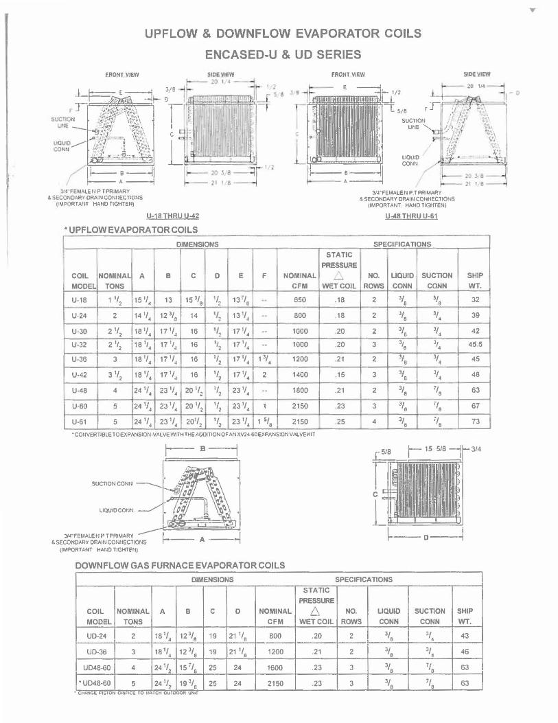
'. '
UPFLOW & DOWNFLOW EVAPORATOR COILS
ENCASED-U & UD SERIES
FRO/IJ_VJEW
:lf4•FEMAlE II P TPRIIAARY & 56.COtiCARY ORA ti CONIIECTIONS
t M"ORTAtH HANO TIGHTEN)
U-18JHRU U"'42
• UPFLOW EVAPORATOR COILS
DIMENSIONS
I I I I l
COIL NOMINAL A B C D
MODEL TONS
U-18 1 1/2 15 ,,. 13 15 3/8 ,,2 U-24 2 14 1/4 12 3/8 14 •12
U-30 2 ,,2 18 1/4 17 ,,4 16 ''~ U-32 2\ 18 \ 17 1,4 16 "2 U-36 3 18 ,,4 17 ,,4 16 ,,2
U-42 3 ,,2 18 .,, 171/4 16 1/2 ._ U-48 4 24 ,,. 23 1/4 20 1/2 1/2
U-60 5 24 1/4 23 ,,. 20 1/2 1/2
U-61 5 24 1/4 23 ,,. 201/2 1/2
, 1 ~ e
I
E F NOMINAL
CFM
13r/a .. 650
13 ·,~ •· 800
17 '/4 .. 1000
17\ .. 1000
11'!, 13/. 1200
171/4 2 1400
231/4 .. 1800
23 11, 1 2150
23 ,,, 1 5/8 2150
• COtNERTIBLE TO EXPANSIOII-VALVE WI TH THE AOOITION OF At J XV24-60EXPANS1Ot l VAL VE KIT
B---
SUCTION CONN
LIQUIOCOIIN.
FRONT VlliW
STATIC
PRESSURE
~
WETCOIL
.18
18
.20
.20
.21
.15
.21
.23
.25
UOU!O corm
3/4"FEMAlEN P.T PRIMARY & SECONDARY ORAltl CONIIECTJO•,S
(IMPORTANT. HAND TIGHTEN)
U--18 THRU U-61
SPECIFICATIONS
NO. LIQUID SUCTION
ROWS CONN CONN
2 3/8 5/6
2 3/8 • 3/,
2 3/8 3/,
3 \ 31,
2 3/8 3/4
3 3/8 3/4
2 3/8 7/8
3 3/8 7/8
4 3/8 7/8
SHIP
WT.
32
39
42
45 5
45
48
63
67
73
J/4"FEMALEN P TPRIMARY & SECONDARY DRAlll COllt!ECTIONS
\IMPORTANT HAIID TIGHTHIJ
-1---A---I ---D---
DOWN FLOW GAS FURNACE EVAPORATOR COILS
DIMENSIONS SPECIFICATIONS
STATIC
PRESSURE
COIL NOMINAL A B C D NOMINAL 6 NO. LIQUID SUCTION SHIP
MODEL TONS CFM WET COIL ROWS CONN CONN WT.
UD-24 2 181/4 12 3/8 19 21 1/8 800 .20 2 3/8 3/4 43
UD-36 3 181/4 12 3/8 19 21 1/ 8 1200 .21 2 3/8 3/4 46
UD48-60 4 241/2 15 i/6 25 24 1600 .23 3 3/6 7/8 63
"UD48-60 5 24 1/2 19 3/8 25 24 2150 .23 3 3/8 1/6 63 • CtiJ.NG~ Pl~JOU ORlFICE TO tJAfC.H 0Uf1,, V\,,lll"IUHIT
...
I
I
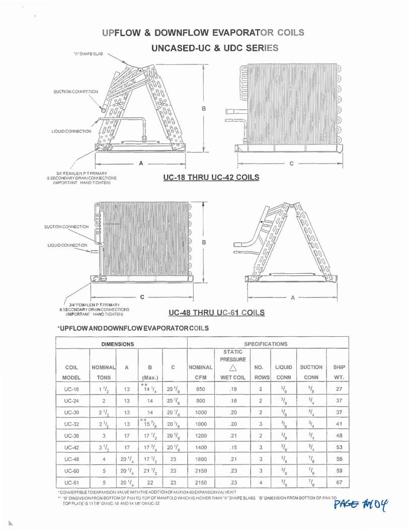
UPFLOW & DOWNFLOW EVAPORATOR COILS
UNCASED-UC & UDC SERIES ,..,.SHM'ESLAB
SUCTIOtl CCtJtJFC:TIOtl
'"
llOUIOCONNECTION
3/4"FEMAlE ti PT PRIMARY "-SECONOARYORAltlCONtlECTIONS
(IMPORTANT HANDT GHTE/ll
3/4"FEMA1EN P TPRIMARY t SECONDARY DRAIN CONNECTIOl'lS
(IMPORTANT HANO TIGHTEN)
B
' A
UC-18 THRU UC-42 COILS
UC-48 THRU UC-61 COILS
•UP FLOW AND DOWN FLOW EVA PORA TOR COILS
DIMENSIONS SPECIFICA TJONS STATIC
PRESSURE
COIL NOMINAL A B C NOMINAL 6 NO. LIQUID SUCTION
MODEL TONS (Max.) CFM WETCOIL ROWS CONN CONN
UC-18 1 1/2 13 * ..
14 1,4 20 1/8
650 ,18 2 3/8 ~,e UC-24 2 13 14 20 1/8 800 .18 2 3/8 3/4
UC-30 2 1/, 13 14 20 '/8 1000 .20 2 3/8 3/4
UC-32 2 1,2 13 ""15 11 6
20 1,8 1000 .20 3 3/6 3/4
UC-36 3 17 17 '/2 201/8 1200 .21 2 3/8 3/4
UC-42 3 1/ 2
17 17 ~,. 20 1/8 1400 . 15 3 3/8 3/4
UC-48 4 20 1/4 17 1/2 23 1800 .21 3 3/8 7 /8
UC-60 5 20 1/4 21 '/2 23 2150 ,23 3 3/6 1/6
UC-61 5 20 1/4 22 23 2150 .23 4 3/8 1/8
·cotNERTIBlE TOEXPANSIOtl -VALVE \'\1TH THE ADDITION OF AtlXV24-6□ EXPAtlSIOtNALVE KIT
SHIP
WT.
27
37
37
41
48
53
56
59
67
•• "B" DlMEtlSION FROM BOTTOM OF PAtl TO TOP OF MAN FOI.DWHICH IS HIGHER THAN "A" SHAPE SlABS "B" OIMENSIOtl FROM BOTTOM OF PAtl TO 4J TOPPLATE S11i,'8"01WC-18 AN014118"0tlUC,32 p~ ~ or
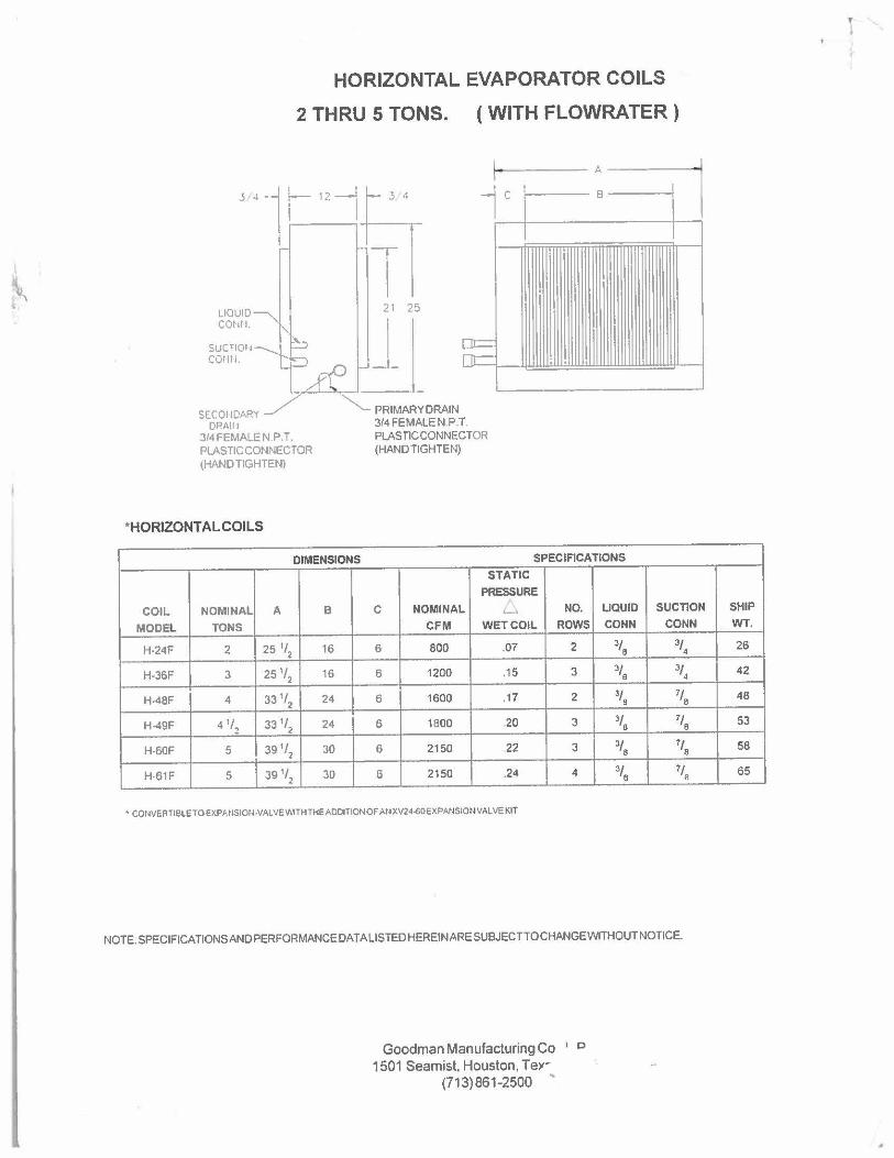
HORIZONTAL EVAPORATOR COILS
2 THRU 5 TONS. ( WITH FLOWRATER)
1------ A ------i
le
1 21 25 LIQUID
CONII.
SUCTIOli COWL
or=: nr::= ~fil
SECOIIDARY DRAIII
J/4FEMALEN.P.T. PLASTIC CONNECTOR (HAND TIGHTEN)
*HORIZONTAL COILS
"- PRIMARY DRAIN 314 FEMALE N.P.T. PLASTIC CONNECTOR (HAND TIGHTEN)
B
DIMENSIONS SPECIFICA TJONS
STATIC
PRESSURE COIL NOMINAL A B C NOMINAL ._. NO. LIQUID
MODEL TONS CFM WET COIL ROWS CONN
H-24F 2 25 ''2 16 6 800 .07 2 3/8
H-36F 3 25 1/2 16 6 1200 .15 3 3/8
H-48F 4 331/2 24 6 1600 .17 2 3/8
H-49F 4 ,,2 331/2 24 6 1800 20 3 3/8
H-60F 5 391/2 30 6 2150 22 3 3/8
H-61F 5 391/2 30 6 2150 .24 4 3/8
• COIM,RTIBLETO E)(PANSIOl~-VALVE V,.HHTHEADDITIONOF AUXV24~0EXPANSIOIJVALVE KIT
l
SUCTION
CONN
3/4
3/4
7/8
7/ B
7/8
7/8
NOTE. SPECIFICATIONS AND PERFORMANCE DATALISTEDHEREINARESUBJECTTOCHANGEWITHOUT NOTICE.
Goodman Manufacturing Co ' c 1501 Seamist, Houston, Teyr
(713)861-2500
SHIP
WT.
26
42
48
53
58
65
Related Documents