Service Manual Colour Television TX-21PZ1D TX-21PZ1F TX-21PZ1P CP-521FS Chassis SPECIFICATIONS Power Source: 220-240V a.c., 50Hz Power Consumption: 52W Stand-by Power Consumption: 1,5W Aerial Impedance: 75 unbalanced, Coaxial Type Receiving System: PAL-I, B/G, D/K, PAL-525/60 SECAM B/G, D/K, L/L’ M.NTSC (AV only) NTSC (AV only) Receiving Channels: VHF E2-E12 VHF H1-H2 (ITALY) VHF A-H (ITALY) VHF R1-R2 VHF R3-R5 VHF R6-R12 UHF E21-E69 CATV (S01-S05) CATV S1-S10 (M1-M10) CATV S11-S20 (U1-U10) CATV S21-S41 (HYPERBAND) Intermediate Frequency: Video/ Audio Video 38,9MHz, 33,9MHz Sound 33,4MHz (B/G), 33,16MHz (A2) 33,05MHz (NICAM B/G,D/K,L) 32,4MHz (D/K),32,66MHz (CZ STEREO) 40,4MHz (L’), 39,75MHz (L’NICAM) Colour 34,47MHz (PAL) 34,5MHz, 34,65MHz (SECAM) 38,3MHz, 38,15MHz (SECAM L’) Terminals: AV1 IN Video (21 pin) 1V p-p 75 Audio (21 pin) 500mV rms 10k RGB (21 pin) 0,7V p-p 75 AV1 OUT Video (21 pin) 1V p-p 75 Audio (21 pin) 500mV rms 1k AV2 IN Video (21 pin) 1V p-p 75 Audio (21 pin) 500mV rms 10k AV2 OUT Video (21 pin) 1V p-p 75 Audio (21 pin) 500mV rms 1k AV3 FRONT Audio (RCAx2) 500mV rms 10k Video (RCAx1) 1V p-p 75 High Voltage: 28kV ± 1kV Picture Tube: A51QDX993X033 51cm Audio Output: 2x5W RMS, 2x10W MPO, 8 impedance Headphones: 8 Impedance Accessories supplied: Remote Control 2 x R6 (UM3) Batteries Dimensions: Height: 489mm Width: 600mm Depth: 464mm Net weight: 23,0kg Specifications are subject to change without notice. Weights and dimensions shown are approximate. ORDER No. PCZ0410022C2 S-Video IN Y: 1V p-p 75 (21-pin) C: 0.3V p-p 75 TX-21PZ1

Welcome message from author
This document is posted to help you gain knowledge. Please leave a comment to let me know what you think about it! Share it to your friends and learn new things together.
Transcript
Service ManualColour Television
TX-21PZ1DTX-21PZ1FTX-21PZ1P
CP-521FS Chassis
SPECIFICATIONS
Power Source: 220-240V a.c., 50Hz
Power Consumption: 52W
Stand-by PowerConsumption: 1,5W
Aerial Impedance: 75 unbalanced, Coaxial Type
Receiving System: PAL-I, B/G, D/K, PAL-525/60SECAM B/G, D/K, L/L’M.NTSC (AV only)NTSC (AV only)
Receiving Channels:VHF E2-E12 VHF H1-H2 (ITALY)VHF A-H (ITALY) VHF R1-R2VHF R3-R5 VHF R6-R12UHF E21-E69 CATV (S01-S05)CATV S1-S10 (M1-M10) CATV S11-S20 (U1-U10)CATV S21-S41 (HYPERBAND)
Intermediate Frequency:Video/ AudioVideo 38,9MHz, 33,9MHzSound 33,4MHz (B/G), 33,16MHz (A2)
33,05MHz (NICAM B/G,D/K,L)32,4MHz (D/K),32,66MHz (CZ STEREO)40,4MHz (L’), 39,75MHz (L’NICAM)
Colour 34,47MHz (PAL)34,5MHz, 34,65MHz (SECAM)38,3MHz, 38,15MHz (SECAM L’)
Terminals:
AV1 IN Video (21 pin) 1V p-p 75Audio (21 pin) 500mV rms 10kRGB (21 pin) 0,7V p-p 75
AV1 OUT Video (21 pin) 1V p-p 75Audio (21 pin) 500mV rms 1k
AV2 IN Video (21 pin) 1V p-p 75Audio (21 pin) 500mV rms 10k
AV2 OUT Video (21 pin) 1V p-p 75Audio (21 pin) 500mV rms 1k
AV3 FRONT Audio (RCAx2) 500mV rms 10kVideo (RCAx1) 1V p-p 75
High Voltage: 28kV ± 1kV
Picture Tube: A51QDX993X033 51cm
Audio Output: 2x5W RMS, 2x10W MPO,8 impedance
Headphones: 8 Impedance
Accessoriessupplied: Remote Control
2 x R6 (UM3) Batteries
Dimensions:Height: 489mmWidth: 600mmDepth: 464mmNet weight: 23,0kg
Specifications are subject to change without notice.Weights and dimensions shown are approximate.
ORDER No. PCZ0410022C2
S-Video IN Y: 1V p-p 75(21-pin) C: 0.3V p-p 75
TX-21PZ1

CONTENTSSAFETY PRECAUTIONS ......................................................................................................................................................... 2
SERVICE HINTS ...................................................................................................................................................................... 3
VOLTAGE CHECK AND OPTION BYTES ................................................................................................................................... 4
WAVEFORM PATTERN TABLE............................................................................................................................................... 5
ALIGNMENT SETTINGS .......................................................................................................................................................... 6
BLOCK DIAGRAMS.................................................................................................................................................................. 7
PARTS LOCATION................................................................................................................................................................... 9
REPLACEMENT PARTS LIST................................................................................................................................................ 10
SCHEMATIC DIAGRAMS....................................................................................................................................................... 15
CONDUCTOR VIEWS ............................................................................................................................................................ 17
SAFETY PRECAUTIONGENERAL GUIDE LINES
1. It is advisable to insert an isolation transformer in thea.c. supply before servicing a hot chassis.
2. When servicing, observe the original lead dress in thehigh voltage circuits. If a short circuit is found, replaceall parts that have been overheated or damaged bythe short circuit.
3. After servicing, see that all the protective devicessuch as insulation barriers, insulation papers, shieldsand isolation R-C combinations are correctlyinstalled.
4. When the receiver is not being used for a long periodof time, unplug the power cord from the a.c. outlet.
5. Potentials as high as 29 kV are present when thisreceiver is in operation. Operation of the receiverwithout the rear cover involves the danger of a shockhazard from the receiver power supply. Servicingshould not be attempted by anyone who is notfamiliar with the precautions necessary when workingon high voltage equipment. Always discharge theanode of the tube.
6. After servicing make the following leakage currentchecks to prevent the customer from being exposedto shock hazard.
LEAKAGE CURRENT COLD CHECK1. Unplug the a.c. cord and connect a jumper between
the two prongs of the plug.2. Turn on the receiver’s power switch.3. Measure the resistance value with an ohmmeter,
between the jumpered a.c. plug and each exposedmetallic cabinet part on the receiver, such as screwheads, aerials, connectors, control shafts etc. Whenthe exposed metallic part has a return path to thechassis, the reading should be between 4M ohm and20M ohm. When the exposed metal does not have areturn path to the chassis, the reading must beinfinite.
LEAKAGE CURRENT HOT CHECK1. Plug the a.c. cord directly into the a.c. outlet. Do not
use an isolation transformer for this check.2. Connect a 2k 10W resistor in series with an
exposed metallic part on the receiver and an earth,such as a water pipe.
3. Use an a.c. voltmeter with high impedance tomeasure the potential across the resistor.
4. Check each exposed metallic part and check thevoltage at each point.
5. Reverse the a.c. plug at the outlet and repeat each ofthe previous measurements.
6. The potential at any point should not exceed1,4 Vrms. In case a measurement is outside the limitsspecified, there is a possibility of a shock hazard, andthe receiver should be repaired and rechecked beforeit is returned to the customer.
X-RADIATION WARNING1. The potential sources of X-Radiation in TV sets are
the high voltage section and the picture tube.2. When using a picture tube test jig for service, ensure
that the jig is capable of handling 29 kV withoutcausing X-Radiation.
NOTE: It is important to use an accurate periodicallycalibrated high voltage meter.1. Set the brightness to minimum.2. Measure the high voltage. The meter should indicate:
28 kV ± 1kV.If the meter indication is out of tolerance, immediateservice and correction is required to prevent thepossibility of premature component failure.
3. To prevent any X-Radiation possibility, it is essentialto use the specified tube.
HOT CHECK CIRCUIT
a.c. VOLTMETER
WATER PIPE(EARTH)
TO INSTRUMENT'S EXPOSEDMETALLIC PARTS
Fig. 1.
2k 10 Watts
2

3
SERVICE HINTSHow to remove the rear cover1. Remove the 5 screws as shown in Fig. 2
LOCATION OF CONTROLS
Fig. 2
Fig. 3
SCREWS SCREWS
CRT Board Focus ScreenMAIN Board

VOLTAGE CHECK
OPTION BYTES
4
1. Receive a Colour bar pattern
2. Set the TV into Service mode
3. Select G2 SCREEN item
Adjust the screen VR will OSD is just changeto GREEN square.
G2 SCREEN / CUTTOFF
MODEL OPTION BYTE 1 OPTION BYTE 2
TX-21PZ1D 0 0 1 1 1 1 0 0 0 x 3C 0 x 4F0 1 0 0 1 1 1 1
1 0 1 1 1 1 0 0 0 x BC 0 x 4F0 1 0 0 1 1 1 1
1 0 1 1 1 1 0 0 0 x BC 0 x 6F0 1 1 0 1 1 1 1
0 0 1 1 1 1 0 0 0 x 3C 0 x 6F0 1 1 0 1 1 1 1
TX-21PZ1F
TX-21PZ1P
TX-21PZ1
SMT 2084.0125B*
MAIN B+ Voltage [V] 123,9 +1V_
12V [V] 12,1 +0,5V_
STAND BY [V] 12,1 +0,5V_
SOUND B+ [V]12,6 +0,5V_
_
*Volume Min.
*Volume Max.12,1 +0,5V
TEST CONDITIONS ;
Input voltage : 230VACTV set on ON mode (if othing specifed)Picture : colour bar - DynamicSound : 1khz - (mode : Music)
FBT 1412.7009*
HIGH VOLTAGE [V]27,0 +1kV_
_28,0 +1kV
RETRACE TIME 10,3 +0,2us_
Vcp [V] +20V_
_
_
_
_
1094
191,5VIDEO VOLTGE [V] +5%
13,013V LINE [V] +5%
45,445V LINE [V] +5%
6,21HEATER VOLTAGE [Vrms] +5%
TEST CONDITIONS ;
Input voltage : 230VACCt = 6200 pFCs = 0,27 uFL linearity : L-125CRT : A51QDX993X033

WAVEFORM PATTERN TABLE
5
CONDITIONS: Contrast: MAX, Brightness: MID, Colour: MID, Sharpness: MID
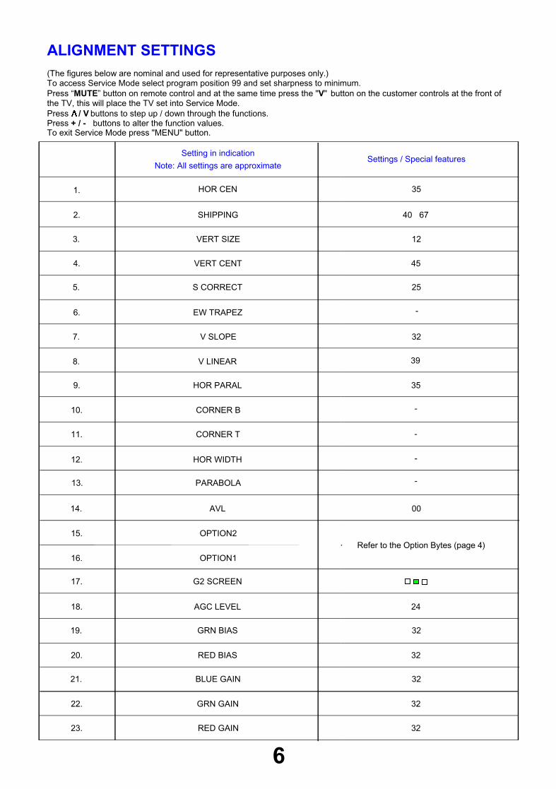
ALIGNMENT SETTINGS(The figures below are nominal and used for representative purposes only.)To access Service Mode select program position 99 and set sharpness to minimum.Press “MUTE” button on remote control and at the same time press the "V" button on the customer controls at the front ofthe TV, this will place the TV set into Service Mode.Press / V buttons to step up / down through the functions.Press + / - buttons to alter the function values.To exit Service Mode press "MENU" button.
6
Setting in indication
Note: All settings are approximateSettings / Special features
1. HOR CEN 35
2. SHIPPING 40 67
3. VERT SIZE 12
4. VERT CENT 45
5. S CORRECT
-6. EW TRAPEZ
7. V SLOPE 32
8. V LINEAR 39
9. HOR PARAL 35
10. CORNER B
11. CORNER T
12. HOR WIDTH
13. PARABOLA
14. AVL 00
15. OPTION2
16. OPTION1
17. G2 SCREEN
18. AGC LEVEL 24
19. GRN BIAS 32
20. RED BIAS 32
21. BLUE GAIN 32
22. GRN GAIN 32
23. RED GAIN 32
-
25
-
-
-
Refer to the Option Bytes (page 4)

7
VID
EO
& S
TE
RE
O A
UD
IO B
LO
CK
DIA
GR
AM
Z10
1
Z10
2
Q60
1Q
602
MU
TE
Q50
6L
ED
Q81
3Q
815
R70
0
T80
14
26
8
MA
IN-B
OA
RD
8
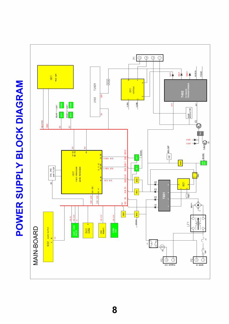
PO
WE
RS
UP
PL
YB
LO
CK
DIA
GR
AM
T40
2F
LY
BA
CK
TR
AN
SF
OR
ME
R
T40
1
190V
5VHE
AT
ER
5V
5V 8V
S.B
3.3V
5V33
V
S.B
3.3V
S.B
3.3V
S.B
3.3V
5VS.B
5V
S.B
3.3V
S.B3.3V
S.B1.8V-1
S.B1.8V-2
12V
S.B
3.3V
S.B
1.8V
-1S
.B1.
8V-2
S.B
5V8V
12V
5V
131V
14V
1
38V
1
190V
1
45V1
12V1
Q50
1
Q50
3
Q50
2
Q50
4
Q80
9Q
810
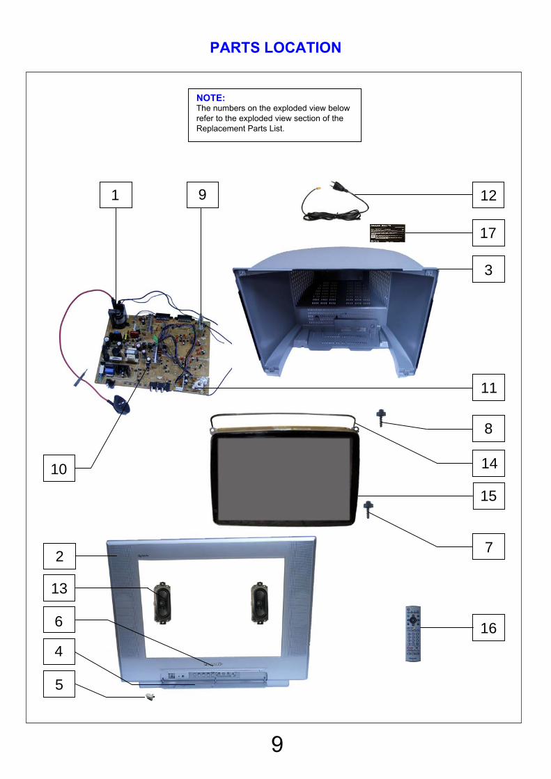
PARTS LOCATION
9
NOTE:The numbers on the exploded view belowrefer to the exploded view section of theReplacement Parts List.
1
2
3
4
5
6
7
8
9
10
11
12
13
14
15
16
17
Components Identified by mark have special characteristics important for safety.* When replacing any of these components, use only manufacturers specified parts.In case of ordering these spare parts, please always add the complete Model-Type number to your order.
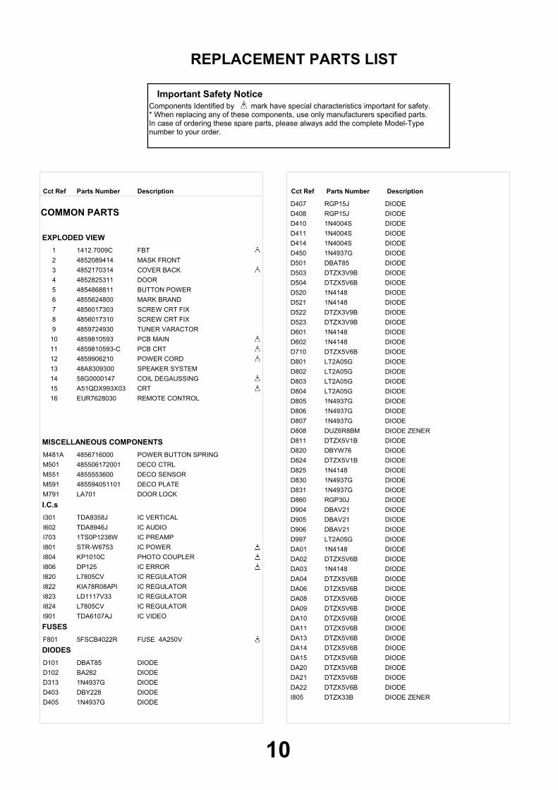
REPLACEMENT PARTS LIST
Important Safety Notice
DescriptionCct Ref Parts Number DescriptionCct Ref Parts Number
COMMON PARTS
EXPLODED VIEWFBT 1 1412.7009CMASK FRONT 2 4852089414COVER BACK 3 4852170314DOOR 4 4852825311BUTTON POWER 5 4854868811MARK BRAND 6 4855624800SCREW CRT FIX 7 4856017303SCREW CRT FIX 8 4856017310TUNER VARACTOR 9 4859724930PCB MAIN 10 4859810593PCB CRT 11 4859810593-CPOWER CORD 12 4859906210SPEAKER SYSTEM 13 48A8309300COIL DEGAUSSING 14 58G0000147CRT 15 A51QDX993X03REMOTE CONTROL 16 EUR7628030
MISCELLANEOUS COMPONENTSPOWER BUTTON SPRING M481A 4856716000DECO CTRL M501 485506172001DECO SENSOR M551 4855553600DECO PLATE M591 485594051101DOOR LOCK M791 LA701
I.C.sIC VERTICAL I301 TDA8358JIC AUDIO I602 TDA8946JIC PREAMP I703 1TS0P1238WIC POWER I801 STR-W6753PHOTO COUPLER I804 KP1010CIC ERROR I806 DP125IC REGULATOR I820 L7805CVIC REGULATOR I822 KIA78R08APIIC REGULATOR I823 LD1117V33IC REGULATOR I824 L7805CVIC VIDEO I901 TDA6107AJ
FUSESFUSE 4A250V F801 5FSCB4022R
DIODESDIODE D101 DBAT85DIODE D102 BA282DIODE D313 1N4937GDIODE D403 DBY228DIODE D405 1N4937G
DIODE D407 RGP15JDIODE D408 RGP15JDIODE D410 1N4004SDIODE D411 1N4004SDIODE D414 1N4004SDIODE D450 1N4937GDIODE D501 DBAT85DIODE D503 DTZX3V9BDIODE D504 DTZX5V6BDIODE D520 1N4148DIODE D521 1N4148DIODE D522 DTZX3V9BDIODE D523 DTZX3V9BDIODE D601 1N4148DIODE D602 1N4148DIODE D710 DTZX5V6BDIODE D801 LT2A05GDIODE D802 LT2A05GDIODE D803 LT2A05GDIODE D804 LT2A05GDIODE D805 1N4937GDIODE D806 1N4937GDIODE D807 1N4937GDIODE ZENER D808 DUZ6R8BMDIODE D811 DTZX5V1BDIODE D820 DBYW76DIODE D824 DTZX5V1BDIODE D825 1N4148DIODE D830 1N4937GDIODE D831 1N4937GDIODE D860 RGP30JDIODE D904 DBAV21DIODE D905 DBAV21DIODE D906 DBAV21DIODE D997 LT2A05GDIODE DA01 1N4148DIODE DA02 DTZX5V6BDIODE DA03 1N4148DIODE DA04 DTZX5V6BDIODE DA06 DTZX5V6BDIODE DA08 DTZX5V6BDIODE DA09 DTZX5V6BDIODE DA10 DTZX5V6BDIODE DA11 DTZX5V6BDIODE DA13 DTZX5V6BDIODE DA14 DTZX5V6BDIODE DA15 DTZX5V6BDIODE DA20 DTZX5V6BDIODE DA21 DTZX5V6BDIODE DA22 DTZX5V6BDIODE ZENER I805 DTZX33B
10

DescriptionCct Ref Parts Number DescriptionCct Ref Parts Number
TRANSISTORSTRANSISTOR Q120 2SC5343YTRANSISTOR Q401 2SD2578TRANSISTOR Q402 2SD1207TRANSISTOR Q501 2SC5343YTRANSISTOR Q502 2SA1980YTRANSISTOR Q503 2SC5343YTRANSISTOR Q504 2SA1980YTRANSISTOR Q506 2SC5343YTRANSISTOR Q508 2SC5343YTRANSISTOR Q513 2SA1980YTRANSISTOR Q515 H2N7000TRANSISTOR Q601 2SC5343YTRANSISTOR Q602 2SA1980YTRANSISTOR Q807 KTA1659AYTRANSISTOR Q809 2SC5343YTRANSISTOR Q810 2SC5343YTRANSISTOR Q812 KTC3203-YTRANSISTOR Q813 2SA1980YTRANSISTOR Q814 2SC5343YTRANSISTOR Q815 2SA1980YTRANSISTOR Q816 2SC5343Y
TRANSFORMERSTRANSFORMER DRIVET401 TD-19A1TRANSFORMER SMPS T801 2084.0125B
COILSPEAKING COIL L101 5CPZ100K02COIL PEAKING L350 5CPZ109K04COIL PEAKING L351 5CPZ109K04COIL H-LINEARITY L401 58H0000018PEAKING COIL L505 PZ479K02PEAKING COIL L506 PZ479K02PEAKING COIL L507 PZ479K02PEAKING COIL L508 PZ479K02PEAKING COIL L509 PZ479K02PEAKING COIL L510 PZ479K02PEAKING COIL L512 PZ479K02PEAKING COIL L513 PZ479K02PEAKING COIL L514 5CPZ100K04PEAKING COIL L515 5CPZ100K02PEAKING COIL L516 PZ479K02COIL PEAKING L517 5CPZ479K04COIL PEAKING L518 5CPZ479K04COIL PEAKING L519 5CPZ479K04PEAKING COIL L523 PZ479K02COIL BEAD L650 5MC0000100COIL BEAD L801 5MC0000100COIL CHOKE L802 58CX430599COIL BEAD L804 5MC0000100PEAKING COIL R713 5CPZ560K02
FILTERSFILTER LINE LF801 5PLF24A3FILTER SAW Z101 K3953MFILTER SAW Z102 5PK9650M--FILTER Z601 5PXF1B471MFILTER Z602 5PXF1B471MFILTER Z603 5PXF1B471MFILTER Z604 5PXF1B471MFILTER Z605 5PXF1B471MFILTER Z606 5PXF1B471MFILTER Z607 5PXF1B471MFILTER Z608 5PXF1B471MFILTER Z609 5PXF1B471MFILTER Z610 5PXF1B471MFILTER Z611 5PXF1B471M
FILTER Z612 5PXF1B471MCRYSTALS
CRYSTAL QUARTZ X501 5XJ24R576ERESISTORS
CARBOND826 ERD25TJ103 0.25W 5% 10K ΩCARBONJ7 ERD25TJ101 0.25W 5% 100 ΩCARBONJ25 ERD25TJ101 0.25W 5% 100 ΩCARBONJ26 ERD25TJ101 0.25W 5% 100 ΩCARBONJ50 ERD25TJ101 0.25W 5% 100 ΩCARBON J76 ERD25TJ202 0.25W 5% 2K ΩCARBONJ83 ERD25TJ101 0.25W 5% 100 ΩCARBONJ84 ERD25TJ101 0.25W 5% 100 ΩCARBON R103 ERD25TJ393 0.25W 5% 39K ΩCARBONR104 ERD25TJ683 0.25W 5% 68K ΩCARBONR105 ERD25TJ103 0.25W 5% 10K ΩCARBONR106 ERD25TJ101 0.25W 5% 100 ΩCARBONR107 ERD25TJ101 0.25W 5% 100 ΩCARBONR114 ERD25TJ473 0.25W 5% 47K ΩCARBONR115 ERD25TJ101 0.25W 5% 100 ΩCARBONR120 ERD25TJ101 0.25W 5% 100 ΩCARBONR131 ERD25TJ472 0.25W 5% 4K7 ΩCARBONR310 ERD25TJ471 0.25W 5% 470 ΩCARBONR311 ERD25TJ471 0.25W 5% 470 ΩCARBONR331 ERDS1TJ201 0.5W 5% 200 ΩCARBONR340 ERD25TJ473 0.25W 5% 47K ΩMETALR350 RN-AZ2201F 0.17W - 2K2 ΩMETALR351 RN-AZ2201F 0.17W - 2K2 ΩCARBONR370 ERD25TJ159 0.25W 5% 1.5 ΩCARBONR394 ERD25TJ272 0.25W 5% 2K7 ΩCARBONR395 ERD25TJ304 0.25W 5% 300K ΩCARBONR396 ERD25TJ103 0.25W 5% 10K ΩFILMR398 RS02Y189JS 2W - 1.8 ΩCARBONR401 ERD25TJ272 0.25W 5% 2K7 ΩCARBONR402 ERD25TJ220 0.25W 5% 22 ΩCARBONR403 ERD25TJ102 0.25W 5% 1K ΩCARBONR404 ERD25TJ109 0.25W 5% 1 ΩCARBONR405 ERD25TJ102 0.25W 5% 1K ΩMETALR406 RS02Y471JS 2W - 470 ΩCARBONR407 ERD25TJ182 0.25W 5% 1K8 ΩMETALR415 RN02B112JS 2W - 1K1 ΩCARBONR420 ERDS1TJ103 0.5W 5% 10K ΩCARBONR422 ERD25TJ102 0.25W 5% 1K ΩCARBON R423 ERD25TJ622 0.25W 5% 6K2 ΩMETALR444 RS02Y478JS 2W - R47 ΩMETAL R450 ERG2FJ223 2W 5% 22K ΩMETAL R451 ERG2FJ223 2W 5% 22K ΩCARBONR500 ERD25TJ101 0.25W 5% 100 ΩCARBONR501 ERD25TJ332 0.25W 5% 3K3 ΩCARBONR502 ERD25TJ332 0.25W 5% 3K3 ΩCARBONR503 ERD25TJ102 0.25W 5% 1K ΩCARBONR504 ERD25TJ152 0.25W 5% 1K5 ΩCARBONR505 ERD25TJ101 0.25W 5% 100 ΩCARBONR506 ERD25TJ103 0.25W 5% 10K ΩCARBONR507 ERD25TJ332 0.25W 5% 3K3 ΩCARBONR508 ERD25TJ332 0.25W 5% 3K3 ΩCARBONR510 ERD25TJ103 0.25W 5% 10K ΩCARBONR511 ERD25TJ103 0.25W 5% 10K ΩCARBONR512 ERD25TJ101 0.25W 5% 100 ΩCARBONR513 ERD25TJ101 0.25W 5% 100 ΩCARBONR514 ERD25TJ101 0.25W 5% 100 ΩCARBONR515 ERD25TJ101 0.25W 5% 100 ΩCARBONR516 ERD25TJ153 0.25W 5% 15K ΩCARBONR517 ERD25TJ101 0.25W 5% 100 ΩCARBONR518 ERD25TJ101 0.25W 5% 100 ΩCARBONR519 ERD25TJ102 0.25W 5% 1K ΩCARBONR527 ERD25TJ101 0.25W 5% 100 Ω
11
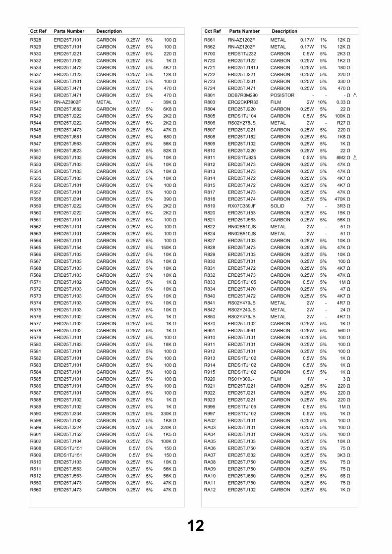
DescriptionCct Ref Parts Number DescriptionCct Ref Parts Number
CARBONR528 ERD25TJ101 0.25W 5% 100 ΩCARBONR529 ERD25TJ101 0.25W 5% 100 ΩCARBONR530 ERD25TJ221 0.25W 5% 220 ΩCARBONR532 ERD25TJ102 0.25W 5% 1K ΩCARBONR534 ERD25TJ472 0.25W 5% 4K7 ΩCARBON R537 ERD25TJ123 0.25W 5% 12K ΩCARBONR538 ERD25TJ101 0.25W 5% 100 ΩCARBONR539 ERD25TJ471 0.25W 5% 470 ΩCARBONR540 ERD25TJ471 0.25W 5% 470 ΩMETALR541 RN-AZ3902F 0.17W - 39K ΩCARBONR542 ERD25TJ682 0.25W 5% 6K8 ΩCARBONR543 ERD25TJ222 0.25W 5% 2K2 ΩCARBONR544 ERD25TJ222 0.25W 5% 2K2 ΩCARBONR545 ERD25TJ473 0.25W 5% 47K ΩCARBONR546 ERD25TJ681 0.25W 5% 680 ΩCARBONR547 ERD25TJ563 0.25W 5% 56K ΩCARBONR551 ERD25TJ823 0.25W 5% 82K ΩCARBONR552 ERD25TJ103 0.25W 5% 10K ΩCARBONR553 ERD25TJ103 0.25W 5% 10K ΩCARBONR554 ERD25TJ103 0.25W 5% 10K ΩCARBONR555 ERD25TJ103 0.25W 5% 10K ΩCARBONR556 ERD25TJ101 0.25W 5% 100 ΩCARBONR557 ERD25TJ101 0.25W 5% 100 ΩCARBONR558 ERD25TJ391 0.25W 5% 390 ΩCARBONR559 ERD25TJ222 0.25W 5% 2K2 ΩCARBONR560 ERD25TJ222 0.25W 5% 2K2 ΩCARBONR561 ERD25TJ101 0.25W 5% 100 ΩCARBONR562 ERD25TJ101 0.25W 5% 100 ΩCARBONR563 ERD25TJ101 0.25W 5% 100 ΩCARBONR564 ERD25TJ101 0.25W 5% 100 ΩCARBONR565 ERD25TJ154 0.25W 5% 150K ΩCARBONR566 ERD25TJ103 0.25W 5% 10K ΩCARBONR567 ERD25TJ103 0.25W 5% 10K ΩCARBONR568 ERD25TJ103 0.25W 5% 10K ΩCARBONR569 ERD25TJ103 0.25W 5% 10K ΩCARBONR571 ERD25TJ102 0.25W 5% 1K ΩCARBONR572 ERD25TJ103 0.25W 5% 10K ΩCARBONR573 ERD25TJ103 0.25W 5% 10K ΩCARBONR574 ERD25TJ103 0.25W 5% 10K ΩCARBONR575 ERD25TJ103 0.25W 5% 10K ΩCARBONR576 ERD25TJ102 0.25W 5% 1K ΩCARBONR577 ERD25TJ102 0.25W 5% 1K ΩCARBONR578 ERD25TJ102 0.25W 5% 1K ΩCARBONR579 ERD25TJ101 0.25W 5% 100 ΩCARBONR580 ERD25TJ183 0.25W 5% 18K ΩCARBONR581 ERD25TJ101 0.25W 5% 100 ΩCARBONR582 ERD25TJ101 0.25W 5% 100 ΩCARBONR583 ERD25TJ101 0.25W 5% 100 ΩCARBONR584 ERD25TJ101 0.25W 5% 100 ΩCARBONR585 ERD25TJ101 0.25W 5% 100 ΩCARBONR586 ERD25TJ101 0.25W 5% 100 ΩCARBONR587 ERD25TJ101 0.25W 5% 100 ΩCARBONR588 ERD25TJ102 0.25W 5% 1K ΩCARBONR589 ERD25TJ102 0.25W 5% 1K ΩCARBON R590 ERD25TJ334 0.25W 5% 330K ΩCARBONR598 ERD25TJ182 0.25W 5% 1K8 ΩCARBON R599 ERD25TJ224 0.25W 5% 220K ΩCARBONR601 ERD25TJ152 0.25W 5% 1K5 ΩCARBONR602 ERD25TJ104 0.25W 5% 100K ΩCARBON R608 ERDS1TJ151 0.5W 5% 150 ΩCARBON R609 ERDS1TJ151 0.5W 5% 150 ΩCARBONR610 ERD25TJ103 0.25W 5% 10K ΩCARBONR611 ERD25TJ563 0.25W 5% 56K ΩCARBONR612 ERD25TJ563 0.25W 5% 56K ΩCARBONR650 ERD25TJ473 0.25W 5% 47K ΩCARBONR660 ERD25TJ473 0.25W 5% 47K Ω
METALR661 RN-AZ1202F 0.17W 1% 12K ΩMETALR662 RN-AZ1202F 0.17W 1% 12K ΩCARBONR700 ERDS1TJ232 0.5W 5% 2K3 ΩCARBONR720 ERD25TJ122 0.25W 5% 1K2 ΩCARBONR721 ERD25TJ181J 0.25W 5% 180 ΩCARBONR722 ERD25TJ221 0.25W 5% 220 ΩCARBONR723 ERD25TJ331 0.25W 5% 330 ΩCARBONR724 ERD25TJ471 0.25W 5% 470 ΩPOSISTORR801 DDB7R0M290 - - - ΩFILMR803 ERQ2CKPR33 2W 10% 0.33 ΩCARBONR804 ERD25TJ220 0.25W 5% 22 ΩCARBONR805 ERDS1TJ104 0.5W 5% 100K ΩMETALR806 RS02Y278JS 2W - R27 ΩCARBONR807 ERD25TJ221 0.25W 5% 220 ΩCARBONR808 ERD25TJ182 0.25W 5% 1K8 ΩCARBONR809 ERD25TJ102 0.25W 5% 1K ΩCARBONR810 ERD25TJ220 0.25W 5% 22 ΩCARBONR811 ERDS1TJ825 0.5W 5% 8M2 ΩCARBONR812 ERD25TJ473 0.25W 5% 47K ΩCARBONR813 ERD25TJ473 0.25W 5% 47K ΩCARBONR814 ERD25TJ472 0.25W 5% 4K7 ΩCARBONR815 ERD25TJ472 0.25W 5% 4K7 ΩCARBONR817 ERD25TJ473 0.25W 5% 47K ΩCARBONR818 ERD25TJ474 0.25W 5% 470K ΩSOLIDR819 RX07C339JF 7W - 3R3 ΩCARBONR820 ERD25TJ153 0.25W 5% 15K ΩCARBONR821 ERD25TJ563 0.25W 5% 56K ΩMETALR822 RN02B510JS 2W - 51 ΩMETALR824 RN02B510JS 2W - 51 ΩCARBONR827 ERD25TJ103 0.25W 5% 10K ΩCARBONR828 ERD25TJ473 0.25W 5% 47K ΩCARBONR829 ERD25TJ103 0.25W 5% 10K ΩCARBONR830 ERD25TJ101 0.25W 5% 100 ΩCARBONR831 ERD25TJ472 0.25W 5% 4K7 ΩCARBONR832 ERD25TJ473 0.25W 5% 47K ΩCARBONR833 ERDS1TJ105 0.5W 5% 1M ΩCARBONR834 ERD25TJ470 0.25W 5% 47 ΩCARBONR840 ERD25TJ472 0.25W 5% 4K7 ΩMETALR841 RS02Y479JS 2W - 4R7 ΩMETALR842 RS02Y240JS 2W - 24 ΩMETALR850 RS02Y479JS 2W - 4R7 ΩCARBONR870 ERD25TJ102 0.25W 5% 1K ΩCARBONR901 ERD25TJ561 0.25W 5% 560 ΩCARBONR910 ERD25TJ101 0.25W 5% 100 ΩCARBONR911 ERD25TJ101 0.25W 5% 100 ΩCARBONR912 ERD25TJ101 0.25W 5% 100 ΩCARBON R913 ERDS1TJ102 0.5W 5% 1K ΩCARBON R914 ERDS1TJ102 0.5W 5% 1K ΩCARBON R915 ERDS1TJ102 0.5W 5% 1K ΩFILMR920 RS01Y309J- 1W - 3 ΩCARBONR921 ERD25TJ221 0.25W 5% 220 ΩCARBONR922 ERD25TJ221 0.25W 5% 220 ΩCARBONR923 ERD25TJ221 0.25W 5% 220 ΩCARBONR996 ERDS1TJ105 0.5W 5% 1M ΩCARBON R997 ERDS1TJ102 0.5W 5% 1K ΩCARBONRA02 ERD25TJ101 0.25W 5% 100 ΩCARBONRA03 ERD25TJ101 0.25W 5% 100 ΩCARBONRA04 ERD25TJ101 0.25W 5% 100 ΩCARBONRA05 ERD25TJ103 0.25W 5% 10K ΩCARBON RA06 ERD25TJ750 0.25W 5% 75 ΩCARBONRA07 ERD25TJ332 0.25W 5% 3K3 ΩCARBON RA08 ERD25TJ750 0.25W 5% 75 ΩCARBON RA09 ERD25TJ750 0.25W 5% 75 ΩCARBONRA10 ERD25TJ680 0.25W 5% 68 ΩCARBON RA11 ERD25TJ750 0.25W 5% 75 ΩCARBONRA12 ERD25TJ102 0.25W 5% 1K Ω
12
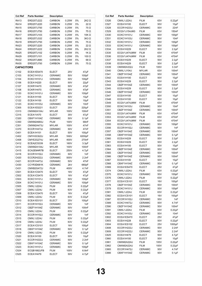
DescriptionCct Ref Parts Number DescriptionCct Ref Parts Number
CARBONRA13 ERD25TJ222 0.25W 5% 2K2 ΩCARBONRA14 ERD25TJ220 0.25W 5% 22 ΩCARBON RA15 ERD25TJ750 0.25W 5% 75 ΩCARBON RA16 ERD25TJ750 0.25W 5% 75 ΩCARBONRA17 ERD25TJ103 0.25W 5% 10K ΩCARBONRA18 ERD25TJ332 0.25W 5% 3K3 ΩCARBON RA19 ERD25TJ750 0.25W 5% 75 ΩCARBONRA23 ERD25TJ220 0.25W 5% 22 ΩCARBONRA24 ERD25TJ222 0.25W 5% 2K2 ΩCARBONRA25 ERD25TJ102 0.25W 5% 1K ΩCARBONRA29 ERD25TJ101 0.25W 5% 100 ΩCARBONRA32 ERD25TJ680 0.25W 5% 68 ΩCARBON RA35 ERD25TJ750 0.25W 5% 75 Ω
CAPACITORSELECTC102 ECEA1ES470 25V 47µFCERAMIC C103 ECKC1H101J 50V 100pFCERAMIC C104 ECKC1H101J 50V 100pFELECTC106 ECEA1H220 50V 22µFCERAMICC107 ECKR1H470 50V 47pFCERAMICC108 ECKR1H470 50V 47pFCERAMIC C120 ECKC1H101J 50V 100pFELECTC121 ECEA1H100 50V 10µFELECTC122 ECEA1H100 50V 10µFCERAMICC123 ECKC1H103J 50V 10nFELECTC305 ECEA1ES221 25V 220µFMYLARC313 CMXM2A104J 100V 100nFELECTC315 ECEA1V470 35V 47µFCERAMICC320 CBXF1H104Z 50V 0.1µFFILMC350 CMXM2A683J 100V 68nFMYLARC351 CMXM2A473J 100V 47nFCERAMICC370 ECCR1H473J 50V 47nFELECTC401 ECEA1H101 50V 100µFMYLARC402 CMYH3C622J 1K6V 6200pFMYLARC408 CMYE2G274J 400V 270nFELECTC412 ECEA2CS339 160V 3.3µFMYLARC414 CMXM2A104J 100V 100nFELECTC415 ECA2EM4R7B 250V 4.7µFCERAMICC418 ECCR1H102J 50V 1nFCERAMICC420 ECCR2H222J 500V 2.2nFCERAMICC421 ECCR1H473J 50V 47nFCERAMICC430 CCYR3D681K 2kV 680pFFILMC431 CMXB2G472J 400V 4.7nFELECTC501 ECEA1CS470 16V 47µFELECTC502 ECEA1CS470 16V 47µFCERAMIC C503 ECKC1H101J 50V 100pFCERAMIC C504 ECKC1H101J 50V 100pFFILMC505 CMXL1J224J 63V 0.22µFFILMC507 CMXL1J224J 63V 0.22µFELECTC508 ECEA1CS470 16V 47µFFILMC509 CMXL1J224J 63V 0.22µFELECTC510 ECEA1ES101 25V 100µFCERAMICC511 ECCR1H102J 50V 1nFCERAMICC512 CBZF1H104Z 50V 100nFFILMC513 CMXL1J224J 63V 0.22µFCERAMICC514 ECCR1H102J 50V 1nFFILMC515 CMXL1J224J 63V 0.22µFFILMC516 CMXL1J224J 63V 0.22µFELECTC517 ECEA1CS101 16V 100µFCERAMICC518 CBXF1H104Z 50V 0.1µFFILMC519 CMXL1J224J 63V 0.22µFELECTC520 ECEA1H100 50V 10µFCERAMICC521 ECCR1H222J 50V 2.2nFCERAMICC522 CBXF1H104Z 50V 0.1µFCERAMIC C523 ECKC1H101J 50V 100pFFILMC524 ECQB1682JFB 100V 6.8nFELECTC525 ECEA1H479 50V 4.7µF
FILMC526 CMXL1J224J 63V 0.22µFELECTC527 ECEA1H100 50V 10µFCERAMICC528 ECCR1H223J 50V 22nFFILMC529 ECQV1J154JM3 63V 150nFCERAMIC C530 ECKC1H101J 50V 100pFCERAMICC531 ECKC1H103J 50V 10nFCERAMIC C532 ECKC1H101J 50V 100pFCERAMIC C533 ECKC1H101J 50V 100pFELECTC534 ECEA1H229 50V 2.2µFFILMC535 ECQV1J474JMW 63V 470nFFILMC536 ECQV1J474JMW 63V 470nFELECTC537 ECEA1H229 50V 2.2µFELECTC538 ECEA1H229 50V 2.2µFFILMC539 CMXM2A332J 100V 3.3nFMYLARC540 CMXL1J104J 63V 100nFCERAMICC541 CBZF1H104Z 50V 100nFELECTC542 ECEA1H100 50V 10µFELECTC543 ECEA1H229 50V 2.2µFCERAMICC544 CBZF1H104Z 50V 100nFELECTC545 ECEA1H229 50V 2.2µFCERAMICC546 CBZF1H104Z 50V 100nFELECTC547 ECEA1H100 50V 10µFELECTC548 ECEA1H100 50V 10µFFILMC549 ECQV1J474JMW 63V 470nFCERAMICC550 ECKC1H103J 50V 10nFCERAMICC551 CBZF1H104Z 50V 100nFFILMC552 ECQV1J474JMW 63V 470nFFILMC553 ECQV1J474JMW 63V 470nFFILMC554 ECQV1J474JMW 63V 470nFCERAMIC C555 ECKC1H101J 50V 100pFCERAMICC556 ECCR1H102J 50V 1nFCERAMICC557 CBZF1H104Z 50V 100nFCERAMICC558 CBXF1H104Z 50V 0.1µFELECTC560 ECEA1H229 50V 2.2µFELECTC561 ECEA1H229 50V 2.2µFELECTC563 ECEA1H100 50V 10µFCERAMICC564 CBZF1H104Z 50V 100nFCERAMICC565 CBZF1H104Z 50V 100nFCERAMICC566 CBZF1H104Z 50V 100nFELECTC567 ECEA1H100 50V 10µFCERAMICC568 CBXF1H104Z 50V 0.1µFELECTC569 ECEA1ES470 25V 47µFFILMC574 CMXL1J224J 63V 0.22µFCERAMIC C575 ECKC1H101J 50V 100pFFILMC576 CMXL1J224J 63V 0.22µFELECTC577 ECEA1CS101 16V 100µFCERAMICC578 CBZF1H104Z 50V 100nFCERAMIC C579 ECKC1H101J 50V 100pFFILMC581 CMXL1J224J 63V 0.22µFELECTC582 ECEA1CS101 16V 100µFCERAMICC587 ECCR1H102J 50V 1nFCERAMIC C589 ECKC1H472J 50V 4.7nFCERAMICC590 CBZF1H104Z 50V 100nFFILMC591 CMXL1J224J 63V 0.22µFCERAMICC592 ECKC1H103J 50V 10nFELECTC602 ECEA1ES470 25V 47µFELECTC603 ECEA1H228 50V 0.22µFELECTC604 ECEA1ES102 25V 1000µFCERAMICC608 ECCR1H222J 50V 2.2nFCERAMICC609 ECCR1H222J 50V 2.2nFELECTC625 ECEA1H479 50V 4.7µFELECTC660 ECEA1H100 50V 10µFFILMC661 CMXM2A224J 100V 0.22µFFILMC662 CMXM2A224J 100V 0.22µFCERAMICC665 ECCR1H472J 50V 4.7nFCERAMICC666 CBXF1H104Z 50V 0.1µF
13

DescriptionCct Ref Parts Number DescriptionCct Ref Parts Number
CERAMICC667 ECCR1H472J 50V 4.7nFFILMC668 CMXM2A224J 100V 0.22µFFILMC669 CMXM2A224J 100V 0.22µFELECTC690 ECEA1H479 50V 4.7µFELECTC691 ECEA1H479 50V 4.7µFELECTC770 ECEA1CS101 16V 100µFCERAMICC801 CL1UC3474M 250V 470nFCERAMICC803 ECCR3A472J 1kV 4.7nFCERAMICC804 ECCR3A472J 1kV 4.7nFELECTC805 ECA2GM181B 400V 180µFCERAMICC806 CCXR3A102K 1kV 1nFELECTC807 ECEA1H109 50V 1µFCERAMIC C809 ECKC1H101J 50V 100pFELECTC810 ECEA1H220 50V 22µFMYLARC811 CMXM2A473J 100V 47nFCERAMICC812 CH1BFE472M 400V 4.7nFELECTC813 CEYF2E470V 250V 47µFELECTC814 ECA2EM101 250V 100µFCERAMICC820 CCYR3D221K 2kV 220pFELECTC823 ECEA1ES471 25V 470µFELECTC830 ECEA1H479 50V 4.7µFELECTC831 ECEA1H330 50V 33µFCERAMICC833 CCXB1H821K 50V 820pFCERAMICC834 ECCR1H103J 50V 10nFELECTC835 ECEA1ES470 25V 47µFELECTC840 ECEA1CS332 16V 3300µFELECTC844 ECEA1ES101 25V 100µFELECTC861 ECEA1ES102 25V 1000µFELECTC862 ECEA1ES101 25V 100µFELECTC863 ECEA1CS101 16V 100µFCERAMIC C866 ECKC3A471J 1KV 470pFCERAMICC901 ECCR1H221J 50V 220pFELECTC905 ECA2EM4R7B 250V 4.7µFCERAMIC C965 ECKC3D102J 2KV 1nFMYLARC968 CMXL2E104K 250V 100nFELECTC997 ECA2EM100B 250V 10µFCERAMIC CA01 ECKC1H101J 50V 100pFCERAMIC CA02 ECKC1H101J 50V 100pFCERAMIC CA03 ECKC1H101J 50V 100pFCERAMIC CA04 ECKC1H101J 50V 100pFCERAMIC CA05 ECKC1H101J 50V 100pFCERAMIC CA06 ECKC1H101J 50V 100pFCERAMICCA10 ECCR1H102J 50V 1nFCERAMIC CA28 ECKC1H101J 50V 100pF
TERMINALS AND LINKSHEADPHONE SOCKET JP01 4859102130AV TERMINAL JPA1 4859200401AV TERMINAL JPA2 4859200401JACK PIN BOARD JPA3 4859108450SOCKET CRT SCT1 4859303530
SWITCHESSWITCH SW700 5S50101Z90SWITCH SW701 5S50101Z90SWITCH SW702 5S50101Z90SWITCH SW703 5S50101Z90SWITCH SW704 5S50101Z90SWITCH SW801 5S40101143
RELAYSRELAY Y801 5SC0101003
DIFFERENCES FOR MODEL TX--21PZ1
EXPLODED VIEWS/PLATE 17 DMP4502800
INSTRUCTION BOOKSENGLISH . TQB0E0136-M
I.C.sIC MICOM FLASH I501 TDA21HD01-UKIC MEMORY I502 X24C21PZ1
DIFFERENCES FOR MODEL TX--21PZ1D
EXPLODED VIEWS/PLATE 17 DMP4502900
INSTRUCTION BOOKSGERMAN . TQB0E0138A-MITALIAN . TQB0E0138C-MFRENCH . TQB0E0138D-M
I.C.sIC MICOM FLASH I501 TDA21HD01-WIC MEMORY I502 X24C21PZ1D
DIFFERENCES FOR MODEL TX--21PZ1F
EXPLODED VIEWS/PLATE 17 DMP4503000
INSTRUCTION BOOKSGERMAN . TQB0E0137A-MDUTCH . TQB0E0137B-MFRENCH . TQB0E0137D-MSPANISH . TQB0E0137E-MSWEDISH . TQB0E0137F-MNORWEGIAN . TQB0E0137G-MFINNISH . TQB0E0137H-MPORTUGUESE . TQB0E0137J-MDANISH . TQB0E0137K-M
I.C.sIC MICOM FLASH I501 TDA21HD01-WIC MEMORY I502 X24C21PZ1F
DIFFERENCES FOR MODEL TX--21PZ1P
EXPLODED VIEWS/PLATE 17 DMP4503100
INSTRUCTION BOOKSBULGARIAN . TQB0E0139M-MROMANIAN . TQB0E0139N-MPOLISH . TQB0E0139P-MHUNGARIAN . TQB0E0139Q-MCZECH . TQB0E0139R-MENGLISH . TQB0E0139U-MSLOVAKIAN . TQB0E0139W-M
I.C.sIC MICOM FLASH I501 TDA21HD01-EIC MEMORY I502 X24C21PZ1P
14

SCHEMATIC DIAGRAMS FOR MODELSTX-21PZ1, TX-21PZ1D, TX-21PZ1F, TX-21PZ1P
(CP-521FS CHASSIS)
NOTE1. RESISTOR
All resistors are carbon ¼W resistor, unless marked otherwise.Unit of resistance is OHM ( ) (k=1,000, M=1,000,000)
2. CAPACITORSAll capacitors are ceramic 50V unless marked otherwise.Unit of capacitance is F unless otherwise stated.
3. COILUnit of inductance is H, unless otherwise stated.
4. EARTH SYMBOL
Chassis Earth (Cold)
Line Earth (Hot)
5. VOLTAGE MEASUREMENTVoltage is measured by a d.c. voltmeter.Measurement conditions are as follows:Power source a.c. 220V-240V, 50HzReceiving Signal Colour Bar signal (RF)All customer controls Maximum position
These schematic diagrams are the latest at time of printing and are subject to change without notice.
REMARKSa. Do not touch the hot part, or the hot and cold parts at the same time, as you are liable to a shock hazard.
b. Do not short circuit the hot and cold circuits as electrical components may be damaged.
c. Do not connect an instrument, such as an oscilloscope, to the hot and cold circuits simultaneously as this may causefuse failure. Connect the earth of the instruments to the earth connection of the circuit being measured.
d. Make sure to disconnect the power plug before removing the chassis.
NOTE1. The Power Supply Circuit contains a circuit area, which uses a separate power supply to isolate the earth connection.
The circuit is defined by HOT and COLD indications in the schematic diagram. All circuits, except the Power Circuit, are COLD.
IMPORTANT SAFETY NOTICEComponents identified by mark have special characteristicsimportant for safety. When replacing any of these components, useonly manufacturers' specified parts.
15
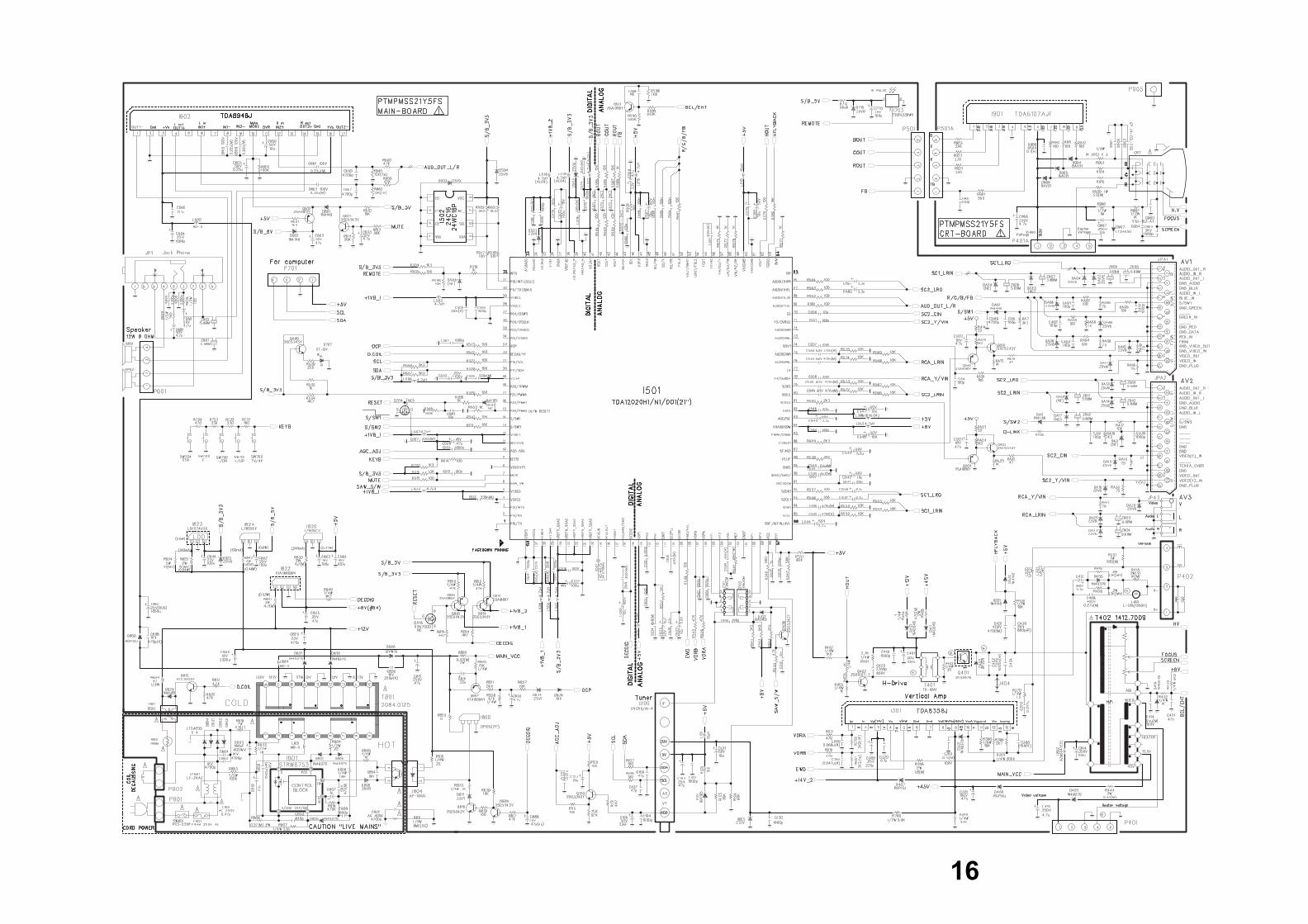
16
19
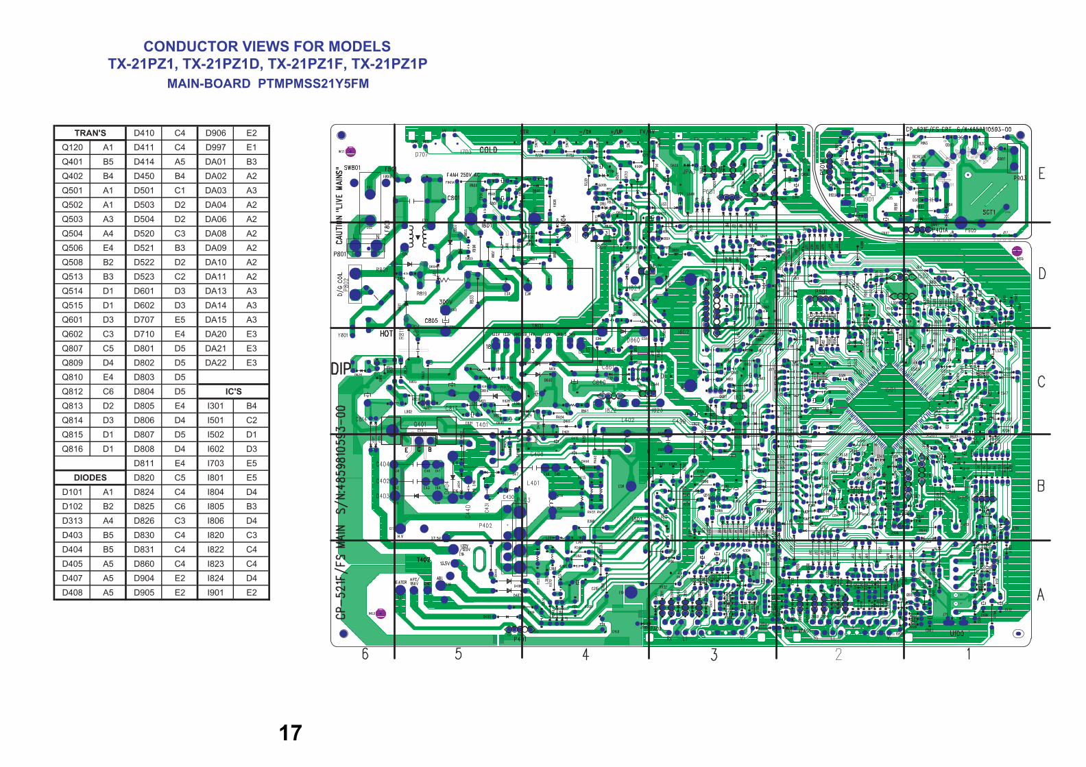
D410 C4 D906 E2
Q120 A1 D411 C4 D997 E1
Q401 B5 D414 A5 DA01 B3
Q402 B4 D450 B4 DA02 A2
Q501 A1 D501 C1 DA03 A3
Q502 A1 D503 D2 DA04 A2
Q503 A3 D504 D2 DA06 A2
Q504 A4 D520 C3 DA08 A2
Q506 E4 D521 B3 DA09 A2
Q508 B2 D522 D2 DA10 A2
Q513 B3 D523 C2 DA11 A2
Q514 D1 D601 D3 DA13 A3
Q515 D1 D602 D3 DA14 A3
Q601 D3 D707 E5 DA15 A3
Q602 C3 D710 E4 DA20 E3
Q807 C5 D801 D5 DA21 E3
Q809 D4 D802 D5 DA22 E3
Q810 E4 D803 D5
Q812 C6 D804 D5
Q813 D2 D805 E4 I301 B4
Q814 D3 D806 D4 I501 C2
Q815 D1 D807 D5 I502 D1
Q816 D1 D808 D4 I602 D3
D811 E4 I703 E5
D820 C5 I801 E5
D101 A1 D824 C4 I804 D4
D102 B2 D825 C6 I805 B3
D313 A4 D826 C3 I806 D4
D403 B5 D830 C4 I820 C3
D404 B5 D831 C4 I822 C4
D405 A5 D860 C4 I823 C4
D407 A5 D904 E2 I824 D4
D408 A5 D905 E2 I901 E2
TRAN'S
DIODES
IC'S
CONDUCTOR VIEWS FOR MODELSTX-21PZ1, TX-21PZ1D, TX-21PZ1F, TX-21PZ1P
MAIN-BOARD PTMPMSS21Y5FM
17
Related Documents