CRANFIELD UNIVERSITY RONGXIN XU Optimal Design of a Composite Wing Structure for a Flying-Wing Aircraft Subject to Multi-constraint School of Engineering Aerospace Engineering Aircraft# Design Programme MSc /by Research Academic /Year: 2011 - 2012 Supervisor: #SHIJUN /GUO /JANUARY 2012

Welcome message from author
This document is posted to help you gain knowledge. Please leave a comment to let me know what you think about it! Share it to your friends and learn new things together.
Transcript
CRANFIELD UNIVERSITY
RONGXIN XU
Optimal Design of a Composite Wing Structure for a Flying-Wing Aircraft Subject to Multi-constraint
School of Engineering
Aerospace Engineering
Aircraft# Design Programme
MSc /by Research Academic /Year: 2011 - 2012
Supervisor: #SHIJUN /GUO /JANUARY 2012

CRANFIELD #UNIVERSITY
SCHOOL #OF ENGINEERING
Aerospace #Engineering Aircraft /Design
MSc by Research
Academic #Year 2011 - 2012
RONGXIN XU
Optimal Design of a Composite Wing Structure for a Flying-Wing Aircraft Subject to Multi-constraint
Supervisor: /SHIJUN GUO
JANUARY 2012
© Cranfield University 2012. All rights reserved. No part/ of this publication may be reproduced without the written /permission of the
/copyright /owner.

i
ABSTRACT
This thesis presents a research project and results of design and optimization of
a composite wing structure for a large aircraft in flying wing configuration. The
design process started from conceptual design and preliminary design, which
includes initial sizing and stressing followed by numerical modelling and
analysis of the wing structure. The research was then focused on the minimum
weight optimization of the /composite wing structure /subject to multiple design
/constraints. The modelling, analysis and optimization process has been
performed by using the NASTRAN code. The methodology and technique not
only make the modelling in high accuracy, but also keep the whole process
within one commercial package for practical application.
The example aircraft, called FW-11, is a 250-seat commercial airliner of flying
wing configuration designed through our MSc students Group Design Project
(GDP) in Cranfield University. Started from conceptual design in the GDP, a
high-aspect-ratio and large sweepback angle flying wing configuration has been
adopted. During the GDP, the author was responsible for the structural layout
design and material selection. Composite material has been chosen as the
preferable material for both the inner and outer wing components. Based on the
derivation of structural design data in the conceptual phase, the author
continued with the preliminary design of the outer wing airframe and then
focused on the optimization of the composite wing structure.
In the preliminary design phase, classical method based on statistical design
data was used to calculate the initial size of the main structural components at
first. Since this classical technique is always thought to be conservative for
initial design, advanced numerical analysis method, finite element method
(FEM), is subsequently used to update the initial design result.
In the optimization process, attention was mainly focused on the thickness and
layup of the laminated upper and lower stiffened skin panels, which make
significant influence to the structure weight and stiffness. The optimization was
based on the finite element model of the outer wing box. The objective was to
ii
minimize the structure weight. Multiple constraints include failure criterion
related to laminate strength, allowable design limiting strain covering damage
tolerance, minimum flutter speed reflecting dynamic aeroelastic stability and
minimum percentage of each ply orientation considering load condition
uncertainties.
For design variables, a pre-process was adopted by setting the laminate in
blocks regardless the stacking sequence. This allows the laminate thickness
change discretely in the scale of each lamina thickness and makes the
optimization practical and efficient. As a result, a structure weight reduction by
7.7% was achieved for the whole outer wing airframe by only optimising the
laminated skins.
At the end, a post-process was added to arrange the laminate stacking
sequence according to the optimization result. This final result has also proved
the optimization mentioned above is applicable.
In conclusion, the methodology and technique developed in this research has
demonstrated a practical and user friendly approach for aircraft structure
optimization. The whole process can be kept within one commercial package
including high fidelity modelling and high accuracy analysis and also
optimization with multiple design constraints.
Keywords:
Structural Design, Multidisciplinary Optimization, Finite Element, Aeroelasticity,
Flutter, Failure Criterion, NASTRAN
iii
ACKNOWLEDGEMENTS
I expr.ess my sinc.ere gratitude, regards and /thanks to my /supervisor Dr. Shijun
Guo for his excellent /guidance, invaluable /suggestions and /generous help at all
the stages of my individual /research work.
I would like to give my appreciation to Prof. John Pielding, Prof. Howard Smith
and other staff of Department of Aerospace Engineering for their best
instructions throughout the group design project. And thanks to all my
classmates for their hard work and perfect cooperation during the project.
Thank you to Faliang Wang, Chao Tong and Jin Zhang for sharing the
aerodynamic and inertial load data.
Thank you to Dr. Rui Pires for his lecture on practical finite element analysis.
Thank you to Dr. Daochun Li and Dr. Qiang Fu for providing help on my
NASTRAN studying.
Thanks to my company AVIC and also CSC for providing me this opportunity
and sponsorship for studying at Cranfield University.
Finally, thanks to my wife Li and my parents for their support and love and
taking care of my lovely daughter Yuanyuan in my absence.

v
TABLE OF CONTENTS
ABSTRACT ......................................................................................................... i ACKNOWLEDGEMENTS................................................................................... iii TABLE OF CONTENTS ..................................................................................... v LIST OF FIGURES ............................................................................................ vii LIST OF TABLES ............................................................................................. viii LIST OF EQUATIONS ...................................................................................... viii NOTATIONS ...................................................................................................... xi 1 Introduction ................................................................................................. 1
1.1 Background ........................................................................................... 1 1.2 Aim and Objectives ............................................................................... 3
2 Literature Review ........................................................................................ 5 2.1 Analysis of Composite Structures.......................................................... 5 2.2 Flutter Analysis for Wing Structure ........................................................ 6 2.3 Optimization of Composite Structure ..................................................... 8
3 Theory and Methodology ........................................................................... 13 3.1 Composite Failure Theory ................................................................... 13
3.1.1 Tsai-Hill Theory ............................................................................. 13 3.1.2 Hoffman Theory ............................................................................ 13 3.1.3 Tsai-Wu Theory ............................................................................ 14
3.2 Flutter Analysis Theory ........................................................................ 14 3.3 Optimization Theory ............................................................................ 16 3.4 Methodology ........................................................................................ 17
3.4.1 Design Methods ............................................................................ 17 3.4.2 Optimization .................................................................................. 18 3.4.3 Design Tools ................................................................................. 20
4 Derivation of Structural Design Data ......................................................... 23 4.1 Wing Geometry and Specification ....................................................... 23 4.2 Load Analysis ...................................................................................... 24 4.3 Material Selection ................................................................................ 29
5 Structural Layout Design ........................................................................... 33 5.1 General View ....................................................................................... 33 5.2 Inner Wing Structure Concept ............................................................. 33 5.3 Outer Wing Structural Layout .............................................................. 35
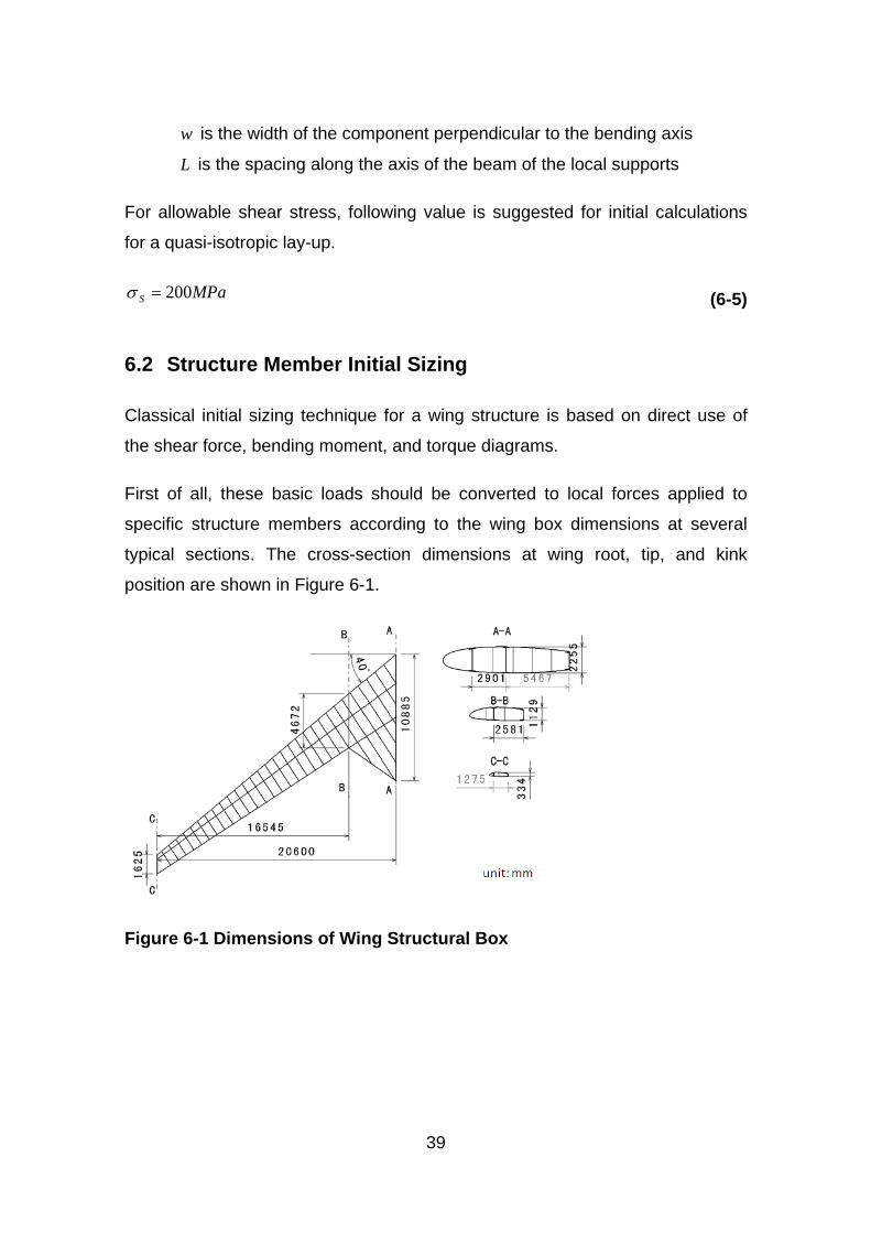
6 Classical Initial Sizing ................................................................................ 37 6.1 Composite Material Property Estimation ............................................. 37 6.2 Structure Member Initial Sizing ........................................................... 39
6.2.1 Spar Webs .................................................................................... 40 6.2.2 Composite Skin ............................................................................. 41
7 Finite Element Approach Estimation ......................................................... 45 7.1 Static Analysis ..................................................................................... 45
7.1.1 FE Structure Modelling ................................................................. 45 7.1.2 Distributed Loads Definition .......................................................... 48 7.1.3 Static Analysis Results ................................................................. 49
7.2 Aeroelastic Analysis ............................................................................ 53 7.2.1 Modelling for Dynamic Analysis .................................................... 53
vi
7.2.2 Flutter Analysis Modelling ............................................................. 56 7.2.3 Flutter Analysis Results ................................................................ 59
8 Optimization .............................................................................................. 63 8.1 Optimization Model Description ........................................................... 63 8.2 Optimization Pre-process .................................................................... 64
8.2.1 Design Variable Definition ............................................................ 64 8.2.2 Response and Constraint Definition ............................................. 67 8.2.3 Optimization Constraints Definition ............................................... 68
8.3 Optimization Results ........................................................................... 69 8.3.1 Optimization Process .................................................................... 69 8.3.2 Optimization Results Analysis....................................................... 71
8.4 Laminate Post-process ........................................................................ 76 9 Discussion and Future Work ..................................................................... 79
9.1 Discussion ........................................................................................... 79 9.2 Future Work ........................................................................................ 80
10 Conclusion ................................................................................................ 83 REFERENCES ................................................................................................. 85 APPENDICES .................................................................................................. 89
vii
LIST OF FIGURES
Figure 2-1 A Flow-chart of the GA Procedure [20] ........................................... 10 Figure 3-1 Structure Design Requirements ...................................................... 19 Figure 4-1 Three-view Drawing of FW-11 ........................................................ 23 Figure 4-2 Flying Wing Aircraft Loads Condition .............................................. 25 Figure 4-3 Span-wise Lift Distribution for Level Flight ...................................... 25 Figure 4-4 Span-wise Mass Distribution ........................................................... 26 Figure 4-5 Shear Force Diagram ...................................................................... 27 Figure 4-6 Bending Moment Diagram .............................................................. 27 Figure 4-7 Torque Diagram .............................................................................. 28 Figure 4-8 FW-11 Material Breakdown ............................................................. 30 Figure 5-1 Main Structure Layout ..................................................................... 33 Figure 5-2 Inner Wing Structure Layout ........................................................... 34 Figure 5-3 Outer Wing Structure Layout ........................................................... 36 Figure 6-1 Dimensions of Wing Structural Box ................................................. 39 Figure 6-2 Design Zones of the Outer Wing ..................................................... 42 Figure 7-1 Advanced Meshing in CATIA .......................................................... 45 Figure 7-2 Composite Laminate Modelling in Patran ........................................ 47 Figure 7-3 Numerical Model for Static Analysis ................................................ 48 Figure 7-4 Initial Deformation Result ................................................................ 49 Figure 7-5 Initial FI Result of Laminated Skin ................................................... 50 Figure 7-6 Initial Strain Result of Laminated Skin ............................................. 51 Figure 7-7 Typical Strain Level for CFRP [8] .................................................... 52 Figure 7-8 Initial Strain Result of Substructure ................................................. 53 Figure 7-9 Mass of Control Surfaces ................................................................ 54 Figure 7-10 Interference Vibration Modes ........................................................ 55 Figure 7-11 Natural Frequency Modes ............................................................. 56 Figure 7-12 FE Method of Aeroelastic Analysis ................................................ 57 Figure 7-13 Aerodynamic Model using DLM .................................................... 58 Figure 7-14 Structural-Aerodynamic Connection .............................................. 59 Figure 7-15 V-g and V-f Curves for Initial Design ............................................. 60 Figure 8-1 Laminate Block Definition ................................................................ 65 Figure 8-2 Laminate Modelling in Block ........................................................... 66 Figure 8-3 Structural Optimization Flow Chart .................................................. 69 Figure 8-4 Optimization History ........................................................................ 70 Figure 8-5 Wing Deflection after Optimization .................................................. 72 Figure 8-6 Optimized FI Result of Laminated Skin ........................................... 73 Figure 8-7 Optimized Strain Result of Laminated Skin ..................................... 74 Figure 8-8 V-g and V-f Curves for Optimized Design ....................................... 75 Figure 8-9 Critical V-g Curves for Optimization Comparison ............................ 76 Figure 8-10 Laminate Post-process Analysis ................................................... 77 Figure 9-1 ABD Matrices Comparison .............................................................. 80
viii
LIST OF TABLES
Table 3-1 Stage Tasks and Tools ..................................................................... 21 Table 4-1 Geometry Parameter of FW-11 ........................................................ 23 Table 4-2 Specification of FW-11 ..................................................................... 24 Table 4-3 Material Properties of T300/N5208 ................................................... 30 Table 6-1 Skin Laminate Thickness in Initial Design ........................................ 43 Table 7-1 Finite Element Statistics ................................................................... 46 Table 7-2 Calculated Equivalent Elastic Constants .......................................... 47 Table 7-3 Inputs and Outputs for Flutter Analysis ............................................ 56 Table 8-1 Design Constraints ........................................................................... 68 Table 8-2 Structure Weight Comparison .......................................................... 71 Table 8-3 Laminate Optimized Design ............................................................. 71 Table 8-4 Optimization Post-process for Zone2 ............................................... 77
LIST OF EQUATIONS
(3-1) .................................................................................................................. 13 (3-2) .................................................................................................................. 14 (3-3) .................................................................................................................. 14 (3-4) .................................................................................................................. 15 (3-5) .................................................................................................................. 15 (3-6) .................................................................................................................. 16 (3-7) .................................................................................................................. 16 (3-8) .................................................................................................................. 16 (3-9) .................................................................................................................. 16 (3-10) ................................................................................................................ 16 (3-11) ................................................................................................................ 17 (3-12) ................................................................................................................ 17 (3-13) ................................................................................................................ 17 (6-1) .................................................................................................................. 38 (6-2) .................................................................................................................. 38 (6-3) .................................................................................................................. 38 (6-4) .................................................................................................................. 38 (6-5) .................................................................................................................. 39 (6-6) .................................................................................................................. 40 (6-7) .................................................................................................................. 40 (6-8) .................................................................................................................. 40 (6-9) .................................................................................................................. 40 (6-10) ................................................................................................................ 40 (6-11) ................................................................................................................ 40 (6-12) ................................................................................................................ 40 (6-13) ................................................................................................................ 40
ix
(6-14) ................................................................................................................ 41 (6-15) ................................................................................................................ 41 (6-16) ................................................................................................................ 41 (6-17) ................................................................................................................ 41 (7-1) .................................................................................................................. 58 (7-2) .................................................................................................................. 61 (8-1) .................................................................................................................. 63 (8-2) .................................................................................................................. 66 (8-3) .................................................................................................................. 68 (8-4) .................................................................................................................. 68 (8-5) .................................................................................................................. 68

xi
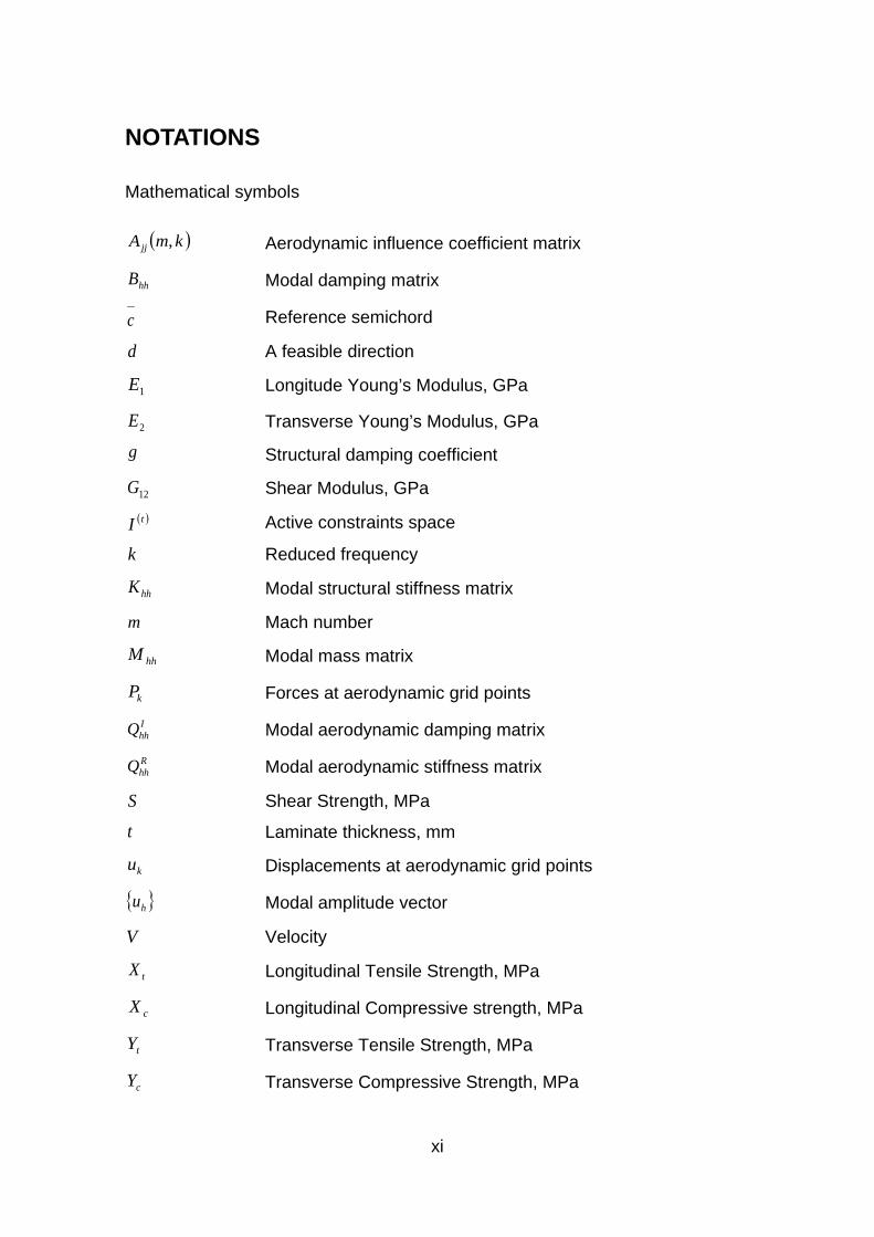
NOTATIONS
Mathematical symbols
( )kmAjj , Aerodynamic influence coefficient matrix
hhB Modal damp.ing matrix
c Reference semichord
d A feasible direction
1E Longitude Young’s Modulus, GPa
2E Transverse Young’s Modulus, GPa
g Structural damping coefficient
12G Shear Modulus, GPa ( )tI Active constraints space
k Reduced frequency
hhK Modal structural stiffness matrix
m Mach number
hhM Modal mass matrix
kP Forces at aerodynamic grid points IhhQ Modal aerodynamic damping mat.rix RhhQ Modal aerodynamic stiffness mat.rix
S Shear Strength, MPa
t Laminate thickness, mm
ku Displacements at aerodynamic grid points
{ }hu Modal amplitude vector
V Velocity
tX Longitudinal Tensile Strength, MPa
cX Longitudinal Compressive strength, MPa
tY Transverse Tensile Strength, MPa
cY Transverse Compressive Strength, MPa
xii
α* Scalar move parameter γ Transient decay rate coefficient
θ Ply orientation
jλ Lagrange multiplier
12ν Possion’s Ratio
ρ Density, kg/m3
1σ 1-direction stress
2σ 2-direction stress
xσ Laminate x-direction stress
yσ Laminate y-direction stress
bσ Allowable direct stress
Sσ Allowable shear stress
12τ Ply shear stress
xyτ Laminate shear stress
ω Circular frequency
Abbreviations
CAD Computer Aided Design
CAE Computer Aided Engineering
CFRP Carbon Fibre Reinforced Plastic
DLL Design Limit Load
DLM Doublet-Lattice Method
DOF Degrees of Freedom
DUL Design Ultimate Load
EAS Equivalent Air Speed
FE Finite Element
FI Failure Index
GA Genetic Algorithm
GD Gradient-based Deterministic Method

xiii
GDP Group Design Project
MTOW Maximum Take-off Weight
TAS True Air Speed

1
1 Introduction
1.1 Background
This research project started from a novel conceptual design of a 250-seat
commercial airliner FW-11 in a student Group Design Project (GDP). As part of
a training cooperation programme between AVIC (Aviation Industry Corporation
of China) and Cranfield University, this aircraft design is divided into three
stages: Conceptual Design (2011), Preliminary Design (2012), and Detailed
Design (2013), and will be completed by three different cohorts of students from
AVIC each year.
The target of the GDP is to design a long range flying wing passenger aircraft to
meet the increasing global air traffic demand. The design philosophy of FW-11
is low fuel consumption and low noise emission. In order to achieve this target,
the conventional aircraft configuration seems to be close to its limits. Alternative
configurations were investigated. Flying wing layout seems to offer promising
benefits in terms of efficiency.
“A flying wing is a tailless fixed-wing aircraft which has no definite fuselage, with
most of the crew, payload and equipment being housed inside the main wing
structure.” [1] Theoretically, a clean flying wing is the most aerodynamically
efficient design configuration for a fixed wing aircraft. It also offers high
structural efficiency for a given wing depth, leading to light weight and high fuel
efficiency. Therefore, flying wing morphology will probably become an attractive
choice for the design of future large aircraft.
Carbon Fibre Reinforced Plastic (CFRP) materials have many advantages over
aluminium alloys, especially in specific stiffness and strength, fatigue resistance,
laminate tailoring and some manufacturing flexibilities. Nowadays, the
percentage of composite materials in the structure of modern aircraft has been
keeping increasing significantly. Consequently, CFRP is selected as the
preferred material in the FW-11wing structure design.
2
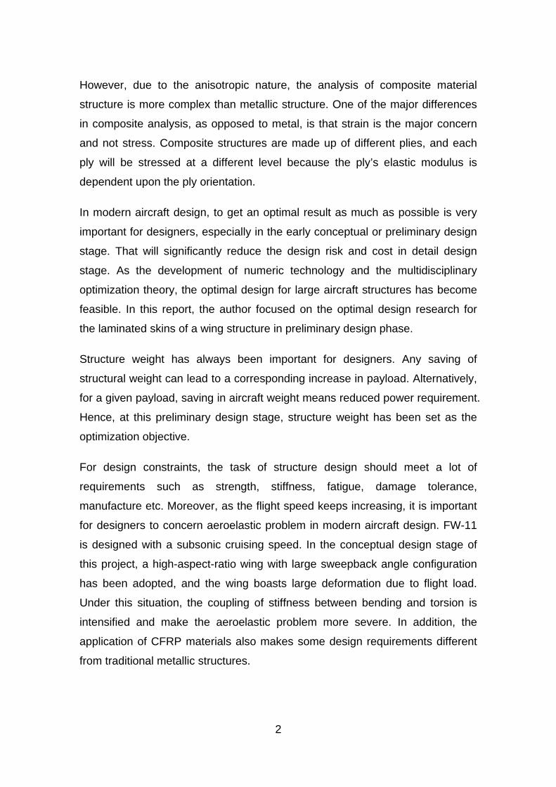
However, due to the anisotropic nature, the analysis of composite material
structure is more complex than metallic structure. One of the major differences
in composite analysis, as opposed to metal, is that strain is the major concern
and not stress. Composite structures are made up of different plies, and each
ply will be stressed at a different level because the ply’s elastic modulus is
dependent upon the ply orientation.
In modern aircraft design, to get an optimal result as much as possible is very
important for designers, especially in the early conceptual or preliminary design
stage. That will significantly reduce the design risk and cost in detail design
stage. As the development of numeric technology and the multidisciplinary
optimization theory, the optimal design for large aircraft structures has become
feasible. In this report, the author focused on the optimal design research for
the laminated skins of a wing structure in preliminary design phase.
Structure weight has always been important for designers. Any saving of
structural weight can lead to a corresponding increase in payload. Alternatively,
for a given payload, saving in aircraft weight means reduced power requirement.
Hence, at this preliminary design stage, structure weight has been set as the
optimization objective.
For design constraints, the task of structure design should meet a lot of
requirements such as strength, stiffness, fatigue, damage tolerance,
manufacture etc. Moreover, as the flight speed keeps increasing, it is important
for designers to concern aeroelastic problem in modern aircraft design. FW-11
is designed with a subsonic cruising speed. In the conceptual design stage of
this project, a high-aspect-ratio wing with large sweepback angle configuration
has been adopted, and the wing boasts large deformation due to flight load.
Under this situation, the coupling of stiffness between bending and torsion is
intensified and make the aeroelastic problem more severe. In addition, the
application of CFRP materials also makes some design requirements different
from traditional metallic structures.
3
In GDP work, the author was mainly in charge of structure layout design and
material selection. Based on some inputs from conceptual design, the author’s
IRP work started practically after GDP work. Attention was then paid to the
optimal design of the composite outer wing structure subject to multi-constraint
including strength, damage tolerance, dynamic aeroelastic stability and other
practical considerations.
In this thesis, an introduction was presented initially, including background, and
research objectives. Secondly, the bibliography work that had been done by the
author before the practical stage of research was shown. Then some related
theories were mentioned to guide the analysis and optimization work. After the
investigation of the methods and theories used by others in related field, the
methodology was chosen for this example by the author. The following chapters
were the practical design and optimization work. At last, discussion was made
based on the results and the future work was included.
1.2 Aim and Objectives
This research project is aimed at optimal design of the wing structure for a 250-
seat flying-wing aircraft. For the initial design, both classic and advanced
numerical approaches are used in this stage to validate the method availability
mutually. In order to get an optimal design, optimization based on the numerical
model for minimum structure weight is a feasible choice. The dimensions and
layup of the composite skin panels will be analysed and optimised subject to
several constraints.
By optimising the composite skin, a minimum structure weight saving of 7%
should be achieved for the whole outer wing structure.
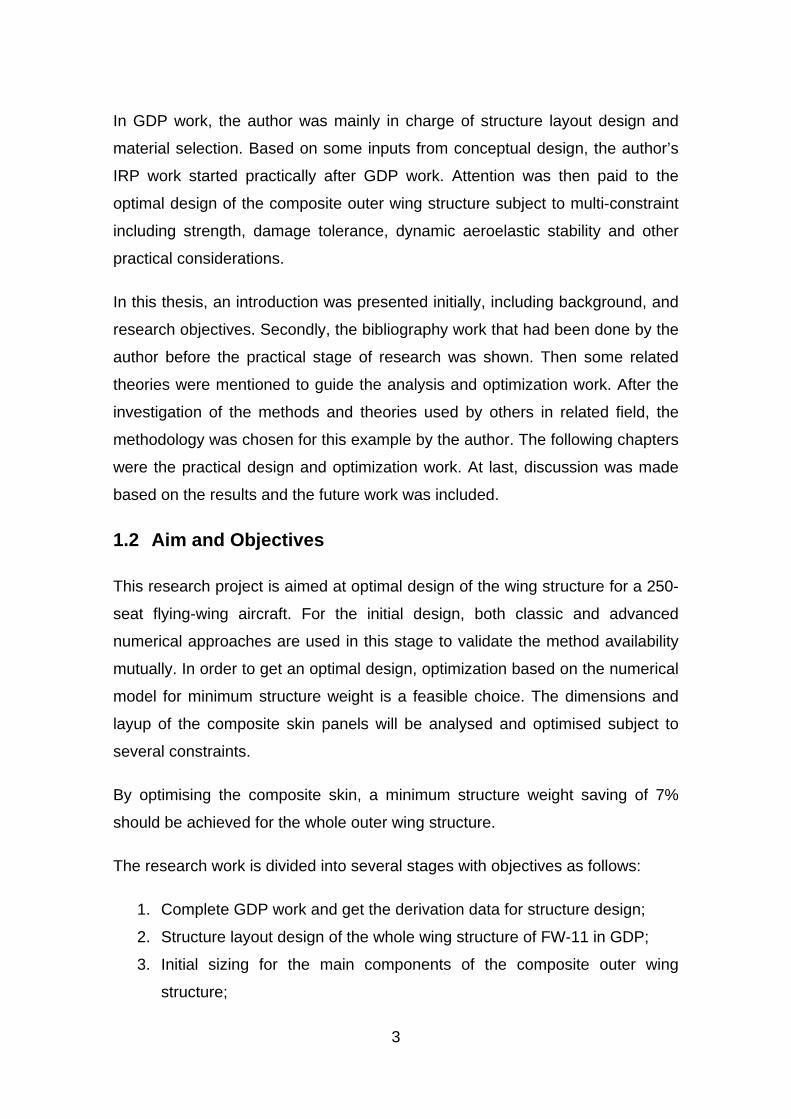
The research work is divided into several stages with objectives as follows:
1. Complete GDP work and get the derivation data for structure design;
2. Structure layout design of the whole wing structure of FW-11 in GDP;
3. Initial sizing for the main components of the composite outer wing
structure;
4
4. Create an analytical and numerical model of the outer wing structure;
5. Carry out static strength and stiffness analysis for initial design;
6. Carry out dynamic flutter analysis;
7. Optimization for composite skin panels subject to multi-constraint;
8. Discussion and thesis writing up.
The modelling, analysis and optimization process has been performed by using
the NASTRAN code. The methodology and technique not only make the
modelling in high accuracy, but also keep the whole process within one
commercial package for practical application.
5
2 Literature Review
2.1 Analysis of Composite Structures
Composite materials have an extremely large group. However, carbon fibre-
reinforced plastic (CFRP) laminates are most widely used in aircraft design,
because laminate theory is getting very sophisticated in both macromechanics
and micromechanics nowadays. Composite structures, compared with
conventional metallic structures, are more complex on structure analysis
because they have more independent constants of properties. Generally, there
are two main methods to analyze composite structures: classical analysis and
finite element analysis.
Classical methods of analyses are based on the application of the equations of
equilibrium and compatibility, together with the stress-strain relations for the
material, to produce governing equations which must be solved to obtain
displacements and stresses. [2]
The major procedures of the classical strength analysis of laminated FRP
structures are shown below:
1) Calculate the equivalent engineering elastic constants for each laminate
of the structure by using laminate theory;
2) Work out the ‘averaged’ stress of the structure subjected to external
loads;
3) Figure out the force and moment from the above ‘averaged’ stress and
go back to the laminate theory for strain;
4) Calculate the ‘local’ stress in fibre and matrix in each ply for strength
evaluation.
However, classical methods are limited to simple geometries and ‘real’
structural features. As we move away from simple situations, the governing
equations become increasingly complicated and require ever-more
6
sophisticated mathematical techniques to solve them. Finite element (FE)
method is an alternative approach to solve the governing equations of a
structural problem. A typical finite element analysis has three main procedures:
preparing FE modelling, performing calculation, and post-process.
Most composite structures are best modelled using plate and shell finite
elements. These have to be modified to allow for laminated materials. In
particular, the strains have to be expressed in terms of mid-plane strains and
curvatures. [2]
However, both classical and FE methods need large amount of calculations
when the composite structure was designed complicatedly. Fortunately, in
practical engineering, engineers usually design laminated structure as simple as
possible due to manufacturing consideration. The ultimate objective of design is
the emergence of an acceptable final product. Less obvious but just as
important, a structure must not be so complex or difficult in concept that its
realization will create great difficulties, or increase the cost of the manufacturing
process. Practically, engineers usually design laminated composite panels in
symmetric and balanced format using four standard angles of 0º, 45º, -45º and
90º. This will also make the analysis of composite structure easier.
2.2 Flutter Analysis for Wing Structure
Flutter is a phenomenon where the interaction between the aerodynamic forces,
structural characteristics, and inertias results in an oscillation. Flutter is
essentially a dynamic aeroelastic stability problem. For a wing lifting surface,
there are mainly two types of flutter: classical bending-torsion flutter and control
surface flutter. However flutter analysis is always a complicated job. Some
investigations had been done by the author before the practical work started.
At the beginning and long term of the aeroelastic mechanics research, the
aircraft structure being idealised as a one-dimensional beam system is a
necessary and basic hypothesis for flutter analysis. And even in modern period,
satisfactory results can also be achieved in many circumstances.
7
Gabriel A. Oyibo [3] carried out the flutter analysis by simplifying a wing as a
cantilevered flat plate-like lifting surface in an incompressible airflow.
This idealization can obviously reduce the quantity of degrees of freedom in
analysis. Meanwhile, an unsteady aerodynamic load and the uncoupled
bending and torsional frequencies are employed in flutter analysis. This
generalized theory of flutter analysis has a good exposure of the interactions
between aerodynamics and elastic structures and makes the flutter analysis
more efficient.
Nowadays, finite element method is commonly applied in aeroelastic analysis.
Aerodynamic and structural analyses can be both based upon FE approach and
two FE models are needed. Lifting surface model calculates unsteady
aerodynamic forces, while structural model provide elastic and inertial
characteristics. These two models are developed independently and then
connected together by numerical interpolation method. At last, discrete method
is used to solve the flutter equation of motion. [4]
There are no method and theoretical differences on flutter analysis between
composite wing and metallic wing. However, the anisotropic nature of
composite material property has significant influence on flutter characteristics.
During the research by Cole, Nagaraja and Rivera [5], a finite-element model of
composite wing was generated to perform flutter analysis for the purpose of
comparing with flutter test result. All components of the wing structure were
modelled with composite laminates. And the wing mass was distributed to the
nodes of the model. As a result, the analysis and test results are very close.
In the research done by Chowdary, Parthan and Sinha [6], quadratic
isoparametric elements were used to establish the finite element model in order
to estimate the flutter characteristics for a laminated panel. Some parameters,
such as ply orientations, stacking sequences and so on are discussed. The
conclusion illustrates that the flutter speed can be significantly increased if the
fibre orientations coincide with the airflow direction. The analysis result also
shows that the coupling effects due to anisotropy of laminates have great effect
8
on the flutter characteristics. The effect will get more pronounced if the panel
has fewer layers.
Qin, Marzocca and Librescu [7] developed a unified aeroelastic model to
perform flutter instability and aeroelastic response analysis at compressible
subsonic flight speed. An asymmetric lay-up composite thin-walled beam was
modelled to simulate the elastic coupling effect for aircraft wings. The
aerodynamic model was based on 2-D strip theory. The result indicated that
elastic tailoring and warping restraint play a considerable role on flutter.
2.3 Optimization of Composite Structure
The directional nature of composite laminae provides the ability to construct a
material which can meet specific loads and/or stiffness requirements without
wasting material by providing strength and stiffness where they are not needed.
[8] Therefore, composite materials offer a great potential and many advantages
in the optimization of aircraft structures.
However, this advantage also makes the optimization of composite structure
more challenging. Compared with traditional metallic materials, anisotropic
composites have much more design variables which all have significant
influence on structure characteristics. For laminated panels that are most widely
used in aircraft structures, ply thickness, fibre orientation angles and stacking
sequences are the most important variables which can be optimised by the
designers.
In order to make the optimization easier, some simplifications should be applied.
Early in the 1970s, Schmit and Farshi [9] had done some optimization work on
homogeneous and orthotropic property laminated composi.tes. The ply
thicknesses were regarded as continuous variables, and the optimization was
considered as a series of linear problems.
Nowadays, the FE method is widely used in the optimization of composite
structures. Almeida [10] and Walker [11] both associated the FE optimization
technique with GA method, and a simple composite plate was used to
9
demonstrated it. In the research done by Honda [12], numerical method
provided accurate optimization solution for the stacking sequence of vibrating
composite plate. Other researches using simple composite plates to perform FE
method of optimization were performed by Kere [13] and Zehnder [14].
In practical engineering, an optimal design should meet all kinds of design
constraints. For composite structure, strength in terms of failure mechanism is
usually the most important one. Different failure criteria, such as maximum
stress, Tsai-Wu and so on, were taken into account by Narayana [15] and
Lopez [16].
All researches mentioned above selected simple composite plates to
demonstrate the optimization technique. However, FE method also makes the
optimization of large composite wing structure possible. Wang, Williams and
Llamas [17] performed a structural optimization for an aircraft wing with
manufacturing considerations. In this paper, a traditional design and
optimization for an aircraft wing without considering composite manufacturability
was performed firstly. The wing was divided into a number of optimization zones
in order to achieve the minimum weight subject to strength constraint. However,
in aircraft industry, the complexity of the wing skin thickness distribution is of
great concern to the manufacturer. Then the author focused on incorporating
manufacturing constraints into optimization with respect to manufacturing
complexity requirements.
Liu, Toropov, Quein and Barton [18] employed a bi-level method to optimize the
stiffened panels of a composite wing subject to manufacturing constraints. At
panel level, the optimization work was focused on the cross section dimensions
of the panel. While at laminate level, the laminate thickness and stacking
sequence of plies was optimised. At last, a considerable structure weight
reduction was obtained and the best stacking sequence was achieved under
deflection and manufacturing constraints for laminated composite wing
structures.
10
Structural optimization usually aims to get minimum structure weight. However,
when tailoring the composite directional property, weight has little change.
Other structure performances should be set as the objective. Aeroelastic
characteristic is usually concerned in such type of optimization. Dr. Guo
contributed a series of investigations on composite wing structure optimization.
Guo, Bannerjee and Cheung [19] carried out an aeroelastic optimization of a
composite wing, and studied the effect of laminate rigidities on flutter speed.
The conclusion demonstrated that the torsion and coupling rigidity had more
significant effects than bending rigidity, and optimizing the fibre orientations was
the best choice to achieve maximum flutter speed without any weight penalty.
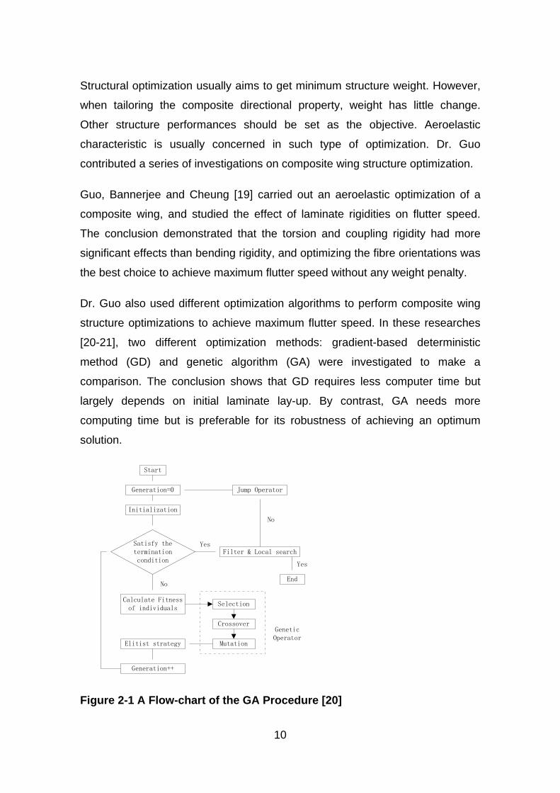
Dr. Guo also used different optimization algorithms to perform composite wing
structure optimizations to achieve maximum flutter speed. In these researches
[20-21], two different optimization methods: gradient-based deterministic
method (GD) and genetic algorithm (GA) were investigated to make a
comparison. The conclusion shows that GD requires less computer time but
largely depends on initial laminate lay-up. By contrast, GA needs more
computing time but is preferable for its robustness of achieving an optimum
solution.
Start
Generation=0
Initialization
Satisfy the termination condition
Jump Operator
Filter & Local search
Calculate Fitness of individuals
Selection
Crossover
MutationElitist strategy
Generation++
End
Genetic Operator
Yes
No
Yes
No
Figure 2-1 A Flow-chart of the GA Procedure [20]
11
Another frequently used method in flutter optimization for composite wing
structure is called dynamic stiffness method (DSM). Lillico, Butler, Guo, and
Banerjee [22] obtained the bending, torsion, and coupling rigidities based on the
composite wing geometry, properties, and laminate layups. Then by solving the
governing equation, the rigidities were optimized.
In order to make full use of the advantages of composite in structural
optimization, a two-stage multi-objective optimization was developed by Dr. Guo
[23-24]. The first stage was focused on the minimum weight optimization
subject to multiple constraints. Laminate thickness was taken as design
variables. Based on this minimum weight composite structure, the second stage
was then focused on increasing flutter or aeroelastic response features.

13
3 Theory and Methodology
3.1 Composite Failure Theory
For the strength analysis of FRP material, there are generally five failure criteria
in macro mechanics:
(1) Maxi.mum stress theory,
(2) Maxi.mum strain theory,
(3) Tsai-Hill theory,
(4) Hoffman theory, and
(5) Tsa.i-Wu theory.
These failure theories are all based on such assumptions: macroscopic
homogeneity, small deformation and linear elasticity, equal modulus in
compression and tension, and plane stress. The first two theories are called
non-interactive theories, while the last three are interactive theories which are
more commonly used. In this report, only the last three failure criteria for stress-
based theory are introduced.
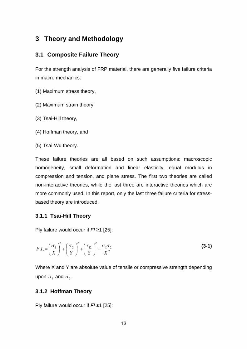
3.1.1 Tsai-Hill Theory
Ply failure would occur if FI ≥1 [25]:
221
212
22
21..
XSYXIF σστσσ
−
+
+
= (3-1)
Where X and Y are absolute value of tensile or compressive strength depending
upon 1σ and 2σ .
3.1.2 Hoffman Theory
Ply failure would occur if FI ≥1 [25]:
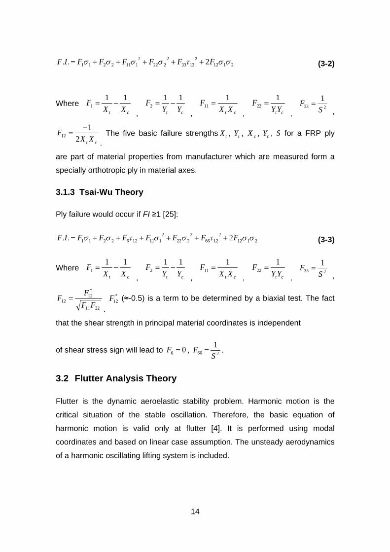
14
21122
12332
2222
1112211 2.. σστσσσσ FFFFFFIF +++++= (3-2)
Where ct XX
F 111 −=
, ct YYF 11
2 −=, ct XX
F 111 =
, ctYYF 1
22 =,
2331
SF =
,
ct XXF
21
12−
=.
The five basic failure strengths tX , tY , cX , cY , S for a FRP ply
are part of material properties from manufacturer which are measured form a
specially orthotropic ply in material axes.
3.1.3 Tsai-Wu Theory
Ply failure would occur if FI ≥1 [25]:
21122
12662
2222
1111262211 2.. σστσστσσ FFFFFFFIF ++++++= (3-3)
Where ct XX
F 111 −=
, ct YYF 11
2 −=, ct XX
F 111 =
, ctYYF 1
22 =,
2331
SF =
,
2211
*12
12 FFFF =
.
*12F (≈-0.5) is a term to be determined by a biaxial test. The fact
that the shear strength in principal material coordinates is independent
of shear stress sign will lead to 06 =F , 2661
SF = .
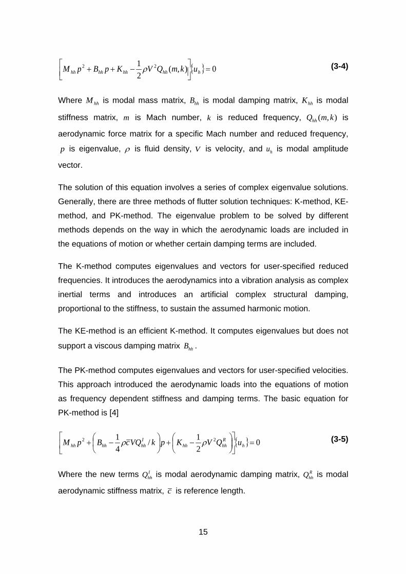
3.2 Flutter Analysis Theory
Flutter is the dynamic aeroelastic stability problem. Harmonic motion is the
critical situation of the stable oscillation. Therefore, the basic equation of
harmonic motion is valid only at flutter [4]. It is performed using modal
coordinates and based on linear case assumption. The unsteady aerodynamics
of a harmonic oscillating lifting system is included.
15
{ } 0),(21 22 =
−++ hhhhhhhhh ukmQVKpBpM ρ (3-4)
Where hhM is modal mass matrix, hhB is modal damping matrix, hhK is modal
stiffness matrix, m is Mach number, k is reduced frequency, ),( kmQhh is
aerodynamic force matrix for a specific Mach number and reduced frequency,
p is eigenvalue, ρ is fluid density, V is velocity, and hu is modal amplitude
vector.
The solution of this equation involves a series of complex eigenvalue solutions.
Generally, there are three methods of flutter solution techniques: K-method, KE-
method, and PK-method. The eigenvalue problem to be solved by different
methods depends on the way in which the aerodynamic loads are included in
the equations of motion or whether certain damping terms are included.
The K-method computes eigenvalues and vectors for user-specified reduced
frequencies. It introduces the aerodynamics into a vibration analysis as complex
inertial terms and introduces an artificial complex structural damping,
proportional to the stiffness, to sustain the assumed harmonic motion.
The KE-method is an efficient K-method. It computes eigenvalues but does not
support a viscous damping matrix hhB .
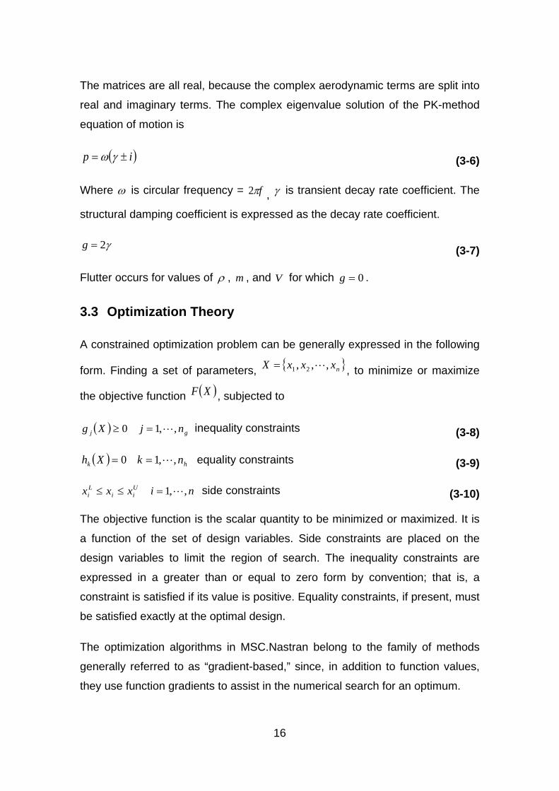
The PK-method computes eigenvalues and vectors for user-specified velocities.
This approach introduced the aerodynamic loads into the equations of motion
as frequency dependent stiffness and damping terms. The basic equation for
PK-method is [4]
{ } 021/
41 22 =
−+
−+ h
Rhhhh
Ihhhhhh uQVKpkVQcBpM ρρ (3-5)
Where the new terms IhhQ is modal aerodynamic damping matrix, R
hhQ is modal
aerodynamic stiffness matrix, c is reference length.
16
The matrices are all real, because the complex aerodynamic terms are split into
real and imaginary terms. The complex eigenvalue solution of the PK-method
equation of motion is
( )ip ±= γω (3-6)
Where ω is circular frequency = fπ2 , γ is transient decay rate coefficient. The
structural damping coefficient is expressed as the decay rate coefficient.
γ2=g (3-7)
Flutter occurs for values of ρ , m , and V for which 0=g .
3.3 Optimization Theory
A constrained optimization problem can be generally expressed in the following
form. Finding a set of parameters, { }nxxxX ,,, 21 = , to minimize or maximize
the objective function ( )XF , subjected to
( ) gj njXg ,,10 =≥ inequality constraints (3-8)
( ) hk nkXh ,,10 == equal.ity constraints (3-9)
nixxx Uii
Li ,,1=≤≤ side constraints (3-10)
The objective function is the scalar quantity to be minimized or maximized. It is
a function of the set of design variables. Side constraints are placed on the
design variables to limit the region of search. The inequality constraints are
expressed in a greater than or equal to zero form by convention; that is, a
constraint is satisfied if its value is positive. Equality constraints, if present, must
be satisfied exactly at the optimal design.
The optimization algorithms in MSC.Nastran belong to the family of methods
generally referred to as “gradient-based,” since, in addition to function values,
they use function gradients to assist in the numerical search for an optimum.
17
qqq SXX *1 α+=+ (3-11)
Where q is iteration number, S is search direction, and α* is scalar move
parameter. The qS*α is the design modification at current step and α* is the step
length that yields the search direction defined by S.
In constrained optimization problems, design points that satisfy Kuhn-Tucker
conditions are likely in the area of optimum results. The governing equation is
the stationary condition of the Lagrange function:
( ) ( ) ( )XgXFXL j
M
jj∑
=
+=1
, λλ (3-12)
0≥jλ (3-13)
Where jλ is Lagrange multiplier.
The optimization algorithms in MSC.Nastran belong to the family of methods
generally referred to as “gradient-based,” since, in addition to function values,
they use function gradients to assist in the numerical search for an optimum.
3.4 Methodology
3.4.1 Design Methods
In this research, the whole structure design process was divided into several
stages including structural layout design, initial sizing, static analysis, and flutter
analysis.
After the literature review work, a certain number of methods were found to
carry out each job in different stages. It is important to find proper methods for
this example.
In the structural layout design phase, M Niu [26] and Denis Howe [27] both
provide some practical techniques. While M Niu supplies more statistical design
18
data which is valuable for making decision of some important design
parameters.
In initial sizing stage, Denis Howe’s method [27] is easy to perform and is
suitable for early design stage. It provides simple experienced equations which
have taken comprehensive design requirements into account. Before calculate
the initial sizes of the structure main parts, the material allowable value should
be estimated. It is a complex job especially for composite material due to its
directional property characteristic. A useful guide and simple method for
evaluating laminate strength is the ‘10-percent rule’ proposed by H Smith [28].
The classical calculations involved in the early design stage are commenced
manually. Although the classical methods are getting more and more
sophisticated in modern aircraft design, they are still approximate sciences and
usually conservative and over-estimated. Therefore, in the following analysis
stages, an advanced numerical method is used to update the initial design
result. Probably the most widely used tool in structural analysis is the use of
finite element (FE) method.
In FE static analysis, Tsai-Wu [29] failure criterion in terms of failure index (FI) is
used for laminate strength evaluation. Besides, laminate strain is also
commonly concerned by designers to estimate the margin of safety considering
impact damage and fracture.
When comes to flutter analysis stage, FE method is also commonly applied
nowadays. Unsteady aerodynamic force can be calculated by the subsonic
Doublet-Lattice theory [30]. The aerodynamic and structural models are
connected by ‘surface spline’ interpolation method. For solving the eigen value
of flutter equation, PK-method is selected because it is more suitable for the
following optimization.
3.4.2 Optimization
Optimization is the most challenging part of this research, because the optimal
solution of an aircraft structure design should be the best compromise taking all
19
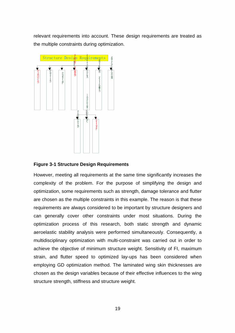
relevant requirements into account. These design requirements are treated as
the multiple constraints during optimization.
Structure Design Requirements
Strength
Stiffness
Fatigue
Damage Tolerance
Aeroelasticity
Divergence
Buckling
&
Stability M
anufacturing
Control Reversal
Flutter
Figure 3-1 Structure Design Requirements
However, meeting all requirements at the same time significantly increases the
complexity of the problem. For the purpose of simplifying the design and
optimization, some requirements such as strength, damage tolerance and flutter
are chosen as the multiple constraints in this example. The reason is that these
requirements are always considered to be important by structure designers and
can generally cover other constraints under most situations. During the
optimization process of this research, both static strength and dynamic
aeroelastic stability analysis were performed simultaneously. Consequently, a
multidisciplinary optimization with multi-constraint was carried out in order to
achieve the objective of minimum structure weight. Sensitivity of FI, maximum
strain, and flutter speed to optimized lay-ups has been considered when
employing GD optimization method. The laminated wing skin thicknesses are
chosen as the design variables because of their effective influences to the wing
structure strength, stiffness and structure weight.
20
3.4.3 Design Tools
In the early days, finite element models were built manually. Because of the
huge amount of data to be handled, manual model-building is tedious, time-
consuming, costly, and error-prone. To overcome these deficiencies, pre-
processors or 3-D mesh graphics programme from CAD#/CAE (Computer-#Aided
Design and Computer-#Aided #Engineering) system were developed to aid in
model building. One of the earliest FEM programs and probably the most well-
known is NASTRAN (NASA STRuctural ANalysis), developed by NASA in the
mid-1960s to handle the analysis of missiles and aircraft structures. A pre-
processor software for NASTRAN is called PATRAN and it makes the analysis
of large complex structure mentioned above feasible.
Nowadays, NASTRAN is becoming a well-developed analysis method and is
also commonly applied in aeroelastic analysis. In NASTRAN flutter analysis
module, aerodynamic and structural models are developed independently and
then connected together by interpolation method.
MSC.NASTRAN is one of the most versatile FE tools and also contains a
powerful multidisciplinary optimization module. For an optimization procedure to
be of maximum benefit, it must be able to simultaneously take into account of all
the conditions that impact the design. For this reason, the design sensitivity and
optimization capability in MSC.Nastran is based on a multidisciplinary analysis
capability that includes statics, normal modes, buckling, direct and modal
frequency, modal transient, static aeroelastic, and flutter analyses.
By contrast, other famous FE software, such as Hyperworks, is also powerful on
optimization. But it cannot involve aeroelastic analysis. Consequently, the
optimization work of this research made full use of NASTRAN code which can
keep the whole analysis and optimization process within one commercial
package for practical application. After the definition of objective, design
variables, responses and optimization constraints in MSC NASTRAN input file,
the optimization module can figure out a theoretical optimum result, which
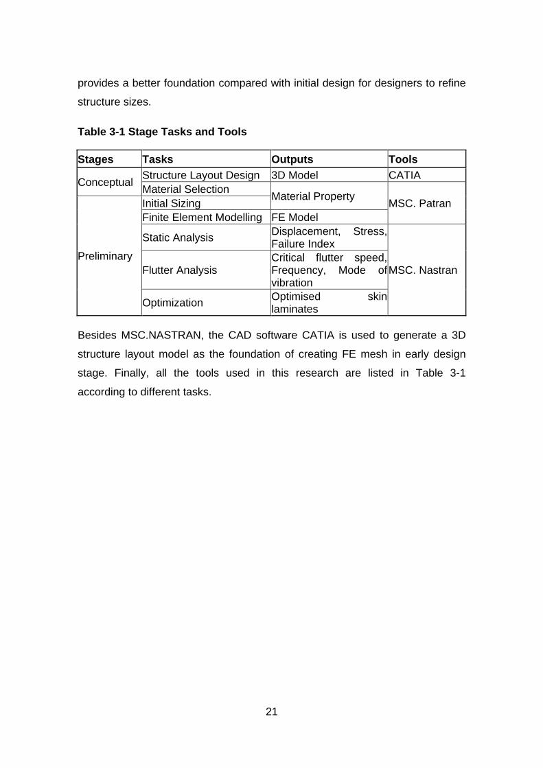
21
provides a better foundation compared with initial design for designers to refine
structure sizes.
Table 3-1 Stage Tasks and Tools
Stages Tasks Outputs Tools
Conceptual Structure Layout Design 3D Model CATIA Material Selection Material Property MSC. Patran
Preliminary
Initial Sizing Finite Element Modelling FE Model
Static Analysis Displacement, Stress, Failure Index
MSC. Nastran Flutter Analysis Critical flutter speed, Frequency, Mode of vibration
Optimization Optimised skin laminates
Besides MSC.NASTRAN, the CAD software CATIA is used to generate a 3D
structure layout model as the foundation of creating FE mesh in early design
stage. Finally, all the tools used in this research are listed in Table 3-1
according to different tasks.

23
4 Derivation of Structural Design Data
4.1 Wing Geometry and Specification
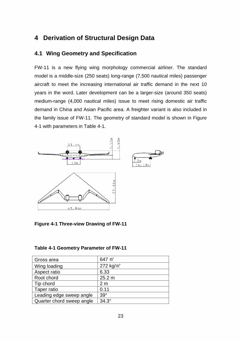
FW-11 is a new flying wing morphology commercial airliner. The standard
model is a middle-size (250 seats) long-range (7,500 nautical miles) passenger
aircraft to meet the increasing international air traffic demand in the next 10
years in the word. Later development can be a larger-size (around 350 seats)
medium-range (4,000 nautical miles) issue to meet rising domestic air traffic
demand in China and Asian Pacific area. A freighter variant is also included in
the family issue of FW-11. The geometry of standard model is shown in Figure
4-1 with parameters in Table 4-1.
Figure 4-1 Three-view Drawing of FW-11
Table 4-1 Geometry Parameter of FW-11
Gross area 647 ㎡ Wing loading 272 kg/㎡ Aspect ratio 6.33 Root chord 25.2 m Tip chord 2 m Taper ratio 0.11 Leading edge sweep angle 39° Quarter chord sweep angle 34.3°
24
Mean aerodynamic chord 12.28 m Dihedral angle 2 ° Central wing airfoil NASA Langley SC Symmetric Outer wing airfoil NASA RC-SC2 Winglet airfoil NACA 0012
The main specifications are listed in Table 4-2.
Table 4-2 Specification of FW-11
Seats 208(3-class), 248 (all economy) Range(nm) 7,500 MTOW(kg) 176,469 OEW(kg) 75,044 Payload(kg) 28,686 Service Ceiling(ft) 35,000 Mach No. 0.82 Fuel capacity(kg) 72,739 Fuel/pax/nm(kg) 0.035
4.2 Load Analysis
Aircraft loads are those forces and loadings applied to the airplane structural
components to establish the strength level of the complete airplane.
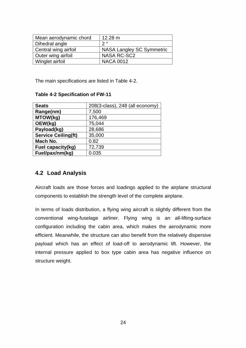
In terms of loads distribution, a flying wing aircraft is slightly different from the
conventional wing-fuselage airliner. Flying wing is an all-lifting-surface
configuration including the cabin area, which makes the aerodynamic more
efficient. Meanwhile, the structure can also benefit from the relatively dispersive
payload which has an effect of load-off to aerodynamic lift. However, the
internal pressure applied to box type cabin area has negative influence on
structure weight.
25
Figure 4-2 Flying Wing Aircraft Loads Condition
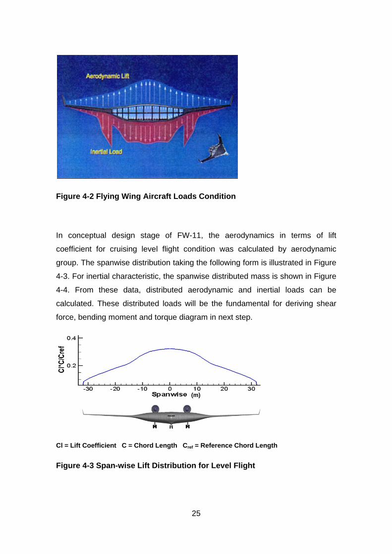
In conceptual design stage of FW-11, the aerodynamics in terms of lift
coefficient for cruising level flight condition was calculated by aerodynamic
group. The spanwise distribution taking the following form is illustrated in Figure
4-3. For inertial characteristic, the spanwise distributed mass is shown in Figure
4-4. From these data, distributed aerodynamic and inertial loads can be
calculated. These distributed loads will be the fundamental for deriving shear
force, bending moment and torque diagram in next step.
Cl = Lift Coefficient C = Chord Length Cref = Reference Chord Length
Figure 4-3 Span-wise Lift Distribution for Level Flight
(m)
26
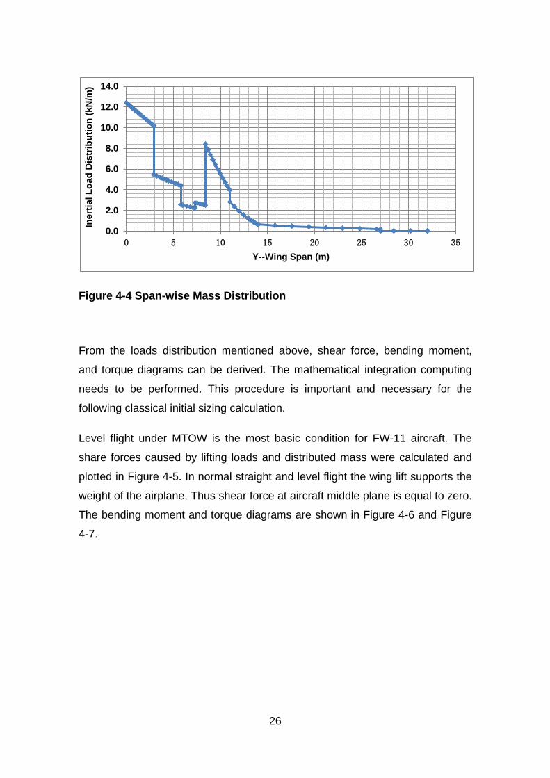
Figure 4-4 Span-wise Mass Distribution
From the loads distribution mentioned above, shear force, bending moment,
and torque diagrams can be derived. The mathematical integration computing
needs to be performed. This procedure is important and necessary for the
following classical initial sizing calculation.
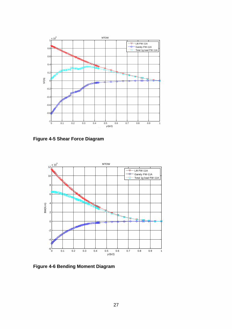
Level flight under MTOW is the most basic condition for FW-11 aircraft. The
share forces caused by lifting loads and distributed mass were calculated and
plotted in Figure 4-5. In normal straight and level flight the wing lift supports the
weight of the airplane. Thus shear force at aircraft middle plane is equal to zero.
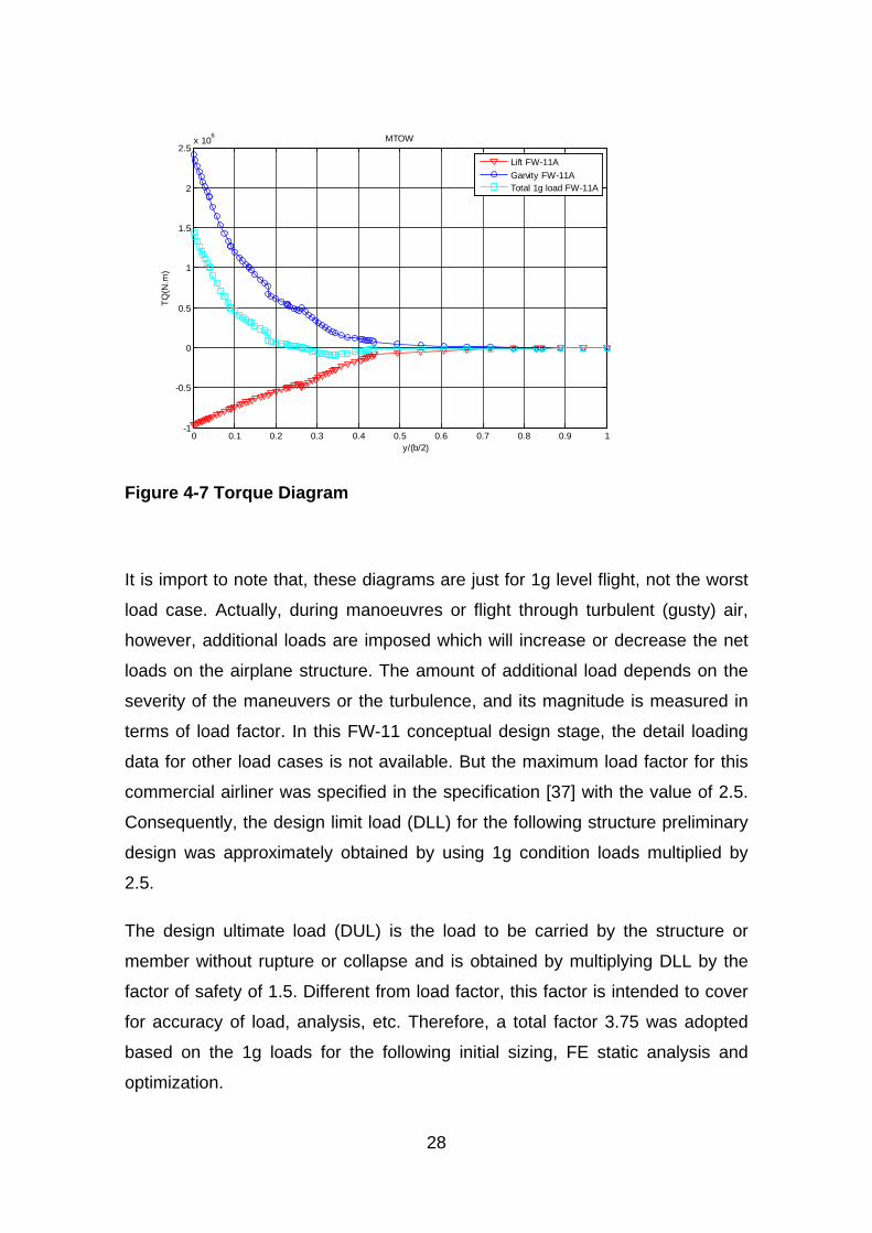
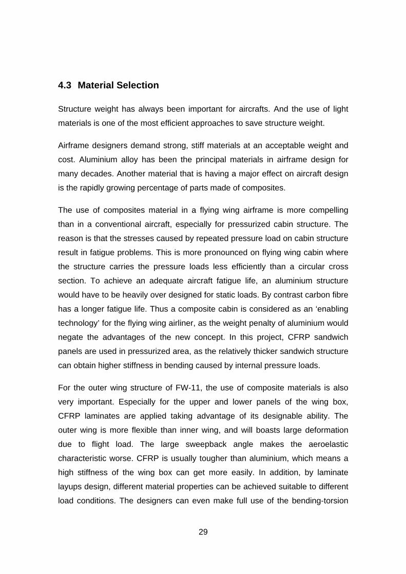
The bending moment and torque diagrams are shown in Figure 4-6 and Figure
4-7.
0.0
2.0
4.0
6.0
8.0
10.0
12.0
14.0
0 5 10 15 20 25 30 35
Iner
tial L
oad
Dis
trib
utio
n (k
N/m
)
Y--Wing Span (m)
27
Figure 4-5 Shear Force Diagram
Figure 4-6 Bending Moment Diagram
0 0.1 0.2 0.3 0.4 0.5 0.6 0.7 0.8 0.9 1-1
-0.8
-0.6
-0.4
-0.2
0
0.2
0.4
0.6
0.8
1x 10
6 MTOW
(a) y/(b/2)
SF(
N)
Lift FW-11AGarvity FW-11ATotal 1g load FW-11A
0 0.1 0.2 0.3 0.4 0.5 0.6 0.7 0.8 0.9 1-6
-4
-2
0
2
4
6
8
10
12x 10
6 MTOW
(a) y/(b/2)
BM
(N.m
)
Lift FW-11AGarvity FW-11ATotal 1g load FW-11A
28
Figure 4-7 Torque Diagram
It is import to note that, these diagrams are just for 1g level flight, not the worst
load case. Actually, during manoeuvres or flight through turbulent (gusty) air,
however, additional loads are imposed which will increase or decrease the net
loads on the airplane structure. The amount of additional load depends on the
severity of the maneuvers or the turbulence, and its magnitude is measured in
terms of load factor. In this FW-11 conceptual design stage, the detail loading
data for other load cases is not available. But the maximum load factor for this
commercial airliner was specified in the specification [37] with the value of 2.5.
Consequently, the design limit load (DLL) for the following structure preliminary
design was approximately obtained by using 1g condition loads multiplied by
2.5.
The design ultimate load (DUL) is the load to be carried by the structure or
member without rupture or collapse and is obtained by multiplying DLL by the
factor of safety of 1.5. Different from load factor, this factor is intended to cover
for accuracy of load, analysis, etc. Therefore, a total factor 3.75 was adopted
based on the 1g loads for the following initial sizing, FE static analysis and
optimization.
0 0.1 0.2 0.3 0.4 0.5 0.6 0.7 0.8 0.9 1-1
-0.5
0
0.5
1
1.5
2
2.5x 10
6 MTOW
(a) y/(b/2)
TQ(N
.m)
Lift FW-11AGarvity FW-11ATotal 1g load FW-11A
29
4.3 Material Selection
Structure weight has always been important for aircrafts. And the use of light
materials is one of the most efficient approaches to save structure weight.
Airframe designers demand strong, stiff materials at an acceptable weight and
cost. Aluminium alloy has been the principal materials in airframe design for
many decades. Another material that is having a major effect on aircraft design
is the rapidly growing percentage of parts made of composites.
The use of composites material in a flying wing airframe is more compelling
than in a conventional aircraft, especially for pressurized cabin structure. The
reason is that the stresses caused by repeated pressure load on cabin structure
result in fatigue problems. This is more pronounced on flying wing cabin where
the structure carries the pressure loads less efficiently than a circular cross
section. To achieve an adequate aircraft fatigue life, an aluminium structure
would have to be heavily over designed for static loads. By contrast carbon fibre
has a longer fatigue life. Thus a composite cabin is considered as an ‘enabling
technology’ for the flying wing airliner, as the weight penalty of aluminium would
negate the advantages of the new concept. In this project, CFRP sandwich
panels are used in pressurized area, as the relatively thicker sandwich structure
can obtain higher stiffness in bending caused by internal pressure loads.
For the outer wing structure of FW-11, the use of composite materials is also
very important. Especially for the upper and lower panels of the wing box,
CFRP laminates are applied taking advantage of its designable ability. The
outer wing is more flexible than inner wing, and will boasts large deformation
due to flight load. The large sweepback angle makes the aeroelastic
characteristic worse. CFRP is usually tougher than aluminium, which means a
high stiffness of the wing box can get more easily. In addition, by laminate
layups design, different material properties can be achieved suitable to different
load conditions. The designers can even make full use of the bending-torsion
30
coupling effect of the laminate to improve aeroelastic behaviour. All these
advantages above play an important role in aeroelastic tailoring technique in
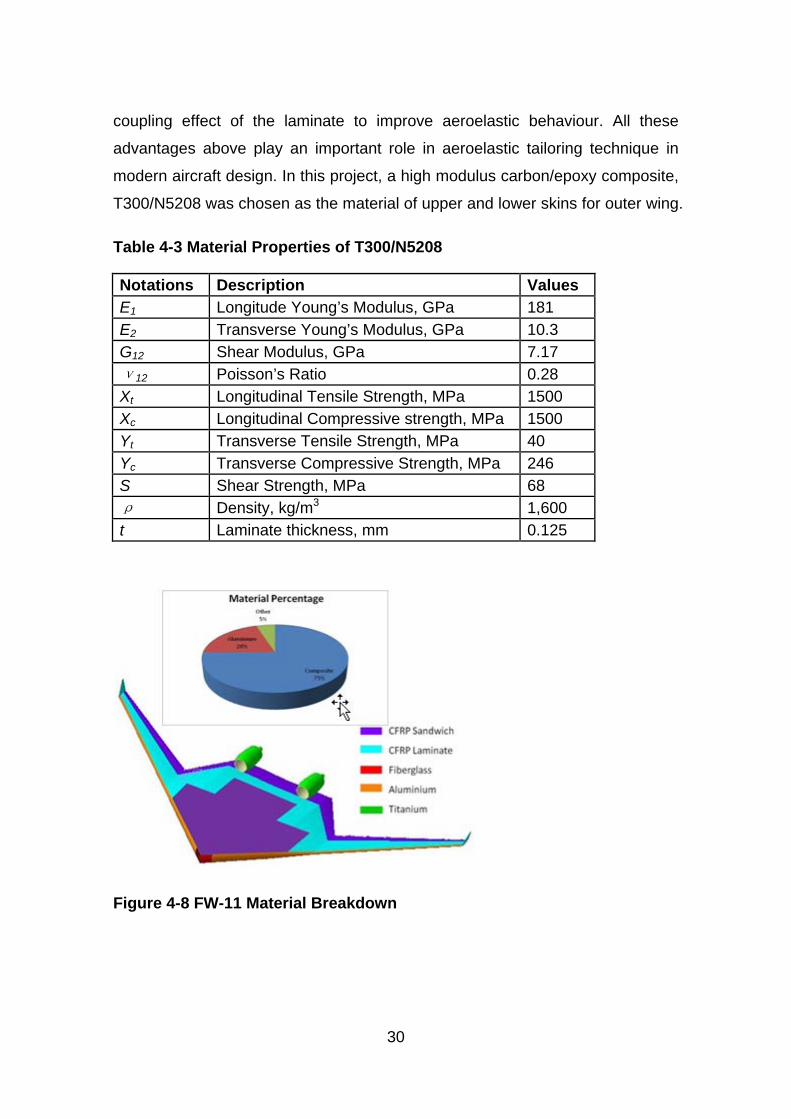
modern aircraft design. In this project, a high modulus carbon/epoxy composite,
T300/N5208 was chosen as the material of upper and lower skins for outer wing.
Table 4-3 Material Properties of T300/N5208
Not.ations Descr.iption Values E1 Longitude Young’s Modulus, GPa 181 E2 Transverse Young’s Modulus, GPa 10.3 G12 Shear Modulus, GPa 7.17 ν12 Poisson’s Ratio 0.28 Xt Longitudinal Tensile Strength, MPa 1500 Xc Longitudinal Compressive strength, MPa 1500 Yt Transverse Tensile Strength, MPa 40 Yc Transverse Compressive Strength, MPa 246 S Shear Strength, MPa 68 ρ Density, kg/m3 1,600 t Laminate thickness, mm 0.125
Figure 4-8 FW-11 Material Breakdown
31
Besides CFRP, a small percentage of other materials are used for specific
components. Another type of composite, fibreglass, is applied on the nose of
the aircraft in order to allow radar waves pass through. Titanium is the major
material for engine pylons. It is important to point out that composite material is
not suitable for leading edge area where has a high possibility of bird strike
because of its vulnerability to impact damage. Hence, aluminium is the first
choice for leading edge skins.
Consequently, composite materials give great promise for lighter airframes with
longer life and better fatigue resistance. Such weight savings will result in
greater payload for a given take-off weight, and hence greater fuel economy.

33
5 Structural Layout Design
5.1 General View
After the basic wing shape has been decided, a preliminary layout of the flying
wing aircraft structure has been designed to carry loads during flight and upon
landing. The whole FW-11 structure is mainly divided into inner wing and outer
wing. As illustrated in Figure 5-1, the inner wing was generally composed of
Cabin, Cargo Compartment, Flight Deck, and Engine Pylon. All the payloads
are held in inner wing. The outer wing is a clean lifting surface with control
surfaces on trailing edge. They are assembled together at the position of Initial
Breakdown Interface which is located just outside of the pressure area.
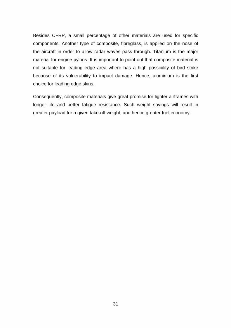
Figure 5-1 Main Structure Layout
5.2 Inner Wing Structure Concept
Like a conventional wing, the primary structure of the inner wing is built up with
spars, stringers, ribs and covers which form a wing box to withstand
34
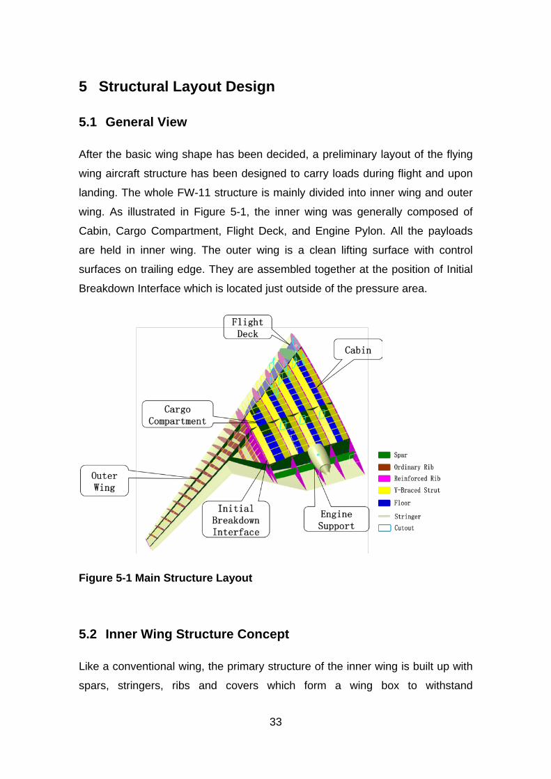
aerodynamic loads. The front, middle and rear spars are located at a suitable
chord-wise station to give an adequate volume for cabin layout design under the
certain wing shape. At last, the front spar is located at 14% wing chord, middle
spar at 50% and rear spar at 80%. The transverse reinforced ribs divide the
inner wing into several bays for cabin or cargo compartments. The reinforced rib
distance is determined by seat arrangement and size of cargo container. A
large value of 2.9m is finally adopted as shown in Figure 5-2.
However, the structure of pressurized cabin area for FW-11 is more complex
than ordinary wing. The cabin structure design is one of the biggest challenges
in this flying wing airliner project. Compared with traditional cylindrical fuselage,
flying wing aircraft has a non-cylindrical box type cabin area which is not
suitable to be a pressurized vessel. The stress level would be extremely high
because the internal pressure mainly causes bending stress rather than
membrane stress.
Figure 5-2 Inner Wing Structure Layout
The special design for this challenge is the use of Y-braced structures
recommended by Mukhopadhyay V [31] applied in a blended-wing-body (BWB)
aircraft. Y-braced structures are chord-wise members attached between ribs
and covers (shown in Figure 5-2). It is important to point out that, the Y-braced
structure in pressurized area had two functions. One is to serve as the pressure
boundary to reduce the bending stress caused by the cabin pressure, i.e. to
make each bay more close to a cylindrical vessel. On the other hand, the Y-
35
braced structures also help the reinforced ribs to support the top and bottom
skin panels, taking the same role as ordinary ribs, due to the large reinforced rib
distance. The integrated CFRP sandwich structure is applied for top and bottom
panels to increase the ability of resisting out-plane bending caused by internal
pressure load.
5.3 Outer Wing Structural Layout
Compared with the inner wing, the outer wing has a much more flexible
structure due to its high-aspect-ratio platform feature and small wing depth.
Besides, the large sweepback aggravated the bending and torsion coupling
effect. Therefore, more attention should be paid on bending and torsion
stiffness when design the outer wing structure. In this thesis, the outer wing
main box was chosen as the example for preliminary design, analysis and
optimization. And dynamic aeroelastic stability was calculated to cover the wing
stiffness.
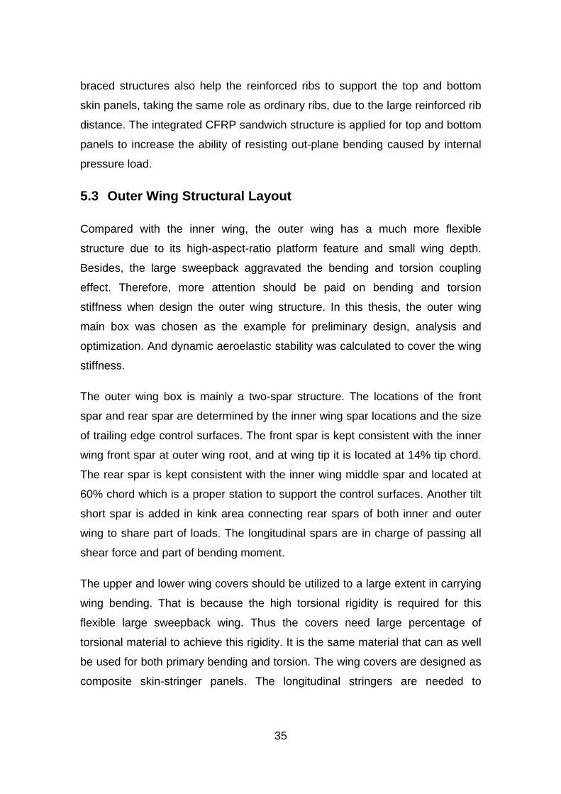
The outer wing box is mainly a two-spar structure. The locations of the front
spar and rear spar are determined by the inner wing spar locations and the size
of trailing edge control surfaces. The front spar is kept consistent with the inner
wing front spar at outer wing root, and at wing tip it is located at 14% tip chord.
The rear spar is kept consistent with the inner wing middle spar and located at
60% chord which is a proper station to support the control surfaces. Another tilt
short spar is added in kink area connecting rear spars of both inner and outer
wing to share part of loads. The longitudinal spars are in charge of passing all
shear force and part of bending moment.
The upper and lower wing covers should be utilized to a large extent in carrying
wing bending. That is because the high torsional rigidity is required for this
flexible large sweepback wing. Thus the covers need large percentage of
torsional material to achieve this rigidity. It is the same material that can as well
be used for both primary bending and torsion. The wing covers are designed as
composite skin-stringer panels. The longitudinal stringers are needed to
36
increase the buckling stability. And a typical pitch of 200mm is adopted
according to other large aircraft statistics in Niu’s handbook [26].
After wing spars are located, the wing ribs can be arranged. In consideration of
the direction, the ribs are finally arranged normal to the rear spar. Such layout
has advantages in supporting control surfaces, manufacture, and weight saving.
The rib spacing is determined from panel-size considerations. Generally, it is a
variable value with the depth of the wing box and has the maximum spacing at
the inboard end. The rib spacing of this outer wing for large airliner is 800mm
recommended by Niu M [26] as well.
Finally, the main elements of the outer wing structure have now been located as
illustrated in Figure 5-3.
Figure 5-3 Outer Wing Structure Layout
Front Spar
Rear Spar
Root Rib
Tip Rib
37
6 Classical Initial Sizing
After the outer wing structural layout was arranged, the structural member size
is mainly dependent upon the load level and material property. Structure loads
can be derived directly from shear force, bending moment and torque diagram
(Figure 4-5, Figure 4-6 and Figure 4-7). Although material property of composite
laminate can be obtained by numerical program, in this chapter, classical
method using hand estimation was adopted firstly.
6.1 Composite Material Property Estimation
Apart from potentially high material properties an advantage of fibre-reinforced
composite is the ability to tailor the properties to meet a given set of
requirements. However, this directional nature also makes the estimation of
composite material property more complex than isotropic metallic material.
For this preliminary design stage, the most important material properties
needed to perform structure member initial sizing work include stiffness and
allowable strength for a certain laminate construction. Stiffness mainly consists
of elastic modulus (E) and shear modulus (G). The single-layer material has
been selected previously and the basic properties are listed in Table 4-3.
However, for a certain laminate construction, the plies in each direction of the
laminate make some contribution to the load carrying capacity in any given
direction. And therefore the overall stiffness and strength is a complex function
of the number and direction of the plies as well as the matrix properties.
Denis Howe’s classical method is to limit the choice of fibre orientations to four
specific directions, namely a datum at 0º, defined by the primary loading,
together with 90º and ±45º to simplify the laminate property estimation. Then a
simple method, called ’10 per cent rule’ proposed by Hart-Smith [28], is used to
make approximate stiffness calculation for the directional interactions. This rule
is based on the assumption that relat.ive to the reference 0º direction each 90º,
+45º and -45º ply contributes 10 per cent of its directional strength or stiffness.
38
In order to simplify the hand calculation work for design and analysis, a quasi-
isotropic lay-up laminate construction has been used for the initial design stage
of this example, which means a laminate has an equal number of fibres in each
of the four directions. According ’10 per cent rule’, 75% layers in all of 90°, +45°
and -45° directions contribute 7.5% of its directional stiffness. Thus the
equivalent tensile stiffness can be estimated as 32.5%Ex0, where Ex0 is the
directional modulus of elasticity. Shear stiffness is calculated by taking 50 per
cent of the directional stiffness of a complementary lay-up defined as one
having the sum of the 0° and 90° disposed equally in the ±45° directions.
Application of the method to shear stiffness yields a value of 0.122 Ex0 for the
quasi-isotropic lay-up. [27]
GPaGPaEE x 8.58181*325.0*%5.32 0 === (6-1)
GPaGPaEG x 1.22181*122.0*%2.12 0 === (6-2)
For allowable strength estimation, Howe recommended that ultimate direct
allowable tensile stress can be calculated by using the elastic moduli with
suggested allowable strain 0.004 [27].
MPaGPaEb 235004.0*8.58* === εσ (6-3)
However, allowable compression may depend upon the buckling characteristics
of the component. Tetlow [32] proposes the following for overall buckling:
( ){ } ( ){ } 2/14/1
02
0 /725.0 wLPZEF xBb =σ (6-4)
Where BF is buckling efficiency factor dependent on panel construction
0xE is directional modulus of elasticity
0Z value is a function of the lay-up, determined in Tetlow’s chart
P is the effect.ive end load which coincides with the maxi.mum direct
stress
39
w is the width of the component perpendicular to the bending axis
L is the spaci.ng along the axis of the beam of the local supports
For allowable shear stress, following value is suggested for initial calculations
for a quasi-isotropic lay-up.
MPaS 200=σ (6-5)
6.2 Structure Member Initial Sizing
Classical initial sizing technique for a wing structure is based on direct use of
the shear force, bending moment, and torque diagrams.
First of all, these basic loads should be converted to local forces applied to
specific structure members according to the wing box dimensions at several
typical sections. The cross-section dimensions at wing root, tip, and kink
position are shown in Figure 6-1.
Figure 6-1 Dimensions of Wing Structural Box
40
6.2.1 Spar Webs
The front and rear spar web reactions due to the ultimate vertical shear loads
are calculated as below:
( )22
21
211 / hhVhF += (6-6)
( )22
21
222 / hhVhF += (6-7)
Where V is the applied ultimate vertical shear load; h1 and h2 are the depths of
the fr.ont and rear spars respectively.
As a result, the shear flow in the spar webs can be calculated by:
111 / hFq = (6-8)
212 / hFq = (6-9)
However, the evaluation of thickness of spar web should also add the effect of
torsion loads. The corresponding shear flow in the covers and webs is
approximately:
ATQT 2/= (6-10)
Where T is the magnitude of the ultimate applied torsion loads; A is the
enclosed area.
The net shear flow in the webs is then given by:
TQqQ += 11 (6-11)
TQqQ += 22 (6-12)
Finally, the thickness of spar webs are obtained from
SQt σ/= (6-13)
41
6.2.2 Composite Skin
The effect.ive direct loads P in the top and bot.tom surfaces required to react the
appropriate ultimate bending moment M at each section is:
hMP /= (6-14)
Where h is the mean depth of the primary structural box.
Then the cross-section area required to meet this direct loads is figured out:
( )bbb hMPA σσ // == (6-15)
An equivalent thickness including skin, stringers and spar caps can be derived
from this cross-section area:
( )bbe hwMwAt σ// == (6-16)
Where w is the width of the box.
Typically the effective thickness due to the stringers is between 50 and 100 per
cent of that of the skin, depending upon the form of construction and the load
intensity. In this example, a lower value was chosen, and the actual skin
thickness needed in the bending case is approximately:
( )bb hwMt σ/65.0= (6-17)
As mentioned above, quasi-isotropic laminate construction was selected to
simplify the calculation. And all the laminated structures were designed
symmetrical and balanced due to manufacturing consideration.
Considering a typical wing box which is tapered from wing root to wing tip, it is
optimum to have the thickness of material reduced gradually coinciding with the
load condition. In initial structure design, the outer wing was divided into nine
zones (zone 0~8, shown in Figure 6-2) which were defined with the positions of
the ribs as the boundary. At different design zone position, the wing box cross-
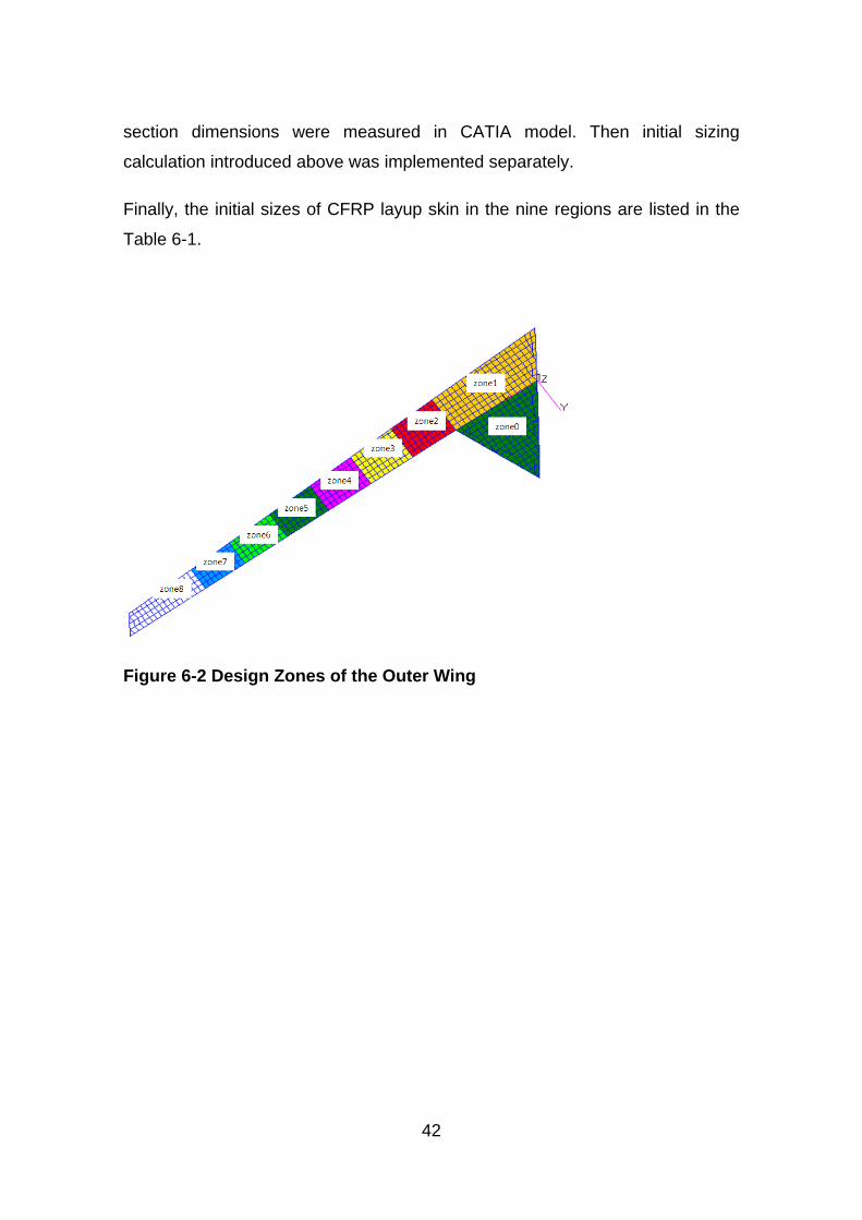
42
section dimensions were measured in CATIA model. Then initial sizing
calculation introduced above was implemented separately.
Finally, the initial sizes of CFRP layup skin in the nine regions are listed in the
Table 6-1.
Figure 6-2 Design Zones of the Outer Wing
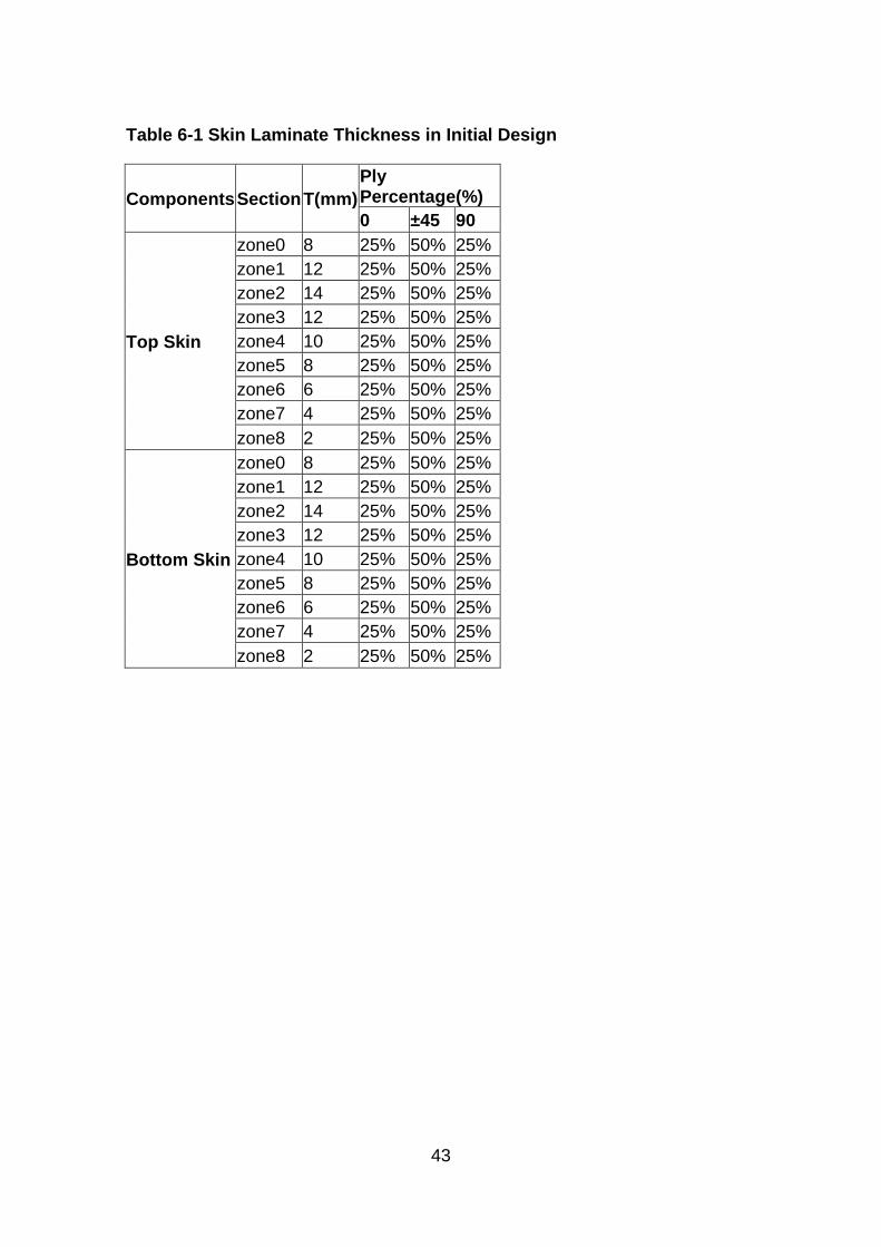
43
Table 6-1 Skin Laminate Thickness in Initial Design
Components Section T(mm) Ply Percentage(%) 0 ±45 90
Top Skin
zone0 8 25% 50% 25% zone1 12 25% 50% 25% zone2 14 25% 50% 25% zone3 12 25% 50% 25% zone4 10 25% 50% 25% zone5 8 25% 50% 25% zone6 6 25% 50% 25% zone7 4 25% 50% 25% zone8 2 25% 50% 25%
Bottom Skin
zone0 8 25% 50% 25% zone1 12 25% 50% 25% zone2 14 25% 50% 25% zone3 12 25% 50% 25% zone4 10 25% 50% 25% zone5 8 25% 50% 25% zone6 6 25% 50% 25% zone7 4 25% 50% 25% zone8 2 25% 50% 25%

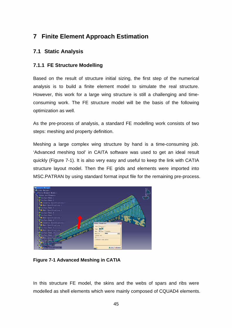
45
7 Finite Element Approach Estimation
7.1 Static Analysis
7.1.1 FE Structure Modelling
Based on the result of structure initial sizing, the first step of the numerical
analysis is to build a finite element model to simulate the real structure.
However, this work for a large wing structure is still a challenging and time-
consuming work. The FE structure model will be the basis of the following
optimization as well.
As the pre-process of analysis, a standard FE modelling work consists of two
steps: meshing and property definition.
Meshing a large complex wing structure by hand is a time-consuming job.
‘Advanced meshing tool’ in CAITA software was used to get an ideal result
quickly (Figure 7-1). It is also very easy and useful to keep the link with CATIA
structure layout model. Then the FE grids and elements were imported into
MSC.PATRAN by using standard format input file for the remaining pre-process.
Figure 7-1 Advanced Meshing in CATIA
In this structure FE model, the skins and the webs of spars and ribs were
modelled as shell elements which were mainly composed of CQUAD4 elements.
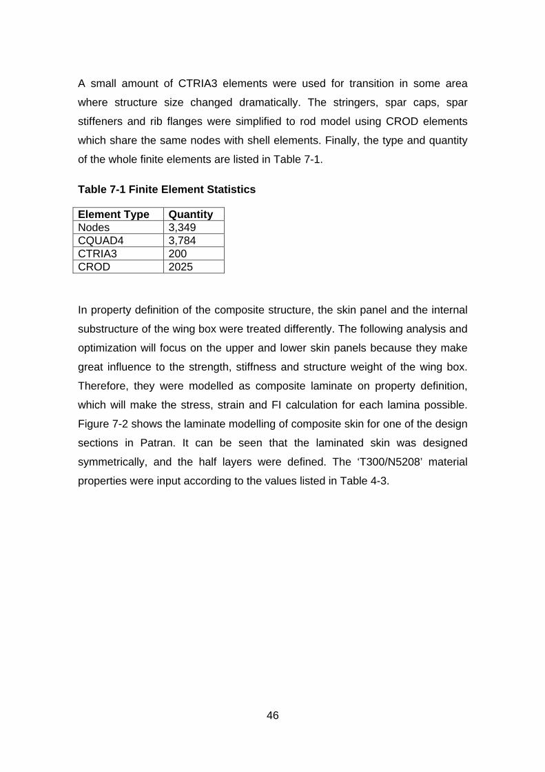
46
A small amount of CTRIA3 elements were used for transition in some area
where structure size changed dramatically. The stringers, spar caps, spar
stiffeners and rib flanges were simplified to rod model using CROD elements
which share the same nodes with shell elements. Finally, the type and quantity
of the whole finite elements are listed in Table 7-1.
Table 7-1 Finite Element Statistics
Element Type Quantity Nodes 3,349 CQUAD4 3,784 CTRIA3 200 CROD 2025
In property definition of the composite structure, the skin panel and the internal
substructure of the wing box were treated differently. The following analysis and
optimization will focus on the upper and lower skin panels because they make
great influence to the strength, stiffness and structure weight of the wing box.
Therefore, they were modelled as composite laminate on property definition,
which will make the stress, strain and FI calculation for each lamina possible.
Figure 7-2 shows the laminate modelling of composite skin for one of the design
sections in Patran. It can be seen that the laminated skin was designed
symmetrically, and the half layers were defined. The ‘T300/N5208’ material
properties were input according to the values listed in Table 4-3.
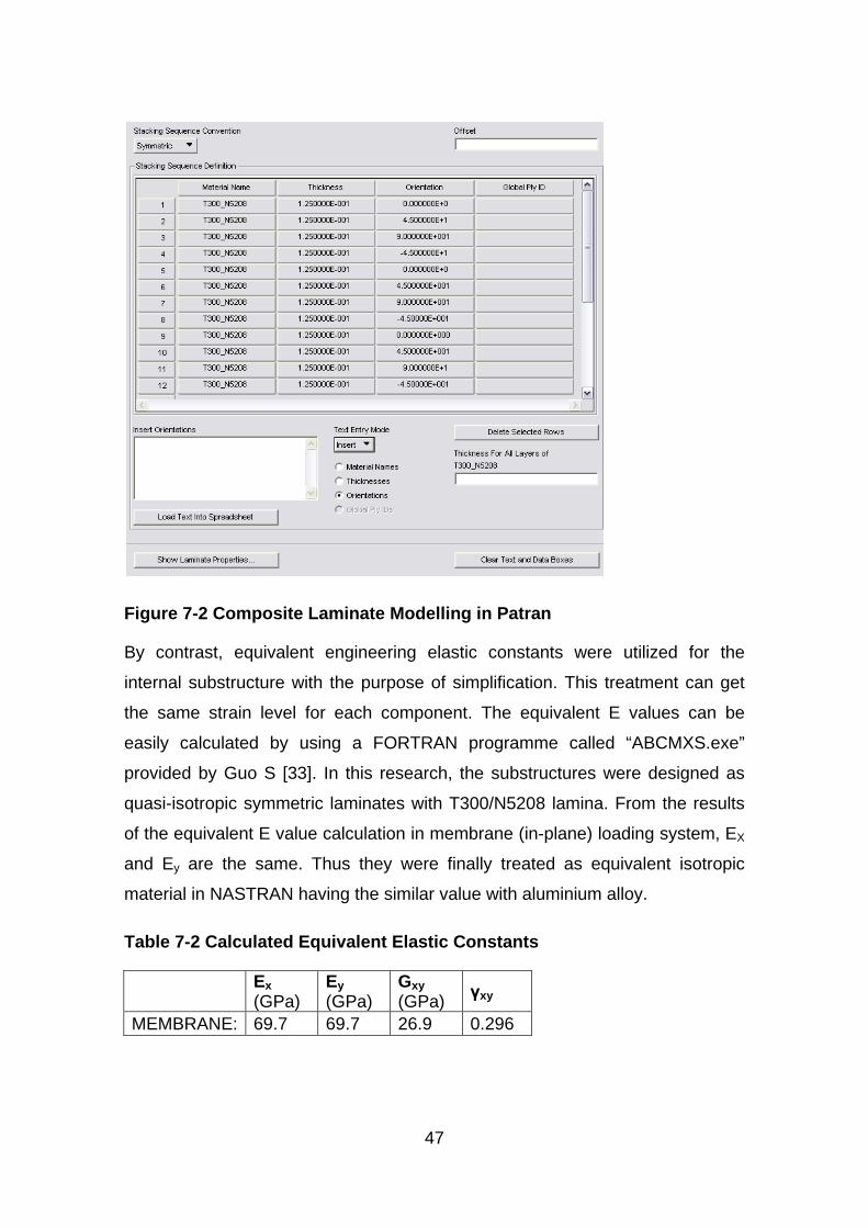
47
Figure 7-2 Composite Laminate Modelling in Patran
By contrast, equivalent engineering elastic constants were utilized for the
internal substructure with the purpose of simplification. This treatment can get
the same strain level for each component. The equivalent E values can be
easily calculated by using a FORTRAN programme called “ABCMXS.exe”
provided by Guo S [33]. In this research, the substructures were designed as
quasi-isotropic symmetric laminates with T300/N5208 lamina. From the results
of the equivalent E value calculation in membrane (in-plane) loading system, EX
and Ey are the same. Thus they were finally treated as equivalent isotropic
material in NASTRAN having the similar value with aluminium alloy.
Table 7-2 Calculated Equivalent Elastic Constants
Ex (GPa)
Ey (GPa)
Gxy (GPa) γxy
MEMBRANE: 69.7 69.7 26.9 0.296
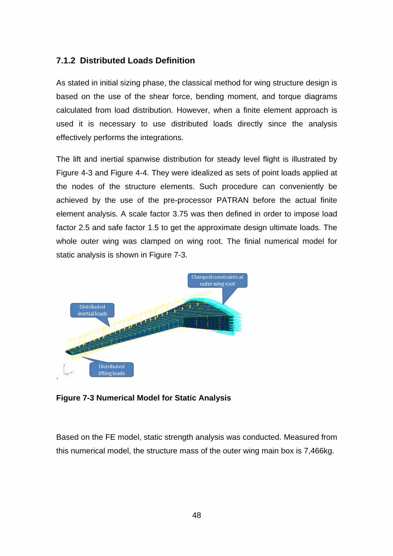
48
7.1.2 Distributed Loads Definition
As stated in initial sizing phase, the classical method for wing structure design is
based on the use of the shear force, bending moment, and torque diagrams
calculated from load distribution. However, when a finite element approach is
used it is necessary to use distributed loads directly since the analysis
effectively performs the integrations.
The lift and inertial spanwise distribution for steady level flight is illustrated by
Figure 4-3 and Figure 4-4. They were idealized as sets of point loads applied at
the nodes of the structure elements. Such procedure can conveniently be
achieved by the use of the pre-processor PATRAN before the actual finite
element analysis. A scale factor 3.75 was then defined in order to impose load
factor 2.5 and safe factor 1.5 to get the approximate design ultimate loads. The
whole outer wing was clamped on wing root. The finial numerical model for
static analysis is shown in Figure 7-3.
.
Figure 7-3 Numerical Model for Static Analysis
Based on the FE model, static strength analysis was conducted. Measured from
this numerical model, the structure mass of the outer wing main box is 7,466kg.
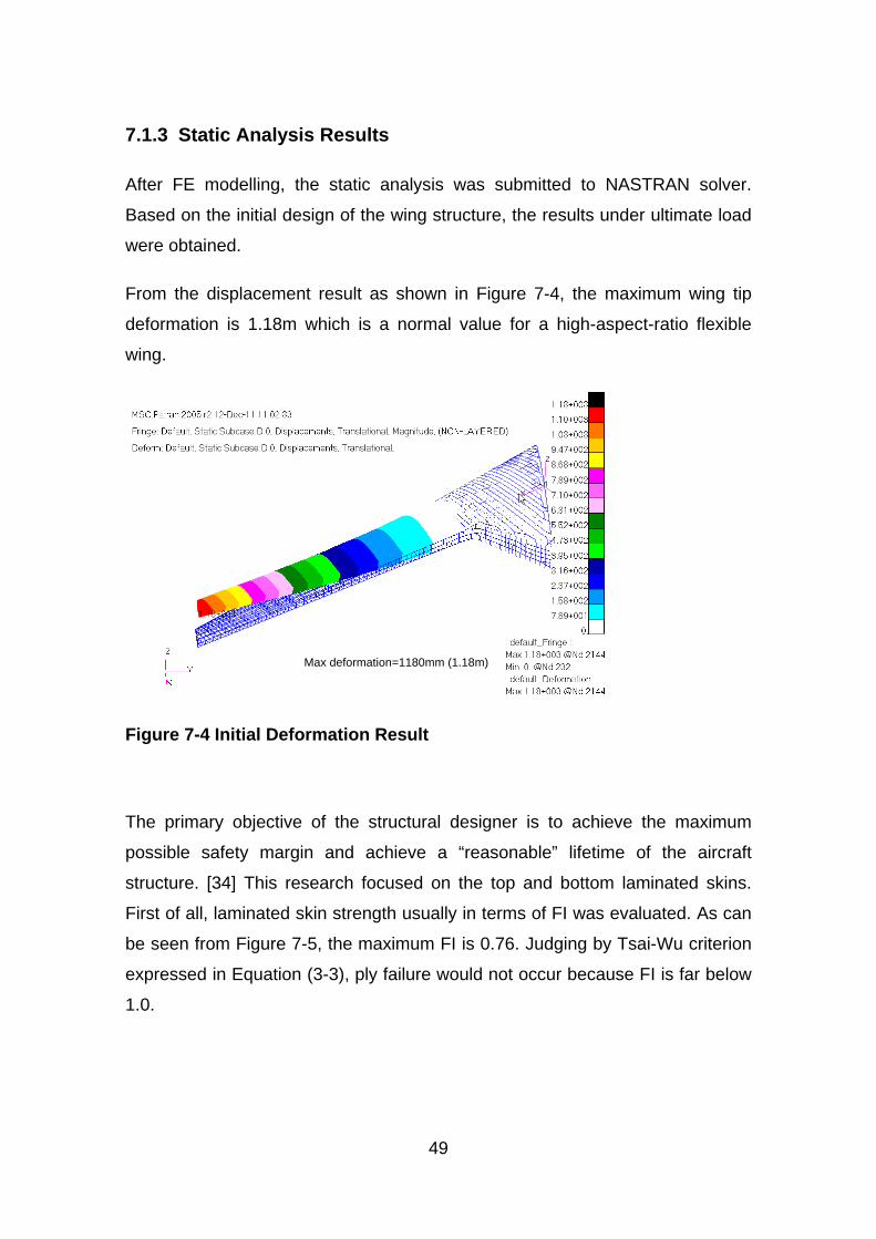
49
7.1.3 Static Analysis Results
After FE modelling, the static analysis was submitted to NASTRAN solver.
Based on the initial design of the wing structure, the results under ultimate load
were obtained.
From the displacement result as shown in Figure 7-4, the maximum wing tip
deformation is 1.18m which is a normal value for a high-aspect-ratio flexible
wing.
Figure 7-4 Initial Deformation Result
The primary objective of the structural designer is to achieve the maximum
possible safety margin and achieve a “reasonable” lifetime of the aircraft
structure. [34] This research focused on the top and bottom laminated skins.
First of all, laminated skin strength usually in terms of FI was evaluated. As can
be seen from Figure 7-5, the maximum FI is 0.76. Judging by Tsai-Wu criterion
expressed in Equation (3-3), ply failure would not occur because FI is far below
1.0.
Max deformation=1180mm (1.18m)
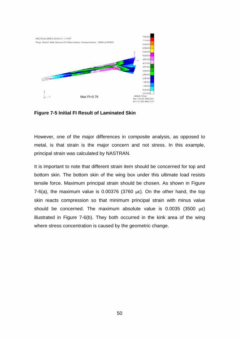
50
Figure 7-5 Initial FI Result of Laminated Skin
However, one of the major differences in composite analysis, as opposed to
metal, is that strain is the major concern and not stress. In this example,
principal strain was calculated by NASTRAN.
It is important to note that different strain item should be concerned for top and
bottom skin. The bottom skin of the wing box under this ultimate load resists
tensile force. Maximum principal strain should be chosen. As shown in Figure
7-6(a), the maximum value is 0.00376 (3760 με). On the other hand, the top
skin reacts compression so that minimum principal strain with minus value
should be concerned. The maximum absolute value is 0.0035 (3500 με)
illustrated in Figure 7-6(b). They both occurred in the kink area of the wing
where stress concentration is caused by the geometric change.
Max FI=0.76
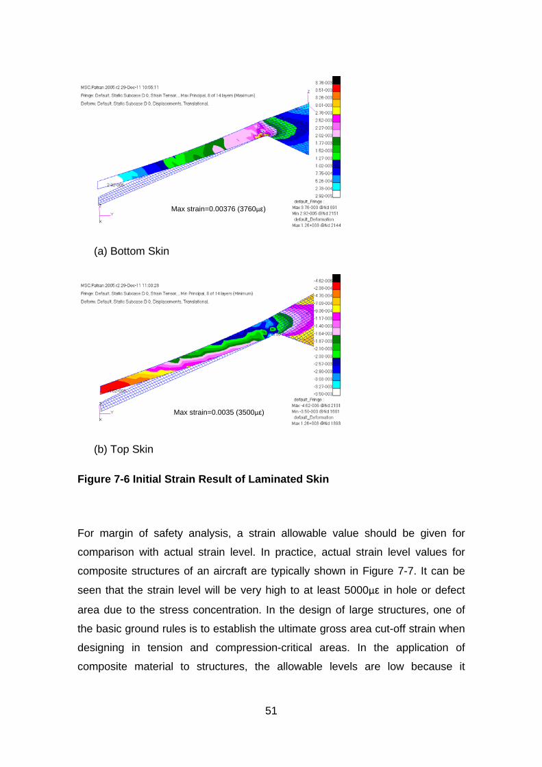
51
(a) Bottom Skin
(b) Top Skin
Figure 7-6 Initial Strain Result of Laminated Skin
For margin of safety analysis, a strain allowable value should be given for
comparison with actual strain level. In practice, actual strain level values for
composite structures of an aircraft are typically shown in Figure 7-7. It can be
seen that the strain level will be very high to at least 5000με in hole or defect
area due to the stress concentration. In the design of large structures, one of
the basic ground rules is to establish the ultimate gross area cut-off strain when
designing in tension and compression-critical areas. In the application of
composite material to structures, the allowable levels are low because it
Max strain=0.00376 (3760με)
Max strain=0.0035 (3500με)
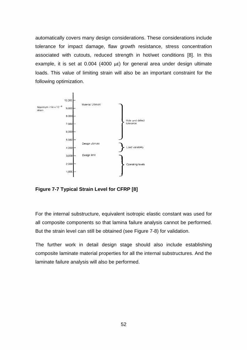
52
automatically covers many design considerations. These considerations include
tolerance for impact damage, flaw growth resistance, stress concentration
associated with cutouts, reduced strength in hot/wet conditions [8]. In this
example, it is set at 0.004 (4000 με) for general area under design ultimate
loads. This value of limiting strain will also be an important constraint for the
following optimization.
Figure 7-7 Typical Strain Level for CFRP [8]
For the internal substructure, equivalent isotropic elastic constant was used for
all composite components so that lamina failure analysis cannot be performed.
But the strain level can still be obtained (see Figure 7-8) for validation.
The further work in detail design stage should also include establishing
composite laminate material properties for all the internal substructures. And the
laminate failure analysis will also be performed.
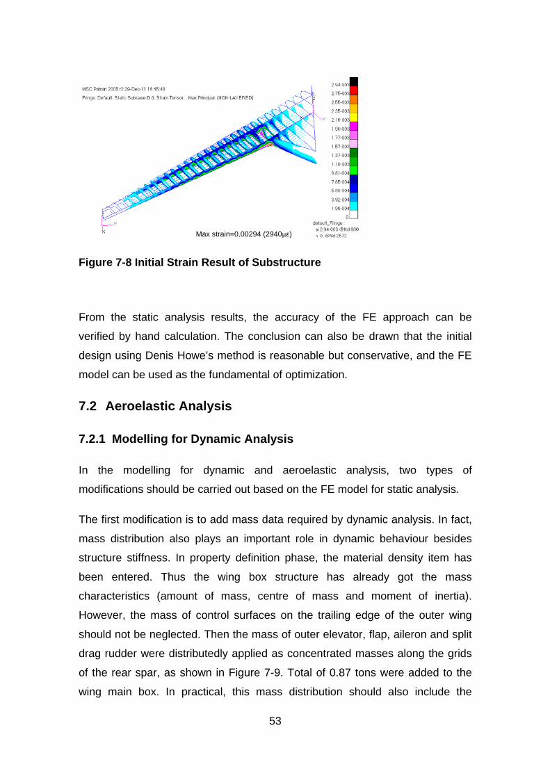
53
Figure 7-8 Initial Strain Result of Substructure
From the static analysis results, the accuracy of the FE approach can be
verified by hand calculation. The conclusion can also be drawn that the initial
design using Denis Howe’s method is reasonable but conservative, and the FE
model can be used as the fundamental of optimization.
7.2 Aeroelastic Analysis
7.2.1 Modelling for Dynamic Analysis
In the modelling for dynamic and aeroelastic analysis, two types of
modifications should be carried out based on the FE model for static analysis.
The first modification is to add mass data required by dynamic analysis. In fact,
mass distribution also plays an important role in dynamic behaviour besides
structure stiffness. In property definition phase, the material density item has
been entered. Thus the wing box structure has already got the mass
characteristics (amount of mass, centre of mass and moment of inertia).
However, the mass of control surfaces on the trailing edge of the outer wing
should not be neglected. Then the mass of outer elevator, flap, aileron and split
drag rudder were distributedly applied as concentrated masses along the grids
of the rear spar, as shown in Figure 7-9. Total of 0.87 tons were added to the
wing main box. In practical, this mass distribution should also include the
Max strain=0.00294 (2940με)
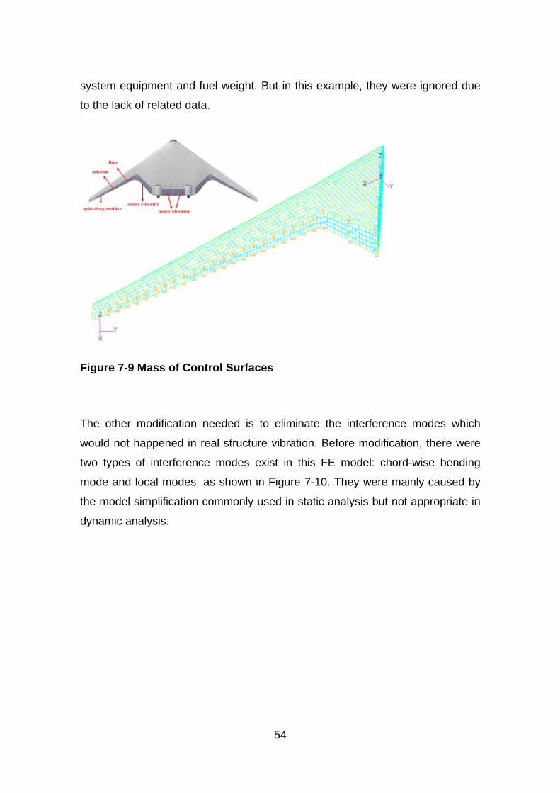
54
system equipment and fuel weight. But in this example, they were ignored due
to the lack of related data.
Figure 7-9 Mass of Control Surfaces
The other modification needed is to eliminate the interference modes which
would not happened in real structure vibration. Before modification, there were
two types of interference modes exist in this FE model: chord-wise bending
mode and local modes, as shown in Figure 7-10. They were mainly caused by
the model simplification commonly used in static analysis but not appropriate in
dynamic analysis.
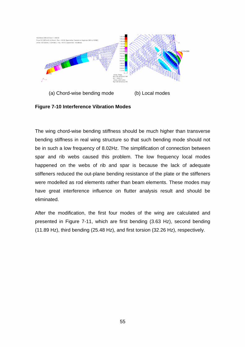
55
(a) Chord-wise bending mode (b) Local modes
Figure 7-10 Interference Vibration Modes
The wing chord-wise bending stiffness should be much higher than transverse
bending stiffness in real wing structure so that such bending mode should not
be in such a low frequency of 8.02Hz. The simplification of connection between
spar and rib webs caused this problem. The low frequency local modes
happened on the webs of rib and spar is because the lack of adequate
stiffeners reduced the out-plane bending resistance of the plate or the stiffeners
were modelled as rod elements rather than beam elements. These modes may
have great interference influence on flutter analysis result and should be
eliminated.
After the modification, the first four modes of the wing are calculated and
presented in Figure 7-11, which are first bending (3.63 Hz), second bending
(11.89 Hz), third bending (25.48 Hz), and first torsion (32.26 Hz), respectively.
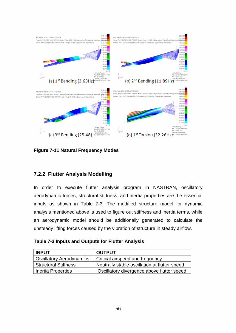
56
Figure 7-11 Natural Frequency Modes
7.2.2 Flutter Analysis Modelling
In order to execute flutter analysis program in NASTRAN, oscillatory
aerodynamic forces, structural stiffness, and inertia properties are the essential
inputs as shown in Table 7-3. The modified structure model for dynamic
analysis mentioned above is used to figure out stiffness and inertia terms, while
an aerodynamic model should be additionally generated to calculate the
unsteady lifting forces caused by the vibration of structure in steady airflow.
Table 7-3 Inputs and Outputs for Flutter Analysis
INPUT OUTPUT Oscillatory Aerodynamics Critical airspeed and frequency Structural Stiffness Neutrally stable oscillation at flutter speed Inertia Properties Oscillatory divergence above flutter speed
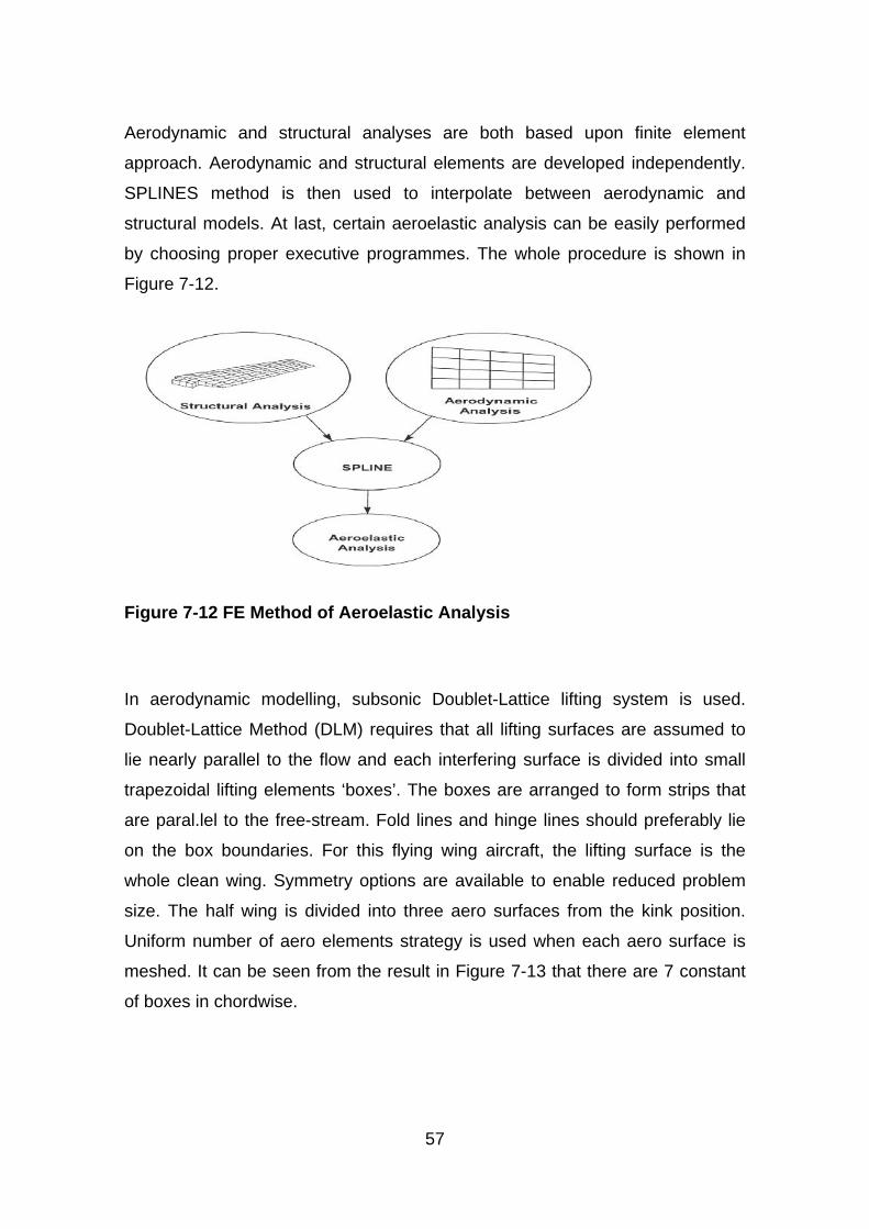
57
Aerodynamic and structural analyses are both based upon finite element
approach. Aerodynamic and structural elements are developed independently.
SPLINES method is then used to interpolate between aerodynamic and
structural models. At last, certain aeroelastic analysis can be easily performed
by choosing proper executive programmes. The whole procedure is shown in
Figure 7-12.
Figure 7-12 FE Method of Aeroelastic Analysis
In aerodynamic modelling, subsonic Doublet-Lattice lifting system is used.
Doublet-Lattice Method (DLM) requires that all lifting surfaces are assumed to
lie nearly parallel to the flow and each interfering surface is divided into small
trapezoidal lifting elements ‘boxes’. The boxes are arranged to form strips that
are paral.lel to the free-stream. Fold lines and hinge lines should preferably lie
on the box boundar.ies. For this flying wing aircraft, the lifting surface is the
whole clean wing. Symmetry options are available to enable reduced problem
size. The half wing is divided into three aero surfaces from the kink position.
Uniform number of aero elements strategy is used when each aero surface is
meshed. It can be seen from the result in Figure 7-13 that there are 7 constant
of boxes in chordwise.
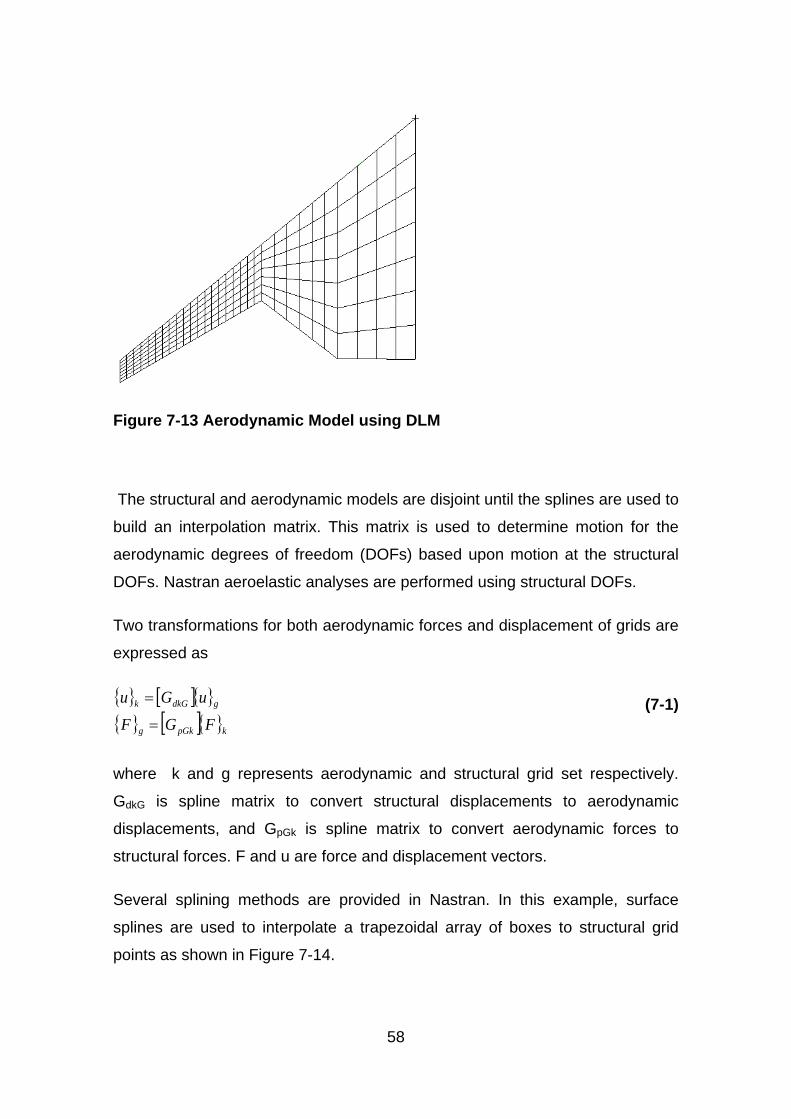
58
Figure 7-13 Aerodynamic Model using DLM
The structural and aerodynamic models are disjoint until the splines are used to
build an interpolation matrix. This matrix is used to determine motion for the
aerodynamic degrees of freedom (DOFs) based upon motion at the structural
DOFs. Nastran aeroelastic analyses are performed using structural DOFs.
Two transformations for both aerodynamic forces and displacement of grids are
expressed as
{ } [ ]{ }{ } [ ]{ }kpGkg
gdkGk
FGFuGu
=
= (7-1)
where k and g represents aerodynamic and structural grid set respectively.
GdkG is spline matrix to convert structural displacements to aerodynamic
displacements, and GpGk is spline matrix to convert aerodynamic forces to
structural forces. F and u are force and displacement vectors.
Several splining methods are provided in Nastran. In this example, surface
splines are used to interpolate a trapezoidal array of boxes to structural grid
points as shown in Figure 7-14.
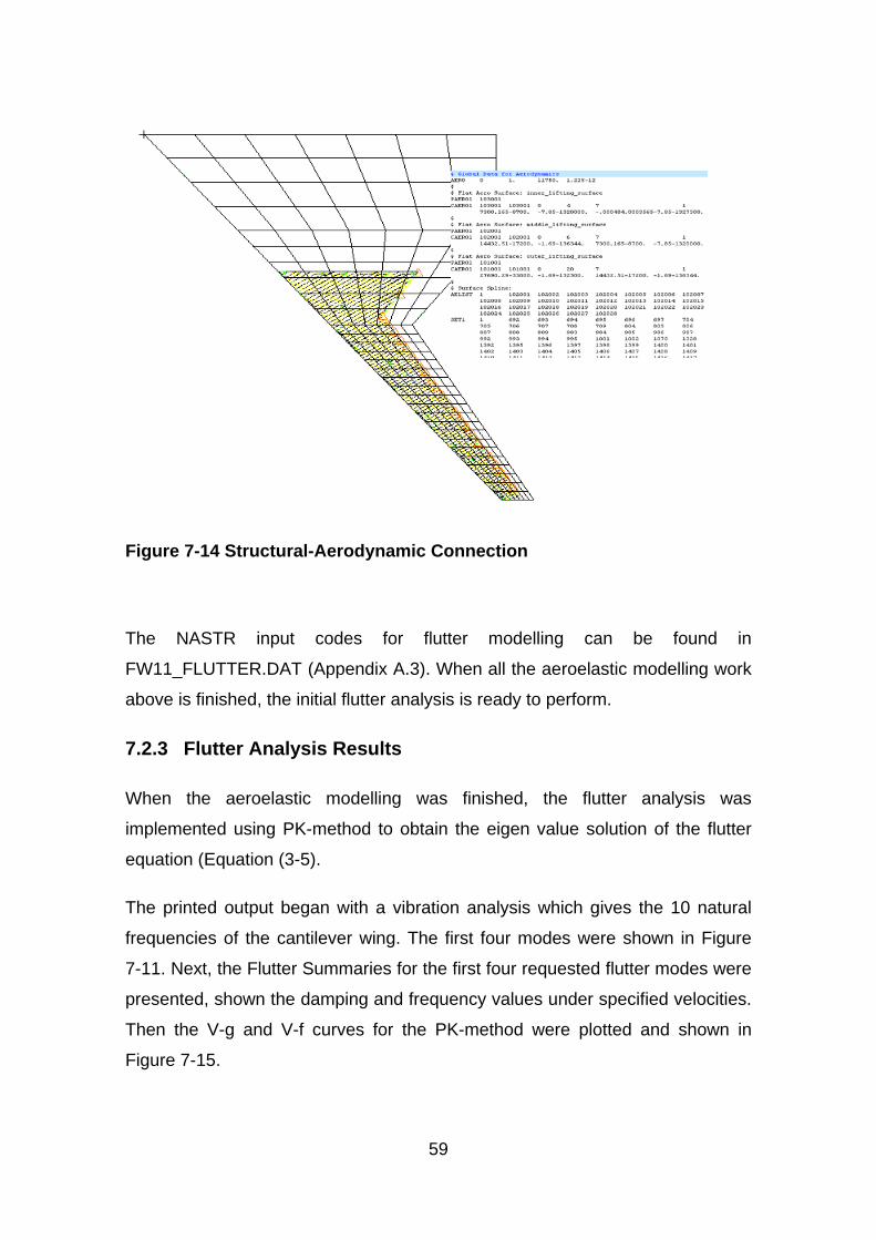
59
Figure 7-14 Structural-Aerodynamic Connection
The NASTR input codes for flutter modelling can be found in
FW11_FLUTTER.DAT (Appendix A.3). When all the aeroelastic modelling work
above is finished, the initial flutter analysis is ready to perform.
7.2.3 Flutter Analysis Results
When the aeroelastic modelling was finished, the flutter analysis was
implemented using PK-method to obtain the eigen value solution of the flutter
equation (Equation (3-5).
The printed output began with a vibration analysis which gives the 10 natural
frequencies of the cantilever wing. The first four modes were shown in Figure
7-11. Next, the Flutter Summaries for the first four requested flutter modes were
presented, shown the damping and frequency values under specified velocities.
Then the V-g and V-f curves for the PK-method were plotted and shown in
Figure 7-15.
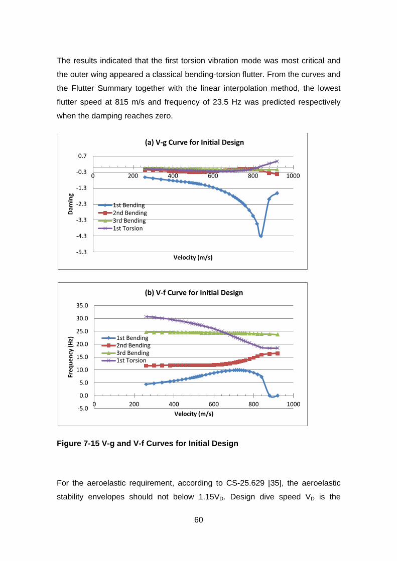
60
The results indicated that the first torsion vibration mode was most critical and
the outer wing appeared a classical bending-torsion flutter. From the curves and
the Flutter Summary together with the linear interpolation method, the lowest
flutter speed at 815 m/s and frequency of 23.5 Hz was predicted respectively
when the damping reaches zero.
Figure 7-15 V-g and V-f Curves for Initial Design
For the aeroelastic requirement, according to CS-25.629 [35], the aeroelastic
stability envelopes should not below 1.15VD. Design dive speed VD is the
-5.3
-4.3
-3.3
-2.3
-1.3
-0.3
0.7
0 200 400 600 800 1000
Dam
ing
Velocity (m/s)
(a) V-g Curve for Initial Design
1st Bending 2nd Bending 3rd Bending 1st Torsion
-5.0
0.0
5.0
10.0
15.0
20.0
25.0
30.0
35.0
0 200 400 600 800 1000
Freq
uenc
y (H
z)
Velocity (m/s)
(b) V-f Curve for Initial Design
1st Bending 2nd Bending 3rd Bending 1st Torsion
61
maximum speed for structural design providing for safe recovery from
inadvertent upsets. VD can be approximately estimated by adding a certain
speed increment to design cruising speed VC. It is recommended by Howe D
[27] in terms of March number as follows.
07.0+= CD MM (7-2)
From the FW-11 Specification [37], design cruising Mach number MC is 0.82.
Converted to true air speed (TAS), the design dive speed (VD) of this aircraft is
302.6 m/s at sea level. Therefore, the critical flutter speed should not less than
348 m/s.
From the flutter analysis of initial design, the actual flutter speed is more than
twice as required. Therefore it can also prove the initial design is a conservative
design in dynamic aeroelastic aspect, and the structure has potential for weight
saving by optimization under flutter constraint.

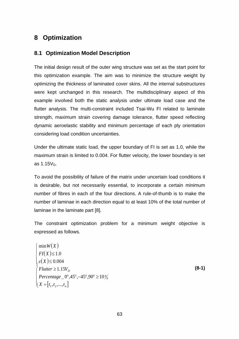
63
8 Optimization
8.1 Optimization Model Description
The initial design result of the outer wing structure was set as the start point for
this optimization example. The aim was to minimize the structure weight by
optimizing the thickness of laminated cover skins. All the internal substructures
were kept unchanged in this research. The multidisciplinary aspect of this
example involved both the static analysis under ultimate load case and the
flutter analysis. The multi-constraint included Tsai-Wu FI related to laminate
strength, maximum strain covering damage tolerance, flutter speed reflecting
dynamic aeroelastic stability and minimum percentage of each ply orientation
considering load condition uncertainties.
Under the ultimate static load, the upper boundary of FI is set as 1.0, while the
maximum strain is limited to 0.004. For flutter velocity, the lower boundary is set
as 1.15VD.
To avoid the possibility of failure of the matrix under uncertain load conditions it
is desirable, but not necessarily essential, to incorporate a certain minimum
number of fibres in each of the four directions. A rule-of-thumb is to make the
number of laminae in each direction equal to at least 10% of the total number of
laminae in the laminate part [8].
The constraint optimization problem for a minimum weight objective is
expressed as follows.
( )( )
( )
[ ]
=≥°°−°°
≥≤≤
n
D
tttXPercentage
VFlutterX
XFIXW
,...,,1090,45,45,0_
15.1004.00.1
min
21
00
ε (8-1)
64
The detail pre-process of the optimization model will be introduced in following
chapters.
8.2 Optimization Pre-process
The optimization pre-process was based on the finite element model of the
outer wing box. For practical application, the whole analysis and optimization
process was kept within one commercial finite element software Nastran. The
optimization solution sequence (SOL200) in Nastran contains full capabilities of
multidisciplinary analysis including statics, normal modes, buckling, direct and
modal frequency, modal transient, static aeroelastic, and flutter analyses. [36] In
this example, statics (SOL 101) and flutter (SOL 145) solution sequences were
involved. In the Case Control Data of the Nastran input file (Appendix A.3),
ANALYSIS = STATICS and FLUTTER commands were designated to perform
corresponding type of analysis for each subcase.
8.2.1 Design Variable Definition
Because of the favourable properties of directional stiffness, composite
materials offer a great potential and many advantages in the optimisation of
aircraft structures. The superior properties can be achieved by optimizing the
thickness of the laminate components, fibre orientations and sequences of the
laminate plies.
In the initial design, the cover skins had layers in the 0°, 90°, +45° and -45°
directions relative to material coordinate system. And they were designed
symmetric and balanced forming an orthotropic nature in order to ease the
design calculation and manufacturing. The laminate properties definition in
Nastran input file are listed in STRUC.DAT (Appendix A.1). In the preliminary
stage, optimization will only focus on laminate thickness due to its great
contribution to the structure weight.
Defining the thickness of laminate components as design variables for
optimization is not an easy job. For real design, one laminate consists of large
number of laminae in various stacking sequence, which means each lamina
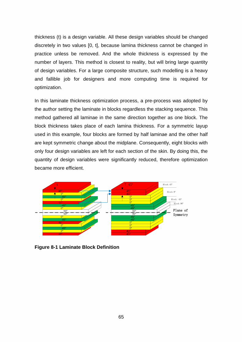
65
thickness (t) is a design variable. All these design variables should be changed
discretely in two values [0, t], because lamina thickness cannot be changed in
practice unless be removed. And the whole thickness is expressed by the
number of layers. This method is closest to reality, but will bring large quantity
of design variables. For a large composite structure, such modelling is a heavy
and fallible job for designers and more computing time is required for
optimization.
In this laminate thickness optimization process, a pre-process was adopted by
the author setting the laminate in blocks regardless the stacking sequence. This
method gathered all laminae in the same direction together as one block. The
block thickness takes place of each lamina thickness. For a symmetric layup
used in this example, four blocks are formed by half laminae and the other half
are kept symmetric change about the midplane. Consequently, eight blocks with
only four design variables are left for each section of the skin. By doing this, the
quantity of design variables were significantly reduced, therefore optimization
became more efficient.
45°45°
0°0°0°-45°-45°90°
45°0°-45°0°
45°-45°0°90°
90°-45°
90°0°-45°
45°0°-45°0°
45°
-45°0°0°0°
45°45°
Plane of Symmetry
t T_45° Block 45°
Block 0°
Block -45°
Block 90°
Figure 8-1 Laminate Block Definition
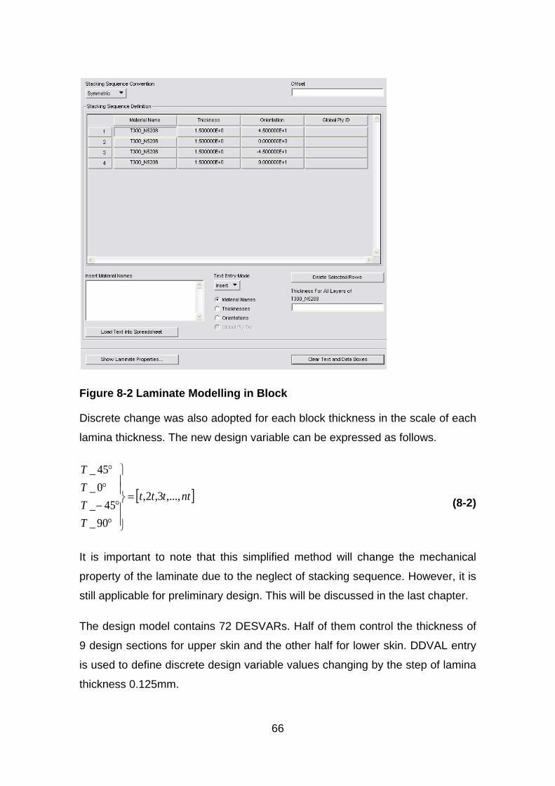
66
Figure 8-2 Laminate Modelling in Block
Discrete change was also adopted for each block thickness in the scale of each
lamina thickness. The new design variable can be expressed as follows.
[ ]ntttt
TTTT
,...,3,2,
90_45_
0_45_
=
°°−
°°
(8-2)
It is important to note that this simplified method will change the mechanical
property of the laminate due to the neglect of stacking sequence. However, it is
still applicable for preliminary design. This will be discussed in the last chapter.
The design model contains 72 DESVARs. Half of them control the thickness of
9 design sections for upper skin and the other half for lower skin. DDVAL entry
is used to define discrete design variable values changing by the step of lamina
thickness 0.125mm.
67
For balanced laminate characteristic, the number of plies with the angle of +45º
and -45º should be the same. The DLINK entries are used in design variable
definition to keep the thickness of ±45º equal for each design sections. Hence,
the number of independent design variables for each section turned into three.
DVPREL1 entries relate the design variables to laminate block thickness.
8.2.2 Response and Constraint Definition
Design responses are used in Nastran as the basis for defining the design
objective and design constraints. There are three types of responses provided
in Nastran. In this example, structure weight, FI, maximum strain and flutter
corresponding damping are all type-1 responses (DRESP1). They can be
derived directly from each cycle analysis of the optimization process. The
response type codes in DRESP1 entry are ‘WEIGHT’, ‘CFAILURE’, ‘CSTRAIN’
and ‘FLUTTER’ respectively. Percentage of each orientation for each laminate
section is user-defined type-2 response (DRESP2). A simple equation is utilized
to calculate it from design variable values. Structure weight response is set as
the objective of optimization, while other responses are used to define design
constraints.
Cautions should be paid into the element strain item code selection when
defining maximum strain responses. In the subcase of statics analysis under
ultimate load, the bottom skin of the wing box mainly resists tensile force.
Maximum principal strain should be chosen as the response for constraint. On
the other hand, the top skin reacts compressive force so that minimum principal
strain with minus value should be concerned. DRESP2 entry was then used to
extract the strain absolute value. In order to avoid possible numerical problem
when the boundary value of strain constraint was too small, a scale factor was
also introduced in the converting equation invoked by DRESP2 entry.
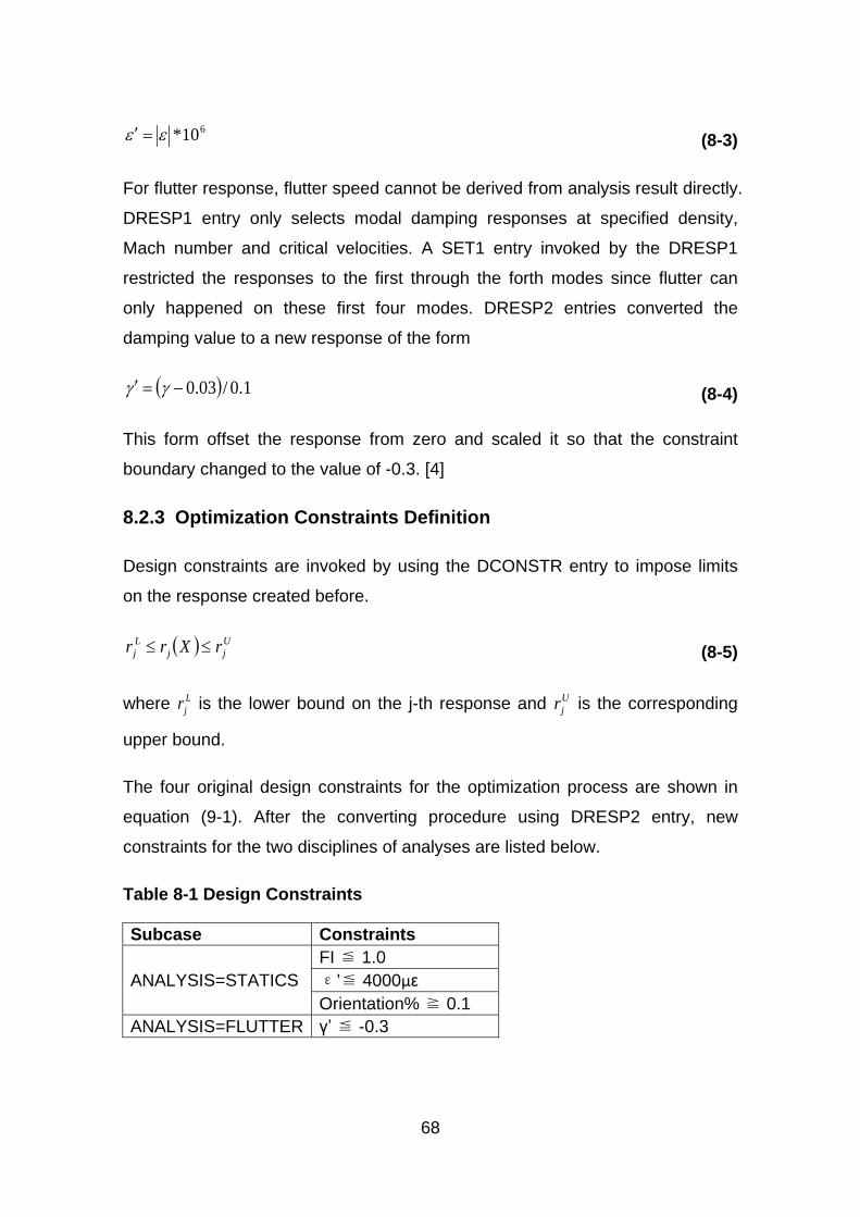
68
610*εε =′ (8-3)
For flutter response, flutter speed cannot be derived from analysis result directly.
DRESP1 entry only selects modal damping responses at specified density,
Mach number and critical velocities. A SET1 entry invoked by the DRESP1
restricted the responses to the first through the forth modes since flutter can
only happened on these first four modes. DRESP2 entries converted the
damping value to a new response of the form
( ) 1.0/03.0−=′ γγ (8-4)
This form offset the response from zero and scaled it so that the constraint
boundary changed to the value of -0.3. [4]
8.2.3 Optimization Constraints Definition
Design constraints are invoked by using the DCONSTR entry to impose limits
on the response created before.
( ) Ujj
Lj rXrr ≤≤ (8-5)
where Ljr is the lower bound on the j-th response and U
jr is the corresponding
upper bound.
The four original design constraints for the optimization process are shown in
equation (9-1). After the converting procedure using DRESP2 entry, new
constraints for the two disciplines of analyses are listed below.
Table 8-1 Design Constraints
Subcase Constraints
ANALYSIS=STATICS FI ≦ 1.0 ε’≦ 4000με Orientation% ≧ 0.1
ANALYSIS=FLUTTER γ’ ≦ -0.3
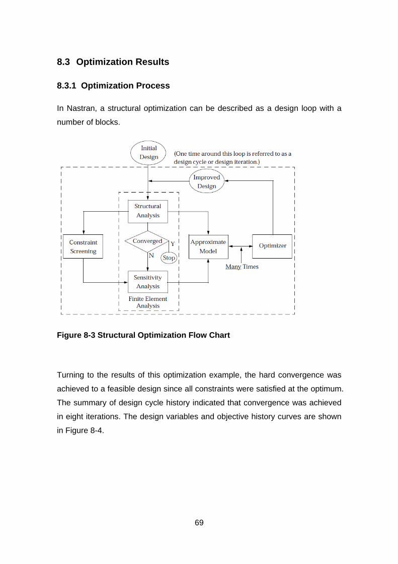
69
8.3 Optimization Results
8.3.1 Optimization Process
In Nastran, a structural optimization can be described as a design loop with a
number of blocks.
Figure 8-3 Structural Optimization Flow Chart
Turning to the results of this optimization example, the hard convergence was
achieved to a feasible design since all constraints were satisfied at the optimum.
The summary of design cycle history indicated that convergence was achieved
in eight iterations. The design variables and objective history curves are shown
in Figure 8-4.
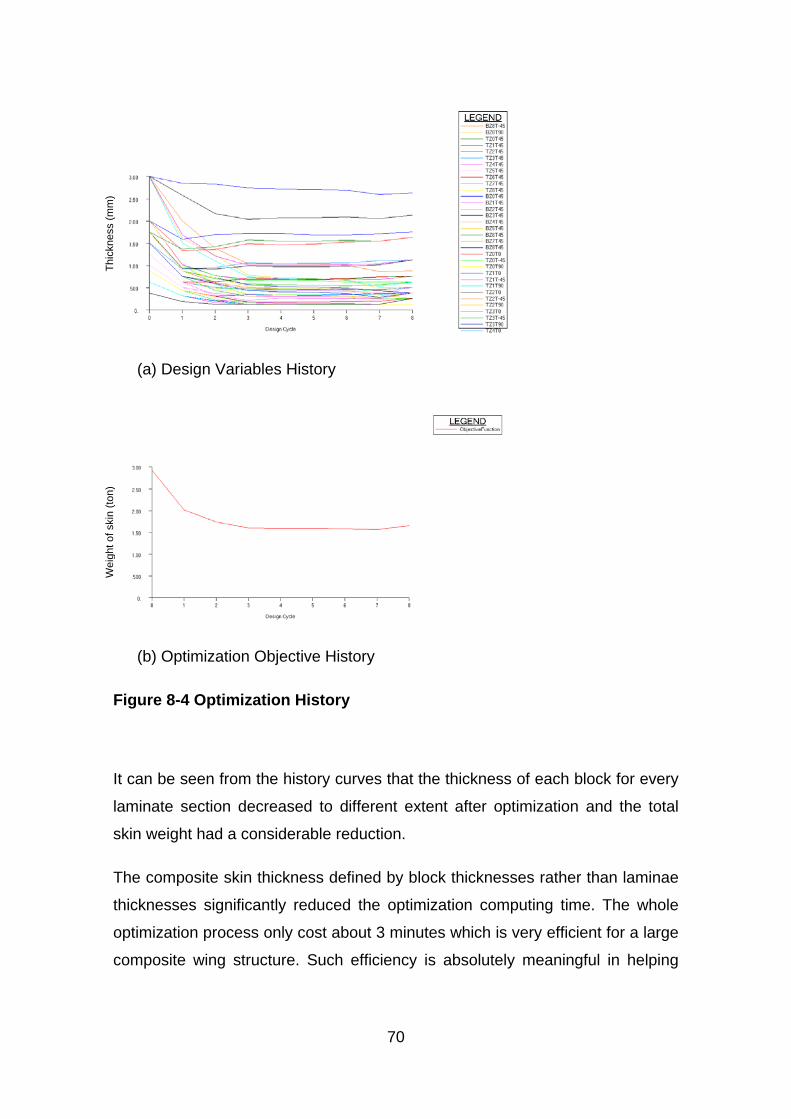
70
(a) Design Variables History
(b) Optimization Objective History
Figure 8-4 Optimization History
It can be seen from the history curves that the thickness of each block for every
laminate section decreased to different extent after optimization and the total
skin weight had a considerable reduction.
The composite skin thickness defined by block thicknesses rather than laminae
thicknesses significantly reduced the optimization computing time. The whole
optimization process only cost about 3 minutes which is very efficient for a large
composite wing structure. Such efficiency is absolutely meaningful in helping
Wei
ght o
f ski
n (to
n)
Thic
knes
s (m
m)
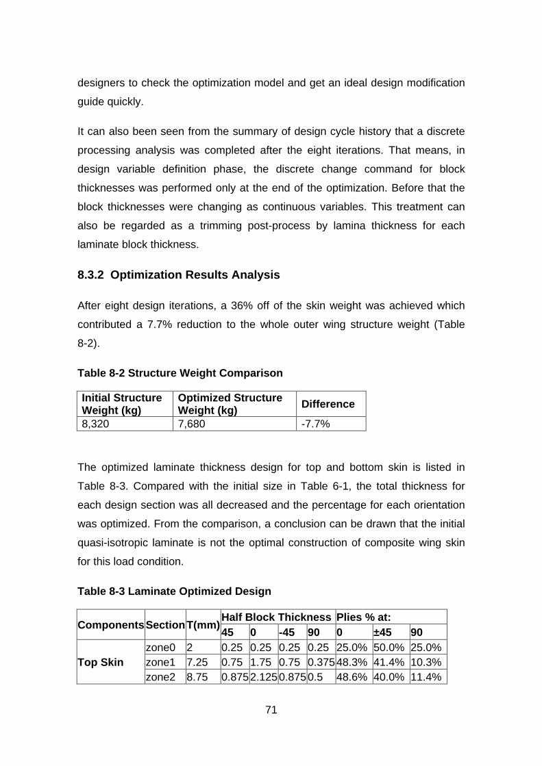
71
designers to check the optimization model and get an ideal design modification
guide quickly.
It can also been seen from the summary of design cycle history that a discrete
processing analysis was completed after the eight iterations. That means, in
design variable definition phase, the discrete change command for block
thicknesses was performed only at the end of the optimization. Before that the
block thicknesses were changing as continuous variables. This treatment can
also be regarded as a trimming post-process by lamina thickness for each
laminate block thickness.
8.3.2 Optimization Results Analysis
After eight design iterations, a 36% off of the skin weight was achieved which
contributed a 7.7% reduction to the whole outer wing structure weight (Table
8-2).
Table 8-2 Structure Weight Comparison
Initial Structure Weight (kg)
Optimized Structure Weight (kg) Difference
8,320 7,680 -7.7%
The optimized laminate thickness design for top and bottom skin is listed in
Table 8-3. Compared with the initial size in Table 6-1, the total thickness for
each design section was all decreased and the percentage for each orientation
was optimized. From the comparison, a conclusion can be drawn that the initial
quasi-isotropic laminate is not the optimal construction of composite wing skin
for this load condition.
Table 8-3 Laminate Optimized Design
Components Section T(mm) Half Block Thickness Plies % at: 45 0 -45 90 0 ±45 90
Top Skin zone0 2 0.25 0.25 0.25 0.25 25.0% 50.0% 25.0% zone1 7.25 0.75 1.75 0.75 0.375 48.3% 41.4% 10.3% zone2 8.75 0.875 2.125 0.875 0.5 48.6% 40.0% 11.4%
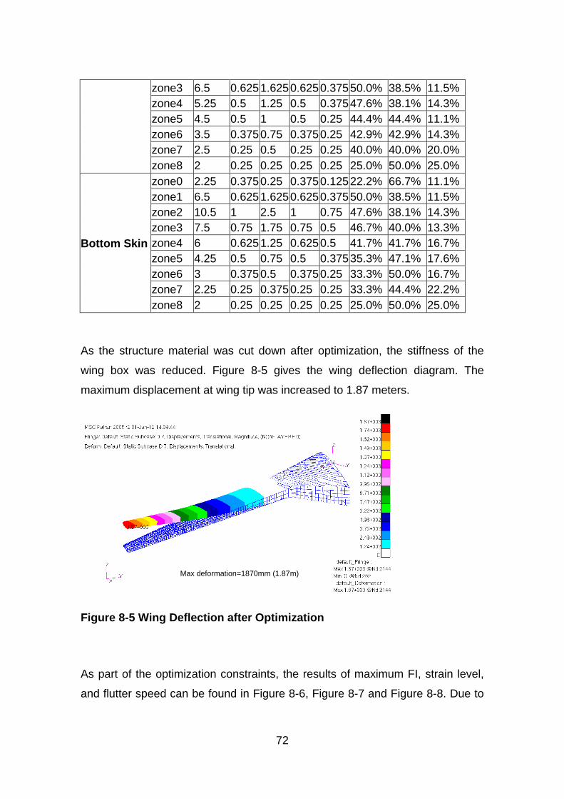
72
zone3 6.5 0.625 1.625 0.625 0.375 50.0% 38.5% 11.5% zone4 5.25 0.5 1.25 0.5 0.375 47.6% 38.1% 14.3% zone5 4.5 0.5 1 0.5 0.25 44.4% 44.4% 11.1% zone6 3.5 0.375 0.75 0.375 0.25 42.9% 42.9% 14.3% zone7 2.5 0.25 0.5 0.25 0.25 40.0% 40.0% 20.0% zone8 2 0.25 0.25 0.25 0.25 25.0% 50.0% 25.0%
Bottom Skin
zone0 2.25 0.375 0.25 0.375 0.125 22.2% 66.7% 11.1% zone1 6.5 0.625 1.625 0.625 0.375 50.0% 38.5% 11.5% zone2 10.5 1 2.5 1 0.75 47.6% 38.1% 14.3% zone3 7.5 0.75 1.75 0.75 0.5 46.7% 40.0% 13.3% zone4 6 0.625 1.25 0.625 0.5 41.7% 41.7% 16.7% zone5 4.25 0.5 0.75 0.5 0.375 35.3% 47.1% 17.6% zone6 3 0.375 0.5 0.375 0.25 33.3% 50.0% 16.7% zone7 2.25 0.25 0.375 0.25 0.25 33.3% 44.4% 22.2% zone8 2 0.25 0.25 0.25 0.25 25.0% 50.0% 25.0%
As the structure material was cut down after optimization, the stiffness of the
wing box was reduced. Figure 8-5 gives the wing deflection diagram. The
maximum displacement at wing tip was increased to 1.87 meters.
Figure 8-5 Wing Deflection after Optimization
As part of the optimization constraints, the results of maximum FI, strain level,
and flutter speed can be found in Figure 8-6, Figure 8-7 and Figure 8-8. Due to
Max deformation=1870mm (1.87m)
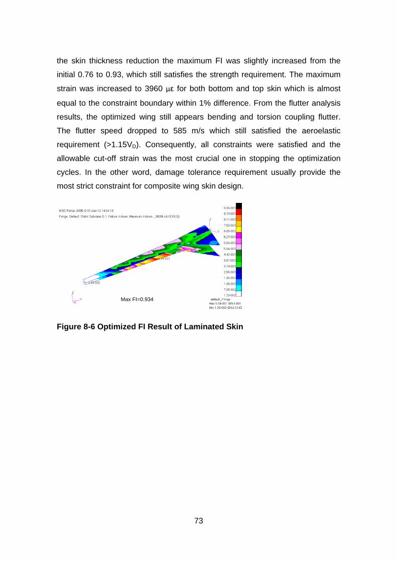
73
the skin thickness reduction the maximum FI was slightly increased from the
initial 0.76 to 0.93, which still satisfies the strength requirement. The maximum
strain was increased to 3960 με for both bottom and top skin which is almost
equal to the constraint boundary within 1% difference. From the flutter analysis
results, the optimized wing still appears bending and torsion coupling flutter.
The flutter speed dropped to 585 m/s which still satisfied the aeroelastic
requirement (>1.15VD). Consequently, all constraints were satisfied and the
allowable cut-off strain was the most crucial one in stopping the optimization
cycles. In the other word, damage tolerance requirement usually provide the
most strict constraint for composite wing skin design.
Figure 8-6 Optimized FI Result of Laminated Skin
Max FI=0.934
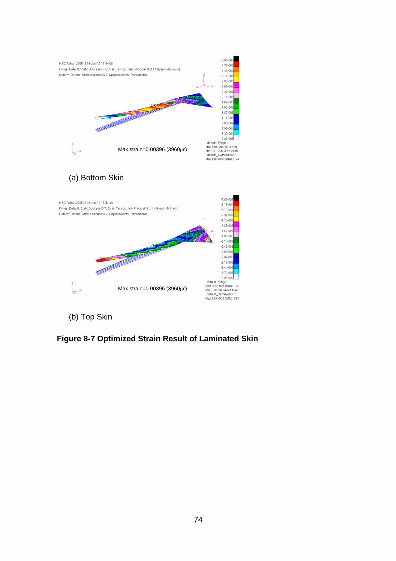
74
(a) Bottom Skin
(b) Top Skin
Figure 8-7 Optimized Strain Result of Laminated Skin
Max strain=0.00396 (3960με)
Max strain=0.00396 (3960με)
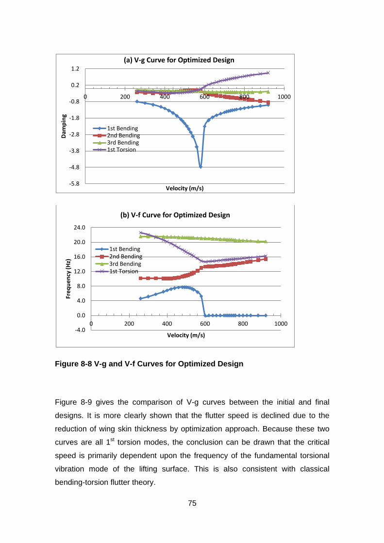
75
Figure 8-8 V-g and V-f Curves for Optimized Design
Figure 8-9 gives the comparison of V-g curves between the initial and final
designs. It is more clearly shown that the flutter speed is declined due to the
reduction of wing skin thickness by optimization approach. Because these two
curves are all 1st torsion modes, the conclusion can be drawn that the critical
speed is primarily dependent upon the frequency of the fundamental torsional
vibration mode of the lifting surface. This is also consistent with classical
bending-torsion flutter theory.
-5.8
-4.8
-3.8
-2.8
-1.8
-0.8
0.2
1.2
0 200 400 600 800 1000
Dam
ping
Velocity (m/s)
(a) V-g Curve for Optimized Design
1st Bending 2nd Bending 3rd Bending 1st Torsion
-4.0
0.0
4.0
8.0
12.0
16.0
20.0
24.0
0 200 400 600 800 1000
Freq
uenc
y (H
z)
Velocity (m/s)
(b) V-f Curve for Optimized Design
1st Bending 2nd Bending 3rd Bending 1st Torsion
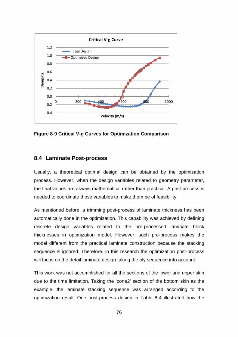
76
Figure 8-9 Critical V-g Curves for Optimization Comparison
8.4 Laminate Post-process
Usually, a theoretical optimal design can be obtained by the optimization
process. However, when the design variables related to geometry parameter,
the final values are always mathematical rather than practical. A post-process is
needed to coordinate those variables to make them be of feasibility.
As mentioned before, a trimming post-process of laminate thickness has been
automatically done in the optimization. This capability was achieved by defining
discrete design variables related to the pre-processed laminate block
thicknesses in optimization model. However, such pre-process makes the
model different from the practical laminate construction because the stacking
sequence is ignored. Therefore, in this research the optimization post-process
will focus on the detail laminate design taking the ply sequence into account.
This work was not accomplished for all the sections of the lower and upper skin
due to the time limitation. Taking the ‘zone2’ section of the bottom skin as the
example, the laminate stacking sequence was arranged according to the
optimization result. One post-process design in Table 8-4 illustrated how the
-0.4
-0.2
0.0
0.2
0.4
0.6
0.8
1.0
1.2
0 200 400 600 800 1000
Dam
ping
Velocity (m/s)
Critical V-g Curve
Initial Design
Optimized Design
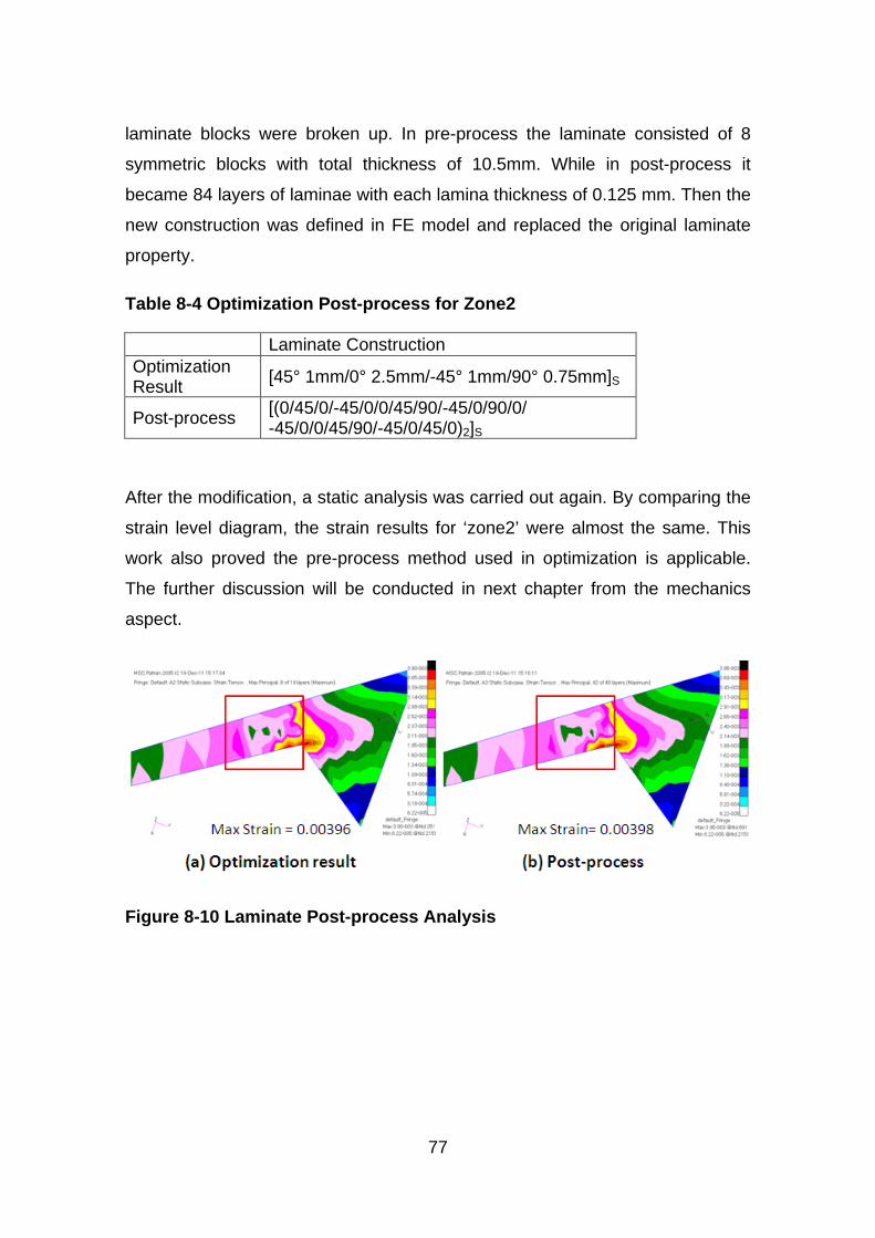
77
laminate blocks were broken up. In pre-process the laminate consisted of 8
symmetric blocks with total thickness of 10.5mm. While in post-process it
became 84 layers of laminae with each lamina thickness of 0.125 mm. Then the
new construction was defined in FE model and replaced the original laminate
property.
Table 8-4 Optimization Post-process for Zone2
Laminate Construction Optimization Result [45° 1mm/0° 2.5mm/-45° 1mm/90° 0.75mm]S
Post-process [(0/45/0/-45/0/0/45/90/-45/0/90/0/ -45/0/0/45/90/-45/0/45/0)2]S
After the modification, a static analysis was carried out again. By comparing the
strain level diagram, the strain results for ‘zone2’ were almost the same. This
work also proved the pre-process method used in optimization is applicable.
The further discussion will be conducted in next chapter from the mechanics
aspect.
Figure 8-10 Laminate Post-process Analysis

79
9 Discussion and Future Work
9.1 Discussion
Discussion will continue focusing on the feasibility of the laminate thickness pre-
process method. As introduced before, this method set the laminate in blocks
regardless the stacking sequence. It has been proved that the optimization
efficiency for a large structure can be increased since it considerably reduces
the quantity of design variables. It was also proved by the FE analysis in post-
process that this treatment had little influence on the laminate strain level.
In terms of classical mechanics, there are two reasons to support the FE
analysis result. First reason is that all the wing skin laminates are designed and
kept symmetric during optimization. This design feature allows the laminated
skin have no bending-torsion coupling effect. From Figure 9-1 (ABD Matrices
calculated in post-process part by NASTRAN) the ‘A’ matrices are exactly the
same and ‘B’ matrices theoretically equals to zero no matter whether the skin is
treated in blocks or in different laminate layup.
From the wing skin loads aspect, the global bending and torsion moment
applied on the wing box are finally converted into in-plane tension or
compression, and shear forces for the upper and lower skin. And the out-plane
bending and torsion applied in local skin caused by the global wing deflection
are much lower. Therefore, this wing skin in-plane load condition is the second
reason. Under such in-plane loads, the strain level of a symmetric laminate is
only determined by ‘A’ matrix.
Consequently, a relatively accurate result can be achieved when the skin
laminate is pre-processed as blocks in this preliminary design stage. Besides,
this method allows the laminate thickness change discretely in the scale of each
lamina thickness and therefore makes the optimization practical.
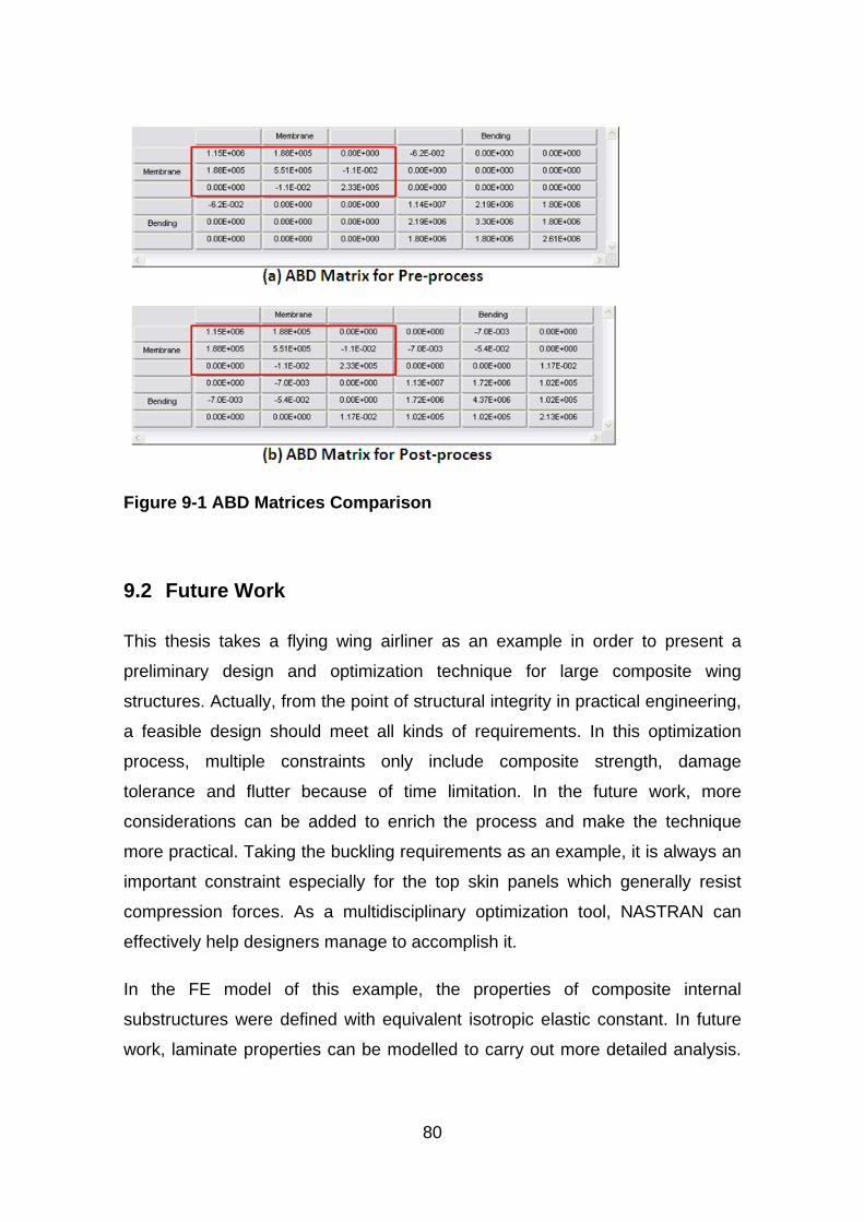
80
Figure 9-1 ABD Matrices Comparison
9.2 Future Work
This thesis takes a flying wing airliner as an example in order to present a
preliminary design and optimization technique for large composite wing
structures. Actually, from the point of structural integrity in practical engineering,
a feasible design should meet all kinds of requirements. In this optimization
process, multiple constraints only include composite strength, damage
tolerance and flutter because of time limitation. In the future work, more
considerations can be added to enrich the process and make the technique
more practical. Taking the buckling requirements as an example, it is always an
important constraint especially for the top skin panels which generally resist
compression forces. As a multidisciplinary optimization tool, NASTRAN can
effectively help designers manage to accomplish it.
In the FE model of this example, the properties of composite internal
substructures were defined with equivalent isotropic elastic constant. In future
work, laminate properties can be modelled to carry out more detailed analysis.

81
For optimization, the internal substructure was also designed conservative, and
can be optimized to achieve extra weight reduction.
Due to the anisotropic nature, composite materials provide more potential in
structure optimization. In this preliminary design stage, laminate thickness was
optimized to achieve weight saving. However, more benefits can be obtained by
tailoring the laminates. At following detail design stage, ply orientation and
stacking sequence can be set as design variables. Since this would not change
the structure weight, the stiffness or flutter features can be set as the new
objectives so that better performance can be got without paying weight penalty.

83
10 Conclusion
In this thesis, efforts have been made to optimize a large composite wing
structure for minimum weight subject to multiple design constraints. It has been
demonstrated that based on the initial sizing, the whole structure FE analysis
and optimization process can be implemented by employing the commercial
package Nastran. An optimized wing structure with detailed FE model can be
obtained automatically and efficiently by this approach. In addition, the following
conclusions can be drawn.
1. The structure initial sizing by Denis Howe’s method is to some extend
conservative and overestimated. And for a structure designed through
routine process, a significant structure weight reduction can still be
achieved by the optimization technique subject to multiple design
constraints;
2. For practical application, the methodology and technique keep the whole
FE modelling, analysis and optimization process within one commercial
package by making full use of NASTRAN code.
3. The pre-process method setting laminate thickness in block is proved to
be efficient with little compromise of accuracy for the optimization of a
large composite wing structure in preliminary design stage;
4. Using discrete design variable for laminate thickness optimization can
reduce the work demand for trimming the ply number and thickness in
post-process and therefore make the optimization more efficient and
practical;
5. In the application of composite material to structures, the allowable strain
level considering damage tolerance plays an important role on the
composite structure design. In a multi-constraint optimization process,
the maximum strain requirement is usually more critical than the stress
and aeroelastic criteria and hence drives the structure design.

84
85
REFERENCES
1. Crane D, “Dict#ionary of #Aeronaut#ical Terms (third edition)”, Avi#ation
Supplies & Academics, 1997.
2. Mat#thews F L, Davies G A O, Hitchings D and Soutis C, “Fi#nite element
modell#ing of composite mat#erials and structures”, Woodhead Publishing
Limited, 2000.
3. Oyibo G A, “A unified flutter analysis for compo#site aircraft wings”, 25TH
#AIAA/#ASME/#ASCE/#AHS Structures, Structural Dynam#ics and Materials
Conference. New York: AIAA, 1984.
4. “Aeroelastic analysis user’s guide”, MSC. Nastran Version 68, MSC.
Software Corporation.
5. Cole S R, Nagaraja K S and Rivera J #A, “Flutter study of an advanced
composite wing with external #stores” 28th #AIAA/#ASME/#ASCE/#AHS
Structures, Str#uctural Dynamics and Materials Conference and AIAA
Dynamics Speciaslists Conference. Part 2. - New York: AIAA, 1987.
6. Chowdary T V R, Parthan S and Sinha P K, "Finite element #flutter
analysis of laminated composite panels", Computers & Structures, 1994.
7. Qin Z, Marzocca P, Librescu L, Aeroelastic instability and response of
advanced aircraft wings at subsonic flight speeds, Aerospace Sci
Technol; 6:195-208, 2002.
8. #Niu M, “Composite Airframe Structures: practical design information and
data”, Hong Kong Conmilit Press Ltd, 1999.
9. Schmit, L.A and Farshi, B. “Optimum design of laminated fibre composite
plates”. International journal for numerical methods in engineering, 1977.
10. Almeida F S and Awruch A M, "Design optimization of composite
laminated structures using genetic algorithms and finite element
analysis", Composite Structures, vol. 88, no. 3, pp. 443-454, 2009.
11. Walker M and Smith RE, “A technique for the multi-objective optimisation
of laminated composite structures using genetic algorithms and finite
element analysis”, Composite Structures 62, 123–128, 2003.
86
12. Honda S, Narita Y, Sasaki K, “Discrete Optimization for Vibration Design
of Composite Plates by Using Lamination Parameters”, Advanced
Composite Materials 18, 297–314, 2009.
13. Kere P, Lyly M and Koski J, "Using multicriterion optimization for strength
design of composite laminates", Composite Structures, vol. 62, no. 3-4,
pp. 329-333, 2003.
14. Zehnder N and Ermanni P, "A methodology for the global optimization of
laminated composite structures", Composite Structures, vol. 72, no. 3,
pp. 311-320, 2006.
15. Narayana N G, Gopalakrishnan S, Ganguli R, “Design optimization of
composites using genetic algorithms and failure mechanism based
failure criterion”, Compos Struct; 83(4): 354-367. 2008.
16. Lopez, R. H., Luersen, M. A. and Cursi, E. S. (2009), "Optimization of
laminated composites considering different failure criteria", Composites
Part B: Engineering, vol. 40, no. 8, pp. 731-740.
17. Wang L, Williams AF, Llamas R, “Aircraft wing structural optimisation
with manufacturing considerations”, AIAA-2000-4842.
18. Liu D, Toropov V V, Querin O M and Barton D C, “Bi-level Optimization
of Blended Composite Panels”, AIAA Journal, AIAA 2009-2182, May
2009.
19. Guo S, Banerjee J R, Cheung C W, “The effect of laminate lay-up on the
flutter speed of composite wings”, Proc. IMechE, Part G: J Aerospace
Eng 2003; 217: 115-122.
20. Guo S, Cheng W and Cui D, “Optimization of Composite Wing Structures
for Maximum Flutter Speed”, 46th AIAA/ASME/ASCE/AHS/ASC
Structures, Structural Dynamics & Materials Conference 18 - 21 April
2005.
21. Guo S, Chen W and Cui D, “Aeroelastic tailoring of composite wing
structures by laminate layup optimization”, AIAA J 2006; 44: 3146-149.
22. Lillico M, Butler R, Guo S, Banerjee JR. “Aeroelastic optimization of
composite wings using the dynamic stiffness method”, Aeronaut J 1997;
101: 77-86.
87
23. Guo S, Li D and Liu Y, “Multi Objective Optimization of a Composite
Wing Subject to Strength and Aeroelastic Constraints”, Proc. IMechE Vol.
0 Part G: J. Aerospace Engineering, Oct 21, 2011.
24. Guo S. “Aeroelastic optimization of an aerobatic aircraft wing structure”,
Aerosp Sci Technol 2007; 11: 396-404.
25. “Failure criteria and laminate strength prediction” (2003), available at:
http://www.admc.esrtechnology.com/Background/Failure/.
26. Niu M, “Airframe structural design: practical design information and data
on aircraft structures”, Hong Kong Conmilit Press Ltd. 1999.
27. Howe D, “Aircraft loading and structural layout”, American Institute of
Aeronautics and Astronautics, Inc, 2004.
28. Hart Smith, “The ten-percent rule”, Aerospace Materials, 5(2),
August/October 1993.
29. Tsai S W, Wu E M, “A general theory of strength for anisotropic
materials”, J. Compos. Mater., 1971, 5, 58–80.
30. Albano E and Rodden W P, “A Doublet Lattice Method for Calulating Lift
Distributions on Oscillating Surfaces in Subsonic Flows”. AIAAJ., Vol. 7
pp279-285 p. 2192 1969
31. Mukhopadhyay V, “Blended-Wing-Body (BWB) Fuselage Structural
Design for Weight Reduction”, AIAA, 2005.
32. Tetlow R, “Design Charts for Carbon-fibre Composites”, Cranfield Memo
No. 9. 1970.
33. Guo S, “USER MANUAL FOR PROGRAM ABDMXS.EXE”.
34. Niu M, “Airframe Stress Analysis and Sizing (2nd edition)”, Hong Kong
Conmilit Press Ltd, 1999.
35. European Aviation Safety Agency, “Certification Specifications for Large
Aeroplanes CS-25”, Amendment 3, 19 September 2007
36. “Design Sensitivity and Optimization User's Guide”, MSC. Nastran
Version 68, MSC. Software Corporation.
37. “Flying Wing Airliner FW-11 Group Project Specification”, Cranfield
University, 2011

88
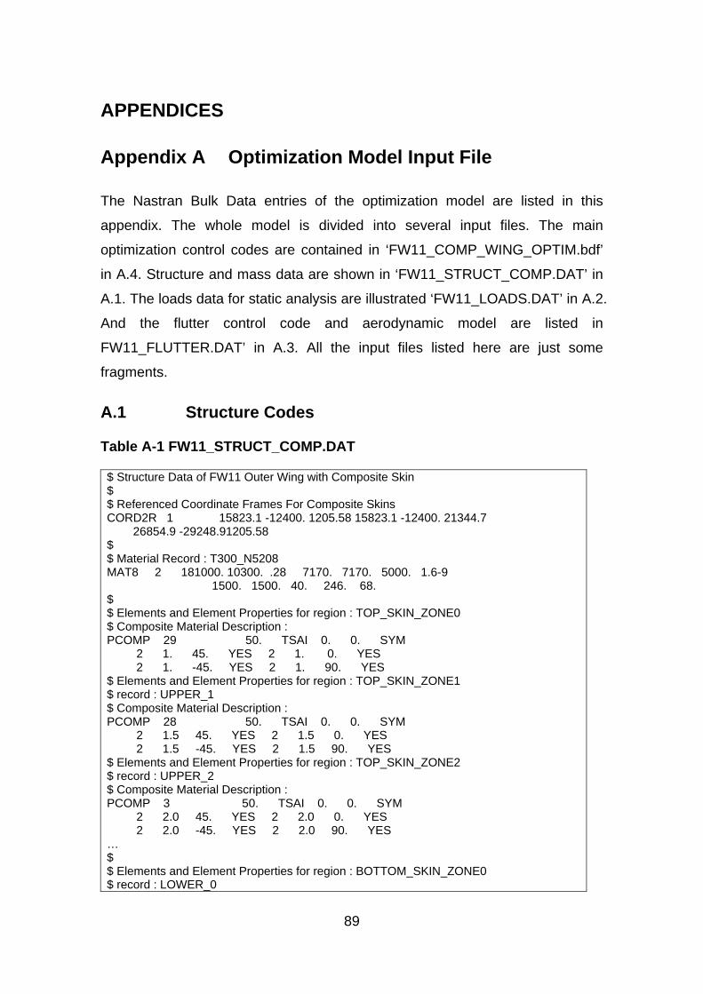
89
APPENDICES
Appendix A Optimization Model Input File
The Nastran Bulk Data entries of the optimization model are listed in this
appendix. The whole model is divided into several input files. The main
optimization control codes are contained in ‘FW11_COMP_WING_OPTIM.bdf’
in A.4. Structure and mass data are shown in ‘FW11_STRUCT_COMP.DAT’ in
A.1. The loads data for static analysis are illustrated ‘FW11_LOADS.DAT’ in A.2.
And the flutter control code and aerodynamic model are listed in
FW11_FLUTTER.DAT’ in A.3. All the input files listed here are just some
fragments.
A.1 Structure Codes
Table A-1 FW11_STRUCT_COMP.DAT
$ Structure Data of FW11 Outer Wing with Composite Skin $ $ Referenced Coordinate Frames For Composite Skins CORD2R 1 15823.1 -12400. 1205.58 15823.1 -12400. 21344.7 26854.9 -29248.91205.58 $ $ Material Record : T300_N5208 MAT8 2 181000. 10300. .28 7170. 7170. 5000. 1.6-9 1500. 1500. 40. 246. 68. $ $ Elements and Element Properties for region : TOP_SKIN_ZONE0 $ Composite Material Description : PCOMP 29 50. TSAI 0. 0. SYM 2 1. 45. YES 2 1. 0. YES 2 1. -45. YES 2 1. 90. YES $ Elements and Element Properties for region : TOP_SKIN_ZONE1 $ record : UPPER_1 $ Composite Material Description : PCOMP 28 50. TSAI 0. 0. SYM 2 1.5 45. YES 2 1.5 0. YES 2 1.5 -45. YES 2 1.5 90. YES $ Elements and Element Properties for region : TOP_SKIN_ZONE2 $ record : UPPER_2 $ Composite Material Description : PCOMP 3 50. TSAI 0. 0. SYM 2 2.0 45. YES 2 2.0 0. YES 2 2.0 -45. YES 2 2.0 90. YES … $ $ Elements and Element Properties for region : BOTTOM_SKIN_ZONE0 $ record : LOWER_0
90
$ Composite Material Description : PCOMP 36 50. TSAI 0. 0. SYM 2 1. 45. YES 2 1. 0. YES 2 1. -45. YES 2 1. 90. YES $ Elements and Element Properties for region : BOTTOM_SKIN_ZONE1 $ record : LOWER_1 $ Composite Material Description : PCOMP 16 50. TSAI 0. 0. SYM 2 1.5 45. YES 2 1.5 0. YES 2 1.5 -45. YES 2 1.5 90. YES $ Elements and Element Properties for region : BOTTOM_SKIN_ZONE2 $ record : LOWER_2 $ Composite Material Description : PCOMP 6 50. TSAI 0. 0. SYM 2 2.0 45. YES 2 2.0 0. YES 2 2.0 -45. YES 2 2.0 90. YES … $ $ $ Elements and Element Properties for region : STRINGER PBARL 2 1 I 60. 60. 50. 2. 4. 3. $ Pset: "STRINGER" will be imported as: "pbarl.2" CBAR 3985 2 1668 1491 0. 0. 1. CBAR 3986 2 1491 1856 0. 0. 1. CBAR 3987 2 1856 1857 0. 0. 1. CBAR 3988 2 1857 1498 0. 0. 1. CBAR 3989 2 1498 1870 0. 0. 1. … $ $ Pset: "TOP_SKIN_ZONE2" will be imported as: "pcomp.3" CQUAD4 264 3 1484 1485 1853 1851 1 CQUAD4 265 3 1853 1852 1850 1851 1 CQUAD4 266 3 1852 1496 1495 1850 1 CQUAD4 267 3 1485 1486 1855 1853 1 CQUAD4 268 3 1855 1854 1852 1853 1 CQUAD4 269 3 1854 1497 1496 1852 1 … $ Nodes of the Entire Model GRID 1 13736.3 -13046.6-852.731 GRID 2 13987.2 -12882.3-900.413 GRID 3 14238.2 -12717.9-944.646 GRID 4 14489.2 -12553.5-985.974 GRID 5 13506.9 -13196.9-805.51 GRID 6 14256.8 -13841.3-740.06 … $ $ $ Mass of Control Surfaces $ $ Elements and Element Properties for region : mass_split_drag_rudder CONM2 102081 1629 .0072 CONM2 102082 230 .0072 CONM2 102083 1624 .0072 CONM2 102084 225 .0072 CONM2 102085 1619 .0072 CONM2 102086 220 .0072 CONM2 102087 1614 .0072
91
CONM2 102088 215 .0072 CONM2 102089 1609 .0072 CONM2 102090 211 .0072 CONM2 102091 1604 .0072 CONM2 102092 206 .0072 CONM2 102093 1598 .0072 CONM2 102094 200 .0072 $ Elements and Element Properties for region : mass_aileron CONM2 102095 1592 .0116 CONM2 102096 194 .0116 CONM2 102097 1586 .0116 CONM2 102098 188 .0116 CONM2 102099 1580 .0116 CONM2 102100 182 .0116 CONM2 102101 1574 .0116 CONM2 102102 176 .0116 CONM2 102103 1568 .0116 CONM2 102104 171 .0116 CONM2 102105 1562 .0116 CONM2 102106 165 .0116 $ Elements and Element Properties for region : mass_flap CONM2 102107 1555 .016 CONM2 102108 158 .016 CONM2 102109 1548 .016 CONM2 102110 151 .016 CONM2 102111 1541 .016 CONM2 102112 144 .016 CONM2 102113 1534 .016 CONM2 102114 137 .016 CONM2 102115 1527 .016 CONM2 102116 131 .016 CONM2 102117 1520 .016 CONM2 102118 124 .016 CONM2 102119 1512 .016 CONM2 102120 116 .016 CONM2 102121 1504 .016 CONM2 102122 108 .016 CONM2 102123 1665 .016 CONM2 102124 252 .016 $ Elements and Element Properties for region : mass_outer_elevator CONM2 102125 1664 .038 CONM2 102126 251 .038 CONM2 102127 1483 .038 CONM2 102128 2510 .038 CONM2 102129 87 .038 CONM2 102130 1468 .038 CONM2 102131 2513 .038 CONM2 102132 2515 .038 CONM2 102133 71 .038
92
A.2 Static Loads Codes
Table A-2 FW11_LOADS.DAT
$ Loads for Static Analysis SPCADD 2 1 3 LOAD 3 3.75 1. 2 1. 4 1. 5 1. 6 1. 7 1. 8 1. 9 1. 10 1. 11 1. 12 1. 13 1. 14 1. 15 1. 16 1. 17 1. 18 1. 19 1. 20 1. 21 1. 22 1. 23 1. 24 1. 25 1. 26 1. 27 1. 28 1. 29 1. 30 1. 31 1. 32 1. 33 1. 34 1. 35 1. 36 1. 37 $ Displacement Constraints of Load Set : spc1.1 SPC1 1 123456 232 THRU 240 SPC1 1 123456 243 245 247 249 662 SPC1 1 123456 804 THRU 814 SPC1 1 123456 816 971 972 973 974 975 976 979 1306 1310 1392 1405 1429 1631 1632 1633 1634 1635 1637 1639 1642 1644 1646 1648 1650 1652 1653 1655 1657 1660 1662 1666 2136 2137 2179 2180 2181 2188 2190 2191 2193 2196 2199 2200 2201 2242 2243 2244 2245 2246 2247 2321 2324 2325 2326 2327 2328 2329 2483 2484 2485 2486 2487 2544 2545 2550 2551 SPC1 1 123456 2554 THRU 2736 $ Displacement Constraints of Load Set : spc2 SPC1 3 1 1393 1541 1592 $ Nodal Forces of Load Set : f2 FORCE 11 1628 0 4646.8 0. 0. 1. $ Nodal Forces of Load Set : f3~5 FORCE 22 1615 0 4428.8 0. 0. 1. FORCE 22 1618 0 4428.8 0. 0. 1. FORCE 22 1623 0 4428.8 0. 0. 1. $ Nodal Forces of Load Set : f6 FORCE 23 1610 0 7193.5 0. 0. 1. $ Nodal Forces of Load Set : f7~8 FORCE 24 1599 0 8826.8 0. 0. 1. FORCE 24 1603 0 8826.8 0. 0. 1. $ Nodal Forces of Load Set : f9 FORCE 25 1593 0 9723.9 0. 0. 1. $ Nodal Forces of Load Set : f10 FORCE 2 1587 0 10589.9 0. 0. 1. $ Nodal Forces of Load Set : f11 FORCE 4 1581 0 11049. 0. 0. 1. $ Nodal Forces of Load Set : f12~13 FORCE 5 1569 0 11932.4 0. 0. 1. FORCE 5 1575 0 11932.4 0. 0. 1. $ Nodal Forces of Load Set : f14 FORCE 6 1563 0 12372. 0. 0. 1. $ Nodal Forces of Load Set : f15~16 FORCE 7 1549 0 13056. 0. 0. 1. FORCE 7 1556 0 13056. 0. 0. 1. $ Nodal Forces of Load Set : f17
93
FORCE 8 1542 0 13818.1 0. 0. 1. $ Nodal Forces of Load Set : f18 FORCE 9 1535 0 14119.5 0. 0. 1. $ Nodal Forces of Load Set : f19 FORCE 10 1041 0 14162. 0. 0. 1. $ Nodal Forces of Load Set : f20~21 FORCE 12 747 0 15132.1 0. 0. 1. FORCE 12 750 0 15132.1 0. 0. 1. $ Nodal Forces of Load Set : f22 FORCE 13 741 0 15486.1 0. 0. 1. $ Nodal Forces of Load Set : f23 FORCE 14 735 0 16095.8 0. 0. 1. $ Nodal Forces of Load Set : f24 FORCE 15 728 0 16859.9 0. 0. 1. $ Nodal Forces of Load Set : f25 FORCE 16 1020 0 18382.8 0. 0. 1. $ Nodal Forces of Load Set : f26 FORCE 17 1467 0 21147. 0. 0. 1. $ Nodal Forces of Load Set : f27 FORCE 18 1430 0 21465. 0. 0. 1. $ Nodal Forces of Load Set : f28 FORCE 19 1415 0 21759.4 0. 0. 1. $ Nodal Forces of Load Set : f29 FORCE 20 1407 0 22068.5 0. 0. 1. $ Nodal Forces of Load Set : f30 FORCE 21 1396 0 25799.3 0. 0. 1. $ Nodal Forces of Load Set : w1 FORCE 26 1638 0 1045.5 0. 0. -1. $ Nodal Forces of Load Set : w2~5 FORCE 35 1613 0 32.5 0. 0. -1. FORCE 35 1617 0 32.5 0. 0. -1. FORCE 35 1622 0 32.5 0. 0. -1. FORCE 35 1627 0 32.5 0. 0. -1. $ Nodal Forces of Load Set : w6~8 FORCE 36 1596 0 70.4 0. 0. -1. FORCE 36 1602 0 70.4 0. 0. -1. FORCE 36 1608 0 70.4 0. 0. -1. $ Nodal Forces of Load Set : w9~10 FORCE 37 1585 0 90. 0. 0. -1. FORCE 37 1590 0 90. 0. 0. -1. $ Nodal Forces of Load Set : w11 FORCE 27 1579 0 811.1 0. 0. -1. $ Nodal Forces of Load Set : w12~13 FORCE 28 1567 0 1351. 0. 0. -1. FORCE 28 1573 0 1351. 0. 0. -1. $ Nodal Forces of Load Set : w14~16 FORCE 29 1547 0 1686.4 0. 0. -1. FORCE 29 1553 0 1686.4 0. 0. -1. FORCE 29 1560 0 1686.4 0. 0. -1. $ Nodal Forces of Load Set : w17~19 FORCE 30 1526 0 2059. 0. 0. -1. FORCE 30 1533 0 2059. 0. 0. -1. FORCE 30 1540 0 2059. 0. 0. -1. $ Nodal Forces of Load Set : w20~21 FORCE 31 1510 0 2469. 0. 0. -1. FORCE 31 1518 0 2469. 0. 0. -1. $ Nodal Forces of Load Set : w22~24 FORCE 32 1470 0 2916.2 0. 0. -1.
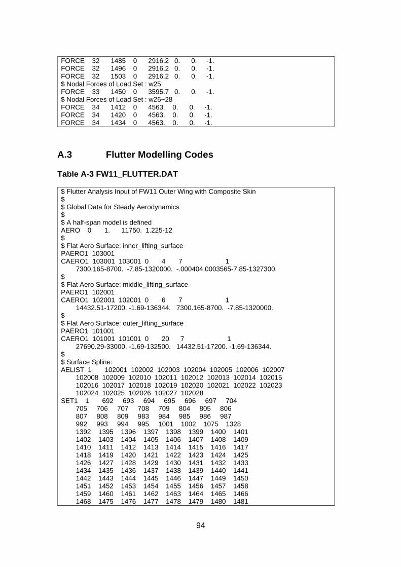
94
FORCE 32 1485 0 2916.2 0. 0. -1. FORCE 32 1496 0 2916.2 0. 0. -1. FORCE 32 1503 0 2916.2 0. 0. -1. $ Nodal Forces of Load Set : w25 FORCE 33 1450 0 3595.7 0. 0. -1. $ Nodal Forces of Load Set : w26~28 FORCE 34 1412 0 4563. 0. 0. -1. FORCE 34 1420 0 4563. 0. 0. -1. FORCE 34 1434 0 4563. 0. 0. -1.
A.3 Flutter Modelling Codes
Table A-3 FW11_FLUTTER.DAT
$ Flutter Analysis Input of FW11 Outer Wing with Composite Skin $ $ Global Data for Steady Aerodynamics $ $ A half-span model is defined AERO 0 1. 11750. 1.225-12 $ $ Flat Aero Surface: inner_lifting_surface PAERO1 103001 CAERO1 103001 103001 0 4 7 1 7300.165-8700. -7.85-1320000. -.000404.0003565-7.85-1327300. $ $ Flat Aero Surface: middle_lifting_surface PAERO1 102001 CAERO1 102001 102001 0 6 7 1 14432.51-17200. -1.69-136344. 7300.165-8700. -7.85-1320000. $ $ Flat Aero Surface: outer_lifting_surface PAERO1 101001 CAERO1 101001 101001 0 20 7 1 27690.29-33000. -1.69-132500. 14432.51-17200. -1.69-136344. $ $ Surface Spline: AELIST 1 102001 102002 102003 102004 102005 102006 102007 102008 102009 102010 102011 102012 102013 102014 102015 102016 102017 102018 102019 102020 102021 102022 102023 102024 102025 102026 102027 102028 SET1 1 692 693 694 695 696 697 704 705 706 707 708 709 804 805 806 807 808 809 983 984 985 986 987 992 993 994 995 1001 1002 1075 1328 1392 1395 1396 1397 1398 1399 1400 1401 1402 1403 1404 1405 1406 1407 1408 1409 1410 1411 1412 1413 1414 1415 1416 1417 1418 1419 1420 1421 1422 1423 1424 1425 1426 1427 1428 1429 1430 1431 1432 1433 1434 1435 1436 1437 1438 1439 1440 1441 1442 1443 1444 1445 1446 1447 1449 1450 1451 1452 1453 1454 1455 1456 1457 1458 1459 1460 1461 1462 1463 1464 1465 1466 1468 1475 1476 1477 1478 1479 1480 1481
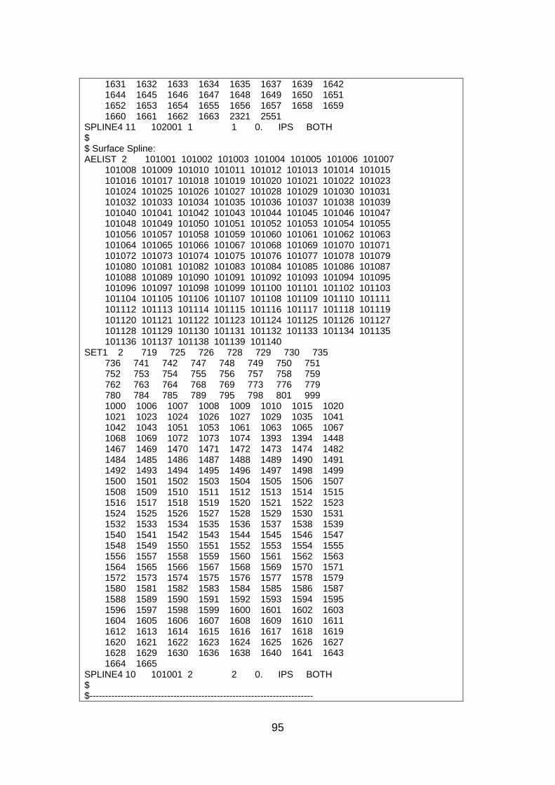
95
1631 1632 1633 1634 1635 1637 1639 1642 1644 1645 1646 1647 1648 1649 1650 1651 1652 1653 1654 1655 1656 1657 1658 1659 1660 1661 1662 1663 2321 2551 SPLINE4 11 102001 1 1 0. IPS BOTH $ $ Surface Spline: AELIST 2 101001 101002 101003 101004 101005 101006 101007 101008 101009 101010 101011 101012 101013 101014 101015 101016 101017 101018 101019 101020 101021 101022 101023 101024 101025 101026 101027 101028 101029 101030 101031 101032 101033 101034 101035 101036 101037 101038 101039 101040 101041 101042 101043 101044 101045 101046 101047 101048 101049 101050 101051 101052 101053 101054 101055 101056 101057 101058 101059 101060 101061 101062 101063 101064 101065 101066 101067 101068 101069 101070 101071 101072 101073 101074 101075 101076 101077 101078 101079 101080 101081 101082 101083 101084 101085 101086 101087 101088 101089 101090 101091 101092 101093 101094 101095 101096 101097 101098 101099 101100 101101 101102 101103 101104 101105 101106 101107 101108 101109 101110 101111 101112 101113 101114 101115 101116 101117 101118 101119 101120 101121 101122 101123 101124 101125 101126 101127 101128 101129 101130 101131 101132 101133 101134 101135 101136 101137 101138 101139 101140 SET1 2 719 725 726 728 729 730 735 736 741 742 747 748 749 750 751 752 753 754 755 756 757 758 759 762 763 764 768 769 773 776 779 780 784 785 789 795 798 801 999 1000 1006 1007 1008 1009 1010 1015 1020 1021 1023 1024 1026 1027 1029 1035 1041 1042 1043 1051 1053 1061 1063 1065 1067 1068 1069 1072 1073 1074 1393 1394 1448 1467 1469 1470 1471 1472 1473 1474 1482 1484 1485 1486 1487 1488 1489 1490 1491 1492 1493 1494 1495 1496 1497 1498 1499 1500 1501 1502 1503 1504 1505 1506 1507 1508 1509 1510 1511 1512 1513 1514 1515 1516 1517 1518 1519 1520 1521 1522 1523 1524 1525 1526 1527 1528 1529 1530 1531 1532 1533 1534 1535 1536 1537 1538 1539 1540 1541 1542 1543 1544 1545 1546 1547 1548 1549 1550 1551 1552 1553 1554 1555 1556 1557 1558 1559 1560 1561 1562 1563 1564 1565 1566 1567 1568 1569 1570 1571 1572 1573 1574 1575 1576 1577 1578 1579 1580 1581 1582 1583 1584 1585 1586 1587 1588 1589 1590 1591 1592 1593 1594 1595 1596 1597 1598 1599 1600 1601 1602 1603 1604 1605 1606 1607 1608 1609 1610 1611 1612 1613 1614 1615 1616 1617 1618 1619 1620 1621 1622 1623 1624 1625 1626 1627 1628 1629 1630 1636 1638 1640 1641 1643 1664 1665 SPLINE4 10 101001 2 2 0. IPS BOTH $ $------------------------------------------------------------------------
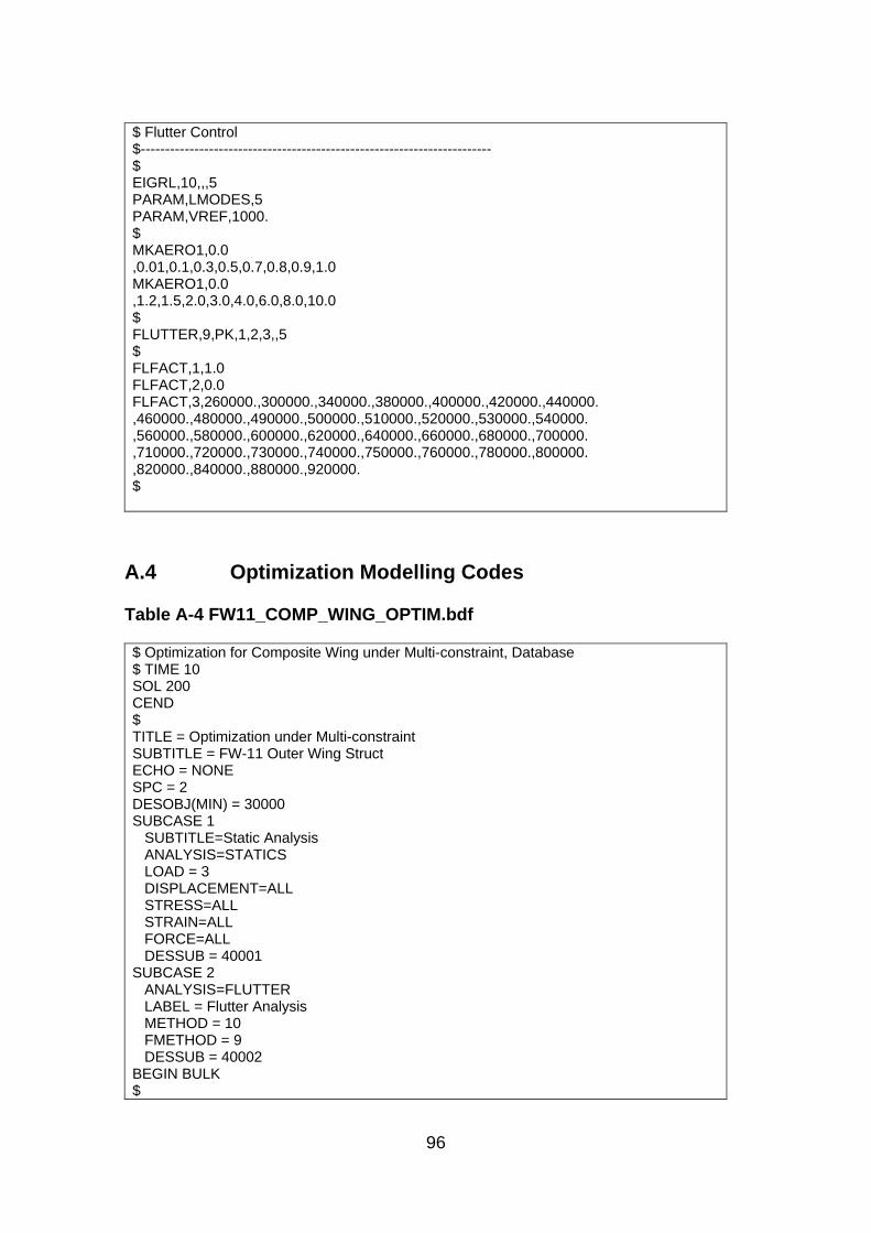
96
$ Flutter Control $------------------------------------------------------------------------ $ EIGRL,10,,,5 PARAM,LMODES,5 PARAM,VREF,1000. $ MKAERO1,0.0 ,0.01,0.1,0.3,0.5,0.7,0.8,0.9,1.0 MKAERO1,0.0 ,1.2,1.5,2.0,3.0,4.0,6.0,8.0,10.0 $ FLUTTER,9,PK,1,2,3,,5 $ FLFACT,1,1.0 FLFACT,2,0.0 FLFACT,3,260000.,300000.,340000.,380000.,400000.,420000.,440000. ,460000.,480000.,490000.,500000.,510000.,520000.,530000.,540000. ,560000.,580000.,600000.,620000.,640000.,660000.,680000.,700000. ,710000.,720000.,730000.,740000.,750000.,760000.,780000.,800000. ,820000.,840000.,880000.,920000. $
A.4 Optimization Modelling Codes
Table A-4 FW11_COMP_WING_OPTIM.bdf
$ Optimization for Composite Wing under Multi-constraint, Database $ TIME 10 SOL 200 CEND $ TITLE = Optimization under Multi-constraint SUBTITLE = FW-11 Outer Wing Struct ECHO = NONE SPC = 2 DESOBJ(MIN) = 30000 SUBCASE 1 SUBTITLE=Static Analysis ANALYSIS=STATICS LOAD = 3 DISPLACEMENT=ALL STRESS=ALL STRAIN=ALL FORCE=ALL DESSUB = 40001 SUBCASE 2 ANALYSIS=FLUTTER LABEL = Flutter Analysis METHOD = 10 FMETHOD = 9 DESSUB = 40002 BEGIN BULK $
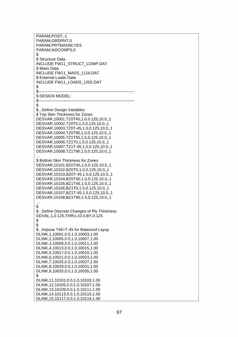
97
PARAM,POST,-1 PARAM,GRDPNT,0 PARAM,PRTMAXIM,YES PARAM,NOCOMPS,0 $ $ Structure Data INCLUDE FW11_STRUCT_COMP.DAT $ Mass Data INCLUDE FW11_MASS_1116.DAT $ External Loads Data INCLUDE FW11_LOADS_1202.DAT $ $------------------------------------------------------------------------ $ DESIGN MODEL: $------------------------------------------------------------------------ $ $...Define Design Variables $ Top Skin Thickness for Zones DESVAR,10001,TZ0T45,1.0,0.125,10.0,,1 DESVAR,10002,TZ0T0,1.0,0.125,10.0,,1 DESVAR,10003,TZ0T-45,1.0,0.125,10.0,,1 DESVAR,10004,TZ0T90,1.0,0.125,10.0,,1 DESVAR,10005,TZ1T45,1.5,0.125,10.0,,1 DESVAR,10006,TZ1T0,1.5,0.125,10.0,,1 DESVAR,10007,TZ1T-45,1.5,0.125,10.0,,1 DESVAR,10008,TZ1T90,1.5,0.125,10.0,,1 … $ Bottom Skin Thickness for Zones DESVAR,10101,BZ0T45,1.0,0.125,10.0,,1 DESVAR,10102,BZ0T0,1.0,0.125,10.0,,1 DESVAR,10103,BZ0T-45,1.0,0.125,10.0,,1 DESVAR,10104,BZ0T90,1.0,0.125,10.0,,1 DESVAR,10105,BZ1T45,1.5,0.125,10.0,,1 DESVAR,10106,BZ1T0,1.5,0.125,10.0,,1 DESVAR,10107,BZ1T-45,1.5,0.125,10.0,,1 DESVAR,10108,BZ1T90,1.5,0.125,10.0,,1 … $ $...Define Discrete Changes of Ply Thickness DDVAL,1,0.125,THRU,10.0,BY,0.125 $ $ $...Impose T45=T-45 for Balanced Layup DLINK,1,10001,0.0,1.0,10003,1.00 DLINK,2,10005,0.0,1.0,10007,1.00 DLINK,3,10009,0.0,1.0,10011,1.00 DLINK,4,10013,0.0,1.0,10015,1.00 DLINK,5,10017,0.0,1.0,10019,1.00 DLINK,6,10021,0.0,1.0,10023,1.00 DLINK,7,10025,0.0,1.0,10027,1.00 DLINK,8,10029,0.0,1.0,10031,1.00 DLINK,9,10033,0.0,1.0,10035,1.00 $ DLINK,11,10101,0.0,1.0,10103,1.00 DLINK,12,10105,0.0,1.0,10107,1.00 DLINK,13,10109,0.0,1.0,10111,1.00 DLINK,14,10113,0.0,1.0,10115,1.00 DLINK,15,10117,0.0,1.0,10119,1.00
98
DLINK,16,10121,0.0,1.0,10123,1.00 DLINK,17,10125,0.0,1.0,10127,1.00 DLINK,18,10129,0.0,1.0,10131,1.00 DLINK,19,10133,0.0,1.0,10135,1.00 $ $...Relate the design variables to analysis model properties $ $ Top Skin DVPREL1,20001,PCOMP,29,T1 ,10001,1.0 DVPREL1,20002,PCOMP,29,T2 ,10002,1.0 DVPREL1,20003,PCOMP,29,T3 ,10003,1.0 DVPREL1,20004,PCOMP,29,T4 ,10004,1.0 DVPREL1,20005,PCOMP,28,T1 ,10005,1.0 DVPREL1,20006,PCOMP,28,T2 ,10006,1.0 DVPREL1,20007,PCOMP,28,T3 ,10007,1.0 DVPREL1,20008,PCOMP,28,T4 ,10008,1.0 … $ $ Bottom Skin DVPREL1,20101,PCOMP,36,T1 ,10101,1.0 DVPREL1,20102,PCOMP,36,T2 ,10102,1.0 DVPREL1,20103,PCOMP,36,T3 ,10103,1.0 DVPREL1,20104,PCOMP,36,T4 ,10104,1.0 … $ $...Identify Analysis Responses $ $ Weight Response for Objective DRESP1,30000,W,WEIGHT $ $ Responses for Failure Index DRESP1,30001,FI,CFAILURE,PCOMP,,5,1,29 ,28,3,32,4,31,5,30,20 ,36,16,6,35,7,34,8,33 ,18 DRESP1,30002,FI,CFAILURE,PCOMP,,5,2,29 ,28,3,32,4,31,5,30,20 ,36,16,6,35,7,34,8,33 ,18 DRESP1,30003,FI,CFAILURE,PCOMP,,5,3,29 ,28,3,32,4,31,5,30,20 ,36,16,6,35,7,34,8,33 ,18 DRESP1,30004,FI,CFAILURE,PCOMP,,5,4,29 ,28,3,32,4,31,5,30,20 ,36,16,6,35,7,34,8,33
99
,18 $ $ Responses for Percentage of Each Orientation $ TZ0 DRESP2,30011,Frac45,1 ,DESVAR,10001,10002,10003,10004 DRESP2,30012,Frac0,1 ,DESVAR,10002,10001,10003,10004 DRESP2,30013,Frac90,1 ,DESVAR,10004,10001,10002,10003 $ TZ1 DRESP2,30014,Frac45,1 ,DESVAR,10005,10006,10007,10008 DRESP2,30015,Frac0,1 ,DESVAR,10006,10005,10007,10008 DRESP2,30016,Frac90,1 ,DESVAR,10008,10005,10006,10007 $ TZ2 DRESP2,30017,Frac45,1 ,DESVAR,10009,10010,10011,10012 DRESP2,30018,Frac0,1 ,DESVAR,10010,10009,10011,10012 DRESP2,30019,Frac90,1 ,DESVAR,10012,10009,10010,10011 … DEQATN 1 F(T1,T2,T3,T4)=T1*100./(T1+T2+T3+T4) $ $ Response for Composite Allowable Strain $ Top Skin under Compression Load, min principal strain selected DRESP1,30101,COMSTRA,CSTRAIN,PCOMP,,10,1,29 ,28,3,32,4,31,5,30,20 DRESP1,30102,COMSTRA,CSTRAIN,PCOMP,,10,2,29 ,28,3,32,4,31,5,30,20 DRESP1,30103,COMSTRA,CSTRAIN,PCOMP,,10,3,29 ,28,3,32,4,31,5,30,20 DRESP1,30104,COMSTRA,CSTRAIN,PCOMP,,10,4,29 ,28,3,32,4,31,5,30,20 $ Bottom Skin under Tension Load, max pricipal strain selected DRESP1,30105,COMSTRA,CSTRAIN,PCOMP,,9,1,36 ,16,6,35,7,34,8,33,18 DRESP1,30106,COMSTRA,CSTRAIN,PCOMP,,9,2,36 ,16,6,35,7,34,8,33,18 DRESP1,30107,COMSTRA,CSTRAIN,PCOMP,,9,3,36 ,16,6,35,7,34,8,33,18 DRESP1,30108,COMSTRA,CSTRAIN,PCOMP,,9,4,36 ,16,6,35,7,34,8,33,18 DEQATN 2 F(STR)=ABS(STR)*1000000. DRESP2,30201,COMSTRA2,2 ,DRESP1,30101 DRESP2,30202,COMSTRA2,2 ,DRESP1,30102 DRESP2,30203,COMSTRA2,2 ,DRESP1,30103 DRESP2,30204,COMSTRA2,2 ,DRESP1,30104 DRESP2,30205,COMSTRA2,2 ,DRESP1,30105 DRESP2,30206,COMSTRA2,2
100
,DRESP1,30106 DRESP2,30207,COMSTRA2,2 ,DRESP1,30107 DRESP2,30208,COMSTRA2,2 ,DRESP1,30108 $ $ Responses for Flutter Constraints DRESP1,30301,FLUTTER,FLUTTER,,,,,999 ,1,2,4 SET1,999,1,THRU,5 FLFACT,4,500000. DRESP2,30302,GDAMP,3 ,DRESP1,30301 DEQATN 3 F(D1)=(D1-0.03)/0.1 $ $ $...Identify the constraints $ $ Constraints for Tsai-Wu Failure Index DCONSTR,40001,30001,,1.0 DCONSTR,40001,30002,,1.0 DCONSTR,40001,30003,,1.0 DCONSTR,40001,30004,,1.0 $ $ Constraints for Percentage of Orientation DCONSTR,40001,30012,10.0 DCONSTR,40001,30013,10.0 DCONSTR,40001,30015,10.0 DCONSTR,40001,30016,10.0 DCONSTR,40001,30018,10.0 DCONSTR,40001,30019,10.0 DCONSTR,40001,30021,10.0 … $ $ Constraint for Allowable Strain DCONSTR,40001,30201,,4000.0 DCONSTR,40001,30202,,4000.0 DCONSTR,40001,30203,,4000.0 DCONSTR,40001,30204,,4000.0 DCONSTR,40001,30205,,4000.0 DCONSTR,40001,30206,,4000.0 DCONSTR,40001,30207,,4000.0 DCONSTR,40001,30208,,4000.0 $ $...Identify Flutter Constraints DCONSTR,40002,30302,-1.0e20,-0.3 $ $...Optional override of design optimization parameters: PARAM,NASPRT,1 DOPTPRM,DESMAX,20,DELX,0.5,P1,1,P2,3 ENDDATA
Related Documents