Optical Manipulation of Multiple Groups of Micro-Objects using Robotic Tweezers Reza Haghighi and Chien Chern Cheah Abstract—Micromanipulation has received increasing attention from robotics researchers, due to its wide applications in ma- nipulation of micro-objects like biological cells and Bio-MEMS components. The demand for accurate and precise manipulation of micro-objects opens up new challenges in automation of micromanipulation tasks. In this paper, we present a concurrent framework for optical manipulation of multiple groups of micro- objects using robotic tweezers. The proposed framework is based on laser-stage coordination control and consists of two sub-schemes: (i) local coordination achieved by asynchronous manipulation of multiple groups of micro-objects using laser beams, (ii) global coordination achieved by manipulation of whole groups using motorized stage. Unlike existing methods which are limited to manipulation of single micro-object or single group of micro-objects, the proposed method considers concurrent laser- stage coordination of multiple groups of micro-objects which enhance capability and flexibility in micromanipulation tasks. In addition, we introduce a unified social interaction function to achieve various cellular behaviours. A mathematical formulation is provided and stability analysis is presented. Using the proposed method, we are able to manipulate multiple groups of micro- objects to construct time-varying micro-formations. Experimen- tal results are presented to illustrate the performance of the proposed method. I. I NTRODUCTION The ability to manipulate microsized-particles and biologi- cal cells plays a key role in physics and biological research. Several techniques have been developed for manipulation of microscopic objects such as electrokinetic manipulation [1], microgripper [2], magnetic tweezers [3], electromagnetic tweezers [4] and optical tweezers [5]. Among the mentioned micromanipulation techniques, optical tweezers has gained increasing attention because of its ability in precise and independent manipulation of multiple objects in a non-invasive nature. The optical trapping phenomenon was first discovered by Ashkin [6] in the early 1970s, who observed that a pair of counter-propagating laser beams are able to confine and levitate micrometer sized dielectric particles both in liquids and air. Further, it was demonstrated that a single focused laser beam can stably trap microparticles and atoms [7]. The single-beam gradient-force optical trap, also known as optical tweezers, is capable to trap nanometer to micrometer sized particles by generating forces in the range of piconewton to nanonewton. Optical tweezers has wide applications in the field of biotechnology such as micromanipulation of cells, viruses, and DNA molecules [8]. Single optical trapping has been utilized for the single cell studies [9]. However, in many applications, it is required to have multiple traps. Applications of multiple optical trap- ping include indirect cell manipulation [10], multiple-particle The authors are with the School of Electrical and Electronic Engineering, Nanyang Technological University, Singapore, 639798. sorting, cell fusion [11], cell-cell interactions [12], forma- tion of microstructures [13], studying of cell migration [14], nanorobots [15] and assembling complex microstructures. Multiple optical traps can be realized either by diffractively splitting the beam into multiple traps as in holographic optical trap (HOT) [16], or by time-sharing a single laser beam as in scanning mirrors [17], piezo-stages [18] and acousto-optic deflectors (AODs) [19]. An AOD consists of a transparent crystal, in which a sound wave causes variations in refractive index of the crystal. The frequency of the sound wave deter- mines the refractive index of the crystal and consequently the deflection angle of the diffracted beam. The demand for the fast and precise cell manipulation has led to the development of automatic micromanipulation techniques [20]- [22]. In [23]- [25], path planning and motion planning for microparticle transportation have been addressed. The performance of linear and nonlinear controllers was dis- cussed in [26]. Wallin et al. [27] designed a real-time feedback control of particle’s position to increases the effective lateral trap stiffness. Cohen and Moerner [28] used a control method to position the trapped object with nanoscale resolution. Cheah et al. [29] developed a vision-based observer technique for cell manipulation using optical tweezers. Li et al. [30] developed a control framework for cell trapping and manipulation by considering both cell dynamics and robotic stage dynamics. A stable optical trap requires a focusing lens with a high numerical aperture which results in a restricted image space. Hence, automatic manipulation of micro-objects by merely controlling the optical traps restricts our automated manip- ulation area. To enlarge the manipulation workspace beyond the image space, Li et al. [31] developed a cell manipulation strategy that allows the manipulation task to operate beyond the field of view. However, the proposed method is limited to single cell manipulation. Cells are the basic building block of living organisms and therefore they usually do not function as independent units. The ability of cells to communicate and coordinate with each other is essential for many biological processes. Though automatic control problems of multi-robot systems have been extensively studied in the literature [32]- [37], the automatic control problems of multiple microparticles using optical tweezers are less well understood and few results have been obtained so far. Chen and Sun [38] proposed a control approach to move microparticles into an array using a robot- tweezers manipulation system. Chapin et al. [39] implemented a strategy for automatically manipulating and sorting multiple optical traps using holographic optical tweezers. Chen et al. [40] considered flocking manipulation of microparticles using optical tweezers. Chowdhury et al. [41] developed a gripper formation planning algorithm as a tool for indirect

Welcome message from author
This document is posted to help you gain knowledge. Please leave a comment to let me know what you think about it! Share it to your friends and learn new things together.
Transcript

Optical Manipulation of Multiple Groups of Micro-Objects usingRobotic Tweezers
Reza Haghighi and Chien Chern Cheah
Abstract—Micromanipulation has received increasing attentionfrom robotics researchers, due to its wide applications in ma-nipulation of micro-objects like biological cells and Bio-MEMScomponents. The demand for accurate and precise manipulationof micro-objects opens up new challenges in automation ofmicromanipulation tasks. In this paper, we present a concurrentframework for optical manipulation of multiple groups of micro-objects using robotic tweezers. The proposed framework isbased on laser-stage coordination control and consists of twosub-schemes: (i) local coordination achieved by asynchronousmanipulation of multiple groups of micro-objects using laserbeams, (ii) global coordination achieved by manipulation of wholegroups using motorized stage. Unlike existing methods which arelimited to manipulation of single micro-object or single group ofmicro-objects, the proposed method considers concurrent laser-stage coordination of multiple groups of micro-objects whichenhance capability and flexibility in micromanipulation tasks.In addition, we introduce a unified social interaction function toachieve various cellular behaviours. A mathematical formulationis provided and stability analysis is presented. Using the proposedmethod, we are able to manipulate multiple groups of micro-objects to construct time-varying micro-formations. Experimen-tal results are presented to illustrate the performance of theproposed method.
I. INTRODUCTION
The ability to manipulate microsized-particles and biologi-cal cells plays a key role in physics and biological research.Several techniques have been developed for manipulationof microscopic objects such as electrokinetic manipulation[1], microgripper [2], magnetic tweezers [3], electromagnetictweezers [4] and optical tweezers [5]. Among the mentionedmicromanipulation techniques, optical tweezers has gainedincreasing attention because of its ability in precise andindependent manipulation of multiple objects in a non-invasivenature. The optical trapping phenomenon was first discoveredby Ashkin [6] in the early 1970s, who observed that a pairof counter-propagating laser beams are able to confine andlevitate micrometer sized dielectric particles both in liquidsand air. Further, it was demonstrated that a single focusedlaser beam can stably trap microparticles and atoms [7]. Thesingle-beam gradient-force optical trap, also known as opticaltweezers, is capable to trap nanometer to micrometer sizedparticles by generating forces in the range of piconewton tonanonewton. Optical tweezers has wide applications in thefield of biotechnology such as micromanipulation of cells,viruses, and DNA molecules [8].
Single optical trapping has been utilized for the single cellstudies [9]. However, in many applications, it is required tohave multiple traps. Applications of multiple optical trap-ping include indirect cell manipulation [10], multiple-particle
The authors are with the School of Electrical and Electronic Engineering,Nanyang Technological University, Singapore, 639798.
sorting, cell fusion [11], cell-cell interactions [12], forma-tion of microstructures [13], studying of cell migration [14],nanorobots [15] and assembling complex microstructures.Multiple optical traps can be realized either by diffractivelysplitting the beam into multiple traps as in holographic opticaltrap (HOT) [16], or by time-sharing a single laser beam asin scanning mirrors [17], piezo-stages [18] and acousto-opticdeflectors (AODs) [19]. An AOD consists of a transparentcrystal, in which a sound wave causes variations in refractiveindex of the crystal. The frequency of the sound wave deter-mines the refractive index of the crystal and consequently thedeflection angle of the diffracted beam.
The demand for the fast and precise cell manipulationhas led to the development of automatic micromanipulationtechniques [20]- [22]. In [23]- [25], path planning and motionplanning for microparticle transportation have been addressed.The performance of linear and nonlinear controllers was dis-cussed in [26]. Wallin et al. [27] designed a real-time feedbackcontrol of particle’s position to increases the effective lateraltrap stiffness. Cohen and Moerner [28] used a control methodto position the trapped object with nanoscale resolution. Cheahet al. [29] developed a vision-based observer technique for cellmanipulation using optical tweezers. Li et al. [30] developeda control framework for cell trapping and manipulation byconsidering both cell dynamics and robotic stage dynamics.A stable optical trap requires a focusing lens with a highnumerical aperture which results in a restricted image space.Hence, automatic manipulation of micro-objects by merelycontrolling the optical traps restricts our automated manip-ulation area. To enlarge the manipulation workspace beyondthe image space, Li et al. [31] developed a cell manipulationstrategy that allows the manipulation task to operate beyondthe field of view. However, the proposed method is limited tosingle cell manipulation.
Cells are the basic building block of living organismsand therefore they usually do not function as independentunits. The ability of cells to communicate and coordinatewith each other is essential for many biological processes.Though automatic control problems of multi-robot systemshave been extensively studied in the literature [32]- [37], theautomatic control problems of multiple microparticles usingoptical tweezers are less well understood and few results havebeen obtained so far. Chen and Sun [38] proposed a controlapproach to move microparticles into an array using a robot-tweezers manipulation system. Chapin et al. [39] implementeda strategy for automatically manipulating and sorting multipleoptical traps using holographic optical tweezers. Chen etal. [40] considered flocking manipulation of microparticlesusing optical tweezers. Chowdhury et al. [41] developed agripper formation planning algorithm as a tool for indirect

2
cell manipulations. Yan and Sun [42] addressed cell patterningusing a multilevel-based topology. To extend the manipula-tion workspace beyond the field of view of the microscope,Chowdhury et al. [43] presented a path planning approachfor separate manipulation of a group of cells by first usinglaser beams and then motorized stage. Haghighi and Cheah[44] proposed a control method for simultaneous manipulationof a group of cells based on concurrent control of laserbeams and motorized stage. However, the existing results onmanipulation of multiple microparticles are limited to singlegroup. Considering a group of cell as a whole during manip-ulation limits the manipulation tasks and makes achieving theadaptation to the environment very difficult. Decompositionof a group of cells into smaller groups gives capability andflexibility in tasks and remarkably increases environmentaladjustability. In fact, the ability to manipulate several groupsof multiple cells is an essential step towards understandinghow groups of cells communicate and function together as awhole. Moreover, independent manipulation of each group ofcells gives capability in studying group interactions betweendifferent types of living organisms. These applications requirecontrolling the interactions between micro-objects in bothtime and space [45]. Another application of manipulation ofmultiple group of micro-objects is micro-patterning wherepatterned arrays of different types of micro-objects can beconstructed [46]. Manipulation of multiple group of micro-objects can also be utilized in cell separation and sorting whendealing with a swarm of heterogeneous cells [47].
In this paper, we propose a micromanipulation techniqueusing robotic tweezers for automatic manipulation of multiplegroups of micro-objects. A concurrent framework is developedwhich enables dynamic micromanipulation of groups of micro-objects beyond the limited image space. Unlike the existingmethods which are limited to manipulation of single micro-object or single group of micro-objects within the imagespace, here, we present a laser-stage coordination scheme thatmakes possible the asynchronous manipulation of multiplegroups of micro-objects beyond the image space. The proposedframework consists of two concurrent subtasks: (i) local co-ordination which includes manipulation of multiple groups ofmicro-objects into the desired time-varying formations withinthe image space using laser beams, (ii) global coordinationwhich includes manipulation of the whole groups using themotorized stage. A rigorous stability analysis is provided andexperimental results are presented to illustrate the applicabilityof the proposed method in micro world. A preliminary versionof this paper was accepted for presentation in [48]. This paperpresents the extended version with the following amendments:(i) the previous results which are limited to micromanipulationwithin the image space, are enhanced to manipulation ofmicro-objects beyond the image space using the motorizedstage coordination control. (ii) A unified social interactionfunction is introduced to achieve various cellular behaviours.
II. PRELIMINARY ON OPTICAL TRAPPING
The major parts of an Optical Tweezers include laser beamsto trap the micro-objects and a motorized stage that movesthe specimen in a plane as illustrated in figure 1. Consider
Motorized
stage
Specimen
Image
Micro-
object
Camera
Micro-
object
Optical
axis
Focused
laser beam
Figure 1: A sketch of the Optical Tweezers system.
+
Micro-object
Laser
Motorized
stage
Image
Figure 2: The positions of micro-objects and optical traps in atwo-dimensional space with respect to a fixed base frame OB ,a motorized stage frame OS and an image frame OI .
N groups of micro-objects (cells or microparticles) whereeach group has nk members. The positions of micro-objectsand optical traps with respect to a fixed base frame OB , amotorized stage frame OS and an image frame OI in a two-dimensional space is illustrated in figure 2, such that xki ∈ R2
is the position of the ith micro-object of group k with respectto the motorized stage frame, yki ∈ R2 is the position of theith micro-object of group k with respect to the image frame,qki ∈ R2 is the position of the corresponding trap with respectto the image frame, z denotes the position of the origin ofimage frame with respect to the motorized stage frame and wrepresents the position of the origin of motorized stage framewith respect to the base frame. The following equality holdsfor the position of the ith micro-object of group k:
xki = z + yki (1)
Since the camera is fixed, the image frame OI is fixed withrespect to the based frame OB . That is,
w + z = const. (2)

3
The two-dimensional motion of N groups of opticallytrapped micro-objects in a viscous medium are specified bythe following equations [49], [30]:
G1 : B1ix1i +K1ix1i = K1i (q1i + z)G2 : B2ix2i +K2ix2i = K2i (q2i + z)...GN : BNixNi +KNixNi = KNi (qNi + z)
(3)
where Bki = diagγxki, γyki ∈ R2×2 are diagonal positive
definite matrices such that γxki and γyki denote the dragcoefficients in horizontal and vertical directions, respectively.Parameters Kki ∈ R2×2 are diagonal positive definite ma-trices and denote the trap stiffness for k = 1, 2, ..., N andi = 1, 2, ..., nk. The drag coefficients for spherical micro-objects immersed in a viscus medium are obtained by γx,yki =6πρvrki where ρ is the density of the surrounding medium,v is the kinematic viscosity of the medium, and rki are theradius of the spherical micro-objects. During a manipulationtask, micro-objects and medium remain fixed; hence the dragcoefficients of micro-objects are constant. The trap stiffnessdepends on various parameters, most notably the size andrefractive index of micro-object, the laser power per trap, andthe numerical aperture (NA) of the objective lens [50], [51].The trap stiffness also depends on the relative refractive indexof the micro-object and the medium which is defined as therefractive index of the micro-object over the refractive indexof the medium. The larger the relative refractive index, themore difficult to trap the micro-object [52].The motorized stage is operating as a robotic system and thedynamic equation is given as:
Msw +Bsw = uw (4)
where Ms ∈ R2×2 is a positive definite mass matrix, Bs ∈R2×2 is a positive definite damping matrix, and uw ∈ R2
represents the control input for the motorized stage. Using theequality (2), the equation (5) can also be written with respectto the parameter z as follows:
Msz +Bsz = uz (5)
where uz = −uw. By linear parameterization, the dynamicequation of motorized stage (5) is written as follows [53]:
Msz +Bsz = Ys(z, z)θs (6)
where Ys(z, z) is known regressor matrix and θs is unknownparameter vector.
III. DYNAMIC FORMATION OF MULTIPLE GROUPS OFMICRO-OBJECTS
An interesting research in microbiology is the study ofinteraction between different groups of microorganisms.A wide variety of social interactions can be observedamong microorganisms including cooperation (or mutualism),altruism, selfishness, and spite. To examine the interactionsamong various kind of microorganisms, robotic tweezerscan be utilized. Hence, multiple groups of microorganisms
Group 2
Group 3
∆
∆
∆ Group 1
Figure 3: An illustration of 3 groups of micro-objects. Theparameters xo and yo denote the reference of all groups withrespect to the stage frame and the image frame, respectively.The parameter xko denotes the reference of group k, andfk(∆Xkio) are region functions such that
f1 (∆X1io) = (∆X1io1)2+ (∆X1io2)
2 − ϱ21 ≤ 0
f2 (∆X2io) =
f12 = (∆X2io1)
2 − ϱ22 ≤ 0
f22 = (∆X2io2)2 − ϱ23 ≤ 0
f3 (∆X3io) =
f13 = ϱ4∆X3io1 + ϱ5∆X3io2 + ϱ6 ≤ 0f23 = ϱ7∆X3io1 + ϱ8∆X3io2 + ϱ9 ≤ 0f33 = ϱ10∆X3io1 + ϱ11∆X3io2 + ϱ12 ≤ 0
where ϱi are constants for i = 1, ..., 12.
where each group consists of a collection of same cell culturecan be properly positioned in neighbourhood of each other.This application requires a possibly time-varying intra-groupformation which specifies the formation of micro-objectsin each group and a dynamic inter-group formation whichspecifies the configuration of groups with respect to eachother. Other application of manipulation of multiple groups ofmicro-objects is to construct more complicated microstructurefrom several simple microstructures.
To obtain formation in each group of micro-objects, theconcept of region function [54] is utilized such that the desiredregion functions that specify time-varying regions for eachgroup of micro-objects are defined as follows:
f1(∆X1io) = [f11 (∆X1io), ..., fm11 (∆X1io)]
T ≤ 0
f2(∆X2io) = [f12 (∆X2io), ..., fm22 (∆X2io)]
T ≤ 0...fN (∆XNio) = [f1N (∆XNio), ..., f
mN
N (∆XNio)]T ≤ 0
(7)where ∆Xkio = (RkSk)
−1∆xkio ∈ R2, such that Rk(t)
and Sk(t) are invertible matrices and represent the time-varying rotation and scaling matrices respectively, which atleast belong to class C2; ∆xkio = xki − xko, xko(t) is a

4
= = 0 > = 0 > = 2
Figure 4: An example of rotation and scaling of a circle region
fk(∆Xkio) =((RkSk)
−1∆xkio
)T ((RkSk)
−1∆xkio
)−1 ≤
0. For this example 3µm latex (polystyrene) microbeads areutilized.
reference point of the desired region of group k. f lk(∆Xkio)are region functions for k = 1, 2, ..., N and l = 1, 2, ...,mk.An illustration of 3 groups of micro-objects is depicted infigure 3.Let us define Rk(t) and Sk(t) as follows:
Rk =
[cos(φk) − sin(φk)sin(φk) cos(φk)
]Sk =
[s1k 00 s2k
]where s1k and s2k are positive constants and φkdenote the rotation angles. An example of rotationand scaling of a circle region fk(∆Xkio) =((RkSk)
−1∆xkio
)T ((RkSk)
−1∆xkio
)− 1 ≤ 0 is
illustrated in figure 4.
The potential energy functions for shape formation are definedas follows:
Pk(∆Xkio) =
mk∑l=1
P lk(∆Xkio) (8)
such that Pk(∆Xkio) is the potential function for the micro-object i of group k, which is defined for each subregion asfollows:
P lk(∆XNio) = kkl∣∣f lk (∆Xkio)
∣∣δ (1 + sign(f lk (∆Xkio)
)=
0, f lk (∆Xkio) ≤ 0
2kkl∣∣f lk (∆Xkio)
∣∣δ, f lk (∆Xkio) > 0
(9)
where kkl are positive constants, δ is defined in such a way thatthe formation potential functions at least belong to class C2.The region error for ith micro-object of group k with respectto the desired reference is obtained by partial differentiationof the potential energy function with respect to ∆Xkio as
∆ξki =mk∑l=1
kklδ(1 + sign
(f lk (∆Xkio)
))×∣∣f lk (∆Xkio)
∣∣δ−1(∂f l
k(∆Xkio)∂∆Xkio
)T (10)
It should be noted that the boundedness of the potential energyfunctions expressed by (8) and (9) lead to the boundedness of
Figure 5: Compound formation by coordination of multi-ple groups of micro-objects. For this example 3µm latex(polystyrene) microbeads are utilized.
the region error expressed by (10).An illustration of compound formation by coordination ofmultiple groups of micro-objects is shown in figure 5.
Remark 1. The concept of region function can be also utilizedfor obstacle avoidance. Complex obstacles can be specified byintersection of several simple avoidance regions.
IV. INTERCELLULAR SPACES
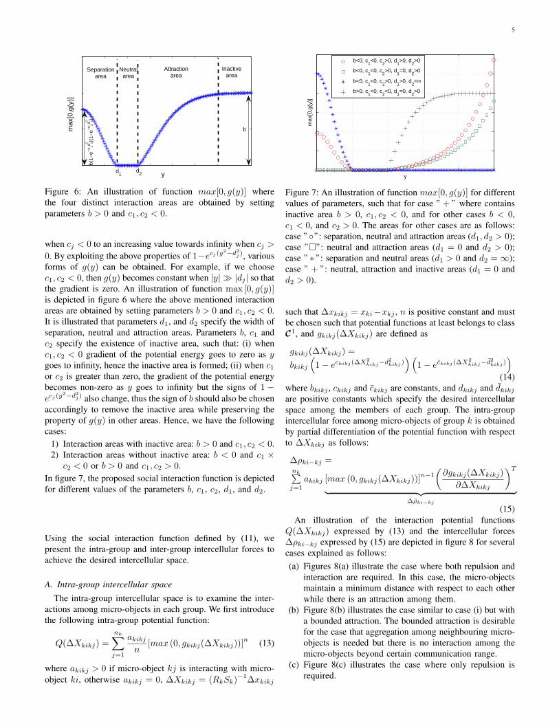
Intercellular spaces play a critical role on the cell-cellinteractions, adhesions and communications. In order to studydifferent cellular behavior, we have introduced the socialinteraction function to decompose the space around eachmicro-object into four areas: separation area, in order to keepminimum distance between micro-objects; neutral area, whichmicro-objects can choose a desired range with respect toeach other; attraction area in order to keep the group unityand also group aggregation; inactive area, which appears byincreasing distance among micro-objects and vanishing ofattractive force. The proposed social interaction function isdefined based on five parameters b, c1, c2, d1, and d2, asfollows:
g (y) = b(1− ec1(y
2−d21))(
1− ec2(y2−d22)
)(11)
where y is a variable, b, c1 and c2 are constants, and d1and d2 are positive constants which specify the desired in-tercellular space. The introduced social interaction functiong(y) is used to form a potential energy function by utilizing”max” function. As the function max [0, g(y)] is not a smoothfunction, we use power n to smoothen max [0, g(y)] and makeit differentiable, as follows:
Uint = max [0, g(y)]n (12)
The gradient of the potential energy is zero if the functionmax [0, g(y)] is constant and thus neutral and inactive areasare formed (depending on the values of y). When the gradientof the potential energy is non-zero, then separation area andattraction area are formed.Note that, for j = 1, 2 when the signs of cj reverses, the signsof 1 − ecj(y
2−d2j ) also reverses. The value of 1 − ecj(y2−d2j )
when y is infinite also changes from a constant finite value of 1
5
y
max
[0,g
(y)]
b(1−
e−c 1d 12 )(
1−e−
c 2d 22 )
Attractionarea
d2
Neutralarea
Separationarea
Inactivearea
b
d1
Figure 6: An illustration of function max[0, g(y)] wherethe four distinct interaction areas are obtained by settingparameters b > 0 and c1, c2 < 0.
when cj < 0 to an increasing value towards infinity when cj >0. By exploiting the above properties of 1−ecj(y
2−d2j ), variousforms of g(y) can be obtained. For example, if we choosec1, c2 < 0, then g(y) becomes constant when |y| ≫ |dj | so thatthe gradient is zero. An illustration of function max [0, g(y)]is depicted in figure 6 where the above mentioned interactionareas are obtained by setting parameters b > 0 and c1, c2 < 0.It is illustrated that parameters d1, and d2 specify the width ofseparation, neutral and attraction areas. Parameters b, c1 andc2 specify the existence of inactive area, such that: (i) whenc1, c2 < 0 gradient of the potential energy goes to zero as ygoes to infinity, hence the inactive area is formed; (ii) when c1or c2 is greater than zero, the gradient of the potential energybecomes non-zero as y goes to infinity but the signs of 1 −ecj(y
2−d2j ) also change, thus the sign of b should also be chosenaccordingly to remove the inactive area while preserving theproperty of g(y) in other areas. Hence, we have the followingcases:
1) Interaction areas with inactive area: b > 0 and c1, c2 < 0.2) Interaction areas without inactive area: b < 0 and c1 ×
c2 < 0 or b > 0 and c1, c2 > 0.In figure 7, the proposed social interaction function is depictedfor different values of the parameters b, c1, c2, d1, and d2.
Using the social interaction function defined by (11), wepresent the intra-group and inter-group intercellular forces toachieve the desired intercellular space.
A. Intra-group intercellular space
The intra-group intercellular space is to examine the inter-actions among micro-objects in each group. We first introducethe following intra-group potential function:
Q(∆Xkikj) =
nk∑j=1
akikjn
[max (0, gkikj(∆Xkikj))]n (13)
where akikj > 0 if micro-object kj is interacting with micro-object ki, otherwise akikj = 0, ∆Xkikj = (RkSk)
−1∆xkikj
y
max
[0,g
(y)]
b<0, c
1<0, c
2>0, d
1>0, d
2>0
b<0, c1<0, c
2>0, d
1=0, d
2>0
b<0, c1<0, c
2>0, d
1>0, d
2=∞
b>0, c1<0, c
2<0, d
1=0, d
2>0
Figure 7: An illustration of function max[0, g(y)] for differentvalues of parameters, such that for case ” + ” where containsinactive area b > 0, c1, c2 < 0, and for other cases b < 0,c1 < 0, and c2 > 0. The areas for other cases are as follows:case ””: separation, neutral and attraction areas (d1, d2 > 0);case ””: neutral and attraction areas (d1 = 0 and d2 > 0);case ” ∗ ”: separation and neutral areas (d1 > 0 and d2 = ∞);case ” + ”: neutral, attraction and inactive areas (d1 = 0 andd2 > 0).
such that ∆xkikj = xki−xkj , n is positive constant and mustbe chosen such that potential functions at least belongs to classC1, and gkikj(∆Xkikj) are defined as
gkikj(∆Xkikj) =
bkikj
(1− eckikj(∆X
2kikj−d
2kikj)
)(1− eckikj(∆X
2kikj−d
2kikj)
)(14)
where bkikj , ckikj and ckikj are constants, and dkikj and dkikjare positive constants which specify the desired intercellularspace among the members of each group. The intra-groupintercellular force among micro-objects of group k is obtainedby partial differentiation of the potential function with respectto ∆Xkikj as follows:
∆ρki−kj =nk∑j=1
akikj [max (0, gkikj(∆Xkikj))]n−1
(∂gkikj(∆Xkikj)
∂∆Xkikj
)T︸ ︷︷ ︸
∆ρki−kj
(15)An illustration of the interaction potential functions
Q(∆Xkikj) expressed by (13) and the intercellular forces∆ρki−kj expressed by (15) are depicted in figure 8 for severalcases explained as follows:(a) Figures 8(a) illustrate the case where both repulsion and
interaction are required. In this case, the micro-objectsmaintain a minimum distance with respect to each otherwhile there is an attraction among them.
(b) Figure 8(b) illustrates the case similar to case (i) but witha bounded attraction. The bounded attraction is desirablefor the case that aggregation among neighbouring micro-objects is needed but there is no interaction among themicro-objects beyond certain communication range.
(c) Figure 8(c) illustrates the case where only repulsion isrequired.

6
0 2 4 6 8 10 120
0.5
1
1.5
||∆ Xkikj
||
Q(∆
Xki
kj)
ckikj
=−0.1
ckikj
=−0.15
ckikj
=−0.2
ckikj
=−0.25
bkikj = −1
ckikj = 0.006
dkikj = 3µm
dkikj = 5µm
∆
∆ < ∆ =
(a) In this case we have both repulsion and attraction forces. By changing theparameters ckikj and ckikj we can change the magnitude of interaction force.Parameters dkikj and dkikj can define the repulsion and attraction area.
0 2 4 6 8 10 120
0.5
1
1.5
||∆ Xkikj
||
Q(∆
Xki
kj)
ckikj
=−0.005
ckikj
=−0.01
ckikj
=−0.02
ckikj
=−0.03
ckikj
=−0.05
dkikj=3µm
dkikj=5µm
bkikj = 1
ckikj = −0.05
∆
∆ <
∆ =
∆ ≅
∆
< ∆
(b) In this case we have both repulsion and attraction forces, however theattraction is limited to micro-objects within certain communication range.Moreover, by proper choosing of ckikj , ckikj and dkikj the repulsion forcecan be eliminated and only attraction force can be obtained.
0 5 10 150
0.5
1
1.5
||∆ Xkikj
||
Q(∆
Xki
kj)
dkikj = 5µm
bkikj = −1
ckikj = −0.03
ckikj = 1
dkikj = ∞
∆
∆ ≤
∆ =
(c) By choosing dkikj large enough we can only obtain repulsion force.
Figure 8: Illustration of the interaction potential functionQ(∆Xkikj) expressed by (13) and the intercellular forces∆ρki−kj expressed by (15) for different parameters values.
B. Inter-group intercellular space
To maintain intercellular space between micro-objects fromneighboring groups, the interaction functions gkikj(∆Xkikj)are defined as
gkikj(∆Xkikj) =
bkikj
(1− eckikj(∆X
2kikj−d
2kikj
))(
1− eckikj(∆X2kikj
−d2kikj
))
(16)where bkikj , ckikj and ckikj are constants, and dkikj and dkikjare positive constants which specify the desired intercellularspace between the members of different groups. The inter-group potential energy functions are defined as
H(∆Xkikj) =
nk∑j=1
akikjn
[max
(0, gkikj(∆Xkikj)
)]n(17)
where akikj > 0 if micro-object kj in group k is inter-acting with micro-object ki in group k, otherwise akikj =
0, ∆Xkikj =((RkSk)
−1+ (RkSk)
−1)∆xkikj such that
∆xkikj = xki − xkj . The inter-group intercellular forcebetween micro-objects from different groups is defined bypartial differentiation of (17) with respect to ∆Xkikj , as
∆ψki−kj =nk∑j=1
akikj[max
(0, gkikj(∆Xkikj)
)]n−1(∂gkikj(∆Xkikj)
∂∆Xkikj
)T︸ ︷︷ ︸
∆ψki−kj
(18)
Property 1. Since the inter-group intercellular interactionrequires only the repulsion and bounded attraction, the in-tercellular force between micro-objects from different groupsare upper bounded, i.e.
∥∥∆ψki−kj∥∥ < σ, where σ is a positiveconstant.
Next, adaptive interaction forces are defined as,
∆ηki−kj =
nk∑j=1
akikjR(θki−kj
)∆ψki−kj (19)
where ∆ψki−kj can be computed based on (18), θki−kj arerotation angles and R
(θki−kj
)are rotation matrices expressed
as follows:
R(θkikj) =
[cos(θkikj) − sin(θkikj)sin(θkikj) cos(θkikj)
](20)
The details will be given in later development.In order to achieve multi-group manipulation of micro-objects,the manipulation process composes of two subtasks:
1) Local manipulation which includes the manipulation oflaser beams to their desired position in the formationwithin the image frame.
2) Global manipulation which includes the manipulation ofthe whole system using the stage movement to follow areference trajectory.
In the next section, we first present the multi-group manipu-lation of micro-objects within the image frame, and later wepresent the overall group manipulation using stage control.
V. ASYNCHRONOUS MANIPULATION OF MULTIPLEGROUPS OF MICRO-OBJECTS
In this section, we present a control methodology to achieveasynchronous manipulation of multiple groups of micro-objects. Here, the asynchronous manipulation is defined as anindependent control and manipulation of each group, thereforelocal manipulation can be achieved.The dynamics of micro-objects expressed by (3) can be writtenas follows:
xki +Ωkixki = Ωki (qki + z) (21)
where Ωki = B−1ki Kki for k = 1, 2, ..., N and i = 1, 2, ..., nk.
In the sequel, we first propose the desired position for theoptical traps to achieve local manipulation of groups withinthe image frame, and after that we propose a feedback lawfor motorized stage control to manipulate the whole groupsbeyond the image frame.
7
A. Local manipulation of optical trapsIn order to achieve local manipulation of optical traps,
the following information is required: the region errors ∆ξkidefined by (10) to move the micro-objects into the desiredregion, the interaction forces ∆ρki−kj defined by (15) toobtain the desired intercellular spaces in each groups, and∆ηki−kj defined by (19) to obtain the desired intercellularspaces between different groups.We first define a reference vector for each micro-object i ingroup k as follows:
xrki= xko − (RkSk)
d
dt
(RkSk)
−1∆xkoi (22)
In the reference vector, the term xko denotes thevelocity of each group’s reference and the term(RkSk)
ddt
(RkSk)
−1∆xkoi denotes the transformation
rate of the desired region of each group. Using the referencevectors, (21) can be expressed as
(RkSk)∆Xkio + xrki+Ωkixki = Ωki (qki + z) (23)
where ∆Xkio = (RkSk)−1
∆xkio ∈ R2. For manipulation ofmultiple groups of micro-objects, models of Ωki are required.However, as mentioned in section II, parameters Ωki dependon several factors like the drag coefficients, size of each micro-object, and the relative refractive index of each micro-objectand the medium, and hence parameters Ωki might vary for dif-ferent tasks. Moreover, due to nonhomogeneity and the lack ofa perfectly spherical shape of micro-objects, the exact valuesfor Ωki are difficult to obtain. To deal with this issues, weconsider estimated models of Ωki i.e. Ωki = B−1
ki Kki whichare constant matrices for k = 1, 2, ..., N and i = 1, 2, ..., nk.The adaptive control laws for local manipulation of multiplegroups of micro-objects are expressed as follows:
qki = xki − z + Ω−1ki
xrki
− kp(RkSk)−T (
∆εki + λ∆ηki−kj)
+Y (xrki) θki
(24)
where kp and λ are positive constants, superscript −T refersto the transpose of the inverse matrix, ∆ηki−kj are adaptiveinteraction forces defined by (19), Ωki are fixed estimationsof Ωki, the terms ∆εki are defined as
∆εki = αki∆ξki + γk∆ρki−kj (25)
where αki and γk are positive constants, and ∆ξki and∆ρki−kj are obtained by (10) and (15), respectively. Theterms Y (xrki
) θki are used to compensate the estimation errorsinduced by the constant estimated matrices Ωki, such thatY (xrki
) are known regressor matrices as detailed later, andθki are estimations of unknown parameters obtained by thefollowing update laws:
˙θki = −ΓkiY (xrki
) (RkSk)−T
∆εki (26)
that preserve the stability of the system, where Γki ∈ R2×2
are diagonal positive definite matrices. Substituting (24) intothe dynamic models of micro-objects (21), yields:
RkSk∆Xkio + kpΩkiΩ−1ki (RkSk)
−T (∆εki + λ∆ηki−kj
)+ΩkiΩ
−1ki
(ΩkiΩ
−1ki − I2
)xrki
− Y (xrki) θki
= 0
(27)
Since the terms(ΩkiΩ
−1ki − I2
)xrki
are linear functions ofunknown parameters, using the parameter separation tech-nique, we have(
ΩkiΩ−1ki − I2
)xrki
= Y (xrki) θki (28)
where Y (xrki) = diag
x1rki
, x2rki
, and xlrki
denotes the lth
element of the vector xrki, and θki denote unknown parameters
due to the approximation errors, such that θki = [θ1ki, θ2ki]T
and θlki = Ωlki/Ωlki− 1, and Ωlki and Ωlki are the lth diagonal
elements of the diagonal matrices Ωki and Ωki, respectively.Using (28), yields(
ΩkiΩ−1ki − I2
)xrki︸ ︷︷ ︸
Y (xrki)θki
−Y (xrki) θki = Y (xrki
)∆θki (29)
where ∆θki = θki− θki. Hence, (27) is simplified as follows:
RkSk∆Xkio + kpΩkiΩ−1ki (RkSk)
−T (∆εki + λ∆ηki−kj
)+ΩkiΩ
−1ki Y (xrki
)∆θki = 0(30)
B. Group maneuvering by means of the stage trajectory track-ing
The standard optical tweezers requires tightly focused laserbeam obtained by high numerical aperture objective lens(typically NA > 1) to achieve a stable trap. However, em-ploying a high NA objective lens restricts the field of viewand consequently limits the area that trapped micro-objectscan be maneuvered. In order to overcome this issue, weutilize the motorized stage to manipulate trapped micro-objectsbeyond the initial field of view. Here, a control methodologyis presented such that the motorized stage follow a desiredreference.To do so, a reference vector is defined as follows:
zr = zd − αs∆z (31)
where αs is a positive constant, ∆z = z−zd such that zd is thedesired reference of the motorized stage. Using the referencevector the sliding vector can be introduce as follows:
ss = z − zr = ∆z + αs∆z (32)
Substituting the sliding vector (32) and its derivative into (5),the following equation is obtained:
Msss +Bsss +Ys(zr, zr)θs = uz (33)
where Ys(zr, zr) is known regressor matrix and θs is unknownparameter vector defined by (6). The feedback law for the stagetrajectory tracking is defined as follows:
uz = −Ksss +Ys(zr, zr)θs (34)
where Ks is a positive definite matrix, and θs are estimatedvalue of θs. The parameters update law is expressed as follows:
˙θs = −LsYTs (zr, zr)ss (35)
where Ls is a positive definite matrix. Substituting the feed-back law (34) into (33), yields
Msss +Bsss +Ksss +Ys(zr, zr)∆θs = 0 (36)
where ∆θs = θs − θs.

8
C. Stability Analysis
From (30) and (36) the overall closed-loop system can beexpressed as follows: RkSk∆Xkio + kpΩkiΩ
−1ki (RkSk)
−T (∆εki + λ∆ηki−kj
)+ΩkiΩ
−1ki Y (xrki
)∆θki = 0Msss +Bsss +Ksss+Y(zr, zr)∆θs = 0
(37)For the stability analysis, the following Lyapunov-like candi-date is proposed:
VT = Vlaser + Vstage (38)
such that
Vlaser =
N∑k=1
[nk∑i=1
αki
mk∑l=1
kkl∣∣f lk (∆Xkio)
∣∣δ (1 + sign(f lk (∆Xkio)
)+
nk∑i=1
1
2γk
nk∑j=1
akikjn
[max (0, gkikj(∆Xkikj))]n
+N∑k=1
nk∑i=1
1
2∆θTkiΩkiΩ
−1ki Γ
−1ki ∆θki
](39)
and
Vstage =1
2sTsMsss +
1
2∆θTs L
−1s ∆θs (40)
Differentiating the Lyapunov-like candidate with respect totime, yields
VT =N∑k=1
[nk∑i=1
αki∆XTkio∆ξki +
12
nk∑i=1
γknk∑j=1
akikj∆XTkikj∆ρki−kj
−nk∑i=1
˙θTkiΩkiΩ
−1ki Γ
−1ki ∆θki
]+ sTsMsss − ˙
θTs L−1s ∆θs
(41)Since ∆ρki−kj = −∆ρkj−ki, we have
nk∑i=1
nk∑j=1
akikj∆XTkikj∆ρki−kj = 2
nk∑i=1
nk∑j=1
akikj∆XTkio∆ρki−kj
(42)Using (42), and substituting the closed-loop system (37) andthe parameters update laws (26) and (35) into VT , yields
VT = −N∑k=1
[nk∑i=1
kp∆εTkiΛki∆εki +
nk∑i=1
kpλ∆εTkiΛki∆ηki−kj
]−sTs (Bs +Ks) ss (43)
where Λki = (RkSk)−1
ΩkiΩ−1ki (RkSk)
−T are positive defi-nite matrices. In order to ensure the stability, we define inter-group interaction terms, ∆ηki−kj , so that
N∑k=1
nk∑i=1
kpλ∆εTkiΛki∆ηki−kj = 0 (44)
Substituting (19) into (44), and simplifying yields(∆εTkiΛki −∆εTkjΛkj
)R
(θkikj
)∆ψki−kj = 0 (45)
Laser source
Stage
Camera
Camera
QPD
Figure 9: The setup consists of the microscope, the motorizedstage, the optical trap device, and the cameras.
Using (20), it can be shown that the equation (45) holds if therotation angles θkikj are defined as follows:
θkikj =
tan−1
− (∆εTkiΛki−∆εTkj
Λkj)∆ψki−kj(∆εTkiΛki−∆εT
kjΛkj
) 0 −11 0
∆ψki−kj
(46)
For the case that ∆εTkiΛki − ∆εTkjΛkj = 0 no updates in
rotation angles are needed since equation (45) is satisfied forany R(θkikj); therefore, previous value of θkikj can be used.Hence, R(θkikj) is always defined. Therefore, VT is simplifiedas follows:
VT = −N∑k=1
nk∑i=1
kp∆εTkiΛki∆εki − sTs (Bs +Ks) ss ≤ 0.
(47)Now we are able to state the following theorem:
Theorem. The multiple groups of micro-objects representedby (3) with the position input of traps expressed by (24), thefeedback law for motorized stage expressed by (34), and theparameters update laws (26) and (35) result in the convergenceof ∆εki, ss → 0 as t → ∞ for k = 1, 2, ..., N and i =1, 2, ..., nk.
Proof. Since VT ≥ 0 and VT ≤ 0, f lk (∆Xkio),gkikj(∆Xkikj), ∆θki, ss and ∆θs are bounded. Hence,∆ξki and ∆ρki−kj are bounded. Using property (1) and theboundedness of ∆ξki, ∆ρki−kj and ∆θki, from closed-loopequation (37) we can conclude the boundedness of ∆Xkio
and ss. Therefore, VT is bounded which means that VT isuniformly continuous. By invoking Barbalat’s Lemma [53],it then follows VT goes to zero as t → ∞, so it can beconcluded that ∆εki, ss → 0 as t → ∞ for k = 1, 2, ..., Nand i = 1, 2, ..., nk.
Remark 2. It should be noted that in the adaptive controlscheme, the task convergence is independent of parametersconvergence. It is shown that persistent excitation (PE) [55]of the input is sufficient condition for convergence of theparameters i.e. ∆θki → 0.

9
VI. EXPERIMENT
The proposed control method was implemented in theoptical tweezers system as shown in Fig. 9. The setup consistsof an inverted microscope (Nikon, Eclipse Ti-U), a motorizedstage (Marzhauser Wetzlar, SCAN IM), and a multipleoptical trap device (Elliot Scientific, E3500). The optical trapdevice is capable of creating and independently manipulatingmultiple laser beams within the field of view, and the opticaltrap is moved by the acousto-optic beam deflector (AOD)with the resolution of 16 pm. The motorized stage is operatedin a 2-D space, with the range of 120 × 100 mm and theresolution of 0.01 µm. A 1070nm fibre laser with the power0.5W was utilized. The objective lens used for the experimentwas Plan Apo VC 100X Oil with NA=1.4. The position ofthe laser beam can be measured by using either the camera orencoders mounted on the stage. Two high speed cameras wereused to take the image from the microscope which include:(i) Basler piA640-210gm with resolution 648px × 488px,pixel size 7.4µm, provides image capture rate of 210 framesper second at VGA resolution, (ii) Teledyne DALSA modelGenie HM640 with resolution 640px × 480px, pixel size7.4µm, provides image capture rate of 300 frames persecond at VGA resolution. The image captured from cameraswere fed into the program written in National InstrumentsLabVIEW. To obtain the position of cells within the capturedimage the IMAQ Vision library in LabVIEW were utilized.Using IMAQ Count Objects 2 VI, we are able to locate,count, and label micro-objects in a rectangular search area.The control algorithm receives the feedback information ofthe micro-objects and the laser beams, and generates thecontrol input. The control methodology has been written inthe National Instruments LabVIEW that could simultaneouslycontrol the piezo stage and optical traps. Two experimentswere conducted to illustrate the performance of the proposedmethod. The medium utilized in both experiments forimmersion of the micro-objects was deionized water. Theexperiments were performed at a room temperature of 296 K.
In the first experiment, the interactions among multiplegroups of micro-objects were considered. In this scenario, ninelaser beams were generated to trap three yeast cells, threelatex (polystyrene) microbeads with the size of 3µm and threelatex (polystyrene) microbeads with the size of 5µm. Due torestrictions in culturing cells in the lab, micro-beads were usedto represent different types of micro-objects. Note that themain focus of this experiment is to illustrate the manipulationtechnique and not measurement of cellular response. After thelasers were assigned to the micro-objects the traps switchedon and remained on during the manipulation. To consider onlyinteractions between micro-objects, the stage was fixed andregion formation was disabled by setting the region gain tozero i.e. αki = 0. The initial position of micro-objects isdepicted in figure 10(a). Different values for the parametersof intra-group intercellular (gkikj(∆Xkikj)) and inter-groupintercellular (gkikj(∆Xkikj)) potential functions defined by(14) and (16) respectively, were chosen to achieve different
intercellular behaviour, which is expressed as follows:
a :
I : bkikj = −1, ckikj = −0.0249, ckikj = 0.0029,dkikj = 13.5µm, dkikj = 15µmII : bkikj = −1, ckikj = −0.0166, ckikj = 0.0025,dkikj = 10µm, dkikj = ∞
(48)
b :
I : bkikj = −1, ckikj = −0.0581, ckikj = 0.0025,dkikj = 8µm, dkikj = 8µmII : bkikj = −1, ckikj = −0.0083, ckikj = 0.0025,dkikj = 13.5µm, dkikj = ∞
(49)
c :
I : bkikj = −1, ckikj = −0.0581, ckikj = 0.0025,dkikj = 8µm, dkikj = 8µmII : bkikj = −1, ckikj = −0.0581, ckikj = 0.0025,dkikj = 8µm, dkikj = 8µm
(50)
In the first case depicted in figure 10(b) the groupsegregation was considered such that the whole group wasdecomposed into three groups. The parameters for intra-groupintercellular and inter-group intercellular potential functionswere chosen as (48).In the second case depicted in figure 10(c), the intra-groupintercellular space is decreased to show the performance ofthe proposed interaction forces in positioning of the micro-objects in the desired distance with respect to each other.The parameters for intra-group intercellular and inter-groupintercellular potential functions were chosen as (49).In the third case depicted in figure 10(d), the mergingscenario was considered such that two groups of microbeadswere merged together. This case is useful for the study ofinteractions between two kinds of microorganisms. It shouldbe noted that the movements of yeast cells were happened byinter-group interactions between yeast cells and microbeads.The parameters for intra-group intercellular and inter-groupintercellular potential functions were chosen as (49) for yeastcells, and the parameters of intra-group intercellular potentialfunctions for two groups of microbeads were chosen as (49-I)and for the inter-group intercellular potential functions werechosen as (50-II) for microbeads-microbeads and (49-II) formicrobeads-yeast cells.In the fourth case depicted in figure 10(e), the aggregationof all micro-objects was considered. For this case, theparameters of the intra-cellular and the inter-cellular potentialfunctions were chosen similarly. The parameters for theintra-group intercellular and the inter-group intercellularpotential functions were chosen as (50).
In the second experiment, dynamic manipulation of multiplegroups of micro-objects was considered. Seven laser beamswere generated to trap seven yeast cells with an average sizeof 4µm. The yeast cells were decomposed into four groups toform a star shape. The global reference in image coordinateswas chosen as xo = [Zx(t) + 25 + sin(kt)µm,Zy(t) + 18 +

10
5 10 15 20 25 30 35 40 45
0
5
10
15
20
25
30
35
x (µm)
y (µ
m)
(a) Initial position of yeast cells. For the right figure: the cells whichbelong to the same group is shown with the same marker, and the positionsof micro-objects are shown in the image frame.
5 10 15 20 25 30 35 40 45
0
5
10
15
20
25
30
35
x (µm)
y (µ
m)
(b) Segregation of a group into three smaller groups using interactionpotential function. The solid paths in the right figure denote the trajectoryof yeast cells with respect to the image frame. from t = 0 s to t = 18 s.
5 10 15 20 25 30 35 40 45
0
5
10
15
20
25
30
35
x (µm)
y (µ
m)
(c) Decreasing the intra-group intercellular space by reducing dkikj anddkikj . The solid paths in the right figure denote the trajectory of yeastcells with respect to the image frame. from t = 18 s to t = 19 s.
5 10 15 20 25 30 35 40 45
0
5
10
15
20
25
30
35
x (µm)
y (µ
m)
(d) Merging two groups of microbeads. The movements of yeast cellswere due to inter-group interactions between yeast cells and microbeads.The solid paths in the right figure denote the trajectory of yeast cells withrespect to the image frame. from t = 19 s to t = 30 s.
5 10 15 20 25 30 35 40
0
5
10
15
20
25
30
35
x (µm)
y (µ
m)
(e) Aggregation of all micro-objects. The solid paths in the right figuredenote the trajectory of yeast cells with respect to the image frame. fromt = 30 s to t = 46 s.
Figure 10: Snapshots of yeast cells and laser beams at different time instants. In this scenario, the group segregation andmerging were considered. The ”+” represents the positions of the laser beams.
cos(kt)µm]T , and the references of groups were chosen as
x10 = xo
x20 = xo − l2s2(t)
[sin(kt)cos(kt)
]x30 = xo − l3s3(t)
[sin(kt+ 2π/3)cos(kt+ 2π/3)
]x40 = xo − l4s4(t)
[sin(kt+ 4π/3)cos(kt+ 4π/3)
]where k = π/22, l2 = l3 = l4 = 9µm, s2, s3 and s4 aretime-varying scalers. The rotation angles for groups two tofour were chosen as φ2 = kt, φ3 = kt+ 2π
3 and φ4 = kt+ 4π3 .
The control parameters were chosen as αk = 0.05, andγk = λ = 0.2 for all k = 1, 2, 3, 4. The minimum inter-cellular space is set to d1 = 5.2µm.The initial position of the yeast cells is depicted in figure11(a). In order to control the movement of the stage, anobject in image space is specified (the filled black circle atthe right bottom of figure 11(a)) such that the displacementof the object with respect to its desired position is considered
as stage tracking error, and the desired reference speed setas zero. The snapshots of the yeast cells at different timeinstants are shown in figure 11. Figure 11(b) depicts the starshape formation by yeast cells. Consequently, the reference ofeach group follows their desired trajectory expressed in (51)while the motorize stage tracks the desired reference givenby operator. Independent scaling up of group two is depictedin figure 11(c). Consequently, group two is scaled down andgroup three scaled up independently as depicted in figure11(d). Finally, independent scaling down of group three andscaling up of group four were performed as depicted in 11(e).Note that the multi-group manipulation of micro-objects wasachieved by concurrent control of laser beams and motorizedstage. The trajectory of the yeast cells within the image frameis depicted in figure 12.
Remark 3. The manipulation time depends on various fac-tors such as manipulation distance, escape velocity and alsocontrol gains. The escape velocity imposes a constraint on themaximum manipulation velocity [56] of the optical trapping

11
−1.64 −1.63 −1.62 −1.61 −1.6 −1.59 −1.582.18
2.185
2.19
2.195
2.2
2.205
2.21
2.215
2.22
2.225
x (mm)
y (m
m)
(a) Initial position of yeast cells. For the left figure: the circle at theright bottom is showing the stage movement by displacement of the filledblack circle with respect to the center of the circle. For the right figure:the micro-object which belong to the same group is shown with the samemarker, and the dashed line box represents the initial position of the Fieldof View with respect to the stage frame.
Group
1
Group 2
Group 3
Group 4
−1.64 −1.61 −1.582.18
2.185
2.19
2.195
2.2
2.205
2.21
2.215
2.22
2.225
x (mm)
y (m
m)
(b) Formation of star shape by four groups of yeast cells. The solid pathsin the right figure denote the trajectory of yeast cells with respect to thebase frame from t = 0 s to t = 4 s. The dashed line box represents theinitial position of the Field of View.
Group
1
Group 2
Group 3
Group 4
−1.62 −1.61 −1.6 −1.59 −1.58 −1.57 −1.56
2.175
2.18
2.185
2.19
2.195
2.2
2.205
2.21
2.215
2.22
2.225
x (mm)
y (m
m)
(c) The groups follow their desired references specified by (51) mean-while the groups are scaled independently. Independent scaling up ofgroup two (t = 10 s). The solid paths in the right figure denote thetrajectory of yeast cells with respect to the base frame from t = 4 s tot = 10 s. The dashed line box represents the initial position of the Fieldof View at t = 4 s, and the dotted line box represents the position of theField of View at t = 10 s.
Group
1
Group 2
Group 3
Group 4
−1.58 −1.56 −1.54 −1.52 −1.5
2.15
2.16
2.17
2.18
2.19
2.2
2.21
2.22
2.23
x (mm)
y (m
m)
(d) Independent scaling down of group two and scaling up of group three(t = 20 s). The solid paths in the right figure denote the trajectory ofyeast cells with respect to the base frame from t = 10 s to t = 20 s.The dashed line box represents the initial position of the Field of Viewat t = 10 s, and the dotted line box represents the position of the Fieldof View at t = 20 s.
Group
1
Group 2
Group 3
Group 4
−1.64 −1.62 −1.6 −1.58 −1.56 −1.54 −1.522.15
2.16
2.17
2.18
2.19
2.2
2.21
2.22
2.23
2.24
2.25
x (mm)
y (m
m)
(e) Independent scaling down of group three and scaling up of group four(t = 30 s). The solid paths in the right figure denote the trajectory ofyeast cells with respect to the base frame from t = 20 s to t = 30 s.The dashed line box represents the initial position of the Field of Viewat t = 20 s, and the dotted line box represents the position of the Fieldof View at t = 30 s.
Figure 11: Snapshots of yeast cells and laser beams at different time instants. In this scenario, the group is divided into fourgroups to form a complex time-varying formation. The ”+” represents the positions of the laser beams.
problem. The main factor which affects the escape velocityis the finite trapping stiffness of the optical trap, which canbe increased by using higher laser power. However, the highintensity of laser might damage the live micro-objects. Thecontrol gains can be adjusted to increase the manipulationspeed provided that it is within the maximum manipulationvelocity.
VII. CONCLUSIONS
In this paper, a framework based on concurrent stage-lasercoordination has been proposed to achieve multi-group micro-object manipulation using robotic tweezers. A local coordina-tion control has been developed to achieve dynamic formation
of multiple groups of micro-objects using laser beams anda global coordination of groups of micro-objects has beenpresented based on the stage coordination control. The stabilityof the system has been analyzed by means of Lyapunov-likeanalysis. Experimental results have been presented to illustratethe performance of the proposed method.
ACKNOWLEDGMENT
The work was supported by the Agency For Science, Tech-nology And Research of Singapore (A*STAR), (Reference No.1121202014).

12
5 10 15 20 25 30 35 40 45 50 55
0
5
10
15
20
25
30
35
x (µm)
y (µ
m)
k=1,i=1
k=2,i=1
k=2,i=2
k=3,i=1
k=3,i=2
k=4,i=1
k=4,i=2
Figure 12: Trajectory of the yeast cells within the image framefrom t = 0 s to t = 30 s.
REFERENCES
[1] P.K. Wong, T.-H. Wang, J.H. Deval, and C.-M. Ho, ”Electrokinetics inmicro devices for biotechnology applications”, IEEE/ASME Transactionson Mechatronics, vol. 9, no. 2, pp. 366-376, 2004.
[2] Y. Zhang, B.K. Chen, X. Liu, and Y. Sun,, ”Autonomous robotic pick-andplace of microobjects”, IEEE Transactions on Robotics, vol. 26, no.1, pp. 200-207, 2010.
[3] Z. Zhang, Y. Huang, and C.-H. Menq, ”Visually controlled manipulationof a magnetic microbead using magnetic tweezers”, IEEE transactionson Robotics, vol. 26, no. 3, pp. 531-541, 2010.
[4] K.B. Yesin, K. Vollmers, and B.J. Nelson, ”Modeling and control ofuntethered biomicrorobots in a fluidic environment using electromagneticfields”, International Journal of Robotics Research, vol. 25, no. 4-5, pp.527-536, 2006.
[5] A.G. Banerjee, S. Chowdhury, and S.K. Gupta, ”Optical tweezers: au-tonomous robots for the manipulation of biological cells”, IEEE Robotics& Automation Magazine, vol. 21, no. 3, pp. 81-88, 2014.
[6] A. Ashkin, ”Acceleration and trapping of particles by radiation pressure”,Physical Review Letters, vol. 24, pp. 156-159, 1970.
[7] A. Ashkin, ”History of optical trapping and maniupulation of small-neutral particles, atoms, and molecules”, Journal of Quantum Electronics,vol. 6, pp. 841-859, 2000.
[8] K.C. Neuman, and S.M. Block, ”Optical trapping”, Review of ScientificInstruments, vol. 75, pp. 2787-2809, 2004.
[9] K. Ramser, and D. Hanstorp, ”Review article: Optical manipulation forsingle cell studies”, Journal of Biophotonics, vol. 3, no. 4, pp. 187-206,2009.
[10] A. Thakur, S. Chowdhury, P. Svec, C. Wang, W. Losert, and S.K. Gupta,”Indirect pushing based automated micromanipulation of biological cellsusing optical tweezers”, International Journal of Robotics Research, vol.33, no. 8, pp. 1098-1111, 2014.
[11] S. Chen, J. Cheng, C.W. Kong, X. Wang, S.H. Cheng, R.A. Li, and D.Sun, ”Laser-induced fusion of human embryonic stem cells with opticaltweezers”, Applied Physics Letters, vol. 103, 033701, 2013.
[12] X. Gou, H. Han, S. Hu, A.Y.H. Leung, and D. Sun, ”Applying combinedoptical tweezers and fluorescence microscopy technologies to manipulatecell adhesions for cell-to-cell interaction study”, IEEE Transactions onBiomedical Engineering, vol. 60, no. 8, pp. 2308-2315, 2013.
[13] V.R. Daria, P.J. Rodrigo, and J. Glckstad, ”Dynamic formation of op-tically trapped microstructure arrays for biosensor applications”, Biosen-sors and Bioelectronics, vol. 19, pp. 1439-1444, 2004.
[14] X. Gou, H. Yang, T.M. Fahmy, Y. Wang, and D. Sun, ”Direct measure-ment of cell protrusion force utilizing a robot-aided cell manipulationsystem with optical tweezers for cell migration control”, InternationalJournal of Robotics Research, vol. 33, no. 14, pp. 1782-1792, 2014.
[15] T. Hayakawa, S. Fukada, and F. Arai, ”Fabrication of an on-chipnanorobot integrating functional nanomaterials for single-cell Hayakawa”,IEEE Transactions on Robotics, vol. 30, no. 1, pp. 59-67, 2014.
[16] E. Dufresne, G. Spalding, M. Dearing, S. Sheets, and D. Grier,”Computer-generated holographic optical tweezers arrays”, Review ofScientific Instruments, vol. 72, pp. 1820-1816, 2001.
[17] K. Visscher, G.J. Brakenhoff, and J.J. Kroll, ”Micromanipulation bymultiple optical traps created by a single fast scanning trap integratedwith the bilateral confocal scanning laser microscope”, Cytometry, vol.14, pp. 105-114, 1993.
[18] C. Mio, T. Gong, A. Terray, and D.W.M. Marr, ”Design of a scanninglaser optical trap for multiparticle manipulation”, Review of ScientificInstruments, vol. 71, pp. 2196-2200, 2000.
[19] K. Vermeulen, J. van Mameren, G. Stienen, E. Peterman, G. Wuite,and C. Schmidt, ”Calibrating bead displacements in optical tweezersusing acousto-optic deflectors”, Review of Scientific Instruments, vol. 77,013704, 2006.
[20] Y. Tanaka, H. Kawada, K. Hirano, M. Ishikawa1, and H. Kitajima,”Automated manipulation of non-spherical microobjects using opticaltweezers combined with image processing techniques”, Optics Express,vol. 16, no. 19, pp. 15115-15122, 2008.
[21] S. Hu, and D. Sun, ”Automatic transportation of biological cells witha robot-tweezer manipulation system”, International Journal of RoboticResearch, vol. 30, no. 14, pp. 1681-1694, 2011.
[22] A.G. Banerjee, and S.K. Gupta, ”Research in automated planningand control for micromanipulation ”, IEEE Transactions on AutomationScience and Engineering, vol. 10, no. 3, pp. 485-495, 2013.
[23] A.G. Banerjee, A. Pomerance, W. Losert, and S.K. Gupta, ”Developinga stochastic dynamic programming framework for optical tweezer basedautomated particle transport operations”, IEEE Transactions on Automa-tion Science and Engineering, vol. 7, no. 2, pp. 218-227, 2010.
[24] A.G. Banerjee, S. Chowdhury, W. Losert, and S.K. Gupta, ”Real-timepath planning for coordinated transport of multiple particles using opticaltweezers”, IEEE Transactions on Automation Science and Engineering,vol. 9, no. 4, pp. 669-678, 2012.
[25] Y. Wu, D. Sun, W. Huang, and N. Xi, ”Dynamics analysis and mo-tion planning for automated cell transportation with optical tweezers”,IEEE/ASME Transactions on Mechatronics, vol. 30, issue 2, pp. 706-713,2013.
[26] A. Ranaweera, and B. Bamieh, ”Modeling, identification, and control ofa spherical particle trapped in an optical tweezer”, International Journalof Robust and Nonlinear Control, vol. 15, pp. 747-768, 2005.
[27] A.E. Wallin, H. Ojala, E. Haeggstrom, and R. Tuma, ”Stiffer opticaltweezers through real-time feedback control”, Applied Physics Letters,vol. 92, 224104, 2008.
[28] A.E. Cohen, and W.E. Moerner, ”Method for trapping and manipulatingnanoscale objects in solution”, Applied Physics Letters, vol. 86, 093109,2005.
[29] C.C. Cheah, X. Li, X. Yan, D. Sun, ”Observer Based Optical Manip-ulation of Biological Cells with Robotic Tweezers”, IEEE Transactionson Robotics, pp. 68-80, 2013.
[30] X. Li, C. C. Cheah, S. Hu, and D. Sun, ”Dynamic trapping andmanipulation of biological cells with optical tweezers”, Automatica, vol.49, no. 6, pp. 1614-1625, 2013.
[31] X. Li, and C.C. Cheah, ”Robotic cell manipulation using opti-cal tweezers with unknown trapping stiffness and limited FOV”,IEEE/ASME Transactions on Mechatronics , pp. 1-9, 2014, DOI:10.1109/TMECH.2014.2364620.
[32] J.T. Feddema, C. Lewis, and D.A. Schoenwald, ”Decentralized control ofcooperative robotic vehicles: theory and application”, IEEE Transactionson Robotics and Automation, vol. 18, no. 5, pp. 852-864, 2002.
[33] M. Ji, and M. Egerstedt, ”Distributed coordination control of multi-agent systems while preserving connectedness”, IEEE Transactions onRobotics, vol. 23, no. 4, pp. 693-703, 2007.
[34] R.M. Murray, ”Recent research in cooperative control of multi-vehiclesystems”, Journal of Dynamic Systems, Measurement and Control, vol.129, no. 5, pp. 571-583, 2007.
[35] W. Ren, and N. Sorensen, ”Distributed coordination architecture formulti-robot formation control”, Journal of Robotics and AutonomousSystems, vol. 56, no. 4, pp. 324-333, 2008.
[36] C.C. Cheah, S.P. Hou, and J.J.E. Slotine, ”Region-based shape controlfor a swarm of robots”, Automatica, vol. 45, no. 10, pp. 2406-2411, 2009.
[37] R. Haghighi, and C.C. Cheah, ”Multi-group coordination control forrobot swarms”, Automatica, vol. 48, no. 10, pp. 2526-2534, 2012.
[38] H. Chen, and D. Sun, ”Moving Groups of Microparticles into Array witha Robot-tweezers Manipulation System”, IEEE Transactions on Robotics,vol. 28, no. 5, pp. 1069-1080, 2012.
[39] S.C. Chapin, V. Germain, and E.R. Dufresne, ”Automated trapping,assembly, and sorting with holographic optical tweezers”, Optics Express,vol. 14, pp. 13095-13100, 2006.
[40] H. Chen, C. Wang, and Y. Lou, ”Flocking multiple microparticles withautomatically controlled optical tweezers: Solutions and experiments”,

13
IEEE Transactions on Biomedical Engineering, vol. 60, no. 6, pp. 1518-1527, 2013.
[41] S. Chowdhury, A. Thakur, P. Svec, C. Wang, W. Losert, and S. K.Gupta, ”Automated manipulation of biological cells using gripper forma-tions controlled by optical tweezers”, IEEE Transactions on AutomationScience and Engineering, vol. 11, no. 2, pp. 338-347, 2014.
[42] X. Yan, and D. Sun, ”Multilevel-based topology design and cell pattern-ing with robotically controlled optical tweezers”, IEEE Transactions onControl Systems Technology, vol. 23, no. 1, pp. 176-185, 2015.
[43] S. Chowdhury, P. Svec, A. Thakur, C. Wang, W. Losert, and S.K. Gupta,”Enhancing Range of Transport in Optical Tweezers Assisted MicrofluidicChambers Using Automated Stage Motion”, ASME International Confer-ence on Micro and Nanosystems, Portland, Oregon, pp. 1-10, 2013.
[44] R. Haghighi, and C.C. Cheah, ”Multi-cell formation following ina concurrent control framework”, IEEE International Conference onRobotics and Biomimetics, pp. 499-504, 2014, DOI: 10.1109/RO-BIO.2014.7090380.
[45] E.E. Hui, and S.N. Bhatia, ”Micromechanical control of cell-cell in-teractions”, in Proceedings of the National Academy of Sciences of theUnited States of America, vol. 104, no. 14, pp. 5722-5726, 2007.
[46] D.J. Odde, and M.J. Renn, ”Laser-guided direct writing of living cells”,Biotechnology and Bioengineering, vol. 67, pp. 312-318, 2000.
[47] S.F. Ibrahim, G. van den Engh, ”High-speed cell sorting: fundamentalsand recent advances”, Current Opinion in Biotechnology, vol. 14, pp.5-12, 2003.
[48] R. Haghighi, C.C. Cheah, ”Optical micromanipulation of multiplegroups of cells”, IEEE International Conference on Robotics and Au-tomation, pp. 3543-3548, 2015.
[49] C. Aguilar-Ibanez, M.S. Suarez-Castanon, and L.I. Rosas-Soriano, ”Asimple control scheme for the manipulation of a particle by means ofoptical tweezers”, International Journal of Robust and Nonlinear Control,vol. 21, no. 3, pp. 328-337, 2010.
[50] A. Ashkin, ”Forces of a single-beam gradient laser trap on a dielectricsphere in the ray optics regime”, Biophysical Journal, vol. 61, Issue 2,pp. 569-582 , 1992.
[51] N. Malagnino, G. Pesce, A. Sasso, and E. Arimondo, ”Measurementsof trapping efficiency and stiffness in optical tweezers”, Optics Commu-nications, vol. 214, pp. 15-24, 2002.
[52] W.H. Wright, G.J. Sonek, and M.W. Berns, ”Parametric study of theforces on microspheres held by optical tweezers”, Applied Optics, vol.33, pp. 1735-1748, 1994.
[53] J.J.E. Slotine, and W. Li, ”Applied nonlinear control”, Englewood Cliffs,New Jersy: Prentice Hall , 1991.
[54] C.C. Cheah, D.Q. Wang and Y.C. Sun, ”Region reaching control ofrobots”, IEEE Transactions on Robotics, vol. 23, no. 6, pp. 1260-1264,2007.
[55] P.A. Ioannou, and J. Sun, ”Robust adaptive control”, Englewood Cliffs,NJ: Prentice Hall, 1996.
[56] X. Yan, C.C. Cheah, Q.-C. Pham, and J.-J. E. Slotine, ”Roboticmanipulation of micro/nanoparticles using optical tweezers with velocityconstraints and stochastic perturbations”, IEEE International Conferenceon Robotics and Automation, pp. 797-802, 2015.
Related Documents