Safe Robotic Manipulation to Extract Objects from Piles: From 3D Perception to Object Selection

Welcome message from author
This document is posted to help you gain knowledge. Please leave a comment to let me know what you think about it! Share it to your friends and learn new things together.
Transcript

Safe Robotic Manipulation to Extract Objects fromPiles: From 3D Perception to Object Selection


Örebro Studies in Technology
Rasoul Mojtahedzadeh
Safe Robotic Manipulation to ExtractObjects from Piles: From 3D
Perception to Object Selection

© Rasoul Mojtahedzadeh, 2016
Title: Safe Robotic Manipulation to Extract Objects from Piles: From 3DPerception to Object Selection
Publisher: Örebro University, 2016www.publications.oru.se
Printer:
ISSN 1650-8580ISBN
Abstract Rasoul Mojtahedzadeh (2016): Safe Robotic Manipulation to Extract Objects from Piles: From 3D Perception to Object Selection. Örebro Studies in Technology 71.
Keywords: Object Selection; Object Pose Refinement; Gravitational Sup-port Relation; Inter-penetration Resolving; 3D Ranging Sensor Evaluation. Rasoul Mojtahedzadeh, School of Science and Technology Örebro University, SE-701 82 Örebro, Sweden
Abstract
Rasoul Mojtahedzadeh (2016): Safe Robotic Manipulation to ExtractObjects from Piles: From 3D Perception to Object Selection. Örebro Studies in Technology 71.
Keywords: Object Selection; Object Pose Refinement; Gravitational Sup-port Relation; Inter-penetration Resolving; 3D Ranging Sensor Evaluation. Rasoul Mojtahedzadeh, School of Science and Technology Örebro University, SE-701 82 Örebro, Sweden
Abstract
This thesis is concerned with the task of autonomous selection of objects to re-move (unload) them from a pile in robotic manipulation systems. Applicationssuch as the automation of logistics processes and service robots require an abil-ity to autonomously manipulate objects in the environment. A collapse of a pileof objects due to an inappropriate choice of the object to be removed from thepile cannot be afforded for an autonomous robotic manipulation system. Thisdissertation presents an in-depth analysis of the problem and proposes methodsand algorithms to empower robotic manipulation systems to select a safe objectfrom a pile elaborately and autonomously.
The contributions presented in this thesis are three-fold. First, a set of al-gorithms is proposed for extracting a minimal set of high level symbolic rela-tions, namely, gravitational act and support relations, of physical interactionsbetween objects composing a pile. The symbolic relations, extracted by a geo-metrical reasoning method and a static equilibrium analysis can be readily usedby AI paradigms to analyze the stability of a pile and reason about the safestset of objects to be removed. Considering the problem of undetected objectsand the uncertainty in the estimated poses as they exist in realistic perceptionsystems, a probabilistic approach is proposed to extract the support relationsand to make a probabilistic decision about the set of safest objects using no-tions from machine learning and decision theory. Second, an efficient searchbased algorithm is proposed in an internal representation to automatically re-solve the inter-penetrations between the shapes of objects due to errors in theposes estimated by an existing object detection module. Refining the poses byresolving the inter-penetrations results in a geometrically consistent model ofthe environment, and was found to reduce the overall pose error of the objects.This dissertation presents the concept of minimum translation search for objectpose refinement and discusses a discrete search paradigm based on the conceptof depth of penetration between two polyhedrons. Third, an application centricevaluation of ranging sensors for selecting a set of appropriate sensors for thetask of object detection in the design process of a real-world robotics manip-ulation system is presented. The performance of the proposed algorithms aretested on data sets generated in simulation and from real-world scenarios.
Keywords: Object Selection; Object Pose Refinement; Gravitational SupportRelation; Inter-penetration Resolving; 3D Ranging Sensor Evaluation.
i


Acknowledgements
Foremost, I would like to express my sincere gratitude to my supervisor Prof.Achim J. Lilienthal for the continuous support of my Ph.D study and research,whose expertise, understanding and patience added considerably to my grad-uate experience. His guidance always helped me not only in all the time ofresearch and writing this thesis, but also during the most difficult times of myPh.D life. Thanks to him I had the opportunity to learn from and work in anexcellent atmosphere for doing research and developing my ideas.
Many thanks to my co-supervisors, Dr. Todor Stoyanov, Dr. AbdelbakiBouguerra and Dr. Erik Schaffernicht for many fruitful discussions and valu-able feedback. I will certainly miss all the technical discussion we have hadduring these years. I appreciate all the moments you patiently listened to mynext research idea following with long but constructive discussions led me towrite and publish articles. Next, I would like to extend my thanks to all my co-workers and friends at the university who made this place a friendly researchenvironment.
Finally, I want to express my appreciation for my family, my parents andsiblings, and my nephew and nice, Arian and Helia for their love and supportwhere visiting them far back home always gave me extra energy to continue.Without their emotional support and encouragement over these years I couldn’tmake it. Last but not least, I would like to thank Mehdi Bidokhti, one of mybest friends, for being present and encouraging me during writing this thesis.
iii


Contents
1 Introduction 11.1 Motivation . . . . . . . . . . . . . . . . . . . . . . . . . . . . . 31.2 Problem Statement . . . . . . . . . . . . . . . . . . . . . . . . . 41.3 Challenges . . . . . . . . . . . . . . . . . . . . . . . . . . . . . . 51.4 Outline . . . . . . . . . . . . . . . . . . . . . . . . . . . . . . . 71.5 Contributions . . . . . . . . . . . . . . . . . . . . . . . . . . . . 81.6 Publications . . . . . . . . . . . . . . . . . . . . . . . . . . . . . 8
2 Background 112.1 RobLog Project . . . . . . . . . . . . . . . . . . . . . . . . . . . 122.2 Related Work . . . . . . . . . . . . . . . . . . . . . . . . . . . . 13
2.2.1 Bin-Picking . . . . . . . . . . . . . . . . . . . . . . . . . 142.2.2 Support Relation Analysis . . . . . . . . . . . . . . . . . 16
2.3 Discussion . . . . . . . . . . . . . . . . . . . . . . . . . . . . . . 17
3 3D Range Sensor Selection 213.1 An Overview of Range Sensor Evaluation . . . . . . . . . . . . . 223.2 Application Centric 3D Range Sensor Evaluation . . . . . . . . 23
3.2.1 Performance Indicators . . . . . . . . . . . . . . . . . . . 233.2.2 Evaluation Methodology . . . . . . . . . . . . . . . . . . 253.2.3 Data Collection . . . . . . . . . . . . . . . . . . . . . . . 253.2.4 Results . . . . . . . . . . . . . . . . . . . . . . . . . . . . 27
3.3 Discussion . . . . . . . . . . . . . . . . . . . . . . . . . . . . . . 28
4 Object Pose Refinement for Geometrical Consistency 314.1 Depth of Penetration Computation . . . . . . . . . . . . . . . . 33
4.1.1 SAT Algorithm . . . . . . . . . . . . . . . . . . . . . . . 334.2 Pose Refinement Search . . . . . . . . . . . . . . . . . . . . . . 35
4.2.1 Minimum Translations Search Problem . . . . . . . . . . 364.2.2 A-star Search . . . . . . . . . . . . . . . . . . . . . . . . 374.2.3 Depth Limited Search . . . . . . . . . . . . . . . . . . . 404.2.4 Concave Shaped Objects . . . . . . . . . . . . . . . . . . 40
4.3 Results . . . . . . . . . . . . . . . . . . . . . . . . . . . . . . . . 414.3.1 Simulated Configurations . . . . . . . . . . . . . . . . . 42
v
vi CONTENTS
4.3.2 Real-World Configurations . . . . . . . . . . . . . . . . 434.3.3 Evaluation . . . . . . . . . . . . . . . . . . . . . . . . . . 44
4.4 Discussion . . . . . . . . . . . . . . . . . . . . . . . . . . . . . . 47
5 Support Relation Analysis and Decision Making 495.1 Terminology and Notation . . . . . . . . . . . . . . . . . . . . . 515.2 Extracting Support Relations - CSO case . . . . . . . . . . . . . 52
5.2.1 Contact Point-Set Network . . . . . . . . . . . . . . . . 535.2.2 Geometrical Reasoning . . . . . . . . . . . . . . . . . . . 555.2.3 Static Equilibrium Analysis . . . . . . . . . . . . . . . . 56
5.3 Extracting Support Relations - ICSO case . . . . . . . . . . . . . 635.3.1 Class Probability Estimation . . . . . . . . . . . . . . . . 645.3.2 Features Extraction . . . . . . . . . . . . . . . . . . . . . 655.3.3 Possible Worlds of Support Relations . . . . . . . . . . . 67
5.4 Decision Making . . . . . . . . . . . . . . . . . . . . . . . . . . 705.5 Results . . . . . . . . . . . . . . . . . . . . . . . . . . . . . . . . 71
5.5.1 Simulated Configurations . . . . . . . . . . . . . . . . . 715.5.2 Real World Configurations . . . . . . . . . . . . . . . . . 755.5.3 Results for the CSO Case . . . . . . . . . . . . . . . . . 765.5.4 Results for ICSO Case . . . . . . . . . . . . . . . . . . . 79
5.6 Discussion . . . . . . . . . . . . . . . . . . . . . . . . . . . . . . 85
6 Conclusion and Future Work 916.1 Major Contributions . . . . . . . . . . . . . . . . . . . . . . . . 916.2 Limitations . . . . . . . . . . . . . . . . . . . . . . . . . . . . . 936.3 Future Research Directions . . . . . . . . . . . . . . . . . . . . . 94
References 97
List of Figures
1.1 Examples of shipping containers at unloading sites . . . . . . . . 21.2 Atlas Robot Made by Boston Dynamics in Action . . . . . . . . 31.3 Robotic Unloading System Pipeline . . . . . . . . . . . . . . . . 5
2.1 Industrial and Scientific Sub-scenarios of the RobLog Project . . 122.2 Industrial Robotic Platform of the RobLog Project . . . . . . . . 132.3 Sample Configurations of Objects in Related Works to Bin-Picking
Research . . . . . . . . . . . . . . . . . . . . . . . . . . . . . . . 142.4 Experimental Scenarios Used to Infer ON Relation . . . . . . . . 162.5 An Example of Failure in the Topmost Object Selection Strategy 17
3.1 Application Centric 3D Range Sensors Evaluation Block Diagram 243.2 3D Range Sensors Setup for Data Collection . . . . . . . . . . . 253.3 Data Collection Scenarios for 3D Range Sensors Evaluation . . 263.4 Cuboid and Cylinder Templates . . . . . . . . . . . . . . . . . . 283.5 Sensor Evaluation Success Rates vs. Distance . . . . . . . . . . . 30
4.1 Separating Axis Theorem (SAT) for two convex polytopes . . . . 354.2 States and Actions in Discrete Search for Object Pose Refinement 364.3 A-star Heuristic Function Inadmissibility Illustration . . . . . . 374.4 Samples of Simulated Configurations for Experimental Results . 424.5 Real-world Configurations of Objects for Experimental Results . 434.6 Results of Pose Error Reduction . . . . . . . . . . . . . . . . . . 444.7 Results of the Execution Time of the Search Algorithms . . . . . 454.8 An Illustration of Resolving Inter-penetrations through Search
Algorithms . . . . . . . . . . . . . . . . . . . . . . . . . . . . . 46
5.1 The Block Diagram of the CSO and ICSO Cases . . . . . . . . . 505.2 Types of Contact Point-Sets and Separating Planes . . . . . . . . 535.3 The Proof of the ACT Relation Proposition . . . . . . . . . . . . 555.4 The Configurations in Which Highest Objects Are Not Safe to
Remove . . . . . . . . . . . . . . . . . . . . . . . . . . . . . . . 575.5 An Illustration of the Point of Action in the Separating Plane . . 595.6 The Points of Interest for the Scene Point Cloud Features . . . . 66
vii

viii LIST OF FIGURES
5.7 A Graph Illustration of Possible Worlds Model . . . . . . . . . . 695.8 An Illustration of Three Polyhedron Shapes . . . . . . . . . . . . 725.9 Sample Configurations Generated in Simulation . . . . . . . . . 735.10 Classifier Success Rate and Sample Size of Training . . . . . . . 745.11 Sample Configurations of Real-world Setups . . . . . . . . . . . 765.12 Complexity Analysis of Complete Set of Objects . . . . . . . . . 785.13 ROC Curve of Classifiers . . . . . . . . . . . . . . . . . . . . . . 815.14 Results of Applying the Probabilistic Decision Maker on Real-
world Data . . . . . . . . . . . . . . . . . . . . . . . . . . . . . 835.15 A Sequence of the Selected Objects in the RobLog Scenario . . . 845.16 Superquadrics Shape Estimation for Deformable objects . . . . . 855.17 Random Forest based Decision Making Performance . . . . . . 875.18 Support Vector Machine based Decision Making Performance . 885.19 Artificial Neural Network based Decision Making Performance 89
List of Tables
2.1 Related Work Comparison Table . . . . . . . . . . . . . . . . . 19
3.1 Set of Comparable Properties of 3D Range Sensors . . . . . . . 27
4.1 Success Rate Results of A* and DLS Search Algorithms . . . . . 454.2 Results of A* and DLS Search Algorithms on Real-world Data . 47
5.1 Table of Notations . . . . . . . . . . . . . . . . . . . . . . . . . 525.2 The Number of Consistent Possible Worlds Model . . . . . . . . 685.3 Payoff Matrix Structure . . . . . . . . . . . . . . . . . . . . . . 705.4 Results of Extracting Contact Points, Symbolic Relations ACT
and SUPP for CBX,CYL and BRL . . . . . . . . . . . . . . . . . 795.5 Results of Decision Making on Real-world Configurations . . . 80
ix


List of Algorithms
4.1 Computation of MTV and DOP . . . . . . . . . . . . . . . . . . 344.2 Object Pose Refinement Using A* Search . . . . . . . . . . . . . . 384.3 Object Pose Refinement Using Depth Limited Search . . . . . . . 41
5.1 Computation of the Contact Point-Set (CPS) . . . . . . . . . . . . 545.2 The Extraction of the SUPP Relation . . . . . . . . . . . . . . . . 62
xi

Chapter 1Introduction
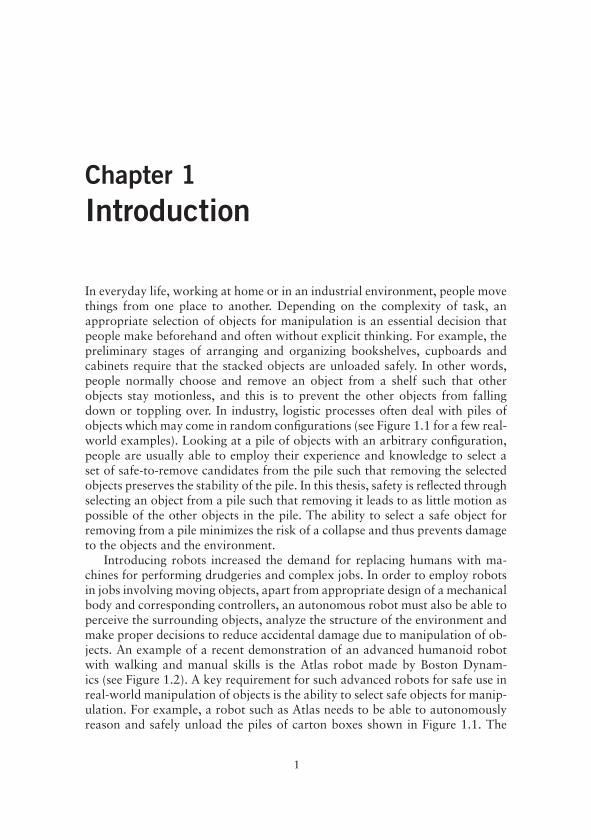
In everyday life, working at home or in an industrial environment, people movethings from one place to another. Depending on the complexity of task, anappropriate selection of objects for manipulation is an essential decision thatpeople make beforehand and often without explicit thinking. For example, thepreliminary stages of arranging and organizing bookshelves, cupboards andcabinets require that the stacked objects are unloaded safely. In other words,people normally choose and remove an object from a shelf such that otherobjects stay motionless, and this is to prevent the other objects from fallingdown or toppling over. In industry, logistic processes often deal with piles ofobjects which may come in random configurations (see Figure 1.1 for a few real-world examples). Looking at a pile of objects with an arbitrary configuration,people are usually able to employ their experience and knowledge to select aset of safe-to-remove candidates from the pile such that removing the selectedobjects preserves the stability of the pile. In this thesis, safety is reflected throughselecting an object from a pile such that removing it leads to as little motion aspossible of the other objects in the pile. The ability to select a safe object forremoving from a pile minimizes the risk of a collapse and thus prevents damageto the objects and the environment.
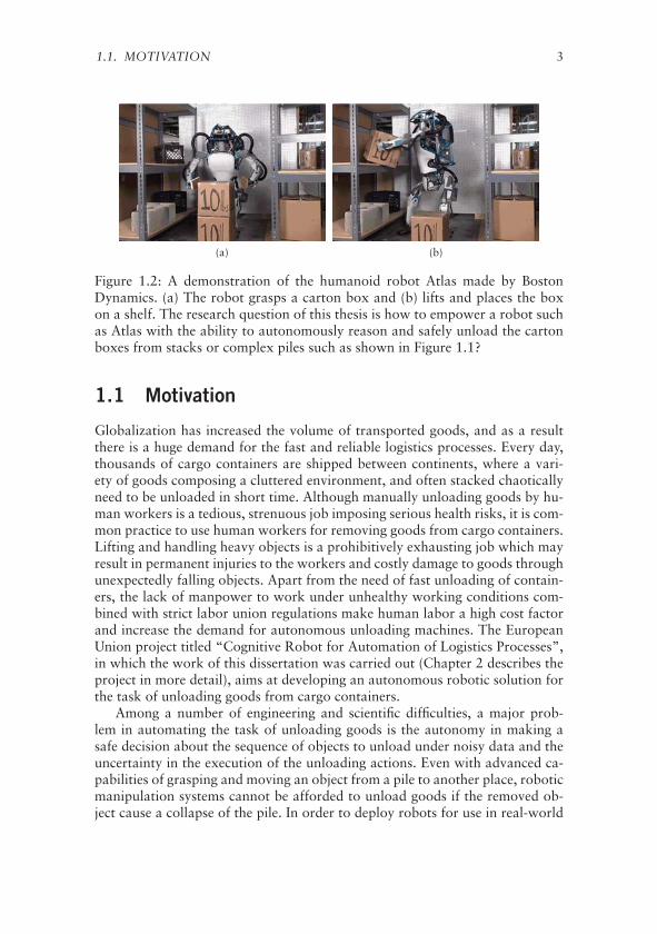
Introducing robots increased the demand for replacing humans with ma-chines for performing drudgeries and complex jobs. In order to employ robotsin jobs involving moving objects, apart from appropriate design of a mechanicalbody and corresponding controllers, an autonomous robot must also be able toperceive the surrounding objects, analyze the structure of the environment andmake proper decisions to reduce accidental damage due to manipulation of ob-jects. An example of a recent demonstration of an advanced humanoid robotwith walking and manual skills is the Atlas robot made by Boston Dynam-ics (see Figure 1.2). A key requirement for such advanced robots for safe use inreal-world manipulation of objects is the ability to select safe objects for manip-ulation. For example, a robot such as Atlas needs to be able to autonomouslyreason and safely unload the piles of carton boxes shown in Figure 1.1. The
1

2 CHAPTER 1. INTRODUCTION
(a) (b)
Figure 1.1: A few snapshots of configurations of objects inside shipping con-tainers at unloading sites.
ability of a robot to answer the questions such as: “how many other objectswould fall down if I remove this object?”, “which object does not support anyother object in the pile?” and “which object is the safest candidate to removefrom a pile?” enables the robot to automatically reason about the safest se-quence of unloading objects from a pile. Robots without the ability to analyzethe complexity of the task and make proper decisions cannot be utilized foraccomplishing tasks autonomously and need to be supervised by humans con-tinuously.
This thesis work presents a set of contributions towards the development ofautonomous robotic manipulation systems for real-world applications of un-loading objects from piles. The main focus is on the ability of a robot to useefficiently the available description of the objects extracted from perceptionto select a safe object to be unloaded from a pile. This ability, which will bediscussed further in Chapter 5, is essential for the autonomy as well as the per-formance of the robotic manipulation system. When the description of posesof objects is inaccurate, the geometrical shapes may inter-penetrate into eachother representing a model of the environment which is inconsistent with arigid body assumption. Inter-penetrations between the shapes of objects haveto be resolved for making proper decisions about the safe-to-remove objects.This thesis presents algorithms to resolve the inter-penetrations and refine theposes of object in order to obtain a model of the environment in which thereis no inter-penetration between pairs of objects. This will be discussed in detailin Chapter 4. One reason for inaccuracy in the poses of objects is the use ofinappropriate visual sensors for the underlying application. In order to studythe effects of appropriate selection of visual sensors on the task of pose estima-tion of objects, this thesis presents an application-centric evaluation of rangesensors, which will be further discussed in Chapter 3.
1.1. MOTIVATION 3
(a) (b)
Figure 1.2: A demonstration of the humanoid robot Atlas made by BostonDynamics. (a) The robot grasps a carton box and (b) lifts and places the boxon a shelf. The research question of this thesis is how to empower a robot suchas Atlas with the ability to autonomously reason and safely unload the cartonboxes from stacks or complex piles such as shown in Figure 1.1?
1.1 Motivation
Globalization has increased the volume of transported goods, and as a resultthere is a huge demand for the fast and reliable logistics processes. Every day,thousands of cargo containers are shipped between continents, where a vari-ety of goods composing a cluttered environment, and often stacked chaoticallyneed to be unloaded in short time. Although manually unloading goods by hu-man workers is a tedious, strenuous job imposing serious health risks, it is com-mon practice to use human workers for removing goods from cargo containers.Lifting and handling heavy objects is a prohibitively exhausting job which mayresult in permanent injuries to the workers and costly damage to goods throughunexpectedly falling objects. Apart from the need of fast unloading of contain-ers, the lack of manpower to work under unhealthy working conditions com-bined with strict labor union regulations make human labor a high cost factorand increase the demand for autonomous unloading machines. The EuropeanUnion project titled “Cognitive Robot for Automation of Logistics Processes”,in which the work of this dissertation was carried out (Chapter 2 describes theproject in more detail), aims at developing an autonomous robotic solution forthe task of unloading goods from cargo containers.
Among a number of engineering and scientific difficulties, a major prob-lem in automating the task of unloading goods is the autonomy in making asafe decision about the sequence of objects to unload under noisy data and theuncertainty in the execution of the unloading actions. Even with advanced ca-pabilities of grasping and moving an object from a pile to another place, roboticmanipulation systems cannot be afforded to unload goods if the removed ob-ject cause a collapse of the pile. In order to deploy robots for use in real-world

4 CHAPTER 1. INTRODUCTION
environments an autonomous understanding of the structure of the underlyingtask is crucial for making proper decisions. A robotic unloading system, in par-ticular, needs to make a safe decision about the sequence of objects to unloadfrom a pile.
The idea that goods are usually stacked neatly into cargo container at load-ing stations may suggest the possibility of using a preprogrammed unloadingplan. However, the long-distance freight transport requires shipping cargo con-tainers between ship, rail and truck resulting the configuration of goods, tosome degree, random, as some real-world examples can be seen in Figure 1.1.Even if the pile of goods inside cargo containers preserves the neat initial con-figuration when reaches to the unloading sites, making decisions based on apreprogrammed plan for unloading goods may fail due to uncertainty bothin perception of objects and in executing unloading actions. Uncertainty inthe perception may cause errors in grasp planning, obstacle avoidance andpath planning of the robotic manipulator, and failures to execute an unload-ing action may change the arrangement of the objects. Consequently, when thearrangement of the objects change the preprogrammed unloading plan is nolonger valid. In addition to the possibility of a change in the arrangement ofobjects that are neatly stacked, the piles of objects for which the arrangement isnot known in advance and may have been chaotically stacked need appropriatealgorithms to analyze the stability of the pile and make safe decision about thenext object to unload.
Domestic and service robots [1, 2] can also benefit from the algorithmspredicting the effects of manipulating a selected object on the stability of theenvironment to make safer decisions. For example, when asking a service robotsuch as a Willow Garage Personal Robot [3] to bring an elderly person a foodbox located inside a refrigerator of possibly filled with other objects it will notbe accepted to cause any object to topple over or fall down. If the robot isable to predict the consequences of manipulating objects on the stability of thesurrounding objects, then it can plan for a safer sequence of actions to performa desired task.
1.2 Problem Statement
The specific research problem addressed in this dissertation can be generallystated as below,
Problem. Given the geometrical shapes and an estimation of the poses of a setof objects that are part of a pile, determine a sequence of unloading actionssuch that removing an object maintains the stability of the pile.
Considering the shapes of commonly-used objects in logistics processes, itis assumed that the shape of an object can be well approximated with a convexpolyhedron. Nevertheless, most of the algorithms presented in this thesis can beextended to deal with concave shaped objects by decomposing a concave shape

1.3. CHALLENGES 5
Figure 1.3: The pipeline of the robotic unloading system starting from percep-tion and moving on to making decision about the safest object to unload.
into a set of connected convex polyhedrons. It is explicitly assumed that the pileis in static equilibrium, that is, the objects composing the pile are motionless. Anestimation of the poses is assumed to be obtained by an existing object detectionand pose estimation module, where, to some extent, there exists uncertainty inthe estimated poses.
It is important to further clarify one condition of the problem statement,that is, there is no guarantee that the description of all the objects composing apile are available for the analysis of the stability of the pile and determining asafe sequence of unloading actions. The undetected objects could be the resultof occlusion or a failure in the detection process of the existing object detectionmodule.
1.3 Challenges
A robotic manipulation system to operate autonomously and unload objectssafely has to deal with a number of scientific and engineering challenges. Start-ing from low-level perception and moving on to complex analysis of the possi-bly noisy and incomplete data to extract a high-level meaningful interpretationof the environment represents a multitude of challenges to address. A variety
6 CHAPTER 1. INTRODUCTION
of the type of objects, which may come in different size, shape and materialimposes not only difficulties in grasp planning and execution, but also it makesreliable identification of objects and making safe decisions challenging.
Figure 1.3 shows a conceptual pipeline for an autonomous robotic unload-ing system starting from perception and moving on to the execution of theunloading action. The process starts by sensing the environment (i.e., the sceneof objects) using perception sensors. The sensor fusion and pre-processing arethen performed to reduce the noise and prepare the data for high level pro-cessing. Scene segmentation further prepares the input data for object detectionand pose estimation algorithms. In the next step, the configuration of the setof detected objects is analyzed for making decision about the safest object toremove from the scene. Motion and grasping plans are then computed for theselected object to move it to the desired place without colliding with the otherobjects in the environment.
The description of objects such as shapes and poses is normally not avail-able and has to be extracted from the sensory data, which is inherently un-certain. For a reliable analysis of the stability of a pile in order to identifysafe-to-remove objects, a fundamental component, similar to the visual systemof human being, is the quality of the detection of objects. Object detection andpose estimation algorithms, however, represent errors in the estimated descrip-tion of objects due to occlusion, noisy data and internal failures in algorithms.Some objects may be inherently invisible due to occlusion or not being in thefield of view of perception sensors. Conversely, false positive objects, which arenon-existing objects that are detected as some type of objects by the object de-tection algorithm are another challenging issue in the analysis of the stabilityof a pile. The uncertainty about the estimated poses of the location of objectsfurther complicates reasoning about the safe object to unload. A misclassifica-tion of the type of objects, as an internal failure in object detection algorithms,represents an incorrect hypotheses about the corresponding geometrical shapesof the objects. The aforementioned difficulties highlight the importance of anevaluation of the perception sensors in order to minimize the negative effectsof an inappropriate sensor selection on the task of object detection.
The problem of undetected objects of a pile could play a dominant rolein the stability analysis of the pile. The objects that are located behind otherobjects are inherently occluded, thus they cannot be perceived and detected.Even objects that are not occluded may not be detected by an existing objectdetection algorithm. The problem of having access to only a subset of objectsof a pile represents the lack of information in making decision about the safestobject. When facing the lack of information, human beings usually use a heuris-tic solution, e.g., not being able to see the objects behind the front layer of apile, people choose an object which is most probable to be safe according totheir own justification. An algorithmic decision making about the set of safe-to-remove objects from a pile, in turn, needs to be able to deal with the lack ofinformation.

1.4. OUTLINE 7
The errors in the estimated poses even for a complete and correct detec-tion of objects may result in a set of inter-penetrations between the shapes ofadjacent objects, which represent a geometrically inconsistent model of the en-vironment. The geometrical consistency of the estimated poses is required dueto a rigid body assumption of the real-world, where solid objects are assumednot to deform or penetrate into each other. A model of the environment thatis inconsistent with a rigid body assumption may cause failures in geometricalreasoning on the stability of a pile. A partial or complete inter-penetration ofshapes thus needs to be resolved as a preliminary stage of a geometrical reason-ing.
1.4 Outline
The rest of this thesis is organized as follows.
Chapter 2 presents an overview of the previous related works on the prob-lems addressed in this thesis, and introduces the EU-funded project ti-tled “Cognitive Robot for Automation of Logistic Processes” (RobLog)in which the presented work was carried out.
Chapter 3 is focused on the problem of 3D range sensor evaluation and se-lection in the design process of a complex robotic system with a specificattention to the challenging scenarios in the RobLog project. An applica-tion centric 3D range sensor evaluation is presented and discussed.
Chapter 4 proposes a framework to refine the noisy estimated poses of a setof objects in order to obtain a geometrically consistent model of the en-vironment. In this chapter, the depth of penetration between two poly-topes is utilized to define a reduced search space for resolving the inter-penetrations between objects due to errors in the initially estimated poses.
Chapter 5 discusses the problem of determining a set of safe-to-remove ob-jects from a pile under complete and incomplete information. Dependingon the availability of a description of the objects, two major approachesare proposed. This chapter introduces algorithms to represent and ex-tract gravitational act and support relations based on notions from ge-ometry and static equilibrium in classical mechanics. Machine learningtechniques and probabilistic decision making approaches are employedto address the problem of undetected objects of a pile and the uncertaintyin the input data.
Chapter 6 concludes this thesis with final remarks and suggested directions forfuture research work.
8 CHAPTER 1. INTRODUCTION
1.5 Contributions
The contributions presented in this thesis work can be summarized as follows:
• An application-centric method for comparative evaluation and selectionof a set of appropriate 3D range sensors in the context of automatic un-loading goods from cargo containers.
• An object pose refinement framework based on the concept of depth ofpenetration between two overlapping polytopes and search algorithms toobtain geometrical consistent models of the environment.
• Development of a methodology to identify and select a set of safe-to-remove objects from a pile for integration into fully autonomous roboticmanipulation systems. The method is not tied to any specific robotic ma-nipulator and neither to a particular object detection algorithm. Thus, theproposed method can be readily adopted for different designs of roboticmanipulation setups.
• A method for extracting gravitational support relations by automaticallyanalyzing the stability of a pile of objects with an arbitrary configurationand possibly under uncertainty and lack of information about the com-plete set of the objects. Machine learning techniques employed to estimatethe probability of the support relations and notions from decision theoryare used to select the set of safe-to-remove objects.
• An open-source C++ library implementing aforementioned object poserefinement framework under Robot Operating System (ROS).
• Comprehensive, quantitative evaluation of the proposed methods on datasets generated in simulation and from real-world scenarios.
1.6 Publications
The contributions of this thesis work have been presented in different peerreviewed journal articles or conference papers. The major results from this dis-sertation were published in the following articles:
• R. Mojtahedzadeh, T. Stoyanov, A. Lilienthal. Application based 3D sen-sor evaluation: A case study in 3D object pose estimation for automatedunloading of containers. In Proc. of 6th European Conference on MobileRobots (ECMR), Barcelona, Spain, 2013, pp 313-318.Part of Chapter 3
• T. Stoyanov, R. Mojtahedzadeh, H. Andreasson, A. Lilienthal. Compara-tive evaluation of range sensor accuracy for indoor mobile robotics and
1.6. PUBLICATIONS 9
automated logistics applications. Robotics and Autonomous Systems (RAS),2012, ISSN 0921-8890, Vol. 61, pp 1094-1105.Part of Chapter 3
• R. Mojtahedzadeh, A. Lilienthal. A Principle of Minimum TranslationSearch Approach for Object Pose Refinement. In Proc. of the IEEE/RSJ In-ternational Conference on Intelligent Robots and Systems (IROS), 2015,pp 2897-2903.Part of Chapter 4
• R. Mojtahedzadeh, A. Bouguerra, A. Lilienthal. Automatic RelationalScene Representation For Safe Robotic Manipulation Tasks. In Proc. ofthe IEEE/RSJ International Conference on Intelligent Robots and Systems(IROS), 2013, pp 1335-1340.Part of Chapter 5
• R. Mojtahedzadeh, A. Bouguerra, E. Schaffernicht, A. Lilienthal. Proba-bilistic Relational Scene Representation and Decision Making Under In-complete Information for Robotic Manipulation Tasks. In Proc. of theIEEE International Conference on Robotics and Automation (ICRA), 2014,pp 5685-5690.Part of Chapter 5
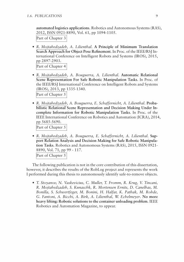
• R. Mojtahedzadeh, A. Bouguerra, E. Schaffernicht, A. Lilienthal. Sup-port Relation Analysis and Decision Making for Safe Robotic Manipula-tion Tasks. Robotics and Autonomous Systems (RAS), 2015, ISSN 0921-8890, Vol. 71, pp 99 - 117.Part of Chapter 5
The following publication is not in the core contribution of this dissertation,however, it describes the results of the RobLog project and represents the workI performed during this thesis to autonomously identify safe-to-remove objects.
• T. Stoyanov, N. Vaskevicius, C. Muller, T. Fromm, R. Krug, V. Tincani,R. Mojtahedzadeh, S. Kunaschk, R. Mortensen Ernits, D. Canelhas, M.Bonilla, S. Schwertfeger, M. Bonini, H. Halfar, K. Pathak, M. Rohde,G. Fantoni, A. Bicchi, A. Birk, A. Lilienthal, W. Echelmeyer. No moreheavy lifting: Robotic solutions to the container unloading problem. IEEERobotics and Automation Magazine, to appear.


Chapter 2Background
In many practical applications of robotic manipulation where the objects arestacked in a pile, it is of great importance to prevent other objects from movingand possibly falling down by an inappropriate selection of an object to removefrom the pile. The process of automating the task of unloading goods insidecargo containers is such a real-world application that requires the ability to au-tonomously select safe-to-remove objects. This chapter reviews literature aboutthe object selection problem and highlights the need for a principled treatmentof the task of identifying safe-to-remove candidates from realistic configura-tions of objects.
The problem of algorithmic object selection for robotic manipulation ismainly investigated in the research for designing “bin-picking” robots. A roboticbin-picking system requires scene analysis, object detection and pose estima-tion, grasp planning, and path planning. The parts to be assembled in a pro-duction line are the main focus of industrial robotic bin-picking systems. Inrelated work about bin-picking systems it is common to assume configurationsof objects sitting on top of a table or being stacked in a bin. In such cases theproblem of object selection typically addressed with a heuristic to pick up thetopmost objects of a bin.
An appropriate selection of an object from an arbitrary configuration ofgoods which are stacked inside a cargo container requires a more complexanalysis than the simple heuristic of always selecting the topmost objects. Fora bin-picking scenario in which the bin is filled with a number of identicalassembly parts it is a plausible strategy to identify and select the topmost object.In such scenarios it makes no difference which part is chosen to be picked up,and also motions of other parts due to the pick-up action do not matter. A cargocontainer filled with possibly fragile goods it is crucial to predict the effects ofunloading a selected object on the stability of the pile of objects.
The key motivation of the problem addressed in this thesis can be seen inthe scenario of the EU-funded project RobLog, which is summarized below.
11
12 CHAPTER 2. BACKGROUND
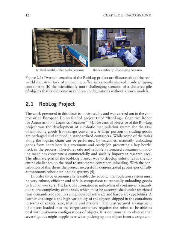
(a) Real-world Coffee Sacks Scenario (b) Scientifically Challenging Scenario
Figure 2.1: Two sub-senarios of the RobLog project are illustrated: (a) the real-world industrial task of unloading coffee sacks neatly stacked inside shippingcontainetrs; (b) the scientifically more challenging scenario of a cluttered pileof objects that could come in random configurations without known models.
2.1 RobLog Project
The work presented in this thesis is motivated by and was carried out in the con-text of an European Union funded project titled “RobLog - Cognitive Robotfor Automation of Logistics Processes” [4]. The central objective of the RobLogproject was the development of a robotic manipulation system for the taskof unloading goods from cargo containers. A large portion of trading goodsare packaged and shipped in standardized containers. While some of the tasksalong the logistic chain can be performed by machines, manually unloadinggoods from containers is a strenuous and costly job presenting a key bottle-neck in the process. Therefore, safe and reliable automated container unload-ing machines constitute a commercially and socially important research area.The ultimate goal of the RobLog project was to develop solutions for the sci-entific challenges on the road to automated container unloading. With the con-tribution of this thesis the project successfully demonstrated prototypes of fullyautonomous robotic unloading systems [4].
In order to be economically feasible, the robotic manipulation system mustbe very robust, efficient and safe in comparison to manually unloading goodsby human workers. The lack of automation in unloading of containers is mainlydue to the complexity of the task, which must be accomplished under restrictedtime demands and requires a high level of software and hardware capabilities. Afurther challenge is the high variability of the objects shipped in the containersin terms of shapes, size, texture and material. The unstructured arrangementof objects loaded into the cargo containers requires the robot to be able todeal with unknown configurations of objects. It is not unusual to observe thatseveral goods might topple over when picking up one object from a cargo con-

2.2. RELATED WORK 13
Figure 2.2: Industrial Robotic Platform of the RobLog Project
tainer. A proper choice of the object to unload reduces the risk of accidentaldamage to other objects due to toppling over or falling down.
The RobLog scenario requires reliable capabilities to address the problem ofselecting objects to pick from varying, possibly heterogeneous, and potentiallychaotically arranged goods inside cargo containers. The project addressed twodifferent sub-scenarios, one motivated by a real-world industrial task of un-loading 70 kg coffee sacks stacked inside cargo containers (see Figure 2.1a),and another scenario aims at the scientifically more challenging domain of un-loading containers (see Figure 2.1b). The latter scenario contributes to researchon autonomous manipulation in unstructured environments that piles of ob-jects may have random configurations, and that there exist objects withoutknown models. Figure 2.2 depicts the industrial robotic platform developed forthe scientific scenario in the design process of the RobLog project.
In the scenario of unloading coffee sacks, a heuristic approach of alwaysselecting the topmost sack from the front layer could efficiently be employedas long as coffee sacks are neatly stacked in layers on top of each other. Theassumption that the objects are neatly stacked considerably simplifies reasoningon the geometry of the pile and reduces the complexity of the scene analysis.However, such a simplified strategy of always selecting the topmost object failsin more complicated configurations where there are complex gravitational sup-port relations between the objects, and where the problem of undetected objectsis more severe. The work of this thesis is dedicated to develop algorithms andpresent methodologies for the problem of selecting safe-to-remove objects inthe more challenging scenario of the RobLog project.
2.2 Related Work
Despite the importance of making a safe decision about the sequence of ob-jects to remove from a pile for autonomous robotic manipulation, only a few

14 CHAPTER 2. BACKGROUND
(a) Bley et al. [5] (b) Jang et al. [6] (c) Klingbeil et al. [7]
(d) Kenney et al. [8] (e) Agrawal et al. [9] (f) Real-world Containers
Figure 2.3: (a)-(e) depict typical configurations of objects in related works tobin-picking research. (f) depicts two real-world configurations of carton boxesinside shipping containers at unloading sites.
papers address this problem. The problem of object selection is occasionallybriefly mentioned within bin-picking literature about object localization. Thissection therefore, first, reviews bin-picking literature with a focus on the targetscenarios and the object selection task. Then, the few available related worksthat specifically attempt to identify gravitational support relations between ob-jects of a pile are reviewed, and their limitations are highlighted. Table 2.1categorizes the related work reviewed in this chapter based on three items, thescenario, the properties of the objects and the type of analysis to represent anoverview of the differences between this work and the related work.
2.2.1 Bin-Picking
In an early work by Ikeuchi et al. [10] in 1983, a bin-picking system was in-troduced based on an analysis of the surface normals extracted from a stereovision sensor. The main focus of their paper is to address the problem of how toisolate an object from the background, and how to determine the relative poseof the object with respect to the camera. One year later in 1984, Horn andIkeuchi [11] published their study about manipulation of randomly orientedparts where they present an object template matching method to autonomouslydetermine the orientation of parts in a pile.
2.2. RELATED WORK 15
Dessimoz et al. [12] propose a fast filtering approach to detect potentialholdsites – a location on an object at which to grasp the part – in images to de-crease the burden of scene analysis on low computational powered computersmade available in 1980’s. Yang and Kak [13] describe strategies for analyzingstructured-light range maps for determining the identity and pose of the top-most object in a pile. Al-Hujazi and Sood [14] propose a range image segmenta-tion method based on region growing technique to determine the best holdsiteposition and orientation of objects for bin-picking. Rahardja and Kosaka [15]present a vision-based bin-picking technique to identify and estimate the poseof assembly parts by stereo vision data, where in particular the objects arealternator covers. Berger et al. [16] propose a three steps methodology for bin-picking where in the first step the robot picks the topmost object from a binwith a vacuum gripper to drop it in an empty workplace, then the CAD modelof the object is fit to a structured light image of the workplace to determine thepose, and finally the correct mounting of the part is being ensured. Agrawalet al. [9] present a bin-picking system with model based 3D pose estimationand with the ability of picking singulated 3D objects. They evaluate the per-formance of the system on experimental setups with few objects sitting on aflat ground and being clearly separated. In a work by Kenney et al. [8], an in-teractive segmentation of cluttered scene is presented, where objects are sittingon a tabletop without being completely nor partly supported by each other.Tabletop scenarios in which objects are either clearly separated or being in asimple interaction are widely used in literature, to name but a few, in a graspplanning based on generic object knowledge by Bley et al. [5], a real-time mo-tion planning for manipulation of objects by Jang et al. [6], an assistive mobilemanipulator implementation for helping people with motor impairments byJain and Kemp [17], a grasp selection algorithm by Klingbeil [7], a frameworkfor push-grasping [18] and a physics-based grasp planning [19] by Dogar etal. Figure 2.3 shows a few sample configurations of objects used in tabletopscenario-based research.
Chaotically stacked objects are also considered in the literature. An ap-proach to interactive singularization of a pile of objects presented by Changet al. [21] which in essence gathers information about a cluttered scene by iter-atively moving hypothetical objects and observing the outcome of taking suchactions. A similar interactive approach for LEGO bricks sorting is presentedby Gupta and Sukhatme [22]. The key problem with the interactive approachwhen dealing with real-world goods stacked inside shipping containers is thefact that it cannot be afforded to risk the possibility of letting objects (e.g., car-ton boxes of electronic appliances) fall down in order to identify the objects.
In all the studies related to bin-picking, the main research focus is on lo-calization and manipulation of objects, and the essential hypothesis is that thetopmost object is the best candidate to be selected; a multitude of experimentsare conducted with the objects sitting on a tabletop scenario and clearly sepa-rated for easy detection and manipulation.

16 CHAPTER 2. BACKGROUND
(a) Sjöö et al. [20] (b) Sjöö et al. [20]
Figure 2.4: Two real-work experimental scenarios of cuboid shaped objectsused in the work by Sjoo et al. [20]. (a) An object labeled as B is leaningon another object labeled A with a probability of P(ON(A,B)) = 0.25, and(b) the objects A and B support another object labeled C with probabilitiesP(ON(C,A)) = 0.28 and P(ON(C,A)) = 0.30. A major drawback of this ap-proach is that it is not clear how to choose a threshold to infer logical values ofthe ON relations.
2.2.2 Support Relation Analysis
In a closely related work to this thesis by Sjöö et al. [20], gravitational supportof a cuboid shaped object by another is represented as symbolic ON relationbetween the objects and modeled to be a function of the minimum of an expo-nential distance factor and a sigmoid-shape contact factor. A conditional prob-ability distribution over poses of the supporting object is then computed andthresholded to imply the logical value of the ON relation. Figure 2.4 shows tworeal-world experimental scenarios composed of a few cuboid shaped objects.The most complex real-world scenario investigated in [20] consists of threeboxes, A, B and C where C is supported by two others (see Figure 2.4b), andthe extracted probabilities for ON(C,A) and ON(C,B) are reported to be bothless than 0.3, while both A and B clearly support C. One major drawback ofthis approach is that in a cluttered pile of objects (see real-world examples inFigure 2.3f) where objects are in complex contact with each other, and conse-quently there would be a set of ON relations with small probabilities, it is notclear how to choose a threshold to imply the logical truth of the ON relations.
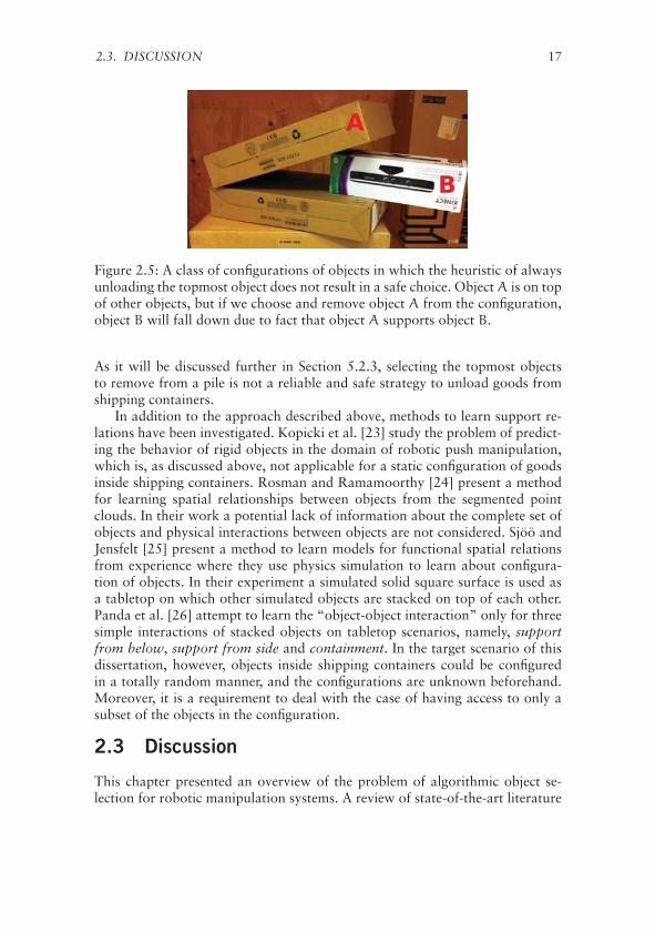
Figure 2.5 depicts one type of configurations of objects in which the top-most object is not the best candidate to remove from the pile. In the shownconfiguration, object A is on top of other objects but it actually supports objectB which is located under object A. If we take the approach proposed in [20],the probability that object B is on object A will be close to zero, while it canbe clearly seen that there is a high probability that object A supports object B.
2.3. DISCUSSION 17
Figure 2.5: A class of configurations of objects in which the heuristic of alwaysunloading the topmost object does not result in a safe choice. Object A is on topof other objects, but if we choose and remove object A from the configuration,object B will fall down due to fact that object A supports object B.
As it will be discussed further in Section 5.2.3, selecting the topmost objectsto remove from a pile is not a reliable and safe strategy to unload goods fromshipping containers.
In addition to the approach described above, methods to learn support re-lations have been investigated. Kopicki et al. [23] study the problem of predict-ing the behavior of rigid objects in the domain of robotic push manipulation,which is, as discussed above, not applicable for a static configuration of goodsinside shipping containers. Rosman and Ramamoorthy [24] present a methodfor learning spatial relationships between objects from the segmented pointclouds. In their work a potential lack of information about the complete set ofobjects and physical interactions between objects are not considered. Sjöö andJensfelt [25] present a method to learn models for functional spatial relationsfrom experience where they use physics simulation to learn about configura-tion of objects. In their experiment a simulated solid square surface is used asa tabletop on which other simulated objects are stacked on top of each other.Panda et al. [26] attempt to learn the “object-object interaction” only for threesimple interactions of stacked objects on tabletop scenarios, namely, supportfrom below, support from side and containment. In the target scenario of thisdissertation, however, objects inside shipping containers could be configuredin a totally random manner, and the configurations are unknown beforehand.Moreover, it is a requirement to deal with the case of having access to only asubset of the objects in the configuration.
2.3 Discussion
This chapter presented an overview of the problem of algorithmic object se-lection for robotic manipulation systems. A review of state-of-the-art literature
18 CHAPTER 2. BACKGROUND
related to the problem of object selection highlighted the type of objects andscenarios considered in the related work. The European Union funded project,RobLog, aiming at automating the task of unloading goods from cargo con-tainers was introduced, where the challenge of algorithmic selection of safe-to-remove objects for the RobLog scenario is one of the motivations of thisthesis.
The task of object selection is mainly considered within “bin-picking” re-search and is normally addressed with a simple heuristic of always selecting thetopmost object from a bin. While such a heuristic is plausible for a bin filledwith identical assembly parts, it may not result in a safe choice when dealingwith piles of objects. Configurations of goods stacked inside cargo containersare one of real-world examples of piles that the unloading strategy of alwaysselecting the topmost objects may cause the pile to collapse. Real-world pilessuch as the RobLog scenario represent a cluttered scene of objects that maycome in random configurations where the objects cannot afford and sustaintumbling and falling over.
The few available research papers that specifically study and propose proba-bilistic and learning based methods for identifying the spatial and gravitationalsupport relations between objects have been reviewed. The single probabilisticmethod attempts to estimate a probability of an on-relation between two box-shaped objects. It is not clear however, how to select a threshold to infer log-ical on-relation between two objects. The other methods reported on learningpush manipulation, spatial relationships of a segmented point cloud, functionalspatial relations and object-object interaction are not capable of dealing withuncertainty and the lack of information about the objects composing a pile.

2.3. DISCUSSION 19
[10,
11]
[12]
[13]
[14]
[15,
16]
[9]
[8]
[5,1
7][6
][7
][1
8][1
9][2
1][2
2][2
5][2
4][2
3][2
6][2
0]th
isw
ork
Scenario
Con
tain
ers
--
--
--
--
--
-�
--
--
--
-�
Clu
tter
edSc
ene
��
�-
�-
--
-�
--
��
��
-�
��
Tabl
etop
s�
-�
��
��
��
��
-�
��
��
��
-Se
para
ted
Obj
ects
--
-�
-�
��
��
��
-�
--
�-
--
Bin
s�
��
-�
--
--
--
--
--
--
�-
-
Objects
Car
gogo
ods
--
--
--
--
--
--
--
--
--
-�
Iden
tica
lpar
ts�
�-
��
�-
--
-�
-�
��
--
��
�
Prim
itiv
esh
apes
�-
��
--
--
-�
��
��
��
��
��
Eve
ryda
yth
ings
--
--
--
��
��
-�
--
--
--
--
Analysis
Supp
ort
rela
tion
--
--
--
--
--
--
--
--
--
-�
On
rela
tion
--
--
--
--
--
--
--
��
-�
�-
Topm
ost
Sele
ctio
n�
��
-�
--
--
�-
--
��
--
--
-Pu
shm
anip
ulat
ion
--
--
--
�-
--
��
��
--
�-
--
Spat
ialr
elat
ions
hip
--
--
--
--
--
--
��
��
�-
--
Segm
enta
tion
��
��
��
�-
��
--
-�
-�
-�
--
Tabl
e2.
1:R
elat
edw
ork
com
pari
son
tabl
e.T
hefe
atur
esar
edi
vide
din
toth
ree
cate
gori
esba
sed
onta
rget
scen
ario
s,ty
peof
obje
cts
and
the
anal
ysis
.

Chapter 33D Range Sensor Selection
The recent developments in range sensing devices introduced relatively low-cost solutions for dense 3D range measurements. Among different technolo-gies, the long distance measurement and accuracy of 2D laser range finders(LRFs) outperforms other competitor devices [27, 28]. Commercially availablecompact designs of 3D laser range finders (e.g., Velodyne LiDAR) are pro-hibitively costly. A popular alternative and cost efficient solution widely usedin the robotics community is to mount a 2D laser range finder on a tilting actu-ator — known as an actuated LRF (aLRF). Nevertheless, the systematic errors,low refresh rates and the required mechanical parts for the actuation are themajor limitations of using the aLRFs in robotic systems.
In order to overcome the shortcomings of actuated LRFs, a number of com-mercially available competing technologies have been recently developed. Pop-ular and widely used among the robotics groups are time-of-flight (TOF) andstructured light cameras. An inexpensive technology of TOF cameras exploitsthe relation between the phase shift of the reflections of a modulated light andthe distance of the surface of the reflections (e.g., SwissRanger SR-4000 andFotonic B70). Structured light cameras, on the other hand, estimate distancessimilar to stereo vision systems by measuring the disparity of a projected lightpattern on a CCD camera (e.g., the Kinect sensor).
This chapter concerns an application centric evaluation of 3D range sensorsused for selecting appropriate 3D perception technology in the development ofthe RobLog project (see Chapter 2). The performance of four carefully selected3D range sensors, an actuated SICK LMS200 laser range finder, two TOF cam-eras SwissRanger SR-4000 and Fotonic B70, and a Microsoft Kinect sensoris evaluated for the task of object detection and pose estimation. A numberof configurations of three commonly-used objects inside shipping containers,namely, carton boxes, sacks and tires is created for data generation. Two rep-resentative state of the art object detection approaches are selected as perfor-mance indicators. It will be demonstrated that sensor characteristics other thanthe traditionally evaluated distance accuracy can influence the performance of
21
22 CHAPTER 3. 3D RANGE SENSOR SELECTION
the target application. Therefore, this chapter makes a case for an application-based evaluation of 3D range sensors — the device with the best performancewith respect to the object detection task is selected for use in the final automatedsystem.
3.1 An Overview of Range Sensor Evaluation
The current literature on 3D range sensor evaluation abounds with examplesof the characterization of the intrinsic parameters and sensor calibration. Yeand Borenstein [29] present a characterization study of the SICK LMS200 laserscanner. They investigate the effect of a number of parameters, such as opera-tion time, data transfer rate, target surface properties, as well as the incidenceangle on the device sensing performance. Luo and Zhang [30] report the char-acterization of the laser range finder AccuRange 4000 by Acuity Research. Theystudy the performance of the ranging device under various operating conditionsincluding lighting, temperature, and surface color, and orientation. A group ofresearchers reported their study on the calibration of the available TOF cam-eras in literature [31, 32, 33]. The utility of TOF cameras in robotics problemssuch as pose estimation [34], 3D mapping [35], 3D shape scanning [36] andcollision avoidance [37] has been also evaluated.
Introducing a low-cost structured light camera, the Kinect sensor by Mi-crosoft motivated researchers to study the properties and the utility of the sen-sor in robotics domain. Khoshelham and Elberink [38] study depth accuracyand resolution, and point density of the Kinect sensor and report a calibrationparameters for the infrared and color cameras of the sensor. Chin et al. [39]present an investigation of the quality of depth data obtained by the Kinectsensor. DiFilippo and Jouaneh [40] report the accuracy, repeatability, and res-olution of the different Kinect models in determining the distance to a planartarget.
Having single-sensor characterization and parameter evaluation, selecting aset of range sensors for a complex robotic system solely based on a comparisonbetween the intrinsic properties and in isolation of the target task may result inan inappropriate choice. Wong et al. [28] evaluated the utility of ten 3D rangesensors in a holistic manner for a real-world industrial application — under-ground void modeling. They define a set of representative metrics of the targetapplication (mapping a tunnel) and evaluate the range sensors based on theobtained metrics. From their experimental results in situ mapping evaluation,while a class of sensors perform better in obtaining some metrics, they rep-resent a weaker ability for other metrics. As they concluded, the selection forthe appropriate sensor considers a right balance of performance, mass, featuresand cost. In the article [27] that the author is involved we develop a holisticmethod for the measurements accuracy evaluation of a set of 3D range sensors— namely, the Swiss Ranger SR-4000, Fotonic B70 and Microsoft Kinect us-ing an actuated laser range finder as reference. Observing the results in [27],
3.2. APPLICATION CENTRIC 3D RANGE SENSOR EVALUATION 23
it is not immediately clear which sensor would represent a better performancefor a complex robotic system such as the RobLog project. In the author’s laterwork [41], which this chapter is based on, we evaluated the same set of 3Drange sensors for the target application of the RobLog scenario. As the discus-sion at the end of this chapter concludes, evaluating 3D range sensors based onan application centric performance reveals the underlying capabilities of differ-ent sensors in dealing with diverse configurations of the target application.
3.2 Application Centric 3D Range Sensor Evaluation
In order to compare two given 3D range sensors, Si and Sj with sets of prop-erties pn
i = {pi,1, . . . ,pi,n} and pmj = {pj,1, . . . ,pj,m} respectively, we define
pc = pni ∩ pm
j and call the elements in pc comparable properties. For 3D rangesensors, the properties such as the distance accuracy, the level and type of noise,field of view, the point cloud density, and the lens distortion can be considered.Some of the properties (e.g., the distance accuracy) may be found in both sen-sors (which are the elements in pc) while some other properties (e.g., the lensdistortion) may be specific for one of the sensors. Comparing the sensors basedon the effects of the properties that are not comparable is not trivial. On theother hand, let’s assume that for the target application (e.g., object pose esti-mation) it is known that a subset qc of pc contains all the properties that havea direct effect on the performance of the target application. Preferring a sensorsolely based on comparing the qc properties and in isolation from the targetapplication is made difficult because, although different properties representdifferent aspects of the sensor, there can be correlations between the effects ofthe sensor properties on the performance of the target application. Having thissaid, selecting a set of 3D range sensors in a holistic manner — when designingautonomous systems with specific target applications, is suggested.
3.2.1 Performance Indicators
The target application is the detection and pose estimation of the most popularcategories of goods, carton boxes and tires [42], that shipping containers aretypically filled with. As performance indicators, two different approaches toestimating object poses from 3D sampled points (e.g., point clouds) are used.The first approach is based on extracting the local features FPFH (Fast PointFeature Histogram) [43] while the second approach, proposed by Detry andPiater [44], is based on a probabilistic framework that can achieve object de-tection by avoiding explicit model-to-scene correspondences.
For the first indicator, FPFH features are initially computed from the iden-tified interest points of the object templates and the scene. Then the SampleConsensus Initial Alignment algorithm (SAC-IA, see section IV in [43]) runsto roughly align the object template to the scene. The final step is to performa local optimization using Levenberg-Marquardt (LM) algorithm to minimize

24 CHAPTER 3. 3D RANGE SENSOR SELECTION
Figure 3.1: Application Centric 3D Range Sensors Evaluation Block Diagram
the distance between the object template and the scene points. The experimen-tal results showed that the final step often fails to produce fine-aligned results,although SAC-IA is able to roughly align the object templates to the scene pointcloud. As an alternative to the final fine-alignment step, a 3D-NDT based reg-istration [45] was examined that turned out to be more successful than LMoptimization. This pose estimation approach, which is the first performanceindicator, is referred to as FPFH-NDT-PE.
For the second indicator, a local surface normal at each point of the objecttemplate is computed using k-nearest neighbors [46]. Sampling points froman object’s surface constructs the spatial configuration consisting of the pointcoordinates and their local orientations — a surface-point distribution, whichhas the highest values around object surfaces. Probabilistic pose inference isobtained by convolving surface-point distributions of the object template andthe scene resulting in a measure of object pose likelihood over the entire scene.Pose estimation, is then performed by searching for the maximum likelihood.The method is capable of learning an initial model from only one view-point ofthe object template, i.e., it can also work with partial models. It is demonstratedthat the performance of this probabilistic approach is competitive to the otherstate-of-the-art algorithms on public datasets (see Evaluation Section in [47]).Moreover, this approach is intended for detection and localization of objectswithin cluttered scenes such as the objects filled in shipping containers.
3.2. APPLICATION CENTRIC 3D RANGE SENSOR EVALUATION 25
SwissRanger SR-4000Actuated LRF LMS-200
Fotonic B70Kinect
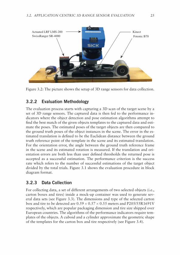
Figure 3.2: The picture shows the setup of 3D range sensors for data collection.
3.2.2 Evaluation Methodology
The evaluation process starts with capturing a 3D scan of the target scene by aset of 3D range sensors. The captured data is then fed to the performance in-dicators where the object detection and pose estimation algorithms attempt tofind the best match of the given objects templates to the captured data and esti-mate the poses. The estimated poses of the target objects are then compared tothe ground truth poses of the object instances in the scene. The error in the es-timated translation is defined to be the Euclidean distance between the groundtruth reference point of the template in the scene and its estimated translation.For the orientation error, the angle between the ground truth reference framein the scene and its estimated rotation is measured. If the translation and ori-entation errors are both less than user defined thresholds the returned pose isaccepted as a successful estimation. The performance criterion is the successrate which refers to the number of successful estimations of the target objectdivided by the total trials. Figure 3.1 shows the evaluation procedure in blockdiagram format.
3.2.3 Data Collection
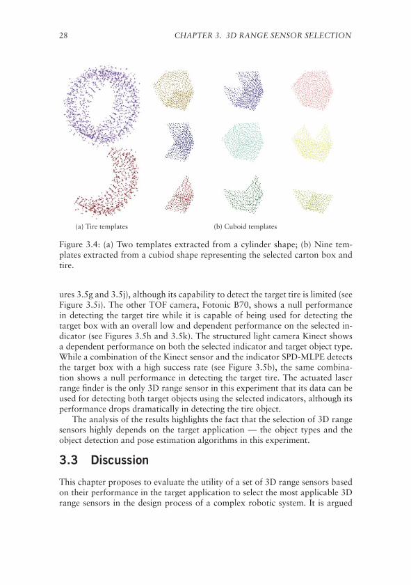
For collecting data, a set of different arrangements of two selected objects (i.e.,carton boxes and tires) inside a mock-up container was used to generate sev-eral data sets (see Figure 3.3). The dimensions and type of the selected cartonbox and tire to be detected are 0.59×0.57×0.55 meters and P205/55R1691Vrespectively, which are popular packaging dimension and tire size shipped overEuropean countries. The algorithms of the performance indicators require tem-plates of the objects. A cuboid and a cylinder approximate the geometric shapeof the templates for the carton box and tire respectively (see Figure 3.4).
26 CHAPTER 3. 3D RANGE SENSOR SELECTION
(a) (b) (c) (d) (e)
(f) (g) (h) (i) (j)
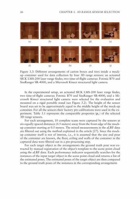
Figure 3.3: Different arrangements of carton boxes and tires inside a mock-up container used for data collection by four 3D range sensors: an actuatedSICK LMS-200 laser range finder, two time-of-flight cameras: Fotonic B70 andSissRanger SR-4000, and a Microsoft Kinect structured light camera.
In the experimental setup, an actuated SICK LMS-200 laser range finder,two time-of-flight cameras: Fotonic B70 and SissRanger SR-4000, and a Mi-crosoft Kinect structured light camera were selected for the evaluation andmounted on a rigid portable stand (see Figure 3.2). The height of the sensorboard was set to be approximately equal to the middle height of the mock-upcontainer. For all the sensors their factory pre-calibrations were used in the ex-periment. Table 3.1 represents the comparable properties (pc) of the selected3D range sensors.
For each arrangement, 10 complete scans were captured by the sensors atsix equally spaced distances (0.5 meters) away from the front edge of the mock-up container starting at 0.5 meters. The mixed measurements in the aLRF dataare filtered out using the method explained in the article [27]. Since the mock-up container itself is not of interest, i.e., it is assumed that the size and poseof the container are known, the floor, ceiling and walls of the container in thecaptured data were filtered out in a pre-processing step.
For each target object in the arrangements the ground truth pose was ex-tracted by manual registration of the object’s template to the scene point cloudusing the aLRF data. Each performance indicator sequentially searches for theinstances of the input target object in the scene point cloud and returns a list ofthe estimated poses. The estimated poses of the target object are then comparedto the ground truth poses of the instances in the corresponding arrangement.
3.2. APPLICATION CENTRIC 3D RANGE SENSOR EVALUATION 27
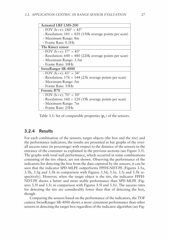
Actuated LRF LMS-200- FOV (h×v): 180◦ × 45◦
- Resolution: 181 × 850 (150k average points per scan)- Maximum Range: 8m- Frame Rate: 0.1Hz
The Kinect sensor- FOV (h×v): 57◦ × 43◦
- Resolution: 640 × 480 (220k average points per scan)- Maximum Range: 3.5m- Frame Rate: 30Hz
SwissRanger SR-4000- FOV (h×v): 43◦ × 34◦
- Resolution: 176 × 144 (25k average points per scan)- Maximum Range: 5m- Frame Rate: 35Hz
Fotonic B70- FOV (h×v): 70◦ × 50◦
- Resolution: 160 × 120 (19k average points per scan)- Maximum Range: 7m- Frame Rate: 25Hz
Table 3.1: Set of comparable properties (pc) of the sensors.
3.2.4 Results
For each combination of the sensors, target objects (the box and the tire) andthe performance indicators, the results are presented in bar graphs of the over-all success rates (in percentage) with respect to the distance of the sensors to theentrance of the container as explained in the previous sections (see Figure 3.5).The graphs with total null performance, which occurred in some combinationsconsisting of the tire object, are not shown. Observing the performance of theindicators for detecting the box from the data captured by the sensors, it can beseen that the indicator SPD-MLPE outperforms FPFH-NDT-PE (Figures 3.5a,3.5b, 3.5g and 3.5h in comparison with Figures 3.5d, 3.5e, 3.5j and 3.5k re-spectively). However, when the target object is the tire, the indicator FPFH-NDT-PE shows a better and more stable performance than SPD-MLPE (Fig-ures 3.5f and 3.5c in comparison with Figures 3.5l and 3.5i). The success ratesfor detecting the tire are considerably lower than that of detecting the box,though.
Comparing the sensors based on the performance of the indicators, the TOFcamera SwissRanger SR-4000 shows a more consistent performance than othersensors in detecting the target box regardless of the indicator algorithm (see Fig-
28 CHAPTER 3. 3D RANGE SENSOR SELECTION
(a) Tire templates (b) Cuboid templates
Figure 3.4: (a) Two templates extracted from a cylinder shape; (b) Nine tem-plates extracted from a cubiod shape representing the selected carton box andtire.
ures 3.5g and 3.5j), although its capability to detect the target tire is limited (seeFigure 3.5i). The other TOF camera, Fotonic B70, shows a null performancein detecting the target tire while it is capable of being used for detecting thetarget box with an overall low and dependent performance on the selected in-dicator (see Figures 3.5h and 3.5k). The structured light camera Kinect showsa dependent performance on both the selected indicator and target object type.While a combination of the Kinect sensor and the indicator SPD-MLPE detectsthe target box with a high success rate (see Figure 3.5b), the same combina-tion shows a null performance in detecting the target tire. The actuated laserrange finder is the only 3D range sensor in this experiment that its data can beused for detecting both target objects using the selected indicators, although itsperformance drops dramatically in detecting the tire object.
The analysis of the results highlights the fact that the selection of 3D rangesensors highly depends on the target application — the object types and theobject detection and pose estimation algorithms in this experiment.
3.3 Discussion
This chapter proposes to evaluate the utility of a set of 3D range sensors basedon their performance in the target application to select the most applicable 3Drange sensors in the design process of a complex robotic system. It is argued

3.3. DISCUSSION 29
that the selection of 3D range sensors solely based on the characteristics of thesensors and in isolation of the target application may result in an inappropriateselection. For example, in a study of the characteristic of the laser range finderSICK LMS200 by Ye and Borenstein [29] they examine the effect of target sur-face properties by three groups of materials — namely, shiny colors, mattedcolors and gray levels (see Section 4.3 in [29]). From their experiment of evalu-ating the range measurement distribution (see Figure 5c in [29]) from white toblack surfaces we can observe slightly more than 0.6% mean error. However,such characteristic is not adequately informative for us to predict, for instance,how well the laser range finder would perform for detecting and pose estimatingof the tires in comparison with carton boxes stacked inside shipping containers.In the results section of this chapter, on the other hand, it can be observed thatthe laser range finder performance considerably drops when dealing with tiresin comparison with carton boxes.
In order to evaluate the performance of the 3D range sensors in the targetapplication, the object detection and pose estimation task in the scenario ofRobLog project was used as performance indicator. The results show that thedark surfaces with tread patterns, as they can be found on the surface of tires,significantly absorb infrared light of the TOF camera SwissRanger SR4000.Such dark surfaces, although not to the same extent, also substantially reducethe performance of the laser range finder SICK LMS200 and the structured lightcamera Kinect sensor. In conclusion, we observe that TOF cameras are notappropriate choice for detecting objects like tires, Kinect-type sensors do notperform better, and even laser range finders have difficulties with such objects.
The experiments presented in this chapter also suggest that the performanceof the different 3D range sensing technologies varies greatly over different ob-ject and surface types. The best overall combined detection rates (in compari-son with aLRF as reference) were obtained by the most dense range sensor —namely, the structured light camera Kinect sensor.

30 CHAPTER 3. 3D RANGE SENSOR SELECTION
(a) aLRF, SPD-MLPE (b) Kinect, SPD-MLPE (c) aLRF, SPD-MLPE
(d) aLRF, FPFH-NDT-PE (e) Kinect, FPFH-NDT-PE (f) aLRF, FPFH-NDT-PE
(g) sr4000, SPD-MLPE (h) FotonicB70, SPD-MLPE (i) sr4000, SPD-MLPE
(j) sr4000, FPFH-NDT-PE (k) FotonicB70, FPFH-NDT-PE (l) Kinect, FPFH-NDT-PE
Figure 3.5: Success rate bar graphs for each combination of sensor model, ob-ject type and performance indicator. Horizontal axis is the distance of the cor-responding sensor to the container, and vertical axis is the average success rateof all scenarios at each distance step in percentage.

Chapter 4Object Pose Refinement forGeometrical Consistency
A complete and accurate estimation of the poses of the objects is of great im-portance especially for high level reasoning (as it is the main topic of the nextchapter) and motion planning for manipulation of the objects. State-of-the-art object pose estimation methods (e.g., [48, 49]) represent the uncertainty intheir estimations, which may result in a geometrically inconsistent model of theenvironment due to inter-penetrations between pairs of adjacent objects. Forexample, a carton box that is partly (or completely) overlapping with the flooror a wall of a container is not consistent with a rigid body assumption.
This chapter concerns the problem of refining the initially estimated posesof a set of objects in order to obtain a geometrically consistent (i.e., an inter-penetration free) model of the environment. A search based methodology ispresented in this chapter to resolve such inter-penetrations between rigid objectsleading to a refinement of the poses. It should be noted that the type of searchpresented in this chapter differs from the search for the initial poses that anobject pose estimation algorithm performs. In other words, the ultimate goal isto refine and not to estimate the initial poses.
A number of approaches have been proposed to estimate the poses of ob-jects from 2D images [50, 51, 52] and 3D sampled points [53, 54, 48]. Themain focus of the proposed approaches for object pose estimation is to obtainaccurate object poses, while geometrical consistency of the estimated poses hasreceived less attention. For example, Lim et al. [55] describe a fine pose esti-mation method to fit 3D models of IKEA furniture to the images. They use adatabase of the 3D models and define a multi-criteria score function to find thebest fit for the models in an image. As their results show, the error in the pose ofthe fit 3D model may result in an inter-penetration with the environment. Forinstance, the fit 3D model of an IKEA bookcase considerably intersects withthe ground floor due to the error in the estimated pose of the bookcase. Such
31

32CHAPTER 4. OBJECT POSE REFINEMENT FOR GEOMETRICAL
CONSISTENCY
geometrically inconsistent situations can be resolved, for example, by a colli-sion detection algorithm (that is expected to push the bookcase up) resulting ina higher accuracy of the estimated pose.
The presence of other objects – either fixed (e.g., a wall) or movable – nearbythe target object corresponds to additional geometrical constraints which re-quires extra analysis. Grundmann et al. [56] present a probabilistic approach,called Rule Set Joint State Update, to estimate the poses of a set of objectssimultaneously using an approximation for the full joint posterior. They as-sume independence between prior belief, measurement and prediction modelsto approximate the full state. The results of the proposed method, however,are presented on tabletop scenarios with only one object. Aldoma et. al [57]describe an approach for verifying 3D models of objects (hypothesis verifying)in cluttered scenes according to a global optimization paradigm by minimiz-ing a cost function which encompasses geometrical cues. The ultimate goal oftheir method is to select the best set of models and poses from a given poolof hypotheses subjective to maximize the number of correct recognitions whileminimizing the number of wrong recognitions. Hypothesis verifying may im-prove the quality of object recognition and pose estimation. However, thereis no guarantee that the verified hypothesis represent an inter-penetration freeconfiguration of objects. Wong et. al [58] propose collision-free state estima-tion where they attempt to solve a constrained optimization problem in orderto find a feasible collision-free configuration. They assume that all the objectsare resting stably on a 2D surface (i.e., no object is on top of another object).In their method, the projections of the objects onto the 2D surface create a setof boundaries, and the inter-penetrations between the boundaries are resolvedthrough optimization. However, the method is not applicable for the problemswhere goods are usually stacked on top of each other (e.g., shipping containers)with arbitrary configurations.
Another approach that one may consider is to utilize the collision resolversof Physics Engines (e.g. see [59]) to tackle the problem of inter-penetrations be-tween a set of static objects. However, the collision resolvers of Physics Enginesare based on dynamic collision detection where impulse forces are used to sim-ulate the trajectories of two objects after their dynamic impact. Such impulseforce based algorithms when initialized with a static configuration of overlap-ping objects result in a spread of objects far from their initially estimated poses.
The approach presented in this chapter, on the other hand, attempts to re-solve all the initial inter-penetrations between objects with minimum change intheir initially estimated poses and independently of the corresponding objectrecognition and pose estimation algorithm.
In what follows, the computation of the depth of penetration is sketched, in-cluding a review of the existing methodologies for convex and concave shapedobjects. Then, the algorithm to compute the depth of penetration of convexpolytopes based on the Separating Axis theorem is described. This will befollowed by formal definition of a graph search problem to resolve the inter-

4.1. DEPTH OF PENETRATION COMPUTATION 33
penetrations between objects. Two selected discrete search algorithms are thendescribed to be applied to the graph search problem. Next, the results of ap-plying the approach of this chapter to the data generated in simulation andfrom real-world setups are presented. The chapter concludes with a discussionof the methodology employed to achieve a geometrically consistent model ofthe environment.
4.1 Depth of Penetration Computation
The inter-penetration between two overlapping polytopes can be representedby another polytope that contains the overlapping space. This representationis a precise description of the inter-penetration space while the computation ofthe overlapping polytope, especially in 3-dimensional space is expensive [60].Although the volume of the overlapping space can be used as a measure forthe amount of inter-penetration between two polytopes, the overlapping spaceprovides no clue about how to separate two overlapping polytopes.
Another representation of the overlapping space between two polytopes isan inter-penetration vector such that translating one of polytopes by the vec-tor will resolve the inter-penetration with the minimum possible translation;the length of this vector is referred to as depth of penetration (DOP). Zhanget. al [61] study the generalized depth of penetration where both translationand rotation are considered. The generalized depth of penetration is the min-imum length of a trajectory along which moving a polytope will disjoint twooverlapping polytopes. They prove [61, Theorem 1] that for convex polytopesthe general depth of penetration is equal to the translational depth of pene-tration. A number of algorithms have been proposed for computing the depthof penetration. A category of algorithms is based on the relation between theMinkowski sum and DOP of two polytopes [62, 63, 64]. Another approachto compute DOP is based on the separating axis theorem (SAT) [60], whichis widely used in computer graphics and physics simulations for collision de-tection. SAT is a corollary of the separating hyperplane theorem [65], whichis an essential theory in convex set analysis. While both approaches, based onMinkowski sum and SAT can be used for computing the depth of penetra-tion, SAT is a faster algorithm for polyhedrons that have less features (facesand edges) [66] such as cuboids and cylinders, where we notice that they aregood geometrical representations for carton boxes and barrels shipped in cargocontainers. This dissertation describes and implements 3-dimensional SAT al-gorithm to compute the minimum translation vector between two overlappingconvex polyhedrons.
4.1.1 SAT Algorithm
The separating hyperplane theorem states that for two convex sets A and B,either the two sets are overlapping or there exists at least one separating hyper-
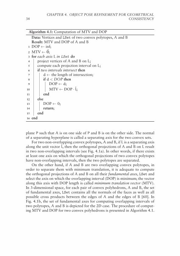
34CHAPTER 4. OBJECT POSE REFINEMENT FOR GEOMETRICAL
CONSISTENCY
Algorithm 4.1: Computation of MTV and DOPData: Vertices and LSet of two convex polytopes, A and BResult: MTV and DOP of A and B
1 DOP ← inf;2 MTV ← �0;3 for each axis L in LSet do4 project vertices of A and B on L;5 compute each projection interval on L;6 if two intervals intersect then7 d ← the length of intersection;8 if d < DOP then9 DOP ← d;
10 MTV ← DOP · l;11 end12 else13 DOP ← 0;14 return;15 end16 end
plane P such that A is on one side of P and B is on the other side. The normalof a separating hyperplane is called a separating axis for the two convex sets.
For two non-overlapping convex polytopes, A and B, if L is a separating axisalong the unit vector l, then the orthogonal projections of A and B on L resultin two non-overlapping intervals (see Fig. 4.1a). In other words, if there existsat least one axis on which the orthogonal projections of two convex polytopeshave non-overlapping intervals, then the two polytopes are separated.
On the other hand, if A and B are two overlapping convex polytopes, inorder to separate them with minimum translation, it is adequate to computethe orthogonal projections of A and B on all their fundamental axes, LSet andselect the axis on which the overlapping interval (DOP) is minimum; the vectoralong this axis with DOP length is called minimum translation vector (MTV).In 3-dimensional space, for each pair of convex polyhedrons, A and B, the setof fundamental axes, LSet contains all the normals of the faces as well as allpossible cross products between the edges of A and the edges of B [60]. InFig. 4.1b, the set of fundamental axes for computing overlapping intervals oftwo polytopes, A and B is depicted for the 2D case. The procedure of comput-ing MTV and DOP for two convex polyhedrons is presented in Algorithm 4.1.

4.2. POSE REFINEMENT SEARCH 35
(a) (b)
Figure 4.1: (a) A Separating axis and a separating hyperplane of two non-overlapping polytopes. (b) A and B are two overlapping convex polytopes. Theset of fundamental separating axes, LSet = {L1, . . . ,L6}, which are along thenormals (e.g., l3) of edges of A and B are drawn. The minimum overlapping in-tervals of the orthogonal projections of A and B on axes in LSet is found on L3.The minimum translation vector (MTV) and depth of penetration (DOP) areidentified by the overlapping projections on L3. Translating A by MTV (or B bynegative MTV) resolves the inter-penetrations between A and B with minimumtranslation.
4.2 Pose Refinement Search
This section describes a discrete search approach in the state space of mini-mum translations vectors to obtain an inter-penetration free configuration ofa set of convex polytopes. A search in the state space of poses to obtain aninter-penetrations free configuration of more than two objects is necessary. Forthe sake of illustration of the problem, Fig. 4.2 depicts a toy configuration ofthree movable polytopes, A, B and C, and one fixed convex polytope, W, inwhich A and B are overlapping. It can be seen that translating A by the MTVintroduces a new inter-penetration between A and W, and translating B by thenegative MTV introduces a new inter-penetration between B and C. Hence, asearch into the state space of poses is required to reach an inter-penetration freeconfiguration, while minimizing the sum of changes in the initial poses of thepolytopes. It is worth mentioning that depending on the initial configurationof the objects and the structure of the environment, there might be no solutionresulting in an inter-penetration free configuration.

36CHAPTER 4. OBJECT POSE REFINEMENT FOR GEOMETRICAL
CONSISTENCY
(a) (b) (c) (d)
Figure 4.2: A configuration of three movable objects, A, B and C, and a fixedobject, W. (a) Initial state, s1 with an inter-penetration between A and B whichgenerates two possible actions, a(s1) = {a1
A,a1B}. (b) Taking action a1
A trans-lates A by MTV resulting in a new inter-penetration between A and W. SinceW is fixed, there is only one possible action in s2, a(s2) = {a2
A}, where takinga2A goes back to s1, and hence this path in the search will not be expanded
further. (c) Taking action a1B translates B by negative MTV which results in a
new inter-penetration between B and C. Since C is a movable object, there aretwo possible actions in s3, a(s3) = {a3
B,a3C}. (d) Taking a3
C results in s4 whichis an inter-penetration-free configuration, i.e., a goal state.
4.2.1 Minimum Translations Search Problem
In this section the problem of searching for an inter-penetration free configura-tion of a set of polytopes is formally defined.
Definition 4.1. A state, s is a configuration of polytopes with a set of posesdenoted by P(s). The initial state, s0 is the given configuration of polytopesthat search progress starts with.
Definition 4.2. A set of possible actions in each state s denoted by A(s) isdefined as below. For each pair of overlapping objects, i.e., ∀DOPij ∈ s suchthat DOPij �= 0, two possible actions, ai,aj ∈ A(s) is defined such that
• ai translates i-th object by the MTVij;
• aj translates j-th object by the negative MTVij.
If a static object (e.g., a wall) overlaps with a movable object, only the actionthat translates the movable object is considered in the search (see Fig. 4.2).
The structure of the search space is a graph. This implies from the fact thata state s′ may have been reachable from multiple predecessors (s1, s2, . . . , sn)by taking different sequence of actions; there may be more than one goal state(i.e., an inter-penetration free configuration) in the graph.
It is worth mentioning that in the actual implementation of generating ac-tions, in order to prevent the search from visiting redundant states it is required
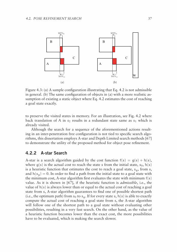
4.2. POSE REFINEMENT SEARCH 37
(a) (b)
Figure 4.3: (a) A sample configuration illustrating that Eq. 4.2 is not admissiblein general. (b) The same configuration of objects in (a) with a more realistic as-sumption of existing a static object where Eq. 4.2 estimates the cost of reachinga goal state exactly.
to preserve the visited states in memory. For an illustration, see Fig. 4.2 whereback translation of A in s2 results in a redundant state same as s1 which isalready visited.
Although the search for a sequence of the aforementioned actions result-ing in an inter-penetration free configuration is not tied to specific search algo-rithms, this dissertation employs A-star and Depth Limited search methods [67]to demonstrate the utility of the proposed method for object pose refinement.
4.2.2 A-star Search
A-star is a search algorithm guided by the cost function f(s) = g(s) + h(s),where g(s) is the actual cost to reach the state s from the initial state, s0, h(s)is a heuristic function that estimates the cost to reach a goal state, sg, from s,and h(sg) = 0. In order to find a path from the initial state to a goal state withthe minimum cost, A-star algorithm first evaluates the state with minimum f(s)value. As it is shown in [67], if the heuristic function is admissible, i.e., thevalue of h(s) is always lower than or equal to the actual cost of reaching a goalstate from s, A-star algorithm guarantees to find one of possible shortest path(i.e., the optimum path) from s0 to sg. If for every state s, h(s) is able to exactlycompute the actual cost of reaching a goal state from s, the A-star algorithmwill follow one of the shortest path to a goal state without evaluating otherpossibilities, resulting in a very fast search. On the other hand, as the value ofa heuristic function becomes lower than the exact cost, the more possibilitieshave to be evaluated, which is making the search slower.
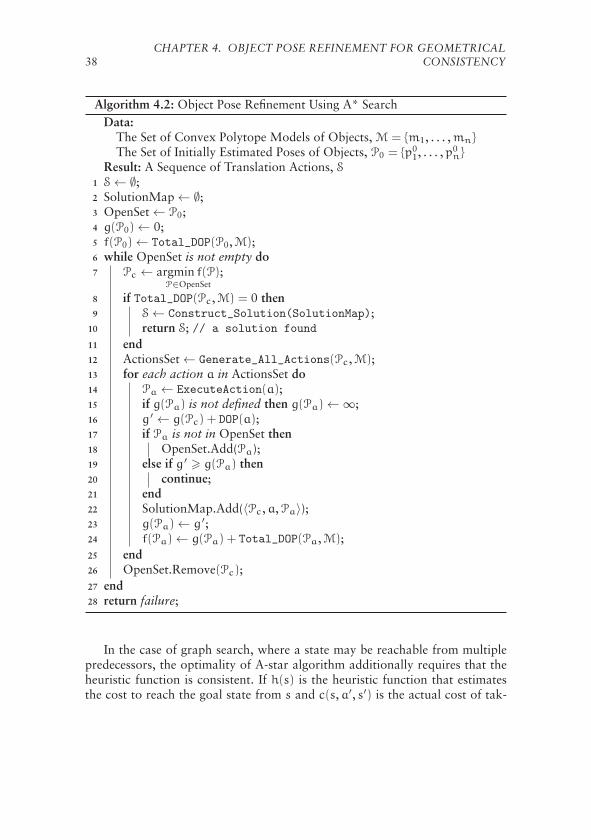
38CHAPTER 4. OBJECT POSE REFINEMENT FOR GEOMETRICAL
CONSISTENCY
Algorithm 4.2: Object Pose Refinement Using A* SearchData:
The Set of Convex Polytope Models of Objects, M = {m1, . . . ,mn}
The Set of Initially Estimated Poses of Objects, P0 = {p01, . . . ,p0
n}
Result: A Sequence of Translation Actions, S1 S ← ∅;2 SolutionMap ← ∅;3 OpenSet ← P0;4 g(P0) ← 0;5 f(P0) ← Total_DOP(P0,M);6 while OpenSet is not empty do7 Pc ← argmin f(P)
P∈OpenSet;
8 if Total_DOP(Pc,M) = 0 then9 S ← Construct_Solution(SolutionMap);
10 return S; // a solution found
11 end12 ActionsSet ← Generate_All_Actions(Pc,M);13 for each action a in ActionsSet do14 Pa ← ExecuteAction(a);15 if g(Pa) is not defined then g(Pa) ← ∞;16 g ′ ← g(Pc) + DOP(a);17 if Pa is not in OpenSet then18 OpenSet.Add(Pa);19 else if g ′ � g(Pa) then20 continue;21 end22 SolutionMap.Add(〈Pc,a,Pa〉);23 g(Pa) ← g ′;24 f(Pa) ← g(Pa) + Total_DOP(Pa,M);25 end26 OpenSet.Remove(Pc);27 end28 return failure;
In the case of graph search, where a state may be reachable from multiplepredecessors, the optimality of A-star algorithm additionally requires that theheuristic function is consistent. If h(s) is the heuristic function that estimatesthe cost to reach the goal state from s and c(s,a′, s′) is the actual cost of tak-

4.2. POSE REFINEMENT SEARCH 39
ing action a′ ∈ A(s) to go from s to the successor state s′, then the heuristicfunction h(.) is said to be consistent if,
h(s) � c(s,a′, s′) + h(s′). (4.1)
It is noted that if a heuristic function is consistent, it is also admissible [67].However, an inadmissible heuristic function cannot be consistent as the in-equality 4.1 will not hold if h(.) overestimates the cost to reach a goal state(i.e., h(s) may be greater than c(s,a′, s′) + h(s′)).
For the graph search problem defined in Section 4.2.1 finding a heuristicfunction that for each state exactly computes the cost of reaching a goal stateis not trivial. One difficulty is due to the fact that although a translation ofa polytope along the corresponding MTV resolves one inter-penetration but itmay introduce one or more inter-penetrations with other polytopes, which can-not be seen before translating a polytope. On the other hand, using a heuristicfunction that estimates a lower bound for the cost results in a very slow search.
It should be noticed that what really matters in our search problem is to findan inter-penetration free configuration (i.e., a goal state) with a minimum totalpose distance between the initial state, s0 and the goal state, sg. Having thissaid, in order to accelerate the A-star search in a large state space, a heuristicfunction that for some states is able to estimate the exact cost is selected asbelow,
h(s) =∑i,j
DOPij(s) , i, j = 1, . . . ,N , i �= j. (4.2)
The motivation is the fact that a goal state is a configuration of objects in whichall the inter-penetrations have been resolved, hence, from any state it is morelikely to reach a goal state by translating polytopes along the correspondingMTVs. However, as mentioned above, Eq. 4.2 is not an admissible heuristicfunction since it may overestimate the cost of reaching a goal state. In Fig. 4.3aif we move C along negative MTVac we reach a goal state, while the sum ofdepth of penetrations in this state (which is |MTVbc| + |MTVac| as Eq. 4.2computes) overestimates the cost to reach a goal state. Nonetheless, from theexperimental results (see Section 4.3) it is observed that in many cases whenthe minimum required cost to reach a goal state is equal to all the translationactions that must be taken to resolve the inter-penetrations, the heuristic func-tion in Eq. 4.2 can be used with good results. This can be especially seen wherethere exists static objects (e.g., walls) that limit the space of moving objects.Fig. 4.3b shows how existing an additional static object nearby the dynamicobjects in Fig. 4.3a limits their movability where Eq. 4.2 estimates the exactcost of reaching a goal state.
The pseudo code shown in Algorithm 4.2 presents an implementation ofthe A-star search for object pose refinement. The function Total_DOP(P,M)computes the sum of depth of penetrations in a configuration identified by theset of shapes, M and the corresponding poses, P according to Eq. 4.2, while the
40CHAPTER 4. OBJECT POSE REFINEMENT FOR GEOMETRICAL
CONSISTENCY
function DOP(a) returns the depth of penetration corresponding to the action a,and the function Generate_All_Actions(P,M) generates all actions accordingto Definition 4.2; the function ExecuteAction(a) returns the new set of posesafter the execution of the action a. If a solution is found, the sequence of actionsthat the execution of them results in an inter-penetration free configuration,i.e., a set of poses, Pgoal that satisfy the condition Total_DOP(Pgoal,M) = 0, isreturned by the function Construct_Solution().
The solution that A-star search finds (if there exists any) is a sequence of ac-tions such that their execution results in a transition from start to goal statewith a minimum total cost of taken actions. Since a goal state is an inter-penetration free configuration, and the total cost of reaching the goal state inmany cases is minimal, a solution returned by the A-star search algorithm sat-isfies the two criteria: maximizing geometrical consistency and (sub-optimally)minimizing the sum of translations required to reach a goal state.
4.2.3 Depth Limited Search
The state space of MTVs can grow exponentially as the successors of statesare expanded. This may limit the number of objects and the inter-penetrationsthat the proposed A-star search is capable to deal with in a reasonable time.In order to accelerate the search in a large state space, Depth Limited Search(DLS) algorithm is selected.
DLS only explores a branch of the state space and finds suboptimal but geo-metrically consistent solutions. A suboptimal solution is a sequence of transla-tion actions that results in an inter-penetration free configuration while the totalcost of taking the actions is not necessarily minimum. On the other hand, asit is mentioned earlier in Section 4.2, there could be configurations of overlap-ping objects for which no goal state exists (i.e., there exists no inter-penetrationfree configuration). In such cases an unlimited search algorithm may generateinfinitely many intermediate states. DLS overcomes this issue by limiting thedepth of search into the state space.
With similar sub-functions explained for Algorithm 4.2, the pseudo codeshown in Algorithm 4.3 presents a recursive implementation of the depth lim-ited search for object pose refinement. The user selected input, limit in the al-gorithm limits the depth of search, where a cutoff message is propagated intorecursive calling of the function RecursiveDLS() in order to execute the nextpossible action and explore another branch of search space.
4.2.4 Concave Shaped Objects
The extension of the search process to cover the objects with concave shapescan be easily conducted by slightly modifying the graph search problem definedin Section 4.2. The first method is based on the decomposition of a concaveshaped object into a set of connected convex shapes [68], where the idea is to
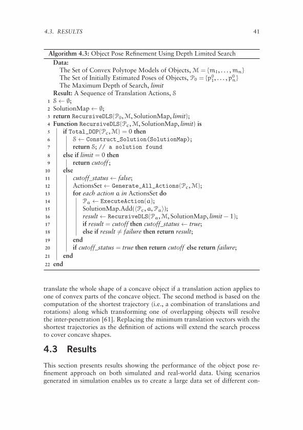
4.3. RESULTS 41
Algorithm 4.3: Object Pose Refinement Using Depth Limited SearchData:
The Set of Convex Polytope Models of Objects, M = {m1, . . . ,mn}
The Set of Initially Estimated Poses of Objects, P0 = {p01, . . . ,p0
n}
The Maximum Depth of Search, limitResult: A Sequence of Translation Actions, S
1 S ← ∅;2 SolutionMap ← ∅;3 return RecursiveDLS(P0,M, SolutionMap, limit);4 Function RecursiveDLS(Pc,M, SolutionMap, limit) is5 if Total_DOP(Pc,M) = 0 then6 S ← Construct_Solution(SolutionMap);7 return S; // a solution found
8 else if limit = 0 then9 return cutoff ;
10 else11 cutoff_status ← false;12 ActionsSet ← Generate_All_Actions(Pc,M);13 for each action a in ActionsSet do14 Pa ← ExecuteAction(a);15 SolutionMap.Add(〈Pc,a,Pa〉);16 result ← RecursiveDLS(Pa,M, SolutionMap, limit − 1);17 if result = cutoff then cutoff_status ← true;18 else if result �= failure then return result;19 end20 if cutoff_status = true then return cutoff else return failure;21 end22 end
translate the whole shape of a concave object if a translation action applies toone of convex parts of the concave object. The second method is based on thecomputation of the shortest trajectory (i.e., a combination of translations androtations) along which transforming one of overlapping objects will resolvethe inter-penetration [61]. Replacing the minimum translation vectors with theshortest trajectories as the definition of actions will extend the search processto cover concave shapes.
4.3 Results
This section presents results showing the performance of the object pose re-finement approach on both simulated and real-world data. Using scenariosgenerated in simulation enables us to create a large data set of different con-
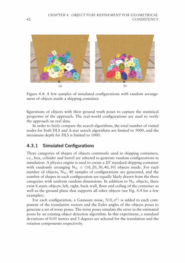
42CHAPTER 4. OBJECT POSE REFINEMENT FOR GEOMETRICAL
CONSISTENCY
(a) (b)
Figure 4.4: A few samples of simulated configurations with random arrange-ment of objects inside a shipping container.
figurations of objects with their ground truth poses to capture the statisticalproperties of the approach. The real-world configurations are used to verifythe approach on real data.
In order to fairly compare the search algorithms, the total number of visitednodes for both DLS and A-star search algorithms are limited to 5000, and themaximum depth for DLS is limited to 1000.
4.3.1 Simulated Configurations
Three categories of shapes of objects commonly used in shipping containers,i.e., box, cylinder and barrel are selected to generate random configurations insimulation. A physics engine is used to create a 20′ standard shipping containerwith randomly arranging NG ∈ {10, 20, 30, 40, 50} objects inside. For eachnumber of objects, NG, 40 samples of configurations are generated, and thenumber of shapes in each configuration are equally likely drawn from the threecategories with uniform random dimensions. In addition to NG objects, thereexist 6 static objects: left, right, back wall, floor and ceiling of the container aswell as the ground plane that supports all other objects (see Fig. 4.4 for a fewexamples).
For each configuration, a Gaussian noise, N(0,σ2) is added to each com-ponent of the translation vectors and the Euler angles of the objects poses togenerate a set of noisy poses. The noisy poses simulate the error in the estimatedposes by an existing object detection algorithm. In this experiment, a standarddeviations of 0.05 meters and 5 degrees are selected for the translation and therotation components respectively.

4.3. RESULTS 43
(a) Scene1 (b) Scene2 (c) Scene3
(d) Scene1 Ground Truth (e) Scene2 Ground Truth (f) Scene3 Ground Truth
Figure 4.5: (a-c) Three real-world configurations of objects inside a mock-upshipping container. (d-f) The ground truth of the objects 3D models and poses.
4.3.2 Real-World Configurations
A set of real-world configurations of objects inside a mock-up shipping con-tainer used for evaluating the approach on real data (see upper row of Fig. 4.5)A Microsoft Kinect sensor looking at the entrance of the mock-up shippingcontainer captures a point cloud of the scene. The set of 3D models of the ob-jects are then registered to the scene point cloud, and the poses are manuallyrefined for obtaining the ground truth of the poses (see lower row of Fig. 4.5).In order to examine the approach independent of and not tied-to any particu-lar object pose estimation algorithm, a set of noisy poses are sampled from theground truth of the poses. This means that we can expect the same results ifthe noise that comes from the sensing and estimation process is distributed inthe same way. Similar to the generated configurations in simulation, a Gaussiannoise, N(0,σ2) is added to each component of the translation vectors and theEuler angles of the poses, which may result in a configuration of overlappingadjacent objects (see Fig. 4.8a for an example). A total of 1000 samples pereach real-world configuration (see upper row of Fig. 4.5) are generated witha standard deviation of 0.05 meters for the translation noise, and a standarddeviation of 5 degrees for the rotation noise.
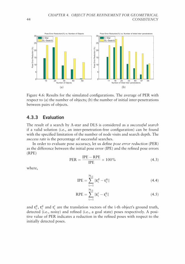
44CHAPTER 4. OBJECT POSE REFINEMENT FOR GEOMETRICAL
CONSISTENCY
10 20 30 40 500
5
10
15
20
25
30Pose Error Reduction(%) vs. Number of Objects
Number of Objects
Pos
e E
rror
Red
uctio
n (%
)
A−StarDL−Search
(a)
11 18 25 33 40 47 540
5
10
15
20
25
30Pose Error Reduction(%) vs. Number of Initial Inter−penetrations
Number of Initial Inter−penetrations
Pos
e E
rror
Red
uctio
n (%
)
A−StarDL−Search
(b)
Figure 4.6: Results for the simulated configurations. The average of PER withrespect to (a) the number of objects; (b) the number of initial inter-penetrationsbetween pairs of objects.
4.3.3 Evaluation
The result of a search by A-star and DLS is considered as a successful searchif a valid solution (i.e., an inter-penetration-free configuration) can be foundwith the specified limitation of the number of node visits and search depth. Thesuccess rate is the percentage of successful searches.
In order to evaluate pose accuracy, let us define pose error reduction (PER)as the difference between the initial pose error (IPE) and the refined pose errors(RPE)
PER =IPE − RPE
IPE× 100% (4.3)
where,
IPE =
NG∑i=1
||tdi − tgi || (4.4)
RPE =
NG∑i=1
||tri − tgi || (4.5)
and tgi , tdi and tri are the translation vectors of the i-th object’s ground truth,detected (i.e., noisy) and refined (i.e., a goal state) poses respectively. A posi-tive value of PER indicates a reduction in the refined poses with respect to theinitially detected poses.

4.3. RESULTS 45
10 20 30 40 500
50
100
150
200
250Time Complexity vs. Number of Objects
Number of Objects
Exe
cutio
n Ti
me
(s)
A−StarDL−Search
(a)
11 18 25 33 40 47 540
20
40
60
80
100
120
140
160
180
200Time Complexity vs. Number of Initial Inter−penetrations
Number of Initial Inter−penetrations
Exe
cutio
n Ti
me
(s)
A−StarDL−Search
(b)
Figure 4.7: Results for the simulated configurations. The average of executiontime with respect to (a) the number of objects; (b) the number of initial inter-penetrations between pairs of objects.
No. Objects 10 20 30 40 50
A* Success Rate 80% 72.5% 35% 25% 2.5%DLS Success Rate 100% 100% 100% 100% 100%
Table 4.1: The success rate (see Section 4.3.3) of the proposed search algorithmswith respect to the number of objects.
Simulated Configurations
In Fig. 4.6a and Fig. 4.6b, the average of PER for each search method is de-picted with respect to the number of objects and initial inter-penetrations be-tween objects respectively. Fig. 4.7a and Fig. 4.7b show the average executiontime for the search methods with respect to the number of objects and theinitial inter-penetrations respectively. It can be seen that both search methodsare approximately equally fast for scenarios with 10 objects. However, as thecomplexity of the scenarios increases with an increasing number of objects,the execution time for A-star rapidly increases, while the depth-limited searchalgorithm is able to resolve the inter-penetrations between objects in highlycluttered scenarios still in a reasonable time (less than 50 seconds on averagefor scenarios with 50 objects).
Table 4.1 depicts the success rate of the search algorithms with respect to thenumber of objects. While depth-limited search manages to find a goal state forall the simulated test scenarios, A-star with the proposed approximate heuristicshows a decreasing performance as the number of objects increases.
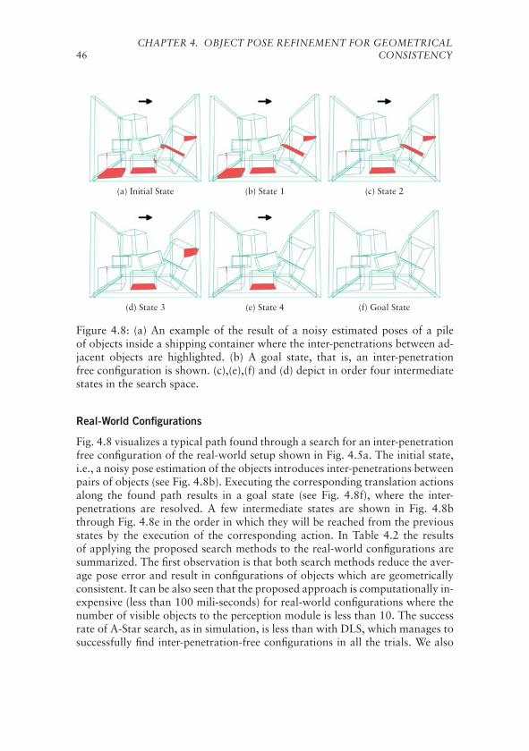
46CHAPTER 4. OBJECT POSE REFINEMENT FOR GEOMETRICAL
CONSISTENCY
(a) Initial State (b) State 1 (c) State 2
(d) State 3 (e) State 4 (f) Goal State
Figure 4.8: (a) An example of the result of a noisy estimated poses of a pileof objects inside a shipping container where the inter-penetrations between ad-jacent objects are highlighted. (b) A goal state, that is, an inter-penetrationfree configuration is shown. (c),(e),(f) and (d) depict in order four intermediatestates in the search space.
Real-World Configurations
Fig. 4.8 visualizes a typical path found through a search for an inter-penetrationfree configuration of the real-world setup shown in Fig. 4.5a. The initial state,i.e., a noisy pose estimation of the objects introduces inter-penetrations betweenpairs of objects (see Fig. 4.8b). Executing the corresponding translation actionsalong the found path results in a goal state (see Fig. 4.8f), where the inter-penetrations are resolved. A few intermediate states are shown in Fig. 4.8bthrough Fig. 4.8e in the order in which they will be reached from the previousstates by the execution of the corresponding action. In Table 4.2 the resultsof applying the proposed search methods to the real-world configurations aresummarized. The first observation is that both search methods reduce the aver-age pose error and result in configurations of objects which are geometricallyconsistent. It can be also seen that the proposed approach is computationally in-expensive (less than 100 mili-seconds) for real-world configurations where thenumber of visible objects to the perception module is less than 10. The successrate of A-Star search, as in simulation, is less than with DLS, which manages tosuccessfully find inter-penetration-free configurations in all the trials. We also

4.4. DISCUSSION 47
Scene 1 Scene 2 Scene 3
A* DLS A* DLS A* DLS
Avg. ExT (ms) 9.53 0.69 45.31 2.86 72.60 4.47Succ. Rate(%) 96.1 100 95.0 100 91.7 100Avg. PER (%) 8.6 11.3 8.9 8.0 19.6 18.0Avg. RPE (m) 0.511 0.496 0.580 0.586 0.500 0.510Avg. IPE (m) 0.559 0.637 0.622Avg. IOL (#N) 6 5 6
Table 4.2: The results of applying the proposed search methods on real-worldconfigurations (see Fig. 4.5). From top to bottom row, the values of averageexecution time in milliseconds (Avg. ExT), success rate (Succ. Rate), averagepose error reduction (Avg. PER, see Eq. 4.3), average refined pose error (Avg.RPE, see Eq. 4.5), average initial pose error (Avg. IPE, see Eq. 4.4), and initialaverage number of overlaps (Avg. IOL).
observe that the results obtained for the real-world data is consistent with thatof simulated data.
4.4 Discussion
In this chapter an algorithm was proposed to resolve the inter-penetrations be-tween a set of convex shaped objects due to errors in the initially estimatedposes. Resolving the inter-penetrations results in a geometrically consistentmodel of the environment that a robotic system works in. The target appli-cation of the framework presented in this chapter is to refine the poses of thedetected objects inside shipping containers in the process of automating the taskof unloading goods. However, the framework can be easily adopted for otherapplications such as domestic robotics where robots are dealing with everydayobjects.
The approach is based on the computation of the minimum translation vec-tors between pairs of overlapping convex objects, where the separating axistheorem is used for this purpose. A discrete search paradigm in the state spaceof the minimum translation vectors is defined to find an inter-penetration freeconfiguration of objects. The utility of two search methods, A-star and depthlimited search examined for exploring a solution in the state space of mini-mum translation vectors. Nevertheless, the extension of the approach to coverconcave shaped objects based on either the decomposition into a set of convexshapes or the direct computation of the shortest resolving penetration trajectoryis discussed.

48CHAPTER 4. OBJECT POSE REFINEMENT FOR GEOMETRICAL
CONSISTENCY
The fact that a solution to the problem is solely based on a high level rea-soning and not tied to any object detection and pose estimation algorithm maysuggest that resolving the inter-penetrations results in less accurate poses. How-ever, the experimental results show that resolving the inter-penetrations notonly represents a geometrically consistent model of the environments, but alsoreduces the total pose error on average.
The approach was tested and verified on data sets generated from real-worldand simulated configurations. From the results we can observe that using thedepth-limited search technique significantly prunes the state space to find a geo-metrically consistent solution. The results also suggest that a trade-off analysisbetween computational resources and the amount of resolved inter-penetrationswith respect to the number of objects is necessary to select a proper searchparadigm.

Chapter 5Support Relation Analysis andDecision Making
Considering the real-world task of unloading goods autonomously, two previ-ous chapters of this dissertation discussed the problems of selecting appropriate3D range sensors for object pose estimation and refining the estimated poses toobtain geometrically consistent models. This chapter analyzes the problem ofidentifying safe-to-remove objects from a pile and presents algorithms to reasonabout the stability of the pile with respect to the configurations of the objects.In the context of unloading a pile of objects, a candidate object is safe to beunloaded if the pile remains static by removing the candidate. Expressly, theultimate goal is to avoid causing the other objects to move (e.g., fall down) byremoving an object from a pile.
For human beings, using the knowledge acquired through experience andthe senses, it may be trivial to immediately identify which objects are safe toremove from a pile. But how can we algorithmically implement such cogni-tive ability into robots? This chapter is an attempt to answer the precedingquestion from deterministic to probabilistic manner. In order to autonomouslyselect safe-to-remove objects, a robotic manipulation system needs two mainabilities. First, it needs to be able to create models to reflect how objects in theconfiguration are physically interacting with each other, i.e., to identify whichobjects are supporting other objects. Second, it should be able to use the cre-ated models to make an optimal decision regarding which object is the safestto remove.
The approach of this chapter incrementally relaxes a set of assumptions onthe input data to address more complicated, real-world scenarios. It is assumedthat an existing object detection algorithm provides the input data for furtheranalysis. In addition to the uncertainty in the estimated poses, object detectionalgorithms may produce false negatives, i.e., a failure in the detection of someexisting objects in the scene. The lack of information about a pile and errors in
49
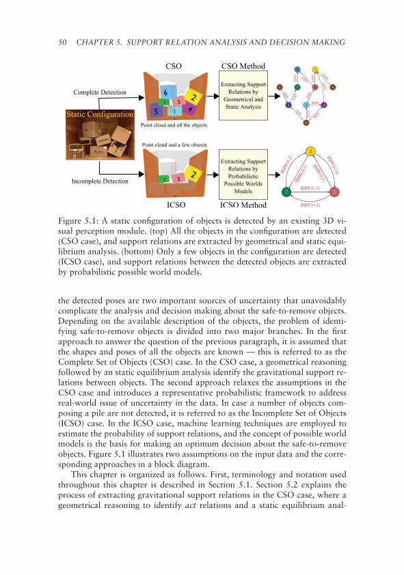
50 CHAPTER 5. SUPPORT RELATION ANALYSIS AND DECISION MAKING
Figure 5.1: A static configuration of objects is detected by an existing 3D vi-sual perception module. (top) All the objects in the configuration are detected(CSO case), and support relations are extracted by geometrical and static equi-librium analysis. (bottom) Only a few objects in the configuration are detected(ICSO case), and support relations between the detected objects are extractedby probabilistic possible world models.
the detected poses are two important sources of uncertainty that unavoidablycomplicate the analysis and decision making about the safe-to-remove objects.Depending on the available description of the objects, the problem of identi-fying safe-to-remove objects is divided into two major branches. In the firstapproach to answer the question of the previous paragraph, it is assumed thatthe shapes and poses of all the objects are known — this is referred to as theComplete Set of Objects (CSO) case. In the CSO case, a geometrical reasoningfollowed by an static equilibrium analysis identify the gravitational support re-lations between objects. The second approach relaxes the assumptions in theCSO case and introduces a representative probabilistic framework to addressreal-world issue of uncertainty in the data. In case a number of objects com-posing a pile are not detected, it is referred to as the Incomplete Set of Objects(ICSO) case. In the ICSO case, machine learning techniques are employed toestimate the probability of support relations, and the concept of possible worldmodels is the basis for making an optimum decision about the safe-to-removeobjects. Figure 5.1 illustrates two assumptions on the input data and the corre-sponding approaches in a block diagram.
This chapter is organized as follows. First, terminology and notation usedthroughout this chapter is described in Section 5.1. Section 5.2 explains theprocess of extracting gravitational support relations in the CSO case, where ageometrical reasoning to identify act relations and a static equilibrium anal-

5.1. TERMINOLOGY AND NOTATION 51
ysis to extract support relations are discussed. The probabilistic approach tothe ICSO case is described in Section 5.3, where this section details the pro-cedure of learning support relations and explains the concept of the possibleworld models employed for a probabilistic representation of the environment.Section 5.4 explains a probabilistic decision making approach to identifyingthe most probable safe-to-remove objects using the representation discussed intwo previous sections. Section 5.5 presents the results of the two approach ondata generated in simulation and from real-world configuration of objects, andSection 5.6 concludes this chapter.
5.1 Terminology and Notation
This section defines terminology and the corresponding assumptions togetherwith Table 5.1 showing the notations consistently used throughout this chapter.Whenever an assumption additionally made or relaxed it is mentioned inlinewith the text.
Definition 5.1. An object is a rigid physical entity with a convex polyhedronshape.
Definition 5.2. A flat ground is a fixed object with a large cuboid shape onwhich other objects can sit, and the gravity force is perpendicular to the flatground.
In practice, a flat ground can be, for example, the floor of a shipping con-tainer, the ledge of a shelf, or a tabletop.
Definition 5.3. The reference frame is a fixed three-dimensional Cartesian co-ordinate system with xz-plane representing the side of the flat ground facingup, where the gravity force direction is opposite to that of y-axis.
Definition 5.4. The geometrical attributes of an object are the geometry of theshape and the pose of the object with respect to the reference frame.
Definition 5.5. A configuration is an environment in which there exists one flatground and a set of static objects with an arbitrary arrangement sitting on topof the flat ground, where the only acting force is gravity.
The term static configuration is interchangeably used instead of configura-tion in the text whenever it is required to emphasize that objects are motionless.
Definition 5.6. For two objects X and Y in a static configuration, if removingX from the configuration causes Y to lose its motionless state, the symbolicsupport relation between X and Y is defined and denoted by SUPP(X, Y); it isread as X supports Y.

52 CHAPTER 5. SUPPORT RELATION ANALYSIS AND DECISION MAKING
Table 5.1: Table of notations, commonly used throughout this chapter.
General NotationR the set of real numbersN the set of natural numbers�a . . .�z column vectors in R
3
�a · �b scalar product of �a and �b�a × �b vector product of �a and �bO a set of objectsC a configuration of objects
Geometrical and Mechanical NotationCPS the contact point-set between two objectsPs the separating plane between two objects�F a mechanical force vector in R
3
�τ a mechanical torque vector in R3
Symbolic RelationsACT symbolic gravitational act relationSUPP symbolic gravitational support relation
A support relation is a directional symbolic relationship that can holdwhether two objects are in direct or indirect contact with each other. Andit should be noted that it is possible to have configurations in which bothSUPP(X,Y) and SUPP(Y,X) hold, i.e., there can be a maximum of two possi-ble support relations between two objects.
5.2 Extracting Support Relations - CSO case
In the CSO case, where all the objects of a pile are assumed to be detected,a geometrical analysis can identify which object acts on another due to grav-ity force. Extracting act relations between objects can explain the stability ofsimple configurations that objects stacked on top of each other, but it fails toidentify which object supports another in more complex configurations. It maybe intuitive to take notions from classical mechanics, especially statics to ana-lyze the stability of a pile. However, in the absence of sensing masses and theirdistribution over geometrical shapes of objects, and the lack of informationabout friction coefficients between the materials of the objects it is not applica-ble to directly use the techniques of statics. This section presents a qualitativeusage of the static equilibrium concept to extract symbolic support relationsbetween objects with an assumption on the masses and their distributions.
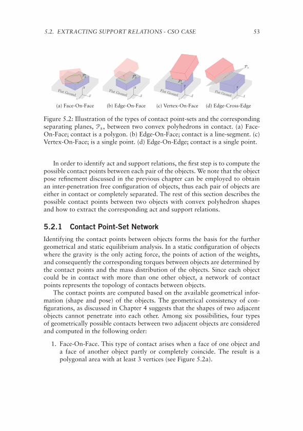
5.2. EXTRACTING SUPPORT RELATIONS - CSO CASE 53
Flat Ground
PsPPPPP
z
y
x
(a) Face-On-Face
Flat Ground
Ps
z
y
x
(b) Edge-On-Face
Flat Ground
Ps
z
y
x
(c) Vertex-On-Face
Flat Ground
Ps
z
y
x
(d) Edge-Cross-Edge
Figure 5.2: Illustration of the types of contact point-sets and the correspondingseparating planes, Ps, between two convex polyhedrons in contact. (a) Face-On-Face; contact is a polygon. (b) Edge-On-Face; contact is a line-segment. (c)Vertex-On-Face; is a single point. (d) Edge-On-Edge; contact is a single point.
In order to identify act and support relations, the first step is to compute thepossible contact points between each pair of the objects. We note that the objectpose refinement discussed in the previous chapter can be employed to obtainan inter-penetration free configuration of objects, thus each pair of objects areeither in contact or completely separated. The rest of this section describes thepossible contact points between two objects with convex polyhedron shapesand how to extract the corresponding act and support relations.
5.2.1 Contact Point-Set Network
Identifying the contact points between objects forms the basis for the furthergeometrical and static equilibrium analysis. In a static configuration of objectswhere the gravity is the only acting force, the points of action of the weights,and consequently the corresponding torques between objects are determined bythe contact points and the mass distribution of the objects. Since each objectcould be in contact with more than one other object, a network of contactpoints represents the topology of contacts between objects.
The contact points are computed based on the available geometrical infor-mation (shape and pose) of the objects. The geometrical consistency of con-figurations, as discussed in Chapter 4 suggests that the shapes of two adjacentobjects cannot penetrate into each other. Among six possibilities, four typesof geometrically possible contacts between two adjacent objects are consideredand computed in the following order:
1. Face-On-Face. This type of contact arises when a face of one object anda face of another object partly or completely coincide. The result is apolygonal area with at least 3 vertices (see Figure 5.2a).
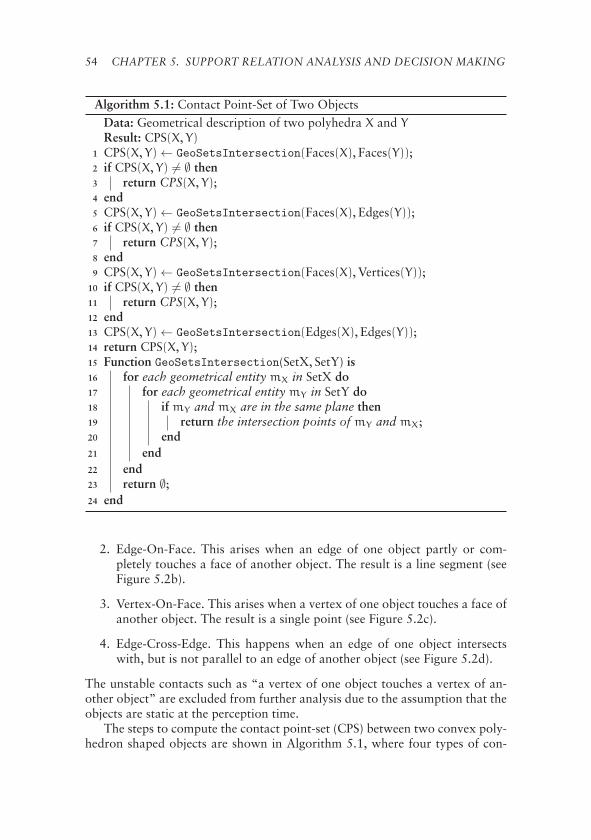
54 CHAPTER 5. SUPPORT RELATION ANALYSIS AND DECISION MAKING
Algorithm 5.1: Contact Point-Set of Two ObjectsData: Geometrical description of two polyhedra X and YResult: CPS(X, Y)
1 CPS(X, Y) ← GeoSetsIntersection(Faces(X), Faces(Y));2 if CPS(X, Y) �= ∅ then3 return CPS(X, Y);4 end5 CPS(X, Y) ← GeoSetsIntersection(Faces(X), Edges(Y));6 if CPS(X, Y) �= ∅ then7 return CPS(X, Y);8 end9 CPS(X, Y) ← GeoSetsIntersection(Faces(X), Vertices(Y));
10 if CPS(X, Y) �= ∅ then11 return CPS(X, Y);12 end13 CPS(X, Y) ← GeoSetsIntersection(Edges(X), Edges(Y));14 return CPS(X, Y);15 Function GeoSetsIntersection(SetX, SetY) is16 for each geometrical entity mX in SetX do17 for each geometrical entity mY in SetY do18 if mY and mX are in the same plane then19 return the intersection points of mY and mX;20 end21 end22 end23 return ∅;24 end
2. Edge-On-Face. This arises when an edge of one object partly or com-pletely touches a face of another object. The result is a line segment (seeFigure 5.2b).
3. Vertex-On-Face. This arises when a vertex of one object touches a face ofanother object. The result is a single point (see Figure 5.2c).
4. Edge-Cross-Edge. This happens when an edge of one object intersectswith, but is not parallel to an edge of another object (see Figure 5.2d).
The unstable contacts such as “a vertex of one object touches a vertex of an-other object” are excluded from further analysis due to the assumption that theobjects are static at the perception time.
The steps to compute the contact point-set (CPS) between two convex poly-hedron shaped objects are shown in Algorithm 5.1, where four types of con-

5.2. EXTRACTING SUPPORT RELATIONS - CSO CASE 55
y
xFlat Ground.z
Z
px
wx
X
py
wy
Y
Ps�n
−�n
+©
-©
Figure 5.3: Extracting the possible ACT relation between two objects X and Y incontact (Proposition 1).
tact points in order mentioned above are evaluated. The abstract functionGeoSetsIntersection(SetX, SetY) computes and returns the intersection oftwo sets of geometrical entities, such as faces, edges and vertices of polyhe-drons. The computed contact points are used to build a network, CPSN =(O,Ω) where the set of nodes, O = {o1, . . . ,oN} represents the objects, and theset of links, Ω = {CPS(oi,oj) : oi,oj ∈ O, i �= j} represents the set of pointsat contact between each pair of objects; such graph is called contact point-setnetwork (CPSN) in this dissertation. We notice that CPS(oi,oj) is an empty setif oi and oj are not in contact, i.e., there is no link between two objects in thenetwork if the objects have no contact point.
5.2.2 Geometrical Reasoning
Having CPSN computed, for each pair of objects in contact, the object actingon another is labeled according to the gravity direction. From Newton’s thirdlaw of motion, we know for two objects X and Y in contact, that if object Xexerts a force on Y, then Y exerts a force, which is equal in magnitude butopposite in direction on X; calling X “acting object” and Y “reacting object”.
The geometrical reasoning to label acting objects is based on extractingthe separating plane, Ps between two objects. Since shapes are convex sets,according to hyperplane separation and supporting hyperplane theorems [69],for each pair of objects in contact there exists a separating plane which divides3D space into two half-spaces such that each half-space contains only one of

56 CHAPTER 5. SUPPORT RELATION ANALYSIS AND DECISION MAKING
the objects. The separating plane is identified by the contact point-sets suchthat CPS(X, Y) ∈ Ps of X and Y. Figure 5.2 shows separating planes for thediscussed contact types in the previous section.
The separated half-spaces are labeled as positive and negative sides of theseparating plane. Considering the definition of reference frame in Section 5.1, ahalf-space is labeled as positive, respectively negative, side, if the y-componentof the separating plane’s normal vector at that side is strictly positive, respec-tively negative. In the case of a perpendicular separating plane to the flat ground(i.e., the y-component of the normal vector is zero), the half-spaces are not la-beled.
In order to identify whether object X acts on another object, Y, the first stepis to ignore all the other objects in contact with X and Y. The acting object isthen determined according to the following proposition.
Proposition 5.1. For two objects X and Y in contact, if their separating planeis not perpendicular to the flat ground, then the positive side of the separatingplane contains the acting object, and the negative side contains the reactingobject. Such a symbolic relation is presented as ACT(X, Y) which is read as “Xacts on Y”.
Proof. Without loss of generality, let us assume that the positive side of theseparating plane contains X and the negative side contains Y (see Figure 5.3).If �n(nx,ny,nz) is the normal vector of the separating plane in the positive side(i.e., ny is strictly positive) and �w(0,−w, 0), w > 0 is the weight of an arbitrarysmall piece of Y, it can be shown that none of such pieces of Y can exert force onX due to their weights. To do this, let us compute the projection of the weight,�w, on the normal vector �n,
Proj(�w,�n) = (�w · �n)�n = −(wny)�n (5.1)
since w > 0 and ny > 0, �w has no contribution towards the positive side, andhence no force exertion on X. Similarly, it can be shown that for all weights ofarbitrary small pieces of X, there exists a non-zero force contribution towardsthe negative side, i.e., ACT(X, Y).
5.2.3 Static Equilibrium Analysis
Having the ACT relations identified as described in the previous section, onemight suggest that the support relations between objects, and consequently thesafest candidates, can be identified through an analysis of the ACT relations. Thehypothesis behind the analysis of the ACT relations is that for each act relation,ACT(A,B), there must be one support relation such that SUPP(B,A), i.e, if A actson B, then B supports A. This can be translated to the intuitive heuristic rule thatstates removing the objects with the highest height is safe. However, there aremany situations where this reasoning fails. In Figure 5.4, through examples, it

5.2. EXTRACTING SUPPORT RELATIONS - CSO CASE 57
(a) (b)
(c) (d)
Figure 5.4: Four example configurations where reasoning about the supportrelations between objects solely based on the extracted ACT relations fail topredict the safest object to remove first.
is illustrated that for a set of configurations reasoning solely based on ACT rela-tions or the height of objects fails to predict the true support relations betweenobjects. In all the configurations shown in Figure 5.4, object A is the highestobject in the configuration. However, A is not the safest object to be removedfirst (A supports B in all the configurations). Figure 5.4a and Figure 5.4b showtwo cases in which the highest object, A, supports another object, B, while B
does not act on A (i.e., ¬ACT(B,A)). In Figure 5.4c, A acts on B (i.e., ACT(A,B)),but B does not support A (i.e., ¬SUPP(B,A)). In Figure 5.4d, the ACT relationbetween A and B cannot be identified (the separating plane is perpendicular tothe flat ground); it can be clearly seen, however, that A supports B. To sum-marize, through the examples in Figure 5.4, three classes of configurations areillustrated that ACT relations analysis cannot be employed to reason about thesafest object to remove: 1) configurations with bidirectional SUPP relations be-tween two objects (see Figure 5.4a and Figure 5.4b); 2) configurations in whichthere is no bidirectional SUPP relation but the highest object is not the safestobject to remove (see Figure 5.4c), and 3) configurations in which ACT relationsbetween two objects cannot be identified (see Figure 5.4d).
58 CHAPTER 5. SUPPORT RELATION ANALYSIS AND DECISION MAKING
At first glance, we may visually ascertain that it is impossible to find any safesequence to remove objects from the configurations illustrated in Figure 5.4aand Figure 5.4b. However, the existence of a sequence of safe-to-remove ob-jects depends on the number of end effectors that the robotic manipulator isequipped with. For a manipulation system with two end effectors, for example,a possible plan to solve the dead-lock in the configurations shown in Figure 5.4aand Figure 5.4b is to grasp and hold B with one of the end-effectors and removeA with the second end-effector.
An intuitive alternative possibility to the analysis suggested in this sectionwould be the use of an existing physics simulator to determine the gravitationalsupport relations. A physics simulator is a computer algorithm for solving dy-namic equations of classical mechanics to predict the future motion states ofa group of objects for a small interval of time; it performs the computationsbased on discretization of continuous real world quantities [70, 71]. The ideabehind utilizing a physics simulator is to remove objects of a static configura-tion one at a time in simulation and then check whether what remains main-tains a stable configuration. A discussion is given below about the reasons thatlimit the applicability of the physics simulation for identifying the gravitationalsupport relations in real-world problems. First we notice that in addition to thegeometrical attributes (shape and pose), a physics simulator needs the physicalquantities (e.g., masses, friction factors, etc.) of all the objects in the scene tobe precisely known, i.e., the accurate input description of the scene is necessaryfor physics simulation [72]. In typical robotic systems that the visual percep-tion is the major source of gathering information about a scene, the physicalquantities such as the friction coefficients and masses of objects cannot be mea-sured, although the boundary (i.e., minimum and maximum) values for suchquantities might be known. In case of drawing a set of values for the physicalquantities, the result of the simulation is valid only for those specific values.Having this said, in order to use a physics simulator for identifying the supportrelations, one may propose to create a grid of possibilities for the uncertainvalues of the physical quantities and then perform physics simulation for eachpossible set of values. Such grid based approach has the following issues. First,it could be extremely time consuming due to the large search space of the grid;second, an effective sampling of the values is not trivial, and third, it is unclearhow to deduce the existence of a support relation between two objects from allthe outcomes of the simulations.
As a more promising solution this dissertation presents a method to performstatic analysis of a configuration of objects to determine symbolic support rela-tions under uncertain values of physical quantities such as friction coefficients.The method employs static equilibrium conditions to anticipate the effect ofremoving an object from a configuration. The problem statement and solutionare formally presented as follows.
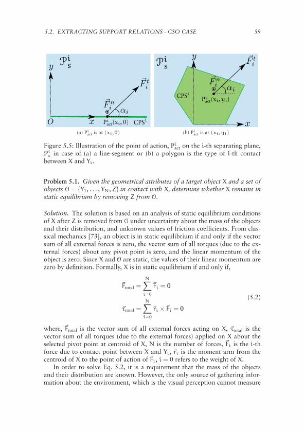
5.2. EXTRACTING SUPPORT RELATIONS - CSO CASE 59
(a) Piact is at (xi, 0) (b) Pi
act is at (xi,yi)
Figure 5.5: Illustration of the point of action, Piact on the i-th separating plane,
Pis in case of (a) a line-segment or (b) a polygon is the type of i-th contact
between X and Yi.
Problem 5.1. Given the geometrical attributes of a target object X and a set ofobjects O = {Y1, . . . ,YN,Z} in contact with X, determine whether X remains instatic equilibrium by removing Z from O.
Solution. The solution is based on an analysis of static equilibrium conditionsof X after Z is removed from O under uncertainty about the mass of the objectsand their distribution, and unknown values of friction coefficients. From clas-sical mechanics [73], an object is in static equilibrium if and only if the vectorsum of all external forces is zero, the vector sum of all torques (due to the ex-ternal forces) about any pivot point is zero, and the linear momentum of theobject is zero. Since X and O are static, the values of their linear momentum arezero by definition. Formally, X is in static equilibrium if and only if,
�Ftotal =
N∑i=0
�Fi = 0
�τtotal =
N∑i=0
�ri �Fi = 0
(5.2)
where, �Ftotal is the vector sum of all external forces acting on X, �τtotal is thevector sum of all torques (due to the external forces) applied on X about theselected pivot point at centroid of X, N is the number of forces, �Fi is the i-thforce due to contact point between X and Yi, �ri is the moment arm from thecentroid of X to the point of action of �Fi, i = 0 refers to the weight of X.
In order to solve Eq. 5.2, it is a requirement that the mass of the objectsand their distribution are known. However, the only source of gathering infor-mation about the environment, which is the visual perception cannot measure

60 CHAPTER 5. SUPPORT RELATION ANALYSIS AND DECISION MAKING
the values of the physical quantities such as the mass of the objects. Moreover,in three-dimensional space where the objects are not mathematically idealizedpoints, configurations of objects often represent a statically indeterminate me-chanical system [74], i.e., a system of equations in which the number of un-knowns (e.g. forces) is greater than the number of independent equations. Thestatic equilibrium conditions in Eq. 5.2 are often insufficient to determine theunknown forces, even if the values of the physical quantities are known.
This section alternatively poses the static equilibrium analysis of a targetobject X as a problem of solving a system of nonlinear equality and inequal-ity equations to overcome the issues mentioned above. The knowledge aboutthe boundary values of the physical quantities are implemented into inequalityconstraints. For example, according to the Coulomb friction model [75] thereis a non-linear inequality relation between the friction force, normal force andthe friction coefficient. On the other hand, since we are interested in abstract-ing the symbolic support relations between objects, and the fact that the exactnumeric computation of unknown forces is irrelevant for identifying supportrelations, it is adequate to find a set of consistent values of unknown variablesto satisfy the system of equations. In other words, the goal is to find a feasiblesolution that satisfies a set of predefined constraints even if the configurationunder study is statically indeterminate.
In order to construct the system of equations, we need to identify the un-known variables in the corresponding equations. Since the certain values of themass of the objects as well as the friction coefficients between pairs of objectsare not given, the boundary values add constraints to the system of equations,
mO,min � mO � mO,max ,O ∈ O ∪ {X}
0 < μi � μmax < ∞ , i = 1, . . . ,N(5.3)
where, mO is an unknown variable referring to the mass of the object O, mO,min
and mO,max are the given boundary values of the mass of objects O, μi is an un-known variable referring to the friction coefficient between X and Yi, and μmax
is the given maximum value of the friction coefficients. The minimum valuefor a friction coefficient is zero by definition, while the maximum value can beset based on the maximum measured friction coefficient of the commonly-usedmaterials in the target environment. In the real-world configurations of objects,where there is no glue, for example, between two objects in contact, the frictioncoefficients have to be bounded (μi < ∞).
In the presence of friction, according to Coulomb friction model, resolvinga force vector �Fi into two components, �Fni and �Fti representing respectivelynormal and tangential (friction) forces, the following inequality must hold,
‖�Fti‖ � μi‖�Fni ‖ , i = 1, . . . ,N. (5.4)
Computing CPS(X, Yi) and the separating planes Pis between X and Yi, (∀ 1 �
i � N) using Algorithm 5.1 discussed in Section 5.2.1, there exist three possi-

5.2. EXTRACTING SUPPORT RELATIONS - CSO CASE 61
bilities of contact point-sets, namely, a single-point, a line-segment or a poly-gon. If a line-segment, L (see Figure 5.5a), or a polygon, G (see Figure 5.5b)is CPS(X, Yi), according to superposition theorem a point in L, respectivelyin G, can summarize the effect of all the other points in L, respectively in G,which is called point of action, Pi
act (see Figure 5.5). Using the superpositiontheorem, Pi
act can be identified by searching in the corresponding contact point-set. In case CPS(X, Yi) is a line-segment, one unknown variable, xi, and in caseCPS(X, Yi) is a polygon, two unknown variables, xi and yi representing theposition of Pi
act are added to the system of equations. The point of action isrequired to identify the momentum arm of the corresponding torque.
The direction of the normal and tangential forces acting at the point ofaction need to be also modeled. An angle, αi (0 � αi < 2π) with respectto a chosen fixed axes in Pi
s (see Figure 5.5) is an unknown variable of thesystem that parameterizes the direction of the friction force �Fti . The magnitudeof �Fti is another unknown variable of the system, together with αi identify thei-th friction force. The direction of the normal force, �Fni is along one of twopossible directions of the normal vector of Pi
s, and is determined by the ACT
relation between X and Yi as follows. For each Yi ∈ O, depending on the ACT
relation three possibilities can be considered,
1. X acts on Yi. X exerts force on Yi due to gravity, thus the direction ofthe reaction force from Yi, that is, the normal vector of Pi
s with positivey-component is the direction of �Fni . In this case four unknown variables‖�Fni ‖, ‖�Fti‖, αi, and μi are defined.
2. Yi acts on X. Yi exerts force on X due to gravity, thus the normal vectorof Pi
s with negative y-component is the direction of �Fni . In this case fourunknown variables ‖�Fni ‖, ‖�Fti‖, αi, and μi are defined.
3. The ACT relation between X and Yi is not identified. In this case the fric-tion coefficient between X and Yi is ignored since we assume that theremust be a third object, Yj(j �= i), in contact with X and Yi to cancel theirweights for some certain friction coefficient. Thus, only the magnitude ofthe normal force ‖�Fni ‖ that Yi may exert on X is defined as an unknownvariable.
At this point we can construct the system of equations based on the discus-sion in the preceding paragraphs and Eq. 5.2, Eq. 5.3 and Eq. 5.4,⎧⎪⎪⎪⎪⎪⎪⎪⎪⎨
⎪⎪⎪⎪⎪⎪⎪⎪⎩
Fx = 0, Fy = 0, Fz = 0τx = 0, τy = 0, τz = 0Pi
act ∈ CPS(X, Yi)0 � αi � 2π0 < μi � μmax
‖�Fti‖ � μi‖�Fni ‖
(5.5)

62 CHAPTER 5. SUPPORT RELATION ANALYSIS AND DECISION MAKING
Algorithm 5.2: The Extraction of the SUPP RelationData: Geometrical attributes of O = {X = Y0, Y1, . . . ,YN,Z}Result: Truth of SUPP(Z,X)
1 VarSet ← ∅ /* the set of unknown variables */;2 VarSet.Add(m0) /* the mass of X */;3 ICSet ← ∅ /* the set of inequality constraints */;4 ICSet.Add(m0,min � m0 � m0,max);5 �Ftotal ← −m0gy /* g: gravity constant, y: unit vector of y-axis */;6 �τtotal ← �0;7 for i = 1, . . . ,N do
/* Compute CPS(X, Yi) and Pis using Algorithm 5.1 */
/* Identify ACT relation between X and Yi using
Proposition 5.1 */
/* Identify Piact based on CPS(X, Yi), see Figures 5.5 */
8 if ACT(X, Yi) or ACT(Yi,X) holds then9 VarSet.Add(‖�Fni ‖, ‖�Fti‖,αi,μi,mi);
10 ICSet.Add(0 � αi � 2π);11 ICSet.Add(0 � μi � μmax);12 ICSet.Add(‖�Fti‖ � μi‖�Fni ‖);13 ICSet.Add(mi,min � mi � mi,max);14 if ACT(X, Yi) holds then15 �Fi = ‖�Fni ‖NormalVectorIn(Pi
s,X) +�Fti ;16 else17 �Fi = ‖�Fni ‖NormalVectorIn(Pi
s, Yi) +�Fti ;18 end19 else20 VarSet.Add(‖�Fni ‖,mi);21 ICSet.Add(mi,min � mi � mi,max);22 �Fi = ‖�Fni ‖NormalVectorIn(Pi
s,X);23 end24 �Ftotal = �Ftotal +�Fi;25 �τtotal = �τtotal + (Pi
act − CX)×�Fi /* CX is the center of mass of X */;26 end
/* Solve the system of equations in Eq. 5.5 */
27 if there is no solution then return true else return false;
where Fx, Fy and Fz are x, y, and z components of �Ftotal, τx, τy and τz arex, y, and z components of �τtotal respectively. Solving the non-linear system ofequalities and inequalities in Eq. 5.5 is the basis of concluding whether thestatic equilibrium conditions of object X are met after Z is removed from O.

5.3. EXTRACTING SUPPORT RELATIONS - ICSO CASE 63
Depending on the existence of a solution, that satisfies all the equations, twopossibilities are discussed. First, if there is no solution for the problem, then itis impossible for X to preserve its static equilibrium state, which means that theremoved object Z supports object X, i.e., we can state that SUPP(Z,X) holds.Second, if the exist at least one solution, it implies that there exists one possi-ble set of forces and friction coefficients that can satisfy the static equilibriumconditions of the target object X under predefined constraints. The implica-tion, however, is valid as long as the assumptions on the mass distributionsare close to reality. In this case, we assume that the removed object, Z, doesnot support X, i.e., ¬SUPP(Z,X) holds. Algorithm 5.2 shows the procedure ofidentifying the truth of SUPP(Z,X). It should be noted that depending on thetype of CPS(X, Yi), as discussed above, maximum two unknown variables willbe added to the system to represent the point of action at line 25 of Algo-rithm 5.2.
5.3 Extracting Support Relations - ICSO case
In the absence of a complete object detection, where some of the objects com-posing a pile are not detected, the approach described in Section 5.2 is notapplicable to extract support relations between objects. The effects of the un-detected objects on the statics of the pile cannot be neglected. For example, inthe ICSO case shown in Figure 5.1, due to the undetected objects (i.e., 1,4,5and 6) identifying all the contact points and ACT relations is not feasible. Thus,the geometrical reasoning and static equilibrium analysis described in the previ-ous section cannot be used to deduce the support relations even if the detectedobjects are in contact with each other.
This section alternatively presents a probabilistic approach to extracting thesupport relations in order to deal with the lack of information and uncertainty.The available data in the ICSO case are the geometrical attributes of the de-tected objects plus a point cloud of the scene. It should be noted that the set ofdetected objects can be either in contact or far from each other. The possibilitythat a detected object, through some undetected objects supports another objectimplies that the support relation may indirectly exist between a pair of sepa-rated objects (see an example of incomplete detection of objects in Figure 5.1).
In the presence of the lack of information, it is of great importance to pro-vide an uncertainty measure of the deduced support relations. Since the un-derlying probability distribution of the support relations between objects inan arbitrary configuration is not known, and it cannot be approximated bya standard distribution in advance, different machine learning techniques areemployed to approximate the probabilities. A set of classifiers are trained toestimate the probability of one object X supporting another object Y given fea-tures extracted from the scene point cloud and the relative position betweenpairs of the detected objects.

64 CHAPTER 5. SUPPORT RELATION ANALYSIS AND DECISION MAKING
In this dissertation the performance of three carefully selected learningparadigms, namely, Support Vector Machines (SVM) [76], Artificial NeuralNetworks (ANN) [77] and Random Forests (RFT) [78] to estimate supportrelation probabilities are examined. Since ordinary versions of these classifiersare employed, for details regarding these standard machine learning techniquesplease see the given references. The only extension being presented in this sec-tion is how the probabilities of the class labels (i.e., support relations) are com-puted. The probabilities of support relations are then used to create possibleworlds models based on which a probabilistic decision making reasons aboutthe set of safe-to-remove objects.
5.3.1 Class Probability Estimation
Support Vector Machine SVM in its original formulation can predict only classlabels, l ∈ {−1,+1}, given the input features, F, and a trained model, f(.); classlabel probabilities, P(l|F), are not directly computed. A training set, T, includesinstances of features and their known class labels, which we call them features-labels. We use a sigmoid function to estimate the posterior probability of thepredicted class labels proposed by Platt [79],
P(l = 1|F) =1
1 + exp(Af(F) + B)(5.6)
where A and B are estimated by minimizing the following negative log likeli-hood,
minimizeA,B
−
u∑i=1
(ti log(pi) + (1 − ti) log(1 − pi))
where pi = P(li = 1|Fi)
ti =
{N++1N++2 , if li = +1
1N−+2 , if li = −1
N+ is the number of li = +1 instances in T
N− is the number of li = −1 instances in T
Artificial Neural Networks In order to predict the class labels we use a multi-layer perceptron [77] with two real valued outputs (for binary classification),a hyperbolic tangent sigmoid transfer function for hidden-layers and a loga-rithmic sigmoid transfer function, logsig, for the output layer. To estimate theprobability of a predicted class label, l, given the corresponding feature vector,F, we first normalize the two output values of logsig, y+
o and y−o , to sum to 1,
β(y+o + y−
o ) = 1 ⇒ β =1
y+o + y−
o
(5.7)
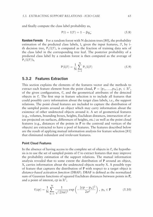
5.3. EXTRACTING SUPPORT RELATIONS - ICSO CASE 65
and finally compute the class label probability as,
P(l = 1|F) = 1 − βy−o (5.8)
Random Forests For a random forest with N decision trees [80], the probabilityestimation of the predicted class labels, l, given the input features, F, by i-th decision tree, Pi(l|F), is computed as the fraction of training data sets ofthe class label in the corresponding tree leaf. The posterior probability of apredicted class label by a random forest is then computed as the average ofPi(l|F)’s,
P(l|F) =1N
N∑i=1
Pi(l|F) (5.9)
5.3.2 Features Extraction
This section explains the elements of the features vector and the methods toextract each feature element from the point cloud, P = {p1, . . . ,pN},pi ∈ R
3,of the given configuration, C, and the geometrical attributes of the detectedobjects in C. The first step in feature selection is to include all features thatcould possibly carry information about the target class labels, i.e., the supportrelations. The point cloud features are included to capture the distribution ofthe sampled points around an object which may carry information about theexistence of other undetected objects around it. A set of geometrical features(e.g., volumes, bounding boxes, heights, Euclidean distances, intersection of ar-eas projected on surfaces, differences of heights, etc.) as well as the point cloudfeatures (e.g., distances of the points in P to the centroid and vertices of theobjects) are extracted to have a pool of features. The features described beloware the result of applying mutual information analysis for feature selection [81]that eliminated redundant and irrelevant features.
Point Cloud Features
In the absence of having access to the complete set of objects in C, the hypothe-sis is to use the set of sampled points of C to extract features that may improvethe probability estimation of the support relations. The mutual informationanalysis revealed that to some extent the distribution of P around an object,X, carries information about the undetected objects nearby X. A possible typeof feature that captures the distribution of P with respect to a target object isdistance-based activation function (DBAF). DBAF is defined as the normalizedsum of Gaussian functions of squared Euclidean distances between points in P,and a point of interest, cp in R
3,
f(cp) =1N
N∑k=1
1√(2πσ)3
exp(−‖cp− pk‖2
2σ2
), pk ∈ P (5.10)
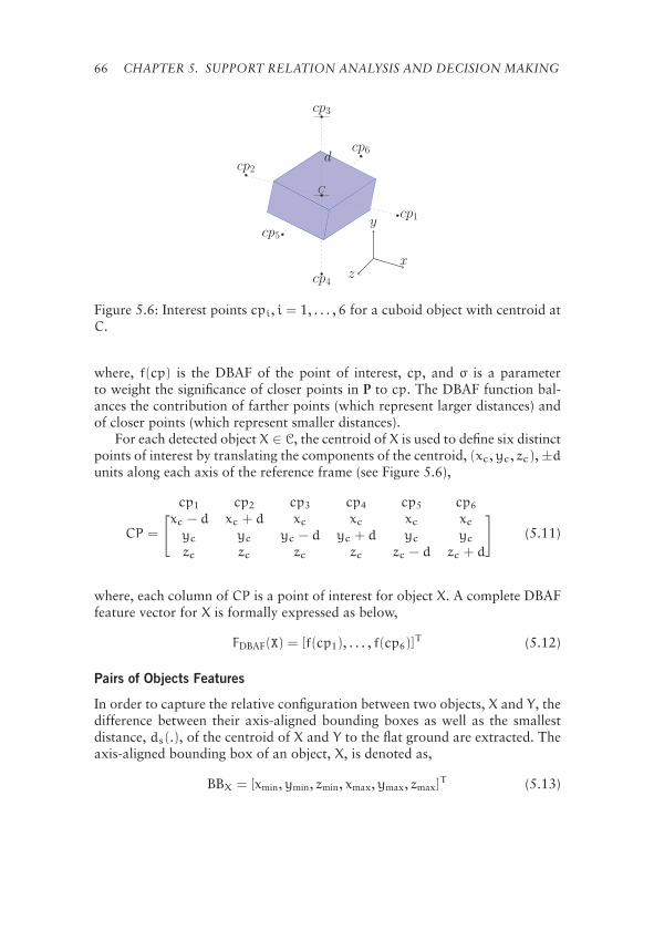
66 CHAPTER 5. SUPPORT RELATION ANALYSIS AND DECISION MAKING
cp5
cp6
cp1
cp2
cp3
cp4
C
d
z
y
x
Figure 5.6: Interest points cpi, i = 1, . . . , 6 for a cuboid object with centroid atC.
where, f(cp) is the DBAF of the point of interest, cp, and σ is a parameterto weight the significance of closer points in P to cp. The DBAF function bal-ances the contribution of farther points (which represent larger distances) andof closer points (which represent smaller distances).
For each detected object X ∈ C, the centroid of X is used to define six distinctpoints of interest by translating the components of the centroid, (xc,yc, zc), ±dunits along each axis of the reference frame (see Figure 5.6),
CP =
cp1 cp2 cp3 cp4 cp5 cp6[ ]xc − d xc + d xc xc xc xcyc yc yc − d yc + d yc yc
zc zc zc zc zc − d zc + d
(5.11)
where, each column of CP is a point of interest for object X. A complete DBAFfeature vector for X is formally expressed as below,
FDBAF(X) = [f(cp1), . . . , f(cp6)]T (5.12)
Pairs of Objects Features
In order to capture the relative configuration between two objects, X and Y, thedifference between their axis-aligned bounding boxes as well as the smallestdistance, ds(.), of the centroid of X and Y to the flat ground are extracted. Theaxis-aligned bounding box of an object, X, is denoted as,
BBX = [xmin,ymin, zmin, xmax,ymax, zmax]T (5.13)

5.3. EXTRACTING SUPPORT RELATIONS - ICSO CASE 67
where, min and max subscripts respectively denote the minimum and maximumof x, y and z components of points in X. For the support relation SUPP(X, Y),the corresponding feature vector is defined to be the following difference,
FBB(X, Y) = BBX − BBY (5.14)
And for the smallest distances, the following feature vector is defined,
FH(X, Y) = [ds(X),ds(Y)]T (5.15)
Complete Features Vector
For each pair of detected objects, X and Y in C, two feature vectors are extractedby combining FH, FBB and FDBAF. The features vector from X’s point of view(whether X supports Y) is,
F(X, Y) = [FH(X, Y), FBB(X, Y), FDBAF(X), FDBAF(Y)]T (5.16)
while from Y’s point of view is,
F(Y,X) = [FH(Y,X), FBB(Y,X), FDBAF(Y), FDBAF(X)]T . (5.17)
A machine learning paradigm uses the features vector F(X, Y) to output theprobability of SUPP(X, Y) being true.
5.3.3 Possible Worlds of Support Relations
A representative model for the probabilistic hypotheses about the support rela-tions is especially important in the ICSO case, where there exists a set of pos-sibilities to infer which object supports another. In order to encode hypothesesabout objects supporting each other, the concept of possible worlds from modallogic is employed.
We define a possible world to be one realization of support relationsbetween all pairs of detected objects. Formally, let each support relationSUPP(X, Y) between two different objects, X and Y be modeled by a binaryrandom variable, Sk such that Sk = 1 if SUPP(X, Y) is true, and Sk = 0 ifSUPP(X, Y) is false. Let Ω = [S1,S2, . . . ,Sη] be a random vector composed ofall the binary random variables. For N detected objects, the number of supportrelations (i.e., the number of the binary random variables), η is,
η = 2(N
2
)= N(N− 1) (5.18)
where(N2
)is a 2-combination of N objects. A possible world is one possible
assignment ω = [s1, s2, . . . , sη] to Ω, where sk ∈ {0, 1},k = 1, . . . ,η. In otherwords, one possible world is equivalent to one hypothesis about the ground

68 CHAPTER 5. SUPPORT RELATION ANALYSIS AND DECISION MAKING
N q = 2N(N−1) q ′ q ′/q (%)3 64 29 45.34 4096 355 8.675 1048576 6942 0.666 1073741824 209527 0.02
Table 5.2: A comparison of the number of consistent worlds, q ′, and the num-ber of all possible worlds, q, for different numbers of objects n = 3, 4, 5, 6.
truth of how objects are supporting each other. The number of all possibleassignments of variables sk to Ω is q = 2η.
The possible worlds of the support relations are illustrated as a graph withnodes and directed links representing the objects and the support relations re-spectively. In the graph, a directed link from node X to Y denotes SUPP(X, Y)with the corresponding binary random variable Sk. For example, Figure 5.7ashows the graph of possible worlds for N = 4 objects, where a total numberof η = 12 directed links (i.e., support relations) represent the set of the binaryrandom variables in this case.
It should be noted that the probability of a support relation between twoobjects is estimated independently of another pair of objects, however, suchprobability may not be independent given the support relation of another pairof objects. Since the underlying conditional probability of support relations isnot known, the joint probability distribution of the random vector Ω is ap-proximated as,
P(Ω = ωi) = P(S1 = si,1, . . . ,Sη = si,η)
=
η∏k=1
P(Sk = si,k) (5.19)
where, ωi = [si,1, . . . , si,η] is the i-th possible assignment to Ω, and P(Sk) isthe estimated probability of Sk by a machine learning paradigm.
Consistent Possible Worlds
Since the support relation is transitive, i.e.,
∀X, Y ∈ C, SUPP(X, Y)∧ SUPP(Y,Z) ⇒ SUPP(X,Z) (5.20)
it is required to make sure that a realization of a possible world, ω, with anassignment of variables is consistent with the transitivity property. For exam-ple, Fig 5.7b and Fig 5.7c depict graph illustrations of one consistent and oneinconsistent possible worlds for four objects respectively. In Fig 5.7c, the in-
5.3. EXTRACTING SUPPORT RELATIONS - ICSO CASE 69
A
B
C
D
S 1
S3
S5S 2
S7
S9
S4
S8
S 11
S6
S 12
S10
(a)
A
B
C
D
(b)
A
B
C
D
(c)
Figure 5.7: Graph illustration of the random vector Ω for four objects, whereeach edge k is labeled with a binary random variable Sk. Solid and dashed edgesdenote Sk = 1 and Sk = 0 respectively. (a) A possible world where all Sk = 1.(b) A possible world where some Sk = 0. This is a consistent world accordingto the transitivity constraint. (c) An inconsistent possible world according tothe transitivity constraint.
consistency is due to the fact that SUPP(A,B) and SUPP(B,D) are both true, butSUPP(A,D) is false.
In order to eliminate such inconsistent worlds, one solution is to employthe Path Consistency Algorithm [82]. Table 5.2 shows the number of consis-tent worlds, q ′, in comparison with the number of all possibilities, q, for dif-ferent numbers of objects, N = 3, 4, 5, 6. It can be observed that discardinginconsistent worlds significantly reduces the size of the representation.
Elimination of the inconsistent worlds implies that the sum of joint prob-abilities of the consistent worlds in Eq. 5.19 becomes less than one. Thus, torepresent a true probability distribution over consistent possible worlds, thecorresponding probabilities must be normalized. To distinguish is from all pos-sibilities, ωc denotes an assignment to a consistent possible world, and i(.)maps index set of the consistent possible worlds into the original set of possibleworlds. Introducing a constant normalizing factor β, such that the probabilityof the j-th consistent world, P(wc
j ), where wcj = [si(j),1, . . . , si(j),η] becomes
P(wcj ) = βP(si(j),1, . . . , si(j),η) (5.21)
and, the sum of probabilities becomes one,
q′∑j=1
P(wcj ) = 1. (5.22)
We note that if p1, p2 and p3 are the estimated probabilities of SUPP(X,Y),SUPP(Y,Z) and SUPP(X,Z) respectively, then it is not necessary to have p3 =
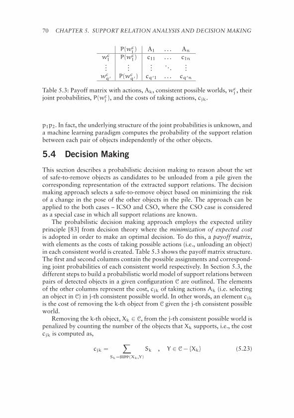
70 CHAPTER 5. SUPPORT RELATION ANALYSIS AND DECISION MAKING
P(wcj ) A1 . . . An
wc1 P(wc
1) c11 . . . c1n...
......
. . ....
wcq′ P(wc
q′) cq′1 . . . cq′n
Table 5.3: Payoff matrix with actions, Ak, consistent possible worlds, wcj , their
joint probabilities, P(wcj ), and the costs of taking actions, cjk.
p1p2. In fact, the underlying structure of the joint probabilities is unknown, anda machine learning paradigm computes the probability of the support relationbetween each pair of objects independently of the other objects.
5.4 Decision Making
This section describes a probabilistic decision making to reason about the setof safe-to-remove objects as candidates to be unloaded from a pile given thecorresponding representation of the extracted support relations. The decisionmaking approach selects a safe-to-remove object based on minimizing the riskof a change in the pose of the other objects in the pile. The approach can beapplied to the both cases – ICSO and CSO, where the CSO case is consideredas a special case in which all support relations are known.
The probabilistic decision making approach employs the expected utilityprinciple [83] from decision theory where the minimization of expected costis adopted in order to make an optimal decision. To do this, a payoff matrix,with elements as the costs of taking possible actions (i.e., unloading an object)in each consistent world is created. Table 5.3 shows the payoff matrix structure.The first and second columns contain the possible assignments and correspond-ing joint probabilities of each consistent world respectively. In Section 5.3, thedifferent steps to build a probabilistic world model of support relations betweenpairs of detected objects in a given configuration C are outlined. The elementsof the other columns represent the cost, cjk of taking actions Ak (i.e. selectingan object in C) in j-th consistent possible world. In other words, an element cjkis the cost of removing the k-th object from C given the j-th consistent possibleworld.
Removing the k-th object, Xk ∈ C, from the j-th consistent possible world ispenalized by counting the number of the objects that Xk supports, i.e., the costcjk is computed as,
cjk =∑
Sk=SUPP(Xk,Y)
Sk , Y ∈ C− {Xk} (5.23)

5.5. RESULTS 71
For example, in Figure 5.7b, the costs of removing A, B, C and D are 3, 2, 0and 1 respectively.
The optimal action, A∗ (i.e., safest object to remove from C) is the one withthe minimum expected cost (EC),
A∗ = argmink
EC(Ak) (5.24)
where EC(Ak) is defined as,
EC(Ak) =
q′∑j=1
P(ωcj )cjk (5.25)
In the CSO case it is assumed that there exists only one consistent possibleworld (with a joint probability of 1) represented by the extracted support rela-tions between objects as described in Section 5.2.
It should be mentioned that scaling is a problem of representations based onpossible worlds concept, where the number of possibilities grows exponentiallyas the number of objects increases. If there are too many objects detected, andN is the maximum number of objects that computationally can be handledin practice, the following heuristic solution can be applied. First, we consideronly N objects which have the highest height with respect to the flat ground,and then we create the consistent possible worlds for those N objects. Theprobabilistic decision maker is then employed to find the best candidate objectsto unload first. The candidate will be unloaded from the configuration, and werepeat this procedure until all the objects are unloaded.
5.5 Results
This section presents the experimental results of applying the methodology de-scribed for the CSO and ICSO cases in the preceding sections. The experimentswere carried out on data generated in simulated and from real-world configu-rations. Simulation facilitates generating a large number of random configura-tions with direct access to the ground truth data of the geometrical attributes ofthe objects. A large number of random configurations is important in analyzingthe statistical behavior of the corresponding approach, while the ground truthdata is required for the learning of the probability distribution of support rela-tions. The performance of the corresponding approach was then evaluated ondata generated on real-world configurations. A mock-up container was used tocreate piles of objects aiming at validating the constructed representation andexamining the probabilistic decision making approach.
5.5.1 Simulated Configurations
For the simulated configurations, a scene generator based on physics simula-tion was developed. The simulator generates random configurations of polyhe-
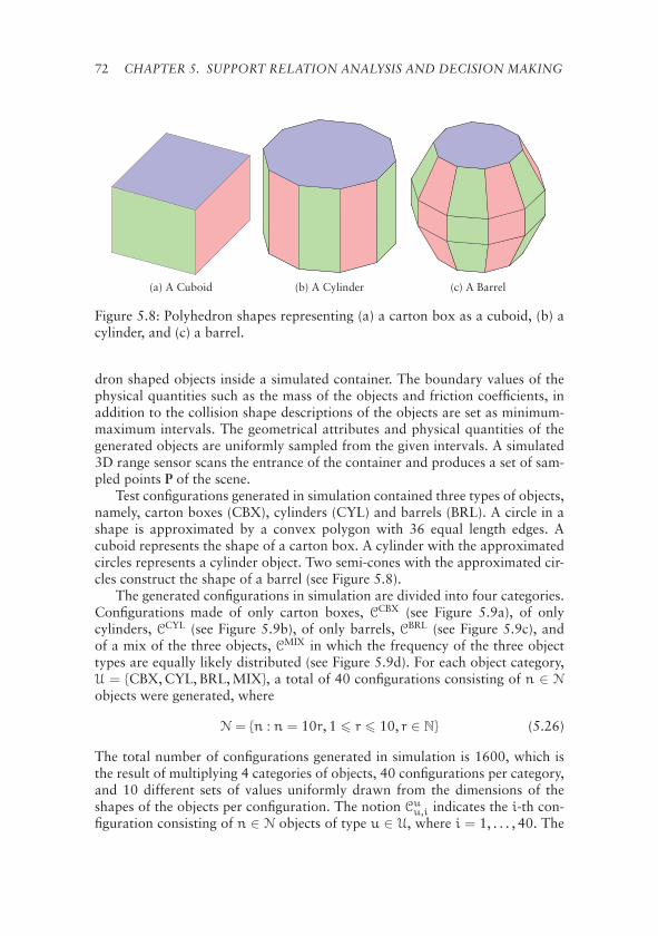
72 CHAPTER 5. SUPPORT RELATION ANALYSIS AND DECISION MAKING
(a) A Cuboid (b) A Cylinder (c) A Barrel
Figure 5.8: Polyhedron shapes representing (a) a carton box as a cuboid, (b) acylinder, and (c) a barrel.
dron shaped objects inside a simulated container. The boundary values of thephysical quantities such as the mass of the objects and friction coefficients, inaddition to the collision shape descriptions of the objects are set as minimum-maximum intervals. The geometrical attributes and physical quantities of thegenerated objects are uniformly sampled from the given intervals. A simulated3D range sensor scans the entrance of the container and produces a set of sam-pled points P of the scene.
Test configurations generated in simulation contained three types of objects,namely, carton boxes (CBX), cylinders (CYL) and barrels (BRL). A circle in ashape is approximated by a convex polygon with 36 equal length edges. Acuboid represents the shape of a carton box. A cylinder with the approximatedcircles represents a cylinder object. Two semi-cones with the approximated cir-cles construct the shape of a barrel (see Figure 5.8).
The generated configurations in simulation are divided into four categories.Configurations made of only carton boxes, CCBX (see Figure 5.9a), of onlycylinders, CCYL (see Figure 5.9b), of only barrels, CBRL (see Figure 5.9c), andof a mix of the three objects, CMIX in which the frequency of the three objecttypes are equally likely distributed (see Figure 5.9d). For each object category,U = {CBX, CYL, BRL, MIX}, a total of 40 configurations consisting of n ∈ N
objects were generated, where
N = {n : n = 10r, 1 � r � 10, r ∈ N} (5.26)
The total number of configurations generated in simulation is 1600, which isthe result of multiplying 4 categories of objects, 40 configurations per category,and 10 different sets of values uniformly drawn from the dimensions of theshapes of the objects per configuration. The notion Cu
u,i indicates the i-th con-figuration consisting of n ∈ N objects of type u ∈ U, where i = 1, . . . , 40. The
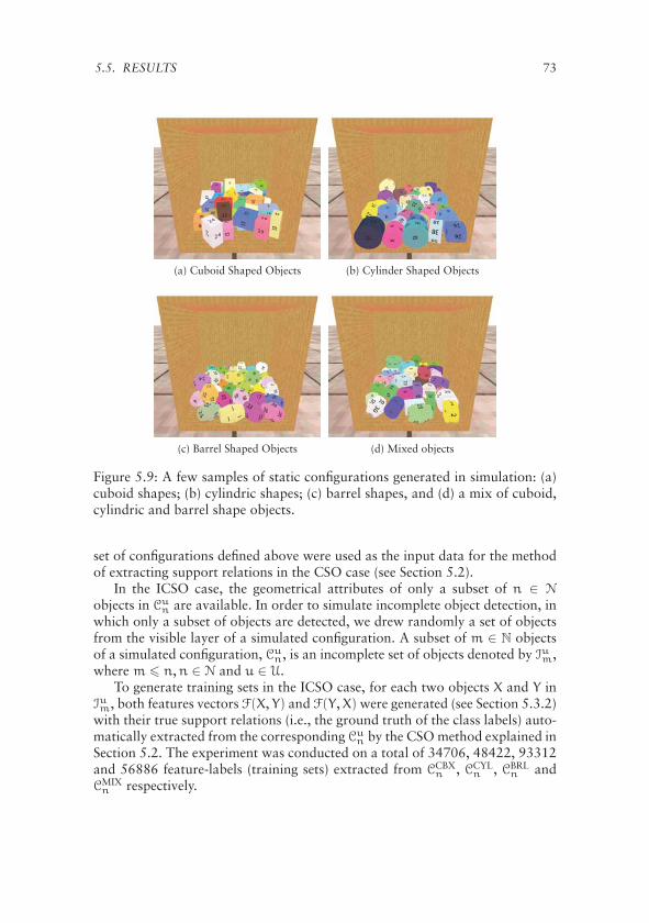
5.5. RESULTS 73
(a) Cuboid Shaped Objects (b) Cylinder Shaped Objects
(c) Barrel Shaped Objects (d) Mixed objects
Figure 5.9: A few samples of static configurations generated in simulation: (a)cuboid shapes; (b) cylindric shapes; (c) barrel shapes, and (d) a mix of cuboid,cylindric and barrel shape objects.
set of configurations defined above were used as the input data for the methodof extracting support relations in the CSO case (see Section 5.2).
In the ICSO case, the geometrical attributes of only a subset of n ∈ N
objects in Cun are available. In order to simulate incomplete object detection, in
which only a subset of objects are detected, we drew randomly a set of objectsfrom the visible layer of a simulated configuration. A subset of m ∈ N objectsof a simulated configuration, Cu
n, is an incomplete set of objects denoted by Ium,where m � n,n ∈ N and u ∈ U.
To generate training sets in the ICSO case, for each two objects X and Y inIum, both features vectors F(X, Y) and F(Y,X) were generated (see Section 5.3.2)with their true support relations (i.e., the ground truth of the class labels) auto-matically extracted from the corresponding Cu
n by the CSO method explained inSection 5.2. The experiment was conducted on a total of 34706, 48422, 93312and 56886 feature-labels (training sets) extracted from CCBX
n , CCYLn , CBRL
n andCMIXn respectively.
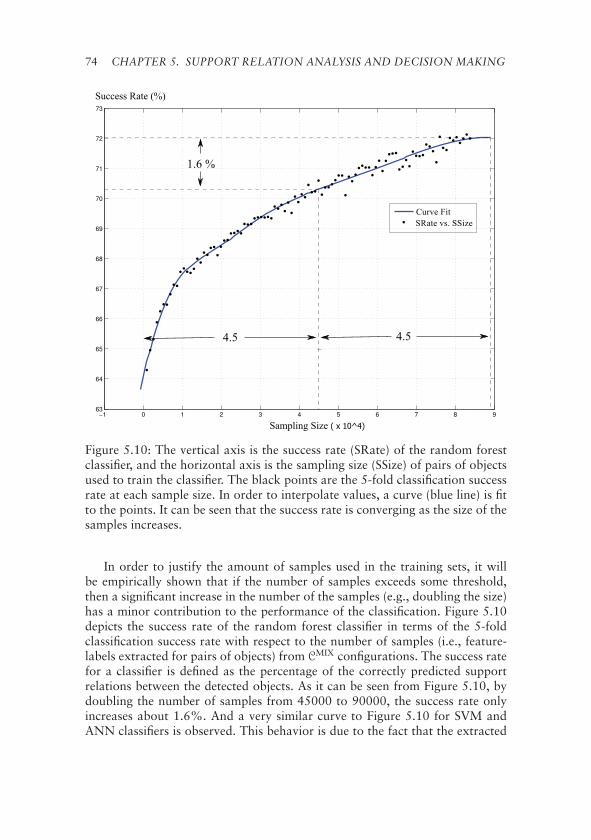
74 CHAPTER 5. SUPPORT RELATION ANALYSIS AND DECISION MAKING
Figure 5.10: The vertical axis is the success rate (SRate) of the random forestclassifier, and the horizontal axis is the sampling size (SSize) of pairs of objectsused to train the classifier. The black points are the 5-fold classification successrate at each sample size. In order to interpolate values, a curve (blue line) is fitto the points. It can be seen that the success rate is converging as the size of thesamples increases.
In order to justify the amount of samples used in the training sets, it willbe empirically shown that if the number of samples exceeds some threshold,then a significant increase in the number of the samples (e.g., doubling the size)has a minor contribution to the performance of the classification. Figure 5.10depicts the success rate of the random forest classifier in terms of the 5-foldclassification success rate with respect to the number of samples (i.e., feature-labels extracted for pairs of objects) from CMIX configurations. The success ratefor a classifier is defined as the percentage of the correctly predicted supportrelations between the detected objects. As it can be seen from Figure 5.10, bydoubling the number of samples from 45000 to 90000, the success rate onlyincreases about 1.6%. And a very similar curve to Figure 5.10 for SVM andANN classifiers is observed. This behavior is due to the fact that the extracted

5.5. RESULTS 75
features from an incomplete set of detected objects can only contain partialinformation about the target classes (i.e., binary support relations); thus, it isto be expected that the classification success rate is bounded at a percentagelevel below 100% even for a very large size of the training set. On the otherhand, overfitting can occur for very large numbers of samples. Since there is noadditional source of information about a configuration of objects in the ICSOcase, a success rate of 70% is considered to be a good performance for thisclassification problem. It is worth mentioning that in the proposed probabilisticapproach the predicted output labels are not directly used, the probability ofthe predicted labels are actually employed (see Section 5.3.1).
To generate test sets in the ICSO case, a separate set of M = 500 simulatedconfigurations was generated similar to that of the training sets. We createdincomplete sets of m = 5 objects, which are supposed to be detected, fromthe separately generated configurations. For each Iu5,j, where j = 1, . . . ,M allpossible pairs of feature-labels, η = 20 (see Eq. 5.18 in Section 5.3.3), wereextracted as the corresponding test set (TSet), which is denoted by Tu
j .
5.5.2 Real World Configurations
In order to validate the process of identifying the set of safe-to-remove objectson real-world data, we used a Microsoft Kinect sensor to scan two setups ofreal-world configurations of objects stacked inside a mock-up container, whichare denoted CRW7 and CRW8 (see Figure 5.11a and Figure 5.11d). The Kinectsensor placed in front of the middle entrance of the mock-up container wasused to capture a point cloud of a configuration. The complete set of detectedobjects (i.e., the CSO case) was then created by registering the 3D models ofthe objects to the point clouds, and then the poses of the objects were refinedmanually (see Figure 5.11b and Figure 5.11e).
For generating the test sets in the ICSO case, a number of subsets of objects,IRW7m,j and IRW8
m,j were drawn randomly from the real-world configurations, CRW7
and CRW8, where, m = 3, 4, 5, 6 is the number of objects in the incomplete setand j is the index of the set. The number of all possible ways of choosing mobjects from n objects is (
n
m
)=
n!m!(n−m)!
(5.27)
thus, the index set for IRWnm,i is i = {1, . . . ,
(nm
)}, where, n = 7, 8 is the number
of all the objects in real-world configurations, CRW7 and CRW8 respectively.In order to train the selected machine learning paradigms for estimating the
probability of support relations, a training set with similar objects to that ofsimulated configurations is required to be generated. Physics simulation wasemployed to generate a set of random configurations, CRAND, consisting of ob-jects with similar shapes of the objects used in the real-world configurations,

76 CHAPTER 5. SUPPORT RELATION ANALYSIS AND DECISION MAKING
(a) Configuration CRW8 (b) Model fit to CRW8
B6
B4
R
C2
B3
B2
B1
L
B5C1
FG
SUPP SUPP
SUPP
SUPP
SUPP
SUPP
SUPP
SUPP
SUPP
SUPP
SUPP
SUPP
SUPP
SUPP
(c) SUPP graph for CRW8
(d) Configuration CRW7 (e) Model fit to CRW7
R
B2C1
L
B5
C2B3
B6B1
FG
SUPP SUPP
SUPP
SUPP
SUPP
SUPP SUPP
SUPP
SUPP
SUPP
SUPP
SUPPSUPP
(f) SUPP graph for CRW7
Figure 5.11: Real world configurations. In the left column two configurationsmade of carton boxes and cylinders inside a mock-up container are shown. Inthe middle column the convex polyhedron models of the objects fit to the pointclouds of the scenes captured by the Kinect sensor are shown. In the right col-umn the extracted support relations between the objects in the configurationsare depicted.
CRW7 and CRW8. The true support relations (i.e., class labels) between pairs ofobjects in CRAND were then extracted by using the CSO method; the featureswere extracted by the method described in Section 5.3.2. The result is a train-ing set of feature-labels for two real-world configurations. The three machinelearning paradigms (i.e., SVM, ANN and random forest) were trained on thegenerated training set, and then used to estimate the probability of class la-bels, i.e., the support relations given the unseen feature-labels of the testing setsextracted from IRW7
m,j and IRW8m,j .
5.5.3 Results for the CSO Case
This section presents the results of applying the geometrical reasoning, staticequilibrium analysis and decision making on the data generated in simulationand from real-world configurations explained in the preceding sub-sections. Asa measure of the complexity of the generated configurations, the number andtype of contact point-sets and the number of ACT and SUPP relations between

5.5. RESULTS 77
objects are reported. Moreover, the corresponding execution times were alsorecorded.
Figure 5.12a and Figure 5.12b respectively show the average time taken bythe geometrical reasoning and static equilibrium analysis for the configurationsCMIXn . We can notice that the geometrical reasoning takes very short time and
increases linearly with the number of objects, while the static equilibrium anal-ysis requires considerably more time, and increases polynomially with respectto the number of objects. The longer execution time taken by the static equi-librium analysis is due to the non-linear solver of the system of equations (seeSection 5.2.3), which has to be called for each object in a configuration. Nev-ertheless, for realistic scenarios, we expect the number of objects extracted byan object detection algorithm to be small, and thus, the execution time of thestatic equilibrium analysis would still be reasonably fast. On the other hand,since for each object the static equilibrium analysis is performed independentlyof the other objects, it is possible to speed up the process by parallelizing thecomputation of the support relations.
Figure 5.12c depicts the average number of contact types with respect tothe number of objects. As expected, the number of single-point contacts whichare the result of less stable configurations (vertex-on-face and edge-cross-edge)is noticeably lower than the number of line-segments and polygons, which arethe result of edge-on-face and face-on-face contact types.
The average number of extracted ACT and SUPP relations between objects isshown in Figure 5.12d. The number of support relations increases linearly. Thelinear growth is due to the fact that adding one object implies a bounded num-ber of contacts that can arise in the contact point-set network. For N < 20, thenumber of ACT and SUPP relations are close to each other, that is, for roughlyeach ACT(X,Y) relation, a corresponding SUPP(Y,X) relation was found. How-ever, as the number of objects increases, the number of corresponding supportrelations diverges from that of ACT relations. This is due to the fact that anincrease in the number of objects stacked in a fixed volume of a containerincreases the physical interaction between objects resulting in a more gravita-tional support dependencies.
The behavior of the execution time, the number of contact types and ACT
and SUPP relations of the other three categories, is similar to those shown in Fig.5.12 for the MIX category, but with different minimum and maximum valuessummarized in Table 5.4. From Table 5.4, we can observe that the minimumand maximum values for barrel shaped objects are greater than those of theother two objects categories. One reason is the higher number of faces in theshape of a barrel object, which is approximated by a polyhedron. The otherreason is the shape of the barrel, which is less stable in a horizontal position.A similar behavior can be observed for cylinder shaped objects with respect tocuboid shaped objects.
The proposed geometrical and static equilibrium analysis (i.e., the methodemployed for the CSO case) was applied to the created 3D models (see Fig-

78 CHAPTER 5. SUPPORT RELATION ANALYSIS AND DECISION MAKING
(a) Geometrical Reasoning Time (b) Static Equilibrium Analysis Time
(c) Contact Types (d) Relations
Figure 5.12: Complexity analysis of the proposed relational scene representa-tion for simulated configurations. The horizontal axes are the number of objectsin the configurations. In (a) and (b) the vertical axes depict the execution timeof geometrical reasoning and static equilibrium analysis respectively. In (c) and(d) the vertical axes are the average of the number of contact types and relationsrespectively.
ure 5.11b and Figure 5.11e) of the two real-world configurations. The set ofextracted support relations is represented as a graph in which each node indi-cates an object, and each directed link between two nodes indicates the exis-tence of the support relation between the two objects. Figure 5.11c and Fig-ure 5.11f show the result of extracting the support relations between objectsin the two real-world configurations, CRW8 and CRW7 respectively. Looking atthe two real-world configurations and the corresponding graphs of the supportrelations between objects, one can intuitively confirm the correctness of the ex-tracted support relations. However, a further test was carried out in order toverify that the hypothesis of the support relations between objects representingby each graph is correct. Given a graph, each candidate object was unloadedmanually from the real-world configurations to find out whether the unloaded
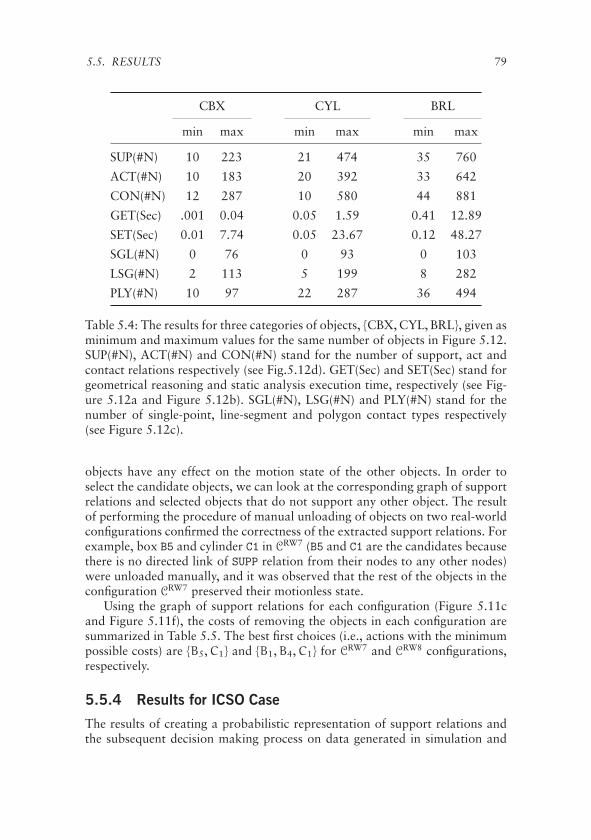
5.5. RESULTS 79
CBX CYL BRL
min max min max min max
SUP(#N) 10 223 21 474 35 760
ACT(#N) 10 183 20 392 33 642
CON(#N) 12 287 10 580 44 881
GET(Sec) .001 0.04 0.05 1.59 0.41 12.89
SET(Sec) 0.01 7.74 0.05 23.67 0.12 48.27
SGL(#N) 0 76 0 93 0 103
LSG(#N) 2 113 5 199 8 282
PLY(#N) 10 97 22 287 36 494
Table 5.4: The results for three categories of objects, {CBX, CYL, BRL}, given asminimum and maximum values for the same number of objects in Figure 5.12.SUP(#N), ACT(#N) and CON(#N) stand for the number of support, act andcontact relations respectively (see Fig.5.12d). GET(Sec) and SET(Sec) stand forgeometrical reasoning and static analysis execution time, respectively (see Fig-ure 5.12a and Figure 5.12b). SGL(#N), LSG(#N) and PLY(#N) stand for thenumber of single-point, line-segment and polygon contact types respectively(see Figure 5.12c).
objects have any effect on the motion state of the other objects. In order toselect the candidate objects, we can look at the corresponding graph of supportrelations and selected objects that do not support any other object. The resultof performing the procedure of manual unloading of objects on two real-worldconfigurations confirmed the correctness of the extracted support relations. Forexample, box B5 and cylinder C1 in CRW7 (B5 and C1 are the candidates becausethere is no directed link of SUPP relation from their nodes to any other nodes)were unloaded manually, and it was observed that the rest of the objects in theconfiguration CRW7 preserved their motionless state.
Using the graph of support relations for each configuration (Figure 5.11cand Figure 5.11f), the costs of removing the objects in each configuration aresummarized in Table 5.5. The best first choices (i.e., actions with the minimumpossible costs) are {B5,C1} and {B1,B4,C1} for CRW7 and CRW8 configurations,respectively.
5.5.4 Results for ICSO Case
The results of creating a probabilistic representation of support relations andthe subsequent decision making process on data generated in simulation and

80 CHAPTER 5. SUPPORT RELATION ANALYSIS AND DECISION MAKING
Objects Set
Cost CRW8 CRW7
0 {B1,B4,C1} {B5,C1}
1 {B2,B5,B6,C2} {B1,B2,B6}
2 ∅ {B3,C2}
3 {B3} ∅
Table 5.5: The result of applying the proposed decision making to real-worldconfigurations CRW7 and CRW8. The objects with equal computed cost are col-lected in the same sets for each configuration.
from real-world configurations are presented in this section. In order to com-pare the performance of the decision making to other possibilities, two heuristicdecision makers are introduced that are supposed to provide a baseline decisionperformance. First, a random decision maker (Random DM) that uniformly se-lects an object, and the second is a heuristic decision maker (Heuristic DM)that selects the object with the highest center of mass to be removed in thecorresponding test set.
The following describes the implementation of the approach for the ICSOcase. The LibSVM [84] with radial basis function kernel was employed for Sup-port Vector Machines, and a Matlab implementation was used for both Artifi-cial Neural Networks and Random Forests (TreeBagger). For SVM and ANN,70% of the training set was used for training and 30% for validation. For eachcategory of objects, a 5-fold cross validation was performed to obtain the bestvalues for the SVM parameters [76]. Measuring the classification success rateof ANN, a network with three hidden-layers of 15 neurons was empiricallyselected, and a Random Forest with 200 decision trees for each category ofobjects was trained. Figure 5.13 depicts the classification error rate of the threetrained classifiers for four objects categories, U = {CBX, CYL, BRL, MIX} ina Receiver Operating Characteristic (ROC) space [85]. The ideal classificationon ROC space is located at the point (0, 1) – zero false positive rate (FPR)and 100% true positive rate (TPR). It can be seen that while SVM and ANNshow a similar classification performance, the RFT classifier performs best forall categories of objects.
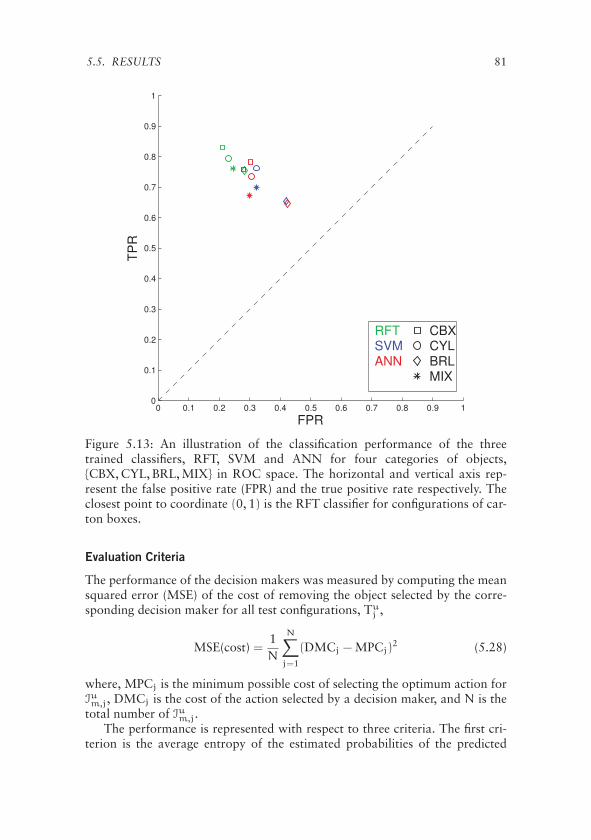
5.5. RESULTS 81
Figure 5.13: An illustration of the classification performance of the threetrained classifiers, RFT, SVM and ANN for four categories of objects,{CBX, CYL, BRL, MIX} in ROC space. The horizontal and vertical axis rep-resent the false positive rate (FPR) and the true positive rate respectively. Theclosest point to coordinate (0, 1) is the RFT classifier for configurations of car-ton boxes.
Evaluation Criteria
The performance of the decision makers was measured by computing the meansquared error (MSE) of the cost of removing the object selected by the corre-sponding decision maker for all test configurations, Tu
j ,
MSE(cost) =1N
N∑j=1
(DMCj − MPCj)2 (5.28)
where, MPCj is the minimum possible cost of selecting the optimum action forIum,j, DMCj is the cost of the action selected by a decision maker, and N is thetotal number of Ium,j.
The performance is represented with respect to three criteria. The first cri-terion is the average entropy of the estimated probabilities of the predicted

82 CHAPTER 5. SUPPORT RELATION ANALYSIS AND DECISION MAKING
support relations by the corresponding machine learning paradigm for a givenIum,j with η support relations,
AEIj =1η
η∑k=1
(−pk log(pk) − p ′k log(p ′
k)) (5.29)
where pk = P(Sk = 1) and p ′k = P(Sk = 0). The idea behind using this criterion
is to show how the performance varies as the uncertainty in the classificationschanges. It is expected that with higher average entropies, we observe a decreasein the performance of the decision makers. The second criterion is the balancederror rate (BER) defined as,
BER =12
(NW(L1)N(L1)
+NW(L2)N(L2)
)(5.30)
where, NW(L1) and NW(L2) are the number of L1 and L2 class instances pre-dicted wrongly, and N(L1) and N(L1) are the number of total L1 and L2 classinstances. The third criterion is the success rate of a machine learning paradigm,which is the percentage of the class instances predicted correctly.
Configurations Generated in Simulation
For each category of objects, Figure 5.17, Figure 5.18 and Figure 5.19 show theperformance of the probabilistic decision maker (e.g., SVM DM) comparing toRandom DM and Heuristic DM with respect to each classifier’s success rate,balanced error rate, and average entropy. The histogram of the percentage oftest configurations Ium,j that fall into each bin of a criterion is depicted at thebottom of each graph.
There are two fundamental observations from the results. First, the perfor-mance of the probabilistic decision makers outperform both Random DM andHeuristic DM, and second, the Random Forest DM was found to be clearlybetter than ANN DM and SVM DM. It can be seen that the performance ofthe probabilistic decision makers improves (i.e., MSE of the cost decreases) asthe success rate of the classifier increases (see the third columns of Figure 5.17,Figure 5.18 and Figure 5.19). As expected, a similar behavior can be seen withthe balanced error rate (see middle columns of Figure 5.17, Figure 5.18 andFigure 5.19).
In Figure 5.17, a majority of test configurations have the average entropybetween 0.4 and 0.7, and for these we observe an approximately constant per-formance. When the average entropy increases from 0.7 upwards the perfor-mance of the decision maker decreases, as higher average entropies reflect thedifficulty of classifying support relations in the corresponding configurations.We can see that the average entropies of the estimated class probabilities byANN are very close to 1 (see the first column of Figure 5.19) which explains

5.5. RESULTS 83
RFT SVM ANN RDM HDM0
0.5
1
1.5
2
2.5
3
3.5
4
4.5
MS
E(c
ost)
RW8RW7
Figure 5.14: An illustration of the proposed decision making performance forthe two real world configurations, CRW7 and CRW8, compared to the perfor-mance of both the random and the heuristic decision maker. The vertical axesrepresent the mean squared error of cost defined in Eq. 5.28. The three binson the left side of the horizontal axes represent decision makers based on RFT,SVM and ANN classifiers while the right side bin represents the random deci-sion maker.
the poor performance of the proposed decision maker when using the outputprobabilities of the ANN. As the average entropy approaches the maximumof entropy, 1, the probabilities of possible worlds are closer to each other, i.e.,different possible worlds become more equally likely, and therefore taking adecision is less and less informed about the true support relations.
Real World Configurations
The performance of the probabilistic decision makers on the real-world dataof CRW7 and CRW8 configurations is presented in Figure 5.14 showing the com-puted MSE(cost) (see Eq. 5.28) of the probabilistic, random and heuristic de-cision makers. Similar to the configurations generated in simulation, it can beseen that the decision making based on the probability estimation of the sup-port relations outperforms both the random and heuristic decision makers. Wealso notice that the performance of decision making based on the ANN classi-fier is comparable to that of RFT classifier, unlike the behavior we observed inthe simulated configurations.

84 CHAPTER 5. SUPPORT RELATION ANALYSIS AND DECISION MAKING
Figure 5.15: The sequence of the selected objects by the probabilistic decisionmaker is shown for a real-world scenario of the RobLog project. Starting fromtop left and following the arrows, the selected object at each step is highlightedby a bold boundary line around the object.
RobLog Scenarios
The probabilistic decision making about the safest object to remove from a pilewas employed for the unloading scenarios of the RobLog project successfully.Figure 5.15 shows the sequence of the selected objects for a sample configura-tion of objects in the RobLog scenario (see Section 2.1 for an explanation of thescenarios of the RobLog project). In the scenario there exist deformable objectssuch as teddy bear dolls and sacks, where the corresponding object detectionmodule estimates the shape of such deformable objects as rigid superquadrics(see Figure 5.16) imposing more uncertainty in the input data to the decisionmaking algorithm. For example, the experiments show that a teddy bear doll isusually detected as two objects, where two superquadrics are fit to the head andbody of a teddy bear representing a more ambiguous scenario. However, ob-serving the sequence of the selected objects in the real-world test configurationscreated for the RobLog project shows a reliable performance of the probabilis-tic decision making presented in this chapter. For example, we can observe thatunloading the sequence of the selected objects in the order shown in Figure 5.15preserves the stability of the configuration, and we can intuitively verify that thesequence of the selected objects is safe.
The analysis of the estimated probabilities of the support relations in thescenario shown in Figure 5.15, verifies the procedure of the probabilistic deci-sion making approach. For example, observing the second selection, the reasonthat the decision maker selected the teddy bear, Bear, standing behind the wash-

5.6. DISCUSSION 85
(a) Teddy Bear Doll (b) Sack
Figure 5.16: Superquadrics shape estimation for deformable objects. (a) Theshape of a teddy bear doll is estimated with two superquadrics representing thehead and the body. (b) The shape of a sack object is estimated by superquadrics.
ing liquid bottle, Bottle, is the probability of SUPP(Bottle,Bear) (Bear leanson Bottle) is higher than SUPP(Bear,Bottle) (Bottle leans on Bear).
5.6 Discussion
This chapter presented a novel approach to analyze and represent static con-figurations of piles of objects under two conditions, having access to completeand incomplete set of objects in the configurations. The proposed approach ismainly aimed to be employed in the process of automating the task of unload-ing goods from shipping containers, however, the methodology is applicable toa wide range of similar applications (e.g., safely picking up an object from ashelf by a domestic robot).
In case of having access to the complete set of objects, a method to automat-ically extracting a symbolic relational representation that uses a minimal set ofrelations to capture possible physical interactions between objects is described.Such a relational representation can be readily used by high-level AI reasoningparadigms to predict the effects of removing objects in contact with each other.
When some objects in a configuration are possibly not detected, a prob-abilistic world model of the support relations was introduced based on ma-chine learning techniques. The performance of three type of classifiers, Ran-dom Forests (of decision trees), Support Vector Machines (SVM) and ArtificialNeural Networks (ANN) in the estimation of the probability of the support re-lations were examined. The probabilistic world models are then used to makean optimal decision on the safest object to be removed from a configurationbased on minimizing the cost of taking unloading actions.
86 CHAPTER 5. SUPPORT RELATION ANALYSIS AND DECISION MAKING
The presented methods were evaluated with the data generated in simula-tion and from real-world configurations of objects. The results show that theperformance of the proposed probabilistic decision maker in combination withthe output of the classifiers outperforms randomly selecting an object to re-move from a pile, and it also shows better results than using a heuristic rule ofalways removing the topmost object. It is also observed that using the outputof Random Forests classifier improves the performance of the probabilistic de-cision maker most. The abundance of diverse training data available throughthe simulator leads to the conjecture that an ensemble learning system is morereliably able to exploit the structure in the data (see, for example, the discus-sion of the advantages of ensemble methods in [86]). Considering the presentedresults, the probabilistic method for making decisions about the safest objectto be removed from a pile in the ICSO case is well motivated. The results alsoconstitute a step forward in terms of bringing cognitive reasoning abilities tothe area of robotic manipulation for autonomous object selection.

5.6. DISCUSSION 87
0.3 0.4 0.5 0.6 0.7 0.8 0.925%
0
3
6
9
Average Entropy
MS
E(c
ost)
Carton BoxesRFT DMRandom DMHeuristic DMTSets(%)
0 5 10 15 20 25 30 35 4023%
0
1
2
3
4
5
6
7
RFT Balenced Error Rate (%)M
SE
(cos
t)
Carton BoxesRFT DMRandom DMHeuristic DMTSets(%)
60 65 70 75 80 85 90 95 100 10525%
0
1
2
3
4
5
6
RFT Success Rate (%)
MS
E(c
ost)
Carton Boxes RFT DMRandom DMHeuristic DMTSets(%)
0.4 0.5 0.6 0.7 0.8 0.918%
0
1
2
3
4
5
6
7
Average Entropy
MS
E(c
ost)
CylindersRFT DMRandom DMHeuristic DMTSets(%)
5 10 15 20 25 30 35 4027%
0
1
2
3
4
5
6
RFT Balenced Error Rate (%)
MS
E(c
ost)
CylindersRFT DMRandom DMHeuristic DMTSets(%)
60 65 70 75 80 85 90 95 100 10528%
0
2
4
6
8
RFT Success Rate (%)
MS
E(c
ost)
CylindersRFT DMRandom DMHeuristic DMTSets(%)
0.6 0.65 0.7 0.75 0.8 0.85 0.927%
0
1
2
3
4
5
6
7
Average Entropy
MS
E(c
ost)
Barrels RFT DMRandom DMHeuristic DMTSets(%)
0 10 20 30 40 5025%
0
1
2
3
4
5
6
RFT Balenced Error Rate (%)
MS
E(c
ost)
Barrels RFT DMRandom DMHeuristic DMTSets(%)
55 60 65 70 75 80 85 90 95 100 10520%
0
1
2
3
4
5
6
7
RFT Success Rate (%)
MS
E(c
ost)
BarrelsRFT DMRandom DMHeuristic DMTSets(%)
0.4 0.5 0.6 0.7 0.8 0.921%
0
1
2
3
4
5
6
7
Average Entropy
MS
E(c
ost)
Mix of Objects RFT DMRandom DMHeuristic DMTSets(%)
0 5 10 15 20 25 30 35 40 4522%
0
1
2
3
4
5
6
7
RFT Balenced Error Rate (%)
MS
E(c
ost)
Mix of ObjectsRFT DMRandom DMHeuristic DMTSets(%)
60 65 70 75 80 85 90 95 10024%
0
1
2
3
4
5
6
7
RFT Success Rate (%)
MS
E(c
ost)
Mix of Objects RFT DMRandom DMHeuristic DMTSets(%)
Figure 5.17: The performance of the proposed RFT decision maker (RFT DM),the random decision maker (Random DM) and the heuristic decision maker(Heuristic DM) are depicted versus RFT classifier’s average entropy, balancederror rate and success rate from the left to right columns respectively. Verticalaxes are MSE(cost) as defined in Section 5.5.4. The category of objects fromtop to bottom row are: (first row) carton boxes; (second row) cylinders; (thirdrow) barrels; (fourth row) mix of objects. The histograms at the bottom of eachgraph shows the percentage of test sets (TSets) in the corresponding bin. Thelower MSE(cost) especially at higher bins shows better performance.

88 CHAPTER 5. SUPPORT RELATION ANALYSIS AND DECISION MAKING
0.5 0.6 0.7 0.8 0.9 1
20%
0
1
2
3
4
5
6
7
Average Entropy
MS
E(c
ost)
Carton BoxesSVM DMRandom DMHeuristic DMTSets(%)
0 10 20 30 40 50 6028%
0
1
2
3
4
5
6
SVM Balenced Error Rate (%)M
SE
(cos
t)
Carton Boxes SVM DMRandom DMHeuristic DMTSets(%)
40 50 60 70 80 90 10014%
0
1
2
3
4
5
6
7
SVM Success Rate (%)
MS
E(c
ost)
Carton BoxesSVM DMRandom DMHeuristic DMTSets(%)
0.55 0.6 0.65 0.7 0.75 0.8 0.85 0.9 0.9520%
0
1
2
3
4
5
Average Entropy
MS
E(c
ost)
CylindersSVM DMRandom DMHeuristic DMTSets(%)
0 10 20 30 40 50 6020%
0
1
2
3
4
5
SVM Balenced Error Rate (%)
MS
E(c
ost)
CylindersSVM DMRandom DMHeuristic DMTSets(%)
40 50 60 70 80 90 10012%
0
1
2
3
4
5
6
SVM Success Rate (%)
MS
E(c
ost)
Cylinders SVM DMRandom DMHeuristic DMTSets(%)
0.88 0.9 0.92 0.94 0.96 0.98 127%
0
1
2
3
4
5
6
Average Entropy
MS
E(c
ost)
BarrelsSVM DMRandom DMHeuristic DMTSets(%)
0 10 20 30 40 50 60 7019%
0
1
2
3
4
5
6
7
SVM Balenced Error Rate (%)
MS
E(c
ost)
BarrelsSVM DMRandom DMHeuristic DMTSets(%)
40 50 60 70 80 90 10011%
0
1
2
3
4
5
6
7
8
SVM Success Rate (%)
MS
E(c
ost)
BarrelsSVM DMRandom DMHeuristic DMTSets(%)
0.65 0.7 0.75 0.8 0.85 0.9 0.95 122%
0
1
2
3
4
5
6
Average Entropy
MS
E(c
ost)
Mix of Objects SVM DMRandom DMHeuristic DMTSets(%)
0 10 20 30 40 50 60 70 8023%
0
2
4
5
8
10
SVM Balenced Error Rate (%)
MS
E(c
ost)
Mix of ObjectsSVM DMRandom DMHeuristic DMTSets(%)
40 50 60 70 80 90 100
12%
0
1
2
3
4
5
6
SVM Success Rate (%)
MS
E(c
ost)
Mix of Objects SVM DMRandom DMHeuristic DMTSets(%)
Figure 5.18: The performance of the proposed SVM decision maker (SVMDM), the random decision maker (Random DM) and the heuristic decisionmaker (Heuristic DM) are depicted versus SVM classifier’s average entropy,balanced error rate and success rate from the left to right columns respectively.Vertical axes are MSE(cost) as defined in Section 5.5.4. The category of objectsfrom top to bottom row are: (first row) carton boxes; (second row) cylinders;(third row) barrels; (fourth row) mix of objects. The histograms at the bottomof each graph shows the percentage of test sets (TSets) in the correspondingbin. The lower MSE(cost) especially at higher bins shows better performance.

5.6. DISCUSSION 89
0.94 0.95 0.96 0.97 0.98 0.99 124%
0
1
2
3
4
5
6
7
8
Average Entropy
MS
E(c
ost)
Carton BoxesANN DMRandom DMHeuristic DMTSets(%)
0 10 20 30 40 50 60 7020%
0
3
6
9
ANN Balenced Error Rate (%)M
SE
(cos
t)
Carton BoxesANN DMRandom DMHeuristic DMTSets(%)
30 40 50 60 70 80 90 10014%
0
2
4
6
8
ANN Success Rate (%)
MS
E(c
ost)
Carton Boxes ANN DMRandom DMHeuristic DMTSets(%)
0.94 0.95 0.96 0.97 0.98 0.99 120%
0
12
3
4
56
7
Average Entropy
MS
E(c
ost)
CylindersANN DMRandom DMHeuristic DMTSets(%)
0 10 20 30 40 50 60 7020%
0
1
2
3
4
5
6
ANN Balenced Error Rate (%)
MS
E(c
ost)
CylindersANN DMRandom DMHeuristic DMTSets(%)
30 40 50 60 70 80 9013%
0
1
2
3
4
5
6
ANN Success Rate (%)
MS
E(c
ost)
Cylinders ANN DMRandom DMHeuristic DMTSets(%)
0.97 0.975 0.98 0.985 0.99 0.995 119%
0
1
2
3
4
5
6
7
Average Entropy
MS
E(c
ost)
BarrelsANN DMRandom DMHeuristic DMTSets(%)
0 10 20 30 40 50 60 70 80 9022%
0
2
4
6
8
10
ANN Balenced Error Rate (%)
MS
E(c
ost)
BarrelsANN DMRandom DMHeuristic DMTSets(%)
30 40 50 60 70 80 9011%
0
3
6
9
ANN Success Rate (%)
MS
E(c
ost)
Barrels ANN DMRandom DMHeuristic DMTSets(%)
0.94 0.95 0.96 0.97 0.98 0.99 120%
0
1
2
3
4
5
6
7
Average Entropy
MS
E(c
ost)
Mix of ObjectsANN DMRandom DMHeuristic DMTSets(%)
0 20 40 60 80 10021%
0
2
4
6
8
10
ANN Balenced Error Rate (%)
MS
E(c
ost)
Mix of ObjectsANN DMRandom DMHeuristic DMTSets(%)
40 50 60 70 80 90 10013%
0
1
2
3
4
5
6
7
ANN Success Rate (%)
MS
E(c
ost)
Mix of Objects ANN DMRandom DMHeuristic DMTSets(%)
Figure 5.19: The performance of the proposed ANN decision maker (ANNDM), the random decision maker (Random DM) and the heuristic decisionmaker (Heuristic DM) are depicted versus ANN classifier’s average entropy,balanced error rate and success rate from the left to right columns respectively.Vertical axes are MSE(cost) as defined in Section 5.5.4. The category of objectsfrom top to bottom row are: (first row) carton boxes; (second row) cylinders;(third row) barrels; (fourth row) mix of objects. The histograms at the bottomof each graph shows the percentage of test sets (TSets) in the correspondingbin. The lower MSE(cost) especially at higher bins shows better performance.

Chapter 6Conclusion and Future Work
This dissertation focused on the essential task of object selection by au-tonomous robotic manipulation systems to reduce the probability of damageto the objects stacked in a pile. Starting from 3D perception and the evaluationof the sensors technologies, reaching geometrical consistency in the detectedposes of objects, this thesis attempted to analyze the stability of a pile under anincomplete detection of objects and uncertainty in the data. The contributionpresented in this thesis work were developed in the scope of a EU-FP7 project,which successfully demonstrated a robotic manipulation system for automatingthe logistics process of unloading goods from shipping containers. This chapterpresents a summary of the main contributions of the thesis and an analysis oftheir significance. Open questions are then discussed together with directionsfor future work.
6.1 Major Contributions
This section highlights the three most important achievements of this work witha description of the corresponding challenges.
The first contribution in this dissertation is an in-depth analysis of the prob-lem of autonomous safe selection of objects from a pile in order to either re-move a single object or unload all the objects from the pile. Depending on theavailable data, two cases were considered: having access to a complete set ofobjects (CSO) and to an incomplete set of objects (ICSO). In the CSO case it isassumed that all the objects composing a pile are detectable while in the ISCOcase only a subset of objects are assumed to be detected.
For the case that shapes and poses of the objects are available, geometricalreasoning following by a static equilibrium analysis were introduced to extracta minimal set of symbolic relations, namely, ACT and SUPPORT relations rep-resenting how the objects in a pile are in physical interactions. Such symbolicACT and SUPPORT relations can be readily used by a high-level AI reason-
91

92 CHAPTER 6. CONCLUSION AND FUTURE WORK
ing module to analyze the stability of a pile and reason about the safest set ofobjects to unload from the pile.
An alternative probabilistic approach to extracting support relations wasdiscussed to tackle the problem of undetected objects of a pile due to occlusionor a failure in the corresponding object detection algorithms, in addition to theproblem of uncertainty in the estimated poses. The probabilistic approach es-timates the probability of the support relations between pairs of the detectedobjects using machine learning techniques by extracting features from the rel-ative position of the two objects and the point cloud of the pile. An extensiveexperimental evaluation of the presented approach to identify the set of safe-to-remove objects was conducted on data generated in simulation and fromreal-world configurations of objects. It was also demonstrated that the objectselection algorithms presented in this dissertation can be employed in practicalapplications such as the RobLog project successfully.
The second major contribution is an efficient search based algorithm thatrefines the poses of a set of objects detected by an existing object detectionmodule. The algorithm resolves the inter-penetrations between the shapes dueto errors in the estimated poses using high-level reasoning in order to obtain ageometrically consistent model of the environment. In this work, the conceptof minimum translation search for object pose refinement was introduced. Adiscrete search paradigm based on the concept of depth of penetration betweentwo polyhedrons was explored to overcome the practical problem of an exhaus-tive search in the full state space of the poses to find a geometrically consistentsolution. The performance of the object pose refinement algorithm was exam-ined on data sets generated in simulation and from real-world configurationsof objects, empirically showing that the presented algorithm not only resolvesthe inter-penetrations but it also reduces the overall pose error on average. Alsoprovided is an open-source C++ implementation of the introduced algorithm.
Last but not least, an application based evaluation of 3D range sensors ispresented in this thesis in order to select a set of appropriate sensors consider-ing the task of object detection in the design process of the RobLog project. Iswas demonstrated that selecting 3D range sensors solely based on comparingtheir intrinsic properties and in isolation of the target application may resultin an inappropriate choice. As performance indicators, two state-of-the-art ob-ject detection and pose estimation algorithms with two major categories ofobjects commonly used in shipping containers, namely, carton boxes and tireswere selected for experimental trials. With the proposed evaluation approachit was shown that in the design process of a robotic system that is required toautonomously detect objects, the applicability of 3D range sensors, regardlessof their intrinsic parameters, significantly depends on the types of objects andthe object detection algorithms. Based on this evaluation the Kinect sensor forshort range scanning and an actuated laser range finder (SICK LMS-200) forscanning longer distances deep inside cargo containers were selected for theRobLog project.
6.2. LIMITATIONS 93
6.2 Limitations
This section discusses the limitations in some of the developed methods of thisdissertation. It is important to take into account the limitations discussed inthis section in the integration process of the presented methods into complexrobotic systems.
In Chapter 5, depending on the available data of a complete set of objects(CSO) or an incomplete set of objects (ICSO), two different approaches to ex-tract gravitational support relations between a set of objects of a pile werediscussed. The presented algorithms have the following limitations to be con-sidered. First, the shapes of objects are assumed to be convex polyhedrons, andthe experimental results are presented under the convexity assumption for theshapes. The probabilistic approach, however, is not restricted to convex shapedobjects, since the probability distributions of the support relations between ob-jects of concave shapes can be learned through machine learning techniques.Second, for the both cases, CSO and ICSO, it is assumed that the objects arerigid and not deformable. However, the presented results of identifying safe-to-remove objects for the practical setups of the RobLog project shows theapplicability of the probabilistic approach to deal with the deformable objectswhen the shapes are represented by superquadrics models. The third limitationto note is the assumption that the geometrical attributes of all the objects areavailable in the CSO case. Such an assumption limits the applicability of theapproach to the configurations consisting of few detectable objects where theerrors in the detected poses are In addition, using the approach presented forthe CSO case enables us to automatically label the true support relations for alarge training dataset, which is generated in simulation, to be used in the prob-abilistic approach. As the last limitation we notice that in order to obtain areliable machine learning model of the support relations of a target configura-tion, we need to create a training dataset of the same configurations of objectsas the target application. The experiments, however, showed that the usage of aphysics simulation to generate random configurations of the target environmentis an appropriate solution together with employing the approach to automaticlabeling of the support relations discussed for the CSO case.
The object pose refinement algorithm, proposed in Chapter 4, has also sev-eral limitations, that should be taken into account. Using different methodsof searching the state space of depth of penetrations, the proposed algorithmattempts to resolve all the inter-penetrations between the shapes of objects inorder to obtain a geometrically consistent model of the environment. Whilethe ultimate goal of the presented algorithm is to obtain an inter-penetrationfree configuration of the objects, for the reasons discussed in Section 4.1, therotation part of the poses was not considered in the search process, which isa direction for further evaluation as future work. Applicable to the discussionin the preceding paragraph, the shapes of objects are assumed to be known,
94 CHAPTER 6. CONCLUSION AND FUTURE WORK
for example, having a descriptive database of the shapes. Another limitation ofthe pose refinement algorithm is the assumption that the shapes of the detectedobjects are classified correctly by the corresponding object detection module. Itshould be noticed that for the experimental results of the proposed object poserefinement algorithm, it is assumed that all the objects of a configuration aredetected, but such assumption is not necessary considering the underlying ob-jective which is to resolve the inter-penetrations due to the errors in the initiallyestimated poses, and not to re-estimate the poses.
6.3 Future Research Directions
Considering the limitations discussed in the previous section, several improve-ments and further investigations of the algorithms proposed in this dissertationare readily identifiable. Relaxing the rigid body assumption made on the ob-jects is an interesting and important direction for further study of the possibleextension to the proposed algorithms for both safe object selection and objectpose refinement. An appropriate model development for the deformable objectsto be used with the aforementioned algorithms implicitly relaxes the convexityassumption on the shapes of the objects. One possible approach for workingwith deformable objects would be to employ a polygon mesh representation ofthe surface of the deformable object and model it as a skeleton of a soft ob-ject. Here, the idea would be to divide the skeleton of a soft object into groupsof connected polygons labeled based on whether a group is in contact withanother object. An extension to the static equilibrium analysis for the labeledregions could identify the stability of the soft object. Assuming that the idea ofthe soft object based analysis has been already developed, a comparative eval-uation is required to contrast the performance of that idea with estimating thedeformable objects with superquadrics models (e.g., the approach employed forthe RobLog scenario).
Another important direction for future work is the investigation of the pos-sibility to integrate visual clues such as a point cloud of the scene into the searchbased algorithms for the object pose refinement presented in Chapter 4. Here,an idea is to define a metric function such as the sum of distances of the closestpoints to the surfaces of the shapes as a measure for the quality of a solutionfound as an inter-penetration free configuration of objects. Using such metricfunction, the rotation component of the poses could be part of an optimizationproblem in an attempt to fine tune the poses while maintaining the geometricalconsistency condition.
Finally, considering the search based object pose refinement approach, givena database of the shapes it would be interesting to cast the problem of misclas-sification of the shapes as, accordingly, object shape hypothesis refinement as-suming that the estimated poses are nearly correct. Here, the idea comes fromthe fact that if the poses are correct, then inter-penetrations between pairs ofobjects are due to misclassification of the estimated shapes. Similar to the pre-
6.3. FUTURE RESEARCH DIRECTIONS 95
sented object pose refinement approach, a discrete search into the state space ofthe shapes would resolve the possible inter-penetrations resulting in a geomet-rically consistent model of the environment, and has the potential to reduce themisclassification error of the estimated shapes. Much like mentioned in aboveparagraph, investigating the possibility of using the visual clues to improve thenumber of correctly classified of the shapes is another interesting direction ofresearch.

References
[1] JaYoung Sung, H.I. Christensen, and R.E. Grinter. Sketching the future:Assessing user needs for domestic robots. In Robot and Human Inter-active Communication, 2009. RO-MAN 2009. The 18th IEEE Interna-tional Symposium on, pages 153–158, Sept 2009. (Cited on page 4.)
[2] H. Moradi, K. Kawamura, E. Prassler, G. Muscato, P. Fiorini, T. Sato, andR. Rusu. Service robotics (the rise and bloom of service robots) [tc spot-light]. Robotics Automation Magazine, IEEE, 20(3):22–24, Sept 2013.(Cited on page 4.)
[3] K.A. Wyrobek, E.H. Berger, H.F.M. Van der Loos, and J.K. Salisbury.Towards a personal robotics development platform: Rationale and designof an intrinsically safe personal robot. In Robotics and Automation, 2008.ICRA 2008. IEEE International Conference on, pages 2165–2170, May2008. (Cited on page 4.)
[4] T. Stoyanov, N. Vaskeviciusz, C. A. Mueller, T. Fromm, R. Krug, V. Tin-cani, R. Mojtahedzadeh, S. Kunaschk, R. M. Ernits, D. R. Canelhas,M. Bonilla, S. Schwertfeger, M. Bonini, H. Halfar, K. Pathak, M. Ro-hde, G Fantoni, A. Bicchi, A. Birk, A. Lilienthal, and W. Echelmeyer. Nomore heavy lifting: Robotic solutions to the container unloading problem.IEEE Robotics and Automation Magazine, In Press. (Cited on page 12.)
[5] F. Bley, V. Schmirgel, and K. F Kraiss. Mobile manipulation based ongeneric object knowledge. In Robot and Human Interactive Communica-tion, 2006. ROMAN 2006. The 15th IEEE International Symposium on,pages 411–416, Sept 2006. (Cited on pages 14, 15, and 19.)
[6] Han-Young Jang, Hadi Moradi, Phuoc Le Minh, Sukhan Lee, andJungHyun Han. Visibility-based spatial reasoning for object manipula-tion in cluttered environments. Computer-Aided Design, 40(4):422 – 438,2008. (Cited on pages 14, 15, and 19.)
[7] E Klingbeil, D Rao, B Carpenter, V Ganapathi, A Y Ng, and O Khatib.Grasping with application to an autonomous checkout robot. In Proc.of the IEEE Int. Conf. on Robotics and Automation, pages 2837–2844,Shanghai, China, 2011. (Cited on pages 14, 15, and 19.)
97

98 REFERENCES
[8] Jacqueline Kenney, T. Buckley, and O. Brock. Interactive segmentation formanipulation in unstructured environments. In Robotics and Automation,2009. ICRA ’09. IEEE International Conference on, pages 1377–1382,May 2009. (Cited on pages 14, 15, and 19.)
[9] Amit Agrawal, Yu Sun, John Barnwell, and Ramesh Raskar. Vision-guidedrobot system for picking objects by casting shadows. Int. J. Rob. Res.,29(2-3):155–173, February 2010. (Cited on pages 14, 15, and 19.)
[10] Katsushi Ikeuchi, Berthhold K.P. Horn, Shigemi Nagata, Tom, Tom Calla-han, and Oded Feingold. Picking up an object from a pile of objects. InProceedings of the First International Symposium on Robotics Research,pages 139–166. MIT Press, 1983. (Cited on pages 14 and 19.)
[11] B.K.P. Horn and Katsushi Ikeuchi. The mechanical manipulation of ran-domly oriented parts. Scientific American, 251(2):100 – 109, August1984. (Cited on pages 14 and 19.)
[12] Jean-Daniel Dessimoz, John R. Birk, Robert B. Kelley, H.A.S. Martins,and Chi Lin. Matched filters for bin picking. Pattern Analysis andMachine Intelligence, IEEE Transactions on, PAMI-6(6):686–697, Nov1984. (Cited on pages 15 and 19.)
[13] H S Yang and A C Kak. Determination of the identity, position and ori-entation of the topmost object in a pile. Comput. Vision Graph. ImageProcess., 36(2-3):229–255, November 1986. (Cited on pages 15 and 19.)
[14] E. Al-Hujazi and A. Sood. Range image segmentation combining edge-detection and region-growing techniques with applications sto robot bin-picking using vacuum gripper. Systems, Man and Cybernetics, IEEETransactions on, 20(6):1313–1325, Nov 1990. (Cited on pages 15and 19.)
[15] K Rahardja and A Kosaka. Vision-based bin-picking: Recognition andlocalization of multiple complex objects using simple visual cues. In 1996IEEE/RSJ Int. Conf. on Intelligent Robots and Systems, pages 1448–57.IEEE Press, 1996. (Cited on pages 15 and 19.)
[16] Martin Berger, Gernot Bachler, and Stefan Scherer. Vision guided bin pick-ing and mounting in a flexible assembly cell. In Rasiah Logananthara,Günther Palm, and Moonis Ali, editors, Intelligent Problem Solving.Methodologies and Approaches, volume 1821 of Lecture Notes in Com-puter Science, pages 109–117. Springer Berlin Heidelberg, 2000. (Citedon pages 15 and 19.)
[17] Advait Jain and CharlesC. Kemp. El-e: an assistive mobile manipula-tor that autonomously fetches objects from flat surfaces. AutonomousRobots, 28(1):45–64, 2010. (Cited on pages 15 and 19.)
REFERENCES 99
[18] Mehmet Dogar and Siddhartha Srinivasa. A framework for push-graspingin clutter. In Proceedings of Robotics: Science and Systems, Los Angeles,CA, USA, June 2011. (Cited on pages 15 and 19.)
[19] Mehmet Dogar, Kaijen Hsiao, Matei Ciocarlie, and Siddhartha Srinivasa.Physics-based grasp planning through clutter. In Robotics: Science andSystems VIII, July 2012. (Cited on pages 15 and 19.)
[20] K. Sjoo, A. Aydemir, T. Morwald, Kai Zhou, and P. Jensfelt. Mechanicalsupport as a spatial abstraction for mobile robots. In Intelligent Robotsand Systems (IROS), 2010 IEEE/RSJ International Conference on, pages4894–4900, Oct 2010. (Cited on pages 16 and 19.)
[21] L. Chang, J.R. Smith, and D. Fox. Interactive singulation of objects from apile. In Robotics and Automation (ICRA), 2012 IEEE International Con-ference on, pages 3875–3882, May 2012. (Cited on pages 15 and 19.)
[22] M Gupta and G S Sukhatme. Using manipulation primitives for bricksorting in clutter. In In Proc. IEEE Int. Conf. on Robotics and Automa-tion , 2012, pages 3883–3889. IEEE Press, 2012. (Cited on pages 15and 19.)
[23] M. Kopicki, S. Zurek, R. Stolkin, T. Morwald, and J. Wyatt. Learning topredict how rigid objects behave under simple manipulation. In Roboticsand Automation (ICRA), 2011 IEEE International Conference on, pages5722–5729, May 2011. (Cited on pages 17 and 19.)
[24] Benjamin Rosman and Subramanian Ramamoorthy. Learning spatial re-lationships between objects. International Journal of Robotics Research,30(11):1328–1342, 2011. (Cited on pages 17 and 19.)
[25] Kristoffer Sjöö and Patric Jensfelt. Learning spatial relations fromfunctional simulation. In In Proceedings of the IEEE/RSJ InternationalConference on Intelligent Robots and Systems (IROS), pages 1513–1519.IEEE, 2011. (Cited on pages 17 and 19.)
[26] S. Panda, A.H.A. Hafez, and C.V. Jawahar. Learning support orderfor manipulation in clutter. In Intelligent Robots and Systems (IROS),2013 IEEE/RSJ International Conference on, pages 809–815, Nov 2013.(Cited on pages 17 and 19.)
[27] Todor Stoyanov, Rasoul Mojtahedzadeh, Henrik Andreasson, andAchim J. Lilienthal. Comparative evaluation of range sensor accuracy forindoor mobile robotics and automated logistics applications. Roboticsand Autonomous Systems, 61(10):1094 – 1105, 2013. Selected Papersfrom the 5th European Conference on Mobile Robots (ECMR 2011).(Cited on pages 21, 22, and 26.)

100 REFERENCES
[28] Uland Wong, Aaron Morris, Colin Lea, James Lee, Chuck Whittaker,Ben Garney, and Red Whittaker. Comparative evaluation of range sens-ing technologies for underground void modeling. In Intelligent Robotsand Systems (IROS), 2011 IEEE/RSJ International Conference on, pages3816–3823, Sept 2011. (Cited on pages 21 and 22.)
[29] Cang Ye and J. Borenstein. Characterization of a 2d laser scanner for mo-bile robot obstacle negotiation. In Robotics and Automation, 2002. Pro-ceedings. ICRA ’02. IEEE International Conference on, volume 3, pages2512–2518, 2002. (Cited on pages 22 and 29.)
[30] Xiujuan Luo and Hong Zhang. Characterization of acuity laser rangefinder. In Control, Automation, Robotics and Vision Conference, 2004.ICARCV 2004 8th, volume 3, pages 2100–2104 Vol. 3, Dec 2004. (Citedon page 22.)
[31] James Christian Charles Mure-Dubois and Heinz Hügli. Real-time scat-tering compensation for time-of-flight camera. In Proceedings of the In-ternational Conference Computer Vision Systems (ICVS), 2007. (Citedon page 22.)
[32] Stefan Fuchs and G. Hirzinger. Extrinsic and depth calibration of tof-cameras. In Computer Vision and Pattern Recognition, 2008. CVPR2008. IEEE Conference on, pages 1–6, June 2008. (Cited on page 22.)
[33] Filiberto Chiabrando, Roberto Chiabrando, Dario Piatti, and Fulvio Rin-audo. Sensors for 3d imaging: Metric evaluation and calibration of accd/cmos time-of-flight camera. Sensors, 9(12):10080, 2009. (Cited onpage 22.)
[34] A. Prusak, O. Melnychuk, H. Roth, I. Schiller, and R. Koch. Pose esti-mation and map building with a time-of-flight-camerafor robot navigation. Int. J. Intell. Syst. Technol. Appl., 5(3/4):355–364,November 2008. (Cited on page 22.)
[35] S. May, D. Droeschel, Stefan Fuchs, D. Holz, and A. Nuchter. Robust 3d-mapping with time-of-flight cameras. In Intelligent Robots and Systems,2009. IROS 2009. IEEE/RSJ International Conference on, pages 1673–1678, Oct 2009. (Cited on page 22.)
[36] Yan Cui, S. Schuon, D. Chan, S. Thrun, and C. Theobalt. 3d shape scan-ning with a time-of-flight camera. In Computer Vision and Pattern Recog-nition (CVPR), 2010 IEEE Conference on, pages 1173–1180, June 2010.(Cited on page 22.)
[37] D. Droeschel, D. Holz, J. Stuckler, and S. Behnke. Using time-of-flightcameras with active gaze control for 3d collision avoidance. In Robotics

REFERENCES 101
and Automation (ICRA), 2010 IEEE International Conference on, pages4035–4040, May 2010. (Cited on page 22.)
[38] Kourosh Khoshelham and Sander Oude Elberink. Accuracy and reso-lution of kinect depth data for indoor mapping applications. Sensors,12(2):1437, 2012. (Cited on page 22.)
[39] Lim Chee Chin, S.N. Basah, S. Yaacob, M.Y. Din, and Y.E. Juan. Accuracyand reliability of optimum distance for high performance kinect sensor. InBiomedical Engineering (ICoBE), 2015 2nd International Conference on,pages 1–7, March 2015. (Cited on page 22.)
[40] N.M. DiFilippo and M.K. Jouaneh. Characterization of different mi-crosoft kinect sensor models. Sensors Journal, IEEE, 15(8):4554–4564,Aug 2015. (Cited on page 22.)
[41] R. Mojtahedzadeh, T. Stoyanov, and A.J. Lilienthal. Application based3d sensor evaluation: A case study in 3d object pose estimation for auto-mated unloading of containers. In Mobile Robots (ECMR), 2013 Euro-pean Conference on, pages 313–318, Sept 2013. (Cited on page 23.)
[42] W Echelmeyer, A Kirchheim, A J Lilienthal, H Akbiyik, and M Bonini.Performance indicators for robotics systems in logistics applications. InIROS Workshop on Metrics and Methodologies for Autonomous RobotTeams in Logistics (MMARTLOG), 2011. (Cited on page 23.)
[43] Radu Bogdan Rusu, Nico Blodow, and Michael Beetz. Fast point featurehistograms (fpfh) for 3d registration. In Proceedings of the 2009 IEEEinternational conference on Robotics and Automation, ICRA’09, pages1848–1853, Piscataway, NJ, USA, 2009. IEEE Press. (Cited on page 23.)
[44] Renaud Detry and Justus Piater. Continuous surface-point distributionsfor 3D object pose estimation and recognition. In Ron Kimmel, ReinhardKlette, and Akihiro Sugimoto, editors, Asian Conference on Computer Vi-sion, volume 6494 of LNCS, pages 572–585, Heidelberg, 2010. Springer.(Cited on page 23.)
[45] Martin Magnusson, Achim Lilienthal, and Tom Duckett. Scan registrationfor autonomous mining vehicles using 3d-ndt. Journal of Field Robotics,pages 803–827, 2007. (Cited on page 24.)
[46] Ping Liang and John S. Todhunter. Representation and recognition of sur-face shapes in range images: a differential geometry approach. Comput.Vision Graph. Image Process., 52(1):78–109, August 1990. (Cited onpage 24.)

102 REFERENCES
[47] Renaud Detry and Justus Piater. Continuous surface-point distributionsfor 3D object pose estimation and recognition. In Ron Kimmel, ReinhardKlette, and Akihiro Sugimoto, editors, Asian Conference on Computer Vi-sion, volume 6494 of LNCS, pages 572–585, Heidelberg, 2010. Springer.(Cited on page 24.)
[48] C. Choi and H.I Christensen. 3D Pose Estimation of Daily Objects Usingan RGB-D Camera. In Proc. of the IEEE/RSJ Int. Conf. on IntelligentRobots and Systems, pages 3342–3349, Oct 2012. (Cited on page 31.)
[49] N. Vaskevicius, K. Pathak, A Ichim, and A Birk. The Jacobs RoboticsApproach to Object Recognition and Localization in the Context of theICRA’11 Solutions in Perception Challenge. In Proc. of the IEEE/RSJ Int.Conf. on Robotics and Automation, pages 3475–3481, May 2012. (Citedon page 31.)
[50] D. Rother and R. Vidal. A Hypothesize-and-Bound Algorithm for Si-multaneous Object Classification, Pose Estimation and 3D Reconstruc-tion from a Single 2D Image. In IEEE Int. Conf. on Computer VisionWorkshops, pages 553–560, Nov 2011. (Cited on page 31.)
[51] R. Sandhu, S. Dambreville, A Yezzi, and A Tannenbaum. Non-Rigid 2D-3D Pose Estimation and 2D Image Segmentation. In IEEE Conf. on Com-puter Vision and Pattern Recognition, pages 786–793, June 2009. (Citedon page 31.)
[52] A Collet, D. Berenson, S.S. Srinivasa, and Dave Ferguson. Object Recogni-tion and Full Pose Registration From a Single Image For Robotic Manipu-lation. In Proc. of the IEEE/RSJ Int. Conf. on Robotics and Automation,pages 48–55, May 2009. (Cited on page 31.)
[53] Wei Wang, Lili Chen, Dongming Chen, Shile Li, and K. Kuhnlenz. FastObject Recognition and 6D Pose Estimation Using Viewpoint OrientedColor-Shape Histogram. In IEEE Int. Conf. on Multimedia and Expo,pages 1–6, July 2013. (Cited on page 31.)
[54] A Aldoma, F. Tombari, J. Prankl, A Richtsfeld, L. Di Stefano, andM. Vincze. Multimodal Cue Integration Through Hypotheses Verificationfor RGB-D Object Recognition and 6DOF Pose Estimation. In Proc. ofthe IEEE/RSJ Int. Conf. on Robotics and Automation, pages 2104–2111,May 2013. (Cited on page 31.)
[55] J.J. Lim, H. Pirsiavash, and A Torralba. Parsing IKEA Objects: Fine PoseEstimation. In IEEE Int. Conf. on Computer Vision, pages 2992–2999,Dec 2013. (Cited on page 31.)
REFERENCES 103
[56] T. Grundmann, M. Fiegert, and W. Burgard. Probabilistic Rule Set JointState Update as Approximation to the Full Joint State Estimation Appliedto Multi Object Scene Analysis. In Proc. of the IEEE/RSJ Int. Conf. onIntelligent Robots and Systems, pages 2047–2052, Oct 2010. (Cited onpage 32.)
[57] Aitor Aldoma, Federico Tombari, Luigi Di Stefano, and Markus Vincze.A global hypotheses verification method for 3d object recognition. In Pro-ceedings of the 12th European Conference on Computer Vision - VolumePart III, ECCV’12, pages 511–524, Berlin, Heidelberg, 2012. Springer-Verlag. (Cited on page 32.)
[58] L.L.S. Wong, L.P. Kaelbling, and T. Lozano-Perez. Collision-free StateEstimation. In Proc. of the IEEE/RSJ Int. Conf. on Intelligent Robotsand Systems, pages 223–228, May 2012. (Cited on page 32.)
[59] Brian Mirtich and John Canny. Impulse-based Simulation of Rigid Bodies.In Proc. of the 1995 Symposium on Interactive 3D Graphics, I3D ’95,pages 181–ff., New York, NY, USA, 1995. ACM. (Cited on page 32.)
[60] Christer Ericson. Real-time Collision Detection. Elsevier, AmsterdamBoston, 2005. isbn: 978-1558607323. (Cited on pages 33 and 34.)
[61] Liangjun Zhang, Young J. Kim, Gokul Varadhan, and Dinesh Manocha.Generalized penetration depth computation. Comput. Aided Des.,39(8):625–638, August 2007. (Cited on pages 33 and 41.)
[62] S. Cameron and R. Culley. Determining the minimum translational dis-tance between two convex polyhedra. In Robotics and Automation. Pro-ceedings. 1986 IEEE International Conference on, volume 3, pages 591–596, Apr 1986. (Cited on page 33.)
[63] Stephen Cameron. Enhancing gjk: Computing minimum and penetra-tion distances between convex polyhedra. In Proceedings of Interna-tional Conference on Robotics and Automation, pages 3112–3117, 1997.(Cited on page 33.)
[64] Y.J. Kim, M.C. Lin, and D. Manocha. Deep: dual-space expansion forestimating penetration depth between convex polytopes. In Robotics andAutomation, 2002. Proceedings. ICRA ’02. IEEE International Confer-ence on, volume 1, pages 921–926 vol.1, 2002. (Cited on page 33.)
[65] S.P. Boyd and L. Vandenberghe. Convex Optimization. Cambridge Uni-versity Press, 2004. isbn: 978-0521833783. (Cited on page 33.)
[66] Gino Van Den Bergen. Proximity queries and penetration depth compu-tation on 3d game objects. In In Game Developers Conference, 2001.(Cited on page 33.)

104 REFERENCES
[67] S.J. Russell and P. Norvig. Artificial Intelligence: A Modern Approach.Prentice Hall series in artificial intelligence. 2010. isbn: 978-0132071482.(Cited on pages 37 and 39.)
[68] Jyh-Ming Lien and Nancy Amato. Approximate Convex Decompositionof Polyhedra and Its Applications. Computer Aided Geometric Design,October 2008. (Cited on page 40.)
[69] S.P. Boyd and L. Vandenberghe. Convex Optimization. Cambridge Uni-versity Press, 2004. isbn: 9780521833783. (Cited on page 55.)
[70] Dave H. Eberly. Game Physics. Elsevier Science Inc., New York, NY,USA, 2003. (Cited on page 58.)
[71] Adrian Boeing and Thomas Bräunl. Evaluation of real-time physics sim-ulation systems. In Proceedings of the 5th International Conference onComputer Graphics and Interactive Techniques in Australia and South-east Asia, GRAPHITE ’07, pages 281–288, New York, NY, USA, 2007.ACM. (Cited on page 58.)
[72] Ian Millington. Game physics engine development. The Morgan Kauf-mann series in interactive 3D technology. Morgan Kaufmann Publishers,San Francisco, CA, 2007. Cd-rom d’accompagnement contenant le codesource. (Cited on page 58.)
[73] D. Halliday, R. Resnick, and J. Walker. Fundamentals of Physics 9thEdition Volume 2 Chapters 18-37 for So Methodist Univ. John Wiley &Sons, 2011. isbn: 9781118115626. (Cited on page 59.)
[74] A Carpinteri. Structural mechanics : a unified approach. E & FN Spon,London New York, 1997. (Cited on page 60.)
[75] Anh. Dynamics of Mechanical Systems with Coulomb Friction. SpringerBerlin Heidelberg, Berlin, Heidelberg, 2003. (Cited on page 60.)
[76] Nello Cristianini and John Shawe-Taylor. An Introduction to SupportVector Machines and Other Kernel-based Learning Methods. CambridgeUniversity Press, 2000. (Cited on pages 64 and 80.)
[77] Simon Haykin. Neural Networks: A Comprehensive Foundation (2ndEdition). Prentice Hall, 2 edition, 1998. (Cited on page 64.)
[78] Leo Breiman. Random forests. Machine Learning, 45(1):5–32, 2001.(Cited on page 64.)
[79] John C. Platt. Probabilistic outputs for support vector machines and com-parisons to regularized likelihood methods. In ADVANCES IN LARGEMARGIN CLASSIFIERS, pages 61–74. MIT Press, 1999. (Cited on page64.)
REFERENCES 105
[80] L. Rokach. Data Mining with Decision Trees: Theory and Applications.Series in machine perception and artificial intelligence. World ScientificPublishing Company, Incorporated, 2008. (Cited on page 65.)
[81] H. Peng, Fulmi Long, and C. Ding. Feature selection based on mu-tual information criteria of max-dependency, max-relevance, and min-redundancy. Pattern Analysis and Machine Intelligence, IEEE Transac-tions on, 27(8):1226–1238, Aug 2005. (Cited on page 65.)
[82] S.J. Russell and P. Norving. Artificial Intelligence: A Modern Approach.Series in Artificial Intelligence. Printice Hall, 2010. ch. 6, p208-210.(Cited on page 69.)
[83] G Parmigiani and L Inoue. Decision Theory: Principles and Approaches.Wiley Series in Probability and Statistics. Wiley, 2009. (Cited on page70.)
[84] Chih-Chung Chang and Chih-Jen Lin. LIBSVM: A library for supportvector machines. ACM Transactions on Intelligent Systems and Technol-ogy, 2:27:1–27:27, 2011. Software available at http://www.csie.ntu.edu.tw/~cjlin/libsvm. (Cited on page 80.)
[85] T. Fawcett. Roc graphs: Notes and practical considerations for re-searchers. Technical report, HP Laboratories, 2004. (Cited on page80.)
[86] T.G. Dietterich. Ensemble methods in machine learning. In Int. Workshopon Multiple Classifier Systems, pages 1–15. Springer-Verlag, 2000. (Citedon page 86.)


Publications in the series Örebro Studies in Technology
1. Bergsten, Pontus (2001) Observers and Controllers for Takagi – Sugeno Fuzzy Systems. Doctoral Dissertation.
2. Iliev, Boyko (2002) Minimum-time Sliding Mode Control of Robot Manipulators. Licentiate Thesis.
3. Spännar, Jan (2002) Grey box modelling for temperature estimation. Licentiate Thesis.
4. Persson, Martin (2002) A simulation environment for visual servoing. Licentiate Thesis.
5. Boustedt, Katarina (2002) Flip Chip for High Volume and Low Cost – Materials and Production Technology. Licentiate Thesis.
6. Biel, Lena (2002) Modeling of Perceptual Systems – A Sensor Fusion Model with Active Perception. Licentiate Thesis.
7. Otterskog, Magnus (2002) Produktionstest av mobiltelefonantenner i mod-växlande kammare. Licentiate Thesis.
8. Tolt, Gustav (2003) Fuzzy-Similarity-Based Low-level Image Processing. Licentiate Thesis.
9. Loutfi, Amy (2003) Communicating Perceptions: Grounding Symbols to Artificial Olfactory Signals. Licentiate Thesis.
10. Iliev, Boyko (2004) Minimum-time Sliding Mode Control of Robot Manipulators. Doctoral Dissertation.
11. Pettersson, Ola (2004) Model-Free Execution Monitoring in Behavior-Based Mobile Robotics. Doctoral Dissertation.
12. Överstam, Henrik (2004) The Interdependence of Plastic Behaviour and Final Properties of Steel Wire, Analysed by the Finite Element Metod. Doctoral Dissertation.
13. Jennergren, Lars (2004) Flexible Assembly of Ready-to-eat Meals. Licentiate Thesis.
14. Jun, Li (2004) Towards Online Learning of Reactive Behaviors in Mobile Robotics. Licentiate Thesis.
15. Lindquist, Malin (2004) Electronic Tongue for Water Quality Assessment. Licentiate Thesis.
16. Wasik, Zbigniew (2005) A Behavior-Based Control System for Mobile Manipulation. Doctoral Dissertation.
17. Berntsson, Tomas (2005) Replacement of Lead Baths with Environment Friendly Alternative Heat Treatment Processes in Steel Wire Production. Licentiate Thesis.
18. Tolt, Gustav (2005) Fuzzy Similarity-based Image Processing. Doctoral Dissertation.
19. Munkevik, Per (2005) ”Artificial sensory evaluation – appearance-based analysis of ready meals”. Licentiate Thesis.
20. Buschka, Pär (2005) An Investigation of Hybrid Maps for Mobile Robots. Doctoral Dissertation.
21. Loutfi, Amy (2006) Odour Recognition using Electronic Noses in Robotic and Intelligent Systems. Doctoral Dissertation.
22. Gillström, Peter (2006) Alternatives to Pickling; Preparation of Carbon and Low Alloyed Steel Wire Rod. Doctoral Dissertation.
23. Li, Jun (2006) Learning Reactive Behaviors with Constructive Neural Networks in Mobile Robotics. Doctoral Dissertation.
24. Otterskog, Magnus (2006) Propagation Environment Modeling Using Scattered Field Chamber. Doctoral Dissertation.
25. Lindquist, Malin (2007) Electronic Tongue for Water Quality Assessment. Doctoral Dissertation.
26. Cielniak, Grzegorz (2007) People Tracking by Mobile Robots using Thermal and Colour Vision. Doctoral Dissertation.
27. Boustedt, Katarina (2007) Flip Chip for High Frequency Applications – Materials Aspects. Doctoral Dissertation.
28. Soron, Mikael (2007) Robot System for Flexible 3D Friction Stir Welding. Doctoral Dissertation.
29. Larsson, Sören (2008) An industrial robot as carrier of a laser profile scanner. – Motion control, data capturing and path planning. Doctoral Dissertation.
30. Persson, Martin (2008) Semantic Mapping Using Virtual Sensors and Fusion of Aerial Images with Sensor Data from a Ground Vehicle. Doctoral Dissertation.
31. Andreasson, Henrik (2008) Local Visual Feature based Localisation and Mapping by Mobile Robots. Doctoral Dissertation.
32. Bouguerra, Abdelbaki (2008) Robust Execution of Robot Task-Plans: A Knowledge-based Approach. Doctoral Dissertation.
33. Lundh, Robert (2009) Robots that Help Each Other: Self-Configuration of Distributed Robot Systems. Doctoral Dissertation.
34. Skoglund, Alexander (2009) Programming by Demonstration of Robot Manipulators. Doctoral Dissertation.
35. Ranjbar, Parivash (2009) Sensing the Environment: Development of Monitoring Aids for Persons with Profound Deafness or Deafblindness. Doctoral Dissertation.
36. Magnusson, Martin (2009) The Three-Dimensional Normal- Distributions Transform – an Efficient Representation for Registration, Surface Analysis, and Loop Detection. Doctoral Dissertation.
37. Rahayem, Mohamed (2010) Segmentation and fitting for Geometric Reverse Engineering. Processing data captured by a laser profile scanner mounted on an industrial robot. Doctoral Dissertation.
38. Karlsson, Alexander (2010) Evaluating Credal Set Theory as a Belief Framework in High-Level Information Fusion for Automated Decision-Making. Doctoral Dissertation.
39. LeBlanc, Kevin (2010) Cooperative Anchoring – Sharing Information About Objects in Multi-Robot Systems. Doctoral Dissertation.
40. Johansson, Fredrik (2010) Evaluating the Performance of TEWA Systems. Doctoral Dissertation.
41. Trincavelli, Marco (2010) Gas Discrimination for Mobile Robots. Doctoral Dissertation.
42. Cirillo, Marcello (2010) Planning in Inhabited Environments: Human-Aware Task Planning and Activity Recognition. Doctoral Dissertation.
43. Nilsson, Maria (2010) Capturing Semi-Automated Decision Making: The Methodology of CASADEMA. Doctoral Dissertation.
44. Dahlbom, Anders (2011) Petri nets for Situation Recognition. Doctoral Dissertation.
45. Ahmed, Muhammad Rehan (2011) Compliance Control of Robot Manipulator for Safe Physical Human Robot Interaction. Doctoral Dissertation.
46. Riveiro, Maria (2011) Visual Analytics for Maritime Anomaly Detection. Doctoral Dissertation.

47. Rashid, Md. Jayedur (2011) Extending a Networked Robot System to Include Humans, Tiny Devices, and Everyday Objects. Doctoral Dissertation.
48. Zain-ul-Abdin (2011) Programming of Coarse-Grained Reconfigurable Architectures. Doctoral Dissertation.
49. Wang, Yan (2011) A Domain-Specific Language for Protocol Stack Implementation in Embedded Systems. Doctoral Dissertation.
50. Brax, Christoffer (2011) Anomaly Detection in the Surveillance Domain. Doctoral Dissertation.
51. Larsson, Johan (2011) Unmanned Operation of Load-Haul-Dump Vehicles in Mining Environments. Doctoral Dissertation.
52. Lidström, Kristoffer (2012) Situation-Aware Vehicles: Supporting the Next Generation of Cooperative Traffic Systems. Doctoral Dissertation.
53. Johansson, Daniel (2012) Convergence in Mixed Reality-Virtuality Environments. Facilitating Natural User Behavior. Doctoral Dissertation.
54. Stoyanov, Todor Dimitrov (2012) Reliable Autonomous Navigation in Semi-Structured Environments using the Three-Dimensional Normal Distributions Transform (3D-NDT). Doctoral Dissertation.
55. Daoutis, Marios (2013) Knowledge Based Perceptual Anchoring: Grounding percepts to concepts in cognitive robots. Doctoral Dissertation.
56. Kristoffersson, Annica (2013) Measuring the Quality of Interaction in Mobile Robotic Telepresence Systems using Presence, Spatial Formations and Sociometry. Doctoral Dissertation.
57. Memedi, Mevludin (2014) Mobile systems for monitoring Parkinson’s disease. Doctoral Dissertation.
58. König, Rikard (2014) Enhancing Genetic Programming for Predictive Modeling. Doctoral Dissertation.
59. Erlandsson, Tina (2014) A Combat Survivability Model for Evaluating Air Mission Routes in Future Decision Support Systems. Doctoral Dissertation.
60. Helldin, Tove (2014) Transparency for Future Semi-Automated Systems. Effects of transparency on operator performance, workload and trust. Doctoral Dissertation.
61. Krug, Robert (2014) Optimization-based Robot Grasp Synthesis and Motion Control. Doctoral Dissertation.
62. Reggente, Matteo (2014) Statistical Gas Distribution Modelling for Mobile Robot Applications. Doctoral Dissertation.
63. Längkvist, Martin (2014) Modeling Time-Series with Deep Networks. Doctoral Dissertation.
64. Hernández Bennetts, Víctor Manuel (2015) Mobile Robots with In-Situ and Remote Sensors for Real World Gas Distribution Modelling. Doctoral Dissertation.
65. Alirezaie, Marjan (2015) Bridging the Semantic Gap between Sensor Data and Ontological Knowledge. Doctoral Dissertation.
66. Pashami, Sepideh (2015) Change Detection in Metal Oxide Gas Sensor Signals for Open Sampling Systems. Doctoral Dissertation.
67. Lagriffoul, Fabien (2016) Combining Task and Motion Planning. Doctoral Dissertation.
68. Mosberger, Rafael (2016) Vision-based Human Detection from Mobile Machinery in Industrial Environments.
69. Mansouri, Masoumeh (2016) A Constraint-Based Approach for Hybrid Reasoning in Robotics.
70. Albitar, Houssam (2016) Enabling a Robot for Underwater Surface Cleaning.
71. Mojtahedzadeh, Rasoul (2016) Safe Robotic Manipulation to Extract Objects from Piles: From 3D Perception to Object Selection.
Related Documents


