PRONAR Sp. z o.o. 17-210 NAREW, UL. MICKIEWICZA 101A, PODLASKIE PROVINCE phone: +48 085 681 63 29 +48 085 681 64 29 +48 085 681 63 81 +48 085 681 63 82 fax: +48 085 681 63 83 +48 085 682 71 10 www.pronar.pl OPERATOR'S MANUAL WHEELED AGRICULTURAL TRACTORS PRONAR 5340 TRANSLATION OF THE ORIGINAL INSTRUCTIONS ISSUE 2A-02-2016 PUBLICATION NO 388N-00000000-UM

Welcome message from author
This document is posted to help you gain knowledge. Please leave a comment to let me know what you think about it! Share it to your friends and learn new things together.
Transcript
PRONAR Sp. z o.o.
17-210 NAREW, UL. MICKIEWICZA 101A, PODLASKIE PROVINCE
phone: +48 085 681 63 29 +48 085 681 64 29 +48 085 681 63 81 +48 085 681 63 82 fax: +48 085 681 63 83 +48 085 682 71 10
www.pronar.pl
OPERATOR'S MANUAL
WHEELED AGRICULTURAL TRACTORS
PRONAR 5340
TRANSLATION OF THE ORIGINAL INSTRUCTIONS
ISSUE 2A-02-2016 PUBLICATION NO 388N-00000000-UM


WHEELED AGRICULTURAL TRACTORS
PRONAR 5340

TABLE OF CONTENTS
SECTION 1: GENERAL INFORMATION
1.1 INTRODUCTION...................................................................................................................................1.2
1.2 SYMBOLS AND TERMS APPEARING IN THIS OPERATOR'S MANUAL ...........................................1.3
1.3 IDENTIFICATION..................................................................................................................................1.4
1.4 PROPER USE.......................................................................................................................................1.7
1.5 TERMS & CONDITIONS OF WARRANTY ...........................................................................................1.8
1.6 TRANSPORT ........................................................................................................................................1.9
1.7 HANDING OVER TRACTOR TO PURCHASER.................................................................................1.10
1.8 ENVIRONMENTAL HAZARDS ...........................................................................................................1.11
1.9 WITHDRAWAL FROM USE................................................................................................................1.12
SECTION 2: SAFETY ADVICE
2.1 BASIC SAFETY RULES .......................................................................................................................2.2
2.1.1 USING THE TRACTOR ......................................................................................................................2.2
2.1.2 HITCHING AND UNHITCHING MACHINES.........................................................................................2.2
2.1.3 DRIVING THE TRACTOR ...................................................................................................................2.3
2.1.4 WORKING WITH TRACTOR................................................................................................................2.4
2.1.5 SAFETY RULES FOR WORK ON SLOPES ............................................................................................2.5
2.1.6 MAINTENANCE ................................................................................................................................2.5
2.1.7 MAINTENANCE OF PTO DRIVE ..........................................................................................................2.6
2.1.8 HYDRAULIC SYSTEM MAINTENANCE .................................................................................................2.7
2.1.9 FIRE SAFETY RULES ........................................................................................................................2.7
2.2 DESCRIPTION OF RESIDUAL RISK ...................................................................................................2.8
2.3 INFORMATION AND WARNING DECALS ...........................................................................................2.9
SECTION 3: STEERING AND OPERATING CONTROLS
3.1 CAB.......................................................................................................................................................3.2
3.2 ARRANGEMENT OF CONTROLS .......................................................................................................3.5
3.3 INDICATOR PANEL..............................................................................................................................3.8
3.4 LCD DISPLAY ON INDICATORS PANEL.............................................................................................3.9
3.5 INDICATOR LIGHTS .........................................................................................................................3.12
3.6 MULTIFUNCTION SWITCHES ...........................................................................................................3.15
3.7 IGNITION ............................................................................................................................................3.16
3.8 ENGINE RPM CONTROL ...................................................................................................................3.17
3.9 DRIVER'S SEAT .................................................................................................................................3.18
3.9.1 MT50/M60 PRONAR SEAT ...............................................................................................................3.18
3.9.2 SEAT TOP S-698 (MOL 698) DRIVER'S SEAT ......................................................................................3.19
3.9.3 GRAMMER MSG85/721 SEAT ...........................................................................................................3.19
3.9.4 GRAMMER MSG95G/731 SEAT.........................................................................................................3.20
3.9.5 ADDITIONAL SEAT ON WHEEL COVERING (OPTION)..........................................................................3.21
3.10 CAB VENTILATION AND HEATING SYSTEM .................................................................................3.22
3.11 AIR CONDITIONER SYSTEM (OPTIONAL EQUIPMENT)...............................................................3.23
3.11.1 SWITCHING AIR CONDITIONER ON ................................................................................................3.23

3.11.2 MAINTENANCE OF AIR CONDITIONER ............................................................................................3.24 3.11.3 MALFUNCTIONS IN AIR CONDITIONER OPERATION .........................................................................3.24
3.12 STEERING SYSTEM ........................................................................................................................3.25
3.13 BRAKES............................................................................................................................................3.26
3.13.1 WORKING BRAKE (MAIN)...............................................................................................................3.26 3.13.2 PARKING BRAKE ..........................................................................................................................3.26
3.14 FRONT AXLE DRIVE........................................................................................................................3.27
3.15 DIFFERENTIAL LOCK ......................................................................................................................3.28
3.16 REAR PTO AND FRONT PTO (OPTION).........................................................................................3.29
3.16.1 SELECTION OF REAR PTO ROTATION SPEED .................................................................................3.29 3.16.2 ENGAGING REAR PTO ..................................................................................................................3.30 3.16.3 ATTACHING EQUIPMENT DRIVEN BY PTO.......................................................................................3.32
SECTION 4 PROPER USE
4.1 PREPARING FOR WORK ....................................................................................................................4.2
4.2 STARTING THE TRACTOR..................................................................................................................4.4
4.3 MOVING OFF ......................................................................................................................................4.7
4.4 STOPPING ENGINE AND TRACTOR ................................................................................................4.10
4.5 REAR THREE-POINT LINKAGE ........................................................................................................4.11
4.5.1 DESIGN ........................................................................................................................................4.11 4.5.2 HITCHING MACHINES (IMPLEMENTS) ...............................................................................................4.11 4.5.3 ADJUSTMENTS ..............................................................................................................................4.13
4.6 UPPER TRANSPORT HITCH .............................................................................................................4.16
4.7 AUTOMATIC UPPER TRANSPORT HITCH (OPTION) ......................................................................4.18
4.8 AGRICULTURAL HITCH.....................................................................................................................4.19
4.9 CONTROLLING THE REAR THREE-POINT LINKAGE BY MEANS OF EHR ELECTROHYDRAULIC SYSTEM ...................................................................................................................................................4.20
4.10 EXTERNAL HYDRAULIC SYSTEM ..................................................................................................4.23
4.11 PNEUMATIC TRAILER BRAKING SYSTEM ....................................................................................4.27
4.12 CHANGING WHEEL TRACK OF TRACTOR'S FRONT AND REAR DRIVE AXLES........................4.29
4.13 FRONT WHEELS TURNING ANGLE ADJUSTMENT ......................................................................4.31
4.14 WHEEL DIMENSION CHOICE PRINCIPLES ...................................................................................4.32
4.15 INCREASING TRACTION OF PRONAR TRACTORS ......................................................................4.34
4.15.1 WEIGHTS ....................................................................................................................................4.34 4.15.2 FILLING TYRES WITH WATER OR NON-FREEZING SOLUTION ...........................................................4.35
4.16 ELECTRICAL SYSTEM ....................................................................................................................4.37
4.16.1 ALTERNATOR ..............................................................................................................................4.37 4.16.2 ELECTRICAL SYSTEM CONNECTION FOR TRAILER AND ADDITIONAL +12V POWER SUPPLY SOCKETS.4.38 4.16.3 CIGARETTE LIGHTER SOCKET ......................................................................................................4.38 4.16.4 ENGINE DIAGNOSTIC SOCKET ......................................................................................................4.39 4.16.5 FUSES AND RELAYS.....................................................................................................................4.40
4.16.6 TRACTOR LIGHTING .....................................................................................................................4.46
4.17 REFUELLING TRACTOR .................................................................................................................4.47
4.18 OPENING BONNET..........................................................................................................................4.48
4.19 WASHING TRACTOR.......................................................................................................................4.49
4.20 RUNNING IN TRACTOR...................................................................................................................4.50
4.21 TOWING TRACTOR .........................................................................................................................4.51
4.22 OPERATING THE TRACTOR WITH FRONT LOADER....................................................................4.52
SECTION 5: MAINTENANCE
5.1 MAINTENANCE OF TRACTOR AFTER RUNNING-IN (P-1) (50 ENGINE HOURS) ............................5.2
5.2 SERVICE INSPECTION PROGRAMME...............................................................................................5.3
5.3 LUBRICATION POINTS (EVERY 50 HOURS) .....................................................................................5.5
5.4 MAINTENANCE EVERY 10 ENGINE HOURS OR DAILY MAINTENANCE .........................................5.7
5.5 MAINTENANCE EVERY 250 ENGINE HOURS [P-2] .........................................................................5.11
5.6 MAINTENANCE EVERY 500 ENGINE HOURS [P-3] .........................................................................5.21
5.7 MAINTENANCE EVERY 1000 ENGINE HOURS [P-4] .......................................................................5.25
5.8 OTHER MAINTENANCE ACTIVITIES ................................................................................................5.29
5.9 PREPARATION OF TRACTOR FOR STORAGE ...............................................................................5.32
5.10 PREPARATION OF TRACTOR FOR WORK AFTER A LONG PERIOD OF STORAGE .................5.33
SECTION 6: TECHNICAL SPECIFICATION
SECTION 7 OILS AND OPERATING LIQUIDS
7.1 RECOMMENDED OILS AND OPERATING LIQUIDS .........................................................................7.2
7.2 REFERENCE LIST OF OILS USED IN DEUTZ ENGINE ....................................................................7.3
7.3 RECOMMENDED COOLANT LIQUID CONCENTRATES FOR DEUTZ ENGINES............................7.6
7.4 REFERENCE LIST OF OILS USED IN ZF GEARBOX
AND REAR AXLE ......................................................................................................................................7.7


SECTION
1
BASIC
INFORMATION

PRONAR 5340 SECTION 1
1.2
1.1 INTRODUCTION
Information contained herein is current at date of publication. As a result of improvements, some numerical values and illustrations contained in this publication may not correspond to the factual specification of the tractor supplied to the user. The manufacturer reserves the right to introduce design changes in tractors produced that facilitate operation and improve the quality of their work, without making minor amendments to this Operator's Manual. Please send comments and observations on the subject of the design and operation of the tractor to the Manufacturer. This information enables objective evaluation of the tractors produced and provides indications for their further improvement. Information on significant design changes is passed on to users on information inserts attached to this Operator's Manual (annexes).
This Operator's Manual is an integral part of the machine's documentation. Before using the machine, the user must carefully read this Operator's Manual and observe all recommendations. This guarantees safe operation and ensures malfunction free work of the tractor. The tractor is designed to meet obligatory standards, documents and legal regulations currently in force.
The Operator's Manual describes the basic rules of safe use and operation of PRONAR tractors. If the information contained in the Operator's Manual needs clarification then the user should refer for assistance to the sale point where the tractor was purchased or to the Manufacturer.
IMPORTANT
This Operator's Manual is an integral part of the t ractor's documentation.
Please read this Operator's Manual carefully before using the tractor and observe all safety precautions contained herein.
If the Operator's Manual is lost or damaged, please order a new copy from the Manufacturer.
If tractor is sold or made available to another use r, please enclose the Operator's Manual.
Manufacturer's address:
PRONAR Sp. z o.o.
ul. Mickiewicza 101A
17-210 Narew
Contact telephones
+48 085 681 63 29 +48 085 681 64 29 +48 085 681 63 81 +48 085 681 63 82
IMPORTANT:
Continuous improvement of the tractor and the assoc iated changes in design may cause this Operator's Manual not correspond to a small degree with the tr actor's actual specification. In the event of any uncertainties please refer to us by letter or telep hone.
SECTION 1 PRONAR 5340
1.3
1.2 SYMBOLS AND TERMS APPEARING IN THIS OPERATOR'S
MANUAL
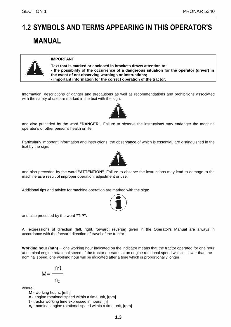
IMPORTANT
Text that is marked or enclosed in brackets draws a ttention to: - the possibility of the occurrence of a dangerous situation for the operator (driver) in the event of not observing warnings or instructions ; - important information for the correct operation o f the tractor.
Information, descriptions of danger and precautions as well as recommendations and prohibitions associated with the safety of use are marked in the text with the sign:
and also preceded by the word "DANGER” . Failure to observe the instructions may endanger the machine operator's or other person's health or life.
Particularly important information and instructions, the observance of which is essential, are distinguished in the text by the sign:
and also preceded by the word "ATTENTION" . Failure to observe the instructions may lead to damage to the machine as a result of improper operation, adjustment or use.
Additional tips and advice for machine operation are marked with the sign:
and also preceded by the word "TIP".
All expressions of direction (left, right, forward, reverse) given in the Operator's Manual are always in accordance with the forward direction of travel of the tractor.
Working hour (mth) – one working hour indicated on the indicator means that the tractor operated for one hour at nominal engine rotational speed. If the tractor operates at an engine rotational speed which is lower than the nominal speed, one working hour will be indicated after a time which is proportionally longer.
n·t M=
nz
where: M - working hours, [mth] n - engine rotational speed within a time unit, [rpm] t - tractor working time expressed in hours, [h] nz - nominal engine rotational speed within a time unit, [rpm]
PRONAR 5340 SECTION 1
1.4
1.3 IDENTIFICATION
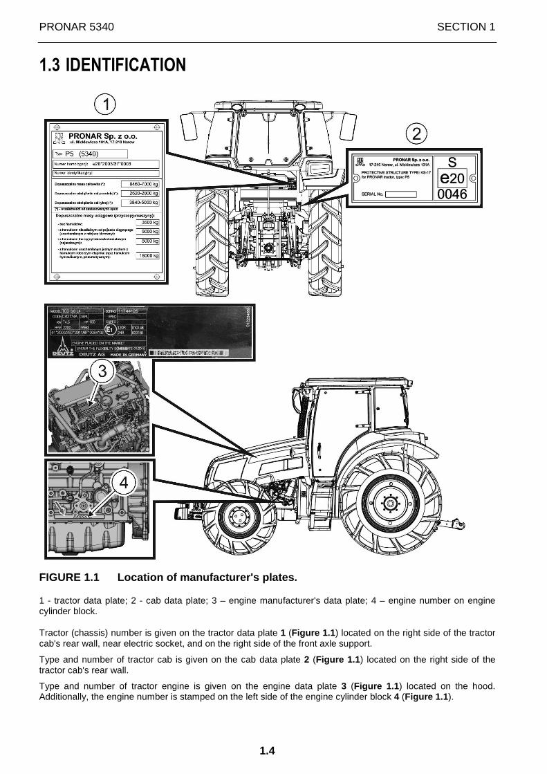
FIGURE 1.1 Location of manufacturer's plates.
1 - tractor data plate; 2 - cab data plate; 3 – engine manufacturer's data plate; 4 – engine number on engine cylinder block.
Tractor (chassis) number is given on the tractor data plate 1 (Figure 1.1 ) located on the right side of the tractor cab's rear wall, near electric socket, and on the right side of the front axle support.
Type and number of tractor cab is given on the cab data plate 2 (Figure 1.1 ) located on the right side of the tractor cab's rear wall.
Type and number of tractor engine is given on the engine data plate 3 (Figure 1.1 ) located on the hood. Additionally, the engine number is stamped on the left side of the engine cylinder block 4 (Figure 1.1 ).

SECTION 1 PRONAR 5340
1.5
FIGURE 1.2 Location of front axle data plate.
1- ZF front axle; 2- DANA front axle; 3- HEMA front axle
FIGURE 1.3 Location of ZF transmission system data plate.

PRONAR 5340 SECTION 1
1.6
FIGURE 1.4 Location of data plates of hitching appl iances
1- data plate of mounting frame of hitching appliances; 2- data plate of upper transport hitch; 3- data plate of agricultural hitch; 4- data plate of automatic upper transport hitch (option)

SECTION 1 PRONAR 5340
1.7
1.4 PROPER USE
PRONAR agricultural tractor is designed according to current safety requirements and engineering standards.
The tractor is designed for agricultural work, maintenance of municipal infrastructure, urban greenery, orchards and wooded areas (depending on its equipment). The tractor, thanks to its parameters and mounting and hitching devices, can work in combination with suspended and hitched implements and agricultural machines. It may equally perform field work, transport and other work depending on the machines or implements with which it is linked.
Only the machines and implements which have technical parameters required for hitching with the tractor can cooperate with the tractor.
During the use of the tractor, comply with all road traffic regulations and transport regulations in force in a given country. Any breach of these regulations is regarded by the Manufacturer as the use contrary to purposes for which the tractor is intended.
Using it as intended involves all actions connected with the safe and proper operation and maintenance of the tractor. In connection with this the user is obliged to:
• carefully read the OPERATOR'S MANUAL and comply with its recommendations,
• understand the tractor's operating principle and how to operate it safely and correctly,
• adhere to the established maintenance and adjustment plans,
• comply with general safety regulations while working and driving the tractor,
• prevent accidents,
• comply with the road traffic regulations and transport regulations in force in a given country, in which the tractor is used,
The tractor may only be used by persons, who:
• are familiar with the contents of this OPERATOR'S MANUAL of the agricultural tractor,
• have been trained in machine operation and safe working conditions,
• have the required authorisation to drive the tractor and are familiar with the road traffic regulations and transport regulations.
IMPORTANT
Each use of the tractor outside the above-specified scope is treated as contrary to purposes for which the tractor is intended.

PRONAR 5340 SECTION 1
1.8
1.5 TERMS & CONDITIONS OF WARRANTY
PRONAR Sp. z o.o. Narew guarantees the reliable operation of the tractor when it is used according to its intended purpose as described in the OPERATOR'S MANUAL. Defects discovered during the warranty period will be removed by the Warranty Service (specified in the WARRANTY BOOK). The repair period is specified in the WARRANTY BOOK.
The warranty does not apply to those parts and sub-assemblies of the tractor, which are subject to wear in normal usage conditions, regardless of the warranty period.
The warranty service only applies to factory defects and mechanical damage that is not due to the user's fault.
In the event of damage arising from:
• mechanical damage which is the user's fault, caused by road accidents,
• inappropriate use, adjustment or maintenance, use of the tractor for purposes other than those for which it is intended,
• use of defective tractor,
• repairs carried out by unauthorised persons, improperly carried out repairs,
• making unauthorised alterations to tractor`s design,
the user will lose the right to warranty service.
TIP
Demand that the seller carefully and precisely fills out the WARRANTY BOOK and warranty repair coupons. A missing date of purchase or sale point stamp, may make the user ineligible for any warranty repair or refund.
The user is obliged to report immediately on noticing any wear in the paint coating or traces of corrosion, and to have the faults rectified whether they are covered by the warranty or not. For detailed Terms & Conditions of Warranty, please refer to the WARRANTY BOOK attached to each tractor.
Modification of the tractor without the written consent of the Manufacturer is forbidden. In particular, do NOT weld, drill holes in, cut or heat the main structural elements of the tractor, which have a direct impact on the tractor operation safety.
IMPORTANT
Equipment protected by lead seals may only be repaired by authorised personnel of service centre. Unauthorised breaking of seals shall cause loss of warranty entitlement
IMPORTANT
Failure to observe instructions contained in the OPERATOR'S MANUAL of the tractor shall invalidate the warranty rights.
Costs of repairs of damages arising as a consequence of use contrary to OPERATOR'S MANUAL shall be borne by the tractor's purchaser.
THE WARRANTY BOOK is the only document enabling the purchaser of the tractor to benefit from warranty service at authorised service points and cannot be replaced.

SECTION 1 PRONAR 5340
1.9
1.6 TRANSPORT
The tractor is prepared for sale completely assembled and does not require packing. Packing is only required for the tractor's technical documentation and any extra equipment.
IMPORTANT
Before transporting independently, the tractor driver must carefully read this operator's manual and observe its recommendations. When being transported on a motor vehicle the tractor must be mounted on the vehicle's platform in accordance with the transport safety requirements. The driver of the vehicle should take particular care while driving. This is due to the vehicle's centre of gravity shifting upwards when loaded with the machine.
Before transporting the tractor on the vehicle's platform, check total height of the vehicle and the tractor in order to make certain that the allowable height of the transport vehicle and the tractor is maintained.
Delivery is either by transport on a vehicle or independently. The tractor may be transported independently provided that the tractor's driver familiarises himself with the Operator's Manual and particularly with the information concerning safety and principles of transport on public roads.
When loading and unloading the tractor comply with the general principles of workplace health and safety for reloading work. Persons operating reloading equipment must have the qualifications required to operate these machines.
The tractor should be attached firmly to the platform of the vehicle using straps or chains fitted with a tightening mechanism. The fastening equipment used must have a valid safety certificate. Be especially careful when driving the tractor onto the transport vehicle's platform. During the loading work particular care should be taken not to damage paint coating.
IMPORTANT
Nobody may be in the manoeuvring zone during transferring tractor to other means of transport.
PRONAR 5340 SECTION 1
1.10
1.7 HANDING THE TRACTOR OVER TO PURCHASER
The new tractor shall be started for the first time by the guarantee mechanic or the authorised employee of the Authorised Service.
The first start-up includes specific inspections and checks of tractor operation and also advising and cautioning the purchaser on the basic principles of using the tractor. It is recommended that the person, who shall operate and use the tractor is present. The owner or user shall obtain instructions on the following issues:
• instructions referring to safe operation of the tractor,
• location and significance of engine and tractor numbers,
• indicators and controls,
• running-in,
• method of starting and stopping,
• selection of gears depending on working conditions,
• use and adjustment of brakes and clutch,
• use and adjustment of differential lock mechanism,
• use of PTO shaft,
• operation and control of hydraulic system,
• hitching implements to and unhitching implements from rear and front (optional) three-point linkage,
• oil and grease lubrication points,
• change of oils,
• change and cleaning of filters,
• operation and air bleeding of fuel system,
• engine cooling system, vee-belt tension,
• electrical system operation,
• steering system and change of wheel track spacing,
• tyre pressure,
• connection, application and control of external hydraulics,
• securing nuts and bolts,
• refuelling.

SECTION 1 PRONAR 5340
1.11
1.8 ENVIRONMENTAL HAZARDS
A hydraulic oil leak constitutes a direct threat to the natural environment owing to its limited biodegradability. While carrying out maintenance and repair work which involves the risk of an oil leak, this work should take place on an oil resistant floor or surface. In the event of oil leaking into the environment, first of all contain the source of the leak, and then collect the leaked oil using available means. Remaining oil should be collected using sorbents, or by mixing the oil with sand, sawdust or other absorbent materials. The oil pollution, once gathered up, should be kept in a sealed, marked, hydrocarbon resistant container, and then passed on to the appropriate oil waste recycling centre. The container should be kept away from heat sources, flammable materials and food.
Oil, which has been used up or is unsuitable for further use owing to a loss of its properties should be stored in its original packaging in the conditions described above.
PRONAR 5340 SECTION 1
1.12
1.9 WITHDRAWAL FROM USE
In the event of decision by the user to withdraw the tractor from use, comply with the regulations in force in a given country concerning withdrawal from use and recycling of vehicles withdrawn from use.
Before proceeding to dismantle the tractor, operating fluids should be completely removed from all tractor assemblies. Locations of drain plugs and the method for draining operating fluids are described in SECTION 5 "MAINTENANCE".
When spare parts are changed, worn out or damaged parts should be taken to a collection point for recyclable raw materials. Waste oil and also rubber and plastic elements should be taken to establishments undertaking the utilisation of such waste.
IMPORTANT
During dismantling personal protection equipment shall be used i.e. protective clothing, boots, gloves and protective goggles etc.
Avoid contact of skin with oil. Do not allow used oil to spill.

SECTION
2
SAFETY
ADVICE

PRONAR 5340 SECTION 2
2.2
2.1 BASIC SAFETY RULES
2.1.1 USING THE TRACTOR
• Before using the tractor, the user must carefully read this Operator's Manual and the WARRANTY BOOK. When operating the machine, the operator must comply with all recommendations contained in the Operator's Manual.
• The tractor may only be used and maintained by persons qualified to drive agricultural tractors and agricultural machines and trained in the operation of the machine. The tractor can be operated by a single person only.
• If the information stated in the Operator's Manual is difficult to understand, contact a seller, who runs an authorised technical service on behalf of the Manufacturer, or contact the Manufacturer directly.
• Careless and improper use and operation of the tractor, and non-compliance with the recommendations given in this Operator's Manual are dangerous to your health.
• Be aware of the existence of a residual risk, and for this reason the fundamental basis for using this tractor should be the application of safety rules and sensible behaviour.
• The tractor must never be used by persons who are not authorised to drive agricultural tractors, including children and people under the influence of alcohol, drugs or other abusive substances.
• Non-compliance with the rules of safety use and the road traffic regulations can be dangerous to the health and life of the operators and other people.
• The tractor must not be used for purposes other than those for which it is intended. Anyone who uses the tractor other than the way intended takes full responsibility for himself for any consequences of this use. Use of the tractor for purposes other than those for which it is intended by the Manufacturer may invalidate the warranty.
• Do not make any modifications, and not mount parts and assemblies, which modify the tractor's structure without consulting the tractor's manufacturer.
• The tractor may only be used when all the safety guards and other protective elements are technically sound and correctly positioned. In the event of loss or destruction of the safety guards, they must be replaced with new ones.
• In order to limit occupational risks associated with exposure to noise during the tractor operation, use individual protection (ear protectors). In order to reduce the level of noise during work the tractor cab window and door should be closed.
• PRONAR 5340 tractor has a KS-17 safety cab which is not suitable for carrying a passenger on public roads. Do not carry a passenger on public roads.
2.1.2 HITCHING AND UNHITCHING FROM CARRYING VEHICLE
• Do not hitch the machines to the tractor when the linkage systems of the machine and the tractor are not compatible.
• After hitching the machine, check the safeguards. Carefully read the Operator's Manual of the hitched machine.
• To hitch the machine to tractor use only original pins and safeguards.
• The machine which will be hitched to the tractor must be technically sound and must meet the requirements specified by the tractor Manufacturer.
• Be especially careful when hitching the machine to the tractor.
• When hitching, there must be nobody between the machine and the tractor.
• Hitching and unhitching may only take place when the machine and the tractor are switched off.
• The machine unhitched from the tractor must be secured against overturning and supported on stable and level surface.

SECTION 2 PRONAR 5340
2.3
2.1.3 DRIVING THE TRACTOR
• To avoid dangerous situations (especially where tractor is at risk of overturning) be careful and pay attention when driving the tractor. Adjust speed to the surface conditions, especially when moving across uneven (hilly) terrain, when passing ditches, on slopes and at corners (turning points). Do not make sharp turns at full loading and high tractor speeds.
• When driving on public roads, comply with the road traffic regulations in force in the country, in which the tractor is used.
• When driving on public roads, the tractor shall be equipped with a reflective warning triangle and a slow-moving vehicle warning triangle plate In the event that the tractor is moving linked to a trailer or machine, the triangular distinguishing plate shall be mounted on the trailer or machine (according to regulations).
• Before using the tractor, always check its technical condition, especially in terms of safety.
• Do not drive the tractor (with trailer, machine or implement) without effective braking and signalling light systems in the vehicles or with the system of the trailer (machine) not connected with the tractor. This could lead to an accident.
• Do not leave trailers (machines and implements) on public roads disconnected from tractor. In the event of malfunction, drive onto the road shoulder, position the reflective warning triangle (the tractor and the trailer equipment) according to the regulations and turn on parking lights.
• Do not leave the tractor (tractor-implement combination) on a slope. If necessary, lower the implement, engage the first gear and parking brake.
• Do not exceed the permitted speed suitable for road conditions and design limitations. Adjust travel speed to the prevailing road conditions and other limitations arising from road traffic regulations valid in the country of the tractor use.
• Do not drive down the slopes with engine switched off, gear and travel direction lever in neutral position („disengaged” ) or with depressed clutch pedal. This could lead to an accident.
• Do not carry people on trailers and machines (implements). It is forbidden!
• Ensure that independent brake pedals are connected and operate simultaneously.
• Do not drive the tractor with a trailer if the red indicator light is on signalling insufficient pressure in the trailer (trailers) braking system. It may prevent effective braking.
• Only connect trailers and machines (implements) to tractor in the manner envisaged by the tractor Manufacturer i.e. using original pins with protections (cotter pins). Other connection methods may pose danger.
• Do not use the trailers of total weight greater than 3500 kg, without brakes.
• While towing the tractor, the traffic code shall be observed at all times. Tractor towing is permitted with an engine turned off, effective steering system and with a speed not exceeding 10 mph.
DANGER
Reckless driving of the tractor and excessive speed may cause accidents.

PRONAR 5340 SECTION 2
2.4
2.1.4 OPERATING THE TRACTOR
• Before starting the tractor operation, make sure that there are no bystanders near the tractor.
• Before starting the tractor make sure that there are no bystanders (especially children) or animals in the danger zone. The tractor operator is obliged to ensure proper visibility of the tractor and the working area.
• Do NOT stand within the working zone of the machine cooperating with the tractor.
• Before beginning work, make a visual inspection of the tractor, its connecting and hitching appliances and linked machine (implement) and do not begin work without assuring yourself of their completeness and correct linkage.
• Always apply secure connection to towed machines (original towing pin and its safety protection).
• Adjust the three-point linkage, so that the machine (implement) mounted on it in transport position is rigidly connected with the tractor.
• Before starting the engine or work with the tractor install all protective guards. The tractor may work only if all the guards of the tractor and the machine are installed.
• Before starting the engine, check that all controls (levers, hand wheels and switches) are in neutral or switched off position. In this way you prevent accidental movement of the tractor and connected machines.
• The control levers may be operated only when sitting in the operator's seat inside the tractor's cab. Do not start the engine and do not operate control levers (pedals) unless you are seated in the driver's seat.
• Before moving off, release parking brake and make sure that any persons assisting in operation or hitching the machines are not in danger, especially that they are not between the tractor and hitched machine (implement). Warn them of intention to move, using the horn.
• Do NOT leave the tractor cab when the tractor is moving.
• Before leaving the cab stop the engine and engage handbrake.
• Do not work with the tractor in closed rooms without intensive and efficiently operating ventilation, because inhaling the exhaust fumes can be fatal.
• If the engine or the steering system is operating incorrectly while driving, stop the tractor, because the tractor in such a situation requires significant strength applied to the steering wheel in order to steer it.
• DO NOT work and do not allow your helpers to work under machines (implements) that are raised by the tractor linkage.
• Do not leave machines (implements) raised by the tractor linkage, while tractor is idle for long periods.
• In the event that the wheels of the tractor front axle loose contact with the ground after raising a machine (implement) attached to the three-point linkage, apply weights to front axle. If the tractor front axle in spite of this does not obtain stable contact with the ground (enabling free manoeuvring of the tractor and implement combination) DO NOT work with that machine or implement.
• If the tractor is dangerously tilted, immediately lower the hitched machine to the ground and stop the tractor.
• Make sure that before raising or lowering three-point linkage mounted machines (implements) and also before turning there is no risk of collision with people or objects or any other danger.
• DO NOT work with PTO shaft, which drives machines and implements from the tractor PTO, without guards installed.
• Disconnect PTO drive before checking (while parked) hitched machines (implements) driven by tractor PTO.
• In the event of using supplementary or assisting assemblies make certain that they are compatible with the tractor. Familiarise yourself with the principles of their correct mounting and operation with the tractor.

SECTION 2 PRONAR 5340
2.5
ATTENTION
In the event of using a front loader observe the maximum permissible front axle load and also recommended (permissible) speed. Counterweights should also be applied to the rear linkage system.
The front loader must not be used without a counterweight suspended from the rear three-point linkage.
DANGER
The tractor is not designed for working with machines using chemicals dangerous to human health (plant sprayers)!
DANGER
If you use the tractor incorrectly, it may be dangerous to you, other persons and the surroundings. Do not work with equipment not designated to work in combination with the tractor!
2.1.5 SAFETY RULES FOR WORKING ON SLOPES
• In order to prevent air from entering the fuel system during work on slopes and undulating fields, the quantity of fuel in the tank should always be a minimum of 1/4 fuel tank capacity.
• If possible, avoid driving tractor across the slopes (required directions - up and down the field). If work shall take place across slope, one should additionally:
• use the widest wheel spacing,
• make turns in an upwards direction,
• do not lift implements higher than necessary in order to make the manoeuvre (e.g. turn),
• check that tyre pressure in rear wheels is uniform,
• reduce the travel speed at turns to the minimum,
• While using a reversible plough, begin ploughing from the top of the hill. Thus, the wheels on the hill top side travel in the furrows and reduce the angle of the tractor inclination.
• Due to changing location of centre of gravity depending on type of hitched machine and various weather and ground conditions, be especially careful and determine by yourself the maximum slope inclination angle for operating the tractor.
2.1.6 MAINTENANCE
• During the warranty period, any repairs may only be carried out by Warranty Service authorised by the manufacturer. It is recommended that necessary repairs to machine should be undertaken by specialised workshops.
• In the event of any fault or damage whatsoever, do not use the tractor until the fault has been corrected.
• During work, use the proper, close-fitting protective clothing, gloves and appropriate tools. When working on hydraulic systems it is recommended to use oil resistant gloves and protective goggles.
• Any modification to the tractor frees the tractor Manufacturer from any responsibility for damage or detriment to health, which may arise as a result.
• Before undertaking any work on the tractor, switch the tractor engine and wait until all rotating parts come to a stop.
PRONAR 5340 SECTION 2
2.6
• Regularly check the technical condition of the safety devices and correct tightening of bolt connections.
• Regularly perform service inspections of the tractor as recommended by the Manufacturer.
• Do NOT perform service or repair work under raised and unsupported tractor.
• Before beginning repair works on hydraulic systems, reduce oil pressure.
• The cooling system is under high pressure while the engine is working. Do not unscrew the radiator cap while the engine is working. Unscrew the radiator cap carefully, after switching the engine off and reducing the temperature in the cooling system, in order to gradually reduce pressure in the system.
• When draining hot liquid from the cooling system or oil from the driving system assemblies and steering system, be especially careful to avoid danger of scalding.
• Perform all servicing of the tractor and its equipment with utmost care, and especially the braking and steering systems, so that they are always in excellent technical condition, because they are vital to your safety.
• Servicing and repair work should be carried out in line with the general principles of workplace health and safety. In the event of injury, the wound must be immediately cleaned and disinfected. In the event of more serious injuries, seek a doctor's advice.
• Repair, maintenance and cleaning work should be carried out with the tractor engine turned off and the ignition key removed. Immobilise tractor with parking brake. Ensure that unauthorised persons do not have access to the tractor cab.
• Should it be necessary to change individual parts, use only original parts. Non-adherence to these requirements may put the user and other people's health and life at risk, and also damage the tractor and invalidate the warranty.
• Regularly check technical condition and mounting of all guards and protective elements.
• In the event of work requiring the tractor to be raised, use properly certified hydraulic or mechanical lifts for this purpose. After lifting the tractor, stable and durable supports must also be used.
• The tractor must not be supported using fragile elements (bricks or concrete blocks).
• After completing work associated with lubrication, remove excess oil or grease.
• In order to reduce the risk of fire, the tractor must be kept clean.
2.1.7 MAINTENANCE OF PTO DRIVE
• While reversing and during turns, the PTO drive must be disengaged.
• Before starting the machine connected to PTO, make sure that there are no bystanders (especially children) in the danger zone. The machine operator is obliged to ensure proper visibility of the machine and the working area.
• Before starting PTO, make certain that the PTO rotation direction is correct.
• In the event of necessity to inspect the machine (its disconnection) during work with machines (implements) driven by the PTO, ensure that PTO does not rotate before leaving cab.
• While working with machines (implements) driven by PTO, the persons in the vicinity of rotating assemblies or machine elements must not wear loose clothing, because it might pose danger.
• While working with stationary machines, driven by PTO, always engage parking brake, block front and rear wheels and position front wheels for driving straight ahead.
• Do not wash, adjust or service machines (implements) driven by PTO when engine is running.
• Always use covering guard, and when PTO is not used, place protective covering over the end of PTO shaft.
• Do not use shafts to drive machines without the complete guards envisaged in tractor design.
• Always apply the appropriately selected PTO shafts (depending on the driven machine's torque that needs to be transferred). Torque value in Nm is normally given on the PTO guard.

SECTION 2 PRONAR 5340
2.7
2.1.8 HYDRAULIC SYSTEM OPERATION
• The tractor's hydraulic system is under high pressure when operating.
• Regularly check the technical condition of the connections and the hydraulic conduits. There must be no oil leaks.
• In the event of the hydraulic system malfunction, discontinue using the tractor until the malfunction is corrected.
• In the event of injuries being caused by pressurised hydraulic oil, contact a doctor immediately. Hydraulic oil may penetrate the skin and cause infections. In the event of contact of oil with eyes, rinse eyes with a large quantity of water and in the event of the occurrence of irritation consult a doctor. In the event of contact of oil with skin wash the area of contact with water and soap. Do NOT apply organic solvents (petrol, kerosene).
• Use the hydraulic oil recommended by the Manufacturer. Never mix two types of oil.
• After changing the hydraulic oil, the used oil should be properly disposed of. Used oil or oil which has lost its properties should be stored in original containers or replacement containers resistant to action of hydrocarbons. Replacement containers must be clearly marked and appropriately stored.
• Do not store hydraulic oil in packaging designed for storing food or foodstuffs.
• Rubber hydraulic conduits must be replaced every 4 years regardless of their technical condition.
• Repair and replacement of hydraulic system elements should be entrusted to the appropriately qualified persons.
2.1.9 FIRE SAFETY RULES
• Do not add, for any reason, petrol or mixtures to the diesel fuel because this may significantly increase the danger of fire or explosion.
• Always screw the fuel cap tightly onto fuel tank inlet.
• Do not pour fuel while engine is running.
• Do not smoke cigarettes while pouring fuel and also while servicing fuel system.
• Do not approach the tractor with an open flame (even a burning cigarette) when refuelling, servicing the fuel system and inspecting batteries.
• Do not fill the total capacity of fuel tank. Always leave a small space for fuel expansion.
• Always refuel after finishing work to reduce water vapour condensation occurring overnight in fuel tank.
• Do not store fuel and lubricant materials within the distance of less than 3 m from the permanent parking place of tractor. Equip the place with reliably operating fire extinguishing equipment.
• Be careful during repairs involving welding. Clean place of repair so that no fire may occur during work.
• Ensure the air-tightness of the exhaust system so that it cannot be contaminated, especially from the exterior with flammable substances.
• Do not allow the occurrence of leaks from fuel and hydraulic systems.
• Equip the tractor with a GP-1X BC or a similar type of extinguisher and secure it in the holder.

PRONAR 5340 SECTION 2
2.8
2.2 DESCRIPTION OF RESIDUAL RISK
Pronar Sp. z o. o. in Narew has made every effort to eliminate the risk of accidents. There is, however, a certain residual risk, which could lead to an accident, and this is connected mainly with the actions described below:
• using the tractor for purposes other than those for which it is intended,
• being between the tractor and the machine while the engine is running and when the machine is being attached,
• being outside the tractor cab while the engine is working,
• operating the tractor with removed or faulty safety guards,
• not maintaining safe distance from the danger zone or being within the zones while the tractor is operating,
• operation of the tractor by unauthorised persons or persons under the influence of alcohol,
• cleaning, maintaining and performing technical checks while the tractor's engine is running,
The residual risk may be kept to a minimum by following the recommendations below:
• perform prudent and unhurried operation of the tractor,
• sensibly adhere to the remarks and recommendations contained in the OPERATOR'S MANUAL,
• carry out repairs and maintenance work in line with operating safety rules,
• repair and maintenance work should be carried out by persons trained to do so,
• use close fitting protective clothing,
• ensure unauthorised persons have no access to the tractor, especially children.
• maintain safe distance from prohibited or dangerous places
• unauthorized persons must not stay inside the tractor's cab during tractor operation

SECTION 2 PRONAR 5340
2.9
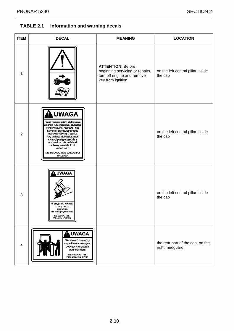
2.3 INFORMATION AND WARNING DECALS
The tractor is marked with the information and warning decals specified in TABLE 2.1. Throughout the time it is in use, the user of the tractor is obliged to take care that notices and warning and information symbols located on the tractor are clear and legible. In the event of their destruction, they must be replaced with new ones. Safety decals can be purchased from the Manufacturer of the tractor or your PRONAR dealer. New assemblies, changed during repair, must be labelled once again with the appropriate safety signs. During cleaning, do not use solvents, which may damage label surface and do not direct a strong water jet at the machine.
ATTENTION
Keep stickers clean so that they are always legible.
FIGURE 2.1 Location of information decals and safety signs on PRONAR tractors
(description in TABLE 2.1).
PRONAR 5340 SECTION 2
2.10
TABLE 2.1 Information and warning decals
ITEM DECAL MEANING LOCATION
1
ATTENTION! Before beginning servicing or repairs, turn off engine and remove key from ignition
on the left central pillar inside the cab
2
on the left central pillar inside the cab
3
on the left central pillar inside the cab
4
the rear part of the cab, on the right mudguard
SECTION 2 PRONAR 5340
2.11
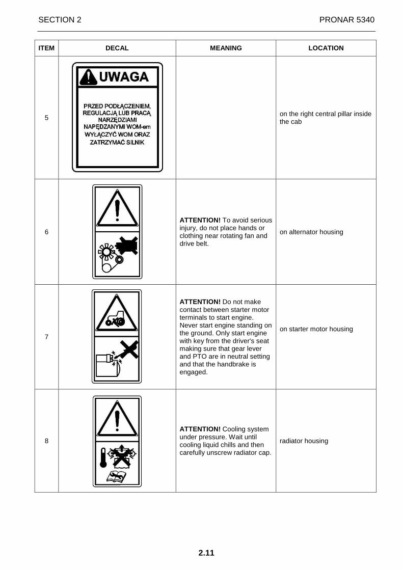
ITEM DECAL MEANING LOCATION
5
on the right central pillar inside the cab
6
ATTENTION! To avoid serious injury, do not place hands or clothing near rotating fan and drive belt.
on alternator housing
7
ATTENTION! Do not make contact between starter motor terminals to start engine. Never start engine standing on the ground. Only start engine with key from the driver's seat making sure that gear lever and PTO are in neutral setting and that the handbrake is engaged.
on starter motor housing
8
ATTENTION! Cooling system under pressure. Wait until cooling liquid chills and then carefully unscrew radiator cap.
radiator housing

PRONAR 5340 SECTION 2
2.12

SECTION
3
STEERING AND
OPERATING CONTROLS
PRONAR 5340 SECTION 3
3.2
3.1 CAB
ATTENTION
Before beginning work with the tractor, carefully read about the purpose of the controls, indicators and their indications. The information contained in this Operator's Manual will help you correctly and safely drive the tractor and, with as little effort as possible, carry out the intended work.
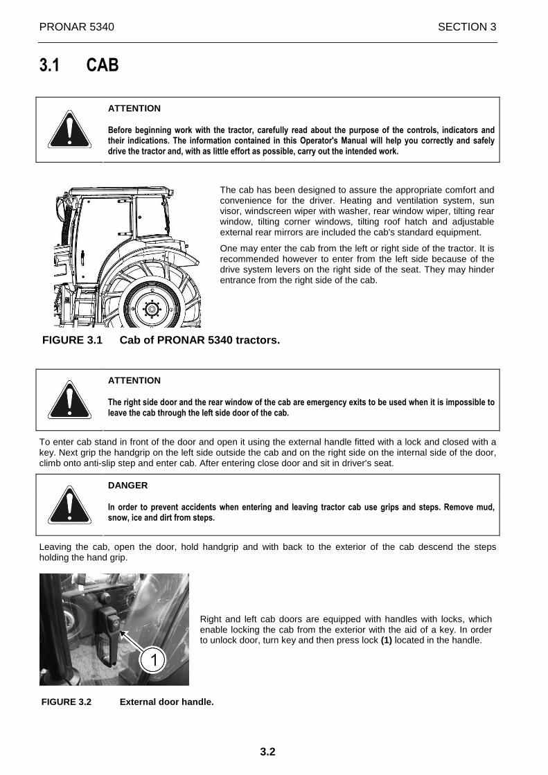
The cab has been designed to assure the appropriate comfort and convenience for the driver. Heating and ventilation system, sun visor, windscreen wiper with washer, rear window wiper, tilting rear window, tilting corner windows, tilting roof hatch and adjustable external rear mirrors are included the cab's standard equipment.
One may enter the cab from the left or right side of the tractor. It is recommended however to enter from the left side because of the drive system levers on the right side of the seat. They may hinder entrance from the right side of the cab.
FIGURE 3.1 Cab of PRONAR 5340 tractors.
ATTENTION
The right side door and the rear window of the cab are emergency exits to be used when it is impossible to leave the cab through the left side door of the cab.
To enter cab stand in front of the door and open it using the external handle fitted with a lock and closed with a key. Next grip the handgrip on the left side outside the cab and on the right side on the internal side of the door, climb onto anti-slip step and enter cab. After entering close door and sit in driver's seat.
DANGER
In order to prevent accidents when entering and leaving tractor cab use grips and steps. Remove mud, snow, ice and dirt from steps.
Leaving the cab, open the door, hold handgrip and with back to the exterior of the cab descend the steps holding the hand grip.
Right and left cab doors are equipped with handles with locks, which enable locking the cab from the exterior with the aid of a key. In order to unlock door, turn key and then press lock (1) located in the handle.
FIGURE 3.2 External door handle.

SECTION 3 PRONAR 5340
3.3
To open door from the interior pull lever (1) releasing door lock mechanism. Lever (2) is used for blocking door lock and preventing accidental opening of the door.
After opening, the door may be set in a slightly tilted position due to special lever (3) mounted on cab frame, which should be tilted back, so that door lock may be secured by it.
FIGURE 3.3 Internal door handle.
DANGER
Do not drive tractor with doors completely open. Doors should be closed while tractor is in motion.
The rear window may be bolted in closed position using bolt handle (1) or completely open and held in position by gas springs.
FIGURE 3.4 Rear window bolt handle
Side windows are mounted on hinges. They may be bolted in closed or partially open position using lever mechanism with a handle (1).
FIGURE 3.5 Side window bolt handle
IMPORTANT
Do not drive the tractor with the rear window completely open. The rear window may be open only while the tractor is parked.

PRONAR 5340 SECTION 3
3.4
The roof hatch may be bolted in closed position or partially open position by means of lever mechanism (1) with a handle. The roof hatch is held in open position by means of gas springs.
FIGURE 3.6 Roof hatch bolt handle
The arms of external rear mirrors (1) can be extended and their angle can be adjusted. In order to extend mirror arm, loosen bolts (2) securing mirror and tighten the bolts after the adjustment. The rear view mirror should be adjusted to achieve the best possible visibility to the rear of the tractor.
FIGURE 3.7 External rear mirrors
In order to facilitate access to battery box, steps (1) on the right side of cab may be raised. In order to do this, loosen bolt (2) securing steps, using lever, and then raise steps and strongly tighten bolt (2) so that steps are held in raised position.
FIGURE 3.8 Anti slip steps

SECTION 3 PRONAR 5340
3.5
3.2 ARRANGEMENT OF CONTROLS
FIGURE 3.9 Arrangement of steering and operating co ntrols of PRONAR 5340 tractor
1 - radio; 2 - knob for controlling speed of air blown from air vents; 3 - directing guides of air vents in upper cab panel; 4 - cab interior lamps; 5 – sun visor holder; 6 - stoppers; 7 - multifunction light and horn switch; 8 - indicator panel; 9 - steering wheel; 10 - switch of rear window wiper and washer; 11 - multifunction switch of windscreen wipers and washer; 12 - starter switch (ignition); 13 - emergency lights switch; 14 - knob for controlling temperature of air blown from air vents; 15 - clutch pedal; 16 - steering column adjustment lever; 17 - right wheel brake pedal; 18 - left wheel brake pedal; 19 - accelerator pedal („accelerator”);
PRONAR 5340 SECTION 3
3.6
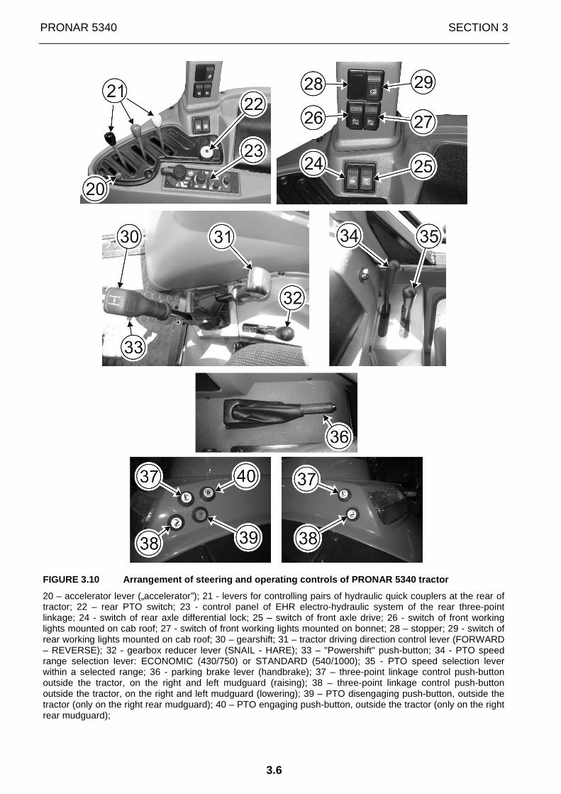
FIGURE 3.10 Arrangement of steering and operating c ontrols of PRONAR 5340 tractor
20 – accelerator lever („accelerator”); 21 - levers for controlling pairs of hydraulic quick couplers at the rear of tractor; 22 – rear PTO switch; 23 - control panel of EHR electro-hydraulic system of the rear three-point linkage; 24 - switch of rear axle differential lock; 25 – switch of front axle drive; 26 - switch of front working lights mounted on cab roof; 27 - switch of front working lights mounted on bonnet; 28 – stopper; 29 - switch of rear working lights mounted on cab roof; 30 – gearshift; 31 – tractor driving direction control lever (FORWARD – REVERSE); 32 - gearbox reducer lever (SNAIL - HARE); 33 – "Powershift" push-button; 34 - PTO speed range selection lever: ECONOMIC (430/750) or STANDARD (540/1000); 35 - PTO speed selection lever within a selected range; 36 - parking brake lever (handbrake); 37 – three-point linkage control push-button outside the tractor, on the right and left mudguard (raising); 38 – three-point linkage control push-button outside the tractor, on the right and left mudguard (lowering); 39 – PTO disengaging push-button, outside the tractor (only on the right rear mudguard); 40 – PTO engaging push-button, outside the tractor (only on the right rear mudguard);

SECTION 3 PRONAR 5340
3.7
FIGURE 3.11 Arrangement of steering and operating c ontrols of PRONAR 5340 tractor
41 - electrical system connection for trailers; 42 - power supply socket +12V 15A; 43- cigarette lighter socket (+12 V 15A); 44 – power supply socket +12V 30A; 45 – engine diagnostic socket; 46 – compressor activation lever; 47 - battery switch; 48 - link for opening cab door from the inside; 49 - cab door lock link; 50 - bonnet opening link.

PRONAR 5340 SECTION 3
3.8
3.3 INDICATOR PANEL
FIGURE 3.12 Control indicators
1 – rev-counter; 2 – coolant temperature gauge; 3 – pneumatic system air pressure gauge; 4 – indicator lights panel; 5 – LCD display; 6, 7, 8, – buttons to set the clock and change the display screens; 9 – button for selecting fixed work mode of engine RPM regulator.
Engine speed (RPM) is indicated on the rev-counter scale (1).
FIGURE 3.13 Rev-counter.
Coolant temperature gauge (2) (FIGURE 3.12)
The gauge indicates coolant temperature in °C. Normal coolant temperature should be within the range of 80 ÷ 110°C (green sector of the scale). If the indicator arrow is in the red field, the engine is overheating. Find the cause. Engine overheating may be caused by:
• insufficient coolant liquid in cooling system; • fan drive vee-belt may be insufficiently tensioned; • defective thermostat • dirt outside or inside radiator.
IMPORTANT
Failure to remove the cause of engine overheating may lead to serious failure.
Pneumatic system air pressure gauge (3) (FIGURE 3.1 2)
Pressure should be within the range of 0.5÷0.8 MPa (5÷8 kG/cm2) i.e. (in the green sector of the scale).

SECTION 3 PRONAR 5340
3.9
3.4 LCD DISPLAY ON INDICATOR PANEL
FIGURE 3.14 LCD display in PRONAR 5340 tractors.
1- LCD display; 2- button for changing data shown on the display; 3- clock settings button; 4- button for changing display backlight mode (daytime/night-time).
Clock 1 is shown on LCD display when the tractor is parked and the engine is switched off.
When the ignition key is turned to position 1 (ON) (FIGURE 3.17) and the tractor's engine is started, the following operating parameters of the tractor are shown on LCD display:
1 - clock 2 - quantity of fuel in the tank 3 - tractor's electrical system voltage (V) 4 - tractor's travelling speed (km/h) 5 - mileage (km) 6 - engine hours worked (mth)
PRONAR 5340 SECTION 3
3.10
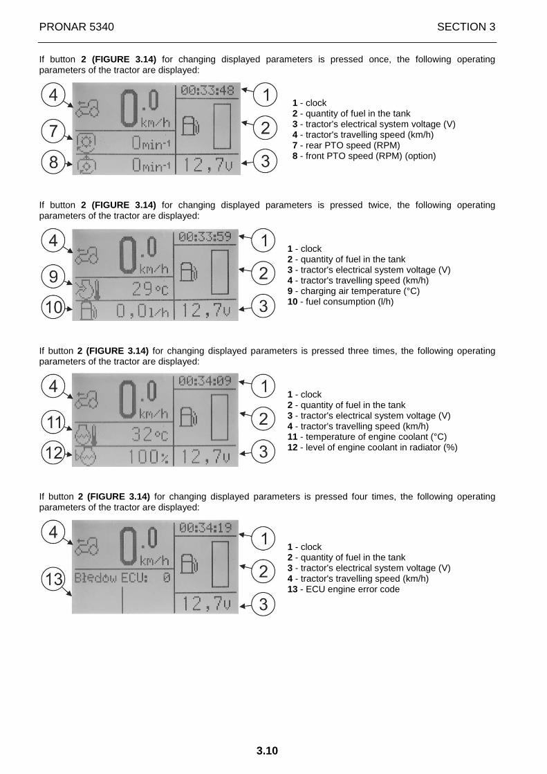
If button 2 (FIGURE 3.14) for changing displayed parameters is pressed once, the following operating parameters of the tractor are displayed:
1 - clock 2 - quantity of fuel in the tank 3 - tractor's electrical system voltage (V) 4 - tractor's travelling speed (km/h) 7 - rear PTO speed (RPM) 8 - front PTO speed (RPM) (option)
If button 2 (FIGURE 3.14) for changing displayed parameters is pressed twice, the following operating parameters of the tractor are displayed:
1 - clock 2 - quantity of fuel in the tank 3 - tractor's electrical system voltage (V) 4 - tractor's travelling speed (km/h) 9 - charging air temperature (°C) 10 - fuel consumption (l/h)
If button 2 (FIGURE 3.14) for changing displayed parameters is pressed three times, the following operating parameters of the tractor are displayed:
1 - clock 2 - quantity of fuel in the tank 3 - tractor's electrical system voltage (V) 4 - tractor's travelling speed (km/h) 11 - temperature of engine coolant (°C) 12 - level of engine coolant in radiator (%)
If button 2 (FIGURE 3.14) for changing displayed parameters is pressed four times, the following operating parameters of the tractor are displayed:
1 - clock 2 - quantity of fuel in the tank 3 - tractor's electrical system voltage (V) 4 - tractor's travelling speed (km/h) 13 - ECU engine error code
SECTION 3 PRONAR 5340
3.11
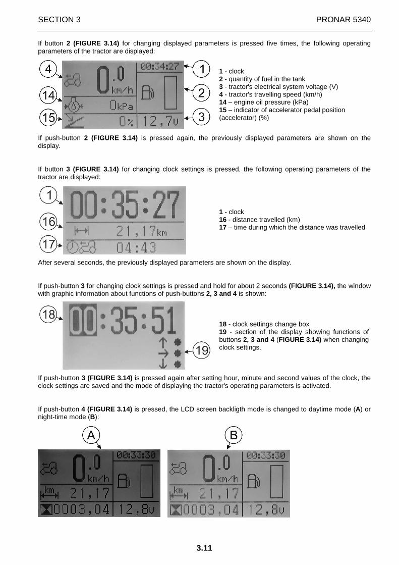
If button 2 (FIGURE 3.14) for changing displayed parameters is pressed five times, the following operating parameters of the tractor are displayed:
1 - clock 2 - quantity of fuel in the tank 3 - tractor's electrical system voltage (V) 4 - tractor's travelling speed (km/h) 14 – engine oil pressure (kPa) 15 – indicator of accelerator pedal position (accelerator) (%)
If push-button 2 (FIGURE 3.14) is pressed again, the previously displayed parameters are shown on the display.
If button 3 (FIGURE 3.14) for changing clock settings is pressed, the following operating parameters of the tractor are displayed:
1 - clock 16 - distance travelled (km) 17 – time during which the distance was travelled
After several seconds, the previously displayed parameters are shown on the display.
If push-button 3 for changing clock settings is pressed and hold for about 2 seconds (FIGURE 3.14), the window with graphic information about functions of push-buttons 2, 3 and 4 is shown:
18 - clock settings change box 19 - section of the display showing functions of buttons 2, 3 and 4 (FIGURE 3.14) when changing clock settings.
If push-button 3 (FIGURE 3.14) is pressed again after setting hour, minute and second values of the clock, the clock settings are saved and the mode of displaying the tractor's operating parameters is activated.
If push-button 4 (FIGURE 3.14) is pressed, the LCD screen backligth mode is changed to daytime mode (A) or night-time mode (B):

PRONAR 5340 SECTION 3
3.12
3.5 INDICATOR LIGHTS
FIGURE 3.15 Indicator lights location
Meaning of indicator light symbols on panel is as f ollows:
- parking lights switched on indicator light
- road lights switched on indicator light
- tractor's left, right indicators switched on
- first trailer's left, right indicator lights switched on
- second trailer's left, right indicator lights switched on
- front axle drive engaged indicator light
- rear axle differential lock engaged indicator light
- indicator light signalling contamination of engine air filter and presence of water in fuel filter - it is illuminated if the filter maintenance is required (contaminations must be removed) Check air filter or fuel filter and clean or replace filtering inserts, if necessary.
- start-up assistance appliance engaged indicator light (glow plugs)
- fuel level reserve indicator light
- dipped beam switched on indicator light
- dipped beam on bracket switched on indicator light (above indicator light) (option)

SECTION 3 PRONAR 5340
3.13
- engine system malfunction indicator light (orange). Non-critical error – engine operation can be continued.
- indicator light of "Powershift" torque amplifier in "HARE" position
- indicator light of "Powershift" torque amplifier in "TORTOISE" position
- rear PTO drive engaged indicator light
- front PTO drive engaged indicator light (option)
- indicator light of air pressure in trailer brake pneumatic system. It illuminates when pressure falls below the allowable level. It illuminates also when pressure in air tank is not sufficient;
- allowable coolant temperature exceeded indicator light. It is on when coolant temperature exceeds permissible value. This means that engine is overheating. Discover the cause of overheating. It is also on when the level of coolant in the balance tank is too low.
- indicator light of brake fluid level in the braking system tank - it lights up when brake fluid level falls below the allowable level. Check braking system and top up brake fluid.
- indicator light of exceeded allowable temperature of charging air. It lights up when charging air temperature exceeds permissible value.
- engine diagnostics indicator light. It lights up when an error occurs in the engine system.
IMPORTANT: Stop the tractor and contact the Authori zed Service of PRONAR. Only an authorised employee of the PRONAR's Authorised Serv ice may read out the meaning of engine system error code (error number is shown on LCD dis play (FIGURE 3.14)) and remove faults.
- engine oil pressure indicator light. It illuminates when pressure falls below the allowable level. It is also on when ignition key is in position 1 (ON) (FIGURE 3.17);
IMPORTANT
Engine must not be operated when oil pressure indicator light is illuminated. In such a situation stop engine and remove cause of low pressure. Low pressure in lubrication system may lead to serious engine malfunction.
- oil pressure in steering system indicator light. It illuminates when pressure during engine operation falls below the allowable level. It is also on when ignition key is in position 1 (ON) (FIGURE 3.17); Momentary flashing is possible.
IMPORTANT
If indicator light of oil pressure in steering system is on, the steering system is out of order. Before commencing work remove cause of low pressure in the system.

PRONAR 5340 SECTION 3
3.14
- battery charging indicator light. If light comes on during engine operation that signifies malfunction and it must be corrected. It is also on when ignition key is in position 1 (ON) (FIGURE 3.17);
- indicator light of oil temperature in the tractor's hydraulic system. It illuminates when oil temperature during engine operation rises above the allowable level.
IMPORTANT! The tractor's hydraulic system is out of order. Before commencing work remove cause of temperature rise in system.
- parking brake engaged indicator light
SECTION 3 PRONAR 5340
3.15
3.6 MULTIFUNCTION SWITCHES
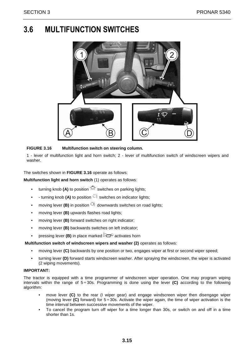
FIGURE 3.16 Multifunction switch on steering column .
1 - lever of multifunction light and horn switch; 2 - lever of multifunction switch of windscreen wipers and washer.
The switches shown in FIGURE 3.16 operate as follows:
Multifunction light and horn switch (1) operates as follows:
• turning knob (A) to position switches on parking lights;
• - turning knob (A) to position switches on indicator lights;
• moving lever (B) in position downwards switches on road lights;
• moving lever (B) upwards flashes road lights;
• moving lever (B) forward switches on right indicator;
• moving lever (B) backwards switches on left indicator;
• pressing lever (B) in place marked activates horn
Multifunction switch of windscreen wipers and washe r (2) operates as follows:
• moving lever (C) backwards by one position or two, engages wiper at first or second wiper speed;
• turning lever (D) forward starts windscreen washer. After spraying the windscreen, the wiper is activated (2 wiping movements).
IMPORTANT:
The tractor is equipped with a time programmer of windscreen wiper operation. One may program wiping intervals within the range of 5 ÷ 30s. Programming is done using the lever (C) according to the following algorithm:
• move lever (C) to the rear (I wiper gear) and engage windscreen wiper then disengage wiper (moving lever (C) forward) for 5 ÷ 30s. Activate the wiper again, the time of wiper activation is the time interval between successive movements of the wiper.
• To cancel the program turn off wiper for a time longer than 30s, or switch on and off in a time shorter than 1s.

PRONAR 5340 SECTION 3
3.16
3.7 IGNITION
FIGURE 3.17 Engine start-up control.
1 – starter switch;
On the right side of the dashboard, there is starter switch (ignition) (1) (FIGURE 3.17) which has four positions:
• 0 (OFF)- disabled (you can remove the key);
• 1 (ON)- activation of control devices;
• 2 (START)- activation of starter (if the switch is held in this position);
• 3 (ACC)- radio power on
The starter is engaged by turning the key from position 0 (OFF) to position 1 (ON), and then to position 2 (START). After starting the engine, the key automatically returns from position 2 (START) to position 1 (ON).
IMPORTANT
Do not leave ignition in position 1 (ON) for longer than necessary, because it may cause damage (burning out) to electrical fuel pump.
SECTION 3 PRONAR 5340
3.17
3.8 ENGINE RPM CONTROL
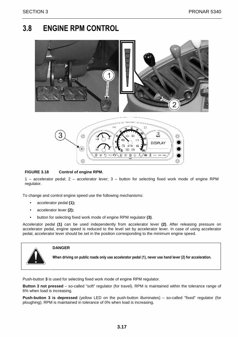
FIGURE 3.18 Control of engine RPM.
1 – accelerator pedal; 2 – accelerator lever; 3 – button for selecting fixed work mode of engine RPM regulator.
To change and control engine speed use the following mechanisms:
• accelerator pedal (1);
• accelerator lever (2);
• button for selecting fixed work mode of engine RPM regulator (3).
Accelerator pedal (1) can be used independently from accelerator lever (2). After releasing pressure on accelerator pedal, engine speed is reduced to the level set by accelerator lever. In case of using accelerator pedal, accelerator lever should be set in the position corresponding to the minimum engine speed.
DANGER
When driving on public roads only use accelerator pedal (1), never use hand lever (2) for acceleration.
Push-button 3 is used for selecting fixed work mode of engine RPM regulator.
Button 3 not pressed – so-called "soft” regulator (for travel). RPM is maintained within the tolerance range of 6% when load is increasing.
Push-button 3 is depressed (yellow LED on the push-button illuminates) – so-called "fixed" regulator (for ploughing); RPM is maintained in tolerance of 0% when load is increasing.
PRONAR 5340 SECTION 3
3.18
3.9 DRIVER'S SEAT
In PRONAR tractors four types of driver's seat may be installed, assuring good working conditions, enabling adjustment and adaptation to the weight of the driver, his dimensions and individual requirements.
The driver's seat installed in PRONAR tractors meet s the requirements of Directive 78/764/EEC concerning vibration level.
Before starting work with tractor, adjust the seat so that the position is the most comfortable for you. All seat adjustment is done while sitting on it.
TIP
Seat adjustment system elements (bolts, nuts, rollers and guides) should be cleaned and greased with a long lasting grease every 1000 mth but no less frequently than once a year.
3.9.1 PRONAR MT50/M60 SEAT
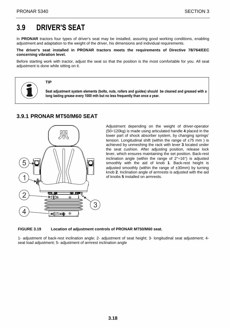
Adjustment depending on the weight of driver-operator (50÷120kg) is made using articulated handle 4 placed in the lower part of shock absorber system, by changing springs' tension. Longitudinal shift (within the range of ±75 mm ) is achieved by unmeshing the rack with lever 3 located under the seat cushion. After adjusting position, release lock lever, which ensures maintaining the set position. Back-rest inclination angle (within the range of 2°÷16°) is adjusted smoothly with the aid of knob 1. Back-rest height is adjusted smoothly (within the range of ±30mm) by turning knob 2. Inclination angle of armrests is adjusted with the aid of knobs 5 installed on armrests.
FIGURE 3.19 Location of adjustment controls of PRON AR MT50/M60 seat.
1- adjustment of back-rest inclination angle; 2- adjustment of seat height; 3- longitudinal seat adjustment; 4- seat load adjustment; 5- adjustment of armrest inclination angle

SECTION 3 PRONAR 5340
3.19
3.9.2 SEAT TOP S-698 (MOL 698) DRIVER'S SEAT
SEAT driver's seat can be adjusted and adapted to operator's weight and dimensions. Shock absorption hardness is set by means of knob 1 depending on operator weight, within the range of 50-120kg.
Lever 2 is used for shifting seat on horizontal plane, within the range of 145 mm. In order to make adjustment, pull lever 2 sideways and then lock the required position by releasing lever.
Knob 3 is used for adjusting seat height within the range of 60 mm.
Using knob 4 one may smoothly adjust back-rest inclination angle within the range up to 15°.
It is possible to adjust the seat head rest height by extending it upwards.
FIGURE 3.20 Location of adjustment controls of SEAT TOP S-698 driver's seat
1- seat load adjustment; 2- longitudinal seat adjustment; 3- seat height adjustment; 4- back-rest inclination angle.
3.9.3 GRAMMER MSG85/721 SEAT
FIGURE 3.21 Location of adjustment controls of GRAM MER MSG85/721 seat
1- seat load adjustment; 2- indicator of set driver weight; 3- push-button for longitudinal adjustment of driver's seat; 4- lever for setting back-rest inclination angle; 5- lumbar support adjustment knob.
Shock absorption hardness is set by means of knob 1 depending on operator weight. Beside the knob, there is indicator 2 of set driver's weight.
PRONAR 5340 SECTION 3
3.20
Lever 3 is used for shifting seat on horizontal plane, within the range of 210 mm, every 10mm. Adjustment is possible after raising lever 3; release lever in order to lock the set position.
Adjustment lever 4 is used for adjusting back-rest inclination angle within the range up to 10º. Adjustment should be done when sitting on the seat. After raising lever 4, set required back-rest inclination angle and lock the set position by releasing lever.
Knob 5 is used for adjusting position and degree of bulge of back-rest. Adjustment is made by turning knob 5 to the right or left to obtain the desired position.
GRAMMER MSG85/721 seat has three height positions; low-1; medium-2; high-3 (FIGURE 3.22)
The position of the sitting operator is set every 30mm. Changing the height involves raising the seat by hand to the point where the catch engages at the desired position. Raising the seat higher than position 3, causes return to position 1.
It is possible to adjust the seat head rest height by extending it upwards.
FIGURE 3.22 Height positions of GRAMMER seat.
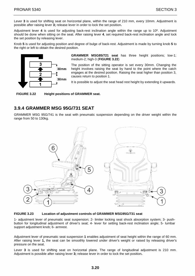
3.9.4 GRAMMER MSG 95G/731 SEAT GRAMMER MSG 95G/741 is the seat with pneumatic suspension depending on the driver weight within the range from 50 to 130kg.
FIGURE 3.23 Location of adjustment controls of GRAM MER MSG95G/731 seat
1- adjustment lever of pneumatic seat suspension; 2- limiter locking seat shock absorption system; 3- push-button for longitudinal adjustment of driver's seat; 4- lever for setting back-rest inclination angle; 5- lumbar support adjustment knob; 6- armrest.
Adjustment lever of pneumatic seat suspension 1 enables adjustment of seat height within the range of 60 mm. After raising lever 1, the seat can be smoothly lowered under driver's weight or raised by releasing driver's pressure on the seat.
Lever 3 is used for shifting seat on horizontal plane. The range of longitudinal adjustment is 210 mm. Adjustment is possible after raising lever 3; release lever in order to lock the set position.

SECTION 3 PRONAR 5340
3.21
Adjustment lever 4 is used for adjusting back-rest inclination angle. The adjustment range of back-rest inclination angle is up to 10°. Adjustment should be done when sitting on the seat. After raising lever 4, set required back-rest inclination angle and lock the set position by releasing lever.
Knob 5 is used for adjusting position and degree of bulge of back-rest. Adjustment is made by turning knob 5 to the right or left to obtain the desired position.
FIGURE 3.24 Pictogram indicating places for securin g safety belt.
IMPORTANT! In the tractor cab there are pictograms placed (Figure 43.24) indicating places for securin g safety belt.
IMPORTANT
The seat is used only for carrying the tractor's driver. The tractor is not designed for carrying passengers.
3.9.5 ADDITIONAL SEAT ON WHEEL COVERING (OPTIONAL E QUIPMENT) Apart from the driver's seat an additional seat (option) is installed on the left side of cab on wheel covering. It is for seating the person training the tractor driver.
FIGURE 3.25 Additional seat.
1– part of seat lowered downwards; 2- part of seat raised upwards; 3- locker
If there is no need to use the additional seat, part 1 (FIGURE 3.25) of the seat should be lowered. After raising part 2 of the seat, one gains access to locker 3.
IMPORTANT
The additional seat is only for carrying the person training the tractor driver. Passengers should not be carried on passenger seat on public r oads.
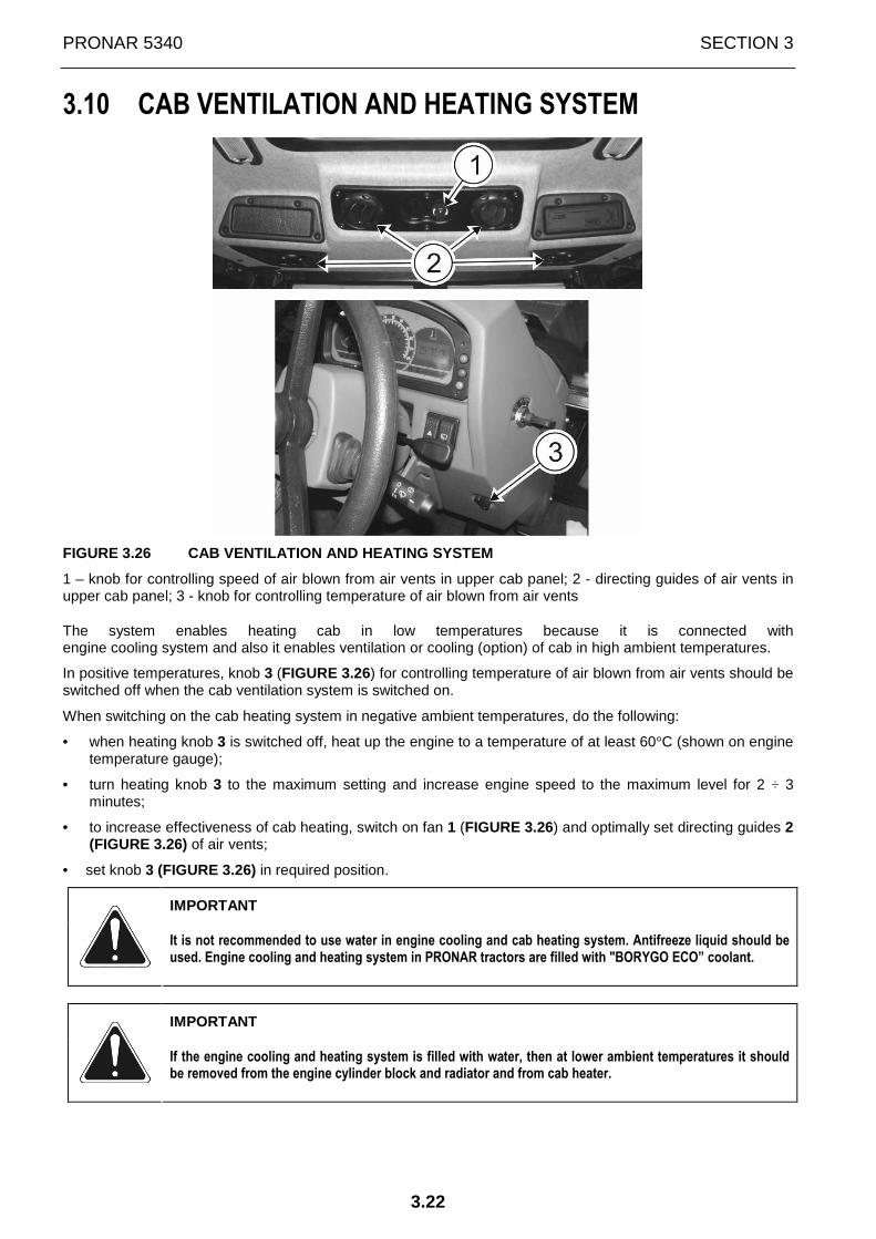
PRONAR 5340 SECTION 3
3.22
3.10 CAB VENTILATION AND HEATING SYSTEM
FIGURE 3.26 CAB VENTILATION AND HEATING SYSTEM
1 – knob for controlling speed of air blown from air vents in upper cab panel; 2 - directing guides of air vents in upper cab panel; 3 - knob for controlling temperature of air blown from air vents
The system enables heating cab in low temperatures because it is connected with engine cooling system and also it enables ventilation or cooling (option) of cab in high ambient temperatures.
In positive temperatures, knob 3 (FIGURE 3.26) for controlling temperature of air blown from air vents should be switched off when the cab ventilation system is switched on.
When switching on the cab heating system in negative ambient temperatures, do the following:
• when heating knob 3 is switched off, heat up the engine to a temperature of at least 60°C (shown on engine temperature gauge);
• turn heating knob 3 to the maximum setting and increase engine speed to the maximum level for 2 ÷ 3 minutes;
• to increase effectiveness of cab heating, switch on fan 1 (FIGURE 3.26) and optimally set directing guides 2 (FIGURE 3.26) of air vents;
• set knob 3 (FIGURE 3.26) in required position.
IMPORTANT
It is not recommended to use water in engine cooling and cab heating system. Antifreeze liquid should be used. Engine cooling and heating system in PRONAR tractors are filled with "BORYGO ECO” coolant.
IMPORTANT
If the engine cooling and heating system is filled with water, then at lower ambient temperatures it should be removed from the engine cylinder block and radiator and from cab heater.
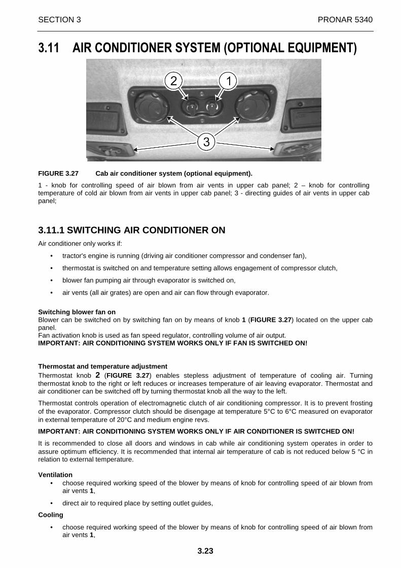
SECTION 3 PRONAR 5340
3.23
3.11 AIR CONDITIONER SYSTEM (OPTIONAL EQUIPMENT)
FIGURE 3.27 Cab air conditioner system (optional eq uipment).
1 - knob for controlling speed of air blown from air vents in upper cab panel; 2 – knob for controlling temperature of cold air blown from air vents in upper cab panel; 3 - directing guides of air vents in upper cab panel;
3.11.1 SWITCHING AIR CONDITIONER ON Air conditioner only works if:
• tractor's engine is running (driving air conditioner compressor and condenser fan),
• thermostat is switched on and temperature setting allows engagement of compressor clutch,
• blower fan pumping air through evaporator is switched on,
• air vents (all air grates) are open and air can flow through evaporator.
Switching blower fan on Blower can be switched on by switching fan on by means of knob 1 (FIGURE 3.27) located on the upper cab panel. Fan activation knob is used as fan speed regulator, controlling volume of air output. IMPORTANT: AIR CONDITIONING SYSTEM WORKS ONLY IF FA N IS SWITCHED ON! Thermostat and temperature adjustment Thermostat knob 2 (FIGURE 3.27) enables stepless adjustment of temperature of cooling air. Turning thermostat knob to the right or left reduces or increases temperature of air leaving evaporator. Thermostat and air conditioner can be switched off by turning thermostat knob all the way to the left.
Thermostat controls operation of electromagnetic clutch of air conditioning compressor. It is to prevent frosting of the evaporator. Compressor clutch should be disengage at temperature 5°C to 6°C measured on evaporator in external temperature of 20°C and medium engine revs.
IMPORTANT: AIR CONDITIONING SYSTEM WORKS ONLY IF AI R CONDITIONER IS SWITCHED ON!
It is recommended to close all doors and windows in cab while air conditioning system operates in order to assure optimum efficiency. It is recommended that internal air temperature of cab is not reduced below 5 °C in relation to external temperature. Ventilation
• choose required working speed of the blower by means of knob for controlling speed of air blown from air vents 1,
• direct air to required place by setting outlet guides,
Cooling
• choose required working speed of the blower by means of knob for controlling speed of air blown from air vents 1,
PRONAR 5340 SECTION 3
3.24
• set required temperature by means of knob for controlling temperature of air blown from air vents 2,
Remember that an inflow of fresh but not cooled air raises the air temperature inside the vehicle.
IMPORTANT
In the event of high air humidity one should avoid simultaneously setting minimum temperature and RPM of fan blower. This may cause frosting of evaporator, which results in reduction of air output.
In this case, switch air conditioning system off for 2-3 minutes and set the maximum fan output.
3.11.2 MAINTENANCE OF AIR CONDITIONER Regularly clean condenser (blow it through with compressed air) with frequency depending on operating conditions.
At each vehicle service check:
- silent running of electromagnetic compressor clutch,
- tension and condition of vee-belt driving compressor,
- the level of refrigerant (cooling effectiveness).
In autumn and winter season air-conditioner should be regularly operated for about 10 minutes (once a month or more often). This is intended to prevent drying of seals of compressor shaft. It also prevents the development of bacteria and fungus on the external surfaces of evaporator sides.
Before summer season, check operation of air conditioner's individual components and tightness of the system.
IMPORTANT: Air-conditioner components include filter-dryer, whose main function is absorbing moisture in the system. Moisture in combination with R134a refrigerant creates an aggressive chemical compound causing corrosion of metal elements of the air-conditioning system. Filter-dryer MUST be changed at least every two years, most preferably, annually. Before changing the filter, remove the refrigerant from the system, and after filter changing, refill the system. Neglecting to change the filter leads to lasting damage to some components of the air-conditioning system, which may require very expensive repairs.
3.11.3 MALFUNCTIONS IN AIR CONDITIONER OPERATION Defect of electrical system.
Check carefully complete electrical system of air conditioner using electrical diagram. Pay special attention to connectors, switches and relays.
Damage to the refrigerant circuit
In the event of damage (leaks, unreliability of valves etc.) refer to an authorised service for assistance. Do not release refrigerant into the atmosphere!
IMPORTANT
The closed-circuit air-conditioning system is filled with R134a refrigerant under pressure.
The user must not release refrigerant from the system.
In the event of damage (leaks, unreliability of valves etc.) refer to an authorised service for assistance.
Do not release refrigerant into the atmosphere!

SECTION 3 PRONAR 5340
3.25
3.12 STEERING SYSTEM
PRONAR tractors are equipped with hydrostatic steering system with a dispensing pump making it possible to drive the tractor with the engine switched off. The system is equipped with a hydraulic pump (permanently engaged) driven by the tractor engine. It is possible to change the inclination angle and the height of the steering wheel to ensure the most comfortable position for the driver.
FIGURE 3.28 Lever for adjusting steering wheel (col umn) inclination and height.
1- steering column adjustment lever.
Lever 1 (FIGURE 3.28) is used or adjusting angular and axial position of steering wheel. Move the lever down and hold it, set the steering wheel at a required inclination. Move the lever up to adjust steering wheel height along its axis. Set the lever in the middle position to lock all previous adjustments.
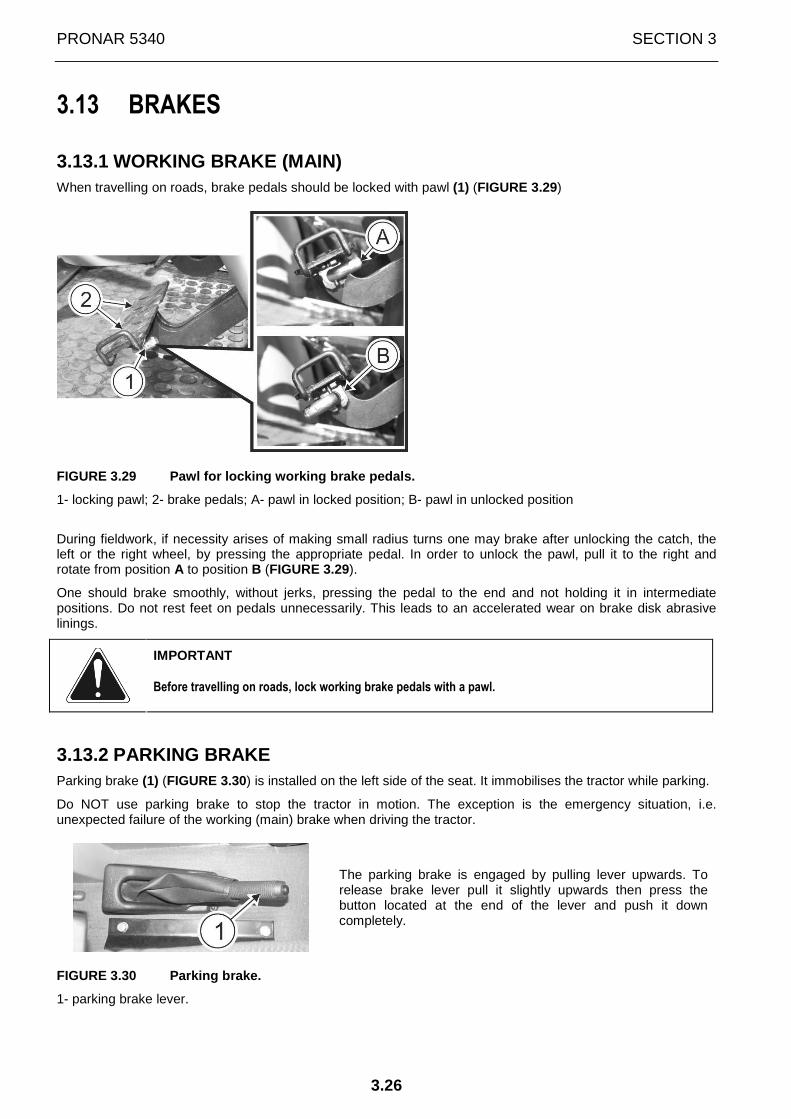
PRONAR 5340 SECTION 3
3.26
3.13 BRAKES
3.13.1 WORKING BRAKE (MAIN) When travelling on roads, brake pedals should be locked with pawl (1) (FIGURE 3.29)
FIGURE 3.29 Pawl for locking working brake pedals.
1- locking pawl; 2- brake pedals; A- pawl in locked position; B- pawl in unlocked position
During fieldwork, if necessity arises of making small radius turns one may brake after unlocking the catch, the left or the right wheel, by pressing the appropriate pedal. In order to unlock the pawl, pull it to the right and rotate from position A to position B (FIGURE 3.29).
One should brake smoothly, without jerks, pressing the pedal to the end and not holding it in intermediate positions. Do not rest feet on pedals unnecessarily. This leads to an accelerated wear on brake disk abrasive linings.
IMPORTANT
Before travelling on roads, lock working brake pedals with a pawl.
3.13.2 PARKING BRAKE Parking brake (1) (FIGURE 3.30) is installed on the left side of the seat. It immobilises the tractor while parking.
Do NOT use parking brake to stop the tractor in motion. The exception is the emergency situation, i.e. unexpected failure of the working (main) brake when driving the tractor.
The parking brake is engaged by pulling lever upwards. To release brake lever pull it slightly upwards then press the button located at the end of the lever and push it down completely.
FIGURE 3.30 Parking brake.
1- parking brake lever.
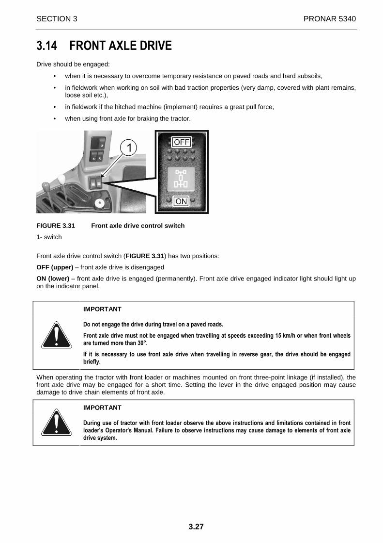
SECTION 3 PRONAR 5340
3.27
3.14 FRONT AXLE DRIVE
Drive should be engaged:
• when it is necessary to overcome temporary resistance on paved roads and hard subsoils,
• in fieldwork when working on soil with bad traction properties (very damp, covered with plant remains, loose soil etc.),
• in fieldwork if the hitched machine (implement) requires a great pull force,
• when using front axle for braking the tractor.
FIGURE 3.31 Front axle drive control switch
1- switch
Front axle drive control switch (FIGURE 3.31) has two positions:
OFF (upper) – front axle drive is disengaged
ON (lower) – front axle drive is engaged (permanently). Front axle drive engaged indicator light should light up on the indicator panel.
IMPORTANT
Do not engage the drive during travel on a paved roads.
Front axle drive must not be engaged when travelling at speeds exceeding 15 km/h or when front wheels are turned more than 30°.
If it is necessary to use front axle drive when travelling in reverse gear, the drive should be engaged briefly.
When operating the tractor with front loader or machines mounted on front three-point linkage (if installed), the front axle drive may be engaged for a short time. Setting the lever in the drive engaged position may cause damage to drive chain elements of front axle.
IMPORTANT
During use of tractor with front loader observe the above instructions and limitations contained in front loader's Operator's Manual. Failure to observe instructions may cause damage to elements of front axle drive system.

PRONAR 5340 SECTION 3
3.28
3.15 DIFFERENTIAL LOCK
DANGER
Do not engage differential lock at speeds above 10 km/h and when turning - it may hinder driving the tractor.
IMPORTANT! Differential lock should be engaged for a short time.
FIGURE 3.32 Controlling rear axle differential lock
1- switch of rear axle differential lock
Switch of rear axle differential lock (FIGURE 3.32) has two positions:
OFF (upper) – rear axle differential lock is disengaged - tractor can perform transport tasks on paved roads and in field conditions on ground (soil) ensuring good traction.
ON (lower) – rear axle differential lock is engaged (permanently) - to be used during fieldwork and transport wh-en driving wheels slip and the tractor is at risk of being bogged down. Rear axle differential lock engaged indicator light should light up on the indicator panel. Differential lock can engaged only at speeds below 20 km/h. Above this speed, differential lock can not be engaged.
IMPORTANT
Differential lock may be engaged during fieldwork and transport when wheel slip is increased.
Engaging differential lock during transport works on paved surface and when turning the front wheels
more than 18 degrees° is FORBIDDEN
IMPORTANT
Failure to observe the above principles reduces the period of faultless operation of the drive system and hinders driving the tractor. Differential lock should be engaged for a short time in order to overcome road obstacles.

SECTION 3 PRONAR 5340
3.29
3.16 REAR PTO AND FRONT PTO (OPTION)
Rear PTO of PRONAR tractors can drive cooperating machines with rotation speeds INDEPENDENT from tractor travelling speed – 540/1000 or 430/750 RPM;
Front PTO (option) of PRONAR tractors can drive cooperating machines with rotation speeds INDEPENDENT from tractor travelling speed – 1000 RPM;
INDEPENDENT PTO DRIVE is the drive in which the rotation speed of PTO end is proportional to engine speed, regardless of tractor travelling speed. The rotation speed of independent PTO end is independent from a selected gear.
Rear PTO end and front PTO end (option) rotate to the right (clockwise) (looking at the PTO shaft front).
IMPORTANT
Before connecting a machine driven by PTO one must check that rotation speed of the tractor's PTO shaft end corresponds to the required speed of the machine shaft.
3.16.1 SELECTION OF REAR PTO ROTATION SPEED
IMPORTANT
Selection of PTO rotation speed must be made with disengaged PTO drive.
FIGURE 3.33 Levers for engaging proper PTO rotation speed: 430, 540, 750 or 1000 rpm.
1- lever for selecting PTO rotation speed range: 430/750 or 540/1000; 2- lever for selecting a PTO rotation speed from a selected range.
In order to select appropriate PTO rotation speed 430, 540, 750 or 1000 rpm do the following:
• using lever 1 (Figure 3.33) , engage appropriate PTO rotation speed range 540/1000 rpm (grey zone on pictogram next to the lever) or 430/750 rpm (green zone on pictogram next to the lever)
• using lever 2 (Figure 3.33) select the required PTO rotation speed from selected PTO rotation speed range
IMPORTANT: Central setting of lever 2 (Figure 3.33) is the neutral position. If the switch is left in this position, PTO drive is disengaged. Do not use PTO speed selection lever 2 (FIGURE 3.33 ) for engaging or disengaging PTO drive.

PRONAR 5340 SECTION 3
3.30
Selected PTO rotation speed is achieved when proper engine speed is set. Actual PTO rotation speed depending on engine speed is shown on LCD display (FIGURE 3.14).
FIGURE 3.34 Dimensions of PTO shaft in PRONAR tract ors – type I acc. to PN-ISO 500
3.16.2 ENGAGING REAR PTO
IMPORTANT
To eliminate dynamic load of PTO drive transmission system reduce engine speed to 900 rpm before engaging PTO shaft drive. After engaging PTO drive, increase RPM to required level. Before disengaging PTO drive also reduce engine RPM. It is particularly important when working with machines with a great moment of inertia. Such machines should be equipped with a one-way clutch.
Failure to comply with the above instructions may lead to accelerated wear of PTO drive transmission system components and, as a consequence, increase the frequency of necessary adjustments or part replacements.
In PRONAR tractors, rear PTO drive is engaged with switch 1 (FIGURE 3.35) located on the console on the right side of the seat or outside the tractor with the push-button located on the rear right mudguard (FIGURE 3.36).
FIGURE 3.35 PTO switch inside the tractor cab (on t he console on the right side of the seat).
1- rear PTO switch;
IMPORTANT
The operation of engaging and disengaging PTO is co nducted only with the engine running.
In order to engage rear PTO first press the black button in the middle of the yellow mushroom part of switch 1 (FIGURE 3.35), and next, pull the yellow part of the switch upwards (as shown on pictogram) and lock it in upper position. Rear PTO engaged indicator light will light up on the indicator panel.
In order to disengage rear PTO depress the yellow mushroom part of switch 1. Rear PTO engaged indicator light on the indicator panel should go out.

SECTION 3 PRONAR 5340
3.31
IMPORTANT
Before raising a machine (implement) mounted on thr ee-point linkage and driven by the tractor's PTO, or when making turns, necessarily di sengage the PTO drive.
IMPORTANT
At shutting down the engine, PTO disengages automat ically.
FIGURE 3.36 PTO controls on the tractor's rear righ t mudguard
1- rear PTO engaging switch; 2- rear PTO disengaging switch
In addition to rear PTO switch inside the cab, the tractor is equipped with external rear PTO engaging switch and rear PTO disengaging switch located on the rear right mudguard (FIGURE 3.36).
IMPORTANT: Operator may only use external PTO switc h standing to the side of the tractor. To avoid damaging machine or tractor do not use simultaneous ly control systems in the cab and outside the tractor.
Rear PTO engaging switch 1 (FIGURE 3.36) (yellow) located externally on the right mudguard is used only for momentary engagement of PTO (e.g. when hitching a machine).
Rear PTO disengaging switch 2 (FIGURE 3.36) (red) located externally on the right mudguard is used for emergency PTO disengagement.
In order to start rear PTO using push-button on the mudguard, first press the yellow mushroom part of PTO switch 1 (FIGURE 3.35) located in the cab (only press the yellow mushroom part, do not pull it up). Next, press and hold yellow push-button 1 on the mudguard (FIGURE 3.36). PTO shaft will rotate as long as operator holds the button. Rear PTO engaged indicator light will light up on the indicator panel.
In order to disengage rear PTO in emergency situation, press red push-button 2 (FIGURE 3.36) of rear PTO disengaging switch on the mudguard. Rear PTO engaged indicator light on the indicator panel should go out.
DANGER
Before using the external PTO switch, make certain that there is nobody and nothing near the machine or PTO shaft.
Never engage PTO standing:
- directly behind the tractor or wheel
- between lower links
- on machine or beside it.
When engaging PTO, never put hand or leg or any other part of the body close to three-point linkage, PTO or machine.

PRONAR 5340 SECTION 3
3.32
3.16.3 ATTACHING EQUIPMENT DRIVEN BY PTO
DANGER
Before attaching or detaching machines driven by the PTO one must:
- engage parking brake fully
- make sure that all gear change levers are in neutral position
- turn off engine before leaving tractor cab
After leaving cab, the operator should attach machine to tractor's three-point linkage in the manner described in SECTION 4 "PROPER USE".
Next, remove the plastic cap from the PTO shaft end (1) (FIGURE 3.37) and attach the machine's PTO shaft to tractor's PTO shaft end. With tractor engine turned off one may turn tractor shaft by hand in order to engage splines on tractor shaft with machine shaft.
After sliding the machine's PTO shaft end onto the tractor PTO shaft end, ensure that the drive shaft locking pin is located in the groove of the PTO end. Secure PTO shaft cover against turning using a small chain.
After attaching mounted machine, raise and lower machine, in order to check clearances and the sliding range of the PTO shaft. If the machine is hitched to an agricultural hitch, check that the hitch is properly set.
If PTO shaft end is not used, cover it with plastic protective cap (1).
FIGURE 3.37 PTO shaft end.
1- protective cap on shaft end
DANGER
While driving machine with PTO, ensure that PTO shaft shield is installed.
PTO shafts without complete original guards must not be used for driving machines.
While using equipment powered by PTO do not wear loose clothing.
Do not clean, adjust or approach equipment driven by PTO while engine is running.
IMPORTANT
Before connecting a machine driven by PTO one must check that rotation speed of the tractor's PTO shaft end corresponds to the required speed of the machine shaft.
When connecting PTO shaft to tractor and agricultural machine, strictly follow the instructions given in the operator's manual of PTO which is sold separately or is included in the machine's equipment.
SECTION 3 PRONAR 5340
3.33
IMPORTANT
Before starting operation of the tractor with PTO driven machines, read the following safety instructions and always adhere to them.
• before connection, adjustment or starting works concerning PTO driven implements, disengage PTO drive and turn the engine off;
• do not drive machines with semi-covered guards of PTO shafts if covering guard is not installed in the tractor;
• after installing PTO shaft, attach a chain to the covering guard for the time of PTO shaft operation;
• after completed work with PTO shaft, put protective cap on PTO shaft end.
DANGER
To avoid accidental starting of machines driven by tractor's PTO, disengage PTO drive at each interval in machine work. Disengage PTO drive at each turn during fieldwork and before raising three-point linkage mounted machine.

PRONAR 5340 SECTION 3
3.34

SECTION
4
CORRECT
USE

PRONAR 5340 SECTION 4
4.2
4.1 PREPARE FOR WORK
The manufacturer guarantees that the tractor is fully operational and has been checked according to quality control procedures and is ready for use. This does not release the user from an obligation to check the tractor's condition after delivery and before first use. The tractor is delivered to the user completely assembled.
DANGER
Before using the tractor, the user must carefully r ead this Operator's Manual.
Careless and improper use and operation of the trac tor and non-compliance with the recommendations given in this operator's manual is dangerous to your health.
The tractor must never be used by persons who are n ot authorised to drive agricultural tractors, including children and people under the i nfluence of alcohol or other drugs.
Non-compliance with the safety rules of this Operat or’s Manual can be dangerous to the health and life of the operator and others.
Before starting the tractor, make sure that there a re no bystanders in the danger zone.
DANGER
Before moving off or beginning work with tractor, c arefully read the information about the precautions contained in Section 2: "SAFETY ADV ICE” of this Operator's Manual.
IMPORTANT
Before starting work with tractor, check its techni cal condition (operation of engine, steering system, braking system and other tractor s ystems and assemblies) and completeness of protective shields.
The engine should run evenly in the whole revolution speed range. Control elements, steering system, brakes, lighting and signalling systems and wipers should be efficient and in good technical condition.
If any faults are detected they must be identified and rectified. If a fault cannot be rectified or the repair could void the warranty, please contact retailer for additional clarifications.
ATTENTION
Do NOT use unreliable tractor.
Before starting a new tractor or one, which has been idle for a long time, check oil level in engine and remaining tractor subassemblies, fluid in brake and cooling systems.
IMPORTANT
Engine MUST NOT be started without coolant liquid i n cooling system
DANGER
Before starting engine ensure that all protective g uards are in place and appropriately secured.

SECTION 4 PRONAR 5340
4.3
DANGER
The tractor's engine may be started only by the ope rator sitting in the driver's seat, after confirming that parking brake is engaged.
IMPORTANT
Tractor (engine) must not be started by towing.
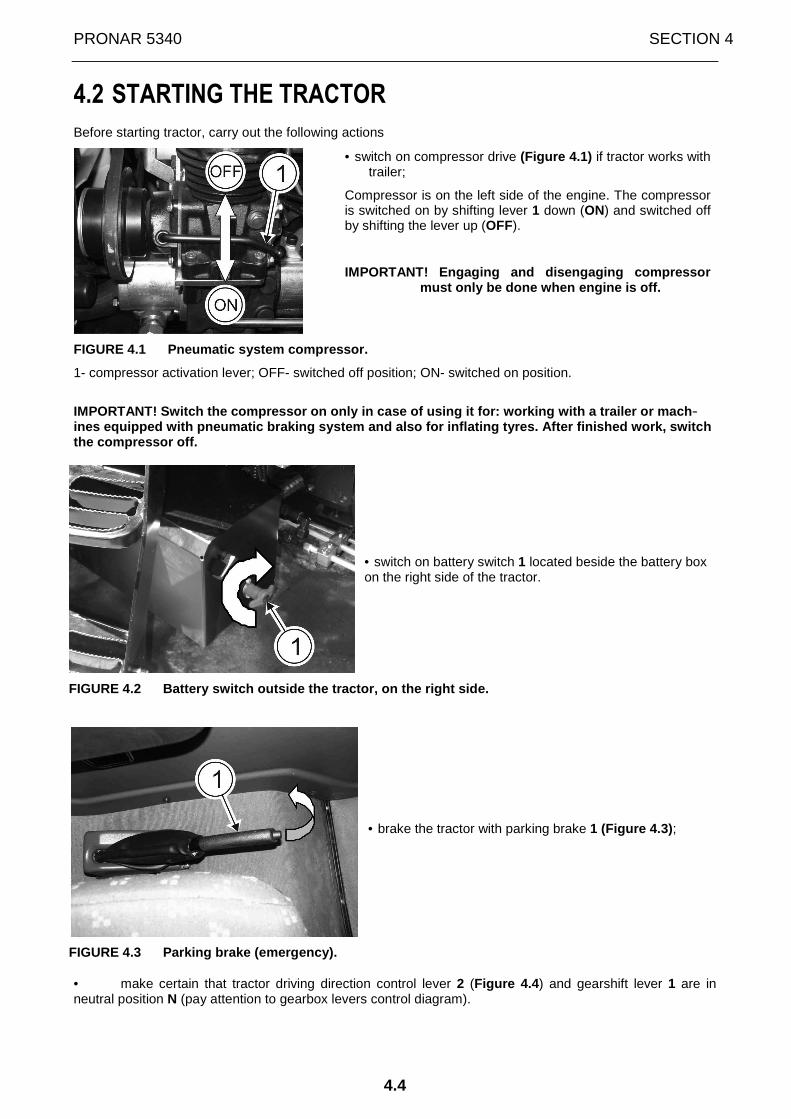
PRONAR 5340 SECTION 4
4.4
4.2 STARTING THE TRACTOR
Before starting tractor, carry out the following actions
• switch on compressor drive (Figure 4.1) if tractor works with trailer;
Compressor is on the left side of the engine. The compressor is switched on by shifting lever 1 down (ON) and switched off by shifting the lever up (OFF).
IMPORTANT! Engaging and disengaging compressor must only be done when engine is off.
FIGURE 4.1 Pneumatic system compressor.
1- compressor activation lever; OFF- switched off position; ON- switched on position.
IMPORTANT! Switch the compressor on only in case of using it for: working with a trailer or mach -ines equipped with pneumatic braking system and als o for inflating tyres. After finished work, switch the compressor off.
• switch on battery switch 1 located beside the battery box on the right side of the tractor.
FIGURE 4.2 Battery switch outside the tractor, on t he right side.
• brake the tractor with parking brake 1 (Figure 4.3) ;
FIGURE 4.3 Parking brake (emergency).
• make certain that tractor driving direction control lever 2 (Figure 4.4 ) and gearshift lever 1 are in neutral position N (pay attention to gearbox levers control diagram).
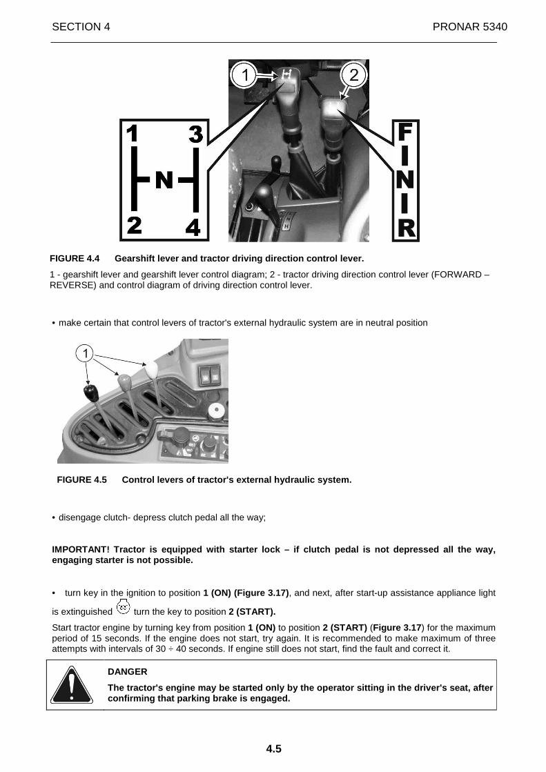
SECTION 4 PRONAR 5340
4.5
FIGURE 4.4 Gearshift lever and tractor driving dire ction control lever.
1 - gearshift lever and gearshift lever control diagram; 2 - tractor driving direction control lever (FORWARD – REVERSE) and control diagram of driving direction control lever.
• make certain that control levers of tractor's external hydraulic system are in neutral position
FIGURE 4.5 Control levers of tractor's external hyd raulic system.
• disengage clutch- depress clutch pedal all the way;
IMPORTANT! Tractor is equipped with starter lock – if clutch pedal is not depressed all the way, engaging starter is not possible.
• turn key in the ignition to position 1 (ON) (Figure 3.17) , and next, after start-up assistance appliance light
is extinguished turn the key to position 2 (START).
Start tractor engine by turning key from position 1 (ON) to position 2 (START) (Figure 3.17 ) for the maximum period of 15 seconds. If the engine does not start, try again. It is recommended to make maximum of three attempts with intervals of 30 ÷ 40 seconds. If engine still does not start, find the fault and correct it.
DANGER
The tractor's engine may be started only by the ope rator sitting in the driver's seat, after confirming that parking brake is engaged.

PRONAR 5340 SECTION 4
4.6
IMPORTANT
Tractor (engine) must not be started by towing.
• after starting, release pressure on clutch pedal
• check if indications of control indicators are correct (oil temperature, coolant temperature, engine oil pressure, etc.).
IMPORTANT: After starting a turbocharged engine, se t slow engine RPM and work for about 3 minutes without loading the engine.
IMPORTANT!
The user MUST NOT:
• disconnect the battery switch while engine is runni ng; • operate tractor without battery.
DANGER
Do not operate the tractor in a closed building. Co mbustion gases can be lethal when inhaled by persons in the building.
HIGH NOISE LEVEL WARNING
Depending on the working conditions, the tractor wi th the machine may generate noise exceeding the level of 85dB at the driver position. In such conditions the driver should apply individual protection (protective ear guards) .
In order to reduce the level of noise during work t he tractor cab window and door should be closed.

SECTION 4 PRONAR 5340
4.7
4.3 MOVING OFF
IMPORTANT
Before starting work with tractor check the operati on of engine, steering system, brakes and remaining tractor systems and assemblies.
The engine should run evenly in the whole revolution speed range.
Control elements, steering system, brakes, lighting and signalling systems, screen wipers should be checked and be in good technical condition.
When moving off, proceed as follows:
• depress clutch pedal 1 all the way (Figure 4.6 );
• release previously engaged handbrake;
FIGURE 4.6 Clutch pedal.
• set reducer lever 1 (Figure 4.7 ) as required to position:
SNAIL – slow gears;
HARE - fast gears.
FIGURE 4.7 Reducer lever "SNAIL - HARE".
IMPORTANT: Changing gear groups "SNAIL - HARE" shou ld take place only when tractor is completely stationary.
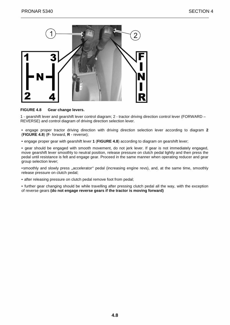
PRONAR 5340 SECTION 4
4.8
FIGURE 4.8 Gear change levers.
1 - gearshift lever and gearshift lever control diagram; 2 - tractor driving direction control lever (FORWARD – REVERSE) and control diagram of driving direction selection lever.
• engage proper tractor driving direction with driving direction selection lever according to diagram 2 (FIGURE 4.8) (F- forward, R - reverse);
• engage proper gear with gearshift lever 1 (FIGURE 4.8) according to diagram on gearshift lever;
• gear should be engaged with smooth movement, do not jerk lever. If gear is not immediately engaged, move gearshift lever smoothly to neutral position, release pressure on clutch pedal lightly and then press the pedal until resistance is felt and engage gear. Proceed in the same manner when operating reducer and gear group selection lever;
•smoothly and slowly press „accelerator” pedal (increasing engine revs), and, at the same time, smoothly release pressure on clutch pedal;
• after releasing pressure on clutch pedal remove foot from pedal;
• further gear changing should be while travelling after pressing clutch pedal all the way, with the exception of reverse gears (do not engage reverse gears if the tractor is mov ing forward)

SECTION 4 PRONAR 5340
4.9
"Powershift" torque amplifier
Gearbox with "Powershift” torque amplifier enables one step reduction of all gears, through which pull force is increased. Change of gear takes place with the aid of switch located in gearshift lever (Figure 4.9 ) without the use of clutch pedal, also during work of tractor under load. Working mode is signalled by the"tortoise” or "hare” lamp on dashboard.
When push-button 1 (FIGURE 4.9) is set in "HARE" position (the indicator light of "HARE " position of "Powershift" torque amplifier should light up on the dashboard), the tractor's travelling speed is increased and torque is simultaneously decreased.
When push-button 1 (FIGURE 4.9) is set in "TORTOISE" position (the indicator light of "TORTOISE" position of "Powershift" torque amplifier should light up on the dashboard), the tractor's travelling speed is decreased and torque is simultaneously increased.
FIGURE 4.9 "Powershift" torque amplifier switch.
1- switch button

PRONAR 5340 SECTION 4
4.10
4.4 STOPPING ENGINE AND TRACTOR
In order to stop the tractor:
• reduce engine RPM;
• press on clutch pedal until resistance is felt;
• move gearshift lever to neutral position (N);
• depress working brake pedal (main pedal);
• after stopping tractor, engage parking brake with hand lever.
IMPORTANT
In the event of emergency braking, simultaneously p ress brake and clutch pedals.
Do not stop engine at high temperatures of lubricating oil and coolant. It is recommended to leave engine running at lower revolution speeds until oil and coolant temperature drops. In order to stop the engine, shift the accelerator lever (Figure 4.5 ) to "minimum”position and turn the ignition key from position 1 (ON) to position 0 (OFF) (Figure 3.17 ) and, if work is completed, disconnect battery with battery switch (Figure 4.2 ). Indicator lamps on the dashboard should be extinguished.
IMPORTANT
After completed work with full load, let PRONAR 534 0 tractor's engine cool down.
Before stopping the engine, first reduce engine rev olution speed to 800-1000 rpm and let the engine run idle, without load, for about 5 minutes.

SECTION 4 PRONAR 5340
4.11
4.5 REAR THREE-POINT LINKAGE
4.5.1 DESIGN
PRONAR tractors are equipped with rear three-point linkage whose attachment dimensions correspond to category 2 of linkage according to ISO–730. Rear three-point linkage makes it possible to hitch mounted and semi-mounted implements to the tractor. The implements are operated and controlled by means of hydraulic system.
The lower links are raised and lowered by means of hanging rods connected to the lift arms. They are equipped with open end jaws, enabling quick coupling and uncoupling of implements. The hanging rods are easily adjusted, to facilitate correct setting of implements in relation to tractor.
The top link is attached to the bracket on the central housing of the rear axle. Rear part of top link shall be attached to upper hitching pin of the attached implement. Top link is also adjustable, to facilitate setting implements.
FIGURE 4.10 Three-point linkage – design.
1 – lower links; 2 – telescopic stabilisers; 3 – hanging rods; 4 – top link;
4.5.2 HITCHING MACHINES (IMPLEMENTS) Suspended machines (implements) are attached (hitched) to the tractor at three points: by two ball joints of lower links and above, by top link.
To attach the equipment, adjust hanging rods and ensure that external stabilisers are mounted and correctly adjusted. Dismantle the agricultural hitch if it is an obstruction.
DANGER:
Before hitching a machine or implement, read the ma chine or implement's operator's manual and follow all instructions contained in it. Do NOT use a hitched machine without prior reading its operator's manual.
Before proceeding to hitch a machine or implement, engage tractor's parking brake.
The majority of implements may be hitched to the tractor in the following manner:
• Set the tractor so that the hitching points of the lower links are levelled and slightly in front in relation to the pins of the implement to be hitched.
• Slide ball coupling sleeves onto pins enabling attachment of implement to lower links of tractor.
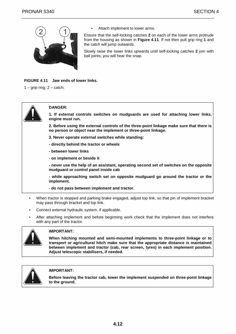
PRONAR 5340 SECTION 4
4.12
• Attach implement to lower arms.
Ensure that the self-locking catches 2 on each of the lower arms protrude from the housing as shown in Figure 4.11 . If not then pull grip ring 1 and the catch will jump outwards.
Slowly raise the lower links upwards until self-locking catches 2 join with ball joints; you will hear the snap.
FIGURE 4.11 Jaw ends of lower links.
1 – grip ring; 2 – catch;
DANGER:
1. If external controls switches on mudguards are u sed for attaching lower links, engine must run.
2. Before using the external controls of the three- point linkage make sure that there is no person or object near the implement or three-poi nt linkage.
3. Never operate external switches while standing:
- directly behind the tractor or wheels
- between lower links
- on implement or beside it
- never use the help of an assistant, operating sec ond set of switches on the opposite mudguard or control panel inside cab
- while approaching switch set on opposite mudguard go around the tractor or the implement.
- do not pass between implement and tractor.
• When tractor is stopped and parking brake engaged, adjust top link, so that pin of implement bracket may pass through bracket and top link.
• Connect external hydraulic system, if applicable.
• After attaching implement and before beginning work check that the implement does not interfere with any part of the tractor.
IMPORTANT:
When hitching mounted and semi-mounted implements t o three-point linkage or to transport or agricultural hitch make sure that the appropriate distance is maintained between implement and tractor (cab, rear screen, ty res) in each implement position. Adjust telescopic stabilisers, if needed.
IMPORTANT:
Before leaving the tractor cab, lower the implement suspended on three-point linkage to the ground.
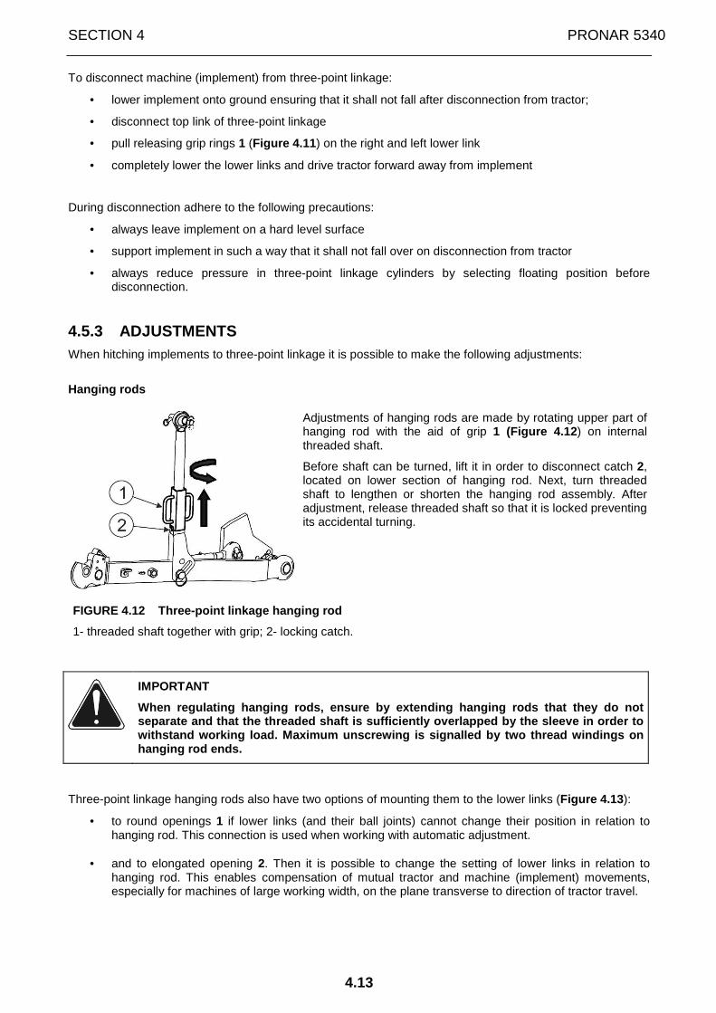
SECTION 4 PRONAR 5340
4.13
To disconnect machine (implement) from three-point linkage:
• lower implement onto ground ensuring that it shall not fall after disconnection from tractor;
• disconnect top link of three-point linkage
• pull releasing grip rings 1 (Figure 4.11 ) on the right and left lower link
• completely lower the lower links and drive tractor forward away from implement
During disconnection adhere to the following precautions:
• always leave implement on a hard level surface
• support implement in such a way that it shall not fall over on disconnection from tractor
• always reduce pressure in three-point linkage cylinders by selecting floating position before disconnection.
4.5.3 ADJUSTMENTS When hitching implements to three-point linkage it is possible to make the following adjustments:
Hanging rods
Adjustments of hanging rods are made by rotating upper part of hanging rod with the aid of grip 1 (Figure 4.12 ) on internal threaded shaft.
Before shaft can be turned, lift it in order to disconnect catch 2, located on lower section of hanging rod. Next, turn threaded shaft to lengthen or shorten the hanging rod assembly. After adjustment, release threaded shaft so that it is locked preventing its accidental turning.
FIGURE 4.12 Three-point linkage hanging rod
1- threaded shaft together with grip; 2- locking catch.
IMPORTANT
When regulating hanging rods, ensure by extending h anging rods that they do not separate and that the threaded shaft is sufficientl y overlapped by the sleeve in order to withstand working load. Maximum unscrewing is signa lled by two thread windings on hanging rod ends.
Three-point linkage hanging rods also have two options of mounting them to the lower links (Figure 4.13 ):
• to round openings 1 if lower links (and their ball joints) cannot change their position in relation to hanging rod. This connection is used when working with automatic adjustment.
• and to elongated opening 2. Then it is possible to change the setting of lower links in relation to
hanging rod. This enables compensation of mutual tractor and machine (implement) movements, especially for machines of large working width, on the plane transverse to direction of tractor travel.

PRONAR 5340 SECTION 4
4.14
FIGURE 4.13 Method of attaching hanging rods to low er links.
1 -three-point linkage hanging rod installed in round opening; 2- three-point linkage hanging rod installed in elongated opening.
IMPORTANT
After change of place of securing hanging rods, pin s of lower links securing hanging rods should be secured with original securing cotte r pins.
Top link
The design of the top link (internally threaded sleeve engaging threaded shafts) enables its shortening or extension (by rotation of central part 1 (Figure 4.14) , as required. After adjusting top link, prevent autonomous change of length by tightening counter nut 2.
FIGURE 4.14 Adjustment of top link of three-point l inkage
IMPORTANT
When regulating top link, ensure that the ends are extended in equal lengths and locked by locking nut 2.
Also ensure that extension of the top link does not cause its separation into several parts and that the threaded shafts shall be suffici ently screwed into the threaded central sleeve in order to bear working load. Maxim um unscrewing is signalled by two thread windings on link ends.
If the top link is not used, it may be dismounted or left in a vertical position secured in holder.
Telescopic stabilisers
Telescopic stabilisers adjust swinging of the lower links and attached equipment during work and transport. It is of major significance during work on slopes and along fencing or ditches and in the use of some implements.
Each telescopic stabiliser is composed of a sleeve 1 (Figure 4.15 ) with articulated joints at each end 2 and 4. The ball ending joint 2 is screwed into the end of the sleeve, enabling adjustment and is attached to the securing bracket 3, bolted to the rear axle housing. Fork end 4 is attached to lower link 5 of the three-point linkage. This end is free and may slide inside the sleeve. The assembly may be locked by inserting retaining cotter pin 6 through C opening in the sleeve and pin.

SECTION 4 PRONAR 5340
4.15
FIGURE 4.15 Telescopic stabilisers of lower links o f three-point linkage.
1- sleeve; 2- ball ending; 3- securing bracket; 4- fork end; 5- lower link; 6- retaining cotter pin; A- round opening; B- elongated opening; C- round opening.
In practice, retaining cotter pin 6 should be taken out from both stabilisers and the implement should be attached to the three-point linkage. In order to take out retaining cotter pin, pull the snap fastening backwards. When the implement is appropriately set, rotate sleeve until openings in sleeve corresponds with openings of free fork end. Insert retaining cotter pin through C opening and secure with snap fastening.
With such a setting the stabilisers are locked as a rigid assembly and the implement is secured against swinging equally during work as in transport.
In certain conditions or during work with such implements as ploughs etc., allowing sideways movement of three-point linkage and implements may be recommended.
If retaining cotter pins 6 are taken out and inserted into elongated opening B located in the middle of the sleeve 1, movements will be possible sideways to a limited angle or to opening A (pin will act as a bumper, limiting angle of swing).
IMPORTANT: When setting the length of the stabilise rs, especially in positions allowing swaying, ensure that there is no possibility of contact betw een tyres and stabilisers or lower arms.
For example if tractor is working with plough, make the following three-point linkage adjustment:
• during ploughing, the tractor's right wheels (normally) are located in the furrow; level the plough frame (by shortening or extending the right hanging rod), because in relation to the field surface, the tractor is tilted to the right side;
• in order to ensure that the depth of work of the first and the last plough body is the same, it is necessary (after levelling) to change the length of the top link using turning lever 1 (Figure 4.14 ) after unscrewing locking nut 2. After the adjustment, tighten locking nut.
During travel of tractor with suspended machine (implement), one may shorten top link to ensure greater clearance (under the machine).
DANGER:
Before moving off, make sure that any persons assis ting in maintenance or hitching the machines are not in danger, especially that the y are not between the tractor and hitched machine (implement). Warn them of intention to move, using the horn.

PRONAR 5340 SECTION 4
4.16
4.6 UPPER TRANSPORT HITCH
IMPORTANT
Each time before driving the tractor with a trailer (even if the trailer was hitched to the tractor for a long time), the driver is obliged to make certain that the hitch works properly.
Damaged or malfunctioning hitches must not be used.
DANGER
Before moving off, make sure that any persons assis ting in maintenance or hitching the machines are not in danger, especially that the y are not between the tractor and hitched (pulled) machine (implement). Warn them of intention to move, using the horn.
FIGURE 4.16 Upper transport hitch
1- transport hitch; 2 – transport hitch pin; 3- lever for vertical adjustment of transport hitch; 4 – guides for vertical adjustment of transport hitch;
Fork type upper transport hitch (FIGURE 4.16) designed for hitching two-axle trailers or agricultural machines installed on two-axle trailer's chassis.
The hitch can change its position on vertical plane. When hitching machines powered by PTO shaft, upper transport hitch should be secured in extreme upper position or dismantled.
In order to change the position of transport hitch on vertical plane, pull lever 3 upwards until locking pins are removed from guide rail openings 4. Afterwards, the upper transport hitch can be freely shifted to a required height. In order to set the hitch in a required position, move lever 3 downwards so that pins reach appropriate openings on guide rail 4 and lock the transport hitch at a required height.
SECTION 4 PRONAR 5340
4.17
In order to hitch trailer to tractor, unlock and remove pin 2 from the opening of hitch fork 1, guide the trailer drawbar eye towards the hitch fork and join them using pin 2 with the tractor's hitch and secure with a cotter pin.
In order to unhitch the tractor from the trailer, unlock the pin, remove it from the fork opening and drive tractor away.
IMPORTANT
SINGLE AXLE TRAILERS OR AGRICULTURAL MACHINES INSTA LLED ON THE CHASSIS OF SUCH TRAILERS, WHICH EXCEED PERMISSIBLE VERTICAL LOAD, MUST NOT BE CONNECTED TO THE UPPER TRANSPORT HITCH.
IMPORTANT: The machines with a rotary drawbar must not be connected to the upper transport hitch.
IMPORTANT:
The maximum static vertical load of upper transport hitch is 20 kN (2000 kg)

PRONAR 5340 SECTION 4
4.18
4.7 AUTOMATIC UPPER TRANSPORT HITCH (OPTIONAL EQUIPMENT)
Towing pin 2 of the automatic transport hitch (FIGURE 4.17) in lowered position is spring-loaded. When hitching a trailer, raise the towing pin (withdraw to casing) using lever 1. Next, direct the trailer drawbar eye towards release lever 3. When drawbar eye hits lever 3, the pin will drop and the trailer drawbar will be connected with the tractor's hitch.
To unhitch, raise lever 1 again.
FIGURE 4.17 Automatic upper transport hitch (option al equipment).
1 – hitch lever; 2 – hitch pin; 3 – release lever.
DANGER
Do not touch release lever 3 (Figure 4.17) with hand, because hand may be hurt by falling towing pin.
IMPORTANT:
SINGLE AXLE TRAILERS OR agricultural machines insta lled on the chassis of such trailers, which exceed permissible vertical load, M UST NOT be connected to the upper transport hitch.
IMPORTANT
The machines with a rotary drawbar must not be conn ected to the upper transport hitch.
IMPORTANT:
The maximum static vertical load of upper transport hitch is 20 kN (2000 kg)

SECTION 4 PRONAR 5340
4.19
4.8 AGRICULTURAL HITCH
IMPORTANT
Each time before driving the tractor with a trailer (even if the trailer was hitched to the tractor for a long time), the driver is obliged to make certain that the hitch works properly.
Damaged or malfunctioning hitches must not be used.
DANGER
Before moving off, make sure that any persons assis ting in maintenance or hitching the machines are not in danger, especially that the y are not between the tractor and hitched (pulled) machine (implement). Warn them of intention to move, using the horn.
PRONAR tractors are supplied with agricultural hitch (FIGURE 4.18) designed for hitching mounted machines. The position of the agricultural hitch can be changed on horizontal plane (if required by the hitched machine) and the hitch can be locked (which is essential) in set position. Basic dimensions, maximum load and adjustment range of the agricultural hitch are given in Figure 4.18.
FIGURE 4.18 Agricultural hitch of PRONAR tractors
1 – agricultural hitch; 2 – agricultural hitch pin; 3 – cotter pin of agricultural hitch pin;
IMPORTANT
The maximum static vertical load of agricultural hi tch is 0.65-10 kN (650-1000 kg) depending on horizontal adjustment of the hitch.
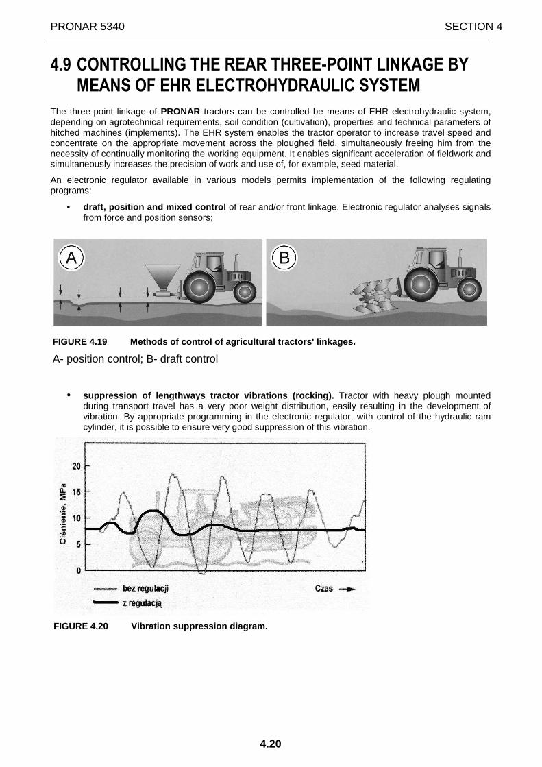
PRONAR 5340 SECTION 4
4.20
4.9 CONTROLLING THE REAR THREE-POINT LINKAGE BY MEANS OF EHR ELECTROHYDRAULIC SYSTEM
The three-point linkage of PRONAR tractors can be controlled be means of EHR electrohydraulic system, depending on agrotechnical requirements, soil condition (cultivation), properties and technical parameters of hitched machines (implements). The EHR system enables the tractor operator to increase travel speed and concentrate on the appropriate movement across the ploughed field, simultaneously freeing him from the necessity of continually monitoring the working equipment. It enables significant acceleration of fieldwork and simultaneously increases the precision of work and use of, for example, seed material.
An electronic regulator available in various models permits implementation of the following regulating programs:
• draft, position and mixed control of rear and/or front linkage. Electronic regulator analyses signals from force and position sensors;
FIGURE 4.19 Methods of control of agricultural trac tors' linkages.
A- position control; B- draft control
• suppression of lengthways tractor vibrations (rocki ng). Tractor with heavy plough mounted during transport travel has a very poor weight distribution, easily resulting in the development of vibration. By appropriate programming in the electronic regulator, with control of the hydraulic ram cylinder, it is possible to ensure very good suppression of this vibration.
FIGURE 4.20 Vibration suppression diagram.

SECTION 4 PRONAR 5340
4.21
FIGURE 4.21 Control panel of EHR electrohydraulic s ystem.
1 – control lever of three-point linkage (upwards - lifting; downwards - lowering; pressing in down position – increasing plough depth during ploughing; central setting – disengaged); 2 – selector knob for adjustment of working depths of implement mounted on three-point linkage (turn clockwise – reduces depth; anti clockwise – increases depth); 3 – selector knob for adjustment of height limit of three-point linkage lift (turn clockwise – minimum limitation; anti clockwise – maximum limitation); 4 – selector knob for selection of methods of adjustment (turn clockwise to extreme setting – position control; anti clockwise to extreme setting – draft control; setting between extreme settings – mixed control); 5 – selector knob for adjustment of lowering speed (upwards - faster; downwards – slower); 6 – switch of implement lock in transport position (locks lever 1 in upper position); 7 –vibration suppression switch; 8 – indicator lights of lifting and lowering of implement mounted on three-point linkage; 9 – diagnostic indicator light; 10 - three-point linkage controls outside tractor.
The electrohydraulic system of the rear three-point linkage is controlled by means of control panel (FIGURE 4.21) located on the right side of the seat and additional push-buttons 10 (FIGURE 4.21) for rising and lowering lower links, located on the rear mudguards, on the right side and the left side of the tractor (they are used when hitching agricultural machines and implements).
The rear three-point linkage is controlled in the following manner:
• using knob 4 (FIGURE 4.21), depending on type of fieldwork, determine the method of implement control (position, draft or mixed control);
• using knob 2 set working depth of implement, and using knob 3 set the height of raising to transport position;
• the implement is lowered by shifting lever 1 to lower position (indicator light 8 lights up)
After lowering implement and its penetration into the soil, conduct additional adjustment of optimum working conditions of the implement:
• using knob 4 - type of control; • using knob 5 - speed of depth correction or working height; • using knob 2 - set working depth of implement.
IMPORTANT: In case of intensive overheating of the control system, turn knob 4 towards position control and knob 5 towards "tortoise" position.
PRONAR 5340 SECTION 4
4.22
If the plough emerges temporarily from heavy soil, deepen the plough by pressing lever 1 to shift it to lower position. When released, lever 1 returns to previously set "lowering" position and the plough returns to the working depth set with knob 4.
IMPORTANT
Do NOT use tractor in the event of hydraulic pump m alfunction, if the light 8 (FIGURE 4.21) is not extinguished after lifting the implement.
Apart from the above described functions, EHR system has the function of suppressing vibration during transport of implements. To engage vibration suppression system:
• set lever 1 (FIGURE 4.21) in "raising" position (then the implement is raised to the extreme upper position)
• press button 7 for vibration suppression (the implement is lowered about 3% from the extreme upper position).
•
IMPORTANT
• The vibration suppression function is active only w hen lever 1 (FIGURE 4.21) is set in "raising" position.
• During fieldwork (ploughing, cultivation etc.) vibr ation suppression function should be switched off.
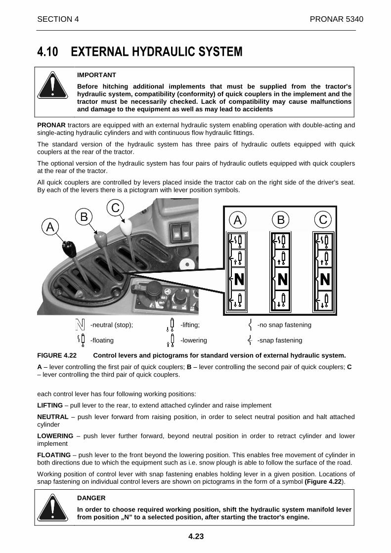
SECTION 4 PRONAR 5340
4.23
4.10 EXTERNAL HYDRAULIC SYSTEM
IMPORTANT
Before hitching additional implements that must be supplied from the tractor's hydraulic system, compatibility (conformity) of qui ck couplers in the implement and the tractor must be necessarily checked. Lack of compat ibility may cause malfunctions and damage to the equipment as well as may lead to accidents
PRONAR tractors are equipped with an external hydraulic system enabling operation with double-acting and single-acting hydraulic cylinders and with continuous flow hydraulic fittings.
The standard version of the hydraulic system has three pairs of hydraulic outlets equipped with quick couplers at the rear of the tractor.
The optional version of the hydraulic system has four pairs of hydraulic outlets equipped with quick couplers at the rear of the tractor.
All quick couplers are controlled by levers placed inside the tractor cab on the right side of the driver's seat. By each of the levers there is a pictogram with lever position symbols.
-neutral (stop);
-lifting; -no snap fastening
-floating
-lowering -snap fastening
FIGURE 4.22 Control levers and pictograms for stand ard version of external hydraulic system.
A – lever controlling the first pair of quick couplers; B – lever controlling the second pair of quick couplers; C – lever controlling the third pair of quick couplers.
each control lever has four following working positions:
LIFTING – pull lever to the rear, to extend attached cylinder and raise implement
NEUTRAL – push lever forward from raising position, in order to select neutral position and halt attached cylinder
LOWERING – push lever further forward, beyond neutral position in order to retract cylinder and lower implement
FLOATING – push lever to the front beyond the lowering position. This enables free movement of cylinder in both directions due to which the equipment such as i.e. snow plough is able to follow the surface of the road.
Working position of control lever with snap fastening enables holding lever in a given position. Locations of snap fastening on individual control levers are shown on pictograms in the form of a symbol (Figure 4.22 ).
DANGER
In order to choose required working position, shift the hydraulic system manifold lever from position „N” to a selected position, after sta rting the tractor's engine.

PRONAR 5340 SECTION 4
4.24
DANGER
Use of the lever controlling a pair of quick couple rs to work with loader in snap fastening position may cause uncontrolled movement and as a result cause damage to loader or pose danger to the operator.
IMPORTANT
Fast and smooth downward movement (under the influe nce of gravity), occurring when the engine and pump do not work and the hydraulic s ystem tank is full, may cause malfunction or damage, especially when a heavy impl ement is mounted.
FIGURE 4.23 Quick couplers of the external hydrauli c system
A-A1 – the first pair of quick couplers at the rear of the tractor; B-B1 – the second pair of quick couplers at the rear of the tractor; C-C1 – the third pair of quick couplers at the rear of the tractor; Z – "free drain” quick coupler; A,B,C - supply quick couplers; A1,B1,C1 - return quick couplers.
The first pair of quick couplers A-A1 regulates oil stream flow. The adjustment is made by means of knob 1 (Figure 4.24). On the knob there is a scale from 0 to 9. To increase flow rate turn knob so that a greater value is visible on the scale on the top of the knob. If a lower value is visible after turning the knob, flow rate will be reduced.
FIGURE 4.24 Flow regulation knob and valves applyin g single or double action.
1 - flow regulation knob for the first pair of quick couplers; 2 – valves applying single or double action

SECTION 4 PRONAR 5340
4.25
When connecting hydraulic conduits, check that they are clean. Connecting dirty conduits causes the hydraulic system tank of your tractor to be contaminated, which may (despite filters installed) cause malfunction of the tractor's hydraulic system (pump, selective control valve etc.).
IMPORTANT
Ensure that oil in cylinders is clean and of the ap propriate grade.
Connecting single-acting cylinders
When connecting single-acting cylinders (e.g. trailer) to quick couplers of supply sockets A, B or C , adapt valve 2 (Figure 4.24) to single-action mode of operation. To do this loosen securing nut, and then using screwdriver screw out valve 2 located below quick coupler to which single acting cylinder will be connected and tighten securing nut again. Then the lower quick coupler is connected directly to drain tank.
Next, raise cover and insert the plug of single acting cylinder conduit to upper supplying quick coupler ensuring that it is properly seated. Check if the conduit has enough slack in order to enable turning the tractor or implement in both directions. Move control lever to supply oil under pressure to complete the process of engaging tractor and implement hydraulic systems.
In order to extend single-acting cylinder pull the lever controlling quick coupler to the rear to "lifting” position. In order to stop the cylinder before it is completely extended move lever to the neutral position.
To retract a single acting cylinder push control lever forward to "lowering" or "floating" position.
IMPORTANT: Do not keep the lever in "lifting” or "lowering” position if external cylinder has reached the end of its stroke, because this causes "impact" to transfer valve. Compression of oil by transfer valve causes heating of oil, which may lead to a malfunction of hydraulic system assemblies.
IMPORTANT: Single acting cylinder may be also controlled by external hydraulic quick coupler adapted to double-action mode of operation. However, remember that "floating" position must be used for retracting the cylinder. To choose this position, move control lever beyond the "lowering" position.
Connecting double-acting cylinders
When connecting double-acting cylinders to quick coupler pairs A-A1, B-B1 or C-C1, adapt valve 2 (Figure 4.24) to double-action mode of operation. To do this, loosen securing nut, and then using screwdriver screw out completely valve 2 located below quick coupler pair to which double acting cylinder will be connected and tighten securing nut again.
Next, raise cover and insert the plug of supply conduit of double-acting cylinder to upper supplying quick coupler and insert the plug of return conduit to the lower socket of a pair of quick couplers adapted to double action mode of operation, ensuring that it is properly seated. Check if the conduits have enough slack in order to enable turning the tractor or implement in both directions. Move control lever to supply oil under pressure to complete the process of engaging tractor and implement hydraulic systems.
IMPORTANT
Before proceeding to work check that movement of hy draulically powered machine assembly corresponds to movement of lever. In the e vent that it does not, swap conduits on pair of quick couplers.
In order to extend double-acting cylinder pull the lever controlling quick coupler to the rear to "lifting” position.
In order to retract double-acting cylinder push the control lever forward, beyond neutral position to "lower” position.
Moving the lever forward beyond the "lower” position selects floating setting, which enables free movement of cylinder in either direction and is suitable while working with such equipment as a snowplough or loader.
IMPORTANT: Snap fastener holds lever in selected position i.e. "lifting” or "lowering”. In order to stop the cylinder before it is completely extended move lever to the neutral position. Lever does not return automatically from "floating" position.
IMPORTANT: Do not keep the lever in "lifting” or "lowering” position if external cylinder has reached the end of its stroke, because this causes "impact" to transfer valve. Compression of oil by transfer valve causes heating of oil, which may lead to a malfunction of hydraulic system assemblies.

PRONAR 5340 SECTION 4
4.26
Connecting hydraulic continuous flow accessories
When connecting continuous flow hydraulic optional equipment (e.g. hydraulic motors), connect supply conduit to the lower quick coupler A1 of the first pair of quick couplers equipped with flow regulation valve, and connect return conduit to "free drain” quick coupler Z (Figure 4.23) . This enables direct return of oil to tractor hydraulic system. Quick coupler A1 should be adapted to double action mode of operation using valve 2 (Figure 4.24 ) as in the case of double-acting cylinders.
Flow regulation valve enables smooth regulation of flow rate or hydraulic motor speed with the aid of selection knob 1 (Figure 4.24) .
For hydraulic motor to operate it is necessary for control lever to be moved into "lowering” position.
To stop motor move lever forward from "lowering" position to "floating" position. The motor then slows down until it stops. Never choose "neutral" or "lifting" position during work of motor, because this will cause rapid stopping and increase the pressure in hydraulic circuit.
IMPORTANT
Before proceeding to work, check that hydraulic mot or rotates after setting control lever in "lowering" position. In the event that it does not, swap conduits.
In order to ensure optimum cooling and prevent oil overheating, operate continuous flow equipment by setting flow rate using knob 1 (Figure 4.24) at maximum and lowest revolution speed of tractor engine, which ensures the required performance of machine and appropriate speed.
Disconnection of hydraulic conduits from quick coup lers
To disconnect hydraulic conduit grasp it with one hand at a short distance from the coupler and with second hand grasp coupler then quickly pull the conduit. To disconnect or to connect quick coupler, reduce pressure in hydraulic system. To do this, before starting the motor, move control lever into "floating" position. This causes pressure drop. Disconnect motor with control levers in "floating" position. After stopping motor, set levers in neutral position. Now quick coupler may be connected and disconnected at minimum pressure with little effort.
DANGER
Before disconnecting motors or implement, make sure that the equipment or implement is supported in a safe manner.

SECTION 4 PRONAR 5340
4.27
4.11 PNEUMATIC TRAILER BRAKING SYSTEM
The combined trailer pneumatic braking system (double and single conduit) is composed of engine driven compressor, air tank, control valves and three pneumatic connectors. The standard version of the tractor is equipped with double-conduit and single-conduit system. Connectors are mounted at rear of tractor and may be connected to single conduit or double conduit trailer braking system. Pneumatic connectors are in three colours: black, red and yellow. Black connector is used for single conduit system, and red (supply) and yellow (control) for double conduit system.
IMPORTANT
Various types of trailer braking systems are availa ble. Before connecting to tractor's pneumatic braking system, read trailer Manufacturer 's Operator's Manual.
FIGURE 4.25 Pneumatic system connectors.
A- yellow connector (double conduit system); B- red connector (double conduit system); C- black connector (single conduit system).
IMPORTANT: Trailer brakes only work when both brake pedals in tractor are depressed. Therefore brake pedals should always be locked together with a catch, if a trailer is hitched to tractor.
Tractor handbrake is connected to the main control valve. After activating handbrake, trailer brakes are also activated.
Single conduit trailer system
If the trailer is equipped with single conduit system then connect pneumatic conduit to black connector C (FIGURE 4.25) of the tractor's pneumatic system. After releasing tractor's brake pedals and parking handbrake, 0.62 MPa pressure is maintained in the connection. Activating tractor brakes causes drop in pressure proportional to pressure applied to brake pedals and activation of trailer brakes.
Double conduit trailer system
In trailer with double conduit braking system, connect supply conduit of trailer's pneumatic system to red connector B (FIGURE 4.25), and connect control conduit to yellow connector A (FIGURE 4.25).
IMPORTANT
Double conduit system only works after connecting b oth conduits to red and yellow connectors.
PRONAR 5340 SECTION 4
4.28
Supply conduit (red) – is the conduit that fills the tank of the trailer's pneumatic system. If for some reason the trailer braking system is disconnected from the tractor, the pressure falls to 0 and trailer brakes are applied.
Control conduit (yellow) – after activation of tractor brakes, increased air pressure is supplied through yellow connector to trailer's control valve until full pressure is generated in the system. Degree of trailer braking is proportional to pressure applied to tractor's brake pedals.
After starting engine, release handbrake and brake pedals. Pressure drop indicator light of pneumatic system (FIGURE 3.15) located next to air pressure indicator will be illuminated until pressure in pneumatic system rises to about 0.5 MPa. When a required pressure within the range of 0.55÷0.8 MPa is reached and shown on air pressure indicator 3 (FIGURE 3.12), a loud sound of releasing excess air through valve to atmosphere will be heard.
Press brake pedal several times to be sure that pressure shown on the gauge falls after engaging brakes and rises after releasing them.
DANGER
Never drive the tractor when indicator light of tra iler brakes is illuminated.
IMPORTANT
Before connecting a pneumatic conduit, clean traile r and tractor connectors. Ensure that connection is secured. Check trailer brakes re gularly to make sure they operate correctly.
DANGER
Do not overuse brakes on steep slope. Use the same gear as when going upwards, for descending slope of the same steepness.

SECTION 4 PRONAR 5340
4.29
4.12 CHANGING WHEEL TRACK OF TRACTOR'S FRONT AND REAR DRIVE AXLES
Wheel track of tractor's front and rear drive axles can be adjusted by swapping wheels (left wheel to the right side, right wheel to the left side) and by changing tyres.
FIGURE 4.26 Wheel track of tractor's front and rear drive axles.
Depending on the size of tyres with which the tractor is equipped the following wheel track ranges are possible:
- front axle: 1500-1860 mm
- rear axle: 1520-1920 mm
When changing wheel track, if change to the other side is necessary, then dismount wheel from tractor, turn by 180° and mount on the opposite side of tractor. Direction of arrows on side of tyres should be according to forward direction of travel of tractor. Projections of tyre tread are then set properly and tyre (wheel and tractor) may ensure maximum traction in given conditions.
DANGER
Tractor wheels are very heavy. Proceed with them ve ry carefully and secure wheels against falling over during dismounting and causing injury.
Due to the associated risk, dismounting rear wheel from tractor requires two people, unless the person changing the wheel has at his dis posal auxiliary appliances (lifting crane, overhead crane, forklift etc.).
After changing and mounting wheels tighten bolts securing wheel disc to hub with torque of:
- front wheel :280 Nm
- rear wheel : 380 Nm

PRONAR 5340 SECTION 4
4.30
DANGER
Never drive tractor with loosened wheel disc. Alway s tighten nuts with the specified torque in the recommended time periods.
IMPORTANT! After changing wheel track it is necessa ry to set toe-in, which should be 0 ÷ 1 mm for front drive axle wheels, when measured at the dista nce of 330mm from the wheel centre.
IMPORTANT
At narrower wheel track settings, there may be inte rference between tyre or mudguard and tractor, if the wheels are in maximal turning p osition. In order to avoid these, adjust wheel turning limiters and mudguards limiters.

SECTION 4 PRONAR 5340
4.31
4.13 FRONT WHEELS TURNING ANGLE ADJUSTMENT
Front wheels of the tractor are equipped with turn limiters 1. The limiters should be so adjusted that they ensure a minimum of 20 mm space between tyres and whatever part of tractor in maximum turn position to the left or the right.
To adjust limiter 1 first loosen securing nut 2, and then, while screwing in or screwing out adjustment bolt 1 set the required turning angle. After the adjustment, tighten securing nuts 2 using tightening torque of 200 Nm.
After adjusting both turn limiters, ensure that the appropriate space is maintained at maximum turn of wheels between tyres and the tractor.
FIGURE 4.27 Front wheels turning angle adjustment

PRONAR 5340 SECTION 4
4.32
4.14 WHEEL DIMENSION CHOICE PRINCIPLES
PRONAR tractors equipped with two driven axles should have appropriately selected tyres (wheels) on front and rear axles.
Table 4.2 Data concerning recommended tyre sets.

SECTION 4 PRONAR 5340
4.33
Table 4.2 shows dimensions of front and rear wheels which may be mounted on PRONAR 5340 tractors. Dimensions of front wheels are given in table lines while the dimensions of rear wheels are given in table columns.
IMPORTANT: One of the wheel selection criteria is t he relationship between the rear wheel's rolling radius (R k) and the front wheel's rolling radius (r k). This value should be within the range of 1.28 ÷1.32. The value of the relationship between the rolling radii of the front and rear wheels (Rk / rk) is given in the table fields which meet this requirement.
The recommended sets of wheels to be installed firstly in the tractor (because the tyre manufacturers are the same) are marked by the fields with thickened frame at the crossing of table lines (dimensions of front wheels) and table columns (dimensions of rear wheels).
The recommended sets of wheels to be installed secondly in the tractor (because the tyre manufacturers are different) are marked by the fields with the value of the relationship between the rolling radii, at the crossing of table lines (dimensions of front wheels) and table columns (dimensions of rear wheels). These fields are not marked with thickened frame.
When required (for various reasons) to change wheel dimensions of one of the drive axles, check whether it will be necessary to change the wheels on the second axle.
IMPORTANT! Application of tyre combination on front and rear drive axles other than given in the table, leads to rapid tyre wear and may damage driv e system.

PRONAR 5340 SECTION 4
4.34
4.15 INCREASING TRACTION OF PRONAR TRACTORS
PRONAR tractors are equipped with a range of appliances and functions for increasing traction, that is increasing the pulling power of the tractor, reducing slip, and increasing speed, which leads to reduction of fuel consumption per unit of area.
Such appliances and methods include:
• 4-wheel drive;
• three-point linkage hydraulic lift - the fact that equipment is mounted on a tractor increases the load on the rear driving axle and reduces slip;
• use of automatic adjustment (especially depth adjustment on machine with working elements operating submerged underground) equally increases load on rear drive axle;
• front axle weight - mainly causing improvement of stability, if a relatively heavy machine is mounted;
• possibility of filling front and rear tyres with liquid (water);
• rear axle differential lock (driver operated),
4.15.1 WEIGHTS (OPTIONAL EQUIPMENT) In order to additionally load the front axle of the tractor cooperating with heavy mounted machines, PRONAR tractors can be equipped with 12 weights (45 kg each) (optional equipment) which are attached to the tractor frame bracket or to the front three-point linkage (FIGURE 4.28).
Front weights should be mainly used to improve stability of tractor when heavy machines (implements) are mounted on the rear three-point linkage (or if centre of gravity is shifted far backward). Before performing light works which do not require maximum pull force, dismount front and rear weights.
FIGURE 4.28 Front weights (optional equipment) atta ched to the tractor's frame or the front three-point linkage.
A- weights attached to the tractor's frame; B- weights attached to the front three-point linkage; 1- 45kg weights (12 weights); 2- securing rods; 3- hitch pin; 4- bolts securing weights to the tractor's frame; 5- bracket securing weights to the tractor's frame; 6- bracket securing weights to the front three-point linkage.

SECTION 4 PRONAR 5340
4.35
IMPORTANT
Tractor should not be used if weights securing rods 2 (FIGURE 4.28) and bolts 4 fixing bracket the tractor's frame are not in place and pr operly tightened.
Clearance between weights is not allowed.
IMPORTANT
Take special care when handling weights because the y are heavy.
IMPORTANT
If tractor is moving at a great speed over uneven t errain, front weights do not always guarantee sufficient stability. In such conditions reduce speed and exercise caution.
Weight of ballast should not exceed load capacity o f tyres and tractor. Each tyre has recommended load capacity, which must not be exceed ed.
IMPORTANT:
• Weights should be used only when it is necessary.
• After installing weights, adjust air pressure in ty res.
4.15.2 FILLING TYRES WITH WATER OR NON-FREEZING SOL UTION. To increase traction, tractor wheels may be filled with water or non-freezing solution (FIGURE 4.29).
IMPORTANT
It is not recommended to fill front wheels with wat er or non-freezing solution, if it reduces tractor's steering ability.
Before filling wheels with water, raise the wheel and release air from inner tube, by screwing out tube valve insert. Turn the wheel in order to set tyre valve in upper position. If you have a special valve for filling wheels with water, screw it onto the valve. If you do not have such a valve, attach a rubber tube with water under pressure (e.g. connected to tap).
Water flows into tyre tube until the pressure equalizes. Then, remove rubber tube and release compressed air from tyre tube. This action should be repeated several times until water overflows from the tyre tube valve placed at the highest possible point. Next, screw in tyre valve insert and inflate tyre to a required pressure.
The amount of solution (water) in tyre tube should constitute 75% of its volume.
FIGURE 4.29 Filing tyres with water.
IMPORTANT
Remove water from tyres before temperatures drop be low 0°C.

PRONAR 5340 SECTION 4
4.36
If increased pull force is required in winter, tyres should be filled with solution of calcium chloride in proportion depending on ambient temperatures and tyre size.
Table 4.3 Type of calcium chloride solution dependi ng on ambient temperatures.
Quantity of calcium chloride in grams per
litre of water
Ambient temperature
200 to -15°C 300 to -25°C 435 to -35°C
Wheels Volume of water 75% [l] 360/70 R24 119 18.4 R34 380 16.9 R38 356
DANGER
All solution preparation work shall be done in rubb er gloves and with utmost care. To ensure safety when preparing the solution, pour cal cium chloride into water and not the reverse.
To drain (remove) liquid from tyre tubes:
• lift the wheel and turn tyre with valve to the top
• release air from tyre tube and unscrew air valve, then turn wheel with valve downwards.
IMPORTANT: LIQUID WILL BE EJECTED!
IMPORTANT: Before releasing liquid there may be pressure in tyre tube. Rotate a wheel several times so that valve is at the top.
• remove remains of liquid by screwing on terminal for liquid filling and with the aid of compressed air, remove for as long as liquid continues to drain out.
• unscrew water filling terminal, screw in air valve and inflate to required pressure
• after inflating the tyre, screw on valve cap.
• proceed in the same way with remaining tyre tubes.
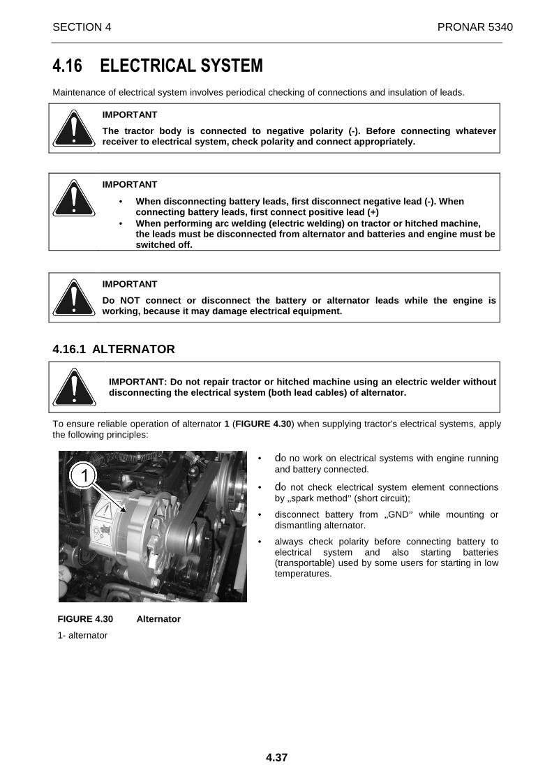
SECTION 4 PRONAR 5340
4.37
4.16 ELECTRICAL SYSTEM
Maintenance of electrical system involves periodical checking of connections and insulation of leads.
IMPORTANT
The tractor body is connected to negative polarity (-). Before connecting whatever receiver to electrical system, check polarity and c onnect appropriately.
IMPORTANT
• When disconnecting battery leads, first disconnect negative lead (-). When connecting battery leads, first connect positive le ad (+)
• When performing arc welding (electric welding) on t ractor or hitched machine, the leads must be disconnected from alternator and batteries and engine must be switched off.
IMPORTANT
Do NOT connect or disconnect the battery or alterna tor leads while the engine is working, because it may damage electrical equipment .
4.16.1 ALTERNATOR
IMPORTANT: Do not repair tractor or hitched machine using an electric welder without disconnecting the electrical system (both lead cabl es) of alternator.
To ensure reliable operation of alternator 1 (FIGURE 4.30) when supplying tractor's electrical systems, apply the following principles:
• do no work on electrical systems with engine running and battery connected.
• do not check electrical system element connections by „spark method” (short circuit);
• disconnect battery from „GND” while mounting or dismantling alternator.
• always check polarity before connecting battery to electrical system and also starting batteries (transportable) used by some users for starting in low temperatures.
FIGURE 4.30 Alternator
1- alternator

PRONAR 5340 SECTION 4
4.38
4.16.2 ELECTRICAL SYSTEM CONNECTION FOR TRAILER AND ADDITIONAL +12V POWER SUPPLY SOCKETS.
PRONAR tractors are equipped with standard (complying with Polish Standards) electrical system connection for trailers A (Figure 4.31 ) located on the cab's rear wall (outside the cab) and +12V supply sockets for additional receivers connected to tractor's electrical system located outside the tractor cab B and located inside the cab C.
FIGURE 4.31 Electrical system connections.
A - electrical system connection for trailers; B - supply socket +12V 15A ; C – +12V supply socket for additional receivers connected to tractor's electrical system +12V 30A.
The following elements are connected to electrical system connection for trailers A (Figure 4.31 ) (marking according to Polish Standards given in brackets):
1 - (L) - indicators - left;
2 - (+) – „plus”;
3 - (31) – „ground”;
4 - (R) - indicators - right;
5 - (58R) - parking lights - right;
6 - (54) - brake lights ("stop”);
7 - (58L) - parking lights - left;
4.16.3 CIGARETTE LIGHTER SOCKET
12V cigarette lighter socket 1 (FIGURE 4.32) is located inside the tractor's cab, on the left post. The socket is used for connecting portable lamp or other electrical appliances supplied with voltage of 12 V. Standard equipment of the tractor does not include heating element (cigarette lighter).
FIGURE 4.32 Cigarette lighter socket
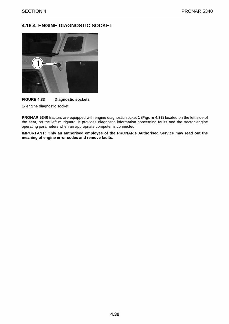
SECTION 4 PRONAR 5340
4.39
4.16.4 ENGINE DIAGNOSTIC SOCKET
FIGURE 4.33 Diagnostic sockets
1- engine diagnostic socket.
PRONAR 5340 tractors are equipped with engine diagnostic socket 1 (Figure 4.33 ) located on the left side of the seat, on the left mudguard. It provides diagnostic information concerning faults and the tractor engine operating parameters when an appropriate computer is connected.
IMPORTANT: Only an authorised employee of the PRONA R's Authorised Service may read out the meaning of engine error codes and remove faults .

PRONAR 5340 SECTION 4
4.40
4.16.5 FUSES AND RELAYS The set of fuses and relays of the tractor's electrical system is installed on the right mudguard. To gain access to these, unscrew catch A (FIGURE 4.34) and remove cover B.
IMPORTANT
Always install new fuses with the appropriate param eters. At each fuse replacement determine and remove cause of damage to fuse.
FIGURE 4.34 Position and description of the set of FB1 main fuses on the right mudguard.
A- catch; B- cover; C- box of FB1 main fuses.
Table 4.4 Specification of main fuses in the fuse b ox (FIGURE 4.34):
Fuse group Fuse number Protected circuit Amperage [A]
1 EDC17CV54 engine controller supply 30
2 Supply of heater fan relay 20
3 Supply of additional banana socket 30
4 Running engine supply 30
5 Direct supply from battery 40
FB1
6 ST15 ignition supply 50

SECTION 4 PRONAR 5340
4.41
FIGURE 4.35 Position and description of the set of FB2 and FB3 fuses in the fuse box on the right mudguard.
A- catch; B- cover; C- fuse and relay box.
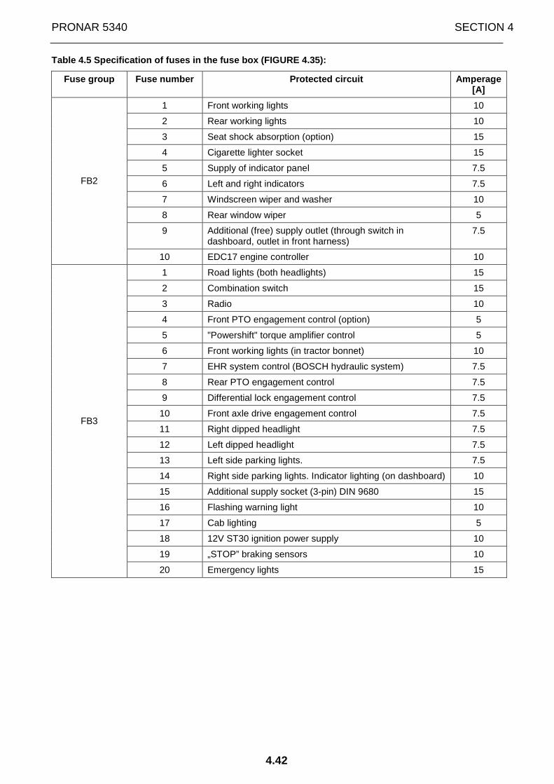
PRONAR 5340 SECTION 4
4.42
Table 4.5 Specification of fuses in the fuse box (F IGURE 4.35):
Fuse group Fuse number Protected circuit Amperage [A]
1 Front working lights 10
2 Rear working lights 10
3 Seat shock absorption (option) 15
4 Cigarette lighter socket 15
5 Supply of indicator panel 7.5
6 Left and right indicators 7.5
7 Windscreen wiper and washer 10
8 Rear window wiper 5
9 Additional (free) supply outlet (through switch in dashboard, outlet in front harness)
7.5
FB2
10 EDC17 engine controller 10
1 Road lights (both headlights) 15
2 Combination switch 15
3 Radio 10
4 Front PTO engagement control (option) 5
5 "Powershift" torque amplifier control 5
6 Front working lights (in tractor bonnet) 10
7 EHR system control (BOSCH hydraulic system) 7.5
8 Rear PTO engagement control 7.5
9 Differential lock engagement control 7.5
10 Front axle drive engagement control 7.5
11 Right dipped headlight 7.5
12 Left dipped headlight 7.5
13 Left side parking lights. 7.5
14 Right side parking lights. Indicator lighting (on dashboard) 10
15 Additional supply socket (3-pin) DIN 9680 15
16 Flashing warning light 10
17 Cab lighting 5
18 12V ST30 ignition power supply 10
19 „STOP” braking sensors 10
FB3
20 Emergency lights 15

SECTION 4 PRONAR 5340
4.43
FIGURE 4.36 Position of the set of relays in the fu se box
A- catch; B- cover; C- fuse and relay box.
Table 4.6 Specification of relays in the fuse box ( FIGURE 4.36).
Relay number Relay function
R1 ST”15” ignition supply relay
R2 Running engine supply relay
R3 Relay of heater fan switch supply
R4 Relay activating the indicator lamp of front drive engagement
R5 Relay activating the indicator lamp of differential lock engagement
R6 Relay activating the indicator lamp of rear PTO engagement
R7 Time relay - 3s ("Powershift" control)
R8 Relay of disengagement of rear axle lock during braking
R9 Relay of disengagement of rear axle lock during braking
R10 Relay of front axle drive engagement
R11 Relay of front axle drive engagement during braking
R12 Relay of front axle drive engagement during braking
R13 Relay of rear axle lock engagement
R14 Relay of rear PTO engagement
R15 Relay of rear PTO engagement
R16 Road lights ON relay
R17 Relay of "Powershift" torque amplifier control
R18 Relay of "Powershift" torque amplifier control
R19 Dipped beam ON relay

PRONAR 5340 SECTION 4
4.44
FIGURE 4.37 Position and description of the set of rectifying diodes on the right mudguard.
A- catch; B- cover.
Table 4.7 Specification of rectifying diodes (FIGUR E 4.37):
Diode number
Protected circuit Amperage [A]
1 Rectifying diode - protection against overvoltage of the circuit of Powershift solenoid valve activation
3
2 Rectifying diode - protection against overvoltage of the circuit of rear PTO solenoid valve activation 3
3 Rectifying diode - protection against overvoltage of the circuit of BD solenoid valve activation (differential lock)
3
4 Rectifying diode - protection against overvoltage of the circuit of 4WD solenoid valve activation (front drive)
3
5 Rectifying diode - spare 3
6 Rectifying diode - spare 3
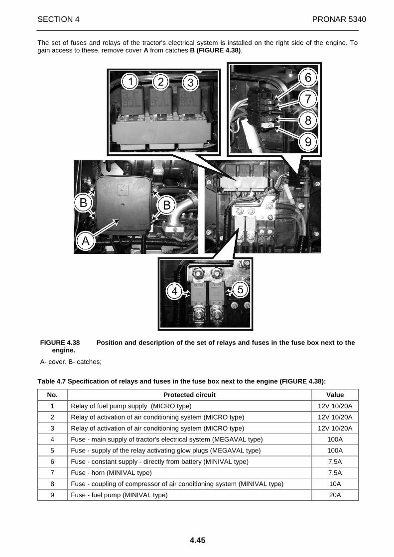
SECTION 4 PRONAR 5340
4.45
The set of fuses and relays of the tractor's electrical system is installed on the right side of the engine. To gain access to these, remove cover A from catches B (FIGURE 4.38).
FIGURE 4.38 Position and description of the set of relays and fuses in the fuse box next to the engine.
A- cover. B- catches;
Table 4.7 Specification of relays and fuses in the fuse box next to the engine (FIGURE 4.38):
No. Protected circuit Value
1 Relay of fuel pump supply (MICRO type) 12V 10/20A
2 Relay of activation of air conditioning system (MICRO type) 12V 10/20A
3 Relay of activation of air conditioning system (MICRO type) 12V 10/20A
4 Fuse - main supply of tractor's electrical system (MEGAVAL type) 100A
5 Fuse - supply of the relay activating glow plugs (MEGAVAL type) 100A
6 Fuse - constant supply - directly from battery (MINIVAL type) 7.5A
7 Fuse - horn (MINIVAL type) 7.5A
8 Fuse - coupling of compressor of air conditioning system (MINIVAL type) 10A
9 Fuse - fuel pump (MINIVAL type) 20A

PRONAR 5340 SECTION 4
4.46
4.16.6 TRACTOR LIGHTING
FIGURE 4.39 Tractor lighting.
1- dipped beams and high beams; 2- front parking lights; 3- front indicator; 4- front working lights; 5- rear working lights; 6- rear indicator; 7- parking lights and stop lights; 8- license plate light; 9- reflector.
Table 4.6 List of bulbs used in lights of PRONAR 53 40 tractor
No.
FIGURE 4.39
Type of lamp Bulb type Number of items on tractor
1 Headlight – dipped beams and high beams H4 (12V, 55/60W) 2
2 Front lamp assembly - parking lights R10W 2
3 Front lamp assembly - indicator P21W 2
4 Front working lights (mounted on cab roof (2 lights) and in tractor bonnet (2 lights)
H3 (12V, 55W) 4
5 Rear working lights (mounted on cab roof) H3 (12V, 55W) 2
6 Rear lamp assembly - indicator P21W 2
7 Rear lamp assembly - stop/parking lights P21/5W 2
8 Licence plate light R10W 1
Cab interior lamp C5W 2

SECTION 4 PRONAR 5340
4.47
4.17 REFUELLING TRACTOR
PRONAR tractors have a fuel tank located on the left side of the tractor (FIGURE 4.40).
IMPORTANT:
1. Lost or damages caps should always be replaced w ith original replacement cap
2. Never take off the cap or pour fuel with engine running.
3. Control filling nozzle while pouring fuel into t ank.
4. Do not fill completely. Allow space for fuel exp ansion.
5. Immediately wipe away spilt fuel.
IMPORTANT:
Fuel is a flammable material. Never refuel tractor when smoking or near open flames or sparks.
In order to fill fuel tank 1 it is necessary to:
• clean the surface around filler plug 2 to prevent dirt from getting into tank and contaminating fuel
• remove the filler plug and place it in a clean place for the time of refuelling
• after refuelling, replace and tighten the filler plug.
FIGURE 4.40 Fuel tank.
1 – fuel tank; 2 –filler plug
In order to remove sediment or drain fuel from tank, unscrew drain plug 1 (FIGURE 4.41) located at the bottom of the tank.
After removal of sediment or fuel from tank, tighten the plug.
FIGURE 4.41 Drain plug of fuel tank
1 – drain plug of fuel tank; 2 – fuel tank
IMPORTANT
Fuel tank drain plug should be tightened using a to rque not exceeding 10 Nm. Otherwise there is a risk of shearing the thread ca using fuel leak.
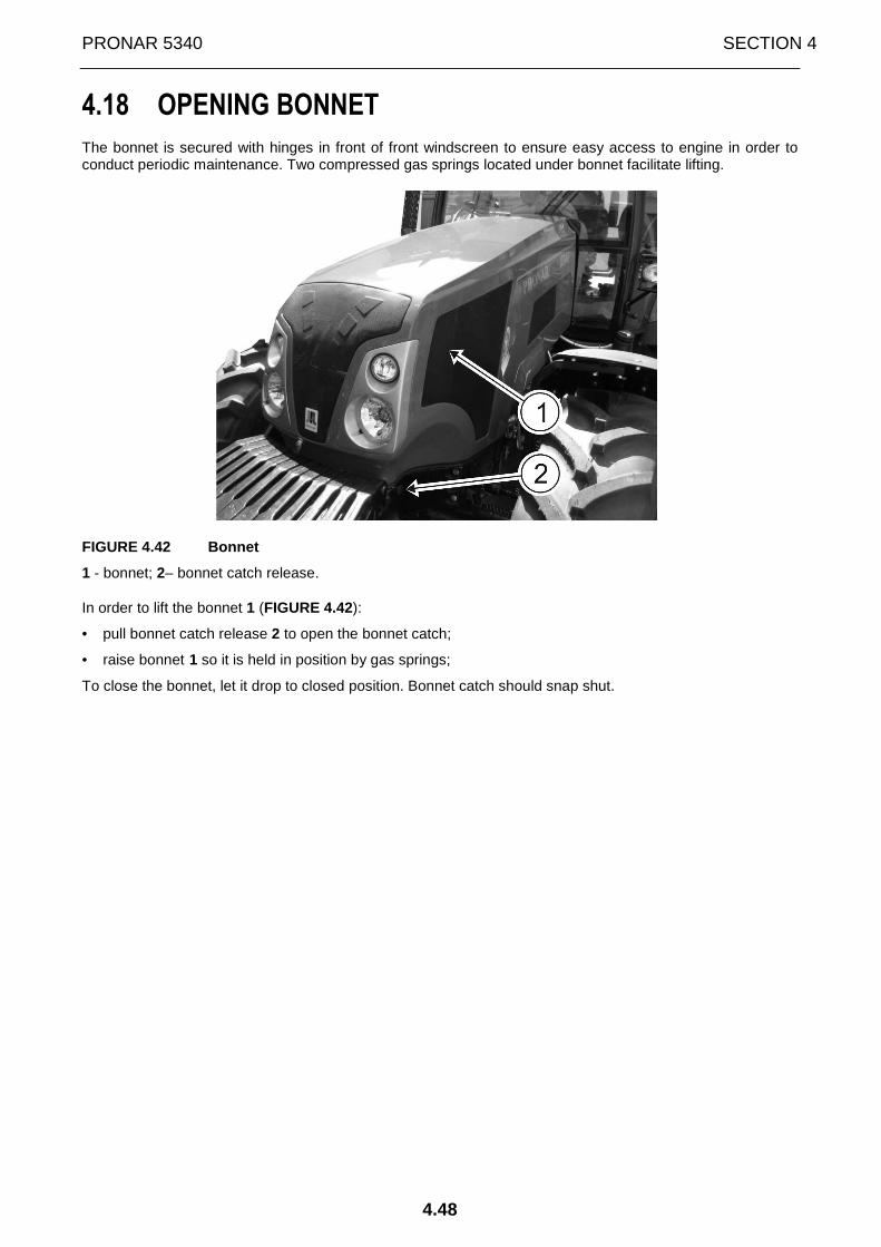
PRONAR 5340 SECTION 4
4.48
4.18 OPENING BONNET
The bonnet is secured with hinges in front of front windscreen to ensure easy access to engine in order to conduct periodic maintenance. Two compressed gas springs located under bonnet facilitate lifting.
FIGURE 4.42 Bonnet
1 - bonnet; 2– bonnet catch release.
In order to lift the bonnet 1 (FIGURE 4.42):
• pull bonnet catch release 2 to open the bonnet catch;
• raise bonnet 1 so it is held in position by gas springs;
To close the bonnet, let it drop to closed position. Bonnet catch should snap shut.

SECTION 4 PRONAR 5340
4.49
4.19 WASHING TRACTOR
PRONAR tractors are modern machines with a large number of electrical sub-assemblies, which are sensitive to water. This should be remembered while washing tractor, especially when using high-pressure washing equipment.
Tractor may be washed with water with addition of commercially available car washing agents. Before washing, first protect battery, starter motor, alternator, exhaust pipe, air filter and sensors. During washing remove dirt from surface of tractor assemblies.
When washing with pressure washer jet do not stand too close to the tractor and avoid directing stream of water at electronic or electrical subassemblies, electrical connections and air bleeders.
IMPORTANT: Never direct stream of cold water on the hot engine or exhaust system.

PRONAR 5340 SECTION 4
4.50
4.20 RUNNING IN TRACTOR
IMPORTANT
The first 50 engine hours of tractor operation have a significant influence on tractor life and especially on the engine.
A new tractor, at the beginning of the working period should be run in for a period of not less than 50 engine hours.
During running in time it is important:
• Not to allow engine overheating;
• Not to allow overloading of engine. Work in high gears under great load may cause overloading of engine. This results in engine's unresponsiveness to increased RPM.
• Do not cause engine smoking and RPM drop due to high load;
• Do not allow engine to work without load. It may have the same negative effect on engine as overloading. Change type of work undertaken so that engine is used in conditions of great and small loads.
• Carefully watch appliance indicators and controls;
• Stop work of tractor and contact service at whatever sign of incorrect operation of engine or tractor.
In addition to normal maintenance during the running in period also check every 10 hours the levels of liquids and oils in gearbox and rear axle, hydraulic systems, forward drive axle and engine. Check the tightness of bolts securing wheels to wheel hubs.
After the running in period, conduct maintenance after 50 engine hours (at the Manufacturer's authorised service) Method of performing all maintenance activities is described in Section 6 "MAINTENANCE”.
Maintenance after running-in is performed at purchaser's cost.
IMPORTANT
If any malfunctions of engine or tractor occur, sto p operating the tractor and contact the nearest authorized service point.

SECTION 4 PRONAR 5340
4.51
4.21 TOWING TRACTOR
For towing tractor use the towing drawbar pin in front weights. If possible, use towing beam or chains. In the event of using chain avoid sudden manoeuvres. Observe the local rules referring to towing.
DANGER
Do not use rope or string to tow the tractor In the event of breaking, rope or string may strike with sufficient force to cause physical inju ry.
IMPORTANT
When towing the tractor, set all levers and gears t o neutral position. Gear reduction lever should be in "ROAD” position. Otherwise transmissio n assemblies may be damaged during towing.

PRONAR 5340 SECTION 4
4.52
4.22 OPERATING THE TRACTOR WITH FRONT LOADER
PRONAR tractors can cooperate with front loaders suitable for mounting on this type of tractors.
In order to mount loader on tractor, use SUITABLE fixing bolts. Install bolts in the tractor's frame in the places indicated in the front loader's operator's manual.
Observe the following principles when installing an d operating the front loader:
• All front loader elements must be bolted to the frame using proper tightening torque (according to the front loader assembling instructions).
• Set the widest possible tractor wheel track in order to maintain stability of tractor when working with front loader.
• When working with front loader, do not exceed the allowable load capacity of front axle and tyres.
• Before mounting the front loader, dismount the tractor's front weights. • Mounted front loader must not reduce access to maintenance points of the tractor (engine oil
dipstick, engine air filter, etc.) • Front loader's frame must not preclude opening the bonnet. • Front loader's design should ensure the maximum turning angle of front wheels.
IMPORTANT
In the event of using a front loader observe the ma ximum permissible front axle load and also recommended (permissible) speed. Counterweight s should be also mounted on the rear linkage.
The front loader must not be used without a counter weight mounted on the rear three-point linkage.

SECTION
5
MAINTENANCE

PRONAR 5340 SECTION 5
5.2
5.1 MAINTENANCE OF TRACTOR AFTER RUNNING-IN (P-1) (50 ENGINE HOURS)
After the running-in period, perform maintenance after 50 engine hours (in the Manufacturer's Authorized Service). This maintenance is performed at the purchaser's cost.
The scope of P-1 maintenance includes the following activities:
• wash the tractor and check operation of engine, steering system, braking system, clutch, electrical system and other systems and assemblies of the tractor;
• change oil in reducers and main gear of front axle;
• check condition and tension of vee-belts of fan drive, alternator and compressor;
• check tightness of engine air filter connection and condition of filtering inserts;
• remove deposits from pre-filter and fine filter and fuel tank;
• remove condensation from pneumatic system tank;
• check and if necessary adjust brake system;
• check level of liquid in engine cooling system;
• check oil level in gearbox and hydraulic system and change oil filters of gearbox and hydraulic system;
• check level of liquid in hydraulic control system of brakes and clutch;
• check technical condition of tyres and air pressure in tyres;
• check tightness of bolts securing rims to discs and disks to hubs of front and rear wheels;
• check (adjust) toe-in of front wheels;
• check and tighten the bolt connections of tractor assemblies;
• check tightness of the bolts securing front weights;
• grease all lubrication points;
• remove all fuel and oil leaks;
• check battery condition, clean terminals;
The methods of performing all the above-mentioned activities are described further in SECTION 5 "MAINTENANCE" .

SECTION 5 PRONAR 5340
5.3
5.2 SERVICE INSPECTION PROGRAMME
TABLE 5.1 SERVICE INSPECTION PROGRAMME
Service inspection after (engine hour): 10* 250 500 1000
Operation No Service operation
PC P-2 P-3 P-4
1 Check oil level in engine X X X X
2 Check level of liquid in engine cooling system X X X X
3 Check level of liquid in windscreen washer tank X X X X
4 Check level of liquid in the hydraulic control system of brakes and clutch
X X X X
5 Remove condensation from pneumatic system tank X X X X
6 Check and remove deposits (contamination) from preliminary decanter and fine fuel filter and fuel tank
X X X X
7 Check tension of fan and alternator drive vee-belt X X X X
8 Check engine, steering system, brakes and remaining systems and assemblies of tractor
X X X X
9 Change oil and oil filter in engine X** X X
10 Change insert in fuel pre-filter X X X
11 Check oil level in gearbox and rear axle and change oil filter in gearbox
X X X
12 Check oil level in front axle drive body and reducers X X X
13 Check oil level and change oil filters in hydraulic system X X X
14 Check and adjust brake system X X
15 Check tightening of wheel hub bolts of front and rear wheels
X X X
16 Check technical condition of tyres and air pressure in tyres
X X X
17 Check batteries X X
18 Maintenance of engine air filter X X
19 Check cab air filter X X
20 Change insert in fine fuel filter X X
21 Clean radiator X X
22 Change oil and oil filters in hydraulic system X
23 Change oil and oil filter in gearbox and rear axle X

PRONAR 5340 SECTION 5
5.4
Service inspection after (engine hour): 10* 250 500 1000
Operation No Service operation
PC P-2 P-3 P-4
24 Change oil in front axle drive body and reducers X
25 Check nut and bolt connections of tractor assemblies (external)
X
26 Change bulbs
27 Adjust road lights
28 Check toe-in of front axle wheels
29 Maintenance of tractor's hydraulic system
* - or daily **- or once a year, depending on which comes earlier IMPORTANT ! Service inspection intervals expressed in engine hours may not be exceeded by more than 10 engine working hours.
ATTENTION
TRACTOR MUST BE WASHED BEFORE EACH SERVICE INSPECTI ON.
ATTENTION
SHOULD IT BE NECESSARY TO CHANGE INDIVIDUAL PARTS, USE ONLY ORIGINAL PARTS OR THOSE INDICATED BY THE MANUFACTURER. NON-A DHERENCE TO THESE REQUIREMENTS MAY PUT THE USER AND OTHER PEOPL E'S HEALTH AND LIFE AT RISK, AND ALSO DAMAGE THE TRACTOR.
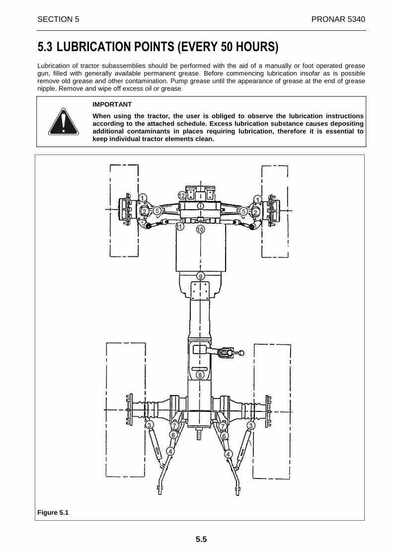
SECTION 5 PRONAR 5340
5.5
5.3 LUBRICATION POINTS (EVERY 50 HOURS)
Lubrication of tractor subassemblies should be performed with the aid of a manually or foot operated grease gun, filled with generally available permanent grease. Before commencing lubrication insofar as is possible remove old grease and other contamination. Pump grease until the appearance of grease at the end of grease nipple. Remove and wipe off excess oil or grease
IMPORTANT
When using the tractor, the user is obliged to obse rve the lubrication instructions according to the attached schedule. Excess lubricat ion substance causes depositing additional contaminants in places requiring lubrica tion, therefore it is essential to keep individual tractor elements clean.
Figure 5.1

PRONAR 5340 SECTION 5
5.6
TABLE 5.2 Lubrication point .
Point in FIGURE 5.1
Lubrication point's name
1 Mudguard rotation brackets 2 Bearing of reducer pivot stub axle of front axle 3 Telescopic stabilisers 4 Upper and lower hanger points 5 Articulated joints of reducer drive shafts 6 Upper and lower securing points of hydraulic cylinder 7 Rotation axis of lift arms 8+9 Articulated joints of front axle drive shaft 10 Front axle drive shaft sleeves 11*+12* Front axle rotation pivot
IMPORTANT: Lubrication points (every 50 hours) Lubr icate points marked with star (*) every 25 engine hours or once a week.

SECTION 5 PRONAR 5340
5.7
5.4 MAINTENANCE EVERY 10 ENGINE HOURS OR DAILY MAINTENANCE
OPERATION No 1. Oil level in the engine.
Engine oil level should be checked before beginning work or after 15 minutes from the moment of stopping heated engine.
Figure 5.2
In order to do this take dipstick 1, wipe it dry and replace. Next remove the dipstick again and check oil level. Oil level should be between "min” and "max” marks on dipstick 1. If oil does not reach lower „MIN” mark, supplement oil in engine. Remove oil filler plug 2, pour oil in and then check if oil level is between the marks on the dipstick.
IMPORTANT
Do NOT operate engine with oil level lower than low er mark on dipstick.
OPERATION No 2. Level of liquid in engine cooling system
DANGER
Engine cooling system operates under pressure. Unsc rewing cap when the engine is hot is dangerous.
Figure 5.3
Raise the bonnet and check coolant level in the coolant balancing tank 1, when the engine is cold. Level of coolant should reach to half the tank volume. If necessary, unscrew cap 2 of balancing tank and fill to the required level with the same type of coolant as used previously. Check that engine cooling system does not leak.
IMPORTANT! It is recommended to change coolant at l east every 2 years.
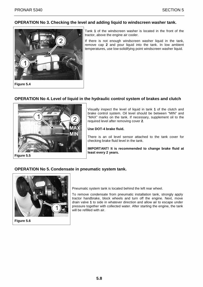
PRONAR 5340 SECTION 5
5.8
OPERATION No 3. Checking the level and adding liquid to windscreen washer tank.
Figure 5.4
Tank 1 of the windscreen washer is located in the front of the tractor, above the engine air cooler.
If there is not enough windscreen washer liquid in the tank, remove cap 2 and pour liquid into the tank. In low ambient temperatures, use low-solidifying point windscreen washer liquid.
OPERATION No 4. Level of liquid in the hydraulic control system of brakes and clutch
Figure 5.5
Visually inspect the level of liquid in tank 1 of the clutch and brake control system. Oil level should be between "MIN” and "MAX” marks on the tank. If necessary, supplement oil to the required level after removing cover 2. Use DOT-4 brake fluid. There is an oil level sensor attached to the tank cover for checking brake fluid level in the tank. IMPORTANT! It is recommended to change brake fluid at least every 2 years.
OPERATION No 5. Condensate in pneumatic system tank.
Figure 5.6
Pneumatic system tank is located behind the left rear wheel.
To remove condensate from pneumatic installation tank, strongly apply tractor handbrake, block wheels and turn off the engine. Next, move drain valve 1 to side in whatever direction and allow air to escape under pressure together with collected water. After starting the engine, the tank will be refilled with air.

SECTION 5 PRONAR 5340
5.9
OPERATION No 6. Sediment in fuel pre-filter decanter and fuel tank.
Figure 5.7
In order to remove sediment (contamination) unscrew:
• drain plug 1 of fuel pre-filter;
• drain plug 2 of fuel tank
and drain sediment to previously prepared basin, until clean fuel appears. After performing these actions, tighten plugs 1 and 2 and confirm their tightness.
IMPORTANT
Fuel tank drain plug should be tightened using a to rque not exceeding 10 Nm. Otherwise there is a risk of shearing the thread causing fuel leak.
If necessary, bleed air from fuel system.
OPERATION No 7. Tension of fan and alternator drive vee-belt.
Figure 5.9
In DEUTZ engines, belt 1 is tightened by automatic tensioner 2. Inspect belt 1 over entire length, checking for wear, cracks, cuts and general wear. If in doubt, replace with new belt. Make sure that belt is properly laid around pulley and check correct operation of tensioner 2.

PRONAR 5340 SECTION 5
5.10
OPERATION No 8. Engine, steering system, hydraulic system, braking system and other systems and assemblies of tractor
The engine should run evenly in the whole revolution speed range. Control elements, steering system, hydraulic system, hydraulic conduits, brakes, lighting and signalling systems and wipers should be efficient and in good technical condition. This should be checked before working with tractor.

SECTION 5 PRONAR 5340
5.11
5.5 MAINTENANCE EVERY 250 ENGINE HOURS [P-2]
Perform complete programme of previous technical in spections and:
OPERATION No 9. Change oil and oil filter in engine
Figure 5.10
Before changing oil filter park tractor on a level surface and brake with parking brake. Start engine in order to obtain a temperature of coolant exceeding 80°C (the best way is to perform oil changes after finishing work). Stop engine, unscrew filler cap 2, and then, unscrew drain plugs 3 and drain oil into previously prepared bath (vessel). Wait for about 10÷15 minutes to ensure that used oil does not remain in engine.
After draining oil, change oil filter 4. To do this, proceed as follows: - unscrew contaminated filter; - cover sealing ring of new filter with oil (a few drops); - screw in new filter until sealing ring and casing make contact and then screw in by hand making one more
half turn (do not screw in too tightly). Tightening torque should be 15-17 Nm.
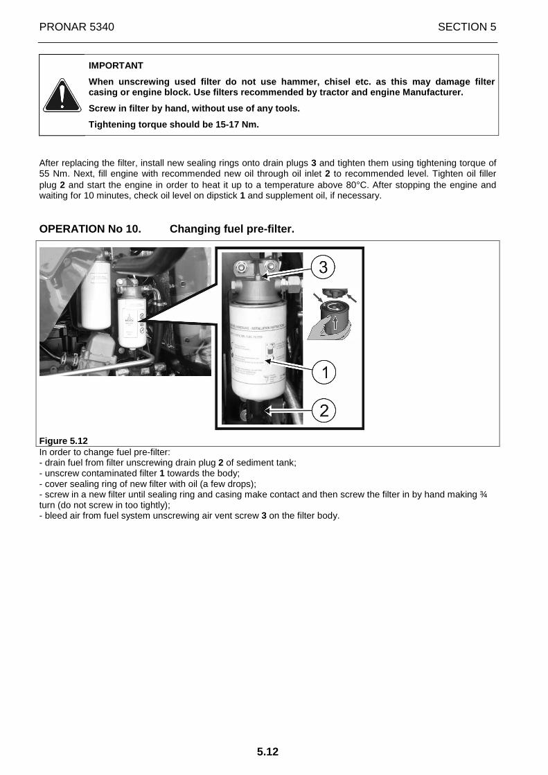
PRONAR 5340 SECTION 5
5.12
IMPORTANT
When unscrewing used filter do not use hammer, chis el etc. as this may damage filter casing or engine block. Use filters recommended by tractor and engine Manufacturer.
Screw in filter by hand, without use of any tools.
Tightening torque should be 15-17 Nm.
After replacing the filter, install new sealing rings onto drain plugs 3 and tighten them using tightening torque of 55 Nm. Next, fill engine with recommended new oil through oil inlet 2 to recommended level. Tighten oil filler plug 2 and start the engine in order to heat it up to a temperature above 80°C. After stopping the engine and waiting for 10 minutes, check oil level on dipstick 1 and supplement oil, if necessary.
OPERATION No 10. Changing fuel pre-filter.
Figure 5.12 In order to change fuel pre-filter: - drain fuel from filter unscrewing drain plug 2 of sediment tank; - unscrew contaminated filter 1 towards the body; - cover sealing ring of new filter with oil (a few drops); - screw in a new filter until sealing ring and casing make contact and then screw the filter in by hand making ¾ turn (do not screw in too tightly); - bleed air from fuel system unscrewing air vent screw 3 on the filter body.

SECTION 5 PRONAR 5340
5.13
OPERATION No 11. Oil level in gearbox and rear axle and change of oi l filter.
IMPORTANT
ATTENTION ! Before checking oil level in gearbox an d rear axle, park tractor on level ground, stop engine and apply parking brake.
Figure 5.13
Level of oil in gearbox and rear axle in PRONAR tractors should be checked visually through sight glass 1, which is located on the rear axle body, at the rear of the tractor.
Oil level should reach the central or upper section of the indicator located on the tank housing.
In the event that oil does not reach halfway up the sight glass scale, then supplement it. To do this, unscrew cap 2 from inlet opening and add oil to the required level.
After checking oil level, replace oil filter 3 located on the right side of the gearbox, behind the battery box.
To do this, proceed as follows:
• tighten air vent 4 located on housing of gear selection mechanism guide • unscrew contaminated filter 3; • cover sealing ring of new filter with oil (a few drops); • screw in new filter until sealing ring and casing make contact and then screw in by hand making one
more half turn (do not screw in too tightly). • unscrew air vent 4 and check oil level again.

PRONAR 5340 SECTION 5
5.14
IMPORTANT
When unscrewing used filter do not use hammer, chis el etc. as this may damage filter casing. Use filters recommended by tractor Manufact urer.
Screw in filter by hand, without use of any tools.
OPERATION No 12. Oil level in front drive axle body and reducers.
Figure 5.14
Oil quantity in the front wheel reducer should be checked after setting inlet-inspection opening 1 on the level of the wheel cross section axis.
Oil level in the front axle reducers should reach the lower edge of inlet-inspection opening 1. If necessary, add oil through inlet-inspection opening 1.
Oil level in the main transmission of the front drive axle should reach the lower edge of inlet-inspection opening 2. If necessary, add oil through inlet-inspection opening 2.
OPERATION No 13. Oil level in the hydraulic system tank and change o f oil filter.
IMPORTANT
ATTENTION ! Before checking oil level in the tank, park tractor on level ground, stop engine and apply parking brake.
Hydraulic oil level in PRONAR tractors should be checked visually through sight-glass 2, which is located on the hydraulic system tank, in the rear of the tractor.
Oil level should reach the central or upper section of the indicator located on the tank housing.
In the event that oil does not reach halfway up the sight glass scale, then supplement it. To do this, unscrew cap 1 from inlet opening and add oil through a strainer to the required level.

SECTION 5 PRONAR 5340
5.15
Figure 5.15
IMPORTANT
When working with machines having large capacity hy draulic systems, oil in the tractor's hydraulic system tank should be filled to the upper edge of the sight-glass on the tank.
Do NOT start tractor if oil level in tank is below the lower mark on sight-glass.
After checking oil level, replace the following filters: suction filter 4, high-pressure filter 5 (located on the left side of the tractor, near the fuel tank) and oil filter 6 located on the right side of the tractor, behind the rear wheel.
Figure 5.16
To do this, proceed as follows:
• stop the air vent located on the filler plug 1 of the hydraulic system tank;

PRONAR 5340 SECTION 5
5.16
• remove bands securing suction filter 4 of hydraulic oil (located on the left side of the tractor, behind the fuel tank), remove the filter from conduits and replace it with a new filter;
• unscrew contaminated high-pressure filter 5 (located on the left side of the tractor, in front of the fuel tank) and replace filter insert;
• cover sealing ring of the filter body with oil (a few drops), and then screw filter housing to the body. • unscrew contaminated filter 6; • cover sealing ring of new filter with oil (a few drops); • screw in new filter until sealing ring and casing make contact and then screw in by hand making one
more half turn (do not screw in too tightly). • unstop the air vent located on the filler plug 1 of the hydraulic system tank; • check oil level again.
IMPORTANT
When unscrewing used filter do not use hammer, chis el etc. as this may damage filter casing. Use filters recommended by tractor Manufact urer.
Screw in filter by hand, without use of any tools.
OPERATION No 14. Checking and adjustment of braking system.
Adjustment of working brake.
Working brake pedals do not require adjustment. They are adjusted in the factory during tractor assembly. However, when changing brake system elements, adjust position of pedals with regard to floor plate as well as free movement of working brake pedals, which should be 4÷6 mm. In order to do this:
Figure 5.17
• Loosen nuts 2 and, using adjustment bolts 1, set cushions of both pedals (3, 5) on one plane (so that they can be freely blocked with a pawl 4). After the adjustment, the distance from the lower part of both brake pedals to the floor plate should be 175±5 mm. Working stroke of brake pedals should be 130 mm.
IMPORTANT: Brake pedals should not touch elements o f cab.
• Secure adjustment bolts 1 by tightening nuts 2; • Adjust free movement of the right pedal (3) within the range of 4...6mm using spade connection 7 (free
movement of the pedals corresponds to a play of 0.5...0.8mm between piston and piston rod of each cylinder 9). In order to do this:
• loosen securing nut 6, and then, unlock and remove pin 8; • disconnect spade connection 7 from pedal lever 3

SECTION 5 PRONAR 5340
5.17
• then, screw out or screw in spade connection 7 so as to adjust the length of cylinder piston 9 in order to achieve required free pedal movement;
• tighten securing nut 6 and connect spade connection 7 with pedal lever 3 using pin 8, and then, secure the pin with a cotter pin
• Repeat the adjustment procedures for the left pedal 5
After adjustment of brake pedals, vent the braking system by performing the following activities:
• fill braking system tank 10 with required brake fluid to "max” level on the tank housing; • clean and remove covers from vents of two brake cylinders of the brakes of the tractor's rear wheels; • put pipes on vents, immerse the other ends of the pipes in transparent vessel partially filled with brake
fluid; • lock brake pedals with catch 4; • unscrew vent screws of right and left brake cylinder by 1/2...3/4 turn and press brake pedals until
resistance is felt. After pressing pedal, tighten vent screws. • Release pedal and repeat action until air bubbles cease to emerge from pipe
During venting observe quantity of brake fluid in tanks and make sure that air is not sucked in. During venting take care that the end of the pipe is continually submerged in brake fluid and vessel is held as high as possible.
After completed venting, remove venting pipes, replace covers on vents and supplement brake fluid in tanks to required level.
After adjusting foot brake, conduct adjustments of parking brake (hand brake).

PRONAR 5340 SECTION 5
5.18
Parking brake adjustment
IMPORTANT
Before checking and adjustment of parking brake (ha nd brake), check and adjust working brake (brake pedals).
Figure 5.18
A- view from the right side of drive axle; B- view from the left side of drive axle
Parking (hand) brake 1 must be able to hold tractor in place on a 18% slope. In the case of insufficient action of parking brake 1, adjust it. Undo securing nuts on cables 2 and 3. Next, adjust dimension X of cables 2 and 3 in such a manner as to ensure that tractor is immobilised on a 18% slope when the brake lever is pulled up to 10-12th tooth of pawl. Tighten securing nuts on cables 2 and 3. Pull lever 1 up to ensure that the brake works correctly.
Tightness of trailer braking pneumatic system.
The air tightness of tractor pneumatic braking system is checked in the following manner:
• switch compressor on, start engine and increase pressure to a value of 0.60÷0.65 MPa (6.0÷6.5 kG/cm2) indicated on pressure gauge located on tractor dashboard;
• set trailer brake controls in free position and stop engine;
• after 10 minutes from stopping the engine, pressure drop indicated on the pressure gauge should not exceed 2% i.e. approx. 0,012÷0,013 MPa (0,12÷0,13 kG/cm2).
While checking air tightness, the tractor pneumatic system may not be connected to the trailer system (loaded).
If pressure drop is outside the allowable range, find the cause of leak and remove it.
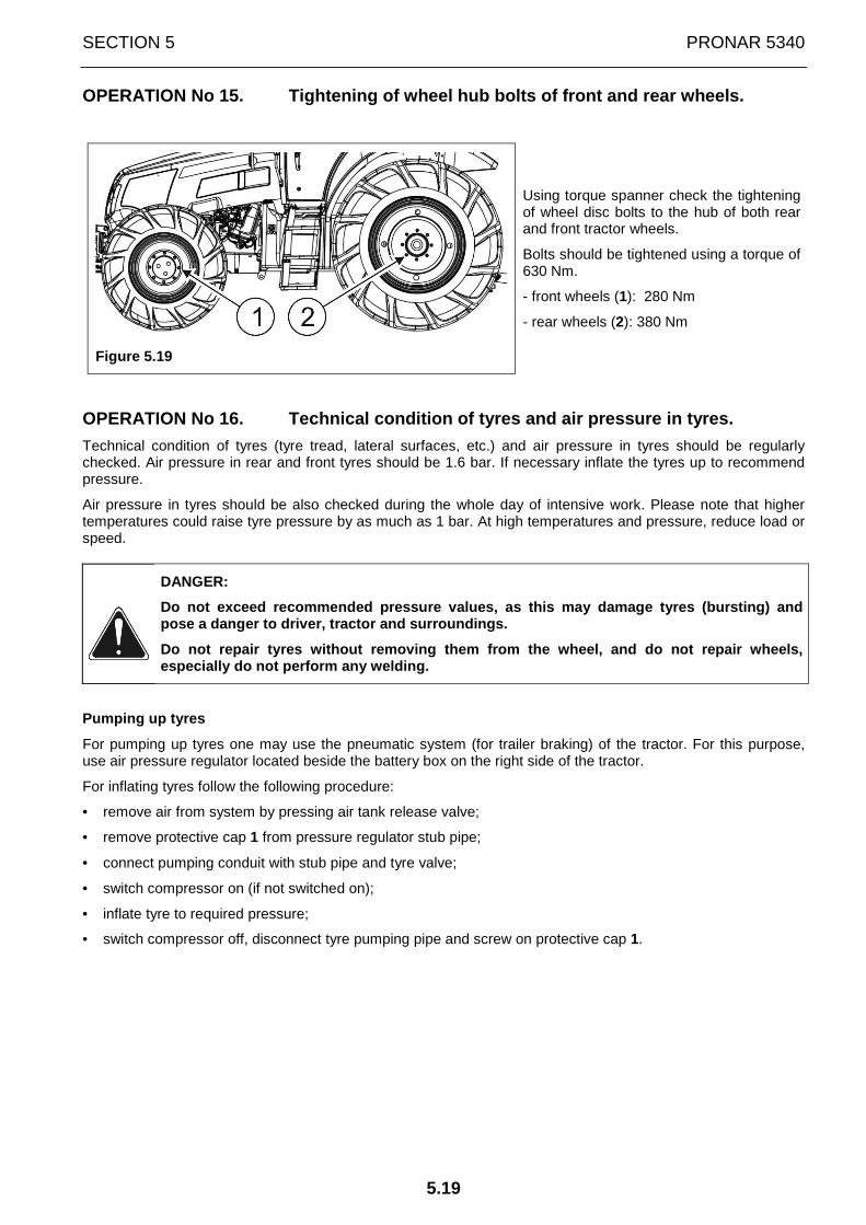
SECTION 5 PRONAR 5340
5.19
OPERATION No 15. Tightening of wheel hub bolts of front and rear whe els.
Figure 5.19
Using torque spanner check the tightening of wheel disc bolts to the hub of both rear and front tractor wheels.
Bolts should be tightened using a torque of 630 Nm.
- front wheels (1): 280 Nm
- rear wheels (2): 380 Nm
OPERATION No 16. Technical condition of tyres and air pressure in ty res.
Technical condition of tyres (tyre tread, lateral surfaces, etc.) and air pressure in tyres should be regularly checked. Air pressure in rear and front tyres should be 1.6 bar. If necessary inflate the tyres up to recommend pressure.
Air pressure in tyres should be also checked during the whole day of intensive work. Please note that higher temperatures could raise tyre pressure by as much as 1 bar. At high temperatures and pressure, reduce load or speed.
DANGER:
Do not exceed recommended pressure values, as this may damage tyres (bursting) and pose a danger to driver, tractor and surroundings.
Do not repair tyres without removing them from the wheel, and do not repair wheels, especially do not perform any welding.
Pumping up tyres
For pumping up tyres one may use the pneumatic system (for trailer braking) of the tractor. For this purpose, use air pressure regulator located beside the battery box on the right side of the tractor.
For inflating tyres follow the following procedure:
• remove air from system by pressing air tank release valve;
• remove protective cap 1 from pressure regulator stub pipe;
• connect pumping conduit with stub pipe and tyre valve;
• switch compressor on (if not switched on);
• inflate tyre to required pressure;
• switch compressor off, disconnect tyre pumping pipe and screw on protective cap 1.

PRONAR 5340 SECTION 5
5.20
Figure 5.20
The pressure regulator contains a filter to remove mechanical impurities from the air. Depending on vehicle's and regulator's working cond itions, it is recommended that lower casing 2 should be dis mantled and the filter washed 2-4 times annually. Filter may be rinsed in petrol or solvent and blown through with compressed air. The dried filter should be reinstalled in the regulator. Besides, the regulator does not require special maintenance during its use.
IMPORTANT ! Air pressure regulator may only be repa ired at authorised service points.
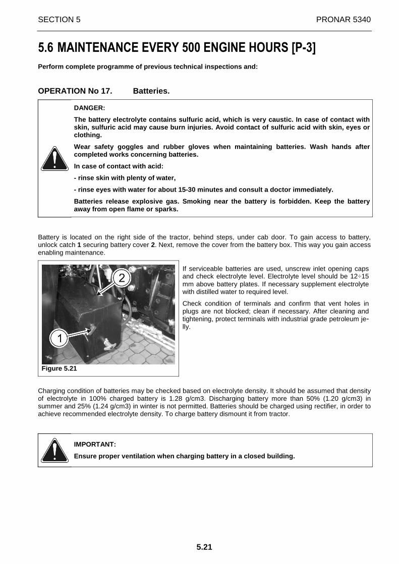
SECTION 5 PRONAR 5340
5.21
5.6 MAINTENANCE EVERY 500 ENGINE HOURS [P-3]
Perform complete programme of previous technical in spections and:
OPERATION No 17. Batteries.
DANGER:
The battery electrolyte contains sulfuric acid, whi ch is very caustic. In case of contact with skin, sulfuric acid may cause burn injuries. Avoid contact of sulfuric acid with skin, eyes or clothing.
Wear safety goggles and rubber gloves when maintain ing batteries. Wash hands after completed works concerning batteries.
In case of contact with acid:
- rinse skin with plenty of water,
- rinse eyes with water for about 15-30 minutes and consult a doctor immediately.
Batteries release explosive gas. Smoking near the b attery is forbidden. Keep the battery away from open flame or sparks.
Battery is located on the right side of the tractor, behind steps, under cab door. To gain access to battery, unlock catch 1 securing battery cover 2. Next, remove the cover from the battery box. This way you gain access enabling maintenance.
Figure 5.21
If serviceable batteries are used, unscrew inlet opening caps and check electrolyte level. Electrolyte level should be 12÷15 mm above battery plates. If necessary supplement electrolyte with distilled water to required level.
Check condition of terminals and confirm that vent holes in plugs are not blocked; clean if necessary. After cleaning and tightening, protect terminals with industrial grade petroleum je-lly.
Charging condition of batteries may be checked based on electrolyte density. It should be assumed that density of electrolyte in 100% charged battery is 1.28 g/cm3. Discharging battery more than 50% (1.20 g/cm3) in summer and 25% (1.24 g/cm3) in winter is not permitted. Batteries should be charged using rectifier, in order to achieve recommended electrolyte density. To charge battery dismount it from tractor.
IMPORTANT:
Ensure proper ventilation when charging battery in a closed building.
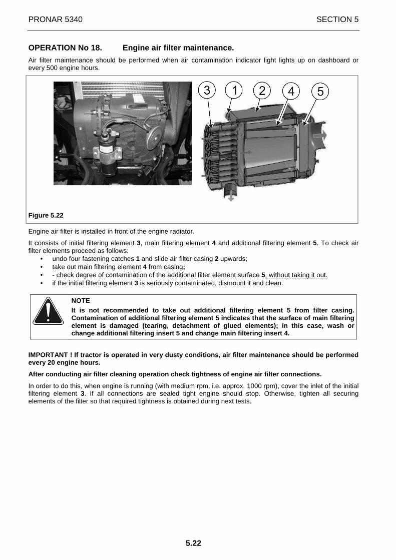
PRONAR 5340 SECTION 5
5.22
OPERATION No 18. Engine air filter maintenance.
Air filter maintenance should be performed when air contamination indicator light lights up on dashboard or every 500 engine hours.
Figure 5.22
Engine air filter is installed in front of the engine radiator.
It consists of initial filtering element 3, main filtering element 4 and additional filtering element 5. To check air filter elements proceed as follows:
• undo four fastening catches 1 and slide air filter casing 2 upwards; • take out main filtering element 4 from casing; • - check degree of contamination of the additional filter element surface 5, without taking it out. • if the initial filtering element 3 is seriously contaminated, dismount it and clean.
NOTE It is not recommended to take out additional filter ing element 5 from filter casing. Contamination of additional filtering element 5 ind icates that the surface of main filtering element is damaged (tearing, detachment of glued el ements); in this case, wash or change additional filtering insert 5 and change mai n filtering insert 4.
IMPORTANT ! If tractor is operated in very dusty co nditions, air filter maintenance should be performe d every 20 engine hours.
After conducting air filter cleaning operation chec k tightness of engine air filter connections.
In order to do this, when engine is running (with medium rpm, i.e. approx. 1000 rpm), cover the inlet of the initial filtering element 3. If all connections are sealed tight engine should stop. Otherwise, tighten all securing elements of the filter so that required tightness is obtained during next tests.
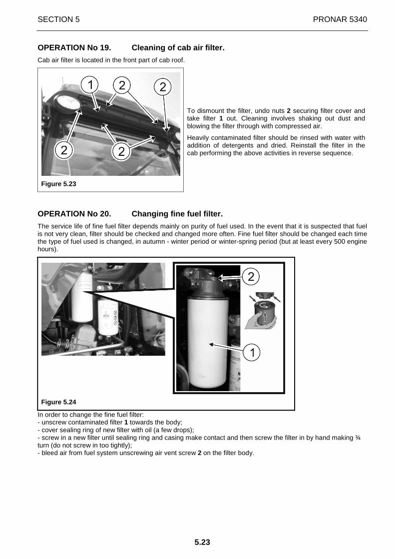
SECTION 5 PRONAR 5340
5.23
OPERATION No 19. Cleaning of cab air filter.
Cab air filter is located in the front part of cab roof.
Figure 5.23
To dismount the filter, undo nuts 2 securing filter cover and take filter 1 out. Cleaning involves shaking out dust and blowing the filter through with compressed air.
Heavily contaminated filter should be rinsed with water with addition of detergents and dried. Reinstall the filter in the cab performing the above activities in reverse sequence.
OPERATION No 20. Changing fine fuel filter.
The service life of fine fuel filter depends mainly on purity of fuel used. In the event that it is suspected that fuel is not very clean, filter should be checked and changed more often. Fine fuel filter should be changed each time the type of fuel used is changed, in autumn - winter period or winter-spring period (but at least every 500 engine hours).
Figure 5.24
In order to change the fine fuel filter: - unscrew contaminated filter 1 towards the body; - cover sealing ring of new filter with oil (a few drops); - screw in a new filter until sealing ring and casing make contact and then screw the filter in by hand making ¾ turn (do not screw in too tightly); - bleed air from fuel system unscrewing air vent screw 2 on the filter body.

PRONAR 5340 SECTION 5
5.24
OPERATION No 21. Cleaning the radiator.
DANGER
When cleaning, wear protective glasses and overalls . Other persons should remain beyond the range of particle dispersion.
Figure 5.25
Check contamination of radiator cover grille nets 1 and 2. If necessary clean them.
Use compressed air or pressure washer.
In order to clean radiator cover grille nets:
• unscrew fixing bolts 4 and pull the nets sideways; • blow them through with compressed air or rinse with water under pressure.
If coolant radiator 3 and oil cooler pipes are also contaminated, wash them using a pressure washer or blow them through with compressed air. In the event that there are greasy substances on pipes, apply detergent and then remove with pressure washer.
After completed cleaning of radiator 3, reinstall radiator cover grille nets 1 and 2.

SECTION 5 PRONAR 5340
5.25
5.7 MAINTENANCE EVERY 1000 ENGINE HOURS [P-4]
Perform complete programme of previous technical in spections and:
OPERATION No 22. Changing oil and hydraulic system filters.
IMPORTANT
Before changing oil, park tractor on level surface. Change oil directly after finishing work, after switching off engine. All hydraulic sys tem cylinders (front and rear three-point linkage) should be retracted.
Figure 5.26

PRONAR 5340 SECTION 5
5.26
In order to change oil and filters in hydraulic system:
- unscrew filler plug 2 - unscrew drain plug 1 - drain oil from the tank into previously prepared bath - remove bands securing suction filter 4 of hydraulic oil (located on the left side of the tractor, behind the fuel
tank), remove the filter from conduits and replace it with a new filter; - unscrew contaminated high-pressure filter 5 (located on the left side of the tractor, in front of the fuel tank)
and replace filter insert; - cover sealing ring of the filter body with oil (a few drops), and then screw filter housing to the body. - unscrew contaminated filter 6; - cover sealing ring of new filter with oil (a few drops); - screw in new filter until sealing ring and casing make contact and then screw in by hand making one more
half turn (do not screw in too tightly). - Tighten drain plug 1 and pour new oil into the tank until oil reaches the required level marked on sight glass
3, located on hydraulic system tank.
Oil level should reach to the central part of the sight glass located on the tank housing.
IMPORTANT
When working with machines having large capacity hy draulic systems, oil in the tractor's hydraulic system tank should be filled to the upper edge of the sight-glass on the tank.
Do NOT start tractor if oil level in tank is below the lower mark on sight-glass.
OPERATION No 23. Changing oil and oil filter in gearbox and rear axl e.
IMPORTANT
Before changing oil, park tractor on a level surfac e and immobilize it with parking brake. Change oil directly after finishing work, after swi tching off engine.
In order to change oil:
- unscrew filler plug 2 and drain plugs 1 in gearbox and rear axle; - drain oil to a previously prepared vessel - change oil filter 4 (located on the right side of gearbox). - tighten drain plugs 1; - pour new oil through filler plug 2 to the required level - tighten filler plug 2;

SECTION 5 PRONAR 5340
5.27
Figure 5.27
OPERATION No 24. Changing oil in front drive axle body and reducers.
Change oil after finishing work and stopping the engine. Before changing oil, park the tractor on a level surface and immobilize with parking brake.
Figure 5.28
In order to change oil:
• set the wheel so that control-drain-filler plug of reducer 1 is at the lowest position. Unscrew the plug and drain oil to previously prepared container.
• repeat oil draining operation for the second wheel reducer. • unscrew drain plug of front axle body 3
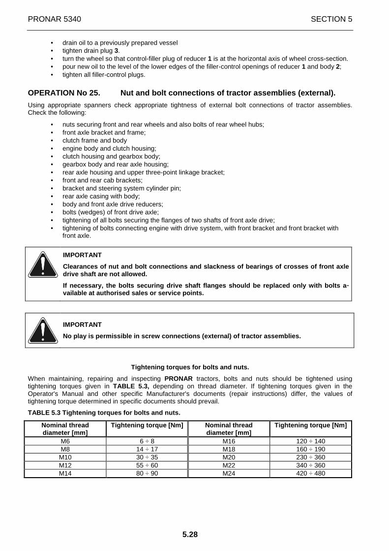
PRONAR 5340 SECTION 5
5.28
• drain oil to a previously prepared vessel • tighten drain plug 3. • turn the wheel so that control-filler plug of reducer 1 is at the horizontal axis of wheel cross-section. • pour new oil to the level of the lower edges of the filler-control openings of reducer 1 and body 2; • tighten all filler-control plugs.
OPERATION No 25. Nut and bolt connections of tractor assemblies (ext ernal).
Using appropriate spanners check appropriate tightness of external bolt connections of tractor assemblies. Check the following:
• nuts securing front and rear wheels and also bolts of rear wheel hubs; • front axle bracket and frame; • clutch frame and body • engine body and clutch housing; • clutch housing and gearbox body; • gearbox body and rear axle housing; • rear axle housing and upper three-point linkage bracket; • front and rear cab brackets; • bracket and steering system cylinder pin; • rear axle casing with body; • body and front axle drive reducers; • bolts (wedges) of front drive axle; • tightening of all bolts securing the flanges of two shafts of front axle drive; • tightening of bolts connecting engine with drive system, with front bracket and front bracket with
front axle.
IMPORTANT
Clearances of nut and bolt connections and slacknes s of bearings of crosses of front axle drive shaft are not allowed.
If necessary, the bolts securing drive shaft flange s should be replaced only with bolts a -vailable at authorised sales or service points.
IMPORTANT
No play is permissible in screw connections (extern al) of tractor assemblies.
Tightening torques for bolts and nuts.
When maintaining, repairing and inspecting PRONAR tractors, bolts and nuts should be tightened using tightening torques given in TABLE 5.3, depending on thread diameter. If tightening torques given in the Operator's Manual and other specific Manufacturer's documents (repair instructions) differ, the values of tightening torque determined in specific documents should prevail.
TABLE 5.3 Tightening torques for bolts and nuts.
Nominal thread diameter [mm]
Tightening torque [Nm] Nominal thread diameter [mm]
Tightening torque [Nm]
M6 6 ÷ 8 M16 120 ÷ 140 M8 14 ÷ 17 M18 160 ÷ 190 M10 30 ÷ 35 M20 230 ÷ 360 M12 55 ÷ 60 M22 340 ÷ 360 M14 80 ÷ 90 M24 420 ÷ 480
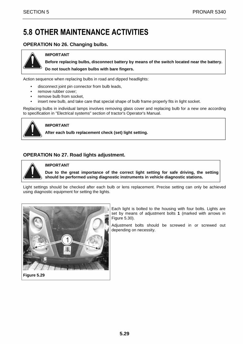
SECTION 5 PRONAR 5340
5.29
5.8 OTHER MAINTENANCE ACTIVITIES
OPERATION No 26. Changing bulbs.
IMPORTANT
Before replacing bulbs, disconnect battery by means of the switch located near the battery.
Do not touch halogen bulbs with bare fingers.
Action sequence when replacing bulbs in road and dipped headlights:
• disconnect joint pin connector from bulb leads, • remove rubber cover; • remove bulb from socket, • insert new bulb, and take care that special shape of bulb frame properly fits in light socket.
Replacing bulbs in individual lamps involves removing glass cover and replacing bulb for a new one according to specification in "Electrical systems" section of tractor's Operator's Manual.
IMPORTANT
After each bulb replacement check (set) light setti ng.
OPERATION No 27. Road lights adjustment.
IMPORTANT
Due to the great importance of the correct light se tting for safe driving, the setting should be performed using diagnostic instruments in vehicle diagnostic stations.
Light settings should be checked after each bulb or lens replacement. Precise setting can only be achieved using diagnostic equipment for setting the lights.
Figure 5.29
Each light is bolted to the housing with four bolts. Lights are set by means of adjustment bolts 1 (marked with arrows in Figure 5.30).
Adjustment bolts should be screwed in or screwed out depending on necessity.

PRONAR 5340 SECTION 5
5.30
OPERATION No 28. Toe-in of front axle wheels.
IMPORTANT
Before each adjustment of toe-in of front axle whee ls, switch engine off and brake tractor wheels with parking brake.
Inspection and adjustment of toe-in of front axle wheels should be performed after each adjustment of front axle wheel track. Wheels should be set in parallel or in convergence in the range of 0÷1 mm .
Figure 5.30
Before proceeding to set wheel toe-in, park tractor on flat, level, hard surface and immobilize it with parking brake. Raise the front of the tractor upwards and remove front wheels. Next, in place of the wheels, attach straight metal strips with openings for bolts for securing to hub, on which the distance Y=330 mm from the centre of the wheel hub will be measured. Metal strips should be set to ensure that extension X of rod 3 of steering system cylinder is the same on both sides.
In order to measure the wheel toe-in, measure distance Y on strips at the distance of 330 mm from the centre of wheel at the height of wheel hub axis and mark the place of measurement (e.g. with chalk). Next, measure distance A2 between strips, rotate hubs by 180° and measure distance A1 in previously marked place. The difference between measurements A2 and A1 (A2-A1) is the toe-in of front wheels and should amount to 0÷1 mm .
If the toe-in value is outside the required range, perform adjustment accordingly. In order to do this:
• rotate articulated joint 1 (screwing it in or screwing it out from the rod 2) to set required toe-in;
• right and left rod should be retracted or extended to identical length

SECTION 5 PRONAR 5340
5.31
OPERATION No. 29 Maintenance of tractor's hydraulic system
DANGER
Before commencing whatever work on hydraulic system reduce the pressure in the system.
DANGER
During work on hydraulic system, use the appropriat e personal protection equipment i.e. protective clothing, footwear, gloves and eye protection. Avoid contact of skin with oil.
Makes sure that the oil in the tractor's hydraulic system is of adequate grade. Do not add hydraulic oil of other grade. The hydraulic system in a new tractor is filled with HL32 hydraulic oil.
ATTENTION
The condition of hydraulic system should be inspect ed regularly while using the machine.
The hydraulic system should be completely tight sealed. Inspect the seals when hydraulic cylinders are completely extended. In the event of confirmation of oil on hydraulic ram cylinder bodies ascertain origin of leak. Minimum leaks are permissible with symptoms of "sweating", however in the event of noticing leaks in the form of "droplets" stop using the tractor until faults are remedied.
In the event of confirmation of an oil leak on hydraulic conduit connections, tighten connections, and if this does not remedy faults then change conduit or connection elements. Change of sub-assemblies is equally required in each instance of mechanical damage. Also, pay attention to ensure that flexible hydraulic conduits are not fractured.
IMPORTANT
Flexible hydraulic conduits should be replaced afte r 4 years of use.
Because of its composition the oil applied is not classified as a dangerous substance, however long-term action on the skin or eyes may cause irritation. In the event of contact of oil with skin wash the place of contact with water and soap. Do NOT apply organic solvents (petrol, kerosene). Contaminated clothing should be changed to prevent access of oil to skin. In the event of contact of oil with eye, rinse with large quantity of water and in the event of the occurrence of irritation consult a doctor. Hydraulic oil in normal conditions is not harmful to the respiratory tract. A hazard only occurs when oil is strongly atomised (oil vapour), or in the case of fire during which toxic compounds may be released. Oil fires should be quenched with the use of carbon dioxide (CO2), foam or extinguisher steam. Do NOT use water for fire extinguishing.
Spilt oil should be immediately collected and placed in marked tight container. Used oil should be taken to the appropriate facility dealing with recycling or regeneration of oils.
ATTENTION
When unscrewing used filter do not use hammer, chis el etc. as this may damage filter casing. Use filters recommended by machine manufact urer (originals).
Screw in filter by hand, without use of any tools.

PRONAR 5340 SECTION 5
5.32
5.9 PREPARATION OF TRACTOR FOR STORAGE
Preparation of tractor for longer storage requires the following actions:
• wash tractor;
• clean all grease nipples;
• park tractor in dry, ventilated and enclosed space;
• drain oil from engine, air filter bowl, drive system and hydraulic system, and then, fill these assemblies with new oil;
• drain fuel from tanks, remove sediments from filters and tanks and refill fuel system with clean fuel in quantity of approximately 10 dm3 (l). After filling, run the engine for about 10 minutes. It is recommended to apply special fuel containing preserving components;
• remove liquid from engine cooling system and cab heating system;
• release tension on vee-belt driving alternator;
• cover exhaust pipe outlet;
• dismount batteries and store them in a warm dry place where they can be occasionally charged;
• set tractor on supports under axles, so that tyres are not burdened and reduce air pressure in tyres to 70% of normal working pressure.

SECTION 5 PRONAR 5340
5.33
5.10 PREPARATION OF TRACTOR FOR WORK AFTER A LONG PERIOD OF STORAGE
Preparation of tractor for work after longer storage requires the following actions:
• supplement air in tractor wheels to values applied in normal work;
• take tractor down from supports;
• fill fuel tanks;
• fill cooling system and cab heating system with coolant;
• mount fully charged batteries;
• check level of lubricating oil in all tractor assemblies (engine, air filter, drive system and hydraulic system, front axle and its reducers, intermediate support of shaft);
• check tension of vee-belt driving alternator;
• remove cover from exhaust pipe outlet;
• start engine and check indications on all indicators and also operations of tractor's control systems;
• test drive tractor without load, to make sure that tractor and sub-assemblies operate within normal parameters.

PRONAR 5340 SECTION 5
5.34

SECTION
6
TECHNICAL
SPECIFICATION

PRONAR 5340 SECTION 6
6.2
DIMENSIONS
Figure 7.1
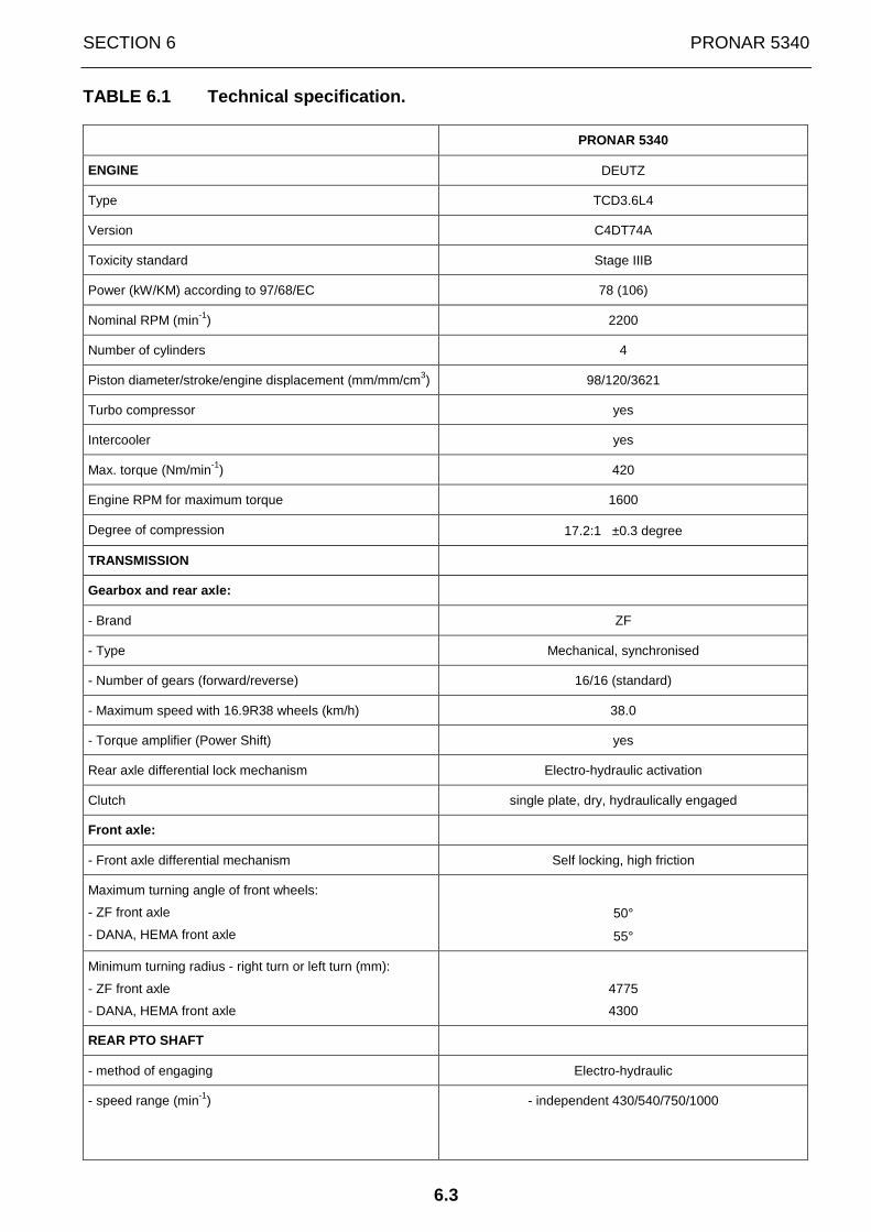
SECTION 6 PRONAR 5340
6.3
TABLE 6.1 Technical specification.
PRONAR 5340
ENGINE DEUTZ
Type TCD3.6L4
Version C4DT74A
Toxicity standard Stage IIIB
Power (kW/KM) according to 97/68/EC 78 (106)
Nominal RPM (min-1) 2200
Number of cylinders 4
Piston diameter/stroke/engine displacement (mm/mm/cm3) 98/120/3621
Turbo compressor yes
Intercooler yes
Max. torque (Nm/min-1) 420
Engine RPM for maximum torque 1600
Degree of compression 17.2:1 ±0.3 degree
TRANSMISSION
Gearbox and rear axle:
- Brand ZF
- Type Mechanical, synchronised
- Number of gears (forward/reverse) 16/16 (standard)
- Maximum speed with 16.9R38 wheels (km/h) 38.0
- Torque amplifier (Power Shift) yes
Rear axle differential lock mechanism Electro-hydraulic activation
Clutch single plate, dry, hydraulically engaged
Front axle:
- Front axle differential mechanism Self locking, high friction
Maximum turning angle of front wheels:
- ZF front axle
- DANA, HEMA front axle
50°
55°
Minimum turning radius - right turn or left turn (mm):
- ZF front axle
- DANA, HEMA front axle
4775
4300
REAR PTO SHAFT
- method of engaging Electro-hydraulic
- speed range (min-1) - independent 430/540/750/1000
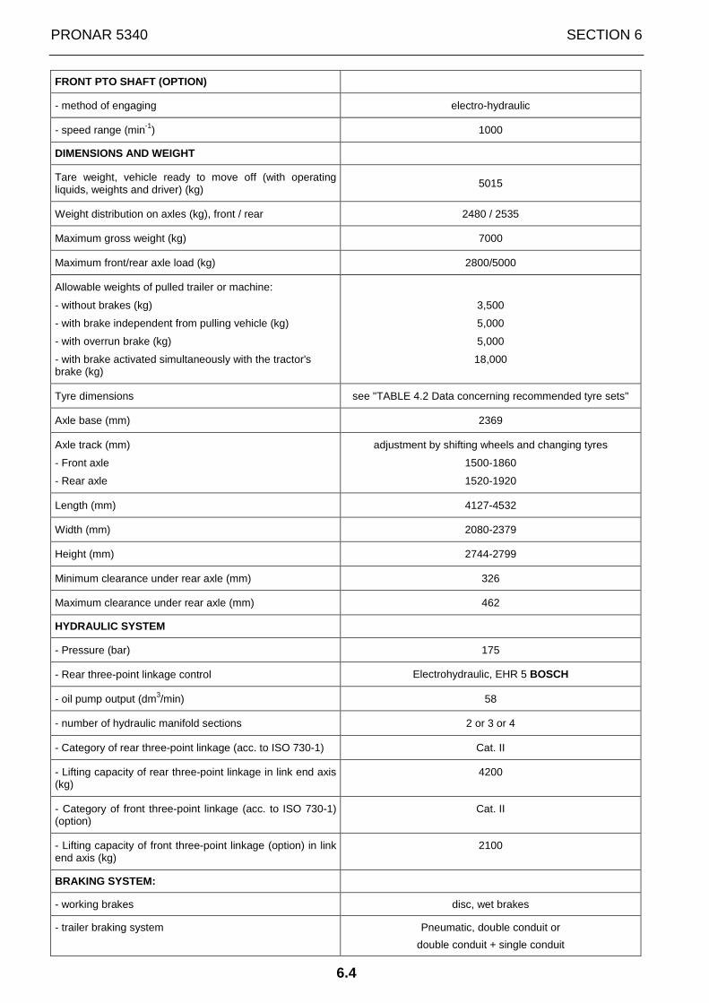
PRONAR 5340 SECTION 6
6.4
FRONT PTO SHAFT (OPTION)
- method of engaging electro-hydraulic
- speed range (min-1) 1000
DIMENSIONS AND WEIGHT
Tare weight, vehicle ready to move off (with operating liquids, weights and driver) (kg)
5015
Weight distribution on axles (kg), front / rear 2480 / 2535
Maximum gross weight (kg) 7000
Maximum front/rear axle load (kg) 2800/5000
Allowable weights of pulled trailer or machine:
- without brakes (kg)
- with brake independent from pulling vehicle (kg)
- with overrun brake (kg)
- with brake activated simultaneously with the tractor's brake (kg)
3,500
5,000
5,000
18,000
Tyre dimensions see "TABLE 4.2 Data concerning recommended tyre sets"
Axle base (mm) 2369
Axle track (mm)
- Front axle
- Rear axle
adjustment by shifting wheels and changing tyres
1500-1860
1520-1920
Length (mm) 4127-4532
Width (mm) 2080-2379
Height (mm) 2744-2799
Minimum clearance under rear axle (mm) 326
Maximum clearance under rear axle (mm) 462
HYDRAULIC SYSTEM
- Pressure (bar) 175
- Rear three-point linkage control Electrohydraulic, EHR 5 BOSCH
- oil pump output (dm3/min) 58
- number of hydraulic manifold sections 2 or 3 or 4
- Category of rear three-point linkage (acc. to ISO 730-1) Cat. II
- Lifting capacity of rear three-point linkage in link end axis (kg)
4200
- Category of front three-point linkage (acc. to ISO 730-1) (option)
Cat. II
- Lifting capacity of front three-point linkage (option) in link end axis (kg)
2100
BRAKING SYSTEM:
- working brakes disc, wet brakes
- trailer braking system Pneumatic, double conduit or
double conduit + single conduit

SECTION 6 PRONAR 5340
6.5
ELECTRICAL SYSTEM
- alternator 95A / 14V
- starter 3.2kW-12V
CAB
Very efficient ventilation and heating systems. Ergonomic control panels. Tilting side corner windows and rear window; numerous storage compartments.
Outside noise level according to Directive 2009/63/EC:
- while parked 81.8 dB (A)
- while driving 72.7 dB (A)
The driver-perceived noise level according to Directive 2009/76/EC:
- open windows 80.1 dB (A)
- closed windows 78.1 dB (A)
IMPORTANT: Due to continuous process of improvement and modernization of PRONAR products, the technical specification of tractors manufactured may differ in some details from the above specification.

PRONAR 5340 SECTION 6
6.6

SECTION
7
OILS AND OPERATING
LIQUIDS

PRONAR 5340 SECTION 7
7.2
7.1 RECOMMENDED OILS AND OPERATING LIQUIDS
TABLE 7.1 Recommended oils and operating liquids.
Place of application Quantity in dm
3
Commercial name Remarks
Fuel tank 125±5 Diesel oil *
DL- in summer; DZ- in winter
according to:
PN-EN 590+ A1:2010
Engine 9.0
DEUTZ AGPI CG-4/CH-4
According to DEUTZ reference list DQC III LA (SECTION 7.2)
e.g. Lotos TURDUS POWERTEC 5100 10W/40
Engine cooling system: 18.0 According to DEUTZ reference list CA-14 (SECTION 7.3)
e.g. FUCHS MAINTAIN FRICOFIN -35
Gearbox and rear axle lubrication system
36.0 ZF TE-ML 06 class 06B SAE 10W/40
According to ZF reference list (SECTION 7.4)
e.g. Lotos STOU Plus 10W/40
Hydraulic system 40.0 Hydraulic oil:
L-HL-32
Clutch and brake assistance system
0.7 Hydraulic oil
DOT-4 or DOT-3
Front drive axle:
- main gear: 6.5
- reducers: 2x0.7
Spec. HEMA: GL-05 SAE 80W/90 e.g. Lotos Titanis LS GL-5 80W/90
Windscreen washer 2.0 Windscreen washer liquid commercially available
Lubrication points 0.3 ŁT–42, ŁT–43
* In low ambient temperatures (below 0°C), use winter diesel oil. IMPORTANT: Detailed technical data for diesel oils used in DEUTZ engines are available on the website of the manufacturer of DEUTZ engines: http://www.deutz.de/service/maintenance/operating_liquids.en.html
IMPORTANT
Capacities of individual tractor systems are approximate. For filling always refer to marks on measuring dipstick or on inspection sight glass appliances.

SECTION 7 PRONAR 5340
7.3
7.2 REFERENCE LIST OF OILS USED IN DEUTZ ENGINE
(issue 02/2016) DEUTZ quality class: DQC III LA
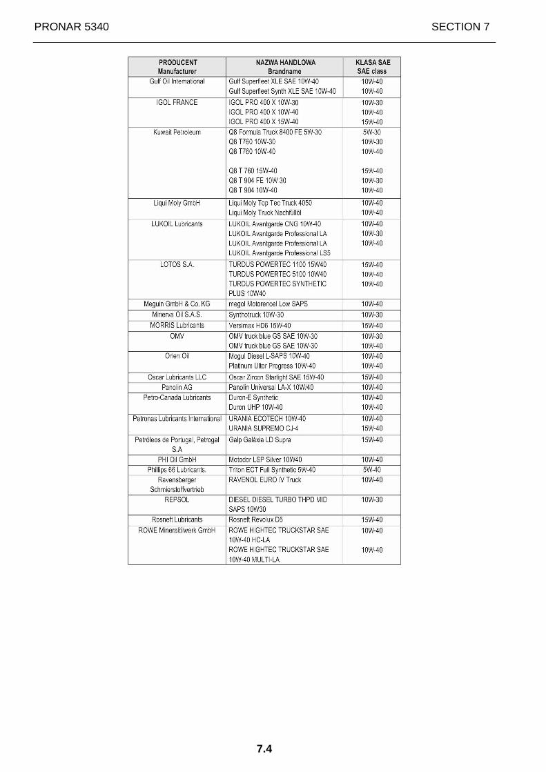
PRONAR 5340 SECTION 7
7.4

SECTION 7 PRONAR 5340
7.5
IMPORTANT: Current reference lists of oils used in DEUTZ engines are available on the website of the manufacturer of DEUTZ engines: http://www.deutz.de/service/maintenance/operating_liquids/oils/deutz_quality_class.en.html

PRONAR 5340 SECTION 7
7.6
7.3 RECOMMENDED COOLANT LIQUID CONCENTRATES FOR
DEUTZ ENGINES
We recommend using coolant liquid concentrate by DEUTZ:
Packaging Part number
5 litre container 0101 1490 20 litre container 0101 4616 210 litre container 1221 1500
The coolant liquid concentrates from the reference list of the manufacturer of DEUTZ engines (issue 02/2015) may be also used:
IMPORTANT: Current reference lists of the coolant liquid concentrates used in DEUTZ engines are available on the website of the manufacturer of DEUTZ engines: http://www.deutz.de/service/maintenance/operating_liquids/coolant.en.html
In exceptional cases, other coolants may be used. To do this, contact an authorized DEUTZ service.
Coolant solution should be prepared as follows:
Coolant concentrate content Water content Minimum ambient temperature
Min. 35% 65% -22°C 40% 60% -28°C 45% 55% -35°C
Max. 50% 50% -41°C
If the tractor is to be used in temperatures below -41°C, consult authorised DEUTZ service.
Water used in preparation of coolant solution must not contain any impurities (especially solids) and should have the following parameters:
WATER PARAMETERS MIN. MAX.
Ph value 6.5 8.5 Chlorine (Cl) mg/l - 100 Sulfates (SO4) mg/l - 100
mmol/l mg/l
3.56 356
°dGH 20.0 °e 25.0
Total hardness (CaCO3)
°fH 35.6
If other qualitative parameters are determined during the analysis, please consult authorized DEUTZ service. IMPORTANT: Industrial sewage, river, sea or salty water must not be used to prepare coolant solution.
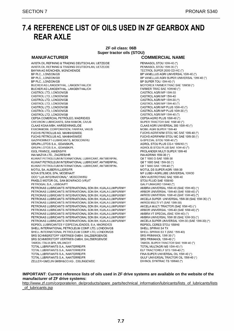
SECTION 7 PRONAR 5340
7.7
7.4 REFERENCE LIST OF OILS USED IN ZF GEARBOX AND
REAR AXLE
ZF oil class: 06B Super tractor oils (STOU)
MANUFACTURER COMMERCIAL NAME
IMPORTANT: Current reference lists of oils used in ZF drive systems are available on the website of the manufacturer of ZF drive systems: http://www.zf.com/corporate/en_de/products/spare_parts/technical_information/lubricants/lists_of_lubricants/lists_of_lubricants.jsp

PRONAR 5340 SECTION 7
7.8

NOTES
……………………………………………………………………………………………………………
……………………………………………………………………………………………………………
……………………………………………………………………………………………………………
……………………………………………………………………………………………………………
……………………………………………………………………………………………………………
……………………………………………………………………………………………………………
……………………………………………………………………………………………………………
……………………………………………………………………………………………………………
……………………………………………………………………………………………………………
……………………………………………………………………………………………………………
……………………………………………………………………………………………………………
……………………………………………………………………………………………………………
……………………………………………………………………………………………………………
……………………………………………………………………………………………………………
……………………………………………………………………………………………………………
……………………………………………………………………………………………………………
……………………………………………………………………………………………………………
……………………………………………………………………………………………………………
……………………………………………………………………………………………………………
……………………………………………………………………………………………………………
……………………………………………………………………………………………………………
……………………………………………………………………………………………………………
……………………………………………………………………………………………………………
……………………………………………………………………………………………………………
……………………………………………………………………………………………………………
……………………………………………………………………………………………………………
……………………………………………………………………………………………………………
……………………………………………………………………………………………………………
……………………………………………………………………………………………………………

……………………………………………………………………………………………………………
……………………………………………………………………………………………………………
……………………………………………………………………………………………………………
……………………………………………………………………………………………………………
……………………………………………………………………………………………………………
……………………………………………………………………………………………………………
……………………………………………………………………………………………………………
……………………………………………………………………………………………………………
……………………………………………………………………………………………………………
……………………………………………………………………………………………………………
……………………………………………………………………………………………………………
……………………………………………………………………………………………………………
……………………………………………………………………………………………………………
……………………………………………………………………………………………………………
……………………………………………………………………………………………………………
……………………………………………………………………………………………………………
……………………………………………………………………………………………………………
……………………………………………………………………………………………………………
……………………………………………………………………………………………………………
……………………………………………………………………………………………………………
……………………………………………………………………………………………………………
……………………………………………………………………………………………………………
……………………………………………………………………………………………………………
……………………………………………………………………………………………………………
……………………………………………………………………………………………………………
……………………………………………………………………………………………………………
……………………………………………………………………………………………………………
……………………………………………………………………………………………………………
……………………………………………………………………………………………………………
……………………………………………………………………………………………………………


Related Documents


