12” STATIONARY DOUBLE RUN GRAIN PUMP® OWNER’S & OPERATOR’S MANUAL Effective April 20, 2013 Publication No. 1036451 Electric Boot Drive Models P3243C4 P3244C4 P3245C4 P3246C4 IMPORTANT! The reducer gear boxes are shipped W ithout Oil. Oil must be added before conveyor operation. Refer to the Lubrication Section in this manual. Electric Head Drive Models P3255C4R P3256C4R This manual is for units with Serial No’s. 939995 or higher. Hutchinson/Mayrath · P.O. Box 629 · Clay Center, KS. 67432 Ph. 785–632–2161 · Fx. 785–632–5964 · Toll Free 800–523–6993 Hutchinson/Mayrath A Division of GLOBAL Industries Inc. www.hutchinson-mayrath.com

Welcome message from author
This document is posted to help you gain knowledge. Please leave a comment to let me know what you think about it! Share it to your friends and learn new things together.
Transcript

12” STATIONARYDOUBLE RUN GRAIN PUMP®
OWNER’S & OPERATOR’SMANUAL
Effective April 20, 2013 Publication No. 1036451
Electric Boot Drive ModelsP3243C4P3244C4P3245C4P3246C4
IMPORTANT! The reducer gear boxes are shipped Without Oil.Oil must be added before conveyor operation.Refer to the Lubrication Section in this manual.
Electric Head Drive ModelsP3255C4RP3256C4R
This manual is for units with Serial No’s. 939995 or higher.
Hutchinson/Mayrath � P.O. Box 629 � Clay Center, KS. 67432Ph. 785–632–2161 � Fx. 785–632–5964 � Toll Free 800–523–6993
Hutchinson/MayrathA Division of GLOBAL Industries Inc.
www.hutchinson-mayrath.com

Prices in effect at time of shipment will apply. Prices are subject to change without notice. All prices areF.O.B. Clay Center, Kansas. Orders shipped from locations other than Clay Center, Kansas will besubject to additional charges, such as back freight and/or additional freight.
A service charge will be assessed for all past due balances as permitted by state law not to exceed1-1/2% per month.
Processing and handling costs necessitate a minimum charge of $15.00 net on all orders.
Back orders will be shipped as they become available. Contact Hutchinson/Mayrath Customer Service foralternative shipping options or if cancellation is desired.
It is the consignee’s responsibility to check all shipments thoroughly upon receipt of goods. If any damageis discovered, it must be noted on the freight bill of lading before signing. The consignee must makenecessary claims against the respective freight line. All damage claims must be submitted within 30 days ofdelivery receipt.
All shortages must be noted at time of delivery. Shortages must be noted on the freight bill of lading beforesigning. Hutchinson/Mayrath must be advised of all concealed shortages upon discovery. Once notified ofconcealed shortages Hutchinson/Mayrath will advise corrective action to be taken.
All returns must be approved by Hutchinson/Mayrath prior to shipment. All return requests will be issued areturn authorization number. NO RETURNS WILL BE ACCEPTED WITHOUT A RETURN AUTHORIZATIONNUMBER AND PRIOR AUTHORIZATION FROM THE FACTORY. All returns must be shipped prepaid. A15% restocking charge will be applied to all returned merchandise. Custom Products may not be returnedfor credit. Only current products in new and salable condition may be returned. No safety devices may bereturned for credit.
It is the policy of Hutchinson/Mayrath to improve its product whenever possible and practical to do so. Wereserve the right to make changes, improvements and modifications at any time without incurring the obligationto make such changes, improvements and modifications on any equipment sold previously.
(a) For a period of (1) year after receipt of goods by the original consumer buyer, Hutchinson/Mayrath willsupply free of charge replacement parts for parts that prove defective in workmanship or material. Defectiveparts must be returned freight prepaid to a specified Hutchinson/Mayrath location. Only Hutchinson/Mayrathoriginal repair parts may be used for warranty repairs.(b) This limited warranty does not extend to parts designed to wear in normal operation and be replacedperiodically; or to damage caused by negligence, accident, abuse or improper installation or operation.(c) GOODS NOT MANUFACTURED BY HUTCHINSON/MAYRATH CARRY ONLY THE MANUFACTURER’SWARRANTY.(d) THIS UNDERTAKING IS IN LIEU OF ALL OTHER WARRANTIES, EXPRESSED OR IMPLIED,INCLUDING MERCHANTABILITY AND FITNESS FOR A PARTICULAR PURPOSE.
FAILURE TO FOLLOW THE INSTRUCTIONS CONTAINED IN THE OWNER’S & OPERATOR’S MANUALSAND THE ITEMS LISTED BELOW WILL RESULT IN THE VOIDING OF THIS LIMITED WARRANTY.(1) Improper assembly, including failure to properly install all safety equipment.(2) Improper installation.(3) Unauthorized alternations of goods.(4) Goods operated when obviously in need of repair.(5) Use of unauthorized repair parts.(6) Irresponsible operation.(7) Used to handle materials other than free flowing, nonabrasive and dry materials, as intended.(8) Damaged through abusive use or accident.
BUYER AGREES THAT IN NO EVENT SHALL HUTCHINSON/MAYRATH HAVE LIABILITY FOR DIRECTDAMAGES THE EXCESS OF THE CONTRACT PRICE OF THE GOODS IN RESPECT OF WHICH CLAIMIS MADE. BUYER FURTHER AGREES THAT IN NO EVENT SHALL HUTCHINSON/MAYRATH ON ANYCLAIM OF ANY KIND HAVE LIABILITY FOR LOSS OF USE, LOSS OF PROFITS, OR FOR ANY INDIRECT,INCIDENTAL OR CONSEQUENTIAL DAMAGES.
Prices:
Hutchinson/MayrathA Division of GLOBAL Industries, Inc.
Service Charge:
POLICIES AND PROCEDURES
Minimum Order:
Back Orders:
Damaged Goods:
Shortages:
Return of Goods:
Modifications:
LimitedWarranty:
Limitation ofLiability:
SAFETYPage 1
SAFETY DECALSCheck to ensure all Safety Decals are present and in good condition. If a decal cannot easily be read for anyreason, or has been painted over, replace the decal immediately. Safety decals are offered free of charge, andcan be ordered through your Hutchinson/Mayrath dealer.
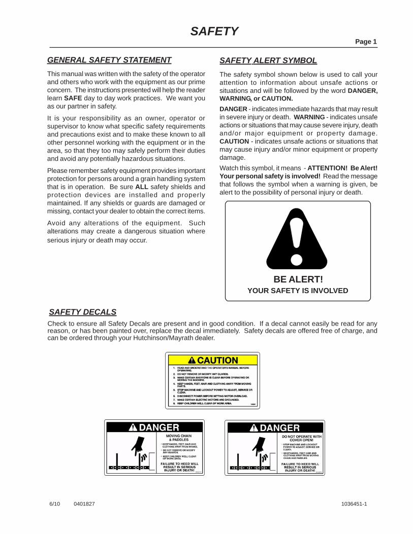
SAFETY ALERT SYMBOLThe safety symbol shown below is used to call yourattention to information about unsafe actions orsituations and will be followed by the word DANGER,WARNING, or CAUTION.DANGER - indicates immediate hazards that may resultin severe injury or death. WARNING - indicates unsafeactions or situations that may cause severe injury, deathand/or major equipment or property damage.CAUTION - indicates unsafe actions or situations thatmay cause injury and/or minor equipment or propertydamage.Watch this symbol, it means - ATTENTION! Be Alert!Your personal safety is involved! Read the messagethat follows the symbol when a warning is given, bealert to the possibility of personal injury or death.
GENERAL SAFETY STATEMENTThis manual was written with the safety of the operatorand others who work with the equipment as our primeconcern. The instructions presented will help the readerlearn SAFE day to day work practices. We want youas our partner in safety.
It is your responsibility as an owner, operator orsupervisor to know what specific safety requirementsand precautions exist and to make these known to allother personnel working with the equipment or in thearea, so that they too may safely perform their dutiesand avoid any potentially hazardous situations.
Please remember safety equipment provides importantprotection for persons around a grain handling systemthat is in operation. Be sure ALL safety shields andprotection devices are installed and properlymaintained. If any shields or guards are damaged ormissing, contact your dealer to obtain the correct items.
Avoid any alterations of the equipment. Suchalterations may create a dangerous situation whereserious injury or death may occur.
6/10 0401827 1036451-1
YOUR SAFETY IS INVOLVEDBE ALERT!
TABLE OF CONTENTSPage 2
6/10 1036451-2
SAFETY ...................................................................................................................... 1General Safety Statement ............................................................................................... 1Safety Alert Symbol ......................................................................................................... 1Safety Decals .................................................................................................................. 1
TABLE OF CONTENTS .............................................................................................. 2
GENERAL INFORMATION .................................................................................... 3 - 9Operator Qualifications ................................................................................................... 3Sign-Off Sheet ................................................................................................................. 3Right and Left Designation .............................................................................................. 3Machine Inspection ......................................................................................................... 4General Conveyor Information ........................................................................................ 4Break-In Information ........................................................................................................ 4Operating Capacities ....................................................................................................... 4Electric Drive Power Requirements ................................................................................ 5Horsepower Requirements Calculation........................................................................... 6Conveyor Dimensions ..................................................................................................... 7Designated Work Area .................................................................................................... 8Operating Procedures .................................................................................................. 8-9Electric Drive Shutdown/Lockout .................................................................................... 9
LUBRICATION & MAINTENANCE .................................................................... 10 - 13General Maintenance Information ................................................................................. 10Bearing Lubrication, Head and Inlet Hopper Bearings ................................................. 10Guards ........................................................................................................................... 10Gearbox Lubrication, Boot Drive Models ...................................................................... 11Gearbox Lubrication, Head Drive Models ................................................................ 12-13Conveyor Chain Adjustment .......................................................................................... 14Conveyor Chain Sprockets ............................................................................................ 14Check Conveyor Drive Chain Tension .......................................................................... 14Drive Belt Adjustment, Head and Boot Drive ................................................................ 15Trouble Shooting ........................................................................................................... 16
ASSEMBLY INSTRUCTIONS ............................................................................ 17 - 25Tubing Layout ........................................................................................................... 17-18Chain and Paddle Assembly ......................................................................................... 19Boot Drive Components ................................................................................................ 20Motor Mount Hole Locations for Boot Drive Units ......................................................... 21Head Drive Components ............................................................................................... 22Motor Mount Hole Locations for Head Drive Units ........................................................ 23Optional Components, Inlet Cover, Tall Hopper Ext., Tapered Hopper Ext. .................. 24Optional Discharge Spouts ............................................................................................ 25
PARTS LIST TABLE of CONTENTS ........................................................................ 26
PARTS LIST.................................................................................................... P1 to P9
POLICIES AND PROCEDURES................................................. (Inside Front Cover)

6/10 0400001 1036451-3
SIGN-OFF SHEETAs a requirement of OSHA, it is necessary for the employer to train the employee in the safe operation and safetyprocedures with this conveyor. We include this sign off sheet for your convenience and personal record keeping.
GENERAL INFORMATION
DATE EMPLOYER SIGNATURE EMPLOYEE SIGNATURE
Operation of this conveyor shall be limited to competentand experienced persons. In addition, anyone who willoperate or work around a conveyor must use goodcommon sense. In order to be qualified, the operatormust also know and meet all other requirements,such as:
1. Some regulations specify that no one under theage of 16 may operate power machinery. Thisincludes this conveyor. It is your responsibility toknow what these regulations are in your area orsituation.
2. Current OSHA regulations state in part: “At thetime of initial assignment and at least annuallythereafter, the employer shall instruct everyemployee in safe operation and servicing of allequipment which the employee is, or will beinvolved with.”*
3. Unqualified persons are to stay out of the workarea. See page 8.
4. A person who has not read and understood alloperating and safety instructions is not qualifiedto operate the machine.
*Federal Occupational Safety & Health Standards forAgriculture Subpart D, Section 1928.57 (a) (6).
Page 3
OPERATOR QUALIFICATIONS
WARNINGAnyone who will operate or work around this machine shall first read this manual! Thismanual must be delivered with the equipment to its owner. Failure to read this manual andits safety instructions is a misuse of the equipment.
RIGHT and LEFT DESIGNATIONWhen referencing the left, right, front or rear of the conveyor, it is always determined by standing at the inlet endof the conveyor and looking towards the discharge end.
GENERAL INFORMATION
MACHINE INSPECTIONOur conveyors are well made and we are proud of ourline of equipment. We would like you, as our customer,to do your part in using caution and good judgement inusing our equipment, as well as any other machinery.After delivery of your new Grain Pump® and/orcompletion of assembly and before each use,inspection of the machine is mandatory. Thisinspection should include, but not be limited to:
1. Check to see that all guards listed in theassembly instructions are in place, secured andfunctional.
2. Check all safety signs (decals) and replace anythat are worn, missing or illegible. Safety signsmay be obtained free of charge from your dealeror ordered from the factory.
3. Check all fasteners; nuts, bolts, set screws etc.for tightness.
4. Check oil levels in gearboxes (See theLubrication and Maintenance Section).
5. Make sure clean-out door in bottom of inlethopper and all inspection opening covers are shutand secured.
6. Are drive belts and conveyor chains properlyadjusted (See Maintenance Section).
Page 4
GENERAL CONVEYOR INFORMATION
It is important to become familiar with the routineoperating procedures before attempting start-up.
General Information (con’t.)
•
•
•
During operation of your conveyor, one person shallbe in a position to monitor the operation.Visually inspect the conveyor periodically duringoperation, be aware of all adjustments and checkswhich should be performed.Do Not attempt full load operation at low speeds, ashigh torque requirements may damage the conveyor.
WARNING! During initial start-up andbreak-in period, the operator shall beaware of any unusual vibrations or noisesthat would indicate a need for service orrepair.Keep all safety shields and devices inplace. Keep hands, feet, and clothingaway from moving parts.The operator should have a full view ofthe conveyor work area and check thatall personnel are free from designatedwork areas before adding power.
•
6/10 1036451-4
IMPORTANT! The conveyor should be frequentlychecked and serviced to operate freely. Keep allguards and shields in place, replace any that aredamaged or missing.
BREAK-IN INFORMATIONAny conveyor when it is new, or after sitting idle for aseason should go through a “break-in” period. Theconveyor should be run at partial capacity until severalhundred bushels of grain have been conveyed to polishthe housing. A conveyor that has not been polished inthis manner requires greater horsepower to operate,and damage to conveyor can occur.When the housing has been polished and smooth, theconveyor can be run at full capacity. Never run conveyorempty for any length of time as excessive wear willresult. If at all possible, do not stop or start the conveyorunder load, especially before the housing becomeswell polished, as this may cause the conveyor to“freeze-up.”
Obtain any needed replacement parts from yourdealer and install before using the machine.
•
OPERATING CAPACITIESThe 12” Grain Pump® conveyor has the ability to convey10,000 Bushels Per Hour (270 MTH) of reasonably drygrain during normal operating conditions.Maximum possible capacity will be less with highmoisture grain (above 15%) than with dry grain. Twenty-five percent (25%) moisture could cut capacity backby as much as 40% under some conditions.The results or capacities of conveyors can vary greatlyunder varying conditions. Different materials, moisturecontent, amounts of foreign matter, angle of operation,methods of feeding and conveyor speed all play a rolein the performance of the conveyor. A conveyoroperating at a 40° incline could be cut by 20% incapacity compared to a conveyor operating horizontally.Overfeeding the conveyor would result in increasedpower requirements, extra strain on the driveline andpossibly a complete stalling out. Under the “extra” grainpressure conditions, a control gate or other method oflimiting the amount of grain being fed into the conveyorshould be used.
• Inspect the drive before adding power and know howto shutdown in an emergency (See Page 9).
GENERAL INFORMATIONPage 5
WARNING! Shut off power and lockoutwhenever cleaning or servicing theconveyor.The reset and starting controls must belocated so that the operator has fullview of the entire operation.Disconnect power before resettingmotor overloads.Make certain electric motor is properlygrounded.A main power disconnect switch thatcan be locked in only the “Off” positionshall be provided. This shall be lockedwhenever work is being done to theconveyor.Do Not enter the grain bin unless allpower driven equipment has beenshutdown and locked out.
6/10 0401828 1036451-5
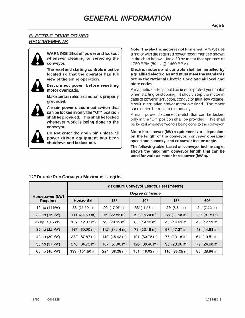
ELECTRIC DRIVE POWERREQUIREMENTS
Note: The electric motor is not furnished. Always usea motor with the required power recommended shownin the chart below. Use a 60 hz motor that operates at1750 RPM (50 hz @ 1460 RPM).Electric motors and controls shall be installed bya qualified electrician and must meet the standardsset by the National Electric Code and all local andstate codes.A magnetic starter should be used to protect your motorwhen starting or stopping. It should stop the motor incase of power interruption, conductor fault, low voltage,circuit interruption and/or motor overload. The motorshould then be restarted manually.A main power disconnect switch that can be lockedonly in the “Off” position shall be provided. This shallbe locked whenever work is being done to the conveyor.
Motor horsepower (kW) requirements are dependanton the length of the conveyor, conveyor operatingspeed and capacity, and conveyor incline angle.The following table, based on conveyor incline angle,shows the maximum conveyor length that can beused for various motor horsepower (kW’s).
12” Double Run Conveyor Maximum Lengths
25 hp (18.5 kW)
15 hp (11 kW)
Horsepower (kW)Required
Maximum Conveyor Length, Feet (meters)
Horizontal 15�
83’ (25.30 m)
Degree of Incline
30� 45� 60�
56’ (17.07 m) 38’ (11.58 m) 29’ (8.84 m) 24’ (7.32 m)
20 hp (15 kW) 111’ (33.83 m) 75’ (22.86 m) 50’ (15.24 m) 38’ (11.58 m) 32’ (9.75 m)
139’ (42.37 m) 93’ (28.35 m) 63’ (19.20 m) 48’ (14.63 m) 40’ (12.19 m)
30 hp (22 kW) 167’ (50.90 m) 112’ (34.14 m) 76’ (23.16 m) 57’ (17.37 m) 48’ (14.63 m)
40 hp (30 kW) 222’ (67.67 m) 149’ (45.42 m) 101’ (30.78 m) 76’ (23.16 m) 64’ (19.51 m)
50 hp (37 kW) 278’ (84.73 m) 187’ (57.00 m) 126’ (38.40 m) 95’ (28.96 m) 79’ (24.08 m)
60 hp (45 kW) 333’ (101.50 m) 224’ (68.28 m) 151’ (46.02 m) 115’ (35.05 m) 95’ (28.96 m)

GENERAL INFORMATION
HORSEPOWER (kW) REQUIREMENTSPOWER CALCULATIONSelect the angle of operation and a grain pump size that can deliver the needed capacity for your application.The maximum capacity for the 12” conveyor is 10,000 bushels per hour (270 MTH) and will likely only beachieved in horizontal operation.Maximum capacity will likely reduce as operating angle increases due to reduced feeding efficiency at the intakehopper. In the higher angles of operation, capacity reductions from 30% to 50% of maximum capacity arepossible. Using the Inlet Extension will place grain higher in the inlet hopper for increased efficiency.Use the table below to determine the horsepower per foot (kW per meter) for the operating capacity and angle ofoperation. The power values are for maximum capacity, for operating capacity below maximum, reduce thepower proportionally.To determine the required power for your application:Multiply the conveyor length by the horsepower per foot (kW per meter) shown in the table below.For calculation purposes, the head and boot together are 13 feet (3.96 m) of conveyor length.Then add the length of tube housing sections for total conveyor length.
Page 6
6/10 0401829 1036451-6
For Example:If using two 10’ (3.05 m) housing sections with conveyor in the 30° operating position.Add the two housing sections together, 10’ + 10’ = 20’ (6.10 m) then add the 13’ (3.96 m) for the headand boot sections. Total conveyor length is 33’ (10.06 m).10’ + 10’ = 20’ + 13’ = 33’(3.05 m + 3.05 m = 6.10 m + 3.96 m = 10.06 m)
Now multiply the 33’ (10.06 m) by the horsepower per foot (kW per meter) shownin the 30° column in the table below.33’ x .397 hp = 13.10 hp you would need a 15 hp motor(10.06 m x .968 kW = 9.74 kW use a 11 kW motor)
To achieve proper operating efficiency, always use a motor with thenext highest horsepower (kW) rating as compared to the answer in your final calculation.
Horizontal
Horsepower Per Foot(kW per meter)
Horsepower (kW)Required 15�
.18 hp(.439 kW)
Angle of Operation
30� 45� 60�
.268 hp(.654 kW)
.397 hp(.968 kW)
.524 hp(1.278 kW)
.629 hp(1.534 kW)
12” Double Run Power TableMaximum Capacity is 10,000 BPH (270 MTH)

CONVEYOR DIMENSIONSThe dimensions shown below are typical for both the boot drive and head drive conveyors (See Fig. 1).Conveyor lengths will vary dependant on the number of housing sections used. Note the maximum conveyorlengths shown in the chart on Page 5. Make sure to use the correct horsepower (kW) requirements for yourparticular application.NOTE: The spouts, tapered hopper extension and the tall hopper extension can be used on either the bootdrive or head drive units.
GENERAL INFORMATIONPage 7
6/10 0401830 1036451-7
3’�1”(94.0 cm)
3’�11 1/8”(1.20 m) Conveyor with Boot Drive
Conveyor with Head Drive
10’(3.05 m)
1’�2 7/16”(36.7 cm)
2’�4 7/8”(73.3 cm)
10’–3 5/8”(3.14 m)
3’�3”(99.1 cm)
2’�8 9/16”(82.7 cm)
Tapered HopperExtension
Tapered ExtensionCover
Tall HopperExtension
2’�2”(66.0 cm)
Tall ExtensionCover
90� Spout
60� Spout45� Spout
Optional SpoutsAvailable
Conveyor Dimesions are thesame for both the Boot Drive
and Head Drive Models.
Fig. 1

GENERAL INFORMATIONPage 8
6/10 1036451-8
WARNING! Under no circumstancesshould persons not involved in theoperation be allowed to trespass intothe work area.It shall be the duty of all operator’s tosee that children and/or other personsstay out of the work areas. Trespassinginto the work area by anyone notinvolved in the actual operation, ortrespassing into a hazard area byanyone shall result in immediateshutdown by the operator.It shall be the responsibility of theoperator’s to see that the work area hassecure footing, is clean and free of alldebris and tools which might causeaccidental tripping and/or falling. Itshall also be their responsibility to keepthe work area clean and orderly duringthe operation.
DESIGNATED WORK AREA
Before starting the conveyor, a designated work areashould be established and properly marked.This areas shall be marked off with colored nylon orplastic rope or banners hung as portable barriers todefine the designated work area.All operator’s shall know how to shutdown and lock-out the equipment in the event of an emergency (seePage 9 for shutdown and lockout information).
OPERATING PROCEDURES
WARNING! The operator shall beaware of any unusual vibrations, noisesand the loosening of any fasteners.Keep all safety shields and devices inplace. Keep hands, feet and clothingaway from moving parts.The operator shall have a full view theconveyor work area and check that allpersonnel are clear of hazard areasbefore adding power.A main power disconnect switch thatcan be locked in only the “Off” positionshall be provided. This shall be lockedwhenever work is being done to theconveyor.The reset and starting controls must belocated so that the operator has fullview of the entire operation.Disconnect power before resettingmotor overloads. Make certain electricmotor is grounded.Shut off power and lockout whenevercleaning or servicing the conveyor.
Check the following before adding power:All safety devices are in place and properlyfastened, and the clean-out door on bottom ofhopper is in place.Drive belts are properly tightened and in goodcondition, Replace belts if they are cracked,frayed, or damaged in anyway.Check electrical cords to ensure they are in goodcondition. Replace if necessary.Check electric power box and controls. Verify thepower source can be locked out.Ensure conveyor is properly positioned and workarea is appropriately marked and free of tools,debris and other hazards.Verify all drive component hardware and fastenersare tight, i.e. motor mount, pulleys, setscrews etc.
•
•
•
•
•
•

1. Start the electric motor and check to make sureconveyor is running properly.
2. Slowly begin filling the inlet hopper with grain untildesired flow rate is achieved.
3. Monitor grain entering and exiting the conveyorduring operation until it is time to shut down theunit.
4. Before shutting down the conveyor, shut off grainflow into the hopper and allow the conveyor toempty.
Begin Grain Conveying Operations
ELECTRIC DRIVE SHUTDOWN/LOCKOUT
WARNING! If the operator must leavethe work area, or whenever servicingor adjusting, the conveyor must bestopped and the power source turnedoff and locked out.Precaution should be made to preventanyone from operating the conveyorwhen the operator is away from thework area.
Emergency ShutdownShould the conveyor be immediately shutdown underload, disconnect and lockout the power source.Clear as much grain from the hopper and conveyor asyou can. Use the clean-out door in the bottom of thehopper to help clean grain from this area.When as much grain as possible has been cleared,reconnect the power source and clear the conveyorgradually.Never attempt to restart conveyor when full of grain.Starting the unit under load may result in damage tothe conveyor, such damage is considered abuse andis not covered by warranty.
Normal ShutdownMake certain that the hopper and conveyor are emptybefore stopping the unit. Before the operator leavesthe work area, the power source shall be locked out(See “Lockout” below).
Intermittent ShutdownWhen a conveyor is stopped and restarted under fullload, it may result in damage to the conveyor. There-fore if intermittent operation is to be carried out, it isadvisable to reduce the load level.When kept from absolute filling, conveyor start-up iseasier and operation more efficient.
LockoutThe power source for electric units shall have a maindisconnect box that can be locked only in the “Off”position. That is what “shutdown and lockout” refersto - Shut off the main power source and lock the handleor breaker switch in the “Off” position.
GENERAL INFORMATIONPage 9
6/10 1036451-9
OPERATING PROCEDURES (con’t.) ELECTRIC DRIVE SHUTDOWN/LOCKOUT (con’t.)

LUBRICATION & MAINTENANCEPage 10
6/10 0401831 1036451-10
WARNING! Shut off power and lockoutbefore attempting to adjust, service,clean or repair the conveyor or any ofits components.Keep hands, feet and clothing awayfrom moving parts.Make sure all safety devices, shieldsand guards are in place and functional.Immediately replace any that aredamaged or missing.Never rely solely on mechanical orhydraulic jacks for support. Use jackstands or equivalent for support.Never operate the conveyor with accessdoors or panels open.
GENERAL MAINTENANCE INFORMATION
For economical and efficient operation of yourconveyor, maintain regular and correct lubrication,maintenance and service schedules. Neglect leadsto reduced efficiency, excessive wear and needlessdown time.Any parts needing replacement should be replacedwith parts of the same type and size. Do Not modifyor alter any of the conveyor components.
GUARDSCheck the guards to see if they are properly adjustedand securely fastened.Guards should not be rubbing against pulleys, belts,chains or sprockets. Immediately replace any guardsthat are damaged.
The head bearings are located on the head section atthe discharge end of the conveyor (one bearing oneach side of the head section) See Fig. 2.The inlet hopper bearing is located on the right handside of the inlet hopper on boot drive units and onboth sides of the hopper on head drive units.These bearings are fitted with grease zerks (lubricationfittings) and should be lubricated approximately onceannually.Before greasing the bearings, make sure the zerksare free of dirt, otherwise the dirt will be passed intothe bearing race which can cause contaminationresulting in bearing failure.Use an SAE multi-purpose type grease.Normally only one to two pumps of the grease gun issufficient when servicing the bearings. NOTE: Overgreasing can be just as harmful as under greasing ifit forces grease out of the bearing seals.The bearings themselves do not require adjustment,but check to make sure the hardware securing thebearings is tight. Also check the setscrews in the lockcollars to ensure they are tight against the shaft.
BEARING LUBRICATIONHEAD & INLET HOPPER BEARINGS
Head Bearings(one on each side)
Boot (Inlet Hopper)Bearing
Only one bearing on Boot Drive Units.Two bearings on inlet hopper with
Head Drive Units (one on each side)
Fig. 2

LUBRICATION & MAINTENANCEPage 11
6/10 0401832 1036451-11
GEARBOX LUBRICATIONBOOT DRIVE MODELS
Even under normal working conditions, oil will stilldissipate. Check oil level in gearboxes periodicallyand maintain proper level.
WARNING! Keep all safety shields anddevices in place.Never clean, adjust or lubricate a machinethat is in operation.
CAUTION: Too much oil will cause overheatingand too little oil will result in gear wear and gearfailure. Check oil level regularly.
IMPORTANT! The gearbox is shipped without oil. Oilneeds to be added before operation of the conveyor.
Proper lubrication is extremely important for operation.Follow the instructions on the reducer nameplate, itswarning tag and in the installation manual provided withthe gearbox. Failure to observe these precautionscould result in damage to the equipment.
Recommended Oil:
Oil Change Intervals:Initial change after 2 weeks (if desired, this oilmay be filtered and reused).Thereafter, every 2500 hours, or 6 months(whichever comes first). Oil should be drained,magnetic plug cleaned, and gearbox flushed andrefilled.Under extreme conditions, 1 to 3 months.
Very often, small metal particles will show up in the oildue to the wearing process. A magnetic drain plug isprovided to help contain the particles.
Oil should be changed more frequently when conveyoris being operated at high temperatures, under extremedirty conditions, or when operated continuously.Under these extreme conditions the oil should bechanged every 1 to 3 months, depending on severityof the conditions.
1. Before adding oil to the gearbox, the conveyorshould be positioned in the operating position it willmost likely be used at. Determine the lowest pointof the gearbox with the conveyor in this position.Remove the existing plug from this location.Replace the plug with the magnetic plug provided.
2. Remove and discard the shipping tape that coversthe fill/ventilation plug and install the provided ventplug in the top most hole of the gearbox asdetermined by its operating position (the plug mayhave been installed at the factory, but may need tobe relocated depending on the conveyors operatingposition).
3. Remove the oil vent/fill plug and add 6 qts. (5.68 l)of a high grade petroleum base, rust & oxidationinhibited (R&O) gear oil.
In some applications, the conveyor may be left in itsoperating position until either moved to a new bin siteor until put into storage at seasons end. To check theoil level during the time the conveyor remains in theoperating position, use a dipstick or similar device andinsert into one of the plug holes to take a reading, markthe oil level on the dipstick. Use this same method fortaking future oil level readings (conveyor must be inthe same position for future oil readings as it was whenthe first initial reading was taken).
For normal operating temperatures (between 40°Fand 120°F) we recommend an SAE 90 weight, highgrade petroleum base, rust and oxidation inhibited(R&O) gear oil.For temperatures below 40°F use an SAE 80 weightoil of the same grade (use a grade commerciallyavailable for automotive differentials).Extra pressure additives may be of value in severeapplications.
0� 15�
45�30�
60�
Vent &Fill PlugOil Level
Vent
VentVent
Vent &Fill Plug
OilLevel
OilLevel
Fig. 3

LUBRICATION & MAINTENANCEPage 12
6/10 1036451-12
GEARBOX LUBRICATIONHEAD DRIVE MODELS
The running position of the gearbox in a horizontalapplication is not limited to the four positions shownon the following page (Page 13). However if runningposition is over 20° either way from the positionsshown, the oil level plug cannot be used to check theoil level unless the torque arm is disconnected andthe gearbox is swung to one of the positions shown.Because of the many possible positions of the gear-box, it may be necessary or desirable to make specialadapters using the lubrication fitting holes furnishedalong with other standard pipe fittings, stand pipes, oillevel gauges or a dipstick as required.If using a dipstick type device, add the appropriateamount of oil and using the dipstick, take a readingfrom any of the upper plug openings. Mark the leveland use this method each time the level is checked(make sure that the gearbox is in the same positionand the same plug opening is used each time the oillevel is checked).
1. The oil fill amount will vary depending on conveyoroperating position. Before adding oil to thegearbox, the conveyor should be positioned in theoperating position it will most likely be used at.Determine the lowest point of the gearbox with theconveyor in this position. Remove the existing plugfrom this location. Replace the plug with themagnetic plug provided.
WARNING! Keep all safety shields anddevices in place.Never clean, adjust or lubricate a machinethat is in operation.
Even under normal working conditions, oil will stilldissipate. Check oil level in gearboxes periodicallyand maintain proper level.
CAUTION: Too much oil will cause overheatingand too little oil will result in gear wear and gearfailure. Check oil level regularly.
IMPORTANT! The gearbox is shipped without oil. Oilneeds to be added before operation of the conveyor.
Proper lubrication is extremely important for operation.
Recommended Oil:For normal operating temperatures (between 40°Fand 120°F) we recommend an SAE 90 weight, highgrade petroleum base, rust and oxidation inhibited(R&O) gear oil.For temperatures below 40°F use an SAE 80 weightoil of the same grade (use a grade commerciallyavailable for automotive differentials).Extra pressure additives may be of value in severeapplications.
Very often, small metal particles will show up in the oildue to the wearing process. A magnetic drain plug isprovided to help contain the particles.
After an initial operation of about 2 weeks, the oil shouldbe changed (if desired this oil can be filtered and re-used). After the first initial break-in period, the oil should bedrained, magnetic plug cleaned gearbox flushed andrefilled every 2500 hours of operation or 6 months,whichever comes first.Oil should be changed more frequently when conveyoris being operated at high temperatures, under extremedirty conditions, or when operated continuously.Under these extreme conditions the oil should bechanged about every 3 months, depending on theseverity of the conditions.
2. The oil vent/fill plug may need to be relocateddepending on the position of the gearbox whenconveyor is in the operating position. If necessarymove the vent/fill plug (breather) to one of thehighest locations possible.Add the necessary amount of a high grade SAE 90weight petroleum base, rust & oxidation inhibited(R&O) gear oil through the vent/fill opening (Seechart on Page 13 for correct amount of oil).
Oil Capacities:See chart on Page 13.
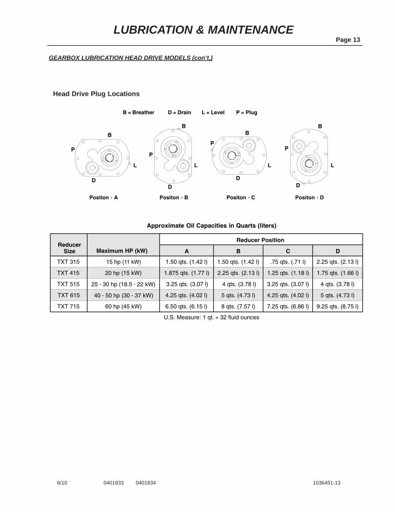
L
B
D
P
Positon � A Positon � B Positon � C Positon � D
L
B
D
P
L
B
D
P
L
B
D
P
L � LevelB � Breather D � Drain P � Plug
Head DrivePlug Locations
TXT 515
TXT 315
ReducerSize Maximum HP (kW) A
15 hp (11 kW)
Reducer Position
B C D
1.50 qts. (1.42 l)
TXT 415 20 hp (15 kW) 1.875 qts. (1.77 l)
25���30 hp (18.5���22 kW) 3.25 qts. (3.07 l)
TXT 615 40���50 hp (30���37 kW) 4.25 qts. (4.02 l)
TXT 715 60 hp (45 kW) 6.50 qts. (6.15 l)
1.50 qts. (1.42 l)
2.25 qts. (2.13 l)
4 qts. (3.78 l)
5 qts. (4.73 l)
8 qts. (7.57 l)
.75 qts. (.71 l)
1.25 qts. (1.18 l)
3.25 qts. (3.07 l)
4.25 qts. (4.02 l)
7.25 qts. (6.86 l)
2.25 qts. (2.13 l)
1.75 qts. (1.66 l)
4 qts. (3.78 l)
5 qts. (4.73 l)
9.25 qts. (8.75 l)
U.S. Measure: 1 qt.�� 32 fluid ounces
Approximate Oil Capacities in Quarts (liters)
GEARBOX LUBRICATION HEAD DRIVE MODELS (con’t.)
LUBRICATION & MAINTENANCEPage 13
6/10 0401833 0401834 1036451-13
Head Drive Plug Locations
LUBRICATION & MAINTENANCEPage 14
2/11 0402031 0402032 1036451-14
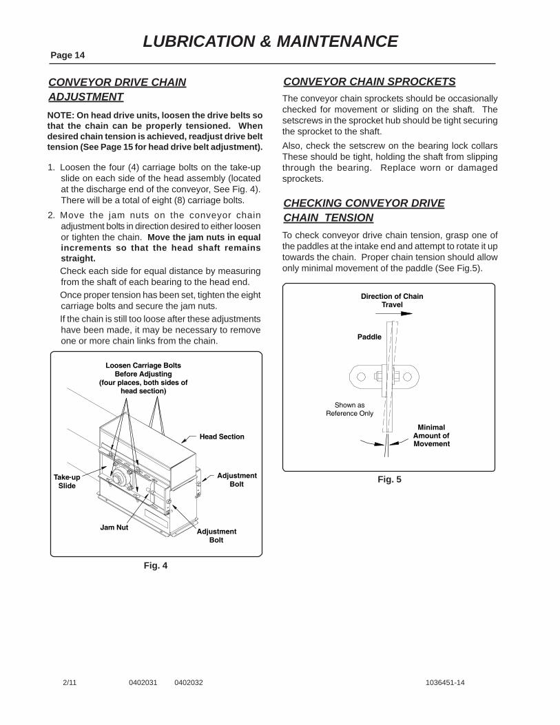
CONVEYOR DRIVE CHAINADJUSTMENTNOTE: On head drive units, loosen the drive belts sothat the chain can be properly tensioned. Whendesired chain tension is achieved, readjust drive belttension (See Page 15 for head drive belt adjustment).
1. Loosen the four (4) carriage bolts on the take-upslide on each side of the head assembly (locatedat the discharge end of the conveyor, See Fig. 4).There will be a total of eight (8) carriage bolts.
2. Move the jam nuts on the conveyor chainadjustment bolts in direction desired to either loosenor tighten the chain. Move the jam nuts in equalincrements so that the head shaft remainsstraight.Check each side for equal distance by measuringfrom the shaft of each bearing to the head end.Once proper tension has been set, tighten the eightcarriage bolts and secure the jam nuts.If the chain is still too loose after these adjustmentshave been made, it may be necessary to removeone or more chain links from the chain.
Fig. 4
CONVEYOR CHAIN SPROCKETSThe conveyor chain sprockets should be occasionallychecked for movement or sliding on the shaft. Thesetscrews in the sprocket hub should be tight securingthe sprocket to the shaft.Also, check the setscrew on the bearing lock collarsThese should be tight, holding the shaft from slippingthrough the bearing. Replace worn or damagedsprockets.
CHECKING CONVEYOR DRIVECHAIN TENSIONTo check conveyor drive chain tension, grasp one ofthe paddles at the intake end and attempt to rotate it uptowards the chain. Proper chain tension should allowonly minimal movement of the paddle (See Fig.5).
Fig. 5
Loosen Carriage BoltsBefore Adjusting
(four places, both sides ofhead section)
AdjustmentBolt
AdjustmentBolt
Jam Nut
Head Section
Take�upSlide
Shown asReference Only
Direction of ChainTravel
Paddle
MinimalAmount ofMovement

DRIVE BELT ADJUSTMENTHEAD DRIVE & BOOT DRIVEAll belts need to be checked and adjusted periodicallyto assure all belt driven components are performingproperly. Check belts for fraying, cracking or any othersigns of damage. Replace as needed.Belt tension must be sufficient to avoid any slipping orabnormal wear during conveyor operation. Do Notovertighten the belts. Overtightening creates highstress on the belts and conveyor components and canresult in excessive vibration. This vibration can resultin damage to the conveyor components.Check to see that correct alignment of the sheavesand belts is maintained. Check that all sheaves aresecured on their shaft, drive key is in place and thesetscrews are tight.
1. Loosen the four (4) carriage bolts securing the feetof the motor mount plate to the brackets on theconveyor housing (See Fig. 6).Note the two 3/4” nuts securing the threaded rod tothe adjustment bracket. Loosen the nut on the backside of the bracket and thread the nut back a coupleof inches.Turn the nut on the front side of the bracket untilproper belt tension has been achieved. Proper belttension is 9/16” of deflection per belt when using7.5 lbs. of force at the center of the span betweenthe two sheaves.After 24 hours of operation, and for the remainderof belt life, deflection should be 9/16” using 4 to 5.5lbs. of force. If you do not have a weight set toapply the recommended amount of force, a fishscale is a good alternative. Tension can also bechecked by pressing firmly on the belts at thecenter of the span between the two sheaves.
LUBRICATION & MAINTENANCEPage 15
6/10 0401837 1036451-15
Adjust Belt TensionBoot Drive Units
1. Locate the 1” diameter threaded adjustment rodattached to the reducer gearbox (See Fig. 6).Use the adjustment nuts to set belt tension. Onceproper tension has been achieved, tighten the nutsagainst the adjustment retainer to secure theadjustment rod into place.Proper belt tension is 9/16” of deflection per beltTension can be checked by pressing firmly on thebelts at the center of the span between the twosheaves.
Adjust Belt TensionHead Drive Units
ThreadedAdjustment Rod
Loosen the 4 Carriage Boltsthat Secure Motor Mount Plate
(2 on each side)
Boot Drive Units
Head Drive UnitsThreaded
Adjustment Rod
Fig. 6

LUBRICATION & MAINTENANCEPage 16
6/10 1036451-16
TROUBLE SHOOTING
Extreme Noise from Housing1. Conveyor chain is too loose. Check chain tension
and adjust if necessary (See Page 14).2. Improper assembly or misalignment of housing.
Loosen housing connection(s) that are source ofnoise and disassemble, Check for end smoothnessand grind if necessary.
3. Sprockets at intake or discharge end may be offcenter. Check the set screw in the sprocket toensure that it is tight.
Belt Slippage on Drive Belts1. Incorrect belt tension. Use the adjustment rods to
set proper belt tension (See Page 15),2. Unit is plugged. Shutdown and lockout power
source. Clean the grain and any obstructions fromthe machine.
Grain Returning to the Intake End Through theTop of the Unit1. The discharge spout may be mounted backwards.
Spout must be mounted so it slopes back towardsthe main body of the conveyor.
2. Partially blocked discharge. Shutdown and lockoutpower source, remove obstruction.
Unit not Running to Full Capacity1. Grain is high in moisture. A low capacity will likely
be achieved with high moisture grain. Excessivefeeding of high moisture grain can cause plugging.
2. Chain speed is too low. See recommendedhorsepower requirements chart on Page 5.
3. Obstruction at intake. Shutdown and lockout powersource, remove obstruction.
Paddle Breaking or Bending1. Paddles may be coming loose from the chain. Keep
paddles securely fastened to chain.2. Housing misalignment.3. Frequent starts under loads. Allow machine to clean
out before shutting down.4. Sprockets at intake or discharge may be off center.
Align in center of housing.5. Overfeeding. Adjust the feeding of the conveyor to
allow less grain to enter while maintaining full speed.
ASSEMBLY INSTRUCTIONSPage 17
6/10 0401838 1036451-17
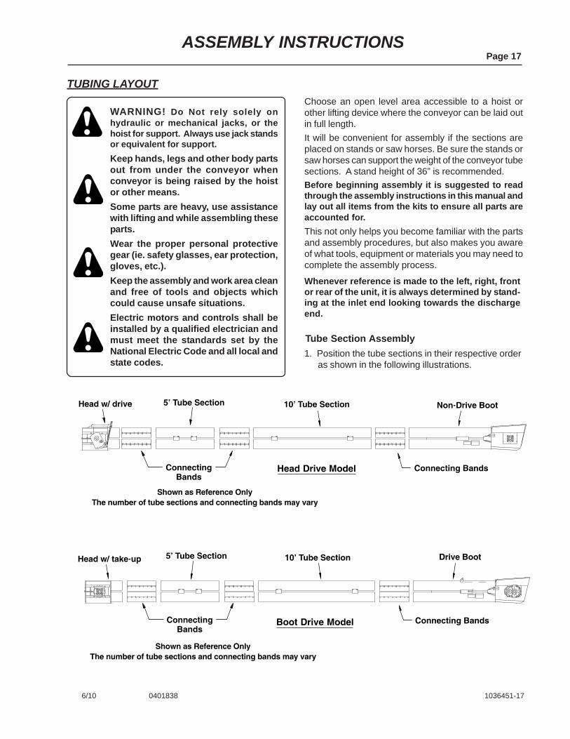
TUBING LAYOUT
WARNING! Do Not rely solely onhydraulic or mechanical jacks, or thehoist for support. Always use jack standsor equivalent for support.Keep hands, legs and other body partsout from under the conveyor whenconveyor is being raised by the hoistor other means.Some parts are heavy, use assistancewith lifting and while assembling theseparts.Wear the proper personal protectivegear (ie. safety glasses, ear protection,gloves, etc.).Keep the assembly and work area cleanand free of tools and objects whichcould cause unsafe situations.Electric motors and controls shall beinstalled by a qualified electrician andmust meet the standards set by theNational Electric Code and all local andstate codes.
Choose an open level area accessible to a hoist orother lifting device where the conveyor can be laid outin full length.It will be convenient for assembly if the sections areplaced on stands or saw horses. Be sure the stands orsaw horses can support the weight of the conveyor tubesections. A stand height of 36” is recommended.Before beginning assembly it is suggested to readthrough the assembly instructions in this manual andlay out all items from the kits to ensure all parts areaccounted for.This not only helps you become familiar with the partsand assembly procedures, but also makes you awareof what tools, equipment or materials you may need tocomplete the assembly process.
1. Position the tube sections in their respective orderas shown in the following illustrations.
Tube Section Assembly
Whenever reference is made to the left, right, frontor rear of the unit, it is always determined by stand-ing at the inlet end looking towards the dischargeend.
Shown as Reference OnlyThe number of tube sections and connecting bands may vary
Drive Boot
Head Drive Model
Boot Drive Model
10’ Tube Section Non�Drive Boot5’ Tube Section
ConnectingBands
Connecting Bands
Head w/ drive
Head w/ take�up
Shown as Reference OnlyThe number of tube sections and connecting bands may vary
10’ Tube Section5’ Tube Section
ConnectingBands
Connecting Bands

ASSEMBLY INSTRUCTIONSPage 18
6/10 0401839 0401840 1036451-18
TUBE SECTION ASSEMBLY (con’t.)
2. With the tubing sections laid out, determine thelocation of your drops and inlets. NOTE: Conveyormust be adequately supported to be rigid andstraight. Supports should be adequate on 20’centers, a maximum span is 30’.
3. Connect the tube sections together using theprovided connecting bands. Make sure the endsof the tube sections are contacting each other andhalf the connecting band is clamping each tube.Position the connecting band with the flanged edgesto the side of the tube. Note the flanged edges,one flange overhangs (protrudes) further than theother (See Fig. 7). Position the connecting bandso this flange is on top (this will help shed waterand not direct it into the tube).
4. Use eight (8) 3/8” x 1 1/2” long bolts and non-locknuts to secure the connecting bands to the tubes.Do Not tighten any bolts until all bolts have beeninstalled. Snug the bolts until they are flush withthe bands. Tighten all bolts starting in the middleand working to one end, then start again on thenext middle bolt and tighten to the other end.Repeat this process until all bolts are tight and theflanged edges are tight against each other.IMPORTANT! The overhangs on the flanges aremeant to be tight against each other, but Do Nottighten so tight that the flanges are crushed andbecome deformed.
Flange that Overhangsthe Most is Positioned
on the Top
FlangeOverhang
Tube Sections areContacting Each Other
Begin Tightening in Middleand Work to One End
DO NOT tighten so tightthat the flanges and
clamp become deformed.
Fig. 7
Fig. 8

Paddle
Mounting BracketWelded on Chain
Direction ofChain Travel
Paddles on top side as theyare returned to inlet end.
Direction ofGrain Movement
Paddle
81XHHChain
5/16” NylonLocknut
Mounting Bracketon Chain
Shown asReference Only
5/16” x 1 1/2” Bolt& Flat Washer
Connecting Link& Cotter Pins
Paddle
Paddles on bottom sideas they are pushing grain
to discharge spout
ASSEMBLY INSTRUCTIONSPage 19
2/11 0401841 1036451-19
CHAIN & PADDLE ASSEMBLY(48 pitch chain lengths)
1. Remove the screen from the top of the inlet hopperand open the access door on front of the headsection.
2. Attach the chain lengths together using the providedconnecting links.
3. Attach the paddles to the mounting brackets weldedto the chain using two 5/16” x 1 1/2” bolts, two flatwashers and two nylon locknuts. (Do Notovertighten the bolts. Excessive tightening candeform the paddles. Recommended torque forpaddle bolts is 15 to 20 ft. lbs.).
IMPORTANT! The chain model number is stampedon the side of the chain links. Be sure that all of theconveyor chain sections are the same.NOTE: One chain assembly will be routed throughthe top tubing sections and another chain assemblythrough the bottom tubing sections. They will thenbe joined together at the discharge and inlet ends.Determine the approximate length of chain needed toreach from the head section to the inlet hopper. Thechains can be assembled as the entire length androuted through, or begin with one section of chain,partially pull this section through the head, then addanother length of chain to this one, pull this length ofchains partially through, add another length and soon, until the chain reaches the inlet hopper.
5. Note the position of the paddle in the bottom tubeas shown below (the mounting bracket needs tobe on the back side of the paddle as grain is beingpushed to the discharge end). Insert the chain andpaddles through the head section and over thesprocket. Route chain down to inlet hopper. Becareful not to twist the chain when feeding throughthe tube sections. To check for twisted conveyorchain, put a light in the boot section and look intothe tube from the head section.Insert the next chain assembly through the bottomtubing section and route to the inlet hopper.
6. Connect the chain assemblies together at the headsection and at the inlet hopper using the connectinglinks provided.
7. Adjust the chain tension as outlined in themaintenance section on Page 14.
8. Check the sprockets at the intake and dischargeends to ensure they are centered in the housing.Also check setscrews in sprocket hubs to see ifthey are tight securing the sprockets to the shaft.
4. Route a wire or strong rope through the top sectionof tubing so it reaches from the head section to theinlet hopper (this wire or rope needs to be strongenough to pull the weight of the chain through thetubing sections).

ASSEMBLY INSTRUCTIONSPage 20
6/10 0401842 1036451-20
BOOT DRIVE COMPONENTS
1. Remove and discard the two existing bolts and lockwashers from the gearbox nearest to the input shaft(See illustration below).Locate the 1/2” x 61/2” bolts (Ref. 1) supplied withthe conveyor and insert a lock washer (Ref. 2) andflat washer (Ref. 12) onto the bolts.Insert the bolts through the slots on the belt guard(Ref. 3) and add another flat washer and the 1”O.D. spacer (Ref. 4) onto the bolts.Attach the belt guard to the gearbox using the holesfrom which the existing bolts were removed.
2. Attach the upper portion of the belt guard to theupper belt guard mounting bracket. Secure usingtwo 3/8” x 1” bolts, four flat washers and two nylonlocknuts.
3. Using the 1 3/4” bore QD type bushing (Ref. 5) and3/8” sq. x 3” long key (Ref. 6) install the 23.6” pitchdiameter sheave (Ref. 7) onto the gearbox shaft.
The instructions below include a reference number inparenthesis ( ), this number refers to the item shownin the assembly illustration below.
5. Install the provided motor bushing (Ref. 8), the 5.5”P.D. sheave (Ref. 9) and the 3/8” sq. x 3” long key(Ref. 6) onto the electric motor shaft (Note: Thebushing size will vary depending on drive size).
6. Align the two sheaves (motor and gearbox) byplacing a straight edge across the face of eachsheave. When properly aligned, tighten thesetscrews to secure the sheaves to the shafts.
7. Install drive belts (Ref. 11) and tighten them byadjusting the motor mount plate (number of beltswill vary with drive). See Page 15 of themaintenance section for proper drive beltadjustment.
Attach belt guard to upperbracket using 3/8” x 1” bolts,
flat washers and nylon locknuts
Check Deflectionat Center of Belt Span
7 1/2 lbs (3 kg) to deflect9/16” (14 mm) 4
321
11
75
6
8
910
Remove the two bolts closest tothe input shaft and attach beltguard with 7” bolt, hardware
and spacers provided.
12
12
4. Install the appropriate sized electric motor onto themotor mount plate (refer to Page 21 for motormounting locations on mount plate). NOTE: Motoris Not furnished.IMPORTANT! Use the proper size and speed motorto ensure satisfactory conveyor operation. Seehorsepower requirements on Pages 5 & 6.
Remove and discard the two boltsclosest to the input shaft and attachbelt guard with 6 1/2” bolt, hardware
and spacer provided.
ASSEMBLY INSTRUCTIONSPage 21
6/10 0401843 1036451-21
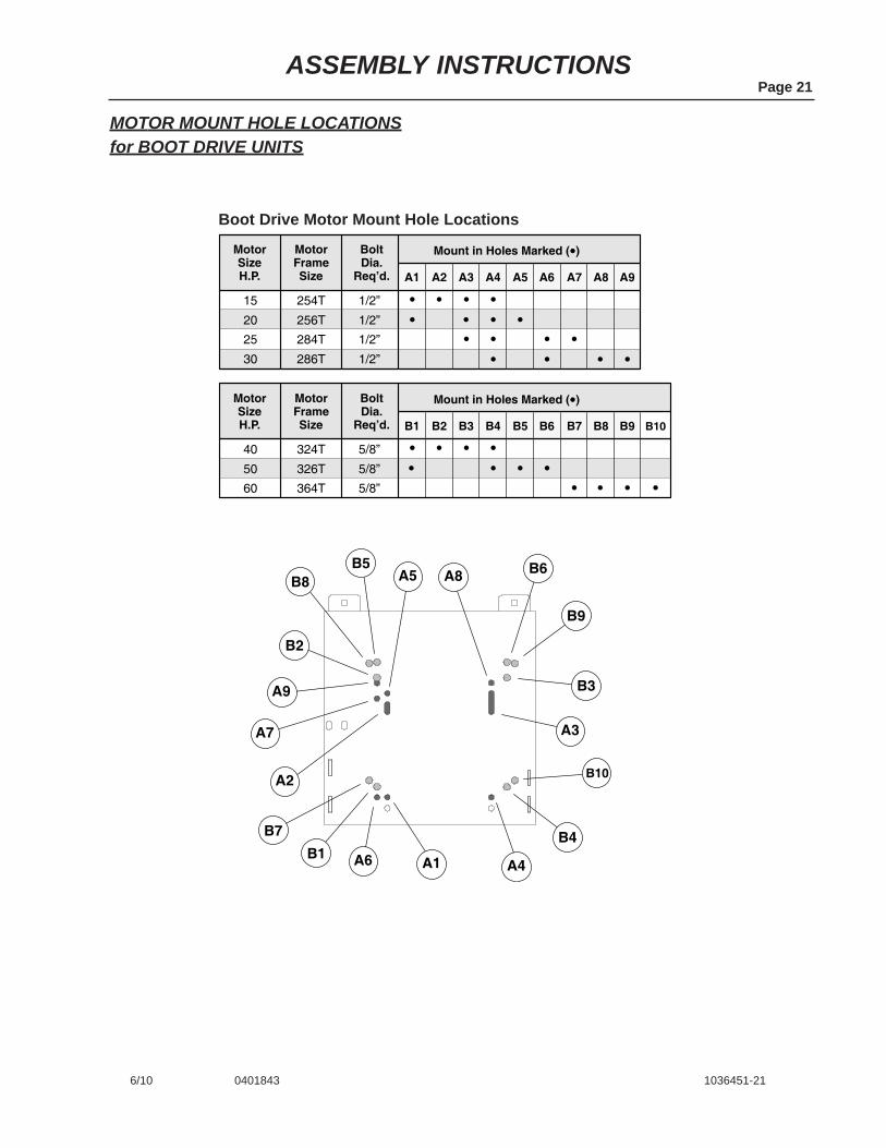
MOTOR MOUNT HOLE LOCATIONSfor BOOT DRIVE UNITS
15
20
25
30
Mount in Holes Marked (�)BoltDia.
Req’d.
MotorFrameSize
MotorSizeH.P.
254T
256T
284T
286T
1/2”
1/2”
1/2”
1/2”
A1 A2 A3 A4 A5 A6 A7 A8
�� ��
�� ��
A9
��
40
50
60
Mount in Holes Marked (�)BoltDia.
Req’d.
MotorFrameSize
MotorSizeH.P.
324T
326T
364T
5/8”
5/8”
5/8”
B1 B2 B3 B4 B5 B6 B7 B8
�� ��
�� ��
B9
�� �
��
����
B10
�
A6
A3
A5
A7
B10
A8
A4
A2
A1
B3
B4B1
B2
B6
B9
B5B8
A9
B7
Boot Drive Motor Mount Hole Locations

Attach upper belt guard bracketusing 5/16” x 3/4” bolts, flatwashers and nylon locknuts
Attach lower belt guard bracketsusing 5/16” x 3/4” bolts, flatwashers and nylon locknuts
Attach belt guard using5/16” x 3/4” bolts, flat washers
and nylon locknuts
ThreadedAdjustment
Rod
Motor NotFurnished
7.4” PD Drive Sheave,1/2” sq. x 2 3/4” lg. Key
and Bushing
Attach Motor to Mount Plateusing appropriate hardware
8.6” PD Driven Sheave,Key and Bushing
Belt(s)
ASSEMBLY INSTRUCTIONSPage 22
6/10 0401844 1036451-22
HEAD DRIVE COMPONENTS1. Install the appropriate sized electric motor onto the
motor mount plate (refer to Page 23 for motormounting locations and mounting hardware used).NOTE: Motor and its mounting hardware are Notfurnished).IMPORTANT! Use the proper size and speed motorto ensure satisfactory conveyor operation. Seehorsepower requirements on Pages 5 & 6.
2. Bolt the lower belt guard brackets to the top side ofthe flange on the head using two 5/16” x 3/4” bolts,flat washers, lock washers and non-lock nuts (Seeillustration below). NOTE: These bolts will also beused when attaching the spout to the headsection.Bolt the upper belt guard bracket to the side of themotor mount plate using two 5/16” x 3/4” bolts, flatwashers, lock washers and non-lock nuts (Seeillustration below).
3. Attach the belt guard to the brackets and secureusing four 5/16” x 3/4” bolts, flat washers, lockwashers and non-lock nuts.
4. Install the 8.6” PD sheave and bushing onto thegearbox shaft. Loosely install the 7.4” PD sheaveand bushing onto the motor shaft.Align the sheaves by placing a straight edge alongthe face of each sheave. When properly aligned,tighten the setscrews to secure the sheaves to theshafts. Make sure the sheaves are not rubbingagainst the belt guard.
5. Install the drive belt(s). Locate the 1” diameterthreaded adjustment rod attached to the reducergearbox (See illustration below).Use the adjustment nuts to set belt tension. Onceproper tension has been achieved, tighten the nutsagainst the adjustment retainer to secure theadjustment rod into place.Proper belt tension is 9/16” of deflection per beltTension can be checked by pressing firmly on thebelts at the center of the span between the twosheaves.
ASSEMBLY INSTRUCTIONSPage 23
6/10 0401845 1036451-23
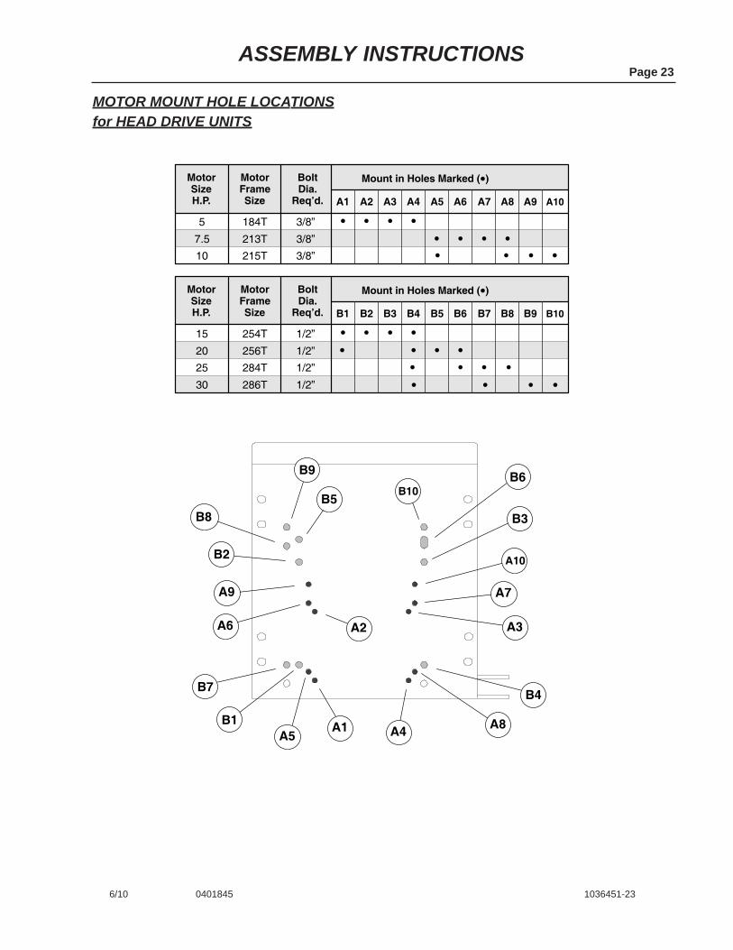
MOTOR MOUNT HOLE LOCATIONSfor HEAD DRIVE UNITS
5
7.5
10
Mount in Holes Marked (�)BoltDia.
Req’d.
MotorFrameSize
MotorSizeH.P.
184T
213T
215T
3/8”
3/8”
3/8”
A1 A2 A3 A4 A5 A6 A7 A8
�� ��
�� ��
A9
��
15
20
25
30
Mount in Holes Marked (�)BoltDia.
Req’d.
MotorFrameSize
MotorSizeH.P.
254T
256T
284T
286T
1/2”
1/2”
1/2”
1/2”
B1 B2 B3 B4 B5 B6 B7 B8
�� ��
�� ��
B9
�� �
��
B10
�
A6 A3
A5
A7
A10
A8A4
A2
A1
B4
B1
B2
B6
B5B8
A9
B7
B9
B3
B10
A10
�� ��
ASSEMBLY INSTRUCTIONSPage 24
6/10 0401846 0401847 1036451-24
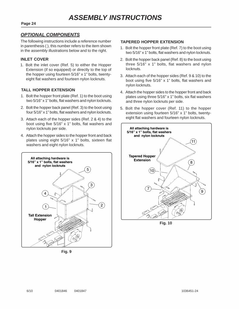
OPTIONAL COMPONENTS
1. Bolt the inlet cover (Ref. 5) to either the HopperExtension (if so equipped) or directly to the top ofthe hopper using fourteen 5/16” x 1” bolts, twenty-eight flat washers and fourteen nylon locknuts.
INLET COVER
1. Bolt the hopper front plate (Ref. 1) to the boot usingtwo 5/16” x 1” bolts, flat washers and nylon locknuts.
2. Bolt the hopper back panel (Ref. 3) to the boot usingfour 5/16” x 1” bolts, flat washers and nylon locknuts.
3. Attach each of the hopper sides (Ref. 2 & 4) to theboot using five 5/16” x 1” bolts, flat washers andnylon locknuts per side.
4. Attach the hopper sides to the hopper front and backplates using eight 5/16” x 1” bolts, sixteen flatwashers and eight nylon locknuts.
The following instructions include a reference numberin parenthesis ( ), this number refers to the item shownin the assembly illustrations below and to the right.
TALL HOPPER EXTENSION
All attaching hardware is5/16” x 1” bolts, flat washers
and nylon locknuts
3
21
5
4
Tall ExtensionHopper
Fig. 9
1. Bolt the hopper front plate (Ref. 7) to the boot usingtwo 5/16” x 1” bolts, flat washers and nylon locknuts.
2. Bolt the hopper back panel (Ref. 8) to the boot usingthree 5/16” x 1” bolts, flat washers and nylonlocknuts.
3. Attach each of the hopper sides (Ref. 9 & 10) to theboot using five 5/16” x 1” bolts, flat washers andnylon locknuts.
4. Attach the hopper sides to the hopper front and backplates using three 5/16” x 1” bolts, six flat washersand three nylon locknuts per side.
5. Bolt the hopper cover (Ref. 11) to the hopperextension using fourteen 5/16” x 1” bolts, twenty-eight flat washers and fourteen nylon locknuts.
TAPERED HOPPER EXTENSION
All attaching hardware is5/16” x 1” bolts, flat washers
and nylon locknuts
7
8
11
10
9
Tapered HopperExtension
Fig. 10
ASSEMBLY INSTRUCTIONSPage 25
6/10 0401848 1036451-25
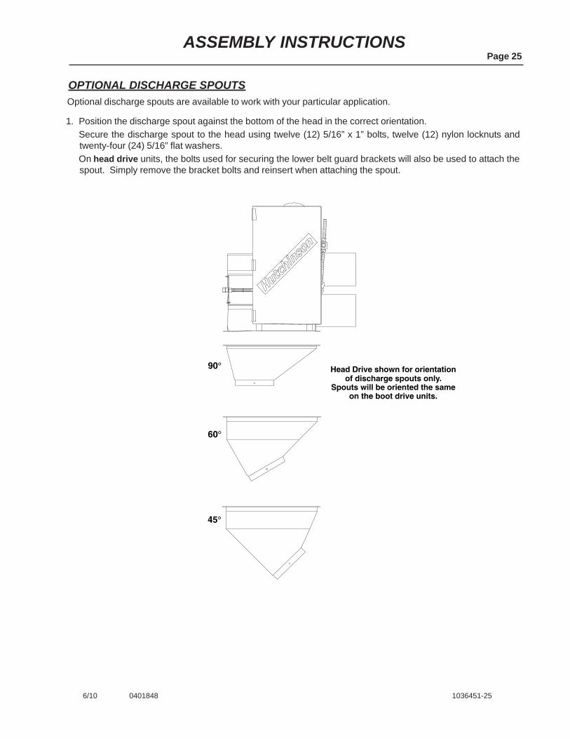
OPTIONAL DISCHARGE SPOUTSOptional discharge spouts are available to work with your particular application.
1. Position the discharge spout against the bottom of the head in the correct orientation.Secure the discharge spout to the head using twelve (12) 5/16” x 1” bolts, twelve (12) nylon locknuts andtwenty-four (24) 5/16” flat washers.On head drive units, the bolts used for securing the lower belt guard brackets will also be used to attach thespout. Simply remove the bracket bolts and reinsert when attaching the spout.
90�
60�
45�
Head Drive shown for orientationof discharge spouts only.
Spouts will be oriented the sameon the boot drive units.

Page 26PARTS LIST TABLE OF CONTENTS
2/10 1033256-62
SAFETY DECALS .................................................................................................. P-1
BOOT COMPONENTS (Non-Drive Units) ................................................... P-2Sprocket, Bearings, Shaft ........................................................................... P-2Boot Weldment ........................................................................................... P-2
BOOT COMPONENTS (With Drive) ............................................................ P-3Sprocket, Bearings, Shaft ........................................................................... P-3Reducer Gearbox ....................................................................................... P-3Boot Weldment ........................................................................................... P-3
HEAD COMPONENTS (Non-Drive Units) ................................................... P-4Sprocket, Bearings, Head Shaft ................................................................. P-4Non-Drive Head Weldment ........................................................................ P-4
HEAD COMPONENTS (With Drive) ............................................................. P-5Sprocket, Bearings, Head Shaft ................................................................. P-5Reducer Gearbox ....................................................................................... P-5Drive Head Weldment ................................................................................ P-5Motor Mount Plate ...................................................................................... P-5Reducer Gearbox, Dodge TXT 515 ............................................................ P-5
ELECTRIC DRIVE COMPONENTS (Head Drive) ........................................ P-6Belt Guard, Drive Belts ............................................................................... P-6Drive Sheave, Motor Sheave...................................................................... P-6
ELECTRIC DRIVE COMPONENTS (Boot Drive) ........................................ P-7Belt Guard, Belts ......................................................................................... P-7Motor Mount Plate ...................................................................................... P-7Drive Sheave, Motor Sheave...................................................................... P-7
TUBE SECTIONS and CONNECTING BANDS ........................................... P-8Connecting Bands ...................................................................................... P-8Tube Sections, 5’, 10’, 20’ and 30’ lengths ................................................. P-8
CHAIN and PADDLES .................................................................................. P-8Chain, 81XHH and Connecting Links ......................................................... P-8Paddles ....................................................................................................... P-8
OPTIONAL ACCESSORIES ......................................................................... P-9Tall Hopper Extension ................................................................................. P-9Tapered Hopper Extension ......................................................................... P-9Discharge Spouts, 45°, 60° and 90° ........................................................... P-9
Page P-1PARTS LIST
6/10 0401849 0401850 1036451-P1
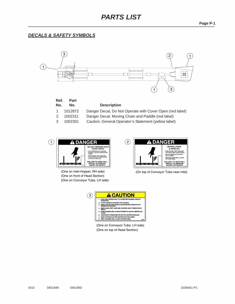
Ref.No.
PartNo. Description
1 1012872 Danger Decal, Do Not Operate with Cover Open (red label)2 1002311 Danger Decal, Moving Chain and Paddle (red label)3 1002301 Caution, General Operator’s Statement (yellow label)
DECALS & SAFETY SYMBOLS
1
13
1
3
2
1
3
2
(One on Inlet Hopper, RH side)(One on front of Head Section)(One on Conveyor Tube, LH side)
(On top of Conveyor Tube near inlet)
(One on Conveyor Tube, LH side)(One on top of Head Section)
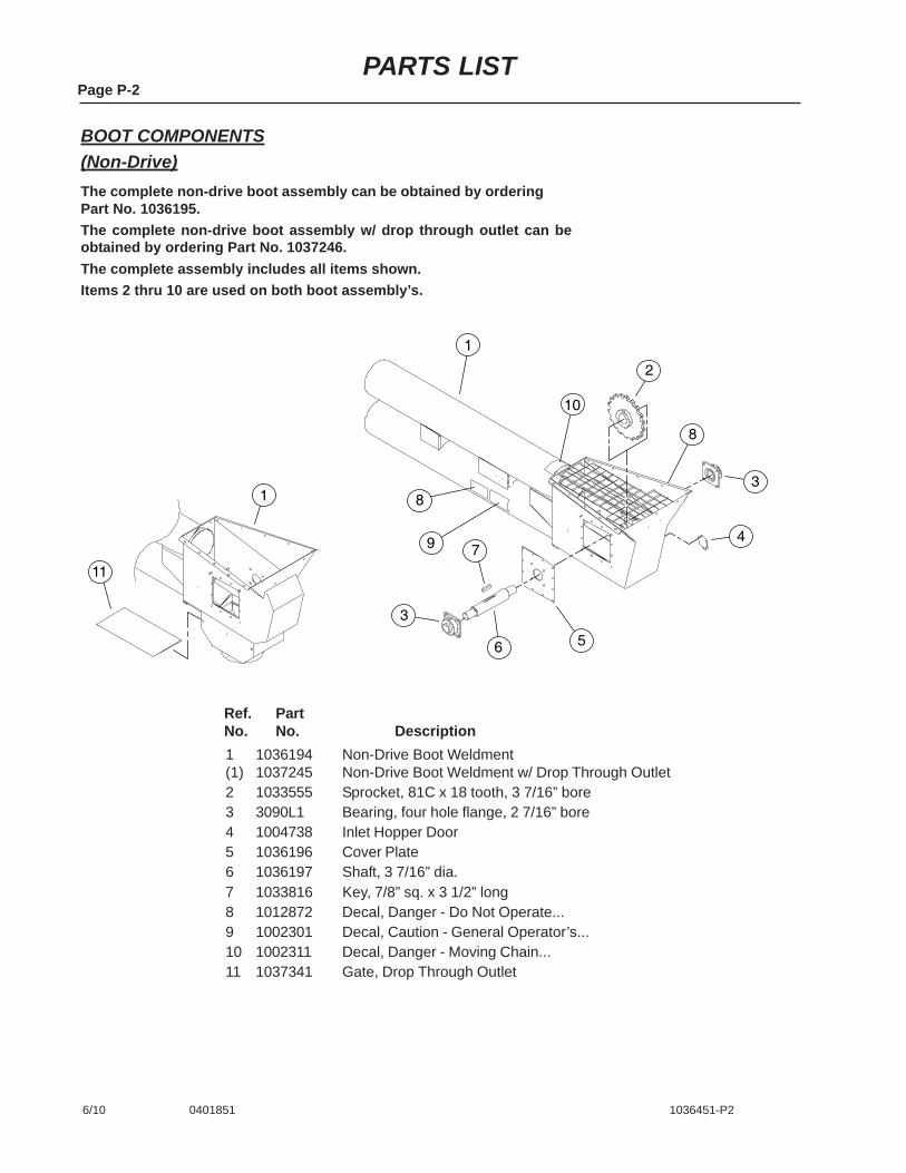
Page P-2PARTS LIST
6/10 0401851 1036451-P2
BOOT COMPONENTS(Non-Drive)
Ref.No.
PartNo. Description
1 1036194 Non-Drive Boot Weldment(1) 1037245 Non-Drive Boot Weldment w/ Drop Through Outlet2 1033555 Sprocket, 81C x 18 tooth, 3 7/16” bore3 3090L1 Bearing, four hole flange, 2 7/16” bore4 1004738 Inlet Hopper Door5 1036196 Cover Plate6 1036197 Shaft, 3 7/16” dia.7 1033816 Key, 7/8” sq. x 3 1/2” long8 1012872 Decal, Danger - Do Not Operate...9 1002301 Decal, Caution - General Operator’s...10 1002311 Decal, Danger - Moving Chain...11 1037341 Gate, Drop Through Outlet
The complete non-drive boot assembly can be obtained by orderingPart No. 1036195.The complete non-drive boot assembly w/ drop through outlet can beobtained by ordering Part No. 1037246.The complete assembly includes all items shown.Items 2 thru 10 are used on both boot assembly’s.
1
10
2
3
4
56
7
3
8
9
8
1
11

Page P-3PARTS LIST
4/13 0401852 1036451-P3
BOOT COMPONENTS(With Drive)
The complete boot assembly can be obtained by orderingPart No. 1036145.The complete boot assembly w/ Drop Through Outlet can beobtained by ordering Part No. 1037342.The complete assembly includes all items shown.Items 2 thru 16 are used in both boot assembly’s.
1 2
13
14
3
4
56
78
12
11
10
17
1
15 16
9
Ref.No.
PartNo. Description
1 1036144 Drive Boot Weldment(1) 1037343 Drive Boot Weldment with
Drop Through Outlet2 1033555 Sprocket, 81C x 18 tooth,
(3 7/16” bore)3 3090L1 Bearing, four hole flange,
(2 7/16” bore)4 1004738 Inlet Hopper Door5 1031905 Cover Plate6 1036151 Shaft, 3 7/16” dia.7 1033816 Key, 7/8” sq. x 3 1/2” long
Ref.No.
PartNo. Description
8 1031921 Key, 5/8” sq. x 5 1/4” long9 1031082-1 Gearbox, Reducer (4:1 ratio)10 1031922 Washer, 3 1/2” OD x 13/16” ID11 33110 Bolt, 3/4-10 x 2” G5 PLT12 1012872 Decal, Danger - Do Not Operate...13 1002301 Decal, Caution - General Operator’s...14 1002311 Decal, Danger - Moving Chain...15 1030211 Bushing, 3/8” to 1/8” NPT16 1015290 Relief Vent17 1037341 Gate, Drop Through Outlet

Page P-4PARTS LIST
6/10 0401853 1036451-P4
HEAD COMPONENTS(Non-Drive)
Ref.No.
PartNo. Description
1 1036098 Non-Drive Head Weldment2 1036114 Take-up Plate3 3090L1 Bearing, four hole flange (2 7/16” bore)4 1036122 Head Shaft (3 7/16” dia.)5 1033555 Sprocket, 81C x 18 tooth, (3 7/16” bore)6 1033816 Key, 7/8” sq. x 3 1/2” long7 1036117 Take-up Bolt8 6328C Roll Pin, 3/8” x 1 1/2” long9 D1158 Nut, 1” non-lock10 1012872 Decal, Danger - Do Not Operate...11 1002301 Decal, Caution - General Operator’s...
2
3 1
2
3
6
4
5
7
8
9
1110
The complete head assembly can be obtained by orderingPart No. 1036097.The complete assembly includes all items shown.

16
1
2
3
4
56
7
8
9
10
14
15
4
2
1112
13
13
18
5
17
Page P-5PARTS LIST
6/10 0401854 1036451-P5
Ref.No.
PartNo. Description
1 1036315 Drive Head Weldment2 3090L1 Bearing, four hole flange,
(2 7/16” bore)3 1036318 Head Shaft (25 to 30 hp)(3) 1036892 Head Shaft (20 hp)4 1036114 Take-up Plate5 D1158 Nut, 1” non-lock6 1030875 Spacer Tube, Adjustment Rod7 1030876 Retainer, Adjustment Rod8 1030878 Adjustment Rod9 1033555 Sprocket, 81C x 18 tooth10 1033816 Key, 7/8” sq. x 3 1/2” long11 3005L91 Reducer, Dodge TXT 515
(25 to 30 hp)
The complete head assembly for 25 & 30 hp modelscan be obtained by ordering Part No. 1036316.The complete head assembly for 20 hp models can be obtainedby ordering Part No. 1036882 (20 hp).The complete assembly includes all items shown.
HEAD COMPONENTS(With Drive)
Ref.No.
PartNo. Description
(11) 3004L91 Reducer, Dodge TXT 415 (20 hp)12 41885 Cooling Fan, f/ Dodge Reducer
(25 to 30 hp only)13 3013L91 Bushing Kit f/ Dodge Reducer
TXT 515 (25 to 30 hp)(13) 3012L91 Bushing Kit f/ Dodge Reducer
TXT 415 (20 hp)14 1036117 Take-up Bolt15 6328C Roll Pin, 3/8” x 1 1/2” long16 1030850 Motor Mount Plate17 1012872 Decal, Danger - Do Not Operate...18 1002301 Decal, Caution - General
Operator’s Statement

Page P-6PARTS LIST
6/10 0401855 1036451-P6
ELECTRIC DRIVE COMPONENTS(Head Assembly)
Ref.No.
PartNo. Description
1 4021L1 Key, 1/2” sq. x 2 3/4” long (25 & 30 hp)(1) 1038D Key, 3/8” sq. x 2” long (20 hp)2 3193A1 Bushing, SK 1 7/8” bore (25 & 30 hp)(2) 3192A1 Bushing, SK 1 5/8” bore (20 hp)3 3244A1 Sheave, QD 3-Belt 7.4” PD (25 & 30 hp)(3) 3235A1 Sheave, QD 2-Belt 7.4” PD (20 hp)4 1036376 Bracket, Belt Guard Bottom5 1031328 Bracket, Belt Guard Top (25 & 30 hp)(5) 1030857 Bracket, Belt Guard Top (20 hp)6 1036374 Belt Guard7 3194A1 Bushing, SK 1 15/16” bore (25 & 30 hp)(7) 3191A1 Bushing, SK 1 7/16” bore (20 hp)8 3270A1 Sheave, QD 3-Belt 8.6” PD (25 & 30 hp)(8) 3090A1 Sheave, QD 2-Belt 8.6” PD (20 hp)9 40127 B-Belt. 75” long
1
2
3
5
6
9
7
8
4
4
Motor NOTFurnished
1 2
3
4
6
7
11
10
12
9 5
8
Motor and Motor MountingHardware are NOT Furnished.
Page P-7PARTS LIST
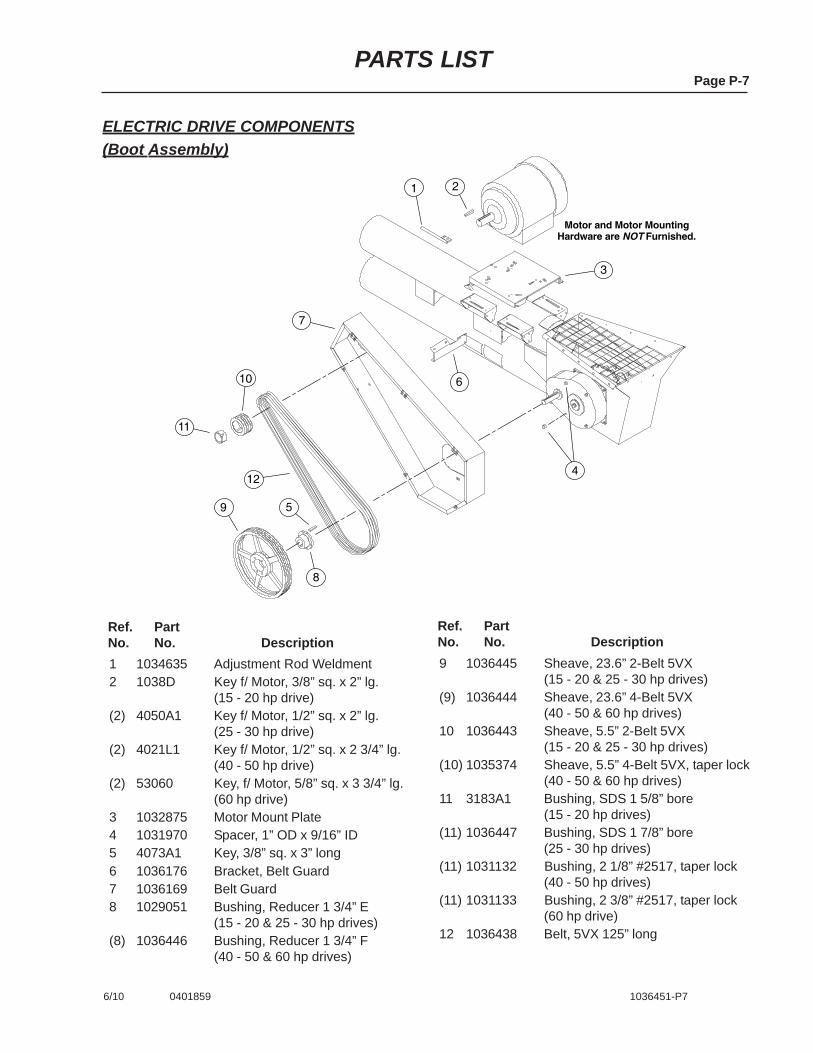
6/10 0401859 1036451-P7
ELECTRIC DRIVE COMPONENTS(Boot Assembly)
Ref.No.
PartNo. Description
1 1034635 Adjustment Rod Weldment2 1038D Key f/ Motor, 3/8” sq. x 2” lg.
(15 - 20 hp drive)(2) 4050A1 Key f/ Motor, 1/2” sq. x 2” lg.
(25 - 30 hp drive)(2) 4021L1 Key f/ Motor, 1/2” sq. x 2 3/4” lg.
(40 - 50 hp drive)(2) 53060 Key, f/ Motor, 5/8” sq. x 3 3/4” lg.
(60 hp drive)3 1032875 Motor Mount Plate4 1031970 Spacer, 1” OD x 9/16” ID5 4073A1 Key, 3/8” sq. x 3” long6 1036176 Bracket, Belt Guard7 1036169 Belt Guard8 1029051 Bushing, Reducer 1 3/4” E
(15 - 20 & 25 - 30 hp drives)(8) 1036446 Bushing, Reducer 1 3/4” F
(40 - 50 & 60 hp drives)
Ref.No.
PartNo. Description
9 1036445 Sheave, 23.6” 2-Belt 5VX(15 - 20 & 25 - 30 hp drives)
(9) 1036444 Sheave, 23.6” 4-Belt 5VX(40 - 50 & 60 hp drives)
10 1036443 Sheave, 5.5” 2-Belt 5VX(15 - 20 & 25 - 30 hp drives)
(10) 1035374 Sheave, 5.5” 4-Belt 5VX, taper lock(40 - 50 & 60 hp drives)
11 3183A1 Bushing, SDS 1 5/8” bore(15 - 20 hp drives)
(11) 1036447 Bushing, SDS 1 7/8” bore(25 - 30 hp drives)
(11) 1031132 Bushing, 2 1/8” #2517, taper lock(40 - 50 hp drives)
(11) 1031133 Bushing, 2 3/8” #2517, taper lock(60 hp drive)
12 1036438 Belt, 5VX 125” long
1
2
3
1
Direction ofGrain Movement
1
4 5
6
Page P-8PARTS LIST
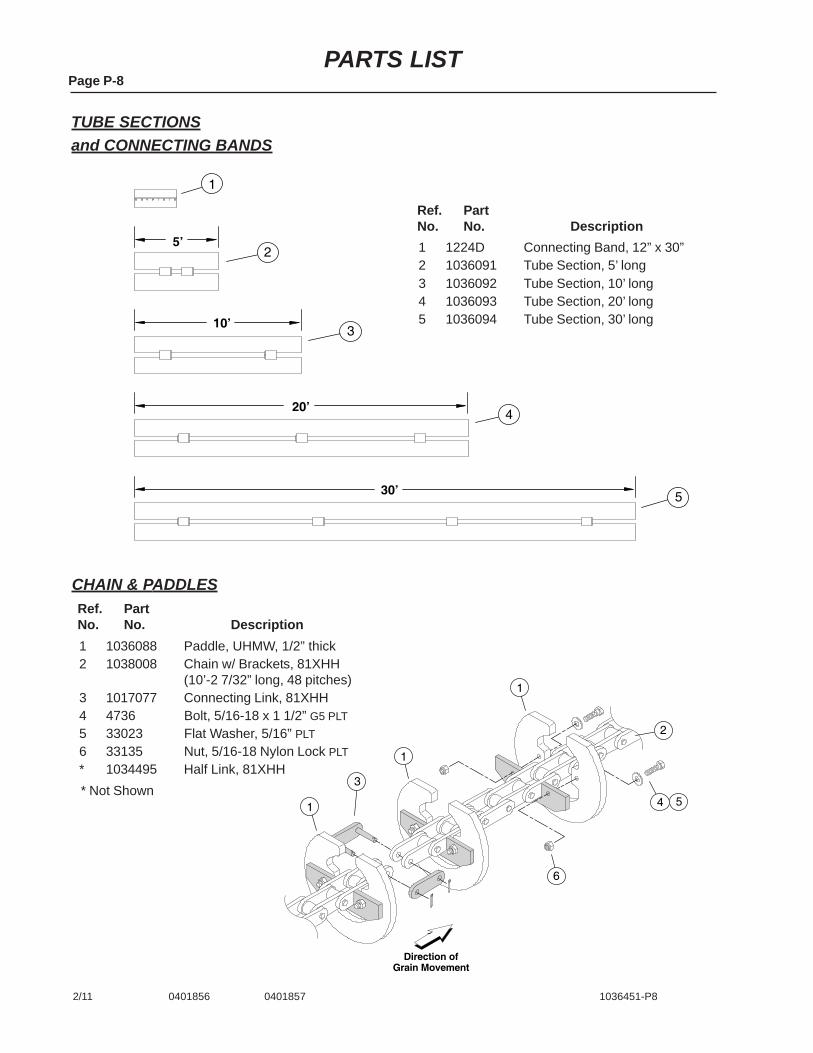
2/11 0401856 0401857 1036451-P8
TUBE SECTIONSand CONNECTING BANDS
Ref.No.
PartNo. Description
1 1036088 Paddle, UHMW, 1/2” thick2 1038008 Chain w/ Brackets, 81XHH
(10’-2 7/32” long, 48 pitches)3 1017077 Connecting Link, 81XHH4 4736 Bolt, 5/16-18 x 1 1/2” G5 PLT5 33023 Flat Washer, 5/16” PLT6 33135 Nut, 5/16-18 Nylon Lock PLT* 1034495 Half Link, 81XHH
5’
10’
20’
30’
1
3
4
5
2
Ref.No.
PartNo. Description
1 1224D Connecting Band, 12” x 30”2 1036091 Tube Section, 5’ long3 1036092 Tube Section, 10’ long4 1036093 Tube Section, 20’ long5 1036094 Tube Section, 30’ long
CHAIN & PADDLES
* Not Shown

Page P-9PARTS LIST
6/10 0401858 1036451-P9
OPTIONAL ACCESSORIES
Ref.No.
PartNo. Description
1 1036189 Cover, f/ tapered hopper ext.2 1036182 Right Panel, tapered hopper ext.3 1036180 Back Panel, tapered hopper ext.4 1036183 Front Panel, tapered hopper ext.5 1036181 Left Panel, tapered hopper ext.6 1036465 Cover, f/ tall hopper extension7 1036221 Right Panel, tall hopper ext.
NOTE: All accessories shown can be used with eitherthe head drive or boot drive units.
Ref.No.
PartNo. Description
8 1036223 Back Panel, tall hopper ext.9 1036222 Front Panel, tall hopper ext.10 1036220 Left Panel, tall hopper ext.11 1036474 Discharge Spout, 90°12 1036479 Discharge Spout, 60°13 1036483 Discharge Spout, 45°
1
2
5
4
3
6
7
10
9
8
11
13
12


Hutchinson/Mayrath � P.O. Box 629 � Clay Center, KS. 67432Ph. 785–632–2161 � Fx. 785–632–5964 � Toll Free 800–523–6993
Hutchinson/MayrathA Division of GLOBAL Industries Inc.
www.hutchinson-mayrath.com
Related Documents