Operator’s Manual SOFTWARE VERSION 2.00 20077/021 US FOR US MARKET ONLY

Welcome message from author
This document is posted to help you gain knowledge. Please leave a comment to let me know what you think about it! Share it to your friends and learn new things together.
Transcript

Operator’s ManualSOFTWARE VERSION 2.00
20077/021 US
FOR US MARKET ONLY

20077/021 US XTRA Operator’s Manual
XTRA® is a registered trademark.
Microsoft® and Windows® are registered trademarks of the Microsoft Corporation.
Manufacturer:LivaNova Deutschland GmbHLindberghstrasse 25D-80939 München GermanyTel: +49.(0)89.32301.0Fax: +49.(0)89.32301.555
Distributor in U.S.A.LivaNova USA, Inc.14401 West 65th WayArvada, Colorado USA 80004Tel: +1.800.221.7943Tel: +1.303.425.5508Fax: +1.303.467.6584
XTRA Operator’s Manual 20077/021 US
Table of Contents
Chapter 1: Introduction and Safety
About the Operating Instructions . . . . . . . . . . . . . . . . . . . . . . . . . . . . . . . . . . . . . . . . . . . . . . . . . . . . . . . . . 1-1Introducing the XTRA System . . . . . . . . . . . . . . . . . . . . . . . . . . . . . . . . . . . . . . . . . . . . . . . . . . . . . . . . . . . . 1-1Indications for Use . . . . . . . . . . . . . . . . . . . . . . . . . . . . . . . . . . . . . . . . . . . . . . . . . . . . . . . . . . . . . . . . . . . 1-3Contraindication for Use . . . . . . . . . . . . . . . . . . . . . . . . . . . . . . . . . . . . . . . . . . . . . . . . . . . . . . . . . . . . . . . . 1-3General Warnings . . . . . . . . . . . . . . . . . . . . . . . . . . . . . . . . . . . . . . . . . . . . . . . . . . . . . . . . . . . . . . . . . . . . 1-3Storage and Transporting Warnings . . . . . . . . . . . . . . . . . . . . . . . . . . . . . . . . . . . . . . . . . . . . . . . . . . . . . . . 1-9Electrical Warnings . . . . . . . . . . . . . . . . . . . . . . . . . . . . . . . . . . . . . . . . . . . . . . . . . . . . . . . . . . . . . . . . . . . 1-9General Precautions . . . . . . . . . . . . . . . . . . . . . . . . . . . . . . . . . . . . . . . . . . . . . . . . . . . . . . . . . . . . . . . . . 1-10Operating Conditions . . . . . . . . . . . . . . . . . . . . . . . . . . . . . . . . . . . . . . . . . . . . . . . . . . . . . . . . . . . . . . . . . 1-14
Warning . . . . . . . . . . . . . . . . . . . . . . . . . . . . . . . . . . . . . . . . . . . . . . . . . . . . . . . . . . . . . . . . . . . . . 1-14Cautions . . . . . . . . . . . . . . . . . . . . . . . . . . . . . . . . . . . . . . . . . . . . . . . . . . . . . . . . . . . . . . . . . . . . . 1-14
Adverse Effects . . . . . . . . . . . . . . . . . . . . . . . . . . . . . . . . . . . . . . . . . . . . . . . . . . . . . . . . . . . . . . . . . . . . . 1-14Installation of the Unit . . . . . . . . . . . . . . . . . . . . . . . . . . . . . . . . . . . . . . . . . . . . . . . . . . . . . . . . . . . . . . . . 1-14
Installation . . . . . . . . . . . . . . . . . . . . . . . . . . . . . . . . . . . . . . . . . . . . . . . . . . . . . . . . . . . . . . . . . . . 1-14Unpacking and Inspection . . . . . . . . . . . . . . . . . . . . . . . . . . . . . . . . . . . . . . . . . . . . . . . . . . . . . . . . 1-15Storage and Transport Conditions . . . . . . . . . . . . . . . . . . . . . . . . . . . . . . . . . . . . . . . . . . . . . . . . . . . 1-15Electrical Requirements . . . . . . . . . . . . . . . . . . . . . . . . . . . . . . . . . . . . . . . . . . . . . . . . . . . . . . . . . . 1-15
Addresses . . . . . . . . . . . . . . . . . . . . . . . . . . . . . . . . . . . . . . . . . . . . . . . . . . . . . . . . . . . . . . . . . . . . . . . . 1-16Service Information . . . . . . . . . . . . . . . . . . . . . . . . . . . . . . . . . . . . . . . . . . . . . . . . . . . . . . . . . . . . . . . . . . 1-17Return of Used Product . . . . . . . . . . . . . . . . . . . . . . . . . . . . . . . . . . . . . . . . . . . . . . . . . . . . . . . . . . . . . . . 1-17
For North American Customers . . . . . . . . . . . . . . . . . . . . . . . . . . . . . . . . . . . . . . . . . . . . . . . . . . . . . 1-17For International Customers . . . . . . . . . . . . . . . . . . . . . . . . . . . . . . . . . . . . . . . . . . . . . . . . . . . . . . . 1-17
Disposal in Accordance with Environmental Regulations . . . . . . . . . . . . . . . . . . . . . . . . . . . . . . . . . . . . . . . . 1-18
Chapter 2: Overview
Advantages of Intra- and Postoperative Red Cell Recovery . . . . . . . . . . . . . . . . . . . . . . . . . . . . . . . . . . . . . . . 2-1Clinical Applications . . . . . . . . . . . . . . . . . . . . . . . . . . . . . . . . . . . . . . . . . . . . . . . . . . . . . . . . . . . . . . . . . . . 2-1Description of the XTRA System . . . . . . . . . . . . . . . . . . . . . . . . . . . . . . . . . . . . . . . . . . . . . . . . . . . . . . . . . . . 2-1How the XTRA System Works . . . . . . . . . . . . . . . . . . . . . . . . . . . . . . . . . . . . . . . . . . . . . . . . . . . . . . . . . . . . 2-3Collection and Anticoagulation . . . . . . . . . . . . . . . . . . . . . . . . . . . . . . . . . . . . . . . . . . . . . . . . . . . . . . . . . . . 2-3Processing . . . . . . . . . . . . . . . . . . . . . . . . . . . . . . . . . . . . . . . . . . . . . . . . . . . . . . . . . . . . . . . . . . . . . . . . . 2-3Reinfusion . . . . . . . . . . . . . . . . . . . . . . . . . . . . . . . . . . . . . . . . . . . . . . . . . . . . . . . . . . . . . . . . . . . . . . . . . 2-4The Basic XTRA . . . . . . . . . . . . . . . . . . . . . . . . . . . . . . . . . . . . . . . . . . . . . . . . . . . . . . . . . . . . . . . . . . . . . . 2-4Options Available with XTRA . . . . . . . . . . . . . . . . . . . . . . . . . . . . . . . . . . . . . . . . . . . . . . . . . . . . . . . . . . . . . 2-5
Programmability Option . . . . . . . . . . . . . . . . . . . . . . . . . . . . . . . . . . . . . . . . . . . . . . . . . . . . . . . . . . . 2-5Emergency Option . . . . . . . . . . . . . . . . . . . . . . . . . . . . . . . . . . . . . . . . . . . . . . . . . . . . . . . . . . . . . . . 2-5Vacuum System (XVAC) . . . . . . . . . . . . . . . . . . . . . . . . . . . . . . . . . . . . . . . . . . . . . . . . . . . . . . . . . . . 2-5Preoperative Sequestration Option (PPP and PRP) . . . . . . . . . . . . . . . . . . . . . . . . . . . . . . . . . . . . . . . . 2-5Data Management Options (USB, Printer, RS232) . . . . . . . . . . . . . . . . . . . . . . . . . . . . . . . . . . . . . . . . . 2-5Quality Control Options . . . . . . . . . . . . . . . . . . . . . . . . . . . . . . . . . . . . . . . . . . . . . . . . . . . . . . . . . . . 2-5
Chapter 3: System Description
Machine Components . . . . . . . . . . . . . . . . . . . . . . . . . . . . . . . . . . . . . . . . . . . . . . . . . . . . . . . . . . . . . . . . . 3-1Handles . . . . . . . . . . . . . . . . . . . . . . . . . . . . . . . . . . . . . . . . . . . . . . . . . . . . . . . . . . . . . . . . . . . . . . 3-3Hooks and Tray Holders . . . . . . . . . . . . . . . . . . . . . . . . . . . . . . . . . . . . . . . . . . . . . . . . . . . . . . . . . . . 3-3Cart . . . . . . . . . . . . . . . . . . . . . . . . . . . . . . . . . . . . . . . . . . . . . . . . . . . . . . . . . . . . . . . . . . . . . . . . . 3-4IV Pole and Reservoir Pole . . . . . . . . . . . . . . . . . . . . . . . . . . . . . . . . . . . . . . . . . . . . . . . . . . . . . . . . . 3-6Reservoir Holder . . . . . . . . . . . . . . . . . . . . . . . . . . . . . . . . . . . . . . . . . . . . . . . . . . . . . . . . . . . . . . . . 3-7Touch Screen Display Panel . . . . . . . . . . . . . . . . . . . . . . . . . . . . . . . . . . . . . . . . . . . . . . . . . . . . . . . . 3-7Centrifuge Assembly . . . . . . . . . . . . . . . . . . . . . . . . . . . . . . . . . . . . . . . . . . . . . . . . . . . . . . . . . . . . . 3-9Clamps . . . . . . . . . . . . . . . . . . . . . . . . . . . . . . . . . . . . . . . . . . . . . . . . . . . . . . . . . . . . . . . . . . . . . . 3-11Processing Pump . . . . . . . . . . . . . . . . . . . . . . . . . . . . . . . . . . . . . . . . . . . . . . . . . . . . . . . . . . . . . . . 3-12Air Detector . . . . . . . . . . . . . . . . . . . . . . . . . . . . . . . . . . . . . . . . . . . . . . . . . . . . . . . . . . . . . . . . . . 3-12Quality Control Indicators . . . . . . . . . . . . . . . . . . . . . . . . . . . . . . . . . . . . . . . . . . . . . . . . . . . . . . . . . 3-13XVAC Vacuum Module (Option) . . . . . . . . . . . . . . . . . . . . . . . . . . . . . . . . . . . . . . . . . . . . . . . . . . . . . 3-13

20077/021 US XTRA Operator’s Manual
Essential Performance . . . . . . . . . . . . . . . . . . . . . . . . . . . . . . . . . . . . . . . . . . . . . . . . . . . . . . . . . . . 3-14Order Guide . . . . . . . . . . . . . . . . . . . . . . . . . . . . . . . . . . . . . . . . . . . . . . . . . . . . . . . . . . . . . . . . . . 3-14
Disposable Description . . . . . . . . . . . . . . . . . . . . . . . . . . . . . . . . . . . . . . . . . . . . . . . . . . . . . . . . . . . . . . . . 3-15Collection Set . . . . . . . . . . . . . . . . . . . . . . . . . . . . . . . . . . . . . . . . . . . . . . . . . . . . . . . . . . . . . . . . . 3-17Bowl Set . . . . . . . . . . . . . . . . . . . . . . . . . . . . . . . . . . . . . . . . . . . . . . . . . . . . . . . . . . . . . . . . . . . . . 3-21Procedure Set . . . . . . . . . . . . . . . . . . . . . . . . . . . . . . . . . . . . . . . . . . . . . . . . . . . . . . . . . . . . . . . . . 3-25Selecting the Disposable . . . . . . . . . . . . . . . . . . . . . . . . . . . . . . . . . . . . . . . . . . . . . . . . . . . . . . . . . 3-26Selecting the Bowl . . . . . . . . . . . . . . . . . . . . . . . . . . . . . . . . . . . . . . . . . . . . . . . . . . . . . . . . . . . . . . 3-26Order Guide . . . . . . . . . . . . . . . . . . . . . . . . . . . . . . . . . . . . . . . . . . . . . . . . . . . . . . . . . . . . . . . . . . 3-27Anticoagulant Solution . . . . . . . . . . . . . . . . . . . . . . . . . . . . . . . . . . . . . . . . . . . . . . . . . . . . . . . . . . . 3-29Wash Solution . . . . . . . . . . . . . . . . . . . . . . . . . . . . . . . . . . . . . . . . . . . . . . . . . . . . . . . . . . . . . . . . . 3-30
Accessories and Optional Devices . . . . . . . . . . . . . . . . . . . . . . . . . . . . . . . . . . . . . . . . . . . . . . . . . . . . . . . . 3-30Cables . . . . . . . . . . . . . . . . . . . . . . . . . . . . . . . . . . . . . . . . . . . . . . . . . . . . . . . . . . . . . . . . . . . . . . 3-31
Chapter 4: Installing the Disposables
Setup for Standby Collection . . . . . . . . . . . . . . . . . . . . . . . . . . . . . . . . . . . . . . . . . . . . . . . . . . . . . . . . . . . . 4-1Supplies Required . . . . . . . . . . . . . . . . . . . . . . . . . . . . . . . . . . . . . . . . . . . . . . . . . . . . . . . . . . . . . . . 4-1
Setup for Whole Blood Separation Program . . . . . . . . . . . . . . . . . . . . . . . . . . . . . . . . . . . . . . . . . . . . . . . . . . 4-1Setup for Intraoperative Red Cell Recovery and Reinfusion . . . . . . . . . . . . . . . . . . . . . . . . . . . . . . . . . . . . . . . 4-2
Power Requirements . . . . . . . . . . . . . . . . . . . . . . . . . . . . . . . . . . . . . . . . . . . . . . . . . . . . . . . . . . . . . 4-2Supplies Required . . . . . . . . . . . . . . . . . . . . . . . . . . . . . . . . . . . . . . . . . . . . . . . . . . . . . . . . . . . . . . . 4-2
Step-by-step Procedures for Installing Disposables . . . . . . . . . . . . . . . . . . . . . . . . . . . . . . . . . . . . . . . . . . . . . 4-3Step 1: Installing the Blood Collection Reservoir . . . . . . . . . . . . . . . . . . . . . . . . . . . . . . . . . . . . . . . . . . 4-3Step 2: Connecting the Suction Line . . . . . . . . . . . . . . . . . . . . . . . . . . . . . . . . . . . . . . . . . . . . . . . . . . 4-4Step 3: Setup of the Vacuum Line . . . . . . . . . . . . . . . . . . . . . . . . . . . . . . . . . . . . . . . . . . . . . . . . . . . . 4-6Step 4: Installing the Bowl Set . . . . . . . . . . . . . . . . . . . . . . . . . . . . . . . . . . . . . . . . . . . . . . . . . . . . . . 4-7Step 5: Connecting Wash Lines to the Saline solution Containers . . . . . . . . . . . . . . . . . . . . . . . . . . . . . 4-10Step 6: Hanging the Waste Bag . . . . . . . . . . . . . . . . . . . . . . . . . . . . . . . . . . . . . . . . . . . . . . . . . . . . 4-10Other Setups . . . . . . . . . . . . . . . . . . . . . . . . . . . . . . . . . . . . . . . . . . . . . . . . . . . . . . . . . . . . . . . . . 4-11Blood Collection . . . . . . . . . . . . . . . . . . . . . . . . . . . . . . . . . . . . . . . . . . . . . . . . . . . . . . . . . . . . . . . 4-11Procedure for Removing Disposables . . . . . . . . . . . . . . . . . . . . . . . . . . . . . . . . . . . . . . . . . . . . . . . . . 4-12
Chapter 5: Processing
Operating the Touch Screen . . . . . . . . . . . . . . . . . . . . . . . . . . . . . . . . . . . . . . . . . . . . . . . . . . . . . . . . . . . . . 5-1Screen Structure . . . . . . . . . . . . . . . . . . . . . . . . . . . . . . . . . . . . . . . . . . . . . . . . . . . . . . . . . . . . . . . . 5-2The Displets . . . . . . . . . . . . . . . . . . . . . . . . . . . . . . . . . . . . . . . . . . . . . . . . . . . . . . . . . . . . . . . . . . . 5-3Modification of Parameters . . . . . . . . . . . . . . . . . . . . . . . . . . . . . . . . . . . . . . . . . . . . . . . . . . . . . . . . . 5-5
Running a Case With the XTRA System . . . . . . . . . . . . . . . . . . . . . . . . . . . . . . . . . . . . . . . . . . . . . . . . . . . . . 5-5Before You Begin . . . . . . . . . . . . . . . . . . . . . . . . . . . . . . . . . . . . . . . . . . . . . . . . . . . . . . . . . . . . . . . 5-5Loading the Pump Segment for a New Case . . . . . . . . . . . . . . . . . . . . . . . . . . . . . . . . . . . . . . . . . . . . . 5-6Processing a Cycle in Automatic or 1 Touch Mode . . . . . . . . . . . . . . . . . . . . . . . . . . . . . . . . . . . . . . . . . 5-7Pausing and Resuming the Cycle . . . . . . . . . . . . . . . . . . . . . . . . . . . . . . . . . . . . . . . . . . . . . . . . . . . . 5-11
Ending the Current Case . . . . . . . . . . . . . . . . . . . . . . . . . . . . . . . . . . . . . . . . . . . . . . . . . . . . . . . . . . . . . . 5-14Unloading the Pump Loop . . . . . . . . . . . . . . . . . . . . . . . . . . . . . . . . . . . . . . . . . . . . . . . . . . . . . . . . 5-15Emptying the RBC Line Without Ending the Case . . . . . . . . . . . . . . . . . . . . . . . . . . . . . . . . . . . . . . . . 5-16Closing the End of Case Screen Without Ending the Case . . . . . . . . . . . . . . . . . . . . . . . . . . . . . . . . . . 5-16Retaining Case Data Between Power Cycles . . . . . . . . . . . . . . . . . . . . . . . . . . . . . . . . . . . . . . . . . . . . 5-16
Dealing With Expected Warnings During a Cycle . . . . . . . . . . . . . . . . . . . . . . . . . . . . . . . . . . . . . . . . . . . . . 5-17Reservoir Empty . . . . . . . . . . . . . . . . . . . . . . . . . . . . . . . . . . . . . . . . . . . . . . . . . . . . . . . . . . . . . . . 5-17Wash Bag Empty . . . . . . . . . . . . . . . . . . . . . . . . . . . . . . . . . . . . . . . . . . . . . . . . . . . . . . . . . . . . . . . 5-19RBC Bag Full . . . . . . . . . . . . . . . . . . . . . . . . . . . . . . . . . . . . . . . . . . . . . . . . . . . . . . . . . . . . . . . . . . 5-20Waste Bag Full . . . . . . . . . . . . . . . . . . . . . . . . . . . . . . . . . . . . . . . . . . . . . . . . . . . . . . . . . . . . . . . . 5-21
Factory Protocols . . . . . . . . . . . . . . . . . . . . . . . . . . . . . . . . . . . . . . . . . . . . . . . . . . . . . . . . . . . . . . . . . . . 5-22The Autotransfusion Protocols . . . . . . . . . . . . . . . . . . . . . . . . . . . . . . . . . . . . . . . . . . . . . . . . . . . . . 5-23Popt . . . . . . . . . . . . . . . . . . . . . . . . . . . . . . . . . . . . . . . . . . . . . . . . . . . . . . . . . . . . . . . . . . . . . . . . 5-24Pstd . . . . . . . . . . . . . . . . . . . . . . . . . . . . . . . . . . . . . . . . . . . . . . . . . . . . . . . . . . . . . . . . . . . . . . . . 5-25Pfat . . . . . . . . . . . . . . . . . . . . . . . . . . . . . . . . . . . . . . . . . . . . . . . . . . . . . . . . . . . . . . . . . . . . . . . . 5-26Emergency . . . . . . . . . . . . . . . . . . . . . . . . . . . . . . . . . . . . . . . . . . . . . . . . . . . . . . . . . . . . . . . . . . . 5-26Post-op . . . . . . . . . . . . . . . . . . . . . . . . . . . . . . . . . . . . . . . . . . . . . . . . . . . . . . . . . . . . . . . . . . . . . 5-29Protocol Parameters (ATS) . . . . . . . . . . . . . . . . . . . . . . . . . . . . . . . . . . . . . . . . . . . . . . . . . . . . . . . . 5-30
The Operating Modes . . . . . . . . . . . . . . . . . . . . . . . . . . . . . . . . . . . . . . . . . . . . . . . . . . . . . . . . . . . . . . . . 5-31Automatic . . . . . . . . . . . . . . . . . . . . . . . . . . . . . . . . . . . . . . . . . . . . . . . . . . . . . . . . . . . . . . . . . . . . 5-31

XTRA Operator’s Manual 20077/021 US
1 Touch . . . . . . . . . . . . . . . . . . . . . . . . . . . . . . . . . . . . . . . . . . . . . . . . . . . . . . . . . . . . . . . . . . . . . 5-31Manual . . . . . . . . . . . . . . . . . . . . . . . . . . . . . . . . . . . . . . . . . . . . . . . . . . . . . . . . . . . . . . . . . . . . . . 5-32
Selecting the Active Protocol and Operating Mode . . . . . . . . . . . . . . . . . . . . . . . . . . . . . . . . . . . . . . . . . . . . 5-34Set the Active Protocol . . . . . . . . . . . . . . . . . . . . . . . . . . . . . . . . . . . . . . . . . . . . . . . . . . . . . . . . . . . 5-35Set the Active Operating Mode . . . . . . . . . . . . . . . . . . . . . . . . . . . . . . . . . . . . . . . . . . . . . . . . . . . . . 5-35
Touch Screen User Interface . . . . . . . . . . . . . . . . . . . . . . . . . . . . . . . . . . . . . . . . . . . . . . . . . . . . . . . . . . . 5-36Alarms Disabled Confirmation Screen . . . . . . . . . . . . . . . . . . . . . . . . . . . . . . . . . . . . . . . . . . . . . . . . 5-36Setup Screen . . . . . . . . . . . . . . . . . . . . . . . . . . . . . . . . . . . . . . . . . . . . . . . . . . . . . . . . . . . . . . . . . 5-37Ready Screen . . . . . . . . . . . . . . . . . . . . . . . . . . . . . . . . . . . . . . . . . . . . . . . . . . . . . . . . . . . . . . . . . 5-38Processing Screen . . . . . . . . . . . . . . . . . . . . . . . . . . . . . . . . . . . . . . . . . . . . . . . . . . . . . . . . . . . . . . 5-39Fat Removal Screens . . . . . . . . . . . . . . . . . . . . . . . . . . . . . . . . . . . . . . . . . . . . . . . . . . . . . . . . . . . . 5-41Menu Screen . . . . . . . . . . . . . . . . . . . . . . . . . . . . . . . . . . . . . . . . . . . . . . . . . . . . . . . . . . . . . . . . . . 5-44End of Case Screen . . . . . . . . . . . . . . . . . . . . . . . . . . . . . . . . . . . . . . . . . . . . . . . . . . . . . . . . . . . . . 5-50Help Screen . . . . . . . . . . . . . . . . . . . . . . . . . . . . . . . . . . . . . . . . . . . . . . . . . . . . . . . . . . . . . . . . . . 5-51Past Cases Screen . . . . . . . . . . . . . . . . . . . . . . . . . . . . . . . . . . . . . . . . . . . . . . . . . . . . . . . . . . . . . . 5-52Automatic Reseparation Screen . . . . . . . . . . . . . . . . . . . . . . . . . . . . . . . . . . . . . . . . . . . . . . . . . . . . 5-55
Stop Button . . . . . . . . . . . . . . . . . . . . . . . . . . . . . . . . . . . . . . . . . . . . . . . . . . . . . . . . . . . . . . . . . . . . . . . 5-55Power Loss . . . . . . . . . . . . . . . . . . . . . . . . . . . . . . . . . . . . . . . . . . . . . . . . . . . . . . . . . . . . . . . . . . . . . . . . 5-55
Chapter 6: Special Cycles
Description . . . . . . . . . . . . . . . . . . . . . . . . . . . . . . . . . . . . . . . . . . . . . . . . . . . . . . . . . . . . . . . . . . . . . . . . . 6-1Enabling Purge and Prime IV Special Cycles . . . . . . . . . . . . . . . . . . . . . . . . . . . . . . . . . . . . . . . . . . . . . . . . . . 6-1The Special Cycles Screen . . . . . . . . . . . . . . . . . . . . . . . . . . . . . . . . . . . . . . . . . . . . . . . . . . . . . . . . . . . . . . 6-1Returning Fluid to the Reservoir: the Return Cycle . . . . . . . . . . . . . . . . . . . . . . . . . . . . . . . . . . . . . . . . . . . . . 6-2Adding Fluid to a Partially Filled Bowl: The Concentrate Cycle . . . . . . . . . . . . . . . . . . . . . . . . . . . . . . . . . . . . . 6-3Priming the Reinfusion Line: Prime IV . . . . . . . . . . . . . . . . . . . . . . . . . . . . . . . . . . . . . . . . . . . . . . . . . . . . . . 6-4Removing Air From the RBC Bag: The Purge Cycle . . . . . . . . . . . . . . . . . . . . . . . . . . . . . . . . . . . . . . . . . . . . . 6-6Reinfusion . . . . . . . . . . . . . . . . . . . . . . . . . . . . . . . . . . . . . . . . . . . . . . . . . . . . . . . . . . . . . . . . . . . . . . . . . 6-7
Description . . . . . . . . . . . . . . . . . . . . . . . . . . . . . . . . . . . . . . . . . . . . . . . . . . . . . . . . . . . . . . . . . . . . 6-7Connecting the Blood Administration Set to the XTRA RBC Bags . . . . . . . . . . . . . . . . . . . . . . . . . . . . . . . 6-8
Chapter 7: Automated Functions
Description . . . . . . . . . . . . . . . . . . . . . . . . . . . . . . . . . . . . . . . . . . . . . . . . . . . . . . . . . . . . . . . . . . . . . . . . . 7-1Enabling Optional Automated Functions . . . . . . . . . . . . . . . . . . . . . . . . . . . . . . . . . . . . . . . . . . . . . . . . 7-1
Autostart Function . . . . . . . . . . . . . . . . . . . . . . . . . . . . . . . . . . . . . . . . . . . . . . . . . . . . . . . . . . . . . . . . . . . . 7-1Continue Function . . . . . . . . . . . . . . . . . . . . . . . . . . . . . . . . . . . . . . . . . . . . . . . . . . . . . . . . . . . . . . . . . . . . 7-3Last Bowl . . . . . . . . . . . . . . . . . . . . . . . . . . . . . . . . . . . . . . . . . . . . . . . . . . . . . . . . . . . . . . . . . . . . . . . . . . 7-4Double Volume Wash Function . . . . . . . . . . . . . . . . . . . . . . . . . . . . . . . . . . . . . . . . . . . . . . . . . . . . . . . . . . . 7-6Better Quality Wash (BQW) Function . . . . . . . . . . . . . . . . . . . . . . . . . . . . . . . . . . . . . . . . . . . . . . . . . . . . . . 7-6Better Empty . . . . . . . . . . . . . . . . . . . . . . . . . . . . . . . . . . . . . . . . . . . . . . . . . . . . . . . . . . . . . . . . . . . . . . . 7-7
Chapter 8: Configuring XTRA
Description . . . . . . . . . . . . . . . . . . . . . . . . . . . . . . . . . . . . . . . . . . . . . . . . . . . . . . . . . . . . . . . . . . . . . . . . . 8-1The Settings Tab of the Menu Screen . . . . . . . . . . . . . . . . . . . . . . . . . . . . . . . . . . . . . . . . . . . . . . . . . . . . . . 8-2Configuration Mode . . . . . . . . . . . . . . . . . . . . . . . . . . . . . . . . . . . . . . . . . . . . . . . . . . . . . . . . . . . . . . . . . . . 8-2
How to Enter the Configuration Mode . . . . . . . . . . . . . . . . . . . . . . . . . . . . . . . . . . . . . . . . . . . . . . . . . 8-2Exit From the Configuration Mode . . . . . . . . . . . . . . . . . . . . . . . . . . . . . . . . . . . . . . . . . . . . . . . . . . . . 8-3Predefined Feature Sets . . . . . . . . . . . . . . . . . . . . . . . . . . . . . . . . . . . . . . . . . . . . . . . . . . . . . . . . . . . 8-3Configuration Mode Screen Tabs . . . . . . . . . . . . . . . . . . . . . . . . . . . . . . . . . . . . . . . . . . . . . . . . . . . . . 8-4
Chapter 9: Programmability Option
Description . . . . . . . . . . . . . . . . . . . . . . . . . . . . . . . . . . . . . . . . . . . . . . . . . . . . . . . . . . . . . . . . . . . . . . . . . 9-1Enabling Programmability Option . . . . . . . . . . . . . . . . . . . . . . . . . . . . . . . . . . . . . . . . . . . . . . . . . . . . . . . . . 9-1Creating Custom Protocols . . . . . . . . . . . . . . . . . . . . . . . . . . . . . . . . . . . . . . . . . . . . . . . . . . . . . . . . . . . . . . 9-1
Entering Values and Text . . . . . . . . . . . . . . . . . . . . . . . . . . . . . . . . . . . . . . . . . . . . . . . . . . . . . . . . . . 9-1Creating a New Protocol . . . . . . . . . . . . . . . . . . . . . . . . . . . . . . . . . . . . . . . . . . . . . . . . . . . . . . . . . . . 9-3Adjusting Parameters of a Protocol . . . . . . . . . . . . . . . . . . . . . . . . . . . . . . . . . . . . . . . . . . . . . . . . . . . 9-3Renaming a Protocol . . . . . . . . . . . . . . . . . . . . . . . . . . . . . . . . . . . . . . . . . . . . . . . . . . . . . . . . . . . . . 9-6Changing the Wakeup Protocol . . . . . . . . . . . . . . . . . . . . . . . . . . . . . . . . . . . . . . . . . . . . . . . . . . . . . . 9-6Deleting a Protocol . . . . . . . . . . . . . . . . . . . . . . . . . . . . . . . . . . . . . . . . . . . . . . . . . . . . . . . . . . . . . . 9-6
20077/021 US XTRA Operator’s Manual
The Protocol/Mode Tab . . . . . . . . . . . . . . . . . . . . . . . . . . . . . . . . . . . . . . . . . . . . . . . . . . . . . . . . . . . . . . . . 9-7Mode Buttons . . . . . . . . . . . . . . . . . . . . . . . . . . . . . . . . . . . . . . . . . . . . . . . . . . . . . . . . . . . . . . . . . . 9-7Protocol Area . . . . . . . . . . . . . . . . . . . . . . . . . . . . . . . . . . . . . . . . . . . . . . . . . . . . . . . . . . . . . . . . . . 9-8Mode Area . . . . . . . . . . . . . . . . . . . . . . . . . . . . . . . . . . . . . . . . . . . . . . . . . . . . . . . . . . . . . . . . . . . . 9-9Save Modifications and Close Buttons . . . . . . . . . . . . . . . . . . . . . . . . . . . . . . . . . . . . . . . . . . . . . . . . . 9-9
Chapter 10: Preoperative Sequestration (PPP and PRP)
Description . . . . . . . . . . . . . . . . . . . . . . . . . . . . . . . . . . . . . . . . . . . . . . . . . . . . . . . . . . . . . . . . . . . . . . . . 10-1Enabling the Preoperative Sequestration Protocols . . . . . . . . . . . . . . . . . . . . . . . . . . . . . . . . . . . . . . . . . . . . 10-2Overview of Preoperative Sequestration . . . . . . . . . . . . . . . . . . . . . . . . . . . . . . . . . . . . . . . . . . . . . . . . . . . 10-2Sequestration Set . . . . . . . . . . . . . . . . . . . . . . . . . . . . . . . . . . . . . . . . . . . . . . . . . . . . . . . . . . . . . . . . . . . 10-3
Order Guide . . . . . . . . . . . . . . . . . . . . . . . . . . . . . . . . . . . . . . . . . . . . . . . . . . . . . . . . . . . . . . . . . . 10-4Before You Begin . . . . . . . . . . . . . . . . . . . . . . . . . . . . . . . . . . . . . . . . . . . . . . . . . . . . . . . . . . . . . . . . . . . 10-4Setup for Preoperative Sequestration . . . . . . . . . . . . . . . . . . . . . . . . . . . . . . . . . . . . . . . . . . . . . . . . . . . . . 10-5
Supplies Required . . . . . . . . . . . . . . . . . . . . . . . . . . . . . . . . . . . . . . . . . . . . . . . . . . . . . . . . . . . . . . 10-5Installing the Blood Collection Reservoir, Connecting the Aspiration Line, Setup of the Vacuum Line, Installing the Bowl Set . . . . . . . . . . . . . . . . . . . . . . . . . . . . . . . . . . . . . . . 10-6Connecting the 4-Way Adapter . . . . . . . . . . . . . . . . . . . . . . . . . . . . . . . . . . . . . . . . . . . . . . . . . . . . . 10-6Connecting and Hanging the Blood Transfer Bags . . . . . . . . . . . . . . . . . . . . . . . . . . . . . . . . . . . . . . . . 10-7Connecting the Blood Bag Connection Line . . . . . . . . . . . . . . . . . . . . . . . . . . . . . . . . . . . . . . . . . . . . 10-8
Selecting the Active Protocol and Operating Mode . . . . . . . . . . . . . . . . . . . . . . . . . . . . . . . . . . . . . . . . . . . . 10-8Running a Preoperative Sequestration Case . . . . . . . . . . . . . . . . . . . . . . . . . . . . . . . . . . . . . . . . . . . . . . . . . 10-9
Processing Considerations . . . . . . . . . . . . . . . . . . . . . . . . . . . . . . . . . . . . . . . . . . . . . . . . . . . . . . . . 10-9Loading the Pump Segment for a New Case . . . . . . . . . . . . . . . . . . . . . . . . . . . . . . . . . . . . . . . . . . . 10-10Processing a Cycle . . . . . . . . . . . . . . . . . . . . . . . . . . . . . . . . . . . . . . . . . . . . . . . . . . . . . . . . . . . . . 10-10
The Concentrate Cycle (With the PPP/PRP Protocols) . . . . . . . . . . . . . . . . . . . . . . . . . . . . . . . . . . . . . . . . . 10-16Dealing With Expected Warnings During a Cycle . . . . . . . . . . . . . . . . . . . . . . . . . . . . . . . . . . . . . . . . . . . . 10-17
Whole Blood Bag Empty . . . . . . . . . . . . . . . . . . . . . . . . . . . . . . . . . . . . . . . . . . . . . . . . . . . . . . . . . 10-17PPP Bag Full . . . . . . . . . . . . . . . . . . . . . . . . . . . . . . . . . . . . . . . . . . . . . . . . . . . . . . . . . . . . . . . . . 10-18PRP Bag Full . . . . . . . . . . . . . . . . . . . . . . . . . . . . . . . . . . . . . . . . . . . . . . . . . . . . . . . . . . . . . . . . . 10-18RBC Bag Full . . . . . . . . . . . . . . . . . . . . . . . . . . . . . . . . . . . . . . . . . . . . . . . . . . . . . . . . . . . . . . . . . 10-18
Finishing Preoperative Separation and Preparing for Blood Recovery . . . . . . . . . . . . . . . . . . . . . . . . . . . . . . 10-19Tally Information . . . . . . . . . . . . . . . . . . . . . . . . . . . . . . . . . . . . . . . . . . . . . . . . . . . . . . . . . . . . . . . . . . 10-20The Preoperative Sequestration Factory Protocols . . . . . . . . . . . . . . . . . . . . . . . . . . . . . . . . . . . . . . . . . . . 10-21
Overview of the Preoperative Sequestration Protocols . . . . . . . . . . . . . . . . . . . . . . . . . . . . . . . . . . . . 10-21PPP . . . . . . . . . . . . . . . . . . . . . . . . . . . . . . . . . . . . . . . . . . . . . . . . . . . . . . . . . . . . . . . . . . . . . . . 10-22PRP1 . . . . . . . . . . . . . . . . . . . . . . . . . . . . . . . . . . . . . . . . . . . . . . . . . . . . . . . . . . . . . . . . . . . . . . 10-23PRP2 . . . . . . . . . . . . . . . . . . . . . . . . . . . . . . . . . . . . . . . . . . . . . . . . . . . . . . . . . . . . . . . . . . . . . . 10-23Protocol Parameters (PPP and PRP) . . . . . . . . . . . . . . . . . . . . . . . . . . . . . . . . . . . . . . . . . . . . . . . . . 10-24
Preoperative Sequestration Operating Modes . . . . . . . . . . . . . . . . . . . . . . . . . . . . . . . . . . . . . . . . . . . . . . . 10-25Spill Screen . . . . . . . . . . . . . . . . . . . . . . . . . . . . . . . . . . . . . . . . . . . . . . . . . . . . . . . . . . . . . . . . . . . . . . 10-25
Chapter 11: Data Download Option
Description . . . . . . . . . . . . . . . . . . . . . . . . . . . . . . . . . . . . . . . . . . . . . . . . . . . . . . . . . . . . . . . . . . . . . . . . 11-1Enabling Data Download Option . . . . . . . . . . . . . . . . . . . . . . . . . . . . . . . . . . . . . . . . . . . . . . . . . . . . . . . . . 11-1XTRA Output Devices . . . . . . . . . . . . . . . . . . . . . . . . . . . . . . . . . . . . . . . . . . . . . . . . . . . . . . . . . . . . . . . . . 11-1
Printer . . . . . . . . . . . . . . . . . . . . . . . . . . . . . . . . . . . . . . . . . . . . . . . . . . . . . . . . . . . . . . . . . . . . . . 11-1USB Ports . . . . . . . . . . . . . . . . . . . . . . . . . . . . . . . . . . . . . . . . . . . . . . . . . . . . . . . . . . . . . . . . . . . . 11-2RS232 Ports . . . . . . . . . . . . . . . . . . . . . . . . . . . . . . . . . . . . . . . . . . . . . . . . . . . . . . . . . . . . . . . . . . 11-3
Case Data Download . . . . . . . . . . . . . . . . . . . . . . . . . . . . . . . . . . . . . . . . . . . . . . . . . . . . . . . . . . . . . . . . . 11-3Entering and Modifying Optional Case Data Fields . . . . . . . . . . . . . . . . . . . . . . . . . . . . . . . . . . . . . . . 11-3Selecting Past Cases . . . . . . . . . . . . . . . . . . . . . . . . . . . . . . . . . . . . . . . . . . . . . . . . . . . . . . . . . . . . 11-4Selecting the Output Device for Data Download . . . . . . . . . . . . . . . . . . . . . . . . . . . . . . . . . . . . . . . . . 11-5Sending Tallies to the Printer . . . . . . . . . . . . . . . . . . . . . . . . . . . . . . . . . . . . . . . . . . . . . . . . . . . . . . 11-6Sending Tallies to the XTRA USB Memory Device . . . . . . . . . . . . . . . . . . . . . . . . . . . . . . . . . . . . . . . . . 11-6Sending Tallies to the Stöckert Data Management System . . . . . . . . . . . . . . . . . . . . . . . . . . . . . . . . . . 11-7Sending Tallies to a PC Through the RS232 Port . . . . . . . . . . . . . . . . . . . . . . . . . . . . . . . . . . . . . . . . . 11-7
XTRA Data Output . . . . . . . . . . . . . . . . . . . . . . . . . . . . . . . . . . . . . . . . . . . . . . . . . . . . . . . . . . . . . . . . . . . 11-9General Report Data . . . . . . . . . . . . . . . . . . . . . . . . . . . . . . . . . . . . . . . . . . . . . . . . . . . . . . . . . . . . 11-9Additional Cycle Data . . . . . . . . . . . . . . . . . . . . . . . . . . . . . . . . . . . . . . . . . . . . . . . . . . . . . . . . . . . 11-11
XTRA Operator’s Manual 20077/021 US
Chapter 12: Quality Management Option
Description . . . . . . . . . . . . . . . . . . . . . . . . . . . . . . . . . . . . . . . . . . . . . . . . . . . . . . . . . . . . . . . . . . . . . . . . 12-1Enabling Quality Management Options . . . . . . . . . . . . . . . . . . . . . . . . . . . . . . . . . . . . . . . . . . . . . . . . . . . . 12-2Hematocrit (Hct) Indicator . . . . . . . . . . . . . . . . . . . . . . . . . . . . . . . . . . . . . . . . . . . . . . . . . . . . . . . . . . . . . 12-2
User Interface . . . . . . . . . . . . . . . . . . . . . . . . . . . . . . . . . . . . . . . . . . . . . . . . . . . . . . . . . . . . . . . . . 12-2Calibration . . . . . . . . . . . . . . . . . . . . . . . . . . . . . . . . . . . . . . . . . . . . . . . . . . . . . . . . . . . . . . . . . . . 12-2
Supernatant Removal Indicator . . . . . . . . . . . . . . . . . . . . . . . . . . . . . . . . . . . . . . . . . . . . . . . . . . . . . . . . . 12-3User Interface . . . . . . . . . . . . . . . . . . . . . . . . . . . . . . . . . . . . . . . . . . . . . . . . . . . . . . . . . . . . . . . . . 12-3
Waste Line Color Indicator . . . . . . . . . . . . . . . . . . . . . . . . . . . . . . . . . . . . . . . . . . . . . . . . . . . . . . . . . . . . . 12-3User Interface . . . . . . . . . . . . . . . . . . . . . . . . . . . . . . . . . . . . . . . . . . . . . . . . . . . . . . . . . . . . . . . . . 12-4Warnings Related to Waste Line Color Indicator . . . . . . . . . . . . . . . . . . . . . . . . . . . . . . . . . . . . . . . . . 12-4
Chapter 13: Vacuum Module
Description . . . . . . . . . . . . . . . . . . . . . . . . . . . . . . . . . . . . . . . . . . . . . . . . . . . . . . . . . . . . . . . . . . . . . . . . 13-1Operating Modes . . . . . . . . . . . . . . . . . . . . . . . . . . . . . . . . . . . . . . . . . . . . . . . . . . . . . . . . . . . . . . . . . . . . 13-2
Intraoperative Mode . . . . . . . . . . . . . . . . . . . . . . . . . . . . . . . . . . . . . . . . . . . . . . . . . . . . . . . . . . . . 13-2Postoperative Mode . . . . . . . . . . . . . . . . . . . . . . . . . . . . . . . . . . . . . . . . . . . . . . . . . . . . . . . . . . . . . 13-2
Setting Wakeup Values for Vacuum Module . . . . . . . . . . . . . . . . . . . . . . . . . . . . . . . . . . . . . . . . . . . . . . . . . 13-2Preliminary Setup . . . . . . . . . . . . . . . . . . . . . . . . . . . . . . . . . . . . . . . . . . . . . . . . . . . . . . . . . . . . . . . . . . . 13-3Performing a Blood Collection Procedure With the XVAC Module . . . . . . . . . . . . . . . . . . . . . . . . . . . . . . . . . . . 13-3
XVAC Used Through the XTRA System Touch Screen Interface (Remote Control) . . . . . . . . . . . . . . . . . . . 13-3Use of the XVAC System Through the XVAC Control Panel (Local Control) . . . . . . . . . . . . . . . . . . . . . . . . 13-6
Alarms . . . . . . . . . . . . . . . . . . . . . . . . . . . . . . . . . . . . . . . . . . . . . . . . . . . . . . . . . . . . . . . . . . . . . . . . . . . 13-8List of Fatal Alarms . . . . . . . . . . . . . . . . . . . . . . . . . . . . . . . . . . . . . . . . . . . . . . . . . . . . . . . . . . . . . 13-8Alarm Management in Local Control . . . . . . . . . . . . . . . . . . . . . . . . . . . . . . . . . . . . . . . . . . . . . . . . . 13-8Alarm Management in Remote Control . . . . . . . . . . . . . . . . . . . . . . . . . . . . . . . . . . . . . . . . . . . . . . . 13-8
Chapter 14: Troubleshooting
General Precautions . . . . . . . . . . . . . . . . . . . . . . . . . . . . . . . . . . . . . . . . . . . . . . . . . . . . . . . . . . . . . . . . . 14-1Supervision and Checks . . . . . . . . . . . . . . . . . . . . . . . . . . . . . . . . . . . . . . . . . . . . . . . . . . . . . . . . . . . . . . . 14-1Alarms and Warnings . . . . . . . . . . . . . . . . . . . . . . . . . . . . . . . . . . . . . . . . . . . . . . . . . . . . . . . . . . . . . . . . 14-1
Visual Alert . . . . . . . . . . . . . . . . . . . . . . . . . . . . . . . . . . . . . . . . . . . . . . . . . . . . . . . . . . . . . . . . . . . 14-2Audible Alert . . . . . . . . . . . . . . . . . . . . . . . . . . . . . . . . . . . . . . . . . . . . . . . . . . . . . . . . . . . . . . . . . . 14-2Stop Button . . . . . . . . . . . . . . . . . . . . . . . . . . . . . . . . . . . . . . . . . . . . . . . . . . . . . . . . . . . . . . . . . . 14-3Alarms and Warnings During Setup . . . . . . . . . . . . . . . . . . . . . . . . . . . . . . . . . . . . . . . . . . . . . . . . . . 14-3During Processing . . . . . . . . . . . . . . . . . . . . . . . . . . . . . . . . . . . . . . . . . . . . . . . . . . . . . . . . . . . . . . 14-8Equipment Malfunctions (Fatal Errors) . . . . . . . . . . . . . . . . . . . . . . . . . . . . . . . . . . . . . . . . . . . . . . . 14-23
Therapy Concerns Unrelated to the Equipment . . . . . . . . . . . . . . . . . . . . . . . . . . . . . . . . . . . . . . . . . . . . . 14-25Quality of Salvaged Blood and Blood Product . . . . . . . . . . . . . . . . . . . . . . . . . . . . . . . . . . . . . . . . . . . . . . . 14-27
Chapter 15: Maintenance
Glossary . . . . . . . . . . . . . . . . . . . . . . . . . . . . . . . . . . . . . . . . . . . . . . . . . . . . . . . . . . . . . . . . . . . . . . . . . . 15-1Routine Maintenance . . . . . . . . . . . . . . . . . . . . . . . . . . . . . . . . . . . . . . . . . . . . . . . . . . . . . . . . . . . . . . . . . 15-1
General Maintenance Instructions . . . . . . . . . . . . . . . . . . . . . . . . . . . . . . . . . . . . . . . . . . . . . . . . . . . 15-1Routine Visual Inspection . . . . . . . . . . . . . . . . . . . . . . . . . . . . . . . . . . . . . . . . . . . . . . . . . . . . . . . . . 15-2Cleaning and Disinfecting . . . . . . . . . . . . . . . . . . . . . . . . . . . . . . . . . . . . . . . . . . . . . . . . . . . . . . . . . 15-2
List of Operator-Replaceable Parts . . . . . . . . . . . . . . . . . . . . . . . . . . . . . . . . . . . . . . . . . . . . . . . . . . . . . . . 15-6Pump Rotor . . . . . . . . . . . . . . . . . . . . . . . . . . . . . . . . . . . . . . . . . . . . . . . . . . . . . . . . . . . . . . . . . . 15-6Centrifuge Well Fluid Container . . . . . . . . . . . . . . . . . . . . . . . . . . . . . . . . . . . . . . . . . . . . . . . . . . . . . 15-8
Preventive Maintenance . . . . . . . . . . . . . . . . . . . . . . . . . . . . . . . . . . . . . . . . . . . . . . . . . . . . . . . . . . . . . . . 15-9Regular maintenance checks by authorized service technicians . . . . . . . . . . . . . . . . . . . . . . . . . . . . . . 15-9
Machine Repair . . . . . . . . . . . . . . . . . . . . . . . . . . . . . . . . . . . . . . . . . . . . . . . . . . . . . . . . . . . . . . . . . . . . . 15-9
Chapter 16: Technical Data
Technical Features of the Equipment . . . . . . . . . . . . . . . . . . . . . . . . . . . . . . . . . . . . . . . . . . . . . . . . . . . . . 16-1Operating Features of the Equipment . . . . . . . . . . . . . . . . . . . . . . . . . . . . . . . . . . . . . . . . . . . . . . . . . . . . . 16-2
20077/021 US XTRA Operator’s Manual
Chapter 17: Warranty
Limited warranty and contractual conditions for LivaNova medical equipment . . . . . . . . . . . . . . . . . . . . . . . . . 17-1Warranty expiry . . . . . . . . . . . . . . . . . . . . . . . . . . . . . . . . . . . . . . . . . . . . . . . . . . . . . . . . . . . . . . . 17-1Contents and necessary requirements of the Warranty . . . . . . . . . . . . . . . . . . . . . . . . . . . . . . . . . . . . 17-1
Appendix A: Safety Standards EN 60601-1-2
Information on electromagnetic compatibility (EMC) . . . . . . . . . . . . . . . . . . . . . . . . . . . . . . . . . . . . . . . . . . . . A-1Guidance and manufacturer’s declaration . . . . . . . . . . . . . . . . . . . . . . . . . . . . . . . . . . . . . . . . . . . . . . . A-1Technical description . . . . . . . . . . . . . . . . . . . . . . . . . . . . . . . . . . . . . . . . . . . . . . . . . . . . . . . . . . . . . A-5
Appendix B: Approvals and Test Certificate
EMC Standards . . . . . . . . . . . . . . . . . . . . . . . . . . . . . . . . . . . . . . . . . . . . . . . . . . . . . . . . . . . . . . . . . . . . . . B-1EMC Emission . . . . . . . . . . . . . . . . . . . . . . . . . . . . . . . . . . . . . . . . . . . . . . . . . . . . . . . . . . . . . . . . . . B-1EMC Immunity . . . . . . . . . . . . . . . . . . . . . . . . . . . . . . . . . . . . . . . . . . . . . . . . . . . . . . . . . . . . . . . . . B-1
Electrical and Mechanical Safety Standards . . . . . . . . . . . . . . . . . . . . . . . . . . . . . . . . . . . . . . . . . . . . . . . . . . B-1Certification . . . . . . . . . . . . . . . . . . . . . . . . . . . . . . . . . . . . . . . . . . . . . . . . . . . . . . . . . . . . . . . . . . . . . . . . B-1
Appendix C: Quick Operating Instructions
Appendix D: Recommended Fluid Bag Configurations
Appendix E: Symbols and Abbreviations
Symbols . . . . . . . . . . . . . . . . . . . . . . . . . . . . . . . . . . . . . . . . . . . . . . . . . . . . . . . . . . . . . . . . . . . . . . . . . . . E-1Electrical Symbols on the Unit . . . . . . . . . . . . . . . . . . . . . . . . . . . . . . . . . . . . . . . . . . . . . . . . . . . . . . . E-1Symbols on the Unit and on the Packaging . . . . . . . . . . . . . . . . . . . . . . . . . . . . . . . . . . . . . . . . . . . . . E-1
Abbreviations . . . . . . . . . . . . . . . . . . . . . . . . . . . . . . . . . . . . . . . . . . . . . . . . . . . . . . . . . . . . . . . . . . . . . . . E-3Units Conversion Table and Measuring Units . . . . . . . . . . . . . . . . . . . . . . . . . . . . . . . . . . . . . . . . . . . . E-3

XTRA Operator’s Manual 20077/021 US
List of Figures
Chapter 1: Introduction and Safety
Chapter 2: Overview
Figure 2-1 Position of Separated Whole Blood Components in Centrifuge Bowl ........................................................2-3
Chapter 3: System Description
Figure 3-1 XTRA Front View .................................................................................................................................3-1
Figure 3-2 XTRA Rear View ...................................................................................................................................3-2
Figure 3-3 Front Handle (left), Rear Handle (center), and Rear Transport Handle (right) .........................................3-3
Figure 3-4 Hooks on Left Side of XTRA .................................................................................................................3-3
Figure 3-5 Left: Disposable Tray on Tray Holders; Right: Waste Bag on Right-Side Hooks .......................................3-4
Figure 3-6 Cart ..................................................................................................................................................3-4
Figure 3-7 Spring Lever Releases Cart ..................................................................................................................3-5
Figure 3-8 Lifting Body from Cart .........................................................................................................................3-5
Figure 3-9 XTRA Body and Cart .............................................................................................................................3-6
Figure 3-10 Reservoir and IV Pole .........................................................................................................................3-6
Figure 3-11 Reservoir Holder .................................................................................................................................3-7
Figure 3-12 XTRA Touch Screen Display Panel ........................................................................................................3-8
Figure 3-13 Centrifuge Assembly ...........................................................................................................................3-9
Figure 3-14 Centrifuge Well Fluid Container ......................................................................................................... 3-10
Figure 3-15 Left: Clamps With Clamp Lid Open | Right: Clamp Lid Closed and Latched .......................................... 3-11
Figure 3-16 Visible Parts of the XTRA Processing Pump ........................................................................................... 3-12
Figure 3-17 Location of the Air Detector ............................................................................................................... 3-12
Figure 3-18 Location of the Hematocrit and Waste Line Color Indicators ................................................................. 3-13
Figure 3-19 Left: Vacuum Module | Right: Integrated Vacuum Module ................................................................ 3-13
Figure 3-20 XVAC Release Screw ........................................................................................................................... 3-14
Figure 3-21 XVAC Control Panel ............................................................................................................................ 3-14
Figure 3-22 XTRA With Disposable Set Installed (Front View) ................................................................................. 3-15
Figure 3-23 XTRA With Disposable Set Installed (Top View) .................................................................................... 3-16
Figure 3-24 XTRA Collection Kit (CARDIO TOP) ...................................................................................................... 3-17
Figure 3-25 XTRA Collection Reservoir (TOP version) ............................................................................................. 3-18
Figure 3-26 Collection Reservoir Lid Ports ............................................................................................................ 3-18
Figure 3-27 Left: Reservoir with TOP Outlet | Right: Reservoir with BOTTOM Outlet .............................................. 3-19
Figure 3-28 Aspiration Line .................................................................................................................................. 3-20
20077/021 US XTRA Operator’s Manual
Figure 3-29 Vacuum Line .................................................................................................................................... 3-20
Figure 3-30 Cardio Kit ......................................................................................................................................... 3-21
Figure 3-31 Bowl Set .......................................................................................................................................... 3-21
Figure 3-32 Cross-Section of Latham Centrifuge Bowl ............................................................................................ 3-22
Figure 3-33 Waste Bag ........................................................................................................................................ 3-23
Figure 3-34 Red Blood Cells (RBC) Bag ................................................................................................................. 3-24
Figure 3-35 Procedure Set ................................................................................................................................... 3-26
Chapter 4: Installing the Disposables
Figure 4-1 Raising the Reservoir Holder ................................................................................................................4-3
Figure 4-2 Positioning the Blood Collection Reservoir on the Reservoir Holder .........................................................4-4
Figure 4-3 Positioning the Blood Collection Reservoir on the Reservoir Holder ........................................................4-5
Figure 4-4 Positioning the Blood Collection Reservoir on the Reservoir Holder ........................................................4-6
Figure 4-5 Machine Top .......................................................................................................................................4-7
Figure 4-6 Inserting the Centrifuge Bowl ..............................................................................................................4-8
Figure 4-7 Inserting the Bowl in Order to Avoid Wobbling ......................................................................................4-8
Figure 4-8 Seating the Pump Loop Cartridge (Left); Latching the Clamp Lid (Right) .................................................4-9
Figure 4-9 Connecting the Bowl Set to the Top of the Blood Collection Reservoir .....................................................4-9
Figure 4-10 Connecting the Bowl Set to the Bottom of the Blood Collection Reservoir ................................................4-9
Figure 4-11 Connecting the Wash Lines (Yellow) to the Washing Solution ............................................................... 4-10
Figure 4-12 Connecting the Waste Bag ................................................................................................................ 4-11
Chapter 5: Processing
Figure 5-1 Example of an Enabled Button .............................................................................................................5-1
Figure 5-2 Example of in Inactive (Left) and Active (Right) Toggle Button ...............................................................5-1
Figure 5-3 Example of a Disabled Button ..............................................................................................................5-1
Figure 5-4 Typical Autotransfusion Processing Screen Structure .............................................................................5-2
Figure 5-5 Reservoir Displet (Open and Closed) ....................................................................................................5-3
Figure 5-6 Vacuum Displet ...................................................................................................................................5-3
Figure 5-7 RBC’s Displet ......................................................................................................................................5-4
Figure 5-8 Waste Bag Displet ...............................................................................................................................5-4
Figure 5-9 PPP/PRP Displet ..................................................................................................................................5-4
Figure 5-10 Processing Displet ...............................................................................................................................5-4
Figure 5-11 A Text Box Before and After Being Selected for Editing .........................................................................5-5
Figure 5-12 Rear Panel of the XTRA ........................................................................................................................5-6
Figure 5-13 Setup Screen ......................................................................................................................................5-7
Figure 5-14 Ready Screen .....................................................................................................................................5-8
XTRA Operator’s Manual 20077/021 US
Figure 5-15 Fill Phase of the Processing Screen .......................................................................................................5-9
Figure 5-16 Wash Phase of the Processing Screen ................................................................................................. 5-10
Figure 5-17 Empty Phase of the Processing Screen ............................................................................................... 5-11
Figure 5-18 Fill Phase Paused .............................................................................................................................. 5-12
Figure 5-19 Wash Phase Paused .......................................................................................................................... 5-12
Figure 5-20 Wash Phase Paused with Pfat protocol ............................................................................................... 5-13
Figure 5-21 Empty Phase Paused ......................................................................................................................... 5-13
Figure 5-22 End of Case Screen ........................................................................................................................... 5-15
Figure 5-23 Reservoir Empty Warning .................................................................................................................. 5-18
Figure 5-24 Wash Bag Empty Warning ................................................................................................................. 5-19
Figure 5-25 RBC Bag Full Warning ....................................................................................................................... 5-20
Figure 5-26 Waste Bag Full Warning .................................................................................................................... 5-21
Figure 5-27 Disposable Setup for ATS Protocols .................................................................................................... 5-23
Figure 5-28 Emergency Activation Screen ............................................................................................................. 5-27
Figure 5-29 Ready Screen in Manual Mode ........................................................................................................... 5-32
Figure 5-30 Fill Phase in Manual Mode ................................................................................................................. 5-32
Figure 5-31 Wash Phase in Manual Mode ............................................................................................................. 5-33
Figure 5-32 Empty Phase in Manual Mode ............................................................................................................ 5-33
Figure 5-33 Protocol/Mode Tab ............................................................................................................................ 5-34
Figure 5-34 Example Alarms Disabled Confirmation Screen .................................................................................... 5-36
Figure 5-35 Setup Screen .................................................................................................................................... 5-37
Figure 5-36 Ready Screen ................................................................................................................................... 5-38
Figure 5-37 Fill Phase of the Processing Screen ..................................................................................................... 5-39
Figure 5-38 Wash Phase of the Processing Screen ................................................................................................. 5-40
Figure 5-39 Empty Phase of the Processing Screen ............................................................................................... 5-41
Figure 5-40 Fat Removal – Wash processing screen .............................................................................................. 5-42
Figure 5-41 Fat Removal - Empty processing screen .............................................................................................. 5-42
Figure 5-42 Fat Removal – Conc processing screen ............................................................................................... 5-43
Figure 5-43 Tally Tab of the Menu Screen ............................................................................................................ 5-44
Figure 5-44 ID Tab of the Menu Screen ................................................................................................................ 5-46
Figure 5-45 Protocol/Mode Tab of the Menu Screen .............................................................................................. 5-47
Figure 5-46 Settings Tab of the Menu Screen ....................................................................................................... 5-48
Figure 5-47 Reset Confirmation Screen ................................................................................................................. 5-49
Figure 5-48 End of Case Screen ........................................................................................................................... 5-50
Figure 5-49 Help Screen ...................................................................................................................................... 5-51
Figure 5-50 Past Cases Screen ............................................................................................................................. 5-52
20077/021 US XTRA Operator’s Manual
Figure 5-51 Automatic Reseparation Screen .......................................................................................................... 5-55
Chapter 6: Special Cycles
Figure 6-1 Special Cycles Screen ..........................................................................................................................6-1
Figure 6-2 Return Screen ....................................................................................................................................6-2
Figure 6-3 Concentrate Screen .............................................................................................................................6-3
Figure 6-4 Prime IV Screen (Paused) ....................................................................................................................6-5
Figure 6-5 Purge Screen ......................................................................................................................................6-6
Figure 6-6 Top: “Y”-Type Blood Administration Set with Integral Filter Bottom: Filter with “Y”-Type Blood Administration Set ...........................................................................6-9
Chapter 7: Automated Functions
Figure 7-1 Autostart Activation Screen ..................................................................................................................7-2
Figure 7-2 Last Bowl Activation Screen .................................................................................................................7-4
Chapter 8: Configuring XTRA
Figure 8-1 Settings Tab of the Menu Screen .........................................................................................................8-2
Figure 8-2 Configuration Mode Password Screen ...................................................................................................8-3
Figure 8-3 Features Tab of the Configuration Mode ...............................................................................................8-4
Figure 8-4 Protocol Set Tab of the Configuration Mode ..........................................................................................8-6
Figure 8-5 Wakeup Tab of the Configuration Mode ................................................................................................8-7
Figure 8-6 Display Tab of the Configuration Mode .................................................................................................8-8
Figure 8-7 Warnings Tab of the Configuration Mode ..............................................................................................8-8
Figure 8-8 ID Tab of the Configuration Mode Screen ........................................................................................... 8-10
Figure 8-9 Edit Field List Screen ......................................................................................................................... 8-11
Figure 8-10 Language Tab of the Configuration Mode ........................................................................................... 8-12
Chapter 9: Programmability Option
Figure 9-1 Keyboard Screen (Caps & Numbers ON) ...............................................................................................9-2
Figure 9-2 Fill Phase Screen With Modifiable Parameter .........................................................................................9-4
Figure 9-3 Protocol/Mode Tab of the Menu Screen ................................................................................................9-7
Chapter 10: Preoperative Sequestration (PPP and PRP)
Figure 10-1 Sequestration Set ............................................................................................................................. 10-3
Figure 10-2 Sequestration Set 4-Way Connection .................................................................................................. 10-6
Figure 10-3 Blood Transfer Bag Setup: For PPP, PRP1, and PRP2 Procedures .......................................................... 10-7
Figure 10-4 Hang the Blood Transfer Bags, Keeping the Inlet Line Facing Up .......................................................... 10-7
Figure 10-5 Connecting the Blood Bag Connection Line ......................................................................................... 10-8
Figure 10-6 Setup Screen .................................................................................................................................. 10-10

XTRA Operator’s Manual 20077/021 US
Figure 10-7 Ready Screen (PRP2) ...................................................................................................................... 10-11
Figure 10-8 Sequestration Fill Phase of the Processing Screen .............................................................................. 10-12
Figure 10-9 Spill Phase (PPP) of the Processing Screen ........................................................................................ 10-13
Figure 10-10 Empty Phase of the Processing Screen ............................................................................................. 10-15
Figure 10-11 Concentrate Screen (Preoperative Protocols) ..................................................................................... 10-16
Figure 10-12 Tally Tab of the Menu Screen (PRP2) ............................................................................................... 10-20
Figure 10-13 Disposable Setup for Sequestration Protocols .................................................................................... 10-21
Figure 10-14 Spill PPP Phase of the Processing Screen (Paused) ............................................................................ 10-25
Figure 10-15 Spill PRP Phase of the Processing Screen .......................................................................................... 10-26
Chapter 11: Data Download Option
Figure 11-1 Data Ports Panel on Rear of Machine .................................................................................................. 11-1
Figure 11-2 Integrated Dot-Matrix Printer ............................................................................................................. 11-2
Figure 11-3 Tally Tab of the Menu Screen ............................................................................................................ 11-3
Figure 11-4 ID Tab of the Menu Screen ................................................................................................................ 11-4
Figure 11-5 Past Cases Screen ............................................................................................................................. 11-5
Figure 11-6 Destination Drop-Down Menu (Expanded) .......................................................................................... 11-6
Chapter 12: Quality Management Option
Figure 12-1 Location of the Hct and WLC Indicators .............................................................................................. 12-1
Chapter 13: Vacuum Module
Figure 13-1 XVAC Vacuum Module ....................................................................................................................... 13-1
Figure 13-2 Vacuum Line Connecting Reservoir to Inlet Port .................................................................................. 13-3
Figure 13-3 Cable connections from the XVAC module to the XTRA system ............................................................... 13-4
Figure 13-4 XVAC Rear Panel ................................................................................................................................ 13-4
Figure 13-5 Vacuum Displet ................................................................................................................................. 13-4
Figure 13-6 XVAC Control Panel ............................................................................................................................ 13-6
Chapter 14: Troubleshooting
Figure 14-1 Example Warning Screen ................................................................................................................... 14-2
Chapter 15: Maintenance
Figure 15-1 Power Supply Cable (A); Serial Cable and Vacuum Pump Power Supply (B) ........................................... 15-2
Figure 15-2 Clamps and Pump Loop Ejector .......................................................................................................... 15-4
Figure 15-3 Centrifuge Well ................................................................................................................................. 15-4
Figure 15-4 Removal of the Overflow Trap from the Vacuum Pump ........................................................................ 15-5
Figure 15-5 Composition of the Overflow Trap ...................................................................................................... 15-5
20077/021 US XTRA Operator’s Manual
Figure 15-6 Sensors Located on Machine Top ....................................................................................................... 15-6
Figure 15-7 Sensors Located on Machine Top ....................................................................................................... 15-7
Figure 15-8 Replacement of the Paper Roll ........................................................................................................... 15-8
Figure 15-9 Removal of the Centrifuge Well Fluid Container ................................................................................... 15-8
Chapter 16: Technical Data
Chapter 17: Warranty
Appendix A: Safety Standards EN 60601-1-2
Appendix B: Approvals and Test Certificate
Appendix C: Quick Operating Instructions
Appendix D: Recommended Fluid Bag Configurations
Appendix E: Symbols and Abbreviations
Introduction and Safety
XTRA Operator’s Manual 20077/021 US 1-1
Chapter 1: Introduction and Safety
About the Operating Instructions
These instructions are intended for personnel responsible for the use and/or maintenance of the XTRA Autotransfusion System, which is an autologous blood recovery system for intra- and postoperative autotransfusion, as well as for preoperative sequestration. These instructions contain all the information necessary for the understanding and use of the unit. Before operating the XTRA, read the instructions carefully.
See “Installation of the Unit” on page 1-14 for unpacking and installation instructions.
Following this chapter, for the rest of the manual, information intended to alert the user to potentially dangerous situations and to ensure correct and safe use of the device is indicated in the text in the following three ways:
Note: A “Note” draws the operator’s attention to important operating procedures and conditions.
Introducing the XTRA System
The XTRA is an autologous blood recovery system which collects blood and then concentrates and washes the red blood cells.
The XTRA can also be used to recover plasma during surgery. The Preoperative Sequestration or Platelet Rich Plasma (PRP) function allows separation of blood drawn from the patient so that plasma containing platelets and clotting factors can be returned to the patient.
The XTRA utilizes the Latham centrifuge bowl, designed specifically for blood processing during any kind of surgical blood loss. The Latham bowl has a conic-side configuration and produces a high quality red blood cell product at reduced processing times.
The XTRA may be used for processing:
• Blood shed by a patient during surgery
• Blood collected preoperatively from trauma patients (e.g., traumatic hemothorax)
• Blood collected postoperatively from chest or wound drains
• Blood in the heart-lung bypass circuit either during or after bypass
• Blood collected for the purpose of autologous preoperative sequestration
This manual is intended for users of the XTRA. The procedures recommended in this book have been developed and tested to provide safe, reliable, and efficient operation of the XTRA. It is important that all operators thoroughly understand the information in this manual before attempting to use the XTRA.
WARNINGA “Warning” indicates serious consequences and possible dangers for the safety of the user and/or the patient. These situations may result from the use of a device in normal operating conditions or from its misuse. These warnings help define both the operating limits and the measures to be taken in such situations.
CAUTIONA “Caution” indicates any possible precaution that the user must adopt inorder to guarantee the safe and correct operation of the unit.
Introduction and Safety
1-2 20077/021 US XTRA Operator’s Manual
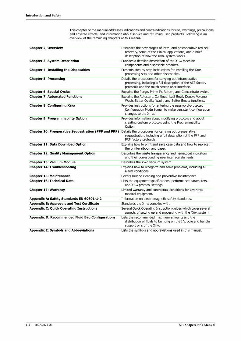
This chapter of the manual addresses indications and contraindications for use; warnings, precautions, and adverse effects; and information about service and returning used products. Following is an overview of the remaining chapters of this manual.
Chapter 2: Overview Discusses the advantages of intra- and postoperative red cell recovery, some of the clinical applications, and a brief description of how the XTRA system works.
Chapter 3: System Description Provides a detailed description of the XTRA machine components and disposable products.
Chapter 4: Installing the Disposables Presents step-by-step instructions for installing the XTRA processing sets and other disposables.
Chapter 5: Processing Details the procedures for carrying out intraoperative processing, including a full description of the ATS factory protocols and the touch screen user interface.
Chapter 6: Special Cycles Explains the Purge, Prime IV, Return, and Concentrate cycles.Chapter 7: Automated Functions Explains the Autostart, Continue, Last Bowl, Double Volume
Wash, Better Quality Wash, and Better Empty functions.Chapter 8: Configuring XTRA Provides instructions for entering the password-protected
Configuration Mode Screen to make persistent configuration changes to the XTRA.
Chapter 9: Programmability Option Provides information about modifying protocols and about creating custom protocols using the Programmability Option.
Chapter 10: Preoperative Sequestration (PPP and PRP) Details the procedures for carrying out preoperative sequestration, including a full description of the PPP and PRP factory protocols.
Chapter 11: Data Download Option Explains how to print and save case data and how to replace the printer ribbon and paper.
Chapter 12: Quality Management Option Describes the waste transparency and hematocrit indicators and their corresponding user interface elements.
Chapter 13: Vacuum Module Describes the XVAC vacuum systemChapter 14: Troubleshooting Explains how to recognize and solve problems, including all
alarm conditions.Chapter 15: Maintenance Covers routine cleaning and preventive maintenance.Chapter 16: Technical Data Lists the equipment specifications, performance parameters,
and XTRA protocol settings.Chapter 17: Warranty Limited warranty and contractual conditions for LivaNova
medical equipment.Appendix A: Safety Standards EN 60601-1-2 Information on electromagnetic safety standards.Appendix B: Approvals and Test Certificate Standards the XTRA complies with.Appendix C: Quick Operating Instructions Several Quick Operating Instruction guides which cover several
aspects of setting up and processing with the XTRA system.Appendix D: Recommended Fluid Bag Configurations Lists the recommended maximum amounts and the
distribution of fluids to be hung on the I.V. pole and handle support pins of the XTRA.
Appendix E: Symbols and Abbreviations Lists the symbols and abbreviations used in this manual.
Introduction and Safety
XTRA Operator’s Manual 20077/021 US 1-3
Indications for Use
The XTRA is indicated for use for intraoperative recovery of blood, washing of blood collected in the postoperative period and preoperative sequestration (with indirect patient connection).
Typical clinical applications of autotransfusion include the following surgical specialties:
• Cardiovascular• Orthopedics• Thoracic• Transplant surgery• Emergency (trauma)• Neurosurgery• Obstetrics and gynecology• Urology
Contraindication for Use
There are no known contraindications for the XTRA. However, the use of blood processed by this device may be contraindicated under some circumstances (see Warning #22 and #23). The responsibility for the use of the device in all cases belongs solely to the physician in charge.
General Warnings
1. The use of operating or maintenance procedures other than those published by LivaNova (hereafter referred to as “the company”), or the use of accessory devices not recommended by the company may result in patient injury or loss of life. The company will not be responsible for patient safety or equipment performance if the procedures to operate, maintain, and calibrate the XTRA system are other than those specified by company. Persons performing the procedures must be appropriately trained and qualified. Any equipment modifications must be performed by qualified persons and be approved in writing by the company.
All electrical installations must comply with all applicable local electrical codes and company specifications.
2. Read the instructions carefully prior to use. Prior to use, this manual must be thoroughly read and understood by the personnel assigned to operate the system. Improper use may cause personal injury and damage to the equipment. Improper use, repair or modifications by unauthorized personnel may invalidate any warranty agreement. In XTRA displayed information and in these instructions for use, the meaning of “fatal alarm” expression is considered as equivalent to “fatal error”. The expression “fatal alarm” has been adopted because it is considered more familiar to the user, but, from regulatory point-of-view, it must be considered as “fatal error”. In a similar way, in XTRA displayed information and in these instructions for use, the meaning of “alarm” expression is considered as equivalent to “information signal”.
3. The XTRA must be operated only by qualified personnel, trained in the use of the unit. Qualified and trained personnel’ means personnel capable of operating according to the directions and methods of use indicated in this manual.
4. Check the product thoroughly on delivery. Transportation and subsequent handling may cause structural and functional damage to the unit.
5. XTRA should be overhauled by authorized service technicians every 12 months.
6. Disconnect the XTRA autotransfusion system from the power source prior to cleaning and maintenance.
7. Do not use the XTRA in the presence of flammable agents because an explosion and/or fire may result.

Introduction and Safety
1-4 20077/021 US XTRA Operator’s Manual
8. The availability of alarms does not relieve the operator of his or her obligation to carefully monitor the entire system during operation. Unattended processing can lead to the development of problems with the operation of the system and/or with the quality of the end product.
9. Do not touch any moving parts of the centrifuge or pump. Injury may result.
10. Besides making the unit not operational, hardware alarms also stop the vacuum pump.
11. The American Association of Blood Banks recommends the following guidelines for expiration of salvaged blood:1
1 American Association of Blood Banks. Standards for Perioperative Autologous Blood Collection and Administration. 4th Edition. Bethesda, MD. 2010 Reference Standard 5.1.8A (Handling, Storage, and Expiration of Perioperative Autologous Red Cell Blood Products).
Collection Type Storage temperatureTime from the Start
of Collection to Expiration
Time from Completion of Processing to
Expiration
Special Conditions
Acute normovolemic hemodilution (whole blood)
Room temperature 8 hours N/A None
Acute normovolemic hemodilution (whole blood)
1-6 °C 24 hours N/A Storage at 1-6 °C shall begin within 8 hours of start of collection
Intraoperative blood recovery with processing
Room temperature N/A 4 hours None
Intraoperative blood recovery with processing
1-6 °C (N/A if bacterial contamination is suspected)
24 hours N/A Storage at 1-6 °C shall begin within 4 hours of completion of processing
Intraoperative blood recovery without processing
Room temperature 6 hours N/A None
Shed blood under postoperative or posttraumatic conditions with or without processing
N/A 6 hours N/A None
Combined Intraoperative and postoperative blood recovery with processing
Room temperature Postoperatively processed units: 6 hours from the start of postoperative collection
Intraoperatively processed units: 4 hours
None
Red Blood cells prepared by apheresis and intended for transfusion
Room temperature 8 hours N/A None
Red Blood cells prepared by apheresis and intended for transfusion
1-6 °C 24 hours N/A Storage at 1-6 °C shall begin within 8 hours of collection
Table 1-1 Guidelines for Expiration of Salvaged Blood

Introduction and Safety
XTRA Operator’s Manual 20077/021 US 1-5
12. The American Association of Blood Banks recommends the following guidelines for expiration of Perioperative Autologous Non-Red-Cell Blood Products:2
13. To minimize blood cell trauma, LivaNova recommends that vacuum levels no higher than (in absolute value) 150 mmHg (20 kPa) be used when aspirating fluid from the surgical field.3
14. Carefully observe the system for leaks before and during use. Leakage may result in loss of sterility or loss of blood and/or fluid. If leakage is observed before or during use, replace or retighten the leaking component as appropriate.
15. To prevent interference with anticoagulation when using citrate anticoagulants, do not use wash solutions containing calcium. Only sterile 0.9% normal saline (injectable or approved for cell processing) should be used as a wash solution.
16. Be sure that every bowl to be processed is adequately filled and packed before washing. Otherwise, the Wash cycle will be ineffective and the hematocrit will be low.
17. Washed, packed red cells are depleted of clotting factors. Patients should be monitored for the presence of clotting abnormalities associated with the transfusion of large volumes of packed red blood cells without clotting factors. Physicians should be prepared to institute the appropriate therapy.
18. Do not reinfuse the patient’s blood from the primary RBC bag when it is connected to the XTRA autologous transfusion circuit. Reinfusion from the primary reinfusion bag connected to the circuit could lead to air embolism.
19. To minimize the complications of particulate matter infusion and the risk of air embolism, use of an in-line microaggregate filter on the patient reinfusion line is STRONGLY RECOMMENDED.
20. Do not reinfuse under pressure (i.e., do not use a blood pressure cuff on the reinfusion bag). Reinfusion under pressure could lead to air embolism.
21. To reduce risk of air embolism, remove all air from the primary reinfusion bag before handing the bag over for reinfusion.
22. The physician ordering the use of this system and/or the surgeon operating the suction/collection wand shall use discretion in the collection of the following substances:
2 American Association of Blood Banks. Standards for Perioperative Autologous Blood Collection and Administration. 3rd Edition. Bethesda, MD. 2007 Reference Standard 5.1.8 (Handling, Storage, Transportation).
Collection Type Storage temperature Expiration Special ConditionsPlatelet-rich plasma intended
for transfusionRoom temperature N/A Shall be used before the
patient leaves the operating room or clinical procedure area
Platelet-rich plasma intended for topical use
Room temperature N/A Shall be used before the patient leaves the operating room or clinical procedure area
Platelet-poor plasma intended for topical use
Room temperature N/A Shall be used before the patient leaves the operating room or clinical procedure area
Thrombin intended for topical use
Room temperature Within 6 hours after component preparation (or not to exceed device manufacture’s recommendations)
Shall be used before the patient leaves the operating room or clinical procedure area
Table 1-2 Guidelines for Expiration of Perioperative Autologous Non-Red-Cell Blood Products
3Guidelines for blood recovery and reinfusion in surgery and trauma. Bethesda, MD; American Association of Blood Banks, 1997: 19-22.
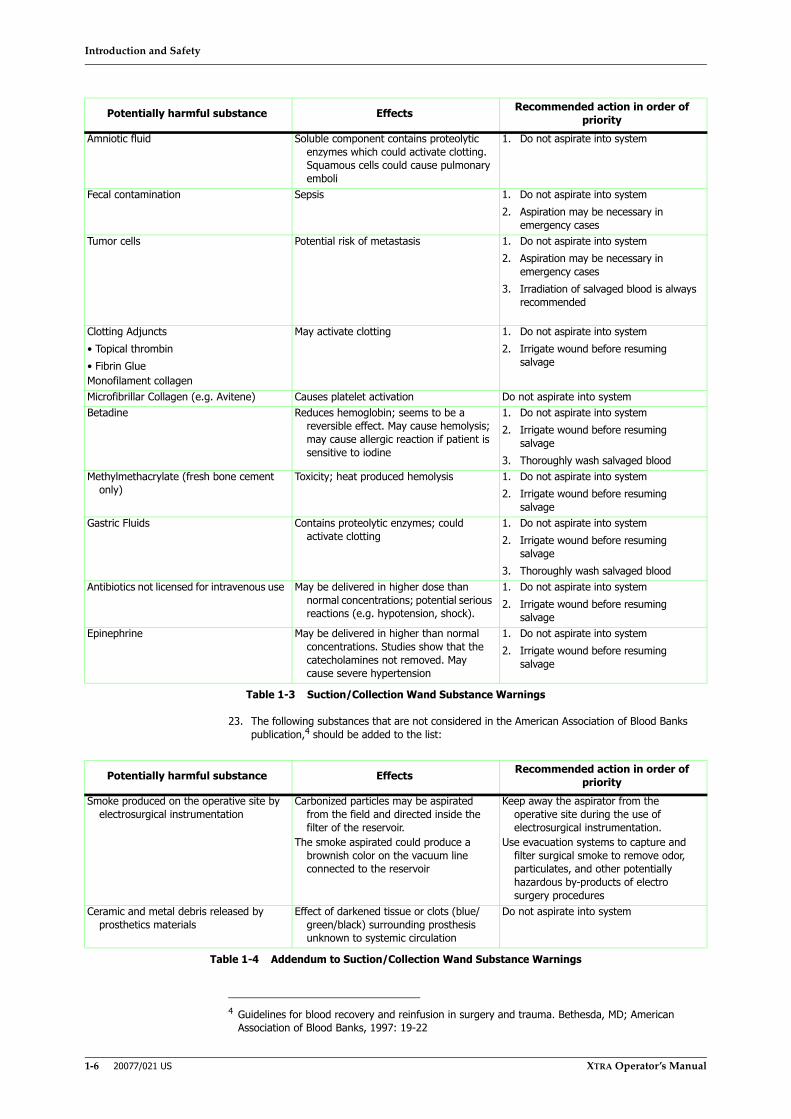
Introduction and Safety
1-6 20077/021 US XTRA Operator’s Manual
23. The following substances that are not considered in the American Association of Blood Banks publication,4 should be added to the list:
Potentially harmful substance Effects Recommended action in order of priority
Amniotic fluid Soluble component contains proteolytic enzymes which could activate clotting. Squamous cells could cause pulmonary emboli
1. Do not aspirate into system
Fecal contamination Sepsis 1. Do not aspirate into system2. Aspiration may be necessary in
emergency casesTumor cells Potential risk of metastasis 1. Do not aspirate into system
2. Aspiration may be necessary in emergency cases
3. Irradiation of salvaged blood is always recommended
Clotting Adjuncts• Topical thrombin• Fibrin GlueMonofilament collagen
May activate clotting 1. Do not aspirate into system2. Irrigate wound before resuming
salvage
Microfibrillar Collagen (e.g. Avitene) Causes platelet activation Do not aspirate into systemBetadine Reduces hemoglobin; seems to be a
reversible effect. May cause hemolysis; may cause allergic reaction if patient is sensitive to iodine
1. Do not aspirate into system2. Irrigate wound before resuming
salvage3. Thoroughly wash salvaged blood
Methylmethacrylate (fresh bone cement only)
Toxicity; heat produced hemolysis 1. Do not aspirate into system2. Irrigate wound before resuming
salvageGastric Fluids Contains proteolytic enzymes; could
activate clotting 1. Do not aspirate into system2. Irrigate wound before resuming
salvage3. Thoroughly wash salvaged blood
Antibiotics not licensed for intravenous use May be delivered in higher dose than normal concentrations; potential serious reactions (e.g. hypotension, shock).
1. Do not aspirate into system2. Irrigate wound before resuming
salvage Epinephrine May be delivered in higher than normal
concentrations. Studies show that the catecholamines not removed. May cause severe hypertension
1. Do not aspirate into system2. Irrigate wound before resuming
salvage
Table 1-3 Suction/Collection Wand Substance Warnings
4 Guidelines for blood recovery and reinfusion in surgery and trauma. Bethesda, MD; American Association of Blood Banks, 1997: 19-22
Potentially harmful substance Effects Recommended action in order of priority
Smoke produced on the operative site by electrosurgical instrumentation
Carbonized particles may be aspirated from the field and directed inside the filter of the reservoir.
The smoke aspirated could produce a brownish color on the vacuum line connected to the reservoir
Keep away the aspirator from the operative site during the use of electrosurgical instrumentation.
Use evacuation systems to capture and filter surgical smoke to remove odor, particulates, and other potentially hazardous by-products of electro surgery procedures
Ceramic and metal debris released by prosthetics materials
Effect of darkened tissue or clots (blue/ green/black) surrounding prosthesis unknown to systemic circulation
Do not aspirate into system
Table 1-4 Addendum to Suction/Collection Wand Substance Warnings

Introduction and Safety
XTRA Operator’s Manual 20077/021 US 1-7
24. Whole blood must be anticoagulated as it is collected into bags containing appropriate anticoagulant for plasma sequestration. Inadequate anticoagulation may result in clotting, interfering with the processing of the blood products.
25. Non-red cell components (e.g., platelet rich/platelet poor plasma intended for transfusion and platelet rich/platelet poor plasma) shall be used or applied before the patient leaves the operating room or clinical procedure area.5
26. If plasma is being collected for transfusion, it must be transfused before the patient leaves the operating room or clinical procedure area.6
27. Do not over anticoagulate collected blood. Plasma Sequestration has no Wash cycle to remove excess anticoagulant. A part of the anticoagulant used will be returned to the patient.
28. Do not overfill PPP and PRP bags. Overfilling may cause back pressure that would cause fluid to exit through the bowl seal.
29. Do not reinfuse the PRP back to the patient if the XTRA fails to operate as intended.
30. To reduce the possibility of air or particulate embolism, LivaNova STRONGLY RECOMMENDS the use of reinfusion protection devices, including microfilters, when infusing processed blood.
31. Do not reinfuse under pressure (i.e., do not use a blood pressure cuff on the RBC or plasma/PRP bags). Reinfusion under pressure could lead to air embolism.
32. Do not use solvents such as alcohol, ether, acetone, etc. to clean the equipment or the disposable circuits as contact of solvents with the plastic components may cause damage to the equipment or to the device. In addition to not using solvents, do not otherwise tamper with or alter the circuit’s configuration.
33. If the rotor of the roller pump has been removed to clean the upper panel, carry out the following operations to replace it correctly: open the lever, insert the rotor into its seat, turn it until aligns with the slot of the metal shaft and reposition the white lever into the slot.
34. During the use and transportation of the unit, do not exceed the maximum loading capacity.
35. The program parameters and the buffy-coat level are optimized according to the bowl size. At the end of the setup, verify that the bowl size automatically recognized by the machine (or manually selected) corresponds to the bowl size present in the disposable kit.
36. In case of malfunction of the integrated vacuum pump, use an alternate vacuum source, i.e. the vacuum present in the operating room, possibly connected to a pressure regulator.
37. Whenever the disposable kit is set to start a new case (or, if needed, substituted during the current case), make sure to conclude the setup by pressing LOAD PUMP; otherwise improper program parameters could be set, compromising performance.
38. After Setup operations, verify that the size of the bowl used corresponds to that indicated on the display.
39. The continuation of the current case by pressing RETAIN is under the full responsibility of the operator.
40. The stand-by function stops the pump for several minutes, but not the centrifuge. Avoid any improper use. Do not activate the stand-by function for prolonged or repeated periods. Instead, press the Stop button and restart the case whenever needed.
41. Improper use of RETAIN can lead to the risk of obtaining an inadequate blood product.
42. XTRA is provided with an indicator which measures the Hct of the fluid entering and of the RBCs leaving the bowl. As this system is mainly intended to provide the user with a trending of Hct values, it is recommended that alternate means of measuring hematocrit be used when it is
5 American Association of Blood Banks. Standards for Perioperative Autologous Blood Collection and Administration. 3rd Edition. Bethesda, MD. 2007 Reference Standard 5.1.8 (Handling, Storage, Transportation)
6 American Association of Blood Banks. Standards for Blood Banks and Transfusion Services. 18th ed. Bethesda, MD: American Association of Blood Banks, 1997.
Introduction and Safety
1-8 20077/021 US XTRA Operator’s Manual
requested to evaluate the final hematocrit in the RBC bag. The same holds true also for volume, supernatant removal and waste line color monitoring features.
43. The XTRA hematocrit sampling system has not been tested for all possible blood conditions. Conditions may exist which will result in hematocrit readings which differ from Coulter Counter readings. For example, conditions which result in cellular changes (sickle cell anemia, high concentrations of anticoagulants which may cause red cell shrinkage, or the use of certain anticoagulants which may cause red cell volume expansion) or conditions outside of the applicable ranges may result in Hematocrit readings which differ from Coulter Counter readings.
44. When releasing an IV pole or reservoir pole locking lever, the operator must always hold the pole and locking mechanism with both hands; otherwise, there is a serious risk of injury.
45. Do not open the lid in the event of a power failure if the centrifuge has not yet come to a stop (which may take between 50 and 90 seconds).
46. In the event of excess heparin in collection reservoir due to inappropriate ratios, the salvaged blood may contain residual heparin.
47. In the event of decreased patient antithrombin III levels if using heparin anti coagulation, consult the physician in order to provide alternate anticoagulation.
48. When the XTRA is used alone, the RS422 serial ports used to connect it to the XVAC must be covered and secured with a cap.
49. The use of the Last Bowl function is recommended only to complete the case, with the following conditions: The reservoir is empty, no more blood is expected to be collected, and sufficient red cells in saline solution are available in the RBC bag to compete the Concentrate cycle.
50. In case a partial bowl is washed, the hematocrit of the collected blood as well as the removal of waste components might be lower than expected.
51. The maximum volume in the RBC bag is 1 liter. To avoid explosions, check the level inside the bag carefully before activating the Last Bowl function.
52. The Last Bowl function automatically activates a second Empty phase at the end of the first Empty phase. Carefully monitor the air in the RBC bag in case of repeated activation of the Last Bowl function.
53. The XTRA and XVAC should not be used adjacent to or stacked with other equipment. However, if adjacent or stacked use is necessary, the XTRA and XVAC should be observed to verify normal operation is occurring in the configuration in which they are used.
54. In order to comply with “General Requirements for basic safety and essential performance of Medical electrical equipments” (IEC 60601-1, Rules preventing instability), it is requested that the waste bag not be filled with more than 9 liters of waste liquid.
55. The blood collected with the XVAC vacuum module must be processed only with the XTRA Autotransfusion System.
56. Use of protocols different from Post-op in postoperative contexts might expose the patient to risks of tissue damage due to high aspiration level of vacuum module and risks of blood return due to availability of the Return function.
57. Use of the vacuum pump in INTRA mode while collecting blood postoperatively might expose the patient to risks of tissue damage.
58. Transport should only be undertaken in a certain condition that is clearly described in Appendix D of this manual.
59. All contents of the waste bag are not intended for further processing and must be properly discarded.
60. In the event of large volumes of blood leaking or splashing inside the centrifuge well, the integrity of the centrifuge plate and centrifuge well gasket could be compromised. In this case please contact the authorized Services of your LivaNova branch or your local LivaNova representative.
Introduction and Safety
XTRA Operator’s Manual 20077/021 US 1-9
Storage and Transporting Warnings
1. When not in use, the unit must be stored under the specified environment conditions in a dust-free place, covered with the protective cover supplied.
2. When the unit is not in use, switch off the main switch, disconnect the plug from the socket and wind the power cord around the holders on the rear of the unit.
3. The unit must be stored in a cool, dry and well ventilated place.
4. When closing the lateral pins, ensure your fingers are kept away from the levers; otherwise you expose yourself to a serious risk of injury.
Electrical Warnings
1. Before connecting the unit, check that the mains socket is supplied at the voltage and frequency shown on the label on the unit.
2. Connect the unit to a mains socket of the same size as the plug used. Do not use adapters between plug and socket.
3. Ensure that the mains socket is equipped with a grounding line and safety devices.
4. For continued protection against risk of fire, replace fuses only with components of the same type and ratings.
5. Electrical shock hazard. No user serviceable parts are inside. For servicing refer to qualified personnel who are authorized only by the manufacturer.
6. Never connect the plug to the mains socket with wet or damp hands. If liquids are poured onto the unit during use, turn off the power switch and remove the plug immediately, before drying the external panels.
7. Always remove the plug from the socket by gripping it with the hand. Do not pull on the power cord.
8. Ensure that the plug is secured to the machine by means of the metallic grid (see Figure 5-12) to prevent accidental unplugging.
9. To prevent risk of electrical shock, do not use alternate power plugs or adapters that disconnect the green/yellow wire safety ground.
10. The electrical installation must be in compliance with electrical safety regulations and according to voltage and current ratings specified on the labels on the back of the unit.
11. The XTRA system must be always grounded via the hospital electrical power source according to the regulations in force in the country of use.
12. Electrical safety features are contained in Appendix A: Safety Standards EN 60601-1-2.
13. The use of accessories and cables other than those provided by LivaNova may result in increased emissions or decreased immunity of the XTRA and XVAC devices.
14. Accessories and cables provided by LivaNova may only be used with the XTRA and XVAC devices. The use with other equipment or system may result in increased emission or decreased immunity of that equipment or system.
15. To prevent risk of electrical shock, shut OFF power and unplug the system from the electrical outlet before performing cleaning procedures.
16. OPERATOR must not touch the relevant part and the PATIENT simultaneously:
– accessible contacts of connectors;
– contacts of fuse holders that are accessible during replacement of the fuse;
– parts inside an ACCESS COVER that can be opened without the use of a TOOL, or where a TOOL is needed but the instructions for use instruct any OPERATOR other than SERVICE PERSONNEL to open the relevant ACCESS COVER.

Introduction and Safety
1-10 20077/021 US XTRA Operator’s Manual
17. Connecting electrical equipment to the integral multiple socket-outlet of XTRA effectively leads to creating an ME system, and can result in a reduced level of safety. Connecting of other devices (which is not allowed according to this user manual), must fulfill all requirements of the standard IEC 60601-1:Edition 3.1.
18. The only way to separate the equipment from the supply mains on all poles simultaneously is by disconnecting the POWER CORD from the mains inlet plug. Do not position XTRA and XVAC in a way to make it difficult to disconnect the POWER CORD.
19. To isolate XTRA and XVAC (if connected) electrically from the SUPPLY MAINS on all poles (Line and Neutral, PE conductor remains connected) simultaneously use the SUPPLY MAINS switch, Figure 3-2 in this manual.
20. Connecting electrical equipment other than XVAC to the integral multiple socket-outlet of XTRA can result in a reduced level of safety.
General Precautions
1. The XTRA must be used only with XTRA disposables.
2. Due to the possibility of operator exposure to blood borne pathogens (such as HIV, hepatitis viruses, bacteria, Cytomegalovirus, etc.) when handling extracorporeal blood circuits, adequate precautions should be taken at all times to prevent the exposure to and transmission of such agents.
3. An adequate quantity of salvaged, viable, washed, packed red blood cells cannot always be predicted or depended upon in a blood salvage procedure. Physicians should be prepared to institute appropriate additional therapy if necessary.
4. Use aseptic technique when installing disposables.
5. Failure to maintain adequate anticoagulation during blood collection can cause excessive clotting in and possible clogging of the collection reservoir or centrifuge bowl.
6. Incorrect assembly of the vacuum overflow trap or assembly using damaged components could allow an overflow to enter the machine and damage internal vacuum system parts.
7. The operator is responsible for setting safe parameters for the custom protocols and for the factory protocols modified during a case.
8. The XTRA will always start up with the Wakeup protocol as the Active protocol. Always verify the Active protocol prior to processing.
9. Sterile 0.9% normal saline, USP (injectable or approved for cell processing) is typically used as a wash solution. Other solutions intended for intravenous use that have been approved by the FDA and have documentation available to show the component is safe may be used.7
10. During the Wash cycle, pump speeds lower than those used in the preset XTRA protocols may decrease the wash quality.
11. Inadequate washing of the packed red blood cells may lead to an excessive level of contaminants (e.g., anticoagulant, plasma free hemoglobin) in the processed blood.
12. The clamp on the inlet port of the waste bag must be open during blood salvage processing.
13. When clearing the line, stop the Empty cycle or manual cranking of the pump before air enters the primary reinfusion bag. Stop the Empty cycle by pressing the Empty or Stop buttons.
14. Overfilling the reinfusion bag may cause it to rupture.
15. Ignoring a full waste bag may cause back pressure from the waste bag that could result in fluid leakage around the bowl's rotating seal or waste fluid being returned to the centrifuge bowl.
7American Association of Blood Banks. Standards for Perioperative Autologous Blood Collection and Administration. 3rd Edition. Bethesda, MD. 2007 Reference Standard 5.4.4 (Addition of Drugs and Solutions)
Introduction and Safety
XTRA Operator’s Manual 20077/021 US 1-11
16. Do not completely empty the waste bag until the end of the case. If you empty the waste bag during the case, leave approximately one liter of fluid in the waste bag to prevent the possibility of vacuum being generated in the waste bag during the Empty cycle. Vacuum in the waste bag may prevent complete emptying of the bowl.
17. The waste bag should be replaced with the equipment STOPPED (pump and centrifuge) and the bowl completely empty. This instruction does not apply if the replacement of the waste bag is done with a vented waste bag.
18. When cleaning the process air detector, red blood cell detector, Hct indicator, and waste line color indicator, do not use bleach, abrasive materials, or solvents, as they may damage the sensors. Use a mild detergent.
19. Do not immerse the rotor in cleaning solution. Do not autoclave. Component damage may result.
20. The fluid collected in the Centrifuge Well Collection may be biohazardous. Handle accordingly and dispose of the container according to hospital protocol.
21. Prior to first use of the XTRA, electrical and operational checks should be performed according to hospital protocol and the company's recommendations.
22. Report immediately to the responsible service personnel any of the following conditions. Do not use the XTRA until corrective action has been taken:
• Damaged or worn power cord, plug or receptacle.
• Switches that are loose or do not operate with a positive action.
• A machine that has been subject to significant physical damage.
• A machine that has given anyone an electrical shock while in use.
• A machine that appears to be overheating.
23. It is the responsibility of the health care institution to adequately prepare and identify the product for return shipment. Do not return products that have been exposed to blood borne infectious diseases.
24. Federal law (USA) restricts this device to sale by or on the order of a physician.
25. Store plasma products containing platelets at room temperature (20 °C to 24 °C) with continuous, gentle agitation.8
26. Make sure that you attach both PRP bags included in the XTRA Sequestration Set. Because the XTRA does not alert you when a specified volume is collected, you must have sufficient bags available for the entire amount that can be collected.
27. Air must be collected and be available to be returned to the centrifuge bowl during the Empty cycle. Otherwise, plasma may be accidentally drawn back into the centrifuge bowl. Ensure that the bag with the air remains attached to the bowl outlet tubing and OPEN during the Empty cycle.
28. If using the waste bag for air management, the waste line should not be clamped until plasma starts to exit the bowl during plasma sequestration.
29. Make sure that the waste line is unclamped before starting blood salvage processing.
30. The physician ordering the collection of PRP shall use discretion when any of the following conditions exist:
• Sepsis
• Preoperative hematocrit less than 30%
• Preoperative platelet count less than 195,000 per µl
• Hemodynamic instability
• Prolonged clotting times
8American Association of Blood Banks. Standards for Blood Banks and Transfusion Services. 18th ed. Bethesda, MD: American Association of Blood Banks, 1997: G3.300.

Introduction and Safety
1-12 20077/021 US XTRA Operator’s Manual
• Recent use of anti-platelet drugs
• Inability to maintain stable oncotic pressure
31. When collecting PRP, LivaNova recommends the following precautions be taken to insure that the PRP product is not contaminated:
• Use sterile techniques when setting up the XTRA disposables.
• Thoroughly clean and disinfect the donation site.
• Use sterile techniques whenever handling the PRP product.
32. Make sure to open a blood collection (plasma) bag flow path before closing the waste bag port. Failure to do so may result in fluid leaking from the centrifuge bowl seal.
33. Any device connected to the RS232 port must comply with the applicable IEC standard for that device.
34. In the event that a hematocrit value is desired and not obtained with the Hct Sampling System of the unit, use an alternate means of measuring hematocrit.
35. Prior to collecting any blood, prime the reservoir with approximately 200 ml of the anticoagulant solution.
36. In the event of anticoagulant deficiency in collection reservoir due to inappropriate ratios, the savaged blood may clot in the reservoir.
37. Avoid use of Ringer’s when using citrate anticoagulant as the simultaneous use of incompatible IV fluids may cause clotting in the system.
38. Use only XTRA USB memory sticks.
39. Be sure to properly place and hook the machine to the cart in order to avoid the danger of the machine falling.
40. If the display shows incomprehensible and erroneous messages or messages different from those indicated in this manual, immediately stop the unit and contact LivaNova Technical Service.
41. In the event of problems with the automatic removal of the lid opening lock: (a) do not attempt to force open the lid; (b) switching the machine off and on might resolve the problem; (c) if the problem persists, contact authorized technical service.
42. The Waste bag must not be squeezed while treatment is being done and must have the space to fill up properly. If the bag is squeezed or cannot fill up properly because it is positioned near an obstacle (for example, a wall) a reflux toward the bowl or a back pressure might be created sufficient to cause the liquid to leak from the bowl seal
43. A failed or improper connection of the lines can lead to the risk of gas or liquids entering the circuit from the environment.
44. Strictly adhere to these disposable installation instructions to guarantee the proper execution of the treatment. In particular, be careful with the: (a) proper connection of the RBC bag to avoid leakage of red blood cells, (b) proper connection of the wash bag to guarantee proper washing, and (c) proper connection of the reservoir to allow access to the blood to be processed.
45. In the event of problems with the automatic unloading of the pump circuit, open the lid of the centrifuge and manually remove the tubing of the pump circuit from the pump rotor: Rotate the pump rotor counterclockwise while extracting the tubing of the pump circuit.
46. Always close the centrifuge lid before starting any function of the machine that uses the pump and/or centrifuge action to avoid the risk of touching any moving parts of the device.
47. The use of phase buttons and, in general, modifications that alter the normal execution of protocols can create reductions of normal machine performance. It is the responsibility of the user to evaluate if and when these procedures can be performed.
48. The availability of alarms does not relieve the operator of his or her obligation to carefully monitor the entire system during operation. Unattended processing can lead to the development of problems with the operation of the system and/or with the quality of the end product.
Introduction and Safety
XTRA Operator’s Manual 20077/021 US 1-13
49. During the execution of emergency protocols, the control that causes a warning of “Minimum wash quality wash might not be reached yet” is automatically disabled.
50. The use of emergency protocols with the Rapid Transfer option produces an unwashed final collection in which the removal of contaminants is only possible through the 40-µm filter in the reservoir. It is the full responsibility of the user to evaluate if the conditions exist to use emergency protocol with the Rapid Transfer option.
51. The emergency protocols promote fast execution rather than the quality of the final product, which is reduced compared to that guaranteed by other predefined protocols. Their use is, therefore, reserved to situations in which there is a preponderant urgent need for blood regarding the concentration of RBC collected and the wash quality. It is the full responsibility of the user to evaluate if the conditions exist to use said protocols.
52. The use of emergency protocols with the No Wash option produces an unwashed final collection in which the removal of contaminants is only possible through the 40-µm filter in the reservoir and the concentration of the Fill phase. It is the full responsibility of the user to evaluate if the conditions exist to use an emergency protocol with the No Wash option.
53. Inadequate washing of concentrated red blood cells can lead to an excessive level of contaminants (i.e. anticoagulants and plasma free hemoglobin) in the treated blood.
54. Use of the vacuum pump in INTRA mode while collecting blood postoperatively might expose the patient to risks of tissue damage
55. As soon as postoperative drainage operations are completed, the patient must be disconnected from the reservoir.
56. The use of protocols different from POST-OP in postoperative contexts might expose the patient to risks of tissue damage due to high aspiration levels of vacuum module and risks of blood return due to availability of the return function.
57. During setup and unload of the kit, the patient must not be connected to the reservoir through the drainage line.
58. The deactivation of the RBC Detector is at the full responsibility of the doctor/operator who must carefully supervise the fill phase (or concentration) and manually touch the Wash button to start the washing phase (or Spill or Empty to start the phase of the same name during a sequestration protocol). A delayed procedure might lead to a loss of red blood cells or, in sequestration procedures to inadequate collections. An early procedure might lead to low quality collection.
59. The repeated use of the Return function on the same red blood cells might lead to them being damaged and therefore to their loss.
60. The Concentration function reprocesses already collected red blood cells subjecting them again to the mechanical action of the pump and the centrifuge. The repeated use of the Concentration function on the same red blood cells might lead to them being damaged and therefore to their loss.
61. Any modification on the acoustic signals can make the operator take longer to realize that the machine has made a warning.
62. The deactivation of the alarms “RBC bag full” and/or “Waste bag full” is under the responsibility of the user who must directly control the fill level of the bags.
63. In the event of replacing a collection bag, verify that the new bags are properly connected and the manual clamps reopened before restarting the process in order to avoid problems of blood component leakage and circuit breaks.
64. In the course of preoperative sequestration treatments, it is necessary to open and/or close some of the manual clamps along the lines. Erroneous execution of these procedures by the operator might lead to breakage of the disposable, blood component leakage and inadequate collections.
65. The use of the Prime IV function or repeated calibration phases of the HCT sensor can lead to a dilution of the collection (PPP/PRP).
66. Always close the centrifuge lid before starting any function of the machine that uses the pump and/or centrifuge action to avoid the risk of touching moving parts of the device.

Introduction and Safety
1-14 20077/021 US XTRA Operator’s Manual
67. Although it is possible to configure some of the acoustic notifications that the machine makes, any modification on the audible signals might make the operator take longer to realize the machine has made a notification.
68. It is possible to temporarily deactivate some of the controls that the machine does. The operator can make use of this possibility, under his own responsibility, therefore directly managing those controls.
69. At the end of installation verify that the bowl outlet is not crushed or obstructed.
70. In the case of malfunction of the integrated vacuum pump, use an alternative vacuum source, i.e., the vacuum present in the operating room, possibly connected to a pressure regulator.
71. If the values regarding volumes, hematocrit, supernatant removal and waste color line are important for the patient, it will always be necessary to use other standard measurement instruments of the hospital.
Operating Conditions
Warning
1. Do not use the unit in the presence of inflammable anaesthetic gases. do not expose to heat sources. Avoid any operating situation where the blood may be exposed to temperatures exceeding 37 °C (98.6 °F).
Cautions
1. When the unit is operating, the following conditions must be met:- Room temperature: 10 - 35 °C (50 - 95 °F)- Relative humidity: 30-75%- Atmospheric pressure: 80 - 106 kPa
2. Conditions that cause the unit to overheat when operating must be avoided.
Adverse Effects
The company is not aware of documented adverse effects when this device is used according to this Operator's Manual.
Installation of the Unit
Installation
The XTRA and XVAC systems are medical electrical equipment and need special precautions regarding electromagnetic compatibility (EMC). They need to be installed and put into service according to the EMC information provided in Appendix A: Safety Standards EN 60601-1-2.
Portable and mobile radio frequency (RF) communications equipment can affect the XTRA and XVAC.
WARNINGThe XTRA and XVAC should not be used adjacent to or stacked with other equipment. However, if adjacent or stacked use is necessary, the XTRA and XVAC should be observed to verify normal operation is occurring in the configuration in which they are used.
Introduction and Safety
XTRA Operator’s Manual 20077/021 US 1-15
Unpacking and Inspection
Prior to delivery, all components and modules of the XTRA have passed quality assurance testing.
Before each XTRA system is considered to be operative, it should be checked by the user according to the instructions given below.
Check on delivery that the unit outer container has not been damaged. If there are signs of deterioration, a formal complaint must be made at once to the transport agents. Check the unit carefully and ensure that there are no missing parts or visible signs of damage.
If any problems are noted, immediately communicate these with a detailed account of the problems either to the local representative or directly to LivaNova, to the following address:
LivaNova Deutschland GmbHLindberghstrasse 25D-80939 München GermanyTel: +49.(0)89.32301.0Fax: +49.(0)89.32301.555
Storage and Transport Conditions
Important: before storing or transporting, refer to “Storage and Transporting Warnings” starting on page 1-9.
When still packed, the unit may be transported or stored under the following conditions:
• Temperature: -10°C (14°F) to +60°C (140°F)
• Humidity: 5% - 85%; RH non-condensing
• Atmospheric pressure: 80 - 106 kPa
Electrical Requirements
Warning: before using device, refer to “Electrical Warnings” starting on page 1-9.
The XTRA must be connected to a fused and grounded wall socket in accordance with the regulations in force in the country of use. Line voltage and current required must comply with what is indicated on the identification labels and on the specification sheets in this manual. The length of the separator power cord is 4m.

Introduction and Safety
1-16 20077/021 US XTRA Operator’s Manual
Addresses
Manufacturer:LivaNova Deutschland GmbHLindberghstrasse 25D-80939 München GermanyTel: +49.(0)89.32301.0Fax: +49.(0)89.32301.555
Distributor in U.S.A.LivaNova USA, Inc.14401 West 65th WayArvada, Colorado USA 80004Tel: +1.800.221.7943Tel: +1.303.425.5508Fax: +1.303.467.6584
Distributor in CanadaLivaNova Canada, Corp.280 Hillmount Road Unit 8Markham, Ontario L6C 3A1 CanadaTel: +1.416.751.8787Fax: +1.416.751.9849
Introduction and Safety
XTRA Operator’s Manual 20077/021 US 1-17
Service Information
The Company and/or its branches provide their customers with a Technical Service Department, composed of experts in installation, maintenance and repair of the LivaNova equipment. To contact a specialized technician of LivaNova Technical Service, call the central service on the following telephone number:
+49 (0)89 41 61 26 462
LivaNova and/or its branches are not responsible for the safety, reliability and function of the unit:
• if routine maintenance, repairs and use of the unit are carried out by non-qualified personnel;
• if the electrical installation does not comply with local regulations and IEC specifications;
• if the equipment is not used according to the above-mentioned instructions.
A specialized technician can be contacted for any technical information regarding the LivaNova equipment, on the following telephone number or email:
ATS-Hotline: +49 (0)89 41 61 26 462ATS Email: [email protected]
The operator will put you through to the specialized technician at LivaNova headquarters or to a local specialized technician.
Return of Used Product
For North American Customers
If for any reason this product must be returned to the company, a returned goods authorization (RGA) number is required prior to shipping. If the product has been in contact with blood or body fluids, it must be thoroughly cleaned and disinfected before packing. It should be shipped in either the original carton, or an equivalent carton, to prevent damage during shipment; and it should be properly labeled with an RGA number and an indication of the biohazardous nature of the contents of the shipment.
Instructions for cleaning and materials, including appropriate shipping containers, proper labeling, and an RGA number may be obtained from the Returned Goods Coordinator, Quality Assurance Department (+1.800.650.2623). The shipping address for returned goods is:
LivaNova USA, Inc.Returned CV Products14401 West 65th WayArvada, CO 80004-3599
For International Customers
If for any reason this product must be returned, please contact your sales representative for specific instructions.
If the product has been in contact with blood or body fluids, it must be thoroughly cleaned and disinfected before packing. It should be shipped in either the original carton, or an equivalent carton, to prevent damage during shipment.
CAUTIONIt is the responsibility of the health care institution to adequately prepare andidentify the product for return shipment. Do not return products that havebeen exposed to blood borne infectious diseases.

Introduction and Safety
1-18 20077/021 US XTRA Operator’s Manual
Disposal in Accordance with Environmental Regulations
• Because the XTRA System must be regarded as potentially infectious after it is finished with, it must not be disposed of in accordance with the EU Directive 2002 96 EC WEEE or its German derivative ElektroG.
• All disposables used in conjunction with the XTRA System must be disposed of in accordance with the local and environmental regulations. Observe hospital regulations when disposing of these items.
• Exchanged batteries of the XTRA System are considered hazardous waste and must be disposed of in accordance with the environmental protection regulations. The authorized service technician will replace the batteries every three years but the user of the XTRA System is responsible for their disposal.

Overview
XTRA Operator’s Manual 20077/021 US 2-1
Chapter 2: Overview
Advantages of Intra- and Postoperative Red Cell Recovery
Although collecting and reinfusing a patient's own blood (referred to as autologous blood) has been reported in the medical literature as far back as 1818, this procedure recently has gained renewed interest due to the growing concern over the possibility of disease transmission via transfusions of blood from a donor (referred to as homologous blood).
Intraoperative blood recovery offers significant advantages to the patient, surgical team, and hospital.
Clinical Applications
Autotransfusion (Intraoperative) processing is widely employed for cardiac and vascular surgery, but is also suitable for other surgical procedures during which blood loss occurs.
Specialties employing this technology include orthopedics, plastic and reconstructive surgery, neurosurgery, solid organ transplants, general surgery, gynecology, and trauma.
Specific clinical applications have included:
• Aneurysm repair
• Artero-venous malformation repair
• Valve replacements and coronary artery bypass grafts
• Primary and revision hip and knee arthroplasty, spinal repair, and Harrington rod procedures
• Ectopic pregnancies
• Major trauma such as penetrating chest and abdominal injuries including injuries to the liver, spleen, chest wall, heart, pulmonary vessels, kidney, iliac vein, portal vein, and inferior vena cava
• Organ transplants
Description of the XTRA System
The XTRA System consists of a blood processing device, used in association with its disposable for processing.
The XTRA is available as an automated system or with any or all of the following programmable options (discussed later in this chapter):
• Programmability (custom protocols)
• Emergency function
• XVAC Vacuum System
• Preoperative Sequestration (automatic or manual)
• Data Management (USB, Printer, RS232)
• Quality Management (Built-in HCT Sampling System, built-in Waste Components Removal System)
The XTRA has been designed with the operator in mind. To allow easy visualization of the system state from across the room, the large touch screen control panel has colors identifying the current phase, and its keys provide a two-way communication while guiding the user through the system's operation.

Overview
2-2 20077/021 US XTRA Operator’s Manual
Installing the disposables, including the centrifuge bowl, is rapid, straightforward, and tool-free. The pump loop cartridge and the tubing organizer of the XTRA Bowl Set make loading the pump, process air detector, and tubing lines easy.
An ultrasonic air detector senses the presence of air or fluid in the tubing harness and discontinues processing should air be present. The processing pump provides high blood flow rates with minimal hemolysis, thus enabling the XTRA to keep up with cases involving high blood loss. The XTRA is easily maneuvered by one person, even in tight spaces, and ergonomically designed to be operated by a standing or sitting operator.
The XTRA incorporates a number of safety features. While the pump and/or centrifuge are in operation, the centrifuge lid remains locked to prevent harm to the operator. All alarm conditions are indicated with both audible and visual signals, and, with most alarm conditions, the centrifuge and/or pump automatically shut down until the condition is cleared.
All disposables used with the XTRA are available through LivaNova. The XTRA Bowl Set includes a color-coded tubing harness with pump loop cartridge, the Latham Centrifuge Bowl (55 ml, 125 ml, 175 ml, or 225 ml), a 10-liter waste bag, and a 1-liter primary RBC bag. Except for the waste bags, XTRA Bowl Set components are preconnected for ease of installation and to maintain the sterility of the system.
The Aspiration line, designed to mix the anticoagulant and the blood near the collection site, will connect to most suction cannulae.
The Blood Collection Reservoirs are available in 40-micron and 120-micron (only BOTTOM version) filtered models. To facilitate ordering, storage, and setup, the company offers sets including several components for blood collection and processing in one package:
• Procedure Sets that combine the key disposables (XTRA Bowl Set, Aspiration and Vacuum Lines, and Blood Collection Reservoir).
• Collection Sets that combine the key disposables (Blood Collection Reservoir, Aspiration and Vacuum Line) for Blood Collection from the operative field.
• The Collection Set is also available in the Cardio configuration which includes the Cardio Kit for the connection of the Blood Collection Reservoir with an oxygenator or circuit for ECC for recovery of priming fluid residue from ECC circuit or concentration of priming fluid.
The company also offers a complete line of accessories to accommodate customized setups and options.
LivaNova also provides the XTRA PRP Processing Sets, based on the bag method of whole blood supply for processing (whole blood collected in bags) for use with the preoperative sequestration option. Each case also requires the use of anticoagulant and sterile wash solution (usually normal saline).
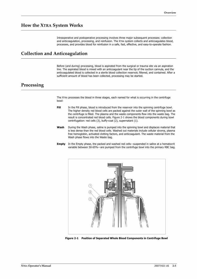
Overview
XTRA Operator’s Manual 20077/021 US 2-3
How the XTRA System Works
Intraoperative and postoperative processing involves three major subsequent processes: collection and anticoagulation, processing, and reinfusion. The XTRA system collects and anticoagulates blood, processes, and provides blood for reinfusion in a safe, fast, effective, and easy-to-operate fashion.
Collection and Anticoagulation
Before (and during) processing, blood is aspirated from the surgical or trauma site via an aspiration line. The aspirated blood is mixed with an anticoagulant near the tip of the suction cannula, and the anticoagulated blood is collected in a sterile blood collection reservoir, filtered, and contained. After a sufficient amount of blood has been collected, processing may be started.
Processing
The XTRA processes the blood in three stages, each named for what is occurring in the centrifuge bowl:
Fill In the Fill phase, blood is introduced from the reservoir into the spinning centrifuge bowl. The higher density red blood cells are packed against the outer wall of the spinning bowl as the centrifuge is filled. The plasma and the waste components flow into the waste bag. The result is concentrated red blood cells. Figure 2-1 shows the blood components during bowl centrifugation: red cells (3), buffy-coat (2), supernatant (1).
Wash During the Wash phase, saline is pumped into the spinning bowl and displaces material that is less dense than the red blood cells. Washed out materials include cellular stroma, plasma free hemoglobin, activated clotting factors, and anticoagulant. The waste material from the Wash phase flows into the Waste bag.
Empty In the Empty phase, the packed and washed red cells—suspended in saline at a hematocrit variable between 50-65%—are pumped from the centrifuge bowl into the primary RBC bag.
Figure 2-1 Position of Separated Whole Blood Components in Centrifuge Bowl
Overview
2-4 20077/021 US XTRA Operator’s Manual
Reinfusion
Reinfusion of the red blood cells processed by the XTRA is under the control and supervision of the physician in charge and can be accomplished by several different means:
• Processed blood can be held in the primary RBC bag until the bag becomes full. Then the bag can be disconnected from the autologous transfusion circuit, hung, and reinfused according to normal blood administration protocol, as described in AABB standards.
• Some of the processed blood can be moved into a transfer pack and handed off to the anesthesiologist for reinfusion while processing of shed blood continues.
• Blood can be stored for later reinfusion. In this case, follow your institution's blood administration protocol for appropriate labeling and blood storage requirements.
The Basic XTRA
The XTRA is equipped with an electronic red cell detector which determines when the appropriate quantity of red cells has accumulated in the centrifuge bowl. This offers three modes for advancing the blood processing phases:
• Automatic: The XTRA will fill, wash, and empty the centrifuge bowl continuously until there is no fluid left to process in the reservoir or until the wash solution is depleted or another waning condition happens.
• 1 Touch: The XTRA will start automatically when a certain level of fluid is reached in the reservoir, and will fill, wash, and empty the centrifuge bowl continuously until there is no fluid left to process in the reservoir or until the wash solution is depleted or another waning/alarm condition happens.
• Manual: The operator has control over each phase transition: from Fill to Wash, and from Wash to Empty. Options are available to prompt the operator when it is time to proceed to the Wash phase, and to automatically proceed to the Empty phase.
WARNINGThe American Association of Blood Banks provides recommendations for expiration of salvaged blood (see Warning #11 on page 1-4).
WARNINGDo not reinfuse the patient’s blood from the primary RBC bag when it is connected to the XTRA autologous transfusion circuit. Reinfusion from the primary reinfusion bag connected to the circuit could lead to air embolism.
WARNINGTo minimize the complications of particulate matter infusion and the risk of air embolism, use of an in-line microaggregate filter on the patient reinfusion line is STRONGLY RECOMMENDED.
WARNINGDo not reinfuse under pressure (i.e., do not use a blood pressure cuff on the reinfusion bag). Reinfusion under pressure could lead to air embolism.
WARNINGTo reduce risk of air embolism, remove all air from the primary reinfusion bag before handing the bag over for reinfusion.
Overview
XTRA Operator’s Manual 20077/021 US 2-5
The basic XTRA has two preset protocols (plus the Emergency protocol) to use for processing (available for all four bowl sizes):
• Popt, available for 55, 125, 175, 225 ml bowl
• Pstd, available for 55, 125, 175, 225 ml bowl
• Emergency, available for 55, 125, 175, 225 ml bowl
Options Available with XTRA
Programmability Option
With the programmability option, the operator can enable the user protocols and non-automated operating modes. User protocols allow creating and permanently storing up to 24 additional protocols.
Emergency Option
The Emergency option enables the Emergency button on all processing screens, from which the Emergency function may be activated. Two additional options are then available: Rapid Transfer and No Wash.
Vacuum System (XVAC)
The XVAC System is a modular source of vacuum for intra- and postoperative aspiration. It is a substitute for hospital vacuum, when none is available or when the available source is difficult to use or regulate. The XVAC allows vacuum levels (in absolute value) ranging from 50 to 300 mmHg (6.7 - 40 kPa) for intraoperative aspiration and 10 to 100 mmHg (1.3 - 13.3 kPa) for postoperative.
Preoperative Sequestration Option (PPP and PRP)
The preoperative sequestration option enables recovery of plasma and platelets from blood by drawing blood from the patient into bags. Whole blood components (PPP and PRP) are thus spared the trauma encountered in some surgical procedures and provide a source of autologous platelets and clotting factors to be returned to the patient.
Data Management Options (USB, Printer, RS232)
The XTRA data management options allows for downloading processing information for blood recovery and preoperative sequestration procedures through a USB Port or an integral RS232 Port to an external IBM PC compatible computer, or through the XTRA integrated printer. The downloaded information includes the time and date, as well as the serial number of the XTRA machine. Use only XTRA USB memory sticks.
Quality Control Options
The XTRA quality control option allows the operator to selectively enable the hematocrit indicator and the waste line color and supernatant removal algorithm.
Hematocrit indicator option
The XTRA hematocrit indicator option enables the operator to measure the hematocrit of the fluid as it is being pumped into the bowl and of the reinfusion product as it is being pumped into the RBC bag. The measured hematocrit will be displayed on the processing screens and appropriate tally screens for
Overview
2-6 20077/021 US XTRA Operator’s Manual
blood recovery protocols. If the data management option is installed, this information will appear with the printed or downloaded data.
Supernatant removal indicator option
It enables the indication of the removal rate (%) of supernatant (and thus plasma contaminants).
Waste line indicator option
It enables the indication of the waste line color when the saline solution is being pumped into the bowl.
Both the supernatant removal rate and waste line color will be displayed on the appropriate tally screens for blood recovery protocols. If the data management option is installed, this information will appear with the printed or downloaded data.

System Description
XTRA Operator’s Manual 20077/021 US 3-1
Chapter 3: System Description
Machine Components
The following two figures illustrate the major components of the XTRA system as viewed from the front and the back.
Figure 3-1 XTRA Front View
1 IV pole 10 Lower IV pole arm and hooks2 Touch screen display panel 11 Rear handle3 Reservoir holder 12 Stop button4 Centrifuge l id 13 IV pole locking levers5 Front handle 14 Centrifuge l id lock6 Storage area 15 Tray holders7 Wheels 16 Waste Bag Holder and Lateral
hooks8 Parking brake pedal (on
front wheels)17 Cart unlocking lever
9 Upper IV pole arm and hook 18 Cart
91
3
2
4
5
6
8
7
10
11
12
14
16
17
18
13
15

System Description
3-2 20077/021 US XTRA Operator’s Manual
Figure 3-2 XTRA Rear View
1 Rear handle 7 Reservoir holder (rest position)
2 Power cord wrap 8 Reservoir pole locking lever3 Rear transport handle 9 Printer4 XVAC electrical connection
(upper callout)10 Rear panel (Ethernet, USB
ports, RS232 ports)XVAC locking mechanism (lower callout)
11 Power switch
5 Reservoir weighing system 12 Power plug6 Reservoir pole
(rest position)1314
Cooling fanBack wheel brake pedals

System Description
XTRA Operator’s Manual 20077/021 US 3-3
Handles
The XTRA has three handles, designed to allow maneuverability and simplify the transport of the unit (see Figure 3-3):
• Front handle for both transporting and maneuvering the system
• Rear handle at top of the machine for maneuvering the system
• Rear transport handle for lifting and transporting the machine body separate from the cart. This handle is the under-side of the upper power cord wrap support.
Figure 3-3 Front Handle (left), Rear Handle (center), and Rear Transport Handle (right)
Hooks and Tray Holders
In addition to the storage area present in the cart, the XTRA has three lateral hooks on the left side (see Figure 3-4). These hooks are composed of an upper part designed to hang saline solution bags and of a lower part designed to store the Bowl Set tray.
Figure 3-4 Hooks on Left Side of XTRA
In addition, a set of tray holders and hooks on the right side provide further storage capacity. The tray holders support the tray of the Bowl Set during disposable set up, facilitating quick and easy installation (see Figure 3-5 left). The two lateral hooks located below the tray holders are used to hold the Waste bag during processing, and they provide additional storage capacity while not processing (see Figure 3-5 right).

System Description
3-4 20077/021 US XTRA Operator’s Manual
Figure 3-5 Left: Disposable Tray on Tray Holders; Right: Waste Bag on Right-Side Hooks
Cart
The XTRA cart provides high storage capacity, allows maneuvering the unit, and simplifies its transport (see Figure 3-6).
The cart is a dedicated separate element, fixed to the body of the machine by means of two spring levers.
Figure 3-6 Cart
Maneuverability
The XTRA cart has four free-swiveling large diameter wheels to enhance maneuverability. A foot lever, located on the front of the machine, controls the locked/unlocked state of the front wheels.
The back wheels have an independent brake pedal for each wheel.
The foot lever may be set in one of two positions:
• Up position: the front wheels are free to rotate and swivel.
• Down position: locks the front wheels to prevent both rotation and swivel.
The two back wheel pedals can be in the following positions:
• Up position: the corresponding wheel is free to rotate and swivel.
• Down position: the corresponding wheel is locked to prevent rotation and swivel.
Storage Capacity
The XTRA cart provides a high storage capacity. It has been designed to store the following elements:
• One 5 liter saline bag (or two 2 liter saline bags, or five 1 liter anticoagulant bags),
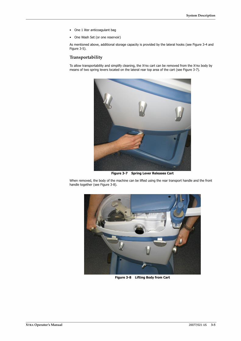
System Description
XTRA Operator’s Manual 20077/021 US 3-5
• One 1 liter anticoagulant bag
• One Wash Set (or one reservoir)
As mentioned above, additional storage capacity is provided by the lateral hooks (see Figure 3-4 and Figure 3-5).
Transportability
To allow transportability and simplify cleaning, the XTRA cart can be removed from the XTRA body by means of two spring levers located on the lateral rear top area of the cart (see Figure 3-7).
Figure 3-7 Spring Lever Releases Cart
When removed, the body of the machine can be lifted using the rear transport handle and the front handle together (see Figure 3-8).
Figure 3-8 Lifting Body from Cart
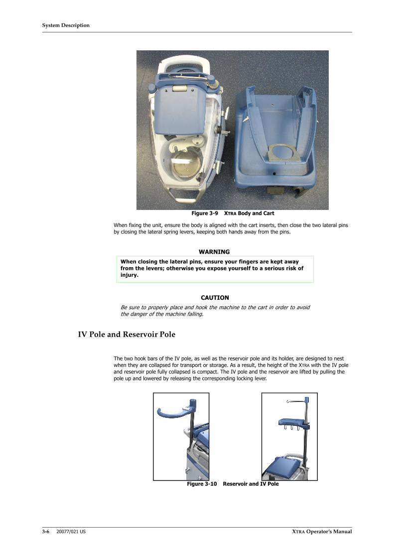
System Description
3-6 20077/021 US XTRA Operator’s Manual
Figure 3-9 XTRA Body and Cart
When fixing the unit, ensure the body is aligned with the cart inserts, then close the two lateral pins by closing the lateral spring levers, keeping both hands away from the pins.
IV Pole and Reservoir Pole
The two hook bars of the IV pole, as well as the reservoir pole and its holder, are designed to nest when they are collapsed for transport or storage. As a result, the height of the XTRA with the IV pole and reservoir pole fully collapsed is compact. The IV pole and the reservoir are lifted by pulling the pole up and lowered by releasing the corresponding locking lever.
Figure 3-10 Reservoir and IV Pole
WARNINGWhen closing the lateral pins, ensure your fingers are kept away from the levers; otherwise you expose yourself to a serious risk of injury.
CAUTIONBe sure to properly place and hook the machine to the cart in order to avoidthe danger of the machine falling.

System Description
XTRA Operator’s Manual 20077/021 US 3-7
Reservoir Holder
When the reservoir pole is collapsed, the reservoir holder may be rotated to fit compactly against the rear of the machine for transport or storage.
Figure 3-11 Reservoir Holder
The reservoir holder contains a weight-sensitive sensor which allows the system to detect the current volume of the reservoir. This allows for the Autostart feature to start the processing cycle as soon as a preset volume of blood is collected inside the reservoir.
Touch Screen Display Panel
The XTRA control panel is mounted centrally at the top, rear of the machine on a hinge that allows the screen to be rotated and tilted. The control panel is protected to avoid problems from spills and simplify cleaning.
The front of the control panel has two major components: the touch screen display area and the physical Stop button on the lower right side (see Figure 3-12).
WARNINGWhen releasing an IV pole or reservoir pole locking lever, the operator must always hold the pole and locking mechanism with both hands; otherwise, there is a serious risk of injury.
WARNINGWhen releasing an IV pole or reservoir pole locking lever, the operator must always hold the pole and locking mechanism with both hands; otherwise, there is a serious risk of injury.

System Description
3-8 20077/021 US XTRA Operator’s Manual
Figure 3-12 XTRA Touch Screen Display Panel
Touch Screen
The operator interacts with the display through various screens by touching the screen where indicated by the presence of buttons and tabs. Instructions on operating and configuring the XTRA system are provided in the remaining chapters of this manual.
Important Notes
The unit displays numeric values and percentages, which are to be interpreted as follows:
• Centrifuge Speed (RPM): The displayed value is the target value set by the user. Once processing is started, the centrifuge accelerates to this set value according to system procedures.
• Pump Flow Rate (ml/min.): As stated above, the displayed value is the target value set by the user. In this case, the real flow-rate value is also affected by the tolerances of the disposable tubing and other variability factors.
• Vacuum pressure (mmHg): The datum visualized is the setpoint set by the user.
• Volumes transferred (mL): The volumes transferred are calculated based on the effective pump speed, although there is always a margin of error due to the variability of the capacity/speed ratio and the piping tolerance. However, these values must not be considered measured values, but only reference values for the user.
• Hematocrit indication (%): The hematocrit value is detected and measured on the basis of the blood flowing through the section of tube inserted into the hematocrit indicator. To prevent the provided indications from varying with the temperature, the current Bowl Set, and other ambient conditions, a preliminary calibration of the indicator is carried out with saline solution during the set-up phase, before blood processing starts.
• Supernatant removal indicator (%): it is an algorithm representing the percentage of supernatant that has been removed, and more specifically, the percentage of supernatant that has been replaced by saline solution during the Wash phase.
• Waste line color indicator (color): it indicates the residual concentration of waste products in the fluid exiting from the bowl, measured on the basis of the color detected on the outlet line of the bowl (waste line).
CAUTIONIf the display shows incomprehensible and erroneous messages or messagesdifferent from those indicated in this manual, immediately stop the unit andcontact LivaNova Technical Service.
1 Cover 3 Stop button2 Touch screen area 4 Hinge
1
2
3
4

System Description
XTRA Operator’s Manual 20077/021 US 3-9
Centrifuge Assembly
The centrifuge assembly is located at the front of the machine and includes the centrifuge arm, centrifuge plate, and centrifuge lid. The centrifuge plate rotates at 5,600 rpm during processing and is not operator adjustable during the autotransfusion protocols. This speed produces rapid separation of the red cells with minimal trauma. The centrifuge speed can be manually adjusted by the operator only during PPP and PRP protocols (from 5,600 down to 2,400 rpm).
Figure 3-13 Centrifuge Assembly
The centrifuge assembly (see Figure 3-13) consists of:
1. The (1) centrifuge arm and the position sensor, which senses the correct positioning and locking of the bowl head.
2. The (2) centrifuge housing, which contains possible leakages of fluids from the bowl.
3. The (3) centrifuge housing light.
4. The fluid loss sensor (not visible in figure), which detects fluid leakages in the centrifuge and stops the centrifuge and pump in case of a leak.
5. The two RBC (Buffy-Coat) sensors (not visible in figure), high and multipoint, which sense when the red blood cells have reached a predetermined level within the centrifuge bowl.
6. The centrifuge lid (not visible in figure) that automatically latches and remains locked as a safety precaution until the centrifuge and pump come to a complete stop.
Note: The XTRA machine prevents access to the centrifuge (while in operation), through a latched lid. In the event of a power failure, this latch will open.
CAUTIONIf the values regarding volumes, hematocrit, supernatant removal and wastecolor line are important for the patient, it will always be necessary to useother standard measurement instruments of the hospital.
WARNINGDo not open the lid in the event of a power failure if the centrifuge has not yet come to a stop (which may take between 50 and 90 seconds).
2
1
3
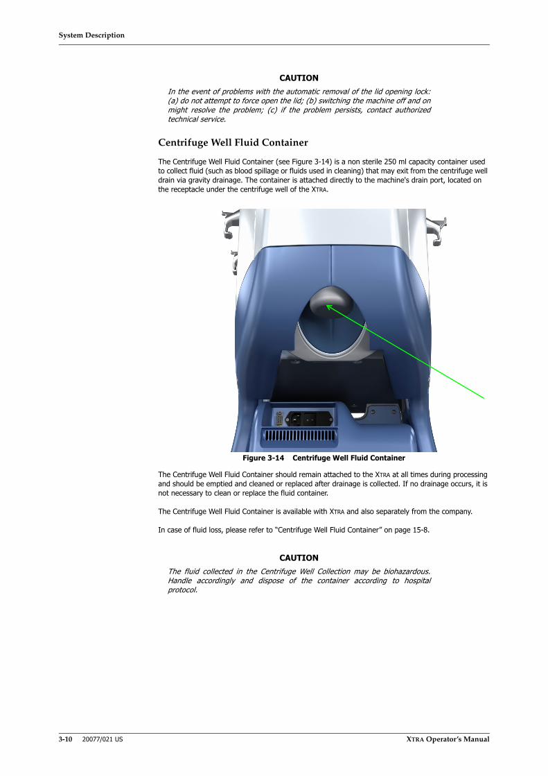
System Description
3-10 20077/021 US XTRA Operator’s Manual
Centrifuge Well Fluid Container
The Centrifuge Well Fluid Container (see Figure 3-14) is a non sterile 250 ml capacity container used to collect fluid (such as blood spillage or fluids used in cleaning) that may exit from the centrifuge well drain via gravity drainage. The container is attached directly to the machine's drain port, located on the receptacle under the centrifuge well of the XTRA.
Figure 3-14 Centrifuge Well Fluid Container
The Centrifuge Well Fluid Container should remain attached to the XTRA at all times during processing and should be emptied and cleaned or replaced after drainage is collected. If no drainage occurs, it is not necessary to clean or replace the fluid container.
The Centrifuge Well Fluid Container is available with XTRA and also separately from the company.
In case of fluid loss, please refer to “Centrifuge Well Fluid Container” on page 15-8.
CAUTIONIn the event of problems with the automatic removal of the lid opening lock:(a) do not attempt to force open the lid; (b) switching the machine off and onmight resolve the problem; (c) if the problem persists, contact authorizedtechnical service.
CAUTIONThe fluid collected in the Centrifuge Well Collection may be biohazardous.Handle accordingly and dispose of the container according to hospitalprotocol.

System Description
XTRA Operator’s Manual 20077/021 US 3-11
Clamps
The XTRA uses three clamps to control the flow of fluids during normal processing of blood. The clamps determine which fluids are routed at each processing stage. The clamp lid allows fixing the tubing lines in place for proper clamp functioning during the case (see Figure 3-15).
Figure 3-15 Left: Clamps With Clamp Lid Open | Right: Clamp Lid Closed and Latched
The location and state (open or closed) of the three clamps during each processing phase are shown in the following table. A clamp is closed when the clamp plunger is extended and totally occludes the tubing, shutting off all fluid flow.
The clamps are electronically controlled and mechanically operated in the all operating modes. If the microprocessor detects an error in the operation of the clamps, an audible and visual alarm occurs and the system stops processing (refer to “Alarms and Warnings” on page 14-1).
Tubing Valve Located Between Valve Positions During CyclesColor Name Fill Wash Empty Return Concentrate PurgeBlue Fill Reservoir/Bowl Open Closed Closed Open Closed ClosedYellow Wash Wash Solution/Bowl Closed Open Closed Closed Closed ClosedRed Empty Bowl/Reinfusion Bag Closed Closed Open Closed Open Open
12345
1 Clamp lid 4 Empty clamp2 Fil l clamp 5 Clamp lid latch3 Wash clamp

System Description
3-12 20077/021 US XTRA Operator’s Manual
Processing Pump
The processing pump (see Figure 3-16) moves fluids into and out of the centrifuge bowl while providing high flow rates with minimal hemolysis. In the autotransfusion protocols, the processing pump can be operated at rates of 25 to 1,000 ml/min. in 25 ml/min. increments. In both the PPP and PRP protocols, the pump can be operated at rates of 10 to 100 ml/min. in 10 ml/min. increments.
Figure 3-16 Visible Parts of the XTRA Processing Pump
The processing pump can be unfixed from its seat for cleaning purposes, as described in Chapter 15: Maintenance.
Air Detector
The air detector is located on the top console between the processing pump and the centrifuge bowl (see Figure 3-17).
Figure 3-17 Location of the Air Detector
The air detector is an ultrasonic device that detects air in the tubing from the pump to the centrifuge bowl. It is responsible for detecting the end point of the Empty phase and detecting when the collection reservoir or wash bag becomes empty.
2
1 Pump rotor 2 Pump handle
1
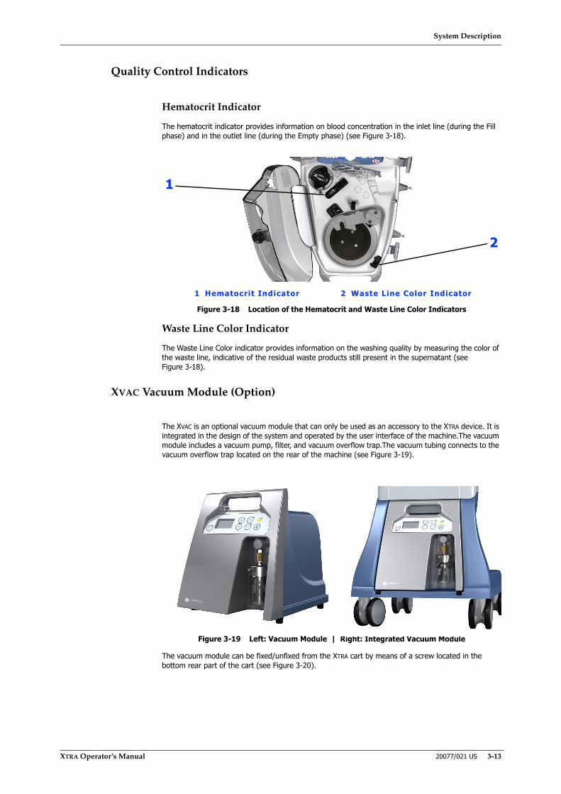
System Description
XTRA Operator’s Manual 20077/021 US 3-13
Quality Control Indicators
Hematocrit Indicator
The hematocrit indicator provides information on blood concentration in the inlet line (during the Fill phase) and in the outlet line (during the Empty phase) (see Figure 3-18).
Figure 3-18 Location of the Hematocrit and Waste Line Color Indicators
Waste Line Color Indicator
The Waste Line Color indicator provides information on the washing quality by measuring the color of the waste line, indicative of the residual waste products still present in the supernatant (see Figure 3-18).
XVAC Vacuum Module (Option)
The XVAC is an optional vacuum module that can only be used as an accessory to the XTRA device. It is integrated in the design of the system and operated by the user interface of the machine.The vacuum module includes a vacuum pump, filter, and vacuum overflow trap.The vacuum tubing connects to the vacuum overflow trap located on the rear of the machine (see Figure 3-19).
Figure 3-19 Left: Vacuum Module | Right: Integrated Vacuum Module
The vacuum module can be fixed/unfixed from the XTRA cart by means of a screw located in the bottom rear part of the cart (see Figure 3-20).
2
1 Hematocrit Indicator 2 Waste Line Color Indicator
1
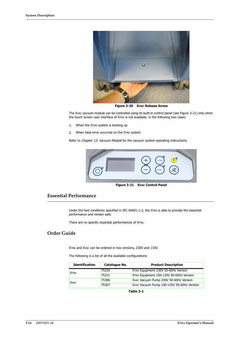
System Description
3-14 20077/021 US XTRA Operator’s Manual
Figure 3-20 XVAC Release Screw
The XVAC vacuum module can be controlled using its built-in control panel (see Figure 3-21) only when the touch screen user interface of XTRA is not available, in the following two cases:
1. When the XTRA system is booting up
2. When fatal error occurred on the XTRA system
Refer to Chapter 13: Vacuum Module for the vacuum system operating instructions.
Figure 3-21 XVAC Control Panel
Essential Performance
Under the test conditions specified in IEC 60601-1-2, the XTRA is able to provide the essential performance and remain safe.
There are no specific essential performances of XTRA.
Order Guide
XTRA and XVAC can be ordered in two versions, 230V and 110V.
The following is a list of all the available configurations:
Identification Catalogue No. Product Description
XTRA75220 XTRA Equipment 230V 50-60Hz Version75221 XTRA Equipment 100-120V 50-60Hz Version
XVAC75306 XVAC Vacuum Pump 230V 50-60Hz Version75307 XVAC Vacuum Pump 100-120V 50-60Hz Version
Table 3-1
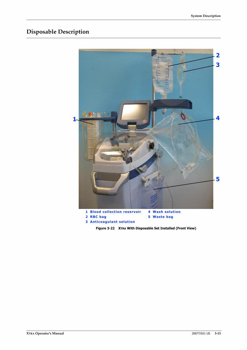
System Description
XTRA Operator’s Manual 20077/021 US 3-15
Disposable Description
Figure 3-22 XTRA With Disposable Set Installed (Front View)
1 Blood collection reservoir 4 Wash solution2 RBC bag 5 Waste bag3 Anticoagulant solution
1
23
4
5

System Description
3-16 20077/021 US XTRA Operator’s Manual
Figure 3-23 XTRA With Disposable Set Installed (Top View)
1 Pump loop tubing 5 Tubing organizer2 Tubing from pump to bowl 6 Bowl outlet port (to Waste bag)3 Bowl inlet port (from pump)4 Centrifuge bowl
1
4
5
3
6
2

System Description
XTRA Operator’s Manual 20077/021 US 3-17
Collection Set
The XTRA Collection set allows the recovery and temporary storage of the blood shed by the surgical wound. It is composed of:
• Blood Collection Reservoir (TOP or BOTTOM)
• Aspiration Line
• Vacuum Line
• Cardio Kit (only for CARDIO Configurations)
Six configurations of the XTRA Collection Set are available:
• XTRA Collection Set CARDIO with TOP reservoir
• XTRA Collection Set not CARDIO with TOP reservoir
• XTRA Collection Set CARDIO with BOTTOM reservoir
• XTRA Collection Set not CARDIO with BOTTOM reservoir (120 μm)
• XTRA Collection Set not CARDIO with BOTTOM reservoir
• XTRA Collection Set CARDIO with BOTTOM reservoir (120 μm)
Figure 3-24 XTRA Collection Kit (CARDIO TOP)
12
341 Aspiration line 3 Vacuum line2 Reservoir 4 Cardio Kit

System Description
3-18 20077/021 US XTRA Operator’s Manual
Blood Collection Reservoir
The XTRA Blood Collection Reservoir (see Figure 3-25) is a rigid 3,800 ml reservoir with a graduated fluid level scale located in three positions at 120°.
Figure 3-25 XTRA Collection Reservoir (TOP version)
Several ports are located on the top of the collection reservoir (see Figure 3-26). The vacuum port (yellow port protector attached) is designed to accept 1/4 inch (6.4 mm) inside diameter tubing. The three angled (45º) blood inlet ports are designed to accept a 1/4 inch (6.4 mm) slip fit connector.
Figure 3-26 Collection Reservoir Lid Ports
The two vent ports with luer cap (one filtered and one unfiltered) as well as the self-pressure relief valve are located on the reservoir lid. The self-pressure relief valve is designed to relieve high vacuum
1 Luer-lock ports 4 Vacuum port2 Pressure self-relief valve 5 3/8” vertical blood inlet port3 Outlet port (TOP version) 6 1/4” angled inlet ports (3)
35
6
1 42

System Description
XTRA Operator’s Manual 20077/021 US 3-19
levels (greater, in absolute value, than 250 mmHg (33.3 kPa)), thus preventing the possibility of implosion.
The reservoir is available in two versions, TOP outlet and BOTTOM outlet, differing only in the location of the outlet port connection to the Bowl set (see Figure 3-27):
• In the TOP outlet version, the outlet port connection to the Bowl set is located at the top of the reservoir.
• In the BOTTOM outlet version, the outlet port connection to the Bowl set is located at the base of the reservoir through a 1/4 inch outlet adapter.
Figure 3-27 Left: Reservoir with TOP Outlet | Right: Reservoir with BOTTOM Outlet
Aspiration Line
The Aspiration Line (see Figure 3-28) consists of clear plastic (PVC) dual lumen tubing.
The proximal end of the large bore tube is designed to be attached to a 1/4” inlet port on the XTRA blood collection reservoir. The proximal end of the smaller bore tubing is connected to the anticoagulant solution bag/bottle via a spike connector.
The smaller lumen tubing has a roller clamp which controls the flow of the anticoagulant solution. The anticoagulant solution is pulled through the smaller bore lumen toward the field by suction acting through the reservoir and the larger bore lumen.
The distal ends of both lumens terminate in an aspiration connector with a diameter of 1/4 inch that connects to most suction cannulae.
In the aspiration connector, anticoagulant solution mixes with the aspirated blood as the blood passes the point where the two lumens join together. This allows the aspirated blood to be anticoagulated after only a short exposure to the cannulae.
The vacuum then draws the anticoagulated blood into the blood collection reservoir.
TOP outlet BOTTOM outlet
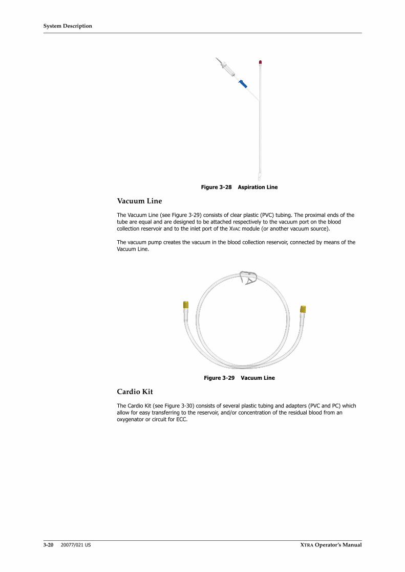
System Description
3-20 20077/021 US XTRA Operator’s Manual
Figure 3-28 Aspiration Line
Vacuum Line
The Vacuum Line (see Figure 3-29) consists of clear plastic (PVC) tubing. The proximal ends of the tube are equal and are designed to be attached respectively to the vacuum port on the blood collection reservoir and to the inlet port of the XVAC module (or another vacuum source).
The vacuum pump creates the vacuum in the blood collection reservoir, connected by means of the Vacuum Line.
Figure 3-29 Vacuum Line
Cardio Kit
The Cardio Kit (see Figure 3-30) consists of several plastic tubing and adapters (PVC and PC) which allow for easy transferring to the reservoir, and/or concentration of the residual blood from an oxygenator or circuit for ECC.
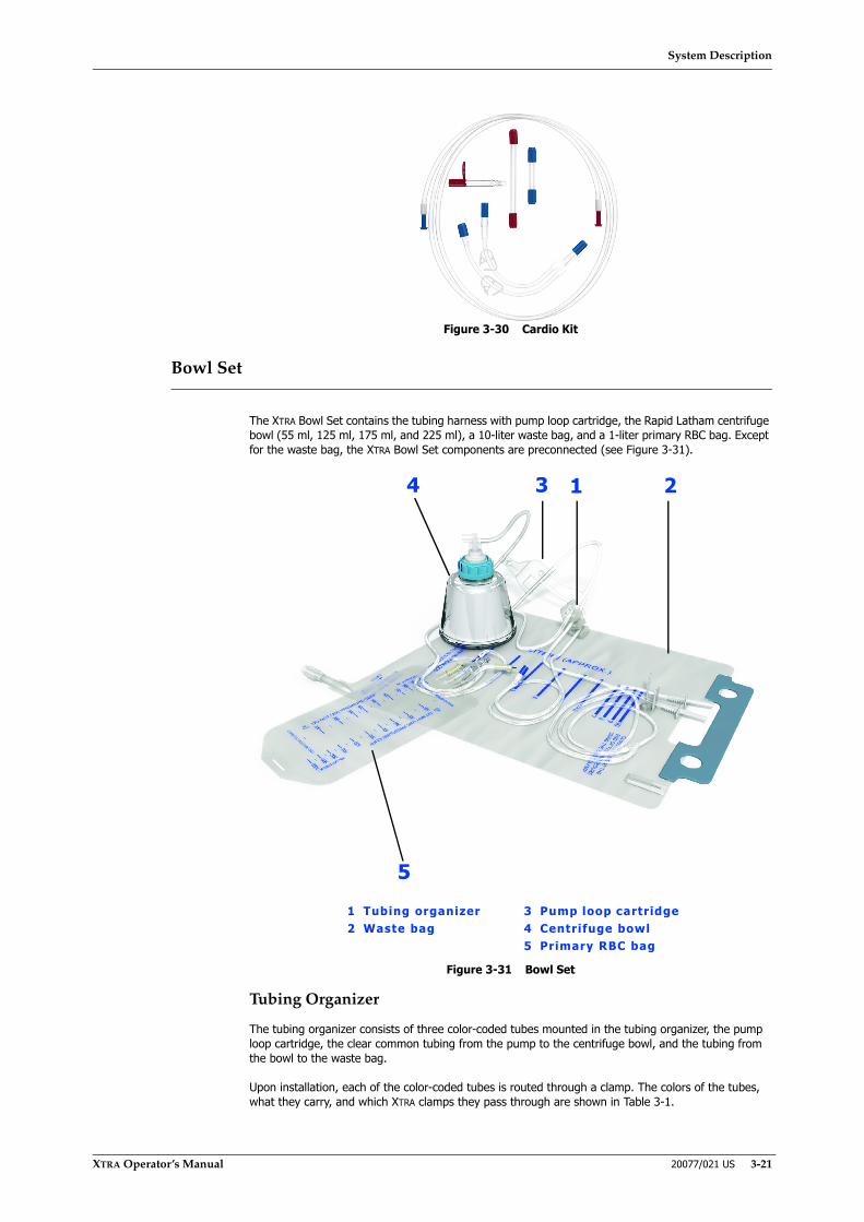
System Description
XTRA Operator’s Manual 20077/021 US 3-21
Figure 3-30 Cardio Kit
Bowl Set
The XTRA Bowl Set contains the tubing harness with pump loop cartridge, the Rapid Latham centrifuge bowl (55 ml, 125 ml, 175 ml, and 225 ml), a 10-liter waste bag, and a 1-liter primary RBC bag. Except for the waste bag, the XTRA Bowl Set components are preconnected (see Figure 3-31).
Figure 3-31 Bowl Set
Tubing Organizer
The tubing organizer consists of three color-coded tubes mounted in the tubing organizer, the pump loop cartridge, the clear common tubing from the pump to the centrifuge bowl, and the tubing from the bowl to the waste bag.
Upon installation, each of the color-coded tubes is routed through a clamp. The colors of the tubes, what they carry, and which XTRA clamps they pass through are shown in Table 3-1.
1 Tubing organizer 3 Pump loop cartridge2 Waste bag 4 Centrifuge bowl
5 Primary RBC bag
1 234
5
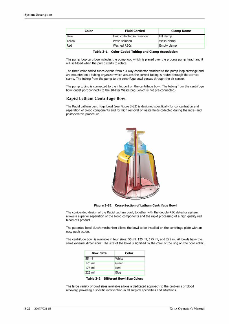
System Description
3-22 20077/021 US XTRA Operator’s Manual
The pump loop cartridge includes the pump loop which is placed over the process pump head, and it will self-load when the pump starts to rotate.
The three color-coded tubes extend from a 3-way connector attached to the pump loop cartridge and are mounted on a tubing organizer which assures the correct tubing is routed through the correct clamp. The tubing from the pump to the centrifuge bowl passes through the air sensor.
The pump tubing is connected to the inlet port on the centrifuge bowl. The tubing from the centrifuge bowl outlet port connects to the 10-liter Waste bag (which is not pre-connected).
Rapid Latham Centrifuge Bowl
The Rapid Latham centrifuge bowl (see Figure 3-32) is designed specifically for concentration and separation of blood components and for high removal of waste fluids collected during the intra- and postoperative procedure.
Figure 3-32 Cross-Section of Latham Centrifuge Bowl
The conic-sided design of the Rapid Latham bowl, together with the double RBC detector system, allows a superior separation of the blood components and the rapid processing of a high quality red blood cell product.
The patented bowl clutch mechanism allows the bowl to be installed on the centrifuge plate with an easy push action.
The centrifuge bowl is available in four sizes: 55 ml, 125 ml, 175 ml, and 225 ml. All bowls have the same external dimensions. The size of the bowl is signified by the color of the ring on the bowl collar:
The large variety of bowl sizes available allows a dedicated approach to the problems of blood recovery, providing a specific intervention in all surgical specialties and situations.
Color Fluid Carried Clamp NameBlue Fluid collected in reservoir Fill clampYellow Wash solution Wash clampRed Washed RBCs Empty clamp
Table 3-1 Color-Coded Tubing and Clamp Association
Bowl Size Color55 ml White125 ml Green175 ml Red225 ml Blue
Table 3-2 Different Bowl Size Colors

System Description
XTRA Operator’s Manual 20077/021 US 3-23
Waste Bag
The XTRA Waste bag (see Figure 3-33) has a 10-liter capacity, a slide clamp on the inlet port, and a drain valve on the outlet port. The bag is hung from two pins on the right side of the XTRA system and receives the overflow from the centrifuge bowl during the Fill and Wash phases.
Figure 3-33 Waste Bag
During processing, the microprocessor continuously calculates the amount of fluid moved into the Waste bag. When the bag is 90 percent full (9,000 ml), processing pauses and both audible and visual alarms occur. The bag has a volume scale (approximate) on its outside face to enable the operator to visually estimate the accumulated waste volume.
The drain valve on the waste bag outlet port should be kept closed during processing. The bag may be emptied by releasing the valve, thus allowing the waste fluid to drain into a bucket. Alternatively, the Waste bag may be discarded and replaced with a new one. Additional Waste bags are available from the company.
The handle of the waste bag allows easy transport for disposal at the end of the procedure.
WARNINGIn order to comply with “General Requirements for basic safety and essential performance of Medical electrical equipments” (IEC 60601-1, Rules preventing instability), it is requested that the waste bag not be filled with more than 9 liters of waste liquid.
WARNINGAll contents of the waste bag are not intended for further processing and must be properly discarded.
CAUTIONThe clamp on the inlet port of the waste bag must be open during bloodsalvage processing.
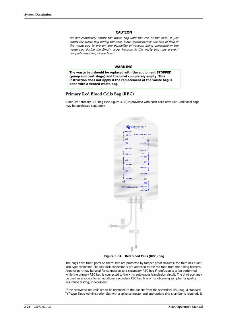
System Description
3-24 20077/021 US XTRA Operator’s Manual
Primary Red Blood Cells Bag (RBC)
A one-liter primary RBC bag (see Figure 3-33) is provided with each XTRA Bowl Set. Additional bags may be purchased separately.
Figure 3-34 Red Blood Cells (RBC) Bag
The bags have three ports on them: two are protected by tamper-proof closures; the third has a luer lock type connector. The luer lock connector is pre-attached to the red tube from the tubing harness. Another port may be used for connection to a secondary RBC bag if reinfusion is to be performed while the primary RBC bag is connected to the XTRA autologous transfusion circuit. The third port may be used as a source for an additional secondary RBC bag line or for obtaining samples for quality assurance testing, if necessary.
If the recovered red cells are to be reinfused to the patient from the secondary RBC bag, a standard “Y”-type Blood Administration Set with a spike connector and appropriate drip chamber is required. It
CAUTIONDo not completely empty the waste bag until the end of the case. If youempty the waste bag during the case, leave approximately one liter of fluid inthe waste bag to prevent the possibility of vacuum being generated in thewaste bag during the Empty cycle. Vacuum in the waste bag may preventcomplete emptying of the bowl.
WARNINGThe waste bag should be replaced with the equipment STOPPED (pump and centrifuge) and the bowl completely empty. This instruction does not apply if the replacement of the waste bag is done with a vented waste bag.

System Description
XTRA Operator’s Manual 20077/021 US 3-25
is strongly recommended that a Microaggregate Blood Filter (20 to 40 micron) be used on the reinfusion line. These two items are not included with the XTRA Bowl Set.
Procedure Set
The Procedure set is equivalent to the Collection Set CARDIO and the Bowl Set (see Figure 3-35). The Procedure set contains all the components needed for blood collection and processing:
• Collection Set CARDIO (TOP or BOTTOM)
◊ Blood Collection Reservoir (TOP or BOTTOM)
◊ Aspiration Line
◊ Vacuum Line
• Bowl Set (55 ml, 125 ml, 175 ml, or 225 ml)
Nine configurations of the XTRA Procedure set are available:
• Procedure set with TOP reservoir and 55 ml bowl
• Procedure set with TOP reservoir and 125 ml bowl
• Procedure set with TOP reservoir and 175 ml bowl
• Procedure set with TOP reservoir and 225 ml bowl
• Procedure set with BOTTOM reservoir and 55 ml bowl
• Procedure set with BOTTOM reservoir and 125 ml bowl
• Procedure set with BOTTOM reservoir and 175 ml bowl
• Procedure set with BOTTOM reservoir and 225 ml bowl
• Procedure set with BOTTOM reservoir 120 μm and 225 ml bowl
WARNINGDo not reinfuse the patient’s blood from the primary RBC bag when it is connected to the XTRA autologous transfusion circuit. Reinfusion from the primary reinfusion bag connected to the circuit could lead to air embolism.
WARNINGTo minimize the complications of particulate matter infusion and the risk of air embolism, use of an in-line microaggregate filter on the patient reinfusion line is STRONGLY RECOMMENDED.
WARNINGTo reduce risk of air embolism, remove all air from the primary reinfusion bag before handing the bag over for reinfusion.
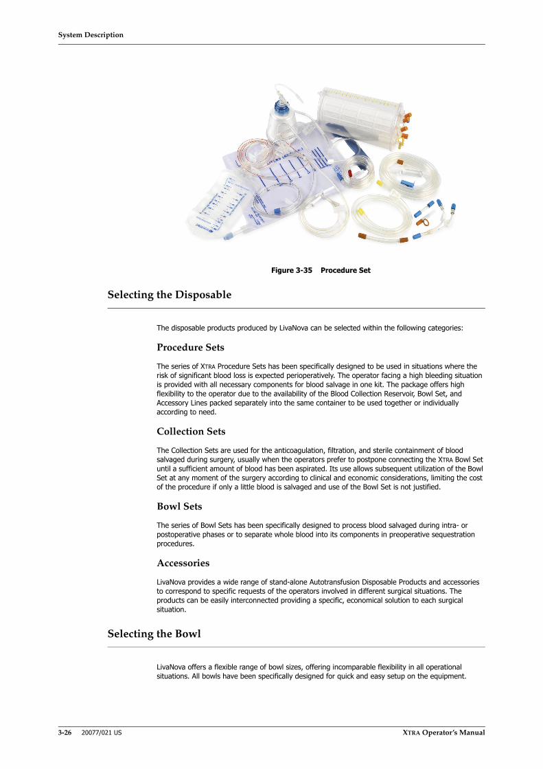
System Description
3-26 20077/021 US XTRA Operator’s Manual
Figure 3-35 Procedure Set
Selecting the Disposable
The disposable products produced by LivaNova can be selected within the following categories:
Procedure Sets
The series of XTRA Procedure Sets has been specifically designed to be used in situations where the risk of significant blood loss is expected perioperatively. The operator facing a high bleeding situation is provided with all necessary components for blood salvage in one kit. The package offers high flexibility to the operator due to the availability of the Blood Collection Reservoir, Bowl Set, and Accessory Lines packed separately into the same container to be used together or individually according to need.
Collection Sets
The Collection Sets are used for the anticoagulation, filtration, and sterile containment of blood salvaged during surgery, usually when the operators prefer to postpone connecting the XTRA Bowl Set until a sufficient amount of blood has been aspirated. Its use allows subsequent utilization of the Bowl Set at any moment of the surgery according to clinical and economic considerations, limiting the cost of the procedure if only a little blood is salvaged and use of the Bowl Set is not justified.
Bowl Sets
The series of Bowl Sets has been specifically designed to process blood salvaged during intra- or postoperative phases or to separate whole blood into its components in preoperative sequestration procedures.
Accessories
LivaNova provides a wide range of stand-alone Autotransfusion Disposable Products and accessories to correspond to specific requests of the operators involved in different surgical situations. The products can be easily interconnected providing a specific, economical solution to each surgical situation.
Selecting the Bowl
LivaNova offers a flexible range of bowl sizes, offering incomparable flexibility in all operational situations. All bowls have been specifically designed for quick and easy setup on the equipment.
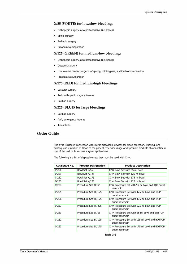
System Description
XTRA Operator’s Manual 20077/021 US 3-27
X/55 (WHITE) for low/slow bleedings
• Orthopedic surgery, also postoperative (i.e. knees)
• Spinal surgery
• Pediatric surgery
• Preoperative Separation
X/125 (GREEN) for medium-low bleedings
• Orthopedic surgery, also postoperative (i.e. knees)
• Obstetric surgery
• Low volume cardiac surgery: off-pump, mini-bypass, suction blood separation
• Preoperative Separation
X/175 (RED) for medium-high bleedings
• Vascular surgery
• Redo orthopedic surgery, trauma
• Cardiac surgery
X/225 (BLUE) for large bleedings
• Cardiac surgery
• AAA, emergency, trauma
• Transplants
Order Guide
The XTRA is used in connection with sterile disposable devices for blood collection, washing, and subsequent reinfusion of blood to the patient. The wide range of disposable products allows optimum use of the unit in its various surgical applications.
The following is a list of disposable sets that must be used with XTRA:
Catalogue No. Product Designation Product Description04250 Bowl Set X/55 XTRA Bowl Set with 55 ml bowl04251 Bowl Set X/125 XTRA Bowl Set with 125 ml bowl04252 Bowl Set X/175 XTRA Bowl Set with 175 ml bowl04253 Bowl Set X/225 XTRA Bowl Set with 225 ml bowl04254 Procedure Set TX/55 XTRA Procedure Set with 55 ml bowl and TOP outlet
reservoir04255 Procedure Set TX/125 XTRA Procedure Set with 125 ml bowl and TOP
outlet reservoir04256 Procedure Set TX/175 XTRA Procedure Set with 175 ml bowl and TOP
outlet reservoir04257 Procedure Set TX/225 XTRA Procedure Set with 225 ml bowl and TOP
outlet reservoir04261 Procedure Set BX/55 XTRA Procedure Set with 55 ml bowl and BOTTOM
outlet reservoir04262 Procedure Set BX/125 XTRA Procedure Set with 125 ml bowl and BOTTOM
outlet reservoir04263 Procedure Set BX/175 XTRA Procedure Set with 175 ml bowl and BOTTOM
outlet reservoir
Table 3-3
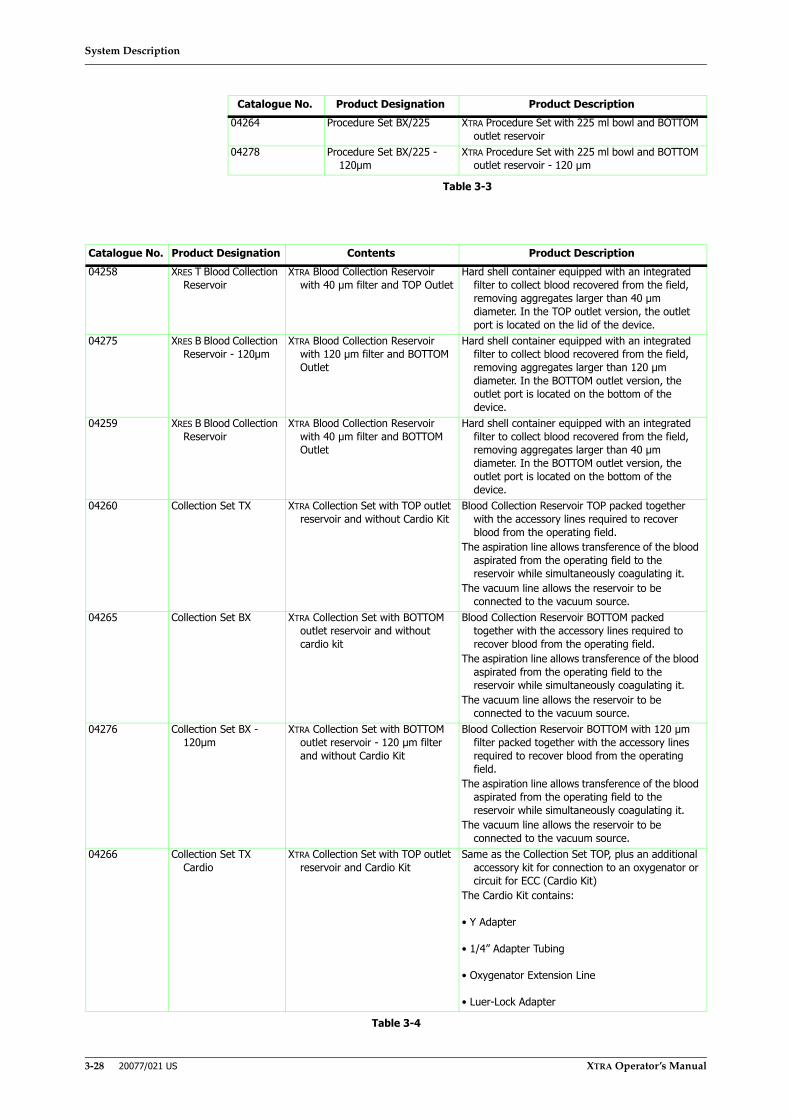
System Description
3-28 20077/021 US XTRA Operator’s Manual
04264 Procedure Set BX/225 XTRA Procedure Set with 225 ml bowl and BOTTOM outlet reservoir
04278 Procedure Set BX/225 - 120µm
XTRA Procedure Set with 225 ml bowl and BOTTOM outlet reservoir - 120 μm
Catalogue No. Product Designation Contents Product Description04258 XRES T Blood Collection
ReservoirXTRA Blood Collection Reservoir
with 40 µm filter and TOP OutletHard shell container equipped with an integrated
filter to collect blood recovered from the field, removing aggregates larger than 40 µm diameter. In the TOP outlet version, the outlet port is located on the lid of the device.
04275 XRES B Blood Collection Reservoir - 120µm
XTRA Blood Collection Reservoir with 120 μm filter and BOTTOM Outlet
Hard shell container equipped with an integrated filter to collect blood recovered from the field, removing aggregates larger than 120 μm diameter. In the BOTTOM outlet version, the outlet port is located on the bottom of the device.
04259 XRES B Blood Collection Reservoir
XTRA Blood Collection Reservoir with 40 µm filter and BOTTOM Outlet
Hard shell container equipped with an integrated filter to collect blood recovered from the field, removing aggregates larger than 40 µm diameter. In the BOTTOM outlet version, the outlet port is located on the bottom of the device.
04260 Collection Set TX XTRA Collection Set with TOP outlet reservoir and without Cardio Kit
Blood Collection Reservoir TOP packed together with the accessory lines required to recover blood from the operating field.
The aspiration line allows transference of the blood aspirated from the operating field to the reservoir while simultaneously coagulating it.
The vacuum line allows the reservoir to be connected to the vacuum source.
04265 Collection Set BX XTRA Collection Set with BOTTOM outlet reservoir and without cardio kit
Blood Collection Reservoir BOTTOM packed together with the accessory lines required to recover blood from the operating field.
The aspiration line allows transference of the blood aspirated from the operating field to the reservoir while simultaneously coagulating it.
The vacuum line allows the reservoir to be connected to the vacuum source.
04276 Collection Set BX - 120µm
XTRA Collection Set with BOTTOM outlet reservoir - 120 μm filter and without Cardio Kit
Blood Collection Reservoir BOTTOM with 120 µm filter packed together with the accessory lines required to recover blood from the operating field.
The aspiration line allows transference of the blood aspirated from the operating field to the reservoir while simultaneously coagulating it.
The vacuum line allows the reservoir to be connected to the vacuum source.
04266 Collection Set TX Cardio
XTRA Collection Set with TOP outlet reservoir and Cardio Kit
Same as the Collection Set TOP, plus an additional accessory kit for connection to an oxygenator or circuit for ECC (Cardio Kit)
The Cardio Kit contains:
• Y Adapter
• 1/4” Adapter Tubing
• Oxygenator Extension Line
• Luer-Lock Adapter
Table 3-4
Catalogue No. Product Designation Product Description
Table 3-3

System Description
XTRA Operator’s Manual 20077/021 US 3-29
Anticoagulant Solution
The anticoagulant solution is prepared by the operator prior to the start of the case. The solution consists of heparin or citrate and sterile normal saline (injectable or special product for cell washing). The ratio of heparin to saline will depend upon hospital protocol. For most cases, a suggested ratio is 30,000 I.U. of heparin in one liter of saline.
Citrate anticoagulation may be achieved by using premixed Anticoagulant Citrate Dextrose Formula A (ACD-A) or by preparing a 3 to 4% Trisodium Citrate solutions.
Prior to collecting any blood, approximately 200 ml of the anticoagulant solution should be allowed to accumulate in the reservoir. Once collection begins, the operator should continually be aware of the rate at which blood is being collected and adjust the flow rate of the anticoagulant solution accordingly:
• If heparin anticoagulant has been prepared as suggested (30,000 I.U. of heparin per liter saline), the flow rate should be adjusted to mix one part anticoagulant with seven parts of collected fluid (1:7 ratio). LivaNova recommends starting with a minimum rate of 100 drops per minute and adjusting accordingly.
• If citrate anticoagulant is used, the flow rate should be adjusted to assure a 1:5 – 1:10 ratio of anticoagulant to blood1. LivaNova recommends starting with a minimum rate of 1 drop per second and adjusting accordingly
• In case of heavy bleeding, appropriately increase the rate.
During blood recovery, particularly when operating in the Automatic mode, the operator should closely monitor the proper anticoagulant ratio. The flow of anticoagulant into the reservoir is manually controlled by the roller clamp on the anticoagulant line. This flow must be adjusted to the rate of blood collection from the surgical field. If the rate of collection varies without adjusting the flow of anticoagulant, the ratio of anticoagulant to blood can be too low or too high. The blood in the reservoir may clot if there is too little anticoagulant.
04267 Collection Set BX Cardio
SXTRA Collection Set with BOTTOM outlet reservoir and Cardio Kit
Same as the Collection Set BOTTOM, plus an additional accessory kit for connection to an oxygenator or circuit for ECC (Cardio Kit)
The Cardio Kit contains:
• Y Adapter
• 1/4” Adapter Tubing
• Oxygenator Extension Line
• Luer-Lock Adapter04277 Collection Set BX
Cardio - 120µmXTRA Collection Set with BOTTOM
outlet reservoir - 120 µm filter and Cardio Kit
Same as the Collection Set BOTTOM - 120 µm, plus an additional accessory kit for connection to an oxygenator or circuit for ECC (Cardio Kit)
The Cardio Kit contains:
• Y Adapter
• 1/4” Adapter Tubing
• Oxygenator Extension Line
• Luer-Lock Adapter
1 American Association of Blood Banks. Guidelines for Blood Recovery and Reinfusion in Surgery and Trauma. Bethesda, MD: American Association of Blood Banks, 1997:19-22.
Catalogue No. Product Designation Contents Product Description
Table 3-4
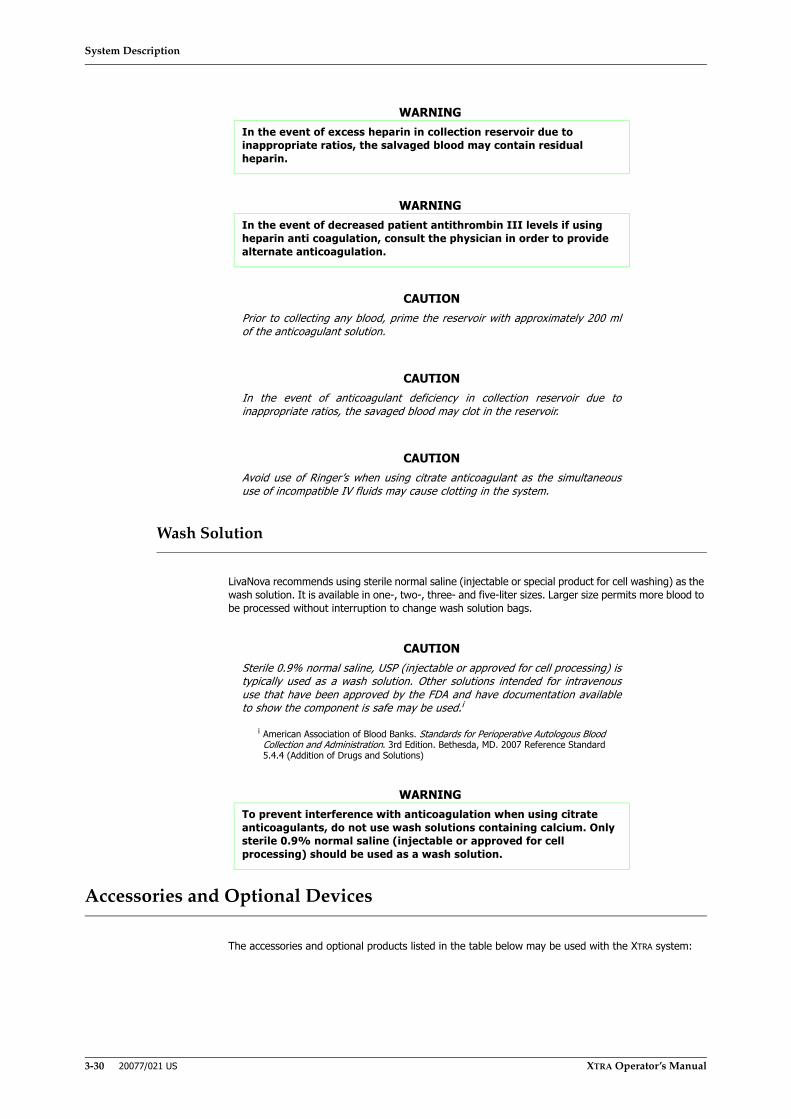
System Description
3-30 20077/021 US XTRA Operator’s Manual
Wash Solution
LivaNova recommends using sterile normal saline (injectable or special product for cell washing) as the wash solution. It is available in one-, two-, three- and five-liter sizes. Larger size permits more blood to be processed without interruption to change wash solution bags.
Accessories and Optional Devices
The accessories and optional products listed in the table below may be used with the XTRA system:
WARNINGIn the event of excess heparin in collection reservoir due to inappropriate ratios, the salvaged blood may contain residual heparin.
WARNINGIn the event of decreased patient antithrombin III levels if using heparin anti coagulation, consult the physician in order to provide alternate anticoagulation.
CAUTIONPrior to collecting any blood, prime the reservoir with approximately 200 mlof the anticoagulant solution.
CAUTIONIn the event of anticoagulant deficiency in collection reservoir due toinappropriate ratios, the savaged blood may clot in the reservoir.
CAUTIONAvoid use of Ringer’s when using citrate anticoagulant as the simultaneoususe of incompatible IV fluids may cause clotting in the system.
CAUTIONSterile 0.9% normal saline, USP (injectable or approved for cell processing) istypically used as a wash solution. Other solutions intended for intravenoususe that have been approved by the FDA and have documentation availableto show the component is safe may be used.i
i American Association of Blood Banks. Standards for Perioperative Autologous BloodCollection and Administration. 3rd Edition. Bethesda, MD. 2007 Reference Standard5.4.4 (Addition of Drugs and Solutions)
WARNINGTo prevent interference with anticoagulation when using citrate anticoagulants, do not use wash solutions containing calcium. Only sterile 0.9% normal saline (injectable or approved for cell processing) should be used as a wash solution.
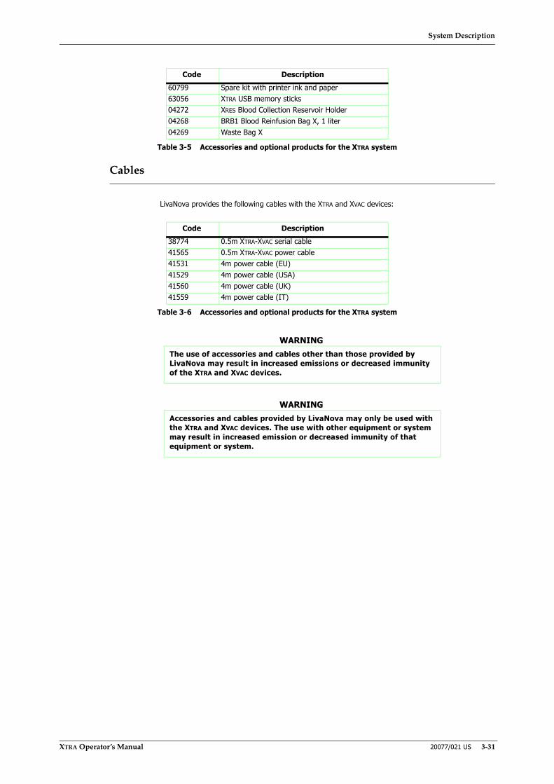
System Description
XTRA Operator’s Manual 20077/021 US 3-31
Cables
LivaNova provides the following cables with the XTRA and XVAC devices:
Code Description60799 Spare kit with printer ink and paper63056 XTRA USB memory sticks04272 XRES Blood Collection Reservoir Holder04268 BRB1 Blood Reinfusion Bag X, 1 liter04269 Waste Bag X
Table 3-5 Accessories and optional products for the XTRA system
Code Description38774 0.5m XTRA-XVAC serial cable41565 0.5m XTRA-XVAC power cable41531 4m power cable (EU)41529 4m power cable (USA)41560 4m power cable (UK)41559 4m power cable (IT)
Table 3-6 Accessories and optional products for the XTRA system
WARNINGThe use of accessories and cables other than those provided by LivaNova may result in increased emissions or decreased immunity of the XTRA and XVAC devices.
WARNINGAccessories and cables provided by LivaNova may only be used with the XTRA and XVAC devices. The use with other equipment or system may result in increased emission or decreased immunity of that equipment or system.

System Description
3-32 20077/021 US XTRA Operator’s Manual

Installing the Disposables
XTRA Operator’s Manual 20077/021 US 4-1
Chapter 4: Installing the Disposables
The following pages describe the step-by-step procedures for installing the disposables.
Detailed instructions for use regarding the setup of disposable products are provided below. It is necessary to read carefully the following information before initiating the procedure.
Before beginning the setup, it is good practice to record into the appropriate record as determined by hospital protocol the lot number from all sterile disposables used during the procedure.
Peelable stickers are available on the product label to be used for recording the item number, lot number, and expiration date.
Setup for Standby Collection
Sometimes it is hard to predict whether or not enough blood will be recovered to render autologous transfusion worthwhile. Thus, when setting up the XTRA for standby, some operators prefer to postpone the connection of the XTRA Bowl Set until a sufficient amount of blood has been aspirated.
All caps and luer locks need to remain sealed and clamps need to be closed until an XTRA Bowl Set is mounted.
Before initializing the aspiration of blood, prime the reservoir filter with 200ml of anticoagulant solution, attaching both the suction line and the vacuum line to the relative connections on the reservoir lid.
Once the decision has been made to process the blood, the bowl set can be installed very quickly and connected to the reservoir via the outlet port covered with a blue cap.
Supplies Required
• Blood Collection Reservoir
• Anticoagulant Solution
• Suction Line (plus a suction cannula and a vacuum source)
• Vacuum line
Setup for Whole Blood Separation Program
If you plan to use Poor Platelet Plasma (PPP) or Platelet Rich Plasma (PRP) program, see Chapter 10: Preoperative Sequestration (PPP and PRP) for instructions.
Installing the Disposables
4-2 20077/021 US XTRA Operator’s Manual
Setup for Intraoperative Red Cell Recovery and Reinfusion
Power Requirements
All XTRA disposables can be at least partially installed before the instrument is turned ON. However, power is required for the following:
• Loading the pump loop into the pump rotor. The XTRA must be turned ON so you can touch the “Load Pump” button from the Setup screen.
• Switch on and set the vacuum level (if you are using the XVAC system linked to the XTRA).
In any case, it is prudent to turn ON the machine before or while you install the disposables to ensure that it will be working properly when it is time to begin processing blood.
Supplies Required
• Blood Collection Reservoir
• XTRA Bowl Set
• Anticoagulant Solution
• Suction Line (plus a suction cannula and a vacuum source)
• Wash Solution - sterile 0.9% normal saline (injectable or approved for cell processing)
• Waste Bag (will not need to be replaced if not used)
• Microaggregate Filter (optional; highly recommended)
• Secondary RBC Bag (optional; order additional RBC bag)
The following pages describe the step-by-step procedures for installing the disposables. These configurations ensure that the XTRA remains stable under normal operating conditions.

Installing the Disposables
XTRA Operator’s Manual 20077/021 US 4-3
Step-by-step Procedures for Installing Disposables
Step 1: Installing the Blood Collection Reservoir
The setup of the Blood Collection Reservoir can be performed by inserting it into its holder on the rear of the unit or by using the separate optional holder, to be fixed to an IV pole in the proximity of the surgical field.
1. Swing open the reservoir holder and raise it to the desired height (see Figure 4-1).
Figure 4-1 Raising the Reservoir Holder
2. Remove the Blood Collection Reservoir from its package.
3. Keep the locking clip on the reservoir holder open, slide the edge of the reservoir lid into the slot of the holder and push the reservoir into position. Release the locking clip (see Figure 4-2).
CAUTIONUse aseptic technique when installing disposables.

Installing the Disposables
4-4 20077/021 US XTRA Operator’s Manual
Figure 4-2 Positioning the Blood Collection Reservoir on the Reservoir Holder
Note: A Blood Collection Reservoir can be also mounted on an IV pole. However, it requires the use of the dedicated additional holder.
4. Tighten all the caps and luer locks on the reservoir lid. In case you are using a Blood Collection Reservoir BOTTOM, close the clamp on the bottom outlet port.
5. Set up of the three-way adapter (Y adapter) for use in cardiac surgery (if you are not using it, you can skip next steps).
If the Blood Collection Reservoir is used during cardiac surgery or has to be connected to a second reservoir, connect the Y adapter, provided in the Cardio Kit (refer to “Vacuum Line” on page 3-20), to the reservoir outlet port . . .
a. located on the reservoir lid, marked WASH and covered with a blue cap, for a Blood Collection Reservoir TOP
b. located on the bottom of the reservoir for a Blood Collection Reservoir BOTTOM.
6. Close the clamps on the Y adapter branches waiting for subsequent connections. The branch ending with a male port is used to connect the reservoir to the XTRA Bowl Set, the second one to the Oxygenator Extension Line.
Step 2: Connecting the Suction Line
1. Raise the IV pole completely.
2. Prepare a bag or bottle of anticoagulant solution by mixing 30,000 international units of heparin per liter of sterile (injectable) normal saline.
Note: Premixed ACD-A or CPD solutions may be used in place of the heparin solution.
3. Remove the dual lumen suction line from its package and carefully open the outer wrap.
WARNINGBefore use, check that the Blood Collection Reservoir is completely inserted in its housing on the holder. In the event of incorrect installation, any accidental knocks against the reservoir might cause it to detach from the holder.
CAUTIONUse aseptic technique when installing disposables.

Installing the Disposables
XTRA Operator’s Manual 20077/021 US 4-5
4. Pass the inner sterile wrapped assembly to the sterile field.
5. At the sterile field, unwrap the assembly, remove the protective cover, and attach the connector to a suction cannula.
6. Pass the other end (the split end) of the aspiration line back from the sterile field to the XTRA operator.
7. Close the roller clamp on the small bore tubing.
8. Remove the protective cover on the large bore tubing of the suction line.
9. Attach the tubing to one of the inlet ports on the lid of the reservoir. The inlet ports are orange-capped.
10. Hang the anticoagulant solution container on one of the holders of the IV pole.
Note: Please refer to Appendix D: Recommended Fluid Bag Configurations for recommended configurations for hanging the maximum number of fluid bags on the XTRA IV poles. These configurations ensure that the XTRA remains stable under normal operating conditions.
11. Using aseptic technique, spike the container of the anticoagulant solution (see Figure 4-3).
Figure 4-3 Positioning the Blood Collection Reservoir on the Reservoir Holder
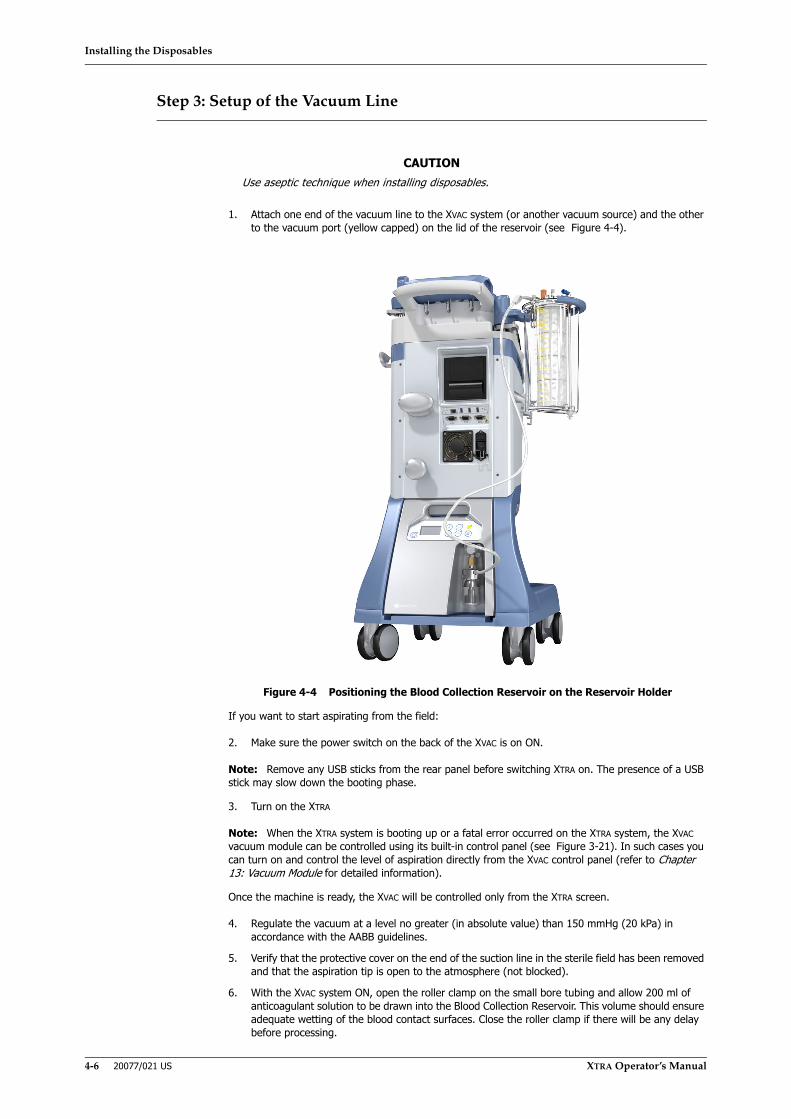
Installing the Disposables
4-6 20077/021 US XTRA Operator’s Manual
Step 3: Setup of the Vacuum Line
1. Attach one end of the vacuum line to the XVAC system (or another vacuum source) and the other to the vacuum port (yellow capped) on the lid of the reservoir (see Figure 4-4).
Figure 4-4 Positioning the Blood Collection Reservoir on the Reservoir Holder
If you want to start aspirating from the field:
2. Make sure the power switch on the back of the XVAC is on ON.
Note: Remove any USB sticks from the rear panel before switching XTRA on. The presence of a USB stick may slow down the booting phase.
3. Turn on the XTRA
Note: When the XTRA system is booting up or a fatal error occurred on the XTRA system, the XVAC vacuum module can be controlled using its built-in control panel (see Figure 3-21). In such cases you can turn on and control the level of aspiration directly from the XVAC control panel (refer to Chapter 13: Vacuum Module for detailed information).
Once the machine is ready, the XVAC will be controlled only from the XTRA screen.
4. Regulate the vacuum at a level no greater (in absolute value) than 150 mmHg (20 kPa) in accordance with the AABB guidelines.
5. Verify that the protective cover on the end of the suction line in the sterile field has been removed and that the aspiration tip is open to the atmosphere (not blocked).
6. With the XVAC system ON, open the roller clamp on the small bore tubing and allow 200 ml of anticoagulant solution to be drawn into the Blood Collection Reservoir. This volume should ensure adequate wetting of the blood contact surfaces. Close the roller clamp if there will be any delay before processing.
CAUTIONUse aseptic technique when installing disposables.
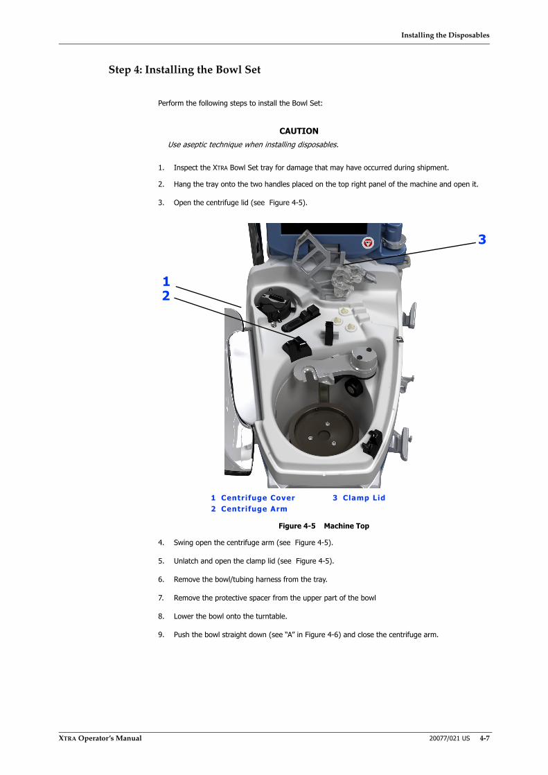
Installing the Disposables
XTRA Operator’s Manual 20077/021 US 4-7
Step 4: Installing the Bowl Set
Perform the following steps to install the Bowl Set:
1. Inspect the XTRA Bowl Set tray for damage that may have occurred during shipment.
2. Hang the tray onto the two handles placed on the top right panel of the machine and open it.
3. Open the centrifuge lid (see Figure 4-5).
Figure 4-5 Machine Top
4. Swing open the centrifuge arm (see Figure 4-5).
5. Unlatch and open the clamp lid (see Figure 4-5).
6. Remove the bowl/tubing harness from the tray.
7. Remove the protective spacer from the upper part of the bowl
8. Lower the bowl onto the turntable.
9. Push the bowl straight down (see “A” in Figure 4-6) and close the centrifuge arm.
CAUTIONUse aseptic technique when installing disposables.
1 Centrifuge Cover 3 Clamp Lid2 Centrifuge Arm
12
3
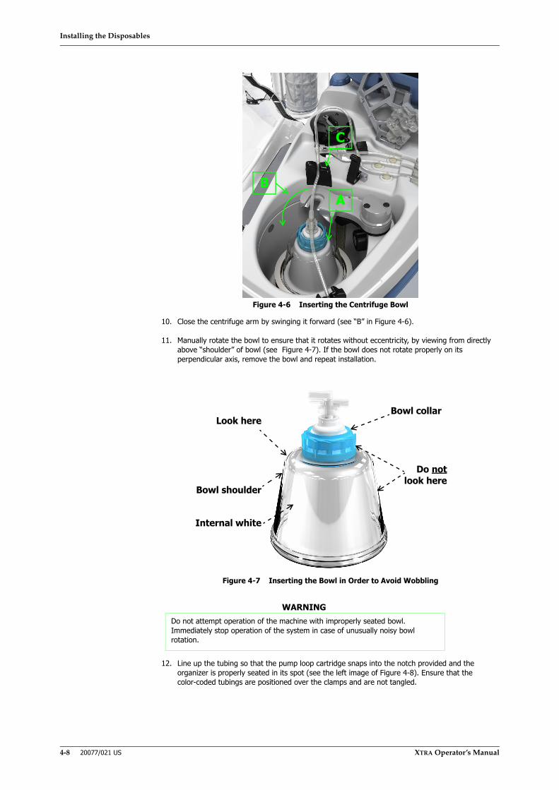
Installing the Disposables
4-8 20077/021 US XTRA Operator’s Manual
Figure 4-6 Inserting the Centrifuge Bowl
10. Close the centrifuge arm by swinging it forward (see “B” in Figure 4-6).
11. Manually rotate the bowl to ensure that it rotates without eccentricity, by viewing from directly above “shoulder” of bowl (see Figure 4-7). If the bowl does not rotate properly on its perpendicular axis, remove the bowl and repeat installation.
Figure 4-7 Inserting the Bowl in Order to Avoid Wobbling
12. Line up the tubing so that the pump loop cartridge snaps into the notch provided and the organizer is properly seated in its spot (see the left image of Figure 4-8). Ensure that the color-coded tubings are positioned over the clamps and are not tangled.
WARNINGDo not attempt operation of the machine with improperly seated bowl. Immediately stop operation of the system in case of unusually noisy bowl rotation.
B
C
A
Look here
Bowl shoulder
Internal white
Bowl collar
Do notlook here

Installing the Disposables
XTRA Operator’s Manual 20077/021 US 4-9
Figure 4-8 Seating the Pump Loop Cartridge (Left); Latching the Clamp Lid (Right)
Note: Do not force the pump loop down the rotor since it will load automatically when the LOAD PUMP button is pressed.
13. Make sure that the tubing is correctly seated into the air sensor (see “C” in Figure 4-6).
14. Close and latch the clamp lid (see the right image of Figure 4-8).
15. Make sure the waste line is properly seated into the waste fluid transparency indicator.
16. Close the centrifuge lid.
17. Connect the fill line (blue) to the outlet port of the reservoir covered with a blue cap . . .
a. located on the reservoir lid, marked WASH, for a Blood Collection Reservoir TOP (see Figure 4-9).
b. located on the bottom of the reservoir for a Blood Collection Reservoir BOTTOM. In this case once connected, open the slide clamp (see Figure 4-10).
Figure 4-9 Connecting the Bowl Set to the Top of the Blood Collection Reservoir
Figure 4-10 Connecting the Bowl Set to the Bottom of the Blood Collection Reservoir

Installing the Disposables
4-10 20077/021 US XTRA Operator’s Manual
Step 5: Connecting Wash Lines to the Saline solution Containers
1. Remove the RBC bag from the tray and hang it on the upper left hanger of the IV pole.
2. Connect the wash lines (yellow) to the wash solution (see Figure 4-11).
a. Close the slide clamp of one of the two yellow wash lines (when using only one bag of saline solution)
b. Hang the wash solution bags on the lower hangers of the IV pole.
c. Using aseptic technique, spike the wash line into a bag of saline solution
Figure 4-11 Connecting the Wash Lines (Yellow) to the Washing Solution
Note: Please refer to Appendix D: Recommended Fluid Bag Configurations for recommended configurations for hanging the maximum number of fluid bags on the XTRA IV poles. These configurations ensure that the XTRA remains stable under normal operating conditions.
Step 6: Hanging the Waste Bag
1. Remove the waste bag from the tray.
2. Hang the waste bag on the two lower hangers located on the right panel of the machine. If Plasma Sequestration is to be performed, skip next step.
CAUTIONUse aseptic technique when installing disposables.
CAUTIONSterile 0.9% normal saline, USP (injectable or approved for cell processing) istypically used as a wash solution. Other solutions intended for intravenoususe that have been approved by the FDA and have documentation availableto show the component is safe may be used.i
i American Association of Blood Banks. Standards for Perioperative Autologous BloodCollection and Administration. 3rd Edition. Bethesda, MD. 2007 Reference Standard5.4.4 (Addition of Drugs and Solutions)
CAUTIONUse aseptic technique when installing disposables.

Installing the Disposables
XTRA Operator’s Manual 20077/021 US 4-11
3. Connect the waste line to the waste bag (see Figure 4-12). The connection must be tight.
4. Close the waste bag drainage port. Ensure that the clamp on the inlet tube of the Waste bag is OPEN.
Figure 4-12 Connecting the Waste Bag
Other Setups
This manual does not discuss all the possible setups that are used in different situations. The company has a number of additional accessories and kits not illustrated in this chapter.
Blood Collection
Once the disposables are in place, vacuum may be applied and blood can be collected. The suction wand is intended to be used manually under the surgeon’s control. No fixed connection, such as a suction shunt, shall be made to the patient.
CAUTIONThe Waste bag must not be squeezed while treatment is being done and musthave the space to fill up properly. If the bag is squeezed or cannot fill upproperly because it is positioned near an obstacle (for example, a wall) areflux toward the bowl or a back pressure might be created sufficient tocause the liquid to leak from the bowl seal
CAUTIONA failed or improper connection of the lines can lead to the risk of gas orliquids entering the circuit from the environment.
CAUTIONStrictly adhere to these disposable installation instructions to guarantee theproper execution of the treatment. In particular, be careful with the:(a) proper connection of the RBC bag to avoid leakage of red blood cells,(b) proper connection of the wash bag to guarantee proper washing, and(c) proper connection of the reservoir to allow access to the blood to beprocessed.
CAUTIONAt the end of installation verify that the bowl outlet is not crushed orobstructed.

Installing the Disposables
4-12 20077/021 US XTRA Operator’s Manual
Procedure for Removing Disposables
Once the case is finished, proceed with the removal of the disposable set:
1. Make sure all the lines are empty.
2. Turn OFF the vacuum source.
3. Close the manual clamps on the lines to avoid leakage of any blood residues during removal operations.
4. From the End of Case Screen touch the Unload Button to automatically unload the pump loop.
5. Open the centrifuge lid.
6. Remove the waste line from the waste fluid transparency indicator.
7. Unlatch and open the clamp lid.
8. Remove the pump loop cartridge from the notch and HCT indicator.
9. Swing open the centrifuge arm.
10. Remove the bowl from the centrifuge plate.
11. Clamp the waste bag and remove it from the hangers on the side of the unit.
Note: Any liquid present in the waste bag should be discarded according to the regulations in force in the country of use.
12. Discard the disposable set into a suitable container.
13. Disconnect the Vacuum line from the vacuum source.
14. Close all the ports and clamp all the lines connected to the blood collection reservoir to isolate its content.
15. Keep the locking clip on the reservoir holder open, slide the reservoir out of the slot of the holder.
16. Discard the reservoir into a suitable container.
CAUTIONIn the event of problems with the automatic unloading of the pump circuit,open the lid of the centrifuge and manually remove the tubing of the pumpcircuit from the pump rotor: Rotate the pump rotor counterclockwise whileextracting the tubing of the pump circuit.
WARNINGAll contents of the waste bag are not intended for further processing and must be properly discarded.

Processing
XTRA Operator’s Manual 20077/021 US 5-1
Chapter 5: Processing
Operating the Touch Screen
The XTRA system is operated and configured through the touch screen display located on the top of the machine. The operator interacts with the display through various screens by touching the screen where indicated by the presence of buttons and tabs.
Enabled buttons and tabs have a raised appearance (see Figure 5-1). To activate a button, press and release on the screen anywhere within the button (an action referred to as “touching” throughout this manual). The button will appear momentarily depressed, and then will perform its associated function.
Figure 5-1 Example of an Enabled Button
Some buttons are used to toggle a function or module between active and inactive states. An active toggle button appears inset and green (see Figure 5-2).
Figure 5-2 Example of in Inactive (Left) and Active (Right) Toggle Button
Disabled buttons appear grey and flat (see Figure 5-3). Pressing a disabled button or tab has no effect.
Figure 5-3 Example of a Disabled Button
Note: In the following screen shots, flows are not necessarily those set as factory protocols.

Processing
5-2 20077/021 US XTRA Operator’s Manual
Screen Structure
Figure 5-4 shows the structure of a typical processing screen.
Note: Opening a menu or help screen will obscure any currently displayed screen. Closing the menu or help screen will return to the screen. Processing screens remain active and continue to be updated even while obscured by a menu or help screen.
Figure 5-4 Typical Autotransfusion Processing Screen Structure
1. Displets AreaMost of the screen is occupied by the displets area which contains all of the displets for the current screen. Visible in Figure 5-4 are the Reservoir, Processing, RBC’s, Waste Bag, and Vacuum displets. See “The Displets” on page 5-3 for a detailed description of each.
2. Status Area
Below the message area is the status area which displays the following information, from left to right:
• The triangle warning icon ( ) appears to the far left if any warnings have been disabled and/or there are any changes to the acoustic signals.
• The detected bowl size (55 ml, 125 ml, 175 ml, or 225 ml) in the form of the bowl size icon ( ).
• The current protocol (Pstd, Popt, Post-op, Pfat, PPP, PRP1, PRP2, or a user defined protocol).
• Icons representing the enabled automations: Autostart ( ) and/or Continue ( ).
• The icon representing disabled automation:
• The button identifying the last bowl appears in the right side of the button bar:
• The BQW icon ( ) is displayed when the Better Quality Wash function is enabled, along with an indication on whether it is set for short cycle (2x) or long cycle (4x).
• While the Emergency function is active with either the No Wash or Rapid Transfer functions enabled, an icon ( ) appears in the status bar above the name of the enabled function.
• And to the far right, the current operating mode (Automatic, 1 Touch, or Manual) is displayed.
1 Displet Area 3 Message Area2 Status Area 4 Button Bar
1
23
4

Processing
XTRA Operator’s Manual 20077/021 US 5-3
Refer to Chapter 7: Automated Functions for a description of the Autostart, Continue, and BQW functions.
3. Message AreaThe top of the screen consists of the message area which contains informational messages (including warnings, alarms, and on-screen instructions) and the Help button. Refer to Chapter 14: Troubleshooting for an explanation of warnings and alarms.
4. Button BarAt the bottom of the screen is the button bar. Many of the buttons which may appear in the button bar are only present during certain protocols and phases. Refer to the section “Factory Protocols” on page 5-22 for a detailed description of each.
The Displets
The largest region of the processing screens consists of up to five display applets called displets (see “Screen Structure” on page 5-2 for a description of the typical autotransfusion (ATS) processing screen structure). Each displet contains a related grouping of status displays and controls for one portion of the system.
With the exception of the processing displet in the center of the screen which is always present and open, each displet may be independently opened or closed. A closed displet has its content hidden, while an open displet’s content is visible. Pressing the title bar of a closed displet opens it; conversely, pressing the title bar of an open displet closes it. Figure 5-5 shows the reservoir displet in first its open and then its closed state.
Whether a displet is opened or closed at wakeup can be configured from the configuration mode screen (see Chapter 8: Configuring Xtra).
Reservoir Displet
Figure 5-5 Reservoir Displet (Open and Closed)
When present, the Reservoir displet is located in the upper-left corner of the displet area. The large field within the reservoir displet displays the volume of fluid currently in the collection reservoir (ml).
If the Autostart function is enabled, the Reservoir displet also contains a smaller autostart volume text box (as in Figure 5-5). The value of the autostart volume may be adjusted in the same manner as all other XTRA parameters: touch the text box, increase or decrease the volume using the arrow keys, touch the text box a second time to save the new volume (see “Modification of Parameters” on page 5-5 for further instruction on modifying parameters using the touch screen interface). Refer to Chapter 7: Automated Functions for information on the Autostart function.
The Reservoir displet is not visible if Reservoir Type in the settings tab has been set to “none” (refer to “Settings Tab” on page 5-48).
Vacuum Displet
Figure 5-6 Vacuum Displet
When the XVAC vacuum module is installed, the Vacuum displet is present in the lower-left corner of the displet area. The controls in the Vacuum displet are used to control the XVAC vacuum module.
1 Displet tit le bar
1
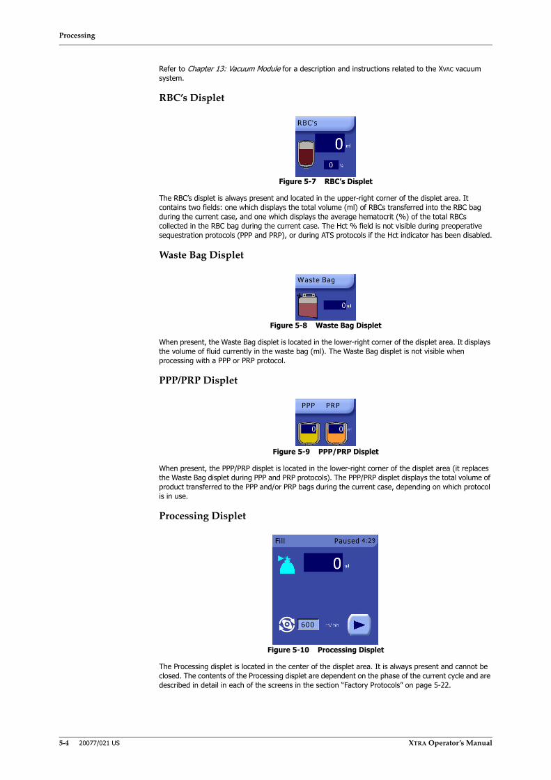
Processing
5-4 20077/021 US XTRA Operator’s Manual
Refer to Chapter 13: Vacuum Module for a description and instructions related to the XVAC vacuum system.
RBC’s Displet
Figure 5-7 RBC’s Displet
The RBC’s displet is always present and located in the upper-right corner of the displet area. It contains two fields: one which displays the total volume (ml) of RBCs transferred into the RBC bag during the current case, and one which displays the average hematocrit (%) of the total RBCs collected in the RBC bag during the current case. The Hct % field is not visible during preoperative sequestration protocols (PPP and PRP), or during ATS protocols if the Hct indicator has been disabled.
Waste Bag Displet
Figure 5-8 Waste Bag Displet
When present, the Waste Bag displet is located in the lower-right corner of the displet area. It displays the volume of fluid currently in the waste bag (ml). The Waste Bag displet is not visible when processing with a PPP or PRP protocol.
PPP/PRP Displet
Figure 5-9 PPP/PRP Displet
When present, the PPP/PRP displet is located in the lower-right corner of the displet area (it replaces the Waste Bag displet during PPP and PRP protocols). The PPP/PRP displet displays the total volume of product transferred to the PPP and/or PRP bags during the current case, depending on which protocol is in use.
Processing Displet
Figure 5-10 Processing Displet
The Processing displet is located in the center of the displet area. It is always present and cannot be closed. The contents of the Processing displet are dependent on the phase of the current cycle and are described in detail in each of the screens in the section “Factory Protocols” on page 5-22.
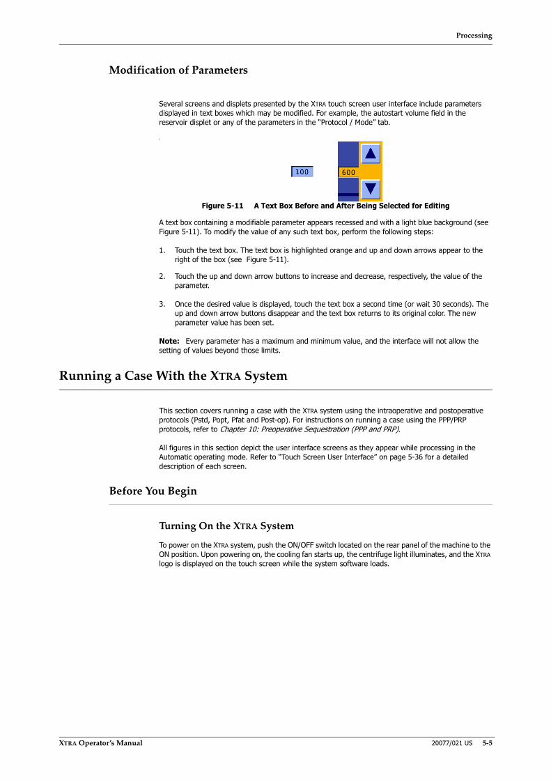
Processing
XTRA Operator’s Manual 20077/021 US 5-5
Modification of Parameters
Several screens and displets presented by the XTRA touch screen user interface include parameters displayed in text boxes which may be modified. For example, the autostart volume field in the reservoir displet or any of the parameters in the “Protocol / Mode” tab.
[
Figure 5-11 A Text Box Before and After Being Selected for Editing
A text box containing a modifiable parameter appears recessed and with a light blue background (see Figure 5-11). To modify the value of any such text box, perform the following steps:
1. Touch the text box. The text box is highlighted orange and up and down arrows appear to the right of the box (see Figure 5-11).
2. Touch the up and down arrow buttons to increase and decrease, respectively, the value of the parameter.
3. Once the desired value is displayed, touch the text box a second time (or wait 30 seconds). The up and down arrow buttons disappear and the text box returns to its original color. The new parameter value has been set.
Note: Every parameter has a maximum and minimum value, and the interface will not allow the setting of values beyond those limits.
Running a Case With the XTRA System
This section covers running a case with the XTRA system using the intraoperative and postoperative protocols (Pstd, Popt, Pfat and Post-op). For instructions on running a case using the PPP/PRP protocols, refer to Chapter 10: Preoperative Sequestration (PPP and PRP).
All figures in this section depict the user interface screens as they appear while processing in the Automatic operating mode. Refer to “Touch Screen User Interface” on page 5-36 for a detailed description of each screen.
Before You Begin
Turning On the XTRA System
To power on the XTRA system, push the ON/OFF switch located on the rear panel of the machine to the ON position. Upon powering on, the cooling fan starts up, the centrifuge light illuminates, and the XTRA logo is displayed on the touch screen while the system software loads.
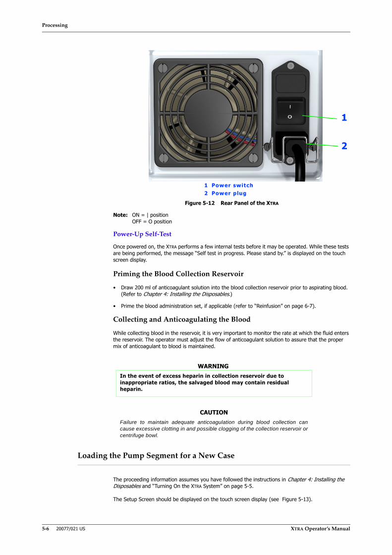
Processing
5-6 20077/021 US XTRA Operator’s Manual
Figure 5-12 Rear Panel of the XTRA
Note: ON = | positionOFF = O position
Power-Up Self-Test
Once powered on, the XTRA performs a few internal tests before it may be operated. While these tests are being performed, the message “Self test in progress. Please stand by.” is displayed on the touch screen display.
Priming the Blood Collection Reservoir
• Draw 200 ml of anticoagulant solution into the blood collection reservoir prior to aspirating blood. (Refer to Chapter 4: Installing the Disposables.)
• Prime the blood administration set, if applicable (refer to “Reinfusion” on page 6-7).
Collecting and Anticoagulating the Blood
While collecting blood in the reservoir, it is very important to monitor the rate at which the fluid enters the reservoir. The operator must adjust the flow of anticoagulant solution to assure that the proper mix of anticoagulant to blood is maintained.
Loading the Pump Segment for a New Case
The proceeding information assumes you have followed the instructions in Chapter 4: Installing the Disposables and “Turning On the XTRA System” on page 5-5.
The Setup Screen should be displayed on the touch screen display (see Figure 5-13).
WARNINGIn the event of excess heparin in collection reservoir due to inappropriate ratios, the salvaged blood may contain residual heparin.
CAUTIONFailure to maintain adequate anticoagulation during blood collection cancause excessive clotting in and possible clogging of the collection reservoir orcentrifuge bowl.
1
1 Power switch2 Power plug
2
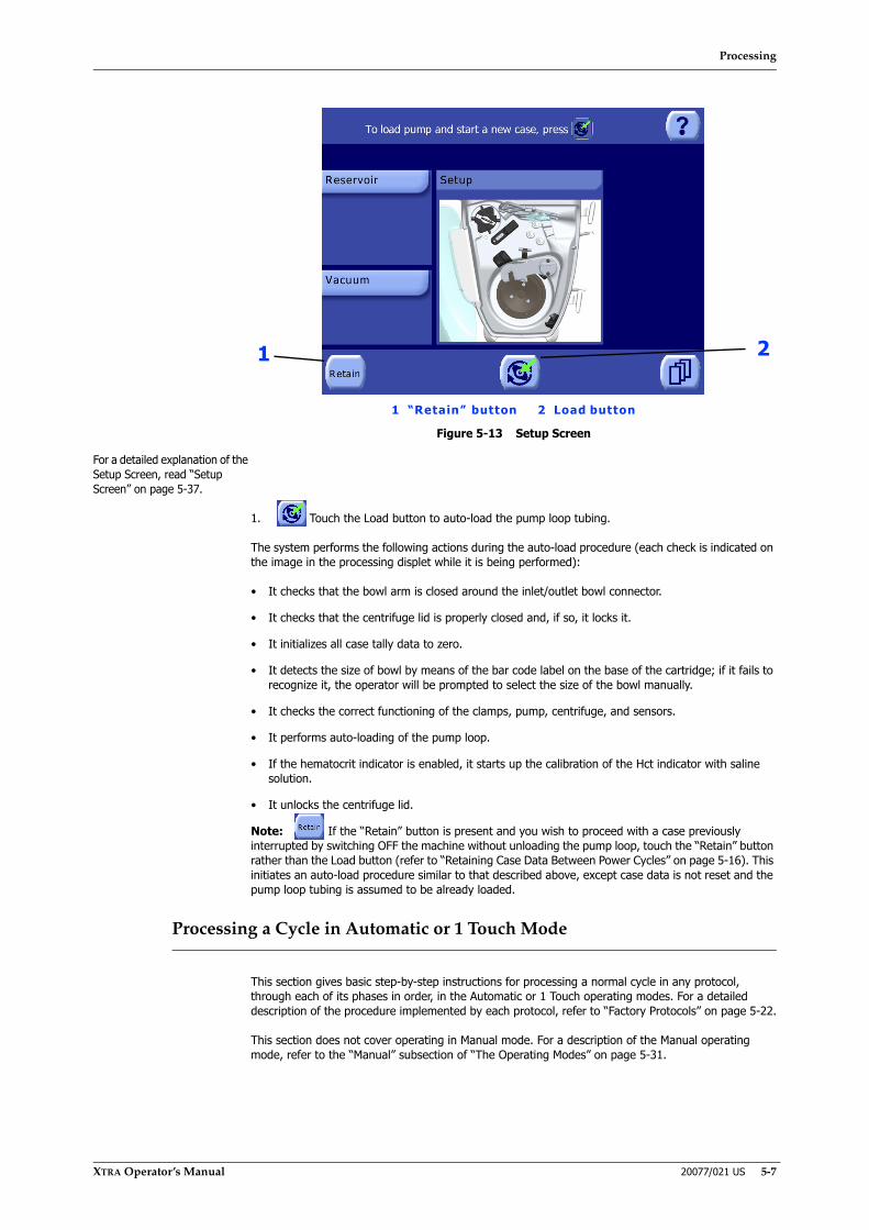
Processing
XTRA Operator’s Manual 20077/021 US 5-7
Figure 5-13 Setup Screen
For a detailed explanation of the Setup Screen, read “Setup Screen” on page 5-37.
1. Touch the Load button to auto-load the pump loop tubing.
The system performs the following actions during the auto-load procedure (each check is indicated on the image in the processing displet while it is being performed):
• It checks that the bowl arm is closed around the inlet/outlet bowl connector.
• It checks that the centrifuge lid is properly closed and, if so, it locks it.
• It initializes all case tally data to zero.
• It detects the size of bowl by means of the bar code label on the base of the cartridge; if it fails to recognize it, the operator will be prompted to select the size of the bowl manually.
• It checks the correct functioning of the clamps, pump, centrifuge, and sensors.
• It performs auto-loading of the pump loop.
• If the hematocrit indicator is enabled, it starts up the calibration of the Hct indicator with saline solution.
• It unlocks the centrifuge lid.
Note: If the “Retain” button is present and you wish to proceed with a case previously interrupted by switching OFF the machine without unloading the pump loop, touch the “Retain” button rather than the Load button (refer to “Retaining Case Data Between Power Cycles” on page 5-16). This initiates an auto-load procedure similar to that described above, except case data is not reset and the pump loop tubing is assumed to be already loaded.
Processing a Cycle in Automatic or 1 Touch Mode
This section gives basic step-by-step instructions for processing a normal cycle in any protocol, through each of its phases in order, in the Automatic or 1 Touch operating modes. For a detailed description of the procedure implemented by each protocol, refer to “Factory Protocols” on page 5-22.
This section does not cover operating in Manual mode. For a description of the Manual operating mode, refer to the “Manual” subsection of “The Operating Modes” on page 5-31.
1
1 “Retain” button 2 Load button
2
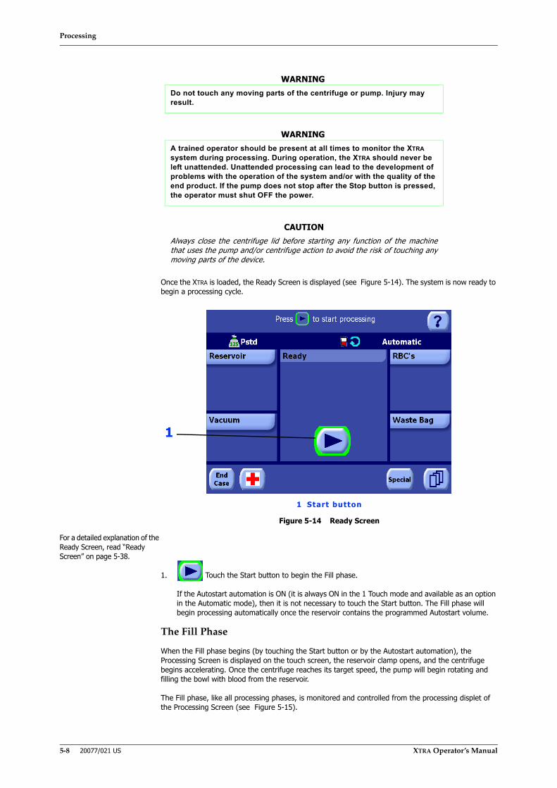
Processing
5-8 20077/021 US XTRA Operator’s Manual
Once the XTRA is loaded, the Ready Screen is displayed (see Figure 5-14). The system is now ready to begin a processing cycle.
Figure 5-14 Ready Screen
For a detailed explanation of the Ready Screen, read “Ready Screen” on page 5-38.
1. Touch the Start button to begin the Fill phase.
If the Autostart automation is ON (it is always ON in the 1 Touch mode and available as an option in the Automatic mode), then it is not necessary to touch the Start button. The Fill phase will begin processing automatically once the reservoir contains the programmed Autostart volume.
The Fill Phase
When the Fill phase begins (by touching the Start button or by the Autostart automation), the Processing Screen is displayed on the touch screen, the reservoir clamp opens, and the centrifuge begins accelerating. Once the centrifuge reaches its target speed, the pump will begin rotating and filling the bowl with blood from the reservoir.
The Fill phase, like all processing phases, is monitored and controlled from the processing displet of the Processing Screen (see Figure 5-15).
WARNINGDo not touch any moving parts of the centrifuge or pump. Injury may result.
WARNINGA trained operator should be present at all times to monitor the XTRA system during processing. During operation, the XTRA should never be left unattended. Unattended processing can lead to the development of problems with the operation of the system and/or with the quality of the end product. If the pump does not stop after the Stop button is pressed, the operator must shut OFF the power.
CAUTIONAlways close the centrifuge lid before starting any function of the machinethat uses the pump and/or centrifuge action to avoid the risk of touching anymoving parts of the device.
1
1 Start button
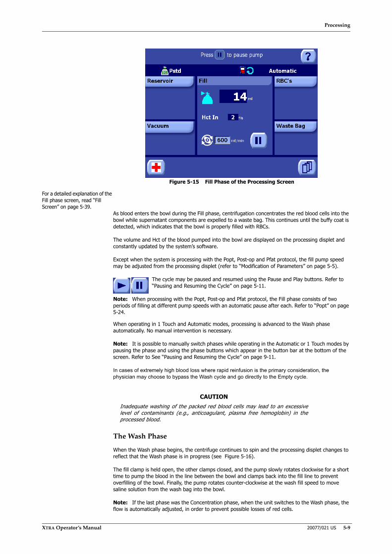
Processing
XTRA Operator’s Manual 20077/021 US 5-9
Figure 5-15 Fill Phase of the Processing Screen
For a detailed explanation of the Fill phase screen, read “Fill Screen” on page 5-39.
As blood enters the bowl during the Fill phase, centrifugation concentrates the red blood cells into the bowl while supernatant components are expelled to a waste bag. This continues until the buffy coat is detected, which indicates that the bowl is properly filled with RBCs.
The volume and Hct of the blood pumped into the bowl are displayed on the processing displet and constantly updated by the system’s software.
Except when the system is processing with the Popt, Post-op and Pfat protocol, the fill pump speed may be adjusted from the processing displet (refer to “Modification of Parameters” on page 5-5).
The cycle may be paused and resumed using the Pause and Play buttons. Refer to “Pausing and Resuming the Cycle” on page 5-11.
Note: When processing with the Popt, Post-op and Pfat protocol, the Fill phase consists of two periods of filling at different pump speeds with an automatic pause after each. Refer to “Popt” on page 5-24.
When operating in 1 Touch and Automatic modes, processing is advanced to the Wash phase automatically. No manual intervention is necessary.
Note: It is possible to manually switch phases while operating in the Automatic or 1 Touch modes by pausing the phase and using the phase buttons which appear in the button bar at the bottom of the screen. Refer to See “Pausing and Resuming the Cycle” on page 9-11.
In cases of extremely high blood loss where rapid reinfusion is the primary consideration, the physician may choose to bypass the Wash cycle and go directly to the Empty cycle.
The Wash Phase
When the Wash phase begins, the centrifuge continues to spin and the processing displet changes to reflect that the Wash phase is in progress (see Figure 5-16).
The fill clamp is held open, the other clamps closed, and the pump slowly rotates clockwise for a short time to pump the blood in the line between the bowl and clamps back into the fill line to prevent overfilling of the bowl. Finally, the pump rotates counter-clockwise at the wash fill speed to move saline solution from the wash bag into the bowl.
Note: If the last phase was the Concentration phase, when the unit switches to the Wash phase, the flow is automatically adjusted, in order to prevent possible losses of red cells.
CAUTIONInadequate washing of the packed red blood cells may lead to an excessivelevel of contaminants (e.g., anticoagulant, plasma free hemoglobin) in theprocessed blood.

Processing
5-10 20077/021 US XTRA Operator’s Manual
Figure 5-16 Wash Phase of the Processing Screen
For a detailed explanation of the Wash phase screen, read “Wash Screen” on page 5-40.
As the saline solution enters the bowl, it washes through the red blood cells, removing remaining supernatant and its contaminants, and is then expelled into the waste bag.
During the Wash phase, the volume of the saline solution pumped into the bowl is displayed on the screen and constantly updated by the system’s software. The desired total volume of saline solution to pump, as well as the wash speed (rate at which the saline solution is moved into the bowl), can be adjusted from the processing displet.
The processing displet during the Wash phase contains a wash quality indication line which displays information on the supernatant removal as well as on the waste line color.
The cycle may be paused and resumed using the Pause and Play buttons. Refer to “Pausing and Resuming the Cycle” on page 5-11.
Once the programmed wash volume has been transferred, the pump and centrifuge will stop and processing will automatically continue to the Empty phase (when operating with Pfat protocol the process will automatically continue to Fat Removal - Wash subphase).
Note: It is possible to manually switch phases while operating in the Automatic or 1 Touch modes by pausing the phase and using the phase buttons which appear in the button bar at the bottom of the screen. Refer to See “Pausing and Resuming the Cycle” on page 9-11.
The Empty Phase
When the Empty phase begins, the centrifuge and pump stop and the processing displet changes to reflect that the Empty phase is in progress (see Figure 5-17).
The saline solution in the line between the bowl and clamps is returned to the fill line by keeping the fill clamp open and the other clamps closed as the pump slowly rotates clockwise for a short time. Finally, the fill clamp closes, the empty clamp opens, and the pump again rotates clockwise to move the red blood cells from the bowl to the RBC bag.
CAUTIONSetting a wash volume lower or a wash volume higher than the one set byLivaNova in the default protocols, prematurely switching to the Empty phase,or enabling the No Wash option are completely under the responsibility of theclinician/operator.
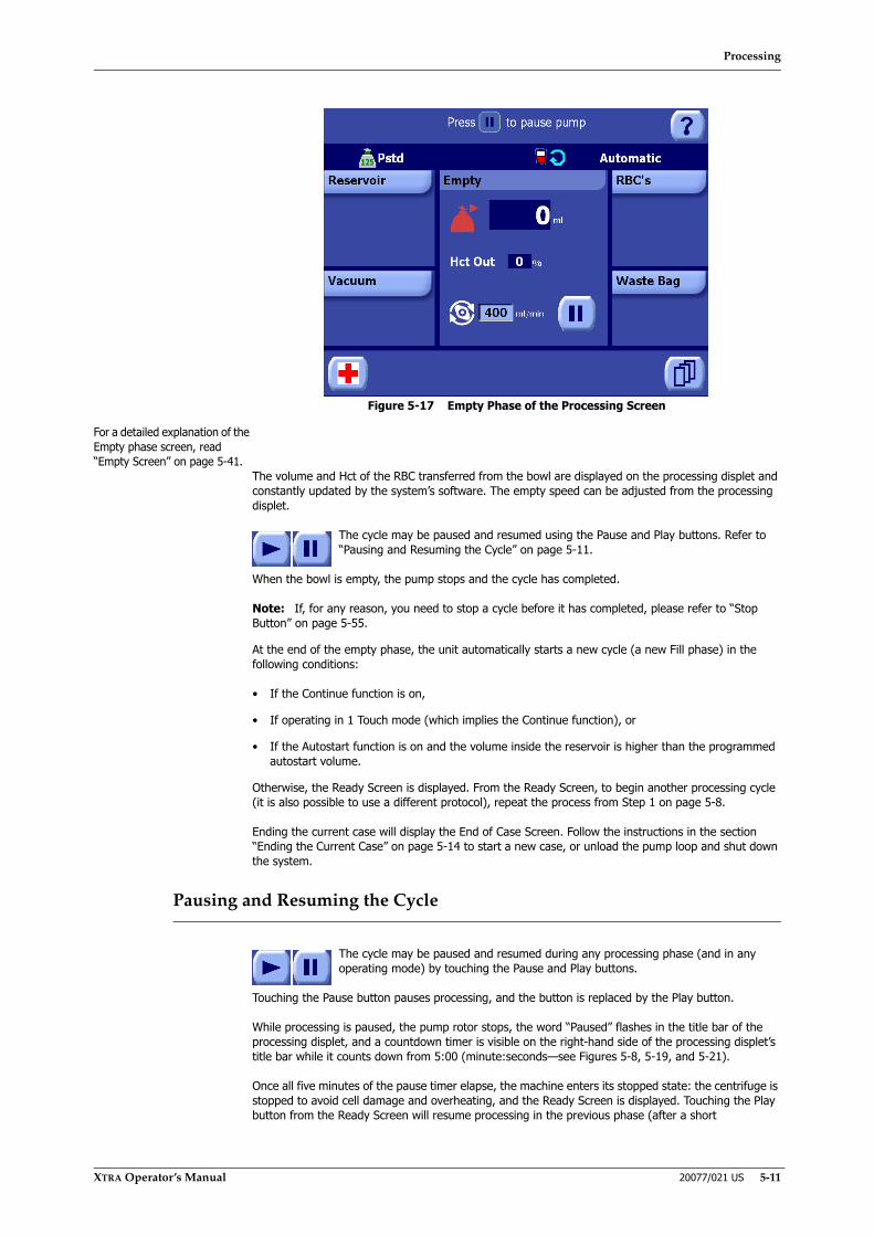
Processing
XTRA Operator’s Manual 20077/021 US 5-11
Figure 5-17 Empty Phase of the Processing Screen
For a detailed explanation of the Empty phase screen, read “Empty Screen” on page 5-41.
The volume and Hct of the RBC transferred from the bowl are displayed on the processing displet and constantly updated by the system’s software. The empty speed can be adjusted from the processing displet.
The cycle may be paused and resumed using the Pause and Play buttons. Refer to “Pausing and Resuming the Cycle” on page 5-11.
When the bowl is empty, the pump stops and the cycle has completed.
Note: If, for any reason, you need to stop a cycle before it has completed, please refer to “Stop Button” on page 5-55.
At the end of the empty phase, the unit automatically starts a new cycle (a new Fill phase) in the following conditions:
• If the Continue function is on,
• If operating in 1 Touch mode (which implies the Continue function), or
• If the Autostart function is on and the volume inside the reservoir is higher than the programmed autostart volume.
Otherwise, the Ready Screen is displayed. From the Ready Screen, to begin another processing cycle (it is also possible to use a different protocol), repeat the process from Step 1 on page 5-8.
Ending the current case will display the End of Case Screen. Follow the instructions in the section “Ending the Current Case” on page 5-14 to start a new case, or unload the pump loop and shut down the system.
Pausing and Resuming the Cycle
The cycle may be paused and resumed during any processing phase (and in any operating mode) by touching the Pause and Play buttons.
Touching the Pause button pauses processing, and the button is replaced by the Play button.
While processing is paused, the pump rotor stops, the word “Paused” flashes in the title bar of the processing displet, and a countdown timer is visible on the right-hand side of the processing displet’s title bar while it counts down from 5:00 (minute:seconds—see Figures 5-8, 5-19, and 5-21).
Once all five minutes of the pause timer elapse, the machine enters its stopped state: the centrifuge is stopped to avoid cell damage and overheating, and the Ready Screen is displayed. Touching the Play button from the Ready Screen will resume processing in the previous phase (after a short
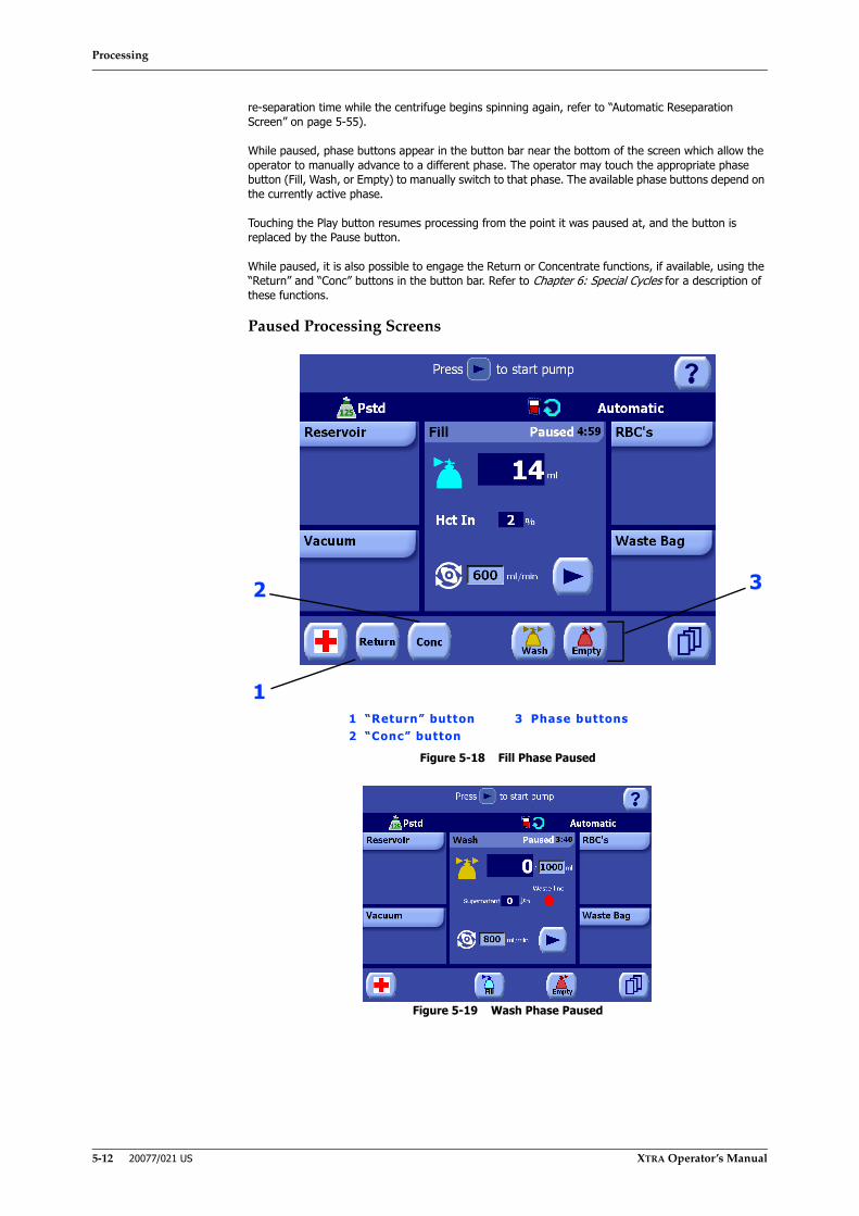
Processing
5-12 20077/021 US XTRA Operator’s Manual
re-separation time while the centrifuge begins spinning again, refer to “Automatic Reseparation Screen” on page 5-55).
While paused, phase buttons appear in the button bar near the bottom of the screen which allow the operator to manually advance to a different phase. The operator may touch the appropriate phase button (Fill, Wash, or Empty) to manually switch to that phase. The available phase buttons depend on the currently active phase.
Touching the Play button resumes processing from the point it was paused at, and the button is replaced by the Pause button.
While paused, it is also possible to engage the Return or Concentrate functions, if available, using the “Return” and “Conc” buttons in the button bar. Refer to Chapter 6: Special Cycles for a description of these functions.
Paused Processing Screens
Figure 5-18 Fill Phase Paused
Figure 5-19 Wash Phase Paused
2
11 “Return” button 3 Phase buttons2 “Conc” button
3
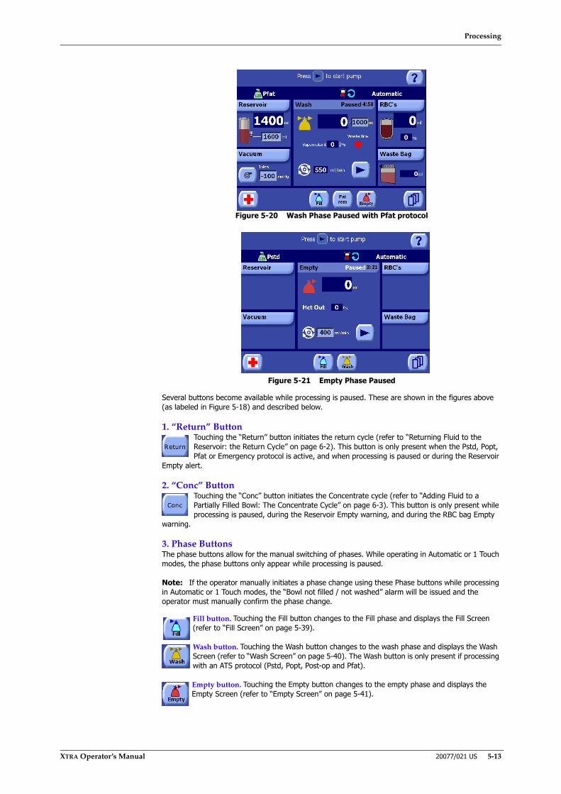
Processing
XTRA Operator’s Manual 20077/021 US 5-13
Figure 5-20 Wash Phase Paused with Pfat protocol
Figure 5-21 Empty Phase Paused
Several buttons become available while processing is paused. These are shown in the figures above (as labeled in Figure 5-18) and described below.
1. “Return” ButtonTouching the “Return” button initiates the return cycle (refer to “Returning Fluid to the Reservoir: the Return Cycle” on page 6-2). This button is only present when the Pstd, Popt, Pfat or Emergency protocol is active, and when processing is paused or during the Reservoir
Empty alert.
2. “Conc” ButtonTouching the “Conc” button initiates the Concentrate cycle (refer to “Adding Fluid to a Partially Filled Bowl: The Concentrate Cycle” on page 6-3). This button is only present while processing is paused, during the Reservoir Empty warning, and during the RBC bag Empty
warning.
3. Phase ButtonsThe phase buttons allow for the manual switching of phases. While operating in Automatic or 1 Touch modes, the phase buttons only appear while processing is paused.
Note: If the operator manually initiates a phase change using these Phase buttons while processing in Automatic or 1 Touch modes, the “Bowl not filled / not washed” alarm will be issued and the operator must manually confirm the phase change.
Fill button. Touching the Fill button changes to the Fill phase and displays the Fill Screen (refer to “Fill Screen” on page 5-39).
Wash button. Touching the Wash button changes to the wash phase and displays the Wash Screen (refer to “Wash Screen” on page 5-40). The Wash button is only present if processing with an ATS protocol (Pstd, Popt, Post-op and Pfat).
Empty button. Touching the Empty button changes to the empty phase and displays the Empty Screen (refer to “Empty Screen” on page 5-41).

Processing
5-14 20077/021 US XTRA Operator’s Manual
Fat Removal Button. This button is available only when operating with Pfat protocol. Touching the Fat Removal button changes to the Fat Removal phase (refer to “Fat Removal Screens” on page 5-41).
Table 5-1 lists which buttons are made available (in addition to the buttons already present) when processing is paused from each screen and condition from which the Pause button is available. The pump is always stopped when the Pause button is touched.
Ending the Current Case
Touch the “End Case” button from the Ready Screen after processing a cycle (refer to “Running a Case With the XTRA System” on page 5-5) to end the current case and display the End of Case Screen (see Figure 5-22).
Condition When Paused Buttons Which Become AvailableIntraoperative Fill phase (Automatic, 1 Touch) Return, Conc, Wash, EmptyIntraoperative Fill phase (Manual) Return, ConcIntraoperative Wash phase (Automatic, 1 Touch) Fill, Empty and Fat Rem (if operating with Pfat
protocol)Intraoperative Wash phase (Manual) -Intraoperative Empty phase (Automatic, 1 Touch) Fill, WashIntraoperative Empty phase (Manual) -Preoperative Fill phase (Automatic) Conc, EmptyPreoperative Fill phase (Manual) ConcPreoperative Spill phase (Automatic) Conc, Empty
Preoperative Spill phase (Manual) Conc
Preoperative Empty phase (Automatic) -
Preoperative Empty phase (Manual) -Postoperative Fill phase (Automatic, 1 Touch) Like IBS excluding Return: Conc, Wash, EmptyPostoperative Wash phase (Automatic, 1 Touch) Like IBS: Fill, EmptyPostoperative Empty phase (Automatic, 1 Touch) Like IBS: Fill, WashPostoperative Empty phase -Intraoperative, Postoperative (Automatic,
1 Touch): Concentrate from Fill Fill, Wash, Empty
Intraoperative and Preoperative (Manual): Concentrate from Fill
-
Preoperative: Concentrate from Spill (Automatic) SpillPreoperative: Concentrate from Spill (Manual) -Intraoperative (Automatic, 1 Touch): Return FillIntraoperative (Manual): Return -Intraoperative, Postoperative and Preoperative:
I.V. prime-
Table 5-1 Buttons Which Become Available While Paused Per Processing Condition
CAUTIONThe use of phase buttons and, in general, modifications that alter the normalexecution of protocols can create reductions of normal machine performance.It is the responsibility of the user to evaluate if and when these procedurescan be performed.
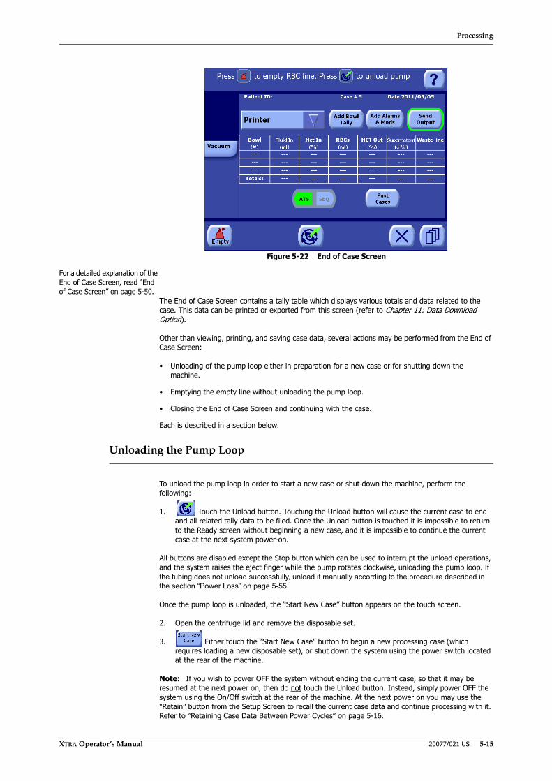
Processing
XTRA Operator’s Manual 20077/021 US 5-15
Figure 5-22 End of Case Screen
For a detailed explanation of the End of Case Screen, read “End of Case Screen” on page 5-50.
The End of Case Screen contains a tally table which displays various totals and data related to the case. This data can be printed or exported from this screen (refer to Chapter 11: Data Download Option).
Other than viewing, printing, and saving case data, several actions may be performed from the End of Case Screen:
• Unloading of the pump loop either in preparation for a new case or for shutting down the machine.
• Emptying the empty line without unloading the pump loop.
• Closing the End of Case Screen and continuing with the case.
Each is described in a section below.
Unloading the Pump Loop
To unload the pump loop in order to start a new case or shut down the machine, perform the following:
1. Touch the Unload button. Touching the Unload button will cause the current case to end and all related tally data to be filed. Once the Unload button is touched it is impossible to return to the Ready screen without beginning a new case, and it is impossible to continue the current case at the next system power-on.
All buttons are disabled except the Stop button which can be used to interrupt the unload operations, and the system raises the eject finger while the pump rotates clockwise, unloading the pump loop. If the tubing does not unload successfully, unload it manually according to the procedure described in the section “Power Loss” on page 5-55.
Once the pump loop is unloaded, the “Start New Case” button appears on the touch screen.
2. Open the centrifuge lid and remove the disposable set.
3. Either touch the “Start New Case” button to begin a new processing case (which requires loading a new disposable set), or shut down the system using the power switch located at the rear of the machine.
Note: If you wish to power OFF the system without ending the current case, so that it may be resumed at the next power on, then do not touch the Unload button. Instead, simply power OFF the system using the On/Off switch at the rear of the machine. At the next power on you may use the “Retain” button from the Setup Screen to recall the current case data and continue processing with it. Refer to “Retaining Case Data Between Power Cycles” on page 5-16.

Processing
5-16 20077/021 US XTRA Operator’s Manual
Emptying the RBC Line Without Ending the Case
From the End of Case Screen, it is possible to empty any blood remaining in the bowl or empty line. To do so, touch the Empty button.
The system enters the Empty phase, and the Empty Phase of the Processing Screen is displayed on the touch screen (refer to “The Empty Phase” on page 5-10).
Closing the End of Case Screen Without Ending the Case
If you decide you do not want to end the current case, the End of Case Screen may be closed and further cycles run in the current case.
To close the End of Case Screen without ending the current case, touch the Close button.
The Ready Screen will be displayed on the touch screen (refer to “Processing a Cycle in Automatic or 1 Touch Mode” on page 5-7).
Retaining Case Data Between Power Cycles
If the XTRA system is powered OFF (through the ON/OFF switch or a power failure) before it has been unloaded, then the case data and any modifications to the protocols are retained in memory and may be resumed at the next power on.
To resume such an interrupted case, perform the following actions:
1. Switch on the system using the ON/OFF switch at the rear of the machine to enter the Setup Screen.
2. From the Setup Screen touch the “Retain” button. (Do not touch the Load button.)
This initiates the usual auto-load procedure, except case data is not reset and the pump loop tubing is assumed to be already loaded. Once the auto-load procedure has completed, the Ready Screen will be displayed as usual.
Note: The “Retain” button is not present on the Setup Screen under any of these conditions:
• The operator explicitly ended the case by touching the Unload button from the End of Case Screen,
• The operator modified any of the machine settings through the Settings tab of the Menu Screen (made exception for the Vacuum pump Intra/Post-op mode switch), or
• A memory failure or initialization occurred.
WARNINGRepeating this operation may cause air to enter the RBC bag with serious risks to the health of the patient. The air in the bag should be removed before reinfusion.

Processing
XTRA Operator’s Manual 20077/021 US 5-17
If an intraoperative protocol is interrupted and if the protocol set (defined in Configuration mode) includes any Post-op protocols (factory or user defined), touching the "Retain" button will prompt the following screen:
By touching “Retain Intra” the interrupted case will be resumed with the vacuum pump and protocol switched to Intraoperative mode.
By touching “Retain Post-op” the interrupted case will be resumed with the vacuum pump and protocol switched to Post-operative mode.
Dealing With Expected Warnings During a Cycle
This section describes the most likely warnings, along with the appropriate response to each, which can be triggered during a processing cycle. For a complete description warnings and alarms, refer to Chapter 14: Troubleshooting.
Reservoir Empty
The Reservoir Empty warning is triggered during the Fill phase if air is detected in the reservoir line. Also refer to “Reservoir empty. Bowl not filled” on page 14-20.
When triggered, the acoustic sequence is sounded, the message “Reservoir empty. Bowl not filled” is displayed in the message area of the current screen, the reservoir displet is highlighted with a yellow outline, and the processing cycle is paused (see Figure 5-23).
CAUTIONWhen retaining case data between power cycles, do not change thedisposable and/or its positioning to avoid potential errors during theauto-load process.

Processing
5-18 20077/021 US XTRA Operator’s Manual
Figure 5-23 Reservoir Empty Warning
The operator can proceed in different ways, depending on the following conditions:
Note: After three minutes, the pump and centrifuge will stop and the Reservoir Empty alarm with all its buttons will remain displayed.
• If the reservoir is empty and more blood is expected in the reservoir:
a. Wait until the volume of blood collected in the reservoir is sufficient to complete the bowl filling.
b. Touch the Fill button to continue with the Fill phase.
• If blood is still present in the reservoir:
a. Check that the connections are properly sealed and eliminate possible occlusions along the fill line.
Note: To check the current positioning of the tubing going to the bowl, you may need to press the Stop button then open the centrifuge and clamp lid. In this case, pay close attention to the correct disposable installation when closing the clamps and centrifuge lid again.
b. Check that the tube going to the bowl is fully down in the air detector seat.
c. Touch the Fill button to continue.
• If the reservoir is empty and no more blood is expected in the reservoir:
a. If the RBC bag contains red blood cells:
• Initiate the Last Bowl function if available (refer to “Last Bowl” on page 7-4).
Note: The “Last Bowl” function is not available when operating in Manual mode.
• Otherwise, touch the “Conc” button to complete the bowl filling by pumping the contents of the RBC bag into the bowl according to the Concentrate function (refer to “Adding Fluid to a Partially Filled Bowl: The Concentrate Cycle” on page 6-3).
b. If the RBC bag is empty:
• Either touch the “Return” button to return the contents of the bowl to the reservoir and then end the case,
• Or continue processing the partially filled bowl by touching the Wash phase button (or the “Double Wash” button to use double the wash volume) to advance to the Wash phase. This will result in lower than usual hematocrit and wash quality of the collected blood.
Note: The “Double Wash” button is not available when operating in Manual mode.
Should the message persist, please contact LivaNova Technical Services.

Processing
XTRA Operator’s Manual 20077/021 US 5-19
Touch the Mute button (located at the far left of the button bar) to silence the alarm for 45 seconds.
[
Wash Bag Empty
The Wash Bag Empty warning is triggered during the Wash phase if air is detected in the wash line. Also refer to “Wash bag empty” on page 14-9.
However, when Popt, Pstd or Post-op protocols are in use, the warning is not triggered if at least 90% of the pre-set volume of washing solution has been transferred to the bowl. This tolerance allows the Wash phase to conclude even if the actual volume of washing solution is slightly lower than the pre-set volume.
When triggered, the acoustic sequence sounds, the message “Wash bag empty” is displayed in the message area of the current screen, the processing displet of the Wash phase is highlighted with a yellow outline, and the phase is paused (see Figure 5-24).
Figure 5-24 Wash Bag Empty Warning
If the wash bag is empty, proceed as follows:
1. Replace the wash bag.
2. Touch the Play button to resume the Wash phase.
If the wash bag is not empty, proceed as follows:
1. Check that the connections are properly sealed and ensure that the line between the saline solution bags and the bowl is not occluded.
2. Check that the tubing going to the bowl is properly inserted in the air detector.
CAUTIONThe use of the Last Bowl function is recommended only to complete the casewith the following conditions: the blood collection reservoir is empty, no moreblood is expected to be further collected, and sufficient red cells are availablein the RBC bag to complete the concentration phase.
WARNINGIn case a bowl only partially filled is washed, the hematocrit of the collected blood will be lower than expected, and the removal of waste components might be lower than expected.
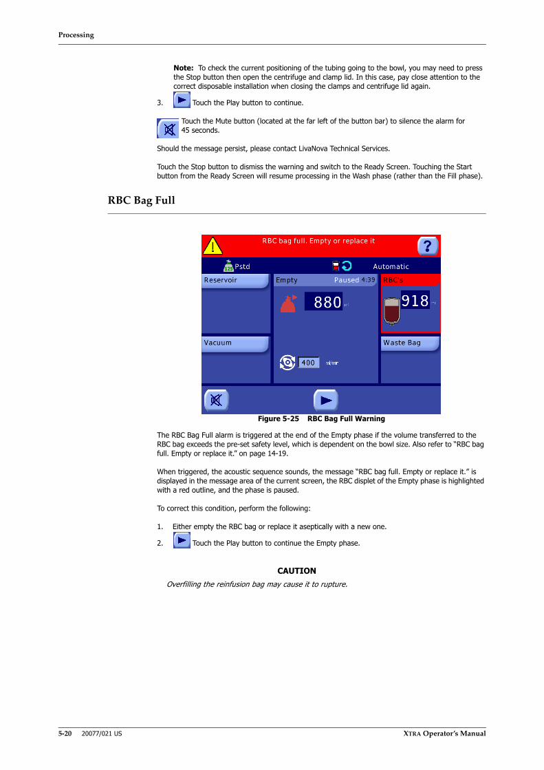
Processing
5-20 20077/021 US XTRA Operator’s Manual
Note: To check the current positioning of the tubing going to the bowl, you may need to press the Stop button then open the centrifuge and clamp lid. In this case, pay close attention to the correct disposable installation when closing the clamps and centrifuge lid again.
3. Touch the Play button to continue.
Touch the Mute button (located at the far left of the button bar) to silence the alarm for 45 seconds.
Should the message persist, please contact LivaNova Technical Services.
Touch the Stop button to dismiss the warning and switch to the Ready Screen. Touching the Start button from the Ready Screen will resume processing in the Wash phase (rather than the Fill phase).
RBC Bag Full
Figure 5-25 RBC Bag Full Warning
The RBC Bag Full alarm is triggered at the end of the Empty phase if the volume transferred to the RBC bag exceeds the pre-set safety level, which is dependent on the bowl size. Also refer to “RBC bag full. Empty or replace it.” on page 14-19.
When triggered, the acoustic sequence sounds, the message “RBC bag full. Empty or replace it.” is displayed in the message area of the current screen, the RBC displet of the Empty phase is highlighted with a red outline, and the phase is paused.
To correct this condition, perform the following:
1. Either empty the RBC bag or replace it aseptically with a new one.
2. Touch the Play button to continue the Empty phase.
CAUTIONOverfilling the reinfusion bag may cause it to rupture.

Processing
XTRA Operator’s Manual 20077/021 US 5-21
Waste Bag Full
Figure 5-26 Waste Bag Full Warning
The Waste Bag Full alarm (if enabled) is triggered at the end of the Empty phase if the volume transferred to the waste bag exceeds the pre-set safety level. It will also be triggered during the Fill/Concentration, Wash and Fat Removal phases if the safety level is reached during those phases. Also refer to “Waste bag full. Empty or replace it.” on page 14-21.
When triggered, the acoustic sequence sounds, the message “Waste bag full. Empty or replace it.” is displayed in the message area of the current screen, the Waste Bag displet of the Fill phase is highlighted with a red outline, and the phase is paused.
To correct this condition, perform the following:
1. If you want to use a new wash bag, replace it aseptically, and then touch the “New Bag” button to resume.
2. Otherwise, if you want to empty the same bag, use the drain at the bottom of the bag. Do not empty below the minimum level. Touch the “Minimum Bag Level” button to resume.
3. Touch the Start button to reset the count of transferred waste volume and continue the Fill phase.
WARNINGThe waste bag should be replaced with the equipment STOPPED (pump and centrifuge) and the bowl completely empty. This instruction does not apply if the replacement of the waste bag is done with a vented waste bag.
CAUTIONIgnoring a full waste bag may cause back pressure from the waste bag thatcould result in fluid leakage around the bowl's rotating seal or waste fluidbeing returned to the centrifuge bowl.
CAUTIONDo not completely empty the waste bag until the end of the case. If youempty the waste bag during the case, leave approximately one liter of fluid inthe waste bag to prevent the possibility of vacuum being generated in thewaste bag during the Empty cycle. Vacuum in the waste bag may preventcomplete emptying of the bowl.
Processing
5-22 20077/021 US XTRA Operator’s Manual
Factory Protocols
Protocols represent specific methods of processing blood in order to obtain hematic components. A protocol defines a processing cycle which may be run one or more times in a case.
The execution of one cycle of a protocol corresponds to the transfer of blood to the centrifuge bowl, the processing of the blood with removal of supernatant and related contaminants, and the collection of packed RBCs.
Each cycle is made up of a sequence of phases. A phase corresponds to a succession of actions which carry out a functional part of the cycle (such as filling the bowl during a Fill phase or washing the bowl content during a Wash phase).
Protocols are not completely rigid. The operator may change some protocol parameters during an active phase (changing the pump rotor speed, for example) and may also manually progress to the next phase.
The XTRA system ships with six factory-defined protocols which are divided into three families:
• Preoperative sequestration: for the separation of whole blood into red cells, platelet poor plasma, and platelet rich plasma (the PPP, PRP1, and PRP2 protocols).
• Autotransfusion (Intraoperative): for the concentration, washing, and collection of red cells (the Popt and Pstd protocols) and enhanced fat particles removal (Pfat) in an intraoperative context.
• Autotransfusion (Postoperative): for the concentration, washing, and collection of red cells (the Post-op protocol) in a postoperative context, allowing the use of the on-board vacuum pump in its postoperative mode.
Note: Only factory Post-op and user protocols derived from it are intended to be used in postoperative contexts.
Note: Make sure the XVAC vacuum pump is set to POST mode, while collecting blood postoperatively.
The intraoperative and postoperative protocols together are referred to as the autotransfusion (ATS) protocols.
Protocols differ from one another in the type and order of the phases, the parameters of each phase, and the algorithms used during each phase.
It is possible to create user-defined custom protocols derived from one of the factory protocols. For details on creating and customizing protocols, refer to Chapter 9: Programmability Option.
This section describes only the ATS protocols which ship with the XTRA system: the three intraoperative protocols (Popt, Pstd and Pfat) and the one postoperative protocol (Post-op). The Preoperative sequestration protocols are described in Chapter 10: Preoperative Sequestration (PPP and PRP).
To learn how to select and actually process a case using these protocols refer to the section “Running a Case With the XTRA System” on page 5-5.
WARNINGUse of protocols different from Post-op in postoperative contexts might expose the patient to risks of tissue damage due to high aspiration level of vacuum module and risks of blood return due to availability of the Return function.
WARNINGUse of the vacuum pump in INTRA mode while collecting blood postoperatively might expose the patient to risks of tissue damage.

Processing
XTRA Operator’s Manual 20077/021 US 5-23
The Autotransfusion Protocols
The intraoperative (Popt, Pstd and Pfat) protocols will concentrate, wash, and collect the blood lost by the patient during a surgical intervention. The postoperative protocol (Post-op) will do the same for blood drained from a surgical cavity of a patient after a surgical intervention.
Note: The Post-op protocol is similar to the Popt protocol. The only difference is that in the Post-op protocol the XVAC vacuum pump is set to its postoperative functioning mode, while in the Popt protocol it is set to its intraoperative mode.
All ATS protocols (except for Pfat) are carried out through the execution of three phases in this sequence:
1. Fill Phase
2. Wash Phase
3. Empty Phase
First, blood is taken up from the operating field, extra-corporeal circulation circuit, or surgical cavity and treated with anticoagulant. It is then sent into the collection reservoir where it is filtered and stored. Next, during the Fill phase, the system transfers blood from the reservoir into the spinning centrifuge bowl by use of the peristaltic pump. Centrifugation concentrates the red blood cells into the bowl while supernatant components are expelled to a waste bag. Next, during the Wash phase, a volume of saline solution is washed through the concentrated red blood cells to remove the free plasma hemoglobin, anticoagulant, and other waste components. Finally, during the Empty phase, the concentrated red blood cells, with minimized amounts of waste contaminants, are pumped into the RBC bag to be returned to the patient as directed by the responsible medical practitioner. The Pfat protocol differs from the other ATS protocols by an additional phase performed between the Wash and Empty phases, named the Fat Removal phase. During this phase the RBCs are washed at a higher flow rate and re-concentrated to optimize the removal of fat particles.
While processing with the ATS protocols, the XTRA machine is set up with three lines connected to the bowl inlet:
• One connected to the reservoir (fill line),
• One connected to a bag containing the washing saline solution (wash line), and
• One connected to the RBC collection bag (empty line).
The outlet line of the bowl is connected to a waste bag (see Figure 5-27).
Figure 5-27 Disposable Setup for ATS Protocols

Processing
5-24 20077/021 US XTRA Operator’s Manual
Popt
The Popt protocol is intended to process the blood recovered from the operating field or the residual volume of an extra-corporeal circuit. It has been designed to achieve an optimal compromise between hematocrit, wash quality, and processing time.
Because the Popt protocol is a substantially automatic protocol where operator intervention is significantly limited, only Automatic and 1 Touch modes shall be available when it is the active protocol (refer to “The Operating Modes” on page 5-31).
Fill Phase
The Fill phase of the Popt protocol differs from the Pstd protocol and is very similar to the Pfat protocol (different only for what concerns number of phases and flows), while it is the same as the Post-op protocol. It consists of the following execution steps:
1. The centrifuge lid lock is engaged, the fill clamp is opened, and the centrifuge accelerates up to 5,600 rpm.
Note: If the bowl already contains blood and the buffy coat is detected before the centrifuge reaches its programmed speed, the pump shall not start until 15 seconds after the centrifuge reaches its target speed. This delay is intended to stabilize the buffy coat. The operator may manually start the pump during this wait by touching the Play button. If the buffy coat is still detected after the delay, then the pump is not started and the next step is skipped. Refer to “Automatic Reseparation Screen” on page 5-55.
2. Once the centrifuge reaches its set speed, the pump begins to rotate counter-clockwise, pumping blood from the reservoir to the bowl, at the factory defined speed. Unlike the other protocols, the fill speed for the Popt protocol cannot be modified. The pump continues to rotate filling the bowl until the buffy coat is detected.
3. Once the buffy coat is detected by the RBC detector, the pump is paused for a matter of seconds (the exact time is determined by the bowl size in use).
4. After the pause time has elapsed, the pump will continue at a second speed and pump an additional volume of blood into the bowl until the buffy coat is detected a second time.
5. If processing with the X/55 bowl size, the Fill phase is concluded at this point and processing moves on to the Wash phase. The procedure for all other bowl sizes proceeds to step 6.
6. Once the buffy coat has been detected, the pump will pause for a second time. The duration of this pause is also determined by the bowl size being used.
7. After the second pause time has elapsed, the Fill phase has concluded and processing moves on to the Wash phase.
Wash Phase
The Wash phase of the Popt protocol is identical to that of the Pstd, Pfat and Post-op protocols. It consists of the following execution steps:
1. The 14 ml of blood in the line between the bowl and clamps is pumped back into the reservoir line by keeping the fill clamp open, the other clamps closed, and slowly rotating the pump clockwise for a short time.
◊ When the Wash phase is entered manually, this only takes place if at least 14 ml were processed during the previous Fill phase.
Note: If processing with the X/55 bowl size, sub-phase where the pump moves a total amount of 25 ml of saline solution at a fixed flow-rate (50 ml/min.) begins at this point. At the conclusion of this sub-phase, the flow rate assumes its programmable (and modifiable) value and the Wash phase continues in the usual way.
2. The pump rotor is stopped, the fill clamp is closed, and the wash clamp is opened.
3. The pump begins to rotate counter-clockwise and reaches either the wash factory-set speed, or, if the pump speed has been modified by the operator in a previous cycle, the new speed, moving saline solution through to the bowl content.
Processing
XTRA Operator’s Manual 20077/021 US 5-25
4. The pump will stop and processing will automatically continue to the Empty phase as soon as one of these conditions is met:
◊ the programmed wash volume has been reached,
◊ according to the rules for the Better Quality Wash function if active, or
◊ air is detected in the wash line after 90% of the programmed volume has been pumped.
Note: In case the Pfat protocol is in use, the pump will stop and processing will automatically continue to the Fat Removal phase when the programmed wash volume has been reached.
Empty Phase
The Empty phase of the Popt protocol is identical to that of the Pstd and Post-op protocols. It consists of the following execution steps:
1. The centrifuge and pump stop.
2. The 9 ml of saline solution in the line between the bowl and clamps is returned to the reservoir line by keeping the fill clamp open, the other clamps closed, and slowly rotating the pump clockwise for a short time.
• When the Empty phase is entered manually by touching the Empty button before the Wash phase is completed, then this only takes place if at least 9 ml of fluid were moved during the Wash phase (this does not happen if Pfat is in use).
3. The pump stops, the fill clamp closes, and the empty clamp opens.
4. In order to move the remaining fluid from the bowl to the RBC bag, the pump begins rotating clockwise with an appropriate acceleration. It reaches either the empty factory pre-set speed, or, if the pump speed has been modified by the operator in a previous cycle, the new speed.
5. When air is detected in the line, the bowl is presumed empty and the pump stops, the empty clamp closes, and the Ready screen is displayed on the touch screen.
Pstd
The Pstd protocol is intended to process the blood recovered from the operating field or the residual volume of an extra-corporeal circuit. It has been designed to achieve a minimum RBC concentration and wash quality in the shortest processing time. This protocol runs in less time than the Popt protocol for a given volume of blood to process.
Fill Phase
The Fill phase of the Pstd protocol is simpler than that of the Popt protocol. It consists of the following execution steps:
1. The centrifuge lid lock is engaged, the fill clamp is opened, and the centrifuge accelerates up to 5,600 rpm.
Note: If the bowl already contains blood and the buffy coat is detected before the centrifuge reaches its programmed speed, the pump shall not start until 15 seconds after the centrifuge reaches its target speed. This delay is intended to stabilize the buffy coat. The operator may manually start the pump during this wait by touching the Play button. If the buffy coat is still detected after the delay, then the pump is not started and the next step is skipped.
2. Once the centrifuge reaches its set speed, the pump begins to rotate counter-clockwise, pumping blood from the reservoir to the bowl, at the factory defined speed. Filling of the bowl continues until the buffy coat is detected.
3. Once the buffy coat is detected, switch to the Wash phase happens automatically.
Wash and Empty Phases
The wash and empty phases of the Pstd protocol are similar to those of the Popt protocol detailed in sections “Wash Phase” on page 5-24 and “Empty Phase” on page 5-25.

Processing
5-26 20077/021 US XTRA Operator’s Manual
Pfat
The Pfat protocol is intended to process the blood recovered from the operating field. It has been designed to remove fat particles, maintaining an optimal compromise between hematocrit and wash quality.
Fill Phase
The Fill phase of the Pfat protocol is similar to that of Popt protocol detailed in section “Fill Phase” on page 5-24.
Wash Phase
The Wash phase of the Pfat protocol is similar to that of the Pstd and Popt protocol detailed in section “Wash Phase” on page 5-24.
Fat Removal Phase
The Fat Removal phase is performed only when processing with Pfat protocol. It consists of the following execution steps:
1. Right after the regular Wash phase, an additional quantity of saline solution is pumped into the bowl at a high flow rate. This process eliminates the residual of fat particles left inside the bowl. This is the “Fat Removal – Wash” subphase.
2. The pump and centrifuge stop, the fill clamp closes, and the empty clamp opens.
3. The pump begins to rotate clockwise and a pre-fixed amount of RBCs is moved to the RBC bag. This is the “Fat Removal – Empty” subphase.
4. The pump stops, the centrifuge restarts to reseparate the remaining RBCs in the bowl from the saline solution.
5. The pump begins to rotate counter-clockwise. The RBCs previously collected in the RBC bag and, if present, more RBCs from previous cycles are pumped back into the bowl until the buffy coat is detected by the RBC sensor or the RBC bag is empty. This is the “Fat Removal – Conc” subphase.
Note: The Fat Removal - Empty and Conc subphases are performed in order to remove the excess of saline solution inside the bowl after the “Fat Removal - Wash” subphase, thus avoiding excessive dilution of the final collected RBCs.
Empty Phase
The Empty phase of the Pfat protocol is similar to that of Popt and Pstd detailed in section “Wash Phase” on page 5-24.
Emergency
The Emergency function uses a special variation of the Pstd protocol intended to minimize the operator’s interventions and the processing time in case of an emergency situation.
The Emergency function can be activated at any time from the Ready or Processing Screen by touching the Emergency button.
Note: The Emergency function can be permanently enabled/disabled from the “Protocol Set” tab of the Configuration Mode Screen. The Emergency button will only be available when it is enabled. For instructions on configuring the XTRA, refer to Chapter 8: Configuring Xtra.
When the Emergency button is touched, the Emergency Activation Screen (see Figure 5-28) is displayed, requiring confirmation before the function is activated.
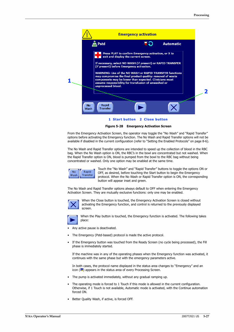
Processing
XTRA Operator’s Manual 20077/021 US 5-27
Figure 5-28 Emergency Activation Screen
From the Emergency Activation Screen, the operator may toggle the “No Wash” and “Rapid Transfer” options before activating the Emergency function. The No Wash and Rapid Transfer options will not be available if disabled in the current configuration (refer to “Setting the Enabled Protocols” on page 8-6).
The No Wash and Rapid Transfer options are intended to speed up the collection of blood in the RBC bag. When the No Wash option is ON, the RBC’s in the bowl are concentrated but not washed. When the Rapid Transfer option is ON, blood is pumped from the bowl to the RBC bag without being concentrated or washed. Only one option may be enabled at the same time.
Touch the “No Wash” and “Rapid Transfer” buttons to toggle the options ON or OFF, as desired, before touching the Start button to begin the Emergency protocol. When the No Wash or Rapid Transfer option is ON, the corresponding button will appear inset and green.
The No Wash and Rapid Transfer options always default to OFF when entering the Emergency Activation Screen. They are mutually exclusive functions: only one may be enabled.
When the Close button is touched, the Emergency Activation Screen is closed without activating the Emergency function, and control is returned to the previously displayed screen.
When the Play button is touched, the Emergency function is activated. The following takes place:
• Any active pause is deactivated.
• The Emergency (Pstd-based) protocol is made the active protocol.
• If the Emergency button was touched from the Ready Screen (no cycle being processed), the Fill phase is immediately started.
If the machine was in any of the operating phases when the Emergency function was activated, it continues with the same phase but with the emergency parameters active.
In both cases, the protocol name displayed in the status area changes to “Emergency” and an icon ( ) appears in the status area of every Processing Screen.
• The pump is activated immediately, without any gradual ramping up.
• The operating mode is forced to 1 Touch if this mode is allowed in the current configuration. Otherwise, if 1 Touch is not available, Automatic mode is activated, with the Continue automation forced ON.
• Better Quality Wash, if active, is forced OFF.
1
2
1 Start button 2 Close button
Processing
5-28 20077/021 US XTRA Operator’s Manual
• The Emergency button appears on all Processing Screens and on the Ready Screen in its pressed status (inset and green). Touching it again will disable the Emergency function, re-enabling the previous protocol (confirmation not required).
Additionally, if the Emergency function is activated with the No Wash option ON, the following takes place:
• The Wash phase is skipped. Processing continues from the Fill phase to the Empty phase.
• If the Emergency function is activated while the Wash phase is in progress, the phase is immediately interrupted and the Empty phase is activated.
Additionally, if the Emergency function is activated with the Rapid Transfer option ON, the following takes place:
• If the Emergency function is activated while the Fill phase is in progress, the centrifuge will stop immediately.
• The Wash phase is skipped. Processing continues from the Fill phase to the Empty phase.
• If the Emergency function is activated while the Wash or Fat Removal phase is in progress, the phase is immediately interrupted and the Empty phase is activated.
To deactivate the Emergency function, touch the enabled Emergency button from any screen.
CAUTIONThe availability of alarms does not relieve the operator of his or her obligationto carefully monitor the entire system during operation. Unattendedprocessing can lead to the development of problems with the operation of thesystem and/or with the quality of the end product.
CAUTIONDuring the execution of emergency protocols, the control that causes awarning of “Minimum wash quality wash might not be reached yet” isautomatically disabled.
CAUTIONThe use of emergency protocols with the Rapid Transfer option produces anunwashed final collection in which the removal of contaminants is onlypossible through the 40-µm filter in the reservoir. It is the full responsibility ofthe user to evaluate if the conditions exist to use emergency protocol with theRapid Transfer option.
CAUTIONThe emergency protocols promote fast execution rather than the quality ofthe final product, which is reduced compared to that guaranteed by otherpredefined protocols. Their use is, therefore, reserved to situations in whichthere is a preponderant urgent need for blood regarding the concentration ofRBC collected and the wash quality. It is the full responsibility of the user toevaluate if the conditions exist to use said protocols.
CAUTIONThe use of emergency protocols with the No Wash option produces anunwashed final collection in which the removal of contaminants is onlypossible through the 40-µm filter in the reservoir and the concentration of theFill phase. It is the full responsibility of the user to evaluate if the conditionsexist to use an emergency protocol with the No Wash option.

Processing
XTRA Operator’s Manual 20077/021 US 5-29
Post-op
The postoperative Post-op protocol is intended to concentrate, wash, and collect the blood drained from a surgical cavity of a patient in a postoperative context.
If the XVAC vacuum module is present while Post-op is the active protocol, it will provide a negative pressure in the cardiotomy suitable for the drainage from the surgical cavity of the patient.
To avoid the risk of moving air toward the patient, it is not possible to activate the Return function while the Post-op protocol is active.
The Post-op protocol uses the same procedure as the Popt protocol, except that the vacuum pump works in the postoperative mode (refer to Chapter 13: Vacuum Module).
Fill, Wash, and Empty Phases
The execution steps of the Fill, Wash, and Empty phases are identical to those of the Popt protocol (refer to “Popt” on page 5-24).
Note: Verify that the XVAC vacuum pump is set to the POST-OP mode when collecting blood postoperatively.
CAUTIONInadequate washing of concentrated red blood cells can lead to an excessivelevel of contaminants (i.e. anticoagulants and plasma free hemoglobin) in thetreated blood.
CAUTIONUse of the vacuum pump in INTRA mode while collecting bloodpostoperatively might expose the patient to risks of tissue damage
CAUTIONAs soon as postoperative drainage operations are completed, the patientmust be disconnected from the reservoir.
CAUTIONThe use of protocols different from POST-OP in postoperative contexts mightexpose the patient to risks of tissue damage due to high aspiration levels ofvacuum module and risks of blood return due to availability of the returnfunction.
CAUTIONDuring setup and unload of the kit, the patient must not be connected to thereservoir through the drainage line.
CAUTIONThe availability of alarms does not relieve the operator of his or her obligationto carefully monitor the entire system during operation. Unattendedprocessing can lead to the development of problems with the operation of thesystem and/or with the quality of the end product.
CAUTIONIn the case of malfunction of the integrated vacuum pump, use an alternativevacuum source, i.e., the vacuum present in the operating room, possiblyconnected to a pressure regulator.
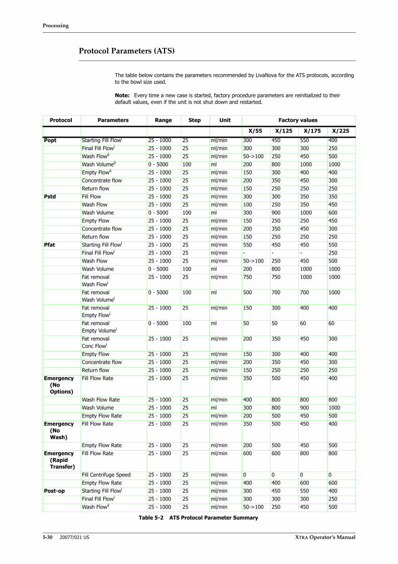
Processing
5-30 20077/021 US XTRA Operator’s Manual
Protocol Parameters (ATS)
The table below contains the parameters recommended by LivaNova for the ATS protocols, according to the bowl size used.
Note: Every time a new case is started, factory procedure parameters are reinitialized to their default values, even if the unit is not shut down and restarted.
Protocol Parameters Range Step Unit Factory values
X/55 X/125 X/175 X/225Popt Starting Fill Flowi 25 - 1000 25 ml/min 300 450 550 400
Final Fill Flowi 25 - 1000 25 ml/min 300 300 300 250Wash Flowii 25 - 1000 25 ml/min 50->100 250 450 500Wash Volumeii 0 - 5000 100 ml 200 800 1000 1000Empty Flowii 25 - 1000 25 ml/min 150 300 400 400Concentrate flow 25 - 1000 25 ml/min 200 350 450 300Return flow 25 - 1000 25 ml/min 150 250 250 250
Pstd Fill Flow 25 - 1000 25 ml/min 300 300 350 350Wash Flow 25 - 1000 25 ml/min 100 250 350 450Wash Volume 0 - 5000 100 ml 300 900 1000 600Empty Flow 25 - 1000 25 ml/min 150 250 250 450Concentrate flow 25 - 1000 25 ml/min 200 350 450 300Return flow 25 - 1000 25 ml/min 150 250 250 250
Pfat Starting Fill Flowi 25 - 1000 25 ml/min 550 450 450 550Final Fill Flowi 25 - 1000 25 ml/min - - - 250Wash Flow 25 - 1000 25 ml/min 50->100 250 450 500Wash Volume 0 - 5000 100 ml 200 800 1000 1000Fat removalWash Flowi
25 - 1000 25 ml/min 750 750 1000 1000
Fat removalWash Volumei
0 - 5000 100 ml 500 700 700 1000
Fat removalEmpty Flowi
25 - 1000 25 ml/min 150 300 400 400
Fat removalEmpty Volumei
0 - 5000 100 ml 50 50 60 60
Fat removalConc Flowi
25 - 1000 25 ml/min 200 350 450 300
Empty Flow 25 - 1000 25 ml/min 150 300 400 400Concentrate flow 25 - 1000 25 ml/min 200 350 450 300Return flow 25 - 1000 25 ml/min 150 250 250 250
Emergency (No Options)
Fill Flow Rate 25 - 1000 25 ml/min 350 500 450 400
Wash Flow Rate 25 - 1000 25 ml/min 400 800 800 800Wash Volume 25 - 1000 25 ml 300 800 900 1000Empty Flow Rate 25 - 1000 25 ml/min 200 500 450 500
Emergency (No Wash)
Fill Flow Rate 25 - 1000 25 ml/min 350 500 450 400
Empty Flow Rate 25 - 1000 25 ml/min 200 500 450 500Emergency
(Rapid Transfer)
Fill Flow Rate 25 - 1000 25 ml/min 600 600 800 800
Fill Centrifuge Speed 25 - 1000 25 ml/min 0 0 0 0Empty Flow Rate 25 - 1000 25 ml/min 400 400 600 600
Post-op Starting Fill Flowi 25 - 1000 25 ml/min 300 450 550 400Final Fill Flowi 25 - 1000 25 ml/min 300 300 300 250Wash Flowii 25 - 1000 25 ml/min 50->100 250 450 500
Table 5-2 ATS Protocol Parameter Summary

Processing
XTRA Operator’s Manual 20077/021 US 5-31
The Operating Modes
The XTRA system is equipped with three operating modes:
• Automatic
• 1 Touch
• Manual
Each is described in the sections below.
Modes of operation influence the execution of the active protocol, affecting the transition between phases and cycles.
The current operating mode can be set from the Protocol/Mode tab of the Menu Screen. The operating mode may be changed while the machine is stopped (at the Ready Screen), or any time during a cycle. Step-by-step instructions can be found in the section “Running a Case With the XTRA System” on page 5-5.
Automatic
In Automatic mode the system recognizes the end of each phase and automatically switches to the next phase without any intervention from the operator (Fill to Wash/Spill to Empty). By default, at the end of each cycle the system displays the Ready Screen and does not begin a new cycle automatically.
Automatic mode is compatible with all protocols and can be switched to at any time.
While Automatic mode is active, the word “Automatic” appears in the status area of every screen.
If an intraoperative or postoperative protocol is selected (Pstd, Popt, Post-op and Pfat), then either or both of the Continue and Autostart functions may be enabled in conjunction with Automatic mode. If both Continue and Autostart are enabled, then Automatic mode behaves exactly like 1 Touch mode.
1 Touch
The 1 Touch operating mode is a shortcut to running the Automatic mode with both the Autostart and Continue functions enabled. It is only available if processing with an intraoperative or postoperative protocol (Pstd, Popt, Pfat or Post-op).
In 1 Touch mode, each cycle is started automatically (Autostart function), the system recognizes the end of each phase and automatically switches to the next phase without operator intervention (Fill to Wash to Empty), and the system starts a subsequent cycle automatically as long as sufficient blood volume is available in the reservoir (Continue function).
While 1 Touch mode is active, “1 Touch” appears in the status area of every screen.
The 1 Touch mode will not be available if disabled in the current configuration (refer to Chapter 8: Configuring Xtra).
Although it is possible to disable the Autostart function when 1 Touch mode is selected, it is considered exceptional. On the contrary, it is not possible to disable the Continue function when 1 Touch mode is selected.
Wash Volumeii 0 - 5000 100 ml 200 800 1000 1000Empty Flowii 25 - 1000 25 ml/min 150 300 400 400Concentrate flow 25 - 1000 25 ml/min 200 350 450 300
i These parameters can not be modified by the user.ii These parameters can be modified by the user but in case of modifications a marker will appear telling factory protocol has been modified.
Protocol Parameters Range Step Unit Factory values
X/55 X/125 X/175 X/225
Table 5-2 ATS Protocol Parameter Summary (Continued)
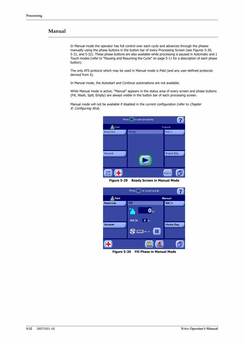
Processing
5-32 20077/021 US XTRA Operator’s Manual
Manual
In Manual mode the operator has full control over each cycle and advances through the phases manually using the phase buttons in the button bar of every Processing Screen (see Figures 5-30, 5-31, and 5-32). These phase buttons are also available while processing is paused in Automatic and 1 Touch modes (refer to “Pausing and Resuming the Cycle” on page 5-11 for a description of each phase button).
The only ATS protocol which may be used in Manual mode is Pstd (and any user-defined protocols derived from it).
In Manual mode, the Autostart and Continue automations are not available.
While Manual mode is active, “Manual” appears in the status area of every screen and phase buttons (Fill, Wash, Spill, Empty) are always visible in the button bar of each processing screen.
Manual mode will not be available if disabled in the current configuration (refer to Chapter 8: Configuring Xtra).
Figure 5-29 Ready Screen in Manual Mode
Figure 5-30 Fill Phase in Manual Mode
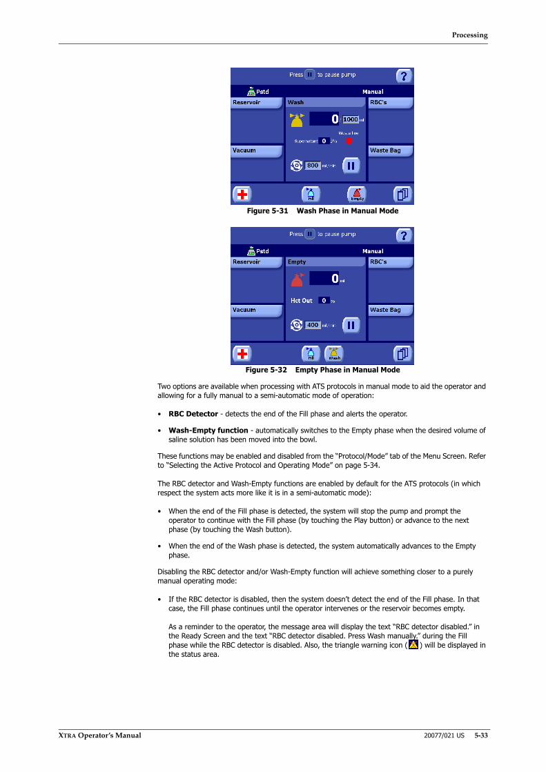
Processing
XTRA Operator’s Manual 20077/021 US 5-33
Figure 5-31 Wash Phase in Manual Mode
Figure 5-32 Empty Phase in Manual Mode
Two options are available when processing with ATS protocols in manual mode to aid the operator and allowing for a fully manual to a semi-automatic mode of operation:
• RBC Detector - detects the end of the Fill phase and alerts the operator.
• Wash-Empty function - automatically switches to the Empty phase when the desired volume of saline solution has been moved into the bowl.
These functions may be enabled and disabled from the “Protocol/Mode” tab of the Menu Screen. Refer to “Selecting the Active Protocol and Operating Mode” on page 5-34.
The RBC detector and Wash-Empty functions are enabled by default for the ATS protocols (in which respect the system acts more like it is in a semi-automatic mode):
• When the end of the Fill phase is detected, the system will stop the pump and prompt the operator to continue with the Fill phase (by touching the Play button) or advance to the next phase (by touching the Wash button).
• When the end of the Wash phase is detected, the system automatically advances to the Empty phase.
Disabling the RBC detector and/or Wash-Empty function will achieve something closer to a purely manual operating mode:
• If the RBC detector is disabled, then the system doesn’t detect the end of the Fill phase. In that case, the Fill phase continues until the operator intervenes or the reservoir becomes empty.
As a reminder to the operator, the message area will display the text “RBC detector disabled.” in the Ready Screen and the text “RBC detector disabled. Press Wash manually.” during the Fill phase while the RBC detector is disabled. Also, the triangle warning icon ( ) will be displayed in the status area.

Processing
5-34 20077/021 US XTRA Operator’s Manual
• If the Wash-Empty function is disabled, then the system doesn’t detect the end of the Wash phase. In that case, the Wash phase continues until the operator intervenes or an alarm/warning is triggered.
As a reminder to the operator, the message area will display the text “Wash/Empty disabled.” in the Ready Screen and the text “Wash/Empty disabled. Press Empty manually.” during the Wash phase while the Wash-Empty function is disabled. Also, the triangle warning icon ( ) will be displayed in the status area
Selecting the Active Protocol and Operating Mode
Each cycle of a case may be processed using a different protocol and operating mode. The protocol may be selected only after the pump segment is loaded and before the cycle is initiated. The operating mode may be changed at any time during processing. The protocol and mode are selected from the Protocol/Mode tab of the Menu Screen (see Figure 5-33).
For details about each protocol and operating mode, refer to “Factory Protocols” on page 5-22 and “The Operating Modes” on page 5-31, respectively.
Figure 5-33 Protocol/Mode Tab
For a detailed explanation of the Protocol/Tab screen, read “Protocol/Mode Tab” on page 5-46.
CAUTIONThe deactivation of the RBC Detector is at the full responsibility of the doctor/operator who must carefully supervise the fill phase (or concentration) andmanually touch the Wash button to start the washing phase (or Spill or Emptyto start the phase of the same name during a sequestration protocol). Adelayed procedure might lead to a loss of red blood cells or, in sequestrationprocedures to inadequate collections. An early procedure might lead to lowquality collection.
CAUTIONInadequate washing of the packed red blood cells may lead to an excessivelevel of contaminants (e.g., anticoagulant, plasma free hemoglobin) in theprocessed blood.
2
1 Mode menu2 Protocol menu
1
Processing
XTRA Operator’s Manual 20077/021 US 5-35
Set the Active Protocol
By default, when the XTRA is powered on, the active protocol is the protocol which has been designated as the wakeup protocol. To change the wakeup protocol, refer to “Changing the Wakeup Protocol” on page 9-6.
If you want to use a protocol for the next cycle that is different from the currently active protocol, do the following:
1. Touch the Menu button from the Ready Screen to enter the Menu Screen.
2. From the left side of the Menu Screen, touch the Protocol/Mode tab.
3. Using the protocol drop-down menu at the top of the Protocol/Mode tab, select the desired protocol:
a. Touch the triangle menu button located on the right side of the protocol drop-down menu. A list of available protocols will be displayed.
b. Touch the name of the desired protocol to close the menu and set it as the active protocol. (Touching the triangle menu button a second time without selecting a protocol from the list will close the Protocol menu without changing the active protocol.)
4. Touch the Save Modifications button to make all changes in the Protocol/Mode tab take effect. If the screen is exited by touching the Close button, or is interrupted by a warning or alarm, then the modifications are not saved.
Set the Active Operating Mode
Do the following to set the active operating mode:
1. Touch the Menu button from the Ready Screen or any Processing Screen to enter the Menu Screen.
2. From the left side of the Menu Screen, touch the Protocol/Mode tab.
3. Using the mode drop-down menu at the top right of the Protocol/Mode tab, select the desired operating mode:
a. Touch the triangle menu button located on the right side of the Mode menu. A list of available modes for the selected protocol will be displayed.
b. Touch the name of the desired mode to close the menu and set it as the active operating mode. (Touching the triangle menu button a second time without selecting a mode from the list will close the Mode menu without changing the active mode.)
4. Optionally, enable or disable any automations desired for the selected mode using the controls in the area immediately below the mode drop-down menu. Refer to Chapter 7: Automated Functions for a full description of each.
Touching the button for the Autostart and Continue automations will toggle its state. When the automation is ON (active), its button will appear inset and green; when the automation is OFF, its button will return to the normal raised
appearance. When the Autostart and/or Continue automations are enabled, its icon will appear in the status area of every screen.
When Manual mode is selected, the RBC detector and Wash-Empty automation may be enabled or disabled by touching the appropriate check box. When the box is checked, the detector/automation is ON.
5. Touch the Save Modifications button to make all changes in the Protocol/Mode tab take effect. If the screen is exited by touching the Close button, or is interrupted by a warning or alarm, then the modifications are not saved.

Processing
5-36 20077/021 US XTRA Operator’s Manual
Touch Screen User Interface
The following section offers a detailed description of the user interface. The figures in this section are based on typical screens encountered during normal use in Automatic or 1 Touch modes. The actual presence, visibility, and content of the displets and button bar depend on the configuration of the XTRA system.
Buttons and other interface elements which appear in multiple screens with the same function are only labeled and described under the first screen in which they appear in this section.
Alarms Disabled Confirmation Screen
If no errors are detected during the power-up self-test, the operator will be prompted to check and confirm any disabled warnings or changes to default acoustic signals (see Figure 5-34).
If all warnings are enabled and no changes to the acoustic signals exist, then the Alarms Disabled Confirmation Screen is not displayed and operation continues directly to the Setup Screen (see “Setup Screen” on page 5-37).
Figure 5-34 Example Alarms Disabled Confirmation Screen
Touching the Play button on the Alarms Disabled Confirmation Screen will accept the status of the disabled alarms, warnings, and acoustic signals, and will display the Setup Screen (see “Setup Screen” on page 5-37).
To change the status of alarms and warnings, use the “Warnings” tab of the Configuration Mode Screen (refer to “Warnings Tab” on page 8-8).

Processing
XTRA Operator’s Manual 20077/021 US 5-37
Setup Screen
After powering on and confirming any disabled warnings or alarms (see “Turning On the XTRA System” on page 5-5), the operator is presented with the setup screen (see Figure 5-35).
Figure 5-35 Setup Screen
1. “Retain” ButtonThe “Retain” button allows the operator to proceed with a case previously interrupted by switching OFF the machine without unloading the pump loop (refer to “Retaining Case Data Between Power Cycles” on page 5-16). Touching the “Retain” button will initiate the
auto-load process much like touching the Load button. The pump and bowl will spin during testing/loading. Each step of the load process is tracked visually by the processing displet. Once loaded, the Ready Screen is displayed (refer to “Ready Screen” on page 5-38).
2. Load DiagramThe processing displet of the Setup screen contains a top-view diagram of the XTRA system. A green circle highlights the component in the diagram being tested and loaded during each step of the auto-load process.
3. Help ButtonTouching the help button from any screen will toggle the display of a context-sensitive Help Screen. Refer to the section “Help Screen” on page 5-51.
4. Load ButtonTouching the load button will initiate the auto-load process which tests that the disposable is installed correctly (as described in Chapter 4: Installing the Disposables) and loads the pump-loop tubing. The pump and bowl will spin during testing/loading. Each step of the load
process is tracked visually by the processing displet. Once loaded, the Ready Screen is displayed (refer to “Ready Screen” on page 5-38). If an error is detected during the loading/testing sequence, a warning message will be displayed (refer to “Alarms and Warnings During Setup” on page 14-3).
CAUTIONWhen Retaining Case Data Between Power Cycles, do not change thedisposable and/or its positioning to avoid potential errors during theauto-load process.
2
3
4
1 5
1 “Retain” button 3 Help button2 Load diagram 4 Load button
5 Menu button

Processing
5-38 20077/021 US XTRA Operator’s Manual
5. Menu ButtonTouching the menu button will bring up the Menu Screen. Various XTRA settings can be adjusted from the Menu Screen. Touching the close button in the Menu Screen will close the Menu Screen and display the previously displayed screen. Refer to the section “Menu Screen”
on page 5-44.
Ready Screen
Once the XTRA has completely loaded, the Ready Screen is displayed on the touch screen display. The Ready Screen is used to begin each processing cycle (see Figure 5-36).
Figure 5-36 Ready Screen
1. Start ButtonTouching the Start button begins a processing cycle and displays the Processing Screen (refer to “Processing Screen” on page 5-39). In case a cycle is interrupted by pressing the Stop button, touching the Start button resumes processing from the state the processing phase was in when it was stopped.
2. “Special” ButtonTouching the “Special” button displays the Special Cycles Menu (refer to “The Special Cycles Screen” on page 6-1).
3. Menu ButtonTouching the menu button will bring up the Menu Screen. Various XTRA settings can be adjusted from the Menu Screen. Touching the close button in the Menu Screen will close the Menu Screen and display the previously displayed screen. Refer to the section “Menu Screen”
on page 5-44.
4. Processed VolumeIf a cycle has already been run in the current case, the processing displet of the Ready Screen contains a multi-bowl icon and a text field which displays the total volume of fluid processed in the case so far (ml).
5
6
4 Processed volume 1 Start button5 Emergency button 2 “Special” button6 “End Case” button 3 Menu button
4
1
23

Processing
XTRA Operator’s Manual 20077/021 US 5-39
5. Emergency ButtonTouching the Emergency button, and then confirming in the subsequent confirmation screen, initiates the Emergency function (refer to “Emergency” on page 5-26).
While the Emergency function is active, this button appears in its pressed state (inset and green). Touching it again will disable the Emergency function, re-enabling the previous protocol (confirmation not required).
The Emergency button is only available during intraoperative and postoperative protocols.
6. “End Case” ButtonTouching the “End Case” button displays the End of Case Screen and allows the operator to end the current case (refer to “End of Case Screen” on page 5-50).
Processing Screen
Once a processing cycle has been initiated from the Ready Screen, the Processing Screen is displayed on the touch screen display.
From the Processing Screen, each phase of each cycle may be monitored and controlled. The processing displet (in the center of the screen) changes during processing to present controls and information relevant to the current phase. The title bar of the processing displet always indicates the current phase. In this section, the Processing Screen is described as four different screens, one for each phase: Fill, Wash, Empty and Fat Removal (only present if Pfat protocol is being used).
Fill Screen
Figure 5-37 Fill Phase of the Processing Screen
1. Pump SpeedThe pump speed (ml/min.) is displayed in a text box in the processing displet to the right of the pump rotor icon. Except during the Fill phase of the Popt, Pfat and Post-op protocols, the pump speed may be adjusted by touching the text box and using the up and down arrow buttons
(refer to “Modification of Parameters” on page 5-5).
2. Fill Status LineThe fill status line indicates the current phase with the fill icon. To the right of the icon is a text field which displays the amount of fluid which has been pumped into the bowl (ml) during the current cycle.
1 Pump speed 2 Fill Status line3 Play/Pause button
1
2
3

Processing
5-40 20077/021 US XTRA Operator’s Manual
“Hct In” FieldThe “Hct In” field located in the processing displet displays the current hematocrit (%) of the blood entering the bowl. The “Hct In” field is not present while processing with PPP/PRP sequestration protocols. The “Hct In” field is never present if the Hct indicator has been disabled.
3. Play/Pause buttonTouching the Pause button pauses the processing cycle: the pump is stopped, the Pause button changes to the Play button, and the word “Paused” flashes and a 5:00 minute countdown timer appears in the title bar of the processing displet. The
centrifuge will continue to spin for five minutes.
If Automatic mode is active, phase buttons appear in the button bar of the processing screen while the cycle is paused, as listed in Table 5-1, “Buttons Which Become Available While Paused Per Processing Condition,” on page 14. This allows for manual intervention in the phase progression. (If Manual mode is active, these phase buttons are always visible.)
Touching the Play button resumes processing from the state the phase was in when it was paused.
Pausing and resuming a cycle is discussed further in “Pausing and Resuming the Cycle” on page 5-11.
Wash Screen
The Wash Screen only appears during the Wash phase of intra- and postoperative protocols (Pstd, Popt, Post-op).
Figure 5-38 Wash Phase of the Processing Screen
1. Wash Quality LineThe wash quality line consists of two fields, from left to right: a text field which displays the current percentage of plasma contaminants which have been removed from the blood, and a colored dot (red, orange, or green) indicating the current waste line color (red indicating an opaque color; green indicating a transparent color). The wash quality line is only present if at least the supernatant removal indicator is enabled.
2. Wash Status lineThe Wash Status line consists of three elements, from left to right: the wash icon indicating the current phase, a large text field which displays the current volume of saline solution which has been pumped into the bowl, and a smaller text box which displays the total volume of
saline solution to pump. Unless operating in Manual Mode with the Wash-Empty function disabled, the total volume of saline solution to pump into the bowl can be set by touching the text box and using the up and down arrow buttons.
2
1
1 Wash quality l ine2 Wash Status l ine

Processing
XTRA Operator’s Manual 20077/021 US 5-41
Empty Screen
Figure 5-39 Empty Phase of the Processing Screen
1. Empty Status LineThe empty status line indicates the current phase with the empty icon. To the right of the icon is a text field which displays the volume of fluid which has been emptied from the bowl (ml) into the RBC bag during the current cycle.
“Hct Out” FieldThe “Hct Out” field located in the processing displet displays the current hematocrit (%) of the blood exiting the bowl. The “Hct Out” field is not present while processing with PPP/PRP sequestration protocols or if the Hct indicator has been disabled.
Fat Removal Screens
The Fat Removal screens are displayed during the Fat Removal phase which is active only if a Pfat protocol or derived is being used.
The screens display the information related to the three subphases of the Fat Removal: the Fat Removal - Wash, Fat Removal - Empty and Fat Removal - Conc.
1 Empty Status line
1
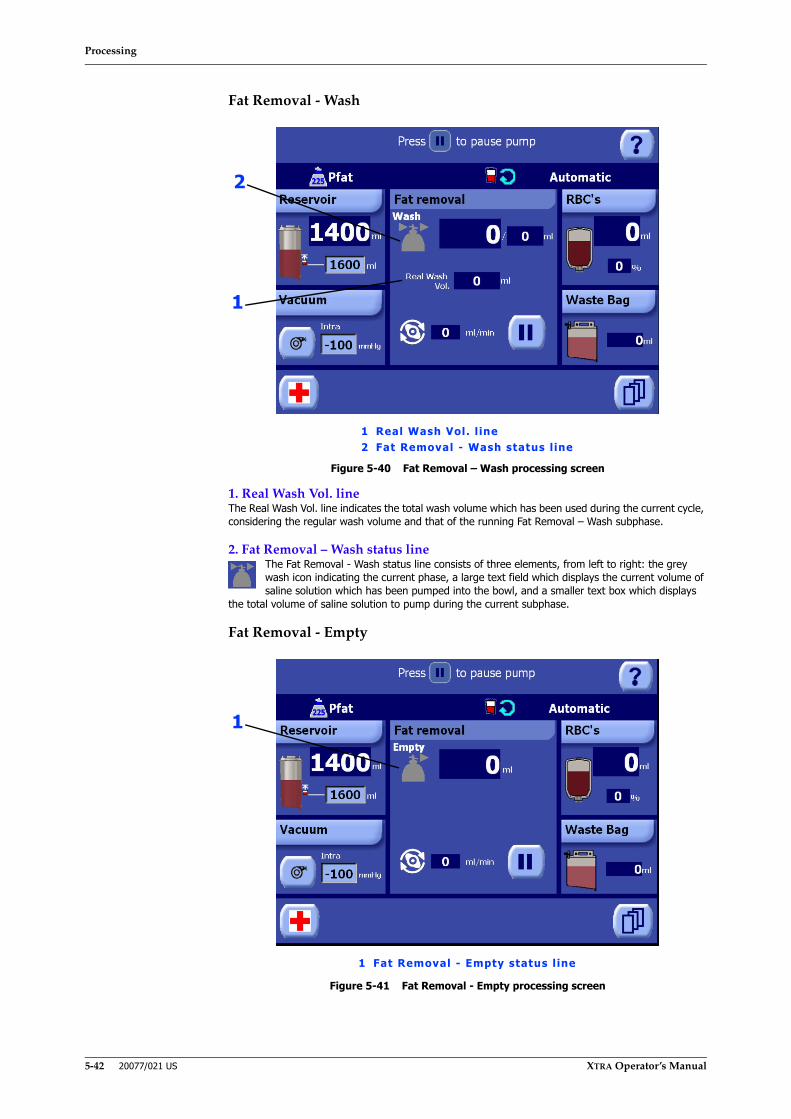
Processing
5-42 20077/021 US XTRA Operator’s Manual
Fat Removal - Wash
Figure 5-40 Fat Removal – Wash processing screen
1. Real Wash Vol. lineThe Real Wash Vol. line indicates the total wash volume which has been used during the current cycle, considering the regular wash volume and that of the running Fat Removal – Wash subphase.
2. Fat Removal – Wash status lineThe Fat Removal - Wash status line consists of three elements, from left to right: the grey wash icon indicating the current phase, a large text field which displays the current volume of saline solution which has been pumped into the bowl, and a smaller text box which displays
the total volume of saline solution to pump during the current subphase.
Fat Removal - Empty
Figure 5-41 Fat Removal - Empty processing screen
1 Real Wash Vol. l ine2 Fat Removal - Wash status l ine
2
1
1 Fat Removal - Empty status l ine
1
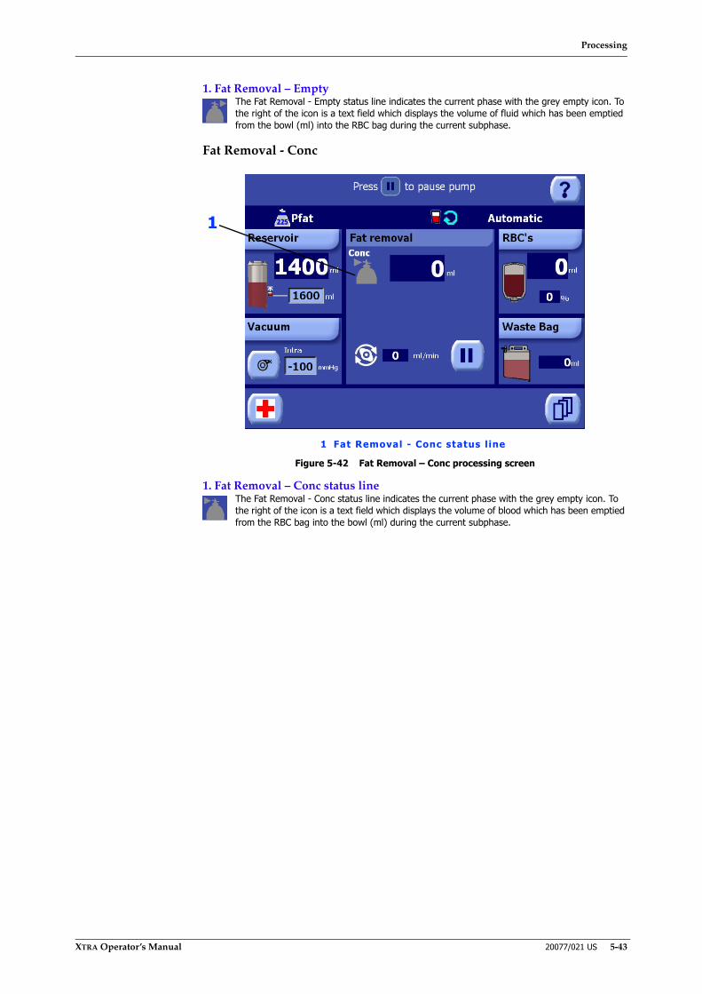
Processing
XTRA Operator’s Manual 20077/021 US 5-43
1. Fat Removal – EmptyThe Fat Removal - Empty status line indicates the current phase with the grey empty icon. To the right of the icon is a text field which displays the volume of fluid which has been emptied from the bowl (ml) into the RBC bag during the current subphase.
Fat Removal - Conc
Figure 5-42 Fat Removal – Conc processing screen
1. Fat Removal – Conc status lineThe Fat Removal - Conc status line indicates the current phase with the grey empty icon. To the right of the icon is a text field which displays the volume of blood which has been emptied from the RBC bag into the bowl (ml) during the current subphase.
1 Fat Removal - Conc status line
1
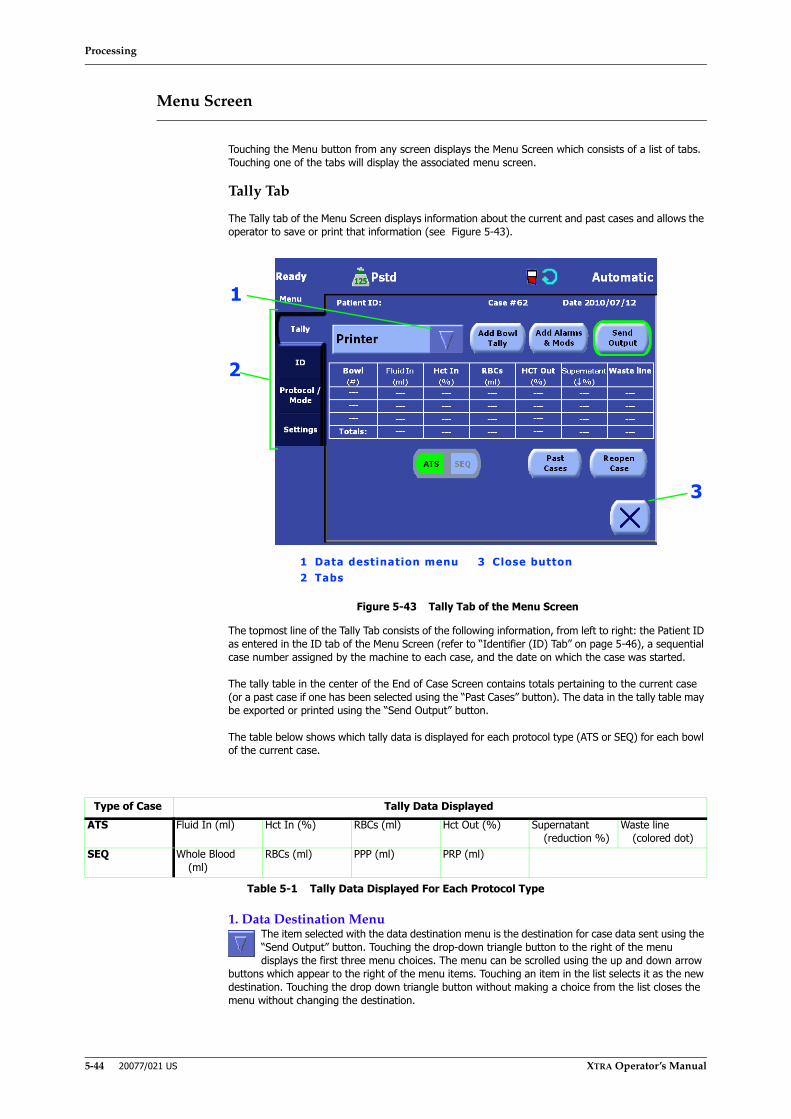
Processing
5-44 20077/021 US XTRA Operator’s Manual
Menu Screen
Touching the Menu button from any screen displays the Menu Screen which consists of a list of tabs. Touching one of the tabs will display the associated menu screen.
Tally Tab
The Tally tab of the Menu Screen displays information about the current and past cases and allows the operator to save or print that information (see Figure 5-43).
Figure 5-43 Tally Tab of the Menu Screen
The topmost line of the Tally Tab consists of the following information, from left to right: the Patient ID as entered in the ID tab of the Menu Screen (refer to “Identifier (ID) Tab” on page 5-46), a sequential case number assigned by the machine to each case, and the date on which the case was started.
The tally table in the center of the End of Case Screen contains totals pertaining to the current case (or a past case if one has been selected using the “Past Cases” button). The data in the tally table may be exported or printed using the “Send Output” button.
The table below shows which tally data is displayed for each protocol type (ATS or SEQ) for each bowl of the current case.
1. Data Destination MenuThe item selected with the data destination menu is the destination for case data sent using the “Send Output” button. Touching the drop-down triangle button to the right of the menu displays the first three menu choices. The menu can be scrolled using the up and down arrow
buttons which appear to the right of the menu items. Touching an item in the list selects it as the new destination. Touching the drop down triangle button without making a choice from the list closes the menu without changing the destination.
Type of Case Tally Data DisplayedATS Fluid In (ml) Hct In (%) RBCs (ml) Hct Out (%) Supernatant
(reduction %)Waste line
(colored dot)SEQ Whole Blood
(ml)RBCs (ml) PPP (ml) PRP (ml)
Table 5-1 Tally Data Displayed For Each Protocol Type
2
3
1
1 Data destination menu 3 Close button2 Tabs
Processing
XTRA Operator’s Manual 20077/021 US 5-45
“Send Output” ButtonTouching the “Send Output” button sends case data to the destination selected with the data destination menu.
If the printer is selected, this button prints general information about the case. To add additional information to the printout, use the following two buttons:
“Add Bowl Tally” ButtonTouch the “Add Bowl Tally” button to enable the inclusion of bowl tally data in printed reports. When enabled, the button will appear inset and green. Touch the button a second time to disable the inclusion of bowl tally data. Refer to “Bowl tally” on page 11-11 for a
list of information included in reports when the “Add Bowl Tally” button is enabled. This button is only enabled if “Printer” is selected from the drop-down destination menu.
“Add Alarms & Mods” ButtonTouch the “Add Alarms & Mods” button to enable the inclusion of event data (such as alarms and modification of parameters which occurred during the case) in printed reports. When enabled, the button will appear inset and green. Touch the button a
second time to disable the inclusion of event data. Refer to “Bowl tally” on page 11-11 for a list of information included in reports when the “Add Alarms & Mods” button is enabled. This button is only enabled if “Printer” is selected from the drop-down destination menu.
“ATS | SEQ” Selector ButtonThe “ATS | SEQ” Selector button is used to switch between viewing the data tallies for ATS processing cycles and for whole-blood sequestration (PPP/PRP) processing cycles. If only one type of cycle has been performed for the case being displayed, the “ATS |
SEQ” Selector button is disabled.
“Past Cases” ButtonTouching the “Past Cases” button displays the Past Cases Screen (refer to “Past Cases Screen” on page 5-52). This button is only available when processing is stopped, or from the Setup Screen before a case has been started.
“Reopen Case” ButtonWhen viewing a previously concluded case while processing is stopped, the “Reopen Case” Button will be enabled. Touching the button will reopen the case for further processing, appending tally data to the current case. Refer to “Selecting Past Cases” on
page 11-4.
Close buttonTouching the Close button from any tab will close the Menu Screen and return to the active Processing or Ready Screen.
Refer to Chapter 11: Data Download Option for complete instructions on exporting and printing the data of current and past cases.

Processing
5-46 20077/021 US XTRA Operator’s Manual
Identifier (ID) Tab
The ID tab is used to enter information (such as the patient ID) pertaining to the current case (see Figure 5-44).
Figure 5-44 ID Tab of the Menu Screen
1. ID Fields ListThe ID tab contains labeled ID fields which are stored along with the rest of the case data.
Field values may be edited in two ways:
• by touching the field value box, or
• by using the field’s drop-down rapid selection menu if enabled.
Touching the field’s value box will display a full QWERTY keyboard which may be used to input numbers, letters, and symbols. The drop-down rapid selection menu will only be available if that field has a list of pre-entered values associated with it in the ID Tab of the Configuration Mode Screen.
To create, modify, and delete fields, and to configure the list of values available via the drop-down rapid selection menu for a field, refer to “Setting the Rapid Selection of ID” on page 8-10.
2. Page Arrow ButtonsIf the number of ID fields is greater than that which can be displayed on the screen at once, use the left and right arrow buttons to scroll through the additional pages of fields.
Protocol/Mode Tab
When accessed from the Ready Screen, after the pump loop has been loaded, The Protocol/Mode tab allows for the selection, modification, and creation of protocols as well as the selection of the operating mode (see Figure 5-45).
When accessed from the Setup Screen (before the pump has been loaded), it is labeled simply the Protocol tab. In that case it allows for the viewing of protocol parameters for all protocols and bowl sizes.
2
1 ID Fields List 2 Left and Right Page Buttons
1

Processing
XTRA Operator’s Manual 20077/021 US 5-47
Figure 5-45 Protocol/Mode Tab of the Menu Screen
The Protocol/Mode tab is divided into two areas: the protocol area on the left which contains the protocol selection menu, parameters and automations related to the selected protocol, and the mode area on the right which usually contains the operating mode selection menu and automations related to the selected mode.
1. Protocol AreaThe protocol area contains the controls used to select and modify the active processing protocol. At the top is the protocol drop-down menu, which is used to select the active protocol. Below that appear parameters and controls specific to the selected protocol. If the User Protocols option is enabled, buttons which can be used to create, rename, and delete custom protocols, as well as designate the wakeup protocol are displayed at the bottom of the screen. Modifying the parameters of protocols and managing custom protocols are described in Chapter 9: Programmability Option, specifically “The Protocol/Mode Tab” on page 9-7.
The active protocol cannot be changed during a processing cycle.
2. Mode AreaWhen the Protocol/Mode tab is entered after the pump has been loaded, the mode area contains the drop-down operating mode selection menu used to select the active operating mode.
Controls for any automated functions (such as Autostart, Continue, RBC Detector, and the Wash-Empty functions) which are available for the selected mode will appear directly beneath the drop-down Mode menu. For details on each automation, refer to Chapter 7: Automated Functions.
Touching the button for the Autostart and Continue automations will toggle its state. When the automation is on, its button will appear inset and green; when the automation is OFF, its button will return to the normal raised appearance. When the Autostart and/
or Continue automations are enabled, its icon will appear in the status area of every screen.
When Manual mode is selected, the RBC detector and Wash-Empty automation may be enabled or disabled by touching the appropriate check box. When the box is checked, the detector/automation is ON.
When the Protocol/Mode tab is entered from the Setup Screen (before the pump has been loaded), the mode area contains a single “Bowl” button. Each time the button is touched, it toggles the bowl size for the processing case (55 ml, 125 ml, 175 ml, or 225 ml). This
allows the operator to:
• view the protocols available for each bowl size (also factory protocols)
• create new user protocols and set their parameters for each bowl size.
• to change the wake up protocol for each bowl size.
12
1 Protocol area 2 Mode area3 Save Modifications button
3

Processing
5-48 20077/021 US XTRA Operator’s Manual
3. Save Modifications buttonThe Save Modifications button appears to the left of the Close button as soon as any modifications are made to the current protocol or operating mode. Touching the Modifications Button applies all modifications and closes the Menu Screen.
4. Close buttonTouching the Close button will close the “Protocol/Mode” tab without saving or applying any modifications made to the operating protocol or mode.
Settings Tab
The Settings tab of the Menu Screen is used to view and modify the current configuration of the XTRA system (see Figure 5-46).
The settings of the current configuration may be viewed at any time (by touching the “View” button); however, settings may only be modified if the Menu Screen was accessed from the Setup Screen (no changes to the configuration settings may be made after the XTRA system has been loaded). The majority of settings can be modified only by accessing the password protected area; a few changes are not password protected to allow eventual modifications for the current case, before loading the pump. All changes made from the Settings tab take effect immediately. The “Anticoagulant”, “ReservoirType”, and “Vacuum” settings affect only the current case.
Figure 5-46 Settings Tab of the Menu Screen
“View” ButtonTouching the “View” button allows the operator to view all of the settings in the current configuration, but does not allow them to be modified. Use the “Configuration Mode” button to modify the configuration settings.
AnticoagulantThe “Anticoagulant” setting may be used to toggle the anticoagulant type between “Heparin” and “ACD”. The currently selected setting appears inset and green.
The set anticoagulant type is used by the software’s hematocrit signal conversion algorithms. Changing the anticoagulant type here will affect the hematocrit values determined by the system during processing.
Reservoir TypeThe “ReservoirType” setting may be used to toggle the reservoir type between “XTRA” and “none”. The currently selected setting appears inset and green.
When “ReservoirType” is set to “XTRA”, the system software will take into consideration the characteristics of the standard XTRA reservoir in order to manage the functions related to it (such as the Autostart function and the “Reservoir Full” alarm). This is the preferred setting when using the standard XTRA reservoir.

Processing
XTRA Operator’s Manual 20077/021 US 5-49
When “ReservoirType” is set to “none”, all functionality related to the reservoir will not be available from the user interface: the reservoir displet, the Autostart function, the “Reservoir full: on-board vacuum pump disabled alarm” and the “Weight not reliable. Autostart temporarily disabled.” warning.
VacuumThe “Vacuum” setting may be used to toggle the vacuum operating mode between “Intra” and “Post-op” modes. The currently selected setting appears inset and green, and is also displayed in the vacuum displet. For a description of the vacuum operating modes refer to “Operating Modes” on page 13-2.
In case the operator attempts to change the current vacuum operating mode when the vacuum pump is running, the vacuum pump will be automatically stopped by the system before the mode change is effected. All applied modifications have an immediate effect (no need for confirmation).
When the system starts up, before the protocol that will be executed is determined, the vacuum will be put into the mode in which it is most likely needed: one corresponding to the wake up protocol (or the last used protocol if no wake up protocol exists) if the previous treatment has been concluded (the case was ended), or the last used mode in the case of a previous unconcluded treatment.
Having the vacuum mode setting available from the Settings tab before processing begins allows the operator to make a change in case it is started up in an undesired mode.
“RBC bag full” Warning Counter - Reset to ZeroThe “RBC bag full” alarm is triggered by a counter that calculates when the RBC volume pumped into the bag reach the safety level. By touching RESET TO ZERO it will be possible to reset the counter, preventing a false “RBC bag full” alarm due to the
premature reinfusion of the blood to the patient. A screen is displayed prompting the operator to confirm the resetting of the counter.
Figure 5-47 Reset Confirmation Screen
“Configuration Mode” ButtonTouching the “Configuration Mode” button enters configuration mode (after prompting for a password). Read Chapter 8: Configuring Xtra to learn how to change the configuration settings in configuration mode.
Adjust Date and TimeTouching the “Adjust date and time” button causes it to be replaced by six modifiable text boxes containing the currently set year, month, day, hour, minute, and second. Each text box may be modified by touching it and using the up and down arrow buttons. No time zone or daylight savings settings are stored by the XTRA system.
The date and time settings are used by the system for reports generated by the system and for diagnostic purposes. The user has to take into consideration the local time zone and daylight savings state, and consequently must update time when needed.
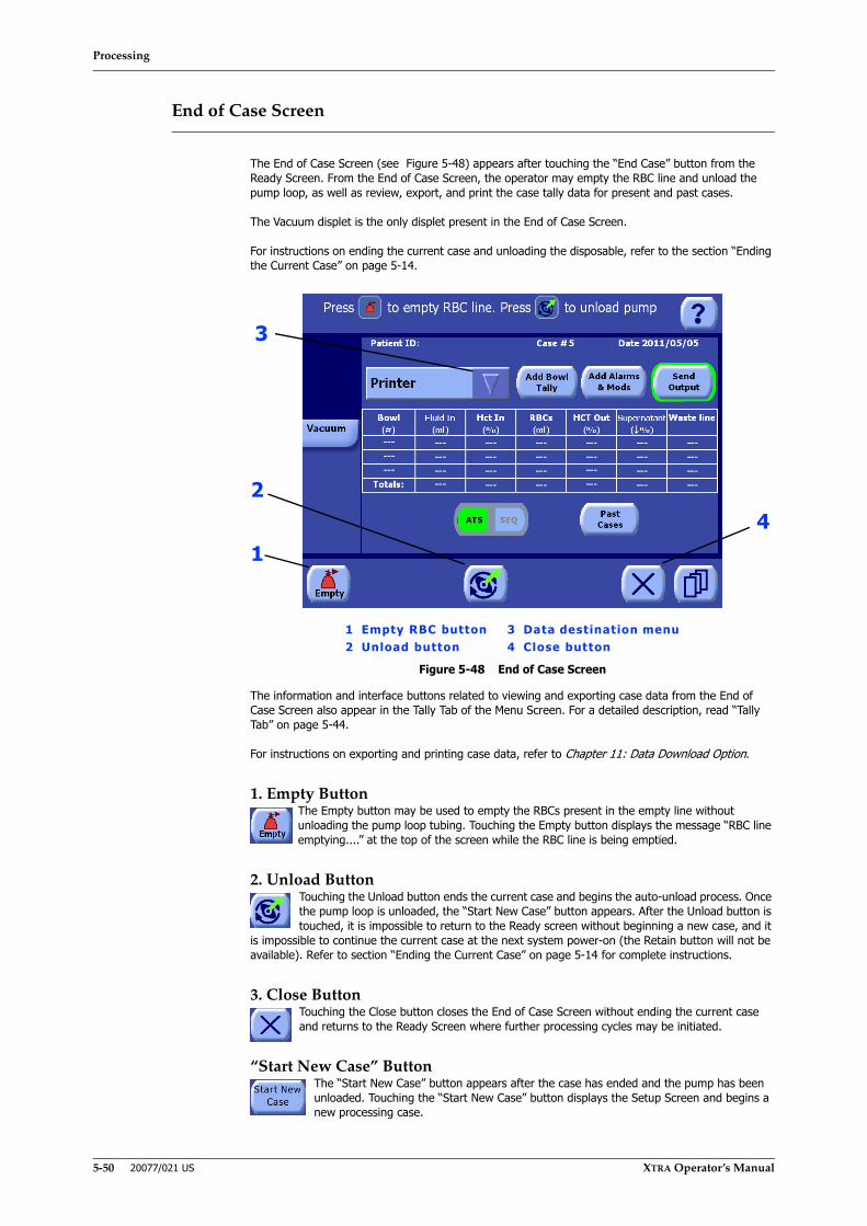
Processing
5-50 20077/021 US XTRA Operator’s Manual
End of Case Screen
The End of Case Screen (see Figure 5-48) appears after touching the “End Case” button from the Ready Screen. From the End of Case Screen, the operator may empty the RBC line and unload the pump loop, as well as review, export, and print the case tally data for present and past cases.
The Vacuum displet is the only displet present in the End of Case Screen.
For instructions on ending the current case and unloading the disposable, refer to the section “Ending the Current Case” on page 5-14.
Figure 5-48 End of Case Screen
The information and interface buttons related to viewing and exporting case data from the End of Case Screen also appear in the Tally Tab of the Menu Screen. For a detailed description, read “Tally Tab” on page 5-44.
For instructions on exporting and printing case data, refer to Chapter 11: Data Download Option.
1. Empty ButtonThe Empty button may be used to empty the RBCs present in the empty line without unloading the pump loop tubing. Touching the Empty button displays the message “RBC line emptying....” at the top of the screen while the RBC line is being emptied.
2. Unload ButtonTouching the Unload button ends the current case and begins the auto-unload process. Once the pump loop is unloaded, the “Start New Case” button appears. After the Unload button is touched, it is impossible to return to the Ready screen without beginning a new case, and it
is impossible to continue the current case at the next system power-on (the Retain button will not be available). Refer to section “Ending the Current Case” on page 5-14 for complete instructions.
3. Close ButtonTouching the Close button closes the End of Case Screen without ending the current case and returns to the Ready Screen where further processing cycles may be initiated.
“Start New Case” ButtonThe “Start New Case” button appears after the case has ended and the pump has been unloaded. Touching the “Start New Case” button displays the Setup Screen and begins a new processing case.
1
3
1 Empty RBC button 3 Data destination menu2 Unload button 4 Close button
24

Processing
XTRA Operator’s Manual 20077/021 US 5-51
Help Screen
The Help Screen is displayed by touching the Help button from any other screen. The first page will display all the modifications applied to the Warning settings and also warnings and features disabled run-time.
Figure 5-49 Help Screen
The second page contains the software version and serial number are displayed at the bottom of the Help Screen. The rest of the screen contains context-sensitive help for the screen from which it was invoked.
To close the Help Screen and return to the previously displayed screen, touch the Help button a second time.
Left and Right Page Buttons
Touching left and right arrow buttons at the bottom of the Help screen will flip through the available help pages. For example, the Help screen as entered from any processing page will contain three pages: one which labels the main buttons encountered while operating the system, and two pages describing all displets and icons.
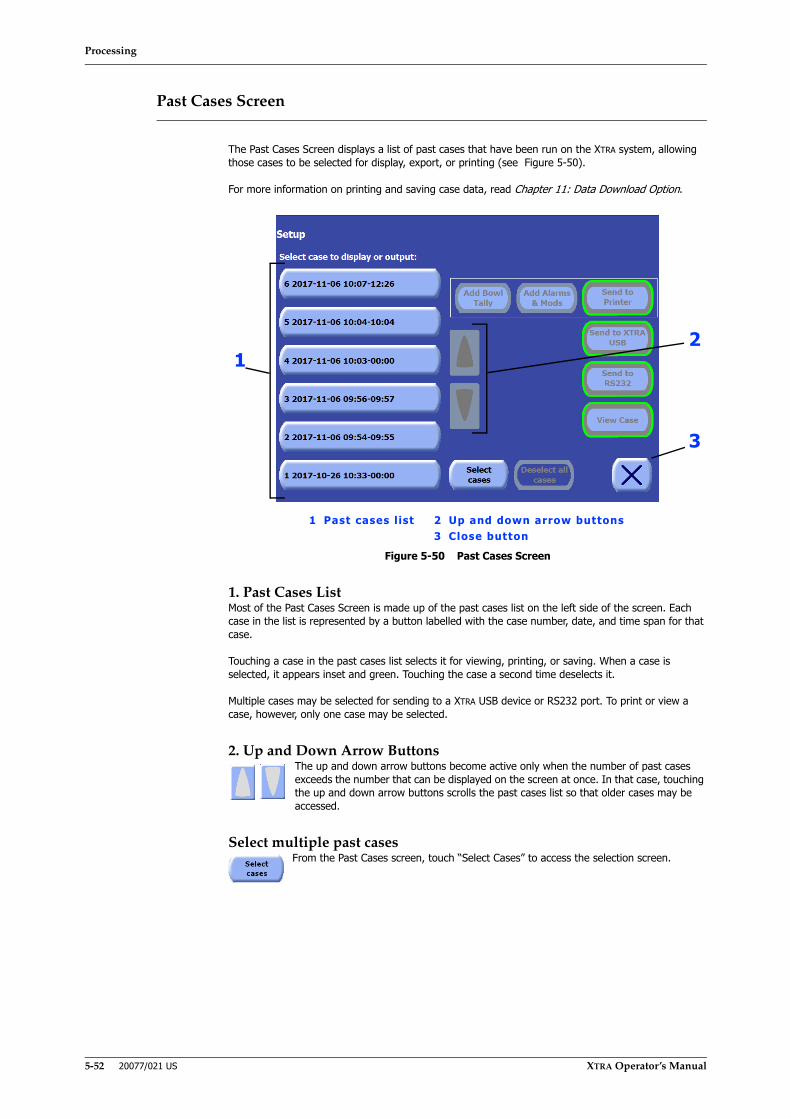
Processing
5-52 20077/021 US XTRA Operator’s Manual
Past Cases Screen
The Past Cases Screen displays a list of past cases that have been run on the XTRA system, allowing those cases to be selected for display, export, or printing (see Figure 5-50).
For more information on printing and saving case data, read Chapter 11: Data Download Option.
Figure 5-50 Past Cases Screen
1. Past Cases ListMost of the Past Cases Screen is made up of the past cases list on the left side of the screen. Each case in the list is represented by a button labelled with the case number, date, and time span for that case.
Touching a case in the past cases list selects it for viewing, printing, or saving. When a case is selected, it appears inset and green. Touching the case a second time deselects it.
Multiple cases may be selected for sending to a XTRA USB device or RS232 port. To print or view a case, however, only one case may be selected.
2. Up and Down Arrow ButtonsThe up and down arrow buttons become active only when the number of past cases exceeds the number that can be displayed on the screen at once. In that case, touching the up and down arrow buttons scrolls the past cases list so that older cases may be accessed.
Select multiple past casesFrom the Past Cases screen, touch “Select Cases” to access the selection screen.
3
1 Past cases l ist 2 Up and down arrow buttons3 Close button
21
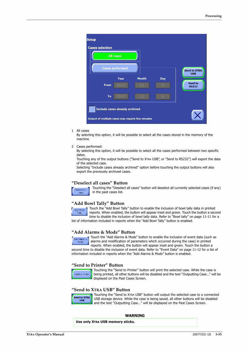
Processing
XTRA Operator’s Manual 20077/021 US 5-53
1 All casesBy selecting this option, it will be possible to select all the cases stored in the memory of the machine.
2 Cases performed:By selecting this option, it will be possible to select all the cases performed between two specific dates. Touching any of the output buttons (“Send to XTRA USB”, or “Send to RS232”) will export the data of the selected case. Selecting “Include cases already archived” option before touching the output buttons will also export the previously archived cases.
“Deselect all cases” ButtonTouching the “Deselect all cases” button will deselect all currently selected cases (if any) in the past cases list.
“Add Bowl Tally” ButtonTouch the “Add Bowl Tally” button to enable the inclusion of bowl tally data in printed reports. When enabled, the button will appear inset and green. Touch the button a second time to disable the inclusion of bowl tally data. Refer to “Bowl tally” on page 11-11 for a
list of information included in reports when the “Add Bowl Tally” button is enabled.
“Add Alarms & Mods” ButtonTouch the “Add Alarms & Mods” button to enable the inclusion of event data (such as alarms and modification of parameters which occurred during the case) in printed reports. When enabled, the button will appear inset and green. Touch the button a
second time to disable the inclusion of event data. Refer to “Event Data” on page 11-12 for a list of information included in reports when the “Add Alarms & Mods” button is enabled.
“Send to Printer” ButtonTouching the “Send to Printer” button will print the selected case. While the case is being printed, all other buttons will be disabled and the text “Outputting Case...” will be displayed on the Past Cases Screen.
“Send to XTRA USB” ButtonTouching the “Send to XTRA USB” button will output the selected case to a connected USB storage device. While the case is being saved, all other buttons will be disabled and the text “Outputting Case...” will be displayed on the Past Cases Screen.
WARNINGUse only XTRA USB memory sticks.
Processing
5-54 20077/021 US XTRA Operator’s Manual
“Send to RS232” ButtonTouching the “Send to RS232” button will output the selected case to the RS232 port. While the case is being transferred, all other buttons will be disabled and the text “Outputting Case...” will be displayed on the Past Cases Screen.
“View Case” ButtonTouching the “View Case” button will display the Tally tab of the Menu screen, with the tally table populated with data from the selected case. Refer to “Tally Tab” on page 5-44.
3. Close ButtonTouching the Close button closes the Past Cases Screen and returns to the previously displayed screen.

Processing
XTRA Operator’s Manual 20077/021 US 5-55
Automatic Reseparation Screen
Whenever a phase is interrupted by the operator (by use of the Stop or Pause buttons) or by an alarm, it is possible to resume processing at the same point by touching the Start button from the Ready Screen. In order to re-separate blood components, the pump will activate 15 seconds after the centrifuge reaches its target speed. During this time the message “Wait for automatic reseparate” will be displayed (see Figure 5-51).
Figure 5-51 Automatic Reseparation Screen
The operator may touch the Play button to start the pump and continue processing before the automatic re-separation has completed.
Stop Button
The Stop button is a physical button located on the lower-right corner of the display panel. It is not required in normal use of the XTRA system. However, it can be used to interrupt auto-loading, auto-unloading, and any processing phase.
Touching the Stop button during a processing phase will stop the pump rotor and centrifuge, end the current cycle, and then display the Ready Screen (refer to “Ready Screen” on page 5-38).
When resuming a processing phase with blood in the bowl after pressing the Stop button (or after being interrupted by an alarm/warning), the centrifuge will spin for about 15 seconds before the pump activates in order to reseparate blood components. Refer to “Automatic Reseparation Screen” on page 5-55.
Power Loss
If power is lost to the machine and residual concentrated and washed blood is in the centrifuge bowl, follow these steps to manually empty the bowl (and collect RBCs into the RBC bag) and safely remove the disposable bowl set from the machine:
1. Open the centrifuge lid (the lid will only unlock once the centrifuge has stopped).
2. Manually clamp the Fill line, the Wash line, and the Empty line.
3. Pull the black clamps latch locking lever up (and towards the front of the machine) to unlock the clamps latch, and then raise the clamps latch.
4. Unclamp the Empty line so that fluid can flow from the bowl to the Empty bag.
5. Grip and pull up on the white handle on top of the pump rotor.

Processing
5-56 20077/021 US XTRA Operator’s Manual
6. Using the pump handle, manually turn the pump rotor clockwise until all the remaining fluid in the centrifuge bowl has been emptied into the Empty bag.
7. Remove the pump loop tubing from the pump rotor. To do so, turn the pump rotor counter clockwise while pulling the pump loop tubing free.
8. Fold the pump handle back to its closed position, lining up the tab on the bottom of the handle with the groove in the pump rotor.
9. Dismount the bowl and the rest of the disposable set.
10. Close the centrifuge lid.
Note: In case the power loss occurs before washing of the blood is complete, the operator may decide to manually return the bowl content to the reservoir. In this case, the same steps as above can be followed with differences to these two steps:
4. Unclamp the Fill line so that fluid can flow from the bowl to the Reservoir.
5. Using the pump handle, manually turn the pump rotor clockwise until all the remaining fluid in the centrifuge bowl has been emptied into the reservoir.

Special Cycles
XTRA Operator’s Manual 20077/021 US 6-1
Chapter 6: Special Cycles
Description
Several processing cycles are available to facilitate operating the XTRA system during special circumstances:
• Return - the Return cycle allows the operator to return blood from the bowl back to the reservoir.
• Concentrate - the Concentrate cycle (“Conc”) allows the bowl to be filled from the RBC bag (rather than the reservoir).
• Prime IV - the Prime IV cycle allows the RBC bag and empty line to be primed with saline wash solution.
• Purge - the Purge cycle allows the operator to purge air from the RBC bag.
As Table 6-1 shows, not all special cycles are available with all processing protocols: YES means the cycle is available under that protocol; NO means the cycle is not available.
Enabling Purge and Prime IV Special Cycles
The “Purge” and “Prime IV” features must be enabled in the Features tab of the Configuration Mode Screen before they will be available for use. Refer to “How to Enter the Configuration Mode” on page 8-2 for instructions on entering the Configuration Mode Screen. For more on configuring the XTRA system refer to the rest of Chapter 8: Configuring Xtra.
The Special Cycles Screen
Touching the “Special” button from the Ready Screen displays the Special Cycles Screen which allows independent access to the Return, Concentrate, Prime IV, and Purge cycles via the buttons in the button bar (see Figure 6-1).
Figure 6-1 Special Cycles Screen
Popt Pstd Pfat Post-op PPP PRP1/PRP2Return YES YES YES NO NO NOConcentrate YES YES YES YES YES YESPrime IV YES YES YES YES YES YESPurge YES YES YES YES YES YES
Table 6-1 Special Cycles Available in Each Protocol

Special Cycles
6-2 20077/021 US XTRA Operator’s Manual
The “Special” button is only available while the machine is stopped with the Ready Screen displayed. However, by use of the “Conc” and “Return” buttons in the button bar, the Concentrate and Return cycles may be initiated at any time from the Processing Screen while processing is paused (or from a warning screen, such as during the “Reservoir empty. Bowl not filled” warning). The Return cycle is only available if processing with Pstd or Popt protocols.
Touching the Close button from the Special Cycles Screen returns to the Ready Screen.
Returning Fluid to the Reservoir: the Return Cycle
The Return cycle serves to return the blood in the bowl back to the reservoir. This is useful when there is insufficient blood in the reservoir to complete the current cycle or when the RBC bag has been removed.
The Return cycle is only available when operating with the Pstd or Popt protocols (or custom protocols derived from the Pstd or Popt protocols).
The Return cycle is initiated by touching the “Return” button, which is accessible from three places:
• the Special Cycles Screen when the machine is stopped (refer to “The Special Cycles Screen” on page 6-1),
• the button bar of the Fill phase when the machine is paused, or
• when the “Reservoir empty. Bowl not filled” warning occurs.
When the Return cycle is initiated, the pump and centrifuge stop (if rotating), the fill clamp opens and the other clamps close, the pump begins rotating clockwise at a programmed speed to move fluid from the bowl to the reservoir, and the Return Screen is displayed on the touch screen display (see Figure 6-2).
Figure 6-2 Return Screen
As the pump rotates, the blood cells empty through the blue tubing line back to the reservoir until air is detected in the line indicating that the bowl is empty, at which point the machine is stopped and the Ready Screen is displayed. This cycle may be repeated if necessary.
The processing displet of the Return Screen tracks the volume of fluid pumped from the bowl to the reservoir (ml). The Return pump speed (ml/min.) may be adjusted by touching the pump rotor text box.
CAUTIONThe repeated use of the Return function on the same red blood cells mightlead to them being damaged and therefore to their loss.

Special Cycles
XTRA Operator’s Manual 20077/021 US 6-3
Touching the Pause button will stop the pump rotor. The centrifuge will continue to spin for five minutes. While the system is paused, the operator may use the Phase buttons in the button bar to abort the Return cycle and continue processing in the
selected phase. To continue the Return cycle while paused, touch the Play button.
Adding Fluid to a Partially Filled Bowl: The Concentrate Cycle
When there is insufficient blood volume in the reservoir to complete the Fill phase of a cycle, the Concentrate cycle may be used to complete filling the bowl from the RBC bag. This further concentrates the collected RBC and is referred to as “concentrating” the bowl.
This is useful during intraoperative and postoperative processing (Pstd, Popt, Pfat and Post-op protocols) because washing a partially full bowl results in a blood product with poor wash quality and a low hematocrit. The preferred option is to pump already washed cells back from the RBC bag to properly fill the bowl prior to washing.
For information on using the Concentrate cycle with the PPP/PRP protocols, refer to “The Concentrate Cycle (With the PPP/PRP Protocols)” on page 10-16.
The Concentrate cycle is only available and can only be used if the RBC collection bag contains a sufficient volume of blood. It is available regardless of the active operating mode or protocol.
The Concentrate cycle is initiated by touching the “Conc” button. This button is accessible from three places:
• the Special Cycles Screen when the machine is stopped (refer to “The Special Cycles Screen” on page 6-1),
• the button bar of the Fill phase when the machine is paused, or
• when the “Reservoir empty. Bowl not filled” warning occurs.
When the Concentrate cycle is initiated, the fill clamp closes and the empty clamp opens, the centrifuge continues to spin at or accelerates to its programmed rate (always 5,600 RPM for intra- and postoperative protocols), the pump rotates counter-clockwise at the Concentrate speed to move fluid from the RBC collection bag into the centrifuge bowl, and the Concentrate Screen is displayed (see Figure 6-3).
Note: When the Concentrate cycle is initiated while the machine is stopped (from the Special Cycles Screen), the centrifuge will spin for a time to reseparate the bowl contents before the pump begins rotating. The operator may start the pump before this reseparation time has elapsed by touching the Start button.
Figure 6-3 Concentrate Screen
During intraoperative and postoperative protocols, the processing displet of the Concentrate Screen tracks the volume of blood pumped into the bowl from the RBC collection bag (ml), as well as the

Special Cycles
6-4 20077/021 US XTRA Operator’s Manual
hematocrit of the incoming blood (%). The Concentrate pump speed (ml/min.) may be adjusted by touching the pump rotor text box.
Touching the Pause button will stop the pump rotor. The centrifuge will continue to spin for five minutes. While the system is paused, the operator may use the Phase buttons in the button bar to abort the Concentrate cycle and continue processing in
the selected (or a different) phase. To resume the paused Concentrate cycle, touch the Play button.
When the buffy coat is detected, exit from the Concentrate cycle comes about in the same way as in the Fill or Spill phases, according to the active operating mode and protocol (refer to “Running a Case With the XTRA System” on page 5-5 and “Running a Preoperative Sequestration Case” on page 10-9).
Note: If the Last Bowl function is activated and the air sensor detects the RBC bag to be empty before the bowl is filled, the system will stop and prompt the operator to decide how to continue processing (refer to “Last Bowl” on page 7-4).
Priming the Reinfusion Line: Prime IV
The XTRA system has a Prime IV function which can be used to pump 5 ml and 30 ml of wash solution into the RBC bag and empty line, respectively, to simplify priming the reinfusion line. However, it is strongly recommended that this feature not be used unless the reinfusion line is routed through reinfusion protection devices. See “Reinfusion” on page 6-7 for instructions. The prime volume is not counted in any tally data for the case.
The Prime IV cycle is initiated by touching the “Prime IV” button, which is accessible from the Special Cycles Screen when the machine is stopped prior to the start of a processing protocol (refer to “The Special Cycles Screen” on page 6-1). The Prime IV button is only
available if the function is enabled in the “Features” tab of the Configuration Mode Screen.
During this cycle, the Wash clamp is opened (the other clamps remaining closed) and the pump rotates counterclockwise to move 47 ml saline solution from the Wash bag into the bowl. Then, the Wash clamp is closed and the Empty clamp is opened, and the pump rotates clockwise to move 35 ml
CAUTIONThe Concentration function reprocesses already collected red blood cellssubjecting them again to the mechanical action of the pump and thecentrifuge. The repeated use of the Concentration function on the same redblood cells might lead to them being damaged and therefore to their loss.
WARNINGTo reduce the possibility of air or particulate embolism, LivaNova STRONGLY RECOMMENDS the use of reinfusion protection devices, including microfilters, when infusing processed blood.
WARNINGDo not reinfuse the patient’s blood from the primary RBC bag when it is connected to the XTRA autologous transfusion circuit. Reinfusion from the primary reinfusion bag connected to the circuit could lead to air embolism.
WARNINGDo not reinfuse under pressure (i.e., do not use a blood pressure cuff on the RBC or plasma/PRP bags). Reinfusion under pressure could lead to air embolism.
WARNINGTo reduce risk of air embolism, remove all air from the primary reinfusion bag before handing the bag over for reinfusion.
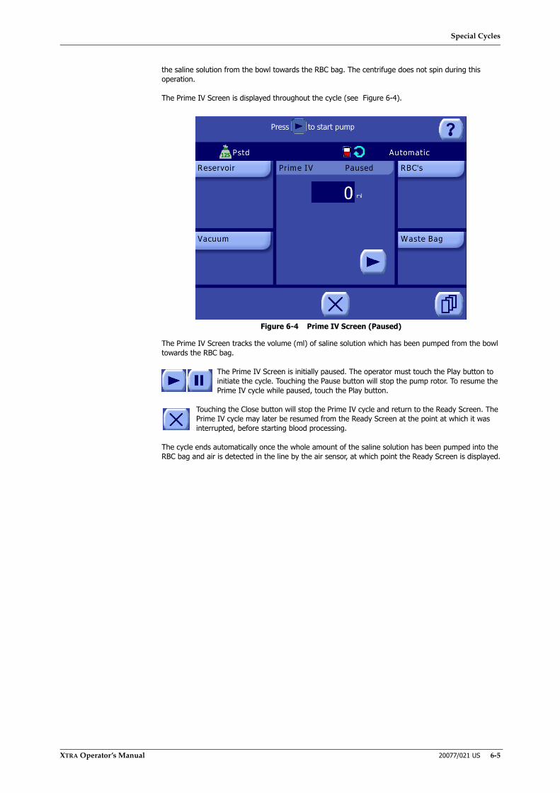
Special Cycles
XTRA Operator’s Manual 20077/021 US 6-5
the saline solution from the bowl towards the RBC bag. The centrifuge does not spin during this operation.
The Prime IV Screen is displayed throughout the cycle (see Figure 6-4).
Figure 6-4 Prime IV Screen (Paused)
The Prime IV Screen tracks the volume (ml) of saline solution which has been pumped from the bowl towards the RBC bag.
The Prime IV Screen is initially paused. The operator must touch the Play button to initiate the cycle. Touching the Pause button will stop the pump rotor. To resume the Prime IV cycle while paused, touch the Play button.
Touching the Close button will stop the Prime IV cycle and return to the Ready Screen. The Prime IV cycle may later be resumed from the Ready Screen at the point at which it was interrupted, before starting blood processing.
The cycle ends automatically once the whole amount of the saline solution has been pumped into the RBC bag and air is detected in the line by the air sensor, at which point the Ready Screen is displayed.
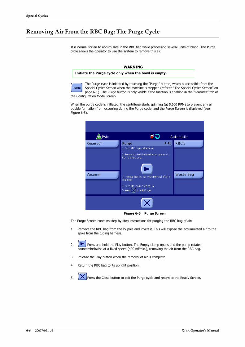
Special Cycles
6-6 20077/021 US XTRA Operator’s Manual
Removing Air From the RBC Bag: The Purge Cycle
It is normal for air to accumulate in the RBC bag while processing several units of blood. The Purge cycle allows the operator to use the system to remove this air.
The Purge cycle is initiated by touching the “Purge” button, which is accessible from the Special Cycles Screen when the machine is stopped (refer to “The Special Cycles Screen” on page 6-1). The Purge button is only visible if the function is enabled in the “Features” tab of
the Configuration Mode Screen.
When the purge cycle is initiated, the centrifuge starts spinning (at 5,600 RPM) to prevent any air bubble formation from occurring during the Purge cycle, and the Purge Screen is displayed (see Figure 6-5).
Figure 6-5 Purge Screen
The Purge Screen contains step-by-step instructions for purging the RBC bag of air:
1. Remove the RBC bag from the IV pole and invert it. This will expose the accumulated air to the spike from the tubing harness.
2. Press and hold the Play button. The Empty clamp opens and the pump rotates counterclockwise at a fixed speed (400 ml/min.), removing the air from the RBC bag.
3. Release the Play button when the removal of air is complete.
4. Return the RBC bag to its upright position.
5. Press the Close button to exit the Purge cycle and return to the Ready Screen.
WARNINGInitiate the Purge cycle only when the bowl is empty.

Special Cycles
XTRA Operator’s Manual 20077/021 US 6-7
Reinfusion
Description
Reinfusion of the red blood cells processed by the XTRA is under the control and supervision of the physician in charge and can be accomplished by several different means:
• Processed blood can be held in the RBC bag until the bag becomes full. Use the Purge function (refer to “Removing Air From the RBC Bag: The Purge Cycle” on page 6-6) to remove any accumulated air and then disconnect the bag from the autologous transfusion circuit, hang, and reinfuse according to normal blood administration protocol, as described in AABB standards.
• Some of the processed blood can be moved into a transfer pack and handed off to the anesthesiologist for reinfusion while processing of shed blood continues.
• If necessary—for example, when a patient’s religion requires that blood be maintained in a continuous loop—a secondary transfer pack or blood RBC bag can be attached to the XTRA RBC bag with a Y-type blood administration set. The processed blood can be reinfused by transferring the blood to the secondary RBC bag and closing the clamp between the two bags.
• Blood can be stored for later reinfusion. In this case, follow your institution’s blood administration protocol for appropriate labeling and blood storage requirements.
WARNINGThe American Association of Blood Banks (AABB) provides recommendations for expiration of salvaged blood. See Warning #11 in “Chapter 1: Introduction and Safety” for specific recommendations.i
i American Association of Blood Banks. Standards for PerioperativeAutologous Blood Collection and Administration. 3rd Edition. Bethesda,MD. 2007 Reference Standard 5.1.8 (Handling, Storage, Transportation).
WARNINGDo not reinfuse the patient’s blood from the primary RBC bag when it is connected to the XTRA autologous transfusion circuit. Reinfusion from the primary reinfusion bag connected to the circuit could lead to air embolism.
WARNINGDo not reinfuse under pressure (i.e., do not use a blood pressure cuff on the RBC or plasma/PRP bags). Reinfusion under pressure could lead to air embolism.
WARNINGTo reduce risk of air embolism, remove all air from the primary reinfusion bag before handing the bag over for reinfusion.
Special Cycles
6-8 20077/021 US XTRA Operator’s Manual
Connecting the Blood Administration Set to the XTRA RBC Bags
If it is necessary to establish a continuous loop for reinfusion of blood processed by the XTRA, follow these steps:
1. Using aseptic technique, spike one of the unused ports of the XTRA RBC bag (either of the two unused ports may be used) with either:
◊ a blood administration set which has an integral microaggregate (20-40 micron) transfusion filter (see Figure 6-6 Top).
OR
◊ a separate microaggregate (20-40 micron) transfusion filter (see Figure 6-6 Bottom).
2. Make certain that the primary clamp is in the open position. Prime and de-bubble the blood administration and microaggregate filter set according to manufacturer's recommendations. Then close the distal roller clamp on the blood administration line.
3. Clamp off a secondary RBC bag.
4. Attach the second leg of the “Y”-type blood administration set to one of the remaining ports of the secondary RBC bag.
5. Close the primary clamp. This clamp should remain closed during processing with the XTRA system.
6. After a unit of packed red blood cells has been emptied into the XTRA RBC bag, open the primary clamp to allow the cells to flow into the secondary RBC bag. Then close the primary clamp prior to initiating reinfusion to the patient.
Note: The primary clamp on the leg of the “Y”-type blood administration set attached to the RBC bag should remain closed during processing and/or reinfusion.
7. The distal end of the blood administration set is now ready to be connected to a suitable venous catheter by the anesthesiologist.
WARNINGTo reduce the possibility of air or particulate embolism, LivaNova STRONGLY RECOMMENDS the use of reinfusion protection devices, including microfilters, when infusing processed blood.
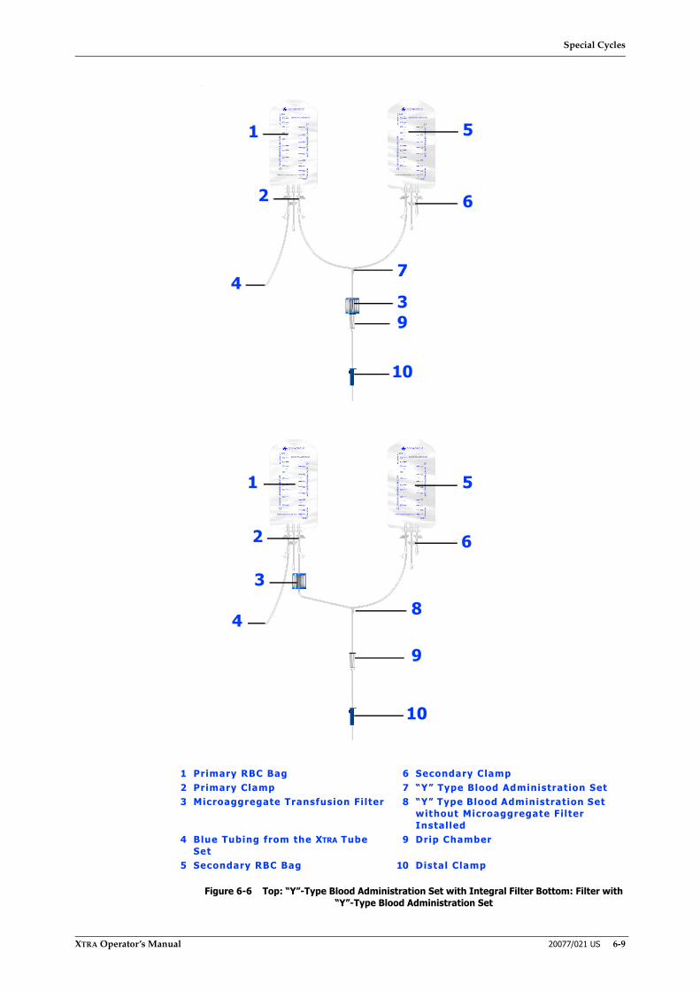
Special Cycles
XTRA Operator’s Manual 20077/021 US 6-9
.
Figure 6-6 Top: “Y”-Type Blood Administration Set with Integral Filter Bottom: Filter with “Y”-Type Blood Administration Set
1
2
34
5
6
7
9
10
1 Primary RBC Bag 6 Secondary Clamp2 Primary Clamp 7 “Y” Type Blood Administration Set3 Microaggregate Transfusion Filter 8 “Y” Type Blood Administration Set
without Microaggregate Filter Installed
4 Blue Tubing from the XTRA Tube Set
9 Drip Chamber
5 Secondary RBC Bag 10 Distal Clamp
1
3
2
4
5
6
8
9
10

Special Cycles
6-10 20077/021 US XTRA Operator’s Manual

Automated Functions
XTRA Operator’s Manual 20077/021 US 7-1
Chapter 7: Automated Functions
Description
Several automated functions are available for use during processing with the XTRA system:
• Autostart function - Automatically start a cycle based on the volume of blood in the reservoir.
• Continue function - Sequentially process multiple cycles without any intervention required by the operator.
• Last Bowl function - Automate the conclusion of the case: empty the reservoir, concentrate the last bowl, and empty the RBC line without intervention from the operator.
• Double Volume Wash function - Double the wash volume for a single cycle.
• Better Quality Wash (BQW) function - Run multiple decelerations and accelerations of the centrifuge during the Wash phase of a cycle.
• Better Empty function - A special Empty phase which is automatically initiated when the system detects the first Empty phase did not completely empty the bowl.
When an automation is active, the standard execution of a protocol will change, and specific actions will be automatically executed until the automation is deactivated.
Availability of automations depends on the selected protocol and functional context. As Table 7-1 shows, the automations described in this chapter are only available with intraoperative and postoperative protocols.
Enabling Optional Automated Functions
Some automated functions may only be initiated by the operator if they are enabled in the Features tab of the Configuration Mode Screen. Refer to “How to Enter the Configuration Mode” on page 8-2 for instructions on entering the Configuration Mode Screen. For more on configuring the XTRA system refer to the rest of Chapter 8: Configuring XTRA.
Autostart Function
The Autostart function allows the XTRA to automatically initiate the first Fill phase of a cycle after the system recognizes the quantity of blood present in the reservoir by means of a weight-sensitive sensor situated on the reservoir holder. When active, once the reservoir contains the target volume of blood, the Autostart function will automatically start the Fill phase of the selected protocol and operating mode without any intervention from the operator.
The Autostart function may be used in conjunction with the Continue function (refer to “Continue Function” on page 7-3). When both the Autostart and Continue automations are active, the Autostart function manages the start of the first cycle while the Continue function manages all subsequent starts regardless of the blood quantity in the reservoir.
Popt Pstd Pfat Post-op PPP PRP1/PRP2Autostart YES YES YES YES NO NOContinue YES YES YES YES NO NOLast Bowl YES YES YES YES NO NODouble Wash volume YES YES YES YES NO NOBetter Quality Wash YES YES YES YES NO NOBetter Empty YES YES YES YES NO NO
Table 7-1 Automated Functions Available in Each Protocol

Automated Functions
7-2 20077/021 US XTRA Operator’s Manual
This automation is available only for intraoperative and postoperative protocols (Pstd, Popt, Pfat, Post-op, and derivatives) in the Automatic and 1 Touch operating modes. It is neither available if the reservoir type is set to “none” in the Settings tab of the Menu Screen, nor when processing with the Manual operating mode.
The Autostart function can be activated and deactivated from Protocol/Mode tab of the Menu Screen by following these steps:
1. Touch the Menu button from the Ready Screen or any Processing Screen to enter the Menu Screen.
2. From the left side of the Menu Screen, touch the Protocol/Mode tab.
3. From the Protocol/Mode tab, ensure that Automatic or 1 Touch mode is selected from the mode drop-down menu. Then, touch the Autostart button to toggle the activation of the Autostart automation. When active, the button appears inset and green.
4. Optionally, using the text box immediately below the Autostart button, set the Autostart target volume (ml). This is the volume of fluid which the reservoir must contain before the Autostart function initiates the cycle.
5. Touch the Save Modifications button to make all changes in the Protocol/Mode tab take effect. If the screen is exited by touching the Close button, or is interrupted by an alarm, then the modifications are not saved.
Refer also to “Set the Active Operating Mode” on page 5-35.
When the Autostart function is active, the Autostart symbol ( ) appears in the status area of the Ready Screen and every processing screen.
The Autostart target volume may be set from the Protocol/Mode tab (as described in the steps above) or from the Reservoir displet in the Ready Screen and any processing screen. The target volume may be set from 200 ml - 3,500 ml, in 100 ml steps.
Each bowl size may have a unique Autostart target wakeup volume. Refer to “Setting the Wakeup Configuration” on page 8-7.
When the system registers the correct conditions for starting the procedure (the reservoir having been detected to contain at least the Autostart target volume for at least 3 seconds), it displays the Autostart Activation Screen (see Figure 7-1).
Figure 7-1 Autostart Activation Screen
Automated Functions
XTRA Operator’s Manual 20077/021 US 7-3
The screen is displayed for 4 seconds, during which time the operator may take the following actions:
• Touch the Autostart Disable button to interrupt the automatic start and deactivate the Autostart automation. The system will return to the stopped state and display the Ready Screen. The Autostart automation may be reactivated from the Protocol/Mode tab of the Menu Screen.
• Touch the Autostart Delay button to delay the automatic start of the Fill phase. This causes the Autostart target volume to be set to the current Autostart target volume plus an additional 500 ml of blood (or sets the target to the maximum of 3,500 ml, whichever is less). The Ready Screen is then re-displayed.
During a delay introduced in this manner, a delay counter appears in the reservoir displet with a display indicating how many milliliters of fluid need to be collected in the reservoir before a new Autostart is initiated. The operator can interrupt the delay by touching the Play button to manually start the Fill phase.
• Wait 4 seconds to start the Fill phase.
If no action is taken by the operator within the 4 seconds that the message is displayed, the Fill phase of the cycle will be started automatically.
Note: The Autostart disabled icon will temporarily be displayed if a situation is detected where the weight of the reservoir is considered unreliable.
The Autostart function may be deactivated in the following ways:
• Manually by the operator from the Protocol/Mode tab of the Menu Screen.
• Manually by the operator by touching the Autostart Disable button during the warning of the onset of automatic fill.
• Automatically when the user selects a protocol or operating mode for which this automation is not allowed or is preset to its OFF status (such as the Manual mode).
• Automatically, and temporarily, when the volume of the reservoir cannot be reliably measured by the system, or when the cover is not closed and locked, or when a blood loss in the centrifuge is detected when the Autostart target volume is reached.
Continue Function
Activation of the Continue function allows the XTRA system to automatically perform a number of cycles consecutively without any intervention from the operator. Specifically, at the end of the Empty phase the unit automatically starts a new Fill phase (without checking the volume of liquid inside the reservoir).
This function can be activated only in the Automatic processing mode and is always active in the 1 Touch mode. It can be used in conjunction with the Autostart and Better Quality Wash functions.
It can be activated and deactivated from Protocol/Mode tab of the Menu Screen by following these steps:
1. Touch the Menu button from the Ready Screen or any Processing Screen to enter the Menu Screen.
2. From the left side of the Menu Screen, touch the Protocol/Mode tab.
3. From the Protocol/Mode tab, ensure that Automatic mode is selected from the mode drop-down menu. Then, touch the Continue button to toggle the activation of the Continue automation. When active, the button appears inset and green.
4. Touch the Save Modifications button to make all changes in the Protocol/Mode tab take effect. If the screen is exited by touching the Close button, or is interrupted by an alarm, then the modifications are not saved.
Refer also to “Set the Active Operating Mode” on page 5-35.
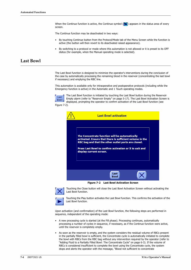
Automated Functions
7-4 20077/021 US XTRA Operator’s Manual
When the Continue function is active, the Continue symbol ( ) appears in the status area of every screen.
The Continue function may be deactivated in two ways:
• By touching Continue button from the Protocol/Mode tab of the Menu Screen while the function is active (the button will then revert to its deactivated raised appearance).
• By switching to a protocol or mode where this automation is not allowed or it is preset to its OFF status (for example, when the Manual operating mode is selected).
Last Bowl
The Last Bowl function is designed to minimize the operator’s interventions during the conclusion of the case by automatically processing the remaining blood in the reservoir (concentrating the last bowl if necessary) and emptying the RBC line.
This automation is available only for intraoperative and postoperative protocols (including while the Emergency function is active) in the Automatic and 1 Touch operating modes.
The Last Bowl function is initiated by touching the Last Bowl button during the Reservoir Empty alarm (refer to “Reservoir Empty” on page 5-17). The Last Bowl Activation Screen is displayed, prompting the operator to confirm activation of the Last Bowl function (see
Figure 7-2).
Figure 7-2 Last Bowl Activation Screen
Touching the Close button will close the Last Bowl Activation Screen without activating the Last Bowl function.
Touching the Play button activates the Last Bowl function. This confirms the activation of the Last Bowl function.
Upon activation (and confirmation) of the Last Bowl function, the following steps are performed in sequence, independent of the operating mode:
• A new processing cycle is started (at the Fill phase). Processing continues, automatically processing a number of cycles in sequence, if necessary, as if the Continue function were active, until the reservoir is completely empty.
• As soon as the reservoir is empty, and the system considers the residual volume of RBCs present in the partially filled bowl is sufficient, the Concentrate cycle is automatically initiated to complete the bowl with RBCs from the RBC bag without any intervention required by the operator (refer to “Adding Fluid to a Partially Filled Bowl: The Concentrate Cycle” on page 6-3). If the volume of RBCs is considered insufficient to complete the bowl using the Concentrate cycle, the system stops and alerts the operator with the message, “Blood not sufficient to concentrate
Automated Functions
XTRA Operator’s Manual 20077/021 US 7-5
automatically,” and the Last Bowl function is terminated.
If the volume of RBCs is sufficient to start a Concentrate cycle automatically but not to complete filling the bowl, the system alerts the operator with the message, “RBC bag empty. Bowl not filled”. In this case, the operator can decide to either process a partial bowl (with normal or double saline solution volume) or to discard the residual volume in the bowl.
• At the end of the Concentrate phase, the Wash phase is activated automatically without any intervention required by the operator.
• At the end of the Wash phase or at the end of the Fat Removal phase (if the Pfat protocol is in use), the Empty phase is automatically initiated. Once the bowl is empty, the Empty phase continues to empty the Empty line without any intervention required by the operator. The Last Bowl function is then complete and deactivated.
While the Last Bowl function is active, the Last Bowl symbol is displayed in the status area.
The Last Bowl function may be interrupted in the following ways:
• By pushing the Stop button.
• By activating the Emergency function.
• By switching to the Manual operating mode.
CAUTIONThe Concentration function reprocesses already collected red blood cellssubjecting them again to the mechanical action of the pump and thecentrifuge. The repeated use of the Concentration function on the same redblood cells might lead to them being damaged and therefore to their loss.
WARNINGThe use of the Last Bowl function is recommended only to complete the case, with the following conditions: The reservoir is empty, no more blood is expected to be collected, and sufficient red cells in saline solution are available in the RBC bag to compete the Concentrate cycle.
WARNINGIn case a partial bowl is washed, the hematocrit of the collected blood as well as the removal of waste components might be lower than expected.
WARNINGThe maximum volume in the RBC bag is 1 liter. To avoid explosions, check the level inside the bag carefully before activating the Last Bowl function.
WARNINGThe Last Bowl function automatically activates a second Empty phase at the end of the first Empty phase. Carefully monitor the air in the RBC bag in case of repeated activation of the Last Bowl function.
Automated Functions
7-6 20077/021 US XTRA Operator’s Manual
Double Volume Wash Function
If at any time during processing a bowl cannot be completely filled (such as the reservoir becoming empty during the Fill phase), a suitable warning is issued and the Double Volume Wash function becomes available.
The Double Volume Wash function is initiated by touching the “Double Wash” button which appears in the button bar at the bottom of the screen during warnings when the bowl cannot be completely filled.
Once initiated, a Wash phase will be started where double the current programmed wash volume will be set. The operator may modify this volume as usual during the phase from the processing displet of the Wash Screen.
The double wash volume only persists for the cycle in which it is initiated. In subsequent cycles, the wash volume is set to the programmed value for the current protocol.
Better Quality Wash (BQW) Function
When the Better Quality Wash (BQW) function is active, the blood in the bowl undergoes a series of operations on the basis of a special protocol (accelerations and decelerations of the centrifuge) designed to optimize the Wash phase of a cycle.
The BQW function is only available for intraoperative and postoperative protocols (Pstd, Popt, Post-op, and derivatives except for Pfat protocol). It is available under every operating mode.
The BQW function is a protocol parameter that can be permanently stored in custom protocols, so that unlike the other automations, BQW activation may have a different status for each protocol that supports it.
If the BQW function is activated before processing reaches the Wash phase, then for every 200 ml of wash solution used during the Wash phase the unit runs a BQW cycle which includes the following steps:
1. The pump stops and the centrifuge decelerates to 1,500 RPM.
2. The centrifuge then accelerates to 5,600 RPM.
3. After a short delay, the pump starts rotating again with a slow ramp-up to the standard Wash speed. The length of the delay is dependent on the bowl size in use:
Þ X/55: 13 seconds
Þ X/125: 8 seconds
Þ X/175: 18 seconds
Þ X/225: 18 seconds
The BQW function can be in one of three states:
• Off - In this state the BQW function is OFF and no BQW cycle will be performed during the Wash phase.
• 2x (short BQW) - In this state, the BQW cycle will be performed on the RBCs in the bowl up to two times during the Wash phase.
• 4x (standard BQW) - In this state, the BQW cycle will be performed on the RBCs in the bowl up to four times during the Wash phase.
When the BQW function is activated during the Wash phase, a BQW cycle is immediately performed if the following condition is true:
WARNINGIn case a partial bowl is washed, the hematocrit of the collected blood as well as the removal of waste components might be lower than expected.

Automated Functions
XTRA Operator’s Manual 20077/021 US 7-7
• Fewer than three BQW cycles have been performed during the current Wash phase and the volume already processed exceeds 100 ml. (If 100 ml of wash solution has not yet been pumped to the bowl, then the start of the first BQW cycle will wait until it has.)
The interval between two subsequent BQW cycles is always 200 ml except when air is detected between two BQW cycles. In this event, the subsequent BQW cycle takes place 200 ml after the volume recorded when the alarm was sounded.
The BQW state can be set for each protocol from Protocol/Mode tab of the Menu Screen by following these steps:
1. Touch the Menu button from the Ready Screen.
2. From the left side of the Menu Screen, touch the Protocol/Mode tab.
3. From the Protocol/Mode tab, ensure that an intraoperative or postoperative protocol is selected from the protocol drop-down menu. Then, touch one of the states of the BQW button to toggle the activation of the status of the BQW automation: Off, 2x, or 4x. The section of the button representing the active state appears inset and green.
4. Touch the Save Modifications button to make all changes in the Protocol/Mode tab take effect. If the screen is exited by touching the Close button, or is interrupted by an alarm, then the modifications are not saved.
Refer also to “Set the Active Protocol” on page 5-35.
The BQW function may be deactivated in the following ways:
• Manually accessing the Protocol/Mode tab of the Menu Screen.
• Switching to a protocol where this automation is not allowed or is preset to its OFF status (such as when a PPP or PRP protocol is selected).
Activating or deactivating the BQW during Wash does not alter the volume in the wash solution counter or the tallied totals stored with the case data.
Better Empty
The Better Empty function is designed to solve problems of incomplete bowl emptying by automatically activating a further special Empty phase. In case the volume of RBC collected in the RBC bag is lower than expected for the current bowl size, the bowl is “stirred” by means of a double alternating acceleration of the centrifuge and an additional Empty phase.
The Better Empty function is activated and deactivated from the Configuration Mode Screen. When it is active, it is automatically applied to each Empty phase when the system detects that the bowl was not completely emptied.
When applied, the Better Empty function performs the following sequence after the normal Empty phase:
1. Stop the pump.
2. Spin the centrifuge clockwise for a short time.
3. Stop the centrifuge; spin the centrifuge counterclockwise for a short time.
4. Start the pump using the Empty phase ramped acceleration and complete an Empty phase again.
The Better Empty function is executed just once per cycle.

Automated Functions
7-8 20077/021 US XTRA Operator’s Manual
Configuring XTRA
XTRA Operator’s Manual 20077/021 US 8-1
Chapter 8: Configuring XTRA
Description
The XTRA system includes a number of settings and optional features that may be configured.
Because modifying system settings affects the operational conditions of the machine, they may only be modified before starting a new case.
However, after a case has been started, the current settings may be viewed, but not modified, from the Settings tab of the Menu Screen (by touching the View button).
Without entering a password, a limited number of system settings may be modified directly from the Settings tab of the Menu Screen:
• Anticoagulant type
• Reservoir type
• Vacuum mode
• Date and time
These settings are described in “The Settings Tab of the Menu Screen” on page 8-2.
The general configuration of the XTRA system, consisting of the majority of settings, can be set in a protected domain, the Configuration Mode Screen, accessible from the Settings tab of the Menu Screen after entering a password. The settings programmed from the Configuration Mode Screen are permanently kept in the systems’s memory and cannot be modified from any other screen.
The Configuration Mode Screen is divided into several tabs, each of which contains a group of settings for a related part of the system:
• Features
• Protocol Set
• Wake up
• Display
• Warnings
• ID
• Language
The section “Configuration Mode” on page 8-2 explains how to enter the Configuration Mode Screen and describes each tab of the screen.
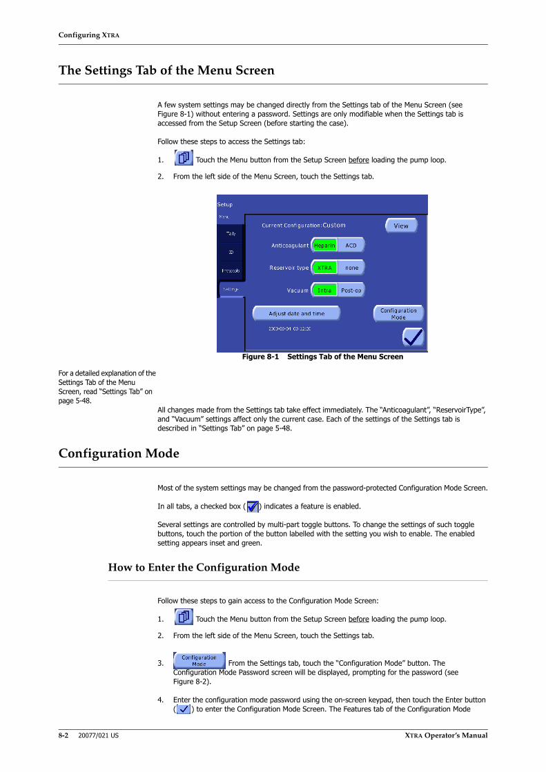
Configuring XTRA
8-2 20077/021 US XTRA Operator’s Manual
The Settings Tab of the Menu Screen
A few system settings may be changed directly from the Settings tab of the Menu Screen (see Figure 8-1) without entering a password. Settings are only modifiable when the Settings tab is accessed from the Setup Screen (before starting the case).
Follow these steps to access the Settings tab:
1. Touch the Menu button from the Setup Screen before loading the pump loop.
2. From the left side of the Menu Screen, touch the Settings tab.
Figure 8-1 Settings Tab of the Menu Screen
For a detailed explanation of the Settings Tab of the Menu Screen, read “Settings Tab” on page 5-48.
All changes made from the Settings tab take effect immediately. The “Anticoagulant”, “ReservoirType”, and “Vacuum” settings affect only the current case. Each of the settings of the Settings tab is described in “Settings Tab” on page 5-48.
Configuration Mode
Most of the system settings may be changed from the password-protected Configuration Mode Screen.
In all tabs, a checked box ( ) indicates a feature is enabled.
Several settings are controlled by multi-part toggle buttons. To change the settings of such toggle buttons, touch the portion of the button labelled with the setting you wish to enable. The enabled setting appears inset and green.
How to Enter the Configuration Mode
Follow these steps to gain access to the Configuration Mode Screen:
1. Touch the Menu button from the Setup Screen before loading the pump loop.
2. From the left side of the Menu Screen, touch the Settings tab.
3. From the Settings tab, touch the “Configuration Mode” button. The Configuration Mode Password screen will be displayed, prompting for the password (see Figure 8-2).
4. Enter the configuration mode password using the on-screen keypad, then touch the Enter button ( ) to enter the Configuration Mode Screen. The Features tab of the Configuration Mode

Configuring XTRA
XTRA Operator’s Manual 20077/021 US 8-3
Screen will be displayed (see Figure 8-3). Alternatively, touch the Close button ( ) to close the password screen without entering the Configuration Mode Screen.
Figure 8-2 Configuration Mode Password Screen
Exit From the Configuration Mode
To exit the Configuration Mode Screen, simply touch the Close button from any tab. The Configuration Mode Screen will close, any changes made will have already taken effect and will be saved, and the Settings tab of the Menu Screen will be displayed.
Predefined Feature Sets
To simplify configuration from the Configuration Mode Screen, two predefined feature sets are available: Basic and Advanced. In addition, a Custom configuration can be programmed, allowing the operator to modify every setting.
Use the three-part Feature Set button at the top of the Features tab (refer to “Setting the Enabled Features” on page 8-4) to select one of the predefined feature sets (Basic or Advanced) or select Custom
to create a custom configuration. The part of the button corresponding to the currently selected feature set appears green and inset.
These predefined feature sets affect the settings in several tabs of the Configuration Mode Screen. The following table summarizes the settings of the Basic and Advanced predefined feature sets:
Tab Feature/Function Basic AdvancedFeatures 1 touch enabled enabled
Better empty disabled disabledNot reached disabled disabledSupernatant removal disabled enabledWaste line disabled enabledWash Quality indicator disabled enabledHCT disabled enabledLast Bowl enabled enabledManual disabled enabledRBC detector disabling option disabled disabledPrime IV disabled enabledPrinter disabled enabledPurge disabled enabledRS232 disabled disabledReached disabled disabledUSB disabled enabled
Table 8-1 Comparison of the Predefined Feature Sets

Configuring XTRA
8-4 20077/021 US XTRA Operator’s Manual
Configuration Mode Screen Tabs
Setting the Enabled Features
The first tab (from the top) of the Configuration Mode Screen is the Features tab (see Figure 8-3). The optional features of the XTRA system may be enabled and disabled from this tab.
Figure 8-3 Features Tab of the Configuration Mode
As mentioned under “Predefined Feature Sets” on page 8-3, from this tab it is possible to select a predefined configuration set using the Feature Set button at the top of the screen.
Indicators
The following three settings relate to the wash quality indicators as described in Chapter 12: Quality Management Option.
Hct indicator. The Hct indicator option turns the Hct (hematocrit) indicator ON (enabled) and OFF (disabled). It must be enabled for features related to the Hct indicator to be available during processing (such as for the “Hct in” and “Hct out” figures to appear on processing screens and be stored with the case data). If the Hct indicator is disabled, the Hct indicator will NOT be calibrated during setup.
Supernatant removal indicator. This option turns the supernatant removal indicator ON (enabled) and OFF (disabled). It must be enabled in order to have the possibility to activate the Waste line color indicator.
Waste line color indicator. This option turns the three-color waste line indicator ON (enabled) and OFF (disabled).
Protocol Set Popt enabled enabledPstd disabled enabledPfat enabled enabledPost-op disabled disabledPPP disabled disabledPRP1 disabled disabledPRP2 disabled disabledEmergency key enabled enabledNo Wash option disabled disabledRapid Transfer option disabled disabledUser Protocols disabled disabled
Wake up ATS (Intraoperative) Mode of Operation
1 touch 1 touch
Tab Feature/Function Basic Advanced
Table 8-1 Comparison of the Predefined Feature Sets (Continued)

Configuring XTRA
XTRA Operator’s Manual 20077/021 US 8-5
The quality warnings depend on the WLC indicator being enabled. Disabling the WLC indicator will also disable the “Reached” and “Not reached” quality warning settings.
Wash Quality Warnings
The following two settings relate to the wash quality warnings as described in Chapter 12: Quality Management Option.
Reached. With this feature enabled, if a minimum wash quality is reached before the Wash phase has completed, the system will issue a warning and allow the operator to switch to the Empty phase.
Not reached. With this feature enabled, if a minimum wash quality has not been reached by the time the Wash phase has completed, the system will issue a warning and continue in the Wash phase.
Operating Modes
1 Touch. This setting must be enabled to process a cycle in the 1 Touch operating mode as described in “1 Touch” on page 5-31.
Manual. This setting must be enabled to process a cycle in the Manual operating mode as described in “Manual” on page 5-32.
Manual RBC option. This setting must be enabled to give the operator the option of disabling the RBC detector during Manual mode operation. When enabled, the “RBC detector” option will be displayed in the Protocol/Mode tab of the Menu Screen.
Note: Automatic mode is available in every configuration and cannot be disabled.
Automated Functions
The following two settings relate to automations as described in Chapter 7: Automated Functions.
Last Bowl. This setting must be enabled to use the Last Bowl automation as described in “Last Bowl” on page 7-4.
Better Empty. This setting must be enabled to use the Better Empty automation as described in “Better Empty” on page 7-7.
Special Cycles
The following two settings relate to special cycles as described in Chapter 6: Special Cycles.
Purge. This setting must be enabled to use the special Purge cycle as described in “Removing Air From the RBC Bag: The Purge Cycle” on page 6-6.
Prime IV. This setting must be enabled to use the special Prime IV cycle as described in “Priming the Reinfusion Line: Prime IV” on page 6-4.
Data Download Options
The following three settings relate to the data download options as described in Chapter 11: Data Download Option.
RS232. This setting must be enabled to download case data through the dedicated RS232 serial port.
Printer. This setting must be enabled to print case data from the on-board printer.
USB. This setting must be enabled to download case data through the dedicated USB serial port.
WARNINGUse only XTRA USB memory sticks.

Configuring XTRA
8-6 20077/021 US XTRA Operator’s Manual
Setting the Enabled Protocols
The Protocol Set tab of the Configuration Mode Screen (see Figure 8-4) allows for the available processing protocols to be configured.
Figure 8-4 Protocol Set Tab of the Configuration Mode
ATS Protocols
The four settings under the “ATS Protocols” heading determine which intraoperative (Popt, Pstd and Pfat) and postoperative (Post-op) protocols are available for processing.
A check next to the protocol name indicates that it may be selected as the active processing protocol from the Protocol/Mode tab of the Menu Screen.
The ATS protocols are described in detail in “Factory Protocols” on page 5-22.
SEQ Protocols
The three settings under the “SEQ Protocols” heading determine which sequestration protocols are available for processing.
A check next to the protocol name indicates that it may be selected as the active processing protocol from the Protocol/Mode tab of the Menu Screen.
The sequestration protocols are described in detail in “The Preoperative Sequestration Factory Protocols” on page 10-21.
Emergency
The three settings under the “Emergency” heading configure the Emergency feature as described in “Emergency” on page 5-26.
Emergency key. This setting must be enabled for the Emergency function to be available. If it is disabled, the “No wash option” and “Rapid Transfer option” settings are also disabled.
No wash option. This setting must be enabled for the No Wash option to be available from the Emergency Activation Screen.
Rapid Transfer option. This setting must be enabled for the Rapid Transfer option to be available from the Emergency Activation Screen.
User Protocols
The “User Protocols” setting must be enabled to allow operators to create, rename, delete, modify, and use custom operating protocols. Refer to “Creating Custom Protocols” on page 9-1.

Configuring XTRA
XTRA Operator’s Manual 20077/021 US 8-7
Setting the Wakeup Configuration
From the Protocol Set tab (see Figure 8-5) the various wakeup settings may be configured. The wakeup settings determine the system’s initial configuration at power on or when a new case is started after loading the pump loop.
Figure 8-5 Wakeup Tab of the Configuration Mode
ATS Mode of Operation
Using the two-part toggle button it is possible to set the wakeup operating mode for intraoperative and postoperative protocols to either Automatic or 1 Touch. The mode selected with this setting will be the mode that is active by default every time an intraoperative or postoperative protocol is selected either when a new case is started or after processing with a sequestration protocol.
If 1 Touch mode is disabled in the Features tab, then it will not be possible to set it as the wakeup mode here.
This setting does not affect the default mode for sequestration protocols (which is always Automatic).
The Autostart and Continue wakeup settings determine the state of the Autostart and Continue automations, respectively, whenever an intraoperative or postoperative protocol is activated after a new case or after processing with a sequestration protocol.
Autostart Levels
Each bowl size (55, 125, 175, and 225 ml) may have a unique wakeup Autostart target volume configured which will be used as the default Autostart target volume when starting a new case with the corresponding bowl size. The volume for each bowl size may be set from 200 ml up to 3,500 ml, with a step of 100 ml.
Vacuum Set Points
Each vacuum mode (Intra and Post-op) may have a unique wakeup negative pressure set (mmHg). These set points are used every time the vacuum operating mode is changed (including at module power on).
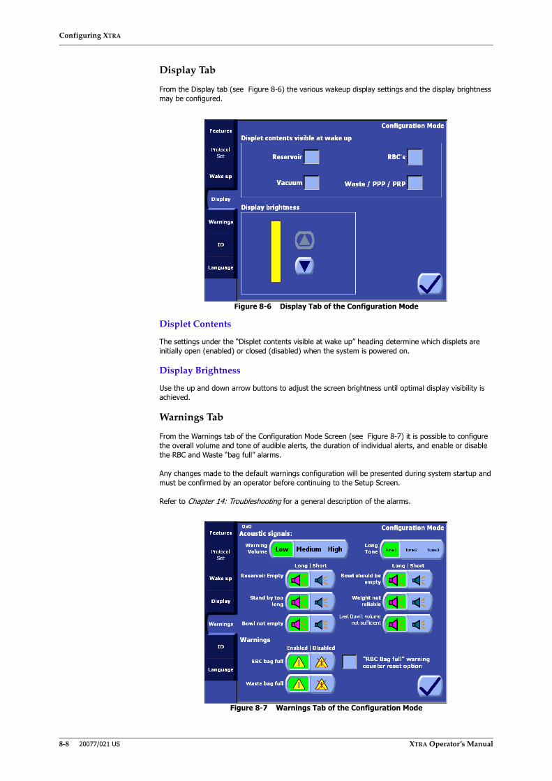
Configuring XTRA
8-8 20077/021 US XTRA Operator’s Manual
Display Tab
From the Display tab (see Figure 8-6) the various wakeup display settings and the display brightness may be configured.
Figure 8-6 Display Tab of the Configuration Mode
Displet Contents
The settings under the “Displet contents visible at wake up” heading determine which displets are initially open (enabled) or closed (disabled) when the system is powered on.
Display Brightness
Use the up and down arrow buttons to adjust the screen brightness until optimal display visibility is achieved.
Warnings Tab
From the Warnings tab of the Configuration Mode Screen (see Figure 8-7) it is possible to configure the overall volume and tone of audible alerts, the duration of individual alerts, and enable or disable the RBC and Waste “bag full” alarms.
Any changes made to the default warnings configuration will be presented during system startup and must be confirmed by an operator before continuing to the Setup Screen.
Refer to Chapter 14: Troubleshooting for a general description of the alarms.
Figure 8-7 Warnings Tab of the Configuration Mode

Configuring XTRA
XTRA Operator’s Manual 20077/021 US 8-9
Volume of Alarm
Use this three-part toggle button at the top of the screen to set the volume for all acoustic alarms (Low, Medium, or High).
Standard Tone
The tone of the standard audible alarms and beeps may be configured to one of three available acoustic sequences.
• Tone 1: three pulses, the last pulse is of a different tone
• Tone 2: three pulses, the last pulse is of a different duration
• Tone 3: two pulses
Once selected, this sequence will be associated to all alarms/warnings that emit an endless acoustic sequence.
Alarms and warnings that issue a finite acoustic sequence will always produce a fixed signal composed of three short beeps.
Acoustic Signal
The duration of several alarms may be configured individually using each alarm’s two-part toggle button under the “Acoustic signal” heading:
• Long - continuously repeated acoustic alarm
• Short - three single beeps
“RBC Bag full” Warning Counter Reset Option
By activating this option, it will be possible to reset the counter controlling the “RBC Bag full” warning.
Enable or Disable Bag Warnings
The buttons labeled “RBC bag full” and “Waste bag full” may be used to enable or disable the corresponding bag warnings.
CAUTIONAny modification on the acoustic signals can make the operator take longer torealize that the machine has made a warning.
CAUTIONThe deactivation of the alarms “RBC bag full” and/or “Waste bag full” is underthe responsibility of the user who must directly control the fill level of thebags.

Configuring XTRA
8-10 20077/021 US XTRA Operator’s Manual
Setting the Rapid Selection of ID
From the ID tab of the Configuration Mode Screen (see Figure 8-8) it is possible to configure the rapid selection of ID for use from the ID Tab of the Menu Screen as described in “Identifier (ID) Tab” on page 5-46.
Figure 8-8 ID Tab of the Configuration Mode Screen
The left side of the screen contains a list of existing ID Fields. These fields may be selected by touching them. Selected fields appear inset and green. The right side of the screen contains buttons with which the operator may create, edit/rename, and delete the selected ID Field.
The default ID fields which exist are “Patient ID,” “Operator,” and “Lot Num”. The “Patient ID” field cannot be deleted or renamed.
A maximum of 13 user-definable ID fields may be created (in addition to the permanent “Patient ID” field).
Add ID Field
Touching the “Add ID Field” button will display a QWERTY keyboard, allowing the operator to enter a name for the new ID field. Touching the “Enter” button from the Keyboard Screen will create the new ID field and return to the ID Tab of the
Configuration Mode Screen. Touching the Close button will return to the ID Tab without creating a new ID field.
Rename ID Field
Touching the “Rename ID Field” button will display a QWERTY keyboard, allowing the operator to rename the selected ID field. Touching the “Enter” button will save the entered name as the new name for the selected ID field and return to the ID Tab of the
Configuration Mode Screen. Touching the Close button will return to the ID Tab without changing the name of the selected ID field. The Rename ID Field button is only enabled if an ID field is currently selected from the list.
Delete ID Field
Touching the “Delete ID Field” button will immediately delete the selected ID field and its associated field list.
Field Lists
Once an ID field has been created, a field list may be assigned to the field which associates a list of possible values with that field. For example, if the “Operator” field exists, a list of names of operators may be created and assigned to the “Operator” ID field. Then, with the use of the rapid selection menu from the ID tab of the Menu Screen, a name from the list can be quickly selected to populate the field, with the result that the name is saved with the case tally data and appears on data management reports. Refer to “Identifier (ID) Tab” on page 5-46 for a instructions on populating an ID field with a value from a field list.

Configuring XTRA
XTRA Operator’s Manual 20077/021 US 8-11
Once created, elements from field content lists may be renamed and deleted. Empty field lists are allowed.
Touching the “Edit Field List” button will allow the operator to create a new field list for the selected item; or to add, rename, and delete items if the selected field contains an existing field list.
If the selected field contains an empty field list, touching the “Edit Field List” button will display a full QWERTY keyboard, allowing the operator to enter a name for the first item in the field list. Touching the “Enter” button from the keyboard screen will create the field list and display the Edit Field List Screen (see Figure 8-9). Touching the Close button from the Keyboard Screen will cancel the creation of the field list.
If the selected field contains a non-empty field list, touching the “Edit Field List” button will immediately display the Edit Field List Screen from which the operator may add, rename, and delete items from the field list (see Figure 8-9).
Figure 8-9 Edit Field List Screen
The center of the Edit Field List Screen contains the Items drop-down menu. Touching the triangle button will collapse and expand the list of items contained in the list. Touching an item in the list will move it to the top position. The item in the top position is always the item
operated upon by the “Rename Item” and “Delete Item” buttons.
To add an item to the field list, touch the “Add Item” button. A full QWERTY keyboard will be displayed, allowing the operator to enter a value for the new item. Touching the “Enter” button will save the item to the field list. Touching the close button will close the
Keyboard Screen without creating a new item.
To rename the item at the top of the Items drop-down menu, touch the “Rename Item” button. A full QWERTY keyboard will be displayed, allowing the operator to enter a new value for the item. Touching the “Enter” button will save the new value and return to
the Edit Field List Screen. Touching the close button will close the Keyboard Screen without renaming the item.
To delete the item at the top of the Items drop-down menu, touch the “Delete Item” button. The item will immediately be deleted and removed from the drop-down menu.
Touching the Close button will close the Edit Field List Screen and return to the ID Tab of the Configuration Mode Screen.

Configuring XTRA
8-12 20077/021 US XTRA Operator’s Manual
Setting the Language
From the Language tab of the Configuration Mode Screen (see Figure 8-10) it is possible to configure the language used for the user interface throughout the XTRA system.
The language setting also affects the text of data management reports created with the data download option.
Figure 8-10 Language Tab of the Configuration Mode
The current language is set by touching the button containing the desired language’s flag and name. The setting takes immediate effect.
Reset Options
In order to guarantee the protection of important data, this Tab can be visualized only using a secondary password when entering the Configuration Mode (see Figure 8-2).
From the “Reset Options” Tab it is possible to:
1. Reset machine configurationBy pressing “Restore Factory Configuration” button it will be possible to restore the original configuration of the machine as if it came out from the LivaNova Factory. By confirming this action, user defined configuration, setting and protocol will be lost.
2. Delete all cases from machine memoryBy pressing “Delete all cases” and confirming the action, all the cases stored in the memory of the machine will be lost.
Programmability Option
XTRA Operator’s Manual 20077/021 US 9-1
Chapter 9: Programmability Option
Description
The XTRA system ships with seven factory-programmed protocols: four ATS protocols (Pstd, Popt, Pfat and Post-op) and three SEQ protocols (PPP, PRP1, PRP2). The parameters of these factory protocols have been extensively tested and optimized to produce consistent results. However, by selecting the Protocol/Mode tab of the Menu Screen (see Figure 9-3), you may create custom protocols which have different parameters.
It is also possible to change the parameters of factory protocols during a case without creating a custom protocol. The modified parameters of a factory protocol are stored for only the duration of the case. Refer to “Modifications Performed in the Protocol/Mode Tab” on page 9-5.
Before creating or editing custom protocols, it is recommended that the operator become familiar with the factory protocols by reading “Factory Protocols” starting on page 5-22 and “The Preoperative Sequestration Factory Protocols” starting on page 10-21. Also, to understand the whole blood separation process (PPP and PRP sequestration protocols), refer to “Overview of Preoperative Sequestration” starting on page 10-2.
Enabling Programmability Option
In order to create, rename, edit, or delete custom protocols, the “User Protocols” setting must be enabled from the Protocol Set tab of the Configuration Mode Screen. Refer to “How to Enter the Configuration Mode” on page 8-2 for instructions on entering the Configuration Mode Screen. For more on configuring the XTRA system refer to the rest of Chapter 8: Configuring XTRA.
Creating Custom Protocols
Custom protocols are created, modified, and deleted from the Protocol/Mode tab of the Menu Screen (see Figure 9-3). All instructions in this section assume the Protocol/Mode tab is the currently displayed screen. Follow these steps to enter the Protocol/Mode tab.
1. Touch the Menu button from the Setup Screen or the Ready Screen. Protocols cannot be created, renamed, or deleted during processing.
Note: Accessing the Protocol tab from the Setup Screen allows the operator to create and modify protocols for all bowl sizes, while accessing the Protocol/Mode tab from the Ready Screen allows the operator to create and modify protocols for the current bowl size alone.
2. From the left side of the Menu Screen, touch the Protocol/Mode tab.
The programmability options of the Protocol/Mode tab are described in “The Protocol/Mode Tab” on page 9-7.
Entering Values and Text
Before creating or modifying a custom protocol, you should familiarize yourself with the controls for making modifications.
Numerical values (such as the Fill pump speed) are contained in editable text boxes, and may be modified in the usual way by touching the text box and using the up and down arrow buttons which appear next to it (for complete instructions, review “Modification of Parameters” on page 5-5).
CAUTIONThe operator is responsible for setting safe parameters for the customprotocols and for the factory protocols modified during a case.
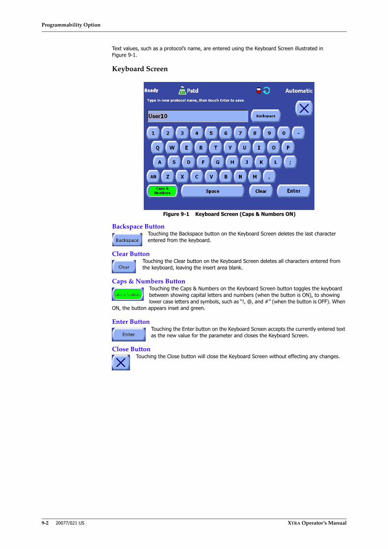
Programmability Option
9-2 20077/021 US XTRA Operator’s Manual
Text values, such as a protocol’s name, are entered using the Keyboard Screen illustrated in Figure 9-1.
Keyboard Screen
Figure 9-1 Keyboard Screen (Caps & Numbers ON)
Backspace ButtonTouching the Backspace button on the Keyboard Screen deletes the last character entered from the keyboard.
Clear ButtonTouching the Clear button on the Keyboard Screen deletes all characters entered from the keyboard, leaving the insert area blank.
Caps & Numbers ButtonTouching the Caps & Numbers on the Keyboard Screen button toggles the keyboard between showing capital letters and numbers (when the button is ON), to showing lower case letters and symbols, such as “!, @, and #” (when the button is OFF). When
ON, the button appears inset and green.
Enter ButtonTouching the Enter button on the Keyboard Screen accepts the currently entered text as the new value for the parameter and closes the Keyboard Screen.
Close ButtonTouching the Close button will close the Keyboard Screen without effecting any changes.
Programmability Option
XTRA Operator’s Manual 20077/021 US 9-3
Creating a New Protocol
Follow these steps to create a new protocol:
1. Select a base protocol from the protocol drop-down menu. This can be either a factory protocol or an existing custom protocol. You will duplicate and then customize the base protocol in order to create the new protocol.
Choose a base protocol whose parameters are closest to what you desire for the new protocol.
2. Touch the New button. This will duplicate the protocol you selected in step 1 and will give the newly created protocol a unique name (prefixed by the base protocol’s factory type).
3. Touch the Rename button to rename the newly created protocol to a more useful name. Refer to “Renaming a Protocol” on page 9-6.
4. Make any desired changes to the protocol parameters. Refer to “Adjusting Parameters of a Protocol” on page 9-3.
5. Once all parameters have been set to your desired values, touch the Save Modifications button to save your modifications and close the Protocol/Mode tab. Alternatively, if you wish to close the tab without saving your modifications, touch the Close ( ) button.
The base protocol determines the fundamental type and behavior of a custom protocol. Wherever the intraoperative and postoperative protocols (Pstd, Popt, and Post-op) are discussed in this manual, the discussion applies equally to custom protocols that are derived from those protocols. The same is true for sequestration protocols (PPP, PRP1, and PRP2) and their derived custom protocols.
Custom protocol names are prefixed with the name of their base factory protocol. For example, a custom protocol created with a base of the Pstd factory protocol and named “user1” at the Keyboard Screen will have a final name of “Pstd_user1”. The prefix may not be removed or renamed during the lifetime of the protocol. Please refer to “Renaming a Protocol” on page 9-6 for more information.
A maximum of six custom protocols may be created for each bowl size (giving a total of 24 custom protocols). If the maximum number of custom protocols already exists for the current bowl size, the New button will be disabled and the operator must delete an existing custom protocol before creating a new one.
Adjusting Parameters of a Protocol
The parameters of existing protocols (both factory and custom protocols) may be adjusted before and during each processing cycle (as well as before the start of each case).
Protocol parameters may be adjusted in two ways:
• At run time from the Processing Screen while the current phase of the cycle is running, or
• At any time from the Protocol/Mode tab of the Menu Screen.
Modifications Performed During Current Phase
The operator may modify the parameters of the ongoing phase, without entering the Protocol/Mode tab, through the controls presented in the processing displet of each phase (refer to “Processing Screen” on page 5-39).
As an example, Figure 9-2 shows a Fill phase of a Pstd cycle in progress. At the bottom of the processing displet is an editable text box which controls the fill pump speed parameter.
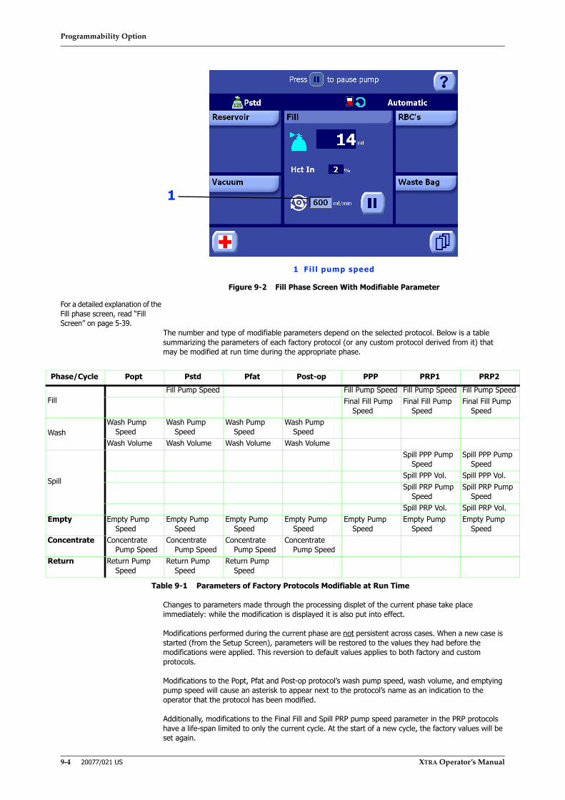
Programmability Option
9-4 20077/021 US XTRA Operator’s Manual
Figure 9-2 Fill Phase Screen With Modifiable Parameter
For a detailed explanation of the Fill phase screen, read “Fill Screen” on page 5-39.
The number and type of modifiable parameters depend on the selected protocol. Below is a table summarizing the parameters of each factory protocol (or any custom protocol derived from it) that may be modified at run time during the appropriate phase.
Changes to parameters made through the processing displet of the current phase take place immediately: while the modification is displayed it is also put into effect.
Modifications performed during the current phase are not persistent across cases. When a new case is started (from the Setup Screen), parameters will be restored to the values they had before the modifications were applied. This reversion to default values applies to both factory and custom protocols.
Modifications to the Popt, Pfat and Post-op protocol’s wash pump speed, wash volume, and emptying pump speed will cause an asterisk to appear next to the protocol’s name as an indication to the operator that the protocol has been modified.
Additionally, modifications to the Final Fill and Spill PRP pump speed parameter in the PRP protocols have a life-span limited to only the current cycle. At the start of a new cycle, the factory values will be set again.
Phase/Cycle Popt Pstd Pfat Post-op PPP PRP1 PRP2
FillFill Pump Speed Fill Pump Speed Fill Pump Speed Fill Pump Speed
Final Fill Pump Speed
Final Fill Pump Speed
Final Fill Pump Speed
WashWash Pump
SpeedWash Pump
SpeedWash Pump
SpeedWash Pump
SpeedWash Volume Wash Volume Wash Volume Wash Volume
Spill
Spill PPP Pump Speed
Spill PPP Pump Speed
Spill PPP Vol. Spill PPP Vol.Spill PRP Pump
SpeedSpill PRP Pump
SpeedSpill PRP Vol. Spill PRP Vol.
Empty Empty Pump Speed
Empty Pump Speed
Empty Pump Speed
Empty Pump Speed
Empty Pump Speed
Empty Pump Speed
Empty Pump Speed
Concentrate Concentrate Pump Speed
Concentrate Pump Speed
Concentrate Pump Speed
Concentrate Pump Speed
Return Return Pump Speed
Return Pump Speed
Return Pump Speed
Table 9-1 Parameters of Factory Protocols Modifiable at Run Time
1
1 Fil l pump speed
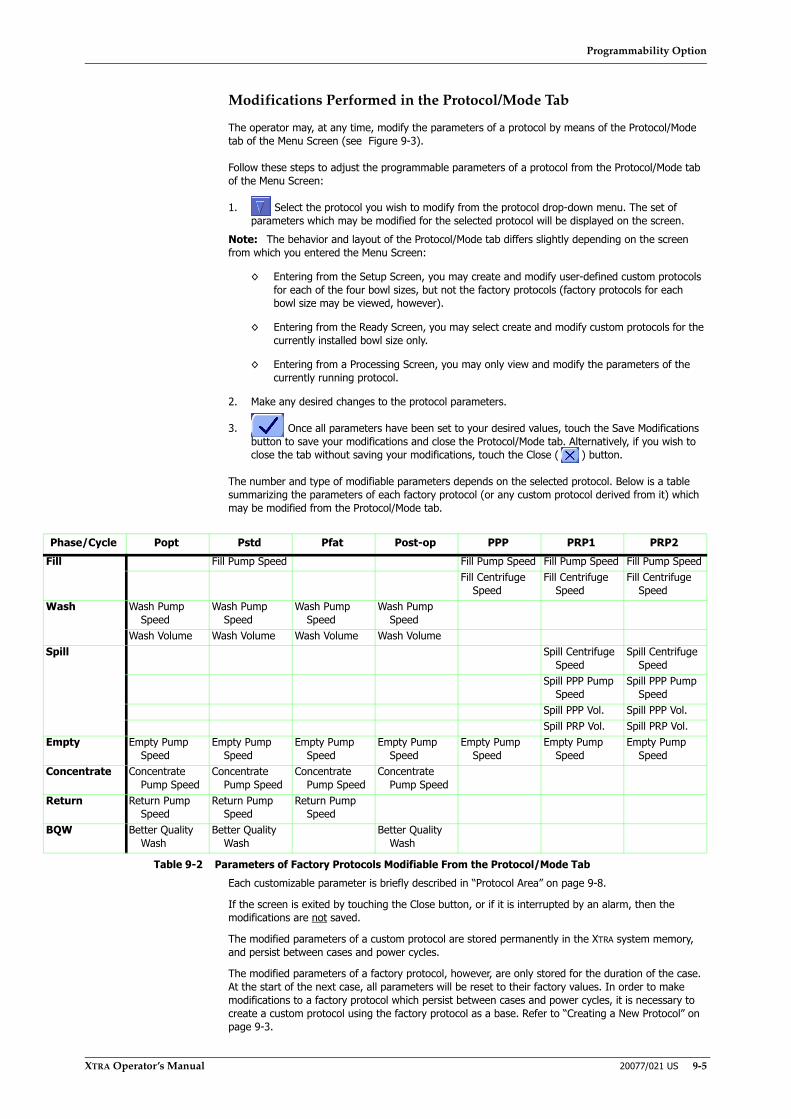
Programmability Option
XTRA Operator’s Manual 20077/021 US 9-5
Modifications Performed in the Protocol/Mode Tab
The operator may, at any time, modify the parameters of a protocol by means of the Protocol/Mode tab of the Menu Screen (see Figure 9-3).
Follow these steps to adjust the programmable parameters of a protocol from the Protocol/Mode tab of the Menu Screen:
1. Select the protocol you wish to modify from the protocol drop-down menu. The set of parameters which may be modified for the selected protocol will be displayed on the screen.
Note: The behavior and layout of the Protocol/Mode tab differs slightly depending on the screen from which you entered the Menu Screen:
◊ Entering from the Setup Screen, you may create and modify user-defined custom protocols for each of the four bowl sizes, but not the factory protocols (factory protocols for each bowl size may be viewed, however).
◊ Entering from the Ready Screen, you may select create and modify custom protocols for the currently installed bowl size only.
◊ Entering from a Processing Screen, you may only view and modify the parameters of the currently running protocol.
2. Make any desired changes to the protocol parameters.
3. Once all parameters have been set to your desired values, touch the Save Modifications button to save your modifications and close the Protocol/Mode tab. Alternatively, if you wish to close the tab without saving your modifications, touch the Close ( ) button.
The number and type of modifiable parameters depends on the selected protocol. Below is a table summarizing the parameters of each factory protocol (or any custom protocol derived from it) which may be modified from the Protocol/Mode tab.
Each customizable parameter is briefly described in “Protocol Area” on page 9-8.
If the screen is exited by touching the Close button, or if it is interrupted by an alarm, then the modifications are not saved.
The modified parameters of a custom protocol are stored permanently in the XTRA system memory, and persist between cases and power cycles.
The modified parameters of a factory protocol, however, are only stored for the duration of the case. At the start of the next case, all parameters will be reset to their factory values. In order to make modifications to a factory protocol which persist between cases and power cycles, it is necessary to create a custom protocol using the factory protocol as a base. Refer to “Creating a New Protocol” on page 9-3.
Phase/Cycle Popt Pstd Pfat Post-op PPP PRP1 PRP2Fill Fill Pump Speed Fill Pump Speed Fill Pump Speed Fill Pump Speed
Fill Centrifuge Speed
Fill Centrifuge Speed
Fill Centrifuge Speed
Wash Wash Pump Speed
Wash Pump Speed
Wash Pump Speed
Wash Pump Speed
Wash Volume Wash Volume Wash Volume Wash VolumeSpill Spill Centrifuge
SpeedSpill Centrifuge
SpeedSpill PPP Pump
SpeedSpill PPP Pump
SpeedSpill PPP Vol. Spill PPP Vol.Spill PRP Vol. Spill PRP Vol.
Empty Empty Pump Speed
Empty Pump Speed
Empty Pump Speed
Empty Pump Speed
Empty Pump Speed
Empty Pump Speed
Empty Pump Speed
Concentrate Concentrate Pump Speed
Concentrate Pump Speed
Concentrate Pump Speed
Concentrate Pump Speed
Return Return Pump Speed
Return Pump Speed
Return Pump Speed
BQW Better Quality Wash
Better Quality Wash
Better Quality Wash
Table 9-2 Parameters of Factory Protocols Modifiable From the Protocol/Mode Tab

Programmability Option
9-6 20077/021 US XTRA Operator’s Manual
Renaming a Protocol
Follow these steps to rename an existing custom protocol. Note that the factory protocols cannot be renamed.
1. Select the protocol you wish to rename from the protocol drop-down menu.
2. Touch the Rename button to rename the newly created protocol to a more useful name. Touching the Rename button will display the Keyboard Screen (see Figure 9-1).
3. Using the controls on the Keyboard Screen, type in the new name for the protocol. When satisfied with the name as entered, touch the Enter button to save the new name and return to the Protocol/Mode tab. The text entered from the Keyboard Screen will be appended to the base protocol’s name to create the new protocol’s name.
Touching the Close button will close the Keyboard Screen without renaming the protocol.
Custom protocol names are prefixed with the name of their base factory protocol. For example, a custom protocol created with a base of the Pstd factory protocol and named “user1” at the Keyboard Screen will have a final name of “Pstd_user1”. The prefix cannot be removed or renamed during the lifetime of the protocol.
Changing the Wakeup Protocol
The wakeup protocol is the protocol which is set as the initially active protocol every time a new case is started after loading the pump loop.
Only one protocol per bowl size may be designated as a wakeup protocol. Designating a new protocol will automatically cause the previous wakeup protocol to lose its designation. It is possible to have no protocol designated as the wakeup protocol. In that case, the protocol last active with the latest bowl used when the XTRA system was powered down will be used as the wakeup protocol.
The currently designated wakeup protocol is indicated by a clock symbol to the right of its name in the protocol drop-down menu in the Protocol/Mode tab of the Menu Screen.
Follow these steps to change the designated wakeup protocol:
1. From the protocol drop-down menu, select the protocol you wish to use for give wakeup status.
2. Touch the Wakeup button to toggle the wakeup state of the selected protocol. The clock icon will appear or disappear to the right of the protocol’s name, indicating its current state. (To have no wakeup protocol, select the protocol with a clock and toggle it so there is no clock symbol.)
Deleting a Protocol
Follow these steps to delete an existing custom protocol. Note that the factory protocols cannot be deleted.
1. From the protocol drop-down menu, select the protocol you wish to delete.
2. Touch the Delete button to delete the selected protocol. It is deleted immediately without confirmation and removed from the protocol drop-down menu.
Deleting the wakeup protocol causes there to be no designated wakeup protocol (and the last used protocol will be used as the wakeup protocol).

Programmability Option
XTRA Operator’s Manual 20077/021 US 9-7
The Protocol/Mode Tab
Figure 9-3 Protocol/Mode Tab of the Menu Screen
For a description of the non-programmability related features of the Protocol/Tab screen, read “Protocol/Mode Tab” on page 5-46.
Mode Buttons
New ButtonTouching the New button creates a new custom protocol based on the selected protocol. Refer to “Creating a New Protocol” on page 9-3.
Rename ButtonTouching the Rename button displays the Keyboard Screen allowing the operator to rename the suffix portion of a custom protocol’s name. A factory protocol cannot be renamed. Refer to “Renaming a Protocol” on page 9-6.
Delete ButtonTouching the Delete button deletes the selected custom protocol. Factory protocols cannot be deleted. Refer to “Deleting a Protocol” on page 9-6.
Wakeup ButtonTouching the Wakeup button toggles the wakeup designation of the selected protocol. Refer to “Changing the Wakeup Protocol” on page 9-6.
4
5
23
1 Protocol buttons 3 Mode area2 Protocol area 4 Save Modifications button
5 Close button
1

Programmability Option
9-8 20077/021 US XTRA Operator’s Manual
Protocol Area
The protocol area contains the parameters and controls used to select and modify the active processing protocol. At the top is the protocol drop-down menu, which is used to select the active protocol. Below that appear parameters specific to the selected protocol.
The parameters which are available for modification vary depending on the selected protocol. Table 9-2, “Parameters of Factory Protocols Modifiable From the Protocol/Mode Tab,” on page 5 summarizes the available parameters for each factory protocol. Those parameters are described below.
Pstd and Derived Protocols
Fill SpeedThe speed at which the pump moves fluid from the reservoir into the bowl during the Fill phase (ml/min).
Wash SpeedThe speed at which the pump moves saline wash solution from the wash bag into the bowl during the Wash phase (ml/min).
Wash VolumeThe volume of wash solution to be pumped from the wash bag into the centrifuge bowl during the Wash phase (ml).
Empty SpeedThe speed at which the pump moves fluid from the bowl into the RBC bag during the Empty phase (ml/min).
Conc SpeedThe speed at which the pump moves fluid from the RBC bag into the bowl during the special Concentrate phase (ml/min).
Return SpeedThe speed at which the pump moves fluid from the bowl back into the reservoir during the special Return phase (ml/min).
The Better Quality Wash button is present in the protocol area for intraoperative and postoperative protocols (Pstd, Popt, Post-op) if it is enabled in the Configuration Mode Screen. This button controls the BQW automation as described in “Better Quality Wash (BQW) Function” on page 7-6.
Popt, Post-op, and Derived Protocols
The customizable parameters available for the Popt and Post-op protocols (and custom protocols derived from them) differ from the Pstd protocols only in that the Fill Speed may not be modified. Refer to “Pstd and Derived Protocols” on page 9-8.
Pfat and Derived Protocols
The customizable parameters available for the Pfat protocol (and custom protocols derived from them) differ from the Popt and Post-op protocols only in that a new parameter, Fat Wash Vol. is shown and may not be modified. Refer to “Popt, Post-op, and Derived Protocols” on page 9-8.
PPP and Derived Protocols
Fill SpeedThe speed at which the pump moves fluid from the pre-donated whole blood bag into the bowl during the Fill phase (ml/min).
Fill Centrifuge SpeedThe speed at which the centrifuge spins during the Fill phase (RPM).
Empty SpeedThe speed at which the pump moves fluid from the bowl into the RBC bag during the Empty phase (ml/min).

Programmability Option
XTRA Operator’s Manual 20077/021 US 9-9
PRP1, PRP2, and Derived Protocols
The PRP protocols contain a few parameters which are not available in the PPP protocol:
Spill SpeedThe speed at which the pump moves fluid from the centrifuge bowl into the PPP and PRP bags during the Spill phase (ml/min).
Spill PPP VolumeThe volume of PPP to spill during the Spill PPP sub-phase (ml).
Spill PRP VolumeThe volume of PRP to spill during the Spill PRP sub-phase (ml).
Spill Centrifuge SpeedThe speed at which the centrifuge spins during the Spill phase (RPM).
Mode Area
The mode area contains the controls for selecting the active operating mode. It is not involved with the XTRA programmability option and is described in “Protocol/Mode Tab” on page 5-46.
Save Modifications and Close Buttons
Touching the Save Modifications button saves any modifications made in the Protocol/Mode tab and closes the Menu Screen.
Touching the Close button closes the Menu Screen without saving any modifications to the Protocol/Mode tab.

Programmability Option
9-10 20077/021 US XTRA Operator’s Manual

Preoperative Sequestration (PPP and PRP)
XTRA Operator’s Manual 20077/021 US 10-1
Chapter 10: Preoperative Sequestration (PPP and PRP)
Description
The preoperative sequestration (SEQ) option of the XTRA system allows separation of plasma and platelets from whole blood previously collected in bags. Typically, whole blood separation is performed so that the patient can receive a supply of autologous plasma containing clotting factors and platelets at the end of a procedure. The XTRA system allows for the collection of platelet-poor plasma (PPP) and platelet-rich plasma (PRP) either in separate bags or together in the same bag.
The SEQ protocols (PPP, PRP1, or PRP2) are often referred to as sequestration and/or preoperative protocols throughout this manual.
Familiarity with the intraoperative and postoperative operating procedures will be helpful in understanding the preoperative sequestration procedures (refer to Chapter 5: Processing).
WARNINGNon-red cell components (e.g., platelet rich/platelet poor plasma intended for transfusion and platelet rich/platelet poor plasma) shall be used or applied before the patient leaves the operating room or clinical procedure area.i
i American Association of Blood Banks. Standards for Perioperative Autologous BloodCollection and Administration. 3rd Edition. Bethesda, MD. 2007 Reference Standard5.1.8 (Handling, Storage, Transportation)
WARNINGDo not reinfuse the PRP back to the patient if the XTRA fails to operate as intended.
WARNINGWhole blood must be anticoagulated as it is collected into bags containing appropriate anticoagulant for plasma sequestration. Inadequate anticoagulation may result in clotting, interfering with the processing of the blood products.
WARNINGIf plasma is being collected for transfusion, it must be transfused before the patient leaves the operating room or clinical procedure area.i
i American Association of Blood Banks. Standards for Blood Banks and TransfusionServices. 18th ed. Bethesda, MD: American Association of Blood Banks, 1997.
WARNINGDo not overfill PPP and PRP bags. Overfilling may cause back pressure that would cause fluid to exit through the bowl seal.
WARNINGTo minimize the complications of particulate matter infusion and the risk of air embolism, use of an in-line microaggregate filter on the patient reinfusion line is STRONGLY RECOMMENDED.
Preoperative Sequestration (PPP and PRP)
10-2 20077/021 US XTRA Operator’s Manual
Enabling the Preoperative Sequestration Protocols
Whole blood separation with the XTRA system requires that at least one of the sequestration protocols be enabled. These protocols may be enabled and disabled from the Protocol Set tab of the Configuration Mode Screen. To enter the Configuration Mode Screen, follow the instructions in “How to Enter the Configuration Mode” on page 8-2.
Overview of Preoperative Sequestration
The XTRA preoperative sequestration option enables the sequestering of plasma, plasma proteins, and platelets from the patient’s own whole blood before initiating intraoperative red blood cell recovery. The preoperative sequestration program is used preoperatively in cardiac surgical procedures and other procedures in which bleeding may occur during the postoperative course, or in those procedures in which platelets may be required postoperatively.
For a detailed description of each of the sequestration protocols shipped with the XTRA, refer to “The Preoperative Sequestration Factory Protocols” on page 10-21.
Regardless of the active sequestration protocol, sequestration processing will be performed after the preliminary collection of the patient’s blood into a transfer bag containing anticoagulant (the machine is not involved in this collection). Whole blood separation consists of three steps:
• Collecting, anticoagulating, and storing the patient's blood. The anticoagulant of choice for plasma sequestration is citrate (ACD-A).
• Processing the blood to separate platelets, plasma, and red blood cells.
• Returning the blood in the RBC bag and the plasma and platelets collected in the PPP and/or PRP bags to the patient.
Preoperative sequestration is performed on the recommendation of a physician and is conducted under close supervision by a trained operator. Blood is withdrawn from the patient through routine hemodilution techniques and collected in a blood bag pre-filled with citrate, such as ACD-A. The volume of blood obtained is determined by the physician and is dependent on the condition of the patient, the patient’s hematocrit, and the amount of plasma desired. The patient’s hemodynamic status and the sequestration procedure should be monitored closely by a physician.
Processing with the sequestration protocols is carried out through the execution of three phases, in this sequence:
1. Fill Phase
2. Spill Phase (except with the PPP protocol)
3. Empty Phase
During the Fill phase, the blood is pumped into the spinning centrifuge bowl. Red cells are retained in the bowl because of their higher density. During the initial phase of the sequestration process, the centrifuge speed of 5600 RPM forces the red blood cells to pack tightly against the side of the bowl. The plasma and plasma proteins are separated from the red cells by a thick white layer, known as the buffy coat, which is rich in platelets and white blood cells (WBC).
As the blood fills the bowl, the plasma, which is of lower density, separates from the red cells and spills into the PPP bag. (When using the PPP protocol, processing ends with the collection of this platelet-poor plasma.)
When enough red cells have filled the bowl to push the buffy coat into a predetermined position, the centrifuge is slowed to 2400 RPM, which enables a “soft spin” that gently releases the buffy coat from the red cell pack. During the Spill phase, blood continues to fill the bowl and the second component, a concentrated platelet product (PRP), spills into the bag (or into a separate PRP bag when the PRP2 protocol is active).
Since the young platelets extend beyond the buffy coat into the red cell layer, red blood cells are collected with the platelet concentrate to maximize platelet yields collected.
At the end of the plasma/platelet collection phase, the red cells are emptied from the bowl into the RBC bag. The fluid in the RBC bag consists of red cells, other formed elements, and some plasma. The
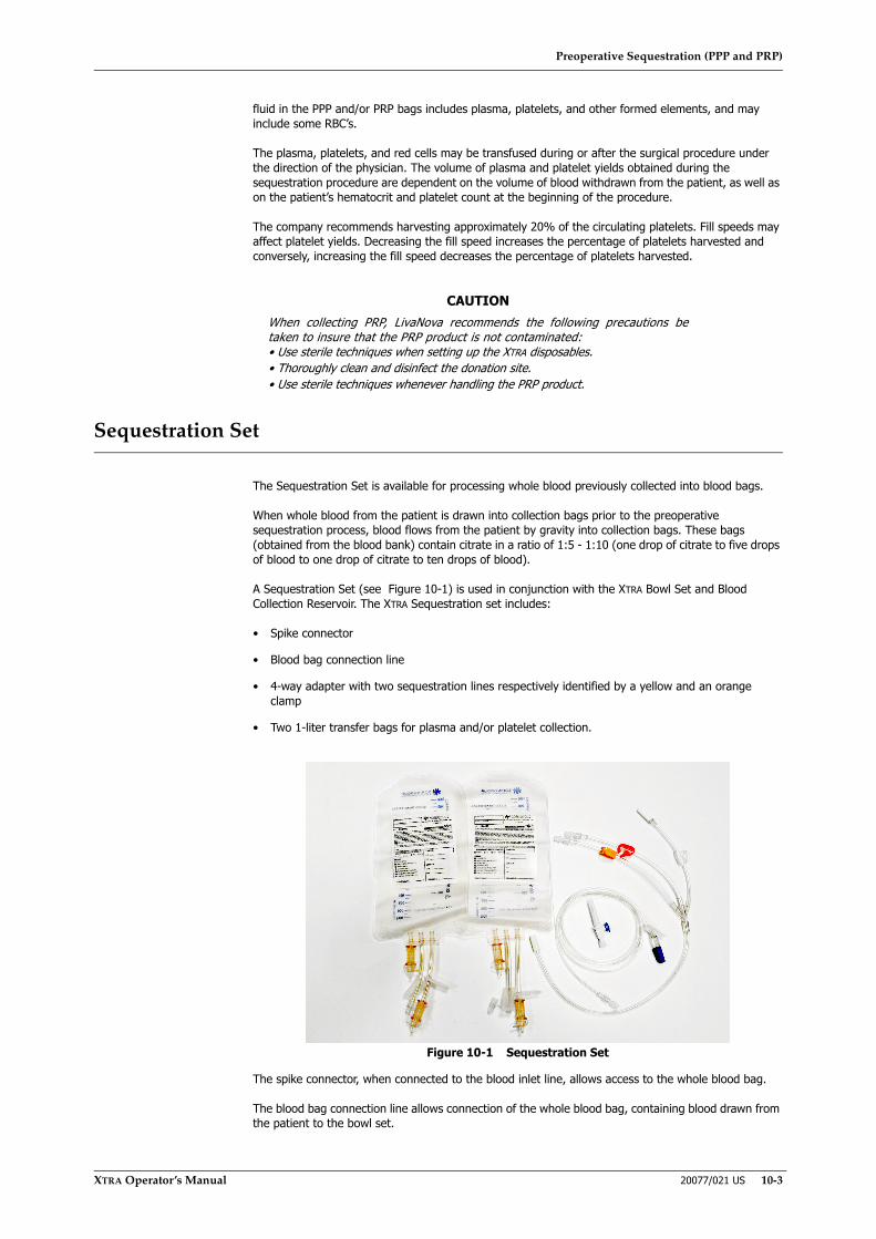
Preoperative Sequestration (PPP and PRP)
XTRA Operator’s Manual 20077/021 US 10-3
fluid in the PPP and/or PRP bags includes plasma, platelets, and other formed elements, and may include some RBC’s.
The plasma, platelets, and red cells may be transfused during or after the surgical procedure under the direction of the physician. The volume of plasma and platelet yields obtained during the sequestration procedure are dependent on the volume of blood withdrawn from the patient, as well as on the patient’s hematocrit and platelet count at the beginning of the procedure.
The company recommends harvesting approximately 20% of the circulating platelets. Fill speeds may affect platelet yields. Decreasing the fill speed increases the percentage of platelets harvested and conversely, increasing the fill speed decreases the percentage of platelets harvested.
Sequestration Set
The Sequestration Set is available for processing whole blood previously collected into blood bags.
When whole blood from the patient is drawn into collection bags prior to the preoperative sequestration process, blood flows from the patient by gravity into collection bags. These bags (obtained from the blood bank) contain citrate in a ratio of 1:5 - 1:10 (one drop of citrate to five drops of blood to one drop of citrate to ten drops of blood).
A Sequestration Set (see Figure 10-1) is used in conjunction with the XTRA Bowl Set and Blood Collection Reservoir. The XTRA Sequestration set includes:
• Spike connector
• Blood bag connection line
• 4-way adapter with two sequestration lines respectively identified by a yellow and an orange clamp
• Two 1-liter transfer bags for plasma and/or platelet collection.
Figure 10-1 Sequestration Set
The spike connector, when connected to the blood inlet line, allows access to the whole blood bag.
The blood bag connection line allows connection of the whole blood bag, containing blood drawn from the patient to the bowl set.
CAUTIONWhen collecting PRP, LivaNova recommends the following precautions betaken to insure that the PRP product is not contaminated:• Use sterile techniques when setting up the XTRA disposables.• Thoroughly clean and disinfect the donation site.• Use sterile techniques whenever handling the PRP product.
Preoperative Sequestration (PPP and PRP)
10-4 20077/021 US XTRA Operator’s Manual
The 4-way adapter is inserted between the outlet tubing from the centrifuge bowl and the waste bag; its two sequestration lines are connected to the blood bags, for plasma (yellow clamp) and platelet collection (orange clamp). During a preoperative sequestration, the clamps are used to direct the flow of plasma and platelets into the collection bags.
Order Guide
The following is the disposable set that must be used with XTRA for sequestration:
Before You Begin
The XTRA enables you to conduct preoperative sequestration and then convert easily and quickly to intraoperative blood recovery. This section explains how to:
• Set up and load disposables for sequestration
• Process blood for sequestration
• Convert to intraoperative blood recovery
Before beginning preoperative sequestration, note the following warnings and cautions.
Catalogue No. Product Designation Product Description04015 Sequestration Set X The product is used for separation of Platelet-Poor
Plasma (PPP) and Platelet-Rich Plasma (PRP) from the patient’s whole blood collected into transfer bags.
Table 10-1
WARNINGWhole blood must be anticoagulated as it is collected into bags containing appropriate anticoagulant for plasma sequestration. Inadequate anticoagulation may result in clotting, interfering with the processing of the blood products.
WARNINGIf plasma is being collected for transfusion, it must be transfused before the patient leaves the operating room or clinical procedure area.
WARNINGDo not over anticoagulate collected blood. Plasma Sequestration has no Wash cycle to remove excess anticoagulant. A part of the anticoagulant used will be returned to the patient.
WARNINGDo not overfill PPP and PRP bags. Overfilling may cause back pressure that would cause fluid to exit through the bowl seal.
WARNINGDo not reinfuse the PRP back to the patient if the XTRA fails to operate as intended.

Preoperative Sequestration (PPP and PRP)
XTRA Operator’s Manual 20077/021 US 10-5
Setup for Preoperative Sequestration
The setup for preoperative sequestration differs slightly from that for intraoperative blood recovery. When using the sequestration protocols, you will first install disposables and set up for sequestration. When the sequestration procedure is completed, it is easy to convert the system quickly to intraoperative blood recovery.
Supplies Required
The following supplies are required to set up the XTRA for both sequestration and intraoperative blood recovery.
1. XTRA Sequestration Set
2. XTRA Bowl Set with 55 ml, 125 ml, 175 ml, or 225 ml bowl
3. XTRA Collection Set
WARNINGTo reduce the possibility of air or particulate embolism, LivaNova STRONGLY RECOMMENDS the use of reinfusion protection devices, including microfilters, when infusing processed blood.
WARNINGTo reduce risk of air embolism, remove all air from the plasma bags before handing the bag over for reinfusion.
WARNINGDo not reinfuse under pressure (i.e., do not use a blood pressure cuff on the RBC or plasma/PRP bags). Reinfusion under pressure could lead to air embolism.
WARNINGNon-red cell components (e.g., platelet rich/platelet poor plasma intended for transfusion and platelet rich/platelet poor plasma) shall be used or applied before the patient leaves the operating room or clinical procedure area.i
i American Association of Blood Banks. Standards for Perioperative Autologous BloodCollection and Administration. 3rd Edition. Bethesda, MD. 2007 Reference Standard5.1.8 (Handling, Storage, Transportation)
CAUTIONMake sure that you attach both PRP bags included in the XTRA SequestrationSet. Because the XTRA does not alert you when a specified volume iscollected, you must have sufficient bags available for the entire amount thatcan be collected.
CAUTIONStore plasma products containing platelets at room temperature (20 °C to 24°C) with continuous, gentle agitation.i
i American Association of Blood Banks. Standards for Blood Banks and TransfusionServices. 18th ed. Bethesda, MD: American Association of Blood Banks, 1997:G3.300.

Preoperative Sequestration (PPP and PRP)
10-6 20077/021 US XTRA Operator’s Manual
Note: The Procedure Set can be used instead of sets indicated in points 2 and 3.
Installing the Blood Collection Reservoir, Connecting the Aspiration Line, Setup of the Vacuum Line, Installing the Bowl Set
For general information about installing disposables, refer to Chapter 4: Installing the Disposables.
1. Follow Steps 1-4 in Chapter 4: Installing the Disposables: “Step 1: Installing the Blood Collection Reservoir” on page 4-3, “Step 2: Connecting the Suction Line” on page 4-4, “Step 3: Setup of the Vacuum Line” on page 4-6, and “Step 4: Installing the Bowl Set” on page 4-7.
2. Hang the Waste bag on the two lower hangers located on the right panel of the machine.
3. Do not clamp the top of the Waste bag.
Note: Do not connect the Waste bag to the bowl outlet tubing at this time.
Connecting the 4-Way Adapter
Figure 10-2 Sequestration Set 4-Way Connection
4. Open the XTRA Sequestration Set
5. Remove the 4-way adapter from the package
6. Connect the inlet port of the 4-Way adapter to the port on the bowl outlet tubing
7. Connect the inlet port of the Waste bag to the port of the branch of the 4-way adapter with the white clamp
CAUTIONUse aseptic technique when installing disposables.

Preoperative Sequestration (PPP and PRP)
XTRA Operator’s Manual 20077/021 US 10-7
Connecting and Hanging the Blood Transfer Bags
8. Remove the two blood transfer bags from the package
9. Connect the blood transfer bags to the sequestration lines as follows:
◊ In PPP procedures, connect one of the blood transfer bags to the sequestration line with the yellow clamp of the 4-way adapter. Close the clamp on the second sequestration line, as it is not used.
◊ In PRP1 procedures, connect one of the blood transfer bags to the sequestration line with the orange clamp of the 4-way adapter. Close the clamp on the second sequestration line, as it is not used.
◊ In PRP2 procedures, connect the blood transfer bag for PPP collection to the sequestration line with the yellow clamp and the other bag for PRP collection to the sequestration line with the orange clamp. Close the clamp on the PRP sequestration line (orange). Make sure the yellow clamp on the PPP sequestration line is open.
Figure 10-3 Blood Transfer Bag Setup: For PPP, PRP1, and PRP2 Procedures
10. Hang the blood transfer bags on the I.V. pole, keeping the inlet line face up (see Figure 10-4). To prevent blood from accumulation in the upper parts of the bags, it is recommended to pass the corresponding lines over the I.V. pole’s arm.
Figure 10-4 Hang the Blood Transfer Bags, Keeping the Inlet Line Facing Up

Preoperative Sequestration (PPP and PRP)
10-8 20077/021 US XTRA Operator’s Manual
Connecting the Blood Bag Connection Line
11. Remove the blood bag connection line from the package. If necessary, connect the adapter with spike
12. Connect the blood bag connection line to the inlet port of the bowl set
13. Spike or connect the whole blood bag with the blood bag connection line
14. Unclamp the lines as appropriate
Figure 10-5 Connecting the Blood Bag Connection Line
Selecting the Active Protocol and Operating Mode
Each cycle of a preoperative sequestration case may be processed using a different sequestration protocol and operating mode (Automatic or Manual). The protocol may be selected only before the cycle is initiated. The operating mode may be changed at any time during processing. The protocol and mode are selected from the Protocol/Mode tab of the Menu Screen.
The process of selecting the active sequestration protocol and operating mode is the same as for selecting an intraoperative or postoperative protocol and operating mode. For step-by-step instructions refer to “Running a Case With the XTRA System” on page 5-5.
WARNINGPositioning the collection bags with the inlet line facing down does not permit the correct execution of the sequestration procedure.
CAUTIONUse aseptic technique when installing disposables.
CAUTIONUse aseptic technique when installing disposables.
Preoperative Sequestration (PPP and PRP)
XTRA Operator’s Manual 20077/021 US 10-9
Running a Preoperative Sequestration Case
This section covers running a preoperative sequestration case with the XTRA system using the dedicated SEQ protocols (PPP, PRP1, and PRP2). To learn how to run a blood recovery case using the intraoperative and postoperative blood recovery protocols, refer to Chapter 5: Processing.
Processing Considerations
An operator must remain in attendance during processing and should carefully monitor the following:
• Observe for adequate filling and emptying of the bowl.
• Check the level of plasma/platelets in the plasma/platelets collection bags and replace as necessary.
• Check the volume in the RBC bag.
WARNINGA trained operator should be present at all times to monitor the XTRA system during processing. During operation, the XTRA should never be left unattended. Unattended processing can lead to the development of problems with the operation of the system and/or with the quality of the end product. If the pump does not stop after the STOP button is pressed, the operator must shut OFF the power.
WARNINGDo not touch any moving parts of the centrifuge or pump. Injury may result.
CAUTIONIn the event of replacing a collection bag, verify that the new bags areproperly connected and the manual clamps reopened before restarting theprocess in order to avoid problems of blood component leakage and circuitbreaks.
CAUTIONIn the course of preoperative sequestration treatments, it is necessary toopen and/or close some of the manual clamps along the lines. Erroneousexecution of these procedures by the operator might lead to breakage of thedisposable, blood component leakage and inadequate collections.
CAUTIONThe use of the Prime IV function or repeated calibration phases of the HCTsensor can lead to a dilution of the collection (PPP/PRP).
CAUTIONAlways close the centrifuge lid before starting any function of the machinethat uses the pump and/or centrifuge action to avoid the risk of touchingmoving parts of the device.
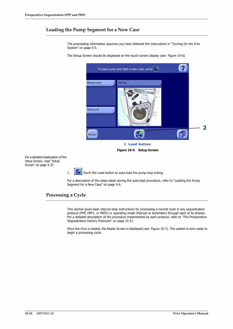
Preoperative Sequestration (PPP and PRP)
10-10 20077/021 US XTRA Operator’s Manual
Loading the Pump Segment for a New Case
The proceeding information assumes you have followed the instructions in “Turning On the XTRA System” on page 5-5.
The Setup Screen should be displayed on the touch screen display (see Figure 10-6).
Figure 10-6 Setup Screen
For a detailed explanation of the Setup Screen, read “Setup Screen” on page 5-37.
1. Touch the Load button to auto-load the pump loop tubing.
For a description of the steps taken during the auto-load procedure, refer to “Loading the Pump Segment for a New Case” on page 5-6.
Processing a Cycle
This section gives basic step-by-step instructions for processing a normal cycle in any sequestration protocol (PPP, PRP1, or PRP2) or operating mode (Manual or Automatic) through each of its phases. For a detailed description of the procedure implemented by each protocol, refer to “The Preoperative Sequestration Factory Protocols” on page 10-21.
Once the XTRA is loaded, the Ready Screen is displayed (see Figure 10-7). The system is now ready to begin a processing cycle.
1 Load button
2
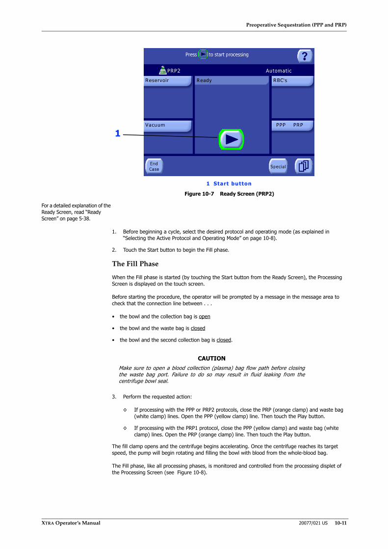
Preoperative Sequestration (PPP and PRP)
XTRA Operator’s Manual 20077/021 US 10-11
Figure 10-7 Ready Screen (PRP2)
For a detailed explanation of the Ready Screen, read “Ready Screen” on page 5-38.
1. Before beginning a cycle, select the desired protocol and operating mode (as explained in “Selecting the Active Protocol and Operating Mode” on page 10-8).
2. Touch the Start button to begin the Fill phase.
The Fill Phase
When the Fill phase is started (by touching the Start button from the Ready Screen), the Processing Screen is displayed on the touch screen.
Before starting the procedure, the operator will be prompted by a message in the message area to check that the connection line between . . .
• the bowl and the collection bag is open
• the bowl and the waste bag is closed
• the bowl and the second collection bag is closed.
3. Perform the requested action:
◊ If processing with the PPP or PRP2 protocols, close the PRP (orange clamp) and waste bag (white clamp) lines. Open the PPP (yellow clamp) line. Then touch the Play button.
◊ If processing with the PRP1 protocol, close the PPP (yellow clamp) and waste bag (white clamp) lines. Open the PRP (orange clamp) line. Then touch the Play button.
The fill clamp opens and the centrifuge begins accelerating. Once the centrifuge reaches its target speed, the pump will begin rotating and filling the bowl with blood from the whole-blood bag.
The Fill phase, like all processing phases, is monitored and controlled from the processing displet of the Processing Screen (see Figure 10-8).
CAUTIONMake sure to open a blood collection (plasma) bag flow path before closingthe waste bag port. Failure to do so may result in fluid leaking from thecentrifuge bowl seal.
1
1 Start button

Preoperative Sequestration (PPP and PRP)
10-12 20077/021 US XTRA Operator’s Manual
Figure 10-8 Sequestration Fill Phase of the Processing Screen
As blood enters the bowl during the Fill phase, centrifugation concentrates the red blood cells into the bowl while the platelet-poor plasma is spilled into the collection bag. This continues until the buffy coat is detected, which indicates that the majority of PPP has been spilled into the collection bag.
1. Pump SpeedThe pump speed (ml/min.) is displayed in a text box in the processing displet to the right of the pump rotor icon. Except during the Fill phase of the Popt and Post-op protocols, the pump speed may be adjusted by touching the text box and using the up and down arrow buttons
(refer to “Modification of Parameters” on page 5-5).
Note: Fill speeds may affect platelet yields. Decreasing the fill speed increases the percentage of platelets harvested and, conversely, increasing the fill speed decreases the percentage of platelets harvested.
2. Fill Status LineThe fill status line indicates the current phase with the fill icon. To the right of the icon is a text field which displays the amount of fluid which has been pumped into the bowl (ml) during the current cycle.
3. Play/Pause buttonTouching the Pause button pauses the processing cycle: the pump is stopped, the Pause button changes to the Play button, and the word “Paused” flashes and a 5:00 minute countdown timer appears in the title bar of the processing displet. The
centrifuge will continue to spin for five minutes.
If Automatic modes are active, phase buttons appear in the button bar of the processing screen while the cycle is paused. This allows for manual intervention in the phase progression. (If Manual mode is active, these phase buttons are always visible.)
Touching the Play button resumes processing from the state the phase was in when it was paused.
Pausing and resuming a cycle is discussed further in “Pausing and Resuming the Cycle” on page 5-11.
The next phase of the processing cycle depends on the active protocol:
4. When processing with the PPP protocol, processing advances directly from the Fill phase to the Empty phase (there is no Spill phase, because PRP is not collected):
◊ If operating in Automatic mode the transition to the Empty phase will happen automatically once the buffy coat is detected.
◊ If operating in Manual mode with the RBC detector enabled: a message will be displayed in the message area and the pump will stop. Touch the Empty phase button in the button bar to advance to the Empty phase. To continue in the Fill phase, touch the Play button.
1 Pump speed 2 Fill Status line3 Play/Pause button
1
2
3

Preoperative Sequestration (PPP and PRP)
XTRA Operator’s Manual 20077/021 US 10-13
◊ If operating in Manual mode with the RBC detector disabled: the buffy coat will not be detected automatically. When you have determined that enough blood has been pumped into the bowl, touch the Empty phase button in the button bar to advance to the Empty phase.
When processing with the PRP protocols, the next phase of operation is the Spill phase:
◊ When operating in Automatic mode, the pump is stopped and processing is advanced to the Spill phase automatically once the buffy coat is detected. No intervention is necessary in this mode.
◊ If operating in Manual mode with the RBC detector enabled: a message will be displayed in the message area and the pump will stop. Touch the Spill phase button in the button bar to advance to the Spill phase. To continue in the Fill phase, touch the Play button.
◊ If operating in Manual mode with the RBC detector disabled: the buffy coat will not be detected automatically. When you have determined that enough blood has been pumped into the bowl, touch the Spill phase button in the button bar to advance to the Spill phase.
Note: It is possible to manually advance phases while operating in the Automatic mode. Touching the Pause button from a Processing Screen will stop the pump and display phase buttons in the button bar. The operator may touch the appropriate phase button (Spill or Empty) to switch to that phase, or touch the Play button to continue processing in the current phase.
The Spill Phase
Note: The Spill phase may be activated from the Fill phase only when the centrifuge has reached its full speed, or when the pump is rotating.
The Spill phase is only entered when processing with the PRP1 or PRP2 protocols. It consists of two sub-phases: during the first (Spill PPP), an additional volume of plasma is collected; during the second (Spill PRP), the concentrated platelets are collected.
The processing displet changes to reflect that the Spill phase is in progress (see Figure 10-9). Depending on which sub-phase is active, either the text “Spill PPP” or “Spill PRP” is displayed in the title bar of the processing displet.
Figure 10-9 Spill Phase (PPP) of the Processing Screen
For a detailed explanation of the Spill phase screen, read “Spill Screen” on page 10-25.
During the Spill PPP sub-phase, the volume of PPP spilled into the collection bag is displayed on the screen and constantly updated by the system’s software. The desired total volume of PPP to spill, as well as the spill speed, can be adjusted from the processing displet. The desired volume of PRP to spill during the Spill PRP sub-phase may also be set from processing displet during this sub-phase.
1 Desired volume of PPP to spil l
2 Desired volume of PRP to spil l
12

Preoperative Sequestration (PPP and PRP)
10-14 20077/021 US XTRA Operator’s Manual
When the Spill PPP sub-phase begins, the centrifuge speed starts decreasing slowly until it reaches the pre-set Spill PPP speed. During this time the message “Automatic pause - Please wait for centrifuge deceleration” is displayed in the message area.
At this stage, the pump remains paused for one minute to improve blood sedimentation. The message “Automatic Pause - Press Play button to start pump” is displayed in the message area. Touching the Play button will interrupt the pause and start the pump.
At the end of the automatic pause period, the pump resumes its rotation at the set speed until the set PPP Spill volume is transferred to the bowl.
At this point, if processing with the PRP2 protocol, the message “Close PPP line. Open PRP line. Then press Play button” is displayed in the message area. Performing these actions allows PRP to be collected in a separate bag.
5. If processing with the PRP2 protocol, clamp the PPP line (yellow clamp), open the PRP line (orange clamp), then touch the Play button, as prompted.
The Spill PRP sub-phase begins, as indicated in the title bar of the processing displet.
During the Spill PRP sub-phase, the volume of PRP spilled into the collection bag, as well as the total volume of PPP and PRP spilled, is displayed on the screen and constantly updated by the system’s software. The desired total volume of PRP to spill, and the spill speed, can be adjusted from the processing displet.
With the pump stopped, the system enters a second automatic pause period to again compress the buffy coat and improve the blood sedimentation. The message “Automatic Pause - Press Play button to start pump” is displayed in the message area. Touching the Play button will interrupt the pause and start the pump.
At the end of this second automatic pause period, the pump resumes its rotation at the set speed until the set PRP Spill volume is transferred to the bowl.
Note: To get better platelets yield, it is advisable not to vary the pump flow during the PRP Spill phase.
6. When operating in both the Automatic mode and in Manual mode, the pump will stop and processing will automatically continue to the Empty phase as soon as the set PRP volume has been spilled.
Note: It is possible to manually advance phases while operating in the Automatic mode. Touching the Pause button from a Processing Screen will stop the pump and display phase buttons in the button bar. The operator may touch the appropriate phase button (Spill or Empty) to switch to that phase, or touch the Play button to continue processing in the current phase.
The Empty Phase
When the Empty phase begins, the centrifuge and pump stop and the processing displet changes to reflect that the Empty phase is in progress (see Figure 10-10).
7. If processing with the PRP2 protocol, the message “Close PRP line. Open PPP line. Then press Play button” is displayed in the message area. Perform the actions as prompted. This allows air to enter the bowl during emptying.
The fill clamp closes, the Empty clamp opens, and the pump rotates clockwise to move the remaining blood components from the bowl to the RBC bag.
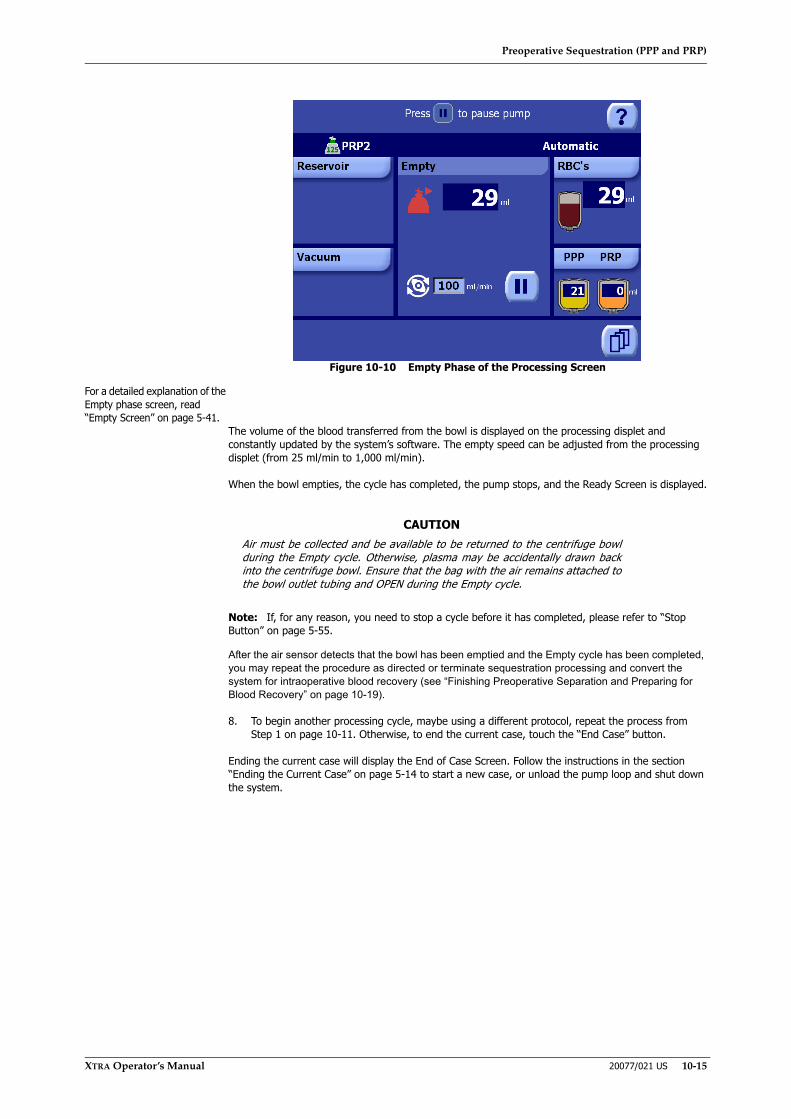
Preoperative Sequestration (PPP and PRP)
XTRA Operator’s Manual 20077/021 US 10-15
Figure 10-10 Empty Phase of the Processing Screen
For a detailed explanation of the Empty phase screen, read “Empty Screen” on page 5-41.
The volume of the blood transferred from the bowl is displayed on the processing displet and constantly updated by the system’s software. The empty speed can be adjusted from the processing displet (from 25 ml/min to 1,000 ml/min).
When the bowl empties, the cycle has completed, the pump stops, and the Ready Screen is displayed.
Note: If, for any reason, you need to stop a cycle before it has completed, please refer to “Stop Button” on page 5-55.
After the air sensor detects that the bowl has been emptied and the Empty cycle has been completed, you may repeat the procedure as directed or terminate sequestration processing and convert the system for intraoperative blood recovery (see “Finishing Preoperative Separation and Preparing for Blood Recovery” on page 10-19).
8. To begin another processing cycle, maybe using a different protocol, repeat the process from Step 1 on page 10-11. Otherwise, to end the current case, touch the “End Case” button.
Ending the current case will display the End of Case Screen. Follow the instructions in the section “Ending the Current Case” on page 5-14 to start a new case, or unload the pump loop and shut down the system.
CAUTIONAir must be collected and be available to be returned to the centrifuge bowlduring the Empty cycle. Otherwise, plasma may be accidentally drawn backinto the centrifuge bowl. Ensure that the bag with the air remains attached tothe bowl outlet tubing and OPEN during the Empty cycle.
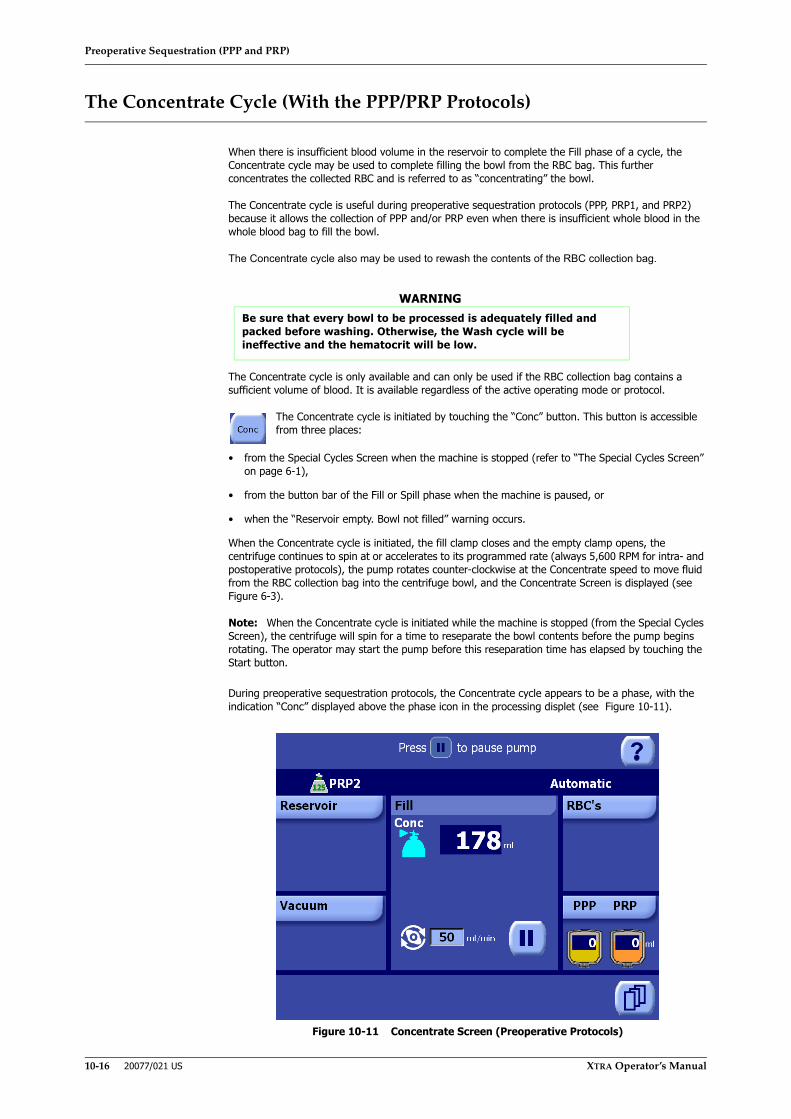
Preoperative Sequestration (PPP and PRP)
10-16 20077/021 US XTRA Operator’s Manual
The Concentrate Cycle (With the PPP/PRP Protocols)
When there is insufficient blood volume in the reservoir to complete the Fill phase of a cycle, the Concentrate cycle may be used to complete filling the bowl from the RBC bag. This further concentrates the collected RBC and is referred to as “concentrating” the bowl.
The Concentrate cycle is useful during preoperative sequestration protocols (PPP, PRP1, and PRP2) because it allows the collection of PPP and/or PRP even when there is insufficient whole blood in the whole blood bag to fill the bowl.
The Concentrate cycle also may be used to rewash the contents of the RBC collection bag.
The Concentrate cycle is only available and can only be used if the RBC collection bag contains a sufficient volume of blood. It is available regardless of the active operating mode or protocol.
The Concentrate cycle is initiated by touching the “Conc” button. This button is accessible from three places:
• from the Special Cycles Screen when the machine is stopped (refer to “The Special Cycles Screen” on page 6-1),
• from the button bar of the Fill or Spill phase when the machine is paused, or
• when the “Reservoir empty. Bowl not filled” warning occurs.
When the Concentrate cycle is initiated, the fill clamp closes and the empty clamp opens, the centrifuge continues to spin at or accelerates to its programmed rate (always 5,600 RPM for intra- and postoperative protocols), the pump rotates counter-clockwise at the Concentrate speed to move fluid from the RBC collection bag into the centrifuge bowl, and the Concentrate Screen is displayed (see Figure 6-3).
Note: When the Concentrate cycle is initiated while the machine is stopped (from the Special Cycles Screen), the centrifuge will spin for a time to reseparate the bowl contents before the pump begins rotating. The operator may start the pump before this reseparation time has elapsed by touching the Start button.
During preoperative sequestration protocols, the Concentrate cycle appears to be a phase, with the indication “Conc” displayed above the phase icon in the processing displet (see Figure 10-11).
Figure 10-11 Concentrate Screen (Preoperative Protocols)
WARNINGBe sure that every bowl to be processed is adequately filled and packed before washing. Otherwise, the Wash cycle will be ineffective and the hematocrit will be low.
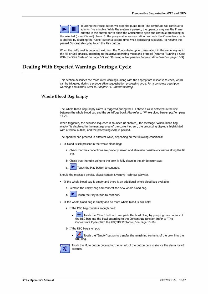
Preoperative Sequestration (PPP and PRP)
XTRA Operator’s Manual 20077/021 US 10-17
Touching the Pause button will stop the pump rotor. The centrifuge will continue to spin for five minutes. While the system is paused, the operator may use the Phase buttons in the button bar to abort the Concentrate cycle and continue processing in
the selected (or a different) phase. In the preoperative sequestration protocols, the Concentrate cycle is aborted by touching the “Conc” button a second time while processing is paused. To resume the paused Concentrate cycle, touch the Play button.
When the buffy coat is detected, exit from the Concentrate cycle comes about in the same way as in the Fill or Spill phases, according to the active operating mode and protocol (refer to “Running a Case With the XTRA System” on page 5-5 and “Running a Preoperative Sequestration Case” on page 10-9).
Dealing With Expected Warnings During a Cycle
This section describes the most likely warnings, along with the appropriate response to each, which can be triggered during a preoperative sequestration processing cycle. For a complete description warnings and alarms, refer to Chapter 14: Troubleshooting.
Whole Blood Bag Empty
The Whole Blood Bag Empty alarm is triggered during the Fill phase if air is detected in the line between the whole blood bag and the centrifuge bowl. Also refer to “Whole blood bag empty.” on page 14-22.
When triggered, the acoustic sequence is sounded (if enabled), the message “Whole blood bag empty.” is displayed in the message area of the current screen, the processing displet is highlighted with a yellow outline, and the processing cycle is paused.
The operator can proceed in different ways, depending on the following conditions:
• If blood is still present in the whole blood bag:
a. Check that the connections are properly sealed and eliminate possible occlusions along the fill line.
b. Check that the tube going to the bowl is fully down in the air detector seat.
c. Touch the Play button to continue.
Should the message persist, please contact LivaNova Technical Services.
• If the whole blood bag is empty and there is an additional whole blood bag available:
a. Remove the empty bag and connect the new whole blood bag.
b. Touch the Play button to continue.
• If the whole blood bag is empty and no more whole blood is available:
a. If the RBC bag contains enough fluid:
• Touch the “Conc” button to complete the bowl filling by pumping the contents of the RBC bag into the bowl according to the Concentrate function (refer to “The Concentrate Cycle (With the PPP/PRP Protocols)” on page 10-16).
b. If the RBC bag is empty:
• Touch the “Empty” button to transfer the remaining contents of the bowl into the RBC bag.
Touch the Mute button (located at the far left of the button bar) to silence the alarm for 45 seconds.

Preoperative Sequestration (PPP and PRP)
10-18 20077/021 US XTRA Operator’s Manual
PPP Bag Full
The PPP Bag Full warning is triggered during the Fill or Spill phases if the volume transferred to the PPP bag exceeds the pre-set safety level. Also refer to “PPP bag full. Empty or replace it.” on page 14-18.
When triggered, the acoustic sequence is sounded (if enabled), the message “PPP bag full. Empty or replace it.” is displayed in the message area of the current screen, the PPP/PRP displet is highlighted with a red outline, and the processing cycle is paused.
To proceed, empty or replace the PPP bag, then touch the Play button to resume.
Note: The volume counter will be reset to zero.
PRP Bag Full
The PRP Bag Full warning is triggered during the Fill or Spill phases if the volume transferred to the PRP bag exceeds the pre-set safety level. Also refer to “PRP bag full. Empty or replace it.” on page 14-18.
When triggered, the acoustic sequence is sounded (if enabled), the message “PRP bag full. Empty or replace it.” is displayed in the message area of the current screen, the PPP/PRP displet is highlighted with a red outline, and the processing cycle is paused.
To proceed, empty or replace the PRP bag, then touch the Play button to resume.
Note: The volume counter will be reset to zero.
RBC Bag Full
The RBC Bag Full warning is triggered during the Empty phase if the volume transferred to the RBC bag exceeds the pre-set safety level. Also refer to “RBC bag full. Empty or replace it.” on page 14-19.
When triggered, the acoustic sequence is sounded (if enabled), the message RBC bag full. Empty or replace it. is displayed in the message area of the current screen, the RBC displet is highlighted with a red outline, and the processing cycle is paused.
To proceed, empty or replace the RBC bag, then touch the Play button to resume.
Note: The volume counter will be reset to zero.

Preoperative Sequestration (PPP and PRP)
XTRA Operator’s Manual 20077/021 US 10-19
Finishing Preoperative Separation and Preparing for Blood Recovery
To finish preoperative sequestration and prepare for blood recovery, do the following:
1. Remove any air from the PRP bags.
2. Clamp both PRP bags. Detach the PRP bags from the plasma sequestration lines.
3. using the caps and plugs provided, cap and plug the PRP bags and lines. This will decrease the chance of contamination and any bio-hazard caused by dripping.
4. Reinfuse autologous plasma according to hospital guidelines and/or AABB standards.
5. Unclamp the inlet tube to the waste bag.
6. Clamp the blood inlet line from the whole blood bag to isolate the patient line and unclamp the line from the reservoir.
7. Connect the Wash line to the wash solution.
a. Hang the wash solution bags on the lower hooks of the IV pole.
b. Using aseptic technique, spike each Wash line into a bag of wash solution. Unclamp at least one line.
8. If you are using a new reinfusion bag:
a. Remove the cap from the reinfusion bag.
b. Remove the cap from the tubing line and twist connect to the reinfusion bag
c. Hang the new reinfusion bag.
WARNINGTo reduce risk of air embolism, remove all air from the plasma bags before handing the bag over for reinfusion.
WARNINGDo not reinfuse under pressure (i.e., do not use a blood pressure cuff on the RBC or plasma/PRP bags). Reinfusion under pressure could lead to air embolism.
WARNINGNon-red cell components (e.g., platelet rich/platelet poor plasma intended for transfusion and platelet rich/platelet poor plasma) shall be used or applied before the patient leaves the operating room or clinical procedure area.i
i American Association of Blood Banks. Standards for Perioperative Autologous BloodCollection and Administration. 3rd Edition. Bethesda, MD. 2007 Reference Standard5.1.8 (Handling, Storage, Transportation)
WARNINGDo not reinfuse the PRP back to the patient if the XTRA fails to operate as intended.
CAUTIONMake sure that the waste line is unclamped before starting blood salvageprocessing.

Preoperative Sequestration (PPP and PRP)
10-20 20077/021 US XTRA Operator’s Manual
9. Connect the suction line, described in “Step 2: Connecting the Suction Line” on page 4-4.
10. See Chapter 5: Processing for instructions on processing for intraoperative blood recovery.
Tally Information
A table containing total processed and collected volumes is available at any time during processing from the Tally tab of the Menu Screen (see Figure 10-12).
Figure 10-12 Tally Tab of the Menu Screen (PRP2)
For a detailed explanation of the Tally tab of the Menu Screen, read “Tally Tab” on page 5-44.
The Tally tab of the Menu Screen displays the total volume of whole blood processed in the second column, followed by the total volumes of RBC, PPP, and PRP collected in each cycle. The totals at the bottom of each column reflect the volumes of the entire case.
The PPP and PRP volumes are completely separate from the intraoperative blood recovery volumes. The tallies are reset only when the XTRA is shut down or a new case is started.
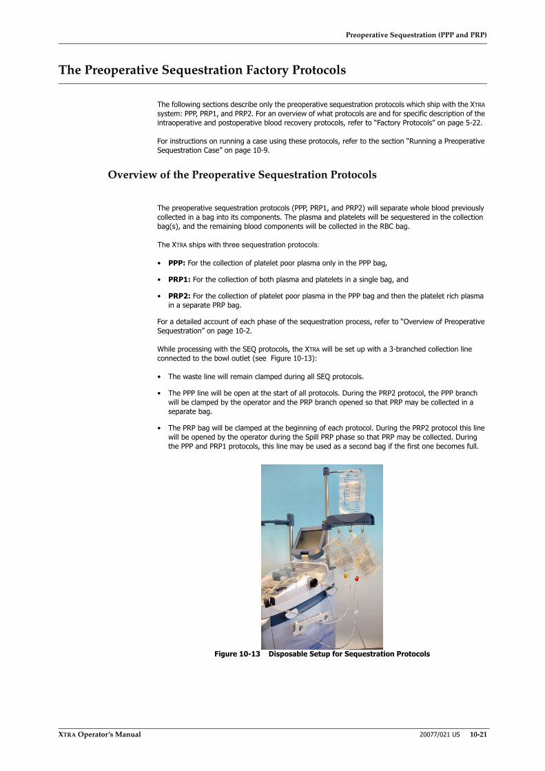
Preoperative Sequestration (PPP and PRP)
XTRA Operator’s Manual 20077/021 US 10-21
The Preoperative Sequestration Factory Protocols
The following sections describe only the preoperative sequestration protocols which ship with the XTRA system: PPP, PRP1, and PRP2. For an overview of what protocols are and for specific description of the intraoperative and postoperative blood recovery protocols, refer to “Factory Protocols” on page 5-22.
For instructions on running a case using these protocols, refer to the section “Running a Preoperative Sequestration Case” on page 10-9.
Overview of the Preoperative Sequestration Protocols
The preoperative sequestration protocols (PPP, PRP1, and PRP2) will separate whole blood previously collected in a bag into its components. The plasma and platelets will be sequestered in the collection bag(s), and the remaining blood components will be collected in the RBC bag.
The XTRA ships with three sequestration protocols:
• PPP: For the collection of platelet poor plasma only in the PPP bag,
• PRP1: For the collection of both plasma and platelets in a single bag, and
• PRP2: For the collection of platelet poor plasma in the PPP bag and then the platelet rich plasma in a separate PRP bag.
For a detailed account of each phase of the sequestration process, refer to “Overview of Preoperative Sequestration” on page 10-2.
While processing with the SEQ protocols, the XTRA will be set up with a 3-branched collection line connected to the bowl outlet (see Figure 10-13):
• The waste line will remain clamped during all SEQ protocols.
• The PPP line will be open at the start of all protocols. During the PRP2 protocol, the PPP branch will be clamped by the operator and the PRP branch opened so that PRP may be collected in a separate bag.
• The PRP bag will be clamped at the beginning of each protocol. During the PRP2 protocol this line will be opened by the operator during the Spill PRP phase so that PRP may be collected. During the PPP and PRP1 protocols, this line may be used as a second bag if the first one becomes full.
Figure 10-13 Disposable Setup for Sequestration Protocols

Preoperative Sequestration (PPP and PRP)
10-22 20077/021 US XTRA Operator’s Manual
PPP
The PPP protocol is intended to collect platelet-poor plasma in the PPP bag. The remaining blood components will be emptied to the RBC bag. Unlike the other sequestration protocols, the PPP protocol is made up of only two phases: Fill and Empty.
Fill Phase
The Fill phase of the PPP protocol is identical to that of the PRP protocols. It consists of the following execution steps:
1. The centrifuge lid lock is engaged, the fill clamp is opened, and the centrifuge accelerates up to the programmed speed (default is 5,600 RPM).
Note: If the bowl already contains blood and the buffy coat is detected before the centrifuge reaches its programmed speed, the pump shall not start until 15 seconds after the centrifuge reaches its target speed. This delay is intended to stabilize the buffy coat. The operator may manually start the pump during this wait by touching the Play button. If the buffy coat is still detected after the delay, then the pump is not started and the next step is skipped.
2. Once the centrifuge reaches its set speed, the pump begins to rotate counter-clockwise, pumping blood from the whole blood bag to the bowl, at the factory defined speed (with a maximum speed of 100 ml/min.). The pump continues to rotate at this speed until the bowl is 3/4 full of concentrated red blood cells, at which point the Final Fill sub-phase begins.
3. During the Final Fill sub-phase, the pump speed is decreased in order to increase the thickness of the buffy coat layer. (Modifications made by the operator to the pump speed during the Final Flow sub-phase are reset to the factory settings at the next Fill phase.) The Final Fill sub-phase continues until the buffy coat is detected, indicating that all the PPP has spilled into the PPP bag.
4. The next action after the buffy coat is detected depends on the operating mode:
◊ If Automatic mode is active, the switch from the Fill phase to the Empty phase happens automatically.
◊ If Manual mode is active and the RBC detector is enabled, the system will issue a message in the message area and stop the pump. The operator may then either continue with the Fill phase or move forward to a different phase.
◊ If Manual mode is active and the RBC detector is disabled, no actions will be performed by the system until the operator presses a key or some event is triggered (such as an alarm).
Empty Phase
The Empty phase of the PPP protocol is identical to that of the PRP protocols. It consists of the following execution steps:
1. The centrifuge and pump stop, the fill clamp closes, and the empty clamp opens.
2. In order to move the remaining fluid from the bowl to the RBC bag, the pump begins rotating clockwise with an appropriate acceleration. It reaches either the Empty factory pre-set pump speed, or, if the pump speed has been modified by the operator in a previous cycle, the new speed.
3. When air is detected in the line, the bowl is presumed empty and the pump stops, the empty clamp closes, and the Ready screen is displayed on the touch screen.

Preoperative Sequestration (PPP and PRP)
XTRA Operator’s Manual 20077/021 US 10-23
PRP1
The PRP1 protocol is intended to collect plasma, including platelet-rich plasma, into the PRP bag. The remaining blood components will be emptied to the RBC bag. The PRP protocol is made up of three phases: Fill, Spill, and Empty.
Fill Phase
The Fill phase of the PRP1 protocol is similar to that of the PPP protocol detailed in “PPP” on page 10-22, with exception that at the end of the Fill phase, while operating in Automatic mode, the processing phase is automatically advanced to the Spill phase instead of to the Empty phase.
Spill Phase
Unlike the PPP protocol, the PRP protocols enter a Spill phase once the buffy coat is detected and the PPP has been collected in the collection bag. The Spill phase makes possible further separation and enrichment of the platelet harvest.
The first half of the Spill phase is the Spill PPP sub-phase. It consists of the following execution steps:
1. The pump stops and the centrifuge speed is steadily decreased to a set speed (2,400 RPM by default). This slowing of the centrifuge de-compacts the red blood cells and enhances the buffy coat.
2. The centrifuge spins for one minute at this slower speed with the pump stopped. This one-minute delay serves to re-compact the buffy coat.
3. At the end of the one-minute delay, the pump resumes its rotation at the set speed until the set PPP spill volume is transferred to the bowl (which causes an additional volume of PPP to spill into the PRP collection bag).
The second half of the Spill phase is the Spill PRP sub-phase. It consists of the following execution steps:
4. The pump stops for a second one-minute delay to again compact the buffy coat.
5. At the end of the one-minute delay, the pump resumes its rotation at the set speed until the set PRP spill volume is transferred to the bowl (which causes an equal volume of PRP to spill into the PRP collection bag).
6. After the set volume of PRP is spilled, the switch from the Spill phase to the Empty phase happens automatically.
Empty Phase
The Empty phase of the PRP1 protocol, during which the remaining blood components in the bowl are transferred to the RBC bag, is identical to that of the PPP and PRP2 protocols detailed in “PPP” on page 10-22.
PRP2
The PRP2 protocol is intended to collect platelet-poor plasma in the PPP bag, and platelet-rich plasma in the separate PRP bag. The remaining blood components will be emptied to the RBC bag. The PRP protocol is made up of three phases: Fill, Spill, and Empty.
Fill Phase
The Fill phase of the PRP2 protocol is identical to the PRP1 Fill phase (refer to “PRP1” on page 10-23).
Spill Phase
The Spill phase of the PRP2 protocol is similar to the PRP1 Spill phase (refer to “PRP1” on page 10-23). The difference is that between the Spill PPP and Spill PRP sub-phases, the operator will be asked to clamp the PPP bag and open the PRP bag, allowing the PPP and PRP to be collected in separate bags.
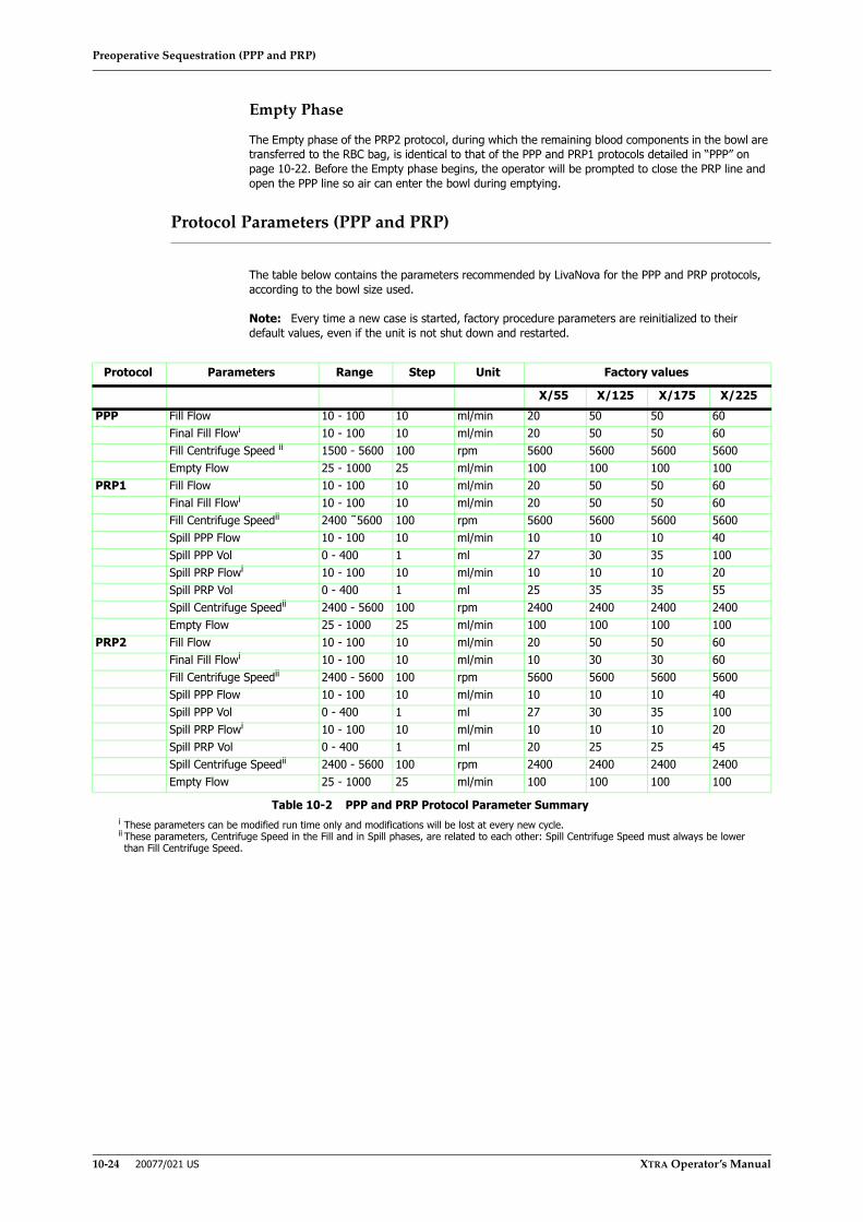
Preoperative Sequestration (PPP and PRP)
10-24 20077/021 US XTRA Operator’s Manual
Empty Phase
The Empty phase of the PRP2 protocol, during which the remaining blood components in the bowl are transferred to the RBC bag, is identical to that of the PPP and PRP1 protocols detailed in “PPP” on page 10-22. Before the Empty phase begins, the operator will be prompted to close the PRP line and open the PPP line so air can enter the bowl during emptying.
Protocol Parameters (PPP and PRP)
The table below contains the parameters recommended by LivaNova for the PPP and PRP protocols, according to the bowl size used.
Note: Every time a new case is started, factory procedure parameters are reinitialized to their default values, even if the unit is not shut down and restarted.
Protocol Parameters Range Step Unit Factory values
X/55 X/125 X/175 X/225PPP Fill Flow 10 - 100 10 ml/min 20 50 50 60
Final Fill Flowi
i These parameters can be modified run time only and modifications will be lost at every new cycle.
10 - 100 10 ml/min 20 50 50 60Fill Centrifuge Speed ii
ii These parameters, Centrifuge Speed in the Fill and in Spill phases, are related to each other: Spill Centrifuge Speed must always be lowerthan Fill Centrifuge Speed.
1500 - 5600 100 rpm 5600 5600 5600 5600Empty Flow 25 - 1000 25 ml/min 100 100 100 100
PRP1 Fill Flow 10 - 100 10 ml/min 20 50 50 60Final Fill Flowi 10 - 100 10 ml/min 20 50 50 60Fill Centrifuge Speedii 2400 ˜5600 100 rpm 5600 5600 5600 5600Spill PPP Flow 10 - 100 10 ml/min 10 10 10 40Spill PPP Vol 0 - 400 1 ml 27 30 35 100Spill PRP Flowi 10 - 100 10 ml/min 10 10 10 20Spill PRP Vol 0 - 400 1 ml 25 35 35 55Spill Centrifuge Speedii 2400 - 5600 100 rpm 2400 2400 2400 2400Empty Flow 25 - 1000 25 ml/min 100 100 100 100
PRP2 Fill Flow 10 - 100 10 ml/min 20 50 50 60Final Fill Flowi 10 - 100 10 ml/min 10 30 30 60Fill Centrifuge Speedii 2400 - 5600 100 rpm 5600 5600 5600 5600Spill PPP Flow 10 - 100 10 ml/min 10 10 10 40Spill PPP Vol 0 - 400 1 ml 27 30 35 100Spill PRP Flowi 10 - 100 10 ml/min 10 10 10 20Spill PRP Vol 0 - 400 1 ml 20 25 25 45Spill Centrifuge Speedii 2400 - 5600 100 rpm 2400 2400 2400 2400Empty Flow 25 - 1000 25 ml/min 100 100 100 100
Table 10-2 PPP and PRP Protocol Parameter Summary

Preoperative Sequestration (PPP and PRP)
XTRA Operator’s Manual 20077/021 US 10-25
Preoperative Sequestration Operating Modes
The XTRA system is equipped with two operating modes which may be used with the whole blood separation protocols:
• Automatic
• Manual
The 1 Touch mode is not available during whole blood processing.
Modes of operation influence the execution of the active protocol, affecting the transition between phases and cycles.
The current operating mode can be set from the Protocol/Mode tab of the Menu Screen. The operating mode may be changed while the machine is stopped (at the Ready Screen), or any time during a cycle. Step-by-step instructions for selecting the active operating mode can be found in the section “Running a Case With the XTRA System” on page 5-5.
When operating in Automatic mode, the machine detects the end of each phase and advances to the next phase automatically. When operating in Manual mode, the operator must manually advance to the next processing phase (possibly being prompted by the machine at the end of the Fill phase, if the RBC detector option is ON).
Both modes are described in detail in “The Operating Modes” on page 5-31
Spill Screen
The Spill Screen only appears when processing with a PRP collection protocol (PRP1 or PRP2). The Spill Screen has two sub-phases: Spill PPP (see Figure 10-14) and Spill PRP (see Figure 10-15). The processing displet changes to present relevant controls to each.
Figure 10-14 Spill PPP Phase of the Processing Screen (Paused)
3
1 “Conc” button 4 Play/Pause button2 Pump speed 5 Empty button3 Spill Status l ine 6 Menu button
12 4
5
6

Preoperative Sequestration (PPP and PRP)
10-26 20077/021 US XTRA Operator’s Manual
Figure 10-15 Spill PRP Phase of the Processing Screen
1. “Conc” ButtonTouching the “Conc” button initiates the Concentrate cycle (refer to “The Concentrate Cycle (With the PPP/PRP Protocols)” on page 10-16). This button is only present while processing is paused.
2. Pump SpeedThe pump speed (ml/min.) is displayed in a text box in the processing displet to the right of the pump rotor icon. The pump speed may be adjusted by touching the text box and using the up and down arrow buttons (refer to “Modification of Parameters” on page 5-5).
3. Spill Status LineThe spill status line consists of three elements, from left to right: an icon indicating the current sub-phase (yellow for PPP Spill, orange for PRP Spill), a text field displaying the current volume of PPP or PRP spilled, and a text box displaying the target volume of PPP or PRP to spill. The
target spill volume may be modified by touching the text box and using the up and down arrow buttons.
“Spill PRP” Text BoxThe “Spill PRP” field and text box displays the target volume of PRP to spill during the PRP Spill sub-phase. The target spill volume may be modified by touching the text box and using the up and down arrow buttons. The “Spill PRP” text box is only present during the PPP Spill sub-phase.
“Total Spill” FieldThe “Total Spill” field displays the total volume (ml) of both PPP and PRP collected. It is only present during the PRP Spill sub-phase.
4. Play/Pause buttonTouching the Pause button pauses the processing cycle: the pump is stopped, the Pause button changes to the Play button, and the word “Paused” flashes and a 5:00 countdown timer appears in the title bar of the processing displet. The centrifuge will
continue to spin for five minutes.
If Automatic mode is active, phase buttons appear in the button bar of the processing screen while the cycle is paused. This allows for manually intervention in the phase progression. (If Manual mode is active, these phase buttons are always visible.)
Touching the Play button resumes processing from the state the phase was in when it was paused.
Pausing and resuming a cycle is discussed further in “Pausing and Resuming the Cycle” on page 5-11.

Preoperative Sequestration (PPP and PRP)
XTRA Operator’s Manual 20077/021 US 10-27
5. Empty buttonTouching the Empty button changes to the empty phase and displays the Empty Screen (refer to “Empty Screen” on page 5-41). While operating in Automatic mode, the Empty button is only visible while processing is paused; it is always visible in Manual mode.
6. Menu ButtonTouching the menu button will bring up the Menu Screen. Various XTRA settings can be adjusted from the Menu Screen. Touching the close button in the Menu Screen will close the Menu Screen and display the previously displayed screen. Refer to the section “Menu Screen”
on page 5-44.

Preoperative Sequestration (PPP and PRP)
10-28 20077/021 US XTRA Operator’s Manual

Data Download Option
XTRA Operator’s Manual 20077/021 US 11-1
Chapter 11: Data Download Option
Description
The XTRA data download option enables the operator to download processing tallies and information for blood recovery and preoperative sequestration procedures in several ways:
• Integrated printer module
• Integrated USB (three) and RS232 serial ports (three)
• Ethernet port[
Figure 11-1 Data Ports Panel on Rear of Machine
Enabling Data Download Option
The various methods of data download must be enabled in the Features tab of the Configuration Mode Screen before they will be available for use. Refer to “How to Enter the Configuration Mode” on page 8-2 for instructions on entering the Configuration Mode Screen. For more on configuring the XTRA system refer to the rest of Chapter 8: Configuring XTRA.
XTRA Output Devices
Printer
The integrated dot-matrix printer situated inside the rear panel enables the operator to print paper reports of case data (see Figure 11-2).
WARNINGUse only XTRA USB memory sticks.
1 Ethernet Port 2 USB Ports3 RS232 Ports
3
21

Data Download Option
11-2 20077/021 US XTRA Operator’s Manual
Figure 11-2 Integrated Dot-Matrix Printer
The printer consists of:
• a front cover that allows access to the paper roll and the print head, and
• a control panel comprising the PRINT and FEED buttons, and the POWER and STATUS LEDs, which have the following functions:
◊ Pressing the PRINT button together with the FEED button allows the printer parameters to be modified.
◊ Pressing the FEED key advances the paper forward.
◊ When lit, the POWER LED indicates that the printer is receiving a power supply.
◊ When lit, the STATUS LED indicates that the printer is on.
Refer to “Sending Tallies to the Printer” on page 11-6 for instructions on printing case data.
Refer to “List of Operator-Replaceable Parts” on page 15-6 for instructions on replacing the printer paper and ink cartridge.
USB Ports
The three integrated USB ports situated on the rear panel of the XTRA system allow case data to be saved to the XTRA USB memory sticks.
CAUTIONThe factory set printer parameters allow the best printing result. It isadvisable NOT to alter them.
WARNINGUse only XTRA USB memory sticks.
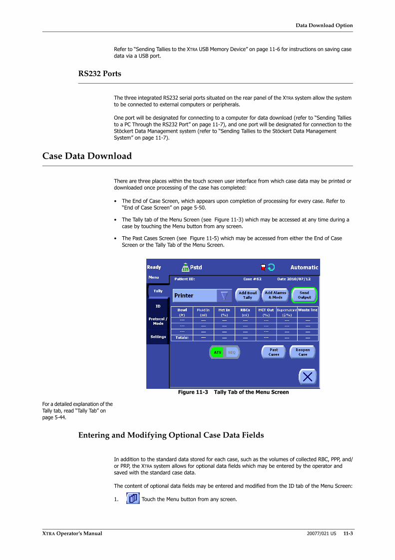
Data Download Option
XTRA Operator’s Manual 20077/021 US 11-3
Refer to “Sending Tallies to the XTRA USB Memory Device” on page 11-6 for instructions on saving case data via a USB port.
RS232 Ports
The three integrated RS232 serial ports situated on the rear panel of the XTRA system allow the system to be connected to external computers or peripherals.
One port will be designated for connecting to a computer for data download (refer to “Sending Tallies to a PC Through the RS232 Port” on page 11-7), and one port will be designated for connection to the Stöckert Data Management system (refer to “Sending Tallies to the Stöckert Data Management System” on page 11-7).
Case Data Download
There are three places within the touch screen user interface from which case data may be printed or downloaded once processing of the case has completed:
• The End of Case Screen, which appears upon completion of processing for every case. Refer to “End of Case Screen” on page 5-50.
• The Tally tab of the Menu Screen (see Figure 11-3) which may be accessed at any time during a case by touching the Menu button from any screen.
• The Past Cases Screen (see Figure 11-5) which may be accessed from either the End of Case Screen or the Tally Tab of the Menu Screen.
Figure 11-3 Tally Tab of the Menu Screen
For a detailed explanation of the Tally tab, read “Tally Tab” on page 5-44.
Entering and Modifying Optional Case Data Fields
In addition to the standard data stored for each case, such as the volumes of collected RBC, PPP, and/or PRP, the XTRA system allows for optional data fields which may be entered by the operator and saved with the standard case data.
The content of optional data fields may be entered and modified from the ID tab of the Menu Screen:
1. Touch the Menu button from any screen.

Data Download Option
11-4 20077/021 US XTRA Operator’s Manual
2. From the left side of the Menu Screen, touch the ID tab. The ID tab will be displayed (see Figure 11-4).
Figure 11-4 ID Tab of the Menu Screen
For a detailed explanation of the ID Tab, read “Identifier (ID) Tab” on page 5-46.
Field values may be edited in two ways:
• by touching the field value box, or
• by using the field’s drop-down rapid selection menu if enabled.
To create, modify, and delete fields, and to configure the list of values available via the drop-down rapid selection menu for a field, refer to “Setting the Rapid Selection of ID” on page 8-10.
Selecting Past Cases
By default, both the End of Case Screen and the Tally tab of the Menu Screen only display and allow for the saving of the current case. To select past cases for display or saving, perform the following steps from the End of Case Screen or the Tally tab of the Menu Screen:
1. Touch the “Past Cases” button. The Past Cases Screen will appear on the touch screen display (see Figure 11-5).

Data Download Option
XTRA Operator’s Manual 20077/021 US 11-5
Figure 11-5 Past Cases Screen
For a detailed explanation of the Past Cases Screen, read “Past Cases Screen” on page 5-52.
2. From the Past Cases Screen, locate and select (touch) the case(s) you wish to view or export. Scroll through the list of past cases by touching the arrow buttons to the right of the list.
Touching the “View Case” button with a single case selected will display the Tally tab of the Menu screen with the tally table populated with data from the selected case.
Touching any of the output buttons (“Send to Printer”, “Send to XTRA USB”, or “Send to RS232”) will export the data of the selected case(s) as described in the sections below. Only a single case may be printed or viewed at the same time, but multiple cases may be selected for exporting via XTRA USB or RS232.
Touching the Close button will exit the Past Cases Screen without selecting a past case to view or export.
Re-opening Past Cases
It is possible to re-open a past case, which has been selected for viewing, for further processing. To do so, touch the “Reopen Case” button from the Tally Tab of the Menu Screen. The operator will be prompted for confirmation before the case is reopened.
Once the re-opening has been confirmed by the operator, the setup data of the original case will be assumed as the setup data of the re-opened case, and all further processing and tally data will be considered part of the re-opened case.
Selecting the Output Device for Data Download
Case data may be exported to several output destinations. Before sending case data from the End of Case Screen or Tally tab of the Menu Screen, the operator must select the output destination using the drop-down menu:
1. Touch the arrow portion of the destination drop-down menu. The menu will then expand displaying a list of available output destinations (see Figure 11-6). If necessary, the list may be scrolled using the up and down arrow buttons which appear to the right of the list.
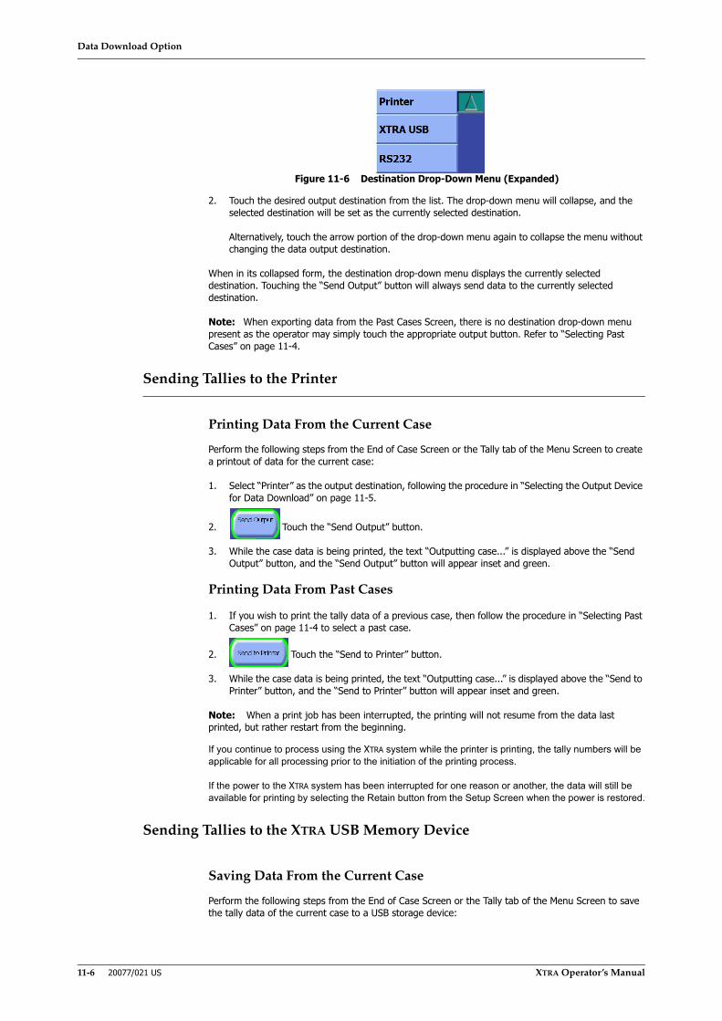
Data Download Option
11-6 20077/021 US XTRA Operator’s Manual
Figure 11-6 Destination Drop-Down Menu (Expanded)
2. Touch the desired output destination from the list. The drop-down menu will collapse, and the selected destination will be set as the currently selected destination.
Alternatively, touch the arrow portion of the drop-down menu again to collapse the menu without changing the data output destination.
When in its collapsed form, the destination drop-down menu displays the currently selected destination. Touching the “Send Output” button will always send data to the currently selected destination.
Note: When exporting data from the Past Cases Screen, there is no destination drop-down menu present as the operator may simply touch the appropriate output button. Refer to “Selecting Past Cases” on page 11-4.
Sending Tallies to the Printer
Printing Data From the Current Case
Perform the following steps from the End of Case Screen or the Tally tab of the Menu Screen to create a printout of data for the current case:
1. Select “Printer” as the output destination, following the procedure in “Selecting the Output Device for Data Download” on page 11-5.
2. Touch the “Send Output” button.
3. While the case data is being printed, the text “Outputting case...” is displayed above the “Send Output” button, and the “Send Output” button will appear inset and green.
Printing Data From Past Cases
1. If you wish to print the tally data of a previous case, then follow the procedure in “Selecting Past Cases” on page 11-4 to select a past case.
2. Touch the “Send to Printer” button.
3. While the case data is being printed, the text “Outputting case...” is displayed above the “Send to Printer” button, and the “Send to Printer” button will appear inset and green.
Note: When a print job has been interrupted, the printing will not resume from the data last printed, but rather restart from the beginning.
If you continue to process using the XTRA system while the printer is printing, the tally numbers will be applicable for all processing prior to the initiation of the printing process.
If the power to the XTRA system has been interrupted for one reason or another, the data will still be available for printing by selecting the Retain button from the Setup Screen when the power is restored.
Sending Tallies to the XTRA USB Memory Device
Saving Data From the Current Case
Perform the following steps from the End of Case Screen or the Tally tab of the Menu Screen to save the tally data of the current case to a USB storage device:
Data Download Option
XTRA Operator’s Manual 20077/021 US 11-7
1. Ensure that a XTRA USB memory stick is connected to one of the USB ports on the rear panel of the XTRA system.
2. Select “XTRA USB” as the output destination, following the procedure in “Selecting the Output Device for Data Download” on page 11-5.
3. Touch the “Send Output” button.
4. While the case data is being saved, the text “Outputting case...” is displayed above the “Send Output” button, and the “Send Output” button will appear inset and green.
Saving Data From Past Cases
1. If you wish to save the tally data of a previous case, then follow the procedure in “Selecting Past Cases” on page 11-4 to select one or more past cases.
2. Touch the “Send to XTRA USB” button.
3. While the case data is being saved, the text “Outputting case...” is displayed above the “Send to XTRA USB” button, and the “Send to XTRA USB” button will appear inset and green.
Sending Tallies to the Stöckert Data Management System
Saving Data From the Current Case
Perform the following steps from the End of Case Screen or the Tally tab of the Menu Screen to send the tally data of the current case to the Stöckert Data Management System:
1. Ensure that the serial cable is connected an RS232 port on the rear panel of the XTRA system.
2. Select “RS232” as the output destination, following the procedure in “Selecting the Output Device for Data Download” on page 11-5.
3. Touch the “Send Output” button.
4. While the case data is being saved, the text “Outputting case...” is displayed above the “Send Output” button, and the “Send Output” button will appear inset and green.
Saving Data From Past Cases
1. If you wish to send the tally data of a previous case, then follow the procedure in “Selecting Past Cases” on page 11-4 to select one ore more past cases.
2. Touch the “Send to RS232” button.
3. While the case data is being saved, the text “Outputting case...” is displayed above the “Send to RS232” button, and the “Send to RS232” button will appear inset and green.
Sending Tallies to a PC Through the RS232 Port
Transmitting tally data to an external PC through the designated RS232 port requires an IBM compatible computer with standard PC communications software (e.g., Windows® Terminal or Windows® Hyperterminal). Using a standard serial cable (9 pin D connector for mating to the RS232), connect the serial port of the XTRA to the serial port of the IBM compatible computer.
WARNINGUse only XTRA USB memory sticks.
CAUTIONAny device connected to the RS232 port must comply with the applicable IECstandard for that device.

Data Download Option
11-8 20077/021 US XTRA Operator’s Manual
Initial Computer Setup
The personal computer COM port (e.g. COM1, COM2, etc.) must be configured as follows:
• 9600 Baud (per character) 800 characters per second
• 8 Bit data
• No Parity
• 1 Stop bit
• No flow control
This configuration can be saved for future use.
Transferring Data From the Current Case
Perform the following steps from the End of Case Screen or the Tally tab of the Menu Screen to send the tally data of a case to a PC connected to the designated RS232 port:
1. Start the data transfer program on the computer according to the directions in the software manual.
2. Ensure that the serial cable is connected to the PC-designated RS232 port at the rear of the XTRA system.
3. Select “RS232” as the output destination, following the procedure in “Selecting the Output Device for Data Download” on page 11-5.
4. Touch the “Send Output” button.
5. While the case data is being saved, the text “Outputting case...” is displayed above the “Send Output” button, and the “Send Output” button will appear inset and green.
Transferring Data From Past Cases
1. Start the data transfer program on the computer according to the directions in the software manual.
2. Ensure that the serial cable is connected to the PC-designated RS232 port at the rear of the XTRA system.
3. If you wish to send the tally data of a previous case, then follow the procedure in “Selecting Past Cases” on page 11-4 to select one or more past cases.
4. Touch the “Send to RS232” button.
5. While the case data is being saved, the text “Outputting case...” is displayed above the “Send to RS232” button, and the “Send to RS232” button will appear inset and green.
When the transfer is complete, save the file and exit the communications software. The tally data sent through the RS232 port are tab delimited between fields on a line for maximum compatibility with IBM PC compatible programs such as Microsoft® Excel, Microsoft® Access, etc. Data downloaded into the spreadsheet or database can be manipulated by the operator.

Data Download Option
XTRA Operator’s Manual 20077/021 US 11-9
XTRA Data Output
Reports may be printed in containing different levels of detail about the case(s):
Reports transferred using one of the data download options (XTRA USB or RS232) always include all information (General Report + Bowl Tally + Alarms/Warnings + Modifications).
By default, printed reports include general information about each case: header, setup, totals, and blank lines for notes. To add additional information to the printout, use the “Add Bowl Tally” and “Add Alarms & Mods” buttons which are available on the End of Case Screen, Tally Tab of the Menu Screen, and the Past Cases Screen.
“Add Bowl Tally” ButtonTouch the “Add Bowl Tally” button to enable the inclusion of bowl tally data in printed reports. When enabled, the button will appear inset and green. Touch the button a second time to disable the inclusion of bowl tally data. Refer to “Bowl tally” on page 11-11 for a
list of information included in reports when the “Add Bowl Tally” button is enabled.
“Add Alarms & Mods” ButtonTouch the “Add Alarms & Mods” button to enable the inclusion of event data (such as alarms and modification of parameters which occurred during the case) in printed reports. When enabled, the button will appear inset and green. Touch the button a
second time to disable the inclusion of event data. Refer to “Event Data” on page 11-12 for a list of information included in reports when the “Add Alarms & Mods” button is enabled.
General Report Data
For each case, the following data is recorded to the system’s internal memory and may be exported using one of the data download options:
Header Information
The header information appears first.
Setup
• General Report: header, setup, totals, blank lines for notes • General Report + Bowl Tally
• General Report + Alarms/Warnings + Modifications
• General Report + Bowl Tally + Alarms/Warnings + Modifications
• XTRA software version and serial number • Case number
• Patient ID and other optional identifiers defined by the operator • Date (yyyy/mm/dd)
• Time (hh:mm)
• Case type (plasma sequestration or blood recovery • Protocol
• Mode • Bowl size
Data Download Option
11-10 20077/021 US XTRA Operator’s Manual
Preoperative Sequestration
Autotransfusion
• Date and time of the start of the first Fill phase
• Date and time of the end of the last Empty phase
• Total number of cycles • Total volume of blood processed (ml)
• Total RBCs collected (ml) • Total PPP collected (ml)
• Total PRP collected (ml)
• Date and time of the start of the first Fill phase
• Date and time of the end of the last Empty phase
• Total number of cycles • Total volume of fluid in (ml)
• Average Hct in (%) • Total RBCs collected (ml)
• Average Hct out (%) • Total wash volume (ml)
• Total waste volume (ml) • Total efficiency (%)
WARNINGUse of the vacuum pump in INTRA mode while collecting blood postoperatively might expose the patient to risks of tissue damage.
Data Download Option
XTRA Operator’s Manual 20077/021 US 11-11
Additional Cycle Data
For each cycle of each case, the following data is recorded to the system’s internal memory and may be exported using one of the data download options by enabling the “Add Bowl Tally” and/or “Add Alarms & Mods” buttons:
Bowl tally
• Cycle status • Date and time of Fill start
• Date and time of Empty end • Total number of cycle events recorded
• Active protocol • Initial operating mode
• Initial Fill flow speed (ml/min.) • Initial Empty flow speed (ml/min.)
• Initial Wash flow speed (ml/min.) • Initial Spill PPP flow speed (ml/min.)
• Initial Spill PRP flow speed (ml/min.) • Initial Spill PPP volume (ml)
• Initial Spill PRP volume (ml) • Initial Wash volume (ml)
• Initial vacuum status • Initial BQW status (Off/2X/4X)
• Initial Autostart status • Initial Continue status (On/Off)
• Initial Return flow speed (ml/min.) • Initial Concentrate flow speed (ml/min.)
• Initial RBC sensor status (On/Off) • Initial Wash-Empty status (On/Off)
• Processed volume (ml) • PPP collected (ml)
• PRP collected (ml) • RBCs collected (ml)
• Wash volume (ml) • Waste volume (ml)
• Average Hct in (%) • Average Hct out (%)
• Supernatant removal (%) • Waste Line Color indicator
• Return volume (ml) • Concentrate volume (ml)
• Emergency performed during cycle (yes/no) • Emergency Rapid Transfer performed during cycle (yes/no)
• Emergency No Wash performed during cycle (yes/no) • Double Wash performed during cycle (yes/no)
WARNINGUse of the vacuum pump in INTRA mode while collecting blood postoperatively might expose the patient to risks of tissue damage.
Data Download Option
11-12 20077/021 US XTRA Operator’s Manual
Event Data
For each event (alarm, programmable parameter change) during each cycle, the following data is recorded to the system’s internal memory and may be exported using one of the data download options:
• Event type and ID • Timestamp
• New value for the parameter (in case of parameter change event)
• Timestamp for end of alarm (in case of an alarm event)

Quality Management Option
XTRA Operator’s Manual 20077/021 US 12-1
Chapter 12: Quality Management Option
Description
The XTRA system is equipped with indicators that monitor the quality of blood processed using the intraoperative or postoperative protocols:
• Hematocrit (Hct) indicator - measures the hematocrit (%) of fluid entering and of RBCs leaving the bowl.
• Waste Line Color (WLC) indicator - measures the color of the fluid in the waste line.
• Supernatant Removal Indicator - calculates the removal of supernatant during the Wash phase.
Figure 12-1 Location of the Hct and WLC Indicators
Together, these indicators and the user interface elements associated with them offer the operator useful feedback and options for managing the quality of each case.
WARNINGOnce the setup is completed, it is highly recommended not to alter the position of the cassette and the tubes. Any alteration might invalidate the calibration of the indicator.
CAUTIONWhenever the hematocrit value is relevant to the patient’s treatment, it isalways necessary to use other hospital standard measuring instruments.
1 Hct Indicator2 WLC Indicator
1
2
Quality Management Option
12-2 20077/021 US XTRA Operator’s Manual
Enabling Quality Management Options
The hematocrit indicator (“Hct indicator”), the supernatant removal indicator and waste line color indicator (“WLC indicator”) are optional features and must be enabled in the Features tab of the Configuration Mode Screen before the functions associated with them will be available. Refer to “How to Enter the Configuration Mode” on page 8-2 for instructions on entering the Configuration Mode Screen. For more on configuring the XTRA system refer to the rest of Chapter 8: Configuring XTRA.
Hematocrit (Hct) Indicator
The XTRA system is equipped with an integrated, non-invasive, optical hematocrit (Hct) indicator which measures the Hct (%) of the fluid entering and of the RBCs leaving the bowl.
The Hct indicator is located under the clamp latch on the top surface of the machine (see Figure 12-1).
Neither the user interface elements associated with the Hct indicator, nor the data it collects, will be available unless the “HCT indicator” feature is enabled from the Configuration Mode Screen (refer to “Enabling Quality Management Options” on page 12-2).
User Interface
When the hematocrit indicator is enabled, the information gathered by the indicator is presented to the operator during processing through the user interface in two ways:
• The Fill phase and Empty phase screens will display an “Hct In” and “Hct Out” fields, respectively, containing the Hct (%) of the fluid entering or of the RBCs leaving the bowl. The “Hct In” field is also displayed during the Concentrate cycle.
• The tally table displayed in the Tally tab of the Menu Screen and in the End of Case Screen will contain a “Hct (%)” column containing the average hematocrit of the processed blood for each cycle of the case.
Calibration
If enabled from the Configuration Mode Screen (refer to “Enabling Quality Management Options” on page 12-2), the hematocrit indicator is calibrated with saline solution during the initial software testing and loading of the pump loop when the XTRA system is powered on.
If the system does not detect the presence of saline solution at calibration time, it issues the message: “HCT indicator calibration: connect saline solution”. To troubleshoot, refer to Chapter 14: Troubleshooting, specifically the description of “HCT indicator calibration: connect saline solution” on page 14-6.
CAUTIONIt is recommended that the operator manually monitors the color of the fluidin the waste line before proceeding with the Empty phase.
WARNINGXTRA is provided with an indicator which measures the Hct of the fluid entering and of the RBCs leaving the bowl. As this system is mainly intended to provide the user with a trending of Hct values, it is recommended that alternate means of measuring hematocrit be used when it is requested to evaluate the final hematocrit in the RBC bag. The same holds true also for volume, supernatant removal and waste line color monitoring features.

Quality Management Option
XTRA Operator’s Manual 20077/021 US 12-3
If calibration is otherwise not successful, the system displays the message: “HCT indicator calibration failed”. To troubleshoot, refer to Chapter 14: Troubleshooting, specifically the description of “HCT indicator calibration failed” on page 14-5.
In either of these cases the operator should check the disposable installation, check for the presence of saline solution, and then proceed in one of two ways:
• Touch the Play button to retry calibration, or
• Touch the “Delay calibration” button to continue setup without calibrating the Hct indicator. Calibration may then be attempted at a later time before processing begins. If you intend to proceed with HCT indicator calibration, switch the machine off and on again, then press RETAIN. Make sure to do this before pressing the LOAD PUMP button.
The Hct functions will not be available until the indicator is successfully calibrated.
Supernatant Removal Indicator
The XTRA System visualizes an algorithm representing the percentage of supernatant that has been removed, and more specifically, the percentage of supernatant that has been replaced by saline solution during the Wash phase.
Neither the user interface elements associated with the supernatant removal indicator, nor the calculated information, will be available unless the “Supernatant Removal” feature is enabled from the Configuration Mode Screen (refer to “Enabling Quality Management Options” on page 12-2).
User Interface
When the supernatant removal indicator is enabled, the information calculated is presented to the operator during processing through the user interface in two ways:
• The Wash phase screen will display a “Supernatant Removal %” field which displays the current contaminants reduction (%).
• The tally table displayed in the Tally tab of the Menu Screen and in the End of Case Screen will show the supernatant removal percentage.
Waste Line Color Indicator
The XTRA system is equipped with an integrated waste line color indicator which detects the color of the waste line during the entire Wash phase.
The waste line color indicator is located on the top perimeter of the centrifuge well, where the waste line exits the cover (see Figure 12-1).
Neither the user interface elements associated with the waste fluid transparency indicator, nor the data it collects, will be available unless the “Waste Line” feature is enabled from the Configuration Mode Screen (refer to “Enabling Quality Management Options” on page 12-2).
WARNINGOnce the setup is completed, it is highly recommended not to alter the position of the cassette and the tubes. Any alteration might invalidate the calibration of the indicator.

Quality Management Option
12-4 20077/021 US XTRA Operator’s Manual
User Interface
When the waste line color indicator is enabled, the information gathered by the indicator is presented to the operator during processing through the user interface in two ways:
• The Wash phase screen will display a waste line color indicator dot which changes color from red to yellow to green with the color of the waste line (red indicating an opaque color; green indicating a transparent color).
• The tally table displayed in the Tally tab of the Menu Screen and in the End of Case Screen will show the waste line color indicator dot (red, yellow, or green) for each cycle of the case.
Warnings Related to Waste Line Color Indicator
If the waste line color indicator is enabled, then the “Reached” and “Not reached” quality warnings may also be enabled.
“Not reached” Warning
When the “Not reached” quality warning is enabled, and if the minimum wash quality (a pre-defined combination of minimum supernatant removal and waste line color) has not been reached by the time the Wash phase has completed, the system will issue the following warning and continue in the Wash phase: “Minimum wash quality might be not reached yet”.
The machine will then continue in the Wash phase transferring additional wash solution by steps of 100 ml until the contaminants removal % is satisfactory, or until the additional volume of saline solution is equal to max 50% of the currently set wash volume.
Touch the Empty button to manually switch to the Empty phase without further washing.
“Reached” Warning
If the “Reached” quality warning is enabled, and if sufficient wash quality (a pre-defined combination of minimum supernatant removal and waste line color) is detected before the Wash phase has completed, the system will issue the following warning and the operator may switch directly to the Empty phase: “Minimum wash quality might be already reached”. The Wash phase continues automatically until the operator manually switches to the empty phase or until the pre-set volume is reached.
Touch the Empty button switch to the Empty phase without further washing.
CAUTIONIt is recommended that the operator manually monitors the color of the fluidin the waste line before proceeding with the Empty phase.
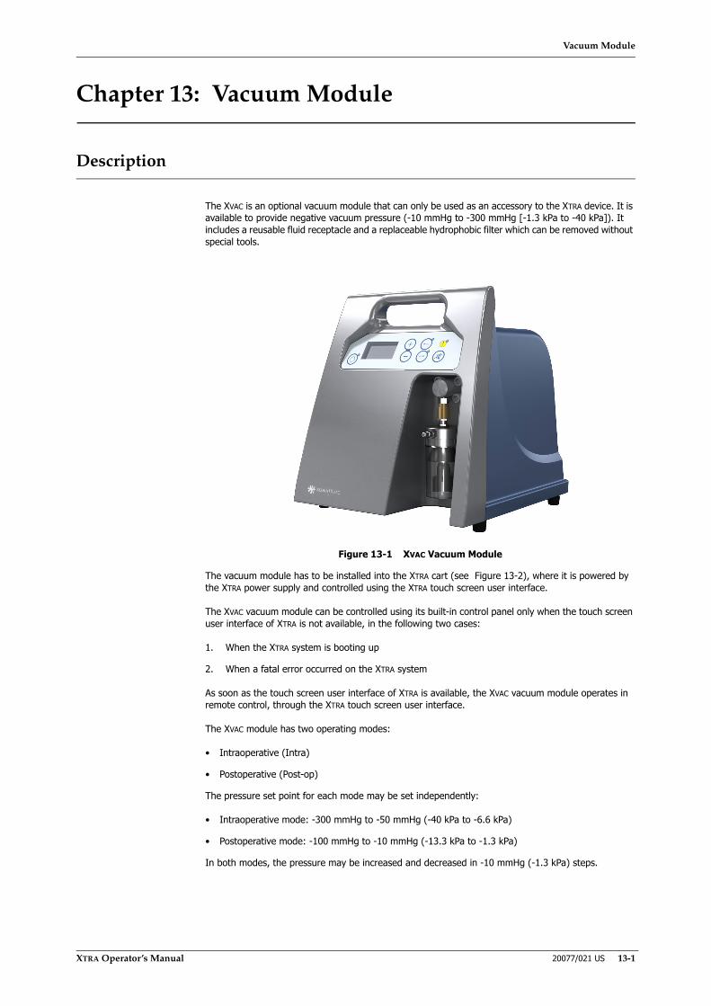
Vacuum Module
XTRA Operator’s Manual 20077/021 US 13-1
Chapter 13: Vacuum Module
Description
The XVAC is an optional vacuum module that can only be used as an accessory to the XTRA device. It is available to provide negative vacuum pressure (-10 mmHg to -300 mmHg [-1.3 kPa to -40 kPa]). It includes a reusable fluid receptacle and a replaceable hydrophobic filter which can be removed without special tools.
Figure 13-1 XVAC Vacuum Module
The vacuum module has to be installed into the XTRA cart (see Figure 13-2), where it is powered by the XTRA power supply and controlled using the XTRA touch screen user interface.
The XVAC vacuum module can be controlled using its built-in control panel only when the touch screen user interface of XTRA is not available, in the following two cases:
1. When the XTRA system is booting up
2. When a fatal error occurred on the XTRA system
As soon as the touch screen user interface of XTRA is available, the XVAC vacuum module operates in remote control, through the XTRA touch screen user interface.
The XVAC module has two operating modes:
• Intraoperative (Intra)
• Postoperative (Post-op)
The pressure set point for each mode may be set independently:
• Intraoperative mode: -300 mmHg to -50 mmHg (-40 kPa to -6.6 kPa)
• Postoperative mode: -100 mmHg to -10 mmHg (-13.3 kPa to -1.3 kPa)
In both modes, the pressure may be increased and decreased in -10 mmHg (-1.3 kPa) steps.
Vacuum Module
13-2 20077/021 US XTRA Operator’s Manual
Operating Modes
The operating mode may only be changed when the vacuum pump is off. There are three ways to change the vacuum operating mode:
• Changing the current active protocol. This is the usual way of changing operating modes. Protocol changes requiring changes to the vacuum operating mode while the vacuum pump is ON will produce a warning and prompt the operator to confirm the stop of the vacuum before proceeding.
• Through the Settings tab of the Menu Screen (accessed from the Setup Screen) before the pump loop has been loaded.
• An “Inconsistent vacuum mode” warning occurs during setup. The operator will be given the opportunity to change the vacuum mode.
Intraoperative Mode
In the intraoperative operating mode, the vacuum module may be set to provide negative pressure between -50 mmHg (-6.6 kPa) and -300 mmHg (-40 kPa), with steps of -10 mmHg (-1.3 kPa).
Postoperative Mode
In the postoperative operating mode, the vacuum module may be set to provide negative pressure between -100 mmHg (-13.3 kPa) and -10 mmHg (-1.3 kPa), with steps of -10 mmHg (-1.3 kPa).
Setting Wakeup Values for Vacuum Module
The operating mode and pressure set points that are used by default when the XVAC system is powered on are determined by how the module was last used.
The wakeup operating mode and setpoint values are determined as follows:
• If the XTRA system has no wakeup protocol set, or if it was powered down in the middle of a case, then the XVAC operating mode and setpoints retain the same values they had when the system was last shutdown.
• If the XTRA system does have a wakeup protocol set and no case was interrupted by the last shutdown, then the vacuum module’s operating mode is set to the XTRA wakeup operating mode (Intra or Post) and the pressure setpoints are set to the corresponding wakeup setpoints (see below).
All wakeup protocols that provide the Intra aspiration mode have the same Intra wakeup set point. Likewise, all wakeup protocols that provide the Post aspiration mode have the same Post setpoint.
Follow these steps to set the wakeup vacuum setpoints for each mode:
1. Enter the Configuration Mode Screen by following the instructions in “How to Enter the Configuration Mode” on page 8-2.
2. From the left side of the Configuration Mode Screen, touch the Wake up tab.
3. From the Wake up tab of the Configuration Mode Screen, locate the “Vacuum Levels” section and the text boxes labeled “Intra” and “Post-op” at the bottom of the screen.
Modify the value of these boxes to set the wakeup value for the associated mode.
4. Touch the Close button to return to the Menu Screen. Touch the Close button again to close the Menu Screen.
For more on configuring the XTRA system refer to Chapter 8: Configuring XTRA.

Vacuum Module
XTRA Operator’s Manual 20077/021 US 13-3
Preliminary Setup
To use the XVAC, attach the vacuum line from the blood collection reservoir vacuum port to the inlet port on the lid of the vacuum overflow trap. Refer to “Step 3: Setup of the Vacuum Line” on page 4-6.
Refer to Chapter 15: Maintenance for information about removing the vacuum overflow trap for cleaning.
Figure 13-2 Vacuum Line Connecting Reservoir to Inlet Port
Performing a Blood Collection Procedure With the XVAC Module
XVAC Used Through the XTRA System Touch Screen Interface (Remote Control)
The XVAC vacuum module may be used in combination with the XTRA system when it is installed into the XTRA cart and is connected to the XTRA via the power and serial communications cables:
1. Connect the XVAC to the XTRA power supply (see Figure 13-3).
2. Connect the XVAC RS422 female serial connector to the XTRA RS422 female serial connector using the DB9 male to DB9 male cable (see Figure 13-3).
1
1 Vacuum port (yellow capped)2 Vacuum inlet port
2
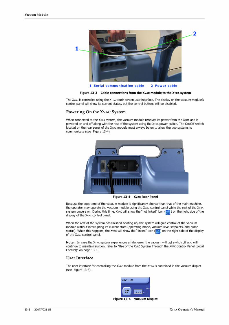
Vacuum Module
13-4 20077/021 US XTRA Operator’s Manual
Figure 13-3 Cable connections from the XVAC module to the XTRA system
The XVAC is controlled using the XTRA touch screen user interface. The display on the vacuum module’s control panel will show its current status, but the control buttons will be disabled.
Powering On the XVAC System
When connected to the XTRA system, the vacuum module receives its power from the XTRA and is powered on and off along with the rest of the system using the XTRA power switch. The On/Off switch located on the rear panel of the XVAC module must always be on to allow the two systems to communicate (see Figure 13-4).
Figure 13-4 XVAC Rear Panel
Because the boot time of the vacuum module is significantly shorter than that of the main machine, the operator may operate the vacuum module using the XVAC control panel while the rest of the XTRA system powers on. During this time, XVAC will show the “not linked” icon ( ) on the right side of the display of the XVAC control panel.
When the rest of the system has finished booting up, the system will gain control of the vacuum module without interrupting its current state (operating mode, vacuum level setpoints, and pump status). When this happens, the XVAC will show the “linked” icon ( ) on the right side of the display of the XVAC control panel.
Note: In case the XTRA system experiences a fatal error, the vacuum will not switch off and will continue to maintain suction; refer to “Use of the XVAC System Through the XVAC Control Panel (Local Control)” on page 13-6.
User Interface
The user interface for controlling the XVAC module from the XTRA is contained in the vacuum displet (see Figure 13-5).
Figure 13-5 Vacuum Displet
1
1 Serial communication cable 2 Power cable
2

Vacuum Module
XTRA Operator’s Manual 20077/021 US 13-5
When the XVAC vacuum module is installed, the vacuum displet is present in the lower-left corner of the displet area in the Setup Screen, Ready Screen, all Processing Screens, and the End Case Screen. Refer to “The Displets” on page 5-3 for a review of the displet concept.
The vacuum displet contains two controls: the Vacuum button, which toggles the vacuum pump ON and OFF; and the vacuum level text box, which controls the vacuum’s negative pressure setpoint.
In addition, the vacuum displet will contain the text “Intra” or “Post-op” indicating the mode it is currently set to operate in.
Touching the Vacuum button once activates the vacuum. While activated, the button appears green and depressed. Touching the Vacuum button a second time deactivates the vacuum and the button returns to a blue and raised appearance.
The pressure of the vacuum is controlled by the value of the vacuum level text box. This value can be changed in the same manner as other XTRA parameters (as explained in “Modification of Parameters” on page 5-5).
Note: If a hospital vacuum is used, the hospital procedures for use of that vacuum apply. As stated in the Warning above, t is recommended that the vacuum be regulated to a maximum (in absolute value) of 150 mmHg (20 kPa).
Performing an Intra or Post Blood Collection Procedure
1. Ensure the module is powered on (the on/off switch located on the rear panel of the vacuum module must be switched on).
2. Refer to the vacuum displet that appears on the XTRA touch screen display and check the aspiration mode (Intra or Post). If the desired aspiration mode is not set, the operator has three ways to change it:
◊ By changing the currently active operating protocol from the Protocol/Mode Tab of the Menu Screen. Refer to “Set the Active Protocol” on page 5-35 for instructions on changing the active operating protocol. When the current protocol changes (for example from Pstd to Popt), the system will communicate to the XVAC module the corresponding change in aspiration mode: Post, if a postoperative protocol is selected; otherwise, Intra. The current aspiration mode of the XVAC module is always indicated in the Vacuum displet.
◊ Through the Settings Tab of the Menu Screen before the pump loop has been loaded. Refer to “Settings Tab” on page 5-48. If a change occurs while the vacuum pump is on, an automatic stop of the pump will be executed.
◊ When an “Inconsistent vacuum mode” warning occurs during setup.
3. Set the target set point to the desired value using the Vacuum displet:
◊ Touch the value in the displet
◊ Use the up and down arrow buttons to adjust the value
◊ Touch the value a second time to confirm the new value
4. Touch the Vacuum button in the Vacuum displet to start the vacuum pump. While the pump is on, the Vacuum button will appear inset and green. On the XVAC’s control panel, the LCD display will show the same set point as the Vacuum displet.
Note: While the pump is running, it is possible to adjust the set point as described in step 3. It is not, however, possible to change the aspiration mode (i.e. switching from Intra to Post mode). Before changing the aspiration mode, for example when changing the active protocol from the XTRA’s touch screen interface, the vacuum pump will be stopped
5. To end the blood collection procedure, touch the (green) Vacuum button in the Vacuum displet. The pump will stop and the aspiration pressure value will quickly return to atmospheric pressure.
WARNINGTo minimize blood cell trauma, LivaNova recommends that vacuum levels no higher than (in absolute value) 150 mmHg (20 kPa) be used when aspirating fluid from the surgical field.i
i Guidelines for blood recovery and reinfusion in surgery and trauma. Bethesda, MD;American Association of Blood Banks, 1997: 19-22.

Vacuum Module
13-6 20077/021 US XTRA Operator’s Manual
Use of the XVAC System Through the XVAC Control Panel (Local Control)
The XVAC vacuum module can be controlled using its built-in control panel only when the touch screen user interface of XTRA is not available, in the following two cases:
1. When the XTRA system is booting up
2. When a fatal error occurred on the XTRA system
XVAC Control Panel
The control panel (see Figure 13-6) is located on the front of the XVAC module and is used to control the vacuum when the XTRA user interface is not available (local control) (i.e., when the XTRA system is booting up or when a fatal error occurred on the XTRA system).
Figure 13-6 XVAC Control Panel
When operating in local control, the display of the XVAC control panel will show the “not linked” icon:
Vacuum Pump On/Off Button
Pressing the vacuum on/off button will toggle the vacuum pump on and off when it is operating in local control. The current state of the vacuum pump is indicated by the green vacuum status LED (light=ON; dark=OFF).
Vacuum Level Setpoint Selector (Up/Down buttons)
Pressing the increase (+) and decrease (-) buttons will change the vacuum level setpoint (mmHg) for the selected operating mode.
Mode Buttons
Pressing the INTRA and POST mode buttons changes the XVAC’s operating mode between intraoperative and postoperative, respectively. A green LED next to each button indicates the current mode (LED on or blinking next to a button indicates that the module is working
or is ready to work in that mode).
Mute Button
Pressing the mute button silences the system beep when an alarm occurs.
Alarm Indicator LED
The red LED, located near the yellow warning icon at the upper-right corner of the control panel, turns on to indicate that an alarm or error has occurred.
WARNINGThe blood collected with the XVAC vacuum module must be processed only with the XTRA Autotransfusion System.

Vacuum Module
XTRA Operator’s Manual 20077/021 US 13-7
Performing an Intra or Post Blood Collection Procedure
1. Ensure the module is powered on (the on/off switch located on the rear panel of the vacuum module must be switched on).
2. Check the status of the Intra and Post mode button LEDs. To perform an Intra procedure, press the Intra button. To perform a Post procedure, press the Post button. Verify that the LED next to the desired mode button is on ( ).
3. Set the target set point to the desired value using the vacuum level set point buttons (“+” to increase the value; “-” to decrease the value). Hold down the button to quickly change the set point. The current set point is shown on the LCD display.
4. Once the set point has been adjusted, start the pump by pressing the vacuum pump On/Off button ( ). The green vacuum status LED will turn on, and the pump will engage and work to reach the level of aspiration indicated by the set point.
Note: While the pump is running, it is possible to adjust the set point as described in step 3. It is not, however, possible to change the aspiration mode (i.e. switching from Intra to Post mode).
5. To end the blood collection procedure, press the vacuum pump On/Off button a second time. The green vacuum status LED will turn off, and aspiration pressure will quickly fall down to 0 mmHg.
WARNINGThe blood collected with the XVAC vacuum module must be processed only with the XTRA Autotransfusion System.
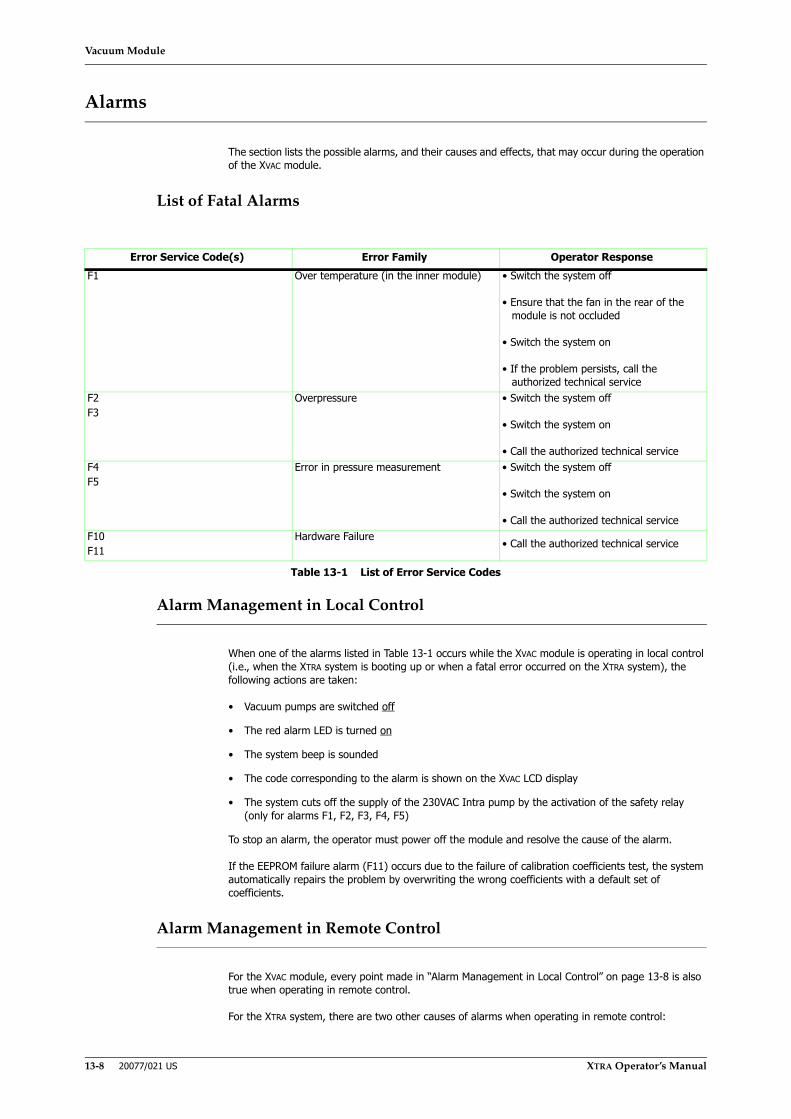
Vacuum Module
13-8 20077/021 US XTRA Operator’s Manual
Alarms
The section lists the possible alarms, and their causes and effects, that may occur during the operation of the XVAC module.
List of Fatal Alarms
Alarm Management in Local Control
When one of the alarms listed in Table 13-1 occurs while the XVAC module is operating in local control (i.e., when the XTRA system is booting up or when a fatal error occurred on the XTRA system), the following actions are taken:
• Vacuum pumps are switched off
• The red alarm LED is turned on
• The system beep is sounded
• The code corresponding to the alarm is shown on the XVAC LCD display
• The system cuts off the supply of the 230VAC Intra pump by the activation of the safety relay (only for alarms F1, F2, F3, F4, F5)
To stop an alarm, the operator must power off the module and resolve the cause of the alarm.
If the EEPROM failure alarm (F11) occurs due to the failure of calibration coefficients test, the system automatically repairs the problem by overwriting the wrong coefficients with a default set of coefficients.
Alarm Management in Remote Control
For the XVAC module, every point made in “Alarm Management in Local Control” on page 13-8 is also true when operating in remote control.
For the XTRA system, there are two other causes of alarms when operating in remote control:
Error Service Code(s) Error Family Operator ResponseF1 Over temperature (in the inner module) • Switch the system off
• Ensure that the fan in the rear of the module is not occluded
• Switch the system on
• If the problem persists, call the authorized technical service
F2F3
Overpressure • Switch the system off
• Switch the system on
• Call the authorized technical serviceF4F5
Error in pressure measurement • Switch the system off
• Switch the system on
• Call the authorized technical serviceF10F11
Hardware Failure • Call the authorized technical service
Table 13-1 List of Error Service Codes

Vacuum Module
XTRA Operator’s Manual 20077/021 US 13-9
• Timeout communication failure: Communication on the XTRA-XVAC RS-422 serial connection has timed out (for example, because of a damaged cable or loose connection).
• Serial communication failure: A double communication error on the same communication window on the XTRA-XVAC serial line has occurred.
When an alarm occurs (F1 to F11 and the two listed above) during or immediately after the prelink phase, the XTRA user interface displays the message “Vacuum pump out of order”. The XTRA system will continue working as if the XVAC module were absent.
When an alarm occurs during the T1 test (alarm F10 or F11) when the boot is over, the XTRA system will consider the XVAC module absent without displaying any message.
When one of the two serial connection failures (listed above) occurs, the XTRA system switches from remote control to local control. In addition, the red alarm LED lights up. Unlike with the other alarms, in the case of the connection failures, the module continues to work (in local control).

Vacuum Module
13-10 20077/021 US XTRA Operator’s Manual
Troubleshooting
XTRA Operator’s Manual 20077/021 US 14-1
Chapter 14: Troubleshooting
General Precautions
To prevent critical situations it is important that all alarms, warnings, and precautions for safe operation are observed. While setting up the XTRA, the operator should always check the unit thoroughly.
Refer to Chapter 1: Introduction and Safety regarding warnings and cautions related to the use and management of the XTRA equipment.
Supervision and Checks
During the operation of the unit, a number of tests are carried out by the system to check the safety, reliability, and performance of the equipment. If functional anomalies are detected, suitable safety measures are immediately taken.
Only one alarm or warning can be active at once. If more than one anomalous situation is detected simultaneously, the one with the higher priority will determine the machine’s response.
When an alarm or warning is issued, the system enters a safe state (corresponding to the stopped Ready Screen): the pump and centrifuge are halted, the clamps closed, and the lid lock opened.
Alarms and Warnings
The XTRA uses audible and visual signals to inform the user about the occurrence of meaningful events.
Such events may be grouped into three classes:
• Warnings – refer to detection of events that can be interesting for the user and in some cases can imply the interruption of the process in progress. Prosecution of process interrupted by the occurrence of a warning requires confirmation from the operator.
• Alarms – refer to detection of events that imply interruption of the process in progress. Detection of these events is usually accompanied by suggestions for the operator to perform checks or actions. Process prosecution after occurrence of this kind of information signals always requires the operator confirmation.
• Fatal Errors – signify detection of unrecoverable hardware anomalies. Technical intervention may be required to recover the system from a fatal error.
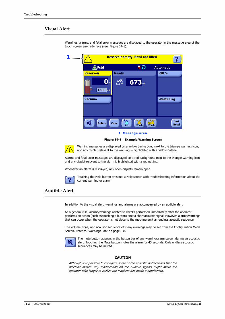
Troubleshooting
14-2 20077/021 US XTRA Operator’s Manual
Visual Alert
Warnings, alarms, and fatal error messages are displayed to the operator in the message area of the touch screen user interface (see Figure 14-1).
Figure 14-1 Example Warning Screen
Warning messages are displayed on a yellow background next to the triangle warning icon, and any displet relevant to the warning is highlighted with a yellow outline.
Alarms and fatal error messages are displayed on a red background next to the triangle warning icon and any displet relevant to the alarm is highlighted with a red outline.
Whenever an alarm is displayed, any open displets remain open.
Touching the Help button presents a Help screen with troubleshooting information about the current warning or alarm.
Audible Alert
In addition to the visual alert, warnings and alarms are accompanied by an audible alert.
As a general rule, alarms/warnings related to checks performed immediately after the operator performs an action (such as touching a button) emit a short acoustic signal. However, alarms/warnings that can occur when the operator is not close to the machine emit an endless acoustic sequence.
The volume, tone, and acoustic sequence of many warnings may be set from the Configuration Mode Screen. Refer to “Warnings Tab” on page 8-8.
The mute button appears in the button bar of any warning/alarm screen during an acoustic alert. Touching the Mute button mutes the alarm for 45 seconds. Only endless acoustic sequences may be muted.
CAUTIONAlthough it is possible to configure some of the acoustic notifications that themachine makes, any modification on the audible signals might make theoperator take longer to realize the machine has made a notification.
1
1 Message area
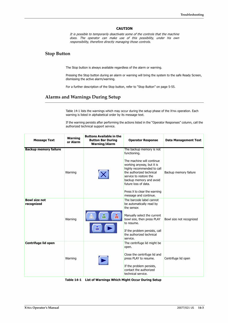
Troubleshooting
XTRA Operator’s Manual 20077/021 US 14-3
Stop Button
The Stop button is always available regardless of the alarm or warning.
Pressing the Stop button during an alarm or warning will bring the system to the safe Ready Screen, dismissing the active alarm/warning.
For a further description of the Stop button, refer to “Stop Button” on page 5-55.
Alarms and Warnings During Setup
Table 14-1 lists the warnings which may occur during the setup phase of the XTRA operation. Each warning is listed in alphabetical order by its message text.
If the warning persists after performing the actions listed in the “Operator Responses” column, call the authorized technical support service.
CAUTIONIt is possible to temporarily deactivate some of the controls that the machinedoes. The operator can make use of this possibility, under his ownresponsibility, therefore directly managing those controls.
Message Text Warning or Alarm
Buttons Available in the Button Bar During
Warning/AlarmOperator Response Data Management Text
Backup memory failure
Warning
The backup memory is not functioning.
The machine will continue working anyway, but it is highly recommended to call the authorized technical service to restore the backup memory and avoid future loss of data.
Press X to clear the warning message and continue.
Backup memory failure
Bowl size not recognized
Warning
The barcode label cannot be automatically read by the sensor.
Manually select the current bowl size, then press PLAY to resume.
If the problem persists, call the authorized technical service.
Bowl size not recognized
Centrifuge lid open
Warning
The centrifuge lid might be open.
Close the centrifuge lid and press PLAY to resume.
If the problem persists, contact the authorized technical service.
Centrifuge lid open
Table 14-1 List of Warnings Which Might Occur During Setup

Troubleshooting
14-4 20077/021 US XTRA Operator’s Manual
Centrifuge test failed
Warning
The centrifuge could not rotate properly.
Do not force the centrifuge lid.
• Verify that the centrifuge is not blocked by any object, which might prevent its proper rotation. Press PLAY to try to resume.
• Restarting the machine might solve the problem.
If the problem persists, call the authorized technical service.
Centrifuge test failed
Check centrifuge arm closure
Warning
The centrifuge arm might be mispositioned.
Check bowl insertion into the centrifuge, verify that the centrifuge arm is locked, close the centrifuge lid and press PLAY to resume.
If the problem persists, call the authorized technical service.
Check centr. arm closure
Check centrifuge lid lock
Warning
The centrifuge lid lock is malfunctioning.
Press X to restore Lock position, then close the lid.
If the problem persists, call the authorized technical service.
Check centr. lid lock
Current bowl size different from previous
Warning
You are trying to retain data but the bowl you have just mounted is of a different size from the previous one.
• If you want to start a new case, press LOAD PUMP.
• If you want to continue the last case with a different bowl size, press LOAD PUMP and reopen the case from the Tally screen.
Bowl size different
Message Text Warning or Alarm
Buttons Available in the Button Bar During
Warning/AlarmOperator Response Data Management Text
Table 14-1 List of Warnings Which Might Occur During Setup (Continued)

Troubleshooting
XTRA Operator’s Manual 20077/021 US 14-5
Memory not functioning. Part of the data has been lost.
Warning
Memory might have lost user protocol names and/or user protocol parameters. The machine will continue working anyway, but it is recommended to call the authorized technical service.
Press X to clear the warning message and continue
Memory not functioning
Empty clamp test failed
WarningA hardware anomaly was detected while testing the Empty clamp.
Empty clamp test failed
Fill clamp test failed
WarningA hardware anomaly was detected while testing the Fill clamp.
Fill clamp test failed
HCT indicator calibration failed
Warning
The machine cannot calibrate the HCT indicator.
• Verify that the line is properly seated in the indicator and not dirty on the outside. Press PLAY to retry (max. 3 attempts)
• After 3 failures, press DELAY CALIBRATION to exit. The system can still be operated, but the HCT indicator will not be available for the current case.
If the problem persists, call the authorized technical service.
HCT indicator calib. failed
Message Text Warning or Alarm
Buttons Available in the Button Bar During
Warning/AlarmOperator Response Data Management Text
Table 14-1 List of Warnings Which Might Occur During Setup (Continued)
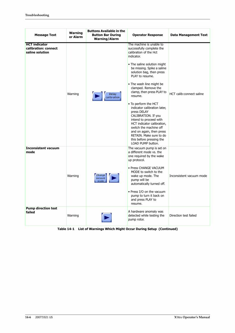
Troubleshooting
14-6 20077/021 US XTRA Operator’s Manual
HCT indicator calibration: connect saline solution
Warning
The machine is unable to successfully complete the calibration of the Hct indicator.
• The saline solution might be missing. Spike a saline solution bag, then press PLAY to resume.
• The wash line might be clamped. Remove the clamp, then press PLAY to resume.
• To perform the HCT indicator calibration later, press DELAY CALIBRATION. If you intend to proceed with HCT indicator calibration, switch the machine off and on again, then press RETAIN. Make sure to do this before pressing the LOAD PUMP button.
HCT calib:connect saline
Inconsistent vacuum mode
Warning
The vacuum pump is set on a different mode vs. the one required by the wake up protocol.
• Press CHANGE VACUUM MODE to switch to the wake up mode. The pump will be automatically turned off.
• Press I/O on the vacuum pump to turn it back on and press PLAY to resume.
Inconsistent vacuum mode
Pump direction test failed
WarningA hardware anomaly was detected while testing the pump rotor.
Direction test failed
Message Text Warning or Alarm
Buttons Available in the Button Bar During
Warning/AlarmOperator Response Data Management Text
Table 14-1 List of Warnings Which Might Occur During Setup (Continued)

Troubleshooting
XTRA Operator’s Manual 20077/021 US 14-7
Pump loop loading failed
Warning
The machine cannot properly load the pump loop.
• If the pump loop is blocking the rotor, manually remove it. Check for any eventual damage to the pump loop and, if present, replace the disposable. If the pump loop is not damaged, manually seat it and press PLAY to resume.
• If the rotor is blocked by any other object, remove it, then press PLAY to resume.
If the problem persists, call the authorized technical service
Pump loop loading failed
Pump rotor out of position
Warning
The pump rotor cannot rotate, it might be missing or not seated correctly.
1. Open the centrifuge lid and check the position of the pump rotor:
• open the white lever
• push the pump rotor fully down
• turn the pump rotor to align the white lever with the slot in the metal shaft
• close the white lever into the slot
• make sure the white level is completely down
2. Close the centrifuge lid and press PLAY to resume.
If the problem persists, call the authorized technical service
Pump rotor mispositioned
Wash clamp test failed
WarningA hardware anomaly was detected while testing the Wash clamp.
Wash clamp test failed
Message Text Warning or Alarm
Buttons Available in the Button Bar During
Warning/AlarmOperator Response Data Management Text
Table 14-1 List of Warnings Which Might Occur During Setup (Continued)

Troubleshooting
14-8 20077/021 US XTRA Operator’s Manual
During Processing
Table 14-2 lists the warnings and alarms which may occur during processing with the XTRA. Each warning or alarm is listed in alphabetical order by its message text.
If the warning or alarm persists after performing the actions listed in the “Operator Response” column, call the authorized technical support service.
Message Text Warning or Alarm
Buttons Available in the Button Bar During
Warning/AlarmOperator Response Data Management
Text
Abnormally long fill cycle
Alarm
More than default fill volume has been pumped into the bowl.
• If the bowl is not sufficiently packed with RBCs, press PLAY resume the current phase.
• If the RBCs are spilling out of the bowl, the RBC sensor might be faulty and you might want to proceed in MANUAL MODE (If enabled).
If so, press STOP, enter the MENU screen and, from the PROTOCOL MODE tab, set the protocol to Pstd and switch to MANUAL MODE
• You may decide to disable the alarm for the current case by pressing DISABLE ALARM.
If the problem persists, call the authorized technical service.
Fill cycle too long
Abnormally long fill cycle (PPP/PRP)
Alarm
More than default fill volume has been pumped into the bowl. The PPP/PRP sequestration could be compromised.
• If the bowl is not sufficiently packed with RBCs, press PLAY resume the current phase.
• If the RBCs are spilling out of the bowl, the RBC sensor might be faulty and you might want to proceed in MANUAL MODE (If enabled).
If so, press STOP, enter the MENU screen and, from the PROTOCOL MODE tab, switch to MANUAL MODE
• You may decide to disable the alarm for the current case by pressing DISABLE ALARM
If the problem persists, call the authorized technical service.
Fill cycle too long, PPP/PRP
Table 14-2 List of Warnings and Alarms Which Might Occur During Processing
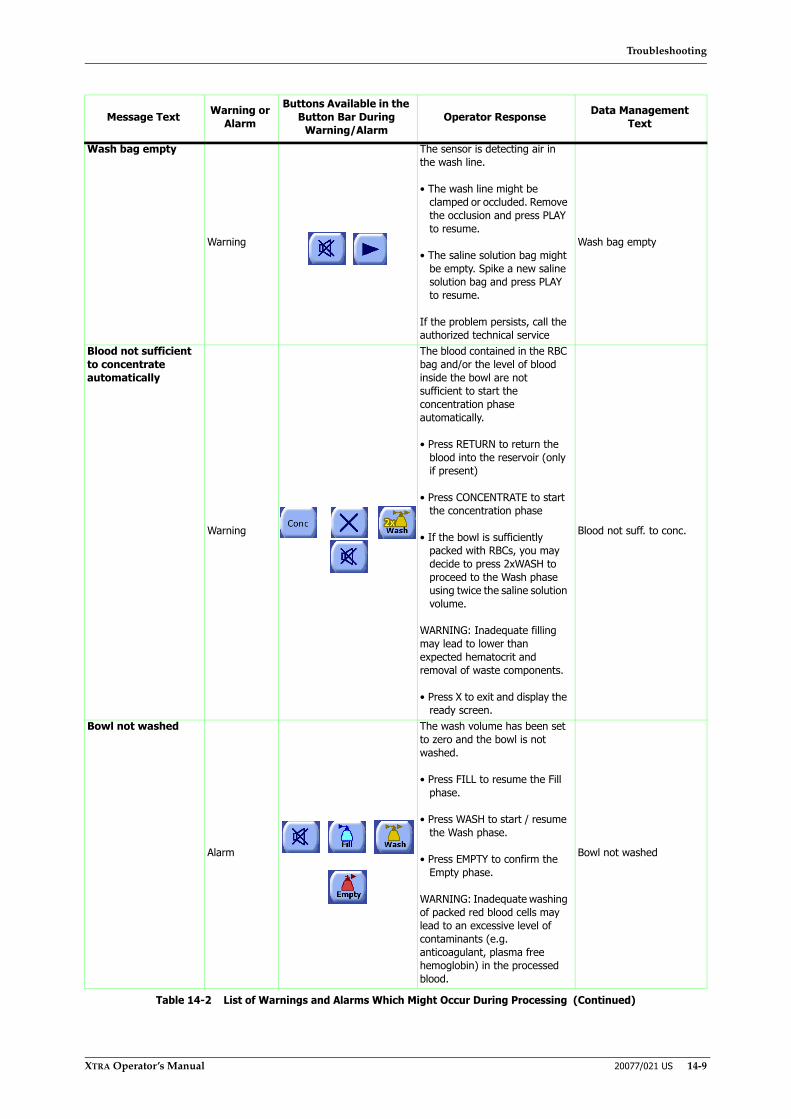
Troubleshooting
XTRA Operator’s Manual 20077/021 US 14-9
Wash bag empty
Warning
The sensor is detecting air in the wash line.
• The wash line might be clamped or occluded. Remove the occlusion and press PLAY to resume.
• The saline solution bag might be empty. Spike a new saline solution bag and press PLAY to resume.
If the problem persists, call the authorized technical service
Wash bag empty
Blood not sufficient to concentrate automatically
Warning
The blood contained in the RBC bag and/or the level of blood inside the bowl are not sufficient to start the concentration phase automatically.
• Press RETURN to return the blood into the reservoir (only if present)
• Press CONCENTRATE to start the concentration phase
• If the bowl is sufficiently packed with RBCs, you may decide to press 2xWASH to proceed to the Wash phase using twice the saline solution volume.
WARNING: Inadequate filling may lead to lower than expected hematocrit and removal of waste components.
• Press X to exit and display the ready screen.
Blood not suff. to conc.
Bowl not washed
Alarm
The wash volume has been set to zero and the bowl is not washed.
• Press FILL to resume the Fill phase.
• Press WASH to start / resume the Wash phase.
• Press EMPTY to confirm the Empty phase.
WARNING: Inadequate washing of packed red blood cells may lead to an excessive level of contaminants (e.g. anticoagulant, plasma free hemoglobin) in the processed blood.
Bowl not washed
Message Text Warning or Alarm
Buttons Available in the Button Bar During
Warning/AlarmOperator Response Data Management
Text
Table 14-2 List of Warnings and Alarms Which Might Occur During Processing (Continued)
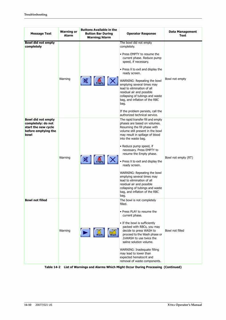
Troubleshooting
14-10 20077/021 US XTRA Operator’s Manual
Bowl did not empty completely
Warning
The bowl did not empty completely.
• Press EMPTY to resume the current phase. Reduce pump speed, if necessary.
• Press X to exit and display the ready screen.
WARNING: Repeating the bowl emptying several times may lead to elimination of all residual air and possible collapsing of tubings and waste bag, and inflation of the RBC bag.
If the problem persists, call the authorized technical service.
Bowl not empty
Bowl did not empty completely: do not start the new cycle before emptying the bowl
Warning
The rapid transfer fill and empty phases are based on volumes. Resuming the fill phase with volume still present in the bowl may result in spillage of blood into the waste bag.
• Reduce pump speed, if necessary. Press EMPTY to resume the Empty phase.
• Press X to exit and display the ready screen.
WARNING: Repeating the bowl emptying several times may lead to elimination of all residual air and possible collapsing of tubings and waste bag, and inflation of the RBC bag.
Bowl not empty (RT)
Bowl not filled
Warning
The bowl is not completely filled.
• Press PLAY to resume the current phase.
• If the bowl is sufficiently packed with RBCs, you may decide to press WASH to proceed to the Wash phase or 2xWASH to use twice the saline solution volume.
WARNING: Inadequate filling may lead to lower than expected hematocrit and removal of waste components.
Bowl not filled
Message Text Warning or Alarm
Buttons Available in the Button Bar During
Warning/AlarmOperator Response Data Management
Text
Table 14-2 List of Warnings and Alarms Which Might Occur During Processing (Continued)
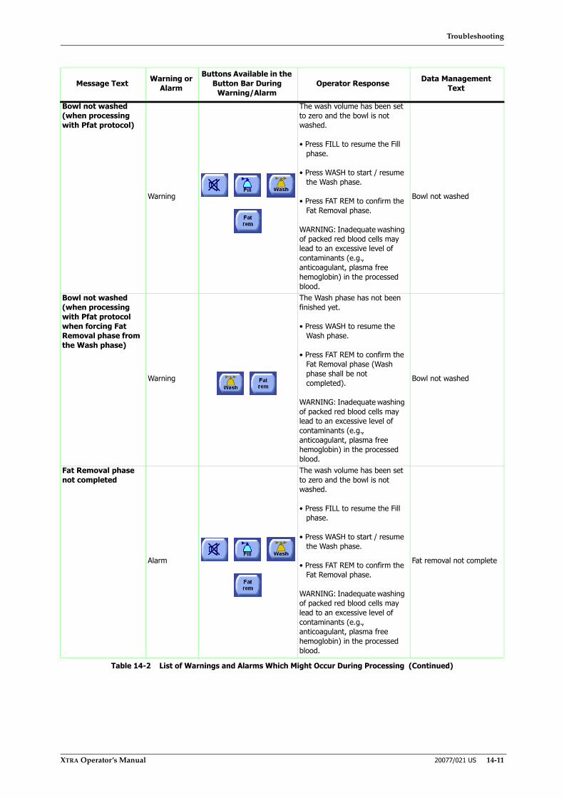
Troubleshooting
XTRA Operator’s Manual 20077/021 US 14-11
Bowl not washed (when processing with Pfat protocol)
Warning
The wash volume has been set to zero and the bowl is not washed.
• Press FILL to resume the Fill phase.
• Press WASH to start / resume the Wash phase.
• Press FAT REM to confirm the Fat Removal phase.
WARNING: Inadequate washing of packed red blood cells may lead to an excessive level of contaminants (e.g., anticoagulant, plasma free hemoglobin) in the processed blood.
Bowl not washed
Bowl not washed (when processing with Pfat protocol when forcing Fat Removal phase from the Wash phase)
Warning
The Wash phase has not been finished yet.
• Press WASH to resume the Wash phase.
• Press FAT REM to confirm the Fat Removal phase (Wash phase shall be not completed).
WARNING: Inadequate washing of packed red blood cells may lead to an excessive level of contaminants (e.g., anticoagulant, plasma free hemoglobin) in the processed blood.
Bowl not washed
Fat Removal phase not completed
Alarm
The wash volume has been set to zero and the bowl is not washed.
• Press FILL to resume the Fill phase.
• Press WASH to start / resume the Wash phase.
• Press FAT REM to confirm the Fat Removal phase.
WARNING: Inadequate washing of packed red blood cells may lead to an excessive level of contaminants (e.g., anticoagulant, plasma free hemoglobin) in the processed blood.
Fat removal not complete
Message Text Warning or Alarm
Buttons Available in the Button Bar During
Warning/AlarmOperator Response Data Management
Text
Table 14-2 List of Warnings and Alarms Which Might Occur During Processing (Continued)
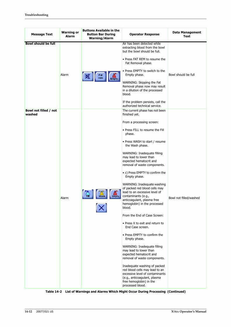
Troubleshooting
14-12 20077/021 US XTRA Operator’s Manual
Bowl should be full
Alarm
Air has been detected while extracting blood from the bowl but the bowl should be full.
• Press FAT REM to resume the Fat Removal phase.
• Press EMPTY to switch to the Empty phase.
WARNING: Skipping the Fat Removal phase now may result in a dilution of the processed blood.
If the problem persists, call the authorized technical service.
Bowl should be full
Bowl not filled / not washed
Alarm
The current phase has not been finished yet.
From a processing screen:
• Press FILL to resume the Fill phase.
• Press WASH to start / resume the Wash phase.
WARNING: Inadequate filling may lead to lower than expected hematocrit and removal of waste components.
• c) Press EMPTY to confirm the Empty phase.
WARNING: Inadequate washing of packed red blood cells may lead to an excessive level of contaminants (e.g., anticoagulant, plasma free hemoglobin) in the processed blood.
From the End of Case Screen:
• Press X to exit and return to End Case screen.
• Press EMPTY to confirm the Empty phase.
WARNING: Inadequate filling may lead to lower than expected hematocrit and removal of waste components.
Inadequate washing of packed red blood cells may lead to an excessive level of contaminants (e.g., anticoagulant, plasma free hemoglobin) in the processed blood.
Bowl not filled/washed
Message Text Warning or Alarm
Buttons Available in the Button Bar During
Warning/AlarmOperator Response Data Management
Text
Table 14-2 List of Warnings and Alarms Which Might Occur During Processing (Continued)
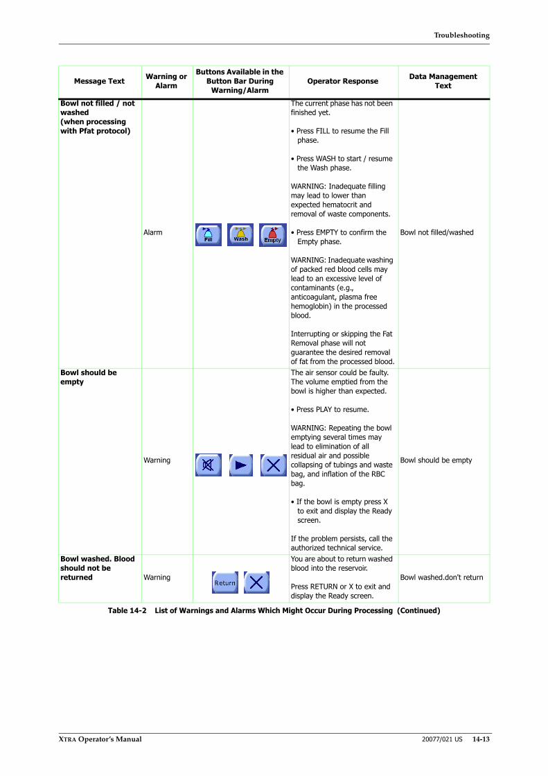
Troubleshooting
XTRA Operator’s Manual 20077/021 US 14-13
Bowl not filled / not washed(when processing with Pfat protocol)
Alarm
The current phase has not been finished yet.
• Press FILL to resume the Fill phase.
• Press WASH to start / resume the Wash phase.
WARNING: Inadequate filling may lead to lower than expected hematocrit and removal of waste components.
• Press EMPTY to confirm the Empty phase.
WARNING: Inadequate washing of packed red blood cells may lead to an excessive level of contaminants (e.g., anticoagulant, plasma free hemoglobin) in the processed blood.
Interrupting or skipping the Fat Removal phase will not guarantee the desired removal of fat from the processed blood.
Bowl not filled/washed
Bowl should be empty
Warning
The air sensor could be faulty. The volume emptied from the bowl is higher than expected.
• Press PLAY to resume.
WARNING: Repeating the bowl emptying several times may lead to elimination of all residual air and possible collapsing of tubings and waste bag, and inflation of the RBC bag.
• If the bowl is empty press X to exit and display the Ready screen.
If the problem persists, call the authorized technical service.
Bowl should be empty
Bowl washed. Blood should not be returned Warning
You are about to return washed blood into the reservoir.
Press RETURN or X to exit and display the Ready screen.
Bowl washed.don't return
Message Text Warning or Alarm
Buttons Available in the Button Bar During
Warning/AlarmOperator Response Data Management
Text
Table 14-2 List of Warnings and Alarms Which Might Occur During Processing (Continued)
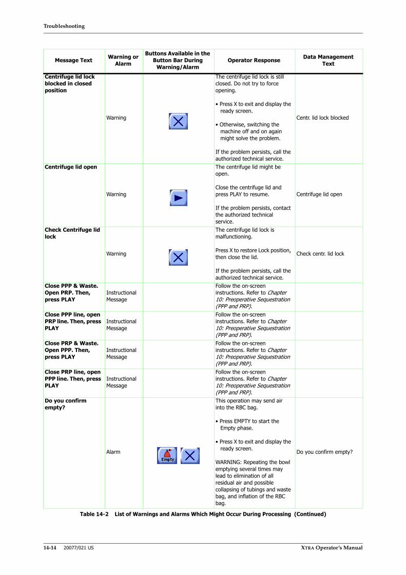
Troubleshooting
14-14 20077/021 US XTRA Operator’s Manual
Centrifuge lid lock blocked in closed position
Warning
The centrifuge lid lock is still closed. Do not try to force opening.
• Press X to exit and display the ready screen.
• Otherwise, switching the machine off and on again might solve the problem.
If the problem persists, call the authorized technical service.
Centr. lid lock blocked
Centrifuge lid open
Warning
The centrifuge lid might be open.
Close the centrifuge lid and press PLAY to resume.
If the problem persists, contact the authorized technical service.
Centrifuge lid open
Check Centrifuge lid lock
Warning
The centrifuge lid lock is malfunctioning.
Press X to restore Lock position, then close the lid.
If the problem persists, call the authorized technical service.
Check centr. lid lock
Close PPP & Waste. Open PRP. Then, press PLAY
Instructional Message
Follow the on-screen instructions. Refer to Chapter 10: Preoperative Sequestration (PPP and PRP).
Close PPP line, open PRP line. Then, press PLAY
Instructional Message
Follow the on-screen instructions. Refer to Chapter 10: Preoperative Sequestration (PPP and PRP).
Close PRP & Waste. Open PPP. Then, press PLAY
Instructional Message
Follow the on-screen instructions. Refer to Chapter 10: Preoperative Sequestration (PPP and PRP).
Close PRP line, open PPP line. Then, press PLAY
Instructional Message
Follow the on-screen instructions. Refer to Chapter 10: Preoperative Sequestration (PPP and PRP).
Do you confirm empty?
Alarm
This operation may send air into the RBC bag.
• Press EMPTY to start the Empty phase.
• Press X to exit and display the ready screen.
WARNING: Repeating the bowl emptying several times may lead to elimination of all residual air and possible collapsing of tubings and waste bag, and inflation of the RBC bag.
Do you confirm empty?
Message Text Warning or Alarm
Buttons Available in the Button Bar During
Warning/AlarmOperator Response Data Management
Text
Table 14-2 List of Warnings and Alarms Which Might Occur During Processing (Continued)
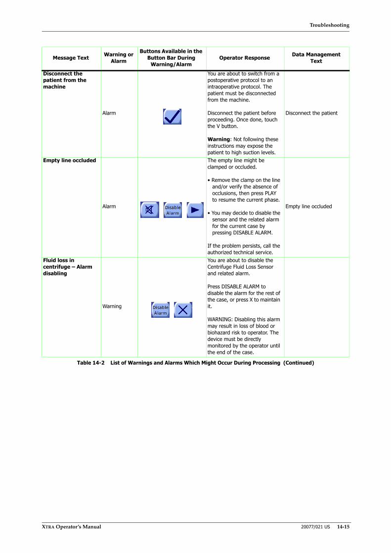
Troubleshooting
XTRA Operator’s Manual 20077/021 US 14-15
Disconnect the patient from the machine
Alarm
You are about to switch from a postoperative protocol to an intraoperative protocol. The patient must be disconnected from the machine.
Disconnect the patient before proceeding. Once done, touch the V button.
Warning: Not following these instructions may expose the patient to high suction levels.
Disconnect the patient
Empty line occluded
Alarm
The empty line might be clamped or occluded.
• Remove the clamp on the line and/or verify the absence of occlusions, then press PLAY to resume the current phase.
• You may decide to disable the sensor and the related alarm for the current case by pressing DISABLE ALARM.
If the problem persists, call the authorized technical service.
Empty line occluded
Fluid loss in centrifuge – Alarm disabling
Warning
You are about to disable the Centrifuge Fluid Loss Sensor and related alarm.
Press DISABLE ALARM to disable the alarm for the rest of the case, or press X to maintain it.
WARNING: Disabling this alarm may result in loss of blood or biohazard risk to operator. The device must be directly monitored by the operator until the end of the case.
Message Text Warning or Alarm
Buttons Available in the Button Bar During
Warning/AlarmOperator Response Data Management
Text
Table 14-2 List of Warnings and Alarms Which Might Occur During Processing (Continued)

Troubleshooting
14-16 20077/021 US XTRA Operator’s Manual
Fluid loss in centrifuge: Biohazard risk
Alarm
The centrifuge fluid loss sensor has detected fluid leakage in the centrifuge housing.
Open the centrifuge lid and the centrifuge arm, check that the bowl is not leaking, make sure that all clamps of bowl set and waste bag are open.
• If there is a leak, press X to exit and display the current screen, unload the pump loop and remove the disposable. Clean the centrifuge housing and sensor, install a new disposable, start a new case and eventually reopen the case from the Tally Screen.
• If there is no leak, clean the ‘Centrifuge Fluid Loss’ sensor with a dry cloth, make sure the bowl set is mounted properly, close the centrifuge lid and press X to exit and display the current screen.
• You may decide to disable the sensor and the related alarm for the current case by pressing DISABLE ALARM.
If the problem persists, call the authorized technical service.
Fluid loss in centrifuge
Inconsistent vacuum mode
Warning
The vacuum pump is set on a different mode vs. the one required by the wake up protocol.
• Press CHANGE VACUUM MODE to switch to the wake up mode. The pump will be automatically turned off.
• Press I/O on the vacuum pump to turn it back on and press PLAY to resume.
Inconsistent vacuum mode
Make sure the reservoir weight is reliable before proceeding
Warning
The load cell registered a inconsistent weight.
• Make sure that the reservoir is free from anything that can compromise its real weight.
• Press V to resume.
If the problem persists, call the authorized technical service.
Weight unreliable
Message Text Warning or Alarm
Buttons Available in the Button Bar During
Warning/AlarmOperator Response Data Management
Text
Table 14-2 List of Warnings and Alarms Which Might Occur During Processing (Continued)
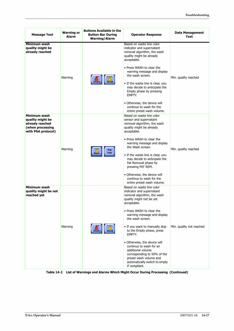
Troubleshooting
XTRA Operator’s Manual 20077/021 US 14-17
Minimum wash quality might be already reached
Warning
Based on waste line color indicator and supernatant removal algorithm, the wash quality might be already acceptable.
• Press WASH to clear the warning message and display the wash screen.
• If the waste line is clear, you may decide to anticipate the Empty phase by pressing EMPTY.
• Otherwise, the device will continue to wash for the entire preset wash volume.
Min. quality reached
Minimum wash quality might be already reached (when processing with Pfat protocol)
Warning
Based on waste line color sensor and supernatant removal algorithm, the wash quality might be already acceptable.
• Press WASH to clear the warning message and display the Wash screen.
• If the waste line is clear, you may decide to anticipate the Fat Removal phase by pressing FAT REM.
• Otherwise, the device will continue to wash for the entire preset wash volume.
Min. quality reached
Minimum wash quality might be not reached yet
Warning
Based on waste line color indicator and supernatant removal algorithm, the wash quality might not be yet acceptable.
• Press WASH to clear the warning message and display the wash screen.
• If you want to manually skip to the Empty phase, press EMPTY.
• Otherwise, the device will continue to wash for an additional volume corresponding to 50% of the preset wash volume and automatically switch to empty if compliant.
Min. quality not reached
Message Text Warning or Alarm
Buttons Available in the Button Bar During
Warning/AlarmOperator Response Data Management
Text
Table 14-2 List of Warnings and Alarms Which Might Occur During Processing (Continued)

Troubleshooting
14-18 20077/021 US XTRA Operator’s Manual
Minimum wash quality might be not reached yet(when processing with Pfat protocol)
Warning
Based on waste line color sensor and supernatant removal algorithm, the wash quality might not be yet acceptable.
• Press WASH to clear the warning message and display the Wash screen.
• If you want to manually switch to the Fat Removal phase, press FAT REM.
• Otherwise, the device will continue to wash for an additional volume corresponding to 50% of the preset wash volume and automatically switch to the Fat Removal phase if compliant.
Min. quality not reached
PPP bag full. Empty or replace it.
Alarm
The volume transferred to the bag exceeds the pre-set safety level.
Empty or replace the PPP bag, then press PLAY to resume. The bag volume counter will be reset to Zero.
WARNING: Not following these instructions may expose the operator to biohazard risk and compromise the current case.
PPP bag full
Process quickly to avoid vacuum deactivation
Warning
The volume of blood inside the reservoir has reached the preset safety level.
Process the blood as soon as possible to avoid vacuum deactivation.
Process quickly
PRP bag full. Empty or replace it.
Alarm
The volume transferred to the bag exceeds the pre-set safety level.
Empty or replace the PRP bag, then press PLAY to resume. The bag volume counter will be reset to Zero.
WARNING: Not following these instructions may expose the operator to biohazard risk and compromise the current case.
PRP bag full
Message Text Warning or Alarm
Buttons Available in the Button Bar During
Warning/AlarmOperator Response Data Management
Text
Table 14-2 List of Warnings and Alarms Which Might Occur During Processing (Continued)
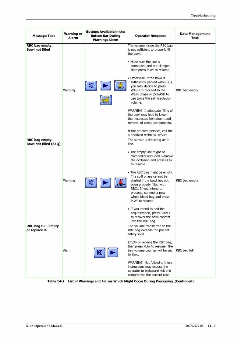
Troubleshooting
XTRA Operator’s Manual 20077/021 US 14-19
RBC bag empty. Bowl not filled
Warning
The volume inside the RBC bag is not sufficient to properly fill the bowl.
• Make sure the line is connected and not clamped, then press PLAY to resume.
• Otherwise, if the bowl is sufficiently packed with RBCs, you may decide to press WASH to proceed to the Wash phase or 2xWASH to use twice the saline solution volume.
WARNING: Inadequate filling of the bowl may lead to lower than expected hematocrit and removal of waste components.
If the problem persists, call the authorized technical service.
RBC bag empty
RBC bag empty. Bowl not filled (SEQ)
Warning
The sensor is detecting air in line.
• The empty line might be clamped or occluded. Remove the occlusion and press PLAY to resume.
• The RBC bag might be empty. The spill phase cannot be started if the bowl has not been properly filled with RBCs. If you intend to proceed, connect a new whole blood bag and press PLAY to resume.
• If you intend to end the sequestration, press EMPTY to recover the bowl content into the RBC bag.
RBC bag empty
RBC bag full. Empty or replace it.
Alarm
The volume transferred to the RBC bag exceeds the pre-set safety level.
Empty or replace the RBC bag, then press PLAY to resume. The bag volume counter will be set to Zero.
WARNING: Not following these instructions may expose the operator to biohazard risk and compromise the current case.
RBC bag full
Message Text Warning or Alarm
Buttons Available in the Button Bar During
Warning/AlarmOperator Response Data Management
Text
Table 14-2 List of Warnings and Alarms Which Might Occur During Processing (Continued)

Troubleshooting
14-20 20077/021 US XTRA Operator’s Manual
RBCs detected during purge
Warning
The sensor detected more than 3 ml of RBCs returning into the bowl.
If you forgot to turn the RBC bag upside down, press X to display the Purge screen, then carefully follow the instructions displayed on screen.
RBCs during purge
Reservoir empty. Bowl not filled
Warning
The reservoir might be empty. The bowl is not properly filled.
• If the reservoir is not empty, check the air sensor, make sure the tubing going to the bowl is seated properly inside the sensor and the fill line is not occluded/clamped. Press FILL to resume.
• If this is the last cycle, press LAST BOWL (only if enabled) to automatically complete the case.
• Press CONCENTRATE to start the concentration phase.
• Press RETURN (only if present) to return the blood into the reservoir.
• If the bowl is sufficiently packed with RBCs, you may decide to press WASH to proceed to the Wash phase or 2XWASH to use twice the saline solution.
WARNING: Inadequate filling may lead to lower than expected hematocrit and removal of waste components.
Reservoir empty
Reservoir full: on-board vacuum pump disabled
Alarm
The vacuum pump has automatically stopped to prevent fluid spillage and serious damage to the pump.
Process the blood immediately.
Once the reservoir level lowers under the safety level, the vacuum pump will automatically reactivate itself.
Res.full:vacuum disabled
Standby too long: “alarm name”
Warning
The current warning message has occurred and the centrifuge has automatically stopped after 5 minutes.
• Press PLAY to resume from the warning message screen.
• Otherwise, press X to display the ready screen.
Stand-by too long
Message Text Warning or Alarm
Buttons Available in the Button Bar During
Warning/AlarmOperator Response Data Management
Text
Table 14-2 List of Warnings and Alarms Which Might Occur During Processing (Continued)
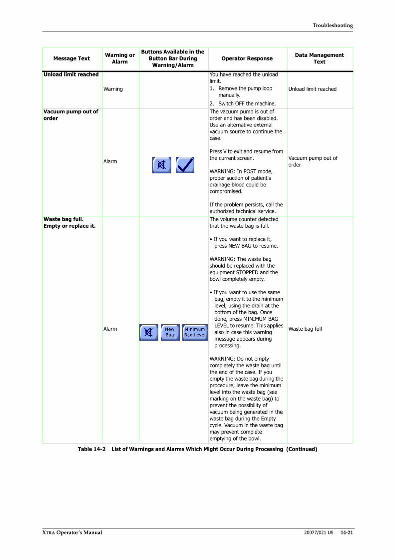
Troubleshooting
XTRA Operator’s Manual 20077/021 US 14-21
Unload limit reached
Warning
You have reached the unload limit.1. Remove the pump loop
manually.2. Switch OFF the machine.
Unload limit reached
Vacuum pump out of order
Alarm
The vacuum pump is out of order and has been disabled. Use an alternative external vacuum source to continue the case.
Press V to exit and resume from the current screen.
WARNING: In POST mode, proper suction of patient's drainage blood could be compromised.
If the problem persists, call the authorized technical service.
Vacuum pump out of order
Waste bag full. Empty or replace it.
Alarm
The volume counter detected that the waste bag is full.
• If you want to replace it, press NEW BAG to resume.
WARNING: The waste bag should be replaced with the equipment STOPPED and the bowl completely empty.
• If you want to use the same bag, empty it to the minimum level, using the drain at the bottom of the bag. Once done, press MINIMUM BAG LEVEL to resume. This applies also in case this warning message appears during processing.
WARNING: Do not empty completely the waste bag until the end of the case. If you empty the waste bag during the procedure, leave the minimum level into the waste bag (see marking on the waste bag) to prevent the possibility of vacuum being generated in the waste bag during the Empty cycle. Vacuum in the waste bag may prevent complete emptying of the bowl.
Waste bag full
Message Text Warning or Alarm
Buttons Available in the Button Bar During
Warning/AlarmOperator Response Data Management
Text
Table 14-2 List of Warnings and Alarms Which Might Occur During Processing (Continued)
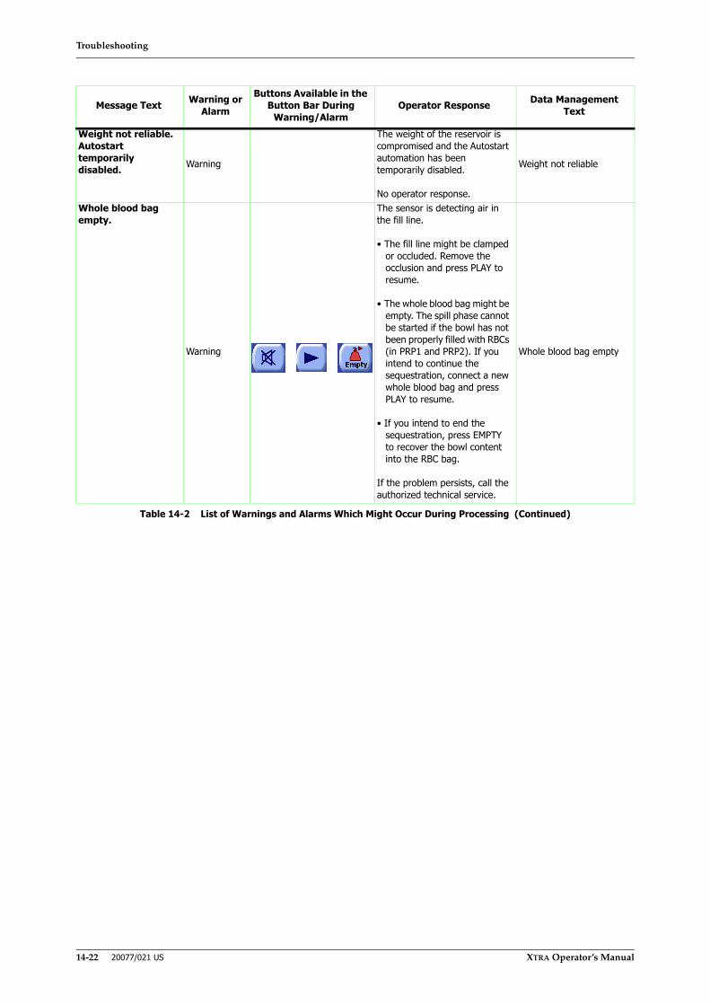
Troubleshooting
14-22 20077/021 US XTRA Operator’s Manual
Weight not reliable. Autostart temporarily disabled. Warning
The weight of the reservoir is compromised and the Autostart automation has been temporarily disabled.
No operator response.
Weight not reliable
Whole blood bag empty.
Warning
The sensor is detecting air in the fill line.
• The fill line might be clamped or occluded. Remove the occlusion and press PLAY to resume.
• The whole blood bag might be empty. The spill phase cannot be started if the bowl has not been properly filled with RBCs (in PRP1 and PRP2). If you intend to continue the sequestration, connect a new whole blood bag and press PLAY to resume.
• If you intend to end the sequestration, press EMPTY to recover the bowl content into the RBC bag.
If the problem persists, call the authorized technical service.
Whole blood bag empty
Message Text Warning or Alarm
Buttons Available in the Button Bar During
Warning/AlarmOperator Response Data Management
Text
Table 14-2 List of Warnings and Alarms Which Might Occur During Processing (Continued)
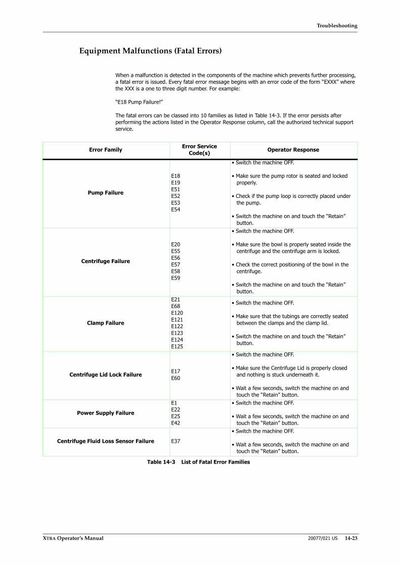
Troubleshooting
XTRA Operator’s Manual 20077/021 US 14-23
Equipment Malfunctions (Fatal Errors)
When a malfunction is detected in the components of the machine which prevents further processing, a fatal error is issued. Every fatal error message begins with an error code of the form “EXXX” where the XXX is a one to three digit number. For example:
“E18 Pump Failure!”
The fatal errors can be classed into 10 families as listed in Table 14-3. If the error persists after performing the actions listed in the Operator Response column, call the authorized technical support service.
Error Family Error Service Code(s) Operator Response
Pump Failure
E18E19E51E52E53E54
• Switch the machine OFF.
• Make sure the pump rotor is seated and locked properly.
• Check if the pump loop is correctly placed under the pump.
• Switch the machine on and touch the “Retain” button.
Centrifuge Failure
E20E55E56E57E58E59
• Switch the machine OFF.
• Make sure the bowl is properly seated inside the centrifuge and the centrifuge arm is locked.
• Check the correct positioning of the bowl in the centrifuge.
• Switch the machine on and touch the “Retain” button.
Clamp Failure
E21E68E120E121E122E123E124E125
• Switch the machine OFF.
• Make sure that the tubings are correctly seated between the clamps and the clamp lid.
• Switch the machine on and touch the “Retain” button.
Centrifuge Lid Lock Failure E17E60
• Switch the machine OFF.
• Make sure the Centrifuge Lid is properly closed and nothing is stuck underneath it.
• Wait a few seconds, switch the machine on and touch the “Retain” button.
Power Supply Failure
E1E22E25E42
• Switch the machine OFF.
• Wait a few seconds, switch the machine on and touch the “Retain” button.
Centrifuge Fluid Loss Sensor Failure E37
• Switch the machine OFF.
• Wait a few seconds, switch the machine on and touch the “Retain” button.
Table 14-3 List of Fatal Error Families

Troubleshooting
14-24 20077/021 US XTRA Operator’s Manual
Electronic Failure - Memory or Microcontroller
E3E16E26E27E28E30E36E40E61E87
• Switch the machine OFF.
• Wait a few seconds, switch the machine on and touch the “Retain” button.
Electronic Failure - Serial Communication
E4E5E6E8E9E10E12E13E14E31E32E39
• Switch the machine OFF.
• Wait a few seconds, switch the machine on and touch the “Retain” button.
Electronic Failure - NMC Board Overtemperature E23
• Switch the machine OFF.
• Wait a few minutes to allow the board to cool down, then switch the machine on and touch the “Retain” button.
Pump Loop Ejector Failure E123
• Switch the machine OFF.
• Wait a few minutes, switch the machine on and touch the “Retain” button.
Error Family Error Service Code(s) Operator Response
Table 14-3 List of Fatal Error Families (Continued)
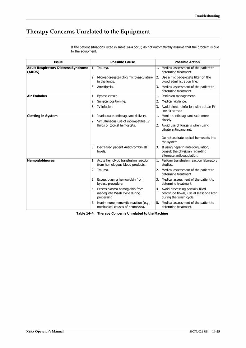
Troubleshooting
XTRA Operator’s Manual 20077/021 US 14-25
Therapy Concerns Unrelated to the Equipment
If the patient situations listed in Table 14-4 occur, do not automatically assume that the problem is due to the equipment.
Issue Possible Cause Possible ActionAdult Respiratory Distress Syndrome (ARDS)
1. Trauma.
2. Microaggregates clog microvasculature in the lungs.
3. Anesthesia.
1. Medical assessment of the patient to determine treatment.
2. Use a microaggregate filter on the blood administration line.
3. Medical assessment of the patient to determine treatment.
Air Embolus 1. Bypass circuit.2. Surgical positioning.3. IV infusion.
1. Perfusion management.2. Medical vigilance.3. Avoid direct reinfusion with-out an IV
line air sensor.Clotting in System 1. Inadequate anticoagulant delivery.
2. Simultaneous use of incompatible IV fluids or topical hemostats.
3. Decreased patient Antithrombin III levels.
1. Monitor anticoagulant ratio more closely.
2. Avoid use of Ringer's when using citrate anticoagulant.
Do not aspirate topical hemostats into the system.
3. If using heparin anti-coagulation, consult the physician regarding alternate anticoagulation.
Hemoglobinurea 1. Acute hemolytic transfusion reaction from homologous blood products.
2. Trauma.
3. Excess plasma hemoglobin from bypass procedure.
4. Excess plasma hemoglobin from inadequate Wash cycle during processing.
5. Nonimmune hemolytic reaction (e.g., mechanical causes of hemolysis).
1. Perform transfusion reaction laboratory studies.
2. Medical assessment of the patient to determine treatment.
3. Medical assessment of the patient to determine treatment.
4. Avoid processing partially filled centrifuge bowls; use at least one liter during the Wash cycle.
5. Medical assessment of the patient to determine treatment.
Table 14-4 Therapy Concerns Unrelated to the Machine
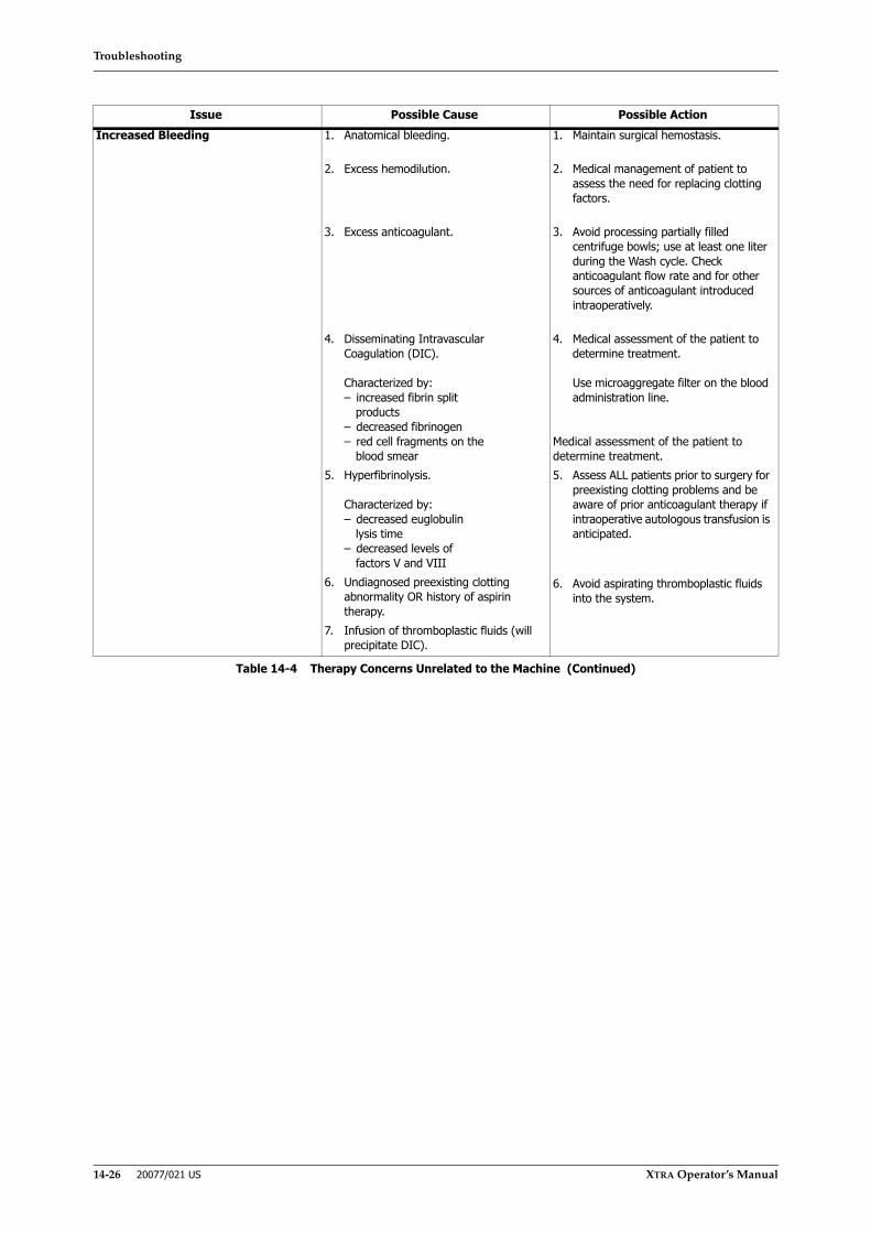
Troubleshooting
14-26 20077/021 US XTRA Operator’s Manual
Increased Bleeding 1. Anatomical bleeding.
2. Excess hemodilution.
3. Excess anticoagulant.
4. Disseminating Intravascular Coagulation (DIC).
Characterized by:– increased fibrin split
products– decreased fibrinogen– red cell fragments on the
blood smear5. Hyperfibrinolysis.
Characterized by:– decreased euglobulin
lysis time– decreased levels of
factors V and VIII6. Undiagnosed preexisting clotting
abnormality OR history of aspirin therapy.
7. Infusion of thromboplastic fluids (will precipitate DIC).
1. Maintain surgical hemostasis.
2. Medical management of patient to assess the need for replacing clotting factors.
3. Avoid processing partially filled centrifuge bowls; use at least one liter during the Wash cycle. Check anticoagulant flow rate and for other sources of anticoagulant introduced intraoperatively.
4. Medical assessment of the patient to determine treatment.
Use microaggregate filter on the blood administration line.
Medical assessment of the patient to determine treatment.5. Assess ALL patients prior to surgery for
preexisting clotting problems and be aware of prior anticoagulant therapy if intraoperative autologous transfusion is anticipated.
6. Avoid aspirating thromboplastic fluids into the system.
Issue Possible Cause Possible Action
Table 14-4 Therapy Concerns Unrelated to the Machine (Continued)

Troubleshooting
XTRA Operator’s Manual 20077/021 US 14-27
Quality of Salvaged Blood and Blood Product
The quality of the salvaged blood and resultant blood products are dependent upon good operator techniques and knowledge of how the XTRA operates. Listed below in Table 14-5 are four situations that may occur and suggested measures to overcome them.
Issue Possible Cause Possible ActionLow Hematocrit 1. Centrifuge bowl not completely filled.
May be caused by premature triggering of red blood cell detector due to gross hemolysis of blood in the collection reservoir.
2. High hematocrit in collection reservoir.
3. Increased roller pump speed during Fill or Wash cycle.
4. Dilution from saline prime to patient IV line.
5. Custom protocol (operator-defined) has Fill or Wash speeds set too high.
6. Custom protocol (operator-defined) has Refill option DISABLED
1. Fill bowl in Manual until red cell interface reaches the outside surface of the Marker.
2. Observe how quickly the bowl fills and decrease roller pump speeds; observe fill volume and if low, decrease the roller pump speed.
3. Reduce pump speeds for Fill or Wash cycles.
4. Remove all prime from blue line before processing.
5. Adjust parameters of custom protocol to reduce Fill or Wash pump speeds.
6. Adjust parameters of custom protocol to ENABLE Refill option.
Hemolysis 1. Use of hypo- or hypertonic IV solutions.
2. Improper sampling techniques.
3. Hemolytic substances introduced into surgical wound.
1. Use only isotonic normal saline.
2. Do not aspirate from the RBC bag with a needle. This creates a vacuum, causing a sampling artifact.
3. Do not aspirate hemolytic substances into collection reservoir or aspirate blood exposed to these substances.
Plasma Free Hemoglobin 1. Incomplete filling of centrifuge bowl.
2. Incomplete Wash cycle.
3. Excess plasma Hgb in collection reservoir.
1. Fill bowl in Manual until red cell interface reaches 1/8” (3.2 mm) from white spacer.
2. Use minimum of one liter wash (1.5 liter in orthopedics) but more as needed.
3. Control aspiration technique and vacuum level to assure minimal hemolysis.
Residual Heparin 1. Incomplete filling of centrifuge bowl.
2. Incomplete Wash cycle.
3. Excess heparin in collection reservoir due to inappropriate ratios through suction assembly or from other sources.
4. Improper testing procedure.
5. Custom protocol (operator-defined) has Fill or Wash speeds set too high.
1. Fill bowl in Manual until red cell interface reaches 1/8” (3.2 mm) from white spacer.
2. Use minimum of one liter wash (1.5 liter in orthopedics) but more as needed.
3. Assure proper anticoagulant to blood ratio; use low volume bowl to prevent excess levels.
4. Do not use coagulation studies which require the presence of plasma in blood.
5. Adjust parameters of custom protocol to reduce Fill or Wash pump speeds.
Table 14-5 Quality of Salvaged Blood and Blood Product

Troubleshooting
14-28 20077/021 US XTRA Operator’s Manual

Maintenance
XTRA Operator’s Manual 20077/021 US 15-1
Chapter 15: Maintenance
Glossary
• Routine Maintenance: is defined as every maintenance action that must be performed regularly by the user of the XTRA
• Preventive Maintenance: is defined as every maintenance action performed by an authorized technician every interval defined by the equipment manufacturer
Routine Maintenance
Regular care and maintenance is important for the function and operation of the XTRA because it:
• Increases operational safety and reliability;
• Reduces susceptibility to failure;
• Increases the service life of all the components (value maintenance).
The instructions for routine maintenance which are given in the following sections form part of the operating conditions for the XTRA. This applies both to the routine maintenance which is carried out by the user of the XTRA and to the preventive maintenance which is performed by authorized service technicians and other testing entities.
To maintain the basic safety and essential performance all requirements concerning the electromagnetic compatibility described in appendix A must be complied with throughout the entire expected service life of the XTRA System.
General Maintenance Instructions
Safety Instructions for Routine Maintenance
• Before carrying out routine maintenance, disconnect the XTRA fully from the mains power supply. Make certain that the system is switched off.
• Do not fail to follow the regulations concerning routine maintenance, as well as the prescribed maintenance intervals stated in the operating instructions.
• Follow the separate operating instructions for all accessories.
• Use recommended cleaning agents.
• Wear protective gloves when disconnecting used tubing sets and disposables.
Discarding of disposables
Environmental regulations request proper ways of discarding refuse separated by their chemical compounds.
The technical personnel in hospitals involved with it must be adequately informed.
Disposables must be discarded in conformity with the law in force in the country of use.

Maintenance
15-2 20077/021 US XTRA Operator’s Manual
Routine Visual Inspection
The XTRA equipment should be inspected periodically for any problems such as bent or broken switches, frayed or twisted power cords, and loose or missing hardware. Discontinue use of the XTRA if the device displays one or more of the above conditions until the problem is corrected and it has been verified that the device is operating correctly. Verify that the connectors, located on the exterior of the XTRA, for Data and Ethernet are intact and are not damaged and that the cables are correctly connected.
Check the following components:
• Power supply cable (see Figure 15-1 “A”): check the power supply insulation and shielding is undamaged along the entire length of the cable (cracks, cuts, clearly visible kinks).
• Vacuum Pump and Serial Connection cables (see Figure 15-1 “B”): check the power supply insulation and shielding is undamaged along the entire length of the cable (cracks, cuts, clearly visible kinks).
Figure 15-1 Power Supply Cable (A); Serial Cable and Vacuum Pump Power Supply (B)
If any of the above cables are found damaged replace it. Have the service technician check defective accessories in any case.
Cleaning and Disinfecting
Apart from the hygienic aspect, it is essential for the operational safety and reliability of the XTRA that it be kept clean. Perform the following cleaning routine every time it is necessary.
Perform the disinfection only in case of loss of blood.
Before cleaning the XTRA, disconnect it from the mains power supply and ensure that the system is switched off.
External Surfaces
Clean all surfaces of the XTRA equipment, including the trolley surfaces.
Cleaning
To clean the external surfaces use soapy water, ethyl alcohol and ammonia based cleaning solutions.
Disinfecting
Use disinfectant products specifically provided for rubber / plastic medical tools and devices.
WARNINGComply with the dilution required and with instructions provided by the manufacturer of the product (read carefully instructions for use and label of the product).
Maintenance
XTRA Operator’s Manual 20077/021 US 15-3
Rinse with water and wipe off the disinfectant product in order to prevent possible damage. Comply with the dilution required and with instructions provided by the manufacturer of the product (read carefully instructions for use and label of the product).
Touch Screen
To clean the touch screen:
• Use a soft lint-free cloth.
• The cloth may be used dry or lightly dampened with a mild cleaner or Ethanol.
• Be sure the cloth is only lightly dampened, not wet.
• Cleaner must be neither acid nor alkali (neutral pH).
• Wipe the surface gently; if there is a directional surface texture, wipe in the same direction as the texture.
• Suitable cleaning products are commercially available pre-packaged for use;
• Use of incorrect cleaners can result in optical impairment of touch panel and/or damage to functionality.
Note: Most products contain 1-3% Isopropyl Alcohol by volume, which is within acceptable limits for Resistive Touch Panel cleaning use.
WARNINGDo not use sodium hypochlorite based disinfectants, aldehydes (formic aldehide, glutaralehyde) and solvents.
WARNINGNever apply cleaner directly to touch panel surface; if cleaner is spilled onto touch panel, soak it up immediately with absorbent cloth.
WARNINGNever use acidic or alkaline cleaners or organic chemicals such as: paint thinner, acetone, tolulene, xylene, propyl or isopropyl alcohol, or kerosene.
CAUTIONMany products contain Ammonia, Phosphates, and/or Ethylene Glycol, whichare NOT ACCEPTABLE; check product content label carefully.

Maintenance
15-4 20077/021 US XTRA Operator’s Manual
Clamps and Pump Loop Ejector
Figure 15-2 Clamps and Pump Loop Ejector
To clean clamps (see Figure 15-2), unlatch the clamp lid, lift it and follow the indications reported in section “External Surfaces” on page 15-2. Follow the same indications for the pump loop ejector (see Figure 15-2).
Pump Rotor
Remove the rotor (see Figure 15-2 and refer to “Pump Rotor” on page 15-6) and clean the area underneath it following the indications reported in section “External Surfaces” on page 15-2.
Centrifuge Well
Swing open the centrifuge arm (see Figure 15-3) and clean the well following the indications reported in section “External Surfaces” on page 15-2.
Figure 15-3 Centrifuge Well
Centrifuge Well Fluid Container
Whenever organic fluids enter it, the container must be cleaned with suitable disinfectant solution or alternatively, replaced. Refer to “Centrifuge Well Fluid Container” on page 15-8.
Vacuum System Overflow Trap
Accumulation of dust, dirt, or other debris within the trap assembly may block air passage or prevent effective vacuum shutoff. Cleaning should be performed when liquid overflows into the trap.
1 Pump rotor 2 Pump loop ejector3 Clamps
321
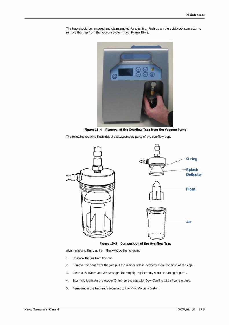
Maintenance
XTRA Operator’s Manual 20077/021 US 15-5
The trap should be removed and disassembled for cleaning. Push up on the quick-lock connector to remove the trap from the vacuum system (see Figure 15-4).
Figure 15-4 Removal of the Overflow Trap from the Vacuum Pump
The following drawing illustrates the disassembled parts of the overflow trap.
Figure 15-5 Composition of the Overflow Trap
After removing the trap from the XVAC do the following:
1. Unscrew the jar from the cap.
2. Remove the float from the jar; pull the rubber splash deflector from the base of the cap.
3. Clean all surfaces and air passages thoroughly; replace any worn or damaged parts.
4. Sparingly lubricate the rubber O-ring on the cap with Dow-Corning 111 silicone grease.
5. Reassemble the trap and reconnect to the XVAC Vacuum System.
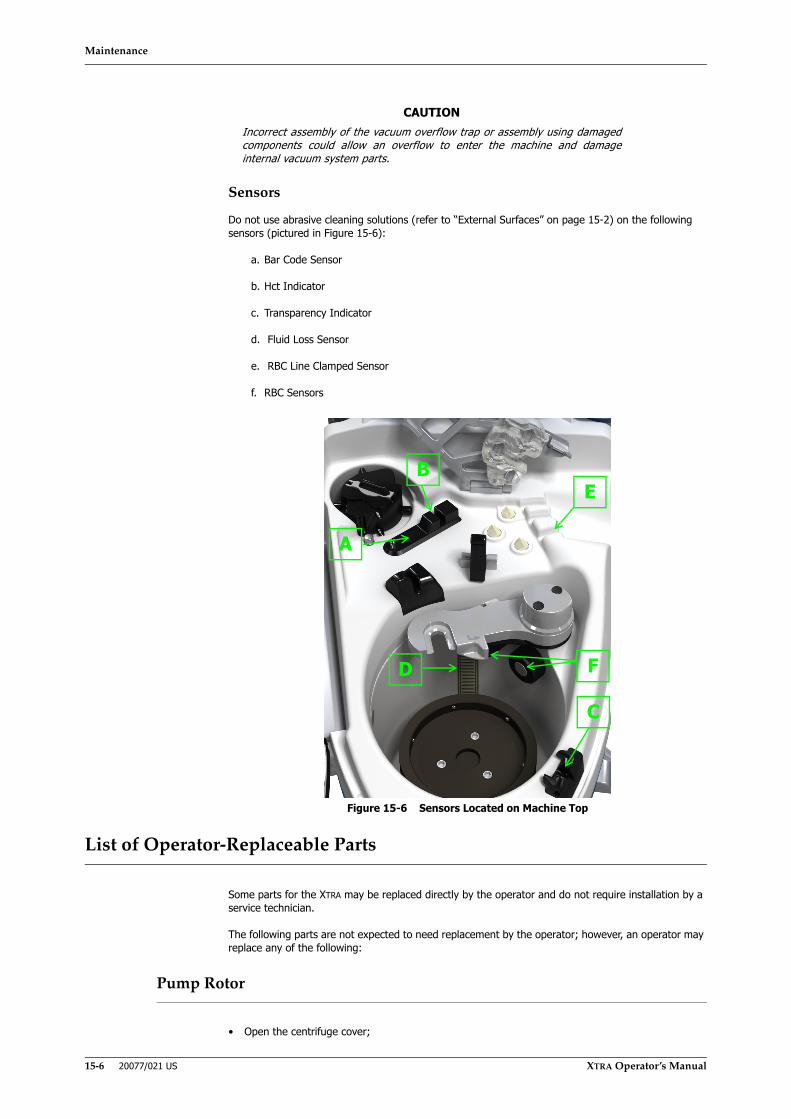
Maintenance
15-6 20077/021 US XTRA Operator’s Manual
Sensors
Do not use abrasive cleaning solutions (refer to “External Surfaces” on page 15-2) on the following sensors (pictured in Figure 15-6):
a. Bar Code Sensor
b. Hct Indicator
c. Transparency Indicator
d. Fluid Loss Sensor
e. RBC Line Clamped Sensor
f. RBC Sensors
Figure 15-6 Sensors Located on Machine Top
List of Operator-Replaceable Parts
Some parts for the XTRA may be replaced directly by the operator and do not require installation by a service technician.
The following parts are not expected to need replacement by the operator; however, an operator may replace any of the following:
Pump Rotor
• Open the centrifuge cover;
CAUTIONIncorrect assembly of the vacuum overflow trap or assembly using damagedcomponents could allow an overflow to enter the machine and damageinternal vacuum system parts.
B
C
A
D
E
F
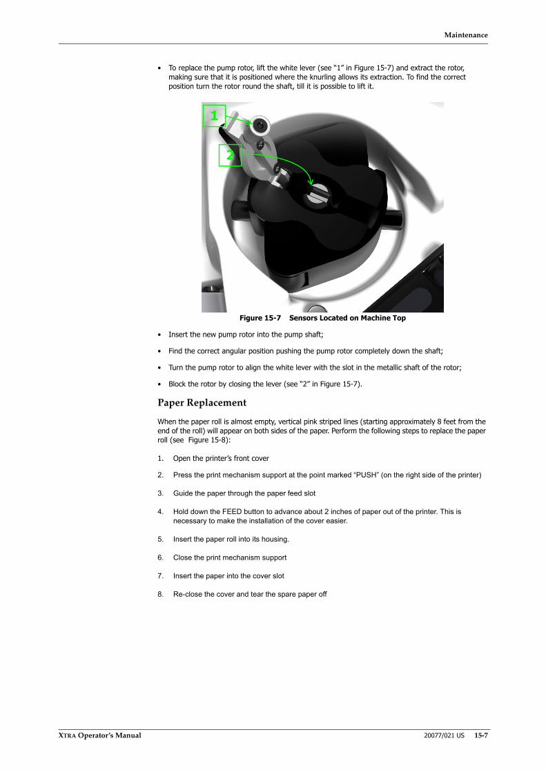
Maintenance
XTRA Operator’s Manual 20077/021 US 15-7
• To replace the pump rotor, lift the white lever (see “1” in Figure 15-7) and extract the rotor, making sure that it is positioned where the knurling allows its extraction. To find the correct position turn the rotor round the shaft, till it is possible to lift it.
Figure 15-7 Sensors Located on Machine Top
• Insert the new pump rotor into the pump shaft;
• Find the correct angular position pushing the pump rotor completely down the shaft;
• Turn the pump rotor to align the white lever with the slot in the metallic shaft of the rotor;
• Block the rotor by closing the lever (see “2” in Figure 15-7).
Paper Replacement
When the paper roll is almost empty, vertical pink striped lines (starting approximately 8 feet from the end of the roll) will appear on both sides of the paper. Perform the following steps to replace the paper roll (see Figure 15-8):
1. Open the printer’s front cover
2. Press the print mechanism support at the point marked “PUSH” (on the right side of the printer)
3. Guide the paper through the paper feed slot
4. Hold down the FEED button to advance about 2 inches of paper out of the printer. This is necessary to make the installation of the cover easier.
5. Insert the paper roll into its housing.
6. Close the print mechanism support
7. Insert the paper into the cover slot
8. Re-close the cover and tear the spare paper off
1
2
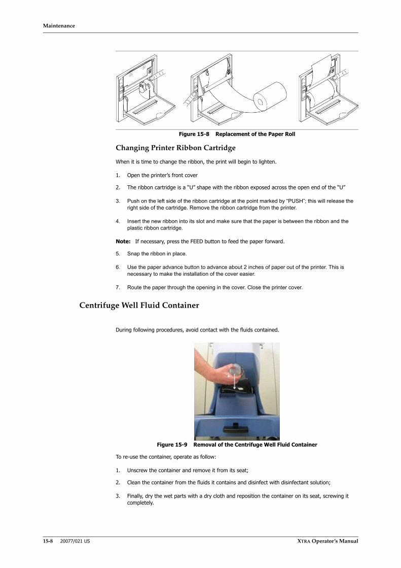
Maintenance
15-8 20077/021 US XTRA Operator’s Manual
Figure 15-8 Replacement of the Paper Roll
Changing Printer Ribbon Cartridge
When it is time to change the ribbon, the print will begin to lighten.
1. Open the printer’s front cover
2. The ribbon cartridge is a “U” shape with the ribbon exposed across the open end of the “U”
3. Push on the left side of the ribbon cartridge at the point marked by “PUSH”; this will release the right side of the cartridge. Remove the ribbon cartridge from the printer.
4. Insert the new ribbon into its slot and make sure that the paper is between the ribbon and the plastic ribbon cartridge.
Note: If necessary, press the FEED button to feed the paper forward.
5. Snap the ribbon in place.
6. Use the paper advance button to advance about 2 inches of paper out of the printer. This is necessary to make the installation of the cover easier.
7. Route the paper through the opening in the cover. Close the printer cover.
Centrifuge Well Fluid Container
During following procedures, avoid contact with the fluids contained.
Figure 15-9 Removal of the Centrifuge Well Fluid Container
To re-use the container, operate as follow:
1. Unscrew the container and remove it from its seat;
2. Clean the container from the fluids it contains and disinfect with disinfectant solution;
3. Finally, dry the wet parts with a dry cloth and reposition the container on its seat, screwing it completely.

Maintenance
XTRA Operator’s Manual 20077/021 US 15-9
Alternatively, perform the following to replace the container:
1. Unscrew the container from its seat;
2. Close it with the available cap and discard it;
3. Fit a new container to the output connector and screw into seat.
The container can be ordered as a spare part.
Preventive Maintenance
Regular maintenance checks by authorized service technicians
The preventive maintenance of the XTRA must be carried out by an authorized service technician at regular intervals in accordance with the maintenance contract (where a contract exists). Regardless of whether there is a service contract or not, the XTRA must be subjected to a regular maintenance check by the authorized service technician (in accordance with the European Directive 93/42 EEC and the national standards which are based on this directive). The XTRA should be overhauled by authorized service technicians every 12 months.
Machine Repair
The hospital personnel is allowed to perform the routine checks described in this chapter.
The Preventive maintenance as well as all the corrective maintenances on the XTRA must be performed by Field Service Engineers expressly authorized by LivaNova (refer to “Service Information” on page 1-17).
LivaNova Deutschland GmbHLindberghstrasse 25D-80939 München GermanyTel: +49.(0)89.32301.0Fax: +49.(0)89.32301.555

Maintenance
15-10 20077/021 US XTRA Operator’s Manual

Technical Data
XTRA Operator’s Manual 20077/021 US 16-1
Chapter 16: Technical Data
Technical Features of the Equipment
Unit Dimensions Height = 660 mm (1055 mm*) - pole loweredHeight = 1585 mm (1980 mm*) - pole completely liftedHeight = 835 mm (1230 mm*) - display liftedWidth = 375 mm - including the eccentric ringsWidth = 800 mm - with poles completely openDepth = 500 mm - 680 mm including the front and rear handles* = with cart.
Cart Dimensions Height = 500 mmWidth = 480 mmDepth = 595 mm
Unit weight 37 kgCart weight 22.5 kgDisplay Type: graphic color LCD TFT 8.4"
Dimensions: 172 mm x 130 mm (screen)Keyboard 1 STOP key
Touch screen keysMains voltage (Power
supply)230 V~ or 100-120 V~
Frequency 50 - 60 Hz
Power absorption Maximum: 320VA (550VA w/ vacuum on Intra mode)Functioning: 160VA (390VA w/ vacuum on Intra mode)
Fuses 2xT6.3AH (230V~) and 2xT6.3AH (100-120V~)Power cord Section = 3x1 mm2 (3x18AWG)
Length = 4 mCable / connection
peripheralsXTRA memory stick
Socket on cords Type C13 (EN 60320/C13)
Plug on cords Type VII (CEE (7) VII)Type NEMA 5-15Type BS89/10 (BS 1363/A)Type I/3 (CEI 23-16)
Unit electrical safety Class I, Type B (EN 60601-1)Drip proofing IPX1
Table 16-1

Technical Data
16-2 20077/021 US XTRA Operator’s Manual
Operating Features of the Equipment
Centrifuge speed In ATS protocols: 5600rpm, accuracy ±40rpmIn SEQ protocols: PPP: 1500÷5600rpm, steps of 100rpm, accuracy ±50rpmPRP1 and PRP2: 2400÷5600rpm, steps of 100rpm, accuracy ±50rpm
Peristaltic pump In ATS protocols the flow range is: 25÷1000mL/min, steps of 25mL/minIn SEQ protocols the flow range is: Fill/Spill phase: 10÷100mL/min, steps of
10mL/minEmpty phase: 25÷1000mL/min, steps of 25mL/min
Scale Capacity: 0 ˜ 5000 gAccuracy: ± 5%
Hct indicator Type: opticalPosition: Inlet/Outlet lineRange: 0% - 70%
Air sensor Type: ultrasonic waves ON / OFF with auto-testPosition: between pump and bowl
Waste line color indicator Type: opticalPosition: waste lineRange: 0 - 3000 mg/dl
Waste bag level Type: SoftwareIntervention Range: 7 - 10 l
RBC sensor (or Buffy-Coat sensor)
Low: optical linear CCD
High: punctual opticalClamped empty line
sensor Type: pressure sensor
Position: reinfusion lineIntervention: 1.5 - 3.0 bar
Centrifuge fluid loss sensor
Type: resistive
Position: centrifuge wellBar Code reader Type: optical
Position: topVacuum Pump (optional) In POST-OP mode the range is: -10 ÷ -100 mmHg, steps of -10 mmHg
In INTRA mode the range is: -50 ÷ -300 mmHg, steps of -10 mmHgAccuracy: ± 20 mmHg intraoperative, ± 10 mmHg postoperativeBoth POST-OP and INTRA aspiration modes are available with the Vacuum
module operating independently and operating connected to XTRA.Data storage Type: not-rechargeable buffer battery
Duration: (10 year functioning)Communication ports 1 Ethernet (port not available in current software version)
3 RS232 serial3 USB1 RS422 serial
Table 16-2
Warranty
XTRA Operator’s Manual 20077/021 US 17-1
Chapter 17: Warranty
Limited warranty and contractual conditions for LivaNova medical equipment
This Limited Warranty is in addition to any statutory rights of the Purchaser pursuant to applicable law.
Warranty expiry
LivaNova certifies to the Buyer that all supplied products are free of manufacturing defects and that, under normal and appropriate conditions of use, such products are guaranteed for a period of 12 months starting on the date of installation and, in any event, for not more than 13 months starting on the date of dispatch, even when, in this latter case, the period of installation of the equipment is less than 12 months.
For such warranty to be effective, any defects or faults shall be notified to the Manufacturer or his authorized representative by the Buyer within 8 days from the discovery of such defects or faults.
Any replacements and/or repairs made to products under warranty shall under no circumstances be considered as representing an extension of the overall warranty period as agreed above.
Contents and necessary requirements of the Warranty
a. Any service rendered under this warranty shall be limited to the repair and/or replacement, in the LivaNova factory, of materials with faults verified and ascertained by LivaNova. LivaNova guarantees that the safety of the devices is in no way altered by maintenance and/or repair activities performed by its engineers.
b. In the event of a formal request being made for servicing at the Buyer’s premises by LivaNova personnel. LivaNova shall be entitled to accept such request and, if necessary, to charge a service call or ask for a contribution to transfer expenses, the amount of which shall be previously agreed between the parties in case of acceptance of such request.
In such a case, excepting national and local holidays, the time lapse between acceptance of the Buyer’s request and the arrival of the supplier’s personnel on the buyer’s premises shall be 48 solar hours, spread over 5 working days.
c. LivaNova shall consider itself responsible for the safety, performance and operation of its products providing that:
1. installation, updating, extensions, modifications and repairs are done by authorized LivaNova personnel;
2. the electrical system to which the devices are connected conforms to the relevant applicable standards (special care has to be taken for the integrity of the earth conductors and environmental protection circuits);
3. the products are used in conformity with the user instructions in the “USER MANUAL” delivered to the customer together with the equipment (of which this “LIMITED WARRANTY” is an integral part).
d. The warranty does not cover those parts which, by their very nature, are likely to deteriorate or which LivaNova considers should be periodically replaced consistently with normal routine or preventive maintenance requirements.

Warranty
17-2 20077/021 US XTRA Operator’s Manual
Cases in which the Warranty shall not be effective
The warranty shall not be effective in the case of products and/or materials with defects deriving from:
poor handling and maintenance of the machine, incorrect use of device, tampering, modifications made by unauthorized personnel, use of materials and devices wrong or different from those indicated by the supplier and, however, in all those cases where the reasons for the defect or problem can be ascribed to the Buyer’s environment or personnel.
Warranty for replaced parts
The warranty provided by LivaNova with respect to repairs or updating of a device no longer under guarantee, as provided for by this certificate, shall be restricted to the replaced parts only, in the case of these not being included among those indicated above, according to paragraph d of “Contents and necessary requirements of the Warranty” on page 17-1, and shall not be effective for more than three months from the date of replacement.
Availability of spare parts
LivaNova guarantees availability of spare parts and trained personnel to repair and/or service its devices for a period of 60 months (5 years) from the date of going out of production of each model and, in any case, for a period of not more than 12 months (1 year) from the date of notification to the user of suspension of production in the event of such notification being given after 4 years from the date of going out of production of the equipment.
Technical documentation
a. LivaNova products are always supplied complete with adequate documentation, including, inter alia, instructions for correct use, identification of replaceable parts and relevant replacement procedures, as well as the list of routine and preventive maintenance activities. Other details may concern any disposables needed for correct use of the device.
b. All the documentation and information, drawings and descriptions contained in the manual or, for whatever reason, provided to the user, shall be considered as confidential and as belonging exclusively to LivaNova. These shall not therefore be revealed, distributed, copied or reproduced by any means and for whatever purpose, nor to be given out for consultation, total or partial, to anyone, without specific prior authorization being formally given by LivaNova.
c. LivaNova reserves the right to make, without prior notice, amendments or updates to the contents of previously distributed documentation.
Maintenance contracts
LivaNova offers its customers “customized” maintenance contracts to meet specific requirements. In the event of customers being interested, they are kindly asked to contact LivaNova or the local representative/distributor for further details and applicable contractual conditions.
LivaNova guarantees that all maintenance work done on its own responsibility, including work done in performance of maintenance contracts executed with LivaNova, will be made by specialized personnel, using original spare parts. In this way, products are kept in very best condition and maintain their original characteristics and capacity to achieve and assure the performances for which they were designed, manufactured and marketed.
Limits to the warranty with regard to product use by the buyer and/or user
Without prejudice to the provisions of the previous clauses, LivaNova guarantees that in manufacturing the medical device in question, all reasonable precautions have been taken as imposed by the nature and use for which the product is intended.
LivaNova guarantees that the medical device is able to operate in conformity with the information contained in the USER MANUAL, provided that it is used in compliance with the instructions given in such Manual and within the expiry date (whenever indicated on the device and/or its packaging).
Nevertheless, LivaNova cannot guarantee that the device will be correctly used by the user, nor that the diagnosis, pathology and/or specific physical and biological characteristics of the individual patients will, even when the aforementioned instructions are followed, not impair the performance and effectiveness of the device, with negative consequences for the patient.
Warranty
XTRA Operator’s Manual 20077/021 US 17-3
LivaNova consequently renews its invitation to scrupulously follow the user instructions and to take all the precautions necessary to ensure correct use of the device and declines all responsibility for any loss, damage, cost, accident or consequences deriving directly or indirectly from the improper use of the device.
This “Limited Warranty” substitutes any legal warranty, explicit or implicit, written or verbal, including marketability and/or operation warranties.
Technical safety standards applicable for the purpose of the Warranty
a. The safety standards applicable for the purpose of this warranty shall be those enforced in the Country where the device is addressed by the Manufacturer at the time of marketing of such device.
b. In Europe, safety as regards electrical and mechanical hazards, explosions and fires, with respect to medical electrical equipment, is defined by the following harmonized standard:
EN 60601-1: Medical electrical equipment - Part 1: general requirements for safety which implements the requirements of the International Standard IEC 60601-1
Such standards apply to medical electrical equipment intended for use by or under the control of qualified personnel in the immediate proximity of the patient and in relation to the patient him/herself (by proximity is meant the area within 1.5 m from the patient).
c. Each equipment manufactured by LivaNova undergoes safety tests as prescribed by the relevant standard IEC 60601-1, the results of which are available from LivaNova.
d. Any requests for specific measurements of safety parameters different from those above quoted shall be analyses and assessed by LivaNova as appropriate and, in the event of these being accepted by LivaNova, shall be expounded in a specific statement.
Absolute prohibition to amend the conditions of this Warranty
No representative, agent, dealer, retailer or intermediary of LivaNova shall be authorized to amend the contents of this document or assume any other liability in relation to the medical device in question. LivaNova only is entitled to amend, albeit formally and in writing, the contents of this “Limited Warranty” whenever, according to its own decision, LivaNova considers it appropriate or necessary.
The purchasing party takes note of such prohibition and shall not consequently request LivaNova to accept amendments or any other changes made by the aforementioned persons in contrast and/or in addition to the provisions indicated herein.
Applicable law and jurisdiction - Competent court
Relations between the parties with respect to the agreement for which this warranty is issued, as well as any disputes relating or in any way connected thereto, and all relations or any disputes concerning this warranty, its construal and execution, nothing excluded and/or reserved, by express agreement between the parties themselves, shall be exclusively governed by Italian law and Italian jurisdiction.
The competent court for the settlement of any disputes shall be exclusively the Court of Modena - Italy.

Warranty
17-4 20077/021 US XTRA Operator’s Manual
Identification of Manufacturer
While kindly asking you to scrupulously observe all the aforementioned provisions, please feel free to contact LivaNova or the authorized LivaNova representative, for any further details and/or technical assistance you might require.
LivaNova Deutschland GmbHLindberghstrasse 25D-80939 München GermanyTel: +49.(0)89.32301.0Fax: +49.(0)89.32301.555

XTRA Operator’s Manual 20077/021 US A-1
Appendix A: Safety Standards EN 60601-1-2
Information on electromagnetic compatibility (EMC)
Guidance and manufacturer’s declaration
Warnings
• Note: Medical electrical equipment needs precautions regarding electromagnetic compatibility and has to be installed and put into service according to the EMC information provided in the following guidance and the manufacturer's declaration.
• Portable and mobile RF-communications equipment can affect medical electrical equipment.
• The XTRA System can have a performance degradation, but the basic safety and essential performance will not be influenced. If the XTRA system is operated outside the EMC environment specified here, basic safety as well as essential features may fail. In this case the operator should be aware of a possible risk to the patient.
Guidance and manufacturer's declaration – electromagnetic emission
The XTRA is intended for use in the professional healthcare facility environment specified below. In order to prevent adverse advents to the patient and operator due to electromagnetic disturbances, the XTRA System must not be operated outside its intended EMC environment. Furthermore, the XTRA must not be operated if the enclosure, cables or measures for electromagnetic shielding are damaged.
Phenomenon Professional healthcare facility environment Electromagnetic environment - guidance
Conducted EMISSIONS CISPR 11 Note: The emissions characteristics of this equipment make it suitable for use in industrial areas and hospitals (CISPR 11 class A). If it is used in a residential environment (for which CISPR 11 class B is normally required) this equipment might not offer adequate protection to radio-frequency communication services. The user might need to take mitigation measures, such as relocating or reorienting the equipment.
Radiated emissions CISPR 11
Harmonic distorsion IEC 61000-3-2 See IEC 61000-3-2
Voltage fluctuations and flicker See IEC 61000-3-2
Table A-1 Emission limits
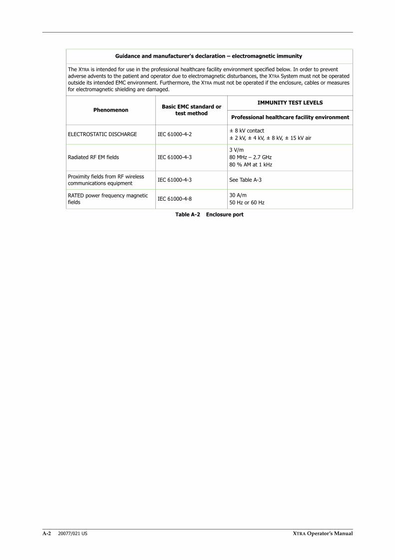
A-2 20077/021 US XTRA Operator’s Manual
Guidance and manufacturer's declaration – electromagnetic immunity
The XTRA is intended for use in the professional healthcare facility environment specified below. In order to prevent adverse advents to the patient and operator due to electromagnetic disturbances, the XTRA System must not be operated outside its intended EMC environment. Furthermore, the XTRA must not be operated if the enclosure, cables or measures for electromagnetic shielding are damaged.
Phenomenon Basic EMC standard or test method
IMMUNITY TEST LEVELS
Professional healthcare facility environment
ELECTROSTATIC DISCHARGE IEC 61000-4-2 ± 8 kV contact± 2 kV, ± 4 kV, ± 8 kV, ± 15 kV air
Radiated RF EM fields IEC 61000-4-33 V/m80 MHz – 2.7 GHz80 % AM at 1 kHz
Proximity fields from RF wireless communications equipment IEC 61000-4-3 See Table A‐3
RATED power frequency magnetic fields IEC 61000-4-8 30 A/m
50 Hz or 60 Hz
Table A-2 Enclosure port

XTRA Operator’s Manual 20077/021 US A-3
Test frequency
(MHz)
Band(MHz) Service Modulation
Maximum power
(W)
Distance(m)
Immunity test level
(V/m)
385 380 – 390 TETRA 400 Pulse modulation18 Hz 1.8 0.3 27
450 430– 470 GMRS 460FRS 460
FM± 5 kHz deviation
1 kHz sine2 0.3 28
710
704 – 787 LTE Band 13, 17 Pulse modulation217 Hz 0.2 0.3 9745
780
810
800 – 960
GSM 800/900TETRA 800iDEN 820CDMA 850LTE Band 5
Pulse modulation18 Hz 2 0.3 28870
930
1720
1700 – 1990
GSM 1800CDMA 1900GSM 1900
DECTLTE Band 1, 3, 4,
25UMTS
Pulse modulation217 Hz 2 0.3 28
1845
1970
2450 2400 – 2570
BluetoothWLAN 802.11 b/
g/nRFID 2450LTE Band 7
Pulse modulation217 Hz 2 0.3 28
5240
5100 – 5800 WLAN 802.11 a/n Pulse modulation217 Hz 0.2 0.3 95500
5785
Note: If necessary to achieve the immunity test level, the distance between the transmitting antenna and the XTRA System may be reduced to 1 m. The 1 m test distance is permitted by IEC 61000-4-3.
Note: Portable radio frequency (RF) communications equipment (including peripherals such as antenna cables and external antennas) as well as cables specified by the manufacturer should be used no closer than 30 cm to any part of the XTRA System. Otherwise this could result in performance degradation of this equipment.
Table A-3 Test specifications for enclosure port immunity to RF wireless communications equipment

A-4 20077/021 US XTRA Operator’s Manual
Phenomenon Basic EMC standardIMMUNITY TEST LEVELS
Professional healthcare facility environment
Electrical fast transients / bursts IEC 61000-4-4 ± 2 kV100 kHz repetition frequency
SurgesLine-to-line IEC 61000-4-5 ± 0.5 kV, ± 1 kV
SurgesLine-to-ground IEC 61000-4-5 ± 0.5 kV, ± 1 kV, ± 2 kV
Conducted disturbances induced by RF fields IEC 61000-4-6
3 V0.15 MHz – 80 MHz6 V in ISM bandsbetween 0.15 MHz and 80 MHz80 % AM at 1 kHz
Voltage dips IEC 61000-4-11
0 % UT; 0.5 cycleAt 0°, 45°, 90°, 135°, 180°, 225°, 270° and 315°
0 % UT; 1 cycleand70 % UT; 25/30 cycles
Single phase: at 0°
Voltage interruptions IEC 61000-4-11 0 % UT; 250/300 cycles
Table A-4 Input a.c. power port (1 & 2)
Phenomenon Basic EMC standardIMMUNITY TEST LEVELS
Professional healthcare facility environment
ELECTROSTATIC DISCHARGE IEC 61000-4-2 ± 8 kV contact± 2 kV, ± 4 kV, ± 8 kV, ± 15 kV air
Conducted disturbances induced by RF fields IEC 61000-4-6
3 V0.15 MHz – 80 MHz6 V in ISM bands between 0.15 MHz and 80 MHz80 % AM at 1 kHz
Table A-5 Patient coupling port
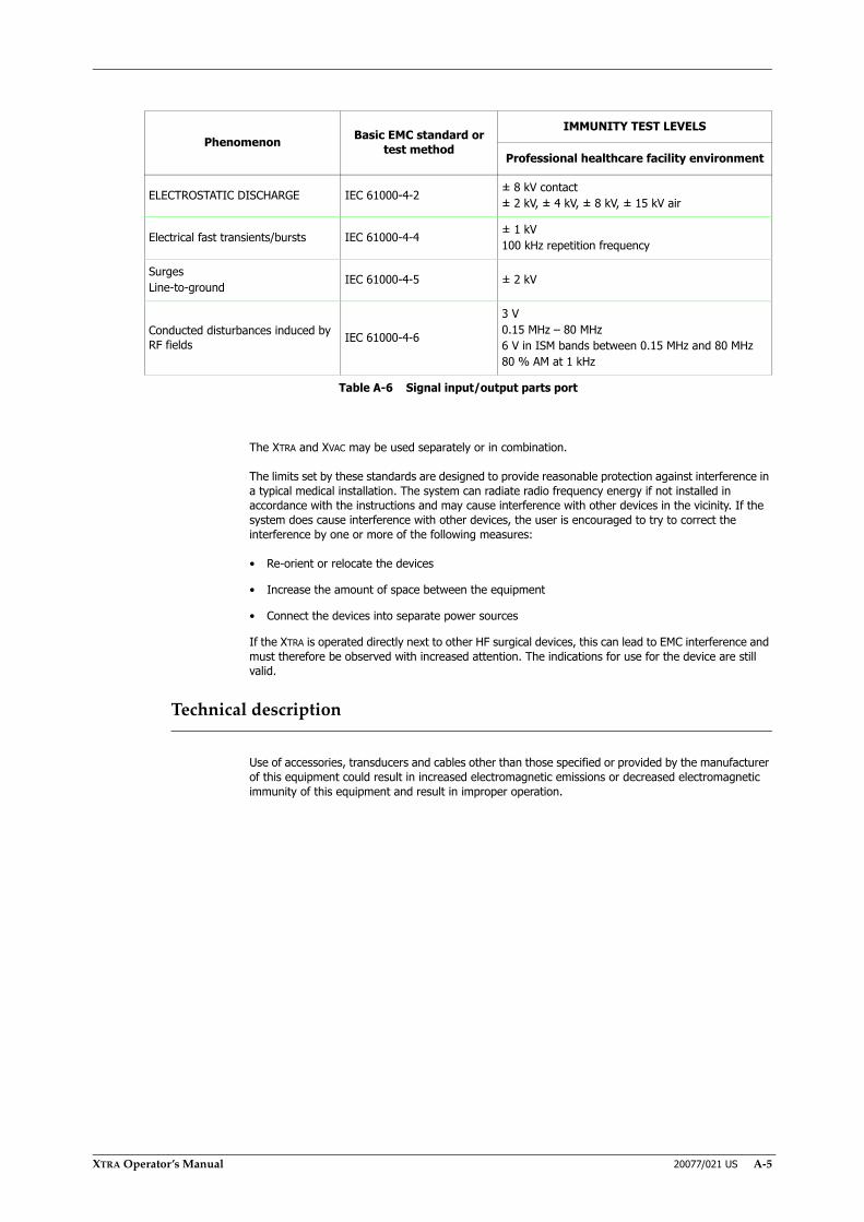
XTRA Operator’s Manual 20077/021 US A-5
The XTRA and XVAC may be used separately or in combination.
The limits set by these standards are designed to provide reasonable protection against interference in a typical medical installation. The system can radiate radio frequency energy if not installed in accordance with the instructions and may cause interference with other devices in the vicinity. If the system does cause interference with other devices, the user is encouraged to try to correct the interference by one or more of the following measures:
• Re-orient or relocate the devices
• Increase the amount of space between the equipment
• Connect the devices into separate power sources
If the XTRA is operated directly next to other HF surgical devices, this can lead to EMC interference and must therefore be observed with increased attention. The indications for use for the device are still valid.
Technical description
Use of accessories, transducers and cables other than those specified or provided by the manufacturer of this equipment could result in increased electromagnetic emissions or decreased electromagnetic immunity of this equipment and result in improper operation.
Phenomenon Basic EMC standard or test method
IMMUNITY TEST LEVELS
Professional healthcare facility environment
ELECTROSTATIC DISCHARGE IEC 61000-4-2 ± 8 kV contact± 2 kV, ± 4 kV, ± 8 kV, ± 15 kV air
Electrical fast transients/bursts IEC 61000-4-4 ± 1 kV100 kHz repetition frequency
SurgesLine-to-ground IEC 61000-4-5 ± 2 kV
Conducted disturbances induced by RF fields IEC 61000-4-6
3 V0.15 MHz – 80 MHz6 V in ISM bands between 0.15 MHz and 80 MHz80 % AM at 1 kHz
Table A-6 Signal input/output parts port

A-6 20077/021 US XTRA Operator’s Manual

XTRA Operator’s Manual 20077/021 US B-1
Appendix B: Approvals and Test Certificate
The XTRA and XVAC equipment have been tested and comply with the following:
EMC Standards
(See Appendix A: Safety Standards EN 60601-1-2)
EMC Emission
• IEC 60601-1-2 : 2007 and : 2014
EMC Immunity
• IEC 60601-1-2 : 2007 and : 2014
Electrical and Mechanical Safety Standards
• IEC 60601-1 Edition 3.1
Certification
• C-US NRTL Certification
• CB Certification
The LivaNova quality assurance system complies with the following standards:
• UNI - EN - ISO - 13485

B-2 20077/021 US XTRA Operator’s Manual
XTRA Operator’s Manual 20077/021 US C-1
Appendix C: Quick Operating Instructions
Note: These Quick Operating Instructions represent only an overview of the operating procedures. For a complete setup and use of the machine, please refer to the XTRA Operator’s Manual.
These documents may be printed as standalone documents, preferably color and double-sided.
Contents:
“Setting Up the Disposables” ...............................................................................3
“Setting the Active Protocol and Mode”.................................................................8
“Running an ATS Case” .......................................................................................9
“Running a PRP Sequestration Case” ..................................................................10
“Creating a Custom Protocol”.............................................................................11
“Printing a Report for the Current Case” .............................................................12

C-2 20077/021 US XTRA Operator’s Manual

Note: These Quick Operating Instructions represent only anoverview of the operating procedures. For a complete setup anduse of the machine, please refer to the Xtra Operator’s Manual.
XTRA Operator’s Manual 20077/021 US C-3
1. Install the Blood Collection Reservoir:a. Swing open the reservoir holder and raise it to the desired height
1. Install the Blood Collection Reservoir:b. Remove the Blood Collection Reservoir from its package
1. Install the Blood Collection Reservoir:c. Keep the locking clip on the reservoir holder open
1. Install the Blood Collection Reservoir:d. Slide the edge of the reservoir lid into the slot of the holder
1. Install the Blood Collection Reservoir:e. Push the reservoir into position
1. Install the Blood Collection Reservoir:f. Release the locking clip
1. Install the Blood Collection Reservoir:g. Tighten all the caps and luer locks on the reservoir lid
1. Install the Blood Collection Reservoir:h. In case you are using a Blood Collection Reservoir BOTTOM, connect the
outlet port and close the clamp on the bottom outlet port
1. Install the Blood Collection Reservoir:i. Set up of the three-way adapter (Y adapter) for use in cardiac surgery (if
you are using it).
1. Install the Blood Collection Reservoir:j. Close the clamps on the Y adapter branches waiting for subsequent
connections
Qui
ck S
tart
Ins
truc
tions
:S
etti
ng
Up
the
Dis
pos
able
s
Setting Up the Disposables

Note: These Quick Operating Instructions represent only anoverview of the operating procedures. For a complete setup anduse of the machine, please refer to the Xtra Operator’s Manual.
C-4 20077/021 US XTRA Operator’s Manual
1. Install the Blood Collection Reservoir:k. The branch ending with a male port is used to connect the reservoir to the
XTRA Bowl Set, the second one to the Oxygenator Extension Line
2. Connect the Suction Line:a. Raise the IV pole and the display completely
2. Connect the Suction Line:b. Prepare a bag or bottle of anticoagulant solution by mixing 30,000
international units of heparin per liter of sterile (injectable) normal saline
2. Connect the Suction Line:c. Remove the dual lumen suction line from its package and carefully open the
outer wrap
2. Connect the Suction Line:d. Pass the inner sterile wrapped assembly to the sterile field. At the sterile
field, unwrap the assembly, remove the protective cover, and attach the connector to a suction cannula
2. Connect the Suction Line:e. Pass the other end (the split end) of the aspiration line back from the sterile
field to the XTRA operator
2. Connect the Suction Line:f. Close the roller clamp on the small bore tubing
2. Connect the Suction Line:g. Remove the protective cover on the large bore tubing of the suction line
2. Connect the Suction Line:h. Attach the tubing to one of the inlet ports on the lid of the reservoir. The inlet
ports are orange-capped
2. Connect the Suction Line:i. Hang the anticoagulant solution container on one of the holders of the IV
pole
A
B
Setting Up the Disposables
Qui
ck S
tart
Ins
truc
tions
:S
etti
ng
Up
the
Dis
pos
able
s
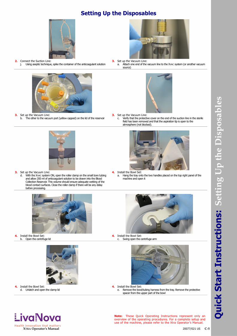
Note: These Quick Operating Instructions represent only anoverview of the operating procedures. For a complete setup anduse of the machine, please refer to the Xtra Operator’s Manual.
XTRA Operator’s Manual 20077/021 US C-5
2. Connect the Suction Line:j. Using aseptic technique, spike the container of the anticoagulant solution
3. Set up the Vacuum Line:a. Attach one end of the vacuum line to the XVAC system (or another vacuum
source)
3. Set up the Vacuum Line:b. The other to the vacuum port (yellow capped) on the lid of the reservoir
3. Set up the Vacuum Line:c. Verify that the protective cover on the end of the suction line in the sterile
field has been removed and that the aspiration tip is open to the atmosphere (not blocked).
3. Set up the Vacuum Line:d. With the XVAC system ON, open the roller clamp on the small bore tubing
and allow 200 ml of anticoagulant solution to be drawn into the Blood Collection Reservoir. This volume should ensure adequate wetting of the blood contact surfaces. Close the roller clamp if there will be any delay before processing.
4. Install the Bowl Set:a. Hang the tray onto the two handles placed on the top right panel of the
machine and open it
4. Install the Bowl Set:b. Open the centrifuge lid
4. Install the Bowl Set:c. Swing open the centrifuge arm
4. Install the Bowl Set:d. Unlatch and open the clamp lid
4. Install the Bowl Set:e. Remove the bowl/tubing harness from the tray. Remove the protective
spacer from the upper part of the bowl
Setting Up the Disposables
Qui
ck S
tart
Ins
truc
tions
:S
etti
ng
Up
the
Dis
pos
able
s

Note: These Quick Operating Instructions represent only anoverview of the operating procedures. For a complete setup anduse of the machine, please refer to the Xtra Operator’s Manual.
C-6 20077/021 US XTRA Operator’s Manual
4. Install the Bowl Set:f. Lower the bowl onto the turntable
4. Install the Bowl Set:g. Push the bowl straight down
4. Install the Bowl Set:h. Close the centrifuge arm by swinging it forward
4. Install the Bowl Set:i. Manually rotate the bowl to ensure that it rotates without eccentricity
4. Install the Bowl Set:j. Line up the tubing so that the pump loop cartridge snaps into the notch
provided and the organizer is properly seated
4. Install the Bowl Set:k. Make sure that the tubing is correctly seated into the air sensor
4. Install the Bowl Set:l. Close and latch the clamp lid
4. Install the Bowl Set:m. Make sure the waste line is properly seated into the waste fluid transparency
indicator
4. Install the Bowl Set:n. Close the centrifuge lid
4. Install the Bowl Set:o. Connect the fill line (blue) to the outlet port of the reservoir covered with a
blue cap
Look here
Bowl shoulder
Internal white
Bowl collar
Do notlook here
Setting Up the Disposables
Qui
ck S
tart
Ins
truc
tions
:S
etti
ng
Up
the
Dis
pos
able
s
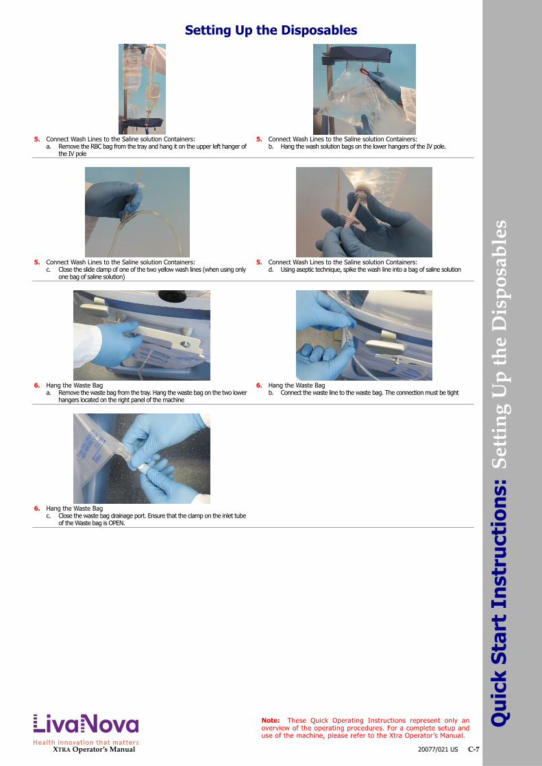
Note: These Quick Operating Instructions represent only anoverview of the operating procedures. For a complete setup anduse of the machine, please refer to the Xtra Operator’s Manual.
XTRA Operator’s Manual 20077/021 US C-7
5. Connect Wash Lines to the Saline solution Containers:a. Remove the RBC bag from the tray and hang it on the upper left hanger of
the IV pole
5. Connect Wash Lines to the Saline solution Containers:b. Hang the wash solution bags on the lower hangers of the IV pole.
5. Connect Wash Lines to the Saline solution Containers:c. Close the slide clamp of one of the two yellow wash lines (when using only
one bag of saline solution)
5. Connect Wash Lines to the Saline solution Containers:d. Using aseptic technique, spike the wash line into a bag of saline solution
6. Hang the Waste Baga. Remove the waste bag from the tray. Hang the waste bag on the two lower
hangers located on the right panel of the machine
6. Hang the Waste Bagb. Connect the waste line to the waste bag. The connection must be tight
6. Hang the Waste Bagc. Close the waste bag drainage port. Ensure that the clamp on the inlet tube
of the Waste bag is OPEN.
Setting Up the Disposables
Qui
ck S
tart
Ins
truc
tions
:S
etti
ng
Up
the
Dis
pos
able
s

Note: These Quick Operating Instructions represent only anoverview of the operating procedures. For a complete setup anduse of the machine, please refer to the Xtra Operator’s Manual.
C-8 20077/021 US XTRA Operator’s Manual
Setting the Active Protocol and Mode
1. From either the Setup Screen or the Ready Screen (pictured), touch the Menu button (A) to enter the Menu Screen.
2. The Menu Screen will initially display the Tally tab. From the left side of the Menu Screen, touch the Protocol/Mode tab (A).
3. Perform the following to set the active protocol from the Protocol/Mode tab:a. Touch the triangle menu button located on the right side of the protocol
drop-down menu (A). A list of available protocols will be displayed.b. Touch the name of the desired protocol to close the menu and set it as the
active protocol. (Touching the triangle menu button a second time without selecting a protocol from the list will close the Protocol menu without changing the active protocol.)
4. Perform the following to set the active operating mode from the Protocol/Mode tab:a. Touch the triangle menu button located on the right side of the Mode menu
(A). A list of available modes for the selected protocol will be displayed.b. Touch the name of the desired mode to close the menu and set it as the
active operating mode. (Touching the triangle menu button a second time without selecting a mode from the list will close the Mode menu without changing the active mode.)
5. Optionally, enable or disable any automations desired for the selected mode using the buttons (A) in the area immediately below the mode drop-down menu.
6. Touch the Save Modifications button (A) to exit and make all changes in the Protocol/Mode tab take effect.
If the screen is exited by touching the Close button (B), or is interrupted by a warning or alarm, then the modifications are not saved.
A
A
A A
A
A
B
Qui
ck S
tart
Ins
truc
tions
:S
etti
ng
the
Act
ive
Pro
toco
l an
d M
ode

Note: These Quick Operating Instructions represent only anoverview of the operating procedures. For a complete setup anduse of the machine, please refer to the Xtra Operator’s Manual.
XTRA Operator’s Manual 20077/021 US C-9
1. Install the disposable set. Draw 200 ml of anticoagulant solution into the blood collection reservoir prior to aspirating blood. Prime the blood administration set, if applicable.
2. Turn on the machine using the ON/OFF switch located on the rear panel. Once the system has booted and the Setup Screen is displayed, touch the Load button (A) to autoload the pump loop tubing and begin a new case.
3. Looking at the status area (A) of the Ready Screen, make sure that the active protocol is one of the ATS protocols (Pstd, Popt, or Post-op), the active operating mode is either 1 Touch or Automatic, and that the Autostart and Continue icons are present.If they aren’t, touch the Menu button (B) to enter the Menu Screen, select the Protocols/Mode tab from the left of the Menu Screen, set the active protocol to an ATS protocol, set the mode to 1 Touch or Automatic, and ensure the Autostart and Continue automations are enabled.
4. Once ready, touch the Start button (A) to begin processing.Alternatively, wait until there is sufficient blood in the reservoir to trigger the Autostart automation (1,600 ml by default).
5. The machine will begin processing through the Fill-Wash-Empty cycle, starting a new cycle at the end of each Empty phase, until the reservoir is empty.
6. When the reservoir is empty, the “Reservoir empty. Bowl not filled” alarm is issued. Touch the Last Bowl button (A) to concentrate and wash the remaining blood and empty the RBC line.
7. The case is complete. Proceed in one of the following ways:• Save the case tally data to an external destination using the “Select destination” drop-down menu and the Send Output button (A).• To process another case, touch the Start New Case button (B) to return to the Ready Screen and begin a new case.• If there are no other cases to process, shut down the machine.
A
B
A
A
A
A
B
Running an ATS Case
Qui
ck S
tart
Ins
truc
tions
:R
un
nin
g an
AT
S C
ase
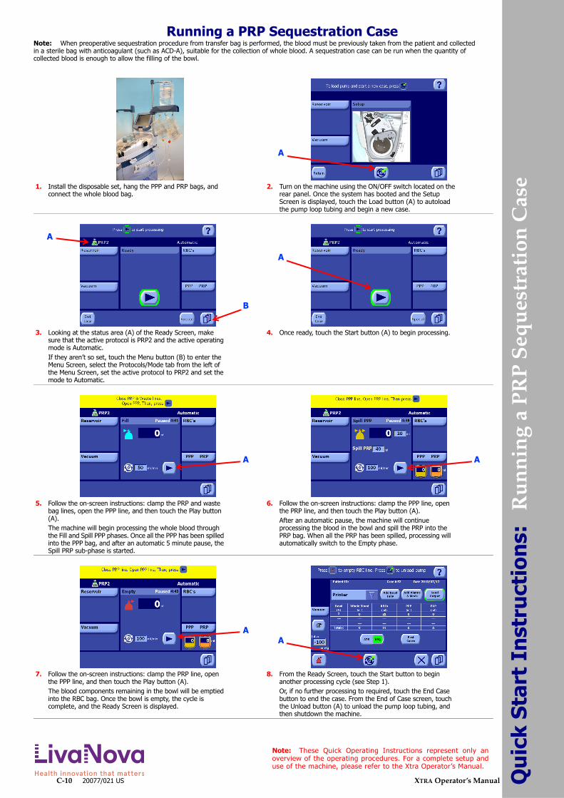
Note: These Quick Operating Instructions represent only anoverview of the operating procedures. For a complete setup anduse of the machine, please refer to the Xtra Operator’s Manual.
C-10 20077/021 US XTRA Operator’s Manual
Note: When preoperative sequestration procedure from transfer bag is performed, the blood must be previously taken from the patient and collected in a sterile bag with anticoagulant (such as ACD-A), suitable for the collection of whole blood. A sequestration case can be run when the quantity of collected blood is enough to allow the filling of the bowl.
1. Install the disposable set, hang the PPP and PRP bags, and connect the whole blood bag.
2. Turn on the machine using the ON/OFF switch located on the rear panel. Once the system has booted and the Setup Screen is displayed, touch the Load button (A) to autoload the pump loop tubing and begin a new case.
3. Looking at the status area (A) of the Ready Screen, make sure that the active protocol is PRP2 and the active operating mode is Automatic.If they aren’t so set, touch the Menu button (B) to enter the Menu Screen, select the Protocols/Mode tab from the left of the Menu Screen, set the active protocol to PRP2 and set the mode to Automatic.
4. Once ready, touch the Start button (A) to begin processing.
5. Follow the on-screen instructions: clamp the PRP and waste bag lines, open the PPP line, and then touch the Play button (A).The machine will begin processing the whole blood through the Fill and Spill PPP phases. Once all the PPP has been spilled into the PPP bag, and after an automatic 5 minute pause, the Spill PRP sub-phase is started.
6. Follow the on-screen instructions: clamp the PPP line, open the PRP line, and then touch the Play button (A).After an automatic pause, the machine will continue processing the blood in the bowl and spill the PRP into the PRP bag. When all the PRP has been spilled, processing will automatically switch to the Empty phase.
7. Follow the on-screen instructions: clamp the PRP line, open the PPP line, and then touch the Play button (A).The blood components remaining in the bowl will be emptied into the RBC bag. Once the bowl is empty, the cycle is complete, and the Ready Screen is displayed.
8. From the Ready Screen, touch the Start button to begin another processing cycle (see Step 1).Or, if no further processing to required, touch the End Case button to end the case. From the End of Case screen, touch the Unload button (A) to unload the pump loop tubing, and then shutdown the machine.
A
B
A
A
A A
AA
Running a PRP Sequestration Case
Qui
ck S
tart
Ins
truc
tions
: R
un
nin
g a
PR
P S
equ
estr
atio
n C
ase

Note: These Quick Operating Instructions represent only anoverview of the operating procedures. For a complete setup anduse of the machine, please refer to the Xtra Operator’s Manual.
XTRA Operator’s Manual 20077/021 US C-11
1. From either the Setup Screen, the Ready Screen (pictured), or any processing screen, touch the Menu button (A) to enter the Menu Screen.
2. The Menu Screen will initially display the Tally tab. From the left side of the Menu Screen, touch the Protocol/Mode tab (A).
3. Select a base protocol from the protocol drop-down menu (A). This can be either a factory protocol or an existing custom protocol. You will duplicate and then customize the base protocol in order to create the new protocol.
Choose a base protocol whose parameters are closest to what you desire for the new protocol.
4. Touch the New button (A). This will duplicate the selected protocol and will give the newly created protocol a unique name (prefixed by the base protocol’s factory type).
5. Touch the Rename button (A) to display the Keyboard Screen.
6. Use the keys on the Keyboard Screen to rename the newly created protocol to a more useful name. When satisfied with the name, touch the “Enter” button (A).
7. Make any desired changes to the protocol parameters using the controls in the protocol area beneath the protocol drop-down menu. For example, adjust the pump speed for each of the protocol’s phases.
The parameters available for modification are dependent on the base protocol.
8. Once all parameters have been set to your desired values, touch the Save Modifications button (A) to save your modifications and close the Protocol/Mode tab.
Alternatively, if you wish to close the tab without saving your modifications, touch the Close button (B).
A
A
A
A
A A
A
B
Qui
ck S
tart
Ins
truc
tions
:C
reat
ing
a C
ust
om P
roto
col
Creating a Custom Protocol

Note: These Quick Operating Instructions represent only anoverview of the operating procedures. For a complete setup anduse of the machine, please refer to the Xtra Operator’s Manual.
C-12 20077/021 US XTRA Operator’s Manual
The tally data for the current case may be printed from either the Tally tab of the Menu Screen at any time or from the End of Case Screen after processing the case. These quick operating instructions illustrate printing from the Tally tab of the Menu Screen:
1. From either the Setup Screen, the Ready Screen (pictured), or any processing screen, touch the Menu button (A) to enter the Menu Screen.
2. From the Tally tab, check to see if “Printer” is set as the current destination in the destination drop-down menu (A).
3. If “Printer” is not the currently selected destination, then touch the arrow portion of the destination drop-down menu to display the list of available destinations. From the displayed list, touch “Printer” to select it as the destination for the case data.
4. Touch the “Send Output” button (A). While the case data is being printed, the text “Outputting case...” is displayed above the “Send Output” button, and the “Send Output” button will appear inset and green.
A
A
A
Printing a Report for the Current Case
Qui
ck S
tart
Ins
truc
tions
:P
rin
tin
g a
Rep
ort f
or th
e C
urr
ent C
ase
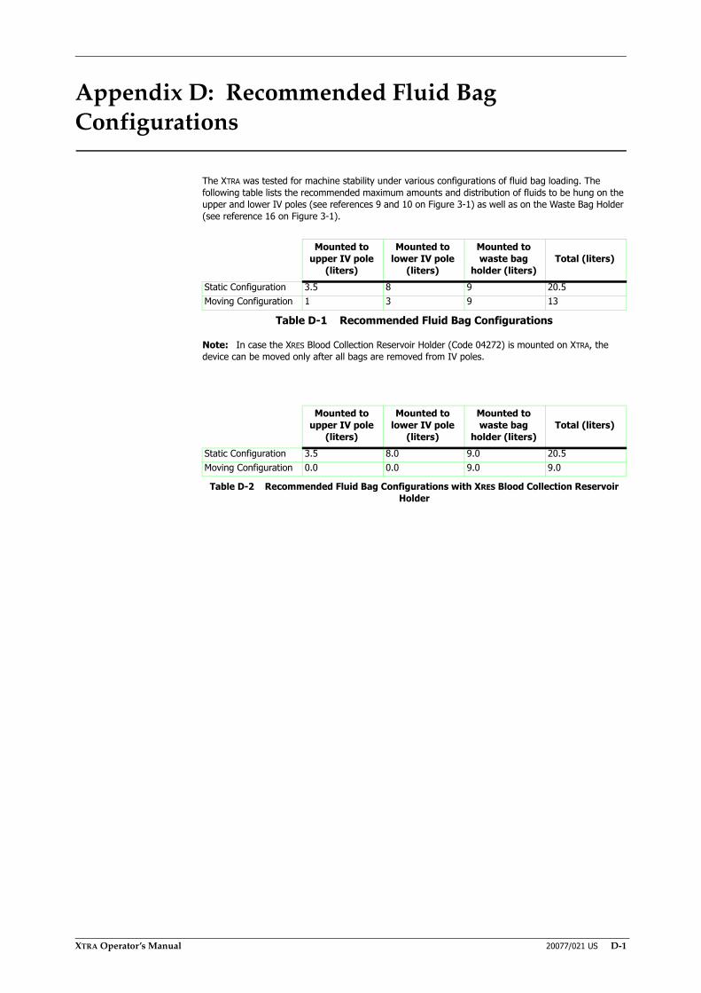
XTRA Operator’s Manual 20077/021 US D-1
Appendix D: Recommended Fluid Bag Configurations
The XTRA was tested for machine stability under various configurations of fluid bag loading. The following table lists the recommended maximum amounts and distribution of fluids to be hung on the upper and lower IV poles (see references 9 and 10 on Figure 3-1) as well as on the Waste Bag Holder (see reference 16 on Figure 3-1).
Note: In case the XRES Blood Collection Reservoir Holder (Code 04272) is mounted on XTRA, the device can be moved only after all bags are removed from IV poles.
Mounted to upper IV pole
(liters)
Mounted to lower IV pole
(liters)
Mounted to waste bag
holder (liters)Total (liters)
Static Configuration 3.5 8 9 20.5Moving Configuration 1 3 9 13
Table D-1 Recommended Fluid Bag Configurations
Mounted to upper IV pole
(liters)
Mounted to lower IV pole
(liters)
Mounted to waste bag
holder (liters)Total (liters)
Static Configuration 3.5 8.0 9.0 20.5Moving Configuration 0.0 0.0 9.0 9.0
Table D-2 Recommended Fluid Bag Configurations with XRES Blood Collection Reservoir Holder

D-2 20077/021 US XTRA Operator’s Manual

XTRA Operator’s Manual 20077/021 US E-1
Appendix E: Symbols and Abbreviations
Symbols
Electrical Symbols on the Unit
Symbols on the Unit and on the Packaging
Symbol Designation DescriptionAlternate current (A.C.) This symbol indicates that the device
requires an alternating supply current.
Equipment Type B This symbol indicates that the device is classified as Type B per electrical safety standard IEC 60601-1. This classification is based on the degree of protection afforded against electrical shock, as defined in that standard.
Applied part is the fluid circuit from the tube.
Main switch (primary) O = off (not connected to mains)I = on (connected to mains)
External fuse (replaceable)
Table E-1 Electrical Symbols on the Unit
Symbol Designation DescriptionCE Approval Equipment complying with the
requirements set by the European Council Directive 93/42/EEC relating to medical equipment
Drip water protected
Code number
Warning This symbol indicates that consultation of the accompanying documents prior to equipment operation is critical to the safe operation of the device.
This side up Keep shipping crate upright
Table E-2 Symbols on the Unit and on the Packaging
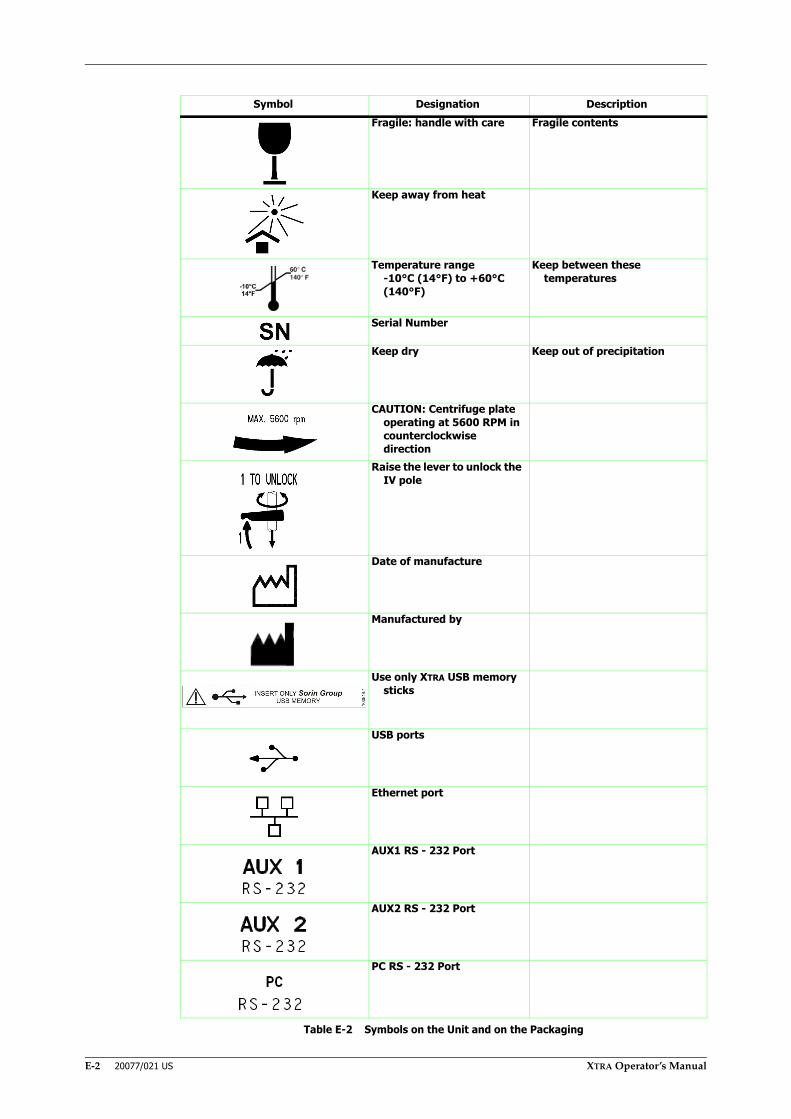
E-2 20077/021 US XTRA Operator’s Manual
Fragile: handle with care Fragile contents
Keep away from heat
Temperature range-10°C (14°F) to +60°C (140°F)
Keep between these temperatures
Serial Number
Keep dry Keep out of precipitation
CAUTION: Centrifuge plate operating at 5600 RPM in counterclockwise direction
Raise the lever to unlock the IV pole
Date of manufacture
Manufactured by
Use only XTRA USB memory sticks
USB ports
Ethernet port
AUX1 RS - 232 Port
AUX2 RS - 232 Port
PC RS - 232 Port
Symbol Designation Description
Table E-2 Symbols on the Unit and on the Packaging

XTRA Operator’s Manual 20077/021 US E-3
Abbreviations
Units Conversion Table and Measuring Units
Relative humidity range5 - 85%
Atmospheric pressure range80 - 106 kPa
Consult Operator's Manual(Required to consult for
safety)
STOP Button This symbol is located on a processing key on the front panel of the XTRA. Pressing this key stops the pumps, centrifuge, and automatic processing.
No Pushing
Protection Class I
Only applies in the U.S.A.: Sale (and prescription) is restricted to physicians
1 pound 453.6 g1 mm 0.039 in.1 bar 15 psi°Celsius Freezing point: 0°C
Boiling point of water: 100°C under normal atmospheric pressure
°Fahrenheit Freezing point: 32°FBoiling point of water: 212°F under normal
atmospheric pressure
Table E-3 Units Conversion Table and Measuring Units
Symbol Designation Description
Table E-2 Symbols on the Unit and on the Packaging

E-4 20077/021 US XTRA Operator’s Manual

This medical device bears the marking according to theEuropean Council Directive MDD 93/42/EEC.
Further information is available from Manufacturer (contact LivaNova’s local Representative
or directly LivaNova’s RA & QA).

LivaNova Deutschland GmbHLindberghstrasse 25
D-80939 München GermanyTel: +49.(0)89.32301.0
Fax: +49.(0)89.32301.555
Related Documents


