Operator's Manual VST-36/40/47/52-l Aerial Device SERIAL NUMBER 39014-03 MANUAL PART NUMBER PLEASE NOTETHE ANSI A92.2 STANDARD ANDTHE MAN JALOF RESPONSIBILITIES CONTAINS RECENTLY UPDATED INFORMATION. DEALERS, OWNERS, USERS, OPERATORS, LESSORS AND LESSEES MUST ADHERE TO "mESE UPDATED STANDARDS. ATTENTION: DO NOT ATTEMPT TO OPERATE THIS VERSALIFT UNTIL YOU HAVE READ AND UNDERSTOOD ALL INFORMATION IN BOTH OPERATOR'S AND SERVICE MANUALS, PROVIDED WITH EACH VERSALIFT THIS MANUAL CONTAINS CONFIDENTIAL INFORMATION AND IS THE SOLE PROPERTY OF TIME MANUFACTURING CO. CONTENTS ARE NOTTO BE DISCLOSED, COPIED, OR REPRODUCED IN ANY MANNER WITHOUT THE EXPRESSED, WRITTEN PERMISSION OF TIME MANUFACTURING CO. ^PIUU; Time Manufacturing Co. 7601 Imperial Drive P.O.Box20368 Waco,Texas 76702 Phone:254-399-2100 Fax: 254-7S1-077S Time Manufacturing Co. reserves the right to improve the design or change speci^cations at any time without notice.

Welcome message from author
This document is posted to help you gain knowledge. Please leave a comment to let me know what you think about it! Share it to your friends and learn new things together.
Transcript
Operator's Manual
VST-36/40/47/52-l
Aerial Device
SERIAL NUMBER
39014-03
MANUAL PART NUMBER
PLEASE NOTETHE ANSI A92.2 STANDARD ANDTHE MAN JALOF RESPONSIBILITIES CONTAINS RECENTLY
UPDATED INFORMATION. DEALERS, OWNERS, USERS, OPERATORS, LESSORS AND LESSEES MUST ADHERE TO"mESE UPDATED STANDARDS.
ATTENTION:
DO NOT ATTEMPT TO OPERATE THIS VERSALIFT UNTIL
YOU HAVE READ AND UNDERSTOOD ALL INFORMATION IN BOTH
OPERATOR'S AND SERVICE MANUALS, PROVIDED WITH EACHVERSALIFT
THIS MANUAL CONTAINS CONFIDENTIAL INFORMATION
AND IS THE SOLE PROPERTY OF TIME MANUFACTURING CO.
CONTENTS ARE NOTTO BE DISCLOSED, COPIED, OR REPRODUCEDIN ANY MANNER WITHOUT THE EXPRESSED, WRITTEN PERMISSIONOF TIME MANUFACTURING CO.
^PIUU; Time Manufacturing Co. 7601 Imperial Drive P.O.Box20368 Waco,Texas 76702 Phone:254-399-2100 Fax: 254-7S1-077S
Time Manufacturing Co. reserves the right to improve the design or change speci^cations at any time without notice.
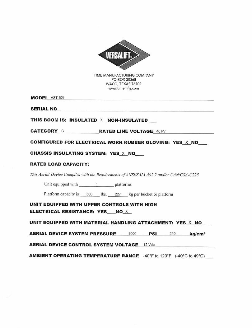
MODEL VST-521
SERIAL NO
TIME MANUFACTURING COMPANY
PO BOX 20368
WACO, TEXAS 76702wwfw.timemfg.com
THIS BOOM IS: INSULATED X NON-INSULATED
CATEGORY 0 RATED LINE VOLTAGE 46 kV
CONFIGURED FOR ELECTRICAL WORK RUBBER GLOVING: YES X NO
CHASSIS INSULATING SYSTEM: YES x NO
RATED LOAD CAPACITY:
ThisAerial Device Complies with the Requirements ofANSI/SAIA A92.2 and/or CAN/CSA-C225
Unit equipped with platforms
Platform capacity is 500 lbs. 227 kg per bucket or platform
UNIT EQUIPPED WITH UPPER CONTROLS WITH HIGH
ELECTRICAL RESISTANCE: YES NO X
UNIT EQUIPPED WITH MATERIAL HANDLING ATTACHMENT: YES X NO
AERIAL DEVICE SYSTEM PRESSURE 3000 PSI 210 ka/cm
AERIAL DEVICE CONTROL SYSTEM VOLTAGE 12 Vdc
AMBIENT OPERATING TEMPERATURE RANGE -40°Fto120°F (-40°Cto49°C
%
9
WANUFAQTURINQ CQMPANY
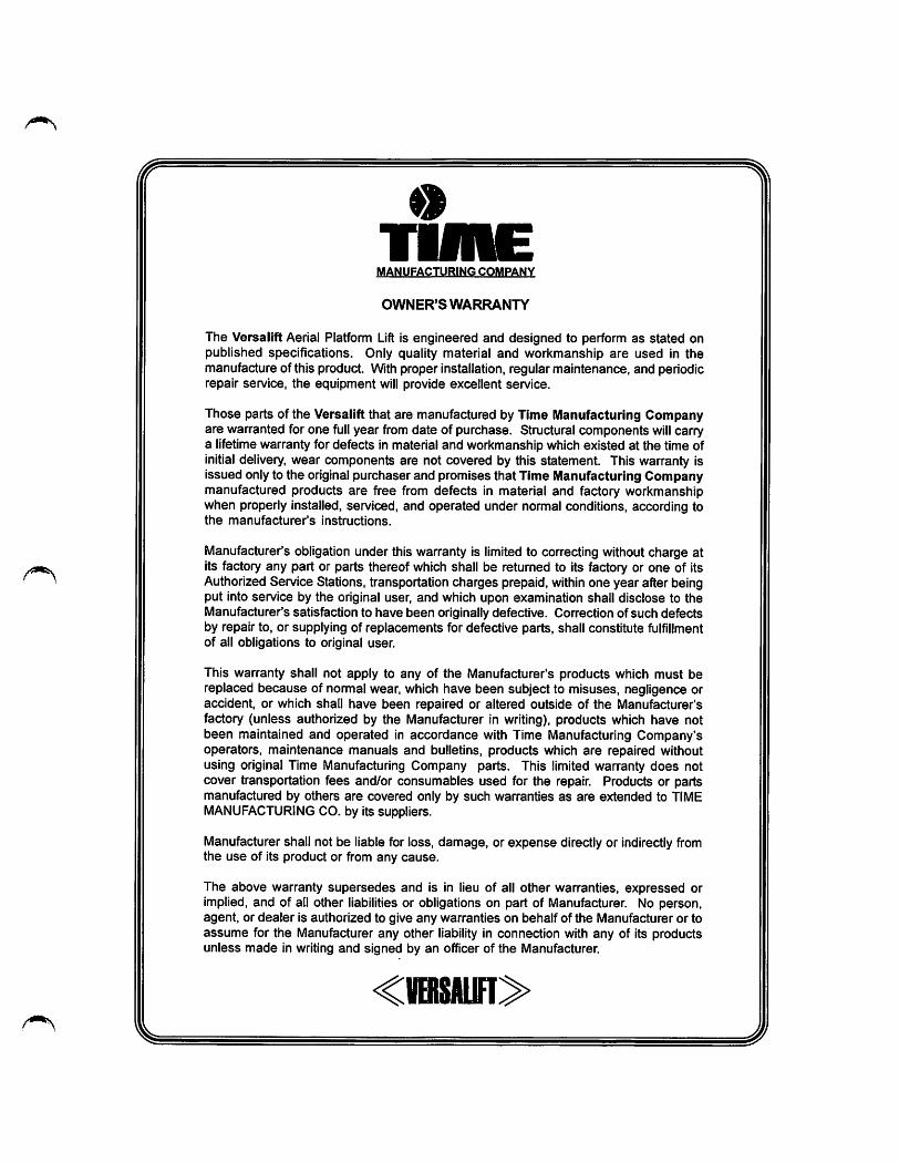
OWNER'S WARRANTY
The Versalift Aerial Platform Lift is engineered and designed to perform as stated onpublished specifications. Only quality material and workmanship are used in themanufacture of this product. With proper installation, regular maintenance, and periodicrepair service, the equipment will provide excellent service.
Those parts of the Versalift that are manufactured by Time Manufacturing Companyare warranted for one full year from date of purchase. Structural components will carrya lifetime warranty for defects in material and workmanship which existed at the time ofinitial delivery, wear components are not covered by this statement. This warranty isissued onlyto the original purchaser and promises that Time Manufacturing Companymanufactured products are free from defects in material and factory workmanshipwhen properly installed, serviced, and operated under nornnal conditions, according tothe manufacturer's instructions.
Manufacturer's obligation under this warranty is limited to correcting without charge atits factory any part or parts thereof which shall be returned to its factory or one of itsAuthorizedService Stations, transportation charges prepaid, within one year after beingput into service by the original user, and which upon examination shall disclose to theManufacturer's satisfaction to have been originallydefective. Correction of such defectsby repair to, or supplying of replacements for defective parts, shall constitute fulfillmentof all obligations to original user.
This warranty shall not apply to any of the Manufacturer's products which must bereplaced because of normal wear, which have been subject to misuses, negligence oraccident, or which shall have been repaired or altered outside of the Manufacturer'sfactory (unless authorized by the Manufacturer in writing), products which have notbeen maintained and operated in accordance with Time Manufacturing Company'soperators, maintenance manuals and bulletins, products which are repaired withoutusing original Time Manufacturing Company parts. This limited warranty does notcover transportation fees and/or consumables used for the repair. Products or partsmanufactured by others are covered only by such warranties as are extended to TIMEMANUFACTURING CO. by its suppliers.
Manufacturer shall not be liable for loss, damage, or expense directly or indirectly fromthe use of its product or from any cause.
The above warranty supersedes and is in lieu of all other warranties, expressed orimplied, and of all other liabilities or obligations on part of Manufacturer. No person,agent, or dealer is authorized to give any warranties on behalf of the Manufacturer or toassume for the Manufacturer any other liability in connection with any of its productsunless made in writing and signed by an officer of the Manufacturer.
<1IBISAIIIT>
%
J'
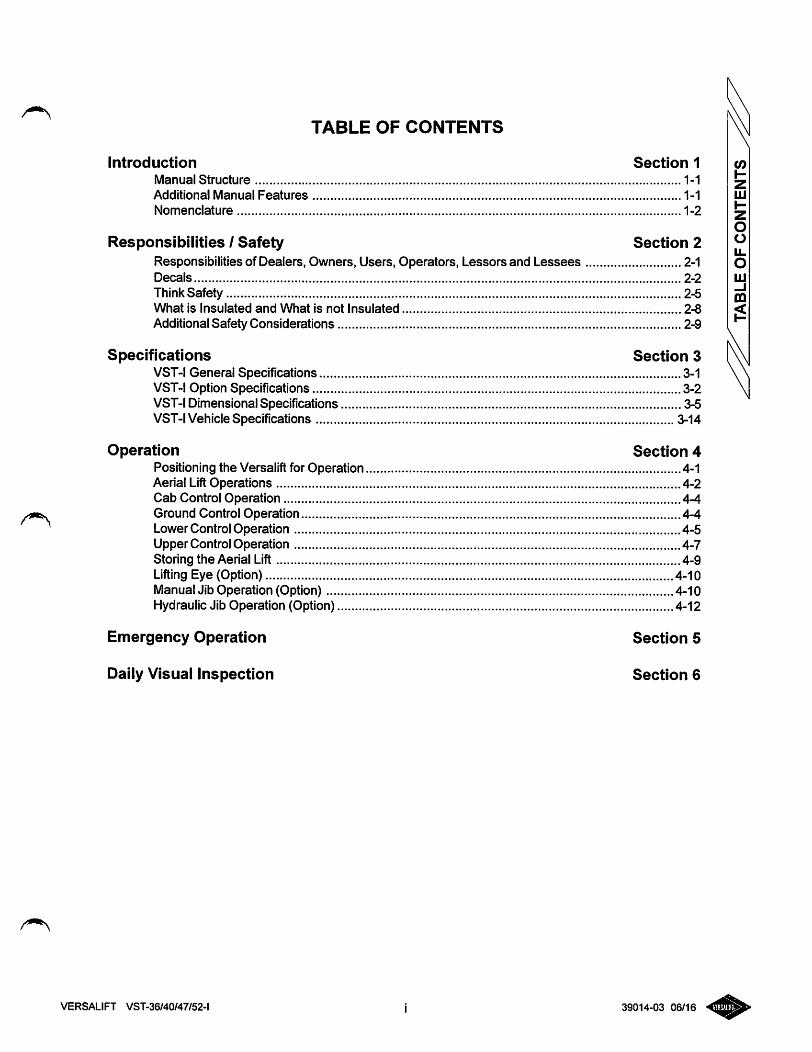
TABLE OF CONTENTS
Introduction Section 1
Manual Structure 1-1
Additional Manual Features 1-1
Nomenclature 1-2
Responsibilities I Safety Section 2Responsibilities of Dealers, Owners, Users, Operators, Lessors and Lessees 2-1Decals 2-2
Think Safety 2-5What is Insulated and What is not Insulated 2-8
Additional Safety Considerations 2-9
Specifications Section 3VST-I General Specifications 3-1VST-I Option Specifications 3-2VST-I Dimensional Specifications 3-5VST-I Vehicle Specifications 3-14
Operation Section 4Positioning the Versalift for Operation 4-1Aerial LiftOperations 4-2Cab Control Operation 4-4Ground Control Operation 4-4Lower Control Operation 4-5Upper Control Operation 4-7Storing the Aerial Lift 4-9Lifting Eye (Option) 4-10Manual Jib Operation (Option) 4-10Hydraulic Jib Operation (Option) 4-12
Emergency Operation Section 5
Daily Visual Inspection Section 6
VERSALIFT VST-36/40/47/52-l i 39014-03 06/16
INTRODUCTION
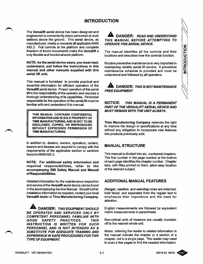
The Versalift aerial device has been designed andengineered to conveniently place personnel at workstations above the ground. This aerial device, asmanufactured, meets or exceeds all applicable ANSIA92.2. Full controls at the platform and completefreedom of boom movements make the Versalift a
truly flexible and functional work platform.
NOTE: As the aerial device users, you must read,understand, and follow the instructions in thismanual and other manuals supplied with thisaerial lift unit.
This manual is furnished to provide practical andessential information for efficient operation of theVersalift aerial device. Proper operation of this aerialliftis the responsibility of the operator and requires athorough understanding of its capabilities. Personnelresponsible for the operation of the aerial liftmust befamiliar with and understand this manual.
THIS MANUAL CONTAINS CONFIDENTAL
INFORMATION AND IS SOLE PROPERTY OF
TIME MANUFACTURING, AND IS NOT TO BEDISCLOSED, COPIED, OR REPRODUCEDWITHOUT EXPRESSED PERMISSION OFTIME MANUFACTURINa
In addition to, dealers, owners, operators, renters,lessors and lessees are required to comply with therequirements of the applicable section or sectionsfound inANSIA92.2.
NOTE: For additional safety information andrequired responsibilities, refer to theaccompanying EMI Safety Manual and Manualof Responsibiltities.
Detailed information for the maintenance inspectionand service ofthe Versalift aerial device can be found
in the accompanying Service Manual. Should furtherinstallation infomiation be required, contact your localVersalift dealer or Time Manufacturing Company.
DANGER: THIS EQUIPMENTSHOULDBE OPERATED AND SERVICED ONLY BY
COMPETENT PERSONNEL FAMILIAR WITH
GOOD SAFETY PRACTICES. THIS
INSTRUCTION IS WRITTEN FOR SUCH
PERSONNEL AND IS NOT INTENDED AS A
SUBSTITUTE FOR ADEQUATE TRAINING ANDEXPERIENCE IN SAFE PROCEDURES FOR THIS
TYPE OF EQUIPMENT.
^ DANGER: READ AND UNDERSTANDTHIS MANUAL BEFORE ATTEMPTING TO
OPERATE THIS AERIAL DEVICE.
The manual identifies all the controls and their
locations and describes how the controls function.
Routine preventive maintenance is very important inmaintaining reliable aerial lift service. A preventivemaintenance schedule is provided and must beunderstood and followed by all operators.
Mk. DANGER: THIS ISNOTMAINTENANCEFREE EQUIPMENT
NOTICE: THIS MANUAL IS A PERMANENT
PART OF THE VERSALIFTAERIAL DEVICEAND
MUST REMAIN WITH THE UNITALWAYS.
Time Manufacturing Company reserves the rightto improve the design or specifications at any timewithout any obligation to incorporate new featuresinto products previously sold.
MANUALSTRUCTURE
This manual is divided into six, numbered chapters.The first number in the page number at the bottomof each page identifies the chapter number. Chaptertabs, with titles printed on them, allow easy locationof the desired subject.
ADDITIONAL MANUAL FEATURES
Danger, caution, and warning notes are indented,bold faced, and separated from the regular text toemphasize their importance and the need forattention.
English measurements are followed by equivalentmetric measurements in parenthesis.
Non-critical units of measure are usually rounded-off to the nearest whole unit.
Notes referring the reader to related infonnation inthe manual indicate the chapter or a section of achapter, not to a single page. The reader may needto scan a few pages to find the needed information.
VERSALIFT VST-36/40/47/52-l 1-1 39014-03 06/16
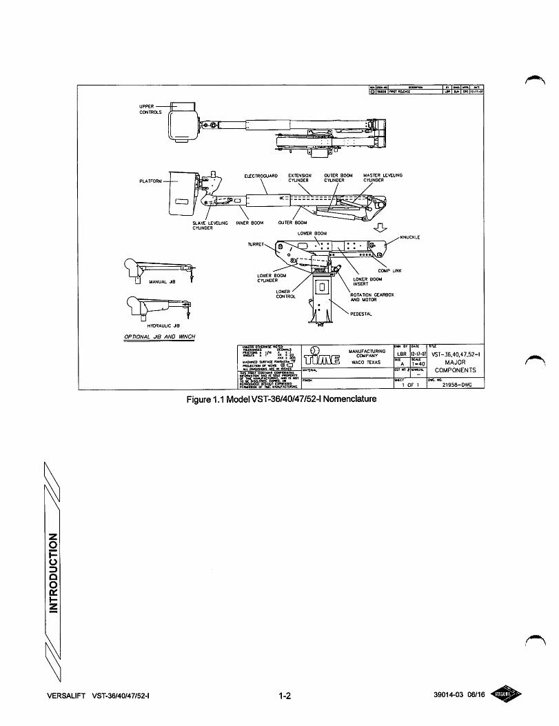
PLATFORM
MANUAL JI8
SLAVE LEVELINGCYLINDER
HYDRAULIC JIB
OPTIONAL JIB AND WINCH
ELECTROGUARO EXTENSIONCYUNDER
INNER BOOM OUTER BOOM
OUTER BOOM MASTER LEVELINGCYUNOER CYLINDER
LO^ER BOOM
TURRET
LOttER BOOMCYUNOER
LOWERCONTROL
ancuT a r xK t.».XKX ± .00:
UACHMCD SURFACE ftNlSPTOJCCnON Of XCWl (_ _
. OMEKSOWS Apt X i*CHCS
^l::- li-s- r« "\ »»o«Jkra/
T&Dl
LOWER BOOMINSERT
rotation gearboxAND MOTOR
MANUFACTURINGCOMPANY
WACO TEXAS
Figure 1.1 ModelVST-36/40/47/52-l Nomenclature
VERSALIFT VST-36/40/47/52-l 1-2
0«I£
12-17-07
i la* I I SIS ii-u-o*
Tiiil
VST-36,40.47,52-1
MAJOR
COMPONENTS
21958-DWG
39014-03 06/16
RESPONSIBILITIES
(for Dealers, Owners, Users, Operator, Lessors and Lessees)
DANGER: FAILURE TO COMPLY WITHYOUR REQUIRED RESPONSIBILITIES IN THE
USE AND OPERA TION OF THE AERIAL DEVICE
COULD RESULT IN DEATH OR SERIOUS
INJURY.
IMPORTANT
You are required by ANSI/SIA A92.2 to read andunderstand YOUR RESPONSIBILITIES before youuse or operate the Aerial Device. It is yourresponsibility and your employer's responsibility toidentify and comply with applicable codes, standards,and regulations.
The operation of any aerial device is subject to certainHAZARDSthat can be protected against only by theexercise of INTELLIGENCE, CARE AND COMMONSENSE. It is essential to have COMPETENT,CAREFUL PERSONNEL, TRAINED in theINTENDED USE, SAFE OPERATION,MAINTENANCE AND SERVICE of this type ofequipment.
The USER and OPERATOR MUST MAKE
^ DECISIONS onthemaintenance, useandoperationof the Aerial Device with due consideration for thefact that the SAFETY OF THE OPERATOR ANDOTHER PERSONNEL is dependent on thosedecisions. FAILURE TO COMPLY with yourREQUIRED RESPONSIBILITIES in the use and
operation of the Aerial Device could result in DEATHOR SERIOUS INJURY.
DANGER: READ AND UNDERSTANDTHIS MANUAL BEFORE ATTEMPTING TO
OPERATE THIS AERIAL DEVICE.
VERSALIFT VST-36/40/47/52-l 2-1 39014-03 06/16
SAFETY
Only properly trained operators are qualified to operatethe Versalift aerial lift. Operator training shall includecomplete instruction and understanding of themanufacturer's manuals, employer's work rules, andall related governmental regulations. Priorto operationfrom the platform the machine must be operatingproperly, must have been installed properly, inspected,and maintained in accordance with the manufacturer's
instructions. All safety signs, guards, and covers mustbe in place and in proper condition,
iik, DANGER: AN UNTRAINED ORCARELESS OPERATOR SUBJECTS HIM/
HERSELFAND OTHERS TO DEATH OR SERIOUS
INJURY.
Throughout this manual there are danger, warning.and caution notes that emphasize the possiblehazards when operating the Versalift, It is theresponsibility of the operator to become familiarwiththe contents of this manual.
Two of the main risks associated with operating anaerial lift;
(1) Electrocution caused by operating too closeto power lines.
(2) Injuries caused by falling as a result ofequipment failure or the operator performingan unsafe or unstable maneuver.
No manual can address every conceivable operatinghazard. Therefore, the prevention of accidents isgreatly dependent upon good judgement and commonsense of the operator.
It is the responsibility of the operator to use theVersalift only when it has been installed andmaintained in accordance with the manufacturer's
manuals. The preventive maintenance programoutlined in this manual and the Service manual must
be followed.
It is extremely important for the operator to bethoroughly familiar with the Versalift aerial device.Study the information inthis manual and the Versaliftcontrols until both are completely mastered. Then goto a large, open area to practice using the aerial lift.
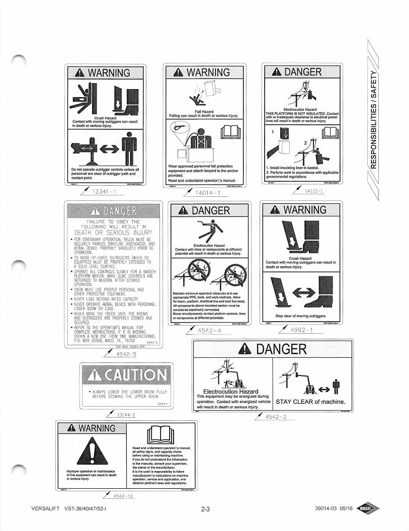
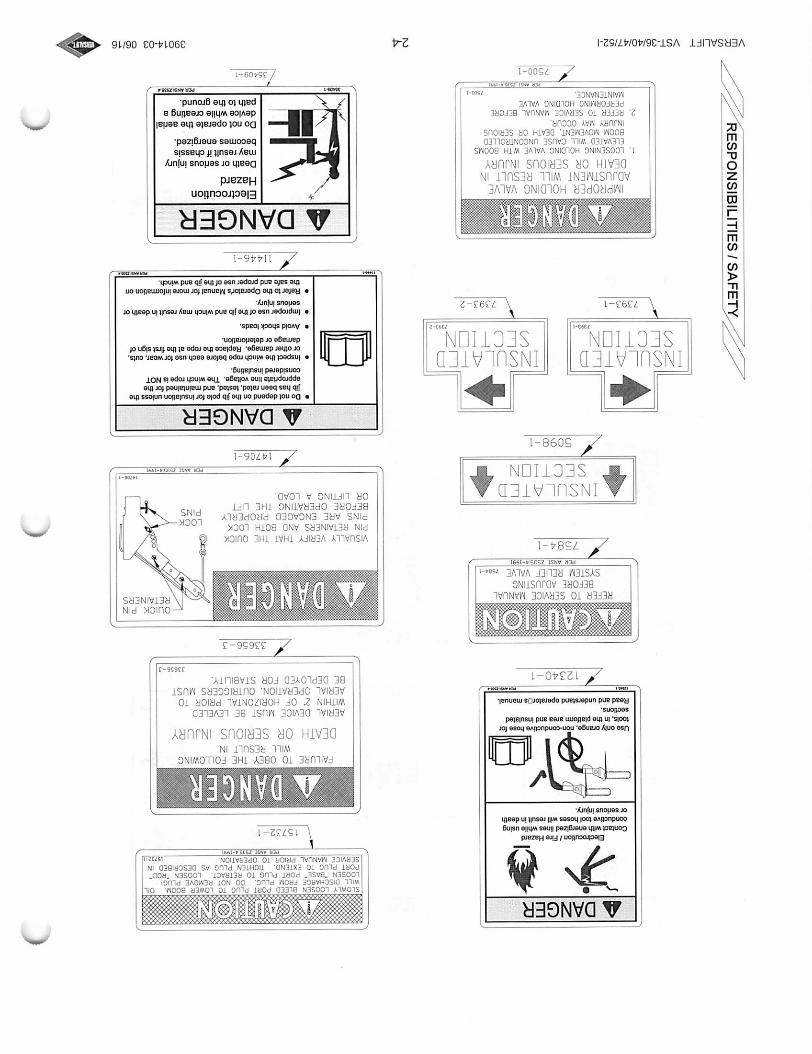
Decals are installed at numerous locations on the
aerial lift to warn personnel of the potential hazardsduring the use and operation of the aerial lift. It isimportant that the operator and ground personnel readand understand the information on the decals. Ifanydecals are defaced, illegible or lost, they must bereplaced. Refer to the "Decal Placement" illustrationin this manual for a complete listing and the locations
VERSALIFT VST-36/40/47/52-l
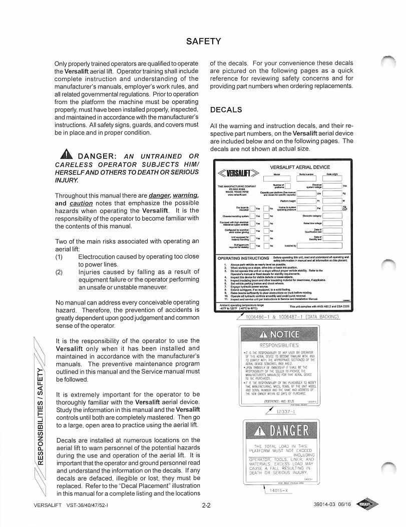
of the decals. For your convenience these decalsare pictured on the following pages as a quickreference for reviewing safety concerns and forproviding part numbers when ordering replacements.
DECALS
All the warning and instruction decals, and their respective part numbers, on the Versalift aerial deviceare included below and on the following pages. Thedecals are not shown at actual size.
VERSALIFT AERIAL DEVICE
TWS MfkNUFACTVONO CCaJPANY
WACO. TEXAS 76702
V boom h I I [ '1^ fMMM I I'** I I"" Ofumij
OwlsewWi Y* •
•-ssssasD''- •-
OPERATING INSTRUCTIONS 6W>™opw«n#ll*<»tre»dif«li»i««»afd«iici(w»lne»<dwrcrvMiMO WomtOon Inm»nu»l ind hfcnnMoii enWe(pl«wa,
I. AMyipwkvmtttwrwatiirlMlMcmitM.Z. Whc>i<ira>llreon>aliipa,dfMiiloc>b*di»<lDpo«len3, 0» notopMa M unl on «ilcpe mWioU profio «Mda ilibar. Rat* B M
OpondDf's mvniil cr tod dais fcr Ktiblty requtfvffwnts.4, lni{>6aTiltdevtealorvlibla4«lKt>>irloouobtKa,5, in^acl»mAI><gMomt>ManerlfnuMrgmilwlallbrclaanDn*M,llfpplMM.6, SatvtHdopiffVig bnketandctkOCMwtm^7, Enga^ h|4mjle power tource,0, Eia»ndoulrtgg«n,V«o«4t^ppod,t»ll*c£dfeatng,9. RaIs4 Dooffl«su9ci«nQyto cl«irab*Vucb0AS0ntnjab«ferare(aBng,1D, Openis «l Mnulc cortcb imoallily ird nM qiM revetMl,II. InipadinilHivlcaunlparlntvuaintiSsnioandUatalMionliUrajaL
Th«i»i*eiiri*i»M»«iANSIAM2».T(JCSAC225
1006486-1 & 1006487-1 (DATA BACKING)
RESPONSIBILITIES
•It IS THC HESPONSlSlUrr Of an* US£R or OP[R*rOROF THG tfRW. DEVICE 10 KCaK FAUUW wm, ttC10 csuPiYmm. mc /Wwoprime SEcnoN(S) Of the
DEVICE SrWEMtO, MSI A92.2.•UPON nWNSFER OF (MNQ?SHIP ITSMWi, BE IHE
RtsPCKsaury of the seoer io pswoe i«llANUFKruROi'S U».*m(S) FOR rH*[A£fi«L OWCE10 IH- RJOCHASER.
•IT IS THE RESPONSIBILIIY OF IHE PURCHASER 10 NOTIFYnME UWUFACrURIMC, *ACO, TEXAS, OF IHEUNIT liOOaAND SCRW.NUUSR AND THE NAUE MO fCOKESI OfW «N£R HITHH SO OATS OF PUKJiAS.
(REFERENCE: ANSI 92?)
THE TOTAL LOAD IN THISPLATFORM MUST NOT EXCEED
INCLUDINGOPERATOR. TOOLS, LINER, ANDMATERIALS, EXCESS LOAD MAYCAUSE A FALL RESULTING INDEATH OR SERIOUS INJURY.
39014-03 06/16
A WARNING
Crush HazardContact with nwvlng outriggers can resultin death or serious Irjury.
Do not operate outrigger controls unless allpersonnel are dear (rf outrigger path andcontact point
12341-1
A WARNING
Fall HazardFalling can result in death or serious Injury.
Wear approved personnel fall protectionequipment and attach lanyard to the anchorprovtdad.
Read and understand oparatoras manual.
y 14014-1
A DANGER
Beetrocution Hazard
Contact with lines or components at differentpotential willresult In death or serious injuiy.
Maintain irlnlmum approach distancss and UM
appraprtate PPE. tooM, and work melhods. Allowfor boom, platform, alectrteal Unaand load Una sway.
Allcomponents abovs Insulated secOsn muil t)econsMaivd eloetrlcally oonnactM.Naver almultaneauajy contact plaifonn controlt. Ineaor components al dKferent potenBafa.
4542-4
A DANGER
Electrocution Hazard
THIS PLATFORM IS NOT INSULATED .Contactwith or Uiadequate dearartce to electrical powerIir)e3wSlresult Indeath or serious Injury,
' i
1. Install Insulating liner in twskeL
2. Perforrn work In accordance with applicatilegovernmental regitlaSons.
A WARNING
Crush HazardContact with moving outiiggers can result indeath or serious Injury.
Istay dear of moving outriggers.
4992--
FAILURE TO OBEY THEFOLLOWING WILL RESULT IN
DEATH OR SERIOUS INJURYFOR STATIONARY OPERATION, TRUCK MUST BESECURELY PARKED, DRIVELINE DISENGAGED, ANDAERIAL DEVICE PROPERLY STABILIZED PRIOR TOOPERATION.TO AVOID TIP-OVER. OUTRIGGERS (WHEN SOEQUIPPED) MUST BE PROPERLY EXTWDED TOA SOLID LEVEL SURFACE.
OPERATE ALL CONTROLS SLOWLY FOR A SMOOTHPLATFORM MOTION. MAKE SURE CONTROLS ARERETURNED TO NEUTRAL W^ER DESIREDOPERATION.
CREW MUST USE PROPER PERSONAL ANDOTHER PROTECTIVE EOLPMENT.NEVER LOAD BEYOND RATED CAPACIIY.
NEVER OPERATE AERIAL DEVICE WITH PERSONNELUNDER BOOM OR LOAD.
• NEVER MOVE THE TRUCK UNTIL THE BOOMSAND OUTRIGGERS ARE PROPERLY STOWED ANDSECURED.
RErtR TO THE OPERATOR'S MANUAL FORCOMPLETE INSTRUCTIONS. IF IT IS MISSING,OBTAIN A NEW ONE FROM TIME MWIUFACTURING.P.O. BOX 20368. WACO, TX., 76702 ,
4542-5 A DANGER
ALWAYS LOWER THE LOWER BOOM FULLYBEFORE STOWING THE UPPER BOOM.
A WARNING
AInipraper eperalion or maintenanceof Ihia equlpmsnt can resutt In deathoraadoutin^.
VERSALIFT VST-36/40M7/52-I
Read and undarstand oparatort^a (ruuual.all safety algnt, and capadtir ctiartabafofe ijak>gor maintaining machine.If you do not undaratand lha Mtonnatlan
In the manuals, eonault your Bupanriiar,the Dwnar or the manufacoirar.
Ida tha usarGa responsibility to followmanufactjrerCIs InsUuctlons on macnirwoparation. urrlce and application, andobserve pvtlnenl lews end regulaOofta.
Electrocution HazardThis equipment may be energized duringoperBtlorf. Contact with energized vehldewill result in death or serious injury.
STAY CLEAR of machine.
4542-2
39014-03 06/16
ADANGER
Bedrecudon/RmHazard
ContactwHheoerglzedEneswNleusingconducUvetoolhoseswHresultIndeath
orseriousInjury.
Useonlyorange,non-conduOlvahoseiortools,IntnaplatfotmareaandInsulatedsections.
Readandunderstandoperatorosmanual.
/12340-1
REFERTOSERVICEMANUALBEFOREADJUSTING
SYSTEMRELIEFVALVE7504-.PERANSIZ535.«-mi
7584-1
INSULATED
SECTION
INSULATEDSECTIDN
5098-1
INSULATEDSECTIDN
7393-2
IMPROPERHOLDINGVALVEADJUSTMENTWILLRESULTINDEATHORSERIOUSINJURY
1.LOOSENINGHOLDINGVALVEWITHBOOMSELEVATEDWILLCAUSEUNCONTROLLEDBOOMMOVEMENT,DEATHORSERIOUSINJURYMAYOCCUR.
2.REFERTOSERVICEMANUALBEFOREPERFORMINGHOLDINGVALVEMAINTENANCE,jjoo-
VERSALIFTVST-36/40/47/52-i
SLOWLYlooseneiEIEDPORrPLUGTOLOWERBOOM.OILWILLDISCHARGEFROMPLUG-00NOTREMOVEPLUGILOOSEN"BASE"POfiTPLUGTORETRACT.LOOSEN"ROD*PORTPLUGTOEXTEND.TIGHTENPLUGASDESCRIBEDINSERVICEMANUALPRIORTOOPERATION.n738-i
PERaNSC
FAILURETOOBEYTHEFOLLOWINGWILLRESULTIN
DEATHORSERIOUSINJURY
AERIALDEVICEMUSTBELEVELEDWITHIN2"OFHORIZONTALPRIORTOAERIALOPERATION.OUTRIGGERSMUSTBEDEPLOYEDFORSTABILITY.
33656-3
VISUALLYVERIFYTHATTHEQUICK
PINRETAINERSANDBOTHLOCK
PINSAREENGAGEDPROPERLYBEFOREOPERATINGTHELIFTORLIFTINGALOAD.
ADANGER
-QUICKPINRETAINERS
•OonotdependonthejibpoleforInsulationunlesstheJibhasbeenrated,tested,andmaintainedfbftheappreprlatelinevonage.ThewirwhropeIsNOTconsideredinsulating.
•Inspectthewinchropebeforeeachuseforwear,cuts,orotherdamage.Rieplaeetheropeatthefirstsignofdamageordetectoratliin.
eAvoidshockloads.
•Impr^ruseofthe)lbendwinchmayresultIndeathorseriousInjury.
•RefertotheOperator'sManualformoreinformationonthesafeandproperuseofthep>andwnch.
ADANGERElectrocution
Hazard
DeathorseriousInjurymayresultifchassisbecomesenergized.
Donotoperatetheaerialdevicewhilecreatingapathtotheground.
39014-0306/16
The total load in this
platform must not exceedthe rated capacityIndudlng operator, tools,liner, and materials.Excess load may cause afell resulting In death orserious Iniury.
RATED PUTFORM CAPACITY
I AAALBS (AAAIcg)wtih|lb and win^ removed
F~bbb lbs (BBBkg)withjib and wfn^ installed
Jib pol«capadtydMal
RATED JIB CAPACmr
- Do not exceed boom material handlingcapacity plus unused platform capacity.- Do not exceed jib pole capacity.• Excess load may causs a fall resultingIn death or serious injury.
Boom material
handlingopsclty dscil
RATED JIB CAPACITY
- Do not exceed boom material handlingcapacity plus unused platform capacity.- Do not exceed Jib pole capacity.• Lower boom must be above 30* for Jibloads greater than 100 lbs (4S kg).- Excess load may cause a tell resultingIn death or eerious Injury.
- Jib polaeapadty daeal
BMm material
handlingcapacity deeel
Lower Inom -
angta bidlealer
ELECTROCUTION HAZARD
FAILURE TO OBEY THE
FOLLOWING WILL RESULT IN
DEATH OR SERIOUS INJURY
THE UPPER CONTROLS DO NOT PROVIDE
PROTECTION IN THE EVENT OF ELECTRICALCONTACT AND ARE NOT A SUBSTITUTEFOR MINIMUM APPROACH DISTANCES,
COVER-UPS, RUBBER GLOVES AND OTHER
PERSONAL PROTECTIVE EQUIPMENT.
VERSALIFT VST-36/40/47/52-l
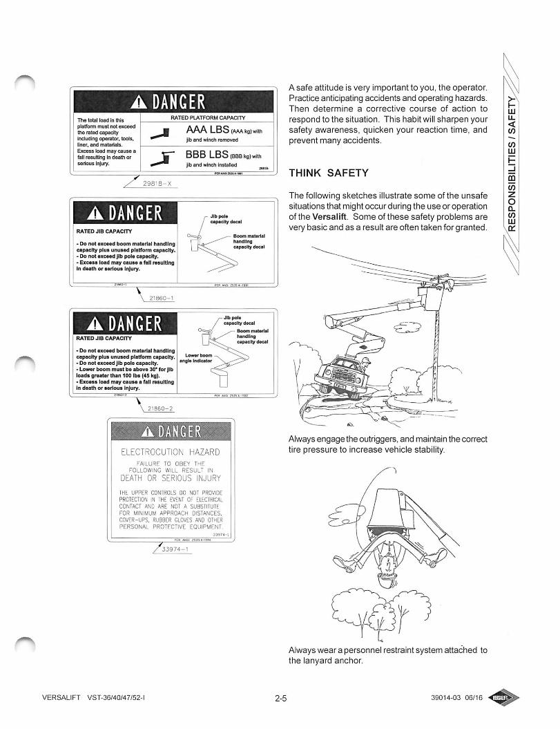
A safe attitude is very important to you, the operator.Practice anticipating accidents and operating hazards.Then determine a corrective course of action to
respond to the situation. This habit willsharpen yoursafety awareness, quicken your reaction time, andprevent many accidents.
THINK SAFETY
The following sketches illustrate some of the unsafesituations that might occur during the use or operationof the Versalift. Some of these safety problems arevery basic and as a result are often taken for granted.
Always engage the outriggers, and maintain the correcttire pressure to increase vehicle stability.
Always wear a personnel restraint system attached tothe lanyard anchor.
39014-03 06/16
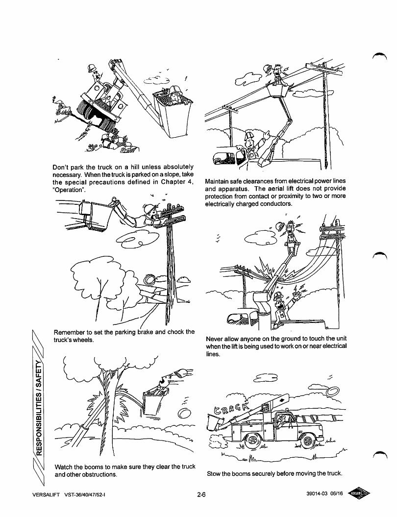
Don't park the truck on a hill unless absolutelynecessary. When the truck is parked on a slope, takethe special precautions defined in Chapter 4,"Operation".
Remember to set the parking brake and chock thetruck's wheels.
Watch the booms to make sure they clear the truckand other obstructions.
Maintain safe clearances from electrical power linesand apparatus. The aerial lift does not provideprotection from contact or proximity to two or moreelectrically charged conductors.
k/L
Never allow anyone on the ground to touch the unitwhen the lift is being used to workon or near electricallines.
Stow the booms securely before moving the truck.
VERSALIFT VST-36/40/47/52-l 2-6 39014-03 06/16
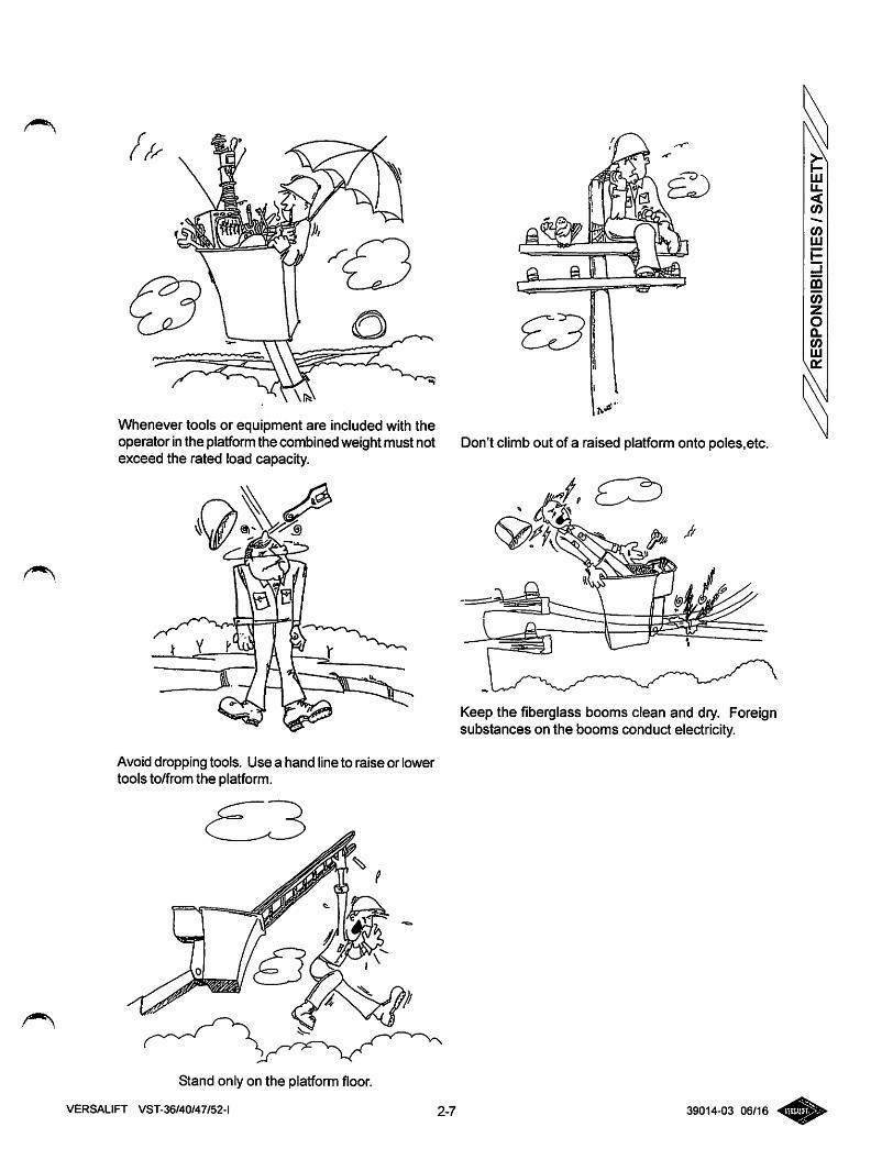
Whenever tools or equipment are included with theoperator inthe platform the combined weightmust not Don't climb out of a raised platform onto poles,etc.exceed the rated load capacity.
Avoid dropping tools. Use a hand line to raise or lowertools to/from the platform.
•f,
Keep the fiberglass booms clean and dry. Foreignsubstances on the booms conduct electricity.
Stand only on the platform floor.
VERSALIFT VST-36/40/47/52-l 2-7 39014-03 06/16
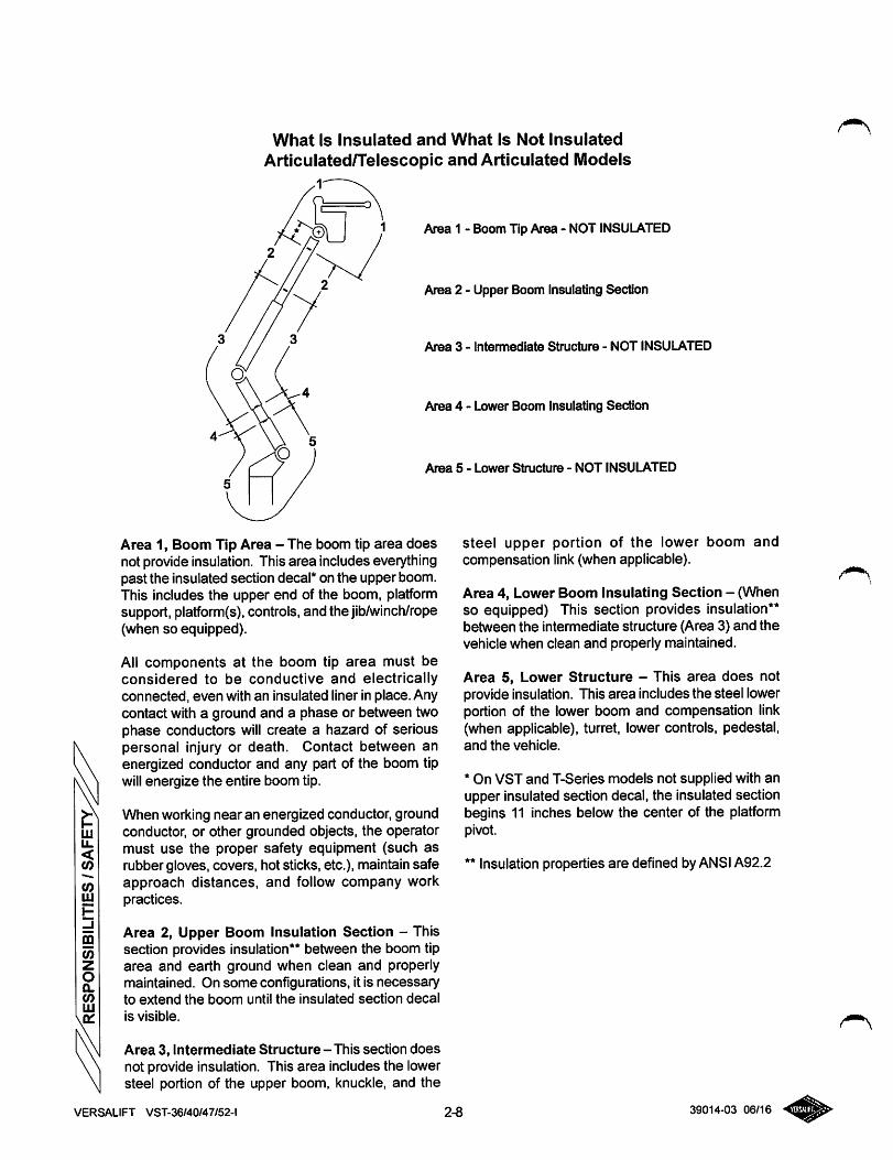
What Is Insulated and What Is Not InsulatedArticulated/Telescopic and Articulated Models
Area 1 - Boom Tip Area - NOT INSULATED
Area 2 - Upper Boom Insulating Section
Area 3 - Intemaediate Structure - NOT INSULATED
Area 4 - Lower Boom Insulating Section
Area 5 - Lower Structure - NOT INSULATED
Area 1, Boom Tip Area - The boom tip area doesnot provide insulation. This area includes everythingpast the insulated section decal* on the upper boom.This includes the upper end of the boom, platformsupport, platform(s),controls, and the jib/winch/rope(when so equipped).
All components at the boom tip area must beconsidered to be conductive and electricallyconnected, even with an insulated liner in place. Anycontact with a ground and a phase or between twophase conductors will create a hazard of seriouspersonal injury or death. Contact between anenergized conductor and any part of the boom tipwill energize the entire boom tip.
When working near an energized conductor, groundconductor, or other grounded objects, the operatormust use the proper safety equipment (such asrubber gloves, covers, hot sticks, etc.), maintainsafe 'approach distances, and follow company workpractices.
Area 2, Upper Boom Insulation Section - Thissection provides insulation** between the boom tiparea and earth ground when clean and properlymaintained. On some configurations, it is necessaryto extend the boom until the insulated section decal
is visible.
Area 3, Intermediate Structure-This section doesnot provide insulation. This area includes the lowersteel portion of the upper boom, knuckle, and the
VERSALIFT VST-36/40/47/52-l 2-8
steel upper portion of the lower boom andcompensation link(when applicable).
Area 4, Lower Boom Insulating Section - (Whenso equipped) This section provides insulation**between the intermediate structure (Area 3) and thevehicle when clean and properly maintained.
Area 5, Lower Structure - This area does notprovide insulation. This area includes the steel lowerportion of the lower boom and compensation link(when applicable), turret, lower controls, pedestal,and the vehicle.
* On VST and T-Series models not supplied with anupper insulated section decal, the insulated sectionbegins 11 inches below the center of the platformpivot.
** Insulation properties are defined byANSIA92.2
39014-03 06/16
ADDITIONAL SAFETY CONSIDERATIONS
1. Report any unusual occurrence during theoperation of the aerial lift that nnay requirerepair or adjustment.
2. Keep the work space in the truck bed cleanand neat.
3. Avoid parking on soft surfaces. Soft surfacesmay suddenly collapse, shift, or sink beneaththe truck's weight.
4. There is no insulating value in the fiberglassplatform without a platform liner.
5. No attempt should be made to clean, oil, oradjust a machine while the machine is inmotion.
6. If an aerial lift has set idle for an extended
period (i.e. overnight) or has been recentlyserviced, cycle the aerial-lift through it's fullrange of motion several times. This procedurewill force any trapped air out of the hydraulicsystem. Do not operate the lift from theplatform until this process is completed. Airtrapped in the hydraulic oil can cause liftmovements to be erratic and unpredictable.
7. Don't operate any part of the unit (platform,booms, outriggers, etc.) outside the work-sitebarricades into the traffic lanes. Set upadequate cones or barricades to mark theboundaries of the work-site to alert motorists
and pedestrians.
8. Only qualified mechanics are authorized toservice the aerial lift.
9. The polyester winch rope is not an insulator.Dirt, grease, and moisture (humidity) make therope conductive.
10. Make a thorough check of the winch rope forabrasive wear, pulled strands, cuts, and otherdefects daily.
11. Replace the winch rope at the first sign ofdamage or deterioration. Use only non-conductive rope of the size and type specified.
12. Avoid shock loads. A shock load is caused byjerking a line with a load or a sudden change inrope tension from a light load to a heavy load.
13. Do not contact energized conductors with thewinch line. Contacting the load line with anenergized conductor could create a completepath for electricity when the rope is extendedto the ground. This could cause death orserious injury.
14. Avoid using the winch line to wrap or tie anobject for lifting. The hook attached to the endof the winch linecan damage or cut the rope. Asling or lifting strap is recommended for thispurpose.
15. Do not stand in line with a rope under tension.If the rope should fail the recoil could causeserious injury to personnel.
16. Inspect the jib-pole assembly to make sure thevarious lock pins are secure.
17. Make sure the winch-rope coils are spoolingevenly to avoid clogging the winch orproducing shock loads when liftinga load.
18. Avoid contacting a spray or mist produced by ahigh pressure hydraulic leak. This spray ormist can puncture or become embeddedbeneath the skin or contaminate the eyes.These conditions requires immediate medicalattention.
19. Hydraulic oil is flammable. Avoid any contactbetween hydraulic oiland sources of high heator open flames.
20. Bodily contact with hot hydraulic oil can causeserious burns which require immediatemedical attention.
VERSALIFT VST-36/40/47/52-l 2-9 39014-03 06/16
SPECIFICATIONS
GENERAL SPECIFICATIONS - VST-36/
40/47/52-1
Note: Specifications on units may vary or changewithout priornotifications due to option selections.
This section includes a brief description of each ofthe major (standard) components.
PLATFORM - The closed fiberglass platform is 24In. X24 In. x 42 In. deep (.61 m x .61 m x 1.07 m)with an inside and outside step for easy access.
Maximum rated platform capacity for all models is600 lbs (272 kg) without jib/winch and 500 lbs (227kg) with jib/winch.
The actual platform capacity may be reduceddepending on the chassis and mounting configuration.See "Vehicle Specifications" for the actual platformcapacity of a particular installation.
PERSONNEL RESTRAINT SYSTEM -A safety beltor harness and a lanyard are required and can besupplied by Time Manufacturing Company at anadditional cost. Consult applicable work practicesand regulations to choose between a safety belt anda harness. The anchor for the lanyard is attachedto the platform support.
INDIVIDUAL LOWER CONTROLS - Individual full-
pressure controls at the turret actuate all boomfunctions. The lower control station is equipped witha selector valve to override the upper controls.
SINGLE STICK UPPER CONTROL - The full-
pressure single-stick upper control includes a safetytrigger to prevent inadvertent operation. The liftmovements correspond with control handlemovements. An emergency stop and a tool selectorcontrol are located at the upper controls.
HYDRAULIC PLATFORM ROTATION- A hydraulicrotary actuator, operated by a control lever, rotatesthe platfomi 180° from one side of the boom, to theend-hung position, and to the other side of the boom.
HYDRAULIC PLATFORM LEVELING - A master
and slave cylinder controls platform leveling. Theleveling system can be operated from the upper orlower controls to adjust platform leveling, tilt theplatform for clean out, or to ease the removal of aninjured operator.
OUTER/INNER BOOM ASSEMBLY-The outer/inner
boom assembly includes an outer boom, telescopic
VERSALIFT VST-36/40/47/52-l
inner boom, extension system, and hose assemblies.The outer boom consists of an 8 in. x 10 in. (203 mmX 254 mm) steel section, with a 9 in. x 11 in. (229mm X279 mm) fiberglass Electroguard section (N/Aon VST-52). The 6-7/8 in. x 8-7/8 in. (165 mm x 216mm) rectangular fiberglass inner boom is housedwithin the outer boom. The extension systemconsists of an extension cylinder, holding valves, anda hose carrier housed inside the boom. The hoses
routed through the outer/inner boom assembly arenon-conductive and fully contained within the boomassembly.
A double acting cylinder with two integral holdingvalves articulates the outer/inner boom assembly. Aboom support cradle and a boom tie down strap areincluded.
LOWER BOOM WITH CHASSIS INSULATING
SYSTEM - Each end of a high strength fiberglassinsert (chassis insulating system) is installed insidea rectangular 8 in. x 10 in. (203 mm x 254 mm) highstrength steel section. The steel and fiberglasssections are bonded with pressure-injected epoxyto fill any voids. A double acting cylinder, with twointegral holding valves, articulates the lower boom.The lower boom and compensation link form aparallelogram linkage to maintain the knuckle at aconstant angle to the turret.
CYLINDERS - Both the upper and lower cylindersare a threaded head-cap design. Both are equippedwith two integral holding valves that prevent downcreep and to lock the booms in position in the eventof hose failure.
TURRET - The turret wings are designed for strengthand rigidity. A bearing cover seals out moisture andprevents foreign materials from obstructing the turretrotation. The turret plate is machined to provide aflat surface to support the rotation bearing.
CONTINUOUS ROTATION - Unrestricted rotation
is accomplished by a hydraulically driven worm andspur gear with a shear-ball rotation bearing. Thecritical bolts holding the lift to the rotation bearingand the rotation bearing to the pedestal are grade 8hex head capscrews. These critical bolts are torqueseal marked to provide a quick means of detectingany turning of the bolt upon inspection. An eccentricring is used for gearbox backlash adjustment.
LUBRICATION - Non-lube bearings are used at mostpoints of motion. Only the rotation bearing requiresperiodic lubrication.
PEDESTAL - The pedestal is tubular with a reinforced
3-1 39014-03 06/16
mounting plate. The top plate of the pedestal is 1-1/4 in. (32 mm) thick and machined flat to support therotation bearing.
HYDRAULIC OIL RESERVOIR - A17 gallon (64.4I) hydraulic oil reservoir is built integral to thepedestal. Two sight gauges allow quick hydraulicfluid level checks.
HYDRAULICSYSTEM - The open-center hydraulicsystem operates at 3000 psi (210 kg/cm^) at 6 gpm(22.7 Ipm). A 10-micron return-line filter, mountedabove the hydraulic oillevel and inside the pedestal,can be easily changed withoutdraining the reservoir.The 100 mesh (149 micron) suction strainer in thereservoir can be removed for cleaning. A gate valve,located below the reservoir, prevents oil loss whenthe pump is serviced. Amagnetic drain plug attractsmetal particles from the oil.
PAINT - The complete unit is primed and paintedprior to assembly. The standard color is whiteurethane.
HOSES AND FITTINGS - The hoses routed throughthe booms are high pressure and non-conductivewith swaged hose end fittings. Retainers separatethe hoses inside the booms to prevent chafing andnylon sleeves are installed over hoses at points ofmovement. Reusable fittings can be installed if ahose is damaged.
ENGINE START / STOP - The start/stop circuit hasbeen designed so the lift cannot be operated unlessthe truck ignition switch is inthe "RUN" positionandthe master control is activated. This feature makesit difficultfor unauthorized individuals to operate theliftwhen the truck is locked. An air cylinder at theupper controls and a toggle switch at the pedestalenergize this system.
HYDRAULIC TOOL CIRCUIT AT THE PLATFORM- This system is intended for open center hydraulictools. The tool circuit provides 6 gpm (22.7 Ipm). Apressure reducing valve in the tool circuit limits thetool pressure. The valve can be adjusted from 1000to 2500 psi (70 to 175 kg/cm^).
LINE-LIFTING SOCKET - Built as part of theplatform support structure, is a vertical line-liftingsocket for 3 in. (76 mm) diameter line-liftingattachments. The socket is automatically leveledwith the platform without any manual adjustments.
ELECTRICAL INSULATION SPECIFICATIONS -
The outer/inner boom assembly is tested andcertified for electrical work at 46 KV and below in
accordance with ANSI A92.2 requirements. Aerialdevices may be designed and configured for glovingwork and tool methods at 46KV and below. The
outer/inner boom assembly is fully insulated even ina retracted position. The chassis insulating system(lower boom insert) is also tested according to ANSIA92.2.
SLOPE INDICATORS - Slope indicators are requiredon Versalift units and supplied by Time ManufacturingCo. Slope indicators shall be installed to indicatethe level of the rotation bearing relative to the ground.
OUTRIGGER / BOOM INTERLOCK SYSTEM - The
outrigger/boom interlock system prevents lift operationuntil the outriggers contact the ground and outriggerretraction before the aerial liftis properly stored.
MANUALS - Two Operator's Manuals, two ServiceManuals, one Manual of Responsibilities, and oneEMI Safety Manual are includedwitheach aerial lift.
OPTION SPECIFICATIONS - VST-36/40/
47/52-1
Below is a brief description of some of the availableoptions for the aerial lift.
OUTRIGGERS - The modified A-frame outriggers areequipped with pilotoperated check valves, internalthennal reliefvalves, pivotfeet, and separate controls.Outrigger dimensions vary withchassis application.For a 31 in. (0.79 m) frame height, the, the outriggersfurnish 122 in. (3.1 m) of spread, 8 in. (203 mm) ofpenetration, and 18 in. (457 mm) of ground clearance.For a 37-1/4 in. (0.95 m) frame height, the, theoutriggers furnish125-3/8 in. (3.2 m)ofspread, 8 in.(203mm)ofpenetration, and 18 in. (457mm)ofgroundclearance.
INDEPENDENT OUTRIGGERS - Narrow anglemodified A-frame outriggers are shear-platemounted to the frame and are equipped with pilotoperated check valves, internal thermal reliefvalves,pivot feet, and separate controls. Outriggerdimensions vary with chassis application. For a 37-1/4 in. (0.95 m) frame height, the outriggers furnish101-3/4 in. (2.6 m) of spread, 7-3/4 in. (197 mm) ofpenetration, and 15-3/4 in. (400 mm) of groundclearance.
TORSION BAR- (VST-36/40 only)An over-frame orunder-frame torsion bar for the rear axle adds stabilityto the vehicle and is available as an option. Ballastmay be required with the use of a torsion bar. Afrontaxle under-frame torsion bar is also available and can
VERSALIFT VST-36/40/47/52-l 3-2 39014-03 06/16
be used in conjunction with the rear torsion bar toreduce the amount of baiiast needed.
BACKUP PUMP - An auxiliary hydraulic pumpdesigned to bring the booms down in case the mainhydraulic source fails. The back up hydraulic pumpis driven by a DC motor, which is powered by thetruck-engine battery. The system is connected inparallel with the main pump and is designed for non-continuous operation. An air cylinder at the uppercontrols and a toggle switch at the pedestal are usedto energize the system.
SECOND SET OF TOOL POWER PORTS - A
second set of tool power ports are installed at theplatform to accommodate a second open center tool.
EXTRA CONTROL CIRCUIT - Consists of an
additional air cylinder at the platform, toggle switchat the pedestal, pressure switch in the turret andairline to the platform. An additional pass in thecollector ring is required for each control circuit.
MANUAL THROTTLE CONTROL - Gives the
operator a choice of economical engine idle speedsor faster engine speeds with faster lift movementswhen required. The manual throttle control isdesigned to operate only when the truck engine isrunning and the master control is activated. An aircylinder at the platform or a toggle switch at thepedestal can be used to energize the manual throttlecontrol.
UNITROL 4-FUNCTION CONTROL - The 4-Axis
controller option is a full pressure control. Located atthe platform, the 4-axis control consists of a singlehandle control which, through linkage, actuates theinterlock section and four individual boom function
valves.
TRUGUARD - This advanced upper controls isolationsystem provides 4" of electrical isolation from theentire upper controls, including the control dashpanel. This system also includes a protective shieldwhich helps prevent environmental and work relatedcontaminants from making direct contact with theisolating surfaces.
THE UPPER CONTROLS DO NOT PROVIDE
PROTECTION IN THE EVENT OF ELECTRICAL
CONTACTAND ARE NOT A SUBSTITUTE FOR
MINIMUMAPPROACH DISTANCES, COVER-UPS, RUBBER GLOVES AND OTHERPERSONAL PROTECTIVE EQUIPMENT.
VERSALIFT VST-36/40/47/52-l
CATEGORY D DIELECTRIC TESTING AND
CERTIFICATION - Testing and certification for ANSIA92.2 Category D are available. These aerial deviceswhich are designed and manufactured for work inwhich the insulating system is not considered asprimary insulation, but secondary. These aerialdevices are NOT designed for gloving wori< methods.They are rated at voltages of 46kv.
REMOTE LOWER CONTROL - This option allowsremote operation of the aerial device. The remotelower controls override the upper controls and arehoused in a weather-resistant hand held box or metal
box.
PLATFORM VARIATIONS:
24 in. X24 in. (0.61 m x 0.61 m) Fiberglass Platform(Standard)24 in. X30 in. (0.61 m x 0.76 m) Fiberglass Platform24 in. X42 in. (0.61 m x 1.07 m) Fiberglass Platform
24 in. X48 in. (0.61 m x 1.22 m) Fiberglass Platform
36 in. x60 in. (0.91 m x 1.52 m) Aluminum Walk-InPlatform (Reduces maximum platform capacity by100 lbs.) This option requires Category D rating.
40 in. X64 in. (1.02 m x 1.55 m) Aluminum Walk-InPlatform (Reduces maximum platform capacity by100 lbs.) This option requires Category D rating.
PLATFORM COVER - Vinylcovers are available forthe platforms.
PLATFORM LINER - Platform liners are available
for each of the platforms.
LIFTING EYE - A liftingeye attachment near the endof the outer boom has a 1000 lbs. (455 kg) maximumcapacity. (Not available on the VST-36-1)
PEDESTAL HEIGHTVARIATIONS - Various heightpedestals are available to accommodate differentcab heights and mounting locations. See the detailedDimensional Specifications below for the availableand standard pedestal heights of each model.
MANUAL JIB AND WINCH - The material handlingjib and winch consists of a winch and a jib pole thatare automatically leveled with the platform. Up to1000 lbs. (454 kg) material handling capacity canbe provided at elevated boom angles. The winch ishydraulically powered through a self-locking wormgear drive, so a load-holding brake is not required.The winch provides line speeds of 15 to 30 ft. perminute (5 to 9 m per min.). Eighty feet (24 m) of 1/2-in. (13 mm) diameter polyester rope with a clevis hook
3-3 39014-03 06/16
CO
(O
o
!<o
oLUQ.(O
is provided.
The angle of the jib pole is manually adjusted; thejib-pole assembly tilts in 10° increments fromhorizontal to a maximum of 50° above horizontal.The jib-pole assembly also can be rotated to any ofthe three convenient load-lifting positions toaccommodate a load. Those positions are 30° CW,0°, and 30° CCWfrom the boom centerline. The jibpole and winch assemblies can be rotated to astowed position 180° from the end hung position, orthey can be easily removed when not needed.
HYDRAULIC JIB AND WINCH - The materialhandling jib and winch consists of a winch and a jibpole that are automatically leveled withthe platform.Upto 1000 lbs. (454 kg) material-handling capacitycan be providedat elevated boomangles. The winchis hydraulically powered through a self-lockingwormgear drive, so a load-holding brake is not required.The winch provides line speeds of 15 to 30 ft. perminute (5 to 9 m per min.). Eightyfeet (24 m) of 1/2-in.(13mm)diameter polyesterropewith a clevishookis provided.
The 4 in. (100 mm) square jib pole hydraulically tiltswith90°oftravelrelative to the platfonn. fromhorizontalto vertical. Since the pole is automatically leveledwith the platform, there is a total of 200° of jib polearticulation relative to the upper boom. The jib polealso hydraulically extends and retracts, providing 16-in. (400-mm) travel, from44 in. to 60 in. (1.1 m to 1.5m). The jib-pole assembly also can be rotated toany of three convenient load-lifting positions toaccommodate a load. The jib pole and winchassemblies can be rotated to a stowed position 180°from the end-hung position, or they can be easilyremoved when not needed.
ARTICULATED JIB - Jib and winch consisting of awinch, two piece jib pole assembly, and articulatingarm. Upto 1000lbsmaterial handling can be provideddepending on boom and jib positions. The winch ishydraulically powered by a self-locking worm geardrive and is rated at 1000 lbs full drum. The winchprovides an average linespeed ofapproximately 20FPM (6.1 m/minute).
The 3" diameter round inner jib pole is dielectricallytested and can be manuallypinned in5 differentlengthpositions, for a total of 22" length adjustment. The4" diameter round outer jib pole is manufactured fromFRP but is not dielectrically tested. The jib poleassembly is automatically leveled with the platformand can be hydraulically tiltedfrom -10°to + 86°for atotal of 96°.
The jib pole assembly is mounted on an articulatingarm. The arm is compensated so the jib pole staysat approximatelythe same angle relativeto the groundas the amriarticulates. The ami travels 91°, providingthe equivalent to 17.5" horizontal jib pole extensionand 20" vertical jib pole extension. The jib and winchassembly can be manually indexed about a verticalaxis in one of three different pin positions. Thispositions the jib up to 30° to either side of the boom,for a total travel of 60°. The jib and winch assemblycan be removed without tools when not needed.
AUTOMATIC BOOM LATCH - The automatic boom
latch is designed to automatically restrain the upperboom in the cradle when stowed and automaticallyrelease the boom when the liftis operated. The latchis actuated by a hydraulic cylinder and includes amanual over-ride to open the latch without hydraulicpower.
PLATFORM ELEVATOR(Single Platform Only) -Hydraulically controlled platform elevator which willraise the platform and control panel 24" at the boomtip. Driven by a telescoping cylinder, the platformelevator can be raised proportionally using the samestyle control valve used forall boom function. Note:This reduces the platform capacity and jib capacityby 100 lbs.
VERSALIFT VST-36/40/47/52-l 3^ 39014-03 06/16
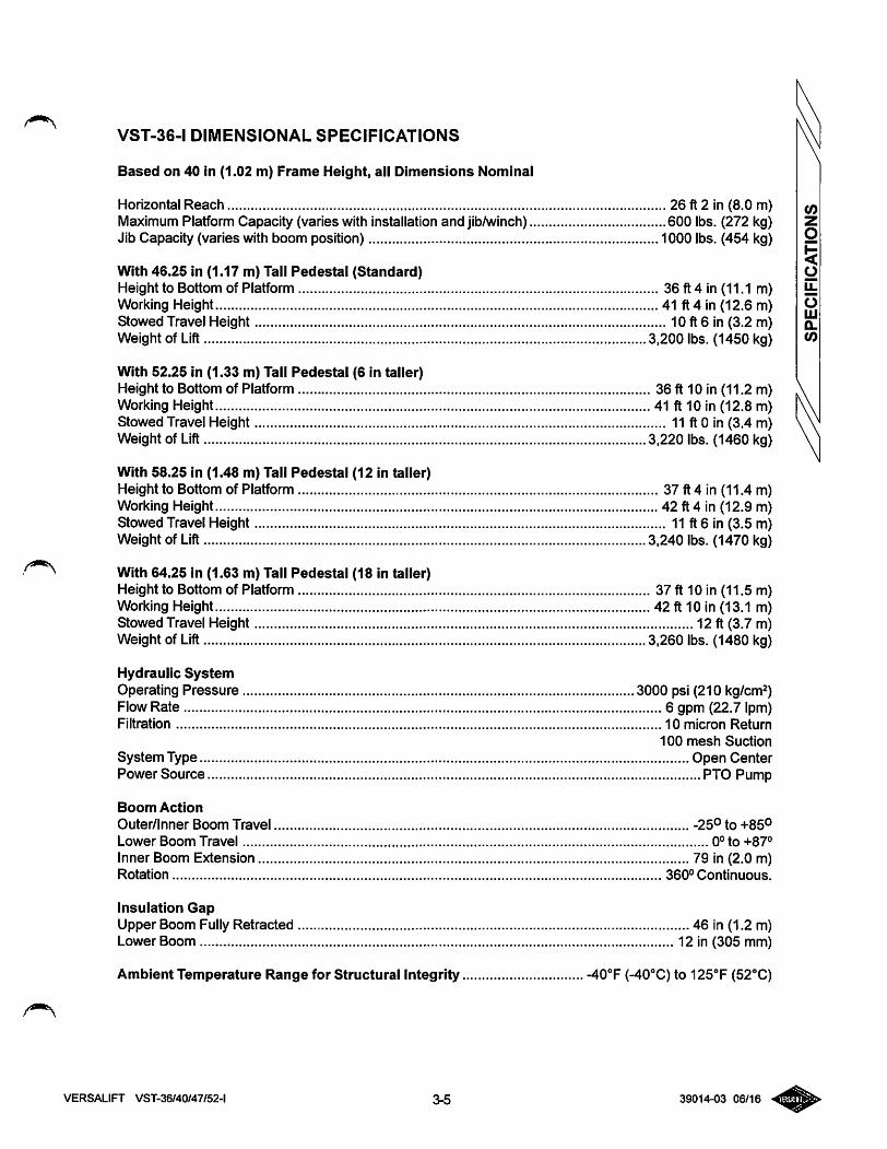
VST-36-1 DIMENSIONAL SPECIFICATIONS
Based on 40 in (1.02 m) Frame Height, all Dimensions Nominal
Horizontal Reach 26 ft 2 in (8.0 m)Maximum Platform Capacity (varies with installation and jib/winch) 600 lbs. (272 kg)Jib Capacity (varies with boom position) 1000 lbs. (454 kg)
With 46.25 in (1.17 m) Tall Pedestal (Standard)Height to Bottom of Platform 36 ft 4 in (11.1 m)Working Height 41 ft 4 in (12.6 m)Stowed Travel Height 10 ft 6 in (3.2 m)Weight of Lift 3,200 lbs. (1450 kg)
With 52.25 in (1.33 m) Tall Pedestal (6 in taller)Height to Bottom of Platform 36 ft 10 in (11.2 m)Working Height 41 ft 10 in (12.8 m)Stowed Travel Height 11 ft 0 in (3.4 m)Weight of Lift 3,220 lbs. (1460 kg)
With 58.25 in (1.48 m) Tall Pedestal (12 in taller)Height to Bottom of Platform 37 ft 4 in (11.4 m)Working Height 42 ft 4 in (12.9 m)Stowed Travel Height 11 ft 6 in (3.5 m)Weight of Lift 3.240 lbs. (1470 kg)
With 64.25 in (1.63 m) Tall Pedestal (18 in taller)Height to Bottom of Platform 37 ft 10 in (11.5 m)Working Height 42 ft 10 in (13.1 m)Stowed Travel Height 12 ft (3.7 m)Weight of Lift 3.260 lbs. (1480 kg)
Hydraulic SystemOperating Pressure 3000 psi (210 kg/cm^)Flow Rate 6 gpm (22.7 Ipm)Filtration 10 micron Return
100 mesh Suction
System Type Open CenterPower Source PTO Pump
Boom Action
Outer/Inner Boom Travel -25° to +85°Lower Boom Travel 0° to +87°
Inner Boom Extension 79 in (2.0 m)Rotation 360° Continuous.
Insulation GapUpper Boom Fully Retracted 46 in (1.2 m)Lower Boom 12 in (305 mm)
Ambient Temperature Range for Structural Integrity -40''F (-40''C) to 125^ (52°C)
VERSALIFT VST-36/40/47/52-l 3-5 39014-03 06/16
(0
<o
olUQ.(0
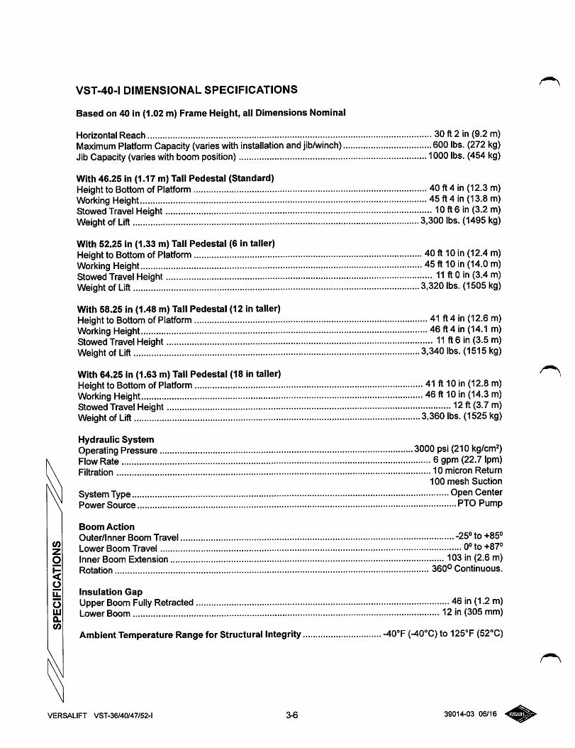
VST-40-1 DIMENSIONAL SPECIFICATIONS
Based on 40 in (1.02 m) Frame Height, all Dimensions Nominal
Horizontal Reach 30 ft 2 in (9.2 m)Maximum Platform Capacity(varieswith installation and jib/winch) 600 lbs. (272 kg)Jib Capacity (varies with boom position) 1000lbs. (454 kg)
With 46.25 in (1.17 m) Tall Pedestal (Standard)Height to Bottom of Platform 40 ft4 in (12.3 m)Working Height 45 ft4 in (13.8 m)Stowed Travel Height 10 ft6 in (3.2 m)Weight of Lift 3.300lbs. (1495 kg)
With 52.25 in (1.33 m) Tall Pedestal (6 in taller)Height to Bottom ofPlatform 40ft 10in (12.4 m)Working Height 45 ft 10 in (14.0 m)Stowed Travel Height 11 ft 0 in (3.4 m)Weight of Lift 3,320 lbs. (1505 kg)
With 58.25 in (1.48 m) Tall Pedestal (12 in taller)Height to Bottom ofPlatform 41 ft 4 in (12.6 m)Working Height 46 ft4 in (14.1 m)Stowed Travel Height 11 ft 6 in (3.5 m)Weight of Lift 3,340 lbs. (1515 kg)
With 64.25 in (1.63 m) Tall Pedestal (18 in taller)Height to Bottom ofPlatform 41 ft10 in (12.8 m)Working Height 46 ft 10 in (14.3 m)Stowed Travel Height 12ft (3.7 m)Weight of Lift 3.360 lbs. (1525 kg)
Hydraulic SystemOperating Pressure 3000 psi (210 kg/cm^)Flow Rate 6 gpm (22.7 Ipm)Filtration 10 micron Return
100 mesh Suction
SystemType OpenCenterPower Source PTO Pump
Boom Action
Outer/Inner Boom Travel -25° to +85°Lower Boom Travel 0° to +87°Inner Boom Extension 103 in (2.6 m)Rotation 360° Continuous.
Insulation GapUpper Boom Fully Retracted 46 in (1.2 m)Lower Boom 12 in (305 mm)
Ambient Temperature Range for Structural Integrity -40®F (-40°C) to 125T (52°C)
VERSALIFT VST-36/40/47/52-l 3-6 39014-03 06/16
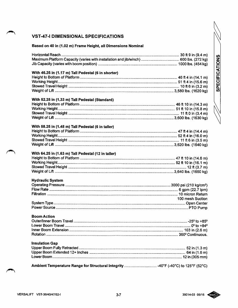
VST-47-1 DIMENSIONAL SPECIFICATIONS
Based on 40 in (1.02 m) Frame Height, all Dimensions Nominal
Horizontal Reach 30 ft 9 in (9.4 m)Maximum Platform Capacity (varies with installation and jib/winch) 600 lbs. (272 kg)Jib Capacity (varies with boom position) 1000 lbs. (454 kg)
With 46.25 in (1.17 m) Tall Pedestal (6 in shorter)Height to Bottom of Platform 46 ft 4 in (14.1 m)Working Height 51 ft 4 in (15.6 m)Stowed Travel Height 10 ft 6 in (3.2 m)Weight of Lift 3,580 lbs. (1620 kg)
With 52.25 in (1.33 m) Tall Pedestal (Standard)Height to Bottom of Platform 46 ft 10 in (14.3 m)Working Height 51 ft 10 in (15.8 m)Stowed Travel Height 11 ft 0 in (3.4 m)Weight of Lift 3,600 lbs. (1630 kg)
With 58.25 in (1.48 m) Tall Pedestal (6 in taller)Height to Bottom of Platform 47 ft 4 in (14.4 m)Working Height 52 ft 4 in (16.0 m)Stowed Travel Height 11 ft 6 in (3.5 m)Weight of Lift 3,620 lbs. (1640 kg)
With 64.25 in (1.63 m) Tall Pedestal (12 In taller)Height to Bottom of Platform 47 ft 10 in (14.6 m)Working Height 52 ft 10 in (16.1 m)Stowed Travel Height 12 ft (3.7 m)Weight of Lift 3,640 lbs. (1650 kg)
Hydraulic SystemOperating Pressure 3000 psi (210 kg/cm^)FlowRate 6 gpm (22.7 Ipm)Filtration 10 micron Return
100 mesh Suction
System Type Open CenterPower Source PTO Pump
Boom Action
Outer/Inner Boom Travel -25° to +85°Lower Boom Travel 0° to +84°Inner Boom Extension 103 in (2.6 m)Rotation 360° Continuous.
Insulation GapUpper Boom FullyRetracted 52 in (1.3 m)Upper Boom Extended 12+ Inches 64 in (1.6 m)Lower Boom 12 in (305 mm)
Ambient Temperature Range for Structural Integrity -40^ (-40°C) to 125°F (52°C)
VERSALIFT VST-36/40/47/52-l 3-7 39014-03 06/16
CO
omQ.(0
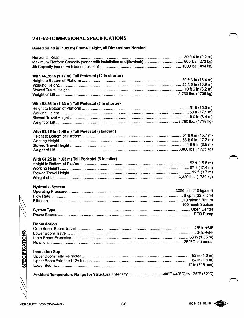
VST-52-1 DIMENSIONAL SPECIFICATIONS
Based on 40 in (1.02 m) Frame Height, all Dimensions Nominal
Horizontal Reach 30 ft 4 in (9.2 m)Maximum Platform Capacity(varieswith installation and jib/winch) 600 lbs. (272 kg)Jib Capacity (varieswith boomposition) 1000lbs. (454kg)
With 46.25 in (1.17 m) Tali Pedestal (12 in shorter)Height to Bottom of Platform 50 ft6 in (15.4 m)Working Height 55 ft6 in (16.9 m)Stowed Travel Height 10 ft6 in (3.2 m)Weight of Lift 3.760 lbs. (1705 kg)
With 52.25 in (1.33 m) Tall Pedestal (6 in shorter)Height to Bottom of Platform 51 ft (15.5 m)Working Height 56ft (17.1 m)Stowed Travel Height 11 ft 0 in (3.4 m)Weight of Lift 3,780 lbs. (1715 kg)
With 58.25 in (1.48 m) Tall Pedestal (standard)Height to Bottom ofPlatform 51 ft6 in (15.7 m)Working Height 56 ft 6 in (17.2 m)Stowed Travel Height 11 ft 6 in (3.5 m)Weight of Lift 3,800 lbs. (1725 kg)
With 64.25 in (1.63 m) Tall Pedestal (6 in taller)Height to Bottom ofPlatform 52ft (15.8 m)Working Height 57ft (17.4 m)Stowed Travel Height 12 ft (3.7 m)Weight of Lift 3,820 lbs. (1730 kg)
Hydraulic SystemOperating Pressure 3000 psi (210 kg/cm^)Flow Rate 6gpm (22.7 Ipm)Filtration 10 micron Return
100 mesh Suction
System Type Open CenterPower Source PTO Pump
Boom Action
Outer/Inner Boom Travel -25° to +85°Lower Boom Travel 0° to +84°Inner Boom Extension 53 in (1.35 m)Rotation 360° Continuous.
Insulation GapUpper Boom Fully Retracted 52 in (1.3m)Upper Boom Extended 12+Inches 64 in(1.6m)Lower Boom 12 in (305 mm)
Ambient Temperature Range for Structural Integrity -40°F (-40°C) to 125°F(52''C)
VERSALIFT VST-36/40/47/52-l 3-8 39014-03 06/16
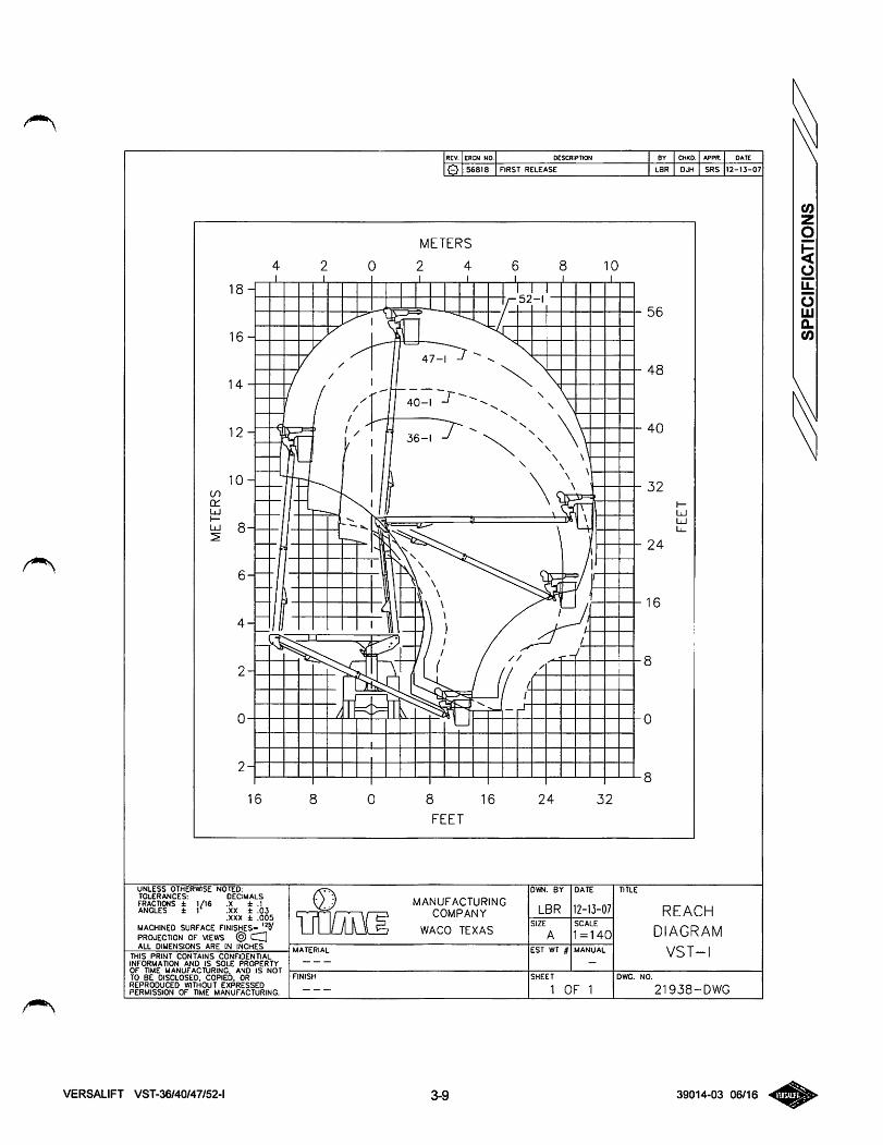
REV. ERCN NO. DESCRIPTION BY CHKO. APPR. DATE
0 56818 FIRST RELEASE LBR DJH SRS 12-13-07
METERS
4 2 0 2 4 6I I I I I
18-
16-
14
tncc
12-
10-
uj 8-
6-
4-
2-
2H
16 8 0 8 16 24 32
FEET
UNLESS OTHERWISE NOTED:TOLERANCES: DECIMALSFRACTIONS ± I/I6 .X ± .1ANGLES ± r .XX ± .03
.XXX ± .005
MACHINED SURFACE FINISHES= ''VPROJECTION OF VIEWS ® CZ]ALL DIMENSIONS ARE IN INCHES
THIS PRINT CONTAINS CONFIDENTIALINFORMATION AND IS SOLE PROPERTYOF TIME MANUFACTURING. AND IS NOTTO BE DISCLOSED. COPIED. ORREPRODUCED WITHOUT EXPRESSEDPERMISSION OF TIME MANUFACTURING.
VERSALIFT VST-36/40/47/52-l
FINISH
IMEMANUFACTURING
COMPANY
WACO TEXAS
3-9
DWN. BY
LBRSIZE
EST WT #
DATE
12-13-07SCALE
1=140
SHEET
1 OF 1
TITLE
56
48
40
32
24
16
REACH
DIAGRAM
VST-I
21938-DWG
39014-03 06/16
o
SPECIFICATIONS
271/2(070M]
191/2[0.50MJ
i
l€}|SWe|f«STREtCASEtwS»St2->J-07
411/4[1.05M]
51/4(0.13M]-I109[2.77M]43/4[0.12MJ-I
STANDARD={>
DIMENSIONALCHART
PEDESTAL
OPVON'A""fi"WEIGHT*
P-1260-8(46"TALL)
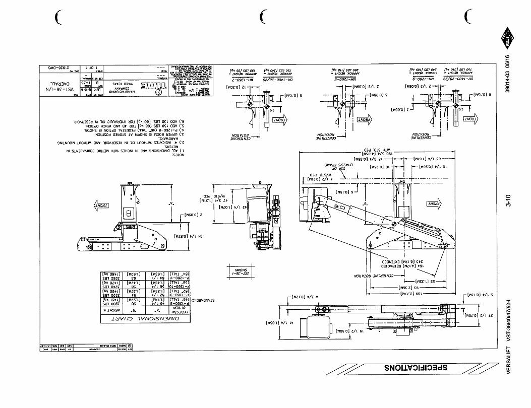
461/4[1.17M]
50[1.27M]
3200LBS[1451kg]
P-1260-9(52"TALL)
521/4[1.33M]
54[1.37M]
3220LBS[1460kg]
P-1260-10
(58"TALL)581/4[1.48M]
58
[1.47M]3240LBS[1470kg]
P-1260-11
(64"TALL)641/4[1.63M1
63
[1.60M]3260LBS[1480kg]
93[2.36M]
52[1.32MJCENT£RUNEROTATION
164[4.17M]RETRACTED243[6.17M]EXTENDED
FRONT\
101/4(0.26M]—-
631/4[V61M]
CENTERUNEROTATION
10[0.25M]
^6(0.15M]
TOPOFCHASSISFRAME
133/4[0.35M]
1903/4(4.85M]WITHSTD.PED
FRONT
CENTERUNEROTATION
3(0.C8M]
6[0.15M]
0R-I400-28/29
—21/2[0.06MJ
MH-1260-9
APPROX.XICHT-APPROX.KICHT-750LBS[340240LBS[109kg]
)
3[0.08M]
31/2[0,09M]
UH-1260-8
APPROX.mCHT-260LBS[nakg]
41/2[0.11M]JW/STD.PED.
FRONT
6(0.15M]
APPROX.\KIGHT-750LBS[J40kg]
VST-36-1SHOWN
421/4[1.07M)
341/4[0.87M]
2[0.05M]
IMullW.
FRONT
473/4[1.21M]W/STD.PED.
o
CENTERUNEROTATION
i=k.cj:
12[0.30M]
OR-1400-28/29MH-1260-7
APPROX.ttr/CMr-190LBS[86kg]
NOTES:
1.)ALLDIMENSIONSAREININCHESWITHMETRICEQUIVALENTSINMETERS.
2.)*INDICATESWITHOUTOILINRESERVOIR.ANDV/ITHOUTMOUNTINGHARDWARE.
3.)UPPERBOOMISSHOWNATSTOWEDPOSITION.4.)P-1260-a(46"TALL)PEDESTALOPTIONISSHOWN.5.)ADD150LBS[68kg]FORJIBANDV/INCHOPTION.6.)ADD130LBS.(60kg]FORHYDRAULICOILINRESERVOIR.
UNIXSSOnCRMSCNOTONN.BYOATC
LBRlMJ-07
ES1WT§UANUAJ.
VST-36-1/NOVERALL
))
m7}
%
<O)
271/2[0.70M]
51/4(0,13M]-J
/front\
TV.l 6[0.15M]—I
or-MOO-28/29
APPROX.nEtCHJ•
750LBS[HOkg]
109[2.77M]
93[2.36M]
52[1.32M]
FRONT\
101/4[0.26M]—
631/4[1.61M]
CENTERUNErotation
•St•3[0.08M]
191/2[0.50MJ
i
CeNT£RUN£ROTATION
14[0.36M]
133/4[0.35M]
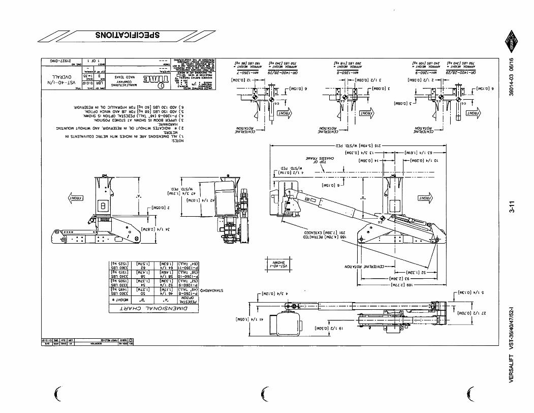
188[4.78M]RETRACTED291[7.39M]EXTENDED
6[0.15MJ
TOPorCHASSISrRAME
216(5.49M]W/STD.PED•
CENTERUNEROTAnON
FRONT
)
411/4[1.05M]
43/4[0.12M]-'
VST-40-1SHOm
41/2[0.11M]J\W/STD.PED
X.i
/front\
n
CENTERUNE'ROTAVON
'Prf- 1—1-12[0.3[0.08M]6(0.15M]ri
—21/2[0.06M]
MH^1260^APPROXHEIGHT-
240IBS[109kg}
31/2[0.09M]—1UH-I260-8
APPROX.mCHT=
260LBS[tiakg]
0-28/29
APPROX.WCICHT-750LBS[340kg]
[0.30M]
UH-1260-7
APPROXKICHT-190LBS[86kg]
STANDARDcO
|*t»loiCW
I QI&6>18If<«THtlX^g
DIMENSIONALCHART
PEDESTAL
option'A'
.g.WEIGHT*
P-1260-8(46"TALL)
461/4[1.17M)
50[1.27M1
3300LBS[1495kg]
P-1260-9
(52"TALL)521/4[1.33M]
54
[1.37M]3320LBS[1505kg]
P-1260-10
(58"TALL)581/4[1.48M1
58
[1.47M]3340LBS
[1515kg]P-1260-11(64"TALL)
641/4fl.63Ml
62[1.57M1
3360LBS[1525kg]
)
IMDJ49tS13*1>*07
341/4[0.87M]
e~'>o•::II::•I'.B-<
2[0.05M]T421/4[1.07MJ0
IFRaJh473/4[1.21M)
W/STD.PED.
NOTES:
1.)ALLDIMENSIONSAREININCHESWITHMETRICEQUIVALENTSINMETERS.
2.)*INDICATESWITHOUTOILINRESERVOIR.ANDWITHOUTMOUNTINGHARDWARE.
3.)UPPERBOOMISSHOWNATSTOWEDPOSITION.4.)P-1260-8(46"TALL)PEDESTALOPTIONISSHOWN.5.)ADD150LBS[68kg)FORJIBANDWINCHOPTION.6.)ADD130LBS[60kg]FORHYDRAULICOILINRESERVOIR.
.ctjMtta
iSiaiMANUFACTURING
COMPANY
WACOTEXAS
o«Her|o^
LBR12-13-07\Stt
B£51WT#
»4t£1
1OF1
SPECIFICATIONS
VST-40-I/NOVERALL
271/2[0.70M]
51/4(0.13M]-J
)
SPECIFICATIONS
-191/2[0.50M]
411/4[1.05M]
43/4[012M]
1641/4(4.17M]
148[3.76M]
107[2.72M]
CENTERUNEROTATION
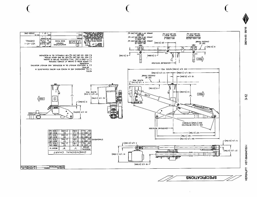
206[5.23M]RETRACTED309[7.85M]EXTENDED
FRONT
13[0.33M]
101/4[0.26M]—
1181/4[3.00M]
6(0.15M]
TOPorCHASSISFRAME
41/2[O.llM]^\W/STD.PED.
133/4(0.35M]
2323/45.91M]W/STDPED.
-CENTERUNEROTAVON
/front\
iliL[-3[0.08M]•6[0.15M]
._..JI:20[0.5IM]
P—[0.15M)Jy"Jjl11»|.
TOPofI,CHASSISFRAME^
OR-1400-28/29
APPROX.»r/CHr-
750LBS[J*0kg]APPROX.MIGHT-
595LBS(270kg]
OR-1400-16
APPtiOX.WT-590LBS[266kg}0R-I400-5
APPROX.WT-685LBS[311kg]OR-304
APPROX.m-650LBS(295kg]
3
STANDAROc{>
421/4[1.07M]
OOWK
fftlif|l(M|P>1swst2-l>W
DIMENSIONALCHART
PEDESTAL
OPTION"A""B"WEIGHT*
P-1260-8
(46"TALL)461/4[1.17M]
53[1.37M1
3580LBSfl620kg]
P-1260-9
(52"TALL)521/4(1.33M]
57[1.45M]
3600LBS
[1630kg]P-1260-10
(58"TALL)581/4(1.48M]
60
[1.52M]3620LBS[1640kg]
P-1260-11(64"TALL)
641/4[1.63M]
64
[1.63M]3640LBS[1650kg]
341/4(0.87M]
2[0.05M]
IfffOWQ
473/4[1.21MJW/STOPED
NOTES:
1.)ALLDIMENSIONSAREININCHESWITHMETRICEQUIVALENTSINMETERS.
2.)*INDICATESWITHOUTOILINRESERVOIR.ANDWITHOUTMOUNTINGHARDWARE.
3.)UPPERBOOMISSHOWNATSTOWEDPOSITION.4.)P-1260-9{52"TALL)PEDESTALOPTIONISSHOWN.5.)ADD150LBS[68kg]FORJIBANDWINCHOPTION.6.)ADD130LBS[60kg]FORHYDRAULICOILINRESERVOIR.
•ifeaiown.BYOATt
LBRI?-lJ-07
etSTWT4
VST-47-1
OVERALL
21928-DWG
)
< m s CO
271/
2[0
.70M
] i_
e:
1/4[0.1
3M)-l
)
-19
1/2
(0.5
0M]
3H
:41
1/2
(1.0
5M]
3B
5[0
.13M
]-
214
1/4
[54
4M
]
198
[S.0
3M]
157
(3.9
9M)
CE
NT
ER
UN
CR
OT
AT
ION
256
[6.5
0M]
RETR
ACT
ED30
9r7
.B5M
]EX
TEN
DED
FR
ON
T
TO
PO
FC
HA
SS
ISF
RA
ME
31(0
79M
)
101
/4[0
.26M
]
168
1/4
[4.2
7M1
283
1/4
[7.1
9UJ
DIM
EN
SIO
NA
LC
HA
RT
PE
DE
ST
AL
OP
TIO
N'A
''B
-W
EIG
HT
*
P-1
26
0-8
(46
-T
AL
L)
461
/4[1
.17M
]5
4[1
.37M
]3
76
0L
BS
[17
05
kal
P-1
26
0-9
(52"
tall
)52
1/4
[1.3
3M]
58
[1.4
7M]
37
80
LB
S
[171
5k
,]P
-1
26
0-1
0(5
8*
TA
LL
)58
1/4
ri.4
8M
l6
2ri
.57
Ml
38
00
LB
S
[17
25
kq]
P-1
26
0-1
1(6
4"
TA
LL
)64
1/4
[1.6
3M]
66
ri.6
8M
l3
82
0L
BS
[17
30
ko
l
6[O
.ISM
J
133
/4[0
.35M
]
—4
1/2[0.
11M]J
W/S
TO
.PE
O
i6
{6!i5
iST
M«
t«If
MS
fn
UA
St
-CrN
TE
RL
INC
RO
TA
TIO
N
Ill
-r-
1—9
[0.23M
]
r-3
[0.0
8M)
)
OR
-14
00
-28
/29
341
/4[0
.87M
)
2[0
.05M
1
421
/4[1
.07M
]
473
/4ri
.21M
]W
/ST
D.
PED
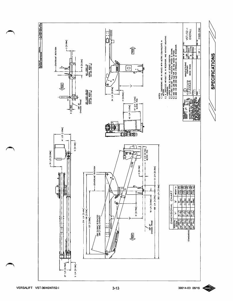
NO
TE
S:
1)
AL
LD
IMEN
SIO
NS
AR
EIN
INC
HES
WIT
HM
ETRI
CEQ
UIV
ALE
NTS
INM
ET
ER
S2.
)iK
IND
ICA
TES
WIT
HO
UT
OIL
INR
ESER
VO
IR,
AN
DW
ITH
OU
TM
OU
NTI
NG
HA
RD
WA
RE
.
3.)
UPP
ER
BOO
MIS
SHO
WN
AT
STO
WED
POSI
TIO
N.
4.)
P-1
26
0-1
0(5
8"TA
LL)
PED
ESTA
LO
PTIO
NIS
SHO
WN
.5.
)AD
D15
0L
BS
[68
kg)
FOR
JI8
AND
WIN
CHO
PTIO
N.
6.)
ADO
130
LB
S[6
0kg
]FO
RHY
DRAU
LIC
OIL
INRE
SERV
OIR
.
MA
CK
NC
DSU
RT
AC
Cm
iMS
*m
occT
iON
orv
im@
C3
tSm
iM
lH
rID
ATE
LB
R1
M3
-07
GtS
T«
I>
SP
EC
IFIC
AT
ION
S
VS
T-5
2-1
OV
ER
AL
L
(0
<o
oUJQ.(0
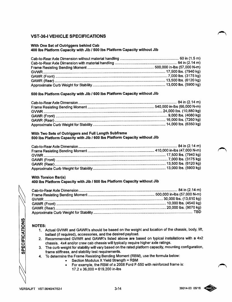
VST-36-1 VEHICLE SPECIFICATIONS
With One Set of Outriggers behind Cab400 lbs Platform Capacity with Jib 1500 lbs Platform Capacity without Jib
Cab-to-RearAxle Dimension without material handling 60 in (1.5 m)Cab-to-RearAxle Dimension with material handling 84 in (2.14 m)Frame Resisting Bending Moment 500,000 in-lbs (57,000 N-m)GVWR 17.500 lbs. (7940 kg)GAWR (Front) 7,000 lbs. (3175kg)GAWR (Rear) 13,500 lbs. (6120kg)Approximate Curb Weight forStability 13,000lbs. (5900 kg)
500 lbs Platform Capacity with Jib 1600 lbs Platform Capacity without Jib
Cab-to-RearAxle Dimension 84 in (2.14 m)Frame Resisting Bending Moment 540,000 in-lbs (66,000 N-m)GVWR 24,000 lbs. (10,880 kg)GAWR (Front) 9,000 lbs. (4080 kg)GAWR (Rear) 16,000 lbs. (7260 kg)Approximate Curb Weight for Stability 14,000 lbs. (6350 kg)
With Two Sets of Outriggers and Full Length Subframe500 lbs Platform Capacity with Jib 1600 lbs Platform Capacity without Jib
Cab-to-RearAxle Dimension 84 in (2.14 m)Frame Resisting Bending Moment 410,000 in-lbs (47,000 N-m) r \GVWR 17,500 lbs. (7940 kg)GAWR (Front) 7,000 lbs. (3175 kg)GAWR (Rear) 13,500 lbs. (6120 kg)Approximate Curb Weight for Stability 13,000 lbs. (5900 kg)
With Torsion Bar(s)400 lbs Platform Capacity with Jib 1500 lbs Platform Capacity without Jib
Cab-to-RearAxle Dimension 84 in (2.14 m)FrameResisting Bending Moment 500,000 in-lbs (57,000 N-m)GVWR 30,000 lbs. (13,610 kg)GAWR (Front) 10,000 lbs. (4540 kg)GAWR (Rear) 20,000lbs. (9070 kg)Approximate Curb Weight for Stability TBD
NOTES:
1. Actual GVWR and GAWR's should be based on the weight and location of the chassis, body, lift,ballast (if required), accessories, and the desired payload.
2. Recommended GVWR and GAWR's listed above are based on typical installations with a 4x2chassis. 4x4 and/or crew cab chassis will typically require higher axle ratings.
3. The curb weightforstability will vary based on the rated platform capacity, mounting configuration,frame stiffness, and stability test requirements.
4. Todetermine the Frame Resisting Bending Moment (RBM), use the formula below:• Section Modulus X Yield Strength = RBM• For example, the RBM of a 2008 Ford F-550 with reinforced frame is:
17.2 X36,000 = 619,200 in-lbs
VERSALIFT VST-36/40/47/52-l 3-14 39014-03 06/16
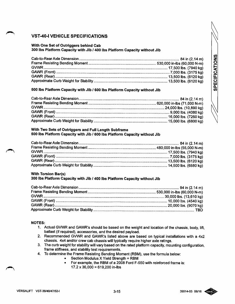
VST-40-1 VEHICLE SPECIFICATIONS
With One Set of Outriggers behind Cab300 lbs Platform Capacity with Jib / 400 lbs Platform Capacity without Jib
Cab-to-RearAxle Dimension 84 in (2.14 m)Frame Resisting Bending Moment 530,000 in-lbs (60,000 N-m)GVWR 17.500 lbs. (7940 kg)GAWR (Front) 7,000 lbs. (3175 kg)GAWR (Rear) 13,500 lbs. (6120 kg)Approximate Curb Weightfor Stability 13,500 lbs. (6120 kg)
500 lbs Platform Capacity with Jib 1600 lbs Platform Capacity without Jib
Cab-to-RearAxleDimension 84 in (2.14 m)Frame Resisting Bending Moment 620,000 in-lbs (71,000 N-m)GVWR 24,000lbs. (10,890 kg)GAWR (Front) 9,000 lbs. (4080 kg)GAWR (Rear) 16,000 lbs. (7260 kg)Approximate CurbWeight for Stability 15,000 lbs. (6800 kg)
With Two Sets of Outriggers and Full Length Subframe500 lbs Platform Capacity with Jib 1600 lbs Platform Capacity without Jib
Cab-to-RearAxle Dimension 84 in (2.14 m)Frame ResistingBending Moment 480,000 in-lbs (55,000 N-m)GVWR 17,500 lbs. (7940 kg)GAWR (Front) 7,000 lbs. (3175 kg)GAWR (Rear) 13,500 lbs. (6120 kg)Approximate Curb Weight forStability 14,500 lbs. (6580 kg)
With Torsion Bar(s)300 lbs Platform Capacity with Jib 1400 lbs Platform Capacity without Jib
Cab-to-RearAxleDimension 84 in (2.14 m)Frame Resisting Bending Moment 530,000 in-lbs(60,000 N-m)GVWR 30,000 lbs. (13,610 kg)GAWR (Front) 10,000 lbs. (4540 kg)GAWR (Rear) 20,000 lbs. (9070 kg)Approximate Curb Weight for Stability TBD
NOTES:
1. Actual GVWR and GAWR's should be based on the weight and location of the chassis, body, lift,ballast (if required), accessories, and the desired payload.
2. Recommended GVWR and GAWR's listed above are based on typical installations with a 4x2chassis. 4x4 and/or crew cab chassis will typically require higher axle ratings.
3. The curb weight for stabilitywill vary based on the rated platform capacity, mounting configuration,frame stiffness, and stability test requirements.
4. To determine the Frame Resisting Bending Moment (RBM), use the formula below:• Section Modulus X Yield Strength = RBM• For example, the RBM of a 2008 Ford F-550 with reinforced frame is:
17.2 X36,000 = 619,200 in-lbs
VERSALIFT VST-36/40/47/52-l 3-15 39014-03 06/16
(0
g
ou.
oUJQ.(0
(0zg
!5g
omQ.(O
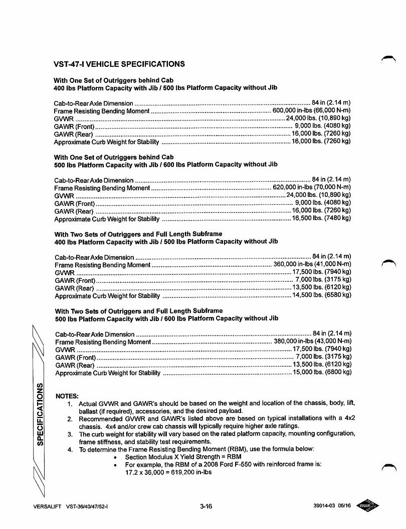
VST-47-1 VEHICLE SPECIFICATIONS
With One Set of Outriggers beliind Cab400 lbs Platform Capacity with Jib 1500 lbs Platform Capacity without Jib
Cab-to-RearAxle Dimension 84 in (2.14 m)Frame Resisting Bending Moment 600,000in-lbs (66,000 N-m)GVWR 24,000 lbs. (10,890 kg)GAWR (Front) 9,000 lbs. (4080kg)GAWR (Rear) 16,000 lbs. (7260kg)Approximate CurbWeight forStability 16,000lbs. (7260kg)
With One Set of Outriggers behind Cab500 lbs Platform Capacity with Jib 1600 lbs Platform Capacity without Jib
Cab-to-RearAxle Dimension 84 in (2.14 m)FrameResisting Bending Moment 620,000 in-lbs (70,000 N-m)GVWR 24,000 lbs. (10,890 kg)GAWR (Front) 9,000lbs. (4080kg)GAWR (Rear) 16,000 lbs. (7260 kg)Approximate Curb Weight forStability 16,500lbs. (7480 kg)
With Two Sets of Outriggers and Full Length Subframe400 lbs Platform Capacity with Jib 1500 lbs Platform Capacity without Jib
Cab-to-RearAxle Dimension 84 in (2.14 m)FrameResisting Bending Moment 360,000 in-lbs (41,000 N-m)GVWR 17.500 lbs. (7940 kg)GAWR (Front) 7.000lbs. (3175 kg)GAWR (Rear) 13,500lbs. (6120 kg)Approximate Curb Weight for Stability 14,500 lbs. (6580 kg)
With Two Sets of Outriggers and Full Length Subframe500 lbs Platform Capacity with Jib 1600 lbs Platform Capacity without Jib
Cab-to-RearAxle Dimension 84 in (2.14 m)FrameResisting Bending Moment 380,000 in-lbs (43,000 N-m)GVWR 17,500 lbs. (7940 kg)GAWR (Front) 7,000 lbs. (3175kg)GAWR (Rear) 13,500 lbs. (6120 kg)Approximate Curb Weight forStability 15,000lbs. (6800 kg)
NOTES:
1. Actual GVWRand GAWR's should be based on the weight and location of the chassis, body, lift,ballast (if required), accessories, and the desired payload.
2. Recommended GVWR and GAWR's listed above are based on typical installations with a 4x2chassis. 4x4 and/or crew cab chassis will typically require higher axle ratings.
3. The curb weightforstability will vary based on the rated platform capacity, mounting configuration,frame stiffness, and stability test requirements.
4. Todetermine the Frame Resisting Bending Moment (RBM), use the formula below:• Section Modulus X Yield Strength = RBM• For example, the RBM of a 2008 Ford F-550 with reinforced frame is:
17.2 X36,000 =619.200 in-lbs ^
VERSALIFT VST-36/40/47/52-l 3-16 39014-03 06/16
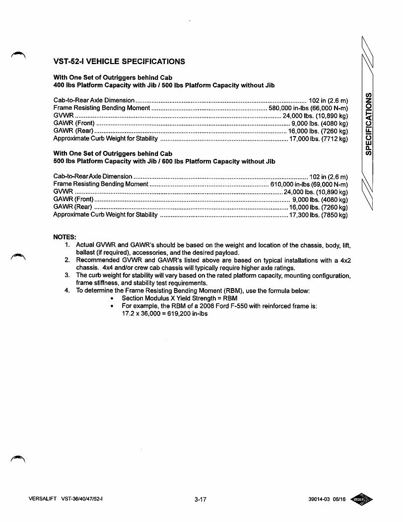
VST-52.1 VEHICLE SPECIFICATIONS
With One Set of Outriggers behind Cab400 lbs Platform Capacity with Jib 1500 lbs Platform Capacity without Jib
Cab-to-RearAxle Dimension 102 in (2.6 m)Frame Resisting Bending Moment 580,000 in-lbs (66,000 N-m)GVWR 24.000 lbs. (10,890 kg)GAWR (Front) 9,000 lbs. (4080 kg)GAWR (Rear) 16,000 lbs. (7260 kg)Approximate Curb Weight for Stability 17,000 lbs. (7712 kg)
With One Set of Outriggers behind Cab500 lbs Platform Capacity with Jib / 600 lbs Platform Capacity without Jib
Cab-to-RearAxle Dimension 102 in (2.6 m)Frame Resisting Bending Moment 610,000 in-lbs(69,000 N-m)GVWR 24,000 lbs. (10,890 kg)GAWR (Front) 9,000 lbs. (4080 kg)GAWR (Rear) 16,000 lbs. (7260 kg)Approximate Curb Weightfor Stability 17,300 lbs. (7850 kg)
NOTES:
1. Actual GVWR and GAWR's should be based on the weight and location of the chassis, body, lift,ballast (if required), accessories, and the desired payload.
2. Recommended GVWR and GAWR's listed above are based on typical installations with a 4x2chassis. 4x4 and/or crew cab chassis will typically require higher axle ratings.
3. The curb weight for stability will vary based on the rated platform capacity, mounting configuration,frame stiffness, and stability test requirements.
4. To determine the Frame Resisting Bending Moment (RBM), use the formula below:• Section Modulus X Yield Strength = RBM• For example, the RBM of a 2008 Ford F-550 with reinforced frame is:
17.2 X36,000 = 619,200 in-lbs
VERSALIFT VST-36/40/47/52-l 3-17 39014-03 06/16
(0
g
!<oIL
oLJJQ.(0
oLLJCL<0
32(0.81M]FRAMEHT
32[0.81M]FRAMEHT
VERSALIFTVST-36/40/47/52-l
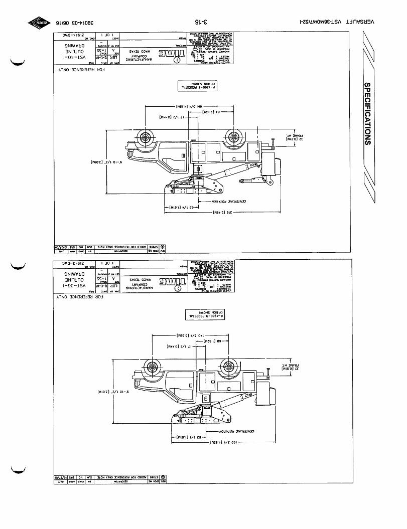
-190J/4(4.85M][—631/4[1.61M]—
CENTERUNCROTATION
171/2[0.44M]
-—60(1.52M1—-
-1403/4(3.58M)-
P-1260-BpedestalOPTIONSHOWN
RCV.CR04NO.OCSCftPItON0TCMKO.APPR.OArt
<*>57989AOOeOFORREFERENCEONLYNOTEDJHucSRStO/27/09
9'-101/2"(3.01M]
FORREFERENCEONLYoltT unlessoi«i.««s£»oitO:
TOlIHWCtS:^OEOMAtS
1^'i:l3uAOiiNCOsuRrAceP«0JESTK3HOf>«W5_AU.0UtH90Ht
;•"ViMmeMANUFACTURING
COMPANY
WACOTEXAS
0»N.BT
LBRIZ-13-0?SCAU
VST-36-1
OUTLINE
DRAWING
-216(5.49M1
l^NOI
rywYiwiufAcruatic.SHEET
1OF121943-DWG
*cv.notMOOCSCW»TOIevcmo.APR*OATt
<S>57989ADDEDFORREFERENCEONLYNOTEDJHMCSRSXO/27/09
f~631/4[1.61M]—CENTZRUNEROTAVON
171/2(0.44M]
-84(2.13M]
1643/4[4.18M]-
P-1260-8pedestalOPTIONSHOWN
u>ni:ss6Th»«IUHOitO:
V"rti
......CONfCewTIAL
3-18
tslfll
9'-101/2"[3.01M)
MANUFACTURINGCOMPANY
WACOTEXAS
FORREFERENCEONLY
0*.^a>|D«ttLBR12-13-0;
S2C
£SIWIIU«NU«.
SHEET
1or1
Tncr
VST-40-1
OUTLINE
DRAWING
21944-DWC
39014-0306/16
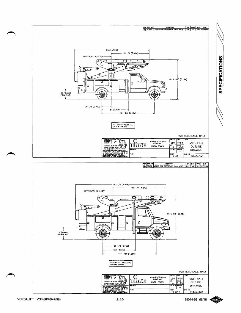
32 [0.8IM)frame ht.
39 [0.99M]FRAME HT
VERSALIFT VST-36/40/47/52-l
-23i [5.92M1
118 1/i [3.00M)
«tv. CRCN NO xscRtf>noN BY CHKO. Af»M. OATC
<i} 57989 ADDED FOft REFERENCE ONLY NOTE djh MC SRS 10/27/09
CENTERUNE ROTATION
29 1/2 (0.75M]
0-::|
84 [2.13M]
164 3/4 r4.1BM]
P-1260-9 PEDESTALOPTION SHOWN
UNUSS OFHCRwm NOTCO:lOXRWICCS: iieci>ui.s
2gg«; I'" :5, l i,.XXX ± .00
UACMNgO SUHTACC n»«»CS^PROJECTMN Of VKWS ® 0AU OMgNStCWS MZ IN WChES
IO"-4 \/2' (3.16M]
FOR REFERENCE ONLY
Mir
I2-13-07ifinnMANUFACTURING
COMPANY
WACO TEXAS
D-m. Qy
LBR VST-47-1
OUTLINE
DRAWING
283 1/4 [7 I9M]
eST wr § MANUAL
ȣEI
1 OF 1 21945-DyVG
RCV. EROI NO oescwnoN er CMXO APPR. DATE
<?> 57969 ADDED FOR REFERENCE ONLY NOTE OJH MG SRS 10/27/09
168 1/4 (4.27M]
CENTERLINE ROTATION
-29 1/2 [0,75M)
102 [2.59M)
169 (4.29M]-
P-1260-10 pedestalOPnON SHOWN
•••vitfiis 6h.£»«<4£ "OtEO:
1 '̂ rri.Kxx ± 005
MMMHEO su«r«a: nNtsMS- "yPROJECnON Of «£« @ QW.L OUgHSOWS «RC IH HCMES
3-19
I&d
tf-5 t/2- [3.49M)
DON ar
LBR
FOR REFERENCE ONLY
oAtr
12-ij-o;
nnx
eST WT # MANUAL
VST-52-1
OUTLINE
DRAWING
SHcet
1 OF 1 21946-OWG
39014-03 06/16
OPERATION
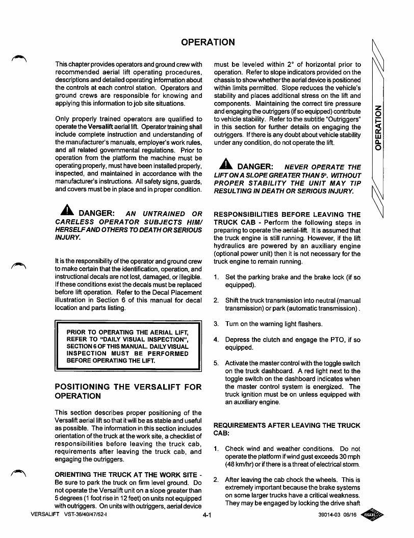
This chapter provides operators and ground crew withrecommended aerial lift operating procedures,descriptions and detailed operating information aboutthe controls at each control station. Operators andground crews are responsible for knowing andapplying this information to job site situations.
Only properly trained operators are qualified tooperate the Versalift aerial lift. Operator training shallinclude complete instruction and understanding ofthe manufacturer's manuals, employer's work rules,and all related governmental regulations. Prior tooperation from the platform the machine must beoperating properly,must have been installed properly,inspected, and maintained in accordance with themanufacturer's instructions. All safety signs, guards,and covers must be in place and in proper condition.
DANGER: AN UNTRAINED ORCARELESS OPERATOR SUBJECTS HIM/HERSELFAND OTHERS TO DEATH OR SERIOUS
INJURY.
Itis the responsibilityofthe operator and ground crewto make certain that the identification, operation, andinstructional decals are not lost, damaged, or illegible.Ifthese conditions exist the decals must be replacedbefore liftoperation. Refer to the Decal Placementillustration in Section 6 of this manual for decallocation and parts listing.
PRIOR TO OPERATING THE AERIAL LIFT,REFER TO "DAILY VISUAL INSPECTION",SECTION 6 OF THIS MANUAL. DAILY VISUAL
INSPECTION MUST BE PERFORMED
BEFORE OPERATING THE LIFT
POSITIONING THE VERSALIFT FOR
OPERATION
This section describes proper positioning of theVersalift aerial lift so that it will be as stable and usefulas possible. The information in this section includesorientation of the truck at the work site, a checklist ofresponsibilities before leaving the truck cab,requirements after leaving the truck cab. andengaging the outriggers.
ORIENTING THE TRUCK AT THE WORK SITE -
Be sure to park the truck on firm level ground. Donot operate the Versalift unit on a slope greater than5 degrees (1 foot rise in 12 feet) on units not equippedwith outriggers. On units with outriggers, aerial device
VERSALIFT VST-36/40/47/52-l 4-1
must be leveled within 2° of horizontal prior tooperation. Refer to slope indicators provided on thechassis to showwhether the aerial device is positionedwithin limits permitted. Slope reduces the vehicle'sstability and places additional stress on the lift andcomponents. Maintaining the correct tire pressureand engaging the outriggers (ifso equipped) contributeto vehicle stability. Refer to the subtitle "Outriggers"in this section for further details on engaging theoutriggers. Ifthere is any doubt about vehicle stabilityunder any condition, do not operate the lift.
DANGER: NEVER OPERATE THELIFT ON A SLOPE GREATER THAN 5". WITHOUT
PROPER STABILITY THE UNIT MAY TIP
RESULTING IN DEATH OR SERIOUS INJURY.
RESPONSIBILITIES BEFORE LEAVING THE
TRUCK CAB - Perform the following steps inpreparing to operate the aerial-lift. It is assumed thatthe truck engine is still running. However, if the lifthydraulics are powered by an auxiliary engine(optional power unit) then it is not necessary for thetruck engine to remain running.
1. Set the parking brake and the brake lock (if soequipped).
2. Shift the truck transmission into neutral (manualtransmission) or park (automatic transmission).
3. Turn on the warning light flashers.
4. Depress the clutch and engage the PTO, if soequipped.
5. Activate the master control with the toggle switchon the truck dashboard. A red light next to thetoggle switch on the dashboard indicates whenthe master control system is energized. Thetruck ignition must be on unless equipped withan auxiliary engine.
REQUIREMENTS AFTER LEAVING THE TRUCK
CAB:
1. Check wind and weather conditions. Do not
operate the platfonn ifwind gust exceeds 30 mph(48 km/hr) or ifthere is a threat of electrical storm.
2. After leaving the cab chock the wheels. This isextremely important because the brake systemson some larger trucks have a critical weakness.They may be engaged by locking the drive shaft
39014-03 06/16
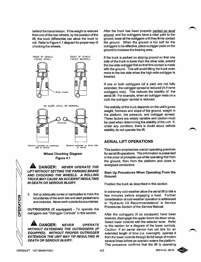
behind the transmission. Ifthe weight is reducedfrom one of the rear wheels, by the position of thelift, the truck differential can allow the truck toroll. Refer to Figure4.1 diagram forproper way ofchocking the wheels.
FRONT OF VEHICLE
FACING UPHILL
FRONT OF VEHICLEFACING DOWNHILL
•Wheel chocks
NO SLOPE UPHILL OR DOWNHILL
Platforms
Plotform extended on passengerside of vehicle
Plotform extended on driver sideof vehicle
Wheel Chocking DiagramFigure 4.1
^ DANGER: NEVER OPERATE THELIFT WITHOUT SETTING THE PARKING BRAKE
AND CHOCKING THE WHEELS. A ROLLINGTRUCK MA Y CAUSE AN ACCIDENTRESULTINGIN DEATH OR SERIOUS INJURY.
3. Set up adequate cones or barricades to mark theboundaries of the work site and alert pedestriansand motorists. Never work outside the boundaries.
OUTRIGGERS (If equipped) - To operate theoutriggers see "Outrigger Controls" in this section.
^ DANGER: NEVER OPERATEWITHOUT EXTENDING THE OUTRIGGERS (IFEQUIPPED). WITHOUT PROPER OUTRIGGEREXTENSION THE UNIT MAY TIP RESULTING IN
DEATH OR SERIOUS INJURY.
After the truck has been properly parked on levelaround, and the outriggers have a clear path to theground, lowerallthe outriggers until they firmly contactthe ground. When the ground is too soft for theoutriggers to be effective, place outrigger pads on theground to increase the bearing area.
Ifthe truck is parked on sloping ground so that oneside of the truck is lower than the other side, extendthe low-side outrigger firstso that firmcontact is madewith the ground. This will avoid tilting the truck evenmore to the low side when the high-side outrigger islowered.
If one or both outriggers (of a pair) are not fullyextended, the outrigger spread is reduced (A-Frameoutriggers only). This reduces the stability of theaerial lift. For example, when an outrigger rests on acurb the outrigger spread is reduced.
The stability of the truck depends on the unit's grossweight, firmness and slope of the ground, weight inthe platform, tire pressure, and outrigger spread.These factors are widely variable and caution mustbe used when determining the stability of the unit. If,under any condition, there is doubt about vehiclestability do not operate the lift.
AERIAL LIFT OPERATIONS
This section emphasizes overall operating practicesforaerial lift operations. This infonnationis presentedinthe order of probable use whileoperating firstfromthe ground, then from the platform and close toenergized conductors.
Start Up Procedures When Operating From theGround:
Position the truck as described in this section.
In extremely cold weather allowthe aerial lift to idle afew minutes before engaging a load. Furtherconsideration of cold weather operation is addressedin "Hydraulic Oil Recommendations" in ServiceProcedures Section of the Service Manual.
After the outriggers (if so equipped) have beenlowered, disengage the upper-boom tie-down strap.Select lower controls with the selector lever. Referto this section for a diagram of the lower controls.Caution: if an aerial device has set idle for an
extended length of time (i.e. overnight) operate itfrom the lower controls through its full range of motionseveral times before an operator enters the platform.This procedure confirms that the lift is operating
VERSALIFT VST-36/40/47/52-l 4-2 39014-03 06/16
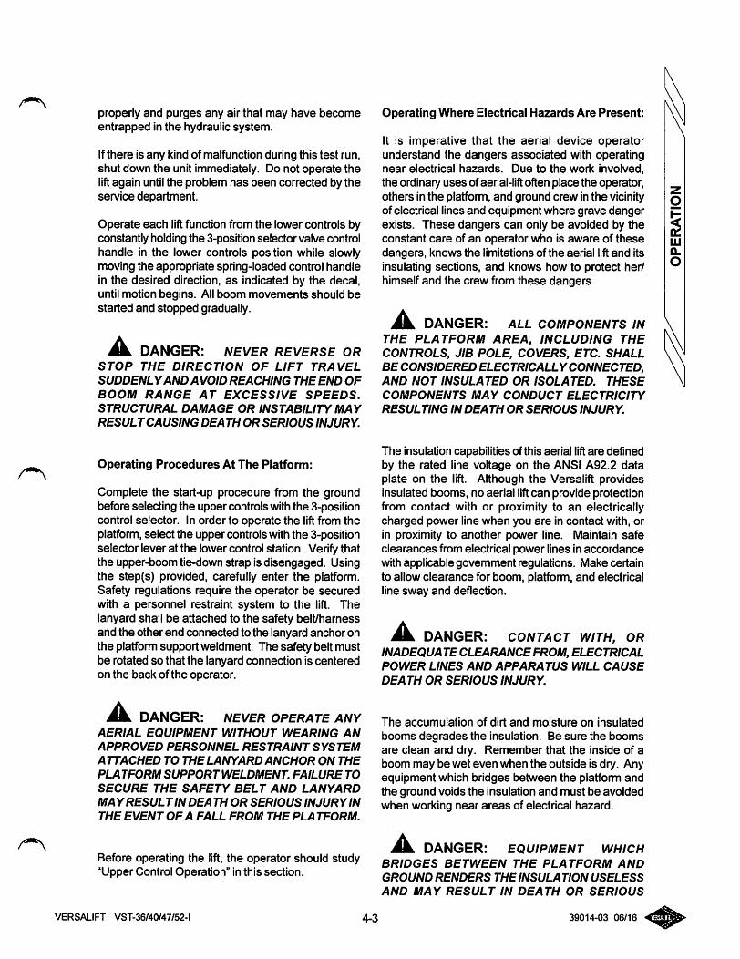
properly and purges any air that may have becomeentrapped in the hydraulic system.
Ifthere is any kind of malfunction during this test run,shut down the unit immediately. Do not operate thelift again until the problem has been corrected by theservice department.
Operate each liftfunction from the lower controls byconstantly holding the 3-position selector valve controlhandle in the lower controls position while slowlymoving the appropriate spring-loaded control handlein the desired direction, as indicated by the decal,until motion begins. Allboom movements should bestarted and stopped gradually.
^ DANGER: NEVER REVERSE ORSTOP THE DIRECTION OF LIFT TRAVEL
SUDDENLYAND AVOID REACHING THE END OF
BOOM RANGE AT EXCESSIVE SPEEDS.
STRUCTURAL DAMAGE OR INSTABILITY MAY
RESULTCAUSING DEATH OR SERIOUS INJURY.
Operating Procedures At The Platform:
Complete the start-up procedure from the groundbefore selecting the upper controls with the 3-positioncontrol selector. In order to operate the liftfrom theplatfomi, select the upper controls with the 3-positionselector lever at the lower control station. Verifythatthe upper-boom tie-down strap is disengaged. Usingthe step(s) provided, carefully enter the platform.Safety regulations require the operator be securedwith a personnel restraint system to the lift. Thelanyard shall be attached to the safety belt/harnessand the other end connected to the lanyard anchor onthe platform support weldment. The safety belt mustbe rotated so that the lanyard connection is centeredon the back of the operator.
DANGER: NEVER OPERATE ANYAERIAL EQUIPMENT WITHOUT WEARING AN
APPROVED PERSONNEL RESTRAINT SYSTEM
ATTACHED TO THE LANYARD ANCHOR ON THE
PLATFORM SUPPORTWELDMENT. FAILURE TO
SECURE THE SAFETY BELT AND LANYARD
MAYRESULTIN DEATH OR SERIOUS INJURYIN
THE EVENT OF A FALL FROM THE PLATFORM.
Before operating the lift, the operator should study"Upper Control Operation" in this section.
Operating Where Electrical Hazards Are Present:
It is imperative that the aerial device operatorunderstand the dangers associated with operatingnear electrical hazards. Due to the work involved,the ordinary uses of aerial-liftoften place the operator,others in the platfomi, and ground crew in the vicinityof electrical lines and equipment where grave dangerexists. These dangers can only be avoided by theconstant care of an operator who is aware of thesedangers, knows the limitations of the aerial lift and itsinsulating sections, and knows how to protect her/himself and the crew from these dangers.
DANGER: ALL COMPONENTS INTHE PLATFORM AREA, INCLUDING THECONTROLS, JIB POLE, COVERS, ETC. SHALLBE CONSIDERED ELECTRICALLY CONNECTED,AND NOT INSULATED OR ISOLATED. THESE
COMPONENTS MAY CONDUCT ELECTRICITY
RESULTING IN DEA TH OR SERIOUS INJURY.
The insulation capabilities of this aerial lift are definedby the rated line voltage on the ANSI A92.2 dataplate on the lift. Although the Versalift providesinsulated booms, no aerial liftcan provide protectionfrom contact with or proximity to an electricallycharged power line when you are in contact with, orin proximity to another power line. Maintain safeclearances from electrical power lines in accordancewith applicable government regulations. Make certainto allow clearance for boom, platfomn, and electricalline sway and deflection.
DANGER: CONTACT WITH, ORINADEQUATE CLEARANCE FROM, ELECTRICALPOWER LINES AND APPARATUS WILL CAUSE
DEATH OR SERIOUS INJURY.
The accumulation of dirt and moisture on insulated
booms degrades the insulation. Be sure the boomsare clean and dry. Remember that the inside of aboom may be wet even when the outside is dry. Anyequipment which bridges between the platform andthe ground voids the insulation and must be avoidedwhen working near areas of electrical hazard.
DANGER: EQUIPMENT WHICHBRIDGES BETWEEN THE PLATFORM AND
GROUND RENDERS THE INSULATION USELESS
AND MAY RESULT IN DEATH OR SERIOUS
VERSALIFT VST-36/40/47/52-l 4-3 39014-03 06/16
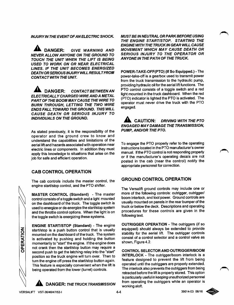
INJURYIN THE EVENT OFAN ELECTRIC SHOCK.
^ DANGER: GIVE WARNING ANDNEVER ALLOW ANYONE ON THE GROUND TO
TOUCH THE UNIT WHEN THE LIFT IS BEINGUSED TO WORK ON OR NEAR ELECTRICALLINES. IF THE UNIT BECOMES ENERGIZED
DEATH ORSERIOUS INJURYWILL RESULTFROMCONTACT WITH THE UNIT.
^ DANGER: CONTACTBETWEENANELECTRICALLY CHARGED WIRE AND A METALPART OF THE BOOM MA Y CAUSE THE WIRE TOBURN THROUGH, LETTING THE TWO WIREENDS FALL TOWARD THE GROUND. THIS WILLCAUSE DEATH OR SERIOUS INJURY TOINDIVIDUALS ON THE GROUND.
As stated previously, it is the responsibility of theoperator and the ground crew to know andunderstand the capabilities and limitations of theaerial lift and hazards associated with operation nearelectric lines or components. In addition they mustapply this knowledge to situations that arise on thejob for safe and efficient operation.
CAB CONTROL OPERATION
The cab controls include the master control, theengine start/stop control, and the PTO shifter.
MASTER CONTROL (Standard) - The mastercontrolconsists ofa toggle switchand a light mountedon the dashboard of the truck. The toggle switch isused to energize or de-energize the start/stop systemand the throttle control options. When the light is onthe toggle switch is energizing these systems.
ENGINE START/STOP (Standard) - The enginestart/stop is a push button control that is usuallymounted on the dashboard of the truck. The systemis activated by pushing and holding the buttonmomentarily to "start" the engine. Ifthe engine doesnot crank then the start/stop button may require asecond push to get the latching relay into the "start"position so the truck engine will turn over. Then toturn the engine off press the start/stop button again.This feature is especially convenient when the lift isbeing operated from the lower (turret) controls.
^ DAGGER: THETRUCKTRANSMISSIONVERSALIFT VST-36/40/47/52-l
MUSTBE IN NEUTRAL OR PARKBEFORE USING
THE ENGINE START/STOP. STARTING THE
ENGINE WITH THE TRUCK IN GEAR WILL CAUSE
MOVEMENT WHICH MAY CAUSE DEATH OR
SERIOUS INJURY TO THE OPERATOR ORANYONE IN THE PA TH OF THE TRUCK.
POWER-TAKE-OFF(PTO) (IfSo Equipped.) - Thepower-take-off is a gearbox used to transmit powerfrom the truck transmission to the hydraulic pump,providing hydraulicoilfor the aerial lift functions. ThePTO control consists of a toggle switch and a redlightmounted inthe truck dashboard. When the red(PTO) indicator is lighted the PTO is activated. Theoperator must never drive the truck with the PTOengaged.
^ CAUTION: DRIVING WITH THE PTOENGAGED MAY DAMAGE THE TRANSMISSION,PUMP, AND/OR THE PTO.
To engage the PTO properly refer to the operatinginstructions located in the PTO manufacturer's ownermanual. Ifthe PTO control is not responding properlyor if the manufacturer's operating decals are notposted in the cab (near the control) notify theappropriate personnel for correction.
GROUND CONTROL OPERATION
The Versalift ground controls may include one ormore of the following controls: outrigger, outrigger/boom interlock, and tool power. Ground controls areusually mounted on panels inthe rear bumper of thetruck or below the deck. Descriptions and operatingprocedures for these controls are given in thefollowing text.
OUTRIGGER OPERATION - The outriggers (if soequipped) should always be extended to providestability for the aerial lift. The outrigger controlsconsist of a control selector and a control valve as
shown. Figure 4.2.
CONTROL SELECTOR AND OUTRIGGER/BOOM
INTERLOCK - The outrigger/boom interlock is afeature designed to prevent the lift from beingoperated until the outriggers are properly extended.The interlock also prevents the outriggers from beingretracted before the lift is properly stored. This optionis particularly usefulinkeeping unauthorized personnelfrom operating the outriggers while an operator isworking aloft.
44 39014-03 06/16
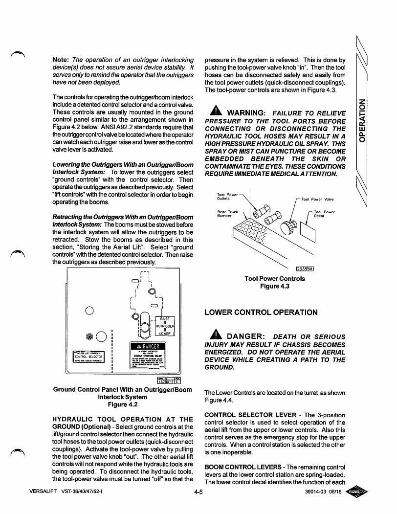
Note: The operation of an outrigger interlockingclevice(s) does not assure aerial device stability. Itserves only to remind the operator that the outriggershave not been deployed.
The controls for operating the outrigger/boom interlockInclude a detented control selector and a control valve.
These controls are usually mounted in the groundcontrol panel similar to the arrangement shown inFigure 4.2 below. ANSIA92.2 standards require thatthe outriggercontrolvalve be locatedwhere the operatorcan watch each outrigger raise and loweras the controlvalve lever is activated.
Lowering the Outriggers With an Outrigger/BoomInterlock System: To lower the outriggers select"ground controls" with the control selector. Thenoperate the outriggers as described previously. Select"lift controls"withthe controlselector inorder to beginoperating the booms.
Retracting the Outriggers With an Outrigger/BoomInteriock System: The booms must be stowed beforethe interlock system will allow the outriggers to beretracted. Stow the booms as described in this
section, "Storing the Aerial Lift". Select "groundcontrols" with the detented control selector. Then raise
the outriggers as described previously.
o
orot kirr comoLS
CONTRtlL SELECTOR
r--)
yr
I
6^-1
. RAISEr" 01
OUTRIGGERn
1LOWER i
A DANGER
Ground Control Panel With an Outrigger/BoomInterlock System
Figure 4.2
HYDRAULIC TOOL OPERATION AT THE
GROUND (Optional) - Select ground controls at thelift/groundcontrol selector then connect the hydraulictool hoses to the tool power outlets (quick-disconnectcouplings). Activate the tool-power valve by pullingthe tool power valve knob "out". The other aerial liftcontrols willnot respond while the hydraulic tools arebeing operated. To disconnect the hydraulic tools,the tool-power valve must be turned "off"so that the
VERSALIFT VST-36/40/47/52-l
pressure in the system is relieved. This is done bypushing the tool-power valve knob "in". Then the toolhoses can be disconnected safely and easily fromthe tool power outlets (quick-disconnect couplings).The tool-power controls are shown in Figure 4.3.
^ WARNING: FAILURE TO RELIEVEPRESSURE TO THE TOOL PORTS BEFORE
CONNECTING OR DISCONNECTING THE
HYDRAULIC TOOL HOSES MAY RESULT IN A
HIGH PRESSURE HYDRAULIC OIL SPRA Y. THIS
SPRA Y OR MIST CAN PUNCTURE OR BECOME
EMBEDDED BENEATH THE SKIN OR
CONTAMINATE THE EYES. THESE CONDITIONS
REQUIRE IMMEDIATE MEDICAL A TTENTION.
Tool Power
Outlets
Rear TruckBumper
Tool Power Valve
Tool Power
Oecol
I25385MI
Tool Power Controls
Figure 4.3
LOWER CONTROL OPERATION
^ DANGER: DEATH OR SERIOUSINJURY MAY RESULT IF CHASSIS BECOMES
ENERGIZED. DO NOT OPERATE THE AERIAL
DEVICE WHILE CREATING A PATH TO THE
GROUND.
The Lower Controls are located on the turret as shown
Figure 4.4.
CONTROL SELECTOR LEVER - The 3-positioncontrol selector is used to select operation of theaerial lift from the upper or lower controls. Also thiscontrol serves as the emergency stop for the uppercontrols. When a control station is selected the other
is one inoperable.
BOOM CONTROL LEVERS - The remaining controllevers at the lower control station are spring-loaded.The lower control decal identifies the function of each
4-5 39014-03 06/16
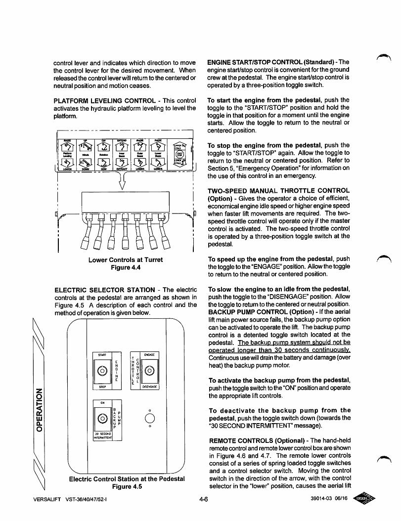
control lever and indicates which direction to move
the control lever for the desired movement. When
released the control lever will return to the centered or
neutral position and motion ceases.
PLATFORM LEVELING CONTROL - This control
activates the hydraulic platform leveling to level theplatform.
fwse
PMbnn
rsrecToo
hmr
RMSe
Outv
RMS8
Lowvr
CTRtS.
(9\ fiUMftig
1M LOWER DOWN ocw
Ooon
RSTRACr LOWER LOWER
umXgScmsJJ
K
n-n-n-g-n
Lower Controls at Turret
Figure 4.4
ELECTRIC SELECTOR STATION - The electric
controls at the pedestal are arranged as shown inFigure 4.5 A description of each control and themethod of operation is given below.
START
EN
© G1
N
E
STOP
ON
BA P
0 c uK MU Pp
30 SECOND
INTERUITTENI
ENGAGE
T rrO0?T ^
u©
OtSesGAC£
O
Electric Control Station at the PedestalFigure 4.5
ENGINE START/STOP CONTROL (Standard) - Theengine start/stop control is convenient for the groundcrew at the pedestal. The engine start/stop control isoperated by a three-position toggle switch.
To start the engine from the pedestal, push thetoggle to the "START/STOP" position and hold thetoggle in that position for a moment until the enginestarts. Allow the toggle to return to the neutral orcentered position.
To stop the engine from the pedestal, push thetoggle to "START/STOP" again. Allow the toggle toreturn to the neutral or centered position. Refer toSection 5, "Emergency Operation" for informationonthe use of this control in an emergency.
TWO-SPEED MANUAL THROTTLE CONTROL(Option) - Gives the operator a choice of efficient,economical engine idlespeed or higher engine speedwhen faster lift movements are required. The two-speed throttle control will operate only ifthe mastercontrol is activated. The two-speed throttle controlis operated by a three-position toggle switch at thepedestal.
To speed up the engine from the pedestal, pushthe toggle to the "ENGAGE" position. Allow the toggleto return to the neutral or centered position.
To slow the engine to an idle from the pedestal,push the toggle to the "DISENGAGE" position. Allowthe toggleto returnto the centered or neutralposition.BACKUP PUMP CONTROL (Option) - Ifthe aeriallift main power source fails, the backup pump optioncan be activated to operate the lift. The backup pumpcontrol is a detented toggle switch located at thepedestal. The backup pumo system should not beoperated longer than 30 seconds continuously.
Continuous use will drain the battery and damage (overheat) the backup pump motor.
To activate the backup pump from the pedestal,push the toggle switch to the "ON" position and operatethe appropriate lift controls.
To deactivate the backup pump from thepedestal, push the toggle switch down (towards the"30 SECOND INTERMITTENr message).
REMOTE CONTROLS (Optional) - The hand-heldremote control and remote lower control box are shownin Figure 4.6 and 4.7. The remote lower controlsconsist of a series of spring loaded toggle switchesand a control selector switch. Moving the controlswitch in the direction of the arrow, with the controlselector in the "lower" position, causes the aerial lift
VERSALIFT VST-36/40/47/52-l 4-6 39014-03 06/16
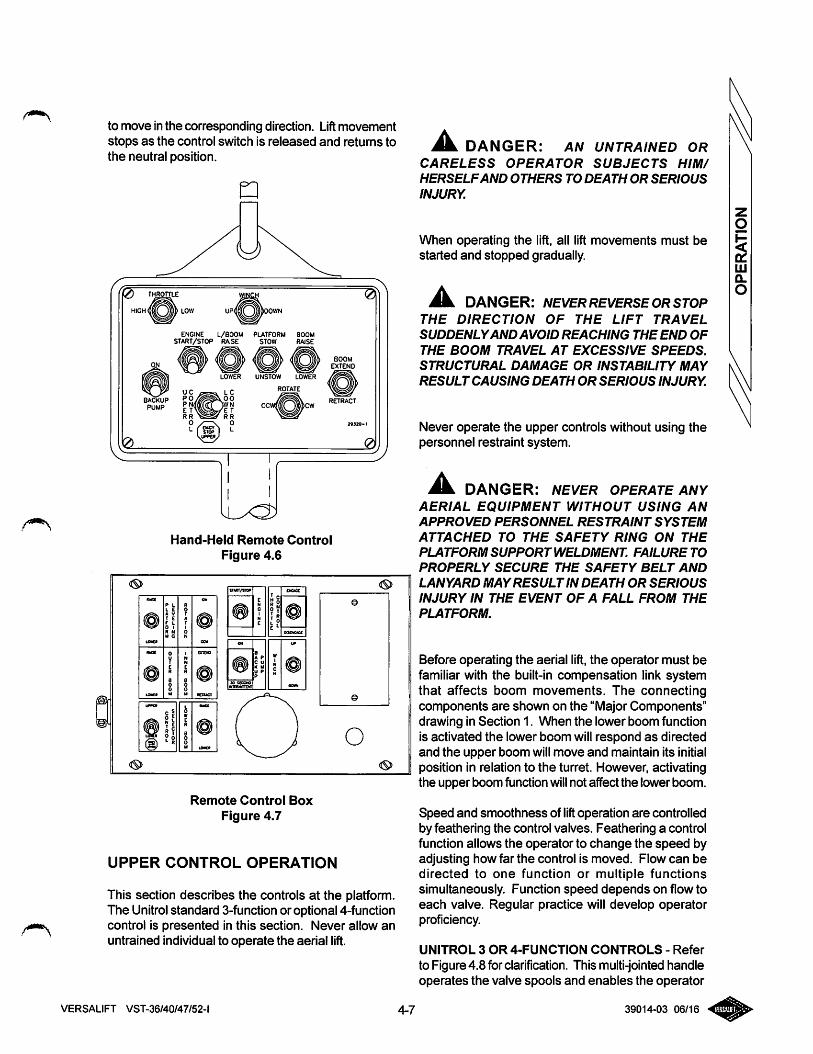
to move inthe corresponding direction. Lift movementstops as the control switch is released and retums tothe neutral position.
PUMP
ENGINE L/600M PLATFORM BOOMSTART/STOP RA.SE STOW RAISE
LOWER UNSTOW LOWER
ROTATE
BOOMEXTEND
RETRACT
Hand-Held Remote Control
Figure 4.6
Remote Control Box
Figure 4.7
UPPER CONTROL OPERATION
This section describes the controls at the platform.The Unitrol standard 3-function or optional 4-functioncontrol is presented in this section. Never allow anuntrained individual to operate the aerial lift.
Jk DANGER: AN UNTRAINED ORCARELESS OPERATOR SUBJECTS HIM/
HERSELFAND OTHERS TO DEATH OR SERIOUS
INJURY.
When operating the lift, all lift movements must bestarted and stopped gradually.
DANGER: NEVER REVERSE OR STOPTHE DIRECTION OF THE LIFT TRAVEL
SUDDENLYAND AVOID REACHING THE END OF
THE BOOM TRAVEL AT EXCESSIVE SPEEDS.
STRUCTURAL DAMAGE OR INSTABILITY MAY
RESULT CAUSING DEATH OR SERIOUS INJURY.
Never operate the upper controls without using thepersonnel restraint system.
Ml DANGER: NEVER OPERATE ANYAERIAL EQUIPMENT WITHOUT USING AN
APPROVED PERSONNEL RESTRAINT SYSTEM
ATTACHED TO THE SAFETY RING ON THE
PLATFORM SUPPORT WELDMENT. FAILURE TO
PROPERLY SECURE THE SAFETY BELT AND
LANYARD MAYRESULT IN DEATH OR SERIOUS
INJURY IN THE EVENT OF A FALL FROM THE
PLATFORM.
Before operating the aerial lift, the operator must befamiliar with the built-in compensation link systemthat affects boom movements. The connectingcomponents are shown on the "Major Components"drawing in Section 1. When the lower boom functionis activated the lower boom will respond as directedand the upper boom will move and maintain its initialposition in relation to the turret. However, activatingthe upper boom function will not affect the lower boom.
Speed and smoothness of lift operation are controlledby feathering the control valves. Feathering a controlfunction allows the operator to change the speed byadjusting how far the control is moved. Flow can bedirected to one function or multiple functionssimultaneously. Function speed depends on flow toeach valve. Regular practice will develop operatorproficiency.
UNITROL 3 OR 4-FUNCTION CONTROLS - Refer
to Figure 4.8 for clarification. This multi-jointedhandleoperates the valve spools and enables the operator
39014-03 06/16VERSALIFT VST-36/40/47/52-l 4-7
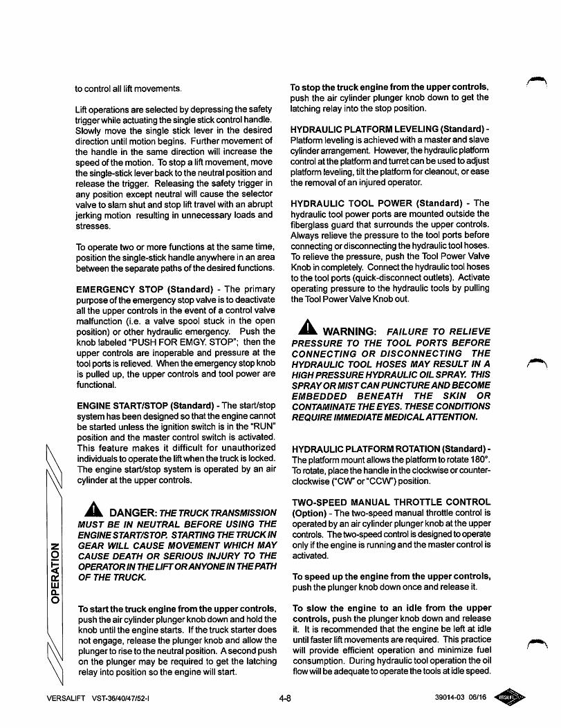
to control all lift movements.
Lift operations are selected by depressing the safetytriggerwhileactuating the single stickcontrol handle.Slowly move the single stick lever in the desireddirection until motion begins. Further movement ofthe handle in the same direction will increase thespeed of the motion. To stop a lift movement, movethe single-stick lever back to the neutral positionandrelease the trigger. Releasing the safety trigger inany position except neutral will cause the selectorvalve to slam shut and stop lift travel with an abruptjerking motion resulting in unnecessary loads andstresses.
To operate two or more functions at the same time,position the single-stick handle anywhere in an areabetween the separate paths of the desired functions.
EMERGENCY STOP (Standard) - The primarypurpose of the emergency stop valve is to deactivateall the upper controls in the event of a control valvemalfunction (i.e. a valve spool stuck in the openposition) or other hydraulic emergency. Push theknob labeled "PUSH FOR EMGY. STOP"; then theupper controls are inoperable and pressure at thetool ports is relieved. When the emergency stop knobis pulled up, the upper controls and tool power arefunctional.
ENGINE START/STOP (Standard) - The start/stopsystem has been designed so that the engine cannotbe started unless the ignition switch is in the "RUN"position and the master control switch is activated.This feature makes it difficult for unauthorized
individuals to operate the lift when the truck is locked.The engine start/stop system is operated by an aircylinder at the upper controls.
^ DANGER: THE TRUCK TRANSMISSIONMUST BE IN NEUTRAL BEFORE USING THEENGINE START/STOP. STARTING THE TRUCK INGEAR WILL CAUSE MOVEMENT WHICH MAYCAUSE DEATH OR SERIOUS INJURY TO THE
OPERATOR IN THE LIFTORANYONE IN THE PATH
OF THE TRUCK.
To start the truck engine from the upper controls,push the air cylinder plunger knob down and hold theknob until the engine starts. Ifthe truck starter doesnot engage, release the plunger knob and allow theplunger to rise to the neutral position. Asecond pushon the plunger may be required to get the latchingrelay into position so the engine will start.
Tostop the truck engine from the upper controls,push the air cylinder plunger knob down to get thelatching relay into the stop position.
HYDRAULIC PLATFORM LEVELING (Standard) -Platform leveling is achieved with a master and slavecylinder arrangement. However, the hydraulic platfomncontrolat the platformand tun'et can be used to adjustplatform leveling, tiltthe platform for cleanout, or easethe removal of an injured operator.
HYDRAULIC TOOL POWER (Standard) - Thehydraulictool power ports are mounted outside thefiberglass guard that surrounds the upper controls.Always relieve the pressure to the tool ports beforeconnecting or disconnecting the hydraulictool hoses.To relieve the pressure, push the Tool Power ValveKnob incompletely. Connect the hydraulic tool hosesto the tool ports (quick-disconnect outlets). Activateoperating pressure to the hydraulic tools by pullingthe Tool Power Valve Knob out.
Mm. WARNING: FAILURE TO RELIEVE
PRESSURE TO THE TOOL PORTS BEFORECONNECTING OR DISCONNECTING THE
HYDRAULIC TOOL HOSES MAY RESULT IN A
HIGH PRESSURE HYDRAULIC OIL SPRAY. THIS
SPRAYOR MIST CAN PUNCTUREAND BECOME
EMBEDDED BENEATH THE SKIN ORCONTAMINATE THE EYES. THESE CONDITIONS
REQUIRE IMMEDIATE MEDICAL ATTENTION.
HYDRAULIC PLATFORM ROTATION (Standard) -The platformmount allowsthe platformto rotate 180°.To rotate, place the handle inthe clockwise or counterclockwise ("CW or"CCW") position.
TWO-SPEED MANUAL THROTTLE CONTROL
(Option) - The two-speed manual throttle control isoperated by an air cylinder plunger knob at the uppercontrols. The two-speed control is designed to operateonly ifthe engine is running and the master control isactivated.
To speed up the engine from the upper controls,push the plunger knob down once and release it.
To slow the engine to an idle from the uppercontrols, push the plunger knob down and releaseit. It is recommended that the engine be left at idleuntil faster liftmovements are required. This practicewill provide efficient operation and minimize fuelconsumption. During hydraulic tool operation the oilflowwill be adequate to operate the tools at idle speed.
VERSALIFT VST-36/40/47/52-l 4-8 39014-03 06/16
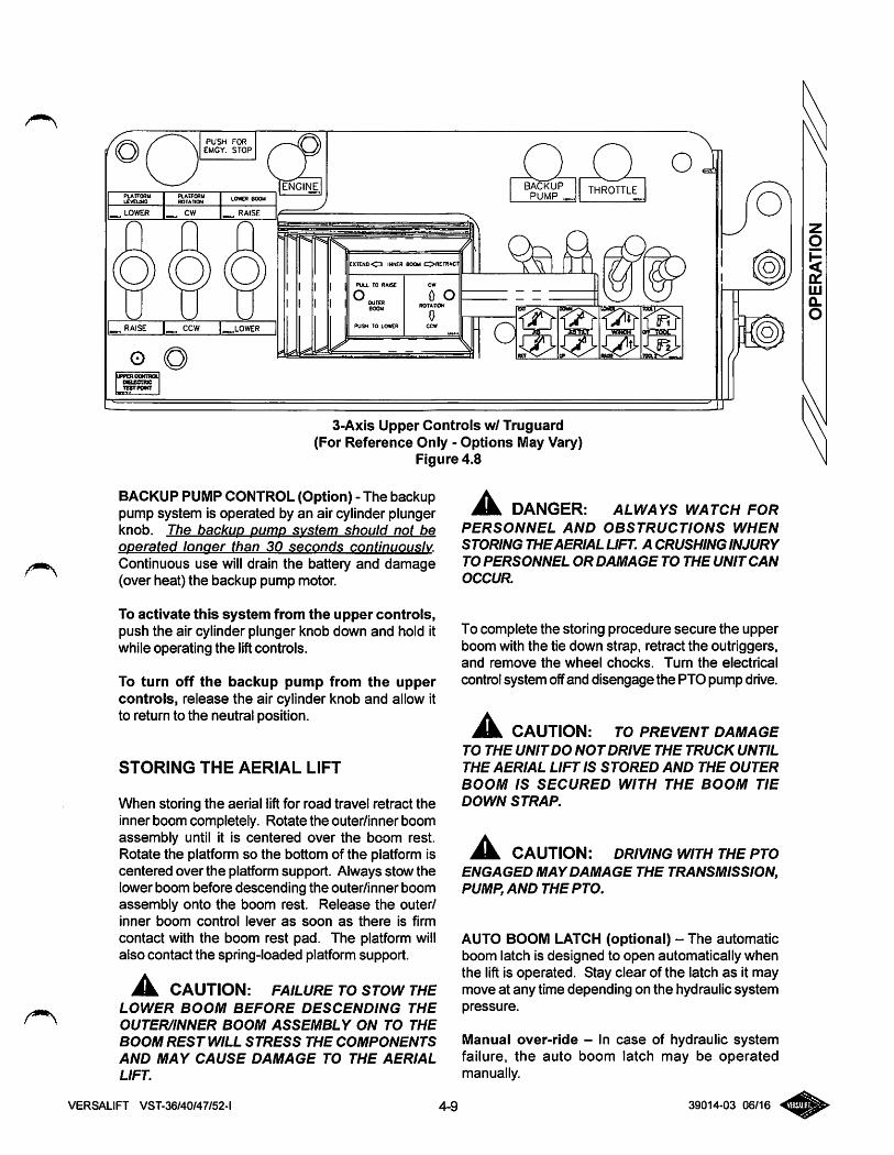
PUSH FOREMGY. STOP
PLATFOftUtxveuNC
platformROTATION
LOWER BOOM
lower raise
ENGINE BACKUPPUMP
O oTHROTTLE
. RAISE ^LOWER
EXTEND CD IMMEH eOOM C>«ETR*Cn
pua TO RAise
oOUTER800M
PySH TO LOWER
0 oROTATION
Ao
(JPPEROOKTnOlDsccmeTESTPOMT
3-Axis Upper Controls w/ Truguard(For Reference Only - Options May Vary)
Figure 4.8
BACKUP PUMP CONTROL (Option) - The backuppump system is operated by an air cylinder plungerknob. The backup oumo system should not be
operated longer than 30 seconds continuously.
Continuous use will drain the battery and damage(over heat) the backup pump motor.
To activate this system from the upper controls,push the air cylinder plunger knob down and hold itwhile operating the liftcontrols.
To turn off the backup pump from the uppercontrols, release the air cylinder knob and allow itto return to the neutral position.
STORING THE AERIAL LIFT
When storing the aerial liftfor road travel retract theinner boom completely. Rotate the outer/inner boomassembly until it is centered over the boom rest.Rotate the platform so the bottom of the platform iscentered over the platform support. Always stow thelower boom before descending the outer/inner boomassembly onto the boom rest. Release the outer/inner boom control lever as soon as there is firm
contact with the boom rest pad. The platform willalso contact the spring-loaded platform support.
JL CAUTION: FAILURE TO STOW THELOWER BOOM BEFORE DESCENDING THE
OUTER/INNER BOOM ASSEMBLY ON TO THE
BOOM REST WILL STRESS THE COMPONENTS
AND MAY CAUSE DAMAGE TO THE AERIAL
LIFT.
A DANGER: ALWAYS WATCH FORPERSONNEL AND OBSTRUCTIONS WHEN
STORING THEAERIAL LIFT. A CRUSHING INJURY
TO PERSONNEL OR DAMAGE TO THE UNIT CAN
OCCUR.
To complete the storing procedure secure the upperboom with the tie down strap, retract the outriggers,and remove the wheel chocks. Turn the electrical
control system offand disengage the PTO pump drive.
Jk. CAUTION: TO PREVENT DAMAGETO THE UNITDO NOTDRIVE THE TRUCK UNTIL
THE AERIAL LIFT IS STORED AND THE OUTER
BOOM IS SECURED WITH THE BOOM TIE
DOWN STRAP.
A. CAUTION: DRIVING WITH THE PTOENGAGED MAY DAMAGE THE TRANSMISSION,PUMP, AND THE PTO.
AUTO BOOM LATCH (optional) - The automaticboom latch is designed to open automatically whenthe lift is operated. Stay clear of the latch as it maymove at any time depending on the hydraulic systempressure.
Manual over-ride - In case of hydraulic systemfailure, the auto boom latch may be operatedmanually.
VERSALIFT VST-36/40/47/52-l 4-9 39014-03 06/16
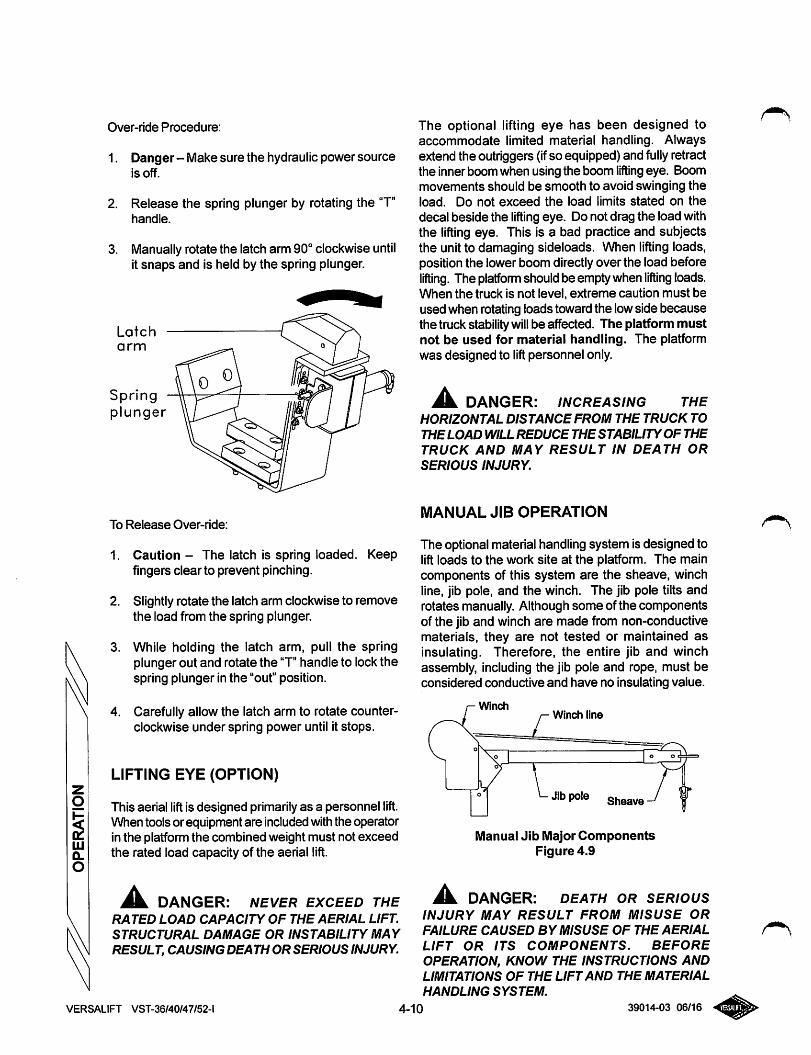
Over-ride Procedure:
1. Danger - Make sure the hydraulic power sourceis off.
2. Release the spring plunger by rotating the "T"handle.
3. Manually rotate the latch arm 90° clockwise untilit snaps and is held by the spring plunger.
Latcharm
Springplunger
To Release Over-ride:
1. Caution - The latch is spring loaded,fingers clear to prevent pinching.
Keep
2. Slightly rotate the latch arm clockwise to removethe load from the spring plunger.
3. While holding the latch arm, pull the springplunger out and rotate the "T" handle to lockthespring plunger in the "out" position.
4. Carefully allow the latch arm to rotate counterclockwise under spring power until it stops.
LIFTING EYE (OPTION)
This aerial lift is designed primarilyas a personnel lift.When tools or equipment are included withthe operatorin the platfomi the combined weight must not exceedthe rated load capacity of the aerial lift.
DANGER: NEVER EXCEED THE
RATED LOAD CAPACITY OF THE AERIAL LIFT.
STRUCTURAL DAMAGE OR INSTABILITY MAYRESULT, CAUSING DEATH OR SERIOUS INJURY.
VERSALIFT VST-36/40/47/52-l
The optional lifting eye has been designed toaccommodate limited material handling. Alwaysextend the outriggers (ifso equipped) and fully retractthe inner boom when using the boom lifting eye. Boommovements should be smooth to avoid swinging theload. Do not exceed the load limits stated on thedecal beside the lifting eye. Do not drag the load withthe lifting eye. This is a bad practice and subjectsthe unit to damaging sideloads. When lifting loads,position the lower boom directlyover the load beforelifting. The platform should be emptywhen lifting loads.When the truck is not level, extreme caution must beused when rotating loads toward the lowside becausethe tmck stabilitywill be affected. The platform mustnot be used for material handling. The platformwas designed to lift personnel only.
^ DANGER: INCREASING THEHORIZONTAL DISTANCE FROM THE TRUCK TO
THE LOAD WILL REDUCE THE STABILITYOF THETRUCK AND MAY RESULT IN DEATH ORSERIOUS INJURY.
MANUAL JIB OPERATION
The optional material handling system is designed tolift loads to the work site at the platform. The maincomponents of this system are the sheave, winchline, jib pole, and the winch. The jib pole tilts androtates manually. Although some of the componentsof the jib and winch are made from non-conductivematerials, they are not tested or maintained asinsulating. Therefore, the entire jib and winchassembly, including the jib pole and rope, must beconsidered conductive and have no insulating value.
Winch
Lwinch line
Y Sheave-^ |Manual Jib Major Components
Figure 4.9
^ DANGER: DEATH OR SERIOUSINJURY MAY RESULT FROM MISUSE OR
FAILURE CAUSED BY MISUSE OF THE AERIAL
LIFT OR ITS COMPONENTS. BEFORE
OPERATION, KNOW THE INSTRUCTIONS ANDLIMITATIONS OF THE LIFT AND THE MATERIAL
HANDLING SYSTEM.
4-10 39014-03 06/16
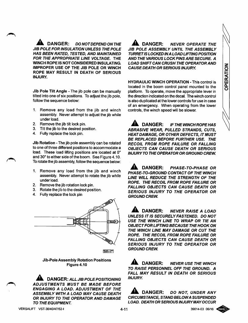
Jk DANGER: DO NOTDEPEND ON THEJIB POLE FOR INSULATION UNLESS THE POLE
HAS BEEN RATED, TESTED, AND MAINTAINEDFOR THE APPROPRIATE LINE VOLTAGE. THE
WINCH ROPE IS NOT CONSIDERED INSULATING
IMPROPER USE OF THE JIB POLE OR WINCH
ROPE MAY RESULT IN DEATH OF SERIOUSINJURY.
Jib Pole Tilt Angle - The jib pole can be manuallytilted into one of six positions. To adjust the jib pole,follow the sequence below:
1.
2.
3.
4.
Remove any load from the jib and winchassembly. Never attempt to adjust the jib whileunder load.
Remove the jib tilt lock pin.Tilt the jib to the desired position.Fully replace the lock pin.
Jib Rotation - The jib pole assembly can be rotatedto one of three different positions to accommodate aload. These load lifting positions are located at 0°and 30° to either side of the boom. See Figure 4.10.To rotate the jib assembly, followthe sequence below:
1.
2.
3.
4.
Remove any load from the jib and winchassembly. Never attempt to rotate the jib whileunderload.
Remove the jib rotation lock pin.Rotate the jib to the desired position.Fully replace the lock pin
Jib-Pole Assembly Rotation PositionsFigure 4.10
^ DANGER: ALL JIB POLEPOSITIONINGADJUSTMENTS MUST BE MADE BEFORE
ENGAGING A LOAD. ADJUSTMENT OF THE
ASSEMBLY WITH A LOAD MAY CAUSE DEATH
OR INJURY TO THE OPERATOR AND DAMAGE
TO THE EQUIPMENT
VERSALIFT VST-36/40/47/52-l
JL DANGER: NEVER OPERATE THEJIB POLE ASSEMBLY UNTIL THE ASSEMBLY
TURRETIS LOCKED INA LOAD UFTING POSITION
AND THE VARIOUS LOCK PINS ARE SECURE. A
LOAD SHIFT CAN CRUSH THE OPERATOR AND
CAUSE DEATH OR SERIOUS INJURY.
HYDRAULIC WINCH OPERATION - This control is
located in the boom control panel mounted to theplatform. To operate, move the appropriate lever inthe direction indicated on the decal. The winch control
is also duplicated at the lower controls for use in caseof an emergency. When operating from the lowercontrols, the winch speed will be slower.
^ DANGER: IFTHE WINCH ROPEHASABRASIVE WEAR, PULLED STRANDS, CUTS,HEAT DAMAGE, OR OTHER DEFECTS, IT MUSTBE REPLACED BEFORE FURTHER USE. THE
RECOIL FROM ROPE FAILURE OR FALLING
OBJECTS CAN CAUSE DEATH OR SERIOUS
INJURY TO THE OPERATOR OR GROUND CREW.
Jk. DANGER: PHASE-TO-PHASE ORPHASE-TO-GROUND CONTACT OF THE WINCH
LINE WILL REDUCE THE STRENGTH OF THE
ROPE. THE RECOIL FROM ROPE FAILURE OR
FALLING OBJECTS CAN CAUSE DEATH OR
SERIOUS INJURY TO THE OPERATOR OR
GROUND CREW.
JL DANGER: NEVER RAISE ALOADUNLESS IT IS SECURELY FASTENED. DO NOT
USE THE WINCH LINE TO WRAP OR TIE AN
OBJECTFOR LIFTING BECAUSE THE HOOK ON
THE WINCH LINE MAY DAMAGE OR CUT THE
ROPE. THE RECOIL FROM ROPE FAILURE OR
FALLING OBJECTS CAN CAUSE DEATH OR
SERIOUS INJURY TO THE OPERATOR OR
GROUND CREW.
DANGER: NEVER USE THE WINCHTO RAISE PERSONNEL OFF THE GROUND. A
FALL MAY RESULT IN DEATH OR SERIOUS
INJURY.
JiL DANGER: DO NOT, UNDER ANYCIRCUMSTANCE, STAND BELOWA SUSPENDEDLOAD. DEATH OR SERIOUS INJURYMAYOCCUR
4-11 39014-03 06/16
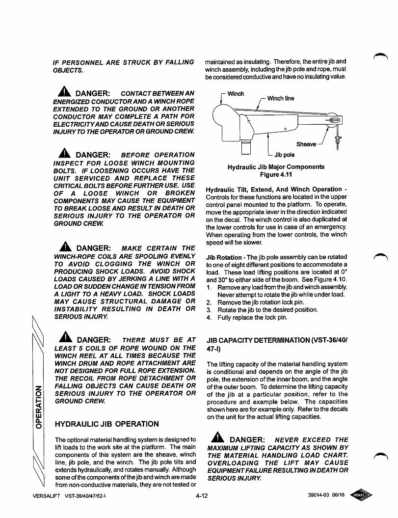
IF PERSONNEL ARE STRUCK BY FALLINGOBJECTS.
DANGER: CONTACT BETWEEN ANENERGIZED CONDUCTOR AND A WINCH ROPEEXTENDED TO THE GROUND OR ANOTHER
CONDUCTOR MAY COMPLETE A PATH FORELECTRICITYAND CAUSE DEATH OR SERIOUSINJURY TO THE OPERATOR OR GROUND CREW.
^ DANGER: BEFORE OPERATIONINSPECT FOR LOOSE WINCH MOUNTINGBOLTS. IF LOOSENING OCCURS HAVE THEUNIT SERVICED AND REPLACE THESECRITICAL BOLTS BEFORE FURTHER USE. USE
OF A LOOSE WINCH OR BROKENCOMPONENTS MAY CAUSE THE EQUIPMENT
TO BREAK LOOSE AND RESULT IN DEATH ORSERIOUS INJURY TO THE OPERATOR ORGROUND CREW.
^ DANGER: MAKE CERTAIN THEWINCH-ROPE COILS ARE SPOOLING EVENLYTO AVOID CLOGGING THE WINCH OR
PRODUCING SHOCK LOADS. AVOID SHOCKLOADS CAUSED BY JERKING A LINE WITH ALOAD OR SUDDEN CHANGE IN TENSION FROM
A LIGHT TO A HEAVY LOAD. SHOCK LOADSMAY CAUSE STRUCTURAL DAMAGE ORINSTABILITY RESULTING IN DEATH ORSERIOUS INJURY.
Mm. DANGER: THERE MUST BE AT
LEAST 5 COILS OF ROPE WOUND ON THEWINCH REEL AT ALL TIMES BECAUSE THEWINCH DRUM AND ROPE ATTACHMENT ARENOT DESIGNED FOR FULL ROPE EXTENSION.THE RECOIL FROM ROPE DETACHMENT ORFALLING OBJECTS CAN CAUSE DEATH OR
SERIOUS INJURY TO THE OPERATOR OR
GROUND CREW.
HYDRAULIC JIB OPERATION
The optional material handling system is designed tolift loads to the work site at the platform. The maincomponents of this system are the sheave, winchline, jib pole, and the winch. The jib pole tilts andextends hydraulically, and rotates manually. Althoughsome of the components ofthe jiband winch are madefrom non-conductive materials, they are not tested or
maintained as insulating. Therefore, the entire jibandwinch assembly, including the jib pole and rope, mustbe considered conductive and have no insulating value.
WinchWinch line
Sheave
>- Jib pole
Hydraulic Jib Major ComponentsFigure 4.11
Hydraulic Tilt, Extend, And Winch Operation -Controls for these functions are located in the uppercontrol panel mounted to the platform. To operate,move the appropriate lever in the direction indicatedon the decal. The winch control is also duplicated atthe lower controls for use in case of an emergency.When operating from the lower controls, the winchspeed will be slower.
Jib Rotation - The jib pole assembly can be rotatedto one of eight different positions to accommodate aload. These load lifting positions are located at 0°and 30° to either side of the boom. See Figure 4.10.1.
2.
3.
4.
Remove any loadfromthe jiband winch assembly.Never attempt to rotate the jibwhile under load.Remove the jib rotation lock pin.Rotate the jib to the desired position.Fully replace the lock pin.
JIB CAPACITY DETERMINATION (VST-36/40/47-1)
The lifting capacity of the material handling systemis conditional and depends on the angle of the jibpole, the extension of the inner boom, and the angleof the outer boom. To determine the liftingcapacityof the jib at a particular position, refer to theprocedure and example below. The capacitiesshown here are for example only. Refer to the decalson the unit for the actual liftingcapacities.
DANGER: NEVER EXCEED THE
MAXIMUM LIFTING CAPACITY AS SHOWN BY
THE MATERIAL HANDLING LOAD CHART.OVERLOADING THE LIFT MAY CAUSE
EQUIPMENTFAILURE RESULTING IN DEATH ORSERIOUS INJURY.
VERSALIFT VST-36/40/47/52-l 4-12 39014-03 06/16
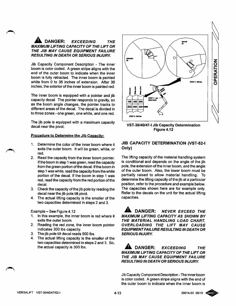
^ DANGER: EXCEEDING THEMAXIMUM LIFTING CAPACITY OF THE LIFT OR
THE JIB MAY CAUSE EQUIPMENT FAILURE
RESULTING IN DEATH OR SERIOUS INJURY.
Jib Capacity Component Description - The innerboom is color coded. A green stripe aligns with theend of the outer boom to indicate when the inner
boom is fully retracted. The inner boom is paintedwhite from 0 to 36 inches of extension. After 36
inches, the exterior of the inner boom is painted red.
The inner boom is equipped with a pointer and jibcapacity decal. The pointer responds to gravity, soas the boom angle changes, the pointer tracks todifferent areas of the decal. The decal is divided into three zones - one green, one white, and one red.
The jib pole is equipped with a maximum capacitydecal near the pivot.
Procedure to Determine the Jib Capacity:
1. Determine the color of the inner boom where itexits the outer boom. It will be green, white, orred.
2. Read the capacity from the inner boom pointer.Ifthe boom instep 1 was green, read the capacityfrom the green portion of the decal. Ifthe boom instep 1 was white, read the capacity from the whiteportion of the decal. If the boom in step 1 wasred, read the capacity from the red portion of thedecal.
3. Check the capacity of the jib pole by reading thedecal near the jib pole tilt pivot.
4. The actual lifting capacity is the smaller of thetwo capacities determined in steps 2 and 3.
Example-See Figure 4.121. In this example, the inner boom is red where it
exits the outer boom.
2. Reading the red zone, the inner boom pointerindicates 300 lbs capacity.
3. The jib pole tilt decal reads 500 lbs.4. The actual lifting capacity is the smaller of the
two capacities determined in steps 2 and 3. So,the actual capacity is 300 lbs.
8TEP2-30aibt
VST-36/40/47-l Jib Capacity DeterminationFigure 4.12
JIB CAPACITY DETERMINATION (VST-52-1Only)
The lifting capacity of the material handling systemis conditional and depends on the angle of the jibpole, the extension of the inner boom, and the angleof the outer boom. Also, the lower boom must bepartially raised to allow material handling. Todetermine the lifting capacity of the jib at a particularposition, refer to the procedure and example below.The capacities shown here are for example only.Refer to the decals on the unit for the actual liftingcapacities.
Jk DANGER: NEVER EXCEED THEMAXIMUM LIFTING CAPACITY AS SHOWN BY
THE MATERIAL HANDLING LOAD CHART.
OVERLOADING THE LIFT MAY CAUSE
EQUIPMENTFAILURE RESULTING IN DEATH OR
SERIOUS INJURY.
JL DANGER: EXCEEDING THEMAXIMUM LIFTING CAPACITY OF THE LIFT OR
THE JIB MAY CAUSE EQUIPMENT FAILURE
RESULTING IN DEATH OR SERIOUS INJURY.
Jib Capacity Component Description - The inner boomis color coded. A green stripe aligns with the end ofthe outer boom to indicate when the inner boom is
4-13 39014-03 06/16VERSALIFT VST-36/40/47/52-l
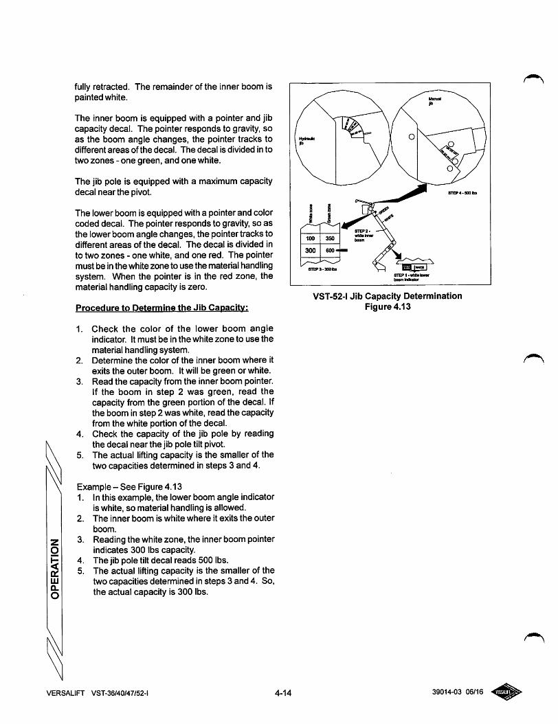
fully retracted. The remainder of the inner boom ispainted white.
The inner boom is equipped with a pointer and jibcapacity decal. The pointer responds to gravity, soas the boom angle changes, the pointer tracks todifferent areas of the decal. The decal is divided in to
two zones - one green, and one white.
The jib pole is equipped with a maximum capacitydecal near the pivot.
The lower boom is equipped with a pointer and colorcoded decal. The pointer responds to gravity, so asthe lower boom angle changes, the pointer tracks todifferent areas of the decal. The decal is divided into two zones - one white, and one red. The pointermust be in the white zone to use the material handlingsystem. When the pointer is in the red zone, thematerial handling capacity is zero.
Procedure to Determine the Jib Capacity:
1. Check the color of the lower boom angleindicator. It must be in the white zone to use thematerial handling system.
2. Determine the color of the inner boom where itexits the outer boom. It will be green or white.
3. Read the capacity from the inner boom pointer.If the boom in step 2 was green, read thecapacity from the green portion of the decal. Ifthe boom in step 2 was white, read the capacityfrom the white portion of the decal.
4. Check the capacity of the jib pole by readingthe decal near the jib pole tilt pivot.
5. The actual lifting capacity is the smaller of thetwo capacities determined in steps 3 and 4.
Example - See Figure 4.131. In this example, the lower boom angle indicator
is white, so material handling is allowed.2. The inner boom is white where it exits the outer
boom.
3. Reading the white zone, the inner boom pointerindicates 300 lbs capacity.
4. The jib pole tilt decal reads 500 lbs.5. The actual lifting capacity is the smaller of the
two capacities determined in steps 3 and 4. So,the actual capacity is 300 lbs.
VERSALIFT VST-36/40/47/52-l 4-14
8TEP4.S00bs
VST-52-1 Jib Capacity DeterminationFigure 4.13
39014-03 06/16
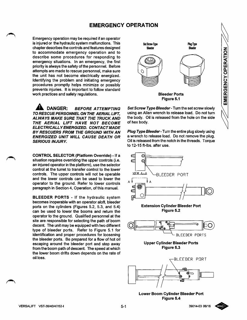
EMERGENCY OPERATION
Emergency operation may be required ifan operatoris injured or the hydraulic system malfunctions. Thischapter describes the controls and features designedto accommodate emergency operation and todescribe some procedures for responding toemergency situations. In an emergency, the firstpriority is always the safety of the personnel. Beforeattempts are made to rescue personnel, make surethe unit has not become electrically energized.Identifying the problem and initiating emergencyprocedures promptly helps minimize or possiblyprevents injuries. It is important to follow standardwork practices and safety regulations.
DANGER: BEFORE ATTEMPTINGTO RESCUE PERSONNEL ON THE AERIAL LIFT,ALWAYS MAKE SURE THAT THE TRUCK AND
THE AERIAL LIFT HAVE NOT BECOME
ELECTRICALLYENERGIZED. CONTACTMADE
BY RESCUERS FROM THE GROUND WITH AN
ENERGIZED UNIT WILL CAUSE DEATH OR
SERIOUS INJURY.
CONTROL SELECTOR (Platform Override) - If asituation requires overriding the upper controls (i.e.an injured operator in the platfonn), use the selectorcontrol at the turret to transfer control to the lower
controls. The upper controls will not be operableand the lower controls can be used to lower the
operator to the ground. Refer to lower controlsparagraph in Section 4, Operation, of this manual.
BLEEDER PORTS - If the hydraulic systembecomes inoperable with an operator aloft, bleederports on the cylinders (Figures 5.2, 5.3, and 5.4)can be used to lower the booms and return the
operator to the ground. Qualified personnel at thesite are responsible for selecting the path of boomdecent. The unit may be equipped with two differenttype of bleeder ports. Refer to Figure 5.1 foridentification and proper procedures for looseningthe bleeder ports. Be prepared for a flow of hot oilescaping around the bleeder port and step awayfrom the boom path of descent. The speed at whichthe lower boom drifts down depends on the rate ofoil loss.
S^ScrewType
Bleeder Ports
Figure 5.1
SetScrew Type S/eeder- Turn the set screw slowlyusing an Allen wrench to release load. Do not turnthe body. Oil is released from the hole on the sideof hex body.
Plug Type Bleeder-Tum the entire plug slowly usinga wrench to release load. Do not remove the plug.Oil is released from the notch in the threads. Torqueto 12-15 ft-lbs. after use.
"^BLEEDER PORT
AI I A
VIEW A-A•BLEEDER PORT
Extension Cylinder Bleeder PortFigure 5.2
:]0\ a 0 ^L-L 9
1 dJ^Q
BLEEDER PORTS
Upper Cylinder Bleeder PortsFigure 5.3
•BLEEDER PORT
Lower Boom Cylinder Bleeder PortFigure 5.4
VERSALIFT VST-36/40/47/52-l 5-1 39014-03 06/16
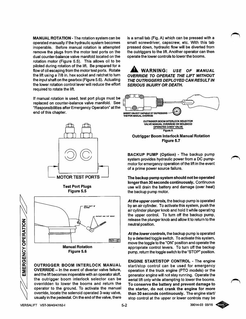
MANUAL ROTATION - The rotation system can beoperated manually ifthe hydraulic system becomesinoperable. Before manual rotation is attemptedremove the plugs from the motor test ports on thedual counter-balance valve manifold located on the
rotation motor (Figure 5.5). This allows oil to bepiloted during rotation of the lift. Be prepared for aflowof oilescaping from the motor test ports. Rotatethe lift using a 7/8 in. hex socket and ratchet to turnthe inputshaft on the gearbox (Figure 5.6). Actuatingthe lower rotation control lever will reduce the effort
required to rotate the lift.
If manual rotation is used, test port plugs must bereplaced on counter-balance valve manifold. See"Responsibilities after Emergency Operation" at theend of this chapter.
cm ^
MOTOR TEST PORTS
Test Port PlugsFigure 5.5
BAfCtCT «M0 r/r SOCKET
Manual Rotation
Figure 5.6
l«277-ile I
OUTRIGGER BOOM INTERLOCK MANUAL
OVERRIDE - In the event of diverter valve failure,and the lift becomes inoperable with an operator aloft,the outrigger boom interlock selector can beoverridden to lower the booms and return the
operator to the ground. To activate the manualoverride, locate the solenoid operated 3-way valve,usually inthe pedestal. On the end of the valve, there
VERSALIFT VST-36/40/47/52-l
is a small tab (Fig. A) which can be pressed with asmall screwdriver, capscrew, etc. With this tabpressed down, hydraulic flow will be diverted fromthe outriggers to the lift. Another operator can thenoperate the lower controls to lower the booms.
^ WARNING: USE OF MANUALOVERRIDE TO OPERATE THE LIFT WITHOUT
THE OUTRIGGERS DEPLOYED CAN RESULT IN
SERIOUS INJURY OR DEATH.
(NSERT OBJECT CAPABLE OF DEPRESSINGTAB FOR MANUAL OVERRIDE
OUTRIGGER BOOM INTERLOCK SELECTORVALVE MANUAL OVERRIDE ON SOLENOID
OPERATED 3-WAY VALVE
Figure A
Outrigger Boom Interlock Manual RotationFigure 5.7
BACKUP PUMP (Option) - The backup pumpsystem provides hydraulic power from a DC pump-motor for emergency operation of the lift in the eventof a prime power source failure.
The backup pump system should not be operatedlongerthan 30 seconds continuously. Continuoususe will drain the battery and damage (over heat)the backup pump motor.
At the upper controls, the backup pump is operatedby an air cylinder. To activate this system, push theair cylinder plunger knob and hold itwhile operatingthe upper control. To turn off the backup pump,release the plunger knob and allow it to return to theneutral position.
At the lowercontrols, the backup pump is operatedby a detented toggle switch. To activate this system,move the toggle to the "ON"position and operate theappropriate control levers. To turn off the backuppump, return the toggle switch to the "STOP" position.
ENGINE START/STOP CONTROL - The enginestart/stop control can be used for emergencyoperation if the truck engine (PTO models) or thegenerator engine will not stay running. Operate theaerial liftonly while attempting to lower the booms.To conserve the battery and prevent damage tothe starter, do not crank the engine for morethan 30 seconds continuously. The engine start/stop control at the upper or lower controls may be
5-2 39014-03 06/16
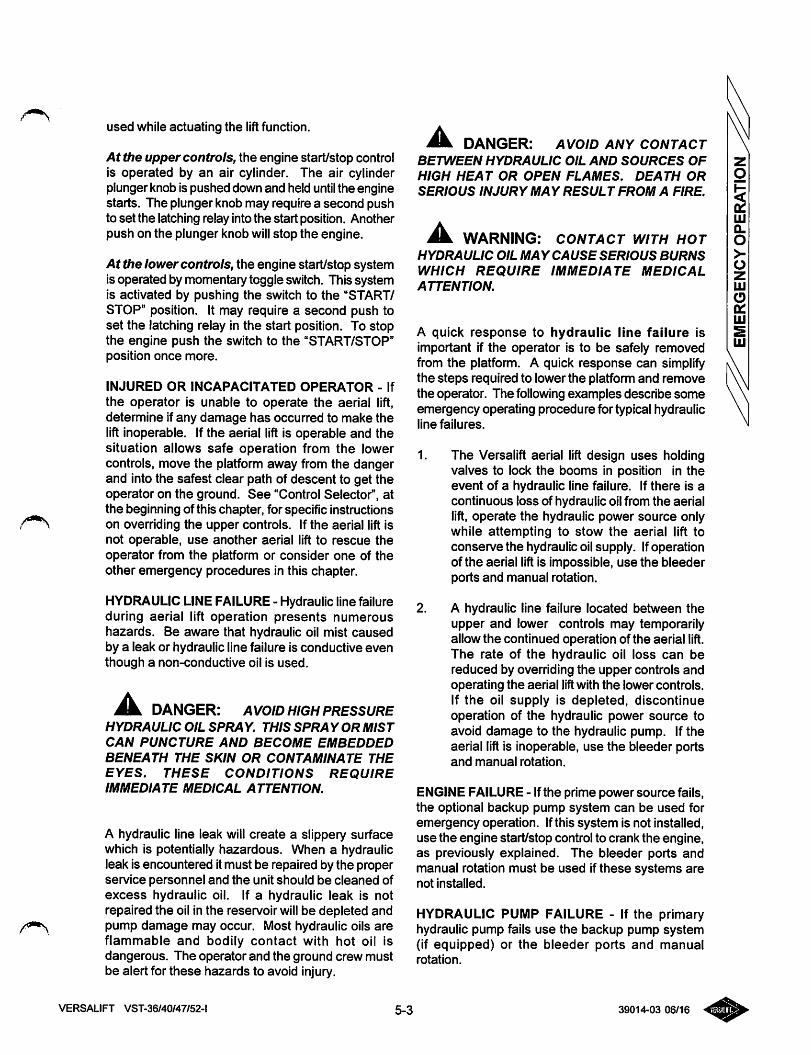
used while actuating the liftfunction.
At the upper controls, the engine start/stop controlis operated by an air cylinder. The air cylinderplunger knob is pushed down and held until the enginestarts. The plunger knob may require a second pushto set the latching relay into the start position. Anotherpush on the plunger knob will stop the engine.
At the lowercontrols, the engine start/stop systemis operated by momentary toggle switch. This systemis activated by pushing the switch to the "START/STOP" position. It may require a second push toset the latching relay in the start position. To stopthe engine push the switch to the "START/STOP"position once more.
INJURED OR INCAPACITATED OPERATOR - If
the operator is unable to operate the aerial lift,determine ifany damage has occurred to make thelift inoperable. If the aerial lift is operable and thesituation allows safe operation from the lowercontrols, move the platform away from the dangerand into the safest clear path of descent to get theoperator on the ground. See "Control Selector", atthe beginning of this chapter, for specific instructionson overriding the upper controls. If the aerial lift isnot operable, use another aerial lift to rescue theoperator from the platform or consider one of theother emergency procedures in this chapter.
HYDRAULIC LINEFAILURE - Hydraulic line failureduring aerial lift operation presents numeroushazards. Be aware that hydraulic oil mist causedby a leak or hydraulic line failure is conductive eventhough a non-conductive oil is used.
DANGER: AVOID HIGH PRESSUREHYDRAULIC OIL SPRAY. THIS SPRAY OR MIST
CAN PUNCTURE AND BECOME EMBEDDED
BENEATH THE SKIN OR CONTAMINATE THEEYES. THESE CONDITIONS REQUIREIMMEDIATE MEDICAL ATTENTION.
A hydraulic line leak will create a slippery surfacewhich is potentially hazardous. When a hydraulicleak is encountered itmust be repaired by the properservice personnel and the unit should be cleaned ofexcess hydraulic oil. If a hydraulic leak is notrepaired the oil in the reservoir will be depleted andpump damage may occur. Most hydraulic oils areflammable and bodily contact with hot oil isdangerous. The operator and the ground crew mustbe alert for these hazards to avoid injury.
jUk. DANGER: AVOID ANY CONTACTBETWEEN HYDRAULIC OIL AND SOURCES OF
HIGH HEAT OR OPEN FLAMES. DEATH OR
SERIOUS INJURY MAY RESULT FROM A FIRE.
mK WARNING: CONTACT WITH HOTHYDRAULIC OIL MAY CAUSE SERIOUS BURNS
WHICH REQUIRE IMMEDIATE MEDICAL
ATTENTION.
A quick response to hydraulic line failure isimportant if the operator is to be safely removedfrom the platform. A quick response can simplifythe steps required to lower the platform and removethe operator. The following examples describe someemergency operating procedure for typical hydraulicline failures.
1. The Versalift aerial lift design uses holdingvalves to lock the booms in position in theevent of a hydraulic line failure. If there is acontinuous loss of hydraulic oil from the aeriallift, operate the hydraulic power source onlywhile attempting to stow the aerial lift toconserve the hydraulic oil supply. Ifoperationof the aerial lift is impossible, use the bleederports and manual rotation.
2. A hydraulic line failure located between theupper and lower controls may temporarilyallow the continued operation of the aerial lift.The rate of the hydraulic oil loss can bereduced by overriding the upper controls andoperating the aerial liftwith the lower controls.If the oil supply is depleted, discontinueoperation of the hydraulic power source toavoid damage to the hydraulic pump. If theaerial lift is inoperable, use the bleeder portsand manual rotation.
ENGINE FAILURE - Ifthe prime power source fails,the optional backup pump system can be used foremergency operation. Ifthis system is not installed,use the engine start/stop control to crank the engine,as previously explained. The bleeder ports andmanual rotation must be used if these systems arenot installed.
HYDRAULIC PUMP FAILURE - If the primaryhydraulic pump fails use the backup pump system(if equipped) or the bleeder ports and manualrotation.
VERSALIFT VST-36/40/47/52-l 5-3 39014-03 06/16
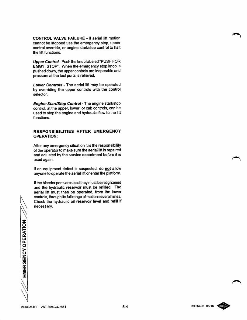
CONTROL VALVE FAILURE - If aerial lift motion
cannot be stopped use the emergency stop, uppercontrol override, or engine start/stop control to haltthe lift functions.
Upper Control - Push the knob labeled "PUSHFOREMGY. STOP". When the emergency stop knob ispushed down, the upper controls are inoperable andpressure at the tool ports is relieved.
Lower Controls - The aerial lift may be operatedby overriding the upper controls with the controlselector.
Engine Start/Stop Control - The engine start/stopcontrol, at the upper, lower, or cab controls, can beused to stop the engine and hydraulicflowto the liftfunctions.
RESPONSIBILITIES AFTER EMERGENCY
OPERATION:
Afterany emergency situation it is the responsibilityof the operator to make sure the aerial lift is repairedand adjusted by the service department before it isused again.
If an equipment defect is suspected, do not allowanyone to operate the aerial lift or enter the platform.
Ifthe bleeder portsare used they must be retightenedand the hydraulic reservoir must be refilled. Theaerial lift must then be operated, from the lowercontrols, through itsfull range ofmotionseveral times.Check the hydraulic oil reservoir level and refill ifnecessary.
VERSALIFT VST-36/40/47/52-l 5-4 39014-03 06/16
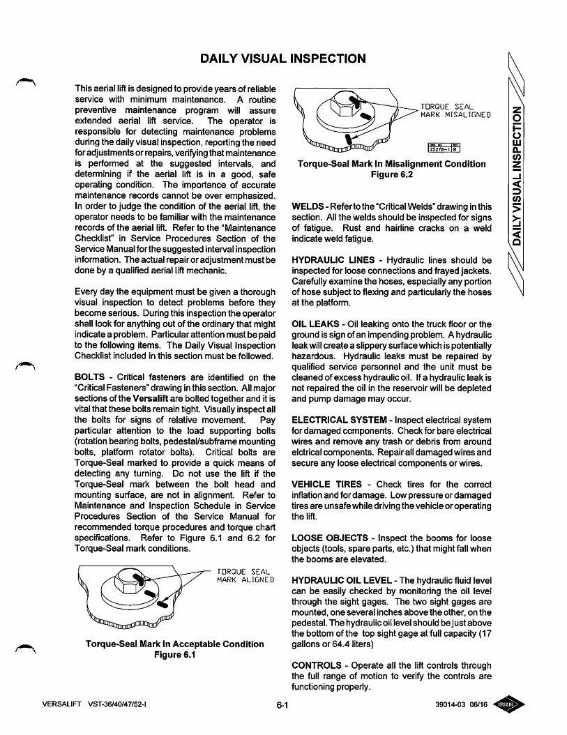
DAILY VISUAL INSPECTION
This aerial lift is designed to provide years of reliableservice with minimum maintenance. A routine
preventive maintenance program will assureextended aerial lift service. The operator isresponsible for detecting maintenance problemsduring the daily visual inspection, reporting the needfor adjustments or repairs, verifyingthat maintenanceis performed at the suggested intervals, anddetermining if the aerial lift is in a good, safeoperating condition. The importance of accuratemaintenance records cannot be over emphasized.In order to judge the condition of the aerial lift, theoperator needs to be familiar with the maintenancerecords of the aerial lift. Refer to the "Maintenance
Checklist" in Service Procedures Section of the
Service Manual for the suggested interval inspectioninformation. The actual repair or adjustment must bedone by a qualified aerial liftmechanic.
Every day the equipment must be given a thoroughvisual inspection to detect problems before theybecome serious. During this inspection the operatorshall look for anything out of the ordinary that mightindicate a problem. Particular attention must be paidto the following items. The Daily Visual InspectionChecklist included in this section must be followed.
BOLTS - Critical fasteners are identified on the
"Critical Fasteners" drawing inthis section. Allmajorsections of the Versalift are bolted together and it isvital that these bolts remain tight. Visually inspect allthe bolts for signs of relative movement. Payparticular attention to the load supporting bolts(rotation bearing bolts, pedestal/subframe mountingbolts, platform rotator bolts). Critical bolts areTorque-Seal marked to provide a quick means ofdetecting any turning. Do not use the lift if theTorque-Seal mark between the bolt head andmounting surface, are not in alignment. Refer toMaintenance and Inspection Schedule in ServiceProcedures Section of the Service Manual for
recommended torque procedures and torque chartspecifications. Refer to Figure 6.1 and 6.2 forTorque-Seal mark conditions.
TORQUE SEAL
MARK ALIGNED
Torque-Seal Mark In Acceptable ConditionFigure 6.1
VERSALIFT VST-36/40/47/52-l
TORQUE SEAL
MARK MISALIGNED
fSaTB-i Ib" I
Torque-Seal Mark In Misalignment ConditionFigure 6.2
WELDS - Refer to the "CriticalWelds" drawing inthissection. All the welds should be inspected for signsof fatigue. Rust and hairline cracks on a weldindicate weld fatigue.
IHYDRAULIC LINES - Hydraulic lines should beinspected for loose connections and frayed jackets.Carefully examine the hoses, especially any portionof hose subject to flexing and particularly the hosesat the platfonn.
OIL LEAKS - Oil leaking onto the truck floor or theground is sign of an impending problem. A hydraulicleak will create a slippery surface which is potentiallyhazardous. Hydraulic leaks must be repaired byqualified service personnel and the unit must becleaned of excess hydraulic oil. Ifa hydraulic leak isnot repaired the oil in the reservoir will be depletedand pump damage may occur.
ELECTRICAL SYSTEM - Inspect electrical systemfor damaged components. Check for bare electricalwires and remove any trash or debris from aroundelctrical components. Repair all damaged wires andsecure any loose electrical components or wires.
VEHICLE TIRES - Check tires for the correct
inflation and for damage. Low pressure or damagedtires are unsafe while driving the vehicle or operatingthe lift.
LOOSE OBJECTS - Inspect the booms for looseobjects (tools, spare parts, etc.) that might fall whenthe booms are elevated.
HYDRAULIC OIL LEVEL - The hydraulic fluid levelcan be easily checked by monitoring the oil levelthrough the sight gages. The two sight gages aremounted, one several inches above the other, on thepedestal. The hydraulic oil level should be just abovethe bottom of the top sight gage at full capacity (17gallons or 64.4 liters)
CONTROLS - Operate all the lift controls throughthe full range of motion to verify the controls arefunctioning properly.
6-1 39014-03 06/16
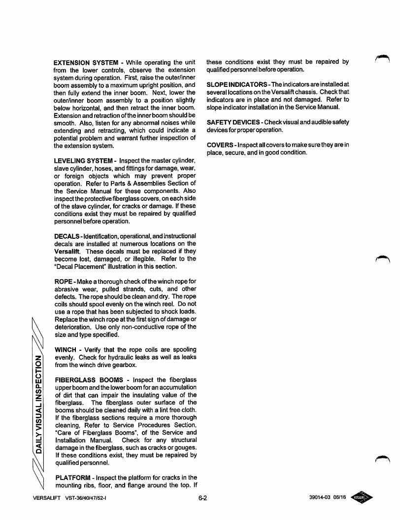
EXTENSION SYSTEM - While operating the unitfrom the lower controls, observe the extensionsystem during operation. First, raise the outer/innerboom assembly to a maximum upright position, andthen fully extend the inner boom. Next, lower theouter/inner boom assembly to a position slightlybelow horizontal, and then retract the inner boom.Extension and retraction ofthe inner boom should besmooth. Also, listen for any abnormal noises whileextending and retracting, which could indicate apotential problem and warrant further inspection ofthe extension system.
LEVELINGSYSTEM - Inspect the master cylinder,slave cylinder, hoses, and fittings for damage, wear,or foreign objects which may prevent properoperation. Refer to Parts &Assemblies Section ofthe Service Manual for these components. Alsoinspect the protective fiberglass covers, on each sideof the slave cylinder, for cracks or damage. Iftheseconditions exist they must be repaired by qualifiedpersonnel before operation.
DECALS- Identification, operational,and instructionaldecals are installed at numerous locations on theVersalift. These decals must be replaced if theybecome lost, damaged, or illegible. Refer to the"Decal Placement" illustration in this section.
ROPE - Make a thorough check ofthe winch rope forabrasive wear, pulled strands, cuts, and otherdefects. The rope should be clean and dry. The ropecoils should spool evenly on the winch reel. Do notuse a rope that has been subjected to shock loads.Replace the winch rope at the first sign of damage ordeterioration. Use only non-conductive rope of thesize and type specified.
WINCH - Verify that the rope coils are spoolingevenly. Check for hydraulic leaks as well as leaksfrom the winch drive gearbox.
FIBERGLASS BOOMS - Inspect the fiberglassupper boom and the lowerboom foran accumulationof dirt that can impair the insulating value of thefiberglass. The fiberglass outer surface of thebooms should be cleaned daily with a lintfree cloth.If the fiberglass sections require a more thoroughcleaning. Refer to Service Procedures Section,"Care of Fiberglass Booms", of the Service andInstallation Manual. Check for any structuraldamage in the fiberglass, such as cracks or gouges.If these conditions exist, they must be repaired byqualified personnel.
PLATFORM - Inspect the platform for cracks in themounting ribs, floor, and flange around the top. If
these conditions exist they must be repaired byqualified personnel before operation.
SLOPE INDICATORS - The indicators are installed at
several locations on the Versalift chassis. Check thatindicators are in place and not damaged. Refer toslope indicator installation inthe Service Manual.
SAFETY DEVICES - Check visual and audible safetydevices for proper operation.
COVERS - Inspect allcovers to make sure they are inplace, secure, and in good condition.
VERSALIFT VST-36/40/47/52-l 6-2 39014-03 06/16
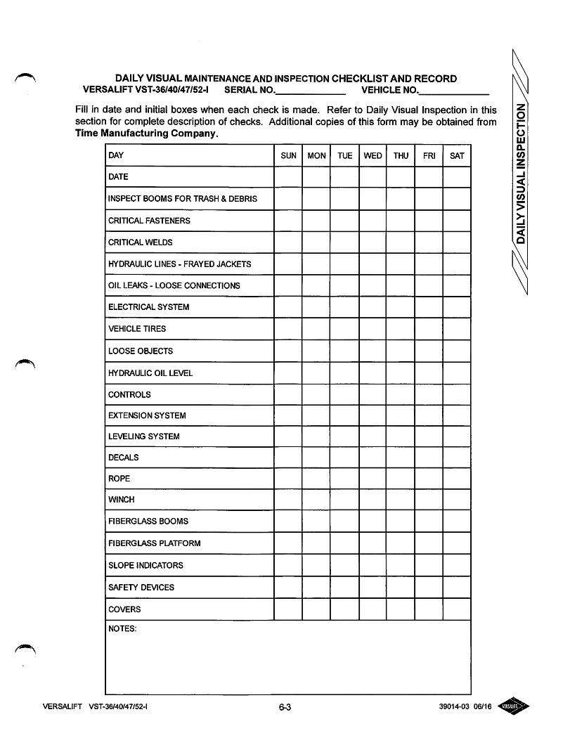
DAILY VISUAL MAINTENANCE AND INSPECTION CHECKLIST AND RECORDVERSALIFT VST-36/40/47/52-l SERIAL NO. VEHICLE NO.
Fill in date and initial boxes when each check is made. Refer to Daily Visual Inspection in thissection for complete description of checks. Additional copies of this form may be obtained fromTime Manufacturing Company.
DAY SUN MON TUE WED THU FRI SAT
DATE
INSPECT BOOMS FOR TRASH & DEBRIS
CRITICAL FASTENERS
CRITICAL WELDS
HYDRAULIC LINES - FRAYED JACKETS
OIL LEAKS - LOOSE CONNECTIONS
ELECTRICAL SYSTEM
VEHICLE TIRES
LOOSE OBJECTS
HYDRAULIC OIL LEVEL
CONTROLS
EXTENSION SYSTEM
LEVELING SYSTEM
DECALS
ROPE
WINCH
FIBERGLASS BOOMS
FIBERGLASS PLATFORM
SLOPE INDICATORS
SAFETY DEVICES
COVERS
NOTES:
VERSALIFT VST-36/40/47/52-l 6^ 39014-03 06/16
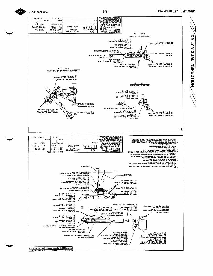
platformMOUNHNGa"K0L£CCNTERS:(4)(400W-T2)0/2X2!/♦HHCS)(4)(4200S-S)(1/2PTLN)(e)(44013-3)(1/2MHOPLATfOftMUOUNIINC16"MOUCCNTERS:(4)(40007-12)(5/8X23/4MMCS)(4)(42005-7)(5/ePUN)(B)(440I3>I)(5/eMW).
PLArrOftUPIVOTPM:
(2)(4000S-T43)(7/16X33/4(2)(4200S-4)(7/iePTIW)(4)(44013-9)(7/ieMW)(2)(4S0t4-S8)(2.313i0.9tAPRING)
ROTARYACTUATOR:
(4)(40054-13)(5/8X3MMCSCR.B)(4)(42005-7)(5/8PTUI)(«)(44013-1)(5/8MHO(6){40111-4)(3/8X7/8MMCSCR.8)(«)(44013-8)(3/8H*0(1)(40104-28)(3/4X91/2HMCSCR.6)(1)(42005-6)(PTIN)(1)(44013-4)(3/4HW)
EXTCNSiONCTLtNOCK(4)(40000-16)(t/2X1f»tCS)NOroRcueseal
NEARANOFARSOE:
(1)(40004-3)(3/8X3/4MMCS)(1)(44013-6)(3/8HW)
0-13)(3/8X3/4fSKCS)
(2)(40004
(I)(44013
-3)(3/8X3/4MMCS)6)(3/8HW)
5)(1/2XIMHCS)3)(1/2MW)
NEARANOFaASOE:(I)(40004-3)(3/8X3/4MMCS)(1)(44013-6)(3/8kW)
M«77AOOCDMnCM.AtEOHVOJtaAHQWNCMTOS>C£fa.
NEARStOC:(2)(40004-3)(3/8X3/4HHCS)(2)(44013-8)(3/8HW)
NCARSOC
(I)(40006-5)(1/2X1MMCS)(I)(44013-3)(1/2HW)rARS:0E
2)(40004-3)(3/8X3/4MMCS)2)(44013-6)(3/8MW)
FarSIDE:(2)(40004-3)(3/8X3/4MMCS)(2)(44013-6)(3/8MW)
•NEARSOE:
(2)(40004-3)(3/8X3/4MMCS)(2)(44013-6)(3/8MW)FaASiOE:
(1)(40006-5)(1/2X1MMCS)(1)(44013-3)(1/2MW)
TURRETTOROTAHONBEARING:(22)(40054-10)(5/8X21/4HMCSCR.8)(22)(44013-1)(5/8MW)
CEAR80XMOUNTING:(4)(40077-15)(5/8X31/2SMCSCR.8)(4)(44000-15)(5/8LOCKWAS«R)(4)(44013-1)(5/8HW)(4)(42027-7)(5/8PTlNCR.C)
PEDESTALTOROTAHONBEAAMC:(18)(40054-10)(5/8X21/4HHCSCR.8)(t8)(44013-1)(5/8HW)
NOTES:
1.)AaFASTEKERSIMATARESTRUCTURALORRETAWANOTHERSTRUCTURALMEMBERARECRITICAL
2.)HEXMEADBOLTSAREGRADE5.WTSAREGRADEB.ANDWASHERSAREHARDENEDSTEELUNLESSNOTEOOTMERMSE.
3.)MINUUMorTWOTHREADSTHROUGHANTLOCKNUT.4.)FASTENERCALLOUTSREAOASFOU.OWS:
(OTYPERARftOHKHEAO)(PARTNUMBER)(OESCR:PTION).5.)TOROUEALLTHREAOEOCfOnCALFASTENERSPERTHETOROUECHART
*TllC-776*NTHEOPERATORSANOSERVICEMANUALS.tfHSSSNOTEOOTHERWISE.
6.)AILTHREADEDFASTENERSTO8EMARKEOMIHTOROUESEALTOPROVIDEINDICATIONOFTURNiNaUNLESSOTMERMSENOTED.
7.)ABBREVIATIONS:HMCS-MEXHEADCAPSCfiEWSFSMCS-FLATSOCKETMEADCAPSCREWSHW•MAR0E«0WASHERSPTIN•PREVAILINGTORQUELOCKNUTS
8.)OUTRIGGERSANOUOUNDNCMATVARY.AaPEDESTALMOUNTBOLTS.
MACMiNCDSURFACEFINI%j£S^*yPROJECTIONOFVJEWS®tC]I&EI
MANUFACTURINGCOMPANY
WACOTEXAS
DM
LBR1-8-08CRITICAL
FASTENERS
VST-I/N
(2)(40000-7)(3/8XI1/4SMCS)(2)(40003-7)(5/16X11/2HHCS)(2)(44013-5)(5/16H*>
NEARSIDE
<1)(40004-3)(3/8X3/4HHCS)(I)(44013-6)(3/8HW)FaA9DC;(1)(40004-2)(3/8X5/8MMCS)(1)(44013-6)(3/8MW)
NEARSDE;(1)(45016-1)(LYNCMPIN)
ISOE:(1)(40004-2)(3/8X5/8HHCS)(1)(44013-6)(3/8HW)
(1)(45016-1)(LYNCHP«)
NEARSiOEANOFARSlOE(2)(400D4-2)(3/8X5/8HHCS)(2)(44013-6)(3/8HW)
tsrwt»luNuw.
1OF221969-DWG
GEARBOXMOUNTINGFARSDE:(4)(40003-5)(5/16X1WCS)(4)(44013-5)(5/16MW).
MANUALJfBANOmNCH
SCALE2X
(2)(40000-7)(3/8XI1/4SMCS)(2)(40003-7)(5/16X11/2MMCS)(2)(44013-5)(5/16HW)
-BOTHS6ES:(1)(40004-3)(3/8X3/4MMCS)(1)(44013-6)(3/8MW)
BOTHaoes:(1)(48014-26)(3/4RETAirCNGRWC)
NCARsoe
(I)(40004-5)(3/8X1MMCS)(»(44013-6)(3/8MW)(1)(4200S-3)(3/8PTLN)FARSIDE:
(1)(40004-3)(3/8X3/4MMCS)0)(44013-6)(3/8K«)
SCALE2XUNL£SSOTHCftwrSeNOrcO;_
iSmi
VERSALIFTVST-36/40/47/52-l
I1^*UACHNCDSUftFACCnNI»<S-^PRCjECnONOFvc«s©Cj
•PKW^ONSARC9iINOO
&4
motorMOUNTKCfarStOE:(2)(40006-6)(1/2X11/4MMCS)(2)(44000-13)(1/2LW)
ARTICULATEDHYDRAULICJBANDWINCH
scale.3X
MANUfACTURINGCOMPANY
WACOTEXAS
OKNorOAIt
LBRt-8-08
tsi*1I««KUAL
CRITICAL
-"ASTENERS
VST-I/N
21969-DWG
39014-0306/16
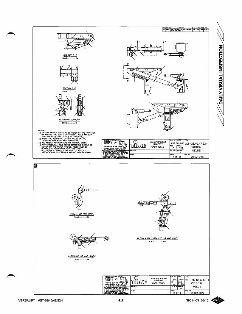
SECTION A-A
SCAIX 1.5X
nscale 2X
PLATFORM SUPPORT
NOTES:
1.) CRITICAL WELDED JOINTS TO BE tN$PECT£0 ARE tNDlCATEOBY ARROWS. THE JOINTS MAY (NCLUOE WELOS ON BOTHSIDES OR INSIDE AND OUTSIDE AS APPUCA8t£.
2.) THERE ARE ADDITIONAL CRITICAL WELDS ON THEMOUNTING HARDWARE AND OUTRIGGERS.
3.) ALL MCLCED RN RETAINERS ARE CRITICAL WELDS.4.) ANY STRUCTURAL WELD FOUND DEFFXCTlVE SHOULD BE
CORRECTED AND NEVER IGNORED. W€LOS MUST BEREPAIRED IN ACCORDANCE WITH ANSI A92.2
REQUIREMENTS. CONSULT FACTORY FOR MATERIALSPECIFICATIONS AND PROPER WELDING SPEOHCATIONS.
UANUAL JB AND WINCH
/
\
UYDRAUUC JB AND MNCH
VERSALIFT VST-36/40/47/52-l
:5x i
UAO«NCO SURTACe RfaSHCS-MOjccncM or vcws ®
• OMCKSOKS ARE IN INCMCS
yACKNCD SURTACe tpftOjcciaON or vce*s _ _oa. o»o<aONS a«c in mCMtz
6-5
Wt MOCO MACUUIO HTO M MO
MANUFACTURINGCOMPANY
WACO TEXAS
<^5iehz3
oiiH at tt»tt
LBR 12-I«-0?
csr WT I UAKUAl
SHC£t
t OF 2
ARTICULATED HYDRAULIC JiB AND mNCH
SCALE. 2.67X
T&Ddo»N. ar OAIt
LBR IM8-o;
SXCI
2 OF 2
mix
VST-36,40.47.52-1
CRITICAL
WELDS
21962-DWG
mi£
VST-36.40.47,52-CRITICAL
WELDS
21962-DWC
39014-03 06/16
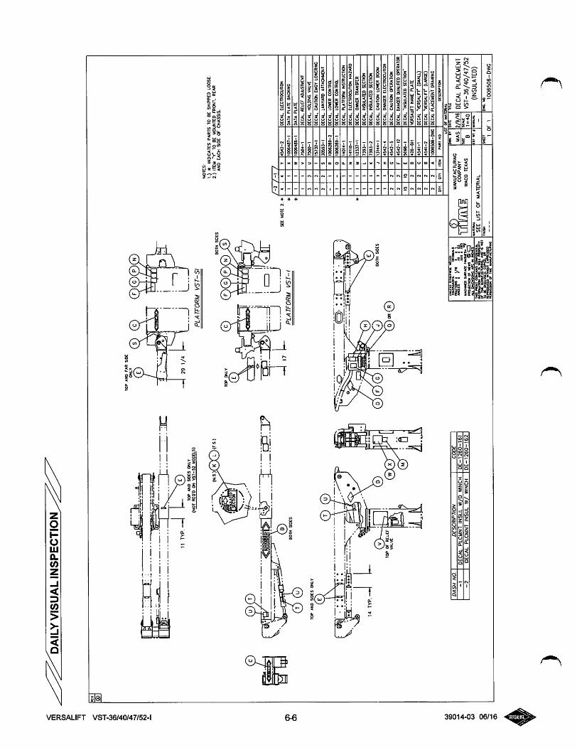
I,^
^^^D
AIL
YVI
SUAL
INSP
ECTI
ON
§ s
)
rm
"<
Vir
-—
TO
PA
ND
SlO
eS
ON
LY
E
14
TY
P
nT
YP
BO
TH
SID
ES
TO
PO
FR
EU
EF
VA
LV
E
lOP
AN
DS
IDE
SO
Nli
r
(NO
TR
EQ
'DO
NV
ST
-S;
MO
DE
LS)
(N.S
)K
IL
)(F
S.)
m
DA
SH
NO
.D
ES
CR
tPT
/ON
CO
D€
-1
DE
CA
LPL
CM
NT
INSU
LV
//0
WIN
CH
DE
-12
60
-16
1
-2
DE
CA
LPL
CM
NT
INSU
LW
/W
INC
HD
E-1
26
0-1
62
-H
291
/4
TO
PO
NL
Y )
..J
L..
.P
LA
TF
OR
MV
5T
-5I
BO
TH
SID
ES
NO
TE
S:
1.)
*IN
DIC
ATE
SPA
RT
S10
BE
SHIP
PED
LOO
SE-
2.)
ITEM
"Y*
TO
BE
MO
UN
TED
FRO
NT.
REA
RA
ND
EA
CH
SID
EO
fC
HA
SS
IS.
I1
IP
LA
JFO
Rh
AV
ST
-\
BO
TH
SiD
CS
uw
uii
Hti
lib
TC
UR
AN
CC
S:
OC
CM
sasir1
s.
AM
D<
SN
OT
Ww
iigSO
N^G
f"T
M
7T
44
Y4
54
2-2
DE
CA
L.E
LEC
THO
CU
TIO
N
11
X1
00
64
87
-1D
AT
AP
LA
TE
BA
CK
ING
11
w1
00
64
86
-1D
AT
APL
AT
E
11
V7
58
4-1
DE
CA
L,R
EL
IEF
AD
JUST
MEN
T
33
u7
50
0-1
DE
CA
L,H
OLD
ING
VA
LVE
33
T1
57
32
-1O
EC
AL
.CA
UTI
ON
EM
CY
LOW
ERIN
G
72
S3
05
93
-1D
EC
AL
.LA
NY
AR
DA
TTA
CH
MEN
T
-1
R1
00
62
89
-2D
EC
AL
.L
OW
ER
CO
NT
RO
L
I0
10
06
28
9-1
DE
CA
L.
LO
WtR
CO
NT
RO
L
I1
P1
40
14
-1D
EC
AL
.PLA
TFO
RM
INST
RU
CTI
ON
11
N1
41
10
-1D
EC
AL
.E
LE
CT
RO
CU
TIO
NH
AZ
AR
D
)1
M1
23
37
-1K
CA
L.
OW
NE
RT
RA
NSF
ER
1t
L7
39
3-1
KC
AU
INSU
LATE
DSE
CT
ION
1t
K7
39
3-2
DE
CA
UIN
SULA
TED
SEC
TIO
N
11
J1
31
44
-1D
EC
AL
.C
AU
TIO
NLO
HIC
RB
OO
M
1}
H4
54
2-4
DE
CA
L.
DA
NG
ER
EL
EC
TR
OC
UT
ION
22
c4
54
2-5
DE
CA
L.C
AU
TIO
NO
PER
AT
ION
22
F4
54
2-1
2D
EC
AL
.DA
NC
ER
OU
AL
IRE
DO
PER
AT
OR
15IS
C5
09
8-1
DEC
AL.
"IN
SULA
TED
SEC
TIO
N"
22
D4
26
-01
1V
ER
SAU
FTN
AM
EPL
AT
E
22
C4
54
1-1
DECA
L"V
ERSA
LlFr
(SM
ALL
)
22
e4
54
1-2
DECA
L'V
ER
SAL
lFr(
LARG
E)
22
A1
00
65
06
-DW
GD
EC
AL
PLA
CE
ME
NT
DR
AW
ING
OIY
QT
riT
tMP
AR
TN
OD
CS
CR
tPn
ON
US
To
rk
lAT
IRlA
L
0}
MANU
FACT
URIN
GV
rl'i
riT
Yl
UU
LA
J\V
RW
ACO
TEX
AS
SiM
.bV
MA
S
Wt£
2/9/
16
tlll
E
DE
CA
LP
LA
CE
ME
NT
VS
T-3
6/40
/47/
52(IN
SULA
TED)
an
B5
CA
iC
1=
40
•u
ltn
u.
SE
EL
IST
OF
mate
ria
ltS
T«
1U
MU
AL
HN
ISH
sx
ti 1
OF
1
D«
C.
NO 1
00
65
06
-DW
G
Related Documents


![Operator's manual for truck, platform utility, 1/2 ton, 4 x … Operator's manual for truck, platform utility, 1/2 ton, 4 x 4, M274A2, [2320-074-1167], M274A3, [2320-782-5792], M274A4,](https://static.cupdf.com/doc/110x72/5b23ea6e7f8b9a25128b49f0/operators-manual-for-truck-platform-utility-12-ton-4-x-operators-manual-for.jpg)