SELF-PROPELLED SCISSOR LIFTS OPERATOR’S MANUAL with Maintenance Information S06-HAE/ACE S0608-HAE/ACE S0808-HAE/ACE S0812-HAE/ACE S1012-HAE/ACE S1212-HAE/ACE S1412-HAE/ACE (Hydraulic Motor Drive / Electric Motor Drive) Part Number: SM0120117A_Rev1.2 Zhejiang Dingli Machinery Co., Ltd. First Edition, July 2021 Printing WARNING THE MANUFACTURER SHALL NOT BE HELD LIABLE IN CASE OF FAULTS OR ACCIDENTS DUE TO NEGLIGENCE, INCAPACITY, INSTALLATION BY UNQUALIFIED TECHNICIANS AND IMPROPER USE OF THE MACHINE DO NOT OPERATE THIS MACHINE UNTIL YOU READ AND UNDERSTAND ALL THE DANGERS,WARNINGS AND CAUTIONS IN THIS MANUAL

Welcome message from author
This document is posted to help you gain knowledge. Please leave a comment to let me know what you think about it! Share it to your friends and learn new things together.
Transcript
SELF-PROPELLED SCISSOR LIFTS
OPERATOR’S MANUALwith Maintenance Information
S06-HAE/ACE S0608-HAE/ACE S0808-HAE/ACE S0812-HAE/ACE
S1012-HAE/ACE S1212-HAE/ACE S1412-HAE/ACE
(Hydraulic Motor Drive / Electric Motor Drive)
Part Number: SM0120117A_Rev1.2
Zhejiang Dingli Machinery Co., Ltd. First Edition, July 2021 Printing
WARNINGTHE MANUFACTURER SHALL NOT BE HELD LIABLE IN CASE OF FAULTSOR ACCIDENTS DUE TO NEGLIGENCE, INCAPACITY, INSTALLATION BYUNQUALIFIED TECHNICIANS AND IMPROPER USE OF THE MACHINE
DO NOT OPERATE THIS MACHINE UNTIL YOU READ AND UNDERSTANDALL THE DANGERS,WARNINGS AND CAUTIONS IN THIS MANUAL

OPERATOR’S MANUAL with Maintenance Information
Version of the Record
i
Version of the RecordVersion Number Create Date
SM0120117A_Rev1.0 ………………………………………………………………………… 2021-03
SM0120117A_Rev1.1 ………………………………………………………………………… 2021-04
SM0120117A_Rev1.2 ………………………………………………………………………… 2021-07

OPERATOR’S MANUAL with Maintenance Information
i
ImportantRead, understand and obey these safety rulesand operating instructions before operatingthis machine.
Only trained and authorized personnel shall bepermitted to operate this machine. Thismanual should be considered a permanentpart of your machine and should remain withthe machine at all times. If you have anyquestions, please call DINGLI Machinery.
ContentsPage
Safety Rules 1
Legend 10
Decals 11
Specifications 19
Control panel 35
Pre-operation Inspection 38
Workplace Inspection 40
Function Tests 41
Operating Instructions 46
Transport and Lifting Instructions 60
Storage 64
Maintenance 66
Schematic 89
Inspection and Repair Log 103
Owners, Users and operators:We appreciate your choice of our machine foryour application. Our number one priority isuser safety, which is best achieved by our jointefforts. We feel that you make a majorcontribution to safety if you, as the equipmentusers and operators:
1 Comply with employer, job site andgovernmental rules.
2 Read, understand and follow theinstructions in this and other manualssupplied with this machine.
3 Use good safe work practices in acommonsense way.
4 Only have trained / certified operators,directed by informed and knowledgeablesupervision, running the machine.
If there is anything in this manual that is notclear or which you believe should be added,please contact us.
Contact us:
Zhejiang Dingli Machinery Co., Ltd.
1255 Baiyun South Road. Leidian Town.Deqing Zhejiang
China
Tel: +86-572-8681688
Fax: +86-572-8681690
Web: www.cndingli.com
E-mail:[email protected]

OPERATOR’S MANUAL with Maintenance Information
Safety Rules
1
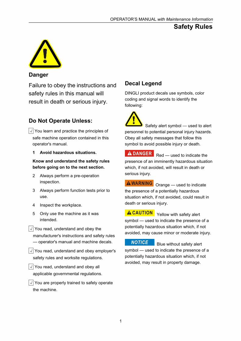
Danger
Failure to obey the instructions andsafety rules in this manual willresult in death or serious injury.
Do Not Operate Unless:√ You learn and practice the principles of
safe machine operation contained in thisoperator's manual.
1 Avoid hazardous situations.
Know and understand the safety rulesbefore going on to the next section.
2 Always perform a pre-operationinspection.
3 Always perform function tests prior touse.
4 Inspect the workplace.
5 Only use the machine as it wasintended.
√ You read, understand and obey themanufacturer's instructions and safety rules— operator's manual and machine decals.
√ You read, understand and obey employer'ssafety rules and worksite regulations.
√ You read, understand and obey allapplicable governmental regulations.
√ You are properly trained to safely operatethe machine.
Decal LegendDINGLI product decals use symbols, colorcoding and signal words to identify thefollowing:
Safety alert symbol — used to alertpersonnel to potential personal injury hazards.Obey all safety messages that follow thissymbol to avoid possible injury or death.
Red — used to indicate thepresence of an imminently hazardous situationwhich, if not avoided, will result in death orserious injury.
Orange — used to indicatethe presence of a potentially hazardoussituation which, if not avoided, could result indeath or serious injury.
Yellow with safety alertsymbol — used to indicate the presence of apotentially hazardous situation which, if notavoided, may cause minor or moderate injury.
Blue without safety alertsymbol — used to indicate the presence of apotentially hazardous situation which, if notavoided, may result in property damage.
OPERATOR’S MANUAL with Maintenance Information
Safety Rules
2
The relevant conditions of usingthe equipmentThe surface of work ground should be flat andhard with no obstacles in air and the safetydistance between the equipment andhigh-tension line is adequate.
The environment temperature should be within-20℃~40℃; Height above sea level ≤1000m.
The environment humidity ≤ 90%.
Electrical power: AC 110~230V±10%,50~60Hz.
Intended UseThis machine is intended to be used only to liftpersonnel, along with their tools and materialsto an aerial work site.
Safety Sign MaintenanceReplace any missing or damaged safety signs.Keep operator safety in mind at all times.
Use mild soap and water to clean safety signs.
Do not use solvent-based cleaners becausethey may damage the safety sign material.
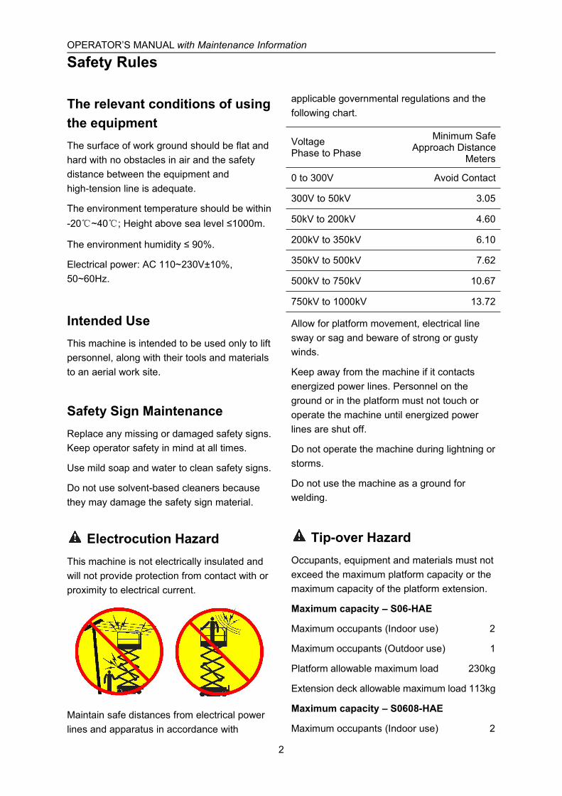
Electrocution HazardThis machine is not electrically insulated andwill not provide protection from contact with orproximity to electrical current.
Maintain safe distances from electrical powerlines and apparatus in accordance with
applicable governmental regulations and thefollowing chart.
VoltagePhase to Phase
Minimum SafeApproach Distance
Meters
0 to 300V Avoid Contact
300V to 50kV 3.05
50kV to 200kV 4.60
200kV to 350kV 6.10
350kV to 500kV 7.62
500kV to 750kV 10.67
750kV to 1000kV 13.72
Allow for platform movement, electrical linesway or sag and beware of strong or gustywinds.
Keep away from the machine if it contactsenergized power lines. Personnel on theground or in the platform must not touch oroperate the machine until energized powerlines are shut off.
Do not operate the machine during lightning orstorms.
Do not use the machine as a ground forwelding.
Tip-over HazardOccupants, equipment and materials must notexceed the maximum platform capacity or themaximum capacity of the platform extension.
Maximum capacity – S06-HAE
Maximum occupants (Indoor use) 2
Maximum occupants (Outdoor use) 1
Platform allowable maximum load 230kg
Extension deck allowable maximum load 113kg
Maximum capacity – S0608-HAE
Maximum occupants (Indoor use) 2

OPERATOR’S MANUAL with Maintenance Information
Safety Rules
3
Maximum occupants (Outdoor use) 1
Platform allowable maximum load 380kg
Extension deck allowable maximum load 113kg
Maximum capacity – S0808-HAE
Maximum occupants (Indoor use ONLY) 2
Platform allowable maximum load 230kg
Extension deck allowable maximum load 113kg
Maximum capacity – S0812-HAE
Maximum occupants (Indoor / Outdoor use) 2
Platform allowable maximum load 450kg
Extension deck allowable maximum load 113kg
Maximum capacity – S1012-HAE
Maximum occupants (Indoor use) 2
Maximum occupants (Outdoor use) 1
Platform allowable maximum load 320kg
Extension deck allowable maximum load 113kg
Maximum capacity – S1212-HAE
Maximum occupants (Indoor use ONLY) 3
Platform allowable maximum load 320kg
Extension deck allowable maximum load 113kg
Maximum capacity – S1412-HAE
Maximum occupants (Indoor use ONLY) 2
Platform allowable maximum load 250kg
Extension deck allowable maximum load 113kg
Maximum capacity – S06-ACE
Maximum occupants (Indoor use) 2
Maximum occupants (Outdoor use) 1
Platform allowable maximum load 230kg
Extension deck allowable maximum load 113kg
Maximum capacity – S0608-ACE
Maximum occupants (Indoor use) 2
Maximum occupants (Outdoor use) 1
Platform allowable maximum load 380kg
Extension deck allowable maximum load 113kg
Maximum capacity – S0808-ACE
Maximum occupants (Indoor use ONLY) 2
Platform allowable maximum load 230kg
Extension deck allowable maximum load 113kg
Maximum capacity – S0812-ACE
Maximum occupants (Indoor/Outdoor use) 2
Platform allowable maximum load 450kg
Extension deck allowable maximum load 113kg
Maximum capacity – S1012-ACE
Maximum occupants (Indoor use) 2
Maximum occupants (Outdoor use) 1
Platform allowable maximum load 320kg
Extension deck allowable maximum load 113kg
Maximum capacity – S1212-ACE
Maximum occupants (Indoor use ONLY) 3
Platform allowable maximum load 320kg
Extension deck allowable maximum load 113kg
Maximum capacity – S1412-ACE
Maximum occupants (Indoor use ONLY) 2
Platform allowable maximum load 250kg
Extension deck allowable maximum load 113kg
Platform retracted Platform extended
Extension Platformonly only
Work Area SafetyDo not raise the platform unless the machineis on a firm, level surface.
OPERATOR’S MANUAL with Maintenance Information
Safety Rules
4
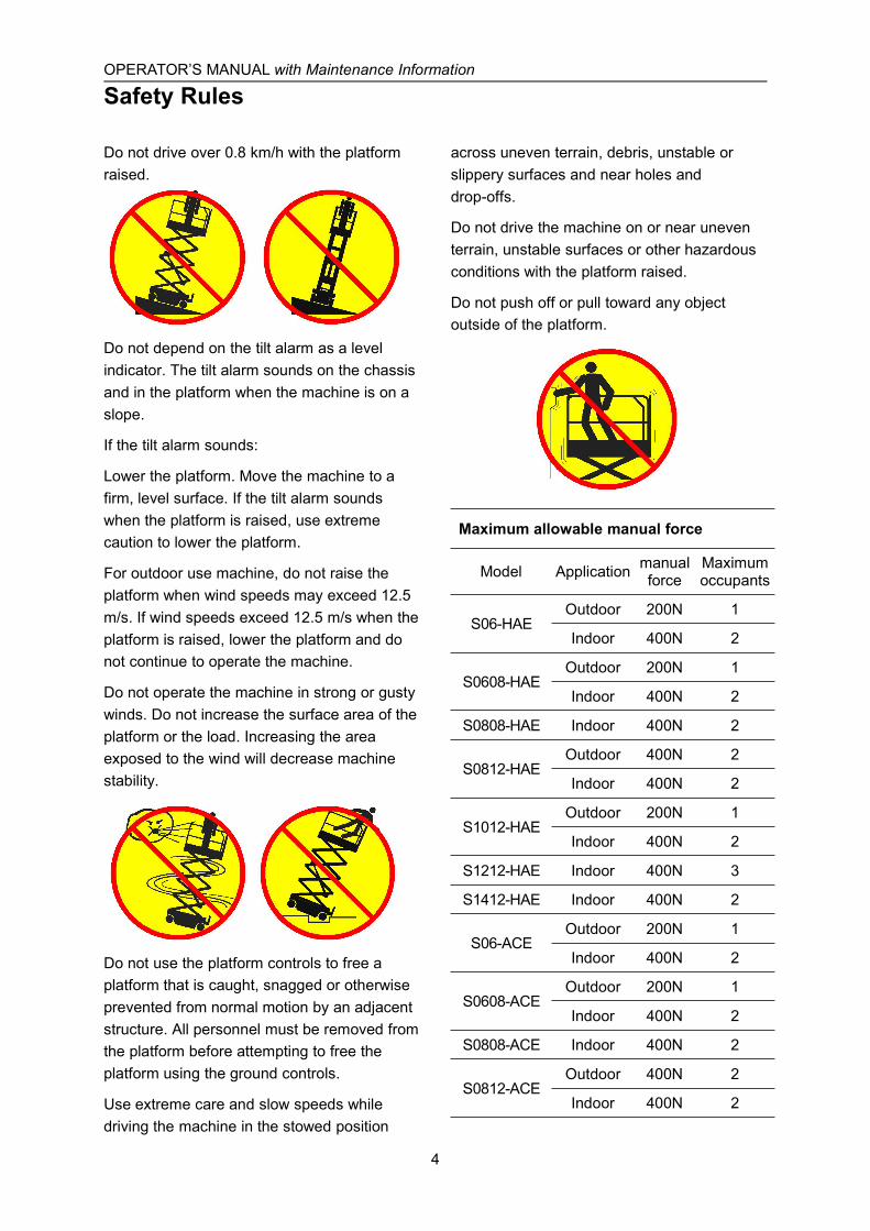
Do not drive over 0.8 km/h with the platformraised.
Do not depend on the tilt alarm as a levelindicator. The tilt alarm sounds on the chassisand in the platform when the machine is on aslope.
If the tilt alarm sounds:
Lower the platform. Move the machine to afirm, level surface. If the tilt alarm soundswhen the platform is raised, use extremecaution to lower the platform.
For outdoor use machine, do not raise theplatform when wind speeds may exceed 12.5m/s. If wind speeds exceed 12.5 m/s when theplatform is raised, lower the platform and donot continue to operate the machine.
Do not operate the machine in strong or gustywinds. Do not increase the surface area of theplatform or the load. Increasing the areaexposed to the wind will decrease machinestability.
Do not use the platform controls to free aplatform that is caught, snagged or otherwiseprevented from normal motion by an adjacentstructure. All personnel must be removed fromthe platform before attempting to free theplatform using the ground controls.
Use extreme care and slow speeds whiledriving the machine in the stowed position
across uneven terrain, debris, unstable orslippery surfaces and near holes anddrop-offs.
Do not drive the machine on or near uneventerrain, unstable surfaces or other hazardousconditions with the platform raised.
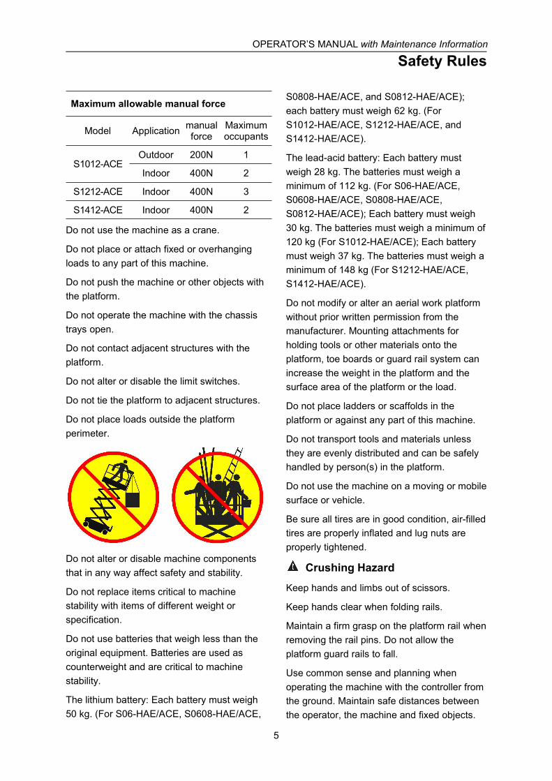
Do not push off or pull toward any objectoutside of the platform.
Maximum allowable manual force
Model Application manualforce
Maximumoccupants
S06-HAEOutdoor 200N 1
Indoor 400N 2
S0608-HAEOutdoor 200N 1
Indoor 400N 2
S0808-HAE Indoor 400N 2
S0812-HAEOutdoor 400N 2
Indoor 400N 2
S1012-HAEOutdoor 200N 1
Indoor 400N 2
S1212-HAE Indoor 400N 3
S1412-HAE Indoor 400N 2
S06-ACEOutdoor 200N 1
Indoor 400N 2
S0608-ACEOutdoor 200N 1
Indoor 400N 2
S0808-ACE Indoor 400N 2
S0812-ACEOutdoor 400N 2
Indoor 400N 2
OPERATOR’S MANUAL with Maintenance Information
Safety Rules
5
Maximum allowable manual force
Model Application manualforce
Maximumoccupants
S1012-ACEOutdoor 200N 1
Indoor 400N 2
S1212-ACE Indoor 400N 3
S1412-ACE Indoor 400N 2
Do not use the machine as a crane.
Do not place or attach fixed or overhangingloads to any part of this machine.
Do not push the machine or other objects withthe platform.
Do not operate the machine with the chassistrays open.
Do not contact adjacent structures with theplatform.
Do not alter or disable the limit switches.
Do not tie the platform to adjacent structures.
Do not place loads outside the platformperimeter.
Do not alter or disable machine componentsthat in any way affect safety and stability.
Do not replace items critical to machinestability with items of different weight orspecification.
Do not use batteries that weigh less than theoriginal equipment. Batteries are used ascounterweight and are critical to machinestability.
The lithium battery: Each battery must weigh50 kg. (For S06-HAE/ACE, S0608-HAE/ACE,
S0808-HAE/ACE, and S0812-HAE/ACE);each battery must weigh 62 kg. (ForS1012-HAE/ACE, S1212-HAE/ACE, andS1412-HAE/ACE).
The lead-acid battery: Each battery mustweigh 28 kg. The batteries must weigh aminimum of 112 kg. (For S06-HAE/ACE,S0608-HAE/ACE, S0808-HAE/ACE,S0812-HAE/ACE); Each battery must weigh30 kg. The batteries must weigh a minimum of120 kg (For S1012-HAE/ACE); Each batterymust weigh 37 kg. The batteries must weigh aminimum of 148 kg (For S1212-HAE/ACE,S1412-HAE/ACE).
Do not modify or alter an aerial work platformwithout prior written permission from themanufacturer. Mounting attachments forholding tools or other materials onto theplatform, toe boards or guard rail system canincrease the weight in the platform and thesurface area of the platform or the load.
Do not place ladders or scaffolds in theplatform or against any part of this machine.
Do not transport tools and materials unlessthey are evenly distributed and can be safelyhandled by person(s) in the platform.
Do not use the machine on a moving or mobilesurface or vehicle.
Be sure all tires are in good condition, air-filledtires are properly inflated and lug nuts areproperly tightened.
Crushing Hazard
Keep hands and limbs out of scissors.
Keep hands clear when folding rails.
Maintain a firm grasp on the platform rail whenremoving the rail pins. Do not allow theplatform guard rails to fall.
Use common sense and planning whenoperating the machine with the controller fromthe ground. Maintain safe distances betweenthe operator, the machine and fixed objects.
OPERATOR’S MANUAL with Maintenance Information
Safety Rules
6
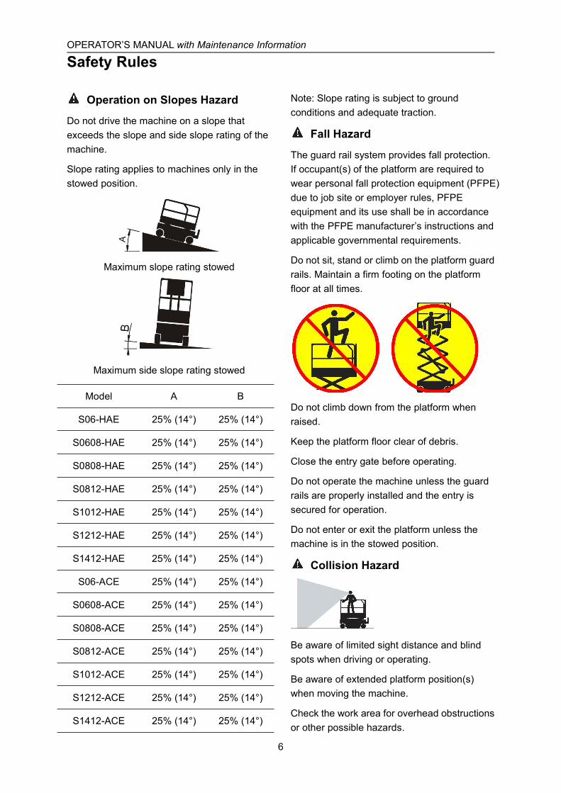
Operation on Slopes Hazard
Do not drive the machine on a slope thatexceeds the slope and side slope rating of themachine.
Slope rating applies to machines only in thestowed position.
Maximum slope rating stowed
Maximum side slope rating stowed
Model A B
S06-HAE 25% (14°) 25% (14°)
S0608-HAE 25% (14°) 25% (14°)
S0808-HAE 25% (14°) 25% (14°)
S0812-HAE 25% (14°) 25% (14°)
S1012-HAE 25% (14°) 25% (14°)
S1212-HAE 25% (14°) 25% (14°)
S1412-HAE 25% (14°) 25% (14°)
S06-ACE 25% (14°) 25% (14°)
S0608-ACE 25% (14°) 25% (14°)
S0808-ACE 25% (14°) 25% (14°)
S0812-ACE 25% (14°) 25% (14°)
S1012-ACE 25% (14°) 25% (14°)
S1212-ACE 25% (14°) 25% (14°)
S1412-ACE 25% (14°) 25% (14°)
Note: Slope rating is subject to groundconditions and adequate traction.
Fall Hazard
The guard rail system provides fall protection.If occupant(s) of the platform are required towear personal fall protection equipment (PFPE)due to job site or employer rules, PFPEequipment and its use shall be in accordancewith the PFPE manufacturer’s instructions andapplicable governmental requirements.
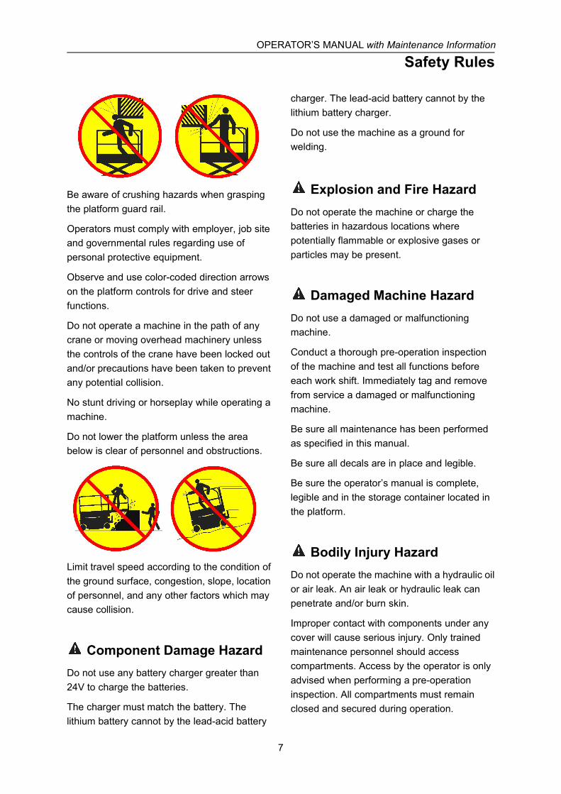
Do not sit, stand or climb on the platform guardrails. Maintain a firm footing on the platformfloor at all times.
Do not climb down from the platform whenraised.
Keep the platform floor clear of debris.
Close the entry gate before operating.
Do not operate the machine unless the guardrails are properly installed and the entry issecured for operation.
Do not enter or exit the platform unless themachine is in the stowed position.
Collision Hazard
Be aware of limited sight distance and blindspots when driving or operating.
Be aware of extended platform position(s)when moving the machine.
Check the work area for overhead obstructionsor other possible hazards.
OPERATOR’S MANUAL with Maintenance Information
Safety Rules
7
Be aware of crushing hazards when graspingthe platform guard rail.
Operators must comply with employer, job siteand governmental rules regarding use ofpersonal protective equipment.
Observe and use color-coded direction arrowson the platform controls for drive and steerfunctions.
Do not operate a machine in the path of anycrane or moving overhead machinery unlessthe controls of the crane have been locked outand/or precautions have been taken to preventany potential collision.
No stunt driving or horseplay while operating amachine.
Do not lower the platform unless the areabelow is clear of personnel and obstructions.
Limit travel speed according to the condition ofthe ground surface, congestion, slope, locationof personnel, and any other factors which maycause collision.
Component Damage HazardDo not use any battery charger greater than24V to charge the batteries.
The charger must match the battery. Thelithium battery cannot by the lead-acid battery
charger. The lead-acid battery cannot by thelithium battery charger.
Do not use the machine as a ground forwelding.
Explosion and Fire HazardDo not operate the machine or charge thebatteries in hazardous locations wherepotentially flammable or explosive gases orparticles may be present.
Damaged Machine HazardDo not use a damaged or malfunctioningmachine.
Conduct a thorough pre-operation inspectionof the machine and test all functions beforeeach work shift. Immediately tag and removefrom service a damaged or malfunctioningmachine.
Be sure all maintenance has been performedas specified in this manual.
Be sure all decals are in place and legible.
Be sure the operator’s manual is complete,legible and in the storage container located inthe platform.
Bodily Injury HazardDo not operate the machine with a hydraulic oilor air leak. An air leak or hydraulic leak canpenetrate and/or burn skin.
Improper contact with components under anycover will cause serious injury. Only trainedmaintenance personnel should accesscompartments. Access by the operator is onlyadvised when performing a pre-operationinspection. All compartments must remainclosed and secured during operation.
OPERATOR’S MANUAL with Maintenance Information
Safety Rules
8
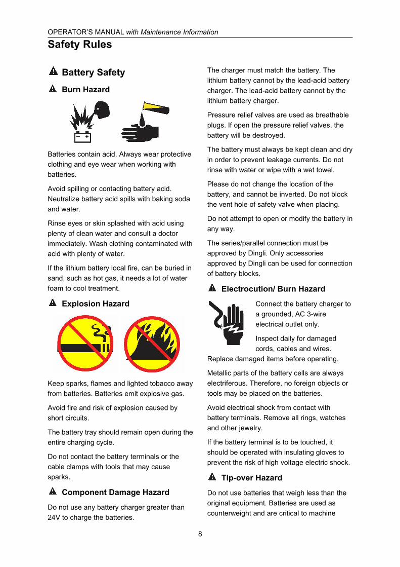
Battery Safety
Burn Hazard
Batteries contain acid. Always wear protectiveclothing and eye wear when working withbatteries.
Avoid spilling or contacting battery acid.Neutralize battery acid spills with baking sodaand water.
Rinse eyes or skin splashed with acid usingplenty of clean water and consult a doctorimmediately. Wash clothing contaminated withacid with plenty of water.
If the lithium battery local fire, can be buried insand, such as hot gas, it needs a lot of waterfoam to cool treatment.
Explosion Hazard
Keep sparks, flames and lighted tobacco awayfrom batteries. Batteries emit explosive gas.
Avoid fire and risk of explosion caused byshort circuits.
The battery tray should remain open during theentire charging cycle.
Do not contact the battery terminals or thecable clamps with tools that may causesparks.
Component Damage Hazard
Do not use any battery charger greater than24V to charge the batteries.
The charger must match the battery. Thelithium battery cannot by the lead-acid batterycharger. The lead-acid battery cannot by thelithium battery charger.
Pressure relief valves are used as breathableplugs. If open the pressure relief valves, thebattery will be destroyed.
The battery must always be kept clean and dryin order to prevent leakage currents. Do notrinse with water or wipe with a wet towel.
Please do not change the location of thebattery, and cannot be inverted. Do not blockthe vent hole of safety valve when placing.
Do not attempt to open or modify the battery inany way.
The series/parallel connection must beapproved by Dingli. Only accessoriesapproved by Dingli can be used for connectionof battery blocks.
Electrocution/ Burn Hazard
Connect the battery charger toa grounded, AC 3-wireelectrical outlet only.
Inspect daily for damagedcords, cables and wires.
Replace damaged items before operating.
Metallic parts of the battery cells are alwayselectriferous. Therefore, no foreign objects ortools may be placed on the batteries.
Avoid electrical shock from contact withbattery terminals. Remove all rings, watchesand other jewelry.
If the battery terminal is to be touched, itshould be operated with insulating gloves toprevent the risk of high voltage electric shock.
Tip-over Hazard
Do not use batteries that weigh less than theoriginal equipment. Batteries are used ascounterweight and are critical to machine
OPERATOR’S MANUAL with Maintenance Information
Safety Rules
9
stability.
The lithium battery: The battery must weigh aminimum of 50 kg. (For S06-HAE/ACE,S0608-HAE/ACE, S0808-HAE/ACE, andS0812-HAE/ACE); The battery must weigh aminimum of 62 kg. (For S1012-HAE/ACE,S1212-HAE/ACE, and S1412-HAE/ACE).
The lead-acid battery: Each battery mustweigh 28 kg. The batteries must weigh aminimum of 112 kg. (For S06-HAE/ACE,S0608-HAE/ACE, S0808-HAE/ACE,S0812-HAE/ACE); Each battery must weigh30 kg. The batteries must weigh a minimum of120 kg (For S1012-HAE/ACE); Each batterymust weigh 37 kg. The batteries must weigh aminimum of 148 kg (For S1212-HAE/ACE,S1412-HAE/ACE).
Lifting Hazard
Use the appropriate number of people andproper lifting techniques when lifting hooksmust not cause any damage to cells,connectors and connecting cables.
The lithium battery shall be operated smoothlyin the process of handling and assembly, andcollision and other impact phenomena arestrictly prohibited.
Environmental Hazard
30°C battery temperature is considered therated temperature. Higher temperaturesreduce the service life, while lowertemperatures reduce the availablecapacity.45°C is the upper limit temperatureand is not permissible as an operatingtemperature.
The rated temperature range of lithium batteryis-30℃~55℃.if it is found that thetemperature of the battery exceeds 60℃during use, the battery should be stoppedimmediately and put aside separately.
Batteries must not be exposed to sunlightwithout protection.
Transportation and storageHazard
Charge the battery as soon as receive themachine or after long distance transportation
When the battery is stored for a long time, itneeds to be charged regularly. Failure tocharge in time may permanently damage thebattery.
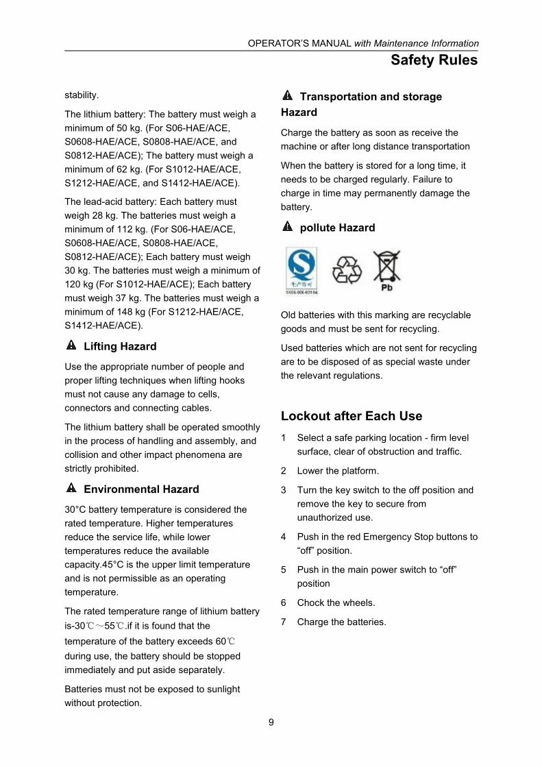
pollute Hazard
Old batteries with this marking are recyclablegoods and must be sent for recycling.
Used batteries which are not sent for recyclingare to be disposed of as special waste underthe relevant regulations.
Lockout after Each Use1 Select a safe parking location - firm level
surface, clear of obstruction and traffic.
2 Lower the platform.
3 Turn the key switch to the off position andremove the key to secure fromunauthorized use.
4 Push in the red Emergency Stop buttons to“off” position.
5 Push in the main power switch to “off”position
6 Chock the wheels.
7 Charge the batteries.

OPERATOR’S MANUAL with Maintenance Information
Legend
10
Legend
1 Platform extension
2 Manual storage container
3 Platform control
4 Lanyard anchorage point
5 Platform guard rails
6 Platform extension release pedal
7 Main platform
8 Platform entry gate
9 Scissor arms
10 Lift cylinder
11 Ground controls (on opposite side ofmachine)
12 Entry ladder
13 Brake release pump
14 Non-steer tire
15 Battery charger
16 Pothole guard
17 Steer tire
18 Safety arm
12 3
4
5
7
8
9
10
6
18
17
11
12
1314
15
16
OPERATOR’S MANUAL with Maintenance Information
Decals
11
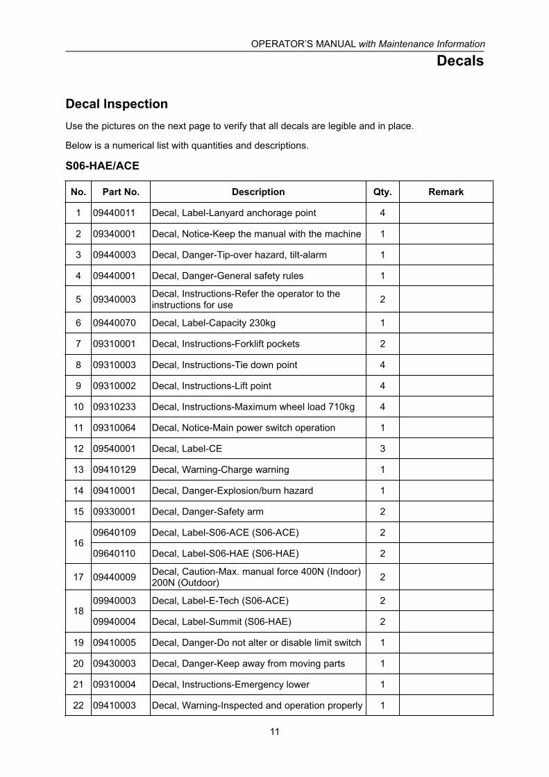
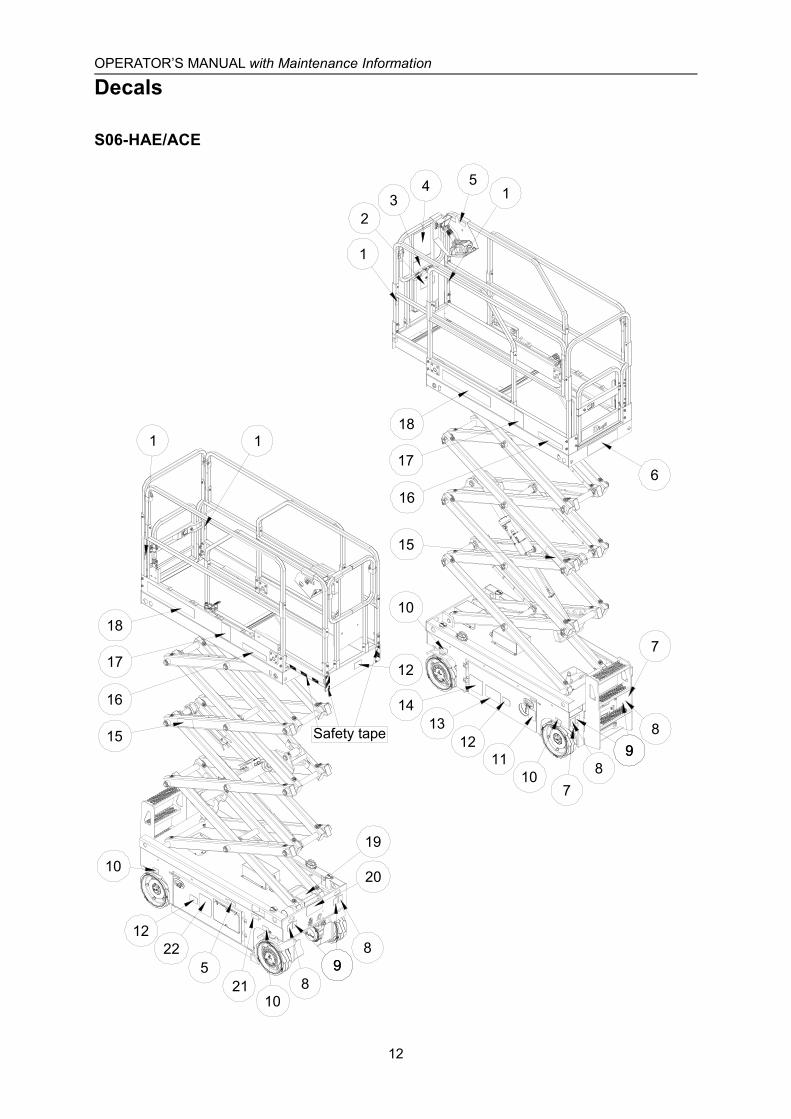
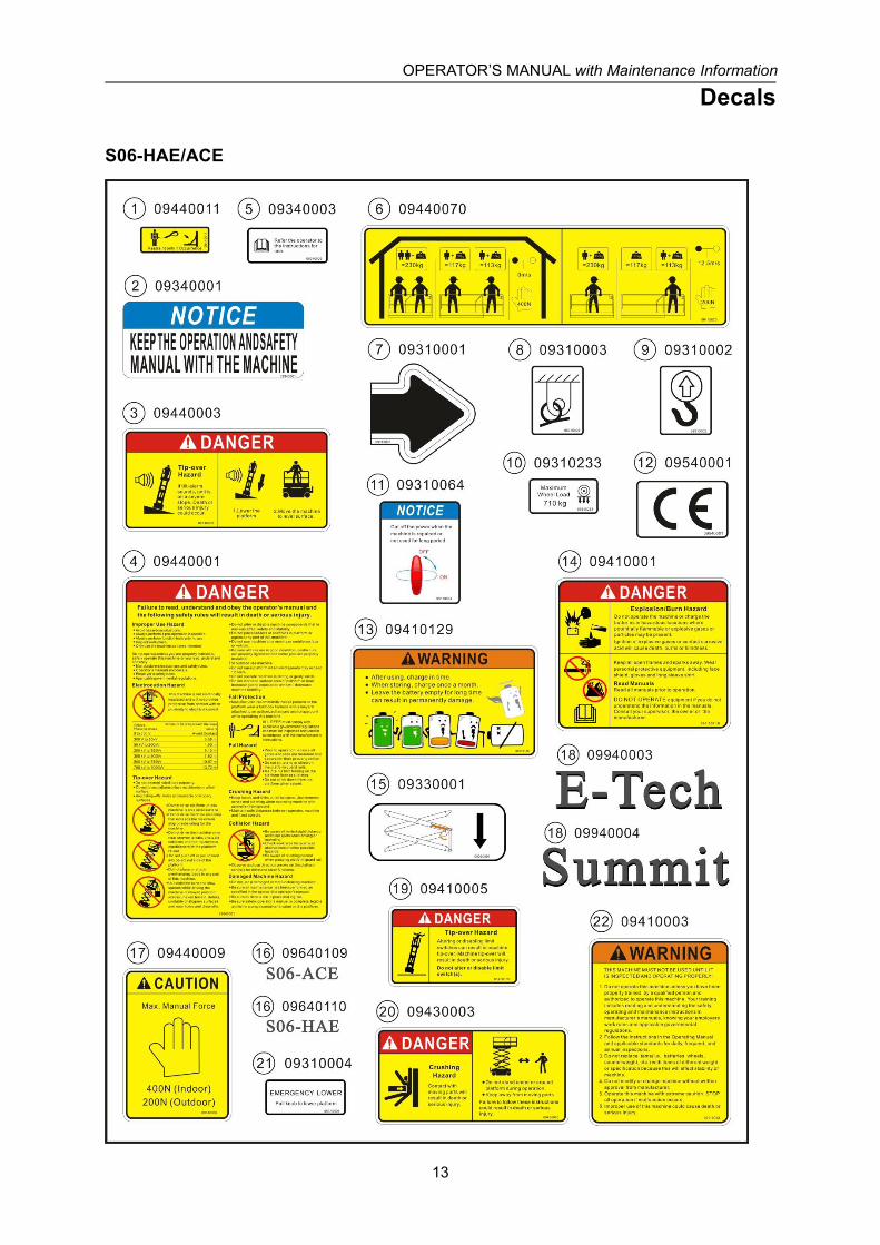
Decal InspectionUse the pictures on the next page to verify that all decals are legible and in place.
Below is a numerical list with quantities and descriptions.
S06-HAE/ACE
No. Part No. Description Qty. Remark
1 09440011 Decal, Label-Lanyard anchorage point 4
2 09340001 Decal, Notice-Keep the manual with the machine 1
3 09440003 Decal, Danger-Tip-over hazard, tilt-alarm 1
4 09440001 Decal, Danger-General safety rules 1
5 09340003 Decal, Instructions-Refer the operator to theinstructions for use 2
6 09440070 Decal, Label-Capacity 230kg 1
7 09310001 Decal, Instructions-Forklift pockets 2
8 09310003 Decal, Instructions-Tie down point 4
9 09310002 Decal, Instructions-Lift point 4
10 09310233 Decal, Instructions-Maximum wheel load 710kg 4
11 09310064 Decal, Notice-Main power switch operation 1
12 09540001 Decal, Label-CE 3
13 09410129 Decal, Warning-Charge warning 1
14 09410001 Decal, Danger-Explosion/burn hazard 1
15 09330001 Decal, Danger-Safety arm 2
1609640109 Decal, Label-S06-ACE (S06-ACE) 2
09640110 Decal, Label-S06-HAE (S06-HAE) 2
17 09440009 Decal, Caution-Max. manual force 400N (Indoor)200N (Outdoor) 2
1809940003 Decal, Label-E-Tech (S06-ACE) 2
09940004 Decal, Label-Summit (S06-HAE) 2
19 09410005 Decal, Danger-Do not alter or disable limit switch 1
20 09430003 Decal, Danger-Keep away from moving parts 1
21 09310004 Decal, Instructions-Emergency lower 1
22 09410003 Decal, Warning-Inspected and operation properly 1
OPERATOR’S MANUAL with Maintenance Information
Decals
12
S06-HAE/ACE
12
1413
10
15
5
12
10
15
6
89
7
19
20
899
810
21
22
15
1
23
4
98
7
1011
17
18
12
Safety tape
17
18
1 1
16
16
OPERATOR’S MANUAL with Maintenance Information
Decals
13
S06-HAE/ACE

OPERATOR’S MANUAL with Maintenance Information
Decals
14
S0608-HAE/ACE~ S1412-HAE/ACE
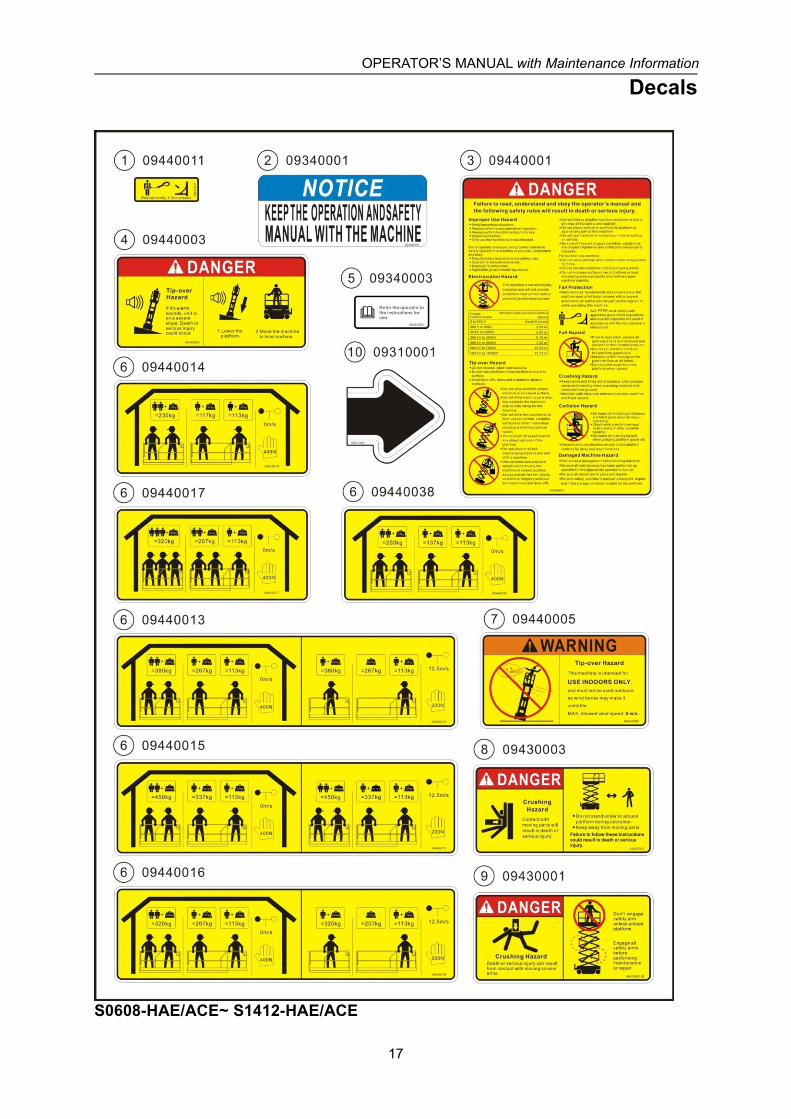
No. Part No. Description Qty. Remark
1 09440011 Decal, Label-Lanyard anchorage point 4
2 09340001 Decal, Notice-Keep the manual with the machine 1
3 09440001 Decal, Danger-General safety rules 1
4 09440003 Decal, Danger-Tip-over hazard, tilt-alarm 1
5 09340003 Decal, Instructions-Refer the operator to theinstructions for use 2
6
09440013 Decal, Label-Capacity 380kg 1 S0608-HAE/ACE
09440014 Decal, Label-Capacity 230kg 1 S0808-HAE/ACE
09440015 Decal, Label-Capacity 450kg 1 S0812-HAE/ACE
09440016 Decal, Label-Capacity 320kg 1 S1012-HAE/ACE
09440017 Decal, Label-Capacity 320kg 1 S1212-HAE/ACE
09440038 Decal, Label-Capacity 250kg 1 S1412-HAE/ACE
7 09440005 Decal, Warning-Use indoors only 1S0808-HAE/ACE,S1212-HAE/ACE,S1412-HAE/ACE
809430003 Decal, Danger-Keep away from moving parts 3
S0608-HAE/ACE,S0808-HAE/ACE,S0812-HAE/ACE,S1012-HAE/ACE
09430003 Decal, Danger-Keep away from moving parts 5 S1212-HAE/ACE,S1412-HAE/ACE
909430001 Decal, Danger-Safety arm 2
S0608-HAE/ACE,S0808-HAE/ACE,S0812-HAE/ACE,S1012-HAE/ACE
09430001 Decal, Danger-Safety arm 4 S1212-HAE/ACE,S1412-HAE/ACE
10 09310001 Decal, Instructions-Forklift pockets 2
11 09310003 Decal, Instructions-Tie down point 4
12 09310002 Decal, Instructions-Lift point 4
1309310008 Decal, Instructions-Maximum wheel load 1000kg 4 S0608-HAE/ACE
09310010 Decal, Instructions-Maximum wheel load 960kg 4 S0808-HAE/ACE
No. Part No. Description Qty. Remark
OPERATOR’S MANUAL with Maintenance Information
Decals
15
S0608-HAE/ACE~ S1412-HAE/ACE
13
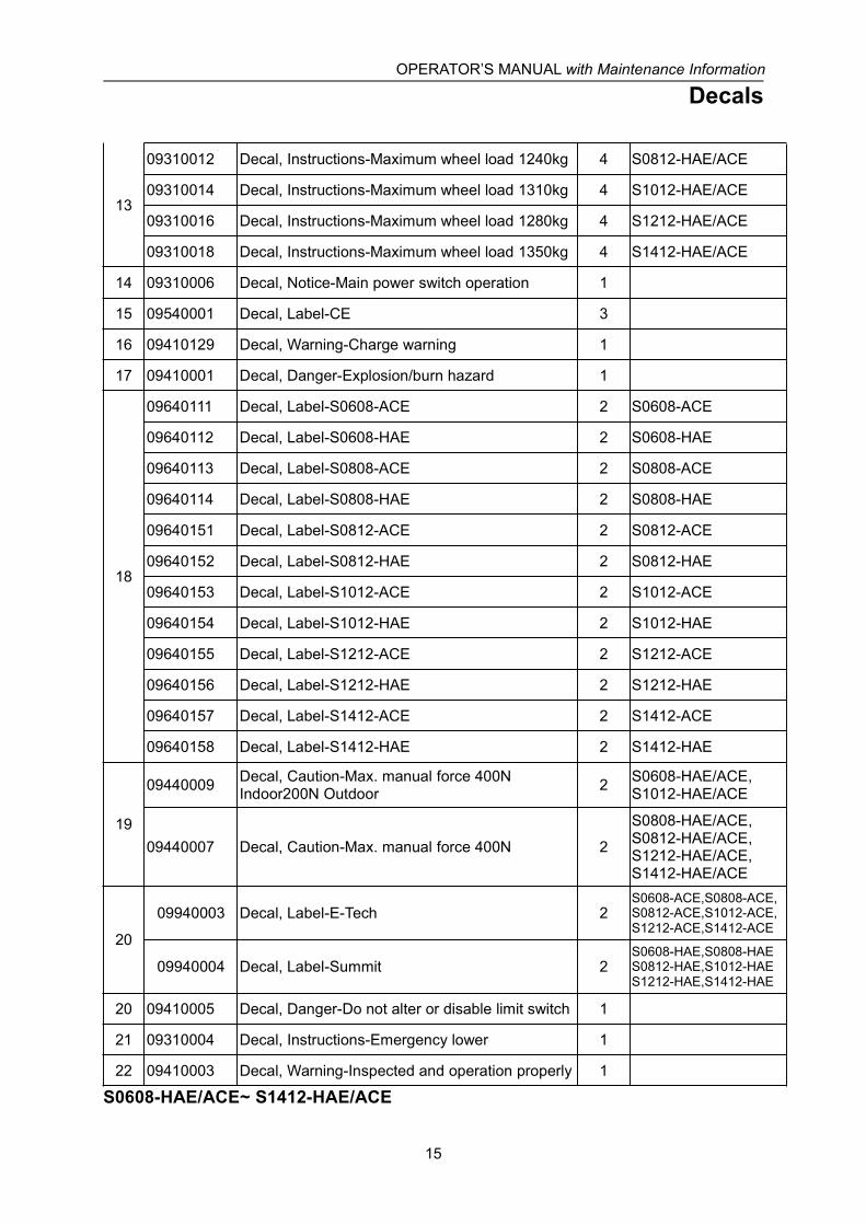
09310012 Decal, Instructions-Maximum wheel load 1240kg 4 S0812-HAE/ACE
09310014 Decal, Instructions-Maximum wheel load 1310kg 4 S1012-HAE/ACE
09310016 Decal, Instructions-Maximum wheel load 1280kg 4 S1212-HAE/ACE
09310018 Decal, Instructions-Maximum wheel load 1350kg 4 S1412-HAE/ACE
14 09310006 Decal, Notice-Main power switch operation 1
15 09540001 Decal, Label-CE 3
16 09410129 Decal, Warning-Charge warning 1
17 09410001 Decal, Danger-Explosion/burn hazard 1
18
09640111 Decal, Label-S0608-ACE 2 S0608-ACE
09640112 Decal, Label-S0608-HAE 2 S0608-HAE
09640113 Decal, Label-S0808-ACE 2 S0808-ACE
09640114 Decal, Label-S0808-HAE 2 S0808-HAE
09640151 Decal, Label-S0812-ACE 2 S0812-ACE
09640152 Decal, Label-S0812-HAE 2 S0812-HAE
09640153 Decal, Label-S1012-ACE 2 S1012-ACE
09640154 Decal, Label-S1012-HAE 2 S1012-HAE
09640155 Decal, Label-S1212-ACE 2 S1212-ACE
09640156 Decal, Label-S1212-HAE 2 S1212-HAE
09640157 Decal, Label-S1412-ACE 2 S1412-ACE
09640158 Decal, Label-S1412-HAE 2 S1412-HAE
19
09440009 Decal, Caution-Max. manual force 400NIndoor200N Outdoor 2 S0608-HAE/ACE,
S1012-HAE/ACE
09440007 Decal, Caution-Max. manual force 400N 2
S0808-HAE/ACE,S0812-HAE/ACE,S1212-HAE/ACE,S1412-HAE/ACE
20
09940003 Decal, Label-E-Tech 2S0608-ACE,S0808-ACE,S0812-ACE,S1012-ACE,S1212-ACE,S1412-ACE
09940004 Decal, Label-Summit 2S0608-HAE,S0808-HAES0812-HAE,S1012-HAES1212-HAE,S1412-HAE
20 09410005 Decal, Danger-Do not alter or disable limit switch 1
21 09310004 Decal, Instructions-Emergency lower 1
22 09410003 Decal, Warning-Inspected and operation properly 1
OPERATOR’S MANUAL with Maintenance Information
Decals
16
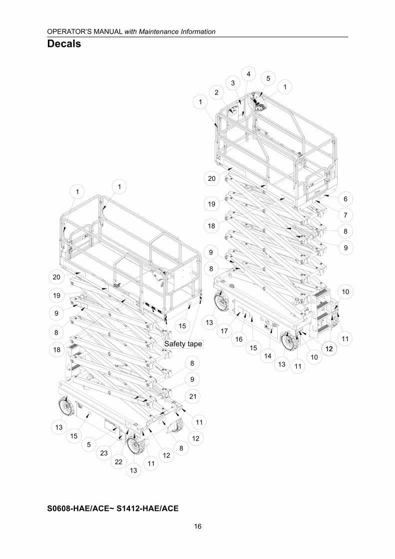
12
15
13
13
5
15
12
34 5
1
11
6
1415
17
8
19
20
13
9
13
19
20
2223
11
12
11
8
9
10
1112
1011
12
8
9
8
9
16
7
21
Safety tape
8
18
18
S0608-HAE/ACE~ S1412-HAE/ACE
OPERATOR’S MANUAL with Maintenance Information
Decals
17
S0608-HAE/ACE~ S1412-HAE/ACE

OPERATOR’S MANUAL with Maintenance Information
Decals
18
OPERATOR’S MANUAL with Maintenance Information
Specifications
19
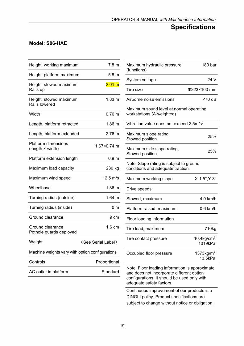
Model: S06-HAE
Height, working maximum 7.8 m
Height, platform maximum 5.8 m
Height, stowed maximumRails up
2.01 m
Height, stowed maximumRails lowered
1.83 m
Width 0.76 m
Length, platform retracted 1.86 m
Length, platform extended 2.76 m
Platform dimensions(length × width) 1.67×0.74 m
Platform extension length 0.9 m
Maximum load capacity 230 kg
Maximum wind speed 12.5 m/s
Wheelbase 1.36 m
Turning radius (outside) 1.64 m
Turning radius (inside) 0 m
Ground clearance 9 cm
Ground clearancePothole guards deployed
1.6 cm
Weight (See Serial Label)
Machine weights vary with option configurations
Controls Proportional
AC outlet in platform Standard
Maximum hydraulic pressure(functions)
180 bar
System voltage 24 V
Tire size Φ323×100 mm
Airborne noise emissions <70 dB
Maximum sound level at normal operatingworkstations (A-weighted)
Vibration value does not exceed 2.5m/s2
Maximum slope rating,Stowed position 25%
Maximum side slope rating,Stowed position 25%
Note: Slope rating is subject to groundconditions and adequate traction.
Maximum working slope X-1.5°,Y-3°
Drive speeds
Stowed, maximum 4.0 km/h
Platform raised, maximum 0.6 km/h
Floor loading information
Tire load, maximum 710kg
Tire contact pressure 10.4kg/cm2
1019kPa
Occupied floor pressure 1373kg/m2
13.5kPa
Note: Floor loading information is approximateand does not incorporate different optionconfigurations. It should be used only withadequate safety factors.
Continuous improvement of our products is aDINGLI policy. Product specifications aresubject to change without notice or obligation.

OPERATOR’S MANUAL with Maintenance Information
Specifications
20
Model: S0608-HAE
Height, working maximum 8 m
Height, platform maximum 6 m
Height, stowed maximumRails up
2.23 m
Height, stowed maximumRails folded
1.87 m
Width 0.83 m
Length, platform retracted 2.48 m
Length, platform extended 3.38 m
Platform dimensions(length × width) 2.27×0.81 m
Platform extension length 0.9 m
Maximum load capacity 380 kg
Maximum wind speed 12.5 m/s
Wheelbase 1.87 m
Turning radius (outside) 2.10 m
Turning radius (inside) 0 m
Ground clearance 10 cm
Ground clearancePothole guards deployed
1.9 cm
Weight (See Serial Label)
Machine weights vary with option configurations
Controls Proportional
AC outlet in platform Standard
Maximum hydraulic pressure(functions)
240 bar
System voltage 24 V
Tire size Φ381×127 mm
Airborne noise emissions <70 dB
Maximum sound level at normal operatingworkstations (A-weighted)
Vibration value does not exceed 2.5m/s2
Maximum slope rating,Stowed position 25%
Maximum side slope rating,Stowed position 25%
Note: Slope rating is subject to groundconditions and adequate traction.
Maximum working slope X-1.5°,Y-3°
Drive speeds
Stowed, maximum 3.5 km/h
Platform raised, maximum 0.8 km/h
Floor loading information
Tire load, maximum 1000 kg
Tire contact pressure 11.1 kg/cm2
1086.9 kPa
Occupied floor pressure 1339 kg/m2
13.1 kPa
Note: Floor loading information is approximateand does not incorporate different optionconfigurations. It should be used only withadequate safety factors.
Continuous improvement of our products is aDINGLI policy. Product specifications aresubject to change without notice or obligation.
OPERATOR’S MANUAL with Maintenance Information
Specifications
21
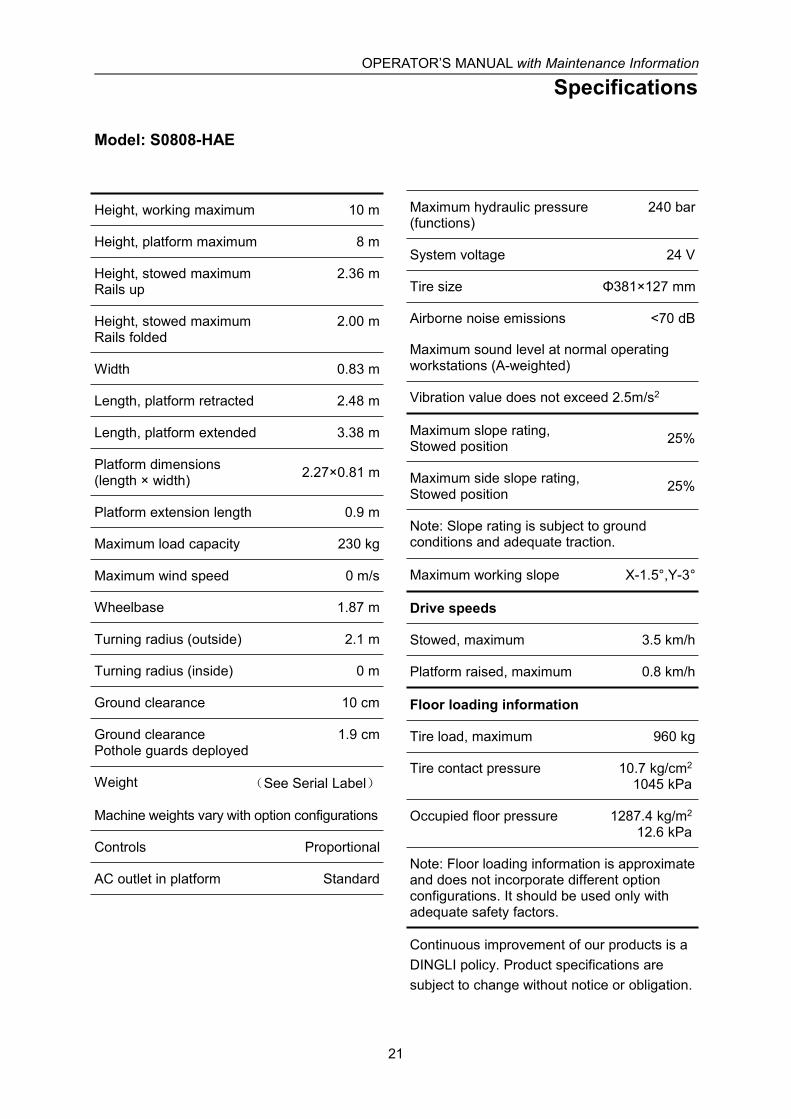
Model: S0808-HAE
Height, working maximum 10 m
Height, platform maximum 8 m
Height, stowed maximumRails up
2.36 m
Height, stowed maximumRails folded
2.00 m
Width 0.83 m
Length, platform retracted 2.48 m
Length, platform extended 3.38 m
Platform dimensions(length × width) 2.27×0.81 m
Platform extension length 0.9 m
Maximum load capacity 230 kg
Maximum wind speed 0 m/s
Wheelbase 1.87 m
Turning radius (outside) 2.1 m
Turning radius (inside) 0 m
Ground clearance 10 cm
Ground clearancePothole guards deployed
1.9 cm
Weight (See Serial Label)
Machine weights vary with option configurations
Controls Proportional
AC outlet in platform Standard
Maximum hydraulic pressure(functions)
240 bar
System voltage 24 V
Tire size Φ381×127 mm
Airborne noise emissions <70 dB
Maximum sound level at normal operatingworkstations (A-weighted)
Vibration value does not exceed 2.5m/s2
Maximum slope rating,Stowed position 25%
Maximum side slope rating,Stowed position 25%
Note: Slope rating is subject to groundconditions and adequate traction.
Maximum working slope X-1.5°,Y-3°
Drive speeds
Stowed, maximum 3.5 km/h
Platform raised, maximum 0.8 km/h
Floor loading information
Tire load, maximum 960 kg
Tire contact pressure 10.7 kg/cm2
1045 kPa
Occupied floor pressure 1287.4 kg/m2
12.6 kPa
Note: Floor loading information is approximateand does not incorporate different optionconfigurations. It should be used only withadequate safety factors.
Continuous improvement of our products is aDINGLI policy. Product specifications aresubject to change without notice or obligation.

OPERATOR’S MANUAL with Maintenance Information
Specifications
22
Model: S0812-HAE
Height, working maximum 10 m
Height, platform maximum 8 m
Height, stowed maximumRails up
2.36 m
Height, stowed maximumRails folded
1.83 m
Width 1.15 m
Length, platform retracted 2.48 m
Length, platform extended 3.38 m
Platform dimensions(length × width) 2.27×1.12 m
Platform extension length 0.9 m
Maximum load capacity 450 kg
Maximum wind speed 12.5 m/s
Wheelbase 1.87 m
Turning radius (outside) 2.2 m
Turning radius (inside) 0 m
Ground clearance 10 cm
Ground clearancePothole guards deployed
1.9 cm
Weight (See Serial Label)
Machine weights vary with option configurations
Controls Proportional
AC outlet in platform Standard
Maximum hydraulic pressure(functions)
240 bar
System voltage 24 V
Tire size Φ381×127 mm
Airborne noise emissions <70 dB
Maximum sound level at normal operatingworkstations (A-weighted)
Vibration value does not exceed 2.5m/s2
Maximum slope rating,Stowed position 25%
Maximum side slope rating,Stowed position 25%
Note: Slope rating is subject to groundconditions and adequate traction.
Maximum working slope X-1.5°, Y-3°
Drive speeds
Stowed, maximum 3.5 km/h
Platform raised, maximum 0.8 km/h
Floor loading information
Tire load, maximum 1240 kg
Tire contact pressure 12.1 kg/cm2
1182.6 kPa
Occupied floor pressure 1174.1 kg/m2
11.5 kPa
Note: Floor loading information is approximateand does not incorporate different optionconfigurations. It should be used only withadequate safety factors.
Continuous improvement of our products is aDINGLI policy. Product specifications aresubject to change without notice or obligation.
OPERATOR’S MANUAL with Maintenance Information
Specifications
23
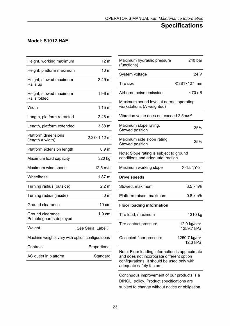
Model: S1012-HAE
Height, working maximum 12 m
Height, platform maximum 10 m
Height, stowed maximumRails up
2.49 m
Height, stowed maximumRails folded
1.96 m
Width 1.15 m
Length, platform retracted 2.48 m
Length, platform extended 3.38 m
Platform dimensions(length × width) 2.27×1.12 m
Platform extension length 0.9 m
Maximum load capacity 320 kg
Maximum wind speed 12.5 m/s
Wheelbase 1.87 m
Turning radius (outside) 2.2 m
Turning radius (inside) 0 m
Ground clearance 10 cm
Ground clearancePothole guards deployed
1.9 cm
Weight (See Serial Label)
Machine weights vary with option configurations
Controls Proportional
AC outlet in platform Standard
Maximum hydraulic pressure(functions)
240 bar
System voltage 24 V
Tire size Φ381×127 mm
Airborne noise emissions <70 dB
Maximum sound level at normal operatingworkstations (A-weighted)
Vibration value does not exceed 2.5m/s2
Maximum slope rating,Stowed position 25%
Maximum side slope rating,Stowed position 25%
Note: Slope rating is subject to groundconditions and adequate traction.
Maximum working slope X-1.5°,Y-3°
Drive speeds
Stowed, maximum 3.5 km/h
Platform raised, maximum 0.8 km/h
Floor loading information
Tire load, maximum 1310 kg
Tire contact pressure 12.9 kg/cm2
1259.7 kPa
Occupied floor pressure 1250.7 kg/m2
12.3 kPa
Note: Floor loading information is approximateand does not incorporate different optionconfigurations. It should be used only withadequate safety factors.
Continuous improvement of our products is aDINGLI policy. Product specifications aresubject to change without notice or obligation.

OPERATOR’S MANUAL with Maintenance Information
Specifications
24
Model: S1212-HAE
Height, working maximum 13.8 m
Height, platform maximum 11.8 m
Height, stowed maximumRails up
2.62 m
Height, stowed maximumRails folded
2.09 m
Width 1.19 m
Length, platform retracted 2.48 m
Length, platform extended 3.38 m
Platform dimensions(length × width) 2.27×1.12 m
Platform extension length 0.9 m
Maximum load capacity 320 kg
Maximum wind speed 0 m/s
Wheelbase 1.87 m
Turning radius (outside) 2.2 m
Turning radius (inside) 0 m
Ground clearance 10 cm
Ground clearancePothole guards deployed
1.9 cm
Weight (See Serial Label)
Machine weights vary with option configurations
Controls Proportional
AC outlet in platform Standard
Maximum hydraulic pressure(functions)
240 bar
System voltage 24 V
Tire size Φ381×127 mm
Airborne noise emissions <70 dB
Maximum sound level at normal operatingworkstations (A-weighted)
Vibration value does not exceed 2.5m/s2
Maximum slope rating,Stowed position 25%
Maximum side slope rating,Stowed position 25%
Note: Slope rating is subject to groundconditions and adequate traction.
Maximum working slope X-1.5°,Y-3°
Drive speeds
Stowed, maximum 3.5 km/h
Platform raised, maximum 0.8 km/h
Floor loading information
Tire load, maximum 1280 kg
Tire contact pressure 11.1 kg/cm2
1083.7 kPa
Occupied floor pressure 1169.8 kg/m2
11.5 kPa
Note: Floor loading information is approximateand does not incorporate different optionconfigurations. It should be used only withadequate safety factors.
Continuous improvement of our products is aDINGLI policy. Product specifications aresubject to change without notice or obligation.

OPERATOR’S MANUAL with Maintenance Information
Specifications
25
Model: S1412-HAE
Height, working maximum 15.7 m
Height, platform maximum 13.7 m
Height, stowed maximumRails up
2.62 m
Height, stowed maximumRails folded
2.09 m
Width 1.25 m
Length, platform retracted 2.84 m
Length, platform extended 3.74 m
Platform dimensions(length × width) 2.64×1.12 m
Platform extension length 0.9 m
Maximum load capacity 250 kg
Maximum wind speed 0 m/s
Wheelbase 2.22 m
Turning radius (outside) 2.65 m
Turning radius (inside) 0 m
Ground clearance 10 cm
Ground clearancePothole guards deployed
1.9 cm
Weight (See Serial Label)
Machine weights vary with option configurations
Controls Proportional
AC outlet in platform Standard
Maximum hydraulic pressure(functions)
240 bar
System voltage 24 V
Tire size Φ381×127 mm
Airborne noise emissions <70 dB
Maximum sound level at normal operatingworkstations (A-weighted)
Vibration value does not exceed 2.5m/s2
Maximum slope rating,Stowed position 25%
Maximum side slope rating,Stowed position 25%
Note: Slope rating is subject to groundconditions and adequate traction.
Maximum working slope X-1.5°,Y-3°
Drive speeds
Stowed, maximum 3.5 km/h
Platform raised, maximum 0.8 km/h
Floor loading information
Tire load, maximum 1350 kg
Tire contact pressure 11.7 kg/cm2
1142 kPa
Occupied floor pressure 1013.1 kg/m2
9.9 kPa
Note: Floor loading information is approximateand does not incorporate different optionconfigurations. It should be used only withadequate safety factors.
Continuous improvement of our products is aDINGLI policy. Product specifications aresubject to change without notice or obligation.
OPERATOR’S MANUAL with Maintenance Information
Specifications
26
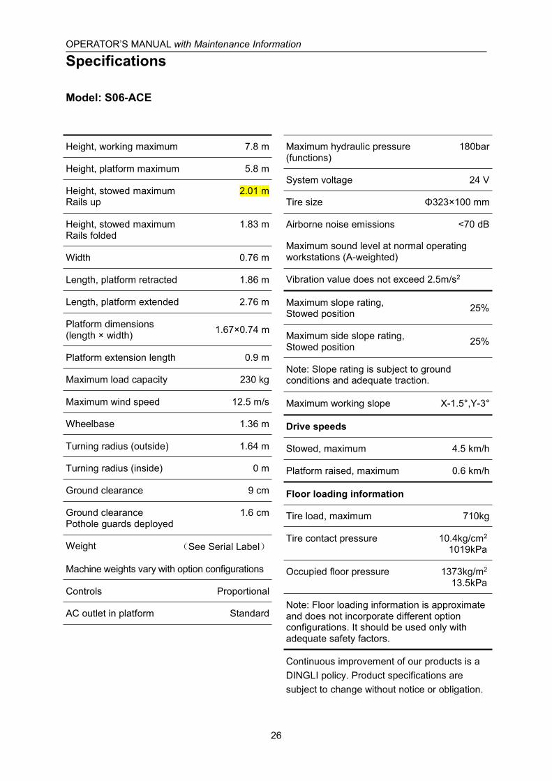
Model: S06-ACE
Height, working maximum 7.8 m
Height, platform maximum 5.8 m
Height, stowed maximumRails up
2.01 m
Height, stowed maximumRails folded
1.83 m
Width 0.76 m
Length, platform retracted 1.86 m
Length, platform extended 2.76 m
Platform dimensions(length × width) 1.67×0.74 m
Platform extension length 0.9 m
Maximum load capacity 230 kg
Maximum wind speed 12.5 m/s
Wheelbase 1.36 m
Turning radius (outside) 1.64 m
Turning radius (inside) 0 m
Ground clearance 9 cm
Ground clearancePothole guards deployed
1.6 cm
Weight (See Serial Label)
Machine weights vary with option configurations
Controls Proportional
AC outlet in platform Standard
Maximum hydraulic pressure(functions)
180bar
System voltage 24 V
Tire size Φ323×100 mm
Airborne noise emissions <70 dB
Maximum sound level at normal operatingworkstations (A-weighted)
Vibration value does not exceed 2.5m/s2
Maximum slope rating,Stowed position 25%
Maximum side slope rating,Stowed position 25%
Note: Slope rating is subject to groundconditions and adequate traction.
Maximum working slope X-1.5°,Y-3°
Drive speeds
Stowed, maximum 4.5 km/h
Platform raised, maximum 0.6 km/h
Floor loading information
Tire load, maximum 710kg
Tire contact pressure 10.4kg/cm2
1019kPa
Occupied floor pressure 1373kg/m2
13.5kPa
Note: Floor loading information is approximateand does not incorporate different optionconfigurations. It should be used only withadequate safety factors.
Continuous improvement of our products is aDINGLI policy. Product specifications aresubject to change without notice or obligation.

OPERATOR’S MANUAL with Maintenance Information
Specifications
27
Model: S0608-ACE
Height, working maximum 8 m
Height, platform maximum 6 m
Height, stowed maximumRails up
2.23 m
Height, stowed maximumRails folded
1.87 m
Width 0.83 m
Length, platform retracted 2.48 m
Length, platform extended 3.38 m
Platform dimensions(length × width) 2.27×0.81 m
Platform extension length 0.9 m
Maximum load capacity 380 kg
Maximum wind speed 12.5 m/s
Wheelbase 1.87 m
Turning radius (outside) 2.1 m
Turning radius (inside) 0 m
Ground clearance 10 cm
Ground clearancePothole guards deployed
1.9 cm
Weight (See Serial Label)
Machine weights vary with option configurations
Controls Proportional
AC outlet in platform Standard
Maximum hydraulic pressure(functions)
240 bar
System voltage 24 V
Tire size Φ381×127 mm
Airborne noise emissions <70 dB
Maximum sound level at normal operatingworkstations (A-weighted)
Vibration value does not exceed 2.5m/s2
Maximum slope rating,Stowed position 25%
Maximum side slope rating,Stowed position 25%
Note: Slope rating is subject to groundconditions and adequate traction.
Maximum working slope X-1.5°,Y-3°
Drive speeds
Stowed, maximum 5.0 km/h
Platform raised, maximum 0.8 km/h
Floor loading information
Tire load, maximum 1000 kg
Tire contact pressure 11.3 kg/cm2
1104.6 kPa
Occupied floor pressure 1360.7 kg/m2
13.3 kPa
Note: Floor loading information is approximateand does not incorporate different optionconfigurations. It should be used only withadequate safety factors.
Continuous improvement of our products is aDINGLI policy. Product specifications aresubject to change without notice or obligation.

OPERATOR’S MANUAL with Maintenance Information
Specifications
28
Model: S0808-ACE
Height, working maximum 10 m
Height, platform maximum 8 m
Height, stowed maximumRails up
2.36 m
Height, stowed maximumRails folded
2.00 m
Width 0.83 m
Length, platform retracted 2.48 m
Length, platform extended 3.38 m
Platform dimensions(length × width) 2.27×0.81 m
Platform extension length 0.9 m
Maximum load capacity 230 kg
Maximum wind speed 0 m/s
Wheelbase 1.87 m
Turning radius (outside) 2.1 m
Turning radius (inside) 0 m
Ground clearance 10 cm
Ground clearancePothole guards deployed
1.9 cm
Weight (See Serial Label)
Machine weights vary with option configurations
Controls Proportional
AC outlet in platform Standard
Maximum hydraulic pressure(functions)
240 bar
System voltage 24 V
Tire size Φ381×127 mm
Airborne noise emissions <70 dB
Maximum sound level at normal operatingworkstations (A-weighted)
Vibration value does not exceed 2.5m/s2
Maximum slope rating,Stowed position 25%
Maximum side slope rating,Stowed position 25%
Note: Slope rating is subject to groundconditions and adequate traction.
Maximum working slope X-1.5°,Y-3°
Drive speeds
Stowed, maximum 5.0 km/h
Platform raised, maximum 0.8 km/h
Floor loading information
Tire load, maximum 960 kg
Tire contact pressure 10.8 kg/cm2
1062.7 kPa
Occupied floor pressure 1309.1 kg/m2
12.8 kPa
Note: Floor loading information is approximateand does not incorporate different optionconfigurations. It should be used only withadequate safety factors.
Continuous improvement of our products is aDINGLI policy. Product specifications aresubject to change without notice or obligation.

OPERATOR’S MANUAL with Maintenance Information
Specifications
29
Model: S0812-ACE
Height, working maximum 10 m
Height, platform maximum 8 m
Height, stowed maximumRails up
2.36 m
Height, stowed maximumRails folded
1.83 m
Width 1.15 m
Length, platform retracted 2.48 m
Length, platform extended 3.38 m
Platform dimensions(length × width) 2.27×1.12 m
Platform extension length 0.9 m
Maximum load capacity 450 kg
Maximum wind speed 12.5 m/s
Wheelbase 1.87 m
Turning radius (outside) 2.2 m
Turning radius (inside) 0 m
Ground clearance 10 cm
Ground clearancePothole guards deployed
1.9 cm
Weight (See Serial Label)
Machine weights vary with option configurations
Controls Proportional
AC outlet in platform Standard
Maximum hydraulic pressure(functions)
240 bar
System voltage 24 V
Tire size Φ381×127 mm
Airborne noise emissions <70 dB
Maximum sound level at normal operatingworkstations (A-weighted)
Vibration value does not exceed 2.5m/s2
Maximum slope rating,Stowed position 25%
Maximum side slope rating,Stowed position 25%
Note: Slope rating is subject to groundconditions and adequate traction.
Maximum working slope X-1.5°,Y-3°
Drive speeds
Stowed, maximum 5.0 km/h
Platform raised, maximum 0.8 km/h
Floor loading information
Tire load, maximum 1240 kg
Tire contact pressure 12.2 kg/cm2
1198 kPa
Occupied floor pressure 1189.4 kg/m2
11.7 kPa
Note: Floor loading information is approximateand does not incorporate different optionconfigurations. It should be used only withadequate safety factors.
Continuous improvement of our products is aDINGLI policy. Product specifications aresubject to change without notice or obligation.

OPERATOR’S MANUAL with Maintenance Information
Specifications
30
Model: S1012-ACE
Height, working maximum 12 m
Height, platform maximum 10 m
Height, stowed maximumRails up
2.49 m
Height, stowed maximumRails folded
1.96 m
Width 1.15 m
Length, platform retracted 2.48 m
Length, platform extended 3.38 m
Platform dimensions(length × width) 2.27×1.12 m
Platform extension length 0.9 m
Maximum load capacity 320 kg
Maximum wind speed 12.5 m/s
Wheelbase 1.87 m
Turning radius (outside) 2.2 m
Turning radius (inside) 0 m
Ground clearance 10 cm
Ground clearancePothole guards deployed
1.9 cm
Weight (See Serial Label)
Machine weights vary with option configurations
Controls Proportional
AC outlet in platform Standard
Maximum hydraulic pressure(functions)
240 bar
System voltage 24 V
Tire size Φ381×127 mm
Airborne noise emissions <70 dB
Maximum sound level at normal operatingworkstations (A-weighted)
Vibration value does not exceed 2.5m/s2
Maximum slope rating,Stowed position 25%
Maximum side slope rating,Stowed position 25%
Note: Slope rating is subject to groundconditions and adequate traction.
Maximum working slope X-1.5°,Y-3°
Drive speeds
Stowed, maximum 5.0 km/h
Platform raised, maximum 0.8 km/h
Floor loading information
Tire load, maximum 1310 kg
Tire contact pressure 12.9 kg/cm2
1267.4 kPa
Occupied floor pressure 1258.4 kg/m2
12.3 kPa
Note: Floor loading information is approximateand does not incorporate different optionconfigurations. It should be used only withadequate safety factors.
Continuous improvement of our products is aDINGLI policy. Product specifications aresubject to change without notice or obligation.

OPERATOR’S MANUAL with Maintenance Information
Specifications
31
Model: S1212-ACE
Height, working maximum 13.8 m
Height, platform maximum 11.8 m
Height, stowed maximumRails up
2.62 m
Height, stowed maximumRails folded
2.09 m
Width 1.19 m
Length, platform retracted 2.48 m
Length, platform extended 3.38 m
Platform dimensions(length × width) 2.27×1.12 m
Platform extension length 0.9 m
Maximum load capacity 320 kg
Maximum wind speed 0 m/s
Wheelbase 1.87 m
Turning radius (outside) 2.2 m
Turning radius (inside) 0 m
Ground clearance 10 cm
Ground clearancePothole guards deployed
1.9 cm
Weight (See Serial Label)
Machine weights vary with option configurations
Controls Proportional
AC outlet in platform Standard
Maximum hydraulic pressure(functions)
240 bar
System voltage 24 V
Tire size Φ381×127 mm
Airborne noise emissions <70 dB
Maximum sound level at normal operatingworkstations (A-weighted)
Vibration value does not exceed 2.5m/s2
Maximum slope rating,Stowed position 25%
Maximum side slope rating,Stowed position 25%
Note: Slope rating is subject to groundconditions and adequate traction.
Maximum working slope X-1.5°,Y-3°
Drive speeds
Stowed, maximum 5.0 km/h
Platform raised, maximum 0.8 km/h
Floor loading information
Tire load, maximum 1280 kg
Tire contact pressure 11.2 kg/cm2
1097.5 kPa
Occupied floor pressure 1184.6 kg/m2
11.6 kPa
Note: Floor loading information is approximateand does not incorporate different optionconfigurations. It should be used only withadequate safety factors.
Continuous improvement of our products is aDINGLI policy. Product specifications aresubject to change without notice or obligation.
OPERATOR’S MANUAL with Maintenance Information
Specifications
32
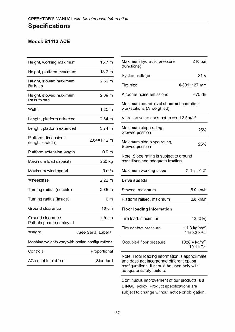
Model: S1412-ACE
Height, working maximum 15.7 m
Height, platform maximum 13.7 m
Height, stowed maximumRails up
2.62 m
Height, stowed maximumRails folded
2.09 m
Width 1.25 m
Length, platform retracted 2.84 m
Length, platform extended 3.74 m
Platform dimensions(length × width) 2.64×1.12 m
Platform extension length 0.9 m
Maximum load capacity 250 kg
Maximum wind speed 0 m/s
Wheelbase 2.22 m
Turning radius (outside) 2.65 m
Turning radius (inside) 0 m
Ground clearance 10 cm
Ground clearancePothole guards deployed
1.9 cm
Weight (See Serial Label)
Machine weights vary with option configurations
Controls Proportional
AC outlet in platform Standard
Maximum hydraulic pressure(functions)
240 bar
System voltage 24 V
Tire size Φ381×127 mm
Airborne noise emissions <70 dB
Maximum sound level at normal operatingworkstations (A-weighted)
Vibration value does not exceed 2.5m/s2
Maximum slope rating,Stowed position 25%
Maximum side slope rating,Stowed position 25%
Note: Slope rating is subject to groundconditions and adequate traction.
Maximum working slope X-1.5°,Y-3°
Drive speeds
Stowed, maximum 5.0 km/h
Platform raised, maximum 0.8 km/h
Floor loading information
Tire load, maximum 1350 kg
Tire contact pressure 11.8 kg/cm2
1159.2 kPa
Occupied floor pressure 1028.4 kg/m2
10.1 kPa
Note: Floor loading information is approximateand does not incorporate different optionconfigurations. It should be used only withadequate safety factors.
Continuous improvement of our products is aDINGLI policy. Product specifications aresubject to change without notice or obligation.
OPERATOR’S MANUAL with Maintenance Information
Specifications
33
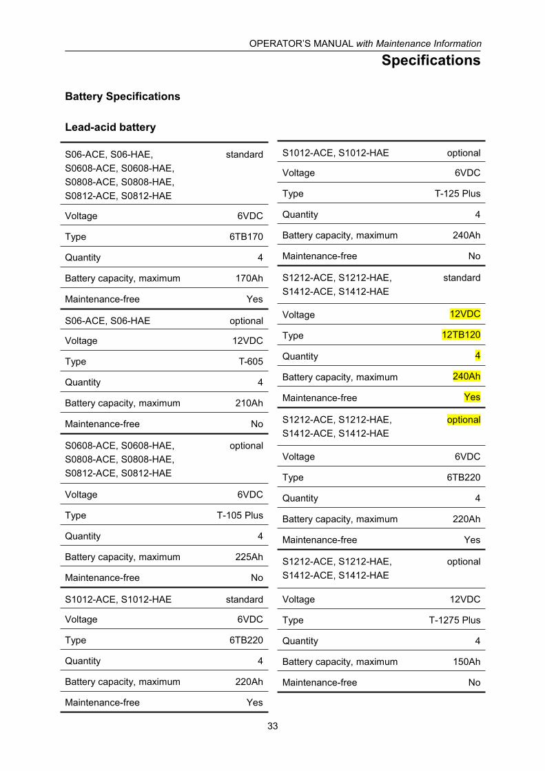
Battery Specifications
Lead-acid battery
S06-ACE, S06-HAE,S0608-ACE, S0608-HAE,S0808-ACE, S0808-HAE,S0812-ACE, S0812-HAE
standard
Voltage 6VDC
Type 6TB170
Quantity 4
Battery capacity, maximum 170Ah
Maintenance-free Yes
S06-ACE, S06-HAE optional
Voltage 12VDC
Type T-605
Quantity 4
Battery capacity, maximum 210Ah
Maintenance-free No
S0608-ACE, S0608-HAE,S0808-ACE, S0808-HAE,S0812-ACE, S0812-HAE
optional
Voltage 6VDC
Type T-105 Plus
Quantity 4
Battery capacity, maximum 225Ah
Maintenance-free No
S1012-ACE, S1012-HAE standard
Voltage 6VDC
Type 6TB220
Quantity 4
Battery capacity, maximum 220Ah
Maintenance-free Yes
S1012-ACE, S1012-HAE optional
Voltage 6VDC
Type T-125 Plus
Quantity 4
Battery capacity, maximum 240Ah
Maintenance-free No
S1212-ACE, S1212-HAE,S1412-ACE, S1412-HAE
standard
Voltage 12VDC
Type 12TB120
Quantity 4
Battery capacity, maximum 240Ah
Maintenance-free Yes
S1212-ACE, S1212-HAE,S1412-ACE, S1412-HAE
optional
Voltage 6VDC
Type 6TB220
Quantity 4
Battery capacity, maximum 220Ah
Maintenance-free Yes
S1212-ACE, S1212-HAE,S1412-ACE, S1412-HAE
optional
Voltage 12VDC
Type T-1275 Plus
Quantity 4
Battery capacity, maximum 150Ah
Maintenance-free No
OPERATOR’S MANUAL with Maintenance Information
Specifications
34
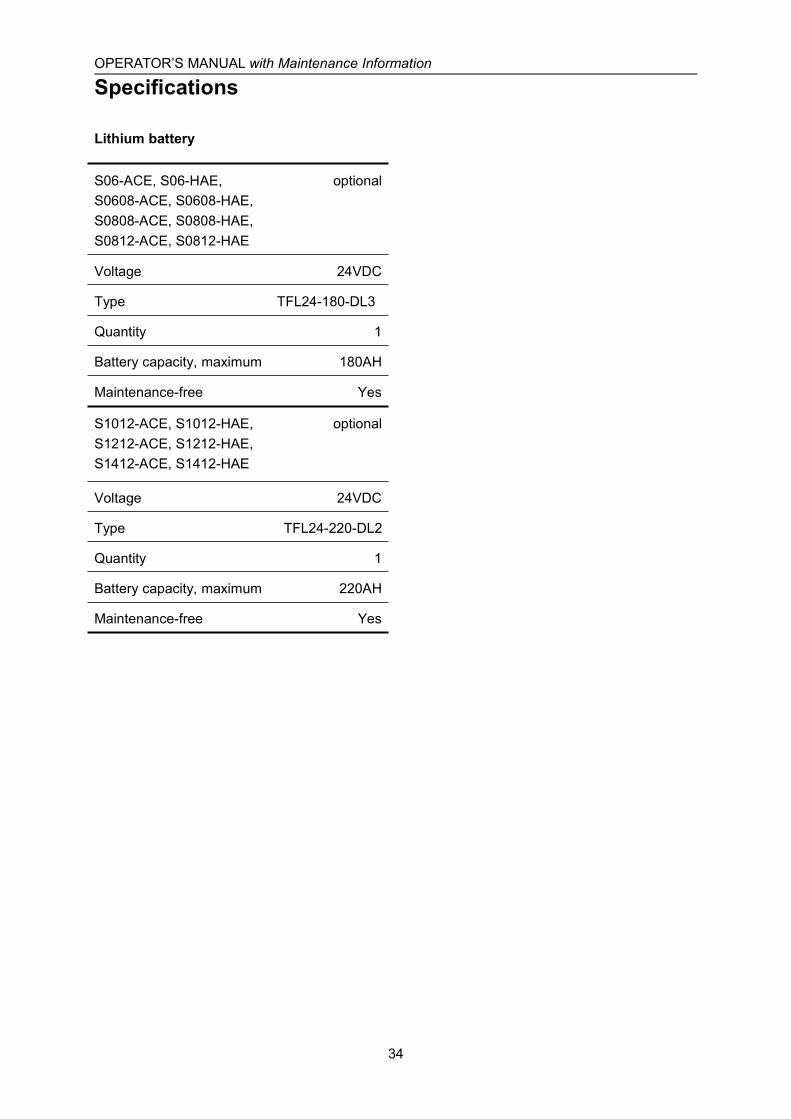
Lithium battery
S06-ACE, S06-HAE,S0608-ACE, S0608-HAE,S0808-ACE, S0808-HAE,S0812-ACE, S0812-HAE
optional
Voltage 24VDC
Type TFL24-180-DL3
Quantity 1
Battery capacity, maximum 180AH
Maintenance-free Yes
S1012-ACE, S1012-HAE,S1212-ACE, S1212-HAE,S1412-ACE, S1412-HAE
optional
Voltage 24VDC
Type TFL24-220-DL2
Quantity 1
Battery capacity, maximum 220AH
Maintenance-free Yes
OPERATOR’S MANUAL with Maintenance Information
Control Panel
35
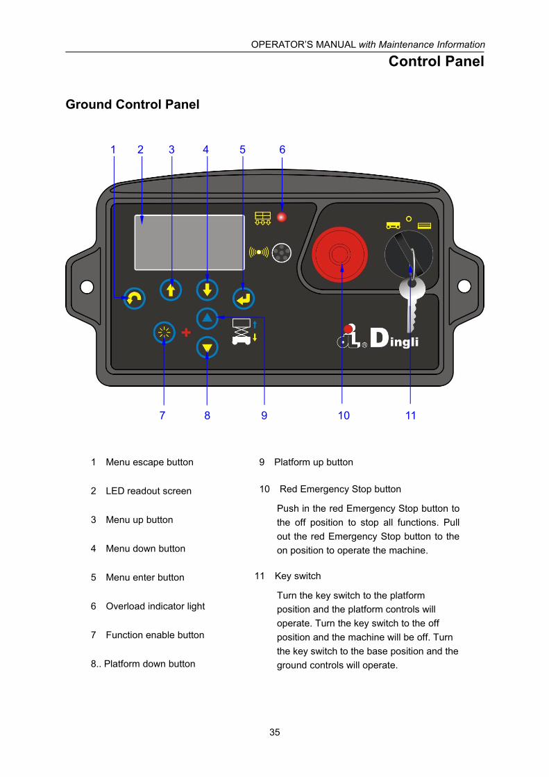
Ground Control Panel
1 Menu escape button 9 Platform up button
2 LED readout screen 10 Red Emergency Stop button
Push in the red Emergency Stop button tothe off position to stop all functions. Pullout the red Emergency Stop button to theon position to operate the machine.
3 Menu up button
4 Menu down button
5 Menu enter button 11 Key switch
Turn the key switch to the platformposition and the platform controls willoperate. Turn the key switch to the offposition and the machine will be off. Turnthe key switch to the base position and theground controls will operate.
6 Overload indicator light
7 Function enable button
8.. Platform down button
1 2 3 4 5 6
7 8 9 10 11
OPERATOR’S MANUAL with Maintenance Information
Control Panel
36
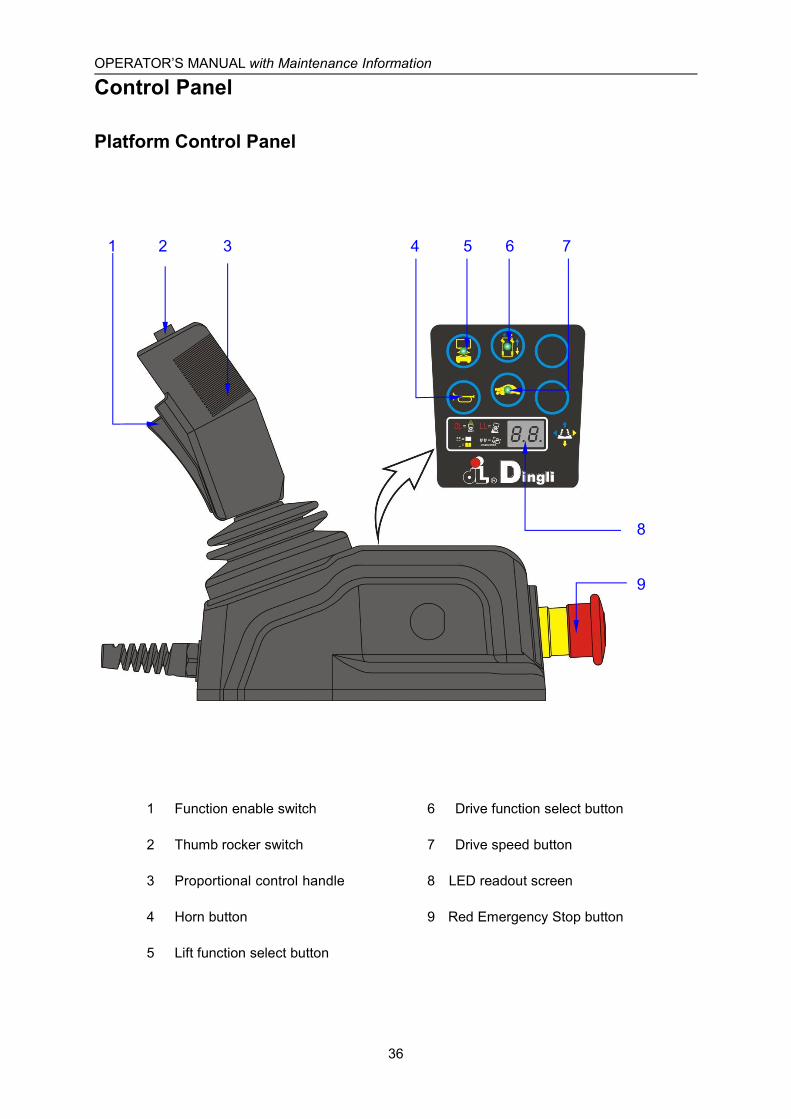
Platform Control Panel
1 Function enable switch 6 Drive function select button
2 Thumb rocker switch 7 Drive speed button
3 Proportional control handle 8 LED readout screen
4 Horn button 9 Red Emergency Stop button
5 Lift function select button
1 2 3 4 5 6 7
8
9
OPERATOR’S MANUAL with Maintenance Information
Control Panel
37
Platform Control Panel1 Function enable switch
Press and hold the function enable switchto enable the drive/lift function.
2 Thumb rocker switch
Press the thumb rocker switch in eitherdirection to activate steer function.
3 Proportional control handle
Lift function: Press and hold the functionenable switch to enable the lift function onthe platform control handle. Move thecontrol handle in the direction indicated bythe blue arrow and the platform will raise.Move the control handle in the directionindicated by the yellow arrow and theplatform will lower. The descent alarmshould sound while the platform islowering.
Drive function: Press and hold the functionenable switch to enable the drive functionon the platform control handle. Move thecontrol handle in the direction indicated bythe blue arrow on the control panel and themachine will move in the direction that theblue arrow points. Move the control handlein the direction indicated by the yellowarrow on the control panel and themachine will move in the direction that theyellow arrow points.
4 Horn Button
Push the horn button and the horn willsound. Release the horn button and thehorn will stop.
5 Lift function select button
Press this button to activate the liftfunction.
6 Drive function select button
Press this button to activate the drivefunction.
7 Drive speed button
Press this button to activate the slow orfast drive function.
8 LED readout screen
Diagnostic readout and battery chargeindicator.
9 Red Emergency Stop button
Push in the red Emergency Stop button tothe off position to stop all functions. Pullout the red Emergency Stop button to theon position to operate the machine.

OPERATOR’S MANUAL with Maintenance Information
Pre-operation Inspection
38
Do Not Operate Unless:√ You learn and practice the principles of
safe machine operation contained in thisoperator's manual.
1 Avoid hazardous situations.
2 Always perform a pre-operationinspection.
Know and understand the pre-operationinspection before going on to the nextsection.
3 Inspect the workplace.
4 Always perform function tests prior touse.
5 Only use the machine as it wasintended.
FundamentalsIt is the responsibility of the operator toperform a pre-operation inspection and routinemaintenance.
The pre-operation inspection is a visualinspection performed by the operator prior toeach work shift. The inspection is designed todiscover if anything is apparently wrong with amachine before the operator performs thefunction tests.
The pre-operation inspection also serves todetermine if routine maintenance proceduresare required. Only routine maintenance itemsspecified in this manual may be performed bythe operator.
Refer to the list on the next page and checkeach of the items.
If damage or any unauthorized variation fromfactory delivered condition is discovered, themachine must be tagged and removed fromservice.
Repairs to the machine may only be made bya qualified service technician, according to themanufacturer's specifications. After repairs arecompleted, the operator must perform apre-operation inspection again before going onto the function tests.
Scheduled maintenance inspections shall beperformed by qualified service technicians,according to the manufacturer's specificationsand the requirements listed in this manual.
OPERATOR’S MANUAL with Maintenance Information
Pre-operation Inspection
39
Pre-operation Inspection Be sure that the operator’s manual are
complete, legible and in the storagecontainer located in the platform.
Be sure that all decals are legible and inplace. See Decals section.
Check for hydraulic oil leaks and properoil level. Add oil if needed. SeeMaintenance section.
Check for battery fluid leaks and properfluid level. Add distilled water if needed.See Maintenance section.
Check the following components or areas fordamage, improperly installed or missing partsand unauthorized modifications:
Electrical components, wiring andelectrical cables
Hydraulic hoses, fittings, cylinders andmanifolds
Battery pack and connections
Drive motors
Wear pads
Tires and wheels
Ground strap
Limit switches, alarms and horn
Nuts, bolts and other fasteners
Platform overload components
Platform entry gate
Beacon (if equipped)
Safety arm
Platform extension(s)
Scissor pins and retaining fasteners
Platform control joystick
Brake release components
Pothole guard
Check entire machine for:
Cracks in welds or structuralcomponents
Dents or damage to machine
Be sure that all structural and othercritical components are present andall associated fasteners and pins arein place and properly tightened
Be sure side rails are installed and railpins and bolts are fastened.
Be sure that the chassis trays areclosed and latched and the batteriesare properly connected.
Note: If the platform must be raised to inspectthe machine, make sure the safety arm is inplace. See Operating Instructions section.
OPERATOR’S MANUAL with Maintenance Information
Workplace Inspection
40
Do Not Operate Unless:√ You learn and practice the principles of
safe machine operation contained in thisoperator's manual.
1 Avoid hazardous situations.
2 Always perform a pre-operationinspection.
3 Inspect the workplace.
Know and understand the workplaceinspection before going on to the nextsection.
4 Always perform function tests prior touse.
5 Only use the machine as it wasintended.
FundamentalsThe workplace inspection helps the operatordetermine if the workplace is suitable for safemachine operation. It should be performed bythe operator prior to moving the machine to theworkplace.
It is the operator's responsibility to read andremember the workplace hazards, then watchfor and avoid them while moving, setting upand operating the machine.
Workplace InspectionBe aware of and avoid the following hazardoussituations:
- Drop-offs or holes
- Bumps, floor obstructions or debris
- Sloped surfaces
- Unstable or slippery surfaces
- Overhead obstructions and high voltageconductors
- Hazardous locations
- Inadequate surface support to withstand allload forces imposed by the machine
- Wind and weather conditions
- The presence of unauthorized personnel
- Other possible unsafe conditions
OPERATOR’S MANUAL with Maintenance Information
Function Tests
41
Do Not Operate Unless:√ You learn and practice the principles of
safe machine operation contained in thisoperator's manual.
1 Avoid hazardous situations.
2 Always perform a pre-operationinspection.
3 Inspect the workplace.
4 Always perform function tests priorto use.
Know and understand the function testsbefore going on to the next section.
5 Only use the machine as it wasintended.
FundamentalsThe function tests are designed to discoverany malfunctions before the machine is putinto service.
The operator must follow the step-by-stepinstructions to test all machine functions.
A malfunctioning machine must never be used.If malfunctions are discovered, the machinemust be tagged and removed from service.Repairs to the machine may only be made bya qualified service technician, according to themanufacturer's specifications.
After repairs are completed, the operator mustperform a pre-operation inspection andfunction tests again before putting the machineinto service.
OPERATOR’S MANUAL with Maintenance Information
Function Tests
42
1 Select a test area that is firm, level andfree of obstruction.
2 Be sure the battery pack is connected.
3 Pull out the main power switch to “on”position.
At the Ground Controls4 Pull out the platform and ground red
Emergency Stop button to the on position.
5 Turn the key switch to ground control.
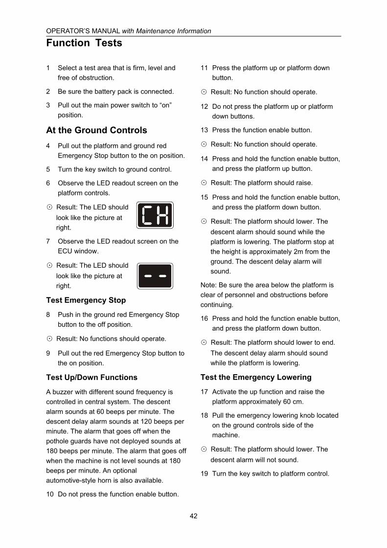
6 Observe the LED readout screen on theplatform controls.
⊙ Result: The LED shouldlook like the picture atright.
7 Observe the LED readout screen on theECU window.
⊙ Result: The LED shouldlook like the picture atright.
Test Emergency Stop
8 Push in the ground red Emergency Stopbutton to the off position.
⊙ Result: No functions should operate.
9 Pull out the red Emergency Stop button tothe on position.
Test Up/Down Functions
A buzzer with different sound frequency iscontrolled in central system. The descentalarm sounds at 60 beeps per minute. Thedescent delay alarm sounds at 120 beeps perminute. The alarm that goes off when thepothole guards have not deployed sounds at180 beeps per minute. The alarm that goes offwhen the machine is not level sounds at 180beeps per minute. An optionalautomotive-style horn is also available.
10 Do not press the function enable button.
11 Press the platform up or platform downbutton.
⊙ Result: No function should operate.
12 Do not press the platform up or platformdown buttons.
13 Press the function enable button.
⊙ Result: No function should operate.
14 Press and hold the function enable button,and press the platform up button.
⊙ Result: The platform should raise.
15 Press and hold the function enable button,and press the platform down button.
⊙ Result: The platform should lower. Thedescent alarm should sound while theplatform is lowering. The platform stop atthe height is approximately 2m from theground. The descent delay alarm willsound.
Note: Be sure the area below the platform isclear of personnel and obstructions beforecontinuing.
16 Press and hold the function enable button,and press the platform down button.
⊙ Result: The platform should lower to end.The descent delay alarm should soundwhile the platform is lowering.
Test the Emergency Lowering
17 Activate the up function and raise theplatform approximately 60 cm.
18 Pull the emergency lowering knob locatedon the ground controls side of themachine.
⊙ Result: The platform should lower. Thedescent alarm will not sound.
19 Turn the key switch to platform control.

OPERATOR’S MANUAL with Maintenance Information
Function Tests
43
At the Platform ControlsTest Emergency Stop
20 Push in the platform red Emergency Stopbutton to the off position.
⊙ Result: No functions should operate.
21 Pull out the red Emergency Stop button tothe on position.
⊙ Result: The LED indicator light shouldcome on.
Test the Horn
22 Push the horn button.
⊙ Result: The horn should sound.
Test Function Enable and Up/DownFunctions
23 Do not hold the function enable switch onthe control handle.
24 Slowly move the control handle in thedirection indicated by the blue up arrow,then in the direction indicated by the yellowdown arrow.
⊙ Result: No functions should operate.
25 Press the lift function select button.
26 Press and hold the function enable switchon the control handle.
27 Slowly move the control handle in thedirection indicated by the blue up arrow.
⊙ Result: The platform should raise. Thepothole guards should deploy.
28 Release the control handle.
⊙ Result: The platform should stop raising.
29 Press and hold the function enable switch.Slowly move the control handle in thedirection indicated by the yellow downarrow.
⊙ Result: The platform should lower. The
descent alarm should sound while theplatform is lowering.
Test the Steering
Note: When performing the steer and drivefunction tests, stand in the platform facing thesteer end of the machine.
30 Press the drive function select button. Theindicator light should turn on.
31 Press and hold the function enable switchon the control handle.
32 Depress the thumb rocker switch on top ofthe control handle in the direction identifiedby the blue left arrow on the control panel.
⊙ Result: The steer wheels should turn in thedirection that the blue left arrow points onthe control panel.
33 Depress the thumb rocker switch in thedirection identified by the yellow rightarrow on the control panel.
⊙ Result: The steer wheels should turn in thedirection that the yellow right arrow pointson the control panel.
Test Drive and Braking
34 Press the drive function select button. Theindicator light should turn on.
35 Press and hold the function enable switchon the control handle.
36 Slowly move the control handle in thedirection indicated by the blue up arrow onthe control panel until the machine beginsto move, then return the handle to thecenter position.
⊙ Result: The machine should move in thedirection that the blue up arrow points onthe control panel, then come to an abruptstop.
37 Press and hold the function enable switchon the control handle.
OPERATOR’S MANUAL with Maintenance Information
Function Tests
44
38 Slowly move the control handle in thedirection indicated by the yellow downarrow on the control panel until themachine begins to move, then return thehandle to the center position.
⊙ Result: The machine should move in thedirection that the yellow down arrow pointson the control panel, then come to anabrupt stop.
Note: The brakes must be able to hold themachine on any slope it is able to climb.
Test Limited Drive Speed
39 Press and hold the function enable switch.Raise the platform approximately 2m fromthe ground.
⊙ Result: The pothole guards should deploy.
40 Press and hold the function enable switchon the control handle.
41 Slowly move the control handle to the fulldrive position.
⊙ Result: The maximum achievable drivespeed with the platform raised should notexceed 22 cm/s.
¤ Result: If the drive speed with the platformraised exceeds 22 cm/s, immediately tagand remove the machine from service.
Test the Tilt Sensor Operation
Note: Perform this test from the ground withthe platform controller. Do not stand in theplatform.
42 Fully lower the platform.
43 Place a 3.5×20cm or similar piece of woodunder both wheels on one side and drivethe machine up onto them.
44 Raise the platform approximately 2m fromthe ground.
⊙ Result: The platform should stop and the tiltalarm will sound at 180 beeps per minute.
The platform controls LED readout shoulddisplay LL.
45 Press the drive function select button.
46 Press and hold the function enable switchon the control handle.
47 Move the control handle in the directionindicated by the blue up arrow, then movethe control handle in the direction indicatedby the yellow down arrow.
⊙ Result: The drive function should not workin either direction.
48 Lower the platform and drive the machineoff the block.
Test the Pothole Guards
Note: The pothole guards should automaticallydeploy when the platform is raised. Thepothole guards activate another limit switchwhich allows the machine to continue tofunction. If the pothole guards do not deploy,an alarm sounds and the machine will notdrive and lift.
49 Raise the platform.
⊙ Result: When the platform is raisedapproximately 2m from the ground, thepothole guards should deploy.
50 Press on the pothole guards on one side,and then the other.
⊙ Result: The pothole guards should notmove.
51 Lower the platform.
⊙ Result: The pothole guards should return tothe stowed position.
52 Place a 3.5×20cm or similar piece of woodunder a pothole guard. Raise the platform.
⊙ Result: When the platform is raisedapproximately 2m from the ground, thepothole alarm will sound at 180 beeps perminute, and the platform controls LED
OPERATOR’S MANUAL with Maintenance Information
Function Tests
45
screen readout should display 18.
53 Press the drive function select button.
54 Press and hold the function enable switchon the control handle.
55 Move the control handle in the directionindicated by the blue up arrow, and thenmove the control handle in the directionindicated by the yellow down arrow.
⊙ Result: The drive function should not workin either direction.
56 Press and hold the function enable switchon the control handle.
57 Depress the thumb rocker switch on top ofthe control handle in the direction identifiedby the blue and yellow arrow on the controlpanel.
⊙ Result: The steer function should not workin either direction.
58 Lower the platform and remove the3.5×20cm wood block.
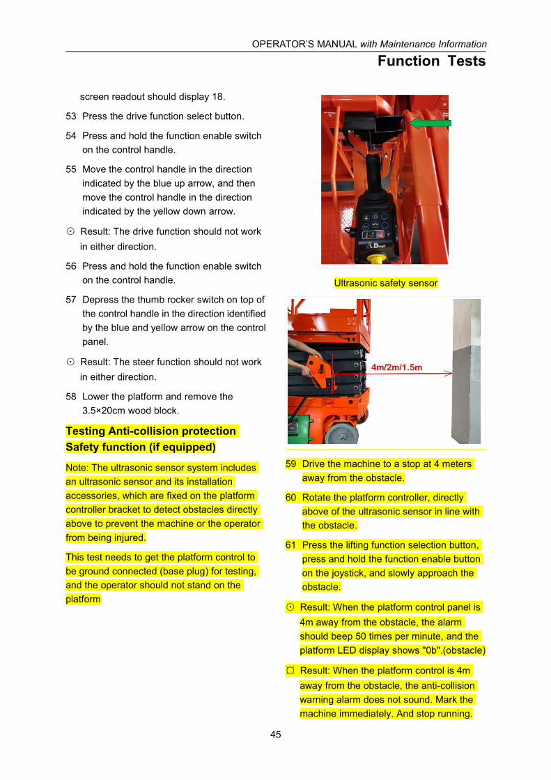
Testing Anti-collision protectionSafety function (if equipped)
Note: The ultrasonic sensor system includesan ultrasonic sensor and its installationaccessories, which are fixed on the platformcontroller bracket to detect obstacles directlyabove to prevent the machine or the operatorfrom being injured.
This test needs to get the platform control tobe ground connected (base plug) for testing,and the operator should not stand on theplatform
Ultrasonic safety sensor
59 Drive the machine to a stop at 4 metersaway from the obstacle.
60 Rotate the platform controller, directlyabove of the ultrasonic sensor in line withthe obstacle.
61 Press the lifting function selection button,press and hold the function enable buttonon the joystick, and slowly approach theobstacle.
⊙ Result: When the platform control panel is4m away from the obstacle, the alarmshould beep 50 times per minute, and theplatform LED display shows "0b".(obstacle)
¤ Result: When the platform control is 4maway from the obstacle, the anti-collisionwarning alarm does not sound. Mark themachine immediately. And stop running.
OPERATOR’S MANUAL with Maintenance Information
Function Tests
46
62 Try to raise the platform.
⊙ Result: The platform can be raised thealarm should beep 50 times per minute andcontinue, the platform LED display shows"0b". (Obstacle)
63 Press the drive function enable button todrive the machine to a stop at 2 metersaway from the obstacle. Rotate theplatform controller until the directly aboveof the ultrasonic sensor in line with theobstacle.
64 Press the lift function enable button, pressand hold the function enable button on thejoystick, and slowly approach the obstacle.
⊙ Result: When the platform control is 2maway from the obstacle, the alarm will beep110 times per minute, and the platformLED display shows "0b".(Obstacle)
¤ Result: When the platform control is 2maway from the obstacle, the anti-collisionwarning alarm will not sound (beep). Markthe machine immediately. And stopfunction.
65 Raise the platform while ensuring that theultrasonic sensor moves in line with theobstacle.
⊙ Result: When the platform control is 1.5maway from the obstacle, the platform willstop the lift function, the alarm shouldcontinue to beep 110 times per minute, andthe platform LED display shows "0b".(Obstacle)
¤ Result: When the platform control is 1.5maway from the obstacle, the anti-collisionwarning alarm (beep) does not sound, andthe platform will continue to rise. Pleasemark the machine immediately. And stopfunction.
66 Release the joystick and raise the machineagain within 5 seconds (within the time thealarm sounds).
⊙ Result: The platform will continue to raise,the alarm should continue to beeps 110times per minute, and the platform LEDdisplay shows "0b".(Obstacle)
67 Release the joystick and raise the machineagain after 5 seconds (after the alarmstops).
⊙ Result: The lift function will be disabled andnot allowed to raise, the alarm shouldsound continuously 110 beeps per minute,and the platform LED display shows"0b".(Obstacle)
Note: The ultrasonic safety sensor will onlyprotect the operator and platform directlyabove the platform control.
OPERATOR’S MANUAL with Maintenance Information
Operating Instructions
47
Do Not Operate Unless:√ You learn and practice the principles of
safe machine operation contained in thisoperator's manual.
1 Avoid hazardous situations.
2 Always perform a pre-operationinspection.
3 Inspect the workplace.
4 Always perform function tests prior touse.
5 Only use the machine as it wasintended.
FundamentalsThis machine is a self-propelled hydraulic liftequipped with a work platform on the scissormechanism. Vibrations emitted by thesemachines are not hazardous to an operator inthe work platform. The machine can be usedto position personnel with their tools andsupplies at position above ground level andcan be used to reach work areas locatedabove and over machinery or equipment.
A full and detailed implementation of EN ISO13849-1/2 is correctly applied on our MEWPdesign. SISTEMA, a software tool for PLCalculation Tool, is also used to perform somerelatively straightforward calculations onsubsystem to determine the overall PL of thesystem. Reliability data, diagnostic coverage[DC], the system architecture [Category],common cause failure and, where relevant,requirements for software are used to assessthe PL to comply with PLr of SRP/CS inClause 5.11 of EN 280.
The Operating Instructions section providesinstructions for each aspect of machineoperation.
It is the operator's responsibility to follow allthe safety rules and instructions in theoperator's manual.
Using the machine for anything other thanlifting personnel, along with their tools andmaterials, to an aerial work site is unsafe anddangerous.
Only trained and authorized personnel shouldbe permitted to operate a machine. If morethan one operator is expected to use amachine at different times in the same workshift, they must all be qualified operators andare all expected to follow all safety rules andinstructions in the operator's manual. Thatmeans every new operator should perform apre-operation inspection, function tests, and aworkplace inspection before using themachine.

OPERATOR’S MANUAL with Maintenance Information
Operating Instructions
48
Emergency StopPush in the red Emergency Stop button to theoff position at the ground controls or theplatform controls to stop all machine functions.
Repair any function that operates when eitherred Emergency Stop button is pushed in.
Emergency Lowering1 Pull the emergency lowering knob.
Operation from Ground1 Be sure the battery pack is connected
before operating the machine.
2 Turn the key switch to ground control.
3 Pull out the platform and ground redEmergency Stop button to the on position.
To Position Platform
1 At the control panel, press and hold the liftfunction enable button.
2 Press the platform up or down button.
Drive and steer functions are not availablefrom the ground controls.
Operation from Platform1 Be sure the battery pack is connected
before operating the machine.
2 Turn the key switch to platform control.
3 Pull out the platform and ground redEmergency Stop button to the on position.
To Position Platform
1 Press the lift function select button.
2 Press and hold the function enable switchon the control handle.
3 Move the control handle according to themarkings on the control panel.
To Steer
1 Press the drive function select button.
2 Press and hold the function enable switchon the control handle.
3 Turn the steer wheels with the thumbrocker switch located on the top of thecontrol handle.
To Drive
1 Press the drive function select button.
2 Press and hold the function enable switchon the control handle.
3 Increase speed: Slowly move the controlhandle off center.
Decrease speed: Slowly move the controlhandle toward center.
Stop: Return the control handle to center orrelease the function enable switch.
Use the color-coded direction arrows on theplatform controls to identify the direction themachine will travel.
Machine travel speed is restricted when theplatform is raised.
Battery condition will affect machineperformance. Machine drive speed andfunction speed will drop when the battery levelindicator is flashing.
To reduce drive speed
The drive controls can operate in two differentdrive speed modes. When the drive speedbutton light is on, slow drive speed mode isactive. When the button light is off, fast drivespeed mode is active.
Press the drive speed button to select thedesired drive speed.
Driving on a slope
Determine the slope and side slope ratings forthe machine and determine the slope grade.
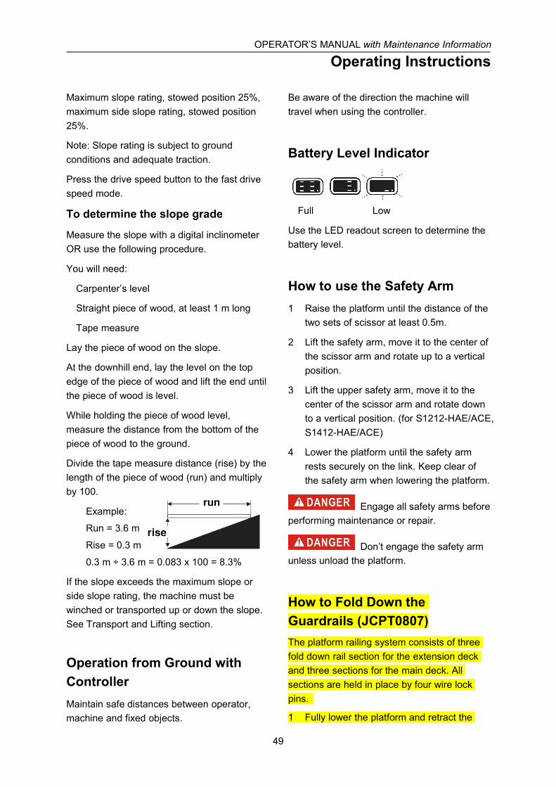
OPERATOR’S MANUAL with Maintenance Information
Operating Instructions
49
Maximum slope rating, stowed position 25%,maximum side slope rating, stowed position25%.
Note: Slope rating is subject to groundconditions and adequate traction.
Press the drive speed button to the fast drivespeed mode.
To determine the slope grade
Measure the slope with a digital inclinometerOR use the following procedure.
You will need:
Carpenter’s level
Straight piece of wood, at least 1 m long
Tape measure
Lay the piece of wood on the slope.
At the downhill end, lay the level on the topedge of the piece of wood and lift the end untilthe piece of wood is level.
While holding the piece of wood level,measure the distance from the bottom of thepiece of wood to the ground.
Divide the tape measure distance (rise) by thelength of the piece of wood (run) and multiplyby 100.
Example:
Run = 3.6 m
Rise = 0.3 m
0.3 m ÷ 3.6 m = 0.083 x 100 = 8.3%
If the slope exceeds the maximum slope orside slope rating, the machine must bewinched or transported up or down the slope.See Transport and Lifting section.
Operation from Ground withControllerMaintain safe distances between operator,machine and fixed objects.
Be aware of the direction the machine willtravel when using the controller.
Battery Level Indicator
Full Low
Use the LED readout screen to determine thebattery level.
How to use the Safety Arm1 Raise the platform until the distance of the
two sets of scissor at least 0.5m.
2 Lift the safety arm, move it to the center ofthe scissor arm and rotate up to a verticalposition.
3 Lift the upper safety arm, move it to thecenter of the scissor arm and rotate downto a vertical position. (for S1212-HAE/ACE,S1412-HAE/ACE)
4 Lower the platform until the safety armrests securely on the link. Keep clear ofthe safety arm when lowering the platform.
Engage all safety arms beforeperforming maintenance or repair.
Don’t engage the safety armunless unload the platform.
How to Fold Down theGuardrails (JCPT0807)The platform railing system consists of threefold down rail section for the extension deckand three sections for the main deck. Allsections are held in place by four wire lockpins.
1 Fully lower the platform and retract the
OPERATOR’S MANUAL with Maintenance Information
Operating Instructions
50
platform extension.
2 Remove the platform controls.
3 From inside the platform, remove the twofront extension deck wire lock pins.
4 Fold down the front rail assembly. Keephands clear of pinch points.
5 Replace the two removed pins back intoeach side rail bracket.
6 Fold down the extension platform right railassembly. Keep hands clear of pinchpoints.
7 Fold down the extension platform left railassembly. Keep hands clear of pinchpoints.
8 Carefully open the gate and move to therear step or the ground.
9 From the rear step or from the ground,remove the right rear main deck wire lockpins.
10 Fold down the right rail assembly. Keephands clear of pinch points.
11 Replace the removed pin back into rear railbracket.
12 Remove the left rear main deck wire lockpins.
13 Fold down the left rail assembly. Keephands clear of pinch points.
14 Replace the removed pin back into rear railbracket.
15 Fold down the rear rail assembly. Keephands free of pinch points.
How to Fold Down the Guardrails(JCPT0808 ~ JCPT1612S)The platform railing system consists of threefold down rail section for the extension deckand three sections for the main deck. Allsections are held in place by four wire lockpins.
1 Fully lower the platform and retract theplatform extension.
2 Remove the platform controls.
3 From inside the platform, remove the twofront extension deck wire lock pins.
4 Fold down the front rail assembly. Keephands clear of pinch points.
5 Replace the two removed pins back intoeach side rail bracket.
6 Fold down the extension platform left railassembly. Keep hands clear of pinchpoints.
7 Fold down the extension platform right railassembly. Keep hands clear of pinchpoints.
8 Carefully open the gate and move to therear step or the ground.
9 From the rear step or from the ground,remove the left rear main deck wire lockpins.
10 Fold down the left rail assembly. Keephands clear of pinch points.
11 Replace the removed pin back into rear railbracket.
12 Remove the right rear main deck wire lockpins.
13 Fold down the right rail assembly. Keephands clear of pinch points.
14 Replace the removed pin back into rear railbracket.
15 Fold down the rear rail assembly. Keephands free of pinch points.
How to Raise the GuardrailsFollow the fold down instructions but in reverseorder.
To Extend and Retract Platform1 Press the platform lock pin pedal on the

OPERATOR’S MANUAL with Maintenance Information
Operating Instructions
51
extension deck by foot.
2 Push the platform extension guardrail toextend the platform to the desired position.
Do not stand on the platform extensionwhile trying to extend it.
Anti-collision protection Safetyfunction introduction (ifequipped)When the anti-collision protection function isactivated, there are three levels of prompts(Danger Warnings).
1 When the Ultrasonic sensor (platformcontrol panel) is 4 meters away from theobstacle zone, the machine will alarm (50beeps per minute).
2 When the Ultrasonic sensor (platformcontrol panel) is 2 meters away from theobstacle zone, the machine will alarm (110beeps per minute).
Note: The above two levels do not limit the liftfunction.
3 When the Ultrasonic sensor (platformcontrol panel) is 1.5 meters away from theobstacle zone, the lift function is disabled,and the alarm will be constant.
After the lift function is disabled, release thejoystick back to neutral position (center) andoperate the joystick to lift again within 5seconds (within the time of the alarmsounding), with in this period the machine willbe enabled to lift again; at this point if notoperated to lift again after 5 seconds (thealarm is relieved), the machine cannot be liftedand alarm sounds again.
Note: After the anti-collision protection functionis triggered, the machine can only be operatedby lowering the height of the platform or drivingto an open position. Do not remove the
ultrasonic sensor and the wiring harnessconnected to the platform control to relieve thelimit.
Sensor Characteristic Response Curve
(Default curve: wide sound lobe)
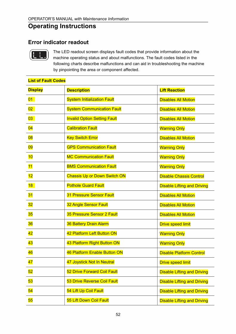
OPERATOR’S MANUAL with Maintenance Information
Operating Instructions
52
Error indicator readoutThe LED readout screen displays fault codes that provide information about themachine operating status and about malfunctions. The fault codes listed in thefollowing charts describe malfunctions and can aid in troubleshooting the machineby pinpointing the area or component affected.
List of Fault Codes
Display Description Lift Reaction
01 System Initialization Fault Disables All Motion
02 System Communication Fault Disables All Motion
03 Invalid Option Setting Fault Disables All Motion
04 Calibration Fault Warning Only
08 Key Switch Error Disables All Motion
09 GPS Communication Fault Warning Only
10 MC Communication Fault Warning Only
11 BMS Communication Fault Warning Only
12 Chassis Up or Down Switch ON Disable Chassis Control
18 Pothole Guard Fault Disable Lifting and Driving
31 31 Pressure Sensor Fault Disables All Motion
32 32 Angle Sensor Fault Disables All Motion
35 35 Pressure Sensor 2 Fault Disables All Motion
36 36 Battery Drain Alarm Drive speed limit
42 42 Platform Left Button ON Warning Only
43 43 Platform Right Button ON Warning Only
46 46 Platform Enable Button ON Disable Platform Control
47 47 Joystick Not In Neutral Drive speed limit
52 52 Drive Forward Coil Fault Disable Lifting and Driving
53 53 Drive Reverse Coil Fault Disable Lifting and Driving
54 54 Lift Up Coil Fault Disable Lifting and Driving
55 55 Lift Down Coil Fault Disable Lifting and Driving
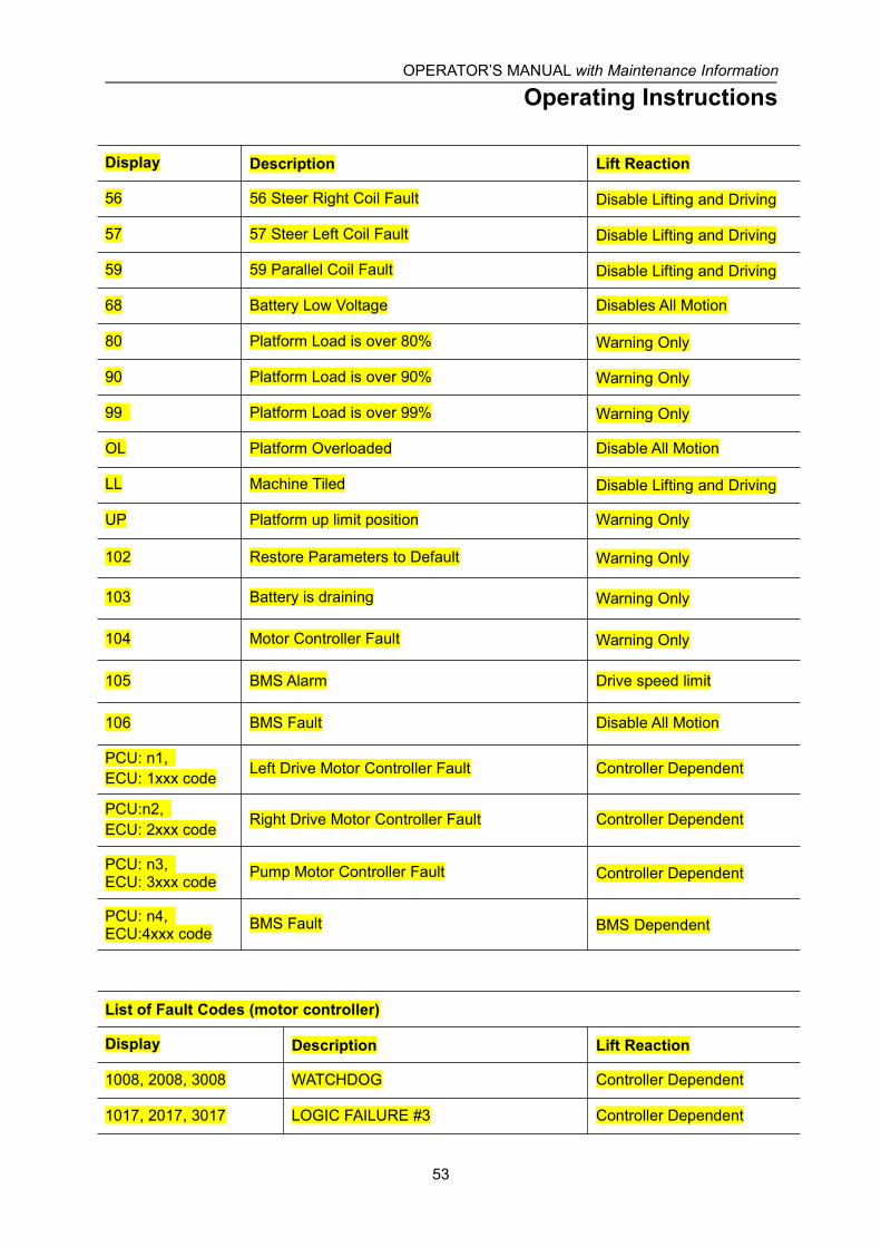
OPERATOR’S MANUAL with Maintenance Information
Operating Instructions
53
Display Description Lift Reaction
56 56 Steer Right Coil Fault Disable Lifting and Driving
57 57 Steer Left Coil Fault Disable Lifting and Driving
59 59 Parallel Coil Fault Disable Lifting and Driving
68 Battery Low Voltage Disables All Motion
80 Platform Load is over 80% Warning Only
90 Platform Load is over 90% Warning Only
99 Platform Load is over 99% Warning Only
OL Platform Overloaded Disable All Motion
LL Machine Tiled Disable Lifting and Driving
UP Platform up limit position Warning Only
102 Restore Parameters to Default Warning Only
103 Battery is draining Warning Only
104 Motor Controller Fault Warning Only
105 BMS Alarm Drive speed limit
106 BMS Fault Disable All Motion
PCU: n1,ECU: 1xxx code Left Drive Motor Controller Fault Controller Dependent
PCU:n2,ECU: 2xxx code
Right Drive Motor Controller Fault Controller Dependent
PCU: n3,ECU: 3xxx code
Pump Motor Controller Fault Controller Dependent
PCU: n4,ECU:4xxx code
BMS Fault BMS Dependent
List of Fault Codes (motor controller)
Display Description Lift Reaction
1008, 2008, 3008 WATCHDOG Controller Dependent
1017, 2017, 3017 LOGIC FAILURE #3 Controller Dependent

OPERATOR’S MANUAL with Maintenance Information
Operating Instructions
54
Display Description Lift Reaction
1018, 2018, 3018 LOGIC FAILURE #2 Controller Dependent
1019, 2019, 3019 LOGIC FAILURE #1 Controller Dependent
1028, 2028, 3028 PUMP VMN LOW Controller Dependent
1029, 2029, 3029 PUMP VMN HIGH Controller Dependent
1030, 2030, 3030 VMN LOW Controller Dependent
1031, 2031, 3031 VMN HIGH Controller Dependent
1037, 2037, 3037 CONTACTOR CLOSED Controller Dependent
1038, 2038, 3038 CONTACTOR OPEN Controller Dependent
1052, 2052, 3052 PUMP I=0 EVER Controller Dependent
1053, 2053, 3053 STBY I HIGH Controller Dependent
1060, 2060, 3060 CAPACITOR CHARGE Controller Dependent
1062, 2062, 3062 TH. PROTECTION Controller Dependent
1065, 2065, 3065 MOTOR TEMPERAT. Controller Dependent
1066, 2066, 3066 BATTERY LOW Controller Dependent
1074, 2074, 3074 DRIVER SHORTED Controller Dependent
1075, 2075, 3075 CONTACTOR DRIVER Controller Dependent
1078, 2078, 3078 VACC NOT OK Controller Dependent
1079, 2079, 3079 INCORRECT START Controller Dependent
1080, 2080, 3080 FORW + BACK Controller Dependent
1086, 2086, 3086 PEDAL WIRE KO Controller Dependent
1152, 2152, 3152 IIC BUS ERROR Controller Dependent
1153, 2153, 3153 ENCODER ERROR XX Controller Dependent
1154, 2154, 3154 OUT MISMATCHXX Controller Dependent
1155, 2155, 3155 SP MISMATCHXX Controller Dependent
1157, 2157, 3157 INPUT MISMATCHXX Controller Dependent
1158, 2158, 3158 NOT RDY DRV.POW. Controller Dependent
1159, 2159, 3159 HVIL FAIL Controller Dependent

OPERATOR’S MANUAL with Maintenance Information
Operating Instructions
55
Display Description Lift Reaction
1160, 2160, 3160 SENS BAT TEMP KO Controller Dependent
1161, 2161, 3161 RPM HIGH Controller Dependent
1162, 2162, 3162 BUMPER STOP Controller Dependent
1163, 2163, 3163 ED SLIP MISMATCH Controller Dependent
1164, 2164, 3164 PWM ACQ. ERROR Controller Dependent
1168, 2168, 3168 SIN/COS D.ERR XX Controller Dependent
1169, 2169, 3169 ENCODER D.ERR XX Controller Dependent
1170, 2170, 3170 WRONG KEY VOLT. Controller Dependent
1171, 2171, 3171 ACQUIRING A.S. Controller Dependent
1172, 2172, 3172 ACQUIRE ABORT Controller Dependent
1173, 2173, 3173 ACQUIRE END Controller Dependent
1174, 2174, 3174 OFFSET SPD.SENS. Controller Dependent
1175, 2175, 3175 SPEED FB. ERROR Controller Dependent
1176, 2176, 3176 HOME SENS.ERR XX Controller Dependent
1177, 2177, 3177 COIL SHOR. EB. Controller Dependent
1178, 2178, 3178 MOTOR TEMP. STOP Controller Dependent
1179, 2179, 3179 STEER SENSOR KO Controller Dependent
1180, 2180, 3180 OVERLOAD Controller Dependent
1181, 2181, 3181 WRONG ENC SET Controller Dependent
1185, 2185, 3185 TILLER ERROR Controller Dependent
1186, 2186, 3186 WAIT MOT.P STILL Controller Dependent
1187, 2187, 3187 LIFT+LOWER Controller Dependent
1188, 2188, 3188 INT. CANBUSKO Controller Dependent
1189, 2189, 3189 PUMP INC START Controller Dependent
1190, 2190, 3190 PUMP VMN NOT OK Controller Dependent
1191, 2191, 3191 PUMP VACC NOT OK Controller Dependent
1192, 2192, 3192 PUMP VACC RANGE Controller Dependent
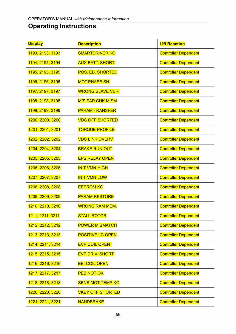
OPERATOR’S MANUAL with Maintenance Information
Operating Instructions
56
Display Description Lift Reaction
1193, 2193, 3193 SMARTDRIVER KO Controller Dependent
1194, 2194, 3194 AUX BATT. SHORT. Controller Dependent
1195, 2195, 3195 POS. EB. SHORTED Controller Dependent
1196, 2196, 3196 MOT.PHASE SH. Controller Dependent
1197, 2197, 3197 WRONG SLAVE VER. Controller Dependent
1198, 2198, 3198 M/S PAR CHK MISM Controller Dependent
1199, 2199, 3199 PARAM TRANSFER Controller Dependent
1200, 2200, 3200 VDC OFF SHORTED Controller Dependent
1201, 2201, 3201 TORQUE PROFILE Controller Dependent
1202, 2202, 3202 VDC LINK OVERV. Controller Dependent
1204, 2204, 3204 BRAKE RUN OUT Controller Dependent
1205, 2205, 3205 EPS RELAY OPEN Controller Dependent
1206, 2206, 3206 INIT VMN HIGH Controller Dependent
1207, 2207, 3207 INIT VMN LOW Controller Dependent
1208, 2208, 3208 EEPROM KO Controller Dependent
1209, 2209, 3209 PARAM RESTORE Controller Dependent
1210, 2210, 3210 WRONG RAM MEM. Controller Dependent
1211, 2211, 3211 STALL ROTOR Controller Dependent
1212, 2212, 3212 POWER MISMATCH Controller Dependent
1213, 2213, 3213 POSITIVE LC OPEN Controller Dependent
1214, 2214, 3214 EVP COIL OPEN Controller Dependent
1215, 2215, 3215 EVP DRIV. SHORT. Controller Dependent
1216, 2216, 3216 EB. COIL OPEN Controller Dependent
1217, 2217, 3217 PEB NOT OK Controller Dependent
1218, 2218, 3218 SENS MOT TEMP KO Controller Dependent
1220, 2220, 3220 VKEY OFF SHORTED Controller Dependent
1221, 2221, 3221 HANDBRAKE Controller Dependent

OPERATOR’S MANUAL with Maintenance Information
Operating Instructions
57
Display Description Lift Reaction
1223, 2223, 3223 COIL SHOR.MC Controller Dependent
1224, 2224, 3224 WAITING FOR NODE Controller Dependent
1224, 2224, 3224 WAITING FOR NODE Controller Dependent
1224, 2224, 3224 WAITING FOR NODE Controller Dependent
1226, 2226, 3226 VACC OUT RANGE Controller Dependent
1227, 2227, 3227 HW FAULT Controller Dependent
1228, 2228, 3228 TILLER OPEN Controller Dependent
1229, 2229, 3229 HW FAULT EB. Controller Dependent
1230, 2230, 3230 LC COIL OPEN Controller Dependent
1231, 2231, 3231 PUMP I NO ZERO Controller Dependent
1232, 2232, 3232 CONT. DRV. EV Controller Dependent
1233, 2233, 3233 POWERMOS SHORTED Controller Dependent
1234, 2234, 3234 DRV. SHOR. EV Controller Dependent
1235, 2235, 3235 CTRAP THRESHOLD Controller Dependent
1236, 2236, 3236 CURRENT GAIN Controller Dependent
1237, 2237, 3237 ANALOG INPUT Controller Dependent
1238, 2238, 3238 HW FAULT EV. Controller Dependent
1239, 2239, 3239 CONTROLLER MISM. Controller Dependent
1240, 2240, 3240 EVP DRIVER OPEN Controller Dependent
1241, 2241, 3241 COIL SHOR. EVAUX Controller Dependent
1242, 2242, 3242 OPEN COIL EV. Controller Dependent
1243, 2243, 3243 THROTTLE PROG. Controller Dependent
1244, 2244, 3244 WARNING SLAVE Controller Dependent
1245, 2245, 3245 IQMISMATCHED Controller Dependent
1246, 2246, 3246 EB. DRIV.OPEN Controller Dependent
1247, 2247, 3247 DATA ACQUISITION Controller Dependent
1248, 2248, 3248 NO CAN MSG. Controller Dependent
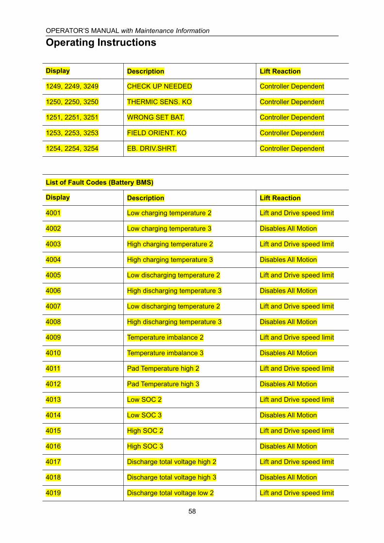
OPERATOR’S MANUAL with Maintenance Information
Operating Instructions
58
Display Description Lift Reaction
1249, 2249, 3249 CHECK UP NEEDED Controller Dependent
1250, 2250, 3250 THERMIC SENS. KO Controller Dependent
1251, 2251, 3251 WRONG SET BAT. Controller Dependent
1253, 2253, 3253 FIELD ORIENT. KO Controller Dependent
1254, 2254, 3254 EB. DRIV.SHRT. Controller Dependent
List of Fault Codes (Battery BMS)
Display Description Lift Reaction
4001 Low charging temperature 2 Lift and Drive speed limit
4002 Low charging temperature 3 Disables All Motion
4003 High charging temperature 2 Lift and Drive speed limit
4004 High charging temperature 3 Disables All Motion
4005 Low discharging temperature 2 Lift and Drive speed limit
4006 High discharging temperature 3 Disables All Motion
4007 Low discharging temperature 2 Lift and Drive speed limit
4008 High discharging temperature 3 Disables All Motion
4009 Temperature imbalance 2 Lift and Drive speed limit
4010 Temperature imbalance 3 Disables All Motion
4011 Pad Temperature high 2 Lift and Drive speed limit
4012 Pad Temperature high 3 Disables All Motion
4013 Low SOC 2 Lift and Drive speed limit
4014 Low SOC 3 Disables All Motion
4015 High SOC 2 Lift and Drive speed limit
4016 High SOC 3 Disables All Motion
4017 Discharge total voltage high 2 Lift and Drive speed limit
4018 Discharge total voltage high 3 Disables All Motion
4019 Discharge total voltage low 2 Lift and Drive speed limit
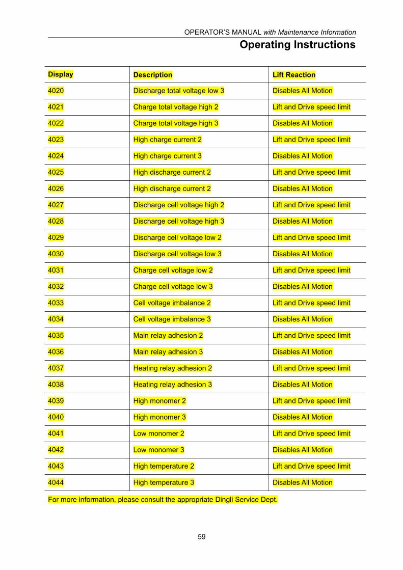
OPERATOR’S MANUAL with Maintenance Information
Operating Instructions
59
Display Description Lift Reaction
4020 Discharge total voltage low 3 Disables All Motion
4021 Charge total voltage high 2 Lift and Drive speed limit
4022 Charge total voltage high 3 Disables All Motion
4023 High charge current 2 Lift and Drive speed limit
4024 High charge current 3 Disables All Motion
4025 High discharge current 2 Lift and Drive speed limit
4026 High discharge current 2 Disables All Motion
4027 Discharge cell voltage high 2 Lift and Drive speed limit
4028 Discharge cell voltage high 3 Disables All Motion
4029 Discharge cell voltage low 2 Lift and Drive speed limit
4030 Discharge cell voltage low 3 Disables All Motion
4031 Charge cell voltage low 2 Lift and Drive speed limit
4032 Charge cell voltage low 3 Disables All Motion
4033 Cell voltage imbalance 2 Lift and Drive speed limit
4034 Cell voltage imbalance 3 Disables All Motion
4035 Main relay adhesion 2 Lift and Drive speed limit
4036 Main relay adhesion 3 Disables All Motion
4037 Heating relay adhesion 2 Lift and Drive speed limit
4038 Heating relay adhesion 3 Disables All Motion
4039 High monomer 2 Lift and Drive speed limit
4040 High monomer 3 Disables All Motion
4041 Low monomer 2 Lift and Drive speed limit
4042 Low monomer 3 Disables All Motion
4043 High temperature 2 Lift and Drive speed limit
4044 High temperature 3 Disables All Motion
For more information, please consult the appropriate Dingli Service Dept.

OPERATOR’S MANUAL with Maintenance Information
Operating Instructions
60
Battery and Charger Instructions
Observe and Obey:√ Do not use an external charger or booster
battery.
√ Charge the battery in a well-ventilated area.
√ Use proper AC input voltage for chargingas indicated on the charger.
√ Use only a Dingli authorized battery andcharger.
√ Charge the battery as soon as receive themachine or after long distance transportation
√ When the battery is stored for a long time, itneeds to be charged regularly. Failure tocharge in time may permanently damage thebattery.
To Charge Battery1 Be sure the batteries are connected before
charging.
2 Open the battery compartment. Thecompartment should remain open for theentire charging cycle.
Maintenance - free battery
3 Connect the battery charger to a groundedAC circuit.
4 The charger will indicate when the batteryis fully charged.
Standard Battery
5 Remove the battery vent caps and checkthe battery acid level. If necessary, addonly enough distilled water to cover theplates. Do not overfill prior to the chargecycle.
6 Replace the battery vent caps.
7 Connect the battery charger to a groundedAC circuit.
8 The charger will indicate when the batteryis fully charged.
9 Check the battery acid level when thecharging cycle is complete. Replenish withdistilled water to the bottom of the fill tube.Do not overfill.
Lithium battery
10 During the charging operation,professional personnel should take care ofit. During the charging process, the plugand socket should be in good contact, thecharging equipment should work normally,and the connection points of the battery
OPERATOR’S MANUAL with Maintenance Information
Operating Instructions
61
pack should be in good contact. Ifsomething goes wrong, it needs to be fixedbefore it can be charged.
11 During charging and discharging, try toavoid water or other conductive objectssplashing on the battery cover and pole.
12 Avoid charging at low temperature (below0 ℃) to ensure battery life
Dry Battery Filling andCharging Instructions1 Remove the battery vent caps and
permanently remove the plastic seal fromthe battery vent openings.
2 Fill each cell with battery acid (electrolyte)until the level is sufficient to cover theplates.
Do not fill to maximum level until the batterycharge cycle is complete. Overfilling cancause the battery acid to overflow duringcharging. Neutralize battery acid spills withbaking soda and water.
3 Install the battery vent caps.
4 Charge the battery.
5 Check the battery acid level when thecharging cycle is complete. Replenish withdistilled water to the bottom of the fill tube.Do not overfill.
Note: In order to achieve an optimal servicelife, discharge of over 60% of the ratedcapacity should be avoided. Discharge of over80% of the rated capacity is a deep dischargeand is not permissible. These significantlyreduce the service life of the battery. Onlythose discharge state indicators that havebeen approved by the battery manufacturermay be used.
Discharged batteries must be chargedimmediately and must not remain in
discharged state. This also applies to batteriesin a state of deep discharge. Otherwise, theservice life of the battery will be significantlyreduced. The battery may freeze when indischarged state
Charge the battery immediately when themachine displays “36” or “68” alarm codeduring work.
During the charging process, if temperaturesare consistently higher than 40°C or lowerthan 15°C, stop charging to check whether thebattery and charger are normal..
OPERATOR’S MANUAL with Maintenance Information
Transport and Lifting Instructions
62
Observe and Obey:√ Common sense and planning must be
applied to control the movement of themachine when lifting it with a crane orforklift.
√ Only qualified aerial lift operators shouldmove the machine on or off the truck.
√ The transport vehicle must be parked on alevel surface.
√ The transport vehicle must be secured toprevent rolling while the machine is beingloaded.
√ Be sure the vehicle capacity, loadingsurfaces and chains or straps are sufficientto withstand the machine weight. See theserial label for the machine weight.
√ The machine must be on a level surface orsecured before releasing the brakes.
√ Do not allow the rails to fall when the snappins are removed. Maintain a firm grasp onthe rails when the rails are lowered.
√ Do not drive the machine on a slope thatexceeds the slope or side slope rating. SeeDriving on a Slope in the OperatingInstructions section.
√ If the slope of the transport vehicle bedexceeds the maximum slope rating, themachine must be loaded and unloadedusing a winch as described.
Brake Release OperationFor the Hydraulic Motor Drive Model
1 Chock the wheels to prevent the machinefrom rolling.
2 Be sure the winch line is properly securedto the drive chassis tie points and the pathis clear of all obstructions.
3 Push in the black brake release knob toopen the brake valve.
4 Pump the red brake release pump knob.
5 If you want to close the brake release, justpull out the black brake release knob.
For the Electric Motor Drive Model
1 Chock the wheels to prevent the machinefrom rolling.
2 Pull out the platform and emergency redEmergency Stop button to the on position.
3 Turn the key switch to the groundcontroller.
4 At the same time, long press the "Enter"button on the ECU panel to enter the thepassword input screen .
5 Press the “Menu enter button” 4 times toenter the Menu screen .
6 Press the "up" or "down" button to switchto the Special mode (" 4. Special Mode ")
7 Press the "Enter" button to display theSpecial mode. Press the "up" or "down"button to switch to the manual push menu(" 1. Brake Release ")
8 Press "Enter" button to display "long pressto confirm release of brake". Long pressthe "enter" button to show "Brake
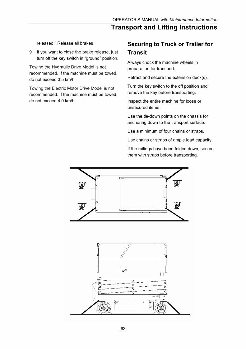
OPERATOR’S MANUAL with Maintenance Information
Transport and Lifting Instructions
63
released!" Release all brakes
9 If you want to close the brake release, justturn off the key switch in “ground” position.
Towing the Hydraulic Drive Model is notrecommended. If the machine must be towed,do not exceed 3.5 km/h.
Towing the Electric Motor Drive Model is notrecommended. If the machine must be towed,do not exceed 4.0 km/h.
Securing to Truck or Trailer forTransitAlways chock the machine wheels inpreparation for transport.
Retract and secure the extension deck(s).
Turn the key switch to the off position andremove the key before transporting.
Inspect the entire machine for loose orunsecured items.
Use the tie-down points on the chassis foranchoring down to the transport surface.
Use a minimum of four chains or straps.
Use chains or straps of ample load capacity.
If the railings have been folded down, securethem with straps before transporting.
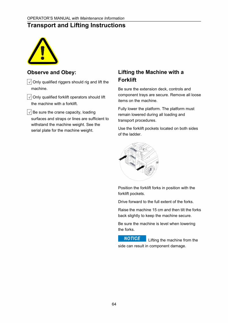
OPERATOR’S MANUAL with Maintenance Information
Transport and Lifting Instructions
64
Observe and Obey:√ Only qualified riggers should rig and lift the
machine.
√ Only qualified forklift operators should liftthe machine with a forklift.
√ Be sure the crane capacity, loadingsurfaces and straps or lines are sufficient towithstand the machine weight. See theserial plate for the machine weight.
Lifting the Machine with aForkliftBe sure the extension deck, controls andcomponent trays are secure. Remove all looseitems on the machine.
Fully lower the platform. The platform mustremain lowered during all loading andtransport procedures.
Use the forklift pockets located on both sidesof the ladder.
Position the forklift forks in position with theforklift pockets.
Drive forward to the full extent of the forks.
Raise the machine 15 cm and then tilt the forksback slightly to keep the machine secure.
Be sure the machine is level when loweringthe forks.
Lifting the machine from theside can result in component damage.
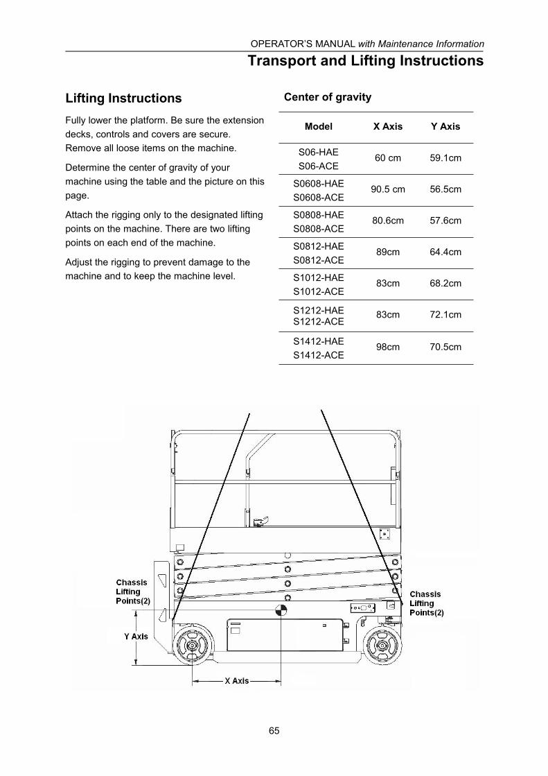
OPERATOR’S MANUAL with Maintenance Information
Transport and Lifting Instructions
65
Lifting InstructionsFully lower the platform. Be sure the extensiondecks, controls and covers are secure.Remove all loose items on the machine.
Determine the center of gravity of yourmachine using the table and the picture on thispage.
Attach the rigging only to the designated liftingpoints on the machine. There are two liftingpoints on each end of the machine.
Adjust the rigging to prevent damage to themachine and to keep the machine level.
Center of gravity
Model X Axis Y Axis
S06-HAES06-ACE
60 cm 59.1cm
S0608-HAES0608-ACE
90.5 cm 56.5cm
S0808-HAES0808-ACE
80.6cm 57.6cm
S0812-HAES0812-ACE
89cm 64.4cm
S1012-HAES1012-ACE
83cm 68.2cm
S1212-HAES1212-ACE
83cm 72.1cm
S1412-HAES1412-ACE
98cm 70.5cm
OPERATOR’S MANUAL with Maintenance Information
Storage
66
Observe and Obey:√ The storage of the machine shall be asfollows, Incorrect storage may affect theperformance and service life of the machine
1 The machine should be stored indoorcoeditor and the ground should be firm andlevel. If be stored in outdoor condition themachine should be covered to prevent thewater and dust.
2 Ensure the machine have been cleanedand the functional before stop to thestorage. Repair an maintain it if necessary.
3 Stop the machine in suitable position so asthe drive or move the machinesconveniently.
Rust protection1 Before the machine is stored into the
storage. Inspecting the paint before themachine is stored into the storage repaintthe machine partly all completely againstthe damage.
2 For moving parts grease can be applied toprevent rust, such as bearings, joints andsliding rails
The machine be stored longtime cannot be used to service until it has beeninspected and maintained according to thedaily check procedure.
How to store the batteries1 When storing the machine for a long time
(one month to six months) be sure to turnoff the main power switch, key switch andemergency stop switch, fully charge. Inorder to ensure that these batteries stayready for operation, the following chargingprocedures must be applied:The machine or check the voltage of eachbattery on the machine once a month toensure that the voltage of battery is notlower than 25.2V, otherwise pleasecharge the machine immediately.
2 When storing the machine for a long time(half a year or more), should be fullycharged state. The batteries should beremoved from the machine. keep thebatteries being clean and ensure nothingbeing placed on the top of batteries. Thebatteries connection should bedisconnection as bellow. Disconnect thewire from the negative pole first thedisconnect the wires from the positive pole.The batteries should be connected asbellow: First connect the positive powerwires with the positive pole then connectthe negative cable line to the negative polefinally. In order to ensure that thesebatteries stay ready for operation, thebatteries should be charged one time inevery quarter.
Lithium battery storage1 When storing the machine for a long time,
be sure to turn off the main power switch,key switch and emergency stop switch andfully charge it
2 In order to avoid the loss of power and theimpact on the service life of the battery, the

OPERATOR’S MANUAL with Maintenance Information
Storage
67
negative pole of the battery should beremoved and the lithium battery should becharged regularly once a month
3 Lithium batteries should be stored in a dry,frost-free room.
4 Avoid contact between lithium batteriesand corrosive objects, and keep away fromplaces with fire sources and heat sources.The electrode should be insulated whenstored (e.g. cover with protective cover) toensure that no metal part is exposed toprevent short circuit.
5 If there are more than 10 groups ofbatteries in centralized storage, it is betterto install a camera for 24-hour monitoring.
The following conditions can result in batteryserious injuries:
- The battery was not charged in timewhen the machine displays “36” or “68”alarm code during work.- Leave the Key Switch, EmergencySwitch or Power Switch on.- Forget to charge the battery regularlywhen storing the machine for a long time.
OPERATOR’S MANUAL with Maintenance Information
Maintenance
68
Observe and Obey:√ Only routine maintenance items specified in
this manual shall be performed by theoperator.
√ Scheduled maintenance inspections shallbe completed by qualified servicetechnicians, according to the manufacturer'sspecifications and the requirementsspecified in this manual.
Maintenance Symbols Legend
The following symbols havebeen used in this manual to help communicatethe intent of the instructions. When one ormore of the symbols appear at the beginningof a maintenance procedure, it conveys themeaning below.
Indicates that tools will be required toperform this procedure.
Indicates that new parts will be requiredto perform this procedure.
Indicates that dealer service will berequired to perform this procedure.
Pre-delivery Preparation ReportThe pre-delivery preparation report containschecklists for each type of scheduledinspection.
Make copies of the Pre-delivery Preparationreport to use for each inspection. Storecompleted forms as required.
Maintenance ScheduleThere are five types of maintenanceinspections that must be performed accordingto a schedule— daily, quarterly, semi-annually,annually, and two year. The ScheduledMaintenance Procedures Section and theMaintenance Inspection Report have beendivided into five subsections—A, B, C, D, andE. Use the following chart to determine whichgroup(s) of procedures are required to performa scheduled inspection.
Inspection Checklist
Daily or every 8 hours A
Quarterly or every 250 hours A+B
Semi-annually or every 500 hours A+B+C
Annually or every 1000 hours A+B+C+D
Two year or every 2000 hours A+B+C+D+E
Maintenance Inspection ReportThe maintenance inspection report containschecklists for each type of scheduledinspection.
Make copies of the Maintenance InspectionReport to use for each inspection. Maintaincompleted forms for a minimum of 4 years orin compliance with your employer, jobsite andgovernmental regulations and requirements.
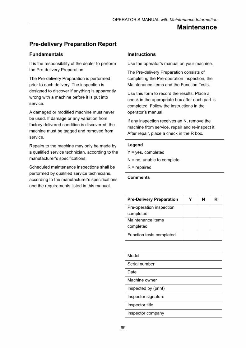
OPERATOR’S MANUAL with Maintenance Information
Maintenance
69
Pre-delivery Preparation ReportFundamentals
It is the responsibility of the dealer to performthe Pre-delivery Preparation.
The Pre-delivery Preparation is performedprior to each delivery. The inspection isdesigned to discover if anything is apparentlywrong with a machine before it is put intoservice.
A damaged or modified machine must neverbe used. If damage or any variation fromfactory delivered condition is discovered, themachine must be tagged and removed fromservice.
Repairs to the machine may only be made bya qualified service technician, according to themanufacturer’s specifications.
Scheduled maintenance inspections shall beperformed by qualified service technicians,according to the manufacturer’s specificationsand the requirements listed in this manual.
Instructions
Use the operator’s manual on your machine.
The Pre-delivery Preparation consists ofcompleting the Pre-operation Inspection, theMaintenance items and the Function Tests.
Use this form to record the results. Place acheck in the appropriate box after each part iscompleted. Follow the instructions in theoperator’s manual.
If any inspection receives an N, remove themachine from service, repair and re-inspect it.After repair, place a check in the R box.
LegendY = yes, completed
N = no, unable to complete
R = repaired
Comments
Pre-Delivery Preparation Y N R
Pre-operation inspectioncompletedMaintenance itemscompleted
Function tests completed
Model
Serial number
Date
Machine owner
Inspected by (print)
Inspector signature
Inspector title
Inspector company
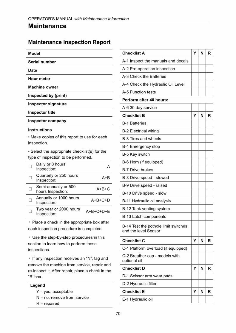
OPERATOR’S MANUAL with Maintenance Information
Maintenance
70
Maintenance Inspection Report
Model
Serial number
Date
Hour meter
Machine owner
Inspected by (print)
Inspector signature
Inspector title
Inspector company
Instructions• Make copies of this report to use for eachinspection.
• Select the appropriate checklist(s) for thetype of inspection to be performed.
□Daily or 8 hoursInspection: A
□Quarterly or 250 hoursInspection: A+B
□Semi-annually or 500hours Inspection: A+B+C
□Annually or 1000 hoursInspection: A+B+C+D
□Two year or 2000 hoursInspection: A+B+C+D+E
• Place a check in the appropriate box aftereach inspection procedure is completed.
• Use the step-by-step procedures in thissection to learn how to perform theseinspections.
• If any inspection receives an “N”, tag andremove the machine from service, repair andre-inspect it. After repair, place a check in the“R’ box.
LegendY = yes, acceptableN = no, remove from serviceR = repaired
Checklist A Y N R
A-1 Inspect the manuals and decals
A-2 Pre-operation inspection
A-3 Check the Batteries
A-4 Check the Hydraulic Oil Level
A-5 Function tests
Perform after 40 hours:
A-6 30 day service
Checklist B Y N R
B-1 Batteries
B-2 Electrical wiring
B-3 Tires and wheels
B-4 Emergency stop
B-5 Key switch
B-6 Horn (if equipped)
B-7 Drive brakes
B-8 Drive speed - stowed
B-9 Drive speed - raised
B-10 Drive speed - slow
B-11 Hydraulic oil analysis
B-12 Tank venting system
B-13 Latch components
B-14 Test the pothole limit switchesand the level Sensor
Checklist C Y N R
C-1 Platform overload (if equipped)
C-2 Breather cap - models withoptional oil
Checklist D Y N R
D-1 Scissor arm wear pads
D-2 Hydraulic filter
Checklist E Y N R
E-1 Hydraulic oil

OPERATOR’S MANUAL with Maintenance Information
Maintenance
71
Checklist A ProceduresA-1
Inspect the Manuals and Decals
Maintaining the operator’s manual in goodcondition is essential to safe machineoperation. Manuals are included with eachmachine and should be stored in the containerprovided in the platform. An illegible or missingmanual will not provide safety and operationalinformation necessary for a safe operatingcondition.
In addition, maintaining all of the safety andinstructional decals in good condition ismandatory for safe machine operation. Decalsalert operators and personnel to the manypossible hazards associated with using thismachine. They also provide users withoperation and maintenance information. Anillegible decal will fail to alert personnel of aprocedure or hazard and could result in unsafeoperating conditions.
1 Check to make sure that the operator’smanual is present and complete in thestorage container on the platform.
2 Examine the pages of manual to be surethat they are legible and in good condition.
⊙ Result: The operator’s manual isappropriate for the machine and themanual are legible and in good condition.
¤ Result: The operator’s manual is notappropriate for the machine or the manualis not in good condition or is illegible.Remove the machine from service until themanual is replaced.
3 Open the operator’s manual to the decalsinspection section. Carefully andthoroughly inspect all decals on themachine for legibility and damage.
⊙ Result: The machine is equipped with allrequired decals, and all decals are legibleand in good condition.
¤ Result: The machine is not equipped withall required decals, or one or more decalsare illegible or in poor condition. Removethe machine from service until the decalsare replaced.
4 Always return the manual to the storagecontainer after use.
Note: Contact your authorized DINGLIdistributor or DINGLI machinery if replacementmanuals or decals are needed.
OPERATOR’S MANUAL with Maintenance Information
Maintenance
72
A-2
Perform Pre-operation Inspection
Completing a Pre-operation Inspection isessential to safe machine operation. ThePre-operation Inspection is a visual inspectionperformed by the operator prior to each workshift. The inspection is designed to discover ifanything is apparently wrong with a machinebefore the operator performs the function tests.The Pre-operation Inspection also serves todetermine if routine maintenance proceduresare required.
Complete information to perform thisprocedure is available in the appropriateoperator’s manual. Refer to the operator’smanual on your machine.
A-3
Check the Batteries
Proper battery condition is essential to goodmachine performance and operational safety.Improper fluid levels or damaged cables andconnections can result in component damageand hazardous conditions.
Note: This check is not required for machineswith lithium batteries, sealed batteries, orMaintenance - free batteries.
Electrocution hazard.Contact with hot or live circuits may result indeath or serious injury. Remove all rings,watches and other jewelry.
Bodily injury hazard.Batteries contain acid. Avoid spilling orcontacting battery acid. Neutralize battery acidspills with baking soda and water.
1 Put on protective clothing and eye wear.
2 Be sure that the battery cable connectionsare tight and free of corrosion.
3 Be sure that the battery hold-down barsare secure.
4 Remove the battery vent caps.
5 Check the battery acid level. If needed,replenish with distilled water to the bottomof the battery fill tube. Do not overfill.
6 Install the vent caps.

OPERATOR’S MANUAL with Maintenance Information
Maintenance
73
A-4
Check the Hydraulic Oil Level
Maintaining the hydraulic oil at the proper levelis essential to machine operation. Improperhydraulic oil levels can damage hydrauliccomponents. Daily checks allow the inspectorto identify changes in oil level that mightindicate the presence of hydraulic systemproblems.
Perform this procedurewith the platform in the stowed position.
1 Visually inspect the sight of hydraulic oillevel from the side of the hydraulic oil tank.
⊙ Result: The hydraulic oil level should be atthe mark of the fuel tank. (Refer to thefollowing table).
Model Scale line(L)
S06-HAE/ACE 5.5
S0608-HAE/ACES0808-HAE/ACES0812-HAE/ACE
15
S1012-HAE/ACES1212-HAE/ACE
17.5
S1412-HAE/ACE 19
2 Add oil if necessary. Do not overfill.
Original Hydraulic oilspecifications:L-HV46
Customers shall choose the appropriatehydraulic oil according to the ambienttemperature used.
Example: L-HV32 or L-HV68
A-5
Perform Function Tests
Completing the function tests is essential tosafe machine operation. Function tests aredesigned to discover any malfunctions beforethe machine is put into service. Amalfunctioning machine must never be used. Ifmalfunctions are discovered, the machinemust be tagged and removed from service.
Complete information to perform thisprocedure is available in the appropriateoperator’s manual. Refer to the operator’smanual on your machine.
A-6
Perform 30 Day Service
The 30 day maintenance procedure is a onetime procedure to be performed after the first30 days or 40 hours of usage. After thisinterval, refer to the maintenance tables forcontinued scheduled maintenance.
Perform the following maintenanceprocedures:
• B-3 Inspect the Tires, Wheels and CastleNut Torque
• D-2 Replace the Hydraulic Tank ReturnFilter Element

OPERATOR’S MANUAL with Maintenance Information
Maintenance
74
Checklist B ProceduresB-1
Inspect the Batteries
DINGLI requires that this procedure beperformed every 250 hours or quarterly,whichever comes first.
Proper battery condition is essential to goodmachine performance and operational safety.Improper fluid levels or damaged cables andconnections can result in component damageand hazardous conditions.
Electrocution / burn hazard.Contact with electrically charged circuits couldresult in death or serious injury. Remove allrings, watches and other jewelry.
Bodily injury hazard.Batteries contain acid. Avoid spilling orcontacting battery acid. Neutralize battery acidspills with baking soda and water.
1 Put on protective clothing and eye wear.
2 Release the battery pack latch and rotatethe battery pack out and away from thechassis.
3 Be sure that the battery cable connectionsare free of corrosion.
Note: Adding terminal protectors and acorrosion preventative sealant will helpeliminate corrosion on the battery terminalsand cables.
4 Be sure that the battery retainers andcable connections are tight.
5 Fully charge the batteries. Allow thebatteries to rest 24 hours beforeperforming this procedure to allow thebattery cells to equalize.
Models without maintenance-free or sealedbatteries:
6 Remove the battery vent caps and checkthe specific gravity of each battery cell witha hydrometer. Note the results.
7 Check the ambient air temperature andadjust the specific gravity reading for eachcell as follows:
• Add 0.004 to the reading of each cell forevery 5.5° C above 26.7° C.
• Subtract 0.004 from the reading of eachcell for every 5.5° C below 26.7° C.
⊙ Result: All battery cells display an adjustedspecific gravity of 1.277 or higher. Thebattery is fully charged. Proceed to step 11.
¤ Result: One or more battery cells display aspecific gravity of 1.217 or below. Proceedto step 8.
8 Perform an equalizing charge OR fullycharge the batteries and allow thebatteries to rest at least 6 hours.
9 Remove the battery vent caps and checkthe specific gravity of each battery cell witha hydrometer. Note the results.
10 Check the ambient air temperature andadjust the specific gravity reading for eachcell as follows:
• Add 0.004 to the reading of each cell forevery 5.5° C above 26.7° C.
• Subtract 0.004 from the reading of eachcell for every 5.5° C below 26.7° C.
⊙ Result: All battery cells display a specificgravity of 1 .277 or greater. The battery is
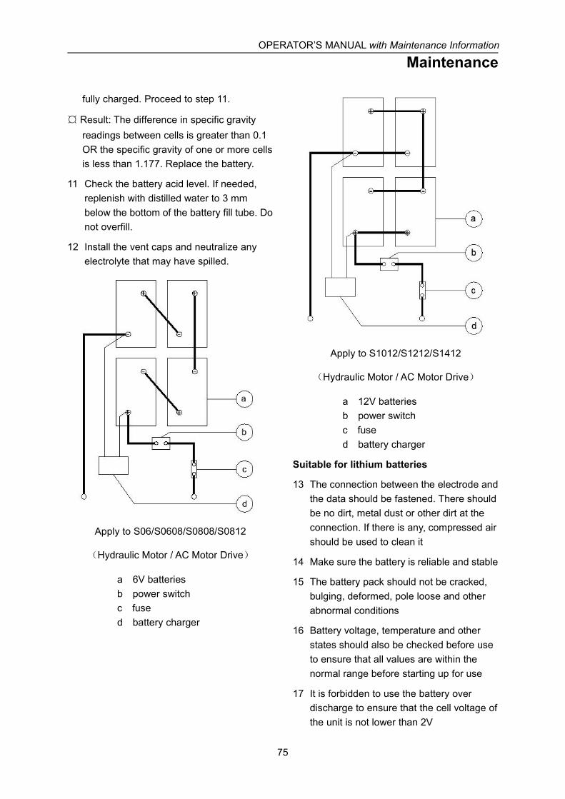
OPERATOR’S MANUAL with Maintenance Information
Maintenance
75
fully charged. Proceed to step 11.
¤ Result: The difference in specific gravityreadings between cells is greater than 0.1OR the specific gravity of one or more cellsis less than 1.177. Replace the battery.
11 Check the battery acid level. If needed,replenish with distilled water to 3 mmbelow the bottom of the battery fill tube. Donot overfill.
12 Install the vent caps and neutralize anyelectrolyte that may have spilled.
Apply to S06/S0608/S0808/S0812
(Hydraulic Motor / AC Motor Drive)
a 6V batteriesb power switchc fused battery charger
Apply to S1012/S1212/S1412
(Hydraulic Motor / AC Motor Drive)
a 12V batteriesb power switchc fused battery charger
Suitable for lithium batteries
13 The connection between the electrode andthe data should be fastened. There shouldbe no dirt, metal dust or other dirt at theconnection. If there is any, compressed airshould be used to clean it
14 Make sure the battery is reliable and stable
15 The battery pack should not be cracked,bulging, deformed, pole loose and otherabnormal conditions
16 Battery voltage, temperature and otherstates should also be checked before useto ensure that all values are within thenormal range before starting up for use
17 It is forbidden to use the battery overdischarge to ensure that the cell voltage ofthe unit is not lower than 2V
OPERATOR’S MANUAL with Maintenance Information
Maintenance
76
All models:
18 Check each battery pack and verify thatthe batteries are wired correctly.
19 Inspect the battery charger plug and pigtailfor damage or excessive insulation wear.Replace as required.
20 Connect the battery charger to a properlygrounded 110 - 230V / 50 – 60 Hz singlephase AC power supply.
⊙ Result: The charger should operate andbegin charging the batteries.
¤ Result: If, simultaneously, the charger alarmsounds and the LEDs blink, correct thecharger connections at the fuse and battery.The charger will then operate correctly andbegin charging the batteries.
Note: For best results, use an extension ofadequate size with a length no longer than15m.
The following must be measured and recordedonce the battery has been fully charged, aftera waiting time of at least 12 hours:
- Total voltage
- Individual voltage of the block battery
If significant changes to previousmeasurements or differences between theblock batteries are identified, then customerservice must be contacted for further testing orrepairs.
Note: If you have any further questionsregarding the battery charger operation,please contact the DINGLI ServiceDepartment.
B-2
Inspect the Electrical Wiring
DINGLI requires that this procedure beperformed every 250 hours or quarterly,whichever comes first.
Maintaining electrical wiring in good conditionis essential to safe operation and goodmachine performance. Failure to find andreplace burnt, chafed, corroded or pinchedwires could result in unsafe operatingconditions and may cause componentdamage.
Electrocution / burn hazard.Contact with electrically charged circuits couldresult in death or serious injury. Remove allrings, watches and other jewelry.
1 Inspect the underside of the chassis fordamaged or missing ground strap(s).
2 Inspect the following areas for burnt,chafed, corroded and loose wires:
• Ground control panel
• Hydraulic power unit module tray
• Battery pack module tray
• Platform controls
3 Turn the key switch to ground control. Turnthe ground red Emergency Stop buttonclockwise to the on position. Pull out theplatform red Emergency Stop button to theon position.
4 Raise the platform until the distance of thetwo sets of scissor at least 0.5m.
5 Lift the safety arm, move it to the center ofthe scissor arm and rotate up to a verticalposition.
OPERATOR’S MANUAL with Maintenance Information
Maintenance
77
6 Lift the upper safety arm, move it to thecenter of the scissor arm and rotate downto a vertical position. (for S1212-HAE/ACE,S1412-HAE/ACE).
7 Lower the platform until the safety armrests securely on the link. Keep clear ofthe safety arm when lowering the platform.
Crushing hazard. Keephands clear of the safety arm when loweringthe platform.
8 Inspect the center chassis area andscissor arms for burnt, chafed and pinchedcables.
9 Inspect the following areas for burnt,chafed, corroded, pinched and loosewires:
• Scissor arms
• ECU to platform controls
• Power to platform wiring
10 Inspect for a liberal coating of dielectricgrease in the following locations:
• Between the ECU and platform controls
• All wire harness connectors Level sensor
11 Raise the platform and return the safetyarm to the stowed position.
12 Lower the platform to the stowed positionand turn the machine off.
B-3
Inspect the Tires and Wheels(including castle nut torque)
DINGLI requires that this procedure beperformed every 250 hours or quarterly,whichever comes first.
Maintaining the tires and wheels in goodcondition is essential to safe operation andgood performance. Tire and/or wheel failurecould result in a machine tip-over. Componentdamage may also result if problems are notdiscovered and repaired in a timely fashion.
1 Check the tire surface and sidewalls forcuts, cracks, punctures and unusual wear.
2 Check each wheel for damage, bends andcracks.
For HA model machine
3 Remove the cotter pin and check eachcastle nut for proper torque.
Note: Always replace the cotter pin with a newone when removing the castle nut or whenchecking the torque of the castle nut.
4 Install a new cotter pin. Bend the cotter pinto lock it in place.
Castle nut torque, dry 406.7Nm
Castle nut torque, lubricated 305Nm
For AC model machine
3 Check each bolt for proper torque.
Bolt torque, dry 125Nm
Bolt torque, lubricated 115Nm
OPERATOR’S MANUAL with Maintenance Information
Maintenance
78
B-4
Test the Emergency Stop
DINGLI requires that this procedure beperformed every 250 hours or quarterly,whichever comes first.
A properly functioning Emergency Stop isessential for safe machine operation. Animproperly operating red Emergency Stopbutton will fail to shut off power and stop allmachine functions, resulting in a hazardoussituation.
As a safety feature, selecting and operatingthe ground controls will override the platformcontrols, except the platform red EmergencyStop button.
1 Turn the key switch to ground control. Pullout the platform and ground redEmergency Stop button to the on position.
2 Push in the red Emergency Stop button atthe ground controls to the off position.
⊙ Result: No machine functions shouldoperate.
3 Turn the key switch to platform control.Pull out the platform and ground redEmergency Stop button to the on position.
4 Push in the red Emergency Stop button atthe platform controls to the off position.
⊙ Result: No machine functions shouldoperate.
Note: The red Emergency Stop button at theground controls will stop all machine operation,even if the key switch is switched to platformcontrol.
B-5
Test the Key Switch
DINGLI requires that this procedure beperformed every 250 hours or quarterly,whichever comes first.
Proper key switch action and response isessential to safe machine operation. Themachine can be operated from the ground orplatform controls and the activation of one orthe other is accomplished with the key switch.Failure of the key switch to activate theappropriate control panel could cause ahazardous operating situation.
Perform this procedure from the ground usingthe platform controls. Do not stand in theplatform.
1 Pull out the platform and ground redEmergency Stop button to the on position.
2 Turn the key switch to platform control.
3 Check the platform up/down function fromthe ground controls.
⊙ Result: The machine functions should notoperate.
4 Turn the key switch to ground control.
5 Check the machine functions from theplatform controls.
⊙ Result: The machine functions should notoperate.
6 Turn the key switch to the off position.
⊙ Result: No function should operate.
OPERATOR’S MANUAL with Maintenance Information
Maintenance
79
B-6
Test the Automotive-style Horn (ifequipped)
DINGLI requires that this procedure beperformed every 250 hours or quarterly,whichever comes first.
The horn is activated at the platform controlsand sounds at the ground as a warning toground personnel. An improperly functioninghorn will prevent the operator from alertingground personnel of hazards or unsafeconditions.
1 Turn the key switch to platform control.Pull out the platform and ground redEmergency Stop button to the on position.
2 Push down the horn button at the platformcontrols.
⊙ Result: The horn should sound.
B-7
Test the Drive Brakes
DINGLI requires that this procedure beperformed every 250 hours or quarterly,whichever comes first.
Proper brake action is essential to safemachine operation. The drive brake functionshould operate smoothly, free of hesitation,jerking and unusual noise.Hydraulically-released individual wheel brakescan appear to operate normally when not fullyoperational.
Perform this procedure with the machine on afirm level surface that is free of obstructions,with the platform extension deck fully retractedand the platform in the stowed position.
1 Mark a test line on the ground forreference.
2 Turn the key switch to platform control.Pull out the platform and ground redEmergency Stop button to the on position.
3 Lower the platform to the stowed position.
4 Press the drive function select button.
5 Choose a point on the machine; i.e.,contact patch of a tire, as a visualreference for use when crossing the testline.
6 Bring the machine to top drive speedbefore reaching the test line. Release thefunction enable switch or the joystick whenyour reference point on the machinecrosses the test line.
7 Measure the distance between the test lineand your machine reference point.
⊙ Result: The machine stops within thespecified braking distance. No actionrequired.

OPERATOR’S MANUAL with Maintenance Information
Maintenance
80
¤ Result: The machine does not stop withinthe specified braking distance.
Note: The brakes must be able to hold themachine on any slope it is able to climb.
8 Replace the brakes and repeat thisprocedure beginning with step 1.
Braking distance, maximum
High range on paved surface 61cm±30cm
B-8
Test the Drive Speed - StowedPosition
DINGLI requires that this procedure beperformed every 250 hours or quarterly,whichever comes first.
Proper drive functions are essential to safemachine operation. The drive function shouldrespond quickly and smoothly to operatorcontrol. Drive performance should also be freeof hesitation, jerking and unusual noise overthe entire proportionally controlled speedrange.
Perform this procedure with the machine on afirm, level surface that is free of obstructions.
1 Create start and finish lines by markingtwo lines on the ground 12.2 m apart.
2 Turn the key switch to platform control.Pull out the platform and ground redEmergency Stop button to the on position.
3 Lower the platform to the stowed position.
4 Press the drive function select button.
5 Choose a point on the machine; i.e.,contact patch of a tire, as a visualreference for use when crossing the startand finish lines.
6 Bring the machine to top drive speedbefore reaching the start line. Begin timingwhen your reference point on the machinecrosses the start line.
7 Continue at full speed and note the timewhen your reference point on the machinepasses over the finish line. Refer tospecifications.

OPERATOR’S MANUAL with Maintenance Information
Maintenance
81
B-9
Test the Drive Speed - RaisedPosition
DINGLI requires that this procedure beperformed every 250 hours or quarterly,whichever comes first.
Proper drive functions are essential to safemachine operation. The drive function shouldrespond quickly and smoothly to operatorcontrol. Drive performance should also be freeof hesitation, jerking and unusual noise overthe entire proportionally controlled speedrange.
Perform this procedure with the machine on afirm, level surface that is free of obstructions.
1 Create start and finish lines by markingtwo lines on the ground 12.2 m apart.
2 Turn the key switch to platform control.Pull out the platform and ground redEmergency Stop button to the on position.
3 Press the lift function select button.
4 Press and hold the function enable switchon the joystick.
5 Raise the platform approximately 2 m fromthe ground.
6 Press the drive function select button.
7 Choose a point on the machine; i.e.,contact patch of a tire, as a visualreference for use when crossing the startand finish lines.
8 Bring the machine to top drive speedbefore reaching the start line. Begin timingwhen your reference point on the machinecrosses the start line.
9 Continue at full speed and note the timewhen your reference point on the machinepasses over the finish line. Refer tospecifications.
B-10
Test the Slow Drive Speed
DINGLI requires that this procedure beperformed every 250 hours or quarterly,whichever comes first.
Proper drive functions are essential to safemachine operation. The drive function shouldrespond quickly and smoothly to operatorcontrol. Drive performance should also be freeof hesitation, jerking and unusual noise overthe entire proportionally controlled speedrange.
Perform this procedure with the machine on afirm, level surface that is free of obstructions.
1 Create start and finish lines by markingtwo lines on the ground 12.2 m apart.
2 Turn the key switch to platform control.Pull out the platform and ground redEmergency Stop button to the on position.
3 Lower the platform to the stowed position.
4 Press the slow speed select button.
5 Choose a point on the machine; i.e.,contact patch of a tire, as a visualreference for use when crossing the startand finish lines.
6 Bring the machine to top drive speedbefore reaching the start line. Begin timingwhen your reference point on the machinecrosses the start line.
7 Continue at full speed and note the timewhen your reference point on the machinepasses over the finish line. The time is lessthan 25 sec.
OPERATOR’S MANUAL with Maintenance Information
Maintenance
82
B-11
Perform Hydraulic Oil Analysis
DINGLI requires that this procedure beperformed every 250 hours or quarterly,whichever comes first.
Replacement or testing of the hydraulic oil isessential for good machine performance andservice life. Dirty oil may cause the machine toperform poorly and continued use may causecomponent damage. Extremely dirtyconditions may require oil changes to beperformed more often.
Before replacing the hydraulic oil, the oil maybe tested by an oil distributor for specific levelsof contamination to verify that changing the oilis necessary.
If the hydraulic oil is not replaced at the twoyear inspection, test the oil quarterly. Replacethe oil when it fails the test. See E-1, Test orReplace the Hydraulic Oil.
B-12
Inspect the Hydraulic Tank CapVenting System
DINGLI requires that this procedure beperformed quarterly or every 250 hours,whichever comes first. Perform this proceduremore often if dusty conditions exist.
A free-breathing hydraulic tank cap is essentialfor good machine performance and service life.A dirty or clogged cap may cause the machineto perform poorly. Extremely dirty conditionsmay require that the cap be inspected moreoften.
1 Remove the breather cap from thehydraulic tank.
2 Check for proper venting.
⊙ Result: Air passes through the breather cap.
¤ Result: If air does not pass through the cap,clean or replace the cap. Proceed to step3.
Note: When checking for positive tank capventing, air should pass freely through the cap.
3 Using a mild solvent, carefully wash thecap venting system. Dry using lowpressure compressed air. Repeat step 2.
4 Install the breather cap onto the hydraulictank.
OPERATOR’S MANUAL with Maintenance Information
Maintenance
83
B-13
Check the Module Tray LatchComponents
DINGLI requires that this procedure beperformed every 250 hours or quarterly,whichever comes first.
Maintaining the module tray latch componentsin good condition is essential to goodperformance and service life. Failure to detectworn out latch components may result inmodule trays opening unexpectedly, creatingan unsafe operating condition.
1 Inspect each module tray rotary latch andrelated components for wear. Tighten anyloose fasteners.
2 Lubricate each module tray rotary latch.Using light oil, apply a few drops to each ofthe springs and to the sides of the rotarylatch mechanism.
B-14
Test the Pothole Limit Switches andthe Level Sensor
DINGLI requires that this procedure beperformed every 250 hours or quarterly,whichever comes first.
Maintaining the limit switches is essential tosafe operation and good machineperformance. Operating the machine with afaulty limit switch could result in reducedmachine performance and a potentially unsafeoperating condition.
Perform these procedures with the machine ona firm, level surface that is free of obstructions.
Level sensor
1 Remove the platform controls from theplatform.
2 Turn the key switch to platform control.Pull out the platform and ground redEmergency Stop button to the on position.
3 Press the drive function select button
4 Move the machine onto a grade whichexceeds the rating of the level sensor.Refer to the serial label on the machine.
5 Press the lift function select button.Standing on the up-hill side of the machine,attempt to raise the platform toapproximately 2.4 m.
⊙ Result: The LED readout screen showscode LL, an alarm sounds, and themachine stops lifting after the potholeguards are deployed. The machine isfunctioning properly.
¤ Result: The LED readout screen does notshow code LL, the alarm does not soundand the machine will continue to lift theplatform after the pothole guards are
OPERATOR’S MANUAL with Maintenance Information
Maintenance
84
deployed. Adjust or replace the levelsensor.
6 Press the drive function select button.Standing on the up-hill side of the machine,attempt to steer and drive the machine.
⊙ Result: The LED readout screen showscode LL, an alarm sounds, and themachine will not steer or drive. Themachine is functioning properly.
¤ Result: The LED readout screen does notshow code LL, the alarm does not soundand the steer and drive functions operate.Adjust or replace the level sensor.
Pothole Limit Switches
7 Lower the platform to the stowed position.Move the machine onto a firm, levelsurface.
8 Place a wooden block approximately 5 cmtall under the right pothole guard.
9 Press the lift function select button.Attempt to raise the platformapproximately 2.4m.
⊙ Result: The pothole guard contacts theblock and does not fully deploy, the LEDreadout screen shows code 18, an alarmsounds and the platform will lift to 2.4m orbeyond. The machine is functioningproperly.
¤ Result: The pothole guard contacts theblock and does not fully deploy, the LEDreadout screen does not show code 18, thealarm does not sound and the machine willcontinue to lift the platform after the potholeguards are deployed. Adjust or replace thepothole limit switch.
10 Press the drive function select button.Attempt to steer or drive the machine.
⊙ Result: The LED readout screen showscode 18, an alarm sounds, and themachine will not steer or drive. The
machine is functioning properly.
¤ Result: The LED readout screen does notshow code 18, the alarm does not soundand the steer and drive functions operate.Adjust or replace the down limit switch.
11 Lower the platform to the stowed positionand remove the block under the rightpothole guard.
12 Repeat this procedure beginning with step34 for the left pothole guard.
13 Lower the platform to the stowed position,remove the block under the left potholeguard.
14 Turn off the machine.
OPERATOR’S MANUAL with Maintenance Information
Maintenance
85
Checklist C ProceduresC-1
Test the Platform Overload System (ifequipped)
DINGLI requires that this procedure beperformed every 500 hours or six months,whichever comes first or when the machinefails to lift the maximum rated load.
Testing the platform overload system regularlyis essential to safe machine operation.Continued use of an improperly operatingplatform overload system could result in thesystem not sensing an overloaded platformcondition. Machine stability could becompromised resulting in the machine tippingover.
The platform overload system is designed toprevent machine operation in the event theplatform is overloaded. Models equipped withthe platform overload option are provided withtwo additional machine control components:the overload pressure sensor and the platformheight sensor.
The overload pressure transducer, located atthe valve of the lift cylinder, is used todetermine the pressure inside the lift cylinder.
The platform height sensor, located at thesteer end of the chassis, battery side, is usedto determine the height of the platform.
The overload pressure transducer and theplatform height sensor provide the GCON withnecessary information to determine the load inthe platform.
Note: The overload system will not measureloads at or below the height of the Down Limit.
Note: Perform this test from the ground withthe platform controller. Do not stand in theplatform.
Perform this procedure withthe machine on a firm, level surface.
1 Turn the key switch to platform controls.
Pull out the platform and ground redEmergency Stop button to the on position.
2 Determine the maximum platform capacity.
3 Using a suitable lifting device, place anappropriate test weight equal to themaximum platform capacity in the centerof the platform floor. Raise the platform.
⊙ Result: The overload alarm not soundsduring the whole trip, indicating a normalcondition.
¤ Result: The overload alarm sounds duringthe whole trip. Calibrate the platformoverload system.
4 The platform should lower to the stowedposition
5 Add an additional weight to the platformnot to exceed 20% of the maximum ratedload. Raise the platform.
⊙ Result: The overload alarm at the platformcontrols sound, indicating a normalcondition.
¤ Result: The overload alarm at the platformcontrols does not sound. Calibrate theplatform overload system.
6 Test all machine functions from theplatform controls.
⊙ Result: All platform control functions shouldnot operate.
OPERATOR’S MANUAL with Maintenance Information
Maintenance
86
7 Turn the key switch to ground control.
8 Test all machine functions from the groundcontrols
⊙ Result: All ground control functions shouldnot operate.
9 Lift the test weight off the platform floorusing a suitable lifting device.
10 The platform should lower to the stowedposition.
C-2
Replace the Hydraulic Tank BreatherCap
DINGLI requires that this procedure beperformed every 500 hours or semi-annually,whichever comes first.
The hydraulic tank is a vented-type tank. Thebreather cap has an internal air filter that canbecome clogged or, over time, can deteriorate.If the breather cap is faulty or improperlyinstalled, impurities can enter the hydraulicsystem which may cause component damage.Extremely dirty conditions may require that thecap be inspected more often.
1 Remove and discard the hydraulic tankbreather cap.
2 Install a new cap onto the tank.
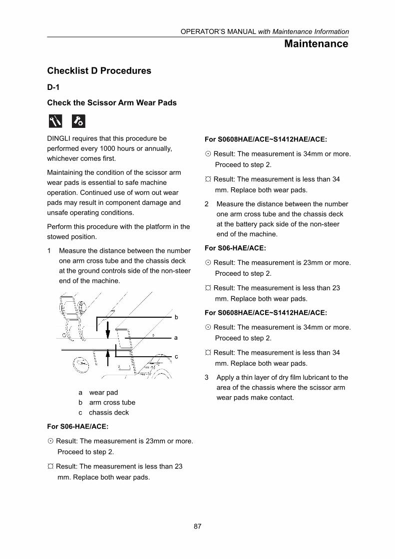
OPERATOR’S MANUAL with Maintenance Information
Maintenance
87
Checklist D ProceduresD-1
Check the Scissor Arm Wear Pads
DINGLI requires that this procedure beperformed every 1000 hours or annually,whichever comes first.
Maintaining the condition of the scissor armwear pads is essential to safe machineoperation. Continued use of worn out wearpads may result in component damage andunsafe operating conditions.
Perform this procedure with the platform in thestowed position.
1 Measure the distance between the numberone arm cross tube and the chassis deckat the ground controls side of the non-steerend of the machine.
a wear padb arm cross tubec chassis deck
For S06-HAE/ACE:
⊙ Result: The measurement is 23mm or more.Proceed to step 2.
¤ Result: The measurement is less than 23mm. Replace both wear pads.
For S0608HAE/ACE~S1412HAE/ACE:
⊙ Result: The measurement is 34mm or more.Proceed to step 2.
¤ Result: The measurement is less than 34mm. Replace both wear pads.
2 Measure the distance between the numberone arm cross tube and the chassis deckat the battery pack side of the non-steerend of the machine.
For S06-HAE/ACE:
⊙ Result: The measurement is 23mm or more.Proceed to step 2.
¤ Result: The measurement is less than 23mm. Replace both wear pads.
For S0608HAE/ACE~S1412HAE/ACE:
⊙ Result: The measurement is 34mm or more.Proceed to step 2.
¤ Result: The measurement is less than 34mm. Replace both wear pads.
3 Apply a thin layer of dry film lubricant to thearea of the chassis where the scissor armwear pads make contact.
OPERATOR’S MANUAL with Maintenance Information
Maintenance
88
D-2
Replace the Hydraulic Tank ReturnFilter Element
DINGLI requires that this procedure beperformed every 1000 hours or annually,whichever comes first.
Replacement of the hydraulic tank return filteris essential for good machine performanceand service life. A dirty or clogged filter maycause the machine to perform poorly andcontinued use may cause component damage.Extremely dirty conditions may require that thefilter be replaced more often.
Beware of hot oil. Contactwith hot oil may cause severe burns.
The hydraulic tank returnfilter is mounted on the bracket between thefunction manifold and the hydraulic power unit.
1 Clean the area around the oil filter.Remove the filter with an oil filter wrench.
2 Apply a thin layer of oil to the new oil filtergasket.
3 Install the new filter and tighten it securelyby hand.
4 Use a permanent ink marker to write thedate and number of hours from the hourmeter onto the filter.
5 Turn the key switch to ground control. Pullout the platform and ground redEmergency Stop button to the on position.
6 Activate and hold the platform up toggleswitch.
7 Inspect the filter and related componentsto be sure that there are no leaks.
8 Clean up any oil that may have spilled.
OPERATOR’S MANUAL with Maintenance Information
Maintenance
89
Checklist E ProcedureE-1
Test or Replace the Hydraulic Oil
DINGLI requires that this procedure beperformed every 2000 hours or every twoyears, whichever comes first.
Replacement or testing of the hydraulic oil isessential for good machine performance andservice life. Dirty oil may cause the machine toperform poorly and continued use may causecomponent damage. Extremely dirtyconditions may require oil changes to beperformed more often.
Before replacing the hydraulic oil, the oil maybe tested by an oil distributor for specific levelsof contamination to verify that changing the oilis necessary.
If the hydraulic oil is not replaced at the twoyear inspection, test the oil quarterly. Replacethe oil when it fails the test.
Note: Perform this procedure with the platformin the stowed position.
1 Disconnect the battery pack from themachine.
Electrocution / burn hazard:Contact with electrically charged circuits couldresult in death or serious injury. Remove allrings, watches and other jewelry.
2 Open the power unit module tray.
3 Remove the oil drain plug at bottom.
4 Drain all of the oil into a suitable container.
5 Tag and disconnect the hydraulic tankreturn line from the hydraulic filter headand remove the line from the tank. Cap thefitting on the filter head.
6 Tag and disconnect the hydraulic pumpinlet line and remove the line from the tank.Cap the fitting on the pump.
7 Remove the hydraulic tank retainingfasteners and remove the hydraulic tankfrom the machine.
Bodily injury hazard.Spraying hydraulic oil can penetrate and burnskin. Loosen hydraulic connections very slowlyto allow the oil pressure to dissipate gradually.Do not allow oil to squirt or spray.
8 Clean up any oil that may have spilled.Properly discard the used oil.
9 Clean the inside of the hydraulic tank usinga mild solvent. Allow the tank to drycompletely.
10 Install a new filter onto the tank.
11 Tighten the drain plug. Torque tospecification.
Torque specifications
Hydraulic tank drain plug, dry 4.5Nm
Hydraulic tank drain plug, lubricated 3.4Nm
12 Install the hydraulic tank and install andtighten the hydraulic tank retainingfasteners. Torque to specification.
Torque specifications
Hydraulic tank retaining fasteners, dry 4Nm
Hydraulic tank drain plug, lubricated 2.9Nm

OPERATOR’S MANUAL with Maintenance Information
Maintenance
90
13 Install the hydraulic pump inlet line into thetank. Install the fitting onto the pump andtorque.
14 Install the hydraulic pump return line intothe tank. Install the fitting onto thehydraulic filter head and torque.
15 Fill the tank with hydraulic oil until the fluidis full in the hydraulic tank. Do not overfill.
16 Activate the pump to fill the hydraulicsystem with oil and bleed the system of air.
Component damage hazard.The pump can be damaged if operated withoutoil. Be careful not to empty the hydraulic tankwhile in the process of filling the hydraulicsystem. Do not allow the pump to cavitate.
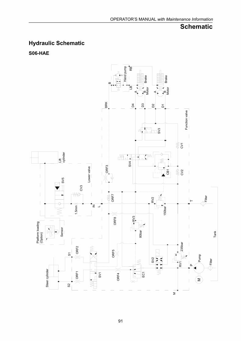
OPERATOR’S MANUAL with Maintenance Information
Schematic
91
Hydraulic SchematicS06-HAE
Pum
p
IN
A A BB
SV5
CV3
D3
D2
D1D4
SV4
SV3
P
M
T
BR
K
L
S2
S1
LB
B
RB
RV3
SV2
RV2
CB1
CV2
CV1
RV1
EC
1
OR
F7
OR
F3
SV1
OR
F1O
RF2
OR
F5O
RF4
80ba
r
Tank
Filte
r
Func
tion
valv
e
Ste
er c
ylin
der
Pla
tform
load
ing
(Opt
ion)
Lift
cylin
der
Low
er v
alve
Sen
sor
Han
d pu
mp
Mot
orB
rake
Mot
orB
rake
235b
ar
1.5m
m
150b
ar
Filte
r
OR
F8
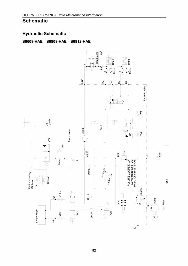
OPERATOR’S MANUAL with Maintenance Information
Schematic
92
Hydraulic SchematicS0608-HAE S0808-HAE S0812-HAE
Pum
p
IN
A A BB
SV
5
CV
3
D3
D2
D1D4
LB
B
RB
RV
3
SV
2R
V2
CB
1
CV
2C
V1
RV
1
EC
1
OR
F7
OR
F3
SV
1
OR
F1O
RF2
OR
F5O
RF4
120b
ar
Tank
Filte
r
Func
tion
valv
e
Ste
er c
ylin
der
Pla
tform
load
ing
(Opt
ion)
Lift
cylin
der
Low
er v
alve
Sen
sor
Han
d pu
mp
Mot
orB
rake
SV
4
SV
3
P
M
T
BR
K
L
S2
S1
1.5m
m
235b
ar
Mot
orB
rake
Filte
r
OR
F8
RV2
=130
bar(J
CPT
0808
HA)
RV2
=160
bar(J
CPT
0812
HA)
RV2
=160
bar(J
CPT
1008
HA)
RV2
=210
bar(J
CPT
1012
HA)
RV2
=130
bar(
S060
8-H
AE)
RV2
=160
bar(
S080
8-H
AE)
RV2
=210
bar(
S081
2-H
AE)
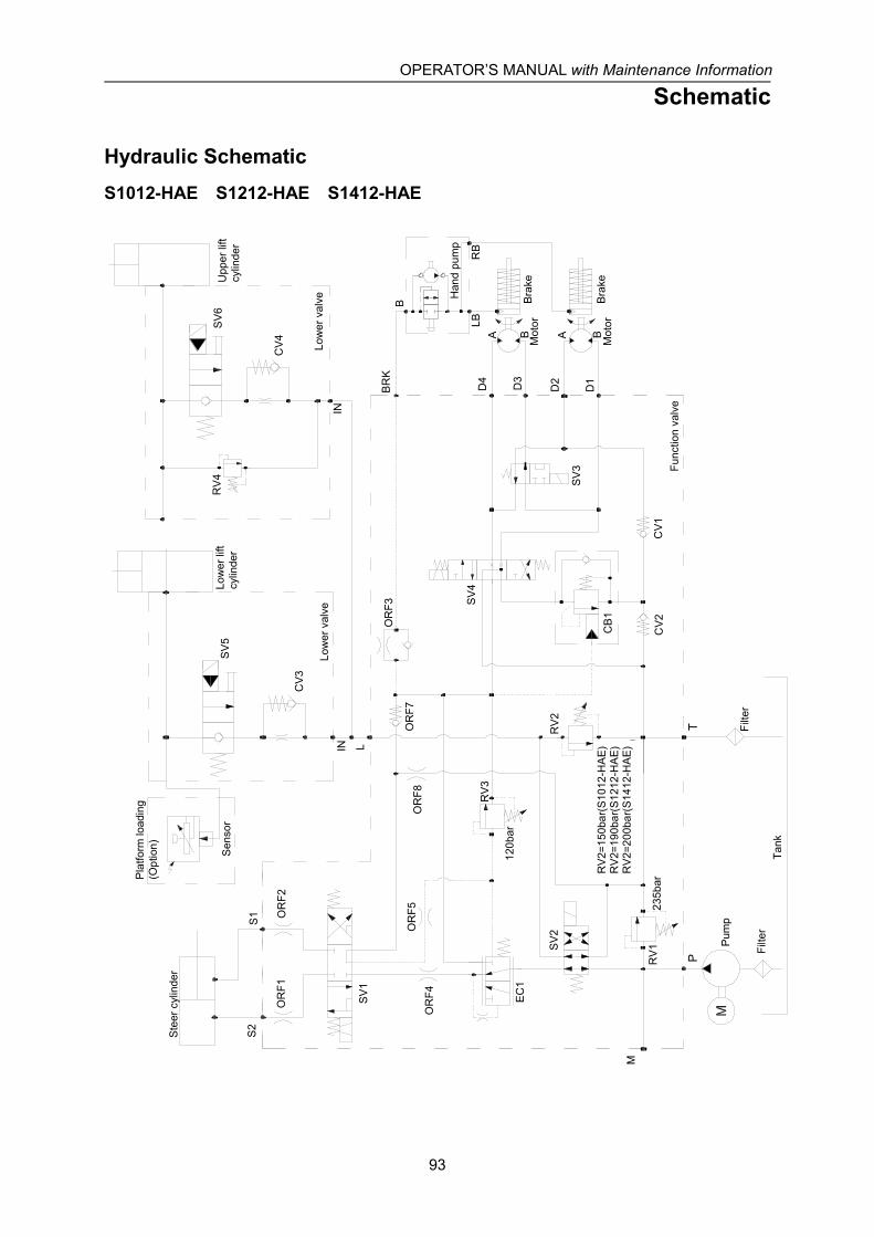
OPERATOR’S MANUAL with Maintenance Information
Schematic
93
Hydraulic SchematicS1012-HAE S1212-HAE S1412-HAE
235b
ar
SV
5
CV3
SV
6
CV4
Filte
r
Pum
p
D3
D2
D1D4
IN
A A BB
IN
RV4
Pla
tform
load
ing
(Opt
ion)
Low
er li
ftcy
linde
r
Low
er v
alve
Upp
er li
ftcy
linde
r
Low
er v
alve
Sen
sor
Han
d pu
mp
Mot
orB
rake
Mot
orB
rake
SV
4
SV
3
P
M
T
BR
K
L
S2
S1
LB
B
RB
RV3
SV
2R
V2
CB1
CV2
CV1
RV1
EC
1
OR
F7
OR
F3
SV
1
OR
F1O
RF2
OR
F5O
RF4
120b
ar
Tank
Filte
r
Func
tion
valv
e
Ste
er c
ylin
der
OR
F8
RV
2=15
0bar
(JC
PT1
212H
A)
RV
2=19
0bar
(JC
PT1
412H
A)
RV
2=20
0bar
(JC
PT1
612H
A)
RV
2=21
0bar
(JC
PT1
612H
AS
)
RV2
=150
bar(
S101
2-H
AE)
RV2
=190
bar(
S121
2-H
AE)
RV2
=200
bar(
S141
2-H
AE)

OPERATOR’S MANUAL with Maintenance Information
Schematic
94
Hydraulic SchematicS06-ACE
IN
SV3
CV1
Pump
Tank
Filter
Function valve
Steer cylinder
Platform loading(Option)
Liftcylinder
Lower valve
Sensor
FR1
RV2
150bar
Filter
P
M
SV2
SV1
S1 S2
L
T
80bar
RV1
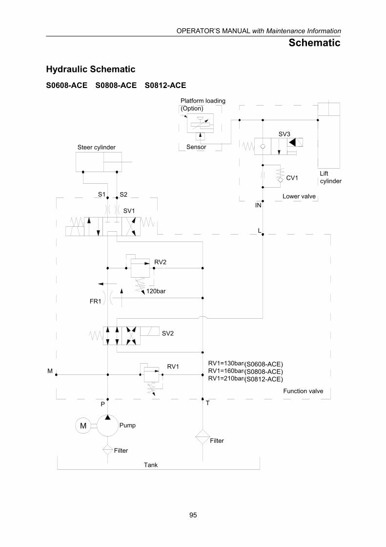
OPERATOR’S MANUAL with Maintenance Information
Schematic
95
Hydraulic SchematicS0608-ACE S0808-ACE S0812-ACE
P
M
SV2
SV1
S1 S2
L
T
120bar
RV1
IN
SV3
CV1
Pump
Tank
Filter
Function valve
Steer cylinder
Platform loading(Option)
Liftcylinder
Lower valve
Sensor
RV1=130bar(JCPT0808AC)RV1=160bar(JCPT1008AC)RV1=210bar(JCPT1012AC)
FR1
RV2
Filter
(S0608-ACE)(S0808-ACE)(S0812-ACE)
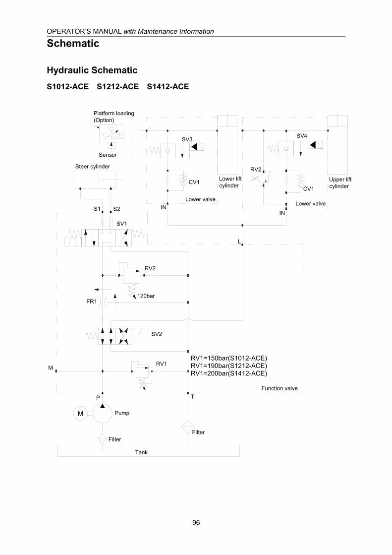
OPERATOR’S MANUAL with Maintenance Information
Schematic
96
Hydraulic SchematicS1012-ACE S1212-ACE S1412-ACE
Pump
Tank
SV3
CV1
IN
P
M
SV2
SV1
S1 S2
L
T
120bar
RV1
Filter
Function valve
Steer cylinder
Platform loading(Option)
Lower liftcylinder
Lower valveLower valve
Upper liftcylinder
Sensor
IN
SV4
CV1
RV2
FR1
RV2
Filter
RV1=150bar(JCPT1212AC)RV1=190bar(JCPT1412AC)RV1=200bar(JCPT1612AC)RV1=210bar(JCPT1612ACS)
RV1=150bar(S1012-ACE)RV1=190bar(S1212-ACE)RV1=200bar(S1412-ACE)
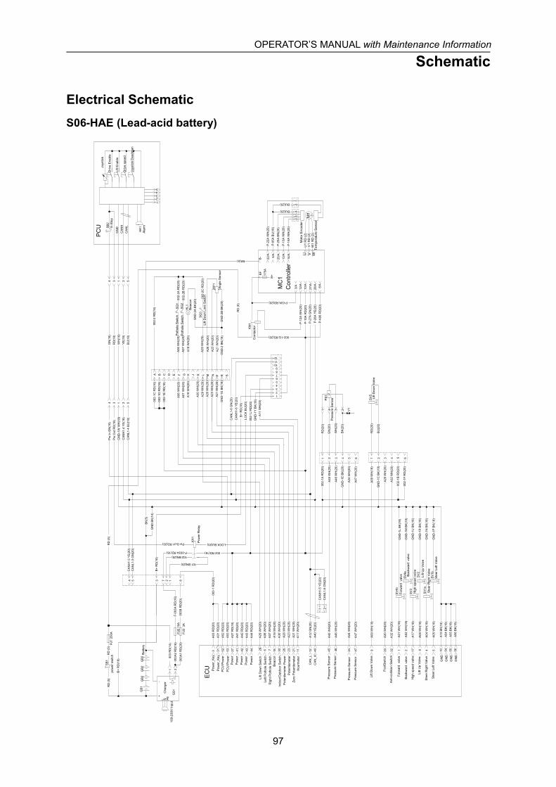
OPERATOR’S MANUAL with Maintenance Information
Schematic
97
Electrical SchematicS06-HAE (Lead-acid battery)
GN
D-1
W W
H(1
8)C
AN
H1-
4 Y
E(1
8)C
AN
L1-4
BU
(18)
4 3 1 2 5
GN
(18)
RD
(18)
WH
(18)
YE
(18)
BU
(18)
4 3 1 2 5
1 2
F-003A RD(16)
Pw Out1 RD(20) KA
1
002 RD(16)
A03
RD
(20)
A31
RD
(20)
A52
RD
(20)
A53
RD
(20)
A27
RD
(18)
A41
RD
(20)
A42
RD
(20)
A43
RD
(20)
A44
RD
(20)
A06
WH
(20)
A07
WH
(20)
A20
WH
(20)
A32
WH
(20)
A24
WH
(20)
A47
WH
(20)
A23
WH
(20)
3 31 52 53 27 41 42 43 44 6 7 20 3224 4723
EC
U
CA
N_L
CA
N_H
A12
GN
(20)
A40
YE
(20)
A26
WH
(20)
12 4026
A09
WH
(18)
A18
WH
(20)
A45
WH
(20)
A46
WH
(20)
A08
WH
(18)
A04
WH
(18)
A05
WH
(18)
918 45 46 8 4 5S
V1b
SV
1a
SV
2
002-
1A R
D(2
0)
A09
WH
(18)
GN
D-1
C B
K(1
8)
GN
D-1
E B
K(2
0)
A45
WH
(20)
A46
WH
(20)
1 2 3 4 5 6 1 2 3 4 5 6
RD
(20)
BK
(20)
GN
(20)
WH
(20)
RD
(5)
BK(5)
SB
2
GN
DC
AN
HC
AN
L
HA
1
PC
U
A30
WH
(20)
30
A01
WH
(18)
A02
WH
(18)
SV
4a
SV
4b
GN
D-1
M B
K(1
8)
GN
D-1
L B
K(1
8)
A17
WH
(18)
17S
V3
GN
D-1
U B
K(1
8)
BK
(5)
175A
B+
P-1
0A R
D(2
0)10
/A
27/A
28/A
P-2
7A G
N(2
0)
P-2
8A Y
E(2
0)
3/A 6/A
GN
DA
55 B
K(1
8)55
GN
DA
56 B
K(1
8)56
P-1
2A W
H(2
0)12
/A
A21
WH
(20)
21
002-1G RD(20)
P-03A RD(20)
002-
1B R
D(2
0)
002-
1F R
D(2
0)
A24
WH
(20)
A47
WH
(20)
A20
WH
(20)
A32
WH
(20)
12
1 2C
AN
H1-
5 Y
E(2
0)C
AN
L1-5
GN
(20)
12345
+-
L N PE
GN
D B
K(1
4)
GN
D-1
P B
K(1
8)
GN
D-1
N B
K(1
8)
RD
(20)
BU
(20)
SV
5
PS
1 P
MC
1
U V WM
13~
W1
RD
(2)
V1
RD
(2)
U1
RD
(2)
22/A 5/A
25/A
13/A
14/A
BF
B-
1 2
P-2
2A W
H(2
0)
P-0
5A B
U(1
8)
P-2
5A B
N(2
0)
P-1
3A W
H(2
0)
P-1
4A W
H(2
0)
41
32
BU(20)
BU(20)
P-A
06 R
D(2
0)
GN
D-1
R B
K(1
8)
GN
DG
ND
A10
BK
(18)
A54
BK
(18)
10 54
RD
(5)
KM
1
Pw
In G
N(1
8)P
w O
ut R
D(1
8)
A29
WH
(20)
29
102 BN(20)
101 BN(20)
GS
1
003-
1 R
D(2
0)812754 3
CA
NL1
-3 G
N(2
0)C
AN
H1-
3 Y
E(2
0)
B+
RD
(18)
121110987654321
A11
WH
(20)
11
LOC
K B
U(2
0)
A11
WH
(20)
LOCK BU(20)B
+ R
D(1
8)
GN
D-1
Y B
K(1
8)00
2-1J
RD
(20)
CA
NH
1-6
YE
(20)
CA
NL1
-6 G
N(2
0)
1 4 3 2
GB
2G
B1
GB
2G
B2
FU3
3A
FU1
250A
RD
(5)
003A
1 R
D(2
0)00
3B R
D(2
0)
F-00
3A R
D(1
6)
B+
RD
(18)
SB
1R
D (5
)
FU2
10A
003A
2 R
D(1
6)
003
RD
(14)
V1
002-
1C R
D(1
6)00
2-1D
RD
(18)
002-
1E R
D(1
8)
A06
WH
(20)
A07
WH
(20)
A18
WH
(20)
A26
WH
(20)
A23
WH
(20)
GN
D-1
G B
K(1
8)
A B C D E F G H J K L M
A06
WH
(20)
SQ
1
RP
1
HL1
A07
WH
(20)
SQ
2
A30
WH
(20)
A21
WH
(20)
002-
2 R
D(1
6)
002-
2A R
D(2
0)
002-
2B R
D(2
0)
A26
WH
(20)
A23
WH
(20)
GN
D-2
B B
K(2
0)A
21 W
H(2
0)G
ND
-2 B
K(1
8)
A18
WH
(20)
GN
D-2
A B
K(2
0)
002-
2C R
D(2
0)A
29 W
H(2
0)S
Q3
A29
WH
(20)
N P R S
Pot
hole
Sw
itch
Pot
hole
Sw
itch
Bea
con
Lift
Dow
n Li
mit
Sw
itch
Ang
le S
enso
r
Pre
ssur
e S
enso
r
Pow
er_K
eyP
ower
_Key
PC
U P
ower
PC
U P
ower
Left
Poth
ole
Switc
h
Bea
con
Pow
erP
ower
Rig
ht P
otho
le S
witc
h
Lift
Dow
n S
witc
h
Pow
erP
ower
Indo
or/O
utdo
or S
witc
h
Foot
Switc
h
Ant
i-col
lisio
n Sw
itch
Pot
entio
met
er Z
ero
Pote
ntio
met
er
Lift
Dow
n V
alve
Lift
Up
Valv
e
Ste
er R
ight
Val
ve
Ste
er L
eft V
alve
Pre
ssur
e S
enso
r
Pre
ssur
e S
enso
r
Pot
entio
met
er P
ower
Lift
Dow
n V
alve
100-
230V
Inpu
t
Cha
rger
Pow
er R
elay
Bat
tery
pow
er s
witc
h
Tem
pera
ture
Sen
sor
Mot
or E
ncod
er
Con
tact
or
E-S
top
Ala
rm
Joys
tick
Driv
e E
nabl
e
Lift
Enab
le
Driv
e sp
eed
Joys
tick
Dea
dman
Lift
Up
Valv
e
Ste
er R
ight
Val
ve
Ste
er L
eft V
alve
Forw
ard
val
ve
Bac
kwar
d v
alve
Hig
h sp
eed
valv
e
Forw
ard
val
ve Bac
kwar
d v
alve
Hig
h sp
eed
valv
e
Con
trolle
r
Pow
er
Pre
ssur
e S
enso
r
Pre
ssur
e S
enso
r
Hou
rmet
er
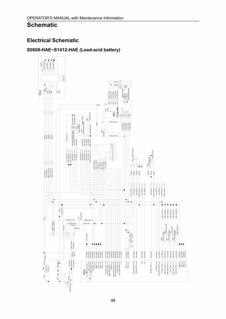
OPERATOR’S MANUAL with Maintenance Information
Schematic
98
Electrical SchematicS0608-HAE~S1412-HAE (Lead-acid battery)
GN
D-1
P BK
(18)
GN
D-1
N B
K(1
8)
RD
(20)
RD
(20)
BU
(20)
HL1
SV5
SV6
PS1
P
MC
1
U V WM
13~
W1
RD
(2)
V1
RD
(2)
U1
RD
(2)
22/A 5/A
25/A
13/A
14/A
BF
B-
CANL
CANH
key
contactor
1 2
002-
1B R
D(2
0)
002-
1F R
D(2
0)
A24
WH
(20)
A47
WH
(20)
A20
WH
(20)
A32
WH
(20)
12
1 2C
ANH
1-5
YE(
20)
CAN
L1-5
GN
(20)
002-
2 R
D(1
6)
002-
2A R
D(2
0)
002-
2B R
D(2
0)
A26
WH
(20)
A23
WH
(20)
GN
D-2
B BK
(20)
A21
WH
(20)
GN
D-2
BK(
18)
A18
WH
(20)
GN
D-2
A BK
(20)
1
GN
D-1
M B
K(1
8)
GN
D-1
L BK
(18)
A17
WH
(18)
17S
V3G
ND
-1U
BK
(18)
BK
(2)
175A
B+
P-1
0A R
D(2
0)10
/A
27/A
28/A
P-2
7A G
N(2
0)
P-2
8A Y
E(20
)
3/A 6/A
A55
BK(
18)
55A
56 B
K(18
)56
钥匙
开关
急停
开关
P-1
2A W
H(2
0)12
/A
A21
WH
(20)
21
A21
WH
(20)
002-1G RD(20)
P-03A RD(20)
P-2
2A W
H(2
0)
P-0
5A B
U(1
8)
P-2
5A B
N(2
0)
P-1
3A W
H(2
0)
P-1
4A W
H(2
0)
41
32
BU(20)
BU(20)
P-A
06 R
D(2
0)
A07
WH
(20)
SQ
2
GN
D-1
R B
K(1
8)
A10
BK(
18)
A54
BK(
18)
10 54
A30
WH
(20)
30
A30
WH
(20)
A01
WH
(18)
A02
WH
(18)
SV4
a
SV4
b
2345
+-
L N PE
GN
D B
K(14
)
002-
2C R
D(2
0)A
29 W
H(2
0)S
Q3
A29
WH
(20)
A29
WH
(20)
29
102 BN(20)
101 BN(20)
GS1
003-
1 R
D(2
0)812754 3
CAN
L1-3
GN
(20)
CAN
H1-
3 Y
E(20
)
B+
RD
(18)
121110987654321
A11
WH
(20)
11
LOC
K BU
(20)
A11
WH
(20)
LOCK BU(20)B
+ R
D(1
8)
GN
D-1
Y BK
(18)
002-
1J R
D(2
0)
CAN
H1-
6 Y
E(20
)C
ANL1
-6 G
N(2
0)
1 4 3 2
GB2
GB1
GB3
GB4
FU3
3A
FU1
250A
RD
(2)
003A
1 R
D(2
0)00
3B R
D(2
0)
F-00
3A R
D(1
6)
B+
RD
(18)
SB1
RD
(2)
FU2
10A
003A
2 R
D(1
6)
003
RD
(14)
V1
Hig
h sp
eed
valv
e
GN
DG
ND
GN
DG
ND
Pot
hole
Sw
itch
Pot
hole
Sw
itch
Bea
con
Lift
Dow
n Li
mit
Switc
h
Ang
le S
enso
r
Pre
ssur
e Se
nsor
Pow
er_K
eyP
ower
_Key
PC
U P
ower
PC
U P
ower
Left
Pot
hole
Sw
itch
Bea
con
Pow
erP
ower
Rig
ht P
otho
le S
witc
h
Lift
Dow
n Sw
itch
Con
trolle
r
Pow
erP
ower
Pow
er
Indo
or/O
utdo
or S
witc
h
Foot
Sw
itch
Ant
i-col
lisio
n Sw
itch
Pot
entio
met
er Z
ero
Pot
entio
met
er
Lift
Dow
n Va
lve
Lift
Up
Valv
e
Ste
er R
ight
Val
ve
Ste
er L
eft V
alve
Pre
ssur
e Se
nsor
Pre
ssur
e Se
nsor
Pot
entio
met
er P
ower
Lift
Dow
n Va
lve
100-
220V
Inpu
tC
harg
er
Pow
er R
elay
Bat
tery
pow
er s
witc
h
Tem
pera
ture
Sen
sor
Mot
or E
ncod
er
Con
tact
or
E-S
top
Ala
rm
Joys
tick
Driv
e En
able
Lift
Ena
ble
Driv
e sp
eed
Joys
tick
Dea
dman
Lift
Dow
n Va
lve
Lift
Up
Valv
e
Ste
er R
ight
Val
ve
Ste
er L
eft V
alve
Forw
ard
val
ve
Bac
kwar
d v
alve
Hig
h sp
eed
valv
e
Forw
ard
val
ve Bac
kwar
d v
alve
RD
(2)
KM
1
Pw
In G
N(1
8)P
w O
ut R
D(1
8)G
ND
-1W
WH
(18)
CAN
H1-
4 Y
E(18
)C
ANL1
-4 B
U(1
8)
4 3 1 2 5
GN
(18)
RD
(18)
WH
(18)
YE
(18)
BU
(18)
4 3 1 2 5
1 2
F-003A RD(16)
Pw Out1 RD(20) KA1
002 RD(16)
A03
RD
(20)
A31
RD
(20)
A52
RD
(20)
A53
RD
(20)
A27
RD
(18)
A41
RD
(20)
A42
RD
(20)
A43
RD
(20)
A44
RD
(20)
A06
WH
(20)
A07
WH
(20)
A20
WH
(20)
A32
WH
(20)
A24
WH
(20)
A47
WH
(20)
A23
WH
(20)
3 31 52 53 27 41 42 43 44 6 7 20 3224 4723
EC
U
A12
GN
(20)
A40
YE(
20)
A26
WH
(20)
12 4026
A09
WH
(18)
A18
WH
(20)
A45
WH
(20)
A46
WH
(20)
A08
WH
(18)
A04
WH
(18)
A05
WH
(18)
918 45 46 8 4 5S
V1b
SV1
a
SV2
002-
1A R
D(2
0)
A09
WH
(18)
GN
D-1
C B
K(1
8)
GN
D-1
E BK
(20)
A45
WH
(20)
A46
WH
(20)
1 2 3 4 5 6 1 2 3 4 5 6
RD
(20)
BK
(20)
GN
(20)
WH
(20)
RD
(2)
BK(2)
002-
1C R
D(1
6)00
2-1D
RD
(18)
002-
1E R
D(1
8)A
06 W
H(2
0)A
07 W
H(2
0)A
18 W
H(2
0)
A26
WH
(20)
A23
WH
(20)
GN
D-1
G B
K(1
8)
1 2 3 4 5 6 7 8 9 10 11 12
A06
WH
(20)
SQ
1
RP1
SB2
GN
DC
ANH
CAN
L
HA1
PC
U
CAN
_LC
AN_H
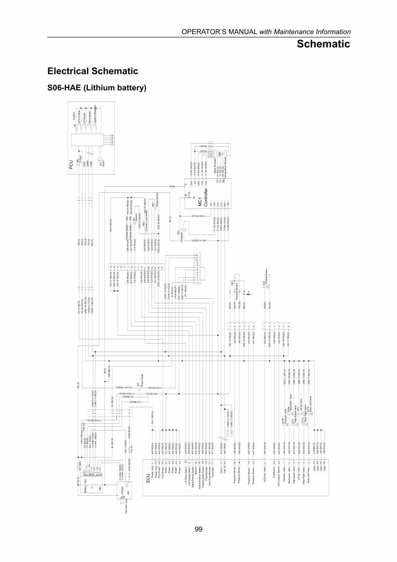
OPERATOR’S MANUAL with Maintenance Information
Schematic
99
Electrical SchematicS06-HAE (Lithium battery)
HL1
A07
WH
(20)
SQ
2
A30
WH
(20)
A21
WH
(20)
002-
2 R
D(1
6)
002-
2A R
D(2
0)
002-
2B R
D(2
0)
A26
WH
(20)
A23
WH
(20)
GN
D-2
B B
K(2
0)A
21 W
H(2
0)G
ND
-2 B
K(1
8)
A18
WH
(20)
GN
D-2
A B
K(2
0)
002-
2C R
D(2
0)A
29 W
H(2
0)S
Q3
A29
WH
(20)
N P R S
Pot
hole
Sw
itch
Pot
hole
Sw
itch
Bea
con
Lift
Dow
n Li
mit
Sw
itch
Ang
le S
enso
r
Pre
ssur
e S
enso
r
Pow
er_K
eyP
ower
_Key
PC
U P
ower
PC
U P
ower
Left
Poth
ole
Switc
h
Bea
con
002-
1C R
D(1
6)00
2-1D
RD
(18)
002-
1E R
D(1
8)
A06
WH
(20)
A07
WH
(20)
A18
WH
(20)
A26
WH
(20)
A23
WH
(20)
GN
D-1
G B
K(1
8)
A B C D E F G H J K L M
A06
WH
(20)
SQ
1
RP
1
1 2
003-
1 R
D(2
0)
FU3
3A
FU1
250A
+-
L N PE
GB
1
RD
(5)
CEC-
CANH
C-CA
NL
V-CA
NH
V-CA
NLLK
Acti
vate
24V+
D F M24
V+(
BMS)
C-C
AN
L G
N(2
0)C
-CA
NH
YE
(20)
V-C
AN
L G
N(2
0)V
-CA
NH
YE
(20)
GS
1
003-
1 R
D(2
0)
003A
RD
(20)
003B
RD
(20)
FU2
10A
F-003A RD(16)
003-
2 R
D(1
6)10
2 B
N(2
0)10
1 B
N(2
0)
B+
RD
(18)
100-
230V
Inpu
t
Cha
rger
Bat
tery(
24V)
Pow
erP
ower
Rig
ht P
otho
le S
witc
h
Lift
Dow
n S
witc
h
Pow
erP
ower
Indo
or/O
utdo
or S
witc
h
Foot
Switc
h
Ant
i-col
lisio
n Sw
itch
Pot
entio
met
er Z
ero
Pote
ntio
met
er
Lift
Dow
n V
alve
Lift
Up
Valv
e
Ste
er R
ight
Val
ve
Ste
er L
eft V
alve
Pre
ssur
e S
enso
r
Pre
ssur
e S
enso
r
Pot
entio
met
er P
ower
Lift
Dow
n V
alve
Pow
er R
elay
Tem
pera
ture
Sen
sor
Mot
or E
ncod
er
Con
tact
or
E-S
top
Ala
rm
Joys
tick
Driv
e E
nabl
e
Lift
Enab
le
Driv
e sp
eed
Joys
tick
Dea
dman
Lift
Up
Valv
e
Ste
er R
ight
Val
ve
Ste
er L
eft V
alve
Forw
ard
val
ve
Bac
kwar
d v
alve
Hig
h sp
eed
valv
e
Forw
ard
val
ve Bac
kwar
d v
alve
Hig
h sp
eed
valv
e
Con
trolle
r
Pow
er
Pre
ssur
e S
enso
r
Pre
ssur
e S
enso
r
Hou
rmet
er
RD
(5)
KM
1
Pw
In G
N(1
8)P
w O
ut R
D(1
8)G
ND
-1W
WH
(18)
CA
NH
1-4
YE
(18)
CA
NL1
-4 B
U(1
8)
4 3 1 2 5
GN
(18)
RD
(18)
WH
(18)
YE
(18)
BU
(18)
4 3 1 2 5
F-003A RD(16)
Pw Out1 RD(20) KA
1
002 RD(16)
A03
RD
(20)
A31
RD
(20)
A52
RD
(20)
A53
RD
(20)
A27
RD
(18)
A41
RD
(20)
A42
RD
(20)
A43
RD
(20)
A44
RD
(20)
A06
WH
(20)
A07
WH
(20)
A20
WH
(20)
A32
WH
(20)
A24
WH
(20)
A47
WH
(20)
A23
WH
(20)
3 31 52 53 27 41 42 43 44 6 7 20 3224 4723
EC
U
CA
N_L
CA
N_H
A12
GN
(20)
A40
YE
(20)
A26
WH
(20)
12 4026
A09
WH
(18)
A18
WH
(20)
A45
WH
(20)
A46
WH
(20)
A08
WH
(18)
A04
WH
(18)
A05
WH
(18)
918 45 46 8 4 5S
V1b
SV
1a
SV
2
002-
1A R
D(2
0)
A09
WH
(18)
GN
D-1
C B
K(1
8)
GN
D-1
E B
K(2
0)
A45
WH
(20)
A46
WH
(20)
1 2 3 4 5 6 1 2 3 4 5 6
RD
(20)
BK
(20)
GN
(20)
WH
(20)
RD
(5)
BK(5)
SB
2
GN
DC
AN
HC
AN
L
HA
1
PC
U
GN
D-1
P B
K(1
8)
GN
D-1
N B
K(1
8)
RD
(20)
BU
(20)
SV
5
PS
1 P
MC
1
U V WM
13~
W1
RD
(2)
V1
RD
(2)
U1
RD
(2)
22/A 5/A
25/A
13/A
14/A
BF
B-
1 2
P-2
2A W
H(2
0)
P-0
5A B
U(1
8)
P-2
5A B
N(2
0)
P-1
3A W
H(2
0)
P-1
4A W
H(2
0)
41
32
BU(20)
BU(20)
P-A
06 R
D(2
0)
GN
D-1
R B
K(1
8)
GN
DG
ND
A10
BK
(18)
A54
BK
(18)
10 54
A30
WH
(20)
30
A01
WH
(18)
A02
WH
(18)
SV
4a
SV
4b
GN
D-1
M B
K(1
8)
GN
D-1
L B
K(1
8)
A17
WH
(18)
17S
V3
GN
D-1
U B
K(1
8)
BK
(5)
175A
B+
P-1
0A R
D(2
0)10
/A
27/A
28/A
P-2
7A G
N(2
0)
P-2
8A Y
E(2
0)
3/A 6/A
GN
DA
55 B
K(1
8)55
GN
DA
56 B
K(1
8)56
P-1
2A W
H(2
0)12
/A
A21
WH
(20)
21
002-1G RD(20)
P-03A RD(20)
002-
1B R
D(2
0)
002-
1F R
D(2
0)
A24
WH
(20)
A47
WH
(20)
A20
WH
(20)
A32
WH
(20)
12
1 2C
AN
H1-
5 Y
E(2
0)C
AN
L1-5
GN
(20)
12345
GN
D B
K(1
4)
A29
WH
(20)
29
102 BN(20)
101 BN(20)
003-
1 R
D(2
0)812754 3
CA
NL1
-3 G
N(2
0)C
AN
H1-
3 Y
E(2
0)
B+
RD
(18)
121110987654321
A11
WH
(20)
11
LOC
K B
U(2
0)
A11
WH
(20)
LOCK BU(20)B
+ R
D(1
8)
GN
D-1
Y B
K(1
8)00
2-1J
RD
(20)
CA
NH
1-6
YE
(20)
CA
NL1
-6 G
N(2
0)
1 4 3 2 V1
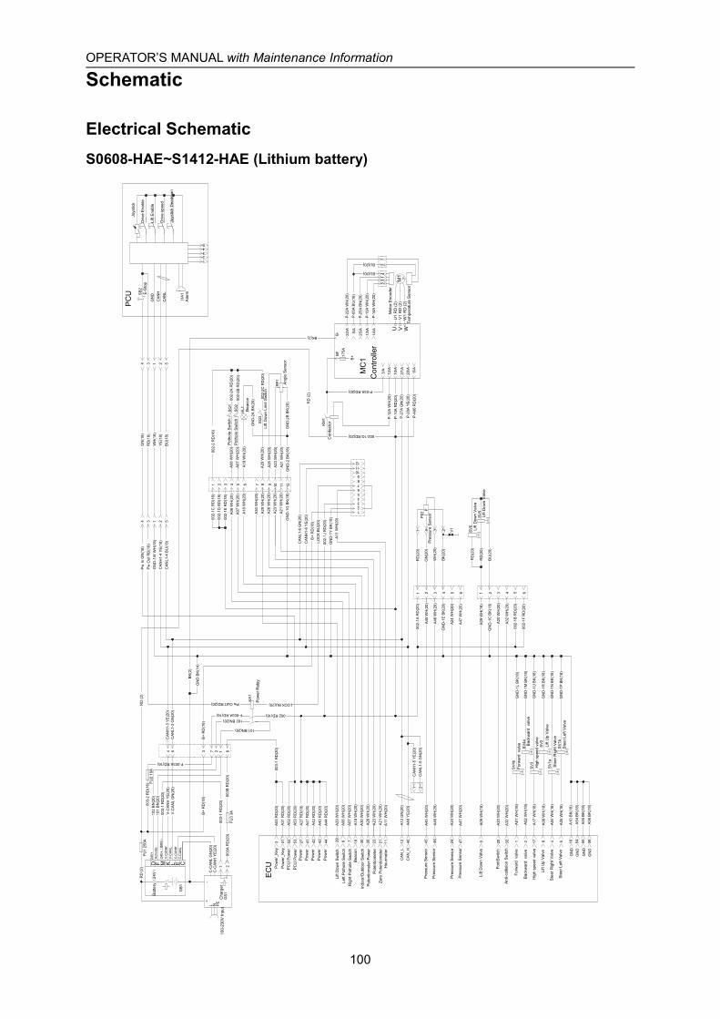
OPERATOR’S MANUAL with Maintenance Information
Schematic
100
Electrical SchematicS0608-HAE~S1412-HAE (Lithium battery)
RD
(2)
KM1
Pw
In G
N(1
8)P
w O
ut R
D(1
8)G
ND
-1W
WH
(18)
CAN
H1-
4 Y
E(18
)C
ANL1
-4 B
U(1
8)
4 3 1 2 5
GN
(18)
RD
(18)
WH
(18)
YE(
18)
BU
(18)
4 3 1 2 5
1 2
003-
1 R
D(2
0)
F-003A RD(16)
Pw Out1 RD(20) KA1
FU3
3A
002 RD(16)
A03
RD
(20)
A31
RD
(20)
A52
RD
(20)
A53
RD
(20)
A27
RD
(18)
A41
RD
(20)
A42
RD
(20)
A43
RD
(20)
A44
RD
(20)
A06
WH
(20)
A07
WH
(20)
A20
WH
(20)
A32
WH
(20)
A24
WH
(20)
A47
WH
(20)
A23
WH
(20)
3 31 52 53 27 41 42 43 44 6 7 20 3224 4723
ECU
CAN
_LC
AN_H
A12
GN
(20)
A40
YE(
20)
A26
WH
(20)
12 4026
A09
WH
(18)
A18
WH
(20)
A45
WH
(20)
A46
WH
(20)
A08
WH
(18)
A04
WH
(18)
A05
WH
(18)
918 45 46 8 4 5S
V1b
SV1
a
SV2
002-
1A R
D(2
0)
A09
WH
(18)
GN
D-1
C B
K(1
8)
GN
D-1
E BK
(20)
A45
WH
(20)
A46
WH
(20)
1 2 3 4 5 6 1 2 3 4 5 6
RD
(20)
BK(
20)
GN
(20)
WH
(20)
RD
(2)
BK(2)
002-
1C R
D(1
6)00
2-1D
RD
(18)
002-
1E R
D(1
8)A
06 W
H(2
0)A
07 W
H(2
0)
A18
WH
(20)
A26
WH
(20)
A23
WH
(20)
GN
D-1
G B
K(1
8)
1 2 3 4 5 6 7 8 9 10 11 12
A06
WH
(20)
SQ
1
RP1
SB2
GN
DC
ANH
CAN
L
HA1
PCU
GN
D-1
P BK
(18)
GN
D-1
N B
K(1
8)
RD
(20)
RD
(20)
BU
(20)
HL1
SV5
SV6
PS1
P
MC
1
U V WM
13~
W1
RD
(2)
V1
RD
(2)
U1
RD
(2)
22/A 5/A
25/A
13/A
14/A
BFB
-
1 2
P-2
2A W
H(2
0)
P-0
5A B
U(1
8)
P-2
5A B
N(2
0)
P-1
3A W
H(2
0)
P-1
4A W
H(2
0)
FU1
250A
41
32
BU(20)
BU(20)
P-A
06 R
D(2
0)
A07
WH
(20)
SQ
2
GN
D-1
R B
K(1
8)
GN
DA
10 B
K(18
)A
54 B
K(18
)10 54
A30
WH
(20)
30
A30
WH
(20)
A01
WH
(18)
A02
WH
(18)
SV4
a
SV4
b
GN
D-1
M B
K(1
8)
GN
D-1
L BK
(18)
A17
WH
(18)
17S
V3G
ND
-1U
BK
(18)
BK(
2)
175A
B+
P-1
0A R
D(2
0)10
/A
27/A
28/A
P-2
7A G
N(2
0)
P-2
8A Y
E(20
)
3/A 6/A
GN
DA
55 B
K(18
)55
A56
BK(
18)
56
P-1
2A W
H(2
0)12
/A
A21
WH
(20)
21
A21
WH
(20)
002-1G RD(20)
P-03A RD(20)
002-
1B R
D(2
0)
002-
1F R
D(2
0)
A24
WH
(20)
A47
WH
(20)
A20
WH
(20)
A32
WH
(20)
12
1 2C
ANH
1-5
YE(
20)
CAN
L1-5
GN
(20)
002-
2 R
D(1
6)
002-
2A R
D(2
0)
002-
2B R
D(2
0)
A26
WH
(20)
A23
WH
(20)
GN
D-2
B BK
(20)
A21
WH
(20)
GN
D-2
BK(
18)
A18
WH
(20)
GN
D-2
A BK
(20)
12345
+-
L N PE
GN
D B
K(14
)
GB1
002-
2C R
D(2
0)A
29 W
H(2
0)S
Q3
A29
WH
(20)
A29
WH
(20)
29
RD
(2)
CELKD F M
102 BN(20)
101 BN(20)
C-C
ANL
GN
(20)
C-C
ANH
YE
(20)
V-C
ANL
GN
(20)
V-C
ANH
YE
(20)
GS1
003-
1 R
D(2
0)812754 3
CAN
L1-3
GN
(20)
CAN
H1-
3 Y
E(20
)
B+
RD
(18)
121110987654321
A11
WH
(20)
11
LOC
K BU
(20)
A11
WH
(20)
LOCK BU(20)B
+ R
D(1
8)
GN
D-1
Y BK
(18)
002-
1J R
D(2
0)
CAN
H1-
6 Y
E(20
)
CAN
L1-6
GN
(20)
1 4 3 2
003-
1 R
D(2
0)
003A
RD
(20)
003B
RD
(20)
FU2
10A
F-003A RD(16)
003-
2 R
D(1
6)10
2 B
N(2
0)10
1 B
N(2
0)
B+
RD
(18)
V1
GN
D
GN
D
Pot
hole
Sw
itch
Pot
hole
Sw
itch
Bea
con
Lift
Dow
n Li
mit
Sw
itch
Ang
le S
enso
r
Pre
ssur
e S
enso
r
Pow
er_K
eyP
ower
_Key
PC
U P
ower
PC
U P
ower
Left
Poth
ole
Switc
h
Bea
con
Pow
erP
ower
Rig
ht P
otho
le S
witc
h
Lift
Dow
n S
witc
h
Con
trolle
r
Pow
erP
ower
Pow
er
Indo
or/O
utdo
or S
witc
h
Foot
Switc
h
Ant
i-col
lisio
n Sw
itch
Pot
entio
met
er Z
ero
Pote
ntio
met
er
Lift
Dow
n V
alve
Lift
Up
Valv
e
Ste
er R
ight
Val
ve
Ste
er L
eft V
alve
Pre
ssur
e S
enso
r
Pre
ssur
e S
enso
r
Pot
entio
met
er P
ower
Lift
Dow
n V
alve
Pow
er R
elay
Tem
pera
ture
Sen
sor
Mot
or E
ncod
er
Con
tact
or
E-S
top
Ala
rm
Joys
tick
Driv
e E
nabl
e
Lift
Enab
le
Driv
e sp
eed
Joys
tick
Dea
dman
Lift
Dow
n V
alve
Lift
Up
Valv
e
Ste
er R
ight
Val
ve
Ste
er L
eft V
alve
Forw
ard
val
ve
Bac
kwar
d v
alve
Hig
h sp
eed
valv
e
Forw
ard
val
ve Bac
kwar
d v
alve
Hig
h sp
eed
valv
e
Pre
ssur
e S
enso
r
Pre
ssur
e S
enso
r
Hou
rmet
er
24V
+(B
MS)
C-C
AN
HC
-CA
NL
V-C
AN
HV
-CA
NL
Act
ivat
e24
V+
100-
230V
Inpu
tC
harg
er
Bat
tery(
24V)

OPERATOR’S MANUAL with Maintenance Information
Schematic
101
Electrical SchematicS06-ACE (Lead-acid battery)
RD
(5)
KM1
Pw
In G
N(1
8)P
w O
ut R
D(1
8)G
ND
-1W
WH
(18)
CAN
H1-
4 Y
E(18
)C
ANL1
-4 B
U(1
8)
4 3 1 2 5
GN
(18)
RD
(18)
WH
(18)
YE(
18)
BU
(18)
4 3 1 2 5
F-003A RD(16)
Pw Out1 RD(20) KA1
002 RD(16)
A03
RD
(20)
A31
RD
(20)
A52
RD
(20)
A53
RD
(20)
A27
RD
(18)
A41
RD
(20)
A42
RD
(20)
A43
RD
(20)
A44
RD
(20)
A06
WH
(20)
A07
WH
(20)
A20
WH
(20)
A32
WH
(20)
A23
WH
(20)
3 31 52 53 27 41 42 43 44 6 7 20 3223
ECU
CAN
_LC
AN_H
A12
GN
(20)
A40
YE(
20)
A26
WH
(20)
12 4026
A09
WH
(18)
A18
WH
(20)
A45
WH
(20)
A46
WH
(20)
A08
WH
(18)
A04
WH
(18)
A05
WH
(18)
918 45 46 8 4 5S
V1b
SV1
a
SV2
002-
1A R
D(2
0)
A09
WH
(18)
GN
D-1
C B
K(1
8)
GN
D-1
E BK
(20)
A45
WH
(20)
A46
WH
(20)
1 2 3 4 5 6 1 2 3 4 5 6
RD
(20)
BK(
20)
GN
(20)
WH
(20)
RD
(5)
BK(5)
002-
1C R
D(1
6)00
2-1D
RD
(18)
002-
1E R
D(1
8)
A06
WH
(20)
A07
WH
(20)
A18
WH
(20)
A26
WH
(20)
A23
WH
(20)
GN
D-1
G B
K(1
8)
A B C D E F G H J K L M
A06
WH
(20)
SQ
1
RP1
SB2
GN
DC
ANH
CAN
L
HA1
PCU
GN
D-1
P BK
(18)
GN
D-1
N B
K(1
8)
RD
(20)
BU
(20)
HL1
SV3
PS1
P
MC
1
U V WM
13~
W1
RD
(5)
V1
RD
(5)
U1
RD
(5)
22/A 5/A
25/A
13/A
14/A
BFB
-
P-2
2A W
H(2
0)
P-0
5A B
U(1
8)
P-2
5A B
N(2
0)
P-1
3A W
H(2
0)
P-1
4A W
H(2
0)
41
32
BU(20)
BU(20)
P-A
06 R
D(2
0)
A07
WH
(20)
SQ
2
GN
D-1
R B
K(1
8)
GN
DG
ND
A10
BK(
18)
A54
BK(
18)
10 54
A30
WH
(20)
30
A30
WH
(20)
BK(
5)
175A
B+
P-1
0A R
D(2
0)10
/A
27/A
28/A
P-2
7A G
N(2
0)
P-2
8A Y
E(20
)
3/A 6/A
GN
DA
55 B
K(18
)55
GN
DA
56 B
K(18
)56
P-1
2A W
H(2
0)12
/A
A21
WH
(20)
21
A21
WH
(20)
002-1G RD(20)
P-03A RD(20)
002-
1B R
D(2
0)
002-
1F R
D(2
0)
A20
WH
(20)
A32
WH
(20)
12
1 2C
ANH
1-5
YE(
20)
CAN
L1-5
GN
(20)
002-
2 R
D(1
6)
002-
2A R
D(2
0)
002-
2B R
D(2
0)
A26
WH
(20)
A23
WH
(20)
GN
D-2
B BK
(20)
A21
WH
(20)
GN
D-2
BK(
18)
A18
WH
(20)
GN
D-2
A BK
(20)
12345
GN
D B
K(14
)
002-
2C R
D(2
0)A
29 W
H(2
0)S
Q3
A29
WH
(20)
A29
WH
(20)
29
102 BN(20)
101 BN(20)
003-
1 R
D(2
0)812754 3
CAN
L1-3
GN
(20)
CAN
H1-
3 Y
E(20
)
LOCK BU(20)
1 4 3 2
FU4 10A
BAT
T+B
ATT-
U V WM
3 3~W
3 R
D (5
)V
3 R
D (5
)U
3 R
D (5
)
A32
A21
A10
A09A20
A18A31
U V WM
2 3~W
2 R
D (5
)V
2 R
D (5
)U
2 R
D (5
)
A30
A15 A04A17
A19
左 电 机
A03
D-A
30 B
U(1
8)
D-A
15 B
K(18
)
D-A
04 R
D(2
0)D
-A17
YE(
20)
D-A
19 G
N(2
0)
D-A
32 W
H(2
0)D
-A21
BK(
18)
D-A
10 R
D(2
0)D
-A09
YE(
20)
D-A
20 G
N(2
0)
A13
35
46
A28
D-A
28 B
U(1
8)
A33
D-A
33 W
H(2
0)
Brake+R RD(18)Brake+L RD(18)
D-A13 RD(16)
D-A
03 R
D(1
8)
D-A
31 Y
E(20
)D
-A18
GN
(20)
12
78
35
46
12
78
1 2
003
RD
(14)
FU3
3A
FU1
250A
+-
L N PE
RD
(5)
GS1
003A
1 R
D(2
0)00
3B R
D(2
0)
F-00
3A R
D(1
6)
SB1
RD
(5)
FU2
10A
003A
2 R
D(1
6)
GB2
GB1
GB3
GB4
N P R S
CAN
H1-
2 Y
E(20
)C
ANL1
-2 G
N(2
0)
A24
WH
(20)
A47
WH
(20)
24 47
A24
WH
(20)
A47
WH
(20)
B+
RD
(18)
121110987654321
A11
WH
(20)
11
LOC
K BU
(20)
A11
WH
(20)
B+
RD
(18)
GN
D-1
Y BK
(18)
002-
1J R
D(2
0)
CAN
H1-
6 Y
E(20
)
CAN
L1-6
GN
(20)
B+
RD
(18)
Pot
hole
Sw
itch
Pot
hole
Sw
itch
Bea
con
Lift
Dow
n Li
mit
Sw
itch
Ang
le S
enso
r
Pre
ssur
e S
enso
r
Pow
er_K
eyP
ower
_Key
PC
U P
ower
PC
U P
ower
Left
Poth
ole
Switc
h
Bea
con
Pow
erP
ower
Rig
ht P
otho
le S
witc
h
Lift
Dow
n S
witc
h
Tem
pera
ture
Sen
sor
Mot
or E
ncod
er
Tem
pera
ture
Sen
sor
Brake
Mot
or E
ncod
er
Con
trolle
r
Con
trolle
r
Pow
erP
ower
Pow
er
Indo
or/O
utdo
or S
witc
h
Foot
Switc
h
Ant
i-col
lisio
n Sw
itch
Pot
entio
met
er Z
ero
Pote
ntio
met
er
Lift
Dow
n V
alve
Lift
Up
Valv
e
Ste
er R
ight
Val
ve
Ste
er L
eft V
alve
Pre
ssur
e S
enso
r
Pre
ssur
e S
enso
r
Pot
entio
met
er P
ower
Lift
Up
Valv
e
Ste
er R
ight
Val
ve
Ste
er L
eft V
alve
Lift
Dow
n V
alve
100-
230V
Inpu
t
Bat
tery
pow
er s
witc
h
Brake
Tem
pera
ture
Sen
sor
Mot
or E
ncod
er
Con
tact
or
E-S
top
Ala
rm
Joys
tick
Driv
e E
nabl
e
Lift
Enab
le
Driv
e sp
eed
Joys
tick
Dea
dman
Cha
rger
Pow
er R
elay
Pre
ssur
e S
enso
r
Pre
ssur
e S
enso
r
Hou
rmet
er
V1
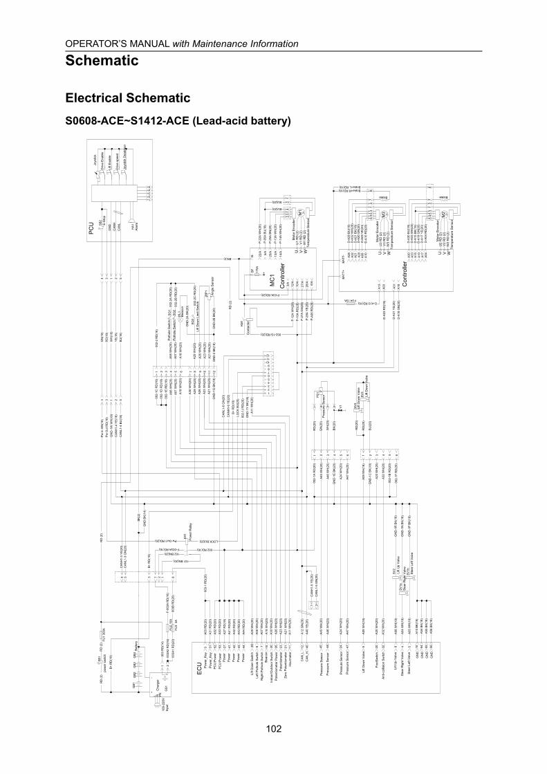
OPERATOR’S MANUAL with Maintenance Information
Schematic
102
Electrical SchematicS0608-ACE~S1412-ACE (Lead-acid battery)
RD
(2)
KM
1
Pw
In G
N(1
8)P
w O
ut R
D(1
8)G
ND
-1W
WH
(18)
CAN
H1-
4 Y
E(18
)C
ANL1
-4 B
U(1
8)
4 3 1 2 5
GN
(18)
RD
(18)
WH
(18)
YE(
18)
BU
(18)
4 3 1 2 5
F-003A RD(16)
Pw Out1 RD(20) KA1
002 RD(16)
A03
RD
(20)
A31
RD
(20)
A52
RD
(20)
A53
RD
(20)
A27
RD
(18)
A41
RD
(20)
A42
RD
(20)
A43
RD
(20)
A44
RD
(20)
A06
WH
(20)
A07
WH
(20)
A20
WH
(20)
A32
WH
(20)
A24
WH
(20)
A47
WH
(20)
A23
WH
(20)
3 31 52 53 27 41 42 43 44 6 7 20 3224 4723
EC
U
CAN
_LC
AN
_HA
12 G
N(2
0)A
40 Y
E(20
)
A26
WH
(20)
12 4026
A09
WH
(18)
A18
WH
(20)
A45
WH
(20)
A46
WH
(20)
A08
WH
(18)
A04
WH
(18)
A05
WH
(18)
918 45 46 8 4 5S
V1b
SV1
a
SV2
002-
1A R
D(2
0)
A09
WH
(18)
GN
D-1
C B
K(1
8)
GN
D-1
E BK
(20)
A45
WH
(20)
A46
WH
(20)
1 2 3 4 5 6 1 2 3 4 5 6
RD
(20)
BK(
20)
GN
(20)
WH
(20)
RD
(2)
BK(2)
002-
1C R
D(1
6)00
2-1D
RD
(18)
002-
1E R
D(1
8)A
06 W
H(2
0)A
07 W
H(2
0)A
18 W
H(2
0)
A26
WH
(20)
A23
WH
(20)
GN
D-1
G B
K(1
8)
1 2 3 4 5 6 7 8 9 10 11 12
A06
WH
(20)
SQ
1
RP1
SB2
GN
DC
AN
HC
AN
L
HA1
PC
U
GN
D-1
P BK
(18)
GN
D-1
N B
K(1
8)
RD
(20)
RD
(20)
BU
(20)
HL1
SV3
SV4
PS1
P
MC
1
U V WM
13~
W1
RD
(2)
V1
RD
(2)
U1
RD
(2)
22/A 5/A
25/A
13/A
14/A
BF
B-
P-2
2A W
H(2
0)
P-0
5A B
U(1
8)
P-2
5A B
N(2
0)
P-1
3A W
H(2
0)
P-1
4A W
H(2
0)
41
32
BU(20)
BU(20)
P-A
06 R
D(2
0)
A07
WH
(20)
SQ
2
GN
D-1
R B
K(1
8)
GN
DG
ND
A10
BK(
18)
A54
BK(
18)
10 54
A30
WH
(20)
30
A30
WH
(20)
BK(
2)
175A
B+
P-1
0A R
D(2
0)10
/A
27/A
28/A
P-2
7A G
N(2
0)
P-2
8A Y
E(20
)
3/A 6/A
GN
DA
55 B
K(18
)55
GN
DA
56 B
K(18
)56
P-1
2A W
H(2
0)12
/A
A21
WH
(20)
21
A21
WH
(20)
002-1G RD(20)
P-03A RD(20)
002-
1B R
D(2
0)
002-
1F R
D(2
0)
A24
WH
(20)
A47
WH
(20)
A20
WH
(20)
A32
WH
(20)
12
1 2C
ANH
1-5
YE(
20)
CAN
L1-5
GN
(20)
002-
2 R
D(1
6)
002-
2A R
D(2
0)
002-
2B R
D(2
0)
A26
WH
(20)
A23
WH
(20)
GN
D-2
B BK
(20)
A21
WH
(20)
GN
D-2
BK(
18)
A18
WH
(20)
GN
D-2
A BK
(20)
12345
GN
D B
K(14
)
002-
2C R
D(2
0)A
29 W
H(2
0)S
Q3
A29
WH
(20)
A29
WH
(20)
29
102 BN(20)
101 BN(20)
003-
1 R
D(2
0)812754 3
CAN
L1-3
GN
(20)
CAN
H1-
3 Y
E(20
)
B+
RD
(18)
121110987654321
A11
WH
(20)
11
LOC
K BU
(20)
A11
WH
(20)
LOCK BU(20)B
+ R
D(1
8)
GN
D-1
Y BK
(18)
002-
1J R
D(2
0)
CAN
H1-
6 Y
E(20
)
CAN
L1-6
GN
(20)
1 4 3 2
FU4 10A
BAT
T+B
ATT-
U V WM
3 3~W
3 R
D (2
)V
3 R
D (2
)U
3 R
D (2
)
A32
A21
A10
A09A20
A18A31
U V WM
2 3~W
2 R
D (2
)V
2 R
D (2
)U
2 R
D (2
)
A30
A15 A04A17
A19
A03
D-A
30 B
U(1
8)
D-A
15 B
K(18
)
D-A
04 R
D(2
0)D
-A17
YE(
20)
D-A
19 G
N(2
0)
D-A
32 W
H(2
0)D
-A21
BK(
18)
D-A
10 R
D(2
0)D
-A09
YE(
20)
D-A
20 G
N(2
0)
A13
35
46
A28
D-A
28 B
U(1
8)
A33
D-A
33 W
H(2
0)
Brake+R RD(18)Brake+L RD(18)
D-A13 RD(16)
D-A
03 R
D(1
8)
D-A
31 Y
E(20
)D
-A18
GN
(20)
V1
12
78
35
46
12
78
1 2
003
RD
(14)
FU3
3A
FU1
300A
+-
L N PE
RD
(2)
GS1
003A
1 R
D(2
0)00
3B R
D(2
0)
F-00
3A R
D(1
6)
B+
RD
(18)
SB1
RD
(2)
FU2
10A
003A
2 R
D(1
6)
GB2
GB1
GB3
GB4
Pot
hole
Sw
itch
Pot
hole
Sw
itch
Bea
con
Lift
Dow
n Li
mit
Sw
itch
Ang
le S
enso
r
Pre
ssur
e Se
nsor
Pow
er_K
eyP
ower
_Key
PC
U P
ower
PC
U P
ower
Left
Poth
ole
Switc
h
Bea
con
Pow
erP
ower
Rig
ht P
otho
le S
witc
h
Lift
Dow
n S
witc
h
Tem
pera
ture
Sen
sor
Mot
or E
ncod
er
Tem
pera
ture
Sen
sor
Brake
Mot
or E
ncod
er
Con
trolle
r
Con
trolle
r
Pow
erP
ower
Pow
er
Indo
or/O
utdo
or S
witc
h
Foot
Sw
itch
Ant
i-col
lisio
n Sw
itch
Pot
entio
met
er Z
ero
Pote
ntio
met
er
Lift
Dow
n V
alve
Lift
Up
Val
ve
Ste
er R
ight
Val
ve
Ste
er L
eft V
alve
Pre
ssur
e Se
nsor
Pre
ssur
e Se
nsor
Pot
entio
met
er P
ower
Lift
Up
Val
ve
Ste
er R
ight
Val
ve
Ste
er L
eft V
alve
Lift
Dow
n V
alve
100-
220V
Inpu
t
Cha
rger
Pow
er R
elay
Bat
tery
pow
er s
witc
h
Brake
Tem
pera
ture
Sen
sor
Mot
or E
ncod
er
Con
tact
or
E-S
top
Ala
rm
Joys
tick
Driv
e En
able
Lift
Enab
le
Driv
e sp
eed
Joys
tick
Dea
dman
Lift
Dow
n V
alve
Hou
rmet
er
Pre
ssur
e Se
nsor
Pre
ssur
e Se
nsor

OPERATOR’S MANUAL with Maintenance Information
Schematic
103
Electrical SchematicS06-ACE (Lithium battery)
002-
2 R
D(1
6)
002-
2A R
D(2
0)
002-
2B R
D(2
0)
A26
WH
(20)
A23
WH
(20)
GN
D-2
B BK
(20)
A21
WH
(20)
GN
D-2
BK(
18)
A18
WH
(20)
GN
D-2
A BK
(20)
12345
GN
D B
K(14
)
002-
2C R
D(2
0)A
29 W
H(2
0)S
Q3
A29
WH
(20)
A29
WH
(20)
29
102 BN(20)
101 BN(20)
003-
1 R
D(2
0)812754 3
CAN
L1-3
GN
(20)
CAN
H1-
3 Y
E(20
)
LOCK BU(20)
1 4 3 2
FU4 10A
BAT
T+B
ATT-
U V WM
3 3~W
3 R
D (5
)V
3 R
D (5
)U
3 R
D (5
)
A32
A21
A10
A09A20
A18A31
Pot
hole
Sw
itch
Pot
hole
Sw
itch
Bea
con
Lift
Dow
n Li
mit
Sw
itch
Ang
le S
enso
r
Pre
ssur
e S
enso
r
Pow
er_K
eyP
ower
_Key
PC
U P
ower
PC
U P
ower
Left
Pot
hole
Sw
itch
Bea
con
Pow
erP
ower
Rig
ht P
otho
le S
witc
h
Lift
Dow
n S
witc
h
Tem
pera
ture
Sen
sor
Mot
or E
ncod
er
Tem
pera
ture
Sen
sor
Brake
Mot
or E
ncod
er
Con
trolle
r
Con
trolle
r
Pow
erP
ower
Pow
er
Indo
or/O
utdo
or S
witc
h
Foot
Sw
itch
Ant
i-col
lisio
n S
witc
h
Pot
entio
met
er Z
ero
Pot
entio
met
er
Lift
Dow
n V
alve
Lift
Up
Val
ve
Ste
er R
ight
Val
ve
Ste
er L
eft V
alve
Pre
ssur
e S
enso
r
Pre
ssur
e S
enso
r
Pot
entio
met
er P
ower
Lift
Up
Val
ve
Ste
er R
ight
Val
ve
Ste
er L
eft V
alve
Lift
Dow
n V
alve
Brake
Tem
pera
ture
Sen
sor
Mot
or E
ncod
er
Con
tact
or
E-S
top
Ala
rm
Joys
tick
Driv
e E
nabl
e
Lift
Ena
ble
Driv
e sp
eed
Joys
tick
Dea
dman
U V WM
2 3~W
2 R
D (5
)V
2 R
D (5
)U
2 R
D (5
)
A30
A15 A04A17
A19
A03
D-A
30 B
U(1
8)
D-A
15 B
K(18
)
D-A
04 R
D(2
0)D
-A17
YE(
20)
D-A
19 G
N(2
0)
D-A
32 W
H(2
0)D
-A21
BK(
18)
D-A
10 R
D(2
0)D
-A09
YE(
20)
D-A
20 G
N(2
0)
A13
35
46
A28
D-A
28 B
U(1
8)
A33
D-A
33 W
H(2
0)
Brake+R RD(18)Brake+L RD(18)
D-A13 RD(16)
D-A
03 R
D(1
8)
D-A
31 Y
E(20
)D
-A18
GN
(20)
12
78
35
46
GN
D-1
P BK
(18)
GN
D-1
N B
K(1
8)
RD
(20)
BU
(20)
HL1
SV3
PS1
P
MC
1
U V WM
13~
W1
RD
(5)
V1
RD
(5)
U1
RD
(5)
22/A 5/A
25/A
13/A
14/A
BFB
-
P-2
2A W
H(2
0)
P-0
5A B
U(1
8)
P-2
5A B
N(2
0)
P-1
3A W
H(2
0)
P-1
4A W
H(2
0)
41
32
BU(20)
BU(20)
P-A
06 R
D(2
0)
A07
WH
(20)
SQ
2
GN
D-1
R B
K(1
8)
GN
DG
ND
A10
BK(
18)
A54
BK(
18)
10 54
A30
WH
(20)
30
A30
WH
(20)
BK(
5)
175A
B+
P-1
0A R
D(2
0)10
/A
27/A
28/A
P-2
7A G
N(2
0)
P-2
8A Y
E(20
)
3/A 6/A
GN
DA
55 B
K(18
)55
GN
DA
56 B
K(18
)56
P-1
2A W
H(2
0)12
/A
A21
WH
(20)
21
A21
WH
(20)
002-1G RD(20)
P-03A RD(20)
002-
1B R
D(2
0)
002-
1F R
D(2
0)
A20
WH
(20)
A32
WH
(20)
12
1 2C
ANH
1-5
YE(
20)
CAN
L1-5
GN
(20)
12
78
N P R S
CAN
H1-
2 Y
E(20
)C
ANL1
-2 G
N(2
0)
A24
WH
(20)
A47
WH
(20)
24 47
A24
WH
(20)
A47
WH
(20)
B+
RD
(18)
121110987654321
A11
WH
(20)
11
LOC
K BU
(20)
A11
WH
(20)
B+
RD
(18)
GN
D-1
Y BK
(18)
002-
1J R
D(2
0)
CAN
H1-
6 Y
E(20
)
CAN
L1-6
GN
(20)
1 2
003-
1 R
D(2
0)
FU3
3A
FU1
250A
+-
L N PE
GB1
RD
(5)
CEC-CANH
C-CANL
V-CANH
V-CANL
LK
Activate
24V+
D F M24V
+(BMS)
C-C
ANL
GN
(20)
C-C
ANH
YE
(20)
V-C
ANL
GN
(20)
V-C
ANH
YE
(20)
GS1
003-
1 R
D(2
0)
003A
RD
(20)
003B
RD
(20)
FU2
10A
F-003A RD(16)
003-
2 R
D(1
6)10
2 B
N(2
0)10
1 B
N(2
0)
B+
RD
(18)
100-
230V
Inpu
t
Cha
rger
Bat
tery(
24V)
Pow
er R
elay
Pre
ssur
e S
enso
r
Pre
ssur
e S
enso
r
Hou
rmet
er
V1
RD
(5)
KM1
Pw
In G
N(1
8)P
w O
ut R
D(1
8)G
ND
-1W
WH
(18)
CAN
H1-
4 Y
E(18
)C
ANL1
-4 B
U(1
8)
4 3 1 2 5
GN
(18)
RD
(18)
WH
(18)
YE(
18)
BU
(18)
4 3 1 2 5
F-003A RD(16)
Pw Out1 RD(20) KA1
002 RD(16)
A03
RD
(20)
A31
RD
(20)
A52
RD
(20)
A53
RD
(20)
A27
RD
(18)
A41
RD
(20)
A42
RD
(20)
A43
RD
(20)
A44
RD
(20)
A06
WH
(20)
A07
WH
(20)
A20
WH
(20)
A32
WH
(20)
A23
WH
(20)
3 31 52 53 27 41 42 43 44 6 7 20 3223
EC
U
CAN
_L
CAN
_HA
12 G
N(2
0)A
40 Y
E(20
)
A26
WH
(20)
12 4026
A09
WH
(18)
A18
WH
(20)
A45
WH
(20)
A46
WH
(20)
A08
WH
(18)
A04
WH
(18)
A05
WH
(18)
918 45 46 8 4 5S
V1b
SV1
a
SV2
002-
1A R
D(2
0)
A09
WH
(18)
GN
D-1
C B
K(1
8)
GN
D-1
E BK
(20)
A45
WH
(20)
A46
WH
(20)
1 2 3 4 5 6 1 2 3 4 5 6
RD
(20)
BK(
20)
GN
(20)
WH
(20)
RD
(5)
BK(5)
002-
1C R
D(1
6)00
2-1D
RD
(18)
002-
1E R
D(1
8)
A06
WH
(20)
A07
WH
(20)
A18
WH
(20)
A26
WH
(20)
A23
WH
(20)
GN
D-1
G B
K(1
8)
A B C D E F G H J K L M
A06
WH
(20)
SQ
1
RP1
SB2
GN
DC
ANH
CAN
L
HA1
PC
U
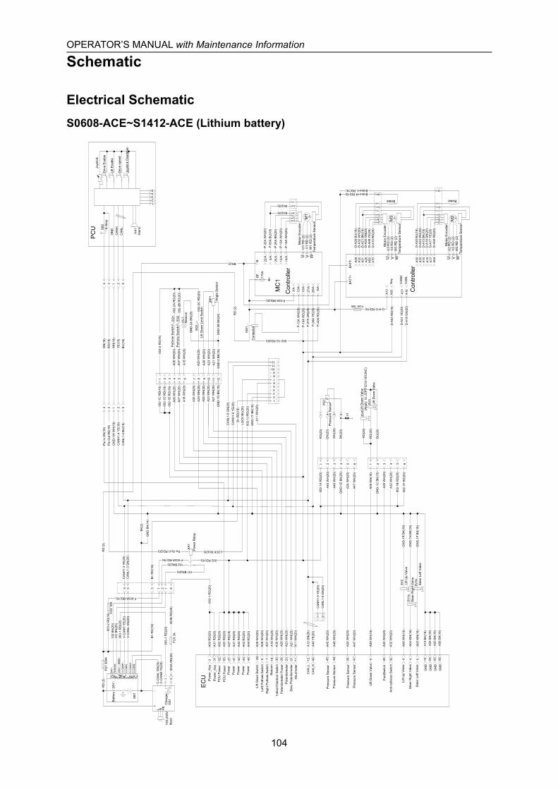
OPERATOR’S MANUAL with Maintenance Information
Schematic
104
Electrical SchematicS0608-ACE~S1412-ACE (Lithium battery)
RD
(2)
KM
1
Pw
In G
N(1
8)P
w O
ut R
D(1
8)G
ND
-1W
WH
(18)
CA
NH
1-4
YE(1
8)C
AN
L1-4
BU
(18)
4 3 1 2 5
GN
(18)
RD
(18)
WH
(18)
YE
(18)
BU
(18)
4 3 1 2 5
1 2
003-
1 R
D(2
0)
F-003A RD(16)
Pw Out1 RD(20) KA1
FU3
3A
002 RD(16)
A03
RD
(20)
A31
RD
(20)
A52
RD
(20)
A53
RD
(20)
A27
RD
(18)
A41
RD
(20)
A42
RD
(20)
A43
RD
(20)
A44
RD
(20)
A06
WH
(20)
A07
WH
(20)
A20
WH
(20)
A32
WH
(20)
A24
WH
(20)
A47
WH
(20)
A23
WH
(20)
3 31 52 53 27 41 42 43 44 6 7 20 3224 4723
EC
U
CA
N_L
CA
N_H
A12
GN
(20)
A40
YE(
20)
A26
WH
(20)
12 4026
A09
WH
(18)
A18
WH
(20)
A45
WH
(20)
A46
WH
(20)
A08
WH
(18)
A04
WH
(18)
A05
WH
(18)
918 45 46 8 4 5S
V1b
SV
1a
SV2
002-
1A R
D(2
0)
A09
WH
(18)
GN
D-1
C B
K(18
)
GN
D-1
E B
K(20
)
A45
WH
(20)
A46
WH
(20)
1 2 3 4 5 6 1 2 3 4 5 6
RD
(20)
BK
(20)
GN
(20)
WH
(20)
RD
(2)
BK(2)
002-
1C R
D(1
6)00
2-1D
RD
(18)
002-
1E R
D(1
8)A
06 W
H(2
0)A
07 W
H(2
0)A
18 W
H(2
0)
A26
WH
(20)
A23
WH
(20)
GN
D-1
G B
K(18
)
1 2 3 4 5 6 7 8 9 10 11 12
A06
WH
(20)
SQ
1
RP
1
SB2
GN
DC
AN
HC
AN
L
HA
1
PC
U
GN
D-1
P B
K(18
)
GN
D-1
N B
K(18
)
RD
(20)
RD
(20)
BU
(20)
HL1
SV3
SV4
PS1
P
MC
1
U V WM
13~
W1
RD
(2)
V1
RD
(2)
U1
RD
(2)
22/A 5/A
25/A
13/A
14/A
BF
B-
P-2
2A W
H(2
0)
P-0
5A B
U(1
8)
P-2
5A B
N(2
0)
P-1
3A W
H(2
0)
P-1
4A W
H(2
0)
FU1
300A
41
32
BU(20)
BU(20)
P-A
06 R
D(2
0)
A07
WH
(20)
SQ
2
GN
D-1
R B
K(18
)
GN
DG
ND
A10
BK(
18)
A54
BK(
18)
10 54
A30
WH
(20)
30
A30
WH
(20)
BK(
2)
175A
B+
P-1
0A R
D(2
0)10
/A
27/A
28/A
P-2
7A G
N(2
0)
P-2
8A Y
E(20
)
3/A 6/A
GN
DA
55 B
K(18
)55
GN
DA
56 B
K(18
)56
P-1
2A W
H(2
0)12
/A
A21
WH
(20)
21
A21
WH
(20)
002-1G RD(20)
P-03A RD(20)
002-
1B R
D(2
0)
002-
1F R
D(2
0)
A24
WH
(20)
A47
WH
(20)
A20
WH
(20)
A32
WH
(20)
12
1 2C
AN
H1-
5 YE
(20)
CA
NL1
-5 G
N(2
0)
002-
2 R
D(1
6)
002-
2A R
D(2
0)
002-
2B R
D(2
0)
A26
WH
(20)
A23
WH
(20)
GN
D-2
B B
K(20
)A
21 W
H(2
0)G
ND
-2 B
K(18
)
A18
WH
(20)
GN
D-2
A B
K(20
)
12345
+-
L N PE
GN
D B
K(14
)
GB
1
002-
2C R
D(2
0)A
29 W
H(2
0)S
Q3
A29
WH
(20)
A29
WH
(20)
29
RD
(2) CELKD F M
24V+
(B
MS)
102 BN(20)
101 BN(20)
C-C
AN
L G
N(2
0)C
-CA
NH
YE(
20)
V-C
AN
L G
N(2
0)V
-CA
NH
YE(
20)
GS
1
003-
1 R
D(2
0)812754 3
CA
NL1
-3 G
N(2
0)C
AN
H1-
3 YE
(20)
B+
RD
(18)
121110987654321
A11
WH
(20)
11
LOC
K B
U(2
0)
A11
WH
(20)
LOCK BU(20)B
+ R
D(1
8)
GN
D-1
Y B
K(18
)00
2-1J
RD
(20)
CA
NH
1-6
YE(2
0)
CA
NL1
-6 G
N(2
0)
1 4 3 2
003-
1 R
D(2
0)
003A
RD
(20)
003B
RD
(20)
FU2
10A
F-003A RD(16)
003-
2 R
D(1
6)10
2 B
N(2
0)10
1 B
N(2
0)
B+
RD
(18)
FU4 10A
BA
TT+
BAT
T-
U V WM
3 3~W
3 R
D (2
)V
3 R
D (2
)U
3 R
D (2
)
A32
A21
A10
A09A20
CA
NL
CA
NH
A18A31
U V WM
2 3~W
2 R
D (2
)V
2 R
D (2
)U
2 R
D (2
)
A30
A15 A04A17
A19
Key
A03
D-A
30 B
U(1
8)
D-A
15 B
K(18
)
D-A
04 R
D(2
0)D
-A17
YE(
20)
D-A
19 G
N(2
0)
D-A
32 W
H(2
0)D
-A21
BK(
18)
D-A
10 R
D(2
0)D
-A09
YE(
20)
D-A
20 G
N(2
0)
A13
35
46
A28
D-A
28 B
U(1
8)
A33
D-A
33 W
H(2
0)
Brake+R RD(18)Brake+L RD(18)
D-A13 RD(16)
D-A
03 R
D(1
8)
D-A
31 Y
E(20
)D
-A18
GN
(20)
V1
12
78
35
46
12
78
Pot
hole
Sw
itch
Pot
hole
Sw
itch
Bea
con
Lift
Dow
n Li
mit
Sw
itch
Ang
le S
enso
r
Pre
ssur
e Se
nsor
Pow
er_K
eyP
ower
_Key
PC
U P
ower
PC
U P
ower
Left
Pot
hole
Sw
itch
Bea
con
Pow
erP
ower
Rig
ht P
otho
le S
witc
h
Lift
Dow
n Sw
itch
Tem
pera
ture
Sen
sor
Mot
or E
ncod
er
Tem
pera
ture
Sen
sor
Brake
Mot
or E
ncod
er
Con
trolle
r
Con
trolle
r
Pow
erP
ower
Pow
er
Indo
or/O
utdo
or S
witc
h
Foot
Sw
itch
Ant
i-col
lisio
n Sw
itch
Pot
entio
met
er Z
ero
Pot
entio
met
er
Lift
Dow
n V
alve
Lift
Up
Val
ve
Ste
er R
ight
Val
ve
Ste
er L
eft V
alve
Pre
ssur
e Se
nsor
Pre
ssur
e Se
nsor
Pot
entio
met
er P
ower
Lift
Up
Val
ve
Ste
er R
ight
Val
ve
Ste
er L
eft V
alve
Lift
Dow
n V
alve
Pow
er R
elay
Brake
Tem
pera
ture
Sen
sor
Mot
or E
ncod
er
E-S
top
Ala
rm
Joys
tick
Driv
e En
able
Lift
Enab
le
Driv
e sp
eed
Joys
tick
Dea
dman
Lift
Dow
n V
alve
(App
ly t
o JC
PT1
212-
1612
AC)
Con
tact
or
Hou
rmet
er
Pre
ssur
e Se
nsor
Pre
ssur
e Se
nsor
C-C
AN
HC
-CAN
L
V-C
ANH
V-C
ANL
Act
ivat
e24
V+
100-
230V
Inpu
tC
harg
er
Bat
tery(
24V)

OPERATOR’S MANUAL with Maintenance Information
Schematic
105
Inspection and Repair Log
Date Comments
Related Documents