or Op Amps for short

Welcome message from author
This document is posted to help you gain knowledge. Please leave a comment to let me know what you think about it! Share it to your friends and learn new things together.
Transcript
or Op Amps for short
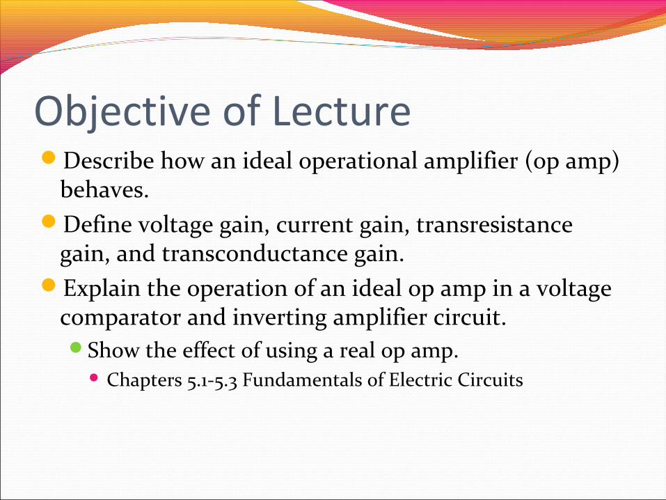
Objective of LectureDescribe how an ideal operational amplifier (op amp)
behaves.Define voltage gain, current gain, transresistance
gain, and transconductance gain.Explain the operation of an ideal op amp in a voltage
comparator and inverting amplifier circuit.Show the effect of using a real op amp.
Chapters 5.1-5.3 Fundamentals of Electric Circuits
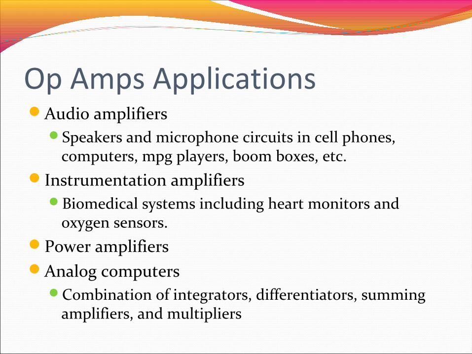
Op Amps ApplicationsAudio amplifiers
Speakers and microphone circuits in cell phones, computers, mpg players, boom boxes, etc.
Instrumentation amplifiersBiomedical systems including heart monitors and
oxygen sensors.Power amplifiersAnalog computers
Combination of integrators, differentiators, summing amplifiers, and multipliers
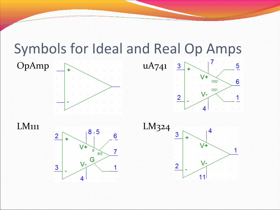
Symbols for Ideal and Real Op AmpsOpAmp uA741
LM111 LM324
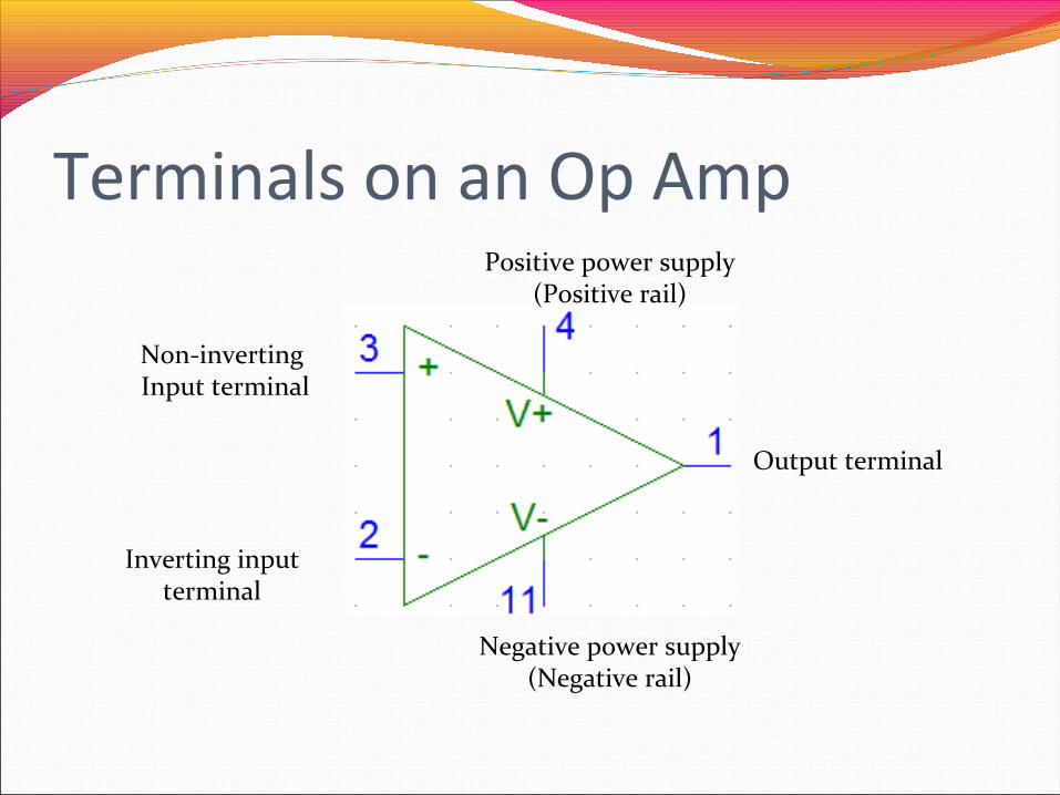
Terminals on an Op Amp
Non-inverting Input terminal
Inverting inputterminal
Output terminal
Positive power supply (Positive rail)
Negative power supply (Negative rail)
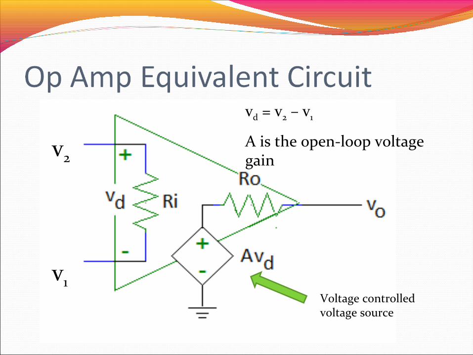
vd = v2 – v1
A is the open-loop voltage gainv2
v1Voltage controlled voltage source
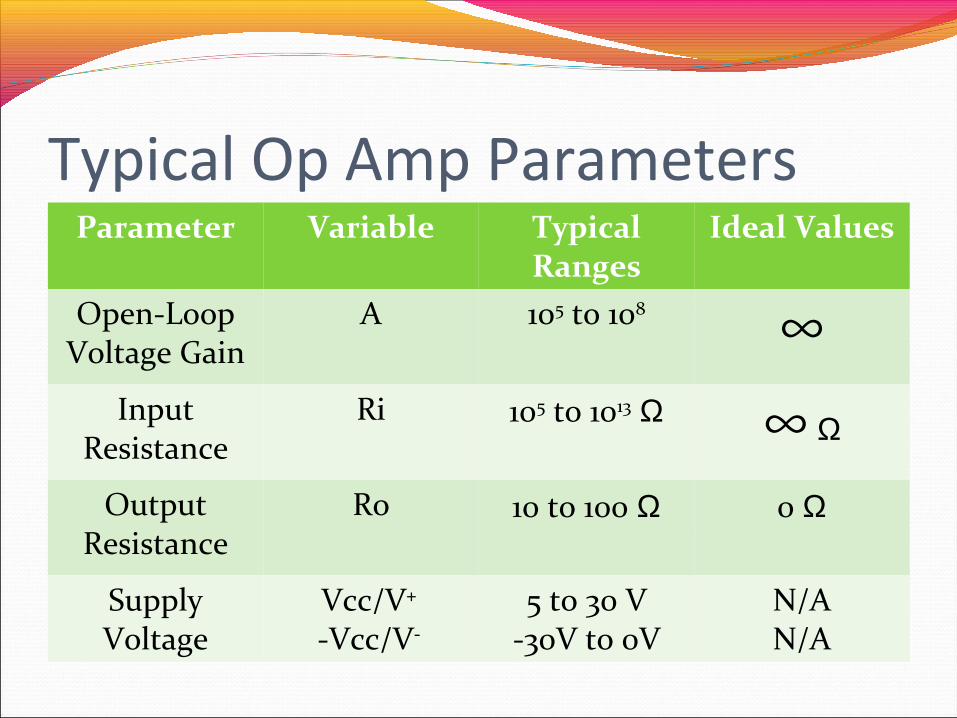
Typical Op Amp ParametersParameter Variable Typical
RangesIdeal Values
Open-Loop Voltage Gain
A 105 to 108 ∞Input
ResistanceRi 105 to 1013 Ω ∞ Ω
Output Resistance
Ro 10 to 100 Ω 0 Ω
Supply Voltage
Vcc/V+
-Vcc/V-
5 to 30 V-30V to 0V
N/AN/A

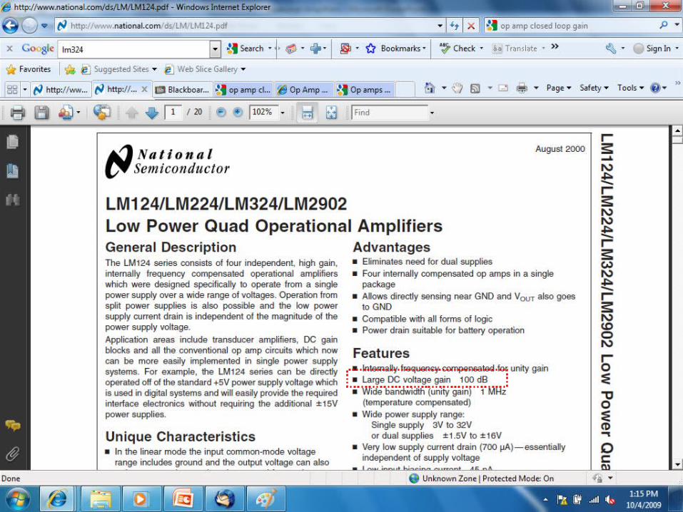
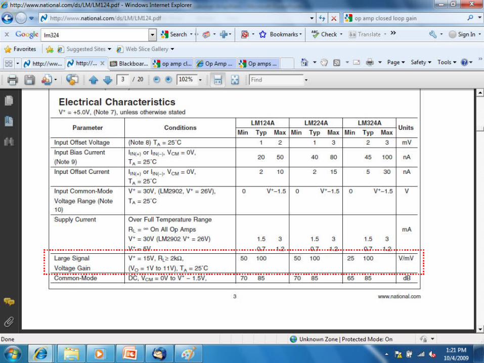
How to Find These ValuesComponent Datasheets
Many manufacturers have made these freely available on the internet Example: LM 324 Operational Amplifier
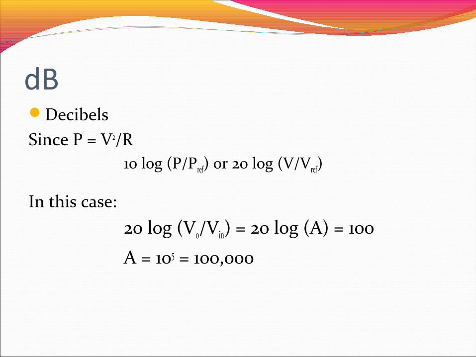
dBDecibelsSince P = V2/R
10 log (P/Pref) or 20 log (V/Vref)
In this case:
20 log (Vo/Vin) = 20 log (A) = 100
A = 105 = 100,000
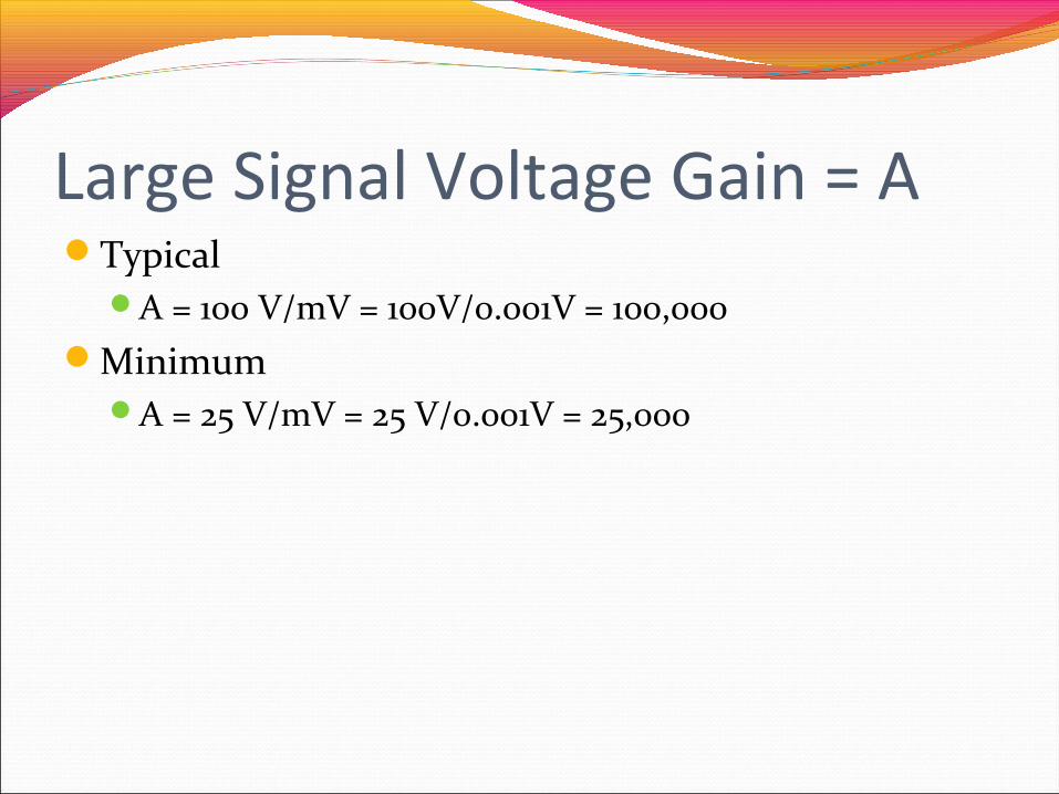
Large Signal Voltage Gain = A Typical
A = 100 V/mV = 100V/0.001V = 100,000Minimum
A = 25 V/mV = 25 V/0.001V = 25,000
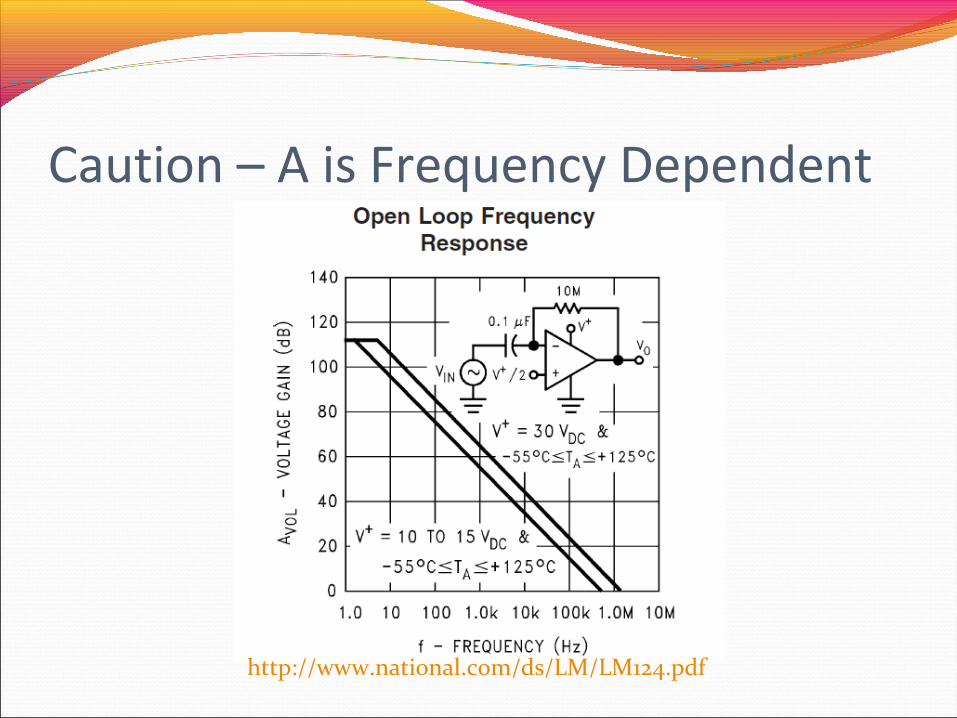
Caution – A is Frequency Dependent
http://www.national.com/ds/LM/LM124.pdf

Modifying Gain in Pspice OpAmpPlace part in a circuitDouble click on componentEnter a new value for the part attribute called GAIN

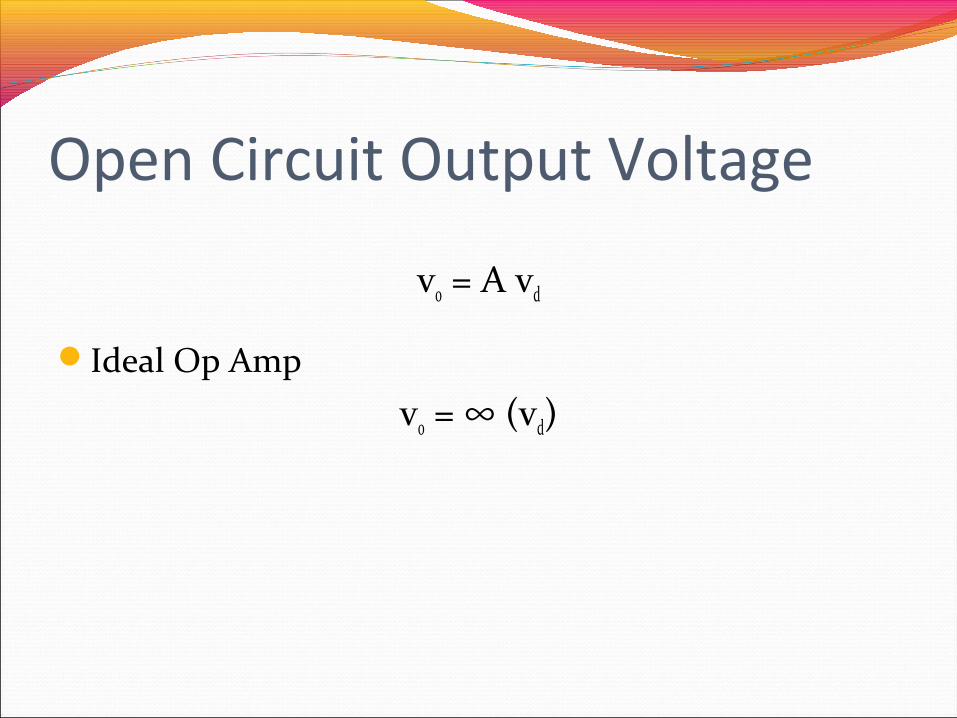
Open Circuit Output Voltage
vo = A vd
Ideal Op Amp
vo = ∞ (vd)
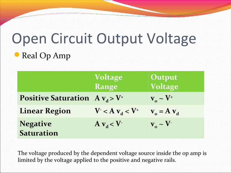
Open Circuit Output VoltageReal Op Amp
Voltage Range
Output Voltage
Positive Saturation A vd > V+ vo ~ V+
Linear Region V- < A vd < V+ vo = A vd
Negative Saturation
A vd < V- vo ~ V-
The voltage produced by the dependent voltage source inside the op amp is limited by the voltage applied to the positive and negative rails.
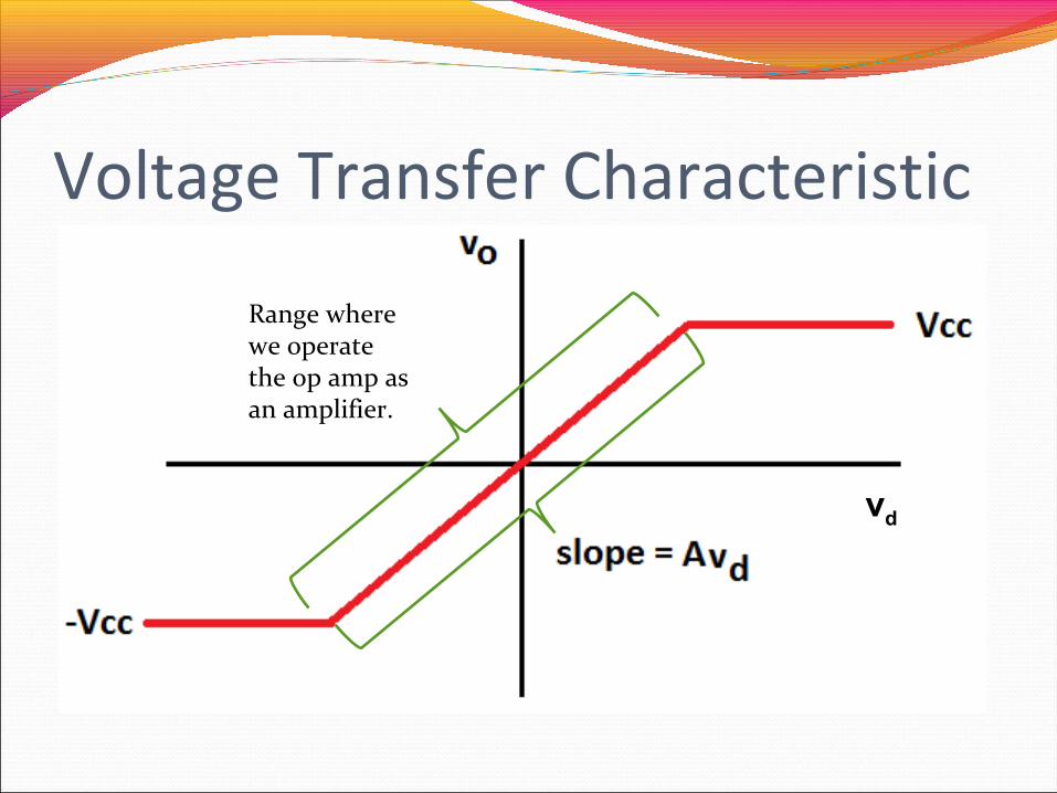
Voltage Transfer Characteristic
Range where we operate the op amp as an amplifier.
vd
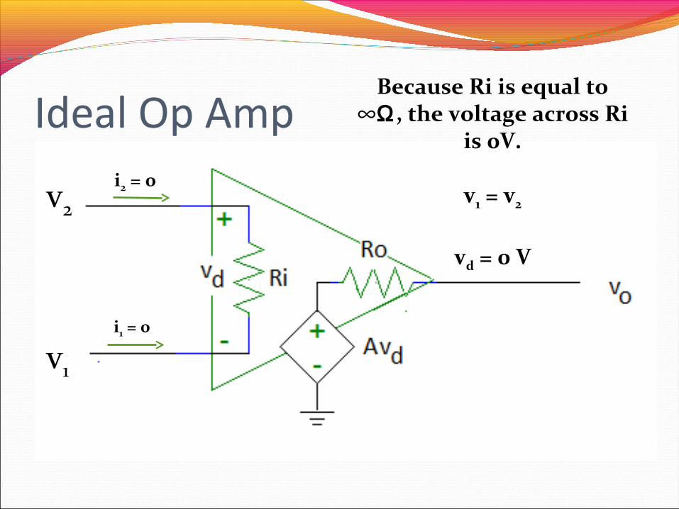
Ideal Op Ampi2 = 0
i1 = 0
Because Ri is equal to ∞Ω , the voltage across Ri
is 0V.
v1 = v2
vd = 0 V
v1
v2
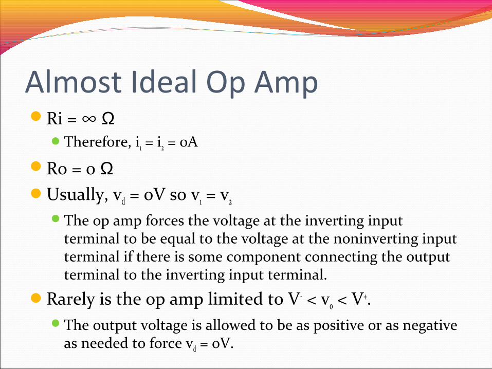
Almost Ideal Op AmpRi = ∞ Ω
Therefore, i1 = i2 = 0A
Ro = 0 ΩUsually, vd = 0V so v1 = v2
The op amp forces the voltage at the inverting input terminal to be equal to the voltage at the noninverting input terminal if there is some component connecting the output terminal to the inverting input terminal.
Rarely is the op amp limited to V- < vo < V+.The output voltage is allowed to be as positive or as negative
as needed to force vd = 0V.
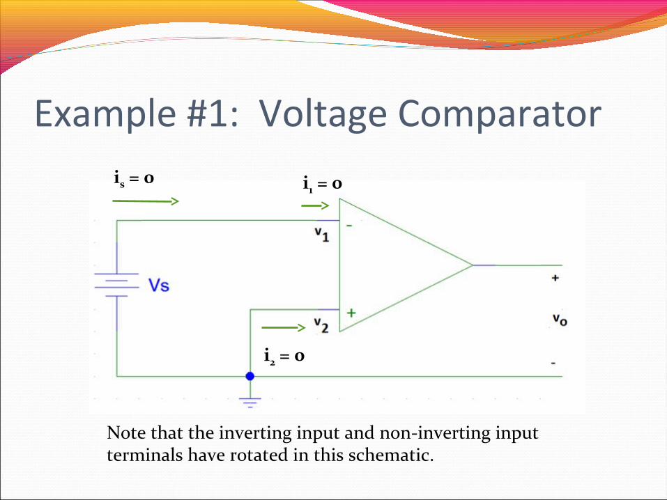
Example #1: Voltage Comparator
i2 = 0
i1 = 0is = 0
Note that the inverting input and non-inverting input terminals have rotated in this schematic.
Example #1 (con’t)The internal circuitry in the op amp tries to force the
voltage at the inverting input to be equal to the non-inverting input.As we will see shortly, a number of op amp circuits have
a resistor between the output terminal and the inverting input terminals to allow the output voltage to influence the value of the voltage at the inverting input terminal.
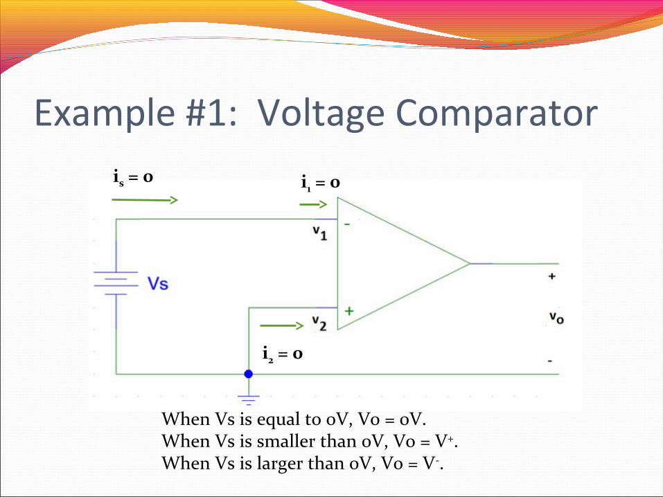
Example #1: Voltage Comparator
i2 = 0
i1 = 0is = 0
When Vs is equal to 0V, Vo = 0V.When Vs is smaller than 0V, Vo = V+.When Vs is larger than 0V, Vo = V-.
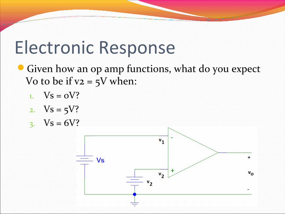
Electronic ResponseGiven how an op amp functions, what do you expect
Vo to be if v2 = 5V when:1. Vs = 0V?2. Vs = 5V?3. Vs = 6V?
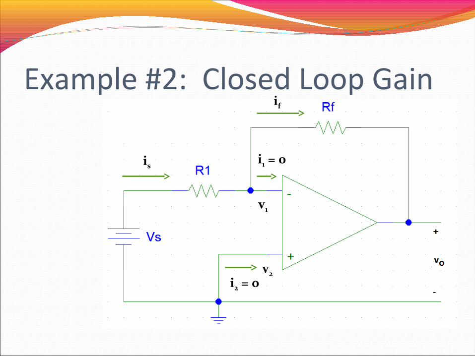
Example #2: Closed Loop Gain
i2 = 0
i1 = 0is
if
v1
v2
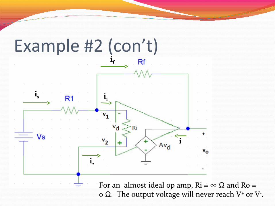
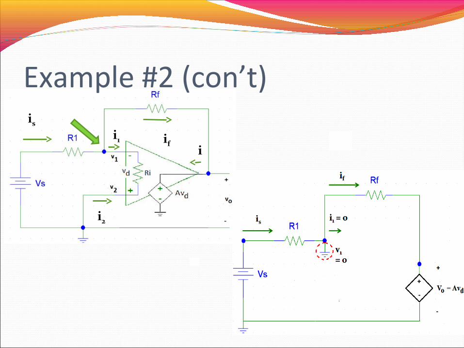
Example #2 (con’t)
is
if
i2
io
is
if
i1
For an almost ideal op amp, Ri = ∞ Ω and Ro = 0 Ω. The output voltage will never reach V+ or V-.
Example #2 (con’t)
is
if
i2
i
is
if
i1
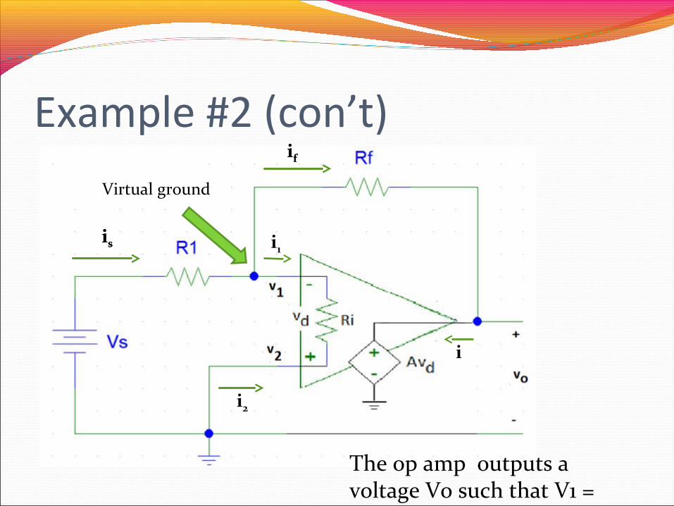
The op amp outputs a voltage Vo such that V1 = V2.
Virtual ground
Example #2 (con’t)
i1
i2
i
is
if
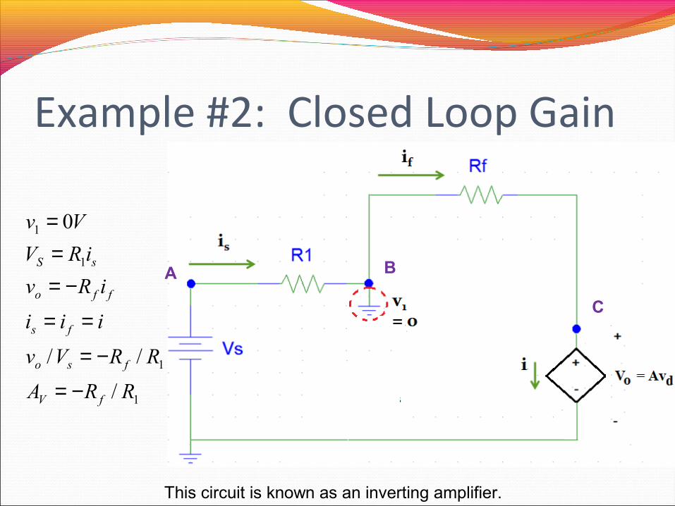
Example #2: Closed Loop Gain
This circuit is known as an inverting amplifier.
1
1
1
1
/
//
0
RRA
RRVv
iii
iRv
iRV
Vv
fV
fso
fs
ffo
sS
−=
−=
==
−===
C
A B
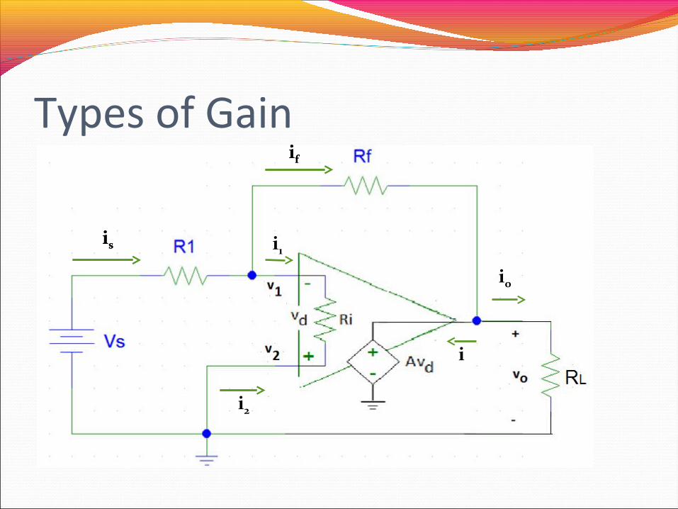
Types of Gain
is
if
i2
i
is
if
i1
io
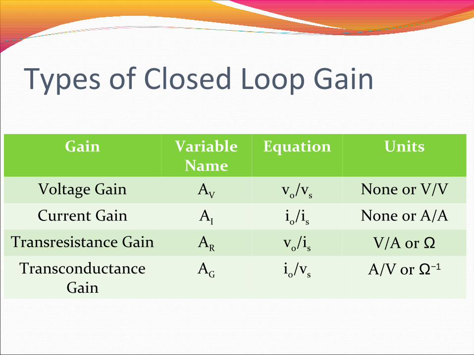
Types of Closed Loop Gain
Gain Variable Name
Equation Units
Voltage Gain AV vo/vs None or V/V
Current Gain AI io/is None or A/A
Transresistance Gain AR vo/is V/A or ΩTransconductance
GainAG io/vs A/V or Ω−1
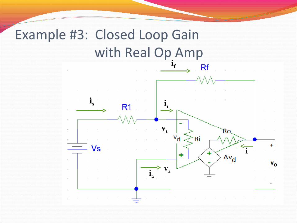
Example #3: Closed Loop Gain with Real Op Amp
is
if
i2
i
v1
v2
is
if
i1
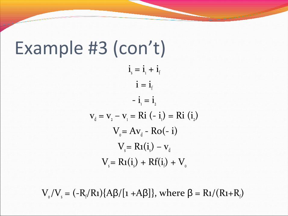
Example #3 (con’t)is = i1 + if
i = if
- i1 = i2
vd = v2 – v1 = Ri (- i1) = Ri (i2)
Vo = Avd - Ro(- i)
Vs = R1(is) – vd
Vs = R1(is) + Rf(if) + Vo
Vo /Vs = (-Rf/R1)Aβ/[1 +Aβ], where β = R1/(R1+Rf)
SummaryThe output of an ideal op amp is a voltage from a dependent
voltage source that attempts to force the voltage at the inverting input terminal to equal the voltage at the non-inverting input terminal.Almost ideal op amp: Output voltage limited to the range between
V+ and V-.Ideal op amp is assumed to have Ri = ∞ Ω and Ro = 0 Ω.
Almost ideal op amp: vd = 0 V and the current flowing into the output terminal of the op amp is as much as required to force v 1 = v2 when V+< vo< V-.
Operation of an op amp was used in the analysis of voltage comparator and inverting amplifier circuits.Effect of Ri < ∞ Ω and Ro > 0 Ω was shown.
Related Documents


