XL200CL Closed Loop Controller –Version 1.XX Operation & Reference Manual Manual # OM-XL2C-V101

Welcome message from author
This document is posted to help you gain knowledge. Please leave a comment to let me know what you think about it! Share it to your friends and learn new things together.
Transcript
XL200CL Closed Loop Controller –Version 1.XX
Operation & Reference Manual
Manual # OM-XL2C-V101

ii Introduction XL200 Series – VERSION 1
XL200 Closed Loop Version 1 Controller
Operation & Reference Manual
AMS Controls, Inc. 12180 Prichard Farm Road Maryland Heights, MO 63043
Phone 314.344.3144 • Fax 314.344.9996
!! WARNING !! AMS CONTROLS, INC. reserves the right to change the contents of this manual without customer notice or permission. Although every effort is made to insure the correctness off this manual, It should be noted that AMS CONTROLS, INC. is not responsible for personal or equipment damage caused by the contents of this manual. It is not the intent of this manual to cover every possible revision or version of controller. For specific controller questions contact AMS Controls, Inc. !! Important Version Information !! This manual is an interim manual to be used with the XL200, Version 1 controller only. Some instructions and diagrams may refer to interface techniques as used by the XL200 series controller. The manual applies only to Version 1 XL200 controllers.

iii Introduction XL200 Series – VERSION 1
Summary SUMMARY III
INTRODUCTION XV
Accuracy xvi
Productivity xvi
Easy to Use xvii
Easy to Install xvii
About this Manual xvii
System Description xviii The Closed Loop Control Sys tem xviii
XL200 VERSION 1 Hardware Description xx XL200 SERIES Controller Hardware Description xx
Microcomputer xx Controller Keys and Functions xxi
F1 – Set to Next xxi F2 – Skip/Ready xxi F3 – Add Line xxi F4 - Delete xxi F5 - Print xxi F6- Decrement Quantity xxii
Hot Keys xxii Help xxii Diagnostics xxii Increase Quantity xxii Production Data xxii Status xxii Setup xxii Program xxii Enter xxii
Navigation Keys xxiii Arrow Keys ↑,↓,←,→ xxiii Move Up, Move Down xxiii Page Up, Page Down xxiii Home xxiii
Numeric Entry Keys xxiii

iv Introduction XL200 Series – VERSION 1
INS xxiii End xxiii CE Key xxiv Decimal Point, • xxiv Dash (-) xxiv Number Keys, 0-9 xxiv
Display Brightness xxiv Inputs xxv Outputs xxvi
Special Features xxvii Die Test Mode xxvii Die Jog Mode xxvii Material Change Point xxviii Punch Presses xxviii Built- in Programmable Logic Controller xxix
Flexible Punching Options (XL200, XL202, XL206. And XL 212 Only) xxx
INSTALLATION 1-2
Controller Power 1-2
Emergency Stop Circuit 1-2
Run Circuit 1-4
Shear Control Circuit 1-6
Press Control Circuit 1-8
Initial Machine Tests 1-9 Manual Shear 1-9 Manual Press 1-9 Jogging 1-9
MACHINE CONFIGURATION 2-1
Setup 2-1
Machine Data 2-2 General Parameters 2-3
Halt Mode 2-3 Format 2-4 Bundle Qty Reload Value 2-4 Bundle Qty Count 2-4 Set Done Items to Ready? 2-4
v Introduction XL200 Series – VERSION 1
Auto-Delete Done Orders 2-5 Halt No More Item? (With Punch Only) 2-5 Use Order Numbers? 2-5 Halt Delay Minimum (With XL Link Only) 2-5 Minimum Footage to Request Order (With XL-Link Only) 2-6 Manual Shear Scrap Length (With XL-Link Only) 2-6 Shear Dwell Down 2-6 Shear Dwell Up 2-6 Auxiliary Shear Compensation 2-6 Shear Kerf 2-7 Shear Reaction 2-7 Minimum Part 2-8 Delay After Shear 2-8 Item Complete Dwell (XL200CL Only) 2-8 Shear-Encoder Distance 2-8 Coil End Point 2-8 Coil End Offset 2-9 Short Part Length (“U” option only) 2-9 Short Part Delay (“U” option only) 2-9 Very Short Part Length (“U” option only) 2-9 Very Short Part Delay (“U” option only) 2-9 Mode Select 2-10 No Hole Stop 2-10 Shear-Detect 2-10 Min Hole Spacing 2-10 Hole-Detect Logic 2-10 Line Movement Select (Single speed, non-stopping lines only) 2-10 Scrap Length (All Models Except XL200CL Without a Punch) 2-11 Loop Gain 2-11 Jog Select Mode? (Non-Stopping only) 2-12 Jog Velocity 2-12 Minimum Die Return Velocity (Non-Stopping only) 2-12 Maximum Die Return Velocity 2-12 Slow Run Velocity 2-12 Acceleration 2-12 Return Accel 2-13 Minimum Die Distance 2-13 Maximum Die Dist 2-13 Manual Shear Die Distance 2-14 Enable Alternate Die Parameters 2-14 The setup lockout key locks out all parameters. 2-14 Die Home Offset 2-15 Advance After Cut 2-15 Retract After Cut 2-15 On Tolerance Error? 2-15 Tolerance 2-17

vi Introduction XL200 Series – VERSION 1
Offset Volts (Auto) 2-17 Offset Integral 2-17 Lag Compensation (Auto) 2-18 Lag Integral 2-18 Derivative 2-18 Encoder Direction 2-18 Line Resolution 2-18 Die Resolution 2-19 Motor Resolution 2-19 Correction Feature 2-19 Filter Constant 2-20 Tool Select (XL202CL, XL206CL, XL212CL Only) 2-20 Press Dwell (When There Is More Than One Press) 2-20
Initial Machine Tests 2-21 Directions and Polarity 2-21 Manual Shear 2-21 Manual Press 2-22 Encoder Operation on Feed Systems 2-22
Single Encoder 2-22 Two Encoder 2-22
Slip Test on Feed-to-Stop Machines with 2 Encoders 2-23
Testing Without Material 2-24 Feed-To-Stop Mode 2-24 Die Accelerator Mode 2-24
Test Phase of Analog 2-31 Calibration 2-32
Calibrate Trim 2-33
Time Clock 2-34
Input/Output Status 2-35 E-Stop Input 2-35 Feed-OK Input (Feed-To-Stop only) 2-35 Setup Lockout Input 2-36 Enable Output 2-36
Memory Test 2-37 Clearing Memory While Energizing Controller 2-37
Communications 2-38 Communications Setup 2-39 Scrap Code 2-39 Product Code 2-40 Delay Reason 2-40
vii Introduction XL200 Series – VERSION 1
Employee Numbers 2-40 Communications Test 2-41
Request Order 2-42
EDIT TOOL DATA 3-1
The AMS Model XL200CL SERIES Controller 3-1 Glossary of Terms 3-2
Machine Configuration 3-3 Programming Press Parameters 3-3 Determining the Machine Zero Reference Point 3-3 Programming Tool Parameters 3-5
Nested Tooling 3-7
PART PROGRAMMING 4-1
Pattern Programming 4-1 LEADING EDGE 4-4 TRAILING EDGE 4-4 LEAD CENTER 4-4 TRAIL CENTER 4-4 EVEN SPACE 4-4 SPACING LIMIT 4-4
Order Programming 4-6 Lift Number 4-7 Quantity 4-7 Length 4-7 Pattern Number 4-7 Option 4-7
R-(RIGHT) 4-7 L-(LEFT) 4-8 A-(ALTERNATE RIGHT-LEFT) 4-8 M-(MIRRORED) 4-8
Application Example 1 4-9 Single Press with Multiple Gags 4-9 Die Layout 4-10 Tool Data Screen 4-11 Pattern 100 Screen 4-11 Pattern 200 Screen 4-12
Special Pattern Notes: 4-12

viii Introduction XL200 Series – VERSION 1
OPERATING PROCEDURE 5-2
Programming Overview 5-2
Entering Orders 5-3 Order Number 5-4 Material Code 5-4 Product Code 5-4 Lift (Bundle) Number 5-5 Quantity 5-5 Length 5-5 Punch Pattern 5-6 Standard Macro Programming 5-6
Edit Tool Data 5-6 Programming Macro Patterns 5-7 Macro Patterns 5-7 Inserting Macros Into Other Patterns 5-7
Exiting the Program Mode 5-14
Referencing Controller to the Material 5-15
Running the Machine 5-16 Main Status Display 5-16 Status Mode Display 5-17 Setting the Next Order (Item) to Run 5-18 Skipping an Order or an Item 5-18 Adding an Item While in the Run Mode 5-19 Deleting an Order (Item) 5-19 Changing the Sequence of Orders (Items) 5-20 Starting the Machine 5-20 Manual Shear 5-20 Halting Production 5-21 Completed Orders (Items) 5-21 Requesting Order (When using Eclipse Only) 5-21
Footage Totalizer 5-23 Coil Inventory 5-23
Display Coil Footage 5-23 Display Coil Material 5-24
Changing Product Code 5-24 Shift Totals and Job Totals 5-25
Special Procedures 5-27 Scrap Code 5-27 Delay Reason 5-27 Employee Numbers 5-27

ix Introduction XL200 Series – VERSION 1
Changing Coils 5-29 When No Good Footage is Run for a Coil 5-29 No Sheet Detect When a New Coil is Entered 5-29
Handling Material Flaws 5-31 Increase Quantity 5-31 Decrease Quantity 5-33
TROUBLESHOOTING 6-1
Troubleshooting Guide 6-2 When did the Problem Start? 6-2 Check the Machine 6-2 Collect Data 6-3 Re-check Setups 6-3 Run the Calibration mode 6-3 Use Built- in Diagnostic features 6-3 Check Incoming Power 6-3 Cycle Power 6-4 Electrical Noise 6-4 Clear Memory 6-5 Contact AMS 6-6 FAX Setup and Parts data to AMS 6-6
OPTIONS 7-1
Outputs to the Printer 7-3 Print Initiate Output 7-3 Printer Encoder 7-3 Citoh T4 Printer 7-7 Telesis 3225 Printer 7-8 Matthews 2001 Printer 7-10 Fox 8231M Printer 7-13 Willett 3150 Printer 7-16 Test Print on Part 7-17
Bundle Tag Printer 7-18 Citoh T4 Printer 7-18 CITOH SETUP MODES 7-23 Zebra Z4000 Printer 7-25
EXPANSION BOARD 7-31 EXP Hardware 7-31 Expansion Board Characteristics 7-31
Bar Code Scanner 7-33
x Introduction XL200 Series – VERSION 1
Extended Macro Patterns 7-36 Programming Patterns 7-36 Edit Tool Data 7-36 Macro Patterns 7-36 Inserting Macros Patterns Into Standard Patterns 7-37 A Programming Example Using Macro Patterns 7-37
Auxiliary Controller 7-41
Installation 7-42 Mechanical Installation 7-42 Electrical Installation 7-42 Controller Power 7-42
Machine State 7-44 Emergency Stop Circuit 7-44 Shear Control Circuit 7-45 Drive Control Circuit 7-46 Run Mode Control Circuit 7-46
Setting the Customizing Switches 7-46
Initial Power Test 7-47
Configuration Programming 7-47 General Parameters 7-47
Press (SHEAR) Dwell Down 7-47 Press Dwell Up 7-47 Press Reaction Time 7-48 Refresh Done Job (SL350HCLR ONLY!) 7-48 Batching (SL350HCLR ONLY!) 7-48 Mode (SL350HCLR ONLY!) 7-48 Press-Detect (Shear-Detect on SL350HCLR) 7-48 Minimum Hole Spacing 7-49 No-Hole Stop 7-49 Minimum Part (SL350HCLR ONLY!) 7-49 Loop Gain 7-49 Jog Die Velocity 7-49 Max Die Velocity 7-49 Acceleration 7-49 Return Accel 7-50 Min Die Dist 7-50 Max Die Dist 7-50 Advance After Cut 7-51 On Tolerance Error 7-51 Tolerance 7-51 Offset Auto 7-51 Offset Integral 7-52

xi Introduction XL200 Series – VERSION 1
Lag Auto 7-52 Lag Integral 7-52 Derivative 7-52 Line Resolution 7-53 Circumference (SL350HCLR ONLY!) 7-53 Rotary Count (SL350HCLR ONLY!) 7-53 Rotary Start (SL350HCLR ONLY!) 7-54 Rotary Stop (SL350HCLR ONLY!) 7-54 Die Resolution 7-54 Correction Factor 7-54 Filter Constant 7-54 Units 7-55 Jog Select 7-55 Minimum Velocity 7-55 Shear Dead Band 7-55 Print On Coil Changes 7-55 Manual Shear Die Distance 7-55 Hole Detect 7-55 Line movement 7-56
Editing the Auxiliary Controller Parameters 7-56 Auxiliary Setup 7-58 Auxiliary Program 7-59
Quantity 7-60 Hole Count 7-60 Length From Hole 7-60
Auxiliary Status 7-61 Search For All Devices 7-62
Initial Machine Tests 7-63 Manual Shear 7-63 Jogging 7-63 Referencing Controller to the Material 7-63 Die Accelerator Test 7-63
Running the Machine 7-65 Tolerance Error Display 7-65 Clear Holes 7-65
SL 301 H Switch Settings and I/O 7-75 7-66
SL 301 HCLR Switch Settings and I/O 7-76 7-66
SL 301 HCL Switch Settings and I/O 7-77 7-66
SL 301 HCLS Switch Settings and I/O 7-78 7-66
SL 301 H Plus Switch Settings and I/O 7-67
xii Introduction XL200 Series – VERSION 1
SL 301 HCLR Switch Settings and I/O 7-68
SL 301 HCL Switch Settings and I/O 7-69
SL 301 HCLS Switch Settings and I/O 7-70
Hole Detect Option 7-71 Hole Option Parameters 7-72
Mode 7-72 Shear Detect 7-72 Minimum Hole Spacing 7-72 No Hole Stop Distance 7-72 Hole Detect Logic 7-72 Programming 7-72
Programming in Hole Mode 7-74 QTY: 7-74 Hole: 7-74 Offset: 7-74
MODEL TYPES 8-1
Model Customization 8-1 Controller Model Types 8-1 Closed Loop Switch Settings 8-2
XL200CL Customization 8-2 XL200HCL Customization 8-2 XL202CLF, XL206CLF, XL212CLF Customizations 8-3 Models: XL202CL, XL206CL, XL212CL 8-3 Encoder 1 and Encoder 2 are used as follows: 8-4
Closed Loop Inputs and Outputs 8-5 Notes: 8-6
Machine Parameter Sheet 8-7 Press Dwell Sheet 8-7 Press Dwell Sheet 8-8 Tool Data Sheet 8-9 Patterns Sheet 8-10
SPECIFICATION 9-1
Mechanical 9-1
Electrical 9-1
Input Characteristics 9-1
Output Characteristics 9-1
xiii Introduction XL200 Series – VERSION 1
Encoder Input 9-1
Operation 9-2
Features 9-2
Options 9-2 Eclipse 9-2 Computer Requirements 9-2
Printer Specs 9-3 Bundle Tag Printer 9-3
Label 9-3 Print Head 9-3 Label Capacity 9-3 Ribbon 9-3 Resolution 9-3 Bar Codes 9-3
Inkjet Print on Part Printer 9-4 Power Requirements 9-4 Output 9-4 Ambient Requirements 9-4 Weight 9-4
Bar Code Scanner 9-5 Power Requirements 9-5 Scan Repetition Rate 9-5 Start-up Time 9-5 Data Acquisition Time 9-5 Skew Tolerance 9-5 Pitch Angle 9-5 Decode Capability 9-5 Element Width 9-5 Print Contrast 9-5 Ambient Light Immunity 9-5 Durability 9-6 Operating Temperature 9-6 Humidity 9-6 Height 9-6 Length 9-6 Width 9-6
DIAGRAMS 10-1
About Wiring Diagrams 10-1 XL Series Wiring Diagrams 10-1 SL (Auxiliary) Series Wiring Diagrams 10-1

xiv Introduction XL200 Series – VERSION 1
Expansion Board Diagrams 10-1 Printer Diagrams 10-1 4390-1 Encoder Expander/Driver 10-25 4390-2 Printer Encoder Driver 10-26
SOFTWARE CHANGES 11-1 Faster Processing 11-1 New 10.5-inch color display 11-1 “Downloadable” software upgrades 11-1 Standardized and Expanded Input and Outputs 11-1 Isolated (Floating) interface 11-1 Function key inputs 11-1 Version 1.00 to 1.01 11-2 Version 1.01 to 1.02 11-2
INDEX 12-1

xv Introduction XL200 Series – VERSION 1
Introduction AMS Controls Inc. has years of experience with controls for roll formers. Much of this is with multiple press machines that punch and notch prior to cutoff. The XL200 VERSION 1 SERIES is the ultimate controller for roll forming and cut-to-length machines. Unlike general-purpose controllers, AMS controllers are designed specifically for the needs of the roll forming industry. With an AMS controller installed on the roll forming line, many customers report a 20-30% increase in productivity due to the elimination of costly delays. Production can also be monitored with a PC from the office. The Model XL200 VERSION 1 SERIES controller is the latest and best of a long line of controllers.
With the XL200 VERSION 1 SERIES, parts are produced with a minimum amount of scrap. The powerful microprocessor can sequence from one size to another without waste. This unique feature makes in line punching practical for JIT (just in time) production systems.
Of equal importance to roll forming, is the ease of interfacing with the program and control system. Many machines are not used to their full potential because the controls are too complicated for the average production worker to understand. This is not the case with the AMS controller. AMS strives to make programming as simple as possible without loss of capability.
With the controller design, AMS incorporated the following objectives:
Ø Describe a part in finished part dimensions.
Ø Prompt for data with plain English prompts using standard industry terminology.
Ø Allow user flexibility to use the same controller on several machine configurations.
Ø Minimize the amount of data that must be entered.
Note: This manual applies to Version 1 Controllers (XL200 Series)

xvi Introduction XL200 Series – VERSION 1
Accuracy On cut-to-length machines without servo drives, accuracy depends on the repeatability of the machine to run at a constant speed and the repeatable reaction delays for each type of operation, punch and shear. If an electronic length controller is used, accuracy is lost when machine fluctuations occur.
The XL200 VERSION 1 SERIES Controller however, constantly monitors the performance of the machine and compensates for these variations resulting in improved accuracy. For flying cutoff machines, the exclusive Speed Compensation feature allows accurate punches and cuts at any line speed. For feed-to-stop machines, the automatic Adaptive Slowdown feature and the automatic Overshoot Compensation feature greatly improve machine accuracy.
Productivity The AMS controller improves productivity three ways.
Ø First, the improved accuracy with the XL200 VERSION 1 SERIES controller allows machines to run at higher line speeds.
Ø Second, for all types of machines, the multiple order feature allows many jobs to be programmed at one time (even while other orders are being processed and run) so delays between orders can be eliminated.
Ø The third way that the AMS controller can improve productivity is with the built in scrap control functions. These functions include “Increment Quantity”, “Decrement Quantity”, and “Add Line”, and are explained in the “Part Programming” section of the manual.
The AMS Controller eliminates a large amount of material waste by requiring only a single manual cut at the beginning of a new coil. This cut can be made while the machine is stopped, as opposed to a flying crop cut, which further reduces waste.
The automatic “Coil End Point” feature helps reduce the amount of scrap created by stopping the line and allowing the operator to cut the coil so that the exact amount of material is used for the order. The controller also includes “Scrap Length” parameters for punching lines
The XL200 VERSION 1 SERIES Controller includes an RS-485 communications port for connection to a remote office computer. With optional XL-LINK software, orders can be scheduled and sent to the

xvii Introduction XL200 Series – VERSION 1
controller, as well as machine performance monitored from the remote location. Productivity in this application can be greatly increased.
Easy to Use The XL200 VERSION 1 SERIES Controller is a sophisticated computer running very complex programs. This does not mean however, that an expert is required to operate it. A large liquid crystal display (LCD) prompts the operator for information in plain English and with words that are familiar. On the main display, the operator can see the order that is ran, the progress through the order, and the speed of the line.
Easy to Install The XL200 VERSION 1 SERIES Controller has built-in logic to handle most machine control functions. The user no longer needs to add Programmable Logic Controllers (PLCs) or relay logic circuits to get the correct machine sequence and safety features.
The AMS control will control a variety of different machines. For each type of machine, a different set of machine parameters are programmed into the controller. To simplify this procedure, the type of machine is programmed via a set of switches; these switches are in a single (DIP type) package, located on the back of the control. The controller reads the switches to determine the type of machine it is used with. Setup parameters are also limited by the switch settings to the parameters required only for the machine in use.
About this Manual This manual gives detailed information on the installation, operation and maintenance of the XL200 VERSION 1 SERIES Controller. Instructions for installing the AMS Controller on most machine types are included. AMS engineers can help on installation conditions not covered by this manual. A Customer Service Representative can be reached by Phone at 1-800-344-5213, FAX 1-314-344-9996 or questions can be sent through the Web Site at www.amscontrols.com. This Manual tells how to program orders and run them, gives the best way to handle a variety of special circumstances that can come up with most machines types and in the last section, includes a troubleshooting guide to follow if problems arise.
The Setup sheets in the back of this manual provide a place to record information about specific installations. Be sure to record this information at start-up and keep this manual in a safe place for later referral. If calling AMS for technical assistance, have this manual information, as well as the model number and serial number of the controller. The software version number is also needed and is displayed on the XL screen at power-up.

xviii Introduction XL200 Series – VERSION 1
System Description The Closed Loop Control System
There are two types of closed loop control systems. The closed loop die accelerator is used on flying die machines. The closed loop roll feeder is used on feed to stop machines.
Figure 1.1. Closed Loop Die Accelerator System
The material is driven through the press by the roll former at a steady speed. The closed loop controller measures the material movement. When the cut point is near the cutoff press, the motor accelerates the die. The servo loop attempts to drive the position error between the die and the cut point to zero. When this is achieved, the speed of the die matches the speed of the material, and the cut can occur.
The main difference between this system and the open loop cutoff system with a die boost device is the fact that the controller knows the exact position of the die at all times. This allows the controller to make an exact match up of the cut point with the die. With the open loop system, the controller has no control over the position of the die and depends upon material speed matching and consistent machine speed to get accurate results.
xix Introduction XL200 Series – VERSION 1
Roll Former
Press
Servo Amplifier
Servo with
Encoder
Closed Loop Controller
Press
Shear Punch Direction of Material Flow
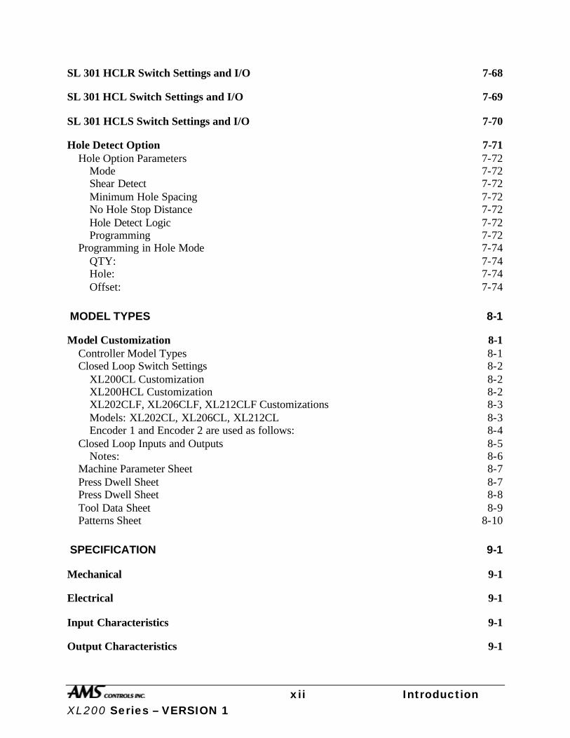
Figure 1.2. Closed Loop Roll Feed System.
A block diagram of the Closed Loop Roll Feed System is shown above. In this system, the XL200CL SERIES controller controls the material’s position and velocity via the servo amplifier and a set of pinch rollers. The amount of material movement is measured by an encoder (resolver), which is coupled to the motor. This method can generally provide even greater accuracy, since the resolution of most resolvers is much finer than that of most line encoders.
Assuming that there is no slippage between the material and the pinch rolls, the controller is able to track the exact position of the material, control its acceleration and velocity, and stop it at a pre-programmed punch or cut length. Only one punch press is shown in Figure 1.2, but the XL202CL can control up to two presses and/or gags, the XL206CL can control up to six presses and/or gags, and the XL212CL can control up to twelve presses and/or gags.
For feed roll systems with a large distance between the feed rolls and the press, an encoder may be added. The encoder should ride on the material and should be placed close to the punch press. With the two inputs, the controller will monitor any slip between the line encoder and the drive resolver. If the material slips under the encoder or jams, if the encoder becomes faulty such that a slip develops between the encoder and resolver, an appropriate alarm and shutdown will occur. Testing for slip will execute when material is detected and the controller is in the run or jog mode of operation.

xx Introduction XL200 Series – VERSION 1
XL200 VERSION 1 Hardware Description
XL200 SERIES Controller Hardware Description
Microcomputer
The XL200 SERIES controller is the critical element of an advanced length control system. It is equivalent to a personal computer (PC) packaged in a rugged industrial enclosure. Programs are stored in PROM (Programmable Read Only Memory) electronics instead of temporary disks. These programs were written by AMS to perform the specific task of length control. The PROM is factory programmed.
Status
Set Up
Program
Enter
INS
End
CE
_
.
7 8 9
654
1 2 30
AMS Controls XL 200 Series
Display
F1
F2
F3
F4
F5
F6
Help
Diagnostics
Inc. Qty
ProductionData
MoveUp
MoveDown
Page
PageUp
Down
Home
Figure I-3 XL200 SERIES Front Panel
The user does not need to write programs for the controller and only has to enter data on what to produce. This data is stored in RAM (Random Access Memory). In a normal PC, this memory is erased when power to the PC is removed. In the XL200 SERIES controller, an internal battery maintains this memory upon controller power down. Battery-back RAM is used to store machine setup and job information data. Operator Interface
xxi Introduction XL200 Series – VERSION 1
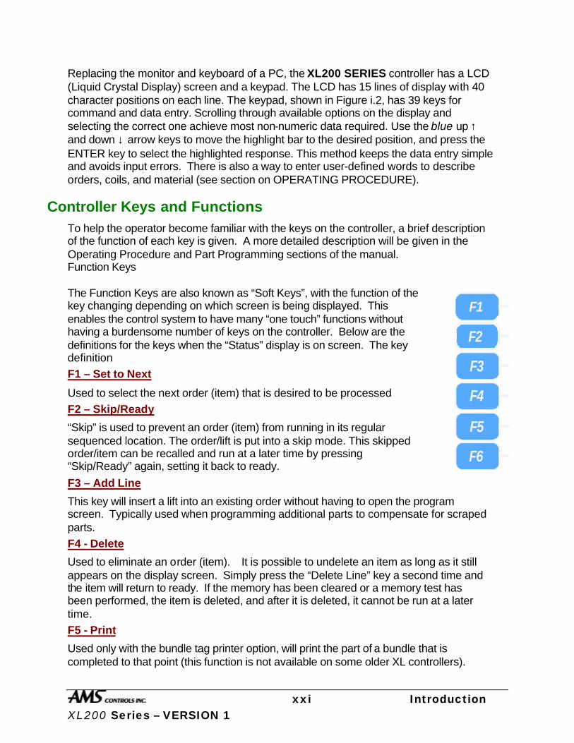
Replacing the monitor and keyboard of a PC, the XL200 SERIES controller has a LCD (Liquid Crystal Display) screen and a keypad. The LCD has 15 lines of display with 40 character positions on each line. The keypad, shown in Figure i.2, has 39 keys for command and data entry. Scrolling through available options on the display and selecting the correct one achieve most non-numeric data required. Use the blue up ↑ and down ↓ arrow keys to move the highlight bar to the desired position, and press the ENTER key to select the highlighted response. This method keeps the data entry simple and avoids input errors. There is also a way to enter user-defined words to describe orders, coils, and material (see section on OPERATING PROCEDURE).
Controller Keys and Functions To help the operator become familiar with the keys on the controller, a brief description of the function of each key is given. A more detailed description will be given in the Operating Procedure and Part Programming sections of the manual. Function Keys The Function Keys are also known as “Soft Keys”, with the function of the key changing depending on which screen is being displayed. This enables the control system to have many “one touch” functions without having a burdensome number of keys on the controller. Below are the definitions for the keys when the “Status” display is on screen. The key definition
F1 – Set to Next
Used to select the next order (item) that is desired to be processed
F2 – Skip/Ready
“Skip” is used to prevent an order (item) from running in its regular sequenced location. The order/lift is put into a skip mode. This skipped order/item can be recalled and run at a later time by pressing “Skip/Ready” again, setting it back to ready.
F3 – Add Line
This key will insert a lift into an existing order without having to open the program screen. Typically used when programming additional parts to compensate for scraped parts.
F4 - Delete
Used to eliminate an order (item). It is possible to undelete an item as long as it still appears on the display screen. Simply press the “Delete Line” key a second time and the item will return to ready. If the memory has been cleared or a memory test has been performed, the item is deleted, and after it is deleted, it cannot be run at a later time.
F5 - Print
Used only with the bundle tag printer option, will print the part of a bundle that is completed to that point (this function is not available on some older XL controllers).
F1
F2
F3
F4
F5
F6
xxii Introduction XL200 Series – VERSION 1
F6- Decrement Quantity
Decreases the number of parts remaining to be processed in an order (commonly used to decrease the scrap in the footage totalizer when parts that were defective are modified to be counted as good parts).
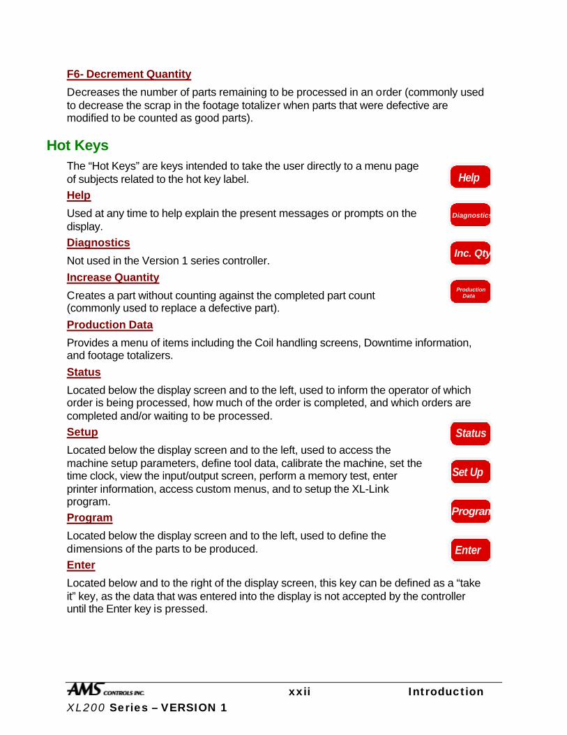
Hot Keys The “Hot Keys” are keys intended to take the user directly to a menu page of subjects related to the hot key label.
Help
Used at any time to help explain the present messages or prompts on the display.
Diagnostics
Not used in the Version 1 series controller.
Increase Quantity
Creates a part without counting against the completed part count (commonly used to replace a defective part).
Production Data
Provides a menu of items including the Coil handling screens, Downtime information, and footage totalizers.
Status
Located below the display screen and to the left, used to inform the operator of which order is being processed, how much of the order is completed, and which orders are completed and/or waiting to be processed.
Setup
Located below the display screen and to the left, used to access the machine setup parameters, define tool data, calibrate the machine, set the time clock, view the input/output screen, perform a memory test, enter printer information, access custom menus, and to setup the XL-Link program.
Program
Located below the display screen and to the left, used to define the dimensions of the parts to be produced.
Enter
Located below and to the right of the display screen, this key can be defined as a “take it” key, as the data that was entered into the display is not accepted by the controller until the Enter key is pressed.
Help
Diagnostics
Inc. Qty
ProductionData
Status
Set Up
Program
Enter

xxiii Introduction XL200 Series – VERSION 1
Navigation Keys
Arrow Keys ↑↑ ,↓↓ ,←← ,→→
Located below the display screen and to the left, used to move the cursor or highlighted item in the direction of the arrow pressed
Move Up, Move Down
Used only in the “Programming Screens” when editing orders, lifts, or patterns. Pressing the Move Up or Move Down key will move the highlighted order or pattern in the indicated direction, changing the sequence of operations.
Page Up, Page Down
The “Page Up” will move the highlighted line to the top of the display and “Page Down” will move it to the bottom of the display screen. If there is more data that cannot fit on the current screen, pressing the Page Up or Page Down key a second time, will move to the next page to be displayed.
Home
The Home key will move the highlighted line to the first line of the current item being displayed, even if the display is currently showing a different page.
Numeric Entry Keys
INS
Located below the display screen and to the right, the Pick key will allow the user to toggle through the displayed items whenever there is more than one possible option for a parameter. The Pick key has further functions that are described later in the manual. In these applications the Pick key is used as an editor for Orders, Items, Patterns, etc. Note: If using a remote terminal, the Insert Key is the same as the Pick key. Any number key will also provide the “Pick” function and allows the user to toggle through the displayed options.
End
The End key will move the highlighted line to the last line of the current item being displayed, even if the display is currently showing a different page.
MoveUp
MoveDown
Page
PageUp
Down
Home
INS
End
CE
_
.
7 8 9
654
1 2 30

xxiv Introduction XL200 Series – VERSION 1
CE Key
Located below and to the right of the display screen, this is a “Clear Entry” key. The main use of this key is to correct the entered data when a mistake is made. Pressing this button will clear out the previously entered data so that the data can be entered again from the beginning. This key is also used to clear controller errors and warning prompts.
Decimal Point, ••
This key is used to place a decimal point when entering a number, and it will also display a dash when entering alphanumeric data (for order and material numbers). A third use of this key is to produce the dividing line of a fraction when in the fractional mode, and entering fractions.
Dash (-)
The Dash is used to put a dash in Order Numbers, Material Codes, etc. Example: Order Number 123-456-78. The Decimal Point on the number keypad will also provide the same function as the Dash
Number Keys, 0-9
Used to enter numerical data.
Display Brightness Located to the right of the screen, pressing the up or down arrow will lighten or darken the display respectively. Note: Display adjustments are only available once the controller has powered up completely.
Display
xxv Introduction XL200 Series – VERSION 1
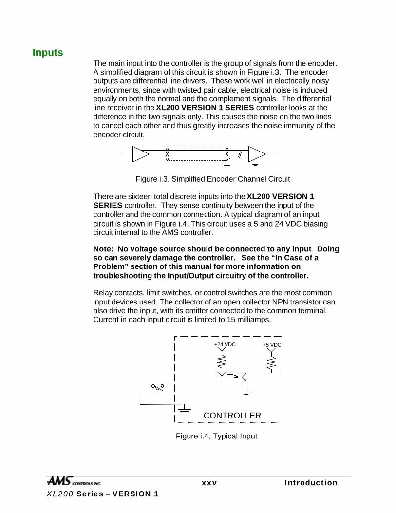
Inputs The main input into the controller is the group of signals from the encoder. A simplified diagram of this circuit is shown in Figure i.3. The encoder outputs are differential line drivers. These work well in electrically noisy environments, since with twisted pair cable, electrical noise is induced equally on both the normal and the complement signals. The differential line receiver in the XL200 VERSION 1 SERIES controller looks at the difference in the two signals only. This causes the noise on the two lines to cancel each other and thus greatly increases the noise immunity of the encoder circuit.
Figure i.3. Simplified Encoder Channel Circuit
There are sixteen total discrete inputs into the XL200 VERSION 1 SERIES controller. They sense continuity between the input of the controller and the common connection. A typical diagram of an input circuit is shown in Figure i.4. This circuit uses a 5 and 24 VDC biasing circuit internal to the AMS controller.
Note: No voltage source should be connected to any input. Doing so can severely damage the controller. See the “In Case of a Problem” section of this manual for more information on troubleshooting the Input/Output circuitry of the controller.
Relay contacts, limit switches, or control switches are the most common input devices used. The collector of an open collector NPN transistor can also drive the input, with its emitter connected to the common terminal. Current in each input circuit is limited to 15 milliamps.
+24 VDC +5 VDC
CONTROLLER
Figure i.4. Typical Input

xxvi Introduction XL200 Series – VERSION 1
Outputs The Standard DC output of the XL200 VERSION 1 SERIES controller is a 4-Ampere JFET. This is available in all configurations and for all outputs. A diagram of this circuit is shown in Figure i.5. The biasing voltage for the load can be from 5 to 24 volts DC. If this voltage source comes from outside of the controller, the common of this supply must be connected to the common of the controller. The suppressing diode shown reduces the noise generated by inductive loads when the JFET turns off. The load can be either a DC solenoid or a DC Relay.
+24 VDC
CONTROLLER
Figure i.5. Standard DC Output
+24 VDC
Suppressing Diode
xxvii Introduction XL200 Series – VERSION 1
Special Features
The XL200CL SERIES Controller has been designed to offer advanced features for length control that are not available on simple electronic counters. These features offer better accuracy and reduce the amount of waste that can occur. They also eliminate the need for additional control circuits to control the machine.
Die Test Mode A closed loop die accelerator system is a highly sensitive and precise system that must be carefully adjusted to achieve good results. With any sensitive servo system, the possibility for instability is always present. Dampening the response of the loop will stabilize the system but too much dampening will make the system sluggish and unresponsive.
To optimize the system, the die accelerator needs to be tested under normal operating conditions. Test pieces can be cut, but this produces scrap and can cause jamming or die damage if conditions are not right.
To solve this problem, the XL200CL SERIES controller has a DIE TEST mode that simulates material movement without actually running the roll former. The operator sets the line speed and part length to run, and the AMS controller will generate internal line encoder pulses to mimic what will happen when the roll former is running. The die accelerator cycles as it normally would, and the only difference between this mode and normal operation is that the controller will not stop the line on an OUT OF TOLERANCE error. The shear will not be cycled when the die is out of tolerance (if a NO CUT mode is selected). While in the DIE TEST mode, both servo amplifier parameters and controller parameters can be adjusted to achieve stable, responsive results. When TOLERANCE is achieved, or at the MINIMUM DIE DISTANCE, the controller will begin cycling the shear.
Die Jog Mode The DIE JOG mode is only used on Die Accelerators. When using the DIE JOG mode, the operator will have the ability to jog the die in and out by using the JOG FORWARD and JOG REVERSE inputs. The display will show the position of the die. When the JOG FORWARD switch is made, the die will move forward at the programmed JOG VELOCITY. When the JOG REVERSE switch is made, the die will move in the reverse direction. Pressing the JOG buttons outside of the JOG DIE mode screen will move the roll former or feeding device.
xxviii Introduction XL200 Series – VERSION 1
Material Change Point Most post-cut roll former machines will waste material when a material change occurs and the old coil is returned to stock. If the order is run to the end, the roll former is full of material that cannot be backed out of the machine. The coil must be cut free at the entrance to the roll former. The piece left in the roll former is then fed through and becomes scrap if it cannot be cut into a useful part.
An alert operator can stop the line with a few pieces left and cut the coil free at the entrance to the roll former. If he guesses correctly, scrap can be minimized. If, however, he makes a mistake and does not allow enough material, then the coil has to be threaded through the machine again.
The XL200CL SERIES controller solves this problem by automatically stopping the line when the trailing end of the last piece is at a predetermined point at the entrance to the roll former. The AMS controller is always alert and never stops with too much, or too little material to finish the order.
Punch Presses All these accuracy-enhancing features apply to the in-line punch presses used on Feed-to-Stop systems, as well as to the cutoff shear press.

xxix Introduction XL200 Series – VERSION 1
Built-in Programmable Logic Controller When designing a cut-to-length machine with an electronic counter for the length control device, a Programmable Logic Controller (PLC) or relay logic is normally added to generate the proper sequence for the machine and add standard safety features. AMS has eliminated the need for a PLC by building comprehensive control logic into the XL200 VERSION 1 SERIES controller. This logic implements the following features:
• Four output configurations for speed control
• Run-Halt control by external contact
• Manual cycle of the Presses only in the Halt mode on feed-to-stop machines
• Manual crop allowed while running on non-stop machines
• Jog in manual only
• Motor starter interlock circuit
• Automatic Shear or Press operation only in Run mode
• Halt on emergency stop or overload
The result is that the XL200 VERSION 1 SERIES controller can be adapted to most machines with a minimum amount of external electrical components. The only "programming" that a user must do is selecting the proper TYPE of machine through some switch settings. The controller then implements the proper logic based on the TYPE.

xxx Introduction XL200 Series – VERSION 1
Flexible Punching Options (XL200, XL202, XL206. And XL 212 Only)
The AMS controller offers a machine designer many punching options within the same controller. Before the XL200 VERSION 1 SERIES controller, complex operations required the use of a PLC that needed an expensive custom program written to handle particular applications. The next project would require re-engineering with new programming developed. This process would be repeated every time the number of presses changed or the different gag arrangement was used.
The XL200 VERSION 1 SERIES controller is designed with enough flexibility, to work on virtually any combination of presses and gags. No custom programming is required. The XL202 will control one press with one gag or two individual presses, (shear and punch). The XL206 will control one press with five gags, six individual presses, or any combination of presses and gags. The XL212 will control one press with eleven gags, twelve individual presses, or any combination of presses and gags.

1-2 Installation XL200CL Series - VERSION 1
Installation
Controller Power
The AMS controller requires a 24VDC supply for operating power. It is preferable to have two 24VDC supplies, one for the inputs and outputs and the other for the controller CPU power. Separate power supplies will isolate the input/output circuits from the Processor, reducing noise interference. The common of the supplies used must be connected to the common of the control, this circuit being grounded. The common of the supply will be switched into the inputs of the controller and the 24 VDC will be used in conjunction with the outputs to pull-in control relaying. All input power should be within the specification limits.
Power to the controller should be switched independent of other devices through it’s own circuitry. The emergency stop circuit should not interrupt power. In an emergency-stop condition, the controller will track any movement of the material with controller power still applied. This allows continued production to resume after the emergency stop condition, without loss in accuracy. See Figure 1.1.
Emergency Stop Circuit
An emergency stop circuit is required for each machine, giving operator safety and protection of system equipment.
A typical emergency stop circuit is shown in Figure 1.1. Pressing the guarded push-button RESET switch arms this circuit. The relay remains energized after the RESET switch opens because of the hold-in contacts of the relay. The relay condition depends on current flow through the normally closed emergency stop switches and any other emergency stop contacts in series with the switches. A momentary opening of either switch or contact will cause the relay to de-energize which cuts off power to all load devices. Adding devices in series with the emergency stop contacts or switches easily expands the circuit.
A higher degree of safety is achieved by placing switches behind safety guards and in doors of electric panels. These are wired in the Emergency Stop Circuit, so when opened, the machine is shut down
The emergency stop circuit should not interrupt power to the AMS controller, however the AMS controller must know when an emergency stop has occurred in order to drop the line out of the RUN mode. This can be accomplished by breaking the run circuit or by opening the safely interlock input to the control. If an emergency stop condition occurs, power should be

1-3 Installation XL200CL Series - VERSION 1
isolated from all output devices. This would include all 24VDC devices as well as all 115VAC devices. Please refer again to Figure 1.1.
CR1
+-
OFF ON
CR1
CR1
RESET
STOP START
CR2
CR3
24 VDCPOWER
SUPPLY
E-STOPE-STOP
G
A
LINE ACN
"TYPICAL"
RUN OUTPUTRUN INPUT
E-STOP INPUT(CLOSED LOOP ONLY)
AMS CONTROLLER
CONTROLLER SUPPLY NOTINHIBITED BY E-STOP CIRCUIT
OVERLOAD
AC SUPPLYISOLATED BY
STOP CONTACTSEMERGENCY
E-STOP RELAYTO ISOLATEI/O POWER
CR2
CR1
CR3
FORWARD OUTPUT
SLOW OUTPUT
CR4
CR5
MATERIAL FEEDOUTPUTS
CPU COM CPU 24V
Figure 1.1 Typical Wiring Configuration for Run and E-Stop Circuits

1-4 Installation XL200CL Series - VERSION 1
Run Circuit
Also shown in Figure 1.1 is the most common way of wiring the run circuit. Note that by wiring the controller in this manner, a halt, a controller error or an E-stop will halt the system. The sequence of events follows:
Ø Operator presses a momentary “Run” switch, energizing the “Run” relay (CR2).
Ø Once CR2 is energized, this closes the “Run” input to the AMS controller.
Ø The AMS controller detects the input.
Ø If a job is programmed, no errors exist and all other pertinent items are present, then the controller turns on the “Run” output.
Ø The output energizes the “Run Latch” relay (CR3)
Ø CR3 closes a set of contacts that latch in around the momentary “Run” switch, maintaining the Run condition.
The Run output should also energize lights, buzzers or other safety devices to let personnel know that the machine is now in automatic mode.
The “Forward” and “Slow” outputs should be used to put the material into motion. If this is the case, a special parameter called “Line Movement Select” should be set to “Fst/Fwd”. This parameter selection allows the “Forward” and “Run” outputs to work independently. The “Run” output would then be used purely as an output to latch the run circuit and to energize run lights or safety devices. Using the “Run” output to put the material in motion could cause some problems in the operation of the machine. This is due to other features that are used in the controller. First, some controllers will continue to shear or punch after a halt has been performed in order to catch targets as the line coasts to a stop. Second, a “Delay after Shear” feature is available to stop the material motion (Forward Output) after each cutoff. Even though the motion is turned off in both cases through the “Forward” output, the “Run” output remains on the entire time. If “Run” is used as the motion output in these cases, the line will not stop at the correct times!
The “Line Movement” parameter will allow the user to connect only the “Run” output to the motion device(s). If “Run” is selected as the parameter setting, the run output works more like the forward output. The run output would turn off immediately after the line halts for any reason, even during the deceleration of the line. Note: the controller will still fire on targets as the material coasts to a stop.
1-5 Installation XL200CL Series - VERSION 1
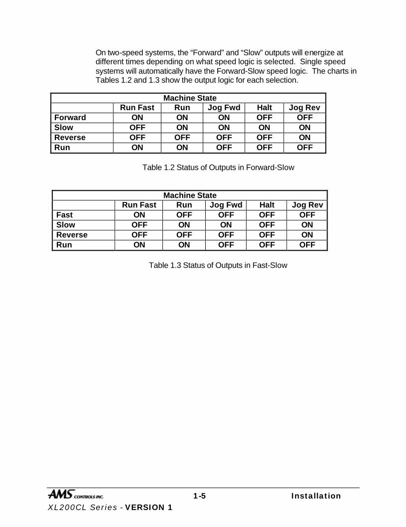
On two-speed systems, the “Forward” and “Slow” outputs will energize at different times depending on what speed logic is selected. Single speed systems will automatically have the Forward-Slow speed logic. The charts in Tables 1.2 and 1.3 show the output logic for each selection.
Machine State Run Fast Run
Slow Jog Fwd Halt Jog Rev
Forward output
ON ON ON OFF OFF Slow OFF ON ON ON ON Reverse OFF OFF OFF OFF ON Run ON ON OFF OFF OFF
Table 1.2 Status of Outputs in Forward-Slow
Machine State Run Fast Run Jog Fwd Halt Jog Rev
Fast ON OFF OFF OFF OFF Slow OFF ON ON OFF ON Reverse OFF OFF OFF OFF ON Run ON ON OFF OFF OFF
Table 1.3 Status of Outputs in Fast-Slow

1-6 Installation XL200CL Series - VERSION 1
Shear Control Circuit
Optimal performance of the shear circuit can be met by customizing the AMS controller to a particular type of press and feed control. This is accomplished by changing the customer available switch settings. The switches are in a single package located on the back of the controller. The controller can be configured to work with flying-cut or feed-to-stop applications. Outputs are available for SHEAR DOWN and SHEAR UP or SHEAR DIE BOOST.
AMS controllers are designed to connect directly to 24VDC solenoids for optimal performance. A solenoid-driving device, such as the AMS 3840 power module, can provide more accurate firing of the press. See Figure 1.4 for wiring possibilities.
AMS #3840-1 POWER MODULE
8 7
6-
+
SOLENOIDDRIVER
IN1 SOL1 (+)
SOL1 (-)
ESR 24VDCShear Input FromController
Shear Valve
Figure 1.4
If the solenoid for the shear outputs is not 24VDC, then an attempt should be made to replace the solenoid with a compatible 24VDC type. If this is not possible, then a 24VDC relay will have to be installed between the AMS output and the solenoid.
AMS controllers have a timed shear output with an input switch override feature. The duration of the SHEAR DWELL or SHEAR DOWN output is programmable from 0.000 to 9.999 seconds. Please refer to timing diagram - Figure 1.5. If the AMS controller detects a switch closure at the SHEAR COMPLETE input during the dwell time, the shear output will turn off immediately (Figure 1.6). This is especially useful on mechanical presses that need the shear-complete switch mounted in a location that will return
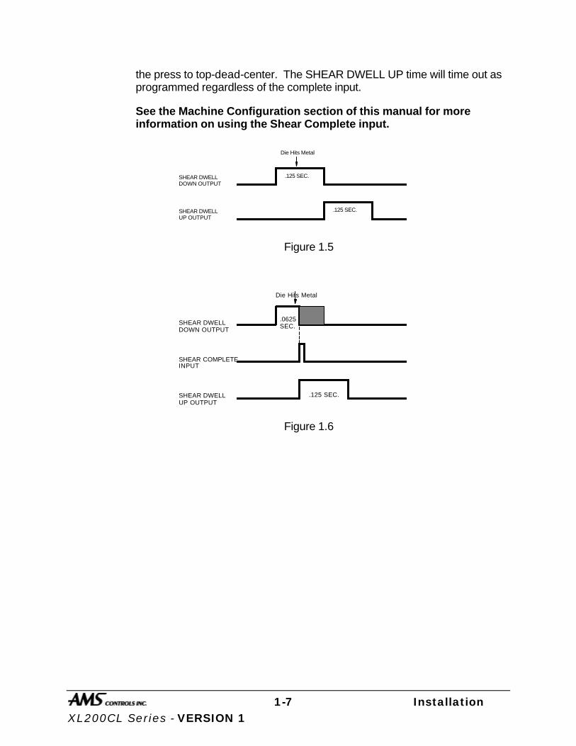
1-7 Installation XL200CL Series - VERSION 1
the press to top-dead-center. The SHEAR DWELL UP time will time out as programmed regardless of the complete input.
See the Machine Configuration section of this manual for more information on using the Shear Complete input.
SHEAR DWELL DOWN OUTPUT
SHEAR DWELL UP OUTPUT
.125 SEC.
.125 SEC.
Die Hits Metal
Figure 1.5
SHEAR DWELL DOWN OUTPUT
SHEAR DWELL UP OUTPUT
.125 SEC.
INPUTSHEAR COMPLETE
.0625SEC.
Die Hits Metal
Figure 1.6

1-8 Installation XL200CL Series - VERSION 1
Press Control Circuit
The terms and definitions for the press control parameters are identical to its shear control counterparts. The press parameters will include PRESS DWELL DOWN and PRESS DWELL UP or PRESS DIE BOOST depending on the machine’s configuration. The press outputs can also signal the AMS 3840 power module (or similar unit) or isolation relays for use with higher voltage solenoids.
Like the shear output, the PRESS DWELL DOWN can be programmed from 0.000 to 9.999 seconds. A PRESS COMPLETE input will override the press’s timed output and turn the output off immediately upon detection.
See the Machine Configuration section of this manual for more information on using the Press Complete input.

1-9 Installation XL200CL Series - VERSION 1
Initial Machine Tests
Manual Shear The shear can be manually activated using the MANUAL SHEAR input. This causes the SHEAR output to turn on for the SHEAR DOWN time or until the SHEAR COMPLETE input switch closes. Make adjustments to the SHEAR DWELL time or the position of the SHEAR COMPLETE switch until the shear cycles properly.
Manual Press Entering a tool number under the “Tool Select” parameter in the Machine Data screen can test any one of the tools. When the MANUAL PRESS input is closed, the appropriate gag will be selected and the press will fire for the PRESS DOWN time or until the PRESS COMPLETE switch closes. Make adjustments to the PRESS DOWN time or to the position of the PRESS COMPLETE switch until the press cycles properly.
Jogging If the jogging inputs are used, they can be tested and adjustments made. On two-speed machines, jogging is always done in slow speed.
2-1 Machine Configuration XL200CL Series - VERSION 1 1
Machine Configuration
Setup
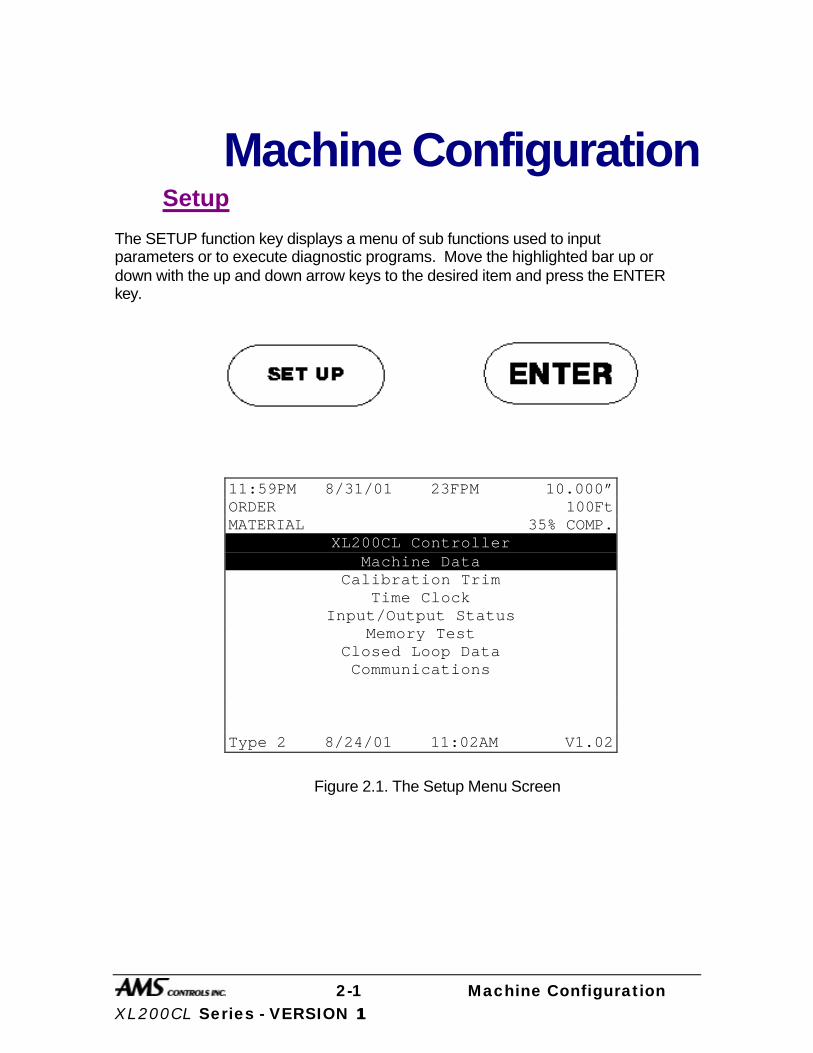
The SETUP function key displays a menu of sub functions used to input parameters or to execute diagnostic programs. Move the highlighted bar up or down with the up and down arrow keys to the desired item and press the ENTER key.
Figure 2.1. The Setup Menu Screen
11:59PM 8/31/01 23FPM 10.000” ORDER 100Ft MATERIAL 35% COMP.
XL200CL Controller Machine Data
Calibration Trim Time Clock
Input/Output Status Memory Test
Closed Loop Data Communications
Type 2 8/24/01 11:02AM V1.02

2-2 Machine Configuration XL200CL Series - VERSION 1 1
Machine Data
In addition to setting the customization switches, the user can further customize the XL200CL SERIES by programming parameters in the Machine Data mode. If the customizing switches have been changed, the XL200CL SERIES will erase all memory and go immediately into the Machine Data mode. The Machine Data mode can be entered in the future by pressing SET UP then ENTER while Machine Data is highlighted.
Some of these parameters are general and apply to all controller models and switch settings. Others apply only to specific models and switch settings. In this section, all of the parameters will be defined. The specific switch settings and I/O listings for each model are listed in Chapter 9.
Figure 2.2. Machine Data Screen
1:59PM 8/31/01 0FPM 0.000” ORDER 0Ft MATERIAL N/A% COMP. Parameters Setup Value Halt Mode Bundle Halt Format Decimal Inch Set Done Items to Ready? No Auto-Delete Done Orders 14 Days Use Order Numbers? Yes Shear Dwell Dn *****sec Shear Dwell Up *****sec Shear Kerf 0.0000” Shear Reaction 0.0000sec Minimum Part 0.0000” Type 2 7/2/01 3:04PM V1.02

2-3 Machine Configuration XL200CL Series - VERSION 1 1
General Parameters
Halt Mode
Determines when the controller will execute an automatic line halt. The user has the choice of going from one item to the next without stopping, stopping after the completion of an item, stopping after the completion of a bundle, or stopping after the completion of an order.
The HALT MODE parameter is located when in the Machine Data mode. This will replace the old setup parameter HALT AFTER JOB. HALT MODE will have four options.
ITEM HALT
BUNDLE HALT (default)
ORDER HALT
DON’T HALT
When ITEM HALT is selected, the controller will halt the line after the completion of every line item, regardless of the Lift Number.
In the BUNDLE HALT mode, the controller will halt the machine when the Lift Number, Order Number, Material or Pcode (Product Code) changes.
When the ORDER HALT mode is selected, the controller will halt the machine when the Order Number, Material or Pcode changes, but not with a change in the Lift Number.
In the DON’T HALT mode, the controller will halt the machine only when the Material or Pcode changes. The controller will not halt until ALL batches are done.
To toggle through the choices, use any number key or the blue INS (Insert) key, and then press ENTER to lock in the selection.
2-4 Machine Configuration XL200CL Series - VERSION 1 1
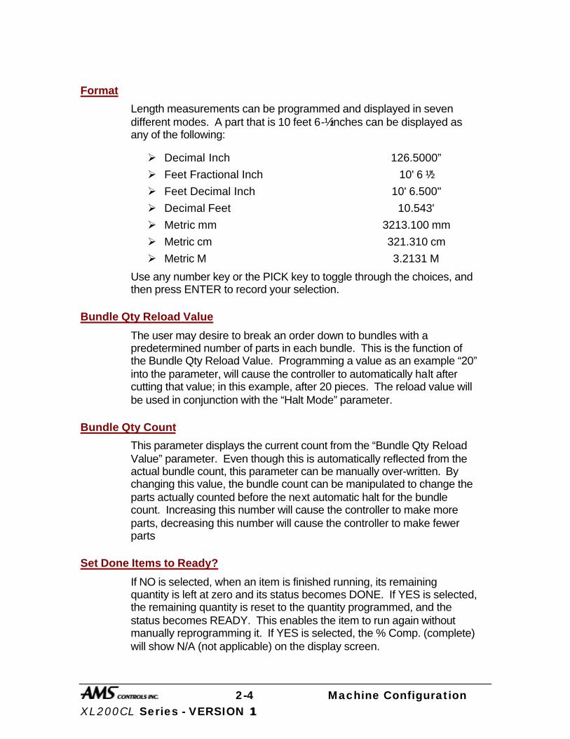
Format
Length measurements can be programmed and displayed in seven different modes. A part that is 10 feet 6-½ inches can be displayed as any of the following:
Ø Decimal Inch 126.5000”
Ø Feet Fractional Inch 10' 6 ½”
Ø Feet Decimal Inch 10' 6.500"
Ø Decimal Feet 10.543'
Ø Metric mm 3213.100 mm
Ø Metric cm 321.310 cm
Ø Metric M 3.2131 M
Use any number key or the PICK key to toggle through the choices, and then press ENTER to record your selection.
Bundle Qty Reload Value
The user may desire to break an order down to bundles with a predetermined number of parts in each bundle. This is the function of the Bundle Qty Reload Value. Programming a value as an example “20” into the parameter, will cause the controller to automatically halt after cutting that value; in this example, after 20 pieces. The reload value will be used in conjunction with the “Halt Mode” parameter.
Bundle Qty Count
This parameter displays the current count from the “Bundle Qty Reload Value” parameter. Even though this is automatically reflected from the actual bundle count, this parameter can be manually over-written. By changing this value, the bundle count can be manipulated to change the parts actually counted before the next automatic halt for the bundle count. Increasing this number will cause the controller to make more parts, decreasing this number will cause the controller to make fewer parts
Set Done Items to Ready?
If NO is selected, when an item is finished running, its remaining quantity is left at zero and its status becomes DONE. If YES is selected, the remaining quantity is reset to the quantity programmed, and the status becomes READY. This enables the item to run again without manually reprogramming it. If YES is selected, the % Comp. (complete) will show N/A (not applicable) on the display screen.
2-5 Machine Configuration XL200CL Series - VERSION 1 1
Press any number key to toggle between YES and NO to select the desired mode of operation. When the correct choice is highlighted, Press ENTER to record your selection.
Auto-Delete Done Orders
Completed Orders and Items remain in the XL200CL SERIES controller memory for the number of days specified in this parameter. The default value is 14 days. This allows the operator to quickly review production history. Enter the number of days before a DONE order is automatically deleted.
Items that are flagged as DONE will be removed from memory at either 12 AM or 12 PM after the specified time has elapsed.
Halt No More Item? (With Punch Only)
If YES is selected, the controller will halt when all remaining parts have been loaded into the controller's memory. At this time it is desirable to program more orders so that scrap is not produced. If NO is selected the controller will not halt when all parts are loaded into memory and thus may produce scrap when more orders are run.
Use Order Numbers?
If YES is selected, the user has the capability to program several different items and group them together as orders. This feature can be used as a convenience to the operator if many different orders are used, each containing multiple items to program at the same time.
Using order numbers is also helpful in situations where the material is changed often. Each order is associated with its corresponding material and the AMS controller will warn the operator if he tries to run an order using the wrong coil. If NO is selected, all items will be grouped together with a heading NO ORDERS. USE ORDER NUMBERS must be set to YES when using XL-LINK.
Halt Delay Minimum (With XL Link Only)
This setup parameter is the amount of time the machine may be halted before the operator is prompted to enter a reason and an employee number upon re-initiating the run mode. This feature is only available if the XL is given a XL-Link ID code. Entering the number 99 will disable this feature.
2-6 Machine Configuration XL200CL Series - VERSION 1 1
Minimum Footage to Request Order (With XL-Link Only)
The XL will automatically request more orders to run from the XL-Link when the controller has less than a specified amount of material to make. This value will be displayed as feet or meters depending upon the FORMAT selection.
Manual Shear Scrap Length (With XL-Link Only)
Sets the maximum length of material than can be manually cut without prompted for a Scrap Code. Manual cuts producing lengths longer than this maximum will force the operator to input the Scrap Code before being allowed to run again. The Unit ID must be programmed to a valid number and Scrap Codes must be enabled before the parameter is displayed.
Shear Dwell Down
SHEAR DWELL DOWN is the time it takes for the shear to move from the top of the stroke to the bottom of the stroke. The range of time allowed is 0.000 to 9.999 seconds and can be set to the nearest millisecond. If a SHEAR COMPLETE switch is wired in, the SHEAR DWELL should be set to a time somewhat longer than the expected time for the SHEAR COMPLETE switch to turn on. When the SHEAR COMPLETE switch closes, the SHEAR DWELL time is overridden and the output is turned off immediately.
NOTE: To ensure that a feed-to-stop line is not restarted until the shear complete switch has closed, it is now possible to enter a SHEAR DWELL TIME OF ZERO. With a zero entered, the controller will interpret this as “do not restart the line until the complete switch closes.” If the complete input is not made within 10 seconds, then the line is halted. A non-stop line with a SHEAR DWELL OF ZERO will run normally as long as the shear complete is activated after a shear. If the shear complete is not activated, the machine will continue to run for ten seconds, halt automatically and display an error.
Shear Dwell Up
SHEAR DWELL UP is the time necessary for the shear to return from the bottom to the top of its stroke.
Auxiliary Shear Compensation
Used on XL200CL Series Controllers when configured to use auxiliary controllers. The range of this parameter setting is 0 to 1000, with a default value of zero (disabled). The parameter is used to compensate for a long

2-7 Machine Configuration XL200CL Series - VERSION 1 1
first part after a cutoff operation by the auxiliary controller. The cutoff operation is initiated by the XL200CL Series controller giving the auxiliary controller a shear output to trigger it’s cut operation. The parameter only applies to machines where an auxiliary device controls the shear. The value should be equal to the Shear to Detect distance plus the Minimum Die Distance of the auxiliary controller in inches.
Aux Shear Compensation = Shear Detect + Minimum Die Distance.
Shear Kerf
The SHEAR KERF is defined as the amount of material removed when the shear cycles. Some cutoff dies have two cutting edges that blank out a slug of material. Shears that have a cutting action similar to a pair of scissors would use a kerf value of zero. For other types of dies or saws, the SHEAR KERF should be set to the length of the slug removed. This length is added to the length (by the controller), of each part programmed so that the resulting part length is correct. The maximum SHEAR KERF is 10.0000 inches.
Shear Reaction
SHEAR REACTION time is used in high-speed flying die applications to reduce the overall stroke length of the cut cycle. Without a reaction time, the XL200CL SERIES controller waits until the die has moved to the MINIMUM DIE DISTANCE before the Shear Output is turned on.
The SHEAR REACTION time causes the controller to turn on the Shear Output early, allowing time for relays to activate and solenoid valves to energize. The tolerance test is performed at the end of the Shear Dwell Down signal (after the part has been cut). A SHEAR REACTION of 0 to 0.5 seconds is allowed, but the user should note that the Shear Output is not turned on before the die has started its acceleration ramp.
Also note that the SHEAR REACTION time is only in effect when the parameter ON TOLERANCE ERROR is set to “Cut & Stop” or “Warn Only”.
2-8 Machine Configuration XL200CL Series - VERSION 1 1
Minimum Part
The MINIMUM PART defines the length of the shortest piece the XL200CL SERIES controller is allowed to make. For some applications short part lengths may cause problems for the roll former or other tooling. By setting a value for the MINIMUM PART, the user is not allowed to program any items that make parts shorter than this length. Any value from 0 to 999.999 inches may be entered.
Delay After Shear
This parameter allows the operator to create a separation between parts. The line remains stopped for this amount of time after the shear has cycled. Increase this time to produce a longer pause between parts up to a maximum of 60.0 seconds. For no pause, enter zero.
Important Notice:
The customer is responsible for adequate safety devices as well as visual and audible indicators to prevent personnel from potential hazards. The longer time delay that is now allowed must not be confused for a machine-off condition!
Item Complete Dwell (XL200CL Only)
This sets the length of time the ITEM COMPLETE output (ITEM COMP on the I/O screen), will remain on at the completion of each line item. This output can be useful on pre-cut lines that need to keep the output drive running at the end of a batch, in order to process the last few parts. This parameter defaults to .25 seconds when the controller is first powered on and the parameter limits are 0 to 99.99 seconds.
Shear-Encoder Distance
The SHEAR-ENCODER DISTANCE is the physical length between the encoder and the shear point. The largest acceptable value is 10,000 inches. This parameter is used when loading new coils as well as in conjunction with the “Coil End Point” parameter in order to properly track total coil usage.
Coil End Point
This is a feature of the controller that helps minimize scrap. This is the distance from the shear press to the point where the material can be manually cut in order to change coils. The XL200CL SERIES controller will display a new message when it halts the line for a COIL END POINT and will notify the operator of a pending material change. The operator
2-9 Machine Configuration XL200CL Series - VERSION 1 1
should measure from the COIL END POINT mark towards the shear the length given in the AMS controller message and cut the coil at this point.
The COIL END POINT should be long enough to ensure the cut point does not coast into the roll former and become inaccessible. To prevent the material that is not needed for the current job from entering the roll former, use the general formula:
Coil End Point = Shear to Machine Entrance Distance + Material Coast Distance
Coil End Offset
The COIL END OFFSET parameter will delay the COIL END POINT warning. This parameter is used on a system when the customer does not desire the line to be halted within a given distance of the next shear operation. The COIL END POINT message will give the distance that the material went past the COIL END POINT mark.
Enter the distance from the COIL END POINT that a press operation should not occur. For example: assume the COIL END POINT is 10’, and the COIL END OFFSET is 1’. If the line is approaching the COIL END POINT, but a shear is about to occur within 1’, the COIL END POINT line halt would be delayed so the shear can take place.
Short Part Length (“U” option only)
Specifies the length of what will be regarded a “Short Part” on a Hump and Brake machine. Range is 0.000” to 1000.000”.
Short Part Delay (“U” option only)
If a part is equal to or shorter than the “Short Part Length” but longer than the “Very Short Part Length”, this parameter becomes the “Delay after Shear” time, overriding the actual time programmed in the “Delay after Shear program”.
Very Short Part Length (“U” option only)
Specifies the length of what will be regarded a “Short Part” on a Hump and Brake machine. Range is 0.000” to 1000.000”.
Very Short Part Delay (“U” option only)
If a part is equal to or shorter than the “Very Short Part Length”, this parameter becomes the “Delay after Shear” time, overriding the actual time programmed in the “Delay after Shear program”.
2-10 Machine Configuration XL200CL Series - VERSION 1 1
Mode Select
This mode describes whether the controller is used to count holes or operates in the default (STANDARD) setting as a standard controller and is only active in non-stop applications. In the STANDARD mode, the controller uses a programmed part length to control the cutoff press. The operator can change this parameter to COUNT HOLE any time the line is halted. When changed, the controller will not loose track of holes that have already been counted before the cut-off. In the COUNT HOLE mode the shear press fires dependent on the number of holes counted and the distance from the last hole. The number of holes to count and the distance from the last hole to shear is programmed in the Program Orders screen.
No Hole Stop
When in the Hole Mode, this parameter keeps the line from running when a hole-detector is faulty. If holes are not detected within a programmed distance determined by the parameter, the line will halt. The default value zero disables this feature.
Shear-Detect
This is the physical distance from the hole-detector and the shear home position. Default is 10 inches.
Min Hole Spacing
This parameter should never be zero. The default is 1 inch. The parameter requires a value smaller than the minimum distance between holes of the parts being produced and keeps the controller from counting the leading and trailing edge of the same hole, giving extra hole counts.
Hole-Detect Logic
Selects the logic of the hole detect input. The default ACTIVE LOW triggers a hole count when the input goes low. An ACTIVE HIGH triggers a hole count when the input goes high.
Line Movement Select (Single speed, non-stopping lines only)
Used on flying cut lines only, the Line Movement parameter determines whether the forward output will be used to move the material or if the run
2-11 Machine Configuration XL200CL Series - VERSION 1 1
output is used. Pressing any number key will choose between “Fst/Fwd” and “Run”.
With the parameter set to “Run” the Run output turns off immediately after the Halt button is pressed. Warning; though the run output is turned off with a Halt, presses will continue to fire as the material coasts to a stop! The “Delay After Shear” feature will not work in this mode.
If the Line Movement parameter is set to the default “Fst/Fwd”, the “Run” output remains on while the material coasts to stop, and the “Forward” output shuts off immediately. In this mode the “Delay After Shear” feature is operational. During the coast-to-stop period, presses will fire.
If the Run output is wired to control the motion of the material, the setup parameter Line Movement should be set to “Run”. If the Forward output is wired to control the motion of the material the setup parameter Line Movement should be set to “Fst/Fwd”.
Use Caution when the “Line Movement Select” parameter is set to “RUN”. When the line is halted, the Fast, Forward and Run outputs will all turn off. However, the press(es) will continue to fire on any targets that may coast by them. Lights or buzzers that operate with the run output will not be energized unless the customer uses external timers.
Scrap Length (All Models Except XL200CL Without a Punch)
When a new coil is loaded with the material threaded through the shear, the XL controller may not be able to immediately produce the next order without incurring some scrap. The next potential part may be past a required punching station and therefore cannot be made. To solve this problem, the AMS controller will insert shear only parts until the next normal part is beyond the first required punch operation. The lengths of these shear only parts are determined by the SCRAP LENGTH parameter.
The user can set this parameter to produce usable parts or lengths that are at least easy to handle. For example, if your SHEAR TO PUNCH DISTANCE is 300” and the SCRAP LENGTH is set to 120,” the XL controller will make 3 pieces that are 120” long, that may be sold without holes. If a SCRAP LENGTH of zero is entered, the controller will produce pieces at the part length of the current order.
Loop Gain
LOOP GAIN is a parameter that sets the sensitivity of the servo loop. Lowering this number will make the drive less responsive. If it is too

2-12 Machine Configuration XL200CL Series - VERSION 1 1
low, the system will be sluggish. Raising this number will make the system more sensitive and responsive. If the LOOP GAIN is too high, the system will become unstable and oscillate. Great care should be used in changing this number. Make gradual changes.
Jog Select Mode? (Non-Stopping only)
This mode will determine how the jog inputs to the controller are used. “Jog Line” and “Jog Die” are the two possible selections. The “Jog Line” selection is the default value. This will cause a jog input to cause the line (material) to jog through the forward, reverse and slow outputs. The exception to this would be when the “Die Jog Screen” is displayed on the controller. At this time, the jog inputs will cause the die to move forward or reverse through the analog output to the drive. If “Jog Die” is selected, the jog inputs only cause the die to jog regardless of which screen is being displayed.
Jog Velocity
The JOG VELOCITY sets the speed that the rolls turn on a feed-to-stop machine during jog operations. On a flying die machine, the JOG VELOCITY sets the speed during die jog operations and also for referencing.
Minimum Die Return Velocity (Non-Stopping only)
When the Die on a Die-accelerator is returning after a cut, it will return only as fast as is necessary to make the next target. If a faster return is desired, the “Min Velocity” parameter can be used to set the lowest allowable return velocity. The range of this parameter is 10 to 500 FPM.
Maximum Die Return Velocity
MAX VELOCITY sets the running speed in a feed-to-stop machine. In a flying die machine, it sets the maximum return speed of the die.
Slow Run Velocity
Sets the velocity for material feeding when the “Slow Run” input (input #16) is activated.
Acceleration
ACCELERATION sets the rate of change of velocity for either the feed rolls or the die travel. This parameter controls both the acceleration and deceleration of the forward travel for Die Accelerators.
2-13 Machine Configuration XL200CL Series - VERSION 1 1
Return Accel
The RETURN ACCELERATION sets the acceleration for the flying die to return to home after the cut has been made. This parameter typically can be set higher than the forward ACCELERATION since the die return is not a critical movement. This will decrease the overall cycle time of each cut. The RETURN ACCELERATION can also be adjusted for a lower value, which will result in less wear and tear on the actuating system. Units are expressed in inches per second, per second (Inches/second2).
Minimum Die Distance
The MINIMUM DIE DISTANCE defines the shortest distance from the home position that a cut can be made. With most presses, improper cutting will occur if the die is not near the center of the press, or if it is not up to the full line speed. The MINIMUM DIE DISTANCE defines one side of this acceptable window. As the die accelerates for a cut, the die must be past this MINIMUM DIE DISTANCE and in tolerance (if a “no cut” mode is selected), before a cut can be made. This is also the place that all manual referencing will occur, unless a Die Home Offset is entered.
The MINIMUM DIE value must also meet the following criteria:
(Min Die Dist – Die Home Offset) = (Line Velocity²) / (2 • Acceleration)
In the formula, Velocity is the expected speed of the line expressed in inches per second (found by dividing the FPM as displayed by 5), and Acceleration is the programmed parameter in the controller expressed in inches / second 2.
The formula will produce a MINIMUM DIE DISTANCE that will allow the die to achieve a stable speed prior to cutting. If the current line velocity goes beyond velocity with which the Minimum Die Distance was calculated, the line will be halted and an error will be displayed.
Maximum Die Dist
The MAXIMUM DIE DISTANCE defines the furthest distance from the home position that a shear can occur. This defines the other side of the acceptable window within the press. When the machine is being operated in a “no cut” mode and the tolerance is not obtained by the time the die reaches the Max Die Distance, no cut is made.
2-14 Machine Configuration XL200CL Series - VERSION 1 1
If the tolerance is obtained at the MAXIMUM DIE DISTANCE, the cut will be made. Because of this, there must be enough travel left to complete a cycle. The MAXIMUM DIE DISTANCE should be adjusted so that there is enough travel left for the die to cycle the press within the remaining travel distance.
Manual Shear Die Distance
The Physical movement of the Die from the Die Home position to perform a manual shear. When a Die Home Offset is used, this parameter will give the physical movement for a Manual Shear from the Die Home offset position.
Enable Alternate Die Parameters
Due to customer request, a new feature has been added to closed loop models of XL controllers. This change provides a simple procedure for changing from long parts running at high speeds to short parts running at a slower speed. This implementation required an alternate list of setup parameters that pertain to the die accelerator. Once the new setup values are entered, the user can select which list of parameters to use by means of an input selector switch. The new list of setup parameters is included in the Machine Data list and contains the following.
Enable Alternate Die Parameters
Ø Alternate Minimum Die Distance Ø Alternate Maximum Die Distance Ø Alternate Manual Shear Die Distance Ø Alternate Die Home Position
The setup lockout key locks out all parameters.
Only the “Enable Alternate Die Parameters” setup appears in the list until the user toggles its selection to “Yes”. This causes the four remaining “alternative” parameters to appear. This parameter only enables the other parameters to appear in the list, it does not apply the alternate values to the running operation. This is accomplished by external switching to the controller. The last four parameters define alternate values for the setups they are named after. As with previous versions, the Alt. Die Home Position cannot be edited while the line is running. All distances are assumed to be measured from the die home switch.
The alternate parameter list may be selected for use by activating an input while the controller is halted. The input number is input 16. When

2-15 Machine Configuration XL200CL Series - VERSION 1 1
the input is turned OFF the original values are applied. When the input is turned ON, the alternate values are in effect. The alternate values may be used regardless of the state of the setup parameter “Enable Alternate Die Parameters”.
When running the machine with either the standard parameters or when using the alternate parameter list, the Shear Die will perform one of two functions controlled by the AMS Controller. If an unprocessed target lies between the die home switch and the Maximum Die Distance target, the shear will move forward to the target and perform a cut. On earlier versions the shear would return to its respective home position and then move forward. If the target is before the shear, the material will move forward. The Shear Die will perform the cut at the proper location as the target passes by. After both conditions, the Die will return to the appropriate home position as set by the Home Offset Distance parameter.
Die Home Offset
For Die Accelerator applications, this parameter will cause the Die to return to the Die Home Offset position versus the Die Home switch position after each cycle.
Advance After Cut
ADVANCE AFTER CUT is the distance on a non-stop line that the die will advance after the shear down and during the shear up. The purpose of this parameter is to prevent the shear blade from scraping against the leading edge of the metal as it moves up.
Retract After Cut
RETRACT AFTER CUT is the distance on a feed-to-stop line that the die will retract after the shear down and during the shear up. The purpose of this parameter is to prevent the shear blade from scraping against the trailing edge of the metal as it moves up.
On Tolerance Error?
Some roll form manufacturers would prefer to have the controller cut an incorrect part when an error occurs, instead of having to handle a large amount of material past the shear that can not be easily reversed. They would prefer that the line be stopped and have the operator inspect the part to determine if it is unusable. On the other hand, other users may be concerned with a possible speed mismatch if a cut is made on an error.
2-16 Machine Configuration XL200CL Series - VERSION 1 1
When the XL200CL SERIES controller detects that a part is about to be made outside of the specified tolerance range, the operator has four options:
If STOP NO CUT is selected, the controller will check for tolerance before firing the shear. Tolerance will be checked starting at the Minimum Die Distance until tolerance is achieved. If tolerance is not achieved by the time the die reaches the Maximum Die Distance, the controller will display an error message and stop the line without making the cut.
If CUT & STOP is selected, the controller will make the cut at the Minimum Die Distance and then check for tolerance at the end of the “Shear Dwell Down” time (bottom of stroke). If tolerance is not met, the controller will then stop the line and display an error message. The die control parameters must be properly set in order to avoid unnecessary tolerance errors.
NOTE: WARN ONLY and WARN NO CUT are special cases that will drastically affect the operation of your machine. The options are commonly used for extrusion lines. Consult AMS Controls before using a WARN mode.
If WARN ONLY is selected, the controller will make the cut without stopping the line. An error message will remain on the display until it is cleared by the operator, but the line will continue to run. The Warn Only mode checks for tolerance at the end of the “Shear Dwell Down” time.
If the fourth option WARN NO CUT is selected, the controller will prompt the operator with an error message, but the line will not stop and the cut will not be made. Operators should be very cautious when using this option. If several parts in a row are out of tolerance, a large amount of uncut material beyond the shear can build up very quickly. The Warn No Cut mode checks for tolerance between the Minimum and Maximum Die Distances.
When the WARN modes are used on extrusion lines the following differences are seen:
Ø Manual Crop - When attempting to perform a manual crop in the WARN mode, a standing cut will not be made. The controller will find the Home Switch without making a crop.
Ø Auto Crop - After the Manual Shear button is pressed the controller will then be in the Auto Crop mode, and the display will

2-17 Machine Configuration XL200CL Series - VERSION 1 1
flash “Auto-Crop”. When the RUN mode is entered, the machine will then make a flying crop at the MINIMUM DIE DISTANCE.
When the WARN ONLY mode is selected, the tolerance is checked only at the bottom of the stroke while the cut is being made. If the machine is out of tolerance, a warning is given but the machine will continue to cut the parts.
When the WARN NO CUT mode is selected, the tolerance will first be checked at the MINIMUM DIE DISTANCE. If the machine is still not within tolerance by the MAXIMUM DIE DISTANCE, the machine will continue to run but no cut will be made.
Pressing any number key or the PICK key toggles between the four options.
Tolerance
TOLERANCE defines the acceptable band of length variation that a user will accept and defines both the upper and lower limits. For a TOLERANCE of 0.01 inch the allowable range of variation would be ± 0.01 inch. If the controller is unable to achieve a length within this band, an error will occur and the machine may be stopped depending upon the setting in the “On Tolerance Error” parameter.
Offset Volts (Auto)
The OFFSET VOLTS is the voltage required to hold the drive motor at a stopped position, with no drift in either direction. The AMS controller automatically adjusts this parameter, but the user can change it. This would only be done if the initial value is grossly off, and it would take too long for the controller to integrate out the error. The more common usage of this parameter is for monitoring the amount of offset, and making external balance adjustments to the drive. This parameter should be as close to zero as possible to give the controller the maximum control range.
Offset Integral
The OFFSET INTEGRAL defines the integral time constant for the removal of position error (DRIFT), when the closed loop servo system attempts to hold the die/feed rolls in a locked position. An OFFSET INTEGRAL time constant of 100 seconds is recommended and is the default value
2-18 Machine Configuration XL200CL Series - VERSION 1 1
Lag Compensation (Auto)
LAG COMPENSATION is the integral that is used to correct for a condition where the speed is matched, but the position lags behind the target. This parameter is automatically adjusted and is not normally changed by the user. If this value becomes unstable, there may be a mechanical problem in the system.
Lag Integral
A Die Accelerator parameter, the LAG INTEGRAL defines the integral time constant for the removal of velocity error (LAG), when tracking a moving target.
Derivative
This parameter is used in special application loop control systems. On systems that use hydraulics or have a lot of inertia, it is possible that the system may have a slow response time. If this is the case, it may be possible to have a faster response by entering a DERIVATIVE value. The sluggish response of the machine will result in an error, and the purpose of the DERIVATIVE is to anticipate the rate of change in the error, and amplify the rate of change to improve performance.
If it is determined that this parameter is to be used, start with a value of 3 seconds and then decrease the value until a change in pitch or “hum” is heard in the motor. The “hum” indicates that the controller is overcorrecting the error. When this occurs, increase the value until the system stops oscillating.
CAUTION: Changing this value will amplify any noise in the system, as well as the error, which can cause problems in the system. This parameter may also increase the tolerance of the system that could cause variation errors. Entering a zero for DERIVATIVE will disable the parameter.
Encoder Direction
Pressing any number key or the PICK key toggles between CW (Clockwise) and CCW (Counter-Clockwise) for the direction of the encoder. If you run the line and the display counts negative, change the ENCODER DIRECTION.
Line Resolution
The RESOLUTION parameter defines the length of material movement for each increment of the encoder. It is a function of the circumference

2-19 Machine Configuration XL200CL Series - VERSION 1 1
of the measuring wheel and the number of counts per revolution of the encoder. The formula for calculating RESOLUTION is as follows:
Resolution = Circumference
4 x Encoder Count
For an AMS encoder, the encoder count is the model number of the encoder. A Model 256 is a 256-count encoder. A Model 1000Z is a 1000-count encoder.
The most common wheel used has a circumference of 12 inches. For this size wheel, RESOLUTION would be as follows:
It is not necessary to precisely measure the circumference or calculate the formula to any great precision. Nominal values can be used with precise results achieved during calibration. Values between 0.00004000 inches and 0.04000000 inches are acceptable.
Die Resolution
DIE RESOLUTION defines the value of one count from the die encoder as reflected in the movement of the die. See Line Resolution above.
Motor Resolution
MOTOR RESOLUTION defines the value of one count from the motor encoder. See LINE RESOLUTION above for more details on determining the motor encoder resolution. This parameter is available only on machines using two-encoder operation.
Correction Feature
The CORRECTION FACTOR adjusts for errors in the size and tracking of the measuring wheel. It is expressed as a percentage, with 100 % being no correction. Increasing the CORRECTION FACTOR causes the parts to become longer and decreasing the value will shorten the parts.
Model Resolution 256 0.01171875 500 0.006 1000 0.003 2000 0.0015
2-20 Machine Configuration XL200CL Series - VERSION 1 1
Filter Constant
The FILTER CONSTANT can be adjusted in order to improve accuracy. A low value should be used on machines with very stable line speeds. A high value (greater than 50 Hz) should be used when rapid fluctuations in line speeds occur. Some trial may be necessary to achieve an accurate value.
The default value is 32 Hz, which is considered to be a proper value for stable lines. The controller will allow values from 1.0 Hz to 200.0 Hz.
Tool Select (XL202CL, XL206CL, XL212CL Only)
On machines using one or more presses with multiple gagged tools, TOOL SELECT determines which tool will be activated when a MANUAL PRESS input occurs. To operate properly, all of the tools, presses, and gags must be defined in the EDIT TOOL DATA menu.
Press Dwell (When There Is More Than One Press)
For each press on the machine, a dwell time is programmed. This sets the time duration of each press cycle in seconds. PRESS DWELL DOWN is the time it takes for the press to go from the top of its stroke to the bottom and PRESS DWELL UP is the return time. On flying die machines these parameters are combined into one called PRESS DWELL. The range of time allowed is 0.000 to 9.999 seconds, which can be set to the nearest millisecond. The PRESS DWELL time will be overridden by the closure of a PRESS COMPLETE switch if one or more of those inputs are used.
ionFactorOldCorrectthActualLeng
ngthogrammedLeCorrection ×=
Pr
2-21 Machine Configuration XL200CL Series - VERSION 1 1
Initial Machine Tests
Directions and Polarity Before engaging the servo drive, polarity of all encoders should be checked. It would be safest to disconnect the motor from the drive system (particularly on Die Accelerators) so that no die or roller movement can occur.
After programming the initial configuration values, press the STATUS key to get to the normal running display. The length past the shear is shown in the upper right corner of the display. This will show the relative position of the material with respect to the die. On flying die machines, rotate the line encoder in the same direction that the material moving through the machine would cause it to rotate. If the displayed length decreases, then the direction is wrong and the configuration switches must be changed.
On roll feeders, the encoder is mounted to the motor and the rolls must be turned by hand to check the direction. Again, if the direction is wrong, the configuration switches must be changed.
After setting the encoder directions, connect the DRIVE ENABLE output so that the analog polarity can be checked. Be sure that no material is loaded into the machine. Use the JOG FORWARD switch or DIE JOG FORWARD switch, in the case of the die accelerator, to activate the drive. If the drive runs out of control, then the analog polarity or the motor encoder direction is wrong, and the configuration switches must be changed.
Manual Shear Performing a MANUAL SHEAR on the machine is also referred to as “Referencing”. In the feed-to-stop mode, closing the input switch connected to the shear input can manually activate the shear. This causes the SHEAR output to turn on for the SHEAR DWELL time, or until the SHEAR COMPLETE input switch closes. Make adjustments to the SHEAR DWELL time or the position of the SHEAR COMPLETE switch until the shear cycles properly.
In the flying die mode, a manual CYCLE function consists of a series of moves. In this mode, the die must be referenced to the machine and the material referenced to the die. When the CYCLE button is pressed, the controller seeks the closing point of the DIE RETRACTED switch. If

2-22 Machine Configuration XL200CL Series - VERSION 1 1
the switch is initially open, the die will move in reverse until the switch is made then come just off of the switch and then back on it again.
If the switch is initially closed, the die will move in the forward direction until the switch opens and then it will move in the reverse direction until it closes.
Note: The cycle switch must be maintained until the shear is fired.
After the DIE RETRACTED switch is found, the die will move to the MANAUL SHEAR DIE DISTANCE from the home position and the cut will be made.
Manual Press Entering that tool number under the “Tool Select” parameter in the Machine Data screen can test any one of the tools. When the MANUAL PRESS input is closed, the appropriate gag will be selected and the press will fire for the PRESS DWELL time or until the PRESS COMPLETE switch closes.
Make adjustments to the PRESS DWELL time or to the position of the PRESS COMPLETE switch until the press cycles properly.
Encoder Operation on Feed Systems
Single Encoder
The single encoder will always use the motor encoder for position feedback during jog and run operations.
Two Encoder
When using two encoders, the Servo Positioning Encoder will vary by the operating mode and by the position of the sheet detect switch. The table below describes the operation of the two-encoder system when in the Jog and Run Mode. When using both a line encoder and a motor encoder, the material must be fully engaged into the encoder before the sheet detect switch is made.

2-23 Machine Configuration XL200CL Series - VERSION 1 1
The controller will use the Line Encoder for material positioning.
The controller will use the Line Encoder for material positioning.
The controller will use the Motor Encoder for material positioning.
The controller will shift from the Motor Encoder to the Line Encoder when the RUN mode is entered, and go back to Motor feedback when halted.
Slip Test on Feed-to-Stop Machines with 2 Encoders For a controller to display a MAXIMUM SLIP ERROR, the following conditions must be true:
There must be a sheet loaded (sheet detect input must be true). Previously the controller had to be in the RUN mode before a slip test was performed. Now the slip test is done while in JOG or RUN.
The velocity from at least one of the two encoders must be greater than 10 FPM.
The difference in velocity between the two encoders must be greater than 50 % of the motor encoder velocity for at least 0.25 consecutive seconds.
If all of the conditions above are satisfied, the controller will display a “Maximum Slip Error” and shut down the control loop. The operator may then initiate another JOG or RUN without clearing the error message.
Jog Mode Run Mode Sheet Detect True 1 2 Sheet Detect False 3 4

2-24 Machine Configuration XL200CL Series - VERSION 1 1
Testing Without Material
Feed-To-Stop Mode Since feedback comes from the encoder on the motor, it is easy to test the system without material by just programming an order and running it. Start with the TOLERANCE set to about one inch and a five second DELAY AFTER SHEAR. This will avoid OUT OF TOLERANCE errors until parameters have had a chance to adjust themselves.
The long delay will allow time for the error to be read at the end of each cycle. After stable operation is achieved, LOOP GAIN, MAX VELOCITY, and ACCELERATION can be adjusted to optimize performance.
Die Accelerator Mode Normal operation cannot be used to test performance without material in this mode since the line encoder must be turning. To handle this situation, a DIE ACCELERATOR TEST mode has been included. From the Setup Menu screen highlight the line that is listed “Closed Loop Data” and press ENTER.
Figure 2.3. The Closed Loop Data Setup Screen
11:59PM 8/31/01 0FPM 0.000” ORDER 0Ft MATERIAL N/A% COMP.
XL200CL Controller Machine Data
Calibration Trim Time Clock
Input/Output Status Memory Test
Closed Loop Data Communications
Type 2 8/24/01 11:02AM V1.02

2-25 Machine Configuration XL200CL Series - VERSION 1 1
Highlight the Jog Die Accelerator line and press “enter” to jog the die forward and reverse.
Figure 2.4. Closed Loop Data Selection Screen
Figure 2.5. Test Mode Jog Die Screen
The Jog Die screen will tell the operator if the die is on or off of the home switch and will also give the die position relative to the home
11:59PM 8/31/01 0FPM 0.000” ORDER 0Ft MATERIAL N/A% COMP.
XL200CL Controller Jog Die Accelerator Die Accelerator Test Tolerance Display Graphic Display
Test Phase of Analog Type 2 8/24/01 11:02AM V1.02
1:53PM 7/18/01 0FPM 0.000” ORDER 0Ft MATERIAL N/A% COMP.
Test Mode Jog Die
Die Home Switch : Off Die Position : 0.000”
Use Jog Fwd and Jog Rev Inputs to Position the Die

2-26 Machine Configuration XL200CL Series - VERSION 1 1
position. The value in the upper right corner of the display refers to the location of the edge of the metal in relation to the die. In the Jog Die mode the die can be jogged back and forth with no movement of the material.
A standing crop can also be performed in this mode by jogging the die out and activating the manual shear. This is typically done to cut a scrap piece while halted or while cutting hand-measured pieces at the end of a coil no longer able to be driven by the material feeding device.
Highlight the Die Accelerator Test line of the Closed Loop Data Selection Screen (figure 2.4), and press enter to start the test. The DIE ACCELERATOR TEST program is a function designed to simulate an actual run operation. The controller will first ask for the length of the part to be run along with the line velocity to be simulated.
When the program is run, the controller will generate line encoder pulses in proportion to the programmed speed. The system will function normally with the exception that the mill outputs will not turn on, and a tolerance error will not occur.
While the program is running, parameters such as LOOP GAIN, ACCELERATION, and TOLERANCE can be adjusted to achieve optimum performance. NOTE: Do not change the CORRECTION FACTOR while this program is running.
When running the Die Accelerator Test, the screen goes to the “Tolerance Display” screen. The Tolerance Display will list the following items: Tolerance Error, Max Tolerance, Offset Volts, Analog Output, Lag Comp, and End of Stroke. This screen allows the operator to view the parameters listed as the machine goes through the DIE ACCELERATOR TEST. This screen is instantaneously updated as the test is performed. For information on the Tolerance, Offset Volts, and Lag Comp see the section on General Parameters starting on page 2-2.
“Tolerance Error” gives the current error that is being recorded by the Die Accelerator Test, and “Max Tolerance” will list the maximum error that was recorded during the Die Test. This value can be reset to the current tolerance while the machine is running by pressing the “CE” key.
“Analog Output” gives a visual display of the voltage that is driving the actuator. As the die is driven in the forward direction this voltage will be positive, and as the die is driven in the reverse direction the voltage will be negative. This value should typically be set not to exceed 8.5 to 9
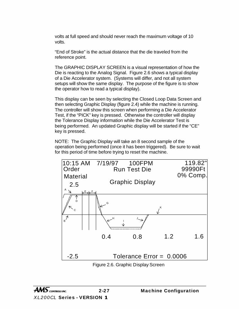
2-27 Machine Configuration XL200CL Series - VERSION 1 1
volts at full speed and should never reach the maximum voltage of 10 volts.
“End of Stroke” is the actual distance that the die traveled from the reference point.
The GRAPHIC DISPLAY SCREEN is a visual representation of how the Die is reacting to the Analog Signal. Figure 2.6 shows a typical display of a Die Accelerator system. (Systems will differ, and not all system setups will show the same display. The purpose of the figure is to show the operator how to read a typical display).
This display can be seen by selecting the Closed Loop Data Screen and then selecting Graphic Display (figure 2.4) while the machine is running. The controller will show this screen when performing a Die Accelerator Test, if the “PICK” key is pressed. Otherwise the controller will display the Tolerance Display information while the Die Accelerator Test is being performed. An updated Graphic display will be started if the “CE” key is pressed.
NOTE: The Graphic Display will take an 8 second sample of the operation being performed (once it has been triggered). Be sure to wait for this period of time before trying to reset the machine.
10:15 AMOrderMaterial
2.5 Graphic Display
-2.5 Tolerance Error = 0.0006
0.4
Run Test Die 99990Ft0% Comp.
0.8 1.2 1.6
7/19/97 100FPM 119.82"
A
C
D
E F
B
G
HI
J
K
Figure 2.6. Graphic Display Screen
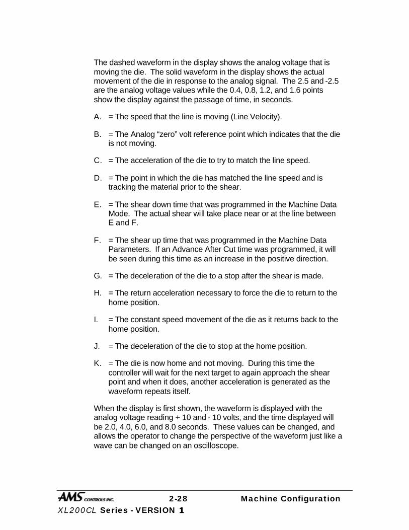
2-28 Machine Configuration XL200CL Series - VERSION 1 1
The dashed waveform in the display shows the analog voltage that is moving the die. The solid waveform in the display shows the actual movement of the die in response to the analog signal. The 2.5 and -2.5 are the analog voltage values while the 0.4, 0.8, 1.2, and 1.6 points show the display against the passage of time, in seconds.
A. = The speed that the line is moving (Line Velocity).
B. = The Analog “zero” volt reference point which indicates that the die is not moving.
C. = The acceleration of the die to try to match the line speed.
D. = The point in which the die has matched the line speed and is tracking the material prior to the shear.
E. = The shear down time that was programmed in the Machine Data Mode. The actual shear will take place near or at the line between E and F.
F. = The shear up time that was programmed in the Machine Data Parameters. If an Advance After Cut time was programmed, it will be seen during this time as an increase in the positive direction.
G. = The deceleration of the die to a stop after the shear is made.
H. = The return acceleration necessary to force the die to return to the home position.
I. = The constant speed movement of the die as it returns back to the home position.
J. = The deceleration of the die to stop at the home position.
K. = The die is now home and not moving. During this time the controller will wait for the next target to again approach the shear point and when it does, another acceleration is generated as the waveform repeats itself.
When the display is first shown, the waveform is displayed with the analog voltage reading + 10 and - 10 volts, and the time displayed will be 2.0, 4.0, 6.0, and 8.0 seconds. These values can be changed, and allows the operator to change the perspective of the waveform just like a wave can be changed on an oscilloscope.

2-29 Machine Configuration XL200CL Series - VERSION 1 1
To change the analog voltage value, use the green MOVE UP and MOVE DOWN keys.
MoveUp
MoveDown
Page
PageUp
Down
Home
The available voltage ranges for the analog voltage is 10 volts, 5 volts and 2.5 volts positive and negative. Pressing the MOVE DOWN key will decrease the voltage to 5.0 and - 5.0 volts and then to 2.5 and -2.5 volts. Pressing the MOVE UP key will increase the voltage to 5.0 and pressing it again will increase the voltage back to 10.0.
The time base can be changed in the same manner as the voltage by pressing the PAGE UP and PAGE DOWN keys. The PAGE DOWN key will decrease to a minimum of a 0.8 second sample. When the PAGE UP key is pressed, the range will be increased up to the maximum of an 8 second sample.
The ↑, ↓, ←, → arrow keys can be used to isolate a section of the wave form as pressing the appropriate arrow will move the wave form on the screen in that direction. The UP arrow moves the wave form up, the DOWN arrow moves it down, the LEFT arrow moves it left, and the RIGHT arrow moves it right.
The final adjustments to the display can be performed with the 1, 2, and 3 number keys.
When the display is first shown, the analog signal and the actual die position are shown. If the machine is a Die Accelerator, the line velocity is also shown. To remove one of these waveforms from the display, the number keys are used.

2-30 Machine Configuration XL200CL Series - VERSION 1 1
INS
End
CE
_
.
7 8 9
654
1 2 30
Key “1” = Removes the Analog Signal waveform.
Key “2” = Removes the Line Velocity waveform.
Key “3” = Removes the Actual Die Position waveform.
Pressing the appropriate number key a second time will put the waveform back onto the display.
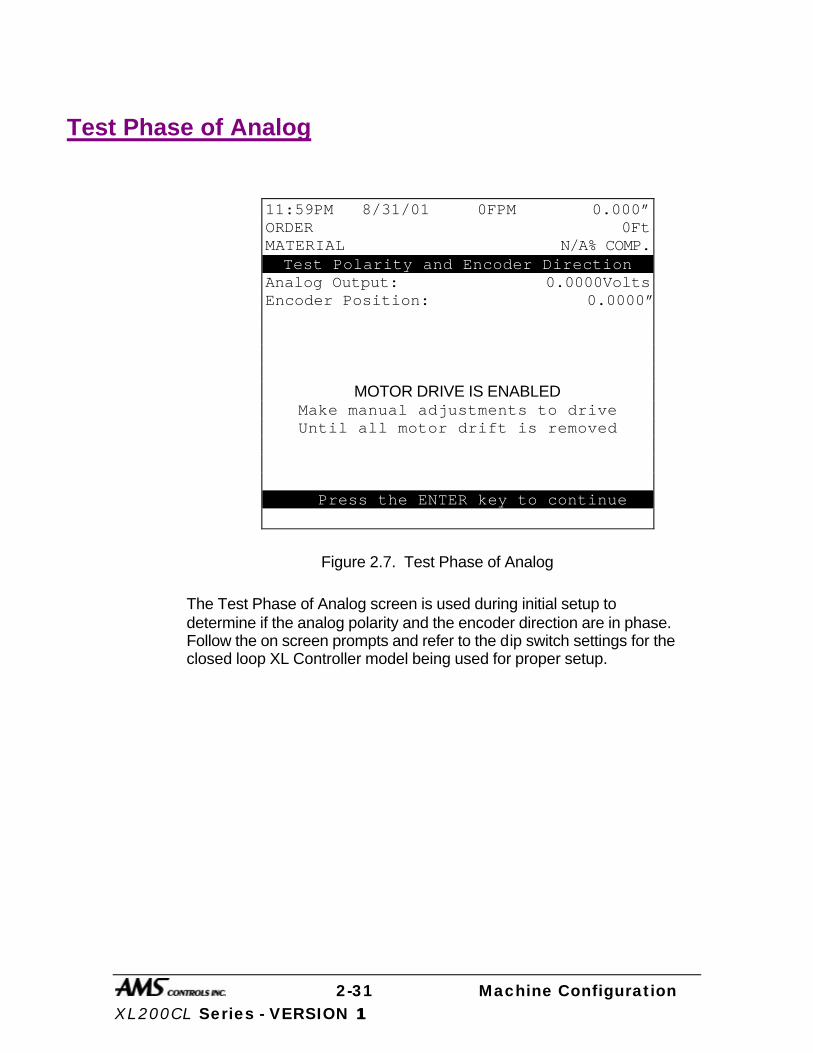
2-31 Machine Configuration XL200CL Series - VERSION 1 1
Test Phase of Analog
Figure 2.7. Test Phase of Analog
The Test Phase of Analog screen is used during initial setup to determine if the analog polarity and the encoder direction are in phase. Follow the on screen prompts and refer to the dip switch settings for the closed loop XL Controller model being used for proper setup.
11:59PM 8/31/01 0FPM 0.000” ORDER 0Ft MATERIAL N/A% COMP. Test Polarity and Encoder Direction
Analog Output: 0.0000Volts Encoder Position: 0.0000”
MOTOR DRIVE IS ENABLED Make manual adjustments to drive Until all motor drift is removed
PpPPress the ENTER key to continue

2-32 Machine Configuration XL200CL Series - VERSION 1 1
Calibration After good performance is achieved in tests without material the machine can be loaded and actual parts run to check for calibration. Short length parts can be run to verify consistent lengths.
After repeatable lengths are achieved, the system can be calibrated. The longest possible part size should be run. If short parts must be used, try to use a vernier caliper for the measurement. If parts longer than 4 feet are run, the only practical measuring device is a steel tape. Verify the accuracy of these devices by comparing several steel tapes measuring the same object. The ends of these tapes can be damaged and give bad readings. If this is questionable, have someone hold the tape carefully on the one-inch mark and subtract an inch from each measurement made.
The best way to calibrate the system is to run 10 parts, carefully measure them, and calculate an average length. The new CORRECTION FACTOR is calculated as follows:
New Correction =Old Correction x Programmed length
Average Measured Length
For machines with a punch press, if parts are being made at the correct programmed length but the punch spacing is incorrect, a simple adjustment to the SHEAR-PRESS distance may solve the problem. Load the machine until there is material under both the punch press and the shear press. Manually cycle both presses, then jog the material forward until the punched hole is beyond the shear and cut it off. Now accurately measure the length from the leading edge of the material to the reference point of the hole or pattern and enter this length for your SHEAR-PRESS distance.
If you do not wish to calculate the CORRECTION FACTOR yourself, the controller will do it automatically with the CALIBRATE TRIM mode.
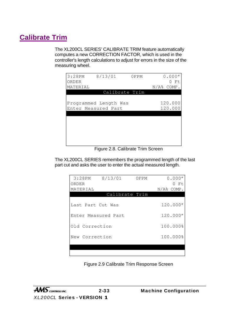
2-33 Machine Configuration XL200CL Series - VERSION 1 1
Calibrate Trim
The XL200CL SERIES’ CALIBRATE TRIM feature automatically computes a new CORRECTION FACTOR, which is used in the controller's length calculations to adjust for errors in the size of the measuring wheel.
Figure 2.8. Calibrate Trim Screen
The XL200CL SERIES remembers the programmed length of the last part cut and asks the user to enter the actual measured length.
Figure 2.9 Calibrate Trim Response Screen
3:28PM 8/13/01 0FPM 0.000” ORDER 0 Ft MATERIAL N/A% COMP.
Calibrate Trim Programmed Length Was 120.000 Enter Measured Part 120.000 ate Correction? NO
3:28PM 8/13/01 0FPM 0.000” ORDER 0 Ft MATERIAL N/A% COMP.
Calibrate Trim Last Part Cut Was 120.000” Enter Measured Part 120.000” Old Correction 100.000% New Correction 100.000% UpDate Correction? NO

2-34 Machine Configuration XL200CL Series - VERSION 1 1
The controller then calculates a new CORRECTION FACTOR and asks the user if he would like to update the current value with the new value.
CALIBRATE TRIM should be used any time part lengths are incorrect but in a consistent pattern (i.e. all parts 3/16" long, etc.). Also, the CORRECTION FACTOR may be computed by hand using the formula described on page 2-30.
Time Clock
This mode allows you to set the XL200CL SERIES’ built-in calendar/clock, as well as to set the time display format.
The first option allows you to choose between AM/PM and 24-Hour (Military-style) time display. Press any number key to toggle between the two modes, and press ENTER when the correct one is shown.
The remaining lines allow entry of the current time and date. When you make any changes on this screen, the XL200CL SERIES will begin keeping track of the time and date from that point.
When using the XL Link option, the PC will automatically control the TIME CLOCK and will override any time entered in the controller using this mode.
Figure 2.10. Time Clock Setup Screen
2:07PM 5/17/01 0FPM 0.000” ORDER 0 Ft MATERIAL N/A% COMP.
Setup Clock Time Format AM/PM Set AM/PM AM Set Hours 8 Set Minutes 45 Set Seconds 10 Set Day 11 Set Month 9 Set Year 2001 Type 6 3/9/01 4:01PM V1.02

2-35 Machine Configuration XL200CL Series - VERSION 1 1
Input/Output Status
This mode allows you to view the current status of all the XL200CL SERIES’ inputs and outputs. This can be very helpful in troubleshooting the system during and after an installation.
Figure 2.11. Input/Output Status Screen
E-Stop Input
This input enables the controller’s outputs to become operational. The enable, shear and motion outputs will remain off until an E-Stop input is given. The same outputs will turn off if the E-Stop input is lost. It is highly recommended to use this input properly with closed-loop systems.
Feed-OK Input (Feed-To-Stop only)
The FEED-OK input must be turned ON before the controller will recognize a Jog or Run input.
If the FEED-OK input is turned OFF while the controller is jogging, the motor will decelerate to a stop at the programmed acceleration velocity.
If the FEED-OK input is turned OFF while the controller is in the Run mode, the motor will decelerate to a stop at the programmed acceleration velocity and wait for the FEED-OK input to be turned on again. The Run and Drive Enable outputs are NOT turned off.
9:04AM 6/3/01 0FPM 0.000” ORDER 0 Ft MATERIAL N/A% COMP. Inputs Inputs Outputs Outputs JogFwd 0 E-Stop 0 Fast 0 Output9 0 JogRev 0 DieHome 0 Slow 0 ItemComp 0 Run 0 Input11 0 Reverse 0 Output11 0 ShrComp 0 Input12 0 Shear 0 Output12 0 Lockout 0 Input13 0 Enable 0 Output13 0 ManShr 0 Input14 0 ShearUp 0 Output14 0 ManPun 0 Input15 0 Output7 0 Output15 0 Detect 1 Input16 0 Run 0 Output16 0 1=ON 0=OFF
2-36 Machine Configuration XL200CL Series - VERSION 1 1
Setup Lockout Input
This input will normally be in the form of a security key and will keep the operator from changing critical parameters on the controller. The SETUP LOCKOUT input does NOT lock the operator out of the following parameters:
Ø Halt After Item
Ø Halt No Items to Run
Ø Delay After Shear
Ø Units of Measure
Enable Output
After an ENABLE OUTPUT, the controller will wait 2 seconds before attempting to control the drive system. This allows time for the drive to react to the ENABLE OUTPUT for it’s internal programming. This will include the drive being enabled by a JOG, RUN, or MANUAL CYCLE input.

2-37 Machine Configuration XL200CL Series - VERSION 1 1
Memory Test
This causes the XL200CL SERIES to enter a self-test mode in which it verifies all internal memory "chains." If no errors are reported, all memory can be considered good.
Figure 2.12. Memory Test Screen
Clearing Memory While Energizing Controller There has been a small change in the memory clear procedure. Clearing memory will erase all Setup, Pattern, and Order information in the controller’s memory.
Don’t try clearing memory unless you have written down all Setup, Pattern, and Order information for re-entry.
If you are experiencing controller problems, it is not recommended that you try clearing memory unless you have made extensive troubleshooting checks (see the section in the back of the controller manual titled “In case of a Problem”). The steps listed include: making sure you have checked the encoder, the shear, the calibration procedure, rechecked setups, used the built-in diagnostic features, checked the incoming power, and cycled power off and on.
10:31AM 5/8/01 10FPM 3.002” ORDER 5 Ft MATERIAL 25% COMP.
XL200CL Controller Machine Data
Auto Calibration Calibration Trim
Manual Calibration Time Clock
Input/Output Status Memory Test
Communications Type 17 3/7/01 7:09AM V1.02
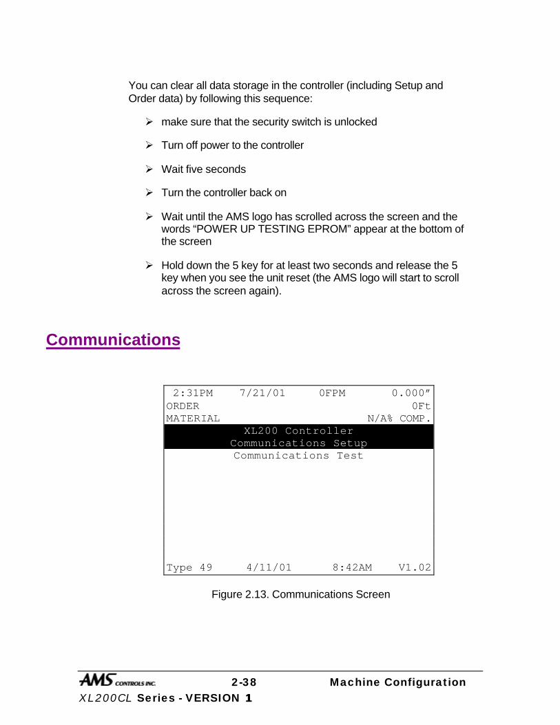
2-38 Machine Configuration XL200CL Series - VERSION 1 1
You can clear all data storage in the controller (including Setup and Order data) by following this sequence:
Ø make sure that the security switch is unlocked
Ø Turn off power to the controller
Ø Wait five seconds
Ø Turn the controller back on
Ø Wait until the AMS logo has scrolled across the screen and the words “POWER UP TESTING EPROM” appear at the bottom of the screen
Ø Hold down the 5 key for at least two seconds and release the 5 key when you see the unit reset (the AMS logo will start to scroll across the screen again).
Communications
Figure 2.13. Communications Screen
2:31PM 7/21/01 0FPM 0.000” ORDER 0Ft MATERIAL N/A% COMP.
XL200 Controller Communications Setup Communications Test
Type 49 4/11/01 8:42AM V1.02

2-39 Machine Configuration XL200CL Series - VERSION 1 1
Communications Setup The “Communications Setup Screen”, figure 2.13, displays information for use with XL-LINK software. Up to 30 controllers can be connected on a single network for communications with a computer for remote order entry, when the Serial Communications option has been purchased. The Baud Rate listed below does not match itself to the office computer’s Baud Rate. The typical rate is 9600. The following parameters can be programmed:
Network Unit Number 1-30 Baud Rate 300,600,1200,2400,4800,
9600,19200,38400 Stop Bit 1 or 2 Data Bit 7 or 8 Parity Even,Odd,Off
If not using the Link program, set Network Unit Number to zero. The display will show ** after a zero is entered.
When the XL-Link program is used, there are lists of codes that are available. These codes include: SCRAP CODES, PRODUCT CODES, DELAY REASONS, and EMPLOYEE NUMBERS. Explanations of these codes follow.
Scrap Code The SCRAP CODE parameter is used with the XL-Link program and will define what type of scrap is produced. In the COMMUNICATION screen the question is asked “USE SCRAP CODES?” with a choice of YES and NO.
If scrap codes are used, and are defined by name via the XL-Link program, the controller will provide a list when INCREASE QUANTITY is selected. If scrap codes are used but are not defined, the operator can enter a numerical number for the type of scrap produced by an INCREASE QUANTITY.
00 = General Production Scrap
01 to ZZ = The valid range of codes
This coincides with lift # 900 through 9ZZ, i.e. “9” plus a 2 digit scrap code = lift number to generate specific scrap.

2-40 Machine Configuration XL200CL Series - VERSION 1 1
Product Code The PRODUCT CODE parameter enables an operator to use and designate a particular PRODUCT CODE for use on a per order basis. The controller prompts the user for a “Yes” or “No” answer to the prompt “Use Product Codes?”
This PRODUCT CODE will describe the specific product being produced for an order or the tooling required for a specific product. If the PRODUCT CODE changes when going from one order to another, a warning is posted and the new product code must be entered into the controller.
Delay Reason Any time the line is halted longer than the HALT DELAY MINIMUM (new setup parameter), the operator is prompted to enter a 2-digit DELAY REASON before he is allowed to re-enter the RUN mode. This code is added to all production records to be used by the XL-Link software. If the XL-Link is not being used, a DELAY REASON is not necessary.
The limits for the HALT DELAY MINIMUM are 0 to 99 minutes. A value of zero will force the operator to enter a DELAY REASON after every line halt. A value of 99 will disable the function and the controller will never force the operator to enter a DELAY REASON.
Employee Numbers Each time an operator is prompted to enter a DELAY REASON (see description above), he/she will also be prompted to enter his/her EMPLOYEE NUMBER. This number can be up to 7 digits long (1-9999999), and will be included on all production records when using the XL-Link Communications Software.
The operator is also prompted to enter the employee number at every shift change. The employee number may be changed at any time by entering the FOOTAGE TOTALIZER menu under the subheading of EMPLOYEE INFORMATION.
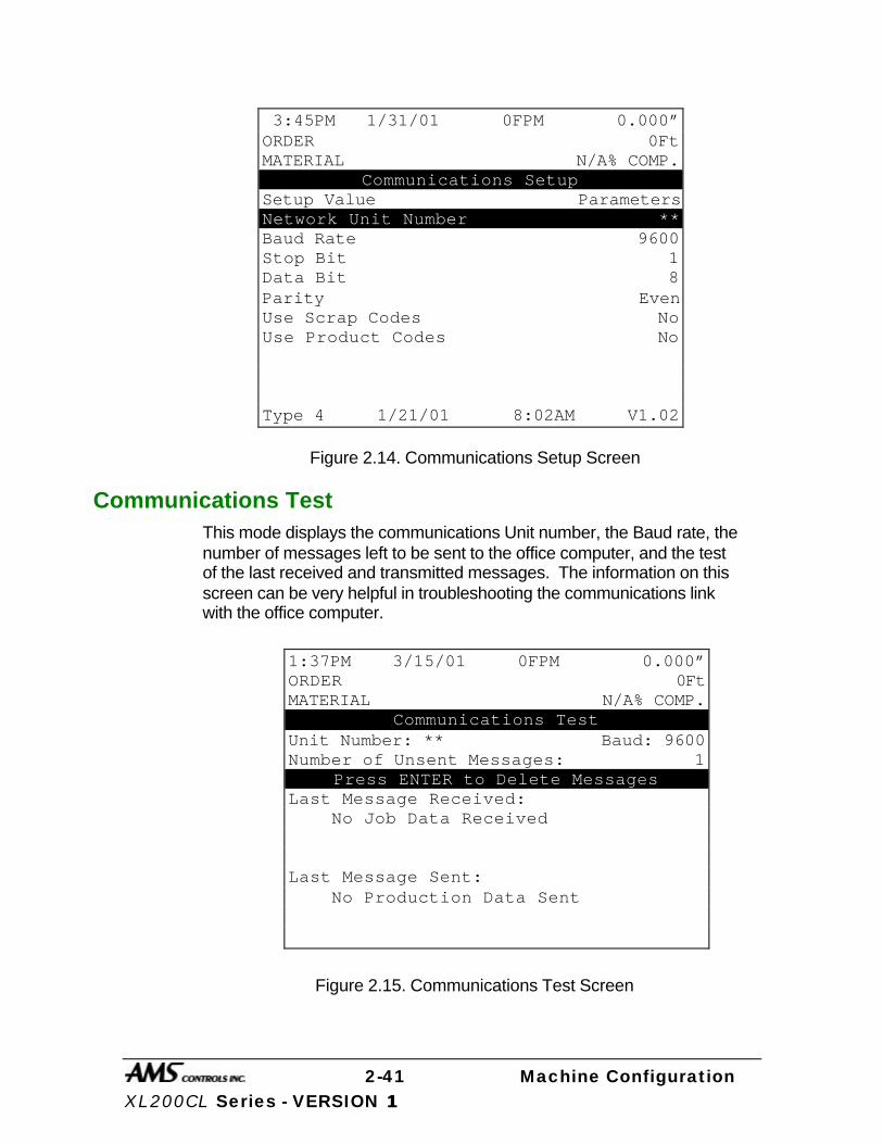
2-41 Machine Configuration XL200CL Series - VERSION 1 1
Figure 2.14. Communications Setup Screen
Communications Test
This mode displays the communications Unit number, the Baud rate, the number of messages left to be sent to the office computer, and the test of the last received and transmitted messages. The information on this screen can be very helpful in troubleshooting the communications link with the office computer.
Figure 2.15. Communications Test Screen
3:45PM 1/31/01 0FPM 0.000” ORDER 0Ft MATERIAL N/A% COMP.
Communications Setup Setup Value Parameters Network Unit Number ** Baud Rate 9600 Stop Bit 1 Data Bit 8 Parity Even Use Scrap Codes No Use Product Codes No
Type 4 1/21/01 8:02AM V1.02
1:37PM 3/15/01 0FPM 0.000” ORDER 0Ft MATERIAL N/A% COMP.
Communications Test Unit Number: ** Baud: 9600 Number of Unsent Messages: 1
Press ENTER to Delete Messages Last Message Received: No Job Data Received Last Message Sent: No Production Data Sent
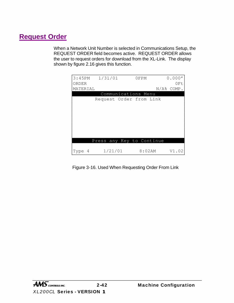
2-42 Machine Configuration XL200CL Series - VERSION 1 1
Request Order
When a Network Unit Number is selected in Communications Setup, the REQUEST ORDER field becomes active. REQUEST ORDER allows the user to request orders for download from the XL-Link. The display shown by figure 2.16 gives this function.
Figure 3-16. Used When Requesting Order From Link
3:45PM 1/31/01 0FPM 0.000” ORDER 0Ft MATERIAL N/A% COMP.
Communications Menu Request Order from Link
Press any Key to Continue Type 4 1/21/01 8:02AM V1.02
3-1 Edit Tool Data XL200CL Series – VERSION 1
Edit Tool Data
The AMS Model XL200CL SERIES Controller
Before the XL200CL SERIES controller, machine designers often had to use “Flagged Cutoffs” or simple counters to measure the part length prior to the shear function. The “Flagged Cutoff” uses a rod that is the length of the desired part with a metal plate that activates the shear when the part strikes the metal or some other triggering device. The setup time on this system can be extensive and involves much trial and error as the rod and metal plate are moved back and forth to achieve the exact part length desired. If the next order has a different part length, another extensive setup time is required. This is a time consuming process and is definitely not suited for short production runs.
Another method that was used, was a simple counter that measured a fixed number of counts before a part was sheared. The counter by itself does not allow for any Shear Reaction time, and will give incorrect lengths if the speed of the line is varied. Programming lengths and patterns where often complicated and confusing.
The AMS controller takes a different approach to multiple press control. With the XL200CL SERIES controller, the user enters machine parameters and finished part dimensions. The controller determines the machine sequence. It not only handles the normal sequence for a part but also the transitional sequences required when the part pattern changes. The AMS controller can go from one part pattern to another with no scrap generated between part types.
The result is a machine that most operators can program from a part drawing. It is ideally suited for short production runs and special
patterns, giving the same quality operation for larger production requirements.
This section describes the various press parameters and functions used by the XL200CL SERIES controller. A user should read this section carefully in order to make the best use of the features of the controller.
3-2 Edit Tool Data XL200CL Series – VERSION 1
Glossary of Terms The following definitions apply throughout this document:
Press
A press is a device that closes a die set that is to punch, notch or shear a given material. Air, hydraulics, or a mechanical flywheel may power the press.
Die Set
A die set is a mechanical assembly containing any number of tools that punch, notch, or shear.
Gag
A gag is a device that can select or deselect specific tools in a die set. This is most often a sliding block that is moved by an air cylinder prior to activation of the press.
Tool
A tool is the smallest section of a die set that can be engaged with one cycle of the press. A tool may produce a single hole, notch or shear, or a group of holes, notches and shear. In the XL200CL SERIES controller, a tool is defined by a press number, an optional gag number (or multiple gag numbers), and an offset distance from the front of the press.
Pattern
A pattern is a set of tool operations that define most of the details of a finished part. Each entry has a tool number, a reference designation, and a dimension.
Batch Item
A batch item in the AMS controller is used to actually produce parts. Each batch item defines a lift number, quantity, length, pattern number, and production option.
3-3 Edit Tool Data XL200CL Series – VERSION 1
Machine Configuration
The XL200CL SERIES controller can be adapted to several types of machines. The XL202CL can control a machine with two individual presses, a machine with only one press and one gag, or any combination of presses and gags that add up to two. The XL206CL can control a machine with six individual presses, a machine with only one press and five gags, or any combination of presses and gags that add up to six. The XL212CL can control a machine with twelve individual presses, a machine with only one press and eleven gags, or any combinations of presses and gags that add up to twelve. Once the configuration of the machine is determined, the AMS controller can be set to match that configuration. Please refer to Section 9 of this manual, on each individual controller for the proper switch configuration.
Programming Press Parameters PRESS 0 is always connected to OUTPUT Number 4, the first press output, and must contain the shear die. For this reason, it is always called the SHEAR OUTPUT in the controller.
For the SHEAR PRESS, the Shear Dwell Down, Shear Dwell Up, and Shear Kerf are programmed. The Dwell is the time required to energize the press for full movement. The Kerf is the amount of material removed if the shear has two cutting edges and removes a slot of material during the shear cycle. If other presses are used, a separate Dwell time is programmed for each press.
Determining the Machine Zero Reference Point For each application, a Machine Zero Reference Point is required. From this point, an offset to each die can be measured. The only requirement for this point is that it must be downstream from any tool location to avoid a negative reference. See Figure 3.1.

3-4 Edit Tool Data XL200CL Series – VERSION 1
In most cases the easiest point to use for a reference point, is the back edge of the shear die. Tool offsets are then determined by activating all dies, including the shear, with material loaded and clamped in a stationary position. The strip is then fed forward and the distance from the leading edge to each die is measured. These dimensions become the tool offsets.
Some dies may have tools that are downstream of the shear. In these cases, the back edge of the shear cannot be used as the reference point. An arbitrary reference point can then be chosen past the tool that is downstream, as long as all offsets are positive numbers. In this case, the tool for the shear will have a positive offset from the arbitrary reference point.
Shear Press (0) Press 1
Material Flow
Tool 1 Offset
Tool 2 Offset Machine
Zero Point
Figure 3.1. Press Reference Distance

3-5 Edit Tool Data XL200CL Series – VERSION 1
Programming Tool Parameters
The EDIT TOOL DATA screen is used to enter tool data. A typical tool data entry screen is shown in Figure 4-2. Each entry contains: TOOL NUMBER, PRESS NUMBER, GAG NUMBER, OFFSET DISTANCE, and NAME.
Figure 3.2. Typical Edit Tool Data Screen
The TOOL NUMBER is any alphanumeric number from 0 to ZZZ. TOOL 0 is reserved for the shear and must always be programmed. (See Figure 3.2, Line 1.) Otherwise, there is no other restriction on the TOOL NUMBER (except for MACROS which use tool numbers Z00-ZZZ and are discussed in the “Operating Procedure” section of this manual and Extended MACROS which use numbers 650-ZZZ and are discussed in the “Options” section of this manual). Tools can be entered in any order and numbers can be skipped.
The PRESS NUMBER refers to the PRESS OUTPUT associated with that tool. The PRESS NUMBER must be from 1 to the number of presses programmed into
2:00PM 5/15/01 0FPM 0.000” ORDER 0Ft MATERIAL N/A% COMP. TOOL PRESS GAG OFFSET NAME 0 1 2 0.000” SHEAR 1 1 3 4.000” 2HOLE1 2 1 4 16.000” 2HOLE2 3 1 5 28.000” 2HOLE3 4 1 6 36.000” SQUARE 5 1 0 8.000” PRESS

3-6 Edit Tool Data XL200CL Series – VERSION 1
the configuration switches. If any other number is entered, an error will be displayed.
The GAG NUMBER is usually the OUTPUT NUMBER that is energized when this tool is to be activated. The number must be greater than the number of presses programmed into the configuration switches and not greater than the number of maximum presses allowed (XL202CL = two, XL206CL = six, XL212CL = twelve). The number 0 can also be used. This designates that no gag is to be energized for this tool. (See Figure 3.2, Line 6)
The OFFSET DISTANCE is the distance from the designated machine zero point to a reference point on the tool. In some cases, this point may be the centerline of a hole or cluster of holes. In others it may be the leading or trailing edge of a notching die.
The NAME is any 8-character name that may help the operator identify a particular tool. Programming the NAME is not necessary.
More than one tool can be defined for a single die. For example, a notching die that removes a piece from the corner of both the leading and trailing edges can have a tool defined for both corners. They would have the same press and gag data but different offsets. When programming a pattern, one can use one tool for the leading edge referenced from the leading edge and the other for the trailing edge referenced from the trailing edge. The dimensions used would come directly from the part drawing.
A second use for multiple tool entries is for cases where dies may be changed to run certain parts. Offsets for both dies would be available and patterns that used these dies would contain the corresponding tool reference. This means that no change in tool data is required when dies are changed.

3-7 Edit Tool Data XL200CL Series – VERSION 1
Nested Tooling
If a press has multiple dies, the user has the option of assigning different tool numbers to each die, or the press can be labeled as having one tool number with multiple gags. Each die can then be operated separately by using a different tool number.
When using gags, the operator is not limited to just one gag per tool. Multiple gags may be assigned to the same tool. As an example, assume that you have a shear for Press 0 and several tools on Press 1, figure 3.3.
TOOL 2 TOOL 3 TOOL 1
GAG 3 GAG 4 GAG 5
PRESS 1
Figure 3.3. Example Punch Press
With this tool arrangement, the following part can be made:
Example Part 1
TOOL 1 TOOL 3 TOOL 2

3-8 Edit Tool Data XL200CL Series – VERSION 1
If there are parts that can be made with all of the tools at once (see Example Part 2), the individual tools could be entered separately, or the whole press could be assigned another tool number, which would reduce the programming steps.
Example Part 2 TOOL 1
TOOL 3
TOOL 2 TOOL 4
An example of the Edit Tool Data screen is shown in figure 4-4, and Part 1 can be made with Tools 1, 2, and 3. Part 2 could be made with Tools 1, 2, and 3, but a better method would be to use Tool 4, which includes all three tools.
Figure 3.4. Different Gags on the Same Tool and Press
When using NESTED TOOLING to make the part, use the standard references when programming a part (Leading Edge, Length = 24”). This will place the first tool in the group at that point
2:34PM 5/15/01 0FPM 0.000” ORDER 0Ft MATERIAL N/A% COMP. TOOL PRESS GAG OFFSET NAME 0 0 0 0.000” SHEAR 1 1 3 32.000” SQUARE 2 1 4 35.000” 2HOLES 3 1 5 38.000” 1HOLE 4 1 3 32.000” PRESS 4 1 4 35.000” PRESS 4 1 5 38.000” PRESS

4-1 Part Programming XL200CL Series – Version 1
Part Programming
Pattern Programming
Tool locations on specific parts are defined in the PROGRAM PATTERNS screen. All details about the part except the total length are defined here. The part length is defined in the PROGRAM ORDER section when parts are to be actually made. This allows patterns to be defined independent of the length.
Often, the same basic pattern may work for several length parts. The XL200CL SERIES controller allows holes to be defined relative to the leading edge, trailing edge, or center of a part.
Some users may not be able to use this feature. For them, they would only use the leading edge reference on each tool and define the total length in the PROGRAM ORDER screen.
To program a pattern follow these keystrokes:
When first entering the PROGRAM PATTERN mode, a screen for entry of PATTERN NUMBERS similar to Figure 5-1 is displayed. This screen shows the user what patterns are stored in memory, how many operations each pattern has, and what the status of each pattern is. A pattern with no operations is said to be EMPTY. The pattern *** designates a new pattern. Enter the new pattern when the cursor is on this line. If no *** is visible, move the cursor down until one appears (or press the “END” key and then “F3” (ADD LINE). Patterns previously programmed can be reviewed or changed by moving the cursor to that number and pressing the ENTER key.
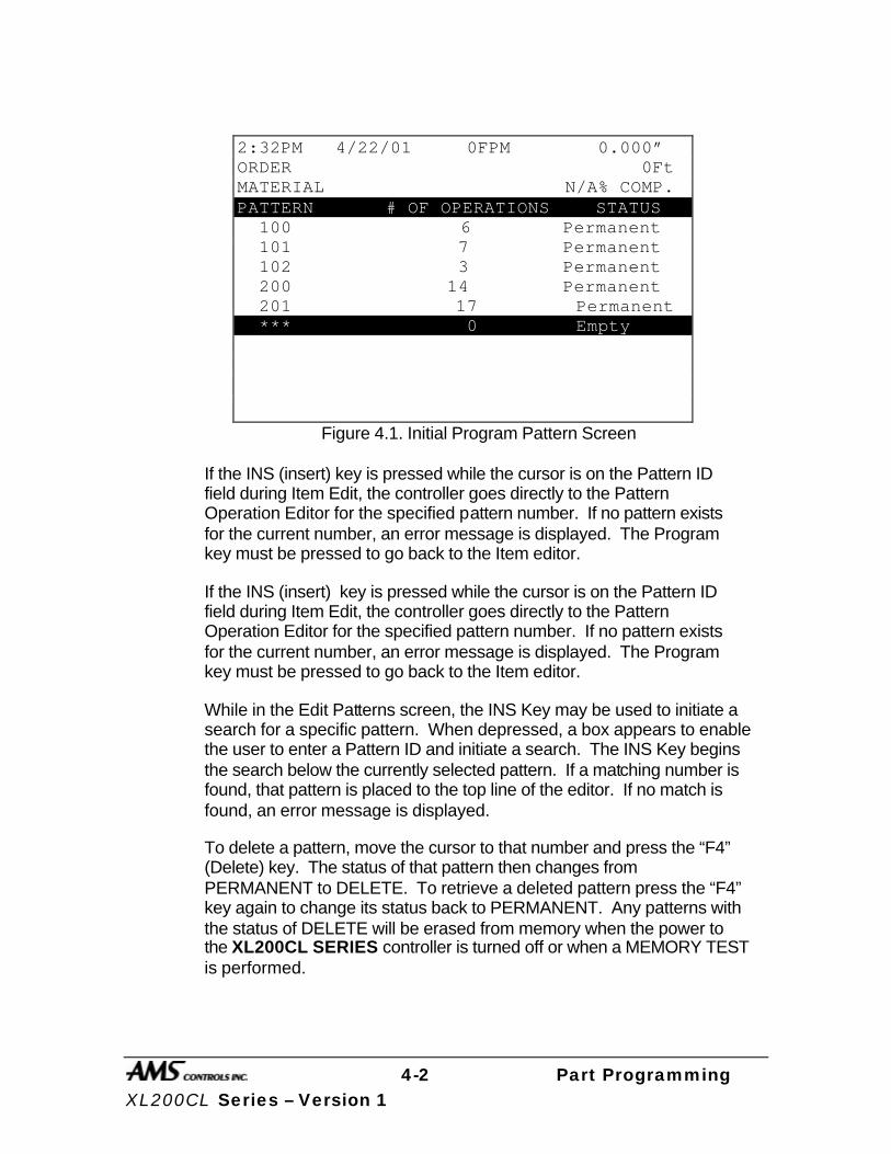
4-2 Part Programming XL200CL Series – Version 1
Figure 4.1. Initial Program Pattern Screen
If the INS (insert) key is pressed while the cursor is on the Pattern ID field during Item Edit, the controller goes directly to the Pattern Operation Editor for the specified pattern number. If no pattern exists for the current number, an error message is displayed. The Program key must be pressed to go back to the Item editor.
If the INS (insert) key is pressed while the cursor is on the Pattern ID field during Item Edit, the controller goes directly to the Pattern Operation Editor for the specified pattern number. If no pattern exists for the current number, an error message is displayed. The Program key must be pressed to go back to the Item editor.
While in the Edit Patterns screen, the INS Key may be used to initiate a search for a specific pattern. When depressed, a box appears to enable the user to enter a Pattern ID and initiate a search. The INS Key begins the search below the currently selected pattern. If a matching number is found, that pattern is placed to the top line of the editor. If no match is found, an error message is displayed.
To delete a pattern, move the cursor to that number and press the “F4” (Delete) key. The status of that pattern then changes from PERMANENT to DELETE. To retrieve a deleted pattern press the “F4” key again to change its status back to PERMANENT. Any patterns with the status of DELETE will be erased from memory when the power to the XL200CL SERIES controller is turned off or when a MEMORY TEST is performed.
2:32PM 4/22/01 0FPM 0.000” ORDER 0Ft MATERIAL N/A% COMP. PATTERN # OF OPERATIONS STATUS 100 6 Permanent 101 7 Permanent 102 3 Permanent 200 14 Permanent 201 17 Permanent *** 0 Empty
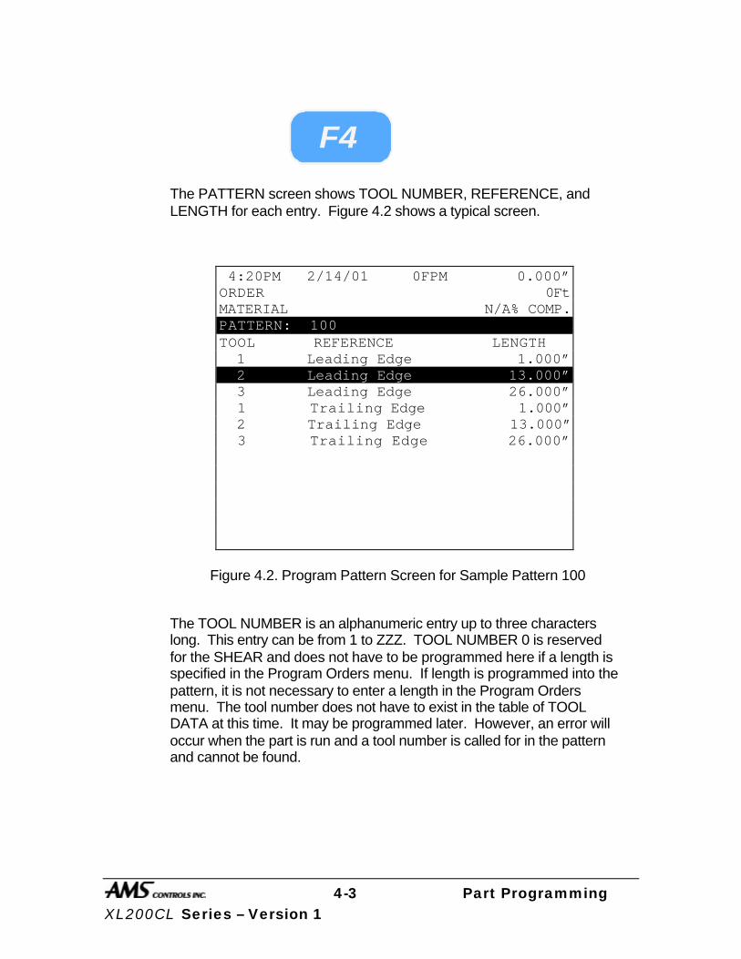
4-3 Part Programming XL200CL Series – Version 1
F4
The PATTERN screen shows TOOL NUMBER, REFERENCE, and LENGTH for each entry. Figure 4.2 shows a typical screen.
Figure 4.2. Program Pattern Screen for Sample Pattern 100
The TOOL NUMBER is an alphanumeric entry up to three characters long. This entry can be from 1 to ZZZ. TOOL NUMBER 0 is reserved for the SHEAR and does not have to be programmed here if a length is specified in the Program Orders menu. If length is programmed into the pattern, it is not necessary to enter a length in the Program Orders menu. The tool number does not have to exist in the table of TOOL DATA at this time. It may be programmed later. However, an error will occur when the part is run and a tool number is called for in the pattern and cannot be found.
4:20PM 2/14/01 0FPM 0.000” ORDER 0Ft MATERIAL N/A% COMP. PATTERN: 100 TOOL REFERENCE LENGTH 1 Leading Edge 1.000” 2 Leading Edge 13.000” 3 Leading Edge 26.000” 1 Trailing Edge 1.000” 2 Trailing Edge 13.000” 3 Trailing Edge 26.000”
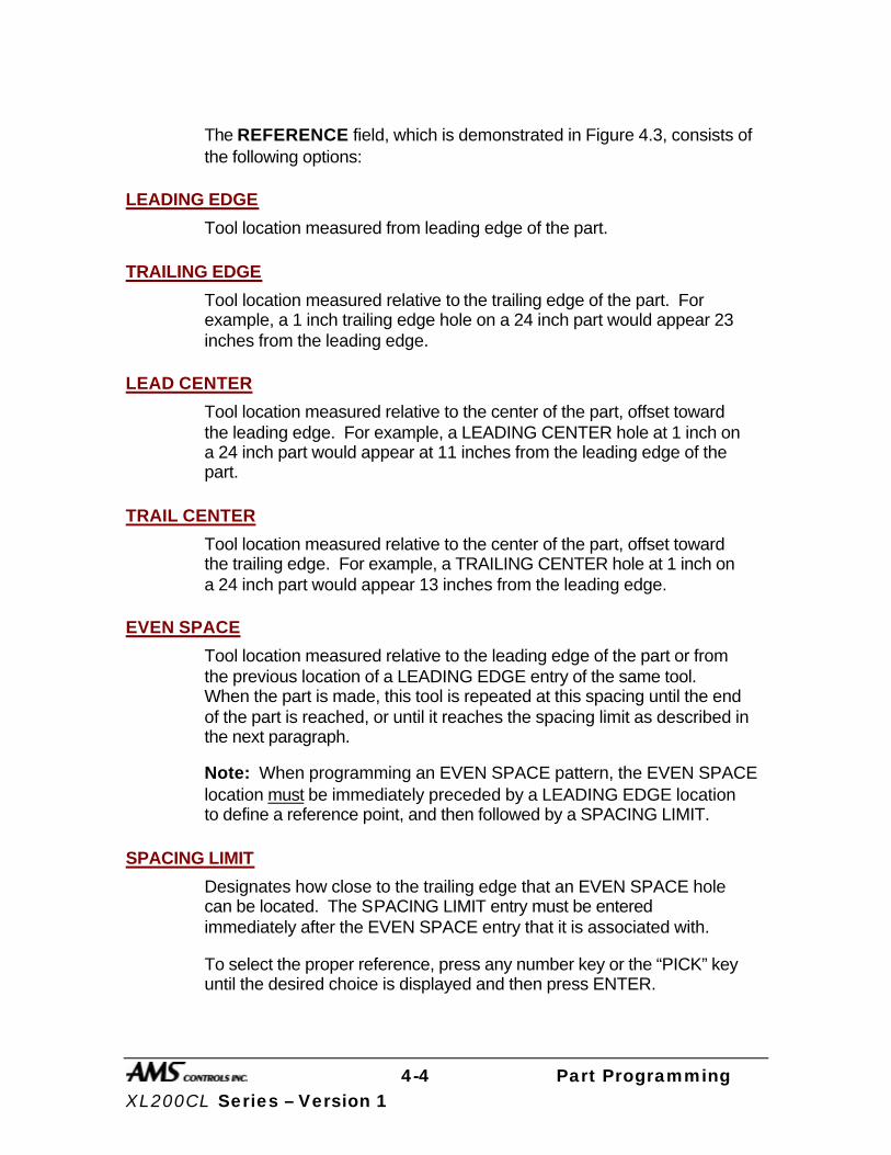
4-4 Part Programming XL200CL Series – Version 1
The REFERENCE field, which is demonstrated in Figure 4.3, consists of the following options:
LEADING EDGE
Tool location measured from leading edge of the part.
TRAILING EDGE
Tool location measured relative to the trailing edge of the part. For example, a 1 inch trailing edge hole on a 24 inch part would appear 23 inches from the leading edge.
LEAD CENTER
Tool location measured relative to the center of the part, offset toward the leading edge. For example, a LEADING CENTER hole at 1 inch on a 24 inch part would appear at 11 inches from the leading edge of the part.
TRAIL CENTER
Tool location measured relative to the center of the part, offset toward the trailing edge. For example, a TRAILING CENTER hole at 1 inch on a 24 inch part would appear 13 inches from the leading edge.
EVEN SPACE
Tool location measured relative to the leading edge of the part or from the previous location of a LEADING EDGE entry of the same tool. When the part is made, this tool is repeated at this spacing until the end of the part is reached, or until it reaches the spacing limit as described in the next paragraph.
Note: When programming an EVEN SPACE pattern, the EVEN SPACE location must be immediately preceded by a LEADING EDGE location to define a reference point, and then followed by a SPACING LIMIT.
SPACING LIMIT
Designates how close to the trailing edge that an EVEN SPACE hole can be located. The SPACING LIMIT entry must be entered immediately after the EVEN SPACE entry that it is associated with.
To select the proper reference, press any number key or the “PICK” key until the desired choice is displayed and then press ENTER.

4-5 Part Programming XL200CL Series – Version 1
E v e n S p a c e E v e n S p a c e E v e n S p a c e E v e n S p a c e S p a c i n g L i m i t
Ma te r i a l F l ow
Lead ing Edge
Dis tance Dis tance Dis tance Dis tance
Lead ing Trai l ing
Tra i l i ng EdgeC e n t e r C e n t e r
Figure 4.3. Reference Examples
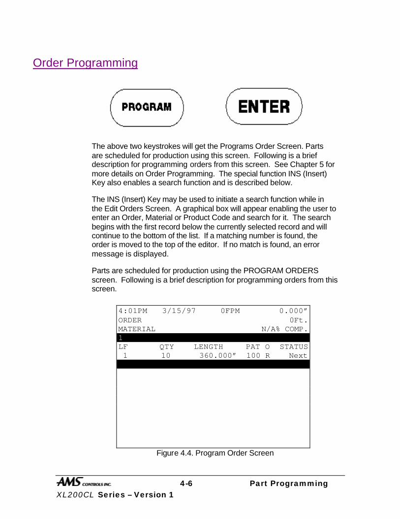
4-6 Part Programming XL200CL Series – Version 1
Order Programming
The above two keystrokes will get the Programs Order Screen. Parts are scheduled for production using this screen. Following is a brief description for programming orders from this screen. See Chapter 5 for more details on Order Programming. The special function INS (Insert) Key also enables a search function and is described below.
The INS (Insert) Key may be used to initiate a search function while in the Edit Orders Screen. A graphical box will appear enabling the user to enter an Order, Material or Product Code and search for it. The search begins with the first record below the currently selected record and will continue to the bottom of the list. If a matching number is found, the order is moved to the top of the editor. If no match is found, an error message is displayed.
Parts are scheduled for production using the PROGRAM ORDERS screen. Following is a brief description for programming orders from this screen.
Figure 4.4. Program Order Screen
4:01PM 3/15/97 0FPM 0.000” ORDER 0Ft. MATERIAL N/A% COMP. 1 LF QTY LENGTH PAT O STATUS 1 10 360.000” 100 R Next 1 15 240.000” 200 R Ready
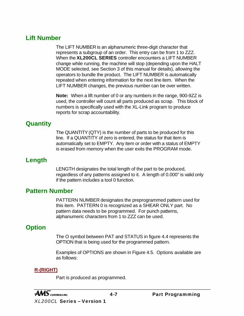
4-7 Part Programming XL200CL Series – Version 1
Lift Number The LIFT NUMBER is an alphanumeric three-digit character that represents a subgroup of an order. This entry can be from 1 to ZZZ. When the XL200CL SERIES controller encounters a LIFT NUMBER change while running, the machine will stop (depending upon the HALT MODE selected, see Section 3 of this manual for details), allowing the operators to bundle the product. The LIFT NUMBER is automatically repeated when entering information for the next line item. When the LIFT NUMBER changes, the previous number can be over written.
Note: When a lift number of 0 or any numbers in the range, 900-9ZZ is used, the controller will count all parts produced as scrap. This block of numbers is specifically used with the XL-Link program to produce reports for scrap accountability.
Quantity The QUANTITY (QTY) is the number of parts to be produced for this line. If a QUANTITY of zero is entered, the status for that item is automatically set to EMPTY. Any item or order with a status of EMPTY is erased from memory when the user exits the PROGRAM mode.
Length LENGTH designates the total length of the part to be produced, regardless of any patterns assigned to it. A length of 0.000” is valid only if the pattern includes a tool 0 function.
Pattern Number PATTERN NUMBER designates the preprogrammed pattern used for this item. PATTERN 0 is recognized as a SHEAR ONLY part. No pattern data needs to be programmed. For punch patterns, alphanumeric characters from 1 to ZZZ can be used.
Option The O symbol between PAT and STATUS in figure 4.4 represents the OPTION that is being used for the programmed pattern.
Examples of OPTIONS are shown in Figure 4.5. Options available are as follows:
R-(RIGHT)
Part is produced as programmed.
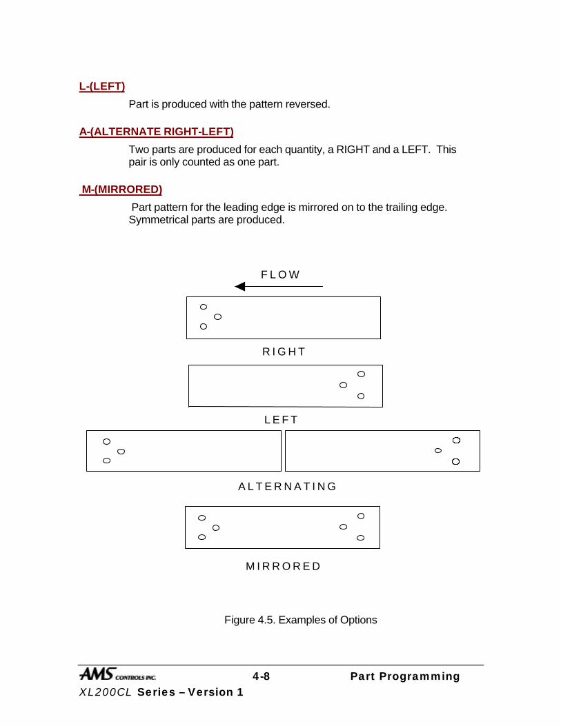
4-8 Part Programming XL200CL Series – Version 1
L-(LEFT)
Part is produced with the pattern reversed.
A-(ALTERNATE RIGHT-LEFT)
Two parts are produced for each quantity, a RIGHT and a LEFT. This pair is only counted as one part.
M-(MIRRORED)
Part pattern for the leading edge is mirrored on to the trailing edge. Symmetrical parts are produced.
F L O W
R I G H T
L E F T
A L T E R N A T I N G
M I R R O R E D
Figure 4.5. Examples of Options

4-9 Part Programming XL200CL Series – Version 1
Application Example 1
Single Press with Multiple Gags
In this example, the user has one large press with a gagged die. The end products produced are purlins used in metal buildings. These parts typically have a standard pattern of holes on the leading and trailing ends but the total length varies from one order to the next. This makes the pattern scheme of the XL200CL SERIES controller ideal for this application.
Pattern 100 uses Leading Edge and Trailing Edge references while Pattern 200 uses Leading Edge, Trailing Edge, Leading Center, and Trailing Center references.
Example Parts
1"13"
26" 26"
13"
1"
PATTERN 100
PATTERN 200
1"
13"
26"26"
13"1"
12" 12"
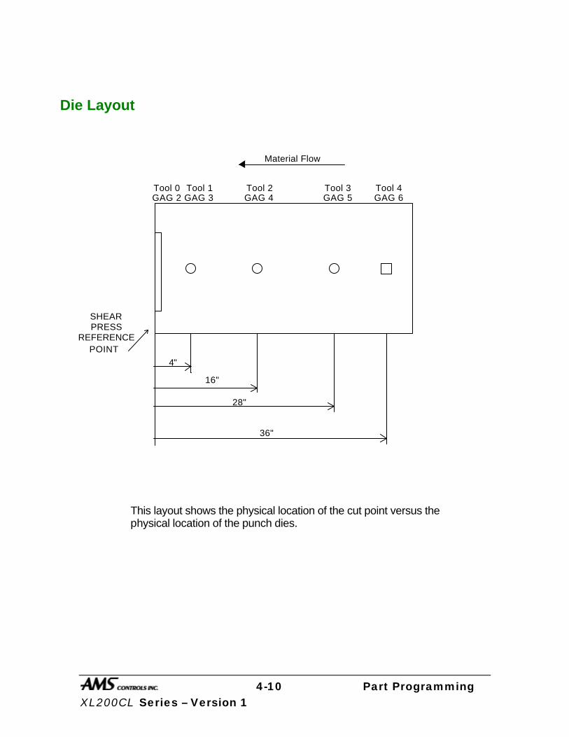
4-10 Part Programming XL200CL Series – Version 1
Die Layout
This layout shows the physical location of the cut point versus the physical location of the punch dies.
4"
16"
28"
36"
SHEARPRESS
REFERENCEPOINT
Tool 0 Tool 1 Tool 2 Tool 3 Tool 4GAG 2 GAG 4 GAG 5 GAG 6GAG 3
Material Flow
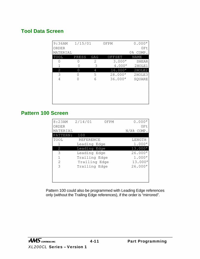
4-11 Part Programming XL200CL Series – Version 1
Tool Data Screen
Pattern 100 Screen
Pattern 100 could also be programmed with Leading Edge references only (without the Trailing Edge references), if the order is “mirrored”.
9:36AM 1/15/01 0FPM 0.000” ORDER 0Ft MATERIAL 0% COMP. TOOL PRESS GAG OFFSET NAME 0 0 2 3.000” SHEAR 1 0 3 4.000” 2HOLE1 2 0 4 16.000” 2HOLE2 3 0 5 28.000” 2HOLE3 4 0 6 36.000” SQUARE
8:23AM 2/14/01 0FPM 0.000” ORDER 0Ft MATERIAL N/A% COMP. PATTERN: 100 TOOL REFERENCE LENGTH 1 Leading Edge 1.000” 2 Leading Edge 13.000” 3 Leading Edge 26.000” 1 Trailing Edge 1.000” 2 Trailing Edge 13.000” 3 Trailing Edge 26.000”

4-12 Part Programming XL200CL Series – Version 1
Pattern 200 Screen
Special Pattern Notes:
The preceding patterns have no relation to the actual length of the part.
The Leading Center reference of 0 is the equivalent of a Trailing Center reference of 0.
The 1st and 2nd hole from each end can actually be fired together. The pattern shows holes at 12 inches apart and the dies are also physically 12 inches apart. This can be used as an advantage and will require two less press operations per part. This saves wear on equipment, and could increase productivity and possibly line speed.
11:44AM 4/10/01 0FPM 0.000” ORDER 0Ft MATERIAL N/A% COMP. PATTERN: 200 TOOL REFERENCE LENGTH 1 Leading Edge 1.000” 2 Leading Edge 13.000” 3 Leading Edge 26.000” 4 Lead Center 12.000” 4 Lead Center 0.000” 4 Trail Center 12.000” 1 Trailing Edge 1.000” 2 Trailing Edge 13.000” 3 Trailing Edge 26.000”
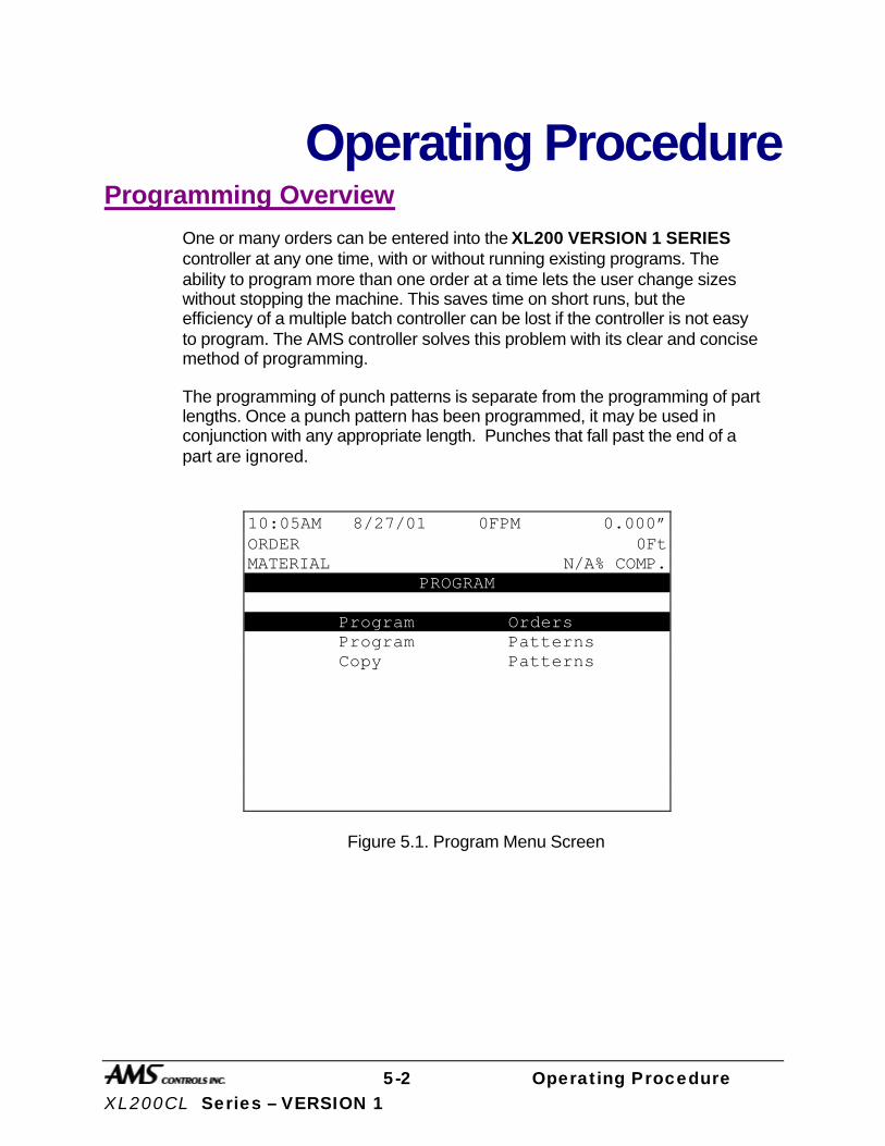
5-2 Operating Procedure XL200CL Series – VERSION 1
Operating Procedure
Programming Overview
One or many orders can be entered into the XL200 VERSION 1 SERIES controller at any one time, with or without running existing programs. The ability to program more than one order at a time lets the user change sizes without stopping the machine. This saves time on short runs, but the efficiency of a multiple batch controller can be lost if the controller is not easy to program. The AMS controller solves this problem with its clear and concise method of programming.
The programming of punch patterns is separate from the programming of part lengths. Once a punch pattern has been programmed, it may be used in conjunction with any appropriate length. Punches that fall past the end of a part are ignored.
Figure 5.1. Program Menu Screen
10:05AM 8/27/01 0FPM 0.000” ORDER 0Ft MATERIAL N/A% COMP.
PROGRAM Program Orders Program Patterns Copy Patterns
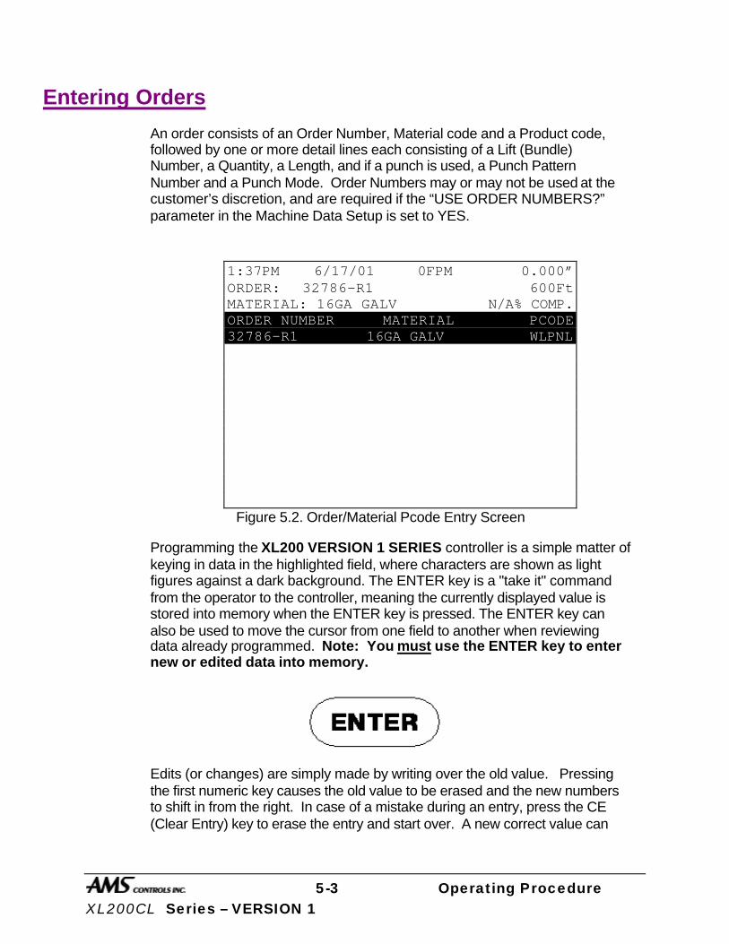
5-3 Operating Procedure XL200CL Series – VERSION 1
Entering Orders
An order consists of an Order Number, Material code and a Product code, followed by one or more detail lines each consisting of a Lift (Bundle) Number, a Quantity, a Length, and if a punch is used, a Punch Pattern Number and a Punch Mode. Order Numbers may or may not be used at the customer’s discretion, and are required if the “USE ORDER NUMBERS?” parameter in the Machine Data Setup is set to YES.
Figure 5.2. Order/Material Pcode Entry Screen
Programming the XL200 VERSION 1 SERIES controller is a simple matter of keying in data in the highlighted field, where characters are shown as light figures against a dark background. The ENTER key is a "take it" command from the operator to the controller, meaning the currently displayed value is stored into memory when the ENTER key is pressed. The ENTER key can also be used to move the cursor from one field to another when reviewing data already programmed. Note: You must use the ENTER key to enter new or edited data into memory.
Edits (or changes) are simply made by writing over the old value. Pressing the first numeric key causes the old value to be erased and the new numbers to shift in from the right. In case of a mistake during an entry, press the CE (Clear Entry) key to erase the entry and start over. A new correct value can
1:37PM 6/17/01 0FPM 0.000” ORDER: 32786-R1 600Ft MATERIAL: 16GA GALV N/A% COMP. ORDER NUMBER MATERIAL PCODE 32786-R1 16GA GALV WLPNL
5-4 Operating Procedure XL200CL Series – VERSION 1
then be keyed in. When the correct value is displayed, press the ENTER key to move to the next field.
Order Number
Enter the Programming Mode by pressing the PROGRAM key. The first option is Program Orders. Make sure this option is highlighted and press the ENTER key. The first data item to enter is the Order Number (see figure 5.2), indicated by the highlighted portion of the display. The Order Number can be up to eighteen characters long (Unless PRODUCT CODES are used, then the order number is limited to 15 characters). You may review and correct jobs previously programmed. Press the ENTER key to confirm the present Order Number.
Material Code Next to be programmed is the Material Code, which can be up to twenty characters long, and may include numbers, the letters A-Z, and some symbols. Only 18 characters will be allowed when using PRODUCT CODES. You may review and correct jobs previously programmed. To enter a letter, simply press the “CE” key and then use the blue UP ↑ and DOWN ↓ arrows to toggle through the letters and symbols. A RIGHT arrow moves to the next letter or number to be entered. Do not press “ENTER” until the entire number or word is completed. Pressing “ENTER” will take the operator to the next location.
Product Code PRODUCT CODE can now be programmed if PRODUCT CODES are enabled for use in the Communications Setup screen. The Product Code can be 5 characters long and can consist of numbers and letters.
After entering the Product Code, a screen for entering the cut list appears. On this screen, the Lift Number, Quantity, Length, Pattern Number, and Options appear. This is the only screen that will be seen if not using Order Numbers.

5-5 Operating Procedure XL200CL Series – VERSION 1
If PRODUCT CODE is not selected for use in the Communications Setup screen, than Product Code will not be displayed. Pressing ENTER after inputting the material field will cause the cut list screen to display immediately.
Figure 5.3. Part Programming Screen
Note: Each order consists of one or more line items, or, lengths to be cut.
Lift (Bundle) Number The first input field is for the Lift (LF), or Bundle Number. Finished parts that are kept together or bundled as a unit should be made in sequence, and should all have the same Lift Number. The machine will automatically stop when it encounters a new Lift Number (if the BUNDLE HALT mode is selected). This enables the operator to take whatever action is needed to get the just-finished bundle out of the way so that the next one can be produced. If there are a number of orders that have previously been entered, you can program another order by pressing the “END” key and then the “F3” (ADD LINE) key.
Quantity After the Lift Number is entered, the Quantity will be highlighted. Enter here the number of pieces needed of a single length. The Quantity can be set from 1 to 9999 pieces.
Length After the Quantity is programmed, the Length field will be highlighted. Enter here the finished length of the part to be made (do not count the shear kerf; the controller will automatically add in this amount, if any). Enter the length using the appropriate Display Format as selected when the XL200 VERSION
1:45PM 6/17/01 0FPM 0.000” ORDER: 32786-R1 600Ft MATERIAL: 16GA GALV 0% COMP. 32786-R1 16GA GALV WLPNL LF QTY LENGTH PAT O STATUS 1 10 360.000” 100 R Next 1 15 240.000” 200 R Ready

5-6 Operating Procedure XL200CL Series – VERSION 1
1 SERIES controller was installed. If you are using the Feet Fractional Inch or Feet Decimal Inch display mode, use the decimal point (•) key, or the “enter” key to finish entering the Feet portion, and switch to the Inch entry field. In the Feet Fractional Inch display mode, use the “decimal point” key or the “enter” key to separate the elements of the Inch entry as well. The longest length the AMS controller will accept is 3500.000" or 291‘ 8”, depending upon the Format mode.
When entering lengths, no leading or trailing zeros are required. The following entries (in Decimal Inch mode) each produce the same 10-inch part:
10 010 10. 10.00 10.000
Punch Pattern If Punch Pattern zero is selected, a shear-only part will be produced. Pattern numbers in the range 1-ZZZ will reference an already-programmed punch pattern, or one to be programmed later, and add a punch or punches to the part. Note that any punch pattern referenced in an ITEM must be defined before the ITEM is run.
Punch patterns Z00-ZZZ are used exclusively as MACRO patterns, which are explained later. Punch Patterns 650-ZZZ are Extended MACROS and are explained in the “Options” section of this manual.
Standard Macro Programming Pattern program numbers Z00-ZZZ are reserved for creating multiple operations that can be used in another pattern. A MACRO is a single pattern or keystroke that can be used to represent multiple patterns or keystrokes. If a series of operations are frequently used in other patterns, it can be turned into a MACRO and the operator need only enter one pattern to represent a number of operations. If more MACROS are required, an Extended MACRO Option is available which uses pattern numbers 650 through ZZZ. See the “Options” section of this manual for more information.
Edit Tool Data
Tool data should be entered by the normal procedure in the EDIT TOOL DATA screen. Tool Number zero is reserved for the shear and must always be entered. Each tool is defined by an alphanumeric Tool Number from 0 to Z00, a Press Number, Gag Number, and Offset Distance. Tool numbers Z00-ZZZ may not be programmed. These Tool Numbers are reserved for

5-7 Operating Procedure XL200CL Series – VERSION 1
MACRO patterns and may be programmed later. Defining a Tool Number greater than Z00 will result in an error.
Programming Macro Patterns
Programming Macro Patterns is very similar to non-macro applications. Press the PROGRAM key to enter the Program Mode. Select PROGRAM PATTERNS. Any number (1 - ZZZ) can be used to define a pattern, however, patterns Z00 - ZZZ may be inserted into other patterns as MACROS.
Macro Patterns
Enter the first tool to be used in this MACRO pattern. You may use any Tool Number that has been defined in the Edit Tool Data mode. You may NOT use Tool Numbers Z00 - ZZZ (a MACRO within a MACRO). Trying to do so will result in an error.
Enter a Reference location for the tool. Within a MACRO pattern the only valid Reference locations are LEAD CENTER and TRAIL CENTER. Enter a Length (offset from the Reference location) for the tool. This is the same procedure that is used on non-macro applications.
Enter as many tools in the pattern as required up to but not including tool Z00. When finished, press the PROGRAM key to enter more patterns or press the STATUS key to return to the Status mode. This pattern may now be run as a standard pattern or inserted into another pattern as a MACRO.
Inserting Macros Into Other Patterns
Again select PROGRAM PATTERNS from the PROGRAM menu. To enter an ordinary pattern select a number between 1 and Z00. Program the patterns normally.
To insert a MACRO into an ordinary pattern use the MACRO Pattern number in place of the tool number. Enter the Reference location and offset length for the MACRO Pattern. All of the tool operations within the MACRO (remember only LEADING CENTER and TRAILING CENTER are valid) will be located with respect to this location. You may insert as many MACROS as you like within the same standard pattern. When finished, press the PROGRAM key and enter more patterns or press the STATUS key to return to the Status mode.
Jobs can be run with ordinary patterns, with MACRO Patterns, or with ordinary patterns that contain MACROS.

5-8 Operating Procedure XL200CL Series – VERSION 1
A Programming Example Using Macro Patterns
Suppose you have an XL212 controller with one press and seven gags, and your tool data looked like this:
9"
20"
31"
35"
SHEARPRESS
REFERENCEPOINT
Tool 0 Tool 10 Tool 11 Tool 12 Tool 20
Material Flow
Tool 21 Tool 22
40"
45"
11:16AM 7/25/97 0FPM 0.000” ORDER 0Ft MATERIAL 0% COMP. TOOL PRESS GAG OFFSET NAME 0 0 2 0.000” 10 0 3 9.000” 11 0 4 20.000” 12 0 5 31.000” 20 0 6 35.000” 21 0 7 40.000” 22 0 8 45.000”

5-9 Operating Procedure XL200CL Series – VERSION 1
Some sample MACRO patterns could look like this:
Pattern Z00
Center of Part
Material Flow
1" 3" 5"
Tools 10 11 12
11:23AM 7/25/01 0FPM 0.000” ORDER 0Ft MATERIAL N/A% COMP. PATTERN: Z00 TOOL REFERENCE LENGTH 10 Trail Center 1.000” 11 Trail Center 3.000” 12 Trail Center 5.000”

5-10 Operating Procedure XL200CL Series – VERSION 1
Pattern Z01
Center of Part
Material Flow
5"
Tools 20 21 22
5"
11:29AM 7/25/01 0FPM 0.000” ORDER 0Ft MATERIAL N/A% COMP. PATTERN: Z01 TOOL REFERENCE LENGTH 20 Lead Center 5.000” 21 Lead Center 0.000” 22 Trail Center 5.000”

5-11 Operating Procedure XL200CL Series – VERSION 1
Pattern Z02
Center of Part
Material Flow
12"
Tools 1112
10"
11:33AM 7/25/01 0FPM 0.000” ORDER 0Ft MATERIAL N/A% COMP. PATTERN: Z02 TOOL REFERENCE LENGTH 11 Lead Center 10.000” 12 Lead Center 12.000”

5-12 Operating Procedure XL200CL Series – VERSION 1
Some sample STANDARD patterns may look like this:
Pattern 1
Note: Notice that the operations using MACROS are placed as needed at the center and at 30 inches from either end of the part.
Center of Part
Material Flow
Tools
10" fromLeading Edge Leading Edge
30" from 30" fromTrailing Edge Trailing Edge
10" from
10 10 11 12 20 21 22 12 11 10
1" 3" 5" 5" 5" 12" 10"
11:36AM 7/25/01 0FPM 0.000” ORDER 0Ft MATERIAL N/A% COMP. PATTERN: 1 TOOL REFERENCE LENGTH 1 Leading Edge 10.000” Z00 Leading Edge 30.000” Z01 Lead Center 0.000” Z02 Trailing Edge 30.000” 1 Trailing Edge 10.000”
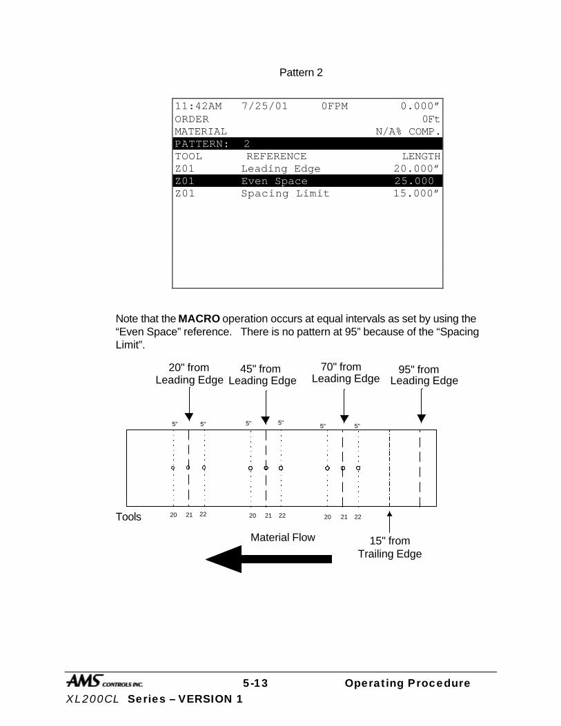
5-13 Operating Procedure XL200CL Series – VERSION 1
Pattern 2
Note that the MACRO operation occurs at equal intervals as set by using the “Even Space” reference. There is no pattern at 95” because of the “Spacing Limit”.
Material Flow
Tools
20" fromLeading Edge Leading Edge
45" from 70" fromLeading Edge
20 21 22
5" 5" 5"
95" from
15" from
Leading Edge
20 21 2220 21 22
Trailing Edge
5" 5" 5"
11:42AM 7/25/01 0FPM 0.000” ORDER 0Ft MATERIAL N/A% COMP. PATTERN: 2 TOOL REFERENCE LENGTH Z01 Leading Edge 20.000” Z01 Even Space 25.000” Z01 Spacing Limit 15.000”
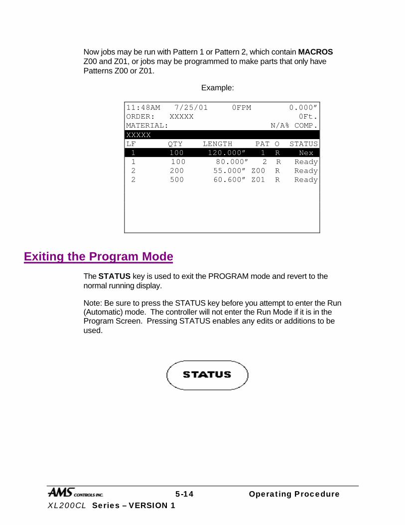
5-14 Operating Procedure XL200CL Series – VERSION 1
Now jobs may be run with Pattern 1 or Pattern 2, which contain MACROS Z00 and Z01, or jobs may be programmed to make parts that only have Patterns Z00 or Z01.
Example:
Exiting the Program Mode
The STATUS key is used to exit the PROGRAM mode and revert to the normal running display.
Note: Be sure to press the STATUS key before you attempt to enter the Run (Automatic) mode. The controller will not enter the Run Mode if it is in the Program Screen. Pressing STATUS enables any edits or additions to be used.
11:48AM 7/25/01 0FPM 0.000” ORDER: XXXXX 0Ft. MATERIAL: N/A% COMP. XXXXX LF QTY LENGTH PAT O STATUS 1 100 120.000” 1 R Next 1 100 80.000” 2 R Ready 2 200 55.000” Z00 R Ready 2 500 60.600” Z01 R Ready
5-15 Operating Procedure XL200CL Series – VERSION 1
Referencing Controller to the Material
The XL200CL SERIES controller measures relative movement of the material through the machine and has no way of measuring the absolute amount of material that is past the shear. In order to cut accurate lengths, the controller must know how much material is past the shear at some point in time and then it can make relative measurements thereafter. This is a process called referencing.
Referencing is simply loading material into the machine past the shear and closing the MANUAL SHEAR input switch. At the bottom of the shear stroke, the length counter is set to zero and the controller is referenced. If the controller is set to punch and there are FILLED parts, the shear must be cycled twice to reference the AMS controller. The controller will remain referenced as long as the encoder stays in contact with the material and the material does not move while the controller is turned off.
On some flying die machines there are a series of moves that are made. Refer to page 3-17 for this sequence. On feed-to-stop machines, the controller re-references itself to the material on each automatic cut, at the bottom of the shear cycle. This is done to improve accuracy. The material can overshoot or undershoot the shear point on each feed. With simple electrnonic counters, an overshoot on one cut, followed by the udnershoot on the next cut, will cause the second part to be short by the sum of the overshoot plus the undershoot. By re-referencing on each cut, the XL200CLCL controller limits the error to either an undershhot or an overshoot. This effectively cuts the error in half.

5-16 Operating Procedure XL200CL Series – VERSION 1
Running the Machine
Main Status Display The top three rows of the XL200 VERSION 1 SERIES controller’s display always show certain vital information, regardless of the controller's current programming mode and resulting display on the lower rows. The top display consists of the current time of day, date, line speed, amount of uncut material past the shear, order number, total length of the order, material code, and percentage of order completion.
Figure 5.4. Typical Status Screen
If there are no items programmed or if the setup parameter “Set Done Items to Ready” is set to YES, the (% Comp) will be displayed as N/A (not applicable)
1:52PM 6/17/01 0FPM 0.000” ORDER: 32786-R1 600Ft MATERIAL: 16GA GALV 0% COMP. LF QTY DONE LENGTH PAT O STATUS 32786-R1 16GA GALV WLPNL 1 10 0 360.000” 100 R Next 1 15 0 240.000” 200 R Ready

5-17 Operating Procedure XL200CL Series – VERSION 1
Figure 5.5. Status Screen With No Items Programmed
Status Mode Display When the XL200 VERSION 1 SERIES controller is in the Status mode, the lower twelve lines of the display are used to show details of the Order currently being run.
The STATUS display is the same as the ORDER ENTRY screen with the addition of the quantity completed. The letter code on the right hand column shows the status of each line. The codes are as follows:
Program Screen Status Screen Status
W Work The item currently being cut F Fill Item started but not yet being cut N Next Next item to run R Ready This item is ready to run S Skip Skip this item D Done This item is done X Delete This item has been deleted
:52PM 6/17/01 0FPM 0.000” ORDER: 0Ft MATERIAL: N/A% COMP. LF QTY DONE LENGTH PAT O STATUS

5-18 Operating Procedure XL200CL Series – VERSION 1
Setting the Next Order (Item) to Run To set the Next Order or Item to run, press the STATUS key to enter the Status Display mode. Then use the green UP ↑ and DOWN ↓ arrow keys to highlight an Order (Item) that has a current status of READY or SKIP. When the desired row is highlighted, press the “F1” (NEXT LINE) key to cause the status of this Item to change to NEXT. This can be done ONLY while the machine is halted.
F1
If an Item with a punch pattern has been partially completed when another Order (Item) is set to NEXT, two changes of status will occur. The new Order (Item) will obtain a status of NEXT while the partially completed Item will obtain a status of FILLED. A status of FILLED means that information about the next several parts (between one and three) has already been targeted in memory. The XL200 VERSION 1 SERIES controller will make these few pieces immediately after the RUN input is closed regardless of which line is set to NEXT. The machine will then halt (depending upon the halt mode), and the new NEXT LINE TO RUN will be ready for production.
If the operator desires to halt the current Item that is running and immediately begin making parts from a different Order (Item), these steps must be followed:
Ø Halt the machine. Ø Manually cycle the shear (TWICE for punch parts only) to eliminate
the parts that have already been FILLED. Ø Set NEXT LINE TO RUN as above. Ø Press the RUN input switch.
Doing this may cause one or more scrap pieces to be generated.
Skipping an Order or an Item To skip an entire Order, or just an Item, press the STATUS key to enter the Status Display mode, and then use the green UP ↑ and DOWN ↓ arrow keys to highlight the desired ORDER (ITEM). When the desired line is highlighted, press the “F2” (SKIP LINE) key to cause the status of this line to change to SKIP. This can be reversed to READY by pressing the “F2” key again with the same line highlighted.
5-19 Operating Procedure XL200CL Series – VERSION 1
The controller must be in STATUS mode for the SKIP LINE key to take effect. SKIPPED items can be set to “NEXT” or “DELETE” without setting them to “READY” first.
F2
Adding an Item While in the Run Mode While the machine is running, or any time the XL200 VERSION 1 SERIES controller is in the Status Display mode, the operator may add an Item to any Order currently programmed. To do this, use the green UP ↑ and Down ↓ arrow keys to move the highlighted row to the item below which the added line will be inserted. Press the “F3” (ADD LINE) key. Enter the Lift Number, Quantity, Length, Pattern Number, and Pattern Mode. This new Item may be set to NEXT (if the machine is halted) or simply be READY for production at a later time.
F3
Deleting an Order (Item) To delete an Order (Item), press the STATUS key to enter the Status Display mode, then use the green UP ↑ and DOWN ↓ arrow keys to highlight an Order (Item) which has the status of READY or SKIP. Press the “F4” (DELETE LINE) key. The status of that Order (Item) is now DELETE (X).
To UNDELETE an Order (Item) that has been deleted, simply highlight that row and press the “F4” (DELETE LINE) key again. Any Order (Item) having a status of DELETE will be erased from memory when an XL200 VERSION 1 SERIES controller MEMORY TEST is performed or when the power is turned off.
F4

5-20 Operating Procedure XL200CL Series – VERSION 1
To delete an Order (Item) that has been partially run, these steps must be followed:
Ø Halt the machine. Ø Manually cycle the shear (TWICE for punched parts) to eliminate parts
that have already been FILLED. Ø Select any other Order (Item) as NEXT to run. Ø Delete the partially run Order (Item) as above.
Changing the Sequence of Orders (Items)
Orders and Items will be run in the sequence in which they appear on the AMS controller screen. To modify the sequence, press the PROGRAM key to enter the PROGRAM mode. Highlight the line containing the order or item to be moved, then press the green MOVE UP or MOVE DOWN key as many times as needed to move the selected line to the desired position. This can be done only while the line is halted and the controller is in the PROGRAM mode. This will move orders in the “Orders Screen” and items in the “Program Items Screen”.
MoveDown
MoveUp
Starting the Machine After the NEXT LINE is set, the machine is placed in the RUN mode by closing the RUN input. The XL200 VERSION 1 SERIES controller will begin shearing parts at the programmed length and increment the quantity completed for the item.
When the quantity completed reaches the programmed total, the controller will automatically halt or continue running the next sequential line without halting, depending or how the Machine Data parameter ‘HALT MODE” is set. See Chapter 2 of this manual for the ‘HALT MODE” settings.
Manual Shear On feed-to-stop machines, the MANUAL SHEAR input is active only when the machine is halted. Most flying die machines have the capability to shear on the fly. The MANUAL SHEAR may or may not be active in the RUN mode depending upon the switch configuration. If production has started and the material has to be cut, perhaps to clear a jam up, no other effect occurs except to destroy one piece. However, if the MANUAL SHEAR is cycled a second time before the line is placed back into the run mode, all pending

5-21 Operating Procedure XL200CL Series – VERSION 1
operations will be canceled (only during punching routines). This double shear operation should be done each time a new coil is loaded so that operations pending before the coil ran out will not occur (again, only during punching routines).
Halting Production At any time, the operator can halt the line by opening the Run contact. Depending on how the controller is installed, this may take the form of pressing any of a number of HALT buttons located on the machine.
The movement outputs will be turned off immediately but the XL200 VERSION 1 SERIES controller will remain in the RUN mode until the material has stopped or until 5 seconds has past. Because of this, the feeding device should be connected to the FORWARD output and not the RUN output.
This allows for an automatic cut to be made as the material decelerates. The controller will remain in the RUN mode until the material has stopped or 5 seconds have elapsed. Normally, the operator would halt the machine just after a shear is made and a cut would not occur during deceleration. If the RUN contact is opened while a press is operating, the movement outputs will remain ON until the press has completed its cycle (SHEAR or PRESS DWELL time).
Completed Orders (Items) When an Order (Item) has been completed it will take on a status of DONE and remain on the main Status Display of the AMS controller for recording purposes. When the completed Order (Item) information is no longer needed it may be cleared from the display by simply highlighting that line and pressing the DELETE LINE key. If DONE Orders (Items) are not cleared within the number of days specified for “Auto-Delete Done Orders” in Machine Parameters, they will be automatically erased during the POWER UP TEST or by running the MEMORY TEST.
Requesting Order (When using Eclipse Only) If Eclipse is used to program orders into the XL200 VERSION 1 SERIES controller, the “Request Order” feature may be used. This is done by selecting the “Communication” item from the setup menu. Once “Communication” is selected the screen in figure 6-6 will be displayed. Highlight the “Request Order” selection and press enter to ask for an order form the Eclipse program. The controller will verify your request by the prompt “Request Order From Link, Press any Key to Continue”. One or more orders will than automatically download from the Eclipse database.

5-22 Operating Procedure XL200CL Series – VERSION 1
Figure 5.6. Request Order Screen
1:52PM 6/17/01 0FPM 0.000” ORDER: 32786-R1 600Ft MATERIAL: 16GA GALV 0%COMP.
Communications Test Request Order
Type 1 7/7/01 1:24PM V 1.02
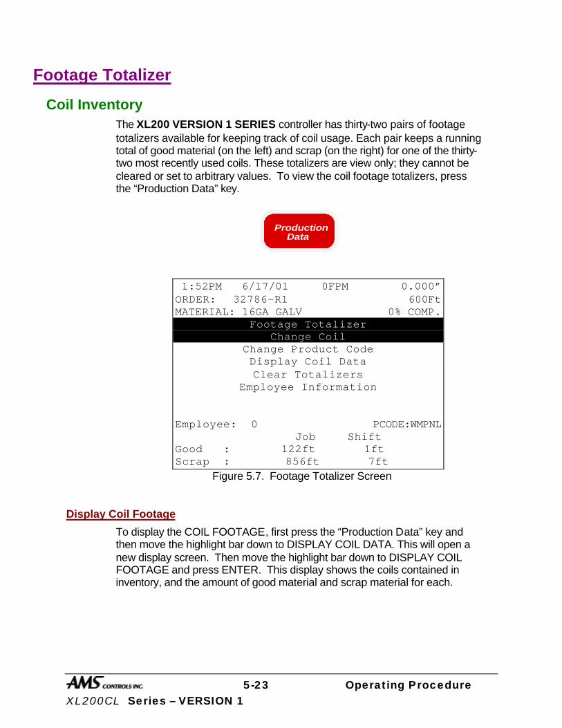
5-23 Operating Procedure XL200CL Series – VERSION 1
Footage Totalizer
Coil Inventory The XL200 VERSION 1 SERIES controller has thirty-two pairs of footage totalizers available for keeping track of coil usage. Each pair keeps a running total of good material (on the left) and scrap (on the right) for one of the thirty-two most recently used coils. These totalizers are view only; they cannot be cleared or set to arbitrary values. To view the coil footage totalizers, press the “Production Data” key.
ProductionData
Figure 5.7. Footage Totalizer Screen
Display Coil Footage
To display the COIL FOOTAGE, first press the “Production Data” key and then move the highlight bar down to DISPLAY COIL DATA. This will open a new display screen. Then move the highlight bar down to DISPLAY COIL FOOTAGE and press ENTER. This display shows the coils contained in inventory, and the amount of good material and scrap material for each.
1:52PM 6/17/01 0FPM 0.000” ORDER: 32786-R1 600Ft MATERIAL: 16GA GALV 0% COMP.
Footage Totalizer Change Coil
Change Product Code Display Coil Data Clear Totalizers
Employee Information Employee: 0 PCODE:WMPNL Job Shift Good : 122ft 1ft Scrap : 856ft 7ft

5-24 Operating Procedure XL200CL Series – VERSION 1
Figure 5.8. Coil Data Screen
Display Coil Material
To display the COIL MATERIAL, first press the “Production Data” key and then move the highlight bar down to DISPLAY COIL DATA. This will open a new display screen. Next move the highlight bar down to DISPLAY COIL MATERIAL and press ENTER. This display shows the coils contained in inventory and the corresponding material for each.
Changing Product Code If PRODUCT CODES are enabled in the “Communications Setup” screen, a “Change Product Code” selection will be displayed in the “Production Data” screen. Highlighting the selection and pressing “ENTER” will display a screen with the prompt to “Enter Product Code”. See figure 5.9.
2:54PM 6/17/01 0FPM 0.000” ORDER: 32786-R1 600Ft MATERIAL: 16GA GALV 0% COMP.
Display Coil Data Display Coil Footage
Display Coil Material
Coil: Material: Employee: 0 PCODE:WMPNL Job Shift Good : 122ft 1ft Scrap : 856ft 7ft
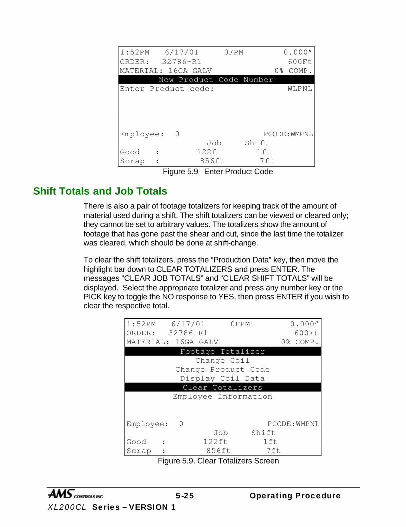
5-25 Operating Procedure XL200CL Series – VERSION 1
Figure 5.9 Enter Product Code
Shift Totals and Job Totals There is also a pair of footage totalizers for keeping track of the amount of material used during a shift. The shift totalizers can be viewed or cleared only; they cannot be set to arbitrary values. The totalizers show the amount of footage that has gone past the shear and cut, since the last time the totalizer was cleared, which should be done at shift-change.
To clear the shift totalizers, press the “Production Data” key, then move the highlight bar down to CLEAR TOTALIZERS and press ENTER. The messages “CLEAR JOB TOTALS” and “CLEAR SHIFT TOTALS” will be displayed. Select the appropriate totalizer and press any number key or the PICK key to toggle the NO response to YES, then press ENTER if you wish to clear the respective total.
Figure 5.9. Clear Totalizers Screen
1:52PM 6/17/01 0FPM 0.000” ORDER: 32786-R1 600Ft MATERIAL: 16GA GALV 0% COMP.
New Product Code Number Enter Product code: WLPNL Employee: 0 PCODE:WMPNL Job Shift Good : 122ft 1ft Scrap : 856ft 7ft
1:52PM 6/17/01 0FPM 0.000” ORDER: 32786-R1 600Ft MATERIAL: 16GA GALV 0% COMP.
Footage Totalizer Change Coil
Change Product Code Display Coil Data Clear Totalizers
Employee Information Employee: 0 PCODE:WMPNL Job Shift Good : 122ft 1ft Scrap : 856ft 7ft

5-26 Operating Procedure XL200CL Series – VERSION 1
This feature is useful when several different orders or jobs are completed during one shift.
All footage totalizers display in whole feet, or whole meters if the controller is set to a metric display mode.
5-27 Operating Procedure XL200CL Series – VERSION 1
Special Procedures
When the Eclipse program is used, there are lists of codes that are available. These codes include: SCRAP CODES, DELAY REASONS, and EMPLOYEE NUMBERS. Explanations of these codes follow.
Scrap Code The SCRAP CODE parameter is used with the Eclipse program and will define what type of scrap is being produced. In the COMMUNICATION screen the question is asked “USE SCRAP CODES?” with a choice of YES and NO.
If scrap codes are used, and are defined by name via the Eclipse program, a list will be provided by the controller when INCREASE QUANTITY (Inc. Qty.) is selected or if a manual cut is made that is longer that the “Manual Shear Scrap Length” parameter. If scrap codes are used but are not defined by the Link program, the operator can enter a numerical number for the type of scrap produced by an INCREASE QUANTITY.
00 = General Production Scrap
01 to ZZ = the valid range of codes
This coincides with lift # 900 through 9ZZ, i.e. “9” plus a 2 digit scrap code = lift number to generate specific scrap.
Delay Reason Any time the line is halted longer than the HALT DELAY MINIMUM (new setup parameter), the operator is prompted to enter a 2-digit DELAY REASON before he is allowed to re-enter the RUN mode. This code is added to all production records to be used by the Eclipse software. If the Eclipse is not being used, a DELAY REASON is not necessary.
The limits for the HALT DELAY MINIMUM are 0 to 99 minutes. A value of zero will force the operator to enter a DELAY REASON after every line halt. A value of 99 will disable the function and the controller will never force the operator to enter a DELAY REASON.
Employee Numbers Each time an operator is prompted to enter a DELAY REASON (see description above), he/she will also be prompted to enter his/her EMPLOYEE NUMBER. This number can be up to 7 digits long (1-9999999), and will be included on all production records when using the Eclipse Communications Software.
5-28 Operating Procedure XL200CL Series – VERSION 1
The operator is also prompted to enter the employee number at every shift change. The employee number may be changed at any time by entering the “Production Data” menu under the subheading of EMPLOYEE INFORMATION.

5-29 Operating Procedure XL200CL Series – VERSION 1
Changing Coils The following procedure should be used when changing coils to ensure proper accounting of the material used on a coil and an accurate first part after the new coil is loaded:
Ø If the coil has been completely consumed or the material has been cut free of
the stock reel, as is the case with most roll formers, feed the material through the shear in the forward direction and dispose of the scrap piece.
Ø On a cut-to-length machine with no roll former involved, all of the unused material can be rewound on the mandrel for later use. In this case, back the material out through the entrance end of the shear until it is out from under the encoder.
Ø After the machine is empty, close the Manual Shear input.
Ø This registers all material used to the totalizers.
Ø Press “Production Data” key and select CHANGE COIL. If loading a new coil a new COIL NUMBER must be entered. This number field can accept up to sixteen characters.
Ø If loading a partially used coil which is already in the coil inventory of the XL200 VERSION 1 SERIES controller, press the ENTER key when prompted to enter a COIL NUMBER. Select one of the coils already contained in inventory by highlighting the correct line and pressing enter.
Ø Thread the next coil into the machine until a clean edge is past the shear and the material is under the encoder.
Close the Manual Shear input to reference the new coil.
When No Good Footage is Run for a Coil
If after a coil is loaded and no acceptable parts are ran for that coil, the material for the order that is assigned NEXT, will be assigned to that coil. If the operator changes the priority of the orders and designates a different order to be NEXT, this order will now be assigned to the coil as long as no good parts are run. The operator will not receive a warning in this case.
If good parts are run from a coil and a different order is assigned to be NEXT and it is assigned to a different material, the operator will receive a warning that “wrong coil is loaded.” This is a warning only and can be ignored.
No Sheet Detect When a New Coil is Entered
If a new coil is loaded and the sheet detect input is false (not activated), a new coil will not be asked for when the sheet detect switch is actuated. In
5-30 Operating Procedure XL200CL Series – VERSION 1
previous versions if the coil information was entered into the controller before the coil was physically changed and the sheet detect switch activated, the controller would call for another coil change when the new coil is actually changed and the sheet detect switch closed.

5-31 Operating Procedure XL200CL Series – VERSION 1
Handling Material Flaws With most roll formers and cut-to-length machines, material problems are common. The XL200 VERSION 1 SERIES controller has features that aid the operator when these flaws occur.
The best method of handling material flaws depends on when the flaws are detected and the duration of the flaw. If random small flaws occur, they are not likely to be detected until after the controller has cut the part. In this case, the only thing that the operator can do is make another part to replace it. This is easily done with the “Inc. Qty.” (INCREASE QUANTITY) key.
Inc. Qty
Increase Quantity
Pressing the INCREASE QUANTITY key while the AMS controller is in the RUN mode will cause the fourth line of the Status Display to flash "Quantity +1" and it will continue to flash until a shear is fired. The current part will be completed with no decrease in quantity, and the controller will continue running the item with no interruption.
If the INCREASE QUANTITY key is pressed while the machine is HALTED, the fourth line of the display will flash the same message, but the operator will have two options: Start the machine to make the extra part or press “CE” to cancel the incremented quantity. In either application, if an extra part is made, the scrap total in the Coil Footage Totalizer is automatically adjusted.
If a small flaw is detected before the shear, the operator may wish to crop the flaw out to minimize the amount of scrap material. On flying die machines, the MANUAL SHEAR input is active while the machine is running. The crop starts the production of the part over again and the operator can repeat this process until good material occurs. A MANUAL SHEAR in the Run Mode will not produce a part smaller then the MINIMUM PART LENGTH. The XL200 VERSION 1 SERIES controller will delay the cut until this amount of material has past. In the case of feed-to-stop machines, the machine must be halted before the MANUAL SHEAR input is active. The operator would most likely jog the material forward until the flaw is past the shear and then close the MANUAL SHEAR input a second time.
All manual shears that are performed will count the amount of material that is past the shear as scrap, and will automatically adjust the scrap total in the Coil Footage Totalizer.
There are times when material flaws can be extensive and last for a large portion of a coil. A user may find that this material is easier to handle if it is cut
5-32 Operating Procedure XL200CL Series – VERSION 1
into short lengths rather than relying on the operator to crop repeatedly. There may also be secondary outlets for such material if they can be cut to standard lengths of perhaps 8, 10, and 12 feet. If this is the case, jobs for this purpose can be programmed at lift number 0 or between 900 and 9ZZ before hand, and the operator can switch production to these jobs when extensive flaws occur.
Any parts made from jobs that have Lift Numbers 0 or are between 900 and 9ZZ will be recorded as scrap material in the FOOTAGE TOTALIZER. A common use of this is to use different lift numbers to represent different types of scrap (900 = bad paint, 901 = bent edge, etc.). If Eclipse is installed, these scrap codes can be sent to the Eclipse PC and allows for the tracking of the different types of scrap encountered on the machine.
If the ADD LINE “F3” function that is discussed on page 6-19 is used, a pattern number of zero, or 900 to 9ZZ, will allow the operator to create the designated number of parts as scrap. When the operator detects an extensive amount of flawed material, he/she may select one of these jobs with the NEXT LINE “F1” key. After the flaw has been cleared, he/she may use the NEXT LINE “F1” key to set the original lift being run and to resume normal production.
If it is discovered that completed items that were counted as “good” parts are later determined to be scrap, the controller will compensate for this by allowing Done items to be incremented. When the INCREASE QUANTITY is used on a Done item the controller will prompt the operator requesting the number of pieces to increment and the coil to which the action applies.
When performing a normal INCREASE QUANTITY it is important to highlight the current item that is running before pressing the INCREASE QUANTITY key, otherwise you may increase an item that you do not wish to increase. If the highlighted line is on an item that is not done, the current running item will be incremented. If, however, the highlighted line is on a DONE item, the total for the item that is DONE will be increased.
5-33 Operating Procedure XL200CL Series – VERSION 1
Decrease Quantity
The “F6” (DECREASE QUANTITY) key is used when it is necessary to decrease the quantity of an order. A common use of this function is when scrap is produced at some point, but later it is manually cut or altered so that it is no longer considered to be scrap. Using DECREASE QUANTITY (F6) at this point can adjust what needs to be produced after the “once scrap” parts are now made usable. The scrap may have come from a manual cycle, INCREASE QUANTITY, or from a lift that is dedicated to scrap. When the line is halted, pressing the “F6” (DECREASE QUANTITY) key will increase the number DONE on the STATUS screen.
F6
To decrement an order the line must first be halted. If the DECREASE QUANTITY key is pressed while the machine is halted, the fourth line of the display will flash “Enter Quantity To Decrement” and line 5 will default to a quantity of 1. If the number to be decremented is one, just press ENTER. If the number to be decremented is another number, enter that number into the controller and then press ENTER. The controller will then ask for a coil number that you wish to decrement the quantity against. If the coil number is the one that is presently in use, that coil number will appear on line five, so just press ENTER.
Note: If there are parts already in the controller’s queue, they will not be decremented. To decrement parts that are in the queue, first double cycle the shear or press to clear the queue, then press “F6” and enter the number to be decremented and then the coil number to be decremented against.
6-1 Troubleshooting XL200CL Series - VERSION 1
Troubleshooting
The XL200CL VERSION 1 SERIES controller is a very reliable product, but things can go wrong. The user can clear most problems, but AMS experts are always ready to help if needed.
We have many years of experience with all types of length controls and coil processing equipment. Our experience shows that problems are grouped into:
Ø Machine problems (most common)
Ø Operator mistakes
Ø Incorrect Setup data
Ø Corrupted controller memory
Ø Cable damage
Ø Controller fault (least common)
Troubleshooting is just a logical series of steps that lead to the likely cause of a problem. The only tools you need are an accurate scale or steel tape, and perhaps a multi-meter.
This guide is a “self help guide” for the user to help troubleshoot the system. Follow these suggestions in the order listed.
6-2 Troubleshooting XL200CL Series - VERSION 1
Troubleshooting Guide
When did the Problem Start? Did the machine work properly at one time? If not, have you done the Calibration procedure?
If the machine did work properly at one time, what has changed since then?
Did the problem start after routine maintenance, electrical panel work, or a material change or after an operator change? Trace back in time to find what is different.
Check the Machine Check the Encoder to make sure it tracks the material perfectly.
The encoder wheel must be at right angles to the material. The wheel must rotate exactly parallel to the direction of material movement.
The wheel must be in firm contact with the material. No slippage is allowed!
Re-run the length Calibration Trim procedure after any changes to the encoder mounting.
Check the encoder cable connections. They may have worked loose from material movement or vibration. Make sure there are no nicks or cuts in the cable.
Check the shear (or punch) press to make sure that it returns fully to its home position after each cycle. The press will make accurate cuts only if it starts from a known position for each cycle.
Re-run the length Calibration Trim procedure after any changes to either press.
Visually check other parts of the machine for loose fasteners, excessive wear, proper lubrication, proper material feed, and roll former adjustment.
Re-run the length Calibration Trim procedure after any changes to the machine.
6-3 Troubleshooting XL200CL Series - VERSION 1
Collect Data Often the problem is that the machine is making out-of-tolerance parts. To deal with this type of problem, carefully measure the parts made and compare these numbers with those that were programmed. Also take note of the order in which the shear cut the parts.
Write down these measurements for possible later reference.
If length and punch placement seem to vary at random, check the encoder mounting very carefully. The encoder must move with the material, and cannot be allowed to slip. If dimensions are off in a consistent pattern, run the Calibration Trim procedure.
Re-check Setups Re-check Setup values with originally recorded values. When you installed the XL200CL VERSION 1 SERIES controller, you should have recorded the Setup values on the form provided in the manual for your machine TYPE. Make sure that none of these values have changed.
Run the Calibration mode When you do the Calibration Trim, take great care to make accurate measurements. Be sure that you know how to reduce measuring error as much as possible with the scale or steel tape you use. A loose tip on your steel tape can add a large error into your measurements.
Use Built-in Diagnostic features The XL200CL VERSION 1 SERIES controller has a display mode (press SETUP, then highlight Input/Output Status and press ENTER) that allows you to monitor the controller's inputs and outputs. Watch this display while the machine is running to check for slowdown, stopping, die boost, and press actuation points.
On the main Status display, you can watch line speed and distance past the shear. Compare what you see here to what should be happening as the machine runs.
Check Incoming Power Check incoming power for proper voltage. If you suspect fluctuations, watch the needle indication with an analog meter to see if they show up.
More advanced line monitors are available for stubborn cases that you can't see with ordinary meters. Use a recording line monitor to find

6-4 Troubleshooting XL200CL Series - VERSION 1
problems that seldom show up. Your local power company may be able to help with this.
Cycle Power Cycle power off and on. Try this if the controller "locks up" (won't respond to the keyboard). This may restore normal operation after an electrical surge. If not, clear the controller’s memory.
Electrical Noise The AMS controller should not lock up frequently. If it does, you should suspect that electrical noise is present.
Noise problems can be very hard to locate. The best way to avoid noise is by using good cable layout and wiring methods. Also, noise suppresser devices such as varistors are needed in some cases.
Refer to the AMS Application Note "Noise Suppression Methods" for details.
Be sure to send a copy of the Setup Data Sheet, and all information about the problem. FAX us at 1-314-344-9996.
Don't forget to include your name and phone number so we can call you back.
6-5 Troubleshooting XL200CL Series - VERSION 1
Clear Memory Clearing memory will erase all Setup, Pattern, and Order information in the XL200CL VERSION 1 SERIES controller's memory.
Do not clear the memory unless you have written down all Setup, Pattern, and Order information for re-entry, and you have tried everything else above.
You can clear all storage in the controller (including Setup and Order data) by following this sequence:
Make sure that the Security switch is unlocked
Turn off power to the controller
Wait five seconds
Turn the controller back on
Wait until the AMS logo has scrolled across the screen and the words “POWER UP TESTING EPROM” appear at the bottom of the screen
Hold down the “5” key for at least two seconds and release the “5” key when you see the unit reset (the AMS logo will start to scroll across the screen again).
6-6 Troubleshooting XL200CL Series - VERSION 1
Contact AMS AMS Controls, Inc.
12180 Prichard Farm Road
Maryland Heights, MO 63043
Tel # 1 (800) 334 – 5213
Fax # 1 (800) 344 – 9996
Check our website at “amscontrols.com”
FAX Setup and Parts data to AMS FAX Setup and Parts data to AMS with a full description of the problem. Unless you think your problem is very simple, you might as well FAX this information to us before you call. We'll probably ask you for it anyway.
Include the Model, Serial, and Software Version numbers.

7-1 Controller Options XL200CL Series - VERSION 1
Options
There are some features offered by AMS Controls that are not present on all controllers. The following options will be discussed in this section:
Ø Print-on-Part Printer
Ø Bundle Tag Printer
Ø Expansion Board
Ø Remote Terminal
Ø Bar Code Scanner
Ø Extended Macro Patterns
Ø Auxiliary Controller
Ø Hole Detect
As a guide to help the user find the different options available, an index is provided below.
Ø Print-on-Part Printer Page 7-2
§ Citoh T4 Page 7-7
§ Telesis 3225 Page 7-9
§ Matthews 2001 Page 7-11
§ Fox 8231M Page 7-14
§ Willet 3150 Page 7-18
Ø Bundle Tag Printer Page 7-21
§ Citoh T$ Page 7-21
§ Zebra Z4000 Page 7-28
Ø Expansion Board Page 7-34
Ø Remote Terminal Page 7-36
§ Qume Page 7-36
§ TeleVideo Page 7-38
Ø Bar Code Scanner Page 7-39
Ø Extended Macro Pattern Page 8-42
Ø Auxiliary Controller Page 8-47
Ø Hole Detect Page 8-79
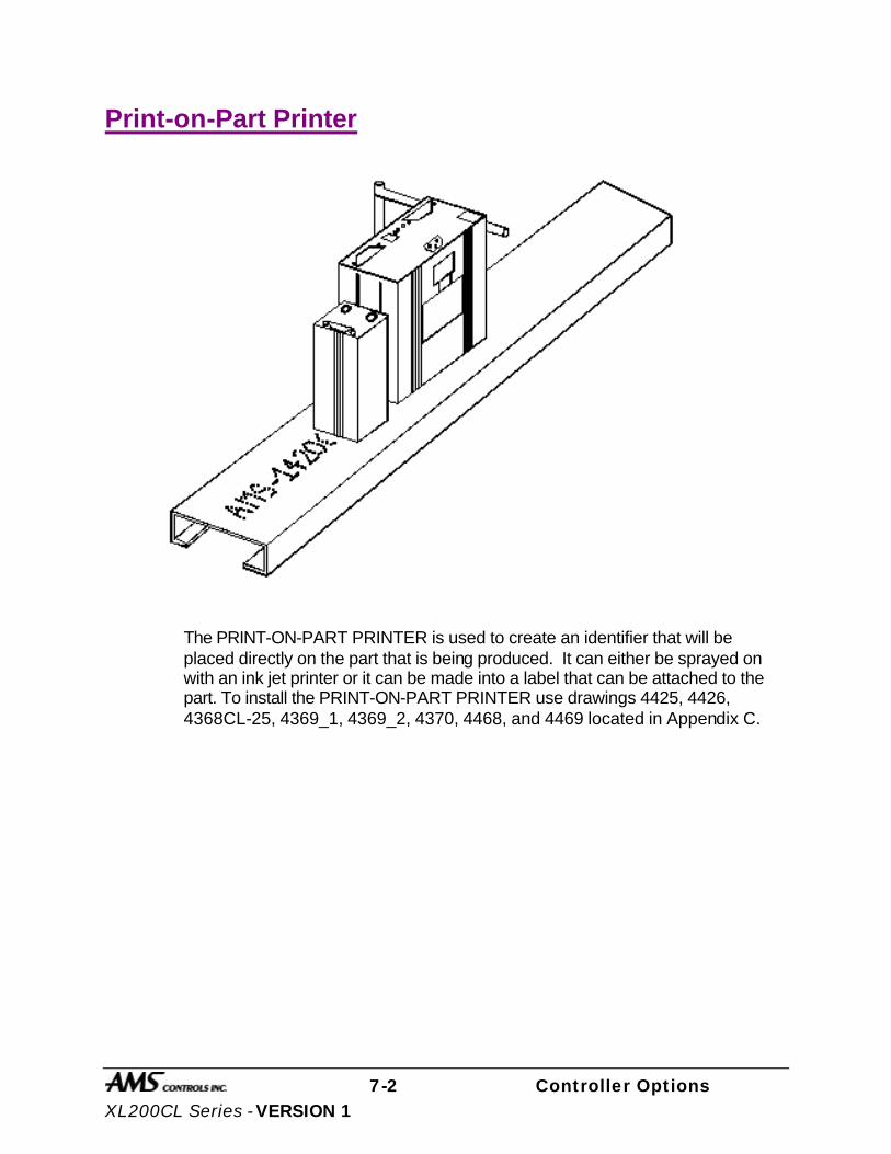
7-2 Controller Options XL200CL Series - VERSION 1
Print-on-Part Printer
The PRINT-ON-PART PRINTER is used to create an identifier that will be placed directly on the part that is being produced. It can either be sprayed on with an ink jet printer or it can be made into a label that can be attached to the part. To install the PRINT-ON-PART PRINTER use drawings 4425, 4426, 4368CL-25, 4369_1, 4369_2, 4370, 4468, and 4469 located in Appendix C.

7-3 Controller Options XL200CL Series - VERSION 1
Outputs to the Printer
Print Initiate Output The location of the output signal that is sent from the controller to activate the printer will vary depending upon the model controller and the number of presses that are used by the system.
The Print Initiate output will always be on Output 8 (terminal E9).
Note: When using the Print-on-Part Printer, the maximum number of gags and/or presses for the XL212CL VERSION 1 without an expansion board is 10.
Printer Encoder When using the Print-on-Part Printer, the user has the option of using the internal timing of the printer or to use an encoder output that is generated by an external encoder. The internal timing of the printer will print at the same speed regardless of variations in the line, which could result in variations in the printing process. The printer encoder, however, will send to the printer encoder pulses, which allow the printer to adjust to the line variations. An 80-count encoder is suggested.
Figure 7.1. Printer Setup Screen
1:23PM 8/24/01 0FPM 0.000” ORDER 0Ft MATERIAL N/A% COMP. XL200CLP Controller
Machine Data Edit Tool Data
Calibration Trim Manual Calibration
Time Clock Printer Setup
Input/Output Status Memory Test
Communications Type 17 3/15/01 4:43PM V1.02

7-4 Controller Options XL200CL Series - VERSION 1
In order to use the PART PRINTER, the type of printer must first be selected. When the PRINTER SETUP mode is selected, the first screen allows you to enter the SELECT PART PRINTER mode.
Figure 7.2. Printer Menu Screen
A choice of printers will be offered. Select the printer that applies to your application and hit the ENTER button.
Figure 7.3. Select Part Printer Screen
When the proper printer is selected, the controller returns to the PRINTER SETUP screen. If you reenter this screen you will again enter the PRINTER MENU screen with an added option of viewing the PART PRINT STATUS or,
1:25PM 8/24/01 0FPM 0.000” ORDER 0Ft MATERIAL N/A% COMP.
Printer Menu Select Part Printer
Type 17 3/15/01 4:43PM V1.02
1:32PM 8/24/01 0FPM 0.000” ORDER 0Ft MATERIAL N/A% COMP.
Select Part Printer Selected: No Printer
No Printer Citoh T4
Telesis 3225 Matthews 2001
Fox 8231M Willet 3150
Type 17 3/15/01 4:43PM V1.02

7-5 Controller Options XL200CL Series - VERSION 1
depending upon the printer, PART PRINT SETUP and/or TEST PRINT ON PART.
Figure 7.4. Printer Menu with Part Print Status
Figure 7.5. Printer Menu with Part Printer Setup
1:50PM 8/24/01 0FPM 0.000” ORDER 0Ft MATERIAL N/A% COMP.
Printer Menu Select Part Printer Part Printer Status
Type 17 3/15/01 4:43PM V1.02
1:50PM 8/24/01 0FPM 0.000” ORDER 0Ft MATERIAL N/A% COMP.
Printer Menu Select Part Printer Part Printer Setup Part Printer Status
Type 17 3/15/01 4:43PM V7.02
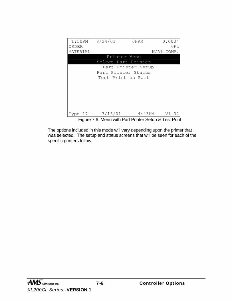
7-6 Controller Options XL200CL Series - VERSION 1
Figure 7.6. Menu with Part Printer Setup & Test Print
The options included in this mode will vary depending upon the printer that was selected. The setup and status screens that will be seen for each of the specific printers follow:
1:50PM 8/24/01 0FPM 0.000” ORDER 0Ft MATERIAL N/A% COMP.
Printer Menu Select Part Printer
Part Printer Setup Part Printer Status Test Print on Part
Type 17 3/15/01 4:43PM V1.02

7-7 Controller Options XL200CL Series - VERSION 1
Citoh T4 Printer
Figure 7.7, Parameters listed for the Citoh Printer.
Printer: This parameter shows that the proper hardware to communicate to the printer is installed in the XL controller, and will display INSTALL OK.
RS485: DEVICE IS ON LINE indicates that the controller is able to communicate with the RS485 board (AMS 4370). RESPONSE TIMEOUT is displayed when the controller cannot communicate with the RS485 board.
Command Busy: If the printer has received print instructions from the controller and there is an order being produced, this status will be YES. If there is no print order to be run, the status will be NO.
Paper Out: If the printer runs out of paper, this status will be YES. If paper is present, the status is NO.
Ribbon Out: If a ribbon is not present in the printer, this status will be YES. If there is a usable ribbon in the printer, the status is NO.
Printing Batch: If the printer is receiving print instructions from the controller, this status will be YES. This indicates there is information in the printer buffer.
Busy Printing: This parameter will read YES when the printer is in the process of making a label. When the label has been printed it will return to NO.
Printer Pause: If the PAUSE button is pressed on the front of the Citoh printer, the controller will display a YES. Press the PAUSE again to reset this parameter to NO.
Label Present: This requires the use of a separate sensor from the PAPER OUT sensor, and will indicate that the label has been ejected from the printer.
1:55PM 8/24/01 0FPM 0.000” ORDER 0Ft MATERIAL N/A% COMP.
Citoh T4 Printer Status Printer : Install Ok Rs485 : Device is on line
Command Busy : No Paper Out : No Ribbon Out : No Printing Batch : No Busy Printing : No Printer Pause : No Label Present : No
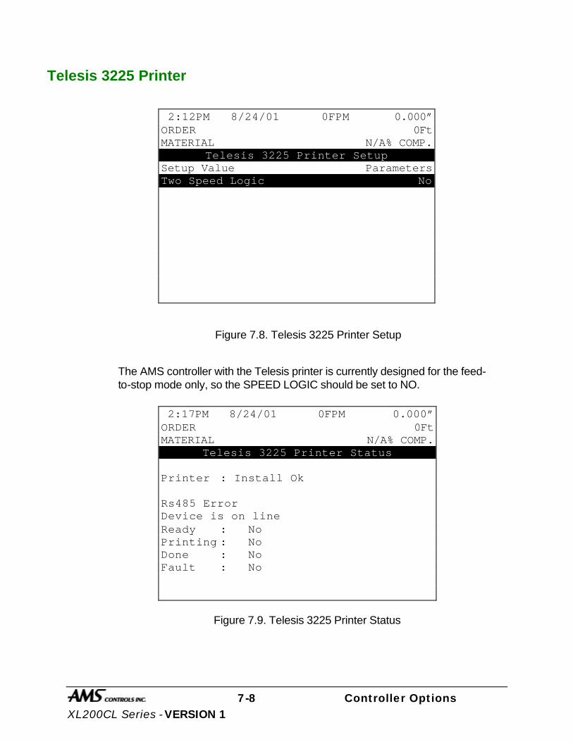
7-8 Controller Options XL200CL Series - VERSION 1
Telesis 3225 Printer
Figure 7.8. Telesis 3225 Printer Setup
The AMS controller with the Telesis printer is currently designed for the feed-to-stop mode only, so the SPEED LOGIC should be set to NO.
Figure 7.9. Telesis 3225 Printer Status
2:12PM 8/24/01 0FPM 0.000” ORDER 0Ft MATERIAL N/A% COMP.
Telesis 3225 Printer Setup Setup Value Parameters Two Speed Logic No
2:17PM 8/24/01 0FPM 0.000” ORDER 0Ft MATERIAL N/A% COMP.
Telesis 3225 Printer Status
Printer : Install Ok
Rs485 Error Device is on line Ready : No Printing : No Done : No Fault : No

7-9 Controller Options XL200CL Series - VERSION 1
In figure 7.9 the printer status parameters are shown.
Printer: This parameter shows that the proper hardware to communicate to the printer is installed in the XL controller, and will display INSTALL OK.
RS485 Error: DEVICE IS ON LINE indicates that the controller is able to communicate with the RS485 board (AMS 4370). RESPONSE TIMEOUT is displayed when the controller cannot communicate with the RS485 board.
Ready: If the printer has received print instructions from the controller and there is an order being produced, this status will be YES. If there is no print order to be run is the status will be NO.
Printing: This parameter will read YES when the printer is in the process of making a label. When the label has been printed it will return to NO.
Done: This display will change momentarily to YES when a part is printed.
Fault: If a fault is detected this parameter will display YES. If there are no errors, it will display NO.
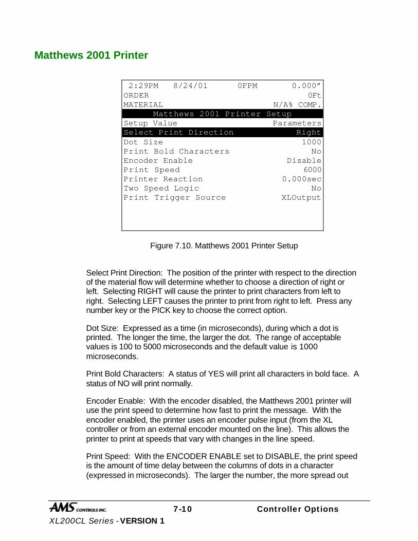
7-10 Controller Options XL200CL Series - VERSION 1
Matthews 2001 Printer
Figure 7.10. Matthews 2001 Printer Setup
Select Print Direction: The position of the printer with respect to the direction of the material flow will determine whether to choose a direction of right or left. Selecting RIGHT will cause the printer to print characters from left to right. Selecting LEFT causes the printer to print from right to left. Press any number key or the PICK key to choose the correct option.
Dot Size: Expressed as a time (in microseconds), during which a dot is printed. The longer the time, the larger the dot. The range of acceptable values is 100 to 5000 microseconds and the default value is 1000 microseconds.
Print Bold Characters: A status of YES will print all characters in bold face. A status of NO will print normally.
Encoder Enable: With the encoder disabled, the Matthews 2001 printer will use the print speed to determine how fast to print the message. With the encoder enabled, the printer uses an encoder pulse input (from the XL controller or from an external encoder mounted on the line). This allows the printer to print at speeds that vary with changes in the line speed.
Print Speed: With the ENCODER ENABLE set to DISABLE, the print speed is the amount of time delay between the columns of dots in a character (expressed in microseconds). The larger the number, the more spread out
2:29PM 8/24/01 0FPM 0.000” ORDER 0Ft MATERIAL N/A% COMP.
Matthews 2001 Printer Setup Setup Value Parameters Select Print Direction Right Dot Size 1000 Print Bold Characters No Encoder Enable Disable Print Speed 6000 Printer Reaction 0.000sec Two Speed Logic No Print Trigger Source XLOutput

7-11 Controller Options XL200CL Series - VERSION 1
the character will be. The accepted range of values for the print speed is 0 to 25,500 microseconds with 6000 microseconds given as the default value.
With the ENCODER ENABLE set to ENABLE, this number is a divide by function of the line encoder. It is used to divide the number of encoder pulses received from the line encoder by the print speed. It then sends that number of pulses to the printer. This must be done due to the printer’s slow calculation time. There is no exact formula for the print speed value; it is mainly a trial and error method due to the type of encoder used and the operating speed of the line. This number will typically be less than 15 for a 256 encoder. As a rule of thumb, if the printed letters are too close together, increase the print speed value. If the printed letters are too far apart, decrease the print speed value.
Printer Reaction: The time between the XL telling the printer to print and the printer executing the command. The acceptable range of values is 0 to .5 seconds.
Two Speed Logic: If YES is selected, it will shift the machine into slow speed just before printing (if the controller is set up for two speed punching). Select NO on non-stopping, single speed lines.
Printer: This parameter shows that the proper hardware to communicate to the printer is installed in the XL controller, and will display INSTALL OK.
Printer Trigger Source: Selects what device will trigger the print message during operation. If “XLOutput” is selected, the XL series controller will give a print initiate through the appropriate output (Output #8 – Terminal E9). If “Photocell” is selected, then the internal detector on the printer will initiate the print message.

7-12 Controller Options XL200CL Series - VERSION 1
Figure 7.11. Matthews 2001 Printer Status
RS485: DEVICE IS ON LINE indicates that the controller is able to communicate with the RS485 board (AMS 4370). RESPONSE TIMEOUT is displayed when the controller cannot communicate with the RS485 board.
Version: Lists the current software version of the Matthews printer.
Memory: This parameter will show the number of bytes left in the printer buffer.
Prnt Msg: The PRINT MESSAGE is the last message that was sent to the printer buffer. If there is no programmed message from an XL Link program, the default message is the controller’s programmed part length and pattern number.
2:37PM 8/24/01 0FPM 0.000” ORDER 0Ft MATERIAL N/A% COMP.
Matthews 2001 Printer Status Printer : Install Ok Rs485 : Device is on line Version : SD2001 Ver 1.2 Memory : MEMORY OK 1740 BYTES FREE Prnt Msg : 50.000”
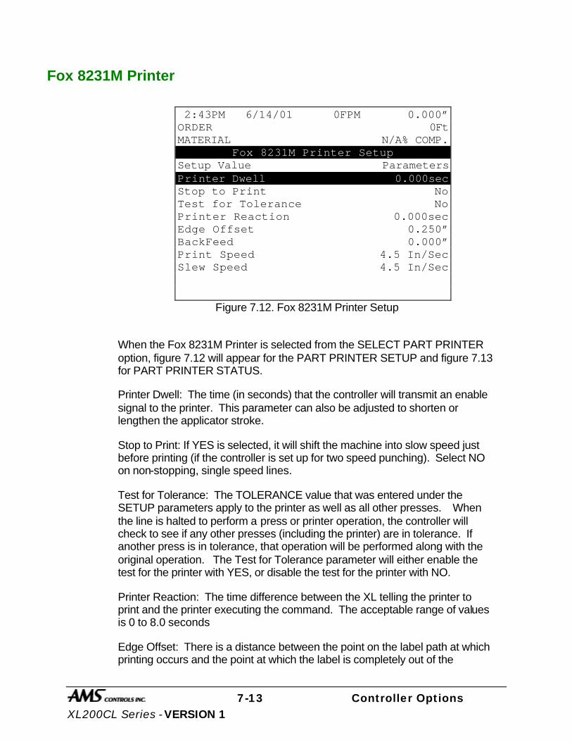
7-13 Controller Options XL200CL Series - VERSION 1
Fox 8231M Printer
Figure 7.12. Fox 8231M Printer Setup
When the Fox 8231M Printer is selected from the SELECT PART PRINTER option, figure 7.12 will appear for the PART PRINTER SETUP and figure 7.13 for PART PRINTER STATUS.
Printer Dwell: The time (in seconds) that the controller will transmit an enable signal to the printer. This parameter can also be adjusted to shorten or lengthen the applicator stroke.
Stop to Print: If YES is selected, it will shift the machine into slow speed just before printing (if the controller is set up for two speed punching). Select NO on non-stopping, single speed lines.
Test for Tolerance: The TOLERANCE value that was entered under the SETUP parameters apply to the printer as well as all other presses. When the line is halted to perform a press or printer operation, the controller will check to see if any other presses (including the printer) are in tolerance. If another press is in tolerance, that operation will be performed along with the original operation. The Test for Tolerance parameter will either enable the test for the printer with YES, or disable the test for the printer with NO.
Printer Reaction: The time difference between the XL telling the printer to print and the printer executing the command. The acceptable range of values is 0 to 8.0 seconds
Edge Offset: There is a distance between the point on the label path at which printing occurs and the point at which the label is completely out of the
2:43PM 6/14/01 0FPM 0.000” ORDER 0Ft MATERIAL N/A% COMP.
Fox 8231M Printer Setup Setup Value Parameters Printer Dwell 0.000sec Stop to Print No Test for Tolerance No Printer Reaction 0.000sec Edge Offset 0.250” BackFeed 0.000” Print Speed 4.5 In/Sec Slew Speed 4.5 In/Sec

7-14 Controller Options XL200CL Series - VERSION 1
printing mechanism and can be removed. It is sometimes desirable to feed the label out of the print mechanism to the point at which it can be easily removed or applied before printing the next label. This value is the distance that the label will be moved. The acceptable range of values for this parameter is 0 to 512.000” and the default value is 0.250”.
BackFeed: When the EDGE OFFSET parameter is used, it is possible that the next label to be printed may have moved beyond the print head so that part of the label is past the printing area. If this is the case, the label may be “backed up” by using the BACKFEED parameter. This parameter will define the distance that the next label to be printed will be fed backwards, so that the entire label in is the printing area. The acceptable range of values for this parameter is 0 to 1.000” and the default value is 0.000”.
Print Speed: The PRINT SPEED parameter sets the maximum speed at which label stock will be fed though the print head while printing is occurring. Typically higher print speeds will cause some reduction in print quality. It may be desirable to sacrifice some print quality for increased label speed. This feature allows the label to be printed at the highest speed that results in acceptable print quality. The print speed may be reduced to obtain the best quality with acceptable label speed while the label is being fed. The acceptable range of values for this parameter is 1.0 to 8.0 inches per second and the default value is 4.5 inches per second.
Slew Speed: The SLEW SPEED parameter sets the maximum speed at which label stock will be fed through the print head while printing is not occurring. In other words, the speed while the printer is “slewing” past unprinted areas. This feature allows the printer to use the highest slew speed that results in acceptable print quality. Typically the slew speed will be set equal to or higher than the print speed. If there is a large difference between the speed settings, print quality may be reduced. If the Print Speed parameter is changed, it may be necessary to change the Slew Speed as well, because the highest print quality is attained when the difference between the Print Speed and the Slew Speed is kept small. The acceptable range of values for this parameter is 1.0 to 8.0 inches per second and the default value is 4.5 inches per second.
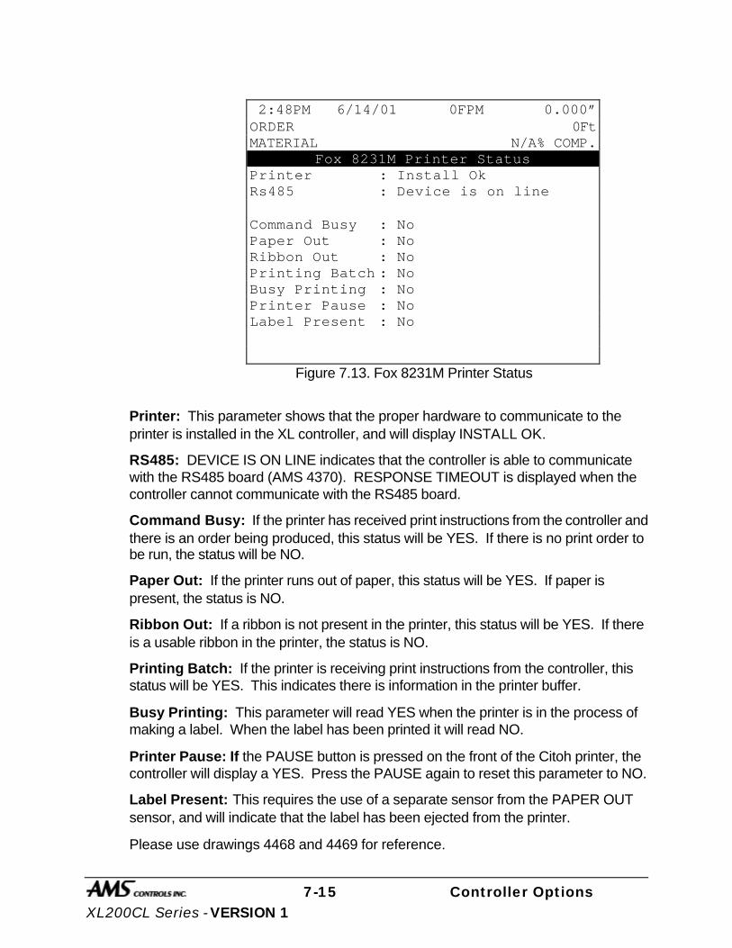
7-15 Controller Options XL200CL Series - VERSION 1
Figure 7.13. Fox 8231M Printer Status
Printer: This parameter shows that the proper hardware to communicate to the printer is installed in the XL controller, and will display INSTALL OK.
RS485: DEVICE IS ON LINE indicates that the controller is able to communicate with the RS485 board (AMS 4370). RESPONSE TIMEOUT is displayed when the controller cannot communicate with the RS485 board.
Command Busy: If the printer has received print instructions from the controller and there is an order being produced, this status will be YES. If there is no print order to be run, the status will be NO.
Paper Out: If the printer runs out of paper, this status will be YES. If paper is present, the status is NO.
Ribbon Out: If a ribbon is not present in the printer, this status will be YES. If there is a usable ribbon in the printer, the status is NO.
Printing Batch: If the printer is receiving print instructions from the controller, this status will be YES. This indicates there is information in the printer buffer.
Busy Printing: This parameter will read YES when the printer is in the process of making a label. When the label has been printed it will read NO.
Printer Pause: If the PAUSE button is pressed on the front of the Citoh printer, the controller will display a YES. Press the PAUSE again to reset this parameter to NO.
Label Present: This requires the use of a separate sensor from the PAPER OUT sensor, and will indicate that the label has been ejected from the printer.
Please use drawings 4468 and 4469 for reference.
2:48PM 6/14/01 0FPM 0.000” ORDER 0Ft MATERIAL N/A% COMP.
Fox 8231M Printer Status Printer : Install Ok Rs485 : Device is on line
Command Busy : No Paper Out : No Ribbon Out : No Printing Batch : No Busy Printing : No Printer Pause : No Label Present : No
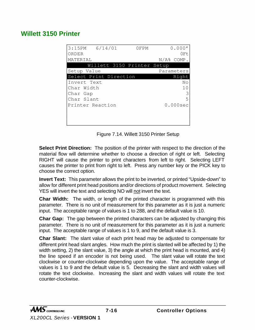
7-16 Controller Options XL200CL Series - VERSION 1
Willett 3150 Printer
Figure 7.14. Willett 3150 Printer Setup
Select Print Direction: The position of the printer with respect to the direction of the material flow will determine whether to choose a direction of right or left. Selecting RIGHT will cause the printer to print characters from left to right. Selecting LEFT causes the printer to print from right to left. Press any number key or the PICK key to choose the correct option.
Invert Text: This parameter allows the print to be inverted, or printed “Upside-down” to allow for different print head positions and/or directions of product movement. Selecting YES will invert the text and selecting NO will not invert the text.
Char Width: The width, or length of the printed character is programmed with this parameter. There is no unit of measurement for this parameter as it is just a numeric input. The acceptable range of values is 1 to 288, and the default value is 10.
Char Gap: The gap between the printed characters can be adjusted by changing this parameter. There is no unit of measurement for this parameter as it is just a numeric input. The acceptable range of values is 1 to 9, and the default value is 3.
Char Slant: The slant value of each print head may be adjusted to compensate for different print head slant angles. How much the print is slanted will be affected by 1) the width setting, 2) the slant value, 3) the angle at which the print head is mounted, and 4) the line speed if an encoder is not being used. The slant value will rotate the text clockwise or counter-clockwise depending upon the value. The acceptable range of values is 1 to 9 and the default value is 5. Decreasing the slant and width values will rotate the text clockwise. Increasing the slant and width values will rotate the text counter-clockwise.
3:15PM 6/14/01 0FPM 0.000” ORDER 0Ft MATERIAL N/A% COMP.
Willett 3150 Printer Setup Setup Value Parameters Select Print Direction Right Invert Text No Char Width 10 Char Gap 3 Char Slant 5 Printer Reaction 0.000sec
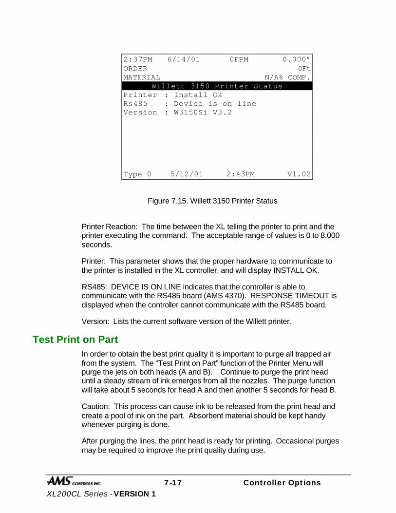
7-17 Controller Options XL200CL Series - VERSION 1
Figure 7.15. Willett 3150 Printer Status
Printer Reaction: The time between the XL telling the printer to print and the printer executing the command. The acceptable range of values is 0 to 8.000 seconds.
Printer: This parameter shows that the proper hardware to communicate to the printer is installed in the XL controller, and will display INSTALL OK.
RS485: DEVICE IS ON LINE indicates that the controller is able to communicate with the RS485 board (AMS 4370). RESPONSE TIMEOUT is displayed when the controller cannot communicate with the RS485 board.
Version: Lists the current software version of the Willett printer.
Test Print on Part In order to obtain the best print quality it is important to purge all trapped air from the system. The “Test Print on Part” function of the Printer Menu will purge the jets on both heads (A and B). Continue to purge the print head until a steady stream of ink emerges from all the nozzles. The purge function will take about 5 seconds for head A and then another 5 seconds for head B.
Caution: This process can cause ink to be released from the print head and create a pool of ink on the part. Absorbent material should be kept handy whenever purging is done.
After purging the lines, the print head is ready for printing. Occasional purges may be required to improve the print quality during use.
2:37PM 6/14/01 0FPM 0.000” ORDER 0Ft MATERIAL N/A% COMP.
Willett 3150 Printer Status Printer : Install Ok Rs485 : Device is on line Version : W3150Si V3.2
Type 0 5/12/01 2:43PM V1.02

7-18 Controller Options XL200CL Series - VERSION 1
Bundle Tag Printer
Citoh T4 Printer
The BUNDLE PRINTER will print a bundle tag that can be attached to the parts when a lift is completed. The setup parameters for the printer will appear in the setup screen. After the printer is selected, other options include viewing the print status or activating a bundle reprint.
When a bundle is completed, its information is held in a buffer and this information can be reprinted at any time until a new bundle is completed. A lift whose bundle information is in the buffer cannot be deleted. The following information can be printed:
Ø Order field
Ø Material field
Ø Coil inventory number
Ø Quantity
Ø Length
Ø Pattern
Ø Bundle # of ___
When a BUNDLE PRINTER is selected, there will be a PRINTER SETUP parameter in the SETUP screen.
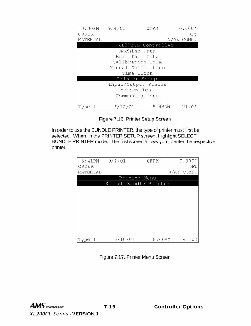
7-19 Controller Options XL200CL Series - VERSION 1
Figure 7.16. Printer Setup Screen
In order to use the BUNDLE PRINTER, the type of printer must first be selected. When in the PRINTER SETUP screen, Highlight SELECT BUNDLE PRINTER mode. The first screen allows you to enter the respective printer.
Figure 7.17. Printer Menu Screen
3:30PM 9/4/01 0FPM 0.000” ORDER 0Ft MATERIAL N/A% COMP. XL202CL Controller
Machine Data Edit Tool Data
Calibration Trim Manual Calibration
Time Clock Printer Setup
Input/Output Status Memory Test
Communications Type 1 6/10/01 8:46AM V1.02
3:41PM 9/4/01 0FPM 0.000” ORDER 0Ft MATERIAL N/A% COMP.
Printer Menu Select Bundle Printer
Type 1 6/10/01 8:46AM V1.02

7-20 Controller Options XL200CL Series - VERSION 1
Figure 7.18. Select Bundle Printer Screen
When the proper printer is selected, the controller returns to the PRINTER SETUP screen. If you reenter this screen you will again enter the PRINT MENU screen with added options of BUNDLE PRINT SETUP, BUNDLE PRINT STATUS and selecting BUNDLE REPRINT.
Figure 7.19. Printer Menu w/ Bundle Status & Reprint
3:46PM 9/4/01 0FPM 0.000” ORDER 0Ft MATERIAL N/A% COMP.
Select Bundle Printer Selected: No Printer
No Printer Citoh T4
Type 1 6/10/01 8:46AM V1.02
3:52PM 9/4/01 0FPM 0.000” ORDER 0Ft MATERIAL N/A% COMP.
Printer Menu Select Bundle Printer Bundle Printer Setup Bundle Printer Status
Bundle RePrint
Type 1 6/10/01 8:46AM V1.02
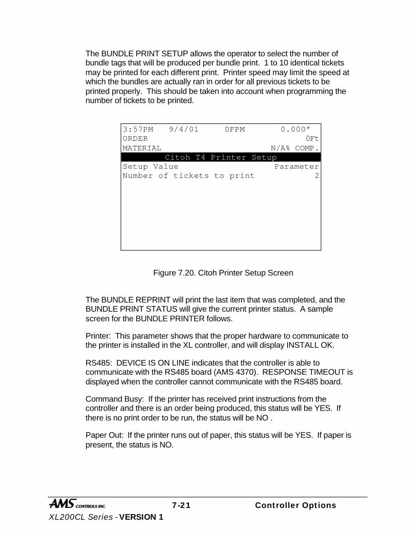
7-21 Controller Options XL200CL Series - VERSION 1
The BUNDLE PRINT SETUP allows the operator to select the number of bundle tags that will be produced per bundle print. 1 to 10 identical tickets may be printed for each different print. Printer speed may limit the speed at which the bundles are actually ran in order for all previous tickets to be printed properly. This should be taken into account when programming the number of tickets to be printed.
Figure 7.20. Citoh Printer Setup Screen
The BUNDLE REPRINT will print the last item that was completed, and the BUNDLE PRINT STATUS will give the current printer status. A sample screen for the BUNDLE PRINTER follows.
Printer: This parameter shows that the proper hardware to communicate to the printer is installed in the XL controller, and will display INSTALL OK.
RS485: DEVICE IS ON LINE indicates that the controller is able to communicate with the RS485 board (AMS 4370). RESPONSE TIMEOUT is displayed when the controller cannot communicate with the RS485 board.
Command Busy: If the printer has received print instructions from the controller and there is an order being produced, this status will be YES. If there is no print order to be run, the status will be NO .
Paper Out: If the printer runs out of paper, this status will be YES. If paper is present, the status is NO.
3:57PM 9/4/01 0FPM 0.000” ORDER 0Ft MATERIAL N/A% COMP.
Citoh T4 Printer Setup Setup Value Parameter Number of tickets to print 2
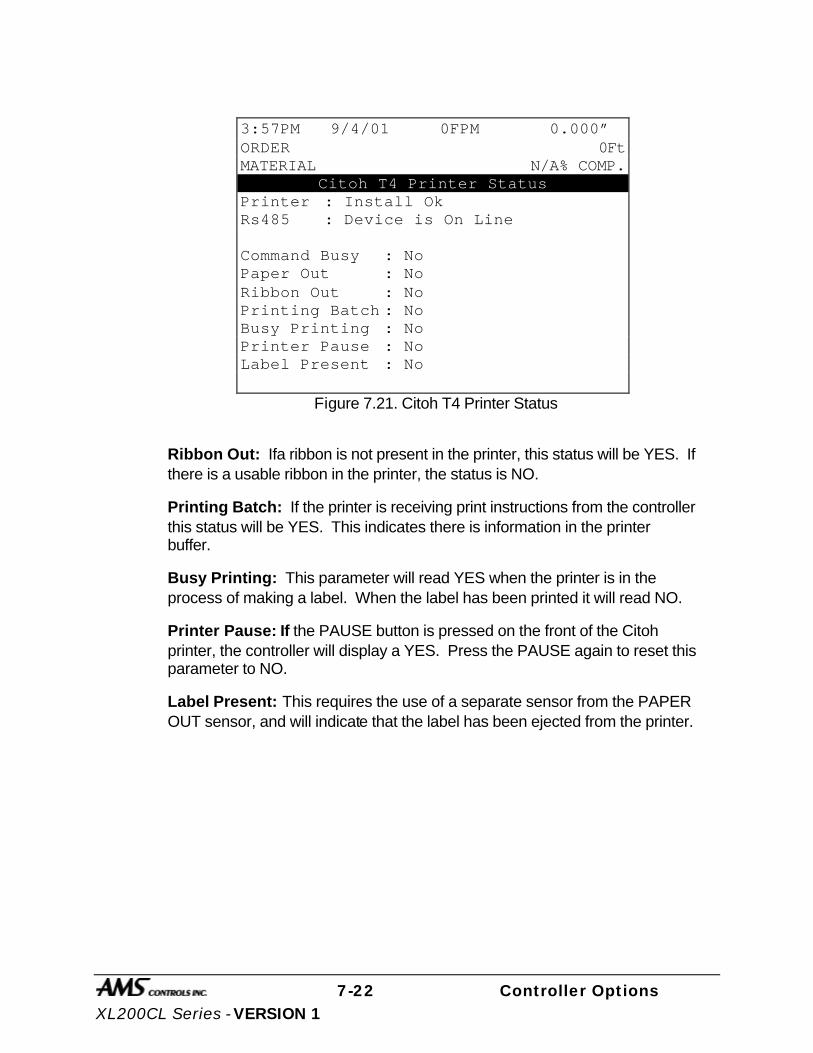
7-22 Controller Options XL200CL Series - VERSION 1
Figure 7.21. Citoh T4 Printer Status
Ribbon Out: Ifa ribbon is not present in the printer, this status will be YES. If there is a usable ribbon in the printer, the status is NO.
Printing Batch: If the printer is receiving print instructions from the controller this status will be YES. This indicates there is information in the printer buffer.
Busy Printing: This parameter will read YES when the printer is in the process of making a label. When the label has been printed it will read NO.
Printer Pause: If the PAUSE button is pressed on the front of the Citoh printer, the controller will display a YES. Press the PAUSE again to reset this parameter to NO.
Label Present: This requires the use of a separate sensor from the PAPER OUT sensor, and will indicate that the label has been ejected from the printer.
3:57PM 9/4/01 0FPM 0.000” ORDER 0Ft MATERIAL N/A% COMP.
Citoh T4 Printer Status Printer : Install Ok Rs485 : Device is On Line Command Busy : No Paper Out : No Ribbon Out : No Printing Batch : No Busy Printing : No Printer Pause : No Label Present : No

7-23 Controller Options XL200CL Series - VERSION 1
CITOH SETUP MODES The following setup modes are explained in detail in the CITOH printer manual.
1. NORMAL OPERATING MODE - Normal operation.
2. PRINTER SETTING MODE - Print mode selection, end-of-ribbon detection, label-peeling sensor actuation and use of auto-cutter are provided.
Press “PAUSE” and “FEED” key simultaneously to enter the printer setting mode. Press “STOP” to exit.
3. SELF - TEST MODE - Performs test printing and then is set to data dump mode.
Press “FEED” key while turning power on. Turn power off to exit.
4. SYSTEM MAINTENANCE MODE - Allows user to set communications and memory switches to a specific value.
Press “PAUSE”, “FEED”, and “STOP” keys while turning power on.
5. Press “STOP” key to exit.
NOTE: The C.ITOH printer works properly with the default parameters listed below:
Baud Rate 9600 bps
Data Length 8 bits
Parity Parity N
Flow Control XON/XOFF
Interface RS232C
Model NativeOF
Voltage Setting PE *.*V
Additional information is also available on custom bundle tag labels. The XL-Link for Windows package is required to produce custom labels.
If the line is halted in the middle of an order, a printing function can be activated with the “F5” (PRINT) key on the front panel.

7-24 Controller Options XL200CL Series - VERSION 1
F5
This will print a tag for the parts that have been completed so far. When RUN is pressed again, the rest of the order will be completed and a BUNDLE TAG will be printed for the remainder of the order, only.

7-25 Controller Options XL200CL Series - VERSION 1
Zebra Z4000 Printer
FEED PAUSE CANCEL
POWER DATA ERROR
ZEBRA
XXXXXXXXXXXXXXXXXXXXXXXXXXXXXXXXXXXXXXXXXXXXXXXXXXXXXXXXXXXXXXXXXXXXXXXXXXXXXXXXXXXXXXXXXXXXX
XXXXXXXXXXXXXXXXXXXXXXXXXXXXXXXXXXXXXXXXXXXXXXXXXXXXXXXXXXXXXX
XXXXXXXXXXXXXXXXXXXXXXXXXXXXXXXXXXXXXXXXXXXXXXXXXXXXXXXXXXXXXX
Z 4000
The BUNDLE PRINTER will print a bundle tag that can be attached to the parts when a lift is completed. The setup parameters for the printer will appear in the setup screen. After the printer is selected, other options include viewing the print status or activating a bundle reprint.
When a bundle is completed, its information is held in a buffer and this information can be reprinted at any time until a new bundle is completed. A lift whose bundle information is in the buffer cannot be deleted. The following information can be printed:
Order field
Material field
Coil inventory number
Quantity
Length
Pattern
Bundle # of ___

7-26 Controller Options XL200CL Series - VERSION 1
When a BUNDLE PRINTER is selected, there will be a PRINTER SETUP parameter in the SETUP screen.
Figure 7.16. Printer Setup Screen
In order to use the BUNDLE PRINTER, the type of printer must first be selected. When the PRINTER SETUP mode is selected, the first screen allows you to enter the SELECT BUNDLE PRINTER mode.
Figure 7.17. Printer Menu Screen
3:30PM 9/23/01 0FPM 0.000” ORDER 0Ft MATERIAL N/A% COMP. XL202CLB Controller
Machine Data Edit Tool Data
Calibration Trim Manual Calibration
Time Clock Printer Setup
Input/Output Status Memory Test
Communications Type 1 6/10/01 8:46AM V1.02
3:41PM 9/23/01 0FPM 0.000” ORDER 0Ft MATERIAL N/A% COMP.
Printer Menu Select Bundle Printer
Type 1 6/10/01 8:46AM V1.02

7-27 Controller Options XL200CL Series - VERSION 1
Figure 7.18. Select Bundle Printer Screen
When the proper printer is selected, the controller returns to the PRINTER SETUP screen. If you reenter this screen you will again enter the PRINT MENU screen with added options of BUNDLE PRINT SETUP, BUNDLE PRINT STATUS, BUNDLE REPRINT and TEST BUNDLE PRINT.
Figure 7.19. Printer Menu with Bundle Status and Reprint
3:46PM 9/23/01 0FPM 0.000” ORDER 0Ft MATERIAL N/A% COMP.
Select Bundle Printer Selected: No Printer
No Printer Citoh T4
Zebra Z4000
Type 1 6/10/01 8:46AM V1.02
3:52PM 7/23/01 0FPM 0.000” ORDER 0Ft MATERIAL N/A% COMP.
Printer Menu Select Bundle Printer Bundle Printer Setup Bundle Printer Status
Bundle RePrint Test Bundle Print
Type 1 6/10/01 8:46AM V1.02

7-28 Controller Options XL200CL Series - VERSION 1
The BUNDLE PRINT SETUP allows the operator to select the number of bundle tags that will be produced per bundle print. 1 to 10 identical tickets may be printed for each different print. Printer speed may limit the speed at which the bundles are actually ran in order for all previous tickets to be printed properly. This should be taken into account when programming the number of tickets to be printed.
Figure 7.20. Z4000 Printer Setup Screen
The BUNDLE REPRINT will print the last item that was completed.
BUNDLE PRINT STATUS will give the current printer status. A sample screen for the BUNDLE PRINTER follows.
Figure 7.21. Z4000 Printer Status
3:57PM 7/23/01 0FPM 0.000” ORDER 0Ft MATERIAL N/A% COMP.
Zebra Z4000 Printer Setup Setup Value Parameter Number of tickets to print 2 Length of Label 6.00”
3:57PM 7/23/01 0FPM 0.000” ORDER 0Ft MATERIAL N/A% COMP.
Zebra Z4000 Printer Status Printer: Install Ok Tx: 72 Rs485 : Device is On Line Rx: 72 Paper Out :N/A Ram Corrupted :N/A Pause Active :N/A Head Up :N/A Buffer Full :N/A Ribbon Out :N/A Partial Format :N/A Printing :N/A Resp: None
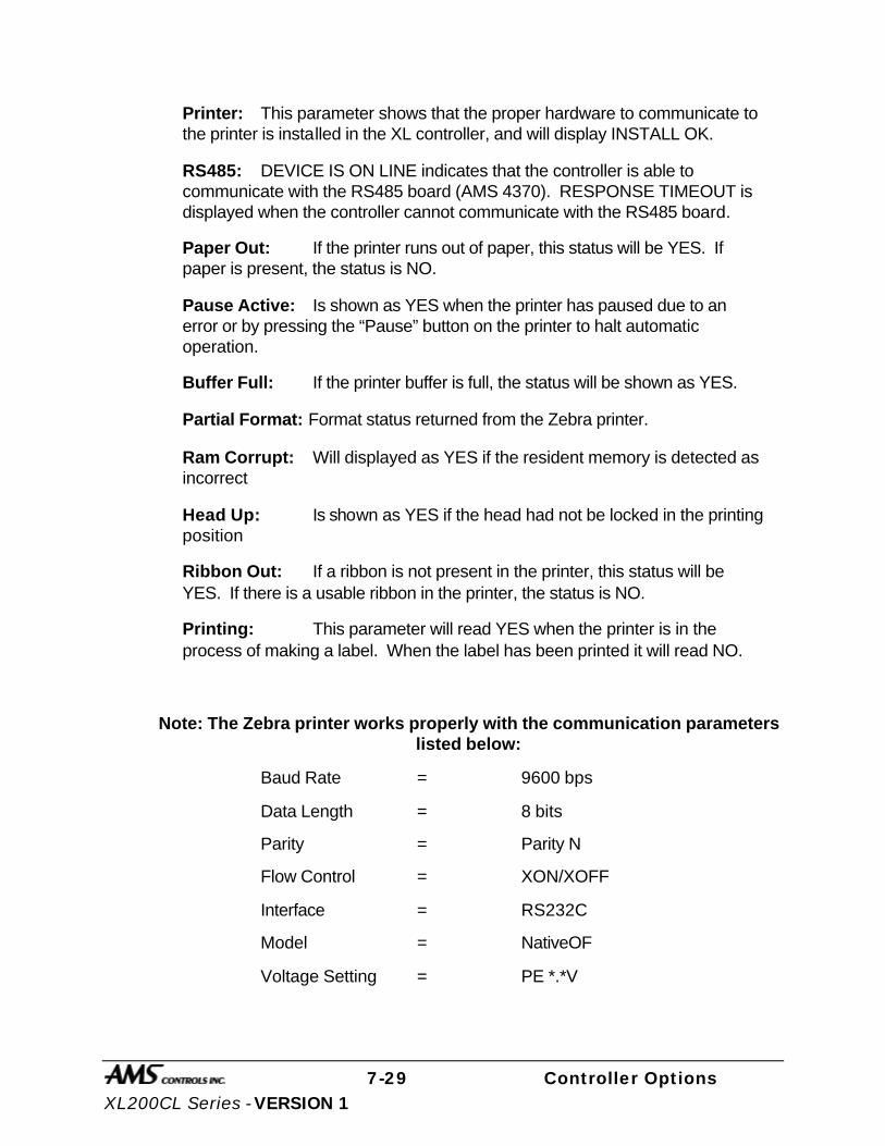
7-29 Controller Options XL200CL Series - VERSION 1
Printer: This parameter shows that the proper hardware to communicate to the printer is installed in the XL controller, and will display INSTALL OK.
RS485: DEVICE IS ON LINE indicates that the controller is able to communicate with the RS485 board (AMS 4370). RESPONSE TIMEOUT is displayed when the controller cannot communicate with the RS485 board.
Paper Out: If the printer runs out of paper, this status will be YES. If paper is present, the status is NO.
Pause Active: Is shown as YES when the printer has paused due to an error or by pressing the “Pause” button on the printer to halt automatic operation.
Buffer Full: If the printer buffer is full, the status will be shown as YES.
Partial Format: Format status returned from the Zebra printer.
Ram Corrupt: Will displayed as YES if the resident memory is detected as incorrect
Head Up: Is shown as YES if the head had not be locked in the printing position
Ribbon Out: If a ribbon is not present in the printer, this status will be YES. If there is a usable ribbon in the printer, the status is NO.
Printing: This parameter will read YES when the printer is in the process of making a label. When the label has been printed it will read NO.
Note: The Zebra printer works properly with the communication parameters listed below:
Baud Rate = 9600 bps
Data Length = 8 bits
Parity = Parity N
Flow Control = XON/XOFF
Interface = RS232C
Model = NativeOF
Voltage Setting = PE *.*V

7-30 Controller Options XL200CL Series - VERSION 1
Additional information is also available on custom bundle tag labels. The XL-Link for Windows package is required to produce custom labels.
If the line is halted in the middle of an order, a printing function can be activated with the “F5” (PRINT) key on the front panel.
F5
This will print a tag for the parts that have been completed so far. When RUN is pressed again, the rest of the order will be completed and a BUNDLE TAG will be printed for the remainder of the order, only.

7-31 Controller Options XL200CL Series - VERSION 1
Expansion Board
To install the EXPANSION BOARD use drawings 4353A, 4357B, and 4425 located in Appendix C.
EXP Hardware To use the expansion option the following equipment is required:
Ø 5 volt, 6 amp power supply
Ø Expansion board EXP-1
Ø Input/output card EXP-IO
Ø Communication cable (open ended for Phoenix- style)
Expansion Board Characteristics The EXP-1 expansion board will be used with up to 16 plug-in modules (typically ODC-5 and/or OAC-5) which are labeled 0-15 on the expansion board. These modules are used for gags 13 through 28. Module 0 would be gag 13 and Module 15 would be gag 28.
The ODC-5 output modules are normally open contacts and are rated to withstand up to 3 amps. The OAC-5 modules are solid-state devices and are rated to withstand up to 1 amp.
Note: OAC-5 is a solid-state device and must be installed properly. Do not connect this module backwards.
Gags are immediately set for the next operation after the previous operation is completed. Gags that are manually fired will be energized 0.5 seconds before the press fires, and held ON until the completion of the cycle.
The expansion board will also include an LED representing each module. When the LED is on, it indicates that the module is receiving a signal to energize. These LEDs can be used to troubleshoot the circuitry if the appropriate gag is not energizing.

7-32 Controller Options XL200CL Series - VERSION 1
The 32 connection terminal strip is connected to the normally open contacts associated with each module. A “power on” indicator light is located next to the terminal strip
Connected to the expansion board is a plug-in input/output (I/O) EXP-IO board. The I/O board will interface the controller to the expansion board. Communication between the EXP-IO board and the AMS controller is with an RS-485 converter and the gag board can be placed up to 4000 feet away from the controller.
Located on the I/O board are two strips labeled “Group A” and “Group B”, which have movable jumpers. The jumpers must be set as specified for the I/O circuitry to work properly (see the enclosed electrical interface diagram for the proper jumper connections).
The I/O board will also have two communication lights labeled “REC” and “XMT” that will flash when there is communication taking place, to and from the XL controller.

7-33 Controller Options XL200CL Series - VERSION 1
Bar Code Scanner
The BARCODE SCANNER system allows a code to be entered with one scan. These codes include:
Scrap codes
Delay codes
Employee numbers
Coil inventory numbers
Using the scanner, specific keystrokes for the AMS controller can also be entered. The following is a list of codes that are used by AMS to create bar codes for use by the BARCODE SCANNER. There are many types of software programs that can be used, but the type that works best is one that uses barcode font code 128. Contact your AMS representative for available barcode programs.

7-34 Controller Options XL200CL Series - VERSION 1
REQUIRED AMS CODE DESIRED KEYSTROKE OR HOT KEY
013 Enter
027 Status
001 064 013 Help
001 065 013 Setup
001 066 013 Program
001 067 013 Footage Totalizer
001 068 013 Next Line
001 069 013 Skip Line
001 070 013 Add Line
001 071 013 Delete Line
001 072 013 Increase Quantity
001 073 013 Decrease Quantity
027 084 End
027 087 Delete
012 Right Arrow
008 Left Arrow
011 Up Arrow
010 Down Arrow
027 074 Page Up
027 075 Page Down
030 Home
001 096 013 XX 013 Enter Delay Reason Hot Key
XX = 2 digit delay code
001 097 013 XXXXXXX 013 Enter Employee # Hot Key
XXXXXXX = 7 digit employee code
001 099 013 XX 013 Scrap Code w/Inc. Qty Hot Key
XX = 2 digit scrap code

7-35 Controller Options XL200CL Series - VERSION 1
001 100 013 XXXXXXXXXXXXXXXX 013Load Coil- Coil Completely Used Hot XXXXXXXXXXXXXXXX= 16 digit coil inventory code Key
001 101 013 XXXXXXXXXXXXXXXX 013Load Coil-Coil Not Completely Used XXXXXXXXXXXXXXXX= 16 digit coil inventory code Hot Key
Each 3-digit number listed above (i.e. 013, 027, 001, 084) represents a single ASCII character
Note: When making the barcodes you must use the format as defined. You should NOT take individual keystrokes and link them together to form a barcode. When AMS makes further software changes it may alter the keystroke sequence, which will invalidate any barcodes made by stringing together keystrokes.

7-36 Controller Options XL200CL Series - VERSION 1
Extended Macro Patterns
Pattern numbers 650 - ZZZ are reserved for creating special patterns, called MACRO PATTERNS, which can be used within another pattern. If a specific sequence of operations is frequently used in numerous parts, it can be turned into a MACRO PATTERN, and the operator need only enter one pattern to represent a number of operations. STANDARD MACRO PATTERNS were discussed in the Operating Procedure section of this manual and used the numbers Z00 - ZZZ for MACRO PATTERNS. The EXTENDED MACRO PATTERN OPTION increases the numbers of available MACRO PATTERNS, and includes Pattern Numbers 650 to ZZZ.
Programming Patterns
Programming patterns, when using MACRO PATTERNS is very similar to non-macro pattern applications. Press the PROGRAM key to enter the Program Mode. Select PROGRAM PATTERNS. Any number (1 - ZZZ) can be used to define a pattern, however, patterns 650 - ZZZ may be inserted into other patterns as MACRO PATTERNS.
Edit Tool Data
Tool data should be entered by the normal procedure in the EDIT TOOL DATA screen. Tool Number zero is reserved for the shear and must always be entered. Each tool is defined by a Tool Number, Press Number, Gag Number, and Offset Distance. The only difference is that tools 650 - ZZZ may not be programmed as a Tool Number. These Tool Numbers are reserved for MACRO PATTERNS and will be programmed later. Defining a Tool Number greater than 649 will result in an error.
Macro Patterns
Enter the first tool to be used in this MACRO PATTERN. You may use any Tool Number that has been defined in the Edit Tool Data mode. You may NOT use Tool Numbers 650 - 999 (a MACRO PATTERN within a MACRO PATTERN). Trying to do so will result in an error.
Enter a Reference location for the tool. Within a MACRO PATTERN, the only valid Reference locations are LEAD CENTER and TRAIL CENTER. Enter a Length (offset from the Reference location) for the tool. This is the same procedure that is used on non-macro pattern applications.
Enter as many tools in the MACRO PATTERN as required. When finished, press the PROGRAM key to enter more patterns or press the STATUS key to return to the Status mode. This pattern may now be run as a standard pattern or inserted into a standard pattern as a MACRO PATTERN.
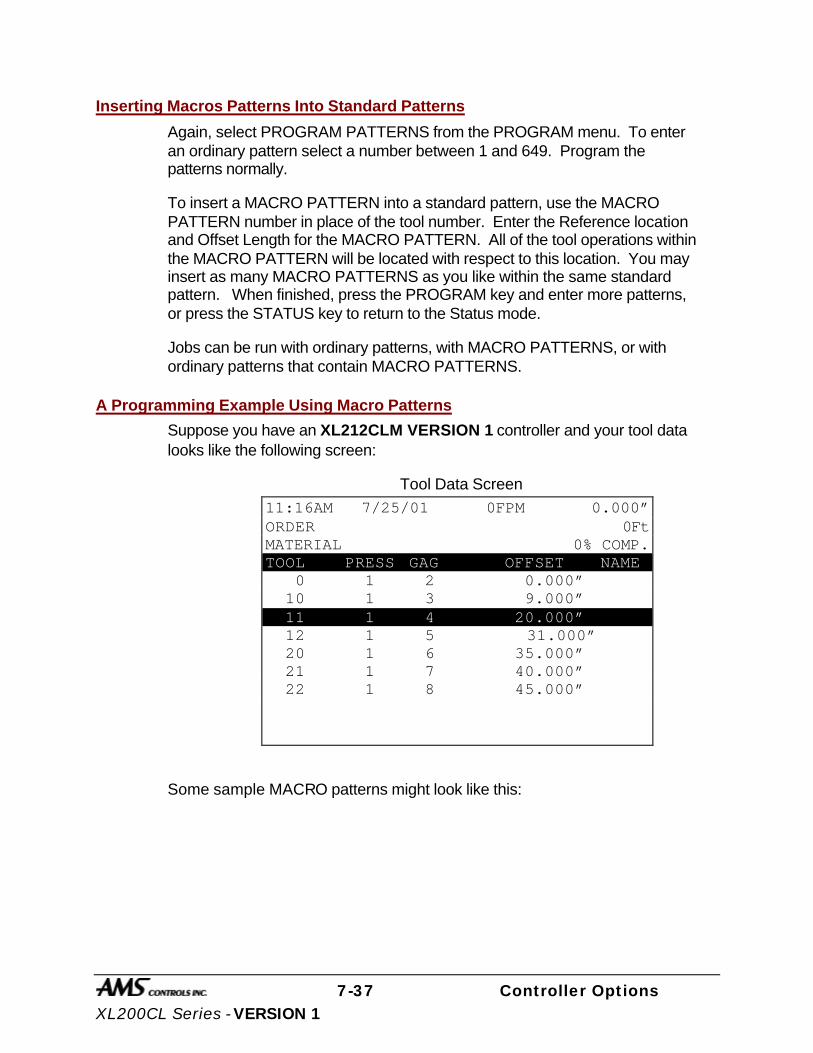
7-37 Controller Options XL200CL Series - VERSION 1
Inserting Macros Patterns Into Standard Patterns
Again, select PROGRAM PATTERNS from the PROGRAM menu. To enter an ordinary pattern select a number between 1 and 649. Program the patterns normally.
To insert a MACRO PATTERN into a standard pattern, use the MACRO PATTERN number in place of the tool number. Enter the Reference location and Offset Length for the MACRO PATTERN. All of the tool operations within the MACRO PATTERN will be located with respect to this location. You may insert as many MACRO PATTERNS as you like within the same standard pattern. When finished, press the PROGRAM key and enter more patterns, or press the STATUS key to return to the Status mode.
Jobs can be run with ordinary patterns, with MACRO PATTERNS, or with ordinary patterns that contain MACRO PATTERNS.
A Programming Example Using Macro Patterns
Suppose you have an XL212CLM VERSION 1 controller and your tool data looks like the following screen:
Tool Data Screen
Some sample MACRO patterns might look like this:
11:16AM 7/25/01 0FPM 0.000” ORDER 0Ft MATERIAL 0% COMP. TOOL PRESS GAG OFFSET NAME 0 1 2 0.000” 10 1 3 9.000” 11 1 4 20.000” 12 1 5 31.000” 20 1 6 35.000” 21 1 7 40.000” 22 1 8 45.000”

7-38 Controller Options XL200CL Series - VERSION 1
Pattern 975
Pattern 976
11:23AM 7/25/01 0FPM 0.000” ORDER 0Ft MATERIAL N/A% COMP. PATTERN: 975 TOOL REFERENCE LENGTH 10 Trail Center 1.000” 11 Trail Center 3.000” 12 Trail Center 5.000”
11:29AM 7/25/01 0FPM 0.000” ORDER 0Ft MATERIAL N/A% COMP. PATTERN: 976 TOOL REFERENCE LENGTH 20 Lead Center 5.000” 21 Lead Center 0.000” 22 Trail Center 5.000”
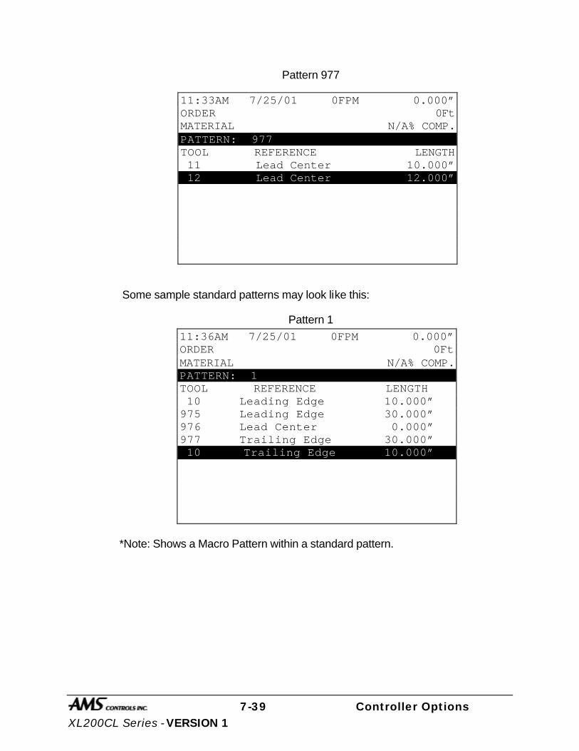
7-39 Controller Options XL200CL Series - VERSION 1
Pattern 977
Some sample standard patterns may look like this:
Pattern 1
*Note: Shows a Macro Pattern within a standard pattern.
11:33AM 7/25/01 0FPM 0.000” ORDER 0Ft MATERIAL N/A% COMP. PATTERN: 977 TOOL REFERENCE LENGTH 11 Lead Center 10.000” 12 Lead Center 12.000”
11:36AM 7/25/01 0FPM 0.000” ORDER 0Ft MATERIAL N/A% COMP. PATTERN: 1 TOOL REFERENCE LENGTH 10 Leading Edge 10.000” 975 Leading Edge 30.000” 976 Lead Center 0.000” 977 Trailing Edge 30.000” 10 Trailing Edge 10.000”

7-40 Controller Options XL200CL Series - VERSION 1
Pattern 2
Now jobs may be run with Pattern 1 or Pattern 2, which contain MACROS 975 and 976, or jobs may be programmed to make parts that only have Patterns 975 or 976.
Example:
11:42AM 7/25/01 0FPM 0.000” ORDER 0Ft MATERIAL N/A% COMP. PATTERN: 2 TOOL REFERENCE LENGTH 976 Leading Edge 20.000” 976 Even Space 25.000” 976 Spacing Limit 15.000”
11:48AM 7/25/01 0FPM 0.000” ORDER: 12-34 0Ft. MATERIAL: N/A% COMP. 12-34 LF QTY LENGTH PAT O STATUS 1 100 120.000” 1 R Next 1 100 80.000” 2 R Ready 2 500 60.600” 976 R Ready
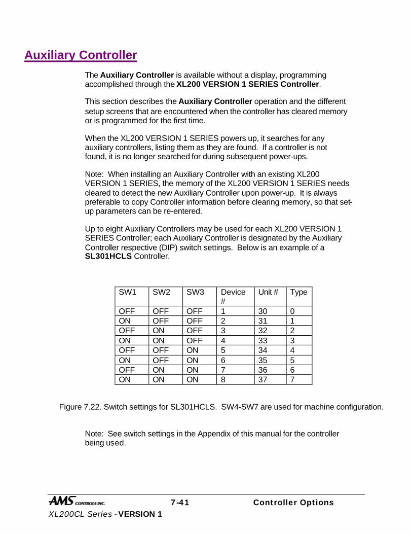
7-41 Controller Options XL200CL Series - VERSION 1
Auxiliary Controller
The Auxiliary Controller is available without a display, programming accomplished through the XL200 VERSION 1 SERIES Controller.
This section describes the Auxiliary Controller operation and the different setup screens that are encountered when the controller has cleared memory or is programmed for the first time.
When the XL200 VERSION 1 SERIES powers up, it searches for any auxiliary controllers, listing them as they are found. If a controller is not found, it is no longer searched for during subsequent power-ups.
Note: When installing an Auxiliary Controller with an existing XL200 VERSION 1 SERIES, the memory of the XL200 VERSION 1 SERIES needs cleared to detect the new Auxiliary Controller upon power-up. It is always preferable to copy Controller information before clearing memory, so that set-up parameters can be re-entered.
Up to eight Auxiliary Controllers may be used for each XL200 VERSION 1 SERIES Controller; each Auxiliary Controller is designated by the Auxiliary Controller respective (DIP) switch settings. Below is an example of a SL301HCLS Controller.
SW1 SW2 SW3 Device #
Unit # Type
OFF OFF OFF 1 30 0 ON OFF OFF 2 31 1 OFF ON OFF 3 32 2 ON ON OFF 4 33 3 OFF OFF ON 5 34 4 ON OFF ON 6 35 5 OFF ON ON 7 36 6 ON ON ON 8 37 7
Figure 7.22. Switch settings for SL301HCLS. SW4-SW7 are used for machine configuration.
Note: See switch settings in the Appendix of this manual for the controller being used.

7-42 Controller Options XL200CL Series - VERSION 1
Installation Installing the Auxiliary Controller on a machine involves the following steps:
Ø Mechanical Installation
Ø Electric wiring
Ø Setting the customizing switch (DIP Switch)
Ø Programming the setup data
Ø Stabilizing the Loop
Ø Calibration
Mechanical Installation The typical installation of the Auxiliary Controller is inside a console or rack. No display or keypad is used on the controller itself.
Electrical Installation Installing the Auxiliary Controller requires knowledge of electric control circuits and of the machine that the controller is connected to. An accurate wiring diagram is essential for trouble-free installation. If none is available, it is valuable to trace wiring in the machine and reconstruct the wiring diagram. The time spent shall be saved when troubleshooting, installing and solving machine problems.
Controller Power The Auxiliary Controller is powered by 24 VDC. Power should be within plus or minus 5% and not interrupted by the emergency stop circuit, see figure 2. The controller can continue to monitor the material position after an emergency stop with power still applied and will continue production after an emergency stop, without loss of accuracy.
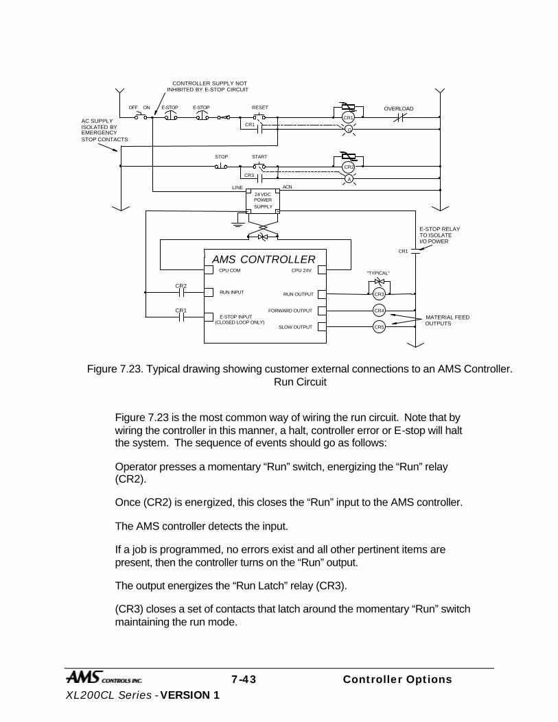
7-43 Controller Options XL200CL Series - VERSION 1
CR1
+-
OFF ON
CR1
CR1
RESET
STOP START
CR2
CR3
24 VDCPOWER
SUPPLY
E-STOPE-STOP
G
A
LINE ACN
"TYPICAL"
RUN OUTPUTRUN INPUT
E-STOP INPUT(CLOSED LOOP ONLY)
AMS CONTROLLER
CONTROLLER SUPPLY NOTINHIBITED BY E-STOP CIRCUIT
OVERLOAD
AC SUPPLYISOLATED BY
STOP CONTACTSEMERGENCY
E-STOP RELAYTO ISOLATEI/O POWER
CR2
CR1
CR3
FORWARD OUTPUT
SLOW OUTPUT
CR4
CR5
MATERIAL FEEDOUTPUTS
CPU COM CPU 24V
Figure 7.23. Typical drawing showing customer external connections to an AMS Controller.
Run Circuit
Figure 7.23 is the most common way of wiring the run circuit. Note that by wiring the controller in this manner, a halt, controller error or E-stop will halt the system. The sequence of events should go as follows:
Operator presses a momentary “Run” switch, energizing the “Run” relay (CR2).
Once (CR2) is energized, this closes the “Run” input to the AMS controller.
The AMS controller detects the input.
If a job is programmed, no errors exist and all other pertinent items are present, then the controller turns on the “Run” output.
The output energizes the “Run Latch” relay (CR3).
(CR3) closes a set of contacts that latch around the momentary “Run” switch maintaining the run mode.

7-44 Controller Options XL200CL Series - VERSION 1
The Run output can also energize lights, buzzers or other safety devices to let personnel know that the machine is in the automatic mode.
Controllers used for Single-speed, non-stopping lines will contain a parameter called “Line Movement”. The default value of “FWD/FST” will operate the controller as just described. If “Run” is selected, the Run output will turn on and off with the Forward and Fast outputs. The “Delay After Shear” parameter will be disabled if “Run” is selected.
Caution should be used during operation of the controller! The press(es) may continue to fire on targets while the material is decelerating to a stop after the line is halted and the Run output has turned off!
A Closed-loop system uses Forward-Slow speed logic when the outputs are available. The chart in Table 3 will show the output logic for different conditions. These outputs can be used with different motion devices to control the line.
Machine State
Output Run Fast Run Slow Jog Fwd Halt Jog Rev Forward ON ON ON OFF OFF Slow OFF ON ON ON ON Reverse OFF OFF OFF OFF ON Run ON ON OFF OFF OFF
Table 3. Status of outputs in Forward-Slow
Emergency Stop Circuit An emergency stop circuit is required for each machine, giving operator safety and protection of system equipment. A typical emergency stop circuit is shown in Figure 2. Pressing a guarded push-button RESET switch arms this circuit. The relay remains energized after the RESET switch opens because of the hold-in contacts of the relay. The relay condition depends on current flow through the normally closed emergency stop switches and any other emergency stop contacts in series. A momentary opening of either switch or contact will cause the relay to de-energize which cuts off power to all load devices. Adding devices in series with the emergency stop contacts or switches easily expands the circuit.
A higher degree of safety can be achieved by placing switches behind safety guards and in doors of electric panels. These are wired in the Emergency Stop Circuit, so when opened, the machine is shut down.

7-45 Controller Options XL200CL Series - VERSION 1
The emergency stop circuit should never interrupt power to the Auxiliary Controller. However, the Controller must know when an emergency stop has occurred in order to disable the RUN mode. An E-Stop input to the Control will perform this function. In Figure 2 an unused contact of the reset relay is connected. When this contact opens, the Controller will go into an emergency stop condition, disabling the run function.
Shear Control Circuit Optimal performance of the shear circuit is met when customizing the AMS controller for the type of press and feed control used. This is accomplished by the appropriate selection of switch settings. These switches are in a single switch package located on the back of the controller. Through proper selection, the Control can be configured for flying-cut or feed-to-stop machines. The Controller will supply SHEAR DOWN, along with SHEAR UP and SHEAR DIE BOOST functions when selected for varying applications.
AMS controllers are designed to connect directly to 24 VDC solenoids for optimal performance. A solenoid-driving device, such as the AMS 3840 power module, can provide greater accuracy when firing presses.
AMS controllers have a timed shear output with a switch input (PRESS COMPLETE) override feature. The duration of the SHEAR DWELL UP or SHEAR DWELL DOWN output is programmable from 0.000 to 9.999 seconds. Please refer to timing diagram, Figure 4. If the AMS controller detects a SHEAR COMPLETE switch closure during the dwell down time, the shear output will turn off immediately, Figure 5. This is especially useful on mechanical presses that need the shear-complete switch mounted in a location that will return the press to top-dead-center. The SHEAR DWELL UP time will time out as programmed regardless of the complete input.
SHEAR DWELL DOWN OUTPUT
SHEAR DWELL UP OUTPUT
.125 SEC.
.125 SEC.
Die Hits Metal
Figure 7.24

7-46 Controller Options XL200CL Series - VERSION 1
SHEAR DWELLDOWN OUTPUT
SHEAR DWELLUP OUTPUT
.125 SEC.
INPUTSHEAR COMPLETE
.0625SEC.
Die Hits Metal
Figure 7.25
Drive Control Circuit The Auxiliary Controller has two ways of controlling the servo drive device. The ANALOG OUTPUT is connected to the speed reference input of the servo drive and is a 0-10 VDC analog signal. The DRIVE ENABLE output of the controller connects to the enable circuit of the servo drive. This circuit switches common, an open causing a complete shutdown of the drive. When used, the DRIVE ENABLE should completely de-energize the motor. In a hydraulic servo system, the output should turn the hydraulic system completely off.
Run Mode Control Circuit The machine is placed in the RUN mode by closing the RUN input. If a valid job is programmed, the Auxiliary Controller will turn the RUN output on. This seals the contact across the RUN switch, the machine remaining in RUN until a batch halt occurs or the HALT switch is pressed. See drawing, Figure 2
Setting the Customizing Switches
When installing the Auxiliary Controller, the customizing switches must be set before initial power is applied. These switches are found by removing the cover of the controller. The switches are located near the center of the printed circuit board in a single (DIP) switch package. There are seven switch segments in the package numbered 1 through 7. The switches are changed to either ON or OFF to match machine requirements. See the drawings at the end of this section for proper switch settings for the Controller used.

7-47 Controller Options XL200CL Series - VERSION 1
Initial Power Test
Before plugging external connectors into the controller, check for proper voltage and voltage polarity. This is accomplished by monitoring the voltage on the connector that supplies the plus 24 VDC and common. See the respective drawing of the Controller for proper terminal connection to be tested.
Configuration Programming
In addition to setting customizing switches, the user can further customize the Auxiliary Controller to the machine by programming parameters in the Configuration mode. The Configuration mode has a list of parameters that are customer selected. The parameters are selected after changing the customizing switches, since the Auxiliary Controller erases all memory, setting the Configuration mode back to the factory default settings after a switch change.
Some of these parameters are general and apply to all switch settings and Auxiliary Controllers; others apply only to certain controllers and switch settings. In this section, all parameters will be defined and discussed.
General Parameters
Press (SHEAR) Dwell Down
PRESS (SHEAR) DWELL DOWN is the time it takes for the shear to move from the top of the stroke to the bottom of the stroke. The allowable range is 0.000 to 9.999 seconds and can be set to the nearest millisecond. If a COMPLETE switch is used, the PRESS (SHEAR) DWELL is set to a time somewhat longer than the expected time for the COMPLETE switch to turn on. When the SHEAR COMPLETE switch closes, the PRESS (SHEAR) DWELL time is overridden and the output turns off immediately.
Press Dwell Up
PRESS (SHEAR) DWELL UP is the time necessary for the shear to return from the bottom to the top of its stroke.
Note: To ensure that a feed-to stop line is not restarted until the press complete switch has closed, it is now possible to enter a PRESS DWELL time of zero. With zero entered, the controller will interpret this as “do not restart the line until the complete switch closes.” If the complete input is not made within 10 seconds, then the line is halted. A non-stop line with a PRESS DWELL of zero will run normally as long as the press complete is activated after a press cycle. If the press complete is not activated, the machine will continue to run for ten seconds, halt automatically and display an error.

7-48 Controller Options XL200CL Series - VERSION 1
A programmed time greater than zero is treated as it has been in the past, it will give a timed output according to the PRESS DWELL TIME or turn on until a PRESS COMPLETE is seen, whichever comes first. If any value other than zero is entered, this feature is disabled.
Press Reaction Time
The PRESS (SHEAR) REACTION time is used in high-speed flying die applications to reduce the overall stroke length of the cut cycle. Without a reaction time, the Auxiliary Controller waits until the die has moved to the MINIMUM DIE DISTANCE before the Shear Output is turned on.
The PRESS (SHEAR) REACTION time causes the controller to turn the Shear Output on early. This allows time for relays to activate and solenoid valves to energize. The tolerance test is performed at the end of the Shear Dwell Down signal (after the part has been cut). A SHEAR REACTION of 0.0 to 0.5 seconds is allowed, but the user should note that the Shear Output is not turned on before the die has started its acceleration ramp.
Also note that the PRESS (SHEAR) REACTION time is only in effect when the parameter ON TOLERANCE ERROR is set to “Cut & Stop”.
Refresh Done Job (SL350HCLR ONLY!)
This Parameter can be ignored and is only applicable in non-auxiliary applications.
Batching (SL350HCLR ONLY!)
This Parameter can be ignored and is only applicable in non-auxiliary applications.
Mode (SL350HCLR ONLY!)
This parameter is used to select between modes of the controller. The two options are Count Hole and Standard. This parameter must be set to Count Hole to operate normally as an auxiliary controller.
Press-Detect (Shear-Detect on SL350HCLR)
The press to detect distance is the physical distance between the shear press and the hole detector. The hole detector should be located as close to the shear press as possible for accuracy. However, the detector must have enough distance (typically 10" or more) to allow the controller time to see the hole and activate the shear press. Units for PRESS-DETECT are in inches or millimeters.
7-49 Controller Options XL200CL Series - VERSION 1
Minimum Hole Spacing
For Minimum Hole Spacing, enter a value slightly smaller than the minimum distance between holes in the material. When the Auxiliary Controller detects a hole in the run mode, the material must move the MINIMUM HOLE SPACING distance forward before another hole can be detected. This prevents the controller from accidentally reading twice on the leading and trailing edge of the same hole. Units for MINIMUM HOLE SPACING are in inches or millimeters.
No-Hole Stop
This parameter defines the maximum length of material past the shear without the proper holes made, in making the current part. Operators may use this parameter to protect machinery in the case of a photo-detector failure. The Auxiliary Controller will halt the line and display an error message if the “Length Past Shear” +” Shear To Detector Distance” is greater than “No-Hole Stop Distance”.
This function is disabled if No-Hole Stop equals zero inches or the operator chooses the standard operating mode.
Minimum Part (SL350HCLR ONLY!)
This parameter can be ignored and is only applicable in non-auxiliary applications.
Loop Gain
LOOP GAIN sets the sensitivity of the servo loop (electronic drive). Lowering this number will make the drive less responsive. If it is too low, the system will become sluggish. Raising this number makes the system more sensitive and responsive. If the LOOP GAIN is too high, the system will become unstable and oscillate. Great care should be used in changing this number. Make gradual changes.
Jog Die Velocity
The JOG DIE VELOCITY sets the speed during die jog operations and also for referencing.
Max Die Velocity
MAX DIE VELOCITY sets the maximum return speed of the die.
Acceleration
ACCELERATION sets the rate of velocity change for die travel. This parameter controls both the acceleration and deceleration of the forward travel for Die Accelerators.
7-50 Controller Options XL200CL Series - VERSION 1
Return Accel
RETURN ACCELERATION sets the acceleration for the flying die to return home after the cut is made. This parameter typically is set higher than the forward ACCELERATION, since the die return is not a critical movement. This decreases the overall cycle time of each cut. The RETURN ACCELERATION is also adjustable to a lower value. This results in less wear and tear on the actuating system. Units are expressed in inches per second, per second (Inches/second2).
Min Die Dist
The MINIMUM DIE DISTANCE defines the shortest distance from the home position where a cut can be made. With most presses, improper cutting will occur if the die is not near the center of the press, or if it is not up to the full line speed. The MINIMUM DIE DISTANCE defines one side of this acceptable window. As the die accelerates for a cut, the die must be past this MINIMUM DIE DISTANCE and in tolerance (if a “no cut” mode is selected), before a cut can be made. This is also the place that all manual referencing occur.
Note: The minimum Die Distance must meet the following criteria.
Minimum Die Distance = Velocity squared divided by 2 times acceleration, this value plus 11 percent.
(Velocity * Velocity) /(2 * Acceleration)+11%
In the formula, Velocity is the expected speed of the line expressed in inches per second (not feet per second), and Acceleration is the programmed parameter in the controller expressed in inches / second 2.
The formula will produce a MINIMUM DIE DISTANCE that will allow the die to achieve a stable speed prior to cutting.
Max Die Dist
The MAXIMUM DIE DISTANCE defines the furthest distance from the home position that a shear can occur. This defines the other side of the acceptable window within the press. If the die reaches the MAXIMUM DIE DISTANCE and is not within tolerance, an error will occur. When the machine is operated in a “no cut” mode and the tolerance is not obtained, no cut will be made. If the tolerance is obtained at the MAXIMUM DIE DISTANCE, the cut will be made. Because of this, the MAXIMUM DIE DISTANCE needs adjusted so that enough travel is left over to complete the cycle.
7-51 Controller Options XL200CL Series - VERSION 1
Advance After Cut
ADVANCE AFTER CUT is the distance on a non-stop line that the die will advance after the shear down and during the shear up. The purpose of this parameter is to prevent the shear blade from scraping against the leading edge of the metal as the shear moves up.
On Tolerance Error
When a tolerance error occurs, some roll form manufacturers would prefer that the controller cut an incorrect part, instead of producing a large amount of material past the shear. This is especially true if the material past the shear is not easily reversed. In some cases it is preferred that the line is stopped, with the operator inspecting the part to determine if it is usable. On the other hand, other users may be concerned with a possible speed mismatch if a cut is made on the error.
When the controller detects that a part is about to be made outside of the specified tolerance range, the operator has two options:
If STOP NO CUT is selected, the controller will display an error message and stop the line without making the cut.
If CUT & STOP is selected, the controller will make the cut, then stop the line and display an error message.
Auto Crop - After the Manual Shear button is pressed the controller is in the Auto Crop mode. The display will flash “Auto-Crop”. When the RUN mode is entered, the machine will then make a flying crop at the MINIMUM DIE DISTANCE.
Tolerance
TOLERANCE defines the acceptable band of length variation that a user will accept and defines both the upper and lower limits. For a TOLERANCE of 0.01 inch the allowable range of variation would be ± 0.01 inch. If the controller is unable to achieve a length within this band, an error occurs and the machine is stopped.
Offset Auto
The OFFSET AUTO is the voltage required to hold the feed rolls at stop, with no drift in either direction. This parameter is automatically adjusted by the AMS controller, and can be adjusted by the customer. Customer adjustment is done if the initial value is grossly off, and the time to automatically correct the error would be excessive. The more common usage of this parameter is for monitoring the amount of offset, and making external balance adjustments
7-52 Controller Options XL200CL Series - VERSION 1
to the drive. This parameter should be as close to zero as possible giving the controller the maximum control range.
Offset Integral
The OFFSET INTEGRAL defines the integral time constant for the removal of position error (DRIFT), when the closed loop servo system attempts to hold the die/feed rolls in a locked position. An OFFSET INTEGRAL time constant of 100 seconds is recommended and is the default value
Lag Auto
LAG AUTO (COMPENSATION) is an integral used to correct for conditions where the speed is matched, but the position lags behind the target. This parameter is automatically adjusted and is not normally changed by the user. If this value becomes unstable, there may be a problem in the system.
Lag Integral
A Die Accelerator parameter, the LAG INTEGRAL defines the integral time constant for the removal of velocity error (LAG), when tracking a moving target.
Derivative
This parameter is used in special application loop control systems. On systems that use hydraulics or have a lot of inertia, it is possible that the systems have a slow response time. If this is the case, entering a DERIVATIVE value can increase the response. The sluggish response of the machine will result in an error, and the purpose of the DERIVATIVE is to anticipate the rate of change in the error, and amplify the rate of change to improve performance.
If it is determined that this parameter is to be used, start with a value of 10 seconds (or less), and then decrease the value until a change in pitch or “hum” is heard in the motor. This indicates that the controller is overcorrecting the error. When this occurs, increase the value until the system stops oscillating.
CAUTION:
Changing this value will amplify any noise in the system, as well as the error. This can cause problems in the system. The parameter may also increase the tolerance of the system, which could cause variation errors. Entering zero for the DERIVATIVE will disable the parameter.
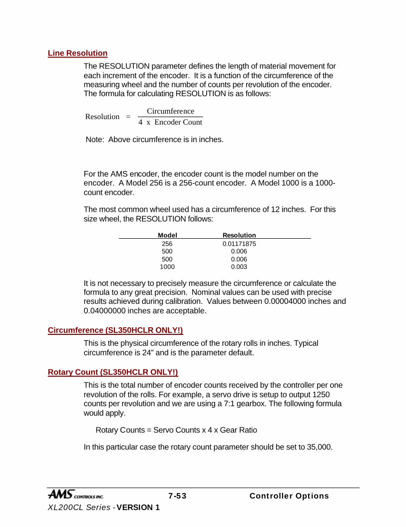
7-53 Controller Options XL200CL Series - VERSION 1
Line Resolution
The RESOLUTION parameter defines the length of material movement for each increment of the encoder. It is a function of the circumference of the measuring wheel and the number of counts per revolution of the encoder. The formula for calculating RESOLUTION is as follows:
Resolution = Circumference
4 x Encoder Count
Note: Above circumference is in inches.
For the AMS encoder, the encoder count is the model number on the encoder. A Model 256 is a 256-count encoder. A Model 1000 is a 1000-count encoder.
The most common wheel used has a circumference of 12 inches. For this size wheel, the RESOLUTION follows:
Model Resolution 256 0.01171875 500 0.006 500 0.006 1000 0.003
It is not necessary to precisely measure the circumference or calculate the formula to any great precision. Nominal values can be used with precise results achieved during calibration. Values between 0.00004000 inches and 0.04000000 inches are acceptable.
Circumference (SL350HCLR ONLY!)
This is the physical circumference of the rotary rolls in inches. Typical circumference is 24” and is the parameter default.
Rotary Count (SL350HCLR ONLY!)
This is the total number of encoder counts received by the controller per one revolution of the rolls. For example, a servo drive is setup to output 1250 counts per revolution and we are using a 7:1 gearbox. The following formula would apply.
Rotary Counts = Servo Counts x 4 x Gear Ratio
In this particular case the rotary count parameter should be set to 35,000.
7-54 Controller Options XL200CL Series - VERSION 1
Rotary Start (SL350HCLR ONLY!)
This parameter is used to inform the controller at what position or angle the Rotary die must be at line speed to enter the material. This parameter is expressed in Degrees and defaults to 135. If this number is too small the controller will error with a Drive Not Responding message, indicating that not enough time was allowed to accelerate to line speed. If this number is too large the die will enter the material before line speed was matched and cause material jam ups. It is recommended that the default number be used.
Rotary Stop (SL350HCLR ONLY!)
This parameter is used to inform the controller at what position or angle the die is no longer in the material. This parameter is expressed in degrees and defaults to 225. The default parameter is recommended.
Die Resolution
DIE RESOLUTION defines the value of one count from the die encoder as reflected in the movement of the die.
Correction Factor
The CORRECTION FACTOR adjusts for errors in the size and tracking of the measuring wheel. It is expressed as a percentage, with 100% being no correction. Increasing the CORRECTION FACTOR causes the parts to become longer and decreasing the value will shorten the parts.
The best way to calibrate the system is to run 10 parts, carefully measure them, and calculate an average length. The new CORRECTION FACTOR is calculated as follows:
New Correction =Old Correction x Programmed length
Average Measured Length
Filter Constant
The FILTER CONSTANT can be adjusted to improve accuracy. A low value is used on machines with very stable line speeds. A high value (greater than 50 Hz) is used when rapid fluctuations in line speeds occur. Some trial may be necessary to achieve an accurate value.
The default value is 32 Hz, which is considered to be the higher of the low side values. The controller will allow values from 1.0 Hz to 200.0 Hz.

7-55 Controller Options XL200CL Series - VERSION 1
Units
Length measurements can be programmed and displayed as either inches or millimeters. The parameter is selectable between either ENGLISH for inches or METRIC for mm and cm. The ENGLISH parameter will also measure in feet and feet/minute while the METRIC parameters will also measure in meters and meters/second. Press any number key to toggle through the choices, and then press ENTER to record your selection
Jog Select
The default is LINE with the selection of LINE or DIE. LINE will enable a line jog except when the controller is in the Die Jog screen. DIE mode will enable jog of the die at all times. This parameter is displayed only in the non-stopping mode.
Minimum Velocity
This is the minimum die return speed. The default is 10.0 FPM with a range of 10 to 500 FPM. This parameter is only displayed in the non-stopping mode.
Shear Dead Band
Shear Dead Band provides a programmable delay between turning off the Shear Down output and turning on the Shear Up output. Delay occurs anytime the shear is fired, including run, test and normal modes. Default is 0.000, which disables the feature. The adjust range is 0.000 to 9.999 seconds. Delay will occur during both stopping and flying-cut modes of operation.
Print On Coil Changes
This is a parameter for Citoh bundle ticket printers. A value of YES will print a bundle ticket for every coil change. A NO will not print a bundle ticket for a coil change.
Manual Shear Die Distance
Defines the location that all manual shear operations will occur. The default is 0.000 “ with the adjust range between 0.000 “ to 350.000 “. The Setup Lockout on the Control locks out this parameter.
Hole Detect
The two selections are ACTIVE LOW and ACTIVE HIGH. LOW is the default. In LOW, the encoder interrupts look to see if the input from the Omron or Banner hole detect switches are on (LOW) to initiate a hole count. For ACTIVE HIGH, the encoder interrupts look to see if the input is off (HIGH) to initiate the hole count.

7-56 Controller Options XL200CL Series - VERSION 1
Line movement
Used to select either “FWD/FST” or “RUN”. In the Default mode “FWD/FST”, the Run Output will initiate before any tasks are started and will stay on until all press tasks have stopped. “RUN” will initiate the Run output when the Fast or Forward output is on for the first time and will stay on until the Fast or Forward output is turned off for the last time. This mode is only active for single speed, open loop, and non-stopping lines. In this mode the delay after shear will not work.
Editing the Auxiliary Controller Parameters The XL200 VERSION 1 SERIES controller should first be configured with its initial setup parameters (figure 7.26), as discussed in Chapter 2 of this manual. The Auxiliary Controllers can then be programmed through the auxiliary screens.
Figure 7.26. Machine Data Screen
To exit the initial setup mode press the SETUP key
10:59AM 9/05/01 0FPM 0.000” ORDER 0Ft MATERIAL N/A COMP. Parameters Setup Value Halt Mode Bundle Halt Format Decimal Inch Set Done Items to Ready? No Auto-Delete Done Orders 14 Days Use Order Numbers? Yes Shear Dwell Dn 1.000sec Shear Boost Dwell 0.000sec Die Boost Comp 0.0000” Shear Kerf 0.0000” Minimum Part 30.0000” Type 17 9/1/01 1:52PM V1.02
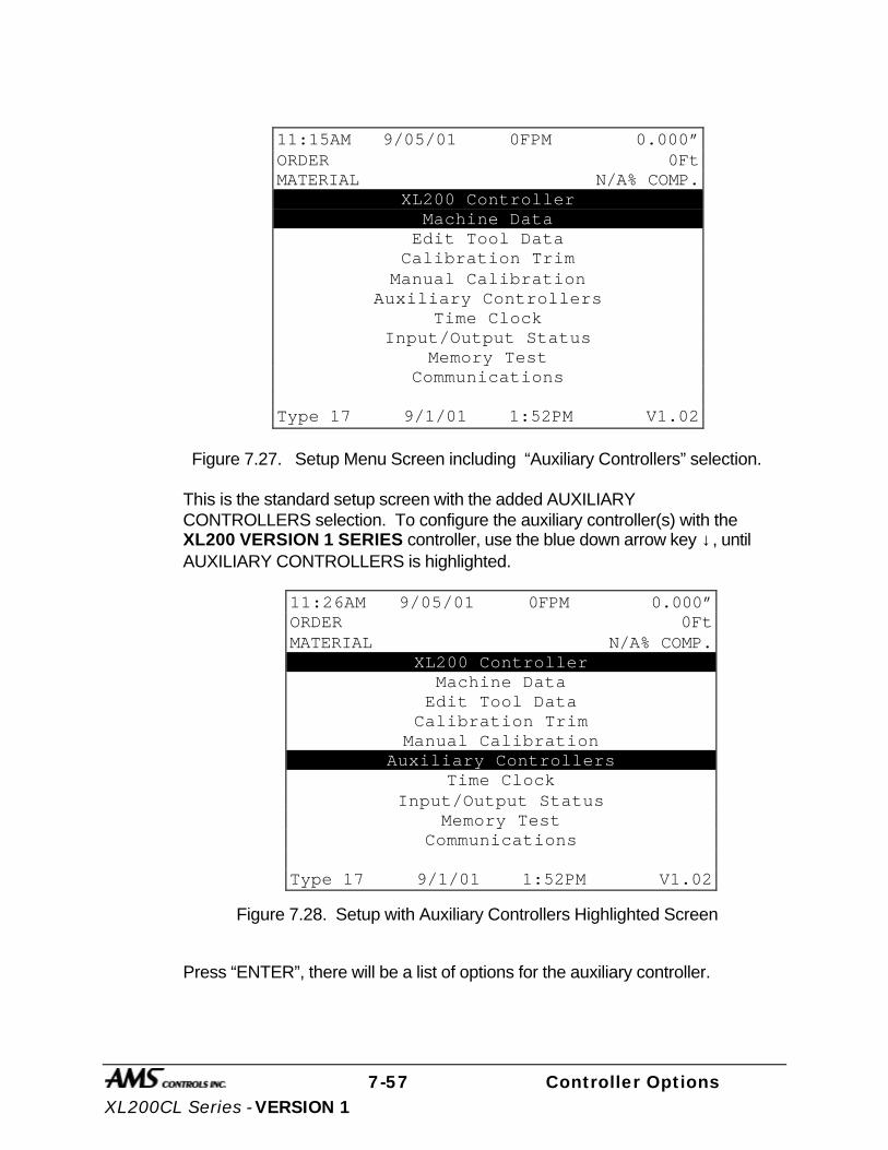
7-57 Controller Options XL200CL Series - VERSION 1
Figure 7.27. Setup Menu Screen including “Auxiliary Controllers” selection.
This is the standard setup screen with the added AUXILIARY CONTROLLERS selection. To configure the auxiliary controller(s) with the XL200 VERSION 1 SERIES controller, use the blue down arrow key ↓, until AUXILIARY CONTROLLERS is highlighted.
Figure 7.28. Setup with Auxiliary Controllers Highlighted Screen
Press “ENTER”, there will be a list of options for the auxiliary controller.
11:15AM 9/05/01 0FPM 0.000” ORDER 0Ft MATERIAL N/A% COMP.
XL200 Controller Machine Data
Edit Tool Data Calibration Trim
Manual Calibration Auxiliary Controllers
Time Clock Input/Output Status
Memory Test Communications
Type 17 9/1/01 1:52PM V1.02
11:26AM 9/05/01 0FPM 0.000” ORDER 0Ft MATERIAL N/A% COMP.
XL200 Controller Machine Data
Edit Tool Data Calibration Trim
Manual Calibration Auxiliary Controllers
Time Clock Input/Output Status
Memory Test Communications
Type 17 9/1/01 1:52PM V1.02

7-58 Controller Options XL200CL Series - VERSION 1
Figure 7.29. Auxiliary Controller Menu Screen
When one of the “Auxiliary” options is chosen in this screen, there will be a list of all of the auxiliary controllers found, so the operator can chose which controller they wish to view or edit. If there is only one auxiliary controller found, this list will not be shown and the operator is taken directly to the selected option.
Auxiliary Setup This screen is used for viewing or editing the setup parameters for the auxiliary controllers. When this screen is first entered, the message “Uploading Setup Parameters” will be seen on the controller screen. A list of the controller setup parameters will then be given, and the operator will enter these parameters the same way as the XL200 VERSION 1 SERIES controller setup parameters.
Once the operator has selected an auxiliary controller to setup, the setup values are temporarily stored in the XL200 VERSION 1 SERIES controller. This allows the user to edit parameters without having to upload them every time. Use this screen to adjust the setup parameters for the auxiliary controllers. The setups will be lost in the XL200 VERSION 1 SERIES controller, when power is turned off or when setups from another unit are uploaded.
11:38AM 9/05/01 0FPM 0.000” ORDER 0Ft MATERIAL N/A% COMP.
Auxiliary Controller Menu Auxiliary Setup
Auxiliary Program Auxiliary Status
Auxiliary Terminal Mode Search For All Devices
Type 17 9/1/01 1:52PM V1.02
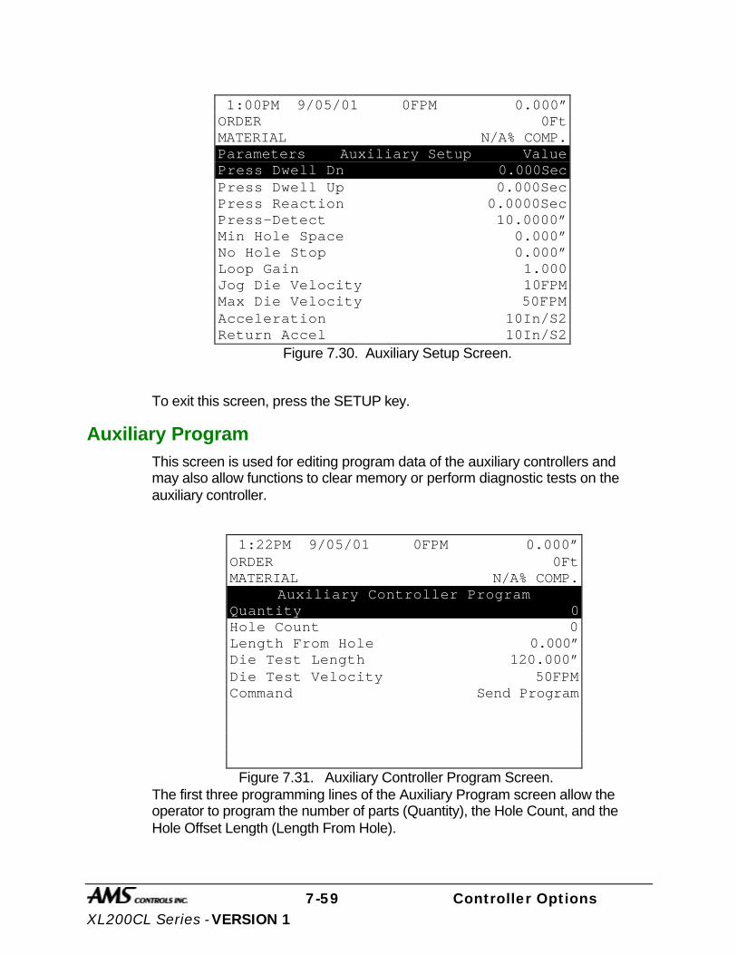
7-59 Controller Options XL200CL Series - VERSION 1
Figure 7.30. Auxiliary Setup Screen.
To exit this screen, press the SETUP key.
Auxiliary Program This screen is used for editing program data of the auxiliary controllers and may also allow functions to clear memory or perform diagnostic tests on the auxiliary controller.
Figure 7.31. Auxiliary Controller Program Screen. The first three programming lines of the Auxiliary Program screen allow the operator to program the number of parts (Quantity), the Hole Count, and the Hole Offset Length (Length From Hole).
1:00PM 9/05/01 0FPM 0.000” ORDER 0Ft MATERIAL N/A% COMP. Parameters Auxiliary Setup Value Press Dwell Dn 0.000Sec Press Dwell Up 0.000Sec Press Reaction 0.0000Sec Press-Detect 10.0000” Min Hole Space 0.000” No Hole Stop 0.000” Loop Gain 1.000 Jog Die Velocity 10FPM Max Die Velocity 50FPM Acceleration 10In/S2 Return Accel 10In/S2
1:22PM 9/05/01 0FPM 0.000” ORDER 0Ft MATERIAL N/A% COMP.
Auxiliary Controller Program Quantity 0 Hole Count 0 Length From Hole 0.000” Die Test Length 120.000” Die Test Velocity 50FPM Command Send Program

7-60 Controller Options XL200CL Series - VERSION 1
Quantity
Simply key in the desired quantity, and press ENTER to confirm. The quantity can be set from 1 to 9998 pieces. The Auxiliary Controller treats the quantity 9999 as a special case. When an order with a quantity of 9999 pieces is run, the quantity does not decrement when a piece is made. This is done so that he master XL SERIES controller can regulate the number of parts being made.
Hole Count
Key in the number of holes per each part and press ENTER to confirm. The Auxiliary Controller detects holes in the material and cycles the shear press when this number is reached. To cut on every hole detected, program a count of one. The maximum number of holes per part is 500.
Length From Hole
The next item to be programmed for a job is the Length From Hole. Key in the number of inches or millimeters and press ENTER to confirm. THIS IS NOT THE OVERALL LENGTH OF THE PART. The Offset Length is the distance from the leading edge of the last hole counted to the point where the shear occurs. See figure below.
DESIRED CUT POINT
OFFSET LENGTH
MATERIAL FLOW
The next two programming lines set the length and velocity of the Die Test function.
The last programming line (Command) has three functions. The INS (Insert) key can be used to toggle through the selections.
Send Program- This function will send the part information to the auxiliary controller.
Die Accel Test- This function is designed to simulate an actual run operation. When this program is run, the controller will generate line encoder pulses in proportion to the programmed speed. The system will function normally with

7-61 Controller Options XL200CL Series - VERSION 1
the exception that the mill outputs will not be turned on, and a tolerance error will not occur.
Clear Memory- This function will clear the memory of the auxiliary controller.
To exit this screen, press the SETUP button.
Auxiliary Status This screen is used for viewing the current status information of the auxiliary controller.
Figure 7.32. Auxiliary Status Screen
The information on the status screen includes the Auxiliary Controller version, unit, and type number, the current length past the shear, the auxiliary controller status, the line speed, the number of holes counted, the input and output status, the value of the tolerance error, the lag compensation, the offset voltage, the length of the die stroke, and the programmed part information.
To exit the Auxiliary Status Screen, press the SETUP key.
Note: If the XL200 VERSION 1 SERIES controller can not communicate with the auxiliary controller, the message “Error! No Response From RS485 Port” will be seen. To clear the error message, press the “CE” key.
Pressing “Setup” will not allow the operator to exit this screen. The “End” key must be used to exit this screen.
2:24PM 9/05/01 0FPM 0.000” ORDER 0Ft MATERIAL N/A% COMP. MP301HCL Ver:14.00 Unit:30 Type: 0 Position: 0.000” Status: Halted Speed: 0FPM Holes: 0 Inputs: -------- Outputs: -------- TolError: 0.0000” LagComp:0.0000Sec Offset: 0.000V StrokeEnd: 0.000” Prg Data: Qty Left HoleCnt Length 0 0 0 0.000”
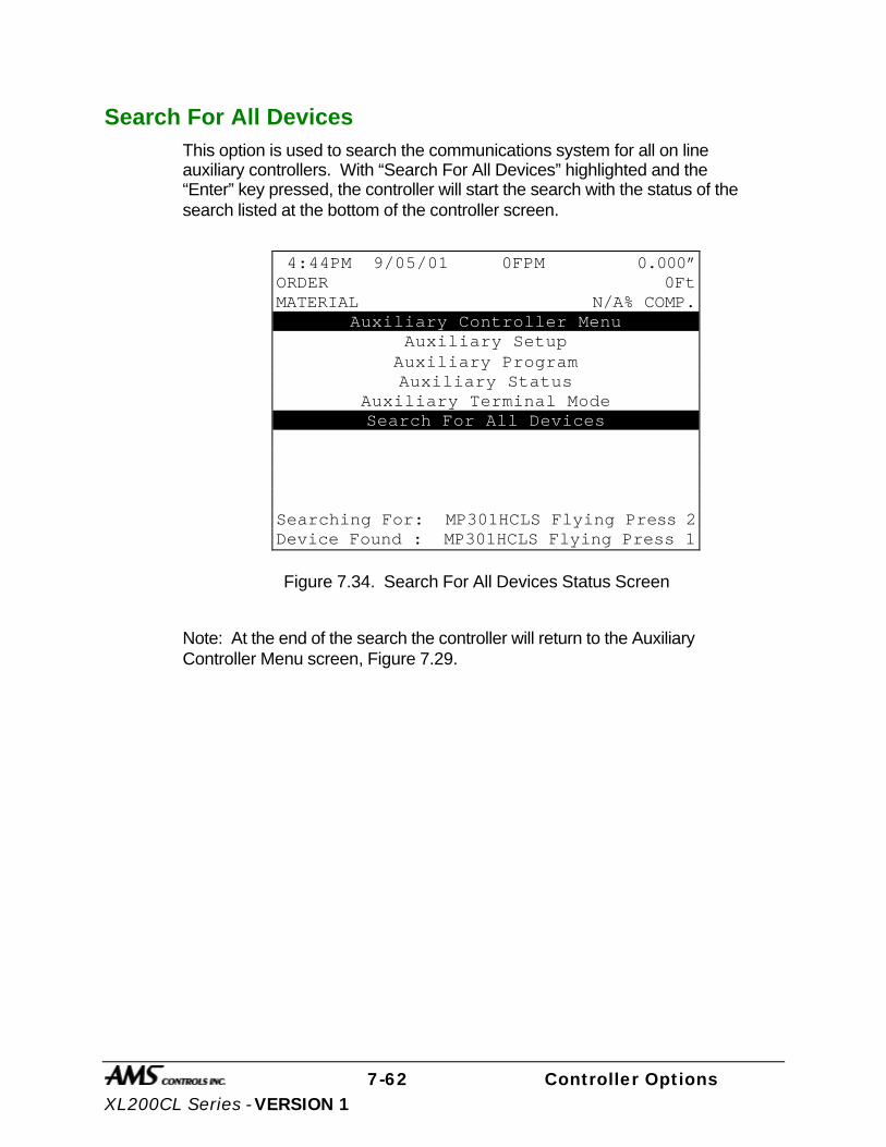
7-62 Controller Options XL200CL Series - VERSION 1
Search For All Devices This option is used to search the communications system for all on line auxiliary controllers. With “Search For All Devices” highlighted and the “Enter” key pressed, the controller will start the search with the status of the search listed at the bottom of the controller screen.
Figure 7.34. Search For All Devices Status Screen
Note: At the end of the search the controller will return to the Auxiliary Controller Menu screen, Figure 7.29.
4:44PM 9/05/01 0FPM 0.000” ORDER 0Ft MATERIAL N/A% COMP.
Auxiliary Controller Menu Auxiliary Setup
Auxiliary Program Auxiliary Status
Auxiliary Terminal Mode Search For All Devices
Searching For: MP301HCLS Flying Press 2 Device Found : MP301HCLS Flying Press 1

7-63 Controller Options XL200CL Series - VERSION 1
Initial Machine Tests
Manual Shear The shear can be manually activated using the CYCLE input. This causes the SHEAR output to turn on for the SHEAR DWELL time or until the SHEAR COMPLETE input switch closes. Make adjustments to the SHEAR DWELL time or the position of the SHEAR COMPLETE switch until the shear cycles properly.
Jogging The Die can be jogged forward and in reverse with the Die Jog Forward Input and Die Jog Reverse Input.
Referencing Controller to the Material The Auxiliary Controller measures relative movement of the material through the machine and has no way of measuring the absolute amount of material that is past the shear. In order to cut accurate lengths, the controller must know how much material is past the shear at some point in time and then it can make relative measurements there after. This is a process called referencing.
Referencing is simply loading material into the machine past the shear and activating the CYCLE input. The Die must locate the reference switch, move to the minimum die distance, fire the press, and then return to the reference switch (home location).
Note: The Manual Cycle switch must be held closed until the referencing process is complete or an error will be displayed.
At the bottom of the shear stroke, the length counter is set to zero and the Auxiliary Controller is referenced. The controller will remain referenced as long as the encoder stays in contact with the material and the material does not move while the controller is turned off.
Die Accelerator Test There are two ways that the DIE ACCELERATOR TEST can be performed. The purpose of the test is to simulate an actual run operation without creating scrap material.
The first method is to use the COMMAND function in the Auxiliary Controller Program screen, figure 7.31. Select the Die Test Length and the Die Test Velocity of the line that you wish to use. Toggle the COMMAND choices with the “PICK” key until “Die Accel Test” is highlighted and then press ENTER.

7-64 Controller Options XL200CL Series - VERSION 1
The second way to perform a DIE ACCELERATOR TEST is to use the Auxiliary Terminal Mode Screen, figure 12. Press the SETUP button until the option 1 = Die Accelerator Test, 2 = Error Display is shown. Press the number 1 on the number keypad to enter the Die Accelerator Test mode. The display will then prompt the operator for the test length and velocity. Press ENTER to start the test.
Ensure that the material is referenced by activating the Manual Shear Input and that the E-Stop input is closed before performing the test. During the test the controller will generate line encoder pulses in proportion to the programmed speed and move the die to simulate a shearing operation. While the test is being performed, the Auxiliary Status Screen, figure 7.32, will be displayed.

7-65 Controller Options XL200CL Series - VERSION 1
Running the Machine
After an order has been entered, the machine is placed in the RUN mode by either activating the RUN input. The Auxiliary Controller will begin counting holes and shearing parts to the programmed hole count. It will decrement the quantity remaining after each piece is cut and halt the line automatically when the quantity remaining reaches zero.
Note: If the target is beyond the die when the RUN mode is entered, a “Missed Shear: error message will be generated.
Tolerance Error Display The user may display the length error after each cut part. To enter this display, use the Auxiliary Terminal Mode Screen, toggle the SETUP key until 1 = Die Accelerator Test, 2 = Error Display is shown, and press the number 2. Note that this display shows the electronic tolerance error of the cut part by comparing the number of pulses received by the Line Encoder to the number of pulses received by the Die Encoder. The physical tolerance of the cut part may or may not be as accurate as the displayed value due to mechanical tolerances in the die accelerator mounting, cutoff press, or material tracking inaccuracies.
Clear Holes During jogging operations, the controller continues to count holes and records their positions in memory. If for any reason, the operator wishes to discard all of the hole locations, which are currently in the controller's memory, he may do so by clearing the "Hole Queue." To clear the hole queue, the machine must be halted. Cycle the shear press TWICE by activating the MANUAL CYCLE input.
Any holes, which have been counted but not yet cut off, will be cleared from memory. After the controller is placed back into the RUN mode, it will begin a new count of holes after the first hole passes the photo-detector.Switch Settings for Slave Controllers

7-66 Controller Options XL200CL Series - VERSION 1
SL 301 H Switch Settings and I/O 7-75
SL 301 HCLR Switch Settings and I/O 7-76
SL 301 HCL Switch Settings and I/O 7-77
SL 301 HCLS Switch Settings and I/O 7-78

7-67 Controller Options XL200CL Series - VERSION 1
SL 301 H Plus Switch Settings and I/O SW1 OFF Feed-to-Stop Shear ON Non-Stop Shear SW2 OFF Shear Die Boost Active ON No Shear Die Boost SW3 OFF Single Speed Shear ON Two Speed Shear SW4 Not Used – Must be OFF SW5 SW6 SW7 OFF OFF OFF Unit ID 30 ON OFF OFF Unit ID 31 OFF ON OFF Unit ID 32 ON ON OFF Unit ID 33 OFF OFF ON Unit ID 34 ON OFF ON Unit ID 35 OFF ON ON Unit ID 36 ON ON ON Unit ID 37 NO. INPUTS OUTPUTS 1 Jog Forward Forward/Fast 2 Jog Reverse Slow 3 Run Reverse 4 Shear Complete Shear 5 Setup Lockout N/A 6 N/A Run 7 Hole Detector Shear Die Boost/Shear Up 8 Manual Shear N/A Shear Up is available when Die Boost is not used.

7-68 Controller Options XL200CL Series - VERSION 1
SL 301 HCLR Switch Settings and I/O
SW1 Line Encoder (1) Direction SW2 Die Encoder (2) Direction SW3 Sets the Analog output voltage polarity (+ or -) SW4 SW5 SW6 OFF OFF OFF Unit ID 30 ON OFF OFF Unit ID 31 OFF ON OFF Unit ID 32 ON ON OFF Unit ID 33 OFF OFF ON Unit ID 34 ON OFF ON Unit ID 35 OFF ON ON Unit ID 36 ON ON ON Unit ID 37 SW7 Must be off. NO. INPUTS OUTPUTS 1 Jog Forward Forward 2 Jog Reverse Not Used 3 Remote Run Reverse 4 Manual Shear Run Disable 5 Setup/Lockout Drive Enable 6 Home Not Used 7 Hole Interrupt on SL Not Used
8 E-Stop Run
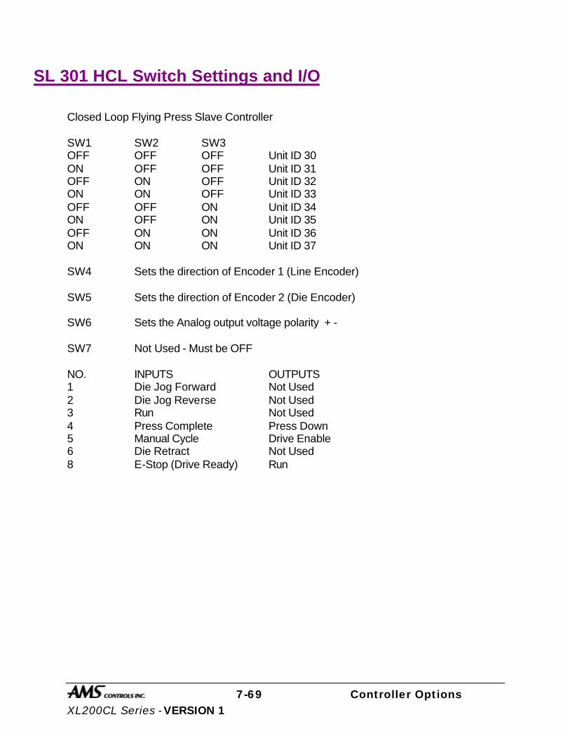
7-69 Controller Options XL200CL Series - VERSION 1
SL 301 HCL Switch Settings and I/O
Closed Loop Flying Press Slave Controller SW1 SW2 SW3 OFF OFF OFF Unit ID 30 ON OFF OFF Unit ID 31 OFF ON OFF Unit ID 32 ON ON OFF Unit ID 33 OFF OFF ON Unit ID 34 ON OFF ON Unit ID 35 OFF ON ON Unit ID 36 ON ON ON Unit ID 37 SW4 Sets the direction of Encoder 1 (Line Encoder) SW5 Sets the direction of Encoder 2 (Die Encoder) SW6 Sets the Analog output voltage polarity + - SW7 Not Used - Must be OFF NO. INPUTS OUTPUTS 1 Die Jog Forward Not Used 2 Die Jog Reverse Not Used 3 Run Not Used 4 Press Complete Press Down 5 Manual Cycle Drive Enable 6 Die Retract Not Used 8 E-Stop (Drive Ready) Run
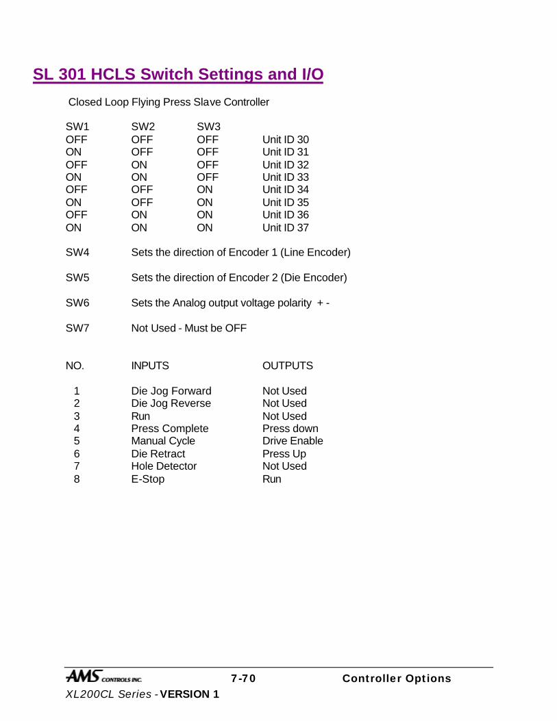
7-70 Controller Options XL200CL Series - VERSION 1
SL 301 HCLS Switch Settings and I/O
Closed Loop Flying Press Slave Controller SW1 SW2 SW3 OFF OFF OFF Unit ID 30 ON OFF OFF Unit ID 31 OFF ON OFF Unit ID 32 ON ON OFF Unit ID 33 OFF OFF ON Unit ID 34 ON OFF ON Unit ID 35 OFF ON ON Unit ID 36 ON ON ON Unit ID 37 SW4 Sets the direction of Encoder 1 (Line Encoder) SW5 Sets the direction of Encoder 2 (Die Encoder) SW6 Sets the Analog output voltage polarity + - SW7 Not Used - Must be OFF NO. INPUTS OUTPUTS 1 Die Jog Forward Not Used 2 Die Jog Reverse Not Used 3 Run Not Used 4 Press Complete Press down 5 Manual Cycle Drive Enable 6 Die Retract Press Up 7 Hole Detector Not Used 8 E-Stop Run

7-71 Controller Options XL200CL Series - VERSION 1
Hole Detect Option
Hole Counters are an available option for the XL200 VERSION 1CL SERIES controller. When this option is added, the controller will take on its model number followed by an H (XL200 VERSION 1CL becomes a XL200 VERSION 1CLH). Following is a typical drawing; Notice the hole detect input is input 16.
REVISIONS
NO. DATE BY
A
B
C
D
E
TITLE
DRAWN BY
CHK'D
FILE APP'D
DATE
SCALE MATERIAL
DRAWING NO.
AMS CONTROLS, INC.
1
2
3
4
5
6
7
8
9
10
11
12
13
14
15
16
17
18
19
20
21
22
23
24
25
26
27
28
29
30
31
32
33
34
35
36
37
38
39
40
41
42
43
44
45
46
47
48
49
1CR
JOG FORWARD
JOG REVERSE
RUN
SHEAR COMPLETE
SETUP LOCKOUT
MANUAL SHEAR
MANUAL PUNCH
SHEET DETECT
PUNCH COMPLETE
FAST
SLOW
REVERSE
SHEAR (PRESS1)
RUN
PUNCH
FORWARD
SHR UP/DIE BOOST
PUN UP/DIE BOOST
ITEM COMPLETE
A
B
C
D
I
J
ENCODER1
BLK W/ WHT
WHT
GRN
BLK W/ GRN
RED
BLK W/ RED
AMS
B
A
OFFICEPC WITHXL-LINK
XL100H ELECTRICAL INTERFACE DIAGRAMWITH TERMINAL CONNECTIONS
9-2-994483
+-
24 VDCPOWERSUPPLY
INPUT 1
INPUT 2
INPUT 3
INPUT 4
INPUT 5
INPUT 6
INPUT 7
INPUT 8
INPUT 9
INPUT 10
INPUT 11
INPUT 12
INPUT 13
OUTPUT 10
OUTPUT 1
OUTPUT 2
OUTPUT 4
OUTPUT 9
OUTPUT 3
OUTPUT 5
OUTPUT 6
OUTPUT 7
OUTPUT 8
GND CPU +24V CPU+24V I/O
GND I/O
RS485-BCOMM. 1
A+
A-
B+
B-
+5V
GND CPU
LINEENCODER
XL100HA2
A3
A4
A5
A6
A7
B2
B3
B4
A1
A8
A9
A10
A11
A12
A13
A16
B1
C3C11
C12
C13
C14
C16
C4
C2
D6
D7
B14
B13
B12
B11
B8
B7
B6
REMOTETERMINAL &KEYBOARD
RED
BLACK
RS232 TX
RS232 RX
RS232 GND
COMM. 2D9
D10
D15
B5
D4
C15
NOTES:
AMS provides this drawing for illustration purposes only.It is not to be taken as a literal example for wiring yourmachine. Each machine is different, having its own safetyconsiderations. the customer is responsible for theinstallation of adequate emergency stop circuitry, safetyguards and enclosing all equipment potentially hazardousto personnel.
CR1
SHIELD
WHITE
SHIELD
D12SHIELD
RS485-A
D16 CHASSIS CONNECTION
INPUT 14
INPUT 15
INPUT 16
D1
D2
D3OUTPUT 16
OUTPUT 15
OUTPUT 14
+24V I/O
C8
C9
C10
C1
OUTPUT 13
OUTPUT 12
OUTPUT 11C5
C6
C7
"TYPICAL"
D12
PRINTER ENCODER
PRINT INITIATE
(OPTIONAL)
(OPTIONAL)
24VDC
24VDC
24VDC
24VDC
24VDC
24VDC
24VDC
24VDC
24VDC
I/O COMMON
Twisted Pair
I/O POWER (+24)
TO AUXILIARYCONTROLLERS
D13
D14
L1 L2
CR1
HOLE DETECT
4483.DW1
WGWH
Figure 7.35. Typical Drawing of Controller Using Hole Detect Input.
The XL1XXCLH SERIES has the same general parameters as other AMS hole counting controllers. These parameters are located in the Machine Data section of the controller and follow. Use the Pick key or any number key to toggle between the selections and press Enter to save the new value.
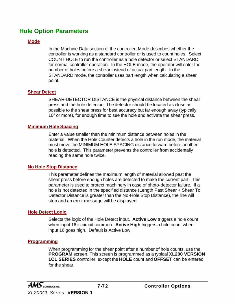
7-72 Controller Options XL200CL Series - VERSION 1
Hole Option Parameters
Mode
In the Machine Data section of the controller, Mode describes whether the controller is working as a standard controller or is used to count holes. Select COUNT HOLE to run the controller as a hole detector or select STANDARD for normal controller operation. In the HOLE mode, the operator will enter the number of holes before a shear instead of actual part length. In the STANDARD mode, the controller uses part length when calculating a shear point.
Shear Detect
SHEAR-DETECTOR DISTANCE is the physical distance between the shear press and the hole detector. The detector should be located as close as possible to the shear press for best accuracy but far enough away (typically 10” or more), for enough time to see the hole and activate the shear press.
Minimum Hole Spacing
Enter a value smaller than the minimum distance between holes in the material. When the Hole Counter detects a hole in the run mode, the material must move the MINIMUM HOLE SPACING distance forward before another hole is detected. This parameter prevents the controller from accidentally reading the same hole twice.
No Hole Stop Distance
This parameter defines the maximum length of material allowed past the shear press before enough holes are detected to make the current part. This parameter is used to protect machinery in case of photo-detector failure. If a hole is not detected in the specified distance (Length Past Shear + Shear To Detector Distance is greater than the No-Hole Stop Distance), the line will stop and an error message will be displayed.
Hole Detect Logic
Selects the logic of the Hole Detect input. Active Low triggers a hole count when input 16 is circuit common. Active High triggers a hole count when input 16 goes high. Default is Active Low.
Programming
When programming for the shear point after a number of hole counts, use the PROGRAM screen. This screen is programmed as a typical XL200 VERSION 1CL SERIES controller, except the HOLE count and OFFSET can be entered for the shear.

7-73 Controller Options XL200CL Series - VERSION 1
Enter the amount of holes in the HOLE parameter that should be counted before the shear point, which is determined by the OFFSET parameter. The OFFSET is the distance from the last hole, where the shear should occur.
Figure 7.36. Status Display Screen When Mode Select Is Set For Count Hole.
When the MODE SELECT is changed to Count Hole in [SETUP]/[MACHINE DATA] program area of the controller, the above status display, figure 7.36, is shown. The programming of the order is similar to programming a standard order with the following exceptions:
4:44PM 9/05/01 0FPM 0.000” ORDER 0 HOLES MATERIAL LF QTY DONE HOLE OFFSET PAT STA 1 20 10 20 100 NEXT

7-74 Controller Options XL200CL Series - VERSION 1
Programming in Hole Mode
QTY:
Is the number of part pieces required. In the above example, 20 parts will be produced for the order.
Hole:
This is the number of holes that are to be counted for each part. In figure 7.36, 10 holes are to be detected before the shear.
Offset:
This is the distance from the last hole that the shear is to occur. The reference of the hole for this distance is set by the “Shear-to-Detector Distance” parameter. In the above example, the shear will occur 20 inches past the hole.
Call 1 (800) 334 – 5213 or email [email protected] for more information on optional devices to enhance your controllers’ performance.

8-1 Controller Model Types XL200CL Series - VERSION 1
Model Types
Model Customization
Controller Model Types There are several different controller models available from AMS controls. Each individual model may be setup to operate in different modes depending on how the customization switches are set. The factors that will influence the model selected will include whether the machine stops for a press operation or continues in motion, whether the line runs a single speed or shifts into a “creep” speed before the operation, and the number of presses that are to be controlled. The following section lists the proper position for the configuration switches to be set to customize the operation for a specific machine. A map of the inputs and outputs is provided as well as recording lists for machine parameters, tools, and other critical information. A generic setup data sheet that includes all possible setup parameters is also included. Fill in the appropriate data for your individual controller on this sheet, as it will help the AMS Customer Service Department troubleshoot your machine in the event it is not performing at the required standards. It is also a written back-up should the controller data be lost for any reason. The numbers shown are the numbers of the basic controller without options. The Remote Terminal and Bar Code Scanner are hardware additions and do not change the controller number. Other optional items will change the controller model number with the appropriate letter or letters added to the end of the number (M = Extended Macros, B = Bundle Tag Printer, P = Print-on-Part Printer, E = Expansion Board). See chapter 10 for details. For Example: XL200CLB = Has Bundle Tag Printer option XL212CLE = Has Expansion Board option XL206CLM = Has Extended Macros XL202CLP = Has Print-on-Part Printer XL202CLBP= Has Bundle Tag Printer and Print-on-Part Printer XL212CLMBEP = Has Extended Macros, Bundle Tag Printer, Expansion Board, and
Print-on-Part Printer

8-2 Controller Model Types XL200CL Series - VERSION 1
Closed Loop Switch Settings
XL200CL Customization
Switch 1 Switch 2 Description OFF OFF Feed-to-Stop, One Encoder ON OFF Feed-to-Stop, Two Encoders OFF ON Single-Speed Die Accelerator ON ON Two-Speed Die Accelerator Switch # OFF ON 3 NOT USED – MUST BE OFF NOT USED – MUST BE OFF 4 CW Encoder 1 Direction CCW Encoder 1 Direction 5 CW Encoder 2 Direction CCW Encoder 2 Direction 6 Normal Analog Voltage Polarity Inverted Analog Voltage Polarity 7 Disable Punch Enable Punch 8 NOT USED – MUST BE OFF NOT USED – MUST BE OFF 9 CRT Disabled CRT Enabled 10 NOT USED – MUST BE OFF NOT USED – MUST BE OFF
XL200HCL Customization
Switch 1 Switch 2 Description OFF OFF INVALID ON OFF INVALID OFF ON Single-Speed Die Accelerator ON ON Two-Speed Die Accelerator Switch # OFF ON 3 NOT USED – MUST BE OFF NOT USED – MUST BE OFF 4 CW Encoder 1 Direction CCW Encoder 1 Direction 5 CW Encoder 2 Direction CCW Encoder 2 Direction 6 Normal Analog Voltage Polarity Inverted Analog Voltage Polarity 7 NOT USED – MUST BE OFF NOT USED – MUST BE OFF 8 NOT USED – MUST BE OFF NOT USED – MUST BE OFF 9 CRT Disabled CRT Enabled 10 NOT USED – MUST BE OFF NOT USED – MUST BE OFF
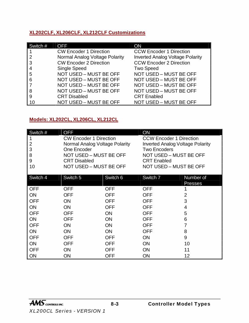
8-3 Controller Model Types XL200CL Series - VERSION 1
XL202CLF, XL206CLF, XL212CLF Customizations
Switch # OFF ON 1 CW Encoder 1 Direction CCW Encoder 1 Direction 2 Normal Analog Voltage Polarity Inverted Analog Voltage Polarity 3 CW Encoder 2 Direction CCW Encoder 2 Direction 4 Single Speed Two Speed 5 NOT USED – MUST BE OFF NOT USED – MUST BE OFF 6 NOT USED – MUST BE OFF NOT USED – MUST BE OFF 7 NOT USED – MUST BE OFF NOT USED – MUST BE OFF 8 NOT USED – MUST BE OFF NOT USED – MUST BE OFF 9 CRT Disabled CRT Enabled 10 NOT USED – MUST BE OFF NOT USED – MUST BE OFF
Models: XL202CL, XL206CL, XL212CL
Switch # OFF ON 1 CW Encoder 1 Direction CCW Encoder 1 Direction 2 Normal Analog Voltage Polarity Inverted Analog Voltage Polarity 3 One Encoder Two Encoders 8 NOT USED – MUST BE OFF NOT USED – MUST BE OFF 9 CRT Disabled CRT Enabled 10 NOT USED – MUST BE OFF NOT USED – MUST BE OFF Switch 4 Switch 5 Switch 6 Switch 7 Number of
Presses OFF OFF OFF OFF 1 ON OFF OFF OFF 2 OFF ON OFF OFF 3 ON ON OFF OFF 4 OFF OFF ON OFF 5 ON OFF ON OFF 6 OFF ON ON OFF 7 ON ON ON OFF 8 OFF OFF OFF ON 9 ON OFF OFF ON 10 OFF ON OFF ON 11 ON ON OFF ON 12
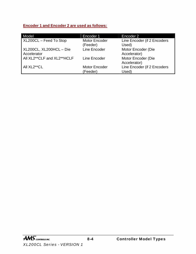
8-4 Controller Model Types XL200CL Series - VERSION 1
Encoder 1 and Encoder 2 are used as follows:
Model Encoder 1 Encoder 2 XL200CL – Feed To Stop Motor Encoder
(Feeder) Line Encoder (if 2 Encoders Used)
XL200CL, XL200HCL – Die Accelerator
Line Encoder Motor Encoder (Die Accelerator)
All XL2**CLF and XL2**HCLF Line Encoder Motor Encoder (Die Accelerator)
All XL2**CL Motor Encoder (Feeder)
Line Encoder (if 2 Encoders Used)

8-5 Controller Model Types XL200CL Series - VERSION 1
Closed Loop Inputs and Outputs
IO# Inputs Outputs 1 Jog Forward Fast | Forward 2 Jog Reverse Slow 3 Run Reverse 4 Emergency Stop (E-Stop) Run 5 Setup Lockout Item Complete 6 Manual Shear Drive Enable 7 Manual Punch Print Flush/Encoder 8 Tail Out (Inverted Sheet Detect) Print Trigger 9 Press 1 Complete (Shear) Press 1 Down (Shear) 10 Press 2 Complete Press 2 Down | Gag 2 11 Press 3 Complete Press 3 Down | Gag 3 | Press 1 Up 12 Press 4 Complete Press 4 Down | Gag 4 13 Press 5 Complete Press 5 Down | Gag 5 14 Press 6 Complete Press 6 Down | Gag 6 15 Press 7 Complete Press 7 Down | Gag 7 16 Press 8 Complete Press 8 Down | Gag 8 17 Press 9 Complete Press 9 Down | Gag 9 18 Press 10 Complete Press 10 Down | Gag 10 19 Press 11 Complete Press 11 Down | Gag 11 20 Press 12 Complete Press 12 Down | Gag 12 21 Asynchronous Print Input Not Used 22 Feed Ready | Die Home Not Used 23 Slow Run | Alternate List Select Short Sheet 24 Hole Detect Very Short Sheet

8-6 Controller Model Types XL200CL Series - VERSION 1
Notes:
Ø Each model will have enough Press Down outputs available for the
maximum number of presses allowed for that model. Press Up/Boost outputs will begin at the next available output following last Press Down output.
Ø The maximum number of presses allowed for each model is as follows:
Models Max
Presses XL200HCL, All XL2**CLF, All XL2**HCLF
1
XL200CL, XL202CL 2 XL206CL 6 XL212CL 12
Ø Gag outputs are only available on models XL202CL, XL206CL, XL212CL
Ø Hole Detect Input available only on models with an “H” in their name.
Ø Feed Ready and Slow Run inputs are available only in Feed-to-Stop
mode.
Ø Die Home and Alternate List Select inputs are available only in Die Accelerator mode.
Ø Exp. Gag Board option will only be available on model XL212CL.
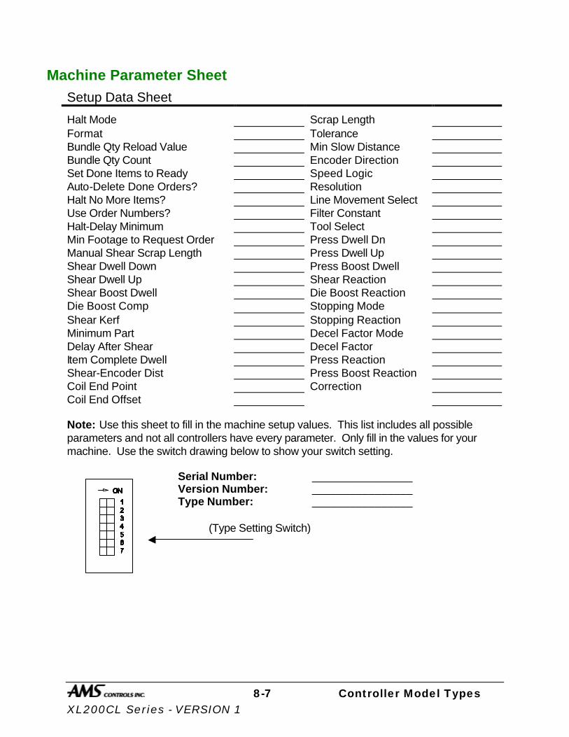
8-7 Controller Model Types XL200CL Series - VERSION 1
Machine Parameter Sheet Setup Data Sheet
Halt Mode Scrap Length Format Tolerance Bundle Qty Reload Value Min Slow Distance Bundle Qty Count Encoder Direction Set Done Items to Ready Speed Logic Auto-Delete Done Orders? Resolution Halt No More Items? Line Movement Select Use Order Numbers? Filter Constant Halt-Delay Minimum Tool Select Min Footage to Request Order Press Dwell Dn Manual Shear Scrap Length Press Dwell Up Shear Dwell Down Press Boost Dwell Shear Dwell Up Shear Reaction Shear Boost Dwell Die Boost Reaction Die Boost Comp Stopping Mode Shear Kerf Stopping Reaction Minimum Part Decel Factor Mode Delay After Shear Decel Factor Item Complete Dwell Press Reaction Shear-Encoder Dist Press Boost Reaction Coil End Point Correction Coil End Offset Note: Use this sheet to fill in the machine setup values. This list includes all possible parameters and not all controllers have every parameter. Only fill in the values for your machine. Use the switch drawing below to show your switch setting.
Serial Number: ________________ Version Number: ________________ Type Number: ________________ (Type Setting Switch)

8-8 Controller Model Types XL200CL Series - VERSION 1
Press Dwell Sheet Press Dwell Data
Press 1 Dwell Dn Press 7 Dwell Dn Press 1 Dwell Up Press 7 Dwell Up Press 2 Dwell Dn Press 8 Dwell Dn Press 2 Dwell Up Press 8 Dwell Up Press 3 Dwell Dn Press 9 Dwell Dn Press 3 Dwell Up Press 9 Dwell Up Press 4 Dwell Dn Press 10 Dwell Dn Press 4 Dwell Up Press 10 Dwell Up Press 5 Dwell Dn Press 11 Dwell Dn Press 5 Dwell Up Press 11 Dwell Up Press 6 Dwell Dn Press 12 Dwell Dn Press 6 Dwell Up Press 12 Dwell Up

8-9 Controller Model Types XL200CL Series - VERSION 1
Tool Data Sheet Edit Tool Data
Tool Press Gag Offset Name
8-10 Controller Model Types XL200CL Series - VERSION 1
Patterns Sheet Pattern #: __________ Tool # Reference Length
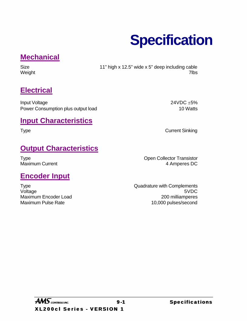
99 --11 Specifications Specifications XL200cl Ser ies XL200cl Ser ies -- VERSION 1 VERSION 1
Specification Mechanical Size 11" high x 12.5" wide x 5" deep including cable Weight 7lbs
Electrical
Input Voltage 24VDC ±5% Power Consumption plus output load 10 Watts
Input Characteristics Type Current Sinking
Output Characteristics Type Open Collector Transistor Maximum Current 4 Amperes DC
Encoder Input Type Quadrature with Complements Voltage 5VDC Maximum Encoder Load 200 milliamperes Maximum Pulse Rate 10,000 pulses/second

99 --22 Specifications Specifications XL200cl Ser ies XL200cl Ser ies -- VERSION 1 VERSION 1
Operation Number of Order Items 999 Maximum number of Patterns 999 Maximum Operations per part per press Limited by Available Memory Maximum Part Length 3500.000 inches
(88900.01 millimeters) Maximum Quantity / Item 9999 Units of Measurement 4 English, 3 Metric modes Coil Footage Totalizers 32 Maximum Footage/Totalizer 1,000,000 feet
1,000,000 meters
Features Display 40 characters by 15 rows Keys 39
Options Eclipse
Protocol RS-485 Baud Rate 300-38400 Data Bits 7 or 8 Parity Even, Odd, & None Stop Bits 1 or 2
Computer Requirements Processor Pentium -66 MHZ minimum Memory (Windows 95, 98, NT, or 2000) 12 M of RAM Hard Drive 540 MB or more Serial Ports 1 “available” port Printer Windows Compatible
(such as an ink-jet or laser) CD-ROM drive Required Mouse Recommended
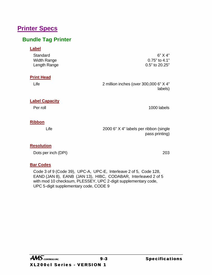
99 --33 Specifications Specifications XL200cl Ser ies XL200cl Ser ies -- VERSION 1 VERSION 1
Printer Specs
Bundle Tag Printer
Label
Standard 6” X 4” Width Range 0.75” to 4.1” Length Range 0.5” to 20.25”
Print Head
Life 2 million inches (over 300,000 6” X 4” labels)
Label Capacity
Per roll 1000 labels
Ribbon
Life 2000 6” X 4” labels per ribbon (single pass printing)
Resolution
Dots per inch (DPI) 203
Bar Codes
Code 3 of 9 (Code 39), UPC-A, UPC-E, Interleave 2 of 5, Code 128, EAND (JAN 8), EANB (JAN 13), HIBC, CODABAR, Interleaved 2 of 5 with mod 10 checksum, PLESSEY, UPC 2-digit supplementary code, UPC 5-digit supplementary code, CODE 9

99 --44 Specifications Specifications XL200cl Ser ies XL200cl Ser ies -- VERSION 1 VERSION 1
Inkjet Print on Part Printer
Power Requirements
Voltage 90 - 130 and 190 - 250 VAC Frequency 50 - 60 HZ Power 50 Watts
Output
Character Size Approximately 10 to 35 mm (0.3” to 1.3”) depending upon printhead used
Printheads 14, 14 - 35, or 28 mm printheads Printable Characters 64 (Swedish/Norwegian), US ASCII,
or European versions optional
Ambient Requirements
Operating Temperature 5 to 40° C (41 to 104° F) Humidity 95% non condensing
Weight
Excluding Printhead 1.96kg (4.3 lbs)
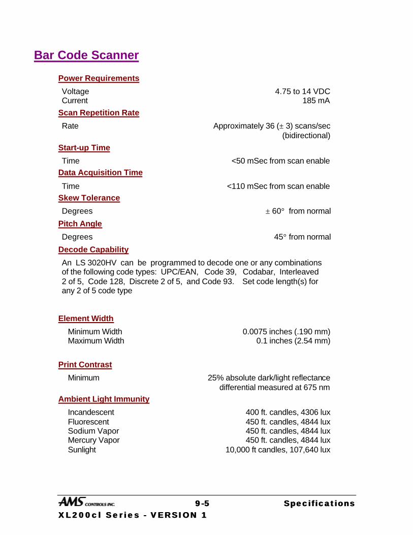
99 --55 Specifications Specifications XL200cl Ser ies XL200cl Ser ies -- VERSION 1 VERSION 1
Bar Code Scanner
Power Requirements
Voltage 4.75 to 14 VDC Current 185 mA
Scan Repetition Rate
Rate Approximately 36 (± 3) scans/sec (bidirectional)
Start-up Time
Time <50 mSec from scan enable
Data Acquisition Time
Time <110 mSec from scan enable
Skew Tolerance
Degrees ± 60° from normal
Pitch Angle
Degrees 45° from normal
Decode Capability
An LS 3020HV can be programmed to decode one or any combinations of the following code types: UPC/EAN, Code 39, Codabar, Interleaved 2 of 5, Code 128, Discrete 2 of 5, and Code 93. Set code length(s) for any 2 of 5 code type
Element Width
Minimum Width 0.0075 inches (.190 mm) Maximum Width 0.1 inches (2.54 mm)
Print Contrast
Minimum 25% absolute dark/light reflectance differential measured at 675 nm
Ambient Light Immunity
Incandescent 400 ft. candles, 4306 lux Fluorescent 450 ft. candles, 4844 lux Sodium Vapor 450 ft. candles, 4844 lux Mercury Vapor 450 ft. candles, 4844 lux Sunlight 10,000 ft candles, 107,640 lux

99 --66 Specifications Specifications XL200cl Ser ies XL200cl Ser ies -- VERSION 1 VERSION 1
Durability
Drop to Concrete 6 ft. (183 cm)
Operating Temperature
Degrees 0 to 40° C (32 to 104° F)
Humidity
Per Cent 5 to 95 % (non-condensing)
Height
6.3 inches (16 cm)
Length
5 inches (12.7 cm)
Width
2.8 inches (7.1 cm)

10-1 Diagrams XL200CL Series – VERSION 1
Diagrams About Wiring Diagrams
Generic wiring diagrams have been provided in order to give the installer an idea of how each system is to be wired. Adequate safety circuits and guards must be added to any installation.
XL Series Wiring Diagrams XL200CL Pg. 13-3 XL202CL Pg. 13-4 XL206CL Pg. 13-5 XL212CL Pg. 13-6
SL (Auxiliary) Series Wiring Diagrams SL301H Pg. 13-7 SL301HCL Pg. 13-8 SL301HCLR Pg. 13-9 SL304 Pg. 13-10
Expansion Board Diagrams Single Expansion Board Pg. 13-11 Multiple Expansion Boards Pg. 13-12
Printer Diagrams Communications Block Diagram Pg. 13-13 PM5100 Wiring Diagram Pg. 13-14 5120 Cable for the PM5100 Pg. 13-15 Typical Inkjet Connection Diagram Pg. 13-16 4450 Matthews 2001 interface cable Pg. 13-17 Matthews Local Installation Diagram Pg. 13-18 Matthews Remote Installation Diagram Pg. 13-19 Typical Bundle Tag Connection Diagram Pg. 13-20 Simplified Bundle Tag Connection Diagram Pg. 13-21 4467 Citoh interface cable Pg. 13-22 Citoh (typical BTP) Local Installation Diagram Pg. 13-24 4390-1 Encoder Driver Pg. 13-25 4390-2 Printer Encoder Driver Pg. 13-26
I M P O R T A N T - R E F E R T O W A R N I N G S O N P A G E 1 0 - 2
10-2 Diagrams XL200CL Series – VERSION 1
!! Warning !!
AMS provides the following drawings for illustration purposes only. They are not to be taken as literal examples for wiring machinery.
Every machine is different and has its own safety considerations. The customer is responsible for the installation of adequate emergency stop circuitry , safety guards, and the enclosure of all equipment that
is potentially hazardous to personnel.

I M P O R T A N T - R E F E R T O W A R N I N G S O N P A G E 1 0 - 2
10-3 Diagrams XL200CL Series – VERSION 1
OFFICEPC WITHXL-LINK
NOTES:
INPUT 1
INPUT 2
INPUT 3
INPUT 4
INPUT 5
INPUT 6
INPUT 7
INPUT 8
INPUT 9
INPUT 10
INPUT 11
INPUT 12
INPUT 13
INPUT 14
INPUT 15
INPUT 16
OUTPUT 10
OUTPUT 1
OUTPUT 2
OUTPUT 4
OUTPUT 9
OUTPUT 11
OUTPUT 12
OUTPUT 13
OUTPUT 15
OUTPUT 16
OUTPUT 3
OUTPUT 5
OUTPUT 6
OUTPUT 7
OUTPUT 8
OUTPUT 14
GND CPU +24V CPU+24V I/O
+24V I/OGND I/O
Twisted Pair
INPUT 17
INPUT 18
INPUT 19
INPUT 20
INPUT 21
INPUT 22
INPUT 23
INPUT 24
OUTPUT 18
OUTPUT 17
OUTPUT 19
OUTPUT 20
OUTPUT 21
OUTPUT 23
OUTPUT 24
OUTPUT 22
Figure 13-1 XL212CL Wiring Diagram
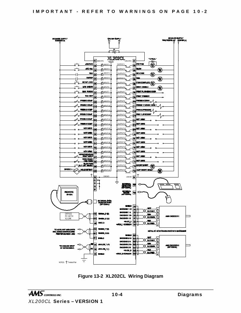
I M P O R T A N T - R E F E R T O W A R N I N G S O N P A G E 1 0 - 2
10-4 Diagrams XL200CL Series – VERSION 1
OFFICEPC WITHXL-LINK
NOTES:
INPUT 1
INPUT 2
INPUT 3
INPUT 4
INPUT 5
INPUT 6
INPUT 7
INPUT 8
INPUT 9
INPUT 10
INPUT 11
INPUT 12
INPUT 13
INPUT 14
INPUT 15
INPUT 16
OUTPUT 10
OUTPUT 1
OUTPUT 2
OUTPUT 4
OUTPUT 9
OUTPUT 11
OUTPUT 12
OUTPUT 13
OUTPUT 15
OUTPUT 16
OUTPUT 3
OUTPUT 5
OUTPUT 6
OUTPUT 7
OUTPUT 8
OUTPUT 14
GND CPU +24V CPU+24V I/O
+24V I/OGND I/O
Twisted Pair
INPUT 17
INPUT 18
INPUT 19
INPUT 20
INPUT 21
INPUT 22
INPUT 23
INPUT 24
OUTPUT 18
OUTPUT 17
OUTPUT 19
OUTPUT 20
OUTPUT 21
OUTPUT 23
OUTPUT 24
OUTPUT 22
Figure 13-2 XL202CL Wiring Diagram

I M P O R T A N T - R E F E R T O W A R N I N G S O N P A G E 1 0 - 2
10-5 Diagrams XL200CL Series – VERSION 1
OFFICEPC WITHXL-LINK
NOTES:
INPUT 1
INPUT 2
INPUT 3
INPUT 4
INPUT 5
INPUT 6
INPUT 7
INPUT 8
INPUT 9
INPUT 10
INPUT 11
INPUT 12
INPUT 13
INPUT 14
INPUT 15
INPUT 16
OUTPUT 10
OUTPUT 1
OUTPUT 2
OUTPUT 4
OUTPUT 9
OUTPUT 11
OUTPUT 12
OUTPUT 13
OUTPUT 15
OUTPUT 16
OUTPUT 3
OUTPUT 5
OUTPUT 6
OUTPUT 7
OUTPUT 8
OUTPUT 14
GND CPU +24V CPU+24V I/O
+24V I/OGND I/O
Twisted Pair
INPUT 17
INPUT 18
INPUT 19
INPUT 20
INPUT 21
INPUT 22
INPUT 23
INPUT 24
OUTPUT 18
OUTPUT 17
OUTPUT 19
OUTPUT 20
OUTPUT 21
OUTPUT 23
OUTPUT 24
OUTPUT 22
Figure 13-3 XL206CL Wiring Diagram
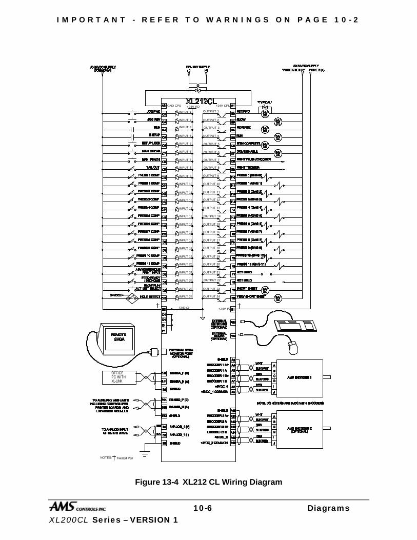
I M P O R T A N T - R E F E R T O W A R N I N G S O N P A G E 1 0 - 2
10-6 Diagrams XL200CL Series – VERSION 1
OFFICEPC WITHXL-LINK
NOTES:
INPUT 1
INPUT 2
INPUT 3
INPUT 4
INPUT 5
INPUT 6
INPUT 7
INPUT 8
INPUT 9
INPUT 10
INPUT 11
INPUT 12
INPUT 13
INPUT 14
INPUT 15
INPUT 16
OUTPUT 10
OUTPUT 1
OUTPUT 2
OUTPUT 4
OUTPUT 9
OUTPUT 11
OUTPUT 12
OUTPUT 13
OUTPUT 15
OUTPUT 16
OUTPUT 3
OUTPUT 5
OUTPUT 6
OUTPUT 7
OUTPUT 8
OUTPUT 14
GND CPU +24V CPU+24V I/O
+24V I/OGND I/O
Twisted Pair
INPUT 17
INPUT 18
INPUT 19
INPUT 20
INPUT 21
INPUT 22
INPUT 23
INPUT 24
OUTPUT 18
OUTPUT 17
OUTPUT 19
OUTPUT 20
OUTPUT 21
OUTPUT 23
OUTPUT 24
OUTPUT 22
Figure 13-4 XL212 CL Wiring Diagram
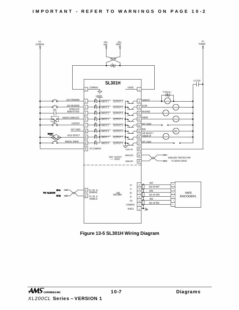
I M P O R T A N T - R E F E R T O W A R N I N G S O N P A G E 1 0 - 2
10-7 Diagrams XL200CL Series – VERSION 1
FWD/FST
NOT USED
A
B
C
D
I
J
ENCODER1
BLK W/ WHT
WHT
GRN
BLK W/ GRN
RED
BLK W/ RED
AMS
SHIELDED TWISTED PAIR
JOG FORWARD
JOG REVERSE
SHEAR COMPLETE
MANUAL SHEAR
NOT USED
+24VDC
SL301H
OUTPUT 1
OUTPUT 2
OUTPUT 3
OUTPUT 4
OUTPUT 5
OUTPUT 6
OUTPUT 7
OUTPUT 8
INPUT 1
INPUT 2
INPUT 3
INPUT 4
INPUT 5
INPUT 6
INPUT 7
INPUT 8
A+
A-
B+
B-
+5V
COMMON
SHIELD
LINEENCODER
2
3
4
5
6
7
18
19
20 17
16
13
12
11
10
9
8
1
14
15
9
8
7
ANALOG+
ANALOG-
DIFF. OUTPUT+ / - 10VDC
COMMON +24VDC
6
3
2
1
NOT USED
SHEAR
LOCKOUT
E-STOP
RUN
DIE BOOST /HOLE DETECT
REMOTE RUN
12
13
TX / RX E+
TX / RX E-(RS485-A)
(RS485-B)
CR2
TO SERVO DRIVE
CPU CPUGND 24VDC
2221 I/O COMMON +24V I/O
I/OCOMMON
I/OPOWER
SLOW
REVERSE
SHEAR UP
INTERLOCK
"TYPICAL"
CR3
24VDC
24VDC
24VDC
24VDC
24VDC
Figure 13-5 SL301H Wiring Diagram
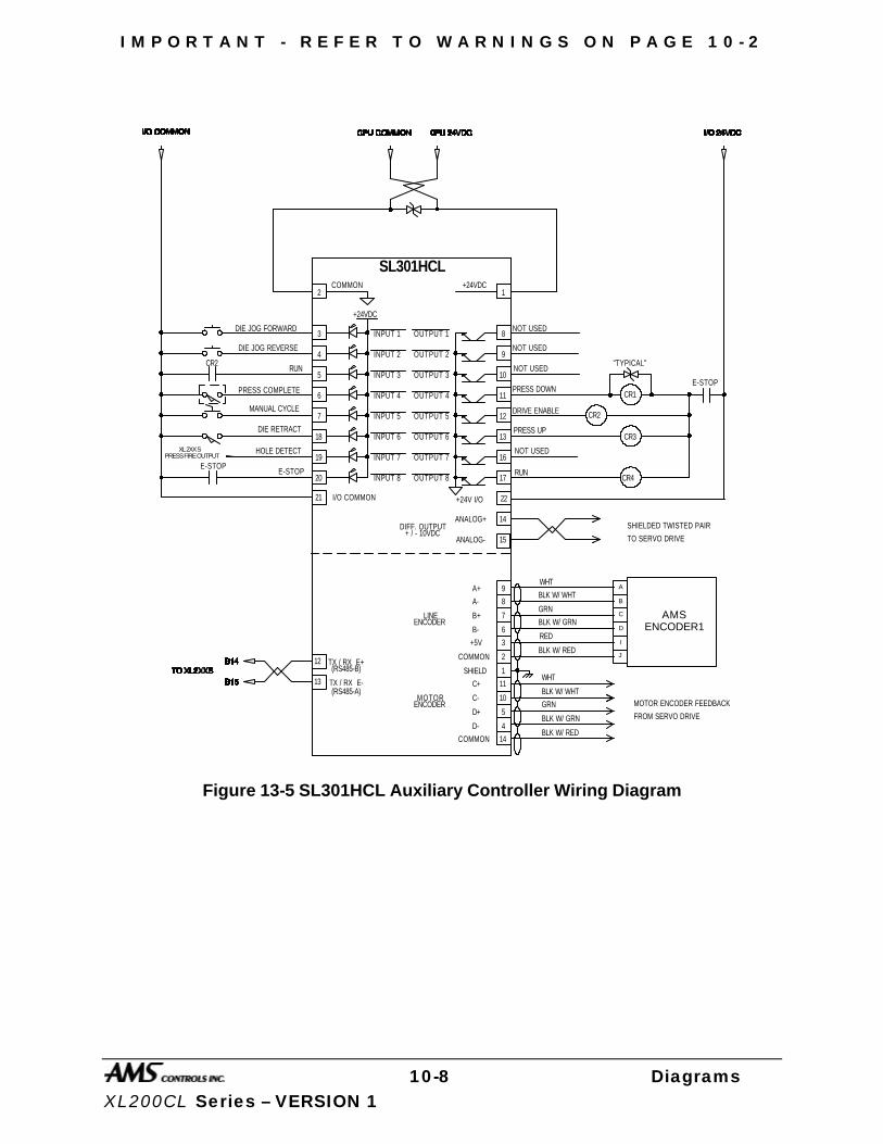
I M P O R T A N T - R E F E R T O W A R N I N G S O N P A G E 1 0 - 2
10-8 Diagrams XL200CL Series – VERSION 1
E-STOP
NOT USED
RUN
A
B
C
D
I
J
ENCODER1
BLK W/ WHT
WHT
GRN
BLK W/ GRN
RED
BLK W/ RED
AMS
SHIELDED TWISTED PAIR
FROM SERVO DRIVE
WHT
BLK W/ WHT
GRN
BLK W/ GRN
BLK W/ RED
DIE JOG FORWARD
DIE JOG REVERSE
PRESS COMPLETE
E-STOP
DIE RETRACT
+24VDC
SL301HCL
OUTPUT 1
OUTPUT 2
OUTPUT 3
OUTPUT 4
OUTPUT 5
OUTPUT 6
OUTPUT 7
OUTPUT 8
INPUT 1
INPUT 2
INPUT 3
INPUT 4
INPUT 5
INPUT 6
INPUT 7
INPUT 8
A+
A-
B+
B-
+5V
COMMON
SHIELD
LINEENCODER
2
3
4
5
6
7
18
19
20 17
16
13
12
11
10
9
8
1
14
15
9
8
7
5
4
ANALOG+
ANALOG-
DIFF. OUTPUT+ / - 10VDC
COMMON +24VDC
6
3
2
1
C+
C-
D+
D-
MOTORENCODER
DRIVE ENABLE
PRESS DOWN
MANUAL CYCLE
E-STOP
11
10
14COMMON
PRESS UP
HOLE DETECT
RUN
12
13
TX / RX E+
TX / RX E-(RS485-A)
(RS485-B)
CR2
CR4
TO SERVO DRIVE
2221 I/O COMMON +24V I/O
NOT USED
NOT USED
PRESS FIRE OUTPUT
"TYPICAL"
CR1
CR2
CR3XL 2XX S
MOTOR ENCODER FEEDBACK
NOT USED
Figure 13-5 SL301HCL Auxiliary Controller Wiring Diagram

I M P O R T A N T - R E F E R T O W A R N I N G S O N P A G E 1 0 - 2
10-9 Diagrams XL200CL Series – VERSION 1
BLK W/ RED
SHIELDEDTWISTEDPAIR
TO SERVO MOTOR DRIVE
WHT
BLK W/ WHT
GRN
BLK W/ GRN
RED
BLK
+24VDC
OUTPUT 1
OUTPUT 2
OUTPUT 3
OUTPUT 4
OUTPUT 5
OUTPUT 6
OUTPUT 7
OUTPUT 8
INPUT 1
INPUT 2
INPUT 3
INPUT 4
INPUT 5
INPUT 6
INPUT 7
INPUT 8
A+
A-
B+
B-
+5V
COMMON
SHIELD
LINEENCODER
2
3
4
5
6
7
18
19
20 17
16
13
12
11
10
9
8
1
14
15
9
8
7
5
4
ANALOG+
ANALOG-
DIFF. OUTPUT+ / - 10VDC
COMMON +24VDC
6
3
2
1
C+
C-
D+
D-
MOTORENCODER
11
10
"TYPICAL"
FROMSERVO MOTOR DRIVE
GROUND CONTROLLER AT MOUNT LUG.
BLK W/ WHT
WHT
GRN
BLK W/ GRN
12
13
SHIELDEDTWISTEDPAIR
TX/RX B
TX/RX A
EMULATED ENCODER SIGNAL
Figure 13-7 SL301HCLR Wiring Diagram (Rotary Controller)
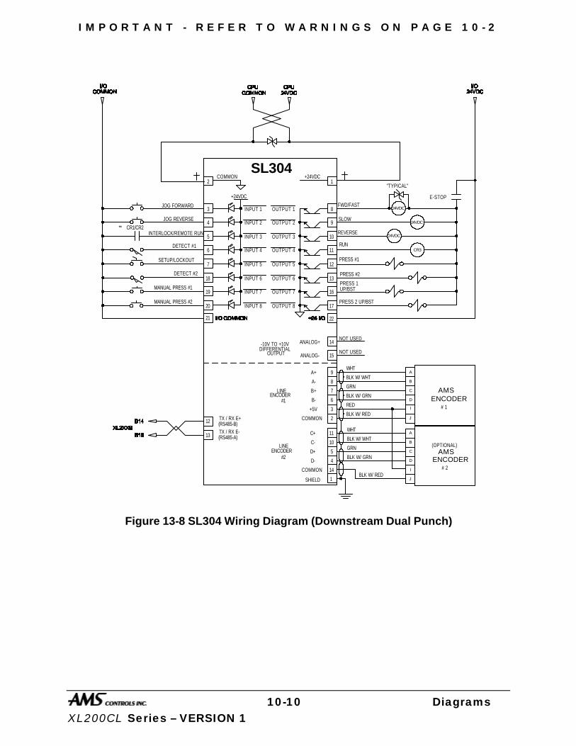
I M P O R T A N T - R E F E R T O W A R N I N G S O N P A G E 1 0 - 2
10-10 Diagrams XL200CL Series – VERSION 1
+24VDC
SL304
OUTPUT 1
OUTPUT 2
OUTPUT 3
OUTPUT 4
OUTPUT 5
OUTPUT 6
OUTPUT 7
OUTPUT 8
INPUT 1
INPUT 2
INPUT 3
INPUT 4
INPUT 5
INPUT 6
INPUT 7
INPUT 8
2
3
4
5
6
7
18
19
20 17
16
13
12
11
10
9
8
1COMMON +24VDC
CR1/CR2**24VDC
24VDC
24VDC
PRESS #1
E-STOP
JOG FORWARD
JOG REVERSE
INTERLOCK/REMOTE RUN
DETECT #1
SETUP/LOCKOUT
MANUAL PRESS #1
FWD/FAST
SLOW
REVERSE
RUN
PRESS #2
"TYPICAL"
14
15
ANALOG+
ANALOG-
-10V TO +10VDIFFERENTIAL
OUTPUT
NOT USED
NOT USED
DETECT #2
MANUAL PRESS #2 PRESS 2 UP/BST
PRESS 1UP/BST
A
B
C
D
I
J
ENCODER
BLK W/ WHT
WHT
GRN
BLK W/ GRN
RED
BLK W/ RED
AMS
A+
A-
B+
B-
+5V
COMMON
SHIELD
LINEENCODER
9
8
7
5
4
6
3
2
1
C+
C-
D+
D-
ENCODER
11
10
14COMMON
#1
LINE
#2
A
B
C
D
I
J
ENCODERAMS
BLK W/ WHT
WHT
GRN
BLK W/ GRN
BLK W/ RED
(OPTIONAL)
# 1
# 2
21 22
CR3
12
13
TX / RX E+(RS485-B)TX / RX E-(RS485-A)
Figure 13-8 SL304 Wiring Diagram (Downstream Dual Punch)
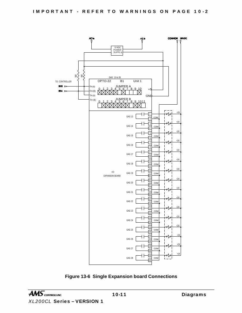
I M P O R T A N T - R E F E R T O W A R N I N G S O N P A G E 1 0 - 2
10-11 Diagrams XL200CL Series – VERSION 1
TO: CONTROLLER
10 2 3 4 5 6 7 8 9 10 11
10 2 3 4 5 6 7 8 9 10
JUMPER B
JUMPER AFH-(A)
FH+(B)
TH-(A)
TH+(B)
+5
GND
OPTO-22 B1 Unit 1GAG 13 to 2856
0
560
+-
5 VDCPOWERSUPPLY
1
2
3
4
5
6
7
8
9
10
11
12
13
14
15
16
17
18
19
20
21
22
23
24
25
26
27
28
29
30
31
32
I/O
EXPANSION BOARD
GAG 13
GAG 14
GAG 15
GAG 16
GAG 17
GAG 18
GAG 19
GAG 20
GAG 21
GAG 22
GAG 23
GAG 24
GAG 25
GAG 26
GAG 27
GAG 28
+24
+24
+24
+24
+24
+24
+24
+24
+24
+24
+24
+24
+24
+24
+24
+24
COM
COM
COM
COM
COM
COM
COM
COM
COM
COM
COM
COM
COM
COM
COM
COM
Figure 13-6 Single Expansion board Connections
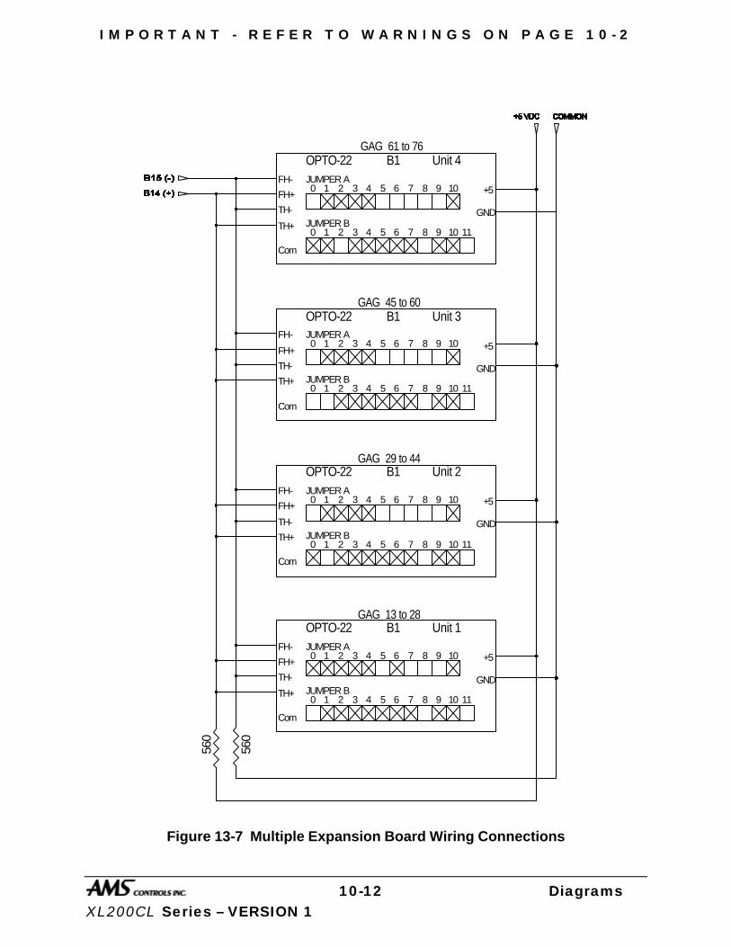
I M P O R T A N T - R E F E R T O W A R N I N G S O N P A G E 1 0 - 2
10-12 Diagrams XL200CL Series – VERSION 1
10 2 3 4 5 6 7 8 9 10 11
10 2 3 4 5 6 7 8 9 10
JUMPER B
JUMPER AFH-
FH+
TH-
TH+
Com
+5
GND
OPTO-22 B1 Unit 4
10 2 3 4 5 6 7 8 9 10 11
10 2 3 4 5 6 7 8 9 10
JUMPER B
JUMPER AFH-
FH+
TH-
TH+
Com
+5
GND
OPTO-22 B1 Unit 3
10 2 3 4 5 6 7 8 9 10 11
10 2 3 4 5 6 7 8 9 10
JUMPER B
JUMPER AFH-
FH+
TH-
TH+
Com
+5
GND
OPTO-22 B1 Unit 2
10 2 3 4 5 6 7 8 9 10 11
10 2 3 4 5 6 7 8 9 10
JUMPER B
JUMPER AFH-
FH+
TH-
TH+
Com
+5
GND
OPTO-22 B1 Unit 1
560
560
GAG 61 to 76
GAG 45 to 60
GAG 29 to 44
GAG 13 to 28
Figure 13-7 Multiple Expansion Board Wiring Connections

I M P O R T A N T - R E F E R T O W A R N I N G S O N P A G E 1 0 - 2
10-13 Diagrams XL200CL Series – VERSION 1
NO
TE
S:
BU
ND
LE
TA
G
PR
INT
ER
PR
INT
-ON
-PA
RT
PR
INT
ER
XL
2X
XB
PE
CO
NT
RO
LL
ER
43
70
BO
AR
D
12
34
J20
0
EX
PB
OA
RD
A
B1
3
B1
5
B1
4A
1A
2B
1C
1
B A
-+
24
VD
CP
OW
ER
SU
PP
LY
L1
L2
AM
S E
nco
de
rO
ptio
na
l En
cod
er
for
Clo
sed
Lo
op
Sys
tem
s
PR
INT
ER
EN
CO
DE
R I
NP
UT
(O
PE
N L
OO
P O
NL
Y)
B
AA
BB
PR
INT
ER
IN
ITIA
TE
43
69
CA
BL
E4
36
8-2
5 C
AB
LE
300
300
30
0
-+
5VD
CP
OW
ER
SU
PP
LY
L1
L2
+5
VG
ND
AL
L W
IRE
S A
RE
TW
IST
ED
PA
IRS
RE
SIS
TO
RS
AR
E P
LA
CE
D A
T T
HE
CO
NT
RO
LL
ER
AN
D A
TT
HE
LA
ST
UN
IT I
N L
INE
ON
CO
MM
UN
ICA
TIO
N L
INE
43
70
BO
AR
D
12
34
J20
0
E8
E9
Figure 13-9 Communications Block Diagram
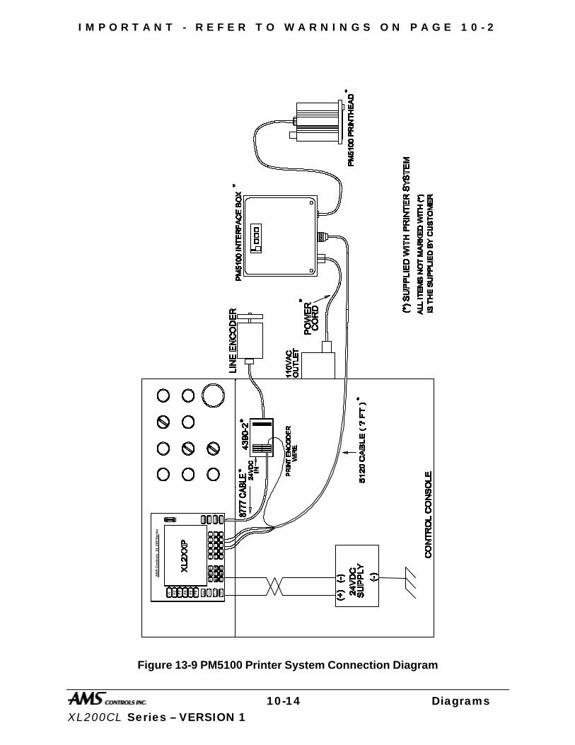
I M P O R T A N T - R E F E R T O W A R N I N G S O N P A G E 1 0 - 2
10-14 Diagrams XL200CL Series – VERSION 1
AM
S C
on
tro
ls
XL
20
0 S
eri
es
F1 F2
F3
F4
F5
F6
He
lp
Dia
gn
ost
ics
Inc
. Q
ty
Pro
du
ctio
nD
ata
Sta
tus
Se
t U
p
Pro
gra
m
En
ter
Mo
veUp Mo
veD
ow
nPa
ge
Page Up Do
wn
Hom
e
INS
End
CE
_ .
78
9 65
4 12
30
Dis
pla
y
Figure 13-9 PM5100 Printer System Connection Diagram
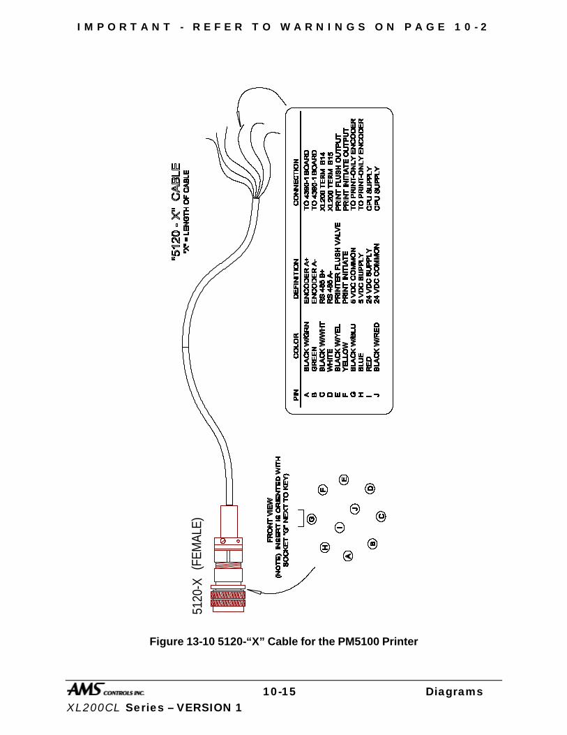
I M P O R T A N T - R E F E R T O W A R N I N G S O N P A G E 1 0 - 2
10-15 Diagrams XL200CL Series – VERSION 1
5120
-X(F
EMAL
E)
Figure 13-10 5120-“X” Cable for the PM5100 Printer
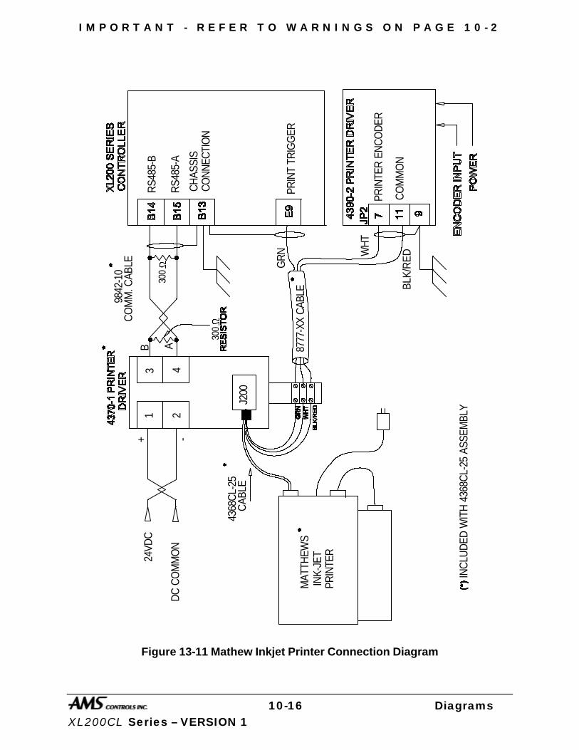
I M P O R T A N T - R E F E R T O W A R N I N G S O N P A G E 1 0 - 2
10-16 Diagrams XL200CL Series – VERSION 1
24VD
C
DC
CO
MM
ON
MAT
THEW
SIN
K-JE
TPR
INTE
R
INC
LUD
ED W
ITH
436
8CL-
25 A
SSEM
BLY
8777
-XX
CAB
LE
J200
B A
9842
-10
CO
MM
. CAB
LE
RS4
85-B
RS4
85-A
CH
ASSI
SC
ON
NEC
TIO
N
PRIN
T TR
IGG
ER
PRIN
TER
EN
CO
DER
GR
N WH
T
+ -
1 2
3 4
300
300
CO
MM
ON
BLK/
RED
4368
CL-
25C
ABLE
Figure 13-11 Mathew Inkjet Printer Connection Diagram
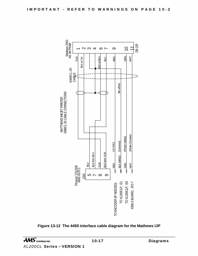
I M P O R T A N T - R E F E R T O W A R N I N G S O N P A G E 1 0 - 2
10-17 Diagrams XL200CL Series – VERSION 1
10 11
9
GR
N
WH
T
GR
N
WH
T
(Prin
ter I
nitia
te)
(Prin
ter E
ncod
er)
Mat
tew
s 20
01
DB-1
5P
4368
CL-
25
MAT
THEW
S IN
KJET
PRI
NTER
1 2 3 4 6 7
5 7 8
BLU
BLK
from
BLU
YLW
BLK
from
YLW
Phoe
nix 2
7615
09AM
S 43
70-1
J200
Ink
Jet P
rinte
r
YLW
BLK
w/ Y
el
BLK
w/ B
LU
BLU
4368
CL-2
5 CA
BLE
CONN
ECTI
ONS
CA
BLE
TO X
L200
CLP,
E9
4390
-2 B
OAR
D,
JP2-
7
BLK
W/R
ED
(Com
mon
)B
lk w
/Red
TO X
L200
CLP,
E1
9R
ED
(+5
VD
C)
RE
DTO
ENC
ODE
R (IF
NEE
DED)
Figure 13-12 The 4450 interface cable diagram for the Mathews IJP
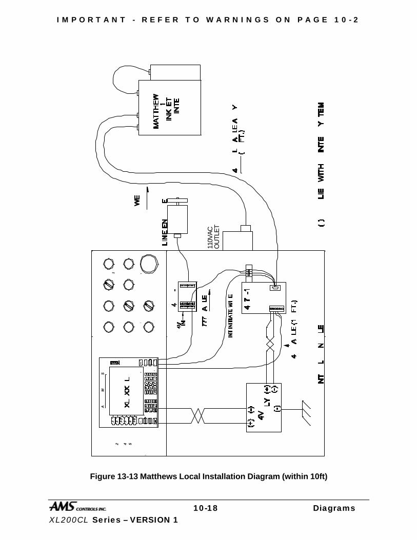
I M P O R T A N T - R E F E R T O W A R N I N G S O N P A G E 1 0 - 2
10-18 Diagrams XL200CL Series – VERSION 1
110V
AC
AM
S
Co
nt
ro
ls
XL
20
0
Se
ri
es
F1
F2
F3
F4
F5
F6
He
lp
Status
Se
t
Up
En
te
r
OU
TLE
T
Figure 13-13 Matthews Local Installation Diagram (within 10ft)
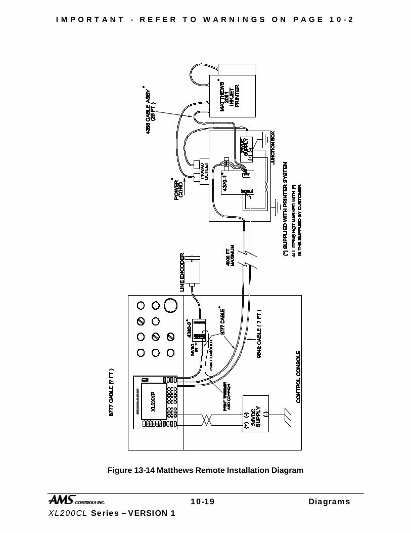
I M P O R T A N T - R E F E R T O W A R N I N G S O N P A G E 1 0 - 2
10-19 Diagrams XL200CL Series – VERSION 1
AM
S C
on
tro
ls
XL
200
Ser
ies
F1 F2 F3 F4 F5 F6 He
lp
Dia
gn
ost
ics
Inc
. Q
ty
Pro
du
ctio
nD
ata
Sta
tus
Se
t U
p
Pro
gra
m
En
ter
Mo
veUp Mo
veD
ow
nPa
ge
Page Up Do
wn
Hom
e
INS
End CE
_ .
78
9 65
4 12
30
Dis
pla
y
Figure 13-14 Matthews Remote Installation Diagram
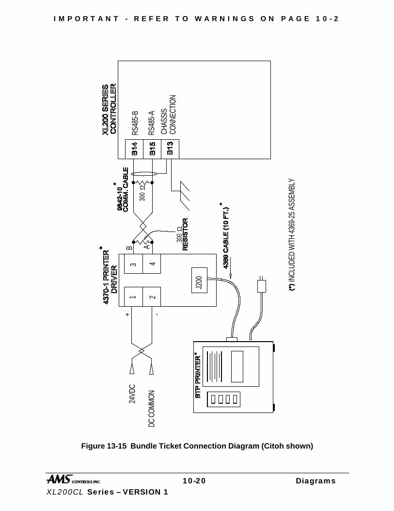
I M P O R T A N T - R E F E R T O W A R N I N G S O N P A G E 1 0 - 2
10-20 Diagrams XL200CL Series – VERSION 1
24VD
C
DC C
OMM
ON
INCL
UDED
WIT
H 43
69-2
5 AS
SEM
BLY
J200
B ARS
485-
B
RS48
5-A
CHAS
SIS
CONN
ECTI
ON
+ -
1 2
3 4
300
300
Figure 13-15 Bundle Ticket Connection Diagram (Citoh shown)
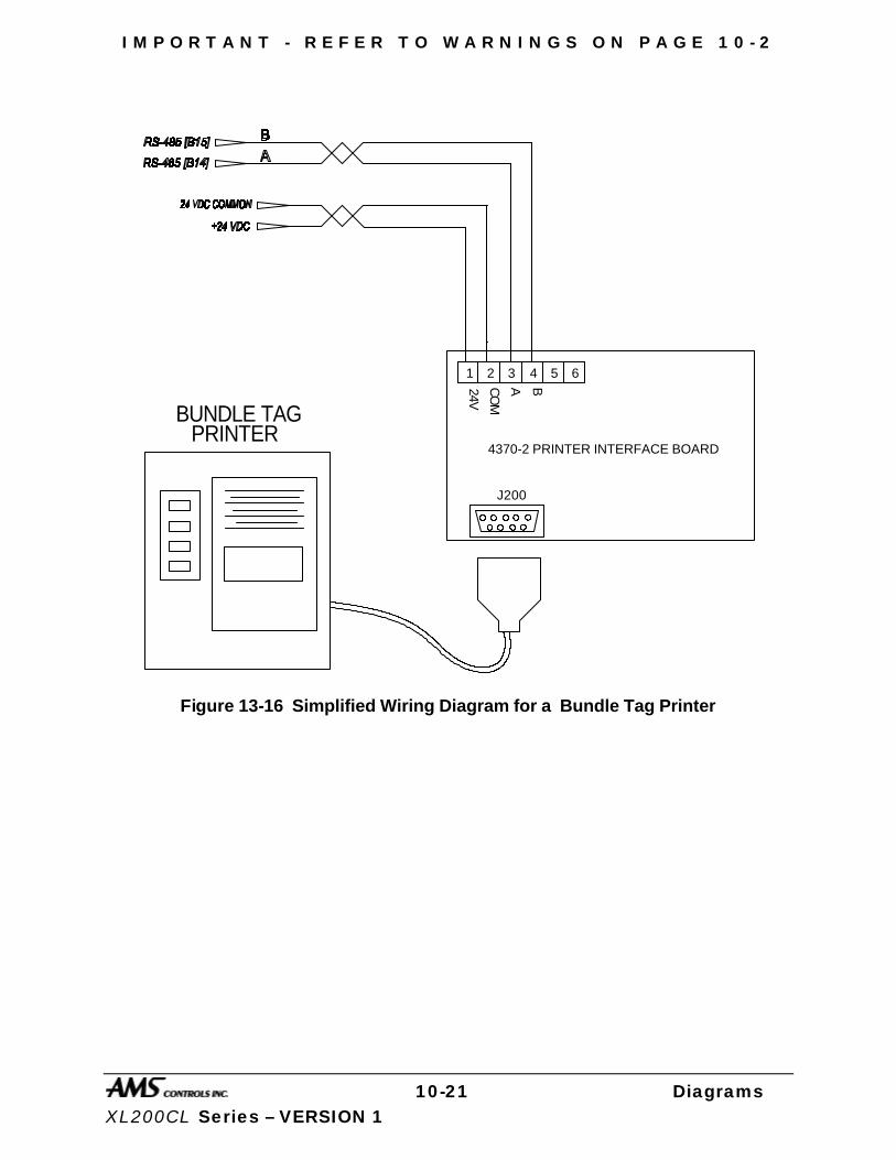
I M P O R T A N T - R E F E R T O W A R N I N G S O N P A G E 1 0 - 2
10-21 Diagrams XL200CL Series – VERSION 1
1 2 3 4 5 6
J200
4370-2 PRINTER INTERFACE BOARD
24V
CO
M
A B
BUNDLE TAGPRINTER
Figure 13-16 Simplified Wiring Diagram for a Bundle Tag Printer
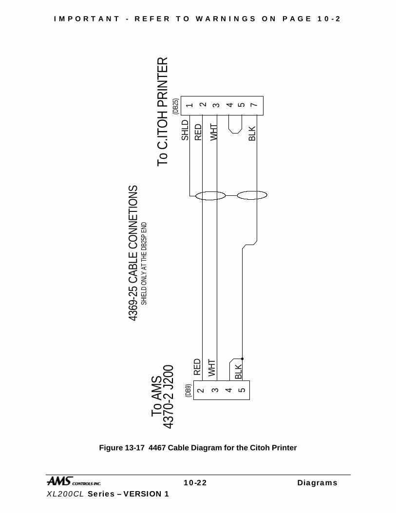
I M P O R T A N T - R E F E R T O W A R N I N G S O N P A G E 1 0 - 2
10-22 Diagrams XL200CL Series – VERSION 1
To C
.ITO
H P
RIN
TER
To A
MS
4370
-2 J
200
(DB9
)
4369
-25
CAB
LE C
ON
NET
ION
S
(DB2
5)
2 3 4 5
1 2 3 4 5
WH
T
RE
D
BLK
RE
D
BLKWH
T
7
SHLD
SHIE
LD O
NLY
AT T
HE D
B25P
END
Figure 13-17 4467 Cable Diagram for the Citoh Printer

I M P O R T A N T - R E F E R T O W A R N I N G S O N P A G E 1 0 - 2
10-23 Diagrams XL200CL Series – VERSION 1
AM
S C
ontro
ls X
L 20
0 S
erie
s
F1 F2 F3 F4 F5 F6 H
elp
Dia
gn
ost
ics
Inc
. Q
ty
Pro
du
ctio
nD
ata
Sta
tus
Se
t U
p
Pro
gra
m
Ente
r
Mo
veUp Mo
veD
ow
nPa
ge
Page Up Do
wn
Hom
e
INS
End CE
_ .
78
9 65
4 12
30
Dis
pla
y
Figure 13-18 Wiring Block Diagram for Local BTP Installation
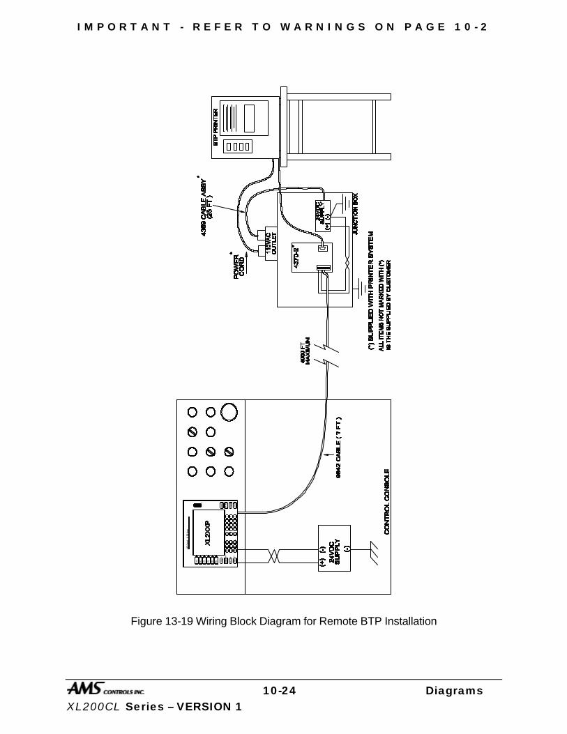
I M P O R T A N T - R E F E R T O W A R N I N G S O N P A G E 1 0 - 2
10-24 Diagrams XL200CL Series – VERSION 1
AMS C
ontro
ls X
L 200
Serie
s
F1 F2 F3 F4 F5 F6 He
lp
Dia
gn
ost
ics
Inc
. Q
ty
Pro
du
ctio
nD
ata
Sta
tus
Set
Up
Pro
gra
m
En
ter
Mo
veUp M
ove
Do
wn
Page
Page Up Do
wn
Hom
e
INS
End
CE
_ .
78
9 65
4 12
30
Dis
pla
y
Figure 13-19 Wiring Block Diagram for Remote BTP Installation
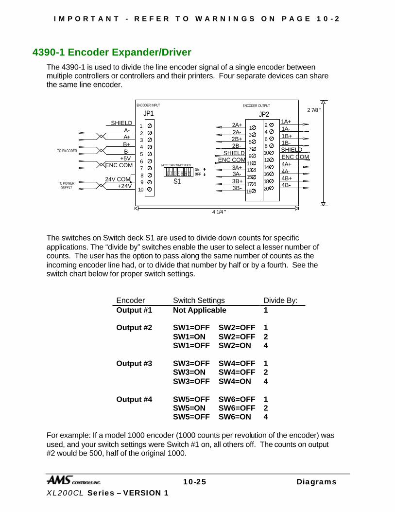
I M P O R T A N T - R E F E R T O W A R N I N G S O N P A G E 1 0 - 2
10-25 Diagrams XL200CL Series – VERSION 1
4390-1 Encoder Expander/Driver The 4390-1 is used to divide the line encoder signal of a single encoder between multiple controllers or controllers and their printers. Four separate devices can share the same line encoder.
JP1 JP2
S1
1 2
3 4
5 6
7 8
910
1112
13 14
15 16
17 18
19 20
123456789
10
SHIELDA-A+B+B-
+5VENC COM
24V COM+24V
2A+2A-2B+2B-
SHIELDSHIELDENC COMENC COM
3A+3A-3B+3B-
1A+1A-1B+1B-
4A+4A-4B+4B-
4 1/4 "
2 7/8 "
ONOFF
TO POWER SUPPLY
TO ENCODER
1 2 3 4 5 6 7
NOTE: SW 7 IS NOT USED
ENCODER INPUT ENCODER OUTPUT
The switches on Switch deck S1 are used to divide down counts for specific applications. The “divide by” switches enable the user to select a lesser number of counts. The user has the option to pass along the same number of counts as the incoming encoder line had, or to divide that number by half or by a fourth. See the switch chart below for proper switch settings.
Encoder Switch Settings Divide By: Output #1 Not Applicable 1
SW1=OFF SW2=OFF 1 SW1=ON SW2=OFF 2
Output #2
SW1=OFF SW2=ON 4
SW3=OFF SW4=OFF 1 SW3=ON SW4=OFF 2
Output #3
SW3=OFF SW4=ON 4
SW5=OFF SW6=OFF 1 SW5=ON SW6=OFF 2
Output #4
SW5=OFF SW6=ON 4 For example: If a model 1000 encoder (1000 counts per revolution of the encoder) was used, and your switch settings were Switch #1 on, all others off. The counts on output #2 would be 500, half of the original 1000.
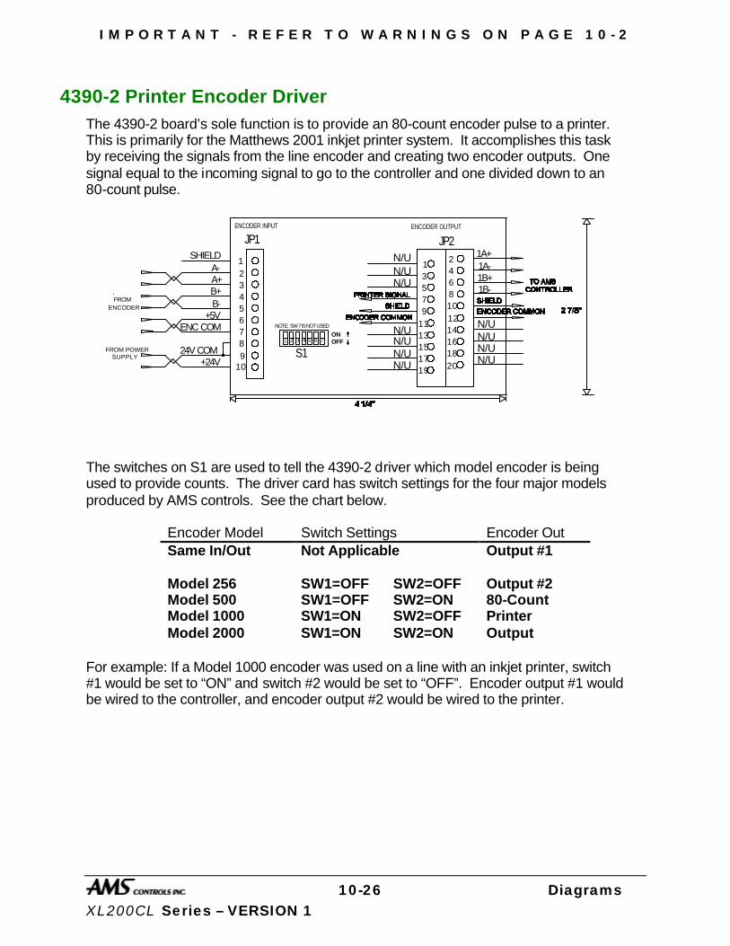
I M P O R T A N T - R E F E R T O W A R N I N G S O N P A G E 1 0 - 2
10-26 Diagrams XL200CL Series – VERSION 1
4390-2 Printer Encoder Driver The 4390-2 board’s sole function is to provide an 80-count encoder pulse to a printer. This is primarily for the Matthews 2001 inkjet printer system. It accomplishes this task by receiving the signals from the line encoder and creating two encoder outputs. One signal equal to the incoming signal to go to the controller and one divided down to an 80-count pulse.
JP1 JP2
S1
12
34
56
78
910
1112
1314
1516
1718
19 20
123456789
10
SHIELDA-A+B+B-
+5VENC COM
24V COM+24V
1A+1A-1B+1B-
ONOFF
FROM POWER SUPPLY
1 2 3 4 5 6 7
NOTE: SW 7 IS NOT USED N/UN/UN/UN/U
N/UN/UN/UN/U
N/UN/UN/U
ENCODER INPUT ENCODER OUTPUT
FROMENCODER
The switches on S1 are used to tell the 4390-2 driver which model encoder is being used to provide counts. The driver card has switch settings for the four major models produced by AMS controls. See the chart below.
Encoder Model Switch Settings Encoder Out Same In/Out Not Applicable Output #1
Model 256 SW1=OFF SW2=OFF Model 500 SW1=OFF SW2=ON Model 1000 SW1=ON SW2=OFF Model 2000 SW1=ON SW2=ON
Output #2 80-Count Printer Output
For example: If a Model 1000 encoder was used on a line with an inkjet printer, switch #1 would be set to “ON” and switch #2 would be set to “OFF”. Encoder output #1 would be wired to the controller, and encoder output #2 would be wired to the printer.
11-1 Software Changes XL200CL Series – VERSION 1
Software Changes The following is a list of the software changes and procedures that have been made to the AMS Controls XL Series Open Loop controllers. This document provides a list of “Software Change Notices” (changes that have been made).
Faster Processing Higher Line Speeds
Improved Accuracy
Faster Communications
Faster screen updates
New 10.5-inch color display Color Display
Larger, enhanced text
Highlighted “Status” display
“Downloadable” software upgrades Download updates when attached to Eclipse
Standardized and Expanded Input and Outputs Inputs expanded to 24 in
Outputs expanded to 24 out
Common I/O connections between models
Isolated (Floating) interface Improved Noise immunity
Increased reliability
Function key inputs Ease in performing functions
Less keystrokes

11-2 Software Changes XL200CL Series – VERSION 1
Version 1.00 to 1.01 Ø SCN 694 – Analog Programming
Software was improved to allow analog circuits on the XL200 to function properly.
Ø SCN 698 – Link Hole Counting Changes Changes were made to command the 4370 interface board to translate printer communications into a binary format to the printer, while the format between the 4370 and the controller remained “ASCII”.
Ø SCN 701 – Communication Bugs Software was enhanced to make Eclipse/Link communications more efficient and eliminate potential communication hang-ups.
Ø SCN 702 – Partition Record Hole Count Mode Bug An error in how part options where reported to Eclipse was corrected.
Ø SCN 705 - Eclipse/Link Units > 9 A correction was made to allow unit number greater than 9 to be programmed. The range for unit ID’s is 1 through 30.
Ø SCN 706 – Brake and Hump Machines An “option” was added to the XL2XXCL controllers for handling ASC brake and hump machines. When the option is included, a “U” will be added to the model number “XL2XXCLU”. Four parameters are added with this option: “Short Part Length”, “Short Part Delay”, “Very Short Part Length”, Very Short Part Delay”. Two new outputs are also added: “Short Part”, “Very Short Part”.
Version 1.01 to 1.02 Ø SCN 707 - Printing Bug
§ Enhanced interface to barcode scanner, allowing larger barcodes to be printed.
§ Downloaded “expected lengths” from Eclipse to the XL200 series controller for hole-type parts in order for the printer to be able to print part length.
Ø SCN 708 – XL-Link Hole Count Command A new command was added for downloading hole count items to an XL2XXHCL series controller, enabling it to update its hole count and Length_2 field (expected length for hole-detected parts).
Ø SCN 710 – Auxiliary Device Port Bug Correction was made to allow communications between the XL200 series controller and its auxiliary controllers.
Ø SCN 711 – Print Macro Concatenation The ability to printer several strings in one string was fixed.
12-1 Index XL200CL Series – VERSION 1
Index (
(Auxiliary) Controller Power, 7-42 (Bundle) Citoh T4 Printer, 7-18
A
A-(ALTERNATE RIGHT-LEFT), 4-8 About this Manual, xvii Acceleration
Parameter, 2-12 Accuracy, xvi ADD LINE, 5-19 Advance After Cut
Parameter, 2-15 AMS Controls Inc., xv anual Shear Scrap Length
Parameter, 2-6 Arrow Keys, xxiii Auto-Delete Done Orders
Parameter, 2-5 Auxiliary Controller, 7-41 Auxiliary Controller Parameters, 7-56 Auxiliary Program, 7-59 Auxiliary Setup, 7-58 Auxiliary Shear Compensation
Parameter, 2-6 Auxiliary Status, 7-61
B
BARCODE SCANNER, 7-33 Batch Item, 3-2 Bundle Number, 5-5 Bundle Qty Count
Parameter, 2-4 Bundle Qty Reload Value
Parameter, 2-4
C
Calibrate Trim, 2-33 Calibration, 2-32 CE Key, xxiv
changing coils, 5-29 Changing Product Code, 5-24 Changing the Sequence of Orders, 5-20 CITOH SETUP MODES, 7-23 Citoh T4 Printer, 7-7 CLEAR TOTALIZERS, 5-25 Clearing memory, 6-5 Clearing Memory, 2-37 closed loop control systems, xviii Coil End Point
Parameter, 2-8 COIL FOOTAGE, 5-23 Coil Inventory, 5-23 Communications, 2-38 Communications Setup, 2-39 Communications Test, 2-41 Contact AMS, 6-6 Controller Keys, xxi Controller Power, 1-2, 7-42 CORRECTION FACTOR, 2-32 Correction Feature
Parameter, 2-19
D
DECREASE QUANTITY, 5-33 Delay Reason, 2-40 DELAY REASON, 5-27 Delete Line, xxi DELETE LINE, 5-19 Delete status, 5-17 Die Accelerator Mode, 2-24 Die Home Offset
Parameter, 2-15 Die Jog Mode, xxvii Die Resolution
Parameter, 2-19 Die Set, 3-2 Die Test Mode, xxvii Display Brightness, xxiv Distance
Parameter, 2-9

12-2 Index XL200CL Series – VERSION 1
E
Edit Tool Data, 5-6, 8-9 EDIT TOOL DATA, 3-5 Electrical Installation, 7-42 Electrical Noise, 6-4 Emergency Stop, 1-2 EMPLOYEE NUMBER., 5-27 Employee Numbers, 2-40 Enable Alternate Die Parameters
Parameter, 2-14 Enable Output
Output, 2-36 Encoder Direction
Parameter, 2-18 End, xxiii Enter, xxii Entering Orders, 5-3 E-Stop Input
Input, 2-35 EVEN SPACE, 4-4 EXPANSION BOARD, 7-31 EXTENDED MACRO PATTERN
OPTION, 7-36
F
Fast-Slow, 1-5 Fax AMS, 6-4 Feed-OK Input
Input, 2-35 Feed-To-Stop Mode, 2-24 Filter Constant
Parameter, 2-20 FOOTAGE TOTALIZER, 5-23 Format
Parameter, 2-4 Forward-Slow, 1-5 Fox 8231M Printer, 7-13
G
Gag, 3-2 GAG NUMBER, 3-6 Graphic Display, 2-27
H
Halt Delay Minimum
Parameter, 2-5 Halt Mode
Parameter, 2-3 Halt No More Item?
Parameter, 2-5 Help, xxii Hole Detect Logic, 7-72 Hole Detect Option, 7-71 Hole Option Parameters, 7-72 Home, xxiii
I
Increase Quantity, xxii INCREASE QUANTITY, 5-31 Input Circuits, xxv Input/Output Status, 2-35 Inserting Macros, 5-7 Installation, 7-42 Item Complete Dwell (
Parameter, 2-8
J
Job Totals, 5-25 Jogging, 1-9
L
L-(LEFT) hand part, 4-8 Lag Integral
Parameter, 2-18 LEAD CENTER, 4-4 LEADING EDGE, 4-4 Length, 5-5 LENGTH, 4-7 Lift (Bundle) Number, 5-5 LIFT NUMBER, 4-7 Line Movement Select
Parameter, 2-10 Line Resolution
Parameter, 2-18 Loop Gain
Parameter, 2-11
M
M-(MIRRORED), 4-8 Machine Configuration, 3-3

12-3 Index XL200CL Series – VERSION 1
Machine Data, 2-2 Macro Patterns, 5-7 Macro Programming, 5-6 Main Status Display, 5-16 Manual Press, 1-9, 2-22 Manual Shear, 1-9, 2-21 Manual Shear Die Distance
Parameter, 2-14 Material Change Point, xxviii Material Code, 5-4 Matthews 2001 Printer, 7-10 Maximum Die Dist
Parameter, 2-13 Maximum Die Return Velocity
Parameter, 2-12 Mechanical Installation, 7-42 Memory Test, 2-37 Min Hole Spacing
Parameter, 2-10 Minimum Die Distance
Parameter, 2-13 Minimum Die Return Velocity
Parameter, 2-12 Minimum Footage to Request Order
Parameter, 2-6 Minimum Hole Spacing, 7-72 Minimum Part
Parameter, 2-8 Mode Select
Parameter, 2-10 Motor Resolution
Parameter, 2-19 Move Down, xxiii MOVE DOWN, 5-20 Move Up, xxiii MOVE UP, 5-20
N
Nested Tooling, 3-7 Next Line, xxi NEXT LINE, 5-18 Next status, 5-17 No Hole Stop
Parameter, 2-10 No Hole Stop Distance, 7-72
O
OFFSET DISTANCE (Tool Data), 3-6 On Tolerance Error?
Parameter, 2-15 Operator Interface, xx OPTION, 4-7 options, 7-1 Order Number, 5-4 Output Circuits, xxvi
P
Page Down, xxiii Page Up, xxiii Parameters, 2-3 Pattern, 3-2 PATTERN NUMBER, 4-7 PATTERN NUMBERS, 4-1 Patterns List, 8-10 Pick, xxiii Polarity, 2-21 Press, 3-2 PRESS COMPLETE, 1-8 Press Dwell
Parameter, 2-20 Press Dwell Data, 8-8 PRESS NUMBER, 3-5 Print Initiate Output, 7-3 Printer Encoder, 7-3 Product Code, 2-40 PRODUCT CODE, 5-4 Program, xxii PROGRAM PATTERNS, 4-1 Programming Macro Patterns, 5-7 Programming Overview, 5-12 Programs Order, 4-6 Punch Pattern, 5-6 Punching Options, xxx
Q
Quantity, 5-5 QUANTITY, 4-7
R
R-(RIGHT) hand part, 4-7 REFERENCE, 4-4

12-4 Index XL200CL Series – VERSION 1
Referencing, 5-15 REQUEST ORDER, 2-42 RESOLUTION, 2-18 Retract After Cut
Parameter, 2-15 Roll Feed System, xix Run Circuit, 1-4 Running the Machine, 5-16
S
Scrap Code, 2-39 SCRAP CODE, 5-27 Scrap Length
Parameter, 2-11 Set Done Items to Ready?
Parameter, 2-4 Setup, xxii, 2-1 Setup Data Sheet Page #1, 8-7 Setup Data Sheet Page #2, 8-8 setup lockout, 2-14 Setup Lockout Input
Input, 2-36 SHEAR COMPLETE, 1-6 Shear Control Circuit, 1-6 Shear Detect, 7-72 Shear Dwell Down
Parameter, 2-6 Shear Dwell Up
Parameter, 2-6 Shear Kerf
Parameter, 2-7 Shear Reaction
Parameter, 2-7 Shear-Encoder Distance
Parameter, 2-8 Shift Totals, 5-25 Single Encoder, 2-22 Skip Line, xxi SKIP LINE, 5-18 SL 301 H Plus Switch Settings and I/O, 7-67 SL 301 HCL Switch Settings and I/O, 7-69 SL 301 HCLR Switch Settings and I/O, 7-68 SL 301 HCLS Switch Settings and I/O, 7-70 SL301HCLS, 7-41
Slip Test, 2-23 software changes, 11-1 SPACING LIMIT, 4-4 Specifications, 9-1 Status, xxii System Description, xviii
T
Telesis 3225 Printer, 7-8 Test Phase of Analog, 2-31 Time Clock, 2-34 Tolerance
Parameter, 2-17 Tool, 3-2 TOOL NUMBER, 3-5 Tool Select
Parameter, 2-20 TRAIL CENTER, 4-4 TRAILING EDGE, 4-4 Troubleshooting, 6-1 Two Encoder, 2-22
U
Unit number, 2-41 Use Order Numbers
Parameter, 2-5 used in changing this number. Make
gradual changes. Parameter, 2-12
W
Web Site, xvii Willett 3150 Printer, 7-16 Work status, 5-17
X
XL200 VERSION 1, xx
Z
Zebra Z4000 Printer, 7-25 Zero Reference Point, 3-3
Related Documents