Manufacturer reserves the right to discontinue, or change at any time, specifications or designs without notice and without incurring obligations. Catalog No. 04-53480384-01 Printed in U.S.A. Form S-VU-LC-4-26-04T Pg 1 10-21 Replaces: S-VU-LC-4-26-03T Controls, Start-Up, Operation, and Troubleshooting NOTE: This literature covers 48/50LC 04-26 models with SystemVu controls version 5.X (factory-installed option). CONTENTS Page SAFETY CONSIDERATIONS . . . . . . . . . . . . . . . . . . . . 2 GENERAL . . . . . . . . . . . . . . . . . . . . . . . . . . . . . . . . . . . 2 Conventions Used in This Manual . . . . . . . . . . . . . . . 3 BASIC CONTROL USAGE . . . . . . . . . . . . . . . . . . . . . . 3 SystemVu™ Control (factory-installed option) . . . . . 3 SystemVu Interface . . . . . . . . . . . . . . . . . . . . . . . . . . . 3 Accessory Navigator Display . . . . . . . . . . . . . . . . . . . 5 System Pilot™ and Touch Pilot™ Devices . . . . . . . . 7 CCN Tables and Display . . . . . . . . . . . . . . . . . . . . . . . 7 START-UP . . . . . . . . . . . . . . . . . . . . . . . . . . . . . . . . . . . 7 Unit Preparation . . . . . . . . . . . . . . . . . . . . . . . . . . . . . . 7 Refrigerant Service Ports . . . . . . . . . . . . . . . . . . . . . . 7 Crankcase Heater . . . . . . . . . . . . . . . . . . . . . . . . . . . . . 7 Compressor Rotation . . . . . . . . . . . . . . . . . . . . . . . . . 7 Power Supply . . . . . . . . . . . . . . . . . . . . . . . . . . . . . . . . 7 Internal Wiring . . . . . . . . . . . . . . . . . . . . . . . . . . . . . . . 8 Evaporator Fan . . . . . . . . . . . . . . . . . . . . . . . . . . . . . . . 8 Condenser Fans and Motors. . . . . . . . . . . . . . . . . . . . 8 Return-Air Filters . . . . . . . . . . . . . . . . . . . . . . . . . . . . . 8 Outdoor-Air Inlet Screens . . . . . . . . . . . . . . . . . . . . . . 8 Accessory Installation . . . . . . . . . . . . . . . . . . . . . . . . . 8 Gas Heat (48LC units only) . . . . . . . . . . . . . . . . . . . . 10 CONTROLS QUICK SET-UP . . . . . . . . . . . . . . . . . . . 10 Control Set Point and Configuration Log . . . . . . . . 10 Initial Startup . . . . . . . . . . . . . . . . . . . . . . . . . . . . . . . 10 Thermostat Control . . . . . . . . . . . . . . . . . . . . . . . . . . 11 Space Temperature Sensor Control — Direct Wired (T-55 or T-56 or T-59) . . . . . . . . . . . . 11 Space Humidistat Control . . . . . . . . . . . . . . . . . . . . . 11 Relative Humidity Sensor Control . . . . . . . . . . . . . . 11 CCN Communication . . . . . . . . . . . . . . . . . . . . . . . . . 11 BACnet Communication . . . . . . . . . . . . . . . . . . . . . . 11 RNET Communication Space Sensors . . . . . . . . . . 12 Accessories . . . . . . . . . . . . . . . . . . . . . . . . . . . . . . . . 12 Programming Operating Schedules . . . . . . . . . . . . . 12 SERVICE TEST . . . . . . . . . . . . . . . . . . . . . . . . . . . . . . 13 Independent Outputs . . . . . . . . . . . . . . . . . . . . . . . . . 13 Fan Test . . . . . . . . . . . . . . . . . . . . . . . . . . . . . . . . . . . 13 Cooling Test . . . . . . . . . . . . . . . . . . . . . . . . . . . . . . . . 13 Heating Test . . . . . . . . . . . . . . . . . . . . . . . . . . . . . . . . 14 Automatic Test . . . . . . . . . . . . . . . . . . . . . . . . . . . . . . 14 THIRD PARTY CONTROL . . . . . . . . . . . . . . . . . . . . . 14 Cooling/Heating Control. . . . . . . . . . . . . . . . . . . . . . . 14 Dehumidification Control . . . . . . . . . . . . . . . . . . . . . . 14 Remote Occupancy . . . . . . . . . . . . . . . . . . . . . . . . . . 14 Remote Shutdown . . . . . . . . . . . . . . . . . . . . . . . . . . . 14 Alarm Output . . . . . . . . . . . . . . . . . . . . . . . . . . . . . . . . 14 Economizer Damper Control . . . . . . . . . . . . . . . . . . . 14 CONTROLS OPERATION . . . . . . . . . . . . . . . . . . . . . . 14 Display Configuration. . . . . . . . . . . . . . . . . . . . . . . . . 14 Unit Configuration . . . . . . . . . . . . . . . . . . . . . . . . . . . 15 Configurable Switches and Analog Sensors . . . . . . 15 GENERAL OPERATION . . . . . . . . . . . . . . . . . . . . . . . 16 Demand Determination. . . . . . . . . . . . . . . . . . . . . . . . 16 Occupancy Determination . . . . . . . . . . . . . . . . . . . . . 18 Indoor Fan Operation . . . . . . . . . . . . . . . . . . . . . . . . . 19 Cooling Operation. . . . . . . . . . . . . . . . . . . . . . . . . . . . 20 Optional Humidi-MiZer Dehumidification System . .22 Indoor Fan Based Dehumidification . . . . . . . . . . . . . 25 Heating Operation . . . . . . . . . . . . . . . . . . . . . . . . . . . . 26 Supply Air Tempering. . . . . . . . . . . . . . . . . . . . . . . . . 27 Economizer Operation . . . . . . . . . . . . . . . . . . . . . . . . 27 Power Exhaust . . . . . . . . . . . . . . . . . . . . . . . . . . . . . . 29 Indoor Air Quality (IAQ) . . . . . . . . . . . . . . . . . . . . . . . 30 Pre-occupancy Purge . . . . . . . . . . . . . . . . . . . . . . . . . 31 Temperature Compensated Start . . . . . . . . . . . . . . . 31 Smoke Control . . . . . . . . . . . . . . . . . . . . . . . . . . . . . . 31 Linkage . . . . . . . . . . . . . . . . . . . . . . . . . . . . . . . . . . . . 32 Carrier Comfort Network (CCN) Operation . . . . . . . . 32 BACnet Network Operation . . . . . . . . . . . . . . . . . . . . 32 Alarm Handling . . . . . . . . . . . . . . . . . . . . . . . . . . . . . . 32 TROUBLESHOOTING . . . . . . . . . . . . . . . . . . . . . . . . . 33 Complete Unit Stoppage . . . . . . . . . . . . . . . . . . . . . . 33 Restart Procedure. . . . . . . . . . . . . . . . . . . . . . . . . . . . 33 Faults and Alerts. . . . . . . . . . . . . . . . . . . . . . . . . . . . . 33 Control Module Communication . . . . . . . . . . . . . . . . 40 Communication Failures . . . . . . . . . . . . . . . . . . . . . . 41 Cooling Troubleshooting . . . . . . . . . . . . . . . . . . . . . . 41 Humidi-MiZer System Troubleshooting . . . . . . . . . . 42 Economizer Troubleshooting . . . . . . . . . . . . . . . . . . 43 Economizer Calibration . . . . . . . . . . . . . . . . . . . . . . . 43 Heating Troubleshooting . . . . . . . . . . . . . . . . . . . . . . 44 Phase Protection. . . . . . . . . . . . . . . . . . . . . . . . . . . . . 47 Thermistor Troubleshooting . . . . . . . . . . . . . . . . . . . 47 Sensor Trim . . . . . . . . . . . . . . . . . . . . . . . . . . . . . . . . . 48 Transducer Troubleshooting . . . . . . . . . . . . . . . . . . . 48 MAJOR SYSTEM COMPONENTS . . . . . . . . . . . . . . . 55 General . . . . . . . . . . . . . . . . . . . . . . . . . . . . . . . . . . . . 55 Main Base Board (MBB) . . . . . . . . . . . . . . . . . . . . . . . 63 48/50LC 04-26 Single Package Rooftop Units with SystemVu™ Controls Version 5.X and Puron ® (R-410A) Refrigerant

Welcome message from author
This document is posted to help you gain knowledge. Please leave a comment to let me know what you think about it! Share it to your friends and learn new things together.
Transcript
Manufacturer reserves the right to discontinue, or change at any time, specifications or designs without notice and without incurring obligations.Catalog No. 04-53480384-01 Printed in U.S.A. Form S-VU-LC-4-26-04T Pg 1 10-21 Replaces: S-VU-LC-4-26-03T
Controls, Start-Up, Operation, and Troubleshooting
NOTE: This literature covers 48/50LC 04-26 models withSystemVu controls version 5.X (factory-installed option).
CONTENTSPage
SAFETY CONSIDERATIONS . . . . . . . . . . . . . . . . . . . . 2GENERAL . . . . . . . . . . . . . . . . . . . . . . . . . . . . . . . . . . . 2Conventions Used in This Manual . . . . . . . . . . . . . . . 3BASIC CONTROL USAGE . . . . . . . . . . . . . . . . . . . . . . 3SystemVu™ Control (factory-installed option) . . . . . 3SystemVu Interface . . . . . . . . . . . . . . . . . . . . . . . . . . . 3Accessory Navigator Display . . . . . . . . . . . . . . . . . . . 5System Pilot™ and Touch Pilot™ Devices . . . . . . . . 7CCN Tables and Display . . . . . . . . . . . . . . . . . . . . . . . 7START-UP . . . . . . . . . . . . . . . . . . . . . . . . . . . . . . . . . . . 7Unit Preparation . . . . . . . . . . . . . . . . . . . . . . . . . . . . . . 7Refrigerant Service Ports . . . . . . . . . . . . . . . . . . . . . . 7Crankcase Heater. . . . . . . . . . . . . . . . . . . . . . . . . . . . . 7Compressor Rotation . . . . . . . . . . . . . . . . . . . . . . . . . 7Power Supply . . . . . . . . . . . . . . . . . . . . . . . . . . . . . . . . 7Internal Wiring . . . . . . . . . . . . . . . . . . . . . . . . . . . . . . . 8Evaporator Fan. . . . . . . . . . . . . . . . . . . . . . . . . . . . . . . 8Condenser Fans and Motors. . . . . . . . . . . . . . . . . . . . 8Return-Air Filters . . . . . . . . . . . . . . . . . . . . . . . . . . . . . 8Outdoor-Air Inlet Screens . . . . . . . . . . . . . . . . . . . . . . 8Accessory Installation . . . . . . . . . . . . . . . . . . . . . . . . . 8Gas Heat (48LC units only) . . . . . . . . . . . . . . . . . . . . 10CONTROLS QUICK SET-UP . . . . . . . . . . . . . . . . . . . 10Control Set Point and Configuration Log . . . . . . . . 10Initial Startup . . . . . . . . . . . . . . . . . . . . . . . . . . . . . . . 10Thermostat Control . . . . . . . . . . . . . . . . . . . . . . . . . . 11Space Temperature Sensor Control —
Direct Wired (T-55 or T-56 or T-59) . . . . . . . . . . . . 11Space Humidistat Control . . . . . . . . . . . . . . . . . . . . . 11Relative Humidity Sensor Control . . . . . . . . . . . . . . 11CCN Communication . . . . . . . . . . . . . . . . . . . . . . . . . 11BACnet Communication . . . . . . . . . . . . . . . . . . . . . . 11RNET Communication Space Sensors . . . . . . . . . . 12Accessories . . . . . . . . . . . . . . . . . . . . . . . . . . . . . . . . 12Programming Operating Schedules. . . . . . . . . . . . . 12SERVICE TEST . . . . . . . . . . . . . . . . . . . . . . . . . . . . . . 13Independent Outputs . . . . . . . . . . . . . . . . . . . . . . . . . 13Fan Test . . . . . . . . . . . . . . . . . . . . . . . . . . . . . . . . . . . 13Cooling Test . . . . . . . . . . . . . . . . . . . . . . . . . . . . . . . . 13Heating Test . . . . . . . . . . . . . . . . . . . . . . . . . . . . . . . . 14Automatic Test . . . . . . . . . . . . . . . . . . . . . . . . . . . . . . 14THIRD PARTY CONTROL . . . . . . . . . . . . . . . . . . . . . 14
Cooling/Heating Control. . . . . . . . . . . . . . . . . . . . . . .14Dehumidification Control . . . . . . . . . . . . . . . . . . . . . .14Remote Occupancy . . . . . . . . . . . . . . . . . . . . . . . . . .14Remote Shutdown . . . . . . . . . . . . . . . . . . . . . . . . . . .14Alarm Output . . . . . . . . . . . . . . . . . . . . . . . . . . . . . . . .14Economizer Damper Control . . . . . . . . . . . . . . . . . . .14CONTROLS OPERATION . . . . . . . . . . . . . . . . . . . . . .14Display Configuration. . . . . . . . . . . . . . . . . . . . . . . . .14Unit Configuration . . . . . . . . . . . . . . . . . . . . . . . . . . .15Configurable Switches and Analog Sensors . . . . . .15GENERAL OPERATION . . . . . . . . . . . . . . . . . . . . . . .16Demand Determination. . . . . . . . . . . . . . . . . . . . . . . .16Occupancy Determination . . . . . . . . . . . . . . . . . . . . .18Indoor Fan Operation . . . . . . . . . . . . . . . . . . . . . . . . .19Cooling Operation. . . . . . . . . . . . . . . . . . . . . . . . . . . .20Optional Humidi-MiZer Dehumidification System . .22Indoor Fan Based Dehumidification . . . . . . . . . . . . .25Heating Operation. . . . . . . . . . . . . . . . . . . . . . . . . . . .26Supply Air Tempering. . . . . . . . . . . . . . . . . . . . . . . . .27Economizer Operation . . . . . . . . . . . . . . . . . . . . . . . .27Power Exhaust . . . . . . . . . . . . . . . . . . . . . . . . . . . . . .29Indoor Air Quality (IAQ) . . . . . . . . . . . . . . . . . . . . . . .30Pre-occupancy Purge. . . . . . . . . . . . . . . . . . . . . . . . .31Temperature Compensated Start . . . . . . . . . . . . . . .31Smoke Control . . . . . . . . . . . . . . . . . . . . . . . . . . . . . .31Linkage . . . . . . . . . . . . . . . . . . . . . . . . . . . . . . . . . . . .32Carrier Comfort Network (CCN) Operation. . . . . . . .32BACnet Network Operation . . . . . . . . . . . . . . . . . . . .32Alarm Handling . . . . . . . . . . . . . . . . . . . . . . . . . . . . . .32TROUBLESHOOTING . . . . . . . . . . . . . . . . . . . . . . . . .33Complete Unit Stoppage . . . . . . . . . . . . . . . . . . . . . .33Restart Procedure. . . . . . . . . . . . . . . . . . . . . . . . . . . .33Faults and Alerts. . . . . . . . . . . . . . . . . . . . . . . . . . . . .33Control Module Communication . . . . . . . . . . . . . . . .40Communication Failures . . . . . . . . . . . . . . . . . . . . . .41Cooling Troubleshooting . . . . . . . . . . . . . . . . . . . . . .41Humidi-MiZer System Troubleshooting . . . . . . . . . .42Economizer Troubleshooting . . . . . . . . . . . . . . . . . .43Economizer Calibration . . . . . . . . . . . . . . . . . . . . . . .43Heating Troubleshooting . . . . . . . . . . . . . . . . . . . . . .44Phase Protection. . . . . . . . . . . . . . . . . . . . . . . . . . . . .47Thermistor Troubleshooting . . . . . . . . . . . . . . . . . . .47Sensor Trim. . . . . . . . . . . . . . . . . . . . . . . . . . . . . . . . .48Transducer Troubleshooting . . . . . . . . . . . . . . . . . . .48MAJOR SYSTEM COMPONENTS . . . . . . . . . . . . . . .55General . . . . . . . . . . . . . . . . . . . . . . . . . . . . . . . . . . . .55Main Base Board (MBB) . . . . . . . . . . . . . . . . . . . . . . .63
48/50LC 04-26Single Package Rooftop Units
with SystemVu™ Controls Version 5.Xand Puron® (R-410A) Refrigerant
2
Input-Output Board (IOB). . . . . . . . . . . . . . . . . . . . . . 65Integrated Gas Control (IGC) Board . . . . . . . . . . . . . 66Protective Devices . . . . . . . . . . . . . . . . . . . . . . . . . . . 67Space Mounted Sensors . . . . . . . . . . . . . . . . . . . . . . 67Variable Frequency Drive (VFD) . . . . . . . . . . . . . . . . 69Carrier Comfort Network (CCN) Interface . . . . . . . . 83APPENDIX A — SYSTEMVU™ CONTROLLER
DISPLAY . . . . . . . . . . . . . . . . . . . . . . . . . . . . . . . . . 85APPENDIX B — SYSTEMVU CONTROLLER TEXT
POINT REFERENCE . . . . . . . . . . . . . . . . . . . . . . . 109APPENDIX C — NAVIGATOR™ DISPLAY . . . . . . . 114APPENDIX D — SYSTEMVU CONTROLLER CCN
TABLES. . . . . . . . . . . . . . . . . . . . . . . . . . . . . . . . . 127APPENDIX E — BACNET POINTS LIST . . . . . . . . . 157CONTROL SETPOINT AND CONFIGURATION
LOG . . . . . . . . . . . . . . . . . . . . . . . . . . . . . . . . . . . . 172UNIT START-UP CHECKLIST . . . . . . . . . . . . . . . . CL-1
SAFETY CONSIDERATIONSInstallation and servicing of air-conditioning equipment can behazardous due to system pressure and electrical components. Onlytrained and qualified service personnel should install, repair, orservice air-conditioning equipment.Untrained personnel can perform basic maintenance functions ofcleaning coils and filters and replacing filters. All other operationsshould be performed by trained service personnel. When workingon air-conditioning equipment, observe precautions in theliterature, tags and labels attached to the unit, and other safetyprecautions that may apply.Follow all safety codes, including ANSI (American NationalStandards Institute) Z223.1. Wear safety glasses and work gloves.Use quenching cloth for unbrazing operations. Have fireextinguisher available for all brazing operations.It is important to recognize safety information. This is the safety-alert symbol . When you see this symbol on the unit and ininstructions or manuals, be alert to the potential for personalinjury.Understand the signal words DANGER, WARNING, CAUTION,and NOTE. These words are used with the safety-alert symbol.DANGER identifies the most serious hazards which will result insevere personal injury or death. WARNING signifies hazardswhich could result in personal injury or death. CAUTION is usedto identify unsafe practices, which may result in minor personalinjury or product and property damage. NOTE is used to highlightsuggestions which will result in enhanced installation, reliability,or operation.
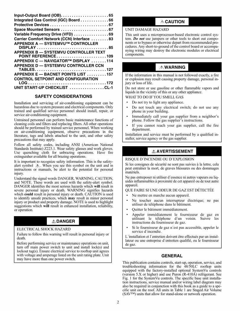
GENERALThis publication contains controls, start-up, operation, service, andtroubleshooting information for the 48/50LC rooftop unitsequipped with the factory-installed optional SystemVu controls(version 5.X or higher) and use Puron (R-410A) refrigerant. SeeFig. 1 for the SystemVu controls. The specific base unit installa-tion instructions, service manual and/or wiring label diagram mayalso be required in conjunction with this book as a guide to a spe-cific unit on the roof. All units in Table 1 are Staged Air Volume(SAV™) units that allow for stand-alone or network operation.
DANGER
ELECTRICAL SHOCK HAZARDFailure to follow this warning will result in personal injury ordeath.Before performing service or maintenance operations on unit,turn off main power switch to unit and install lock(s) andlockout tag(s). Ensure electrical service to rooftop unit agreeswith voltage and amperage listed on the unit rating plate. Unitmay have more than one power switch.
CAUTION
UNIT DAMAGE HAZARDThis unit uses a microprocessor-based electronic control sys-tem. Do not use jumpers or other tools to short out compo-nents or to bypass or otherwise depart from recommended pro-cedures. Any short-to-ground of the control board or accompa-nying wiring may destroy the electronic modules or electricalcomponents.
WARNING
If the information in this manual is not followed exactly, a fireor explosion may result causing property damage, personal in-jury or loss of life.Do not store or use gasoline or other flammable vapors andliquids in the vicinity of this or any other appliance.WHAT TO DO IF YOU SMELL GAS• Do not try to light any appliance.• Do not touch any electrical switch; do not use any
phone in your building.• Immediately call your gas supplier from a neighbor’s
phone. Follow the gas supplier’s instructions.• If you cannot reach your gas supplier, call the fire
department.Installation and service must be performed by a qualified in-staller, service agency or the gas supplier.
AVERTISSEMENT
RISQUE D´INCENDIE OU D´EXPLOSIONSi les consignes de sécurité ne sont pas suivies à la lettre, celapeut entraîner la mort, de graves blessures ou des dommagesmatériels.Ne pas entreposer ni utiliser d´essence ni autres vapeurs ou liq-uides inflammables à proximité de cet appareil ou de tout autreappareil.QUE FAIRE SI UNE ODEUR DE GAZ EST DÉTECTÉE• Ne mettre en marche aucun appareil.• Ne toucher aucun interrupteur électrique; ne pas
utiliser de téléphone dans le bâtiment.• Quitter le bâtiment immédiatement.• Appeler immédiatement le fournisseur de gaz en
utilisant le téléphone d´un voisin. Suivre lesinstructions du fournisseur de gaz.
• Si le fournisseur de gaz n´est pas accessible, appeler leservice d´incendie.
L´installation et l´entretien doivent être effectués par un instal-lateur ou une entreprise d´entretien qualifié, ou le fournisseurde gaz.
3
Fig. 1 — SystemVu Controls
Conventions Used in This ManualThe following conventions for discussing configuration points forthe local display (SystemVu controller or Navigator™ accessory)will be used in this manual.Menu paths will be written with the main menu name first,then any menus or submenus, each separated by an arrowsymbol () and will also be shown in bold and italics. As anexample, the General submenu, which is located in the Settingmain menu under Unit Configuration menu, would be writtenas SETTINGSUNIT CONFIGURATIONSGENERAL.This path name will show the user how to navigate through the lo-cal display to reach the desired menu. The user scrolls through theMenus using the up and down keys. The arrow symbol in the pathname represents pressing ENTER to move into the next level ofthe menu structure.Point names are referenced in parentheses and in bold and italicsas would be shown on the local display.CCN point names are also referenced for users configuring theunit with CCN software instead of the local display. SeeAppendix D.
BASIC CONTROL USAGE
SystemVu™ Control (factory-installed option)The SystemVu control is a comprehensive unit-management sys-tem. The control system is easy to access, configure, diagnose andtroubleshoot.The SystemVu control system is fully communicating and cable-ready for connection to the Carrier Comfort Network® (CCN),Carrier i-Vu®, and Third Party BACnet1 building managementsystems. The control provides high-speed communications for re-mote monitoring via the Internet. Multiple units can be linked to-gether (and to other Direct Digital Control (DDC) equipped units)using a 3-wire communication bus.The SystemVu control system is easy to access through the use ofa integrated display module. A computer is not required for start-up. Access to control menus is simplified by the ability to quicklyselect from 7 main menu items. An expanded readout provides de-tailed explanations of control information. Only six buttons are re-quired to maneuver through the entire controls menu. The displayreadout is designed to be visible even in bright sunlight.
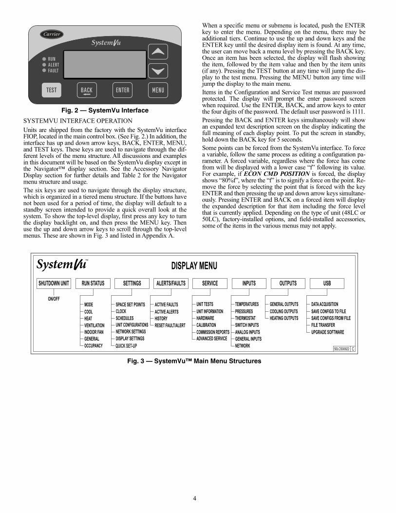
SystemVu InterfaceThis integrated device is the keypad interface used to access thecontrol information, read sensor values, and test the unit. The in-terface is located in the main control box and is standard on allunits. The interface is a 6-key, 4x30 character, LCD (liquid-crystaldisplay) display module. The interface also contains Status LEDs.(See Fig. 2.) The interface is easy to operate using 6 buttons andthe main menu structures shown in Fig. 3.Through the SystemVu interface, the user can access all of theinputs and outputs to check on their values and status, configureoperating parameters, and evaluate the current decision status foroperating modes. The control also includes an alarm historywhich can be accessed from the display. The user can access abuilt-in test routine that can be used at start-up commissioningand troubleshooting.
Table 1 — Rooftop Units
MODEL SIZE NOMINAL TONS
48/50LC
04 305 406 507 608 7.509 8.512 1014 12.517 1520 17.524 2026 23
1. BACnet is a trademark of ASHRAE.
4
Fig. 2 — SystemVu Interface
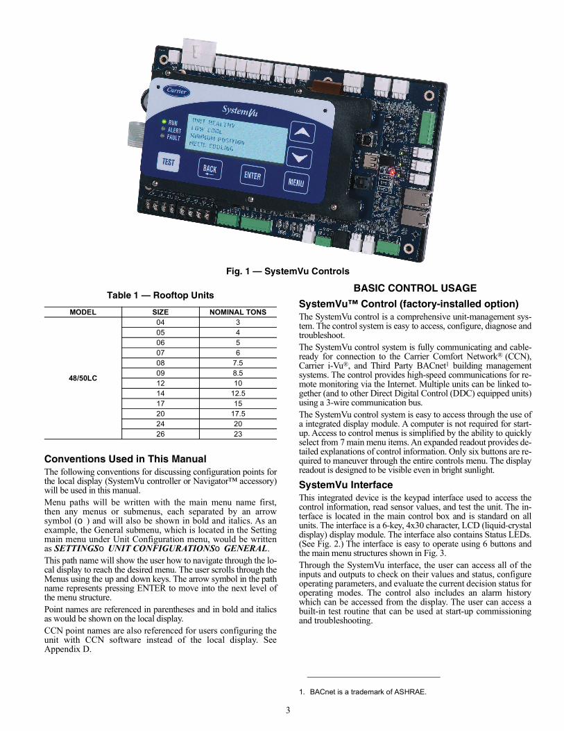
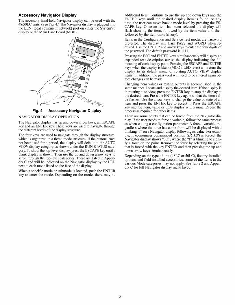
SYSTEMVU INTERFACE OPERATIONUnits are shipped from the factory with the SystemVu interfaceFIOP, located in the main control box. (See Fig. 2.) In addition, theinterface has up and down arrow keys, BACK, ENTER, MENU,and TEST keys. These keys are used to navigate through the dif-ferent levels of the menu structure. All discussions and examplesin this document will be based on the SystemVu display except inthe Navigator™ display section. See the Accessory NavigatorDisplay section for further details and Table 2 for the Navigatormenu structure and usage.The six keys are used to navigate through the display structure,which is organized in a tiered menu structure. If the buttons havenot been used for a period of time, the display will default to astandby screen intended to provide a quick overall look at thesystem. To show the top-level display, first press any key to turnthe display backlight on, and then press the MENU key. Thenuse the up and down arrow keys to scroll through the top-levelmenus. These are shown in Fig. 3 and listed in Appendix A.
When a specific menu or submenu is located, push the ENTERkey to enter the menu. Depending on the menu, there may beadditional tiers. Continue to use the up and down keys and theENTER key until the desired display item is found. At any time,the user can move back a menu level by pressing the BACK key.Once an item has been selected, the display will flash showingthe item, followed by the item value and then by the item units(if any). Pressing the TEST button at any time will jump the dis-play to the test menu. Pressing the MENU button any time willjump the display to the main menu.Items in the Configuration and Service Test menus are passwordprotected. The display will prompt the enter password screenwhen required. Use the ENTER, BACK, and arrow keys to enterthe four digits of the password. The default user password is 1111.Pressing the BACK and ENTER keys simultaneously will showan expanded text description screen on the display indicating thefull meaning of each display point. To put the screen in standby,hold down the BACK key for 5 seconds.Some points can be forced from the SystemVu interface. To forcea variable, follow the same process as editing a configuration pa-rameter. A forced variable, regardless where the force has comefrom will be displayed with a lower case “f” following its value.For example, if ECON CMD POSITION is forced, the displayshows “80%f”, where the “f” is to signify a force on the point. Re-move the force by selecting the point that is forced with the keyENTER and then pressing the up and down arrow keys simultane-ously. Pressing ENTER and BACK on a forced item will displaythe expanded description for that item including the force levelthat is currently applied. Depending on the type of unit (48LC or50LC), factory-installed options, and field-installed accessories,some of the items in the various menus may not apply.
Fig. 3 — SystemVu™ Main Menu Structures
5
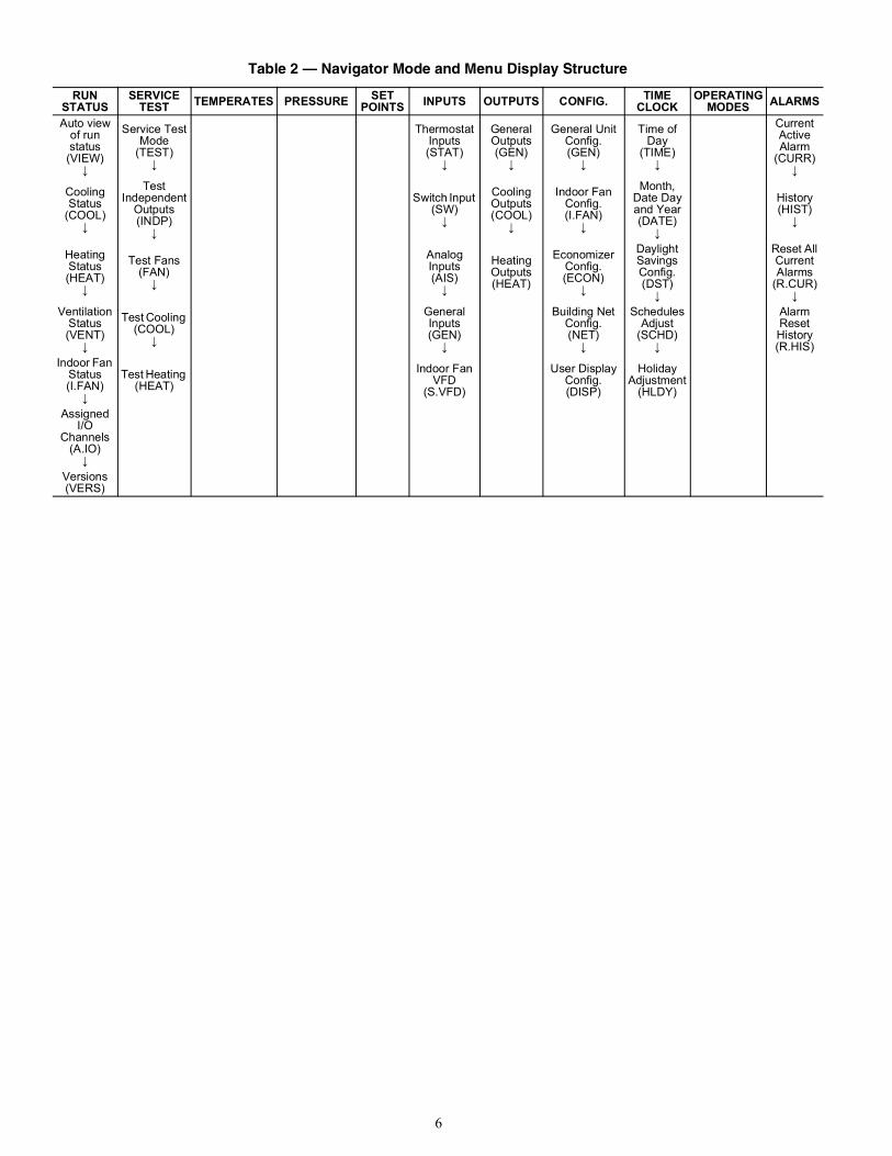
Accessory Navigator DisplayThe accessory hand-held Navigator display can be used with the48/50LC units. (See Fig. 4.) The Navigator display is plugged intothe LEN (local equipment network) port on either the SystemVudisplay or the Main Base Board (MBB).
Fig. 4 — Accessory Navigator Display
NAVIGATOR DISPLAY OPERATIONThe Navigator display has up and down arrow keys, an ESCAPEkey and an ENTER key. These keys are used to navigate throughthe different levels of the display structure.The four keys are used to navigate through the display structure,which is organized in a tiered mode structure. If the buttons havenot been used for a period, the display will default to the AUTOVIEW display category as shown under the RUN STATUS cate-gory. To show the top-level display, press the ESCAPE key until ablank display is shown. Then use the up and down arrow keys toscroll through the top-level categories. These are listed in Appen-dix C and will be indicated on the Navigator display by the LEDnext to each mode listed on the face of the display.When a specific mode or submode is located, push the ENTERkey to enter the mode. Depending on the mode, there may be
additional tiers. Continue to use the up and down keys and theENTER keys until the desired display item is found. At anytime, the user can move back a mode level by pressing the ES-CAPE key. Once an item has been selected the display willflash showing the item, followed by the item value and thenfollowed by the item units (if any).Items in the Configuration and Service Test modes are passwordprotected. The display will flash PASS and WORD when re-quired. Use the ENTER and arrow keys to enter the four digits ofthe password. The default password is 1111.Pressing the ESC and ENTER keys simultaneously will display anexpanded text description across the display indicating the fullmeaning of each display point. Pressing the ESCAPE and ENTERkeys when the display is blank (MODE LED level) will return thedisplay to its default menu of rotating AUTO VIEW displayitems. In addition, the password will need to be entered again be-fore changes can be made.Changing item values or testing outputs is accomplished in thesame manner. Locate and display the desired item. If the display isin rotating auto-view, press the ENTER key to stop the display atthe desired item. Press the ENTER key again so that the item val-ue flashes. Use the arrow keys to change the value of state of anitem and press the ENTER key to accept it. Press the ESCAPEkey and the item, value or units display will resume. Repeat theprocess as required for other items.There are some points that can be forced from the Navigator dis-play. If the user needs to force a variable, follow the same processas when editing a configuration parameter. A forced variable, re-gardless where the force has come from will be displayed with ablinking “f” on a Navigator display following its value. For exam-ple, if economizer commanded position (EC.CP) is forced, theNavigator display shows “80f”, where the “f” is blinking to signi-fy a force on the point. Remove the force by selecting the pointthat is forced with the key ENTER and then pressing the up anddown arrow keys simultaneously.Depending on the type of unit (48LC or 50LC), factory-installedoptions, and field-installed accessories, some of the items in thevarious Mode categories may not apply. See Table 2 and Appen-dix C for full Navigator display menu layout.
Run StatusService TestTemperaturesPressures
SetpointsInputs
OutputsConfigurationTime Clock
Operating ModesAlarms
ENTER
E S C
M O D EAlarm Status
TIMEEWTLWTSETP
1 2 . 5 85 4 . 6 ° F4 4 . 1 ° F4 4 . 0 ° F
N A V I G A T O R
C om f o r t L i n k
6
Table 2 — Navigator Mode and Menu Display Structure
RUN STATUS
SERVICE TEST TEMPERATES PRESSURE SET
POINTS INPUTS OUTPUTS CONFIG. TIME CLOCK
OPERATING MODES ALARMS
Auto view of run status (VIEW)
↓
Service TestMode
(TEST)↓
Thermostat Inputs (STAT)
↓
General Outputs (GEN)
↓
General Unit Config.(GEN)
↓
Time of Day
(TIME)↓
Current Active Alarm
(CURR)↓
Cooling Status
(COOL)↓
Test Independent
Outputs (INDP)
↓
Switch Input (SW)
↓
Cooling Outputs (COOL)
↓
Indoor Fan Config. (I.FAN)
↓
Month, Date Day and Year (DATE)
↓
History (HIST)
↓
Heating Status (HEAT)
↓
Test Fans (FAN)
↓
Analog Inputs(AIS)
↓
Heating Outputs (HEAT)
Economizer Config.(ECON)
↓
Daylight Savings Config. (DST)
↓
Reset All Current Alarms
(R.CUR)↓
Ventilation Status (VENT)
↓
Test Cooling (COOL)
↓
General Inputs (GEN)
↓
Building Net Config.(NET)
↓
Schedules Adjust
(SCHD)↓
Alarm Reset History (R.HIS)
Indoor Fan Status (I.FAN)
↓
Test Heating (HEAT)
Indoor Fan VFD
(S.VFD)
User Display Config.(DISP)
Holiday Adjustment
(HLDY)
AssignedI/O
Channels (A.IO)
↓Versions (VERS)
7
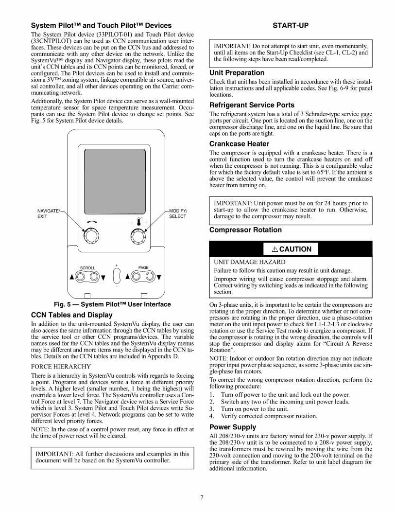
System Pilot™ and Touch Pilot™ DevicesThe System Pilot device (33PILOT-01) and Touch Pilot device(33CNTPILOT) can be used as CCN communication user inter-faces. These devices can be put on the CCN bus and addressed tocommunicate with any other device on the network. Unlike theSystemVu™ display and Navigator display, these pilots read theunit’s CCN tables and its CCN points can be monitored, forced, orconfigured. The Pilot devices can be used to install and commis-sion a 3V™ zoning system, linkage compatible air source, univer-sal controller, and all other devices operating on the Carrier com-municating network.Additionally, the System Pilot device can serve as a wall-mountedtemperature sensor for space temperature measurement. Occu-pants can use the System Pilot device to change set points. SeeFig. 5 for System Pilot device details.
Fig. 5 — System Pilot™ User Interface
CCN Tables and DisplayIn addition to the unit-mounted SystemVu display, the user canalso access the same information through the CCN tables by usingthe service tool or other CCN programs/devices. The variablenames used for the CCN tables and the SystemVu display menusmay be different and more items may be displayed in the CCN ta-bles. Details on the CCN tables are included in Appendix D.FORCE HIERARCHYThere is a hierarchy in SystemVu controls with regards to forcinga point. Programs and devices write a force at different prioritylevels. A higher level (smaller number, 1 being the highest) willoverride a lower level force. The SystemVu controller uses a Con-trol Force at level 7. The Navigator device writes a Service Forcewhich is level 3. System Pilot and Touch Pilot devices write Su-pervisor Forces at level 4. Network programs can be set to writedifferent level priority forces.NOTE: In the case of a control power reset, any force in effect atthe time of power reset will be cleared.
START-UP
Unit PreparationCheck that unit has been installed in accordance with these instal-lation instructions and all applicable codes. See Fig. 6-9 for panellocations.
Refrigerant Service PortsThe refrigerant system has a total of 3 Schrader-type service gageports per circuit. One port is located on the suction line, one on thecompressor discharge line, and one on the liquid line. Be sure thatcaps on the ports are tight.
Crankcase HeaterThe compressor is equipped with a crankcase heater. There is acontrol function used to turn the crankcase heaters on and offwhen the compressor is not running. This is a configurable valuefor which the factory default value is set to 65°F. If the ambient isabove the selected value, the control will prevent the crankcaseheater from turning on.
Compressor Rotation
On 3-phase units, it is important to be certain the compressors arerotating in the proper direction. To determine whether or not com-pressors are rotating in the proper direction, use a phase-rotationmeter on the unit input power to check for L1-L2-L3 or clockwiserotation or use the Service Test mode to energize a compressor. Ifthe compressor is rotating in the wrong direction, the controls willstop the compressor and display alarm for “Circuit A ReverseRotation”.NOTE: Indoor or outdoor fan rotation direction may not indicateproper input power phase sequence, as some 3-phase units use sin-gle-phase fan motors.To correct the wrong compressor rotation direction, perform thefollowing procedure:1. Turn off power to the unit and lock out the power.2. Switch any two of the incoming unit power leads.3. Turn on power to the unit.4. Verify corrected compressor rotation.
Power SupplyAll 208/230-v units are factory wired for 230-v power supply. Ifthe 208/230-v unit is to be connected to a 208-v power supply,the transformers must be rewired by moving the wire from the230-volt connection and moving to the 200-volt terminal on theprimary side of the transformer. Refer to unit label diagram foradditional information.
IMPORTANT: All further discussions and examples in thisdocument will be based on the SystemVu controller.
SCROLL+
-
NAVIGATE/EXIT
MODIFY/SELECT
PAGE
IMPORTANT: Do not attempt to start unit, even momentarily,until all items on the Start-Up Checklist (see CL-1, CL-2) andthe following steps have been read/completed.
IMPORTANT: Unit power must be on for 24 hours prior tostart-up to allow the crankcase heater to run. Otherwise,damage to the compressor may result.
CAUTION
UNIT DAMAGE HAZARDFailure to follow this caution may result in unit damage.Improper wiring will cause compressor stoppage and alarm.Correct wiring by switching leads as indicated in the followingsection.
8
Internal WiringCheck all electrical connections in unit control boxes; tighten asrequired.
Evaporator FanThe evaporator fan should be checked and may need to beadjusted for specific applications. The unit will have a belt drivemotor powered by a Variable Frequency Drive (VFD). Refer tothe unit product data for fan performance tables and physical data.The fan belt and variable pulleys are factory installed and set, butmay need to be adjusted for specific applications. Check the fan toensure its rotation is in the proper direction before adjusting per-formance. To alter fan performance, first adjust the pulley settingsto provide the application’s full load design air flow when runningat the IDF Maximum Fan Speed (MAXIMUM IDF SPEED).The unit operating speeds can then be adjusted with Free CoolingIDF Speed (FREE COOL IDF SPEED), High Cooling IDFSpeed (HIGH COOL IDF SPEED), Medium Cooling IDF Speed(MED COOL IDF SPEED), Low Cooling IDF Speed (LOWCOOL IDF SPEED), Heating IDF Speed (HEATING IDFSPEED), and Ventilation Only IDF Speed (VENT IDF SPEED).Set the indoor fan pulley to the greater application design pointCFM for heating or cooling and equal to 100% fan speed. Adjustthe Heating Fan Speed and High Cooling Fan Speed so that theCFM is not lower than the minimum CFM allowed in the productdata. If the exact CFM cannot be set by the half turn pulley set-tings then adjust the IDF Maximum Fan Speed (MAXIMUM IDFSPEED) to fine tune the CFM to the application requirements.
The VFD’s settings should not be used for adjusting fan perfor-mance. Specific VFD information can be found in the major com-ponents section.
Condenser Fans and MotorsCondenser fans and motors are factory set.
Return-Air FiltersCheck that correct filters are installed in filter tracks (see phys-ical data table in unit product data). Do not operate unit with-out return-air filters. Determine the filter change run time(DIRTY FILTER TIME) to be set in the quick setup configu-rations menu.
Outdoor-Air Inlet ScreensOutdoor-air inlet screens must be in place before operating unit.
Accessory InstallationCheck to make sure that all accessories including space thermo-stats and sensors have been installed and wired as required by theinstructions and unit wiring diagrams.
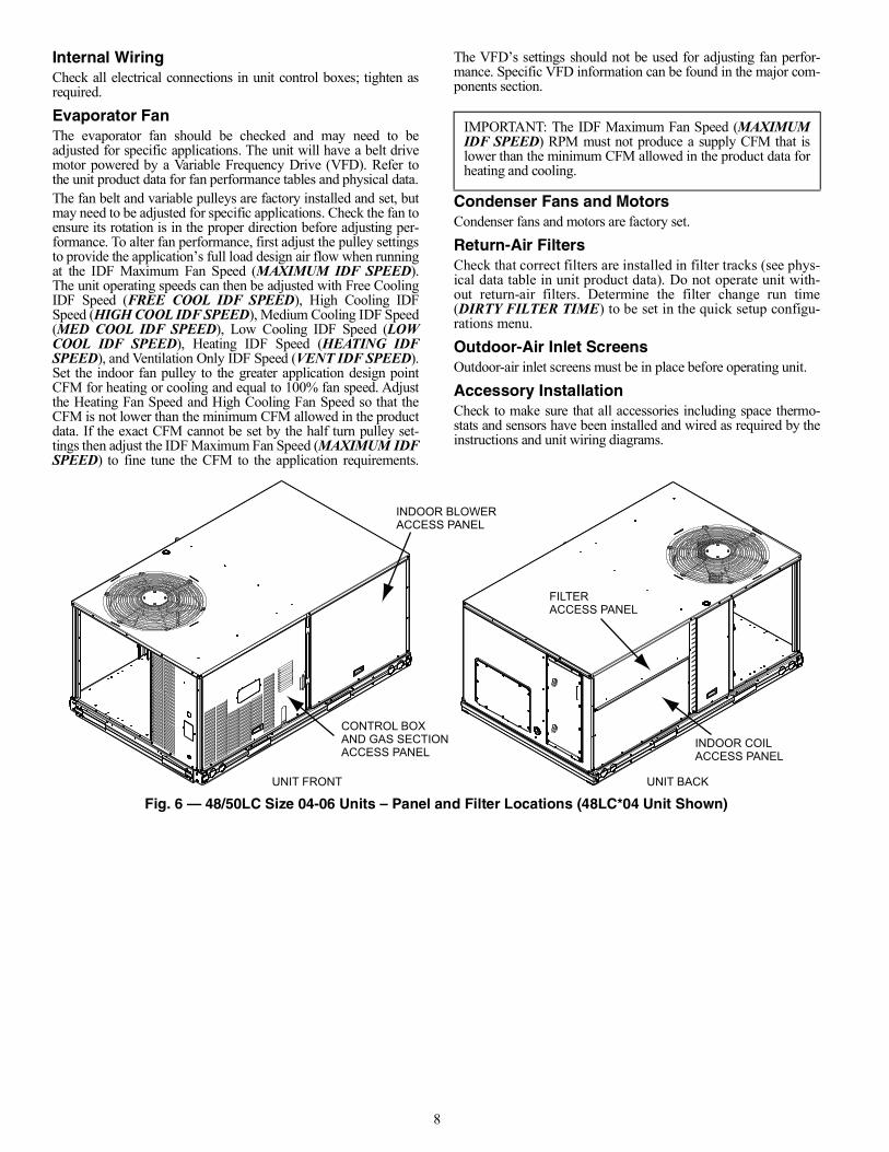
Fig. 6 — 48/50LC Size 04-06 Units – Panel and Filter Locations (48LC*04 Unit Shown)
IMPORTANT: The IDF Maximum Fan Speed (MAXIMUMIDF SPEED) RPM must not produce a supply CFM that islower than the minimum CFM allowed in the product data forheating and cooling.
INDOOR BLOWERACCESS PANEL
CONTROL BOXAND GAS SECTIONACCESS PANEL
INDOOR COILACCESS PANEL
FILTER ACCESS PANEL
UNIT BACKUNIT FRONT
9
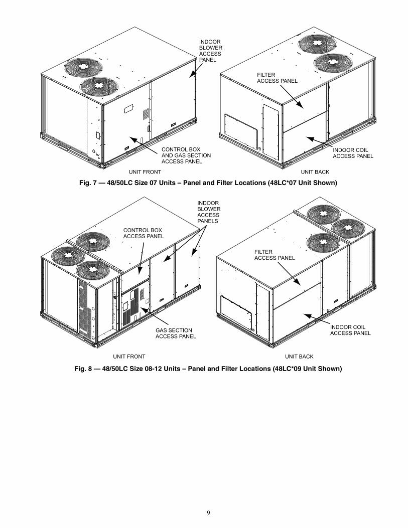
Fig. 7 — 48/50LC Size 07 Units – Panel and Filter Locations (48LC*07 Unit Shown)
Fig. 8 — 48/50LC Size 08-12 Units – Panel and Filter Locations (48LC*09 Unit Shown)
INDOORBLOWERACCESSPANEL
CONTROL BOXAND GAS SECTIONACCESS PANEL
INDOOR COILACCESS PANEL
FILTER ACCESS PANEL
UNIT BACKUNIT FRONT
INDOORBLOWERACCESSPANELS
GAS SECTIONACCESS PANEL
INDOOR COILACCESS PANEL
FILTER ACCESS PANEL
UNIT BACKUNIT FRONT
CONTROL BOXACCESS PANEL
10
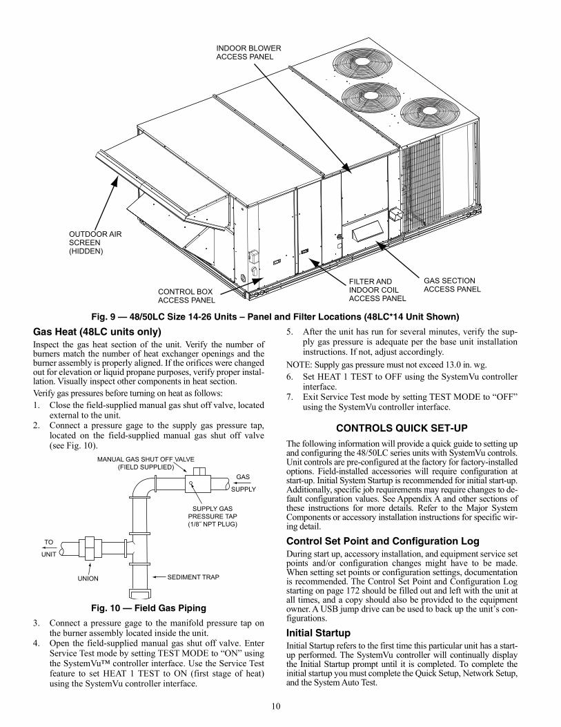
Fig. 9 — 48/50LC Size 14-26 Units – Panel and Filter Locations (48LC*14 Unit Shown)
Gas Heat (48LC units only)Inspect the gas heat section of the unit. Verify the number ofburners match the number of heat exchanger openings and theburner assembly is properly aligned. If the orifices were changedout for elevation or liquid propane purposes, verify proper instal-lation. Visually inspect other components in heat section.Verify gas pressures before turning on heat as follows:1. Close the field-supplied manual gas shut off valve, located
external to the unit.2. Connect a pressure gage to the supply gas pressure tap,
located on the field-supplied manual gas shut off valve(see Fig. 10).
Fig. 10 — Field Gas Piping
3. Connect a pressure gage to the manifold pressure tap onthe burner assembly located inside the unit.
4. Open the field-supplied manual gas shut off valve. EnterService Test mode by setting TEST MODE to “ON” usingthe SystemVu™ controller interface. Use the Service Testfeature to set HEAT 1 TEST to ON (first stage of heat)using the SystemVu controller interface.
5. After the unit has run for several minutes, verify the sup-ply gas pressure is adequate per the base unit installationinstructions. If not, adjust accordingly.
NOTE: Supply gas pressure must not exceed 13.0 in. wg.6. Set HEAT 1 TEST to OFF using the SystemVu controller
interface.7. Exit Service Test mode by setting TEST MODE to “OFF”
using the SystemVu controller interface.
CONTROLS QUICK SET-UPThe following information will provide a quick guide to setting upand configuring the 48/50LC series units with SystemVu controls.Unit controls are pre-configured at the factory for factory-installedoptions. Field-installed accessories will require configuration atstart-up. Initial System Startup is recommended for initial start-up.Additionally, specific job requirements may require changes to de-fault configuration values. See Appendix A and other sections ofthese instructions for more details. Refer to the Major SystemComponents or accessory installation instructions for specific wir-ing detail.
Control Set Point and Configuration LogDuring start up, accessory installation, and equipment service setpoints and/or configuration changes might have to be made.When setting set points or configuration settings, documentationis recommended. The Control Set Point and Configuration Logstarting on page 172 should be filled out and left with the unit atall times, and a copy should also be provided to the equipmentowner. A USB jump drive can be used to back up the unit’s con-figurations.
Initial StartupInitial Startup refers to the first time this particular unit has a start-up performed. The SystemVu controller will continually displaythe Initial Startup prompt until it is completed. To complete theinitial startup you must complete the Quick Setup, Network Setup,and the System Auto Test.
OUTDOOR AIRSCREEN(HIDDEN)
CONTROL BOXACCESS PANEL
FILTER AND INDOOR COILACCESS PANEL
INDOOR BLOWERACCESS PANEL
GAS SECTIONACCESS PANEL
MANUAL GAS SHUT OFF VALVE(FIELD SUPPLIED)
SUPPLY GASPRESSURE TAP(1/8˝ NPT PLUG)
GAS
SUPPLY
SEDIMENT TRAPUNION
TO
UNIT
11
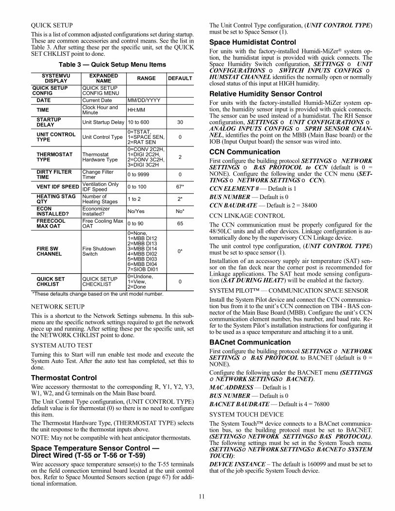
QUICK SETUPThis is a list of common adjusted configurations set during startup.These are common accessories and control means. See the list inTable 3. After setting these per the specific unit, set the QUICKSET CHKLIST point to done.
NETWORK SETUPThis is a shortcut to the Network Settings submenu. In this sub-menu are the specific network settings required to get the networkpiece up and running. After setting these per the specific unit, setthe NETWORK CHKLIST point to done.SYSTEM AUTO TESTTurning this to Start will run enable test mode and execute theSystem Auto Test. After the auto test has completed, set this todone.
Thermostat ControlWire accessory thermostat to the corresponding R, Y1, Y2, Y3,W1, W2, and G terminals on the Main Base board.The Unit Control Type configuration, (UNIT CONTROL TYPE)default value is for thermostat (0) so there is no need to configurethis item.The Thermostat Hardware Type, (THERMOSTAT TYPE) selectsthe unit response to the thermostat inputs above.NOTE: May not be compatible with heat anticipator thermostats.
Space Temperature Sensor Control — Direct Wired (T-55 or T-56 or T-59)Wire accessory space temperature sensor(s) to the T-55 terminalson the field connection terminal board located at the unit controlbox. Refer to Space Mounted Sensors section (page 67) for addi-tional information.
The Unit Control Type configuration, (UNIT CONTROL TYPE)must be set to Space Sensor (1).
Space Humidistat ControlFor units with the factory-installed Humidi-MiZer® system op-tion, the humidistat input is provided with quick connects. TheSpace Humidity Switch configuration, SETTINGS UNITCONFIGURATIONS SWITCH INPUTS CONFIGS HUMSTAT CHANNEL identifies the normally open or normallyclosed status of this input at HIGH humidity.
Relative Humidity Sensor ControlFor units with the factory-installed Humidi-MiZer system op-tion, the humidity sensor input is provided with quick connects.The sensor can be used instead of a humidistat. The RH Sensorconfiguration, SETTINGS UNIT CONFIGURATIONS ANALOG INPUTS CONFIGS SPRH SENSOR CHAN-NEL, identifies the point on the MBB (Main Base board) or theIOB (Input Output board) the sensor was wired into.
CCN CommunicationFirst configure the building protocol SETTINGS NETWORKSETTINGS BAS PROTOCOL to CCN (default is 0 =NONE). Configure the following under the CCN menu (SET-TINGS NETWORK SETTINGS CCN).CCN ELEMENT # — Default is 1BUS NUMBER — Default is 0CCN BAUDRATE — Default is 2 = 38400CCN LINKAGE CONTROLThe CCN communication must be properly configured for the48/50LC units and all other devices. Linkage configuration is au-tomatically done by the supervisory CCN Linkage device.The unit control type configuration, (UNIT CONTROL TYPE)must be set to space sensor (1).Installation of an accessory supply air temperature (SAT) sen-sor on the fan deck near the corner post is recommended forLinkage applications. The SAT heat mode sensing configura-tion (SAT DURING HEAT?) will be enabled at the factory.SYSTEM PILOT™ — COMMUNICATION SPACE SENSORInstall the System Pilot device and connect the CCN communica-tion bus from it to the unit’s CCN connection on TB4 - BAS con-nector of the Main Base Board (MBB). Configure the unit’s CCNcommunication element number, bus number, and baud rate. Re-fer to the System Pilot’s installation instructions for configuring itto be used as a space temperature and attaching it to a unit.
BACnet CommunicationFirst configure the building protocol SETTINGS NETWORKSETTINGS BAS PROTOCOL to BACNET (default is 0 =NONE).Configure the following under the BACNET menu (SETTINGSNETWORK SETTINGSBACNET).MAC ADDRESS — Default is 1BUS NUMBER — Default is 0BACNET BAUDRATE — Default is 4 = 76800SYSTEM TOUCH DEVICEThe System Touch™ device connects to a BACnet communica-tion bus, so the building protocol must be set to BACNET.(SETTINGSNETWORK SETTINGSBAS PROTOCOL).The following settings must be set in the System Touch menu.(SETTINGSNETWORK SETTINGSBACNETSYSTEMTOUCH):DEVICE INSTANCE – The default is 160099 and must be set tothat of the job specific System Touch device.
Table 3 — Quick Setup Menu Items
SYSTEMVU DISPLAY
EXPANDED NAME RANGE DEFAULT
QUICK SETUPCONFIG
QUICK SETUPCONFIG MENU
DATE Current Date MM/DD/YYYY
TIME Clock Hour and Minute HH:MM
STARTUP DELAY Unit Startup Delay 10 to 600 30
UNIT CONTROL TYPE Unit Control Type
0=TSTAT,1=SPACE SEN,2=RAT SEN
0
THERMOSTAT TYPE
Thermostat Hardware Type
0=CONV 2C2H,1=DIGI 2C2H,2=CONV 3C2H,3=DIGI 3C2H
2
DIRTY FILTER TIME
Change Filter Timer 0 to 9999 0
VENT IDF SPEED Ventilation Only IDF Speed 0 to 100 67*
HEATING STAG QTY
Number of Heating Stages 1 to 2 2*
ECON INSTALLED?
Economizer Installed? No/Yes No*
FREECOOL MAX OAT
Free Cooling Max OAT 0 to 90 65
FIRE SW CHANNEL
Fire Shutdown Switch
0=None,1=MBB DI122=MBB DI133=MBB DI144=MBB DI025=MBB DI036=MBB DI047=SIOB DI01
0*
QUICK SET CHKLIST
QUICK SETUP CHECKLIST
0=Undone,1=View,2=Done
0
*These defaults change based on the unit model number.
12
POLLING RATE – The default is 0 to prevent scanning. Thismust be set to at least 10 to allow communication with the SystemTouch device.
RNET Communication Space SensorsThe SystemVu controller will support the use of ZS sensors andEquipment Touch™ on the RNET communication bus connec-tions J20 and J24. Set the Unit Control Type configuration tospace sensor to enable unit control with these sensors. RNETcommunication can only be enabled or disabled through BACnetcommunication and is defaulted to enabled.
AccessoriesBelow are quick configuration settings for field-installed accesso-ries. When factory-installed as options, the points will already beconfigured. See the Space Mounted Sensors section (page 67),third party control, control connection tables, and CCN or Displayparameter tables for any accessories not mentioned below and re-fer to installation manual of the accessory.CONDENSATE OVERFLOWWhen Condensate Overflow (COFS) sensor is installed in thefield, the unit must be configured for it by setting SETTINGS UNIT CONFIGURATION SWITCH INPUTS CONFIGS COFS CHANNEL to the channel number the switch was wiredinto. ECONOMIZERWhen an economizer is field-installed, the unit must be configuredfor it by setting SETTINGS UNIT CONFIGURATIONSECONOMIZER ECON INSTALLED? to YES. The defaultsettings for the other economizer configurations should besatisfactory. If they need to be changed, additional informationabout these configuration settings can be found in “EconomizerOperation” on page 27.POWER EXHAUSTWhen power exhaust is field-installed, the unit must be configuredfor it by setting SETTINGS UNIT CONFIGURATIONS ECONOMIZER POWER EXHAUST CONFIGS PE1RELAY CHANNEL to the channel the accessory was wired into.The default settings for the other power exhaust configurationsshould be satisfactory. If they need to be changed, additional infor-mation about these configurations can be found in “Power Ex-haust” on page 29.ELECTRIC HEATWhen electric heat is field-installed, the number of electric heatstages must be configured by setting SETTINGS UNIT CON-FIGURATIONS HEATING HEATING STAGE QTY perthe installed heater.FIRE SHUTDOWNWhen Fire Shutdown or Smoke Detector sensors are field-installed, the unit must be configured for it by setting SETTINGS UNIT CONFIGURATIONS SWITCH INPUTS CON-FIGS FIRE SW CHANNEL to the channel number the switchwas wired into.OUTDOOR ENTHALPYWhen an Outdoor Enthalpy sensor is field-installed, the unitmust be configured for it by setting SETTINGS UNIT CON-FIGURATIONS ANALOG INPUTS CONFIGS OARHSENSOR CHAN to the channel number the sensor was wiredinto.IAQ SENSORWhen a CO2 sensor is field-installed, the unit must be configuredfor it by setting SETTINGS UNIT CONFIGURATIONS ANALOG INPUT CONFIGS IAQ SENSOR CHAN selectsthe unit response to this input. Default conversion to 0 to 2000ppm.
OAQ SENSORWhen an Outdoor Air Quality sensor is field-installed, the unitmust be configured for it by setting SETTINGS UNITCONFIGURATIONS ANALOG INPUT CONFIGS OAQ SENSOR CHAN. Default conversion to 0 to 2000 ppm.FILTER STATUSWhen a Filter Status sensor is field-installed, the unit must beconfigured for it by setting SETTINGS UNIT CONFIGU-RATIONS SWITCH INPUT CONFIGS FILTER SWCHANNEL to the channel number the switch was wired into.
Programming Operating SchedulesWhen the building automation system you have the SystemVu™controller configured for (BAS Protocol Select) is None (0) orCCN (1) the SystemVu controller can follow a standard CCN oc-cupancy table. The occupancy can be modified from any CCNtool or from the local display.OCCUPANCY SCHEDULEFor flexibility of scheduling, the occupancy programming is bro-ken into eight separate periods. For each period the schedulecontains the following fields: Day of Week, Occupied From,and Occupied To.When the Network protocol as configured in SETTINGS NETWORK SETTINGS BAS PROTOCOL is BACnet, thecontroller will support a BACnet weekly schedule and all typesof override and exception schedules allowed for BACnetlevel 12 compliance. SystemVu will also support a special i-Vutype of BACnet schedule sent from i-Vu or WebCTRL. Pleaserefer to the iVu operator’s manual for more information.Day Of WeekThe day of week configuration consists of eight fields correspond-ing to the seven days of the week and a holiday field in the follow-ing order: Monday, Tuesday, Wednesday, Thursday, Friday, Satur-day, Sunday, and Holiday. If a 1 is configured in the correspondingplace for a certain day of the week, the related “Occupied from”and “Occupied to” times for that period will take effect on that dayof the week. If a 1 is placed in the holiday field, the related timeswill take effect on a day configured as a holiday. A zero means theschedule period will not apply to that day.Day of week: Range 0 or 1Default Values 0 for all of the periods.Occupied FromThis field is used to configure the hour and minute, in 24 hourclock, that the mode for the controller will switch to occupied.Occupied From: Units Hours:MinutesRange 00:00 to 24:00(Minutes 00 to 59)Default Value 00:00Occupied ToThis field is used to configure the hour and minute, in 24 hourclock, that the mode for the controller switches from occupied tounoccupied.Occupied To: Units Hours:MinutesRange 00:00 to 24:00(Minutes 00 to 59)Default Value 00:00When the building automation system configured to (BASPROTOCOL) is BACnet, the occupancy and holiday informa-tion will be reset to defaults in preparation for receiving aBACnet occupancy object. While participating on a BACnetnetwork these configurations cannot be changed at the local in-terface or with CCN tools. All scheduling is done from theBACnet interface designated to provide schedules.
13
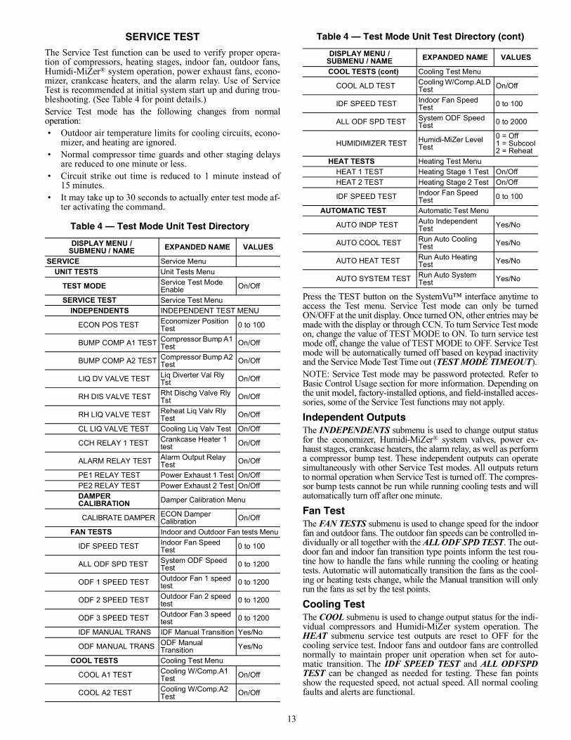
SERVICE TESTThe Service Test function can be used to verify proper opera-tion of compressors, heating stages, indoor fan, outdoor fans,Humidi-MiZer® system operation, power exhaust fans, econo-mizer, crankcase heaters, and the alarm relay. Use of ServiceTest is recommended at initial system start up and during trou-bleshooting. (See Table 4 for point details.)Service Test mode has the following changes from normaloperation:• Outdoor air temperature limits for cooling circuits, econo-
mizer, and heating are ignored.• Normal compressor time guards and other staging delays
are reduced to one minute or less.• Circuit strike out time is reduced to 1 minute instead of
15 minutes.• It may take up to 30 seconds to actually enter test mode af-
ter activating the command.
Press the TEST button on the SystemVu™ interface anytime toaccess the Test menu. Service Test mode can only be turnedON/OFF at the unit display. Once turned ON, other entries may bemade with the display or through CCN. To turn Service Test modeon, change the value of TEST MODE to ON. To turn service testmode off, change the value of TEST MODE to OFF. Service Testmode will be automatically turned off based on keypad inactivityand the Service Mode Test Time out (TEST MODE TIMEOUT).NOTE: Service Test mode may be password protected. Refer toBasic Control Usage section for more information. Depending onthe unit model, factory-installed options, and field-installed acces-sories, some of the Service Test functions may not apply.
Independent OutputsThe INDEPENDENTS submenu is used to change output statusfor the economizer, Humidi-MiZer® system valves, power ex-haust stages, crankcase heaters, the alarm relay, as well as performa compressor bump test. These independent outputs can operatesimultaneously with other Service Test modes. All outputs returnto normal operation when Service Test is turned off. The compres-sor bump tests cannot be run while running cooling tests and willautomatically turn off after one minute.
Fan TestThe FAN TESTS submenu is used to change speed for the indoorfan and outdoor fans. The outdoor fan speeds can be controlled in-dividually or all together with the ALL ODF SPD TEST. The out-door fan and indoor fan transition type points inform the test rou-tine how to handle the fans while running the cooling or heatingtests. Automatic will automatically transition the fans as the cool-ing or heating tests change, while the Manual transition will onlyrun the fans as set by the test points.
Cooling TestThe COOL submenu is used to change output status for the indi-vidual compressors and Humidi-MiZer system operation. TheHEAT submenu service test outputs are reset to OFF for thecooling service test. Indoor fans and outdoor fans are controllednormally to maintain proper unit operation when set for auto-matic transition. The IDF SPEED TEST and ALL ODFSPDTEST can be changed as needed for testing. These fan pointsshow the requested speed, not actual speed. All normal coolingfaults and alerts are functional.
Table 4 — Test Mode Unit Test Directory
DISPLAY MENU /SUBMENU / NAME EXPANDED NAME VALUES
SERVICE Service MenuUNIT TESTS Unit Tests Menu
TEST MODE Service Test Mode Enable On/Off
SERVICE TEST Service Test MenuINDEPENDENTS INDEPENDENT TEST MENU
ECON POS TEST Economizer Position Test 0 to 100
BUMP COMP A1 TEST Compressor Bump A1 Test On/Off
BUMP COMP A2 TEST Compressor Bump A2 Test On/Off
LIQ DV VALVE TEST Liq Diverter Val Rly Tst On/Off
RH DIS VALVE TEST Rht Dischg Valve Rly Tst On/Off
RH LIQ VALVE TEST Reheat Liq Valv Rly Test On/Off
CL LIQ VALVE TEST Cooling Liq Valv Test On/Off
CCH RELAY 1 TEST Crankcase Heater 1 test On/Off
ALARM RELAY TEST Alarm Output Relay Test On/Off
PE1 RELAY TEST Power Exhaust 1 Test On/OffPE2 RELAY TEST Power Exhaust 2 Test On/OffDAMPER CALIBRATION Damper Calibration Menu
CALIBRATE DAMPER ECON Damper Calibration On/Off
FAN TESTS Indoor and Outdoor Fan tests Menu
IDF SPEED TEST Indoor Fan Speed Test 0 to 100
ALL ODF SPD TEST System ODF Speed Test 0 to 1200
ODF 1 SPEED TEST Outdoor Fan 1 speed test 0 to 1200
ODF 2 SPEED TEST Outdoor Fan 2 speed test 0 to 1200
ODF 3 SPEED TEST Outdoor Fan 3 speed test 0 to 1200
IDF MANUAL TRANS IDF Manual Transition Yes/No
ODF MANUAL TRANS ODF Manual Transition Yes/No
COOL TESTS Cooling Test Menu
COOL A1 TEST Cooling W/Comp.A1 Test On/Off
COOL A2 TEST Cooling W/Comp.A2 Test On/Off
COOL TESTS (cont) Cooling Test Menu
COOL ALD TEST Cooling W/Comp.ALD Test On/Off
IDF SPEED TEST Indoor Fan Speed Test 0 to 100
ALL ODF SPD TEST System ODF Speed Test 0 to 2000
HUMIDIMIZER TEST Humidi-MiZer Level Test
0 = Off1 = Subcool2 = Reheat
HEAT TESTS Heating Test MenuHEAT 1 TEST Heating Stage 1 Test On/OffHEAT 2 TEST Heating Stage 2 Test On/Off
IDF SPEED TEST Indoor Fan Speed Test 0 to 100
AUTOMATIC TEST Automatic Test Menu
AUTO INDP TEST Auto Independent Test Yes/No
AUTO COOL TEST Run Auto Cooling Test Yes/No
AUTO HEAT TEST Run Auto Heating Test Yes/No
AUTO SYSTEM TEST Run Auto System Test Yes/No
Table 4 — Test Mode Unit Test Directory (cont)
DISPLAY MENU /SUBMENU / NAME EXPANDED NAME VALUES
14
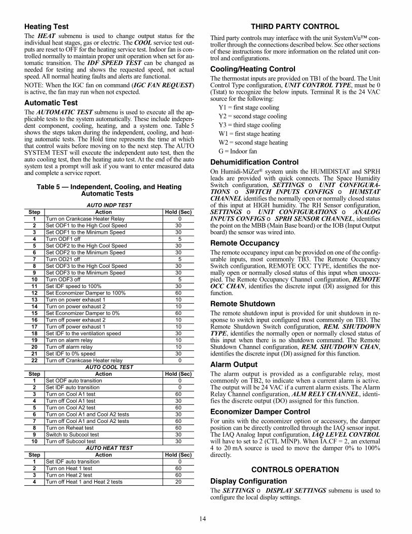
Heating TestThe HEAT submenu is used to change output status for theindividual heat stages, gas or electric. The COOL service test out-puts are reset to OFF for the heating service test. Indoor fan is con-trolled normally to maintain proper unit operation when set for au-tomatic transition. The IDF SPEED TEST can be changed asneeded for testing and shows the requested speed, not actualspeed. All normal heating faults and alerts are functional.NOTE: When the IGC fan on command (IGC FAN REQUEST)is active, the fan may run when not expected.
Automatic TestThe AUTOMATIC TEST submenu is used to execute all the ap-plicable tests to the system automatically. These include indepen-dent component, cooling, heating, and a system one. Table 5shows the steps taken during the independent, cooling, and heat-ing automatic tests. The Hold time represents the time at whichthat control waits before moving on to the next step. The AUTOSYSTEM TEST will execute the independent auto test, then theauto cooling test, then the heating auto test. At the end of the autosystem test a prompt will ask if you want to enter measured dataand complete a service report.
THIRD PARTY CONTROLThird party controls may interface with the unit SystemVu™ con-troller through the connections described below. See other sectionsof these instructions for more information on the related unit con-trol and configurations.
Cooling/Heating ControlThe thermostat inputs are provided on TB1 of the board. The UnitControl Type configuration, UNIT CONTROL TYPE, must be 0(Tstat) to recognize the below inputs. Terminal R is the 24 VACsource for the following:
Y1 = first stage coolingY2 = second stage coolingY3 = third stage coolingW1 = first stage heatingW2 = second stage heatingG = Indoor fan
Dehumidification ControlOn Humidi-MiZer® system units the HUMIDISTAT and SPRHleads are provided with quick connects. The Space HumiditySwitch configuration, SETTINGS UNIT CONFIGURA-TIONS SWITCH INPUTS CONFIGS HUMSTATCHANNEL identifies the normally open or normally closed statusof this input at HIGH humidity. The RH Sensor configuration,SETTINGS UNIT CONFIGURATIONS ANALOGINPUTS CONFIGS SPRH SENSOR CHANNEL, identifiesthe point on the MBB (Main Base board) or the IOB (Input Outputboard) the sensor was wired into.
Remote OccupancyThe remote occupancy input can be provided on one of the config-urable inputs, most commonly TB3. The Remote OccupancySwitch configuration, REMOTE OCC TYPE, identifies the nor-mally open or normally closed status of this input when unoccu-pied. The Remote Occupancy Channel configuration, REMOTEOCC CHAN, identifies the discrete input (DI) assigned for thisfunction.
Remote ShutdownThe remote shutdown input is provided for unit shutdown in re-sponse to switch input configured most commonly on TB3. TheRemote Shutdown Switch configuration, REM. SHUTDOWNTYPE, identifies the normally open or normally closed status ofthis input when there is no shutdown command. The RemoteShutdown Channel configuration, REM. SHUTDOWN CHAN,identifies the discrete input (DI) assigned for this function.
Alarm OutputThe alarm output is provided as a configurable relay, mostcommonly on TB2, to indicate when a current alarm is active.The output will be 24 VAC if a current alarm exists. The AlarmRelay Channel configuration, ALM RELY CHANNEL, identi-fies the discrete output (DO) assigned for this function.
Economizer Damper ControlFor units with the economizer option or accessory, the damperposition can be directly controlled through the IAQ sensor input.The IAQ Analog Input configuration, IAQ LEVEL CONTROLwill have to set to 2 (CTL MINP). When IA.CF = 2, an external4 to 20 mA source is used to move the damper 0% to 100%directly.
CONTROLS OPERATION
Display ConfigurationThe SETTINGS DISPLAY SETTINGS submenu is used toconfigure the local display settings.
Table 5 — Independent, Cooling, and Heating Automatic Tests
AUTO INDP TESTStep Action Hold (Sec)
1 Turn on Crankcase Heater Relay 02 Set ODF1 to the High Cool Speed 303 Set ODF1 to the Minimum Speed 304 Turn ODF1 off 55 Set ODF2 to the High Cool Speed 306 Set ODF2 to the Minimum Speed 307 Turn OD21 off 58 Set ODF3 to the High Cool Speed 309 Set ODF3 to the Minimum Speed 3010 Turn ODF3 off 511 Set IDF speed to 100% 3012 Set Economizer Damper to 100% 6013 Turn on power exhaust 1 1014 Turn on power exhaust 2 1015 Set Economizer Damper to 0% 6016 Turn off power exhaust 2 1017 Turn off power exhaust 1 1018 Set IDF to the ventilation speed 3019 Turn on alarm relay 1020 Turn off alarm relay 1021 Set IDF to 0% speed 3022 Turn off Crankcase Heater relay 0
AUTO COOL TESTStep Action Hold (Sec)
1 Set ODF auto transition 02 Set IDF auto transition 03 Turn on Cool A1 test 604 Turn off Cool A1 test 305 Turn on Cool A2 test 606 Turn on Cool A1 and Cool A2 tests 307 Turn off Cool A1 and Cool A2 tests 608 Turn on Reheat test 609 Switch to Subcool test 3010 Turn off Subcool test 30
AUTO HEAT TESTStep Action Hold (Sec)
1 Set IDF auto transition 02 Turn on Heat 1 test 603 Turn on Heat 2 test 604 Turn off Heat 1 and Heat 2 tests 20
15
METRIC DISPLAYThis variable is used to change the display from English units toMetric units.LANGUAGEThis variable is used to change the language of the SystemVu dis-play. CONTRAST ADJUSTThis is used to adjust the contrast of the SystemVu display.PASSWORD ENABLE?This variable enables or disables the use of a user password. Thepassword is used to restrict use of the control to change configura-tions.VIEW USER PASSWORDThis menu allows the user to view the user password. The pass-word must be entered or disabled to view it.CHANGE USER PASSWORDThis menu allows the user to change the user password. The pass-word must be entered or disabled to change it.
Unit ConfigurationMany configurations that indicate what factory options and/orfield accessories are installed and other common operation vari-ables are included in SETTINGS UNIT CONFIGURATIONsubmenu. Some of these configurations will be set in the factoryfor the factory-installed options (FIOPs). Field installed accesso-ries and custom control functions will require configurationchanges. The SETTINGS UNIT CONFIGURATION GENERAL submenu contains the following control configura-tions. Refer to other specific sections for other configurations.STARTUP DELAYThis configuration sets the control start-up delay after the power isinterrupted. This can be used to stagger the start-up of multipleunits.UNIT CONTROL TYPEThis configuration defines if temperature control is based on ther-mostat inputs or space temperature sensor input. TSTAT value iswhen the unit determines cooling and heating demand by the stateof G, Y1, Y2, W1, and W2 inputs from a space thermostat. Thisvalue is the factory default. SPACE SEN value is when the unitdetermines cooling and heating demand based on the space tem-perature and the appropriate set point. RAT SEN value is when theunit determines cooling and heating demand based on the returnair temperature and the appropriate set point. SPACE SEN or RATSEN are also used as Linkage configuration.THERMOSTAT TYPEThis configuration applies only if Unit Control Type is Thermo-stat. The value determines how the inputs are interpreted. See thespecific operation sections for more information. The followingdescriptions define what each value means.0 = CONV 2C2H – Conventional Thermostat 2 stage cool and 2
stage heat.1 = DIGI 2C2H – Digital Thermostat 2 stage cool and 2 stage
heat.2 = CONV 3C2H – Conventional Thermostat 3 stage cool and 2
stage heat. This is the default setting.3 = DIGI 3C2H – Digital Thermostat 3 stage cool and 2 stage
heat.ADAPTIVE TSTATThis configuration applies only if the unit control type is Thermo-stat. When this is YES, the control will use Adaptive Control forcooling and heating staging.When this is set to NO, the controlwill use the Traditional Thermostat Control; however, during inte-grated cooling, Adaptive is always used.
DIRTY FILTER TIMEThis configuration defines the life of the installed filter. A timerwill count down from this number while the indoor fan is running.At the expiration of this timer, an alert will be activated to indicatea filter change is required.TEST MODE TIMEOUTThis configuration defines the time at which a test mode test thathas not changed state will automatically disable test mode. Thisconfiguration will disable the timeout when set to 0 (Disabled).CCH MAX TEMPThis configuration defines the temperature threshold for which thecrankcase heater is no longer required to heat the compressor shell.STD BARO PRESSUREThis configuration is used to specify the job location’s standardbarometer pressure reading. This will feed the BAROMETRICPRESS when a network is not writing to it. This should be used toaccount for job site elevation if enthalpy calculations are beingused.LINK STAGEUP TIMEThis configuration sets the cooling and heating stage up timeduring linkage operation.UNIT’S MAX SATThis setting is used to trigger the F412 — Run Away Heat Fault.Any time the unit supply air temperature is higher than this valuethe alarm will be generated and shutdown the unit. Default is200°F (93°C).UNIT’S MIN SATThis setting is used to trigger the F202 — Freeze Protection Fault.Any time the unit supply air temperature falls below this value thealarm will be generated and shutdown the unit. Default is 32°F(0°C).AUTO SAT FAULTS?This setting allows the user to select whether the F202 — FreezeProtection Fault and F412 — Run Away Heat Fault can automati-cally reset with improved supply air temperatures, or if the unit re-mains in shutdown until the unit can be manually reset. Default isYes to allow auto reset.SA FREEZE PROTECTThis setting allows the F202 — Freeze Protection Fault to be dis-abled if the function is not desired. The fault will not activate, andunit will continue to run with extreme low supply air tempera-tures. Default is enabled to allow the function.
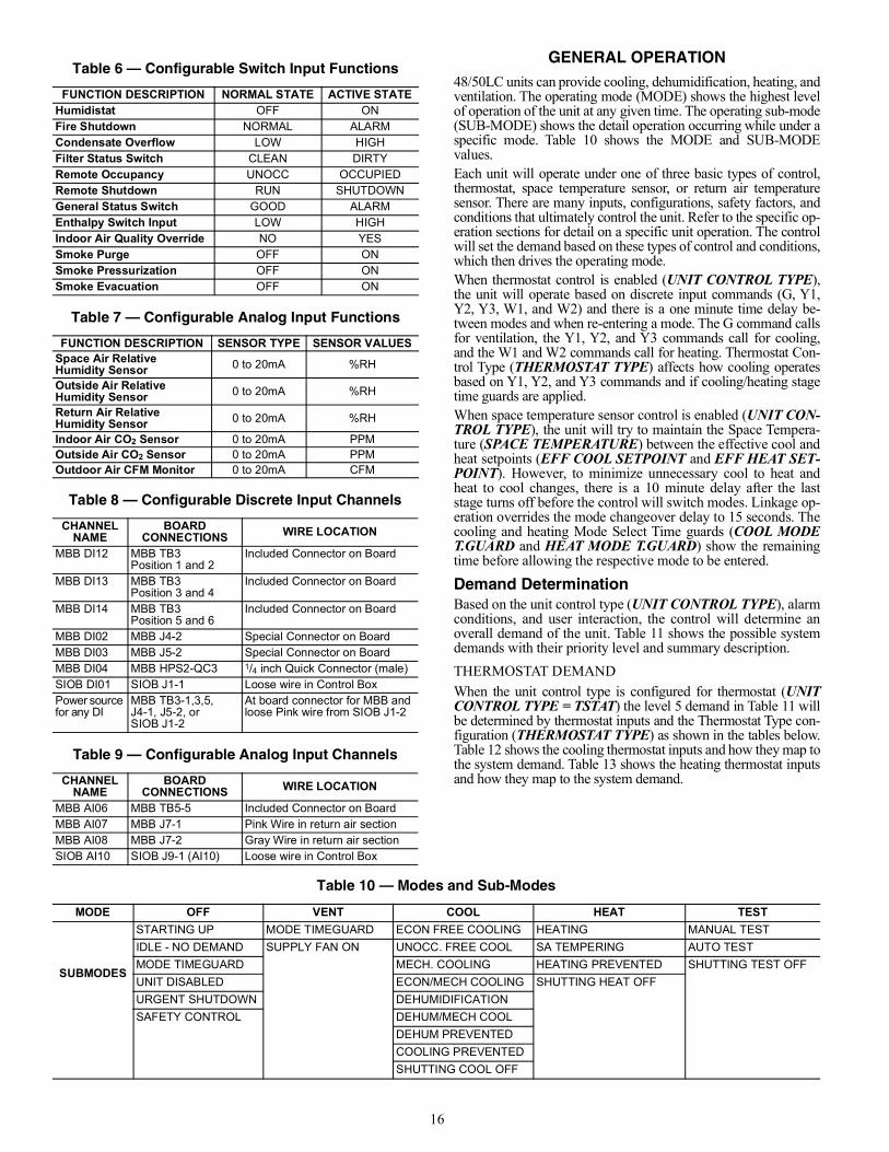
Configurable Switches and Analog SensorsThe SystemVu controller has optional configurable inputs. Theseconsist of six physical board switch inputs (discrete inputs) andfour physical board analog inputs. There are more functions al-lowed for configuration than there are inputs. Each function willhave a configuration for which channel it is assigned to. Eachswitch function will also have a switch type configuration whichdefines that switch’s normal state. Table 6 shows the configurablefunctions and what their normal and active states are. Table 7shows the configurable analog input functions. The switch config-urations can be found in the SETTINGS UNIT CONFIGU-RATIONS → SWITCH INPUT CONFIGS sub-menu. The ana-log input configurations can be found in the SETTINGS UNITCONFIGURATIONS SWITCH INPUT CONFIGS sub-menu. The configurable input assignment can be viewed in theSERVICE HARDWARE ASSIGNED INPUTS/OUT-PUTS sub-menu. Any of the Switch input functions can be configured and wired foruse on any of the discrete input channels, see Table 8. Any of theanalog sensor functions can be configured and wired for use inany of the analog input channels, see Table 9.
16
GENERAL OPERATION48/50LC units can provide cooling, dehumidification, heating, andventilation. The operating mode (MODE) shows the highest levelof operation of the unit at any given time. The operating sub-mode(SUB-MODE) shows the detail operation occurring while under aspecific mode. Table 10 shows the MODE and SUB-MODEvalues.Each unit will operate under one of three basic types of control,thermostat, space temperature sensor, or return air temperaturesensor. There are many inputs, configurations, safety factors, andconditions that ultimately control the unit. Refer to the specific op-eration sections for detail on a specific unit operation. The controlwill set the demand based on these types of control and conditions,which then drives the operating mode.When thermostat control is enabled (UNIT CONTROL TYPE),the unit will operate based on discrete input commands (G, Y1,Y2, Y3, W1, and W2) and there is a one minute time delay be-tween modes and when re-entering a mode. The G command callsfor ventilation, the Y1, Y2, and Y3 commands call for cooling,and the W1 and W2 commands call for heating. Thermostat Con-trol Type (THERMOSTAT TYPE) affects how cooling operatesbased on Y1, Y2, and Y3 commands and if cooling/heating stagetime guards are applied.When space temperature sensor control is enabled (UNIT CON-TROL TYPE), the unit will try to maintain the Space Tempera-ture (SPACE TEMPERATURE) between the effective cool andheat setpoints (EFF COOL SETPOINT and EFF HEAT SET-POINT). However, to minimize unnecessary cool to heat andheat to cool changes, there is a 10 minute delay after the laststage turns off before the control will switch modes. Linkage op-eration overrides the mode changeover delay to 15 seconds. Thecooling and heating Mode Select Time guards (COOL MODET.GUARD and HEAT MODE T.GUARD) show the remainingtime before allowing the respective mode to be entered.
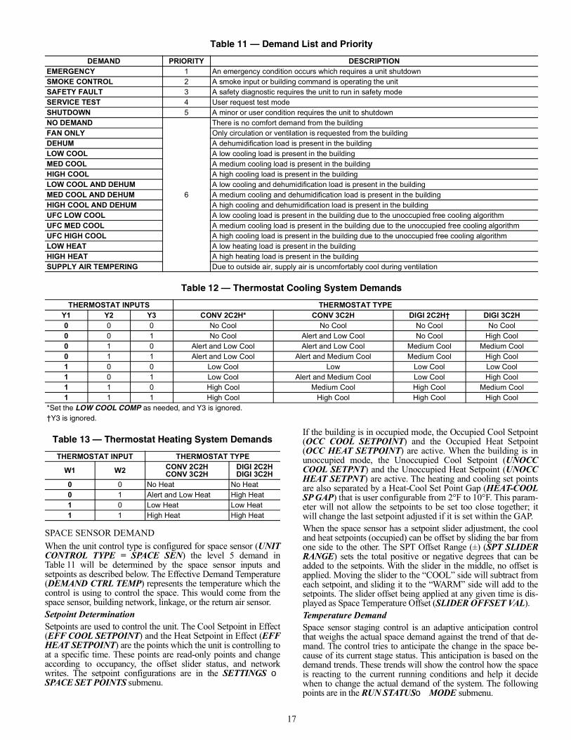
Demand DeterminationBased on the unit control type (UNIT CONTROL TYPE), alarmconditions, and user interaction, the control will determine anoverall demand of the unit. Table 11 shows the possible systemdemands with their priority level and summary description.THERMOSTAT DEMANDWhen the unit control type is configured for thermostat (UNITCONTROL TYPE = TSTAT) the level 5 demand in Table 11 willbe determined by thermostat inputs and the Thermostat Type con-figuration (THERMOSTAT TYPE) as shown in the tables below.Table 12 shows the cooling thermostat inputs and how they map tothe system demand. Table 13 shows the heating thermostat inputsand how they map to the system demand.
Table 6 — Configurable Switch Input Functions
FUNCTION DESCRIPTION NORMAL STATE ACTIVE STATEHumidistat OFF ONFire Shutdown NORMAL ALARMCondensate Overflow LOW HIGHFilter Status Switch CLEAN DIRTYRemote Occupancy UNOCC OCCUPIEDRemote Shutdown RUN SHUTDOWNGeneral Status Switch GOOD ALARMEnthalpy Switch Input LOW HIGHIndoor Air Quality Override NO YESSmoke Purge OFF ONSmoke Pressurization OFF ONSmoke Evacuation OFF ON
Table 7 — Configurable Analog Input Functions
FUNCTION DESCRIPTION SENSOR TYPE SENSOR VALUESSpace Air Relative Humidity Sensor 0 to 20mA %RH
Outside Air Relative Humidity Sensor 0 to 20mA %RH
Return Air Relative Humidity Sensor 0 to 20mA %RH
Indoor Air CO2 Sensor 0 to 20mA PPMOutside Air CO2 Sensor 0 to 20mA PPMOutdoor Air CFM Monitor 0 to 20mA CFM
Table 8 — Configurable Discrete Input Channels
CHANNEL NAME
BOARD CONNECTIONS WIRE LOCATION
MBB DI12 MBB TB3Position 1 and 2
Included Connector on Board
MBB DI13 MBB TB3Position 3 and 4
Included Connector on Board
MBB DI14 MBB TB3Position 5 and 6
Included Connector on Board
MBB DI02 MBB J4-2 Special Connector on BoardMBB DI03 MBB J5-2 Special Connector on BoardMBB DI04 MBB HPS2-QC3 1/4 inch Quick Connector (male)SIOB DI01 SIOB J1-1 Loose wire in Control BoxPower source for any DI
MBB TB3-1,3,5, J4-1, J5-2, or SIOB J1-2
At board connector for MBB and loose Pink wire from SIOB J1-2
Table 9 — Configurable Analog Input Channels
CHANNEL NAME
BOARD CONNECTIONS WIRE LOCATION
MBB AI06 MBB TB5-5 Included Connector on BoardMBB AI07 MBB J7-1 Pink Wire in return air sectionMBB AI08 MBB J7-2 Gray Wire in return air sectionSIOB AI10 SIOB J9-1 (AI10) Loose wire in Control Box
Table 10 — Modes and Sub-Modes
MODE OFF VENT COOL HEAT TEST
SUBMODES
STARTING UP MODE TIMEGUARD ECON FREE COOLING HEATING MANUAL TESTIDLE - NO DEMAND SUPPLY FAN ON UNOCC. FREE COOL SA TEMPERING AUTO TESTMODE TIMEGUARD MECH. COOLING HEATING PREVENTED SHUTTING TEST OFFUNIT DISABLED ECON/MECH COOLING SHUTTING HEAT OFFURGENT SHUTDOWN DEHUMIDIFICATIONSAFETY CONTROL DEHUM/MECH COOL
DEHUM PREVENTEDCOOLING PREVENTEDSHUTTING COOL OFF
17
SPACE SENSOR DEMANDWhen the unit control type is configured for space sensor (UNITCONTROL TYPE = SPACE SEN) the level 5 demand inTable 11 will be determined by the space sensor inputs andsetpoints as described below. The Effective Demand Temperature(DEMAND CTRL TEMP) represents the temperature which thecontrol is using to control the space. This would come from thespace sensor, building network, linkage, or the return air sensor.Setpoint DeterminationSetpoints are used to control the unit. The Cool Setpoint in Effect(EFF COOL SETPOINT) and the Heat Setpoint in Effect (EFFHEAT SETPOINT) are the points which the unit is controlling toat a specific time. These points are read-only points and changeaccording to occupancy, the offset slider status, and networkwrites. The setpoint configurations are in the SETTINGS SPACE SET POINTS submenu.
If the building is in occupied mode, the Occupied Cool Setpoint(OCC COOL SETPOINT) and the Occupied Heat Setpoint(OCC HEAT SETPOINT) are active. When the building is inunoccupied mode, the Unoccupied Cool Setpoint (UNOCCCOOL SETPNT) and the Unoccupied Heat Setpoint (UNOCCHEAT SETPNT) are active. The heating and cooling set pointsare also separated by a Heat-Cool Set Point Gap (HEAT-COOLSP GAP) that is user configurable from 2°F to 10°F. This param-eter will not allow the setpoints to be set too close together; itwill change the last setpoint adjusted if it is set within the GAP.When the space sensor has a setpoint slider adjustment, the cooland heat setpoints (occupied) can be offset by sliding the bar fromone side to the other. The SPT Offset Range (±) (SPT SLIDERRANGE) sets the total positive or negative degrees that can beadded to the setpoints. With the slider in the middle, no offset isapplied. Moving the slider to the “COOL” side will subtract fromeach setpoint, and sliding it to the “WARM” side will add to thesetpoints. The slider offset being applied at any given time is dis-played as Space Temperature Offset (SLIDER OFFSET VAL).Temperature DemandSpace sensor staging control is an adaptive anticipation controlthat weighs the actual space demand against the trend of that de-mand. The control tries to anticipate the change in the space be-cause of its current stage status. This anticipation is based on thedemand trends. These trends will show the control how the spaceis reacting to the current running conditions and help it decidewhen to change the actual demand of the system. The followingpoints are in the RUN STATUSMODE submenu.
Table 11 — Demand List and Priority
DEMAND PRIORITY DESCRIPTIONEMERGENCY 1 An emergency condition occurs which requires a unit shutdownSMOKE CONTROL 2 A smoke input or building command is operating the unitSAFETY FAULT 3 A safety diagnostic requires the unit to run in safety modeSERVICE TEST 4 User request test modeSHUTDOWN 5 A minor or user condition requires the unit to shutdownNO DEMAND
6
There is no comfort demand from the buildingFAN ONLY Only circulation or ventilation is requested from the buildingDEHUM A dehumidification load is present in the buildingLOW COOL A low cooling load is present in the buildingMED COOL A medium cooling load is present in the buildingHIGH COOL A high cooling load is present in the buildingLOW COOL AND DEHUM A low cooling and dehumidification load is present in the buildingMED COOL AND DEHUM A medium cooling and dehumidification load is present in the buildingHIGH COOL AND DEHUM A high cooling and dehumidification load is present in the buildingUFC LOW COOL A low cooling load is present in the building due to the unoccupied free cooling algorithmUFC MED COOL A medium cooling load is present in the building due to the unoccupied free cooling algorithmUFC HIGH COOL A high cooling load is present in the building due to the unoccupied free cooling algorithmLOW HEAT A low heating load is present in the buildingHIGH HEAT A high heating load is present in the buildingSUPPLY AIR TEMPERING Due to outside air, supply air is uncomfortably cool during ventilation
Table 12 — Thermostat Cooling System Demands
THERMOSTAT INPUTS THERMOSTAT TYPEY1 Y2 Y3 CONV 2C2H* CONV 3C2H DIGI 2C2H† DIGI 3C2H0 0 0 No Cool No Cool No Cool No Cool0 0 1 No Cool Alert and Low Cool No Cool High Cool0 1 0 Alert and Low Cool Alert and Low Cool Medium Cool Medium Cool0 1 1 Alert and Low Cool Alert and Medium Cool Medium Cool High Cool1 0 0 Low Cool Low Low Cool Low Cool1 0 1 Low Cool Alert and Medium Cool Low Cool High Cool1 1 0 High Cool Medium Cool High Cool Medium Cool1 1 1 High Cool High Cool High Cool High Cool
*Set the LOW COOL COMP as needed, and Y3 is ignored.†Y3 is ignored.
Table 13 — Thermostat Heating System Demands
THERMOSTAT INPUT THERMOSTAT TYPE
W1 W2 CONV 2C2HCONV 3C2H
DIGI 2C2HDIGI 3C2H
0 0 No Heat No Heat0 1 Alert and Low Heat High Heat1 0 Low Heat Low Heat1 1 High Heat High Heat
18
COOLING DEMANDThis is the difference between the Cool Setpoint in Effect (EFFCOOL SETPOINT) and the Effective Demand Temperature (DE-MAND CTRL TEMP) representing the demand of the space forcooling.COOL DEMAND TRENDThis is the rate of change of the cooling demand in degrees perminute, representing how the space is changing its demand forcooling.HEATING DEMANDThis is the difference between the Heat Setpoint in Effect (EFFHEAT SETPOINT) and the Effective DemandTemperature (DEMAND CTRL TEMP) representing the demandof the space for cooling.HEAT DEMAND TRENDThis is the rate of change of the heating demand in degrees perminute, representing how the space is changing its demand forcooling.In general, the system demand will increase based on the demandcompared to the demand switch states in Fig. 11. The demand can-not increase until Time Guard 1 (DEMAND TIMEGUARD1) ex-pires. The LCON and LHON thresholds will also cause the sys-tem demand to be reduced.When the demand hits the off switchstages, the system demand will be set to NO DEMAND. Theseswitch stages are in the SETTINGS SET POINTS TEMPDEMAND CONFIG submenu.
Fig. 11 — Space Sensor System Demand Switch States
The cooling and heating demand level up configurations (COOLDMD LEVEL UP and HEAT DMD LEVEL UP) will restrict asystem demand increase if the demand trend is less than the levelup configuration. These level up configurations will alsoincrease the system demand if the demand trend is greater thanTime Guard 2 (DEMAND TIMEGUARD2).The system demand will increase if it has remained at the samestate for greater than Time Guard 3 (DEMAND TIMEGUARD3).RAT DEMANDWhen the unit control type is configured for return air sensor(UNIT CONTROL TYPE = RAT SEN), the level 5 demand inTable 11 will be determined the same as space sensor but using thereturn air temperature (RETURN AIR TEMP) instead of thespace temperature (SPACE TEMPERATURE).
Occupancy DeterminationThe building’s occupancy is affected by a number of different fac-tors. Occupancy affects the unit set points and the operation of theeconomizer. The factors affecting occupancy are listed belowfrom highest to lowest priority.When Native BACnet is chosen as the Network communicationmethod, SETTINGS NETWORK SETTINGS BAS PRO-TOCOL = BACNET, the Occupancy priorities will be adjustedto meet BACnet acceptable priorities. While in BACnet, therewill be only one schedule (Schedule zero) and the CCN scheduledata will be cleared out and placed under BACnet control. TheRemote occupancy switch is still allowed for BACnet, while set-ting the schedule number to Zero for always occupied is not.LEVEL 1 PRIORITYLevel 1 classification is a force/write to occupancy and can oc-cur two ways, listed in order of priority: force on OCCUPIED,and a Linkage write. The CCN point OCCUPIED is forced viaan external device such as a ComfortID™ controller or a servicetool: when OCCUPIED is forced to YES, the unit is consideredoccupied, when OCCUPIED is forced to NO, the unit is consid-ered unoccupied. If the unit is being controlled by Linkage, theoccupancy is communicated and mapped to OCCUPIED as aninput. Linkage does not force the point, only write to it, thereforea force applied to OCCUPIED will override it.If OCCUPIED is not being forced or written to, proceed to thelevel 2 priority.LEVEL 2 PRIORITYLevel 2 is considered occupant interaction, and consists of TimedOverride and Remote Occupancy Switch. A timed override buttonpress will override a remote occupancy switch if both are installedfor operation.While using the programmed schedule, occupancy can be tempo-rarily switched from unoccupied to occupied by pressing the over-ride button for approximately 3 seconds on the T-55, T-56, or T-59space temperature sensor. The length of the override period whenpressing the override button is determined by the Override TimeLimit (TIMED OVR LENGTH). The hours remaining in overrideis displayed as Timed Override Hours (TIMED OVR HOURS).This point can also be changed from the local display or networkto set or change the override period length.Remote Occupancy Switch (REMOTE OCC SWITCH) can beforced or configured for operation based on an actual switch. Thephysical switch should be configured to either Normally Open orNormally Closed when the user would like to control the occupan-cy with an external switch. This switch is field-supplied (24v, sin-gle pole, single throw [SPST]). There are two possible configura-tions for the remote occupancy switch:
1. (REMOTE OCC TYPE = 0) Normally Open Switch2. (REMOTE OCC TYPE = 1) Normally Closed Switch
If the switch is configured to No Switch (REMOTE OCCCHAN = None), the switch input value will be ignored andsoftware will proceed to level 3 priority. For each type of switch,the appropriate configuration and states are listed in Table 14.
Cool Setpoint
Heat Setpoint
LCON
LHON
MCON
HCON
HHON
LHOF
LCOF
DecreaseDemand
DecreaseDemand
SPACE TEM
P
Table 14 — Switch Configurations
TYPE OF SWITCH SWITCH CONFIGURATION
STATE OF SWITCH AND OF OCCUPANCY
Occupied when closed orUnoccupied when open
Normal Open (0)Open and Unoccupied
Closed and Occupied
Occupied when openorUnoccupied when closed
Normal Closed (1)Open and Occupied
Closed and Unoccupied
19
LEVEL 3 PRIORITYThe following occupancy options are determined by the state ofOccupancy Schedule Number (SCHEDULE NUMBER) andthe Global Schedule Broadcast (BROADCAST SCHEDL?).1. (SCHEDULE NUMBER = 0) The unit is always consid-
ered occupied and the programmed schedule is ignored.This is the factory default.
2. (SCHEDULE NUMBER = 1-64) Follow the local pro-grammed schedule. Schedules 1 to 64 are local within thecontroller. The unit can only store one local schedule andtherefore changing this number only changes the title ofthe schedule table.
3. (SCHEDULE NUMBER = 65-99) Follow the global pro-grammed schedule. If the unit is configured as a GlobalSchedule Broadcaster (BROADCAST SCHEDL? = YES),the unit will follow the unit’s programmed schedule andbroadcast the schedule so that other devices programmedto follow this schedule number can receive the schedule. Ifthe unit is not programmed as a Global Schedule Broad-caster (BROADCAST SCHEDL? = NO), the unit willreceive broadcasted schedules from a unit programmed tobroadcast this schedule number.
HUMIDITY DEMANDWhen the unit is configured for either a Humidistat input (HUM-STAT CHANNEL) or Space Humidity Sensor (SPRH SENSCHANNEL), the level 5 demand in Table 11 will include a deter-mination of dehumidification demand.HUMIDISTATWhen receiving an active input from the Humidistat (HUMIDI-STAT), dehumidification will be demanded.SPACE RELATIVE HUMIDITYOn units with a relative humidity sensor, when the received valueof space relative humidity (SPRH LEVEL) has exceeded the hu-midity set point (SPRH SET POINT), dehumidification will bedemanded. This demand will remain until the space relative hu-midity has fallen below the humidity set point by more than thehumidity set point deadband (SPRH DEADBAND). This wouldcome from the space humidity sensor or building network.
Indoor Fan OperationThese units use the Staged Air Volume (SAV™) method of con-trolling the supply fan for a typical constant volume rooftop unit.This control method employs a variable frequency drive (VFD) tooperate the supply fan at different speeds in order to achieve ener-gy savings through reduced fan power. This method is specificallynot concerned with controlling static pressure in the supply duct,but rather with setting different fan speeds for different operatingconditions, such as ventilation mode or part-load mechanicalcooling.The SAV function is NOT a Variable Air Volume (VAV) func-tion. The fan adapts its speed to one of eight options based onmode and current state to satisfy a demand. The eight speedsconsist of: off (0%) and seven configurable values. The sevenconfigurable fan speeds are: Maximum Speed (MAXIMUMIDF SPEED), Ventilation (VENT IDF SPEED), Heating(HEATING IDF SPD), Free Cool (FREE COOL IDF SPD),Mechanical Low Cooling (LOW COOL IDF SPD), MechanicalMedium Cooling (MED COOL IDF SPD), and MechanicalHigh Cooling (HIGH COOL IDF SPD), The VFD is powereddirect from the distribution block or circuit breaker (CB) and isalways on with power applied unless the CB is tripped. Whenthe thermostat or space sensor control conditions require the fanon, the VFD will then ramp to desired speed. Fan speed is al-ways calculated by evaluating the current applicable conditions.Each fan speed condition is evaluated independently, and thehighest fan speed is used. For example, if a cooling call occurs
during Ventilation mode, the unit mode will transition to coolingbut the fan speed is set to the higher of the two (VENT IDFSPEED or LOW COOL IDF SPD). Refer to the speed configu-rations below for when the fan will run at the various speeds.DIRECT DRIVE UNITSAlternately, 48/50LC*04-06 units can have either a direct driveElectronic Commutated Motor (ECM) fan system or a belt drivemotor powered by a Variable Frequency Drive (VFD). An IDF-TYPE=1 indicates a unit with VFD, while an IDFTYPE=2 indi-cates a direct drive system. Refer to the unit product data for fanperformance tables and physical data. On direct drive units, theECM has 5 speed taps to allow a range of fan performance. Thecontrol has 2 output wires to connect to 2 different taps. At the fac-tory, the low and high speed wires are connected to the first andsecond speed taps, respectively. The speed taps increase in speedthe higher the tap number, so tap 1 is the lowest speed and tap 5 isthe highest speed. To activate the use of the ventilation speed wire,the Number of Speeds (SETTINGS UNIT CONFIGURA-TIONS INDOOR FAN NUMFSPDS) configuration mustbe set to 3.NOTE: The Blue loose wire from J3B-1 is reserved for future use,therefore do not connect to the ECM.The Commanded Fan Speed (OUTPUTS INDOOR FAN FANSPEED) represents the control’s commanded speed for thefan at any given time. This commanded speed is determined bythe unit’s current HVAC mode and the unit control type. For gasheating units, the IGC fan request output (Inputs GEN.I IGC.F) is monitored by the control. This can result in additionalmodification of fan delays or other operation due to safety func-tions of the IGC control. See “Heating Operation” on page 26for more details. If configured for IAQ fan operation, the fanmay be turned on to satisfy air quality demands. See “Indoor AirQuality (IAQ)” on page 30 if using IAQ (indoor air quality) ac-cessory sensors. The fan can run under thermostat or space sen-sor control and will remain on if compressors or heat relays areever stuck on. If Shut Down on IDF Failure is enabled (SHUT-DOWN IDF FAIL = Yes), the fan and unit will be shutdownwithout delay on fan alarm conditions. Fan off delays are hon-ored when exiting specific HVAC modes. The Fan-off Delay de-lays are as follows: Cooling (COOL FANOFF DELAY), andHeating (HEAT FANOFF DELAY).Indoor (Supply) Fan Maximum Speed (MAXIMUM IDF SPEED)Max speed is the highest fan speed allowed. This is typically100% when pulleys are set to deliver design CFM to the space perjob requirement. Most safety conditions for the unit will overridethe fan speed to this to help protect the unit.Ventilation Indoor Fan Speed (VENT IDF SPEED)This configuration defines the fan speed used in Ventilation (fan-only) mode. Ventilation mode is when the supply fan is running,but there is no demand for heating or cooling. In thermostatmode, this is with just a G call. In space sensor control, this iswhen the unit is Occupied mode and the indoor fan is configuredto always run while occupied (OCCUPIED FAN?). If the indoorfan is configured for intermittent fan (OCCUPIED FAN? = No),the Mode will be off instead of Ventilation and the fan will notrun unless a heating or cooling mode is needed. During the unoc-cupied period, the fan will always operate intermittently. Theeconomizer damper will adjust its position based on how faraway this speed is from max speed for ventilation.
IMPORTANT: It is important that the ventilation rate ischecked after setting this speed to verify that the unit canproperly ventilate the space per requirements. Adjustingthis configuration or the economizer minimum settingcurve should be performed to meet job requirements.
20
Heating Indoor Fan Speed (HEATING IDF SPD)This configuration defines the fan speed used when in heatingmode and running heat. On units equipped with gas heat (UNITTYPE OF HEAT), this heat speed will be delayed on based on theIGC’s fan on call (IGC FAN REQUEST). Once the IGC requeststhe fan, the fan will run what this heating speed configuration isset for until heating is ended. On units configured for electric heat(UNIT TYPE OF HEAT) and configured for Preheat without thefan (PREHEAT W/O IDF), this heat speed will be delayed onbased on the Preheat fan delay time (PREHEAT FAN DELAY).Once this preheat time has expired or not configured for preheat,the fan will run at this heat speed while heat is on.Free Cooling Indoor Fan Speed (FREE COOL IDF SPD)This configuration defines the initial fan speed used when in FreeCooling. Refer to “Economizer Operation” on page 27 for detailson free cooling. The fan will stay at this configured speed whenev-er only the damper is being used for free cooling. If the damper isat 100% for 5 minutes, the fan will ramp to the high cooling speed.It is locked there until the actual damper position falls below 75%,at which time it will ramp back down to this configured speed.Low Cooling Indoor Fan Speed (LOWCOOL IDF SPD)This configuration defines the fan speed used when only one stagemechanical cooling is being performed.Medium Cooling Indoor Fan Speed (MED COOL IDF SPD)This configuration defines the fan speed used when only secondstage mechanical cooling is being performed.High Cooling Indoor Fan Speed (HIGH COOL IDF SPD)This configuration defines the fan speed used when third (fullload) stage mechanical cooling is being performed. When per-forming integrated cooling with the economizer, this speed will beused. When only free cooling with a high cool demand, this speedwill be used.
Cooling OperationThe 48/50LC unit’s cooling operation consists of: demand andmode determination, staging request to satisfy the demand, andhandling a request with the unit’s resources. These resources caninclude compressors, Humidi-MiZer® system, an economizer, andfan speed based on options. This section covers mechanical cool-ing. For economizer free cooling, refer to “Economizer Opera-tion” on page 27.For Humidi-MiZer system operation, refer to “Optional Humidi-MiZer Dehumidification System” on page 22.COOLING MODE CONTROLThe cooling HVAC mode (OPERATING MODE) has 9 differentoperating sub modes (SUBMODE): ECON FREE COOLING,UNOCC. FREE COOL, MECH. COOLING, ECON/MECHCOOLING, DEHUMIDIFICATION, DEHUM/MECH COOL-ING, DEHUM PREVENTED, COOLING PREVENTED, andSHUTTING COOL OFF. These are all part of a general coolingmode and resemble the specific type of cooling that is being per-formed at any given time. All types of cooling are still performedunder the general cooling function, and the expanded text is foruser reference only.For the unit to enter cooling mode, three things must be true: theindoor fan must be ok to use, the mode changeover time guardmust be expired, and there must be a cooling or dehumidificationdemand (Y1, Y2, Y3, space cool demand, or humidity demand).The unit will remain in cooling for at least one minute or until anyof the above conditions turn false. The cooling mode does notofficially end until the compressor is off and the fan off delay hasexpired.COOLING STAGING CONTROLOnce the unit is in a cooling mode, determine what the demand isand how to satisfy it. If an economizer is installed and can be usedfor cooling (OK TO USE FREE COOLING? = Yes), the unit will
use it first (see “Economizer Operation” on page 27 for its opera-tion). If the economizer cannot be used or additional cooling isneeded, a mechanical cooling check is performed. OK to useCompressors? (OK TO USE COMPS?) will be set to yes whenthe outdoor temperature (OUTDOOR AIR TEMP) is above theCircuit A Lockout temperature (CIR.A LOCKOUT OAT) and theCircuit A is not locked out for diagnostic reasons (CIRCUIT ALOCKOUT). Based on the unit control configuration, requestedcooling stages (REQ. COOL STAGES) will be determined thenpassed to compressor control to actually add the cooling stages.There are two ways of requesting stages when thermostat controlis enabled: traditional thermostat control or adaptive control. Tra-ditional thermostat control is used if set for non-adaptivethermostat (ADAPTIVE TSTAT = NO) and the unit cannot usethe economizer for free cooling. If set for adaptive thermostat(ADAPTIVE TSTAT = YES) or any time the economizer is avail-able for free cooling, the unit will use adaptive control for staging.When configured for space sensor or RAT control (UNIT CON-TROL TYPE), the unit will use adaptive control for staging.With either staging method there are two supply air temperaturelimits that apply, one restricts more cooling stages and the otherwill remove cooling stages. If at any time the Supply-Air Tem-perature (SUPPLY AIR TEMP) falls below the Minimum Sup-ply Air Temperature Upper Level (UPPER MIN SAT), the re-quested stages will not be allowed to increase. If at any time theSAT falls below the Minimum Supply Air Temperature LowerLevel (LOWER MIN SAT), the requested stages will be reducedby one. If these SAT limits are configured so that they are tooclose together, the last stage might cycle rapidly, slowed only byits minimum on and off-time requirements.Adaptive ControlStage timers and Supply air trend apply when determining therequest for stages. The first request (REQ. COOL STAGES =1)comes immediately when starting the staging process. The CoolStage Increase Time (COOL STAGEUP TIME) has to expireand the Supply-Air Trend (SUPPLY AIR TREND) has to beabove the cooling supply air trend level (COOL SATTRENDLEV) before another stage can be added. Requested stages willonly be allowed to increase as the actual system demand allows(DEMAND). A “LOW COOL” demand will only allow one re-quested stage, “MED COOL” two stages, and “HIGH COOL” 3stages. The requested stages will be reduced if the cooling de-mand is lowered or dropped completely, or if the supply air fallsbelow the lower level (LOWER MIN SAT).Traditional Thermostat ControlStage timers and Supply air trend do not apply when determiningthe request for stages. Request staging will follow the thermostatinputs directly. “LOW COOL” will request one stage. “MEDCOOL” will request two stages. “HIGH COOL” will request 3stages.COMPRESSOR CONTROLThe compressor control works hand in hand with the staging con-trol. As the staging control request stages, the compressor controldetermines what is available or running and tries to provide stagesfor what is requested. The availability of the compressors dependson time guards, circuit diagnostics, and outdoor temperature. Thelow cooling compressor (LOW COOL COMP) informs the con-trol which compressor is desired for a low cooling demand.
There are time guards to protect the compressor: Compressor MinOn Time (COMP MIN ON TIME) and Compressor Min OffTime (COMP MIN OFF TIME) apply before the compressorscan be turned back on or turned off. Timeguard A1 (COMP A1TIMEGUARD) and Timeguard A2 (COMP A2 TIMEGUARD)
IMPORTANT: When LOW COOL COMP is set to 2, theunit will operate as a 2 stage unit where the larger compres-sor is stage one and both compressors are stage 2.
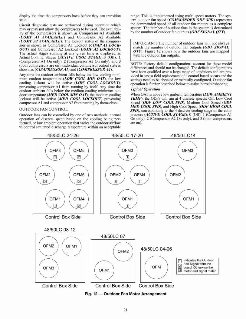
21
display the time the compressors have before they can transitionstate.Circuit diagnostic tests are performed during operation whichmay or may not allow the compressors to be used. The availabil-ity of the compressors is shown as Compressor A1 Available(COMP A1 AVAILABLE) and Compressor A2 Available(COMP A2 AVAILABLE). The lockout status of the compres-sors is shown as Compressor A1 Lockout (COMP A1 LOCK-OUT) and Compressor A2 Lockout (COMP A2 LOCKOUT).The actual stages running at any given time is displayed asActual Cooling Stages (ACTIVE COOL STAGE):0 (Off), 1(Compressor A1 On only), 2 (Compressor A2 On only), and 3(both compressors are on). Individual compressor output state isshown as (COMPRESSOR A1) and (COMPRESSOR A2).Any time the outdoor ambient falls below the low cooling mini-mum outdoor temperature (LOW COOL MIN OAT), the lowcooling lockout will be active (LOW COOL LOCKOUT),preventing compressor A1 from running by itself. Any time theoutdoor ambient falls below the medium cooling minimum out-door temperature (MED COOL MIN OAT), the medium coolinglockout will be active (MED COOL LOCKOUT) preventingcompressor A1 and compressor A2 from running by themselves.OUTDOOR FAN CONTROLOutdoor fans can be controlled by one of two methods: normaloperation of discrete speed based on the cooling being per-formed, or low ambient operation that varies the outdoor airflowto control saturated discharge temperature within an acceptable
range. This is implemented using multi-speed motors. The sys-tem outdoor fan speed (COMMANDED ODF SPD) representsthe commanded speed of all outdoor fan motors as a completesystem. The number of outdoor fans in the system is determinedby the number of outdoor fan outputs (ODF SIGNAL QTY).
NOTE: Factory default configurations account for these modeldifferences and should not be changed. The default configurationshave been qualified over a large range of conditions and are pro-vided in case a field replacement of a control board occurs and thesettings need to be checked or manually configured. Outdoor fanoperation is further described below to assist in troubleshooting.Typical OperationWhen OAT is above low ambient temperature (LOW AMBIENTTEMP), the ODFs will run at 4 discrete speeds: Off, Low CoolSpeed (ODF LOW COOL SPD), Medium Cool Speed (ODFMED COOL SPD), and High Cool Speed (ODF HIGH COOLSPD), corresponding to the 4 discrete cooling stage of the com-pressors (ACTIVE COOL STAGE): 0 (Off), 1 (Compressor A1On only), 2 (Compressor A2 On only), and 3 (both compressorsare on).
Fig. 12 — Outdoor Fan Motor Arrangement
IMPORTANT: The number of outdoor fans will not alwaysmatch the number of outdoor fan outputs (ODF SIGNALQTY). Figure 12 shows how the outdoor fans are mappedwith the outdoor fan outputs.
48/50LC 24-26 48/50LC 17-20 48/50 LC14
OFM1
OFM5
OFM6
OFM4
OFM3
OFM2
Control Box Side
1
1
2
2
33
OFM1
OFM4
OFM3
OFM2
Control Box Side Control Box Side
2
1
2
1
OFM1
OFM3
OFM2
48/50LC 08-1248/50LC 07
OFM1
OFM3
OFM2
Control Box Side
OFM1
OFM2
Control Box Side
Indicates the Outdoor Fan Signal from theboard. Otherwise the motor and signal match.
123
OFM
48/50LC 04-06
Control Box Side
22
Low Ambient OperationLow ambient operation will be used when either of the 2 condi-tions is met: 1) OAT is less than low ambient temperature (LOWAMBIENT TEMP) – 5°F or 2) OAT is less than low ambienttemperature (LOW AMBIENT TEMP) – 2.5°F and the SaturatedDischarge Temperature (CIR.A DIS. TEMP) is less than 92°F.The low ambient ODF control will manipulate ODF speed to keepthe discharge temp above 95°F. As OAT continues to drop, ODFspeed will continue to decrease. At a certain point, the low ambi-ent control may decide to turn off ODFs and only control thespeed of the rest of the outdoor fans. If the discharge temp keepson decreasing, it may reach a point that all ODF fans will beturned off. The ODFs will be turned on starting from the highestnumber first, meaning the ODF1 will be the last one to shut off.The ODFs are protected with a 45 second run time and a 60 sec-ond off time. See Fig. 12 for the ODF arrangement. The lowestspeed allowed to run any ODF is determined by the outdoor fanMinimum Speed Configuration (ODF MINIMUM SPEED).NOTE: During ODF cycling all fans that are commanded on willbe at the same speed and the off ones will be at zero speed. Themotors will not be allowed to run different speeds at the sametime.When OAT rises above low ambient temperature (LOW AM-BIENT TEMP), ODF control will transition from low ambientto normal operation. A period (5 min) is allowed for the ODFspeed to ramp from current position to one of the 4 discretespeed settings.
Optional Humidi-MiZer Dehumidification SystemUnits with the factory-installed Humidi-MiZer system optionare capable of providing multiple modes of improved dehu-midification as a variation of the normal cooling cycle. TheHumidi-MiZer system option includes additional valves in theliquid line and discharge line of each refrigerant circuit, a reheatcoil downstream of the evaporator, and variable-speed control ofall the outdoor fans. The Humidi-MiZer system equipped configu-ration is factory set to Yes for Humidi-MiZer system equippedunits (HUMIDIMIZER OK = YES). This enables Humidi-MiZersystem operating modes and service test.Humidi-MiZer system operation requires the installation and con-figuration of a relative humidity switch input or a space relativehumidity sensor. The HUMIDISTAT and SPRH leads are provid-ed with quick connects. The Space Humidity Switch configura-tion, SETTINGS UNIT CONFIGURATIONS SWITCHINPUTS CONFIGS HUMSTAT CHANNEL identifies thenormally open or normally closed status of this input at high hu-midity. The Space RH Sensor configuration, SETTINGS UNIT CONFIGURATIONS ANALOG INPUTS CONFIGS SPRH SENS CHANNEL, identifies to the channel number thesensor is wired into.DEHUMIDIFICATION DEMANDWhen using a humidistat or switch input, the demand for dehu-midification is seen as Space Humidity Switch (INPUTS SWITCH INPUTS HUMIDISTAT) being Low or High. Alow value means humidity level is good and a high value meansthat dehumidification is needed.When using an SPRH sensor, the demand is based on the SpaceHumidity Sensor (INPUTS ANALOG INPUTS SPRH)value compared to the Space RH Setpoint (SETTINGS SPACE SETPOINTS SPRH SETPOINT). If the SpaceHumidity Sensor (SPRH) value is above the Space RH Set-point (SPRH Setpoint), then dehumidification is needed. If theSpace Humidity Sensor (SPRH) value is below the Space RHSetpoint (SPRH Setpoint) minus the Space RH Deadband
(SETTINGS UNIT CONFIGURATIONS COOLINGSPRH DEADBAND), then dehumidification is no longerneeded.NOTE: When there is a dehumidification demand, the economizerdamper position is limited to its minimum damper position.HUMIDI-MIZER SYSTEM MODESWith Humidi-MiZer system units, there are two additional HVACmodes available for the user: Dehumidification and Dehum/MechCooling. Selection of the Dehum/Mech Cooling mode is deter-mined by the dehumidification demand and the cooling demand.Tables 15 and 16 show the corresponding circuit mode and outputstatus for the different demand combinations.NORMAL COOLINGFor 48/50LC04-06 units, refrigerant flows from the outdoor con-denser and is diverted at the energized Reheat Liquid Valve (RLV)and flows through the de-energized Cooling Liquid Valve (CLV)to the expansion device bypassing the reheat condenser coil. TheRDV is closed (see Fig. 13).For 48/50LC07-26 units, refrigerant flows from the outdoor con-denser through the de-energized 3-Way Liquid Diverter Valve(LDV) to the expansion device bypassing the reheat condensercoil. The Reheat Discharge Valve (RDV) is closed. (See Fig. 14.)DEHUM/MECH COOLING (SUBCOOLING MODE)This mode increases latent heat removal and decreases sensiblecooling compared to normal cooling.For 48/50LC*04-06 units, refrigerant flows from the outdoor con-denser through the de-energized Reheat Liquid Valve (RLV) andthrough the reheat condenser coil to the expansion device. The Re-heat Discharge Valve (RDV) and Cooling Liquid (CLV) areclosed. (See Fig. 15.)For 48/50LC*07-26 units, refrigerant flows from the outdoor con-denser, through the energized 3-Way Liquid Diverter Valve(LDV) and through the reheat condenser coil to the expansion de-vice. The Reheat Discharge Valve (RDV) is closed. (See Fig. 16.)DEHUMIDIFICATION (HOT GAS REHEAT MODE)This mode provides maximum latent cooling with little to no sen-sible capacity. This mode can operate to provide dehumidificationwhen there is no cooling demand.For 48/50LC*04-06 units, the refrigerant flows from the outdoorcondenser, through the de-energized RLV and through the reheatcondenser coil to the expansion device. The Cooling Liquid Valve(CLV) is closed. (See Fig. 17.)For 48/50LC*07-26 units, the refrigerant flows from the outdoorcondenser, through the energized 3-Way Liquid Diverter Valve(LDV) and through the reheat condenser coil to the expansion de-vice. (See Fig. 18.)For 48/50LC*04-26 units, the Reheat Discharge Valve (RDV) isopen, which provides some compressor discharge gas to the reheatcondenser to further increase the reheat of the evaporator airstream. (See Fig. 17 and 18.)REHEAT CONTROLWhen there is only a cooling demand, the unit will operate in nor-mal cooling mode. When there is only dehumidification demand,the unit will operate in Dehumidification mode (Hot Gas Reheat).When there is both cooling demand and dehumidification de-mand, the unit will operate in Dehum/Mech Cooling mode (Sub-cooling). During Dehumidification and Dehum/Mech coolingmode, the unit will run all cooling stages. When the Outside AirTemperature is above 80°F, the Outdoor Fans will run at maxi-mum fan speed. When the Outside Air Temperature is below80°F, the Outdoor Fans will modulate to maintain Saturated Dis-charge Temperature setpoint LA DEHUM LEV 1, LA DEHUMLEV 2 and LA DEHUM LEV, (SETTINGS UNIT CONFIG-URATIONS COOLING LOW AMBIENT). The unit can
IMPORTANT: The low ambient temperature (LOW AMBIENTTEMP) is default to 66 degrees and should not be changedunless directed by authorized Carrier personnel.
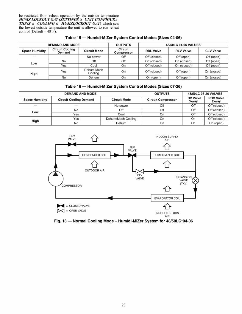
23
be restricted from reheat operation by the outside temperatureHUMZ LOCKOUT OAT (SETTINGS UNIT CONFIGURA-TIONS COOLING HUMZLOCKOUT OAT) which setsthe lowest outside temperature the unit is allowed to run reheatcontrol (Default = 40°F).
Fig. 13 — Normal Cooling Mode – Humidi-MiZer System for 48/50LC*04-06
Table 15 — Humidi-MiZer System Control Modes (Sizes 04-06)
DEMAND AND MODE OUTPUTS 48/50LC 04-06 VALUES
Space Humidity Circuit CoolingDemand Circuit Mode Circuit
Compressor RDL Valve RLV Valve CLV Valve
— — No power Off Off (closed) Off (open) Off (open)
Low No Off Off Off (closed) On (closed) Off (open)Yes Cool On Off (closed) On (closed) Off (open)
High Yes Dehum/MechCooling On Off (closed) Off (open) On (closed)
No Dehum On On (open) Off (open) On (closed)
Table 16 — Humidi-MiZer System Control Modes (Sizes 07-26)
DEMAND AND MODE OUTPUTS 48/50LC 07-26 VALVES
Space Humidity Circuit Cooling Demand Circuit Mode Circuit Compressor LDV Valve3-way
RDV Valve2-way
— — No power Off Off Off (closed)
Low No Off Off Off Off (closed)Yes Cool On Off Off (closed)
High Yes Dehum/Mech Cooling On On Off (closed)No Dehum On On On (open)
HUMIDI-MIZER COIL
COMPRESSOR
OUTDOOR AIR
INDOOR SUPPLYAIR
INDOOR RETURNAIR
RLVVALVE
EXPANSIONVALVE(TXV)
= CLOSED VALVE
= OPEN VALVE
RDVVALVE
EVAPORATOR COIL
CONDENSER COIL
CLVVALVE
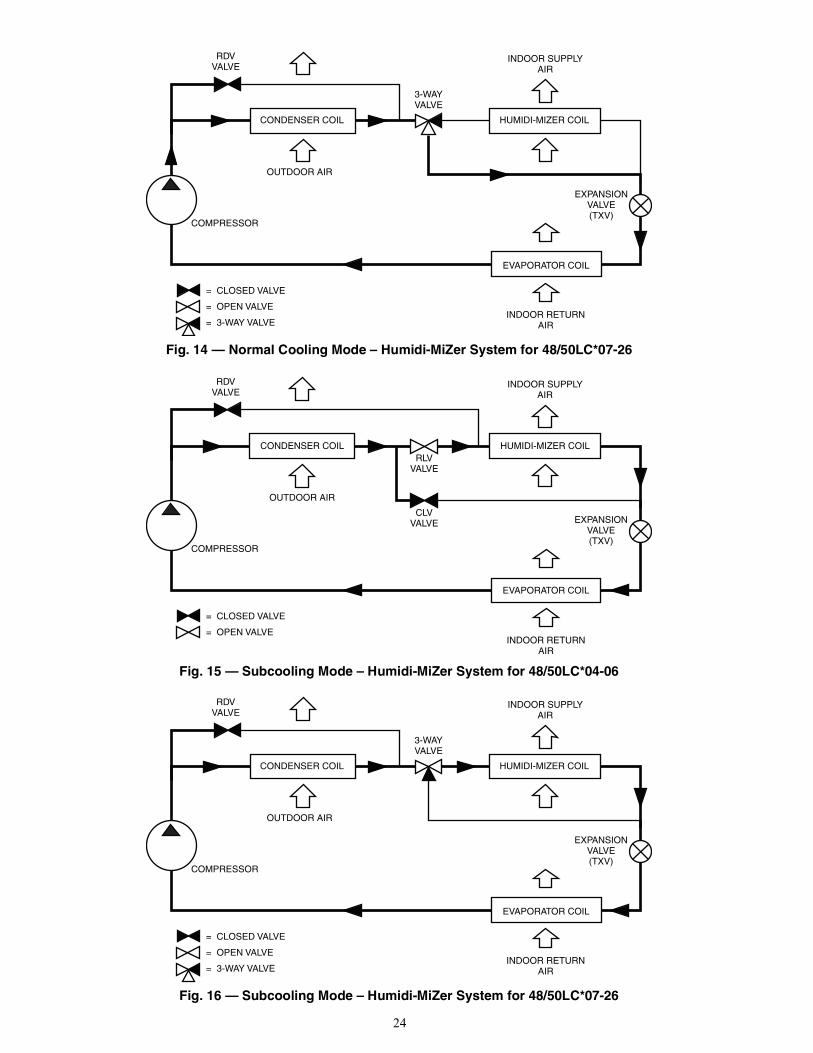
24
Fig. 14 — Normal Cooling Mode – Humidi-MiZer System for 48/50LC*07-26
Fig. 15 — Subcooling Mode – Humidi-MiZer System for 48/50LC*04-06
Fig. 16 — Subcooling Mode – Humidi-MiZer System for 48/50LC*07-26
HUMIDI-MIZER COIL
COMPRESSOR
OUTDOOR AIR
INDOOR SUPPLYAIR
INDOOR RETURNAIR
3-WAYVALVE
EXPANSIONVALVE(TXV)
= CLOSED VALVE
= OPEN VALVE
= 3-WAY VALVE
RDVVALVE
EVAPORATOR COIL
CONDENSER COIL
HUMIDI-MIZER COIL
COMPRESSOR
OUTDOOR AIR
INDOOR SUPPLYAIR
INDOOR RETURNAIR
RLVVALVE
CLVVALVE EXPANSION
VALVE(TXV)
RDVVALVE
EVAPORATOR COIL
CONDENSER COIL
= CLOSED VALVE
= OPEN VALVE
HUMIDI-MIZER COIL
COMPRESSOR
OUTDOOR AIR
INDOOR SUPPLYAIR
INDOOR RETURNAIR
3-WAYVALVE
EXPANSIONVALVE(TXV)
RDVVALVE
EVAPORATOR COIL
CONDENSER COIL
= CLOSED VALVE
= OPEN VALVE
= 3-WAY VALVE
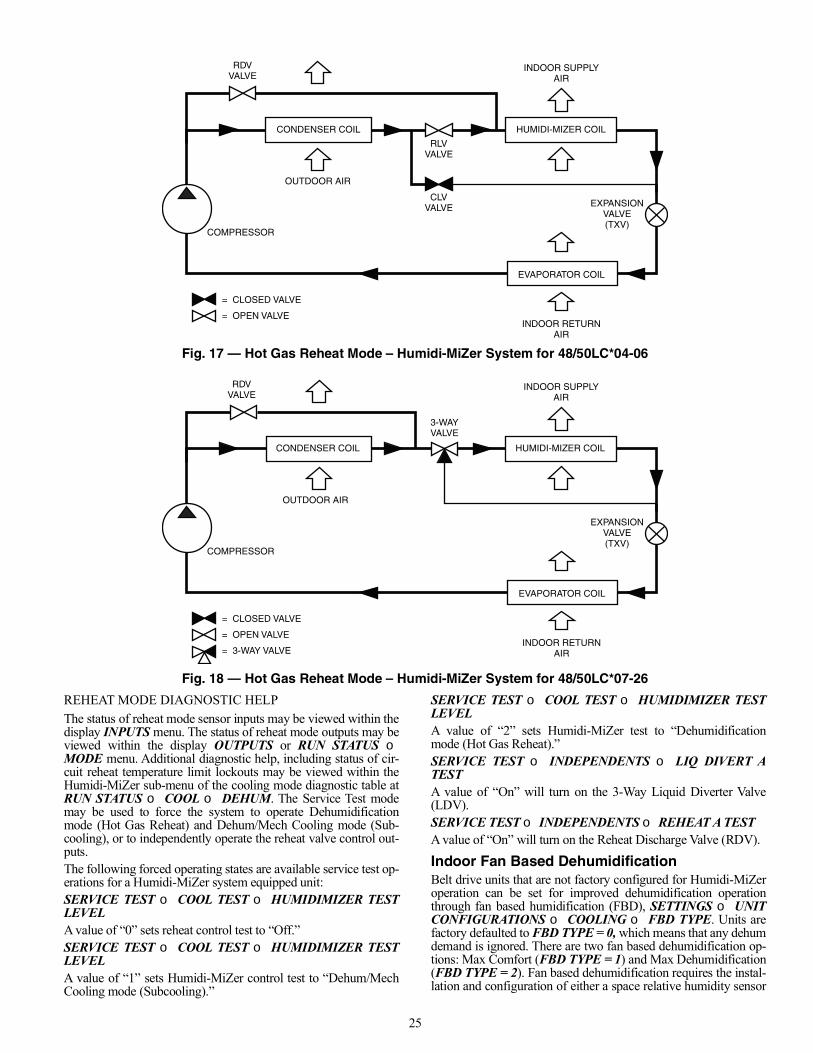
25
Fig. 17 — Hot Gas Reheat Mode – Humidi-MiZer System for 48/50LC*04-06
Fig. 18 — Hot Gas Reheat Mode – Humidi-MiZer System for 48/50LC*07-26
REHEAT MODE DIAGNOSTIC HELPThe status of reheat mode sensor inputs may be viewed within thedisplay INPUTS menu. The status of reheat mode outputs may beviewed within the display OUTPUTS or RUN STATUS MODE menu. Additional diagnostic help, including status of cir-cuit reheat temperature limit lockouts may be viewed within theHumidi-MiZer sub-menu of the cooling mode diagnostic table atRUN STATUS COOL DEHUM. The Service Test modemay be used to force the system to operate Dehumidificationmode (Hot Gas Reheat) and Dehum/Mech Cooling mode (Sub-cooling), or to independently operate the reheat valve control out-puts.The following forced operating states are available service test op-erations for a Humidi-MiZer system equipped unit:SERVICE TEST COOL TEST HUMIDIMIZER TESTLEVELA value of “0” sets reheat control test to “Off.”SERVICE TEST COOL TEST HUMIDIMIZER TESTLEVELA value of “1” sets Humidi-MiZer control test to “Dehum/MechCooling mode (Subcooling).”
SERVICE TEST COOL TEST HUMIDIMIZER TESTLEVELA value of “2” sets Humidi-MiZer test to “Dehumidificationmode (Hot Gas Reheat).”SERVICE TEST INDEPENDENTS LIQ DIVERT ATESTA value of “On” will turn on the 3-Way Liquid Diverter Valve(LDV).SERVICE TEST INDEPENDENTS REHEAT A TESTA value of “On” will turn on the Reheat Discharge Valve (RDV).
Indoor Fan Based DehumidificationBelt drive units that are not factory configured for Humidi-MiZeroperation can be set for improved dehumidification operationthrough fan based humidification (FBD), SETTINGS UNITCONFIGURATIONS COOLING FBD TYPE. Units arefactory defaulted to FBD TYPE = 0, which means that any dehumdemand is ignored. There are two fan based dehumidification op-tions: Max Comfort (FBD TYPE = 1) and Max Dehumidification(FBD TYPE = 2). Fan based dehumidification requires the instal-lation and configuration of either a space relative humidity sensor
HUMIDI-MIZER COIL
COMPRESSOR
OUTDOOR AIR
INDOOR SUPPLYAIR
INDOOR RETURNAIR
RLVVALVE
CLVVALVE
RDVVALVE
EVAPORATOR COIL
CONDENSER COIL
= CLOSED VALVE
= OPEN VALVE
EXPANSIONVALVE(TXV)
HUMIDI-MIZER COIL
COMPRESSOR
OUTDOOR AIR
INDOOR SUPPLYAIR
INDOOR RETURNAIR
3-WAYVALVE
RDVVALVE
EVAPORATOR COIL
CONDENSER COIL
= CLOSED VALVE
= OPEN VALVE
= 3-WAY VALVE
EXPANSIONVALVE(TXV)
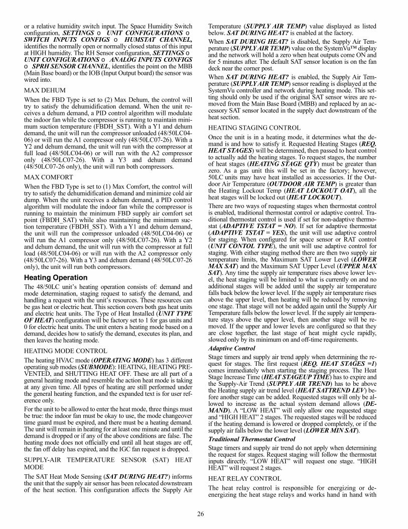
26
or a relative humidity switch input. The Space Humidity Switchconfiguration, SETTINGS UNIT CONFIGURATIONS SWITCH INPUTS CONFIGS HUMSTAT CHANNEL,identifies the normally open or normally closed status of this inputat HIGH humidity. The RH Sensor configuration, SETTINGS UNIT CONFIGURATIONS ANALOG INPUTS CONFIGS SPRH SENSOR CHANNEL, identifies the point on the MBB(Main Base board) or the IOB (Input Output board) the sensor waswired into.MAX DEHUMWhen the FBD Type is set to (2) Max Dehum, the control willtry to satisfy the dehumidification demand. When the unit re-ceives a dehum demand, a PID control algorithm will modulatethe indoor fan while the compressor is running to maintain mini-mum suction temperature (FBDH_SST). With a Y1 and dehumdemand, the unit will run the compressor unloaded (48/50LC04-06) or will run the A1 compressor only (48/50LC07-26). With aY2 and dehum demand, the unit will run with the compressor atfull load (48/50LC04-06) or will run with the A2 compressoronly (48/50LC07-26). With a Y3 and dehum demand(48/50LC07-26 only), the unit will run both compressors.MAX COMFORTWhen the FBD Type is set to (1) Max Comfort, the control willtry to satisfy the dehumidification demand and minimize cold airdump. When the unit receives a dehum demand, a PID controlalgorithm will modulate the indoor fan while the compressor isrunning to maintain the minimum FBD supply air comfort setpoint (FBDH_SAT) while also maintaining the minimum suc-tion temperature (FBDH_SST). With a Y1 and dehum demand,the unit will run the compressor unloaded (48/50LC04-06) orwill run the A1 compressor only (48/50LC07-26). With a Y2and dehum demand, the unit will run with the compressor at fullload (48/50LC04-06) or will run with the A2 compressor only(48/50LC07-26). With a Y3 and dehum demand (48/50LC07-26only), the unit will run both compressors.
Heating OperationThe 48/50LC unit’s heating operation consists of: demand andmode determination, staging request to satisfy the demand, andhandling a request with the unit’s resources. These resources canbe gas heat or electric heat. This section covers both gas heat unitsand electric heat units. The Type of Heat Installed (UNIT TYPEOF HEAT) configuration will be factory set to 1 for gas units and0 for electric heat units. The unit enters a heating mode based on ademand, decides how to satisfy the demand, executes its plan, andthen leaves the heating mode.HEATING MODE CONTROLThe heating HVAC mode (OPERATING MODE) has 3 differentoperating sub modes (SUBMODE): HEATING, HEATING PRE-VENTED, and SHUTTING HEAT OFF. These are all part of ageneral heating mode and resemble the action heat mode is takingat any given time. All types of heating are still performed underthe general heating function, and the expanded text is for user ref-erence only.For the unit to be allowed to enter the heat mode, three things mustbe true: the indoor fan must be okay to use, the mode changeovertime guard must be expired, and there must be a heating demand.The unit will remain in heating for at least one minute and until thedemand is dropped or if any of the above conditions are false. Theheating mode does not officially end until all heat stages are off,the fan off delay has expired, and the IGC fan request is dropped.SUPPLY-AIR TEMPERATURE SENSOR (SAT) HEATMODEThe SAT Heat Mode Sensing (SAT DURING HEAT?) informsthe unit that the supply air sensor has been relocated downstreamof the heat section. This configuration affects the Supply Air
Temperature (SUPPLY AIR TEMP) value displayed as listedbelow. SAT DURING HEAT? is enabled at the factory.When SAT DURING HEAT? is disabled, the Supply Air Tem-perature (SUPPLY AIR TEMP) value on the SystemVu™ displayand the network will hold a zero when heat outputs come ON andfor 5 minutes after. The default SAT sensor location is on the fandeck near the corner post.When SAT DURING HEAT? is enabled, the Supply Air Tem-perature (SUPPLY AIR TEMP) sensor reading is displayed at theSystemVu controller and network during heating mode. This set-ting should only be used if the original SAT sensor wires are re-moved from the Main Base Board (MBB) and replaced by an ac-cessory SAT sensor located in the supply duct downstream of theheat section.HEATING STAGING CONTROLOnce the unit is in a heating mode, it determines what the de-mand is and how to satisfy it. Requested Heating Stages (REQ.HEAT STAGES) will be determined, then passed to heat controlto actually add the heating stages. To request stages, the numberof heat stages (HEATING STAGE QTY) must be greater thanzero. As a gas unit this will be set in the factory; however,50LC units may have heat installed as accessories. If the Out-door Air Temperature (OUTDOOR AIR TEMP) is greater thanthe Heating Lockout Temp (HEAT LOCKOUT OAT), all theheat stages will be locked out (HEAT LOCKOUT).There are two ways of requesting stages when thermostat controlis enabled, traditional thermostat control or adaptive control. Tra-ditional thermostat control is used if set for non-adaptive thermo-stat (ADAPTIVE TSTAT = NO). If set for adaptive thermostat(ADAPTIVE TSTAT = YES), the unit will use adaptive controlfor staging. When configured for space sensor or RAT control(UNIT CONTOL TYPE), the unit will use adaptive control forstaging. With either staging method there are then two supply airtemperature limits, the Maximum SAT Lower Level (LOWERMAX SAT) and the Maximum SAT Upper Level (UPPER MAXSAT). Any time the supply air temperature rises above lower lev-el, the heat staging will be limited to what is currently on and noadditional stages will be added until the supply air temperaturefalls back below the lower level. If the supply air temperature risesabove the upper level, then heating will be reduced by removingone stage. That stage will not be added again until the Supply AirTemperature falls below the lower level. If the supply air tempera-ture stays above the upper level, then another stage will be re-moved. If the upper and lower levels are configured so that theyare close together, the last stage of heat might cycle rapidly,slowed only by its minimum on and off-time requirements.Adaptive ControlStage timers and supply air trend apply when determining the re-quest for stages. The first request (REQ. HEAT STAGES =1)comes immediately when starting the staging process. The HeatStage Increase Time (HEAT STAGEUP TIME) has to expire andthe Supply-Air Trend (SUPPLY AIR TREND) has to be abovethe Heating supply air trend level (HEAT SATTREND LEV) be-fore another stage can be added. Requested stages will only be al-lowed to increase as the actual system demand allows (DE-MAND). A “LOW HEAT” will only allow one requested stageand “HIGH HEAT” 2 stages. The requested stages will be reducedif the heating demand is lowered or dropped completely, or if thesupply air falls below the lower level (LOWER MIN SAT).Traditional Thermostat ControlStage timers and supply air trend do not apply when determiningthe request for stages. Request staging will follow the thermostatinputs directly. “LOW HEAT” will request one stage. “HIGHHEAT” will request 2 stages.HEAT RELAY CONTROLThe heat relay control is responsible for energizing or de-energizing the heat stage relays and works hand in hand with
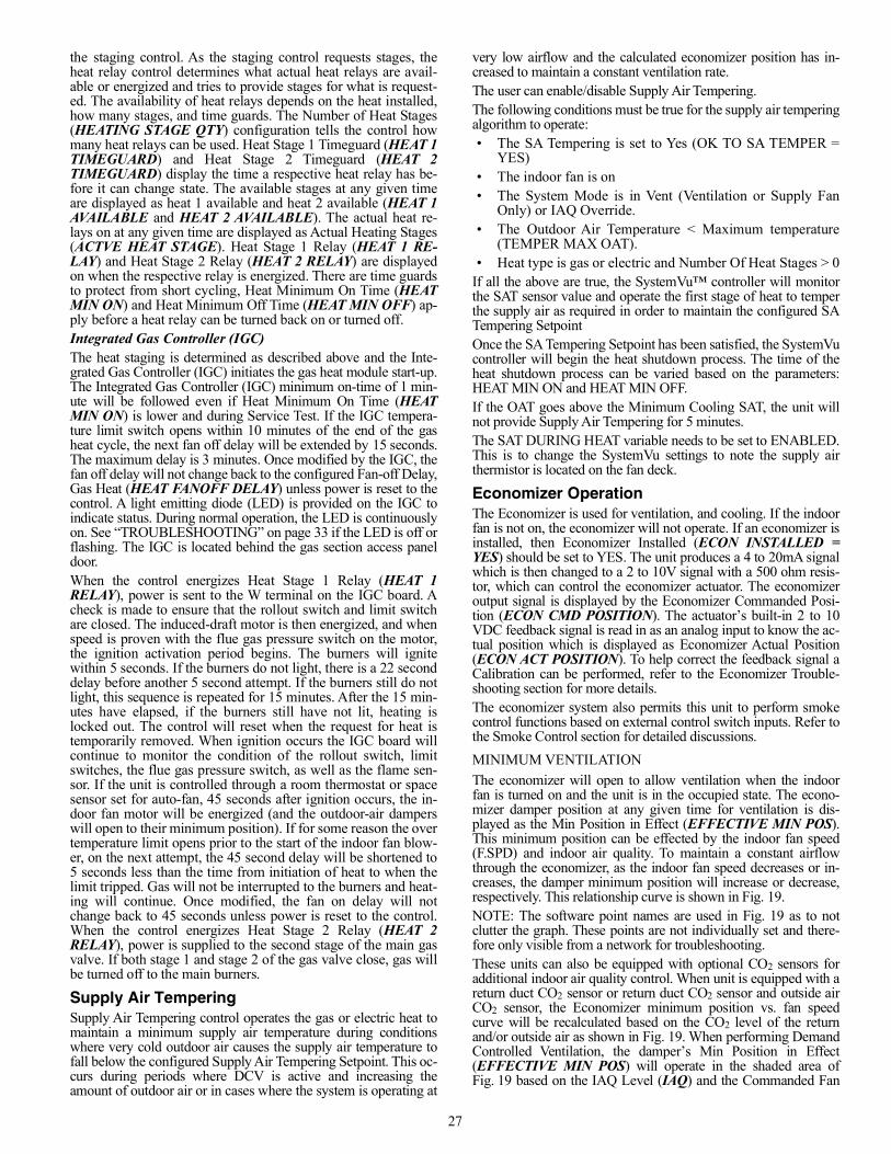
27
the staging control. As the staging control requests stages, theheat relay control determines what actual heat relays are avail-able or energized and tries to provide stages for what is request-ed. The availability of heat relays depends on the heat installed,how many stages, and time guards. The Number of Heat Stages(HEATING STAGE QTY) configuration tells the control howmany heat relays can be used. Heat Stage 1 Timeguard (HEAT 1TIMEGUARD) and Heat Stage 2 Timeguard (HEAT 2TIMEGUARD) display the time a respective heat relay has be-fore it can change state. The available stages at any given timeare displayed as heat 1 available and heat 2 available (HEAT 1AVAILABLE and HEAT 2 AVAILABLE). The actual heat re-lays on at any given time are displayed as Actual Heating Stages(ACTVE HEAT STAGE). Heat Stage 1 Relay (HEAT 1 RE-LAY) and Heat Stage 2 Relay (HEAT 2 RELAY) are displayedon when the respective relay is energized. There are time guardsto protect from short cycling, Heat Minimum On Time (HEATMIN ON) and Heat Minimum Off Time (HEAT MIN OFF) ap-ply before a heat relay can be turned back on or turned off. Integrated Gas Controller (IGC)The heat staging is determined as described above and the Inte-grated Gas Controller (IGC) initiates the gas heat module start-up.The Integrated Gas Controller (IGC) minimum on-time of 1 min-ute will be followed even if Heat Minimum On Time (HEATMIN ON) is lower and during Service Test. If the IGC tempera-ture limit switch opens within 10 minutes of the end of the gasheat cycle, the next fan off delay will be extended by 15 seconds.The maximum delay is 3 minutes. Once modified by the IGC, thefan off delay will not change back to the configured Fan-off Delay,Gas Heat (HEAT FANOFF DELAY) unless power is reset to thecontrol. A light emitting diode (LED) is provided on the IGC toindicate status. During normal operation, the LED is continuouslyon. See “TROUBLESHOOTING” on page 33 if the LED is off orflashing. The IGC is located behind the gas section access paneldoor.When the control energizes Heat Stage 1 Relay (HEAT 1RELAY), power is sent to the W terminal on the IGC board. Acheck is made to ensure that the rollout switch and limit switchare closed. The induced-draft motor is then energized, and whenspeed is proven with the flue gas pressure switch on the motor,the ignition activation period begins. The burners will ignitewithin 5 seconds. If the burners do not light, there is a 22 seconddelay before another 5 second attempt. If the burners still do notlight, this sequence is repeated for 15 minutes. After the 15 min-utes have elapsed, if the burners still have not lit, heating islocked out. The control will reset when the request for heat istemporarily removed. When ignition occurs the IGC board willcontinue to monitor the condition of the rollout switch, limitswitches, the flue gas pressure switch, as well as the flame sen-sor. If the unit is controlled through a room thermostat or spacesensor set for auto-fan, 45 seconds after ignition occurs, the in-door fan motor will be energized (and the outdoor-air damperswill open to their minimum position). If for some reason the overtemperature limit opens prior to the start of the indoor fan blow-er, on the next attempt, the 45 second delay will be shortened to5 seconds less than the time from initiation of heat to when thelimit tripped. Gas will not be interrupted to the burners and heat-ing will continue. Once modified, the fan on delay will notchange back to 45 seconds unless power is reset to the control.When the control energizes Heat Stage 2 Relay (HEAT 2RELAY), power is supplied to the second stage of the main gasvalve. If both stage 1 and stage 2 of the gas valve close, gas willbe turned off to the main burners.
Supply Air TemperingSupply Air Tempering control operates the gas or electric heat tomaintain a minimum supply air temperature during conditionswhere very cold outdoor air causes the supply air temperature tofall below the configured Supply Air Tempering Setpoint. This oc-curs during periods where DCV is active and increasing theamount of outdoor air or in cases where the system is operating at
very low airflow and the calculated economizer position has in-creased to maintain a constant ventilation rate.The user can enable/disable Supply Air Tempering.The following conditions must be true for the supply air temperingalgorithm to operate:• The SA Tempering is set to Yes (OK TO SA TEMPER =
YES)• The indoor fan is on• The System Mode is in Vent (Ventilation or Supply Fan
Only) or IAQ Override.• The Outdoor Air Temperature < Maximum temperature
(TEMPER MAX OAT).• Heat type is gas or electric and Number Of Heat Stages > 0
If all the above are true, the SystemVu™ controller will monitorthe SAT sensor value and operate the first stage of heat to temperthe supply air as required in order to maintain the configured SATempering SetpointOnce the SA Tempering Setpoint has been satisfied, the SystemVucontroller will begin the heat shutdown process. The time of theheat shutdown process can be varied based on the parameters:HEAT MIN ON and HEAT MIN OFF.If the OAT goes above the Minimum Cooling SAT, the unit willnot provide Supply Air Tempering for 5 minutes. The SAT DURING HEAT variable needs to be set to ENABLED.This is to change the SystemVu settings to note the supply airthermistor is located on the fan deck.
Economizer OperationThe Economizer is used for ventilation, and cooling. If the indoorfan is not on, the economizer will not operate. If an economizer isinstalled, then Economizer Installed (ECON INSTALLED =YES) should be set to YES. The unit produces a 4 to 20mA signalwhich is then changed to a 2 to 10V signal with a 500 ohm resis-tor, which can control the economizer actuator. The economizeroutput signal is displayed by the Economizer Commanded Posi-tion (ECON CMD POSITION). The actuator’s built-in 2 to 10VDC feedback signal is read in as an analog input to know the ac-tual position which is displayed as Economizer Actual Position(ECON ACT POSITION). To help correct the feedback signal aCalibration can be performed, refer to the Economizer Trouble-shooting section for more details. The economizer system also permits this unit to perform smokecontrol functions based on external control switch inputs. Refer tothe Smoke Control section for detailed discussions.MINIMUM VENTILATIONThe economizer will open to allow ventilation when the indoorfan is turned on and the unit is in the occupied state. The econo-mizer damper position at any given time for ventilation is dis-played as the Min Position in Effect (EFFECTIVE MIN POS).This minimum position can be effected by the indoor fan speed(F.SPD) and indoor air quality. To maintain a constant airflowthrough the economizer, as the indoor fan speed decreases or in-creases, the damper minimum position will increase or decrease,respectively. This relationship curve is shown in Fig. 19.NOTE: The software point names are used in Fig. 19 as to notclutter the graph. These points are not individually set and there-fore only visible from a network for troubleshooting.These units can also be equipped with optional CO2 sensors foradditional indoor air quality control. When unit is equipped with areturn duct CO2 sensor or return duct CO2 sensor and outside airCO2 sensor, the Economizer minimum position vs. fan speedcurve will be recalculated based on the CO2 level of the returnand/or outside air as shown in Fig. 19. When performing DemandControlled Ventilation, the damper’s Min Position in Effect(EFFECTIVE MIN POS) will operate in the shaded area ofFig. 19 based on the IAQ Level (IAQ) and the Commanded Fan
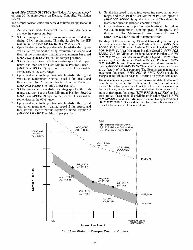
28
Speed (IDF SPEED OUTPUT). See “Indoor Air Quality (IAQ)”on page 30 for more details on Demand Controlled Ventilation(DCV).The damper position curve can be field adjusted per application ifneeded.1. Activate test mode to control the fan and dampers to
achieve the correct numbers.2. Set the fan speed for the maximum amount needed for
design CFM requirements. This should also be the IDFmaximum Fan speed (MAXIMUM IDF SPEED).
3. Open the damper to the position which satisfies the highestventilation requirement running maximum fan speed, andthen set the Economizer minimum at maximum fan speed(MIN POS @ MAX FAN) to this damper position.
4. Set the fan speed to a realistic operating speed in the upperrange, and then set the User Minimum Position Speed 1(MIN POS SPEED 1) equal to that speed. This should besomewhere in the 80% range.
5. Open the damper to the position which satisfies the highestventilation requirement running speed 1 fan speed, andthen set the User Minimum Position Damper Position 1(MIN POS DAMP 1) to this damper position.
6. Set the fan speed to a realistic operating speed in the mid-range, and then set the User Minimum Position Speed 2(MIN POS SPEED 2) equal to that speed. This should besomewhere in the 60% range.
7. Open the damper to the position which satisfies the highestventilation requirement running speed 2 fan speed, andthen set the User Minimum Position Damper Position 2(MIN POS DAMP 2) to this damper position.
8. Set the fan speed to a realistic operating speed in the low-range, and then set the User Minimum Position Speed 3(MIN POS SPEED 3) equal to that speed. This should belowest fan speed in planned operating range.
9. Open the damper to the position which satisfies the highestventilation requirement running speed 3 fan speed, andthen set the User Minimum Position Damper Position 3(MIN POS DAMP 3) to this damper position.
The shape of the curves in Fig. 19 are determined by the configu-ration parameters: User Minimum Position Speed 1 (MIN POSSPEED 1), User Minimum Position Damper Position 1 (MINPOS DAMP 1), User Minimum Position Speed 2 (MIN POSSPEED 2), User Minimum Position Damper Position 2 (MINPOS DAMP 2), User Minimum Position Speed 3 (MIN POSSPEED 3), User Minimum Position Damper Position 3 (MINPOS DAMP 3), and Economizer minimum at maximum fanspeed (MIN POS @ MAX FAN). These configurations are presetat the factory of default purposes. The Economizer minimum atmaximum fan speed (MIN POS @ MAX FAN) should bechanged based on the air balance of the unit for proper ventilation.The user adjustable points discussed above are defaulted to zerofrom the factory which forces the control to use a set of defaultpoints. The default points should not be left for permanent opera-tion, as it may cause inadequate ventilation. Economizer mini-mum at maximum fan speed (MIN POS @ MAX FAN) and atleast one set of user points User Minimum Position Speed 1 (MINPOS SPEED 1) and User Minimum Position Damper Position 1(MIN POS DAMP 1) should be used to create a linear curve tocover the broad scope of fan operation.
Fig. 19 — Minimum Damper Position Curves
Econo MaxPosition
(DAMPMAX)
Dam
per P
ositi
on
Indoor Fan SpeedMaximum Speed
(SPEEDMAX)10%
MINP_MAX
(MP_SPD3,MP_POS3)
(MP_SPD2,MP_POS2)
(MP_SPD1,MP_POS1)
Key:
Minimum Position Curve
IAQPMAX
(AQP_SPD3,AQP_POS3)
(AQP_SPD2,AQP_POS2)
(AQP_SPD1,AQP-POS1)
IAQ Purge Position Curve
IAQMINP
(AQ_SPD3,AQ_POS3)
(AQ_SPD2,AQ_POS2)
(AQ_SPD1,AQ_POS1)
IAQ Minimum Position Curve
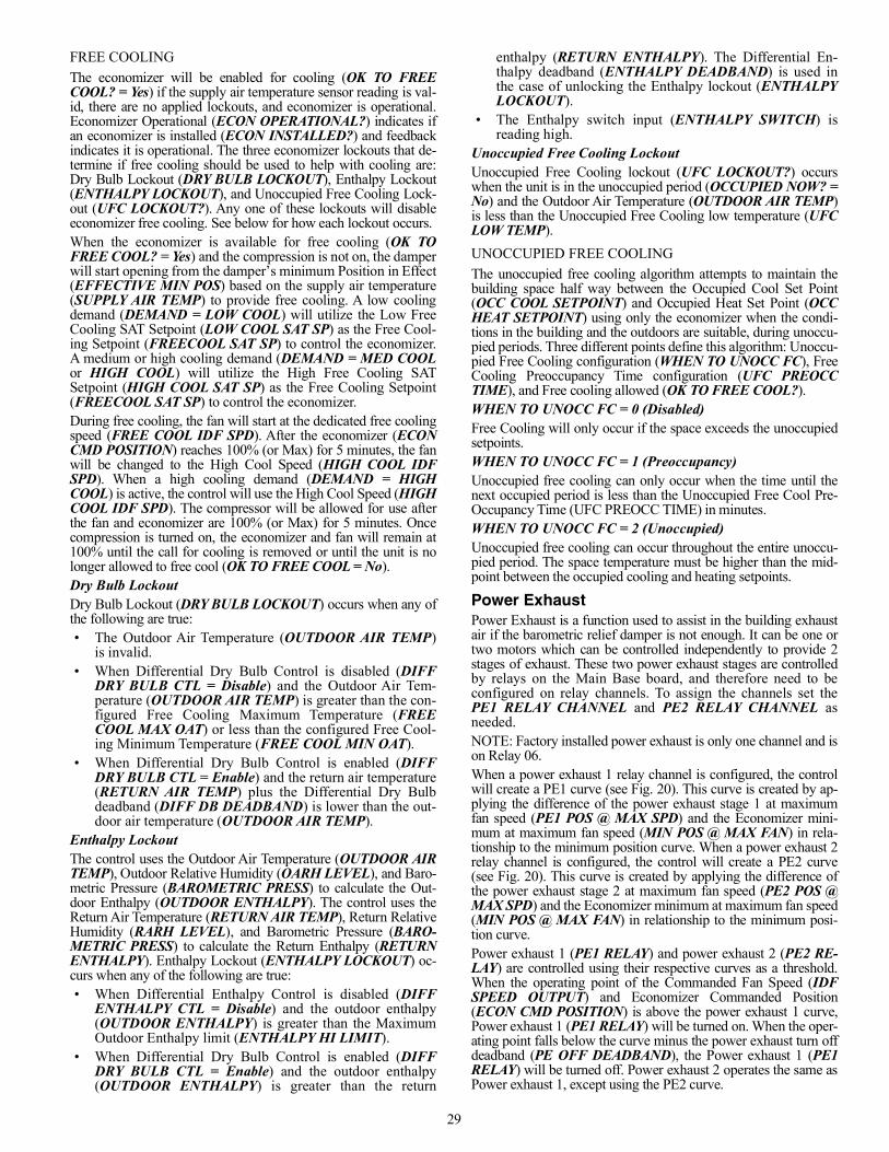
29
FREE COOLINGThe economizer will be enabled for cooling (OK TO FREECOOL? = Yes) if the supply air temperature sensor reading is val-id, there are no applied lockouts, and economizer is operational.Economizer Operational (ECON OPERATIONAL?) indicates ifan economizer is installed (ECON INSTALLED?) and feedbackindicates it is operational. The three economizer lockouts that de-termine if free cooling should be used to help with cooling are:Dry Bulb Lockout (DRY BULB LOCKOUT), Enthalpy Lockout(ENTHALPY LOCKOUT), and Unoccupied Free Cooling Lock-out (UFC LOCKOUT?). Any one of these lockouts will disableeconomizer free cooling. See below for how each lockout occurs.When the economizer is available for free cooling (OK TOFREE COOL? = Yes) and the compression is not on, the damperwill start opening from the damper’s minimum Position in Effect(EFFECTIVE MIN POS) based on the supply air temperature(SUPPLY AIR TEMP) to provide free cooling. A low coolingdemand (DEMAND = LOW COOL) will utilize the Low FreeCooling SAT Setpoint (LOW COOL SAT SP) as the Free Cool-ing Setpoint (FREECOOL SAT SP) to control the economizer.A medium or high cooling demand (DEMAND = MED COOLor HIGH COOL) will utilize the High Free Cooling SATSetpoint (HIGH COOL SAT SP) as the Free Cooling Setpoint(FREECOOL SAT SP) to control the economizer.During free cooling, the fan will start at the dedicated free coolingspeed (FREE COOL IDF SPD). After the economizer (ECONCMD POSITION) reaches 100% (or Max) for 5 minutes, the fanwill be changed to the High Cool Speed (HIGH COOL IDFSPD). When a high cooling demand (DEMAND = HIGHCOOL) is active, the control will use the High Cool Speed (HIGHCOOL IDF SPD). The compressor will be allowed for use afterthe fan and economizer are 100% (or Max) for 5 minutes. Oncecompression is turned on, the economizer and fan will remain at100% until the call for cooling is removed or until the unit is nolonger allowed to free cool (OK TO FREE COOL = No).Dry Bulb LockoutDry Bulb Lockout (DRY BULB LOCKOUT) occurs when any ofthe following are true:• The Outdoor Air Temperature (OUTDOOR AIR TEMP)
is invalid.• When Differential Dry Bulb Control is disabled (DIFF
DRY BULB CTL = Disable) and the Outdoor Air Tem-perature (OUTDOOR AIR TEMP) is greater than the con-figured Free Cooling Maximum Temperature (FREECOOL MAX OAT) or less than the configured Free Cool-ing Minimum Temperature (FREE COOL MIN OAT).
• When Differential Dry Bulb Control is enabled (DIFFDRY BULB CTL = Enable) and the return air temperature(RETURN AIR TEMP) plus the Differential Dry Bulbdeadband (DIFF DB DEADBAND) is lower than the out-door air temperature (OUTDOOR AIR TEMP).
Enthalpy LockoutThe control uses the Outdoor Air Temperature (OUTDOOR AIRTEMP), Outdoor Relative Humidity (OARH LEVEL), and Baro-metric Pressure (BAROMETRIC PRESS) to calculate the Out-door Enthalpy (OUTDOOR ENTHALPY). The control uses theReturn Air Temperature (RETURN AIR TEMP), Return RelativeHumidity (RARH LEVEL), and Barometric Pressure (BARO-METRIC PRESS) to calculate the Return Enthalpy (RETURNENTHALPY). Enthalpy Lockout (ENTHALPY LOCKOUT) oc-curs when any of the following are true:• When Differential Enthalpy Control is disabled (DIFF
ENTHALPY CTL = Disable) and the outdoor enthalpy(OUTDOOR ENTHALPY) is greater than the MaximumOutdoor Enthalpy limit (ENTHALPY HI LIMIT).
• When Differential Dry Bulb Control is enabled (DIFFDRY BULB CTL = Enable) and the outdoor enthalpy(OUTDOOR ENTHALPY) is greater than the return
enthalpy (RETURN ENTHALPY). The Differential En-thalpy deadband (ENTHALPY DEADBAND) is used inthe case of unlocking the Enthalpy lockout (ENTHALPYLOCKOUT).
• The Enthalpy switch input (ENTHALPY SWITCH) isreading high.
Unoccupied Free Cooling LockoutUnoccupied Free Cooling lockout (UFC LOCKOUT?) occurswhen the unit is in the unoccupied period (OCCUPIED NOW? =No) and the Outdoor Air Temperature (OUTDOOR AIR TEMP)is less than the Unoccupied Free Cooling low temperature (UFCLOW TEMP).UNOCCUPIED FREE COOLINGThe unoccupied free cooling algorithm attempts to maintain thebuilding space half way between the Occupied Cool Set Point(OCC COOL SETPOINT) and Occupied Heat Set Point (OCCHEAT SETPOINT) using only the economizer when the condi-tions in the building and the outdoors are suitable, during unoccu-pied periods. Three different points define this algorithm: Unoccu-pied Free Cooling configuration (WHEN TO UNOCC FC), FreeCooling Preoccupancy Time configuration (UFC PREOCCTIME), and Free cooling allowed (OK TO FREE COOL?).WHEN TO UNOCC FC = 0 (Disabled)Free Cooling will only occur if the space exceeds the unoccupiedsetpoints.WHEN TO UNOCC FC = 1 (Preoccupancy)Unoccupied free cooling can only occur when the time until thenext occupied period is less than the Unoccupied Free Cool Pre-Occupancy Time (UFC PREOCC TIME) in minutes.WHEN TO UNOCC FC = 2 (Unoccupied)Unoccupied free cooling can occur throughout the entire unoccu-pied period. The space temperature must be higher than the mid-point between the occupied cooling and heating setpoints.
Power ExhaustPower Exhaust is a function used to assist in the building exhaustair if the barometric relief damper is not enough. It can be one ortwo motors which can be controlled independently to provide 2stages of exhaust. These two power exhaust stages are controlledby relays on the Main Base board, and therefore need to beconfigured on relay channels. To assign the channels set thePE1 RELAY CHANNEL and PE2 RELAY CHANNEL asneeded.NOTE: Factory installed power exhaust is only one channel and ison Relay 06.When a power exhaust 1 relay channel is configured, the controlwill create a PE1 curve (see Fig. 20). This curve is created by ap-plying the difference of the power exhaust stage 1 at maximumfan speed (PE1 POS @ MAX SPD) and the Economizer mini-mum at maximum fan speed (MIN POS @ MAX FAN) in rela-tionship to the minimum position curve. When a power exhaust 2relay channel is configured, the control will create a PE2 curve(see Fig. 20). This curve is created by applying the difference ofthe power exhaust stage 2 at maximum fan speed (PE2 POS @MAX SPD) and the Economizer minimum at maximum fan speed(MIN POS @ MAX FAN) in relationship to the minimum posi-tion curve.Power exhaust 1 (PE1 RELAY) and power exhaust 2 (PE2 RE-LAY) are controlled using their respective curves as a threshold.When the operating point of the Commanded Fan Speed (IDFSPEED OUTPUT) and Economizer Commanded Position(ECON CMD POSITION) is above the power exhaust 1 curve,Power exhaust 1 (PE1 RELAY) will be turned on. When the oper-ating point falls below the curve minus the power exhaust turn offdeadband (PE OFF DEADBAND), the Power exhaust 1 (PE1RELAY) will be turned off. Power exhaust 2 operates the same asPower exhaust 1, except using the PE2 curve.
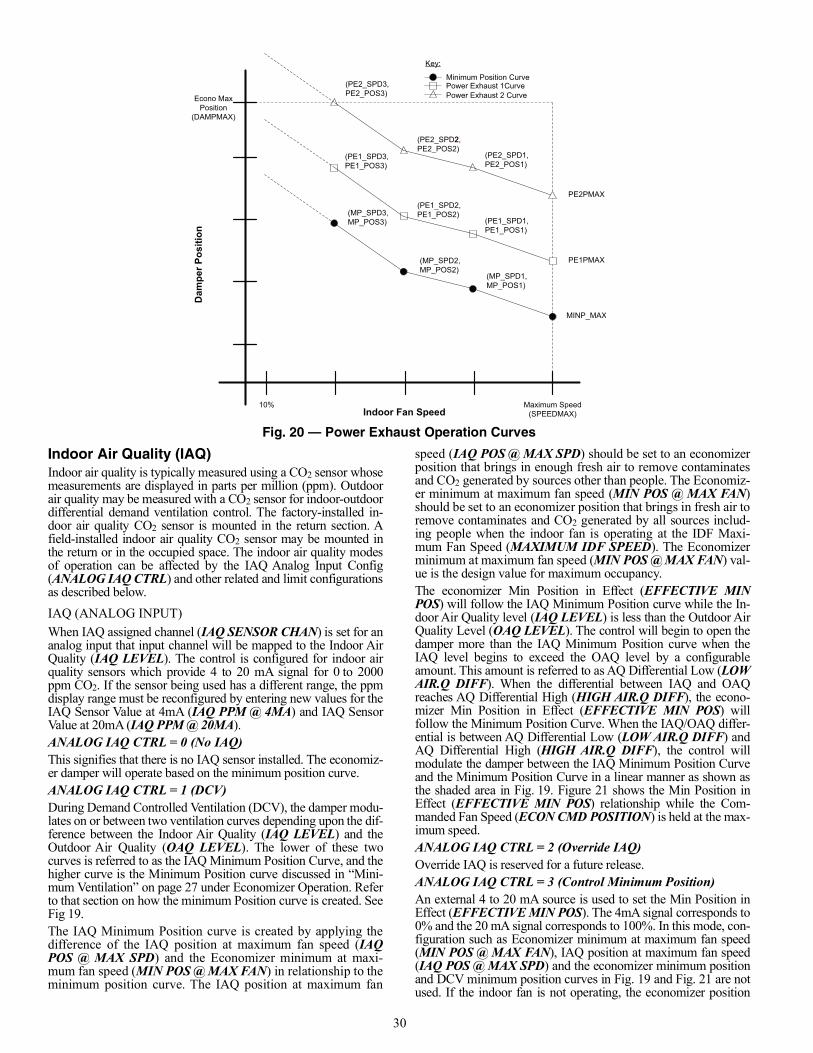
30
Fig. 20 — Power Exhaust Operation Curves
Indoor Air Quality (IAQ)Indoor air quality is typically measured using a CO2 sensor whosemeasurements are displayed in parts per million (ppm). Outdoorair quality may be measured with a CO2 sensor for indoor-outdoordifferential demand ventilation control. The factory-installed in-door air quality CO2 sensor is mounted in the return section. Afield-installed indoor air quality CO2 sensor may be mounted inthe return or in the occupied space. The indoor air quality modesof operation can be affected by the IAQ Analog Input Config(ANALOG IAQ CTRL) and other related and limit configurationsas described below.IAQ (ANALOG INPUT)When IAQ assigned channel (IAQ SENSOR CHAN) is set for ananalog input that input channel will be mapped to the Indoor AirQuality (IAQ LEVEL). The control is configured for indoor airquality sensors which provide 4 to 20 mA signal for 0 to 2000ppm CO2. If the sensor being used has a different range, the ppmdisplay range must be reconfigured by entering new values for theIAQ Sensor Value at 4mA (IAQ PPM @ 4MA) and IAQ SensorValue at 20mA (IAQ PPM @ 20MA).ANALOG IAQ CTRL = 0 (No IAQ)This signifies that there is no IAQ sensor installed. The economiz-er damper will operate based on the minimum position curve.ANALOG IAQ CTRL = 1 (DCV)During Demand Controlled Ventilation (DCV), the damper modu-lates on or between two ventilation curves depending upon the dif-ference between the Indoor Air Quality (IAQ LEVEL) and theOutdoor Air Quality (OAQ LEVEL). The lower of these twocurves is referred to as the IAQ Minimum Position Curve, and thehigher curve is the Minimum Position curve discussed in “Mini-mum Ventilation” on page 27 under Economizer Operation. Referto that section on how the minimum Position curve is created. SeeFig 19.The IAQ Minimum Position curve is created by applying thedifference of the IAQ position at maximum fan speed (IAQPOS @ MAX SPD) and the Economizer minimum at maxi-mum fan speed (MIN POS @ MAX FAN) in relationship to theminimum position curve. The IAQ position at maximum fan
speed (IAQ POS @ MAX SPD) should be set to an economizerposition that brings in enough fresh air to remove contaminatesand CO2 generated by sources other than people. The Economiz-er minimum at maximum fan speed (MIN POS @ MAX FAN)should be set to an economizer position that brings in fresh air toremove contaminates and CO2 generated by all sources includ-ing people when the indoor fan is operating at the IDF Maxi-mum Fan Speed (MAXIMUM IDF SPEED). The Economizerminimum at maximum fan speed (MIN POS @ MAX FAN) val-ue is the design value for maximum occupancy.The economizer Min Position in Effect (EFFECTIVE MINPOS) will follow the IAQ Minimum Position curve while the In-door Air Quality level (IAQ LEVEL) is less than the Outdoor AirQuality Level (OAQ LEVEL). The control will begin to open thedamper more than the IAQ Minimum Position curve when theIAQ level begins to exceed the OAQ level by a configurableamount. This amount is referred to as AQ Differential Low (LOWAIR.Q DIFF). When the differential between IAQ and OAQreaches AQ Differential High (HIGH AIR.Q DIFF), the econo-mizer Min Position in Effect (EFFECTIVE MIN POS) willfollow the Minimum Position Curve. When the IAQ/OAQ differ-ential is between AQ Differential Low (LOW AIR.Q DIFF) andAQ Differential High (HIGH AIR.Q DIFF), the control willmodulate the damper between the IAQ Minimum Position Curveand the Minimum Position Curve in a linear manner as shown asthe shaded area in Fig. 19. Figure 21 shows the Min Position inEffect (EFFECTIVE MIN POS) relationship while the Com-manded Fan Speed (ECON CMD POSITION) is held at the max-imum speed.ANALOG IAQ CTRL = 2 (Override IAQ)Override IAQ is reserved for a future release.ANALOG IAQ CTRL = 3 (Control Minimum Position)An external 4 to 20 mA source is used to set the Min Position inEffect (EFFECTIVE MIN POS). The 4mA signal corresponds to0% and the 20 mA signal corresponds to 100%. In this mode, con-figuration such as Economizer minimum at maximum fan speed(MIN POS @ MAX FAN), IAQ position at maximum fan speed(IAQ POS @ MAX SPD) and the economizer minimum positionand DCV minimum position curves in Fig. 19 and Fig. 21 are notused. If the indoor fan is not operating, the economizer position
Indoor Fan Speed
Dam
per P
ositi
on
Econo MaxPosition
(DAMPMAX)
(MP_SPD2,MP_POS2)
(MP_SPD3,MP_POS3)
Maximum Speed(SPEEDMAX)
(MP_SPD1,MP_POS1)
10%
MINP_MAX
Minimum Position Curve
Key:
(PE1_SPD3,PE1_POS3)
(PE1_SPD2,PE1_POS2)
(PE1_SPD1,PE1_POS1)
PE1PMAX
Power Exhaust 1Curve(PE2_SPD3,PE2_POS3)
2(PE2_SPD2,PE2_POS2)
(PE2_SPD1,PE2_POS1)
Power Exhaust 2 Curve
PE2PMAX
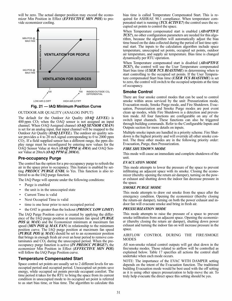
31
will be zero. The actual damper position may exceed the econo-mizer Min Position in Effect (EFFECTIVE MIN POS) to pro-vide economizer cooling.
Fig. 21 — IAQ Minimum Position Curve
OUTDOOR AIR QUALITY (ANALOG INPUT)The default for the Outdoor Air Quality (OAQ LEVEL) is400 ppm CO2 when the OAQ sensor is not assigned an inputchannel. When OAQ Assigned channel (OAQ SENSOR CHAN)is set for an analog input, that input channel will be mapped to theOutdoor Air Quality (OAQ LEVEL). The outdoor air quality sen-sor provides a 4 to 20 mA signal corresponding to 0 to 2000 ppmCO2. If a field supplied sensor has a different range, the ppm dis-play range must be reconfigured by entering new values for theOAQ Sensor Value at 4mA (OAQ PPM @ 4MA) and OAQ Sen-sor Value at 20mA (OAQ PPM @ 20MA).
Pre-occupancy PurgeThe control has the option for a pre-occupancy purge to refresh theair in the space prior to occupancy. This feature is enabled by set-ting PREOCC PURGE ENBL to Yes. This function is also re-ferred to as the IAQ purge function.The IAQ Purge will operate under the following conditions:• Purge is enabled• the unit is in the unoccupied state• Current Time is valid• Next Occupied Time is valid• time is one hour prior to next occupied period• the OAT is greater than the lockout (PREOCC LOW LIMIT)
The IAQ Purge Position curve is created by applying the differ-ence of the IAQ purge position at maximum fan speed (PURGEPOS @ MAX) and the Economizer minimum at maximum fanspeed (MIN POS @ MAX FAN) in relationship to the minimumposition curve. The IAQ purge position at maximum fan speed(PURGE POS @ MAX) should be set to an economizer positionthat brings in enough fresh air over an hour period to remove con-taminates and CO2 during the unoccupied period. When the pre-occupancy purge function is active (IN PREOCC PURGE?), theeconomizer Min Position in Effect (EFFECTIVE MIN POS)will follow the IAQ Purge Position curve.
Temperature Compensated StartSpace control set points are usually set to 2 different levels for un-occupied period and occupied period. Unoccupied set points saveenergy, while occupied set points provide occupant comfort. Thetime period it takes for the RTU to bring the space from its currentcondition in unoccupied mode to its occupied set point is referredto as start bias time, or bias time. The algorithm to calculate this
bias time is called Temperature Compensated Start. This is re-quired for ASHRAE 90.1 compliance. When temperature com-pensated start is running (TCS ACTIVE?) the control uses the oc-cupied set points to control the space.When Temperature compensated start is enabled (ADAPTIVETCS?), no other configuration parameters are needed for this algo-rithm, because the algorithm will automatically adjust the biastime based on the data collected during the period of last time opti-mal start. The inputs to the calculation algorithm include spacetemperature, unoccupied set points, occupied set points, outdoorair temperature, and supply air temperature. Bias time is changeddynamically per RTU operation.When Temperature compensated start is disabled (ADAPTIVETCS?), the control will use the User Temperature compensatedStart bias time (USER TCS BIASTIME) in determining when tostart controlling to the occupied set points. If the User Tempera-ture compensated Start bias time (USER TCS BIASTIME) is setto zero, the control will switch to the occupied setpoints at the timeof occupancy.
Smoke ControlThere are four smoke control modes that can be used to controlsmoke within areas serviced by the unit: Pressurization mode,Evacuation mode, Smoke Purge mode, and Fire Shutdown. Evac-uation, Pressurization and Smoke Purge modes are post eventclean up modes, while Fire Shutdown is a detection and preven-tion mode. All four functions are configurable on any of theswitch input channels. These functions can also be triggeredthrough building commands. Refer to the Configurable Inputs andOutputs section for more details on inputs.Multiple smoke inputs are handled in a priority scheme. Fire Shut-down is the highest priority and will override all other smoke con-trol. The three other modes are in the following priority order:Evacuation, Purge, then Pressurization.FIRE SHUTDOWN MODEThis mode will cause an immediate and complete shutdown of theunit.EVACUATON MODEThis mode attempts to lower the pressure of the space to preventinfiltrating an adjacent space with its smoke. Closing the econo-mizer (thereby opening the return air damper), turning on the pow-er exhaust and shutting down the indoor fan decrease pressure inthe space.SMOKE PURGE MODEThis mode attempts to draw out smoke from the space after theemergency condition. Opening the economizer (thereby closingthe return-air damper), turning on both the power exhaust and in-door fan will evacuate smoke and bring in fresh air.PRESSURIZATION MODEThis mode attempts to raise the pressure of a space to preventsmoke infiltration from an adjacent space. Opening the economiz-er (thereby closing the return air damper), shutting down powerexhaust and turning the indoor fan on will increase pressure in thespace.AIRFLOW CONTROL DURING THE FIRE/SMOKEMODESAll non-smoke related control outputs will get shut down in thefire/smoke modes. Those related to airflow will be controlled asexplained below. Table 17 specifies all actions the control shallundertake when each mode occurs.NOTE: The importance of the EVAC WITH DAMPER settingdepends on the intent of the Evacuation function. The traditionalbuilding Evacuation mode would be best used with the off settingas it is using other spaces pressurization to help move the air. Totruly help evacuate the direct space this setting should be yes.
VENTILATION FOR PEOPLE
VENTILATION FOR SOURCES
INC
REA
SIN
G V
ENTI
LATI
ON
MIN POS @MAX FAN
IAQ POS @MAX FAN
100 700 INSIDE/OUTSIDE CO2DIFFERENTIAL
LOW AIR.Q DIFF HIGH AIR.Q FIFF
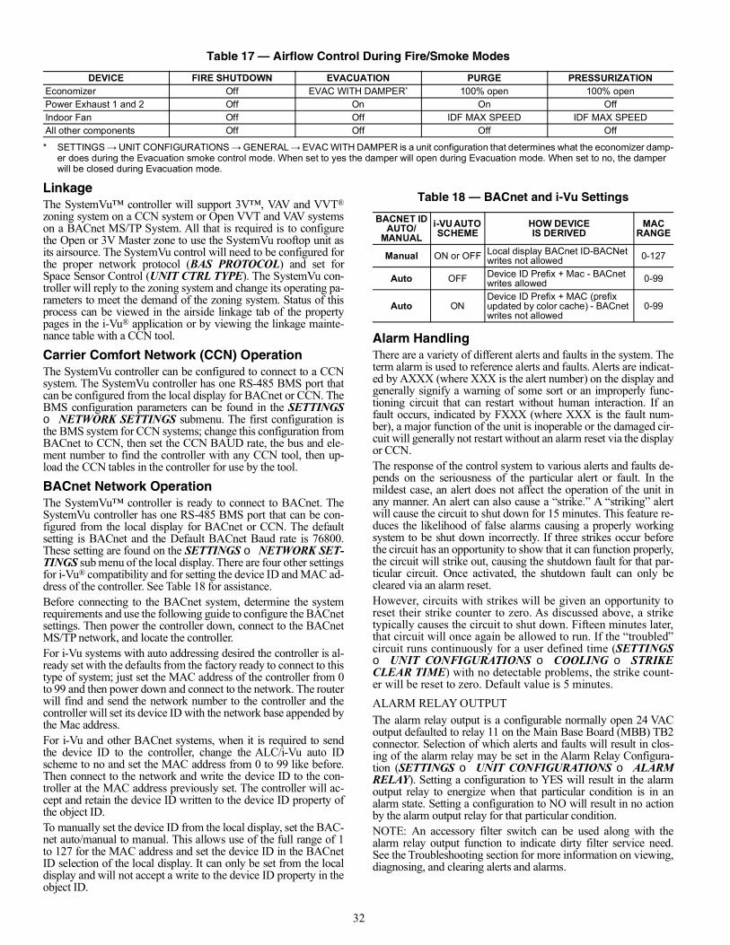
32
LinkageThe SystemVu™ controller will support 3V™, VAV and VVT®
zoning system on a CCN system or Open VVT and VAV systemson a BACnet MS/TP System. All that is required is to configurethe Open or 3V Master zone to use the SystemVu rooftop unit asits airsource. The SystemVu control will need to be configured forthe proper network protocol (BAS PROTOCOL) and set forSpace Sensor Control (UNIT CTRL TYPE). The SystemVu con-troller will reply to the zoning system and change its operating pa-rameters to meet the demand of the zoning system. Status of thisprocess can be viewed in the airside linkage tab of the propertypages in the i-Vu® application or by viewing the linkage mainte-nance table with a CCN tool.
Carrier Comfort Network (CCN) OperationThe SystemVu controller can be configured to connect to a CCNsystem. The SystemVu controller has one RS-485 BMS port thatcan be configured from the local display for BACnet or CCN. TheBMS configuration parameters can be found in the SETTINGSNETWORK SETTINGS submenu. The first configuration isthe BMS system for CCN systems; change this configuration fromBACnet to CCN, then set the CCN BAUD rate, the bus and ele-ment number to find the controller with any CCN tool, then up-load the CCN tables in the controller for use by the tool.
BACnet Network OperationThe SystemVu™ controller is ready to connect to BACnet. TheSystemVu controller has one RS-485 BMS port that can be con-figured from the local display for BACnet or CCN. The defaultsetting is BACnet and the Default BACnet Baud rate is 76800.These setting are found on the SETTINGS NETWORK SET-TINGS sub menu of the local display. There are four other settingsfor i-Vu® compatibility and for setting the device ID and MAC ad-dress of the controller. See Table 18 for assistance.Before connecting to the BACnet system, determine the systemrequirements and use the following guide to configure the BACnetsettings. Then power the controller down, connect to the BACnetMS/TP network, and locate the controller.For i-Vu systems with auto addressing desired the controller is al-ready set with the defaults from the factory ready to connect to thistype of system; just set the MAC address of the controller from 0to 99 and then power down and connect to the network. The routerwill find and send the network number to the controller and thecontroller will set its device ID with the network base appended bythe Mac address.For i-Vu and other BACnet systems, when it is required to sendthe device ID to the controller, change the ALC/i-Vu auto IDscheme to no and set the MAC address from 0 to 99 like before.Then connect to the network and write the device ID to the con-troller at the MAC address previously set. The controller will ac-cept and retain the device ID written to the device ID property ofthe object ID.To manually set the device ID from the local display, set the BAC-net auto/manual to manual. This allows use of the full range of 1to 127 for the MAC address and set the device ID in the BACnetID selection of the local display. It can only be set from the localdisplay and will not accept a write to the device ID property in theobject ID.
Alarm HandlingThere are a variety of different alerts and faults in the system. Theterm alarm is used to reference alerts and faults. Alerts are indicat-ed by AXXX (where XXX is the alert number) on the display andgenerally signify a warning of some sort or an improperly func-tioning circuit that can restart without human interaction. If anfault occurs, indicated by FXXX (where XXX is the fault num-ber), a major function of the unit is inoperable or the damaged cir-cuit will generally not restart without an alarm reset via the displayor CCN.The response of the control system to various alerts and faults de-pends on the seriousness of the particular alert or fault. In themildest case, an alert does not affect the operation of the unit inany manner. An alert can also cause a “strike.” A “striking” alertwill cause the circuit to shut down for 15 minutes. This feature re-duces the likelihood of false alarms causing a properly workingsystem to be shut down incorrectly. If three strikes occur beforethe circuit has an opportunity to show that it can function properly,the circuit will strike out, causing the shutdown fault for that par-ticular circuit. Once activated, the shutdown fault can only becleared via an alarm reset.However, circuits with strikes will be given an opportunity toreset their strike counter to zero. As discussed above, a striketypically causes the circuit to shut down. Fifteen minutes later,that circuit will once again be allowed to run. If the “troubled”circuit runs continuously for a user defined time (SETTINGS UNIT CONFIGURATIONS COOLING STRIKECLEAR TIME) with no detectable problems, the strike count-er will be reset to zero. Default value is 5 minutes.ALARM RELAY OUTPUTThe alarm relay output is a configurable normally open 24 VACoutput defaulted to relay 11 on the Main Base Board (MBB) TB2connector. Selection of which alerts and faults will result in clos-ing of the alarm relay may be set in the Alarm Relay Configura-tion (SETTINGS UNIT CONFIGURATIONS ALARMRELAY). Setting a configuration to YES will result in the alarmoutput relay to energize when that particular condition is in analarm state. Setting a configuration to NO will result in no actionby the alarm output relay for that particular condition.NOTE: An accessory filter switch can be used along with thealarm relay output function to indicate dirty filter service need.See the Troubleshooting section for more information on viewing,diagnosing, and clearing alerts and alarms.
Table 17 — Airflow Control During Fire/Smoke Modes
DEVICE FIRE SHUTDOWN EVACUATION PURGE PRESSURIZATIONEconomizer Off EVAC WITH DAMPER*
* SETTINGS → UNIT CONFIGURATIONS → GENERAL → EVAC WITH DAMPER is a unit configuration that determines what the economizer damp-er does during the Evacuation smoke control mode. When set to yes the damper will open during Evacuation mode. When set to no, the damper will be closed during Evacuation mode.
100% open 100% openPower Exhaust 1 and 2 Off On On OffIndoor Fan Off Off IDF MAX SPEED IDF MAX SPEEDAll other components Off Off Off Off
Table 18 — BACnet and i-Vu Settings
BACNET IDAUTO/
MANUALi-VU AUTO SCHEME
HOW DEVICEIS DERIVED
MAC RANGE
Manual ON or OFF Local display BACnet ID-BACNet writes not allowed 0-127
Auto OFF Device ID Prefix + Mac - BACnet writes allowed 0-99
Auto ONDevice ID Prefix + MAC (prefix updated by color cache) - BACnet writes not allowed
0-99
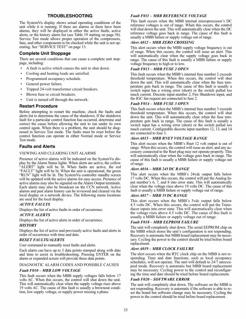
33
TROUBLESHOOTINGThe SystemVu display shows actual operating conditions of theunit while it is running. If there are alarms or there have beenalarms, they will be displayed in either the active faults, activealerts, or the history alarm list (see Table 19 starting on page 38).Service Test mode allows proper operation of the compressors,fans, and other components to be checked while the unit is not op-erating. See “SERVICE TEST” on page 13.
Complete Unit StoppageThere are several conditions that can cause a complete unit stop-page, including:• A fault is active which causes the unit to shut down.• Cooling and heating loads are satisfied.• Programmed occupancy schedule.• General power failure.• Tripped 24-volt transformer circuit breakers.• Blown fuse or circuit breakers.• Unit is turned off through the network.
Restart ProcedureBefore attempting to restart the machine, check the faults andalerts list to determine the cause of the shutdown. If the shutdownfault for a particular control function has occurred, determine andcorrect the cause before allowing the unit to run under its owncontrol again. When there is a problem, the unit should be diag-nosed in Service Test mode. The faults must be reset before thecontrol function can operate in either Normal mode or ServiceTest mode.
Faults and AlertsVIEWING AND CLEARING UNIT ALARMSPresence of active alarms will be indicated on the SystemVu dis-play by the Alarm Status lights. When alerts are active, the yellow“ALERT” light will be lit. When faults are active, the red“FAULT” light will be lit. When the unit is operational, the green“RUN” light will be lit. The SystemVu controller standby screenwill be updated with the active alarms for easy access. Presence ofactive alarms may also be signaled on the Alarm Output terminals.Each alarm may also be broadcast on the CCN network. Activealarms and past alarm history can be reviewed and cleared via thelocal display or a network device. The following menu locationsare used for the local display.ACTIVE FAULTSDisplays the list of active faults in order of occurrence.ACTIVE ALERTSDisplays the list of active alerts in order of occurrence.HISTORYDisplays the list of active and previously active faults and alerts inorder of occurrence with time and date.RESET FAULTS/ALERTSUser command to manually reset faults and alerts.Each alarm can have up to 3 data points stamped along with dateand time to assist in troubleshooting. Pressing ENTER on thealarm or expanded screen will provide these data points.DIAGNOSTIC ALARM CODES AND POSSIBLE CAUSESFault F010 – MBB LOW VOLTAGEThis fault occurs when the MBB supply voltages falls below 17volts AC. When this occurs, the control will shut down the unit.This will automatically clear when the supply voltage rises above19 volts AC. The cause of this fault is usually a brownout condi-tion, low supply voltage, or supply power missing a phase.
Fault F011 – MBB REFERENCE VOLTAGEThis fault occurs when the MBB internal microprocessor’s DCreference voltages is out of range. When this occurs, the controlwill shut down the unit. This will automatically clear when the DCreference voltage goes back in range. The cause of this fault isusually a MBB failure or supply voltage out of range.Alert A012 – MBB ZERO CROSSINGThis alert occurs when the MBB supply voltage frequency is outof range. When this occurs, the control will issue an alert. Thiswill automatically clear when the supply voltage goes back inrange. The cause of this fault is usually a MBB failure or supplyvoltage frequency to high or to low.Fault F013 – MBB FUSE 2 OPENThis fault occurs when the MBB’s internal fuse number 2 exceedsthreshold temperature. When this occurs, the control will shutdown the unit. This will automatically clear when the fuse tem-perature gets back in range. The cause of this fault is usually aswitch input has a wiring error (short) or the switch pulled toomuch current. Discrete input number 2, Fire Shutdown input, andthe IGC fan request are connected to fuse 2.Fault F014 – MBB FUSE 3 OPENThis fault occurs when the MBB’s internal fuse number 3 exceedsthreshold temperature. When this occurs, the control will shutdown the unit. This will automatically clear when the fuse tem-perature gets back in range. The cause of this fault is usually aswitch input has a wiring error (short) or the switch pulled toomuch current. Configurable discrete input numbers 12, 13, and 14are connected to fuse 3.Alert A015 – MBB RNET VOLTAGE RANGEThis alert occurs when the MBB’s Rnet 12 volt output is out ofrange. When this occurs, the control will issue an alert, and any ac-cessory connected to the Rnet plug may not operate properly. Thiswill automatically clear when the voltage goes back in range. Thecause of this fault is usually a MBB failure or supply voltage outof range.Alert A016 – MBB 24VDC RANGEThis alert occurs when the MBB’s 24vdc output falls below17 volts DC. When this occurs, the control will put the Analog In-put number’s 6, 7, and 8 into error state. This will automaticallyclear when the voltage rises above 19 volts DC. The cause of thisfault is usually a MBB failure or supply voltage out of range.Alert A017 – MBB 5VDC RANGEThis alert occurs when the MBB’s 5vdc output falls below4.5 volts DC. When this occurs, the control will put the Trans-ducer inputs into error state. This will automatically clear whenthe voltage rises above 4.5 volts DC. The cause of this fault isusually a MBB failure or supply voltage out of range.Fault F018 – MBB EEPROM FAILUREThe unit will completely shut down. The serial EEPROM chip onthe MBB which stores the unit’s configuration is not responding.Recovery is automatic but MBB board replacement may be neces-sary. Cycling the power to the control should be tried before boardreplacement.Alert A019 – MBB CLOCK FAILUREThe alert occurs when the RTC clock chip on the MBB is not re-sponding. Time and date functions, such as local occupancyschedules, will not operate. The unit will default to 24/7 unoccu-pied mode. Recovery is automatic but MBB board replacementmay be necessary. Cycling power to the control and reconfigur-ing the time and date should be tried before board replacement.Fault F020 – SOFTWARE ERRORThe unit will completely shut down. The software on the MBB isnot responding. Recovery is automatic if the software is able to re-set the board but software change may be necessary. Cycling thepower to the control should be tried before board replacement.
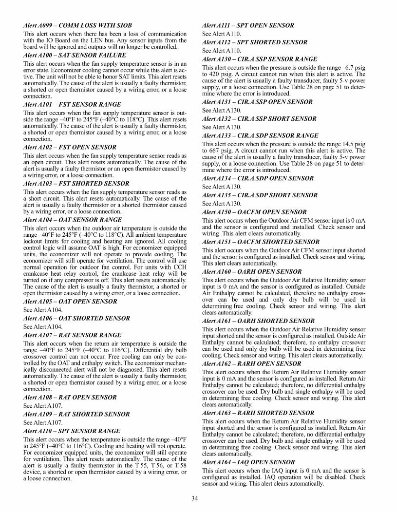
34
Alert A099 – COMM LOSS WITH SIOBThis alert occurs when there has been a loss of communicationwith the IO Board on the LEN bus. Any sensor inputs from theboard will be ignored and outputs will no longer be controlled.Alert A100 – SAT SENSOR FAILUREThis alert occurs when the fan supply temperature sensor is in anerror state. Economizer cooling cannot occur while this alert is ac-tive. The unit will not be able to honor SAT limits. This alert resetsautomatically. The cause of the alert is usually a faulty thermistor,a shorted or open thermistor caused by a wiring error, or a looseconnection.Alert A101 – FST SENSOR RANGEThis alert occurs when the fan supply temperature sensor is out-side the range –40°F to 245°F (–40°C to 118°C). This alert resetsautomatically. The cause of the alert is usually a faulty thermistor,a shorted or open thermistor caused by a wiring error, or a looseconnection.Alert A102 – FST OPEN SENSORThis alert occurs when the fan supply temperature sensor reads asan open circuit. This alert resets automatically. The cause of thealert is usually a faulty thermistor or an open thermistor caused bya wiring error, or a loose connection.Alert A103 – FST SHORTED SENSORThis alert occurs when the fan supply temperature sensor reads asa short circuit. This alert resets automatically. The cause of thealert is usually a faulty thermistor or a shorted thermistor causedby a wiring error, or a loose connection.Alert A104 – OAT SENSOR RANGEThis alert occurs when the outdoor air temperature is outside therange –40°F to 245°F (–40°C to 118°C). All ambient temperaturelockout limits for cooling and heating are ignored. All coolingcontrol logic will assume OAT is high. For economizer equippedunits, the economizer will not operate to provide cooling. Theeconomizer will still operate for ventilation. The control will usenormal operation for outdoor fan control. For units with CCHcrankcase heat relay control, the crankcase heat relay will beturned on if any compressor is off. This alert resets automatically.The cause of the alert is usually a faulty thermistor, a shorted oropen thermistor caused by a wiring error, or a loose connection.Alert A105 – OAT OPEN SENSORSee Alert A104.Alert A106 – OAT SHORTED SENSORSee Alert A104.Alert A107 – RAT SENSOR RANGEThis alert occurs when the return air temperature is outside therange –40°F to 245°F (–40°C to 116°C). Differential dry bulbcrossover control can not occur. Free cooling can only be con-trolled by the OAT and enthalpy switch. The economizer mechan-ically disconnected alert will not be diagnosed. This alert resetsautomatically. The cause of the alert is usually a faulty thermistor,a shorted or open thermistor caused by a wiring error, or a looseconnection.Alert A108 – RAT OPEN SENSORSee Alert A107.Alert A109 – RAT SHORTED SENSORSee Alert A107.Alert A110 – SPT SENSOR RANGEThis alert occurs when the temperature is outside the range –40°Fto 245°F (–40°C to 116°C). Cooling and heating will not operate.For economizer equipped units, the economizer will still operatefor ventilation. This alert resets automatically. The cause of thealert is usually a faulty thermistor in the T-55, T-56, or T-58device, a shorted or open thermistor caused by a wiring error, ora loose connection.
Alert A111 – SPT OPEN SENSORSee Alert A110.Alert A112 – SPT SHORTED SENSORSee Alert A110.Alert A130 – CIR.A SSP SENSOR RANGEThis alert occurs when the pressure is outside the range –6.7 psigto 420 psig. A circuit cannot run when this alert is active. Thecause of the alert is usually a faulty transducer, faulty 5-v powersupply, or a loose connection. Use Table 28 on page 51 to deter-mine where the error is introduced.Alert A131 – CIR.A SSP OPEN SENSORSee Alert A130.Alert A132 – CIR.A SSP SHORT SENSORSee Alert A130.Alert A133 – CIR.A SDP SENSOR RANGEThis alert occurs when the pressure is outside the range 14.5 psigto 667 psig. A circuit cannot run when this alert is active. Thecause of the alert is usually a faulty transducer, faulty 5-v powersupply, or a loose connection. Use Table 28 on page 51 to deter-mine where the error is introduced.Alert A134 – CIR.A SDP OPEN SENSORSee Alert A130.Alert A135 – CIR.A SDP SHORT SENSORSee Alert A130.Alert A150 – OACFM OPEN SENSORThis alert occurs when the Outdoor Air CFM sensor input is 0 mAand the sensor is configured and installed. Check sensor andwiring. This alert clears automatically.Alert A151 – OACFM SHORTED SENSORThis alert occurs when the Outdoor Air CFM sensor input shortedand the sensor is configured as installed. Check sensor and wiring.This alert clears automatically.Alert A160 – OARH OPEN SENSORThis alert occurs when the Outdoor Air Relative Humidity sensorinput is 0 mA and the sensor is configured as installed. OutsideAir Enthalpy cannot be calculated, therefore no enthalpy cross-over can be used and only dry bulb will be used indetermining free cooling. Check sensor and wiring. This alertclears automatically.Alert A161 – OARH SHORTED SENSORThis alert occurs when the Outdoor Air Relative Humidity sensorinput shorted and the sensor is configured as installed. Outside AirEnthalpy cannot be calculated; therefore, no enthalpy crossovercan be used and only dry bulb will be used in determining freecooling. Check sensor and wiring. This alert clears automatically.Alert A162 – RARH OPEN SENSORThis alert occurs when the Return Air Relative Humidity sensorinput is 0 mA and the sensor is configured as installed. Return AirEnthalpy cannot be calculated; therefore, no differential enthalpycrossover can be used. Dry bulb and single enthalpy will be usedin determining free cooling. Check sensor and wiring. This alertclears automatically.Alert A163 – RARH SHORTED SENSORThis alert occurs when the Return Air Relative Humidity sensorinput shorted and the sensor is configured as installed. Return AirEnthalpy cannot be calculated; therefore, no differential enthalpycrossover can be used. Dry bulb and single enthalpy will be usedin determining free cooling. Check sensor and wiring. This alertclears automatically.Alert A164 – IAQ OPEN SENSORThis alert occurs when the IAQ input is 0 mA and the sensor isconfigured as installed. IAQ operation will be disabled. Checksensor and wiring. This alert clears automatically.
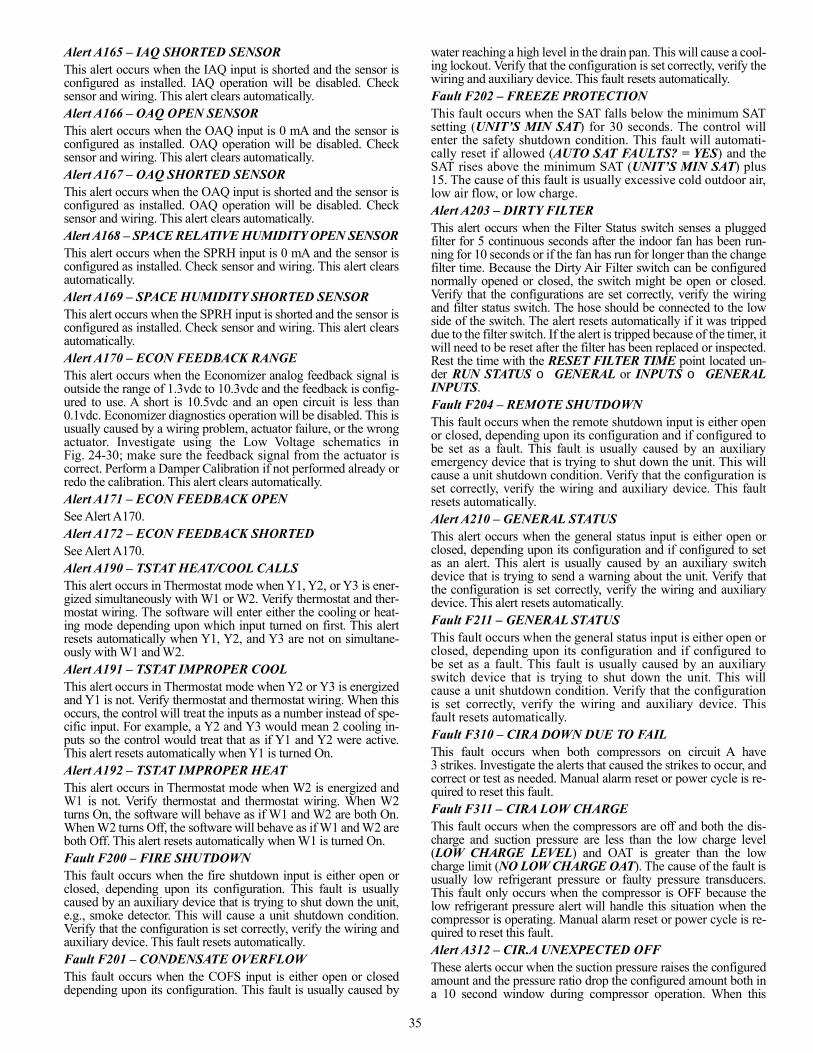
35
Alert A165 – IAQ SHORTED SENSORThis alert occurs when the IAQ input is shorted and the sensor isconfigured as installed. IAQ operation will be disabled. Checksensor and wiring. This alert clears automatically.Alert A166 – OAQ OPEN SENSORThis alert occurs when the OAQ input is 0 mA and the sensor isconfigured as installed. OAQ operation will be disabled. Checksensor and wiring. This alert clears automatically.Alert A167 – OAQ SHORTED SENSORThis alert occurs when the OAQ input is shorted and the sensor isconfigured as installed. OAQ operation will be disabled. Checksensor and wiring. This alert clears automatically.Alert A168 – SPACE RELATIVE HUMIDITY OPEN SENSORThis alert occurs when the SPRH input is 0 mA and the sensor isconfigured as installed. Check sensor and wiring. This alert clearsautomatically.Alert A169 – SPACE HUMIDITY SHORTED SENSORThis alert occurs when the SPRH input is shorted and the sensor isconfigured as installed. Check sensor and wiring. This alert clearsautomatically.Alert A170 – ECON FEEDBACK RANGEThis alert occurs when the Economizer analog feedback signal isoutside the range of 1.3vdc to 10.3vdc and the feedback is config-ured to use. A short is 10.5vdc and an open circuit is less than0.1vdc. Economizer diagnostics operation will be disabled. This isusually caused by a wiring problem, actuator failure, or the wrongactuator. Investigate using the Low Voltage schematics inFig. 24-30; make sure the feedback signal from the actuator iscorrect. Perform a Damper Calibration if not performed already orredo the calibration. This alert clears automatically.Alert A171 – ECON FEEDBACK OPENSee Alert A170.Alert A172 – ECON FEEDBACK SHORTEDSee Alert A170.Alert A190 – TSTAT HEAT/COOL CALLSThis alert occurs in Thermostat mode when Y1, Y2, or Y3 is ener-gized simultaneously with W1 or W2. Verify thermostat and ther-mostat wiring. The software will enter either the cooling or heat-ing mode depending upon which input turned on first. This alertresets automatically when Y1, Y2, and Y3 are not on simultane-ously with W1 and W2.Alert A191 – TSTAT IMPROPER COOLThis alert occurs in Thermostat mode when Y2 or Y3 is energizedand Y1 is not. Verify thermostat and thermostat wiring. When thisoccurs, the control will treat the inputs as a number instead of spe-cific input. For example, a Y2 and Y3 would mean 2 cooling in-puts so the control would treat that as if Y1 and Y2 were active.This alert resets automatically when Y1 is turned On.Alert A192 – TSTAT IMPROPER HEATThis alert occurs in Thermostat mode when W2 is energized andW1 is not. Verify thermostat and thermostat wiring. When W2turns On, the software will behave as if W1 and W2 are both On.When W2 turns Off, the software will behave as if W1 and W2 areboth Off. This alert resets automatically when W1 is turned On.Fault F200 – FIRE SHUTDOWNThis fault occurs when the fire shutdown input is either open orclosed, depending upon its configuration. This fault is usuallycaused by an auxiliary device that is trying to shut down the unit,e.g., smoke detector. This will cause a unit shutdown condition.Verify that the configuration is set correctly, verify the wiring andauxiliary device. This fault resets automatically.Fault F201 – CONDENSATE OVERFLOWThis fault occurs when the COFS input is either open or closeddepending upon its configuration. This fault is usually caused by
water reaching a high level in the drain pan. This will cause a cool-ing lockout. Verify that the configuration is set correctly, verify thewiring and auxiliary device. This fault resets automatically.Fault F202 – FREEZE PROTECTIONThis fault occurs when the SAT falls below the minimum SATsetting (UNIT’S MIN SAT) for 30 seconds. The control willenter the safety shutdown condition. This fault will automati-cally reset if allowed (AUTO SAT FAULTS? = YES) and theSAT rises above the minimum SAT (UNIT’S MIN SAT) plus15. The cause of this fault is usually excessive cold outdoor air,low air flow, or low charge.Alert A203 – DIRTY FILTERThis alert occurs when the Filter Status switch senses a pluggedfilter for 5 continuous seconds after the indoor fan has been run-ning for 10 seconds or if the fan has run for longer than the changefilter time. Because the Dirty Air Filter switch can be configurednormally opened or closed, the switch might be open or closed.Verify that the configurations are set correctly, verify the wiringand filter status switch. The hose should be connected to the lowside of the switch. The alert resets automatically if it was trippeddue to the filter switch. If the alert is tripped because of the timer, itwill need to be reset after the filter has been replaced or inspected.Rest the time with the RESET FILTER TIME point located un-der RUN STATUS GENERAL or INPUTS GENERALINPUTS.Fault F204 – REMOTE SHUTDOWNThis fault occurs when the remote shutdown input is either openor closed, depending upon its configuration and if configured tobe set as a fault. This fault is usually caused by an auxiliaryemergency device that is trying to shut down the unit. This willcause a unit shutdown condition. Verify that the configuration isset correctly, verify the wiring and auxiliary device. This faultresets automatically.Alert A210 – GENERAL STATUSThis alert occurs when the general status input is either open orclosed, depending upon its configuration and if configured to setas an alert. This alert is usually caused by an auxiliary switchdevice that is trying to send a warning about the unit. Verify thatthe configuration is set correctly, verify the wiring and auxiliarydevice. This alert resets automatically.Fault F211 – GENERAL STATUSThis fault occurs when the general status input is either open orclosed, depending upon its configuration and if configured tobe set as a fault. This fault is usually caused by an auxiliaryswitch device that is trying to shut down the unit. This willcause a unit shutdown condition. Verify that the configurationis set correctly, verify the wiring and auxiliary device. Thisfault resets automatically.Fault F310 – CIRA DOWN DUE TO FAILThis fault occurs when both compressors on circuit A have3 strikes. Investigate the alerts that caused the strikes to occur, andcorrect or test as needed. Manual alarm reset or power cycle is re-quired to reset this fault.Fault F311 – CIRA LOW CHARGEThis fault occurs when the compressors are off and both the dis-charge and suction pressure are less than the low charge level(LOW CHARGE LEVEL) and OAT is greater than the lowcharge limit (NO LOW CHARGE OAT). The cause of the fault isusually low refrigerant pressure or faulty pressure transducers.This fault only occurs when the compressor is OFF because thelow refrigerant pressure alert will handle this situation when thecompressor is operating. Manual alarm reset or power cycle is re-quired to reset this fault.Alert A312 – CIR.A UNEXPECTED OFFThese alerts occur when the suction pressure raises the configuredamount and the pressure ratio drop the configured amount both ina 10 second window during compressor operation. When this
36
occurs, the control turns off the compressors and logs a strike forthe compressor that was on. This alert resets automatically. Thepossible causes are: high-pressure switch (HPS) open (the HPS iswired in series with compressor relays on the MBB), compressorinternal protection is open, or a wiring error (a wiring error mightnot allow the compressor to start).This alert can be disabled under menu: SETTINGS UNITCONFIGURATIONS COOLING COMPRESSORTRANSITION.Alert A313 – CIR.A HIGH DISCHARGEThis alert occurs when the discharge pressure is greater than theconfigured CIR.A SDP LIMIT amount. This alert resets automat-ically when the pressure falls 20 psig below the threshold. Whenrunning both compressors, the control will remove A1 and add astrike to it. The control will also set the ODFs to the high coolspeed. The cause of the alert is usually an overcharged system,high outdoor ambient temperature coupled with dirty outdoor coil,plugged filter drier, or ODF speeds being set too low.Alert A314 – CIR.A HPS TRIPThis alert occurs when the discharge high pressure switch opens.This alert resets automatically when the pressure falls below theswitch threshold and the switch closes for 3 minutes. The controlwill add a strike for whichever compressors were on. The controlwill also set the ODFs to the high cool speed. The cause of thealert is usually an overcharged system, high outdoor ambient tem-perature coupled with dirty outdoor coil, plugged filter drier, orODF speeds being set too low.Alert A315 – CIR.A LOW DISCHARGEThis alert occurs when the discharge pressure is less than the OATplus the configured LOW DISCHARGE LEV amount for 1 min-ute. This alert resets automatically. The control will add a strikefor whichever compressors were on. The cause of the alert is usu-ally an undercharged system, low outdoor ambient temperaturecoupled with dirty outdoor coil, plugged filter drier, or ODFspeeds being set too high.This alert can be disabled under menu: SETTINGS UNITCONFIGURATIONS COOLING COMPRESSORTRANSITION.Alert A316 – CIR.A LOW SUCTIONThis alert occurs when the compressor is operating and the evapo-rating temperature (converted from the suction pressure) is lessthan configured low suction control levels, LOW SUC LEVEL 1,LOW SUC LEVEL 2, or LOW SUC LEVEL 3. The circuit SSTvalue must be less than LOW SUC LEVEL 1 (for 5 minutes),LOW SUC LEVEL 2 (for 4 minutes), or LOW SUC LEVEL 3(for 3 minutes when using the economizer and 1.5 minutes whennot using the economizer) for the alert to occur. When the outdoortemperature is less than 40°F, the above values are reduced 1°F forevery 2°F OAT is below 40°F. All the above timers will reset if thesuction temperature rises above LOW SUC OK TEMP for 1 min-ute. This alert causes a strike for the respective circuit. This alertwill activate when the coil becomes frosted. However, during the15 minute reset period, the coils will thaw and the strike shouldclear and restart if there is nothing else wrong with the circuit. Thealert resets automatically. The cause of the alert is usually low re-frigerant charge, dirty filters, evaporator fan operating backwards,loose or broken belt, plugged filter drier, faulty transducer, exces-sively cold return air, or stuck open economizer when the ambienttemperature is low.Alert A317 – CIR.A PRESSURE RATIOThis alert occurs when the Circuit A pressure ratio is less than theconfigured MIN PRESSURE RATIO amount. This alert resetsautomatically. The control will add a strike for whichever com-pressors were on. The cause of the alert is usually an underchargedsystem, low outdoor ambient temperature coupled with dirty out-door coil, plugged filter drier, or ODF speeds being set too high.
Fault F318 – COMPRESSOR STUCK ONThis fault occurs when the suction pressure does not raise the min-imum suction amount (CIR.A MIN SUC.P) and the ratio did notfall at least the off pressure ratio (OFF P.RATIO). When this oc-curs, the control turns off all of the compressors, and enters a safe-ty shutdown condition. The possible causes are a welded contactoror frozen compressor relay on MBB. Manual alarm reset or powercycle is required to reset this fault.This alert can be disabled under menu: SETTINGS UNITCONFIGURATIONS COOLING COMPRESSORTRANSITION.Fault F319 – C.A1 DOWN DUE TOFAILThis fault occurs when compressor A1 has 3 strikes. Investigatethe alerts that caused the strikes to occur, and correct or test asneeded. Manual alarm reset or power cycle is required to reset thisfault.Alert A320 – C.A1 REVERSE ROTATIONThis alert occurs when 10 seconds after the compressor turns on,the suction rose and the discharge pressure dropped. This alertcauses a strike for the compressor. The alert resets automatically.The cause of the alert is usually compressor wiring causing re-verse rotation or a faulty compressor.Alert A321 – C.A1 FAIL TO PRESSUREThis alert occurs when 10 seconds after the compressor turns on,the suction did not drop more than suction amount (CIR.A MINSUC.P) and discharge pressure did not rise more than dischargeamount (CIR.A MIN DIS.P). This alert causes a strike for thecompressor. The alert resets automatically. The cause of the alert isusually compressor wiring causing reverse rotation or a faultycompressor.Fault F322 – C.A2 DOWN DUE TO FAILThis fault occurs when compressor A2 has 3 strikes. Investigatethe alerts that caused the strikes to occur, and correct or test asneeded. Manual alarm reset or power cycle is required to reset thisfault.Alert A323 – C.A2 REVERSE ROTATIONThis alert occurs when 10 seconds after the compressor turns on,the suction rose and the discharge pressure dropped. This alertcauses a strike for the compressor. The alert resets automatically.The cause of the alert is usually compressor wiring causing re-verse rotation or a faulty compressor.Alert A324 – C.A2 FAIL TO PRESSUREThis alert occurs when 10 seconds after the compressor turns on,the suction did not drop more than suction amount (CIR.A MINSUC.P) and discharge pressure did not rise more than dischargeamount (CIR.A MIN DIS.P). This alert causes a strike for thecompressor. The alert resets automatically. The cause of the alert isusually compressor wiring causing reverse rotation or a faultycompressor.Alert A410 – IGC IGNITION FAILUREThis alert occurs when the IGC fan request does not activate15 minutes after turning heat 1 on when configured for Gas Heat.The control will lockout all the heat stages. This alert will auto-matically reset after the IGC fan request occurs. The cause of thisalert is usually faulty wiring of the IGC, no gas flow, or wrongconfiguration.Fault F411 – ROLLOUT WITHOUT HEATThis fault occurs when the IGC fan request activates and the heathas been off for at least 3 minutes when configured for Gas Heat.The control will enter the safety shutdown condition. This alertwill automatically reset after the IGC fan request turns off for 10minutes. The cause of this alert is usually faulty wiring of the IGC,or rollout switch trip without a heat call.Fault F412 – RUNAWAY HEATThis fault occurs when the SAT rises above the maximum SAT.The control will enter the safety shutdown condition. This alert
37
will automatically reset after if configured to and the SAT falls50°F below the maximum SAT. The cause of this alert is usuallyheat stuck on causing high SAT, or low air flow.Alert A510 – INDOOR FAN STATUSThis alert occurs when the unit is configured not to shut down onfan status and either the fan is requested off and the fan speedfeedback does not reach zero in the VFD deceleration time or thefan is requested greater than zero and the fan speed feedback doesnot reach that speed in the VFD acceleration time. This alert willreset automatically. The cause of this alert is usually broken belt,motor failure, or configuration error.Fault F511 – IDF OFF WHEN COMMAND ONThis fault occurs when the unit is configured to shut down on fanstatus, the fan is requested greater than zero, and the fan speedfeedback does not reach that speed in the VFD acceleration time.The cause of this alert is usually Fan stuck on, or Configuration in-correct. Manual alarm reset or power cycle is required to reset thisfault.Fault F512 – IDF ON WHEN COMMAND OFFThis fault occurs when the unit is configured to shut down on fanstatus, the fan is requested off, and the fan speed feedback does notreach zero in the VFD deceleration time. The cause of this alert isusually tripped circuit breaker, broken belt, bad indoor fan motor,or configuration incorrect. Manual alarm reset or power cycle isrequired to reset this fault.Fault F600 – IDF VFD COMMUNICATIONThis fault occurs when the indoor fan VFD and the SystemVu™control are not communicating properly. This will cause a unitshutdown, and will automatically reset when communication isproperly restored. The cause of this is usually a break in the com-munication connection, noise on the LEN bus, wiring error, or aconfiguration error. Verify VFD configurations are set per the lat-est literature.Fault F601 – IDF VFD UNEXPECTEDThis fault occurs when the indoor fan VFD informs the SystemVucontrol that it has an active fault. This will cause a unit shutdown,and will automatically reset when the VFD fault is cleared butlikely will require a manual reset to reset the VFD. Refer to theVFD section or literature for details on the specific VFD fault.Verify VFD configurations are set per the latest literature.Fault F602 – IDF VFD LOCKOUTThis fault occurs when the indoor fan VFD informs the SystemVucontrol that it has an active lockout fault. This will cause a unitshutdown, and requires a power cycle to reset the VFD. Refer tothe VFD section or literature for details on the specific VFD fault.Verify VFD configurations are set per the latest literature.Alert A603 – IDF VFD IN HANDThis alert occurs when the indoor fan VFD informs the SystemVucontrol that it is no longer in auto control and in either hand or offmode. This can only be done with the accessory VFD keypad.This will automatically reset when the VFD is placed back intoauto mode for the VFD keypad. Refer to the VFD section or liter-ature for details on the specific VFD fault. Verify VFD configura-tions are set per the latest literature.Fault F604 – IDF VFD IN HANDThis fault occurs when the indoor fan VFD informs the SystemVucontrol that it is no longer in auto control and in either hand or offmode. This can only be done with the accessory VFD keypad.This will cause a unit shutdown, and will automatically reset whenthe VFD is placed back into auto mode for the VFD keypad. Referto the VFD section or literature for details on the specific VFDfault. Verify VFD configurations are set per the latest literature.Alert A605 – IDF VFD THERMAL WARNINGThis alert occurs when the indoor fan VFD informs the SystemVucontrol that it has an active warning. This will cause an IDF speedreduction of 10%, and will automatically reset when the VFD alert
is cleared. Refer to the VFD section or literature for details on thespecific VFD fault. Verify VFD configurations are set per the lat-est literature.Alert A606 – IDF VFD VOLTAGE WARNINGSee alert A605.Alert A607 – IDF VFD CURRENT LIMITSee alert A605.Alert A608 – IDF VFD WARNINGSee alert A605.Fault F611 – IDF VFD EARTH FAULTSee fault F601.Fault F612 – IDF VFD CTLWORD LOSSSee fault F601.Fault F613 – IDF VFD OVER CURRENTSee fault F601.Fault F614 – IDF VFD MOTOR OVER TEMPSee fault F601.Fault F615 – IDF VFD OVERLOADSee fault F601.Fault F616 – IDF VFD UNDER VOLTAGESee fault F601.Fault F617 – IDF VFD OVER VOLTAGESee fault F601.Fault F618 – IDF VFD SHORT CIRCUITSee fault F601.Fault F619 – IDF VFD MAIN PHASE LOSSSee fault F601.Fault F620 – IDF VFD PHASE U LOSSSee fault F601.Fault F621 – IDF VFD PHASE V LOSSSee fault F601.Fault F622 – IDF VFD PHASEWLOSSSee fault F601.Fault F623 – IDF VFD CONTROL VOLTAGESee fault F601.Fault F624 – IDF VFD SUPPLY VDDSee fault F601.Alert A700 – ECON NOT MODULATINGThis alert occurs when the economizer feedback is enabled andthe actual speed does reach the commanded speed in the econo-mizer travel time configuration value. This alert will automaticallyreset when the actual position does reach the commanded position.This is usually caused by installation of the wrong actuator, noeconomizer gear motion, or actuator direction control switch(CCW, CW) wrong. Check damper blades, gears, and actuator.This alert will usually be accompanied by another descriptive in-formational alert.An Economizer Calibration can be performed in test mode. SeeEconomizer Troubleshooting section for more details.Alert A701 – ECON STUCK CLOSEDThis alert occurs when damper not modulating alert is active andactual damper position is zero. This alert will be reset once thedamper not modulating alert becomes inactive. This alert will alsobe reset upon resetting all current alarm commands.Alert A702 – ECON STUCK OPENThis alert occurs when damper not modulating alert is active,commanded damper position is zero and actual damper positionis greater than two. This alert will be reset once the damper not
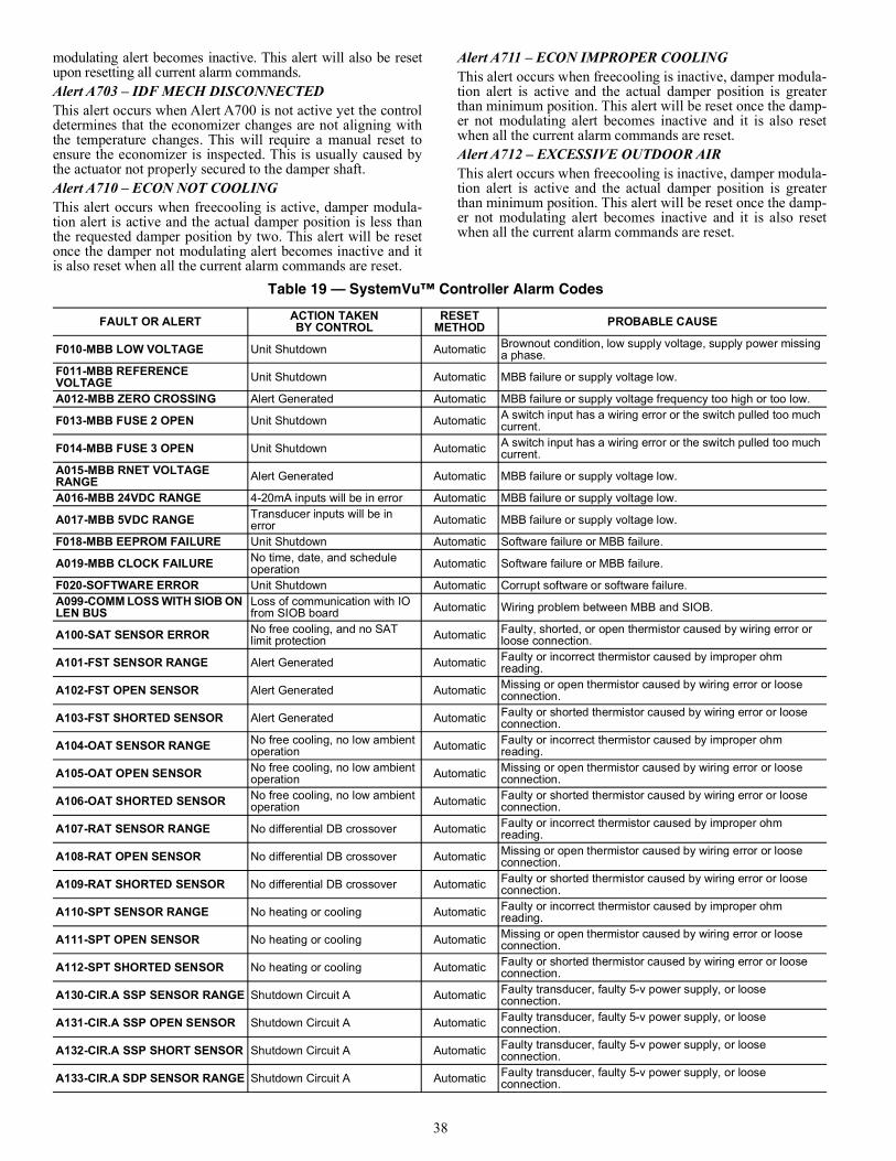
38
modulating alert becomes inactive. This alert will also be resetupon resetting all current alarm commands.Alert A703 – IDF MECH DISCONNECTEDThis alert occurs when Alert A700 is not active yet the controldetermines that the economizer changes are not aligning withthe temperature changes. This will require a manual reset toensure the economizer is inspected. This is usually caused bythe actuator not properly secured to the damper shaft.Alert A710 – ECON NOT COOLINGThis alert occurs when freecooling is active, damper modula-tion alert is active and the actual damper position is less thanthe requested damper position by two. This alert will be resetonce the damper not modulating alert becomes inactive and itis also reset when all the current alarm commands are reset.
Alert A711 – ECON IMPROPER COOLINGThis alert occurs when freecooling is inactive, damper modula-tion alert is active and the actual damper position is greaterthan minimum position. This alert will be reset once the damp-er not modulating alert becomes inactive and it is also resetwhen all the current alarm commands are reset.Alert A712 – EXCESSIVE OUTDOOR AIRThis alert occurs when freecooling is inactive, damper modula-tion alert is active and the actual damper position is greaterthan minimum position. This alert will be reset once the damp-er not modulating alert becomes inactive and it is also resetwhen all the current alarm commands are reset.
Table 19 — SystemVu™ Controller Alarm Codes
FAULT OR ALERT ACTION TAKENBY CONTROL
RESET METHOD PROBABLE CAUSE
F010-MBB LOW VOLTAGE Unit Shutdown Automatic Brownout condition, low supply voltage, supply power missing a phase.
F011-MBB REFERENCE VOLTAGE Unit Shutdown Automatic MBB failure or supply voltage low.
A012-MBB ZERO CROSSING Alert Generated Automatic MBB failure or supply voltage frequency too high or too low.
F013-MBB FUSE 2 OPEN Unit Shutdown Automatic A switch input has a wiring error or the switch pulled too much current.
F014-MBB FUSE 3 OPEN Unit Shutdown Automatic A switch input has a wiring error or the switch pulled too much current.
A015-MBB RNET VOLTAGE RANGE Alert Generated Automatic MBB failure or supply voltage low.
A016-MBB 24VDC RANGE 4-20mA inputs will be in error Automatic MBB failure or supply voltage low.
A017-MBB 5VDC RANGE Transducer inputs will be in error Automatic MBB failure or supply voltage low.
F018-MBB EEPROM FAILURE Unit Shutdown Automatic Software failure or MBB failure.
A019-MBB CLOCK FAILURE No time, date, and schedule operation Automatic Software failure or MBB failure.
F020-SOFTWARE ERROR Unit Shutdown Automatic Corrupt software or software failure.A099-COMM LOSS WITH SIOB ON LEN BUS
Loss of communication with IO from SIOB board Automatic Wiring problem between MBB and SIOB.
A100-SAT SENSOR ERROR No free cooling, and no SAT limit protection Automatic Faulty, shorted, or open thermistor caused by wiring error or
loose connection.
A101-FST SENSOR RANGE Alert Generated Automatic Faulty or incorrect thermistor caused by improper ohm reading.
A102-FST OPEN SENSOR Alert Generated Automatic Missing or open thermistor caused by wiring error or loose connection.
A103-FST SHORTED SENSOR Alert Generated Automatic Faulty or shorted thermistor caused by wiring error or loose connection.
A104-OAT SENSOR RANGE No free cooling, no low ambient operation Automatic Faulty or incorrect thermistor caused by improper ohm
reading.
A105-OAT OPEN SENSOR No free cooling, no low ambient operation Automatic Missing or open thermistor caused by wiring error or loose
connection.
A106-OAT SHORTED SENSOR No free cooling, no low ambient operation Automatic Faulty or shorted thermistor caused by wiring error or loose
connection.
A107-RAT SENSOR RANGE No differential DB crossover Automatic Faulty or incorrect thermistor caused by improper ohm reading.
A108-RAT OPEN SENSOR No differential DB crossover Automatic Missing or open thermistor caused by wiring error or loose connection.
A109-RAT SHORTED SENSOR No differential DB crossover Automatic Faulty or shorted thermistor caused by wiring error or loose connection.
A110-SPT SENSOR RANGE No heating or cooling Automatic Faulty or incorrect thermistor caused by improper ohm reading.
A111-SPT OPEN SENSOR No heating or cooling Automatic Missing or open thermistor caused by wiring error or loose connection.
A112-SPT SHORTED SENSOR No heating or cooling Automatic Faulty or shorted thermistor caused by wiring error or loose connection.
A130-CIR.A SSP SENSOR RANGE Shutdown Circuit A Automatic Faulty transducer, faulty 5-v power supply, or loose connection.
A131-CIR.A SSP OPEN SENSOR Shutdown Circuit A Automatic Faulty transducer, faulty 5-v power supply, or loose connection.
A132-CIR.A SSP SHORT SENSOR Shutdown Circuit A Automatic Faulty transducer, faulty 5-v power supply, or loose connection.
A133-CIR.A SDP SENSOR RANGE Shutdown Circuit A Automatic Faulty transducer, faulty 5-v power supply, or loose connection.
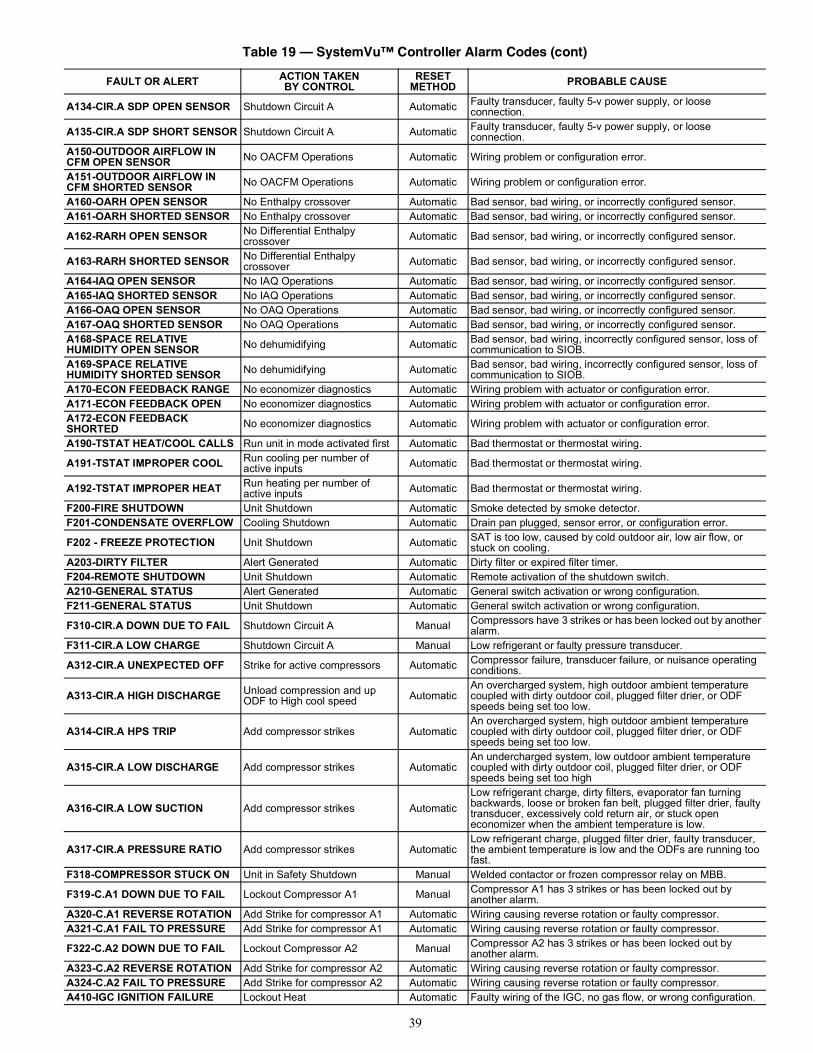
39
A134-CIR.A SDP OPEN SENSOR Shutdown Circuit A Automatic Faulty transducer, faulty 5-v power supply, or loose connection.
A135-CIR.A SDP SHORT SENSOR Shutdown Circuit A Automatic Faulty transducer, faulty 5-v power supply, or loose connection.
A150-OUTDOOR AIRFLOW IN CFM OPEN SENSOR No OACFM Operations Automatic Wiring problem or configuration error.
A151-OUTDOOR AIRFLOW IN CFM SHORTED SENSOR No OACFM Operations Automatic Wiring problem or configuration error.
A160-OARH OPEN SENSOR No Enthalpy crossover Automatic Bad sensor, bad wiring, or incorrectly configured sensor.A161-OARH SHORTED SENSOR No Enthalpy crossover Automatic Bad sensor, bad wiring, or incorrectly configured sensor.
A162-RARH OPEN SENSOR No Differential Enthalpy crossover Automatic Bad sensor, bad wiring, or incorrectly configured sensor.
A163-RARH SHORTED SENSOR No Differential Enthalpy crossover Automatic Bad sensor, bad wiring, or incorrectly configured sensor.
A164-IAQ OPEN SENSOR No IAQ Operations Automatic Bad sensor, bad wiring, or incorrectly configured sensor.A165-IAQ SHORTED SENSOR No IAQ Operations Automatic Bad sensor, bad wiring, or incorrectly configured sensor.A166-OAQ OPEN SENSOR No OAQ Operations Automatic Bad sensor, bad wiring, or incorrectly configured sensor.A167-OAQ SHORTED SENSOR No OAQ Operations Automatic Bad sensor, bad wiring, or incorrectly configured sensor.A168-SPACE RELATIVE HUMIDITY OPEN SENSOR No dehumidifying Automatic Bad sensor, bad wiring, incorrectly configured sensor, loss of
communication to SIOB.A169-SPACE RELATIVE HUMIDITY SHORTED SENSOR No dehumidifying Automatic Bad sensor, bad wiring, incorrectly configured sensor, loss of
communication to SIOB.A170-ECON FEEDBACK RANGE No economizer diagnostics Automatic Wiring problem with actuator or configuration error.A171-ECON FEEDBACK OPEN No economizer diagnostics Automatic Wiring problem with actuator or configuration error.A172-ECON FEEDBACK SHORTED No economizer diagnostics Automatic Wiring problem with actuator or configuration error.
A190-TSTAT HEAT/COOL CALLS Run unit in mode activated first Automatic Bad thermostat or thermostat wiring.
A191-TSTAT IMPROPER COOL Run cooling per number of active inputs Automatic Bad thermostat or thermostat wiring.
A192-TSTAT IMPROPER HEAT Run heating per number of active inputs Automatic Bad thermostat or thermostat wiring.
F200-FIRE SHUTDOWN Unit Shutdown Automatic Smoke detected by smoke detector.F201-CONDENSATE OVERFLOW Cooling Shutdown Automatic Drain pan plugged, sensor error, or configuration error.
F202 - FREEZE PROTECTION Unit Shutdown Automatic SAT is too low, caused by cold outdoor air, low air flow, or stuck on cooling.
A203-DIRTY FILTER Alert Generated Automatic Dirty filter or expired filter timer.F204-REMOTE SHUTDOWN Unit Shutdown Automatic Remote activation of the shutdown switch.A210-GENERAL STATUS Alert Generated Automatic General switch activation or wrong configuration.F211-GENERAL STATUS Unit Shutdown Automatic General switch activation or wrong configuration.
F310-CIR.A DOWN DUE TO FAIL Shutdown Circuit A Manual Compressors have 3 strikes or has been locked out by another alarm.
F311-CIR.A LOW CHARGE Shutdown Circuit A Manual Low refrigerant or faulty pressure transducer.
A312-CIR.A UNEXPECTED OFF Strike for active compressors Automatic Compressor failure, transducer failure, or nuisance operating conditions.
A313-CIR.A HIGH DISCHARGE Unload compression and up ODF to High cool speed Automatic
An overcharged system, high outdoor ambient temperature coupled with dirty outdoor coil, plugged filter drier, or ODF speeds being set too low.
A314-CIR.A HPS TRIP Add compressor strikes AutomaticAn overcharged system, high outdoor ambient temperature coupled with dirty outdoor coil, plugged filter drier, or ODF speeds being set too low.
A315-CIR.A LOW DISCHARGE Add compressor strikes AutomaticAn undercharged system, low outdoor ambient temperature coupled with dirty outdoor coil, plugged filter drier, or ODF speeds being set too high
A316-CIR.A LOW SUCTION Add compressor strikes AutomaticLow refrigerant charge, dirty filters, evaporator fan turning backwards, loose or broken fan belt, plugged filter drier, faulty transducer, excessively cold return air, or stuck open economizer when the ambient temperature is low.
A317-CIR.A PRESSURE RATIO Add compressor strikes AutomaticLow refrigerant charge, plugged filter drier, faulty transducer, the ambient temperature is low and the ODFs are running too fast.
F318-COMPRESSOR STUCK ON Unit in Safety Shutdown Manual Welded contactor or frozen compressor relay on MBB.
F319-C.A1 DOWN DUE TO FAIL Lockout Compressor A1 Manual Compressor A1 has 3 strikes or has been locked out by another alarm.
A320-C.A1 REVERSE ROTATION Add Strike for compressor A1 Automatic Wiring causing reverse rotation or faulty compressor.A321-C.A1 FAIL TO PRESSURE Add Strike for compressor A1 Automatic Wiring causing reverse rotation or faulty compressor.
F322-C.A2 DOWN DUE TO FAIL Lockout Compressor A2 Manual Compressor A2 has 3 strikes or has been locked out by another alarm.
A323-C.A2 REVERSE ROTATION Add Strike for compressor A2 Automatic Wiring causing reverse rotation or faulty compressor.A324-C.A2 FAIL TO PRESSURE Add Strike for compressor A2 Automatic Wiring causing reverse rotation or faulty compressor.A410-IGC IGNITION FAILURE Lockout Heat Automatic Faulty wiring of the IGC, no gas flow, or wrong configuration.
Table 19 — SystemVu™ Controller Alarm Codes (cont)
FAULT OR ALERT ACTION TAKENBY CONTROL
RESET METHOD PROBABLE CAUSE
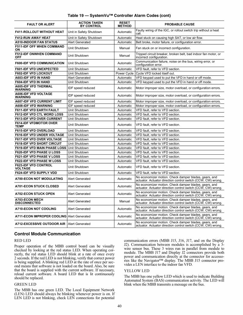
40
Control Module CommunicationRED LEDProper operation of the MBB control board can be visuallychecked by looking at the red status LED. When operating cor-rectly, the red status LED should blink at a rate of once every2 seconds. If the red LED is not blinking, verify that correct poweris being supplied. A blinking red LED at the rate of once per sec-ond means that software is not loaded on the board. Also, be surethat the board is supplied with the current software. If necessary,reload current software. A board LED that is lit continuouslyshould be replaced.GREEN LEDThe MBB has one green LED. The Local Equipment Network(LEN) LED should always be blinking whenever power is on. IfLEN LED is not blinking, check LEN connections for potential
communication errors (MBB J15, J16, J17, and on the DisplayJ2). Communication between modules is accomplished by a 3-wire sensor bus. These 3 wires run in parallel from module tomodule. The MBB J17 and Display J2 connectors provide bothpower and communication directly at the connector for accesso-ries like the Navigator™ display. The MBB J15 connector pro-vides a LEN interface to the indoor fan VFD.YELLOW LEDThe MBB has one yellow LED which is used to indicate BuildingAutomated System (BAS) communication activity. The LED willblink when the MBB transmits a message on the bus.
F411-ROLLOUT WITHOUT HEAT Unit in Safety Shutdown Automatic Faulty wiring of the IGC, or rollout switch trip without a heat call.
F412-RUN AWAY HEAT Unit in Safety Shutdown Automatic Heat stuck on causing high SAT, or low air flow.A510-INDOOR FAN STATUS Alert Generated Automatic Belt broke, motor failure, or configuration error.F511-IDF OFF WHEN COMMAND ON Unit Shutdown Manual Fan stuck on or incorrect configuration.
F512-IDF ONWHEN COMMAND OFF Unit Shutdown Manual Tripped circuit breaker, broken belt, bad indoor fan motor, or
incorrect configuration.
F600-IDF VFD COMMUNICATION Unit Shutdown Automatic Communication failure, noise on the bus, wiring error, or configuration error.
F601-IDF VFD UNEXPECTED Unit Shutdown Automatic VFD fault, refer to VFD section.F602-IDF VFD LOCKOUT Unit Shutdown Power Cycle Cycle VFD locked itself out.A603-IDF VFD IN HAND Alert Generated Automatic VFD keypad used to put the VFD in hand or off mode.F604-IDF VFD IN HAND Unit Shutdown Automatic VFD keypad used to put the VFD in hand or off mode.A605-IDF VFD THERMAL WARNING IDF speed reduced Automatic Motor improper size, motor overload, or configuration errors.
A606-IDF VFD VOLTAGE WARNING IDF speed reduced Automatic Motor improper size, motor overload, or configuration errors.
A607-IDF VFD CURRENT LIMIT IDF speed reduced Automatic Motor improper size, motor overload, or configuration errors.A608-IDF VFD WARNING IDF speed reduced Automatic Motor improper size, motor overload, or configuration errors.F611-IDF VFD EARTH FAULT Unit Shutdown Automatic VFD fault, refer to VFD section.F612-IDF VFD CTL WORD LOSS Unit Shutdown Automatic VFD fault, refer to VFD section.F613-IDF VFD OVER CURRENT Unit Shutdown Automatic VFD fault, refer to VFD section.F614-IDF VFDMOTOR OVER TEMP Unit Shutdown Automatic VFD fault, refer to VFD section.
F615-IDF VFD OVERLOAD Unit Shutdown Automatic VFD fault, refer to VFD section.F616-IDF VFD UNDER VOLTAGE Unit Shutdown Automatic VFD fault, refer to VFD section.F617-IDF VFD OVER VOLTAGE Unit Shutdown Automatic VFD fault, refer to VFD section.F618-IDF VFD SHORT CIRCUIT Unit Shutdown Automatic VFD fault, refer to VFD section.F619-IDF VFD MAIN PHASE LOSS Unit Shutdown Automatic VFD fault, refer to VFD section.F620-IDF VFD PHASE U LOSS Unit Shutdown Automatic VFD fault, refer to VFD section.F621-IDF VFD PHASE V LOSS Unit Shutdown Automatic VFD fault, refer to VFD section.F622-IDF VFD PHASE W LOSS Unit Shutdown Automatic VFD fault, refer to VFD section.F623-IDF VFD CONTROL VOLTAGE Unit Shutdown Automatic VFD fault, refer to VFD section.
F624-IDF VFD SUPPLY VDD Unit Shutdown Automatic VFD fault, refer to VFD section.
A700-ECON NOT MODULATING Alert Generated Automatic No economizer motion. Check damper blades, gears, and actuator. Actuator direction control switch (CCW, CW) wrong.
A701-ECON STUCK CLOSED Alert Generated Automatic No economizer motion. Check damper blades, gears, and actuator. Actuator direction control switch (CCW, CW) wrong.
A702-ECON STUCK OPEN Alert Generated Automatic No economizer motion. Check damper blades, gears, and actuator. Actuator direction control switch (CCW, CW) wrong.
A703-ECON MECH DISCONNECTED Alert Generated Manual No economizer motion. Check damper blades, gears, and
actuator. Actuator direction control switch (CCW, CW) wrong.
A710-ECON NOT COOLING Alert Generated Automatic No economizer motion. Check damper blades, gears, and actuator. Actuator direction control switch (CCW, CW) wrong.
A711-ECON IMPROPER COOLING Alert Generated Automatic No economizer motion. Check damper blades, gears, and actuator. Actuator direction control switch (CCW, CW) wrong.
A712-EXCESSIVE OUTDOOR AIR Alert Generated Automatic No economizer motion. Check damper blades, gears, and actuator. Actuator direction control switch (CCW, CW) wrong.
Table 19 — SystemVu™ Controller Alarm Codes (cont)
FAULT OR ALERT ACTION TAKENBY CONTROL
RESET METHOD PROBABLE CAUSE
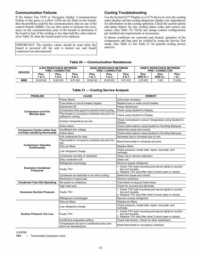
41
Communication FailuresIf the Indoor Fan VFD or Navigator display CommunicationFailure or the green or yellow LEDs do not flash on the boards,then the problem could be the communication chip on one of thecontrol boards (MBB). Use an ohm meter to measure the resis-tance on the communication pins of the boards to determine ifthe board is bad. If the reading is less than half the value indicat-ed in Table 20, then the board needs to be replaced.
Cooling TroubleshootingUse the SystemVu™ Display or a CCN device to view the coolingstatus display and the cooling diagnostic display (see Appendices)for information on the cooling operation. Check the current alarmsand alarm history for any cooling alarm codes and correct anycauses. (See Table 19.) Verify any unique control configurationsper installed site requirements or accessories.If alarms conditions are corrected and cleared, operation of thecompressors and fans may be verified by using the Service Testmode. (See Table 4.) See Table 21 for general cooling serviceanalysis.
IMPORTANT: The resistive values should be read when theboard is powered off, the unit is locked out, and boardconnectors are disconnected.
Table 20 — Communication Resistances
DEVICES(LEN) RESISTANCE BETWEEN
PINS / CONNECTOR(BAS) RESISTANCE BETWEEN
PINS / CONNECTOR(RNET) RESISTANCE BETWEEN
PINS / CONNECTORPins1 to 3
Pins1 to 2
Pins2 to 3
Pins1 to 3
Pins1 to 2
Pins2 to 3
PinsGND to +
PinsGND to -
Pins+ to -
MBB 19.92 KΩ 10.63 KΩ 9.51 KΩ 19.92 KΩ 10.63 KΩ 9.51 KΩ 2.25 KΩ 1 KΩ 3.3 KΩ
Table 21 — Cooling Service Analysis
PROBLEM CAUSE REMEDY
Compressor and FanWill Not Start
Power failure. Call power company.Fuse blown or circuit breaker tripped. Replace fuse or reset circuit breaker.Disconnect off. Power disconnect.Compressor time guard to prevent short cycling. Check using SystemVu Display.Thermostat or occupancy schedule set point not calling for cooling. Check using SystemVu Display.
Outdoor temperature too low. Check Compressor Lockout Temperature using SystemVu Display.
Active alarm. Check active alarms using SystemVu Scrolling Marquee.Compressor Cycles (other thannormally satisfying thermostat)
Insufficient line voltage. Determine cause and correct.Active alarm. Check active alarms using SystemVu Scrolling Marquee.
Compressor OperatesContinuously
Unit undersized for load. Decrease load or increase size of unit.Thermostat or occupancy schedule set point too low. Reset thermostat or schedule set point.
Dirty air filters. Replace filters.
Low refrigerant charge. Check pressure, locate leak, repair, evacuate, and recharge.
Condenser coil dirty or restricted. Clean coil or remove restriction.
Excessive CondenserPressures
Dirty condenser coil. Clean coil.Refrigerant overcharge. Recover excess refrigerant.
Faulty TXV.1. Check TXV bulb mounting and secure tightly to suction line and insulate.2. Replace TXV (and filter drier) if stuck open or closed.
Condenser air restricted or air short cycling. Determine cause and correct.Restriction in liquid tube. Remove restriction.
Condenser Fans Not Operating No power to contactors. Fuse blown or plug at motor loose.
Excessive Suction Pressure
High heat load. Check for sources and eliminate.
Faulty TXV.1. Check TXV bulb mounting and secure tightly to suction line and insulate.2. Replace TXV (and filter drier) if stuck open or closed.
Refrigerant overcharged. Recover excess refrigerant.
Suction Pressure Too Low
Dirty air filters. Replace air filters.
Low refrigerant charge. Check pressure, locate leak, repair, evacuate, and recharge.
Faulty TXV.1. Check TXV bulb mounting and secure tightly to suction line and insulate.2. Replace TXV (and filter drier) if stuck open or closed.
Insufficient evaporator airflow. Check belt tension. Check for other restrictions.Temperature too low in conditioned area (low return-air temperature). Reset thermostat or occupancy schedule.
LEGENDTXV — Thermostatic Expansion Valve
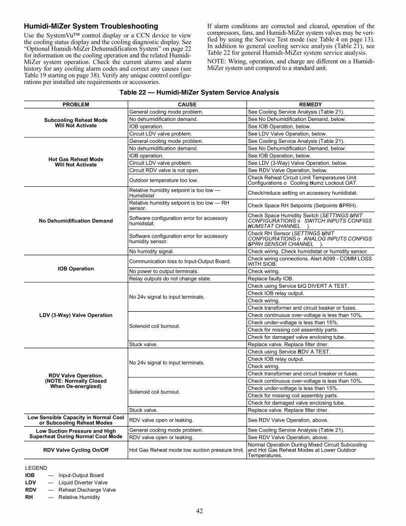
42
Humidi-MiZer System TroubleshootingUse the SystemVu™ control display or a CCN device to viewthe cooling status display and the cooling diagnostic display. See“Optional Humidi-MiZer Dehumidification System” on page 22for information on the cooling operation and the related Humidi-MiZer system operation. Check the current alarms and alarmhistory for any cooling alarm codes and correct any causes (seeTable 19 starting on page 38). Verify any unique control configu-rations per installed site requirements or accessories.
If alarm conditions are corrected and cleared, operation of thecompressors, fans, and Humidi-MiZer system valves may be veri-fied by using the Service Test mode (see Table 4 on page 13).In addition to general cooling service analysis (Table 21), seeTable 22 for general Humidi-MiZer system service analysis.NOTE: Wiring, operation, and charge are different on a Humidi-MiZer system unit compared to a standard unit.
Table 22 — Humidi-MiZer System Service Analysis
PROBLEM CAUSE REMEDY
Subcooling Reheat ModeWill Not Activate
General cooling mode problem. See Cooling Service Analysis (Table 21).No dehumidification demand. See No Dehumidification Demand, below.IOB operation. See IOB Operation, below.Circuit LDV valve problem. See LDV Valve Operation, below.
Hot Gas Reheat ModeWill Not Activate
General cooling mode problem. See Cooling Service Analysis (Table 21).No dehumidification demand. See No Dehumidification Demand, below.IOB operation. See IOB Operation, below.Circuit LDV valve problem. See LDV (3-Way) Valve Operation, below.Circuit RDV valve is not open. See RDV Valve Operation, below.
Outdoor temperature too low. Check Reheat Circuit Limit Temperatures Unit Configurations Cooling Humz Lockout OAT.
No Dehumidification Demand
Relative humidity setpoint is too low — Humidistat Check/reduce setting on accessory humidistat.
Relative humidity setpoint is too low — RH sensor. Check Space RH Setpoints (Setpoints SPRH).
Software configuration error for accessory humidistat.
Check Space Humidity Switch (SETTINGS UNIT CONFIGURATIONS SWITCH INPUTS CONFIGS HUMSTAT CHANNEL).
Software configuration error for accessory humidity sensor.
Check RH Sensor (SETTINGS UNIT CONFIGURATIONS ANALOG INPUTS CONFIGS SPRH SENSOR CHANNEL).
No humidity signal. Check wiring. Check humidistat or humidity sensor.
IOB OperationCommunication loss to Input-Output Board. Check wiring connections. Alert A099 - COMM LOSS
WITH SIOB.No power to output terminals. Check wiring.Relay outputs do not change state. Replace faulty IOB.
LDV (3-Way) Valve Operation
No 24v signal to input terminals.
Check using Service LIQ DIVERT A TEST.Check IOB relay output.Check wiring.Check transformer and circuit beaker or fuses.
Solenoid coil burnout.
Check continuous over-voltage is less than 10%.Check under-voltage is less than 15%.Check for missing coil assembly parts.Check for damaged valve enclosing tube.
Stuck valve. Replace valve. Replace filter drier.
RDV Valve Operation.(NOTE: Normally Closed
When De-energized)
No 24v signal to input terminals.
Check using Service RDV A TEST.Check IOB relay output.Check wiring.Check transformer and circuit breaker or fuses.
Solenoid coil burnout.
Check continuous over-voltage is less than 10%.Check under-voltage is less than 15%.Check for missing coil assembly parts.Check for damaged valve enclosing tube.
Stuck valve. Replace valve. Replace filter drier.Low Sensible Capacity in Normal Cool
or Subcooling Reheat Modes RDV valve open or leaking. See RDV Valve Operation, above.
Low Suction Pressure and HighSuperheat During Normal Cool Mode
General cooling mode problem. See Cooling Service Analysis (Table 21).RDV valve open or leaking. See RDV Valve Operation, above.
RDV Valve Cycling On/Off Hot Gas Reheat mode low suction pressure limit.Normal Operation During Mixed Circuit Subcooling and Hot Gas Reheat Modes at Lower Outdoor Temperatures.
LEGENDIOB — Input-Output BoardLDV — Liquid Diverter ValveRDV — Reheat Discharge ValveRH — Relative Humidity
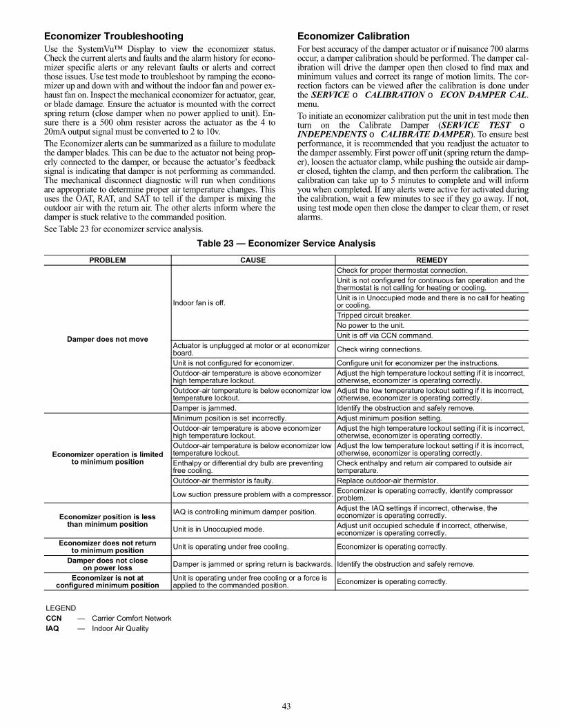
43
Economizer TroubleshootingUse the SystemVu™ Display to view the economizer status.Check the current alerts and faults and the alarm history for econo-mizer specific alerts or any relevant faults or alerts and correctthose issues. Use test mode to troubleshoot by ramping the econo-mizer up and down with and without the indoor fan and power ex-haust fan on. Inspect the mechanical economizer for actuator, gear,or blade damage. Ensure the actuator is mounted with the correctspring return (close damper when no power applied to unit). En-sure there is a 500 ohm resister across the actuator as the 4 to20mA output signal must be converted to 2 to 10v.The Economizer alerts can be summarized as a failure to modulatethe damper blades. This can be due to the actuator not being prop-erly connected to the damper, or because the actuator’s feedbacksignal is indicating that damper is not performing as commanded.The mechanical disconnect diagnostic will run when conditionsare appropriate to determine proper air temperature changes. Thisuses the OAT, RAT, and SAT to tell if the damper is mixing theoutdoor air with the return air. The other alerts inform where thedamper is stuck relative to the commanded position.See Table 23 for economizer service analysis.
Economizer CalibrationFor best accuracy of the damper actuator or if nuisance 700 alarmsoccur, a damper calibration should be performed. The damper cal-ibration will drive the damper open then closed to find max andminimum values and correct its range of motion limits. The cor-rection factors can be viewed after the calibration is done underthe SERVICE CALIBRATION ECON DAMPER CAL.menu. To initiate an economizer calibration put the unit in test mode thenturn on the Calibrate Damper (SERVICE TEST INDEPENDENTS CALIBRATE DAMPER). To ensure bestperformance, it is recommended that you readjust the actuator tothe damper assembly. First power off unit (spring return the damp-er), loosen the actuator clamp, while pushing the outside air damp-er closed, tighten the clamp, and then perform the calibration. Thecalibration can take up to 5 minutes to complete and will informyou when completed. If any alerts were active for activated duringthe calibration, wait a few minutes to see if they go away. If not,using test mode open then close the damper to clear them, or resetalarms.
Table 23 — Economizer Service Analysis
PROBLEM CAUSE REMEDY
Damper does not move
Indoor fan is off.
Check for proper thermostat connection.Unit is not configured for continuous fan operation and the thermostat is not calling for heating or cooling.Unit is in Unoccupied mode and there is no call for heating or cooling.Tripped circuit breaker.No power to the unit.Unit is off via CCN command.
Actuator is unplugged at motor or at economizer board. Check wiring connections.
Unit is not configured for economizer. Configure unit for economizer per the instructions.Outdoor-air temperature is above economizer high temperature lockout.
Adjust the high temperature lockout setting if it is incorrect, otherwise, economizer is operating correctly.
Outdoor-air temperature is below economizer low temperature lockout.
Adjust the low temperature lockout setting if it is incorrect, otherwise, economizer is operating correctly.
Damper is jammed. Identify the obstruction and safely remove.
Economizer operation is limitedto minimum position
Minimum position is set incorrectly. Adjust minimum position setting.Outdoor-air temperature is above economizer high temperature lockout.
Adjust the high temperature lockout setting if it is incorrect, otherwise, economizer is operating correctly.
Outdoor-air temperature is below economizer low temperature lockout.
Adjust the low temperature lockout setting if it is incorrect, otherwise, economizer is operating correctly.
Enthalpy or differential dry bulb are preventing free cooling.
Check enthalpy and return air compared to outside air temperature.
Outdoor-air thermistor is faulty. Replace outdoor-air thermistor.
Low suction pressure problem with a compressor. Economizer is operating correctly, identify compressor problem.
Economizer position is lessthan minimum position
IAQ is controlling minimum damper position. Adjust the IAQ settings if incorrect, otherwise, the economizer is operating correctly.
Unit is in Unoccupied mode. Adjust unit occupied schedule if incorrect, otherwise, economizer is operating correctly.
Economizer does not returnto minimum position Unit is operating under free cooling. Economizer is operating correctly.
Damper does not closeon power loss Damper is jammed or spring return is backwards. Identify the obstruction and safely remove.
Economizer is not at configured minimum position
Unit is operating under free cooling or a force is applied to the commanded position. Economizer is operating correctly.
LEGENDCCN — Carrier Comfort NetworkIAQ — Indoor Air Quality
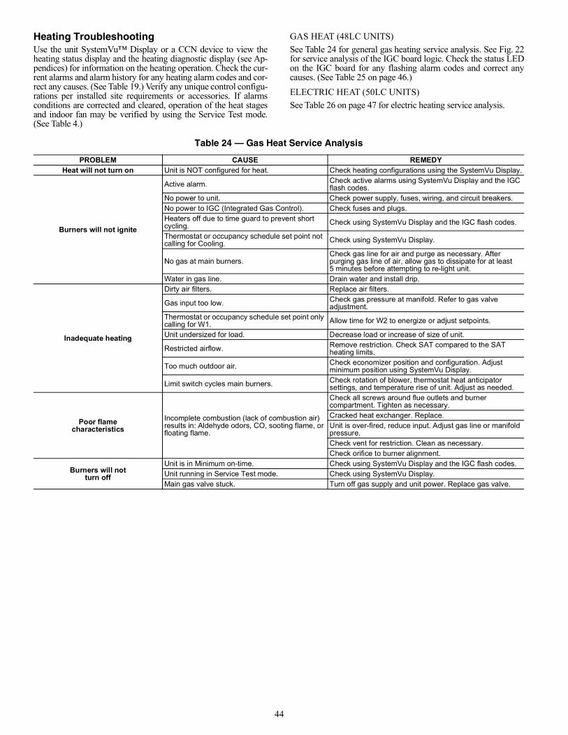
44
Heating TroubleshootingUse the unit SystemVu™ Display or a CCN device to view theheating status display and the heating diagnostic display (see Ap-pendices) for information on the heating operation. Check the cur-rent alarms and alarm history for any heating alarm codes and cor-rect any causes. (See Table 19.) Verify any unique control configu-rations per installed site requirements or accessories. If alarmsconditions are corrected and cleared, operation of the heat stagesand indoor fan may be verified by using the Service Test mode.(See Table 4.)
GAS HEAT (48LC UNITS)See Table 24 for general gas heating service analysis. See Fig. 22for service analysis of the IGC board logic. Check the status LEDon the IGC board for any flashing alarm codes and correct anycauses. (See Table 25 on page 46.)ELECTRIC HEAT (50LC UNITS)See Table 26 on page 47 for electric heating service analysis.
Table 24 — Gas Heat Service Analysis
PROBLEM CAUSE REMEDYHeat will not turn on Unit is NOT configured for heat. Check heating configurations using the SystemVu Display.
Burners will not ignite
Active alarm. Check active alarms using SystemVu Display and the IGC flash codes.
No power to unit. Check power supply, fuses, wiring, and circuit breakers.No power to IGC (Integrated Gas Control). Check fuses and plugs.Heaters off due to time guard to prevent short cycling. Check using SystemVu Display and the IGC flash codes.
Thermostat or occupancy schedule set point not calling for Cooling. Check using SystemVu Display.
No gas at main burners.Check gas line for air and purge as necessary. After purging gas line of air, allow gas to dissipate for at least 5 minutes before attempting to re-light unit.
Water in gas line. Drain water and install drip.
Inadequate heating
Dirty air filters. Replace air filters.
Gas input too low. Check gas pressure at manifold. Refer to gas valve adjustment.
Thermostat or occupancy schedule set point only calling for W1. Allow time for W2 to energize or adjust setpoints.
Unit undersized for load. Decrease load or increase of size of unit.
Restricted airflow. Remove restriction. Check SAT compared to the SAT heating limits.
Too much outdoor air. Check economizer position and configuration. Adjust minimum position using SystemVu Display.
Limit switch cycles main burners. Check rotation of blower, thermostat heat anticipator settings, and temperature rise of unit. Adjust as needed.
Poor flamecharacteristics
Incomplete combustion (lack of combustion air) results in: Aldehyde odors, CO, sooting flame, or floating flame.
Check all screws around flue outlets and burner compartment. Tighten as necessary.Cracked heat exchanger. Replace.Unit is over-fired, reduce input. Adjust gas line or manifold pressure.Check vent for restriction. Clean as necessary.Check orifice to burner alignment.
Burners will notturn off
Unit is in Minimum on-time. Check using SystemVu Display and the IGC flash codes.Unit running in Service Test mode. Check using SystemVu Display.Main gas valve stuck. Turn off gas supply and unit power. Replace gas valve.
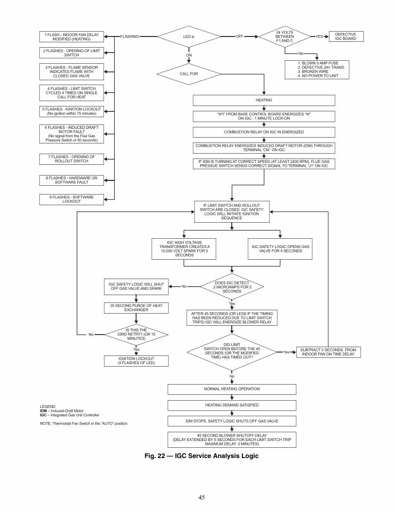
45
Fig. 22 — IGC Service Analysis Logic
1 FLASH - INDOOR FAN DELAYMODIFIED (HEATING)
2 FLASHES - OPENING OF LIMITSWITCH
3 FLASHES - FLAME SENSORINDICATES FLAME WITH
CLOSED GAS VALVE
4 FLASHES - LIMIT SWITCHCYCLED 4 TIMES ON SINGLE
CALL FOR HEAT
5 FLASHES - IGNITION LOCKOUT(No ignition within 15 minutes)
6 FLASHES - INDUCED DRAFTMOTOR FAULT
(No signal from the Flue GasPressure Switch or 60 seconds)
7 FLASHES - OPENING OFROLLOUT SWITCH
8 FLASHES - HARDWARE ORSOFTWARE FAULT
9 FLASHES - SOFTWARELOCKOUT
FLASHING LED is
ON
CALL FOR
24 VOLTSBETWEENF1 AND C
YES
No
DEFECTIVEIGC BOARD
1. BLOWN 5 AMP FUSE2. DEFECTIVE 24V TRANS.3. BROKEN WIRE4. NO POWER TO UNIT
HEATING
“W1” FROM BASE CONTROL BOARD ENERGIZES “W”ON IGC - 1 MINUTE LOCK-ON
COMBUSTION RELAY ON IGC IN ENERGIZED
COMBUSTION RELAY ENERGIZES INDUCED DRAFT MOTOR (IDM) THROUGHTERMINAL ‘CM’ ON IGC
IF IDM IS TURNING AT CORRECT SPEED (AT LEAST 2400 RPM), FLUE GASPRESSUE SWITCH SENDS CORRECT SIGNAL TO TERMINAL “J1” ON IGC
IF LIMIT SWITCH AND ROLLOUTSWITCH ARE CLOSED, IGC SAFETY
LOGIC WILL INITIATE IGNITIONSEQUENCE
IGC HIGH VOLTAGETRANSFORMER CREATES A10,000 VOLT SPARK FOR 5
SECONDS
IGC SAFETY LOGIC OPENS GASVALVE FOR 5 SECONDS
DOES IGC DETECT.2 MICROAMPS FOR 2
SECONDSNo
Yes
AFTER 45 SECONDS (OR LESS IF THE TIMINGHAS BEEN REDUCED DUE TO LIMIT SWITCHTRIPS) IGC WILL ENERGIZE BLOWER RELAY
DID LIMITSWITCH OPEN BEFORE THE 45SECONDS (OR THE MODIFIED
TIME) HAS TIMED OUT?Yes
No
No
IGC SAFETY LOGIC WILL SHUTOFF GAS VALVE AND SPARK
20 SECOND PURGE OF HEATEXCHANGER
IS THIS THE33RD RETRY? (OR 15
MINUTES)
Yes
IGNITION LOCKOUT(5 FLASHES OF LED)
SUBTRACT 5 SECONDS FROMINDOOR FAN ON TIME DELAY
NORMAL HEATING OPERATION
HEATING DEMAND SATISFIED
45 SECOND BLOWER SHUTOFF DELAY(DELAY EXTENDED BY 5 SECONDS FOR EACH LIMIT SWITCH TRIP
MAXIMUM DELAY: 3 MINUTES)
IDM STOPS, SAFETY LOGIC SHUTS OFF GAS VALVE
LEGENDIDM – Induced-Draft MotorIGC – Integrated Gas Unit Controller
NOTE: Thermostat Fan Switch in the “AUTO” position.
OFF
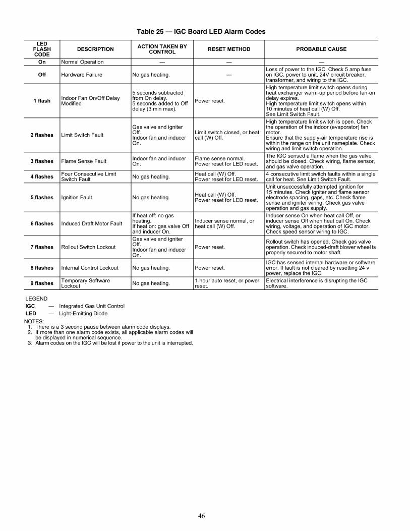
46
NOTES:1. There is a 3 second pause between alarm code displays.2. If more than one alarm code exists, all applicable alarm codes will
be displayed in numerical sequence.3. Alarm codes on the IGC will be lost if power to the unit is interrupted.
Table 25 — IGC Board LED Alarm Codes
LEDFLASHCODE
DESCRIPTION ACTION TAKEN BY CONTROL RESET METHOD PROBABLE CAUSE
On Normal Operation — — —
Off Hardware Failure No gas heating. —Loss of power to the IGC. Check 5 amp fuse on IGC, power to unit, 24V circuit breaker, transformer, and wiring to the IGC.
1 flash Indoor Fan On/Off Delay Modified
5 seconds subtracted from On delay.5 seconds added to Off delay (3 min max).
Power reset.
High temperature limit switch opens during heat exchanger warm-up period before fan-on delay expires.High temperature limit switch opens within 10 minutes of heat call (W) Off.See Limit Switch Fault.
2 flashes Limit Switch FaultGas valve and igniter Off.Indoor fan and inducer On.
Limit switch closed, or heat call (W) Off.
High temperature limit switch is open. Check the operation of the indoor (evaporator) fan motor.Ensure that the supply-air temperature rise is within the range on the unit nameplate. Check wiring and limit switch operation.
3 flashes Flame Sense Fault Indoor fan and inducer On.
Flame sense normal.Power reset for LED reset.
The IGC sensed a flame when the gas valve should be closed. Check wiring, flame sensor, and gas valve operation.
4 flashes Four Consecutive Limit Switch Fault No gas heating. Heat call (W) Off.
Power reset for LED reset.4 consecutive limit switch faults within a single call for heat. See Limit Switch Fault.
5 flashes Ignition Fault No gas heating. Heat call (W) Off.Power reset for LED reset.
Unit unsuccessfully attempted ignition for 15 minutes. Check igniter and flame sensor electrode spacing, gaps, etc. Check flame sense and igniter wiring. Check gas valve operation and gas supply.
6 flashes Induced Draft Motor FaultIf heat off: no gas heating.If heat on: gas valve Off and inducer On.
Inducer sense normal, or heat call (W) Off.
Inducer sense On when heat call Off, or inducer sense Off when heat call On. Check wiring, voltage, and operation of IGC motor. Check speed sensor wiring to IGC.
7 flashes Rollout Switch LockoutGas valve and igniter Off.Indoor fan and inducer On.
Power reset.Rollout switch has opened. Check gas valve operation. Check induced-draft blower wheel is properly secured to motor shaft.
8 flashes Internal Control Lockout No gas heating. Power reset.IGC has sensed internal hardware or software error. If fault is not cleared by resetting 24 v power, replace the IGC.
9 flashes Temporary Software Lockout No gas heating. 1 hour auto reset, or power
reset.Electrical interference is disrupting the IGC software.
LEGENDIGC — Integrated Gas Unit ControlLED — Light-Emitting Diode
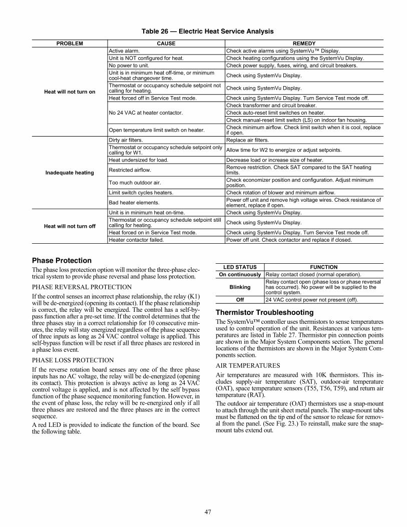
47
Phase ProtectionThe phase loss protection option will monitor the three-phase elec-trical system to provide phase reversal and phase loss protection.PHASE REVERSAL PROTECTIONIf the control senses an incorrect phase relationship, the relay (K1)will be de-energized (opening its contact). If the phase relationshipis correct, the relay will be energized. The control has a self-by-pass function after a pre-set time. If the control determines that thethree phases stay in a correct relationship for 10 consecutive min-utes, the relay will stay energized regardless of the phase sequenceof three inputs as long as 24 VAC control voltage is applied. Thisself-bypass function will be reset if all three phases are restored ina phase loss event.PHASE LOSS PROTECTIONIf the reverse rotation board senses any one of the three phaseinputs has no AC voltage, the relay will be de-energized (openingits contact). This protection is always active as long as 24 VACcontrol voltage is applied, and is not affected by the self bypassfunction of the phase sequence monitoring function. However, inthe event of phase loss, the relay will be re-energized only if allthree phases are restored and the three phases are in the correctsequence.A red LED is provided to indicate the function of the board. Seethe following table.
Thermistor TroubleshootingThe SystemVu™ controller uses thermistors to sense temperaturesused to control operation of the unit. Resistances at various tem-peratures are listed in Table 27. Thermistor pin connection pointsare shown in the Major System Components section. The generallocations of the thermistors are shown in the Major System Com-ponents section.AIR TEMPERATURESAir temperatures are measured with 10K thermistors. This in-cludes supply-air temperature (SAT), outdoor-air temperature(OAT), space temperature sensors (T55, T56, T59), and return airtemperature (RAT).The outdoor air temperature (OAT) thermistors use a snap-mountto attach through the unit sheet metal panels. The snap-mount tabsmust be flattened on the tip end of the sensor to release for remov-al from the panel. (See Fig. 23.) To reinstall, make sure the snap-mount tabs extend out.
Table 26 — Electric Heat Service Analysis
PROBLEM CAUSE REMEDY
Heat will not turn on
Active alarm. Check active alarms using SystemVu™ Display.Unit is NOT configured for heat. Check heating configurations using the SystemVu Display.No power to unit. Check power supply, fuses, wiring, and circuit breakers.Unit is in minimum heat off-time, or minimum cool-heat changeover time. Check using SystemVu Display.
Thermostat or occupancy schedule setpoint not calling for heating. Check using SystemVu Display.
Heat forced off in Service Test mode. Check using SystemVu Display. Turn Service Test mode off.
No 24 VAC at heater contactor.Check transformer and circuit breaker.Check auto-reset limit switches on heater.Check manual-reset limit switch (LS) on indoor fan housing.
Open temperature limit switch on heater. Check minimum airflow. Check limit switch when it is cool, replace if open.
Inadequate heating
Dirty air filters. Replace air filters.Thermostat or occupancy schedule setpoint only calling for W1. Allow time for W2 to energize or adjust setpoints.
Heat undersized for load. Decrease load or increase size of heater.
Restricted airflow. Remove restriction. Check SAT compared to the SAT heating limits.
Too much outdoor air. Check economizer position and configuration. Adjust minimum position.
Limit switch cycles heaters. Check rotation of blower and minimum airflow.
Bad heater elements. Power off unit and remove high voltage wires. Check resistance of element, replace if open.
Heat will not turn off
Unit is in minimum heat on-time. Check using SystemVu Display.Thermostat or occupancy schedule setpoint still calling for heating. Check using SystemVu Display.
Heat forced on in Service Test mode. Check using SystemVu Display. Turn Service Test mode off.Heater contactor failed. Power off unit. Check contactor and replace if closed.
LED STATUS FUNCTIONOn continuously Relay contact closed (normal operation).
BlinkingRelay contact open (phase loss or phase reversal has occurred). No power will be supplied to the control system.
Off 24 VAC control power not present (off).
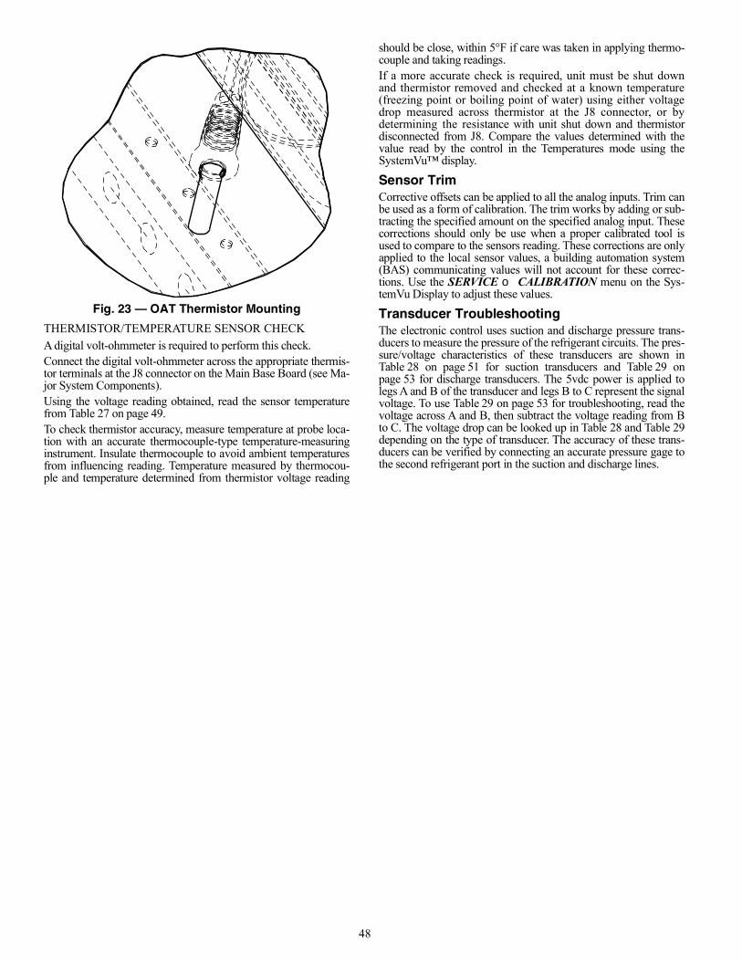
48
Fig. 23 — OAT Thermistor Mounting
THERMISTOR/TEMPERATURE SENSOR CHECKA digital volt-ohmmeter is required to perform this check.Connect the digital volt-ohmmeter across the appropriate thermis-tor terminals at the J8 connector on the Main Base Board (see Ma-jor System Components).Using the voltage reading obtained, read the sensor temperaturefrom Table 27 on page 49.To check thermistor accuracy, measure temperature at probe loca-tion with an accurate thermocouple-type temperature-measuringinstrument. Insulate thermocouple to avoid ambient temperaturesfrom influencing reading. Temperature measured by thermocou-ple and temperature determined from thermistor voltage reading
should be close, within 5°F if care was taken in applying thermo-couple and taking readings.If a more accurate check is required, unit must be shut downand thermistor removed and checked at a known temperature(freezing point or boiling point of water) using either voltagedrop measured across thermistor at the J8 connector, or bydetermining the resistance with unit shut down and thermistordisconnected from J8. Compare the values determined with thevalue read by the control in the Temperatures mode using theSystemVu™ display.
Sensor TrimCorrective offsets can be applied to all the analog inputs. Trim canbe used as a form of calibration. The trim works by adding or sub-tracting the specified amount on the specified analog input. Thesecorrections should only be use when a proper calibrated tool isused to compare to the sensors reading. These corrections are onlyapplied to the local sensor values, a building automation system(BAS) communicating values will not account for these correc-tions. Use the SERVICE CALIBRATION menu on the Sys-temVu Display to adjust these values.
Transducer TroubleshootingThe electronic control uses suction and discharge pressure trans-ducers to measure the pressure of the refrigerant circuits. The pres-sure/voltage characteristics of these transducers are shown inTable 28 on page 51 for suction transducers and Table 29 onpage 53 for discharge transducers. The 5vdc power is applied tolegs A and B of the transducer and legs B to C represent the signalvoltage. To use Table 29 on page 53 for troubleshooting, read thevoltage across A and B, then subtract the voltage reading from Bto C. The voltage drop can be looked up in Table 28 and Table 29depending on the type of transducer. The accuracy of these trans-ducers can be verified by connecting an accurate pressure gage tothe second refrigerant port in the suction and discharge lines.
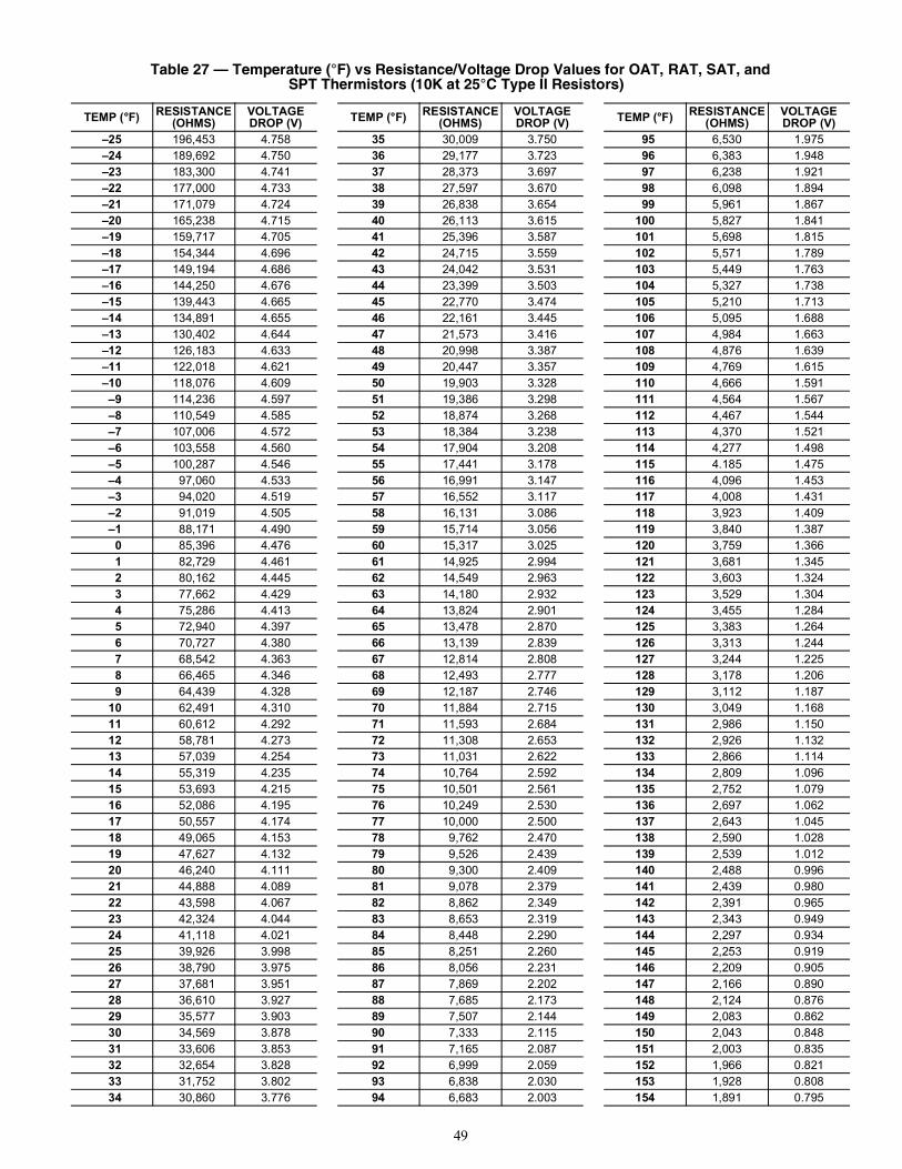
49
Table 27 — Temperature (°F) vs Resistance/Voltage Drop Values for OAT, RAT, SAT, andSPT Thermistors (10K at 25°C Type II Resistors)
TEMP (°F) RESISTANCE (OHMS)
VOLTAGE DROP (V) TEMP (°F) RESISTANCE
(OHMS)VOLTAGE DROP (V) TEMP (°F) RESISTANCE
(OHMS)VOLTAGE DROP (V)
–25 196,453 4.758 35 30,009 3.750 95 6,530 1.975–24 189,692 4.750 36 29,177 3.723 96 6,383 1.948–23 183,300 4.741 37 28,373 3.697 97 6,238 1.921–22 177,000 4.733 38 27,597 3.670 98 6,098 1.894–21 171,079 4.724 39 26,838 3.654 99 5,961 1.867–20 165,238 4.715 40 26,113 3.615 100 5,827 1.841–19 159,717 4.705 41 25,396 3.587 101 5,698 1.815–18 154,344 4.696 42 24,715 3.559 102 5,571 1.789–17 149,194 4.686 43 24,042 3.531 103 5,449 1.763–16 144,250 4.676 44 23,399 3.503 104 5,327 1.738–15 139,443 4.665 45 22,770 3.474 105 5,210 1.713–14 134,891 4.655 46 22,161 3.445 106 5,095 1.688–13 130,402 4.644 47 21,573 3.416 107 4,984 1.663–12 126,183 4.633 48 20,998 3.387 108 4,876 1.639–11 122,018 4.621 49 20,447 3.357 109 4,769 1.615–10 118,076 4.609 50 19,903 3.328 110 4,666 1.591 –9 114,236 4.597 51 19,386 3.298 111 4,564 1.567 –8 110,549 4.585 52 18,874 3.268 112 4,467 1.544 –7 107,006 4.572 53 18,384 3.238 113 4,370 1.521 –6 103,558 4.560 54 17,904 3.208 114 4,277 1.498 –5 100,287 4.546 55 17,441 3.178 115 4.185 1.475 –4 97,060 4.533 56 16,991 3.147 116 4,096 1.453 –3 94,020 4.519 57 16,552 3.117 117 4,008 1.431 –2 91,019 4.505 58 16,131 3.086 118 3,923 1.409 –1 88,171 4.490 59 15,714 3.056 119 3,840 1.387 0 85,396 4.476 60 15,317 3.025 120 3,759 1.366 1 82,729 4.461 61 14,925 2.994 121 3,681 1.345 2 80,162 4.445 62 14,549 2.963 122 3,603 1.324 3 77,662 4.429 63 14,180 2.932 123 3,529 1.304 4 75,286 4.413 64 13,824 2.901 124 3,455 1.284 5 72,940 4.397 65 13,478 2.870 125 3,383 1.264 6 70,727 4.380 66 13,139 2.839 126 3,313 1.244 7 68,542 4.363 67 12,814 2.808 127 3,244 1.225 8 66,465 4.346 68 12,493 2.777 128 3,178 1.206 9 64,439 4.328 69 12,187 2.746 129 3,112 1.187 10 62,491 4.310 70 11,884 2.715 130 3,049 1.168 11 60,612 4.292 71 11,593 2.684 131 2,986 1.150 12 58,781 4.273 72 11,308 2.653 132 2,926 1.132 13 57,039 4.254 73 11,031 2.622 133 2,866 1.114 14 55,319 4.235 74 10,764 2.592 134 2,809 1.096 15 53,693 4.215 75 10,501 2.561 135 2,752 1.079 16 52,086 4.195 76 10,249 2.530 136 2,697 1.062 17 50,557 4.174 77 10,000 2.500 137 2,643 1.045 18 49,065 4.153 78 9,762 2.470 138 2,590 1.028 19 47,627 4.132 79 9,526 2.439 139 2,539 1.012 20 46,240 4.111 80 9,300 2.409 140 2,488 0.996 21 44,888 4.089 81 9,078 2.379 141 2,439 0.980 22 43,598 4.067 82 8,862 2.349 142 2,391 0.965 23 42,324 4.044 83 8,653 2.319 143 2,343 0.949 24 41,118 4.021 84 8,448 2.290 144 2,297 0.934 25 39,926 3.998 85 8,251 2.260 145 2,253 0.919 26 38,790 3.975 86 8,056 2.231 146 2,209 0.905 27 37,681 3.951 87 7,869 2.202 147 2,166 0.890 28 36,610 3.927 88 7,685 2.173 148 2,124 0.876 29 35,577 3.903 89 7,507 2.144 149 2,083 0.862 30 34,569 3.878 90 7,333 2.115 150 2,043 0.848 31 33,606 3.853 91 7,165 2.087 151 2,003 0.835 32 32,654 3.828 92 6,999 2.059 152 1,966 0.821 33 31,752 3.802 93 6,838 2.030 153 1,928 0.808 34 30,860 3.776 94 6,683 2.003 154 1,891 0.795
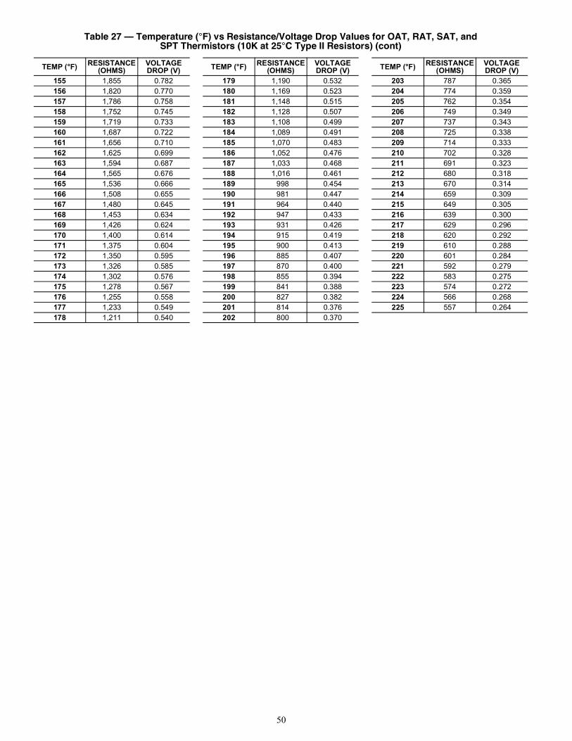
50
155 1,855 0.782 179 1,190 0.532 203 787 0.365156 1,820 0.770 180 1,169 0.523 204 774 0.359157 1,786 0.758 181 1,148 0.515 205 762 0.354158 1,752 0.745 182 1,128 0.507 206 749 0.349159 1,719 0.733 183 1,108 0.499 207 737 0.343160 1,687 0.722 184 1,089 0.491 208 725 0.338161 1,656 0.710 185 1,070 0.483 209 714 0.333162 1,625 0.699 186 1,052 0.476 210 702 0.328163 1,594 0.687 187 1,033 0.468 211 691 0.323164 1,565 0.676 188 1,016 0.461 212 680 0.318165 1,536 0.666 189 998 0.454 213 670 0.314166 1,508 0.655 190 981 0.447 214 659 0.309167 1,480 0.645 191 964 0.440 215 649 0.305168 1,453 0.634 192 947 0.433 216 639 0.300169 1,426 0.624 193 931 0.426 217 629 0.296170 1,400 0.614 194 915 0.419 218 620 0.292171 1,375 0.604 195 900 0.413 219 610 0.288172 1,350 0.595 196 885 0.407 220 601 0.284173 1,326 0.585 197 870 0.400 221 592 0.279174 1,302 0.576 198 855 0.394 222 583 0.275175 1,278 0.567 199 841 0.388 223 574 0.272176 1,255 0.558 200 827 0.382 224 566 0.268177 1,233 0.549 201 814 0.376 225 557 0.264178 1,211 0.540 202 800 0.370
Table 27 — Temperature (°F) vs Resistance/Voltage Drop Values for OAT, RAT, SAT, andSPT Thermistors (10K at 25°C Type II Resistors) (cont)
TEMP (°F) RESISTANCE (OHMS)
VOLTAGE DROP (V) TEMP (°F) RESISTANCE
(OHMS)VOLTAGE DROP (V) TEMP (°F) RESISTANCE
(OHMS)VOLTAGE DROP (V)
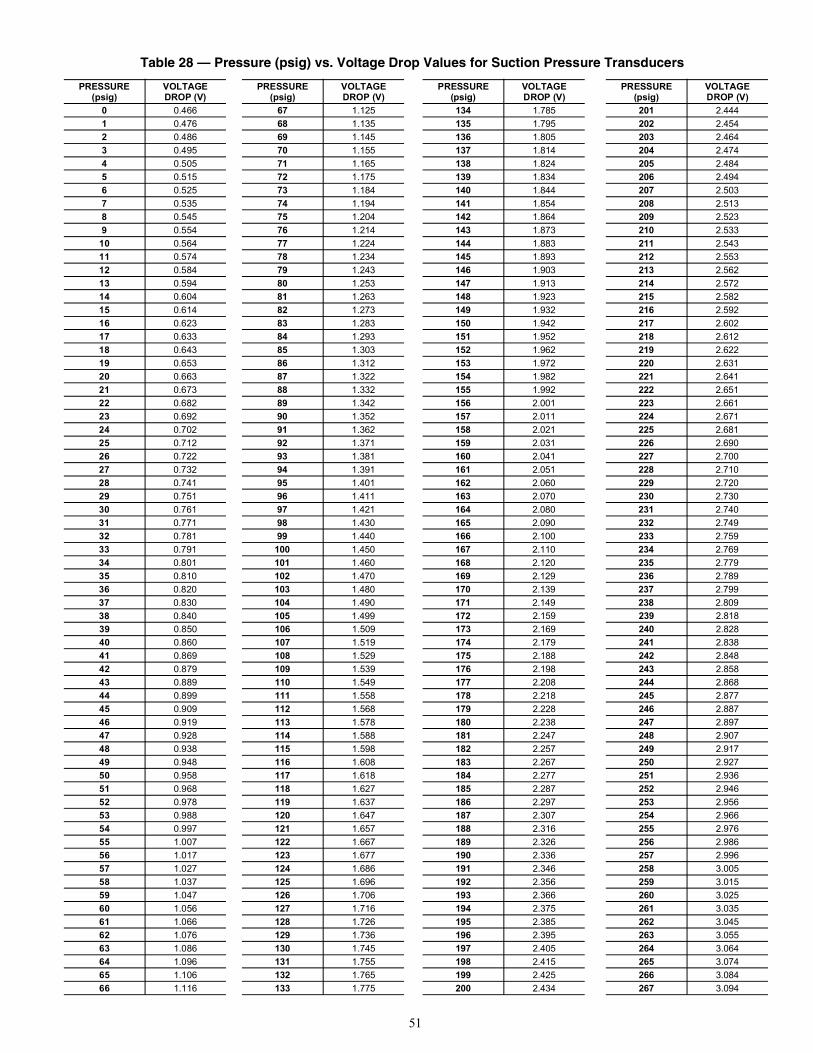
51
Table 28 — Pressure (psig) vs. Voltage Drop Values for Suction Pressure Transducers
PRESSURE(psig)
VOLTAGEDROP (V)
PRESSURE(psig)
VOLTAGEDROP (V)
PRESSURE(psig)
VOLTAGEDROP (V)
PRESSURE(psig)
VOLTAGEDROP (V)
0 0.466 67 1.125 134 1.785 201 2.4441 0.476 68 1.135 135 1.795 202 2.4542 0.486 69 1.145 136 1.805 203 2.4643 0.495 70 1.155 137 1.814 204 2.4744 0.505 71 1.165 138 1.824 205 2.4845 0.515 72 1.175 139 1.834 206 2.4946 0.525 73 1.184 140 1.844 207 2.5037 0.535 74 1.194 141 1.854 208 2.5138 0.545 75 1.204 142 1.864 209 2.5239 0.554 76 1.214 143 1.873 210 2.53310 0.564 77 1.224 144 1.883 211 2.54311 0.574 78 1.234 145 1.893 212 2.55312 0.584 79 1.243 146 1.903 213 2.56213 0.594 80 1.253 147 1.913 214 2.57214 0.604 81 1.263 148 1.923 215 2.58215 0.614 82 1.273 149 1.932 216 2.59216 0.623 83 1.283 150 1.942 217 2.60217 0.633 84 1.293 151 1.952 218 2.61218 0.643 85 1.303 152 1.962 219 2.62219 0.653 86 1.312 153 1.972 220 2.63120 0.663 87 1.322 154 1.982 221 2.64121 0.673 88 1.332 155 1.992 222 2.65122 0.682 89 1.342 156 2.001 223 2.66123 0.692 90 1.352 157 2.011 224 2.67124 0.702 91 1.362 158 2.021 225 2.68125 0.712 92 1.371 159 2.031 226 2.69026 0.722 93 1.381 160 2.041 227 2.70027 0.732 94 1.391 161 2.051 228 2.71028 0.741 95 1.401 162 2.060 229 2.72029 0.751 96 1.411 163 2.070 230 2.73030 0.761 97 1.421 164 2.080 231 2.74031 0.771 98 1.430 165 2.090 232 2.74932 0.781 99 1.440 166 2.100 233 2.75933 0.791 100 1.450 167 2.110 234 2.76934 0.801 101 1.460 168 2.120 235 2.77935 0.810 102 1.470 169 2.129 236 2.78936 0.820 103 1.480 170 2.139 237 2.79937 0.830 104 1.490 171 2.149 238 2.80938 0.840 105 1.499 172 2.159 239 2.81839 0.850 106 1.509 173 2.169 240 2.82840 0.860 107 1.519 174 2.179 241 2.83841 0.869 108 1.529 175 2.188 242 2.84842 0.879 109 1.539 176 2.198 243 2.85843 0.889 110 1.549 177 2.208 244 2.86844 0.899 111 1.558 178 2.218 245 2.87745 0.909 112 1.568 179 2.228 246 2.88746 0.919 113 1.578 180 2.238 247 2.89747 0.928 114 1.588 181 2.247 248 2.90748 0.938 115 1.598 182 2.257 249 2.91749 0.948 116 1.608 183 2.267 250 2.92750 0.958 117 1.618 184 2.277 251 2.93651 0.968 118 1.627 185 2.287 252 2.94652 0.978 119 1.637 186 2.297 253 2.95653 0.988 120 1.647 187 2.307 254 2.96654 0.997 121 1.657 188 2.316 255 2.97655 1.007 122 1.667 189 2.326 256 2.98656 1.017 123 1.677 190 2.336 257 2.99657 1.027 124 1.686 191 2.346 258 3.00558 1.037 125 1.696 192 2.356 259 3.01559 1.047 126 1.706 193 2.366 260 3.02560 1.056 127 1.716 194 2.375 261 3.03561 1.066 128 1.726 195 2.385 262 3.04562 1.076 129 1.736 196 2.395 263 3.05563 1.086 130 1.745 197 2.405 264 3.06464 1.096 131 1.755 198 2.415 265 3.07465 1.106 132 1.765 199 2.425 266 3.08466 1.116 133 1.775 200 2.434 267 3.094
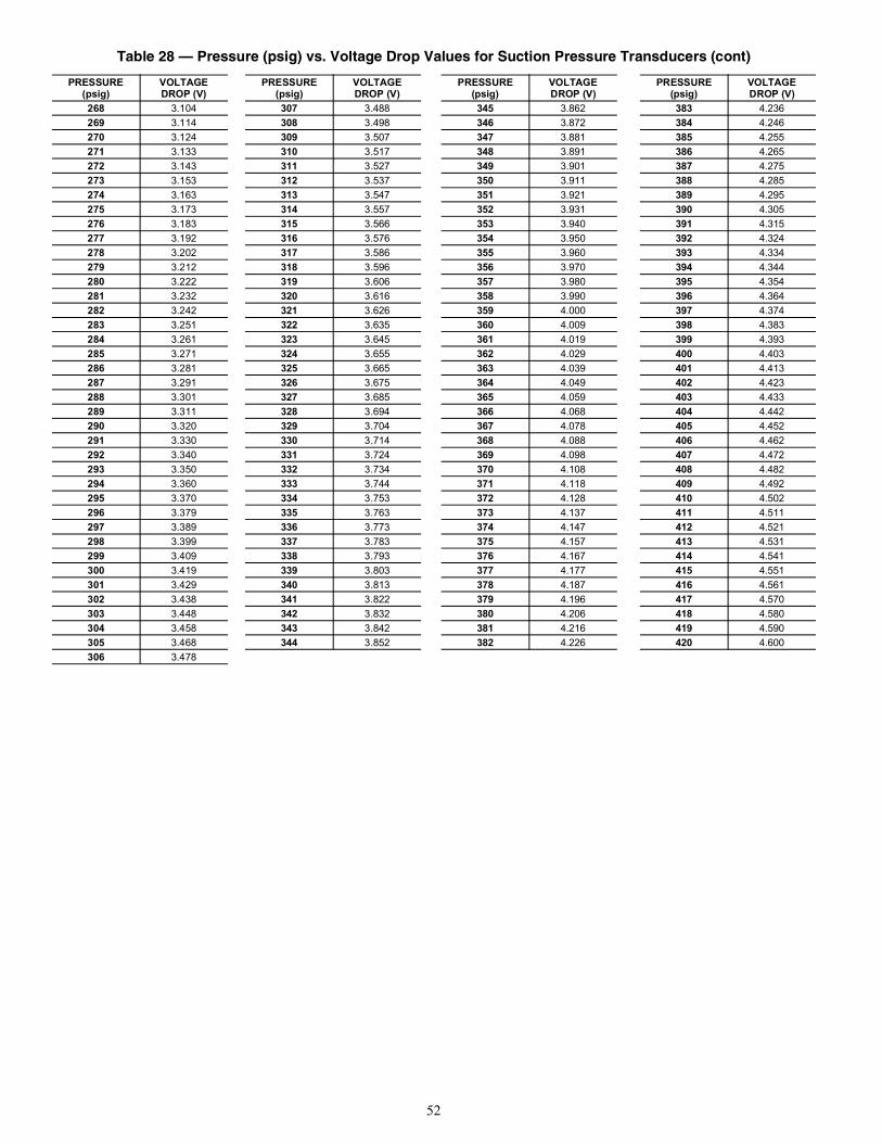
52
268 3.104 307 3.488 345 3.862 383 4.236269 3.114 308 3.498 346 3.872 384 4.246270 3.124 309 3.507 347 3.881 385 4.255271 3.133 310 3.517 348 3.891 386 4.265272 3.143 311 3.527 349 3.901 387 4.275273 3.153 312 3.537 350 3.911 388 4.285274 3.163 313 3.547 351 3.921 389 4.295275 3.173 314 3.557 352 3.931 390 4.305276 3.183 315 3.566 353 3.940 391 4.315277 3.192 316 3.576 354 3.950 392 4.324278 3.202 317 3.586 355 3.960 393 4.334279 3.212 318 3.596 356 3.970 394 4.344280 3.222 319 3.606 357 3.980 395 4.354281 3.232 320 3.616 358 3.990 396 4.364282 3.242 321 3.626 359 4.000 397 4.374283 3.251 322 3.635 360 4.009 398 4.383284 3.261 323 3.645 361 4.019 399 4.393285 3.271 324 3.655 362 4.029 400 4.403286 3.281 325 3.665 363 4.039 401 4.413287 3.291 326 3.675 364 4.049 402 4.423288 3.301 327 3.685 365 4.059 403 4.433289 3.311 328 3.694 366 4.068 404 4.442290 3.320 329 3.704 367 4.078 405 4.452291 3.330 330 3.714 368 4.088 406 4.462292 3.340 331 3.724 369 4.098 407 4.472293 3.350 332 3.734 370 4.108 408 4.482294 3.360 333 3.744 371 4.118 409 4.492295 3.370 334 3.753 372 4.128 410 4.502296 3.379 335 3.763 373 4.137 411 4.511297 3.389 336 3.773 374 4.147 412 4.521298 3.399 337 3.783 375 4.157 413 4.531299 3.409 338 3.793 376 4.167 414 4.541300 3.419 339 3.803 377 4.177 415 4.551301 3.429 340 3.813 378 4.187 416 4.561302 3.438 341 3.822 379 4.196 417 4.570303 3.448 342 3.832 380 4.206 418 4.580304 3.458 343 3.842 381 4.216 419 4.590305 3.468 344 3.852 382 4.226 420 4.600306 3.478
Table 28 — Pressure (psig) vs. Voltage Drop Values for Suction Pressure Transducers (cont)
PRESSURE(psig)
VOLTAGEDROP (V)
PRESSURE(psig)
VOLTAGEDROP (V)
PRESSURE(psig)
VOLTAGEDROP (V)
PRESSURE(psig)
VOLTAGEDROP (V)
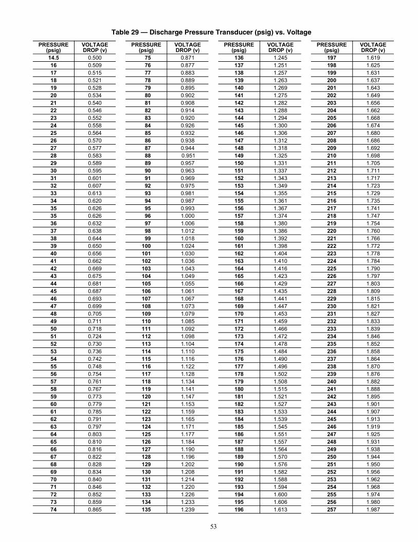
53
Table 29 — Discharge Pressure Transducer (psig) vs. Voltage
PRESSURE (psig)
VOLTAGE DROP (v)
PRESSURE (psig)
VOLTAGE DROP (v)
PRESSURE (psig)
VOLTAGE DROP (v)
PRESSURE (psig)
VOLTAGE DROP (v)
14.5 0.500 75 0.871 136 1.245 197 1.61916 0.509 76 0.877 137 1.251 198 1.62517 0.515 77 0.883 138 1.257 199 1.63118 0.521 78 0.889 139 1.263 200 1.63719 0.528 79 0.895 140 1.269 201 1.64320 0.534 80 0.902 141 1.275 202 1.64921 0.540 81 0.908 142 1.282 203 1.65622 0.546 82 0.914 143 1.288 204 1.66223 0.552 83 0.920 144 1.294 205 1.66824 0.558 84 0.926 145 1.300 206 1.67425 0.564 85 0.932 146 1.306 207 1.68026 0.570 86 0.938 147 1.312 208 1.68627 0.577 87 0.944 148 1.318 209 1.69228 0.583 88 0.951 149 1.325 210 1.69829 0.589 89 0.957 150 1.331 211 1.70530 0.595 90 0.963 151 1.337 212 1.71131 0.601 91 0.969 152 1.343 213 1.71732 0.607 92 0.975 153 1.349 214 1.72333 0.613 93 0.981 154 1.355 215 1.72934 0.620 94 0.987 155 1.361 216 1.73535 0.626 95 0.993 156 1.367 217 1.74135 0.626 96 1.000 157 1.374 218 1.74736 0.632 97 1.006 158 1.380 219 1.75437 0.638 98 1.012 159 1.386 220 1.76038 0.644 99 1.018 160 1.392 221 1.76639 0.650 100 1.024 161 1.398 222 1.77240 0.656 101 1.030 162 1.404 223 1.77841 0.662 102 1.036 163 1.410 224 1.78442 0.669 103 1.043 164 1.416 225 1.79043 0.675 104 1.049 165 1.423 226 1.79744 0.681 105 1.055 166 1.429 227 1.80345 0.687 106 1.061 167 1.435 228 1.80946 0.693 107 1.067 168 1.441 229 1.81547 0.699 108 1.073 169 1.447 230 1.82148 0.705 109 1.079 170 1.453 231 1.82749 0.711 110 1.085 171 1.459 232 1.83350 0.718 111 1.092 172 1.466 233 1.83951 0.724 112 1.098 173 1.472 234 1.84652 0.730 113 1.104 174 1.478 235 1.85253 0.736 114 1.110 175 1.484 236 1.85854 0.742 115 1.116 176 1.490 237 1.86455 0.748 116 1.122 177 1.496 238 1.87056 0.754 117 1.128 178 1.502 239 1.87657 0.761 118 1.134 179 1.508 240 1.88258 0.767 119 1.141 180 1.515 241 1.88859 0.773 120 1.147 181 1.521 242 1.89560 0.779 121 1.153 182 1.527 243 1.90161 0.785 122 1.159 183 1.533 244 1.90762 0.791 123 1.165 184 1.539 245 1.91363 0.797 124 1.171 185 1.545 246 1.91964 0.803 125 1.177 186 1.551 247 1.92565 0.810 126 1.184 187 1.557 248 1.93166 0.816 127 1.190 188 1.564 249 1.93867 0.822 128 1.196 189 1.570 250 1.94468 0.828 129 1.202 190 1.576 251 1.95069 0.834 130 1.208 191 1.582 252 1.95670 0.840 131 1.214 192 1.588 253 1.96271 0.846 132 1.220 193 1.594 254 1.96872 0.852 133 1.226 194 1.600 255 1.97473 0.859 134 1.233 195 1.606 256 1.98074 0.865 135 1.239 196 1.613 257 1.987
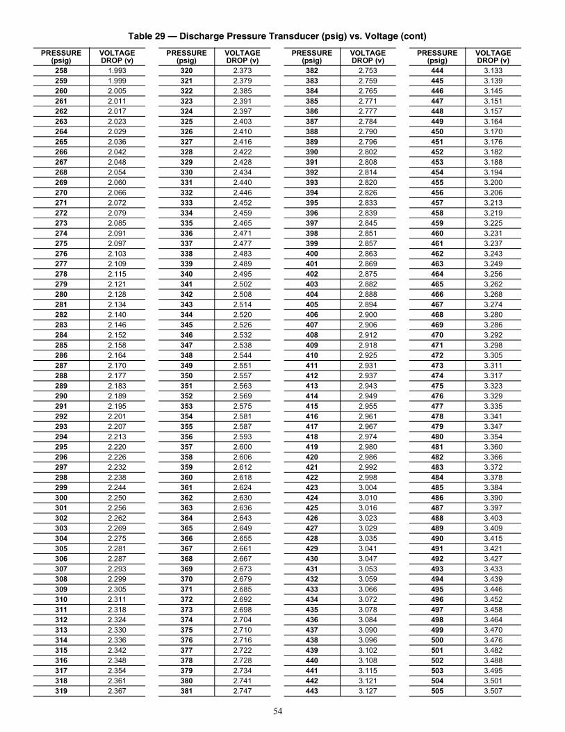
54
258 1.993 320 2.373 382 2.753 444 3.133259 1.999 321 2.379 383 2.759 445 3.139260 2.005 322 2.385 384 2.765 446 3.145261 2.011 323 2.391 385 2.771 447 3.151262 2.017 324 2.397 386 2.777 448 3.157263 2.023 325 2.403 387 2.784 449 3.164264 2.029 326 2.410 388 2.790 450 3.170265 2.036 327 2.416 389 2.796 451 3.176266 2.042 328 2.422 390 2.802 452 3.182267 2.048 329 2.428 391 2.808 453 3.188268 2.054 330 2.434 392 2.814 454 3.194269 2.060 331 2.440 393 2.820 455 3.200270 2.066 332 2.446 394 2.826 456 3.206271 2.072 333 2.452 395 2.833 457 3.213272 2.079 334 2.459 396 2.839 458 3.219273 2.085 335 2.465 397 2.845 459 3.225274 2.091 336 2.471 398 2.851 460 3.231275 2.097 337 2.477 399 2.857 461 3.237276 2.103 338 2.483 400 2.863 462 3.243277 2.109 339 2.489 401 2.869 463 3.249278 2.115 340 2.495 402 2.875 464 3.256279 2.121 341 2.502 403 2.882 465 3.262280 2.128 342 2.508 404 2.888 466 3.268281 2.134 343 2.514 405 2.894 467 3.274282 2.140 344 2.520 406 2.900 468 3.280283 2.146 345 2.526 407 2.906 469 3.286284 2.152 346 2.532 408 2.912 470 3.292285 2.158 347 2.538 409 2.918 471 3.298286 2.164 348 2.544 410 2.925 472 3.305287 2.170 349 2.551 411 2.931 473 3.311288 2.177 350 2.557 412 2.937 474 3.317289 2.183 351 2.563 413 2.943 475 3.323290 2.189 352 2.569 414 2.949 476 3.329291 2.195 353 2.575 415 2.955 477 3.335292 2.201 354 2.581 416 2.961 478 3.341293 2.207 355 2.587 417 2.967 479 3.347294 2.213 356 2.593 418 2.974 480 3.354295 2.220 357 2.600 419 2.980 481 3.360296 2.226 358 2.606 420 2.986 482 3.366297 2.232 359 2.612 421 2.992 483 3.372298 2.238 360 2.618 422 2.998 484 3.378299 2.244 361 2.624 423 3.004 485 3.384300 2.250 362 2.630 424 3.010 486 3.390301 2.256 363 2.636 425 3.016 487 3.397302 2.262 364 2.643 426 3.023 488 3.403303 2.269 365 2.649 427 3.029 489 3.409304 2.275 366 2.655 428 3.035 490 3.415305 2.281 367 2.661 429 3.041 491 3.421306 2.287 368 2.667 430 3.047 492 3.427307 2.293 369 2.673 431 3.053 493 3.433308 2.299 370 2.679 432 3.059 494 3.439309 2.305 371 2.685 433 3.066 495 3.446310 2.311 372 2.692 434 3.072 496 3.452311 2.318 373 2.698 435 3.078 497 3.458312 2.324 374 2.704 436 3.084 498 3.464313 2.330 375 2.710 437 3.090 499 3.470314 2.336 376 2.716 438 3.096 500 3.476315 2.342 377 2.722 439 3.102 501 3.482316 2.348 378 2.728 440 3.108 502 3.488317 2.354 379 2.734 441 3.115 503 3.495318 2.361 380 2.741 442 3.121 504 3.501319 2.367 381 2.747 443 3.127 505 3.507
Table 29 — Discharge Pressure Transducer (psig) vs. Voltage (cont)
PRESSURE (psig)
VOLTAGE DROP (v)
PRESSURE (psig)
VOLTAGE DROP (v)
PRESSURE (psig)
VOLTAGE DROP (v)
PRESSURE (psig)
VOLTAGE DROP (v)
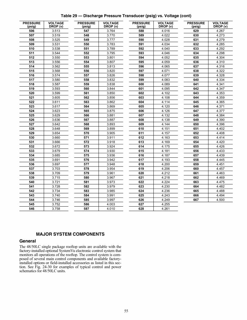
55
MAJOR SYSTEM COMPONENTS
GeneralThe 48/50LC single package rooftop units are available with thefactory-installed optional SystemVu electronic control system thatmonitors all operations of the rooftop. The control system is com-posed of several main control components and available factory-installed options or field-installed accessories as listed in this sec-tion. See Fig. 24-30 for examples of typical control and powerschematics for 48/50LC units.
506 3.513 547 3.764 588 4.016 629 4.267507 3.519 548 3.770 589 4.022 630 4.273508 3.525 549 3.777 590 4.028 631 4.279509 3.531 550 3.783 591 4.034 632 4.285510 3.538 551 3.789 592 4.040 633 4.292511 3.544 552 3.795 593 4.046 634 4.298512 3.550 553 3.801 594 4.052 635 4.304513 3.556 554 3.807 595 4.059 636 4.310514 3.562 555 3.813 596 4.065 637 4.316515 3.568 556 3.820 597 4.071 638 4.322516 3.574 557 3.826 598 4.077 639 4.328517 3.580 558 3.832 599 4.083 640 4.334518 3.587 559 3.838 600 4.089 641 4.341519 3.593 560 3.844 601 4.095 642 4.347520 3.599 561 3.850 602 4.102 643 4.353521 3.605 562 3.856 603 4.108 644 4.359522 3.611 563 3.862 604 4.114 645 4.365523 3.617 564 3.869 605 4.120 646 4.371524 3.623 565 3.875 606 4.126 647 4.377525 3.629 566 3.881 607 4.132 648 4.384526 3.636 567 3.887 608 4.138 649 4.390527 3.642 568 3.893 609 4.144 650 4.396528 3.648 569 3.899 610 4.151 651 4.402529 3.654 570 3.905 611 4.157 652 4.408530 3.660 571 3.911 612 4.163 653 4.414531 3.666 572 3.918 613 4.169 654 4.420532 3.672 573 3.924 614 4.175 655 4.426533 3.679 574 3.930 615 4.181 656 4.433534 3.685 575 3.936 616 4.187 657 4.439535 3.691 576 3.942 617 4.193 658 4.445536 3.697 577 3.948 618 4.200 659 4.451537 3.703 578 3.954 619 4.206 660 4.457538 3.709 579 3.961 620 4.212 661 4.463539 3.715 580 3.967 621 4.218 662 4.469540 3.721 581 3.973 622 4.224 663 4.475541 3.728 582 3.979 623 4.230 664 4.482542 3.734 583 3.985 624 4.236 665 4.488543 3.740 584 3.991 625 4.243 666 4.494544 3.746 585 3.997 626 4.249 667 4.500545 3.752 586 4.003 627 4.255546 3.758 587 4.010 628 4.261
Table 29 — Discharge Pressure Transducer (psig) vs. Voltage (cont)
PRESSURE (psig)
VOLTAGE DROP (v)
PRESSURE (psig)
VOLTAGE DROP (v)
PRESSURE (psig)
VOLTAGE DROP (v)
PRESSURE (psig)
VOLTAGE DROP (v)
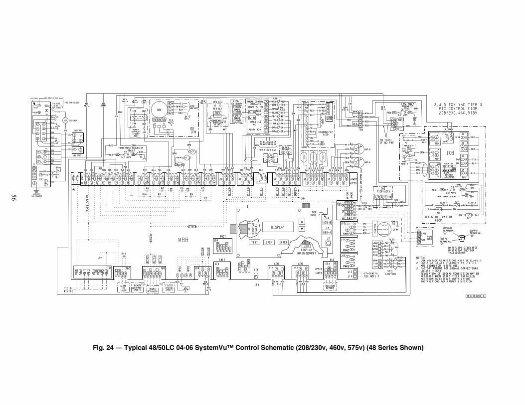
56
Fig. 24 — Typical 48/50LC 04-06 SystemVu™ Control Schematic (208/230v, 460v, 575v) (48 Series Shown)
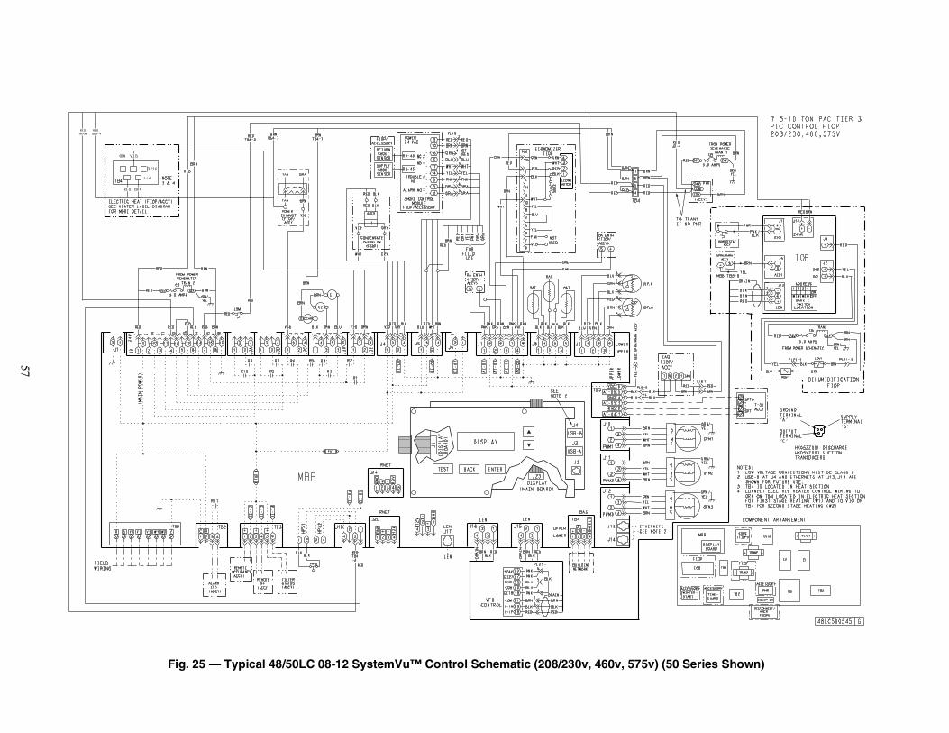
57
Fig. 25 — Typical 48/50LC 08-12 SystemVu™ Control Schematic (208/230v, 460v, 575v) (50 Series Shown)
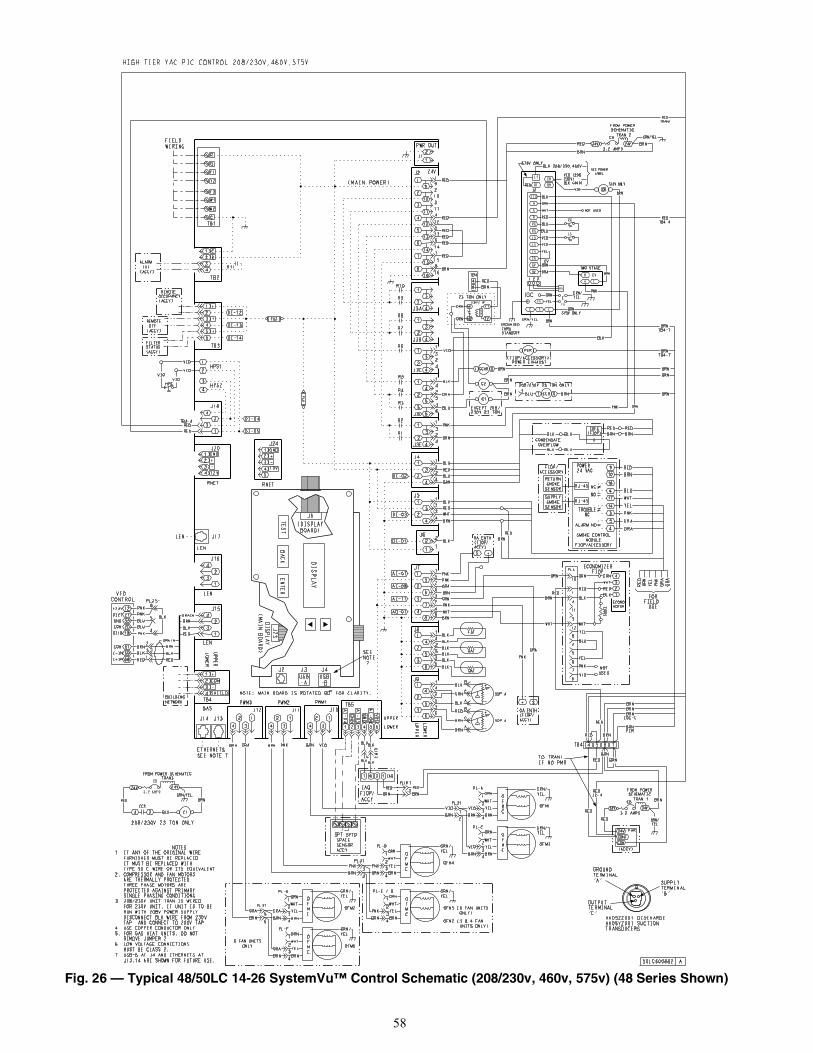
58
Fig. 26 — Typical 48/50LC 14-26 SystemVu™ Control Schematic (208/230v, 460v, 575v) (48 Series Shown)
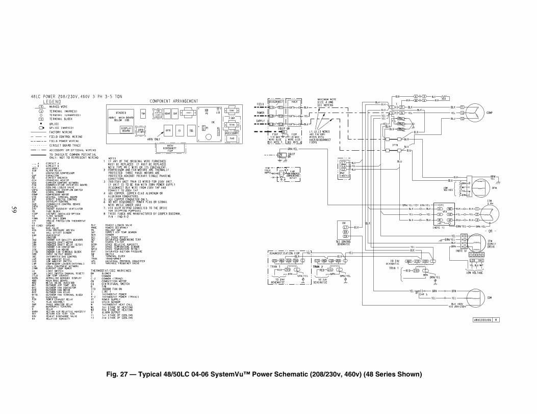
59
Fig. 27 — Typical 48/50LC 04-06 SystemVu™ Power Schematic (208/230v, 460v) (48 Series Shown)
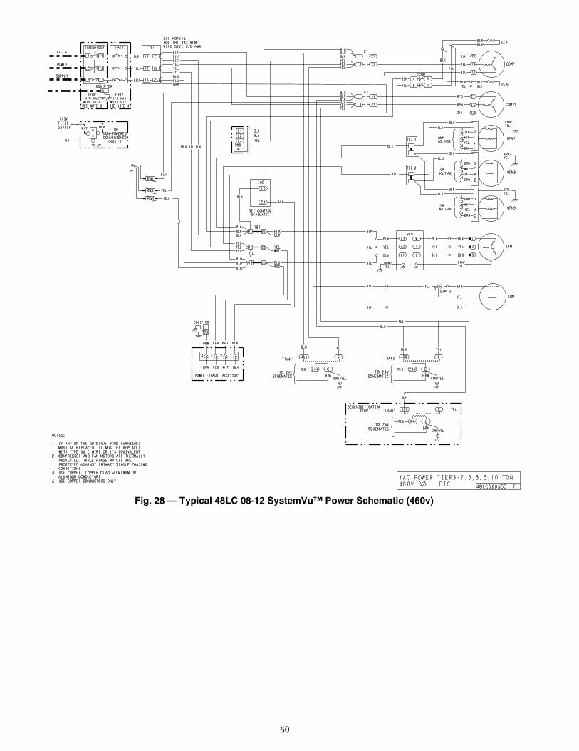
60
Fig. 28 — Typical 48LC 08-12 SystemVu™ Power Schematic (460v)
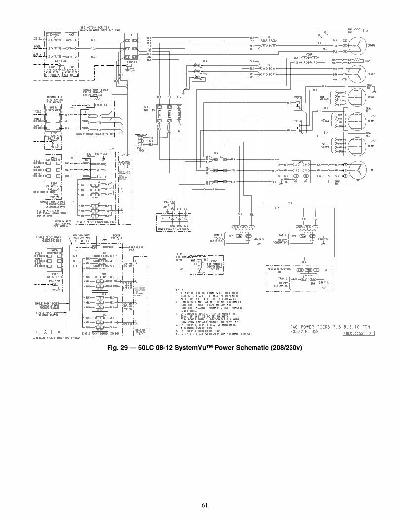
61
Fig. 29 — 50LC 08-12 SystemVu™ Power Schematic (208/230v)
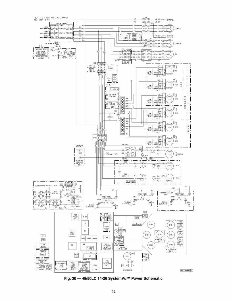
62
Fig. 30 — 48/50LC 14-26 SystemVu™ Power Schematic
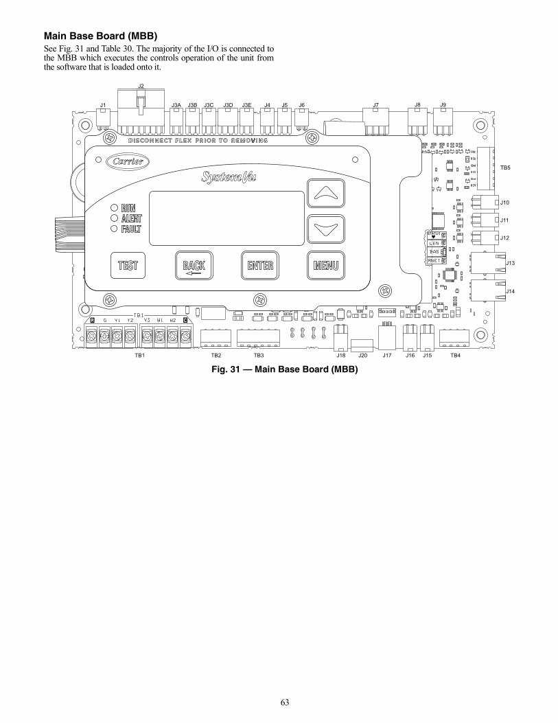
63
Main Base Board (MBB)See Fig. 31 and Table 30. The majority of the I/O is connected tothe MBB which executes the controls operation of the unit fromthe software that is loaded onto it.
Fig. 31 — Main Base Board (MBB)
J1
J2
J3A J3B J3C J3D J3E J4 J5 J6 J7 J8 J9
J10
TB5
J11
J12
J13
J14
TB4J15J16J17J20J18TB3TB2TB1
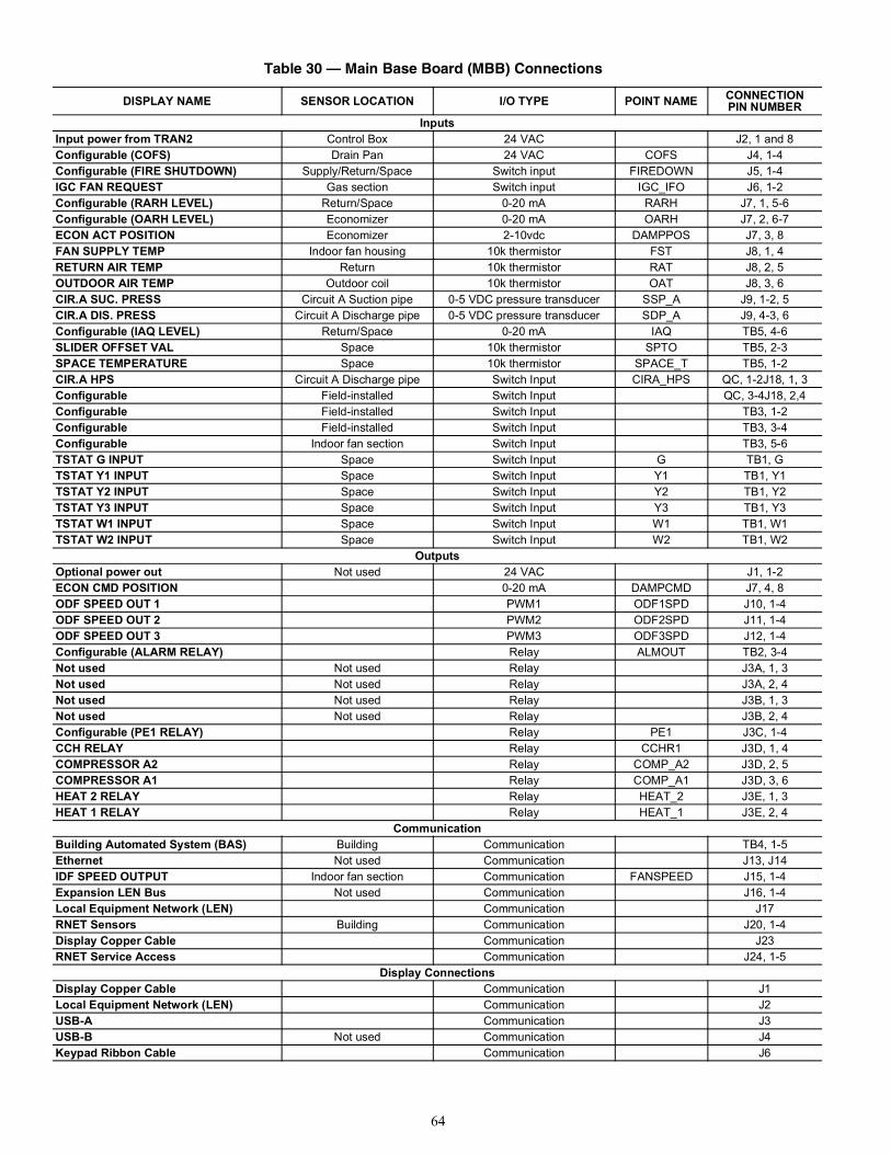
64
Table 30 — Main Base Board (MBB) Connections
DISPLAY NAME SENSOR LOCATION I/O TYPE POINT NAME CONNECTIONPIN NUMBER
InputsInput power from TRAN2 Control Box 24 VAC J2, 1 and 8Configurable (COFS) Drain Pan 24 VAC COFS J4, 1-4Configurable (FIRE SHUTDOWN) Supply/Return/Space Switch input FIREDOWN J5, 1-4IGC FAN REQUEST Gas section Switch input IGC_IFO J6, 1-2Configurable (RARH LEVEL) Return/Space 0-20 mA RARH J7, 1, 5-6Configurable (OARH LEVEL) Economizer 0-20 mA OARH J7, 2, 6-7ECON ACT POSITION Economizer 2-10vdc DAMPPOS J7, 3, 8FAN SUPPLY TEMP Indoor fan housing 10k thermistor FST J8, 1, 4RETURN AIR TEMP Return 10k thermistor RAT J8, 2, 5OUTDOOR AIR TEMP Outdoor coil 10k thermistor OAT J8, 3, 6CIR.A SUC. PRESS Circuit A Suction pipe 0-5 VDC pressure transducer SSP_A J9, 1-2, 5CIR.A DIS. PRESS Circuit A Discharge pipe 0-5 VDC pressure transducer SDP_A J9, 4-3, 6Configurable (IAQ LEVEL) Return/Space 0-20 mA IAQ TB5, 4-6SLIDER OFFSET VAL Space 10k thermistor SPTO TB5, 2-3SPACE TEMPERATURE Space 10k thermistor SPACE_T TB5, 1-2CIR.A HPS Circuit A Discharge pipe Switch Input CIRA_HPS QC, 1-2J18, 1, 3Configurable Field-installed Switch Input QC, 3-4J18, 2,4Configurable Field-installed Switch Input TB3, 1-2Configurable Field-installed Switch Input TB3, 3-4Configurable Indoor fan section Switch Input TB3, 5-6TSTAT G INPUT Space Switch Input G TB1, GTSTAT Y1 INPUT Space Switch Input Y1 TB1, Y1TSTAT Y2 INPUT Space Switch Input Y2 TB1, Y2TSTAT Y3 INPUT Space Switch Input Y3 TB1, Y3TSTAT W1 INPUT Space Switch Input W1 TB1, W1TSTAT W2 INPUT Space Switch Input W2 TB1, W2
OutputsOptional power out Not used 24 VAC J1, 1-2ECON CMD POSITION 0-20 mA DAMPCMD J7, 4, 8ODF SPEED OUT 1 PWM1 ODF1SPD J10, 1-4ODF SPEED OUT 2 PWM2 ODF2SPD J11, 1-4ODF SPEED OUT 3 PWM3 ODF3SPD J12, 1-4Configurable (ALARM RELAY) Relay ALMOUT TB2, 3-4Not used Not used Relay J3A, 1, 3Not used Not used Relay J3A, 2, 4Not used Not used Relay J3B, 1, 3Not used Not used Relay J3B, 2, 4Configurable (PE1 RELAY) Relay PE1 J3C, 1-4CCH RELAY Relay CCHR1 J3D, 1, 4COMPRESSOR A2 Relay COMP_A2 J3D, 2, 5COMPRESSOR A1 Relay COMP_A1 J3D, 3, 6HEAT 2 RELAY Relay HEAT_2 J3E, 1, 3HEAT 1 RELAY Relay HEAT_1 J3E, 2, 4
CommunicationBuilding Automated System (BAS) Building Communication TB4, 1-5Ethernet Not used Communication J13, J14IDF SPEED OUTPUT Indoor fan section Communication FANSPEED J15, 1-4Expansion LEN Bus Not used Communication J16, 1-4Local Equipment Network (LEN) Communication J17RNET Sensors Building Communication J20, 1-4Display Copper Cable Communication J23RNET Service Access Communication J24, 1-5
Display ConnectionsDisplay Copper Cable Communication J1Local Equipment Network (LEN) Communication J2USB-A Communication J3USB-B Not used Communication J4Keypad Ribbon Cable Communication J6
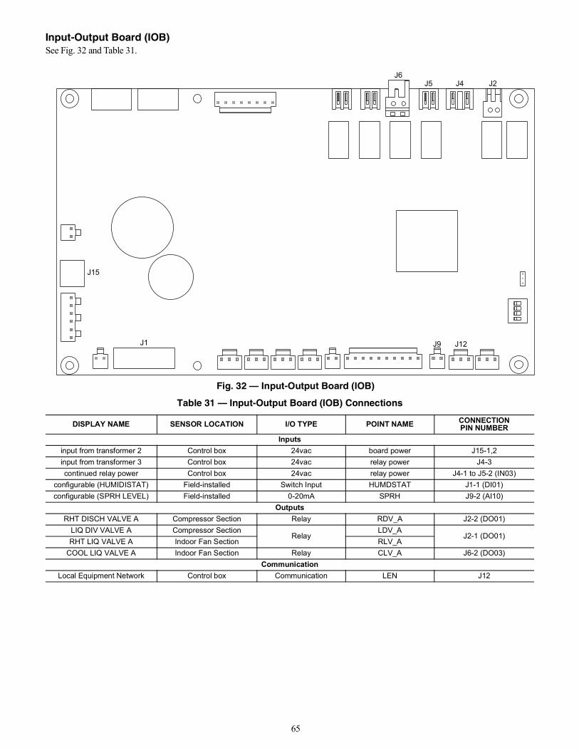
65
Input-Output Board (IOB)See Fig. 32 and Table 31.
Fig. 32 — Input-Output Board (IOB)
J6J5 J4 J2
J9 J12J1
J15
Table 31 — Input-Output Board (IOB) Connections
DISPLAY NAME SENSOR LOCATION I/O TYPE POINT NAME CONNECTIONPIN NUMBER
Inputsinput from transformer 2 Control box 24vac board power J15-1,2input from transformer 3 Control box 24vac relay power J4-3continued relay power Control box 24vac relay power J4-1 to J5-2 (IN03)
configurable (HUMIDISTAT) Field-installed Switch Input HUMDSTAT J1-1 (DI01)configurable (SPRH LEVEL) Field-installed 0-20mA SPRH J9-2 (AI10)
OutputsRHT DISCH VALVE A Compressor Section Relay RDV_A J2-2 (DO01)
LIQ DIV VALVE A Compressor SectionRelay
LDV_AJ2-1 (DO01)
RHT LIQ VALVE A Indoor Fan Section RLV_ACOOL LIQ VALVE A Indoor Fan Section Relay CLV_A J6-2 (DO03)
CommunicationLocal Equipment Network Control box Communication LEN J12
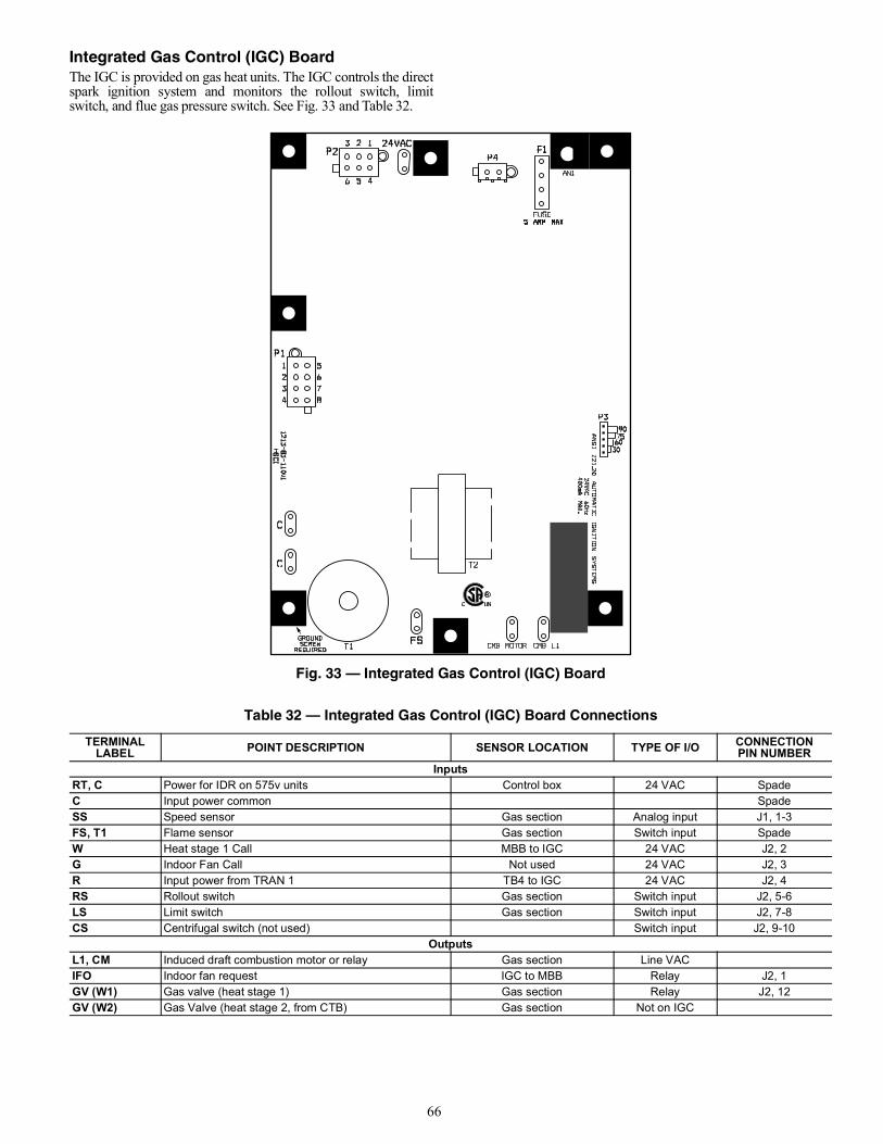
66
Integrated Gas Control (IGC) BoardThe IGC is provided on gas heat units. The IGC controls the directspark ignition system and monitors the rollout switch, limitswitch, and flue gas pressure switch. See Fig. 33 and Table 32.
Fig. 33 — Integrated Gas Control (IGC) Board
Table 32 — Integrated Gas Control (IGC) Board Connections
TERMINAL LABEL POINT DESCRIPTION SENSOR LOCATION TYPE OF I/O CONNECTION
PIN NUMBERInputs
RT, C Power for IDR on 575v units Control box 24 VAC SpadeC Input power common SpadeSS Speed sensor Gas section Analog input J1, 1-3FS, T1 Flame sensor Gas section Switch input SpadeW Heat stage 1 Call MBB to IGC 24 VAC J2, 2G Indoor Fan Call Not used 24 VAC J2, 3R Input power from TRAN 1 TB4 to IGC 24 VAC J2, 4RS Rollout switch Gas section Switch input J2, 5-6LS Limit switch Gas section Switch input J2, 7-8CS Centrifugal switch (not used) Switch input J2, 9-10
OutputsL1, CM Induced draft combustion motor or relay Gas section Line VACIFO Indoor fan request IGC to MBB Relay J2, 1GV (W1) Gas valve (heat stage 1) Gas section Relay J2, 12GV (W2) Gas Valve (heat stage 2, from CTB) Gas section Not on IGC
67
Protective DevicesCOMPRESSOR PROTECTIONOvercurrentEach compressor has internal line break motor protection.OvertemperatureEach compressor has an internal protector to protect it against ex-cessively high discharge gas temperatures.High-Pressure SwitchIf the high-pressure switch trips, the compressor will shut downand the Circuit A High Pressure Alert will activate. Refer to thealarm section for the High pressure alert.EVAPORATOR FAN MOTOR PROTECTIONIn the belt drive application, the VFD serves as the motor thermaland over-current protection. Refer to page 69 for more detail onthe VFD.
CONDENSER-FAN MOTOR PROTECTIONThe ECM motor is protected from locked rotor and over-currentprotection through the electronic control module attached to themotor.SATURATED SUCTION PRESSURE (SSP)If the SSP for a particular circuit is reading below the alarm setpoint for an extended period of time, that circuit will be shutdown. After 15 minutes, the alarm will automatically reset. If thisalarm occurs 3 times consecutively, the circuit will remain lockedout until an alarm reset is initiated via CCN or manually via theSystemVu™ controller display (see “Faults and Alerts” onpage 33 for more details).CONDENSATE OVERFLOW SWITCH (COFS)A separate factory-installed device can detect a full drain pan. Thisdevice consists of a pan sensor to detect the water level and a relaycontrol switch to read the sensor. The control switch is located inthe unit control box and feeds into the SystemVu control to trip acondensate overflow fault. The relay switch is a normally opendevice that closes when power is applied. If the sensor detects highwater levels for 10 seconds straight, it will open the contact
removing the input provided to the SystemVu control. The switchwill also turn its red LED on. If the water level is low enough for5 minutes, the relay will close again applying the input back to theSystemVu controller. A blinking red LED on the switch indicatesthat the sensor has been disconnected.
Space Mounted SensorsSPACE TEMPERATURE SENSOR (T-55)The T-55 space temperature sensor (part no. 33ZCT55SPT) is afield-installed accessory. The sensor is installed on a building in-terior wall to measure room air temperature. The T-55 sensoralso includes an override button on the front cover to permit oc-cupants to override the Unoccupied Schedule (if programmed).TB5-1 Sensor InputTB5-2 Sensor CommonSPACE TEMPERATURE SENSOR (T-56)The T-56 space temperature sensor (part no. 33ZCT56SPT) is afield-installed accessory. This sensor includes a sliding scale onthe front cover that permits an occupant to adjust the space tem-perature set point remotely. The T-56 sensor also includes an over-ride button on the front cover to allow occupants to override theunoccupied schedule (if programmed).TB5-1 Sensor InputTB5-2 Sensor CommonTB5-3 Setpoint Offset InputSPACE TEMPERATURE SENSOR AVERAGINGSee Fig. 34 for space temperature averaging with T-55 sensorsonly. If the use of one T-56 sensor is required, refer to Fig. 35.ZS SPACE SENSORSThe ZS Standard, Plus, or Pro can be wired into J20 or J24 ofthe SystemVu controller. J20 provides an easy field connectionplug. A maximum of 5 ZS sensors can be connected but a sep-arate power supply may be needed. Use the ZS SENSOR CFGmenu (SETTINGS NETWORK SETTINGS) when settingup the ZS sensors in SystemVu. The Sensor addresses have tobe unique and set in the actual sensors via DIP also. The Typi-cal default for the ZS Sensor is address 1. Follow the ZS instal-lation instruction for further details on the sensors. ZS sensordata can be monitored on the SystemVu controller display inthe ZS Sensor Info menu (INPUTS NETWORK ZS SENSOR INFO).J20-1 Sensor CommonJ20-2 Sensor Communication Positive (+)J20-3 Sensor Communication Negative (-)J20-4 Sensor +12vdc Power
CAUTION
EQUIPMENT DAMAGE HAZARDFailure to follow this caution may result in unit damage.DO not bypass the VFD while running the motor. Do notchange VFD parameter associated with motor characteristics,these are factory programmed for motor protection. Damage tothe motor or the VFD can occur.
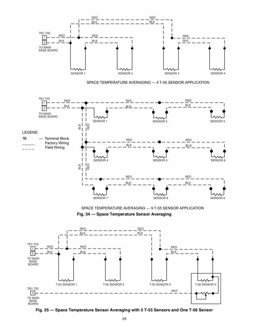
68
Fig. 34 — Space Temperature Sensor Averaging
Fig. 35 — Space Temperature Sensor Averaging with 3 T-55 Sensors and One T-56 Sensor
TO MAINBASE BOARD
RED
BLK
RED
BLK
RE
D
BLK
SENSOR 1 SENSOR 2 SENSOR 3
RED
BLK
SENSOR 6SENSOR 5
RED
BLK
SENSOR 4
RE
D
BLK
RED
BLK
RED
BLK
SENSOR 8SENSOR 7 SENSOR 9
1RED
BLK
TB1-T55
SENSOR 1 SENSOR 2 SENSOR 3 SENSOR 4
RED
BLK
RED
BLK
RED
BLK
RED
BLK
TO MAINBASE BOARD
RED
BLK
TB1-T55
1
2
2
SPACE TEMPERATURE AVERAGING — 4 T-55 SENSOR APPLICATION
SPACE TEMPERATURE AVERAGING — 9 T-55 SENSOR APPLICATION
LEGENDTB — Terminal Block______ Factory Wiring_ _ _ _ Field Wiring
T-55 SENSOR 1 T-55 SENSOR 2 T-55 SENSOR 3 T-56 SENSOR 4
RED
BLK
RED
BLK
RED
BLK
RED
BLK
TO MAINBASE
BOARD
RED
BLK
TB1-T55
1
2
TO MAINBASE
BOARD
3
TB1-T55WHT
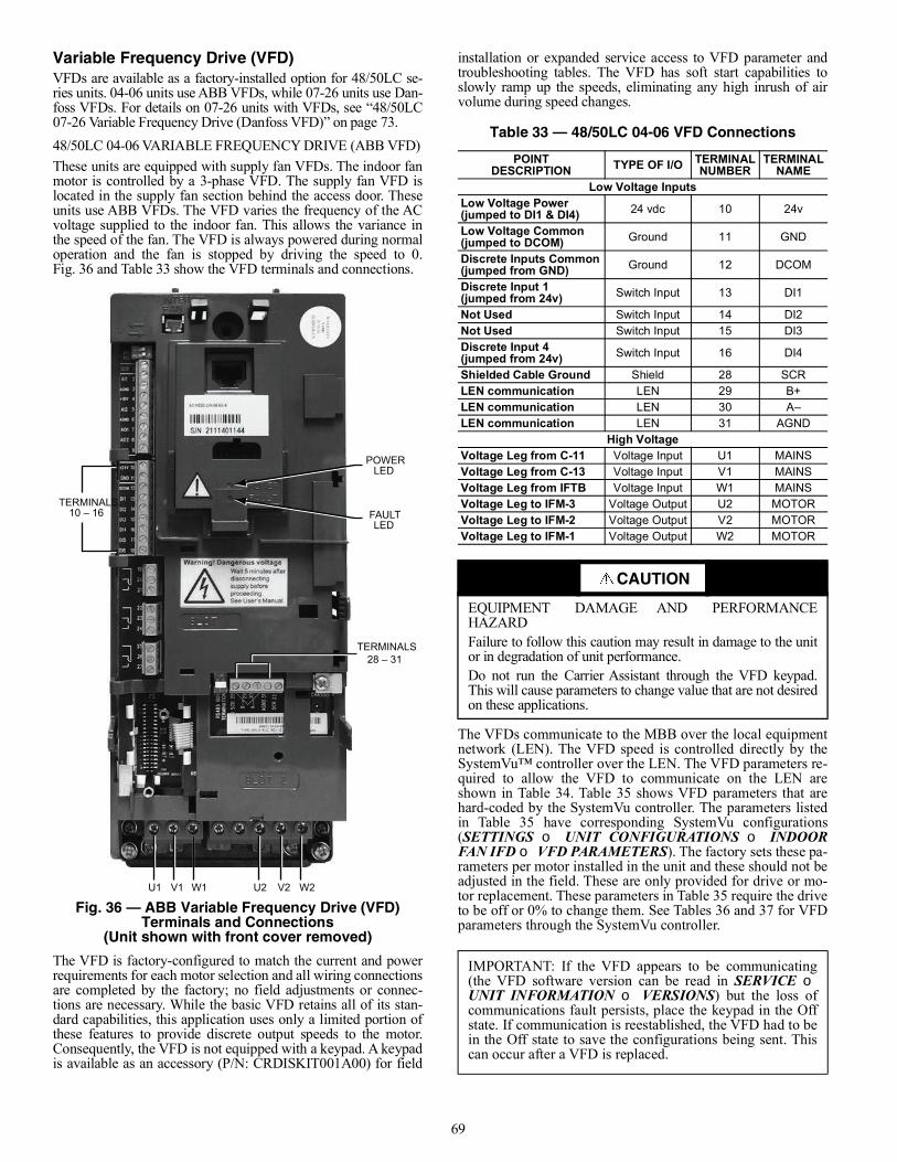
69
Variable Frequency Drive (VFD)VFDs are available as a factory-installed option for 48/50LC se-ries units. 04-06 units use ABB VFDs, while 07-26 units use Dan-foss VFDs. For details on 07-26 units with VFDs, see “48/50LC07-26 Variable Frequency Drive (Danfoss VFD)” on page 73.48/50LC 04-06 VARIABLE FREQUENCY DRIVE (ABB VFD)These units are equipped with supply fan VFDs. The indoor fanmotor is controlled by a 3-phase VFD. The supply fan VFD islocated in the supply fan section behind the access door. Theseunits use ABB VFDs. The VFD varies the frequency of the ACvoltage supplied to the indoor fan. This allows the variance inthe speed of the fan. The VFD is always powered during normaloperation and the fan is stopped by driving the speed to 0.Fig. 36 and Table 33 show the VFD terminals and connections.
Fig. 36 — ABB Variable Frequency Drive (VFD) Terminals and Connections
(Unit shown with front cover removed)
The VFD is factory-configured to match the current and powerrequirements for each motor selection and all wiring connectionsare completed by the factory; no field adjustments or connec-tions are necessary. While the basic VFD retains all of its stan-dard capabilities, this application uses only a limited portion ofthese features to provide discrete output speeds to the motor.Consequently, the VFD is not equipped with a keypad. A keypadis available as an accessory (P/N: CRDISKIT001A00) for field
installation or expanded service access to VFD parameter andtroubleshooting tables. The VFD has soft start capabilities toslowly ramp up the speeds, eliminating any high inrush of airvolume during speed changes.
The VFDs communicate to the MBB over the local equipmentnetwork (LEN). The VFD speed is controlled directly by theSystemVu™ controller over the LEN. The VFD parameters re-quired to allow the VFD to communicate on the LEN areshown in Table 34. Table 35 shows VFD parameters that arehard-coded by the SystemVu controller. The parameters listedin Table 35 have corresponding SystemVu configurations(SETTINGS UNIT CONFIGURATIONS INDOORFAN IFD VFD PARAMETERS). The factory sets these pa-rameters per motor installed in the unit and these should not beadjusted in the field. These are only provided for drive or mo-tor replacement. These parameters in Table 35 require the driveto be off or 0% to change them. See Tables 36 and 37 for VFDparameters through the SystemVu controller.
TERMINALS10 – 16
TERMINALS28 – 31
U1 V1 W1 U2 V2 W2
POWERLED
FAULTLED
Table 33 — 48/50LC 04-06 VFD Connections
POINTDESCRIPTION TYPE OF I/O TERMINAL
NUMBERTERMINAL
NAMELow Voltage Inputs
Low Voltage Power(jumped to DI1 & DI4) 24 vdc 10 24v
Low Voltage Common(jumped to DCOM) Ground 11 GND
Discrete Inputs Common(jumped from GND) Ground 12 DCOM
Discrete Input 1(jumped from 24v) Switch Input 13 DI1
Not Used Switch Input 14 DI2Not Used Switch Input 15 DI3Discrete Input 4(jumped from 24v) Switch Input 16 DI4
Shielded Cable Ground Shield 28 SCRLEN communication LEN 29 B+LEN communication LEN 30 A–LEN communication LEN 31 AGND
High VoltageVoltage Leg from C-11 Voltage Input U1 MAINSVoltage Leg from C-13 Voltage Input V1 MAINSVoltage Leg from IFTB Voltage Input W1 MAINSVoltage Leg to IFM-3 Voltage Output U2 MOTORVoltage Leg to IFM-2 Voltage Output V2 MOTORVoltage Leg to IFM-1 Voltage Output W2 MOTOR
CAUTION
EQUIPMENT DAMAGE AND PERFORMANCEHAZARDFailure to follow this caution may result in damage to the unitor in degradation of unit performance.Do not run the Carrier Assistant through the VFD keypad.This will cause parameters to change value that are not desiredon these applications.
IMPORTANT: If the VFD appears to be communicating(the VFD software version can be read in SERVICE UNIT INFORMATION VERSIONS) but the loss ofcommunications fault persists, place the keypad in the Offstate. If communication is reestablished, the VFD had to bein the Off state to save the configurations being sent. Thiscan occur after a VFD is replaced.
70
For proper operation, there are three jumper wires that must re-main installed and the VFD must be set to the auto mode. The3 jumpers are shown on the unit schematic and are connectedthrough a plug called PL25. These jumpers set the VFD to startenabled, run enabled, and tie the common bus together. TheVFD has 2 LEDs on its front panel to indicate operating status.See below and VFD Troubleshooting section for details onVFD faults and alarms. The VFD faults can be reset with theVFD keypad or through the SystemVu™ controller(ALERTS/FAULTS RESET FAULT/ALERT = Yes).The Green LED on steady indicates power is on the VFD, flashingGreen indicates an alarm condition detected. Alarms are advisoryin nature. These indicate a problem has been detected by theVFD’s diagnostics but this problem will not require a shutdown.The Red LED steady or flashing indicates a fault condition is de-tected. A fault is a significant internal situation for the VFD orMotor. Faults will typically shut down the motor.48/50LC 04-06 VFD TROUBLESHOOTINGWhen communication is successful, the SystemVu control willprovide alerts and faults that correlate to the VFD’s warnings andalarms. Table 39 shows the list of the SystemVu controller faultsand alerts and how they map to the VFD warnings and alarms. Ta-ble 39 also lists the possible causes of these cases.VFD Diagnostics (with Keypad)The drive detects error situations and reports them using:1. Green and red LEDs on the body of the drive (located
under the keypad)2. Status LED on the control panel3. Control panel display4. The Fault Word and Alarm Word parameter bits (parame-
ters 0305 to 0309)The form of the display depends on the severity of the error. Theuser can specify the severity for many errors by directing the driveto ignore the error situation, report the situation as an alarm, or re-port the situation as a fault.Faults (Red LED Lit)The VFD signals that it has detected a severe error, or fault, by:1. Enabling the red LED on the drive (LED is either steady
or flashing)
2. Setting an appropriate bit in a Fault Word parameter (0305to 0307)
3. Overriding the control panel display with the display of afault code
4. Stopping the motor (if it was on)The fault code on the control panel display is temporary. Pressingthe MENU, ENTER, UP or DOWN buttons removes the faultmessage. The message reappears after a few seconds if the controlpanel is not touched and the fault is still active.Alarms (Green LED Flashing)For less severe errors, called alarms, the diagnostic display is ad-visory. For these situations, the drive is simply reporting that ithas detected something unusual. In these situations, the drive:1. Flashes the green LED on the drive (does not apply to
alarms that arise from control panel operation errors)2. Sets an appropriate bit in an Alarm Word parameter (0308
or 0309)3. Overrides the control panel display with the display of an
alarm code and/or nameAlarm messages disappear from the control panel display after afew seconds. The message returns periodically as long as thealarm condition exists.Correcting FaultsThe recommended corrective action for faults is shown in theFault Codes list in Table 39. The VFD can also be reset to removethe fault. If an external source for a start command is selected andis active, the VFD may start immediately after fault reset.To reset a fault indicated by a flashing red LED, turn off the powerfor 5 minutes. To reset a fault indicated by a red LED (not flash-ing), press RESET from the control panel or turn off the power for5 minutes. Depending on the value of parameter 1604 (FAULTRESET SELECT), digital input or serial communication couldalso be used to reset the drive. When the fault has been corrected,the motor can be started.HistoryFor reference, the last three fault codes are stored into parameters0401, 0412, 0413. For the most recent fault (identified by parame-ter 0401), the drive stores additional data (in parameters 0402through 0411) to aid in troubleshooting a problem. For example, aparameter 0404 stores the motor speed at the time of the fault. Toclear the fault history (all of Group 04, Fault History parameters),follow these steps:1. In the control panel, Parameters mode, select parameter
0401.2. Press EDIT.3. Press the UP and DOWN buttons simultaneously.4. Press SAVE.If diagnostics troubleshooting has determined that the drive is de-fective during the warranty period, contact ABB Automation Inc.,at 1-800-435-7365, option 4, option 3. A qualified technician willreview the problem with the caller and make a determination re-garding how to proceed. This may involve dispatching a designat-ed service station (DSS) representative from an authorized station,dispatching a replacement unit, or advising return for repair.
CAUTION
EQUIPMENT DAMAGE HAZARDFailure to follow this warning could result in equipmentdamage.The VFD motor parameters shown in Table 38 should neverbe changed in the field unless authorized by CarrierCorporation. Damage could occur to the motor or unit if theseare set to anything besides what is shown in the table. Theseare only provided for drive or motor replacement or futureadjustments.
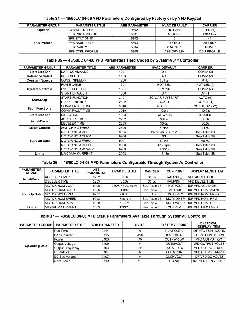
71
Table 34 — 48/50LC 04-06 VFD Parameters Configured by Factory or by VFD Keypad
PARAMETER GROUP PARAMETER TITLE ABB PARAMETER HVAC DEFAULT CARRIEROptions COMM PROT SEL 9802 NOT SEL LEN (6)
EFB Protocol
EFB PROTOCOL ID 5301 0000 hex 0601 hexEFB STATION ID 5302 0 41EFB BAUD RATE 5303 9.6 kb/s 38.4 kb/sEFB PARITY 5304 8 NONE 1 8 NONE 1EFB CTRL PROFILE 5305 ABB DRV LIM DCU PROFILE
Table 35 — 48/50LC 04-06 VFD Parameters Hard Coded by SystemVu™ Controller
PARAMETER GROUP PARAMETER TITLE ABB PARAMETER HVAC DEFAULT CARRIERStart/Stop/Dir EXT1 COMMANDS 1001 DI1 COMM (2)
Reference Select REF1 SELECT 1103 AI1 COMM (2)Constant Speeds CONST SPEED 7 1208 60 Hz 0 Hz
System ControlsRUN ENABLE 1601 NOT SEL NOT SEL (0)FAULT RESET SEL 1604 KEYPAD COMM (7)START ENABLE 1 1608 DI4 DI4 (4)
Start/Stop START FUNCTION 2101 SCALAR FLYSTART AUTO (0)STOP FUNCTION 2102 COAST COAST (1)
Fault Functions COMM FAULT FUNC 3018 NOT SEL CONST SP 7 (2)COMM FAULT TIME 3019 10.0 s 10.0 s
Start/Stop/Dir DIRECTION 1003 FORWARD REQUEST
Accel/Decel ACCELER TIME 1 2202 30.0s 30.0sDECELER TIME 1 2203 30.0s 30.0s
Motor Control SWITCHING FREQ 2606 4 kHz 4 kHz
Start-Up Data
MOTOR NOM VOLT 9905 230V, 460V, 575V See Table 38MOTOR NOM CURR 9906 10*In See Table 38MOTOR NOM FREQ 9907 60 Hz 60 HzMOTOR NOM SPEED 9908 1750 rpm See Table 38MOTOR NOM POWER 9909 1.0*Pn See Table 38
Limits MAXIMUM CURRENT 2003 1.3*i2n See Table 38
Table 36 — 48/50LC 04-06 VFD Parameters Configurable Through SystemVu Controller
PARAMETERGROUP PARAMETER TITLE ABB
PARAMETER HVAC DEFAULT CARRIER CCN POINT DISPLAY MENU ITEM
Accel/Decel ACCELER TIME 1 2202 30.0s 30.0s RAMPUP_T VFD ACCEL TIMEDECELER TIME 1 2203 30.0s 30.0s RAMPDN_T VFD DECEL TIME
Start-Up Data
MOTOR NOM VOLT 9905 230V, 460V, 575V See Table 38 MOTVOLT IDF VFD VOLTAGEMOTOR NOM CURR 9906 1.0*In See Table 38 MOTCUR IDF VFD NOM. AMPSMOTOR NOM FREQ 9907 60 Hz 60 Hz MOTFREQ IDF VFD NOM. FREQMOTOR NOM SPEED 9908 1750 rpm See Table 38 MOTNOMSP IDF VFD NOM. RPMMOTOR NOM POWER 9909 1.0*Pn See Table 38 MOTPWRHP IDF VFD NOM. HP
Limits MAXIMUM CURRENT 2003 1.3*I2n See Table 38 CURRLMT IDF VFD MAX AMPS
Table 37 — 48/50LC 04-06 VFD Status Parameters Available Through SystemVu Controller
PARAMETER GROUP PARAMETER TITLE ABB PARAMETER UNITS SYSTEMVU POINT SYSTEMVUDISPLAY ITEM
Operating Data
Run Time 0114 h RUNHOURS IDF VFD RUN HOURSkWh Counter 0115 kWh KWHCNTR IDF VFD KW HOURSPower 0106 kW OUTPWRKW VFD OUTPUT KWOutput Voltage 0109 v OUTMVOLT VFD OUTPUT VOLTSOutput Frequency 0103 Hz OUTMFREQ VFD OUTPUT FREQCURRENT 0104 A OUTMCUR VFD OUTPUT AMPSDC Bus Voltage 0107 v DLCNVOLT IDF VFD DC VOLTSDrive Temp 0110 °C HTSINKT IDF VFD HSNK TEMP
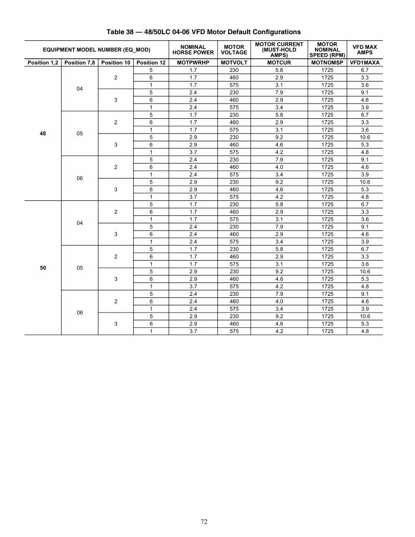
72
Table 38 — 48/50LC 04-06 VFD Motor Default Configurations
EQUIPMENT MODEL NUMBER (EQ_MOD) NOMINALHORSE POWER
MOTOR VOLTAGE
MOTOR CURRENT (MUST-HOLD
AMPS)
MOTOR NOMINAL
SPEED (RPM)VFD MAX
AMPS
Position 1,2 Position 7,8 Position 10 Position 12 MOTPWRHP MOTVOLT MOTCUR MOTNOMSP VFD1MAXA
48
04
25 1.7 230 5.8 1725 6.76 1.7 460 2.9 1725 3.31 1.7 575 3.1 1725 3.6
35 2.4 230 7.9 1725 9.16 2.4 460 2.9 1725 4.61 2.4 575 3.4 1725 3.9
05
25 1.7 230 5.8 1725 6.76 1.7 460 2.9 1725 3.31 1.7 575 3.1 1725 3.6
35 2.9 230 9.2 1725 10.66 2.9 460 4.6 1725 5.31 3.7 575 4.2 1725 4.8
06
25 2.4 230 7.9 1725 9.16 2.4 460 4.0 1725 4.61 2.4 575 3.4 1725 3.9
35 2.9 230 9.2 1725 10.66 2.9 460 4.6 1725 5.31 3.7 575 4.2 1725 4.8
50
04
25 1.7 230 5.8 1725 6.76 1.7 460 2.9 1725 3.31 1.7 575 3.1 1725 3.6
35 2.4 230 7.9 1725 9.16 2.4 460 2.9 1725 4.61 2.4 575 3.4 1725 3.9
05
25 1.7 230 5.8 1725 6.76 1.7 460 2.9 1725 3.31 1.7 575 3.1 1725 3.6
35 2.9 230 9.2 1725 10.66 2.9 460 4.6 1725 5.31 3.7 575 4.2 1725 4.8
06
25 2.4 230 7.9 1725 9.16 2.4 460 4.0 1725 4.61 2.4 575 3.4 1725 3.9
35 2.9 230 9.2 1725 10.66 2.9 460 4.6 1725 5.31 3.7 575 4.2 1725 4.8
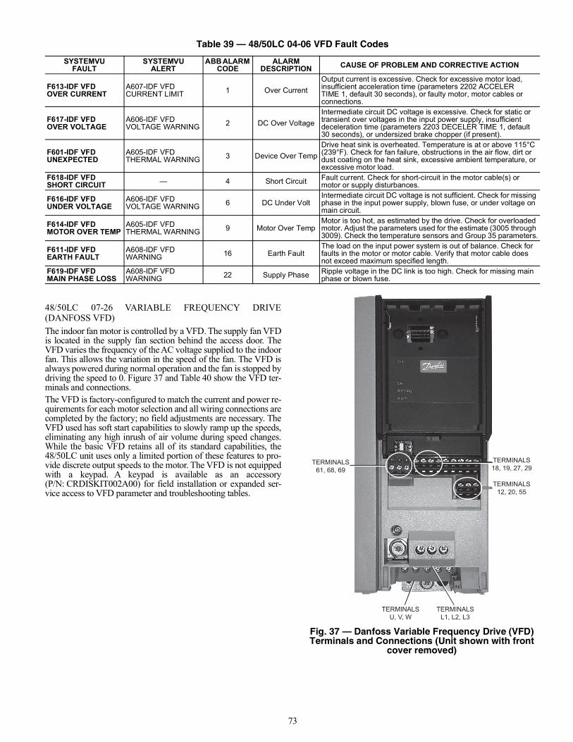
73
48/50LC 07-26 VARIABLE FREQUENCY DRIVE(DANFOSS VFD)The indoor fan motor is controlled by a VFD. The supply fan VFDis located in the supply fan section behind the access door. TheVFD varies the frequency of the AC voltage supplied to the indoorfan. This allows the variation in the speed of the fan. The VFD isalways powered during normal operation and the fan is stopped bydriving the speed to 0. Figure 37 and Table 40 show the VFD ter-minals and connections.The VFD is factory-configured to match the current and power re-quirements for each motor selection and all wiring connections arecompleted by the factory; no field adjustments are necessary. TheVFD used has soft start capabilities to slowly ramp up the speeds,eliminating any high inrush of air volume during speed changes.While the basic VFD retains all of its standard capabilities, the48/50LC unit uses only a limited portion of these features to pro-vide discrete output speeds to the motor. The VFD is not equippedwith a keypad. A keypad is available as an accessory(P/N: CRDISKIT002A00) for field installation or expanded ser-vice access to VFD parameter and troubleshooting tables.
Fig. 37 — Danfoss Variable Frequency Drive (VFD) Terminals and Connections (Unit shown with front
cover removed)
Table 39 — 48/50LC 04-06 VFD Fault Codes
SYSTEMVUFAULT
SYSTEMVUALERT
ABB ALARM CODE
ALARM DESCRIPTION CAUSE OF PROBLEM AND CORRECTIVE ACTION
F613-IDF VFDOVER CURRENT
A607-IDF VFDCURRENT LIMIT 1 Over Current
Output current is excessive. Check for excessive motor load, insufficient acceleration time (parameters 2202 ACCELER TIME 1, default 30 seconds), or faulty motor, motor cables or connections.
F617-IDF VFDOVER VOLTAGE
A606-IDF VFDVOLTAGE WARNING 2 DC Over Voltage
Intermediate circuit DC voltage is excessive. Check for static or transient over voltages in the input power supply, insufficient deceleration time (parameters 2203 DECELER TIME 1, default 30 seconds), or undersized brake chopper (if present).
F601-IDF VFDUNEXPECTED
A605-IDF VFDTHERMAL WARNING 3 Device Over Temp
Drive heat sink is overheated. Temperature is at or above 115°C (239°F). Check for fan failure, obstructions in the air flow, dirt or dust coating on the heat sink, excessive ambient temperature, or excessive motor load.
F618-IDF VFDSHORT CIRCUIT — 4 Short Circuit Fault current. Check for short-circuit in the motor cable(s) or
motor or supply disturbances.
F616-IDF VFDUNDER VOLTAGE
A606-IDF VFDVOLTAGE WARNING 6 DC Under Volt
Intermediate circuit DC voltage is not sufficient. Check for missing phase in the input power supply, blown fuse, or under voltage on main circuit.
F614-IDF VFDMOTOR OVER TEMP
A605-IDF VFDTHERMAL WARNING 9 Motor Over Temp
Motor is too hot, as estimated by the drive. Check for overloaded motor. Adjust the parameters used for the estimate (3005 through 3009). Check the temperature sensors and Group 35 parameters.
F611-IDF VFDEARTH FAULT
A608-IDF VFDWARNING 16 Earth Fault
The load on the input power system is out of balance. Check for faults in the motor or motor cable. Verify that motor cable does not exceed maximum specified length.
F619-IDF VFDMAIN PHASE LOSS
A608-IDF VFDWARNING 22 Supply Phase Ripple voltage in the DC link is too high. Check for missing main
phase or blown fuse.
TERMINALS61, 68, 69
TERMINALS18, 19, 27, 29
TERMINALS12, 20, 55
TERMINALSU, V, W
TERMINALSL1, L2, L3
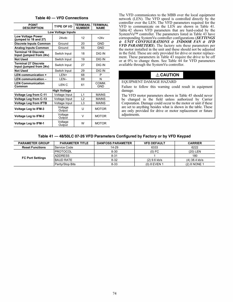
74
The VFD communicates to the MBB over the local equipmentnetwork (LEN). The VFD speed is controlled directly by thecontroller over the LEN. The VFD parameters required for theVFD to communicate on the LEN are shown in Table 41.Table 42 shows VFD parameters that are hard-coded by theSystemVu™ controller. The parameters listed in Table 43 havecorresponding SystemVu controller configurations (SETTINGS UNIT CONFIGURATIONS INDOOR FAN IFDVFD PARAMETERS). The factory sets these parameters perthe motor installed in the unit and these should not be adjustedin the field. These are only provided for drive or motor replace-ment. These parameters in Table 43 require the drive to be offor at 0% to change them. See Table 44 for VFD parametersavailable through the SystemVu controller.
Table 40 — VFD Connections
POINTDESCRIPTION TYPE OF I/O TERMIANL
NUMBERTERMINAL
NAMELow Voltage Inputs
Low Voltage Power (jumped to 18 and 27) 24vdc 12 +24v
Discrete Inputs Common Ground 20 GNDAnalog Inputs Common Ground 55 GNDTerminal 18 Discrete Input (jumped from 24v) Switch Input 18 DIG IN
Not Used Switch Input 19 DIG INTerminal 27 Discrete Input (jumped from 24v) Switch Input 27 DIG IN
Not Used Switch Input 29 DIG INLEN communication + LEN+ 68 PLEN communication – LEN– 69 NLEN CommunicationCommon LEN C 61 COMM.
GNDHigh Voltage
Voltage Leg from C-11 Voltage Input L1 MAINSVoltage Leg from C-13 Voltage Input L2 MAINSVoltage Leg from IFTB Voltage Input L3 MAINS
Voltage Leg to IFM-3 Voltage Output U MOTOR
Voltage Leg to IFM-2 Voltage Output V MOTOR
Voltage Leg to IFM-1 Voltage Output W MOTOR
CAUTION
EQUIPMENT DAMAGE HAZARDFailure to follow this warning could result in equipmentdamage.The VFD motor parameters shown in Table 45 should neverbe changed in the field unless authorized by CarrierCorporation. Damage could occur to the motor or unit if theseare set to anything besides what is shown in the table. Theseare only provided for drive or motor replacement or futureadjustments.
Table 41 — 48/50LC 07-26 VFD Parameters Configured by Factory or by VFD Keypad
PARAMETER GROUP PARAMETER TITLE DANFOSS PARAMETER VFD DEFAULT CARRIERReset Functions Service Code 14-29 6333 6222
FC Port Settings
PROTOCOL 8-30 (0) FC (20) LENADDRESS 8-31 1 180BAUD RATE 8-32 (2) 9.6 kb/s (4) 38.4 kb/sParity/Stop Bits 8-33 (0) 8 EVEN 1 (2) 8 NONE 1
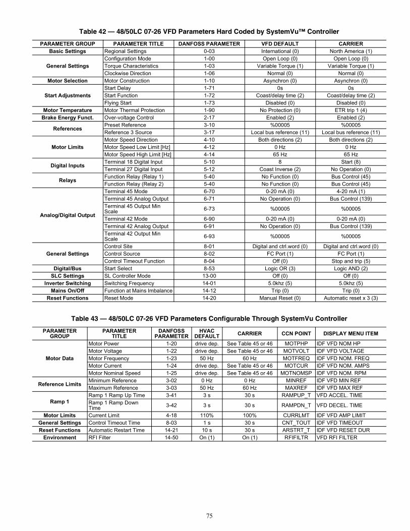
75
Table 42 — 48/50LC 07-26 VFD Parameters Hard Coded by SystemVu™ Controller
PARAMETER GROUP PARAMETER TITLE DANFOSS PARAMETER VFD DEFAULT CARRIERBasic Settings Regional Settings 0-03 International (0) North America (1)
General SettingsConfiguration Mode 1-00 Open Loop (0) Open Loop (0)Torque Characteristics 1-03 Variable Torque (1) Variable Torque (1)Clockwise Direction 1-06 Normal (0) Normal (0)
Motor Selection Motor Construction 1-10 Asynchron (0) Asynchron (0)
Start AdjustmentsStart Delay 1-71 0s 0sStart Function 1-72 Coast/delay time (2) Coast/delay time (2)Flying Start 1-73 Disabled (0) Disabled (0)
Motor Temperature Motor Thermal Protection 1-90 No Protection (0) ETR trip 1 (4)Brake Energy Funct. Over-voltage Control 2-17 Enabled (2) Enabled (2)
References Preset Reference 3-10 %00005 %00005Reference 3 Source 3-17 Local bus reference (11) Local bus reference (11)
Motor LimitsMotor Speed Direction 4-10 Both directions (2) Both directions (2)Motor Speed Low Limit [Hz] 4-12 0 Hz 0 HzMotor Speed High Limit [Hz] 4-14 65 Hz 65 Hz
Digital Inputs Terminal 18 Digital Input 5-10 8 Start (8)Terminal 27 Digital Input 5-12 Coast Inverse (2) No Operation (0)
Relays Function Relay (Relay 1) 5-40 No Function (0) Bus Control (45)Function Relay (Relay 2) 5-40 No Function (0) Bus Control (45)
Analog/Digital Output
Terminal 45 Mode 6-70 0-20 mA (0) 4-20 mA (1)Terminal 45 Analog Output 6-71 No Operation (0) Bus Control (139)Terminal 45 Output Min Scale 6-73 %00005 %00005
Terminal 42 Mode 6-90 0-20 mA (0) 0-20 mA (0)Terminal 42 Analog Output 6-91 No Operation (0) Bus Control (139)Terminal 42 Output Min Scale 6-93 %00005 %00005
General SettingsControl Site 8-01 Digital and ctrl.word (0) Digital and ctrl.word (0)Control Source 8-02 FC Port (1) FC Port (1)Control Timeout Function 8-04 Off (0) Stop and trip (5)
Digital/Bus Start Select 8-53 Logic OR (3) Logic AND (2)SLC Settings SL Controller Mode 13-00 Off (0) Off (0)
Inverter Switching Switching Frequency 14-01 5.0khz (5) 5.0khz (5)Mains On/Off Function at Mains Imbalance 14-12 Trip (0) Trip (0)
Reset Functions Reset Mode 14-20 Manual Reset (0) Automatic reset x 3 (3)
Table 43 — 48/50LC 07-26 VFD Parameters Configurable Through SystemVu Controller
PARAMETER GROUP
PARAMETER TITLE
DANFOSS PARAMETER
HVAC DEFAULT CARRIER CCN POINT DISPLAY MENU ITEM
Motor Data
Motor Power 1-20 drive dep. See Table 45 or 46 MOTPHP IDF VFD NOM HPMotor Voltage 1-22 drive dep. See Table 45 or 46 MOTVOLT IDF VFD VOLTAGEMotor Frequency 1-23 50 Hz 60 Hz MOTFREQ IDF VFD NOM. FREQMotor Current 1-24 drive dep. See Table 45 or 46 MOTCUR IDF VFD NOM. AMPSMotor Nominal Speed 1-25 drive dep. See Table 45 or 46 MOTNOMSP IDF VFD NOM. RPM
Reference Limits Minimum Reference 3-02 0 Hz 0 Hz MINREF IDF VFD MIN REFMaximum Reference 3-03 50 Hz 60 Hz MAXREF IDF VFD MAX REF
Ramp 1Ramp 1 Ramp Up Time 3-41 3 s 30 s RAMPUP_T VFD ACCEL. TIMERamp 1 Ramp Down Time 3-42 3 s 30 s RAMPDN_T VFD DECEL. TIME
Motor Limits Current Limit 4-18 110% 100% CURRLMT IDF VFD AMP LIMITGeneral Settings Control Timeout Time 8-03 1 s 30 s CNT_TOUT IDF VFD TIMEOUTReset Functions Automatic Restart Time 14-21 10 s 30 s ARSTRT_T IDF VFD RESET DUR
Environment RFI Filter 14-50 On (1) On (1) RFIFILTR VFD RFI FILTER
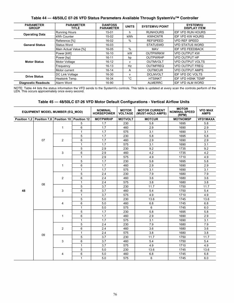
76
NOTE: Table 44 lists the status information the VFD sends to the SystemVu controls. This table is updated at every scan the controls perform of theLEN. This occurs approximately once every second.
Table 44 — 48/50LC 07-26 VFD Status Parameters Available Through SystemVu™ Controller
PARAMETER GROUP
PARAMETER TITLE
DANFOSS PARAMETER UNITS SYSTEMVU POINT SYSTEMVU
DISPLAY ITEM
Operating Data Running Hours 15-01 h RUNHOURS IDF VFD RUN HOURSkWh Counter 15-02 kWh KWHCNTR IDF VFD KW HOURS
General StatusReference [%] 16-02 % REFSPEED VFD REF SPEEDStatus Word 16-03 STATUSWD VFD STATUS WORDMain Actual Value [%] 16-05 % MAV IDF VFD FEEDBACK
Motor Status
Power [kW] 16-10 kW OUTPWRKW VFD OUTPUT KWPower [hp] 16-11 hp OUTPWRHP VFD OUTPUT HPMotor Voltage 16-12 v OUTMVOLT VFD OUTPUT VOLTSFrequency 16-13 Hz OUTMFREQ VFD OUTPUT FREQMotor current 16-14 A OUTMCUR VFD OUTPUT AMPS
Drive Status DC Link Voltage 16-30 v DCLNVOLT IDF VFD DC VOLTSHeatsink Temp. 16-34 °C HTSINKT IDF VFD HSNK TEMP
Diagnostic Readouts Alarm Word 16-90 ALMERRC IDF VFD ALM WORD
Table 45 — 48/50LC 07-26 VFD Motor Default Configurations - Vertical Airflow Units
EQUIPMENT MODEL MUMBER (EQ_MOD) NOMINAL HORSEPOWER
MOTOR VOLTAGE
MOTOR CURRENT (MUST-HOLD AMPS)
MOTOR NOMINAL SPEED
(RPM)VFD MAX
AMPS
Position 1,2 Position 7,8 Position 10 Position 12 MOTPWRHP MOTVOLT MOTCUR MOTNOMSP VFD1MAXA
48
07
15 1.7 230 5.8 1695 5.86 1.7 460 2.9 1690 2.91 1.7 575 3.1 1690 3.1
25 1.7 230 5.8 1695 5.86 1.7 460 2.9 1690 2.91 1.7 575 3.1 1690 3.1
35 2.9 230 9.2 1735 9.26 2.9 460 4.2 1735 4.21 2.9 575 4.9 1710 4.9
08
15 1.7 230 5.8 1695 5.86 1.7 460 2.9 1690 2.91 1.7 575 3.1 1690 3.1
25 2.4 230 7.9 1680 7.96 2.4 460 3.6 1680 3.61 2.4 575 3.8 1680 3.8
35 3.7 230 11.7 1750 11.76 3.7 460 5.4 1750 5.41 3.7 575 4.9 1710 4.9
45 5.0 230 13.6 1745 13.66 5.0 460 6.8 1745 6.81 5.0 575 6 1745 6.0
09
15 1.7 230 5.8 1695 5.86 1.7 460 2.9 1690 2.91 1.7 575 3.1 1690 3.1
25 2.4 230 7.9 1680 7.96 2.4 460 3.6 1680 3.61 2.4 575 3.8 1680 3.8
35 3.7 230 11.7 1750 11.76 3.7 460 5.4 1750 5.41 3.7 575 4.9 1710 4.9
45 5.0 230 13.6 1745 13.66 5.0 460 6.8 1745 6.81 5.0 575 6 1745 6.0
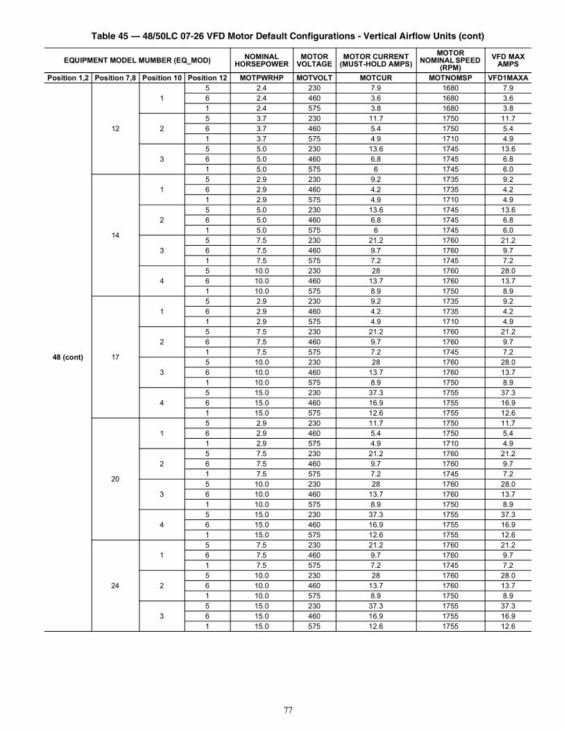
77
48 (cont)
12
15 2.4 230 7.9 1680 7.96 2.4 460 3.6 1680 3.61 2.4 575 3.8 1680 3.8
25 3.7 230 11.7 1750 11.76 3.7 460 5.4 1750 5.41 3.7 575 4.9 1710 4.9
35 5.0 230 13.6 1745 13.66 5.0 460 6.8 1745 6.81 5.0 575 6 1745 6.0
14
15 2.9 230 9.2 1735 9.26 2.9 460 4.2 1735 4.21 2.9 575 4.9 1710 4.9
25 5.0 230 13.6 1745 13.66 5.0 460 6.8 1745 6.81 5.0 575 6 1745 6.0
35 7.5 230 21.2 1760 21.26 7.5 460 9.7 1760 9.71 7.5 575 7.2 1745 7.2
45 10.0 230 28 1760 28.06 10.0 460 13.7 1760 13.71 10.0 575 8.9 1750 8.9
17
15 2.9 230 9.2 1735 9.26 2.9 460 4.2 1735 4.21 2.9 575 4.9 1710 4.9
25 7.5 230 21.2 1760 21.26 7.5 460 9.7 1760 9.71 7.5 575 7.2 1745 7.2
35 10.0 230 28 1760 28.06 10.0 460 13.7 1760 13.71 10.0 575 8.9 1750 8.9
45 15.0 230 37.3 1755 37.36 15.0 460 16.9 1755 16.91 15.0 575 12.6 1755 12.6
20
15 2.9 230 11.7 1750 11.76 2.9 460 5.4 1750 5.41 2.9 575 4.9 1710 4.9
25 7.5 230 21.2 1760 21.26 7.5 460 9.7 1760 9.71 7.5 575 7.2 1745 7.2
35 10.0 230 28 1760 28.06 10.0 460 13.7 1760 13.71 10.0 575 8.9 1750 8.9
45 15.0 230 37.3 1755 37.36 15.0 460 16.9 1755 16.91 15.0 575 12.6 1755 12.6
24
15 7.5 230 21.2 1760 21.26 7.5 460 9.7 1760 9.71 7.5 575 7.2 1745 7.2
25 10.0 230 28 1760 28.06 10.0 460 13.7 1760 13.71 10.0 575 8.9 1750 8.9
35 15.0 230 37.3 1755 37.36 15.0 460 16.9 1755 16.91 15.0 575 12.6 1755 12.6
Table 45 — 48/50LC 07-26 VFD Motor Default Configurations - Vertical Airflow Units (cont)
EQUIPMENT MODEL MUMBER (EQ_MOD) NOMINAL HORSEPOWER
MOTOR VOLTAGE
MOTOR CURRENT (MUST-HOLD AMPS)
MOTOR NOMINAL SPEED
(RPM)VFD MAX
AMPS
Position 1,2 Position 7,8 Position 10 Position 12 MOTPWRHP MOTVOLT MOTCUR MOTNOMSP VFD1MAXA
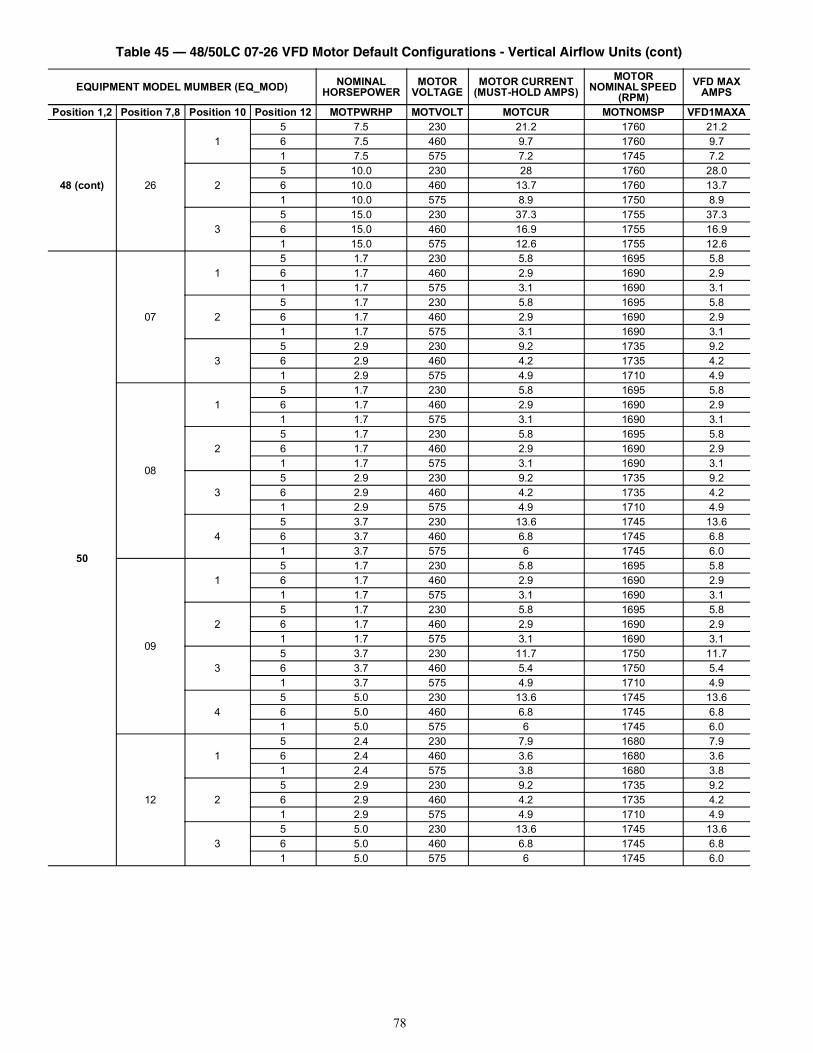
78
48 (cont) 26
15 7.5 230 21.2 1760 21.26 7.5 460 9.7 1760 9.71 7.5 575 7.2 1745 7.2
25 10.0 230 28 1760 28.06 10.0 460 13.7 1760 13.71 10.0 575 8.9 1750 8.9
35 15.0 230 37.3 1755 37.36 15.0 460 16.9 1755 16.91 15.0 575 12.6 1755 12.6
50
07
15 1.7 230 5.8 1695 5.86 1.7 460 2.9 1690 2.91 1.7 575 3.1 1690 3.1
25 1.7 230 5.8 1695 5.86 1.7 460 2.9 1690 2.91 1.7 575 3.1 1690 3.1
35 2.9 230 9.2 1735 9.26 2.9 460 4.2 1735 4.21 2.9 575 4.9 1710 4.9
08
15 1.7 230 5.8 1695 5.86 1.7 460 2.9 1690 2.91 1.7 575 3.1 1690 3.1
25 1.7 230 5.8 1695 5.86 1.7 460 2.9 1690 2.91 1.7 575 3.1 1690 3.1
35 2.9 230 9.2 1735 9.26 2.9 460 4.2 1735 4.21 2.9 575 4.9 1710 4.9
45 3.7 230 13.6 1745 13.66 3.7 460 6.8 1745 6.81 3.7 575 6 1745 6.0
09
15 1.7 230 5.8 1695 5.86 1.7 460 2.9 1690 2.91 1.7 575 3.1 1690 3.1
25 1.7 230 5.8 1695 5.86 1.7 460 2.9 1690 2.91 1.7 575 3.1 1690 3.1
35 3.7 230 11.7 1750 11.76 3.7 460 5.4 1750 5.41 3.7 575 4.9 1710 4.9
45 5.0 230 13.6 1745 13.66 5.0 460 6.8 1745 6.81 5.0 575 6 1745 6.0
12
15 2.4 230 7.9 1680 7.96 2.4 460 3.6 1680 3.61 2.4 575 3.8 1680 3.8
25 2.9 230 9.2 1735 9.26 2.9 460 4.2 1735 4.21 2.9 575 4.9 1710 4.9
35 5.0 230 13.6 1745 13.66 5.0 460 6.8 1745 6.81 5.0 575 6 1745 6.0
Table 45 — 48/50LC 07-26 VFD Motor Default Configurations - Vertical Airflow Units (cont)
EQUIPMENT MODEL MUMBER (EQ_MOD) NOMINAL HORSEPOWER
MOTOR VOLTAGE
MOTOR CURRENT (MUST-HOLD AMPS)
MOTOR NOMINAL SPEED
(RPM)VFD MAX
AMPS
Position 1,2 Position 7,8 Position 10 Position 12 MOTPWRHP MOTVOLT MOTCUR MOTNOMSP VFD1MAXA
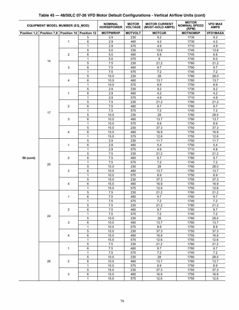
79
50 (cont)
14
15 2.9 230 9.2 1735 9.26 2.9 460 4.2 1735 4.21 2.9 575 4.9 1710 4.9
25 5.0 230 13.6 1745 13.66 5.0 460 6.8 1745 6.81 5.0 575 6 1745 6.0
35 7.5 230 21.2 1760 21.26 7.5 460 9.7 1760 9.71 7.5 575 7.2 1745 7.2
45 10.0 230 28 1760 28.06 10.0 460 13.7 1760 13.71 10.0 575 8.9 1750 8.9
17
15 2.9 230 9.2 1735 9.26 2.9 460 4.2 1735 4.21 2.9 575 4.9 1710 4.9
25 7.5 230 21.2 1760 21.26 7.5 460 9.7 1760 9.71 7.5 575 7.2 1745 7.2
35 10.0 230 28 1760 28.06 10.0 460 13.7 1760 13.71 10.0 575 8.9 1750 8.9
45 15.0 230 37.3 1755 37.36 15.0 460 16.9 1755 16.91 15.0 575 12.6 1755 12.6
20
15 2.9 230 11.7 1750 11.76 2.9 460 5.4 1750 5.41 2.9 575 4.9 1710 4.9
25 7.5 230 21.2 1760 21.26 7.5 460 9.7 1760 9.71 7.5 575 7.2 1745 7.2
35 10.0 230 28 1760 28.06 10.0 460 13.7 1760 13.71 10.0 575 8.9 1750 8.9
45 15.0 230 37.3 1755 37.36 15.0 460 16.9 1755 16.91 15.0 575 12.6 1755 12.6
24
15 7.5 230 21.2 1760 21.26 7.5 460 9.7 1760 9.71 7.5 575 7.2 1745 7.2
25 7.5 230 21.2 1760 21.26 7.5 460 9.7 1760 9.71 7.5 575 7.2 1745 7.2
35 10.0 230 28 1760 28.06 10.0 460 13.7 1760 13.71 10.0 575 8.9 1750 8.9
45 15.0 230 37.3 1755 37.36 15.0 460 16.9 1755 16.91 15.0 575 12.6 1755 12.6
26
15 7.5 230 21.2 1760 21.26 7.5 460 9.7 1760 9.71 7.5 575 7.2 1745 7.2
25 10.0 230 28 1760 28.06 10.0 460 13.7 1760 13.71 10.0 575 8.9 1750 8.9
35 15.0 230 37.3 1755 37.36 15.0 460 16.9 1755 16.91 15.0 575 12.6 1755 12.6
Table 45 — 48/50LC 07-26 VFD Motor Default Configurations - Vertical Airflow Units (cont)
EQUIPMENT MODEL MUMBER (EQ_MOD) NOMINAL HORSEPOWER
MOTOR VOLTAGE
MOTOR CURRENT (MUST-HOLD AMPS)
MOTOR NOMINAL SPEED
(RPM)VFD MAX
AMPS
Position 1,2 Position 7,8 Position 10 Position 12 MOTPWRHP MOTVOLT MOTCUR MOTNOMSP VFD1MAXA
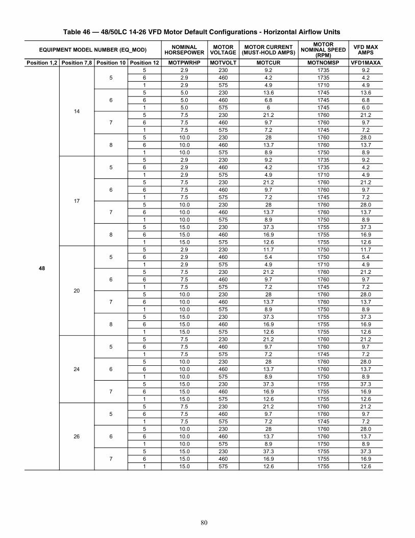
80
Table 46 — 48/50LC 14-26 VFD Motor Default Configurations - Horizontal Airflow Units
EQUIPMENT MODEL NUMBER (EQ_MOD) NOMINAL HORSEPOWER
MOTOR VOLTAGE
MOTOR CURRENT (MUST-HOLD AMPS)
MOTORNOMINAL SPEED
(RPM)VFD MAX
AMPS
Position 1,2 Position 7,8 Position 10 Position 12 MOTPWRHP MOTVOLT MOTCUR MOTNOMSP VFD1MAXA
48
14
55 2.9 230 9.2 1735 9.26 2.9 460 4.2 1735 4.21 2.9 575 4.9 1710 4.9
65 5.0 230 13.6 1745 13.66 5.0 460 6.8 1745 6.81 5.0 575 6 1745 6.0
75 7.5 230 21.2 1760 21.26 7.5 460 9.7 1760 9.71 7.5 575 7.2 1745 7.2
85 10.0 230 28 1760 28.06 10.0 460 13.7 1760 13.71 10.0 575 8.9 1750 8.9
17
55 2.9 230 9.2 1735 9.26 2.9 460 4.2 1735 4.21 2.9 575 4.9 1710 4.9
65 7.5 230 21.2 1760 21.26 7.5 460 9.7 1760 9.71 7.5 575 7.2 1745 7.2
75 10.0 230 28 1760 28.06 10.0 460 13.7 1760 13.71 10.0 575 8.9 1750 8.9
85 15.0 230 37.3 1755 37.36 15.0 460 16.9 1755 16.91 15.0 575 12.6 1755 12.6
20
55 2.9 230 11.7 1750 11.76 2.9 460 5.4 1750 5.41 2.9 575 4.9 1710 4.9
65 7.5 230 21.2 1760 21.26 7.5 460 9.7 1760 9.71 7.5 575 7.2 1745 7.2
75 10.0 230 28 1760 28.06 10.0 460 13.7 1760 13.71 10.0 575 8.9 1750 8.9
85 15.0 230 37.3 1755 37.36 15.0 460 16.9 1755 16.91 15.0 575 12.6 1755 12.6
24
55 7.5 230 21.2 1760 21.26 7.5 460 9.7 1760 9.71 7.5 575 7.2 1745 7.2
65 10.0 230 28 1760 28.06 10.0 460 13.7 1760 13.71 10.0 575 8.9 1750 8.9
75 15.0 230 37.3 1755 37.36 15.0 460 16.9 1755 16.91 15.0 575 12.6 1755 12.6
26
55 7.5 230 21.2 1760 21.26 7.5 460 9.7 1760 9.71 7.5 575 7.2 1745 7.2
65 10.0 230 28 1760 28.06 10.0 460 13.7 1760 13.71 10.0 575 8.9 1750 8.9
75 15.0 230 37.3 1755 37.36 15.0 460 16.9 1755 16.91 15.0 575 12.6 1755 12.6

81
50
14
55 2.9 230 9.2 1735 9.26 2.9 460 4.2 1735 4.21 2.9 575 4.9 1710 4.9
65 5.0 230 13.6 1745 13.66 5.0 460 6.8 1745 6.81 5.0 575 6 1745 6.0
75 7.5 230 21.2 1760 21.26 7.5 460 9.7 1760 9.71 7.5 575 7.2 1745 7.2
85 10.0 230 28 1760 28.06 10.0 460 13.7 1760 13.71 10.0 575 8.9 1750 8.9
17
55 2.9 230 9.2 1735 9.26 2.9 460 4.2 1735 4.21 2.9 575 4.9 1710 4.9
65 7.5 230 21.2 1760 21.26 7.5 460 9.7 1760 9.71 7.5 575 7.2 1745 7.2
75 10.0 230 28 1760 28.06 10.0 460 13.7 1760 13.71 10.0 575 8.9 1750 8.9
85 15.0 230 37.3 1755 37.36 15.0 460 16.9 1755 16.91 15.0 575 12.6 1755 12.6
20
55 2.9 230 11.7 1750 11.76 2.9 460 5.4 1750 5.41 2.9 575 4.9 1710 4.9
65 7.5 230 21.2 1760 21.26 7.5 460 9.7 1760 9.71 7.5 575 7.2 1745 7.2
75 10.0 230 28 1760 28.06 10.0 460 13.7 1760 13.71 10.0 575 8.9 1750 8.9
85 15.0 230 37.3 1755 37.36 15.0 460 16.9 1755 16.91 15.0 575 12.6 1755 12.6
24
55 7.5 230 21.2 1760 21.26 7.5 460 9.7 1760 9.71 7.5 575 7.2 1745 7.2
65 7.5 230 21.2 1760 21.26 7.5 460 9.7 1760 9.71 7.5 575 7.2 1745 7.2
75 10.0 230 28 1760 28.06 10.0 460 13.7 1760 13.71 10.0 575 8.9 1750 8.9
85 15.0 230 37.3 1755 37.36 15.0 460 16.9 1755 16.91 15.0 575 12.6 1755 12.6
26
55 7.5 230 21.2 1760 21.26 7.5 460 9.7 1760 9.71 7.5 575 7.2 1745 7.2
65 10.0 230 28 1760 28.06 10.0 460 13.7 1760 13.71 10.0 575 8.9 1750 8.9
75 15.0 230 37.3 1755 37.36 15.0 460 16.9 1755 16.91 15.0 575 12.6 1755 12.6
Table 46 — 48/50LC 14-26 VFD Motor Default Configurations - Horizontal Airflow Units (cont)
EQUIPMENT MODEL NUMBER (EQ_MOD) NOMINAL HORSEPOWER
MOTOR VOLTAGE
MOTOR CURRENT (MUST-HOLD AMPS)
MOTORNOMINAL SPEED
(RPM)VFD MAX
AMPS
Position 1,2 Position 7,8 Position 10 Position 12 MOTPWRHP MOTVOLT MOTCUR MOTNOMSP VFD1MAXA
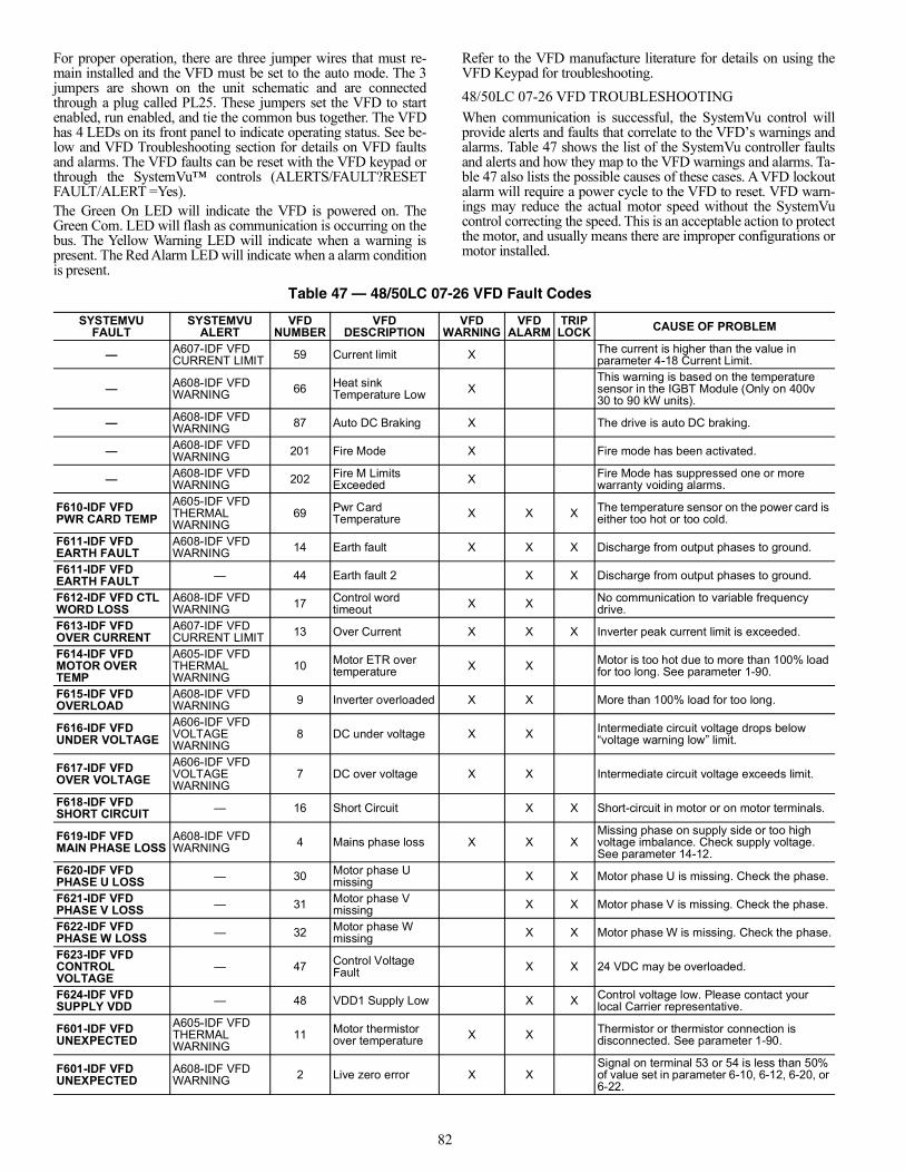
82
For proper operation, there are three jumper wires that must re-main installed and the VFD must be set to the auto mode. The 3jumpers are shown on the unit schematic and are connectedthrough a plug called PL25. These jumpers set the VFD to startenabled, run enabled, and tie the common bus together. The VFDhas 4 LEDs on its front panel to indicate operating status. See be-low and VFD Troubleshooting section for details on VFD faultsand alarms. The VFD faults can be reset with the VFD keypad orthrough the SystemVu™ controls (ALERTS/FAULT?RESETFAULT/ALERT =Yes).The Green On LED will indicate the VFD is powered on. TheGreen Com. LED will flash as communication is occurring on thebus. The Yellow Warning LED will indicate when a warning ispresent. The Red Alarm LED will indicate when a alarm conditionis present.
Refer to the VFD manufacture literature for details on using theVFD Keypad for troubleshooting.48/50LC 07-26 VFD TROUBLESHOOTINGWhen communication is successful, the SystemVu control willprovide alerts and faults that correlate to the VFD’s warnings andalarms. Table 47 shows the list of the SystemVu controller faultsand alerts and how they map to the VFD warnings and alarms. Ta-ble 47 also lists the possible causes of these cases. A VFD lockoutalarm will require a power cycle to the VFD to reset. VFD warn-ings may reduce the actual motor speed without the SystemVucontrol correcting the speed. This is an acceptable action to protectthe motor, and usually means there are improper configurations ormotor installed.
Table 47 — 48/50LC 07-26 VFD Fault Codes
SYSTEMVU FAULT
SYSTEMVU ALERT
VFD NUMBER
VFD DESCRIPTION
VFD WARNING
VFD ALARM
TRIP LOCK CAUSE OF PROBLEM
— A607-IDF VFD CURRENT LIMIT 59 Current limit X The current is higher than the value in
parameter 4-18 Current Limit.
— A608-IDF VFD WARNING 66 Heat sink
Temperature Low XThis warning is based on the temperature sensor in the IGBT Module (Only on 400v30 to 90 kW units).
— A608-IDF VFD WARNING 87 Auto DC Braking X The drive is auto DC braking.
— A608-IDF VFD WARNING 201 Fire Mode X Fire mode has been activated.
— A608-IDF VFD WARNING 202 Fire M Limits
Exceeded X Fire Mode has suppressed one or more warranty voiding alarms.
F610-IDF VFDPWR CARD TEMP
A605-IDF VFD THERMAL WARNING
69 Pwr Card Temperature X X X The temperature sensor on the power card is
either too hot or too cold.
F611-IDF VFDEARTH FAULT
A608-IDF VFD WARNING 14 Earth fault X X X Discharge from output phases to ground.
F611-IDF VFDEARTH FAULT — 44 Earth fault 2 X X Discharge from output phases to ground.
F612-IDF VFD CTL WORD LOSS
A608-IDF VFD WARNING 17 Control word
timeout X X No communication to variable frequency drive.
F613-IDF VFDOVER CURRENT
A607-IDF VFD CURRENT LIMIT 13 Over Current X X X Inverter peak current limit is exceeded.
F614-IDF VFDMOTOR OVERTEMP
A605-IDF VFD THERMAL WARNING
10 Motor ETR over temperature X X Motor is too hot due to more than 100% load
for too long. See parameter 1-90.
F615-IDF VFDOVERLOAD
A608-IDF VFD WARNING 9 Inverter overloaded X X More than 100% load for too long.
F616-IDF VFDUNDER VOLTAGE
A606-IDF VFD VOLTAGE WARNING
8 DC under voltage X X Intermediate circuit voltage drops below “voltage warning low” limit.
F617-IDF VFDOVER VOLTAGE
A606-IDF VFD VOLTAGE WARNING
7 DC over voltage X X Intermediate circuit voltage exceeds limit.
F618-IDF VFDSHORT CIRCUIT — 16 Short Circuit X X Short-circuit in motor or on motor terminals.
F619-IDF VFDMAIN PHASE LOSS
A608-IDF VFD WARNING 4 Mains phase loss X X X
Missing phase on supply side or too high voltage imbalance. Check supply voltage. See parameter 14-12.
F620-IDF VFDPHASE U LOSS — 30 Motor phase U
missing X X Motor phase U is missing. Check the phase.
F621-IDF VFDPHASE V LOSS — 31 Motor phase V
missing X X Motor phase V is missing. Check the phase.
F622-IDF VFDPHASE W LOSS — 32 Motor phase W
missing X X Motor phase W is missing. Check the phase.
F623-IDF VFDCONTROLVOLTAGE
— 47 Control Voltage Fault X X 24 VDC may be overloaded.
F624-IDF VFDSUPPLY VDD — 48 VDD1 Supply Low X X Control voltage low. Please contact your
local Carrier representative.
F601-IDF VFDUNEXPECTED
A605-IDF VFD THERMAL WARNING
11 Motor thermistor over temperature X X Thermistor or thermistor connection is
disconnected. See parameter 1-90.
F601-IDF VFDUNEXPECTED
A608-IDF VFD WARNING 2 Live zero error X X
Signal on terminal 53 or 54 is less than 50% of value set in parameter 6-10, 6-12, 6-20, or 6-22.
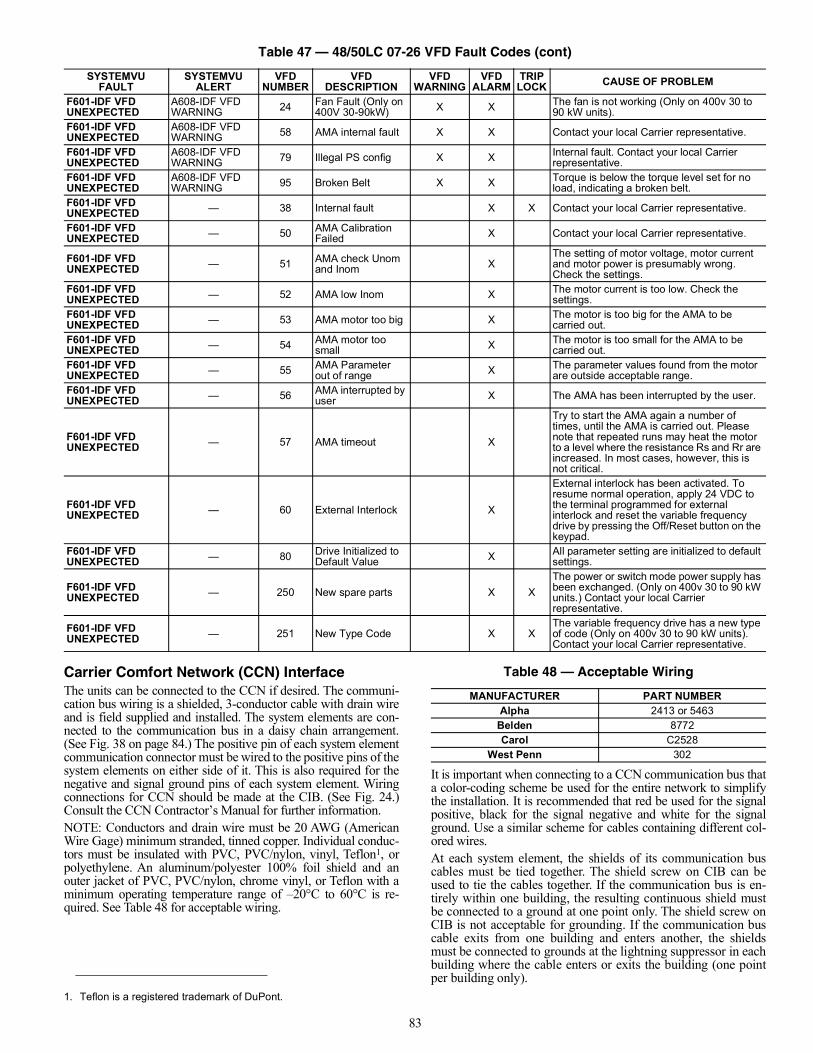
83
Carrier Comfort Network (CCN) InterfaceThe units can be connected to the CCN if desired. The communi-cation bus wiring is a shielded, 3-conductor cable with drain wireand is field supplied and installed. The system elements are con-nected to the communication bus in a daisy chain arrangement.(See Fig. 38 on page 84.) The positive pin of each system elementcommunication connector must be wired to the positive pins of thesystem elements on either side of it. This is also required for thenegative and signal ground pins of each system element. Wiringconnections for CCN should be made at the CIB. (See Fig. 24.)Consult the CCN Contractor’s Manual for further information.NOTE: Conductors and drain wire must be 20 AWG (AmericanWire Gage) minimum stranded, tinned copper. Individual conduc-tors must be insulated with PVC, PVC/nylon, vinyl, Teflon1, orpolyethylene. An aluminum/polyester 100% foil shield and anouter jacket of PVC, PVC/nylon, chrome vinyl, or Teflon with aminimum operating temperature range of –20°C to 60°C is re-quired. See Table 48 for acceptable wiring.
It is important when connecting to a CCN communication bus thata color-coding scheme be used for the entire network to simplifythe installation. It is recommended that red be used for the signalpositive, black for the signal negative and white for the signalground. Use a similar scheme for cables containing different col-ored wires.At each system element, the shields of its communication buscables must be tied together. The shield screw on CIB can beused to tie the cables together. If the communication bus is en-tirely within one building, the resulting continuous shield mustbe connected to a ground at one point only. The shield screw onCIB is not acceptable for grounding. If the communication buscable exits from one building and enters another, the shieldsmust be connected to grounds at the lightning suppressor in eachbuilding where the cable enters or exits the building (one pointper building only).
F601-IDF VFDUNEXPECTED
A608-IDF VFD WARNING 24 Fan Fault (Only on
400V 30-90kW) X X The fan is not working (Only on 400v 30 to 90 kW units).
F601-IDF VFDUNEXPECTED
A608-IDF VFD WARNING 58 AMA internal fault X X Contact your local Carrier representative.
F601-IDF VFDUNEXPECTED
A608-IDF VFD WARNING 79 Illegal PS config X X Internal fault. Contact your local Carrier
representative.F601-IDF VFDUNEXPECTED
A608-IDF VFD WARNING 95 Broken Belt X X Torque is below the torque level set for no
load, indicating a broken belt.F601-IDF VFDUNEXPECTED — 38 Internal fault X X Contact your local Carrier representative.
F601-IDF VFDUNEXPECTED — 50 AMA Calibration
Failed X Contact your local Carrier representative.
F601-IDF VFDUNEXPECTED — 51 AMA check Unom
and Inom XThe setting of motor voltage, motor current and motor power is presumably wrong. Check the settings.
F601-IDF VFDUNEXPECTED — 52 AMA low Inom X The motor current is too low. Check the
settings.F601-IDF VFDUNEXPECTED — 53 AMA motor too big X The motor is too big for the AMA to be
carried out.F601-IDF VFDUNEXPECTED — 54 AMA motor too
small X The motor is too small for the AMA to be carried out.
F601-IDF VFDUNEXPECTED — 55 AMA Parameter
out of range X The parameter values found from the motor are outside acceptable range.
F601-IDF VFDUNEXPECTED — 56 AMA interrupted by
user X The AMA has been interrupted by the user.
F601-IDF VFDUNEXPECTED — 57 AMA timeout X
Try to start the AMA again a number of times, until the AMA is carried out. Please note that repeated runs may heat the motor to a level where the resistance Rs and Rr are increased. In most cases, however, this is not critical.
F601-IDF VFDUNEXPECTED — 60 External Interlock X
External interlock has been activated. To resume normal operation, apply 24 VDC to the terminal programmed for external interlock and reset the variable frequency drive by pressing the Off/Reset button on the keypad.
F601-IDF VFDUNEXPECTED — 80 Drive Initialized to
Default Value X All parameter setting are initialized to default settings.
F601-IDF VFDUNEXPECTED — 250 New spare parts X X
The power or switch mode power supply has been exchanged. (Only on 400v 30 to 90 kW units.) Contact your local Carrier representative.
F601-IDF VFDUNEXPECTED — 251 New Type Code X X
The variable frequency drive has a new type of code (Only on 400v 30 to 90 kW units). Contact your local Carrier representative.
Table 47 — 48/50LC 07-26 VFD Fault Codes (cont)
SYSTEMVU FAULT
SYSTEMVU ALERT
VFD NUMBER
VFD DESCRIPTION
VFD WARNING
VFD ALARM
TRIP LOCK CAUSE OF PROBLEM
1. Teflon is a registered trademark of DuPont.
Table 48 — Acceptable Wiring
MANUFACTURER PART NUMBERAlpha 2413 or 5463Belden 8772Carol C2528
West Penn 302
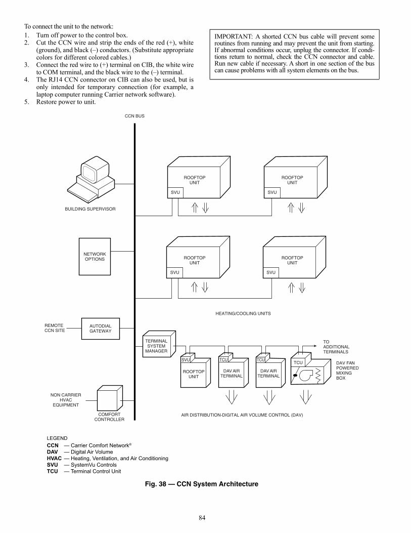
84
To connect the unit to the network:1. Turn off power to the control box.2. Cut the CCN wire and strip the ends of the red (+), white
(ground), and black (–) conductors. (Substitute appropriatecolors for different colored cables.)
3. Connect the red wire to (+) terminal on CIB, the white wireto COM terminal, and the black wire to the (–) terminal.
4. The RJ14 CCN connector on CIB can also be used, but isonly intended for temporary connection (for example, alaptop computer running Carrier network software).
5. Restore power to unit.
Fig. 38 — CCN System Architecture
IMPORTANT: A shorted CCN bus cable will prevent someroutines from running and may prevent the unit from starting.If abnormal conditions occur, unplug the connector. If condi-tions return to normal, check the CCN connector and cable.Run new cable if necessary. A short in one section of the buscan cause problems with all system elements on the bus.
CCN BUS
BUILDING SUPERVISOR
SVU SVU
ROOFTOPUNIT
ROOFTOPUNIT
ROOFTOPUNIT
ROOFTOPUNIT
NETWORKOPTIONS
REMOTECCN SITE
NON CARRIERHVAC
EQUIPMENT
AUTODIALGATEWAY
COMFORTCONTROLLER
HEATING/COOLING UNITS
LEGEND
TOADDITIONALTERMINALS
TERMINALSYSTEM
MANAGER
SVUTCU
TCU TCUDAV FANPOWEREDMIXINGBOX
DAV AIRTERMINAL
DAV AIRTERMINAL
ROOFTOPUNIT
AIR DISTRIBUTION-DIGITAL AIR VOLUME CONTROL (DAV)
CCNDAVHVACSVUTCU
— Carrier Comfort Network®
— Digital Air Volume— Heating, Ventilation, and Air Conditioning— SystemVu Controls— Terminal Control Unit
SVU SVU
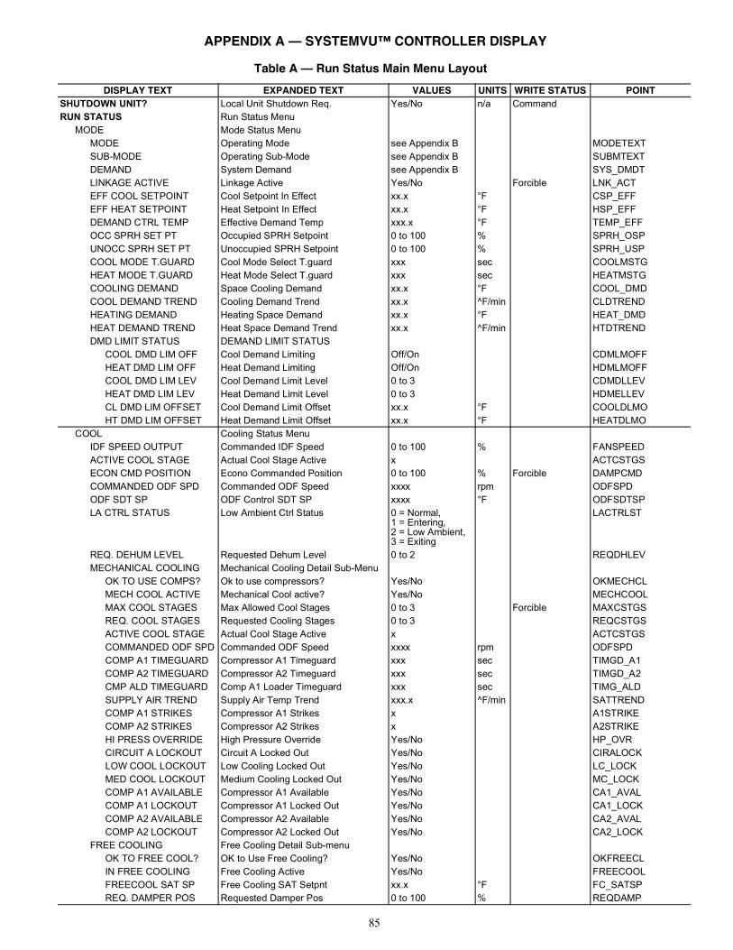
85
Table A — Run Status Main Menu Layout
DISPLAY TEXT EXPANDED TEXT VALUES UNITS WRITE STATUS POINTSHUTDOWN UNIT? Local Unit Shutdown Req. Yes/No n/a CommandRUN STATUS Run Status Menu
MODE Mode Status MenuMODE Operating Mode see Appendix B MODETEXTSUB-MODE Operating Sub-Mode see Appendix B SUBMTEXTDEMAND System Demand see Appendix B SYS_DMDTLINKAGE ACTIVE Linkage Active Yes/No Forcible LNK_ACTEFF COOL SETPOINT Cool Setpoint In Effect xx.x °F CSP_EFFEFF HEAT SETPOINT Heat Setpoint In Effect xx.x °F HSP_EFFDEMAND CTRL TEMP Effective Demand Temp xxx.x °F TEMP_EFFOCC SPRH SET PT Occupied SPRH Setpoint 0 to 100 % SPRH_OSPUNOCC SPRH SET PT Unoccupied SPRH Setpoint 0 to 100 % SPRH_USPCOOL MODE T.GUARD Cool Mode Select T.guard xxx sec COOLMSTGHEAT MODE T.GUARD Heat Mode Select T.guard xxx sec HEATMSTGCOOLING DEMAND Space Cooling Demand xx.x °F COOL_DMDCOOL DEMAND TREND Cooling Demand Trend xx.x ^F/min CLDTRENDHEATING DEMAND Heating Space Demand xx.x °F HEAT_DMDHEAT DEMAND TREND Heat Space Demand Trend xx.x ^F/min HTDTRENDDMD LIMIT STATUS DEMAND LIMIT STATUS
COOL DMD LIM OFF Cool Demand Limiting Off/On CDMLMOFFHEAT DMD LIM OFF Heat Demand Limiting Off/On HDMLMOFFCOOL DMD LIM LEV Cool Demand Limit Level 0 to 3 CDMDLLEVHEAT DMD LIM LEV Heat Demand Limit Level 0 to 3 HDMELLEVCL DMD LIM OFFSET Cool Demand Limit Offset xx.x °F COOLDLMOHT DMD LIM OFFSET Heat Demand Limit Offset xx.x °F HEATDLMO
COOL Cooling Status MenuIDF SPEED OUTPUT Commanded IDF Speed 0 to 100 % FANSPEEDACTIVE COOL STAGE Actual Cool Stage Active x ACTCSTGSECON CMD POSITION Econo Commanded Position 0 to 100 % Forcible DAMPCMDCOMMANDED ODF SPD Commanded ODF Speed xxxx rpm ODFSPDODF SDT SP ODF Control SDT SP xxxx °F ODFSDTSPLA CTRL STATUS Low Ambient Ctrl Status 0 = Normal,
1 = Entering,2 = Low Ambient,3 = Exiting
LACTRLST
REQ. DEHUM LEVEL Requested Dehum Level 0 to 2 REQDHLEVMECHANICAL COOLING Mechanical Cooling Detail Sub-Menu
OK TO USE COMPS? Ok to use compressors? Yes/No OKMECHCLMECH COOL ACTIVE Mechanical Cool active? Yes/No MECHCOOLMAX COOL STAGES Max Allowed Cool Stages 0 to 3 Forcible MAXCSTGSREQ. COOL STAGES Requested Cooling Stages 0 to 3 REQCSTGSACTIVE COOL STAGE Actual Cool Stage Active x ACTCSTGSCOMMANDED ODF SPD Commanded ODF Speed xxxx rpm ODFSPDCOMP A1 TIMEGUARD Compressor A1 Timeguard xxx sec TIMGD_A1COMP A2 TIMEGUARD Compressor A2 Timeguard xxx sec TIMGD_A2CMP ALD TIMEGUARD Comp A1 Loader Timeguard xxx sec TIMG_ALDSUPPLY AIR TREND Supply Air Temp Trend xxx.x ^F/min SATTRENDCOMP A1 STRIKES Compressor A1 Strikes x A1STRIKECOMP A2 STRIKES Compressor A2 Strikes x A2STRIKEHI PRESS OVERRIDE High Pressure Override Yes/No HP_OVRCIRCUIT A LOCKOUT Circuit A Locked Out Yes/No CIRALOCKLOW COOL LOCKOUT Low Cooling Locked Out Yes/No LC_LOCKMED COOL LOCKOUT Medium Cooling Locked Out Yes/No MC_LOCKCOMP A1 AVAILABLE Compressor A1 Available Yes/No CA1_AVALCOMP A1 LOCKOUT Compressor A1 Locked Out Yes/No CA1_LOCKCOMP A2 AVAILABLE Compressor A2 Available Yes/No CA2_AVALCOMP A2 LOCKOUT Compressor A2 Locked Out Yes/No CA2_LOCK
FREE COOLING Free Cooling Detail Sub-menuOK TO FREE COOL? OK to Use Free Cooling? Yes/No OKFREECLIN FREE COOLING Free Cooling Active Yes/No FREECOOLFREECOOL SAT SP Free Cooling SAT Setpnt xx.x °F FC_SATSPREQ. DAMPER POS Requested Damper Pos 0 to 100 % REQDAMP
APPENDIX A — SYSTEMVU™ CONTROLLER DISPLAY
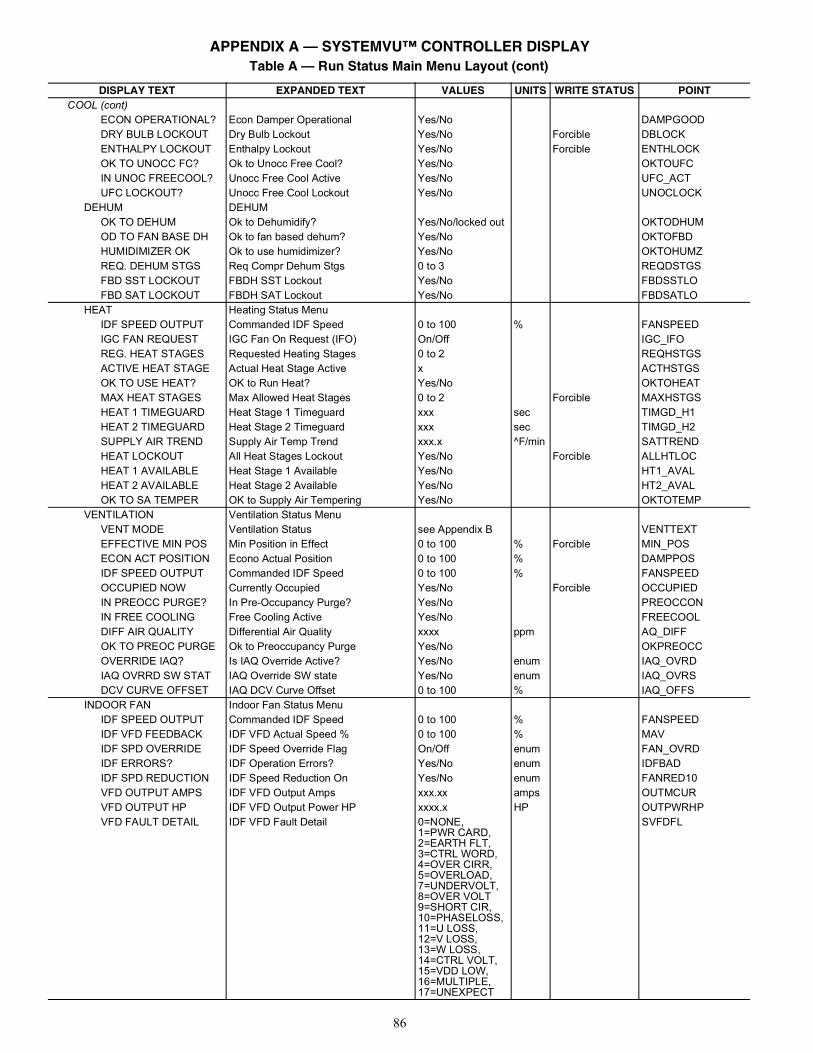
86
COOL (cont)ECON OPERATIONAL? Econ Damper Operational Yes/No DAMPGOODDRY BULB LOCKOUT Dry Bulb Lockout Yes/No Forcible DBLOCKENTHALPY LOCKOUT Enthalpy Lockout Yes/No Forcible ENTHLOCKOK TO UNOCC FC? Ok to Unocc Free Cool? Yes/No OKTOUFCIN UNOC FREECOOL? Unocc Free Cool Active Yes/No UFC_ACTUFC LOCKOUT? Unocc Free Cool Lockout Yes/No UNOCLOCK
DEHUM DEHUMOK TO DEHUM Ok to Dehumidify? Yes/No/locked out OKTODHUMOD TO FAN BASE DH Ok to fan based dehum? Yes/No OKTOFBDHUMIDIMIZER OK Ok to use humidimizer? Yes/No OKTOHUMZREQ. DEHUM STGS Req Compr Dehum Stgs 0 to 3 REQDSTGSFBD SST LOCKOUT FBDH SST Lockout Yes/No FBDSSTLOFBD SAT LOCKOUT FBDH SAT Lockout Yes/No FBDSATLO
HEAT Heating Status MenuIDF SPEED OUTPUT Commanded IDF Speed 0 to 100 % FANSPEEDIGC FAN REQUEST IGC Fan On Request (IFO) On/Off IGC_IFOREG. HEAT STAGES Requested Heating Stages 0 to 2 REQHSTGSACTIVE HEAT STAGE Actual Heat Stage Active x ACTHSTGSOK TO USE HEAT? OK to Run Heat? Yes/No OKTOHEATMAX HEAT STAGES Max Allowed Heat Stages 0 to 2 Forcible MAXHSTGSHEAT 1 TIMEGUARD Heat Stage 1 Timeguard xxx sec TIMGD_H1HEAT 2 TIMEGUARD Heat Stage 2 Timeguard xxx sec TIMGD_H2SUPPLY AIR TREND Supply Air Temp Trend xxx.x ^F/min SATTRENDHEAT LOCKOUT All Heat Stages Lockout Yes/No Forcible ALLHTLOCHEAT 1 AVAILABLE Heat Stage 1 Available Yes/No HT1_AVALHEAT 2 AVAILABLE Heat Stage 2 Available Yes/No HT2_AVALOK TO SA TEMPER OK to Supply Air Tempering Yes/No OKTOTEMP
VENTILATION Ventilation Status MenuVENT MODE Ventilation Status see Appendix B VENTTEXTEFFECTIVE MIN POS Min Position in Effect 0 to 100 % Forcible MIN_POSECON ACT POSITION Econo Actual Position 0 to 100 % DAMPPOSIDF SPEED OUTPUT Commanded IDF Speed 0 to 100 % FANSPEEDOCCUPIED NOW Currently Occupied Yes/No Forcible OCCUPIEDIN PREOCC PURGE? In Pre-Occupancy Purge? Yes/No PREOCCONIN FREE COOLING Free Cooling Active Yes/No FREECOOLDIFF AIR QUALITY Differential Air Quality xxxx ppm AQ_DIFFOK TO PREOC PURGE Ok to Preoccupancy Purge Yes/No OKPREOCCOVERRIDE IAQ? Is IAQ Override Active? Yes/No enum IAQ_OVRDIAQ OVRRD SW STAT IAQ Override SW state Yes/No enum IAQ_OVRSDCV CURVE OFFSET IAQ DCV Curve Offset 0 to 100 % IAQ_OFFS
INDOOR FAN Indoor Fan Status MenuIDF SPEED OUTPUT Commanded IDF Speed 0 to 100 % FANSPEEDIDF VFD FEEDBACK IDF VFD Actual Speed % 0 to 100 % MAVIDF SPD OVERRIDE IDF Speed Override Flag On/Off enum FAN_OVRDIDF ERRORS? IDF Operation Errors? Yes/No enum IDFBADIDF SPD REDUCTION IDF Speed Reduction On Yes/No enum FANRED10VFD OUTPUT AMPS IDF VFD Output Amps xxx.xx amps OUTMCURVFD OUTPUT HP IDF VFD Output Power HP xxxx.x HP OUTPWRHPVFD FAULT DETAIL IDF VFD Fault Detail 0=NONE,
1=PWR CARD,2=EARTH FLT,3=CTRL WORD,4=OVER CIRR,5=OVERLOAD,7=UNDERVOLT,8=OVER VOLT9=SHORT CIR,10=PHASELOSS,11=U LOSS,12=V LOSS,13=W LOSS,14=CTRL VOLT,15=VDD LOW,16=MULTIPLE,17=UNEXPECT
SVFDFL
Table A — Run Status Main Menu Layout (cont)
DISPLAY TEXT EXPANDED TEXT VALUES UNITS WRITE STATUS POINT
APPENDIX A — SYSTEMVU™ CONTROLLER DISPLAY
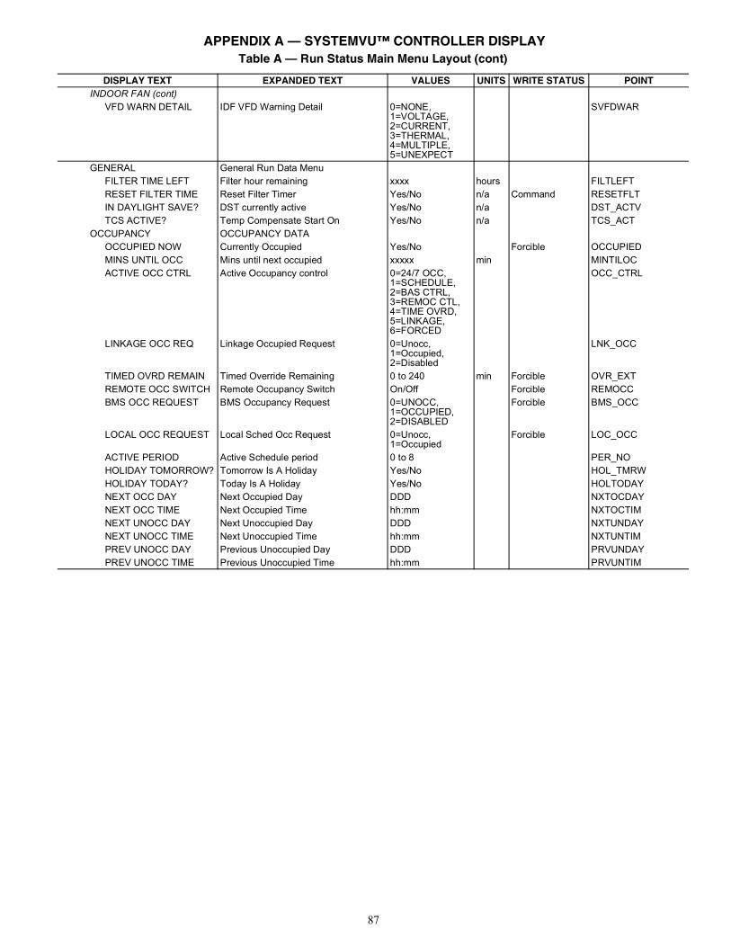
87
INDOOR FAN (cont)VFD WARN DETAIL IDF VFD Warning Detail 0=NONE,
1=VOLTAGE,2=CURRENT,3=THERMAL,4=MULTIPLE,5=UNEXPECT
SVFDWAR
GENERAL General Run Data MenuFILTER TIME LEFT Filter hour remaining xxxx hours FILTLEFTRESET FILTER TIME Reset Filter Timer Yes/No n/a Command RESETFLTIN DAYLIGHT SAVE? DST currently active Yes/No n/a DST_ACTVTCS ACTIVE? Temp Compensate Start On Yes/No n/a TCS_ACT
OCCUPANCY OCCUPANCY DATAOCCUPIED NOW Currently Occupied Yes/No Forcible OCCUPIEDMINS UNTIL OCC Mins until next occupied xxxxx min MINTILOCACTIVE OCC CTRL Active Occupancy control 0=24/7 OCC,
1=SCHEDULE,2=BAS CTRL,3=REMOC CTL,4=TIME OVRD,5=LINKAGE,6=FORCED
OCC_CTRL
LINKAGE OCC REQ Linkage Occupied Request 0=Unocc,1=Occupied,2=Disabled
LNK_OCC
TIMED OVRD REMAIN Timed Override Remaining 0 to 240 min Forcible OVR_EXTREMOTE OCC SWITCH Remote Occupancy Switch On/Off Forcible REMOCCBMS OCC REQUEST BMS Occupancy Request 0=UNOCC,
1=OCCUPIED,2=DISABLED
Forcible BMS_OCC
LOCAL OCC REQUEST Local Sched Occ Request 0=Unocc,1=Occupied
Forcible LOC_OCC
ACTIVE PERIOD Active Schedule period 0 to 8 PER_NOHOLIDAY TOMORROW? Tomorrow Is A Holiday Yes/No HOL_TMRWHOLIDAY TODAY? Today Is A Holiday Yes/No HOLTODAYNEXT OCC DAY Next Occupied Day DDD NXTOCDAYNEXT OCC TIME Next Occupied Time hh:mm NXTOCTIMNEXT UNOCC DAY Next Unoccupied Day DDD NXTUNDAYNEXT UNOCC TIME Next Unoccupied Time hh:mm NXTUNTIMPREV UNOCC DAY Previous Unoccupied Day DDD PRVUNDAYPREV UNOCC TIME Previous Unoccupied Time hh:mm PRVUNTIM
Table A — Run Status Main Menu Layout (cont)
DISPLAY TEXT EXPANDED TEXT VALUES UNITS WRITE STATUS POINT
APPENDIX A — SYSTEMVU™ CONTROLLER DISPLAY
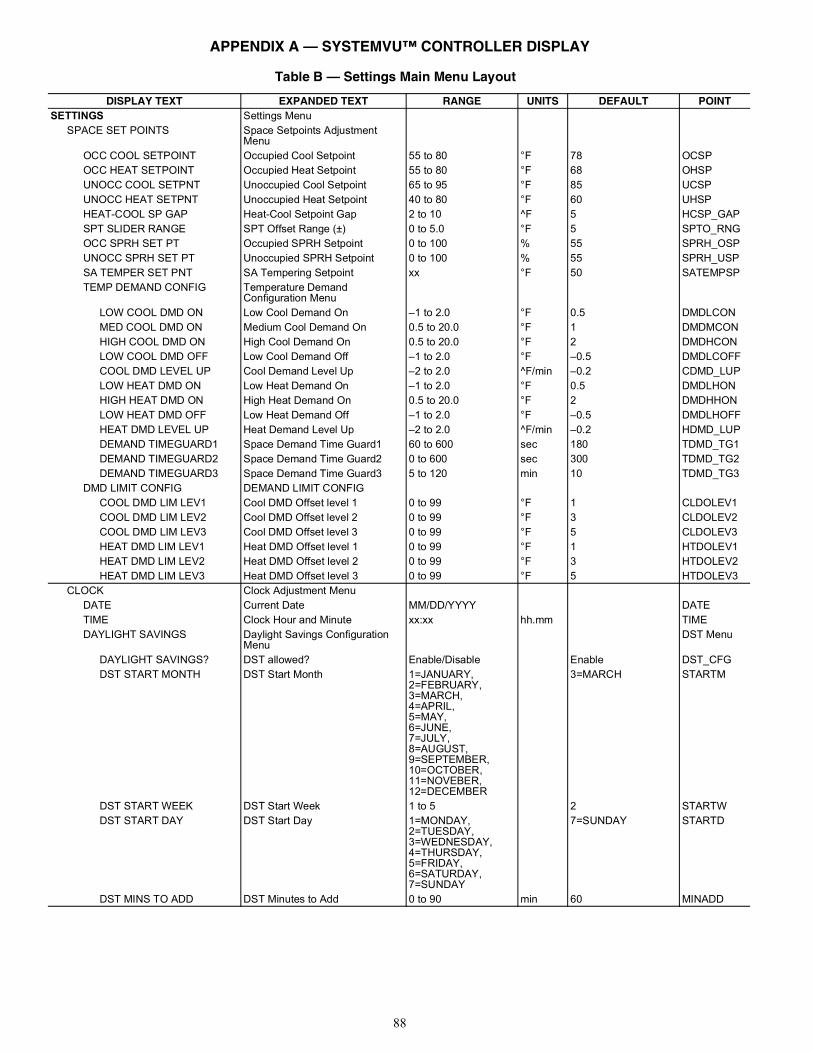
88
Table B — Settings Main Menu Layout
DISPLAY TEXT EXPANDED TEXT RANGE UNITS DEFAULT POINTSETTINGS Settings Menu
SPACE SET POINTS Space Setpoints Adjustment Menu
OCC COOL SETPOINT Occupied Cool Setpoint 55 to 80 °F 78 OCSPOCC HEAT SETPOINT Occupied Heat Setpoint 55 to 80 °F 68 OHSPUNOCC COOL SETPNT Unoccupied Cool Setpoint 65 to 95 °F 85 UCSPUNOCC HEAT SETPNT Unoccupied Heat Setpoint 40 to 80 °F 60 UHSPHEAT-COOL SP GAP Heat-Cool Setpoint Gap 2 to 10 ^F 5 HCSP_GAPSPT SLIDER RANGE SPT Offset Range (±) 0 to 5.0 °F 5 SPTO_RNGOCC SPRH SET PT Occupied SPRH Setpoint 0 to 100 % 55 SPRH_OSPUNOCC SPRH SET PT Unoccupied SPRH Setpoint 0 to 100 % 55 SPRH_USPSA TEMPER SET PNT SA Tempering Setpoint xx °F 50 SATEMPSPTEMP DEMAND CONFIG Temperature Demand
Configuration MenuLOW COOL DMD ON Low Cool Demand On –1 to 2.0 °F 0.5 DMDLCONMED COOL DMD ON Medium Cool Demand On 0.5 to 20.0 °F 1 DMDMCONHIGH COOL DMD ON High Cool Demand On 0.5 to 20.0 °F 2 DMDHCONLOW COOL DMD OFF Low Cool Demand Off –1 to 2.0 °F –0.5 DMDLCOFFCOOL DMD LEVEL UP Cool Demand Level Up –2 to 2.0 ^F/min –0.2 CDMD_LUPLOW HEAT DMD ON Low Heat Demand On –1 to 2.0 °F 0.5 DMDLHONHIGH HEAT DMD ON High Heat Demand On 0.5 to 20.0 °F 2 DMDHHONLOW HEAT DMD OFF Low Heat Demand Off –1 to 2.0 °F –0.5 DMDLHOFFHEAT DMD LEVEL UP Heat Demand Level Up –2 to 2.0 ^F/min –0.2 HDMD_LUPDEMAND TIMEGUARD1 Space Demand Time Guard1 60 to 600 sec 180 TDMD_TG1DEMAND TIMEGUARD2 Space Demand Time Guard2 0 to 600 sec 300 TDMD_TG2DEMAND TIMEGUARD3 Space Demand Time Guard3 5 to 120 min 10 TDMD_TG3
DMD LIMIT CONFIG DEMAND LIMIT CONFIGCOOL DMD LIM LEV1 Cool DMD Offset level 1 0 to 99 °F 1 CLDOLEV1COOL DMD LIM LEV2 Cool DMD Offset level 2 0 to 99 °F 3 CLDOLEV2COOL DMD LIM LEV3 Cool DMD Offset level 3 0 to 99 °F 5 CLDOLEV3HEAT DMD LIM LEV1 Heat DMD Offset level 1 0 to 99 °F 1 HTDOLEV1HEAT DMD LIM LEV2 Heat DMD Offset level 2 0 to 99 °F 3 HTDOLEV2HEAT DMD LIM LEV3 Heat DMD Offset level 3 0 to 99 °F 5 HTDOLEV3
CLOCK Clock Adjustment MenuDATE Current Date MM/DD/YYYY DATETIME Clock Hour and Minute xx:xx hh.mm TIMEDAYLIGHT SAVINGS Daylight Savings Configuration
MenuDST Menu
DAYLIGHT SAVINGS? DST allowed? Enable/Disable Enable DST_CFGDST START MONTH DST Start Month 1=JANUARY,
2=FEBRUARY,3=MARCH,4=APRIL,5=MAY,6=JUNE,7=JULY,8=AUGUST,9=SEPTEMBER,10=OCTOBER,11=NOVEBER,12=DECEMBER
3=MARCH STARTM
DST START WEEK DST Start Week 1 to 5 2 STARTWDST START DAY DST Start Day 1=MONDAY,
2=TUESDAY,3=WEDNESDAY,4=THURSDAY,5=FRIDAY,6=SATURDAY,7=SUNDAY
7=SUNDAY STARTD
DST MINS TO ADD DST Minutes to Add 0 to 90 min 60 MINADD
APPENDIX A — SYSTEMVU™ CONTROLLER DISPLAY
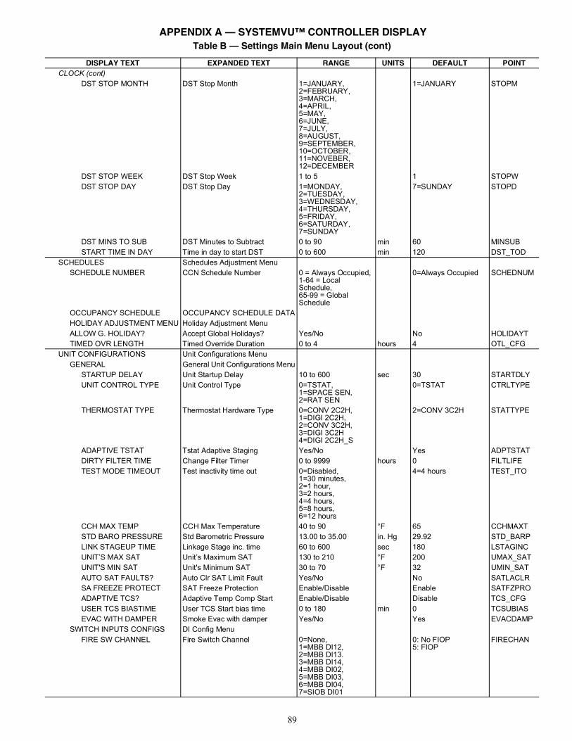
89
CLOCK (cont)DST STOP MONTH DST Stop Month 1=JANUARY,
2=FEBRUARY,3=MARCH,4=APRIL,5=MAY,6=JUNE,7=JULY,8=AUGUST,9=SEPTEMBER,10=OCTOBER,11=NOVEBER,12=DECEMBER
1=JANUARY STOPM
DST STOP WEEK DST Stop Week 1 to 5 1 STOPWDST STOP DAY DST Stop Day 1=MONDAY,
2=TUESDAY,3=WEDNESDAY,4=THURSDAY,5=FRIDAY,6=SATURDAY,7=SUNDAY
7=SUNDAY STOPD
DST MINS TO SUB DST Minutes to Subtract 0 to 90 min 60 MINSUBSTART TIME IN DAY Time in day to start DST 0 to 600 min 120 DST_TOD
SCHEDULES Schedules Adjustment MenuSCHEDULE NUMBER CCN Schedule Number 0 = Always Occupied,
1-64 = Local Schedule,65-99 = Global Schedule
0=Always Occupied SCHEDNUM
OCCUPANCY SCHEDULE OCCUPANCY SCHEDULE DATAHOLIDAY ADJUSTMENT MENU Holiday Adjustment MenuALLOW G. HOLIDAY? Accept Global Holidays? Yes/No No HOLIDAYTTIMED OVR LENGTH Timed Override Duration 0 to 4 hours 4 OTL_CFG
UNIT CONFIGURATIONS Unit Configurations MenuGENERAL General Unit Configurations Menu
STARTUP DELAY Unit Startup Delay 10 to 600 sec 30 STARTDLYUNIT CONTROL TYPE Unit Control Type 0=TSTAT,
1=SPACE SEN,2=RAT SEN
0=TSTAT CTRLTYPE
THERMOSTAT TYPE Thermostat Hardware Type 0=CONV 2C2H,1=DIGI 2C2H,2=CONV 3C2H,3=DIGI 3C2H4=DIGI 2C2H_S
2=CONV 3C2H STATTYPE
ADAPTIVE TSTAT Tstat Adaptive Staging Yes/No Yes ADPTSTATDIRTY FILTER TIME Change Filter Timer 0 to 9999 hours 0 FILTLIFETEST MODE TIMEOUT Test inactivity time out 0=Disabled,
1=30 minutes,2=1 hour,3=2 hours,4=4 hours,5=8 hours,6=12 hours
4=4 hours TEST_ITO
CCH MAX TEMP CCH Max Temperature 40 to 90 °F 65 CCHMAXTSTD BARO PRESSURE Std Barometric Pressure 13.00 to 35.00 in. Hg 29.92 STD_BARPLINK STAGEUP TIME Linkage Stage inc. time 60 to 600 sec 180 LSTAGINCUNIT’S MAX SAT Unit’s Maximum SAT 130 to 210 °F 200 UMAX_SATUNIT'S MIN SAT Unit's Minimum SAT 30 to 70 °F 32 UMIN_SATAUTO SAT FAULTS? Auto Clr SAT Limit Fault Yes/No No SATLACLRSA FREEZE PROTECT SAT Freeze Protection Enable/Disable Enable SATFZPROADAPTIVE TCS? Adaptive Temp Comp Start Enable/Disable Disable TCS_CFGUSER TCS BIASTIME User TCS Start bias time 0 to 180 min 0 TCSUBIASEVAC WITH DAMPER Smoke Evac with damper Yes/No Yes EVACDAMP
SWITCH INPUTS CONFIGS DI Config MenuFIRE SW CHANNEL Fire Switch Channel 0=None,
1=MBB DI12,2=MBB DI13.3=MBB DI14,4=MBB DI02,5=MBB DI03,6=MBB DI04,7=SIOB DI01
0: No FIOP5: FIOP
FIRECHAN
Table B — Settings Main Menu Layout (cont)
DISPLAY TEXT EXPANDED TEXT RANGE UNITS DEFAULT POINT
APPENDIX A — SYSTEMVU™ CONTROLLER DISPLAY
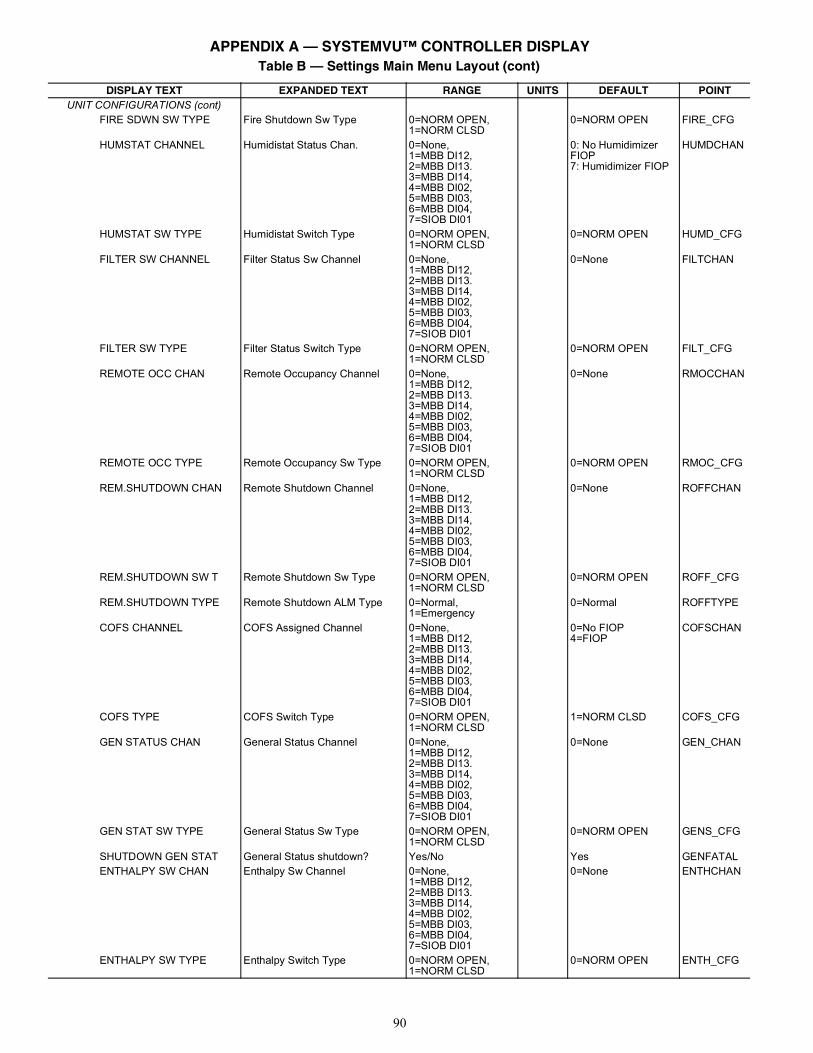
90
UNIT CONFIGURATIONS (cont)FIRE SDWN SW TYPE Fire Shutdown Sw Type 0=NORM OPEN,
1=NORM CLSD0=NORM OPEN FIRE_CFG
HUMSTAT CHANNEL Humidistat Status Chan. 0=None,1=MBB DI12,2=MBB DI13.3=MBB DI14,4=MBB DI02,5=MBB DI03,6=MBB DI04,7=SIOB DI01
0: No Humidimizer FIOP7: Humidimizer FIOP
HUMDCHAN
HUMSTAT SW TYPE Humidistat Switch Type 0=NORM OPEN,1=NORM CLSD
0=NORM OPEN HUMD_CFG
FILTER SW CHANNEL Filter Status Sw Channel 0=None,1=MBB DI12,2=MBB DI13.3=MBB DI14,4=MBB DI02,5=MBB DI03,6=MBB DI04,7=SIOB DI01
0=None FILTCHAN
FILTER SW TYPE Filter Status Switch Type 0=NORM OPEN,1=NORM CLSD
0=NORM OPEN FILT_CFG
REMOTE OCC CHAN Remote Occupancy Channel 0=None,1=MBB DI12,2=MBB DI13.3=MBB DI14,4=MBB DI02,5=MBB DI03,6=MBB DI04,7=SIOB DI01
0=None RMOCCHAN
REMOTE OCC TYPE Remote Occupancy Sw Type 0=NORM OPEN,1=NORM CLSD
0=NORM OPEN RMOC_CFG
REM.SHUTDOWN CHAN Remote Shutdown Channel 0=None,1=MBB DI12,2=MBB DI13.3=MBB DI14,4=MBB DI02,5=MBB DI03,6=MBB DI04,7=SIOB DI01
0=None ROFFCHAN
REM.SHUTDOWN SW T Remote Shutdown Sw Type 0=NORM OPEN,1=NORM CLSD
0=NORM OPEN ROFF_CFG
REM.SHUTDOWN TYPE Remote Shutdown ALM Type 0=Normal,1=Emergency
0=Normal ROFFTYPE
COFS CHANNEL COFS Assigned Channel 0=None,1=MBB DI12,2=MBB DI13.3=MBB DI14,4=MBB DI02,5=MBB DI03,6=MBB DI04,7=SIOB DI01
0=No FIOP4=FIOP
COFSCHAN
COFS TYPE COFS Switch Type 0=NORM OPEN,1=NORM CLSD
1=NORM CLSD COFS_CFG
GEN STATUS CHAN General Status Channel 0=None,1=MBB DI12,2=MBB DI13.3=MBB DI14,4=MBB DI02,5=MBB DI03,6=MBB DI04,7=SIOB DI01
0=None GEN_CHAN
GEN STAT SW TYPE General Status Sw Type 0=NORM OPEN,1=NORM CLSD
0=NORM OPEN GENS_CFG
SHUTDOWN GEN STAT General Status shutdown? Yes/No Yes GENFATALENTHALPY SW CHAN Enthalpy Sw Channel 0=None,
1=MBB DI12,2=MBB DI13.3=MBB DI14,4=MBB DI02,5=MBB DI03,6=MBB DI04,7=SIOB DI01
0=None ENTHCHAN
ENTHALPY SW TYPE Enthalpy Switch Type 0=NORM OPEN,1=NORM CLSD
0=NORM OPEN ENTH_CFG
Table B — Settings Main Menu Layout (cont)
DISPLAY TEXT EXPANDED TEXT RANGE UNITS DEFAULT POINT
APPENDIX A — SYSTEMVU™ CONTROLLER DISPLAY
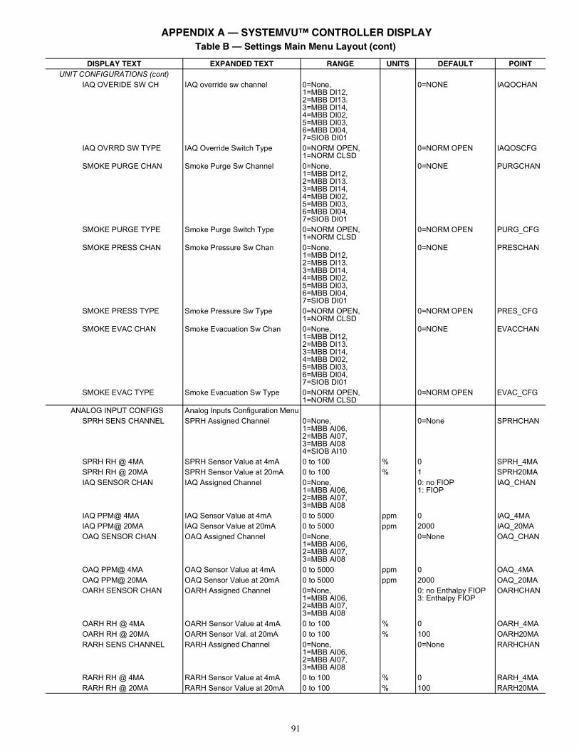
91
UNIT CONFIGURATIONS (cont)IAQ OVERIDE SW CH IAQ override sw channel 0=None,
1=MBB DI12,2=MBB DI13.3=MBB DI14,4=MBB DI02,5=MBB DI03,6=MBB DI04,7=SIOB DI01
0=NONE IAQOCHAN
IAQ OVRRD SW TYPE IAQ Override Switch Type 0=NORM OPEN,1=NORM CLSD
0=NORM OPEN IAQOSCFG
SMOKE PURGE CHAN Smoke Purge Sw Channel 0=None,1=MBB DI12,2=MBB DI13.3=MBB DI14,4=MBB DI02,5=MBB DI03,6=MBB DI04,7=SIOB DI01
0=NONE PURGCHAN
SMOKE PURGE TYPE Smoke Purge Switch Type 0=NORM OPEN,1=NORM CLSD
0=NORM OPEN PURG_CFG
SMOKE PRESS CHAN Smoke Pressure Sw Chan 0=None,1=MBB DI12,2=MBB DI13.3=MBB DI14,4=MBB DI02,5=MBB DI03,6=MBB DI04,7=SIOB DI01
0=NONE PRESCHAN
SMOKE PRESS TYPE Smoke Pressure Sw Type 0=NORM OPEN,1=NORM CLSD
0=NORM OPEN PRES_CFG
SMOKE EVAC CHAN Smoke Evacuation Sw Chan 0=None,1=MBB DI12,2=MBB DI13.3=MBB DI14,4=MBB DI02,5=MBB DI03,6=MBB DI04,7=SIOB DI01
0=NONE EVACCHAN
SMOKE EVAC TYPE Smoke Evacuation Sw Type 0=NORM OPEN,1=NORM CLSD
0=NORM OPEN EVAC_CFG
ANALOG INPUT CONFIGS Analog Inputs Configuration MenuSPRH SENS CHANNEL SPRH Assigned Channel 0=None,
1=MBB AI06,2=MBB AI07,3=MBB AI084=SIOB AI10
0=None SPRHCHAN
SPRH RH @ 4MA SPRH Sensor Value at 4mA 0 to 100 % 0 SPRH_4MASPRH RH @ 20MA SPRH Sensor Value at 20mA 0 to 100 % 1 SPRH20MAIAQ SENSOR CHAN IAQ Assigned Channel 0=None,
1=MBB AI06,2=MBB AI07,3=MBB AI08
0: no FIOP1: FIOP
IAQ_CHAN
IAQ PPM@ 4MA IAQ Sensor Value at 4mA 0 to 5000 ppm 0 IAQ_4MAIAQ PPM@ 20MA IAQ Sensor Value at 20mA 0 to 5000 ppm 2000 IAQ_20MAOAQ SENSOR CHAN OAQ Assigned Channel 0=None,
1=MBB AI06,2=MBB AI07,3=MBB AI08
0=None OAQ_CHAN
OAQ PPM@ 4MA OAQ Sensor Value at 4mA 0 to 5000 ppm 0 OAQ_4MAOAQ PPM@ 20MA OAQ Sensor Value at 20mA 0 to 5000 ppm 2000 OAQ_20MAOARH SENSOR CHAN OARH Assigned Channel 0=None,
1=MBB AI06,2=MBB AI07,3=MBB AI08
0: no Enthalpy FIOP3: Enthalpy FIOP
OARHCHAN
OARH RH @ 4MA OARH Sensor Value at 4mA 0 to 100 % 0 OARH_4MAOARH RH @ 20MA OARH Sensor Val. at 20mA 0 to 100 % 100 OARH20MARARH SENS CHANNEL RARH Assigned Channel 0=None,
1=MBB AI06,2=MBB AI07,3=MBB AI08
0=None RARHCHAN
RARH RH @ 4MA RARH Sensor Value at 4mA 0 to 100 % 0 RARH_4MARARH RH @ 20MA RARH Sensor Value at 20mA 0 to 100 % 100 RARH20MA
Table B — Settings Main Menu Layout (cont)
DISPLAY TEXT EXPANDED TEXT RANGE UNITS DEFAULT POINT
APPENDIX A — SYSTEMVU™ CONTROLLER DISPLAY
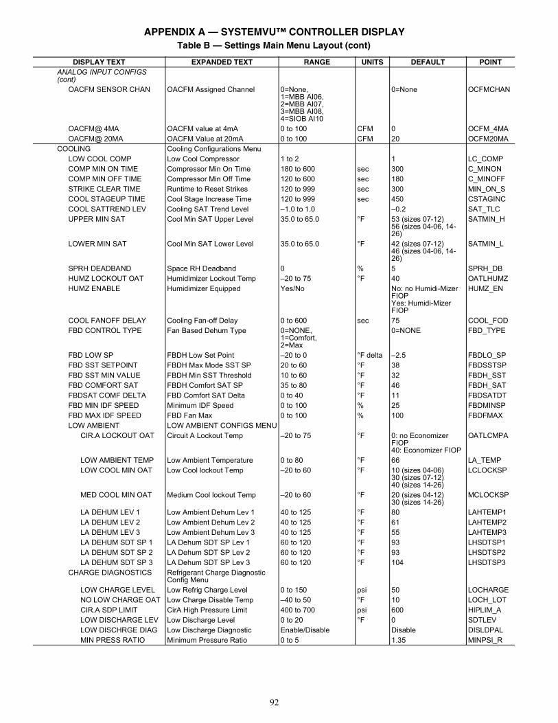
92
ANALOG INPUT CONFIGS (cont)
OACFM SENSOR CHAN OACFM Assigned Channel 0=None,1=MBB AI06,2=MBB AI07,3=MBB AI08,4=SIOB AI10
0=None OCFMCHAN
OACFM@ 4MA OACFM value at 4mA 0 to 100 CFM 0 OCFM_4MAOACFM@ 20MA OACFM Value at 20mA 0 to 100 CFM 20 OCFM20MA
COOLING Cooling Configurations MenuLOW COOL COMP Low Cool Compressor 1 to 2 1 LC_COMPCOMP MIN ON TIME Compressor Min On Time 180 to 600 sec 300 C_MINONCOMP MIN OFF TIME Compressor Min Off Time 120 to 600 sec 180 C_MINOFFSTRIKE CLEAR TIME Runtime to Reset Strikes 120 to 999 sec 300 MIN_ON_SCOOL STAGEUP TIME Cool Stage Increase Time 120 to 999 sec 450 CSTAGINCCOOL SATTREND LEV Cooling SAT Trend Level –1.0 to 1.0 –0.2 SAT_TLCUPPER MIN SAT Cool Min SAT Upper Level 35.0 to 65.0 °F 53 (sizes 07-12)
56 (sizes 04-06, 14-26)
SATMIN_H
LOWER MIN SAT Cool Min SAT Lower Level 35.0 to 65.0 °F 42 (sizes 07-12)46 (sizes 04-06, 14-26)
SATMIN_L
SPRH DEADBAND Space RH Deadband 0 % 5 SPRH_DBHUMZ LOCKOUT OAT Humidimizer Lockout Temp –20 to 75 °F 40 OATLHUMZHUMZ ENABLE Humidimizer Equipped Yes/No No: no Humidi-Mizer
FIOPYes: Humidi-Mizer FIOP
HUMZ_EN
COOL FANOFF DELAY Cooling Fan-off Delay 0 to 600 sec 75 COOL_FODFBD CONTROL TYPE Fan Based Dehum Type 0=NONE,
1=Comfort,2=Max
0=NONE FBD_TYPE
FBD LOW SP FBDH Low Set Point –20 to 0 °F delta –2.5 FBDLO_SPFBD SST SETPOINT FBDH Max Mode SST SP 20 to 60 °F 38 FBDSSTSPFBD SST MIN VALUE FBDH Min SST Threshold 10 to 60 °F 32 FBDH_SSTFBD COMFORT SAT FBDH Comfort SAT SP 35 to 80 °F 46 FBDH_SATFBDSAT COMF DELTA FBD Comfort SAT Delta 0 to 40 °F 11 FBDSATDTFBD MIN IDF SPEED Minimum IDF Speed 0 to 100 % 25 FBDMINSPFBD MAX IDF SPEED FBD Fan Max 0 to 100 % 100 FBDFMAXLOW AMBIENT LOW AMBIENT CONFIGS MENU
CIR.A LOCKOUT OAT Circuit A Lockout Temp –20 to 75 °F 0: no Economizer FIOP40: Economizer FIOP
OATLCMPA
LOW AMBIENT TEMP Low Ambient Temperature 0 to 80 °F 66 LA_TEMPLOW COOL MIN OAT Low Cool lockout Temp –20 to 60 °F 10 (sizes 04-06)
30 (sizes 07-12)40 (sizes 14-26)
LCLOCKSP
MED COOL MIN OAT Medium Cool lockout Temp –20 to 60 °F 20 (sizes 04-12)30 (sizes 14-26)
MCLOCKSP
LA DEHUM LEV 1 Low Ambient Dehum Lev 1 40 to 125 °F 80 LAHTEMP1LA DEHUM LEV 2 Low Ambient Dehum Lev 2 40 to 125 °F 61 LAHTEMP2LA DEHUM LEV 3 Low Ambient Dehum Lev 3 40 to 125 °F 55 LAHTEMP3LA DEHUM SDT SP 1 LA Dehum SDT SP Lev 1 60 to 120 °F 93 LHSDTSP1LA DEHUM SDT SP 2 LA Dehum SDT SP Lev 2 60 to 120 °F 93 LHSDTSP2LA DEHUM SDT SP 3 LA Dehum SDT SP Lev 3 60 to 120 °F 104 LHSDTSP3
CHARGE DIAGNOSTICS Refrigerant Charge Diagnostic Config Menu
LOW CHARGE LEVEL Low Refrig Charge Level 0 to 150 psi 50 LOCHARGENO LOW CHARGE OAT Low Charge Disable Temp –40 to 50 °F 10 LOCH_LOTCIR.A SDP LIMIT CirA High Pressure Limit 400 to 700 psi 600 HIPLIM_ALOW DISCHARGE LEV Low Discharge Level 0 to 20 °F 0 SDTLEVLOW DISCHRGE DIAG Low Discharge Diagnostic Enable/Disable Disable DISLDPALMIN PRESS RATIO Minimum Pressure Ratio 0 to 5 1.35 MINPSI_R
Table B — Settings Main Menu Layout (cont)
DISPLAY TEXT EXPANDED TEXT RANGE UNITS DEFAULT POINT
APPENDIX A — SYSTEMVU™ CONTROLLER DISPLAY
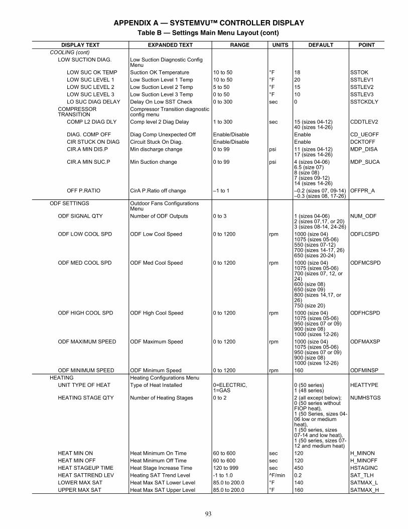
93
COOLING (cont)LOW SUCTION DIAG. Low Suction Diagnostic Config
MenuLOW SUC OK TEMP Suction OK Temperature 10 to 50 °F 18 SSTOKLOW SUC LEVEL 1 Low Suction Level 1 Temp 10 to 50 °F 20 SSTLEV1LOW SUC LEVEL 2 Low Suction Level 2 Temp 5 to 50 °F 15 SSTLEV2LOW SUC LEVEL 3 Low Suction Level 3 Temp 0 to 50 °F 10 SSTLEV3LO SUC DIAG DELAY Delay On Low SST Check 0 to 300 sec 0 SSTCKDLY
COMPRESSOR TRANSITION
Compressor Transition diagnostic config menu
COMP L2 DIAG DLY Comp level 2 Diag Delay 1 to 300 sec 15 (sizes 04-12)40 (sizes 14-26)
CDDTLEV2
DIAG. COMP OFF Diag Comp Unexpected Off Enable/Disable Enable CD_UEOFFCIR STUCK ON DIAG Circuit Stuck On Diag. Enable/Disable Enable DCKTOFFCIR.A MIN DIS.P Min discharge change 0 to 99 psi 11 (sizes 04-12)
17 (sizes 14-26)MDP_DISA
CIR.A MIN SUC.P Min Suction change 0 to 99 psi 4 (sizes 04-06)6.5 (size 07)8 (size 08)7 (sizes 09-12)14 (sizes 14-26)
MDP_SUCA
OFF P.RATIO CirA P.Ratio off change –1 to 1 –0.2 (sizes 07, 09-14)–0.3 (sizes 08, 17-26)
OFFPR_A
ODF SETTINGS Outdoor Fans Configurations Menu
ODF SIGNAL QTY Number of ODF Outputs 0 to 3 1 (sizes 04-06)2 (sizes 07,17, or 20)3 (sizes 08-14, 24-26)
NUM_ODF
ODF LOW COOL SPD ODF Low Cool Speed 0 to 1200 rpm 1000 (size 04)1075 (sizes 05-06)550 (sizes 07-12)700 (sizes 14-17, 26)650 (sizes 20-24)
ODFLCSPD
ODF MED COOL SPD ODF Med Cool Speed 0 to 1200 rpm 1000 (size 04)1075 (sizes 05-06)700 (sizes 07, 12, or 24)600 (size 08)650 (size 09)800 (sizes 14,17, or 26)750 (size 20)
ODFMCSPD
ODF HIGH COOL SPD ODF High Cool Speed 0 to 1200 rpm 1000 (size 04)1075 (sizes 05-06)950 (sizes 07 or 09)900 (size 08)1000 (sizes 12-26)
ODFHCSPD
ODF MAXIMUM SPEED ODF Maximum Speed 0 to 1200 rpm 1000 (size 04)1075 (sizes 05-06)950 (sizes 07 or 09)900 (size 08)1000 (sizes 12-26)
ODFMAXSP
ODF MINIMUM SPEED ODF Minimum Speed 0 to 1200 rpm 160 ODFMINSPHEATING Heating Configurations Menu
UNIT TYPE OF HEAT Type of Heat Installed 0=ELECTRIC,1=GAS
0 (50 series)1 (48 series)
HEATTYPE
HEATING STAGE QTY Number of Heating Stages 0 to 2 2 (all except below);0 (50 series withoutFIOP heat),1 (50 Series, sizes 04-06 low or medium heat),1 (50 series, sizes07-14 and low heat),1 (50 series, sizes 07-12 and medium heat)
NUMHSTGS
HEAT MIN ON Heat Minimum On Time 60 to 600 sec 120 H_MINONHEAT MIN OFF Heat Minimum Off Time 60 to 600 sec 120 H_MINOFFHEAT STAGEUP TIME Heat Stage Increase Time 120 to 999 sec 450 HSTAGINCHEAT SATTREND LEV Heating SAT Trend Level -1 to 1.0 ^F/min 0.2 SAT_TLHLOWER MAX SAT Heat Max SAT Lower Level 85.0 to 200.0 °F 140 SATMAX_LUPPER MAX SAT Heat Max SAT Upper Level 85.0 to 200.0 °F 160 SATMAX_H
Table B — Settings Main Menu Layout (cont)
DISPLAY TEXT EXPANDED TEXT RANGE UNITS DEFAULT POINT
APPENDIX A — SYSTEMVU™ CONTROLLER DISPLAY
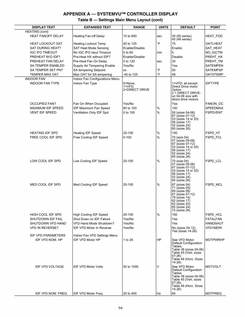
94
HEATING (cont)HEAT FANOFF DELAY Heating Fan-off Delay 10 to 600 sec 30 (50 series)
45 (48 series)HEAT_FOD
HEAT LOCKOUT OAT Heating Lockout Temp 40 to 125 °F 75 OATLHEATSAT DURING HEAT? SAT Heat Mode Sensing Enable/Disable Enable SAT_HEATIGC IFO TIMEOUT No IGC IFO input Timeout 0 to 60 min 5 NO_IGCTMPREHEAT W/O IDF? Pre-Heat HX without IDF? Enable/Disable Disable PREHT_HXPREHEAT FAN DELAY Pre-Heat Fan On Delay 0 to 120 sec 30 PREHT_TMSA TEMPER ENABLED Supply Air Tempering Enable Yes/No Yes SATEMPENSA TEMPER SET PNT SA tempering Setpoint xx °F 50 SATEMPSPTEMPER MAX OAT Max OAT for SA tempering -40 to 125 °F 48 OATSTEMP
INDOOR FAN Indoor Fan Configurations MenuINDOOR FAN TYPE Indoor Fan Type 0=None,
1=VFD,2=DIRECT DRIVE
1=VFD: all except Direct Drive motor Option2 = DIRECT DRIVE: on 04-06 size with direct drive motors
IDFTYPE
OCCUPIED FAN? Fan On When Occupied Yes/No Yes FANON_OCMAXIMUM IDF SPEED IDF Maximum Fan Speed 80 to 100 % 100 SPEEDMAXVENT IDF SPEED Ventilation Only IDF Spd 0 to 100 % 50 (sizes 04-06)
67 (sizes 07-12)53 (sizes 14 or 20)56 (sizes 17)52 (sizes 24)60 (sizes 26)
FSPDVENT
HEATING IDF SPD Heating IDF Speed 20-100 % 100 FSPD_HTFREE COOL IDF SPD Free Cooling IDF Speed 0-100 % 70 (size 04)
57 (sizes 05-06)67 (sizes 07-12)53 (sizes 14 or 20)56 (sizes 17)52 (sizes 24)60 (sizes 26)
FSPD_FCL
LOW COOL IDF SPD Low Cooling IDF Speed 20-100 % 70 (size 04)57 (sizes 05-06)67 (sizes 07-12)53 (sizes 14 or 20)56 (sizes 17)52 (sizes 24)60 (sizes 26)
FSPD_LCL
MED COOL IDF SPD Med Cooling IDF Speed 20-100 % 87 (sizes 04)71 (sizes 05)69 (sizes 06)67 (sizes 07-12)79 (sizes 14)82 (sizes 17)62 (sizes 20)65 (sizes 24)72 (sizes 26)
FSPD_MCL
HIGH COOL IDF SPD High Cooling IDF Speed 20-100 % 100 FSPD_HCLSHUTDOWN IDF FAIL Shut Down on IDF Failure Yes/No Yes FATALFANSHUTDOWN VFD HAND VFD Hand Mode Shutdown? Yes/No Yes HANDSHUTVFD IN REVERSE? IDF VFD Motor In Reverse Yes/No No (sizes 04-12)
Yes (sizes 14-26)VFD1MDIR
IDF VFD PARAMETERS Indoor Fan VFD Settings MenuIDF VFD NOM. HP IDF VFD Motor HP 1 to 26 HP See VFD Motor
Default Configuration Tables.Table 38 (sizes 04-06)Table 45 (Vert. sizes 07-26)Table 46 (Horz. Sizes 14-26)
MOTPWRHP
IDF VFD VOLTAGE IDF VFD Motor Volts 50 to 1000 V See VFD Motor Default Configuration Tables.Table 38 (sizes 04-06)Table 45 (Vert. sizes 07-26)Table 46 (Horz. Sizes 14-26)
MOTVOLT
IDF VFD NOM. FREQ IDF VFD Motor Freq. 20 to 400 Hz 60 MOTFREQ
Table B — Settings Main Menu Layout (cont)
DISPLAY TEXT EXPANDED TEXT RANGE UNITS DEFAULT POINT
APPENDIX A — SYSTEMVU™ CONTROLLER DISPLAY
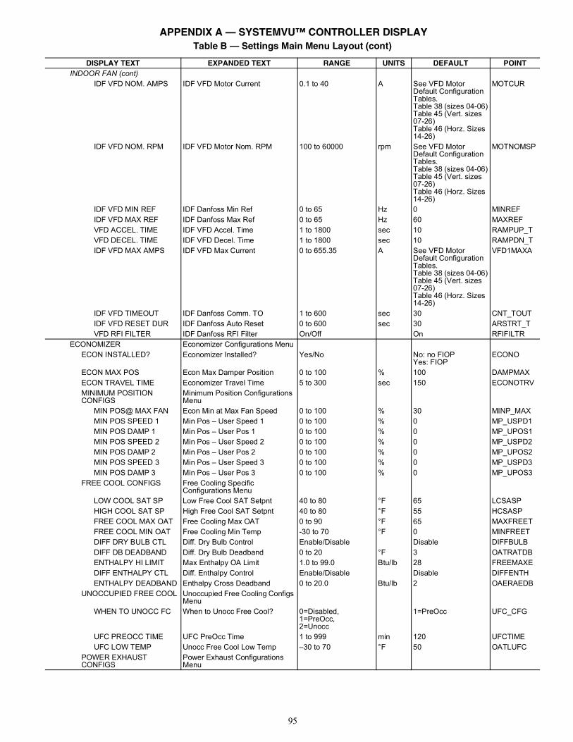
95
INDOOR FAN (cont)IDF VFD NOM. AMPS IDF VFD Motor Current 0.1 to 40 A See VFD Motor
Default Configuration Tables.Table 38 (sizes 04-06)Table 45 (Vert. sizes 07-26)Table 46 (Horz. Sizes 14-26)
MOTCUR
IDF VFD NOM. RPM IDF VFD Motor Nom. RPM 100 to 60000 rpm See VFD Motor Default Configuration Tables.Table 38 (sizes 04-06)Table 45 (Vert. sizes 07-26)Table 46 (Horz. Sizes 14-26)
MOTNOMSP
IDF VFD MIN REF IDF Danfoss Min Ref 0 to 65 Hz 0 MINREFIDF VFD MAX REF IDF Danfoss Max Ref 0 to 65 Hz 60 MAXREFVFD ACCEL. TIME IDF VFD Accel. Time 1 to 1800 sec 10 RAMPUP_TVFD DECEL. TIME IDF VFD Decel. Time 1 to 1800 sec 10 RAMPDN_TIDF VFD MAX AMPS IDF VFD Max Current 0 to 655.35 A See VFD Motor
Default Configuration Tables.Table 38 (sizes 04-06)Table 45 (Vert. sizes 07-26)Table 46 (Horz. Sizes 14-26)
VFD1MAXA
IDF VFD TIMEOUT IDF Danfoss Comm. TO 1 to 600 sec 30 CNT_TOUTIDF VFD RESET DUR IDF Danfoss Auto Reset 0 to 600 sec 30 ARSTRT_TVFD RFI FILTER IDF Danfoss RFI Filter On/Off On RFIFILTR
ECONOMIZER Economizer Configurations MenuECON INSTALLED? Economizer Installed? Yes/No No: no FIOP
Yes: FIOPECONO
ECON MAX POS Econ Max Damper Position 0 to 100 % 100 DAMPMAXECON TRAVEL TIME Economizer Travel Time 5 to 300 sec 150 ECONOTRVMINIMUM POSITION CONFIGS
Minimum Position Configurations Menu
MIN POS@ MAX FAN Econ Min at Max Fan Speed 0 to 100 % 30 MINP_MAXMIN POS SPEED 1 Min Pos – User Speed 1 0 to 100 % 0 MP_USPD1MIN POS DAMP 1 Min Pos – User Pos 1 0 to 100 % 0 MP_UPOS1MIN POS SPEED 2 Min Pos – User Speed 2 0 to 100 % 0 MP_USPD2MIN POS DAMP 2 Min Pos – User Pos 2 0 to 100 % 0 MP_UPOS2MIN POS SPEED 3 Min Pos – User Speed 3 0 to 100 % 0 MP_USPD3MIN POS DAMP 3 Min Pos – User Pos 3 0 to 100 % 0 MP_UPOS3
FREE COOL CONFIGS Free Cooling Specific Configurations Menu
LOW COOL SAT SP Low Free Cool SAT Setpnt 40 to 80 °F 65 LCSASPHIGH COOL SAT SP High Free Cool SAT Setpnt 40 to 80 °F 55 HCSASPFREE COOL MAX OAT Free Cooling Max OAT 0 to 90 °F 65 MAXFREETFREE COOL MIN OAT Free Cooling Min Temp -30 to 70 °F 0 MINFREETDIFF DRY BULB CTL Diff. Dry Bulb Control Enable/Disable Disable DIFFBULBDIFF DB DEADBAND Diff. Dry Bulb Deadband 0 to 20 °F 3 OATRATDBENTHALPY HI LIMIT Max Enthalpy OA Limit 1.0 to 99.0 Btu/lb 28 FREEMAXEDIFF ENTHALPY CTL Diff. Enthalpy Control Enable/Disable Disable DIFFENTHENTHALPY DEADBAND Enthalpy Cross Deadband 0 to 20.0 Btu/lb 2 OAERAEDB
UNOCCUPIED FREE COOL Unoccupied Free Cooling Configs Menu
WHEN TO UNOCC FC When to Unocc Free Cool? 0=Disabled,1=PreOcc,2=Unocc
1=PreOcc UFC_CFG
UFC PREOCC TIME UFC PreOcc Time 1 to 999 min 120 UFCTIMEUFC LOW TEMP Unocc Free Cool Low Temp –30 to 70 °F 50 OATLUFC
POWER EXHAUST CONFIGS
Power Exhaust Configurations Menu
Table B — Settings Main Menu Layout (cont)
DISPLAY TEXT EXPANDED TEXT RANGE UNITS DEFAULT POINT
APPENDIX A — SYSTEMVU™ CONTROLLER DISPLAY
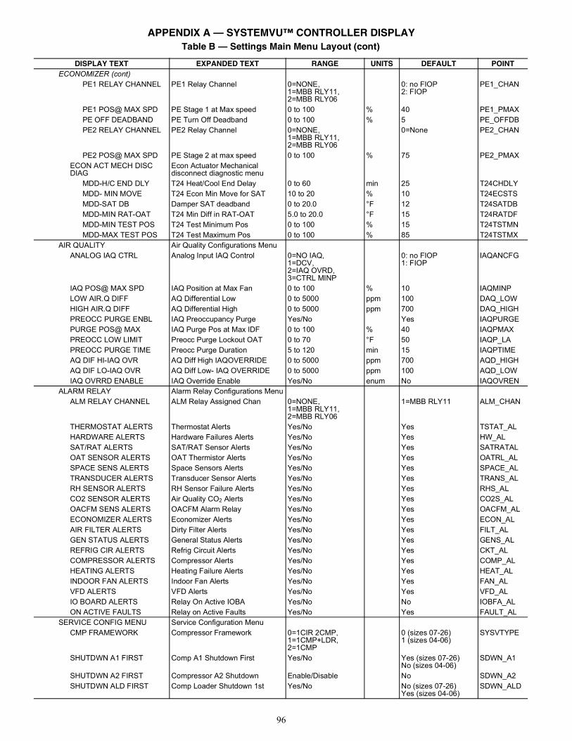
96
ECONOMIZER (cont)PE1 RELAY CHANNEL PE1 Relay Channel 0=NONE,
1=MBB RLY11,2=MBB RLY06
0: no FIOP2: FIOP
PE1_CHAN
PE1 POS@ MAX SPD PE Stage 1 at Max speed 0 to 100 % 40 PE1_PMAXPE OFF DEADBAND PE Turn Off Deadband 0 to 100 % 5 PE_OFFDBPE2 RELAY CHANNEL PE2 Relay Channel 0=NONE,
1=MBB RLY11,2=MBB RLY06
0=None PE2_CHAN
PE2 POS@ MAX SPD PE Stage 2 at max speed 0 to 100 % 75 PE2_PMAXECON ACT MECH DISC DIAG
Econ Actuator Mechanical disconnect diagnostic menu
MDD-H/C END DLY T24 Heat/Cool End Delay 0 to 60 min 25 T24CHDLYMDD- MIN MOVE T24 Econ Min Move for SAT 10 to 20 % 10 T24ECSTSMDD-SAT DB Damper SAT deadband 0 to 20.0 °F 12 T24SATDBMDD-MIN RAT-OAT T24 Min Diff in RAT-OAT 5.0 to 20.0 °F 15 T24RATDFMDD-MIN TEST POS T24 Test Minimum Pos 0 to 100 % 15 T24TSTMNMDD-MAX TEST POS T24 Test Maximum Pos 0 to 100 % 85 T24TSTMX
AIR QUALITY Air Quality Configurations MenuANALOG IAQ CTRL Analog Input IAQ Control 0=NO IAQ,
1=DCV,2=IAQ OVRD,3=CTRL MINP
0: no FIOP1: FIOP
IAQANCFG
IAQ POS@ MAX SPD IAQ Position at Max Fan 0 to 100 % 10 IAQMINPLOW AIR.Q DIFF AQ Differential Low 0 to 5000 ppm 100 DAQ_LOWHIGH AIR.Q DIFF AQ Differential High 0 to 5000 ppm 700 DAQ_HIGHPREOCC PURGE ENBL IAQ Preoccupancy Purge Yes/No Yes IAQPURGEPURGE POS@ MAX IAQ Purge Pos at Max IDF 0 to 100 % 40 IAQPMAXPREOCC LOW LIMIT Preocc Purge Lockout OAT 0 to 70 °F 50 IAQP_LAPREOCC PURGE TIME Preocc Purge Duration 5 to 120 min 15 IAQPTIMEAQ DIF HI-IAQ OVR AQ Diff High IAQOVERRIDE 0 to 5000 ppm 700 AQD_HIGHAQ DIF LO-IAQ OVR AQ Diff Low- IAQ OVERRIDE 0 to 5000 ppm 100 AQD_LOWIAQ OVRRD ENABLE IAQ Override Enable Yes/No enum No IAQOVREN
ALARM RELAY Alarm Relay Configurations MenuALM RELAY CHANNEL ALM Relay Assigned Chan 0=NONE,
1=MBB RLY11,2=MBB RLY06
1=MBB RLY11 ALM_CHAN
THERMOSTAT ALERTS Thermostat Alerts Yes/No Yes TSTAT_ALHARDWARE ALERTS Hardware Failures Alerts Yes/No Yes HW_ALSAT/RAT ALERTS SAT/RAT Sensor Alerts Yes/No Yes SATRATALOAT SENSOR ALERTS OAT Thermistor Alerts Yes/No Yes OATRL_ALSPACE SENS ALERTS Space Sensors Alerts Yes/No Yes SPACE_ALTRANSDUCER ALERTS Transducer Sensor Alerts Yes/No Yes TRANS_ALRH SENSOR ALERTS RH Sensor Failure Alerts Yes/No Yes RHS_ALCO2 SENSOR ALERTS Air Quality CO2 Alerts Yes/No Yes CO2S_ALOACFM SENS ALERTS OACFM Alarm Relay Yes/No Yes OACFM_ALECONOMIZER ALERTS Economizer Alerts Yes/No Yes ECON_ALAIR FILTER ALERTS Dirty Filter Alerts Yes/No Yes FILT_ALGEN STATUS ALERTS General Status Alerts Yes/No Yes GENS_ALREFRIG CIR ALERTS Refrig Circuit Alerts Yes/No Yes CKT_ALCOMPRESSOR ALERTS Compressor Alerts Yes/No Yes COMP_ALHEATING ALERTS Heating Failure Alerts Yes/No Yes HEAT_ALINDOOR FAN ALERTS Indoor Fan Alerts Yes/No Yes FAN_ALVFD ALERTS VFD Alerts Yes/No Yes VFD_ALIO BOARD ALERTS Relay On Active IOBA Yes/No No IOBFA_ALON ACTIVE FAULTS Relay on Active Faults Yes/No Yes FAULT_AL
SERVICE CONFIG MENU Service Configuration MenuCMP FRAMEWORK Compressor Framework 0=1CIR 2CMP,
1=1CMP+LDR,2=1CMP
0 (sizes 07-26)1 (sizes 04-06)
SYSVTYPE
SHUTDWN A1 FIRST Comp A1 Shutdown First Yes/No Yes (sizes 07-26)No (sizes 04-06)
SDWN_A1
SHUTDWN A2 FIRST Compressor A2 Shutdown Enable/Disable No SDWN_A2SHUTDWN ALD FIRST Comp Loader Shutdown 1st Yes/No No (sizes 07-26)
Yes (sizes 04-06)SDWN_ALD
Table B — Settings Main Menu Layout (cont)
DISPLAY TEXT EXPANDED TEXT RANGE UNITS DEFAULT POINT
APPENDIX A — SYSTEMVU™ CONTROLLER DISPLAY
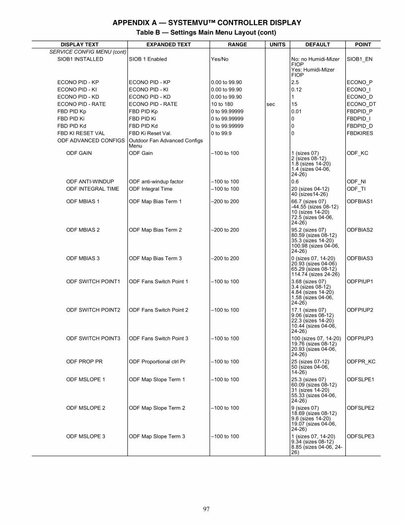
97
SERVICE CONFIG MENU (cont)SIOB1 INSTALLED SIOB 1 Enabled Yes/No No: no Humidi-Mizer
FIOPYes: Humidi-Mizer FIOP
SIOB1_EN
ECONO PID - KP ECONO PID - KP 0.00 to 99.90 2.5 ECONO_PECONO PID - KI ECONO PID - KI 0.00 to 99.90 0.12 ECONO_IECONO PID - KD ECONO PID - KD 0.00 to 99.90 1 ECONO_DECONO PID - RATE ECONO PID - RATE 10 to 180 sec 15 ECONO_DTFBD PID Kp FBD PID Kp 0 to 99.99999 0.01 FBDPID_PFBD PID Ki FBD PID Ki 0 to 99.99999 0 FBDPID_IFBD PID Kd FBD PID Kd 0 to 99.99999 0 FBDPID_DFBD KI RESET VAL FBD Ki Reset Val. 0 to 99.9 0 FBDKIRESODF ADVANCED CONFIGS Outdoor Fan Advanced Configs
MenuODF GAIN ODF Gain –100 to 100 1 (sizes 07)
2 (sizes 08-12)1.8 (sizes 14-20)1.4 (sizes 04-06,24-26)
ODF_KC
ODF ANTI-WINDUP ODF anti-windup factor –100 to 100 0.6 ODF_NIODF INTEGRAL TIME ODF Integral Time –100 to 100 20 (sizes 04-12)
40 (sizes14-26)ODF_TI
ODF MBIAS 1 ODF Map Bias Term 1 –200 to 200 66.7 (sizes 07)-44.55 (sizes 08-12)10 (sizes 14-20)72.5 (sizes 04-06,24-26)
ODFBIAS1
ODF MBIAS 2 ODF Map Bias Term 2 –200 to 200 95.2 (sizes 07)80.59 (sizes 08-12)35.3 (sizes 14-20)100.98 (sizes 04-06, 24-26)
ODFBIAS2
ODF MBIAS 3 ODF Map Bias Term 3 –200 to 200 0 (sizes 07, 14-20)20.93 (sizes 04-06)65.29 (sizes 08-12)114.74 (sizes 24-26)
ODFBIAS3
ODF SWITCH POINT1 ODF Fans Switch Point 1 –100 to 100 3.68 (sizes 07)3.4 (sizes 08-12)4.84 (sizes 14-20)1.58 (sizes 04-06,24-26)
ODFPIUP1
ODF SWITCH POINT2 ODF Fans Switch Point 2 –100 to 100 17.1 (sizes 07)9.06 (sizes 08-12)22.3 (sizes 14-20)10.44 (sizes 04-06, 24-26)
ODFPIUP2
ODF SWITCH POINT3 ODF Fans Switch Point 3 –100 to 100 100 (sizes 07, 14-20)19.76 (sizes 08-12)20.93 (sizes 04-06, 24-26)
ODFPIUP3
ODF PROP PR ODF Proportional ctrl Pr –100 to 100 25 (sizes 07-12)50 (sizes 04-06,14-26)
ODFPR_KC
ODF MSLOPE 1 ODF Map Slope Term 1 –100 to 100 25.3 (sizes 07)60.09 (sizes 08-12)31 (sizes 14-20)55.33 (sizes 04-06, 24-26)
ODFSLPE1
ODF MSLOPE 2 ODF Map Slope Term 2 –100 to 100 9 (sizes 07)18.69 (sizes 08-12)9.6 (sizes 14-20)19.07 (sizes 04-06, 24-26)
ODFSLPE2
ODF MSLOPE 3 ODF Map Slope Term 3 –100 to 100 1 (sizes 07, 14-20)9.34 (sizes 08-12)8.85 (sizes 04-06, 24-26)
ODFSLPE3
Table B — Settings Main Menu Layout (cont)
DISPLAY TEXT EXPANDED TEXT RANGE UNITS DEFAULT POINT
APPENDIX A — SYSTEMVU™ CONTROLLER DISPLAY
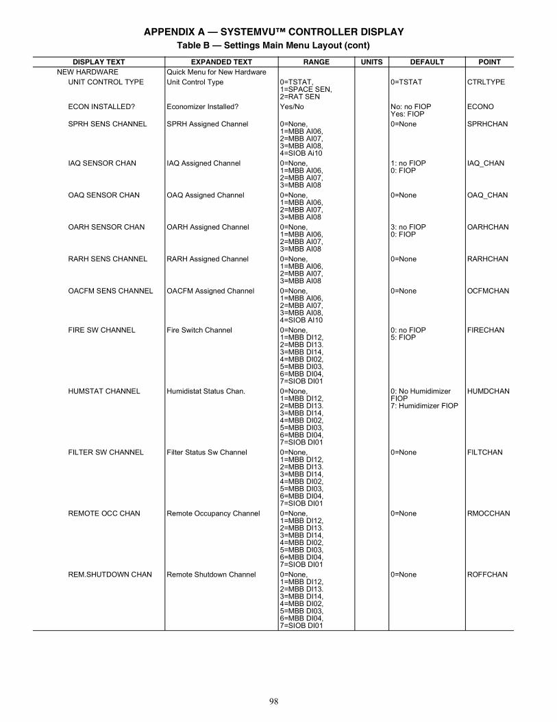
98
NEW HARDWARE Quick Menu for New HardwareUNIT CONTROL TYPE Unit Control Type 0=TSTAT,
1=SPACE SEN,2=RAT SEN
0=TSTAT CTRLTYPE
ECON INSTALLED? Economizer Installed? Yes/No No: no FIOPYes: FIOP
ECONO
SPRH SENS CHANNEL SPRH Assigned Channel 0=None,1=MBB AI06,2=MBB AI07,3=MBB AI08,4=SIOB Ai10
0=None SPRHCHAN
IAQ SENSOR CHAN IAQ Assigned Channel 0=None,1=MBB AI06,2=MBB AI07,3=MBB AI08
1: no FIOP0: FIOP
IAQ_CHAN
OAQ SENSOR CHAN OAQ Assigned Channel 0=None,1=MBB AI06,2=MBB AI07,3=MBB AI08
0=None OAQ_CHAN
OARH SENSOR CHAN OARH Assigned Channel 0=None,1=MBB AI06,2=MBB AI07,3=MBB AI08
3: no FIOP0: FIOP
OARHCHAN
RARH SENS CHANNEL RARH Assigned Channel 0=None,1=MBB AI06,2=MBB AI07,3=MBB AI08
0=None RARHCHAN
OACFM SENS CHANNEL OACFM Assigned Channel 0=None,1=MBB AI06,2=MBB AI07,3=MBB AI08,4=SIOB AI10
0=None OCFMCHAN
FIRE SW CHANNEL Fire Switch Channel 0=None,1=MBB DI12,2=MBB DI13.3=MBB DI14,4=MBB DI02,5=MBB DI03,6=MBB DI04,7=SIOB DI01
0: no FIOP5: FIOP
FIRECHAN
HUMSTAT CHANNEL Humidistat Status Chan. 0=None,1=MBB DI12,2=MBB DI13.3=MBB DI14,4=MBB DI02,5=MBB DI03,6=MBB DI04,7=SIOB DI01
0: No Humidimizer FIOP7: Humidimizer FIOP
HUMDCHAN
FILTER SW CHANNEL Filter Status Sw Channel 0=None,1=MBB DI12,2=MBB DI13.3=MBB DI14,4=MBB DI02,5=MBB DI03,6=MBB DI04,7=SIOB DI01
0=None FILTCHAN
REMOTE OCC CHAN Remote Occupancy Channel 0=None,1=MBB DI12,2=MBB DI13.3=MBB DI14,4=MBB DI02,5=MBB DI03,6=MBB DI04,7=SIOB DI01
0=None RMOCCHAN
REM.SHUTDOWN CHAN Remote Shutdown Channel 0=None,1=MBB DI12,2=MBB DI13.3=MBB DI14,4=MBB DI02,5=MBB DI03,6=MBB DI04,7=SIOB DI01
0=None ROFFCHAN
Table B — Settings Main Menu Layout (cont)
DISPLAY TEXT EXPANDED TEXT RANGE UNITS DEFAULT POINT
APPENDIX A — SYSTEMVU™ CONTROLLER DISPLAY
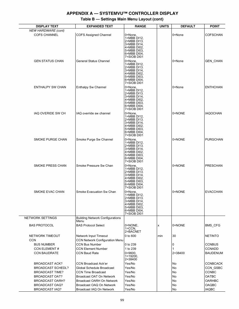
99
NEW HARDWARE (cont)COFS CHANNEL COFS Assigned Channel 0=None,
1=MBB DI12,2=MBB DI13.3=MBB DI14,4=MBB DI02,5=MBB DI03,6=MBB DI04,7=SIOB DI01
0=None COFSCHAN
GEN STATUS CHAN General Status Channel 0=None,1=MBB DI12,2=MBB DI13.3=MBB DI14,4=MBB DI02,5=MBB DI03,6=MBB DI04,7=SIOB DI01
0=None GEN_CHAN
ENTHALPY SW CHAN Enthalpy Sw Channel 0=None,1=MBB DI12,2=MBB DI13.3=MBB DI14,4=MBB DI02,5=MBB DI03,6=MBB DI04,7=SIOB DI01
0=None ENTHCHAN
IAQ OVERIDE SW CH IAQ override sw channel 0=None,1=MBB DI12,2=MBB DI13.3=MBB DI14,4=MBB DI02,5=MBB DI03,6=MBB DI04,7=SIOB DI01
0=NONE IAQOCHAN
SMOKE PURGE CHAN Smoke Purge Sw Channel 0=None,1=MBB DI12,2=MBB DI13.3=MBB DI14,4=MBB DI02,5=MBB DI03,6=MBB DI04,7=SIOB DI01
0=NONE PURGCHAN
SMOKE PRESS CHAN Smoke Pressure Sw Chan 0=None,1=MBB DI12,2=MBB DI13.3=MBB DI14,4=MBB DI02,5=MBB DI03,6=MBB DI04,7=SIOB DI01
0=NONE PRESCHAN
SMOKE EVAC CHAN Smoke Evacuation Sw Chan 0=None,1=MBB DI12,2=MBB DI13.3=MBB DI14,4=MBB DI02,5=MBB DI03,6=MBB DI04,7=SIOB DI01
0=NONE EVACCHAN
NETWORK SETTINGS Building Network Configurations Menu
BAS PROTOCOL BAS Protocol Select 0=NONE,1=CCN,2=BACNET
x 0=NONE BMS_CFG
NETWORK TIMEOUT Network Input Timeout 0 to 600 min 30 NETINTOCCN CCN Network Configuration Menu
BUS NUMBER CCN Bus Number 0 to 239 0 CCNBUSCCN ELEMENT # CCN Element Number 1 to 239 1 CCNADDCCN BAUDRATE CCN Baud Rate 0=9600,
1=19200,2=38400
2=38400 BAUDENUM
BROADCAST ACK? CCN Broadcast Ack’er Yes/No No CCNBCACKBROADCAST SCHEDL? Global Schedule Broadcast Yes/No No CCN_GSBCBROADCAST TIME? CCN Time Broadcast Yes/No No CCNBCBROADCAST OAT? Broadcast OAT On Network Yes/No No OATBCBROADCAST OARH? Broadcast OARH On Network Yes/No No OARHBCBROADCAST OAQ? Broadcast OAQ On Network Yes/No No OAQBCBROADCAST IAQ? Broadcast IAQ On Network Yes/No No IAQBC
Table B — Settings Main Menu Layout (cont)
DISPLAY TEXT EXPANDED TEXT RANGE UNITS DEFAULT POINT
APPENDIX A — SYSTEMVU™ CONTROLLER DISPLAY
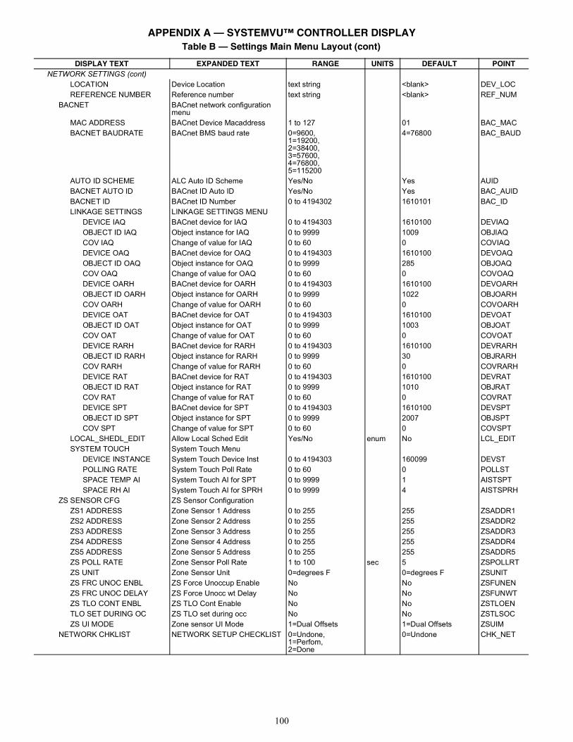
100
NETWORK SETTINGS (cont)LOCATION Device Location text string <blank> DEV_LOCREFERENCE NUMBER Reference number text string <blank> REF_NUM
BACNET BACnet network configuration menu
MAC ADDRESS BACnet Device Macaddress 1 to 127 01 BAC_MACBACNET BAUDRATE BACnet BMS baud rate 0=9600,
1=19200,2=38400,3=57600,4=76800,5=115200
4=76800 BAC_BAUD
AUTO ID SCHEME ALC Auto ID Scheme Yes/No Yes AUIDBACNET AUTO ID BACnet ID Auto ID Yes/No Yes BAC_AUIDBACNET ID BACnet ID Number 0 to 4194302 1610101 BAC_IDLINKAGE SETTINGS LINKAGE SETTINGS MENU
DEVICE IAQ BACnet device for IAQ 0 to 4194303 1610100 DEVIAQOBJECT ID IAQ Object instance for IAQ 0 to 9999 1009 OBJIAQCOV IAQ Change of value for IAQ 0 to 60 0 COVIAQDEVICE OAQ BACnet device for OAQ 0 to 4194303 1610100 DEVOAQOBJECT ID OAQ Object instance for OAQ 0 to 9999 285 OBJOAQCOV OAQ Change of value for OAQ 0 to 60 0 COVOAQDEVICE OARH BACnet device for OARH 0 to 4194303 1610100 DEVOARHOBJECT ID OARH Object instance for OARH 0 to 9999 1022 OBJOARHCOV OARH Change of value for OARH 0 to 60 0 COVOARHDEVICE OAT BACnet device for OAT 0 to 4194303 1610100 DEVOATOBJECT ID OAT Object instance for OAT 0 to 9999 1003 OBJOATCOV OAT Change of value for OAT 0 to 60 0 COVOATDEVICE RARH BACnet device for RARH 0 to 4194303 1610100 DEVRARHOBJECT ID RARH Object instance for RARH 0 to 9999 30 OBJRARHCOV RARH Change of value for RARH 0 to 60 0 COVRARHDEVICE RAT BACnet device for RAT 0 to 4194303 1610100 DEVRATOBJECT ID RAT Object instance for RAT 0 to 9999 1010 OBJRATCOV RAT Change of value for RAT 0 to 60 0 COVRATDEVICE SPT BACnet device for SPT 0 to 4194303 1610100 DEVSPTOBJECT ID SPT Object instance for SPT 0 to 9999 2007 OBJSPTCOV SPT Change of value for SPT 0 to 60 0 COVSPT
LOCAL_SHEDL_EDIT Allow Local Sched Edit Yes/No enum No LCL_EDITSYSTEM TOUCH System Touch Menu
DEVICE INSTANCE System Touch Device Inst 0 to 4194303 160099 DEVSTPOLLING RATE System Touch Poll Rate 0 to 60 0 POLLSTSPACE TEMP AI System Touch AI for SPT 0 to 9999 1 AISTSPTSPACE RH AI System Touch AI for SPRH 0 to 9999 4 AISTSPRH
ZS SENSOR CFG ZS Sensor ConfigurationZS1 ADDRESS Zone Sensor 1 Address 0 to 255 255 ZSADDR1ZS2 ADDRESS Zone Sensor 2 Address 0 to 255 255 ZSADDR2ZS3 ADDRESS Zone Sensor 3 Address 0 to 255 255 ZSADDR3ZS4 ADDRESS Zone Sensor 4 Address 0 to 255 255 ZSADDR4ZS5 ADDRESS Zone Sensor 5 Address 0 to 255 255 ZSADDR5ZS POLL RATE Zone Sensor Poll Rate 1 to 100 sec 5 ZSPOLLRTZS UNIT Zone Sensor Unit 0=degrees F 0=degrees F ZSUNITZS FRC UNOC ENBL ZS Force Unoccup Enable No No ZSFUNENZS FRC UNOC DELAY ZS Force Unocc wt Delay No No ZSFUNWTZS TLO CONT ENBL ZS TLO Cont Enable No No ZSTLOENTLO SET DURING OC ZS TLO set during occ No No ZSTLSOCZS UI MODE Zone sensor UI Mode 1=Dual Offsets 1=Dual Offsets ZSUIM
NETWORK CHKLIST NETWORK SETUP CHECKLIST 0=Undone,1=Perfom,2=Done
0=Undone CHK_NET
Table B — Settings Main Menu Layout (cont)
DISPLAY TEXT EXPANDED TEXT RANGE UNITS DEFAULT POINT
APPENDIX A — SYSTEMVU™ CONTROLLER DISPLAY
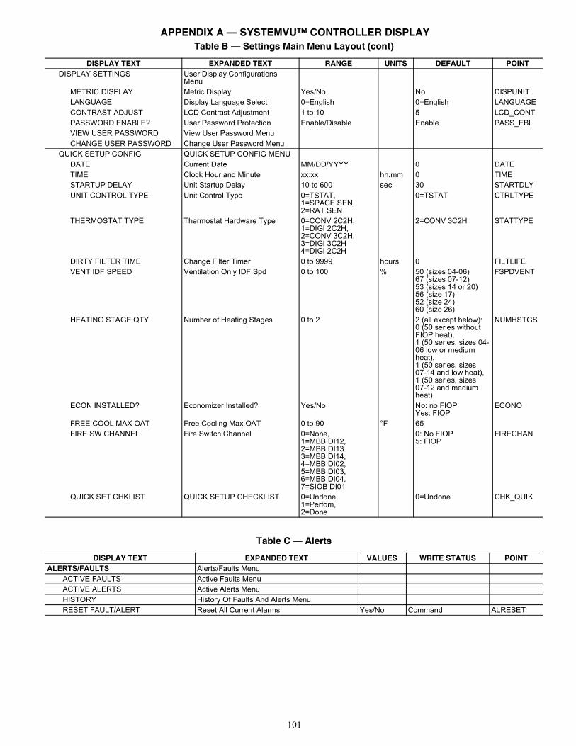
101
DISPLAY SETTINGS User Display Configurations Menu
METRIC DISPLAY Metric Display Yes/No No DISPUNITLANGUAGE Display Language Select 0=English 0=English LANGUAGECONTRAST ADJUST LCD Contrast Adjustment 1 to 10 5 LCD_CONTPASSWORD ENABLE? User Password Protection Enable/Disable Enable PASS_EBLVIEW USER PASSWORD View User Password MenuCHANGE USER PASSWORD Change User Password Menu
QUICK SETUP CONFIG QUICK SETUP CONFIG MENUDATE Current Date MM/DD/YYYY 0 DATETIME Clock Hour and Minute xx:xx hh.mm 0 TIMESTARTUP DELAY Unit Startup Delay 10 to 600 sec 30 STARTDLYUNIT CONTROL TYPE Unit Control Type 0=TSTAT,
1=SPACE SEN,2=RAT SEN
0=TSTAT CTRLTYPE
THERMOSTAT TYPE Thermostat Hardware Type 0=CONV 2C2H,1=DIGI 2C2H,2=CONV 3C2H,3=DIGI 3C2H4=DIGI 2C2H
2=CONV 3C2H STATTYPE
DIRTY FILTER TIME Change Filter Timer 0 to 9999 hours 0 FILTLIFEVENT IDF SPEED Ventilation Only IDF Spd 0 to 100 % 50 (sizes 04-06)
67 (sizes 07-12)53 (sizes 14 or 20)56 (size 17)52 (size 24)60 (size 26)
FSPDVENT
HEATING STAGE QTY Number of Heating Stages 0 to 2 2 (all except below):0 (50 series withoutFIOP heat),1 (50 series, sizes 04-06 low or medium heat),1 (50 series, sizes07-14 and low heat),1 (50 series, sizes07-12 and mediumheat)
NUMHSTGS
ECON INSTALLED? Economizer Installed? Yes/No No: no FIOPYes: FIOP
ECONO
FREE COOL MAX OAT Free Cooling Max OAT 0 to 90 °F 65FIRE SW CHANNEL Fire Switch Channel 0=None,
1=MBB DI12,2=MBB DI13.3=MBB DI14,4=MBB DI02,5=MBB DI03,6=MBB DI04,7=SIOB DI01
0: No FIOP5: FIOP
FIRECHAN
QUICK SET CHKLIST QUICK SETUP CHECKLIST 0=Undone,1=Perfom,2=Done
0=Undone CHK_QUIK
Table B — Settings Main Menu Layout (cont)
DISPLAY TEXT EXPANDED TEXT RANGE UNITS DEFAULT POINT
Table C — Alerts
DISPLAY TEXT EXPANDED TEXT VALUES WRITE STATUS POINTALERTS/FAULTS Alerts/Faults Menu
ACTIVE FAULTS Active Faults MenuACTIVE ALERTS Active Alerts MenuHISTORY History Of Faults And Alerts MenuRESET FAULT/ALERT Reset All Current Alarms Yes/No Command ALRESET
APPENDIX A — SYSTEMVU™ CONTROLLER DISPLAY
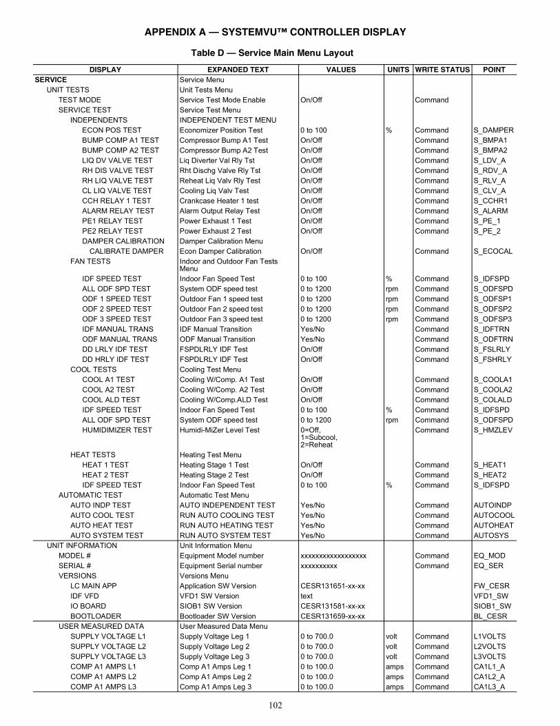
102
Table D — Service Main Menu Layout
DISPLAY EXPANDED TEXT VALUES UNITS WRITE STATUS POINTSERVICE Service Menu
UNIT TESTS Unit Tests MenuTEST MODE Service Test Mode Enable On/Off CommandSERVICE TEST Service Test Menu
INDEPENDENTS INDEPENDENT TEST MENUECON POS TEST Economizer Position Test 0 to 100 % Command S_DAMPERBUMP COMP A1 TEST Compressor Bump A1 Test On/Off Command S_BMPA1BUMP COMP A2 TEST Compressor Bump A2 Test On/Off Command S_BMPA2LIQ DV VALVE TEST Liq Diverter Val Rly Tst On/Off Command S_LDV_ARH DIS VALVE TEST Rht Dischg Valve Rly Tst On/Off Command S_RDV_ARH LIQ VALVE TEST Reheat Liq Valv Rly Test On/Off Command S_RLV_ACL LIQ VALVE TEST Cooling Liq Valv Test On/Off Command S_CLV_ACCH RELAY 1 TEST Crankcase Heater 1 test On/Off Command S_CCHR1ALARM RELAY TEST Alarm Output Relay Test On/Off Command S_ALARMPE1 RELAY TEST Power Exhaust 1 Test On/Off Command S_PE_1PE2 RELAY TEST Power Exhaust 2 Test On/Off Command S_PE_2DAMPER CALIBRATION Damper Calibration Menu
CALIBRATE DAMPER Econ Damper Calibration On/Off Command S_ECOCALFAN TESTS Indoor and Outdoor Fan Tests
MenuIDF SPEED TEST Indoor Fan Speed Test 0 to 100 % Command S_IDFSPDALL ODF SPD TEST System ODF speed test 0 to 1200 rpm Command S_ODFSPDODF 1 SPEED TEST Outdoor Fan 1 speed test 0 to 1200 rpm Command S_ODFSP1ODF 2 SPEED TEST Outdoor Fan 2 speed test 0 to 1200 rpm Command S_ODFSP2ODF 3 SPEED TEST Outdoor Fan 3 speed test 0 to 1200 rpm Command S_ODFSP3IDF MANUAL TRANS IDF Manual Transition Yes/No Command S_IDFTRNODF MANUAL TRANS ODF Manual Transition Yes/No Command S_ODFTRNDD LRLY IDF TEST FSPDLRLY IDF Test On/Off Command S_FSLRLYDD HRLY IDF TEST FSPDLRLY IDF Test On/Off Command S_FSHRLY
COOL TESTS Cooling Test MenuCOOL A1 TEST Cooling W/Comp. A1 Test On/Off Command S_COOLA1COOL A2 TEST Cooling W/Comp. A2 Test On/Off Command S_COOLA2COOL ALD TEST Cooling W/Comp.ALD Test On/Off Command S_COLALDIDF SPEED TEST Indoor Fan Speed Test 0 to 100 % Command S_IDFSPDALL ODF SPD TEST System ODF speed test 0 to 1200 rpm Command S_ODFSPDHUMIDIMIZER TEST Humidi-MiZer Level Test 0=Off,
1=Subcool,2=Reheat
Command S_HMZLEV
HEAT TESTS Heating Test MenuHEAT 1 TEST Heating Stage 1 Test On/Off Command S_HEAT1HEAT 2 TEST Heating Stage 2 Test On/Off Command S_HEAT2IDF SPEED TEST Indoor Fan Speed Test 0 to 100 % Command S_IDFSPD
AUTOMATIC TEST Automatic Test MenuAUTO INDP TEST AUTO INDEPENDENT TEST Yes/No Command AUTOINDPAUTO COOL TEST RUN AUTO COOLING TEST Yes/No Command AUTOCOOLAUTO HEAT TEST RUN AUTO HEATING TEST Yes/No Command AUTOHEATAUTO SYSTEM TEST RUN AUTO SYSTEM TEST Yes/No Command AUTOSYS
UNIT INFORMATION Unit Information MenuMODEL # Equipment Model number xxxxxxxxxxxxxxxxxx Command EQ_MODSERIAL # Equipment Serial number xxxxxxxxxx Command EQ_SERVERSIONS Versions Menu
LC MAIN APP Application SW Version CESR131651-xx-xx FW_CESRIDF VFD VFD1 SW Version text VFD1_SWIO BOARD SIOB1 SW Version CESR131581-xx-xx SIOB1_SWBOOTLOADER Bootloader SW Version CESR131659-xx-xx BL_CESR
USER MEASURED DATA User Measured Data MenuSUPPLY VOLTAGE L1 Supply Voltage Leg 1 0 to 700.0 volt Command L1VOLTSSUPPLY VOLTAGE L2 Supply Voltage Leg 2 0 to 700.0 volt Command L2VOLTSSUPPLY VOLTAGE L3 Supply Voltage Leg 3 0 to 700.0 volt Command L3VOLTSCOMP A1 AMPS L1 Comp A1 Amps Leg 1 0 to 100.0 amps Command CA1L1_ACOMP A1 AMPS L2 Comp A1 Amps Leg 2 0 to 100.0 amps Command CA1L2_ACOMP A1 AMPS L3 Comp A1 Amps Leg 3 0 to 100.0 amps Command CA1L3_A
APPENDIX A — SYSTEMVU™ CONTROLLER DISPLAY
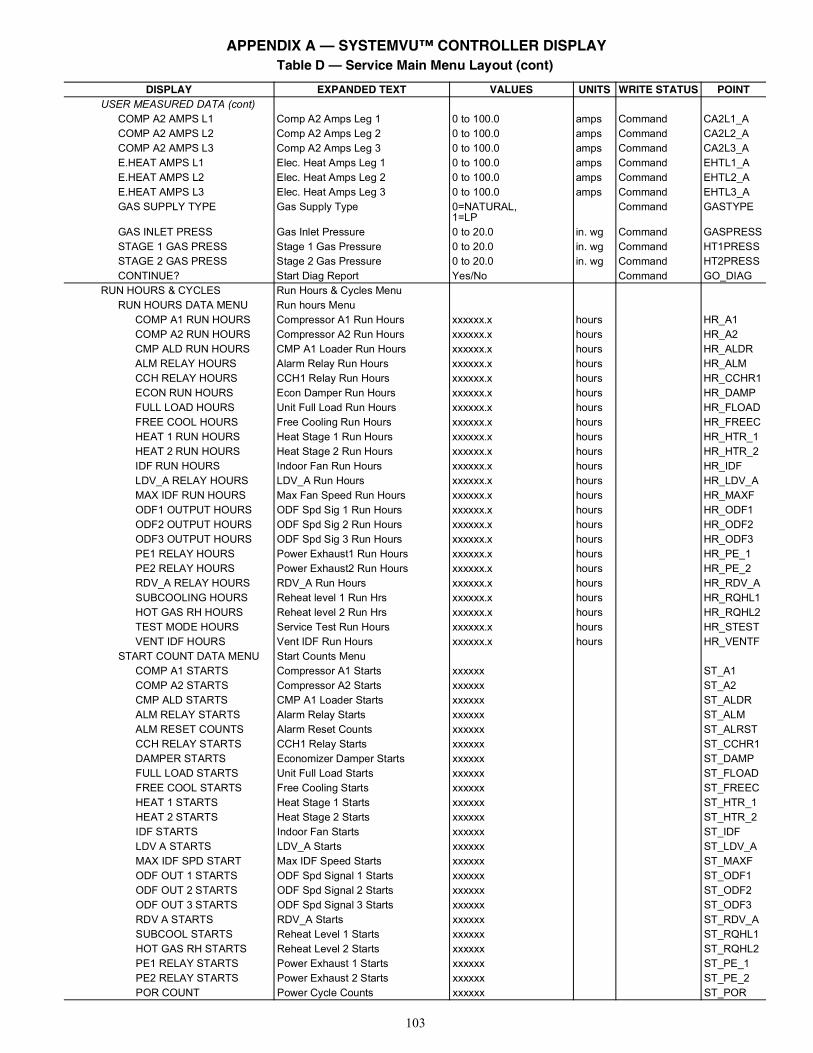
103
USER MEASURED DATA (cont)COMP A2 AMPS L1 Comp A2 Amps Leg 1 0 to 100.0 amps Command CA2L1_ACOMP A2 AMPS L2 Comp A2 Amps Leg 2 0 to 100.0 amps Command CA2L2_ACOMP A2 AMPS L3 Comp A2 Amps Leg 3 0 to 100.0 amps Command CA2L3_AE.HEAT AMPS L1 Elec. Heat Amps Leg 1 0 to 100.0 amps Command EHTL1_AE.HEAT AMPS L2 Elec. Heat Amps Leg 2 0 to 100.0 amps Command EHTL2_AE.HEAT AMPS L3 Elec. Heat Amps Leg 3 0 to 100.0 amps Command EHTL3_AGAS SUPPLY TYPE Gas Supply Type 0=NATURAL,
1=LPCommand GASTYPE
GAS INLET PRESS Gas Inlet Pressure 0 to 20.0 in. wg Command GASPRESSSTAGE 1 GAS PRESS Stage 1 Gas Pressure 0 to 20.0 in. wg Command HT1PRESSSTAGE 2 GAS PRESS Stage 2 Gas Pressure 0 to 20.0 in. wg Command HT2PRESSCONTINUE? Start Diag Report Yes/No Command GO_DIAG
RUN HOURS & CYCLES Run Hours & Cycles MenuRUN HOURS DATA MENU Run hours Menu
COMP A1 RUN HOURS Compressor A1 Run Hours xxxxxx.x hours HR_A1COMP A2 RUN HOURS Compressor A2 Run Hours xxxxxx.x hours HR_A2CMP ALD RUN HOURS CMP A1 Loader Run Hours xxxxxx.x hours HR_ALDRALM RELAY HOURS Alarm Relay Run Hours xxxxxx.x hours HR_ALMCCH RELAY HOURS CCH1 Relay Run Hours xxxxxx.x hours HR_CCHR1ECON RUN HOURS Econ Damper Run Hours xxxxxx.x hours HR_DAMPFULL LOAD HOURS Unit Full Load Run Hours xxxxxx.x hours HR_FLOADFREE COOL HOURS Free Cooling Run Hours xxxxxx.x hours HR_FREECHEAT 1 RUN HOURS Heat Stage 1 Run Hours xxxxxx.x hours HR_HTR_1HEAT 2 RUN HOURS Heat Stage 2 Run Hours xxxxxx.x hours HR_HTR_2IDF RUN HOURS Indoor Fan Run Hours xxxxxx.x hours HR_IDFLDV_A RELAY HOURS LDV_A Run Hours xxxxxx.x hours HR_LDV_AMAX IDF RUN HOURS Max Fan Speed Run Hours xxxxxx.x hours HR_MAXFODF1 OUTPUT HOURS ODF Spd Sig 1 Run Hours xxxxxx.x hours HR_ODF1ODF2 OUTPUT HOURS ODF Spd Sig 2 Run Hours xxxxxx.x hours HR_ODF2ODF3 OUTPUT HOURS ODF Spd Sig 3 Run Hours xxxxxx.x hours HR_ODF3PE1 RELAY HOURS Power Exhaust1 Run Hours xxxxxx.x hours HR_PE_1PE2 RELAY HOURS Power Exhaust2 Run Hours xxxxxx.x hours HR_PE_2RDV_A RELAY HOURS RDV_A Run Hours xxxxxx.x hours HR_RDV_ASUBCOOLING HOURS Reheat level 1 Run Hrs xxxxxx.x hours HR_RQHL1HOT GAS RH HOURS Reheat level 2 Run Hrs xxxxxx.x hours HR_RQHL2TEST MODE HOURS Service Test Run Hours xxxxxx.x hours HR_STESTVENT IDF HOURS Vent IDF Run Hours xxxxxx.x hours HR_VENTF
START COUNT DATA MENU Start Counts MenuCOMP A1 STARTS Compressor A1 Starts xxxxxx ST_A1COMP A2 STARTS Compressor A2 Starts xxxxxx ST_A2CMP ALD STARTS CMP A1 Loader Starts xxxxxx ST_ALDRALM RELAY STARTS Alarm Relay Starts xxxxxx ST_ALMALM RESET COUNTS Alarm Reset Counts xxxxxx ST_ALRSTCCH RELAY STARTS CCH1 Relay Starts xxxxxx ST_CCHR1DAMPER STARTS Economizer Damper Starts xxxxxx ST_DAMPFULL LOAD STARTS Unit Full Load Starts xxxxxx ST_FLOADFREE COOL STARTS Free Cooling Starts xxxxxx ST_FREECHEAT 1 STARTS Heat Stage 1 Starts xxxxxx ST_HTR_1HEAT 2 STARTS Heat Stage 2 Starts xxxxxx ST_HTR_2IDF STARTS Indoor Fan Starts xxxxxx ST_IDFLDV A STARTS LDV_A Starts xxxxxx ST_LDV_AMAX IDF SPD START Max IDF Speed Starts xxxxxx ST_MAXFODF OUT 1 STARTS ODF Spd Signal 1 Starts xxxxxx ST_ODF1ODF OUT 2 STARTS ODF Spd Signal 2 Starts xxxxxx ST_ODF2ODF OUT 3 STARTS ODF Spd Signal 3 Starts xxxxxx ST_ODF3RDV A STARTS RDV_A Starts xxxxxx ST_RDV_ASUBCOOL STARTS Reheat Level 1 Starts xxxxxx ST_RQHL1HOT GAS RH STARTS Reheat Level 2 Starts xxxxxx ST_RQHL2PE1 RELAY STARTS Power Exhaust 1 Starts xxxxxx ST_PE_1PE2 RELAY STARTS Power Exhaust 2 Starts xxxxxx ST_PE_2POR COUNT Power Cycle Counts xxxxxx ST_POR
Table D — Service Main Menu Layout (cont)
DISPLAY EXPANDED TEXT VALUES UNITS WRITE STATUS POINT
APPENDIX A — SYSTEMVU™ CONTROLLER DISPLAY
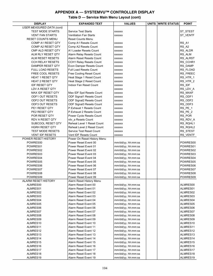
104
USER MEASURED DATA (cont)TEST MODE STARTS Service Test Starts xxxxxx ST_STESTVENT FAN STARTS Ventilation Fan Starts xxxxxx ST_VENTF
RESET COUNTS MENU Reset Counts MenuCOMP A1 RESET QTY Comp A1 Resets Count xxxxxx RS_A1COMP A2 RESET QTY Comp A2 Resets Count xxxxxx RS_A2CMP ALD RESET QTY A1 Loader Resets Count xxxxxx RS_ALDRALM RLY RESET QTY Alarm Relay Resets Count xxxxxx RS_ALMALM RESET RESETS Alarm Reset Resets Count xxxxxx RS_ALRSTCCH RELAY RESETS CCH1 Relay Resets Count xxxxxx RS_CCHR1DAMPER RESET QTY Econ Damper Resets Count xxxxxx RS_DAMPFULL LOAD RESETS Full Load Resets Count xxxxxx RS_FLOADFREE COOL RESETS Free Cooling Reset Count xxxxxx RS_FREECHEAT 1 RESET QTY Heat Stage 1 Reset Count xxxxxx RS_HTR_1HEAT 2 RESET QTY Heat Stage 2 Reset Count xxxxxx RS_HTR_2IDF RESET QTY Indoor Fan Reset Count xxxxxx RS_IDFLDV A RESET QTY xxxxxx RS_LDV_AMAX IDF RESET QTY Max IDF Spd Resets Count xxxxxx RS_MAXFODF1 OUT RESETS ODF Signal1 Resets Count xxxxxx RS_ODF1ODF2 OUT RESETS ODF Signal2 Resets Count xxxxxx RS_ODF2ODF3 OUT RESETS ODF Signal3 Resets Count xxxxxx RS_ODF3PE1 RESET QTY P.Exhaust 1 Resets Count xxxxxx RS_PE_1PE2 RESET QTY P.Exhaust 2 Resets Count xxxxxx RS_PE_2POR RESET QTY Power Cycle Resets Count xxxxxx RS_PORRDV A RESET QTY rdv_a Resets Count xxxxxx RS_RDV_ASUBCOOL RESET QTY Reheat Level 1 Reset Count xxxxxx RS_RQHL1HGRH RESET QTY Reheat Level 2 Reset Count xxxxxx RS_RQHL2TEST MODE RESETS Service Test Reset Count xxxxxx RS_STESTVENT IDF RESETS Vent IDF Resets Count xxxxxx RS_VENTF
POWER RESET HISTORY Power On Reset History MenuPOWRES00 Power Reset Event 00 mm/dd/yy, hh:mm:ss POWRES00POWRES01 Power Reset Event 01 mm/dd/yy, hh:mm:ss POWRES01POWRES02 Power Reset Event 02 mm/dd/yy, hh:mm:ss POWRES02POWRES03 Power Reset Event 03 mm/dd/yy, hh:mm:ss POWRES03POWRES04 Power Reset Event 04 mm/dd/yy, hh:mm:ss POWRES04POWRES05 Power Reset Event 05 mm/dd/yy, hh:mm:ss POWRES05POWRES06 Power Reset Event 06 mm/dd/yy, hh:mm:ss POWRES06POWRES07 Power Reset Event 07 mm/dd/yy, hh:mm:ss POWRES07POWRES08 Power Reset Event 08 mm/dd/yy, hh:mm:ss POWRES08POWRES09 Power Reset Event 09 mm/dd/yy, hh:mm:ss POWRES09
ALARM RESET HISTORY Alarm Reset History MenuALMRES00 Alarm Reset Event 00 mm/dd/yy, hh:mm:ss ALMRES00ALMRES01 Alarm Reset Event 01 mm/dd/yy, hh:mm:ss ALMRES01ALMRES02 Alarm Reset Event 02 mm/dd/yy, hh:mm:ss ALMRES02ALMRES03 Alarm Reset Event 03 mm/dd/yy, hh:mm:ss ALMRES03ALMRES04 Alarm Reset Event 04 mm/dd/yy, hh:mm:ss ALMRES04ALMRES05 Alarm Reset Event 05 mm/dd/yy, hh:mm:ss ALMRES05ALMRES06 Alarm Reset Event 06 mm/dd/yy, hh:mm:ss ALMRES06ALMRES07 Alarm Reset Event 07 mm/dd/yy, hh:mm:ss ALMRES07ALMRES08 Alarm Reset Event 08 mm/dd/yy, hh:mm:ss ALMRES08ALMRES09 Alarm Reset Event 09 mm/dd/yy, hh:mm:ss ALMRES09ALMRES10 Alarm Reset Event 10 mm/dd/yy, hh:mm:ss ALMRES10ALMRES11 Alarm Reset Event 11 mm/dd/yy, hh:mm:ss ALMRES11ALMRES12 Alarm Reset Event 12 mm/dd/yy, hh:mm:ss ALMRES12ALMRES13 Alarm Reset Event 13 mm/dd/yy, hh:mm:ss ALMRES13ALMRES14 Alarm Reset Event 14 mm/dd/yy, hh:mm:ss ALMRES14ALMRES15 Alarm Reset Event 15 mm/dd/yy, hh:mm:ss ALMRES15ALMRES16 Alarm Reset Event 16 mm/dd/yy, hh:mm:ss ALMRES16ALMRES17 Alarm Reset Event 17 mm/dd/yy, hh:mm:ss ALMRES17ALMRES18 Alarm Reset Event 18 mm/dd/yy, hh:mm:ss ALMRES18ALMRES19 Alarm Reset Event 19 mm/dd/yy, hh:mm:ss ALMRES19
Table D — Service Main Menu Layout (cont)
DISPLAY EXPANDED TEXT VALUES UNITS WRITE STATUS POINT
APPENDIX A — SYSTEMVU™ CONTROLLER DISPLAY
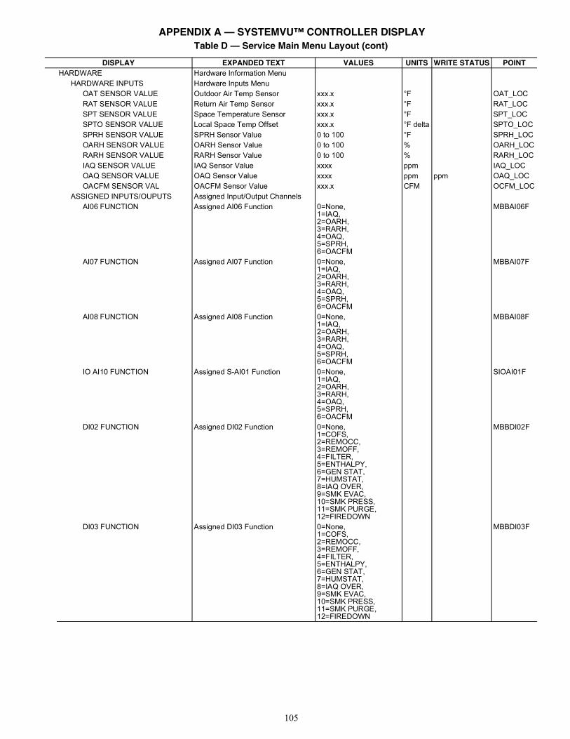
105
HARDWARE Hardware Information MenuHARDWARE INPUTS Hardware Inputs Menu
OAT SENSOR VALUE Outdoor Air Temp Sensor xxx.x °F OAT_LOCRAT SENSOR VALUE Return Air Temp Sensor xxx.x °F RAT_LOCSPT SENSOR VALUE Space Temperature Sensor xxx.x °F SPT_LOCSPTO SENSOR VALUE Local Space Temp Offset xxx.x °F delta SPTO_LOCSPRH SENSOR VALUE SPRH Sensor Value 0 to 100 °F SPRH_LOCOARH SENSOR VALUE OARH Sensor Value 0 to 100 % OARH_LOCRARH SENSOR VALUE RARH Sensor Value 0 to 100 % RARH_LOCIAQ SENSOR VALUE IAQ Sensor Value xxxx ppm IAQ_LOCOAQ SENSOR VALUE OAQ Sensor Value xxxx ppm ppm OAQ_LOCOACFM SENSOR VAL OACFM Sensor Value xxx.x CFM OCFM_LOC
ASSIGNED INPUTS/OUPUTS Assigned Input/Output ChannelsAI06 FUNCTION Assigned AI06 Function 0=None,
1=IAQ,2=OARH,3=RARH,4=OAQ,5=SPRH,6=OACFM
MBBAI06F
AI07 FUNCTION Assigned AI07 Function 0=None,1=IAQ,2=OARH,3=RARH,4=OAQ,5=SPRH,6=OACFM
MBBAI07F
AI08 FUNCTION Assigned AI08 Function 0=None,1=IAQ,2=OARH,3=RARH,4=OAQ,5=SPRH,6=OACFM
MBBAI08F
IO AI10 FUNCTION Assigned S-AI01 Function 0=None,1=IAQ,2=OARH,3=RARH,4=OAQ,5=SPRH,6=OACFM
SIOAI01F
DI02 FUNCTION Assigned DI02 Function 0=None,1=COFS,2=REMOCC,3=REMOFF,4=FILTER,5=ENTHALPY,6=GEN STAT,7=HUMSTAT,8=IAQ OVER,9=SMK EVAC,10=SMK PRESS,11=SMK PURGE,12=FIREDOWN
MBBDI02F
DI03 FUNCTION Assigned DI03 Function 0=None,1=COFS,2=REMOCC,3=REMOFF,4=FILTER,5=ENTHALPY,6=GEN STAT,7=HUMSTAT,8=IAQ OVER,9=SMK EVAC,10=SMK PRESS,11=SMK PURGE,12=FIREDOWN
MBBDI03F
Table D — Service Main Menu Layout (cont)
DISPLAY EXPANDED TEXT VALUES UNITS WRITE STATUS POINT
APPENDIX A — SYSTEMVU™ CONTROLLER DISPLAY
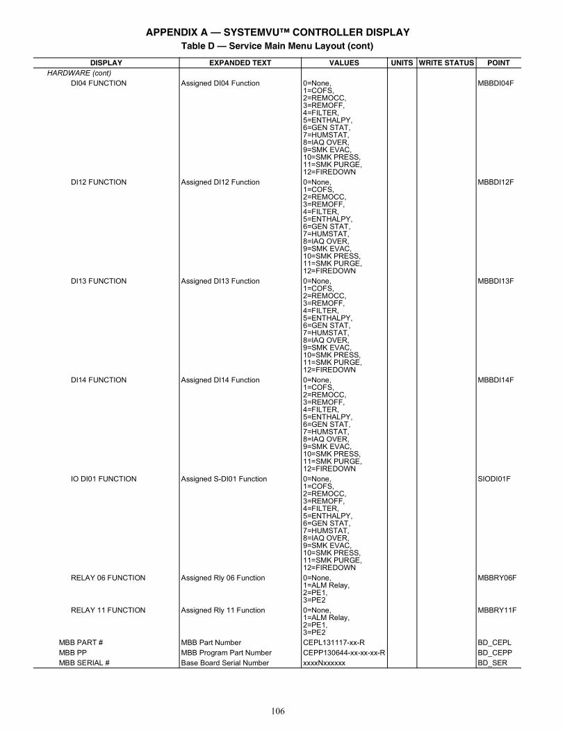
106
HARDWARE (cont)DI04 FUNCTION Assigned DI04 Function 0=None,
1=COFS,2=REMOCC,3=REMOFF,4=FILTER,5=ENTHALPY,6=GEN STAT,7=HUMSTAT,8=IAQ OVER,9=SMK EVAC,10=SMK PRESS,11=SMK PURGE,12=FIREDOWN
MBBDI04F
DI12 FUNCTION Assigned DI12 Function 0=None,1=COFS,2=REMOCC,3=REMOFF,4=FILTER,5=ENTHALPY,6=GEN STAT,7=HUMSTAT,8=IAQ OVER,9=SMK EVAC,10=SMK PRESS,11=SMK PURGE,12=FIREDOWN
MBBDI12F
DI13 FUNCTION Assigned DI13 Function 0=None,1=COFS,2=REMOCC,3=REMOFF,4=FILTER,5=ENTHALPY,6=GEN STAT,7=HUMSTAT,8=IAQ OVER,9=SMK EVAC,10=SMK PRESS,11=SMK PURGE,12=FIREDOWN
MBBDI13F
DI14 FUNCTION Assigned DI14 Function 0=None,1=COFS,2=REMOCC,3=REMOFF,4=FILTER,5=ENTHALPY,6=GEN STAT,7=HUMSTAT,8=IAQ OVER,9=SMK EVAC,10=SMK PRESS,11=SMK PURGE,12=FIREDOWN
MBBDI14F
IO DI01 FUNCTION Assigned S-DI01 Function 0=None,1=COFS,2=REMOCC,3=REMOFF,4=FILTER,5=ENTHALPY,6=GEN STAT,7=HUMSTAT,8=IAQ OVER,9=SMK EVAC,10=SMK PRESS,11=SMK PURGE,12=FIREDOWN
SIODI01F
RELAY 06 FUNCTION Assigned Rly 06 Function 0=None,1=ALM Relay,2=PE1,3=PE2
MBBRY06F
RELAY 11 FUNCTION Assigned Rly 11 Function 0=None,1=ALM Relay,2=PE1,3=PE2
MBBRY11F
MBB PART # MBB Part Number CEPL131117-xx-R BD_CEPLMBB PP MBB Program Part Number CEPP130644-xx-xx-xx-R BD_CEPPMBB SERIAL # Base Board Serial Number xxxxNxxxxxx BD_SER
Table D — Service Main Menu Layout (cont)
DISPLAY EXPANDED TEXT VALUES UNITS WRITE STATUS POINT
APPENDIX A — SYSTEMVU™ CONTROLLER DISPLAY
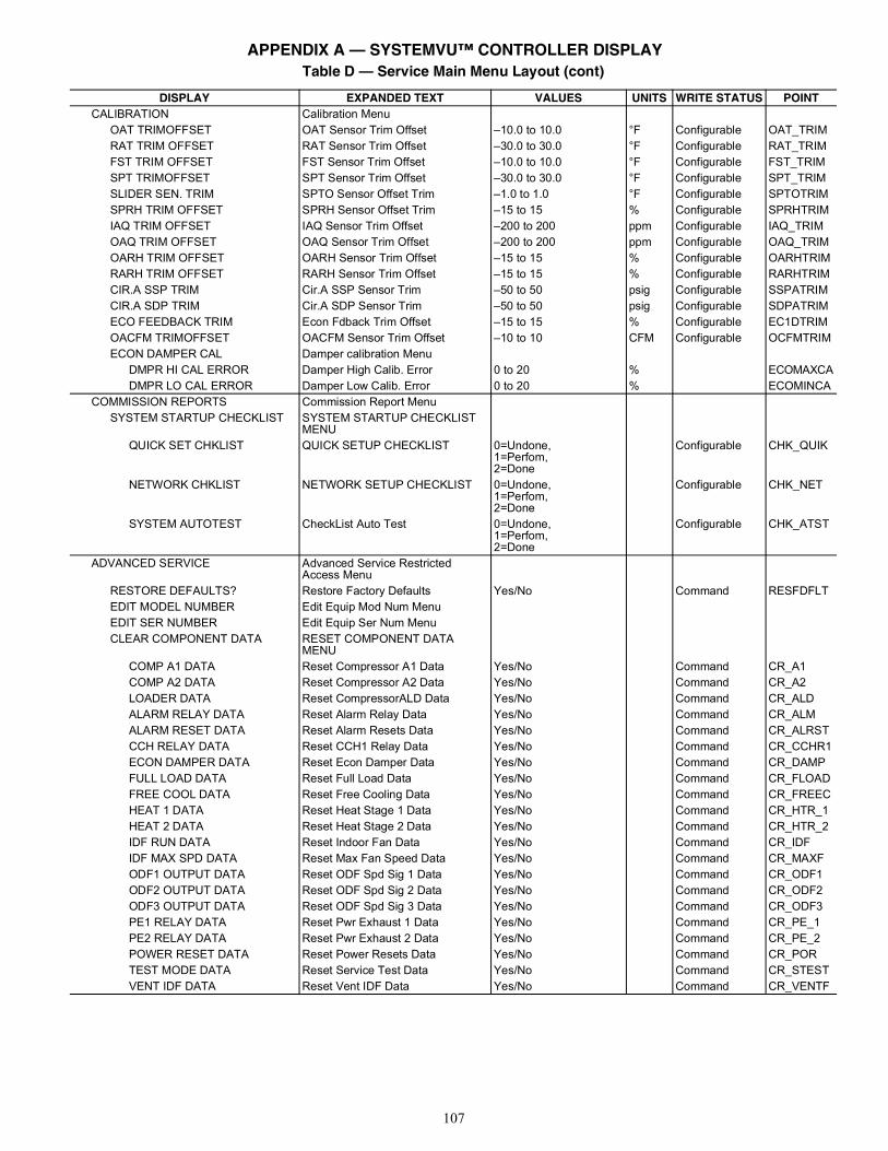
107
CALIBRATION Calibration MenuOAT TRIMOFFSET OAT Sensor Trim Offset –10.0 to 10.0 °F Configurable OAT_TRIMRAT TRIM OFFSET RAT Sensor Trim Offset –30.0 to 30.0 °F Configurable RAT_TRIMFST TRIM OFFSET FST Sensor Trim Offset –10.0 to 10.0 °F Configurable FST_TRIMSPT TRIMOFFSET SPT Sensor Trim Offset –30.0 to 30.0 °F Configurable SPT_TRIMSLIDER SEN. TRIM SPTO Sensor Offset Trim –1.0 to 1.0 °F Configurable SPTOTRIMSPRH TRIM OFFSET SPRH Sensor Offset Trim –15 to 15 % Configurable SPRHTRIMIAQ TRIM OFFSET IAQ Sensor Trim Offset –200 to 200 ppm Configurable IAQ_TRIMOAQ TRIM OFFSET OAQ Sensor Trim Offset –200 to 200 ppm Configurable OAQ_TRIMOARH TRIM OFFSET OARH Sensor Trim Offset –15 to 15 % Configurable OARHTRIMRARH TRIM OFFSET RARH Sensor Trim Offset –15 to 15 % Configurable RARHTRIMCIR.A SSP TRIM Cir.A SSP Sensor Trim –50 to 50 psig Configurable SSPATRIMCIR.A SDP TRIM Cir.A SDP Sensor Trim –50 to 50 psig Configurable SDPATRIMECO FEEDBACK TRIM Econ Fdback Trim Offset –15 to 15 % Configurable EC1DTRIMOACFM TRIMOFFSET OACFM Sensor Trim Offset –10 to 10 CFM Configurable OCFMTRIMECON DAMPER CAL Damper calibration Menu
DMPR HI CAL ERROR Damper High Calib. Error 0 to 20 % ECOMAXCADMPR LO CAL ERROR Damper Low Calib. Error 0 to 20 % ECOMINCA
COMMISSION REPORTS Commission Report MenuSYSTEM STARTUP CHECKLIST SYSTEM STARTUP CHECKLIST
MENUQUICK SET CHKLIST QUICK SETUP CHECKLIST 0=Undone,
1=Perfom,2=Done
Configurable CHK_QUIK
NETWORK CHKLIST NETWORK SETUP CHECKLIST 0=Undone,1=Perfom,2=Done
Configurable CHK_NET
SYSTEM AUTOTEST CheckList Auto Test 0=Undone,1=Perfom,2=Done
Configurable CHK_ATST
ADVANCED SERVICE Advanced Service Restricted Access Menu
RESTORE DEFAULTS? Restore Factory Defaults Yes/No Command RESFDFLTEDIT MODEL NUMBER Edit Equip Mod Num MenuEDIT SER NUMBER Edit Equip Ser Num MenuCLEAR COMPONENT DATA RESET COMPONENT DATA
MENUCOMP A1 DATA Reset Compressor A1 Data Yes/No Command CR_A1COMP A2 DATA Reset Compressor A2 Data Yes/No Command CR_A2LOADER DATA Reset CompressorALD Data Yes/No Command CR_ALDALARM RELAY DATA Reset Alarm Relay Data Yes/No Command CR_ALMALARM RESET DATA Reset Alarm Resets Data Yes/No Command CR_ALRSTCCH RELAY DATA Reset CCH1 Relay Data Yes/No Command CR_CCHR1ECON DAMPER DATA Reset Econ Damper Data Yes/No Command CR_DAMPFULL LOAD DATA Reset Full Load Data Yes/No Command CR_FLOADFREE COOL DATA Reset Free Cooling Data Yes/No Command CR_FREECHEAT 1 DATA Reset Heat Stage 1 Data Yes/No Command CR_HTR_1HEAT 2 DATA Reset Heat Stage 2 Data Yes/No Command CR_HTR_2IDF RUN DATA Reset Indoor Fan Data Yes/No Command CR_IDFIDF MAX SPD DATA Reset Max Fan Speed Data Yes/No Command CR_MAXFODF1 OUTPUT DATA Reset ODF Spd Sig 1 Data Yes/No Command CR_ODF1ODF2 OUTPUT DATA Reset ODF Spd Sig 2 Data Yes/No Command CR_ODF2ODF3 OUTPUT DATA Reset ODF Spd Sig 3 Data Yes/No Command CR_ODF3PE1 RELAY DATA Reset Pwr Exhaust 1 Data Yes/No Command CR_PE_1PE2 RELAY DATA Reset Pwr Exhaust 2 Data Yes/No Command CR_PE_2POWER RESET DATA Reset Power Resets Data Yes/No Command CR_PORTEST MODE DATA Reset Service Test Data Yes/No Command CR_STESTVENT IDF DATA Reset Vent IDF Data Yes/No Command CR_VENTF
Table D — Service Main Menu Layout (cont)
DISPLAY EXPANDED TEXT VALUES UNITS WRITE STATUS POINT
APPENDIX A — SYSTEMVU™ CONTROLLER DISPLAY
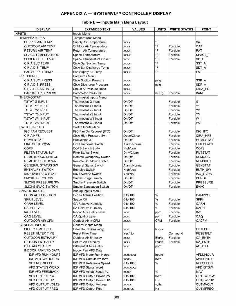
108
Table E — Inputs Main Menu Layout
DISPLAY EXPANDED TEXT VALUES UNITS WRITE STATUS POINTINPUTS Inputs Menu
TEMPERATURES Temperatures MenuSUPPLY AIR TEMP Supply Air Temperature xxx.x °F SATOUTDOOR AIR TEMP Outdoor Air Temperature xxx.x °F Forcible OATRETURN AIR TEMP Return Air Temperature xxx.x °F Forcible RATSPACE TEMPERATURE Space Temperature xxx.x °F Forcible SPACE_TSLIDER OFFSET VAL Space Temperature Offset xx.x °F Forcible SPTOCIR.A SUC TEMP Cir.A Sat.Suction Temp xxx.x °F SST_ACIR.A DIS. TEMP Cir.A Sat.Discharge Temp xxx.x °F SDT_AFAN SUPPLY TEMP Fan Supply Air Temp xxx.x °F FST
PRESSURES Pressures MenuCIR.A SUC. PRESS Cir.A Suction Pressure xxx.x psig SSP_ACIR.A DIS. PRESS Cir.A Discharge Pressure xxx.x psig SDP_ACIR.A PRESS RATIO Circuit A Pressure Ratio xxx.x CIRA_PRBAROMETRIC PRESS Barometric Pressure xxx.x in. Hg Forcible BARP
THERMOSTAT Thermostat Inputs MenuTSTAT G INPUT Thermostat G Input On/Off Forcible GTSTAT Y1 INPUT Thermostat Y1 Input On/Off Forcible Y1TSTAT Y2 INPUT Thermostat Y2 Input On/Off Forcible Y2TSTAT Y3 INPUT Thermostat Y3 Input On/Off Forcible Y3TSTAT W1 INPUT Thermostat W1 Input On/Off Forcible W1TSTAT W2 INPUT Thermostat W2 Input On/Off Forcible W2
SWITCH INPUTS Switch Inputs MenuIGC FAN REQUEST IGC Fan On Request (IFO) On/Off Forcible IGC_IFOCIR.A HPS Cir.A High Pressure Sw Open/Close Forcible CIRA_HPSHUMIDISTAT Humidistat I/P On/Off Forcible HUMDSTATFIRE SHUTDOWN Fire Shutdown Switch Alarm/Normal Forcible FIREDOWNCOFS COFS Switch State High/Low Forcible COFSFILTER STATUS SW Filter Status Switch Dirty/Clean Forcible FILTSTATREMOTE OCC SWITCH Remote Occupancy Switch On/Off Forcible REMOCCREMOTE SHUTDOWN Remote Shutdown Switch On/Off Forcible REMSHUTGENERAL STATUS SW General Status Switch Alarm/Normal Forcible GENSTATENTHALPY SWITCH Enthalpy Switch High/Low Forcible ENTH_SWIAQ OVRRD SW STAT IAQ Override Switch Yes/No Forcible IAQ_OVRSSMOKE PURGE SW Smoke Purge Switch On/Off Forcible PURGESMOKE PRESSURE SW Smoke Pressure Switch On/Off Forcible PRESSURESMOKE EVAC SWITCH Smoke Evacuation Switch On/Off Forcible EVAC
ANALOG INPUTS Analog Inputs MenuECON ACT POSITION Econo Actual Position 0 to 100 % DAMPPOSSPRH LEVEL Space RH 0 to 100 % Forcible SPRHOARH LEVEL OA Relative Humidity 0 to 100 % Forcible OARHRARH LEVEL RA Relative Humidity 0 to 100 % Forcible RARHIAQ LEVEL Indoor Air Quality Level xxxx ppm Forcible IAQOAQ LEVEL OA Quality Level xxxx ppm Forcible OAQOUTDOOR AIR CFM Outdoor Air in CFM xxx.x CFM Forcible OACFM
GENERAL INPUTS General Inputs MenuFILTER TIME LEFT Filter Hour Remaining xxxx hours FILTLEFTRESET FILTER TIME Reset Filter Timer Yes/No Command RESETFLTOUTDOOR ENTHALPY Outdoor Air Enthalpy xxx.x Btu/lb Forcible OA_ENTHRETURN ENTHALPY Return Air Enthalpy xxx.x Btu/lb Forcible RA_ENTHDIFF AIR QUALITY Differential Air Quality xxxx ppm AQ_DIFFINDOOR FAN VFD DATA Indoor Fan VFD Data
IDF VFD RUN HOURS IDF VFD Motor Run Hours xxxxxxxx hours VFDMHOURIDF VFD KW HOURS IDF VFD Cumulative kWh xxxxx kWh KWHCNTRVFD REF SPEED IDF VFD Reference Speed 0 to 1000 % REFSPEEDVFD STATUS WORD IDF VFD Status Word xxxxxxxx VFD1STSWIDF VFD FEEDBACK IDF VFD Actual Speed % xxxxx % MAVVFD OUTPUT KW IDF VFD Output Power kW 0 to 1000 kWh OUTPWRKWVFD OUTPUT HP IDF VFD Output Power HP 0 to 1000 HP OUTPWRHPVFD OUTPUT VOLTS IDF VFD Output Voltage xxxxx volts OUTMVOLTVFD OUTPUT FREQ IDF VFD Output Freq. xxxxx.x Hz OUTMFREQ
APPENDIX A — SYSTEMVU™ CONTROLLER DISPLAY
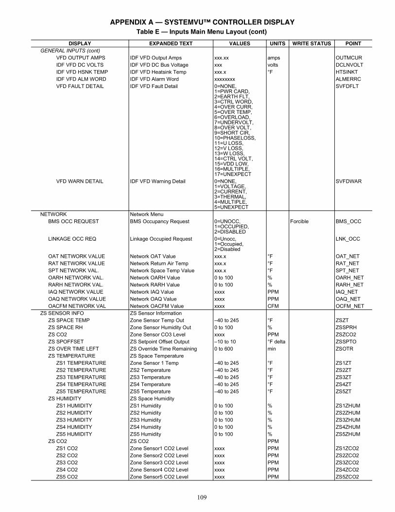
109
GENERAL INPUTS (cont)VFD OUTPUT AMPS IDF VFD Output Amps xxx.xx amps OUTMCURIDF VFD DC VOLTS IDF VFD DC Bus Voltage xxx volts DCLNVOLTIDF VFD HSNK TEMP IDF VFD Heatsink Temp xxx.x °F HTSINKTIDF VFD ALM WORD IDF VFD Alarm Word xxxxxxxx ALMERRCVFD FAULT DETAIL IDF VFD Fault Detail 0=NONE,
1=PWR CARD,2=EARTH FLT,3=CTRL WORD,4=OVER CURR,5=OVER TEMP,6=OVERLOAD,7=UNDERVOLT,8=OVER VOLT,9=SHORT CIR,10=PHASELOSS,11=U LOSS,12=V LOSS,13=W LOSS,14=CTRL VOLT,15=VDD LOW,16=MULTIPLE,17=UNEXPECT
SVFDFLT
VFD WARN DETAIL IDF VFD Warning Detail 0=NONE,1=VOLTAGE,2=CURRENT,3=THERMAL,4=MULTIPLE,5=UNEXPECT
SVFDWAR
NETWORK Network MenuBMS OCC REQUEST BMS Occupancy Request 0=UNOCC,
1=OCCUPIED,2=DISABLED
Forcible BMS_OCC
LINKAGE OCC REQ Linkage Occupied Request 0=Unocc,1=Occupied,2=Disabled
LNK_OCC
OAT NETWORK VALUE Network OAT Value xxx.x °F OAT_NETRAT NETWORK VALUE Network Return Air Temp xxx.x °F RAT_NETSPT NETWORK VAL. Network Space Temp Value xxx.x °F SPT_NETOARH NETWORK VAL. Network OARH Value 0 to 100 % OARH_NETRARH NETWORK VAL. Network RARH Value 0 to 100 % RARH_NETIAQ NETWORK VALUE Network IAQ Value xxxx PPM IAQ_NETOAQ NETWORK VALUE Network OAQ Value xxxx PPM OAQ_NETOACFM NETWORK VAL Network OACFM Value xxxx CFM OCFM_NET
ZS SENSOR INFO ZS Sensor InformationZS SPACE TEMP Zone Sensor Temp Out –40 to 245 °F ZSZTZS SPACE RH Zone Sensor Humidity Out 0 to 100 % ZSSPRHZS CO2 Zone Sensor CO3 Level xxxx PPM ZSZCO2ZS SPOFFSET ZS Setpoint Offset Output –10 to 10 °F delta ZSSPTOZS OVER TIME LEFT ZS Override Time Remaining 0 to 600 min ZSOTRZS TEMPERATURE ZS Space Temperature
ZS1 TEMPERATURE Zone Sensor 1 Temp –40 to 245 °F ZS1ZTZS2 TEMPERATURE ZS2 Temperature –40 to 245 °F ZS2ZTZS3 TEMPERATURE ZS3 Temperature –40 to 245 °F ZS3ZTZS4 TEMPERATURE ZS4 Temperature –40 to 245 °F ZS4ZTZS5 TEMPERATURE ZS5 Temperature –40 to 245 °F ZS5ZT
ZS HUMIDITY ZS Space HumidityZS1 HUMIDITY ZS1 Humidity 0 to 100 % ZS1ZHUMZS2 HUMIDITY ZS2 Humidity 0 to 100 % ZS2ZHUMZS3 HUMIDITY ZS3 Humidity 0 to 100 % ZS3ZHUMZS4 HUMIDITY ZS4 Humidity 0 to 100 % ZS4ZHUMZS5 HUMIDITY ZS5 Humidity 0 to 100 % ZS5ZHUM
ZS CO2 ZS CO2 PPMZS1 CO2 Zone Sensor1 CO2 Level xxxx PPM ZS1ZCO2ZS2 CO2 Zone Sensor2 CO2 Level xxxx PPM ZS2ZCO2ZS3 CO2 Zone Sensor3 CO2 Level xxxx PPM ZS3ZCO2ZS4 CO2 Zone Sensor4 CO2 Level xxxx PPM ZS4ZCO2ZS5 CO2 Zone Sensor5 CO2 Level xxxx PPM ZS5ZCO2
Table E — Inputs Main Menu Layout (cont)
DISPLAY EXPANDED TEXT VALUES UNITS WRITE STATUS POINT
APPENDIX A — SYSTEMVU™ CONTROLLER DISPLAY
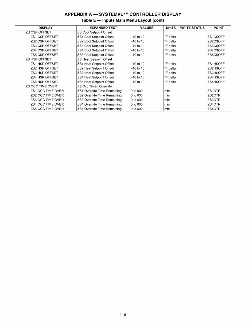
110
ZS CSP OFFSET ZS Cool Setpoint OffsetZS1 CSP OFFSET ZS1 Cool Setpoint Offset –10 to 10 °F delta ZS1CSOFFZS2 CSP OFFSET ZS2 Cool Setpoint Offset –10 to 10 °F delta ZS2CSOFFZS3 CSP OFFSET ZS3 Cool Setpoint Offset –10 to 10 °F delta ZS3CSOFFZS4 CSP OFFSET ZS4 Cool Setpoint Offset –10 to 10 °F delta ZS4CSOFFZS5 CSP OFFSET ZS5 Cool Setpoint Offset –10 to 10 °F delta ZS5CSOFF
ZS HSP OFFSET ZS Heat Setpoint OffsetZS1 HSP OFFSET ZS1 Heat Setpoint Offset –10 to 10 °F delta ZS1HSOFFZS2 HSP OFFSET ZS2 Heat Setpoint Offset –10 to 10 °F delta ZS2HSOFFZS3 HSP OFFSET ZS3 Heat Setpoint Offset –10 to 10 °F delta ZS3HSOFFZS4 HSP OFFSET ZS4 Heat Setpoint Offset –10 to 10 °F delta ZS4HSOFFZS5 HSP OFFSET ZS5 Heat Setpoint Offset –10 to 10 °F delta ZS5HSOFF
ZS OCC TIME OVER ZS Occ Timed OverrideZS1 OCC TIME OVER ZS1 Override Time Remaining 0 to 600 min ZS1OTRZS2 OCC TIME OVER ZS2 Override Time Remaining 0 to 600 min ZS2OTRZS3 OCC TIME OVER ZS3 Override Time Remaining 0 to 600 min ZS3OTRZS4 OCC TIME OVER ZS4 Override Time Remaining 0 to 600 min ZS4OTRZS5 OCC TIME OVER ZS5 Override Time Remaining 0 to 600 min ZS5OTR
Table E — Inputs Main Menu Layout (cont)
DISPLAY EXPANDED TEXT VALUES UNITS WRITE STATUS POINT
APPENDIX A — SYSTEMVU™ CONTROLLER DISPLAY
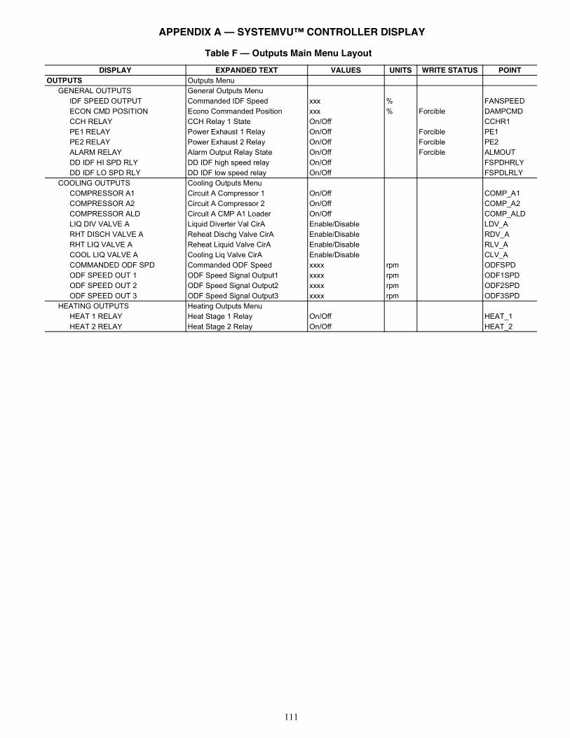
111
Table F — Outputs Main Menu Layout
DISPLAY EXPANDED TEXT VALUES UNITS WRITE STATUS POINTOUTPUTS Outputs Menu
GENERAL OUTPUTS General Outputs MenuIDF SPEED OUTPUT Commanded IDF Speed xxx % FANSPEEDECON CMD POSITION Econo Commanded Position xxx % Forcible DAMPCMDCCH RELAY CCH Relay 1 State On/Off CCHR1PE1 RELAY Power Exhaust 1 Relay On/Off Forcible PE1PE2 RELAY Power Exhaust 2 Relay On/Off Forcible PE2ALARM RELAY Alarm Output Relay State On/Off Forcible ALMOUTDD IDF HI SPD RLY DD IDF high speed relay On/Off FSPDHRLYDD IDF LO SPD RLY DD IDF low speed relay On/Off FSPDLRLY
COOLING OUTPUTS Cooling Outputs MenuCOMPRESSOR A1 Circuit A Compressor 1 On/Off COMP_A1COMPRESSOR A2 Circuit A Compressor 2 On/Off COMP_A2COMPRESSOR ALD Circuit A CMP A1 Loader On/Off COMP_ALDLIQ DIV VALVE A Liquid Diverter Val CirA Enable/Disable LDV_ARHT DISCH VALVE A Reheat Dischg Valve CirA Enable/Disable RDV_ARHT LIQ VALVE A Reheat Liquid Valve CirA Enable/Disable RLV_ACOOL LIQ VALVE A Cooling Liq Valve CirA Enable/Disable CLV_ACOMMANDED ODF SPD Commanded ODF Speed xxxx rpm ODFSPDODF SPEED OUT 1 ODF Speed Signal Output1 xxxx rpm ODF1SPDODF SPEED OUT 2 ODF Speed Signal Output2 xxxx rpm ODF2SPDODF SPEED OUT 3 ODF Speed Signal Output3 xxxx rpm ODF3SPD
HEATING OUTPUTS Heating Outputs MenuHEAT 1 RELAY Heat Stage 1 Relay On/Off HEAT_1HEAT 2 RELAY Heat Stage 2 Relay On/Off HEAT_2
APPENDIX A — SYSTEMVU™ CONTROLLER DISPLAY
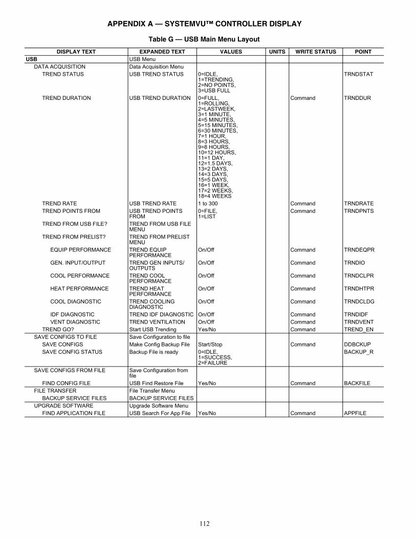
112
Table G — USB Main Menu Layout
DISPLAY TEXT EXPANDED TEXT VALUES UNITS WRITE STATUS POINTUSB USB Menu
DATA ACQUISITION Data Acquisition MenuTREND STATUS USB TREND STATUS 0=IDLE,
1=TRENDING,2=NO POINTS,3=USB FULL
TRNDSTAT
TREND DURATION USB TREND DURATION 0=FULL,1=ROLLING,2=LASTWEEK,3=1 MINUTE,4=5 MINUTES,5=15 MINUTES,6=30 MINUTES,7=1 HOUR,8=3 HOURS,9=8 HOURS,10=12 HOURS,11=1 DAY,12=1.5 DAYS,13=2 DAYS,14=3 DAYS,15=5 DAYS,16=1 WEEK,17=2 WEEKS,18=4 WEEKS
Command TRNDDUR
TREND RATE USB TREND RATE 1 to 300 Command TRNDRATETREND POINTS FROM USB TREND POINTS
FROM0=FILE,1=LIST
Command TRNDPNTS
TREND FROM USB FILE? TREND FROM USB FILE MENU
TREND FROM PRELIST? TREND FROM PRELIST MENU
EQUIP PERFORMANCE TREND EQUIP PERFORMANCE
On/Off Command TRNDEQPR
GEN. INPUT/OUTPUT TREND GEN INPUTS/OUTPUTS
On/Off Command TRNDIO
COOL PERFORMANCE TREND COOL PERFORMANCE
On/Off Command TRNDCLPR
HEAT PERFORMANCE TREND HEAT PERFORMANCE
On/Off Command TRNDHTPR
COOL DIAGNOSTIC TREND COOLING DIAGNOSTIC
On/Off Command TRNDCLDG
IDF DIAGNOSTIC TREND IDF DIAGNOSTIC On/Off Command TRNDIDFVENT DIAGNOSTIC TREND VENTILATION On/Off Command TRNDVENT
TREND GO? Start USB Trending Yes/No Command TREND_ENSAVE CONFIGS TO FILE Save Configuration to file
SAVE CONFIGS Make Config Backup File Start/Stop Command DDBCKUPSAVE CONFIG STATUS Backup File is ready 0=IDLE,
1=SUCCESS,2=FAILURE
BACKUP_R
SAVE CONFIGS FROM FILE Save Configuration from file
FIND CONFIG FILE USB Find Restore File Yes/No Command BACKFILEFILE TRANSFER File Transfer Menu
BACKUP SERVICE FILES BACKUP SERVICE FILESUPGRADE SOFTWARE Upgrade Software Menu
FIND APPLICATION FILE USB Search For App File Yes/No Command APPFILE
APPENDIX A — SYSTEMVU™ CONTROLLER DISPLAY
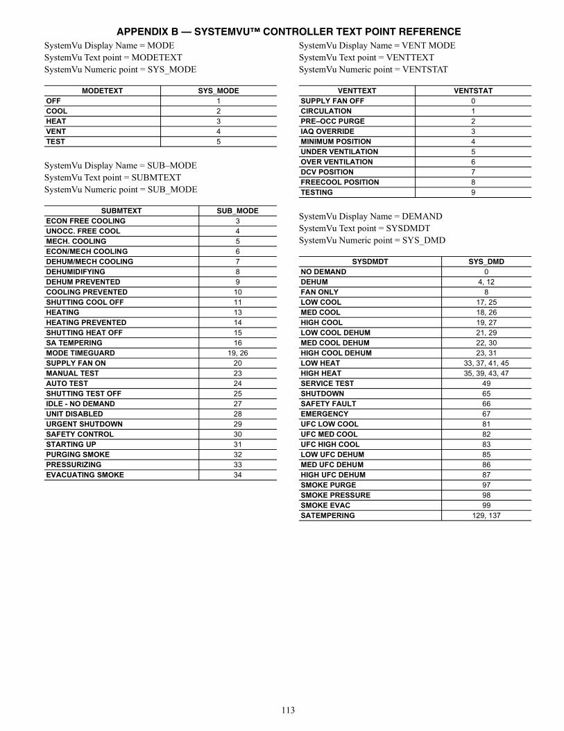
113
SystemVu Display Name = MODESystemVu Text point = MODETEXTSystemVu Numeric point = SYS_MODE
SystemVu Display Name = SUB–MODESystemVu Text point = SUBMTEXTSystemVu Numeric point = SUB_MODE
SystemVu Display Name = VENT MODESystemVu Text point = VENTTEXTSystemVu Numeric point = VENTSTAT
SystemVu Display Name = DEMANDSystemVu Text point = SYSDMDTSystemVu Numeric point = SYS_DMD
MODETEXT SYS_MODEOFF 1COOL 2HEAT 3VENT 4TEST 5
SUBMTEXT SUB_MODEECON FREE COOLING 3UNOCC. FREE COOL 4MECH. COOLING 5ECON/MECH COOLING 6DEHUM/MECH COOLING 7DEHUMIDIFYING 8DEHUM PREVENTED 9COOLING PREVENTED 10SHUTTING COOL OFF 11HEATING 13HEATING PREVENTED 14SHUTTING HEAT OFF 15SA TEMPERING 16MODE TIMEGUARD 19, 26SUPPLY FAN ON 20MANUAL TEST 23AUTO TEST 24SHUTTING TEST OFF 25IDLE - NO DEMAND 27UNIT DISABLED 28URGENT SHUTDOWN 29SAFETY CONTROL 30STARTING UP 31PURGING SMOKE 32PRESSURIZING 33EVACUATING SMOKE 34
VENTTEXT VENTSTATSUPPLY FAN OFF 0CIRCULATION 1PRE–OCC PURGE 2IAQ OVERRIDE 3MINIMUM POSITION 4UNDER VENTILATION 5OVER VENTILATION 6DCV POSITION 7FREECOOL POSITION 8TESTING 9
SYSDMDT SYS_DMDNO DEMAND 0DEHUM 4, 12FAN ONLY 8LOW COOL 17, 25MED COOL 18, 26HIGH COOL 19, 27LOW COOL DEHUM 21, 29MED COOL DEHUM 22, 30HIGH COOL DEHUM 23, 31LOW HEAT 33, 37, 41, 45HIGH HEAT 35, 39, 43, 47SERVICE TEST 49SHUTDOWN 65SAFETY FAULT 66EMERGENCY 67UFC LOW COOL 81UFC MED COOL 82UFC HIGH COOL 83LOW UFC DEHUM 85MED UFC DEHUM 86HIGH UFC DEHUM 87SMOKE PURGE 97SMOKE PRESSURE 98SMOKE EVAC 99SATEMPERING 129, 137
APPENDIX B — SYSTEMVU™ CONTROLLER TEXT POINT REFERENCE
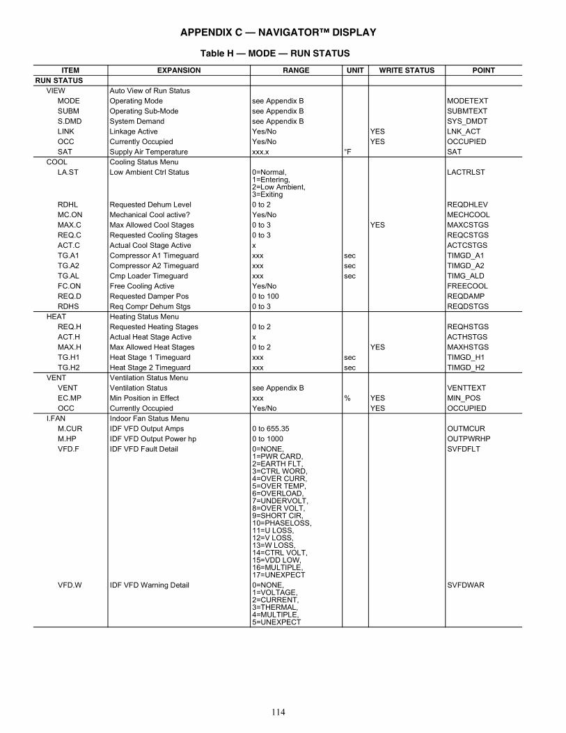
114
Table H — MODE — RUN STATUS
ITEM EXPANSION RANGE UNIT WRITE STATUS POINTRUN STATUS
VIEW Auto View of Run StatusMODE Operating Mode see Appendix B MODETEXTSUBM Operating Sub-Mode see Appendix B SUBMTEXTS.DMD System Demand see Appendix B SYS_DMDTLINK Linkage Active Yes/No YES LNK_ACTOCC Currently Occupied Yes/No YES OCCUPIEDSAT Supply Air Temperature xxx.x °F SAT
COOL Cooling Status MenuLA.ST Low Ambient Ctrl Status 0=Normal,
1=Entering,2=Low Ambient,3=Exiting
LACTRLST
RDHL Requested Dehum Level 0 to 2 REQDHLEVMC.ON Mechanical Cool active? Yes/No MECHCOOLMAX.C Max Allowed Cool Stages 0 to 3 YES MAXCSTGSREQ.C Requested Cooling Stages 0 to 3 REQCSTGSACT.C Actual Cool Stage Active x ACTCSTGSTG.A1 Compressor A1 Timeguard xxx sec TIMGD_A1TG.A2 Compressor A2 Timeguard xxx sec TIMGD_A2TG.AL Cmp Loader Timeguard xxx sec TIMG_ALDFC.ON Free Cooling Active Yes/No FREECOOLREQ.D Requested Damper Pos 0 to 100 REQDAMPRDHS Req Compr Dehum Stgs 0 to 3 REQDSTGS
HEAT Heating Status MenuREQ.H Requested Heating Stages 0 to 2 REQHSTGSACT.H Actual Heat Stage Active x ACTHSTGSMAX.H Max Allowed Heat Stages 0 to 2 YES MAXHSTGSTG.H1 Heat Stage 1 Timeguard xxx sec TIMGD_H1TG.H2 Heat Stage 2 Timeguard xxx sec TIMGD_H2
VENT Ventilation Status MenuVENT Ventilation Status see Appendix B VENTTEXTEC.MP Min Position in Effect xxx % YES MIN_POSOCC Currently Occupied Yes/No YES OCCUPIED
I.FAN Indoor Fan Status MenuM.CUR IDF VFD Output Amps 0 to 655.35 OUTMCURM.HP IDF VFD Output Power hp 0 to 1000 OUTPWRHPVFD.F IDF VFD Fault Detail 0=NONE,
1=PWR CARD,2=EARTH FLT,3=CTRL WORD,4=OVER CURR,5=OVER TEMP,6=OVERLOAD,7=UNDERVOLT,8=OVER VOLT,9=SHORT CIR,10=PHASELOSS,11=U LOSS,12=V LOSS,13=W LOSS,14=CTRL VOLT,15=VDD LOW,16=MULTIPLE,17=UNEXPECT
SVFDFLT
VFD.W IDF VFD Warning Detail 0=NONE,1=VOLTAGE,2=CURRENT,3=THERMAL,4=MULTIPLE,5=UNEXPECT
SVFDWAR
APPENDIX C — NAVIGATOR™ DISPLAY
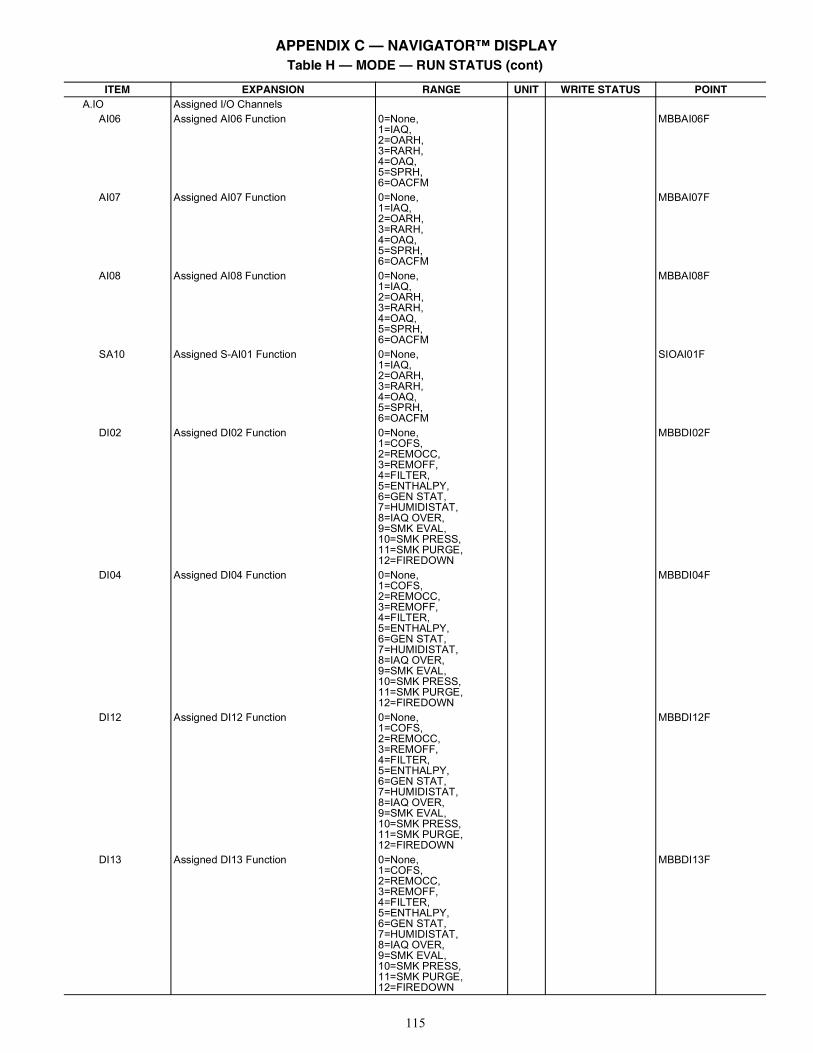
115
A.IO Assigned I/O ChannelsAI06 Assigned AI06 Function 0=None,
1=IAQ,2=OARH,3=RARH,4=OAQ,5=SPRH,6=OACFM
MBBAI06F
AI07 Assigned AI07 Function 0=None,1=IAQ,2=OARH,3=RARH,4=OAQ,5=SPRH,6=OACFM
MBBAI07F
AI08 Assigned AI08 Function 0=None,1=IAQ,2=OARH,3=RARH,4=OAQ,5=SPRH,6=OACFM
MBBAI08F
SA10 Assigned S-AI01 Function 0=None,1=IAQ,2=OARH,3=RARH,4=OAQ,5=SPRH,6=OACFM
SIOAI01F
DI02 Assigned DI02 Function 0=None,1=COFS,2=REMOCC,3=REMOFF,4=FILTER,5=ENTHALPY,6=GEN STAT,7=HUMIDISTAT,8=IAQ OVER,9=SMK EVAL,10=SMK PRESS,11=SMK PURGE,12=FIREDOWN
MBBDI02F
DI04 Assigned DI04 Function 0=None,1=COFS,2=REMOCC,3=REMOFF,4=FILTER,5=ENTHALPY,6=GEN STAT,7=HUMIDISTAT,8=IAQ OVER,9=SMK EVAL,10=SMK PRESS,11=SMK PURGE,12=FIREDOWN
MBBDI04F
DI12 Assigned DI12 Function 0=None,1=COFS,2=REMOCC,3=REMOFF,4=FILTER,5=ENTHALPY,6=GEN STAT,7=HUMIDISTAT,8=IAQ OVER,9=SMK EVAL,10=SMK PRESS,11=SMK PURGE,12=FIREDOWN
MBBDI12F
DI13 Assigned DI13 Function 0=None,1=COFS,2=REMOCC,3=REMOFF,4=FILTER,5=ENTHALPY,6=GEN STAT,7=HUMIDISTAT,8=IAQ OVER,9=SMK EVAL,10=SMK PRESS,11=SMK PURGE,12=FIREDOWN
MBBDI13F
Table H — MODE — RUN STATUS (cont)
ITEM EXPANSION RANGE UNIT WRITE STATUS POINT
APPENDIX C — NAVIGATOR™ DISPLAY
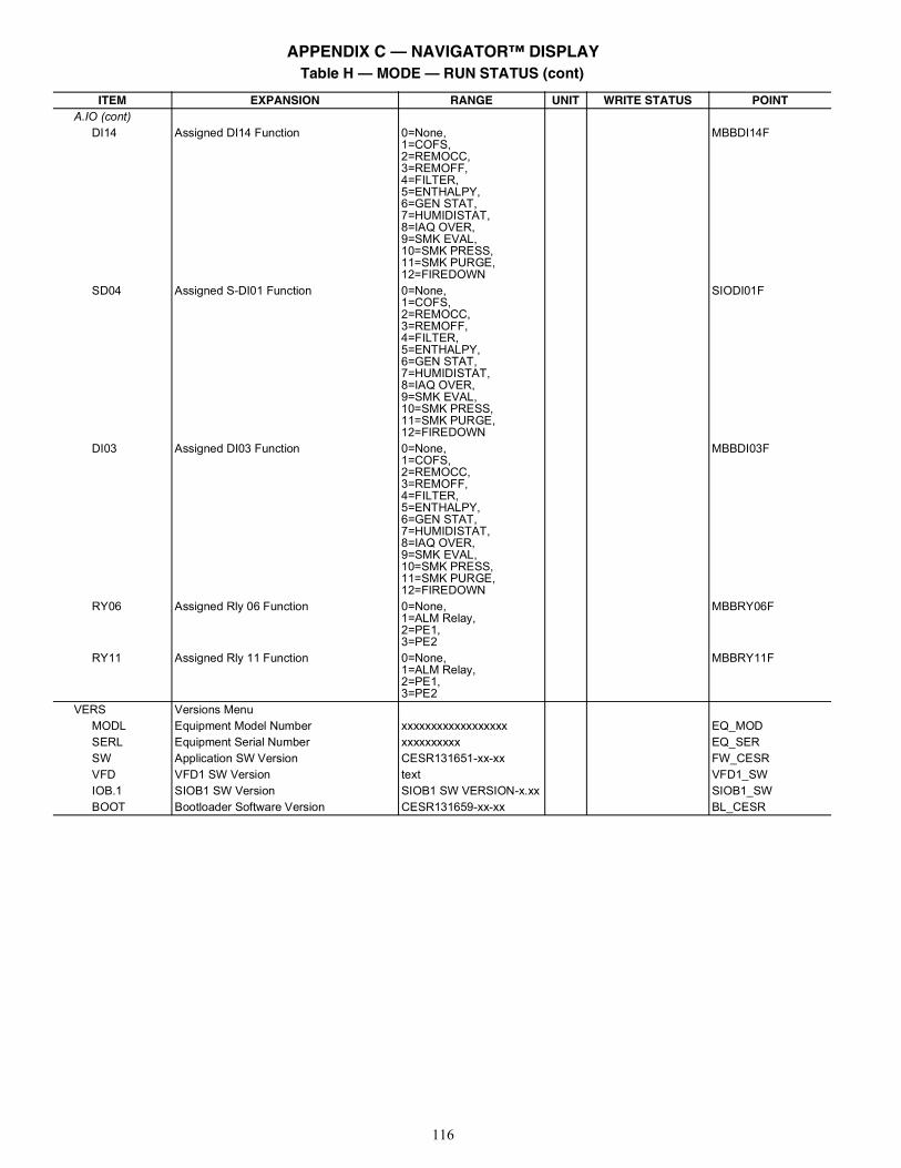
116
A.IO (cont)DI14 Assigned DI14 Function 0=None,
1=COFS,2=REMOCC,3=REMOFF,4=FILTER,5=ENTHALPY,6=GEN STAT,7=HUMIDISTAT,8=IAQ OVER,9=SMK EVAL,10=SMK PRESS,11=SMK PURGE,12=FIREDOWN
MBBDI14F
SD04 Assigned S-DI01 Function 0=None,1=COFS,2=REMOCC,3=REMOFF,4=FILTER,5=ENTHALPY,6=GEN STAT,7=HUMIDISTAT,8=IAQ OVER,9=SMK EVAL,10=SMK PRESS,11=SMK PURGE,12=FIREDOWN
SIODI01F
DI03 Assigned DI03 Function 0=None,1=COFS,2=REMOCC,3=REMOFF,4=FILTER,5=ENTHALPY,6=GEN STAT,7=HUMIDISTAT,8=IAQ OVER,9=SMK EVAL,10=SMK PRESS,11=SMK PURGE,12=FIREDOWN
MBBDI03F
RY06 Assigned Rly 06 Function 0=None,1=ALM Relay,2=PE1,3=PE2
MBBRY06F
RY11 Assigned Rly 11 Function 0=None,1=ALM Relay,2=PE1,3=PE2
MBBRY11F
VERS Versions MenuMODL Equipment Model Number xxxxxxxxxxxxxxxxxx EQ_MODSERL Equipment Serial Number xxxxxxxxxx EQ_SERSW Application SW Version CESR131651-xx-xx FW_CESRVFD VFD1 SW Version text VFD1_SWIOB.1 SIOB1 SW Version SIOB1 SW VERSION-x.xx SIOB1_SWBOOT Bootloader Software Version CESR131659-xx-xx BL_CESR
Table H — MODE — RUN STATUS (cont)
ITEM EXPANSION RANGE UNIT WRITE STATUS POINT
APPENDIX C — NAVIGATOR™ DISPLAY
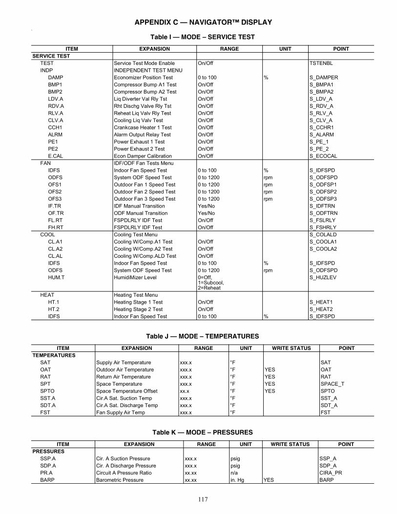
117
%
Table I — MODE – SERVICE TEST
ITEM EXPANSION RANGE UNIT POINTSERVICE TEST
TEST Service Test Mode Enable On/Off TSTENBLINDP INDEPENDENT TEST MENU
DAMP Economizer Position Test 0 to 100 % S_DAMPERBMP1 Compressor Bump A1 Test On/Off S_BMPA1BMP2 Compressor Bump A2 Test On/Off S_BMPA2LDV.A Liq Diverter Val Rly Tst On/Off S_LDV_ARDV.A Rht Dischg Valve Rly Tst On/Off S_RDV_ARLV.A Reheat Liq Valv Rly Test On/Off S_RLV_ACLV.A Cooling Liq Valv Test On/Off S_CLV_ACCH1 Crankcase Heater 1 Test On/Off S_CCHR1ALRM Alarm Output Relay Test On/Off S_ALARMPE1 Power Exhaust 1 Test On/Off S_PE_1PE2 Power Exhaust 2 Test On/Off S_PE_2E.CAL Econ Damper Calibration On/Off S_ECOCAL
FAN IDF/ODF Fan Tests MenuIDFS Indoor Fan Speed Test 0 to 100 % S_IDFSPDODFS System ODF Speed Test 0 to 1200 rpm S_ODFSPDOFS1 Outdoor Fan 1 Speed Test 0 to 1200 rpm S_ODFSP1OFS2 Outdoor Fan 2 Speed Test 0 to 1200 rpm S_ODFSP2OFS3 Outdoor Fan 3 Speed Test 0 to 1200 rpm S_ODFSP3IF.TR IDF Manual Transition Yes/No S_IDFTRNOF.TR ODF Manual Transition Yes/No S_ODFTRNFL.RT FSPDLRLY IDF Test On/Off S_FSLRLYFH.RT FSPDLRLY IDF Test On/Off S_FSHRLY
COOL Cooling Test Menu S_COLALDCL.A1 Cooling W/Comp.A1 Test On/Off S_COOLA1CL.A2 Cooling W/Comp.A2 Test On/Off S_COOLA2CL.AL Cooling W/Comp.ALD Test On/OffIDFS Indoor Fan Speed Test 0 to 100 % S_IDFSPDODFS System ODF Speed Test 0 to 1200 rpm S_ODFSPDHUM.T HumidiMizer Level 0=Off,
1=Subcool,2=Reheat
S_HUZLEV
HEAT Heating Test MenuHT.1 Heating Stage 1 Test On/Off S_HEAT1HT.2 Heating Stage 2 Test On/Off S_HEAT2IDFS Indoor Fan Speed Test 0 to 100 % S_IDFSPD
Table J — MODE – TEMPERATURES
ITEM EXPANSION RANGE UNIT WRITE STATUS POINTTEMPERATURES
SAT Supply Air Temperature xxx.x °F SATOAT Outdoor Air Temperature xxx.x °F YES OATRAT Return Air Temperature xxx.x °F YES RATSPT Space Temperature xxx.x °F YES SPACE_TSPTO Space Temperature Offset xx.x °F YES SPTOSST.A Cir.A Sat. Suction Temp xxx.x °F SST_ASDT.A Cir.A Sat. Discharge Temp xxx.x °F SDT_AFST Fan Supply Air Temp xxx.x °F FST
Table K — MODE – PRESSURES
ITEM EXPANSION RANGE UNIT WRITE STATUS POINTPRESSURES
SSP.A Cir. A Suction Pressure xxx.x psig SSP_ASDP.A Cir. A Discharge Pressure xxx.x psig SDP_APR.A Circuit A Pressure Ratio xx.xx n/a CIRA_PRBARP Barometric Pressure xx.xx in. Hg YES BARP
APPENDIX C — NAVIGATOR™ DISPLAY
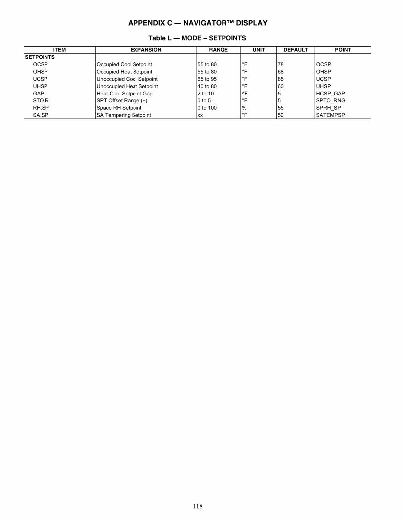
118
Table L — MODE – SETPOINTS
ITEM EXPANSION RANGE UNIT DEFAULT POINTSETPOINTS
OCSP Occupied Cool Setpoint 55 to 80 °F 78 OCSPOHSP Occupied Heat Setpoint 55 to 80 °F 68 OHSPUCSP Unoccupied Cool Setpoint 65 to 95 °F 85 UCSPUHSP Unoccupied Heat Setpoint 40 to 80 °F 60 UHSPGAP Heat-Cool Setpoint Gap 2 to 10 ^F 5 HCSP_GAPSTO.R SPT Offset Range (±) 0 to 5 °F 5 SPTO_RNGRH.SP Space RH Setpoint 0 to 100 % 55 SPRH_SPSA.SP SA Tempering Setpoint xx °F 50 SATEMPSP
APPENDIX C — NAVIGATOR™ DISPLAY
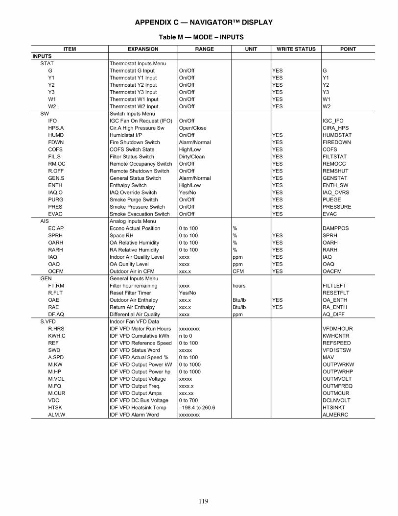
119
Table M — MODE – INPUTS
ITEM EXPANSION RANGE UNIT WRITE STATUS POINTINPUTS
STAT Thermostat Inputs MenuG Thermostat G Input On/Off YES GY1 Thermostat Y1 Input On/Off YES Y1Y2 Thermostat Y2 Input On/Off YES Y2Y3 Thermostat Y3 Input On/Off YES Y3W1 Thermostat W1 Input On/Off YES W1W2 Thermostat W2 Input On/Off YES W2
SW Switch Inputs MenuIFO IGC Fan On Request (IFO) On/Off IGC_IFOHPS.A Cir.A High Pressure Sw Open/Close CIRA_HPSHUMD Humidistat I/P On/Off YES HUMDSTATFDWN Fire Shutdown Switch Alarm/Normal YES FIREDOWNCOFS COFS Switch State High/Low YES COFSFIL.S Filter Status Switch Dirty/Clean YES FILTSTATRM.OC Remote Occupancy Switch On/Off YES REMOCCR.OFF Remote Shutdown Switch On/Off YES REMSHUTGEN.S General Status Switch Alarm/Normal YES GENSTATENTH Enthalpy Switch High/Low YES ENTH_SWIAQ.O IAQ Override Switch Yes/No YES IAQ_OVRSPURG Smoke Purge Switch On/Off YES PUEGEPRES Smoke Pressure Switch On/Off YES PRESSUREEVAC Smoke Evacuation Switch On/Off YES EVAC
AIS Analog Inputs MenuEC.AP Econo Actual Position 0 to 100 % DAMPPOSSPRH Space RH 0 to 100 % YES SPRHOARH OA Relative Humidity 0 to 100 % YES OARHRARH RA Relative Humidity 0 to 100 % YES RARHIAQ Indoor Air Quality Level xxxx ppm YES IAQOAQ OA Quality Level xxxx ppm YES OAQOCFM Outdoor Air in CFM xxx.x CFM YES OACFM
GEN General Inputs MenuFT.RM Filter hour remaining xxxx hours FILTLEFTR.FLT Reset Filter Timer Yes/No RESETFLTOAE Outdoor Air Enthalpy xxx.x Btu/lb YES OA_ENTHRAE Return Air Enthalpy xxx.x Btu/lb YES RA_ENTHDF.AQ Differential Air Quality xxxx ppm AQ_DIFF
S.VFD Indoor Fan VFD DataR.HRS IDF VFD Motor Run Hours xxxxxxxx VFDMHOURKWH.C IDF VFD Cumulative kWh n to 0 KWHCNTRREF IDF VFD Reference Speed 0 to 100 REFSPEEDSWD IDF VFD Status Word xxxxx VFD1STSWA.SPD IDF VFD Actual Speed % 0 to 100 MAVM.KW IDF VFD Output Power kW 0 to 1000 OUTPWRKWM.HP IDF VFD Output Power hp 0 to 1000 OUTPWRHPM.VOL IDF VFD Output Voltage xxxxx OUTMVOLTM.FQ IDF VFD Output Freq. xxxx.x OUTMFREQM.CUR IDF VFD Output Amps xxx.xx OUTMCURVDC IDF VFD DC Bus Voltage 0 to 700 DCLNVOLTHTSK IDF VFD Heatsink Temp –198.4 to 260.6 HTSINKTALM.W IDF VFD Alarm Word xxxxxxxx ALMERRC
APPENDIX C — NAVIGATOR™ DISPLAY
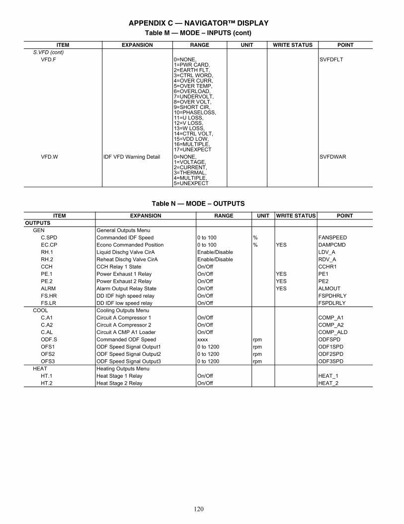
120
S.VFD (cont)VFD.F 0=NONE,
1=PWR CARD,2=EARTH FLT,3=CTRL WORD,4=OVER CURR,5=OVER TEMP,6=OVERLOAD,7=UNDERVOLT,8=OVER VOLT,9=SHORT CIR,10=PHASELOSS,11=U LOSS,12=V LOSS,13=W LOSS,14=CTRL VOLT,15=VDD LOW,16=MULTIPLE,17=UNEXPECT
SVFDFLT
VFD.W IDF VFD Warning Detail 0=NONE,1=VOLTAGE,2=CURRENT,3=THERMAL,4=MULTIPLE,5=UNEXPECT
SVFDWAR
Table M — MODE – INPUTS (cont)
ITEM EXPANSION RANGE UNIT WRITE STATUS POINT
Table N — MODE – OUTPUTS
ITEM EXPANSION RANGE UNIT WRITE STATUS POINTOUTPUTS
GEN General Outputs MenuC.SPD Commanded IDF Speed 0 to 100 % FANSPEEDEC.CP Econo Commanded Position 0 to 100 % YES DAMPCMDRH.1 Liquid Dischg Valve CirA Enable/Disable LDV_ARH.2 Reheat Dischg Valve CirA Enable/Disable RDV_ACCH CCH Relay 1 State On/Off CCHR1PE.1 Power Exhaust 1 Relay On/Off YES PE1PE.2 Power Exhaust 2 Relay On/Off YES PE2ALRM Alarm Output Relay State On/Off YES ALMOUTFS.HR DD IDF high speed relay On/Off FSPDHRLYFS.LR DD IDF low speed relay On/Off FSPDLRLY
COOL Cooling Outputs MenuC.A1 Circuit A Compressor 1 On/Off COMP_A1C.A2 Circuit A Compressor 2 On/Off COMP_A2C.AL Circuit A CMP A1 Loader On/Off COMP_ALDODF.S Commanded ODF Speed xxxx rpm ODFSPDOFS1 ODF Speed Signal Output1 0 to 1200 rpm ODF1SPDOFS2 ODF Speed Signal Output2 0 to 1200 rpm ODF2SPDOFS3 ODF Speed Signal Output3 0 to 1200 rpm ODF3SPD
HEAT Heating Outputs MenuHT.1 Heat Stage 1 Relay On/Off HEAT_1HT.2 Heat Stage 2 Relay On/Off HEAT_2
APPENDIX C — NAVIGATOR™ DISPLAY
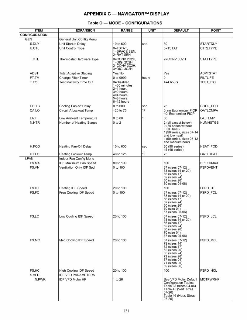
121
Table O — MODE – CONFIGURATIONS
ITEM EXPANSION RANGE UNIT DEFAULT POINTCONFIGURATION
GEN General Unit Config MenuS.DLY Unit Startup Delay 10 to 600 sec 30 STARTDLYU.CTL Unit Control Type 0=TSTAT,
1=SPACE SEN,2=RAT SEN
0=TSTAT CTRLTYPE
T.CTL Thermostat Hardware Type 0=CONV 2C2H,1=DIGI 2C2H,2=CONV 3C2H,3=DIGI 3C2H
2=CONV 3C2H STATTYPE
ADST Tstat Adaptive Staging Yes/No Yes ADPTSTATFT.TM Change Filter Timer 0 to 9999 hours 0 FILTLIFET.TO Test Inactivity Time Out 0=Disabled,
1=30 minutes,2=1 hour,3=2 hours,4=4 hours,5=8 hours,6=12 hours
4=4 hours TEST_ITO
FOD.C Cooling Fan-off Delay 0 to 600 sec 75 COOL_FODCA.LO Circuit A Lockout Temp –20 to 75 °F 0: no Economizer FIOP
40: Economizer FIOPOATLCMPA
LA.T Low Ambient Temperature 0 to 80 °F 66 LA_TEMPN.HTR Number of Heating Stages 0 to 2 2 (all except below);
0 (50 series without FIOP heat)1 (50 series, sizes 07-14 and low heat)1 (50 series, sizes 07-12 and medium heat)
NUMHSTGS
H.FOD Heating Fan-Off Delay 10 to 600 sec 30 (50 series)45 (48 series)
HEAT_FOD
HT.LO Heating Lockout Temp 40 to 125 °F 75 OATLHEATI.FAN Indoor Fan Config Menu
FS.MX IDF Maximum Fan Speed 80 to 100 100 SPEEDMAXFS.VN Ventilation Only IDF Spd 0 to 100 67 (sizes 07-12)
53 (sizes 14 or 20)56 (sizes 17)52 (sizes 24)60 (sizes 26)50 (sizes 04-06)
FSPDVENT
FS.HT Heating IDF Speed 20 to 100 100 FSPD_HTFS.FC Free Cooling IDF Speed 0 to 100 67 (sizes 07-12)
53 (sizes 14 or 20)56 (sizes 17)52 (sizes 24)60 (sizes 26)70 (size 04)57 (sizes 05-06)
FSPD_FCL
FS.LC Low Cooling IDF Speed 20 to 100 67 (sizes 07-12)53 (sizes 14 or 20)56 (sizes 17)52 (sizes 24)60 (sizes 26)70 (size 04)57 (sizes 05-06)
FSPD_LCL
FS.MC Med Cooling IDF Speed 20 to 100 67 (sizes 07-12)79 (sizes 14)82 (sizes 17)62 (sizes 20)65 (sizes 24)72 (sizes 26)87 (sizes 04)71 (sizes 05)69 (sizes 06)
FSPD_MCL
FS.HC High Cooling IDF Speed 20 to 100 100 FSPD_HCLS.VFD IDF VFD PARAMETERS
N.PWR IDF VFD Motor HP 1 to 26 See VFD Motor Default Configuration Tables.Table 38 (sizes 04-06)Table 45 (Vert. sizes07-26)Table 46 (Horz. Sizes 07-26)
MOTPWRHP
APPENDIX C — NAVIGATOR™ DISPLAY
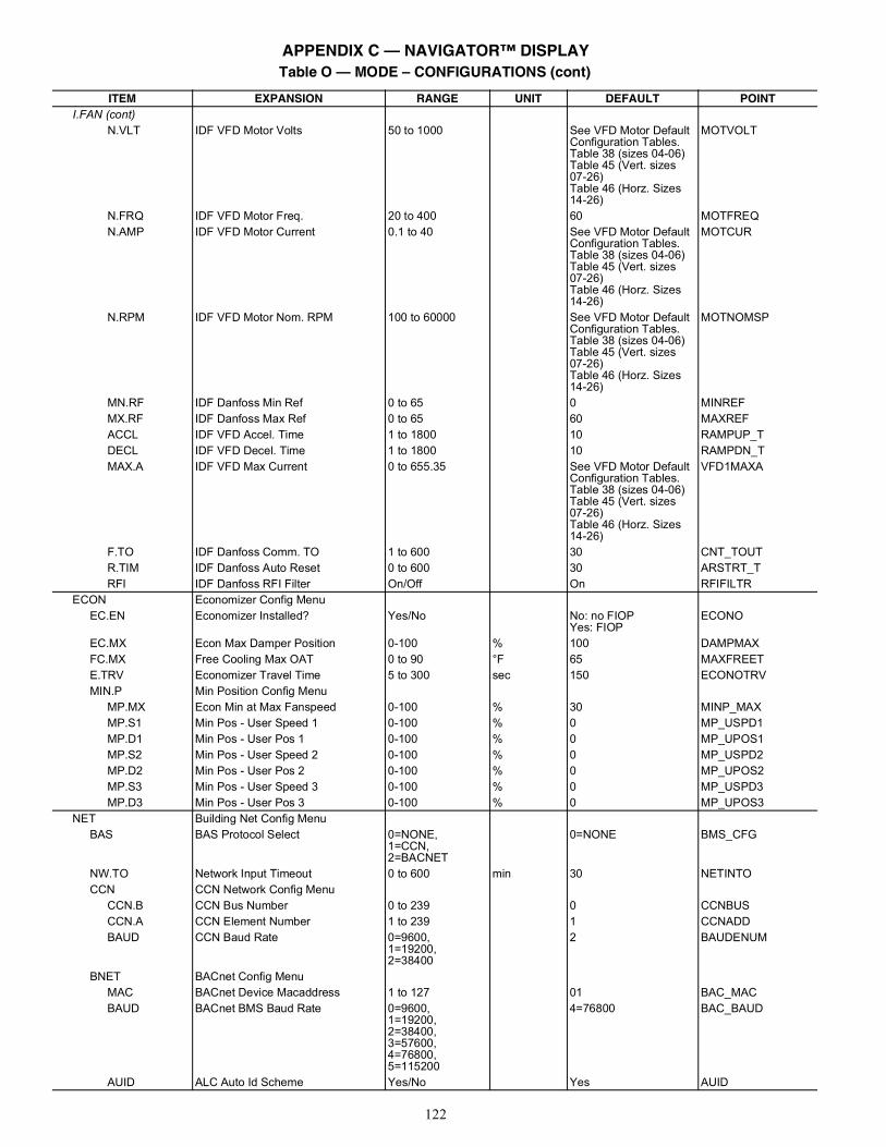
122
I.FAN (cont)N.VLT IDF VFD Motor Volts 50 to 1000 See VFD Motor Default
Configuration Tables.Table 38 (sizes 04-06)Table 45 (Vert. sizes07-26)Table 46 (Horz. Sizes 14-26)
MOTVOLT
N.FRQ IDF VFD Motor Freq. 20 to 400 60 MOTFREQN.AMP IDF VFD Motor Current 0.1 to 40 See VFD Motor Default
Configuration Tables.Table 38 (sizes 04-06)Table 45 (Vert. sizes07-26)Table 46 (Horz. Sizes 14-26)
MOTCUR
N.RPM IDF VFD Motor Nom. RPM 100 to 60000 See VFD Motor Default Configuration Tables.Table 38 (sizes 04-06)Table 45 (Vert. sizes07-26)Table 46 (Horz. Sizes 14-26)
MOTNOMSP
MN.RF IDF Danfoss Min Ref 0 to 65 0 MINREFMX.RF IDF Danfoss Max Ref 0 to 65 60 MAXREFACCL IDF VFD Accel. Time 1 to 1800 10 RAMPUP_TDECL IDF VFD Decel. Time 1 to 1800 10 RAMPDN_TMAX.A IDF VFD Max Current 0 to 655.35 See VFD Motor Default
Configuration Tables.Table 38 (sizes 04-06)Table 45 (Vert. sizes07-26)Table 46 (Horz. Sizes 14-26)
VFD1MAXA
F.TO IDF Danfoss Comm. TO 1 to 600 30 CNT_TOUTR.TIM IDF Danfoss Auto Reset 0 to 600 30 ARSTRT_TRFI IDF Danfoss RFI Filter On/Off On RFIFILTR
ECON Economizer Config MenuEC.EN Economizer Installed? Yes/No No: no FIOP
Yes: FIOPECONO
EC.MX Econ Max Damper Position 0-100 % 100 DAMPMAXFC.MX Free Cooling Max OAT 0 to 90 °F 65 MAXFREETE.TRV Economizer Travel Time 5 to 300 sec 150 ECONOTRVMIN.P Min Position Config Menu
MP.MX Econ Min at Max Fanspeed 0-100 % 30 MINP_MAXMP.S1 Min Pos - User Speed 1 0-100 % 0 MP_USPD1MP.D1 Min Pos - User Pos 1 0-100 % 0 MP_UPOS1MP.S2 Min Pos - User Speed 2 0-100 % 0 MP_USPD2MP.D2 Min Pos - User Pos 2 0-100 % 0 MP_UPOS2MP.S3 Min Pos - User Speed 3 0-100 % 0 MP_USPD3MP.D3 Min Pos - User Pos 3 0-100 % 0 MP_UPOS3
NET Building Net Config MenuBAS BAS Protocol Select 0=NONE,
1=CCN,2=BACNET
0=NONE BMS_CFG
NW.TO Network Input Timeout 0 to 600 min 30 NETINTOCCN CCN Network Config Menu
CCN.B CCN Bus Number 0 to 239 0 CCNBUSCCN.A CCN Element Number 1 to 239 1 CCNADDBAUD CCN Baud Rate 0=9600,
1=19200,2=38400
2 BAUDENUM
BNET BACnet Config MenuMAC BACnet Device Macaddress 1 to 127 01 BAC_MACBAUD BACnet BMS Baud Rate 0=9600,
1=19200,2=38400,3=57600,4=76800,5=115200
4=76800 BAC_BAUD
AUID ALC Auto Id Scheme Yes/No Yes AUID
Table O — MODE – CONFIGURATIONS (cont)
ITEM EXPANSION RANGE UNIT DEFAULT POINT
APPENDIX C — NAVIGATOR™ DISPLAY
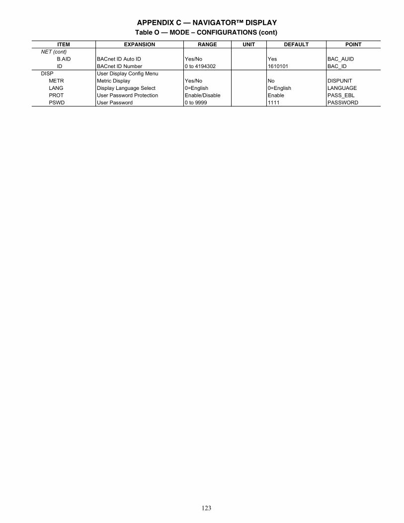
123
NET (cont)B.AID BACnet ID Auto ID Yes/No Yes BAC_AUIDID BACnet ID Number 0 to 4194302 1610101 BAC_ID
DISP User Display Config MenuMETR Metric Display Yes/No No DISPUNITLANG Display Language Select 0=English 0=English LANGUAGEPROT User Password Protection Enable/Disable Enable PASS_EBLPSWD User Password 0 to 9999 1111 PASSWORD
Table O — MODE – CONFIGURATIONS (cont)
ITEM EXPANSION RANGE UNIT DEFAULT POINT
APPENDIX C — NAVIGATOR™ DISPLAY
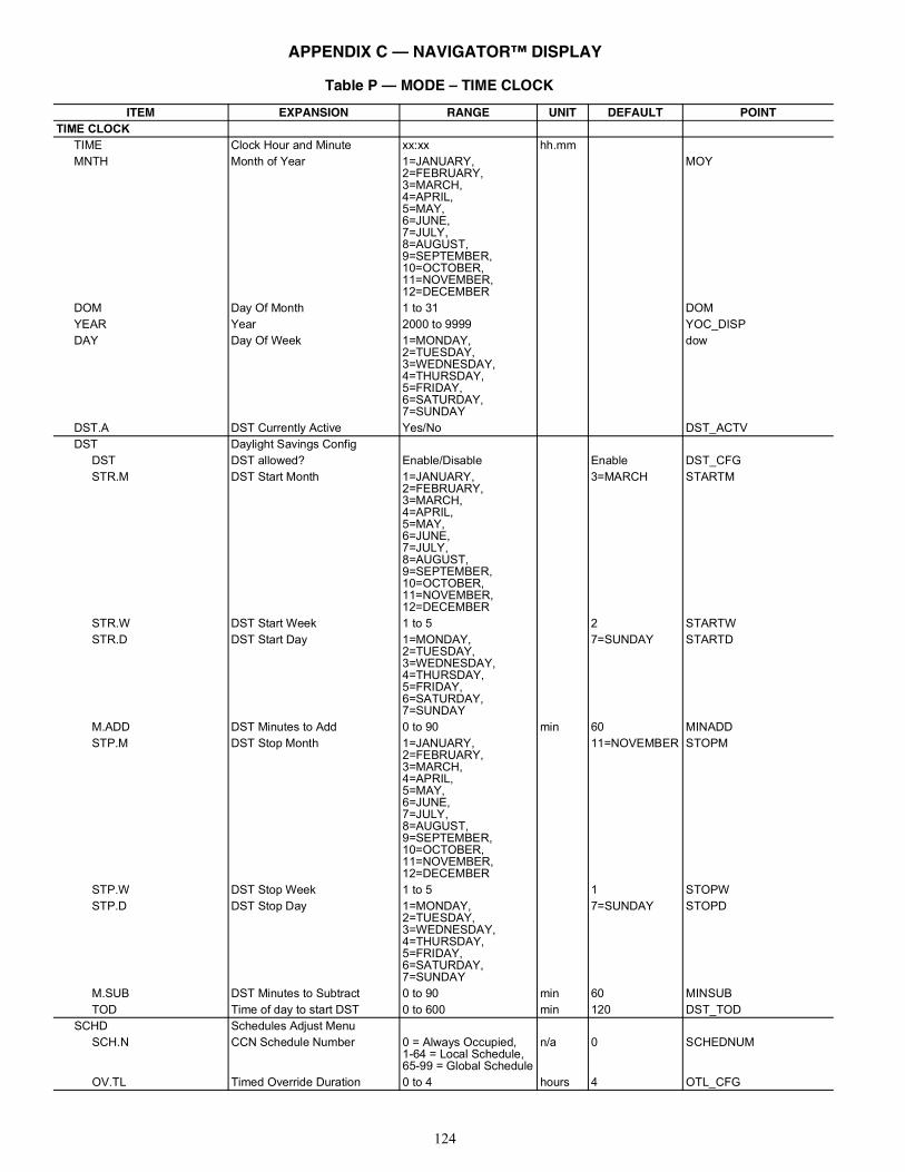
124
Table P — MODE – TIME CLOCK
ITEM EXPANSION RANGE UNIT DEFAULT POINTTIME CLOCK
TIME Clock Hour and Minute xx:xx hh.mmMNTH Month of Year 1=JANUARY,
2=FEBRUARY,3=MARCH,4=APRIL,5=MAY,6=JUNE,7=JULY,8=AUGUST,9=SEPTEMBER,10=OCTOBER,11=NOVEMBER,12=DECEMBER
MOY
DOM Day Of Month 1 to 31 DOMYEAR Year 2000 to 9999 YOC_DISPDAY Day Of Week 1=MONDAY,
2=TUESDAY,3=WEDNESDAY,4=THURSDAY,5=FRIDAY,6=SATURDAY,7=SUNDAY
dow
DST.A DST Currently Active Yes/No DST_ACTVDST Daylight Savings Config
DST DST allowed? Enable/Disable Enable DST_CFGSTR.M DST Start Month 1=JANUARY,
2=FEBRUARY,3=MARCH,4=APRIL,5=MAY,6=JUNE,7=JULY,8=AUGUST,9=SEPTEMBER,10=OCTOBER,11=NOVEMBER,12=DECEMBER
3=MARCH STARTM
STR.W DST Start Week 1 to 5 2 STARTWSTR.D DST Start Day 1=MONDAY,
2=TUESDAY,3=WEDNESDAY,4=THURSDAY,5=FRIDAY,6=SATURDAY,7=SUNDAY
7=SUNDAY STARTD
M.ADD DST Minutes to Add 0 to 90 min 60 MINADDSTP.M DST Stop Month 1=JANUARY,
2=FEBRUARY,3=MARCH,4=APRIL,5=MAY,6=JUNE,7=JULY,8=AUGUST,9=SEPTEMBER,10=OCTOBER,11=NOVEMBER,12=DECEMBER
11=NOVEMBER STOPM
STP.W DST Stop Week 1 to 5 1 STOPWSTP.D DST Stop Day 1=MONDAY,
2=TUESDAY,3=WEDNESDAY,4=THURSDAY,5=FRIDAY,6=SATURDAY,7=SUNDAY
7=SUNDAY STOPD
M.SUB DST Minutes to Subtract 0 to 90 min 60 MINSUBTOD Time of day to start DST 0 to 600 min 120 DST_TOD
SCHD Schedules Adjust MenuSCH.N CCN Schedule Number 0 = Always Occupied,
1-64 = Local Schedule,65-99 = Global Schedule
n/a 0 SCHEDNUM
OV.TL Timed Override Duration 0 to 4 hours 4 OTL_CFG
APPENDIX C — NAVIGATOR™ DISPLAY
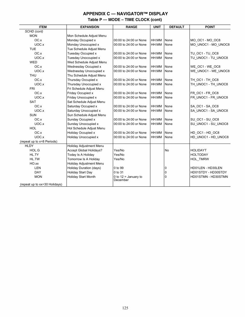
125
SCHD (cont)MON Mon Schedule Adjust Menu
OC.x Monday Occupied x 00:00 to 24:00 or None HH:MM None MO_OC1 - MO_OC8UOC.x Monday Unoccupied x 00:00 to 24:00 or None HH:MM None MO_UNOC1 - MO_UNOC8
TUE Tue Schedule Adjust MenuOC.x Tuesday Occupied x 00:00 to 24:00 or None HH:MM None TU_OC1 - TU_OC8UOC.x Tuesday Unoccupied x 00:00 to 24:00 or None HH:MM None TU_UNOC1 - TU_UNOC8
WED Wed Schedule Adjust MenuOC.x Wednesday Occupied x 00:00 to 24:00 or None HH:MM None WE_OC1 - WE_OC8UOC.x Wednesday Unoccupied x 00:00 to 24:00 or None HH:MM None WE_UNOC1 - WE_UNOC8
THU Thu Schedule Adjust MenuOC.x Thursday Occupied x 00:00 to 24:00 or None HH:MM None TH_OC1 - TH_OC8UOC.x Thursday Unoccupied x 00:00 to 24:00 or None HH:MM None TH_UNOC1 - TH_UNOC8
FRI Fri Schedule Adjust MenuOC.x Friday Occupied x 00:00 to 24:00 or None HH:MM None FR_OC1 - FR_OC8UOC.x Friday Unoccupied x 00:00 to 24:00 or None HH:MM None FR_UNOC1 - FR_UNOC8
SAT Sat Schedule Adjust MenuOC.x Saturday Occupied x 00:00 to 24:00 or None HH:MM None SA_OC1 - SA_OC8UOC.x Saturday Unoccupied x 00:00 to 24:00 or None HH:MM None SA_UNOC1 - SA_UNOC8
SUN Sun Schedule Adjust MenuOC.x Sunday Occupied x 00:00 to 24:00 or None HH:MM None SU_OC1 - SU_OC8UOC.x Sunday Unoccupied x 00:00 to 24:00 or None HH:MM None SU_UNOC1 - SU_UNOC8
HOL Hol Schedule Adjust MenuOC.x Holiday Occupied x 00:00 to 24:00 or None HH:MM None HD_OC1 - HD_OC8UOC.x Holiday Unoccupied x 00:00 to 24:00 or None HH:MM None HD_UNOC1 - HD_UNOC8
(repeat up to x=8 Periods)HLDY Holiday Adjustment Menu
HOL.G Accept Global Holidays? Yes/No No HOLIDAYTHL.TY Today Is A Holiday Yes/No HOLTODAYHL.TW Tomorrow Is A Holiday Yes/No HOL_TMRWHO.xx Holiday Adjustment Menu
LEN Holiday Duration (days) 0 to 99 0 HD01LEN - HD30LENDAY Holiday Start Day 0 to 31 0 HD01STDY - HD30STDYMON Holiday Start Month 0 to 12 = January to
December0 HD01STMN - HD30STMN
(repeat up to xx=30 Holidays)
Table P — MODE – TIME CLOCK (cont)
ITEM EXPANSION RANGE UNIT DEFAULT POINT
APPENDIX C — NAVIGATOR™ DISPLAY
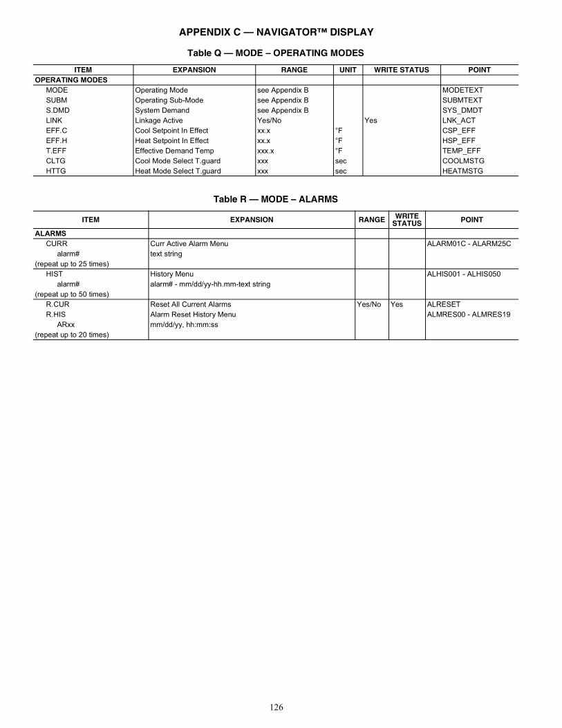
126
Table Q — MODE – OPERATING MODES
ITEM EXPANSION RANGE UNIT WRITE STATUS POINTOPERATING MODES
MODE Operating Mode see Appendix B MODETEXTSUBM Operating Sub-Mode see Appendix B SUBMTEXTS.DMD System Demand see Appendix B SYS_DMDTLINK Linkage Active Yes/No Yes LNK_ACTEFF.C Cool Setpoint In Effect xx.x °F CSP_EFFEFF.H Heat Setpoint In Effect xx.x °F HSP_EFFT.EFF Effective Demand Temp xxx.x °F TEMP_EFFCLTG Cool Mode Select T.guard xxx sec COOLMSTGHTTG Heat Mode Select T.guard xxx sec HEATMSTG
Table R — MODE – ALARMS
ITEM EXPANSION RANGE WRITESTATUS POINT
ALARMSCURR Curr Active Alarm Menu ALARM01C - ALARM25C
alarm# text string(repeat up to 25 times)
HIST History Menu ALHIS001 - ALHIS050alarm# alarm# - mm/dd/yy-hh.mm-text string
(repeat up to 50 times)R.CUR Reset All Current Alarms Yes/No Yes ALRESETR.HIS Alarm Reset History Menu ALMRES00 - ALMRES19
ARxx mm/dd/yy, hh:mm:ss(repeat up to 20 times)
APPENDIX C — NAVIGATOR™ DISPLAY
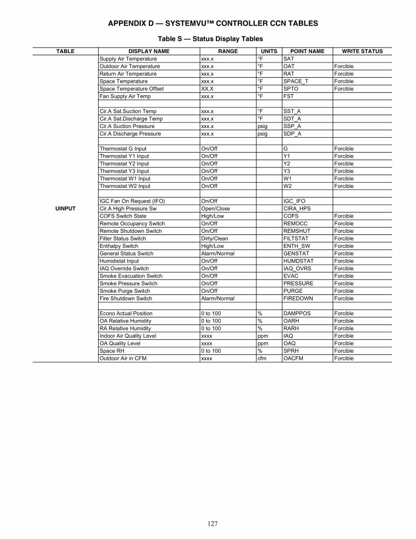
127
Table S — Status Display Tables
TABLE DISPLAY NAME RANGE UNITS POINT NAME WRITE STATUS
UINPUT
Supply Air Temperature xxx.x °F SATOutdoor Air Temperature xxx.x °F OAT ForcibleReturn Air Temperature xxx.x °F RAT ForcibleSpace Temperature xxx.x °F SPACE_T ForcibleSpace Temperature Offset XX.X °F SPTO ForcibleFan Supply Air Temp xxx.x °F FST
Cir.A Sat.Suction Temp xxx.x °F SST_ACir.A Sat.Discharge Temp xxx.x °F SDT_ACir.A Suction Pressure xxx.x psig SSP_ACir.A Discharge Pressure xxx.x psig SDP_A
Thermostat G Input On/Off G ForcibleThermostat Y1 Input On/Off Y1 ForcibleThermostat Y2 Input On/Off Y2 ForcibleThermostat Y3 Input On/Off Y3 ForcibleThermostat W1 Input On/Off W1 ForcibleThermostat W2 Input On/Off W2 Forcible
IGC Fan On Request (IFO) On/Off IGC_IFOCir.A High Pressure Sw Open/Close CIRA_HPSCOFS Switch State High/Low COFS ForcibleRemote Occupancy Switch On/Off REMOCC ForcibleRemote Shutdown Switch On/Off REMSHUT ForcibleFilter Status Switch Dirty/Clean FILTSTAT ForcibleEnthalpy Switch High/Low ENTH_SW ForcibleGeneral Status Switch Alarm/Normal GENSTAT ForcibleHumidistat Input On/Off HUMDSTAT ForcibleIAQ Override Switch On/Off IAQ_OVRS ForcibleSmoke Evacuation Switch On/Off EVAC ForcibleSmoke Pressure Switch On/Off PRESSURE ForcibleSmoke Purge Switch On/Off PURGE ForcibleFire Shutdown Switch Alarm/Normal FIREDOWN Forcible
Econo Actual Position 0 to 100 % DAMPPOS ForcibleOA Relative Humidity 0 to 100 % OARH ForcibleRA Relative Humidity 0 to 100 % RARH ForcibleIndoor Air Quality Level xxxx ppm IAQ ForcibleOA Quality Level xxxx ppm OAQ ForcibleSpace RH 0 to 100 % SPRH ForcibleOutdoor Air in CFM xxxx cfm OACFM Forcible
APPENDIX D — SYSTEMVU™ CONTROLLER CCN TABLES
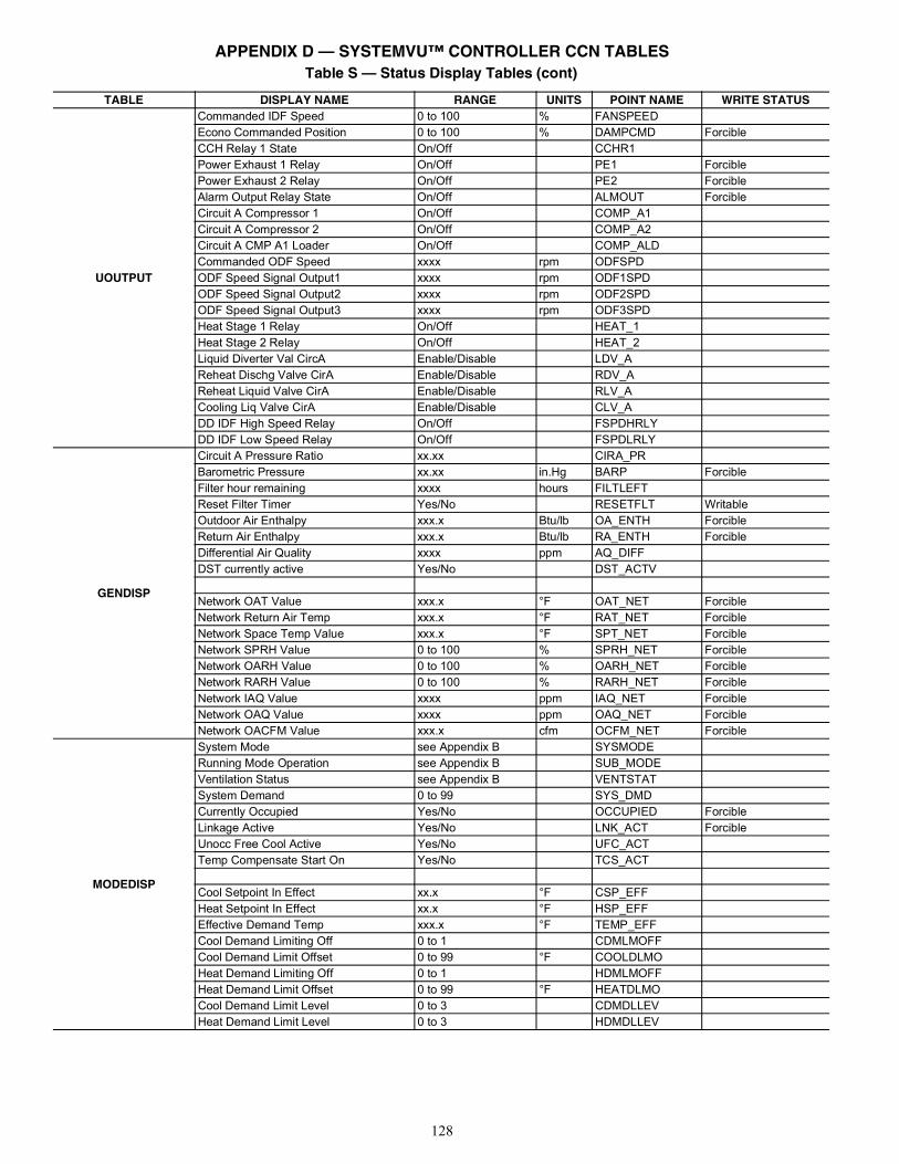
128
UOUTPUT
Commanded IDF Speed 0 to 100 % FANSPEEDEcono Commanded Position 0 to 100 % DAMPCMD ForcibleCCH Relay 1 State On/Off CCHR1Power Exhaust 1 Relay On/Off PE1 ForciblePower Exhaust 2 Relay On/Off PE2 ForcibleAlarm Output Relay State On/Off ALMOUT ForcibleCircuit A Compressor 1 On/Off COMP_A1Circuit A Compressor 2 On/Off COMP_A2Circuit A CMP A1 Loader On/Off COMP_ALDCommanded ODF Speed xxxx rpm ODFSPDODF Speed Signal Output1 xxxx rpm ODF1SPDODF Speed Signal Output2 xxxx rpm ODF2SPDODF Speed Signal Output3 xxxx rpm ODF3SPDHeat Stage 1 Relay On/Off HEAT_1Heat Stage 2 Relay On/Off HEAT_2Liquid Diverter Val CircA Enable/Disable LDV_AReheat Dischg Valve CirA Enable/Disable RDV_AReheat Liquid Valve CirA Enable/Disable RLV_ACooling Liq Valve CirA Enable/Disable CLV_ADD IDF High Speed Relay On/Off FSPDHRLYDD IDF Low Speed Relay On/Off FSPDLRLY
GENDISP
Circuit A Pressure Ratio xx.xx CIRA_PRBarometric Pressure xx.xx in.Hg BARP ForcibleFilter hour remaining xxxx hours FILTLEFTReset Filter Timer Yes/No RESETFLT WritableOutdoor Air Enthalpy xxx.x Btu/lb OA_ENTH ForcibleReturn Air Enthalpy xxx.x Btu/lb RA_ENTH ForcibleDifferential Air Quality xxxx ppm AQ_DIFFDST currently active Yes/No DST_ACTV
Network OAT Value xxx.x °F OAT_NET ForcibleNetwork Return Air Temp xxx.x °F RAT_NET ForcibleNetwork Space Temp Value xxx.x °F SPT_NET ForcibleNetwork SPRH Value 0 to 100 % SPRH_NET ForcibleNetwork OARH Value 0 to 100 % OARH_NET ForcibleNetwork RARH Value 0 to 100 % RARH_NET ForcibleNetwork IAQ Value xxxx ppm IAQ_NET ForcibleNetwork OAQ Value xxxx ppm OAQ_NET ForcibleNetwork OACFM Value xxx.x cfm OCFM_NET Forcible
MODEDISP
System Mode see Appendix B SYSMODERunning Mode Operation see Appendix B SUB_MODEVentilation Status see Appendix B VENTSTATSystem Demand 0 to 99 SYS_DMDCurrently Occupied Yes/No OCCUPIED ForcibleLinkage Active Yes/No LNK_ACT ForcibleUnocc Free Cool Active Yes/No UFC_ACTTemp Compensate Start On Yes/No TCS_ACT
Cool Setpoint In Effect xx.x °F CSP_EFFHeat Setpoint In Effect xx.x °F HSP_EFFEffective Demand Temp xxx.x °F TEMP_EFFCool Demand Limiting Off 0 to 1 CDMLMOFFCool Demand Limit Offset 0 to 99 °F COOLDLMOHeat Demand Limiting Off 0 to 1 HDMLMOFFHeat Demand Limit Offset 0 to 99 °F HEATDLMOCool Demand Limit Level 0 to 3 CDMDLLEVHeat Demand Limit Level 0 to 3 HDMDLLEV
Table S — Status Display Tables (cont)
TABLE DISPLAY NAME RANGE UNITS POINT NAME WRITE STATUS
APPENDIX D — SYSTEMVU™ CONTROLLER CCN TABLES
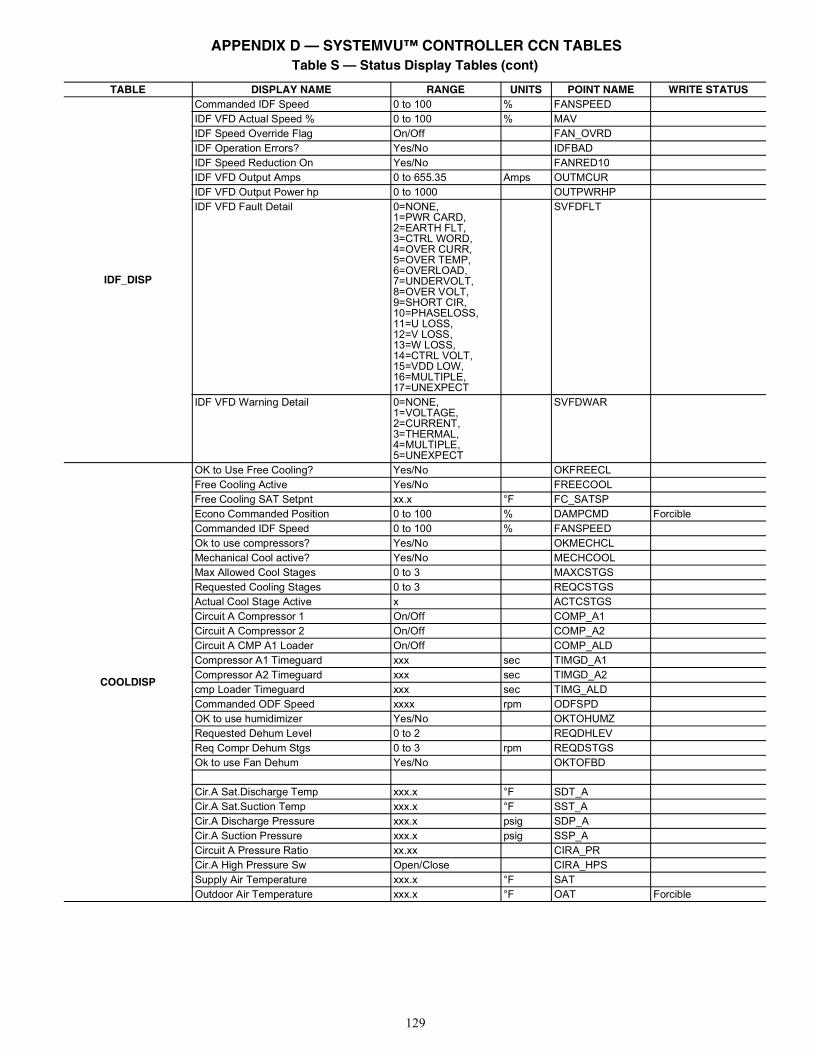
129
IDF_DISP
Commanded IDF Speed 0 to 100 % FANSPEEDIDF VFD Actual Speed % 0 to 100 % MAVIDF Speed Override Flag On/Off FAN_OVRDIDF Operation Errors? Yes/No IDFBADIDF Speed Reduction On Yes/No FANRED10IDF VFD Output Amps 0 to 655.35 Amps OUTMCURIDF VFD Output Power hp 0 to 1000 OUTPWRHPIDF VFD Fault Detail 0=NONE,
1=PWR CARD,2=EARTH FLT,3=CTRL WORD,4=OVER CURR,5=OVER TEMP,6=OVERLOAD,7=UNDERVOLT,8=OVER VOLT,9=SHORT CIR,10=PHASELOSS,11=U LOSS,12=V LOSS,13=W LOSS,14=CTRL VOLT,15=VDD LOW,16=MULTIPLE,17=UNEXPECT
SVFDFLT
IDF VFD Warning Detail 0=NONE,1=VOLTAGE,2=CURRENT,3=THERMAL,4=MULTIPLE,5=UNEXPECT
SVFDWAR
COOLDISP
OK to Use Free Cooling? Yes/No OKFREECLFree Cooling Active Yes/No FREECOOLFree Cooling SAT Setpnt xx.x °F FC_SATSPEcono Commanded Position 0 to 100 % DAMPCMD ForcibleCommanded IDF Speed 0 to 100 % FANSPEEDOk to use compressors? Yes/No OKMECHCLMechanical Cool active? Yes/No MECHCOOLMax Allowed Cool Stages 0 to 3 MAXCSTGSRequested Cooling Stages 0 to 3 REQCSTGSActual Cool Stage Active x ACTCSTGSCircuit A Compressor 1 On/Off COMP_A1Circuit A Compressor 2 On/Off COMP_A2Circuit A CMP A1 Loader On/Off COMP_ALDCompressor A1 Timeguard xxx sec TIMGD_A1Compressor A2 Timeguard xxx sec TIMGD_A2cmp Loader Timeguard xxx sec TIMG_ALDCommanded ODF Speed xxxx rpm ODFSPDOK to use humidimizer Yes/No OKTOHUMZRequested Dehum Level 0 to 2 REQDHLEVReq Compr Dehum Stgs 0 to 3 rpm REQDSTGSOk to use Fan Dehum Yes/No OKTOFBD
Cir.A Sat.Discharge Temp xxx.x °F SDT_ACir.A Sat.Suction Temp xxx.x °F SST_ACir.A Discharge Pressure xxx.x psig SDP_ACir.A Suction Pressure xxx.x psig SSP_ACircuit A Pressure Ratio xx.xx CIRA_PRCir.A High Pressure Sw Open/Close CIRA_HPSSupply Air Temperature xxx.x °F SATOutdoor Air Temperature xxx.x °F OAT Forcible
Table S — Status Display Tables (cont)
TABLE DISPLAY NAME RANGE UNITS POINT NAME WRITE STATUS
APPENDIX D — SYSTEMVU™ CONTROLLER CCN TABLES
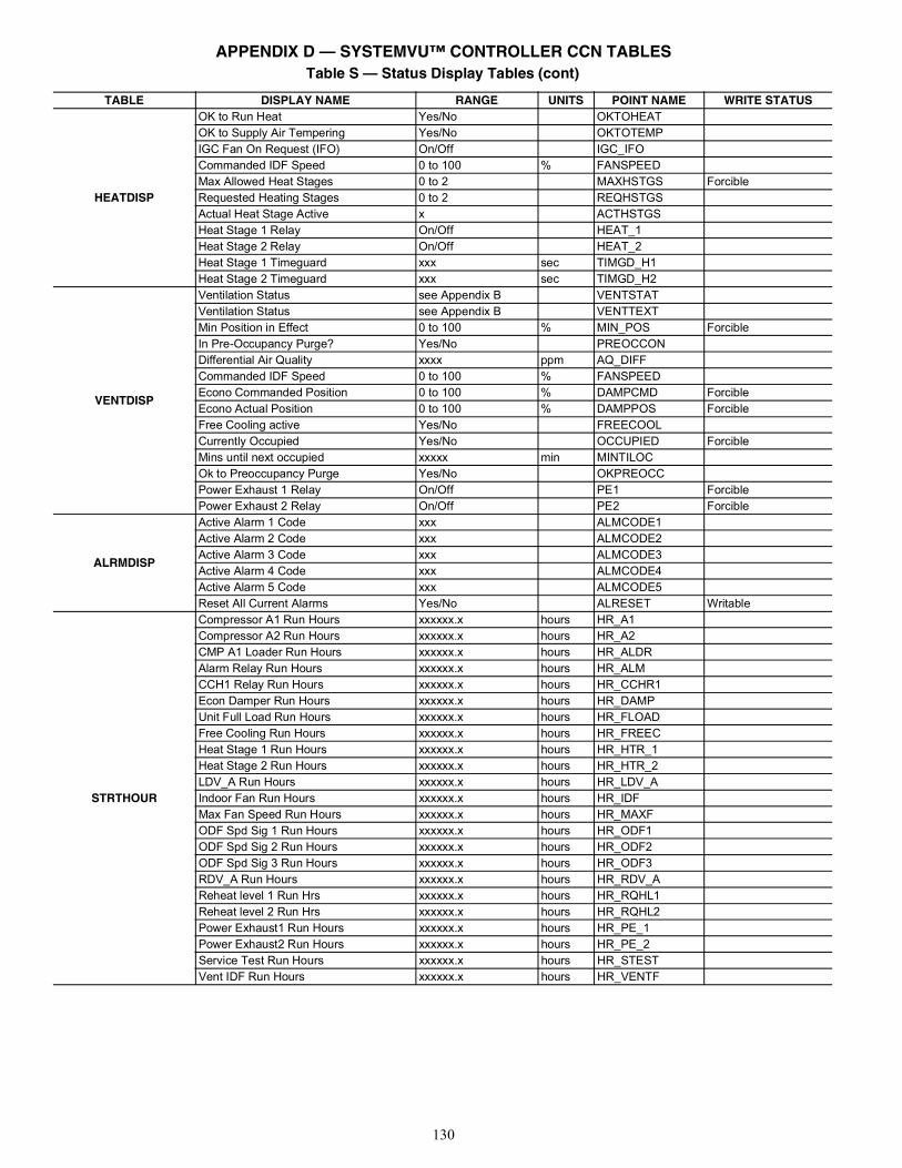
130
HEATDISP
OK to Run Heat Yes/No OKTOHEATOK to Supply Air Tempering Yes/No OKTOTEMPIGC Fan On Request (IFO) On/Off IGC_IFOCommanded IDF Speed 0 to 100 % FANSPEEDMax Allowed Heat Stages 0 to 2 MAXHSTGS ForcibleRequested Heating Stages 0 to 2 REQHSTGSActual Heat Stage Active x ACTHSTGSHeat Stage 1 Relay On/Off HEAT_1Heat Stage 2 Relay On/Off HEAT_2Heat Stage 1 Timeguard xxx sec TIMGD_H1Heat Stage 2 Timeguard xxx sec TIMGD_H2
VENTDISP
Ventilation Status see Appendix B VENTSTATVentilation Status see Appendix B VENTTEXTMin Position in Effect 0 to 100 % MIN_POS ForcibleIn Pre-Occupancy Purge? Yes/No PREOCCONDifferential Air Quality xxxx ppm AQ_DIFFCommanded IDF Speed 0 to 100 % FANSPEEDEcono Commanded Position 0 to 100 % DAMPCMD ForcibleEcono Actual Position 0 to 100 % DAMPPOS ForcibleFree Cooling active Yes/No FREECOOLCurrently Occupied Yes/No OCCUPIED ForcibleMins until next occupied xxxxx min MINTILOCOk to Preoccupancy Purge Yes/No OKPREOCCPower Exhaust 1 Relay On/Off PE1 ForciblePower Exhaust 2 Relay On/Off PE2 Forcible
ALRMDISP
Active Alarm 1 Code xxx ALMCODE1Active Alarm 2 Code xxx ALMCODE2Active Alarm 3 Code xxx ALMCODE3Active Alarm 4 Code xxx ALMCODE4Active Alarm 5 Code xxx ALMCODE5Reset All Current Alarms Yes/No ALRESET Writable
STRTHOUR
Compressor A1 Run Hours xxxxxx.x hours HR_A1Compressor A2 Run Hours xxxxxx.x hours HR_A2CMP A1 Loader Run Hours xxxxxx.x hours HR_ALDRAlarm Relay Run Hours xxxxxx.x hours HR_ALMCCH1 Relay Run Hours xxxxxx.x hours HR_CCHR1Econ Damper Run Hours xxxxxx.x hours HR_DAMPUnit Full Load Run Hours xxxxxx.x hours HR_FLOADFree Cooling Run Hours xxxxxx.x hours HR_FREECHeat Stage 1 Run Hours xxxxxx.x hours HR_HTR_1Heat Stage 2 Run Hours xxxxxx.x hours HR_HTR_2LDV_A Run Hours xxxxxx.x hours HR_LDV_AIndoor Fan Run Hours xxxxxx.x hours HR_IDFMax Fan Speed Run Hours xxxxxx.x hours HR_MAXFODF Spd Sig 1 Run Hours xxxxxx.x hours HR_ODF1ODF Spd Sig 2 Run Hours xxxxxx.x hours HR_ODF2ODF Spd Sig 3 Run Hours xxxxxx.x hours HR_ODF3RDV_A Run Hours xxxxxx.x hours HR_RDV_AReheat level 1 Run Hrs xxxxxx.x hours HR_RQHL1Reheat level 2 Run Hrs xxxxxx.x hours HR_RQHL2Power Exhaust1 Run Hours xxxxxx.x hours HR_PE_1Power Exhaust2 Run Hours xxxxxx.x hours HR_PE_2Service Test Run Hours xxxxxx.x hours HR_STESTVent IDF Run Hours xxxxxx.x hours HR_VENTF
Table S — Status Display Tables (cont)
TABLE DISPLAY NAME RANGE UNITS POINT NAME WRITE STATUS
APPENDIX D — SYSTEMVU™ CONTROLLER CCN TABLES
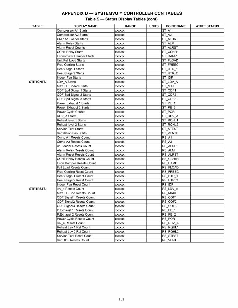
131
STRTCNTS
Compressor A1 Starts xxxxxx ST_A1Compressor A2 Starts xxxxxx ST_A2CMP A1 Loader Starts xxxxxx ST_ALDRAlarm Relay Starts xxxxxx ST_ALMAlarm Reset Counts xxxxxx ST_ALRSTCCH1 Relay Starts xxxxxx ST_CCHR1Economizer Damper Starts xxxxxx ST_DAMPUnit Full Load Starts xxxxxx ST_FLOADFree Cooling Starts xxxxxx ST_FREECHeat Stage 1 Starts xxxxxx ST_HTR_1Heat Stage 2 Starts xxxxxx ST_HTR_2Indoor Fan Starts xxxxxx ST_IDFLDV_A Starts xxxxxx ST_LDV_AMax IDF Speed Starts xxxxxx ST_MAXFODF Spd Signal 1 Starts xxxxxx ST_ODF1ODF Spd Signal 2 Starts xxxxxx ST_ODF2ODF Spd Signal 3 Starts xxxxxx ST_ODF3Power Exhaust 1 Starts xxxxxx ST_PE_1Power Exhaust 2 Starts xxxxxx ST_PE_2Power Cycle Counts xxxxxx ST_PORRDV_A Starts xxxxxx ST_RDV_AReheat level 1 Starts xxxxxx ST_RQHL1Reheat level 2 Starts xxxxxx ST_RQHL2Service Test Starts xxxxxx ST_STESTVentilation Fan Starts xxxxxx ST_VENTF
STRTRSTS
Comp A1 Resets Count xxxxxx RS_A1Comp A2 Resets Count xxxxxx RS_A2A1 Loader Resets Count xxxxxx RS_ALDRAlarm Relay Resets Count xxxxxx RS_ALMAlarm Reset Resets Count xxxxxx RS_ALRSTCCH1 Relay Resets Count xxxxxx RS_CCHR1Econ Damper Resets Count xxxxxx RS_DAMPFull Load Resets Count xxxxxx RS_FLOADFree Cooling Reset Count xxxxxx RS_FREECHeat Stage 1 Reset Count xxxxxx RS_HTR_1Heat Stage 2 Reset Count xxxxxx RS_HTR_2Indoor Fan Reset Count xxxxxx RS_IDFldv_a Resets Count xxxxxx RS_LDV_AMax IDF Spd Resets Count xxxxxx RS_MAXFODF Signal1 Resets Count xxxxxx RS_ODF1ODF Signal2 Resets Count xxxxxx RS_ODF2ODF Signal3 Resets Count xxxxxx RS_ODF3P.Exhaust 1 Resets Count xxxxxx RS_PE_1P.Exhaust 2 Resets Count xxxxxx RS_PE_2Power Cycle Resets Count xxxxxx RS_PORrdv_a Resets Count xxxxxx RS_RDV_AReheat Lev 1 Rst Count xxxxxx RS_RQHL1Reheat Lev 2 Rst Count xxxxxx RS_RQHL2Service Test Reset Count xxxxxx RS_STESTVent IDF Resets Count xxxxxx RS_VENTF
Table S — Status Display Tables (cont)
TABLE DISPLAY NAME RANGE UNITS POINT NAME WRITE STATUS
APPENDIX D — SYSTEMVU™ CONTROLLER CCN TABLES
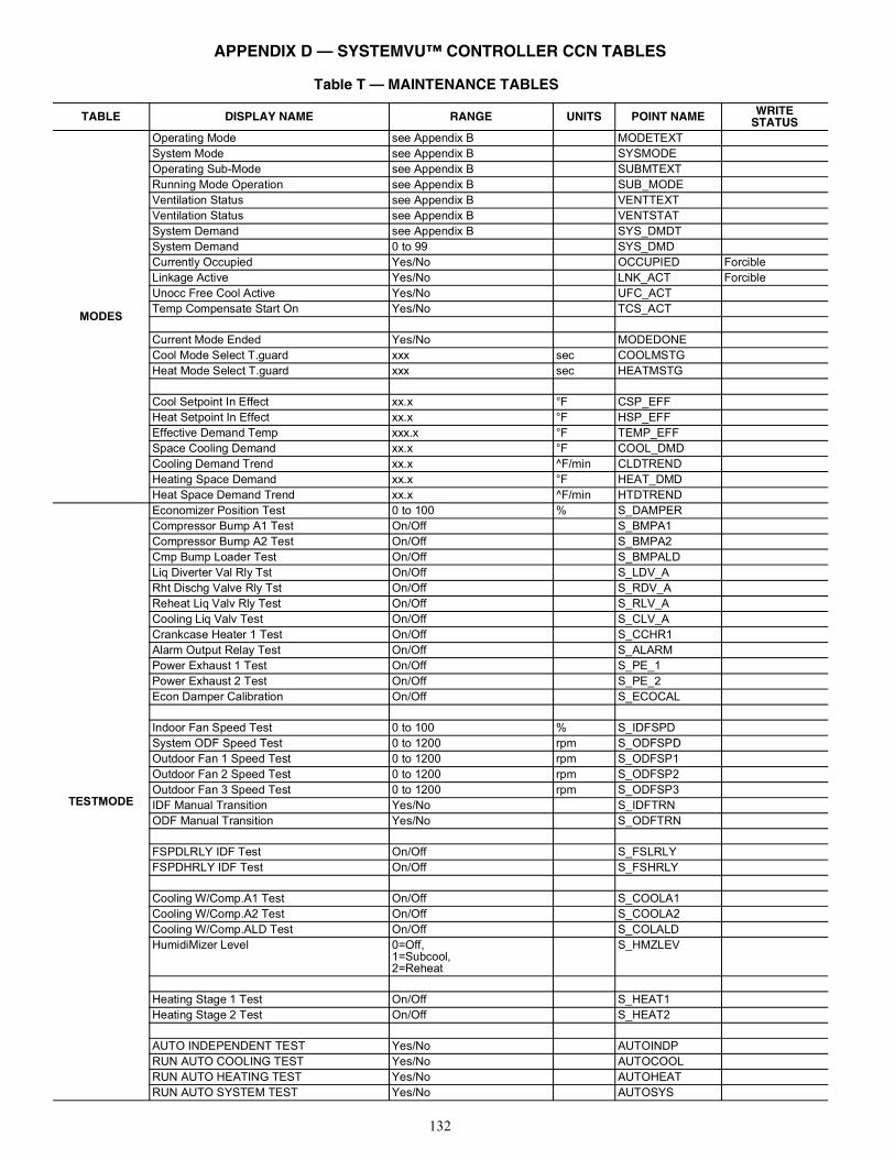
132
Table T — MAINTENANCE TABLES
TABLE DISPLAY NAME RANGE UNITS POINT NAME WRITESTATUS
MODES
Operating Mode see Appendix B MODETEXTSystem Mode see Appendix B SYSMODEOperating Sub-Mode see Appendix B SUBMTEXTRunning Mode Operation see Appendix B SUB_MODEVentilation Status see Appendix B VENTTEXTVentilation Status see Appendix B VENTSTATSystem Demand see Appendix B SYS_DMDTSystem Demand 0 to 99 SYS_DMDCurrently Occupied Yes/No OCCUPIED ForcibleLinkage Active Yes/No LNK_ACT ForcibleUnocc Free Cool Active Yes/No UFC_ACTTemp Compensate Start On Yes/No TCS_ACT
Current Mode Ended Yes/No MODEDONECool Mode Select T.guard xxx sec COOLMSTGHeat Mode Select T.guard xxx sec HEATMSTG
Cool Setpoint In Effect xx.x °F CSP_EFFHeat Setpoint In Effect xx.x °F HSP_EFFEffective Demand Temp xxx.x °F TEMP_EFFSpace Cooling Demand xx.x °F COOL_DMDCooling Demand Trend xx.x ^F/min CLDTRENDHeating Space Demand xx.x °F HEAT_DMDHeat Space Demand Trend xx.x ^F/min HTDTREND
TESTMODE
Economizer Position Test 0 to 100 % S_DAMPERCompressor Bump A1 Test On/Off S_BMPA1Compressor Bump A2 Test On/Off S_BMPA2Cmp Bump Loader Test On/Off S_BMPALDLiq Diverter Val Rly Tst On/Off S_LDV_ARht Dischg Valve Rly Tst On/Off S_RDV_AReheat Liq Valv Rly Test On/Off S_RLV_ACooling Liq Valv Test On/Off S_CLV_ACrankcase Heater 1 Test On/Off S_CCHR1Alarm Output Relay Test On/Off S_ALARMPower Exhaust 1 Test On/Off S_PE_1Power Exhaust 2 Test On/Off S_PE_2Econ Damper Calibration On/Off S_ECOCAL
Indoor Fan Speed Test 0 to 100 % S_IDFSPDSystem ODF Speed Test 0 to 1200 rpm S_ODFSPDOutdoor Fan 1 Speed Test 0 to 1200 rpm S_ODFSP1Outdoor Fan 2 Speed Test 0 to 1200 rpm S_ODFSP2Outdoor Fan 3 Speed Test 0 to 1200 rpm S_ODFSP3IDF Manual Transition Yes/No S_IDFTRNODF Manual Transition Yes/No S_ODFTRN
FSPDLRLY IDF Test On/Off S_FSLRLYFSPDHRLY IDF Test On/Off S_FSHRLY
Cooling W/Comp.A1 Test On/Off S_COOLA1Cooling W/Comp.A2 Test On/Off S_COOLA2Cooling W/Comp.ALD Test On/Off S_COLALDHumidiMizer Level 0=Off,
1=Subcool,2=Reheat
S_HMZLEV
Heating Stage 1 Test On/Off S_HEAT1Heating Stage 2 Test On/Off S_HEAT2
AUTO INDEPENDENT TEST Yes/No AUTOINDPRUN AUTO COOLING TEST Yes/No AUTOCOOLRUN AUTO HEATING TEST Yes/No AUTOHEATRUN AUTO SYSTEM TEST Yes/No AUTOSYS
APPENDIX D — SYSTEMVU™ CONTROLLER CCN TABLES
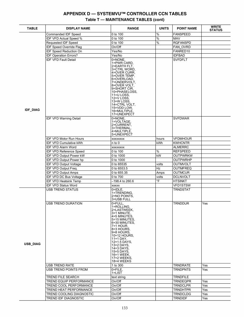
133
IDF_DIAG
Commanded IDF Speed 0 to 100 % FANSPEEDIDF VFD Actual Speed % 0 to 100 % MAVRequested IDF Speed 0 to 100 % RQFANSPDIDF Speed Override Flag On/Off FAN_OVRDIDF Speed Reduction On Yes/No FANRED10IDF Operation Errors? Yes/No IDFBADIDF VFD Fault Detail 0=NONE,
1=PWR CARD,2=EARTH FLT,3=CTRL WORD,4=OVER CURR,5=OVER TEMP,6=OVERLOAD,7=UNDERVOLT,8=OVER VOLT,9=SHORT CIR,10=PHASELOSS,11=U LOSS,12=V LOSS,13=W LOSS,14=CTRL VOLT,15=VDD LOW,16=MULTIPLE,17=UNEXPECT
SVFDFLT
IDF VFD Warning Detail 0=NONE,1=VOLTAGE,2=CURRENT,3=THERMAL,4=MULTIPLE,5=UNEXPECT
SVFDWAR
IDF VFD Motor Run Hours xxxxxxxx hours VFDMHOURIDF VFD Cumulative kWh n to 0 kWh KWHCNTRIDF VFD Alarm Word xxxxxxxx ALMERRCIDF VFD Reference Speed 0 to 100 % REFSPEEDIDF VFD Output Power kW 0 to 1000 kW OUTPWRKWIDF VFD Output Power hp 0 to 1000 OUTPWRHPIDF VFD Output Voltage 0 to 65535 volts OUTMVOLTIDF VFD Output Freq. 0 to 6553.5 Hz OUTMFREQIDF VFD Output Amps 0 to 655.35 Amps OUTMCURIDF VFD DC Bus Voltage 0 to 700 volts DCLNVOLTIDF VFD Heatsink Temp –198.4 to 260.6 °F HTSINKTIDF VFD Status Word xxxxx VFD1STSW
USB_DIAG
USB TREND STATUS 0=IDLE,1=TRENDING,2=NO POINTS,3=USB FULL
TRNDSTAT
USB TREND DURATION 0=FULL,1=ROLLING,2=LASTWEEK,3=1 MINUTE,4=5 MINUTES,5=15 MINUTES,6=30 MINUTES,7=1 HOUR,8=3 HOURS,9=8 HOURS,10=12 HOURS,11=1 DAY,12=1.5 DAYS,13=2 DAYS,14=3 DAYS,15=5 DAYS,16=1 WEEK,17=2 WEEKS,18=4 WEEKS
TRNDDUR Yes
USB TREND RATE 1 to 300 TRNDRATE YesUSB TREND POINTS FROM 0=FILE,
1=LISTTRNDPNTS Yes
TREND FILE SEARCH text string TRNDFILETREND EQUIP PERFORMANCE On/Off TRNDEQPR YesTREND COOL PERFORMANCE On/Off TRNDCLPR YesTREND HEAT PERFORMANCE On/Off TRNDHTPR YesTREND COOLING DIAGNOSTIC On/Off TRNDCLDG YesTREND IDF DIAGNOSTIC On/Off TRNDIDF Yes
Table T — MAINTENANCE TABLES (cont)
TABLE DISPLAY NAME RANGE UNITS POINT NAME WRITESTATUS
APPENDIX D — SYSTEMVU™ CONTROLLER CCN TABLES
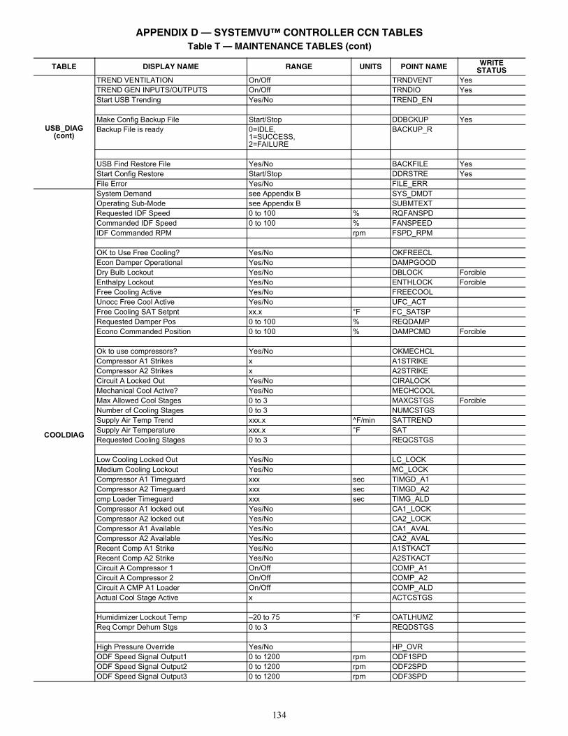
134
USB_DIAG (cont)
TREND VENTILATION On/Off TRNDVENT YesTREND GEN INPUTS/OUTPUTS On/Off TRNDIO YesStart USB Trending Yes/No TREND_EN
Make Config Backup File Start/Stop DDBCKUP YesBackup File is ready 0=IDLE,
1=SUCCESS,2=FAILURE
BACKUP_R
USB Find Restore File Yes/No BACKFILE YesStart Config Restore Start/Stop DDRSTRE YesFile Error Yes/No FILE_ERR
COOLDIAG
System Demand see Appendix B SYS_DMDTOperating Sub-Mode see Appendix B SUBMTEXTRequested IDF Speed 0 to 100 % RQFANSPDCommanded IDF Speed 0 to 100 % FANSPEEDIDF Commanded RPM rpm FSPD_RPM
OK to Use Free Cooling? Yes/No OKFREECLEcon Damper Operational Yes/No DAMPGOODDry Bulb Lockout Yes/No DBLOCK ForcibleEnthalpy Lockout Yes/No ENTHLOCK ForcibleFree Cooling Active Yes/No FREECOOLUnocc Free Cool Active Yes/No UFC_ACTFree Cooling SAT Setpnt xx.x °F FC_SATSPRequested Damper Pos 0 to 100 % REQDAMPEcono Commanded Position 0 to 100 % DAMPCMD Forcible
Ok to use compressors? Yes/No OKMECHCLCompressor A1 Strikes x A1STRIKECompressor A2 Strikes x A2STRIKECircuit A Locked Out Yes/No CIRALOCKMechanical Cool Active? Yes/No MECHCOOLMax Allowed Cool Stages 0 to 3 MAXCSTGS ForcibleNumber of Cooling Stages 0 to 3 NUMCSTGSSupply Air Temp Trend xxx.x ^F/min SATTRENDSupply Air Temperature xxx.x °F SATRequested Cooling Stages 0 to 3 REQCSTGS
Low Cooling Locked Out Yes/No LC_LOCKMedium Cooling Lockout Yes/No MC_LOCKCompressor A1 Timeguard xxx sec TIMGD_A1Compressor A2 Timeguard xxx sec TIMGD_A2cmp Loader Timeguard xxx sec TIMG_ALDCompressor A1 locked out Yes/No CA1_LOCKCompressor A2 locked out Yes/No CA2_LOCKCompressor A1 Available Yes/No CA1_AVALCompressor A2 Available Yes/No CA2_AVALRecent Comp A1 Strike Yes/No A1STKACTRecent Comp A2 Strike Yes/No A2STKACTCircuit A Compressor 1 On/Off COMP_A1Circuit A Compressor 2 On/Off COMP_A2Circuit A CMP A1 Loader On/Off COMP_ALDActual Cool Stage Active x ACTCSTGS
Humidimizer Lockout Temp –20 to 75 °F OATLHUMZReq Compr Dehum Stgs 0 to 3 REQDSTGS
High Pressure Override Yes/No HP_OVRODF Speed Signal Output1 0 to 1200 rpm ODF1SPDODF Speed Signal Output2 0 to 1200 rpm ODF2SPDODF Speed Signal Output3 0 to 1200 rpm ODF3SPD
Table T — MAINTENANCE TABLES (cont)
TABLE DISPLAY NAME RANGE UNITS POINT NAME WRITESTATUS
APPENDIX D — SYSTEMVU™ CONTROLLER CCN TABLES
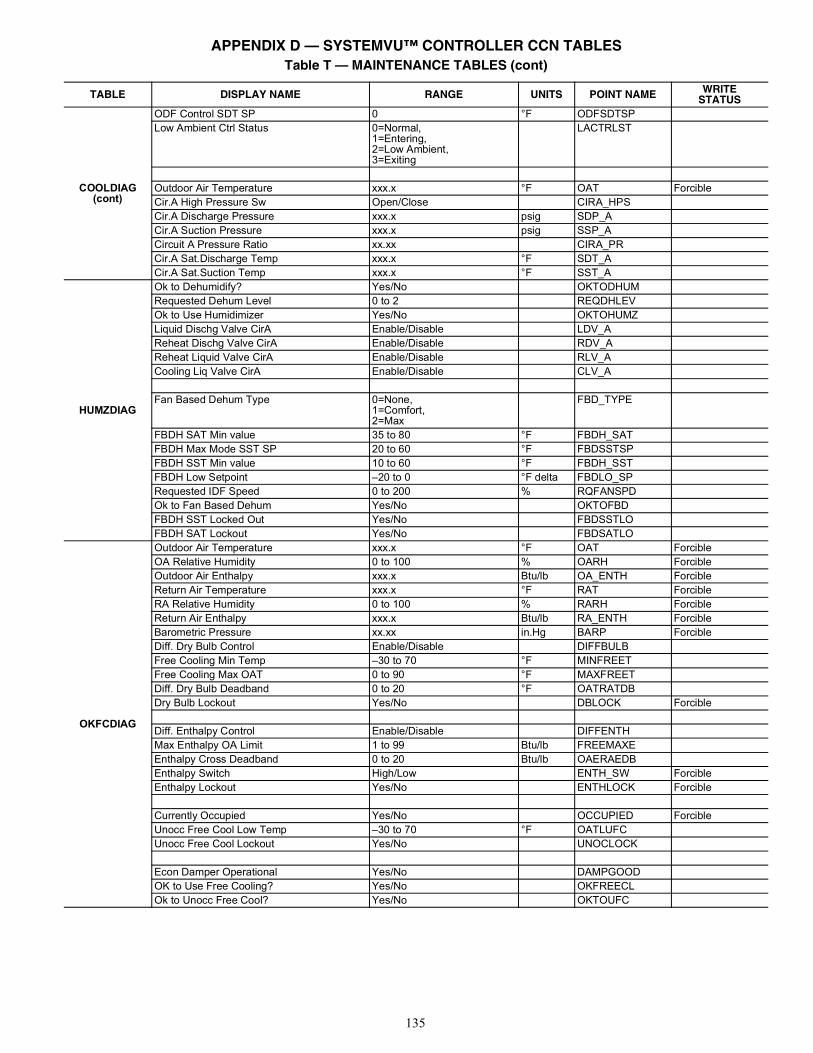
135
COOLDIAG (cont)
ODF Control SDT SP 0 °F ODFSDTSPLow Ambient Ctrl Status 0=Normal,
1=Entering,2=Low Ambient,3=Exiting
LACTRLST
Outdoor Air Temperature xxx.x °F OAT ForcibleCir.A High Pressure Sw Open/Close CIRA_HPSCir.A Discharge Pressure xxx.x psig SDP_ACir.A Suction Pressure xxx.x psig SSP_ACircuit A Pressure Ratio xx.xx CIRA_PRCir.A Sat.Discharge Temp xxx.x °F SDT_ACir.A Sat.Suction Temp xxx.x °F SST_A
HUMZDIAG
Ok to Dehumidify? Yes/No OKTODHUMRequested Dehum Level 0 to 2 REQDHLEVOk to Use Humidimizer Yes/No OKTOHUMZLiquid Dischg Valve CirA Enable/Disable LDV_AReheat Dischg Valve CirA Enable/Disable RDV_AReheat Liquid Valve CirA Enable/Disable RLV_ACooling Liq Valve CirA Enable/Disable CLV_A
Fan Based Dehum Type 0=None,1=Comfort,2=Max
FBD_TYPE
FBDH SAT Min value 35 to 80 °F FBDH_SATFBDH Max Mode SST SP 20 to 60 °F FBDSSTSPFBDH SST Min value 10 to 60 °F FBDH_SSTFBDH Low Setpoint –20 to 0 °F delta FBDLO_SPRequested IDF Speed 0 to 200 % RQFANSPDOk to Fan Based Dehum Yes/No OKTOFBDFBDH SST Locked Out Yes/No FBDSSTLOFBDH SAT Lockout Yes/No FBDSATLO
OKFCDIAG
Outdoor Air Temperature xxx.x °F OAT ForcibleOA Relative Humidity 0 to 100 % OARH ForcibleOutdoor Air Enthalpy xxx.x Btu/lb OA_ENTH ForcibleReturn Air Temperature xxx.x °F RAT ForcibleRA Relative Humidity 0 to 100 % RARH ForcibleReturn Air Enthalpy xxx.x Btu/lb RA_ENTH ForcibleBarometric Pressure xx.xx in.Hg BARP ForcibleDiff. Dry Bulb Control Enable/Disable DIFFBULBFree Cooling Min Temp –30 to 70 °F MINFREETFree Cooling Max OAT 0 to 90 °F MAXFREETDiff. Dry Bulb Deadband 0 to 20 °F OATRATDBDry Bulb Lockout Yes/No DBLOCK Forcible
Diff. Enthalpy Control Enable/Disable DIFFENTHMax Enthalpy OA Limit 1 to 99 Btu/lb FREEMAXEEnthalpy Cross Deadband 0 to 20 Btu/lb OAERAEDBEnthalpy Switch High/Low ENTH_SW ForcibleEnthalpy Lockout Yes/No ENTHLOCK Forcible
Currently Occupied Yes/No OCCUPIED ForcibleUnocc Free Cool Low Temp –30 to 70 °F OATLUFCUnocc Free Cool Lockout Yes/No UNOCLOCK
Econ Damper Operational Yes/No DAMPGOODOK to Use Free Cooling? Yes/No OKFREECLOk to Unocc Free Cool? Yes/No OKTOUFC
Table T — MAINTENANCE TABLES (cont)
TABLE DISPLAY NAME RANGE UNITS POINT NAME WRITESTATUS
APPENDIX D — SYSTEMVU™ CONTROLLER CCN TABLES
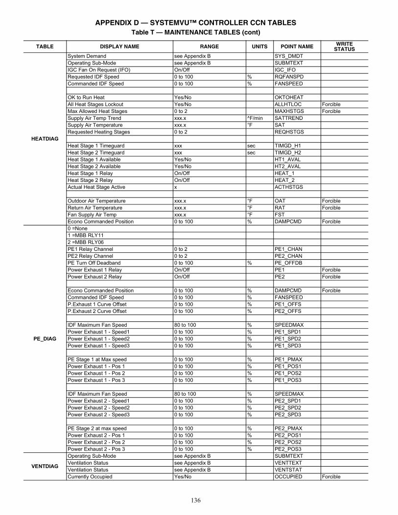
136
HEATDIAG
System Demand see Appendix B SYS_DMDTOperating Sub-Mode see Appendix B SUBMTEXTIGC Fan On Request (IFO) On/Off IGC_IFORequested IDF Speed 0 to 100 % RQFANSPDCommanded IDF Speed 0 to 100 % FANSPEED
OK to Run Heat Yes/No OKTOHEATAll Heat Stages Lockout Yes/No ALLHTLOC ForcibleMax Allowed Heat Stages 0 to 2 MAXHSTGS ForcibleSupply Air Temp Trend xxx.x ^F/min SATTRENDSupply Air Temperature xxx.x °F SATRequested Heating Stages 0 to 2 REQHSTGS
Heat Stage 1 Timeguard xxx sec TIMGD_H1Heat Stage 2 Timeguard xxx sec TIMGD_H2Heat Stage 1 Available Yes/No HT1_AVALHeat Stage 2 Available Yes/No HT2_AVALHeat Stage 1 Relay On/Off HEAT_1Heat Stage 2 Relay On/Off HEAT_2Actual Heat Stage Active x ACTHSTGS
Outdoor Air Temperature xxx.x °F OAT ForcibleReturn Air Temperature xxx.x °F RAT ForcibleFan Supply Air Temp xxx.x °F FSTEcono Commanded Position 0 to 100 % DAMPCMD Forcible
PE_DIAG
0 =None1 =MBB RLY112 =MBB RLY06PE1 Relay Channel 0 to 2 PE1_CHANPE2 Relay Channel 0 to 2 PE2_CHANPE Turn Off Deadband 0 to 100 % PE_OFFDBPower Exhaust 1 Relay On/Off PE1 ForciblePower Exhaust 2 Relay On/Off PE2 Forcible
Econo Commanded Position 0 to 100 % DAMPCMD ForcibleCommanded IDF Speed 0 to 100 % FANSPEEDP.Exhaust 1 Curve Offset 0 to 100 % PE1_OFFSP.Exhaust 2 Curve Offset 0 to 100 % PE2_OFFS
IDF Maximum Fan Speed 80 to 100 % SPEEDMAXPower Exhaust 1 - Speed1 0 to 100 % PE1_SPD1Power Exhaust 1 - Speed2 0 to 100 % PE1_SPD2Power Exhaust 1 - Speed3 0 to 100 % PE1_SPD3
PE Stage 1 at Max speed 0 to 100 % PE1_PMAXPower Exhaust 1 - Pos 1 0 to 100 % PE1_POS1Power Exhaust 1 - Pos 2 0 to 100 % PE1_POS2Power Exhaust 1 - Pos 3 0 to 100 % PE1_POS3
IDF Maximum Fan Speed 80 to 100 % SPEEDMAXPower Exhaust 2 - Speed1 0 to 100 % PE2_SPD1Power Exhaust 2 - Speed2 0 to 100 % PE2_SPD2Power Exhaust 2 - Speed3 0 to 100 % PE2_SPD3
PE Stage 2 at max speed 0 to 100 % PE2_PMAXPower Exhaust 2 - Pos 1 0 to 100 % PE2_POS1Power Exhaust 2 - Pos 2 0 to 100 % PE2_POS2Power Exhaust 2 - Pos 3 0 to 100 % PE2_POS3
VENTDIAG
Operating Sub-Mode see Appendix B SUBMTEXTVentilation Status see Appendix B VENTTEXTVentilation Status see Appendix B VENTSTATCurrently Occupied Yes/No OCCUPIED Forcible
Table T — MAINTENANCE TABLES (cont)
TABLE DISPLAY NAME RANGE UNITS POINT NAME WRITESTATUS
APPENDIX D — SYSTEMVU™ CONTROLLER CCN TABLES
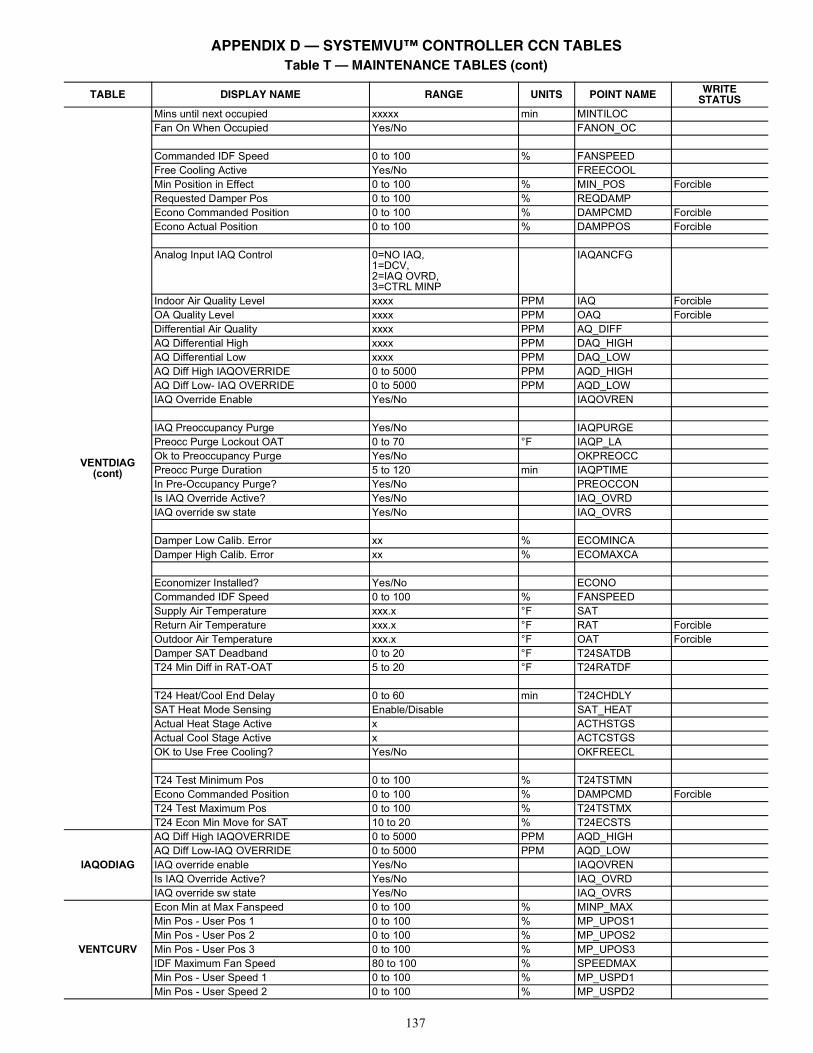
137
VENTDIAG(cont)
Mins until next occupied xxxxx min MINTILOCFan On When Occupied Yes/No FANON_OC
Commanded IDF Speed 0 to 100 % FANSPEEDFree Cooling Active Yes/No FREECOOLMin Position in Effect 0 to 100 % MIN_POS ForcibleRequested Damper Pos 0 to 100 % REQDAMPEcono Commanded Position 0 to 100 % DAMPCMD ForcibleEcono Actual Position 0 to 100 % DAMPPOS Forcible
Analog Input IAQ Control 0=NO IAQ,1=DCV,2=IAQ OVRD,3=CTRL MINP
IAQANCFG
Indoor Air Quality Level xxxx PPM IAQ ForcibleOA Quality Level xxxx PPM OAQ ForcibleDifferential Air Quality xxxx PPM AQ_DIFFAQ Differential High xxxx PPM DAQ_HIGHAQ Differential Low xxxx PPM DAQ_LOWAQ Diff High IAQOVERRIDE 0 to 5000 PPM AQD_HIGHAQ Diff Low- IAQ OVERRIDE 0 to 5000 PPM AQD_LOWIAQ Override Enable Yes/No IAQOVREN
IAQ Preoccupancy Purge Yes/No IAQPURGEPreocc Purge Lockout OAT 0 to 70 °F IAQP_LAOk to Preoccupancy Purge Yes/No OKPREOCCPreocc Purge Duration 5 to 120 min IAQPTIMEIn Pre-Occupancy Purge? Yes/No PREOCCONIs IAQ Override Active? Yes/No IAQ_OVRDIAQ override sw state Yes/No IAQ_OVRS
Damper Low Calib. Error xx % ECOMINCADamper High Calib. Error xx % ECOMAXCA
Economizer Installed? Yes/No ECONOCommanded IDF Speed 0 to 100 % FANSPEEDSupply Air Temperature xxx.x °F SATReturn Air Temperature xxx.x °F RAT ForcibleOutdoor Air Temperature xxx.x °F OAT ForcibleDamper SAT Deadband 0 to 20 °F T24SATDBT24 Min Diff in RAT-OAT 5 to 20 °F T24RATDF
T24 Heat/Cool End Delay 0 to 60 min T24CHDLYSAT Heat Mode Sensing Enable/Disable SAT_HEATActual Heat Stage Active x ACTHSTGSActual Cool Stage Active x ACTCSTGSOK to Use Free Cooling? Yes/No OKFREECL
T24 Test Minimum Pos 0 to 100 % T24TSTMNEcono Commanded Position 0 to 100 % DAMPCMD ForcibleT24 Test Maximum Pos 0 to 100 % T24TSTMXT24 Econ Min Move for SAT 10 to 20 % T24ECSTS
IAQODIAG
AQ Diff High IAQOVERRIDE 0 to 5000 PPM AQD_HIGHAQ Diff Low-IAQ OVERRIDE 0 to 5000 PPM AQD_LOWIAQ override enable Yes/No IAQOVRENIs IAQ Override Active? Yes/No IAQ_OVRDIAQ override sw state Yes/No IAQ_OVRS
VENTCURV
Econ Min at Max Fanspeed 0 to 100 % MINP_MAXMin Pos - User Pos 1 0 to 100 % MP_UPOS1Min Pos - User Pos 2 0 to 100 % MP_UPOS2Min Pos - User Pos 3 0 to 100 % MP_UPOS3IDF Maximum Fan Speed 80 to 100 % SPEEDMAXMin Pos - User Speed 1 0 to 100 % MP_USPD1Min Pos - User Speed 2 0 to 100 % MP_USPD2
Table T — MAINTENANCE TABLES (cont)
TABLE DISPLAY NAME RANGE UNITS POINT NAME WRITESTATUS
APPENDIX D — SYSTEMVU™ CONTROLLER CCN TABLES
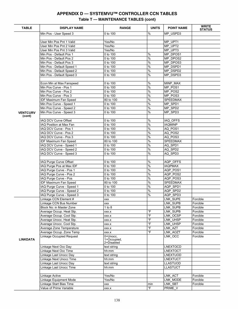
138
VENTCURV (cont)
Min Pos - User Speed 3 0 to 100 % MP_USPD3
User Min Pos Pnt 1 Valid Yes/No MP_UPT1User Min Pos Pnt 2 Valid Yes/No MP_UPT2User Min Pos Pnt 3 Valid Yes/No MP_UPT3Min Pos - Default Pos 1 0 to 100 % MP_DPOS1Min Pos - Default Pos 2 0 to 100 % MP_DPOS2Min Pos - Default Pos 3 0 to 100 % MP_DPOS3Min Pos - Default Speed 1 0 to 100 % MP_DSPD1Min Pos - Default Speed 2 0 to 100 % MP_DSPD2Min Pos - Default Speed 3 0 to 100 % MP_DSPD3
Econ Min at Max Fanspeed 0 to 100 % MINP_MAXMin Pos Curve - Pos 1 0 to 100 % MP_POS1Min Pos Curve - Pos 2 0 to 100 % MP_POS2Min Pos Curve - Pos 3 0 to 100 % MP_POS3IDF Maximum Fan Speed 80 to 100 % SPEEDMAXMin Pos Curve - Speed 1 0 to 100 % MP_SPD1Min Pos Curve - Speed 2 0 to 100 % MP_SPD2Min Pos Curve - Speed 3 0 to 100 % MP_SPD3
IAQ DCV Curve Offset 0 to 100 % IAQ_OFFSIAQ Position at Max Fan 0 to 100 % IAQMINPIAQ DCV Curve - Pos 1 0 to 100 % AQ_POS1IAQ DCV Curve - Pos 2 0 to 100 % AQ_POS2IAQ DCV Curve - Pos 3 0 to 100 % AQ_POS3IDF Maximum Fan Speed 80 to 100 % SPEEDMAXIAQ DCV Curve - Speed 1 0 to 100 % AQ_SPD1IAQ DCV Curve - Speed 2 0 to 100 % AQ_SPD2IAQ DCV Curve - Speed 3 0 to 100 % AQ_SPD3
IAQ Purge Curve Offset 0 to 100 % AQP_OFFSIAQ Purge Pos at Max IDF 0 to 100 % IAQPMAXIAQ Purge Curve - Pos 1 0 to 100 % AQP_POS1IAQ Purge Curve - Pos 2 0 to 100 % AQP_POS2IAQ Purge Curve - Pos 0 to 100 % AQP_POS3IDF Maximum Fan Speed 80 to 100 % SPEEDMAXIAQ Purge Curve - Speed 1 0 to 100 % AQP_SPD1IAQ Purge Curve - Speed 2 0 to 100 % AQP_SPD2IAQ Purge Curve - Speed 3 0 to 100 % AQP_SPD3
LINKDATA
Linkage CCN Element # xxx LNK_SUPE ForcibleLinkage CCN Bus Number xxx LNK_SUPB ForcibleBlock No: in Master Zone 1 to 8 LNK_SUPB ForcibleAverage Occup. Heat Stp. xxx.x °F LNK_SUPB ForcibleAverage Occup. Cool Stp. xxx.x °F LNK_OCSP ForcibleAverage Unocc. Heat Stp. xxx.x °F LNK_UHSP ForcibleAverage Unocc. Cool Stp. xxx.x °F LNK_UHSP ForcibleAverage Zone Temperature xxx.x °F LNK_AZT ForcibleAverage Occup. Zone Temp xxx.x °F LNK_AOZT ForcibleLinkage Occupied Request 0=Unocc,
1=Occupied,2=Disabled
LNK_OCC Forcible
Linkage Next Occ Day text string LNEXTOCDLinkage Next Occ Time hh:mm LNEXTOCTLinkage Last Unocc Day text string LNEXTUODLinkage Next Unocc Time hh:mm LNEXTUCTLinkage Last Unocc Day text string LLASTUODLinkage Last Unocc Time hh:mm LLASTUCT
Linkage Active Yes/No LNK_ACT ForcibleLinkage Equipment Mode Yes/No LNK_MODE ForcibleLinkage Start Bias Time xxx min LNK_SBT ForcibleValue of Prime Variable xxx.x °F PRIME_V
Table T — MAINTENANCE TABLES (cont)
TABLE DISPLAY NAME RANGE UNITS POINT NAME WRITESTATUS
APPENDIX D — SYSTEMVU™ CONTROLLER CCN TABLES
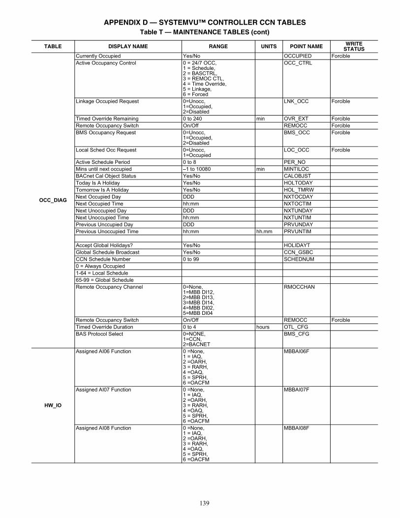
139
OCC_DIAG
Currently Occupied Yes/No OCCUPIED ForcibleActive Occupancy Control 0 = 24/7 OCC,
1 = Schedule,2 = BASCTRL,3 = REMOC CTL,4 = Time Override,5 = Linkage,6 = Forced
OCC_CTRL
Linkage Occupied Request 0=Unocc,1=Occupied,2=Disabled
LNK_OCC Forcible
Timed Override Remaining 0 to 240 min OVR_EXT ForcibleRemote Occupancy Switch On/Off REMOCC ForcibleBMS Occupancy Request 0=Unocc,
1=Occupied,2=Disabled
BMS_OCC Forcible
Local Sched Occ Request 0=Unocc,1=Occupied
LOC_OCC Forcible
Active Schedule Period 0 to 8 PER_NOMins until next occupied –1 to 10080 min MINTILOCBACnet Cal Object Status Yes/No CALOBJSTToday Is A Holiday Yes/No HOLTODAYTomorrow Is A Holiday Yes/No HOL_TMRWNext Occupied Day DDD NXTOCDAYNext Occupied Time hh:mm NXTOCTIMNext Unoccupied Day DDD NXTUNDAYNext Unoccupied Time hh:mm NXTUNTIMPrevious Unccupied Day DDD PRVUNDAYPrevious Unoccupied Time hh:mm hh.mm PRVUNTIM
Accept Global Holidays? Yes/No HOLIDAYTGlobal Schedule Broadcast Yes/No CCN_GSBCCCN Schedule Number 0 to 99 SCHEDNUM0 = Always Occupied1-64 = Local Schedule65-99 = Global ScheduleRemote Occupancy Channel 0=None,
1=MBB DI12,2=MBB DI13,3=MBB DI14,4=MBB DI02,5=MBB DI04
RMOCCHAN
Remote Occupancy Switch On/Off REMOCC ForcibleTimed Override Duration 0 to 4 hours OTL_CFGBAS Protocol Select 0=NONE,
1=CCN,2=BACNET
BMS_CFG
HW_IO
Assigned AI06 Function 0 =None,1 = IAQ,2 =OARH,3 = RARH,4 =OAQ,5 = SPRH,6 =OACFM
MBBAI06F
Assigned AI07 Function 0 =None,1 = IAQ,2 =OARH,3 = RARH,4 =OAQ,5 = SPRH,6 =OACFM
MBBAI07F
Assigned AI08 Function 0 =None,1 = IAQ,2 =OARH,3 = RARH,4 =OAQ,5 = SPRH,6 =OACFM
MBBAI08F
Table T — MAINTENANCE TABLES (cont)
TABLE DISPLAY NAME RANGE UNITS POINT NAME WRITESTATUS
APPENDIX D — SYSTEMVU™ CONTROLLER CCN TABLES
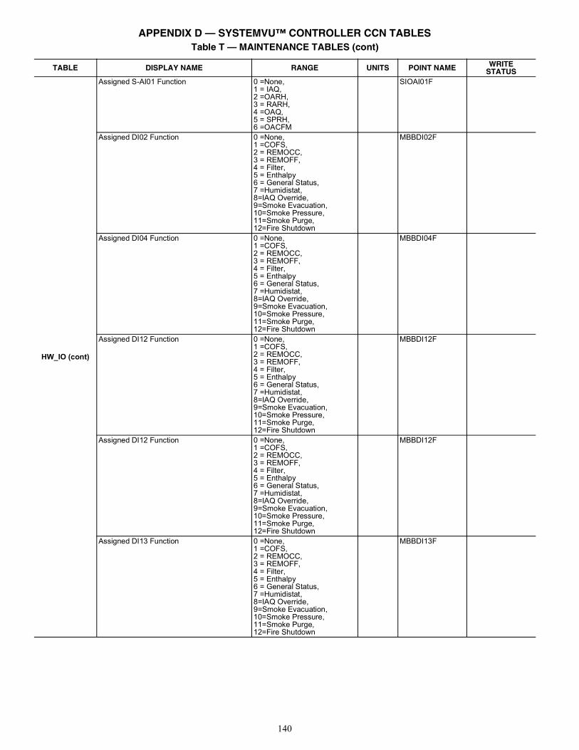
140
HW_IO (cont)
Assigned S-AI01 Function 0 =None,1 = IAQ,2 =OARH,3 = RARH,4 =OAQ,5 = SPRH,6 =OACFM
SIOAI01F
Assigned DI02 Function 0 =None,1 =COFS,2 = REMOCC,3 = REMOFF,4 = Filter,5 = Enthalpy6 = General Status,7 =Humidistat,8=IAQ Override,9=Smoke Evacuation,10=Smoke Pressure,11=Smoke Purge,12=Fire Shutdown
MBBDI02F
Assigned DI04 Function 0 =None,1 =COFS,2 = REMOCC,3 = REMOFF,4 = Filter,5 = Enthalpy6 = General Status,7 =Humidistat,8=IAQ Override,9=Smoke Evacuation,10=Smoke Pressure,11=Smoke Purge,12=Fire Shutdown
MBBDI04F
Assigned DI12 Function 0 =None,1 =COFS,2 = REMOCC,3 = REMOFF,4 = Filter,5 = Enthalpy6 = General Status,7 =Humidistat,8=IAQ Override,9=Smoke Evacuation,10=Smoke Pressure,11=Smoke Purge,12=Fire Shutdown
MBBDI12F
Assigned DI12 Function 0 =None,1 =COFS,2 = REMOCC,3 = REMOFF,4 = Filter,5 = Enthalpy6 = General Status,7 =Humidistat,8=IAQ Override,9=Smoke Evacuation,10=Smoke Pressure,11=Smoke Purge,12=Fire Shutdown
MBBDI12F
Assigned DI13 Function 0 =None,1 =COFS,2 = REMOCC,3 = REMOFF,4 = Filter,5 = Enthalpy6 = General Status,7 =Humidistat,8=IAQ Override,9=Smoke Evacuation,10=Smoke Pressure,11=Smoke Purge,12=Fire Shutdown
MBBDI13F
Table T — MAINTENANCE TABLES (cont)
TABLE DISPLAY NAME RANGE UNITS POINT NAME WRITESTATUS
APPENDIX D — SYSTEMVU™ CONTROLLER CCN TABLES
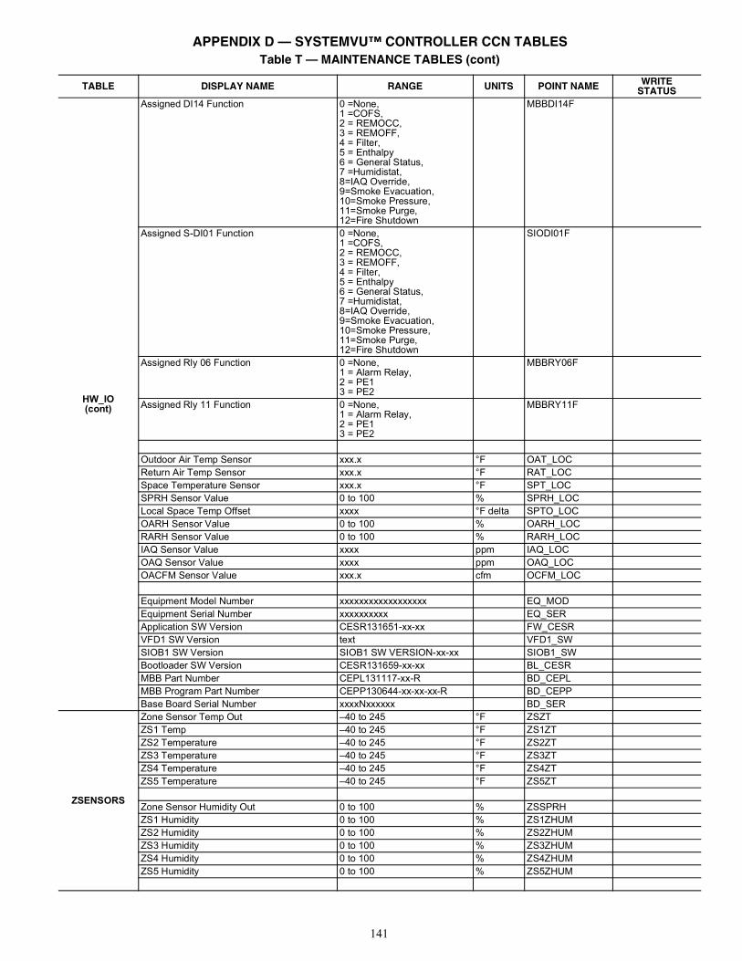
141
HW_IO(cont)
Assigned DI14 Function 0 =None,1 =COFS,2 = REMOCC,3 = REMOFF,4 = Filter,5 = Enthalpy6 = General Status,7 =Humidistat,8=IAQ Override,9=Smoke Evacuation,10=Smoke Pressure,11=Smoke Purge,12=Fire Shutdown
MBBDI14F
Assigned S-DI01 Function 0 =None,1 =COFS,2 = REMOCC,3 = REMOFF,4 = Filter,5 = Enthalpy6 = General Status,7 =Humidistat,8=IAQ Override,9=Smoke Evacuation,10=Smoke Pressure,11=Smoke Purge,12=Fire Shutdown
SIODI01F
Assigned Rly 06 Function 0 =None,1 = Alarm Relay,2 = PE13 = PE2
MBBRY06F
Assigned Rly 11 Function 0 =None,1 = Alarm Relay,2 = PE13 = PE2
MBBRY11F
Outdoor Air Temp Sensor xxx.x °F OAT_LOCReturn Air Temp Sensor xxx.x °F RAT_LOCSpace Temperature Sensor xxx.x °F SPT_LOCSPRH Sensor Value 0 to 100 % SPRH_LOCLocal Space Temp Offset xxxx °F delta SPTO_LOCOARH Sensor Value 0 to 100 % OARH_LOCRARH Sensor Value 0 to 100 % RARH_LOCIAQ Sensor Value xxxx ppm IAQ_LOCOAQ Sensor Value xxxx ppm OAQ_LOCOACFM Sensor Value xxx.x cfm OCFM_LOC
Equipment Model Number xxxxxxxxxxxxxxxxxx EQ_MODEquipment Serial Number xxxxxxxxxx EQ_SERApplication SW Version CESR131651-xx-xx FW_CESRVFD1 SW Version text VFD1_SWSIOB1 SW Version SIOB1 SW VERSION-xx-xx SIOB1_SWBootloader SW Version CESR131659-xx-xx BL_CESRMBB Part Number CEPL131117-xx-R BD_CEPLMBB Program Part Number CEPP130644-xx-xx-xx-R BD_CEPPBase Board Serial Number xxxxNxxxxxx BD_SER
ZSENSORS
Zone Sensor Temp Out –40 to 245 °F ZSZTZS1 Temp –40 to 245 °F ZS1ZTZS2 Temperature –40 to 245 °F ZS2ZTZS3 Temperature –40 to 245 °F ZS3ZTZS4 Temperature –40 to 245 °F ZS4ZTZS5 Temperature –40 to 245 °F ZS5ZT
Zone Sensor Humidity Out 0 to 100 % ZSSPRHZS1 Humidity 0 to 100 % ZS1ZHUMZS2 Humidity 0 to 100 % ZS2ZHUMZS3 Humidity 0 to 100 % ZS3ZHUMZS4 Humidity 0 to 100 % ZS4ZHUMZS5 Humidity 0 to 100 % ZS5ZHUM
Table T — MAINTENANCE TABLES (cont)
TABLE DISPLAY NAME RANGE UNITS POINT NAME WRITESTATUS
APPENDIX D — SYSTEMVU™ CONTROLLER CCN TABLES
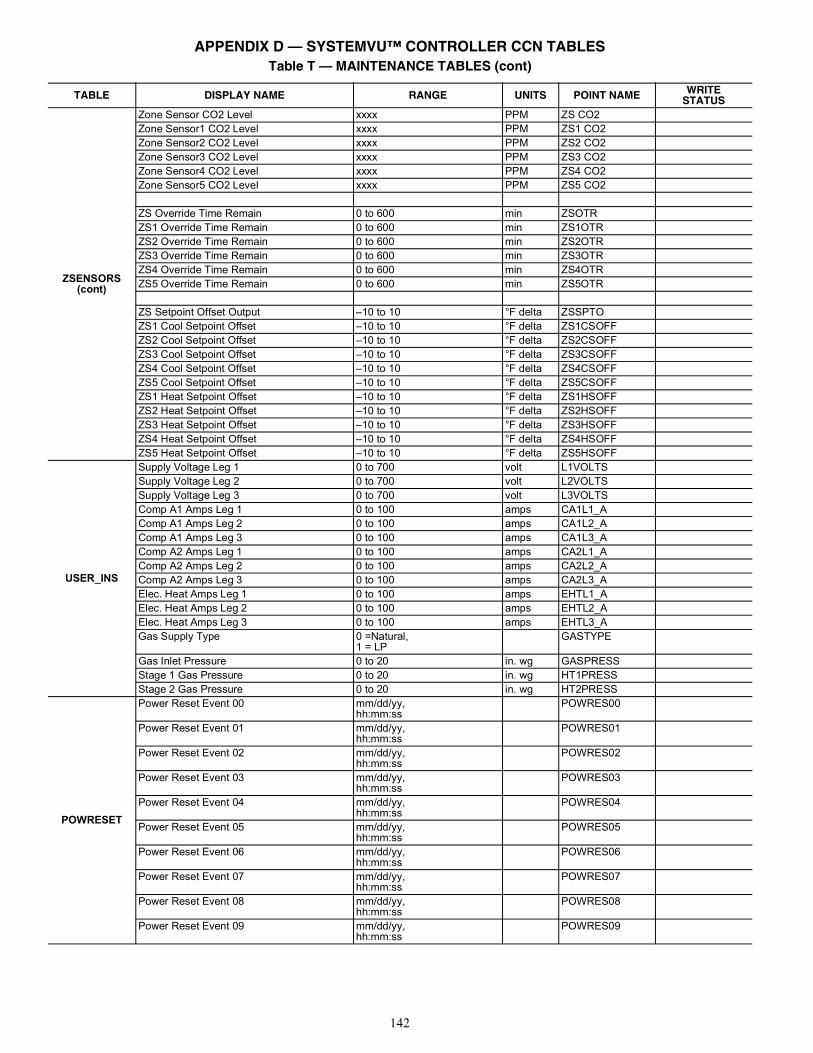
142
ZSENSORS (cont)
Zone Sensor CO2 Level xxxx PPM ZS CO2Zone Sensor1 CO2 Level xxxx PPM ZS1 CO2Zone Sensor2 CO2 Level xxxx PPM ZS2 CO2Zone Sensor3 CO2 Level xxxx PPM ZS3 CO2Zone Sensor4 CO2 Level xxxx PPM ZS4 CO2Zone Sensor5 CO2 Level xxxx PPM ZS5 CO2
ZS Override Time Remain 0 to 600 min ZSOTRZS1 Override Time Remain 0 to 600 min ZS1OTRZS2 Override Time Remain 0 to 600 min ZS2OTRZS3 Override Time Remain 0 to 600 min ZS3OTRZS4 Override Time Remain 0 to 600 min ZS4OTRZS5 Override Time Remain 0 to 600 min ZS5OTR
ZS Setpoint Offset Output –10 to 10 °F delta ZSSPTOZS1 Cool Setpoint Offset –10 to 10 °F delta ZS1CSOFFZS2 Cool Setpoint Offset –10 to 10 °F delta ZS2CSOFFZS3 Cool Setpoint Offset –10 to 10 °F delta ZS3CSOFFZS4 Cool Setpoint Offset –10 to 10 °F delta ZS4CSOFFZS5 Cool Setpoint Offset –10 to 10 °F delta ZS5CSOFFZS1 Heat Setpoint Offset –10 to 10 °F delta ZS1HSOFFZS2 Heat Setpoint Offset –10 to 10 °F delta ZS2HSOFFZS3 Heat Setpoint Offset –10 to 10 °F delta ZS3HSOFFZS4 Heat Setpoint Offset –10 to 10 °F delta ZS4HSOFFZS5 Heat Setpoint Offset –10 to 10 °F delta ZS5HSOFF
USER_INS
Supply Voltage Leg 1 0 to 700 volt L1VOLTSSupply Voltage Leg 2 0 to 700 volt L2VOLTSSupply Voltage Leg 3 0 to 700 volt L3VOLTSComp A1 Amps Leg 1 0 to 100 amps CA1L1_AComp A1 Amps Leg 2 0 to 100 amps CA1L2_AComp A1 Amps Leg 3 0 to 100 amps CA1L3_AComp A2 Amps Leg 1 0 to 100 amps CA2L1_AComp A2 Amps Leg 2 0 to 100 amps CA2L2_AComp A2 Amps Leg 3 0 to 100 amps CA2L3_AElec. Heat Amps Leg 1 0 to 100 amps EHTL1_AElec. Heat Amps Leg 2 0 to 100 amps EHTL2_AElec. Heat Amps Leg 3 0 to 100 amps EHTL3_AGas Supply Type 0 =Natural,
1 = LPGASTYPE
Gas Inlet Pressure 0 to 20 in. wg GASPRESSStage 1 Gas Pressure 0 to 20 in. wg HT1PRESSStage 2 Gas Pressure 0 to 20 in. wg HT2PRESS
POWRESET
Power Reset Event 00 mm/dd/yy,hh:mm:ss
POWRES00
Power Reset Event 01 mm/dd/yy,hh:mm:ss
POWRES01
Power Reset Event 02 mm/dd/yy,hh:mm:ss
POWRES02
Power Reset Event 03 mm/dd/yy,hh:mm:ss
POWRES03
Power Reset Event 04 mm/dd/yy,hh:mm:ss
POWRES04
Power Reset Event 05 mm/dd/yy,hh:mm:ss
POWRES05
Power Reset Event 06 mm/dd/yy,hh:mm:ss
POWRES06
Power Reset Event 07 mm/dd/yy,hh:mm:ss
POWRES07
Power Reset Event 08 mm/dd/yy,hh:mm:ss
POWRES08
Power Reset Event 09 mm/dd/yy,hh:mm:ss
POWRES09
Table T — MAINTENANCE TABLES (cont)
TABLE DISPLAY NAME RANGE UNITS POINT NAME WRITESTATUS
APPENDIX D — SYSTEMVU™ CONTROLLER CCN TABLES
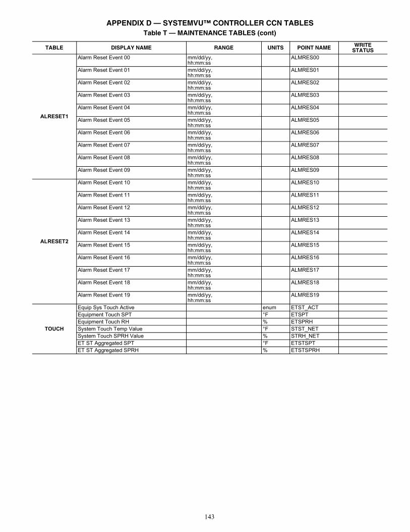
143
ALRESET1
Alarm Reset Event 00 mm/dd/yy,hh:mm:ss
ALMRES00
Alarm Reset Event 01 mm/dd/yy,hh:mm:ss
ALMRES01
Alarm Reset Event 02 mm/dd/yy,hh:mm:ss
ALMRES02
Alarm Reset Event 03 mm/dd/yy,hh:mm:ss
ALMRES03
Alarm Reset Event 04 mm/dd/yy,hh:mm:ss
ALMRES04
Alarm Reset Event 05 mm/dd/yy,hh:mm:ss
ALMRES05
Alarm Reset Event 06 mm/dd/yy,hh:mm:ss
ALMRES06
Alarm Reset Event 07 mm/dd/yy,hh:mm:ss
ALMRES07
Alarm Reset Event 08 mm/dd/yy,hh:mm:ss
ALMRES08
Alarm Reset Event 09 mm/dd/yy,hh:mm:ss
ALMRES09
ALRESET2
Alarm Reset Event 10 mm/dd/yy,hh:mm:ss
ALMRES10
Alarm Reset Event 11 mm/dd/yy,hh:mm:ss
ALMRES11
Alarm Reset Event 12 mm/dd/yy,hh:mm:ss
ALMRES12
Alarm Reset Event 13 mm/dd/yy,hh:mm:ss
ALMRES13
Alarm Reset Event 14 mm/dd/yy,hh:mm:ss
ALMRES14
Alarm Reset Event 15 mm/dd/yy,hh:mm:ss
ALMRES15
Alarm Reset Event 16 mm/dd/yy,hh:mm:ss
ALMRES16
Alarm Reset Event 17 mm/dd/yy,hh:mm:ss
ALMRES17
Alarm Reset Event 18 mm/dd/yy,hh:mm:ss
ALMRES18
Alarm Reset Event 19 mm/dd/yy,hh:mm:ss
ALMRES19
TOUCH
Equip Sys Touch Active enum ETST_ACTEquipment Touch SPT °F ETSPTEquipment Touch RH % ETSPRHSystem Touch Temp Value °F STST_NETSystem Touch SPRH Value % STRH_NETET ST Aggregated SPT °F ETSTSPTET ST Aggregated SPRH % ETSTSPRH
Table T — MAINTENANCE TABLES (cont)
TABLE DISPLAY NAME RANGE UNITS POINT NAME WRITESTATUS
APPENDIX D — SYSTEMVU™ CONTROLLER CCN TABLES
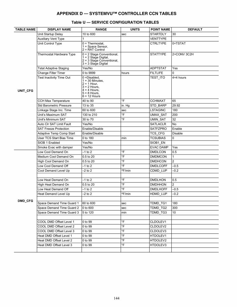
144
Table U — SERVICE CONFIGURATION TABLES
TABLE NAME DISPLAY NAME RANGE UNITS POINT NAME DEFAULT
UNIT_CFG
Unit Startup Delay 10 to 600 sec STARTDLY 30Auxiliary Vent Type 1 VENTTYPEUnit Control Type 0 = Thermostat,
1 = Space Sensor,2 = RAT Control
CTRLTYPE 0=TSTAT
Thermostat Hardware Type 0 = 2 Stage Conventional,1 = 2 Stage Digital,2 = 3 Stage Conventional,3 = 3 Stage Digital
STATTYPE 2=CONV 3C2H
Tstat Adaptive Staging Yes/No ADPTSTAT YesChange Filter Timer 0 to 9999 hours FILTLIFE 0Test Inactivity Time Out 0 =Disabled,
1 = 30 Minutes,2 = 1 Hour,3 = 2 Hours,4 = 4 Hours,5 = 8 Hours,6 = 12 Hours
TEST_ITO 4=4 hours
CCH Max Temperature 40 to 90 °F CCHMAXT 65Std Barometric Pressure 13 to 35 in. Hg STD_BARP 29.92Linkage Stage Inc. Time 60 to 600 sec LSTAGINC 180Unit’s Maximum SAT 130 to 210 °F UMAX_SAT 200Unit's Minimum SAT 30 to 70 °F UMIN_SAT 32Auto Clr SAT Limit Fault Yes/No SATLACLR NoSAT Freeze Protection Enable/Disable SATFZPRO EnableAdaptive Temp Comp Start Enable/Disable TCS_CFG DisableUser TCS Start Bias Time 0 to 180 min TCSUBIAS 0SIOB 1 Enabled Yes/No SIOB1_ENSmoke Evac with damper Yes/No EVAC DAMP Yes
DMD_CFG
Low Cool Demand On –1 to 2 °F DMDLCON 0.5Medium Cool Demand On 0.5 to 20 °F DMDMCON 1High Cool Demand On 0.5 to 20 °F DMDHCON 2Low Cool Demand Off –1 to 2 °F DMDLCOFF –0.5Cool Demand Level Up –2 to 2 ^F/min CDMD_LUP –0.2
Low Heat Demand On –1 to 2 °F DMDLHON 0.5High Heat Demand On 0.5 to 20 °F DMDHHON 2Low Heat Demand Off –1 to 2 °F DMDLHOFF –0.5Heat Demand Level Up –2 to 2 ^F/min HDMD_LUP –0.2
Space Demand Time Guard 1 60 to 600 sec TDMD_TG1 180Space Demand Time Guard 2 0 to 600 sec TDMD_TG2 300Space Demand Time Guard 3 5 to 120 min TDMD_TG3 10
COOL DMD Offset Level 1 0 to 99 °F CLDOLEV1COOL DMD Offset Level 2 0 to 99 °F CLDOLEV2COOL DMD Offset Level 3 0 to 99 °F CLDOLEV3Heat DMD Offset Level 1 0 to 99 °F HTDOLEV1Heat DMD Offset Level 2 0 to 99 °F HTDOLEV2Heat DMD Offset Level 3 0 to 99 °F HTDOLEV3
APPENDIX D — SYSTEMVU™ CONTROLLER CCN TABLES
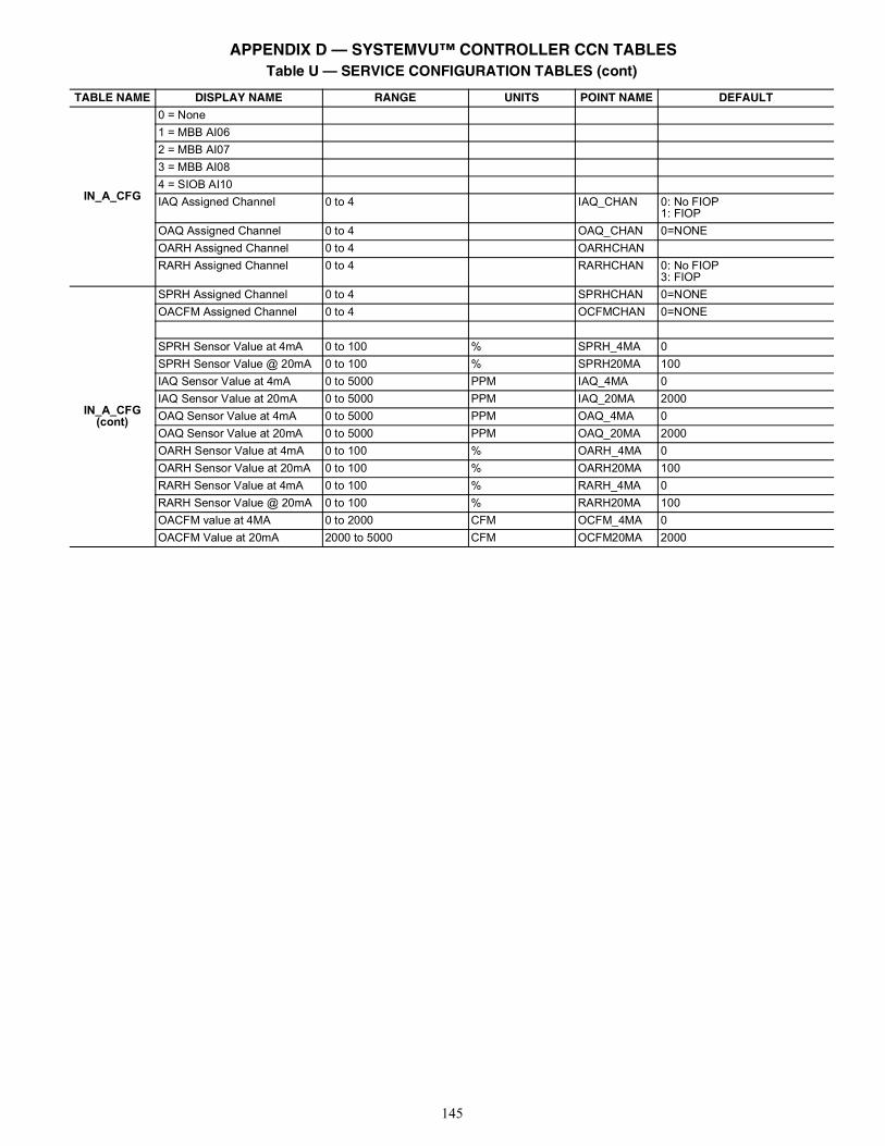
145
IN_A_CFG
0 = None1 = MBB AI062 = MBB AI073 = MBB AI084 = SIOB AI10IAQ Assigned Channel 0 to 4 IAQ_CHAN 0: No FIOP
1: FIOP OAQ Assigned Channel 0 to 4 OAQ_CHAN 0=NONEOARH Assigned Channel 0 to 4 OARHCHANRARH Assigned Channel 0 to 4 RARHCHAN 0: No FIOP
3: FIOP
IN_A_CFG (cont)
SPRH Assigned Channel 0 to 4 SPRHCHAN 0=NONEOACFM Assigned Channel 0 to 4 OCFMCHAN 0=NONE
SPRH Sensor Value at 4mA 0 to 100 % SPRH_4MA 0SPRH Sensor Value @ 20mA 0 to 100 % SPRH20MA 100IAQ Sensor Value at 4mA 0 to 5000 PPM IAQ_4MA 0IAQ Sensor Value at 20mA 0 to 5000 PPM IAQ_20MA 2000OAQ Sensor Value at 4mA 0 to 5000 PPM OAQ_4MA 0OAQ Sensor Value at 20mA 0 to 5000 PPM OAQ_20MA 2000OARH Sensor Value at 4mA 0 to 100 % OARH_4MA 0OARH Sensor Value at 20mA 0 to 100 % OARH20MA 100RARH Sensor Value at 4mA 0 to 100 % RARH_4MA 0RARH Sensor Value @ 20mA 0 to 100 % RARH20MA 100OACFM value at 4MA 0 to 2000 CFM OCFM_4MA 0OACFM Value at 20mA 2000 to 5000 CFM OCFM20MA 2000
Table U — SERVICE CONFIGURATION TABLES (cont)
TABLE NAME DISPLAY NAME RANGE UNITS POINT NAME DEFAULT
APPENDIX D — SYSTEMVU™ CONTROLLER CCN TABLES
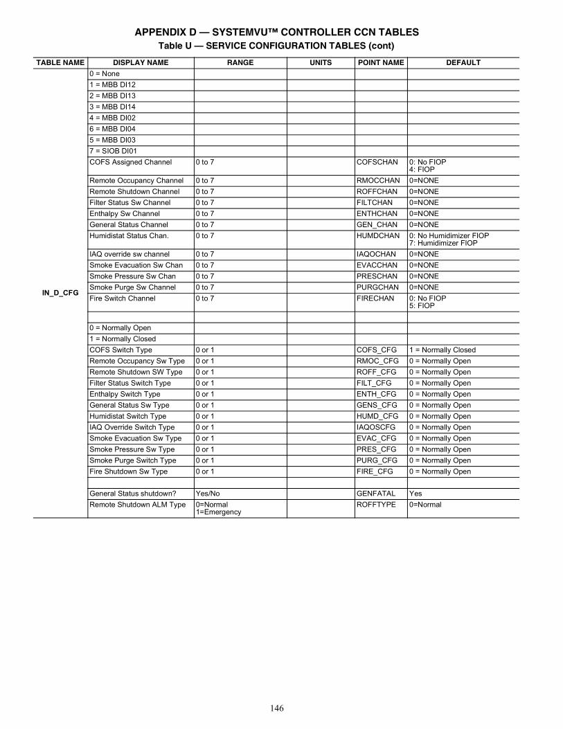
146
IN_D_CFG
0 = None1 = MBB DI122 = MBB DI133 = MBB DI144 = MBB DI026 = MBB DI045 = MBB DI037 = SIOB DI01COFS Assigned Channel 0 to 7 COFSCHAN 0: No FIOP
4: FIOPRemote Occupancy Channel 0 to 7 RMOCCHAN 0=NONERemote Shutdown Channel 0 to 7 ROFFCHAN 0=NONEFilter Status Sw Channel 0 to 7 FILTCHAN 0=NONEEnthalpy Sw Channel 0 to 7 ENTHCHAN 0=NONEGeneral Status Channel 0 to 7 GEN_CHAN 0=NONEHumidistat Status Chan. 0 to 7 HUMDCHAN 0: No Humidimizer FIOP
7: Humidimizer FIOPIAQ override sw channel 0 to 7 IAQOCHAN 0=NONESmoke Evacuation Sw Chan 0 to 7 EVACCHAN 0=NONESmoke Pressure Sw Chan 0 to 7 PRESCHAN 0=NONESmoke Purge Sw Channel 0 to 7 PURGCHAN 0=NONEFire Switch Channel 0 to 7 FIRECHAN 0: No FIOP
5: FIOP
0 = Normally Open1 = Normally ClosedCOFS Switch Type 0 or 1 COFS_CFG 1 = Normally ClosedRemote Occupancy Sw Type 0 or 1 RMOC_CFG 0 = Normally OpenRemote Shutdown SW Type 0 or 1 ROFF_CFG 0 = Normally OpenFilter Status Switch Type 0 or 1 FILT_CFG 0 = Normally OpenEnthalpy Switch Type 0 or 1 ENTH_CFG 0 = Normally OpenGeneral Status Sw Type 0 or 1 GENS_CFG 0 = Normally OpenHumidistat Switch Type 0 or 1 HUMD_CFG 0 = Normally OpenIAQ Override Switch Type 0 or 1 IAQOSCFG 0 = Normally OpenSmoke Evacuation Sw Type 0 or 1 EVAC_CFG 0 = Normally OpenSmoke Pressure Sw Type 0 or 1 PRES_CFG 0 = Normally OpenSmoke Purge Switch Type 0 or 1 PURG_CFG 0 = Normally OpenFire Shutdown Sw Type 0 or 1 FIRE_CFG 0 = Normally Open
General Status shutdown? Yes/No GENFATAL YesRemote Shutdown ALM Type 0=Normal
1=EmergencyROFFTYPE 0=Normal
Table U — SERVICE CONFIGURATION TABLES (cont)
TABLE NAME DISPLAY NAME RANGE UNITS POINT NAME DEFAULT
APPENDIX D — SYSTEMVU™ CONTROLLER CCN TABLES
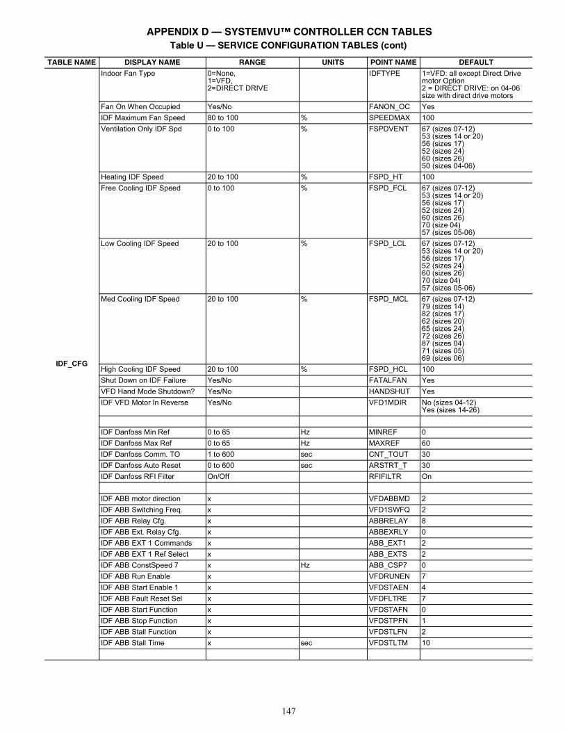
147
IDF_CFG
Indoor Fan Type 0=None,1=VFD,2=DIRECT DRIVE
IDFTYPE 1=VFD: all except Direct Drive motor Option2 = DIRECT DRIVE: on 04-06 size with direct drive motors
Fan On When Occupied Yes/No FANON_OC YesIDF Maximum Fan Speed 80 to 100 % SPEEDMAX 100Ventilation Only IDF Spd 0 to 100 % FSPDVENT 67 (sizes 07-12)
53 (sizes 14 or 20)56 (sizes 17)52 (sizes 24)60 (sizes 26)50 (sizes 04-06)
Heating IDF Speed 20 to 100 % FSPD_HT 100Free Cooling IDF Speed 0 to 100 % FSPD_FCL 67 (sizes 07-12)
53 (sizes 14 or 20)56 (sizes 17)52 (sizes 24)60 (sizes 26)70 (size 04)57 (sizes 05-06)
Low Cooling IDF Speed 20 to 100 % FSPD_LCL 67 (sizes 07-12)53 (sizes 14 or 20)56 (sizes 17)52 (sizes 24)60 (sizes 26)70 (size 04)57 (sizes 05-06)
Med Cooling IDF Speed 20 to 100 % FSPD_MCL 67 (sizes 07-12)79 (sizes 14)82 (sizes 17)62 (sizes 20)65 (sizes 24)72 (sizes 26)87 (sizes 04)71 (sizes 05)69 (sizes 06)
High Cooling IDF Speed 20 to 100 % FSPD_HCL 100Shut Down on IDF Failure Yes/No FATALFAN YesVFD Hand Mode Shutdown? Yes/No HANDSHUT YesIDF VFD Motor In Reverse Yes/No VFD1MDIR No (sizes 04-12)
Yes (sizes 14-26)
IDF Danfoss Min Ref 0 to 65 Hz MINREF 0IDF Danfoss Max Ref 0 to 65 Hz MAXREF 60IDF Danfoss Comm. TO 1 to 600 sec CNT_TOUT 30IDF Danfoss Auto Reset 0 to 600 sec ARSTRT_T 30IDF Danfoss RFI Filter On/Off RFIFILTR On
IDF ABB motor direction x VFDABBMD 2IDF ABB Switching Freq. x VFD1SWFQ 2IDF ABB Relay Cfg. x ABBRELAY 8IDF ABB Ext. Relay Cfg. x ABBEXRLY 0IDF ABB EXT 1 Commands x ABB_EXT1 2IDF ABB EXT 1 Ref Select x ABB_EXTS 2IDF ABB ConstSpeed 7 x Hz ABB_CSP7 0IDF ABB Run Enable x VFDRUNEN 7IDF ABB Start Enable 1 x VFDSTAEN 4IDF ABB Fault Reset Sel x VFDFLTRE 7IDF ABB Start Function x VFDSTAFN 0IDF ABB Stop Function x VFDSTPFN 1IDF ABB Stall Function x VFDSTLFN 2IDF ABB Stall Time x sec VFDSTLTM 10
Table U — SERVICE CONFIGURATION TABLES (cont)
TABLE NAME DISPLAY NAME RANGE UNITS POINT NAME DEFAULT
APPENDIX D — SYSTEMVU™ CONTROLLER CCN TABLES
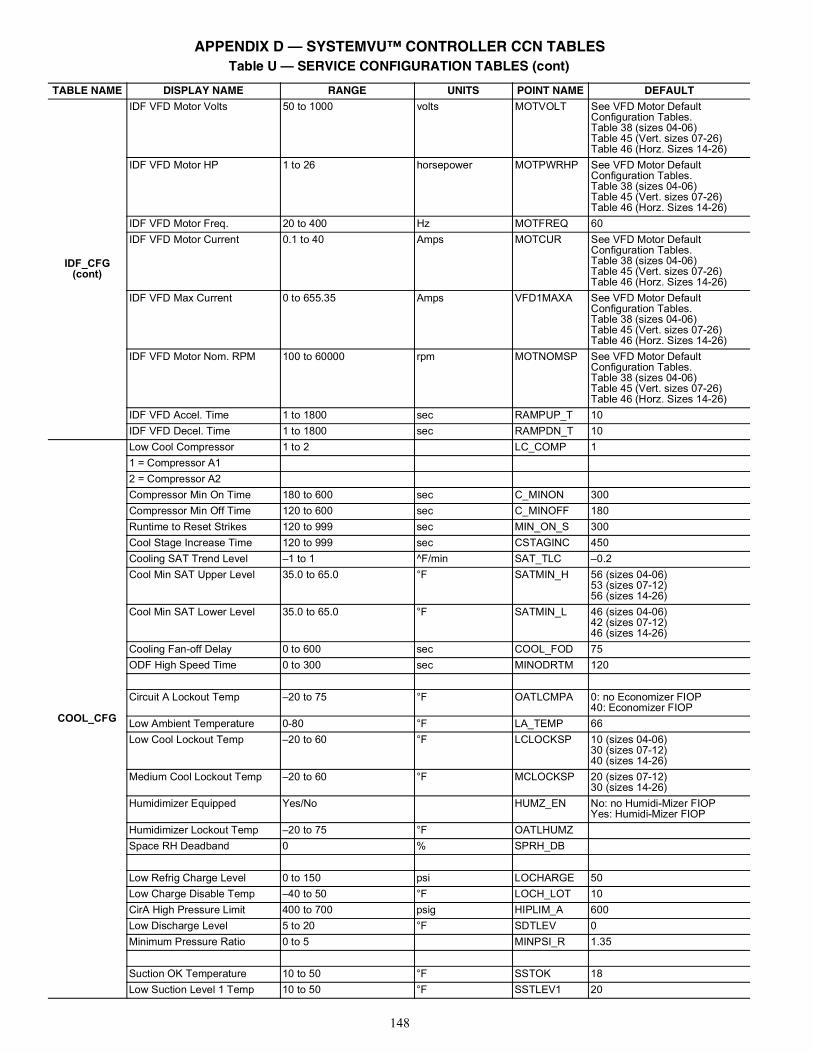
148
IDF_CFG (cont)
IDF VFD Motor Volts 50 to 1000 volts MOTVOLT See VFD Motor Default Configuration Tables.Table 38 (sizes 04-06)Table 45 (Vert. sizes 07-26)Table 46 (Horz. Sizes 14-26)
IDF VFD Motor HP 1 to 26 horsepower MOTPWRHP See VFD Motor Default Configuration Tables.Table 38 (sizes 04-06)Table 45 (Vert. sizes 07-26)Table 46 (Horz. Sizes 14-26)
IDF VFD Motor Freq. 20 to 400 Hz MOTFREQ 60IDF VFD Motor Current 0.1 to 40 Amps MOTCUR See VFD Motor Default
Configuration Tables.Table 38 (sizes 04-06)Table 45 (Vert. sizes 07-26)Table 46 (Horz. Sizes 14-26)
IDF VFD Max Current 0 to 655.35 Amps VFD1MAXA See VFD Motor Default Configuration Tables.Table 38 (sizes 04-06)Table 45 (Vert. sizes 07-26)Table 46 (Horz. Sizes 14-26)
IDF VFD Motor Nom. RPM 100 to 60000 rpm MOTNOMSP See VFD Motor Default Configuration Tables.Table 38 (sizes 04-06)Table 45 (Vert. sizes 07-26)Table 46 (Horz. Sizes 14-26)
IDF VFD Accel. Time 1 to 1800 sec RAMPUP_T 10IDF VFD Decel. Time 1 to 1800 sec RAMPDN_T 10
COOL_CFG
Low Cool Compressor 1 to 2 LC_COMP 11 = Compressor A12 = Compressor A2Compressor Min On Time 180 to 600 sec C_MINON 300Compressor Min Off Time 120 to 600 sec C_MINOFF 180Runtime to Reset Strikes 120 to 999 sec MIN_ON_S 300Cool Stage Increase Time 120 to 999 sec CSTAGINC 450Cooling SAT Trend Level –1 to 1 ^F/min SAT_TLC –0.2Cool Min SAT Upper Level 35.0 to 65.0 °F SATMIN_H 56 (sizes 04-06)
53 (sizes 07-12)56 (sizes 14-26)
Cool Min SAT Lower Level 35.0 to 65.0 °F SATMIN_L 46 (sizes 04-06)42 (sizes 07-12)46 (sizes 14-26)
Cooling Fan-off Delay 0 to 600 sec COOL_FOD 75ODF High Speed Time 0 to 300 sec MINODRTM 120
Circuit A Lockout Temp –20 to 75 °F OATLCMPA 0: no Economizer FIOP40: Economizer FIOP
Low Ambient Temperature 0-80 °F LA_TEMP 66Low Cool Lockout Temp –20 to 60 °F LCLOCKSP 10 (sizes 04-06)
30 (sizes 07-12)40 (sizes 14-26)
Medium Cool Lockout Temp –20 to 60 °F MCLOCKSP 20 (sizes 07-12)30 (sizes 14-26)
Humidimizer Equipped Yes/No HUMZ_EN No: no Humidi-Mizer FIOPYes: Humidi-Mizer FIOP
Humidimizer Lockout Temp –20 to 75 °F OATLHUMZSpace RH Deadband 0 % SPRH_DB
Low Refrig Charge Level 0 to 150 psi LOCHARGE 50Low Charge Disable Temp –40 to 50 °F LOCH_LOT 10CirA High Pressure Limit 400 to 700 psig HIPLIM_A 600Low Discharge Level 5 to 20 °F SDTLEV 0Minimum Pressure Ratio 0 to 5 MINPSI_R 1.35
Suction OK Temperature 10 to 50 °F SSTOK 18Low Suction Level 1 Temp 10 to 50 °F SSTLEV1 20
Table U — SERVICE CONFIGURATION TABLES (cont)
TABLE NAME DISPLAY NAME RANGE UNITS POINT NAME DEFAULT
APPENDIX D — SYSTEMVU™ CONTROLLER CCN TABLES
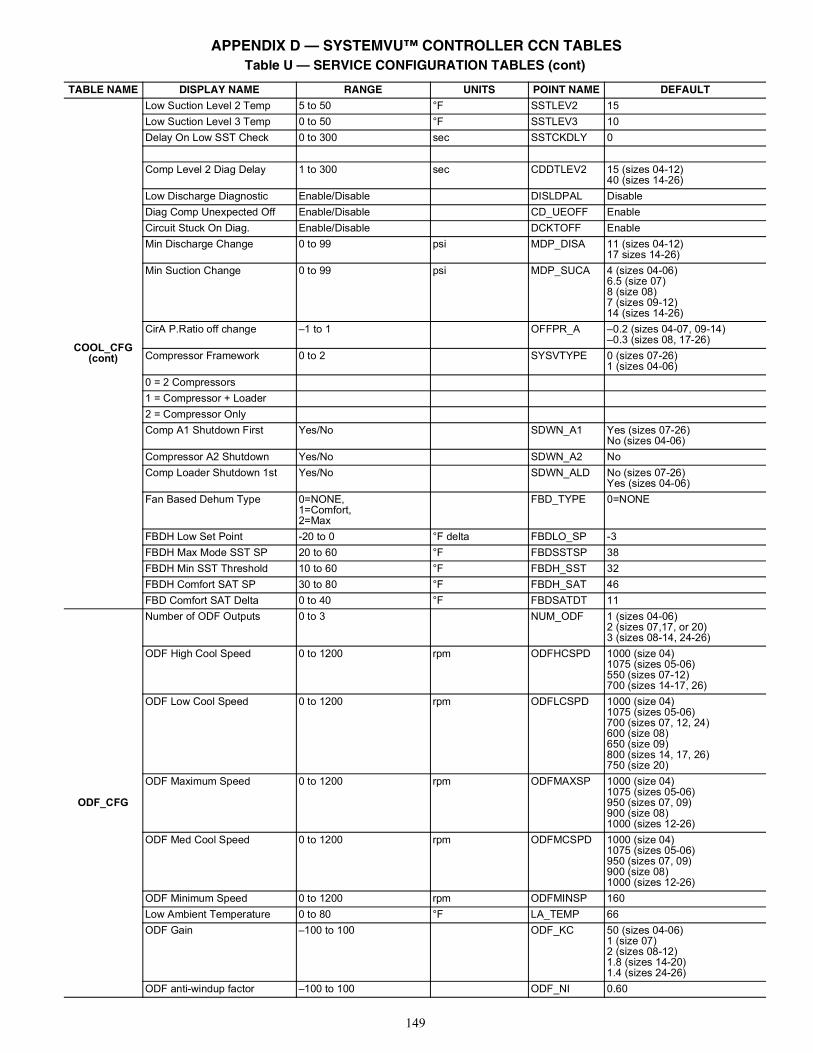
149
COOL_CFG (cont)
Low Suction Level 2 Temp 5 to 50 °F SSTLEV2 15Low Suction Level 3 Temp 0 to 50 °F SSTLEV3 10Delay On Low SST Check 0 to 300 sec SSTCKDLY 0
Comp Level 2 Diag Delay 1 to 300 sec CDDTLEV2 15 (sizes 04-12)40 (sizes 14-26)
Low Discharge Diagnostic Enable/Disable DISLDPAL DisableDiag Comp Unexpected Off Enable/Disable CD_UEOFF EnableCircuit Stuck On Diag. Enable/Disable DCKTOFF EnableMin Discharge Change 0 to 99 psi MDP_DISA 11 (sizes 04-12)
17 sizes 14-26)Min Suction Change 0 to 99 psi MDP_SUCA 4 (sizes 04-06)
6.5 (size 07)8 (size 08)7 (sizes 09-12)14 (sizes 14-26)
CirA P.Ratio off change –1 to 1 OFFPR_A –0.2 (sizes 04-07, 09-14)–0.3 (sizes 08, 17-26)
Compressor Framework 0 to 2 SYSVTYPE 0 (sizes 07-26)1 (sizes 04-06)
0 = 2 Compressors1 = Compressor + Loader2 = Compressor OnlyComp A1 Shutdown First Yes/No SDWN_A1 Yes (sizes 07-26)
No (sizes 04-06)Compressor A2 Shutdown Yes/No SDWN_A2 NoComp Loader Shutdown 1st Yes/No SDWN_ALD No (sizes 07-26)
Yes (sizes 04-06)Fan Based Dehum Type 0=NONE,
1=Comfort,2=Max
FBD_TYPE 0=NONE
FBDH Low Set Point -20 to 0 °F delta FBDLO_SP -3FBDH Max Mode SST SP 20 to 60 °F FBDSSTSP 38FBDH Min SST Threshold 10 to 60 °F FBDH_SST 32FBDH Comfort SAT SP 30 to 80 °F FBDH_SAT 46FBD Comfort SAT Delta 0 to 40 °F FBDSATDT 11
ODF_CFG
Number of ODF Outputs 0 to 3 NUM_ODF 1 (sizes 04-06)2 (sizes 07,17, or 20)3 (sizes 08-14, 24-26)
ODF High Cool Speed 0 to 1200 rpm ODFHCSPD 1000 (size 04)1075 (sizes 05-06)550 (sizes 07-12)700 (sizes 14-17, 26)
ODF Low Cool Speed 0 to 1200 rpm ODFLCSPD 1000 (size 04)1075 (sizes 05-06)700 (sizes 07, 12, 24)600 (size 08)650 (size 09)800 (sizes 14, 17, 26)750 (size 20)
ODF Maximum Speed 0 to 1200 rpm ODFMAXSP 1000 (size 04)1075 (sizes 05-06)950 (sizes 07, 09)900 (size 08)1000 (sizes 12-26)
ODF Med Cool Speed 0 to 1200 rpm ODFMCSPD 1000 (size 04)1075 (sizes 05-06)950 (sizes 07, 09)900 (size 08)1000 (sizes 12-26)
ODF Minimum Speed 0 to 1200 rpm ODFMINSP 160Low Ambient Temperature 0 to 80 °F LA_TEMP 66ODF Gain –100 to 100 ODF_KC 50 (sizes 04-06)
1 (size 07)2 (sizes 08-12)1.8 (sizes 14-20)1.4 (sizes 24-26)
ODF anti-windup factor –100 to 100 ODF_NI 0.60
Table U — SERVICE CONFIGURATION TABLES (cont)
TABLE NAME DISPLAY NAME RANGE UNITS POINT NAME DEFAULT
APPENDIX D — SYSTEMVU™ CONTROLLER CCN TABLES
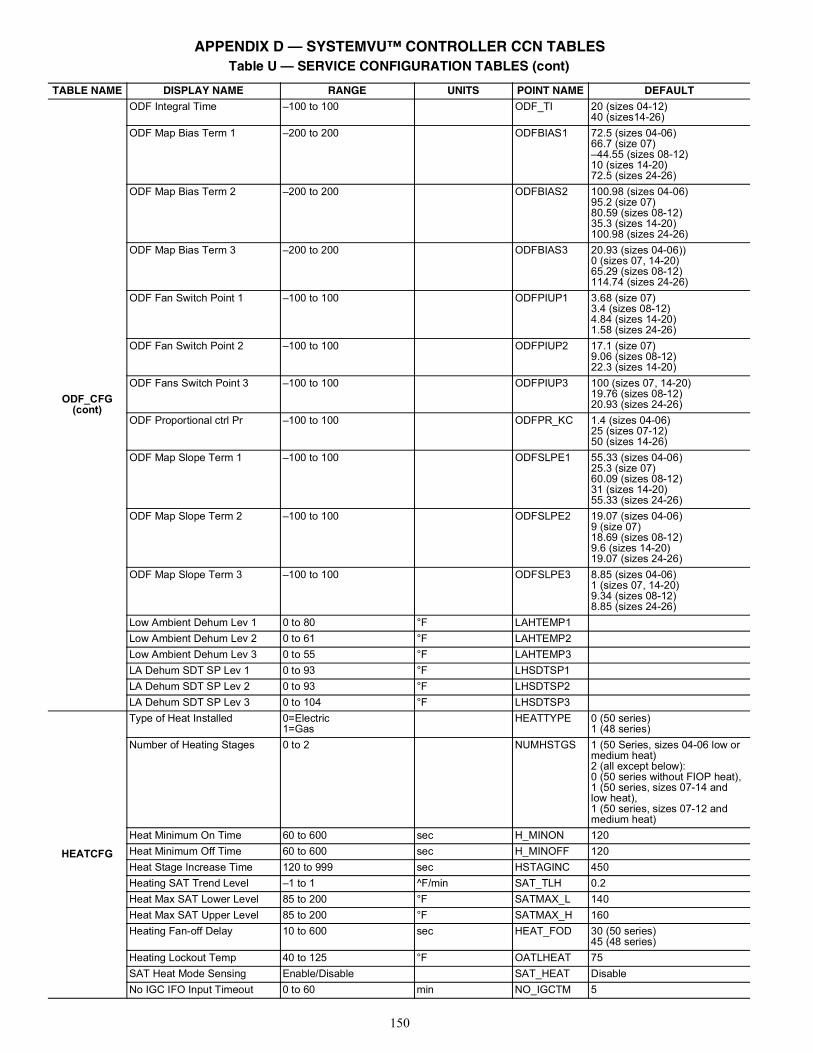
150
ODF_CFG(cont)
ODF Integral Time –100 to 100 ODF_TI 20 (sizes 04-12)40 (sizes14-26)
ODF Map Bias Term 1 –200 to 200 ODFBIAS1 72.5 (sizes 04-06)66.7 (size 07)–44.55 (sizes 08-12)10 (sizes 14-20)72.5 (sizes 24-26)
ODF Map Bias Term 2 –200 to 200 ODFBIAS2 100.98 (sizes 04-06)95.2 (size 07)80.59 (sizes 08-12)35.3 (sizes 14-20)100.98 (sizes 24-26)
ODF Map Bias Term 3 –200 to 200 ODFBIAS3 20.93 (sizes 04-06))0 (sizes 07, 14-20)65.29 (sizes 08-12)114.74 (sizes 24-26)
ODF Fan Switch Point 1 –100 to 100 ODFPIUP1 3.68 (size 07)3.4 (sizes 08-12)4.84 (sizes 14-20)1.58 (sizes 24-26)
ODF Fan Switch Point 2 –100 to 100 ODFPIUP2 17.1 (size 07)9.06 (sizes 08-12)22.3 (sizes 14-20)
ODF Fans Switch Point 3 –100 to 100 ODFPIUP3 100 (sizes 07, 14-20)19.76 (sizes 08-12)20.93 (sizes 24-26)
ODF Proportional ctrl Pr –100 to 100 ODFPR_KC 1.4 (sizes 04-06)25 (sizes 07-12)50 (sizes 14-26)
ODF Map Slope Term 1 –100 to 100 ODFSLPE1 55.33 (sizes 04-06)25.3 (size 07)60.09 (sizes 08-12)31 (sizes 14-20)55.33 (sizes 24-26)
ODF Map Slope Term 2 –100 to 100 ODFSLPE2 19.07 (sizes 04-06)9 (size 07)18.69 (sizes 08-12)9.6 (sizes 14-20)19.07 (sizes 24-26)
ODF Map Slope Term 3 –100 to 100 ODFSLPE3 8.85 (sizes 04-06)1 (sizes 07, 14-20)9.34 (sizes 08-12)8.85 (sizes 24-26)
Low Ambient Dehum Lev 1 0 to 80 °F LAHTEMP1Low Ambient Dehum Lev 2 0 to 61 °F LAHTEMP2Low Ambient Dehum Lev 3 0 to 55 °F LAHTEMP3LA Dehum SDT SP Lev 1 0 to 93 °F LHSDTSP1LA Dehum SDT SP Lev 2 0 to 93 °F LHSDTSP2LA Dehum SDT SP Lev 3 0 to 104 °F LHSDTSP3
HEATCFG
Type of Heat Installed 0=Electric1=Gas
HEATTYPE 0 (50 series)1 (48 series)
Number of Heating Stages 0 to 2 NUMHSTGS 1 (50 Series, sizes 04-06 low ormedium heat)2 (all except below):0 (50 series without FIOP heat),1 (50 series, sizes 07-14 andlow heat),1 (50 series, sizes 07-12 andmedium heat)
Heat Minimum On Time 60 to 600 sec H_MINON 120Heat Minimum Off Time 60 to 600 sec H_MINOFF 120Heat Stage Increase Time 120 to 999 sec HSTAGINC 450Heating SAT Trend Level –1 to 1 ^F/min SAT_TLH 0.2Heat Max SAT Lower Level 85 to 200 °F SATMAX_L 140Heat Max SAT Upper Level 85 to 200 °F SATMAX_H 160Heating Fan-off Delay 10 to 600 sec HEAT_FOD 30 (50 series)
45 (48 series)Heating Lockout Temp 40 to 125 °F OATLHEAT 75SAT Heat Mode Sensing Enable/Disable SAT_HEAT DisableNo IGC IFO Input Timeout 0 to 60 min NO_IGCTM 5
Table U — SERVICE CONFIGURATION TABLES (cont)
TABLE NAME DISPLAY NAME RANGE UNITS POINT NAME DEFAULT
APPENDIX D — SYSTEMVU™ CONTROLLER CCN TABLES
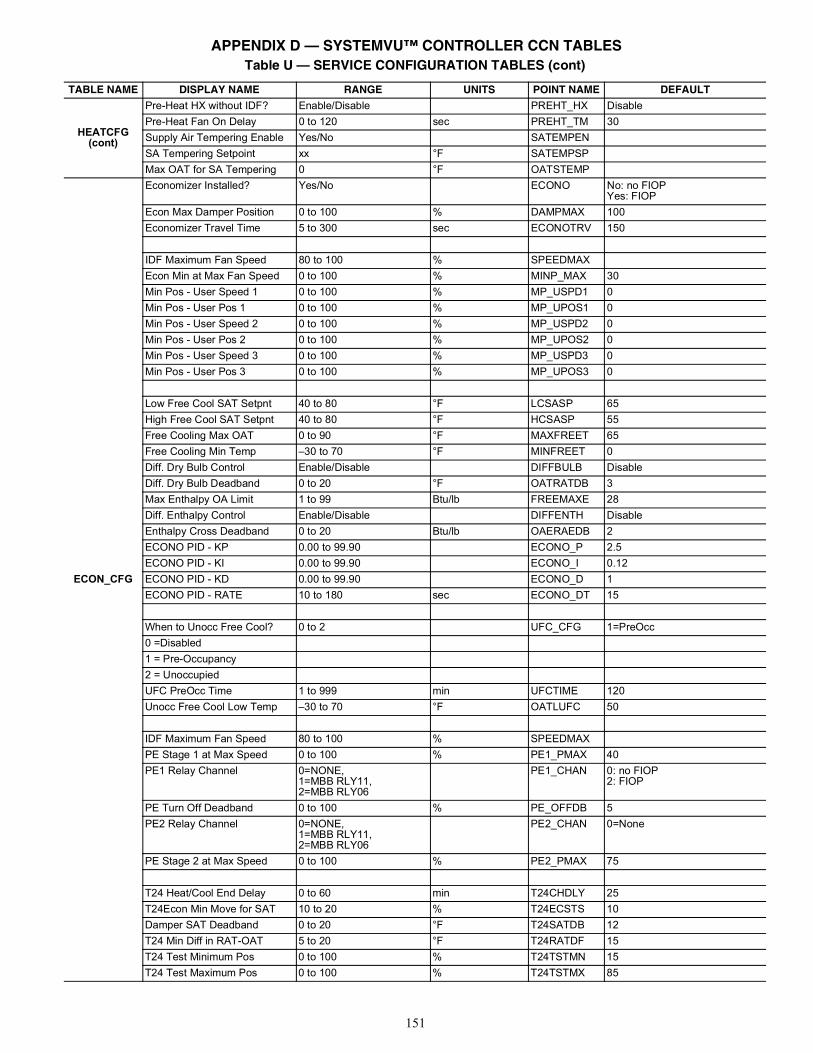
151
HEATCFG (cont)
Pre-Heat HX without IDF? Enable/Disable PREHT_HX DisablePre-Heat Fan On Delay 0 to 120 sec PREHT_TM 30Supply Air Tempering Enable Yes/No SATEMPENSA Tempering Setpoint xx °F SATEMPSPMax OAT for SA Tempering 0 °F OATSTEMP
ECON_CFG
Economizer Installed? Yes/No ECONO No: no FIOPYes: FIOP
Econ Max Damper Position 0 to 100 % DAMPMAX 100Economizer Travel Time 5 to 300 sec ECONOTRV 150
IDF Maximum Fan Speed 80 to 100 % SPEEDMAXEcon Min at Max Fan Speed 0 to 100 % MINP_MAX 30Min Pos - User Speed 1 0 to 100 % MP_USPD1 0Min Pos - User Pos 1 0 to 100 % MP_UPOS1 0Min Pos - User Speed 2 0 to 100 % MP_USPD2 0Min Pos - User Pos 2 0 to 100 % MP_UPOS2 0Min Pos - User Speed 3 0 to 100 % MP_USPD3 0Min Pos - User Pos 3 0 to 100 % MP_UPOS3 0
Low Free Cool SAT Setpnt 40 to 80 °F LCSASP 65High Free Cool SAT Setpnt 40 to 80 °F HCSASP 55Free Cooling Max OAT 0 to 90 °F MAXFREET 65Free Cooling Min Temp –30 to 70 °F MINFREET 0Diff. Dry Bulb Control Enable/Disable DIFFBULB DisableDiff. Dry Bulb Deadband 0 to 20 °F OATRATDB 3Max Enthalpy OA Limit 1 to 99 Btu/lb FREEMAXE 28Diff. Enthalpy Control Enable/Disable DIFFENTH DisableEnthalpy Cross Deadband 0 to 20 Btu/lb OAERAEDB 2ECONO PID - KP 0.00 to 99.90 ECONO_P 2.5ECONO PID - KI 0.00 to 99.90 ECONO_I 0.12ECONO PID - KD 0.00 to 99.90 ECONO_D 1ECONO PID - RATE 10 to 180 sec ECONO_DT 15
When to Unocc Free Cool? 0 to 2 UFC_CFG 1=PreOcc0 =Disabled1 = Pre-Occupancy2 = UnoccupiedUFC PreOcc Time 1 to 999 min UFCTIME 120Unocc Free Cool Low Temp –30 to 70 °F OATLUFC 50
IDF Maximum Fan Speed 80 to 100 % SPEEDMAXPE Stage 1 at Max Speed 0 to 100 % PE1_PMAX 40PE1 Relay Channel 0=NONE,
1=MBB RLY11,2=MBB RLY06
PE1_CHAN 0: no FIOP2: FIOP
PE Turn Off Deadband 0 to 100 % PE_OFFDB 5PE2 Relay Channel 0=NONE,
1=MBB RLY11,2=MBB RLY06
PE2_CHAN 0=None
PE Stage 2 at Max Speed 0 to 100 % PE2_PMAX 75
T24 Heat/Cool End Delay 0 to 60 min T24CHDLY 25T24Econ Min Move for SAT 10 to 20 % T24ECSTS 10Damper SAT Deadband 0 to 20 °F T24SATDB 12T24 Min Diff in RAT-OAT 5 to 20 °F T24RATDF 15T24 Test Minimum Pos 0 to 100 % T24TSTMN 15T24 Test Maximum Pos 0 to 100 % T24TSTMX 85
Table U — SERVICE CONFIGURATION TABLES (cont)
TABLE NAME DISPLAY NAME RANGE UNITS POINT NAME DEFAULT
APPENDIX D — SYSTEMVU™ CONTROLLER CCN TABLES
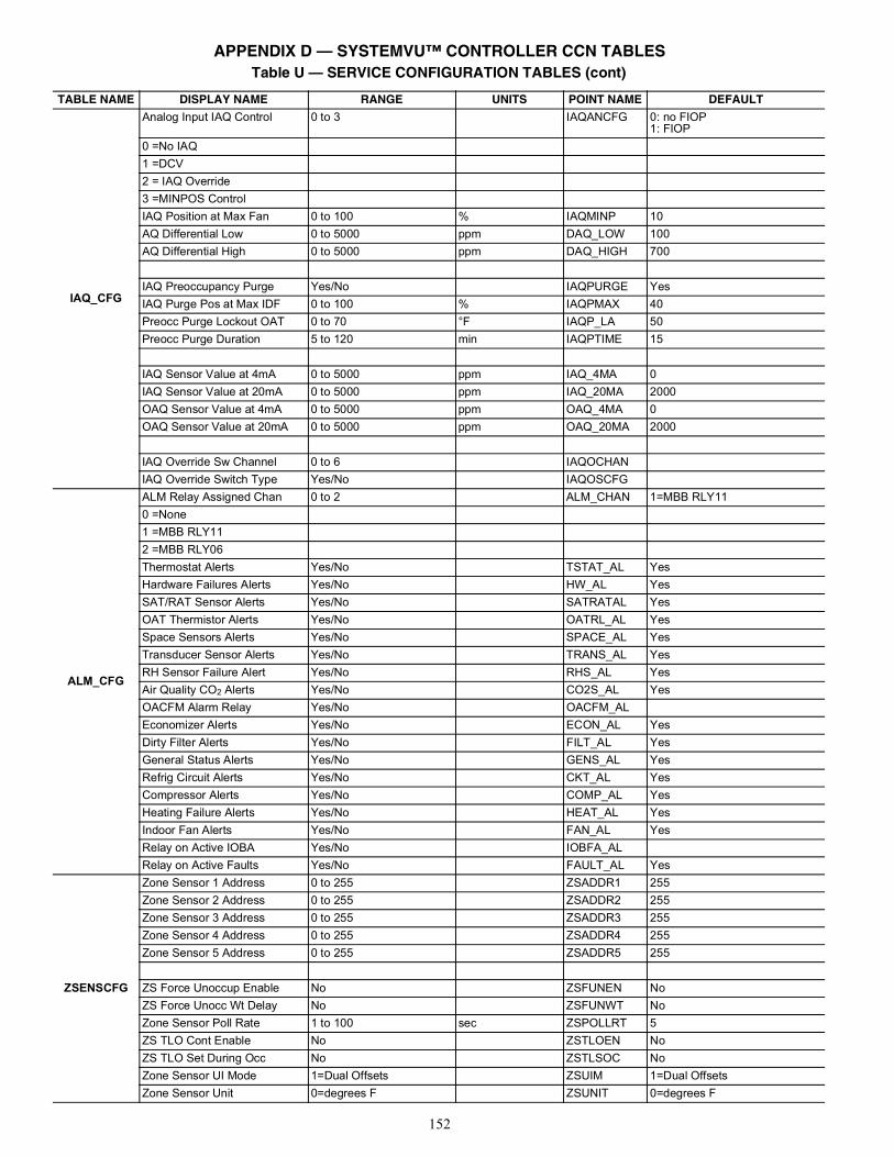
152
IAQ_CFG
Analog Input IAQ Control 0 to 3 IAQANCFG 0: no FIOP1: FIOP
0 =No IAQ1 =DCV2 = IAQ Override3 =MINPOS ControlIAQ Position at Max Fan 0 to 100 % IAQMINP 10AQ Differential Low 0 to 5000 ppm DAQ_LOW 100AQ Differential High 0 to 5000 ppm DAQ_HIGH 700
IAQ Preoccupancy Purge Yes/No IAQPURGE YesIAQ Purge Pos at Max IDF 0 to 100 % IAQPMAX 40Preocc Purge Lockout OAT 0 to 70 °F IAQP_LA 50Preocc Purge Duration 5 to 120 min IAQPTIME 15
IAQ Sensor Value at 4mA 0 to 5000 ppm IAQ_4MA 0IAQ Sensor Value at 20mA 0 to 5000 ppm IAQ_20MA 2000OAQ Sensor Value at 4mA 0 to 5000 ppm OAQ_4MA 0OAQ Sensor Value at 20mA 0 to 5000 ppm OAQ_20MA 2000
IAQ Override Sw Channel 0 to 6 IAQOCHANIAQ Override Switch Type Yes/No IAQOSCFG
ALM_CFG
ALM Relay Assigned Chan 0 to 2 ALM_CHAN 1=MBB RLY110 =None1 =MBB RLY112 =MBB RLY06Thermostat Alerts Yes/No TSTAT_AL YesHardware Failures Alerts Yes/No HW_AL YesSAT/RAT Sensor Alerts Yes/No SATRATAL YesOAT Thermistor Alerts Yes/No OATRL_AL YesSpace Sensors Alerts Yes/No SPACE_AL YesTransducer Sensor Alerts Yes/No TRANS_AL YesRH Sensor Failure Alert Yes/No RHS_AL YesAir Quality CO2 Alerts Yes/No CO2S_AL YesOACFM Alarm Relay Yes/No OACFM_ALEconomizer Alerts Yes/No ECON_AL YesDirty Filter Alerts Yes/No FILT_AL YesGeneral Status Alerts Yes/No GENS_AL YesRefrig Circuit Alerts Yes/No CKT_AL YesCompressor Alerts Yes/No COMP_AL YesHeating Failure Alerts Yes/No HEAT_AL YesIndoor Fan Alerts Yes/No FAN_AL YesRelay on Active IOBA Yes/No IOBFA_ALRelay on Active Faults Yes/No FAULT_AL Yes
ZSENSCFG
Zone Sensor 1 Address 0 to 255 ZSADDR1 255Zone Sensor 2 Address 0 to 255 ZSADDR2 255Zone Sensor 3 Address 0 to 255 ZSADDR3 255Zone Sensor 4 Address 0 to 255 ZSADDR4 255Zone Sensor 5 Address 0 to 255 ZSADDR5 255
ZS Force Unoccup Enable No ZSFUNEN NoZS Force Unocc Wt Delay No ZSFUNWT NoZone Sensor Poll Rate 1 to 100 sec ZSPOLLRT 5ZS TLO Cont Enable No ZSTLOEN NoZS TLO Set During Occ No ZSTLSOC NoZone Sensor UI Mode 1=Dual Offsets ZSUIM 1=Dual OffsetsZone Sensor Unit 0=degrees F ZSUNIT 0=degrees F
Table U — SERVICE CONFIGURATION TABLES (cont)
TABLE NAME DISPLAY NAME RANGE UNITS POINT NAME DEFAULT
APPENDIX D — SYSTEMVU™ CONTROLLER CCN TABLES
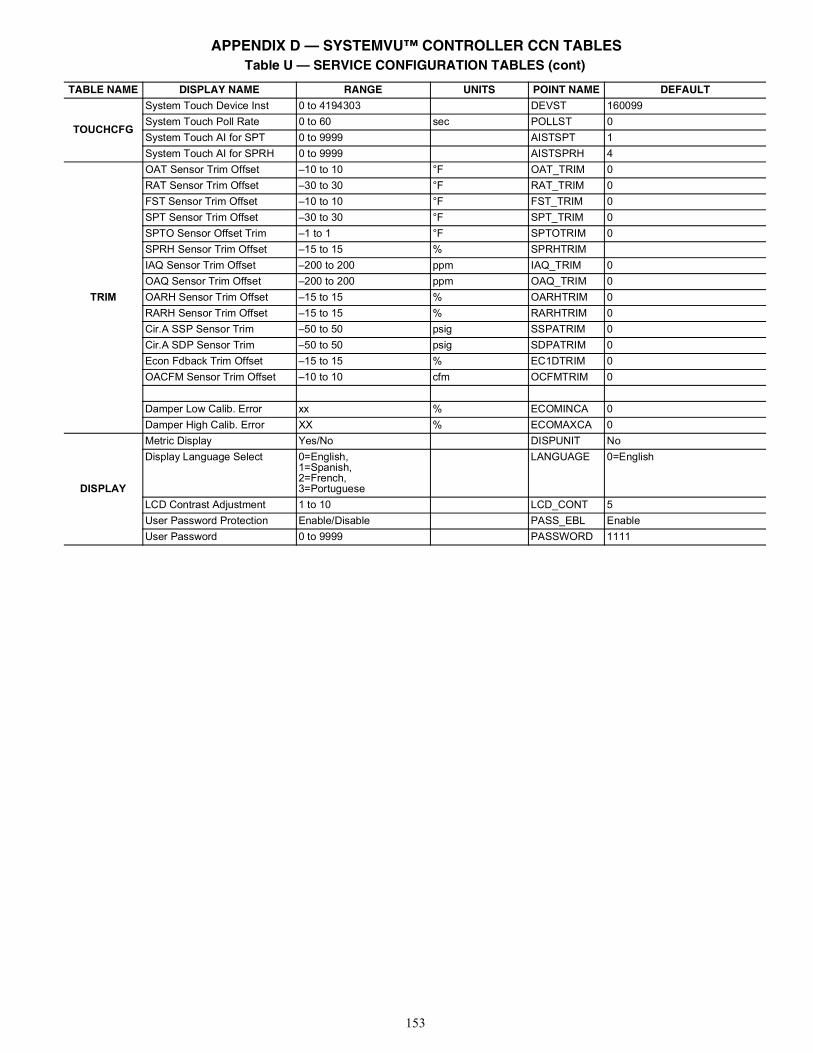
153
TOUCHCFG
System Touch Device Inst 0 to 4194303 DEVST 160099System Touch Poll Rate 0 to 60 sec POLLST 0System Touch AI for SPT 0 to 9999 AISTSPT 1System Touch AI for SPRH 0 to 9999 AISTSPRH 4
TRIM
OAT Sensor Trim Offset –10 to 10 °F OAT_TRIM 0RAT Sensor Trim Offset –30 to 30 °F RAT_TRIM 0FST Sensor Trim Offset –10 to 10 °F FST_TRIM 0SPT Sensor Trim Offset –30 to 30 °F SPT_TRIM 0SPTO Sensor Offset Trim –1 to 1 °F SPTOTRIM 0SPRH Sensor Trim Offset –15 to 15 % SPRHTRIMIAQ Sensor Trim Offset –200 to 200 ppm IAQ_TRIM 0OAQ Sensor Trim Offset –200 to 200 ppm OAQ_TRIM 0OARH Sensor Trim Offset –15 to 15 % OARHTRIM 0RARH Sensor Trim Offset –15 to 15 % RARHTRIM 0Cir.A SSP Sensor Trim –50 to 50 psig SSPATRIM 0Cir.A SDP Sensor Trim –50 to 50 psig SDPATRIM 0Econ Fdback Trim Offset –15 to 15 % EC1DTRIM 0OACFM Sensor Trim Offset –10 to 10 cfm OCFMTRIM 0
Damper Low Calib. Error xx % ECOMINCA 0Damper High Calib. Error XX % ECOMAXCA 0
DISPLAY
Metric Display Yes/No DISPUNIT NoDisplay Language Select 0=English,
1=Spanish,2=French,3=Portuguese
LANGUAGE 0=English
LCD Contrast Adjustment 1 to 10 LCD_CONT 5User Password Protection Enable/Disable PASS_EBL EnableUser Password 0 to 9999 PASSWORD 1111
Table U — SERVICE CONFIGURATION TABLES (cont)
TABLE NAME DISPLAY NAME RANGE UNITS POINT NAME DEFAULT
APPENDIX D — SYSTEMVU™ CONTROLLER CCN TABLES
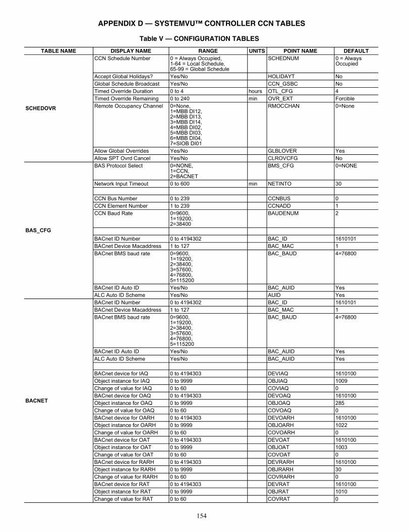
154
Table V — CONFIGURATION TABLES
TABLE NAME DISPLAY NAME RANGE UNITS POINT NAME DEFAULT
SCHEDOVR
CCN Schedule Number 0 = Always Occupied,1-64 = Local Schedule,65-99 = Global Schedule
SCHEDNUM 0 = Always Occupied
Accept Global Holidays? Yes/No HOLIDAYT NoGlobal Schedule Broadcast Yes/No CCN_GSBC NoTimed Override Duration 0 to 4 hours OTL_CFG 4Timed Override Remaining 0 to 240 min OVR_EXT ForcibleRemote Occupancy Channel 0=None,
1=MBB DI12,2=MBB DI13,3=MBB DI14,4=MBB DI02,5=MBB DI03,6=MBB DI04,7=SIOB DI01
RMOCCHAN 0=None
Allow Global Overrides Yes/No GLBLOVER YesAllow SPT Ovrd Cancel Yes/No CLROVCFG No
BAS_CFG
BAS Protocol Select 0=NONE,1=CCN,2=BACNET
BMS_CFG 0=NONE
Network Input Timeout 0 to 600 min NETINTO 30
CCN Bus Number 0 to 239 CCNBUS 0CCN Element Number 1 to 239 CCNADD 1CCN Baud Rate 0=9600,
1=19200,2=38400
BAUDENUM 2
BACnet ID Number 0 to 4194302 BAC_ID 1610101BACnet Device Macaddress 1 to 127 BAC_MAC 1BACnet BMS baud rate 0=9600,
1=19200,2=38400,3=57600,4=76800,5=115200
BAC_BAUD 4=76800
BACnet ID Auto ID Yes/No BAC_AUID YesALC Auto ID Scheme Yes/No AUID Yes
BACNET
BACnet ID Number 0 to 4194302 BAC_ID 1610101BACnet Device Macaddress 1 to 127 BAC_MAC 1BACnet BMS baud rate 0=9600,
1=19200,2=38400,3=57600,4=76800,5=115200
BAC_BAUD 4=76800
BACnet ID Auto ID Yes/No BAC_AUID YesALC Auto ID Scheme Yes/No BAC_AUID Yes
BACnet device for IAQ 0 to 4194303 DEVIAQ 1610100Object instance for IAQ 0 to 9999 OBJIAQ 1009Change of value for IAQ 0 to 60 COVIAQ 0BACnet device for OAQ 0 to 4194303 DEVOAQ 1610100Object instance for OAQ 0 to 9999 OBJOAQ 285Change of value for OAQ 0 to 60 COVOAQ 0BACnet device for OARH 0 to 4194303 DEVOARH 1610100Object instance for OARH 0 to 9999 OBJOARH 1022Change of value for OARH 0 to 60 COVOARH 0BACnet device for OAT 0 to 4194303 DEVOAT 1610100Object instance for OAT 0 to 9999 OBJOAT 1003Change of value for OAT 0 to 60 COVOAT 0BACnet device for RARH 0 to 4194303 DEVRARH 1610100Object instance for RARH 0 to 9999 OBJRARH 30Change of value for RARH 0 to 60 COVRARH 0BACnet device for RAT 0 to 4194303 DEVRAT 1610100Object instance for RAT 0 to 9999 OBJRAT 1010Change of value for RAT 0 to 60 COVRAT 0
APPENDIX D — SYSTEMVU™ CONTROLLER CCN TABLES
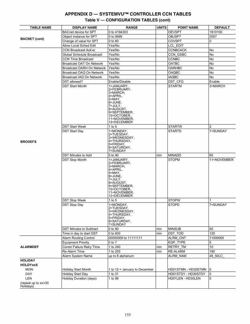
155
BACNET (cont)
BACnet device for SPT 0 to 4194303 DEVSPT 1610100Object instance for SPT 0 to 9999 OBJSPT 2007Change of value for SPT 0 to 60 COVSPT 0Allow Local Sched Edit Yes/No LCL_EDIT
BRODEFS
CCN Broadcast Ack’er Yes/No CCNBCACK NoGlobal Schedule Broadcast Yes/No CCN_GSBC NoCCN Time Broadcast Yes/No CCNBC NoBroadcast OAT On Network Yes/No OATBC NoBroadcast OARH On Network Yes/No OARHBC NoBroadcast OAQ On Network Yes/No OAQBC NoBroadcast IAQ On Network Yes/No IAQBC NoDST allowed? Enable/Disable DST_CFG EnableDST Start Month 1=JANUARY,
2=FEBRUARY,3=MARCH,4=APRIL,5=MAY,6=JUNE,7=JULY,8=AUGUST,9=SEPTEMBER,10=OCTOBER,11=NOVEMBER,12=DECEMBER
STARTM 3=MARCH
DST Start Week 1 to 5 STARTW 2DST Start Day 1=MONDAY,
2=TUESDAY,3=WEDNESDAY,4=THURSDAY,5=FRIDAY,6=SATURDAY,7=SUNDAY
STARTD 7=SUNDAY
DST Minutes to Add 0 to 90 min MINADD 60DST Stop Month 1=JANUARY,
2=FEBRUARY,3=MARCH,4=APRIL,5=MAY,6=JUNE,7=JULY,8=AUGUST,9=SEPTEMBER,10=OCTOBER,11=NOVEMBER,12=DECEMBER
STOPM 11=NOVEMBER
DST Stop Week 1 to 5 STOPW 1DST Stop Day 1=MONDAY,
2=TUESDAY,3=WEDNESDAY,4=THURSDAY,5=FRIDAY,6=SATURDAY,7=SUNDAY
STOPD 7=SUNDAY
DST Minutes to Subtract 0 to 90 min MINSUB 60Time in day to start DST 0 to 600 min DST_TOD 120
ALARMDEF
Alarm Routing Control 00000000 to 11111111 ALRM_CNT 11000000Equipment Priority 0 to 7 EQP_TYPE 5Comm Failure Retry Time 1 to 240 min RETRY_TM 10Re-Alarm Time 1 to 255 min RE-ALARM 180Alarm System Name up to 8 alphanum ALRM_NAM 48_50LC_
HOLIDAYHOLDYxxS
MON Holiday Start Month 1 to 12 = January to December HD01STMN - HD30STMN 0DAY Holiday Start Day 1 to 31 HD01STDY - HD30STDY 0LEN Holiday Duration (days) 1 to 99 HD01LEN - HD30LEN 0
(repeat up to xx=30 Holidays)
Table V — CONFIGURATION TABLES (cont)
TABLE NAME DISPLAY NAME RANGE UNITS POINT NAME DEFAULT
APPENDIX D — SYSTEMVU™ CONTROLLER CCN TABLES
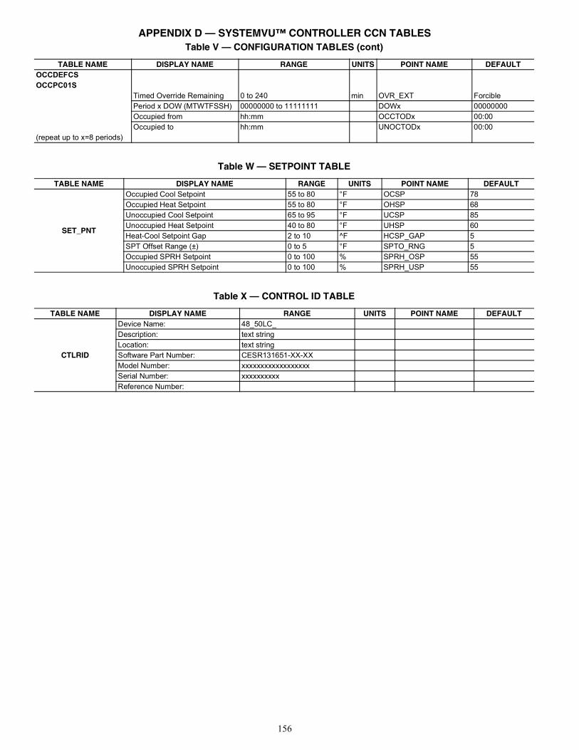
156
OCCDEFCSOCCPC01S
Timed Override Remaining 0 to 240 min OVR_EXT ForciblePeriod x DOW (MTWTFSSH) 00000000 to 11111111 DOWx 00000000Occupied from hh:mm OCCTODx 00:00Occupied to hh:mm UNOCTODx 00:00
(repeat up to x=8 periods)
Table V — CONFIGURATION TABLES (cont)
TABLE NAME DISPLAY NAME RANGE UNITS POINT NAME DEFAULT
Table W — SETPOINT TABLE
TABLE NAME DISPLAY NAME RANGE UNITS POINT NAME DEFAULT
SET_PNT
Occupied Cool Setpoint 55 to 80 °F OCSP 78Occupied Heat Setpoint 55 to 80 °F OHSP 68Unoccupied Cool Setpoint 65 to 95 °F UCSP 85Unoccupied Heat Setpoint 40 to 80 °F UHSP 60Heat-Cool Setpoint Gap 2 to 10 ^F HCSP_GAP 5SPT Offset Range (±) 0 to 5 °F SPTO_RNG 5Occupied SPRH Setpoint 0 to 100 % SPRH_OSP 55Unoccupied SPRH Setpoint 0 to 100 % SPRH_USP 55
Table X — CONTROL ID TABLE
TABLE NAME DISPLAY NAME RANGE UNITS POINT NAME DEFAULT
CTLRID
Device Name: 48_50LC_Description: text stringLocation: text stringSoftware Part Number: CESR131651-XX-XXModel Number: xxxxxxxxxxxxxxxxxxSerial Number: xxxxxxxxxxReference Number:
APPENDIX D — SYSTEMVU™ CONTROLLER CCN TABLES
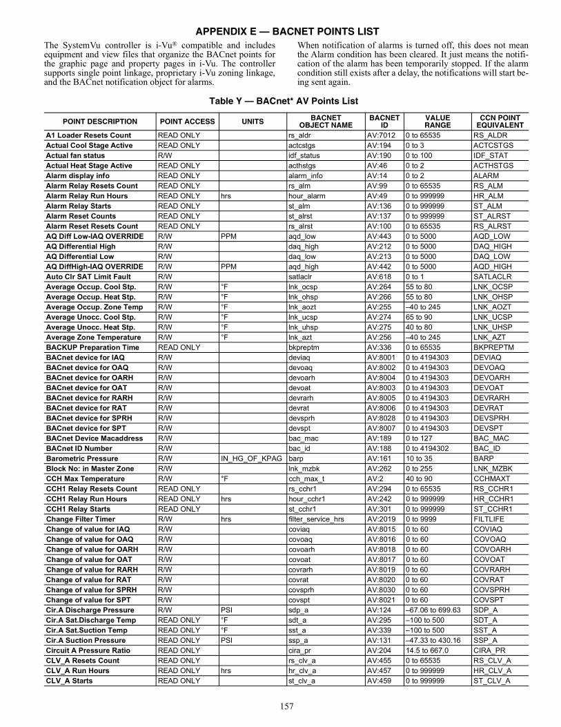
157
The SystemVu controller is i-Vu® compatible and includesequipment and view files that organize the BACnet points forthe graphic page and property pages in i-Vu. The controllersupports single point linkage, proprietary i-Vu zoning linkage,and the BACnet notification object for alarms.
When notification of alarms is turned off, this does not meanthe Alarm condition has been cleared. It just means the notifi-cation of the alarm has been temporarily stopped. If the alarmcondition still exists after a delay, the notifications will start be-ing sent again.
Table Y — BACnet* AV Points List
POINT DESCRIPTION POINT ACCESS UNITS BACNETOBJECT NAME
BACNETID
VALUERANGE
CCN POINTEQUIVALENT
A1 Loader Resets Count READ ONLY rs_aldr AV:7012 0 to 65535 RS_ALDRActual Cool Stage Active READ ONLY actcstgs AV:194 0 to 3 ACTCSTGSActual fan status R/W idf_status AV:190 0 to 100 IDF_STATActual Heat Stage Active READ ONLY acthstgs AV:46 0 to 2 ACTHSTGSAlarm display info READ ONLY alarm_info AV:14 0 to 2 ALARMAlarm Relay Resets Count READ ONLY rs_alm AV:99 0 to 65535 RS_ALMAlarm Relay Run Hours READ ONLY hrs hour_alarm AV:49 0 to 999999 HR_ALMAlarm Relay Starts READ ONLY st_alm AV:136 0 to 999999 ST_ALMAlarm Reset Counts READ ONLY st_alrst AV:137 0 to 999999 ST_ALRSTAlarm Reset Resets Count READ ONLY rs_alrst AV:100 0 to 65535 RS_ALRSTAQ Diff Low-IAQ OVERRIDE R/W PPM aqd_low AV:443 0 to 5000 AQD_LOWAQ Differential High R/W daq_high AV:212 0 to 5000 DAQ_HIGHAQ Differential Low R/W daq_low AV:213 0 to 5000 DAQ_LOWAQ DiffHigh-IAQ OVERRIDE R/W PPM aqd_high AV:442 0 to 5000 AQD_HIGHAuto Clr SAT Limit Fault R/W satlaclr AV:618 0 to 1 SATLACLRAverage Occup. Cool Stp. R/W °F lnk_ocsp AV:264 55 to 80 LNK_OCSPAverage Occup. Heat Stp. R/W °F lnk_ohsp AV:266 55 to 80 LNK_OHSPAverage Occup. Zone Temp R/W °F lnk_aozt AV:255 –40 to 245 LNK_AOZTAverage Unocc. Cool Stp. R/W °F lnk_ucsp AV:274 65 to 90 LNK_UCSPAverage Unocc. Heat Stp. R/W °F lnk_uhsp AV:275 40 to 80 LNK_UHSPAverage Zone Temperature R/W °F lnk_azt AV:256 –40 to 245 LNK_AZTBACKUP Preparation Time READ ONLY bkpreptm AV:336 0 to 65535 BKPREPTMBACnet device for IAQ R/W deviaq AV:8001 0 to 4194303 DEVIAQBACnet device for OAQ R/W devoaq AV:8002 0 to 4194303 DEVOAQBACnet device for OARH R/W devoarh AV:8004 0 to 4194303 DEVOARHBACnet device for OAT R/W devoat AV:8003 0 to 4194303 DEVOATBACnet device for RARH R/W devrarh AV:8005 0 to 4194303 DEVRARHBACnet device for RAT R/W devrat AV:8006 0 to 4194303 DEVRATBACnet device for SPRH R/W devsprh AV:8028 0 to 4194303 DEVSPRHBACnet device for SPT R/W devspt AV:8007 0 to 4194303 DEVSPTBACnet Device Macaddress R/W bac_mac AV:189 0 to 127 BAC_MACBACnet ID Number R/W bac_id AV:188 0 to 4194302 BAC_IDBarometric Pressure R/W IN_HG_OF_KPAG barp AV:161 10 to 35 BARPBlock No: in Master Zone R/W lnk_mzbk AV:262 0 to 255 LNK_MZBKCCH Max Temperature R/W °F cch_max_t AV:2 40 to 90 CCHMAXTCCH1 Relay Resets Count READ ONLY rs_cchr1 AV:294 0 to 65535 RS_CCHR1CCH1 Relay Run Hours READ ONLY hrs hour_cchr1 AV:242 0 to 999999 HR_CCHR1CCH1 Relay Starts READ ONLY st_cchr1 AV:301 0 to 999999 ST_CCHR1Change Filter Timer R/W hrs filter_service_hrs AV:2019 0 to 9999 FILTLIFEChange of value for IAQ R/W coviaq AV:8015 0 to 60 COVIAQChange of value for OAQ R/W covoaq AV:8016 0 to 60 COVOAQChange of value for OARH R/W covoarh AV:8018 0 to 60 COVOARHChange of value for OAT R/W covoat AV:8017 0 to 60 COVOATChange of value for RARH R/W covrarh AV:8019 0 to 60 COVRARHChange of value for RAT R/W covrat AV:8020 0 to 60 COVRATChange of value for SPRH R/W covsprh AV:8030 0 to 60 COVSPRHChange of value for SPT R/W covspt AV:8021 0 to 60 COVSPTCir.A Discharge Pressure R/W PSI sdp_a AV:124 –67.06 to 699.63 SDP_ACir.A Sat.Discharge Temp READ ONLY °F sdt_a AV:295 –100 to 500 SDT_ACir.A Sat.Suction Temp READ ONLY °F sst_a AV:339 –100 to 500 SST_ACir.A Suction Pressure READ ONLY PSI ssp_a AV:131 –47.33 to 430.16 SSP_ACircuit A Pressure Ratio READ ONLY cira_pr AV:204 14.5 to 667.0 CIRA_PRCLV_A Resets Count READ ONLY rs_clv_a AV:455 0 to 65535 RS_CLV_ACLV_A Run Hours READ ONLY hrs hr_clv_a AV:457 0 to 999999 HR_CLV_ACLV_A Starts READ ONLY st_clv_a AV:459 0 to 999999 ST_CLV_A
APPENDIX E — BACNET POINTS LIST
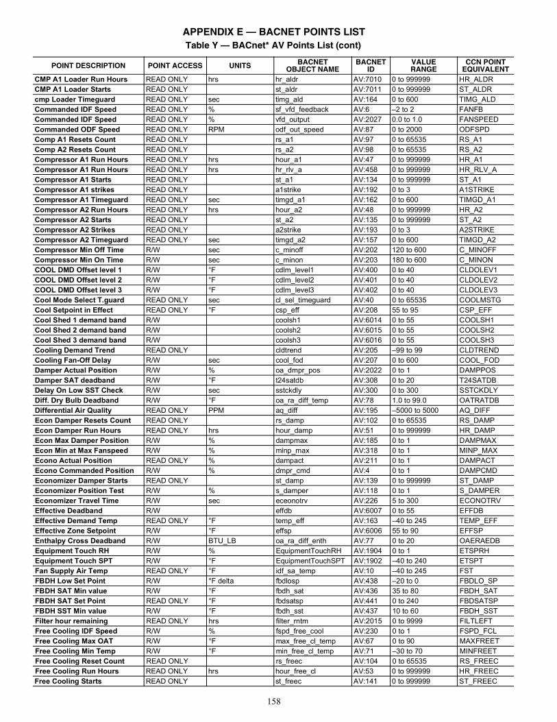
158
CMP A1 Loader Run Hours READ ONLY hrs hr_aldr AV:7010 0 to 999999 HR_ALDRCMP A1 Loader Starts READ ONLY st_aldr AV:7011 0 to 999999 ST_ALDRcmp Loader Timeguard READ ONLY sec timg_ald AV:164 0 to 600 TIMG_ALDCommanded IDF Speed READ ONLY % sf_vfd_feedback AV:6 –2 to 2 FANFBCommanded IDF Speed READ ONLY % vfd_output AV:2027 0.0 to 1.0 FANSPEEDCommanded ODF Speed READ ONLY RPM odf_out_speed AV:87 0 to 2000 ODFSPDComp A1 Resets Count READ ONLY rs_a1 AV:97 0 to 65535 RS_A1Comp A2 Resets Count READ ONLY rs_a2 AV:98 0 to 65535 RS_A2Compressor A1 Run Hours READ ONLY hrs hour_a1 AV:47 0 to 999999 HR_A1Compressor A1 Run Hours READ ONLY hrs hr_rlv_a AV:458 0 to 999999 HR_RLV_ACompressor A1 Starts READ ONLY st_a1 AV:134 0 to 999999 ST_A1Compressor A1 strikes READ ONLY a1strike AV:192 0 to 3 A1STRIKECompressor A1 Timeguard READ ONLY sec timgd_a1 AV:162 0 to 600 TIMGD_A1Compressor A2 Run Hours READ ONLY hrs hour_a2 AV:48 0 to 999999 HR_A2Compressor A2 Starts READ ONLY st_a2 AV:135 0 to 999999 ST_A2Compressor A2 Strikes READ ONLY a2strike AV:193 0 to 3 A2STRIKECompressor A2 Timeguard READ ONLY sec timgd_a2 AV:157 0 to 600 TIMGD_A2Compressor Min Off Time R/W sec c_minoff AV:202 120 to 600 C_MINOFFCompressor Min On Time R/W sec c_minon AV:203 180 to 600 C_MINONCOOL DMD Offset level 1 R/W °F cdlm_level1 AV:400 0 to 40 CLDOLEV1COOL DMD Offset level 2 R/W °F cdlm_level2 AV:401 0 to 40 CLDOLEV2COOL DMD Offset level 3 R/W °F cdlm_level3 AV:402 0 to 40 CLDOLEV3Cool Mode Select T.guard READ ONLY sec cl_sel_timeguard AV:40 0 to 65535 COOLMSTGCool Setpoint in Effect READ ONLY °F csp_eff AV:208 55 to 95 CSP_EFFCool Shed 1 demand band R/W coolsh1 AV:6014 0 to 55 COOLSH1Cool Shed 2 demand band R/W coolsh2 AV:6015 0 to 55 COOLSH2Cool Shed 3 demand band R/W coolsh3 AV:6016 0 to 55 COOLSH3Cooling Demand Trend READ ONLY cldtrend AV:205 –99 to 99 CLDTRENDCooling Fan-Off Delay R/W sec cool_fod AV:207 0 to 600 COOL_FODDamper Actual Position R/W % oa_dmpr_pos AV:2022 0 to 1 DAMPPOSDamper SAT deadband R/W °F t24satdb AV:308 0 to 20 T24SATDBDelay On Low SST Check R/W sec sstckdly AV:300 0 to 300 SSTCKDLYDiff. Dry Bulb Deadband R/W °F oa_ra_diff_temp AV:78 1.0 to 99.0 OATRATDBDifferential Air Quality READ ONLY PPM aq_diff AV:195 –5000 to 5000 AQ_DIFFEcon Damper Resets Count READ ONLY rs_damp AV:102 0 to 65535 RS_DAMPEcon Damper Run Hours READ ONLY hrs hour_damp AV:51 0 to 999999 HR_DAMPEcon Max Damper Position R/W % dampmax AV:185 0 to 1 DAMPMAXEcon Min at Max Fanspeed R/W % minp_max AV:318 0 to 1 MINP_MAXEcono Actual Position READ ONLY % dampact AV:211 0 to 1 DAMPACTEcono Commanded Position R/W % dmpr_cmd AV:4 0 to 1 DAMPCMDEconomizer Damper Starts READ ONLY st_damp AV:139 0 to 999999 ST_DAMPEconomizer Position Test R/W % s_damper AV:118 0 to 1 S_DAMPEREconomizer Travel Time R/W sec eceonotrv AV:226 5 to 300 ECONOTRVEffective Deadband R/W effdb AV:6007 0 to 55 EFFDBEffective Demand Temp READ ONLY °F temp_eff AV:163 –40 to 245 TEMP_EFFEffective Zone Setpoint R/W °F effsp AV:6006 55 to 90 EFFSPEnthalpy Cross Deadband R/W BTU_LB oa_ra_diff_enth AV:77 0 to 20 OAERAEDBEquipment Touch RH R/W % EquipmentTouchRH AV:1904 0 to 1 ETSPRHEquipment Touch SPT R/W °F EquipmentTouchSPT AV:1902 –40 to 240 ETSPTFan Supply Air Temp READ ONLY °F idf_sa_temp AV:10 –40 to 245 FSTFBDH Low Set Point R/W °F delta fbdlosp AV:438 –20 to 0 FBDLO_SPFBDH SAT Min value R/W °F fbdh_sat AV:436 35 to 80 FBDH_SATFBDH SAT Set Point READ ONLY °F fbdsatsp AV:441 0 to 240 FBDSATSPFBDH SST Min value R/W °F fbdh_sst AV:437 10 to 60 FBDH_SSTFilter hour remaining READ ONLY hrs filter_rntm AV:2015 0 to 9999 FILTLEFTFree Cooling IDF Speed R/W % fspd_free_cool AV:230 0 to 1 FSPD_FCLFree Cooling Max OAT R/W °F max_free_cl_temp AV:67 0 to 90 MAXFREETFree Cooling Min Temp R/W °F min_free_cl_temp AV:71 –30 to 70 MINFREETFree Cooling Reset Count READ ONLY rs_freec AV:104 0 to 65535 RS_FREECFree Cooling Run Hours READ ONLY hrs hour_free_cl AV:53 0 to 999999 HR_FREECFree Cooling Starts READ ONLY st_freec AV:141 0 to 999999 ST_FREEC
Table Y — BACnet* AV Points List (cont)
POINT DESCRIPTION POINT ACCESS UNITS BACNETOBJECT NAME
BACNETID
VALUERANGE
CCN POINTEQUIVALENT
APPENDIX E — BACNET POINTS LIST
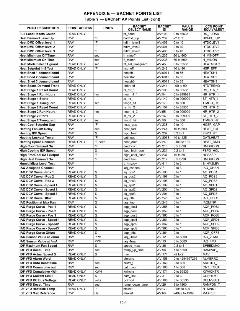
159
Full Load Resets Count READ ONLY rs_fload AV:103 0 to 65535 RS_FLOADHeat Demand Level Up R/W °F hadmd_lup AV:239 –2 to 2 HDMD_LUPHeat DMD Offset level 1 R/W °F hdlm_level1 AV:403 0 to 40 HTDOLEV1Heat DMD Offset level 2 R/W °F hdlm_level2 AV:404 0 to 40 HTDOLEV2Heat DMD Offset level 3 R/W °F hdlm_level3 AV:405 0 to 40 HTDOLEV3Heat Minimum Off Time R/W sec h_minoff AV:235 60 to 600 H_MINOFFHeat Minimum On Time R/W sec h_minon AV:236 60 to 600 H_MINONHeat Mode Select T.guard READ ONLY sec ht_sel_timeguard AV:45 0 to 65535 HEATMSTGHeat Setpoint in Effect READ ONLY °F hsp_eff AV:243 40 to 80 HSP_EFFHeat Shed 1 demand band R/W heatsh1 AV:6011 0 to 55 HEATSH1Heat Shed 2 demand band R/W heatsh2 AV:6012 0 to 55 HEATSH2Heat Shed 3 demand band R/W heatsh3 AV:6013 0 to 55 HEATSH3Heat Space Demand Trend READ ONLY htdtrend AV:244 –99 to 99 HTDTRENDHeat Stage 1 Reset Count READ ONLY rs_htr_1 AV:106 0 to 65535 RS_HTR_1Heat Stage 1 Run Hours READ ONLY hrs hour_ht_1 AV:54 0 to 999999 HR_HTR_1Heat Stage 1 Starts READ ONLY st_htr_1 AV:142 0 to 999999 ST_HTR_1Heat Stage 1 Timeguard READ ONLY sec timgd_h1 AV:173 0 to 600 TIMGD_H1Heat Stage 2 Reset Count READ ONLY rs_htr_2 AV:107 0 to 65535 RS_HTR_2Heat Stage 2 Run Hours READ ONLY hrs hour_ht_2 AV:55 0 to 999999 HR_HTR_2Heat Stage 2 Starts READ ONLY st_htr_2 AV:143 0 to 999999 ST_HTR_2Heat Stage 2 Timeguard READ ONLY sec timgd_h2 AV:50 0 to 600 TIMGD_H2Heat-Cool Setpoint Gap R/W °F hcsp_gap AV:238 2 to 10 HCSP_GAPHeating Fan-Off Delay R/W sec heat_fod AV:241 10 to 600 HEAT_FODHeating IDF Speed R/W % fspd_heat AV:232 0.2 to 1 FSPD_HTHeating Lockout Temp R/W °F oatlheat AV:8033 40 to 125 OATLHEATHeating Space Demand READ ONLY °F delta heat_dmd AV:240 –100 to 100 HEAT_DMDHigh Cool Demand On R/W °F dmdhcon AV:215 0.5 to 20 DMDHCONHigh Cooling IDF Speed R/W % fspd_high_cool AV:231 0.2 to 1 FSPD_HCLHigh FreeCool SAT Setpnt R/W °F high_cool_sasp AV:237 40 to 80 HCSASPHigh Heat Demand On R/W °F dmdhhon AV:217 0.5 to 20 DMDHHONHumidiMizer Level Test R/W s_hmzlev AV:414 0 to 2 S_HMZLEVIAQ Assigned Channel R/W iaq_channel AV:7 0 to 3 IAQ_CHANIAQ DCV Curve - Pos 1 READ ONLY % aq_pos1 AV:196 0 to 1 AQ_POS1IAQ DCV Curve - Pos 2 READ ONLY % aq_pos2 AV:197 0 to 1 AQ_POS2IAQ DCV Curve - Pos 3 READ ONLY % aq_pos3 AV:198 0 to 1 AQ_POS3IAQ DCV Curve - Speed 1 READ ONLY % aq_spd1 AV:199 0 to 1 AQ_SPD1IAQ DCV Curve - Speed 2 READ ONLY % aq_spd2 AV:200 0 to 1 AQ_SPD2IAQ DCV Curve - Speed 3 READ ONLY % aq_spd3 AV:201 0 to 1 AQ_SPD3IAQ DCV Curve Offset READ ONLY % iaq_offs AV:245 0 to 1 IAQ_OFFSIAQ Position at Max Fan R/W % iaqminp AV:246 0 to 1 IAQMINPIAQ Purge Curve - Pos 1 READ ONLY % aqp_pos1 AV:358 0 to 1 AQP_POS1IAQ Purge Curve - Pos 2 READ ONLY % aqp_pos2 AV:359 0 to 1 AQP_POS2IAQ Purge Curve - Pos 3 READ ONLY % aqp_pos3 AV:360 0 to 1 AQP_POS3IAQ Purge Curve - Speed1 READ ONLY % aqp_spd1 AV:361 0 to 1 AQP_SPD1IAQ Purge Curve - Speed2 READ ONLY % aqp_spd2 AV:362 0 to 1 AQP_SPD2IAQ Purge Curve - Speed3 READ ONLY % aqp_spd3 AV:363 0 to 1 AQP_SPD3IAQ Purge Curve Offset READ ONLY % aqp_offs AV:364 0 to 1 AQP_OFFSIAQ Sensor Value at 20mA R/W PPM iaq_20ma AV:12 0 to 5000 IAQ_20MAIAQ Sensor Value at 4mA R/W PPM iaq_4ma AV:13 0 to 5000 IAQ_4MAIDF Maximum Fan Speed R/W % speed_max AV:36 0.8 to 1 SPEEDMAXIDF VFD Accel. Time R/W sec ramp_up_time AV:96 1 to 1800 RAMPUP_TIDF VFD Actual Speed % READ ONLY % mav AV:174 –2 to 2 MAVIDF VFD Alarm Word READ ONLY almerrc AV:158 0 to 4294967295 ALMERRCIDF VFD Auto Reset time R/W sec arstrt_t AV:160 0 to 600 ARSTRT_TIDF VFD Comm time out R/W sec cnt_t_out AV:166 1 to 600 CNT_TOUTIDF VFD Cumulative kWh READ ONLY KWH kwhcntr AV:171 0 to 65535 KWHCNTRIDF VFD Current Limit READ ONLY % curr_limit AV:3 0 to 3 CURRLMTIDF VFD DC Bus Voltage READ ONLY volts dclnvolt AV:168 0 to 65535 DCLNVOLTIDF VFD Decel. Time R/W sec ramp_down_time AV:29 1 to 1800 RAMPDN_TIDF VFD Heatsink Temp READ ONLY °F htsinkt AV:170 –198 to 500 HTSINKTIDF VFD Max Reference R/W Hz maxref AV:68 –4999 to 4999 MAXREF
Table Y — BACnet* AV Points List (cont)
POINT DESCRIPTION POINT ACCESS UNITS BACNETOBJECT NAME
BACNETID
VALUERANGE
CCN POINTEQUIVALENT
APPENDIX E — BACNET POINTS LIST
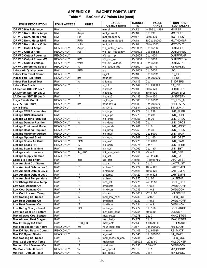
160
IDF VFD Min Reference R/W Hz minref AV:72 –4999 to 4999 MINREFIDF VFD Nom. Motor Amps R/W Amps mot_current AV:16 0 to 999 MOTCURIDF VFD Nom. Motor Freq R/W Hz mot_frequency AV:17 20 to 400 MOTFREQIDF VFD Nom. Motor RPM R/W RPM mot_nom_Speed AV:18 100 to 60000 MOTNOMSPIDF VFD Nom. Motor Volts R/W volts mot_volt AV:20 50 to 1000 MOTVOLTIDF VFD Output Amps READ ONLY Amps vfd_motor_amps AV:3002 0 to 655.35 OUTMCURIDF VFD Output Freq. READ ONLY Hz vfd_out_frequency AV:3003 0 to 6553.5 OUTMFREQIDF VFD Output Power hp READ ONLY vfd_out_hp AV:3005 0 to 1000 OUTPWRHPIDF VFD Output Power kW READ ONLY KW vfd_out_kw AV:3006 0 to 1000 OUTPWRKWIDF VFD Output Voltage READ ONLY volts vfd_out_voltage AV:3004 0 to 65535 OUTMVOLTIDF VFD Reference Speed READ ONLY % vfd_speed_req AV:3007 0.0 to 1.0 REFSPEEDIndoor Air Quality Level R/W PPM iaq AV:1009 0 to 5000 IAQIndoor Fan Reset Count READ ONLY rs_idf AV:108 0 to 65535 RS_IDFIndoor Fan Run Hours READ ONLY hrs hour_idf AV:56 0 to 999999 HR_IDFIndoor Fan Speed Test R/W % s_idfspd AV:119 0 to 1 S_IDFSPDIndoor Fan Starts READ ONLY st_idf AV:144 0 to 999999 ST_IDFLA Dehum SDT SP Lev 1 R/W °F lhsdtsp1 AV:430 60 to 120 LHSDTSP1LA Dehum SDT SP Lev 2 R/W °F lhsdtsp2 AV:431 60 to 120 LHSDTSP2LA Dehum SDT SP Lev 3 R/W °F lhsdtsp3 AV:432 60 to 120 LHSDTSP3ldv_a Resets Count READ ONLY rs_ldv_a AV:388 0 to 65535 RS_LDV_ALDV_A Run Hours READ ONLY hrs hour_ldv_a AV:380 0 to 999999 HR_LDV_Aldv_a Starts READ ONLY st_ldv_a AV:384 0 to 999999 ST_LDV_ALinkage CCN Bus number R/W lnk_supb AV:272 0 to 239 LNK_SUPBLinkage CCN element # R/W lnk_supe AV:273 0 to 239 LNK_SUPELinkage Cooling Required READ ONLY °F lnk_creq AV:257 0 to 30 LNK_CREQLinkage Damper Position READ ONLY % lnk_dpos AV:258 0 to 1 LNK_DPOSLinkage Equipment Mode READ ONLY lnk_mode AV:261 0 to 8 LNK_MODELinkage Heating Required READ ONLY °F lnk_hreq AV:259 0 to 30 LNK_HREQLinkage Maximum Airflow READ ONLY lnk_mair AV:260 0 to 5000 LNK_MAIRLinkage Optimal Start READ ONLY min lnk_opst AV:267 0 to 180 LNK_OPSTLinkage Space Air Qual. READ ONLY PPM lnk_siaq AV:270 0 to 2000 LNK_SIAQLinkage Space RH READ ONLY % lnk_sprh AV:271 0 to 1 LNK_SPRHLinkage Start Bias time R/W min lnk_sbt AV:269 0 to 180 LNK_SBTLinkage static pressure READ ONLY IN_H2O link_ahu_static AV:312 –5 to 5 LNK_DSPLinkage Supply air temp READ ONLY °F lnk_sat AV:268 –40 to 240 LNK_SATLocal Std Time offset R/W min utc_ofst AV:191 –780 to 780 UTC_OFSTLow Ambient Ctrl Status R/W lactrlst AV:434 0 to 3 LACTRLSTLow Ambient Dehum Lev 1 R/W °F lahtemp1 AV:427 40 to 125 LAHTEMP1Low Ambient Dehum Lev 2 R/W °F lahtemp2 AV:428 40 to 125 LAHTEMP2Low Ambient Dehum Lev 3 R/W °F lahtemp3 AV:429 40 to 125 LAHTEMP3Low Ambient Temperature R/W °F la_temp AV:253 0 to 80 LA_TEMPLow Charge Disable Temp R/W °F loch_lot AV:276 –40 to 50 LOCH_LOTLow Cool Demand Off R/W °F dmdlcoff AV:218 –1 to 2 DMDLCOFFLow Cool Demand On R/W °F dmdlcon AV:219 –1 to 2 DMDLCONLow Cool Lockout Temp R/W °F lclocksp AV:8031 –20 to 60 LCLOCKSPLow Cooling IDF Speed R/W % fspd_low_cool AV:233 0.2 to 1 FSPD_LCLLow Heat Demand Off R/W °F dmdlhoff AV:220 –1 to 2 DMDLHOFFLow Heat Demand On R/W °F dmdlhon AV:221 –1 to 2 DMDLHONLow Refrig Charge Level R/W PSI locharge AV:277 0 to 150 LOCHARGELowFree Cool SAT Setpnt R/W °F low_cool_sasp AV:254 40 to 80 LCSASPMax Allowed Cool Stages R/W max_cstgs AV:278 0 to 3 MAXCSTGSMax Allowed Heat Stages R/W max_hstgs AV:279 0 to 2 MAXHSTGSMax Enthalpy OA limit R/W BTU_LB max_enth AV:44 1.0 to 99.0 FREEMAXEMax Fan Speed Run Hours READ ONLY hrs hour_max_fan AV:57 0 to 999999 HR_MAXFMax IDF Spd Resets Count READ ONLY rs_maxf AV:109 0 to 65535 RS_MAXFMax IDF Speed Starts READ ONLY st_maxf AV:145 0 to 999999 ST_MAXFMed Cooling IDF Speed R/W % fspd_medium_cool AV:234 0.2 to 1 FSPD_MCLMed. Cool Lockout Temp R/W °F mclocksp AV:8032 –20 to 60 MCLOCKSPMedium Cool Demand On R/W °F dmdmcon AV:223 0.5 to 20 DMDMCONMin Pos - Default Pos 1 READ ONLY % mp_dpos1 AV:319 0 to 1 MP_DPOS1Min Pos - Default Pos 2 READ ONLY % mp_dpos2 AV:290 0 to 1 MP_DPOS2
Table Y — BACnet* AV Points List (cont)
POINT DESCRIPTION POINT ACCESS UNITS BACNETOBJECT NAME
BACNETID
VALUERANGE
CCN POINTEQUIVALENT
APPENDIX E — BACNET POINTS LIST
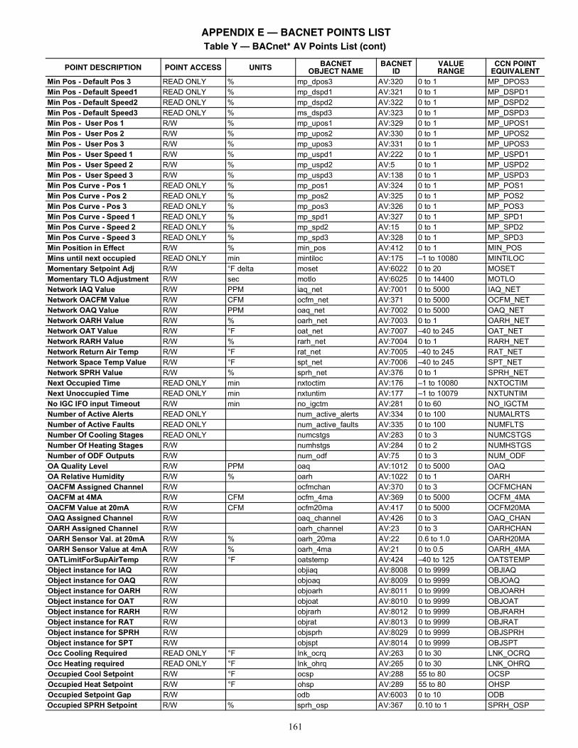
161
Min Pos - Default Pos 3 READ ONLY % mp_dpos3 AV:320 0 to 1 MP_DPOS3Min Pos - Default Speed1 READ ONLY % mp_dspd1 AV:321 0 to 1 MP_DSPD1Min Pos - Default Speed2 READ ONLY % mp_dspd2 AV:322 0 to 1 MP_DSPD2Min Pos - Default Speed3 READ ONLY % ms_dspd3 AV:323 0 to 1 MP_DSPD3Min Pos - User Pos 1 R/W % mp_upos1 AV:329 0 to 1 MP_UPOS1Min Pos - User Pos 2 R/W % mp_upos2 AV:330 0 to 1 MP_UPOS2Min Pos - User Pos 3 R/W % mp_upos3 AV:331 0 to 1 MP_UPOS3Min Pos - User Speed 1 R/W % mp_uspd1 AV:222 0 to 1 MP_USPD1Min Pos - User Speed 2 R/W % mp_uspd2 AV:5 0 to 1 MP_USPD2Min Pos - User Speed 3 R/W % mp_uspd3 AV:138 0 to 1 MP_USPD3Min Pos Curve - Pos 1 READ ONLY % mp_pos1 AV:324 0 to 1 MP_POS1Min Pos Curve - Pos 2 READ ONLY % mp_pos2 AV:325 0 to 1 MP_POS2Min Pos Curve - Pos 3 READ ONLY % mp_pos3 AV:326 0 to 1 MP_POS3Min Pos Curve - Speed 1 READ ONLY % mp_spd1 AV:327 0 to 1 MP_SPD1Min Pos Curve - Speed 2 READ ONLY % mp_spd2 AV:15 0 to 1 MP_SPD2Min Pos Curve - Speed 3 READ ONLY % mp_spd3 AV:328 0 to 1 MP_SPD3Min Position in Effect R/W % min_pos AV:412 0 to 1 MIN_POSMins until next occupied READ ONLY min mintiloc AV:175 –1 to 10080 MINTILOCMomentary Setpoint Adj R/W °F delta moset AV:6022 0 to 20 MOSETMomentary TLO Adjustment R/W sec motlo AV:6025 0 to 14400 MOTLONetwork IAQ Value R/W PPM iaq_net AV:7001 0 to 5000 IAQ_NETNetwork OACFM Value R/W CFM ocfm_net AV:371 0 to 5000 OCFM_NETNetwork OAQ Value R/W PPM oaq_net AV:7002 0 to 5000 OAQ_NETNetwork OARH Value R/W % oarh_net AV:7003 0 to 1 OARH_NETNetwork OAT Value R/W °F oat_net AV:7007 –40 to 245 OAT_NETNetwork RARH Value R/W % rarh_net AV:7004 0 to 1 RARH_NETNetwork Return Air Temp R/W °F rat_net AV:7005 –40 to 245 RAT_NETNetwork Space Temp Value R/W °F spt_net AV:7006 –40 to 245 SPT_NETNetwork SPRH Value R/W % sprh_net AV:376 0 to 1 SPRH_NETNext Occupied Time READ ONLY min nxtoctim AV:176 –1 to 10080 NXTOCTIMNext Unoccupied Time READ ONLY min nxtuntim AV:177 –1 to 10079 NXTUNTIMNo IGC IFO input Timeout R/W min no_igctm AV:281 0 to 60 NO_IGCTMNumber of Active Alerts READ ONLY num_active_alerts AV:334 0 to 100 NUMALRTSNumber of Active Faults READ ONLY num_active_faults AV:335 0 to 100 NUMFLTSNumber Of Cooling Stages READ ONLY numcstgs AV:283 0 to 3 NUMCSTGSNumber Of Heating Stages R/W numhstgs AV:284 0 to 2 NUMHSTGSNumber of ODF Outputs R/W num_odf AV:75 0 to 3 NUM_ODFOA Quality Level R/W PPM oaq AV:1012 0 to 5000 OAQOA Relative Humidity R/W % oarh AV:1022 0 to 1 OARHOACFM Assigned Channel R/W ocfmchan AV:370 0 to 3 OCFMCHANOACFM at 4MA R/W CFM ocfm_4ma AV:369 0 to 5000 OCFM_4MAOACFM Value at 20mA R/W CFM ocfm20ma AV:417 0 to 5000 OCFM20MAOAQ Assigned Channel R/W oaq_channel AV:426 0 to 3 OAQ_CHANOARH Assigned Channel R/W oarh_channel AV:23 0 to 3 OARHCHANOARH Sensor Val. at 20mA R/W % oarh_20ma AV:22 0.6 to 1.0 OARH20MAOARH Sensor Value at 4mA R/W % oarh_4ma AV:21 0 to 0.5 OARH_4MAOATLimitForSupAirTemp R/W °F oatstemp AV:424 –40 to 125 OATSTEMPObject instance for IAQ R/W objiaq AV:8008 0 to 9999 OBJIAQObject instance for OAQ R/W objoaq AV:8009 0 to 9999 OBJOAQObject instance for OARH R/W objoarh AV:8011 0 to 9999 OBJOARHObject instance for OAT R/W objoat AV:8010 0 to 9999 OBJOATObject instance for RARH R/W objrarh AV:8012 0 to 9999 OBJRARHObject instance for RAT R/W objrat AV:8013 0 to 9999 OBJRATObject instance for SPRH R/W objsprh AV:8029 0 to 9999 OBJSPRHObject instance for SPT R/W objspt AV:8014 0 to 9999 OBJSPTOcc Cooling Required READ ONLY °F lnk_ocrq AV:263 0 to 30 LNK_OCRQOcc Heating required READ ONLY °F lnk_ohrq AV:265 0 to 30 LNK_OHRQOccupied Cool Setpoint R/W °F ocsp AV:288 55 to 80 OCSPOccupied Heat Setpoint R/W °F ohsp AV:289 55 to 80 OHSPOccupied Setpoint Gap R/W odb AV:6003 0 to 10 ODBOccupied SPRH Setpoint R/W % sprh_osp AV:367 0.10 to 1 SPRH_OSP
Table Y — BACnet* AV Points List (cont)
POINT DESCRIPTION POINT ACCESS UNITS BACNETOBJECT NAME
BACNETID
VALUERANGE
CCN POINTEQUIVALENT
APPENDIX E — BACNET POINTS LIST
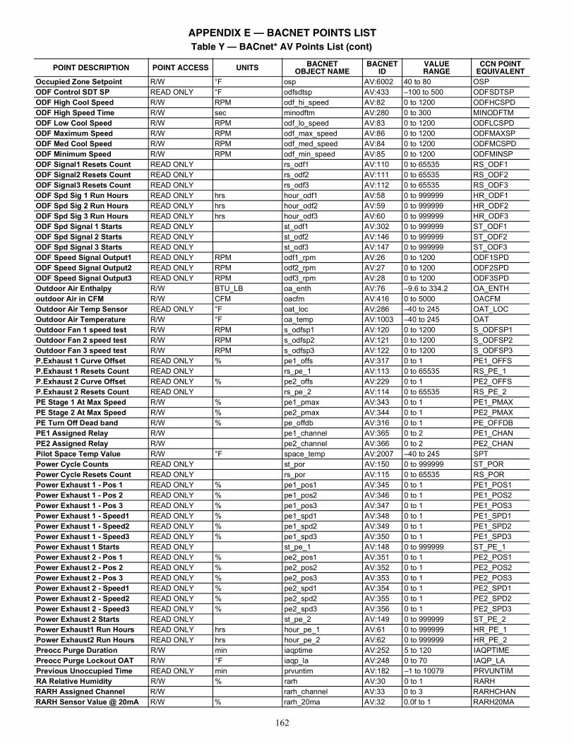
162
Occupied Zone Setpoint R/W °F osp AV:6002 40 to 80 OSPODF Control SDT SP READ ONLY °F odfsdtsp AV:433 –100 to 500 ODFSDTSPODF High Cool Speed R/W RPM odf_hi_speed AV:82 0 to 1200 ODFHCSPDODF High Speed Time R/W sec minodftm AV:280 0 to 300 MINODFTMODF Low Cool Speed R/W RPM odf_lo_speed AV:83 0 to 1200 ODFLCSPDODF Maximum Speed R/W RPM odf_max_speed AV:86 0 to 1200 ODFMAXSPODF Med Cool Speed R/W RPM odf_med_speed AV:84 0 to 1200 ODFMCSPDODF Minimum Speed R/W RPM odf_min_speed AV:85 0 to 1200 ODFMINSPODF Signal1 Resets Count READ ONLY rs_odf1 AV:110 0 to 65535 RS_ODF1ODF Signal2 Resets Count READ ONLY rs_odf2 AV:111 0 to 65535 RS_ODF2ODF Signal3 Resets Count READ ONLY rs_odf3 AV:112 0 to 65535 RS_ODF3ODF Spd Sig 1 Run Hours READ ONLY hrs hour_odf1 AV:58 0 to 999999 HR_ODF1ODF Spd Sig 2 Run Hours READ ONLY hrs hour_odf2 AV:59 0 to 999999 HR_ODF2ODF Spd Sig 3 Run Hours READ ONLY hrs hour_odf3 AV:60 0 to 999999 HR_ODF3ODF Spd Signal 1 Starts READ ONLY st_odf1 AV:302 0 to 999999 ST_ODF1ODF Spd Signal 2 Starts READ ONLY st_odf2 AV:146 0 to 999999 ST_ODF2ODF Spd Signal 3 Starts READ ONLY st_odf3 AV:147 0 to 999999 ST_ODF3ODF Speed Signal Output1 READ ONLY RPM odf1_rpm AV:26 0 to 1200 ODF1SPDODF Speed Signal Output2 READ ONLY RPM odf2_rpm AV:27 0 to 1200 ODF2SPDODF Speed Signal Output3 READ ONLY RPM odf3_rpm AV:28 0 to 1200 ODF3SPDOutdoor Air Enthalpy R/W BTU_LB oa_enth AV:76 –9.6 to 334.2 OA_ENTHoutdoor Air in CFM R/W CFM oacfm AV:416 0 to 5000 OACFMOutdoor Air Temp Sensor READ ONLY °F oat_loc AV:286 –40 to 245 OAT_LOCOutdoor Air Temperature R/W °F oa_temp AV:1003 –40 to 245 OATOutdoor Fan 1 speed test R/W RPM s_odfsp1 AV:120 0 to 1200 S_ODFSP1Outdoor Fan 2 speed test R/W RPM s_odfsp2 AV:121 0 to 1200 S_ODFSP2Outdoor Fan 3 speed test R/W RPM s_odfsp3 AV:122 0 to 1200 S_ODFSP3P.Exhaust 1 Curve Offset READ ONLY % pe1_offs AV:317 0 to 1 PE1_OFFSP.Exhaust 1 Resets Count READ ONLY rs_pe_1 AV:113 0 to 65535 RS_PE_1P.Exhaust 2 Curve Offset READ ONLY % pe2_offs AV:229 0 to 1 PE2_OFFSP.Exhaust 2 Resets Count READ ONLY rs_pe_2 AV:114 0 to 65535 RS_PE_2PE Stage 1 At Max Speed R/W % pe1_pmax AV:343 0 to 1 PE1_PMAXPE Stage 2 At Max Speed R/W % pe2_pmax AV:344 0 to 1 PE2_PMAXPE Turn Off Dead band R/W % pe_offdb AV:316 0 to 1 PE_OFFDBPE1 Assigned Relay R/W pe1_channel AV:365 0 to 2 PE1_CHANPE2 Assigned Relay R/W pe2_channel AV:366 0 to 2 PE2_CHANPilot Space Temp Value R/W °F space_temp AV:2007 –40 to 245 SPTPower Cycle Counts READ ONLY st_por AV:150 0 to 999999 ST_PORPower Cycle Resets Count READ ONLY rs_por AV:115 0 to 65535 RS_PORPower Exhaust 1 - Pos 1 READ ONLY % pe1_pos1 AV:345 0 to 1 PE1_POS1Power Exhaust 1 - Pos 2 READ ONLY % pe1_pos2 AV:346 0 to 1 PE1_POS2Power Exhaust 1 - Pos 3 READ ONLY % pe1_pos3 AV:347 0 to 1 PE1_POS3Power Exhaust 1 - Speed1 READ ONLY % pe1_spd1 AV:348 0 to 1 PE1_SPD1Power Exhaust 1 - Speed2 READ ONLY % pe1_spd2 AV:349 0 to 1 PE1_SPD2Power Exhaust 1 - Speed3 READ ONLY % pe1_spd3 AV:350 0 to 1 PE1_SPD3Power Exhaust 1 Starts READ ONLY st_pe_1 AV:148 0 to 999999 ST_PE_1Power Exhaust 2 - Pos 1 READ ONLY % pe2_pos1 AV:351 0 to 1 PE2_POS1Power Exhaust 2 - Pos 2 READ ONLY % pe2_pos2 AV:352 0 to 1 PE2_POS2Power Exhaust 2 - Pos 3 READ ONLY % pe2_pos3 AV:353 0 to 1 PE2_POS3Power Exhaust 2 - Speed1 READ ONLY % pe2_spd1 AV:354 0 to 1 PE2_SPD1Power Exhaust 2 - Speed2 READ ONLY % pe2_spd2 AV:355 0 to 1 PE2_SPD2Power Exhaust 2 - Speed3 READ ONLY % pe2_spd3 AV:356 0 to 1 PE2_SPD3Power Exhaust 2 Starts READ ONLY st_pe_2 AV:149 0 to 999999 ST_PE_2Power Exhaust1 Run Hours READ ONLY hrs hour_pe_1 AV:61 0 to 999999 HR_PE_1Power Exhaust2 Run Hours READ ONLY hrs hour_pe_2 AV:62 0 to 999999 HR_PE_2Preocc Purge Duration R/W min iaqptime AV:252 5 to 120 IAQPTIMEPreocc Purge Lockout OAT R/W °F iaqp_la AV:248 0 to 70 IAQP_LAPrevious Unoccupied Time READ ONLY min prvuntim AV:182 –1 to 10079 PRVUNTIMRA Relative Humidity R/W % rarh AV:30 0 to 1 RARHRARH Assigned Channel R/W rarh_channel AV:33 0 to 3 RARHCHANRARH Sensor Value @ 20mA R/W % rarh_20ma AV:32 0.0f to 1 RARH20MA
Table Y — BACnet* AV Points List (cont)
POINT DESCRIPTION POINT ACCESS UNITS BACNETOBJECT NAME
BACNETID
VALUERANGE
CCN POINTEQUIVALENT
APPENDIX E — BACNET POINTS LIST
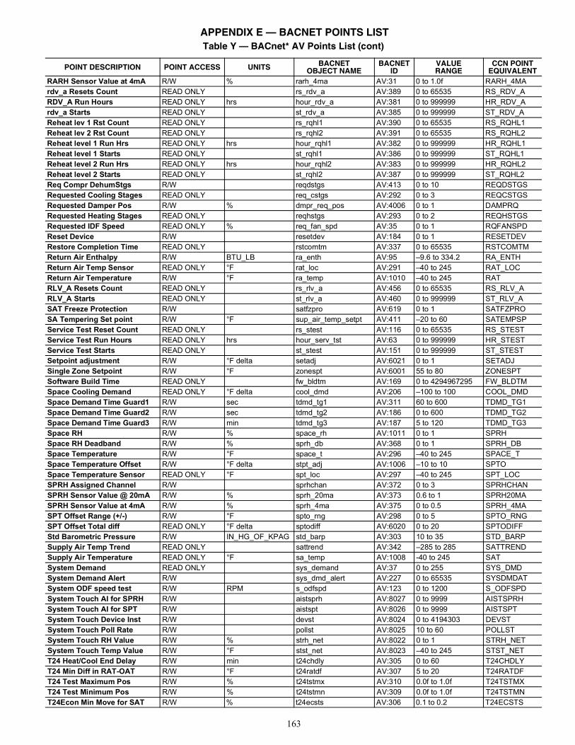
163
RARH Sensor Value at 4mA R/W % rarh_4ma AV:31 0 to 1.0f RARH_4MArdv_a Resets Count READ ONLY rs_rdv_a AV:389 0 to 65535 RS_RDV_ARDV_A Run Hours READ ONLY hrs hour_rdv_a AV:381 0 to 999999 HR_RDV_Ardv_a Starts READ ONLY st_rdv_a AV:385 0 to 999999 ST_RDV_AReheat lev 1 Rst Count READ ONLY rs_rqhl1 AV:390 0 to 65535 RS_RQHL1Reheat lev 2 Rst Count READ ONLY rs_rqhl2 AV:391 0 to 65535 RS_RQHL2Reheat level 1 Run Hrs READ ONLY hrs hour_rqhl1 AV:382 0 to 999999 HR_RQHL1Reheat level 1 Starts READ ONLY st_rqhl1 AV:386 0 to 999999 ST_RQHL1Reheat level 2 Run Hrs READ ONLY hrs hour_rqhl2 AV:383 0 to 999999 HR_RQHL2Reheat level 2 Starts READ ONLY st_rqhl2 AV:387 0 to 999999 ST_RQHL2Req Compr DehumStgs R/W reqdstgs AV:413 0 to 10 REQDSTGSRequested Cooling Stages READ ONLY req_cstgs AV:292 0 to 3 REQCSTGSRequested Damper Pos R/W % dmpr_req_pos AV:4006 0 to 1 DAMPRQRequested Heating Stages READ ONLY reqhstgs AV:293 0 to 2 REQHSTGSRequested IDF Speed READ ONLY % req_fan_spd AV:35 0 to 1 RQFANSPDReset Device R/W resetdev AV:184 0 to 1 RESETDEVRestore Completion Time READ ONLY rstcomtm AV:337 0 to 65535 RSTCOMTMReturn Air Enthalpy R/W BTU_LB ra_enth AV:95 –9.6 to 334.2 RA_ENTHReturn Air Temp Sensor READ ONLY °F rat_loc AV:291 –40 to 245 RAT_LOCReturn Air Temperature R/W °F ra_temp AV:1010 –40 to 245 RATRLV_A Resets Count READ ONLY rs_rlv_a AV:456 0 to 65535 RS_RLV_ARLV_A Starts READ ONLY st_rlv_a AV:460 0 to 999999 ST_RLV_ASAT Freeze Protection R/W satfzpro AV:619 0 to 1 SATFZPROSA Tempering Set point R/W °F sup_air_temp_setpt AV:411 –20 to 60 SATEMPSPService Test Reset Count READ ONLY rs_stest AV:116 0 to 65535 RS_STESTService Test Run Hours READ ONLY hrs hour_serv_tst AV:63 0 to 999999 HR_STESTService Test Starts READ ONLY st_stest AV:151 0 to 999999 ST_STESTSetpoint adjustment R/W °F delta setadj AV:6021 0 to 1 SETADJSingle Zone Setpoint R/W °F zonespt AV:6001 55 to 80 ZONESPTSoftware Build Time READ ONLY fw_bldtm AV:169 0 to 4294967295 FW_BLDTMSpace Cooling Demand READ ONLY °F delta cool_dmd AV:206 –100 to 100 COOL_DMDSpace Demand Time Guard1 R/W sec tdmd_tg1 AV:311 60 to 600 TDMD_TG1Space Demand Time Guard2 R/W sec tdmd_tg2 AV:186 0 to 600 TDMD_TG2Space Demand Time Guard3 R/W min tdmd_tg3 AV:187 5 to 120 TDMD_TG3Space RH R/W % space_rh AV:1011 0 to 1 SPRHSpace RH Deadband R/W % sprh_db AV:368 0 to 1 SPRH_DBSpace Temperature R/W °F space_t AV:296 –40 to 245 SPACE_TSpace Temperature Offset R/W °F delta stpt_adj AV:1006 –10 to 10 SPTOSpace Temperature Sensor READ ONLY °F spt_loc AV:297 –40 to 245 SPT_LOCSPRH Assigned Channel R/W sprhchan AV:372 0 to 3 SPRHCHANSPRH Sensor Value @ 20mA R/W % sprh_20ma AV:373 0.6 to 1 SPRH20MASPRH Sensor Value at 4mA R/W % sprh_4ma AV:375 0 to 0.5 SPRH_4MASPT Offset Range (+/-) R/W °F spto_rng AV:298 0 to 5 SPTO_RNGSPT Offset Total diff READ ONLY °F delta sptodiff AV:6020 0 to 20 SPTODIFFStd Barometric Pressure R/W IN_HG_OF_KPAG std_barp AV:303 10 to 35 STD_BARPSupply Air Temp Trend READ ONLY sattrend AV:342 –285 to 285 SATTRENDSupply Air Temperature READ ONLY °F sa_temp AV:1008 -40 to 245 SATSystem Demand READ ONLY sys_demand AV:37 0 to 255 SYS_DMDSystem Demand Alert R/W sys_dmd_alert AV:227 0 to 65535 SYSDMDATSystem ODF speed test R/W RPM s_odfspd AV:123 0 to 1200 S_ODFSPDSystem Touch AI for SPRH R/W aistsprh AV:8027 0 to 9999 AISTSPRHSystem Touch AI for SPT R/W aistspt AV:8026 0 to 9999 AISTSPTSystem Touch Device Inst R/W devst AV:8024 0 to 4194303 DEVSTSystem Touch Poll Rate R/W pollst AV:8025 10 to 60 POLLSTSystem Touch RH Value R/W % strh_net AV:8022 0 to 1 STRH_NETSystem Touch Temp Value R/W °F stst_net AV:8023 –40 to 245 STST_NETT24 Heat/Cool End Delay R/W min t24chdly AV:305 0 to 60 T24CHDLYT24 Min Diff in RAT-OAT R/W °F t24ratdf AV:307 5 to 20 T24RATDFT24 Test Maximum Pos R/W % t24tstmx AV:310 0.0f to 1.0f T24TSTMXT24 Test Minimum Pos R/W % t24tstmn AV:309 0.0f to 1.0f T24TSTMNT24Econ Min Move for SAT R/W % t24ecsts AV:306 0.1 to 0.2 T24ECSTS
Table Y — BACnet* AV Points List (cont)
POINT DESCRIPTION POINT ACCESS UNITS BACNETOBJECT NAME
BACNETID
VALUERANGE
CCN POINTEQUIVALENT
APPENDIX E — BACNET POINTS LIST
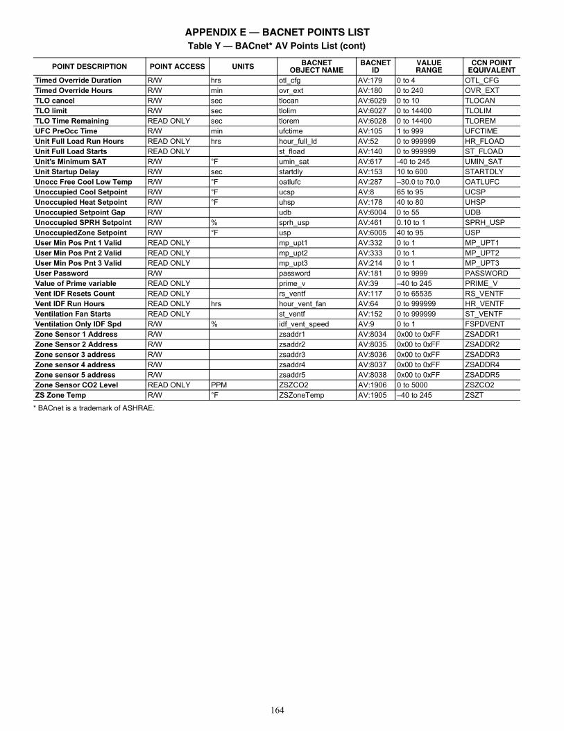
164
* BACnet is a trademark of ASHRAE.
Timed Override Duration R/W hrs otl_cfg AV:179 0 to 4 OTL_CFGTimed Override Hours R/W min ovr_ext AV:180 0 to 240 OVR_EXTTLO cancel R/W sec tlocan AV:6029 0 to 10 TLOCANTLO limit R/W sec tlolim AV:6027 0 to 14400 TLOLIMTLO Time Remaining READ ONLY sec tlorem AV:6028 0 to 14400 TLOREMUFC PreOcc Time R/W min ufctime AV:105 1 to 999 UFCTIMEUnit Full Load Run Hours READ ONLY hrs hour_full_ld AV:52 0 to 999999 HR_FLOADUnit Full Load Starts READ ONLY st_fload AV:140 0 to 999999 ST_FLOADUnit's Minimum SAT R/W °F umin_sat AV:617 -40 to 245 UMIN_SATUnit Startup Delay R/W sec startdly AV:153 10 to 600 STARTDLYUnocc Free Cool Low Temp R/W °F oatlufc AV:287 –30.0 to 70.0 OATLUFCUnoccupied Cool Setpoint R/W °F ucsp AV:8 65 to 95 UCSPUnoccupied Heat Setpoint R/W °F uhsp AV:178 40 to 80 UHSPUnoccupied Setpoint Gap R/W udb AV:6004 0 to 55 UDBUnoccupied SPRH Setpoint R/W % sprh_usp AV:461 0.10 to 1 SPRH_USPUnoccupiedZone Setpoint R/W °F usp AV:6005 40 to 95 USPUser Min Pos Pnt 1 Valid READ ONLY mp_upt1 AV:332 0 to 1 MP_UPT1User Min Pos Pnt 2 Valid READ ONLY mp_upt2 AV:333 0 to 1 MP_UPT2User Min Pos Pnt 3 Valid READ ONLY mp_upt3 AV:214 0 to 1 MP_UPT3User Password R/W password AV:181 0 to 9999 PASSWORDValue of Prime variable READ ONLY prime_v AV:39 –40 to 245 PRIME_VVent IDF Resets Count READ ONLY rs_ventf AV:117 0 to 65535 RS_VENTFVent IDF Run Hours READ ONLY hrs hour_vent_fan AV:64 0 to 999999 HR_VENTFVentilation Fan Starts READ ONLY st_ventf AV:152 0 to 999999 ST_VENTFVentilation Only IDF Spd R/W % idf_vent_speed AV:9 0 to 1 FSPDVENTZone Sensor 1 Address R/W zsaddr1 AV:8034 0x00 to 0xFF ZSADDR1Zone Sensor 2 Address R/W zsaddr2 AV:8035 0x00 to 0xFF ZSADDR2Zone sensor 3 address R/W zsaddr3 AV:8036 0x00 to 0xFF ZSADDR3Zone sensor 4 address R/W zsaddr4 AV:8037 0x00 to 0xFF ZSADDR4Zone sensor 5 address R/W zsaddr5 AV:8038 0x00 to 0xFF ZSADDR5Zone Sensor CO2 Level READ ONLY PPM ZSZCO2 AV:1906 0 to 5000 ZSZCO2ZS Zone Temp R/W °F ZSZoneTemp AV:1905 –40 to 245 ZSZT
Table Y — BACnet* AV Points List (cont)
POINT DESCRIPTION POINT ACCESS UNITS BACNETOBJECT NAME
BACNETID
VALUERANGE
CCN POINTEQUIVALENT
APPENDIX E — BACNET POINTS LIST
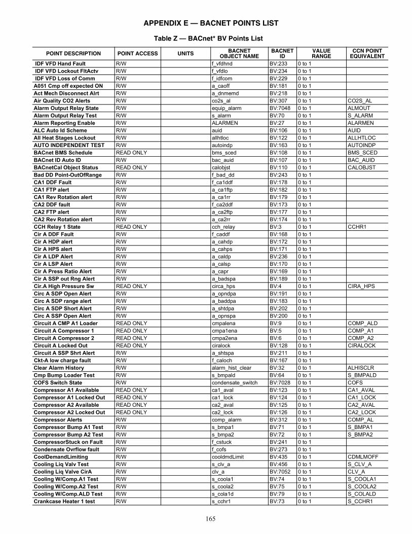
165
Table Z — BACnet* BV Points List
POINT DESCRIPTION POINT ACCESS UNITS BACNETOBJECT NAME
BACNETID
VALUERANGE
CCN POINTEQUIVALENT
IDF VFD Hand Fault R/W f_vfdhnd BV:233 0 to 1 IDF VFD Lockout FltActv R/W f_vfdlo BV:234 0 to 1 IDF VFD Loss of Comm R/W f_idfcom BV:229 0 to 1 A051 Cmp off expected ON R/W a_caoff BV:181 0 to 1 Act Mech Disconnect Alrt R/W a_dnmemd BV:218 0 to 1 Air Quality CO2 Alerts R/W co2s_al BV:307 0 to 1 CO2S_ALAlarm Output Relay State R/W equip_alarm BV:7048 0 to 1 ALMOUTAlarm Output Relay Test R/W s_alarm BV:70 0 to 1 S_ALARMAlarm Reporting Enable R/W ALARMEN BV:27 0 to 1 ALARMENALC Auto Id Scheme R/W auid BV:106 0 to 1 AUIDAll Heat Stages Lockout R/W allhtloc BV:122 0 to 1 ALLHTLOCAUTO INDEPENDENT TEST R/W autoindp BV:163 0 to 1 AUTOINDPBACnet BMS Schedule READ ONLY bms_sced BV:108 0 to 1 BMS_SCEDBACnet ID Auto ID R/W bac_auid BV:107 0 to 1 BAC_AUIDBACnetCal Object Status READ ONLY calobjst BV:110 0 to 1 CALOBJSTBad DD Point-OutOfRange R/W f_bad_dd BV:243 0 to 1 CA1 DDF Fault R/W f_ca1ddf BV:178 0 to 1 CA1 FTP alert R/W a_ca1ftp BV:182 0 to 1 CA1 Rev Rotation alert R/W a_ca1rr BV:179 0 to 1 CA2 DDF fault R/W f_ca2ddf BV:173 0 to 1 CA2 FTP alert R/W a_ca2ftp BV:177 0 to 1 CA2 Rev Rotation alert R/W a_ca2rr BV:174 0 to 1 CCH Relay 1 State READ ONLY cch_relay BV:3 0 to 1 CCHR1Cir A DDF Fault R/W f_caddf BV:168 0 to 1 Cir A HDP alert R/W a_cahdp BV:172 0 to 1 Cir A HPS alert R/W a_cahps BV:171 0 to 1 Cir A LDP Alert R/W a_caldp BV:236 0 to 1 Cir A LSP Alert R/W a_calsp BV:170 0 to 1 Cir A Press Ratio Alert R/W a_capr BV:169 0 to 1 Cir A SSP out Rng Alert R/W a_badspa BV:189 0 to 1 Cir.A High Pressure Sw READ ONLY circa_hps BV:4 0 to 1 CIRA_HPSCirc A SDP Open Alert R/W a_opndpa BV:191 0 to 1 Circ A SDP range alert R/W a_baddpa BV:183 0 to 1 Circ A SDP Short Alert R/W a_shtdpa BV:202 0 to 1 Circ A SSP Open Alert R/W a_opnspa BV:200 0 to 1 Circuit A CMP A1 Loader READ ONLY cmpalena BV:9 0 to 1 COMP_ALDCircuit A Compressor 1 READ ONLY cmpa1ena BV:5 0 to 1 COMP_A1Circuit A Compressor 2 READ ONLY cmpa2ena BV:6 0 to 1 COMP_A2Circuit A Locked Out READ ONLY ciralock BV:128 0 to 1 CIRALOCKCircuit A SSP Shrt Alert R/W a_shtspa BV:211 0 to 1 Ckt-A low charge fault R/W f_caloch BV:167 0 to 1 Clear Alarm History R/W alarm_hist_clear BV:32 0 to 1 ALHISCLRCmp Bump Loader Test R/W s_bmpald BV:64 0 to 1 S_BMPALDCOFS Switch State R/W condensate_switch BV:7028 0 to 1 COFSCompressor A1 Available READ ONLY ca1_aval BV:123 0 to 1 CA1_AVALCompressor A1 Locked Out READ ONLY ca1_lock BV:124 0 to 1 CA1_LOCKCompressor A2 Available READ ONLY ca2_aval BV:125 0 to 1 CA2_AVALCompressor A2 Locked Out READ ONLY ca2_lock BV:126 0 to 1 CA2_LOCKCompressor Alerts R/W comp_alarm BV:312 0 to 1 COMP_ALCompressor Bump A1 Test R/W s_bmpa1 BV:71 0 to 1 S_BMPA1Compressor Bump A2 Test R/W s_bmpa2 BV:72 0 to 1 S_BMPA2CompressorStuck on Fault R/W f_cstuck BV:241 0 to 1 Condensate Ovrflow fault R/W f_cofs BV:273 0 to 1 CoolDemandLimiting R/W cooldmdLimit BV:435 0 to 1 CDMLMOFFCooling Liq Valv Test R/W s_clv_a BV:456 0 to 1 S_CLV_ACooling Liq Valve CirA R/W clv_a BV:7052 0 to 1 CLV_ACooling W/Comp.A1 Test R/W s_coola1 BV:74 0 to 1 S_COOLA1Cooling W/Comp.A2 Test R/W s_coola2 BV:75 0 to 1 S_COOLA2Cooling W/Comp.ALD Test R/W s_cola1d BV:79 0 to 1 S_COLALDCrankcase Heater 1 test R/W s_cchr1 BV:73 0 to 1 S_CCHR1
APPENDIX E — BACNET POINTS LIST
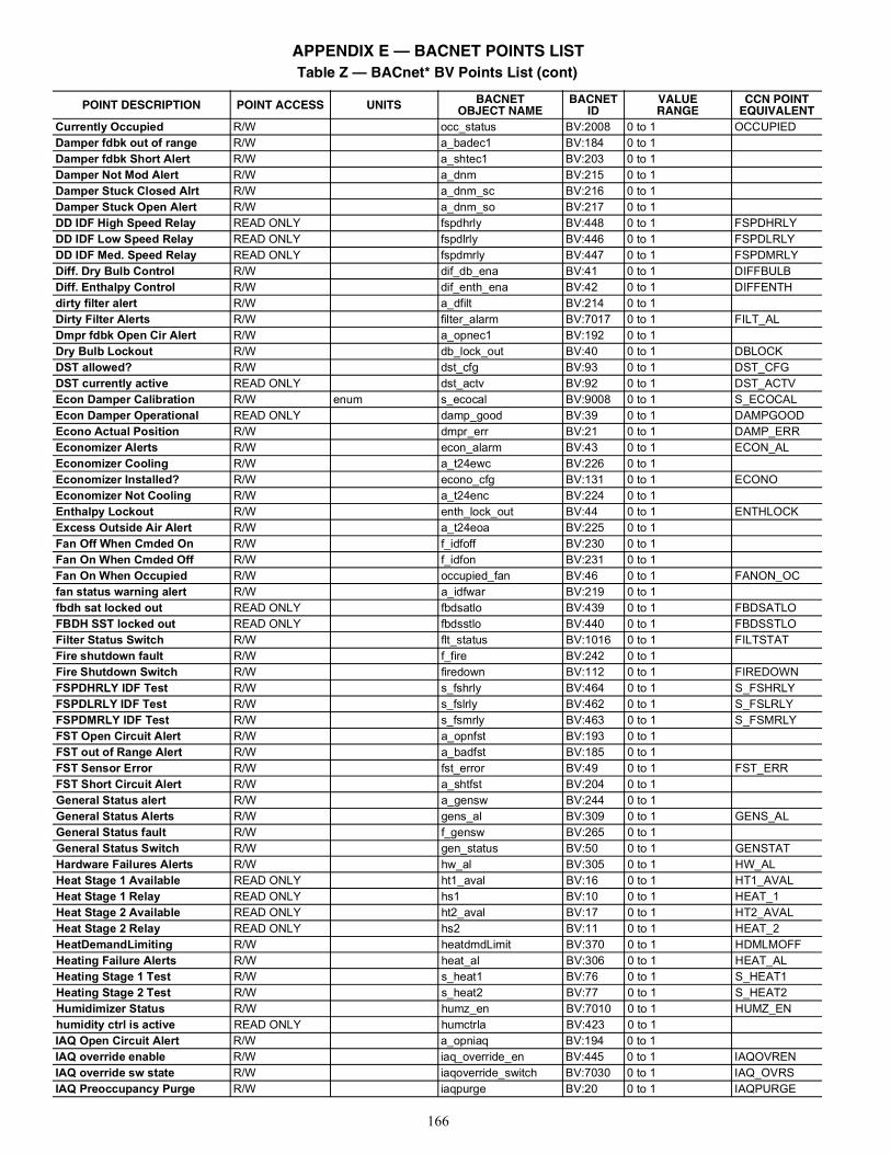
166
Currently Occupied R/W occ_status BV:2008 0 to 1 OCCUPIEDDamper fdbk out of range R/W a_badec1 BV:184 0 to 1 Damper fdbk Short Alert R/W a_shtec1 BV:203 0 to 1 Damper Not Mod Alert R/W a_dnm BV:215 0 to 1 Damper Stuck Closed Alrt R/W a_dnm_sc BV:216 0 to 1 Damper Stuck Open Alert R/W a_dnm_so BV:217 0 to 1 DD IDF High Speed Relay READ ONLY fspdhrly BV:448 0 to 1 FSPDHRLYDD IDF Low Speed Relay READ ONLY fspdlrly BV:446 0 to 1 FSPDLRLYDD IDF Med. Speed Relay READ ONLY fspdmrly BV:447 0 to 1 FSPDMRLYDiff. Dry Bulb Control R/W dif_db_ena BV:41 0 to 1 DIFFBULBDiff. Enthalpy Control R/W dif_enth_ena BV:42 0 to 1 DIFFENTHdirty filter alert R/W a_dfilt BV:214 0 to 1 Dirty Filter Alerts R/W filter_alarm BV:7017 0 to 1 FILT_ALDmpr fdbk Open Cir Alert R/W a_opnec1 BV:192 0 to 1 Dry Bulb Lockout R/W db_lock_out BV:40 0 to 1 DBLOCKDST allowed? R/W dst_cfg BV:93 0 to 1 DST_CFGDST currently active READ ONLY dst_actv BV:92 0 to 1 DST_ACTVEcon Damper Calibration R/W enum s_ecocal BV:9008 0 to 1 S_ECOCALEcon Damper Operational READ ONLY damp_good BV:39 0 to 1 DAMPGOODEcono Actual Position R/W dmpr_err BV:21 0 to 1 DAMP_ERREconomizer Alerts R/W econ_alarm BV:43 0 to 1 ECON_ALEconomizer Cooling R/W a_t24ewc BV:226 0 to 1 Economizer Installed? R/W econo_cfg BV:131 0 to 1 ECONOEconomizer Not Cooling R/W a_t24enc BV:224 0 to 1 Enthalpy Lockout R/W enth_lock_out BV:44 0 to 1 ENTHLOCKExcess Outside Air Alert R/W a_t24eoa BV:225 0 to 1 Fan Off When Cmded On R/W f_idfoff BV:230 0 to 1 Fan On When Cmded Off R/W f_idfon BV:231 0 to 1 Fan On When Occupied R/W occupied_fan BV:46 0 to 1 FANON_OCfan status warning alert R/W a_idfwar BV:219 0 to 1 fbdh sat locked out READ ONLY fbdsatlo BV:439 0 to 1 FBDSATLOFBDH SST locked out READ ONLY fbdsstlo BV:440 0 to 1 FBDSSTLOFilter Status Switch R/W flt_status BV:1016 0 to 1 FILTSTATFire shutdown fault R/W f_fire BV:242 0 to 1 Fire Shutdown Switch R/W firedown BV:112 0 to 1 FIREDOWNFSPDHRLY IDF Test R/W s_fshrly BV:464 0 to 1 S_FSHRLYFSPDLRLY IDF Test R/W s_fslrly BV:462 0 to 1 S_FSLRLYFSPDMRLY IDF Test R/W s_fsmrly BV:463 0 to 1 S_FSMRLYFST Open Circuit Alert R/W a_opnfst BV:193 0 to 1 FST out of Range Alert R/W a_badfst BV:185 0 to 1 FST Sensor Error R/W fst_error BV:49 0 to 1 FST_ERRFST Short Circuit Alert R/W a_shtfst BV:204 0 to 1 General Status alert R/W a_gensw BV:244 0 to 1 General Status Alerts R/W gens_al BV:309 0 to 1 GENS_ALGeneral Status fault R/W f_gensw BV:265 0 to 1 General Status Switch R/W gen_status BV:50 0 to 1 GENSTATHardware Failures Alerts R/W hw_al BV:305 0 to 1 HW_ALHeat Stage 1 Available READ ONLY ht1_aval BV:16 0 to 1 HT1_AVALHeat Stage 1 Relay READ ONLY hs1 BV:10 0 to 1 HEAT_1Heat Stage 2 Available READ ONLY ht2_aval BV:17 0 to 1 HT2_AVALHeat Stage 2 Relay READ ONLY hs2 BV:11 0 to 1 HEAT_2HeatDemandLimiting R/W heatdmdLimit BV:370 0 to 1 HDMLMOFFHeating Failure Alerts R/W heat_al BV:306 0 to 1 HEAT_ALHeating Stage 1 Test R/W s_heat1 BV:76 0 to 1 S_HEAT1Heating Stage 2 Test R/W s_heat2 BV:77 0 to 1 S_HEAT2Humidimizer Status R/W humz_en BV:7010 0 to 1 HUMZ_ENhumidity ctrl is active READ ONLY humctrla BV:423 0 to 1 IAQ Open Circuit Alert R/W a_opniaq BV:194 0 to 1 IAQ override enable R/W iaq_override_en BV:445 0 to 1 IAQOVRENIAQ override sw state R/W iaqoverride_switch BV:7030 0 to 1 IAQ_OVRSIAQ Preoccupancy Purge R/W iaqpurge BV:20 0 to 1 IAQPURGE
Table Z — BACnet* BV Points List (cont)
POINT DESCRIPTION POINT ACCESS UNITS BACNETOBJECT NAME
BACNETID
VALUERANGE
CCN POINTEQUIVALENT
APPENDIX E — BACNET POINTS LIST
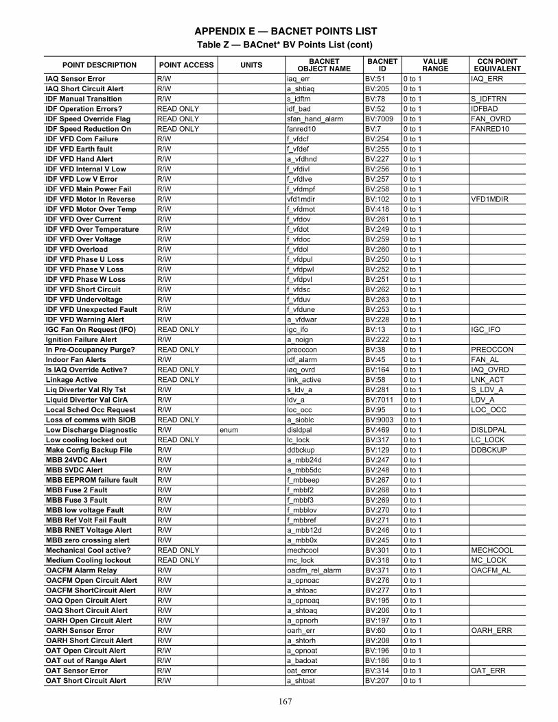
167
IAQ Sensor Error R/W iaq_err BV:51 0 to 1 IAQ_ERRIAQ Short Circuit Alert R/W a_shtiaq BV:205 0 to 1 IDF Manual Transition R/W s_idftrn BV:78 0 to 1 S_IDFTRNIDF Operation Errors? READ ONLY idf_bad BV:52 0 to 1 IDFBADIDF Speed Override Flag READ ONLY sfan_hand_alarm BV:7009 0 to 1 FAN_OVRDIDF Speed Reduction On READ ONLY fanred10 BV:7 0 to 1 FANRED10IDF VFD Com Failure R/W f_vfdcf BV:254 0 to 1 IDF VFD Earth fault R/W f_vfdef BV:255 0 to 1 IDF VFD Hand Alert R/W a_vfdhnd BV:227 0 to 1 IDF VFD Internal V Low R/W f_vfdivl BV:256 0 to 1 IDF VFD Low V Error R/W f_vfdlve BV:257 0 to 1 IDF VFD Main Power Fail R/W f_vfdmpf BV:258 0 to 1 IDF VFD Motor In Reverse R/W vfd1mdir BV:102 0 to 1 VFD1MDIRIDF VFD Motor Over Temp R/W f_vfdmot BV:418 0 to 1 IDF VFD Over Current R/W f_vfdov BV:261 0 to 1 IDF VFD Over Temperature R/W f_vfdot BV:249 0 to 1 IDF VFD Over Voltage R/W f_vfdoc BV:259 0 to 1 IDF VFD Overload R/W f_vfdol BV:260 0 to 1 IDF VFD Phase U Loss R/W f_vfdpul BV:250 0 to 1 IDF VFD Phase V Loss R/W f_vfdpwl BV:252 0 to 1 IDF VFD Phase W Loss R/W f_vfdpvl BV:251 0 to 1 IDF VFD Short Circuit R/W f_vfdsc BV:262 0 to 1 IDF VFD Undervoltage R/W f_vfduv BV:263 0 to 1 IDF VFD Unexpected Fault R/W f_vfdune BV:253 0 to 1 IDF VFD Warning Alert R/W a_vfdwar BV:228 0 to 1 IGC Fan On Request (IFO) READ ONLY igc_ifo BV:13 0 to 1 IGC_IFOIgnition Failure Alert R/W a_noign BV:222 0 to 1 In Pre-Occupancy Purge? READ ONLY preoccon BV:38 0 to 1 PREOCCONIndoor Fan Alerts R/W idf_alarm BV:45 0 to 1 FAN_ALIs IAQ Override Active? READ ONLY iaq_ovrd BV:164 0 to 1 IAQ_OVRDLinkage Active READ ONLY link_active BV:58 0 to 1 LNK_ACTLiq Diverter Val Rly Tst R/W s_ldv_a BV:281 0 to 1 S_LDV_ALiquid Diverter Val CirA R/W ldv_a BV:7011 0 to 1 LDV_ALocal Sched Occ Request R/W loc_occ BV:95 0 to 1 LOC_OCCLoss of comms with SIOB READ ONLY a_sioblc BV:9003 0 to 1 Low Discharge Diagnostic R/W enum disldpal BV:469 0 to 1 DISLDPALLow cooling locked out READ ONLY lc_lock BV:317 0 to 1 LC_LOCKMake Config Backup File R/W ddbckup BV:129 0 to 1 DDBCKUPMBB 24VDC Alert R/W a_mbb24d BV:247 0 to 1 MBB 5VDC Alert R/W a_mbb5dc BV:248 0 to 1 MBB EEPROM failure fault R/W f_mbbeep BV:267 0 to 1 MBB Fuse 2 Fault R/W f_mbbf2 BV:268 0 to 1 MBB Fuse 3 Fault R/W f_mbbf3 BV:269 0 to 1 MBB low voltage Fault R/W f_mbblov BV:270 0 to 1 MBB Ref Volt Fail Fault R/W f_mbbref BV:271 0 to 1 MBB RNET Voltage Alert R/W a_mbb12d BV:246 0 to 1 MBB zero crossing alert R/W a_mbb0x BV:245 0 to 1 Mechanical Cool active? READ ONLY mechcool BV:301 0 to 1 MECHCOOLMedium Cooling lockout READ ONLY mc_lock BV:318 0 to 1 MC_LOCKOACFM Alarm Relay R/W oacfm_rel_alarm BV:371 0 to 1 OACFM_ALOACFM Open Circuit Alert R/W a_opnoac BV:276 0 to 1 OACFM ShortCircuit Alert R/W a_shtoac BV:277 0 to 1 OAQ Open Circuit Alert R/W a_opnoaq BV:195 0 to 1 OAQ Short Circuit Alert R/W a_shtoaq BV:206 0 to 1 OARH Open Circuit Alert R/W a_opnorh BV:197 0 to 1 OARH Sensor Error R/W oarh_err BV:60 0 to 1 OARH_ERROARH Short Circuit Alert R/W a_shtorh BV:208 0 to 1 OAT Open Circuit Alert R/W a_opnoat BV:196 0 to 1 OAT out of Range Alert R/W a_badoat BV:186 0 to 1 OAT Sensor Error R/W oat_error BV:314 0 to 1 OAT_ERROAT Short Circuit Alert R/W a_shtoat BV:207 0 to 1
Table Z — BACnet* BV Points List (cont)
POINT DESCRIPTION POINT ACCESS UNITS BACNETOBJECT NAME
BACNETID
VALUERANGE
CCN POINTEQUIVALENT
APPENDIX E — BACNET POINTS LIST
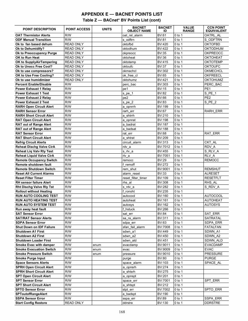
168
OAT Thermistor Alerts R/W oat_rel_alarm BV:61 0 to 1 OATRL_ALODF Manual Transition R/W s_odftrn BV:81 0 to 1 S_ODFTRNOk to fan based dehum READ ONLY oktofbd BV:420 0 to 1 OKTOFBDOk to Dehumidify? READ ONLY oktodhum BV:422 0 to 1 OKTODHUMOk to Preoccupancy Purge READ ONLY okpreocc BV:35 0 to 1 OKPREOCCOK to Run Heat READ ONLY oktoheat BV:36 0 to 1 OKTOHEATOK to SupplyAirTempering READ ONLY oktotemp BV:415 0 to 1 OKTOTEMPOk to Unocc Free Cool? READ ONLY oktoufc BV:37 0 to 1 OKTOUFCOk to use compressors? READ ONLY okmechcl BV:302 0 to 1 OKMECHCLOK to Use Free Cooling? READ ONLY ok_free_cl BV:65 0 to 1 OKFREECLOk to use humidimizer READ ONLY oktohumz BV:421 0 to 1 OKTOHUMZPercent Enable/Disable R/W perc_bac BV:303 0 to 1 PERC_BACPower Exhaust 1 Relay R/W pe1 BV:15 0 to 1 PE1Power Exhaust 1 Test R/W s_pe_1 BV:82 0 to 1 S_PE_1Power Exhaust 2 Relay R/W pe2 BV:66 0 to 1 PE2Power Exhaust 2 Test R/W s_pe_2 BV:83 0 to 1 S_PE_2RARH Open Circuit Alert R/W a_opnrrh BV:199 0 to 1 RARH Sensor Error R/W rarh_err BV:67 0 to 1 RARH_ERRRARH Short Circuit Alert R/W a_shtrrh BV:210 0 to 1 RAT Open Circuit Alert R/W a_opnrat BV:198 0 to 1 RAT out of Range Alert R/W a_badrat BV:187 0 to 1 RAT out of Range Alert R/W a_badsat BV:188 0 to 1 RAT Sensor Error R/W rat_err BV:68 0 to 1 RAT_ERRRAT Short Circuit Alert R/W a_shtrat BV:209 0 to 1 Refrig Circuit Alerts R/W circuit_alarm BV:313 0 to 1 CKT_ALReheat Dischg Valve CirA R/W rdv_a BV:7012 0 to 1 RDV_AReheat Liq Valv Rly Test R/W s_rlv_a BV:455 0 to 1 S_RLV_AReheat Liquid Valve CirA R/W rlv_a BV:7051 0 to 1 RLV_ARemote Occupancy Switch R/W remocc BV:29 0 to 1 REMOCCRemote shutdown fault R/W f_remoff BV:272 0 to 1 Remote Shutdown Switch R/W rem_shut BV:9001 0 to 1 REMSHUTReset All Current Alarms R/W alarm_reset BV:33 0 to 1 ALRESETReset Filter Timer R/W reset_filter_timer BV:109 0 to 1 RESETFLTRH sensor failure Alert R/W rhs_al BV:308 0 to 1 RHS_ALRht Dischg Valve Rly Tst R/W s_rdv_a BV:282 0 to 1 S_RDV_ARollout without Heating R/W f_ronoht BV:235 0 to 1 RUN AUTO COOLING TEST R/W autocool BV:160 0 to 1 AUTOCOOLRUN AUTO HEATING TEST R/W autoheat BV:161 0 to 1 AUTOHEATRUN AUTO SYSTEM TEST R/W autosys BV:162 0 to 1 AUTOSYSRun away heat fault R/W f_hstuck BV:266 0 to 1 SAT Sensor Error R/W sat_err BV:84 0 to 1 SAT_ERRSAT/RAT Sensor Alerts R/W sa_ra_alarm BV:311 0 to 1 SATRATALSDPA Sensor Error R/W sdpa_err BV:63 0 to 1 SDPA_ERRShut Down on IDF Failure R/W sfan_fail_alarm BV:7008 0 to 1 FATALFANShutdown A1 First R/W sdwn_a1 BV:449 0 to 1 SDWN_A1Shutdown A2 First R/W sdwn_a2 BV:450 0 to 1 SDWN_A2Shutdown Loader First R/W sdwn_ald BV:451 0 to 1 SDWN_ALDSmoke Evac with damper R/W enum evacdamp BV:9011 0 to 1 EVACDAMPSmoke Evacuation Switch R/W enum evac BV:9009 0 to 1 EVACSmoke Pressure Switch R/W enum pressure BV:9010 0 to 1 PRESSURESmoke Purge Input R/W purge BV:80 0 to 1 PURGESpace Sensors Alerts R/W space_alarm BV:103 0 to 1 SPACE_ALSPRH Open Circuit Alert R/W a_opnsrh BV:274 0 to 1 SPRH Short Circuit Alert R/W a_shtsrh BV:275 0 to 1 SPT Open Circuit Alert R/W a_opnspt BV:201 0 to 1 SPT Sensor Error R/W space_err BV:7001 0 to 1 SPT_ERRSPT Short Circuit Alert R/W a_shtspt BV:212 0 to 1 SPTO Sensor Error R/W stpt_err BV:7002 0 to 1 SPTO_ERRSPToutofRangeAlert R/W a_badspt BV:190 0 to 1 SSPA Sensor Error R/W sspa_err BV:89 0 to 1 SSPA_ERRStart Config Restore READ ONLY ddrstre BV:130 0 to 1 DDRSTRE
Table Z — BACnet* BV Points List (cont)
POINT DESCRIPTION POINT ACCESS UNITS BACNETOBJECT NAME
BACNETID
VALUERANGE
CCN POINTEQUIVALENT
APPENDIX E — BACNET POINTS LIST
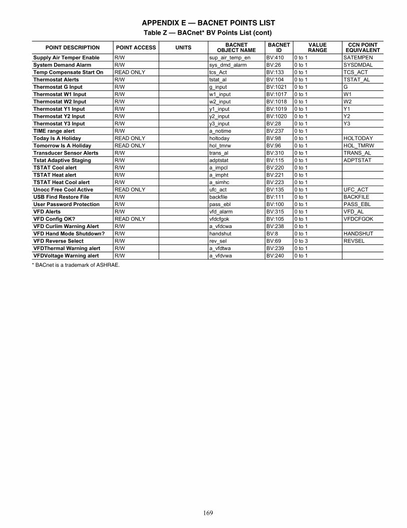
169
* BACnet is a trademark of ASHRAE.
Supply Air Temper Enable R/W sup_air_temp_en BV:410 0 to 1 SATEMPENSystem Demand Alarm R/W sys_dmd_alarm BV:26 0 to 1 SYSDMDALTemp Compensate Start On READ ONLY tcs_Act BV:133 0 to 1 TCS_ACTThermostat Alerts R/W tstat_al BV:104 0 to 1 TSTAT_ALThermostat G Input R/W g_input BV:1021 0 to 1 GThermostat W1 Input R/W w1_input BV:1017 0 to 1 W1Thermostat W2 Input R/W w2_input BV:1018 0 to 1 W2Thermostat Y1 Input R/W y1_input BV:1019 0 to 1 Y1Thermostat Y2 Input R/W y2_input BV:1020 0 to 1 Y2Thermostat Y3 Input R/W y3_input BV:28 0 to 1 Y3TIME range alert R/W a_notime BV:237 0 to 1 Today Is A Holiday READ ONLY holtoday BV:98 0 to 1 HOLTODAYTomorrow Is A Holiday READ ONLY hol_tmrw BV:96 0 to 1 HOL_TMRWTransducer Sensor Alerts R/W trans_al BV:310 0 to 1 TRANS_ALTstat Adaptive Staging R/W adptstat BV:115 0 to 1 ADPTSTATTSTAT Cool alert R/W a_impcl BV:220 0 to 1 TSTAT Heat alert R/W a_impht BV:221 0 to 1 TSTAT Heat Cool alert R/W a_simhc BV:223 0 to 1 Unocc Free Cool Active READ ONLY ufc_act BV:135 0 to 1 UFC_ACTUSB Find Restore File R/W backfile BV:111 0 to 1 BACKFILEUser Password Protection R/W pass_ebl BV:100 0 to 1 PASS_EBLVFD Alerts R/W vfd_alarm BV:315 0 to 1 VFD_ALVFD Config OK? READ ONLY vfdcfgok BV:105 0 to 1 VFDCFGOKVFD Curlim Warning Alert R/W a_vfdcwa BV:238 0 to 1 VFD Hand Mode Shutdown? R/W handshut BV:8 0 to 1 HANDSHUTVFD Reverse Select R/W rev_sel BV:69 0 to 3 REVSELVFDThermal Warning alert R/W a_vfdtwa BV:239 0 to 1 VFDVoltage Warning alert R/W a_vfdvwa BV:240 0 to 1
Table Z — BACnet* BV Points List (cont)
POINT DESCRIPTION POINT ACCESS UNITS BACNETOBJECT NAME
BACNETID
VALUERANGE
CCN POINTEQUIVALENT
APPENDIX E — BACNET POINTS LIST
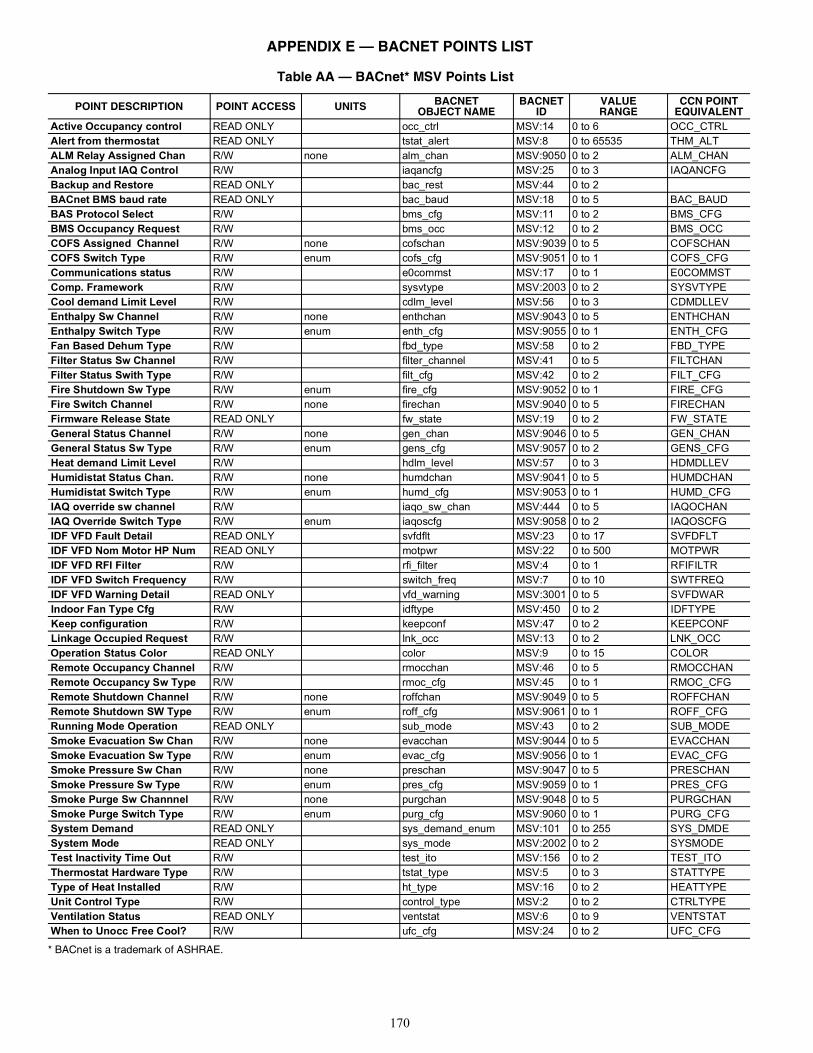
170
* BACnet is a trademark of ASHRAE.
Table AA — BACnet* MSV Points List
POINT DESCRIPTION POINT ACCESS UNITS BACNETOBJECT NAME
BACNETID
VALUERANGE
CCN POINTEQUIVALENT
Active Occupancy control READ ONLY occ_ctrl MSV:14 0 to 6 OCC_CTRLAlert from thermostat READ ONLY tstat_alert MSV:8 0 to 65535 THM_ALTALM Relay Assigned Chan R/W none alm_chan MSV:9050 0 to 2 ALM_CHANAnalog Input IAQ Control R/W iaqancfg MSV:25 0 to 3 IAQANCFGBackup and Restore READ ONLY bac_rest MSV:44 0 to 2 BACnet BMS baud rate READ ONLY bac_baud MSV:18 0 to 5 BAC_BAUDBAS Protocol Select R/W bms_cfg MSV:11 0 to 2 BMS_CFGBMS Occupancy Request R/W bms_occ MSV:12 0 to 2 BMS_OCCCOFS Assigned Channel R/W none cofschan MSV:9039 0 to 5 COFSCHANCOFS Switch Type R/W enum cofs_cfg MSV:9051 0 to 1 COFS_CFGCommunications status R/W e0commst MSV:17 0 to 1 E0COMMSTComp. Framework R/W sysvtype MSV:2003 0 to 2 SYSVTYPECool demand Limit Level R/W cdlm_level MSV:56 0 to 3 CDMDLLEVEnthalpy Sw Channel R/W none enthchan MSV:9043 0 to 5 ENTHCHANEnthalpy Switch Type R/W enum enth_cfg MSV:9055 0 to 1 ENTH_CFGFan Based Dehum Type R/W fbd_type MSV:58 0 to 2 FBD_TYPEFilter Status Sw Channel R/W filter_channel MSV:41 0 to 5 FILTCHANFilter Status Swith Type R/W filt_cfg MSV:42 0 to 2 FILT_CFGFire Shutdown Sw Type R/W enum fire_cfg MSV:9052 0 to 1 FIRE_CFGFire Switch Channel R/W none firechan MSV:9040 0 to 5 FIRECHANFirmware Release State READ ONLY fw_state MSV:19 0 to 2 FW_STATEGeneral Status Channel R/W none gen_chan MSV:9046 0 to 5 GEN_CHANGeneral Status Sw Type R/W enum gens_cfg MSV:9057 0 to 2 GENS_CFGHeat demand Limit Level R/W hdlm_level MSV:57 0 to 3 HDMDLLEVHumidistat Status Chan. R/W none humdchan MSV:9041 0 to 5 HUMDCHANHumidistat Switch Type R/W enum humd_cfg MSV:9053 0 to 1 HUMD_CFGIAQ override sw channel R/W iaqo_sw_chan MSV:444 0 to 5 IAQOCHANIAQ Override Switch Type R/W enum iaqoscfg MSV:9058 0 to 2 IAQOSCFGIDF VFD Fault Detail READ ONLY svfdflt MSV:23 0 to 17 SVFDFLTIDF VFD Nom Motor HP Num READ ONLY motpwr MSV:22 0 to 500 MOTPWRIDF VFD RFI Filter R/W rfi_filter MSV:4 0 to 1 RFIFILTRIDF VFD Switch Frequency R/W switch_freq MSV:7 0 to 10 SWTFREQIDF VFD Warning Detail READ ONLY vfd_warning MSV:3001 0 to 5 SVFDWARIndoor Fan Type Cfg R/W idftype MSV:450 0 to 2 IDFTYPEKeep configuration R/W keepconf MSV:47 0 to 2 KEEPCONFLinkage Occupied Request R/W lnk_occ MSV:13 0 to 2 LNK_OCCOperation Status Color READ ONLY color MSV:9 0 to 15 COLORRemote Occupancy Channel R/W rmocchan MSV:46 0 to 5 RMOCCHANRemote Occupancy Sw Type R/W rmoc_cfg MSV:45 0 to 1 RMOC_CFGRemote Shutdown Channel R/W none roffchan MSV:9049 0 to 5 ROFFCHANRemote Shutdown SW Type R/W enum roff_cfg MSV:9061 0 to 1 ROFF_CFGRunning Mode Operation READ ONLY sub_mode MSV:43 0 to 2 SUB_MODESmoke Evacuation Sw Chan R/W none evacchan MSV:9044 0 to 5 EVACCHANSmoke Evacuation Sw Type R/W enum evac_cfg MSV:9056 0 to 1 EVAC_CFGSmoke Pressure Sw Chan R/W none preschan MSV:9047 0 to 5 PRESCHANSmoke Pressure Sw Type R/W enum pres_cfg MSV:9059 0 to 1 PRES_CFGSmoke Purge Sw Channnel R/W none purgchan MSV:9048 0 to 5 PURGCHANSmoke Purge Switch Type R/W enum purg_cfg MSV:9060 0 to 1 PURG_CFGSystem Demand READ ONLY sys_demand_enum MSV:101 0 to 255 SYS_DMDESystem Mode READ ONLY sys_mode MSV:2002 0 to 2 SYSMODETest Inactivity Time Out R/W test_ito MSV:156 0 to 2 TEST_ITOThermostat Hardware Type R/W tstat_type MSV:5 0 to 3 STATTYPEType of Heat Installed R/W ht_type MSV:16 0 to 2 HEATTYPEUnit Control Type R/W control_type MSV:2 0 to 2 CTRLTYPEVentilation Status READ ONLY ventstat MSV:6 0 to 9 VENTSTATWhen to Unocc Free Cool? R/W ufc_cfg MSV:24 0 to 2 UFC_CFG
APPENDIX E — BACNET POINTS LIST
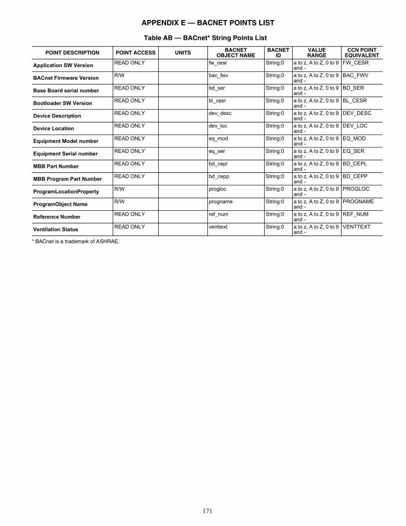
171
* BACnet is a trademark of ASHRAE.
Table AB — BACnet* String Points List
POINT DESCRIPTION POINT ACCESS UNITS BACNETOBJECT NAME
BACNETID
VALUERANGE
CCN POINTEQUIVALENT
Application SW Version READ ONLY fw_cesr String:0 a to z, A to Z, 0 to 9 and -
FW_CESR
BACnet Firmware Version R/W bac_fwv String:0 a to z, A to Z, 0 to 9 and -
BAC_FWV
Base Board serial number READ ONLY bd_ser String:0 a to z, A to Z, 0 to 9 and -
BD_SER
Bootloader SW Version READ ONLY bl_cesr String:0 a to z, A to Z, 0 to 9 and -
BL_CESR
Device Description READ ONLY dev_desc String:0 a to z, A to Z, 0 to 9 and -
DEV_DESC
Device Location READ ONLY dev_loc String:0 a to z, A to Z, 0 to 9 and -
DEV_LOC
Equipment Model number READ ONLY eq_mod String:0 a to z, A to Z, 0 to 9 and -
EQ_MOD
Equipment Serial number READ ONLY eq_ser String:0 a to z, A to Z, 0 to 9 and -
EQ_SER
MBB Part Number READ ONLY bd_cepl String:0 a to z, A to Z, 0 to 9 and -
BD_CEPL
MBB Program Part Number READ ONLY bd_cepp String:0 a to z, A to Z, 0 to 9 and -
BD_CEPP
ProgramLocationProperty R/W progloc String:0 a to z, A to Z, 0 to 9 and -
PROGLOC
ProgramObject Name R/W progname String:0 a to z, A to Z, 0 to 9 and -
PROGNAME
Reference Number READ ONLY ref_num String:0 a to z, A to Z, 0 to 9 and -
REF_NUM
Ventilation Status READ ONLY venttext String:0 a to z, A to Z, 0 to 9 and -
VENTTEXT
APPENDIX E — BACNET POINTS LIST
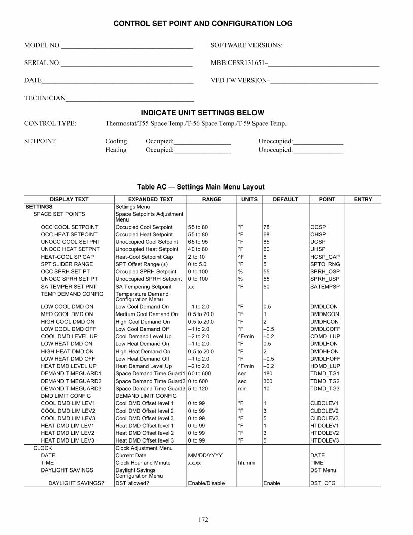
172
MODEL NO._______________________________________
SERIAL NO._______________________________________
DATE_____________________________________________
TECHNICIAN______________________________________
SOFTWARE VERSIONS:
MBB:CESR131651–_________________________________
VFD FW VERSION–________________________________
INDICATE UNIT SETTINGS BELOWCONTROL TYPE: Thermostat/T55 Space Temp./T-56 Space Temp./T-59 Space Temp.
SETPOINT Cooling Occupied:_________________ Unoccupied:_______________Heating Occupied:_________________ Unoccupied:_______________
Table AC — Settings Main Menu Layout
DISPLAY TEXT EXPANDED TEXT RANGE UNITS DEFAULT POINT ENTRYSETTINGS Settings Menu
SPACE SET POINTS Space Setpoints Adjustment Menu
OCC COOL SETPOINT Occupied Cool Setpoint 55 to 80 °F 78 OCSPOCC HEAT SETPOINT Occupied Heat Setpoint 55 to 80 °F 68 OHSPUNOCC COOL SETPNT Unoccupied Cool Setpoint 65 to 95 °F 85 UCSPUNOCC HEAT SETPNT Unoccupied Heat Setpoint 40 to 80 °F 60 UHSPHEAT-COOL SP GAP Heat-Cool Setpoint Gap 2 to 10 ^F 5 HCSP_GAPSPT SLIDER RANGE SPT Offset Range (±) 0 to 5.0 °F 5 SPTO_RNGOCC SPRH SET PT Occupied SPRH Setpoint 0 to 100 % 55 SPRH_OSPUNOCC SPRH SET PT Unoccupied SPRH Setpoint 0 to 100 % 55 SPRH_USPSA TEMPER SET PNT SA Tempering Setpoint xx °F 50 SATEMPSPTEMP DEMAND CONFIG Temperature Demand
Configuration MenuLOW COOL DMD ON Low Cool Demand On –1 to 2.0 °F 0.5 DMDLCONMED COOL DMD ON Medium Cool Demand On 0.5 to 20.0 °F 1 DMDMCONHIGH COOL DMD ON High Cool Demand On 0.5 to 20.0 °F 2 DMDHCONLOW COOL DMD OFF Low Cool Demand Off –1 to 2.0 °F –0.5 DMDLCOFFCOOL DMD LEVEL UP Cool Demand Level Up –2 to 2.0 ^F/min –0.2 CDMD_LUPLOW HEAT DMD ON Low Heat Demand On –1 to 2.0 °F 0.5 DMDLHONHIGH HEAT DMD ON High Heat Demand On 0.5 to 20.0 °F 2 DMDHHONLOW HEAT DMD OFF Low Heat Demand Off –1 to 2.0 °F –0.5 DMDLHOFFHEAT DMD LEVEL UP Heat Demand Level Up –2 to 2.0 ^F/min –0.2 HDMD_LUPDEMAND TIMEGUARD1 Space Demand Time Guard1 60 to 600 sec 180 TDMD_TG1DEMAND TIMEGUARD2 Space Demand Time Guard2 0 to 600 sec 300 TDMD_TG2DEMAND TIMEGUARD3 Space Demand Time Guard3 5 to 120 min 10 TDMD_TG3DMD LIMIT CONFIG DEMAND LIMIT CONFIGCOOL DMD LIM LEV1 Cool DMD Offset level 1 0 to 99 °F 1 CLDOLEV1COOL DMD LIM LEV2 Cool DMD Offset level 2 0 to 99 °F 3 CLDOLEV2COOL DMD LIM LEV3 Cool DMD Offset level 3 0 to 99 °F 5 CLDOLEV3HEAT DMD LIM LEV1 Heat DMD Offset level 1 0 to 99 °F 1 HTDOLEV1HEAT DMD LIM LEV2 Heat DMD Offset level 2 0 to 99 °F 3 HTDOLEV2HEAT DMD LIM LEV3 Heat DMD Offset level 3 0 to 99 °F 5 HTDOLEV3
CLOCK Clock Adjustment MenuDATE Current Date MM/DD/YYYY DATETIME Clock Hour and Minute xx:xx hh.mm TIMEDAYLIGHT SAVINGS Daylight Savings
Configuration MenuDST Menu
DAYLIGHT SAVINGS? DST allowed? Enable/Disable Enable DST_CFG
CONTROL SET POINT AND CONFIGURATION LOG
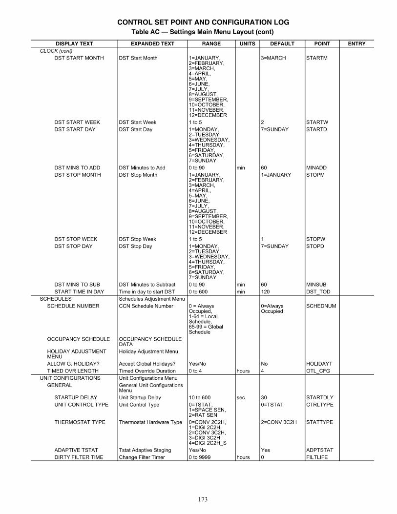
173
CLOCK (cont)DST START MONTH DST Start Month 1=JANUARY,
2=FEBRUARY,3=MARCH,4=APRIL,5=MAY,6=JUNE,7=JULY,8=AUGUST,9=SEPTEMBER,10=OCTOBER,11=NOVEBER,12=DECEMBER
3=MARCH STARTM
DST START WEEK DST Start Week 1 to 5 2 STARTWDST START DAY DST Start Day 1=MONDAY,
2=TUESDAY,3=WEDNESDAY,4=THURSDAY,5=FRIDAY,6=SATURDAY,7=SUNDAY
7=SUNDAY STARTD
DST MINS TO ADD DST Minutes to Add 0 to 90 min 60 MINADDDST STOP MONTH DST Stop Month 1=JANUARY,
2=FEBRUARY,3=MARCH,4=APRIL,5=MAY,6=JUNE,7=JULY,8=AUGUST,9=SEPTEMBER,10=OCTOBER,11=NOVEBER,12=DECEMBER
1=JANUARY STOPM
DST STOP WEEK DST Stop Week 1 to 5 1 STOPWDST STOP DAY DST Stop Day 1=MONDAY,
2=TUESDAY,3=WEDNESDAY,4=THURSDAY,5=FRIDAY,6=SATURDAY,7=SUNDAY
7=SUNDAY STOPD
DST MINS TO SUB DST Minutes to Subtract 0 to 90 min 60 MINSUBSTART TIME IN DAY Time in day to start DST 0 to 600 min 120 DST_TOD
SCHEDULES Schedules Adjustment MenuSCHEDULE NUMBER CCN Schedule Number 0 = Always
Occupied,1-64 = Local Schedule,65-99 = Global Schedule
0=Always Occupied
SCHEDNUM
OCCUPANCY SCHEDULE OCCUPANCY SCHEDULE DATA
HOLIDAY ADJUSTMENT MENU
Holiday Adjustment Menu
ALLOW G. HOLIDAY? Accept Global Holidays? Yes/No No HOLIDAYTTIMED OVR LENGTH Timed Override Duration 0 to 4 hours 4 OTL_CFG
UNIT CONFIGURATIONS Unit Configurations MenuGENERAL General Unit Configurations
MenuSTARTUP DELAY Unit Startup Delay 10 to 600 sec 30 STARTDLYUNIT CONTROL TYPE Unit Control Type 0=TSTAT,
1=SPACE SEN,2=RAT SEN
0=TSTAT CTRLTYPE
THERMOSTAT TYPE Thermostat Hardware Type 0=CONV 2C2H,1=DIGI 2C2H,2=CONV 3C2H,3=DIGI 3C2H4=DIGI 2C2H_S
2=CONV 3C2H STATTYPE
ADAPTIVE TSTAT Tstat Adaptive Staging Yes/No Yes ADPTSTATDIRTY FILTER TIME Change Filter Timer 0 to 9999 hours 0 FILTLIFE
Table AC — Settings Main Menu Layout (cont)
DISPLAY TEXT EXPANDED TEXT RANGE UNITS DEFAULT POINT ENTRY
CONTROL SET POINT AND CONFIGURATION LOG
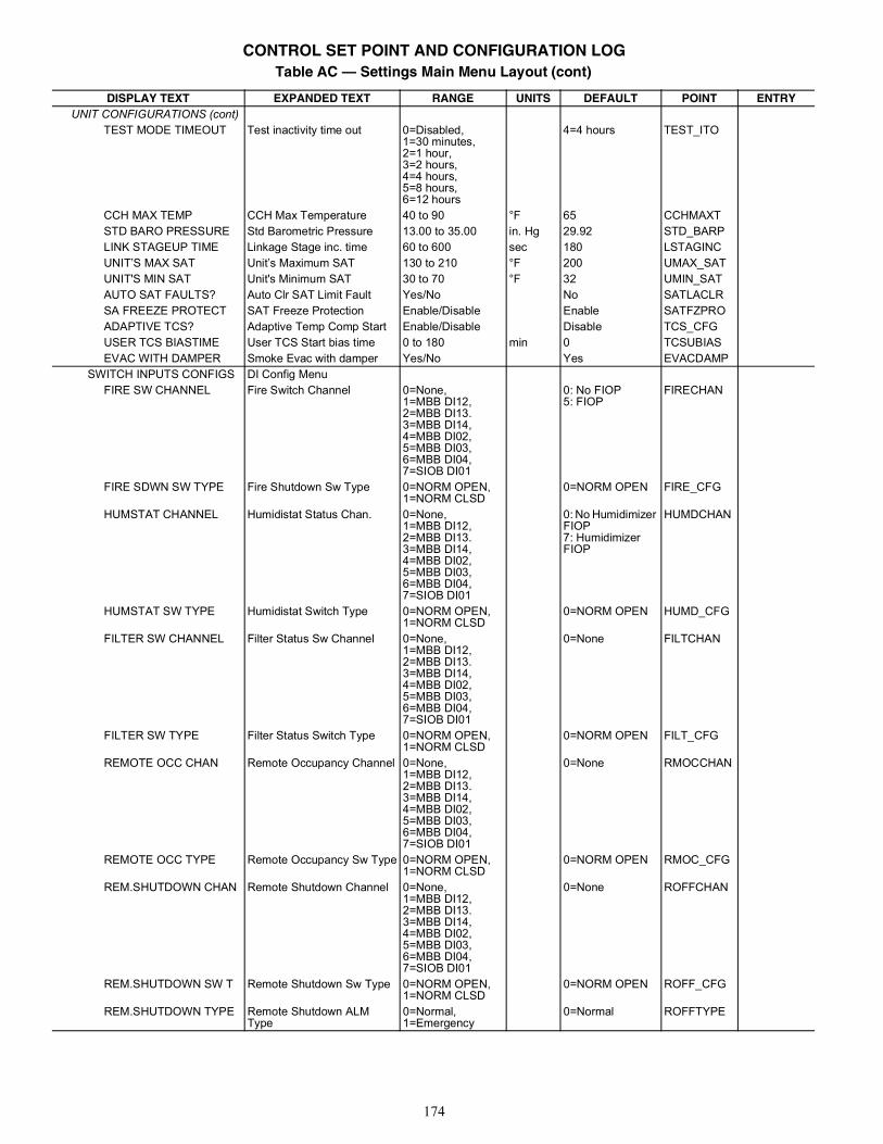
174
UNIT CONFIGURATIONS (cont)TEST MODE TIMEOUT Test inactivity time out 0=Disabled,
1=30 minutes,2=1 hour,3=2 hours,4=4 hours,5=8 hours,6=12 hours
4=4 hours TEST_ITO
CCH MAX TEMP CCH Max Temperature 40 to 90 °F 65 CCHMAXTSTD BARO PRESSURE Std Barometric Pressure 13.00 to 35.00 in. Hg 29.92 STD_BARPLINK STAGEUP TIME Linkage Stage inc. time 60 to 600 sec 180 LSTAGINCUNIT’S MAX SAT Unit’s Maximum SAT 130 to 210 °F 200 UMAX_SATUNIT'S MIN SAT Unit's Minimum SAT 30 to 70 °F 32 UMIN_SATAUTO SAT FAULTS? Auto Clr SAT Limit Fault Yes/No No SATLACLRSA FREEZE PROTECT SAT Freeze Protection Enable/Disable Enable SATFZPROADAPTIVE TCS? Adaptive Temp Comp Start Enable/Disable Disable TCS_CFGUSER TCS BIASTIME User TCS Start bias time 0 to 180 min 0 TCSUBIASEVAC WITH DAMPER Smoke Evac with damper Yes/No Yes EVACDAMP
SWITCH INPUTS CONFIGS DI Config MenuFIRE SW CHANNEL Fire Switch Channel 0=None,
1=MBB DI12,2=MBB DI13.3=MBB DI14,4=MBB DI02,5=MBB DI03,6=MBB DI04,7=SIOB DI01
0: No FIOP5: FIOP
FIRECHAN
FIRE SDWN SW TYPE Fire Shutdown Sw Type 0=NORM OPEN,1=NORM CLSD
0=NORM OPEN FIRE_CFG
HUMSTAT CHANNEL Humidistat Status Chan. 0=None,1=MBB DI12,2=MBB DI13.3=MBB DI14,4=MBB DI02,5=MBB DI03,6=MBB DI04,7=SIOB DI01
0: No Humidimizer FIOP7: Humidimizer FIOP
HUMDCHAN
HUMSTAT SW TYPE Humidistat Switch Type 0=NORM OPEN,1=NORM CLSD
0=NORM OPEN HUMD_CFG
FILTER SW CHANNEL Filter Status Sw Channel 0=None,1=MBB DI12,2=MBB DI13.3=MBB DI14,4=MBB DI02,5=MBB DI03,6=MBB DI04,7=SIOB DI01
0=None FILTCHAN
FILTER SW TYPE Filter Status Switch Type 0=NORM OPEN,1=NORM CLSD
0=NORM OPEN FILT_CFG
REMOTE OCC CHAN Remote Occupancy Channel 0=None,1=MBB DI12,2=MBB DI13.3=MBB DI14,4=MBB DI02,5=MBB DI03,6=MBB DI04,7=SIOB DI01
0=None RMOCCHAN
REMOTE OCC TYPE Remote Occupancy Sw Type 0=NORM OPEN,1=NORM CLSD
0=NORM OPEN RMOC_CFG
REM.SHUTDOWN CHAN Remote Shutdown Channel 0=None,1=MBB DI12,2=MBB DI13.3=MBB DI14,4=MBB DI02,5=MBB DI03,6=MBB DI04,7=SIOB DI01
0=None ROFFCHAN
REM.SHUTDOWN SW T Remote Shutdown Sw Type 0=NORM OPEN,1=NORM CLSD
0=NORM OPEN ROFF_CFG
REM.SHUTDOWN TYPE Remote Shutdown ALM Type
0=Normal,1=Emergency
0=Normal ROFFTYPE
Table AC — Settings Main Menu Layout (cont)
DISPLAY TEXT EXPANDED TEXT RANGE UNITS DEFAULT POINT ENTRY
CONTROL SET POINT AND CONFIGURATION LOG
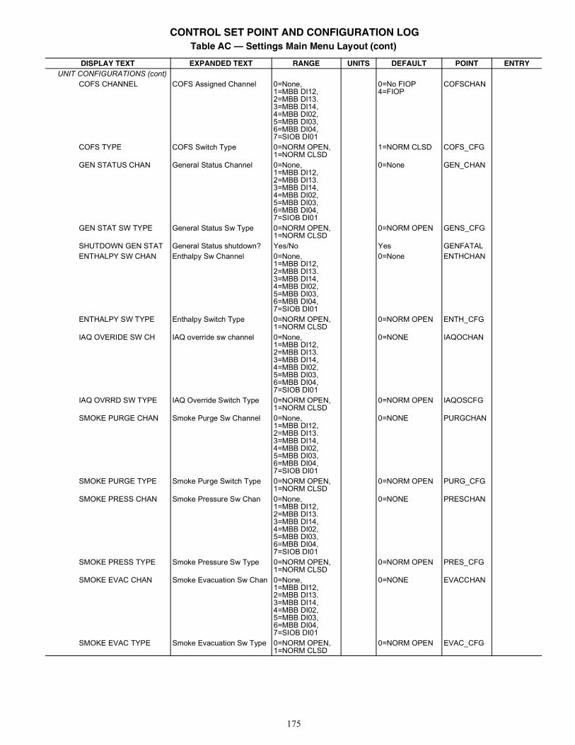
175
UNIT CONFIGURATIONS (cont)COFS CHANNEL COFS Assigned Channel 0=None,
1=MBB DI12,2=MBB DI13.3=MBB DI14,4=MBB DI02,5=MBB DI03,6=MBB DI04,7=SIOB DI01
0=No FIOP4=FIOP
COFSCHAN
COFS TYPE COFS Switch Type 0=NORM OPEN,1=NORM CLSD
1=NORM CLSD COFS_CFG
GEN STATUS CHAN General Status Channel 0=None,1=MBB DI12,2=MBB DI13.3=MBB DI14,4=MBB DI02,5=MBB DI03,6=MBB DI04,7=SIOB DI01
0=None GEN_CHAN
GEN STAT SW TYPE General Status Sw Type 0=NORM OPEN,1=NORM CLSD
0=NORM OPEN GENS_CFG
SHUTDOWN GEN STAT General Status shutdown? Yes/No Yes GENFATALENTHALPY SW CHAN Enthalpy Sw Channel 0=None,
1=MBB DI12,2=MBB DI13.3=MBB DI14,4=MBB DI02,5=MBB DI03,6=MBB DI04,7=SIOB DI01
0=None ENTHCHAN
ENTHALPY SW TYPE Enthalpy Switch Type 0=NORM OPEN,1=NORM CLSD
0=NORM OPEN ENTH_CFG
IAQ OVERIDE SW CH IAQ override sw channel 0=None,1=MBB DI12,2=MBB DI13.3=MBB DI14,4=MBB DI02,5=MBB DI03,6=MBB DI04,7=SIOB DI01
0=NONE IAQOCHAN
IAQ OVRRD SW TYPE IAQ Override Switch Type 0=NORM OPEN,1=NORM CLSD
0=NORM OPEN IAQOSCFG
SMOKE PURGE CHAN Smoke Purge Sw Channel 0=None,1=MBB DI12,2=MBB DI13.3=MBB DI14,4=MBB DI02,5=MBB DI03,6=MBB DI04,7=SIOB DI01
0=NONE PURGCHAN
SMOKE PURGE TYPE Smoke Purge Switch Type 0=NORM OPEN,1=NORM CLSD
0=NORM OPEN PURG_CFG
SMOKE PRESS CHAN Smoke Pressure Sw Chan 0=None,1=MBB DI12,2=MBB DI13.3=MBB DI14,4=MBB DI02,5=MBB DI03,6=MBB DI04,7=SIOB DI01
0=NONE PRESCHAN
SMOKE PRESS TYPE Smoke Pressure Sw Type 0=NORM OPEN,1=NORM CLSD
0=NORM OPEN PRES_CFG
SMOKE EVAC CHAN Smoke Evacuation Sw Chan 0=None,1=MBB DI12,2=MBB DI13.3=MBB DI14,4=MBB DI02,5=MBB DI03,6=MBB DI04,7=SIOB DI01
0=NONE EVACCHAN
SMOKE EVAC TYPE Smoke Evacuation Sw Type 0=NORM OPEN,1=NORM CLSD
0=NORM OPEN EVAC_CFG
Table AC — Settings Main Menu Layout (cont)
DISPLAY TEXT EXPANDED TEXT RANGE UNITS DEFAULT POINT ENTRY
CONTROL SET POINT AND CONFIGURATION LOG
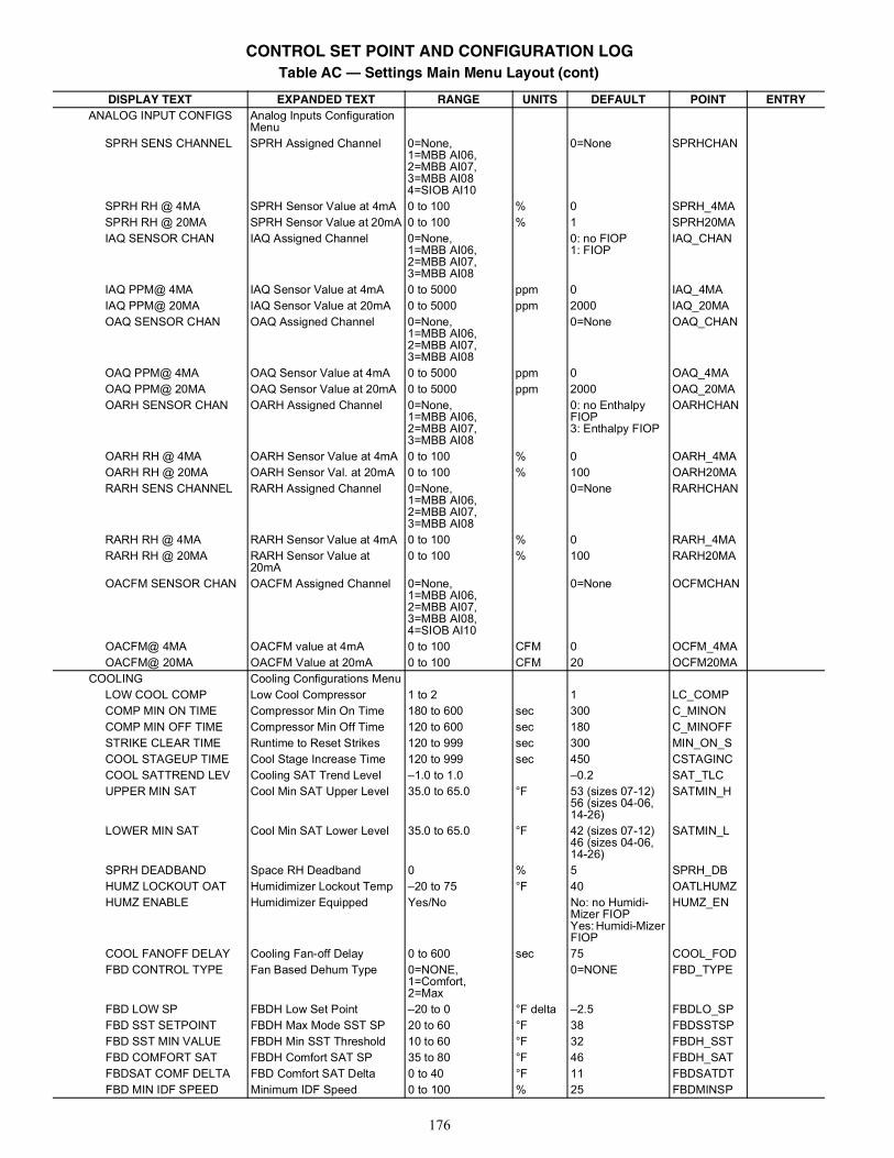
176
ANALOG INPUT CONFIGS Analog Inputs Configuration Menu
SPRH SENS CHANNEL SPRH Assigned Channel 0=None,1=MBB AI06,2=MBB AI07,3=MBB AI084=SIOB AI10
0=None SPRHCHAN
SPRH RH @ 4MA SPRH Sensor Value at 4mA 0 to 100 % 0 SPRH_4MASPRH RH @ 20MA SPRH Sensor Value at 20mA 0 to 100 % 1 SPRH20MAIAQ SENSOR CHAN IAQ Assigned Channel 0=None,
1=MBB AI06,2=MBB AI07,3=MBB AI08
0: no FIOP1: FIOP
IAQ_CHAN
IAQ PPM@ 4MA IAQ Sensor Value at 4mA 0 to 5000 ppm 0 IAQ_4MAIAQ PPM@ 20MA IAQ Sensor Value at 20mA 0 to 5000 ppm 2000 IAQ_20MAOAQ SENSOR CHAN OAQ Assigned Channel 0=None,
1=MBB AI06,2=MBB AI07,3=MBB AI08
0=None OAQ_CHAN
OAQ PPM@ 4MA OAQ Sensor Value at 4mA 0 to 5000 ppm 0 OAQ_4MAOAQ PPM@ 20MA OAQ Sensor Value at 20mA 0 to 5000 ppm 2000 OAQ_20MAOARH SENSOR CHAN OARH Assigned Channel 0=None,
1=MBB AI06,2=MBB AI07,3=MBB AI08
0: no Enthalpy FIOP3: Enthalpy FIOP
OARHCHAN
OARH RH @ 4MA OARH Sensor Value at 4mA 0 to 100 % 0 OARH_4MAOARH RH @ 20MA OARH Sensor Val. at 20mA 0 to 100 % 100 OARH20MARARH SENS CHANNEL RARH Assigned Channel 0=None,
1=MBB AI06,2=MBB AI07,3=MBB AI08
0=None RARHCHAN
RARH RH @ 4MA RARH Sensor Value at 4mA 0 to 100 % 0 RARH_4MARARH RH @ 20MA RARH Sensor Value at
20mA0 to 100 % 100 RARH20MA
OACFM SENSOR CHAN OACFM Assigned Channel 0=None,1=MBB AI06,2=MBB AI07,3=MBB AI08,4=SIOB AI10
0=None OCFMCHAN
OACFM@ 4MA OACFM value at 4mA 0 to 100 CFM 0 OCFM_4MAOACFM@ 20MA OACFM Value at 20mA 0 to 100 CFM 20 OCFM20MA
COOLING Cooling Configurations MenuLOW COOL COMP Low Cool Compressor 1 to 2 1 LC_COMPCOMP MIN ON TIME Compressor Min On Time 180 to 600 sec 300 C_MINONCOMP MIN OFF TIME Compressor Min Off Time 120 to 600 sec 180 C_MINOFFSTRIKE CLEAR TIME Runtime to Reset Strikes 120 to 999 sec 300 MIN_ON_SCOOL STAGEUP TIME Cool Stage Increase Time 120 to 999 sec 450 CSTAGINCCOOL SATTREND LEV Cooling SAT Trend Level –1.0 to 1.0 –0.2 SAT_TLCUPPER MIN SAT Cool Min SAT Upper Level 35.0 to 65.0 °F 53 (sizes 07-12)
56 (sizes 04-06, 14-26)
SATMIN_H
LOWER MIN SAT Cool Min SAT Lower Level 35.0 to 65.0 °F 42 (sizes 07-12)46 (sizes 04-06, 14-26)
SATMIN_L
SPRH DEADBAND Space RH Deadband 0 % 5 SPRH_DBHUMZ LOCKOUT OAT Humidimizer Lockout Temp –20 to 75 °F 40 OATLHUMZHUMZ ENABLE Humidimizer Equipped Yes/No No: no Humidi-
Mizer FIOPYes: Humidi-Mizer FIOP
HUMZ_EN
COOL FANOFF DELAY Cooling Fan-off Delay 0 to 600 sec 75 COOL_FODFBD CONTROL TYPE Fan Based Dehum Type 0=NONE,
1=Comfort,2=Max
0=NONE FBD_TYPE
FBD LOW SP FBDH Low Set Point –20 to 0 °F delta –2.5 FBDLO_SPFBD SST SETPOINT FBDH Max Mode SST SP 20 to 60 °F 38 FBDSSTSPFBD SST MIN VALUE FBDH Min SST Threshold 10 to 60 °F 32 FBDH_SSTFBD COMFORT SAT FBDH Comfort SAT SP 35 to 80 °F 46 FBDH_SATFBDSAT COMF DELTA FBD Comfort SAT Delta 0 to 40 °F 11 FBDSATDTFBD MIN IDF SPEED Minimum IDF Speed 0 to 100 % 25 FBDMINSP
Table AC — Settings Main Menu Layout (cont)
DISPLAY TEXT EXPANDED TEXT RANGE UNITS DEFAULT POINT ENTRY
CONTROL SET POINT AND CONFIGURATION LOG
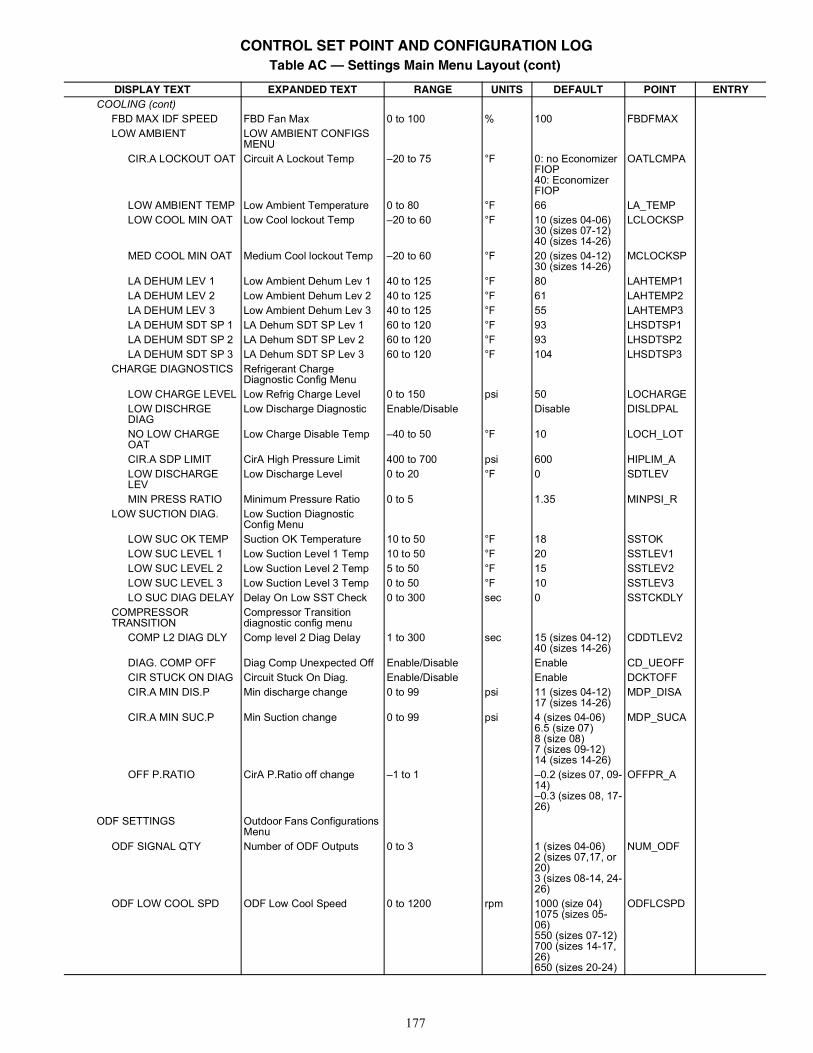
177
COOLING (cont)FBD MAX IDF SPEED FBD Fan Max 0 to 100 % 100 FBDFMAXLOW AMBIENT LOW AMBIENT CONFIGS
MENUCIR.A LOCKOUT OAT Circuit A Lockout Temp –20 to 75 °F 0: no Economizer
FIOP40: Economizer FIOP
OATLCMPA
LOW AMBIENT TEMP Low Ambient Temperature 0 to 80 °F 66 LA_TEMPLOW COOL MIN OAT Low Cool lockout Temp –20 to 60 °F 10 (sizes 04-06)
30 (sizes 07-12)40 (sizes 14-26)
LCLOCKSP
MED COOL MIN OAT Medium Cool lockout Temp –20 to 60 °F 20 (sizes 04-12)30 (sizes 14-26)
MCLOCKSP
LA DEHUM LEV 1 Low Ambient Dehum Lev 1 40 to 125 °F 80 LAHTEMP1LA DEHUM LEV 2 Low Ambient Dehum Lev 2 40 to 125 °F 61 LAHTEMP2LA DEHUM LEV 3 Low Ambient Dehum Lev 3 40 to 125 °F 55 LAHTEMP3LA DEHUM SDT SP 1 LA Dehum SDT SP Lev 1 60 to 120 °F 93 LHSDTSP1LA DEHUM SDT SP 2 LA Dehum SDT SP Lev 2 60 to 120 °F 93 LHSDTSP2LA DEHUM SDT SP 3 LA Dehum SDT SP Lev 3 60 to 120 °F 104 LHSDTSP3
CHARGE DIAGNOSTICS Refrigerant Charge Diagnostic Config Menu
LOW CHARGE LEVEL Low Refrig Charge Level 0 to 150 psi 50 LOCHARGELOW DISCHRGE DIAG
Low Discharge Diagnostic Enable/Disable Disable DISLDPAL
NO LOW CHARGE OAT
Low Charge Disable Temp –40 to 50 °F 10 LOCH_LOT
CIR.A SDP LIMIT CirA High Pressure Limit 400 to 700 psi 600 HIPLIM_ALOW DISCHARGE LEV
Low Discharge Level 0 to 20 °F 0 SDTLEV
MIN PRESS RATIO Minimum Pressure Ratio 0 to 5 1.35 MINPSI_RLOW SUCTION DIAG. Low Suction Diagnostic
Config MenuLOW SUC OK TEMP Suction OK Temperature 10 to 50 °F 18 SSTOKLOW SUC LEVEL 1 Low Suction Level 1 Temp 10 to 50 °F 20 SSTLEV1LOW SUC LEVEL 2 Low Suction Level 2 Temp 5 to 50 °F 15 SSTLEV2LOW SUC LEVEL 3 Low Suction Level 3 Temp 0 to 50 °F 10 SSTLEV3LO SUC DIAG DELAY Delay On Low SST Check 0 to 300 sec 0 SSTCKDLY
COMPRESSOR TRANSITION
Compressor Transition diagnostic config menu
COMP L2 DIAG DLY Comp level 2 Diag Delay 1 to 300 sec 15 (sizes 04-12)40 (sizes 14-26)
CDDTLEV2
DIAG. COMP OFF Diag Comp Unexpected Off Enable/Disable Enable CD_UEOFFCIR STUCK ON DIAG Circuit Stuck On Diag. Enable/Disable Enable DCKTOFFCIR.A MIN DIS.P Min discharge change 0 to 99 psi 11 (sizes 04-12)
17 (sizes 14-26)MDP_DISA
CIR.A MIN SUC.P Min Suction change 0 to 99 psi 4 (sizes 04-06)6.5 (size 07)8 (size 08)7 (sizes 09-12)14 (sizes 14-26)
MDP_SUCA
OFF P.RATIO CirA P.Ratio off change –1 to 1 –0.2 (sizes 07, 09-14)–0.3 (sizes 08, 17-26)
OFFPR_A
ODF SETTINGS Outdoor Fans Configurations Menu
ODF SIGNAL QTY Number of ODF Outputs 0 to 3 1 (sizes 04-06)2 (sizes 07,17, or 20)3 (sizes 08-14, 24-26)
NUM_ODF
ODF LOW COOL SPD ODF Low Cool Speed 0 to 1200 rpm 1000 (size 04)1075 (sizes 05-06)550 (sizes 07-12)700 (sizes 14-17, 26)650 (sizes 20-24)
ODFLCSPD
Table AC — Settings Main Menu Layout (cont)
DISPLAY TEXT EXPANDED TEXT RANGE UNITS DEFAULT POINT ENTRY
CONTROL SET POINT AND CONFIGURATION LOG
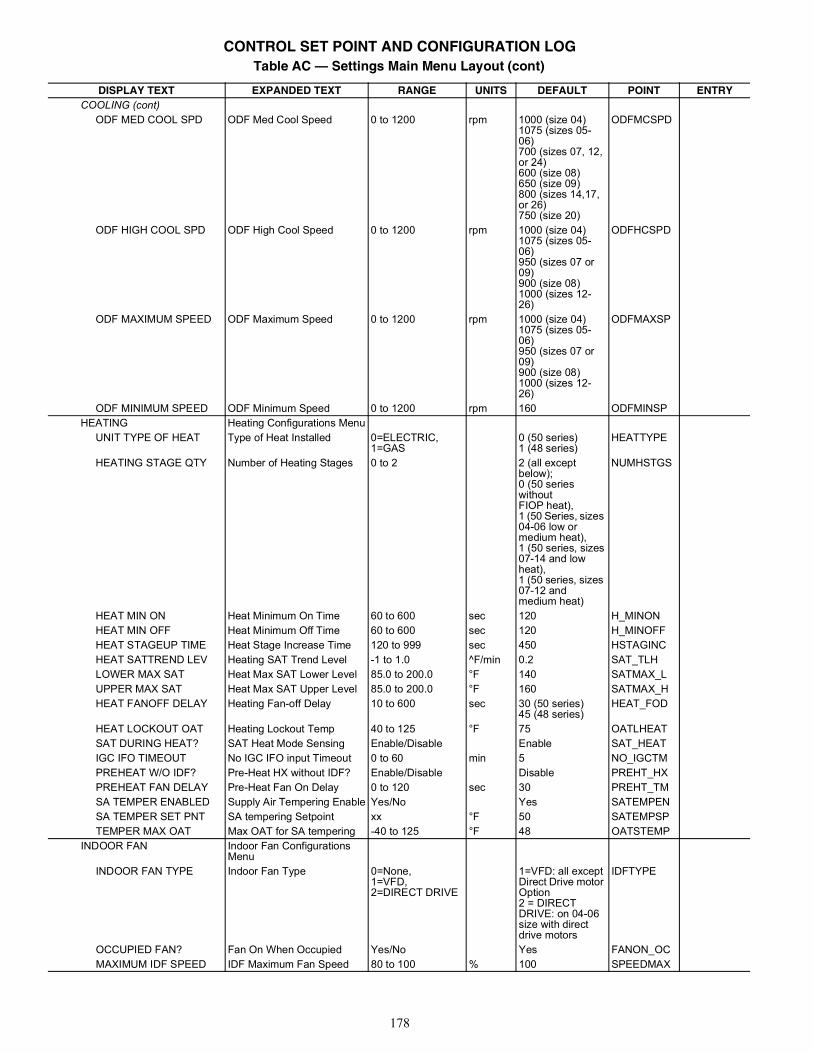
178
COOLING (cont)ODF MED COOL SPD ODF Med Cool Speed 0 to 1200 rpm 1000 (size 04)
1075 (sizes 05-06)700 (sizes 07, 12, or 24)600 (size 08)650 (size 09)800 (sizes 14,17, or 26)750 (size 20)
ODFMCSPD
ODF HIGH COOL SPD ODF High Cool Speed 0 to 1200 rpm 1000 (size 04)1075 (sizes 05-06)950 (sizes 07 or 09)900 (size 08)1000 (sizes 12-26)
ODFHCSPD
ODF MAXIMUM SPEED ODF Maximum Speed 0 to 1200 rpm 1000 (size 04)1075 (sizes 05-06)950 (sizes 07 or 09)900 (size 08)1000 (sizes 12-26)
ODFMAXSP
ODF MINIMUM SPEED ODF Minimum Speed 0 to 1200 rpm 160 ODFMINSPHEATING Heating Configurations Menu
UNIT TYPE OF HEAT Type of Heat Installed 0=ELECTRIC,1=GAS
0 (50 series)1 (48 series)
HEATTYPE
HEATING STAGE QTY Number of Heating Stages 0 to 2 2 (all except below);0 (50 series withoutFIOP heat),1 (50 Series, sizes 04-06 low or medium heat),1 (50 series, sizes07-14 and low heat),1 (50 series, sizes 07-12 and medium heat)
NUMHSTGS
HEAT MIN ON Heat Minimum On Time 60 to 600 sec 120 H_MINONHEAT MIN OFF Heat Minimum Off Time 60 to 600 sec 120 H_MINOFFHEAT STAGEUP TIME Heat Stage Increase Time 120 to 999 sec 450 HSTAGINCHEAT SATTREND LEV Heating SAT Trend Level -1 to 1.0 ^F/min 0.2 SAT_TLHLOWER MAX SAT Heat Max SAT Lower Level 85.0 to 200.0 °F 140 SATMAX_LUPPER MAX SAT Heat Max SAT Upper Level 85.0 to 200.0 °F 160 SATMAX_HHEAT FANOFF DELAY Heating Fan-off Delay 10 to 600 sec 30 (50 series)
45 (48 series)HEAT_FOD
HEAT LOCKOUT OAT Heating Lockout Temp 40 to 125 °F 75 OATLHEATSAT DURING HEAT? SAT Heat Mode Sensing Enable/Disable Enable SAT_HEATIGC IFO TIMEOUT No IGC IFO input Timeout 0 to 60 min 5 NO_IGCTMPREHEAT W/O IDF? Pre-Heat HX without IDF? Enable/Disable Disable PREHT_HXPREHEAT FAN DELAY Pre-Heat Fan On Delay 0 to 120 sec 30 PREHT_TMSA TEMPER ENABLED Supply Air Tempering Enable Yes/No Yes SATEMPENSA TEMPER SET PNT SA tempering Setpoint xx °F 50 SATEMPSPTEMPER MAX OAT Max OAT for SA tempering -40 to 125 °F 48 OATSTEMP
INDOOR FAN Indoor Fan Configurations Menu
INDOOR FAN TYPE Indoor Fan Type 0=None,1=VFD,2=DIRECT DRIVE
1=VFD: all except Direct Drive motor Option2 = DIRECT DRIVE: on 04-06 size with direct drive motors
IDFTYPE
OCCUPIED FAN? Fan On When Occupied Yes/No Yes FANON_OCMAXIMUM IDF SPEED IDF Maximum Fan Speed 80 to 100 % 100 SPEEDMAX
Table AC — Settings Main Menu Layout (cont)
DISPLAY TEXT EXPANDED TEXT RANGE UNITS DEFAULT POINT ENTRY
CONTROL SET POINT AND CONFIGURATION LOG
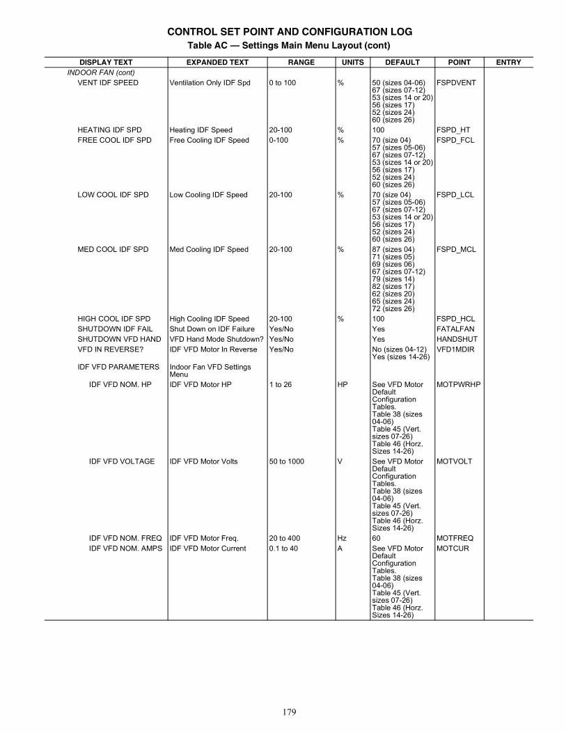
179
INDOOR FAN (cont)VENT IDF SPEED Ventilation Only IDF Spd 0 to 100 % 50 (sizes 04-06)
67 (sizes 07-12)53 (sizes 14 or 20)56 (sizes 17)52 (sizes 24)60 (sizes 26)
FSPDVENT
HEATING IDF SPD Heating IDF Speed 20-100 % 100 FSPD_HTFREE COOL IDF SPD Free Cooling IDF Speed 0-100 % 70 (size 04)
57 (sizes 05-06)67 (sizes 07-12)53 (sizes 14 or 20)56 (sizes 17)52 (sizes 24)60 (sizes 26)
FSPD_FCL
LOW COOL IDF SPD Low Cooling IDF Speed 20-100 % 70 (size 04)57 (sizes 05-06)67 (sizes 07-12)53 (sizes 14 or 20)56 (sizes 17)52 (sizes 24)60 (sizes 26)
FSPD_LCL
MED COOL IDF SPD Med Cooling IDF Speed 20-100 % 87 (sizes 04)71 (sizes 05)69 (sizes 06)67 (sizes 07-12)79 (sizes 14)82 (sizes 17)62 (sizes 20)65 (sizes 24)72 (sizes 26)
FSPD_MCL
HIGH COOL IDF SPD High Cooling IDF Speed 20-100 % 100 FSPD_HCLSHUTDOWN IDF FAIL Shut Down on IDF Failure Yes/No Yes FATALFANSHUTDOWN VFD HAND VFD Hand Mode Shutdown? Yes/No Yes HANDSHUTVFD IN REVERSE? IDF VFD Motor In Reverse Yes/No No (sizes 04-12)
Yes (sizes 14-26)VFD1MDIR
IDF VFD PARAMETERS Indoor Fan VFD Settings Menu
IDF VFD NOM. HP IDF VFD Motor HP 1 to 26 HP See VFD Motor Default Configuration Tables.Table 38 (sizes 04-06)Table 45 (Vert. sizes 07-26)Table 46 (Horz. Sizes 14-26)
MOTPWRHP
IDF VFD VOLTAGE IDF VFD Motor Volts 50 to 1000 V See VFD Motor Default Configuration Tables.Table 38 (sizes 04-06)Table 45 (Vert. sizes 07-26)Table 46 (Horz. Sizes 14-26)
MOTVOLT
IDF VFD NOM. FREQ IDF VFD Motor Freq. 20 to 400 Hz 60 MOTFREQIDF VFD NOM. AMPS IDF VFD Motor Current 0.1 to 40 A See VFD Motor
Default Configuration Tables.Table 38 (sizes 04-06)Table 45 (Vert. sizes 07-26)Table 46 (Horz. Sizes 14-26)
MOTCUR
Table AC — Settings Main Menu Layout (cont)
DISPLAY TEXT EXPANDED TEXT RANGE UNITS DEFAULT POINT ENTRY
CONTROL SET POINT AND CONFIGURATION LOG
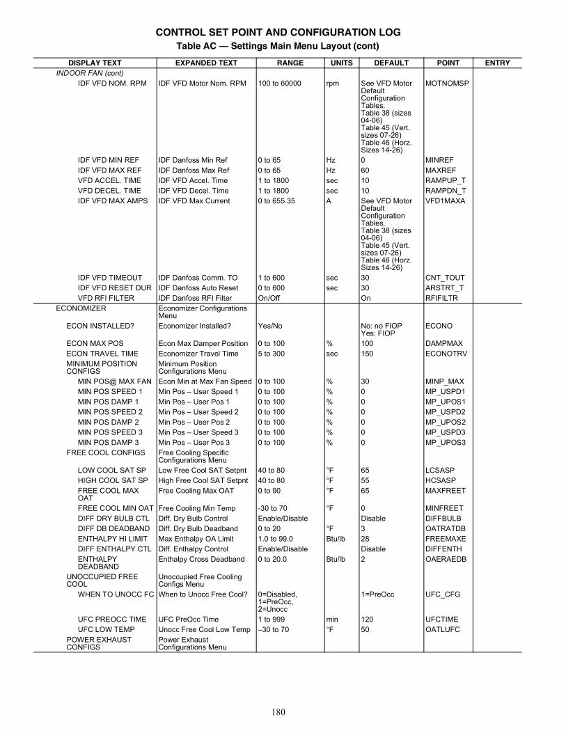
180
INDOOR FAN (cont)IDF VFD NOM. RPM IDF VFD Motor Nom. RPM 100 to 60000 rpm See VFD Motor
Default Configuration Tables.Table 38 (sizes 04-06)Table 45 (Vert. sizes 07-26)Table 46 (Horz. Sizes 14-26)
MOTNOMSP
IDF VFD MIN REF IDF Danfoss Min Ref 0 to 65 Hz 0 MINREFIDF VFD MAX REF IDF Danfoss Max Ref 0 to 65 Hz 60 MAXREFVFD ACCEL. TIME IDF VFD Accel. Time 1 to 1800 sec 10 RAMPUP_TVFD DECEL. TIME IDF VFD Decel. Time 1 to 1800 sec 10 RAMPDN_TIDF VFD MAX AMPS IDF VFD Max Current 0 to 655.35 A See VFD Motor
Default Configuration Tables.Table 38 (sizes 04-06)Table 45 (Vert. sizes 07-26)Table 46 (Horz. Sizes 14-26)
VFD1MAXA
IDF VFD TIMEOUT IDF Danfoss Comm. TO 1 to 600 sec 30 CNT_TOUTIDF VFD RESET DUR IDF Danfoss Auto Reset 0 to 600 sec 30 ARSTRT_TVFD RFI FILTER IDF Danfoss RFI Filter On/Off On RFIFILTR
ECONOMIZER Economizer Configurations Menu
ECON INSTALLED? Economizer Installed? Yes/No No: no FIOPYes: FIOP
ECONO
ECON MAX POS Econ Max Damper Position 0 to 100 % 100 DAMPMAXECON TRAVEL TIME Economizer Travel Time 5 to 300 sec 150 ECONOTRVMINIMUM POSITION CONFIGS
Minimum Position Configurations Menu
MIN POS@ MAX FAN Econ Min at Max Fan Speed 0 to 100 % 30 MINP_MAXMIN POS SPEED 1 Min Pos – User Speed 1 0 to 100 % 0 MP_USPD1MIN POS DAMP 1 Min Pos – User Pos 1 0 to 100 % 0 MP_UPOS1MIN POS SPEED 2 Min Pos – User Speed 2 0 to 100 % 0 MP_USPD2MIN POS DAMP 2 Min Pos – User Pos 2 0 to 100 % 0 MP_UPOS2MIN POS SPEED 3 Min Pos – User Speed 3 0 to 100 % 0 MP_USPD3MIN POS DAMP 3 Min Pos – User Pos 3 0 to 100 % 0 MP_UPOS3
FREE COOL CONFIGS Free Cooling Specific Configurations Menu
LOW COOL SAT SP Low Free Cool SAT Setpnt 40 to 80 °F 65 LCSASPHIGH COOL SAT SP High Free Cool SAT Setpnt 40 to 80 °F 55 HCSASPFREE COOL MAX OAT
Free Cooling Max OAT 0 to 90 °F 65 MAXFREET
FREE COOL MIN OAT Free Cooling Min Temp -30 to 70 °F 0 MINFREETDIFF DRY BULB CTL Diff. Dry Bulb Control Enable/Disable Disable DIFFBULBDIFF DB DEADBAND Diff. Dry Bulb Deadband 0 to 20 °F 3 OATRATDBENTHALPY HI LIMIT Max Enthalpy OA Limit 1.0 to 99.0 Btu/lb 28 FREEMAXEDIFF ENTHALPY CTL Diff. Enthalpy Control Enable/Disable Disable DIFFENTHENTHALPY DEADBAND
Enthalpy Cross Deadband 0 to 20.0 Btu/lb 2 OAERAEDB
UNOCCUPIED FREE COOL
Unoccupied Free Cooling Configs Menu
WHEN TO UNOCC FC When to Unocc Free Cool? 0=Disabled,1=PreOcc,2=Unocc
1=PreOcc UFC_CFG
UFC PREOCC TIME UFC PreOcc Time 1 to 999 min 120 UFCTIMEUFC LOW TEMP Unocc Free Cool Low Temp –30 to 70 °F 50 OATLUFC
POWER EXHAUST CONFIGS
Power Exhaust Configurations Menu
Table AC — Settings Main Menu Layout (cont)
DISPLAY TEXT EXPANDED TEXT RANGE UNITS DEFAULT POINT ENTRY
CONTROL SET POINT AND CONFIGURATION LOG
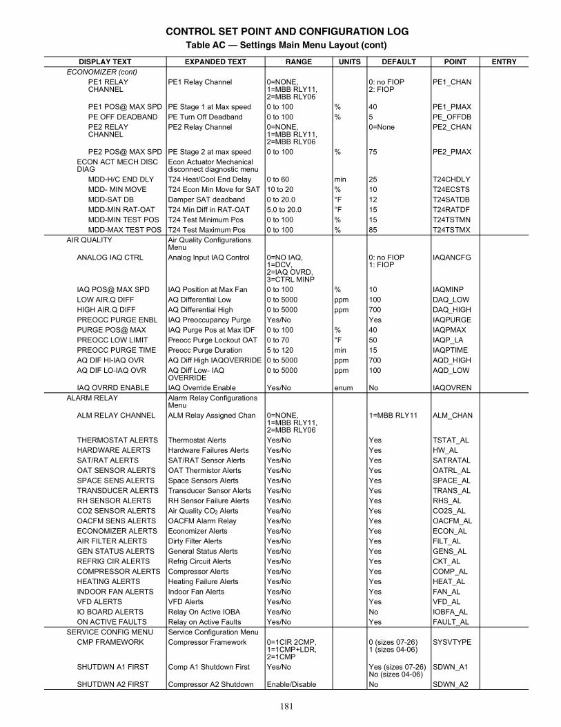
181
ECONOMIZER (cont)PE1 RELAY CHANNEL
PE1 Relay Channel 0=NONE,1=MBB RLY11,2=MBB RLY06
0: no FIOP2: FIOP
PE1_CHAN
PE1 POS@ MAX SPD PE Stage 1 at Max speed 0 to 100 % 40 PE1_PMAXPE OFF DEADBAND PE Turn Off Deadband 0 to 100 % 5 PE_OFFDBPE2 RELAY CHANNEL
PE2 Relay Channel 0=NONE,1=MBB RLY11,2=MBB RLY06
0=None PE2_CHAN
PE2 POS@ MAX SPD PE Stage 2 at max speed 0 to 100 % 75 PE2_PMAXECON ACT MECH DISC DIAG
Econ Actuator Mechanical disconnect diagnostic menu
MDD-H/C END DLY T24 Heat/Cool End Delay 0 to 60 min 25 T24CHDLYMDD- MIN MOVE T24 Econ Min Move for SAT 10 to 20 % 10 T24ECSTSMDD-SAT DB Damper SAT deadband 0 to 20.0 °F 12 T24SATDBMDD-MIN RAT-OAT T24 Min Diff in RAT-OAT 5.0 to 20.0 °F 15 T24RATDFMDD-MIN TEST POS T24 Test Minimum Pos 0 to 100 % 15 T24TSTMNMDD-MAX TEST POS T24 Test Maximum Pos 0 to 100 % 85 T24TSTMX
AIR QUALITY Air Quality Configurations Menu
ANALOG IAQ CTRL Analog Input IAQ Control 0=NO IAQ,1=DCV,2=IAQ OVRD,3=CTRL MINP
0: no FIOP1: FIOP
IAQANCFG
IAQ POS@ MAX SPD IAQ Position at Max Fan 0 to 100 % 10 IAQMINPLOW AIR.Q DIFF AQ Differential Low 0 to 5000 ppm 100 DAQ_LOWHIGH AIR.Q DIFF AQ Differential High 0 to 5000 ppm 700 DAQ_HIGHPREOCC PURGE ENBL IAQ Preoccupancy Purge Yes/No Yes IAQPURGEPURGE POS@ MAX IAQ Purge Pos at Max IDF 0 to 100 % 40 IAQPMAXPREOCC LOW LIMIT Preocc Purge Lockout OAT 0 to 70 °F 50 IAQP_LAPREOCC PURGE TIME Preocc Purge Duration 5 to 120 min 15 IAQPTIMEAQ DIF HI-IAQ OVR AQ Diff High IAQOVERRIDE 0 to 5000 ppm 700 AQD_HIGHAQ DIF LO-IAQ OVR AQ Diff Low- IAQ
OVERRIDE0 to 5000 ppm 100 AQD_LOW
IAQ OVRRD ENABLE IAQ Override Enable Yes/No enum No IAQOVRENALARM RELAY Alarm Relay Configurations
MenuALM RELAY CHANNEL ALM Relay Assigned Chan 0=NONE,
1=MBB RLY11,2=MBB RLY06
1=MBB RLY11 ALM_CHAN
THERMOSTAT ALERTS Thermostat Alerts Yes/No Yes TSTAT_ALHARDWARE ALERTS Hardware Failures Alerts Yes/No Yes HW_ALSAT/RAT ALERTS SAT/RAT Sensor Alerts Yes/No Yes SATRATALOAT SENSOR ALERTS OAT Thermistor Alerts Yes/No Yes OATRL_ALSPACE SENS ALERTS Space Sensors Alerts Yes/No Yes SPACE_ALTRANSDUCER ALERTS Transducer Sensor Alerts Yes/No Yes TRANS_ALRH SENSOR ALERTS RH Sensor Failure Alerts Yes/No Yes RHS_ALCO2 SENSOR ALERTS Air Quality CO2 Alerts Yes/No Yes CO2S_ALOACFM SENS ALERTS OACFM Alarm Relay Yes/No Yes OACFM_ALECONOMIZER ALERTS Economizer Alerts Yes/No Yes ECON_ALAIR FILTER ALERTS Dirty Filter Alerts Yes/No Yes FILT_ALGEN STATUS ALERTS General Status Alerts Yes/No Yes GENS_ALREFRIG CIR ALERTS Refrig Circuit Alerts Yes/No Yes CKT_ALCOMPRESSOR ALERTS Compressor Alerts Yes/No Yes COMP_ALHEATING ALERTS Heating Failure Alerts Yes/No Yes HEAT_ALINDOOR FAN ALERTS Indoor Fan Alerts Yes/No Yes FAN_ALVFD ALERTS VFD Alerts Yes/No Yes VFD_ALIO BOARD ALERTS Relay On Active IOBA Yes/No No IOBFA_ALON ACTIVE FAULTS Relay on Active Faults Yes/No Yes FAULT_AL
SERVICE CONFIG MENU Service Configuration MenuCMP FRAMEWORK Compressor Framework 0=1CIR 2CMP,
1=1CMP+LDR,2=1CMP
0 (sizes 07-26)1 (sizes 04-06)
SYSVTYPE
SHUTDWN A1 FIRST Comp A1 Shutdown First Yes/No Yes (sizes 07-26)No (sizes 04-06)
SDWN_A1
SHUTDWN A2 FIRST Compressor A2 Shutdown Enable/Disable No SDWN_A2
Table AC — Settings Main Menu Layout (cont)
DISPLAY TEXT EXPANDED TEXT RANGE UNITS DEFAULT POINT ENTRY
CONTROL SET POINT AND CONFIGURATION LOG
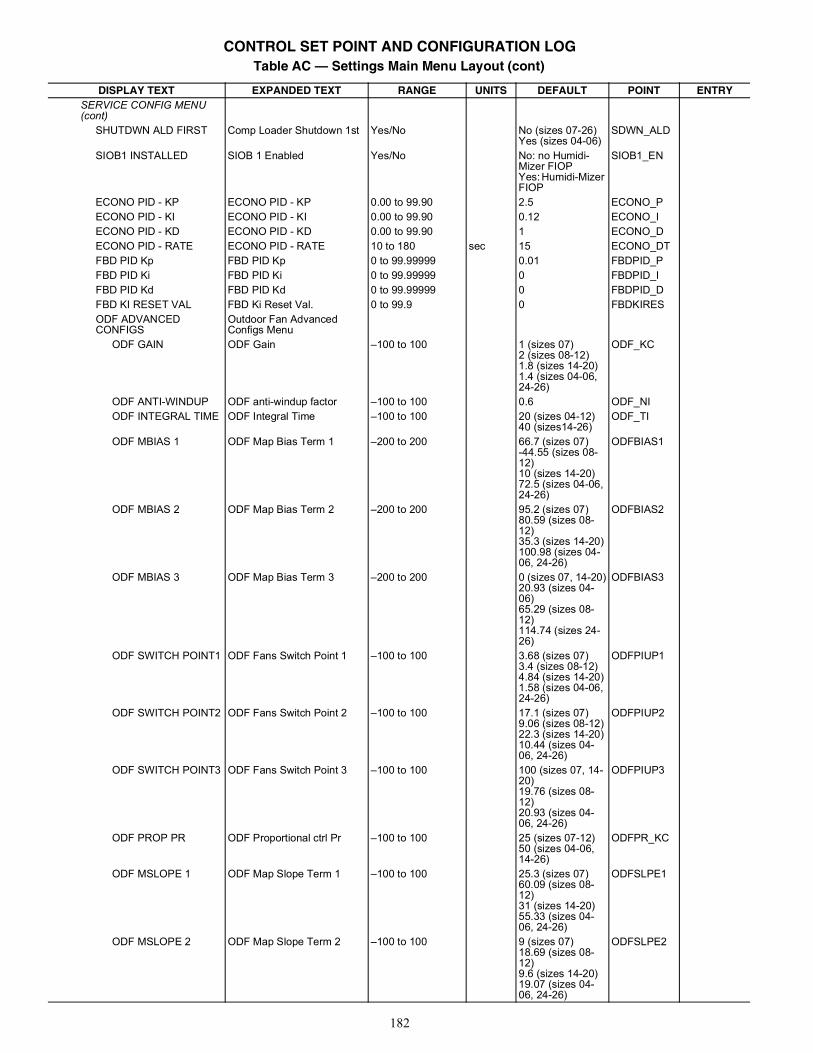
182
SERVICE CONFIG MENU (cont)
SHUTDWN ALD FIRST Comp Loader Shutdown 1st Yes/No No (sizes 07-26)Yes (sizes 04-06)
SDWN_ALD
SIOB1 INSTALLED SIOB 1 Enabled Yes/No No: no Humidi-Mizer FIOPYes: Humidi-Mizer FIOP
SIOB1_EN
ECONO PID - KP ECONO PID - KP 0.00 to 99.90 2.5 ECONO_PECONO PID - KI ECONO PID - KI 0.00 to 99.90 0.12 ECONO_IECONO PID - KD ECONO PID - KD 0.00 to 99.90 1 ECONO_DECONO PID - RATE ECONO PID - RATE 10 to 180 sec 15 ECONO_DTFBD PID Kp FBD PID Kp 0 to 99.99999 0.01 FBDPID_PFBD PID Ki FBD PID Ki 0 to 99.99999 0 FBDPID_IFBD PID Kd FBD PID Kd 0 to 99.99999 0 FBDPID_DFBD KI RESET VAL FBD Ki Reset Val. 0 to 99.9 0 FBDKIRESODF ADVANCED CONFIGS
Outdoor Fan Advanced Configs Menu
ODF GAIN ODF Gain –100 to 100 1 (sizes 07)2 (sizes 08-12)1.8 (sizes 14-20)1.4 (sizes 04-06,24-26)
ODF_KC
ODF ANTI-WINDUP ODF anti-windup factor –100 to 100 0.6 ODF_NIODF INTEGRAL TIME ODF Integral Time –100 to 100 20 (sizes 04-12)
40 (sizes14-26)ODF_TI
ODF MBIAS 1 ODF Map Bias Term 1 –200 to 200 66.7 (sizes 07)-44.55 (sizes 08-12)10 (sizes 14-20)72.5 (sizes 04-06,24-26)
ODFBIAS1
ODF MBIAS 2 ODF Map Bias Term 2 –200 to 200 95.2 (sizes 07)80.59 (sizes 08-12)35.3 (sizes 14-20)100.98 (sizes 04-06, 24-26)
ODFBIAS2
ODF MBIAS 3 ODF Map Bias Term 3 –200 to 200 0 (sizes 07, 14-20)20.93 (sizes 04-06)65.29 (sizes 08-12)114.74 (sizes 24-26)
ODFBIAS3
ODF SWITCH POINT1 ODF Fans Switch Point 1 –100 to 100 3.68 (sizes 07)3.4 (sizes 08-12)4.84 (sizes 14-20)1.58 (sizes 04-06,24-26)
ODFPIUP1
ODF SWITCH POINT2 ODF Fans Switch Point 2 –100 to 100 17.1 (sizes 07)9.06 (sizes 08-12)22.3 (sizes 14-20)10.44 (sizes 04-06, 24-26)
ODFPIUP2
ODF SWITCH POINT3 ODF Fans Switch Point 3 –100 to 100 100 (sizes 07, 14-20)19.76 (sizes 08-12)20.93 (sizes 04-06, 24-26)
ODFPIUP3
ODF PROP PR ODF Proportional ctrl Pr –100 to 100 25 (sizes 07-12)50 (sizes 04-06,14-26)
ODFPR_KC
ODF MSLOPE 1 ODF Map Slope Term 1 –100 to 100 25.3 (sizes 07)60.09 (sizes 08-12)31 (sizes 14-20)55.33 (sizes 04-06, 24-26)
ODFSLPE1
ODF MSLOPE 2 ODF Map Slope Term 2 –100 to 100 9 (sizes 07)18.69 (sizes 08-12)9.6 (sizes 14-20)19.07 (sizes 04-06, 24-26)
ODFSLPE2
Table AC — Settings Main Menu Layout (cont)
DISPLAY TEXT EXPANDED TEXT RANGE UNITS DEFAULT POINT ENTRY
CONTROL SET POINT AND CONFIGURATION LOG
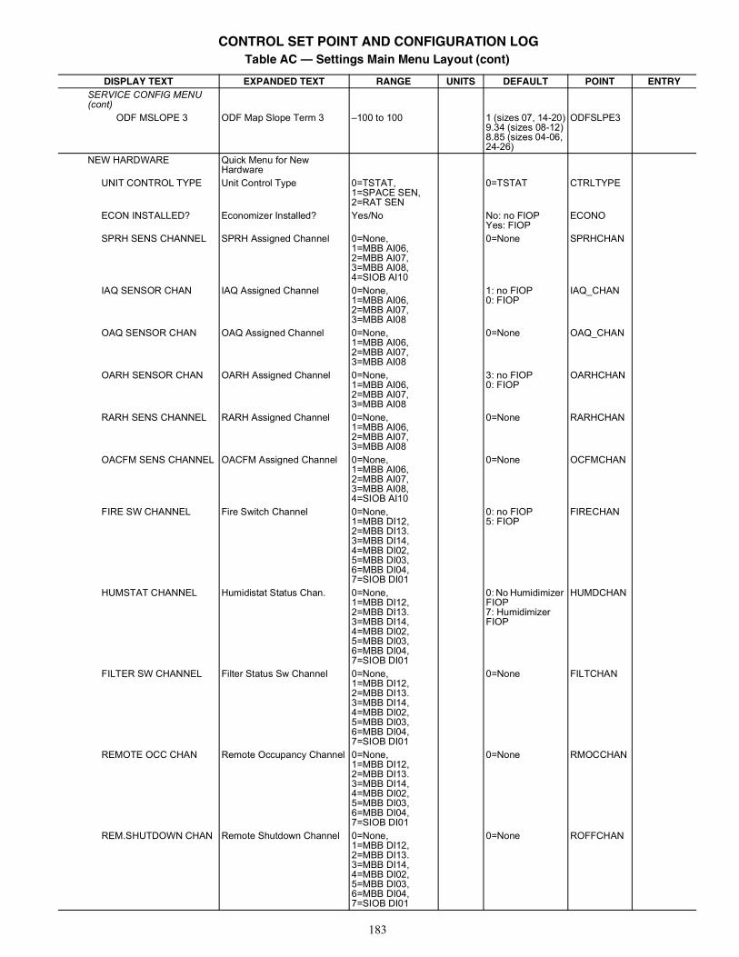
183
SERVICE CONFIG MENU (cont)
ODF MSLOPE 3 ODF Map Slope Term 3 –100 to 100 1 (sizes 07, 14-20)9.34 (sizes 08-12)8.85 (sizes 04-06, 24-26)
ODFSLPE3
NEW HARDWARE Quick Menu for New Hardware
UNIT CONTROL TYPE Unit Control Type 0=TSTAT,1=SPACE SEN,2=RAT SEN
0=TSTAT CTRLTYPE
ECON INSTALLED? Economizer Installed? Yes/No No: no FIOPYes: FIOP
ECONO
SPRH SENS CHANNEL SPRH Assigned Channel 0=None,1=MBB AI06,2=MBB AI07,3=MBB AI08,4=SIOB AI10
0=None SPRHCHAN
IAQ SENSOR CHAN IAQ Assigned Channel 0=None,1=MBB AI06,2=MBB AI07,3=MBB AI08
1: no FIOP0: FIOP
IAQ_CHAN
OAQ SENSOR CHAN OAQ Assigned Channel 0=None,1=MBB AI06,2=MBB AI07,3=MBB AI08
0=None OAQ_CHAN
OARH SENSOR CHAN OARH Assigned Channel 0=None,1=MBB AI06,2=MBB AI07,3=MBB AI08
3: no FIOP0: FIOP
OARHCHAN
RARH SENS CHANNEL RARH Assigned Channel 0=None,1=MBB AI06,2=MBB AI07,3=MBB AI08
0=None RARHCHAN
OACFM SENS CHANNEL OACFM Assigned Channel 0=None,1=MBB AI06,2=MBB AI07,3=MBB AI08,4=SIOB AI10
0=None OCFMCHAN
FIRE SW CHANNEL Fire Switch Channel 0=None,1=MBB DI12,2=MBB DI13.3=MBB DI14,4=MBB DI02,5=MBB DI03,6=MBB DI04,7=SIOB DI01
0: no FIOP5: FIOP
FIRECHAN
HUMSTAT CHANNEL Humidistat Status Chan. 0=None,1=MBB DI12,2=MBB DI13.3=MBB DI14,4=MBB DI02,5=MBB DI03,6=MBB DI04,7=SIOB DI01
0: No Humidimizer FIOP7: Humidimizer FIOP
HUMDCHAN
FILTER SW CHANNEL Filter Status Sw Channel 0=None,1=MBB DI12,2=MBB DI13.3=MBB DI14,4=MBB DI02,5=MBB DI03,6=MBB DI04,7=SIOB DI01
0=None FILTCHAN
REMOTE OCC CHAN Remote Occupancy Channel 0=None,1=MBB DI12,2=MBB DI13.3=MBB DI14,4=MBB DI02,5=MBB DI03,6=MBB DI04,7=SIOB DI01
0=None RMOCCHAN
REM.SHUTDOWN CHAN Remote Shutdown Channel 0=None,1=MBB DI12,2=MBB DI13.3=MBB DI14,4=MBB DI02,5=MBB DI03,6=MBB DI04,7=SIOB DI01
0=None ROFFCHAN
Table AC — Settings Main Menu Layout (cont)
DISPLAY TEXT EXPANDED TEXT RANGE UNITS DEFAULT POINT ENTRY
CONTROL SET POINT AND CONFIGURATION LOG
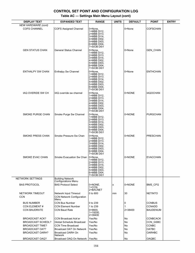
184
NEW HARDWARE (cont)COFS CHANNEL COFS Assigned Channel 0=None,
1=MBB DI12,2=MBB DI13.3=MBB DI14,4=MBB DI02,5=MBB DI03,6=MBB DI04,7=SIOB DI01
0=None COFSCHAN
GEN STATUS CHAN General Status Channel 0=None,1=MBB DI12,2=MBB DI13.3=MBB DI14,4=MBB DI02,5=MBB DI03,6=MBB DI04,7=SIOB DI01
0=None GEN_CHAN
ENTHALPY SW CHAN Enthalpy Sw Channel 0=None,1=MBB DI12,2=MBB DI13.3=MBB DI14,4=MBB DI02,5=MBB DI03,6=MBB DI04,7=SIOB DI01
0=None ENTHCHAN
IAQ OVERIDE SW CH IAQ override sw channel 0=None,1=MBB DI12,2=MBB DI13.3=MBB DI14,4=MBB DI02,5=MBB DI03,6=MBB DI04,7=SIOB DI01
0=NONE IAQOCHAN
SMOKE PURGE CHAN Smoke Purge Sw Channel 0=None,1=MBB DI12,2=MBB DI13.3=MBB DI14,4=MBB DI02,5=MBB DI03,6=MBB DI04,7=SIOB DI01
0=NONE PURGCHAN
SMOKE PRESS CHAN Smoke Pressure Sw Chan 0=None,1=MBB DI12,2=MBB DI13.3=MBB DI14,4=MBB DI02,5=MBB DI03,6=MBB DI04,7=SIOB DI01
0=NONE PRESCHAN
SMOKE EVAC CHAN Smoke Evacuation Sw Chan 0=None,1=MBB DI12,2=MBB DI13.3=MBB DI14,4=MBB DI02,5=MBB DI03,6=MBB DI04,7=SIOB DI01
0=NONE EVACCHAN
NETWORK SETTINGS Building Network Configurations Menu
BAS PROTOCOL BAS Protocol Select 0=NONE,1=CCN,2=BACNET
x 0=NONE BMS_CFG
NETWORK TIMEOUT Network Input Timeout 0 to 600 min 30 NETINTOCCN CCN Network Configuration
MenuBUS NUMBER CCN Bus Number 0 to 239 0 CCNBUSCCN ELEMENT # CCN Element Number 1 to 239 1 CCNADDCCN BAUDRATE CCN Baud Rate 0=9600,
1=19200,2=38400
2=38400 BAUDENUM
BROADCAST ACK? CCN Broadcast Ack’er Yes/No No CCNBCACKBROADCAST SCHEDL? Global Schedule Broadcast Yes/No No CCN_GSBCBROADCAST TIME? CCN Time Broadcast Yes/No No CCNBCBROADCAST OAT? Broadcast OAT On Network Yes/No No OATBCBROADCAST OARH? Broadcast OARH On
NetworkYes/No No OARHBC
BROADCAST OAQ? Broadcast OAQ On Network Yes/No No OAQBC
Table AC — Settings Main Menu Layout (cont)
DISPLAY TEXT EXPANDED TEXT RANGE UNITS DEFAULT POINT ENTRY
CONTROL SET POINT AND CONFIGURATION LOG
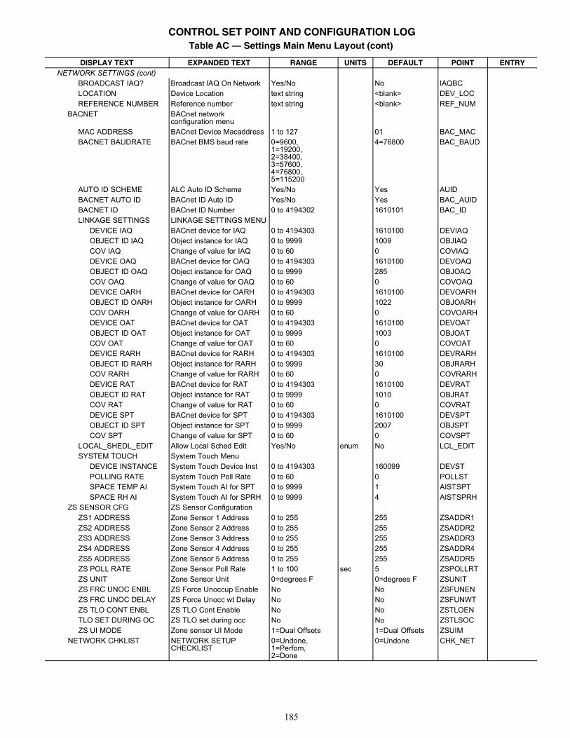
185
NETWORK SETTINGS (cont)BROADCAST IAQ? Broadcast IAQ On Network Yes/No No IAQBCLOCATION Device Location text string <blank> DEV_LOCREFERENCE NUMBER Reference number text string <blank> REF_NUM
BACNET BACnet network configuration menu
MAC ADDRESS BACnet Device Macaddress 1 to 127 01 BAC_MACBACNET BAUDRATE BACnet BMS baud rate 0=9600,
1=19200,2=38400,3=57600,4=76800,5=115200
4=76800 BAC_BAUD
AUTO ID SCHEME ALC Auto ID Scheme Yes/No Yes AUIDBACNET AUTO ID BACnet ID Auto ID Yes/No Yes BAC_AUIDBACNET ID BACnet ID Number 0 to 4194302 1610101 BAC_IDLINKAGE SETTINGS LINKAGE SETTINGS MENU
DEVICE IAQ BACnet device for IAQ 0 to 4194303 1610100 DEVIAQOBJECT ID IAQ Object instance for IAQ 0 to 9999 1009 OBJIAQCOV IAQ Change of value for IAQ 0 to 60 0 COVIAQDEVICE OAQ BACnet device for OAQ 0 to 4194303 1610100 DEVOAQOBJECT ID OAQ Object instance for OAQ 0 to 9999 285 OBJOAQCOV OAQ Change of value for OAQ 0 to 60 0 COVOAQDEVICE OARH BACnet device for OARH 0 to 4194303 1610100 DEVOARHOBJECT ID OARH Object instance for OARH 0 to 9999 1022 OBJOARHCOV OARH Change of value for OARH 0 to 60 0 COVOARHDEVICE OAT BACnet device for OAT 0 to 4194303 1610100 DEVOATOBJECT ID OAT Object instance for OAT 0 to 9999 1003 OBJOATCOV OAT Change of value for OAT 0 to 60 0 COVOATDEVICE RARH BACnet device for RARH 0 to 4194303 1610100 DEVRARHOBJECT ID RARH Object instance for RARH 0 to 9999 30 OBJRARHCOV RARH Change of value for RARH 0 to 60 0 COVRARHDEVICE RAT BACnet device for RAT 0 to 4194303 1610100 DEVRATOBJECT ID RAT Object instance for RAT 0 to 9999 1010 OBJRATCOV RAT Change of value for RAT 0 to 60 0 COVRATDEVICE SPT BACnet device for SPT 0 to 4194303 1610100 DEVSPTOBJECT ID SPT Object instance for SPT 0 to 9999 2007 OBJSPTCOV SPT Change of value for SPT 0 to 60 0 COVSPT
LOCAL_SHEDL_EDIT Allow Local Sched Edit Yes/No enum No LCL_EDITSYSTEM TOUCH System Touch Menu
DEVICE INSTANCE System Touch Device Inst 0 to 4194303 160099 DEVSTPOLLING RATE System Touch Poll Rate 0 to 60 0 POLLSTSPACE TEMP AI System Touch AI for SPT 0 to 9999 1 AISTSPTSPACE RH AI System Touch AI for SPRH 0 to 9999 4 AISTSPRH
ZS SENSOR CFG ZS Sensor ConfigurationZS1 ADDRESS Zone Sensor 1 Address 0 to 255 255 ZSADDR1ZS2 ADDRESS Zone Sensor 2 Address 0 to 255 255 ZSADDR2ZS3 ADDRESS Zone Sensor 3 Address 0 to 255 255 ZSADDR3ZS4 ADDRESS Zone Sensor 4 Address 0 to 255 255 ZSADDR4ZS5 ADDRESS Zone Sensor 5 Address 0 to 255 255 ZSADDR5ZS POLL RATE Zone Sensor Poll Rate 1 to 100 sec 5 ZSPOLLRTZS UNIT Zone Sensor Unit 0=degrees F 0=degrees F ZSUNITZS FRC UNOC ENBL ZS Force Unoccup Enable No No ZSFUNENZS FRC UNOC DELAY ZS Force Unocc wt Delay No No ZSFUNWTZS TLO CONT ENBL ZS TLO Cont Enable No No ZSTLOENTLO SET DURING OC ZS TLO set during occ No No ZSTLSOCZS UI MODE Zone sensor UI Mode 1=Dual Offsets 1=Dual Offsets ZSUIM
NETWORK CHKLIST NETWORK SETUP CHECKLIST
0=Undone,1=Perfom,2=Done
0=Undone CHK_NET
Table AC — Settings Main Menu Layout (cont)
DISPLAY TEXT EXPANDED TEXT RANGE UNITS DEFAULT POINT ENTRY
CONTROL SET POINT AND CONFIGURATION LOG
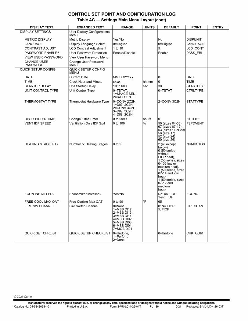
Manufacturer reserves the right to discontinue, or change at any time, specifications or designs without notice and without incurring obligations.Catalog No. 04-53480384-01 Printed in U.S.A. Form S-VU-LC-4-26-04T Pg 186 10-21 Replaces: S-VU-LC-4-26-03T
© 2021 Carrier
DISPLAY SETTINGS User Display Configurations Menu
METRIC DISPLAY Metric Display Yes/No No DISPUNITLANGUAGE Display Language Select 0=English 0=English LANGUAGECONTRAST ADJUST LCD Contrast Adjustment 1 to 10 5 LCD_CONTPASSWORD ENABLE? User Password Protection Enable/Disable Enable PASS_EBLVIEW USER PASSWORD View User Password MenuCHANGE USER PASSWORD
Change User Password Menu
QUICK SETUP CONFIG QUICK SETUP CONFIG MENU
DATE Current Date MM/DD/YYYY 0 DATETIME Clock Hour and Minute xx:xx hh.mm 0 TIMESTARTUP DELAY Unit Startup Delay 10 to 600 sec 30 STARTDLYUNIT CONTROL TYPE Unit Control Type 0=TSTAT,
1=SPACE SEN,2=RAT SEN
0=TSTAT CTRLTYPE
THERMOSTAT TYPE Thermostat Hardware Type 0=CONV 2C2H,1=DIGI 2C2H,2=CONV 3C2H,3=DIGI 3C2H4=DIGI 2C2H
2=CONV 3C2H STATTYPE
DIRTY FILTER TIME Change Filter Timer 0 to 9999 hours 0 FILTLIFEVENT IDF SPEED Ventilation Only IDF Spd 0 to 100 % 50 (sizes 04-06)
67 (sizes 07-12)53 (sizes 14 or 20)56 (size 17)52 (size 24)60 (size 26)
FSPDVENT
HEATING STAGE QTY Number of Heating Stages 0 to 2 2 (all except below):0 (50 series withoutFIOP heat),1 (50 series, sizes 04-06 low or medium heat),1 (50 series, sizes07-14 and low heat),1 (50 series, sizes07-12 and mediumheat)
NUMHSTGS
ECON INSTALLED? Economizer Installed? Yes/No No: no FIOPYes: FIOP
ECONO
FREE COOL MAX OAT Free Cooling Max OAT 0 to 90 °F 65FIRE SW CHANNEL Fire Switch Channel 0=None,
1=MBB DI12,2=MBB DI13.3=MBB DI14,4=MBB DI02,5=MBB DI03,6=MBB DI04,7=SIOB DI01
0: No FIOP5: FIOP
FIRECHAN
QUICK SET CHKLIST QUICK SETUP CHECKLIST 0=Undone,1=Perfom,2=Done
0=Undone CHK_QUIK
Table AC — Settings Main Menu Layout (cont)
DISPLAY TEXT EXPANDED TEXT RANGE UNITS DEFAULT POINT ENTRY
CONTROL SET POINT AND CONFIGURATION LOG
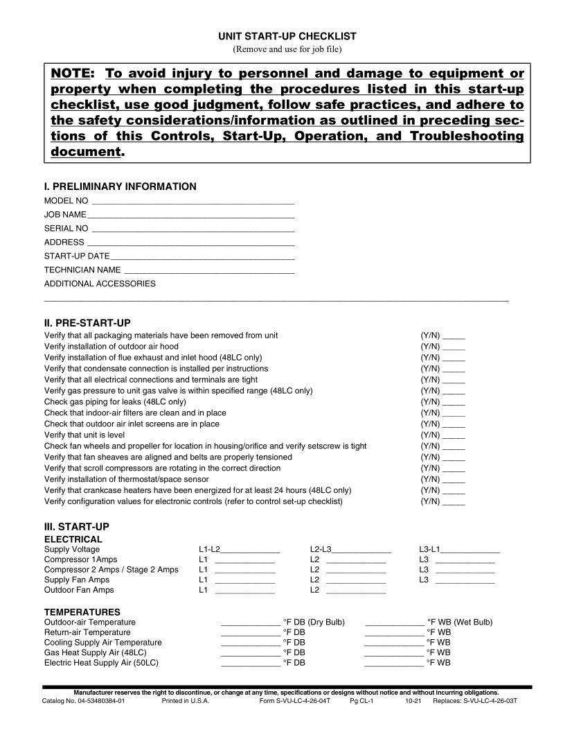
Manufacturer reserves the right to discontinue, or change at any time, specifications or designs without notice and without incurring obligations.Catalog No. 04-53480384-01 Printed in U.S.A. Form S-VU-LC-4-26-04T Pg CL-1 10-21 Replaces: S-VU-LC-4-26-03T
UNIT START-UP CHECKLIST(Remove and use for job file)
I. PRELIMINARY INFORMATIONMODEL NO ____________________________________________
JOB NAME_____________________________________________
SERIAL NO ____________________________________________
ADDRESS _____________________________________________
START-UP DATE________________________________________
TECHNICIAN NAME _____________________________________
ADDITIONAL ACCESSORIES
_____________________________________________________________________________________________________
II. PRE-START-UPVerify that all packaging materials have been removed from unit (Y/N) _____Verify installation of outdoor air hood (Y/N) _____Verify installation of flue exhaust and inlet hood (48LC only) (Y/N) _____Verify that condensate connection is installed per instructions (Y/N) _____Verify that all electrical connections and terminals are tight (Y/N) _____Verify gas pressure to unit gas valve is within specified range (48LC only) (Y/N) _____Check gas piping for leaks (48LC only) (Y/N) _____Check that indoor-air filters are clean and in place (Y/N) _____Check that outdoor air inlet screens are in place (Y/N) _____Verify that unit is level (Y/N) _____Check fan wheels and propeller for location in housing/orifice and verify setscrew is tight (Y/N) _____Verify that fan sheaves are aligned and belts are properly tensioned (Y/N) _____Verify that scroll compressors are rotating in the correct direction (Y/N) _____Verify installation of thermostat/space sensor (Y/N) _____Verify that crankcase heaters have been energized for at least 24 hours (48LC only) (Y/N) _____Verify configuration values for electronic controls (refer to control set-up checklist) (Y/N) _____
III. START-UPELECTRICALSupply Voltage L1-L2_____________ L2-L3_____________ L3-L1_____________Compressor 1Amps L1 _____________ L2 _____________ L3 _____________Compressor 2 Amps / Stage 2 Amps L1 _____________ L2 _____________ L3 _____________Supply Fan Amps L1 _____________ L2 _____________ L3 _____________Outdoor Fan Amps L1 _____________ L2 _____________
TEMPERATURESOutdoor-air Temperature _____________ °F DB (Dry Bulb) _____________ °F WB (Wet Bulb)Return-air Temperature _____________ °F DB _____________ °F WB Cooling Supply Air Temperature _____________ °F DB _____________ °F WBGas Heat Supply Air (48LC) _____________ °F DB _____________ °F WBElectric Heat Supply Air (50LC) _____________ °F DB _____________ °F WB
NOTE: To avoid injury to personnel and damage to equipment orproperty when completing the procedures listed in this start-upchecklist, use good judgment, follow safe practices, and adhere tothe safety considerations/information as outlined in preceding sec-tions of this Controls, Start-Up, Operation, and Troubleshootingdocument.
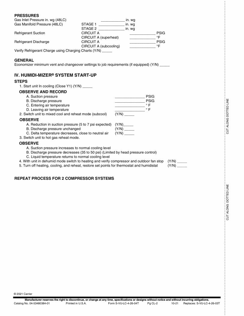
Manufacturer reserves the right to discontinue, or change at any time, specifications or designs without notice and without incurring obligations.Catalog No. 04-53480384-01 Printed in U.S.A. Form S-VU-LC-4-26-04T Pg CL-2 10-21 Replaces: S-VU-LC-4-26-03T
© 2021 Carrier
- -
- -
- -
- -
- -
- -
- -
- -
- -
- -
- -
- -
- -
- -
- -
- -
- -
- -
- -
- -
- -
- -
- -
- -
- -
- -
- -
- -
- -
- -
- -
- -
- -
- -
- -
- -
- -
- -
- -
- -
- -
- -
- -
- -
- -
- -
- -
- -
- -
- -
- -
- -
- -
- -
- -
- -
- -
- -
- -
- -
- -
- -
- -
- -
- -
- -
- -
- -
- -
- -
- -
- -
- -
- -
- -
- -
- -
- -
- -
- -
- -
- -
- -
- -
- -
- -
- -
-- -
- -
- -
- -
- -
- -
- -
- -
- -
- -
C
UT
ALO
NG
DO
TT
ED
LIN
EC
UT
ALO
NG
DO
TT
ED
LIN
E
PRESSURESGas Inlet Pressure in. wg (48LC) ____________ in. wgGas Manifold Pressure (48LC) STAGE 1 _____________ in. wg
STAGE 2 _____________ in. wgRefrigerant Suction CIRCUIT A _____________ PSIG
CIRCUIT A (superheat) _____________ °FRefrigerant Discharge CIRCUIT A _____________ PSIG
CIRCUIT A (subcooling) _____________ °FVerify Refrigerant Charge using Charging Charts (Y/N) _____
GENERALEconomizer minimum vent and changeover settings to job requirements (if equipped) (Y/N) _____
IV. HUMIDI-MIZER® SYSTEM START-UP STEPS
1. Start unit In cooling (Close Y1) (Y/N) _____
OBSERVE AND RECORDA. Suction pressure _______________ PSIGB. Discharge pressure _______________ PSIGC. Entering air temperature _______________ ° FD. Leaving air temperature _______________ ° F
2. Switch unit to mixed cool and reheat mode (subcool) (Y/N) _____
OBSERVEA. Reduction in suction pressure (5 to 7 psi expected) (Y/N)_____B. Discharge pressure unchanged (Y/N) _____C. Delta temperature decreases, close to neutral air (Y/N) _____
3. Switch unit to hot gas reheat mode.
OBSERVEA. Suction pressure increases to normal cooling levelB. Discharge pressure decreases (35 to 50 psi) (Limited by head pressure control)C. Liquid temperature returns to normal cooling level
4. With unit in dehumid mode switch to heating and verify compressor and outdoor fan stop (Y/N) _____5. Turn off heating, cooling, and reheat, restore set points for thermostat and humidistat (Y/N) _____
REPEAT PROCESS FOR 2 COMPRESSOR SYSTEMS
Related Documents