1 Controls, Start-- Up, Operation and Troubleshooting 48/50LC 04---26 Single Package Rooftop Units with SystemVu™ Controls Version 2.X and Puronr (R---410A) Refrigerant C150173 IMPORTANT: This literature covers 48/50LC 04--26 models with SystemVu controls version 2.X (factory--installed option). TABLE OF CONTENTS Page SAFETY CONSIDERATIONS 2 ......................... GENERAL 3 ......................................... Conventions Used in This Manual 3 ...................... BASIC CONTROL USAGE 3 ........................... SystemVu Control 3 .................................. SystemVu Interface 3 ................................. Accessory Navigatort Display 4 ........................ System Pilott and Touch Pilott Devices 5 ................ CCN Tables and Display 5 ............................. START--UP 6 ......................................... Unit Preparation 6 .................................... Refrigerant Service Ports 6 ............................. Crankcase Heater 6 ................................... Compressor Rotation 6 ................................ Power Supply 6 ..................................... Internal Wiring 6 ..................................... Evaporator Fan 6 .................................... Condenser Fans and Motors 7 ........................... Return--Air Filters 7 .................................. Outdoor--Air Inlet Screens 7 ............................ Accessory Installation 7 ............................... Gas Heat (48LC) 8 ................................... CONTROLS QUICK SET--UP 9 ......................... Control Set Point and Confirmation Log 9 ................. Initial Startup 9 ...................................... Thermostat Control 9 ................................. Space Temperature Sensor Control -- Direct Wired (T--55 or T--56 or T--59) 9 ............................. Space Humidistat Control 9 ............................ Relative Humidity Sensor Control 9 ...................... CCN Communication 10 .............................. CCN Linkage Control 10 .............................. System Pilott -- Communication Space Sensor 10 .......... Accessories 10 ......................................

Welcome message from author
This document is posted to help you gain knowledge. Please leave a comment to let me know what you think about it! Share it to your friends and learn new things together.
Transcript

1
Controls, Start--Up, Operationand Troubleshooting
48/50LC 04---26Single Package Rooftop Unitswith SystemVu™ Controls Version 2.Xand Puronr (R---410A) Refrigerant
C150173IMPORTANT: This literature covers 48/50LC 04--26 models with SystemVu controls version 2.X (factory--installed option).
TABLE OF CONTENTSPage
SAFETY CONSIDERATIONS 2. . . . . . . . . . . . . . . . . . . . . . . . .
GENERAL 3. . . . . . . . . . . . . . . . . . . . . . . . . . . . . . . . . . . . . . . . .
Conventions Used in This Manual 3. . . . . . . . . . . . . . . . . . . . . .
BASIC CONTROL USAGE 3. . . . . . . . . . . . . . . . . . . . . . . . . . .
SystemVu Control 3. . . . . . . . . . . . . . . . . . . . . . . . . . . . . . . . . .
SystemVu Interface 3. . . . . . . . . . . . . . . . . . . . . . . . . . . . . . . . .
Accessory Navigatort Display 4. . . . . . . . . . . . . . . . . . . . . . . .
System Pilott and Touch Pilott Devices 5. . . . . . . . . . . . . . . .
CCN Tables and Display 5. . . . . . . . . . . . . . . . . . . . . . . . . . . . .
START--UP 6. . . . . . . . . . . . . . . . . . . . . . . . . . . . . . . . . . . . . . . . .
Unit Preparation 6. . . . . . . . . . . . . . . . . . . . . . . . . . . . . . . . . . . .
Refrigerant Service Ports 6. . . . . . . . . . . . . . . . . . . . . . . . . . . . .
Crankcase Heater 6. . . . . . . . . . . . . . . . . . . . . . . . . . . . . . . . . . .
Compressor Rotation 6. . . . . . . . . . . . . . . . . . . . . . . . . . . . . . . .
Power Supply 6. . . . . . . . . . . . . . . . . . . . . . . . . . . . . . . . . . . . .
Internal Wiring 6. . . . . . . . . . . . . . . . . . . . . . . . . . . . . . . . . . . . .
Evaporator Fan 6. . . . . . . . . . . . . . . . . . . . . . . . . . . . . . . . . . . .
Condenser Fans and Motors 7. . . . . . . . . . . . . . . . . . . . . . . . . . .
Return--Air Filters 7. . . . . . . . . . . . . . . . . . . . . . . . . . . . . . . . . .
Outdoor--Air Inlet Screens 7. . . . . . . . . . . . . . . . . . . . . . . . . . . .
Accessory Installation 7. . . . . . . . . . . . . . . . . . . . . . . . . . . . . . .
Gas Heat (48LC) 8. . . . . . . . . . . . . . . . . . . . . . . . . . . . . . . . . . .
CONTROLS QUICK SET--UP 9. . . . . . . . . . . . . . . . . . . . . . . . .
Control Set Point and Confirmation Log 9. . . . . . . . . . . . . . . . .
Initial Startup 9. . . . . . . . . . . . . . . . . . . . . . . . . . . . . . . . . . . . . .
Thermostat Control 9. . . . . . . . . . . . . . . . . . . . . . . . . . . . . . . . .
Space Temperature Sensor Control -- Direct Wired(T--55 or T--56 or T--59) 9. . . . . . . . . . . . . . . . . . . . . . . . . . . . .
Space Humidistat Control 9. . . . . . . . . . . . . . . . . . . . . . . . . . . .
Relative Humidity Sensor Control 9. . . . . . . . . . . . . . . . . . . . . .
CCN Communication 10. . . . . . . . . . . . . . . . . . . . . . . . . . . . . .
CCN Linkage Control 10. . . . . . . . . . . . . . . . . . . . . . . . . . . . . .
System Pilott -- Communication Space Sensor 10. . . . . . . . . .
Accessories 10. . . . . . . . . . . . . . . . . . . . . . . . . . . . . . . . . . . . . .

2
Programming Operating Schedules 10. . . . . . . . . . . . . . . . . . . .
SERVICE TEST 11. . . . . . . . . . . . . . . . . . . . . . . . . . . . . . . . . . . .
Independent Outputs 11. . . . . . . . . . . . . . . . . . . . . . . . . . . . . . .
Fan Test 11. . . . . . . . . . . . . . . . . . . . . . . . . . . . . . . . . . . . . . . . .
Cooling Test 11. . . . . . . . . . . . . . . . . . . . . . . . . . . . . . . . . . . . .
Heating Test 11. . . . . . . . . . . . . . . . . . . . . . . . . . . . . . . . . . . . . .
Automatic Test 12. . . . . . . . . . . . . . . . . . . . . . . . . . . . . . . . . . . .
THIRD PARTY CONTROL 12. . . . . . . . . . . . . . . . . . . . . . . . . .
Cooling/Heating Control 12. . . . . . . . . . . . . . . . . . . . . . . . . . . .
Dehumidification Control 12. . . . . . . . . . . . . . . . . . . . . . . . . . .
Remote Occupancy 12. . . . . . . . . . . . . . . . . . . . . . . . . . . . . . . .
Remote Shutdown 12. . . . . . . . . . . . . . . . . . . . . . . . . . . . . . . . .
Alarm Output 12. . . . . . . . . . . . . . . . . . . . . . . . . . . . . . . . . . . . .
Economizer Damper Control 12. . . . . . . . . . . . . . . . . . . . . . . . .
CONTROLS OPERATION 12. . . . . . . . . . . . . . . . . . . . . . . . . . .
Display Configuration 12. . . . . . . . . . . . . . . . . . . . . . . . . . . . . .
Unit Configuration 13. . . . . . . . . . . . . . . . . . . . . . . . . . . . . . . . .
General Operation 13. . . . . . . . . . . . . . . . . . . . . . . . . . . . . . . . .
Demand Determination 14. . . . . . . . . . . . . . . . . . . . . . . . . . . . .
Occupancy Determination 15. . . . . . . . . . . . . . . . . . . . . . . . . . .
Indoor Fan Operation 16. . . . . . . . . . . . . . . . . . . . . . . . . . . . . . .
Cooling Operation 17. . . . . . . . . . . . . . . . . . . . . . . . . . . . . . . . .
Optional Humidi--MiZerR Dehumidification System 19. . . . . .
Indoor Fan Based Dehumidification 22. . . . . . . . . . . . . . . . . . .
Heating Operation 22. . . . . . . . . . . . . . . . . . . . . . . . . . . . . . . . .
Supply Air Tempering 24. . . . . . . . . . . . . . . . . . . . . . . . . . . . . .
Economizer Operation 24. . . . . . . . . . . . . . . . . . . . . . . . . . . . . .
Power Exhaust 26. . . . . . . . . . . . . . . . . . . . . . . . . . . . . . . . . . . .
Indoor Air Quality (IAQ) 26. . . . . . . . . . . . . . . . . . . . . . . . . . . .
Pre--occupancy Purge 27. . . . . . . . . . . . . . . . . . . . . . . . . . . . . . .
Temperature Compensated Start 27. . . . . . . . . . . . . . . . . . . . . . .
Linkage 28. . . . . . . . . . . . . . . . . . . . . . . . . . . . . . . . . . . . . . . . .
Carrier Comfort NetworkR (CCN) Operation 28. . . . . . . . . . . .
BACnet Network Operation 28. . . . . . . . . . . . . . . . . . . . . . . . .
Alarm Handling 28. . . . . . . . . . . . . . . . . . . . . . . . . . . . . . . . . . .
TROUBLESHOOTING 28. . . . . . . . . . . . . . . . . . . . . . . . . . . . . .
Complete Unit Stoppage 29. . . . . . . . . . . . . . . . . . . . . . . . . . . .
Restart Procedure 29. . . . . . . . . . . . . . . . . . . . . . . . . . . . . . . . . .
Faults and Alerts 29. . . . . . . . . . . . . . . . . . . . . . . . . . . . . . . . . .
Control Module Communication 36. . . . . . . . . . . . . . . . . . . . . .
Communication Failures 36. . . . . . . . . . . . . . . . . . . . . . . . . . . .
Cooling Troubleshooting 37. . . . . . . . . . . . . . . . . . . . . . . . . . . .
Humidi--MiZer System Troubleshooting 38. . . . . . . . . . . . . . . .
Economizer Troubleshooting 40. . . . . . . . . . . . . . . . . . . . . . . . .
Heating Troubleshooting 41. . . . . . . . . . . . . . . . . . . . . . . . . . . .
Phase Protection 44. . . . . . . . . . . . . . . . . . . . . . . . . . . . . . . . . .
Thermistor Troubleshooting 44. . . . . . . . . . . . . . . . . . . . . . . . .
Sensor Trim 44. . . . . . . . . . . . . . . . . . . . . . . . . . . . . . . . . . . . . .
Transducer Troubleshooting 44. . . . . . . . . . . . . . . . . . . . . . . . .
MAJOR SYSTEM COMPONENTS 49. . . . . . . . . . . . . . . . . . . .
General 49. . . . . . . . . . . . . . . . . . . . . . . . . . . . . . . . . . . . . . . . .
Main Base Board (MBB) 55. . . . . . . . . . . . . . . . . . . . . . . . . . . .
Input--Output Board (IOB) 57. . . . . . . . . . . . . . . . . . . . . . . . . .
Integrated Gas Control (IGC) Board 58. . . . . . . . . . . . . . . . . . .
Protective Devices 59. . . . . . . . . . . . . . . . . . . . . . . . . . . . . . . . .
Space Mounted Sensors 59. . . . . . . . . . . . . . . . . . . . . . . . . . . . .
Variable Frequency Drive (VFD) 61. . . . . . . . . . . . . . . . . . . . . .
LC 04--06 Variable Frequency Drive (ABB VFD) 61. . . . . . .
LC 07--26 Variable Frequency Drive (Danfoss VFD) 65. . . . .
Carrier Comfort NetworkR (CCN) Interface 74. . . . . . . . . . . . .
APPENDIX A: SystemVut Controller Display 76. . . . . . . . . . .
APPENDIX B: SystemVu Controller Text Point Reference 97. . .
APPENDIX C: Navigatort Display 98. . . . . . . . . . . . . . . . . . . .
APPENDIX D: SystemVu Controller CCN Tables 117. . . . . . . . .
APPENDIX E: BACnet Points List 142. . . . . . . . . . . . . . . . . . . .
CONTROL SET POINT AND CONFIGURATION LOG 153. . .
UNIT START--UP CHECKLIST 163. . . . . . . . . . . . . . . . . . . . . .
SAFETY CONSIDERATIONSInstallation and servicing of air-conditioning equipment can behazardous due to system pressure and electrical components. Onlytrained and qualified service personnel should install, repair, orservice air-conditioning equipment. Untrained personnel canperform the basic maintenance functions of replacing filters.Trained service personnel should perform all other operations.When working on air-conditioning equipment, observe precautions inthe literature, tags and labels attached to the unit, and other safetyprecautions that may apply. Follow all safety codes. Wear safetyglasses and work gloves. Use quenching cloth for unbrazingoperations. Have fire extinguishers available for all brazing operations.Follow all safety codes. Wear safety glasses and work gloves. Havefire extinguisher available. Read these instructions thoroughly andfollow all warnings or cautions attached to the unit. Consult localbuilding codes and National Electrical Code (NEC) for specialrequirements.
Recognize safety information. This is the safety--alert symbol .When you see this symbol on the unit and in instructions ormanuals, be alert to the potential for personal injury.Understand the signal words DANGER, WARNING, and CAUTION.These words are used with the safety--alert symbol. DANGERidentifies the most serious hazards which will result in severe personalinjury or death. WARNING signifies a hazard which could result inpersonal injury or death. CAUTION is used to identify unsafepractices which may result in minor personal injury or product andproperty damage. NOTE is used to highlight suggestions which willresult in enhanced installation, reliability, or operation.
ELECTRICAL SHOCK HAZARD
Failure to follow this warning could cause personal injuryor death.
Before performing service or maintenance operations onunit, turn off main power switch to unit and install lockouttag. Ensure electrical service to rooftop unit agrees withvoltage and amperage listed on the unit rating plate.
! WARNING

3
UNIT DAMAGE HAZARD
Failure to follow this caution may cause equipmentdamage.
This unit uses a microprocessor--based electronic controlsystem. Do not use jumpers or other tools to short outcomponents or to bypass or otherwise depart fromrecommended procedures. Any short--to--ground of thecontrol board or accompanying wiring may destroy theelectronic modules or electrical components.
CAUTION!
FIRE, EXPLOSION HAZARD
Failure to follow this warning could result in personalinjury, death and/or property damage.
Improper installation, adjustment, alteration, service, ormaintenance can cause property damage, personal injury, orloss of life. Refer to the User’s Information Manualprovided with this unit for more details.Do not store or use gasoline or other flammable vapors andliquids in the vicinity of this or any other appliance. Whatto do if you smell gas:1. DO NOT try to light any appliance.2. DO NOT touch any electrical switch, or use any phone inyour building.
3. IMMEDIATELY call your gas supplier from a neighbor’sphone. Follow the gas supplier’s instructions.
4. If you cannot reach your gas supplier, call the firedepartment.
! WARNING
GENERALThis publication contains Start--Up, Controls, Operation, Service,and Troubleshooting information for the 48/50LC rooftop unitsequipped with the factory--installed optional SystemVut controls(version 2.X or higher) and use Puronr (R--410A) refrigerant. Thespecific base unit installation instructions, service manual and/orwiring label diagram may also be required in conjunction with thisbook as a guide to a specific unit on the roof. All units in Table 1are Staged Air Volume (SAVt) units that allow for stand--alone ornetwork operation.
Table 1 – Rooftop Units
MODEL SIZE NOMINAL TONS
48/50LC
04 305 406 507 608 7.509 8.512 1014 12.517 1520 17.524 2026 23
Conventions Used in This ManualThe following conventions for discussing configuration points forthe local display (SystemVu controller or Navigatort accessory)will be used in this manual.Menu paths will be written with the main menu name first, thenany menus or sub menus, each separated by an arrow symbol ()
and will also be shown in bold and italics. As an example, theGeneral sub menu which is located in the Setting main menu underUnit Configuration menu would be written as SETTINGSUNIT CONFIGURATIONSGENERAL.This path name will show the user how to navigate through thelocal display to reach the desired menu. The user scrolls throughthe Menus using the up and down keys. The arrow symbol in thepath name represents pressing ENTER to move into the next levelof the menu structure.Point names are referenced in in parentheses and bold and italics aswould be shown on the local display.CCN point names are also referenced for users configuring theunit with CCN software instead of the local display. SeeAppendix A at the end of this manual.
BASIC CONTROL USAGESystemVu Control (factory--installed option)The SystemVu control is a comprehensive unit-managementsystem. The control system is easy to access, configure, diagnoseand troubleshoot.The SystemVu control system is fully communicating andcable-ready for connection to the Carrier Comfort Network
(CCN), Carrier i--Vu, and Third Party BACnet* buildingmanagement systems. The control provides high-speedcommunications for remote monitoring via the Internet. Multipleunits can be linked together (and to other Direct Digital Control(DDC) equipped units) using a 3-wire communication bus.The SystemVu control system is easy to access through the use of aintegrated display module. A computer is not required for start-up.Access to control menus is simplified by the ability to quicklyselect from 7 main menu items. An expanded readout providesdetailed explanations of control information. Only six buttons arerequired to maneuver through the entire controls menu. Thedisplay readout is designed to be visible even in bright sunlight.
BACK ENTER MENU
RUNALERTFAULT
System u
TESTTEST
C14319
Fig. 1 -- SystemVu Interface
SystemVu InterfaceThis integrated device is the keypad interface used to access thecontrol information, read sensor values, and test the unit. Theinterface is located in the main control box and is standard on allunits. The interface is a 6--key, 4x30 character, LCD (liquid--crystaldisplay) display module. The interface also contains Status LEDs.(See Fig. 1.) The interface is easy to operate using 6 buttons andthe main menu structures shown in Fig. 2.Through the SystemVu interface, the user can access all of theinputs and outputs to check on their values and status, configureoperating parameters, and evaluate the current decision status foroperating modes. The control also includes an alarm history whichcan be accessed from the display. The user can access a built--in testroutine that can be used at start--up commissioning andtroubleshooting.
* BACnet is a registered trademark of ASHRAE (American Society ofHeating, Refrigerating and Air ---Conditioning Engineers).

4
a48---9373Fig. 2 -- SystemVut -- Main Menu Structures
SystemVu Interface OperationUnits are shipped from the factory with the SystemVu interfaceFIOP, located in the main control box. (See Fig. 1.) In addition, theinterface has up and down arrow keys, BACK, ENTER, MENU,and TEST keys. These keys are used to navigate through thedifferent levels of the menu structure. All discussions and examplesin this document will be based on the SystemVu display except inthe Navigatort display section. See the Accessory NavigatorDisplay section starting on page 4 for further details and Table 2for the Navigator menu structure and usage.The six keys are used to navigate through the display structure,which is organized in a tiered menu structure. If the buttons havenot been used for a period, the display will default to a standbyscreen intended to provide a quick overall look at the system. Toshow the top--level display, press any key first to turn the displaybacklight on, and then press the MENU key. Then use the up anddown arrow keys to scroll through the top--level menus. These areshown in Fig. 2 and listed in Appendix A.When a specific menu or sub--menu is located, push the ENTERkey to enter the menu. Depending on the menu, there may beadditional tiers. Continue to use the up and down keys and theENTER key until the desired display item is found. At any time,the user can move back a menu level by pressing the BACK key.Once an item has been selected the display will flash showing theitem, followed by the item value and then followed by the itemunits (if any). Pressing the TEST button at any time will jump thedisplay to the test menu. Pressing the MENU button any time willjump the display to the main menu.Items in the Configuration and Service Test menus are passwordprotected. The display will prompt the enter password screen whenrequired. Use the ENTER, BACK, and arrow keys to enter the fourdigits of the password. The default user password is 1111.Pressing the BACK and ENTER keys simultaneously will show anexpanded text description screen on the display indicating the fullmeaning of each display point. To put the screen in standby, holddown the BACK key for 5 seconds.Some points can be forced from the SystemVut interface. To force avariable, follow the same process as editing a configurationparameter. A forced variable, regardless where the force has comefrom will be displayed with a lower case “f” following its value.For example, if ECON CMD POSITION is forced, the displayshows “80%f”, where the “f” is to signify a force on the point.Remove the force by selecting the point that is forced with the keyENTER and then pressing the up and down arrow keyssimultaneously. Pressing ENTER and BACK on a forced item willdisplay the expanded description for that item including the forcelevel that is currently applied. Depending on the type of unit(48LC or 50LC), factory--installed options and field--installedaccessories, some of the items in the various menus may not apply.
Accessory Navigatort DisplayThe accessory hand-held Navigator display can be used with the48/50LC units. (See Fig. 3.) The Navigator display is plugged intothe LEN (local equipment network) port on either the SystemVudisplay or the Main Base Board (MBB).
Navigator Display OperationThe Navigator display has up and down arrow keys, an ESCAPEkey and an ENTER key. These keys are used to navigate throughthe different levels of the display structure.The four keys are used to navigate through the display structure,which is organized in a tiered mode structure. If the buttons havenot been used for a period, the display will default to the AUTOVIEW display category as shown under the RUN STATUScategory. To show the top-level display, press the ESCAPE keyuntil a blank display is shown. Then use the up and down arrowkeys to scroll through the top-level categories. These are listed inAppendix C and will be indicated on the Navigator display by theLED next to each mode listed on the face of the display.
Run StatusService TestTemperaturesPressures
SetpointsInputs
OutputsConfigurationTime Clock
Operating ModesAlarms
ENTER
E S C
M O D EAlarm Status
TIMEEWTLWTSETP
1 2 . 5 85 4 . 6 °F4 4 . 1 °F4 4 . 0 °F
N A V I G A T O R
C om f o r t L i n k
C06321
Fig. 3 -- Accessory Navigator Display
When a specific mode or sub-mode is located, push the ENTER keyto enter the mode. Depending on the mode, there may be additionaltiers. Continue to use the up and down keys and the ENTER keysuntil the desired display item is found. At any time, the user can moveback a mode level by pressing the ESCAPE key. Once an item hasbeen selected the display will flash showing the item, followed by theitem value and then followed by the item units (if any).Items in the Configuration and Service Test modes are passwordprotected. The display will flash PASS and WORD when required.Use the ENTER and arrow keys to enter the four digits of thepassword. The default password is 1111.

5
Table 2 – Navigator Mode and Menu Display Structure
RUNSTATUS
SERVICETEST TEMPERATURES PRESSURES SET-
POINTS INPUTS OUTPUTS CONFIGURATION TIMECLOCK OPERATINGMODES ALARMS
Auto View ofRun Status(VIEW)
Service TestMode(TEST)
TempDemandConfig(T.DMD)
ThermostatInputs(STAT)
GeneralOutputs(GEN)
General UnitConfig(GEN)
DaylightSavingsConfig(DST)
Demand LimitStatus(DMD.S)
Curr ActiveAlarm(CURR)
CoolingStatus(COOL)
Test IndependentOutputs(INDP)
DemandLimit Config(DMD.C)
SwitchInputs(SW)
CoolingOutputs(COOL)
DI Config(DIS)
SchedulesAdjust(SCHD)
History(HIST)
HeatingStatus(HEAT)
Test Fans(FANS)
AnalogInputs(AIS)
HeatingOutputs(HEAT)
Analog InputConfig(AIS)
HolidayAdjustment(HLDY)
Reset AllCurrentAlarms(R.CUR)
VentilationStatus(VENT)
Test Cooling(COOL)
GeneralInputs(GEN)
Cooling Configs(COOL)
Alarm ResetHistory(R.HIS)
Indoor FanStatus(I.FAN)
Test Heating(HEAT)
Network(NET)
Outdoor FansConfig(ODF)
GeneralStatus(GEN)
HardwareInputs(HW)
Heating Config(HEAT)
OccupancyData(OCC)
UserMeasuredData(DATA)
Indoor FanConfig(I.FAN)
Run Hours& Cycles(RUN)
EconomizerConfig(ECON)
Assigned I/OChannels(A.IO)
Air QualityConfig(AIR.Q)
Versions(VERS)
Alarm RelayConfig.(ALM.O)
Calibration(CAL)
Building NetConfig(NET)
User DisplayConfig(DISP)
Pressing the ESC and ENTER keys simultaneously will display anexpanded text description across the display indicating the fullmeaning of each display point. Pressing the ESCAPE and ENTERkeys when the display is blank (MODE LED level) will return thedisplay to its default menu of rotating AUTO VIEW display items.In addition, the password will need to be entered again beforechanges can be made.Changing item values or testing outputs is accomplished in thesame manner. Locate and display the desired item. If the display isin rotating auto-view, press the ENTER key to stop the display atthe desired item. Press the ENTER key again so that the item valueflashes. Use the arrow keys to change the value of state of an itemand press the ENTER key to accept it. Press the ESCAPE key andthe item, value or units display will resume. Repeat the process asrequired for other items.There are some points that can be forced from the Navigatordisplay. If the user needs to force a variable, follow the sameprocess as when editing a configuration parameter. A forcedvariable, regardless where the force has come from will bedisplayed with a blinking “f” on a Navigator display following itsvalue. For example, if economizer commanded position (EC.CP) isforced, the Navigatort display shows “80f”, where the “f” isblinking to signify a force on the point. Remove the force byselecting the point that is forced with the key ENTER and thenpressing the up and down arrow keys simultaneously.Depending on the type of unit (48LC or 50LC), factory-installedoptions and field-installed accessories, some of the items in thevarious Mode categories may not apply.
See Table 2 and Appendix C for full Navigator display menulayout.
System Pilott and Touch Pilott DevicesThe System Pilot device (33PILOT-01) and Touch Pilot device(33CNTPILOT) can be used as CCN communicationuser--interfaces. These devices can be put on the CCN bus andaddressed to communicate with any other device on the network.Unlike the SystemVut display and Navigator display, these pilotsread the unit’s CCN tables and its CCN points can be monitored,forced, or configured. The Pilot devices can be used to install andcommission a 3Vt zoning system, linkage compatible air source,universal controller, and all other devices operating on the Carriercommunicating network.Additionally, the System Pilot device can serve as a wall-mountedtemperature sensor for space temperature measurement. Occupantscan use the System Pilot device to change set points. See Fig. 4 forSystem Pilot device details.
CCN Tables and DisplayIn addition to the unit--mounted SystemVut display, the user canalso access the same information through the CCN tables by usingthe service tool or other CCN programs/devices. The variablenames used for the CCN tables and the SystemVu display menusmay be different and more items may be displayed in the CCNtables. Details on the CCN tables are included in Appendix D.

6
SCROLL+
-
NAVIGATE/EXIT
MODIFY/SELECT
PAGE
C06322
Fig. 4 -- System Pilott User Interface
Force HierarchyThere is a hierarchy in SystemVu controls with regards to forcing apoint. Programs and devices write a force at different prioritylevels. A higher level (smaller number, 1 being the highest) willoverride a lower level force. The SystemVu controller uses aControl Force at level 7. The Navigatort device writes a ServiceForce which is level 3. System Pilott and Touch Pilott deviceswrite Supervisor Forces at level 4. Network programs can be set towrite different level priority forces.NOTE: In the case of a control power reset, any force in effect atthe time of power reset will be cleared.
IMPORTANT: All further discussions and examples in thisdocument will be based on the SystemVut controller.
START-UP
IMPORTANT: Do not attempt to start unit, even momentarily,until all items on the Start--Up Checklist (see page 163) and thefollowing steps have been read/completed.
Unit PreparationCheck that unit has been installed in accordance with theseinstallation instructions and all applicable codes.
Refrigerant Service PortsThe refrigerant system has a total of 3 Schrader-type service gaugeports per circuit. One port is located on the suction line, one on thecompressor discharge line, and one on the liquid line. Be sure thatcaps on the ports are tight.
Crankcase HeaterThe compressor is equipped with a crankcase heater. There is a controlfunction used to turn the crankcase heaters on and off when thecompressor is not running. This is a configurable value for which thefactory default value is set to 65_F. If the ambient is above the selectedvalue the control will prevent the crankcase heater from turning on.IMPORTANT: Unit power must be on for 24 hours prior tostart--up to allow the crankcase heater to run. Otherwise, damage tothe compressor may result.
Compressor Rotation
UNIT DAMAGE HAZARD
Failure to follow this caution may result in unit damage.
Improper wiring will cause compressor stoppage and alarm.Correct wiring by switching leads as indicated below.
CAUTION!
On 3-phase units, it is important to be certain the compressors arerotating in the proper direction. To determine whether or notcompressors are rotating in the proper direction, use a phase-rotationmeter on the unit input power to check for L1-L2-L3 or clockwiserotation or use the Service Test mode to energize a compressor. If thecompressor is rotating in the wrong direction, the controls will stop thecompressor and display alarm for “Circuit A Reverse Rotation”.NOTE: Indoor or outdoor fan rotation direction may not indicateproper input power phase sequence, as some 3-phase units usesingle-phase fan motors.To correct the wrong compressor rotation direction, perform thefollowing procedure:
1. Turn off power to the unit and lock out the power.2. Switch any two of the incoming unit power leads.3. Turn on power to the unit.4. Verify corrected compressor rotation.
Power SupplyAll 208/230-v units are factory wired for 230-v power supply. Ifthe 208/230-v unit is to be connected to a 208-v power supply, thetransformers must be rewired by moving the wire from the230-volt connection and moving to the 200-volt terminal on theprimary side of the transformer. Refer to unit label diagram foradditional information.
Internal WiringCheck all electrical connections in unit control boxes; tighten asrequired.
Evaporator FanThe evaporator fan should be checked and may need to be adjustedfor specific applications. The unit will have a belt drive motorpowered by a Variable Frequency Drive (VFD). Refer to the unitproduct data for Fan Performance tables and physical data.The fan belt and variable pulleys are factory installed and set, but mayneed to be adjusted for specific applications. Check the fan to ensureits rotation is in the proper direction before adjusting performance. Toalter fan performance, first adjust the pulley settings to provide theapplication’s full load design air flow when running at the IDFMaximum Fan Speed (MAXIMUM IDF SPEED). The unitoperating speeds can then be adjusted with Free Cooling IDF Speed(FREE COOL IDF SPEED), High Cooling IDF Speed (HIGHCOOL IDF SPEED), Medium Cooling IDF Speed (MED COOLIDF SPEED), Low Cooling IDF Speed (LOW COOL IDFSPEED), Heating IDF Speed (HEATING IDF SPEED), andVentilation Only IDF Speed (VENT IDF SPEED). Set the indoor fanpulley to the greater application design point CFM for heating orcooling and equal to 100% fan speed. Adjust the Heating Fan Speedand High Cooling Fan Speed so that the CFM is not lower than theminimum CFM allowed in the product data. If the exact CFM cannotbe set by the half turn pulley settings then adjust the IDF MaximumFan Speed (MAXIMUM IDF SPEED) to fine tune the CFM to theapplication requirements. The VFD’s settings should not be used foradjusting fan performance. Specific VFD information can be found inthe major components section.

7
IMPORTANT: The IDF Maximum Fan Speed (MAXIMUMIDF SPEED) RPM must not produce a supply CFM that islower than the minimum CFM allowed in the product data forheating and cooling.
Condenser Fans and MotorsCondenser fans and motors are factory set.
Return--Air FiltersCheck that correct filters are installed in filter tracks (see PhysicalData table in unit Product Data). Do not operate unit without
return-air filters. Determine the filter change run time (DIRTYFILTER TIME) to be set in the quick setup configurations menu.
Outdoor--Air Inlet ScreensOutdoor-air inlet screens must be in place before operating unit.
Accessory InstallationCheck to make sure that all accessories including space thermostatsand sensors have been installed and wired as required by theinstructions and unit wiring diagrams.
INDOORBLOWERACCESSPANEL
CONTROL BOXAND GAS SECTIONACCESS PANEL
INDOOR COILACCESS PANEL
FILTER ACCESS PANEL
UNIT BACKUNIT FRONT
a48---9937
Fig. 5 -- 48/50LC Size 04--06 Units, Panel and Filter Locations (48LC*04 Unit Shown)
INDOORBLOWERACCESSPANEL
CONTROL BOXAND GAS SECTIONACCESS PANEL
INDOOR COILACCESS PANEL
FILTER ACCESS PANEL
UNIT BACKUNIT FRONT
C14321
Fig. 6 -- 48/50LC Size 07 Units, Panel and Filter Locations (48LC*07 Unit Shown)

8
INDOORBLOWERACCESSPANELS
GAS SECTIONACCESS PANEL
INDOOR COILACCESS PANEL
FILTER ACCESS PANEL
UNIT BACKUNIT FRONT
CONTROL BOXACCESS PANEL
C14322
Fig. 7 -- 48/50LC Size 08--12 Units, Panel and Filter Locations (48LC*09 Unit Shown)
OUTDOOR AIRSCREEN(HIDDEN)
CONTROL BOXACCESS PANEL
FILTER AND INDOOR COILACCESS PANEL
INDOOR BLOWERACCESS PANEL
GAS SECTIONACCESS PANEL
C11475
Fig. 8 -- 48/50LC Size 14--26 Units, Panel and Filter Locations (48LC*14 Unit Shown)
Gas Heat (48LC)Inspect the gas heat section of the unit. Verify the number ofburners match the number of heat exchanger openings and theburner assembly is properly aligned. If the orifices were changedout for elevation or Liquid Propane purposes, verify properinstallation. Visually inspect other components in heat section.
Verify gas pressures before turning on heat as follows:1. Close the field-supplied manual gas shut off valve, locatedexternal to the unit.
2. Connect a pressure gauge to the supply gas pressure tap,located on the field-supplied manual gas shut off valve (seeFig. 9).

9
MANUAL GAS SHUT OFF VALVE
(FIELD SUPPLIED)
SUPPLY GAS
PRESSURE TAP
(1/8˝ NPT PLUG)
GAS
SUPPLY
SEDIMENT TRAPUNION
TO
UNIT
a48---9382
Fig. 9 -- Field Gas Piping
3. Connect a pressure gauge to the manifold pressure tap onthe burner assembly located inside the unit.
4. Open the field-supplied manual gas shut off valve. EnterService Test mode by setting TEST MODE to “ON” using theSystemVut controller interface. Use the Service Test featureto set HEAT 1 TEST to ON (first stage of heat) using theSystemVu controller interface.
5. After the unit has run for several minutes, verify the supplygas pressure is adequate per the base unit installation in-structions. If not, adjust accordingly.NOTE: Supply gas pressure must not exceed 13.0--in. wg.
6. Set HEAT 1 TEST to OFF using the SystemVu controllerinterface.
7. Exit Service Test mode by setting TEST MODE to “OFF”using the SystemVu controller interface.
CONTROLS QUICK SET--UPThe following information will provide a quick guide to setting upand configuring the 48/50LC series units with SystemVu controls.Unit controls are pre-configured at the factory for factory-installedoptions. Field-installed accessories will require configuration atstart-up. Initial System Startup is recommended for initial start--up.Additionally, specific job requirements may require changes to defaultconfiguration values. See Appendix A and other sections of theseinstructions for more details. Refer to the Major System Componentsor accessory installation instructions for specific wiring detail.
Control Set Point and Configuration LogDuring start up, accessory installation, and equipment service setpoints and/or configuration changes might have to be made. Whensetting set points or configuration settings, documentation isrecommend. The Control Set Point and Configuration Log startingon page 153 should be filled out and left with the unit at all times,a copy should also be provided to the equipment owner. A USBjump drive can be used to back up the unit’s configurations. Referto the USB Operation section for details.
Initial StartupInitial Startup refers to the first time this particular unit has a startupperformed. The SystemVu controller will continually display theInitial Startup prompt until it is completed. To complete the initialstartup you must complete the Quick Setup, Network Setup, andthe System Auto Test.
Quick SetupThis a list of common adjusted configurations set during startup.These are common accessories, and control means. Set the list inTable 3. After setting these per the specific unit set the QUICKSET CHKLIST point to done.
Table 3 – Quick Setup Menu Items
SystemVu™ Display Expanded Name Range Default
QUICK SETUP CONFIG QUICK SETUPCONFIG MENU
TIME Clock Hour and Minute HH:MM
DATE Current Date MM/DD/YYYY
STARTUP DELAY Unit Startup Delay 10 to 600 30
UNIT CONTROL TYPE Unit Control Type 0=TSTAT,1=SPACE SEN,2=RAT SEN
0
THERMOSTAT TYPE Thermostat HardwareType
0=CONV 2C2H,1=DIGI 2C2H,2=CONV 3C2H,3=DIGI 3C2H
2
DIRTY FILTER TIME Change Filter Timer 0 to 9999 600
VENT IDF SPEED Ventilation Only IDFSpeed
0 to 100 67*
HEATING STAG QTY Number of HeatingStages
1 to 2 2*
ECON INSTALLED? Economizer Installed? No/Yes No*
FREECOOL MAX OAT Free Cooling Max OAT 0 to 90 65
FIRE SHUTDOWN SW Fire Shutdown Switch 0=No Switch,1=N/Open2=N/Close
0*
QUICK SET CHKLIST QUICK SETUPCHECKLIST
0=Undone,1=View,2=Done
0
* These defaults change based on the Unit model number.
Network SetupThis is a shortcut to the Network Settings submenu. In this submenu are the specific network settings required to get the networkpiece up and running. After setting these per the specific unit setthe NETWORK CHKLIST point to done.System Auto TestTurning this to Start will run enable test mode and execute the SystemAuto Test. After the auto test has completed, set this to done.
Thermostat ControlWire accessory thermostat to the corresponding R, Y1, Y2, Y3,W1, W2, and G terminals on the Main Base board.The Unit Control Type configuration, (UNIT CONTROL TYPE)default value is for thermostat (0) so there is no need to configurethis item.The Thermostat Hardware Type, (THERMOSTAT TYPE) selectsthe unit response to the thermostat inputs above.NOTE: May not be compatible with heat anticipator thermostats.
Space Temperature Sensor Control -- Direct Wired(T--55 or T--56 or T--59)Wire accessory space temperature sensor(s) to the T-55 terminalson the field connection terminal board located at the unit controlbox. Refer to Space Mounted Sensors section (page 59) foradditional information.The Unit Control Type configuration, (UNIT CONTROL TYPE)must be set to Space Sensor (1).
Space Humidistat ControlFor units with the factory--installed Humidi--MiZerR systemoption, the humidistat input is provided with quick connects. TheSpace Humidity Switch configuration, SETTINGS UNITCONFIGURATIONS SWITCH INPUTS CONFIGS HUMSTAT CHANNEL identifies the normally open or normallyclosed status of this input at HIGH humidity.
Relative Humidity Sensor ControlFor units with the factory--installed Humidi--MiZer system option,the humidity sensor input is provided with quick connects. Thesensor can be used instead of a humidistat. The RH Sensorconfiguration, SETTINGS UNIT CONFIGURATIONS ANALOG INPUTS CONFIGS SPRH SENSOR CHANNEL,identifies the point on the MBB (Main Base board) or the IOB(Input Output board) the sensor was wired into.
10
CCN CommunicationFirst configure the building protocol SETTINGS NETWORKSETTINGS BAS PROTOCOL to CCN (default is 0 = NONE).Configure the following under the CCN menu (SETTINGS NETWORK SETTINGS CCN).CCN ELEMENT # -- Default is 1BUS NUMBER -- Default is 0CCN BAUDRATE -- Default is 2 = 38400
CCN Linkage ControlThe CCN communication must be properly configured for the48/50LC units and all other devices. Linkage configuration isautomatically done by the supervisory CCN Linkage device.The unit control type configuration, (UNIT CONTROL TYPE)must be set to space sensor (1).Installation of an accessory supply air temperature (SAT) sensor inthe supply duct is recommended for Linkage applications. A SATmeasurement is valid for heating mode display, while thefactory-standard internal SAT is not valid for heating due to itslocation upstream of the heating section. When installing thesupply duct SAT, the heating mode display is enabled by settingthe SAT heat mode sensing configuration (SAT DURING HEAT?)to Enable.
System Pilott -- Communication Space SensorInstall the System Pilot device and connect the CCN communicationbus from it to the unit’s CCN connection on TB4 -- BAS connector ofthe Main Base Board (MBB). Configure the unit’s CCNcommunication element number, bus number, and baud rate. Refer tothe System Pilot’s installation instructions for configuring it to be usedas a space temperature and attaching it to a unit.
AccessoriesBelow are quick configuration settings for field--installedaccessories. When factory--installed as options the points willalready be configured. See the Space Mounted Sensors section(page 59), third party control, control connection tables, and CCNor Display parameter tables for any accessories not mentionedbelow and refer to installation manual of the accessory.
EconomizerWhen an economizer is field--installed, the unit must be configuredfor it by setting SETTINGSUNIT CONFIGURATIONS ECONOMIZER ECON INSTALLED? to YES. The defaultsettings for the other economizer configurations should besatisfactory. If they need to be changed, additional informationabout these configuration settings can be found in the Economizersection.
Power ExhaustWhen power exhaust is field--installed, the unit must beconfigured for it by setting SETTINGSUNITCONFIGURATIONSECONOMIZER POWER EXHAUSTCONFIGS PE1 RELAY CHANNEL to the channel theaccessory was wired into. The default settings for the other powerexhaust configurations should be satisfactory. If they need to bechanged, additional information about these configurations can befound in the Power Exhaust section.
Electric HeatWhen electric heat is field--installed, the number of electric heat stagesmust be configured by setting SETTINGS UNITCONFIGURATIONS HEATING HEATING STAGE QTYper the installed heater.
Fire ShutdownWhen Fire Shutdown or Smoke Detector sensors arefield--installed, the unit must be configured for it by settingSETTINGS UNIT CONFIGURATIONS SWITCH INPUTSCONFIGS FIRE SHUTDOWN SW to normally open (0) ornormally closed (1).
Outdoor EnthalpyWhen an Outdoor Enthalpy sensor is field--installed, the unit mustbe configured for it by setting SETTINGS UNITCONFIGURATIONS ANALOG INPUTS CONFIGS OARHSENSOR CHAN to the channel number the sensor was wired into.
IAQ SensorWhen a CO2 sensor is field--installed, the unit must beconfigured for it by setting SETTINGS UNITCONFIGURATIONS ANALOG INPUT CONFIGS IAQSENSOR CHAN selects the unit response to this input. Defaultconversion to 0 to 2000 ppm.
OAQ SensorWhen an Outdoor Air Quality sensor is field--installed, the unitmust be configured for it by setting SETTINGS UNITCONFIGURATIONS ANALOG INPUT CONFIGS OAQSENSOR CHAN. Default conversion to 0 to 2000 ppm.Filter StatusWhen a Filter Status sensor is field--installed, the unit must beconfigured for it by setting SETTINGSUNITCONFIGURATIONSSWITCH INPUT CONFIGS FILTERSW CHANNEL to normally open (0) or normally closed (1).
Programming Operating SchedulesWhen the building automation system you have the SystemVutcontroller configured for (BAS Protocol Select) is None (0) orCCN (1) the SystemVu controller can follow a standard CCNoccupancy table. The occupancy can be modified from any CCNtool or from the local display.OCCUPANCY SCHEDULE — For flexibility of scheduling, theoccupancy programming is broken into eight separate periods. Foreach period the schedule contains the following fields: Day ofWeek, Occupied From, and Occupied To.DAY OF WEEK — The day of week configuration consists ofeight fields corresponding to the seven days of the week and aholiday field in the following order: Monday, Tuesday,Wednesday, Thursday, Friday, Saturday, Sunday, and Holiday. If a1 is configured in the corresponding place for a certain day of theweek, the related “Occupied from” and “Occupied to” times forthat period will take effect on that day of the week. If a 1 is placedin the holiday field, the related times will take effect on a dayconfigured as a holiday. A zero means the schedule period will notapply to that day.Day of week: Range 0 or 1Default Values 0 for all of the periods.OCCUPIED FROM — This field is used to configure the hour andminute, in 24 hour clock, that the mode for the controller willswitch to occupied.Occupied From: Units Hours:MinutesRange 00:00 to 24:00(Minutes 00 to 59)Default Value 00:00OCCUPIED TO — This field is used to configure the hour andminute, in 24 hour clock, that the mode for the controller switchesfrom occupied to unoccupied.Occupied To: Units Hours:MinutesRange 00:00 to 24:00(Minutes 00 to 59)Default Value 00:00When the building automation system configured to (BASPROTOCOL) is BACnet, the occupancy and holiday informationwill be reset to defaults in preparation for receiving a BACnetoccupancy object. While participating on a BACnet network theseconfigurations cannot be changed at the local interface or withCCN tools. All scheduling is done from the BACnet interfacedesignated to provide schedules.

11
SERVICE TESTThe Service Test function can be used to verify proper operation ofcompressors, heating stages, indoor fan, outdoor fans,Humidi--MiZerR system operation, power exhaust fans, economizer,crankcase heaters, and the alarm relay. Use of Service Test isrecommended at initial system start up and during troubleshooting.(See Table 4 for point details)Service Test mode has the following changes from normal operation:S Outdoor air temperature limits for cooling circuits, economizer,and heating are ignored.S Normal compressor time guards and other staging delays arereduced to one minute or less.S Circuit strike out time is reduced to 1 minute instead of 15 minutes.S It may take up to 30 seconds to actually enter test mode afteractivating the command.
Press the TEST button on the SystemVut interface anytime toaccess the Test menu. Service Test mode can only be turnedON/OFF at the unit display. Once turned ON, other entries may bemade with the display or through CCN. To turn Service Test modeon, change the value of TEST MODE to ON. To turn service testmode off, change the value of TEST MODE to OFF. Service Testmode will be automatically turned off based on keypad inactivityand the Service Mode Test Time out (TEST MODE TIMEOUT).NOTE: Service Test mode may be password protected. Refer toBasic Control Usage section for more information. Depending onthe unit model, factory--installed options, and field--installedaccessories, some of the Service Test functions may not apply.
Independent OutputsThe INDEPENDENTS submenu is used to change output status forthe economizer, Humidi--MiZer system valves, power exhaust stages,crankcase heaters, the alarm relay, as well as perform a compressorbump test. These independent outputs can operate simultaneously withother Service Test modes. All outputs return to normal operation whenService Test is turned off. The compressor bump tests cannot be runwhile running cooling tests and will automatically turn off after oneminute.
Fan TestThe FAN TESTS submenu is used to change speed for the indoorfan and outdoor fans. The outdoor fan speeds can be controlledindividual or all together with the ALL ODF SPD TEST. Theoutdoor fan and indoor fan transition type points inform the testroutine how to handle the fans while running the cooling orheating tests. Automatic will automatically transition the fans as thecooling or heating tests change. While the Manual transition willonly run the fans as set by the test points.
Cooling TestThe COOL submenu is used to change output status for theindividual compressors and Humidi--MiZer system operation. TheHEAT submenu service test outputs are reset to OFF for thecooling service test. Indoor fans and outdoor fans are controllednormally to maintain proper unit operation when set for automatictransition. The IDF SPEED TEST and ALL ODFSPD TEST canbe changed as needed for testing. These fans points show therequested speed not actual speed. All normal cooling faults andalerts are functional.
Heating TestThe HEAT submenu is used to change output status for theindividual heat stages, gas or electric. The COOL service testoutputs are reset to OFF for the heating service test. Indoor fan iscontrolled normally to maintain proper unit operation when set forautomatic transition. The IDF SPEED TEST can be changed asneeded for testing and shows the requested speed not actual speed.All normal heating faults and alerts are functional.NOTE: When the IGC fan on command (IGC FAN REQUEST)is active the fan may run when not expected.
Table 4 – Test Mode Unit Test DirectoryDisplay Menu/Sub Menu/Name Expanded Name Values
UNIT TESTS Unit Tests Menu
TEST MODE Service Test Mode Enable Off/On
SERVICE TEST Service Test Menu
INDEPENDENTS INDEPENDENT TEST MENU
ECON POS TEST Economizer Position Test 0 to 100
BUMP COMP A1 TEST Compressor Bump A1 Test Off/On
BUMP COMP A2 TEST Compressor Bump A2 Test Off/On
LIQ DIVERT A TEST Liquid Divert A Test Off/On
REHEAT A TEST Reheat A Test Off/On
CCH RELAY 1 TEST Crankcase Heater 1 test Off/On
ALARM RELAY TEST Alarm Output Relay Test Off/On
PE1 RELAY TEST Power Exhaust 1 Test Off/On
PE2 RELAY TEST Power Exhaust 2 Test Off/On
FAN TESTS Indoor and Outdoor Fan tests
IDF SPEED TEST Indoor Fan Speed Test 0 to 100
ALL ODF SPD TEST System ODF speed test 0 to 2000
ODF 1 SPEED TEST Outdoor Fan 1 speed test 0 to 2000
ODF 2 SPEED TEST Outdoor Fan 2 speed test 0 to 2000
ODF 3 SPEED TEST Outdoor Fan 3 speed test 0 to 2000
IDF TRANSITION IDF Test Transition Type Automatic/Manual
ODF TRANSITION ODF Test Transition Type Automatic/Manual
COOL Cooling Status Menu
COOL A1 TEST Cooling W/Comp.A1 Test Off/On
COOL A2 TEST Cooling W/Comp.A2 Test Off/On
IDF SPEED TEST Indoor Fan Speed Test 0 to 100
ALL ODF SPD TEST System ODF speed test 0 to 2000
HUMIDIMIZER TEST Humidi---MiZerR system test 0 = off1 = Subcool2 = Reheat
HEAT Heating Status Menu
HEAT 1 TEST Heating Stage 1 Test Off/On
HEAT 2 TEST Heating Stage 2 Test Off/On
IDF SPEED TEST Indoor Fan Speed Test 0 to 100
AUTOMATIC TEST Automatic Test Menu
AUTO INDP TEST AUTO INDEPENDENT TEST Yes/No
AUTO COOL TEST RUN AUTO COOLING TEST Yes/No
AUTO HEAT TEST RUN AUTO HEATING TEST Yes/No
AUTO SYSTEM TEST RUN AUTO SYSTEM TEST Yes/No

12
Automatic TestThe AUTOMATIC TEST submenu is used to execute all theapplicable tests to the system automatically. These includeindependent component, cooling, heating, and a system one.Table 5 shows the steps taken during the independent, cooling,and heating automatic tests. The Hold time represents the time atwhich that control waits before moving on to the next step.The AUTO SYSTEM TEST will execute the independent autotest, then the cooling auto test, then the heating auto test. At the endof the system auto test a prompt will ask if you want to entermeasured data and complete a service report.
Table 5 – Independent, Cooling, and Heating Automatic TestsAUTO INDP TEST
Step Action Hold (Sec)
1 Turn on Crankcase Heater Relay 0
2 Set ODF1 to the High Cool Speed 30
3 Set ODF1 to the Minimum Speed 30
4 Turn ODF1 off 5
5 Set ODF2 to the High Cool Speed 30
6 Set ODF2 to the Minimum Speed 30
7 Turn OD21 off 5
8 Set ODF3 to the High Cool Speed 30
9 Set ODF3 to the Minimum Speed 30
10 Turn ODF3 off 5
11 Set IDF speed to 100% 30
12 Set Economizer Damper to 100% 60
13 Turn on power exhaust 1 10
14 Turn on power exhaust 2 10
15 Set Economizer Damper to 0% 60
16 Turn off power exhaust 2 10
17 Turn off power exhaust 1 10
18 Set IDF to the ventilation speed 30
19 Turn on alarm relay 10
20 Turn off alarm relay 10
21 Set IDF to 0% speed 30
22 Turn off Crankcase Heater relay 0
AUTO COOL TEST
Step Action Hold (Sec)
1 Set ODF auto transition 0
2 Set IDF auto transition 0
3 Turn on Cool A1 test 60
4 Turn off Cool A1 test 30
5 Turn on Cool A2 test 60
6 Turn on Cool A1 and Cool A2 tests 30
7 Turn off Cool A1 and Cool A2 tests 60
AUTO HEAT TEST
Step Action Hold (Sec)
1 Set IDF auto transition 0
2 Turn on Heat 1 test 60
3 Turn on Heat 2 test 60
4 Turn off Heat 1 and Heat 2 tests 20
THIRD PARTY CONTROLThird party controls may interface with the unit SystemVutcontroller through the connections described below. See othersections of these instructions for more information on the relatedunit control and configurations.
Cooling/Heating ControlThe thermostat inputs are provided on TB1 of the board. TheUnit Control Type configuration, UNIT CONTROL TYPE,
must be 0 (Tstat) to recognize the below inputs. Terminal R isthe 24--VAC source for the following:Y1 = first stage coolingY2 = second stage coolingY3 = third stage coolingW1 = first stage heatingW2 = second stage heatingG = Indoor fan
Dehumidification ControlOn Humidi--MiZerR system units the HUMIDISTAT and SPRH leadsare provided with quick connects. The Space Humidity Switchconfiguration, SETTINGSUNIT CONFIGURATIONSSWITCH INPUTS CONFIGSHUMSTAT CHANNELidentifies the normally open or normally closed status of this input atHIGH humidity. The RH Sensor configuration, SETTINGS UNITCONFIGURATIONSANALOG INPUTS CONFIGS SPRHSENSOR CHANNEL, identifies the point on the MBB (Main Baseboard) or the IOB (Input Output board) the sensor was wired into.
Remote OccupancyThe remote occupancy input can be provided on one of theconfigurable inputs, most commonly TB3. The RemoteOccupancy Switch configuration, REMOTE OCC TYPE,identifies the normally open or normally closed status of this inputwhen unoccupied. The Remote Occupancy Channel configuration,REMOTE OCC CHAN, identifies the discrete input (DI) assignedfor this function.
Remote ShutdownThe remote shutdown input is provided for unit shutdown in responseto switch input configured most commonly on TB3. The RemoteShutdown Switch configuration, REM. SHUTDOWN TYPE,identifies the normally open or normally closed status of this inputwhen there is no shutdown command. The Remote ShutdownChannel configuration, REM. SHUTDOWN CHAN, identifies thediscrete input (DI) assigned for this function.
Alarm OutputThe alarm output is provided on as a configurable relay, mostcommonly on TB2, to indicate when a current alarm is active. Theoutput will be 24--VAC if a current alarm exists. The Alarm RelayChannel configuration, ALM RELY CHANNEL, identifies thediscrete output (DO) assigned for this function.
Economizer Damper ControlFor units with the economizer option or accessory, the damperposition can be directly controlled through the IAQ sensor input.The IAQ Analog Input configuration, IAQ LEVEL CONTROLwill have to set to 2 (CTL MINP). When IA.CF = 2, an external 4to 20 mA source is used to move the damper 0% to 100% directly.
CONTROLS OPERATIONDisplay ConfigurationThe SETTINGSDISPLAY SETTINGS submenu is used toconfigure the local display settings.
METRIC DISPLAYThis variable is used to change the display from English units toMetric units.
LANGUAGEThis variable is used to change the language of the SystemVudisplay. At this time, only English is available.
CONTRAST ADJUSTThis is used to adjust the contrast of the SystemVu display.

13
PASSWORD ENABLE?This variable enables or disables the use of a user password. Thepassword is used to restrict use of the control to change configurations.
VIEW USER PASSWORDThis menu allows the user to view the user password. Thepassword must be entered or disabled to view it.
CHANGE USER PASSWORDThis menu allows the user to change the user password. Thepassword must be entered or disabled to change it.
Unit ConfigurationMany configurations that indicate what factory options and/or fieldaccessories are installed and other common operation variables areincluded in SETTINGSUNIT CONFIGURATION submenu.Some of these configurations will be set in the factory for thefactory--installed options (FIOPs). Field installed accessories andcustom control functions will require configuration changes. TheSETTINGSUNIT CONFIGURATIONGENERAL submenucontains the following control configurations. Refer to otherspecific sections for other configurations.
STARTUP DELAYThis configuration sets the control start-up delay after the power isinterrupted. This can be used to stagger the start-up of multipleunits.
UNIT CONTROL TYPEThis configuration defines if temperature control is based onthermostat inputs or space temperature sensor input. TSTAT valueis when then unit determines cooling and heating demand by thestate of G, Y1, Y2, W1, and W2 inputs from a space thermostat.This value is the factory default. SPACE SEN value is when theunit determines cooling and heating demand based on the spacetemperature and the appropriate set point. RAT SEN value is whenthe unit determines cooling and heating demand based on thereturn air temperature and the appropriate set point. SPACE SENor RAT SEN are also used as Linkage configuration.
THERMOSTAT TYPEThis configuration applies only if Unit Control Type is Thermostat.The value determines how the inputs are interpreted. See thespecific operation sections for more information. The followingdescriptions define what each value means.0 = CONV 2C2H – Conventional Thermostat 2 stage cool and
2 stage heat.1 = DIGI 2C2H – Digital Thermostat 2 stage cool and 2 stage heat.2 = CONV 3C2H – Conventional Thermostat 3 stage cool and
2 stage heat. This is the default setting.3 = DIGI 3C2H – Digital Thermostat 3 stage cool and 2 stage heat.
ADAPTIVE TSTATThis configuration applies only if the Unit control type isThermostat. When this is YES the control will use AdaptiveControl for cooling and heating staging. When this is set to NO thecontrol will use the Traditional Thermostat Control, howeverduring integrated cooling Adaptive is always used.
DIRTY FILTER TIMEThis configuration defines the life of the installed filter. A timerwill count down from this number while the indoor fan is running.At the expiration of this timer, an alert will be activated to indicatea filter change is required.
TEST MODE TIMEOUTThis configuration defines the time at which a test mode test hasnot changed state will automatically disable test mode. Thisconfiguration will disable the timeout when set to 0 (Disabled).
CCH MAX TEMPThis configuration defines the temperature threshold for which thecrankcase heater is no longer required to heat the compressor shell.
STD BARO PRESSUREThis configuration is used to specify the job location’s standardbarometer pressure reading. This will feed the BAROMETRICPRESS when a network is not writing to it. This should be used toaccount for job site elevation if enthalpy calculations are being used.
LINK STAGEUP TIMEThis configuration sets the cooling and heating stage up timeduring linkage operation.
Configurable Switches and Analog sensorsThe SystemVut controller has optional configurable inputs. Theseconsist of five physical board switch inputs (discrete inputs) and threephysical board analog inputs. There are more functions allowed forconfiguration than there are inputs. Each function will have aconfiguration for which input channel it is assigned to. Each switchfunction will also have a switch type configuration which defines thatswitches normal state. Table 6 shows the configurable functions andwhat their normal and active states are. Table 7 shows the configurableanalog input functions. The switch configurations can be found in theSETTINGSUNIT CONFIGURATIONSSWITCH INPUTCONFIGS sub--menu. The analog input configurations can be foundin the SETTINGUNIT CONFIGURATIONSSWITCH INPUTCONFIGS sub--menu. The configurable input assignment can beviewed in the SERVICEHARDWAREASSIGNEDINPUTS/OUTPUTS sub--menu.
Table 6 – Configurable Switch Input Functions
Function Description Normal State Active State
Humidistat OFF ON
Condensate Overflow LOW HIGH
Filter Status Switch CLEAN DIRTY
Remote Occupancy UNOCC OCCUPIED
Remote Shutdown RUN SHUTDOWN
General Status Switch GOOD ALARM
Enthalpy Switch Input LOW HIGH
Table 7 – Configurable Analog Input Functions
Function Description Sensor Type Sensor Values
Space Air Relative Humidity Sensor 0---20mA %RH
Return Air Relative Humidity Sensor 0---20mA %RH
Indoor Air CO2 Sensor 0---20mA PPM
Outside Air CO2 Sensor 0---20mA CFM
General Operation48/50LC units can provide cooling, dehumidification, heating, andventilation. The operating mode (MODE) shows the highest levelof operation of the unit at any given time. The operating sub--mode(SUB--MODE) shows the detail operation occurring while under aspecific mode. Fig. 10 shows the MODE and SUB--MODE values.Each unit will operate under one of three basic types of control,thermostat, space temperature sensor, or return air temperaturesensor. There are many inputs, configurations, safety factors, andconditions that ultimately control the unit. Refer to the specificoperation sections for detail on a specific unit operation. Thecontrol will set the demand based on these types of control andconditions, which then drives the operating mode.When thermostat control is enabled (UNIT CONTROL TYPE),the unit will operate based on discrete input commands (G, Y1,Y2, Y3, W1, and W2) and there is a one minute time delaybetween modes and when re--entering a mode. The G commandcalls for ventilation, the Y1, Y2, and Y3 commands call forcooling, and the W1 & W2 commands call for heating. ThermostatControl Type (THERMOSTAT TYPE) affects how coolingoperates based on Y1, Y2, and Y3 commands and ifcooling/heating stage time guards are applied.When space temperature sensor control in enabled (UNITCONTROL TYPE), the unit will try to maintain the SpaceTemperature (SPACE TEMPERATURE) between the effective

14
cool and heat setpoints (EFF COOL SETPOINT and EFF HEATSETPOINT). However, to minimize unnecessary cool to heat andheat to cool changes, there is a 10 minute delay after the last stageturns off before the control will switch modes. Linkage operationoverrides the mode changeover delay to 15 seconds. The coolingand heating Mode Select Time guards (COOL MODE T.GUARDand HEAT MODE T.GUARD) show the remaining time beforeallowing the respective mode to be entered.
Demand DeterminationBased on the unit control type (UNIT CONTROL TYPE), alarmconditions, and user interaction, the control will determine an
overall demand of the unit. Table 8 shows the possible systemdemands with their priority level and summary description.
Thermostat DemandWhen the unit control type is configured for thermostat (UNITCONTROL TYPE = TSTAT) the level 5 demand in Table 8 will bedetermined by thermostat inputs and the Thermostat Typeconfiguration (THERMOSTAT TYPE) as shown in the tablesbelow. Table 9 shows the cooling thermostat inputs and how theymap to the system demand. Table 10 shows the heating thermostatinputs and how they map to the system demand.
SUB-MODE
IDLE - NO DEMAND SUPPLY FAN ON UNOCC. FREE COOL
MODE TIMEGUARD MECH. COOLING
UNIT DISABLED ECON/MECH COOLING
URGENT SHUTDOWN DEHUMIDIFICATION
SAFETY CONTROL DEHUM/MECH COOL
MODE OFF VENT COOL HEAT TEST
STARTING UP MODE TIMEGUARD ECON FREE COOLING HEATING MANUAL TEST
OUTSIDE AIR TEMPERING
HEATING PREVENTED
AUTO TEST
SHUTTING HEAT OFF
SHUTTING TEST OFF
DEHUM PREVENTED
COOLING PREVENTED
SHUTTING COOL OFF
a48---9374Fig. 10 -- Modes and Sub--Modes
Table 8 – Demand List and Priority
DEMAND Priority Description
EMERGENCY 1 An emergency condition occurs which requires a unit shutdown
SAFETY FAULT 2 A safety diagnostic requires the unit to run in safety mode.
SERVICE TEST 3 User request test mode
SHUTDOWN 4 A minor or user condition requires the unit to shutdown
NO DEMAND
5
There is no comfort demand from the building
FAN ONLY Only circulation or ventilation is requested form the building
DEHUM A dehumidification load is present in the building
LOW COOL A low cooling load is present in the building
MED COOL A medium cooling load is present in the building
HIGH COOL A high cooling load is present in the building
LOW COOL & DEHUM A low cooling and dehumidification load is present in the building
MED COOL & DEHUM A medium cooling and dehumidification load is present in the building
HIGH COOL & DEHUM A high cooling and dehumidification load is present in the building
UFC LOW COOL A low cooling load is present in the building due to the unoccupied free cooling algorithm
UFC MED COOL A medium cooling load is present in the building due to the unoccupied free cooling algorithm
UFC HIGH COOL A high cooling load is present in the building due to the unoccupied free cooling algorithm
LOW HEAT A low heating load is present in the building
HIGH HEAT A high heating load is present in the building
SUPPLY AIR TEMPERING Due to outside air, supply air is uncomfortably cool during ventilation
Table 9 – Thermostat Cooling System DemandsThermostat Inputs THERMOSTAT TYPE
Y1 Y2 Y3 CONV 2C2H** CONV 3C2H DIGI 2C2H* DIGI 3C2H
0 0 0 No Cool No Cool No Cool No Cool
0 0 1 No Cool Alert & Low Cool No Cool High Cool
0 1 0 Alert & Low Cool Alert & Low Cool Medium Cool Medium Cool
0 1 1 Alert & Low Cool Alert & Med Cool Medium Cool High Cool
1 0 0 Low Cool Low Cool Low Cool Low Cool
1 0 1 Low Cool Alert & Med Cool Low Cool High Cool
1 1 0 High Cool Medium Cool High Cool Medium Cool
1 1 1 High Cool High Cool High Cool High Cool
* Y3 is ignored** Set the LOW COOL COMP as needed, and Y3 is ignored
15
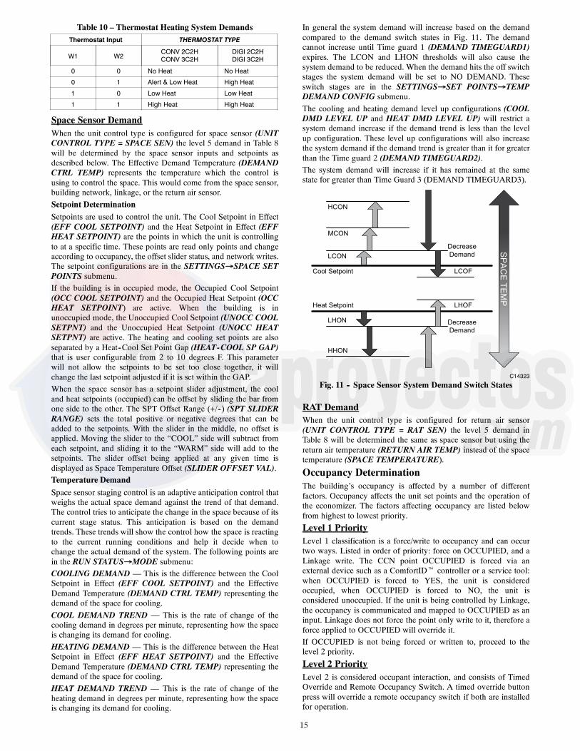
Table 10 – Thermostat Heating System DemandsThermostat Input THERMOSTAT TYPE
W1 W2CONV 2C2HCONV 3C2H
DIGI 2C2HDIGI 3C2H
0 0 No Heat No Heat
0 1 Alert & Low Heat High Heat
1 0 Low Heat Low Heat
1 1 High Heat High Heat
Space Sensor DemandWhen the unit control type is configured for space sensor (UNITCONTROL TYPE = SPACE SEN) the level 5 demand in Table 8will be determined by the space sensor inputs and setpoints asdescribed below. The Effective Demand Temperature (DEMANDCTRL TEMP) represents the temperature which the control isusing to control the space. This would come from the space sensor,building network, linkage, or the return air sensor.Setpoint DeterminationSetpoints are used to control the unit. The Cool Setpoint in Effect(EFF COOL SETPOINT) and the Heat Setpoint in Effect (EFFHEAT SETPOINT) are the points in which the unit is controllingto at a specific time. These points are read only points and changeaccording to occupancy, the offset slider status, and network writes.The setpoint configurations are in the SETTINGSSPACE SETPOINTS submenu.If the building is in occupied mode, the Occupied Cool Setpoint(OCC COOL SETPOINT) and the Occupied Heat Setpoint (OCCHEAT SETPOINT) are active. When the building is inunoccupied mode, the Unoccupied Cool Setpoint (UNOCC COOLSETPNT) and the Unoccupied Heat Setpoint (UNOCC HEATSETPNT) are active. The heating and cooling set points are alsoseparated by a Heat--Cool Set Point Gap (HEAT-COOL SP GAP)that is user configurable from 2 to 10 degrees F. This parameterwill not allow the setpoints to be set too close together, it willchange the last setpoint adjusted if it is set within the GAP.When the space sensor has a setpoint slider adjustment, the cooland heat setpoints (occupied) can be offset by sliding the bar fromone side to the other. The SPT Offset Range (+/--) (SPT SLIDERRANGE) sets the total positive or negative degrees that can beadded to the setpoints. With the slider in the middle, no offset isapplied. Moving the slider to the “COOL” side will subtract fromeach setpoint, and sliding it to the “WARM” side will add to thesetpoints. The slider offset being applied at any given time isdisplayed as Space Temperature Offset (SLIDER OFFSET VAL).Temperature DemandSpace sensor staging control is an adaptive anticipation control thatweighs the actual space demand against the trend of that demand.The control tries to anticipate the change in the space because of itscurrent stage status. This anticipation is based on the demandtrends. These trends will show the control how the space is reactingto the current running conditions and help it decide when tochange the actual demand of the system. The following points arein the RUN STATUSMODE submenu:COOLING DEMAND — This is the difference between the CoolSetpoint in Effect (EFF COOL SETPOINT) and the EffectiveDemand Temperature (DEMAND CTRL TEMP) representing thedemand of the space for cooling.COOL DEMAND TREND — This is the rate of change of thecooling demand in degrees per minute, representing how the spaceis changing its demand for cooling.HEATING DEMAND — This is the difference between the HeatSetpoint in Effect (EFF HEAT SETPOINT) and the EffectiveDemand Temperature (DEMAND CTRL TEMP) representing thedemand of the space for cooling.HEAT DEMAND TREND — This is the rate of change of theheating demand in degrees per minute, representing how the spaceis changing its demand for cooling.
In general the system demand will increase based on the demandcompared to the demand switch states in Fig. 11. The demandcannot increase until Time guard 1 (DEMAND TIMEGUARD1)expires. The LCON and LHON thresholds will also cause thesystem demand to be reduced. When the demand hits the off switchstages the system demand will be set to NO DEMAND. Theseswitch stages are in the SETTINGSSET POINTSTEMPDEMAND CONFIG submenu.The cooling and heating demand level up configurations (COOLDMD LEVEL UP and HEAT DMD LEVEL UP) will restrict asystem demand increase if the demand trend is less than the levelup configuration. These level up configurations will also increasethe system demand if the demand trend is greater than it for greaterthan the Time guard 2 (DEMAND TIMEGUARD2).The system demand will increase if it has remained at the samestate for greater than Time Guard 3 (DEMAND TIMEGUARD3).
Cool Setpoint
Heat Setpoint
LCON
LHON
MCON
HCON
HHON
LHOF
LCOF
Decrease
Demand
Decrease
Demand
SP
AC
E T
EM
P
C14323
Fig. 11 -- Space Sensor System Demand Switch States
RAT DemandWhen the unit control type is configured for return air sensor(UNIT CONTROL TYPE = RAT SEN) the level 5 demand inTable 8 will be determined the same as space sensor but using thereturn air temperature (RETURN AIR TEMP) instead of the spacetemperature (SPACE TEMPERATURE).
Occupancy DeterminationThe building’s occupancy is affected by a number of differentfactors. Occupancy affects the unit set points and the operation ofthe economizer. The factors affecting occupancy are listed belowfrom highest to lowest priority.
Level 1 PriorityLevel 1 classification is a force/write to occupancy and can occurtwo ways. Listed in order of priority: force on OCCUPIED, and aLinkage write. The CCN point OCCUPIED is forced via anexternal device such as a ComfortIDt controller or a service tool:when OCCUPIED is forced to YES, the unit is consideredoccupied, when OCCUPIED is forced to NO, the unit isconsidered unoccupied. If the unit is being controlled by Linkage,the occupancy is communicated and mapped to OCCUPIED as aninput. Linkage does not force the point only write to it, therefore aforce applied to OCCUPIED will override it.If OCCUPIED is not being forced or written to, proceed to thelevel 2 priority.
Level 2 PriorityLevel 2 is considered occupant interaction, and consists of TimedOverride and Remote Occupancy Switch. A timed override buttonpress will override a remote occupancy switch if both are installedfor operation.
16
While using the programmed schedule, occupancy can betemporarily switched from unoccupied to occupied by pressing theoverride button for approximately 3 seconds on the T--55, T--56, orT--59 space temperature sensor. The length of the override periodwhen pressing the override button is determined by the OverrideTime Limit (TIMED OVR LENGTH). The hours remaining inoverride is displayed as Timed Override Hours (TIMED OVRHOURS). This point can also be changed from the local display ornetwork to set or change the override period length.Remote Occupancy Switch (REMOTE OCC SWITCH) can beforced or configured for operation based on an actual switch. Thephysical switch should be configured to either Normally Open orNormally Closed when the user would like to control theoccupancy with an external switch. This switch is field--supplied(24v, single pole, single throw [SPST]). There are two possibleconfigurations for the remote occupancy switch:
1. (REMOTE OCC TYPE = 0) Normally Open Switch1. (REMOTE OCC TYPE = 1) Normally Closed Switch
If the switch is configured to No Switch (REMOTE OCC CHAN =None), the switch input value will be ignored and software willproceed to level 3 priority. For each type of switch, the appropriateconfiguration and states are listed in the table below.
TYPE OF SWITCH SWITCHCONFIGURATION
STATE OF SWITCH ANDSTATE OF OCCUPANCY
Occupied when Closedor Unoccupied when
OpenNormal Open (0)
Open and Unoccupied
Closed and Occupied
Occupied when Open orUnoccupied when
ClosedNormal Closed (1)
Open and Occupied
Closed and Unoccupied
Level 3 PriorityThe following occupancy options are determined by the state ofOccupancy Schedule Number (SCHEDULE NUMBER) and theGlobal Schedule Broadcast (BROADCAST SCHEDL?).
1. (SCHEDULE NUMBER = 0) The unit is alwaysconsidered occupied and the programmed schedule isignored. This is the factory default.
2. (SCHEDULE NUMBER = 1-64) Follow the localprogrammed schedule. Schedules 1 to 64 are local withinthe controller. The unit can only store one local scheduleand therefore changing this number only changes the title ofthe schedule table.
3. (SCHEDULE NUMBER = 65-99) Follow the globalprogrammed schedule. If the unit is configured as a GlobalSchedule Broadcaster (BROADCAST SCHEDL? = YES),the unit will follow the unit s programmed schedule andbroadcast the schedule so that other devices programmed tofollow this schedule number can receive the schedule. If theunit is not programmed as a Global Schedule Broadcaster(BROADCAST SCHEDL? = NO), the unit will receivebroadcasted schedules from a unit programmed to broadcastthis schedule number.
Humidity DemandWhen the unit is configured for either a Humidistat input(HUMSTAT CHANNEL) or Space Humidity Sensor (SPRHSENS CHANNEL) the level 5 demand in Table 8 will include adetermination of dehumidification demand.
HumidistatWhen receiving an active input from the Humidistat(HUMIDISTAT), dehumidification will be demanded.Space Relative HumidityOn units with a relative humidity sensor, when the received valueof space relative humidity (SPRH LEVEL) has exceed thehumidity set point (SPRH SET POINT), dehumidification will bedemanded. This demand will remain until the space relativehumidity has fallen below the humidity set point by more than the
humidity set point deadband (SPRH DEADBAND). This wouldcome from the space humidity sensor, or building network.
Indoor Fan OperationThese units use the Staged Air Volume (SAV) method of controllingthe supply fan for a typical constant volume rooftop unit. This controlmethod employs a variable frequency drive (VFD) to operate thesupply fan at different speeds in order to achieve energy savingsthrough reduced fan power. This method is specifically not concernedwith controlling static pressure in the supply duct, but rather withsetting different fan speeds for different operating conditions, such asventilation mode or part--load mechanical cooling.The SAV function is NOT a Variable Air Volume (VAV) function.The fan adapts its speed to one of eight based on mode and currentstate to satisfy a demand. The eight speeds consist of off (0%) andseven configurable values. The seven configurable fan speeds are:Maximum Speed (MAXIMUM IDF SPEED), Ventilation (VENTIDF SPEED), Heating (HEATING IDF SPD), Free Cool (FREECOOL IDF SPD), Mechanical Low Cooling (LOW COOL IDFSPD), Mechanical Medium Cooling (MED COOL IDF SPD), andMechanical High Cooling (HIGH COOL IDF SPD), The VFD ispowered direct from the distribution block or circuit breaker (CB)and is always on with power applied unless the CB is tripped.When the thermostat or space sensor control conditions require thefan on, the VFD will then ramp to desired speed. Fan speed isalways calculated by evaluating the current applicable conditions.Each fan speed condition is evaluated independently, and thehighest fan speed is used. For example, if a cooling call occursduring Ventilation mode, the unit mode will transition to coolingbut the fan speed is set to the higher of the two (VENT IDFSPEED or LOW COOL IDF SPD). Refer to the speedconfigurations below for when the fan will run at them.
Direct Drive UnitsAlternately, 48/50LC04--06 units can have either a direct driveElectronic Commutated Motor (ECM) fan system or a belt drivemotor powered by a Variable Frequency Drive (VFD). AndIDFTYPE=1 indicates a unit with VFD, while an IDFTYPE=2indicates a direct drive system. Refer to the unit product data forFan Performance tables and physical data. On direct drive units, theECM has 5 speed taps to allow a range of fan performance. Thecontrol has 3 output wires to connect to 3 different taps. From thefactory the low and high speed wires are connected to the first andsecond speed taps, respectively. The ventilation speed tap isdisconnected. The speed taps increase the speed the higher the tapnumber, so the first tap is the lowest speed and tap 5 is the highestspeed. If the low and high speed wires are moved to higher taps,the ventilation speed wire can be wired into the motor. To activatethe use of the ventilation speed wire, the Number of Speeds(SETTINGSUNIT CONFIGURATIONSINDOOR FANNUMFSPDS) configuration must be set to 3.The Commanded Fan Speed (OUTPUTSINDOORFANFANSPEED) represents the controls commanded speed forthe fan at any given time. This commanded speed is determined bythe unit’s current HVAC mode and the unit control type. For gasheating units, the IGC fan request output (InputsGEN.IIGC.F) ismonitored by the control. This can result in additional modification offan delays or other operation due to safety functions of the IGCcontrol. See the Gas Heating operation section for more details. Ifconfigured for IAQ fan operation, the fan may be turned on to satisfyair quality demands. See the Indoor Air Quality section if using IAQ(indoor air quality) accessory sensors. The fan can run underthermostat or space sensor control and will remain on if compressorsor heat relays are ever stuck on. If Shut Down on IDF Failure isenabled (SHUTDOWN IDF FAIL = Yes), the fan and unit will beshutdown without delay on fan alarm conditions. Fan off delays arehonored when exiting specific HVAC modes. The Fan--off Delaydelays are as follows: Cooling (COOL FANOFF DELAY), andHeating (HEAT FANOFF DELAY).

17
Indoor (Supply) Fan Maximum Speed(MAXIMUM IDF SPEED)Max speed is the highest fan speed allowed. This is typically 100%when pulleys are set to deliver design CFM to the space per jobrequirement. Most safety conditions for the unit will override thefan speed to this to help protect the unit.Ventilation Indoor Fan Speed (VENT IDF SPEED)This configuration defines the fan speed used in Ventilation(fan--only) mode. Ventilation mode is when the supply fan isrunning, but there is no demand for heating or cooling. Inthermostat mode, this is with just a G call. In space sensor control,this is when the unit is Occupied mode and the indoor fan isconfigured to always run while occupied (OCCUPIED FAN?). Ifthe indoor fan is configured for intermittent fan (OCCUPIEDFAN? = No), the Mode will be off instead of Ventilation and thefan will not run unless a heating or cooling mode is needed. Duringthe unoccupied period, the fan will always operate intermittently.The economizer damper will adjust its position based on how faraway this speed is from max speed for ventilation.IMPORTANT: It is important that the ventilation rate is checked aftersetting this speed to verify that the unit can properly ventilate the spaceper requirements. Adjusting this configuration or the economizerminimum setting curve should be performed to meet job requirements.
Heating Indoor Fan Speed (HEATING IDF SPD)This configuration defines the fan speed used when in heatingmode and running heat. On units equipped with Gas heat (UNITTYPE OF HEAT), this heat speed will be delayed on based on theIGC’s fan on call (IGC FAN REQUEST). Once the IGC requestthe fan the fan will run what this heating speed configuration is setfor until heating is ended. On units configured for Electric heat(UNIT TYPE OF HEAT) and configured for Preheat without thefan (PREHEAT W/O IDF), this heat speed will be delayed onbased on the Preheat fan delay time (PREHEAT FAN DELAY).Once this preheat time has expired or not configured for preheat,the fan will run at this heat speed while heat is on.Free Cooling Indoor Fan Speed (FREE COOL IDF SPD)This configuration defines the initial fan speed used when in FreeCooling. Refer to the Economizer Controls Operation section fordetails on free cooling. The fan will stay at this configured speedwhenever only the damper is being used for free cooling. If thedamper is at 100% for 5 minutes the fan will ramp to the highcooling speed. It is locked there until the actual damper positionfalls below 75% at which time it will ramp back down to thisconfigured speed.Low Cooling Indoor Fan Speed (LOW COOL IDF SPD)This configuration defines the fan speed used when only one stagemechanical cooling is being performed.Medium Cooling Indoor Fan Speed (MED COOL IDF SPD)This configuration defines the fan speed used when only secondstage mechanical cooling is being performed.High Cooling Indoor Fan Speed (HIGH COOL IDF SPD)This configuration defines the fan speed used when third (full load)stage mechanical cooling is being performed. When performingintegrated cooling with the economizer this speed will be used. Whenonly free cooling with a high cool demand, this speed will be used.
Cooling OperationThe 48/50LC unit’s cooling operation consists of: demand andmode determination, staging request to satisfy the demand, andhandling a request with the unit’s resources. These resources caninclude compressors, Humidi--MiZerR system, an economizer, andfan speed based on options. This section covers mechanicalcooling. For economizer free cooling, refer to the EconomizerOperation section (starting on page 24).For Humidi--MiZer system operation, refer to the OptionalHumidi--MiZer Dehumidification System section (see page 19).
Cooling Mode ControlThe cooling HVAC mode (OPERATING MODE) has 9 differentoperating sub modes (SUBMODE): ECON FREE COOLING,UNOCC. FREE COOL, MECH. COOLING, ECON/MECHCOOLING, DEHUMIDIFICATION, DEHUM/MECH COOLING,DEHUM PREVENTED, COOLING PREVENTED, andSHUTTING COOL OFF. These are all part of a general coolingmode and resemble the specific type of cooling that is beingperformed at any given time. All types of cooling are still performedunder the general cooling function, and the expanded text is for userreference only.For the unit to enter cooling mode, three things must be true: theindoor fan must be ok to use, the mode changeover time guard mustbe expired, and there must be a cooling or dehumidification demand(Y1, Y2, Y3, space cool demand, or humidity demand). The unit willremain in cooling for at least one minute or until any of the aboveconditions turn false. The cooling mode does not officially end untilthe compressor is off and the fan off delay has expired.
Cooling Staging ControlOnce the unit is in a cooling mode, determine what the demand isand how to satisfy it. If an economizer is installed and can be usedfor cooling (OK TO USE FREE COOLING? = Yes), the unit willuse it first (see economizer section for its operation). If theeconomizer cannot be used or additional cooling is needed, amechanical cooling check is performed. OK to use Compressors?(OK TO USE COMPS?) will be set to yes when the outdoortemperature (OUTDOOR AIR TEMP) is above the Circuit ALockout temperature (CIR.A LOCKOUT OAT) and the Circuit Ais not locked out for diagnostic reasons (CIRCUIT A LOCKOUT).Based on the unit control configuration, requested cooling stages(REQ. COOL STAGES) will be determined then passed tocompressor control to actually add the cooling stages.There are two ways of requesting stages when thermostat control isenabled, Traditional thermostat control or adaptive control.Traditional thermostat control is used if set for non--adaptivethermostat (ADAPTIVE TSTAT = NO) and the unit cannot use theeconomizer for free cooling. If set for adaptive thermostat(ADAPTIVE TSTAT = YES) or any time the economizer isavailable for free cooling, the unit will use adaptive control forstaging.When configured for Space sensor or RAT control (UNITCONTOL TYPE) the unit will use adaptive control for staging.With either staging method there are two supply air temperaturelimits that apply, one restricts more cooling stages and the otherwill remove cooling stages. If at any time the Supply--AirTemperature (SUPPLY AIR TEMP) falls below the MinimumSupply Air Temperature Upper Level (UPPER MIN SAT), therequested stages will not be allowed to increase. If at any time theSAT falls below the Minimum Supply Air Temperature LowerLevel (LOWER MIN SAT), the requested stages will be reducedby one. If these SAT limits are configured so that they are too closetogether, the last stage might cycle rapidly, slowed only by itsminimum on and off--time requirements.Adaptive ControlStage timers and Supply air trend apply when determining therequest for stages. The first request (REQ. COOL STAGES =1)comes immediately when starting the staging process. The CoolStage Increase Time (COOL STAGEUP TIME) has to expire andthe Supply--Air Trend (SUPPLY AIR TREND) has to be abovethe cooling supply air trend level (COOL SATTREND LEV)before another stage can be added. Requested stages will only beallowed to increase as the actual system demand allows(DEMAND). A “LOW COOL” demand will only allow onerequested stage, “MED COOL” two stages, and “HIGH COOL” 3stages. The requested stages will be reduced if the cooling demandis lowered or dropped completely, or if the supply air falls belowthe lower level (LOWER MIN SAT).

18
Traditional Thermostat ControlStage timers and Supply air trend do not apply when determining therequest for stages. Request staging will follow the thermostat inputsdirectly. “LOW COOL” will request one stage. “MED COOL” willrequest two stages. “HIGH COOL” will request 3 stages.
Compressor ControlThe compressor control works hand and hand with the stagingcontrol. As the staging control request stages, the compressor controldetermines what is available or running and tries to provide stages forwhat is requested. The availability of the compressors depends on timeguards, circuit diagnostics, and outdoor temperature. The low coolingcompressor (LOW COOL COMP) informs the control whichcompressor is desired for a low cooling demand.IMPORTANT: When LOW COOL COMP is set to 2 the unit willoperate as a 2 stage unit where the larger compressor is stage oneand both compressors are stage 2.There are time guards to protect the compressor, Compressor Min OnTime (COMP MIN ON TIME) and Compressor Min Off Time(COMP MIN OFF TIME) apply before the compressors can beturned back on or turned off. Timeguard A1 (COMP A1TIMEGUARD) and Timeguard A2 (COMP A2 TIMEGUARD)display the time the compressors have before they can transition state.Circuit diagnostic tests are performed during operation which mayor may not allow the compressors to be used. The availability ofthe compressors is shown as Compressor A1 Available (COMP A1AVAILABLE) and Compressor A2 Available (COMP A2AVAILABLE). The lockout status of the compressors is shown asCompressor A1 Lockout (COMP A1 LOCKOUT) andCompressor A2 Lockout (COMP A2 LOCKOUT). The actualstages running at any given time is displayed as Actual CoolingStages (ACTIVE COOL STAGE) :0 (Off), 1 (Compressor A1 Ononly), 2 (Compressor A2 On only), and 3 (both compressors areon). Individual compressor output state is shown as(COMPRESSOR A1) and (COMPRESSOR A2).Any time the outdoor ambient falls below the low cooling minimumoutdoor temperature (LOW COOL MIN OAT), the low cooling
lockout will be active (LOW COOL LOCKOUT) preventingcompressor A1 from running by itself. Any time the outdoor ambientfalls below the medium cooling minimum outdoor temperature (MEDCOOL MIN OAT), the medium cooling lockout will be active (MEDCOOL LOCKOUT) preventing compressor A1 and compressor A2from running by themselves.
Outdoor Fan ControlOutdoor fans can be controlled by one of two methods: normaloperation of discrete speed based on the cooling being performed,or low ambient operation that varies the outdoor airflow to controlsaturated discharge temperature within an acceptable range. This isimplemented using multi--speed motors. The system outdoor fanspeed (COMMANDED ODF SPD) represents the commandedspeed of all outdoor fan motors as a complete system. The numberof outdoor fans in the system is determined by the Number ofoutdoor fan outputs (ODF SIGNAL QTY).IMPORTANT: The number of outdoor fans will not always matchthe number of outdoor fan outputs (ODF SIGNAL QTY). Fig. 12shows how the outdoor fans are mapped with the outdoor fanoutputs.
NOTE: Factory default configurations account for these modeldifferences and should not be changed. The default configurationshave been qualified over a large range of conditions and areprovided in case a field replacement of a control board occurs andthe settings need to be checked or manually configured. Outdoorfan operation is further described below to assist introubleshooting.
Typical OperationWhen OAT is above low ambient temperature (LOW AMBIENTTEMP), the ODFs will run at 4 discrete speeds, off, Low Cool Speed(ODF LOW COOL SPD), Medium Cool Speed (ODF MED COOLSPD), and High Cool Speed (ODF HIGH COOL SPD),corresponding to the 4 discrete cooling stage of the compressors(ACTIVE COOL STAGE): 0 (Off), 1 (Compressor A1 On only), 2(Compressor A2 On only), and 3 (both compressors are on).
48/50LC 24-26 48/50LC 17-20 48/50 LC14
OFM1
OFM5
OFM6
OFM4
OFM3
OFM2
Control Box Side
1
1
2
2
33
OFM1
OFM4
OFM3
OFM2
Control Box Side Control Box Side
2
1
2
1
OFM1
OFM3
OFM2
48/50LC 08-12
48/50LC 07
OFM1
OFM3
OFM2
Control Box Side
OFM1
OFM2
Control Box Side
Indicates the Outdoor Fan Signal from theboard. Otherwise the motor and signal match.
1
2
3OFM
48/50LC 04-06
Control Box Side
a48---9938
Fig. 12 -- Outdoor Fan Motor Arrangement

19
Low Ambient OperationLow ambient operation will be used when either of the 2conditions is met: 1) OAT is less than low ambient temperature(LOW AMBIENT TEMP) – 5_F or 2) OAT is less than lowambient temperature (LOW AMBIENT TEMP) – 2.5_F and theSaturated Discharge Temperature (CIR.A DIS. TEMP) is less than92_F. The low ambient ODF control will manipulate ODF speed tokeep the discharge temp above 95_F. As OAT continues to drop,ODF speed will continue to decrease, at certain point, the lowambient control may decide to turn off ODFs and only control thespeed of the rest of the outdoor fans. If the discharge temp keeps ondecreasing, it may reach a point that all ODF fans will be turnedoff. The ODFs will be turned on starting from the highest numberfirst, meaning the ODF1 will be the last one to shut off. The ODFsare protected with a 45 second run time and a 60 second off time.See Fig. 12 for the ODF arrangement. The lowest speed allowed torun any ODF is determined by the outdoor fan Minimum SpeedConfiguration (ODF MINIMUM SPEED).NOTE: During ODF cycling all fans that are commanded on willbe at the same speed and the ones off will be at zero speed. Themotors will not be allowed to run different speeds at the same time.
When OAT rises above low ambient temperature (LOW AMBIENTTEMP), ODF control will transition from low ambient to normaloperation. A period (5 min) is allowed for the ODF speed to rampfrom current position to one of the 4 discrete speed settings.IMPORTANT: The low ambient temperature (LOW AMBIENTTEMP) is default to 66 degrees and should not be changed unlessdirected by authorized Carrier Personnel.
Optional Humidi--MiZerR Dehumidification SystemUnits with the factory--installed Humidi--MiZer system option arecapable of providing multiple modes of improveddehumidification as a variation of the normal cooling cycle. TheHumidi--MiZer system option includes additional valves in theliquid line and discharge line of each refrigerant circuit, a reheatcoil downstream of the evaporator, and variable--speed control of allthe outdoor fans. The Humidi--MiZer system equipped configurationis factory set to Yes for Humidi--MiZer system equipped units(HUMIDIMIZER OK = YES). This enables Humidi--MiZer systemoperating modes and service test.Humidi--MiZer system operation requires the installation andconfiguration of a relative humidity switch input or a space relativehumidity sensor. The HUMIDISTAT and SPRH leads are providedwith quick connects. The Space Humidity Switch configuration,SETTINGS UNIT CONFIGURATIONS SWITCH INPUTSCONFIGS HUMSTAT CHANNEL identifies the normally openor normally closed status of this input at high humidity. The SpaceRH Sensor configuration, SETTINGS UNITCONFIGURATIONS ANALOG INPUTS CONFIGS SPRHSENS CHANNEL, identifies to the channel number the sensor iswired into.
Dehumidification DemandWhen using a humidistat or switch input, the demand fordehumidification is seen as Space Humidity Switch(INPUTSSWITCH INPUTSHUMIDISTAT) being Low orHigh. A low value means humidity level is good and a high valuemeans that dehumidification is needed.When using an SPRH sensor, the demand is based on the SpaceHumidity Sensor (INPUTSANALOG INPUTSSPRH) valuecompared to the Space RH Setpoint (SETTINGSSPACESETPOINTSSPRH SETPOINT). If the Space Humidity Sensor(SPRH) value is above the Space RH Setpoint (SPRH Setpoint), thendehumidification is needed. If the Space Humidity Sensor (SPRH)value is below the Space RH Setpoint (SPRH Setpoint) minus theSpace RH Deadband (SETTINGSUNIT CONFIGURATIONSCOOLINGSPRH DEADBAND), then dehumidification is nolonger needed.
NOTE: When there is a dehumidification demand, the economizerdamper position is limited to its minimum damper position.
Humidi--MiZer System ModesWith Humidi--MiZer system units there are two additional HVACmodes available for the user: Dehumidification and Dehum/MechCooling. Selection of the Dehum/Mech Cooling mode isdetermined by the dehumidification demand and the coolingdemand. Table 11 shows the corresponding circuit mode andoutput status for the different demand combinations.
Normal CoolingFor 48/50LC07--26 units, refrigerant flows from the outdoorcondenser through the de--energized 3--Way Liquid Diverter Valve(LDV) to the expansion device bypassing the reheat condensercoil. The Reheat Discharge Valve (RDV) is closed. (See Fig. 14.)
Table 11 – Humidi--MiZer System Control Modes -- Sizes 07--26
DEMAND AND MODE OUTPUTS 48/50LC 07---26 Valves
SpaceHumidity
CircuitCoolingDemand
CircuitMode
CircuitCompressor
LDV Valve3---way
RDV Valve2---way
— – No power Off Off Off(closed)
Low No Off Off Off Off(closed)
Low Yes Cool On Off Off(closed)
High Yes Dehum/MechCooling On On Off
(closed)
High No Dehum On On On(open)
For 48/50LC04--06 units, refrigerant flows from the outdoorcondenser and is diverted at the energized Reheat Liquid Valve(RLV) and flows through the de--energized Cooling Liquid Valve(CLV) to the expansion device bypassing the reheat condenser coil.The RDV is closed.
Table 12 – Humidi--MiZer System Control Modes -- Sizes 04--06
DEMAND AND MODE OUTPUTS 48/50LC 04---06 Valves
SpaceHumidity
CircuitCoolingDemand
CircuitMode
CircuitCompressor
RDLValve
RLVValve
CLVValve
— – Nopower Off Off
(closed)Off(open)
Off(open)
Low No Off Off Off(closed)
Off(open)
Off(open)
Low Yes Cool On Off(closed)
Off(closed)
Off(open)
High YesDehum/MechCooling
On Off(closed)
Off(open)
On(closed)
High No Dehum On On(open)
Off(open)
On(closed)
Dehum/Mech Cooling (Subcooling Mode)This mode increases latent heat removal and decreases sensiblecooling compared to normal cooling. For 48/50LC07--26 units,refrigerant flows from the outdoor condenser, through theenergized 3--Way Liquid Diverter Valve (LDV) and through thereheat condenser coil to the expansion device. The ReheatDischarge Valve (RDV) is closed. (See Fig. 16.)For 48/50LC04--06 units, refrigerant flows from the outdoorcondenser through the de--energized Reheat Liquid Valve (RLV)and through the reheat condenser coil to the expansion device. TheReheat Discharge Valve (RDV) and Cooling Liquid (CLV) areclosed. (See Fig. 15.)

20
Dehumidification (Hot Gas Reheat Mode)This mode provides maximum latent cooling with little to nosensible capacity. This mode can operate to providedehumidification when there is no cooling demand. For48/50LC07--26 the refrigerant flows from the outdoor condenser,through the energized 3--Way Liquid Diverter Valve (LDV) andthrough the reheat condenser coil to the expansion device. (SeeFig. 18.) For 48/50LC04--06 units, The refrigerants flows from theoutdoor condenser, through the de--energized RLV and through thereheat condenser coil to the expansion device. The Cooling LquidValve (CLV) is closed. For 48/50LC04--26 units the ReheatDischarge Valve (RDV) is open which provides some compressordischarge gas to the reheat condenser to further increase the reheatof the evaporator air stream. (See Fig. 17.)
Reheat ControlWhen there is only a cooling demand, the unit will operate innormal cooling mode. When there is only dehumidification
demand, the unit will operate in Dehumidification mode (Hot GasReheat). When there is both cooling demand and dehumidificationdemand, the unit will operate in Dehum/Mech Cooling mode(Subcooling). During Dehumidification and Dehum/Mech coolingmode, the unit will run all cooling stages. When the Outside AirTemperature is above 80_F, the Outdoor Fans will run at maximumfan speed. When the Outside Air Temperature is below 80_F, theOutdoor Fans will modulate to maintain Saturated DischargeTemperature setpoint LA DEHUM LEV 1, LA DEHUM LEV 2and LA DEHUM LEV, (SETTINGSUNITCONFIGURATIONSCOOLINGLOW AMBIENT. The unitcan be restricted from reheat operation by the outside temperatureHUMZ LOCKOUT OAT (SETTINGSUNITCONFIGURATIONS > COOLINGHUMZLOCKOUT OAT)sets the lowest outside temperature the unit is allowed to run reheatcontrol (Default = 40_F).
HUMIDI-MIZER COIL
COMPRESSOR
OUTDOOR AIR
INDOOR SUPPLYAIR
INDOOR RETURNAIR
RLVVALVE
EXPANSIONVALVE(TXV)
= CLOSED VALVE
= OPEN VALVE
RDVVALVE
EVAPORATOR COIL
CONDENSER COIL
CLVVALVE
C14121Fig. 13 -- Normal Cooling Mode – Humidi--MiZer System 48/50LC 04--06
HUMIDI-MIZER COIL
COMPRESSOR
OUTDOOR AIR
INDOOR SUPPLYAIR
INDOOR RETURNAIR
3-WAYVALVE
EXPANSIONVALVE(TXV)
= CLOSED VALVE
= OPEN VALVE
= 3-WAY VALVE
RDVVALVE
EVAPORATOR COIL
CONDENSER COIL
C14114Fig. 14 -- Normal Cooling Mode – Humidi--MiZer System 48/50LC 07--26

21
HUMIDI-MIZER COIL
COMPRESSOR
OUTDOOR AIR
INDOOR SUPPLYAIR
INDOOR RETURNAIR
RLVVALVE
CLVVALVE EXPANSION
VALVE(TXV)
RDVVALVE
EVAPORATOR COIL
CONDENSER COIL
= CLOSED VALVE
= OPEN VALVE
C14122Fig. 15 -- Subcooling Mode – Humidi--MiZerR System 48/50LC 04--06
HUMIDI-MIZER COIL
COMPRESSOR
OUTDOOR AIR
INDOOR SUPPLYAIR
INDOOR RETURNAIR
3-WAYVALVE
EXPANSIONVALVE(TXV)
RDVVALVE
EVAPORATOR COIL
CONDENSER COIL
= CLOSED VALVE
= OPEN VALVE
= 3-WAY VALVE
C14115Fig. 16 -- Subcooling Mode – Humidi--MiZerR System 48/50LC 07--26
HUMIDI-MIZER COIL
COMPRESSOR
OUTDOOR AIR
INDOOR SUPPLYAIR
INDOOR RETURNAIR
RLVVALVE
CLVVALVE
RDVVALVE
EVAPORATOR COIL
CONDENSER COIL
= CLOSED VALVE
= OPEN VALVE
EXPANSIONVALVE(TXV)
C14123Fig. 17 -- Hot Gas Reheat Mode – Humidi--MiZer System 48/50LC 04--06

22
HUMIDI-MIZER COIL
COMPRESSOR
OUTDOOR AIR
INDOOR SUPPLYAIR
INDOOR RETURNAIR
3-WAYVALVE
RDVVALVE
EVAPORATOR COIL
CONDENSER COIL
= CLOSED VALVE
= OPEN VALVE
= 3-WAY VALVE
EXPANSIONVALVE(TXV)
C14116Fig. 18 -- Hot Gas Reheat Mode – Humidi--MiZer System 48/50LC 07--26
Reheat Mode Diagnostic HelpThe status of reheat mode sensor inputs may be viewed within thedisplay INPUTS menu. The status of reheat mode outputs may beviewed within the display OUTPUTS or RUN STATUSMODEmenu. Additional diagnostic help, including status of circuit reheattemperature limit lockouts may be viewed within theHumidi--MiZer sub--menu of the cooling mode diagnostic table atRUN STATUSCOOLDEHUM. The Service Test mode maybe used to force the system to operate Dehumidification mode (HotGas Reheat) and Dehum/Mech Cooling mode (Subcooling), or toindependently operate the reheat valve control outputs.The following forced operating states are available service testoperations for a Humidi--MiZer system equipped unit:SERVICE TEST COOL TEST HUMIDIMIZER TESTLEVELA value of “0” sets reheat control test to “Off.”SERVICE TEST COOL TEST HUMIDIMIZER TESTLEVELA value of “1” sets Humidi--MiZer control test to “Dehum/MechCooling mode (Subcooling).”SERVICE TEST COOL TEST HUMIDIMIZER TESTLEVELA value of “2” sets Humidi--MiZer test to “Dehumidification mode(Hot Gas Reheat).”SERVICE TEST INDEPENDENTS LIQ DIVERT A TESTA value of “On” will turn on the 3--Way Liquid Diverter Valve(LDV).SERVICE TEST INDEPENDENTS REHEAT A TESTA value of “On” will turn on the Reheat Discharge Valve (RDV).
Indoor Fan Based DehumidificationBelt Drive units that are not factory configured for Humidi--Mizeroperation can be set for improved dehumidification operationthrough fan based humidification (FBD), SETTINGS UNITCONFIGURATIONS COOLING FBD TYPE. Units arefactory defaulted to FBD TYPE = 0 which means that any dehumdemand is ignored. There are two fan based dehumidificationoptions, Max Comfort (FBD TYPE = 1) and MaxDehumidification (FBD TYPE = 2). Fan based dehumidificationrequires the installation and configuration of either a space relativehumidity sensor or a relative humidity switch input. The SpaceHumidity Switch configuration, SETTINGS UNITCONFIGURATIONS SWITCH INPUTS CONFIGS HUMSTAT CHANNEL identifies the normally open or normallyclosed status of this input at HIGH humidity. The RH Sensor
configuration, SETTINGS UNIT CONFIGURATIONS ANALOG INPUTS CONFIGS SPRH SENSOR CHANNEL,identifies the point on the MBB (Main Base board) or the IOB(Input Output board) the sensor was wired into.
Max DehumWhen the FBD Type is set to (2) Max Dehum, the control will try tosatisfy the dehumidification demand. When the unit receives a dehumdemand a PID control algorithm will modulate the indoor fan whilethe compressor is running to maintain minimum suction temperature(FBDH_SST). With a Y1 and dehum demand, the unit will run thecompressor unloaded (48/50LC04--06) or will run the A1 compressoronly (48/50LC07--26). With a Y2 and dehum demand, the unit willrun with the compressor at full load (48/50LC04--06) or will run withthe A2 compressor only (48/50LC07--26). With a Y3 and dehumdemand (48/50LC07--26 only), the unit will run both compressors.
Max ComfortWhen the FBD Type is set to (1) Max Comfort, the control will tryto satisfy the dehumidification demand and minimize cold airdump. When the unit receives a dehum demand a PID controlalgorithm will modulate the indoor fan while the compressor isrunning to maintain the minimum FBD supply air comfort setpoint (FBDH_SAT) while also maintaining the minimum suctiontemperature (FBDH_SST). With a Y1 and dehum demand, the unitwill run the compressor unloaded (48/50LC04--06) or will run theA1 compressor only (48/50LC07--26). With a Y2 and dehumdemand, the unit will run with the compressor at full load(48/50LC04--06) or will run with the A2 compressor only(48/50LC07--26). With a Y3 and dehum demand (48/50LC07--26only), the unit will run both compressors.
Heating OperationThe 48/50LC unit’s heating operation consists of: demand andmode determination, staging request to satisfy the demand, andhandling a request with the unit’s resources. These resources can begas heat or electric heat. This section covers both gas heat units andelectric heat units. The Type of Heat Installed (UNIT TYPE OFHEAT) configuration will be factory set to 1 for gas units and 0 forelectric heat units. The unit enters a heating mode based on ademand, decides how to satisfy the demand, executes its plan, andthen leaves the heating mode.
Heating Mode ControlThe heating HVAC mode (OPERATING MODE) has 3 differentoperating sub modes (SUBMODE): HEATING, HEATINGPREVENTED, and SHUTTING HEAT OFF. These are all part ofa general heating mode and resemble the action heat mode is taking

23
at any given time. All types of heating are still performed under thegeneral heating function, and the expanded text is for userreference only.For the unit to be allowed to enter the heat mode, three things must betrue: the indoor fan must be ok to use, the mode changeover timeguard must be expired, and there must be a heating demand. The unitwill remain in heating for at least one minute and until the demand isdropped or if any of the above conditions are false. The heating modedoes not officially end until all heat stages are off, the fan off delay hasexpired, and the IGC fan request is dropped.
Supply--Air Temperature Sensor (SAT) Heat ModeThe SAT Heat Mode Sensing (SAT DURING HEAT?) informs theunit that the supply air sensor has been relocated downstream of theheat section. This configuration affects the Supply Air Temperature(SUPPLY AIR TEMP) value displayed as listed below.When SAT DURING HEAT? is disabled, the Supply AirTemperature (SUPPLY AIR TEMP) value on the SystemVutdisplay and the network will hold a zero when heat outputs comeON and for 5 minutes after. The default SAT sensor location is atthe fan inlet, upstream of the heat section.When SAT DURING HEAT? is enabled, the Supply Air Temperature(SUPPLY AIR TEMP) sensor reading is displayed at the SystemVucontroller and network during heating mode. This setting should onlybe used if the original SAT sensor wires are removed from the MainBase Board (MBB) and replaced by an accessory SAT sensor locatedin the supply duct downstream of the heat section.
Heating Staging ControlOnce the unit is in a heating mode, it determines what the demandis and how to satisfy it. Requested Heating Stages (REQ. HEATSTAGES) will be determined then passed to heat control toactually add the heating stages. To request stages the number ofheat stages (HEATING STAGE QTY) must be greater than zero.As a gas unit this will be set in the factory, however 50LC unitsmay have heat installed as accessories. If the Outdoor AirTemperature (OUTDOOR AIR TEMP) is greater than the HeatingLockout Temp (HEAT LOCKOUT OAT), all the heat stages willbe locked out (HEAT LOCKOUT).There are two ways of requesting stages when thermostat control isenabled, traditional thermostat control or adaptive control.Traditional thermostat control is used if set for non--adaptivethermostat (ADAPTIVE TSTAT = NO). If set for adaptive thermostat(ADAPTIVE TSTAT = YES), the unit will use adaptive control forstaging. When configured for space sensor or RAT control (UNITCONTOL TYPE) the unit will use adaptive control for staging.With either staging method there are then two supply airtemperature limits, the Maximum SAT Lower Level (LOWERMAX SAT) the Maximum SAT Upper Level (UPPER MAX SAT).Any time the supply air temperature rises above lower level theheat staging will be limited to what is currently on and noadditional stages will be added until the supply air temperature fallsback below the lower level. If the supply air temperature risesabove the upper level, then heating will be reduced by removingone stage. That stage will not be added again until the Supply AirTemperature falls below the lower level. If the supply airtemperature stays above the upper level, then another stage will beremoved. If the upper and lower levels are configured so that theyare close together, the last stage of heat might cycle rapidly, slowedonly by its minimum on and off--time requirements.Adaptive ControlStage timers and Supply air trend apply when determining therequest for stages. The first request (REQ. HEAT STAGES =1)comes immediately when starting the staging process. The HeatStage Increase Time (HEAT STAGEUP TIME) has to expire andthe Supply--Air Trend (SUPPLY AIR TREND) has to be abovethe Heating supply air trend level (HEAT SATTREND LEV)before another stage can be added. Requested stages will only beallowed to increase as the actual system demand allows
(DEMAND). A “LOW HEAT” will only allow one requested stageand “HIGH HEAT” 2 stages. The requested stages will be reducedif the heating demand is lowered or dropped completely, or if thesupply air falls below the lower level (LOWER MIN SAT).Traditional Thermostat ControlStage timers and Supply air trend do not apply when determiningthe request for stages. Request staging will follow the thermostatinputs directly. “LOW HEAT” will request one stage. “HIGHHEAT” will request 2 stages.
Heat Relay ControlThe heat relay control is responsible for energizing or de--energizingthe heat stage relays and works hand and hand with the stagingcontrol. As the staging control requests stages, the heat relay controldetermines what actual heat relays are available or energized and triesto provide stages for what is requested. The availability of heat relaysdepends on the heat installed, how many stages, and time guards. TheNumber of Heat Stages (HEATING STAGE QTY) configuration tellsthe control how many heat relays can be used. Heat Stage 1Timeguard(HEAT 1 TIMEGUARD) and Heat Stage 2 Timeguard (HEAT 2TIMEGUARD) display the time a respective heat relay has before itcan change state. The available stages at any given time are displayedas heat 1 available and heat 2 available (HEAT 1 AVAILABLE andHEAT 2 AVAILABLE). The actual heat relays on at any given timeare displayed as Actual Heating Stages (ACTVE HEAT STAGE).Heat Stage 1 Relay (HEAT 1 RELAY) and Heat Stage 2 Relay(HEAT 2 RELAY) are displayed on when the respective relay isenergized. There are time guards to protect from short cycling, HeatMinimum On Time (HEAT MIN ON) and Heat Minimum Off Time(HEAT MIN OFF) apply before a heat relay can be turned back onor turned off.Integrated Gas Controller (IGC)The heat staging is determined as described above and the IntegratedGas Controller (IGC) initiates the gas heat module start--up. TheIntegrated Gas Controller (IGC) minimum on--time of 1 minute willbe followed even if Heat Minimum On Time (HEAT MIN ON) islower and during Service Test. If the IGC temperature limit switchopens within 10 minutes of the end of the gas heat cycle, the next fanoff delay will be extended by 15 seconds. The maximum delay is 3minutes. Once modified by the IGC, the fan off delay will not changeback to the configured Fan--off Delay, Gas Heat (HEAT FANOFFDELAY) unless power is reset to the control. A light emitting diode(LED) is provided on the IGC to indicate status. During normaloperation the LED is continuously on. See the Troubleshootingsection if the LED is off or flashing. The IGC is located behind thegas section access panel door.When the control energizes Heat Stage 1 Relay (HEAT 1 RELAY),power is sent to the W terminal on the IGC board. A check is made toensure that the rollout switch and limit switch are closed. Theinduced--draft motor is then energized, and when speed is proven withthe Flue Gas Pressure switch on the motor, the ignition activationperiod begins. The burners will ignite within 5 seconds. If the burnersdo not light, there is a 22--second delay before another 5--secondattempt. If the burners still do not light, this sequence is repeated for15 minutes. After the 15 minutes have elapsed, if the burners still havenot lit, heating is locked out. The control will reset when the requestfor heat is temporarily removed. When ignition occurs the IGC boardwill continue to monitor the condition of the rollout switch, limitswitches, the Flue Gas Pressure switch, as well as the flame sensor. Ifthe unit is controlled through a room thermostat or space sensor set forauto--fan, 45 seconds after ignition occurs the indoor--fan motor willbe energized (and the outdoor--air dampers will open to theirminimum position). If for some reason the over temperature limitopens prior to the start of the indoor fan blower, on the next attempt,the 45--second delay will be shortened to 5 seconds less than the timefrom initiation of heat to when the limit tripped. Gas will not beinterrupted to the burners and heating will continue. Once modified,the fan on delay will not change back to 45 seconds unless power isreset to the control. When the control energizes Heat Stage 2 Relay

24
(HEAT 2 RELAY), power is supplied to the second stage of the maingas valve. If both stage 1 and stage 2 of the gas valve close, gas willbe turned off to the main burners.
Supply Air TemperingSupply Air Tempering control operates the gas or electric heat tomaintain a minimum supply air temperature during conditionswhere very cold outdoor air causes the supply air temperature tofall below the configured Supply Air Tempering Setpoint. Thisoccurs during periods where DCV is active and increasing theamount of outdoor air or in cases where the system is operating atvery low airflow and the calculated economizer position hasincreased to maintain a constant ventilation rate.The user can enable/disable Supply Air Tempering.The following conditions must be true for the supply air temperingalgorithm to operate:S The SA Tempering is set to Yes (OK TO SA TEMPER = YES)S The indoor fan is onS The System Mode is in Vent (Ventilation or Supply Fan Only) orIAQ Override.S The Outdoor Air Temperature < Minimum Cooling SAT 48_F.S Heat type is gas or electric and Number Of Heat Stages > 0
If all the above are true, the SystemVut controller will monitor theSAT sensor value and operate the first stage of heat to temper thesupply air as required in order to maintain the configured SATempering Setpoint
Economizer OperationThe Economizer is used for ventilation, and cooling. If the Indoorfan is not on, the economizer will not operate. If an economizer isinstalled, then Economizer Installed (ECON INSTALLED = YES)should be set to YES. The unit produces a 4--20mA signal which isthen changed to a 2--10V signal with a 500 ohm resistor, which cancontrol the economizer actuator. The economizer output signal isdisplayed by the Economizer Commanded Position (ECON CMDPOSITION). The actuator’s built--in 2 to 10VDC feedback signalis read in as an analog input to know the actual position which isdisplayed as Economizer Actual Position (ECON ACTPOSITION).Minimum VentilationThe economizer will open to allow ventilation when the indoor fanis turned on and the unit is in the occupied state. The economizerdamper position at any given time for ventilation is displayed asthe Min Position in Effect (EFFECTIVE MIN POS). Thisminimum position can be effected by the indoor fan speed (F.SPD)and indoor air quality. To maintain a constant airflow through theeconomizer, as the indoor fan speed decreases or increases thedamper minimum position will increase or decrease, respectively.This relationship curve is shown in Fig. 19.NOTE: The software point names are used in Fig. 19 as to notclutter the graph. These points are not individually set andtherefore only visible from a network for troubleshooting.These units can also be equipped with optional CO2 sensors foradditional indoor air quality control. When unit is equipped with areturn duct CO2 sensor or return duct CO2 sensor and outside airCO2 sensor the Economizer minimum position vs. fan speed curvewill be recalculated based on the CO2 level of the return and/oroutside air as shown in Fig. 19. When performing DemandControlled Ventilation, the damper’s Min Position in Effect(EFFECTIVE MIN POS) will operate in the shaded area of Fig.19 based on the IAQ Level (IAQ) and the Commanded Fan Speed(IDF SPEED OUTPUT). See the Indoor Air Quality (IAQ)section for more details on Demand Controlled Ventilation (DCV).The damper position curve can be field adjusted per application ifneeded.
1. Activate test mode to control the fan and dampers toachieve the correct numbers.
2. Set the fan speed for the maximum amount needed fordesign CFM requirements. This should also be the IDFmaximum Fan speed (MAXIMUM IDF SPEED).
3. Open the damper to the position which satisfies the highestventilation requirement running maximum fan speed, andthen set the Economizer minimum at maximum fan speed(MIN POS @ MAX FAN) to this damper position.
4. Set the fan speed to a realistic operating speed in the upperrange, and then set the User Minimum Position Speed 1(MIN POS SPEED 1) equal to that speed. This should besomewhere in the 80% range.
5. Open the damper to the position which satisfies the highestventilation requirement running speed 1 fan speed, and thenset the User Minimum Position Damper Position 1 (MINPOS DAMP 1) to this damper position.
6. Set the fan speed to a realistic operating speed in the mid--range, and then set the User Minimum Position Speed 2(MIN POS SPEED 2) equal to that speed. This should besomewhere in the 60% range.
7. Open the damper to the position which satisfies the highestventilation requirement running speed 2 fan speed, and thenset the User Minimum Position Damper Position 2 (MINPOS DAMP 2) to this damper position.
8. Set the fan speed to a realistic operating speed in the low--range, and then set the User Minimum Position Speed 3(MIN POS SPEED 3) equal to that speed. This should belowest fan speed in planned operating range.
9. Open the damper to the position which satisfies the highestventilation requirement running speed 3 fan speed, and thenset the User Minimum Position Damper Position 3 (MINPOS DAMP 3) to this damper position.
The shape of the curves in Fig. 19 are determined by theconfiguration parameters: User Minimum Position Speed 1 (MINPOS SPEED 1), User Minimum Position Damper Position 1(MIN POS DAMP 1), User Minimum Position Speed 2 (MINPOS SPEED 2), User Minimum Position Damper Position 2(MIN POS DAMP 2), User Minimum Position Speed 3 (MINPOS SPEED 3), User Minimum Position Damper Position 3(MIN POS DAMP 3), and Economizer minimum at maximum fanspeed (MIN POS @ MAX FAN). These configurations are presetat the factory of default purposes. The Economizer minimum atmaximum fan speed (MIN POS @ MAX FAN) should be changedbased on the air balance of the unit for proper ventilation.The user adjustable points discussed above are defaulted to zerofrom the factory which forces the control to use a set of defaultpoints. The default points should not be left for permanentoperation, as it may cause inadequate ventilation. Economizerminimum at maximum fan speed (MIN POS @ MAX FAN) and atleast one set of user points User Minimum Position Speed 1 (MINPOS SPEED 1) and User Minimum Position Damper Position 1(MIN POS DAMP 1) should be used to create a linear curve tocover the broad scope of fan operation.
Free CoolingThe economizer will be enabled for cooling (OK TO FREE COOL?= Yes) if the supply air temperature sensor reading is valid, there areno applied lockouts, and economizer is operational. EconomizerOperational (ECON OPERATIONAL?) indicates if an economizer isinstalled (ECON INSTALLED?) and feedback indicates it isoperational. The three economizer lockouts that determine if freecooling should be used to help with cooling are: Dry Bulb Lockout(DRY BULB LOCKOUT), Enthalpy Lockout (ENTHALPYLOCKOUT), and Unoccupied Free Cooling Lockout (UFCLOCKOUT?). Any one of these lockouts will disable economizer freecooling. See below for how each lockout occurs.

25
Econo Max
Position
(DAMPMAX)
Dam
per P
ositi
on
Indoor Fan Speed
Maximum Speed
(SPEEDMAX)
10%
MINP_MAX
(MP_SPD3,
MP_POS3)
(MP_SPD2,
MP_POS2)(MP_SPD1,
MP_POS1)
Key:
Minimum Position Curve
IAQPMAX
(AQP_SPD3,
AQP_POS3)
(AQP_SPD2,
AQP_POS2)(AQP_SPD1,
AQP-POS1)
IAQ Purge Position Curve
IAQMINP
(AQ_SPD3,
AQ_POS3)
(AQ_SPD2,
AQ_POS2)
(AQ_SPD1,
AQ_POS1)
IAQ Minimum Position Curve
C14326
Fig. 19 -- Minimum Damper Position CurvesWhen the economizer is available for free cooling (OK TO FREECOOL? = Yes) and the compression is not on, the damper will startopening from the damper’s minimum Position in Effect(EFFECTIVE MIN POS) based on the supply air temperature(SUPPLY AIR TEMP) to provide free cooling. A low coolingdemand (DEMAND = LOW COOL) will utilize the Low FreeCooling SAT Setpoint (LOW COOL SAT SP) as the Free CoolingSetpoint (FREECOOL SAT SP) to control the economizer. Amedium or high cooling demand (DEMAND = MED COOL orHIGH COOL) will utilize the High Free Cooling SAT Setpoint(HIGH COOL SAT SP) as the Free Cooling Setpoint (FREECOOLSAT SP) to control the economizer.During free cooling the fan will start at the dedicated free coolingspeed (FREE COOL IDF SPD). After the economizer (ECONCMD POSITION) reaches 100% (or Max) for 5 minutes, the fanwill be changed to the High Cool Speed (HIGH COOL IDFSPD). When a high cooling demand (DEMAND = HIGH COOL)is active the control will use the High Cool Speed (HIGH COOLIDF SPD). The compressor will be allowed for use after the fanand economizer are 100% (or Max) for 5 minutes. Oncecompression is turned on the economizer and fan will remain at100% until the call for cooling is removed or until the unit is nolonger allowed to free cool (OK TO FREE COOL = No).Dry Bulb LockoutDry Bulb Lockout (DRY BULB LOCKOUT) occurs when any ofthe following are true:S The Outdoor Air Temperature (OUTDOOR AIR TEMP) is invalid.S When Differential Dry Bulb Control is disabled (DIFF DRYBULB CTL = Disable) and the Outdoor Air Temperature(OUTDOOR AIR TEMP) is greater than the configured FreeCooling Maximum Temperature (FREE COOL MAX OAT) orless than the configured Free Cooling Minimum Temperature(FREE COOL MIN OAT).S When Differential Dry Bulb Control is enabled (DIFF DRYBULB CTL = Enable) and the return air temperature (RETURN
AIR TEMP) plus the Differential Dry Bulb deadband (DIFFDB DEADBAND) is lower than the outdoor air temperature(OUTDOOR AIR TEMP).
Enthalpy LockoutThe control uses the Outdoor Air Temperature (OUTDOOR AIRTEMP), Outdoor Relative Humidity (OARH LEVEL), andBarometric Pressure (BAROMETRIC PRESS) to calculate theOutdoor Enthalpy (OUTDOOR ENTHALPY). The control usesthe Return Air Temperature (RETURN AIR TEMP), ReturnRelative Humidity (RARH LEVEL), and Barometric Pressure(BAROMETRIC PRESS) to calculate the Return Enthalpy(RETURN ENTHALPY). Enthalpy Lockout (ENTHALPYLOCKOUT) occurs when any of the following are true:S When Differential Enthalpy Control is disabled (DIFFENTHALPY CTL = Disable) and the outdoor enthalpy(OUTDOOR ENTHALPY) is greater than the MaximumOutdoor Enthalpy limit (ENTHALPY HI LIMIT).S When Differential Dry Bulb Control is enabled (DIFF DRYBULB CTL = Enable) and the outdoor enthalpy (OUTDOORENTHALPY) is greater than the return enthalpy (RETURNENTHALPY). The Differential Enthalpy deadband(ENTHALPY DEADBAND) is use in the case of unlocking theEnthalpy lockout (ENTHALPY LOCKOUT).S The Enthalpy switch input (ENTHALPY SWITCH) is readinghigh.
Unoccupied Free Cooling LockoutUnoccupied Free Cooling lockout (UFC LOCKOUT?) occurs whenthe unit is in the unoccupied period (OCCUPIED NOW? = No) andthe Outdoor Air Temperature (OUTDOOR AIR TEMP) is less thanthe Unoccupied Free Cooling low temperature (UFC LOW TEMP).
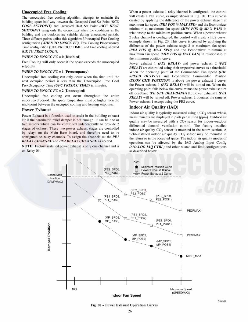
26
Unoccupied Free CoolingThe unoccupied free cooling algorithm attempts to maintain thebuilding space half way between the Occupied Cool Set Point (OCCCOOL SETPOINT) and Occupied Heat Set Point (OCC HEATSETPOINT) using only the economizer when the conditions in thebuilding and the outdoors are suitable, during unoccupied periods.Three different points define this algorithm: Unoccupied Free Coolingconfiguration (WHEN TO UNOCC FC), Free Cooling PreoccupancyTime configuration (UFC PREOCC TIME), and Free cooling allowed(OK TO FREE COOL?).
WHEN TO UNOCC FC = 0 (Disabled)Free Cooling will only occur if the space exceeds the unoccupiedsetpoints.
WHEN TO UNOCC FC = 1 (Preoccupancy)Unoccupied free cooling can only occur when the time until thenext occupied period is less than the Unoccupied Free CoolPre--Occupancy Time (UFC PREOCC TIME) in minutes.WHEN TO UNOCC FC = 2 (Unoccupied)Unoccupied free cooling can occur throughout the entireunoccupied period. The space temperature must be higher then themid--point between the occupied cooling and heating setpoints.
Power ExhaustPower Exhaust is a function used to assist in the building exhaustair if the barometric relief damper is not enough. It can be one ortwo motors which can be controlled independently to provide 2stages of exhaust. These two power exhaust stages are controlledby relays on the Main Base board, and therefore need to beconfigured on relay channels. To assign the channels set the PE1RELAY CHANNEL and PE2 RELAY CHANNEL as needed.NOTE: Factory installed power exhaust is only one channel and ison Relay 06.
When a power exhaust 1 relay channel is configured, the controlwill create a PE1 curve, example shown in Fig. 20. This curve iscreated by applying the difference of the power exhaust stage 1 atmaximum fan speed (PE1 POS @ MAX SPD) and the Economizerminimum at maximum fan speed (MIN POS @ MAX FAN) inrelationship to the minimum position curve. When a power exhaust2 relay channel is configured, the control will create a PE2 curve,example shown in Fig. 20. This curve is created by applying thedifference of the power exhaust stage 2 at maximum fan speed(PE2 POS @ MAX SPD) and the Economizer minimum atmaximum fan speed (MIN POS @ MAX FAN) in relationship tothe minimum position curve.Power exhaust 1 (PE1 RELAY) and power exhaust 2 (PE2RELAY) are controlled using their respective curves as a threshold.When the operating point of the Commanded Fan Speed (IDFSPEED OUTPUT) and Economizer Commanded Position(ECON CMD POSITION) is above the power exhaust 1 curve,the Power exhaust 1 (PE1 RELAY) will be turned on. When theoperating point falls below the curve minus the power exhaust turnoff deadband (PE OFF DEADBAND) the Power exhaust 1 (PE1RELAY) will be turned off. Power exhaust 2 operates the same asPower exhaust 1 except using the PE2 curve.
Indoor Air Quality (IAQ)Indoor air quality is typically measured using a CO2 sensor whosemeasurements are displayed in parts per million (ppm). Outdoor airquality may be measured with a CO2 sensor for indoor--outdoordifferential demand ventilation control. The factory--installedindoor air quality CO2 sensor is mounted in the return section. Afield--installed indoor air quality CO2 sensor may be mounted inthe return or in the occupied space. The indoor air quality modes ofoperation can be affected by the IAQ Analog Input Config(ANALOG IAQ CTRL) and other related and limit configurationsas described below.
Indoor Fan Speed
Dam
per P
ositi
on
Econo Max
Position
(DAMPMAX)
(MP_SPD2,
MP_POS2)
(MP_SPD3,
MP_POS3)
Maximum Speed
(SPEEDMAX)
(MP_SPD1,
MP_POS1)
10%
MINP_MAX
Minimum Position Curve
Key:
(PE1_SPD3,
PE1_POS3)
(PE1_SPD2,
PE1_POS2)(PE1_SPD1,
PE1_POS1)
PE1PMAX
Power Exhaust 1Curve(PE2_SPD3,
PE2_POS3)
2(PE2_SPD2,
PE2_POS2)(PE2_SPD1,
PE2_POS1)
Power Exhaust 2 Curve
PE2PMAX
C14327
Fig. 20 -- Power Exhaust Operation Curves
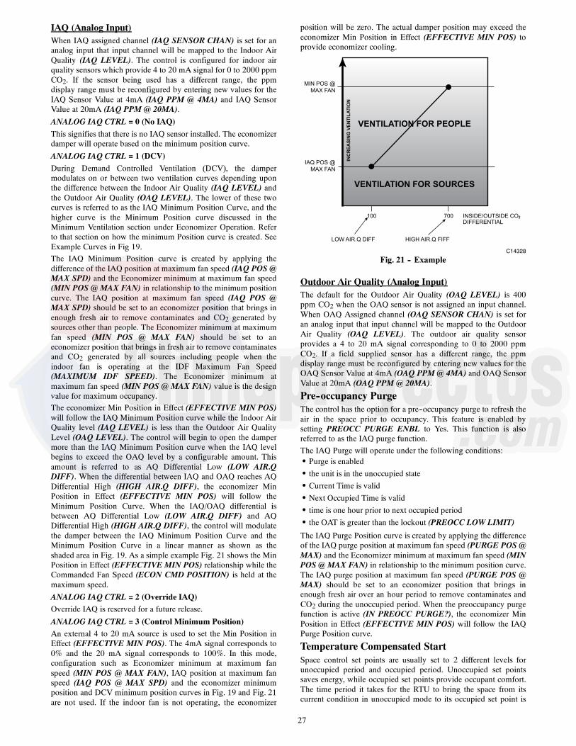
27
IAQ (Analog Input)When IAQ assigned channel (IAQ SENSOR CHAN) is set for ananalog input that input channel will be mapped to the Indoor AirQuality (IAQ LEVEL). The control is configured for indoor airquality sensors which provide 4 to 20 mA signal for 0 to 2000 ppmCO2. If the sensor being used has a different range, the ppmdisplay range must be reconfigured by entering new values for theIAQ Sensor Value at 4mA (IAQ PPM @ 4MA) and IAQ SensorValue at 20mA (IAQ PPM @ 20MA).ANALOG IAQ CTRL = 0 (No IAQ)This signifies that there is no IAQ sensor installed. The economizerdamper will operate based on the minimum position curve.
ANALOG IAQ CTRL = 1 (DCV)During Demand Controlled Ventilation (DCV), the dampermodulates on or between two ventilation curves depending uponthe difference between the Indoor Air Quality (IAQ LEVEL) andthe Outdoor Air Quality (OAQ LEVEL). The lower of these twocurves is referred to as the IAQ Minimum Position Curve, and thehigher curve is the Minimum Position curve discussed in theMinimum Ventilation section under Economizer Operation. Referto that section on how the minimum Position curve is created. SeeExample Curves in Fig 19.The IAQ Minimum Position curve is created by applying thedifference of the IAQ position at maximum fan speed (IAQ POS @MAX SPD) and the Economizer minimum at maximum fan speed(MIN POS @ MAX FAN) in relationship to the minimum positioncurve. The IAQ position at maximum fan speed (IAQ POS @MAX SPD) should be set to an economizer position that brings inenough fresh air to remove contaminates and CO2 generated bysources other than people. The Economizer minimum at maximumfan speed (MIN POS @ MAX FAN) should be set to aneconomizer position that brings in fresh air to remove contaminatesand CO2 generated by all sources including people when theindoor fan is operating at the IDF Maximum Fan Speed(MAXIMUM IDF SPEED). The Economizer minimum atmaximum fan speed (MIN POS @ MAX FAN) value is the designvalue for maximum occupancy.The economizer Min Position in Effect (EFFECTIVE MIN POS)will follow the IAQ Minimum Position curve while the Indoor AirQuality level (IAQ LEVEL) is less than the Outdoor Air QualityLevel (OAQ LEVEL). The control will begin to open the dampermore than the IAQ Minimum Position curve when the IAQ levelbegins to exceed the OAQ level by a configurable amount. Thisamount is referred to as AQ Differential Low (LOW AIR.QDIFF). When the differential between IAQ and OAQ reaches AQDifferential High (HIGH AIR.Q DIFF), the economizer MinPosition in Effect (EFFECTIVE MIN POS) will follow theMinimum Position Curve. When the IAQ/OAQ differential isbetween AQ Differential Low (LOW AIR.Q DIFF) and AQDifferential High (HIGH AIR.Q DIFF), the control will modulatethe damper between the IAQ Minimum Position Curve and theMinimum Position Curve in a linear manner as shown as theshaded area in Fig. 19. As a simple example Fig. 21 shows the MinPosition in Effect (EFFECTIVE MIN POS) relationship while theCommanded Fan Speed (ECON CMD POSITION) is held at themaximum speed.
ANALOG IAQ CTRL = 2 (Override IAQ)Override IAQ is reserved for a future release.
ANALOG IAQ CTRL = 3 (Control Minimum Position)An external 4 to 20 mA source is used to set the Min Position inEffect (EFFECTIVE MIN POS). The 4mA signal corresponds to0% and the 20 mA signal corresponds to 100%. In this mode,configuration such as Economizer minimum at maximum fanspeed (MIN POS @ MAX FAN), IAQ position at maximum fanspeed (IAQ POS @ MAX SPD) and the economizer minimumposition and DCV minimum position curves in Fig. 19 and Fig. 21are not used. If the indoor fan is not operating, the economizer
position will be zero. The actual damper position may exceed theeconomizer Min Position in Effect (EFFECTIVE MIN POS) toprovide economizer cooling.
VENTILATION FOR PEOPLE
VENTILATION FOR SOURCES
INC
REA
SIN
G V
ENTI
LATI
ON
MIN POS @
MAX FAN
IAQ POS @
MAX FAN
100 700 INSIDE/OUTSIDE CO2DIFFERENTIAL
LOW AIR.Q DIFF HIGH AIR.Q FIFF
C14328
Fig. 21 -- Example
Outdoor Air Quality (Analog Input)The default for the Outdoor Air Quality (OAQ LEVEL) is 400ppm CO2 when the OAQ sensor is not assigned an input channel.When OAQ Assigned channel (OAQ SENSOR CHAN) is set foran analog input that input channel will be mapped to the OutdoorAir Quality (OAQ LEVEL). The outdoor air quality sensorprovides a 4 to 20 mA signal corresponding to 0 to 2000 ppmCO2. If a field supplied sensor has a different range, the ppmdisplay range must be reconfigured by entering new values for theOAQ Sensor Value at 4mA (OAQ PPM @ 4MA) and OAQ SensorValue at 20mA (OAQ PPM @ 20MA).
Pre--occupancy PurgeThe control has the option for a pre--occupancy purge to refresh theair in the space prior to occupancy. This feature is enabled bysetting PREOCC PURGE ENBL to Yes. This function is alsoreferred to as the IAQ purge function.The IAQ Purge will operate under the following conditions:S Purge is enabledS the unit is in the unoccupied stateS Current Time is validS Next Occupied Time is validS time is one hour prior to next occupied periodS the OAT is greater than the lockout (PREOCC LOW LIMIT)
The IAQ Purge Position curve is created by applying the differenceof the IAQ purge position at maximum fan speed (PURGE POS @MAX) and the Economizer minimum at maximum fan speed (MINPOS @ MAX FAN) in relationship to the minimum position curve.The IAQ purge position at maximum fan speed (PURGE POS @MAX) should be set to an economizer position that brings inenough fresh air over an hour period to remove contaminates andCO2 during the unoccupied period. When the preoccupancy purgefunction is active (IN PREOCC PURGE?), the economizer MinPosition in Effect (EFFECTIVE MIN POS) will follow the IAQPurge Position curve.
Temperature Compensated StartSpace control set points are usually set to 2 different levels forunoccupied period and occupied period. Unoccupied set pointssaves energy, while occupied set points provide occupant comfort.The time period it takes for the RTU to bring the space from itscurrent condition in unoccupied mode to its occupied set point is
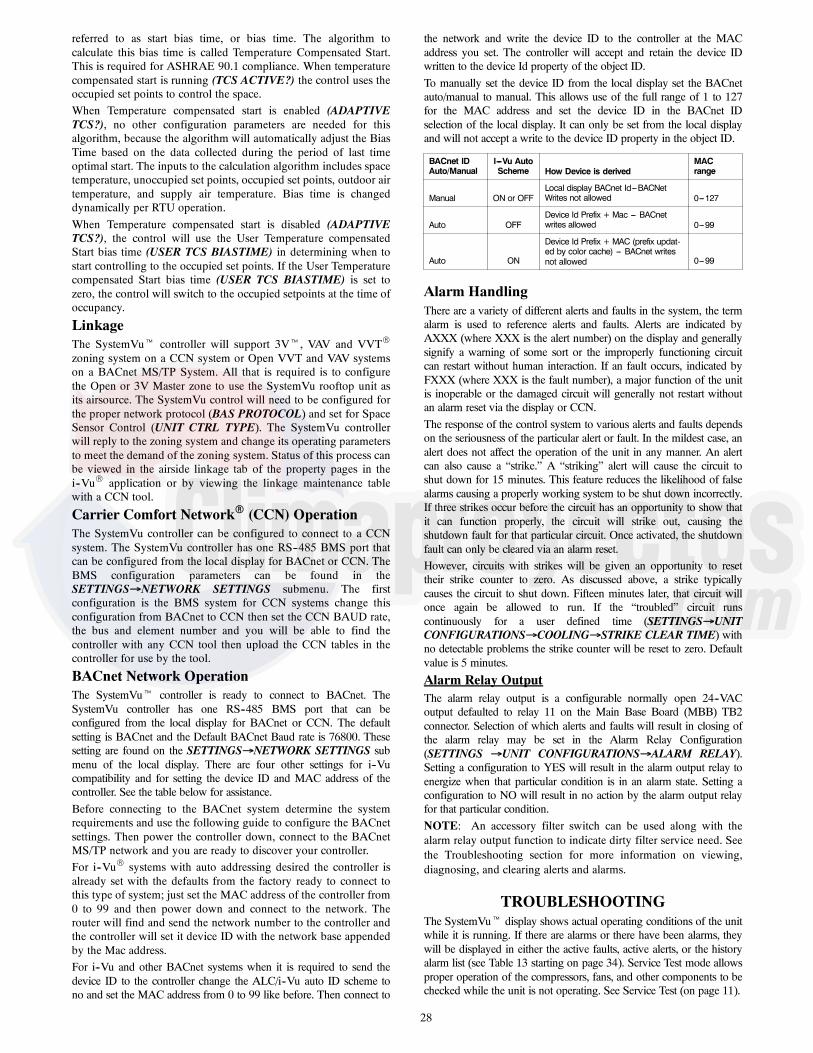
28
referred to as start bias time, or bias time. The algorithm tocalculate this bias time is called Temperature Compensated Start.This is required for ASHRAE 90.1 compliance. When temperaturecompensated start is running (TCS ACTIVE?) the control uses theoccupied set points to control the space.When Temperature compensated start is enabled (ADAPTIVETCS?), no other configuration parameters are needed for thisalgorithm, because the algorithm will automatically adjust the BiasTime based on the data collected during the period of last timeoptimal start. The inputs to the calculation algorithm includes spacetemperature, unoccupied set points, occupied set points, outdoor airtemperature, and supply air temperature. Bias time is changeddynamically per RTU operation.When Temperature compensated start is disabled (ADAPTIVETCS?), the control will use the User Temperature compensatedStart bias time (USER TCS BIASTIME) in determining when tostart controlling to the occupied set points. If the User Temperaturecompensated Start bias time (USER TCS BIASTIME) is set tozero, the control will switch to the occupied setpoints at the time ofoccupancy.
LinkageThe SystemVut controller will support 3Vt, VAV and VVTR
zoning system on a CCN system or Open VVT and VAV systemson a BACnet MS/TP System. All that is required is to configurethe Open or 3V Master zone to use the SystemVu rooftop unit asits airsource. The SystemVu control will need to be configured forthe proper network protocol (BAS PROTOCOL) and set for SpaceSensor Control (UNIT CTRL TYPE). The SystemVu controllerwill reply to the zoning system and change its operating parametersto meet the demand of the zoning system. Status of this process canbe viewed in the airside linkage tab of the property pages in thei--VuR application or by viewing the linkage maintenance tablewith a CCN tool.
Carrier Comfort NetworkR (CCN) OperationThe SystemVu controller can be configured to connect to a CCNsystem. The SystemVu controller has one RS--485 BMS port thatcan be configured from the local display for BACnet or CCN. TheBMS configuration parameters can be found in theSETTINGSNETWORK SETTINGS submenu. The firstconfiguration is the BMS system for CCN systems change thisconfiguration from BACnet to CCN then set the CCN BAUD rate,the bus and element number and you will be able to find thecontroller with any CCN tool then upload the CCN tables in thecontroller for use by the tool.
BACnet Network OperationThe SystemVut controller is ready to connect to BACnet. TheSystemVu controller has one RS--485 BMS port that can beconfigured from the local display for BACnet or CCN. The defaultsetting is BACnet and the Default BACnet Baud rate is 76800. Thesesetting are found on the SETTINGSNETWORK SETTINGS submenu of the local display. There are four other settings for i--Vucompatibility and for setting the device ID and MAC address of thecontroller. See the table below for assistance.Before connecting to the BACnet system determine the systemrequirements and use the following guide to configure the BACnetsettings. Then power the controller down, connect to the BACnetMS/TP network and you are ready to discover your controller.For i--VuR systems with auto addressing desired the controller isalready set with the defaults from the factory ready to connect tothis type of system; just set the MAC address of the controller from0 to 99 and then power down and connect to the network. Therouter will find and send the network number to the controller andthe controller will set it device ID with the network base appendedby the Mac address.For i--Vu and other BACnet systems when it is required to send thedevice ID to the controller change the ALC/i--Vu auto ID scheme tono and set the MAC address from 0 to 99 like before. Then connect to
the network and write the device ID to the controller at the MACaddress you set. The controller will accept and retain the device IDwritten to the device Id property of the object ID.To manually set the device ID from the local display set the BACnetauto/manual to manual. This allows use of the full range of 1 to 127for the MAC address and set the device ID in the BACnet IDselection of the local display. It can only be set from the local displayand will not accept a write to the device ID property in the object ID.
BACnet IDAuto/Manual
I---Vu AutoScheme How Device is derived
MACrange
Manual ON or OFFLocal display BACnet Id---BACNetWrites not allowed 0---127
Auto OFFDevice Id Prefix + Mac --- BACnetwrites allowed 0---99
Auto ON
Device Id Prefix + MAC (prefix updat-ed by color cache) --- BACnet writesnot allowed 0---99
Alarm HandlingThere are a variety of different alerts and faults in the system, the termalarm is used to reference alerts and faults. Alerts are indicated byAXXX (where XXX is the alert number) on the display and generallysignify a warning of some sort or the improperly functioning circuitcan restart without human interaction. If an fault occurs, indicated byFXXX (where XXX is the fault number), a major function of the unitis inoperable or the damaged circuit will generally not restart withoutan alarm reset via the display or CCN.The response of the control system to various alerts and faults dependson the seriousness of the particular alert or fault. In the mildest case, analert does not affect the operation of the unit in any manner. An alertcan also cause a “strike.” A “striking” alert will cause the circuit toshut down for 15 minutes. This feature reduces the likelihood of falsealarms causing a properly working system to be shut down incorrectly.If three strikes occur before the circuit has an opportunity to show thatit can function properly, the circuit will strike out, causing theshutdown fault for that particular circuit. Once activated, the shutdownfault can only be cleared via an alarm reset.However, circuits with strikes will be given an opportunity to resettheir strike counter to zero. As discussed above, a strike typicallycauses the circuit to shut down. Fifteen minutes later, that circuit willonce again be allowed to run. If the “troubled” circuit runscontinuously for a user defined time (SETTINGSUNITCONFIGURATIONSCOOLINGSTRIKE CLEAR TIME) withno detectable problems the strike counter will be reset to zero. Defaultvalue is 5 minutes.
Alarm Relay OutputThe alarm relay output is a configurable normally open 24--VACoutput defaulted to relay 11 on the Main Base Board (MBB) TB2connector. Selection of which alerts and faults will result in closing ofthe alarm relay may be set in the Alarm Relay Configuration(SETTINGS UNIT CONFIGURATIONSALARM RELAY).Setting a configuration to YES will result in the alarm output relay toenergize when that particular condition is in an alarm state. Setting aconfiguration to NO will result in no action by the alarm output relayfor that particular condition.NOTE: An accessory filter switch can be used along with thealarm relay output function to indicate dirty filter service need. Seethe Troubleshooting section for more information on viewing,diagnosing, and clearing alerts and alarms.
TROUBLESHOOTINGThe SystemVut display shows actual operating conditions of the unitwhile it is running. If there are alarms or there have been alarms, theywill be displayed in either the active faults, active alerts, or the historyalarm list (see Table 13 starting on page 34). Service Test mode allowsproper operation of the compressors, fans, and other components to bechecked while the unit is not operating. See Service Test (on page 11).

29
Complete Unit StoppageThere are several conditions that can cause a complete unitstoppage, including:S A fault is active which causes the unit to shut down.S Cooling and heating loads are satisfied.S Programmed occupancy schedule.S General power failure.S Tripped 24-volt transformer circuit breakers.S Blown fuse or circuit breakersS Unit is turned off through the network.Restart ProcedureBefore attempting to restart the machine, check the faults and alertslist to determine the cause of the shut down. If the shutdown faultfor a particular control function has occurred, determine andcorrect the cause before allowing the unit to run under its owncontrol again. When there is problem, the unit should be diagnosedin Service Test mode. The faults must be reset before the controlfunction can operate in either Normal mode or Service Test mode.
Faults and AlertsViewing and Clearing Unit AlarmsPresence of active alarms will be indicated on the SystemVudisplay by the Alarm Status lights. When alerts are active theyellow “ALERT” light will be lit. When faults are active the red“FAULT” light will be lit. When the unit is operational, then green“RUN” light will be lit. The SystemVu controller standby screenwill be updated with the active alarms for easy access. Presence ofactive alarms may also be signaled on the Alarm Output terminals.Each alarm may also be broadcast on the CCN network. Activealarms and past alarm history can be reviewed and cleared via thelocal display or a network device. The following menu locationsare used for the local display:ACTIVE FAULTS -- Displays the list of active faults in order ofoccurrence.ACTIVE ALERTS -- Displays the list of active alerts in order ofoccurrence.HISTORY -- Displays the list of active and previously active faultsand alerts in order of occurrence with time and date.RESET FAULTS/ALERTS --User command to manually resetfaults and alerts.
Each alarm can have up to 3 data points stamped along with dateand time to assist in troubleshooting. Pressing ENTER on thealarm or expanded screen will provide these data points.
Diagnostic Alarm Codes and Possible CausesFault F010 – MBB LOW VOLTAGEThis fault occurs when the MBB supply voltages falls below 17volts AC. When this occurs the control will shut down the unit.This will automatically clear when the supply voltage rises above19 volts AC. The cause of this fault is usually a brownoutcondition, low supply voltage, or supply power missing a phase.Fault F011 – MBB REFERENCE VOLTAGEThis fault occurs when the MBB internal microprocessor’s DCreference voltages is out of range. When this occurs the control willshut down the unit. This will automatically clear when the DCreference voltage goes back in range. The cause of this fault isusually a MBB failure or supply voltage out of range.Alert A012 – MBB ZERO CROSSINGThis fault occurs when the MBB supply voltage frequency is out ofrange. When this occurs the control will issue an alert. This willautomatically clear when the supply voltage goes back in range.The cause of this fault is usually a MBB failure or supply voltagefrequency to high or to low.Fault F013 – MBB FUSE 2 OPENThis fault occurs when the MBB’s internal fuse number 2 exceedsthreshold temperature. When this occurs the control will shut down
the unit. This will automatically clear when the fuse temperaturegets back in range. The cause of this fault is usually a switch inputhas a wiring error (short) or the switch pulled too much current.Discrete input number 2, Fire Shutdown input, and the IGC fanrequest are connected to fuse 2.Fault F014 – MBB FUSE 3 OPENThis fault occurs when the MBB’s internal fuse number 3 exceedsthreshold temperature. When this occurs the control will shut downthe unit. This will automatically clear when the fuse temperaturegets back in range. The cause of this fault is usually a switch inputhas a wiring error (short) or the switch pulled too much current.Configurable discrete input numbers 12, 13, and 14 are connectedto fuse 3.Alert A015 – MBB RNET VOLTAGE RANGEThis fault occurs when the MBB’s Rnet 12 volt output is out ofrange. When this occurs the control will issue an alert, and anyaccessory connected to the Rnet plug may not operate properly.This will automatically clear when the voltage goes back in range.The cause of this fault is usually a MBB failure or supply voltageout of range.Alert A016 – MBB 24VDC RANGEThis fault occurs when the MBB’s 24vdc output falls below 17volts DC. When this occurs the control will put the Analog Inputnumber’s 6, 7, and 8 into error state. This will automatically clearwhen the voltage rises above 19 volts DC. The cause of this fault isusually a MBB failure or supply voltage out of range.Alert A017 – MBB 5VDC RANGEThis fault occurs when the MBB’s 5vdc output falls below 4.5volts DC. When this occurs the control will put the Transducerinputs into error state. This will automatically clear when thevoltage rises above 4.5 volts DC. The cause of this fault is usuallya MBB failure or supply voltage out of range.Fault F018 – MBB EEPROM FAILUREThe unit will completely shut down. The serial EEPROM chip onthe MBB which stores the unit’s configuration is not responding.Recovery is automatic but MBB board replacement may benecessary. Cycling the power to the control should be tried beforeboard replacement.Alert A019 – MBB CLOCK FAILUREThe alert occurs when the RTC clock chip on the MBB is notresponding. Time and date functions will not operate, such as localoccupancy schedules. The unit will default to 24/7 unoccupiedmode. Recovery is automatic but MBB board replacement may benecessary. Cycling power to the control and reconfiguring the timeand date should be tried before board replacement.Fault F020 – SOFTWARE ERRORThe unit will completely shut down. The software on the MBB isnot responding. Recovery is automatic if the software is able toreset the board but software change may be necessary. Cycling thepower to the control should be tried before board replacement.Alert A099 -- COMM LOSS WITH SIOBThis alert occurs when there has been a loss of communicationwith the IO Board on the LEN bus. Any sensor inputs from theboard will be ignored and outputs will no longer be controlled.Alert A100 – SAT SENSOR FAILUREThis alert occurs when the fan supply temperature sensor is in anerror state. Economizer cooling cannot occur while this alert isactive. The unit will not be able to honor SAT limits. This alertresets automatically. The cause of the alert is usually a faultythermistor, a shorted or open thermistor caused by a wiring error,or a loose connection.Alert A101 – FST SENSOR RANGEThis alert occurs when the fan supply temperature sensor is outsidethe range –40_F to 245_F (–40_C to 116_C). This alert resetsautomatically. The cause of the alert is usually a faulty thermistor, a

30
shorted or open thermistor caused by a wiring error, or a looseconnection.Alert A102 – FST OPEN SENSORThis alert occurs when the fan supply temperature sensor reads asan open circuit. This alert resets automatically. The cause of thealert is usually a faulty thermistor or an open thermistor caused bya wiring error, or a loose connection.Alert A103 – FST SHORTED SENSORThis alert occurs when the fan supply temperature sensor reads as ashort circuit. This alert resets automatically. The cause of the alert isusually a faulty thermistor or a shorted thermistor caused by awiring error, or a loose connection.Alert A104 – OAT SENSOR RANGEThis alert occurs when the outdoor air temperature is outside therange –40_F to 245_F (–40_C to 116_C). All ambient temperaturelockout limits for cooling and heating are ignored. All coolingcontrol logic will assume OAT is high. For economizer equippedunits, the economizer will not operate to provide cooling. Theeconomizer will still operate for ventilation. The control will usenormal operation for outdoor fan control. For units with CCHcrankcase heat relay control, the crankcase heat relay will be turnedon if any compressor is off. This alert resets automatically. Thecause of the alert is usually a faulty thermistor, a shorted or openthermistor caused by a wiring error, or a loose connection.Alert A105 – OAT OPEN SENSORSee Alert A104Alert A106 – OAT SHORTED SENSORSee Alert A104Alert A107 -- RAT SENSOR RANGEThis alert occurs when the return air temperature is outside therange –40_F to 245_F (–40_C to 116_C). Differential dry bulbcrossover control can not occur. Free cooling can only becontrolled by the OAT and enthalpy switch. The economizermechanically disconnected alert will not be diagnosed. This alertresets automatically. The cause of the alert is usually a faultythermistor, a shorted or open thermistor caused by a wiring error,or a loose connection.Alert A108 – RAT OPEN SENSORSee Alert A107Alert A109 – RAT SHORTED SENSORSee Alert A107Alert A110 – SPT SENSOR RANGEThis alert occurs when the temperature is outside the range –40_Fto 245_F (–40_C to 116_C). Cooling and heating will not operate.For economizer equipped units, the economizer will still operatefor ventilation. This alert resets automatically. The cause of thealert is usually a faulty thermistor in the T--55, T--56, or T--58device, a shorted or open thermistor caused by a wiring error, or aloose connection.Alert A111 – SPT OPEN SENSORSee Alert A110Alert A112 – SPT SHORTED SENSORSee Alert A110Alert A130 – CIR.A SSP SENSOR RANGEThis alert occurs when the pressure is outside the range --6.7 to 420psig. A circuit cannot run when this alert is active. The cause of thealert is usually a faulty transducer, faulty 5--v power supply, or aloose connection. Use the transducer voltage drop table todetermine where the error is introduced.Alert A131 – CIR.A SSP OPEN SENSORSee Alert A130Alert A132 – CIR.A SSP SHORT SENSORSee Alert A130
Alert A133 – CIR.A SDP SENSOR RANGEThis alert occurs when the pressure is outside the range 14.5 to 667psig. A circuit cannot run when this alert is active. The cause of thealert is usually a faulty transducer, faulty 5--v power supply, or aloose connection. Use the transducer voltage drop table todetermine where the error is introduced.Alert A134 – CIR.A SDP OPEN SENSORSee Alert A130Alert A135 – CIR.A SDP SHORT SENSORSee Alert A130Alert 150 -- OACFM OPEN SENSORThis alert occurs when the Outdoor Air CFM sensor input is 0 mAand the sensor is configured and installed. Check sensor andwiring. This alert clears automatically.Alert 151 -- OACFM SHORTED SENSORThis alert occurs when the Outdoor Air CFM sensor input shortedand the sensor is configured as installed. Check sensor and wiring.This alert clears automatically.Alert A160 – OARH OPEN SENSORThis alert occurs when the Outdoor Air Relative Humidity sensorinput is 0 mA and the sensor is configured as installed. Outside AirEnthalpy cannot be calculated therefore no enthalpy crossover canbe used and only dry bulb will be used in determining free cooling.Check sensor and wiring. This alert clears automatically.Alert A161 – OARH SHORTED SENSORThis alert occurs when the Outdoor Air Relative Humidity sensorinput shorted and the sensor is configured as installed. Outside AirEnthalpy cannot be calculated therefore no enthalpy crossover canbe used and only dry bulb will be used in determining free cooling.Check sensor and wiring. This alert clears automatically.Alert A162 – RARH OPEN SENSORThis alert occurs when the Return Air Relative Humidity sensorinput is 0 mA and the sensor is configured as installed. Return AirEnthalpy cannot be calculated therefore no differential enthalpycrossover can be used. Dry bulb and single enthalpy will be used indetermining free cooling. Check sensor and wiring. This alertclears automatically.Alert A163 – RARH SHORTED SENSORThis alert occurs when the Return Air Relative Humidity sensorinput shorted and the sensor is configured as installed. Return AirEnthalpy cannot be calculated therefore no differential enthalpycrossover can be used. Dry bulb and single enthalpy will be used indetermining free cooling. Check sensor and wiring. This alertclears automatically.Alert A164 -- IAQ OPEN SENSORThis alert occurs when the IAQ input is 0 mA and the sensor isconfigured as installed. IAQ operation will be disabled. Checksensor and wiring. This alert clears automatically.Alert A165 -- IAQ SHORTED SENSORThis alert occurs when the IAQ input is shorted and the sensor isconfigured as installed. IAQ operation will be disabled. Checksensor and wiring. This alert clears automatically.Alert A166 -- OAQ OPEN SENSORThis alert occurs when the OAQ input is 0 mA and the sensor isconfigured as installed. OAQ operation will be disabled. Checksensor and wiring. This alert clears automatically.Alert A167 -- OAQ SHORTED SENSORThis alert occurs when the OAQ input is shorted and the sensor isconfigured as installed. OAQ operation will be disabled. Checksensor and wiring. This alert clears automatically.

31
Alert A168 -- SPACE RELATIVE HUMIDITY OPEN SENSORThis alert occurs when the SPRH input is 0 mA and the sensor isconfigured as installed. Check sensor and wiring. This alert clearsautomatically.Alert A169 -- SPACE HUMIDITY SHORTED SENSORThis alert occurs when the SPRH input is shorted and the sensor isconfigured as installed. Check sensor and wiring. This alert clearsautomatically.Alert A170 – ECON FEEDBACK RANGEThis alert occurs when the Economizer analog feedback signal isoutside the range of 1.3vdc to 10.3vdc and the feedback isconfigured to use. A short is 10.5vdc and an open circuit is lessthan 0.1vdc. Economizer diagnostics operation will be disabled.This is usually caused by a wiring problem, actuator failure, or thewrong actuator. Investigate using the Low Voltage Schematic;make sure the feedback signal from the actuator is correct. Thisalert clears automatically.Alert A171 – ECON FEEDBACK OPENSee Alert A170Alert A172 – ECON FEEDBACK SHORTEDSee Alert A170Alert A190 – TSTAT HEAT/COOL CALLSThis alert occurs in Thermostat mode when Y1, Y2, or Y3 isenergized simultaneously with W1 or W2. Verify thermostat andthermostat wiring. The software will enter either the cooling orheating mode depending upon which input turned on first. Thisalert resets automatically when Y1, Y2, and Y3 are not onsimultaneously with W1 and W2.Alert A191 – TSTAT IMPROPER COOLThis alert occurs in Thermostat mode when Y2 or Y3 is energizedand Y1 is not. Verify thermostat and thermostat wiring. When thisoccurs the control will treat the inputs as a number instead ofspecific input. Example a Y2 and Y3 would mean 2 cooling inputsso the control would treat that as is a Y1 and Y2 was active. Thisalert resets automatically when Y1 is turned On.Alert A192 – TSTAT IMPROPER HEATThis alert occurs in Thermostat mode when W2 is energized andW1 is not. Verify thermostat and thermostat wiring. When W2turns On, the software will behave as if W1 and W2 are both On.When W2 turns Off, the software will behave as if W1 and W2 areboth Off. This alert resets automatically when W1 is turned On.Fault F200 – FIRE SHUTDOWNThis fault occurs when the fire shutdown input is either open orclosed depending upon its configuration. This fault is usuallycaused by an auxiliary device that is trying to shut down the unit,e.g., smoke detector. This will cause a unit shutdown condition.Verify that the configuration is set correct, verify the wiring andauxiliary device. This fault resets automatically.Fault F201 – CONDENSATE OVERFLOWThis fault occurs when the COFS input is either open or closeddepending upon its configuration. This fault is usually caused bywater reaching a high level in the drain pan. This will cause acooling lockout. Verify that the configuration is set correct, verifythe wiring and auxiliary device. This fault resets automatically.Alert A203 – DIRTY FILTERThis alert occurs when the Filter Status switch senses a pluggedfilter for 5 continuous seconds after the indoor fan has beenrunning for 10 seconds or if the fan has run for longer than thechange filter time. Because the Dirty Air Filter switch can beconfigured normally opened or closed, the switch might be open orclosed. Verify that the configurations are set correct, verify thewiring and filter status switch. The hose should be connected to thelow side of the switch. The alert resets automatically if it wastripped due to the filter switch. If the alert is tripped because of thetimer, it will need to be reset after the filter has been replaced or
inspected. Rest the time with the RESET FILTER TIME point islocated under RUN STATUS GENERAL or INPUTS GENERAL INPUTS.Fault F204 – REMOTE SHUTDOWNThis fault occurs when the remote shutdown input is either open orclosed depending upon its configuration and configured to set afault. This fault is usually caused by an auxiliary emergency devicethat is trying to shut down the unit. This will cause a unit shutdowncondition. Verify that the configuration is set correct, verify thewiring and auxiliary device. This fault resets automatically.Alert A210 – GENERAL STATUSThis alert occurs when the general status input is either open orclosed depending upon its configuration and configured to set aalert. This alert is usually caused by an auxiliary switch device thatis trying to send a warning about the unit. Verify that theconfiguration is set correct, verify the wiring and auxiliary device.This alert resets automatically.Fault F211 – GENERAL STATUSThis fault occurs when the general status input is either open orclosed depending upon its configuration and configured to set afault. This fault is usually caused by an auxiliary switch device thatis trying to shut down the unit. This will cause a unit shutdowncondition. Verify that the configuration is set correct, verify thewiring and auxiliary device. This fault resets automatically.Fault F310 – CIRA DOWN DUE TO FAILThis fault occurs when both compressors on circuit A have 3strikes. Investigate the alerts that caused the strikes to occur, andcorrect or test as needed. Manual alarm reset or power cycle isrequired to rest this fault.Fault F311 – CIRA LOW CHARGEThis alert occurs when the compressors are off and both thedischarge and suction pressure are less than the low charge level(LOW CHARGE LEVEL) and OAT is greater than the low chargelimit (NO LOW CHARGE OAT). The cause of the alert is usuallylow refrigerant pressure or faulty pressure transducers. This alertonly occurs when the compressor is OFF because the lowrefrigerant pressure alert will handle this situation when thecompressor is operating. Manual alarm reset or power cycle isrequired to rest this fault.Alert A312 – CIR.A UNEXPECTED OFFThese alerts occur when the suction pressure raises the configuredamount and the pressure ratio drop the configured amount both ina 10 second window during compressor operation. When thisoccurs, the control turns off the compressors and logs a strike forwhich compressor that was on. This alerts reset automatically. Thepossible causes are: high--pressure switch (HPS) open (The HPS iswired in series with compressor relays on the MBB), compressorinternal protection is open, or a wiring error (a wiring error mightnot allow the compressor to start).Alert A313 – CIR.A HIGH DISCHARGEThis alert occurs when the discharge pressure is greater than theconfigured CIR.A SDP LIMIT amount. This alert resetsautomatically when the pressure falls 20 psig below the threshold.When running both compressors the control will remove A1 andadd a strike to it. The control will also set the ODFs to the highcool speed. The cause of the alert is usually an overcharged system,high outdoor ambient temperature coupled with dirty outdoor coil,plugged filter drier, or ODF speeds being set too low.Alert A314 – CIR.A HPS TRIPThis alert occurs when the discharge high pressure switch opens.This alert resets automatically when the pressure falls below theswitch threshold and the switch closes for 3 minutes. The controlwill add a strike for which ever compressors were on. The controlwill also set the ODFs to the high cool speed. The cause of the alertis usually an overcharged system, high outdoor ambient
32
temperature coupled with dirty outdoor coil, plugged filter drier, orODF speeds being set too low.Alert A315 – CIR.A LOW DISCHARGEThis alert occurs when the discharge pressure is less than the OATplus the configured LOW DISCHARGE LEV amount. This alertresets automatically. The control will add a strike for which evercompressors were on. The cause of the alert is usually anundercharged system, low outdoor ambient temperature coupledwith dirty outdoor coil, plugged filter drier, or ODF speeds beingset too high.Alert A316 – CIR.A LOW SUCTIONThis alert occurs when the compressor is operating and theevaporating temperature (converted from the suction pressure) isless than configured low suction control levels, LOW SUCLEVEL 1, LOW SUC LEVEL2, or LOW SUC LEVEL3. Thecircuit SST value must be less than LOW SUC LEVEL 1 (for 5minutes), LOW SUC LEVEL 2 (for 4 minutes), or LOW SUCLEVEL 3 (for 3 minutes when using the economizer and 1.5minutes when not using the economizer) for the alert to occur.When the outdoor temperature is less than 40_F, the above valuesare reduced 1_F for every 2_F OAT is below 40_F. All the abovetimers will reset if the suction temperature rises above LOW SUCOK TEMP for 1 minute. This alert causes a strike for the respectivecircuit. This alert will activate when the coil becomes frosted.However, during the 15--minute reset period, the coils will thawand strike should clear and restart if there is nothing else wrongwith the circuit. The alert resets automatically. The cause of thealert is usually low refrigerant charge, dirty filters, evaporator fanoperating backwards, loose or broken belt, plugged filter drier,faulty transducer, excessively cold return air, or stuck openeconomizer when the ambient temperature is low.Alert A317 – CIR.A LOW DISCHARGEThis alert occurs when the Circuit A pressure ratio is less than theconfigured MIN PRESSURE RATIO amount. This alert resetsautomatically. The control will add a strike for which evercompressors were on. The cause of the alert is usually anundercharged system, low outdoor ambient temperature coupledwith dirty outdoor coil, plugged filter drier, or ODF speeds beingset too high.Fault F318 – COMPRESSOR STUCK ONThis alert occurs when the Suction pressure does not raise theminimum suction amount (CIR.A MIN SUC.P ) and the ratio didnot fall at least the off pressure ratio (OFF P.RATIO). When thisoccurs, the control turns off all of the compressors, and enters asafety shutdown condition. The possible causes are a weldedcontactor or frozen compressor relay on MBB. Manual alarm resetor power cycle is required to rest this fault.Fault F319 – C.A1 DOWN DUE TO FAILThis fault occurs when compressor A1 has 3 strikes. Investigate thealerts that caused the strikes to occur, and correct or test as needed.Manual alarm reset or power cycle is required to rest this fault.Alert A320 – C.A1 REVERSE ROTATIONThis alert occurs when 10 seconds after the compressor turns on,the suction rose and the discharge pressure dropped. This alertcauses a strike for the compressor. The alert resets automatically.The cause of the alert is usually compressor wiring causing reverserotation or a faulty compressor.Alert A321 – C.A1 FAIL TO PRESSUREThis alert occurs when 10 seconds after the compressor turns on,the suction did not drop more that suction amount (CIR.A MINSUC.P) and discharge pressure did not rise more than dischargeamount (CIR.A MIN DIS.P). This alert causes a strike for thecompressor. The alert resets automatically. The cause of the alert isusually compressor wiring causing reverse rotation or a faultycompressor.
Fault F322 – C.A2 DOWN DUE TO FAILThis fault occurs when compressor A2 has 3 strikes. Investigate thealerts that caused the strikes to occur, and correct or test as needed.Manual alarm reset or power cycle is required to rest this fault.Alert A323 – C.A2 REVERSE ROTATIONThis alert occurs when 10 seconds after the compressor turns on,the suction rose and the discharge pressure dropped. This alertcauses a strike for the compressor. The alert resets automatically.The cause of the alert is usually compressor wiring causing reverserotation or a faulty compressor.Alert A324 – C.A2 FAIL TO PRESSUREThis alert occurs when 10 seconds after the compressor turns on,the suction did not drop more that suction amount (CIR.A MINSUC.P) and discharge pressure did not rise more than dischargeamount (CIR.A MIN DIS.P). This alert causes a strike for thecompressor. The alert resets automatically. The cause of the alert isusually compressor wiring causing reverse rotation or a faultycompressor.Alert A410 – IGC IGNITION FAILUREThis alert occurs when the IGC fan request does not activate 15minutes after turning heat 1 on when configured for Gas Heat. Thecontrol will lockout all the heat stages. This alert will automaticallyreset after the IGC fan request occurs. The cause of this alert isusually faulty wiring of the IGC, no gas flow, or wrongconfiguration.Fault F411 – ROLLOUTWITHOUT HEATThis fault occurs when the IGC fan request activates and the heathas been off for at least 3 minutes when configured for Gas Heat.The control will enter the safety shutdown condition. This alertwill automatically reset after the IGC fan request turns off for 10minutes. The cause of this alert is usually faulty wiring of the IGC,or rollout switch trip without a heat call.Fault F412 – RUN AWAY HEATThis fault occurs when the SAT rises above the maximum SAT.The control will enter the safety shutdown condition. This alertwill automatically reset after if configured to and the SAT falls 50degrees below the maximum SAT. The cause of this alert is usuallyheat stuck on causing high SAT, or low air flow.Alert A510 – INDOOR FAN STATUSThis alert occurs when the unit is configured not to shut down onfan status and either the fan is requested off and the fan speedfeedback does not reach zero in the VFD deceleration time or thefan is requested greater than zero and the fan speed feedback doesnot reach that speed in the VFD acceleration time. This alert willreset automatically. The cause of this alert is usually belt broke,motor failure, or configuration error.Fault F511 – IDF OFF WHEN COMMAND ONThis fault occurs when the unit is configured to shut down on fanstatus and the fan is requested greater than zero and the fan speedfeedback does not reach that speed in the VFD acceleration time.The cause of this alert is usually Fan stuck on, or Configurationincorrect. Manual alarm reset or power cycle is required to rest thisfault.Fault F512 – IDF ONWHEN COMMAND OFFThis fault occurs when the unit is configured to shut down on fanstatus and the fan is requested off and the fan speed feedback doesnot reach zero in the VFD deceleration time. The cause of this alertis usually tripped circuit breaker, broken belt, bad indoor fanmotor, or configuration incorrect. Manual alarm reset or powercycle is required to rest this fault.Fault F600 – IDF VFD COMMUNICATIONThis fault occurs when the indoor fan VFD and the SystemVutcontrol are not communicating properly. This will cause a unitshutdown, and will automatically reset when communication isproperly restored. The cause of this is usually a break in the

33
communication connection, noise on the LEN bus, wiring error, or aconfiguration error. Verify VFD configurations are set per the latestliterature.Fault F601 – IDF VFD UNEXPECTEDThis fault occurs when the indoor fan VFD informs the SystemVucontrol that it has an active fault. This will cause a unit shutdown,and will automatically reset when the VFD fault is cleared butlikely will require a manual reset to reset the VFD. Refer to theVFD section or literature for details on the specific VFD fault.Verify VFD configurations are set per the latest literature.Fault F602 – IDF VFD LOCKOUTThis fault occurs when the indoor fan VFD informs the SystemVucontrol that it has an active lockout fault. This will cause a unitshutdown, and requires a power cycle to reset the VFD. Refer tothe VFD section or literature for details on the specific VFD fault.Verify VFD configurations are set per the latest literature.Alert A603 – IDF VFD IN HANDThis alert occurs when the indoor fan VFD informs the SystemVucontrol that it is no longer in auto control and in either hand or offmode. This can only be done with the accessory VFD keypad. Thiswill automatically reset when the VFD is placed back into automode for the VFD keypad. Refer to the VFD section or literaturefor details on the specific VFD fault. Verify VFD configurationsare set per the latest literature.Fault F604 – IDF VFD IN HANDThis fault occurs when the indoor fan VFD informs the SystemVucontrol that it is no longer in auto control and in either hand or offmode. This can only be done with the accessory VFD keypad. Thiswill cause a unit shutdown, and will automatically reset when theVFD is placed back into auto mode for the VFD keypad. Refer tothe VFD section or literature for details on the specific VFD fault.Verify VFD configurations are set per the latest literature.Alert A605 – IDF VFD THERMALWARNINGThis fault occurs when the indoor fan VFD informs the SystemVucontrol that it has an active warning. This will cause an IDF speedreduction of 10%, and will automatically reset when the VFD alertis cleared. Refer to the VFD section or literature for details on thespecific VFD fault. Verify VFD configurations are set per the latestliterature.Alert A606 – IDF VFD VOLTAGEWARNINGSee alert A605Alert A607 – IDF VFD CURRENT LIMITSee alert A605Alert A608 – IDF VFDWARNINGSee alert A605Fault F611 – IDF VFD EARTH FAULTSee fault F601Fault F612 – IDF VFD CTLWORD LOSSSee fault F601Fault F613 – IDF VFD OVER CURRENTSee fault F601
Fault F614 – IDF VFD MOTOR OVER TEMPSee fault F601Fault F615 – IDF VFD OVERLOADSee fault F601Fault F616 – IDF VFD UNDER VOLTAGESee fault F601Fault F617 – IDF VFD OVER VOLTAGESee fault F601Fault F618 – IDF VFD SHORT CIRCUITSee fault F601Fault F619 – IDF VFD MAIN PHASE LOSSSee fault F601Fault F620 – IDF VFD PHASE U LOSSSee fault F601Fault F621 – IDF VFD PHASE V LOSSSee fault F601Fault F622 – IDF VFD PHASE W LOSSSee fault F601Fault F623 – IDF VFD CONTROL VOLTAGESee fault F601Fault F624 – IDF VFD SUPPLY VDDSee fault F601Alert A700 – ECON NOT MODULATINGThis alert occurs when the economizer feedback is enabled and theactual speed does reach the commanded speed in the economizertravel time configuration value. This alert will automatically resetwhen the actual position does reach the commanded position. Thisis usually caused by installation of the wrong actuator, noeconomizer gear motion, or actuator direction control switch(CCW, CW) wrong. Check damper blades, gears, and actuator.This alert will usually be accompanied by another descriptiveinformational alert.Alert A701 – ECON STUCK CLOSEDSee alert A700Alert A702 – ECON STUCK OPENSee alert A700Alert A703 – IDF MECH DISCONNECTEDThis alert occurs when the Alert A700 is not active yet the controldetermines that the economizer changes are not aligning with thetemperature changes. This will require a manual reset to ensure theeconomizer is inspected. This is usually caused by the actuator notproperly secured to the damper shaft.Alert A710 – ECON NOT COOLINGSee alert A700Alert A711 – ECON IMPROPER COOLINGSee alert A700Alert A712 – EXCESSIVE OUTDOOR AIRSee alert A700

34
Table 13 – SystemVut Controller Alarm Codes
FAULT OR ALERT ACTION TAKEN BYCONTROL
RESETMETHOD PROBABLE CAUSE
F010---MBB LOW VOLTAGE Unit Shutdown Automatic Brownout condition, low supply voltage, supply power missing a phase.
F011---MBB REFERENCE VOLTAGE Unit Shutdown Automatic MBB failure or supply voltage low
A012---MBB ZERO CROSSING Alert Generated Automatic MBB failure or supply voltage frequency to high or too low.
F013---MBB FUSE 2 OPEN Unit Shutdown Automatic A switch input has a wiring error or the switch pulled too much current.
F014---MBB FUSE 3 OPEN Unit Shutdown Automatic A switch input has a wiring error or the switch pulled too much current.
A015---MBB RNET VOLTAGE RANGE Alert Generated Automatic MBB failure or supply voltage low
A016---MBB 24VDC RANGE 4---20mA inputs will be in error Automatic MBB failure or supply voltage low
A017---MBB 5VDC RANGE Transducer inputs will be in error Automatic MBB failure or supply voltage low
F018---MBB EEPROM FAILURE Unit Shutdown Automatic Software failure or MBB failure
A019---MBB CLOCK FAILURE No time, date, and scheduleoperation
Automatic Software failure or MBB failure
A099---COMM LOSS WITH SIOB ON LENBUS
Loss of communication with IOfrom SIOB board
Automatic Wiring problem between MBB and SIOB
F020---SOFTWARE ERROR Unit Shutdown Automatic Corrupt Software or software failure
A100---SAT SENSOR ERROR No free cooling, and no SATlimit protection
Automatic Faulty, shorted, or open thermistor caused by wiring error or loose connection.
A101---FST SENSOR RANGE Alert Generated Automatic Faulty or incorrect thermistor caused by improper ohm reading
A102---FST OPEN SENSOR Alert Generated Automatic Missing or open thermistor caused by wiring error or loose connection.
A103---FST SHORTED SENSOR Alert Generated Automatic Faulty or shorted thermistor caused by wiring error or loose connection.
A104---OAT SENSOR RANGE No free cooling, no lowambient operation
Automatic Faulty or incorrect thermistor caused by improper ohm reading
A105---OAT OPEN SENSOR No free cooling, no lowambient operation
Automatic Missing or open thermistor caused by wiring error or loose connection.
A106---OAT SHORTED SENSOR No free cooling, no lowambient operation
Automatic Faulty or shorted thermistor caused by wiring error or loose connection.
A107---RAT SENSOR RANGE No differential DB crossover Automatic Faulty or incorrect thermistor caused by improper ohm reading
A108---RAT OPEN SENSOR No differential DB crossover Automatic Missing or open thermistor caused by wiring error or loose connection.
A109---RAT SHORTED SENSOR No differential DB crossover Automatic Faulty or shorted thermistor caused by wiring error or loose connection.
A110---SPT SENSOR RANGE No heating or cooling Automatic Faulty or incorrect thermistor caused by improper ohm reading
A111---SPT OPEN SENSOR No heating or cooling Automatic Missing or open thermistor caused by wiring error or loose connection.
A112---SPT SHORTED SENSOR No heating or cooling Automatic Faulty or shorted thermistor caused by wiring error or loose connection.
A130---CIR.A SSP SENSOR RANGE Shutdown Circuit A Automatic Faulty transducer, faulty 5---V power supply, or loose connection
A131---CIR.A SSP OPEN SENSOR Shutdown Circuit A Automatic Faulty transducer, faulty 5---V power supply, or loose connection
A132---CIR.A SSP SHORT SENSOR Shutdown Circuit A Automatic Faulty transducer, faulty 5---V power supply, or loose connection
A133---CIR.A SDP SENSOR RANGE Shutdown Circuit A Automatic Faulty transducer, faulty 5---V power supply, or loose connection
A134---CIR.A SDP OPEN SENSOR Shutdown Circuit A Automatic Faulty transducer, faulty 5---V power supply, or loose connection
A135---CIR.A SDP SHORT SENSOR Shutdown Circuit A Automatic Faulty transducer, faulty 5---V power supply, or loose connection
A150---OUTDOOR AIRFLOW IN CFM OPENSENSOR
No OACFM Operations Automatic Wiring problem, or configuration error
A151---OUTDOOR AIRFLOW IN CFMSHORTED SENSOR
No OACFM Operations Automatic Wiring problem, or configuration error
A160---OARH OPEN SENSOR No Enthalpy crossover Automatic Bad sensor, bad wiring, or sensor configured incorrectly.
A161---OARH SHORTED SENSOR No Enthalpy crossover Automatic Bad sensor, bad wiring, or sensor configured incorrectly.
A162---RARH OPEN SENSOR No Differential Enthalpycrossover
Automatic Bad sensor, bad wiring, or sensor configured incorrectly.
A163---RARH SHORTED SENSOR No Differential Enthalpycrossover
Automatic Bad sensor, bad wiring, or sensor configured incorrectly.
A164--- IAQ OPEN SENSOR No IAQ Operations Automatic Bad sensor, bad wiring, or sensor configured incorrectly.
A165--- IAQ SHORTED SENSOR No IAQ Operations Automatic Bad sensor, bad wiring, or sensor configured incorrectly.
A166---OAQ OPEN SENSOR No OAQ Operations Automatic Bad sensor, bad wiring, or sensor configured incorrectly.
A167---OAQ SHORTED SENSOR No OAQ Operations Automatic Bad sensor, bad wiring, or sensor configured incorrectly.
A168---SPACE RELATIVE HUMIDITY OPENSENSOR
No dehumidifying Automatic Bad sensor, bad wiring, sensor configured incorrectly, loss of communicationto SIOB.
A169---SPACE RELATIVE HUMIDITYSHORTED SENSOR
No dehumidifying Automatic Bad sensor, bad wiring, sensor configured incorrectly, loss of communicationto SIOB.
A170---ECON FEEDBACK RANGE No economizer diagnostics Automatic Wiring problem with actuator, or configuration error
A171---ECON FEEDBACK OPEN No economizer diagnostics Automatic Wiring problem with actuator, or configuration error
A172---ECON FEEDBACK SHORTED No economizer diagnostics Automatic Wiring problem with actuator, or configuration error
A190---TSTAT HEAT/COOL CALLS Run unit in mode activated first Automatic Bad Thermostat or Thermostat Wiring
A191---TSTAT IMPROPER COOL Run cooling per number ofactive inputs
Automatic Bad Thermostat or Thermostat Wiring
A192---TSTAT IMPROPER HEAT Run heating per number ofactive inputs
Automatic Bad Thermostat or Thermostat Wiring
F200---FIRE SHUTDOWN Unit Shutdown Automatic Smoke detected by smoke detector
F201---CONDENSATE OVERFLOW Cooling Shutdown Automatic Dain pan plugged, sensor error, or configuration error
A203---DIRTY FILTER Alert Generated Automatic Dirty Filter or filter timer expired
F204---REMOTE SHUTDOWN Unit Shutdown Automatic Remote activation of the shutdown switch

35
Table 13 — SystemVut Controller Alarm Codes (cont)
FAULT OR ALERT ACTION TAKEN BYCONTROL
RESETMETHOD PROBABLE CAUSE
A210---GENERAL STATUS Alert Generated Automatic General Switch activation or wrong configuration
F211---GENERAL STATUS Unit Shutdown Automatic General Switch activation or wrong configuration
F310---CIRA DOWN DUE TO FAIL Shutdown Circuit A Manual Compressors have 3 strikes or has been locked out by another alarm
F311---CIRA LOW CHARGE Shutdown Circuit A Manual Low refrigerant or faulty pressure transducer
A312---CIR.A UNEXPECTED OFF Strike for active compressors Automatic Compressor failure, transducer failure, or nuisance operating conditions
A313---CIR.A HIGH DISCHARGE Unload compression and upODF to High cool speed
Automatic An overcharged system, high outdoor ambient temperature coupled withdirty outdoor coil, plugged filter drier, or ODF speeds being set too low.
A314---CIR.A HPS TRIP Add compressor strikes Automatic An overcharged system, high outdoor ambient temperature coupled withdirty outdoor coil, plugged filter drier, or ODF speeds being set too low.
A315---CIR.A LOW DISCHARGE Add compressor strikes Automatic An undercharged system, low outdoor ambient temperature coupled withdirty outdoor coil, plugged filter drier, or ODF speeds being set too high
A316---CIR.A LOW SUCTION Add compressor strikes Automatic Low refrigerant charge, dirty filters, evaporator fan turning backwards, looseor broken fan belt, plugged filter drier, faulty transducer, excessively coldreturn air, or stuck open economizer when the ambient temperature is low.
A317---CIR.A PRESSURE RATIO Add compressor strikes Automatic Low refrigerant charge, plugged filter drier, faulty transducer, the ambienttemperature is low and the ODFs are running too fast.
F318---COMPRESSOR STUCK ON Unit in Safety Shutdown Manual Welded contactor or frozen compressor relay on MBB
F319---C.A1 DOWN DUE TO FAIL Lockout Compressor A1 Manual Compressor A1 has 3 strikes or has been locked out by another alarm
A320---C.A1 REVERSE ROTATION Add Strike for compressor A1 Automatic Wiring causing reverse rotation or faulty compressor
A321---C.A1 FAIL TO PRESSURE Add Strike for compressor A1 Automatic Wiring causing reverse rotation or faulty compressor
F322---C.A2 DOWN DUE TO FAIL Lockout Compressor A2 Manual Compressor A2 has 3 strikes or has been locked out by another alarm
A323---C.A2 REVERSE ROTATION Add Strike for compressor A2 Automatic Wiring causing reverse rotation or faulty compressor
A324---C.A2 FAIL TO PRESSURE Add Strike for compressor A2 Automatic Wiring causing reverse rotation or faulty compressor
A410--- IGC IGNITION FAILURE Lockout Heat Automatic Faulty wiring of the IGC, no gas flow, or wrong configuration
F411---ROLLOUT WITHOUT HEAT Unit in Safety Shutdown Automatic Faulty wiring of the IGC, or rollout switch trip without a heat call
F412---RUN AWAY HEAT Unit in Safety Shutdown Automatic Heat stuck on causing high SAT, or low air flow
A510--- INDOOR FAN STATUS Alert Generated Automatic Belt broke, motor failure, or configuration error.
F511--- IDF OFF WHEN COMMAND ON Unit Shutdown Manual Fan stuck on, or Configuration incorrect.
F512--- IDF ON WHEN COMMAND OFF Unit Shutdown Manual Tripped Circuit Breaker. Broken belt. Bad indoor fan motor. Configurationincorrect.
F600--- IDF VFD COMMUNICATION Unit Shutdown Automatic Communication failure, noise on the bus, wiring error, or configuration error.
F601--- IDF VFD UNEXPECTED Unit Shutdown Automatic VFD fault, refer to VFD section
F602--- IDF VFD LOCKOUT Unit Shutdown Power Cycle VFD locked itself out
A603--- IDF VFD IN HAND Alert Generated Automatic VFD keypad used to put the VFD in hand or off mode
F604--- IDF VFD IN HAND Unit Shutdown Automatic VFD keypad used to put the VFD in hand or off mode
A605--- IDF VFD THERMAL WARNING IDF speed reduced Automatic Motor improper size, motor overload, or configuration errors
A606--- IDF VFD VOLTAGE WARNING IDF speed reduced Automatic Motor improper size, motor overload, or configuration errors
A607--- IDF VFD CURRENT LIMIT IDF speed reduced Automatic Motor improper size, motor overload, or configuration errors
A608--- IDF VFD WARNING IDF speed reduced Automatic Motor improper size, motor overload, or configuration errors
F611--- IDF VFD EARTH FAULT Unit Shutdown Automatic VFD fault, refer to VFD section
F612--- IDF VFD CTL WORD LOSS Unit Shutdown Automatic VFD fault, refer to VFD section
F613--- IDF VFD OVER CURRENT Unit Shutdown Automatic VFD fault, refer to VFD section
F614--- IDF VFD MOTOR OVER TEMP Unit Shutdown Automatic VFD fault, refer to VFD section
F615--- IDF VFD OVERLOAD Unit Shutdown Automatic VFD fault, refer to VFD section
F616--- IDF VFD UNDER VOLTAGE Unit Shutdown Automatic VFD fault, refer to VFD section
F617--- IDF VFD OVER VOLTAGE Unit Shutdown Automatic VFD fault, refer to VFD section
F618--- IDF VFD SHORT CIRCUIT Unit Shutdown Automatic VFD fault, refer to VFD section
F619--- IDF VFD MAIN PHASE LOSS Unit Shutdown Automatic VFD fault, refer to VFD section
F620--- IDF VFD PHASE U LOSS Unit Shutdown Automatic VFD fault, refer to VFD section
F621--- IDF VFD PHASE V LOSS Unit Shutdown Automatic VFD fault, refer to VFD section
F622--- IDF VFD PHASE W LOSS Unit Shutdown Automatic VFD fault, refer to VFD section
F623--- IDF VFD CONTROL VOLTAGE Unit Shutdown Automatic VFD fault, refer to VFD section
F624--- IDF VFD SUPPLY VDD Unit Shutdown Automatic VFD fault, refer to VFD section
A700---ECON NOT MODULATING Alert Generated Automatic No economizer motion. Check damper blades, gears, and actuator. Actuatordirection control switch (CCW, CW) wrong.
A701---ECON STUCK CLOSED Alert Generated Automatic No economizer motion. Check damper blades, gears, and actuator. Actuatordirection control switch (CCW, CW) wrong.
A702---ECON STUCK OPEN Alert Generated Automatic No economizer motion. Check damper blades, gears, and actuator. Actuatordirection control switch (CCW, CW) wrong.
A703---ECON MECH DISCONNECTED Alert Generated Manual No economizer motion. Check damper blades, gears, and actuator. Actuatordirection control switch (CCW, CW) wrong.
A710---ECON NOT COOLING Alert Generated Automatic No economizer motion. Check damper blades, gears, and actuator. Actuatordirection control switch (CCW, CW) wrong.
A711---ECON IMPROPER COOLING Alert Generated Automatic No economizer motion. Check damper blades, gears, and actuator. Actuatordirection control switch (CCW, CW) wrong.
A712---EXCESSIVE OUTDOOR AIR Alert Generated Automatic No economizer motion. Check damper blades, gears, and actuator. Actuatordirection control switch (CCW, CW) wrong.

36
Control Module CommunicationRed LEDProper operation of the MBB control board can be visuallychecked by looking at the red status LED. When operatingcorrectly, the red status LED should blink at a rate of once every 2seconds. If the red LED is not blinking, verify that correct power isbeing supplied. A blinking red LED at the rate of once per secondmeans that software is not loaded on the board. Also, be sure thatthe board is supplied with the current software. If necessary, reloadcurrent software. A board LED that is lit continuously should bereplaced.
Green LEDThe MBB has one green LED. The Local Equipment Network(LEN) LED should always be blinking whenever power is on. IfLEN LED is not blinking, check LEN connections for potentialcommunication errors (MBB J15, J16, J17, and on the Display J2).Communication between modules is accomplished by a 3--wiresensor bus. These 3 wires run in parallel from module to module.The MBB J17 and Display J2 connectors provide both power andcommunication directly at the connector for accessories like the
Navigatort display. The MBB J15 connector provides a LENinterface to the indoor fan VFD.
Yellow LEDThe MBB has one yellow LED which is used to indicate BuildingAutomated System (BAS) communication activity. The LED willblink when the MBB transmits a message on the bus.
Communication FailuresIf the Indoor Fan VFD or Navigator display CommunicationFailure or the green or yellow LED’s do not flash on the boardsthen the problem could be the communication chip on one of thecontrol boards (MBB). Use an ohm meter to measure the resistanceon the communication pins of the boards to determine if the boardis bad. If the reading is less then half the value indicated in Table14, then the board needs to be replaced.
IMPORTANT: The resistive values should be read when theboard is powered off, the unit is locked out, and boardconnectors are disconnected.
Table 14 – Communication Resistances
Device
(LEN) Resistance between Pins /Connector
(BAS) Resistance between Pins /Connector
(RNET) Resistance between Pins /Connector
Pins1 to 3
Pins1 to 2
Pins2 to 3
Pins1 to 3
Pins1 to 2
Pins2 to 3
PinsGND to +
PinsGND to -
Pins+ to -
MBB 19.92 KΩ 10.63 KΩ 9.51 KΩ 19.92 KΩ 10.63 KΩ 9.51 KΩ 2.25 KΩ 1 KΩ 3.3 KΩ
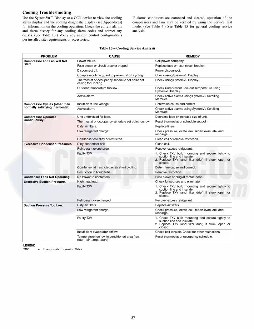
37
Cooling TroubleshootingUse the SystemVut Display or a CCN device to view the coolingstatus display and the cooling diagnostic display (see Appendices)for information on the cooling operation. Check the current alarmsand alarm history for any cooling alarm codes and correct anycauses. (See Table 13.) Verify any unique control configurationsper installed site requirements or accessories.
If alarms conditions are corrected and cleared, operation of thecompressors and fans may be verified by using the Service Testmode. (See Table 4.) See Table 15 for general cooling serviceanalysis.
Table 15 – Cooling Service Analysis
PROBLEM CAUSE REMEDYCompressor and Fan Will NotStart.
Power failure. Call power company.Fuse blown or circuit breaker tripped. Replace fuse or reset circuit breaker.Disconnect off. Power disconnect.Compressor time guard to prevent short cycling. Check using SystemVu Display.Thermostat or occupancy schedule set point notcalling for Cooling.
Check using SystemVu Display.
Outdoor temperature too low. Check Compressor Lockout Temperature usingSystemVu Display.
Active alarm. Check active alarms using SystemVu ScrollingMarquee.
Compressor Cycles (other thannormally satisfying thermostat).
Insufficient line voltage. Determine cause and correct.Active alarm. Check active alarms using SystemVu Scrolling
Marquee.
Compressor OperatesContinuously.
Unit undersized for load. Decrease load or increase size of unit.Thermostat or occupancy schedule set point too low. Reset thermostat or schedule set point.Dirty air filters. Replace filters.Low refrigerant charge. Check pressure, locate leak, repair, evacuate, and
recharge.
Condenser coil dirty or restricted. Clean coil or remove restriction.
Excessive Condenser Pressures. Dirty condenser coil. Clean coil.Refrigerant overcharge. Recover excess refrigerant.Faulty TXV. 1. Check TXV bulb mounting and secure tightly to
suction line and insulate.2. Replace TXV (and filter drier) if stuck open orclosed.
Condenser air restricted or air short cycling. Determine cause and correct.Restriction in liquid tube. Remove restriction.
Condenser Fans Not Operating. No Power to contactors. Fuse blown or plug at motor loose.Excessive Suction Pressure. High heat load. Check for sources and eliminate
Faulty TXV. 1. Check TXV bulb mounting and secure tightly tosuction line and insulate.
2. Replace TXV (and filter drier) if stuck open orclosed.
Refrigerant overcharged. Recover excess refrigerant.
Suction Pressure Too Low. Dirty air filters. Replace air filters.Low refrigerant charge. Check pressure, locate leak, repair, evacuate, and
recharge.
Faulty TXV. 1. Check TXV bulb mounting and secure tightly tosuction line and insulate.
2. Replace TXV (and filter drier) if stuck open orclosed.
Insufficient evaporator airflow. Check belt tension. Check for other restrictions.Temperature too low in conditioned area (lowreturn-air temperature).
Reset thermostat or occupancy schedule.
LEGENDTXV --- Thermostatic Expansion Valve
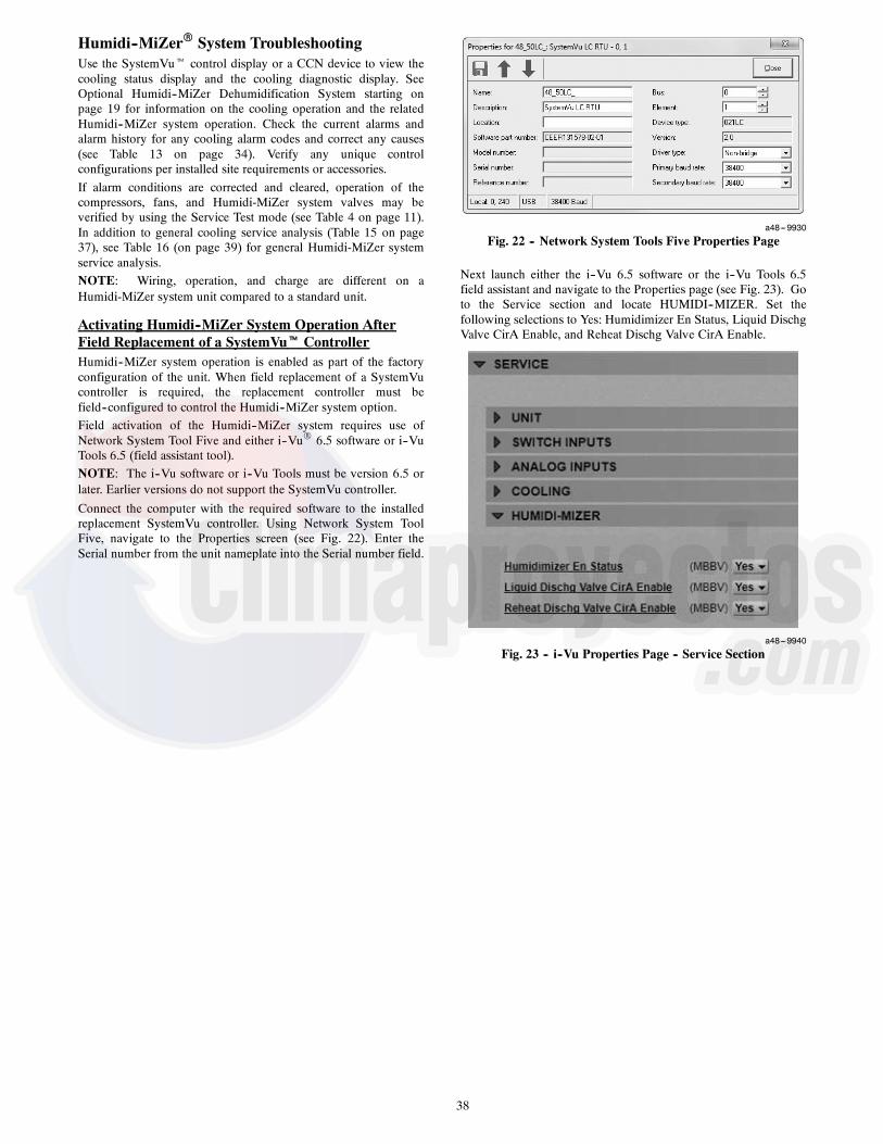
38
Humidi--MiZerR System TroubleshootingUse the SystemVut control display or a CCN device to view thecooling status display and the cooling diagnostic display. SeeOptional Humidi--MiZer Dehumidification System starting onpage 19 for information on the cooling operation and the relatedHumidi--MiZer system operation. Check the current alarms andalarm history for any cooling alarm codes and correct any causes(see Table 13 on page 34). Verify any unique controlconfigurations per installed site requirements or accessories.If alarm conditions are corrected and cleared, operation of thecompressors, fans, and Humidi-MiZer system valves may beverified by using the Service Test mode (see Table 4 on page 11).In addition to general cooling service analysis (Table 15 on page37), see Table 16 (on page 39) for general Humidi-MiZer systemservice analysis.NOTE: Wiring, operation, and charge are different on aHumidi-MiZer system unit compared to a standard unit.
Activating Humidi--MiZer System Operation AfterField Replacement of a SystemVut ControllerHumidi--MiZer system operation is enabled as part of the factoryconfiguration of the unit. When field replacement of a SystemVucontroller is required, the replacement controller must befield--configured to control the Humidi--MiZer system option.Field activation of the Humidi--MiZer system requires use ofNetwork System Tool Five and either i--VuR 6.5 software or i--VuTools 6.5 (field assistant tool).NOTE: The i--Vu software or i--Vu Tools must be version 6.5 orlater. Earlier versions do not support the SystemVu controller.
Connect the computer with the required software to the installedreplacement SystemVu controller. Using Network System ToolFive, navigate to the Properties screen (see Fig. 22). Enter theSerial number from the unit nameplate into the Serial number field.
a48---9930
Fig. 22 -- Network System Tools Five Properties Page
Next launch either the i--Vu 6.5 software or the i--Vu Tools 6.5field assistant and navigate to the Properties page (see Fig. 23). Goto the Service section and locate HUMIDI--MIZER. Set thefollowing selections to Yes: Humidimizer En Status, Liquid DischgValve CirA Enable, and Reheat Dischg Valve CirA Enable.
a48---9940
Fig. 23 -- i--Vu Properties Page -- Service Section

39
Table 16 – Humidi--MiZer System Service Analysis
PROBLEM CAUSE REMEDYSubcooling Reheat ModeWill Not Activate.
General cooling mode problem. See Cooling Service Analysis (Table 15).
No dehumidification demand. See No Dehumidification Demand, below.
IOB operation. See IOB Operation, below.
Circuit LDV valve problem. See LDV Valve Operation, below.
Hot Gas Reheat ModeWill Not Activate.
General cooling mode problem. See Cooling Service Analysis (Table 15).
No dehumidification demand. See No Dehumidification Demand, below.
IOB operation. See IOB Operation, below.
Circuit LDV valve problem. See LDV (3---Way) Valve Operation, below.
Circuit RDV valve is not open. See RDV Valve Operation, below.
Outdoor temperature too low. Check Reheat Circuit Limit TemperaturesUnit ConfigurationsCoolingHumz Lockout OAT
No Dehumidification Demand. Relative humidity setpoint istoo low — Humidistat Check/reduce setting on accessory humidistat.
Relative humidity setpoint istoo low — RH sensor. Check Space RH Setpoints (SetpointsSPRH)
Software configuration errorfor accessory humidistat.
Check Space Humidity Switch (SETTINGSUNIT CONFIGURATIONSSWITCH INPUTS CONFIGSHUMSTAT CHANNEL)
Software configuration errorfor accessory humidity sensor.
Check RH Sensor (SETTINGSUNIT CONFIGURATIONSANALOGINPUTS CONFIGSSPRH SENSOR CHANNEL)
No humidity signal. Check wiring. Check humidistat or humidity sensor.
IOB Operation. Communication loss to Input---Output Board. Check wiring connections. Alert A099 --- COMM LOSS WITH SIOB
No power to output terminals. Check wiring.
Relay outputs do not change state. Replace faulty IOB.
LDV (3---Way) Valve Operation.
No 24V signal to input terminals.
Check using ServiceLIQ DIVERT A TEST
Check IOB relay output.
Check Wiring.
Check transformer and circuit beaker or fuses.
Solenoid coil burnout.
Check continuous over-voltage is less than 10%.
Check under-voltage is less than 15%.
Check for missing coil assembly parts.
Check for damaged valve enclosing tube.
Stuck valve. Replace valve. Replace filter drier.
RDV Valve Operation.(NOTE: Normally ClosedWhen De-energized) No 24V signal to input terminals.
Check using ServiceRDV A TEST
Check IOB relay output.
Check wiring.
Check transformer and circuit breaker or fuses.
Solenoid coil burnout.
Check continuous over-voltage is less than 10%.
Check under-voltage is less than 15%.
Check for missing coil assembly parts.
Check for damaged valve enclosing tube.
Stuck valve. Replace valve. Replace filter drier.
Low Sensible Capacity in Normal Coolor Subcooling Reheat Modes. RDV valve open or leaking. See RDV Valve Operation, above.
Low Suction Pressure and HighSuperheat During Normal Cool Mode.
General cooling mode problem. See Cooling Service Analysis (Table 15).
RDV valve open or leaking. See RDV Valve Operation, above.
RDV Valve Cycling On/Off. Hot Gas Reheat mode low suction pressure limit. Normal Operation During Mixed Circuit Subcooling and Hot Gas ReheatModes at Lower Outdoor Temperatures.
LEGENDIOB --- Input---Output BoardLDV --- Liquid Diverter ValveRDV --- Reheat Discharge ValveRH --- Relative Humidity

40
Economizer TroubleshootingUse the SystemVut Display to view the economizer status. Checkthe current alerts and faults and the alarm history for economizerspecific alerts or any relevant faults or alerts and correct thoseissues. Use test mode to troubleshoot by ramping the economizerup and down with and without the indoor fan and power exhaustfan on. Inspect the mechanical economizer for actuator, gear, orblade damage. Ensure the actuator is mounted with the correctspring return (close damper when no power applied to unit).Ensure there is a 500 ohm resister across the actuator as the4--20mA output signal must be converted to 2--10V.
The Economizer alerts can be summarized as a failure to modulatethe damper blades. This can be due to the actuator not beingproperly connected to the damper, or because the actuator’sfeedback signal is indicating that damper is not performing ascommanded. The mechanical disconnect diagnostic will run whenconditions are appropriate to determine proper air temperaturechanges. This uses the OAT, RAT, and SAT to tell if the damper ismixing the outdoor air with the return air. The other alerts informwhere the damper is stuck relative to the commanded position.
Table 17 – Economizer Service Analysis
PROBLEM POSSIBLE CAUSE REMEDYDamper Does Not Move. Indoor Fan is off. Check for proper thermostat connection.
Unit is not configured for continuous fanoperation and the thermostat is not calling forheating or cooling.Unit is in Unoccupied mode and there is nocall for heating or cooling.
Tripped circuit breaker.No power to the unit.Unit is off via CCN command.
Actuator is unplugged at motor or ateconomizer board.
Check wiring connections.
Unit is not configured for economizer. Configure unit for economizer per theinstructions.
Outdoor-air temperature is above economizerhigh temperature lockout.
Adjust the high temperature lockout settingif it is incorrect, otherwise, economizer isoperating correctly.
Outdoor-air temperature is below economizer lowtemperature lockout.
Adjust the low temperature lockout settingif it is incorrect, otherwise, economizer isoperating correctly.
Communication loss to economizer board. Check wiring connections.Damper is jammed. Identify the obstruction and safely remove.
Economizer Operation is Limitedto Minimum Position.
Minimum position is set incorrectly. Adjust minimum position setting.Outdoor-air temperature is above economizerhigh temperature lockout.
Adjust the high temperature lockout settingif it is incorrect, otherwise, economizer isoperating correctly.
Outdoor-air temperature is below economizerlow temperature lockout.
Adjust the low temperature lockout setting if it isincorrect, otherwise, economizer is operatingcorrectly.
Enthalpy or differential dry bulb are preventing freecooling.
Check enthalpy and return air compared tooutside air temperature.
Outdoor-air thermistor is faulty. Replace outdoor-air thermistor.Low suction pressure problem with a compressor. Economizer is operating correctly, identify
compressor problem.
Economizer Position is LessThan Minimum Position.
IAQ is controlling minimum damper position. Adjust the IAQ settings if incorrect,otherwise, the economizer is operating correctly.
Unit is in Unoccupied mode. Adjust unit occupied schedule if incorrect,otherwise, economizer is operating correctly.
Economizer Does Not Returnto Minimum Position.
Unit is operating under free cooling. Economizer is operating correctly.
Damper Does Not Close onPower Loss.
Damper is jammed or spring return is backwards. Identify the obstruction and safely remove.
Economizer is Not at ConfiguredMinimum Position
Unit is operating under free cooling or a force isapplied to the commanded position.
Economizer is operating correctly.
LEGENDCCN --- Carrier Comfort NetworkR
IAQ --- Indoor Air Quality
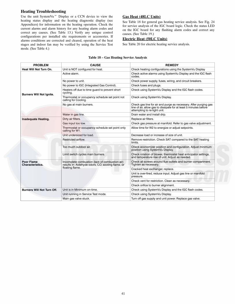
41
Heating TroubleshootingUse the unit SystemVut Display or a CCN device to view theheating status display and the heating diagnostic display (seeAppendices) for information on the heating operation. Check thecurrent alarms and alarm history for any heating alarm codes andcorrect any causes. (See Table 13.) Verify any unique controlconfigurations per installed site requirements or accessories. Ifalarms conditions are corrected and cleared, operation of the heatstages and indoor fan may be verified by using the Service Testmode. (See Table 4.)
Gas Heat (48LC Units)See Table 18 for general gas heating service analysis. See Fig. 24for service analysis of the IGC board logic. Check the status LEDon the IGC board for any flashing alarm codes and correct anycauses. (See Table 19.)
Electric Heat (50LC Units)See Table 20 for electric heating service analysis.
Table 18 – Gas Heating Service Analysis
PROBLEM CAUSE REMEDYHeat Will Not Turn On. Unit is NOT configured for heat. Check heating configurations using the SystemVu Display
Burners Will Not Ignite.
Active alarm. Check active alarms using SystemVu Display and the IGC flashcodes.
No power to unit. Check power supply, fuses, wiring, and circuit breakers.No power to IGC (Integrated Gas Control). Check fuses and plugs.Heaters off due to time guard to prevent shortcycling.
Check using SystemVu Display and the IGC flash codes.
Thermostat or occupancy schedule set point notcalling for Cooling.
Check using SystemVu Display.
No gas at main burners. Check gas line for air and purge as necessary. After purging gasline of air, allow gas to dissipate for at least 5 minutes beforeattempting to re-light unit.
Water in gas line. Drain water and install drip.
Inadequate Heating. Dirty air filters. Replace air filters.Gas input too low. Check gas pressure at manifold. Refer to gas valve adjustment.Thermostat or occupancy schedule set point onlycalling for W1.
Allow time for W2 to energize or adjust setpoints.
Unit undersized for load. Decrease load or increase of size of unit.Restricted airflow. Remove restriction. Check SAT compared to the SAT heating
limits.
Too much outdoor air. Check economizer position and configuration. Adjust minimumposition using SystemVu Display.
Limit switch cycles main burners. Check rotation of blower, thermostat heat anticipator settings,and temperature rise of unit. Adjust as needed.
Poor FlameCharacteristics.
Incomplete combustion (lack of combustion air)results in: Aldehyde odors, CO, sooting flame, orfloating flame.
Check all screws around flue outlets and burner compartment.Tighten as necessary.
Cracked heat exchanger, replace.Unit is over-fired, reduce input. Adjust gas line or manifoldpressure.
Check vent for restriction. Clean as necessary.Check orifice to burner alignment.
Burners Will Not Turn Off. Unit is in Minimum on-time. Check using SystemVu Display and the IGC flash codes.Unit running in Service Test mode. Check using SystemVu Display.Main gas valve stuck. Turn off gas supply and unit power. Replace gas valve.

42
1 FLASH - INDOOR FAN DELAYMODIFIED (HEATING)
2 FLASHES - OPENING OF LIMITSWITCH
3 FLASHES - FLAME SENSORINDICATES FLAME WITH
CLOSED GAS VALVE
4 FLASHES - LIMIT SWITCHCYCLED 4 TIMES ON SINGLE
CALL FOR HEAT
5 FLASHES - IGNITION LOCKOUT(No ignition within 15 minutes)
6 FLASHES - INDUCED DRAFTMOTOR FAULT
(No signal from the Flue GasPressure Switch or 60 seconds)
7 FLASHES - OPENING OFROLLOUT SWITCH
8 FLASHES - HARDWARE ORSOFTWARE FAULT
9 FLASHES - SOFTWARELOCKOUT
FLASHING LED is
ON
CALL FOR
24 VOLTSBETWEENF1 AND C
YES
No
DEFECTIVEIGC BOARD
1. BLOWN 5 AMP FUSE2. DEFECTIVE 24V TRANS.3. BROKEN WIRE4. NO POWER TO UNIT
HEATING
‘W1’ FROM BASE CONTROL BOARD ENERGIZES ‘W’ON IGC - 1 MINUTE LOCK-ON
COMBUSTION RELAY ON IGC IN ENERGIZED
COMBUSTION RELAY ENERGIZES INDUCED DRAFT MOTOR (IDM) THROUGHTERMINAL ′CM′ ON IGC
IF IDM IS TURNING AT CORRECT SPEED (AT LEAST 2400 RPM), FLUE GASPRESSUE SWITCH SENDS CORRECT SIGNAL TO TERMINAL ‘J1’ ON IGC
IF LIMIT SWITCH AND ROLLOUTSWITCH ARE CLOSED, IGC SAFETY
LOGIC WILL INITIATE IGNITIONSEQUENCE
IGC HIGH VOLTAGETRANSFORMER CREATES A10,000 VOLT SPARK FOR 5
SECONDS
IGC SAFETY LOGIC OPENS GASVALVE FOR 5 SECONDS
DOES IGC DETECT.2 MICROAMPS FOR 2
SECONDSNo
Yes
AFTER 45 SECONDS (OR LESS IF THE TIMINGHAS BEEN REDUCED DUE TO LIMIT SWITCHTRIPS) IGC WILL ENERGIZE BLOWER RELAY
DID LIMITSWITCH OPEN BEFORE THE 45SECONDS (OR THE MODIFIED
TIME) HAS TIMED OUT?Yes
No
No
IGC SAFETY LOGIC WILL SHUTOFF GAS VALVE AND SPARK
20 SECOND PURGE OF HEATEXCHANGER
IS THIS THE33RD RETRY? (OR 15
MINUTES)
Yes
IGNITION LOCKOUT(5 FLASHES OF LED)
SUBTRACT 5 SECONDS FROMINDOOR FAN ON TIME DELAY
NORMAL HEATING OPERATION
HEATING DEMAND SATISFIED
45 SECOND BLOWER SHUTOFF DELAY(DELAY EXTENDED BY 5 SECONDS FOR EACH LIMIT SWITCH TRIP
MAXIMUM DELAY: 3 MINUTES)
IDM STOPS, SAFETY LOGIC SHUTS OFF GAS VALVE
LEGEND
IDM – Induced-Draft MotorIGC – Integrated Gas Unit Controller
NOTE: Thermostat Fan Switch in the “AUTO” position.
OFF
a48---9375
Fig. 24 -- IGC Service Analysis Logic
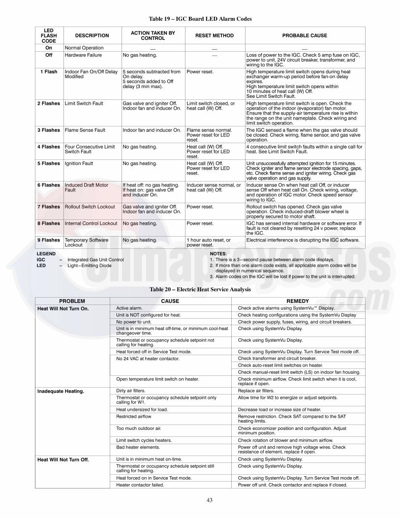
43
Table 19 – IGC Board LED Alarm Codes
LEDFLASHCODE
DESCRIPTION ACTION TAKEN BYCONTROL RESET METHOD PROBABLE CAUSE
On Normal Operation — — —Off Hardware Failure No gas heating. — Loss of power to the IGC. Check 5 amp fuse on IGC,
power to unit, 24V circuit breaker, transformer, andwiring to the IGC.
1 Flash Indoor Fan On/Off DelayModified
5 seconds subtracted fromOn delay.5 seconds added to Offdelay (3 min max).
Power reset. High temperature limit switch opens during heatexchanger warm-up period before fan-on delayexpires.High temperature limit switch opens within10 minutes of heat call (W) Off.See Limit Switch Fault.
2 Flashes Limit Switch Fault Gas valve and igniter Off.Indoor fan and inducer On.
Limit switch closed, orheat call (W) Off.
High temperature limit switch is open. Check theoperation of the indoor (evaporator) fan motor.Ensure that the supply-air temperature rise is withinthe range on the unit nameplate. Check wiring andlimit switch operation.
3 Flashes Flame Sense Fault Indoor fan and inducer On. Flame sense normal.Power reset for LEDreset.
The IGC sensed a flame when the gas valve shouldbe closed. Check wiring, flame sensor, and gas valveoperation.
4 Flashes Four Consecutive LimitSwitch Fault
No gas heating. Heat call (W) Off.Power reset for LEDreset.
4 consecutive limit switch faults within a single call forheat. See Limit Switch Fault.
5 Flashes Ignition Fault No gas heating. Heat call (W) Off.Power reset for LEDreset.
Unit unsuccessfully attempted ignition for 15minutes.Check igniter and flame sensor electrode spacing, gaps,etc. Check flame sense and igniter wiring. Check gasvalve operation and gas supply.
6 Flashes Induced Draft MotorFault
If heat off: no gas heating.If heat on: gas valve Offand inducer On.
Inducer sense normal, orheat call (W) Off.
Inducer sense On when heat call Off, or inducersense Off when heat call On. Check wiring, voltage,and operation of IGC motor. Check speed sensorwiring to IGC.
7 Flashes Rollout Switch Lockout Gas valve and igniter Off.Indoor fan and inducer On.
Power reset. Rollout switch has opened. Check gas valveoperation. Check induced-draft blower wheel isproperly secured to motor shaft.
8 Flashes Internal Control Lockout No gas heating. Power reset. IGC has sensed internal hardware or software error. Iffault is not cleared by resetting 24 v power, replacethe IGC.
9 Flashes Temporary SoftwareLockout
No gas heating. 1 hour auto reset, orpower reset.
Electrical interference is disrupting the IGC software.
LEGENDIGC --- Integrated Gas Unit ControlLED --- Light---Emitting Diode
NOTES:1. There is a 3---second pause between alarm code displays.2. If more than one alarm code exists, all applicable alarm codes will bedisplayed in numerical sequence.
3. Alarm codes on the IGC will be lost if power to the unit is interrupted.
Table 20 – Electric Heat Service Analysis
PROBLEM CAUSE REMEDYHeat Will Not Turn On. Active alarm. Check active alarms using SystemVu™ Display.
Unit is NOT configured for heat. Check heating configurations using the SystemVu DisplayNo power to unit. Check power supply, fuses, wiring, and circuit breakers.Unit is in minimum heat off-time, or minimum cool-heatchangeover time.
Check using SystemVu Display.
Thermostat or occupancy schedule setpoint notcalling for heating.
Check using SystemVu Display.
Heat forced off in Service Test mode. Check using SystemVu Display. Turn Service Test mode off.No 24 VAC at heater contactor. Check transformer and circuit breaker.
Check auto-reset limit switches on heater.Check manual-reset limit switch (LS) on indoor fan housing.
Open temperature limit switch on heater. Check minimum airflow. Check limit switch when it is cool,replace if open.
Inadequate Heating. Dirty air filters. Replace air filters.Thermostat or occupancy schedule setpoint onlycalling for W1.
Allow time for W2 to energize or adjust setpoints.
Heat undersized for load. Decrease load or increase size of heater.Restricted airflow Remove restriction. Check SAT compared to the SAT
heating limits.
Too much outdoor air. Check economizer position and configuration. Adjustminimum position.
Limit switch cycles heaters. Check rotation of blower and minimum airflow.Bad heater elements. Power off unit and remove high voltage wires. Check
resistance of element, replace if open.
Heat Will Not Turn Off. Unit is in minimum heat on-time. Check using SystemVu Display.Thermostat or occupancy schedule setpoint stillcalling for heating.
Check using SystemVu Display.
Heat forced on in Service Test mode. Check using SystemVu Display. Turn Service Test mode off.Heater contactor failed. Power off unit. Check contactor and replace if closed.

44
Phase ProtectionThe phase loss protection option will monitor the three-phase electricalsystem to provide phase reversal and phase loss protection.
Phase Reversal ProtectionIf the control senses an incorrect phase relationship, the relay (K1)will be de-energized (opening its contact). If the phase relationshipis correct, the relay will be energized. The control has a self-bypassfunction after a pre-set time. If the control determines that the threephases stay in a correct relationship for 10 consecutive minutes, therelay will stay energized regardless of the phase sequence of threeinputs as long as 24-VAC control voltage is applied. Thisself-bypass function will be reset if all three phases are restored in aphase loss event.
Phase Loss ProtectionIf the reverse rotation board senses any one of the three phase inputshas no AC voltage, the relay will be de--energized (opening itscontact). This protection is always active as long as 24-VAC controlvoltage is applied, and is not affected by the self by-pass function ofthe phase sequence monitoring function. However, in the event ofphase loss, the relay will be re-energized only if all three phases arerestored and the three phases are in the correct sequence.A red LED is provided to indicate the function of the board. Seethe table below.
LED STATUS FUNCTIONOn Continuously Relay contact closed (normal operation).
BlinkingRelay contact open (phase loss or phasereversal has occurred) — No power will besupplied to the control system.
Off 24---VAC control power not present (off).
Thermistor TroubleshootingThe SystemVut controller uses thermistors to sense temperaturesused to control operation of the unit. Resistances at varioustemperatures are listed in Table 21. Thermistor pin connectionpoints are shown in the Major System Components section. Thegeneral locations of the thermistors are shown the Major SystemComponents section.
Air TemperaturesAir temperatures are measured with 10K thermistors. This includessupply-air temperature (SAT), outdoor-air temperature (OAT),space temperature sensors (T55, T56, T59), and return airtemperature (RAT).The supply air temperature (SAT) and outdoor air temperature(OAT) thermistors use a snap-mount to attach through the unitsheet metal panels. The snap-mount tabs must be flattened on thetip end of the sensor to release for removal from the panel. (SeeFig. 25.) To reinstall, make sure the snap-mount tabs extend out.
C07015
Fig. 25 -- SAT and OAT Thermistor Mounting
Thermistor/Temperature Sensor CheckA digital volt-ohmmeter is required to perform this check.Connect the digital volt--ohmmeter across the appropriatethermistor terminals at the J8 connector on the Main Base Board(see Major System Components section).Using the voltage reading obtained, read the sensor temperaturefrom Table 21 (on page 45).To check thermistor accuracy, measure temperature atprobe location with an accurate thermocouple-typetemperature-measuring instrument. Insulate thermocouple to avoidambient temperatures from influencing reading. Temperaturemeasured by thermocouple and temperature determined fromthermistor voltage reading should be close, within 5F if care wastaken in applying thermocouple and taking readings.If a more accurate check is required, unit must be shut down andthermistor removed and checked at a known temperature (freezingpoint or boiling point of water) using either voltage drop measuredacross thermistor at the J8 connector, or by determining theresistance with unit shut down and thermistor disconnected fromJ8. Compare the values determined with the value read by thecontrol in the Temperatures mode using the SystemVut display.
Sensor TrimCorrective offsets can be applied to all the analog inputs. Trim canbe used as a form of calibration. The trim works by adding orsubtracting the specified amount on the specified analog input.These corrections should only be use when a proper calibrated toolis used to compare to the sensors reading. These corrections areonly applied to the local sensor values, a building systems (BAS)communicating values will not account for these corrections. Usethe SERVICE CALIBRATION menu on the SystemVu Display toadjust these values.
Transducer TroubleshootingThe electronic control uses suction and discharge pressuretransducers to measure the pressure of the refrigerant circuits. Thepressure/voltage characteristics of these transducers are in shown inTable 22 (on page 46) for suction transducers and Table 23 (onpages 47--48) for discharge transducers. The 5vdc power is appliedto legs A and B of the transducer and legs B to C represent thesignal voltage. To use the voltage drop table for troubleshooting,read the voltage across A and B, then subtract the voltage readingfrom B to C. The voltage drop can be looked up in Table 22 andTable 23 depending on the type of transducer. The accuracy ofthese transducers can be verified by connecting an accuratepressure gauge to the second refrigerant port in the suction anddischarge lines.

45
Table 21 – Temperature (_F) vs Resistance/Voltage Drop Values for OAT, RAT, SAT, and SPT Thermistors (10K at 25_C Type II Resistors)TEMP(F)
RESISTANCE(Ohms)
VOLTAGEDROP (V)
TEMP(F)
RESISTANCE(Ohms)
VOLTAGEDROP (V)
TEMP(F)
RESISTANCE(Ohms)
VOLTAGEDROP (V)
–25 196,453 4.758 59 15,714 3.056 143 2,343 0.949–24 189,692 4.750 60 15,317 3.025 144 2,297 0.934–23 183,300 4.741 61 14,925 2.994 145 2,253 0.919–22 177,000 4.733 62 14,549 2.963 146 2,209 0.905–21 171,079 4.724 63 14,180 2.932 147 2,166 0.890–20 165,238 4.715 64 13,824 2.901 148 2,124 0.876–19 159,717 4.705 65 13,478 2.870 149 2,083 0.862–18 154,344 4.696 66 13,139 2.839 150 2,043 0.848–17 149,194 4.686 67 12,814 2.808 151 2,003 0.835–16 144,250 4.676 68 12,493 2.777 152 1,966 0.821–15 139,443 4.665 69 12,187 2.746 153 1,928 0.808–14 134,891 4.655 70 11,884 2.715 154 1,891 0.795–13 130,402 4.644 71 11,593 2.684 155 1,855 0.782–12 126,183 4.633 72 11,308 2.653 156 1,820 0.770–11 122,018 4.621 73 11,031 2.622 157 1,786 0.758–10 118,076 4.609 74 10,764 2.592 158 1,752 0.745–9 114,236 4.597 75 10,501 2.561 159 1,719 0.733–8 110,549 4.585 76 10,249 2.530 160 1,687 0.722–7 107,006 4.572 77 10,000 2.500 161 1,656 0.710–6 103,558 4.560 78 9,762 2.470 162 1,625 0.699–5 100,287 4.546 79 9,526 2.439 163 1,594 0.687–4 97,060 4.533 80 9,300 2.409 164 1,565 0.676–3 94,020 4.519 81 9,078 2.379 165 1,536 0.666–2 91,019 4.505 82 8,862 2.349 166 1,508 0.655–1 88,171 4.490 83 8,653 2.319 167 1,480 0.6450 85,396 4.476 84 8,448 2.290 168 1,453 0.6341 82,729 4.461 85 8,251 2.260 169 1,426 0.6242 80,162 4.445 86 8,056 2.231 170 1,400 0.6143 77,662 4.429 87 7,869 2.202 171 1,375 0.6044 75,286 4.413 88 7,685 2.173 172 1,350 0.5955 72,940 4.397 89 7,507 2.144 173 1,326 0.5856 70,727 4.380 90 7,333 2.115 174 1,302 0.5767 68,542 4.363 91 7,165 2.087 175 1,278 0.5678 66,465 4.346 92 6,999 2.059 176 1,255 0.5589 64,439 4.328 93 6,838 2.030 177 1,233 0.54910 62,491 4.310 94 6,683 2.003 178 1,211 0.54011 60,612 4.292 95 6,530 1.975 179 1,190 0.53212 58,781 4.273 96 6,383 1.948 180 1,169 0.52313 57,039 4.254 97 6,238 1.921 181 1,148 0.51514 55,319 4.235 98 6,098 1.894 182 1,128 0.50715 53,693 4.215 99 5,961 1.867 183 1,108 0.49916 52,086 4.195 100 5,827 1.841 184 1,089 0.49117 50,557 4.174 101 5,698 1.815 185 1,070 0.48318 49,065 4.153 102 5,571 1.789 186 1,052 0.47619 47,627 4.132 103 5,449 1.763 187 1,033 0.46820 46,240 4.111 104 5,327 1.738 188 1,016 0.46121 44,888 4.089 105 5,210 1.713 189 998 0.45422 43,598 4.067 106 5,095 1.688 190 981 0.44723 42,324 4.044 107 4,984 1.663 191 964 0.44024 41,118 4.021 108 4,876 1.639 192 947 0.43325 39,926 3.998 109 4,769 1.615 193 931 0.42626 38,790 3.975 110 4,666 1.591 194 915 0.41927 37,681 3.951 111 4,564 1.567 195 900 0.41328 36,610 3.927 112 4,467 1.544 196 885 0.40729 35,577 3.903 113 4,370 1.521 197 870 0.40030 34,569 3.878 114 4,277 1.498 198 855 0.39431 33,606 3.853 115 4.185 1.475 199 841 0.38832 32,654 3.828 116 4,096 1.453 200 827 0.38233 31,752 3.802 117 4,008 1.431 201 814 0.37634 30,860 3.776 118 3,923 1.409 202 800 0.37035 30,009 3.750 119 3,840 1.387 203 787 0.36536 29,177 3.723 120 3,759 1.366 204 774 0.35937 28,373 3.697 121 3,681 1.345 205 762 0.35438 27,597 3.670 122 3,603 1.324 206 749 0.34939 26,838 3.654 123 3,529 1.304 207 737 0.34340 26,113 3.615 124 3,455 1.284 208 725 0.33841 25,396 3.587 125 3,383 1.264 209 714 0.33342 24,715 3.559 126 3,313 1.244 210 702 0.32843 24,042 3.531 127 3,244 1.225 211 691 0.32344 23,399 3.503 128 3,178 1.206 212 680 0.31845 22,770 3.474 129 3,112 1.187 213 670 0.31446 22,161 3.445 130 3,049 1.168 214 659 0.30947 21,573 3.416 131 2,986 1.150 215 649 0.30548 20,998 3.387 132 2,926 1.132 216 639 0.30049 20,447 3.357 133 2,866 1.114 217 629 0.29650 19,903 3.328 134 2,809 1.096 218 620 0.29251 19,386 3.298 135 2,752 1.079 219 610 0.28852 18,874 3.268 136 2,697 1.062 220 601 0.28453 18,384 3.238 137 2,643 1.045 221 592 0.27954 17,904 3.208 138 2,590 1.028 222 583 0.27555 17,441 3.178 139 2,539 1.012 223 574 0.27256 16,991 3.147 140 2,488 0.996 224 566 0.26857 16,552 3.117 141 2,439 0.980 225 557 0.26458 16,131 3.086 142 2,391 0.965

46
Table 22 – Pressure (psig) vs. Voltage Drop Values for Suction Pressure Transducers
PRESSURE(psig)
VOLTAGEDROP (V)
PRESSURE(psig)
VOLTAGEDROP (V)
PRESSURE(psig)
VOLTAGEDROP (V)
PRESSURE(psig)
VOLTAGEDROP (V)
0 0.465 68 1.135 136 1.804 204 2.474
2 0.485 70 1.154 138 1.824 206 2.493
4 0.505 72 1.174 140 1.844 208 2.513
6 0.524 74 1.194 142 1.863 210 2.533
8 0.544 76 1.214 144 1.883 212 2.553
10 0.564 78 1.233 146 1.903 214 2.572
12 0.583 80 1.253 148 1.922 216 2.592
14 0.603 82 1.273 150 1.942 218 2.612
16 0.623 84 1.292 152 1.962 220 2.631
18 0.642 86 1.312 154 1.982 222 2.651
20 0.662 88 1.332 156 2.001 224 2.671
22 0.682 90 1.351 158 2.021 226 2.690
24 0.702 92 1.371 160 2.041 228 2.710
26 0.721 94 1.391 162 2.060 230 2.730
28 0.741 96 1.410 164 2.080 232 2.749
30 0.761 98 1.430 166 2.100 234 2.769
32 0.780 100 1.450 168 2.119 236 2.789
34 0.800 102 1.470 170 2.139 238 2.809
36 0.820 104 1.489 172 2.159 240 2.828
38 0.839 106 1.509 174 2.178 242 2.848
40 0.859 108 1.529 176 2.198 244 2.868
42 0.879 110 1.548 178 2.218 246 2.887
44 0.898 112 1.568 180 2.237 248 2.907
46 0.918 114 1.588 182 2.257 250 2.927
48 0.938 116 1.607 184 2.277 252 2.946
50 0.958 118 1.627 186 2.297 254 2.966
52 0.977 120 1.647 188 2.316 256 2.986
54 0.997 122 1.666 190 2.336 258 3.005
56 1.017 124 1.686 192 2.356 260 3.025
58 1.036 126 1.706 194 2.375 262 3.045
60 1.056 128 1.726 196 2.395 264 3.065
62 1.076 130 1.745 198 2.415 266 3.084
64 1.095 132 1.765 200 2.434 268 3.104
66 1.115 134 1.785 202 2.454 270 3.124

47
Table 23 – Discharge Pressure Transducer (psig) vs. VoltagePRESSURE
(psig)VOLTAGEDROP (V)
PRESSURE(psig)
VOLTAGEDROP (V)
PRESSURE(psig)
VOLTAGEDROP (V)
PRESSURE(psig)
VOLTAGEDROP (V)
14.5 0.500 95 0.993 176 1.490 257 1.987
16 0.509 96 1.000 177 1.496 258 1.993
17 0.515 97 1.006 178 1.502 259 1.999
18 0.521 98 1.012 179 1.508 260 2.005
19 0.528 99 1.018 180 1.515 261 2.011
20 0.534 100 1.024 181 1.521 262 2.017
21 0.540 101 1.030 182 1.527 263 2.023
22 0.546 102 1.036 183 1.533 264 2.029
23 0.552 103 1.043 184 1.539 265 2.036
24 0.558 104 1.049 185 1.545 266 2.042
25 0.564 105 1.055 186 1.551 267 2.048
26 0.570 106 1.061 187 1.557 268 2.054
27 0.577 107 1.067 188 1.564 269 2.060
28 0.583 108 1.073 189 1.570 270 2.066
29 0.589 109 1.079 190 1.576 271 2.072
30 0.595 110 1.085 191 1.582 272 2.079
31 0.601 111 1.092 192 1.588 273 2.085
32 0.607 112 1.098 193 1.594 274 2.091
33 0.613 113 1.104 194 1.600 275 2.097
34 0.620 114 1.110 195 1.606 276 2.103
35 0.626 115 1.116 196 1.613 277 2.109
35 0.626 116 1.122 197 1.619 278 2.115
36 0.632 117 1.128 198 1.625 279 2.121
37 0.638 118 1.134 199 1.631 280 2.128
38 0.644 119 1.141 200 1.637 281 2.134
39 0.650 120 1.147 201 1.643 282 2.140
40 0.656 121 1.153 202 1.649 283 2.146
41 0.662 122 1.159 203 1.656 284 2.152
42 0.669 123 1.165 204 1.662 285 2.158
43 0.675 124 1.171 205 1.668 286 2.164
44 0.681 125 1.177 206 1.674 287 2.170
45 0.687 126 1.184 207 1.680 288 2.177
46 0.693 127 1.190 208 1.686 289 2.183
47 0.699 128 1.196 209 1.692 290 2.189
48 0.705 129 1.202 210 1.698 291 2.195
49 0.711 130 1.208 211 1.705 292 2.201
50 0.718 131 1.214 212 1.711 293 2.207
51 0.724 132 1.220 213 1.717 294 2.213
52 0.730 133 1.226 214 1.723 295 2.220
53 0.736 134 1.233 215 1.729 296 2.226
54 0.742 135 1.239 216 1.735 297 2.232
55 0.748 136 1.245 217 1.741 298 2.238
56 0.754 137 1.251 218 1.747 299 2.244
57 0.761 138 1.257 219 1.754 300 2.250
58 0.767 139 1.263 220 1.760 301 2.256
59 0.773 140 1.269 221 1.766 302 2.262
60 0.779 141 1.275 222 1.772 303 2.269
61 0.785 142 1.282 223 1.778 304 2.275
62 0.791 143 1.288 224 1.784 305 2.281
63 0.797 144 1.294 225 1.790 306 2.287
64 0.803 145 1.300 226 1.797 307 2.293
65 0.810 146 1.306 227 1.803 308 2.299
66 0.816 147 1.312 228 1.809 309 2.305
67 0.822 148 1.318 229 1.815 310 2.311
68 0.828 149 1.325 230 1.821 311 2.318
69 0.834 150 1.331 231 1.827 312 2.324
70 0.840 151 1.337 232 1.833 313 2.330
71 0.846 152 1.343 233 1.839 314 2.336
72 0.852 153 1.349 234 1.846 315 2.342
73 0.859 154 1.355 235 1.852 316 2.348
74 0.865 155 1.361 236 1.858 317 2.354
75 0.871 156 1.367 237 1.864 318 2.361
76 0.877 157 1.374 238 1.870 319 2.367
77 0.883 158 1.380 239 1.876 320 2.373
78 0.889 159 1.386 240 1.882 321 2.379
79 0.895 160 1.392 241 1.888 322 2.385
80 0.902 161 1.398 242 1.895 323 2.391
81 0.908 162 1.404 243 1.901 324 2.397
82 0.914 163 1.410 244 1.907 325 2.403
83 0.920 164 1.416 245 1.913 326 2.410
84 0.926 165 1.423 246 1.919 327 2.416
85 0.932 166 1.429 247 1.925 328 2.422
86 0.938 167 1.435 248 1.931 329 2.428
87 0.944 168 1.441 249 1.938 330 2.434
88 0.951 169 1.447 250 1.944 331 2.440
89 0.957 170 1.453 251 1.950 332 2.446
90 0.963 171 1.459 252 1.956 333 2.452
91 0.969 172 1.466 253 1.962 334 2.459
92 0.975 173 1.472 254 1.968 335 2.465
93 0.981 174 1.478 255 1.974 336 2.471
94 0.987 175 1.484 256 1.980 337 2.477
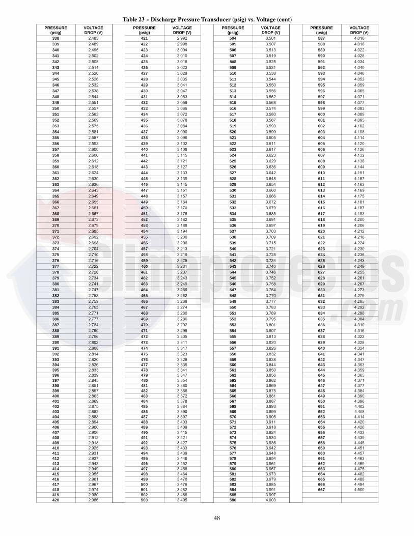
48
Table 23 -- Discharge Pressure Transducer (psig) vs. Voltage (cont)PRESSURE
(psig)VOLTAGEDROP (V)
PRESSURE(psig)
VOLTAGEDROP (V)
PRESSURE(psig)
VOLTAGEDROP (V)
PRESSURE(psig)
VOLTAGEDROP (V)
338 2.483 421 2.992 504 3.501 587 4.010
339 2.489 422 2.998 505 3.507 588 4.016
340 2.495 423 3.004 506 3.513 589 4.022
341 2.502 424 3.010 507 3.519 590 4.028
342 2.508 425 3.016 508 3.525 591 4.034
343 2.514 426 3.023 509 3.531 592 4.040
344 2.520 427 3.029 510 3.538 593 4.046
345 2.526 428 3.035 511 3.544 594 4.052
346 2.532 429 3.041 512 3.550 595 4.059
347 2.538 430 3.047 513 3.556 596 4.065
348 2.544 431 3.053 514 3.562 597 4.071
349 2.551 432 3.059 515 3.568 598 4.077
350 2.557 433 3.066 516 3.574 599 4.083
351 2.563 434 3.072 517 3.580 600 4.089
352 2.569 435 3.078 518 3.587 601 4.095
353 2.575 436 3.084 519 3.593 602 4.102
354 2.581 437 3.090 520 3.599 603 4.108
355 2.587 438 3.096 521 3.605 604 4.114
356 2.593 439 3.102 522 3.611 605 4.120
357 2.600 440 3.108 523 3.617 606 4.126
358 2.606 441 3.115 524 3.623 607 4.132
359 2.612 442 3.121 525 3.629 608 4.138
360 2.618 443 3.127 526 3.636 609 4.144
361 2.624 444 3.133 527 3.642 610 4.151
362 2.630 445 3.139 528 3.648 611 4.157
363 2.636 446 3.145 529 3.654 612 4.163
364 2.643 447 3.151 530 3.660 613 4.169
365 2.649 448 3.157 531 3.666 614 4.175
366 2.655 449 3.164 532 3.672 615 4.181
367 2.661 450 3.170 533 3.679 616 4.187
368 2.667 451 3.176 534 3.685 617 4.193
369 2.673 452 3.182 535 3.691 618 4.200
370 2.679 453 3.188 536 3.697 619 4.206
371 2.685 454 3.194 537 3.703 620 4.212
372 2.692 455 3.200 538 3.709 621 4.218
373 2.698 456 3.206 539 3.715 622 4.224
374 2.704 457 3.213 540 3.721 623 4.230
375 2.710 458 3.219 541 3.728 624 4.236
376 2.716 459 3.225 542 3.734 625 4.243
377 2.722 460 3.231 543 3.740 626 4.249
378 2.728 461 3.237 544 3.746 627 4.255
379 2.734 462 3.243 545 3.752 628 4.261
380 2.741 463 3.249 546 3.758 629 4.267
381 2.747 464 3.256 547 3.764 630 4.273
382 2.753 465 3.262 548 3.770 631 4.279
383 2.759 466 3.268 549 3.777 632 4.285
384 2.765 467 3.274 550 3.783 633 4.292
385 2.771 468 3.280 551 3.789 634 4.298
386 2.777 469 3.286 552 3.795 635 4.304
387 2.784 470 3.292 553 3.801 636 4.310
388 2.790 471 3.298 554 3.807 637 4.316
389 2.796 472 3.305 555 3.813 638 4.322
390 2.802 473 3.311 556 3.820 639 4.328
391 2.808 474 3.317 557 3.826 640 4.334
392 2.814 475 3.323 558 3.832 641 4.341393 2.820 476 3.329 559 3.838 642 4.347394 2.826 477 3.335 560 3.844 643 4.353395 2.833 478 3.341 561 3.850 644 4.359396 2.839 479 3.347 562 3.856 645 4.365397 2.845 480 3.354 563 3.862 646 4.371398 2.851 481 3.360 564 3.869 647 4.377399 2.857 482 3.366 565 3.875 648 4.384400 2.863 483 3.372 566 3.881 649 4.390401 2.869 484 3.378 567 3.887 650 4.396402 2.875 485 3.384 568 3.893 651 4.402403 2.882 486 3.390 569 3.899 652 4.408404 2.888 487 3.397 570 3.905 653 4.414405 2.894 488 3.403 571 3.911 654 4.420406 2.900 489 3.409 572 3.918 655 4.426407 2.906 490 3.415 573 3.924 656 4.433408 2.912 491 3.421 574 3.930 657 4.439409 2.918 492 3.427 575 3.936 658 4.445410 2.925 493 3.433 576 3.942 659 4.451411 2.931 494 3.439 577 3.948 660 4.457412 2.937 495 3.446 578 3.954 661 4.463413 2.943 496 3.452 579 3.961 662 4.469414 2.949 497 3.458 580 3.967 663 4.475415 2.955 498 3.464 581 3.973 664 4.482416 2.961 499 3.470 582 3.979 665 4.488417 2.967 500 3.476 583 3.985 666 4.494418 2.974 501 3.482 584 3.991 667 4.500419 2.980 502 3.488 585 3.997420 2.986 503 3.495 586 4.003

49
MAJOR SYSTEM COMPONENTSGeneralThe 48/50LC single package rooftop units are available with thefactory--installed optional SystemVut electronic control system that
monitors all operations of the rooftop. The control system iscomposed of several main control components and availablefactory-installed options or field-installed accessories as listed insections below. See Fig. 26 -- 31 for examples of typical control andpower schematics for 48/50LC units.
a48---9941Fig. 26 -- 50LC 04--06 SystemVut Control Schematic

50
C14329BFig. 27 -- 48LC 08--12 SystemVut Control Schematic

51
a50---9603Fig. 28 -- 50LC 14--26 SystemVut Control Schematic

52
a48---9942
Fig. 29 -- 50LC 04--06 SystemVut Power Schematic

53
a48---9943
Fig. 30 -- 48LC 08--12 SystemVut Power Schematic

54
a48---9944Fig. 31 -- 48/50LC 14--26 SystemVut Power Schematic

55
Main Base Board (MBB)See Fig. 32 and Table 24. The majority of the I/O is connected tothe MBB which executes the controls operation of the unit fromthe software that is loaded onto it.
J1
J2
J3A J3B J3C J3D J3E J4 J5 J6 J7 J8 J9
J10
TB5
J11
J12
J13
J14
TB4J15J16J17J20J18TB3TB2TB1
C150161
Fig. 32 -- Main Base Board (MBB)

56
Table 24 – Main Base Board (MBB) Connections
DISPLAY NAME SENSOR LOCATION I/O TYPE POINT NAME CONNECTION PINNUMBER
INPUTS
Input power from TRAN2 Control Box 24 VAC J2, 1 & 8
COFS Dain Pan 24 VAC COFS J4, 1--- 4
FIRE SHUTDOWN Supply/Return/Space Switch input FIREDOWN J5, 1---4
IGC FAN REQUEST Gas section Switch input IGC_IFO J6, 1--- 2
RARH LEVEL Return/Space 0---20 mA RARH J7, 1, 5--- 6
OARH LEVEL Economizer 0---20 mA OARH J7, 2, 6--- 7
ECON ACT POSITION Economizer 2---10vdc DAMPPOS J7, 3, 8
FAN SUPPLY TEMP Indoor fan housing 10k thermistor FST J8, 1, 4
RETURN AIR TEMP Return 10k thermistor RAT J8, 2, 5
OUTDOOR AIR TEMP Outdoor coil 10k thermistor OAT J8, 3, 6
CIR.A SUC. PRESS Circuit A Suction pipe 0---5 VDC pressure transducer SSP_A J9, 1--- 2, 5
CIR.A DIS. PRESS Circuit A Discharge pipe 0---5 VDC pressure transducer SDP_A J9, 4--- 3, 6
IAQ LEVEL Return/Space 0---20 mA IAQ TB5, 4---6
SLIDER OFFSET VAL Space 10k thermistor SPTO TB5, 2---3
SPACE TEMPERATURE Space 10k thermistor SPACE_T TB5, 1---2
CIR.A HPS Circuit A Discharge pipe Switch Input CIRA_HPS QC, 1---2J18, 1, 3
Configurable Field--- installed Switch Input QC, 3---4J18, 2,4
REMOTE OCC SWITCH Field--- installed Switch Input REMOCC TB3, 1---2
REMOTE SHUTDOWN Field--- installed Switch Input REMSHUT TB3, 3---4
FILTER STATUS SW Indoor fan section Switch Input FILTSTAT TB3, 5---6
TSTAT G INPUT Space Switch Input G TB1, G
TSTAT Y1 INPUT Space Switch Input Y1 TB1, Y1
TSTAT Y2 INPUT Space Switch Input Y2 TB1, Y2
TSTAT Y3 INPUT Space Switch Input Y3 TB1, Y3
TSTAT W1 INPUT Space Switch Input W1 TB1, W1
TSTAT W2 INPUT Space Switch Input W2 TB1, W2
OUTPUTS
Optional power out Not Used 24 VAC J1, 1--- 2
ECON CMD POSITION 0---20 mA DAMPCMD J7, 4, 8
ODF SPEED OUT 1 PWM1 ODF1SPD J10, 1--- 4
ODF SPEED OUT 2 PWM2 ODF2SPD J11, 1--- 4
ODF SPEED OUT 3 PWM3 ODF3SPD J12, 1--- 4
ALARM RELAY Relay ALMOUT TB2, 3---4
not used Not Used Relay J3A, 1, 3
not used Not Used Relay J3A, 2, 4
not used Not Used Relay J3B, 1, 3
not used Not Used Relay J3B, 2, 4
PE1 RELAY Relay PE1 J3C, 1---4
CCH RELAY Relay CCHR1 J3D, 1, 4
COMPRESSOR A2 Relay COMP_A2 J3D, 2, 5
COMPRESSOR A1 Relay COMP_A1 J3D, 3, 6
HEAT 2 RELAY Relay HEAT_2 J3E, 1, 3
HEAT 1 RELAY Relay HEAT_1 J3E, 2, 4
COMMUNICATION
Building Automated System (BAS) Building Communication TB4, 1---5
Ethernet Not Used Communication J13, J14
IDF SPEED OUTPUT Indoor fan section Communication FANSPEED J15, 1--- 4
Expansion LEN Bus Not Used Communication J16, 1--- 4
Local Equipment Network (LEN) Communication J17
RNET Sensors Building Communication J20, 1--- 4
Display Copper Cable Communication J23
RNET Service Access Communication J24, 1--- 5
DISPLAY CONNECTIONS
Display Copper Cable Communication J1
Local Equipment Network (LEN) Communication J2
USB---A Communication J3
USB---B Not Used Communication J4
Keypad Ribbon Cable Communication J6

57
Input--Output Board (IOB)
PD4-AUX1 32GB 500 322 EE CEPL130487-01 STATUS SIO
CH14
CH13
TPVTPV
SIO
J9J8
J5J4J3
J2
J1J7
J6
CH13
CH14
3--G
RS
VR
SV
+--
G+
21
32
124VA
C12
11
CH 1
-- CH 2
-- CH 3
-- CH 4
-- CH 5
-- CH 6
-- CH 7
-- CH 8
-- CH 9
-- CH 10
-- CH 11
-- CH 12
--
a50---9608
Fig. 33 -- Input--Output Board (IOB)
Table 25 – Input--Output Board (IOB) Connections
DISPLAY NAME POINT DESCRIPTION SENSOR LOCATION TYPE OF I/O CONNECTIONPIN NUMBER
INPUTS
HUM HUMIDISTAT Field--- installed Switch Input J1.1
SPRH SPACE RELATIVE HUMIDITY Field--- installed 0---20 mA J9.2
OUTPUTS
RDV REHEAT DISCHARGE VALVE 24 VAC J2, 1
LDV LIQUID DISCHARGE VALVE 24 VAC J2, 2
COMMUNICATION
LEN LOCAL EQUIPMENT NETWORK (LEN) Communication J12

58
Integrated Gas Control (IGC) BoardThe IGC is provided on gas heat units. The IGC controls the directspark ignition system and monitors the rollout switch, limit switch,and flue gas pressure switch.
RED LED-STATUS
C07028
Fig. 34 -- Integrated Gas Control (IGC) Board
Table 26 – Integrated Gas Control (IGC) Board Connections
TERMINALLABEL POINT DESCRIPTION SENSOR LOCATION TYPE OF I/O CONNECTION
PIN NUMBER
INPUTS
RT, C Power for IDR on 575v units control box 24 VAC Spade
C Input power common Spade
SS Speed sensor gas section analog input J1, 1--- 3
FS, T1 Flame sensor gas section switch input Spade
W Heat stage 1 Call MBB to IGC 24 VAC J2, 2
G Indoor Fan Call not used 24 VAC J2, 3
R Input power from TRAN 1 TB4 to IGC 24 VAC J2, 4
RS Rollout switch gas section switch input J2, 5--- 6
LS Limit switch gas section switch input J2, 7--- 8
CS Centrifugal switch (not used) switch input J2, 9--- 10
OUTPUTS
L1, CM Induced draft combustion motor or relay gas section line VAC
IFO Indoor fan request IGC to MBB relay J2, 1
GV (W1) Gas valve (heat stage 1) gas section relay J2, 12
GV (W2) Gas Valve (heat stage 2, from CTB) gas section Not on IGC

59
Protective DevicesCompressor ProtectionOvercurrentEach compressor has internal line break motor protection.OvertemperatureEach compressor has an internal protector to protect it againstexcessively high discharge gas temperatures.High--Pressure SwitchIf the high-pressure switch trips, the compressor will shut downand the Circuit A High Pressure Alert will activate. Refer to thealarm section for the High pressure alert.
Evaporator Fan Motor ProtectionIn the belt drive application, the VFD serves as the motor thermaland over-current protection. Refer to Major Component’s sectionfor more detail on the VFD.
EQUIPMENT DAMAGE HAZARD
Failure to follow this caution may result in damage to the unit.
DO not bypass the VFD while running the motor. Do notchange VFD parameter associated with motor characteristics,these are factory programmed for motor protection. Damage tothe motor or the VFD can occur.
CAUTION!
Condenser--Fan Motor ProtectionThe ECM motor is protected from locked rotor and over-currentprotection through the electronic control module attached to themotor.
Saturated Suction Pressure (SSP)If the SSP for a particular circuit is reading below the alarm set pointfor an extended period of time, that circuit will be shut down. After 15minutes, the alarm will automatically reset. If this alarm occurs 3 timesconsecutively, the circuit will remain locked out until an alarm reset isinitiated via CCN or manually via the SystemVut controller display(see Alarms and Alerts section for more details).
Condensate Overflow Switch (COFS)A separate factory installed device can detect a full drain pan. Thisdevice consists of a pan sensor to detect the water level and a relaycontrol switch to read the sensor. The control switch is located inthe unit control box and feeds into the SystemVu control to trip acondensate overflow fault. The relay switch is a normally opendevice that closes when power is applied. If the sensor detects highwater levels for 10 seconds straight, it will open the contactremoving the input provided to the SystemVu control. The switchwill also turn its red LED on. If the water level is low enough for 5minutes the relay will close again applying the input back to theSystemVu controller. A blinking red LED on the switch indicatesthat the sensor has been disconnected.
Space Mounted SensorsSpace Temperature Sensor (T--55)The T-55 space temperature sensor (part no. 33ZCT55SPT) is afield-installed accessory. The sensor is installed on a buildinginterior wall to measure room air temperature. The T-55 sensor alsoincludes an override button on the front cover to permit occupantsto override the Unoccupied Schedule (if programmed).TB5--1 Sensor Input. . . . . . . . . . . . .TB5--2 Sensor Common. . . . . . . . . . . . .
Space Temperature Sensor (T--56)The T-56 space temperature sensor (part no. 33ZCT56SPT) is afield-installed accessory. This sensor includes a sliding scale on thefront cover that permits an occupant to adjust the space temperatureset point remotely. The T-56 sensor also includes an overridebutton on the front cover to allow occupants to override theunoccupied schedule (if programmed).TB5--1 Sensor Input. . . . . . . . . . .TB5--2 Sensor Common. . . . . . . . . . .TB5--3 Setpoint Offset Input. . . . . . . . . . .
Space Temperature Sensor AveragingSee Fig. 35 for space temperature averaging with T-55 sensorsonly. If the use of one T-56 sensor is required, refer to Fig. 36.
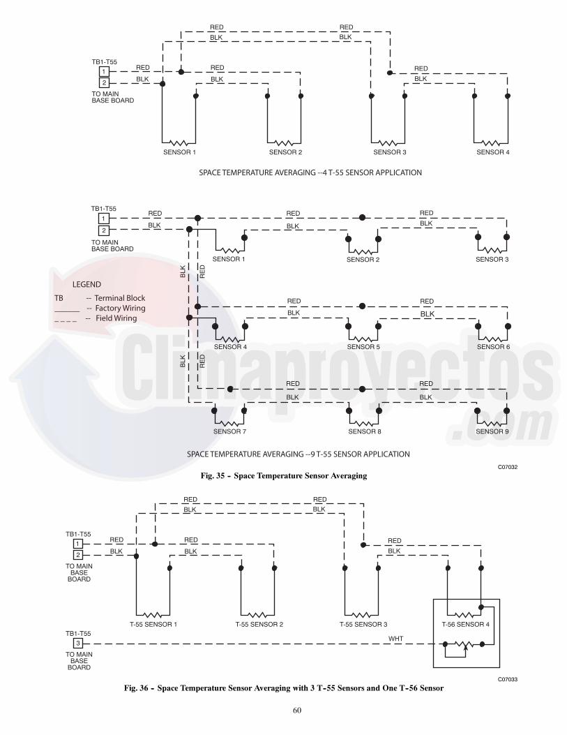
60
TO MAINBASE BOARD
RED
BLK
RED
BLK
RE
D
BLK
SENSOR 1 SENSOR 2 SENSOR 3
RED
BLK
SENSOR 6SENSOR 5
RED
BLK
SENSOR 4
RE
D
BLK
RED
BLK
RED
BLK
SENSOR 8SENSOR 7 SENSOR 9
1RED
BLK
TB1-T55
SENSOR 1 SENSOR 2 SENSOR 3 SENSOR 4
RED
BLK
RED
BLK
RED
BLK
RED
BLK
TO MAINBASE BOARD
RED
BLK
TB1-T55
1
2
2
SPACE TEMPERATURE AVERAGING --4 T-55 SENSOR APPLICATION
SPACE TEMPERATURE AVERAGING --9 T-55 SENSOR APPLICATION
LEGEND
TB -- Terminal Block______ -- Factory Wiring_ _ _ _ -- Field Wiring
C07032
Fig. 35 -- Space Temperature Sensor Averaging
T-55 SENSOR 1 T-55 SENSOR 2 T-55 SENSOR 3 T-56 SENSOR 4
RED
BLK
RED
BLK
RED
BLK
RED
BLK
TO MAINBASE
BOARD
RED
BLK
TB1-T55
1
2
TO MAINBASE
BOARD
3
TB1-T55WHT
C07033
Fig. 36 -- Space Temperature Sensor Averaging with 3 T--55 Sensors and One T--56 Sensor
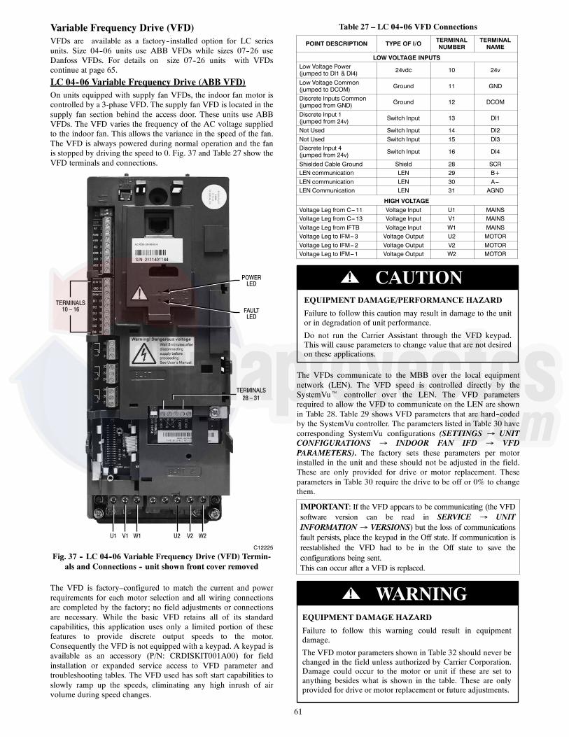
61
Variable Frequency Drive (VFD)VFDs are available as a factory--installed option for LC seriesunits. Size 04--06 units use ABB VFDs while sizes 07--26 useDanfoss VFDs. For details on size 07--26 units with VFDscontinue at page 65.
LC 04--06 Variable Frequency Drive (ABB VFD)On units equipped with supply fan VFDs, the indoor fan motor iscontrolled by a 3-phase VFD. The supply fan VFD is located in thesupply fan section behind the access door. These units use ABBVFDs. The VFD varies the frequency of the AC voltage suppliedto the indoor fan. This allows the variance in the speed of the fan.The VFD is always powered during normal operation and the fanis stopped by driving the speed to 0. Fig. 37 and Table 27 show theVFD terminals and connections.
TERMINALS10 – 16
TERMINALS28 – 31
U1 V1 W1 U2 V2 W2
POWERLED
FAULTLED
C12225
Fig. 37 -- LC 04--06 Variable Frequency Drive (VFD) Termin-als and Connections -- unit shown front cover removed
The VFD is factory–configured to match the current and powerrequirements for each motor selection and all wiring connectionsare completed by the factory; no field adjustments or connectionsare necessary. While the basic VFD retains all of its standardcapabilities, this application uses only a limited portion of thesefeatures to provide discrete output speeds to the motor.Consequently the VFD is not equipped with a keypad. A keypad isavailable as an accessory (P/N: CRDISKIT001A00) for fieldinstallation or expanded service access to VFD parameter andtroubleshooting tables. The VFD used has soft start capabilities toslowly ramp up the speeds, eliminating any high inrush of airvolume during speed changes.
Table 27 – LC 04--06 VFD Connections
POINT DESCRIPTION TYPE OF I/O TERMINALNUMBER
TERMINALNAME
LOW VOLTAGE INPUTSLow Voltage Power(jumped to DI1 & DI4) 24vdc 10 24v
Low Voltage Common(jumped to DCOM) Ground 11 GND
Discrete Inputs Common(jumped from GND) Ground 12 DCOM
Discrete Input 1(jumped from 24v) Switch Input 13 DI1
Not Used Switch Input 14 DI2Not Used Switch Input 15 DI3Discrete Input 4(jumped from 24v) Switch Input 16 DI4
Shielded Cable Ground Shield 28 SCRLEN communication LEN 29 B+LEN communication LEN 30 A---LEN Communication LEN 31 AGND
HIGH VOLTAGEVoltage Leg from C---11 Voltage Input U1 MAINSVoltage Leg from C---13 Voltage Input V1 MAINSVoltage Leg from IFTB Voltage Input W1 MAINSVoltage Leg to IFM---3 Voltage Output U2 MOTORVoltage Leg to IFM---2 Voltage Output V2 MOTORVoltage Leg to IFM---1 Voltage Output W2 MOTOR
EQUIPMENT DAMAGE/PERFORMANCE HAZARD
Failure to follow this caution may result in damage to the unitor in degradation of unit performance.
Do not run the Carrier Assistant through the VFD keypad.This will cause parameters to change value that are not desiredon these applications.
CAUTION!
The VFDs communicate to the MBB over the local equipmentnetwork (LEN). The VFD speed is controlled directly by theSystemVut controller over the LEN. The VFD parametersrequired to allow the VFD to communicate on the LEN are shownin Table 28. Table 29 shows VFD parameters that are hard--codedby the SystemVu controller. The parameters listed in Table 30 havecorresponding SystemVu configurations (SETTINGS UNITCONFIGURATIONS INDOOR FAN IFD VFDPARAMETERS). The factory sets these parameters per motorinstalled in the unit and these should not be adjusted in the field.These are only provided for drive or motor replacement. Theseparameters in Table 30 require the drive to be off or 0% to changethem.
IMPORTANT: If the VFD appears to be communicating (the VFDsoftware version can be read in SERVICE UNITINFORMATION VERSIONS) but the loss of communicationsfault persists, place the keypad in the Off state. If communication isreestablished the VFD had to be in the Off state to save theconfigurations being sent.This can occur after a VFD is replaced.
EQUIPMENT DAMAGE HAZARD
Failure to follow this warning could result in equipmentdamage.
The VFD motor parameters shown in Table 32 should never bechanged in the field unless authorized by Carrier Corporation.Damage could occur to the motor or unit if these are set toanything besides what is shown in the table. These are onlyprovided for drive or motor replacement or future adjustments.
! WARNING

62
Table 28 – LC 04--06 VFD Parameters Configured by Factory or VFD Keypad
Parameter Group Parameter Title ABB Parameter HVAC Default CARRIER
Options COMM PROT SEL 9802 NOT SEL LEN (6)
EFB Protocol
EFB PROTOCOL ID 5301 0000 hex 0601 hex
EFB STATION ID 5302 0 41
EFB BAUD RATE 5303 9.6 kb/s 38.4 kb/s
EFB PARITY 5304 8 NONE 1 8 NONE 1
EFB CTRL PROFILE 5305 ABB DRV LIM DCU PROFILE
Table 29 – LC 04--06 VFD Parameters Hard Coded by SystemVut Controller
Parameter Group Parameter Title ABB Parameter HVAC Default CARRIER
Start/Stop/Dir EXT1 COMMANDS 1001 DI1 COMM (2)
Reference Select REF1 SELECT 1103 AI1 COMM (2)
Constant Speeds CONST SPEED 7 1208 60 Hz 0 Hz
System Controls
RUN ENABLE 1601 NOT SEL NOT SEL (0)
FAULT RESET SEL 1604 KEYPAD COMM (7)
START ENABLE 1 1608 DI4 DI4 (4)
Start/StopSTART FUNCTION 2101 SCALAR FLYSTART AUTO (0)
STOP FUNCTION 2102 COAST COAST (1)
Fault FunctionsCOMM FAULT FUNC 3018 NOT SEL CONST SP 7 (2)
COMM FAULT TIME 3019 10.0 s 10.0 s
Start/Stoop/Dir DIRECTION 1003 FORWARD REQUEST
Accel/DecelACCELER TIME 1 2202 30.0s 30.0s
DECELER TIME 1 2203 30.0s 10.0s
Motor Control SWITCHING FREQ 2606 4 kHz 4 kHz
Start---Up Data
MOTOR NOM VOLT 9905 230V, 460V, 575V See Table 32
MOTOR NOM CURR 9906 10*In See Table 32
MOTOR NOM FREQ 9907 60 Hz 60 Hz
MOTOR NOM SPEED 9908 1750 rpm See Table 32
MOTOR NOM POWER 9909 1.0*Pn See Table 32
Limits MAXIMUM CURRENT 2003 1.3*i2n See Table 32
Table 30 – LC 04--06 VFD Parameters Configurable Through SystemVu Controller
ParameterGroup Parameter Title ABB Parameter HVAC Default CARRIER CCN POINT Display Menu Item
Accel/DecelACCELER TIME 1 2202 30.0s 30.0s RAMPUP_T VFD ACCEL TIME
DECELER TIME 1 2203 30.0s 10.0s RAMPDN_T VFD DECEL TIME
Start---Up Data
MOTOR NOM VOLT 9905 230V,460V,575V See Table 32 MOTVOLT IDF VFD VOLTAGE
MOTOR NOM CURR 9906 1.0*In See Table 32 MOTCUR IDF VFD NOM. AMPS
MOTOR NOM FREQ 9907 60 Hz 60 Hz MOTFREQ IDF VFD NOM. FREQ
MOTOR NOM SPEED 9908 1750 rpm See Table 32 MOTNOMSP IDF VFD NOM. RPM
MOTOR NOMPOWER 9909 1.0*Pn See Table 32 MOTPWRHP IDF VFD NOM. HP
Limits MAXIMUM CURRENT 2003 1.3*I2n See Table 32 CURRLMT IDF VFD MAX AMPS
Table 31 – LC 04--06 VFD Status Parameters Available Through System Vu Controller
Parameter Group Parameter Title ABB Parameter Units SystemVu Point SystemVu Display Item
Operating Data
Run Time 0114 h RUNHOURS IDF VFD RUN HOURS
KWh Counter 0115 kWh KWHCNTR IDF VFD KW HOURS
Power 0106 kW OUTPWRKW VFD OUTPUT KW
Output Voltage 0109 V OUTMVOLT VFD OUTPUT VOLTS
Output Frequency 0103 Hz OUTMFREQ VFD OUTPUT FREQ
CURRENT 0104 A OUTMCUR VFD OUTPUT AMPS
DC Bus Voltage 0107 V DLCNVOLT IDF VFD DC VOLTS
Drive Temp 0110 _C HTSINKT IDF VFD HSNK TEMP

63
Table 32 – LC 04--06 VFD Motor Default Configurations
EQUIPMENT MODEL NUMBER (EQ_MOD) NominalHorse Power Motor Voltage
Motor Current(Must---HoldAmps)
Motor NominalSpeed VFD Max Amps
Position 1,2 Position 7,8 Position 10 Position 12 MOTPWRHP MOTVOLT MOTCUR MOTNOMSP VFD1MAXA
48 04 2 5 1.7 230 5.8 1725 6.7
48 04 2 6 1.7 460 2.9 1725 3.3
48 04 2 1 1.7 575 3.1 1725 3.6
48 04 3 5 2.4 230 7.9 1725 9.1
48 04 3 6 2.4 460 2.9 1725 4.6
48 04 3 1 2.4 575 3.4 1725 3.9
48 05 2 5 1.7 230 5.8 1725 6.7
48 05 2 6 1.7 460 2.9 1725 3.3
48 05 2 1 1.7 575 3.1 1725 3.6
48 05 3 5 2.9 230 9.2 1725 10.6
48 05 3 6 2.9 460 4.6 1725 5.3
48 05 3 1 3.7 575 4.2 1725 4.8
48 06 2 5 2.4 230 7.9 1725 9.1
48 06 2 6 2.4 460 4 1725 4.6
48 06 2 1 2.4 575 3.4 1725 3.9
48 06 3 5 2.9 230 9.2 1725 10.6
48 06 3 6 2.9 460 4.6 1725 5.3
48 06 3 1 3.7 575 4.2 1725 4.8
50 04 2 5 1.7 230 5.8 1725 6.7
50 04 2 6 1.7 460 2.9 1725 3.3
50 04 2 1 1.7 575 3.1 1725 3.6
50 04 3 5 2.4 230 7.9 1725 9.1
50 04 3 6 2.4 460 2.9 1725 4.6
50 04 3 1 2.4 575 3.4 1725 3.9
50 05 2 5 1.7 230 5.8 1725 6.7
50 05 2 6 1.7 460 2.9 1725 3.3
50 05 2 1 1.7 575 3.1 1725 3.6
50 05 3 5 2.9 230 9.2 1725 10.6
50 05 3 6 2.9 460 4.6 1725 5.3
50 05 3 1 3.7 575 4.2 1725 4.8
50 06 2 5 2.4 230 7.9 1725 9.1
50 06 2 6 2.4 460 4 1725 4.6
50 06 2 1 2.4 575 3.4 1725 3.9
50 06 3 5 2.9 230 9.2 1725 10.6
50 06 3 6 2.9 460 4.6 1725 5.3
50 06 3 1 3.7 575 4.2 1725 4.8
For proper operation, there are three jumper wires that mustremain installed and the VFD must be set to the auto mode. The3 jumpers are shown on the unit schematic and are connectedthrough a plug called PL25. These jumpers set the VFD to startenabled, run enabled, and tie the common bus together. TheVFD has 2 LEDs on its front panel to indicate operating status.See below and VFD Troubleshooting section for details on VFDfaults and alarms. The VFD faults can be reset with the VFDkeypad or through the SystemVut controller(ALERTS/FAULTS RESET FAULT/ALERT = Yes).The Green LED on steady indicates power is on the VFD, flashingGreen indicates an alarm condition detected. Alarms are advisoryin nature. These indicate a problem has been detected by the VFD’sdiagnostics but this problem will not require a shutdown.The Red LED steady or flashing indicates a fault condition isdetected. A fault is a significant internal situation for the VFD orMotor. Faults will typically shutdown the motor.
LC 04--06 VFD TroubleshootingWhen communication is successful, the SystemVut control willprovide alerts and faults that correlate to the VFD’s warnings andalarms. Table 33 shows the list of the SystemVu controller faults
and alerts and how they map to the VFD warnings and alarms.Table 33 also lists the possible causes of these cases.VFD Diagnostics (with Keypad)The drive detects error situations and reports them using:
1. Green and red LEDs on the body of the drive (located underthe keypad)
2. Status LED on the control panel3. Control panel display4. The Fault Word and Alarm Word parameter bits (parameters0305 to 0309)
The form of the display depends on the severity of the error. The usercan specify the severity for many errors by directing the drive toignore the error situation, report the situation as an alarm, or report thesituation as a fault.Faults (Red LED Lit)The VFD signals that it has detected a severe error, or fault, by:
1. Enabling the red LED on the drive (LED is either steady orflashing)
2. Setting an appropriate bit in a Fault Word parameter (0305to 0307)

64
3. Overriding the control panel display with the display of afault code
4. Stopping the motor (if it was on)5. Sets an appropriate bit in Fault Word parameter (0305 to0307)
The fault code on the control panel display is temporary. Pressingthe MENU, ENTER, UP or DOWN buttons removes the faultmessage. The message reappears after a few seconds if the controlpanel is not touched and the fault is still active.Alarms (Green LED Flashing)For less severe errors, called alarms, the diagnostic display isadvisory. For these situations, the drive is simply reporting that ithad detected something unusual. In these situations, the drive:
1. Flashes the green LED on the drive (does not apply toalarms that arise from control panel operation errors)
2. Sets an appropriate bit in an Alarm Word parameter (0308or 0309)
3. Overrides the control panel display with the display of analarm code and/or name
Alarm messages disappear from the control panel display after afew seconds. The message returns periodically as long as the alarmcondition exists.Correcting FaultsThe recommended corrective action for faults is shown in the FaultListing Table 33. The VFD can also be reset to remove the fault. Ifan external source for a start command is selected and is active, theVFD may start immediately after fault reset.
To reset a fault indicated by a flashing red LED, turn off the powerfor 5 minutes. To reset a fault indicated by a red LED (notflashing), press RESET from the control panel or turn off thepower for 5 minutes. Depending on the value of parameter 1604(FAULT RESET SELECT), digital input or serial communicationcould also be used to reset the drive. When the fault has beencorrected, the motor can be started.HistoryFor reference, the last three fault codes are stored into parameters0401, 0412, 0413. For the most recent fault (identified byparameter 0401), the drive stores additional data (in parameters0402 through 0411) to aid in troubleshooting a problem. Forexample, a parameter 0404 stores the motor speed at the time of thefault. To clear the fault history (all of Group 04, Fault Historyparameters), follow these steps:
1. In the control panel, Parameters mode, select parameter0401.
2. Press EDIT.3. Press the UP and DOWN buttons simultaneously.4. Press SAVE.
If diagnostics troubleshooting has determined that the drive isdefective during the warranty period, contact ABB AutomationInc., at 1--800--435--7365, option 4, option 3. A qualifiedtechnician will review the problem with the caller and make adetermination regarding how to proceed. This may involvedispatching a designated service station (DSS) representative froman authorized station, dispatching a replacement unit, or advisingreturn for repair.
Table 33 – LC 04--06 VFD Fault Codes
SystemVu Fault SystemVu Alert ABB Alarm Code Alarm Description Cause of Problem and Corrective Action
F613--- IDF VFDOVER CURRENT
A607--- IDF VFDCURRENT LIMIT 1 Over Current
Output current is excessive. Check for excessive motor load, insufficientacceleration time (parameters 2202 ACCELER TIME 1, default 30 seconds),or faulty motor, motor cables or connections.
F617--- IDF VFDOVER VOLTAGE
A606--- IDF VFDVOLTAGE WARNING 2 DC Over Voltage
Intermediate circuit DC voltage is excessive. Check for static or transient overvoltages in the input power supply, insufficient deceleration time (parameters 2203DECELER TIME 1, default 30 seconds), or undersized brake chopper (if present).
F601--- IDF VFDUNEXPECTED
A605--- IDF VFDTHERMAL WARNING 3 Device Over Temp
Drive heat sink is overheated. Temperature is at or above 115° C (239° F).Check for fan failure, obstructions in the air flow, dirt or dust coating on theheat sink, excessive ambient temperature, or excessive motor load.
F618--- IDF VFDSHORT CIRCUIT --- 4 Short Circuit Fault current. Check for short--- circuit in the motor cable(s) or motor or
supply disturbances.
F616--- IDF VFDUNDER VOLTAGE
A606--- IDF VFDVOLTAGE WARNING 6 DC Under Volt Intermediate circuit DC voltage is not sufficient. Check for missing phase in
the input power supply, blown fuse, or under voltage on main circuit.
F614--- IDF VFDMOTOR OVER TEMP
A605--- IDF VFDTHERMALWARNING
9 Motor Over TempMotor is too hot, as estimated by the drive. Check for overloaded motor.Adjust the parameters used for the estimate (3005 through 3009). Check thetemperature sensors and Group 35 parameters.
F611--- IDF VFDEARTH FAULT
A608--- IDF VFDWARNING 16 Earth Fault
The load on the input power system is out of balance. Check for faults in themotor or motor cable. Verify that motor cable does not exceed maximumspecified length.
F619--- IDF VFDMAIN PHASE LOSS
A608--- IDF VFDWARNING 22 Supply Phase Ripple voltage in the DC link is too high. Check for missing main phase or
blown fuse.

65
LC 07--26 Variable Frequency Drive (Danfoss VFD)The indoor fan motor is controlled by a VFD. The supply fan VFDis located in the supply fan section behind the access door. TheVFD varies the frequency of the AC voltage supplied to the indoorfan. This allows the variation in the speed of the fan. The VFD isalways powered during normal operation and the fan is stopped bydriving the speed to 0. Fig. 38 and Table 34 show the VFDterminals and connections.
TERMINALS
61, 68, 69
TERMINALS
18, 19, 27, 29
TERMINALS
12, 20, 55
TERMINALS
U, V, W
TERMINALS
L1, L2, L3
C14334
Fig. 38 -- Variable Frequency Drive (VFD) Terminals andConnections -- unit shown with front cover removed
The VFD is factory–configured to match the current and powerrequirements for each motor selection and all wiring connectionsare completed by the factory; no field adjustments are necessary.The VFD used has soft start capabilities to slowly ramp up thespeeds, eliminating any high inrush of air volume during speedchanges. While the basic VFD retains all of its standardcapabilities, the LC unit uses only a limited portion of thesefeatures to provide discrete output speeds to the motor. The VFD isnot equipped with a keypad. A keypad is available as an accessory(P/N: CRDISKIT002A00) for field installation or expandedservice access to VFD parameter and troubleshooting tables.
Table 34 – VFD Connections
POINT DESCRIPTION TYPE OF I/O TERMINALNUMBER
TERMINALNAME
LOW VOLTAGE INPUTS
Low Voltage Power(jumped to 18 & 27) 24vdc 12 +24v
Discrete Inputs Common Ground 20 GND
Analog Inputs Common Ground 55 GND
Terminal 18 Discrete Input(jumped from 24v) Switch Input 18 DIG IN
Not Used Switch Input 19 DIG IN
Terminal 27 Discrete Input(jumped from 24v) Switch Input 27 DIG IN
Not Used Switch Input 29 DIG IN
LEN communication + LEN+ 68 P
LEN communication --- LEN--- 69 N
LEN CommunicationCommon LEN C 61 COMM. GND
HIGH VOLTAGE
Voltage Leg from C---11 Voltage Input L1 MAINS
Voltage Leg from C---13 Voltage Input L2 MAINS
Voltage Leg from IFTB Voltage Input L3 MAINS
Voltage Leg to IFM---3 Voltage Output U MOTOR
Voltage Leg to IFM---2 Voltage Output V MOTOR
Voltage Leg to IFM---1 Voltage Output W MOTOR
The VFD communicate to the MBB over the local equipmentnetwork (LEN). The VFD speed is controlled directly by thecontroller over the LEN. The VFD parameters required for theVFD to communicate on the LEN are shown in Table 35. Table 36shows VFD parameters that are hard-coded by the SystemVutcontroller. The parameters listed in Table 37 have correspondingSystemVu controller configurations (SETTINGS UNITCONFIGURATIONS INDOOR FAN IFD VFDPARAMETERS). The factory sets these parameters per the motorinstalled in the unit and these should not be adjusted in the field.These are only provided for drive or motor replacement. Theseparameters in Table 37 require the drive to be off or 0% to changethem.
EQUIPMENT DAMAGE HAZARD
Failure to follow this warning could result in equipmentdamage.
The VFD motor parameters shown in Table 39 should never bechanged in the field unless authorized by Carrier Corporation.Damage could occur to the motor or unit if these are set toanything besides what is shown in the table. These are onlyprovided for drive or motor replacement or future adjustments.
! WARNING

66
Table 35 – LC 07--26 VFD Parameters Configured by Factory or VFD Keypad
Parameter Group Parameter Title Danfoss Parameter VFD Default CARRIER
Reset Functions Service Code 14---29 6333 6222
FC Port Settings
PROTOCOL 8---30 (0) FC (20) LEN
ADDRESS 8---31 1 180
BAUD RATE 8---32 (2) 9.6 kb/s (4) 38.4 kb/s
Parity/Stop Bits 8--- 33 (0) 8 EVEN 1 (2) 8 NONE 1
Table 36 – LC 07--26 VFD Parameters Hard Coded by SystemVut Controller
Parameter Group Parameter Title Danfoss Parameter VFD Default CARRIER
Basic Settings Regional Settings 0---03 International (0) North America (1)
General Settings
Configuration Mode 1---00 Open Loop (0) Open Loop (0)
Torque Characteristics 1---03 Variable Torque (1) Variable Torque (1)
Clockwise Direction 1---06 Normal (0) Normal (0)
Motor Selection Motor Construction 1---10 Asynchron (0) Asynchron (0)
Start Adjustments
Start Delay 1---71 0s 0s
Start Function 1---72 Coast/delay time (2) Coast/delay time (2)
Flying Start 1--- 73 Disabled (0) Disabled (0)
Motor Temperature Motor Thermal Protection 1---90 No Protection (0) ETR trip 1 (4)
Brake Energy Funct. Over--- voltage Control 2--- 17 Enabled (2) Enabled (2)
ReferencesPreset Reference 3---10 %00005 %00005
Reference 3 Source 3---17 Local bus reference (11) Local bus reference (11)
Motor Limits
Motor Speed Direction 4---10 Both directions (2) Both directions (2)
Motor Speed Low Limit [Hz] 4---12 0hz 0hz
Motor Speed High Limit [Hz] 4---14 65hz 65hz
Digital InputsTerminal 18 Digital Input 5--- 10 8 Start (8)
Terminal 27 Digital Input 5--- 12 Coast Inverse (2) No Operation (0)
RelaysFunction Relay (Relay 1) 5---40 No Function (0) Bus Control (45)
Function Relay (Relay 2) 5---40 No Function (0) Bus Control (45)
Analog/Digital Output
Terminal 45 Mode 6---70 0---20 mA (0) 4---20 mA (1)
Terminal 45 Analog Output 6--- 71 No Operation (0) Bus Control (139)
Terminal 45 Output Min Scale 6---73 %00005 %00005
Analog/Digital Output
Terminal 42 Mode 6---90 0---20 mA (0) 0---20 mA (0)
Terminal 42 Analog Output 6--- 91 No Operation (0) Bus Control (139)
Terminal 42 Output Min Scale 6---93 %00005 %00005
General Settings
Control Site 8---01 Digital and ctrl.word (0) Digital and ctrl.word (0)
Control Source 8---02 FC Port (1) FC Port (1)
Control Timeout Function 8---04 Off (0) Stop and trip (5)
Digital/Bus Start Select 8--- 53 Logic OR (3) Logic AND (2)
SLC Settings SL Controller Mode 13---00 Off (0) Off (0)
Inverter Switching Switching Frequency 14---01 5.0khz (5) 5.0khz (5)
Mains On/Off Function at Mains Imbalance 14---12 Trip (0) Trip (0)
Reset Functions Reset Mode 14---20 Manual Reset (0) Automatic reset x 3 (3)
Table 37 – LC 07--26 VFD Parameters Configurable Through SystemVu Controller
ParameterGroup Parameter Title Danfoss
Parameter HVAC Default CARRIER CCN Point Display Menu Item
Motor Data
Motor Power 1---20 drive dep. See Table 39 or 40 MOTPHP IDF VFD NOM HP
Motor Voltage 1---22 drive dep. See Table 39 or 40 MOTVOLT IDF VFD VOLTAGE
Motor Frequency 1---23 50hz 60hz MOTFREQ IDF VFD NOM. FREQ
Motor Current 1--- 24 drive dep. See Table 39 or 40 MOTCUR IDF VFD NOM. AMPS
Motor Nominal Speed 1---25 drive dep. See Table 39 or 40 MOTNOMSP IDF VFD NOM. RPM
Reference LimitsMinimum Reference 3---02 0hz 0hz MINREF IDF VFD MIN REF
Maximum Reference 3---03 50hz 60hz MAXREF IDF VFD MAX REF
Ramp 1Ramp 1 Ramp Up Time 3---41 3s 10s RAMPUP_T VFD ACCEL. TIME
Ramp 1 Ramp Down Time 3---42 3s 30s RAMPDN_T VFD DECEL. TIME
Motor Limits Current Limit 4--- 18 110% 100% CURRLMT IDF VFD AMP LIMIT
General Settings Control Timeout Time 8---03 1s 30s CNT_TOUT IDF VFD TIMEOUT
Reset Functions Automatic Restart Time 14---21 10s 30s ARSTRT_T IDF VFD RESET DUR
Environment RFI Filter 14---50 On (1) On (1) RFIFILTR VFD RFI FILTER

67
Table 38 – LC 07--26 VFD Status Parameters Available Through SystemVut Controller
Parameter Group Parameter Title Danfoss Parameter Units SystemVu Point SystemVu Display Item
Operating DataRunning Hours 15---01 h RUNHOURS IDF VFD RUN HOURS
kWh Counter 15---02 kWh KWHCNTR IDF VFD KW HOURS
General Status
Reference [%] 16---02 % REFSPEED VFD REF SPEED
Status Word 16---03 STATUSWD VFD STATUS WORD
Main Actual Value [%] 16---05 % MAV IDF VFD FEEDBACK
Motor Status
Power [kW] 16---10 kW OUTPWRKW VFD OUTPUT KW
Power [hp] 16---11 hp OUTPWRHP VFD OUTPUT HP
Motor Voltage 16---12 V OUTMVOLT VFD OUTPUT VOLTS
Frequency 16---13 Hz OUTMFREQ VFD OUTPUT FREQ
Motor current 16---14 A OUTMCUR VFD OUTPUT AMPS
Drive StatusDC Link Voltage 16---30 V DCLNVOLT IDF VFD DC VOLTS
Heatsink Temp. 16---34 ° C HTSINKT IDF VFD HSNK TEMP
Diagnostic Readouts Alarm Word 16---90 ALMERRC IDF VFD ALM WORD
NOTE: Table 38 lists the status information the VFD sends to the SystemVu controls. This table is updated at every scan the controls perform of the LEN.This occurs approximately once every second.
Table 39 – LC 07--26 VFD Motor Default Configurations -- Vertical Airflow Units
EQUIPMENT MODEL NUMBER (EQ_MOD) NominalHorse Power Motor Voltage
Motor Current(Must---HoldAmps)
Motor NominalSpeed VFD Max Amps
Position 1,2 Position 7,8 Position 10 Position 12 MOTPWRHP MOTVOLT MOTCUR MOTNOMSP VFD1MAXA
48 07 1 5 1.7 230 5.8 1695 5.8
48 07 1 6 1.7 460 2.9 1690 2.9
48 07 1 1 1.7 575 3.1 1690 3.1
48 07 2 5 1.7 230 5.8 1695 5.8
48 07 2 6 1.7 460 2.9 1690 2.9
48 07 2 1 1.7 575 3.1 1690 3.1
48 07 3 5 2.9 230 9.2 1735 9.2
48 07 3 6 2.9 460 4.2 1735 4.2
48 07 3 1 2.9 575 4.9 1710 4.9
48 08 1 5 1.7 230 5.8 1695 5.8
48 08 1 6 1.7 460 2.9 1690 2.9
48 08 1 1 1.7 575 3.1 1690 3.1
48 08 2 5 2.4 230 7.9 1680 7.9
48 08 2 6 2.4 460 3.6 1680 3.6
48 08 2 1 2.4 575 3.8 1680 3.8
48 08 3 5 3.7 230 11.7 1750 11.7
48 08 3 6 3.7 460 5.4 1750 5.4
48 08 3 1 3.7 575 4.9 1710 4.9
48 08 4 5 5.0 230 13.6 1745 13.6
48 08 4 6 5.0 460 6.8 1745 6.8
48 08 4 1 5.0 575 6 1745 6.0
48 09 1 5 1.7 230 5.8 1695 5.8
48 09 1 6 1.7 460 2.9 1690 2.9
48 09 1 1 1.7 575 3.1 1690 3.1
48 09 2 5 2.4 230 7.9 1680 7.9
48 09 2 6 2.4 460 3.6 1680 3.6
48 09 2 1 2.4 575 3.8 1680 3.8
48 09 3 5 3.7 230 11.7 1750 11.7
48 09 3 6 3.7 460 5.4 1750 5.4
48 09 3 1 3.7 575 4.9 1710 4.9
48 09 4 5 5.0 230 13.6 1745 13.6
48 09 4 6 5.0 460 6.8 1745 6.8
48 09 4 1 5.0 575 6 1745 6.0
48 12 1 5 2.4 230 7.9 1680 7.9
48 12 1 6 2.4 460 3.6 1680 3.6
48 12 1 1 2.4 575 3.8 1680 3.8
48 12 2 5 3.7 230 11.7 1750 11.7
48 12 2 6 3.7 460 5.4 1750 5.4
48 12 2 1 3.7 575 4.9 1710 4.9
48 12 3 5 5.0 230 13.6 1745 13.6
48 12 3 6 5.0 460 6.8 1745 6.8
48 12 3 1 5.0 575 6 1745 6.0
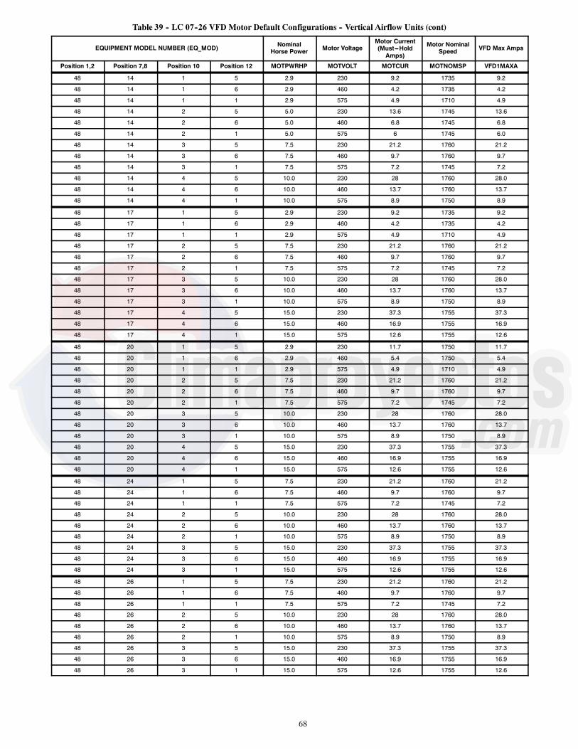
68
Table 39 -- LC 07--26 VFD Motor Default Configurations -- Vertical Airflow Units (cont)
EQUIPMENT MODEL NUMBER (EQ_MOD) NominalHorse Power Motor Voltage
Motor Current(Must---HoldAmps)
Motor NominalSpeed VFD Max Amps
Position 1,2 Position 7,8 Position 10 Position 12 MOTPWRHP MOTVOLT MOTCUR MOTNOMSP VFD1MAXA
48 14 1 5 2.9 230 9.2 1735 9.2
48 14 1 6 2.9 460 4.2 1735 4.2
48 14 1 1 2.9 575 4.9 1710 4.9
48 14 2 5 5.0 230 13.6 1745 13.6
48 14 2 6 5.0 460 6.8 1745 6.8
48 14 2 1 5.0 575 6 1745 6.0
48 14 3 5 7.5 230 21.2 1760 21.2
48 14 3 6 7.5 460 9.7 1760 9.7
48 14 3 1 7.5 575 7.2 1745 7.2
48 14 4 5 10.0 230 28 1760 28.0
48 14 4 6 10.0 460 13.7 1760 13.7
48 14 4 1 10.0 575 8.9 1750 8.9
48 17 1 5 2.9 230 9.2 1735 9.2
48 17 1 6 2.9 460 4.2 1735 4.2
48 17 1 1 2.9 575 4.9 1710 4.9
48 17 2 5 7.5 230 21.2 1760 21.2
48 17 2 6 7.5 460 9.7 1760 9.7
48 17 2 1 7.5 575 7.2 1745 7.2
48 17 3 5 10.0 230 28 1760 28.0
48 17 3 6 10.0 460 13.7 1760 13.7
48 17 3 1 10.0 575 8.9 1750 8.9
48 17 4 5 15.0 230 37.3 1755 37.3
48 17 4 6 15.0 460 16.9 1755 16.9
48 17 4 1 15.0 575 12.6 1755 12.6
48 20 1 5 2.9 230 11.7 1750 11.7
48 20 1 6 2.9 460 5.4 1750 5.4
48 20 1 1 2.9 575 4.9 1710 4.9
48 20 2 5 7.5 230 21.2 1760 21.2
48 20 2 6 7.5 460 9.7 1760 9.7
48 20 2 1 7.5 575 7.2 1745 7.2
48 20 3 5 10.0 230 28 1760 28.0
48 20 3 6 10.0 460 13.7 1760 13.7
48 20 3 1 10.0 575 8.9 1750 8.9
48 20 4 5 15.0 230 37.3 1755 37.3
48 20 4 6 15.0 460 16.9 1755 16.9
48 20 4 1 15.0 575 12.6 1755 12.6
48 24 1 5 7.5 230 21.2 1760 21.2
48 24 1 6 7.5 460 9.7 1760 9.7
48 24 1 1 7.5 575 7.2 1745 7.2
48 24 2 5 10.0 230 28 1760 28.0
48 24 2 6 10.0 460 13.7 1760 13.7
48 24 2 1 10.0 575 8.9 1750 8.9
48 24 3 5 15.0 230 37.3 1755 37.3
48 24 3 6 15.0 460 16.9 1755 16.9
48 24 3 1 15.0 575 12.6 1755 12.6
48 26 1 5 7.5 230 21.2 1760 21.2
48 26 1 6 7.5 460 9.7 1760 9.7
48 26 1 1 7.5 575 7.2 1745 7.2
48 26 2 5 10.0 230 28 1760 28.0
48 26 2 6 10.0 460 13.7 1760 13.7
48 26 2 1 10.0 575 8.9 1750 8.9
48 26 3 5 15.0 230 37.3 1755 37.3
48 26 3 6 15.0 460 16.9 1755 16.9
48 26 3 1 15.0 575 12.6 1755 12.6

69
Table 39 -- LC 07--26 VFD Motor Default Configurations -- Vertical Airflow Units (cont)
EQUIPMENT MODEL NUMBER (EQ_MOD) NominalHorse Power Motor Voltage
Motor Current(Must---HoldAmps)
Motor NominalSpeed VFD Max Amps
Position 1,2 Position 7,8 Position 10 Position 12 MOTPWRHP MOTVOLT MOTCUR MOTNOMSP VFD1MAXA
50 07 1 5 1.7 230 5.8 1695 5.8
50 07 1 6 1.7 460 2.9 1690 2.9
50 07 1 1 1.7 575 3.1 1690 3.1
50 07 2 5 1.7 230 5.8 1695 5.8
50 07 2 6 1.7 460 2.9 1690 2.9
50 07 2 1 1.7 575 3.1 1690 3.1
50 07 3 5 2.9 230 9.2 1735 9.2
50 07 3 6 2.9 460 4.2 1735 4.2
50 07 3 1 2.9 575 4.9 1710 4.9
50 08 1 5 1.7 230 5.8 1695 5.8
50 08 1 6 1.7 460 2.9 1690 2.9
50 08 1 1 1.7 575 3.1 1690 3.1
50 08 2 5 1.7 230 5.8 1695 5.8
50 08 2 6 1.7 460 2.9 1690 2.9
50 08 2 1 1.7 575 3.1 1690 3.1
50 08 3 5 2.9 230 9.2 1735 9.2
50 08 3 6 2.9 460 4.2 1735 4.2
50 08 3 1 2.9 575 4.9 1710 4.9
50 08 4 5 3.7 230 13.6 1745 13.6
50 08 4 6 3.7 460 6.8 1745 6.8
50 08 4 1 3.7 575 6 1745 6.0
50 09 1 5 1.7 230 5.8 1695 5.8
50 09 1 6 1.7 460 2.9 1690 2.9
50 09 1 1 1.7 575 3.1 1690 3.1
50 09 2 5 1.7 230 5.8 1695 5.8
50 09 2 6 1.7 460 2.9 1690 2.9
50 09 2 1 1.7 575 3.1 1690 3.1
50 09 3 5 3.7 230 11.7 1750 11.7
50 09 3 6 3.7 460 5.4 1750 5.4
50 09 3 1 3.7 575 4.9 1710 4.9
50 09 4 5 5.0 230 13.6 1745 13.6
50 09 4 6 5.0 460 6.8 1745 6.8
50 09 4 1 5.0 575 6 1745 6.0
50 12 1 5 2.4 230 7.9 1680 7.9
50 12 1 6 2.4 460 3.6 1680 3.6
50 12 1 1 2.4 575 3.8 1680 3.8
50 12 2 5 2.9 230 9.2 1735 9.2
50 12 2 6 2.9 460 4.2 1735 4.2
50 12 2 1 2.9 575 4.9 1710 4.9
50 12 3 5 5.0 230 13.6 1745 13.6
50 12 3 6 5.0 460 6.8 1745 6.8
50 12 3 1 5.0 575 6 1745 6.0
50 14 1 5 2.9 230 9.2 1735 9.2
50 14 1 6 2.9 460 4.2 1735 4.2
50 14 1 1 2.9 575 4.9 1710 4.9
50 14 2 5 5.0 230 13.6 1745 13.6
50 14 2 6 5.0 460 6.8 1745 6.8
50 14 2 1 5.0 575 6 1745 6.0
50 14 3 5 7.5 230 21.2 1760 21.2
50 14 3 6 7.5 460 9.7 1760 9.7
50 14 3 1 7.5 575 7.2 1745 7.2
50 14 4 5 10.0 230 28 1760 28.0
50 14 4 6 10.0 460 13.7 1760 13.7
50 14 4 1 10.0 575 8.9 1750 8.9

70
Table 39 -- LC 07--26 VFD Motor Default Configurations -- Vertical Airflow Units (cont)
EQUIPMENT MODEL NUMBER (EQ_MOD) NominalHorse Power Motor Voltage
Motor Current(Must---HoldAmps)
Motor NominalSpeed VFD Max Amps
Position 1,2 Position 7,8 Position 10 Position 12 MOTPWRHP MOTVOLT MOTCUR MOTNOMSP VFD1MAXA
50 17 1 5 2.9 230 9.2 1735 9.2
50 17 1 6 2.9 460 4.2 1735 4.2
50 17 1 1 2.9 575 4.9 1710 4.9
50 17 2 5 7.5 230 21.2 1760 21.2
50 17 2 6 7.5 460 9.7 1760 9.7
50 17 2 1 7.5 575 7.2 1745 7.2
50 17 3 5 10.0 230 28 1760 28.0
50 17 3 6 10.0 460 13.7 1760 13.7
50 17 3 1 10.0 575 8.9 1750 8.9
50 17 4 5 15.0 230 37.3 1755 37.3
50 17 4 6 15.0 460 16.9 1755 16.9
50 17 4 1 15.0 575 12.6 1755 12.6
50 20 1 5 2.9 230 11.7 1750 11.7
50 20 1 6 2.9 460 5.4 1750 5.4
50 20 1 1 2.9 575 4.9 1710 4.9
50 20 2 5 7.5 230 21.2 1760 21.2
50 20 2 6 7.5 460 9.7 1760 9.7
50 20 2 1 7.5 575 7.2 1745 7.2
50 20 3 5 10.0 230 28 1760 28.0
50 20 3 6 10.0 460 13.7 1760 13.7
50 20 3 1 10.0 575 8.9 1750 8.9
50 20 4 5 15.0 230 37.3 1755 37.3
50 20 4 6 15.0 460 16.9 1755 16.9
50 20 4 1 15.0 575 12.6 1755 12.6
50 24 1 5 7.5 230 21.2 1760 21.2
50 24 1 6 7.5 460 9.7 1760 9.7
50 24 1 1 7.5 575 7.2 1745 7.2
50 24 2 5 7.5 230 21.2 1760 21.2
50 24 2 6 7.5 460 9.7 1760 9.7
50 24 2 1 7.5 575 7.2 1745 7.2
50 24 3 5 10.0 230 28 1760 28.0
50 24 3 6 10.0 460 13.7 1760 13.7
50 24 3 1 10.0 575 8.9 1750 8.9
50 24 4 5 15.0 230 37.3 1755 37.3
50 24 4 6 15.0 460 16.9 1755 16.9
50 24 4 1 15.0 575 12.6 1755 12.6
50 26 1 5 7.5 230 21.2 1760 21.2
50 26 1 6 7.5 460 9.7 1760 9.7
50 26 1 1 7.5 575 7.2 1745 7.2
50 26 2 5 10.0 230 28 1760 28.0
50 26 2 6 10.0 460 13.7 1760 13.7
50 26 2 1 10.0 575 8.9 1750 8.9
50 26 3 5 15.0 230 37.3 1755 37.3
50 26 3 6 15.0 460 16.9 1755 16.9
50 26 3 1 15.0 575 12.6 1755 12.6
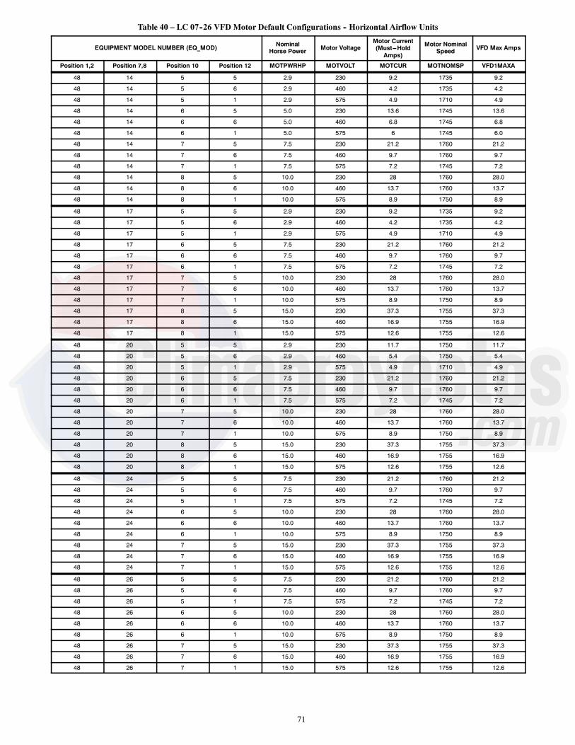
71
Table 40 – LC 07--26 VFD Motor Default Configurations -- Horizontal Airflow Units
EQUIPMENT MODEL NUMBER (EQ_MOD) NominalHorse Power Motor Voltage
Motor Current(Must---HoldAmps)
Motor NominalSpeed VFD Max Amps
Position 1,2 Position 7,8 Position 10 Position 12 MOTPWRHP MOTVOLT MOTCUR MOTNOMSP VFD1MAXA
48 14 5 5 2.9 230 9.2 1735 9.2
48 14 5 6 2.9 460 4.2 1735 4.2
48 14 5 1 2.9 575 4.9 1710 4.9
48 14 6 5 5.0 230 13.6 1745 13.6
48 14 6 6 5.0 460 6.8 1745 6.8
48 14 6 1 5.0 575 6 1745 6.0
48 14 7 5 7.5 230 21.2 1760 21.2
48 14 7 6 7.5 460 9.7 1760 9.7
48 14 7 1 7.5 575 7.2 1745 7.2
48 14 8 5 10.0 230 28 1760 28.0
48 14 8 6 10.0 460 13.7 1760 13.7
48 14 8 1 10.0 575 8.9 1750 8.9
48 17 5 5 2.9 230 9.2 1735 9.2
48 17 5 6 2.9 460 4.2 1735 4.2
48 17 5 1 2.9 575 4.9 1710 4.9
48 17 6 5 7.5 230 21.2 1760 21.2
48 17 6 6 7.5 460 9.7 1760 9.7
48 17 6 1 7.5 575 7.2 1745 7.2
48 17 7 5 10.0 230 28 1760 28.0
48 17 7 6 10.0 460 13.7 1760 13.7
48 17 7 1 10.0 575 8.9 1750 8.9
48 17 8 5 15.0 230 37.3 1755 37.3
48 17 8 6 15.0 460 16.9 1755 16.9
48 17 8 1 15.0 575 12.6 1755 12.6
48 20 5 5 2.9 230 11.7 1750 11.7
48 20 5 6 2.9 460 5.4 1750 5.4
48 20 5 1 2.9 575 4.9 1710 4.9
48 20 6 5 7.5 230 21.2 1760 21.2
48 20 6 6 7.5 460 9.7 1760 9.7
48 20 6 1 7.5 575 7.2 1745 7.2
48 20 7 5 10.0 230 28 1760 28.0
48 20 7 6 10.0 460 13.7 1760 13.7
48 20 7 1 10.0 575 8.9 1750 8.9
48 20 8 5 15.0 230 37.3 1755 37.3
48 20 8 6 15.0 460 16.9 1755 16.9
48 20 8 1 15.0 575 12.6 1755 12.6
48 24 5 5 7.5 230 21.2 1760 21.2
48 24 5 6 7.5 460 9.7 1760 9.7
48 24 5 1 7.5 575 7.2 1745 7.2
48 24 6 5 10.0 230 28 1760 28.0
48 24 6 6 10.0 460 13.7 1760 13.7
48 24 6 1 10.0 575 8.9 1750 8.9
48 24 7 5 15.0 230 37.3 1755 37.3
48 24 7 6 15.0 460 16.9 1755 16.9
48 24 7 1 15.0 575 12.6 1755 12.6
48 26 5 5 7.5 230 21.2 1760 21.2
48 26 5 6 7.5 460 9.7 1760 9.7
48 26 5 1 7.5 575 7.2 1745 7.2
48 26 6 5 10.0 230 28 1760 28.0
48 26 6 6 10.0 460 13.7 1760 13.7
48 26 6 1 10.0 575 8.9 1750 8.9
48 26 7 5 15.0 230 37.3 1755 37.3
48 26 7 6 15.0 460 16.9 1755 16.9
48 26 7 1 15.0 575 12.6 1755 12.6

72
Table 40 -- LC 07--26 VFD Motor Default Configurations -- Horizontal Airflow Units (cont)
EQUIPMENT MODEL NUMBER (EQ_MOD) NominalHorse Power Motor Voltage
Motor Current(Must---HoldAmps)
Motor NominalSpeed VFD Max Amps
Position 1,2 Position 7,8 Position 10 Position 12 MOTPWRHP MOTVOLT MOTCUR MOTNOMSP VFD1MAXA
50 14 5 5 2.9 230 9.2 1735 9.2
50 14 5 6 2.9 460 4.2 1735 4.2
50 14 5 1 2.9 575 4.9 1710 4.9
50 14 6 5 5.0 230 13.6 1745 13.6
50 14 6 6 5.0 460 6.8 1745 6.8
50 14 6 1 5.0 575 6 1745 6.0
50 14 7 5 7.5 230 21.2 1760 21.2
50 14 7 6 7.5 460 9.7 1760 9.7
50 14 7 1 7.5 575 7.2 1745 7.2
50 14 8 5 10.0 230 28 1760 28.0
50 14 8 6 10.0 460 13.7 1760 13.7
50 14 8 1 10.0 575 8.9 1750 8.9
50 17 5 5 2.9 230 9.2 1735 9.2
50 17 5 6 2.9 460 4.2 1735 4.2
50 17 5 1 2.9 575 4.9 1710 4.9
50 17 6 5 7.5 230 21.2 1760 21.2
50 17 6 6 7.5 460 9.7 1760 9.7
50 17 6 1 7.5 575 7.2 1745 7.2
50 17 7 5 10.0 230 28 1760 28.0
50 17 7 6 10.0 460 13.7 1760 13.7
50 17 7 1 10.0 575 8.9 1750 8.9
50 17 8 5 15.0 230 37.3 1755 37.3
50 17 8 6 15.0 460 16.9 1755 16.9
50 17 8 1 15.0 575 12.6 1755 12.6
50 20 5 5 2.9 230 11.7 1750 11.7
50 20 5 6 2.9 460 5.4 1750 5.4
50 20 5 1 2.9 575 4.9 1710 4.9
50 20 6 5 7.5 230 21.2 1760 21.2
50 20 6 6 7.5 460 9.7 1760 9.7
50 20 6 1 7.5 575 7.2 1745 7.2
50 20 7 5 10.0 230 28 1760 28.0
50 20 7 6 10.0 460 13.7 1760 13.7
50 20 7 1 10.0 575 8.9 1750 8.9
50 20 8 5 15.0 230 37.3 1755 37.3
50 20 8 6 15.0 460 16.9 1755 16.9
50 20 8 1 15.0 575 12.6 1755 12.6
50 24 5 5 7.5 230 21.2 1760 21.2
50 24 5 6 7.5 460 9.7 1760 9.7
50 24 5 1 7.5 575 7.2 1745 7.2
50 24 6 5 7.5 230 21.2 1760 21.2
50 24 6 6 7.5 460 9.7 1760 9.7
50 24 6 1 7.5 575 7.2 1745 7.2
50 24 7 5 10.0 230 28 1760 28.0
50 24 7 6 10.0 460 13.7 1760 13.7
50 24 7 1 10.0 575 8.9 1750 8.9
50 24 8 5 15.0 230 37.3 1755 37.3
50 24 8 6 15.0 460 16.9 1755 16.9
50 24 8 1 15.0 575 12.6 1755 12.6
50 26 5 5 7.5 230 21.2 1760 21.2
50 26 5 6 7.5 460 9.7 1760 9.7
50 26 5 1 7.5 575 7.2 1745 7.2
50 26 6 5 10.0 230 28 1760 28.0
50 26 6 6 10.0 460 13.7 1760 13.7
50 26 6 1 10.0 575 8.9 1750 8.9
50 26 7 5 15.0 230 37.3 1755 37.3
50 26 7 6 15.0 460 16.9 1755 16.9
50 26 7 1 15.0 575 12.6 1755 12.6

73
For proper operation, there are three jumper wires that mustremain installed and the VFD must be set to the auto mode. The3 jumpers are shown on the unit schematic and are connectedthrough a plug called PL25. These jumpers set the VFD to startenabled, run enabled, and tie the common bus together. TheVFD has 4 LEDs on its front panel to indicate operating status.See below and VFD Troubleshooting section for details on VFDfaults and alarms. The VFD faults can be reset with the VFDkeypad or through the SystemVut controls(ALERTS/FAULTRESET FAULT/ALERT =Yes).The Green On LED will indicate the VFD is powered on. TheGreen Com. LED will flash as communication is occurring on thebus. The Yellow Warning LED will indicate when a warning ispresent. The Red Alarm LED will indicate when a alarm conditionis present.
Refer to the VFD manufacture literature for details on using theVFD Keypad for troubleshooting.
LC 07--26 VFD TroubleshootingWhen communication is successful, the SystemVu control willprovide alerts and faults that correlate to the VFD’s warnings andalarms. Table 41 shows the list of the SystemVu controller faultsand alerts and how they map to the VFD warnings and alarms.Table 41 also lists the possible causes of these cases.A VFD lockout alarm will require a power cycle to the VFD toreset. VFD warnings may reduce the actual motor speed withoutthe SystemVu control correcting the speed. This is an acceptableaction to protect the motor, and usually means there are improperconfigurations or motor installed.
Table 41 – LC --7--26 VFD Fault Codes
SystemVu Fault SystemVu Alert VFDNumber VFD Description VFD
WarningVFDAlarm
TripLock Cause of Problem
--- A607--- IDF VFD CURRENTLIMIT 59 Current limit X The current is higher than the value in par. 4--- 18 Current
Limit.
--- A608--- IDF VFD WARNING 66 Heat sinkTemperature Low X This warning is based on the temperature sensor in the
IGBT Module (Only on 400 V 30---90 kW units).
--- A608--- IDF VFD WARNING 87 Auto DC Braking X The drive is auto DC braking.
--- A608--- IDF VFD WARNING 201 Fire Mode X Fire mode has been activated.
--- A608--- IDF VFD WARNING 202 Fire M LimitsExceeded X Fire Mode has suppressed on or more warranty voiding
alarms.
F610--- IDF VFDPWR CARD TEMP
A605--- IDF VFD THERMALWARNING 69 Pwr Card
Temperature X X X The temperature sensor on the power card is either toohot or too cold.
F611--- IDF VFDEARTH FAULT A608--- IDF VFD WARNING 14 Earth fault X X X Discharge from output phases to ground.
F611--- IDF VFDEARTH FAULT --- 44 Earth fault 2 X X Discharge from output phases to ground.
F612--- IDF VFD CTLWORD LOSS A608--- IDF VFD WARNING 17 Control word
timeout X X No communication to variable frequency drive.
F613--- IDF VFDOVER CURRENT
A607--- IDF VFD CURRENTLIMIT 13 Over Current X X X Inverter peak current limit is exceeded.
F614--- IDF VFDMOTOR OVERTEMP
A605--- IDF VFD THERMALWARNING 10 Motor ETR over
temperature X X Motor is too hot due to more than 100% load for toolong. See parameter 1--- 90.
F615--- IDF VFDOVERLOAD A608--- IDF VFD WARNING 9 Inverter overloaded X X More than 100% load for too long.
F616--- IDF VFDUNDER VOLTAGE
A606--- IDF VFD VOLTAGEWARNING 8 DC under voltage X X Intermediate circuit voltage drops below “voltage
warning low” limit.
F617--- IDF VFDOVER VOLTAGE
A606--- IDF VFD VOLTAGEWARNING 7 DC over voltage X X Intermediate circuit voltage exceeds limit.
F618--- IDF VFDSHORT CIRCUIT --- 16 Short Circuit X X Short--- circuit in motor or on motor terminals.
F619--- IDF VFDMAIN PHASE LOSS A608--- IDF VFD WARNING 4 Mains phase loss X X X Missing phase on supply side or too high voltage
imbalance. Check supply voltage. See parameter 14---12
F620--- IDF VFDPHASE U LOSS --- 30 Motor phase U
missing X X Motor phase U is missing. Check the phase.
F621--- IDF VFDPHASE V LOSS --- 31 Motor phase V
missing X X Motor phase V is missing. Check the phase.
F622--- IDF VFDPHASE W LOSS --- 32 Motor phase W
missing X X Motor phase W is missing. Check the phase.
F623--- IDF VFDCONTROLVOLTAGE
--- 47 Control VoltageFault X X 24 V DC may be overloaded.
F624--- IDF VFDSUPPLY VDD --- 48 VDD1 Supply Low X X Control voltage low. Please contact your local Carrier
representative.
F601--- IDF VFDUNEXPECTED
A605--- IDF VFD THERMALWARNING 11 Motor thermistor
over temperature X X Thermistor or thermistor connection is disconnected. Seeparameter 1--- 90.
F601--- IDF VFDUNEXPECTED A608--- IDF VFD WARNING 2 Live zero error X X Signal on terminal 53 or 54 is less than 50% of value set
in par 6---10, 6--- 12, 6--- 20, or 6--- 22.
F601--- IDF VFDUNEXPECTED A608--- IDF VFD WARNING 24 Fan Fault (Only on
400V 30---90kW) X X The fan is not working (Only on 400 V 30 to 90 kW units).
F601--- IDF VFDUNEXPECTED A608--- IDF VFD WARNING 58 AMA internal fault X X Contact your local Carrier representative.
F601--- IDF VFDUNEXPECTED A608--- IDF VFD WARNING 79 Illegal PS config X X Internal fault. Contact your local Carrier representative.

74
Table 41 — LC --7--26 VFD Fault Codes (cont)
SystemVu Fault SystemVu Alert VFDNumber VFD Description VFD
WarningVFDAlarm
TripLock Cause of Problem
F601--- IDF VFDUNEXPECTED A608--- IDF VFD WARNING 95 Broken Belt X X Torque is below the torque level set for no load,
indicating a broken belt.
F601--- IDF VFDUNEXPECTED --- 38 Internal fault X X Contact your local Carrier representative.
F601--- IDF VFDUNEXPECTED --- 50 AMA Calibration
Failed X Contact your local Carrier representative.
F601--- IDF VFDUNEXPECTED --- 51 AMA check Unom
and Inom X The setting of motor voltage, motor current and motorpower is presumably wrong. Check the settings.
F601--- IDF VFDUNEXPECTED --- 52 AMA low Inom X The motor current is too low. Check the settings.
F601--- IDF VFDUNEXPECTED --- 53 AMA motor too big X The motor is too big for the AMA to be carried out.
F601--- IDF VFDUNEXPECTED --- 54 AMA motor too
small X The motor is too small for the AMA to be carried out.
F601--- IDF VFDUNEXPECTED --- 55 AMA Parameter out
of range X The parameter values found from the motor are outsideacceptable range.
F601--- IDF VFDUNEXPECTED --- 56 AMA interrupted by
user X The AMA has been interrupted by the user.
F601--- IDF VFDUNEXPECTED --- 57 AMA timeout X
Try to start the AMA again a number of times, until theAMA is carried out. Please note that repeated runs mayheat the motor to a level where the resistance Rs and Rrare increased. In most cases, however, this is not critical.
F601--- IDF VFDUNEXPECTED --- 60 External Interlock X
External interlock has been activated. To resume normaloperation, apply 24 V DC to the terminal programmed forexternal interlock and reset the variable frequency driveby pressing the Off/Reset button on the keypad.
F601--- IDF VFDUNEXPECTED --- 80 Drive Initialized to
Default Value X All parameter setting are initialized to default settings.
F601--- IDF VFDUNEXPECTED --- 250 New spare parts X X
The power or switch mode power supply has beenexchanged. (Only on 400 V 30 to 90 kW units). Contactyour local Carrier representative.
F601--- IDF VFDUNEXPECTED --- 251 New Type Code X X
The variable frequency drive has a new type of code(Only on 400 V 30 to 90 kW units). Contact your localCarrier representative.
Carrier Comfort NetworkR (CCN) InterfaceThe units can be connected to the CCN if desired. Thecommunication bus wiring is a shielded, 3-conductor cable withdrain wire and is field supplied and installed. The system elementsare connected to the communication bus in a daisy chainarrangement. (See Fig. 39.) The positive pin of each systemelement communication connector must be wired to the positivepins of the system elements on either side of it. This is alsorequired for the negative and signal ground pins of each systemelement. Wiring connections for CCN should be made at the CIB.(See Fig. 27 and 28.) Consult the CCN Contractor’s Manual forfurther information.NOTE: Conductors and drain wire must be 20 AWG (AmericanWire Gauge) minimum stranded, tinned copper. Individualconductors must be insulated with PVC, PVC/nylon, vinyl,Teflon*, or polyethylene. An aluminum/polyester 100% foil shieldand an outer jacket of PVC, PVC/nylon, chrome vinyl, or Teflonwith a minimum operating temperature range of –20_C to 60_C isrequired. See Table below for acceptable wiring.
MANUFACTURER PART NO.
Alpha 2413 or 5463
Belden 8772
Carol C2528
West Penn 302
It is important when connecting to a CCN communication bus thata color-coding scheme be used for the entire network to simplifythe installation. It is recommended that red be used for the signalpositive, black for the signal negative and white for the signalground. Use a similar scheme for cables containing differentcolored wires.
*Teflon is a registered trademark of DuPont.
At each system element, the shields of its communication buscables must be tied together. The shield screw on CIB can be usedto tie the cables together. If the communication bus is entirelywithin one building, the resulting continuous shield must beconnected to a ground at one point only. The shield screw on CIBis not acceptable for grounding. If the communication bus cableexits from one building and enters another, the shields must beconnected to grounds at the lightning suppressor in each buildingwhere the cable enters or exits the building (one point per buildingonly).To connect the unit to the network:
1. Turn off power to the control box.2. Cut the CCN wire and strip the ends of the red (+), white(ground), and black (–) conductors. (Substitute appropriatecolors for different colored cables.)
3. Connect the red wire to (+) terminal on CIB, the white wireto COM terminal, and the black wire to the (–) terminal.
4. The RJ14 CCN connector on CIB can also be used, but isonly intended for temporary connection (for example, alaptop computer running Carrier network software).
5. Restore power to unit.IMPORTANT: A shorted CCN bus cable will prevent someroutines from running and may prevent the unit from starting. Ifabnormal conditions occur, unplug the connector. If conditionsreturn to normal, check the CCN connector and cable. Run newcable if necessary. A short in one section of the bus can causeproblems with all system elements on the bus.

75
CCN BUS
BUILDING SUPERVISOR
CL
ROOFTOPUNIT
ROOFTOPUNIT
ROOFTOPUNIT
ROOFTOPUNIT
CL
NETWORKOPTIONS
REMOTECCN SITE
NON CARRIERHVAC
EQUIPMENT
AUTODIALGATEWAY
COMFORTCONTROLLER
CL
CL
HEATING/COOLING UNITS
LEGENDCCN -- Carrier Comfort Network®
CL -- ComfortLink ControlsDAV -- Digital Air VolumeHVAC -- Heating, Ventilation, and Air ConditoningTCU -- Terminal Control Unit
TOADDITIONALTERMINALS
TERMINALSYSTEM
MANAGER
CLTCU
TCU TCUDAV FANPOWEREDMIXINGBOX
DAV AIRTERMINAL
DAV AIRTERMINAL
ROOFTOPUNIT
AIR DISTRIBUTION-DIGITAL AIR VOLUME CONTROL (DAV)
C07030
Fig. 39 -- CCN System Architecture

76
APPENDIX A: SystemVut Controller DisplayRun Status Main Menu Layout
Display Text Expanded Text Values Units Write Status Point
SHUTDOWN UNIT? Local Unit Shutdown Req. Yes/No n/a Command
RUN STATUS Run Status Menu
MODE Mode Status Menu
MODE Operating Mode see Appendix B MODETEXT
SUB---MODE Operating Sub---Mode see Appendix B SUBMTEXT
DEMAND System Demand see Appendix B SYS_DMDT
LINKAGE ACTIVE Linkage Active Yes/No Forcible LNK_ACT
EFF COOL SETPOINT Cool Setpoint In Effect xx.x ° F CSP_EFF
EFF HEAT SETPOINT Heat Setpoint In Effect xx.x ° F HSP_EFF
DEMAND CTRL TEMP Effective Demand Temp xxx.x ° F TEMP_EFF
OCC SPRH SET PT Occupied SPRH Setpoint 0 to 100 % SPRH_OSP
UNOCC SPRH SET PT Unoccupied SPRH Setpoint 0 to 100 % SPRH_USP
COOL MODE T.GUARD Cool Mode Select T.guard xxx sec COOLMSTG
HEAT MODE T.GUARD Heat Mode Select T.guard xxx sec HEATMSTG
COOLING DEMAND Space Cooling Demand xx.x ° F COOL_DMD
COOL DEMAND TREND Cooling Demand Trend xx.x ^F/min CLDTREND
HEATING DEMAND Heating Space Demand xx.x ° F HEAT_DMD
HEAT DEMAND TREND Heat Space Demand Trend xx.x ^F/min HTDTREND
DMD LIMIT STATUS DEMAND LIMIT STATUS
COOL DMD LIM OFF Cool Demand Limiting Off/On CDMLMOFF
HEAT DMD LIM OFF Heat Demand Limiting Off/On HDMLMOFF
COOL DMD LIM LEV Cool demand Limit Level 0 to 3 CDMDLLEV
HEAT DMD LIM LEV Heat demand Limit Level 0 to 3 HDMELLEV
CL DMD LIM OFFSET Cool Demand limit offset xx.x ° F COOLDLMO
HT DMD LIM OFFSET Heat Demand limit offset xx.x ° F HEATDLMO
COOL Cooling Status Menu
IDF SPEED OUTPUT Commanded IDF Speed 0 to 100 % FANSPEED
ACTIVE COOL STAGE Actual Cool Stage Active x ACTCSTGS
COMMANDED ODF SPD Commanded ODF Speed xxxx rpm ODFSPD
ODF SDT SP ODF Control SDT SP xxxx ° F ODFSDTSP
LA CTRL STATUS Low Ambient Ctrl Status 0 = Normal,1 = Entering,2 = Low Ambient,3 = Exiting
LACTRLST
REQ. DEHUM LEVEL Requested Dehum Level 0 to 2 REQDHLEV
MECHANICAL COOLING Mechanical Cooling Detail Sub---Menu
OK TO USE COMPS? Ok to use compressors? Yes/No OKMECHCL
MECH COOL ACTIVE Mechanical Cool active? Yes/No MECHCOOL
MAX COOL STAGES Max Allowed Cool Stages 0 to 3 Forcible MAXCSTGS
REQ. COOL STAGES Requested Cooling Stages 0 to 3 REQCSTGS
ACTIVE COOL STAGE Actual Cool Stage Active x ACTCSTGS
COMMANDED ODF SPD Commanded ODF Speed xxxx rpm ODFSPD
COMP A1 TIMEGUARD Compressor A1 Timeguard xxx sec TIMGD_A1
COMP A2 TIMEGUARD Compressor A2 Timeguard xxx sec TIMGD_A2
SUPPLY AIR TREND Supply Air Temp Trend xxx.x ^F/min SATTREND
COMP A1 STRIKES Compressor A1 Strikes x A1STRIKE
COMP A2 STRIKES Compressor A2 Strikes x A2STRIKE
HI PRESS OVERRIDE High Pressure Override Yes/No HP_OVR
CIRCUIT A LOCKOUT Circuit A Locked Out Yes/No CIRALOCK
LOW COOL LOCKOUT Low cooling locked out Yes/No LC_LOCK
MED COOL LOCKOUT Medium Cooling lockout Yes/No MC_LOCK
COMP A1 AVAILABLE Compressor A1 Available Yes/No CA1_AVAL
COMP A1 LOCKOUT Compressor A1 locked out Yes/No CA1_LOCK
COMP A2 AVAILABLE Compressor A2 Available Yes/No CA2_AVAL
COMP A2 LOCKOUT Compressor A2 locked out Yes/No CA2_LOCK
FREE COOLING Free Cooling Detail Sub---menu
OK TO FREE COOL? OK to Use Free Cooling? Yes/No OKFREECL
IN FREE COOLING Free Cooling active Yes/No FREECOOL
FREECOOL SAT SP Free Cooling SAT Setpnt xx.x ° F FC_SATSP
REQ. DAMPER POS Requested Damper Pos 0 to 100 % REQDAMP
ECON OPERATIONAL? Econ Damper Operational Yes/No DAMPGOOD
DRY BULB LOCKOUT Dry Bulb Lockout Yes/No Forcible DBLOCK
ENTHALPY LOCKOUT Enthalpy Lockout Yes/No Forcible ENTHLOCK
OK TO UNOCC FC? Ok to unocc Free Cool? Yes/No OKTOUFC
IN UNOC FREECOOL? Unocc Free Cool Active Yes/No UFC_ACT
UFC LOCKOUT? Unocc Free Cool Lockout Yes/No UNOCLOCK
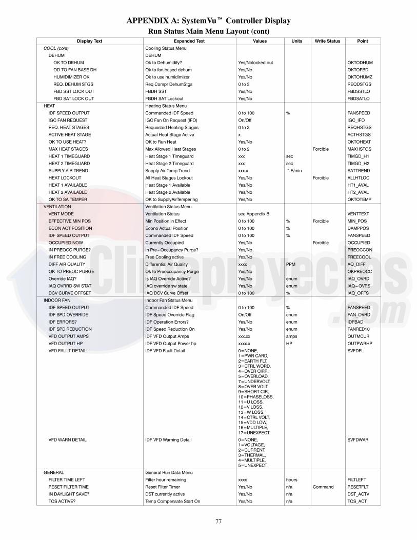
77
APPENDIX A: SystemVut Controller DisplayRun Status Main Menu Layout (cont)
Display Text Expanded Text Values Units Write Status Point
COOL (cont) Cooling Status Menu
DEHUM DEHUM
OK TO DEHUM Ok to Dehumidify? Yes/Nolocked out OKTODHUM
OD TO FAN BASE DH Ok to fan based dehum Yes/No OKTOFBD
HUMIDIMIZER OK Ok to use humidimizer Yes/No OKTOHUMZ
REQ. DEHUM STGS Req Compr DehumStgs 0 to 3 REQDSTGS
FBD SST LOCK OUT FBDH SST Yes/No FBDSSTLO
FBD SAT LOCK OUT FBDH SAT Lockout Yes/No FBDSATLO
HEAT Heating Status Menu
IDF SPEED OUTPUT Commanded IDF Speed 0 to 100 % FANSPEED
IGC FAN REQUEST IGC Fan On Request (IFO) On/Off IGC_IFO
REQ. HEAT STAGES Requested Heating Stages 0 to 2 REQHSTGS
ACTIVE HEAT STAGE Actual Heat Stage Active x ACTHSTGS
OK TO USE HEAT? OK to Run Heat Yes/No OKTOHEAT
MAX HEAT STAGES Max Allowed Heat Stages 0 to 2 Forcible MAXHSTGS
HEAT 1 TIMEGUARD Heat Stage 1 Timeguard xxx sec TIMGD_H1
HEAT 2 TIMEGUARD Heat Stage 2 Timeguard xxx sec TIMGD_H2
SUPPLY AIR TREND Supply Air Temp Trend xxx.x ^F/min SATTREND
HEAT LOCKOUT All Heat Stages Lockout Yes/No Forcible ALLHTLOC
HEAT 1 AVAILABLE Heat Stage 1 Available Yes/No HT1_AVAL
HEAT 2 AVAILABLE Heat Stage 2 Available Yes/No HT2_AVAL
OK TO SA TEMPER OK to SupplyAirTempering Yes/No OKTOTEMP
VENTILATION Ventilation Status Menu
VENT MODE Ventilation Status see Appendix B VENTTEXT
EFFECTIVE MIN POS Min Position in Effect 0 to 100 % Forcible MIN_POS
ECON ACT POSITION Econo Actual Position 0 to 100 % DAMPPOS
IDF SPEED OUTPUT Commanded IDF Speed 0 to 100 % FANSPEED
OCCUPIED NOW Currently Occupied Yes/No Forcible OCCUPIED
IN PREOCC PURGE? In Pre---Occupancy Purge? Yes/No PREOCCON
IN FREE COOLING Free Cooling active Yes/No FREECOOL
DIFF AIR QUALITY Differential Air Quality xxxx PPM AQ_DIFF
OK TO PREOC PURGE Ok to Preoccupancy Purge Yes/No OKPREOCC
Override IAQ? Is IAQ Override Active? Yes/No enum IAQ_OVRD
IAQ OVRRD SW STAT IAQ override sw state Yes/No enum IAQ---OVRS
DCV CURVE OFFSET IAQ DCV Curve Offset 0 to 100 % IAQ_OFFS
INDOOR FAN Indoor Fan Status Menu
IDF SPEED OUTPUT Commanded IDF Speed 0 to 100 % FANSPEED
IDF SPD OVERRIDE IDF Speed Override Flag On/Off enum FAN_OVRD
IDF ERRORS? IDF Operation Errors? Yes/No enum IDFBAD
IDF SPD REDUCTION IDF Speed Reduction On Yes/No enum FANRED10
VFD OUTPUT AMPS IDF VFD Output Amps xxx.xx amps OUTMCUR
VFD OUTPUT HP IDF VFD Output Power hp xxxx.x HP OUTPWRHP
VFD FAULT DETAIL IDF VFD Fault Detail 0=NONE,1=PWR CARD,2=EARTH FLT,3=CTRL WORD,4=OVER CIRR,5=OVERLOAD,7=UNDERVOLT,8=OVER VOLT9=SHORT CIR,10=PHASELOSS,11=U LOSS,12=V LOSS,13=W LOSS,14=CTRL VOLT,15=VDD LOW,16=MULTIPLE,17=UNEXPECT
SVFDFL
VFD WARN DETAIL IDF VFD Warning Detail 0=NONE,1=VOLTAGE,2=CURRENT,3=THERMAL,4=MULTIPLE,5=UNEXPECT
SVFDWAR
GENERAL General Run Data Menu
FILTER TIME LEFT Filter hour remaining xxxx hours FILTLEFT
RESET FILTER TIME Reset Filter Timer Yes/No n/a Command RESETFLT
IN DAYLIGHT SAVE? DST currently active Yes/No n/a DST_ACTV
TCS ACTIVE? Temp Compensate Start On Yes/No n/a TCS_ACT

78
APPENDIX A: SystemVut Controller DisplayRun Status Main Menu Layout (cont)
Display Text Expanded Text Range Units Default Point
OCCUPANCY OCCUPANCY DATA
OCCUPIED NOW Currently Occupied Yes/No Forcible OCCUPIED
MINS UNTIL OCC Mins until next occupied xxxxx min MINTILOC
ACTIVE OCC CTRL Active Occupancy control 0=24/7 OCC,1=SCHEDULE,2=BAS CTRL,3=REMOC CTL,4=TIME OVRD,5=LINKAGE,6=FORCED
OCC_CTRL
LINKAGE OCC REQ Linkage Occupied Request 0=Unocc,1=Occupied,2=Disabled
LNK_OCC
TIMED OVRD REMAIN Timed Override Remaining 0 to 240 min Forcible OVR_EXT
REMOTE OCC SWITCH Remote Occupancy Switch On/Off Forcible REMOCC
BMS OCC REQUEST BMS Occupancy Request 0=UNOCC,1=OCCUPIED,2=DISABLED
Forcible BMS_OCC
LOCAL OCC REQUEST Local Sched Occ Request 0=Unocc,1=Occupied
Forcible LOC_OCC
ACTIVE PERIOD Active Schedule period 0 to 8 PER_NO
HOLIDAY TOMORROW? Tomorrow Is A Holiday Yes/No HOL_TMRW
HOLIDAY TODAY? Today Is A Holiday Yes/No HOLTODAY
NEXT OCC DAY Next Occupied Day DDD NXTOCDAY
NEXT OCC TIME Next Occupied Time hh:mm NXTOCTIM
NEXT UNOCC DAY Next Unoccupied Day DDD NXTUNDAY
NEXT UNOCC TIME Next Unoccupied Time hh:mm NXTUNTIM
PREV UNOCC DAY Previous Unccupied Day DDD PRVUNDAY
PREV UNOCC TIME Previous Unoccupied Time hh:mm PRVUNTIM
Settings Main Menu LayoutDisplay Text Expanded Text Range Units Default Point
SETTINGS Settings Menu
SPACE SET POINTS Space Setpoints Adjustment Menu
OCC COOL SETPOINT Occupied Cool Setpoint 55 to 80 ° F 78 OCSP
OCC HEAT SETPOINT Occupied Heat Setpoint 55 to 80 ° F 68 OHSP
UNOCC COOL SETPNT Unoccupied Cool Setpoint 65 to 95 ° F 85 UCSP
UNOCC HEAT SETPNT Unoccupied Heat Setpoint 40 to 80 ° F 60 UHSP
HEAT---COOL SP GAP Heat---Cool Setpoint Gap 2 to 10 ^F 5 HCSP_GAP
SPT SLIDER RANGE SPT Offset Range (+/--- ) 0 to 5.0 ° F 5 SPTO_RNG
OCC SPRH SET PT Occupied SPRH Setpoint 0 to 100 % 55 SPRH_OSP
UNOCC SPRH SET PT Unoccupied SPRH Setpoint 0 to 100 % 55 SPRH_USP
SA TEMPER SET PNT SA tempering Set point xx ° F 50 SATEMPSP
TEMP DEMAND CONFIG Temperature Demand Configuration menu
LOW COOL DMD ON Low Cool Demand On ---1 to 2.0 ° F 0.5 DMDLCON
MED COOL DMD ON Medium Cool Demand On 0.5 to 20.0 ° F 1 DMDMCON
HIGH COOL DMD ON High Cool Demand On 0.5 to 20.0 ° F 2 DMDHCON
LOW COOL DMD OFF Low Cool Demand Off --- 1 to 2.0 ° F ---0.5 DMDLCOFF
COOL DMD LEVEL UP Cool Demand Level Up ---2 to 2.0 ^F/min ---0.2 CDMD_LUP
LOW HEAT DMD ON Low Heat Demand On ---1 to 2.0 ° F 0.5 DMDLHON
HIGH HEAT DMD ON High Heat Demand On 0.5 to 20.0 ° F 2 DMDHHON
LOW HEAT DMD OFF Low Heat Demand Off --- 1 to 2.0 ° F ---0.5 DMDLHOFF
HEAT DMD LEVEL UP Heat Demand Level Up ---2 to 2.0 ^F/min ---0.2 HDMD_LUP
DEMAND TIMEGUARD1 Space Demand Time Guard1 60 to 600 sec 180 TDMD_TG1
DEMAND TIMEGUARD2 Space Demand Time Guard2 0 to 600 sec 300 TDMD_TG2
DEMAND TIMEGUARD3 Space Demand Time Guard3 5 to 120 min 10 TDMD_TG3
DMD LIMIT CONFIG DEMAND LIMIT CONFIG
COOL DMD LIM LEV1 Cool DMD Offset level 1 0 t0 99 ° F 1 CLDOLEV1
COOL DMD LIM LEV2 Cool DMD Offset level 2 0 t0 99 ° F 3 CLDOLEV2
COOL DMD LIM LEV3 Cool DMD Offset level 3 0 t0 99 ° F 5 CLDOLEV3
HEAT DMD LIM LEV1 Heat DMD Offset level 1 0 t0 99 ° F 1 HTDOLEV1
HEAT DMD LIM LEV2 Heat DMD Offset level 2 0 t0 99 ° F 3 HTDOLEV2
HEAT DMD LIM LEV3 Heat DMD Offset level 3 0 t0 99 ° F 5 HTDOLEV3
CLOCK Clock Adjustment Menu
TIME Clock Hour and Minute xx:xx hh.mm TIME
DATE Current Date MM/DD/YYYY DATE
DAYLIGHT SAVINGS Daylight Savings Configuration Menu DST Menu
DAYLIGHT SAVINGS? DST allowed? Enable/Disable Enable DST_CFG

79
APPENDIX A: SystemVut Controller DisplaySettings Main Menu Layout (cont)
Display Text Expanded Text Range Units Default Point
CLOCK (cont) Clock Adjustment Menu
DST START MONTH DST Start Month 1=JANUARY,2=FEBRUARY,3=MARCH,4=APRIL,5=MAY,6=JUNE,7=JULY,8=AUGUST,9=SEPTEMBER,10=OCTOBER,11=NOVEBER,12=DECEMBER
3 STARTM
DST START WEEK DST Start Week 1 to 5 2 STARTW
DST START DAY DST Start Day 1=MONDAY,2=TUESDAY,3=WEDNESDAY,4=THURSDAY,5=FRIDAY,6=SATURDAY,7=SUNDAY
7 STARTD
DST MINS TO ADD DST Minutes to Add 0 to 90 min 60 MINADD
DST STOP MONTH DST Stop Month 1=JANUARY,2=FEBRUARY,3=MARCH,4=APRIL,5=MAY,6=JUNE,7=JULY,8=AUGUST,9=SEPTEMBER,10=OCTOBER,11=NOVEBER,12=DECEMBER
1 STOPM
DST STOP WEEK DST Stop Week 1 to 5 1 STOPW
DST STOP DAY DST Stop Day 1=MONDAY,2=TUESDAY,3=WEDNESDAY,4=THURSDAY,5=FRIDAY,6=SATURDAY,7=SUNDAY
7 STOPD
DST MINS TO SUB DST Minutes to Subtract 0 to 90 min 60 MINSUB
START TIME IN DAY Time in day to start DST 0 to 600 min 120 DST_TOD
SCHEDULES Schedules Adjustment Menu
SCHEDULE NUMBER CCN Schedule Number 0 = Always Occupied,1--- 64 = Local Schedule,65---99 = Global Schedule
0 SCHEDNUM
OCCUPANCY SCHEDULE OCCUPANCY SCHEDULE DATA
HOLIDAYS Holiday adjustment Menu
ALLOW G. HOLIDAY? Accept Global Holidays? Yes/No No HOLIDAYT
TIMED OVR LENGTH Timed Override Duration 0 to 4 hours 4 OTL_CFG
UNIT CONFIGURATIONS Unit Configurations Menu
GENERAL General Unit Configurations Menu
STARTUP DELAY Unit Startup Delay 10 to 600 sec 30 STARTDLY
UNIT CONTROL TYPE Unit Control Type 0=TSTAT,1=SPACE SEN,2=RAT SEN
0=TSTAT CTRLTYPE
THERMOSTAT TYPE Thermostat Hardware Type 0=CONV 2C2H,1=DIGI 2C2H,2=CONV 3C2H,3=DIGI 3C2H4=DIGI 2C2H_S
2=CONV 3C2H STATTYPE
ADAPTIVE TSTAT Tstat Adaptive Staging Yes/No Yes ADPTSTAT
DIRTY FILTER TIME Change Filter Timer 0 to 9999 hours 600 FILTLIFE
TEST MODE TIMEOUT Test inactivity time out 0=Disabled,1=30 minutes,2=1 hour,3=2 hours,4=4 hours,5=8 hours,6=12 hours
4=4 hours TEST_ITO
CCH MAX TEMP CCH Max Temperature 40 to 90 ° F 65 CCHMAXT
STD BARO PRESSURE Std Barometric Pressure 13.00 to 35.00 in.Hg 29.92 STD_BARP
LINK STAGEUP TIME Linkage Stage inc. time 60 to 600 sec 180 LSTAGINC
UNIT’S MAX SAT Unit’s Maximum SAT 130 to 210 ° F 200 UMAX_SAT
AUTO SAT FAULTS? Auto Clr SAT Limit Fault Yes/No No SATLACLR
ADAPTIVE TCS? Adaptive Temp Comp Start Enable/Disable Yes TCS_CFG
USER TCS BIASTIME User TCS Start bias time 0 to 180 min 0 TCSUBIAS

80
APPENDIX A: SystemVut Controller DisplaySettings Main Menu Layout (cont)
Display Text Expanded Text Range Units Default Point
UNIT CONFIGURATIONS (cont) Unit Configurations Menu
SWITCH INPUTS CONFIGS DI Config Menu
FIRE SHUTDOWN SW Fire Shutdown Switch 0=NORM OPEN,1=NORM CLSD,2=NO SWITCH
2: no FIOP0: FIOP
FIRE_CFG
HUMSTAT CHANNEL HumidistatStatus Channel 0=None,1=MBB DI12,2=MBB DI13.3=MBB DI14,4=MBB DI02,5=MBB DI04,6=SIOB Di01
0=for all exceptHumidimizer6=Humidimizer Units
HUMDCHAN
HUMSTAT SW TYPE Humidistat Switch Type 0=NORM OPEN,1=NORM CLSD,
0=NORM OPEN HUMD_CFG
FILTER SW CHANNEL Filter Status Sw Channel 0=None,1=MBB DI12,2=MBB DI13,3=MBB DI14,4=MBB DI02,5=MBB DI04
0=None FILTCHAN
FILTER SW TYPE Filter Status Swith Type 0=NORM OPEN,1=NORM CLSD
0=NORM OPEN FILT_CFG
REMOTE OCC CHAN Remote Occupancy Channel 0=None,1=MBB DI12,2=MBB DI13,3=MBB DI14,4=MBB DI02,5=MBB DI04
0=None RMOCCHAN
REMOTE OCC TYPE Remote Occupancy Sw Type 0=NORM OPEN,1=NORM CLSD
0=NORM OPEN RMOC_CFG
REM.SHUTDOWN CHAN Remote Shutdown Channel 0=None,1=MBB DI12,2=MBB DI13,3=MBB DI14,4=MBB DI02,5=MBB DI04
0=None ROFFCHAN
REM.SHUTDOWN SW T Remote Shutdown Sw Type 0=NORM OPEN,1=NORM CLSD
0=NORM OPEN ROFF_CFG
REM.SHUTDOWN TYPE Remote Shutdown ALM Type 0=Normal,1=Emergency
0=Normal ROFFTYPE
COFS CHANNEL COFS Assigned Channel 0=None,1=MBB DI12,2=MBB DI13,3=MBB DI14,4=MBB DI02,5=MBB DI04
0=None COFSCHAN
COFS TYPE COFS Switch Type 0=NORM OPEN,1=NORM CLSD
1=NORM CLSD COFS_CFG
GEN STATUS CHAN General Status Channel 0=None,1=MBB DI12,2=MBB DI13,3=MBB DI14,4=MBB DI02,5=MBB DI04
0=None GEN_CHAN
GEN STAT SW TYPE General Status Sw Type 0=NORM OPEN,1=NORM CLSD
0=NORM OPEN GENS_CFG
SHUTDOWN GEN STAT General Status shutdown? Yes/No Yes GENFATAL
ENTHALPY SW CHAN Enthalpy Sw Channel 0=None,1=MBB DI12,2=MBB DI13,3=MBB DI14,4=MBB DI02,5=MBB DI04
0=None ENTHCHAN
ENTHALPY SW TYPE Enthalpy Switch Type 0=NORM OPEN,1=NORM CLSD
0=NORM OPEN ENTH_CFG
ANALOG INPUT CONFIGS Analog Inputs Configuration Menu
SPRH SENS CHANNEL SPRH Assigned Channel 0=None,1=MBB AI06,2=MBB AI07,3=MBB AI084=SIOB AI10
0=None SPRHCHAN
SPRH RH @ 4MA SPRH Sensor Value at 4mA 0 to 100 % 0 SPRH_4MA
SPRH RH @ 20MA SPRH Sensor Value @ 20mA 0 to 100 % 1 SPRH20MA
IAQ SENSOR CHAN IAQ Assigned Channel 0=None,1=MBB AI06,2=MBB AI07,3=MBB AI08
0: no FIOP1: FIOP
IAQ_CHAN
IAQ PPM@ 4MA IAQ Sensor Value at 4mA 0 to 5000 ppm 0 IAQ_4MA
IAQ PPM@ 20MA IAQ Sensor Value at 20mA 0 to 5000 ppm 2000 IAQ_20MA

81
APPENDIX A: SystemVut Controller DisplaySettings Main Menu Layout (cont)
Display Text Expanded Text Range Units Default Point
ANALOG INPUT CONFIGS (cont) Analog Inputs Configuration Menu
OAQ SENSOR CHAN OAQ Assigned Channel 0=None,1=MBB AI06,2=MBB AI07,3=MBB AI08
0=None OAQ_CHAN
OAQ PPM@ 4MA OAQ Sensor Value at 4mA 0 to 5000 ppm 0 OAQ_4MAOAQ PPM@ 20MA OAQ Sensor Value at 20mA 0 to 5000 ppm 2000 OAQ_20MAOARH SENSOR CHAN OARH Assigned Channel 0=None,
1=MBB AI06,2=MBB AI07,3=MBB AI08
n/a 0: no Enthalpy FIOP3: Enthalpy FIOP
OARHCHAN
OARH RH @ 4MA OARH Sensor Value at 4mA 0 to 100 % 0 OARH_4MAOARH RH @ 20MA OARH Sensor Val. at 20mA 0 to 100 % 100 OARH20MARARH SENS CHANNEL RARH Assigned Channel 0=None,
1=MBB AI06,2=MBB AI07,3=MBB AI08
n/a 0=None RARHCHAN
RARH RH @ 4MA RARH Sensor Value at 4mA 0 to 100 % 0 RARH_4MARARH RH @ 20MA RARH Sensor Value @ 20mA 0 to 100 % 100 RARH20MAOACFM SENSOR CHAN OACFM Assigned Channel 0=None,
1=MBB AI06,2=MBB AI07,3=MBB AI08,4=SIOB AI10
n/a 0=None OCFMCHAN
OACFM@ 4MA OACFM value at 4mA 0 to 100 CFM 0 OCFM_4MA
OACFM@ 20MA OACFM Value @ 20mA 0 to 100 CFM 20 OCFM20MA
COOLING Cooling Configurations Menu
COOLING STAGE QTY Number of Cooling Stages 0 to 3 3 NUMCSTGS
LOW COOL COMP Low Cool Compressor 1 to 2 1 LC_COMP
COMP MIN ON TIME Compressor Min On Time 180 to 600 sec 300 C_MINON
COMP MIN OFF TIME Compressor Min Off Time 120 to 600 sec 180 C_MINOFF
STRIKE CLEAR TIME Runtime to Reset Strikes 120 to 999 sec 300 MIN_ON_S
COOL STAGEUP TIME Cool Stage Increase Time 120 to 999 sec 450 CSTAGINC
COOL SATTREND LEV Cooling SAT Trend Level --- 1.0 to 1.0 ^F/min ---0.2 SAT_TLC
UPPER MIN SAT Cool Min SAT Upper Level 35.0 to 65.0 ° F 56 (sizes 04---06)53 (sizes 07---12)56 (sizes 14---26)
SATMIN_H
LOWER MIN SAT Cool Min SAT Lower Level 35.0 to 65.0 ° F 46 (sizes 04---06)42 (sizes 07---12)46 (sizes 14---26)
SATMIN_L
SPRH DEADBAND Space RH Deadband 0 % 5 SPRH_D8
HUMZ LOCKOUT OAT Humidimizer Lockout Temp ---20 to 75 ° F 40 OATLHUMZ
COOL FANOFF DELAY Cooling Fan---off Delay 0 to 600 sec 75 COOL_FOD
FBD TYPE FBD CONTROL TYPE 0=None,1=Comfort,2=Max
0=None FBD_TYPE
FBD SAT MIN VALUE FBD SAT MIN VALUE 35 to 80 ° F 46 FBDH_SAT
FBD LOW SP FBD LOW SP ---20 to 0 ° F delta --- 2.5 FBDLO_SP
FBD SST MIN VALUE FBD SST MIN VALUE 10 to 60 ° F 32 FBDH_SST
LOW AMBIENT LOW AMBIENT CONFIGS MENU
CIR.A LOCKOUT OAT Circuit A Lockout Temp ---20 to 75 ° F 0: no Economizer FIOP40: Economizer FIOP
OATLCMPA
LOW AMBIENT TEMP Low Ambient Temperature 0 to 80 ° F 66 LA_TEMP
LOW COOL MIN OAT Low Cool lockout Temp ---20 to 60 ° F 10 (sizes 04---06)30 (sizes 07---12)40 (sizes 14---26)
LCLOCKSP
MED COOL MIN OAT Medium Cool lockout Temp ---20 to 60 ° F 20 (sizes 07---12)30 (sizes 14---26)
MCLOCKSP
LA DEHUM LEV 1 Low Ambient Dehum Lev 1 40 to 125 ° F 80 LAHTEMP1
LA DEHUM LEV 2 Low Ambient Dehum Lev 2 40 to 125 ° F 61 LAHTEMP2
LA DEHUM LEV 3 Low Ambient Dehum Lev 3 40 to 125 ° F 55 LAHTEMP3
LA DEHUM SDT SP 1 LA Dehum SDT SP Lev 1 60 to 120 ° F 82 LHSDTSP1
LA DEHUM SDT SP 2 LA Dehum SDT SP Lev 2 60 to 120 ° F 93 LHSDTSP2
LA DEHUM SDT SP 3 LA Dehum SDT SP Lev 3 60 to 120 ° F 104 LHSDTSP3
HUMZ ENABLE Humidimizer Status Yes/No enum No for all exceptHumidimizer units
HUMZ_EN
RDVA ENABLE Reheat Dischg Valve CirA Yes/No enum No for all exceptHumidimizer units
RDVA_EN
RLVA ENABLE Reheat Liquid Valve CirA Yes/No enum No for all exceptHumidimizer units sizes04---06
RLVA_EN
CLVA ENABLE Cooling Liq Valve CirA Yes/No enum No for all exceptHumidimizer units sizes04---06
CLVA_EN

82
APPENDIX A: SystemVut Controller DisplaySettings Main Menu Layout (cont)
Display Text Expanded Text Range Units Default Point
COOLING (cont) Cooling Configurations Menu
LDVA ENABLE Liquid Divert Valve CirA Yes/No enum No for all exceptHumidimizer units sizes07---26
LDVA_EN
CHARGE DIAGNOSTICS Refrigerant Charge Diagnostic Config Menu
LOW CHARGE LEVEL Low Refrig Charge Level 0 to 150 psi 50 LOCHARGE
NO LOW CHARGE OAT Low Charge Disable Temp ---40 to 50 ° F 10 LOCH_LOT
CIR.A SDP LIMIT CirA High Pressure Limit 400 to 700 psig 600 HIPLIM_A
LOW DISCHARGE LEV Low Discharge Level 5.0 to 20.0 ° F 7 SDTLEV
MIN PRESS RATIO Minimum pressure ratio 0.00 to 5.00 1.35 MINPSI_R
LOW SUCTION DIAG. Low Suction Diagnostic Config Menu
LOW SUC OK TEMP Suction OK Temperature 10.0 to 50.0 ° F 18 SSTOK
LOW SUC LEVEL 1 Low Suction Level 1 Temp 10.0 to 50.0 ° F 20 SSTLEV1
LOW SUC LEVEL 2 Low Suction Level 2 Temp 5.0 to 50.0 ° F 15 SSTLEV2
LOW SUC LEVEL 3 Low Suction Level 3 Temp 0.0 to 50.0 ° F 10 SSTLEV3
LO SUC DIAG DELAY Delay On Low SST Check 0 to 300 sec 0 SSTCKDLY
COMPRESSOR TRANSISTION Compressor Transition diagnostic config menu
COMP L2 DIAG DLY Comp level 2 diag delay 1 to 99 sec 15 (sizes 04---12)40 (sizes 14---26)
CDDTLEV2
IAG. COMP OFF Diag Comp Unexpected Off Enable/Disable Enable CD_UEOFF
CIR STUCK ON DIAG Circuit Stuck On Diag. Enable/Disable Enable DCKTOFF
CIR.A MIN DIS.P Min discharge change 0 to 99.0 psi 11 (sizes 04---12)17 sizes 14---26)
MDP_DISA
CIR.A MIN SUC.P Min Suction change 0 to 99.0 psi 4 (sizes 04---06)6.5 (size 07)8 (size 08)7 (sizes 09---12)14 (sizes 14---26)
MDP_SUCA
OFF P.RATIO CirA P.Ratio off change ---1.00 to 1.00 ---0.2 (sizes 07, 09---14)--- 0.3 (sizes 08, 17---26)
OFFPR_A
ODF SETTINGS Outdoor Fans Configurations Menu
ODF SIGNAL QTY Number of ODF Outputs 0 to 3 1 (sizes 04---06)2 (sizes 07,17, or 20)3 (sizes 08---14, 24---26)
NUM_ODF
ODF LOW COOL SPD ODF Low Cool Speed 0 to 1200 rpm 1000 (size 04)1075 (sizes 05---06)550 (sizes 07---12)700 (sizes 14---17, 26)650 (sizes 20---24)
ODFLCSPD
ODF MED COOL SPD ODF Med Cool Speed 0 to 1200 rpm 1000 (size 04)1075 (sizes 05---06)700 (sizes 07, 12, or 24)600 (size 08)650 (size 09)800 (sizes 14,17, or 26)750 (size 20)
ODFMCSPD
ODF HIGH COOL SPD ODF High Cool Speed 0 to 1200 rpm 1000 (size 04)1075 (sizes 05---06)950 (sizes 07 or 09)900 (size 08)1000 (sizes 12---26)
ODFHCSPD
ODF MAXIMUM SPEED ODF Maximum Speed 0 to 1200 rpm 1000 (size 04)1075 (sizes 05---06)950 (sizes 07 or 09)900 (size 08)1000 (sizes 12---26)
ODFMAXSP
ODF MINIMUM SPEED ODF Minimum Speed 0 to 1200 rpm 160 ODFMINSP
ODF ADVANCED CONFIGS Outdoor Fan Advanced Configs Menu
ODF GAIN ODF Gain ---100 to 100.00 50 (sizes 04---06)1 (size 07)2 (sizes 08---12)1.8 (sizes 14---20)1.4 (sizes 24---26)
ODF_KC
ODF ANTI---WINDUP ODF anti---windup factor --- 100 to 100.00 0.6 ODF_NI
ODF INTEGRAL TIME ODF Integral Time ---100 to 100.00 20 (sizes 04---12)40 (sizes14---26)
ODF_TI
ODF MBIAS 1 ODF Map Bias Term 1 ---200 to 200.00 72.5 (sizes 04---06)66.7 (size 07)--- 44.55 (sizes 08---12)10 (sizes 14---20)72.5 (sizes 24---26)
ODFBIAS1
ODF MBIAS 2 ODF Map Bias Term 2 ---200 to 200.00 100.98 (sizes 04---06)95.2 (size 07)80.59 (sizes 08---12)35.3 (sizes 14---20)100.98 (sizes 24---26)
ODFBIAS2

83
APPENDIX A: SystemVut Controller DisplaySettings Main Menu Layout (cont)
Display Text Expanded Text Range Units Default Point
ODF SETTINGS (cont) Outdoor Fans Configurations Menu
ODF MBIAS 3 ODF Map Bias Term 3 ---200 to 200.00 20.93 (sizes 04---06)0 (sizes 07, 14---20)65.29 (sizes 08---12)114.74 (sizes 24---26)
ODFBIAS3
ODF SWITCH POINT1 ODF Fan Switch Point 1 --- 100 to 100.00 3.68 (size 07)3.4 (sizes 08---12)4.84 (sizes 14---20)1.58 (sizes 24---26)
ODFPIUP1
ODF SWITCH POINT2 ODF Fan Switch Point 2 --- 100 to 100.00 17.1 (size 07)9.06 (sizes 08---12)22.3 (sizes 14---20)10.44 (sizes 24---26)
ODFPIUP2
ODF SWITCH POINT3 ODF Fans Switch Point 3 --- 100 to 100.00 100 (sizes 07, 14---20)19.76 (sizes 08---12)20.93 (sizes 24---26)
ODFPIUP3
ODF PROP PR ODF Proportional ctrl Pr --- 100 to 100.00 1.4 (sizes 04---06)25 (sizes 07---12)50 (sizes 14---26)
ODFPR_KC
ODF MSLOPE 1 ODF Map Slope Term 1 ---100 to 100.00 55.3 (sizes 04---06)25.3 (size 07)60.09 (sizes 08---12)31 (sizes 14---20)55.33 (sizes 24---26)
ODFSLPE1
ODF MSLOPE 2 ODF Map Slope Term 2 ---100 to 100.00 19.07 (sizes 04---06)9 (size 07)18.69 (sizes 08---12)9.6 (sizes 14---20)19.07 (sizes 24---26)
ODFSLPE2
ODF MSLOPE 3 ODF Map Slope Term 3 ---100 to 100.00 8.85 (sizes 04---06)1 (sizes 07, 14---20)9.34 (sizes 08---12)8.85 (sizes 24---26)
ODFSLPE3
HEATING Heating Configurations Menu
UNIT TYPE OF HEAT Type of Heat Installed 0=ELECTRIC,1=GAS 0 (50 series)1 (48 series)
HEATTYPE
HEATING STAGE QTY Number of Heating Stages 0 to 2 2 (all except below);0 (50 series withoutFIOP heat),1 (50 Series, sizes 04---06low or medium heat),1 (50 series, sizes07---14 and low heat),1 (50 series, sizes 07---12and medium heat)
NUMHSTGS
HEAT MIN ON Heat Minimum On Time 60 to 600 sec 120 H_MINON
HEAT MIN OFF Heat Minimum Off Time 60 to 600 sec 120 H_MINOFF
HEAT STAGEUP TIME Heat Stage Increase Time 120 to 999 sec 450 HSTAGINC
HEAT SATTREND LEV Heating SAT Trend Level --- 1 to 1.0 ^F/min 0.2 SAT_TLH
LOWER MAX SAT Heat Max SAT Lower Level 85.0 to 200.0 ° F 140 SATMAX_L
UPPER MAX SAT Heat Max SAT Upper Level 85.0 to 200.0 ° F 160 SATMAX_H
HEAT FANOFF DELAY Heating Fan---off Delay 10 to 600 sec 30 (50 series)45 (48 series)
HEAT_FOD
HEAT LOCKOUT OAT Heating Lockout Temp 40 to 125 ° F 75 OATLHEAT
SAT DURING HEAT? SAT Heat Mode Sensing Enable/Disable Disable SAT_HEAT
IGC IFO TIMEOUT No IGC IFO input Timeout 0 to 60 min 5 NO_IGCTM
PREHEAT W/O IDF? Pre---Heat HX without IDF? Enable/Disable Disable PREHT_HX
PREHEAT FAN DELAY Pre---Heat Fan On Delay 0 to 120 sec 30 PREHT_TM
SA TEMPER ENABLED SupplyAirTemperingEnable Yes/No Yes SATEMPEN
SA TEMPER SET PNT SA tempering Set point xx ° F 50 SATEMPSP
TEMPER MAX OUT Max OAT for SA tempering ---40 to 125 ° F 48 OATSTEMP
INDOOR FAN Indoor Fan Configurations Menu
OCCUPIED FAN? Fan On When Occupied Yes/No Yes FANON_OC
INDOOR FAN TYPE Indoor Fan Type 0=None1=VFD2=Direct Drive
1 1 = All units except sizes04---06 fan option “0”2 = fan option 0 on sizes04---06
IDFTYPE
DIR DRV IDF SPDS Direct Drive Fan Speeds 2=23=3
2 2 = fan option 0 on sizes04---06
NUMFSPDS
SHUTDOWN IDF FAIL Shut Down on IDF Failure Yes/No enum No FATALFAN
IDF VFD VOLTAGE IDF VFD Nom. Motor Volts 50 to 100 volts See VFD Motor DefaultConfiguration Tables.For sizes 04---06 seeTable 32.For size 07---26 Verticalunits see Table 39.For size 07---26 Horizontalunits see Table 40.
MOTVOLT

84
APPENDIX A: SystemVut Controller DisplaySettings Main Menu Layout (cont)
Display Text Expanded Text Range Units Default Point
INDOOR FAN (cont) Indoor Fan Configurations Menu
IDF VFD NOM. FREQ IDF VFD Nom. Motor Freq 20 to 400 hz 60 MOTRFEQ
IDF VFD NOM. AMPS IDF VFD Nom. Motor Amps 0.1 to 26.0 amps See VFD Motor DefaultConfiguration Tables.For sizes 04---06 seeTable 32.For size 07---26 Verticalunits see Table 39.For size 07---26 Horizontalunits see Table 40.
IDF VFD NOM. RPM IDF VFD Nom. Motor RPM 100 to 60000 rpm See VFD Motor DefaultConfiguration Tables.For sizes 04---06 seeTable 32.For size 07---26 Verticalunits see Table 39.For size 07---26 Horizontalunits see Table 40.
MOTNOMSP
IDF VFD MIN REF IDF VFD Min Reference 0 to 65.0 Hz 0 MINREFIDF VFD MAX REF IDF VFD Max Reference 0 to 65.0 Hz 60 MAXREFVFD ACCEL. TIME IDF VFD Accel. Time 1 to 1800 sec 10 RAMPUP_TVFD DECEL. TIME IDF VFD Decel. Time 1 to 1800 sec 10 RAMPDN_TIDF VFD AMP LIMIT IDF VFD Current Limit 0 to 300 100 CURRLMTIDF VFD TIMEOUT IDF VFD Comm tome out 1 to 600 sec 30 CNT_TOUTIDF VFD RESET DUR IDF VFD Auto Reset time 0 to 600 sec 30 ARSTRT_TVFD RFI FILTER IDF VFD RFI Filter On/Off On RFIFILTR
ECONOMIZER Economizer Configurations Menu
ECON INSTALLED? Economizer Installed? Yes/No No: no FIOPYes: FIOP
ECONO
ECON MAX POS Econ Max Damper Position 0 to 100 % 100 DAMPMAX
ECON TRAVEL TIME Economizer Travel Time 5 to 300 sec 150 ECONOTRV
MINIMUM POSITION CONFIGS Minimum Position Configurations menu
MIN POS@ MAX FAN Econ Min at Max Fanspeed 0 to 100 % 30 MINP_MAX
MIN POS SPEED 1 Min Pos --- User Speed 1 0 to 100 % 0 MP_USPD1
MIN POS DAMP 1 Min Pos --- User Pos 1 0 to 100 % 0 MP_UPOS1
MIN POS SPEED 2 Min Pos --- User Speed 2 0 to 100 % 0 MP_USPD2
MIN POS DAMP 2 Min Pos --- User Pos 2 0 to 100 % 0 MP_UPOS2
MIN POS SPEED 3 Min Pos --- User Speed 3 0 to 100 % 0 MP_USPD3
MIN POS DAMP 3 Min Pos --- User Pos 3 0 to 100 % 0 MP_UPOS3
FREE COOL CONFIGS Free Cooling Specific Configurations Menu
LOW COOL SAT SP Low Free Cool SAT Setpnt 40 to 80 ° F 65 LCSASP
HIGH COOL SAT SP High FreeCool SAT Setpnt 40 to 80 ° F 55 HCSASP
FREE COOL MAX OAT Free Cooling Max OAT 0 to 90 ° F 65 MAXFREET
FREE COOL MIN OAT Free Cooling Min Temp ---30 to 70 ° F 0 MINFREET
DIFF DRY BULB CTL Diff. Dry Bulb Control Enable/Disable Disable DIFFBULB
DIFF DB DEADBAND Diff. Dry Bulb Deadband 0 to 20 ° F 3 OATRATDB
ENTHALPY HI LIMIT Max Enthalpy OA limit 1.0 to 99.0 Btu/lb 28 FREEMAXE
DIFF ENTHALPY CTL Diff. Enthalpy Control Enable/Disable Disable DIFFENTH
ENTHALPY DEADBAND Enthalpy Cross Deadband 0 to 20.0 Btu/lb 2 OAERAEDB
ECONO PID --- KP Economizer PID --- kP 0.00 to 99.90 2.5 ECONO_P
ECONO PID --- KI Economizer PID --- kI 0.00 to 99.90 0.12 ECONO_I
ECONO PID --- KD Economizer PID --- kD 0.00 to 99.90 1 ECONO_D
ECONO PID --- RATE Economizer PID --- rate 10 to 180 sec 15 ECONO_DT
UNOCCUPIED FREE COOL Unoccupied Free Cooling Configs Menu
WHEN TO UNOCC FC When to Unocc Free Cool? 0=Disabled,1=PreOcc,2=Unocc
1=PreOcc UFC_CFG
UFC PREOCC TIME UFC PreOcc Time 1 to 999 min 120 UFCTIME
UFC LOW TEMP Unocc Free Cool Low Temp ---30 to 70 ° F 50 OATLUFC
POWER EXHAUST CONFIGS Power Exhaust Configurations Menu
PE1 RELAY CHANNEL PE1 Relay Channel 0=NONE,1=MBB RLY11,2=MBB RLY06
0: no FIOP2: FIOP
PE1_CHAN
PE1 POS@ MAX SPD PE Stage 1 at Max speed 0 to 100 % 40 PE1_PMAX
PE OFF DEADBAND PE Turn Off Dead band 0 to 100 % 5 PE_OFFDB
PE2 RELAY CHANNEL PE2 Relay Channel 0=NONE,1=MBB RLY11,2=MBB RLY06
0=None PE2_CHAN
PE2 POS@ MAX SPD PE Stage 2 at max speed 0 to 100 % 75 PE2_PMAX
ECON DISCONNECTDIAGNOSTIC
Econ Actuator Mechanical disconnectdiagnostic menu
MDD---H/C END DLY T24 Heat/Cool End Delay 0 to 60 min 25 T24CHDLY

85
APPENDIX A: SystemVut Controller DisplaySettings Main Menu Layout (cont)
Display Text Expanded Text Range Units Default Point
ECONOMIZER (cont) Economizer Configurations MenuMDD---MIN MOVE T24Econ Min Move for SAT 10 to 20 % 10 T24ECSTS
MDD---SAT DB Damper SAT deadband 0 to 20.0 ° F 12 T24SATDB
MDD---MIN RAT---OAT T24 Min Diff in RAT---OAT 5.0 to 20.0 ° F 15 T24RATDF
MDD---MIN TEST POS T24 Test Minimum Pos 0 to 100 % 15 T24TSTMN
MDD---MAX TEST POS T24 Test Maximum Pos 0 to 100 % 85 T24TSTMX
AIR QUALITY Air Quality Configurations Menu
ANALOG IAQ CTRL Analog Input IAQ Control 0=NO IAQ,1=DCV,2=IAQ OVRD,3=CTRL MINP
0: no FIOP1: FIOP
IAQANCFG
IAQ POS@ MAX SPD IAQ Position at Max Fan 0 to 100 % 10 IAQMINP
LOW AIR.Q DIFF AQ Differential Low 0 to 5000 ppm 100 DAQ_LOW
HIGH AIR.Q DIFF AQ Differential High 0 to 5000 ppm 700 DAQ_HIGH
PREOCC PURGE ENBL IAQ Preoccupancy Purge Yes/No Yes IAQPURGE
PURGE POS@ MAX IAQ Purge Pos at Max IDF 0 to 100 % 40 IAQPMAX
PREOCC LOW LIMIT Preocc Purge Lockout OAT 0 to 70 ° F 50 IAQP_LA
PREOCC PURGE TIME Preocc Purge Duration 5 to 120 min 15 IAQPTIME
AQ DIF HI--- IAQ OVR AQ Diff High IAQOVERRIDE 0 to 5000 PPM 700 AQD_HIGH
AQ DIF LO--- IAQ OVR AQ Diff Low--- IAQ OVERRIDE 0 to 5000 PPM 100 AQD_LOW
IAQ OVRRD ENABLE IAQ override enable Yes/No enum No IAQOVREN
ALARM RELAY Alarm Relay Configurations Menu
ALM RELAY CHANNEL ALM Relay Assigned Chan 0=NONE,1=MBB RLY11,2=MBB RLY06
1=MBB RLY11 ALM_CHAN
THERMOSTAT ALERTS Thermostat Alerts Yes/No Yes TSTAT_AL
HARDWARE ALERTS Hardware failures Alerts Yes/No Yes HW_AL
SAT/RAT ALERTS SAT/RAT Sensor Alerts Yes/No Yes SATRATAL
OAT SENSOR ALERTS OAT Thermistor Alerts Yes/No Yes OATRL_AL
SPACE SENS ALERTS Space Sensors Alerts Yes/No Yes SPACE_AL
TRANSDUCER ALERTS Transducer Sensor Alerts Yes/No Yes TRANS_AL
RH SENSOR ALERTS RH sensor failure Alert Yes/No Yes RHS_AL
CO2 SENSOR ALERTS Air Quality CO2 Alerts Yes/No Yes CO2S_AL
OACFM SENS ALERTS OACFM Alarm Relay Yes/No Yes OACFM_AL
ECONOMIZER ALERTS Economizer Alerts Yes/No Yes ECON_ALAIR FILTER ALERTS Dirty Filter Alerts Yes/No Yes FILT_ALGEN STATUS ALERTS General Status Alerts Yes/No Yes GENS_ALREFRIG CIR ALERTS Refrig Circuit Alerts Yes/No Yes CKT_AL
COMPRESSOR ALERTS Compressor Alerts Yes/No Yes COMP_ALHEATING ALERTS Heating failure Alerts Yes/No Yes HEAT_ALINDOOR FAN ALERTS Indoor Fan Alerts Yes/No Yes FAN_ALVFD ALERTS VFD Alerts Yes/No Yes VFD_ALIO BOARD ALERTS Relay On Active IOBA Yes/No No IOBFA_AL
ON ACTIVE FAULTS Relay on Active Faults Yes/No Yes FAULT_ALNEW HARDWARE Quick Menu for New HardwareUNIT CONTROL TYPE Unit Control Type 0=TSTAT,
1=SPACE SEN,2=RAT SEN
0=TSTAT CTRLTYPE
ECON INSTALLED? Economizer Installed? Yes/No No: no FIOPYes: FIOP
ECONO
SPRH SENS CHANNEL SPRH Assigned Channel 0=None,1=MBB AI06,2=MBB AI07,3=MBB AI08,4=SIOB Ai10
0=None SPRHCHAN
IAQ SENSOR CHAN IAQ Assigned Channel 0=None,1=MBB AI06,2=MBB AI07,3=MBB AI08
1: no FIOP0: FIOP
IAQ_CHAN
OAQ SENSOR CHAN OAQ Assigned Channel 0=None,1=MBB AI06,2=MBB AI07,3=MBB AI08
0=None OAQ_CHAN
OARH SENSOR CHAN OARH Assigned Channel 0=None,1=MBB AI06,2=MBB AI07,3=MBB AI08
3: no FIOP0: FIOP
OARHCHAN
RARH SENS CHANNEL RARH Assigned Channel 0=None,1=MBB AI06,2=MBB AI07,3=MBB AI08
0=None RARHCHAN
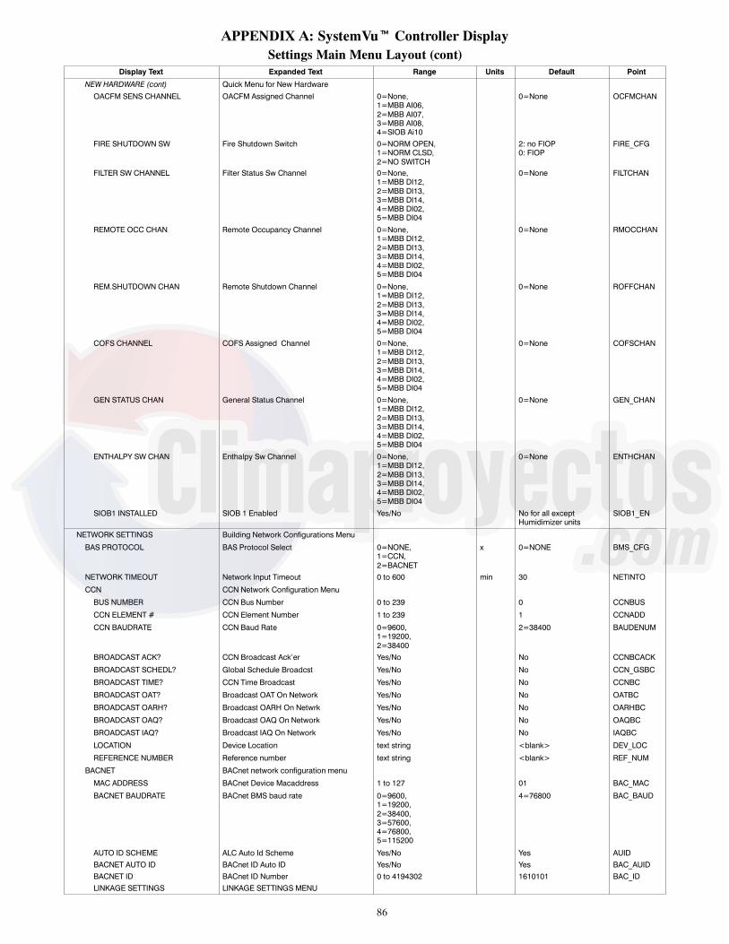
86
APPENDIX A: SystemVut Controller DisplaySettings Main Menu Layout (cont)
Display Text Expanded Text Range Units Default Point
NEW HARDWARE (cont) Quick Menu for New HardwareOACFM SENS CHANNEL OACFM Assigned Channel 0=None,
1=MBB AI06,2=MBB AI07,3=MBB AI08,4=SIOB Ai10
0=None OCFMCHAN
FIRE SHUTDOWN SW Fire Shutdown Switch 0=NORM OPEN,1=NORM CLSD,2=NO SWITCH
2: no FIOP0: FIOP
FIRE_CFG
FILTER SW CHANNEL Filter Status Sw Channel 0=None,1=MBB DI12,2=MBB DI13,3=MBB DI14,4=MBB DI02,5=MBB DI04
0=None FILTCHAN
REMOTE OCC CHAN Remote Occupancy Channel 0=None,1=MBB DI12,2=MBB DI13,3=MBB DI14,4=MBB DI02,5=MBB DI04
0=None RMOCCHAN
REM.SHUTDOWN CHAN Remote Shutdown Channel 0=None,1=MBB DI12,2=MBB DI13,3=MBB DI14,4=MBB DI02,5=MBB DI04
0=None ROFFCHAN
COFS CHANNEL COFS Assigned Channel 0=None,1=MBB DI12,2=MBB DI13,3=MBB DI14,4=MBB DI02,5=MBB DI04
0=None COFSCHAN
GEN STATUS CHAN General Status Channel 0=None,1=MBB DI12,2=MBB DI13,3=MBB DI14,4=MBB DI02,5=MBB DI04
0=None GEN_CHAN
ENTHALPY SW CHAN Enthalpy Sw Channel 0=None,1=MBB DI12,2=MBB DI13,3=MBB DI14,4=MBB DI02,5=MBB DI04
0=None ENTHCHAN
SIOB1 INSTALLED SIOB 1 Enabled Yes/No No for all exceptHumidimizer units
SIOB1_EN
NETWORK SETTINGS Building Network Configurations Menu
BAS PROTOCOL BAS Protocol Select 0=NONE,1=CCN,2=BACNET
x 0=NONE BMS_CFG
NETWORK TIMEOUT Network Input Timeout 0 to 600 min 30 NETINTO
CCN CCN Network Configuration Menu
BUS NUMBER CCN Bus Number 0 to 239 0 CCNBUS
CCN ELEMENT # CCN Element Number 1 to 239 1 CCNADD
CCN BAUDRATE CCN Baud Rate 0=9600,1=19200,2=38400
2=38400 BAUDENUM
BROADCAST ACK? CCN Broadcast Ack’er Yes/No No CCNBCACK
BROADCAST SCHEDL? Global Schedule Broadcst Yes/No No CCN_GSBC
BROADCAST TIME? CCN Time Broadcast Yes/No No CCNBC
BROADCAST OAT? Broadcast OAT On Network Yes/No No OATBC
BROADCAST OARH? Broadcast OARH On Netwrk Yes/No No OARHBC
BROADCAST OAQ? Broadcast OAQ On Network Yes/No No OAQBC
BROADCAST IAQ? Broadcast IAQ On Network Yes/No No IAQBC
LOCATION Device Location text string <blank> DEV_LOC
REFERENCE NUMBER Reference number text string <blank> REF_NUM
BACNET BACnet network configuration menu
MAC ADDRESS BACnet Device Macaddress 1 to 127 01 BAC_MAC
BACNET BAUDRATE BACnet BMS baud rate 0=9600,1=19200,2=38400,3=57600,4=76800,5=115200
4=76800 BAC_BAUD
AUTO ID SCHEME ALC Auto Id Scheme Yes/No Yes AUIDBACNET AUTO ID BACnet ID Auto ID Yes/No Yes BAC_AUIDBACNET ID BACnet ID Number 0 to 4194302 1610101 BAC_IDLINKAGE SETTINGS LINKAGE SETTINGS MENU

87
APPENDIX A: SystemVut Controller DisplaySettings Main Menu Layout (cont)
Display Text Expanded Text Range Units Default Point
NETWORK SETTINGS (cont) Building Network Configurations Menu
DEVICE IAQ BACnet device for IAQ 0 to 4194303 1610100 DEVIAQOBJECT ID IAQ Object instance for IAQ 0 to 9999 1009 OBJIAQCOV IAQ Change of value for IAQ 0 to 60 0 COVIAQDEVICE OAQ BACnet device for OAQ 0 to 4194303 1610100 DEVOAQOBJECT ID OAQ Object instance for OAQ 0 to 9999 285 OBJOAQCOV OAQ Change of value for OAQ 0 to 60 0 COVOAQDEVICE OARH BACnet device for OARH 0 to 4194303 1610100 DEVOARHOBJECT ID OARH Object instance for OARH 0 to 9999 1022 OBJOARHCOV OARH Change of value for OARH 0 to 60 0 COVOARHDEVICE OAT BACnet device for OAT 0 to 4194303 1610100 DEVOATOBJECT ID OAT Object instance for OAT 0 to 9999 1003 OBJOATCOV OAT Change of value for OAT 0 to 60 0 COVOATDEVICE RARH BACnet device for RARH 0 to 4194303 1610100 DEVRARHOBJECT ID RARH Object instance for RARH 0 to 9999 30 OBJRARHCOV RARH Change of value for RARH 0 to 60 0 COVRARHDEVICE RAT BACnet device for RAT 0 to 4194303 1610100 DEVRATOBJECT ID RAT Object instance for RAT 0 to 9999 1010 OBJRATCOV RAT Change of value for RAT 0 to 60 0 COVRATDEVICE SPT BACnet device for SPT 0 to 4194303 1610100 DEVSPTOBJECT ID SPT Object instance for SPT 0 to 9999 2007 OBJSPTCOV SPT Change of value for SPT 0 to 60 0 COVSPTLOCAL_SHEDL_EDIT Allow Local Sched Edit Yes/No enum No LCL_EDITSYSTEM TOUCH System Touch MenuDEVICE INSTANCE System Touch Device Inst 0 to 4194303 160099 DEVSTPOLLING RATE System Touch Poll Rate 10 to 60 10 POLLSTSPACE TEMP AI System Touch AI for SPT 0 to 9999 1 AISTSPTSPACE RH AI System Touch AI for SPRH 0 to 9999 4 AISTSPRH
ZS SENSOR CFG ZS Sensor Configuration
ZS1 ADDRESS Zone Sensor 1 Address 0 to 255 255 ZSADDR1
ZS2 ADDRESS Zone Sensor 2 Address 0 to 255 255 ZSADDR2
ZS3 ADDRESS Zone sensor 3 address 0 to 255 255 ZSADDR3
ZS4 ADDRESS Zone sensor 4 address 0 to 255 255 ZSADDR4
ZS5 ADDRESS Zone sensor 5 address 0 to 255 255 ZSADDR5
ZS POLL RATE Zone sensor poll rate 1 to 100 sec 5 ZSPOLLRT
ZS UNIT Zone sensor unit 0=degrees F 0=degrees F ZSUNIT
ZS FRC UNOC ENBL ZS Force Unoccup enable No No ZSFUNEN
ZS FRC UNOC DELAY ZS Force unocc wt delay No No ZSFUNWT
ZS TLO CONT ENBL ZS TLO Cont Enable No No ZSTLOEN
TLO SET DURING OC ZS TLO set during occ No No ZSTLSOC
ZS UI MODE Zone sensor UI Mode 1=Dual Offsets 1=Dual Offsets ZSUIM
NETWORK CHKLIST NETWORK SETUP CHECKLIST 0=Undone,1=Perfom,2=Done
0=Undone CHK_NET
DISPLAY SETTINGS User Display Configurations Menu
METRIC DISPLAY Metric Display Yes/No No DISPUNIT
LANGUAGE Display Language Select 0=English 0=English LANGUAGE
CONTRAST ADJUST LCD Contrast Adjustment 1 to 10 5 LCD_CONT
PASSWORD ENABLE? User Password Protection Enable/Disable Enable PASS_EBL
VIEW USER PASSWORD View User Password Menu
CHANGE USER PASSWORD Change User Password Menu
QUICK SETUP CONFIG QUICK SETUP CONFIG MENU
TIME Clock Hour and Minute xx:xx hh.mm 0 TIME
DATE Current Date MM/DD/YYYY 0 DATE
STARTUP DELAY Unit Startup Delay 10 to 600 sec 30 STARTDLY
UNIT CONTROL TYPE Unit Control Type 0=TSTAT,1=SPACE SEN,2=RAT SEN
0=TSTAT CTRLTYPE
THERMOSTAT TYPE Thermostat Hardware Type 0=CONV 2C2H,1=DIGI 2C2H,2=CONV 3C2H,3=DIGI 3C2H4=DIGI 2C2H
2=CONV 3C2H STATTYPE
DIRTY FILTER TIME Change Filter Timer 0 to 9999 hours 600 FILTLIFE
VENT IDF SPEED Ventilation Only IDF Spd 0 to 100 % 50 (sizes 04---06)67 (sizes 07---12)53 (sizes 14 or 20)56 (size 17)52 (size 24)60 (size 26)
FSPDVENT

88
APPENDIX A: SystemVut Controller DisplaySettings Main Menu Layout (cont)
Display Text Expanded Text Range Units Default Point
QUICK SETUP CONFIG (cont) Building Network Configurations Menu
HEATING STAGE QTY Number of Heating Stages 0 to 2 2 (all except below):0 (50 series withoutFIOP heat),1 (50 series, sizes 04---06low or medium heat),1 (50 series, sizes07---14 and low heat),1 (50 series, sizes07---12 and mediumheat)
NUMHSTGS
ECON INSTALLED? Economizer Installed? Yes/No No: no FIOPYes: FIOP
ECONO
FREE COOL MAX OAT Free Cooling Max OAT 0 to 90 ° F 65 MAXFREET
FIRE SHUTDOWN SW Fire Shutdown Switch 0=NORM OPEN,1=NORM CLSD,2=NO SWITCH
2: no FIOP0: FIOP
FIRE_CFG
QUICK SET CHKLIST QUICK SETUP CHECKLIST 0=Undone,1=Perfom,2=Done
0=Undone CHK_QUIK
Alerts/Faults Main Menu LayoutDisplay Text Expanded Text Values Write Status Point
ALERTS/FAULTS Alerts/Faults Menu
ACTIVE FAULTS Active Faults Menu
ACTIVE ALERTS Active Alerts Menu
HISTORY History Of Faults And Alerts Menu
RESET FAULT/ALERT Reset All Current Alarms Yes/No Command ALRESET

89
APPENDIX A: SystemVut Controller DisplayService Main Menu Layout
Display Text Expanded Text Values Units Write Status Point
SERVICE Service MenuUNIT TESTS Unit Tests MenuTEST MODE Service Test Mode Enable On/Off CommandSERVICE TEST Service Test MenuINDEPENDENTS INDEPENDENT TEST MENUECON POS TEST Economizer Position Test 0 to 100 % Command S_DAMPERBUMP COMP A1 TEST Compressor Bump A1 Test On/Off On/Off Command S_BMPA1BUMP COMP A2 TEST Compressor Bump A2 Test On/Off On/Off Command S_BMPA2LIQ DIVERT A TEST LiqDivertrValveRelayTest On/Off On/Off Command S_LDV_AREHEAT A TEST ReheatDischgValveRelayTest On/Off On/Off Command S_RDV_AREHEAT LV---A TEST Reheat Liq Valv Rly Test On/Off On/Off Command S_RLV_ACOOLING LV---A TEST Cooling Liq Valv Test On/Off On/Off Command S_CLV_ACCH RELAY 1 TEST Crankcase Heater 1 test On/Off On/Off Command S_CCHR1ALARM RELAY TEST Alarm Output Relay Test On/Off On/Off Command S_ALARMPE1 RELAY TEST Power Exhaust 1 Test On/Off On/Off Command S_PE_1PE2 RELAY TEST Power Exhaust 2 Test On/Off On/Off Command S_PE_2
FAN TESTS Indoor and Outdoor Fan tests MenuIDF SPEED TEST Indoor Fan Speed Test 0 to 100 % Command S_IDFSPDALL ODF SPD TEST System ODF speed test 0 to 1200 rpm Command S_ODFSPDODF 1 SPEED TEST Outdoor Fan 1 speed test 0 to 1200 rpm Command S_ODFSP1ODF 2 SPEED TEST Outdoor Fan 2 speed test 0 to 1200 rpm Command S_ODFSP2ODF 3 SPEED TEST Outdoor Fan 3 speed test 0 to 1200 rpm Command S_ODFSP3IDF MANUAL TRANS IDF Manual Transition Yes/No Command S_IDFTRNODF MANUAL TRANS ODF Manual Transition Yes/No Command S_ODFTRN
COOL TESTS Cooling Test MenuCOOL A1 TEST Cooling W/Comp.A1 Test On/Off Command S_COOLA1COOL A2 TEST Cooling W/Comp.A2 Test On/Off Command S_COOLA2IDF SPEED TEST Indoor Fan Speed Test 0 to 100 % Command S_IDFSPDALL ODF SPD TEST System ODF speed test 0 to 1200 rpm Command S_ODFSPDHUMIDIMIZER TEST HumidiMizer Level 0=Off,
1=Subcool,2=Reheat
Command S_HMZLEV
HEAT TESTS Heating Test MenuHEAT 1 TEST Heating Stage 1 Test On/Off Command S_HEAT1HEAT 2 TEST Heating Stage 2 Test On/Off Command S_HEAT2IDF SPEED TEST Indoor Fan Speed Test 0 to 100 % Command S_IDFSPD
AUTOMATIC TEST Automatic Test MenuAUTO INDP TEST AUTO INDEPENDENT TEST Yes/No Command AUTOINDPAUTO COOL TEST RUN AUTO COOLING TEST Yes/No Command AUTOCOOLAUTO HEAT TEST RUN AUTO HEATING TEST Yes/No Command AUTOHEATAUTO SYSTEM TEST RUN AUTO SYSTEM TEST Yes/No Command AUTOSYS
UNIT INFORMATION Unit Information MenuMODEL # Equipment Model number xxxxxxxxxxxxxxxx Command EQ_MODSERIAL # Equipment Serial number xxxxxxxxxx Command EQ_SERENTER MODEL NUMBER Edit Equipment Model NumberVERSIONS Versions MenuSOFTWARE Application SW Version CESR131651--- xx--- xx FW_CESRVFD VFD1 SW Version FW VERSION--- x.xx VFD1_SWIO BOARD SIOB1 SW Version SIOB1 SW VERSION--- x.xx SIOB1_SWBOOTLOADER Bootloader SW Version CESR131659--- xx--- xx BL_CESR
USER MEASURED DATA User Measured Data MenuSUPPLY VOLTAGE L1 Supply Voltage Leg 1 0 to 700.0 volt Command L1VOLTSSUPPLY VOLTAGE L2 Supply Voltage Leg 2 0 to 700.0 volt Command L2VOLTSSUPPLY VOLTAGE L3 Supply Voltage Leg 3 0 to 700.0 volt Command L3VOLTSCOMP A1 AMPS L1 Comp A1 Amps Leg 1 0 to 100.0 amps Command CA1L1_ACOMP A1 AMPS L2 Comp A1 Amps Leg 2 0 to 100.0 amps Command CA1L2_ACOMP A1 AMPS L3 Comp A1 Amps Leg 3 0 to 100.0 amps Command CA1L3_ACOMP A2 AMPS L1 Comp A2 Amps Leg 1 0 to 100.0 amps Command CA2L1_ACOMP A2 AMPS L2 Comp A2 Amps Leg 2 0 to 100.0 amps Command CA2L2_ACOMP A2 AMPS L3 Comp A2 Amps Leg 3 0 to 100.0 amps Command CA2L3_AE.HEAT AMPS L1 Elec. Heat Amps Leg 1 0 to 100.0 amps Command EHTL1_AE.HEAT AMPS L2 Elec. Heat Amps Leg 2 0 to 100.0 amps Command EHTL2_AE.HEAT AMPS L3 Elec. Heat Amps Leg 3 0 to 100.0 amps Command EHTL3_AGAS SUPPLY TYPE Gas Supply Type 0=NATURAL,
1=LPCommand GASTYPE
GAS INLET PRESS Gas Inlet Pressure 0 to 20.0 in.wc Command GASPRESSSTAGE 1 GAS PRESS Stage 1 Gas Pressure 0 to 20.0 in.wc Command HT1PRESSSTAGE 2 GAS PRESS Stage 2 Gas Pressure 0 to 20.0 in.wc Command HT2PRESSCONTINUE? Start Diag Report Yes/No Command GO_DIAG
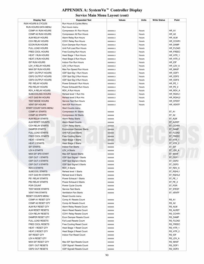
90
APPENDIX A: SystemVut Controller DisplayService Main Menu Layout (cont)
Display Text Expanded Text Values Units Write Status Point
RUN HOURS & CYCLES Run Hours & Cycles Menu
RUN HOURS DATA MENU Run hours menu
COMP A1 RUN HOURS Compressor A1 Run Hours xxxxxx.x hours HR_A1
COMP A2 RUN HOURS Compressor A2 Run Hours xxxxxx.x hours HR_A2
ALM RELAY HOURS Alarm Relay Run Hours xxxxxx.x hours HR_ALM
CCH RELAY HOURS CCH1 Relay Run Hours xxxxxx.x hours HR_CCHR1
ECON RUN HOURS Econ Damper Run Hours xxxxxx.x hours HR_DAMP
FULL LOAD HOURS Unit Full Load Run Hours xxxxxx.x hours HR_FLOAD
FREE COOL HOURS Free Cooling Run Hours xxxxxx.x hours HR_FREEC
HEAT 1 RUN HOURS Heat Stage 1 Run Hours xxxxxx.x hours HR_HTR_1
HEAT 2 RUN HOURS Heat Stage 2 Run Hours xxxxxx.x hours HR_HTR_2
IDF RUN HOURS Indoor Fan Run Hours xxxxxx.x hours HR_IDF
LDV_A RELAY HOURS LDV_A Run Hours xxxxxx.x hours HR_LDV_A
MAX IDF RUN HOURS Max Fan Speed Run Hours xxxxxx.x hours HR_MAXF
ODF1 OUTPUT HOURS ODF Spd Sig 1 Run Hours xxxxxx.x hours HR_ODF1
ODF2 OUTPUT HOURS ODF Spd Sig 2 Run Hours xxxxxx.x hours HR_ODF2
ODF3 OUTPUT HOURS ODF Spd Sig 3 Run Hours xxxxxx.x hours HR_ODF3
PE1 RELAY HOURS Power Exhaust1 Run Hours xxxxxx.x hours HR_PE_1
PE2 RELAY HOURS Power Exhaust2 Run Hours xxxxxx.x hours HR_PE_2
RDV_A RELAY HOURS RDV_A Run Hours xxxxxx.x hours HR_RDV_A
SUBCOOLING HOURS Reheat level 1 Run Hrs xxxxxx.x hours HR_RQHL1
HOT GAS RH HOURS Reheat level 2 Run Hrs xxxxxx.x hours HR_RQHL2
TEST MODE HOURS Service Test Run Hours xxxxxx.x hours HR_STEST
VENT IDF HOURS Vent IDF Run Hours xxxxxx.x hours HR_VENTF
START COUNT DATA MENU Start Counts menu
COMP A1 STARTS Compressor A1 Starts xxxxxx ST_A1
COMP A2 STARTS Compressor A2 Starts xxxxxx ST_A2
ALM RELAY STARTS Alarm Relay Starts xxxxxx ST_ALM
ALM RESET COUNTS Alarm Reset Counts xxxxxx ST_ALRST
CCH RELAY STARTS CCH1 Relay Starts xxxxxx ST_CCHR1
DAMPER STARTS Economizer Damper Starts xxxxxx ST_DAMP
FULL LOAD STARTS Unit Full Load Starts xxxxxx ST_FLOAD
FREE COOL STARTS Free Cooling Starts xxxxxx ST_FREEC
HEAT 1 STARTS Heat Stage 1 Starts xxxxxx ST_HTR_1
HEAT 2 STARTS Heat Stage 2 Starts xxxxxx ST_HTR_2
IDF STARTS Indoor Fan Starts xxxxxx ST_IDF
LDV A STARTS LDV_A Starts xxxxxx ST_LDV_A
MAX IDF SPD START Max IDF Speed Starts xxxxxx ST_MAXF
ODF OUT 1 STARTS ODF Spd Signal 1 Starts xxxxxx ST_ODF1
ODF OUT 2 STARTS ODF Spd Signal 2 Starts xxxxxx ST_ODF2
ODF OUT 3 STARTS ODF Spd Signal 3 Starts xxxxxx ST_ODF3
RDV A STARTS RDV_A Starts xxxxxx ST_RDV_A
SUBCOOL STARTS Reheat level 1 Starts xxxxxx ST_RQHL1
HOT GAS RH STARTS Reheat level 2 Starts xxxxxx ST_RQHL2
PE1 RELAY STARTS Power Exhaust 1 Starts xxxxxx ST_PE_1
PE2 RELAY STARTS Power Exhaust 2 Starts xxxxxx ST_PE_2
POR COUNT Power Cycle Counts xxxxxx ST_POR
TEST MODE STARTS Service Test Starts xxxxxx ST_STEST
VENT FAN STARTS Ventilation Fan Starts xxxxxx ST_VENTF
RESET COUNTS MENU Reset Counts menu
COMP A1 RESET QTY Comp A1 Resets Count xxxxxx RS_A1
COMP A2 RESET QTY Comp A2 Resets Count xxxxxx RS_A2
ALM RLY RESET QTY Alarm Relay Resets Count xxxxxx RS_ALM
ALM RESET RESETS Alarm Reset Resets Count xxxxxx RS_ALRST
CCH RELAY RESETS CCH1 Relay Resets Count xxxxxx RS_CCHR1
DAMPER RESET QTY Econ Damper Resets Count xxxxxx RS_DAMP
FULL LOAD RESETS Full Load Resets Count xxxxxx RS_FLOAD
FREE COOL RESETS Free Cooling Reset Count xxxxxx RS_FREEC
HEAT 1 RESET QTY Heat Stage 1 Reset Count xxxxxx RS_HTR_1
HEAT 2 RESET QTY Heat Stage 2 Reset Count xxxxxx RS_HTR_2
IDF RESET QTY Indoor Fan Reset Count xxxxxx RS_IDF
LDV A RESET QTY xxxxxx RS_LDV_A
MAX IDF RESET QTY Max IDF Spd Resets Count xxxxxx RS_MAXF
ODF1 OUT RESETS ODF Signal1 Resets Count xxxxxx RS_ODF1
ODF2 OUT RESETS ODF Signal2 Resets Count xxxxxx RS_ODF2

91
APPENDIX A: SystemVut Controller DisplayService Main Menu Layout (cont)
Display Text Expanded Text Values Units Write Status Point
RESET COUNTS MENU (cont) Reset Counts menu
ODF3 OUT RESETS ODF Signal3 Resets Count xxxxxx RS_ODF3
PE1 RESET QTY P.Exhaust 1 Resets Count xxxxxx RS_PE_1
PE2 RESET QTY P.Exhaust 2 Resets Count xxxxxx RS_PE_2
POR RESET QTY Power Cycle Resets Count xxxxxx RS_POR
RDV A RESET QTY rdv_a Resets Count xxxxxx RS_RDV_A
SUBCOOL RESET QTY Reheat lev 1 Rst Count xxxxxx RS_RQHL1
HGRH RESET QTY Reheat lev 2 Rse Count xxxxxx RS_RQHL2
TEST MODE RESETS Service Test Reset Count xxxxxx RS_STEST
VENT IDF RESETS Vent IDF Resets Count xxxxxx RS_VENTF
POWER RESET HISTORY Power On Reset History Menu
POWRES00 Power Reset Event 00 mm/dd/yy, hh:mm:ss POWRES00
POWRES01 Power Reset Event 01 mm/dd/yy, hh:mm:ss POWRES01
POWRES02 Power Reset Event 02 mm/dd/yy, hh:mm:ss POWRES02
POWRES03 Power Reset Event 03 mm/dd/yy, hh:mm:ss POWRES03
POWRES04 Power Reset Event 04 mm/dd/yy, hh:mm:ss POWRES04
POWRES05 Power Reset Event 05 mm/dd/yy, hh:mm:ss POWRES05
POWRES06 Power Reset Event 06 mm/dd/yy, hh:mm:ss POWRES06
POWRES07 Power Reset Event 07 mm/dd/yy, hh:mm:ss POWRES07
POWRES08 Power Reset Event 08 mm/dd/yy, hh:mm:ss POWRES08
POWRES09 Power Reset Event 09 mm/dd/yy, hh:mm:ss POWRES09
ALARM RESET HISTORY Alarm Reset History Menu
ALMRES00 Alarm Reset Event 00 mm/dd/yy, hh:mm:ss ALMRES00
ALMRES01 Alarm Reset Event 01 mm/dd/yy, hh:mm:ss ALMRES01
ALMRES02 Alarm Reset Event 02 mm/dd/yy, hh:mm:ss ALMRES02
ALMRES03 Alarm Reset Event 03 mm/dd/yy, hh:mm:ss ALMRES03
ALMRES04 Alarm Reset Event 04 mm/dd/yy, hh:mm:ss ALMRES04
ALMRES05 Alarm Reset Event 05 mm/dd/yy, hh:mm:ss ALMRES05
ALMRES06 Alarm Reset Event 06 mm/dd/yy, hh:mm:ss ALMRES06
ALMRES07 Alarm Reset Event 07 mm/dd/yy, hh:mm:ss ALMRES07
ALMRES08 Alarm Reset Event 08 mm/dd/yy, hh:mm:ss ALMRES08
ALMRES09 Alarm Reset Event 09 mm/dd/yy, hh:mm:ss ALMRES09
ALMRES10 Alarm Reset Event 10 mm/dd/yy, hh:mm:ss ALMRES10
ALMRES11 Alarm Reset Event 11 mm/dd/yy, hh:mm:ss ALMRES11
ALMRES12 Alarm Reset Event 12 mm/dd/yy, hh:mm:ss ALMRES12
ALMRES13 Alarm Reset Event 13 mm/dd/yy, hh:mm:ss ALMRES13
ALMRES14 Alarm Reset Event 14 mm/dd/yy, hh:mm:ss ALMRES14
ALMRES15 Alarm Reset Event 15 mm/dd/yy, hh:mm:ss ALMRES15
ALMRES16 Alarm Reset Event 16 mm/dd/yy, hh:mm:ss ALMRES16
ALMRES17 Alarm Reset Event 17 mm/dd/yy, hh:mm:ss ALMRES17
ALMRES18 Alarm Reset Event 18 mm/dd/yy, hh:mm:ss ALMRES18
ALMRES19 Alarm Reset Event 19 mm/dd/yy, hh:mm:ss ALMRES19

92
APPENDIX A: SystemVut Controller DisplayService Main Menu Layout (cont)
Display Text Expanded Text Values Units Write Status Point
HARDWARE Hardware Information Menu
HARDWARE INPUTS Hardware inputs menu
OAT SENSOR VALUE Outdoor Air Temp Sensor xxx.x ° F OAT_LOC
RAT SENSOR VALUE Return Air Temp Sensor xxx.x ° F RAT_LOC
SPT SENSOR VALUE Space Temperature Sensor xxx.x ° F SPT_LOC
SPTO SENSOR VALUE Local Space Temp Offset xxx.x F delta SPTO_LOC
SPRH SENSOR VALUE SPRH Sensor Value 0 to 100 ° F SPRH_LOC
OARH SENSOR VALUE OARH Sensor Value 0 to 100 % OARH_LOC
RARH SENSOR VALUE RARH Sensor Value 0 to 100 % RARH_LOC
IAQ SENSOR VALUE IAQ Sensor value xxxx ppm IAQ_LOC
OAQ SENSOR VALUE OAQ Sensor Value xxxx ppm ppm OAQ_LOC
OCFM_LOC OACFM Sensor value xxx.x CFM OCFM_LOC
ASSIGNED INPUTS/OUPUTS Assigned Input/Output Channels
AI06 FUNCTION Assigned AI06 Function 0=None,1=IAQ,2=OARH,3=RARH,4=OAQ,5=SPRH,6=OACFM
MBBAI06F
AI07 FUNCTION Assigned AI07 Function 0=None,1=IAQ,2=OARH,3=RARH,4=OAQ,5=SPRH,6=OACFM
MBBAI07F
AI08 FUNCTION Assigned AI08 Function 0=None,1=IAQ,2=OARH,3=RARH,4=OAQ,5=SPRH,6=OACFM
MBBAI08F
IO AI10 FUNCTION Assigned S---AI01 Function 0=None,1=IAQ,2=OARH,3=RARH,4=OAQ,5=SPRH,6=OACFM
SIOAI01F
DI02 FUNCTION Assigned DI02 Function 0=None,1=COFS,2=REMOCC,3=REMOFF,4=FILTER,5=ENTHALPY,6=GEN STAT
MBBDI02F
DI04 FUNCTION Assigned DI04 Function 0=None,1=COFS,2=REMOCC,3=REMOFF,4=FILTER,5=ENTHALPY,6=GEN STAT
MBBDI04F
DI12 FUNCTION Assigned DI12 Function 0=None,1=COFS,2=REMOCC,3=REMOFF,4=FILTER,5=ENTHALPY,6=GEN STAT
MBBDI12F
DI13 FUNCTION Assigned DI13 Function 0=None,1=COFS,2=REMOCC,3=REMOFF,4=FILTER,5=ENTHALPY,6=GEN STAT
MBBDI13F
DI14 FUNCTION Assigned DI14 Function 0=None,1=COFS,2=REMOCC,3=REMOFF,4=FILTER,5=ENTHALPY,6=GEN STAT
MBBDI14F
IO DI01 FUNCTION Assigned S---DI01 Function 0=None,1=COFS,2=REMOCC,3=REMOFF,4=FILTER,5=ENTHALPY,6=GEN STAT
SIODI01F

93
APPENDIX A: SystemVut Controller DisplayService Main Menu Layout (cont)
Display Text Expanded Text Values Units Write Status Point
HARDWARE INPUTS (cont) Hardware inputs menu
RELAY 06 FUNCTION Assigned Rly 06 Function 0=None,1=ALM Relay,2=PE1,3=PE2
MBBRY06F
RELAY 11 FUNCTION Assigned Rly 11 Function 0=None,1=ALM Relay,2=PE1,3=PE2
MBBRY11F
MBB PART # MBB Part Number CEPL131117--- xx---R BD_CEPL
MBB PP MBB Program Part Number CEPP130644--- xx--- xx--- xx---R BD_CEPP
MBB SERIAL # Base Board serial number xxxxNxxxxxx BD_SER
CALIBRATION Calibration Menu
OAT TRIM OFFSET OAT Sensor Trim Offset --- 10.0 to 10.0 ° F Configurable OAT_TRIM
RAT TRIM OFFSET RAT Sensor Trim Offset --- 30.0 to 30.0 ° F Configurable RAT_TRIM
FST TRIM OFFSET FST Sensor Trim Offset --- 10.0 to 10.0 ° F Configurable FST_TRIM
SPT TRIM OFFSET SPT Sensor Trim Offset --- 30.0 to 30.0 ° F Configurable SPT_TRIM
SLIDER SEN. TRIM SPTO Sensor Offset Trim ---1.0 to 1.0 ° F Configurable SPTOTRIM
SPRH TRIM OFFSET SPRH Sensor Offset Trim ---15 to 15 % Configurable SPRHTRIM
IAQ TRIM OFFSET IAQ sensor trim offset --- 200 to 200 ppm Configurable IAQ_TRIM
OAQ TRIM OFFSET OAQ Sensor Trim Offset --- 200 to 200 ppm Configurable OAQ_TRIM
OARH TRIM OFFSET OARH Sensor Trim Offset --- 15 to 15 % Configurable OARHTRIM
RARH TRIM OFFSET RARH Sensor Trim Offset --- 15 to 15 % Configurable RARHTRIM
CIR.A SSP TRIM Cir.A SSP Sensor Trim ---50 to 50 psig Configurable SSPATRIM
CIR.A SDP TRIM Cir.A SDP Sensor Trim ---50 to 50 psig Configurable SDPATRIM
ECO FEEDBACK TRIM Econ Fdback Trim Offset --- 15 to 15 % Configurable EC1DTRIM
OACFM TRIM OFFSET OACFM sensor trim offset --- 10 to 10 CFM Configurable OCFMTRIM
COMMISSION REPORTS Commission Report Menu
SYSTEM STARTUP CHECKLIST SYSTEM STARTUP CHECKLIST MENU
QUICK SET CHKLIST QUICK SETUP CHECKLIST 0=Undone,1=Perfom,2=Done
Configurable CHK_QUIK
NETWORK CHKLIST NETWORK SETUP CHECKLIST 0=Undone,1=Perfom,2=Done
Configurable CHK_NET
SYSTEM AUTOTEST CheckList Auto test 0=Undone,1=Perfom,2=Done
Configurable CHK_ATST
ADVANCED SERVICE Advanced Service Restricted Access Menu
RESTORE DEFAULTS? Restore Factory Defaults Yes/No Command RESFDFLT
CLEAR COMPONENT DATA RESET COMPONENT DATA MENU
COMP A1 DATA Reset Compressor A1 Data Yes/No Command CR_A1
COMP A2 DATA Reset Compressor A2 Data Yes/No Command CR_A2
ALARM RELAY DATA Reset Alarm Relay Data Yes/No Command CR_ALM
ALARM RESET DATA Reset Alarm Resets Data Yes/No Command CR_ALRST
CCH RELAY DATA Reset CCH1 Relay Data Yes/No Command CR_CCHR1
ECON DAMPER DATA Reset Econ Damper Data Yes/No Command CR_DAMP
FULL LOAD DATA Reset Full Load Data Yes/No Command CR_FLOAD
FREE COOL DATA Reset Free Cooling Data Yes/No Command CR_FREEC
HEAT 1 DATA Reset Heat Stage 1 Data Yes/No Command CR_HTR_1
HEAT 2 DATA Reset Heat Stage 2 Data Yes/No Command CR_HTR_2
IDF RUN DATA Reset Indoor Fan Data Yes/No Command CR_IDF
IDF MAX SPD DATA Reset Max Fan Speed Data Yes/No Command CR_MAXF
ODF1 OUTPUT DATA Reset ODF Spd Sig 1 Data Yes/No Command CR_ODF1
ODF2 OUTPUT DATA Reset ODF Spd Sig 2 Data Yes/No Command CR_ODF2
ODF3 OUTPUT DATA Reset ODF Spd Sig 3 Data Yes/No Command CR_ODF3
PE1 RELAY DATA Reset Pwr Exhaust 1 Data Yes/No Command CR_PE_1
PE2 RELAY DATA Reset Pwr Exhaust 2 Data Yes/No Command CR_PE_2
POWER RESET DATA Reset Power Resets Data Yes/No Command CR_POR
TEST MODE DATA Reset Service Test Data Yes/No Command CR_STEST
VENT IDF DATA Reset Vent IDF Data Yes/No Command CR_VENTF
INPUTS Inputs Menu
TEMPERATURES Temperatures Menu
SUPPLY AIR TEMP Supply Air Temperature xxx..x ° F SAT
OUTDOOR AIR TEMP Outdoor Air Temperature xxx.x ° F Forcible OAT
RETURN AIR TEMP Return Air Temperature xxx.x ° F Forcible RAT
SPACE TEMPERATURE Space Temperature xxx.x ° F Forcible SPACE_T
SLIDER OFFSET VAL Space Temperature Offset xx.x ° F Forcible SPTO
CIR.A SUC TEMP Cir.A Sat.Suction Temp xxx.x ° F SST_A

94
APPENDIX A: SystemVut Controller DisplayInputs Main Menu Layout
Display Text Expanded Text Values Units Write Status Point
TEMPERATURES (cont) Temperatures Menu
CIR.A DIS. TEMP Cir.A Sat.Discharge Temp xxx.x ° F SDT_A
FAN SUPPLY TEMP Fan Supply Air Temp xxx.x ° F FST
PRESSURES Pressures Menu
CIR.A SUC. PRESS Cir.A Suction Pressure xxx.x psig SSP_A
CIR.A DIS. PRESS Cir.A Discharge Pressure xxx.x psig SDP_A
CIR.A PRESS RATIO Circuit A Pressure Ratio xx.xx CIRA_PR
BAROMETRIC PRESS Barometric Pressure xx.xx in.Hg Forcible BARP
THERMOSTAT Thermostat Inputs menu
TSTAT G INPUT Thermostat G Input On/Off Forcible G
TSTAT Y1 INPUT Thermostat Y1 Input On/Off Forcible Y1
TSTAT Y2 INPUT Thermostat Y2 Input On/Off Forcible Y2
TSTAT Y3 INPUT Thermostat Y3 Input On/Off Forcible Y3
TSTAT W1 INPUT Thermostat W1 Input On/Off Forcible W1
TSTAT W2 INPUT Thermostat W2 Input On/Off Forcible W2
SWITCH INPUTS Switch Inputs Menu
IGC FAN REQUEST IGC Fan On Request (IFO) On/Off IGC_IFO
CIR.A HPS Cir.A High Pressure Sw Open/Close CIRA_HPS
HUMIDISTAT Humidistat I/P On/Off Forcible HUMDSTAT
FIRE SHUTDOWN Fire Shutdown Switch Alarm/Normal Forcible FIREDOWN
COFS COFS Switch State High/Low Forcible COFS
FILTER STATUS SW Filter Status Switch Dirty/Clean Forcible FILTSTAT
REMOTE OCC SWITCH Remote Occupancy Switch On/Off Forcible REMOCC
REMOTE SHUTDOWN Remote Shutdown Switch On/Off Forcible REMSHUT
GENERAL STATUS SW General Status Switch Alarm/Normal Forcible GENSTAT
ENTHALPY SWITCH Enthalpy Switch High/Low Forcible ENTH_SW
ANALOG INPUTS ANALOG Inputs Menu
ECON ACT POSITION Econo Actual Position 0 to 100 % DAMPPOS
SPRH LEVEL Space RH 0 to 100 % Forcible SPRH
OARH LEVEL OA Relative Humidity 0 to 100 % Forcible OARH
RARH LEVEL RA Relative Humidity 0 to 100 % Forcible RARH
IAQ LEVEL Indoor Air Quality Level xxxx ppm Forcible IAQ
OAQ LEVEL OA Quality Level xxxx ppm Forcible OAQ
OUTDOOR AIR CFM Outdoor Air in CFM xxx.x cfm Forcible OACFM
GENERAL INPUTS General Inputs Menu
FILTER TIME LEFT Filter hour remaining xxxx hours FILTLEFT
RESET FILTER TIME Reset Filter Timer Yes/No Command RESETFLT
OUTDOOR ENTHALPY Outdoor Air Enthalpy xxx.x Btu/lb Forcible OA_ENTH
RETURN ENTHALPY Return Air Enthalpy xxx.x Btu/lb Forcible RA_ENTH
DIFF AIR QUALITY Differential Air Quality xxxx PPM AQ_DIFF
INDOOR FAN VFD DATA Indoor Fan VFD Data
IDF VFD RUN HOURS IDF VFD Motor Run Hours xxxxxxxx hrs VFDMHOUR
IDF VFD KW HOURS IDF VFD Cumulative kWh xxxxx kWh KWHCNTR
VFD REF SPEED IDF VFD Reference Speed 0 to 1000 % REFSPEED
VFD STATUS WORD IDF VFD Status Word xxxxxxxx VFD1STSW
IDF VFD FEEDBACK IDF VFD Actual Speed % xxxxx % MAV
VFD OUTPUT KW IDF VFD Output Power kW 0 to 1000 kW OUTPWRKW
VFD OUTPUT HP IDF VFD Output Power hp 0 to 1000 HP OUTPWRHP
VFD OUTPUT VOLTS IDF VFD Output Voltage xxxxx volts OUTMVOLT
VFD OUTPUT FREQ IDF VFD Output Freq. xxxxx.x Hz OUTMFREQ
VFD OUTPUT AMPS IDF VFD Output Amps xxx.xx amps OUTMCUR
IDF VFD DC VOLTS IDF VFD DC Bus Voltage xxx volts DCLNVOLT
IDF VFD HSNK TEMP IDF VFD Heatsink Temp xxx.x _F HTSINKT
IDF VFD ALM WORD IDF VFD Alarm Word xxxxxxxx ALMERRC

95
APPENDIX A: SystemVut Controller DisplayInputs Main Menu Layout (cont)
Display Text Expanded Text Values Units Write Status Point
GENERAL INPUTS (cont) General Inputs Menu
VFD FAULT DETAIL IDF VFD Fault Detail 0=NONE,1=PWR CARD,2=EARTH FLT,3=CTRL WORD,4=OVER CURR,5=OVER TEMP,6=OVERLOAD,7=UNDERVOLT,8=OVER VOLT,9=SHORT CIR,10=PHASELOSS,11=U LOSS,12=V LOSS,13=W LOSS,14=CTRL VOLT,15=VDD LOW,16=MULTIPLE,17=UNEXPECT
SVFDFLT
VFD WARN DETAIL IDF VFD Warning Detail 0=NONE,1=VOLTAGE,2=CURRENT,3=THERMAL,4=MULTIPLE,5=UNEXPECT
SVFDWAR
NETWORK Network MenuBMS OCC REQUEST BMS Occupancy Request 0=UNOCC,
1=OCCUPIED,2=DISABLED
Forcible BMS_OCC
LINKAGE OCC REQ Linkage Occupied Request 0=Unocc,1=Occupied,2=Disabled
LNK_OCC
OAT NETWORK VALUE Network OAT Value xxx.x ° F OAT_NETRAT NETWORK VALUE Network Return Air Temp xxx.x ° F RAT_NETSPT NETWORK VAL. Network Space Temp Value xxx.x ° F SPT_NETOARH NETWORK VAL. Network OARH Value 0 to 100 % OARH_NETRARH NETWORK VAL. Network RARH Value 0 to 100 % RARH_NETIAQ NETWORK VALUE Network IAQ Value xxxx ppm IAQ_NETOAQ NETWORK VALUE Network OAQ Value xxxx ppm OAQ_NETOACFM NETWORK VAL Network OACFM Value xxxx cfm OCFM_NET
ZS SENSOR INFO ZS Sensor InformationZS SPACE TEMP Zone Sensor Temp Out --- 40 to 245 ° F ZSZTZS SPACE RH Zone Sensor Humidity Out 0 to 100 % ZSSPRHZS SPOFFSET ZS Setpoint Offset Output --- 10 to 10 ° F delta ZSSPTOZS OVER TIME LEFT ZS Override time remain 0 to 600 min ZSOTRZS TEMPERATURE ZS Space TemperatureZS1 TEMPERATRUE Zone Sensor 1 Temp ---40 to 245 ° F ZS1ZTZS2 TEMPERATRUE ZS2 Temperature --- 40 to 245 ° F ZS2ZTZS3 TEMPERATRUE ZS3 Temperature --- 40 to 245 ° F ZS3ZTZS4 TEMPERATRUE ZS4 Temperature --- 40 to 245 ° F ZS4ZTZS5 TEMPERATRUE ZS5 Temperature --- 40 to 245 ° F ZS5ZT
ZS HUMIDITY ZS Space HumidityZS1 HUMIDITY ZS1 Humidity 0 to 100 % ZS1ZHUMZS2 HUMIDITY ZS2 Humidity 0 to 100 % ZS2ZHUMZS3 HUMIDITY ZS3 Humidity 0 to 100 % ZS3ZHUMZS4 HUMIDITY ZS4 Humidity 0 to 100 % ZS4ZHUMZS5 HUMIDITY ZS5 Humidity 0 to 100 % ZS5ZHUM
ZS CSP OFFSET ZS Cool Set Point OffsetZS1 CSP OFFSET ZS1 cool setpoint offset --- 10 to 10 ° F delta ZS1CSOFFZS2 CSP OFFSET ZS2 cool setpoint offset --- 10 to 10 ° F delta ZS2CSOFFZS3 CSP OFFSET ZS3 cool setpoint offset --- 10 to 10 ° F delta ZS3CSOFFZS4 CSP OFFSET ZS4 cool setpoint offset --- 10 to 10 ° F delta ZS4CSOFFZS5 CSP OFFSET ZS5 cool setpoint offset --- 10 to 10 ° F delta ZS5CSOFF
ZS HSP OFFSET ZS Heat Set Point OffsetZS1 HSP OFFSET ZS1 Heat Setpoint Offset --- 10 to 10 ° F delta ZS1HSOFFZS2 HSP OFFSET ZS2 Heat Setpoint Offset --- 10 to 10 ° F delta ZS2HSOFFZS3 HSP OFFSET ZS3 Heat Setpoint Offset --- 10 to 10 ° F delta ZS3HSOFFZS4 HSP OFFSET ZS4 Heat Setpoint Offset --- 10 to 10 ° F delta ZS4HSOFFZS5 HSP OFFSET ZS5 Heat Setpoint Offset --- 10 to 10 ° F delta ZS5HSOFF
ZS OCC TIME OVER ZS Occ Timed OverrideZS1 OCC TIME OVER ZS1 Override time remaining 0 to 600 min ZS1OTRZS2 OCC TIME OVER ZS2 Override time remaining 0 to 600 min ZS2OTRZS3 OCC TIME OVER ZS3 Override time remaining 0 to 600 min ZS3OTRZS4 OCC TIME OVER ZS4 Override time remaining 0 to 600 min ZS4OTRZS5 OCC TIME OVER ZS5 Override time remaining 0 to 600 min ZS5OTR

96
APPENDIX A: SystemVut Controller DisplayOutputs Main Menu Layout
Display Text Expanded Text Values Units Write Status Point
OUTPUTS Outputs MenuGENERAL OUTPUTS General Outputs MenuIDF SPEED OUTPUT Commanded IDF Speed 0 to 100 % FANSPEEDECON CMD POSITION Econo Commanded Position 0 to 100 % Forcible DAMPCMDRHT DISCH VALVE A Reheat Dischg Valve CirA Enable/Disable RDV_ACOOLING LV A Cooling Liq Valve CirA Enable/Disable CLV_ACCH RELAY CCH Relay 1 State On/Off CCHR1PE1 RELAY Power Exhaust 1 Relay On/Off Forcible PE1PE2 RELAY Power Exhaust 2 Relay On/Off Forcible PE2ALARM RELAY Alarm Output Relay State On/Off Forcible ALMOUTDD IDF HI SPD RLY DD IDF high speed relay On/Off FSPDHRLYDD IDF MD SPD RLY DD IDF med. Speed relay On/Off FSPDMRLYDD IDF LO SPD RLY DD IDF low speed relay On/Off FSPDLRLY
COOLING OUTPUTS Cooling Outputs MenuCOMPRESSOR A1 Circuit A Compressor 1 On/Off COMP_A1COMPRESSOR A2 Circuit A Compressor 2 On/Off COMP_A2COMMANDED ODF SPD Commanded ODF Speed xxxx rpm ODFSPDODF SPEED OUT 1 ODF Speed Signal Output1 xxxx rpm ODF1SPDODF SPEED OUT 2 ODF Speed Signal Output2 xxxx rpm ODF2SPDODF SPEED OUT 3 ODF Speed Signal Output3 xxxx rpm ODF3SPD
HEATING OUTPUTS Heating Outputs MenuHEAT 1 RELAY Heat Stage 1 Relay On/Off HEAT_1HEAT 2 RELAY Heat Stage 2 Relay On/Off HEAT_2
USB Main Menu LayoutDisplay Text Expanded Text Values Units Write Status Point
USB USB MenuDATA ACQUISITION Data Acquisition MenuTREND STATUS USB TREND STATUS 0=IDLE,
1=TRENDING,2=NO POINTS,3=USB FULL
TRNDSTAT
TREND DURATION USB TREND DURATION 0=1 MINUTE,1=5 MINUTES,2=15 MINUTES,3=30 MINUTES,4=1 HOUR,5=3 HOURS,6=8 HOURS,7=12 HOURS,8=1 DAYS,9=1.5 DAYS,10=2 DAYS,11=3 DAYS,12=5 DAYS,13=1 WEEK,14=2 WEEK,15=4 WEEK,16=USB FULL
Command TRNDDUR
TREND RATE USB TREND RATE 1 to 300 Command TRNDRATETREND POINTS FROM USB TREND POINTS FROM 0=FILE,
1=LISTCommand TRNDPNTS
TREND FROM USB FILE? TREND FROM USB FILE MENUTREND FROM PRELIST? TREND FROM PRELIST MENUEQUIP PERFORMANCE TREND EQUIP PERFORMANCE On/Off Command TRNDEQPRGEN. INPUT/OUTPUT TREND GEN INPUTS/OUTPUTS On/Off Command TRNDIOCOOL PERFORMANCE TREND COOL PERFORMANCE On/Off Command TRNDCLPRHEAT PERFORMANCE TREND HEAT PERFORMANCE On/Off Command TRNDHTPRCOOL DIAGNOSTIC TREND COOLING DIAGNOSTIC On/Off Command TRNDCLDGIDF DIAGNOSTIC TREND IDF DIAGNOSTIC On/Off Command TRNDIDFVENT DIAGNOSTIC TREND VENTILATION On/Off Command TRNDVENT
TREND GO? Start USB Trending Yes/No Command TREND_ENSAVE CONFIGS TO FILE Save Configuration to fileSAVE CONFIGS Make Config Backup File Start/Stop Command DDBCKUPSAVE CONFIG STATUS Backup File is ready 0=IDLE,
1=SUCCESS,2=FAILURE
BACKUP_R
SAVE CONFIGS FROM FILE Save Configuration from fileFIND CONFIG FILE USB Find Restore File Yes/No Command BACKFILE
FILE TRANSFER File Transfer MenuBACKUP SERVICE FILES BACKUP SERVICE FILES
UPGRADE SOFTWARE Upgrade Software MenuFIND APPLICATION FILE USB search for app file Yes/No Command APPFILE
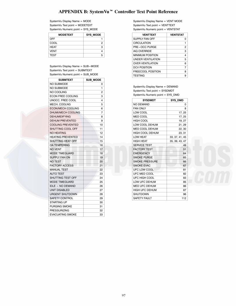
97
APPENDIX B: SystemVut Controller Text Point Reference
SystemVu Display Name = MODESystemVu Text point = MODETEXTSystemVu Numeric point = SYS_MODE
MODETEXT SYS_MODEOFF 1COOL 2HEAT 3VENT 4TEST 5
SystemVu Display Name = SUB---MODESystemVu Text point = SUBMTEXTSystemVu Numeric point = SUB_MODE
SUBMTEXT SUB_MODENO SUBMODE 0NO SUBMODE 1NO COOLING 2ECON FREE COOLING 3UNOCC. FREE COOL 4MECH. COOLNG 5ECON/MECH COOLING 6DHUMI/MECH COOLING 7DEHUMIDIFYING 8DEHUM PREVENTED 9COOLING PREVENTED 10SHUTTING COOL OFF 11NO HEATING 12HEATING PREVENTED 14SHUTTING HEAT OFF 15OA TEMPERING 16NO VENT 17MODE TIMEGUARD 18SUPPLY FAN ON 19NO TEST 20FACTORY ACCESS 21MANUAL TEST 22AUTO TEST 23SHUTTING TEST OFF 24MODE TIMEGUARD 25IDLE --- NO DEMAND 26UNIT DISABLED 27URGENT SHUTDOWN 28SAFETY CONTROL 29STARTING UP 30PURGING SMOKE 31PRESSURIZING 32EVACUATING SMOKE 33
SystemVu Display Name = VENT MODESystemVu Text point = VENTTEXTSystemVu Numeric point = VENTSTAT
VENTTEXT VENTSTATSUPPLY FAN OFF 0CIRCULATION 1PRE---OCC PURGE 2IAQ OVERRIDE 3MINIMUM POSITION 4UNDER VENTILATION 5OVER VENTILATION 6DCV POSITION 7FREECOOL POSITION 8TESTING 9
SystemVu Display Name = DEMANDSystemVu Text point = SYSDMDTSystemVu Numeric point = SYS_DMD
SYSDMDT SYS_DMDNO DEMAND 0FAN ONLY 8LOW COOL 17, 25MED COOL 17, 25HIGH COOL 19, 27LOW COOL DEHUM 21, 29MED COOL DEHUM 22, 30HIGH COOL DEHUM 23, 31LOW HEAT 33, 37, 41, 45HIGH HEAT 35, 39, 43, 47SERVICE TEST 49FACTORY TEST 51EMERGENCY 64SMOKE PURGE 65SMOKE PRESSURE 66SMOKE EVAC 67UFC LOW COOL 81UFC MED COOL 82UFC HIGH COOL 83LOW UFC DEHUM 85MED UFC DEHUM 86HIGH UFC DEHUM 87SHUTDOWN 96SAFETY FAULT 112

98
APPENDIX C: Navigatort DisplayMODE -- RUN STATUS
ITEM EXPANSION RANGE UNIT WRITE STATUS POINTRUN STATUSVIEW Auto View of Run StatusMODE Operating Mode see Appendix B MODETEXTSUBM Operating Sub---Mode see Appendix B SUBMTEXTS.DMD System Demand see Appendix B SYS_DMDTLINK Linkage Active Yes/No YES LNK_ACTOCC Currently Occupied Yes/No YES OCCUPIEDSAT Supply Air Temperature xxx..x ° F SAT
COOL Cooling Status MenuC.SPD Commanded IDF Speed xxx % FANSPEEDACT.C Actual Cool Stage Active x ACTCSTGSODF.S Commanded ODF Speed xxxx rpm ODFSPDEC.CP Econo Commanded Position xxx % YES DAMPCMDOS.SP ODF Control SDT SP xxx.x ° F ODFSDTSPLA.ST Low Ambient Ctrl Status 0=Normal,
1=Entering,2=Low Ambient,3=Exiting
LACTRLST
RDHL Requested Dehum Level 0 to 2 REQDHLEVMECH Mech Cooling Detail MenuOK.MC Ok to use compressors? Yes/No OKMECHCLMC.ON Mechanical Cool active? Yes/No MECHCOOLMAX.C Max Allowed Cool Stages 0 to 3 YES MAXCSTGSREQ.C Requested Cooling Stages 0 to 3 REQCSTGSACT.C Actual Cool Stage Active x ACTCSTGSODF.S Commanded ODF Speed xxxx rpm ODFSPDTG.A1 Compressor A1 Timeguard xxx sec TIMGD_A1TG.A2 Compressor A2 Timeguard xxx sec TIMGD_A2TG.AL cmp Loader Timeguard xxx sec TIMG_ALDSA.TR Supply Air Temp Trend xxx.x ^F/min SATTRENDST.A1 Compressor A1 Strikes x A1STRIKEST.A2 Compressor A2 Strikes x A2STRIKEHP.OV High Pressure Override Yes/No HP_OVRC.LO Circuit A Locked Out Yes/No CIRALOCKLC.LO Low cooling locked out Yes/No LC_LOCKMC.LO Medium Cooling lockout Yes/No MC_LOCKA1.AV Compressor A1 Available Yes/No CA1_AVALA1.LO Compressor A1 locked out Yes/No CA1_LOCKA2.AV Compressor A2 Available Yes/No CA2_AVALA2.LO Compressor A2 locked out Yes/No CA2_LOCK
FC Free Cooling Detail MenuOK.EC OK to Use Free Cooling? Yes/No OKFREECLFC.ON Free Cooling active Yes/No FREECOOLFCSP Free Cooling SAT Setpnt xx.x ° F FC_SATSPREQ.D Requested Damper Pos xxx % REQDAMPECOK Econ Damper Operational Yes/No DAMPGOODE.LOC Dry Bulb Lockout Yes/No YES DBLOCKEN.LO Enthalpy Lockout Yes/No YES ENTHLOCKOK.UF Ok to unocc Free Cool? Yes/No OKTOUFCUFC Unocc Free Cool Active Yes/No UFC_ACTUF.LO Unocc Free Cool Lockout Yes/No UNOCLOCK
DHUM Dehumidification MenuOK.DH OK to Dehumidify? Yes/No OKTODHUMOK. FB OK to fan based dehum Yes/No OKTOFBDOK.HZ OK to use Humidimizer Yes/No ODTOHUMZRDHS Req Compr DehumStgs 0 to 3 REQDSTGSFL.SS FBDH SST locked out Yes/No FBDSSTLOFL.SA FBDH SAT Lockout Yes/No FBDSATLO
HEAT Heating Status MenuC.SPD Commanded IDF Speed xxx % FANSPEEDIFO IGC Fan On Request (IFO) On/Off IGC_IFOREQ.H Requested Heating Stages 0 to 2 REQHSTGSACT.H Actual Heat Stage Active x ACTHSTGSOK.HT OK to Run Heat Yes/No OKTOHEATMAX.H Max Allowed Heat Stages 0 to 2 YES MAXHSTGSTG.H1 Heat Stage 1 Timeguard xxx sec TIMGD_H1TG.H2 Heat Stage 2 Timeguard xxx sec TIMGD_H2SA.TR Supply Air Temp Trend xxx.x ^F/min SATTRENDH.LOC All Heat Stages Lockout Yes/No YES ALLHTLOCH1.AV Heat Stage 1 Available Yes/No HT1_AVALH2.AV Heat Stage 2 Available Yes/No HT2_AVALOK.ST OK to SupplyAirTempering Yes/No OKTOTEMP

99
APPENDIX C: Navigatort DisplayMODE -- RUN STATUS (cont)
ITEM EXPANSION RANGE UNIT WRITE STATUS POINT
VENT Ventilation Status MenuVENT Ventilation Status see Appendix B VENTTEXTEC.MP Min Position in Effect xxx % YES MIN_POSEC.AP Econo Actual Position xxx % DAMPPOSC.SPD Commanded IDF Speed xxx % FANSPEEDOCC Currently Occupied Yes/No YES OCCUPIEDPRE.O In Pre---Occupancy Purge? Yes/No PREOCCONFC.ON Free Cooling active Yes/No FREECOOLDF.AQ Differential Air Quality xxxx PPM AQ_DIFFOK.PG Ok to Preoccupancy Purge Yes/No OKPREOCC
I.OV Is IAQ Override Active? Yes/No YES IAQ_OVRDIO.SS IAQ override SW state Yes/No YES IAQ_OVRSDCV.O IAQ DCV Curve Offset 0 to 100 IAQ_OFFSI.FAN Indoor Fan Status Menu
C.SPD Commanded IDF Speed 0 to 100 % FANSPEED
F.OVR IDF Speed Override Flag On/Off FAN_OVRD
F.BAD IDF Operation Errors? Yes/No IDFBAD
F.RED IDF Speed Reduction On Yes/No FANRED10
GEN General Status Of Menu
FT.RM Filter hour remaining xxxx hours FILTLEFT
R.FLT Reset Filter Timer Yes/No RESETFLT
DST.A DST currently active Yes/No DST_ACTV
TCS Temp Compensate Start On Yes/No TCS_ACT
OCC OCCUPANCY DATA
OCC Currently Occupied Yes/No YES OCCUPIED
MT.OC Mins until next occupied xxxxx min MINTILOC
OC.CL Active Occupancy control 0=24/7 OCC,1=SCHEDULE,2=BAS CTRL,3=REMOC CTL,4=TIME OVRD,5=LINKAGE,6=FORCED
OCC_CTRL
LN.OC Linkage Occupied Request 0=Unocc,1=Occupied,2=Disabled
LNK_OCC
OV.EX Timed Override Remaining 0 to 240 min YES OVR_EXT
RM.OC Remote Occupancy Switch On/Off YES REMOCC
BMS.O BMS Occupancy Request 0=UNOCC,1=OCCUPIED,2=DISABLED
YES BMS_OCC
LC.OC Local Sched Occ Request 0=Unocc,1=Occupied
YES LOC_OCC
PER.N Active Schedule period 0 to 8 PER_NO
HL.TW Tomorrow Is A Holiday Yes/No HOL_TMRW
HL.TY Today Is A Holiday Yes/No HOLTODAY
NOC.D Next Occupied Day DDD NXTOCDAY
NOC.T Next Occupied Time hh:mm NXTOCTIM
NUC.D Next Unoccupied Day DDD NXTUNDAY
NUC.T Next Unoccupied Time hh:mm NXTUNTIM
PUC.D Previous Unccupied Day DDD PRVUNDAY
PUC.T Previous Unoccupied Time hh:mm PRVUNTIM

100
APPENDIX C: Navigatort DisplayMODE -- RUN STATUS (cont)
ITEM EXPANSION RANGE UNIT WRITE STATUS POINTRUN Run Hours & Cycles MenuHRS Run hours menuA1 Compressor A1 Run Hours xxxxxx.x hours HR_A1A2 Compressor A2 Run Hours xxxxxx.x hours HR_A2ALD CMP A1 Loader Run Hours xxxxxx.x hours HR_ALDRALM.O Alarm Relay Run Hours xxxxxx.x hours HR_ALMCCH1 CCH1 Relay Run Hours xxxxxx.x hours HR_CCHR1DAMP Econ Damper Run Hours xxxxxx.x hours HR_DAMPFLD Unit Full Load Run Hours xxxxxx.x hours HR_FLOADFC Free Cooling Run Hours xxxxxx.x hours HR_FREECHT.1 Heat Stage 1 Run Hours xxxxxx.x hours HR_HTR_1HT.2 Heat Stage 2 Run Hours xxxxxx.x hours HR_HTR_2IDF Indoor Fan Run Hours xxxxxx.x hours HR_IDFLDAH LDV_A Run Hours xxxxxx.x hours HR_LDV_AMAXF Max Fan Speed Run Hours xxxxxx.x hours HR_MAXFODF1 ODF Spd Sig 1 Run Hours xxxxxx.x hours HR_ODF1ODF2 ODF Spd Sig 2 Run Hours xxxxxx.x hours HR_ODF2ODF3 ODF Spd Sig 3 Run Hours xxxxxx.x hours HR_ODF3PE.1 Power Exhaust1 Run Hours xxxxxx.x hours HR_PE_1PE.2 Power Exhaust2 Run Hours xxxxxx.x hours HR_PE_2RDAH RDV_A Run Hours xxxxxx.x hours HR_RDV_ASUBH Reheat level 1 Run Hrs xxxxxx.x hours HR_RQHL1HGRH Reheat level 2 Run Hrs xxxxxx.x hours HR_RQHL2TEST Service Test Run Hours xxxxxx.x hours HR_STESTVENT Vent IDF Run Hours xxxxxx.x hours HR_VENTF
STRT Start Counts menuA1 Compressor A1 Starts xxxxxx ST_A1A2 Compressor A2 Starts xxxxxx ST_A2ALM.O Alarm Relay Starts xxxxxx ST_ALMALM.R Alarm Reset Counts xxxxxx ST_ALRSTCCH1 CCH1 Relay Starts xxxxxx ST_CCHR1DAMP Economizer Damper Starts xxxxxx ST_DAMPFLD Unit Full Load Starts xxxxxx ST_FLOADFC Free Cooling Starts xxxxxx ST_FREECHT.1 Heat Stage 1 Starts xxxxxx ST_HTR_1HT.2 Heat Stage 2 Starts xxxxxx ST_HTR_2IDF Indoor Fan Starts xxxxxx ST_IDFLDVA LDV_A Starts xxxxxx ST_LDV_AMAXF Max IDF Speed Starts xxxxxx ST_MAXFODF1 ODF Spd Signal 1 Starts xxxxxx ST_ODF1ODF2 ODF Spd Signal 2 Starts xxxxxx ST_ODF2ODF3 ODF Spd Signal 3 Starts xxxxxx ST_ODF3RDVA RDV_A Starts xxxxxx ST_RDV_ARQD.1 Reheat level 1 Starts xxxxxx ST_RQHL1RQD.2 Reheat level 2 Starts xxxxxx ST_RQHL2PE.1 Power Exhaust 1 Starts xxxxxx ST_PE_1PE.2 Power Exhaust 2 Starts xxxxxx ST_PE_2POR Power Cycle Counts xxxxxx ST_PORTEST Service Test Starts xxxxxx ST_STESTVENT Ventilation Fan Starts xxxxxx ST_VENTF
RST Reset Counts menuA1 Comp A1 Resets Count xxxxxx RS_A1A2 Comp A2 Resets Count xxxxxx RS_A2ALD A1 Loader Resets Count xxxxxx RS_ALDRALM.O Alarm Relay Resets Count xxxxxx RS_ALMALM.R Alarm Reset Resets Count xxxxxx RS_ALRSTCCH1 CCH1 Relay Resets Count xxxxxx RS_CCHR1DAMP Econ Damper Resets Count xxxxxx RS_DAMPFLD Full Load Resets Count xxxxxx RS_FLOADFC Free Cooling Reset Count xxxxxx RS_FREECHT.1 Heat Stage 1 Reset Count xxxxxx RS_HTR_1HT.2 Heat Stage 2 Reset Count xxxxxx RS_HTR_2IDF Indoor Fan Reset Count xxxxxx RS_IDFLDAR ldv_a Resets Count xxxxxx RS_LDV_AMAXF Max IDF Spd Resets Count xxxxxx RS_MAXFODF1 ODF Signal1 Resets Count xxxxxx RS_ODF1ODF2 ODF Signal2 Resets Count xxxxxx RS_ODF2ODF3 ODF Signal3 Resets Count xxxxxx RS_ODF3PE.1 P.Exhaust 1 Resets Count xxxxxx RS_PE_1PE.2 P.Exhaust 2 Resets Count xxxxxx RS_PE_2POR Power Cycle Resets Count xxxxxx RS_PORRDAR RDV_A Resets Count xxxxxx RS_RDV_ASUBR Reheat Level 1 Resets Count xxxxxx RS_RQHL1HGBR Reheat Level 2 Resets Count xxxxxx RS_RQHL2TEST Service Test Reset Count xxxxxx RS_STESTVENT Vent IDF Resets Count xxxxxx RS_VENTF

101
APPENDIX C: Navigatort DisplayMODE -- RUN STATUS (cont)
ITEM EXPANSION RANGE UNIT WRITE STATUS POINT
RUN (CONT) Run Hours & Cycles Menu
POR Power On Reset Hist Menu
POR0 Power Reset Event 00 mm/dd/yy,hh:mm:ss
POWRES00
POR1 Power Reset Event 01 mm/dd/yy,hh:mm:ss
POWRES01
POR2 Power Reset Event 02 mm/dd/yy,hh:mm:ss
POWRES02
POR3 Power Reset Event 03 mm/dd/yy,hh:mm:ss
POWRES03
POR4 Power Reset Event 04 mm/dd/yy,hh:mm:ss
POWRES04
POR5 Power Reset Event 05 mm/dd/yy,hh:mm:ss
POWRES05
POR6 Power Reset Event 06 mm/dd/yy,hh:mm:ss
POWRES06
POR7 Power Reset Event 07 mm/dd/yy,hh:mm:ss
POWRES07
POR8 Power Reset Event 08 mm/dd/yy,hh:mm:ss
POWRES08
POR9 Power Reset Event 09 mm/dd/yy,hh:mm:ss
POWRES09
A.IO Assigned I/O Channels
AI06 Assigned AI06 Function 0=None,1=IAQ,2=OARH,3=RARH,4=OAQ,5=SPRH,6=OACFM
MBBAI06F
AI07 Assigned AI07 Function 0=None,1=IAQ,2=OARH,3=RARH,4=OAQ,5=SPRH,6=OACFM
MBBAI07F
AI08 Assigned AI08 Function 0=None,1=IAQ,2=OARH,3=RARH,4=OAQ,5=SPRH,6=OACFM
MBBAI08F
SA10 Assigned S---AI01 Function 0=None,1=IAQ,2=OARH,3=RARH,4=OAQ,5=SPRH,6=OACFM
SIOAI01F
DI02 Assigned DI02 Function 0=None,1=COFS,2=REMOCC,3=REMOFF,4=FILTER,5=ENTHALPY,6=GEN STAT,7=HUMIDISTAT
MBBDI02F
DI04 Assigned DI04 Function 0=None,1=COFS,2=REMOCC,3=REMOFF,4=FILTER,5=ENTHALPY,6=GEN STAT,7=HUMIDISTAT
MBBDI04F
DI12 Assigned DI12 Function 0=None,1=COFS,2=REMOCC,3=REMOFF,4=FILTER,5=ENTHALPY,6=GEN STAT,7=HUMIDISTAT
MBBDI12F
DI13 Assigned DI13 Function 0=None,1=COFS,2=REMOCC,3=REMOFF,4=FILTER,5=ENTHALPY,6=GEN STAT,7=HUMIDISTAT
MBBDI13F

102
APPENDIX C: Navigatort DisplayMODE -- RUN STATUS (cont)
ITEM EXPANSION RANGE UNIT WRITE STATUS POINT
A.IO (cont) Assigned I/O Channels
DI14 Assigned DI14 Function 0=None,1=COFS,2=REMOCC,3=REMOFF,4=FILTER,5=ENTHALPY,6=GEN STAT,7=HUMIDISTAT
MBBDI14F
SD04 Assigned S---DI01 Function 0=None,1=COFS,2=REMOCC,3=REMOFF,4=FILTER,5=ENTHALPY,6=GEN STAT,7=HUMIDISTAT
SIODI01F
RY06 Assigned Rly 06 Function 0=None,1=ALM Relay,2=PE1,3=PE2
MBBRY06F
RY11 Assigned Rly 11 Function 0=None,1=ALM Relay,2=PE1,3=PE2
MBBRY11F
VERS Versions Menu
MODL Equipment Model number xxxxxxxxxxxxxxxxxx EQ_MOD
SERL Equipment Serial number xxxxxxxxxx EQ_SER
SW Application SW Version CESR131651--- xx--- xx FW_CESR
IOB.1 SIOB1 SW Version SIOB1 SW VERSION--- x.xx SIOB1_SW
BOOT Bootloader Software Version CESR131659--- xx--- xx BL_CESR
MBB MBB Part Number CEPL131117--- xx---R BD_CEPL
MBB.P MBB Program Part Number CEPP130644--- xx--- xx--- xx---R BD_CEPP
MBB.S Base Board serial number xxxxNxxxxxx BD_SER
MODE -- SERVICE TESTITEM EXPANSION RANGE UNIT POINT
SERVICE TEST
TEST Service Test Mode Enable On/Off TSTENBL
INDP INDEPENDENT TEST MENU
DAMP Economizer Position Test 0 to 100 % S_DAMPER
BMP1 Compressor Bump A1 Test On/Off S_BMPA1
BMP2 Compressor Bump A2 Test On/Off S_BMPA2
LDV.A LiqDivertrValveRelayTest On/Off S_LDV_A
RDV.A ReheatDschgValvRelayTest On/Off S_RDV_A
CCH1 Crankcase Heater 1 Test On/Off S_CCHR1
ALRM Alarm Output Relay Test On/Off S_ALARM
PE1 Power Exhaust 1 Test On/Off S_PE_1
PE2 Power Exhaust 2 Test On/Off S_PE_2
FAN IDF/ODF Fan Tests Menu
IDFS Indoor Fan Speed Test 0 to 100 % S_IDFSPD
ODFS System ODF speed test 0 to 1200 rpm S_ODFSPD
OFS1 Outdoor Fan 1 speed test 0 to 1200 rpm S_ODFSP1
OFS2 Outdoor Fan 2 speed test 0 to 1200 rpm S_ODFSP2
OFS3 Outdoor Fan 3 speed test 0 to 1200 rpm S_ODFSP3
IF.TR IDF Manual Transition Yes/No S_IDFTRN
OF.TR ODF Manual Transition Yes/No S_ODFTRN
COOL Cooling Test Menu
CL.A1 Cooling W/Comp.A1 Test On/Off S_COOLA1
CL.A2 Cooling W/Comp.A2 Test On/Off S_COOLA2
IDFS Indoor Fan Speed Test 0 to 100 % S_IDFSPD
ODFS System ODF speed test 0 to 1200 rpm S_ODFSPD
HUM.T HumidiMizer Level 0---Off,1=Subcool,2=Reheat
S_HUZLEV
HEAT Heating Test Menu
HT.1 Heating Stage 1 Test On/Off S_HEAT1
HT.2 Heating Stage 2 Test On/Off S_HEAT2
IDFS Indoor Fan Speed Test 0 to 100 % S_IDFSPD

103
APPENDIX C: Navigatort DisplayMODE -- TEMPERATURES
ITEM EXPANSION RANGE UNIT WRITESTATUS POINT
TEMPERATURES
SAT Supply Air Temperature xxx.x ° F SAT
OAT Outdoor Air Temperature xxx.x ° F YES OAT
RAT Return Air Temperature xxx.x ° F YES RAT
SPT Space Temperature xxx.x ° F YES SPACE_T
SPTO Space Temperature Offset xx.x ° F YES SPTO
SST.A Cir.A Sat. Suction Temp xxx.x ° F SST_A
SDT.A Cir.A Sat. Discharge Temp xxx.x ° F SDT_A
FST Fan Supply Air Temp xxx.x ° F FST
MODE -- PRESSURES
ITEM EXPANSION RANGE UNIT WRITESTATUS POINT
PRESSURES
SSP.A Cir. A Suction Pressure xxx.x psig SSP_A
SDP.A Cir. A Discharge Pressure xxx.x psig SDP_A
PR.A Circuit A Pressure Ratio xx.xx n/a CIRA_PR
BARP Barometric Pressure xx.xx in.Hg YES BARP
MODE -- SETPOINTSITEM EXPANSION RANGE UNIT DEFAULT POINT
SETPOINTS
OCSP Occupied Cool Setpoint 55 to 80 ° F 78 OCSP
OHSP Occupied Heat Setpoint 55 to 80 ° F 68 OHSP
UCSP Unoccupied Cool Setpoint 65 to 95 ° F 85 UCSP
UHSP Unoccupied Heat Setpoint 40 to 80 ° F 60 UHSP
GAP Heat---Cool Setpoint Gap 2 to 10 ^F 5 HCSP_GAP
STO.R SPT Offset Range (+/--- ) 0 to 5 ° F 5 SPTO_RNG
RH.SP Space RH Setpoint 0 to 100 % 55 SPRH_SP
SA.SP SA tempering Set point xx ° F 50 SATEMPSP
T.DMD Temp Demand Config Menu
LCON Low Cool Demand On ---1 to 2 ° F 0.5 DMDLCON
MCON Medium Cool Demand On 0.5 to 20 ° F 1 DMDMCON
HCON High Cool Demand On 0.5 to 20 ° F 2 DMDHCON
LCOF Low Cool Demand Off --- 1 to 2 ° F ---0.5 DMDLCOFF
CLUP Cool Demand Level Up ---2 to 2 ^F/min ---0.2 CDMD_LUP
LHON Low Heat Demand On ---1 to 2 ° F 0.5 DMDLHON
HHON High Heat Demand On 0.5 to 20 ° F 2 DMDHHON
LHOF Low Heat Demand Off --- 1 to 2 ° F ---0.5 DMDLHOFF
HLUP Heat Demand Level Up ---2 to 2 ^F/min ---0.2 HDMD_LUP
TG1 Space Demand Time Guard1 60 to 600 sec 180 TDMD_TG1
TG2 Space Demand Time Guard2 0 to 600 sec 300 TDMD_TG2
TG3 Space Demand Time Guard3 5 to 120 min 10 TDMD_TG3
DMD.C Demand Limit Config Menu
CDL.1 COOL DMD Offset level 1 0 to 99 ° F 1 CLDOLEV1
CDL.2 COOL DMD Offset level 2 0 to 99 ° F 3 CLDOLEV2
CDL.3 COOL DMD Offset level 3 0 to 99 ° F 5 CLDOLEV3
HDL.1 Heat DMD Offset level 1 0 to 99 ° F 1 HTDOLEV1
HDL.2 Heat DMD Offset level 2 0 to 99 ° F 3 HTDOLEV2
HDL.3 Heat DMD Offset level 3 0 to 99 ° F 5 HTDOLEV3

104
APPENDIX C: Navigatort DisplayMODE -- INPUTS
ITEM EXPANSION RANGE UNIT WRITESTATUS POINT
INPUTS
STAT Thermostat Inputs menu
G Thermostat G Input On/Off YES G
Y1 Thermostat Y1 Input On/Off YES Y1
Y2 Thermostat Y2 Input On/Off YES Y2
Y3 Thermostat Y3 Input On/Off YES Y3
W1 Thermostat W1 Input On/Off YES W1
W2 Thermostat W2 Input On/Off YES W2
SW Switch Inputs Menu
IFO IGC Fan On Request (IFO) On/Off IGC_IFO
HPS.A Cir.A High Pressure Sw Open/Close CIRA_HPS
HUMD Humidistat I/P On/Off YES HUMDSTAT
FDWN Fire Shutdown Switch Alarm/Normal YES FIREDOWN
COFS COFS Switch State High/Low YES COFS
FIL.S Filter Status Switch Dirty/Clean YES FILTSTAT
RM.OC Remote Occupancy Switch On/Off YES REMOCC
R.OFF Remote Shutdown Switch On/Off YES REMSHUT
GEN.S General Status Switch Alarm/Normal YES GENSTAT
ENTH Enthalpy Switch High/Low YES ENTH_SW
AIS Analog Inputs Menu
EC.AP Econo Actual Position 0 to 100 % DAMPPOS
SPRH Space RH 0 to 100 % YES SPRH
OARH OA Relative Humidity 0 to 100 % YES OARH
RARH RA Relative Humidity 0 to 100 % YES RARH
IAQ Indoor Air Quality Level xxxx ppm YES IAQ
OAQ OA Quality Level xxxx ppm YES OAQ
OCFM Outdoor Air in CFM xxx.x cfm YES OACFM
GEN General Inputs Menu
FT.RM Filter hour remaining xxxx hours FILTLEFT
R.FLT Reset Filter Timer Yes/No RESETFLT
OAE Outdoor Air Enthalpy xxx.x Btu/lb YES OA_ENTH
RAE Return Air Enthalpy xxx.x Btu/lb YES RA_ENTH
DF.AQ Differential Air Quality xxxx PPM AQ_DIFF
NET Network Menu
BMS.O BMS Occupancy Request 0=UNOCC,1=OCCUPIED,2=DISABLED
YES BMS_OCC
LN.OC Linkage Occupied Request 0=Unocc,1=Occupied,2=Disabled
LNK_OCC
OAT.N Network OAT Value xxx.x ° F OAT_NET
RAT.N Network Return Air Temp xxx.x ° F RAT_NET
SPT.N Network Space Temp Value xxx.x ° F SPT_NET
RH.NT Network SPRH Value 0 to 100 % SPRH_NET
ORH.N Network OARH Value 0 to 100 % OARH_NET
RRH.N Network RARH Value 0 to 100 % RARH_NET
IAQ.N Network IAQ Value xxxx ppm IAQ_NET
OAQ.N Network OAQ Value xxxx ppm OAQ_NET
OCF.N Network OACFM Value xxx.x cfm OCFM_NET

105
APPENDIX C: Navigatort DisplayMODE -- INPUTS
ITEM EXPANSION RANGE UNIT WRITESTATUS POINT
NET (cont) Network Menu
ZSSI ZS Sensor Information
ZS.ZT Zone Sensor Temp Out --- 40 to 245 ° F ZSZT
ZS.RH Zone Sensor Humidity Out 0 to 1 ° F ZSSPRH
ZS.SO ZS Setpoint OffsetOutput --- 5.0 to 5.0 ° F delta ZSSPTO
Z.OTR ZS Override time remaining 0 to 600 min ZSOTR
ZSST ZS Space Temperature
Z1.ST Zone Sensor 1 Temp ---40 to 245 ° F ZS1ZT
Z2.ST ZS2 Temperature --- 40 to 245 ° F ZS2ZT
Z3.ST ZS3 Temperature --- 40 to 245 ° F ZS3ZT
Z.4.ST ZS4 Temperature --- 40 to 245 ° F ZS4ZT
Z.5.ST ZS5 Temperature --- 40 to 245 ° F ZS5ZT
ZSHL ZS Space Humidity
Z1.RH ZS1 Humidity 0 to 1 % ZS1HUM
Z2.RH ZS2 Humidity 0 to 1 % ZS2HUM
Z3.RH ZS3 Humidity 0 to 1 % ZS3HUM
Z.4.RH ZS4 Humidity 0 to 1 % ZS4HUM
Z.5.RH ZS5 Humidity 0 to 1 % ZS5HUM
ZSCO ZS Cool Setpoint Offset
Z1.CO ZS1 cool setpoint offset --- 5.0 to 5.0 % delta ZS1CSOFF
Z2.CO ZS2 cool setpoint offset --- 5.0 to 5.0 % delta ZS2CSOFF
Z3.CO ZS3 cool setpoint offset --- 5.0 to 5.0 % delta ZS3CSOFF
Z.4.CO ZS4 cool setpoint offset --- 5.0 to 5.0 % delta ZS4CSOFF
Z.5.CO ZS5 cool setpoint offset --- 5.0 to 5.0 % delta ZS5CSOFF
ZSHO ZS Heat Setpoint Offset
Z1.HO ZS1 Heat Setpoint Offset --- 5.0 to 5.0 % delta ZS1HSOFF
Z2.HO ZS2 Heat Setpoint Offset --- 5.0 to 5.0 % delta ZS2HSOFF
Z3.HO ZS3 Heat Setpoint Offset --- 5.0 to 5.0 % delta ZS3HSOFF
Z.4.HO ZS4 Heat Setpoint Offset --- 5.0 to 5.0 % delta ZS4HSOFF
Z.5.HO ZS5 Heat Setpoint Offset --- 5.0 to 5.0 % delta ZS5HSOFF
ZOTO ZS Occ Timed Override
Z1.OT ZS1 Override time remain 0 to 600 min ZS1OTR
Z2.OT ZS2 Override time remain 0 to 600 min ZS2OTR
Z3.OT ZS3 Override time remain 0 to 600 min ZS3OTR
Z.4.OT ZS4 Override time remain 0 to 600 min ZS4OTR
Z.5.OT ZS5 Override time remain 0 to 600 min ZS5OTR
HW Hardware inputs menu
OAT.S Outdoor Air Temp Sensor xxx.x ° F OAT_LOC
RAT.S Return Air Temp Sensor xxx.x ° F RAT_LOC
SPT.S Space Temperature Sensor xxx.x ° F SPT_LOC
SPRH Local Space Temp Offset xxxx ° F delta SPTO_LOC
SPR.L OACFM Sensor Value 0 to 100 % SPRH_LOC
ORH.S OARH Sensor Value 0 to 100 % OARH_LOC
RRH.S RARH Sensor Value 0 to 100 % RARH_LOC
IAQ.S IAQ Sensor Value xxxx ppm IAQ_LOC
OAQ.S OAQ Sensor Value xxxx ppm OAQ_LOC
OCF.L OACFM Sensor Value xxx.x ppm OCFM_LOC

106
APPENDIX C: Navigatort DisplayMODE -- INPUTS (cont)
ITEM EXPANSION RANGE UNIT WRITESTATUS POINT
DATA User Measured Data Menu
L1 Supply Voltage Leg 1 0 to 700 volt L1VOLTS
L2 Supply Voltage Leg 2 0 to 700 volt L2VOLTS
L3 Supply Voltage Leg 3 0 to 700 volt L3VOLTS
A1.L1 Comp A1 Amps Leg 1 0 to 100 amps CA1L1_A
A1.L2 Comp A1 Amps Leg 2 0 to 100 amps CA1L2_A
A1.L3 Comp A1 Amps Leg 3 0 to 100 amps CA1L3_A
A2.L1 Comp A2 Amps Leg 1 0 to 100 amps CA2L1_A
A2.L2 Comp A2 Amps Leg 2 0 to 100 amps CA2L2_A
A2.L3 Comp A2 Amps Leg 3 0 to 100 amps CA2L3_A
EH.L1 Elec. Heat Amps Leg 1 0 to 100 amps EHTL1_A
EH.L2 Elec. Heat Amps Leg 2 0 to 100 amps EHTL2_A
EH.L3 Elec. Heat Amps Leg 3 0 to 100 amps EHTL3_A
GAS.T Gas Supply Type 0=NATURAL,1=LP GASTYPE
GAS.P Gas Inlet Pressure 0 to 20 in.wc GASPRESS
HT1.P Stage 1 Gas Pressure 0 to 20 in.wc HT1PRESS
HT2.P Stage 2 Gas Pressure 0 to 20 in.wc HT2PRESS
MODE -- OUTPUTS
ITEM EXPANSION RANGE UNIT WRITESTATUS POINT
OUTPUTS
GEN General Outputs Menu
C.SPD Commanded IDF Speed 0 to 100 % FANSPEED
EC.CP Econo Commanded Position 0 to 100 % YES DAMPCMD
RH.1 Liquid Dischg Valve CirA Enable/Disable LDV_A
RH.2 Reheat Dischg Valve CirA Enable/Disable RDV_A
CCH CCH Relay 1 State On/Off CCHR1
PE.1 Power Exhaust 1 Relay On/Off YES PE1
PE.2 Power Exhaust 2 Relay On/Off YES PE2
ALRM Alarm Output Relay State On/Off YES ALMOUT
COOL Cooling Outputs Menu
C.A1 Circuit A Compressor 1 On/Off COMP_A1
C.A2 Circuit A Compressor 2 On/Off COMP_A2
ODF.S Commanded ODF Speed xxxx rpm ODFSPD
OFS1 ODF Speed Signal Output1 0 to 1200 rpm ODF1SPD
OFS2 ODF Speed Signal Output2 0 to 1200 rpm ODF2SPD
OFS3 ODF Speed Signal Output3 0 to 1200 rpm ODF3SPD
HEAT Heating Outputs Menu
HT.1 Heat Stage 1 Relay On/Off HEAT_1
HT.2 Heat Stage 2 Relay On/Off HEAT_2

107
APPENDIX C: Navigatort DisplayMODE -- CONFIGURATIONS
ITEM EXPANSION RANGE UNIT DEFAULT POINTCONFIGURATIONGEN General Unit Config MenuS.DLY Unit Startup Delay 10 to 600 sec 30 STARTDLYU.CTL Unit Control Type 0=TSTAT,
1=SPACE SEN,2=RAT SEN
0=TSTAT CTRLTYPE
T.CTL Thermostat Hardware Type 0=CONV 2C2H,1=DIGI 2C2H,2=CONV 3C2H,3=DIGI 3C2H
2=CONV 3C2H STATTYPE
ADST Tstat Adaptive Staging Yes/No Yes ADPTSTATFT.TM Change Filter Timer 0 to 9999 hours 600 FILTLIFET.TO Test inactivity time out 0=Disabled,
1=30 minutes,2=1 hour,3=2 hours,4=4 hours,5=8 hours,6=12 hours
4=4 hours TEST_ITO
CCH.T CCH Max Temperature 40 to 90 ° F 65 CCHMAXTSTD.P Std Barometric Pressure 13 to 35 in.Hg 29.92 STD_BARPL.INC Linkage Stage inc. time 60 to 600 sec 180 LSTAGINCMX.SA Unit’s Maximum SAT 130 to 210 ° F 200 UMAX_SATAC.SL Auto Clr SAT Limit Fault Yes/No No SATLACLRATCS Adaptive Temp Comp Start Enable/Disable Yes TCS_CFGTCS.U User TCS Start bias time 0 to 180 min 0 TCSUBIASIOB.E SIOB 1 Enabled Yes/No SIOB1_EN
DIS DI Config MenuFS.SW Fire Shutdown Switch 0=NORM OPEN,
1=NORM CLSD,2=NO SWITCH
2: no FIOP0: FIOP
FIRE_CFG
FIL.C Filter Status Sw Channel 0=None,1=MBB DI12,2=MBB DI13,3=MBB DI14,4=MBB DI02,5=MBB DI04,6=SIOB DI01
0=None FILTCHAN
HUM.S HumidistatStatus Channel 0=None,1=MBB DI12,2=MBB DI13,3=MBB DI14,4=MBB DI02,5=MBB DI04,6=SIOB DI01
0=None HUMDCHAN
HM.SW Humidistat Switch Type 0=NORM OPEN,1=NORM CLSD
0=NORM OPEN HUMD_CFG
FIL.S Filter Status Swith Type 0=NORM OPEN,1=NORM CLSD
0=NORM OPEN FILT_CFG
RO.C Remote Occupancy Channel 0=None,1=MBB DI12,2=MBB DI13,3=MBB DI14,4=MBB DI02,5=MBB DI04,6=SIOB DI01
0=None RMOCCHAN
RO.SW Remote Occupancy Sw Type 0=NORM OPEN,1=NORM CLSD
0=NORM OPEN RMOC_CFG
RS.C Remote Shutdown Channel 0=None,1=MBB DI12,2=MBB DI13,3=MBB DI14,4=MBB DI02,5=MBB DI04,6=SIOB DI01
0=None ROFFCHAN
RS.SW Remote Shutdown Sw Type 0=NORM OPEN,1=NORM CLSD
0=NORM OPEN ROFF_CFG
RS.AT Remote Shutdown ALM Type 0=Normal,1=Emergency
0=Normal ROFFTYPE
COS.C COFS Assigned Channel 0=None,1=MBB DI12,2=MBB DI13,3=MBB DI14,4=MBB DI02,5=MBB DI04,6=SIOB DI01
0=None COFSCHAN
CO.SW COFS Switch Type 0=NORM OPEN,1=NORM CLSD
1=NORM CLSD COFS_CFG
GEN.C General Status Channel 0=None,1=MBB DI12,2=MBB DI13,3=MBB DI14,4=MBB DI02,5=MBB DI04,6=SIOB DI01
0=None GEN_CHAN

108
APPENDIX C: Navigatort DisplayMODE -- CONFIGURATIONS (cont)
ITEM EXPANSION RANGE UNIT DEFAULT POINT
DIS (count) DI Config MenuGN.SW General Status Sw Type 0=NORM OPEN,
1=NORM CLSD0=NORM OPEN GENS_CFG
GEN.F General Status shutdown? Yes/No Yes GENFATALENT.C Enthalpy Sw Channel 0=None,
1=MBB DI12,2=MBB DI13,3=MBB DI14,4=MBB DI02,5=MBB DI04,6=SIOB DI01
0=None ENTHCHAN
ENT.S Enthalpy Switch Type 0=NORM OPEN,1=NORM CLSD
0=NORM OPEN ENTH_CFG
AIS Analog Input Config MenuSRH.C SPRH Assigned Channel 0=None,
1=MBB AI06,2=MBB AI07,3=MBB AI08,4=SIOB AI10
0=None SPRHCHAN
SR.4M SPRH Sensor Value at 4mA 0 to 100 % 0 SPRH_4MASR.20 SPRH Sensor Value at 20mA 0 to 100 % 1 SPRH20MAIAQ.C IAQ Assigned Channel 0=None,
1=MBB AI06,2=MBB AI07,3=MBB AI08,4=SIOB AI10
0: no FIOP1: FIOP
IAQ_CHAN
I.4M IAQ Sensor Value at 4mA 0 to 5000 ppm 0 IAQ_4MAI.20M IAQ Sensor Value at 20mA 0 to 5000 ppm 2000 IAQ_20MAOAQ.C OAQ Assigned Channel 0=None,
1=MBB AI06,2=MBB AI07,3=MBB AI08,4=SIOB AI10
0=None OAQ_CHAN
OQ.4 OAQ Sensor Value at 4mA 0 to 5000 ppm 0 OAQ_4MAOQ.20 OAQ Sensor Value at 20mA 0 to 5000 ppm 2000 OAQ_20MAORH.C OARH Assigned Channel 0=None,
1=MBB AI06,2=MBB AI07,3=MBB AI08,4=SIOB AI10
0: no Enthalpy FIOP3: Enthalpy FIOP
OARHCHAN
OR.4 OARH Sensor Value at 4mA 0 to 100 % 0 OARH_4MAOR.20 OARH Sensor Val. at 20mA 0 to 100 % 100 OARH20MARRH.C RARH Assigned Channel 0=None,
1=MBB AI06,2=MBB AI07,3=MBB AI08,4=SIOB AI10
0=None RARHCHAN
RR.4 RARH Sensor Value at 4mA 0 to 100 % 0 RARH_4MARR.20 RARH Sensor Value @ 20mA 0 to 100 % 100 RARH20MAOC.CH OACFM Assigned Channel 0=None,
1=MBB AI06,2=MBB AI07,3=MBB AI08,4=SIOB AI10
0=None OCFMCHAN
OC.4M OACFM Sensor Value at 4mA 0 to 100 % 0 OCFM_4MAOC.20 OACFM Sensor Value at 20mA 0 to 100 % 100 OCFM20MA
COOL Cooling Configs MenuN.STG Number of Cooling Stages 0 to 3 3 NUMCSTGSL.CMP Low Cool Compressor 1 to 2 1 LC_COMPMRT.C Compressor Min On Time 180 to 600 sec 300 C_MINONMOT.C Compressor Min Off Time 120 to 600 sec 180 C_MINOFFRST.C Runtime to Reset Strikes 120 to 999 sec 300 MIN_ON_SC.INC Cool Stage Increase Time 120 to 999 sec 450 CSTAGINCTLC Cooling SAT Trend Level --- 1 to 1 ^F/min ---0.2 SAT_TLCSAT.U Cool Min SAT Upper Level 35.0 to 65.0 ° F 53 (sizes 07---12)
56 (sizes 14---26)SATMIN_H
SAT.L Cool Min SAT Lower Level 35.0 to 65.0 ° F 42 (sizes 07---12)46 (sizes 14---26)
SATMIN_L
RH.DB Space RH Deadband 0 % 5 SPRH_DBHZ.OL Humidimizer Lockout Temp ---20 to 75 ° F 40 OATHLHUMZFOD.C Cooling Fan---off Delay 0 to 600 sec 75 COOL_FODFBD.T Fan Based Dehum Type 0=NONE,
1=Comfort,2=Max
enum 0=None FBD_TYPE
FDSM FBDH SAT Min Value 35 to 80 ° F 46 FBDH_SATFDSP FBDH Low Set Point --- 20 to 0 ° F delta --- 2.5 FBDLO_SPFSSM FBDH SST Min Value 10 to 60 ° F 32 FBDH_SST
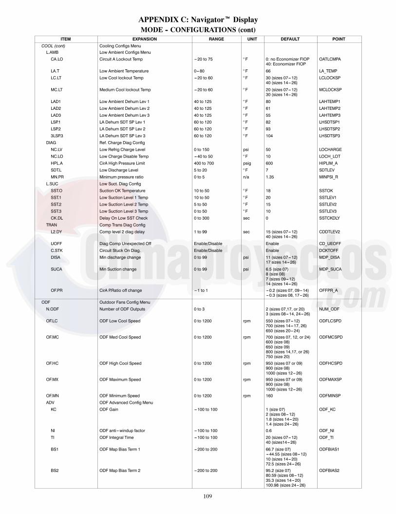
109
APPENDIX C: Navigatort DisplayMODE -- CONFIGURATIONS (cont)
ITEM EXPANSION RANGE UNIT DEFAULT POINT
COOL (cont) Cooling Configs MenuL.AMB Low Ambient Configs Menu
CA.LO Circuit A Lockout Temp ---20 to 75 ° F 0: no Economizer FIOP40: Economizer FIOP
OATLCMPA
LA.T Low Ambient Temperature 0---80 ° F 66 LA_TEMP
LC.LT Low Cool lockout Temp ---20 to 60 ° F 30 (sizes 07---12)40 (sizes 14---26)
LCLOCKSP
MC.LT Medium Cool lockout Temp ---20 to 60 ° F 20 (sizes 07---12)30 (sizes 14---26)
MCLOCKSP
LAD1 Low Ambient Dehum Lev 1 40 to 125 ° F 80 LAHTEMP1
LAD2 Low Ambient Dehum Lev 2 40 to 125 ° F 61 LAHTEMP2
LAD3 Low Ambient Dehum Lev 3 40 to 125 ° F 55 LAHTEMP3
LSP.1 LA Dehum SDT SP Lev 1 60 to 120 ° F 82 LHSDTSP1
LSP.2 LA Dehum SDT SP Lev 2 60 to 120 ° F 93 LHSDTSP2
3LSP.3 LA Dehum SDT SP Lev 3 60 to 120 ° F 104 LHSDTSP3
DIAG Ref. Charge Diag Config
NC.LV Low Refrig Charge Level 0 to 150 psi 50 LOCHARGE
NC.LO Low Charge Disable Temp ---40 to 50 ° F 10 LOCH_LOT
HPL.A CirA High Pressure Limit 400 to 700 psig 600 HIPLIM_A
SDT.L Low Discharge Level 5 to 20 ° F 7 SDTLEV
MN.PR Minimum pressure ratio 0 to 5 n/a 1.35 MINPSI_R
L.SUC Low Suct. Diag Config
SST.O Suction OK Temperature 10 to 50 ° F 18 SSTOK
SST.1 Low Suction Level 1 Temp 10 to 50 ° F 20 SSTLEV1
SST.2 Low Suction Level 2 Temp 5 to 50 ° F 15 SSTLEV2
SST.3 Low Suction Level 3 Temp 0 to 50 ° F 10 SSTLEV3
CK.DL Delay On Low SST Check 0 to 300 sec 0 SSTCKDLY
TRAN Comp Trans Diag Config
L2.DY Comp level 2 diag delay 1 to 99 sec 15 (sizes 07---12)40 (sizes 14---26)
CDDTLEV2
UOFF Diag Comp Unexpected Off Enable/Disable Enable CD_UEOFF
C.STK Circuit Stuck On Diag. Enable/Disable Enable DCKTOFF
DISA Min discharge change 0 to 99 psi 11 (sizes 07---12)17 sizes 14---26)
MDP_DISA
SUCA Min Suction change 0 to 99 psi 6.5 (size 07)8 (size 08)7 (sizes 09---12)14 (sizes 14---26)
MDP_SUCA
OF.PR CirA P.Ratio off change ---1 to 1 ---0.2 (sizes 07, 09---14)--- 0.3 (sizes 08, 17---26)
OFFPR_A
ODF Outdoor Fans Config Menu
N.ODF Number of ODF Outputs 0 to 3 2 (sizes 07,17, or 20)3 (sizes 08---14, 24---26)
NUM_ODF
OF.LC ODF Low Cool Speed 0 to 1200 rpm 550 (sizes 07---12)700 (sizes 14---17, 26)650 (sizes 20---24)
ODFLCSPD
OF.MC ODF Med Cool Speed 0 to 1200 rpm 700 (sizes 07, 12, or 24)600 (size 08)650 (size 09)800 (sizes 14,17, or 26)750 (size 20)
ODFMCSPD
OF.HC ODF High Cool Speed 0 to 1200 rpm 950 (sizes 07 or 09)900 (size 08)1000 (sizes 12---26)
ODFHCSPD
OF.MX ODF Maximum Speed 0 to 1200 rpm 950 (sizes 07 or 09)900 (size 08)1000 (sizes 12---26)
ODFMAXSP
OF.MN ODF Minimum Speed 0 to 1200 rpm 160 ODFMINSP
ADV ODF Advanced Config Menu
KC ODF Gain ---100 to 100 1 (size 07)2 (sizes 08---12)1.8 (sizes 14---20)1.4 (sizes 24---26)
ODF_KC
NI ODF anti---windup factor --- 100 to 100 0.6 ODF_NI
TI ODF Integral Time ---100 to 100 20 (sizes 07---12)40 (sizes14---26)
ODF_TI
BS1 ODF Map Bias Term 1 ---200 to 200 66.7 (size 07)--- 44.55 (sizes 08---12)10 (sizes 14---20)72.5 (sizes 24---26)
ODFBIAS1
BS2 ODF Map Bias Term 2 ---200 to 200 95.2 (size 07)80.59 (sizes 08---12)35.3 (sizes 14---20)100.98 (sizes 24---26)
ODFBIAS2

110
APPENDIX C: Navigatort DisplayMODE -- CONFIGURATIONS (cont)
ITEM EXPANSION RANGE UNIT DEFAULT POINT
ODF (cont) Outdoor Fans Config MenuBS3 ODF Map Bias Term 3 ---200 to 200 0 (sizes 07, 14---20)
65.29 (sizes 08---12)114.74 (sizes 24---26)
ODFBIAS3
PI1 ODF Fan Switch Point 1 --- 100 to 100 3.68 (size 07)3.4 (sizes 08---12)4.84 (sizes 14---20)1.58 (sizes 24---26)
ODFPIUP1
PI2 ODF Fan Switch Point 2 --- 100 to 100 17.1 (size 07)9.06 (sizes 08---12)22.3 (sizes 14---20)10.44 (sizes 24---26)
ODFPIUP2
PI3 ODF Fans Switch Point 3 --- 100 to 100 100 (sizes 07, 14---20)19.76 (sizes 08---12)20.93 (sizes 24---26)
ODFPIUP3
PR.KC ODF Proportional ctrl Pr --- 100 to 100 25 (sizes 07---12)50 (sizes 14---26)
ODFPR_KC
SLP1 ODF Map Slope Term 1 ---100 to 100 25.3 (size 07)60.09 (sizes 08---12)31 (sizes 14---20)55.33 (sizes 24---26)
ODFSLPE1
SLP2 ODF Map Slope Term 2 ---100 to 100 9 (size 07)18.69 (sizes 08---12)9.6 (sizes 14---20)19.07 (sizes 24---26)
ODFSLPE2
SLP3 ODF Map Slope Term 3 ---100 to 100 1 (sizes 07, 14---20)9.34 (sizes 08---12)8.85 (sizes 24---26)
ODFSLPE3
HEAT Heating Config MenuHT.TY Type of Heat Installed 0=ELECTRIC,
1=GAS0 (50 series)1 (48 series)
HEATTYPE
N.HTR Number of Heating Stages 0 to 2 2 (all except below);0 (50 series without FIOPheat)1 (50 series, sizes 07---14and low heat)1 (50 series, sizes 07---12and medium heat)
NUMHSTGS
HMRT Heat Minimum On Time 60 to 600 sec 120 H_MINONHMOT Heat Minimum Off Time 60 to 600 sec 120 H_MINOFFH.INC Heat Stage Increase Time 120 to 999 sec 450 HSTAGINCTLH Heating SAT Trend Level --- 1 to 1 ^F/min 0.2 SAT_TLHSAM.L Heat Max SAT Lower Level 85 to 200 ° F 140 SATMAX_LSAM.U Heat Max SAT Upper Level 85 to 200 ° F 160 SATMAX_HH.FOD Heating Fan---off Delay 10 to 600 sec 30 (50 series)
45 (48 series)HEAT_FOD
HT.LO Heating Lockout Temp 40 to 125 ° F 75 OATLHEATSAT.H SAT Heat Mode Sensing Enable/Disable Disable SAT_HEATN.IFO No IGC IFO input Timeout 0 to 60 min 5 NO_IGCTMPREH Pre---Heat HX without IDF? Enable/Disable Disable PREHT_HXPH.DY Pre---Heat Fan On Delay 0 to 120 sec 30 PREHT_TMSA.EN Supply Air Tempering Enable Yes/No Yes SATEMPENSA.SP SA Tempering Set Point xx ° F 50 SATEMPSPOAT.S Max OAT for SA Tempering ---40 to 125 ° F 48 OATSTEMP
I.FAN Indoor Fan Config MenuOC.FN Fan On When Occupied Yes/No Yes FANON_OCIDF.F Shut Down on IDF Failure Yes/No Yes FATALFANS.MIN IDF Min RPM SP xxxx RPM 0 RPMMINSPS.MAX IDF Max RPM SP xxxx RPM 0 RPMMAXSPFS.LC Low Cooling IDF Speed 20---100 % 67 (sizes 07---12)
53 (sizes 14 or 20)56 (size 17)52 (size 24)60 (size 26)
FSPD_LCL
FS.FC Free Cooling IDF Speed 0---100 % 67 (sizes 07---12)53 (sizes 14 or 20)56 (size 17)52 (size 24)60 (size 26)
FSPD_FCL
FS.HC High Cooling IDF Speed 20---100 % 100 FSPD_HCLS.HT IDF Heat RPM SP xxxx RPM 0 RPM_HEATS.VNT IDF Vent RPM SP xxxx RPM 0 RPM_VENTC.LOP IDF curve PWMmin 0---100 % 0 IFMLOPWMC.HIP IDF curve PWMmax 0---100 % 0 IFMHIPWMC.LOR IDF curve RPM min xxxx RPM 0 IFMLORPMC.HIR IDF curve RPM max xxxx RPM 0 IFMHIRPM

111
APPENDIX C: Navigatort DisplayMODE -- CONFIGURATIONS (cont)
ITEM EXPANSION RANGE UNIT DEFAULT POINT
ECON Economizer Config Menu
EC.EN Economizer Installed? Yes/No No: no FIOPYes: FIOP
ECONO
EC.MX Econ Max Damper Position 0 to 100 % 100 DAMPMAX
E.TRV Economizer Travel Time 5 to 300 sec 150 ECONOTRV
MIN.P Min Position Config Menu
MP.MX Econ Min at Max Fanspeed 0 to 100 % 30 MINP_MAX
MP.S1 Min Pos --- User Speed 1 0 to 100 % 0 MP_USPD1
MP.D1 Min Pos --- User Pos 1 0 to 100 % 0 MP_UPOS1
MP.S2 Min Pos --- User Speed 2 0 to 100 % 0 MP_USPD2
MP.D2 Min Pos --- User Pos 2 0 to 100 % 0 MP_UPOS2
MP.S3 Min Pos --- User Speed 3 0 to 100 % 0 MP_USPD3
MP.D3 Min Pos --- User Pos 3 0 to 100 % 0 MP_UPOS3
FC Free Cooling Config Menu
LCSP Low Free Cool SAT Setpnt 40 to 80 ° F 65 LCSASP
HCSP High FreeCool SAT Setpnt 40 to 80 ° F 55 HCSASP
FC.MX Free Cooling Max OAT 0 to 90 ° F 65 MAXFREET
FC.MN Free Cooling Min Temp ---30 to 70 ° F 0 MINFREET
DF.DB Diff. Dry Bulb Control Enable/Disable Disable DIFFBULB
DB.DB Diff. Dry Bulb Deadband 0 to 20 ° F 3 OATRATDB
EN.MX Max Enthalpy OA limit 1 to 99 Btu/lb 28 FREEMAXE
DF.EN Diff. Enthalpy Control Enable/Disable Disable DIFFENTH
EN.DB Enthalpy Cross Deadband 0 to 20 Btu/lb 2 OAERAEDB
EC.P Economizer PID --- kP 0.00 to 99.90 2.5 ECONO_P
EC.I Economizer PID --- kI 0.00 to 99.90 0.12 ECONO_I
EC.D Economizer PID --- kD 0.00 to 99.90 1 ECONO_D
EC.DT Economizer PID --- rate 10 to 180 sec 15 ECONO_DT
UFC UOCC Free CL Config Menu
UEFC When to Unocc Free Cool? 0=Disabled,1=PreOcc,2=Unocc
1=PreOcc UFC_CFG
UFC.T UFC PreOcc Time 1 to 999 min 120 UFCTIME
UFC.L Unocc Free Cool Low Temp ---30 to 70 ° F 50 OATLUFC
PE Power Exhaust Configs
PE1.C PE1 Relay Channel 0=NONE,1=MBB RLY11,2=MBB RLY06
0: no FIOP2: FIOP
PE1_CHAN
PE1.P PE Stage 1 at Max speed 0 to 100 % 40 PE1_PMAX
PE.DB PE Turn Off Dead band 0 to 100 % 5 PE_OFFDB
PE2.C PE2 Relay Channel 0=NONE,1=MBB RLY11,2=MBB RLY06
0=None PE2_CHAN
PE2.P PE Stage 2 at max speed 0 to 100 % 75 PE2_PMAX
EC.DD Econ Act Mech Disc Diag
HCDY T24 Heat/Cool End Delay 0 to 60 min 25 T24CHDLY
M.SAT T24Econ Min Move for SAT 10 to 20 % 10 T24ECSTS
SA.DB Damper SAT deadband 0 to 20 ° F 12 T24SATDB
RA.OA T24 Min Diff in RAT---OAT 5 to 20 ° F 15 T24RATDF
MIN.P T24 Test Minimum Pos 0 to 100 % 15 T24TSTMN
MAX.P T24 Test Maximum Pos 0 to 100 % 85 T24TSTMX
AIR.Q Air Quality Config Menu
IA.CF Analog Input IAQ Control 0=NO IAQ,1=DCV,2=IAQ OVRD,3=CTRL MINP
0: no FIOP1: FIOP
IAQANCFG
AQ.MN IAQ Position at Max Fan 0 to 100 % 10 IAQMINP
AQD.L AQ Differential Low 0 to 5000 ppm 100 DAQ_LOW
AQD.H AQ Differential High 0 to 5000 ppm 700 DAQ_HIGH
PP.EN IAQ Preoccupancy Purge Yes/No Yes IAQPURGE
PPOS IAQ Purge Pos at Max IDF 0 to 100 % 40 IAQPMAX
PP.LO Preocc Purge Lockout OAT 0 to 70 ° F 50 IAQP_LA
PP.DR Preocc Purge Duration 5 to 120 min 15 IAQPTIME
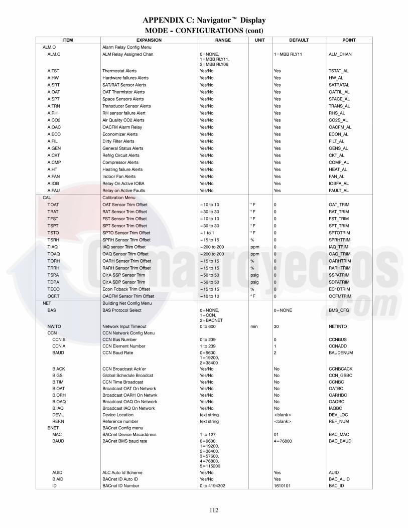
112
APPENDIX C: Navigatort DisplayMODE -- CONFIGURATIONS (cont)
ITEM EXPANSION RANGE UNIT DEFAULT POINT
ALM.O Alarm Relay Config Menu
ALM.C ALM Relay Assigned Chan 0=NONE,1=MBB RLY11,2=MBB RLY06
1=MBB RLY11 ALM_CHAN
A.TST Thermostat Alerts Yes/No Yes TSTAT_AL
A.HW Hardware failures Alerts Yes/No Yes HW_AL
A.SRT SAT/RAT Sensor Alerts Yes/No Yes SATRATAL
A.OAT OAT Thermistor Alerts Yes/No Yes OATRL_AL
A.SPT Space Sensors Alerts Yes/No Yes SPACE_AL
A.TRN Transducer Sensor Alerts Yes/No Yes TRANS_AL
A.RH RH sensor failure Alert Yes/No Yes RHS_AL
A.CO2 Air Quality CO2 Alerts Yes/No Yes CO2S_AL
A.OAC OACFM Alarm Relay Yes/No Yes OACFM_AL
A.ECO Economizer Alerts Yes/No Yes ECON_AL
A.FIL Dirty Filter Alerts Yes/No Yes FILT_AL
A.GEN General Status Alerts Yes/No Yes GENS_AL
A.CKT Refrig Circuit Alerts Yes/No Yes CKT_AL
A.CMP Compressor Alerts Yes/No Yes COMP_AL
A.HT Heating failure Alerts Yes/No Yes HEAT_AL
A.FAN Indoor Fan Alerts Yes/No Yes FAN_AL
A.IOB Relay On Active IOBA Yes/No Yes IOBFA_AL
A.FAU Relay on Active Faults Yes/No Yes FAULT_AL
CAL Calibration Menu
T.OAT OAT Sensor Trim Offset --- 10 to 10 ° F 0 OAT_TRIM
T.RAT RAT Sensor Trim Offset --- 30 to 30 ° F 0 RAT_TRIM
T.FST FST Sensor Trim Offset --- 10 to 10 ° F 0 FST_TRIM
T.SPT SPT Sensor Trim Offset --- 30 to 30 ° F 0 SPT_TRIM
T.STO SPTO Sensor Trim Offset --- 1 to 1 ° F 0 SPTOTRIM
T.SRH SPRH Sensor Trim Offset --- 15 to 15 % 0 SPRHTRIM
T.IAQ IAQ sensor Trim Offset --- 200 to 200 ppm 0 IAQ_TRIM
T.OAQ OAQ Sensor Trim Offset --- 200 to 200 ppm 0 OAQ_TRIM
T.ORH OARH Sensor Trim Offset --- 15 to 15 % 0 OARHTRIM
T.RRH RARH Sensor Trim Offset --- 15 to 15 % 0 RARHTRIM
T.SP.A Cir.A SSP Sensor Trim ---50 to 50 psig 0 SSPATRIM
T.DP.A Cir.A SDP Sensor Trim ---50 to 50 psig 0 SDPATRIM
T.ECO Econ Fdback Trim Offset --- 15 to 15 % 0 EC1DTRIM
OCF.T OACFM Sensor Trim Offset --- 10 to 10 ° F 0 OCFMTRIM
NET Building Net Config Menu
BAS BAS Protocol Select 0=NONE,1=CCN,2=BACNET
0=NONE BMS_CFG
NW.TO Network Input Timeout 0 to 600 min 30 NETINTOCCN CCN Network Config MenuCCN.B CCN Bus Number 0 to 239 0 CCNBUSCCN.A CCN Element Number 1 to 239 1 CCNADDBAUD CCN Baud Rate 0=9600,
1=19200,2=38400
2 BAUDENUM
B.ACK CCN Broadcast Ack’er Yes/No No CCNBCACKB.GS Global Schedule Broadcst Yes/No No CCN_GSBCB.TIM CCN Time Broadcast Yes/No No CCNBCB.OAT Broadcast OAT On Network Yes/No No OATBCB.ORH Broadcast OARH On Netwrk Yes/No No OARHBCB.OAQ Broadcast OAQ On Network Yes/No No OAQBCB.IAQ Broadcast IAQ On Network Yes/No No IAQBCDEV.L Device Location text string <blank> DEV_LOCREF.N Reference number text string <blank> REF_NUM
BNET BACnet Config menuMAC BACnet Device Macaddress 1 to 127 01 BAC_MACBAUD BACnet BMS baud rate 0=9600,
1=19200,2=38400,3=57600,4=76800,5=115200
4=76800 BAC_BAUD
AUID ALC Auto Id Scheme Yes/No Yes AUIDB.AID BACnet ID Auto ID Yes/No Yes BAC_AUIDID BACnet ID Number 0 to 4194302 1610101 BAC_ID
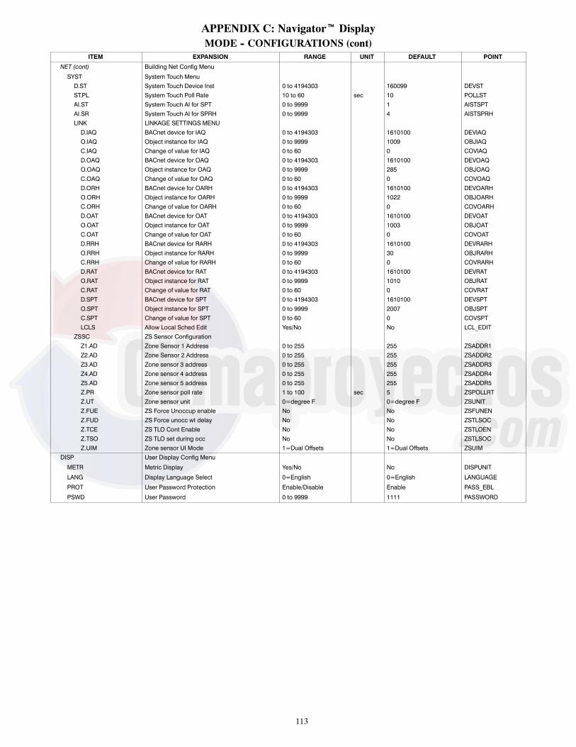
113
APPENDIX C: Navigatort DisplayMODE -- CONFIGURATIONS (cont)
ITEM EXPANSION RANGE UNIT DEFAULT POINT
NET (cont) Building Net Config Menu
SYST System Touch MenuD.ST System Touch Device Inst 0 to 4194303 160099 DEVSTST.PL System Touch Poll Rate 10 to 60 sec 10 POLLSTAI.ST System Touch AI for SPT 0 to 9999 1 AISTSPTAI.SR System Touch AI for SPRH 0 to 9999 4 AISTSPRHLINK LINKAGE SETTINGS MENUD.IAQ BACnet device for IAQ 0 to 4194303 1610100 DEVIAQO.IAQ Object instance for IAQ 0 to 9999 1009 OBJIAQC.IAQ Change of value for IAQ 0 to 60 0 COVIAQD.OAQ BACnet device for OAQ 0 to 4194303 1610100 DEVOAQO.OAQ Object instance for OAQ 0 to 9999 285 OBJOAQC.OAQ Change of value for OAQ 0 to 60 0 COVOAQD.ORH BACnet device for OARH 0 to 4194303 1610100 DEVOARHO.ORH Object instance for OARH 0 to 9999 1022 OBJOARHC.ORH Change of value for OARH 0 to 60 0 COVOARHD.OAT BACnet device for OAT 0 to 4194303 1610100 DEVOATO.OAT Object instance for OAT 0 to 9999 1003 OBJOATC.OAT Change of value for OAT 0 to 60 0 COVOATD.RRH BACnet device for RARH 0 to 4194303 1610100 DEVRARHO.RRH Object instance for RARH 0 to 9999 30 OBJRARHC.RRH Change of value for RARH 0 to 60 0 COVRARHD.RAT BACnet device for RAT 0 to 4194303 1610100 DEVRATO.RAT Object instance for RAT 0 to 9999 1010 OBJRATC.RAT Change of value for RAT 0 to 60 0 COVRATD.SPT BACnet device for SPT 0 to 4194303 1610100 DEVSPTO.SPT Object instance for SPT 0 to 9999 2007 OBJSPTC.SPT Change of value for SPT 0 to 60 0 COVSPTLCLS Allow Local Sched Edit Yes/No No LCL_EDIT
ZSSC ZS Sensor ConfigurationZ1.AD Zone Sensor 1 Address 0 to 255 255 ZSADDR1Z2.AD Zone Sensor 2 Address 0 to 255 255 ZSADDR2Z3.AD Zone sensor 3 address 0 to 255 255 ZSADDR3Z4.AD Zone sensor 4 address 0 to 255 255 ZSADDR4Z5.AD Zone sensor 5 address 0 to 255 255 ZSADDR5Z.PR Zone sensor poll rate 1 to 100 sec 5 ZSPOLLRTZ.UT Zone sensor unit 0=degree F 0=degree F ZSUNITZ.FUE ZS Force Unoccup enable No No ZSFUNENZ.FUD ZS Force unocc wt delay No No ZSTLSOCZ.TCE ZS TLO Cont Enable No No ZSTLOENZ.TSO ZS TLO set during occ No No ZSTLSOCZ.UIM Zone sensor UI Mode 1=Dual Offsets 1=Dual Offsets ZSUIM
DISP User Display Config Menu
METR Metric Display Yes/No No DISPUNIT
LANG Display Language Select 0=English 0=English LANGUAGE
PROT User Password Protection Enable/Disable Enable PASS_EBL
PSWD User Password 0 to 9999 1111 PASSWORD

114
APPENDIX C: Navigatort DisplayMODE -- TIME CLOCK
ITEM EXPANSION RANGE UNIT DEFAULT POINT
TIME CLOCK
TIME Clock Hour and Minute xx:xx hh.mm
MNTH Month of Year 1=JANUARY,2=FEBRUARY,3=MARCH,4=APRIL,5=MAY,6=JUNE,7=JULY,8=AUGUST,9=SEPTEMBER,10=OCTOBER,11=NOVEMBER,12=DECEMBER
MOY
DOM Day Of month 1 to 31 DOM
YEAR Year 2000 to 9999 YOC_DISP
DAY Day Of week 1=MONDAY,2=TUESDAY,3=WEDNESDAY,4=THURSDAY,5=FRIDAY,6=SATURDAY,7=SUNDAY
dow
DST.A DST currently active Yes/No DST_ACTV
DST Daylight Savings Config
DST DST allowed? Enable/Disable Enable DST_CFG
STR.M DST Start Month 1=JANUARY,2=FEBRUARY,3=MARCH,4=APRIL,5=MAY,6=JUNE,7=JULY,8=AUGUST,9=SEPTEMBER,10=OCTOBER,11=NOVEMBER,12=DECEMBER
3 STARTM
STR.W DST Start Week 1 to 5 2 STARTW
STR.D DST Start Day 1=MONDAY,2=TUESDAY,3=WEDNESDAY,4=THURSDAY,5=FRIDAY,6=SATURDAY,7=SUNDAY
7 STARTD
M.ADD DST Minutes to Add 0 to 90 min 60 MINADD
STP.M DST Stop Month 1=JANUARY,2=FEBRUARY,3=MARCH,4=APRIL,5=MAY,6=JUNE,7=JULY,8=AUGUST,9=SEPTEMBER,10=OCTOBER,11=NOVEMBER,12=DECEMBER
11 STOPM
STP.W DST Stop Week 1 to 5 1 STOPW
STP.D DST Stop Day 1=MONDAY,2=TUESDAY,3=WEDNESDAY,4=THURSDAY,5=FRIDAY,6=SATURDAY,7=SUNDAY
7 STOPD
M.SUB DST Minutes to Subtract 0 to 90 min 60 MINSUB
TOD Time in day to start DST 0 to 600 min 120 DST_TOD
SCHD Schedules Adjust Menu
SCH.N CCN Schedule Number 0 = Always Occupied,1---64 = Local Schedule,65---99 = GlobalSchedule
n/a 0 SCHEDNUM
OV.TL Timed Override Duration 0 to 4 hours 4 OTL_CFG
MON Mon Schedule Adjust Menu
OC.x Monday Occupied x 00:00 to 24:00 or None HH:MM None MO_OC1 ---MO_OC8
UOC.x Monday Unoccupied x 00:00 to 24:00 or None HH:MM None MO_UNOC1 ---MO_UNOC8

115
APPENDIX C: Navigatort DisplayMODE -- TIME CLOCK (cont)
ITEM EXPANSION RANGE UNIT DEFAULT POINT
SCHD (cont) Schedules Adjust Menu
TUE Tue Schedule Adjust Menu
OC.x Tuesday Occupied x 00:00 to 24:00 or None HH:MM None TU_OC1 --- TU_OC8
UOC.x Tuesday Unoccupied x 00:00 to 24:00 or None HH:MM None TU_UNOC1 --- TU_UNOC8
WED Wed Schedule Adjust Menu
OC.x Wednesday Occupied x 00:00 to 24:00 or None HH:MM None WE_OC1 --- WE_OC8
UOC.x Wednesday Unoccupied x 00:00 to 24:00 or None HH:MM None WE_UNOC1 --- WE_UNOC8
THU Thu Schedule Adjust Menu
OC.x Thursday Occupied x 00:00 to 24:00 or None HH:MM None TH_OC1 --- TH_OC8
UOC.x Thursday Unoccupied x 00:00 to 24:00 or None HH:MM None TH_UNOC1 --- TH_UNOC8
FRI Fri Schedule Adjust Menu
OC.x Friday Occupied x 00:00 to 24:00 or None HH:MM None FR_OC1 --- FR_OC8
UOC.x Friday Unoccupied x 00:00 to 24:00 or None HH:MM None FR_UNOC1 --- FR_UNOC8
SAT Sat Schedule Adjust Menu
OC.x Saturday Occupied x 00:00 to 24:00 or None HH:MM None SA_OC1 --- SA_OC8
UOC.x Saturday Unoccupied x 00:00 to 24:00 or None HH:MM None SA_UNOC1 --- SA_UNOC8
SUN Sun Schedule Adjust Menu
OC.x Sunday Occupied x 00:00 to 24:00 or None HH:MM None SU_OC1 --- SU_OC8
UOC.x Sunday Unoccupied x 00:00 to 24:00 or None HH:MM None SU_UNOC1 --- SU_UNOC8
HOL Hol Schedule Adjust Menu
OC.x Holiday Occupied x 00:00 to 24:00 or None HH:MM None HD_OC1 --- HD_OC8
UOC.x Holiday Unoccupied x 00:00 to 24:00 or None HH:MM None HD_UNOC1 --- HD_UNOC8
(repeat up to x=8 Periods)
HLDY Holiday adjustment Menu
HOL.G Accept Global Holidays? Yes/No No HOLIDAYT
HL.TY Today Is A Holiday Yes/No HOLTODAY
HL.TW Tomorrow Is A Holiday Yes/No HOL_TMRW
HO.xx Holiday adjustment Menu
LEN Holiday Duration (days) 0 to 99 0 HD01LEN --- HD30LEN
DAY Holiday Start Day 0 to 31 0 HD01STDY --- HD30STDY
MON Holiday Start Month 0 to 12 = January to December 0 HD01STMN --- HD30STMN
(repeat up to xx=30 Holidays)

116
APPENDIX C: Navigatort DisplayMODE -- OPERATING MODES
ITEM EXPANSION RANGE UNIT WRITE STATUS POINT
OPERATING MODES
MODE Operating Mode see Appendix B MODETEXT
SUBM Operating Sub---Mode see Appendix B SUBMTEXT
S.DMD System Demand see Appendix B SYS_DMDT
LINK Linkage Active Yes/No Yes LNK_ACT
EFF.C Cool Setpoint In Effect xx.x ° F CSP_EFF
EFF.H Heat Setpoint In Effect xx.x ° F HSP_EFF
T.EFF Effective Demand Temp xxx.x ° F TEMP_EFF
RH.OS Occupied SPRH Setpoint 0 to 100 % SPRH_OSP
RH.US Unoccupied SPRH Setpoint 0 to 100 % SPRH_USP
CLTG Cool Mode Select T.guard xxx sec COOLMSTG
HTTG Heat Mode Select T.guard xxx sec HEATMSTG
DMD.C Space Cooling Demand xx.x ° F COOL_DMD
TRD.C Cooling Demand Trend xx.x ^F/min CLDTREND
DMD.H Heating Space Demand xx.x ° F HEAT_DMD
TRD.H Heat Space Demand Trend xx.x ^F/min HTDTREND
DMD.S
CDLO Cool Demand Limiting Off/On CDMLMOFF
HDLO Heat Demand Limiting Off/On HDMLMOFF
CDML Cool demand Limit Level 0 to 3 CDMDLLEV
HDML Heat demand Limit Level 0 to 3 HDMDLLEV
CL.DO Cool Demand limit offset xx.x COOLDLMO
HT.DO Heat Demand Limit offset xx.x ° F HEATDLMO
MODE -- ALARMS
ITEM EXPANSION RANGE WRITESTATUS POINT
ALARMS
CURR Curr Active Alarm Menu
alarm# text string ALARM01C --- ALARM25C
(repeat up to 25 times)
HIST History Menu
alarm# alarm# --- mm/dd/yy---hh.mm--- text string ALHIS001 --- ALHIS050
(repeat up to 50 times)
R.CUR Reset All Current Alarms Yes/No Yes ALRESET
R.HIS Alarm Reset History Menu
ARxx mm/dd/yy, hh:mm:ss ALMRES00 --- ALMRES19
(repeat up to 20 times)

117
APPENDIX D: SystemVut Controller CCN TablesStatus Display Tables
Table Display Name Range Units Point Name Write Status
UINPUTSupply Air Temperature xxx..x ° F SATOutdoor Air Temperature xxx.x ° F OAT ForcibleReturn Air Temperature xxx.x ° F RAT ForcibleSpace Temperature xxx.x ° F SPACE_T ForcibleSpace Temperature Offset xx.x ° F SPTO ForcibleFan Supply Air Temp xxx.x ° F FST
Cir.A Sat.Suction Temp xxx.x ° F SST_ACir.A Sat.Discharge Temp xxx.x ° F SDT_ACir.A Suction Pressure xxx.x psig SSP_ACir.A Discharge Pressure xxx.x psig SDP_A
Thermostat G Input On/Off G ForcibleThermostat Y1 Input On/Off Y1 ForcibleThermostat Y2 Input On/Off Y2 ForcibleThermostat Y3 Input On/Off Y3 ForcibleThermostat W1 Input On/Off W1 ForcibleThermostat W2 Input On/Off W2 Forcible
Humidistat I/P On/Off HUMDSTAT ForcibleIGC Fan On Request (IFO) On/Off IGC_IFOCir.A High Pressure Sw Open/Close CIRA_HPSFire Shutdown Switch Alarm/Normal FIREDOWN ForcibleCOFS Switch State High/Low COFS ForcibleFilter Status Switch Dirty/Clean FILTSTAT ForcibleRemote Occupancy Switch On/Off REMOCC ForcibleRemote Shutdown Switch On/Off REMSHUT ForcibleGeneral Status Switch Alarm/Normal GENSTAT ForcibleEnthalpy Switch High/Low ENTH_SW Forcible
Econo Actual Position 0 to 100 % DAMPPOS ForcibleOA Relative Humidity 0 to 100 % OARH ForcibleRA Relative Humidity 0 to 100 % RARH ForcibleIndoor Air Quality Level xxxx ppm IAQ ForcibleOA Quality Level xxxx ppm OAQ ForcibleSpace RH 0 to 100 % SPRH ForcibleOutdoor Air in CFM xxxx cfm, OACFM ForciblePhase Monitor Switch PMR_STAT
UOUTPUTCommanded IDF Speed 0 to 100 % FANSPEEDEcono Commanded Position 0 to 100 % DAMPCMD ForcibleCCH Relay 1 State On/Off CCHR1Power Exhaust 1 Relay On/Off PE1 ForciblePower Exhaust 2 Relay On/Off PE2 ForcibleAlarm Output Relay State On/Off ALMOUT ForcibleCircuit A Compressor 1 On/Off COMP_A1Circuit A Compressor 2 On/Off COMP_A2Circuit A CMP A1 Loader On/Off COMP_ALDCommanded ODF Speed xxxx rpm ODFSPDODF Speed Signal Output1 xxxx rpm ODF1SPDODF Speed Signal Output2 xxxx rpm ODF2SPDODF Speed Signal Output3 xxxx rpm ODF3SPDHeat Stage 1 Relay On/Off HEAT_1Heat Stage 2 Relay On/Off HEAT_2Liquid Dischg Valve CirA Enable/Disable LDV_AReheat Dischg Valve CirA Enable/Disable RDV_AReheat Liquid Valve CirA Enable/Disable RDV_ACooling Liq Valve CirA Enable/Disable CLV_ADD IDF high speed relay On/Off FSPDHRLYDD IDF med. Speed relay On/Off FSPDMRLYDD IDF low speed relay On/Off FSPDLRLY
GENDISPCircuit A Pressure Ratio xx.xx CIRA_PRBarometric Pressure xx.xx in.Hg BARP ForcibleFilter hour remaining xxxx hours FILTLEFTReset Filter Timer Yes/No RESETFLT WritableOutdoor Air Enthalpy xxx.x Btu/lb OA_ENTH ForcibleReturn Air Enthalpy xxx.x Btu/lb RA_ENTH Forcible
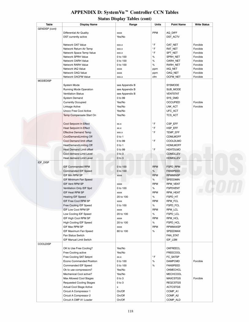
118
APPENDIX D: SystemVut Controller CCN TablesStatus Display Tables (cont)
Table Display Name Range Units Point Name Write Status
GENDISP (cont)Differential Air Quality xxxx PPM AQ_DIFFDST currently active Yes/No DST_ACTV
Network OAT Value xxx.x ° F OAT_NET ForcibleNetwork Return Air Temp xxx.x ° F RAT_NET ForcibleNetwork Space Temp Value xxx.x ° F SPT_NET ForcibleNetwork SPRH Value 0 to 100 % SPRH_NET ForcibleNetwork OARH Value 0 to 100 % OARH_NET ForcibleNetwork RARH Value 0 to 100 % RARH_NET ForcibleNetwork IAQ Value xxxx ppm IAQ_NET ForcibleNetwork OAQ Value xxxx ppm OAQ_NET ForcibleNetwork OACFM Value xxx.x cfm OCFM_NET Forcible
MODEDISP
System Mode see Appendix B SYSMODE
Running Mode Operation see Appendix B SUB_MODE
Ventilation Status see Appendix B VENTSTAT
System Demand 0 to 99 SYS_DMD
Currently Occupied Yes/No OCCUPIED Forcible
Linkage Active Yes/No LNK_ACT Forcible
Unocc Free Cool Active Yes/No UFC_ACT
Temp Compensate Start On Yes/No TCS_ACT
Cool Setpoint In Effect xx.x ° F CSP_EFF
Heat Setpoint In Effect xx.x ° F HSP_EFF
Effective Demand Temp xxx.x ° F TEMP_EFF
CoolDemandLimiting Off 0 to 1 CDMLMOFF
Cool Demand limit offset 0 to 99 ° F COOLDLMO
HeatDemandLimiting Off 0 to 1 HDMLMOFF
Heat Demand Limit offset 0 to 99 ° F HEATDLMO
Cool demand Limit Level 0 to 3 CDMDLLEV
Heat demand Limit Level 0 to 3 HDMDLLEV
IDF_DISP
IDF Commanded RPM 0 to 100 RPM FSPD_RPM
Commanded IDF Speed 0 to 100 % FANSPEED
IDF Min RPM SP xxxx RPM RPMMINSP
IDF Minimum Fan Speed % SPEEDMIN
IDF Vent RPM SP xxxx RPM RPM_VENT
Ventilation Only IDF Spd 0 to 100 % FSPDVENT
IDF Heat RPM SP xxxx RPM RPM_HEAT
Heating IDF Speed 20 to 100 % FSPD_HT
IDF Free Cool RPM SP xxxx RPM RPM_FCL
Free Cooling IDF Speed 0 to 100 % FSPD_FCL
IDF Low Cool RPM SP xxxx RPM RPM_LCL
Low Cooling IDF Speed 20 to 100 % FSPD_LCL
IDF High Cool RPM SP xxxx RPM RPM_HCL
High Cooling IDF Speed 20 to 100 % FSPD_HCL
IDF Max RPM SP xxxx RPM RPMMAXSP
IDF Maximum Fan Speed 80 to 100 % SPEEDMAX
Fan Status Switch FAN_STAT
IDF Manual Limit Switch IDF_LSM
COOLDISP
OK to Use Free Cooling? Yes/No OKFREECL
Free Cooling active Yes/No FREECOOL
Free Cooling SAT Setpnt xx.x ° F FC_SATSP
Econo Commanded Position 0 to 100 % DAMPCMD Forcible
Commanded IDF Speed 0 to 100 % FANSPEED
Ok to use compressors? Yes/No OKMECHCL
Mechanical Cool active? Yes/No MECHCOOL
Max Allowed Cool Stages 0 to 3 MAXCSTGS Forcible
Requested Cooling Stages 0 to 3 REQCSTGS
Actual Cool Stage Active x ACTCSTGS
Circuit A Compressor 1 On/Off COMP_A1
Circuit A Compressor 2 On/Off COMP_A2
Circuit A CMP A1 Loader On/Off COMP_ALD
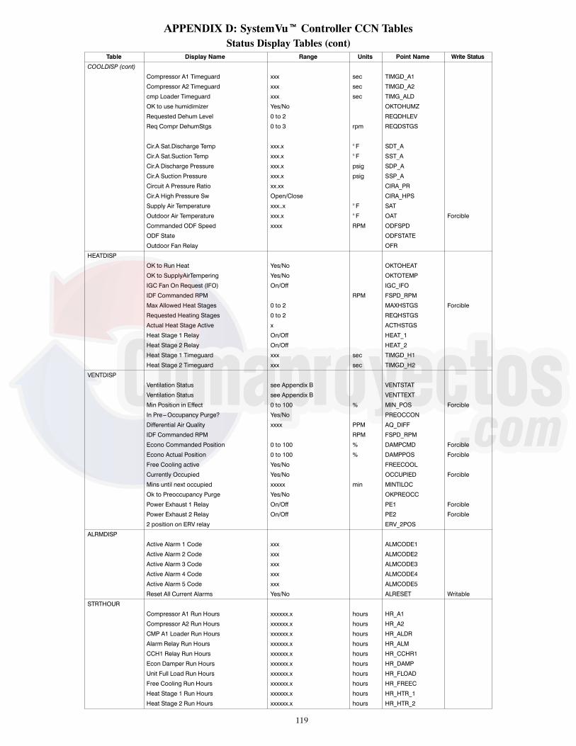
119
APPENDIX D: SystemVut Controller CCN TablesStatus Display Tables (cont)
Table Display Name Range Units Point Name Write Status
COOLDISP (cont)
Compressor A1 Timeguard xxx sec TIMGD_A1
Compressor A2 Timeguard xxx sec TIMGD_A2
cmp Loader Timeguard xxx sec TIMG_ALD
OK to use humidimizer Yes/No OKTOHUMZ
Requested Dehum Level 0 to 2 REQDHLEV
Req Compr DehumStgs 0 to 3 rpm REQDSTGS
Cir.A Sat.Discharge Temp xxx.x ° F SDT_A
Cir.A Sat.Suction Temp xxx.x ° F SST_A
Cir.A Discharge Pressure xxx.x psig SDP_A
Cir.A Suction Pressure xxx.x psig SSP_A
Circuit A Pressure Ratio xx.xx CIRA_PR
Cir.A High Pressure Sw Open/Close CIRA_HPS
Supply Air Temperature xxx..x ° F SAT
Outdoor Air Temperature xxx.x ° F OAT Forcible
Commanded ODF Speed xxxx RPM ODFSPD
ODF State ODFSTATE
Outdoor Fan Relay OFR
HEATDISP
OK to Run Heat Yes/No OKTOHEAT
OK to SupplyAirTempering Yes/No OKTOTEMP
IGC Fan On Request (IFO) On/Off IGC_IFO
IDF Commanded RPM RPM FSPD_RPM
Max Allowed Heat Stages 0 to 2 MAXHSTGS Forcible
Requested Heating Stages 0 to 2 REQHSTGS
Actual Heat Stage Active x ACTHSTGS
Heat Stage 1 Relay On/Off HEAT_1
Heat Stage 2 Relay On/Off HEAT_2
Heat Stage 1 Timeguard xxx sec TIMGD_H1
Heat Stage 2 Timeguard xxx sec TIMGD_H2
VENTDISP
Ventilation Status see Appendix B VENTSTAT
Ventilation Status see Appendix B VENTTEXT
Min Position in Effect 0 to 100 % MIN_POS Forcible
In Pre---Occupancy Purge? Yes/No PREOCCON
Differential Air Quality xxxx PPM AQ_DIFF
IDF Commanded RPM RPM FSPD_RPM
Econo Commanded Position 0 to 100 % DAMPCMD Forcible
Econo Actual Position 0 to 100 % DAMPPOS Forcible
Free Cooling active Yes/No FREECOOL
Currently Occupied Yes/No OCCUPIED Forcible
Mins until next occupied xxxxx min MINTILOC
Ok to Preoccupancy Purge Yes/No OKPREOCC
Power Exhaust 1 Relay On/Off PE1 Forcible
Power Exhaust 2 Relay On/Off PE2 Forcible
2 position on ERV relay ERV_2POS
ALRMDISP
Active Alarm 1 Code xxx ALMCODE1
Active Alarm 2 Code xxx ALMCODE2
Active Alarm 3 Code xxx ALMCODE3
Active Alarm 4 Code xxx ALMCODE4
Active Alarm 5 Code xxx ALMCODE5
Reset All Current Alarms Yes/No ALRESET Writable
STRTHOUR
Compressor A1 Run Hours xxxxxx.x hours HR_A1
Compressor A2 Run Hours xxxxxx.x hours HR_A2
CMP A1 Loader Run Hours xxxxxx.x hours HR_ALDR
Alarm Relay Run Hours xxxxxx.x hours HR_ALM
CCH1 Relay Run Hours xxxxxx.x hours HR_CCHR1
Econ Damper Run Hours xxxxxx.x hours HR_DAMP
Unit Full Load Run Hours xxxxxx.x hours HR_FLOAD
Free Cooling Run Hours xxxxxx.x hours HR_FREEC
Heat Stage 1 Run Hours xxxxxx.x hours HR_HTR_1
Heat Stage 2 Run Hours xxxxxx.x hours HR_HTR_2
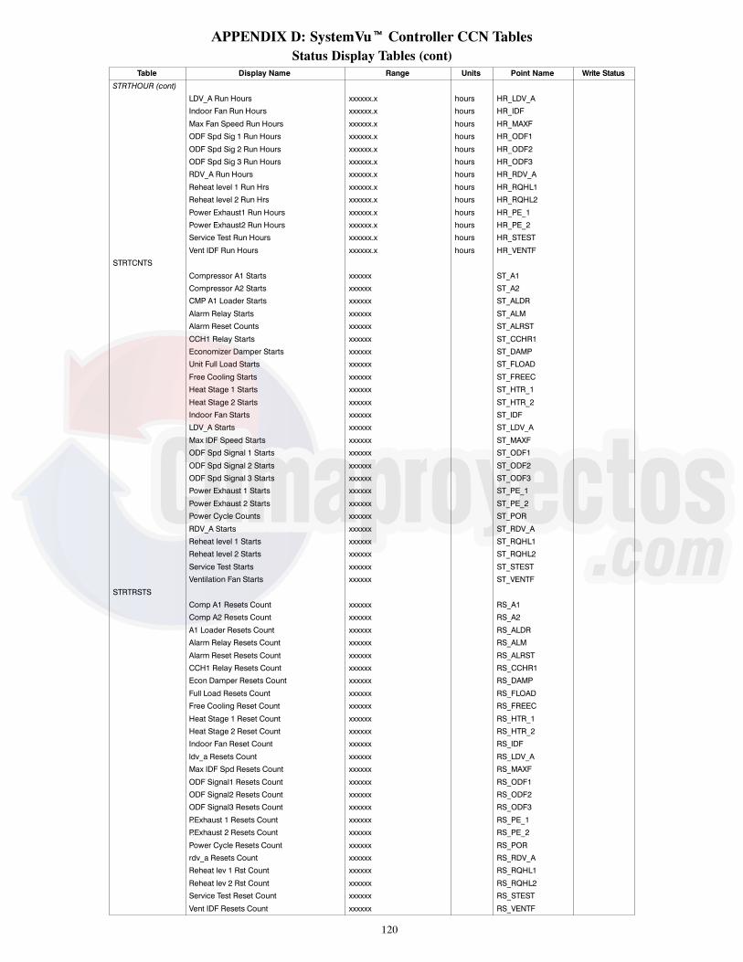
120
APPENDIX D: SystemVut Controller CCN TablesStatus Display Tables (cont)
Table Display Name Range Units Point Name Write Status
STRTHOUR (cont)LDV_A Run Hours xxxxxx.x hours HR_LDV_A
Indoor Fan Run Hours xxxxxx.x hours HR_IDF
Max Fan Speed Run Hours xxxxxx.x hours HR_MAXF
ODF Spd Sig 1 Run Hours xxxxxx.x hours HR_ODF1
ODF Spd Sig 2 Run Hours xxxxxx.x hours HR_ODF2
ODF Spd Sig 3 Run Hours xxxxxx.x hours HR_ODF3
RDV_A Run Hours xxxxxx.x hours HR_RDV_A
Reheat level 1 Run Hrs xxxxxx.x hours HR_RQHL1
Reheat level 2 Run Hrs xxxxxx.x hours HR_RQHL2
Power Exhaust1 Run Hours xxxxxx.x hours HR_PE_1
Power Exhaust2 Run Hours xxxxxx.x hours HR_PE_2
Service Test Run Hours xxxxxx.x hours HR_STEST
Vent IDF Run Hours xxxxxx.x hours HR_VENTF
STRTCNTS
Compressor A1 Starts xxxxxx ST_A1
Compressor A2 Starts xxxxxx ST_A2
CMP A1 Loader Starts xxxxxx ST_ALDR
Alarm Relay Starts xxxxxx ST_ALM
Alarm Reset Counts xxxxxx ST_ALRST
CCH1 Relay Starts xxxxxx ST_CCHR1
Economizer Damper Starts xxxxxx ST_DAMP
Unit Full Load Starts xxxxxx ST_FLOAD
Free Cooling Starts xxxxxx ST_FREEC
Heat Stage 1 Starts xxxxxx ST_HTR_1
Heat Stage 2 Starts xxxxxx ST_HTR_2
Indoor Fan Starts xxxxxx ST_IDF
LDV_A Starts xxxxxx ST_LDV_A
Max IDF Speed Starts xxxxxx ST_MAXF
ODF Spd Signal 1 Starts xxxxxx ST_ODF1
ODF Spd Signal 2 Starts xxxxxx ST_ODF2
ODF Spd Signal 3 Starts xxxxxx ST_ODF3
Power Exhaust 1 Starts xxxxxx ST_PE_1
Power Exhaust 2 Starts xxxxxx ST_PE_2
Power Cycle Counts xxxxxx ST_POR
RDV_A Starts xxxxxx ST_RDV_A
Reheat level 1 Starts xxxxxx ST_RQHL1
Reheat level 2 Starts xxxxxx ST_RQHL2
Service Test Starts xxxxxx ST_STEST
Ventilation Fan Starts xxxxxx ST_VENTF
STRTRSTS
Comp A1 Resets Count xxxxxx RS_A1
Comp A2 Resets Count xxxxxx RS_A2
A1 Loader Resets Count xxxxxx RS_ALDR
Alarm Relay Resets Count xxxxxx RS_ALM
Alarm Reset Resets Count xxxxxx RS_ALRST
CCH1 Relay Resets Count xxxxxx RS_CCHR1
Econ Damper Resets Count xxxxxx RS_DAMP
Full Load Resets Count xxxxxx RS_FLOAD
Free Cooling Reset Count xxxxxx RS_FREEC
Heat Stage 1 Reset Count xxxxxx RS_HTR_1
Heat Stage 2 Reset Count xxxxxx RS_HTR_2
Indoor Fan Reset Count xxxxxx RS_IDF
ldv_a Resets Count xxxxxx RS_LDV_A
Max IDF Spd Resets Count xxxxxx RS_MAXF
ODF Signal1 Resets Count xxxxxx RS_ODF1
ODF Signal2 Resets Count xxxxxx RS_ODF2
ODF Signal3 Resets Count xxxxxx RS_ODF3
P.Exhaust 1 Resets Count xxxxxx RS_PE_1
P.Exhaust 2 Resets Count xxxxxx RS_PE_2
Power Cycle Resets Count xxxxxx RS_POR
rdv_a Resets Count xxxxxx RS_RDV_A
Reheat lev 1 Rst Count xxxxxx RS_RQHL1
Reheat lev 2 Rst Count xxxxxx RS_RQHL2
Service Test Reset Count xxxxxx RS_STEST
Vent IDF Resets Count xxxxxx RS_VENTF

121
APPENDIX D: SystemVut Controller CCN TablesMaintenance Tables
Table Display Name Range Units Point Name WriteStatus
MODES
Operating Mode see Appendix B MODETEXT
System Mode see Appendix B SYSMODE
Operating Sub---Mode see Appendix B SUBMTEXT
Running Mode Operation see Appendix B SUB_MODE
Ventilation Status see Appendix B VENTTEXT
Ventilation Status see Appendix B VENTSTAT
System Demand see Appendix B SYS_DMDT
System Demand 0 to 99 SYS_DMD
Currently Occupied Yes/No OCCUPIED Forcible
Linkage Active Yes/No LNK_ACT Forcible
Unocc Free Cool Active Yes/No UFC_ACT
Temp Compensate Start On Yes/No TCS_ACT
Current Mode Ended Yes/No MODEDONE
Cool Mode Select T.guard xxx sec COOLMSTG
Heat Mode Select T.guard xxx sec HEATMSTG
Cool Setpoint In Effect xx.x ° F CSP_EFF
Heat Setpoint In Effect xx.x ° F HSP_EFF
Effective Demand Temp xxx.x ° F TEMP_EFF
Space Cooling Demand xx.x ° F COOL_DMD
Cooling Demand Trend xx.x ^F/min CLDTREND
Heating Space Demand xx.x ° F HEAT_DMD
Heat Space Demand Trend xx.x ^F/min HTDTREND
TESTMODE
Economizer Position Test 0 to 100 % S_DAMPER
Compressor Bump A1 Test On/Off S_BMPA1
Compressor Bump A2 Test On/Off S_BMPA2
Cmp Bump Loader Test On/Off S_BMPALD
LiqDivertrValveRelayTest On/Off S_LDV_A
ReheatDschgValvRelayTest On/Off S_REV_A
Crankcase Heater 1 test On/Off S_CCHR1
Alarm Output Relay Test On/Off S_ALARM
Power Exhaust 1 Test On/Off S_PE_1
Power Exhaust 2 Test On/Off S_PE_2
Indoor Fan Speed Test 0 to 100 % S_IDFSPD
System ODF speed test 0 to 1200 rpm S_ODFSPD
Outdoor Fan 1 speed test 0 to 1200 rpm S_ODFSP1
Outdoor Fan 2 speed test 0 to 1200 rpm S_ODFSP2
Outdoor Fan 3 speed test 0 to 1200 rpm S_ODFSP3
IDF Manual Transition Yes/No S_IDFTRN
ODF Manual Transition Yes/No S_ODFTRN
Cooling W/Comp.A1 Test On/Off S_COOLA1
Cooling W/Comp.A2 Test On/Off S_COOLA2
Cooling W/Comp.ALD Test On/Off S_COLALD
HumidiMizer Level 0=Off,1=Subcool,2=Reheat
S_HMZLEV
Heating Stage 1 Test On/Off S_HEAT1
Heating Stage 2 Test On/Off S_HEAT2
AUTO INDEPENDENT TEST Yes/No AUTOINDP
RUN AUTO COOLING TEST Yes/No AUTOCOOL
RUN AUTO HEATING TEST Yes/No AUTOHEAT
RUN AUTO SYSTEM TEST Yes/No AUTOSYS
IDF_DIAG
IDF Commanded RPM RPM FSPD_RPM
Commanded IDF Speed 0 to 100 % FANSPEED
Requested IDF Speed 0 to 100 % RQFANSPD
IDF Speed Override Flag On/Off FAN_OVRD
IDF Speed Reduction On Yes/No FANRED10
IDF Operation Errors? Yes/No IDFBAD

122
APPENDIX D: SystemVut Controller CCN TablesMaintenance Tables (cont)
Table Display Name Range Units Point Name WriteStatus
USB_DIAGUSB TREND STATUS 0=IDLE,
1=TRENDING,2=NO POINTS,3=USB FULL
TRNDSTAT
USB TREND DURATION 0=1 MINUTE,1=5 MINUTES,2=15 MINUTES,3=30 MINUTES,4=1 HOUR,5=3 HOURS,6=8 HOURS,7=12 HOURS,8=1 DAYS,9=1.5 DAYS,10=2 DAYS,11=3 DAYS,12=5 DAYS,13=1 WEEK,14=2 WEEK,15=4 WEEK,16=USB FULL
TRNDDUR Yes
USB TREND RATE 1 to 300 TRNDRATE YesUSB TREND POINTS FROM 0=FILE,
1=LISTTRNDPNTS Yes
TREND FILE SEARCH text string TRNDFILETREND EQUIP PERFORMANCE On/Off TRNDEQPR YesTREND COOL PERFORMANCE On/Off TRNDCLPR YesTREND HEAT PERFORMANCE On/Off TRNDHTPR YesTREND COOLING DIAGNOSTIC On/Off TRNDCLDG YesTREND IDF DIAGNOSTIC On/Off TRNDIDF YesTREND VENTILATION On/Off TRNDVENT YesTREND GEN INPUTS/OUTPUTS On/Off TRNDIO YesStart USB Trending Yes/No TREND_EN Yes
Make Config Backup File Start/Stop DDBCKUP YesBackup File is ready 0=IDLE,
1=SUCCESS,2=FAILURE
BACKUP_R
USB Find Restore File Yes/No BACKFILE YesStart Config Restore Start/Stop DDRSTRE YesFile Error Yes/No FILE_ERR
COOLDIAGSystem Demand see Appendix B SYS_DMDTOperating Sub---Mode see Appendix B SUBMTEXTRequested IDF Speed 0 to 100 % RQFANSPDCommanded IDF Speed 0 to 100 % FANSPEEDIDF Commanded RPM RPM FSPD_RPM
OK to Use Free Cooling? Yes/No OKFREECLEcon Damper Operational Yes/No DAMPGOODDry Bulb Lockout Yes/No DBLOCK ForcibleEnthalpy Lockout Yes/No ENTHLOCK ForcibleFree Cooling active Yes/No FREECOOLUnocc Free Cool Active Yes/No UFC_ACTFree Cooling SAT Setpnt xx.x ° F FC_SATSPRequested Damper Pos 0 to 100 % REQDAMPEcono Commanded Position 0 to 100 % DAMPCMD Forcible
Ok to use compressors? Yes/No OKMECHCLCompressor A1 Strikes x A1STRIKECompressor A2 Strikes x A2STRIKECircuit A Locked Out Yes/No CIRALOCKMechanical Cool active? Yes/No MECHCOOLMax Allowed Cool Stages 0 to 3 MAXCSTGS ForcibleNumber of Cooling Stages 0 to 3 NUMCSTGSSupply Air Temp Trend xxx.x ^F/min SATTRENDSupply Air Temperature xxx..x ° F SATRequested Cooling Stages 0 to 3 REQCSTGS
Low cooling locked out Yes/No LC_LOCKMedium Cooling lockout Yes/No MC_LOCKCompressor A1 Timeguard xxx sec TIMGD_A1Compressor A2 Timeguard xxx sec TIMGD_A2

123
APPENDIX D: SystemVut Controller CCN TablesMaintenance Tables (cont)
Table Display Name Range Units Point Name WriteStatus
COOLDIAG (cont)cmp Loader Timeguard xxx sec TIMG_ALDCompressor A1 locked out Yes/No CA1_LOCKCompressor A2 locked out Yes/No CA2_LOCKCompressor A1 Available Yes/No CA1_AVALCompressor A2 Available Yes/No CA2_AVALRecent Comp A1 Strike Yes/No A1STKACTRecent Comp A2 Strike Yes/No A2STKACTCircuit A Compressor 1 On/Off COMP_A1Circuit A Compressor 2 On/Off COMP_A2Circuit A CMP A1 Loader On/Off COMP_ALDActual Cool Stage Active x ACTCSTGS
Ok to Dehumidify? Yes/No OKTODHUMHumidimizer Lockout Temp ---20 to 75 ° F OATLHUMZOk to fan based dehum Yes/No OKTOFBDOk to use humidimizer Yes/No OKTOHUMZReq Compr DehumStgs 0 to 3 REQDSTGSRequested Dehum Level 0 to 2 REQDSTGSLiquid Dischg Valve CirA Enable/Disable LDV_AReheat Dischg Valve CirA Enable/Disable RDV_A
High Pressure Override Yes/No HP_OVRODF Speed Signal Output1 0 to 1200 rpm ODF1SPDODF Speed Signal Output2 0 to 1200 rpm ODF2SPDODF Speed Signal Output3 0 to 1200 rpm ODF3SPDODF Control SDT SP 0 ° F ODFSDTSPLow Ambient Ctrl Status 0=Normal,
1=Entering,2=Low Ambient,3=Exiting
LACTRLST
Outdoor Air Temperature xxx.x ° F OAT ForcibleFBDH SST locked out Yes/No FBDSSTLOFBDH SAT Lockout Yes/No FBDSATLOCir.A High Pressure Sw Open/Close CIRA_HPSCir.A Discharge Pressure xxx.x psig SDP_ACir.A Suction Pressure xxx.x psig SSP_ACircuit A Pressure Ratio xx.xx CIRA_PRCir.A Sat.Discharge Temp xxx.x ° F SDT_ACir.A Sat.Suction Temp xxx.x ° F SST_A
HUMZDIAGOk to Dehumidify? Yes/No OKTODHUMRequested Dehum Level 0 to 2 REQDHLEVOk to use humidimizer Yes/No OKTOHUMZLiquid Dischg Valve CirA Enable/Disable LDV_AReheat Dischg Valve CirA Enable/Disable RDV_AReheat Liquid Valve CirA Enable/Disable RLV_ACooling Liq Valve CirA Enable/Disable CLV_A
Fan Based Dehum Type 0=None,1=Comfort,2=Max
FBD_TYPE
FBDH SAT Min value 35 to 80 ° F FBDH_SATFBDH SST Min value 10 to 60 ° F FBDH_SSTFBDH Low Set Point --- 20 to 0 ° F delta FBDLO_SPRequested IDF Speed 0 to 200 % RQFANSPDOk to fan based dehum Yes/No OKTOFBDFBDH SST locked out Yes/No FBDSSTLOFBDH SAT Lockout Yes/No FBDSATLO
OKFCDIAGOutdoor Air Temperature xxx.x ° F OAT ForcibleOA Relative Humidity 0 to 100 % OARH ForcibleOutdoor Air Enthalpy xxx.x Btu/lb OA_ENTH ForcibleReturn Air Temperature xxx.x ° F RAT ForcibleRA Relative Humidity 0 to 100 % RARH ForcibleReturn Air Enthalpy xxx.x Btu/lb RA_ENTH ForcibleBarometric Pressure xx.xx in.Hg BARP Forcible

124
APPENDIX D: SystemVut Controller CCN TablesMaintenance Tables (cont)
Table Display Name Range Units Point Name WriteStatus
OKFCDIAG (cont)
Diff. Dry Bulb Control Enable/Disable DIFFBULB
Free Cooling Min Temp ---30 to 70 ° F MINFREET
Free Cooling Max OAT 0 to 90 ° F MAXFREET
Diff. Dry Bulb Deadband 0 to 20 ° F OATRATDB
Dry Bulb Lockout Yes/No DBLOCK Forcible
Diff. Enthalpy Control Enable/Disable DIFFENTH
Max Enthalpy OA limit 1 to 99 Btu/lb FREEMAXE
Enthalpy Cross Deadband 0 to 20 Btu/lb OAERAEDB
Enthalpy Switch High/Low ENTH_SW Forcible
Enthalpy Lockout Yes/No ENTHLOCK Forcible
Currently Occupied Yes/No OCCUPIED Forcible
Unocc Free Cool Low Temp ---30 to 70 ° F OATLUFC
Unocc Free Cool Lockout Yes/No UNOCLOCK
Econ Damper Operational Yes/No DAMPGOOD
OK to Use Free Cooling? Yes/No OKFREECL
Ok to unocc Free Cool? Yes/No OKTOUFC
HEATDIAG
System Demand see Appendix B SYS_DMDT
Operating Sub---Mode see Appendix B SUBMTEXT
IGC Fan On Request (IFO) On/Off IGC_IFO
Requested IDF Speed 0 to 100 % RQFANSPD
Commanded IDF Speed 0 to 100 % FANSPEED
IDF Commanded RPM RPM FSPD_RPM
OK to Run Heat Yes/No OKTOHEAT
All Heat Stages Lockout Yes/No ALLHTLOC Forcible
Max Allowed Heat Stages 0 to 2 MAXHSTGS Forcible
Supply Air Temp Trend xxx.x ^F/min SATTREND
Supply Air Temperature xxx..x ° F SAT
Requested Heating Stages 0 to 2 REQHSTGS
Heat Stage 1 Timeguard xxx sec TIMGD_H1
Heat Stage 2 Timeguard xxx sec TIMGD_H2
Heat Stage 1 Available Yes/No HT1_AVAL
Heat Stage 2 Available Yes/No HT2_AVAL
Heat Stage 1 Relay On/Off HEAT_1
Heat Stage 2 Relay On/Off HEAT_2
Actual Heat Stage Active x ACTHSTGS
Outdoor Air Temperature xxx.x ° F OAT Forcible
Return Air Temperature xxx.x ° F RAT Forcible
Fan Supply Air Temp xxx.x ° F FST
Econo Commanded Position 0 to 100 % DAMPCMD Forcible
PE_DIAG
0 = None
1 = MBB RLY11
2 = MBB RLY06
PE1 Relay Channel 0 to 2 PE1_CHAN
PE2 Relay Channel 0 to 2 PE2_CHAN
PE Turn Off Dead band 0 to 100 % PE_OFFDB
Power Exhaust 1 Relay On/Off PE1 Forcible
Power Exhaust 2 Relay On/Off PE2 Forcible
Econo Commanded Position 0 to 100 % DAMPCMD Forcible
Commanded IDF Speed 0 to 100 % FANSPEED
IDF Commanded RPM RPM FSPD_RPM
IDF Maximum Fan Speed 80 to 100 % SPEEDMAX
IDF Max RPM SP xxxx RPM RPMMAXSP
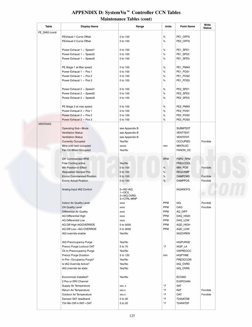
125
APPENDIX D: SystemVut Controller CCN TablesMaintenance Tables (cont)
Table Display Name Range Units Point Name WriteStatus
PE_DIAG (cont)
P.Exhaust 1 Curve Offset 0 to 100 % PE1_OFFS
P.Exhaust 2 Curve Offset 0 to 100 % PE2_OFFS
Power Exhaust 1 --- Speed1 0 to 100 % PE1_SPD1
Power Exhaust 1 --- Speed2 0 to 100 % PE1_SPD2
Power Exhaust 1 --- Speed3 0 to 100 % PE1_SPD3
PE Stage 1 at Max speed 0 to 100 % PE1_PMAX
Power Exhaust 1 --- Pos 1 0 to 100 % PE1_POS1
Power Exhaust 1 --- Pos 2 0 to 100 % PE1_POS2
Power Exhaust 1 --- Pos 3 0 to 100 % PE1_POS3
Power Exhaust 2 --- Speed1 0 to 100 % PE2_SPD1
Power Exhaust 2 --- Speed2 0 to 100 % PE2_SPD2
Power Exhaust 2 --- Speed3 0 to 100 % PE2_SPD3
PE Stage 2 at max speed 0 to 100 % PE2_PMAX
Power Exhaust 2 --- Pos 1 0 to 100 % PE2_POS1
Power Exhaust 2 --- Pos 2 0 to 100 % PE2_POS2
Power Exhaust 2 --- Pos 3 0 to 100 % PE2_POS3
VENTDIAG
Operating Sub---Mode see Appendix B SUBMTEXT
Ventilation Status see Appendix B VENTTEXT
Ventilation Status see Appendix B VENTSTAT
Currently Occupied Yes/No OCCUPIED Forcible
Mins until next occupied xxxxx min MINTILOC
Fan On When Occupied Yes/No FANON_OC
IDF Commanded RPM RPM FSPD_RPM
Free Cooling active Yes/No FREECOOL
Min Position in Effect 0 to 100 % MIN_POS Forcible
Requested Damper Pos 0 to 100 % REQDAMP
Econo Commanded Position 0 to 100 % DAMPCMD Forcible
Econo Actual Position 0 to 100 % DAMPPOS Forcible
Analog Input IAQ Control 0=NO IAQ,1=DCV,2=IAQ OVRD,3=CTRL MINP
IAQANCFG
Indoor Air Quality Level xxxx PPM IAQ Forcible
OA Quality Level xxxx PPM OAQ Forcible
Differential Air Quality xxxx PPM AQ_DIFF
AQ Differential High xxxx PPM DAQ_HIGH
AQ Differential Low xxxx PPM DAQ_LOW
AQ Diff High IAQOVERRIDE 0 to 5000 PPM AQD_HIGH
AQ Diff Low--- IAQ OVERRIDE 0 to 5000 PPM AQD_LOW
IAQ override enable Yes/No IAQOVREN
IAQ Preoccupancy Purge Yes/No IAQPURGE
Preocc Purge Lockout OAT 0 to 70 ° F IAQP_LA
Ok to Preoccupancy Purge Yes/No OKPREOCC
Preocc Purge Duration 5 to 120 min IAQPTIME
In Pre---Occupancy Purge? Yes/No PREOCCON
Is IAQ Override Active? Yes/No IAQ_OVRD
IAQ override sw state Yes/No IAQ_OVRS
Economizer Installed? Yes/No ECONO
2 Pos or ERV Channel EV2PCHAN
Supply Air Temperature xxx..x ° F SAT
Return Air Temperature xxx.x ° F RAT Forcible
Outdoor Air Temperature xxx.x ° F OAT Forcible
Damper SAT deadband 0 to 20 ° F T24SATDB
T24 Min Diff in RAT---OAT 5 to 20 ° F T24RATDF

126
APPENDIX D: SystemVut Controller CCN TablesMaintenance Tables (cont)
Table Display Name Range Units Point Name WriteStatus
VENTDIAG (cont)
T24 Heat/Cool End Delay 0 to 60 min T24CHDLY
SAT Heat Mode Sensing Enable/Disable SAT_HEAT
Actual Heat Stage Active x ACTHSTGS
Actual Cool Stage Active x ACTCSTGS
OK to Use Free Cooling? Yes/No OKFREECL
T24 Test Minimum Pos 0 to 100 % T24TSTMN
Econo Commanded Position 0 to 100 % DAMPCMD Forcible
T24 Test Maximum Pos 0 to 100 % T24TSTMX
T24Econ Min Move for SAT 10 to 20 % T24ECSTS
Econo Actual Position 0 to 100 % DAMPPOS Forcible
IAQODIAG
AQ Diff High IAQOVERRIDE 0 to 5000 PPM AQD_HIGH
AQ Diff Low--- IAQ OVERRIDE 0 to 5000 PPM AQD_LOW
IAQ override enable Yes/No IAQOVREN
Is IAQ Override Active? Yes/No IAQ_OVRD
IAQ override sw state Yes/No IAQ_OVRS
VENTCURV
Econ Min at Max Fanspeed 0 to 100 % MINP_MAX
Min Pos --- User Pos 1 0 to 100 % MP_UPOS1
Min Pos --- User Pos 2 0 to 100 % MP_UPOS2
Min Pos --- User Pos 3 0 to 100 % MP_UPOS3
Min Pos --- User Speed 1 0 to 100 % MP_USPD1
Min Pos --- User Speed 2 0 to 100 % MP_USPD2
Min Pos --- User Speed 3 0 to 100 % MP_USPD3
User Min Pos Pnt 1 Valid Yes/No MP_UPT1
User Min Pos Pnt 2 Valid Yes/No MP_UPT2
User Min Pos Pnt 3 Valid Yes/No MP_UPT3
Min Pos --- Default Pos 1 0 to 100 % MP_DPOS1
Min Pos --- Default Pos 2 0 to 100 % MP_DPOS2
Min Pos --- Default Pos 3 0 to 100 % MP_DPOS3
Min Pos --- Default Speed1 0 to 100 % MP_DSPD1
Min Pos --- Default Speed2 0 to 100 % MP_DSPD2
Min Pos --- Default Speed3 0 to 100 % MP_DSPD3
Min Pos Curve --- Pos 1 0 to 100 % MP_POS1
Min Pos Curve --- Pos 2 0 to 100 % MP_POS2
Min Pos Curve --- Pos 3 0 to 100 % MP_POS3
Min Pos Curve --- Speed 1 0 to 100 % MP_SPD1
Min Pos Curve --- Speed 2 0 to 100 % MP_SPD2
Min Pos Curve --- Speed 3 0 to 100 % MP_SPD3
IAQ DCV Curve Offset 0 to 100 % IAQ_OFFS
IAQ Position at Max Fan 0 to 100 % IAQMINP
IAQ DCV Curve --- Pos 1 0 to 100 % AQ_POS1
IAQ DCV Curve --- Pos 2 0 to 100 % AQ_POS2
IAQ DCV Curve --- Pos 3 0 to 100 % AQ_POS3
IAQ DCV Curve --- Speed 1 0 to 100 % AQ_SPD1
IAQ DCV Curve --- Speed 2 0 to 100 % AQ_SPD2
IAQ DCV Curve --- Speed 3 0 to 100 % AQ_SPD3
IAQ Purge Curve Offset 0 to 100 % AQP_OFFS
IAQ Purge Pos at Max IDF 0 to 100 % IAQPMAX
IAQ Purge Curve --- Pos 1 0 to 100 % AQP_POS1
IAQ Purge Curve --- Pos 2 0 to 100 % AQP_POS2
IAQ Purge Curve --- Pos 3 0 to 100 % AQP_POS3
IDF Maximum Fan Speed 80 to 100 % SPEEDMAX
IAQ Purge Curve --- Speed1 0 to 100 % AQP_SPD1
IAQ Purge Curve --- Speed2 0 to 100 % AQP_SPD2
IAQ Purge Curve --- Speed3 0 to 100 % AQP_SPD3

127
APPENDIX D: SystemVut Controller CCN TablesMaintenance Tables (cont)
Table Display Name Range Units Point Name WriteStatus
LINKDATALinkage CCN element # xxx LNK_SUPE ForcibleLinkage CCN Bus number xxx LNK_SUPB ForcibleBlock No: in Master Zone 1 to 8 LNK_MZBK ForcibleAverage Occup. Heat Stp. xxx.x ° F LNK_OHSP ForcibleAverage Occup. Cool Stp. xxx.x ° F LNK_OCSP ForcibleAverage Unocc. Heat Stp. xxx.x ° F LNK_UHSP ForcibleAverage Unocc. Cool Stp. xxx.x ° F LNK_UCSP ForcibleAverage Zone Temperature xxx.x ° F LNK_AZT ForcibleAverage Occup. Zone Temp xxx.x ° F LNK_AOZT ForcibleLinkage Occupied Request 0=Unocc,
1=Occupied,2=Disabled
LNK_OCC Forcible
Linkage Next Occ Day text string LNEXTOCDLinkage Next Occ Time hh:mm LNEXTOCTLinkage Last Unocc Day text string LNEXTUODLinkage Next Unocc Time hh:mm LNEXTUCTLinkage Last Unocc Day text string LLASTUODLinkage Last Unocc Time hh:mm LLASTUCT
Linkage Active Yes/No LNK_ACT ForcibleLinkage Equipment Mode 1 to 8 LNK_MODE ForcibleLinkage Start Bias time xxx min LNK_SBT ForcibleValue of Prime variable xxx.x ° F PRIME_V
OCC_DIAGCurrently Occupied Yes/No OCCUPIED ForcibleActive Occupancy control 0 = 24/7 OCC,
1 = Schedule,2 = BAS CTRL,3 = REMOC CTL,4 = Time Override,5 = Linkage,6 = Forced
OCC_CTRL
Linkage Occupied Request 0=Unocc,1=Occupied,2=Disabled
LNK_OCC Forcible
Timed Override Remaining 0 to 240 min OVR_EXT ForcibleRemote Occupancy Switch On/Off REMOCC ForcibleBMS Occupancy Request 0=Unocc,
1=Occupied,2=Disabled
BMS_OCC Forcible
Local Sched Occ Request 0=Unocc,1=Occupied
LOC_OCC Forcible
Active Schedule period 0 to 8 PER_NOMins until next occupied ---1 to 10080 min MINTILOCBACnet Cal Object Status Yes/No CALOBJSTToday Is A Holiday Yes/No HOLTODAYTomorrow Is A Holiday Yes/No HOL_TMRWNext Occupied Day DDD NXTOCDAYNext Occupied Time hh:mm NXTOCTIMNext Unoccupied Day DDD NXTUNDAYNext Unoccupied Time hh:mm NXTUNTIMPrevious Unccupied Day DDD PRVUNDAYPrevious Unoccupied Time hh:mm hh.mm PRVUNTIM
Accept Global Holidays? Yes/No HOLIDAYTGlobal Schedule Broadcst Yes/No CCN_GSBCCCN Schedule Number 0 to 99 SCHEDNUM0 = Always Occupied1---64 = Local Schedule65---99 = Global ScheduleRemote Occupancy Channel 0=None,
1=MBB DI12,2=MBB DI13,3=MBB DI14,4=MBB DI02,5=MBB DI04
RMOCCHAN
Remote Occupancy Switch On/Off REMOCC ForcibleTimed Override Duration 0 to 4 hours OTL_CFGBAS Protocol Select 0=NONE,
1=CCN,2=BACNET
BMS_CFG

128
APPENDIX D: SystemVut Controller CCN TablesMaintenance Tables (cont)
Table Display Name Range Units Point Name WriteStatus
HW_IOAssigned AI06 Function 0 = None,
1 = IAQ,2 = OARH,3 = RARH,4 = OAQ,5 = SPRH,6 = OACFM
MBBAI06F
Assigned AI07 Function 0 = None,1 = IAQ,2 = OARH,3 = RARH,4 = OAQ,5 = SPRH,6 = OACFM
MBBAI07F
Assigned AI08 Function 0 = None,1 = IAQ,2 = OARH,3 = RARH,4 = OAQ,5 = SPRH,6 = OACFM
MBBAI08F
Assigned S---AI01 Function 0 = None,1 = IAQ,2 = OARH,3 = RARH,4 = OAQ,5 = SPRH,6 = OACFM
SIOAI01F
Assigned DI02 Function 0 = None,1 = COFS,2 = REMOCC,3 = REMOFF,4 = Filter,5 = Enthalpy6 = General Status,7 = Humidistat
MBBDI02F
Assigned DI04 Function 0 = None,1 = COFS,2 = REMOCC,3 = REMOFF,4 = Filter,5 = Enthalpy6 = General Status,7 = Humidistat
MBBDI04F
Assigned DI12 Function 0 = None,1 = COFS,2 = REMOCC,3 = REMOFF,4 = Filter,5 = Enthalpy6 = General Status,7 = Humidistat
MBBDI12F
Assigned DI12 Function 0 = None,1 = COFS,2 = REMOCC,3 = REMOFF,4 = Filter,5 = Enthalpy6 = General Status,7 = Humidistat
MBBDI12F
Assigned DI13 Function 0 = None,1 = COFS,2 = REMOCC,3 = REMOFF,4 = Filter,5 = Enthalpy6 = General Status,7 = Humidistat
MBBDI13F
Assigned DI14 Function 0 = None,1 = COFS,2 = REMOCC,3 = REMOFF,4 = Filter,5 = Enthalpy6 = General Status,7 = Humidistat
MBBDI14F
Assigned S---DI01 Function 0 = None,1 = COFS,2 = REMOCC,3 = REMOFF,4 = Filter,5 = Enthalpy6 = General Status,7 = Humidistat
SIODI01F

129
APPENDIX D: SystemVut Controller CCN TablesMaintenance Tables (cont)
Table Display Name Range Units Point Name WriteStatus
HW_IO (cont)Assigned Rly 06 Function 0 = None,
1 = Alarm Relay,3 = PE2
MBBRY06F
Assigned Rly 11 Function 0 = None,1 = Alarm Relay,3 = PE2
MBBRY11F
Outdoor Air Temp Sensor xxx.x ° F OAT_LOCReturn Air Temp Sensor xxx.x ° F RAT_LOCSpace Temperature Sensor xxx.x ° F SPT_LOCSPRH Sensor Value 0 to 100 % SPRH_LOCLocal Space Temp Offset xxxx ° F delta SPTO_LOCOARH Sensor Value 0 to 100 % OARH_LOCRARH Sensor Value 0 to 100 % RARH_LOCIAQ Sensor value xxxx ppm IAQ_LOCOAQ Sensor Value xxxx ppm OAQ_LOCOACFM Sensor Value xxx.x cfm OCFM_LOC
Equipment Model number xxxxxxxxxxxxxxxxxx EQ_MODEquipment Serial number xxxxxxxxxx EQ_SERApplication SW Version CESR131651--- xx--- xx FW_CESRSIOB1 SW Version SIOB1 SW VERSION--- xx--- xx SIOB1_SWBootloader SW Version CESR131659--- xx--- xx BL_CESRMBB Part Number CEPL131117--- xx---R BD_CEPLMBB Program Part Number CEPP130644--- xx--- xx--- xx---R BD_CEPPBase Board serial number xxxxNxxxxxx BD_SER
ZSENSORSZone Sensor Temp Out --- 40 to 245 ° F ZSZTZone Sensor 1 Temp ---40 to 245 ° F ZS1ZTZS2 Temperature --- 40 to 245 ° F ZS2ZTZS3 Temperature --- 40 to 245 ° F ZS3ZTZS4 Temperature --- 40 to 245 ° F ZS4ZTZS5 Temperature --- 40 to 245 ° F ZS5ZT
Zone Sensor Humidity Out 0 to 100 % ZSSPRHZS1 Humidity 0 to 100 % ZS1ZHUMZS2 Humidity 0 to 100 % ZS2ZHUMZS3 Humidity 0 to 100 % ZS3ZHUMZS4 Humidity 0 to 100 % ZS4ZHUMZS5 Humidity 0 to 100 % ZS5ZHUMZS Override time remain 0 to 600 min ZSOTRZS1 Override time remain 0 to 600 min ZS1OTRZS2 Override time remain 0 to 600 min ZS2OTRZS3 Override time remain 0 to 600 min ZS3OTRZS4 Override time remain 0 to 600 min ZS4OTRZS5 Override time remain 0 to 600 min ZS5OTR
ZS Setpoint OffsetOutput --- 10 to 10 ° F delta ZSSPTO
ZS1 cool setpoint offset --- 10 to 10 ° F delta ZS1CSOFFZS2 cool setpoint offset --- 10 to 10 ° F delta ZS2CSOFFZS3 cool setpoint offset --- 10 to 10 ° F delta ZS3CSOFFZS4 cool setpoint offset --- 10 to 10 ° F delta ZS4CSOFFZS5 cool setpoint offset --- 10 to 10 ° F delta ZS5CSOFFZS1 Heat Setpoint Offset --- 10 to 10 ° F delta ZS1HSOFFZS2 Heat Setpoint Offset --- 10 to 10 ° F delta ZS2HSOFFZS3 Heat Setpoint Offset --- 10 to 10 ° F delta ZS3HSOFFZS4 Heat Setpoint Offset --- 10 to 10 ° F delta ZS4HSOFFZS5 Heat Setpoint Offset --- 10 to 10 ° F delta ZS5HSOFF
USER_INSSupply Voltage Leg 1 0 to 700 volt L1VOLTSSupply Voltage Leg 2 0 to 700 volt L2VOLTSSupply Voltage Leg 3 0 to 700 volt L3VOLTSComp A1 Amps Leg 1 0 to 100 amps CA1L1_AComp A1 Amps Leg 2 0 to 100 amps CA1L2_AComp A1 Amps Leg 3 0 to 100 amps CA1L3_A
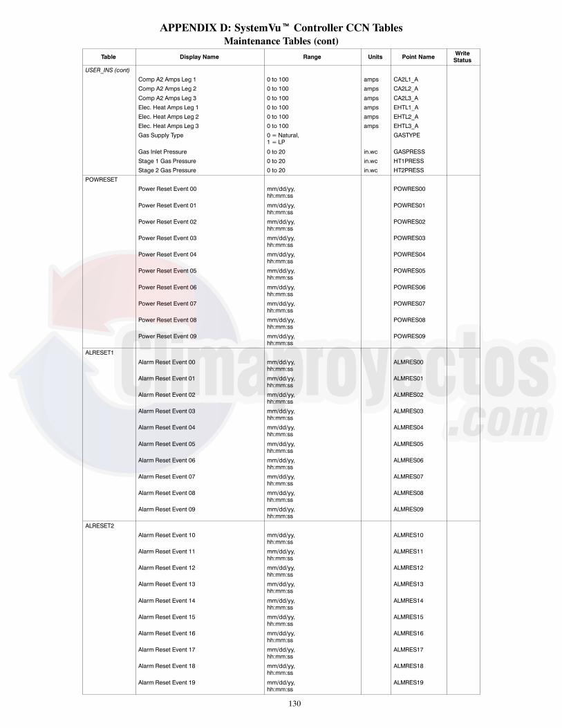
130
APPENDIX D: SystemVut Controller CCN TablesMaintenance Tables (cont)
Table Display Name Range Units Point Name WriteStatus
USER_INS (cont)Comp A2 Amps Leg 1 0 to 100 amps CA2L1_AComp A2 Amps Leg 2 0 to 100 amps CA2L2_A
Comp A2 Amps Leg 3 0 to 100 amps CA2L3_AElec. Heat Amps Leg 1 0 to 100 amps EHTL1_AElec. Heat Amps Leg 2 0 to 100 amps EHTL2_AElec. Heat Amps Leg 3 0 to 100 amps EHTL3_AGas Supply Type 0 = Natural,
1 = LPGASTYPE
Gas Inlet Pressure 0 to 20 in.wc GASPRESSStage 1 Gas Pressure 0 to 20 in.wc HT1PRESSStage 2 Gas Pressure 0 to 20 in.wc HT2PRESS
POWRESETPower Reset Event 00 mm/dd/yy,
hh:mm:ssPOWRES00
Power Reset Event 01 mm/dd/yy,hh:mm:ss
POWRES01
Power Reset Event 02 mm/dd/yy,hh:mm:ss
POWRES02
Power Reset Event 03 mm/dd/yy,hh:mm:ss
POWRES03
Power Reset Event 04 mm/dd/yy,hh:mm:ss
POWRES04
Power Reset Event 05 mm/dd/yy,hh:mm:ss
POWRES05
Power Reset Event 06 mm/dd/yy,hh:mm:ss
POWRES06
Power Reset Event 07 mm/dd/yy,hh:mm:ss
POWRES07
Power Reset Event 08 mm/dd/yy,hh:mm:ss
POWRES08
Power Reset Event 09 mm/dd/yy,hh:mm:ss
POWRES09
ALRESET1
Alarm Reset Event 00 mm/dd/yy,hh:mm:ss
ALMRES00
Alarm Reset Event 01 mm/dd/yy,hh:mm:ss
ALMRES01
Alarm Reset Event 02 mm/dd/yy,hh:mm:ss
ALMRES02
Alarm Reset Event 03 mm/dd/yy,hh:mm:ss
ALMRES03
Alarm Reset Event 04 mm/dd/yy,hh:mm:ss
ALMRES04
Alarm Reset Event 05 mm/dd/yy,hh:mm:ss
ALMRES05
Alarm Reset Event 06 mm/dd/yy,hh:mm:ss
ALMRES06
Alarm Reset Event 07 mm/dd/yy,hh:mm:ss
ALMRES07
Alarm Reset Event 08 mm/dd/yy,hh:mm:ss
ALMRES08
Alarm Reset Event 09 mm/dd/yy,hh:mm:ss
ALMRES09
ALRESET2Alarm Reset Event 10 mm/dd/yy,
hh:mm:ssALMRES10
Alarm Reset Event 11 mm/dd/yy,hh:mm:ss
ALMRES11
Alarm Reset Event 12 mm/dd/yy,hh:mm:ss
ALMRES12
Alarm Reset Event 13 mm/dd/yy,hh:mm:ss
ALMRES13
Alarm Reset Event 14 mm/dd/yy,hh:mm:ss
ALMRES14
Alarm Reset Event 15 mm/dd/yy,hh:mm:ss
ALMRES15
Alarm Reset Event 16 mm/dd/yy,hh:mm:ss
ALMRES16
Alarm Reset Event 17 mm/dd/yy,hh:mm:ss
ALMRES17
Alarm Reset Event 18 mm/dd/yy,hh:mm:ss
ALMRES18
Alarm Reset Event 19 mm/dd/yy,hh:mm:ss
ALMRES19

131
APPENDIX D: SystemVut Controller CCN TablesService Config Tables
Table Name Display Name Range Units Point Name Default
TOUCH
Equip Sys Touch Active enum ETST_ACT
Equipment Touch SPT _F ETSPT
Equipment Touch RH % ETSPRH
System Touch Temp Value _F STST_NET
System Touch SPRH Value % STRH_NET
ET ST Aggregated SPT _F ETSTSPT
ET ST Aggregated SPRH % ETSTSPRH
UNIT_CFG
Unit Startup Delay 10 to 600 sec STARTDLY 30
Auxiliary vent type 1 VENTTYPE
Unit Control Type 0 = Thermostat,1 = Space Sensor,2 = RAT Control
CTRLTYPE 0=TSTAT
Thermostat Hardware Type 0 = 2 Stage Conventional,1 = 2 Stage Digital,2 = 3 Stage Conventional,3 = 3 Stage Digital
STATTYPE 2=CONV 3C2H
Tstat Adaptive Staging Yes/No ADPTSTAT Yes
Change Filter Timer 0 to 9999 hours FILTLIFE 600
Test Inactivity Time Out 0 = Disabled,1 = 30 Minutes,2 = 1 Hour,3 = 2 Hours,4 = 4 Hours,5 = 8 Hours,6 = 12 Hours
TEST_ITO 4=4 hours
CCH Max Temperature 40 to 90 ° F CCHMAXT 65
Std Barometric Pressure 13 to 35 in.Hg STD_BARP 29.92
Linkage Stage inc. time 60 to 600 sec LSTAGINC 180
Unit’s Maximum SAT 130 to 210 ° F UMAX_SAT 200
Auto Clr SAT Limit Fault Yes/No SATLACLR No
Adaptive Temp Comp Start Enable/Disable TCS_CFG Yes
User TCS Start bias time 0 to 180 min TCSUBIAS 0
SIOB 1 Enabled Yes/No SIOB1_EN
Compressor A1 Enabled Enable/Disable CMPA1_EN
Compressor A2 Enabled Enable/Disable CMPA2_EN
Compressor AL Enabled Enable/Disable CMPAL_EN
Compressor A1 Shutdown Enable/Disable SDWN_A1
Compressor A2 Shutdown Enable/Disable SDWN_A2
cmp Loader Shutdown Enable/Disable SDWN_ALD
DMD_CFG
Low Cool Demand On ---1 to 2 ° F DMDLCON 0.5
Medium Cool Demand On 0.5 to 20 ° F DMDMCON 1
High Cool Demand On 0.5 to 20 ° F DMDHCON 2
Low Cool Demand Off --- 1 to 2 ° F DMDLCOFF ---0.5
Cool Demand Level Up ---2 to 2 ^F/min CDMD_LUP ---0.2
Low Heat Demand On ---1 to 2 ° F DMDLHON 0.5
High Heat Demand On 0.5 to 20 ° F DMDHHON 2
Low Heat Demand Off --- 1 to 2 ° F DMDLHOFF ---0.5
Heat Demand Level Up ---2 to 2 ^F/min HDMD_LUP ---0.2
Space Demand Time Guard1 60 to 600 sec TDMD_TG1 180
Space Demand Time Guard2 0 to 600 sec TDMD_TG2 300
Space Demand Time Guard3 5 to 120 min TDMD_TG3 10
COOL DMD Offset level 1 0 to 99 ° F CLDOLEV1
COOL DMD Offset level 2 0 to 99 ° F CLDOLEV2
COOL DMD Offset level 3 0 to 99 ° F CLDOLEV3
Heat DMD Offset level 1 0 to 99 ° F HTDOLEV1
Heat DMD Offset level 2 0 to 99 ° F HTDOLEV2
Heat DMD Offset level 3 0 to 99 ° F HTDOLEV3

132
APPENDIX D: SystemVut Controller CCN TablesService Config Tables (cont)
Table Name Display Name Range Units Point Name DefaultINPUTCFG
HumidistatStatus Channel 0 = None,1 = MBB DI12,2 = MBB DI13,3 = MBB DI14,4 = MBB DI02,5 = MBB DI04,6 = SIOB DI01
HUMDCHAN
Filter Status Sw Channel 0 = None,1 = MBB DI12,2 = MBB DI13,3 = MBB DI14,4 = MBB DI02,5 = MBB DI04,6 = SIOB DI01
FILTCHAN 0=None
Remote Occupancy Channel 0 = None,1 = MBB DI12,2 = MBB DI13,3 = MBB DI14,4 = MBB DI02,5 = MBB DI04,6 = SIOB DI01
RMOCCHAN 0=None
Remote Shutdown Channel 0 = None,1 = MBB DI12,2 = MBB DI13,3 = MBB DI14,4 = MBB DI02,5 = MBB DI04,6 = SIOB DI01
ROFFCHAN 0=None
COFS Assigned Channel 0 = None,1 = MBB DI12,2 = MBB DI13,3 = MBB DI14,4 = MBB DI02,5 = MBB DI04,6 = SIOB DI01
COFSCHAN 0=None
IAQ override sw channel 0 = None,1 = MBB DI12,2 = MBB DI13,3 = MBB DI14,4 = MBB DI02,5 = MBB DI04,6 = SIOB DI01
IAQOCHAN 0=None
General Status Channel 0 = None,1 = MBB DI12,2 = MBB DI13,3 = MBB DI14,4 = MBB DI02,5 = MBB DI04,6 = SIOB DI01
GEN_CHAN 0=None
Enthalpy Sw Channel 0 = None,1 = MBB DI12,2 = MBB DI13,3 = MBB DI14,4 = MBB DI02,5 = MBB DI04,6 = SIOB DI01
ENTHCHAN 0=None
IAQ Assigned Channel 0 = None,1 = MBB AI06,2 = MBB AI07,3 = MBB AI08,4 = SIOB AI10
IAQ_CHAN 0: no FIOP1: FIOP
OAQ Assigned Channel 0 = None,1 = MBB AI06,2 = MBB AI07,3 = MBB AI08,4 = SIOB AI10
OAQ_CHAN 0=None
OARH Assigned Channel 0 = None,1 = MBB AI06,2 = MBB AI07,3 = MBB AI08,4 = SIOB AI10
OARHCHAN 0: no Enthalpy FIOP3: Enthalpy FIOP
RARH Assigned Channel 0 = None,1 = MBB AI06,2 = MBB AI07,3 = MBB AI08,4 = SIOB AI10
RARHCHAN 0=None
SPRH Assigned Channel 0 = None,1 = MBB AI06,2 = MBB AI07,3 = MBB AI08,4 = SIOB AI10
SPRHCHAN
OACFM Assigned Channel 0 = None,1 = MBB AI06,2 = MBB AI07,3 = MBB AI08,4 = SIOB AI10
OCFMCHAN
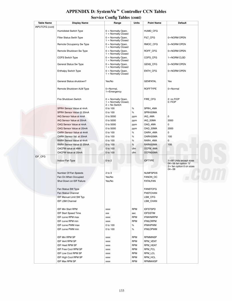
133
APPENDIX D: SystemVut Controller CCN TablesService Config Tables (cont)
Table Name Display Name Range Units Point Name Default
INPUTCFG (cont)
Humidistat Switch Type 0 = Normally Open,1 = Normally Closed
HUMD_CFG
Filter Status Swith Type 0 = Normally Open,1 = Normally Closed
FILT_CFG 0=NORM OPEN
Remote Occupancy Sw Type 0 = Normally Open,1 = Normally Closed
RMOC_CFG 0=NORM OPEN
Remote Shutdown Sw Type 0 = Normally Open,1 = Normally Closed
ROFF_CFG 0=NORM OPEN
COFS Switch Type 0 = Normally Open,1 = Normally Closed
COFS_CFG 1=NORM CLSD
General Status Sw Type 0 = Normally Open,1 = Normally Closed
GENS_CFG 0=NORM OPEN
Enthalpy Switch Type 0 = Normally Open,1 = Normally Closed
ENTH_CFG 0=NORM OPEN
General Status shutdown? Yes/No GENFATAL Yes
Remote Shutdown ALM Type 0=Normal,1=Emergency
ROFFTYPE 0=Normal
Fire Shutdown Switch 0 = Normally Open,1 = Normally Closed,2 = No Switch
FIRE_CFG 2: no FIOP0: FIOP
SPRH Sensor Value at 4mA 0 to 100 % SPRH_4MA
SPRH Sensor Value @ 20mA 0 to 100 % SPRH20MA
IAQ Sensor Value at 4mA 0 to 5000 ppm IAQ_4MA 0
IAQ Sensor Value at 20mA 0 to 5000 ppm IAQ_20MA 2000
OAQ Sensor Value at 4mA 0 to 5000 ppm OAQ_4MA 0
OAQ Sensor Value at 20mA 0 to 5000 ppm OAQ_20MA 2000
OARH Sensor Value at 4mA 0 to 100 % OARH_4MA 0
OARH Sensor Val. at 20mA 0 to 100 % OARH20MA 100
RARH Sensor Value at 4mA 0 to 100 % RARH_4MA 0
RARH Sensor Value @ 20mA 0 to 100 % RARH20MA 100
OACFM value at 4MA 0 to 100 cfm OCFM_4MA
OACFM Value at 20mA 0 to 100 cfm OCFM20MA
IDF_CFG
Indoor Fan Type 0 to 2 IDFTYPE 1=All Units except sizes04---06 fan option “0”2= fan option 0 on sizes04---06
Number Of Fan Speeds 2 to 3 NUMFSPDS
Fan On When Occupied Yes/No FANON_OC
Shut Down on IDF Failure Yes/No FATALFAN
Fan Status SW Type FANSTCFG
Fan Status Channel FNSTCHAN
IDF Manual Limit SW Typ LSM_CFG
IDF LSM Channel LSM_CHAN
IDF Min Start RPM xxxx RPM IDFSTSPD
IDF Start Speed Time xxx sec IDFSSTIM
IDF curve RPM max xxxx RPM IFMHNIRPM
IDF curve RPM min xxxx RPM IFMLORPM
IDF curve PWMmax 0 to 100 % IFMHIPWM
IDF curve PWMmin 0 to 100 % IFMLOPWM
IDF Min RPM SP xxxx RPM RPMMINSP
IDF Vent RPM SP xxxx RPM RPM_VENT
IDF Heat RPM SP xxxx RPM RPM_HEAT
IDF Free Cool RPM SP xxxx RPM RPM_FCL
IDF Low Cool RPM SP xxxx RPM RPM_LCL
IDF High Cool RPM SP xxxx RPM RPM_HCL
IDF Max RPM SP xxxx RPM RPMMAXSP

134
APPENDIX D: SystemVut Controller CCN TablesService Config Tables (cont)
Table Name Display Name Range Units Point Name Default
COOL_CFG
Number of Cooling Stages 0 to 3 NUMCSTGS 3
Low Cool Compressor 1 to 2 LC_COMP 1
1 = Compressor A1
2 = Compressor A2
Compressor Min On Time 180 to 600 sec C_MINON 300
Compressor Min Off Time 120 to 600 sec C_MINOFF 180
Runtime to Reset Strikes 120 to 999 sec MIN_ON_S 300
Cool Stage Increase Time 120 to 999 sec CSTAGINC 450
Cooling SAT Trend Level --- 1 to 1 ^F/min SAT_TLC ---0.2
Cool Min SAT Upper Level 35.0 to 65.0 ° F SATMIN_H 56 (sizes 04---06)53 (sizes 07---12)56 (sizes 14---26)
Cool Min SAT Lower Level 35.0 to 65.0 ° F SATMIN_L 46 (sizes ---4--- 06)42 (sizes 07---12)46 (sizes 14---26)
Cooling Fan---off Delay 0 to 600 sec COOL_FOD 75
Circuit A Lockout Temp ---20 to 75 ° F OATLCMPA 0: no Economizer FIOP40: Economizer FIOP
Low Ambient Temperature 0---80 ° F LA_TEMP 66
Low Cool lockout Temp ---20 to 60 ° F LCLOCKSP 10 (sizes 04---06)30 (sizes 07---12)40 (sizes 14---26)
Medium Cool lockout Temp ---20 to 60 ° F MCLOCKSP 20 (sizes 07---12)30 (sizes 14---26)
Humidimizer Lockout Temp ---20 to 75 ° F OATLHUMZ
Space RH Deadband 0 % SPRH_DB
Low Refrig Charge Level 0 to 150 psi LOCHARGE 50
Low Charge Disable Temp ---40 to 50 ° F LOCH_LOT 10
CirA High Pressure Limit 400 to 700 psig HIPLIM_A 600
Low Discharge Level 5 to 20 ° F SDTLEV 7
Minimum pressure ratio 0 to 5 MINPSI_R 1.35
Suction OK Temperature 10 to 50 ° F SSTOK 18
Low Suction Level 1 Temp 10 to 50 ° F SSTLEV1 20
Low Suction Level 2 Temp 5 to 50 ° F SSTLEV2 15
Low Suction Level 3 Temp 0 to 50 ° F SSTLEV3 10
Delay On Low SST Check 0 to 300 sec SSTCKDLY 0
Comp Level 2 Diag Delay 1 to 99 sec CDDTLEV2 15 (sizes 04---12)40 (sizes 14---26)
Diag Comp Unexpected Off Enable/Disable CD_UEOFF Enable
Circuit Stuck On Diag. Enable/Disable DCKTOFF Enable
Min discharge change 0 to 99 psi MDP_DISA 11 (sizes 04---12)17 sizes 14---26)
Min Suction change 0 to 99 psi MDP_SUCA 4 (sizes 04---06)6.5 (size 07)8 (size 08)7 (sizes 09---12)14 (sizes 14---26)
CirA P.Ratio off change ---1 to 1 OFFPR_A ---0.2 (sizes 04---07, 09---14)---0.3 (sizes 08, 17---26)

135
APPENDIX D: SystemVut Controller CCN TablesService Config Tables (cont)
Table Name Display Name Range Units Point Name DefaultODF_CFG
Number of ODF Outputs 0 to 3 NUM_ODF 1 (sizes 04---06)2 (sizes 07,17, or 20)3 (sizes 08---14, 24---26)
ODF Relay Enabled OFR_ENODF High Cool Speed 0 to 1200 rpm ODFHCSPD 1000 (size 04)
1075 (sizes 05---06)550 (sizes 07---12)700 (sizes 14---17, 26)
ODF Low Cool Speed 0 to 1200 rpm ODFLCSPD 1000 (size 04)1075 (sizes 05---06)700 (sizes 07, 12, 24)600 (size 08)650 (size 09)800 (sizes 14, 17, 26)750 (size 20)
ODF Maximum Speed 0 to 1200 rpm ODFMAXSP 1000 (size 04)1075 (sizes 05---06)950 (sizes 07, 09)900 (size 08)1000 (sizes 12---26)
ODF Med Cool Speed 0 to 1200 rpm ODFMCSPD 1000 (size 04)1075 (sizes 05---06)950 (sizes 07, 09)900 (size 08)1000 (sizes 12---26)
ODF Minimum Speed 0 to 1200 rpm ODFMINSP 160Low Ambient Temperature 0 to 80 ° F LA_TEMP 66ODF Gain ---100 to 100 ODF_KC 50 (sizes 04---06)
1 (size 07)2 (sizes 08---12)1.8 (sizes 14---20)1.4 (sizes 24---26)
ODF anti---windup factor --- 100 to 100 ODF_NI 0.60ODF Integral Time ---100 to 100 ODF_TI 20 (sizes 04---12)
40 (sizes14---26)ODF Map Bias Term 1 ---200 to 200 ODFBIAS1 72.5 (sizes 04---06)
66.7 (size 07)--- 44.55 (sizes 08---12)10 (sizes 14---20)72.5 (sizes 24---26)
ODF Map Bias Term 2 ---200 to 200 ODFBIAS2 100.98 (sizes 04---06)95.2 (size 07)80.59 (sizes 08---12)35.3 (sizes 14---20)100.98 (sizes 24---26)
ODF Map Bias Term 3 ---200 to 200 ODFBIAS3 20.93 (sizes 04---06))0 (sizes 07, 14---20)65.29 (sizes 08---12)114.74 (sizes 24---26)
ODF Fan Switch Point 1 --- 100 to 100 ODFPIUP1 3.68 (size 07)3.4 (sizes 08---12)4.84 (sizes 14---20)1.58 (sizes 24---26)
ODF Fan Switch Point 2 --- 100 to 100 ODFPIUP2 17.1 (size 07)9.06 (sizes 08---12)22.3 (sizes 14---20)
ODF Fans Switch Point 3 --- 100 to 100 ODFPIUP3 100 (sizes 07, 14---20)19.76 (sizes 08---12)20.93 (sizes 24---26)
ODF Proportional ctrl Pr --- 100 to 100 ODFPR_KC 1.4 (sizes 04---06)25 (sizes 07---12)50 (sizes 14---26)
ODF Map Slope Term 1 ---100 to 100 ODFSLPE1 55.33 (sizes 04---06)25.3 (size 07)60.09 (sizes 08---12)31 (sizes 14---20)55.33 (sizes 24---26)
ODF Map Slope Term 2 ---100 to 100 ODFSLPE2 19.07 (sizes 04---06)9 (size 07)18.69 (sizes 08---12)9.6 (sizes 14---20)19.07 (sizes 24---26)
ODF Map Slope Term 3 ---100 to 100 ODFSLPE3 8.85 (sizes 04---06)1 (sizes 07, 14---20)9.34 (sizes 08---12)8.85 (sizes 24---26)
Low Ambient Dehum Lev 1 0 to 80 ° F LAHTEMP1Low Ambient Dehum Lev 2 0 to 61 ° F LAHTEMP2Low Ambient Dehum Lev 3 0 to 55 ° F LAHTEMP3LA Dehum SDT SP Lev 1 0 to 93 ° F LHSDTSP1LA Dehum SDT SP Lev 2 0 to 93 ° F LHSDTSP2LA Dehum SDT SP Lev 3 0 to 104 ° F LHSDTSP3

136
APPENDIX D: SystemVut Controller CCN TablesService Config Tables (cont)
Table Name Display Name Range Units Point Name Default
HEATCFG
Type of Heat Installed 0=Electric1=Gas
HEATTYPE 0 (50 series)1 (48 series)
Number of Heating Stages 0 to 2 NUMHSTGS 1 (50 Series, sizes 04---06low or medium heat)2 (all except below):0 (50 series without FIOPheat),1 (50 series, sizes 07---14and low heat),1 (50 series, sizes 07---12and medium heat)
Heat Minimum On Time 60 to 600 sec H_MINON 120
Heat Minimum Off Time 60 to 600 sec H_MINOFF 120
Heat Stage Increase Time 120 to 999 sec HSTAGINC 450
Heating SAT Trend Level --- 1 to 1 ^F/min SAT_TLH 0.2
Heat Max SAT Lower Level 85 to 200 ° F SATMAX_L 140
Heat Max SAT Upper Level 85 to 200 ° F SATMAX_H 160
Heating Fan---off Delay 10 to 600 sec HEAT_FOD 30 (50 series)45 (48 series)
Heating Lockout Temp 40 to 125 ° F OATLHEAT 75
SAT Heat Mode Sensing Enable/Disable SAT_HEAT Disable
No IGC IFO input Timeout 0 to 60 min NO_IGCTM 5
Pre---Heat HX without IDF? Enable/Disable PREHT_HX Disable
Pre---Heat Fan On Delay 0 to 120 sec PREHT_TM 30
SupplyAirTemperingEnable Yes/No SATEMPEN
SA tempering Set point xx ° F SATEMPSP
Max OAT for SA tempering 0 ° F OATSTEMP
ECON_CFG
Economizer Installed? Yes/No ECONO No: no FIOPYes: FIOP
Econ Max Damper Position 0 to 100 % DAMPMAX 100
Economizer Travel Time 5 to 300 sec ECONOTRV 150
IDF Max RPM SP xxxx RPM RPMMAXSP
Econ Min at Max Fanspeed 0 to 100 % MINP_MAX 30
Min Pos --- User Speed 1 0 to 100 % MP_USPD1 0
Min Pos --- User Pos 1 0 to 100 % MP_UPOS1 0
Min Pos --- User Speed 2 0 to 100 % MP_USPD2 0
Min Pos --- User Pos 2 0 to 100 % MP_UPOS2 0
Min Pos --- User Speed 3 0 to 100 % MP_USPD3 0
Min Pos --- User Pos 3 0 to 100 % MP_UPOS3 0
Low Free Cool SAT Setpnt 40 to 80 ° F LCSASP 65
High FreeCool SAT Setpnt 40 to 80 ° F HCSASP 55
Free Cooling Max OAT 0 to 90 ° F MAXFREET 65
Free Cooling Min Temp ---30 to 70 ° F MINFREET 0
Diff. Dry Bulb Control Enable/Disable DIFFBULB Disable
Diff. Dry Bulb Deadband 0 to 20 ° F OATRATDB 3
Max Enthalpy OA limit 1 to 99 Btu/lb FREEMAXE 28
Diff. Enthalpy Control Enable/Disable DIFFENTH Disable
Enthalpy Cross Deadband 0 to 20 Btu/lb OAERAEDB 2
ECONO PID --- KP 0.00 to 99.90 ECONO_P 2.5
ECONO PID --- KI 0.00 to 99.90 ECONO_I 0.12
ECONO PID --- KD 0.00 to 99.90 ECONO_D 1
ECONO PID --- RATE 10 to 180 sec ECONO_DT 15
When to Unocc Free Cool? 0 to 2 UFC_CFG 1=PreOcc
0 = Disabled
1 = Pre---Occupancy
2 = Unoccupied
UFC PreOcc Time 1 to 999 min UFCTIME 120
Unocc Free Cool Low Temp ---30 to 70 ° F OATLUFC 50
PE Stage 1 at Max speed 0 to 100 % PE1_PMAX 40
PE1 Relay Channel 0=NONE,1=MBB RLY11,2=MBB RLY06
PE1_CHAN 0: no FIOP2: FIOP

137
APPENDIX D: SystemVut Controller CCN TablesService Config Tables (cont)
Table Name Display Name Range Units Point Name Default
ECON_CFG (cont)
PE Turn Off Dead band 0 to 100 % PE_OFFDB 5
PE2 Relay Channel 0=NONE,1=MBB RLY11,2=MBB RLY06
PE2_CHAN 0=None
PE Stage 2 at max speed 0 to 100 % PE2_PMAX 75
T24 Heat/Cool End Delay 0 to 60 min T24CHDLY 25
T24Econ Min Move for SAT 10 to 20 % T24ECSTS 10
Damper SAT deadband 0 to 20 ° F T24SATDB 12
T24 Min Diff in RAT---OAT 5 to 20 ° F T24RATDF 15
T24 Test Minimum Pos 0 to 100 % T24TSTMN 15
T24 Test Maximum Pos 0 to 100 % T24TSTMX 85
IAQ_CFGAnalog Input IAQ Control 0 to 3 IAQANCFG 0: no FIOP
1: FIOP0 = No IAQ1 = DCV2 = IAQ Override3 = MINPOS ControlIAQ Position at Max Fan 0 to 100 % IAQMINP 10AQ Differential Low 0 to 5000 ppm DAQ_LOW 100AQ Differential High 0 to 5000 ppm DAQ_HIGH 700
IAQ Preoccupancy Purge Yes/No IAQPURGE YesIAQ Purge Pos at Max IDF 0 to 100 % IAQPMAX 40Preocc Purge Lockout OAT 0 to 70 ° F IAQP_LA 50Preocc Purge Duration 5 to 120 min IAQPTIME 15
IAQ Sensor Value at 4mA 0 to 5000 ppm IAQ_4MA 0
IAQ Sensor Value at 20mA 0 to 5000 ppm IAQ_20MA 2000
OAQ Sensor Value at 4mA 0 to 5000 ppm OAQ_4MA 0
OAQ Sensor Value at 20mA 0 to 5000 ppm OAQ_20MA 2000
IAQ override sw channel 0 to 6 IAQOCHAN
IAQ Override Switch Type Yes/No IAQOSCFG
USER_INS
Supply Voltage Leg 1 0 to 700 volts L1VOLTS
Supply Voltage Leg 2 0 to 700 volts L2VOLTS
Supply Voltage Leg 3 0 to 700 volts L3VOLTS
Comp A1 Amps Leg 1 0 to 100 Amps CA1L1_A
Comp A1 Amps Leg 2 0 to 100 Amps CA1L2_A
Comp A1 Amps Leg 3 0 to 100 Amps CA1L3_A
Comp A2 Amps Leg 1 0 to 100 Amps CA2L1_A
Comp A2 Amps Leg 2 0 to 100 Amps CA2L2_A
Comp A2 Amps Leg 3 0 to 100 Amps CA2L3_A
Elec. Heat Amps Leg 1 0 to 100 Amps EHTL1_A
Elec. Heat Amps Leg 2 0 to 100 Amps EHTL2_A
Elec. Heat Amps Leg 3 0 to 100 Amps EHTL3_A
Gas Supply Type 0 = Natural,1 = LP
GASTYPE
GAS INLET PRESSURE 0 to 20 IN_HG_OF_KPAG GASPRESS
STAGE 1 GAS PRESSURE 0 to 20 IN_HG_OF_KPAG HT1PRESS
STAGE 2 GAS PRESSURE 0 to 20 IN_HG_OF_KPAG HT2PRESS

138
APPENDIX D: SystemVut Controller CCN TablesService Config Tables (cont)
Table Name Display Name Range Units Point Name Default
ALM_CFG
ALM Relay Assigned Chan 0 to 2 ALM_CHAN 1=MBB RLY11
0 = None
1 = MBB RLY11
2 = MBB RLY06
Thermostat Alerts Yes/No TSTAT_AL Yes
Hardware failures Alerts Yes/No HW_AL Yes
SAT/RAT Sensor Alerts Yes/No SATRATAL Yes
OAT Thermistor Alerts Yes/No OATRL_AL Yes
Space Sensors Alerts Yes/No SPACE_AL Yes
Transducer Sensor Alerts Yes/No TRANS_AL Yes
RH sensor failure Alert Yes/No RHS_AL Yes
Air Quality CO2 Alerts Yes/No CO2S_AL Yes
OACFM Alarm Relay Yes/No OACFM_AL
Economizer Alerts Yes/No ECON_AL Yes
Dirty Filter Alerts Yes/No FILT_AL Yes
General Status Alerts Yes/No GENS_AL Yes
Refrig Circuit Alerts Yes/No CKT_AL Yes
Compressor Alerts Yes/No COMP_AL Yes
Heating failure Alerts Yes/No HEAT_AL Yes
Indoor Fan Alerts Yes/No FAN_AL Yes
Relay on Active IOBA Yes/No IOBFA_AL
Relay on Active Faults Yes/No FAULT_AL Yes
ZSENSCFG
Zone Sensor 1 Address 0 to 255 ZSADDR1 255
Zone Sensor 2 Address 0 to 255 ZSADDR2 255
Zone Sensor 3 address 0 to 255 ZSADDR3 255
Zone Sensor 4 address 0 to 255 ZSADDR4 255
Zone Sensor 5 address 0 to 255 ZSADDR5 255
ZS Force Unoccup enable No ZSFUNEN No
ZS Force unocc wt delay No ZSFUNWT No
Zone sensor poll rate 1 to 100 sec ZSPOLLRT 5
ZS TLO Cont Enable No ZSTLOEN No
ZS TLO set during occ No ZSTLSOC No
Zone sensor UI Mode 1=Dual Offsets ZSUIM 1=Dual Offsets
Zone sensor unit 0=degrees F ZSUNIT 0=degrees F
TOUCHCFG
System Touch Device Inst 0 to 4194303 DEVST
System Touch Poll Rate 10 to 60 sec POLLST
System Touch AI for SPT 0 to 9999 AISTSPT
System Touch AI for SPRH 0 to 9999 AISTSPRH
TRIM
OAT Sensor Trim Offset --- 10 to 10 ° F OAT_TRIM 0
RAT Sensor Trim Offset --- 30 to 30 ° F RAT_TRIM 0
FST Sensor Trim Offset --- 10 to 10 ° F FST_TRIM 0
SPT Sensor Trim Offset --- 30 to 30 ° F SPT_TRIM 0
SPTO Sensor Offset Trim ---1 to 1 ° F SPTOTRIM 0
SPRH Sensor Trim Offset --- 15 to 15 % SPRHTRIM
IAQ sensor trim offset --- 200 to 200 ppm IAQ_TRIM 0
OAQ Sensor Trim Offset --- 200 to 200 ppm OAQ_TRIM 0
OARH Sensor Trim Offset --- 15 to 15 % OARHTRIM 0
RARH Sensor Trim Offset --- 15 to 15 % RARHTRIM 0
Cir.A SSP Sensor Trim ---50 to 50 psig SSPATRIM 0
Cir.A SDP Sensor Trim ---50 to 50 psig SDPATRIM 0
Econ Fdback Trim Offset --- 15 to 15 % EC1DTRIM 0
OACFM sensor trim offset --- 10 to 10 cfm OCFMTRIM 0
DISPLAY
Metric Display Yes/No DISPUNIT No
Display Language Select 0=English,1=Spanish,2=French,3=Portuguese
LANGUAGE 0=English
LCD Contrast Adjustment 1 to 10 LCD_CONT 5
User Password Protection Enable/Disable PASS_EBL Enable
User Password 0 to 9999 PASSWORD 1111
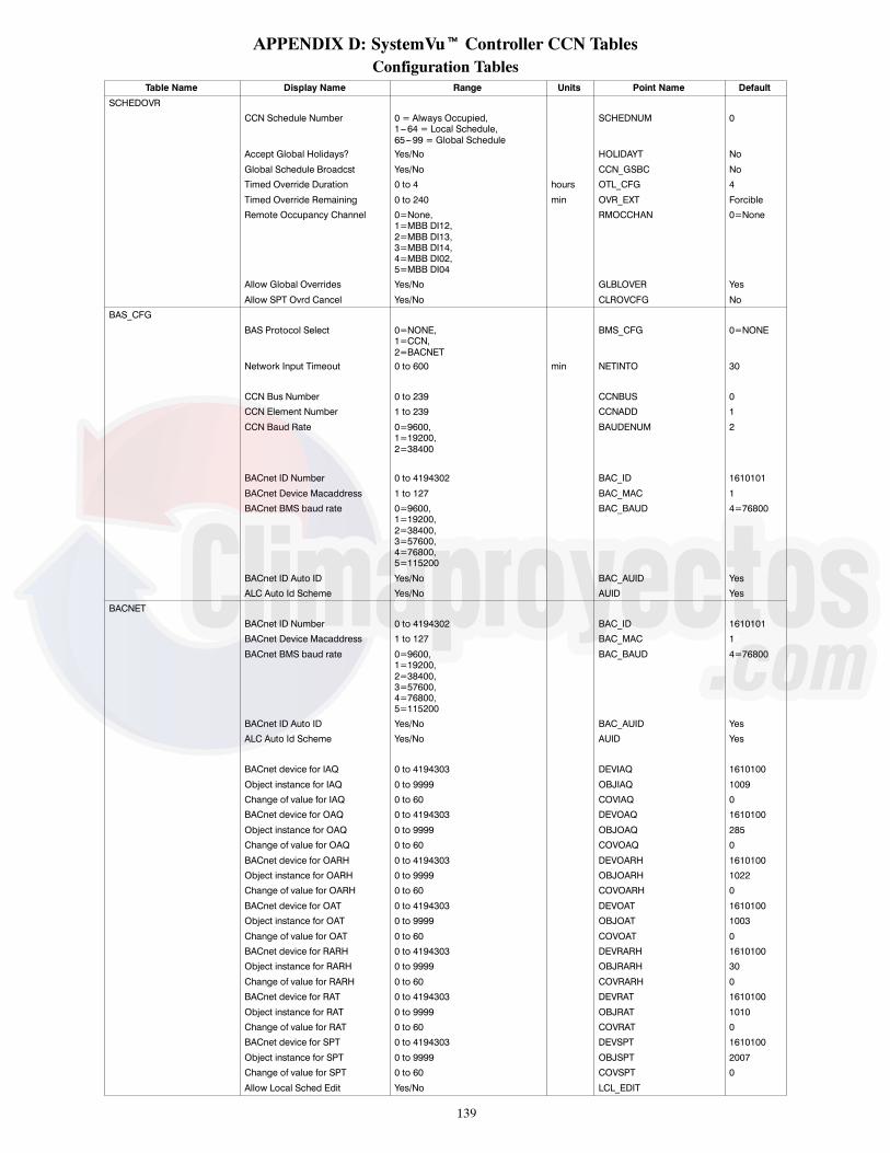
139
APPENDIX D: SystemVut Controller CCN TablesConfiguration Tables
Table Name Display Name Range Units Point Name Default
SCHEDOVR
CCN Schedule Number 0 = Always Occupied,1--- 64 = Local Schedule,65---99 = Global Schedule
SCHEDNUM 0
Accept Global Holidays? Yes/No HOLIDAYT No
Global Schedule Broadcst Yes/No CCN_GSBC No
Timed Override Duration 0 to 4 hours OTL_CFG 4
Timed Override Remaining 0 to 240 min OVR_EXT Forcible
Remote Occupancy Channel 0=None,1=MBB DI12,2=MBB DI13,3=MBB DI14,4=MBB DI02,5=MBB DI04
RMOCCHAN 0=None
Allow Global Overrides Yes/No GLBLOVER Yes
Allow SPT Ovrd Cancel Yes/No CLROVCFG No
BAS_CFG
BAS Protocol Select 0=NONE,1=CCN,2=BACNET
BMS_CFG 0=NONE
Network Input Timeout 0 to 600 min NETINTO 30
CCN Bus Number 0 to 239 CCNBUS 0
CCN Element Number 1 to 239 CCNADD 1
CCN Baud Rate 0=9600,1=19200,2=38400
BAUDENUM 2
BACnet ID Number 0 to 4194302 BAC_ID 1610101
BACnet Device Macaddress 1 to 127 BAC_MAC 1
BACnet BMS baud rate 0=9600,1=19200,2=38400,3=57600,4=76800,5=115200
BAC_BAUD 4=76800
BACnet ID Auto ID Yes/No BAC_AUID Yes
ALC Auto Id Scheme Yes/No AUID Yes
BACNET
BACnet ID Number 0 to 4194302 BAC_ID 1610101
BACnet Device Macaddress 1 to 127 BAC_MAC 1
BACnet BMS baud rate 0=9600,1=19200,2=38400,3=57600,4=76800,5=115200
BAC_BAUD 4=76800
BACnet ID Auto ID Yes/No BAC_AUID Yes
ALC Auto Id Scheme Yes/No AUID Yes
BACnet device for IAQ 0 to 4194303 DEVIAQ 1610100
Object instance for IAQ 0 to 9999 OBJIAQ 1009
Change of value for IAQ 0 to 60 COVIAQ 0
BACnet device for OAQ 0 to 4194303 DEVOAQ 1610100
Object instance for OAQ 0 to 9999 OBJOAQ 285
Change of value for OAQ 0 to 60 COVOAQ 0
BACnet device for OARH 0 to 4194303 DEVOARH 1610100
Object instance for OARH 0 to 9999 OBJOARH 1022
Change of value for OARH 0 to 60 COVOARH 0
BACnet device for OAT 0 to 4194303 DEVOAT 1610100
Object instance for OAT 0 to 9999 OBJOAT 1003
Change of value for OAT 0 to 60 COVOAT 0
BACnet device for RARH 0 to 4194303 DEVRARH 1610100
Object instance for RARH 0 to 9999 OBJRARH 30
Change of value for RARH 0 to 60 COVRARH 0
BACnet device for RAT 0 to 4194303 DEVRAT 1610100
Object instance for RAT 0 to 9999 OBJRAT 1010
Change of value for RAT 0 to 60 COVRAT 0
BACnet device for SPT 0 to 4194303 DEVSPT 1610100
Object instance for SPT 0 to 9999 OBJSPT 2007
Change of value for SPT 0 to 60 COVSPT 0
Allow Local Sched Edit Yes/No LCL_EDIT

140
APPENDIX D: SystemVut Controller CCN TablesConfiguration Tables (cont)
Table Name Display Name Range Units Point Name Default
BRODEFS
CCN Broadcast Ack’er Yes/No CCNBCACK No
Global Schedule Broadcst Yes/No CCN_GSBC No
CCN Time Broadcast Yes/No CCNBC No
Broadcast OAT On Network Yes/No OATBC No
Broadcast OARH On Netwrk Yes/No OARHBC No
Broadcast OAQ On Network Yes/No OAQBC No
Broadcast IAQ On Network Yes/No IAQBC No
DST allowed? Enable/Disable DST_CFG Enable
DST Start Month 1=JANUARY,2=FEBRUARY,3=MARCH,4=APRIL,5=MAY,6=JUNE,7=JULY,8=AUGUST,9=SEPTEMBER,10=OCTOBER,11=NOVEMBER,12=DECEMBER
STARTM 3
DST Start Week 1 to 5 STARTW 2
DST Start Day 1=MONDAY,2=TUESDAY,3=WEDNESDAY,4=THURSDAY,5=FRIDAY,6=SATURDAY,7=SUNDAY
STARTD 7
DST Minutes to Add 0 to 90 min MINADD 60
DST Stop Month 1=JANUARY,2=FEBRUARY,3=MARCH,4=APRIL,5=MAY,6=JUNE,7=JULY,8=AUGUST,9=SEPTEMBER,10=OCTOBER,11=NOVEMBER,12=DECEMBER
STOPM 11
DST Stop Week 1 to 5 STOPW 1
DST Stop Day 1=MONDAY,2=TUESDAY,3=WEDNESDAY,4=THURSDAY,5=FRIDAY,6=SATURDAY,7=SUNDAY
STOPD 7
DST Minutes to Subtract 0 to 90 min MINSUB 60
Time in day to start DST 0 to 600 min DST_TOD 120
ALARMDEF
Alarm Routing Control 00000000 to 11111111 ALRM_CNT 11000000
Equipment Priority 0 to 7 EQP_TYPE 5
Comm Failure Retry Time 1 to 240 min RETRY_TM 10
Re---Alarm Time 1 to 255 min RE---ALARM 180
Alarm System Name up to 8 alphanum ALRM_NAM 48_50LC_
HOLIDAY
HOLDYxxS
MON Holiday Start Month 1 to 12 = January to December HD01STMN --- HD30STMN 0
DAY Holiday Start Day 1 to 31 HD01STDY --- HD30STDY 0
LEN Holiday Duration (days) 1 to 99 HD01LEN --- HD30LEN 0
(repeat up to xx=30 Holidays)
OCCDEFCS
OCCPC01S
Timed Override Remaining 0 to 240 min OVR_EXT Forcible
Period x DOW (MTWTFSSH) 00000000 to 11111111 DOWx 00000000
Occupied from hh:mm OCCTODx 00:00
Occupied to hh:mm UNOCTODx 00:00
(repeat up to x=8 periods)

141
APPENDIX D: SystemVut Controller CCN TablesSetpoint Table
Table Name Display Name Range Units Point Name Default
SET_PNT
Occupied Cool Setpoint 55 to 80 ° F OCSP 78
Occupied Heat Setpoint 55 to 80 ° F OHSP 68
Unoccupied Cool Setpoint 65 to 95 ° F UCSP 85
Unoccupied Heat Setpoint 40 to 80 ° F UHSP 60
Heat---Cool Setpoint Gap 2 to 10 ^F HCSP_GAP 5
SPT Offset Range (+/--- ) 0 to 5 ° F SPTO_RNG 5
Occupied SPRH Setpoint 0 to 100 % SPRH_OSP 55
Unoccupied SPRH Setpoint 0 to 100 % SPRH_USP 55
Control ID TableTable Name Display Name Range Units Point Name Default
CTLRID
Device Name: 48_50LC_
Description: text string
Location: text string
Software Part Number: CESR131651---XX---XX
Model Number: 2 to 10
Serial Number: 0 to 5
Reference Number: 0 to 5

142
APPENDIX E: BACnet* Points List
Point Name Type BACnetObject ID
Alias(CCN Point Name) BACnet Object Name
Actual Cooling Stages BMAV AV:194 actcstgs
Actual Heating Stages BMAV AV:46 acthstgs
Actual Indoor Fan speed BMAV AV:6 fanfb sf_vfd_feedback
Air Quality Differential BMAV AV:195 aq_diff
Alarm Display Info BMAV AV:14 alarm_info
Alarm Relay Reset Count BMAV AV:99 rs_alm
Alarm Relay Run Hours BMAV AV:49 hr_alm hour_alarm
Alarm Relay Starts BMAV AV:136 st_alm
Alarm Resets Count BMAV AV:137 st_alrst
Altitude in Feet BMAV AV:159 altitude
AQ Differential High BMAV AV:212 daq_high
AQ Differential Low BMAV AV:213 daq_low
AQP Offset BMAV AV:364 aqp_offs
BACKUP Preparation Time BMAV AV:336 bkpreptm
BACnet device for IAQ BMAV AV:8001 deviaq
BACnet device for OAQ BMAV AV:8002 devoaq
BACnet device for OARH BMAV AV:8004 devoarh
BACnet device for OAT BMAV AV:8003 devoat
BACnet device for RARH BMAV AV:8005 devrarh
BACnet device for RAT BMAV AV:8006 devrat
BACnet device for SPRH BMAV AV:8028 devsprh
BACnet device for SPT BMAV AV:8007 devspt
BACnet Device ID BMAV AV:188 bac_id
BACnet Device MAC address BMAV AV:189 bac_mac
Barometric Pressure BMAV AV:161 barp
Block Number in Master Zone BMAV AV:262 lnk_mzbk
Brightness Adjustment BMAV AV:165 brts_adj
CCH OAT Threshold BMAV AV:2 cch_max_t
CCHR1 HR Reset Count BMAV AV:294 rs_cchr1
CCHR1 Number of Starts BMAV AV:301 st_cchr1
Change of value for IAQ BMAV AV:8015 coviaq
Change of value for OAQ BMAV AV:8016 covoaq
Change of value for OARH BMAV AV:8018 covoarh
Change of value for OAT BMAV AV:8017 covioat
Change of value for RARH BMAV AV:8019 covrarh
Change of value for RAT BMAV AV:8020 covrat
Change of value for SPRH BMAV AV:8030 covsprh
Change of value for SPT BMAV AV:8021 covspt
Circuit A Pressure Ratio BMAV AV:204 cira_pr
Circuit A Saturated Discharge Temperature BMAV AV:295 sdt_a
Circuit A Suction Temp BMAV AV:339 sst_a
CMP A1 Loader Reset Count BMAV AV:7012 rs_aldr
CMP A1 Loader Run Hrs BMAV AV:7010 hr_aldr
CMP A1 Loader Starts BMAV AV:7011 st_aldr
Commanded IDF Speed BMAV AV:2027 fanspeed vfd_output
Comp A1 Reset Count BMAV AV:97 rs_a1
Comp A2 Reset Count BMAV AV:98 rs_a2
Compressor A1 Run Hrs BMAV AV:47 hr_a1 hour_a1
Compressor A1 Starts BMAV AV:134 st_a1
Compressor A1 strikes BMAV AV:192 a1strike
Compressor A1 Timeguard BMAV AV:162 timgd_a1
Compressor A2 Run Hrs BMAV AV:48 hr_a2 hour_a2
Compressor A2 Starts BMAV AV:135 st_a2
Compressor A2 Strikes BMAV AV:193 a2strike
Compressor A2 Timeguard BMAV AV:157 timgd_a2
Compressor Loader Timeguard BMAV AV:164 timg_ald
Compressor Min Off Time BMAV AV:202 c_minoff
Compressor Min On Time BMAV AV:203 c_minon
Contrast Adjustment BMAV AV:167 cntr_adj
Cool Demand BMAV AV:206 cool_dmd
Cool Demand Trend BMAV AV:205 cldtrend
COOL DMD Offset level 1 BMAV AV:400 cdlm_level1
COOL DMD Offset level 2 BMAV AV:401 cdlm_level2
COOL DMD Offset level 3 BMAV AV:402 cdlm_level3
* BACnet is a registered trademark of ASHRAE (American Society of Heating, Refrigerating and Air---Conditioning Engineers).

143
APPENDIX E: BACnet Points List (cont)
Point Name Type BACnetObject ID
Alias(CCN Point Name) BACnet Object Name
Cooling Fan---Off Delay BMAV AV:207 cool_fod
Cooling Liquid Valve Resets Count BMAV AV:455 rs_clv_a
Cooling Liquid Valve Run Hours BMAV AV:457 hr_clv_a
Cooling Liquid Valve Starts BMAV AV:459 st_clv_a
Cooling Required BMAV AV:257 lnk_creq
Cool Set Point in Effect BMAV AV:208 csp_eff effective_cooling
Cool Shed 1 demand band BMAV AV:6014 cooling_shed1
Cool Shed 2 demand band BMAV AV:6015 coolsh1 cooling_shed2
Cool Shed 3 demand band BMAV AV:6016 coolsh2 cooling_shed3
Cool Time Select Guard BMAV AV:40 coolsh3 cl_sel_timeguard
Crankcase Heater 1 Hours BMAV AV:242 hr_cchr1 hour_cchr1
Damper Actual Position BMAV AV:2022 damppos oa_dmpr_pos
Damper Commanded Pos BMAV AV:4 dmpr_cmd
Damper Max Position BMAV AV:185 dampmax
Damper Motor Reset Count BMAV AV:102 rs_damp
Damper Motor Run Hours BMAV AV:51 hr_damp hour_damp
Damper Motor Starts BMAV AV:139 st_damp
Damper Position BMAV AV:258 lnk_dpos
Damper Test Position BMAV AV:118 s_damper
Delay On Low SST Check BMAV AV:300 sstckdly
Demand Time Guard 1 BMAV AV:311 tdmd_tg1
Demand Time Guard 2 BMAV AV:186 tdmd_tg2
Demand Time Guard 3 BMAV AV:187 tdmd_tg3
Differential Temperature BMAV AV:78 oa_ra_diff_temp
Diffrential Enthalpy BMAV AV:77 oa_ra_diff_enth
Econo Actual Position BMAV AV:211 dampact
Economizer Travel Time BMAV AV:226 eceonotrv
Effective Deadband BMAV AV:6007 effdb effective_deadband
Effective Demand Temperature BMAV AV:163 temp_eff
Effective Zone Setpoint BMAV AV:6006 effsp effective_setpoint
Fan Supply Air Temp BMAV AV:10 fst idf_sa_temp
FBD Low Set Point BMAV AV:438 fbdlosp
FBD SAT Min value BMAV AV:436 fbdh_sat
FBD SST Min value BMAV AV:437 fdbh_sst
Filter Change Time BMAV AV:2019 filter_service_hrs
Filter Time Left BMAV AV:2015 filter_rntm
Free Cooling Fan Speed BMAV AV:230 fspd_free_cool
Free Cooling Reset Count BMAV AV:104 rs_freec
Free Cooling Run Hours BMAV AV:53 hr_freec hour_free_cl
Free Cooling Starts BMAV AV:141 st_freec
Full Load Reset Count BMAV AV:103 rs_fload
Heat Cool Setpoint Gap BMAV AV:238 hcsp_gap actual_min_setpoint_width
Heat Demand Trend BMAV AV:244 htdtrend
Heat DMD Offset level 1 BMAV AV:403 hdlm_level1
Heat DMD Offset level 2 BMAV AV:404 hdlm_level2
Heat DMD Offset level 3 BMAV AV:405 hdlm_level3
Heater Min Off Time BMAV AV:235 h_minoff
Heater Min On Time BMAV AV:236 h_minon
Heat Fan Speed BMAV AV:232 fspd_heat
Heating Demand BMAV AV:240 heat_dmd
Heating Fan---Off Delay BMAV AV:241 heat_fod
Heating Required BMAV AV:259 lnk_hreq
Heat Level Up BMAV AV:239 hdmd_lup
Heat Select Time Guard BMAV AV:45 heatmstg ht_sel_timeguard
Heat Setpoint in Effect BMAV AV:243 hsp_eff effective_heating
Heat Shed 1 demand band BMAV AV:6011 heatsh1 heating_shed1
Heat Shed 2 demand band BMAV AV:6012 heatsh2 heating_shed2
Heat Shed 3 demand band BMAV AV:6013 heatsh3 heating_shed3
Heat Stage 1 Reset Count BMAV AV:106 rs_htr
Heat Stage 1 Run Hours BMAV AV:54 hour_htr
Heat Stage 1 Starts BMAV AV:142 st_htr
Heat Stage 1 Timeguard BMAV AV:173 timgd_h1
Heat Stage 2 Reset Count BMAV AV:107 rs_htr_2
Heat Stage 2 Run Hours BMAV AV:55 hour_htr_2

144
APPENDIX E: BACnet Points List (cont)
Point Name Type BACnetObject ID
Alias(CCN Point Name) BACnet Object Name
Heat Stage 2 Starts BMAV AV:143 st_htr_2
Heat Stage 2 Timeguard BMAV AV:50 timgd_h2
High Cool Demand On BMAV AV:215 dmdhcon dark_blue_width
High Cool Fan Speed BMAV AV:231 fspd_high_cool
High FreeCool SAT Setpoint BMAV AV:237 hcsasp high_cool_sasp
High Heat Demand On BMAV AV:217 dmdhhon orange_width
How long to wait before cancelling TLO BMAV AV:6029 tlocan tlo_cancel
HumidiMizer Level Test BMAV AV:414 s_hmzlev
IAQ Channel Number BMAV AV:7 iaq_channel
IAQ DCV Curve --- Pos 3 BMAV AV:198 aq_pos3
IAQ Min Pos Damper Pos1 BMAV AV:196 aq_pos1
IAQ Min Pos Damper Pos2 BMAV AV:197 aq_pos2
IAQ Min Position Speed 1 BMAV AV:199 aq_spd1
IAQ Min Position Speed 2 BMAV AV:200 aq_spd2
IAQ Min Position Speed 3 BMAV AV:201 aq_spd3
IAQ Offset BMAV AV:245 iaq_offs
IAQ Sensor Value at 4mA BMAV AV:13 iaq_4ma
IAQ Sensor Value at 20mA BMAV AV:12 iaq_20ma
IDF Fan Speed Request BMAV AV:35 req_fan_spd
IDF Speed Test BMAV AV:119 s_idfspd
IDF VFD Message Timeout Time BMAV AV:166 cnt_t_out
IGC IFO input Timeout BMAV AV:281 no_igctm
Indoor Air Quality Level(ppm) BMAV AV:1009 iaq
Indoor Fan Reset Count BMAV AV:108 rs_idf
Indoor Fan Run Hours BMAV AV:56 hour_idf
Indoor Fan Starts BMAV AV:144 st_idf
Indoor Fan Vent speed BMAV AV:9 idf_vent_speed
LA Dehum SDT SP Lev 1 BMAV AV:430 lhsdtsp1
LA Dehum SDT SP Lev 2 BMAV AV:431 lhsdtsp2
LA Dehum SDT SP Lev 3 BMAV AV:432 lhsdtsp3
Language Selection BMAV AV:172 language
LinkageAvg/referZonetemp BMAV AV:256 lnk_azt
Linkage CCN Bus number BMAV AV:272 lnk_supb
Linkage CCN element BMAV AV:273 lnk_supe
Linkage Equipment Mode BMAV AV:261 lnk_mode
Linkage Occupied Cool Setpoint BMAV AV:264 lnk_ocsp
Linkage Occupied Heat Setpoint BMAV AV:266 lnk_ohsp
Linkage Occupied Zone Temp BMAV AV:255 lnk_aozt
Linkage Optimal Start Active BMAV AV:267 lnk_opst
Linkage Start Time Bias BMAV AV:269 lnk_sbt
Linkage Supply Air Temp BMAV AV:268 lnk_sat
Linkage Unoccupied Cool Setpoint BMAV AV:274 lnk_ucsp
Linkage Unoccupied Heat Setpoint BMAV AV:275 lnk_uhsp
Liq Diverter Valve Resets Count BMAV AV:388 rs_ldv_a
Liq Diverter Valve Run Hours BMAV AV:380 hour_ldv_a
Liq Diverter Valve Starts BMAV AV:384 st_ldv_a
Local Outdoor Air Temp Sensor BMAV AV:286 oat_loc
Local Return Air Temp Sensor BMAV AV:291 rat_loc
Local Space Temperature Sensor BMAV AV:297 spt_loc
Local Standard Time offset BMAV AV:191 utc_ofst
Low Ambient Temp Dehum Lev 1 BMAV AV:427 lahtemp1
Low Ambient Temp Dehum Lev 2 BMAV AV:428 lahtemp2
Low Ambient Temp Dehum Lev 3 BMAV AV:429 lahtemp3
Low Charge Lockout Temp BMAV AV:276 loch_lot
Low Charge Pressure Lmt BMAV AV:277 locharge
Low Cool Demand Off BMAV AV:218 dmdlcoff
Low Cool Demand On BMAV AV:219 dmdlcon light_blue_width
Low Cool Fan Speed BMAV AV:233 fspd_low_cool
Low Cool SAT Setpoint BMAV AV:254 lcsasp low_cool_sasp
Low Heat Demand Off BMAV AV:220 dmdlhoff
Low Heat Demand On BMAV AV:221 dmdlhon yellow_width
Manual Alarm Reset Count BMAV AV:100 rs_alrst
Max Allowed Cool Stages BMAV AV:278 max_cstgs
Max Allowed Heat Stages BMAV AV:279 max_hstgs
Max Fan Speed Count BMAV AV:145 st_maxf

145
APPENDIX E: BACnet Points List (cont)
Point Name Type BACnetObject ID
Alias(CCN Point Name) BACnet Object Name
MaxFan Speed Reset Count BMAV AV:109 rs_maxf
Max Fan Speed Run Hours BMAV AV:57 hr_maxf hour_max_fan
Max Free Cooling Temperature BMAV AV:67 maxfreet max_free_cl_temp
Max Free Enthalpy BMAV AV:44 max_enth
Maximum AirFlow BMAV AV:260 lnk_mair
Maximum IDF Speed BMAV AV:36 speed_max
Med Cool Demand On BMAV AV:223 dmdmcon
Medium Cool Fan Speed BMAV AV:234 fspd_medium_cool
Min Free Cooling Temp BMAV AV:71 min_free_cl_temp
Min IAQ Position BMAV AV:246 iaqminp
Min Position Def Pos 1 BMAV AV:319 mp_dpos1
Min Position Def Pos 2 BMAV AV:290 mp_dpos2
Min Position Def Pos 3 BMAV AV:320 mp_dpos3
Min Position Def Speed 1 BMAV AV:321 mp_dspd1
Min Position Def Speed 2 BMAV AV:322 mp_dspd2
Min Position Def Speed 3 BMAV AV:323 mp_dspd3
Min Position Maximum BMAV AV:318 minp_max
Min Position Position 1 BMAV AV:324 mp_pos1
Min Position Position 2 BMAV AV:325 mp_pos2
Min Position Position 3 BMAV AV:326 mp_pos3
Min Position Speed 1 BMAV AV:327 mp_spd1
Min Position Speed 2 BMAV AV:15 mp_spd2
Min Position Speed 3 BMAV AV:328 mp_spd3
Min Position User Pos 1 BMAV AV:329 mp_upos1
Min Position User Pos 2 BMAV AV:330 mp_upos2
Min Position User Pos 3 BMAV AV:331 mp_upos3
Min Position User Spd 1 BMAV AV:222 mp_uspd1
Min Position User Spd 2 BMAV AV:5 mp_uspd2
Min Position User Spd 3 BMAV AV:138 mp_uspd3
Min Pos User Point 1 BMAV AV:332 mp_upt1
Min Pos User Point 2 BMAV AV:333 mp_upt2
Min Pos User Point 3 BMAV AV:214 mp_upt3
Min time at ODF maxSpeed BMAV AV:280 minodftm
Minutes Until Occupied BMAV AV:175 mintiloc
Momentary Setpoint Adj BMAV AV:6022 moset momentary_setpoint_adj
Momentary TLO Adjustment BMAV AV:6025 motlo momentary_tlo
Motor Current BMAV AV:16 mot_current
Motor Frequency BMAV AV:17 motfreq mot_frequency
Motor Nominal Speed BMAV AV:18 mot_nom_speed
Motor Voltage BMAV AV:20 mot_volt
Network Indoor Air Quality BMAV AV:7001 iaq_net
Network OA Relative Humidity BMAV AV:7003 oarh_net
Network Outdoor Air CFM BMAV AV:371 ocfm_net
Network Outdoor Air Quality BMAV AV:7002 oaq_net
Network Outdoor Air Temp BMAV AV:7007 oat_net
Network RA Relative Humidity BMAV AV:7004 rarh_net
Network Return Air Temp BMAV AV:7005 rat_net
Network Space Relative Humidity BMAV AV:376 sprh_net
Network Space Temperature BMAV AV:7006 spt_net
Next Occupied Time BMAV AV:176 nxtoctim
Next Unoccupied Time BMAV AV:177 nxtuntim
Number of Active Alerts BMAV AV:334 numalrts num_active_alerts
Number of Active Faults BMAV AV:335 num_active_faults
Number Of Cooling Stages BMAV AV:283 numcstages
Number Of Heating Stages BMAV AV:284 numhstgs
Number of ODF speed signals BMAV AV:75 num_odf
OACFM Assigned Channel BMAV AV:370 ocfmchan
OACFM Value at 4mA BMAV AV:369 ocfm_4ma
OACFM Value at 20mA BMAV AV:417 ocfm20ma
OARH Channel Number BMAV AV:23 oarh_channel
OARH Sensor Value at 4mA BMAV AV:21 oarh_4ma
OARH Sensor Value at 20mA BMAV AV:22 oarh_20ma
Object instance for IAQ BMAV AV:8008 objiaq
Object instance for OAQ BMAV AV:8009 objoaq
Object instance for OARH BMAV AV:8011 objoarh

146
APPENDIX E: BACnet Points List (cont)
Point Name Type BACnetObject ID
Alias(CCN Point Name) BACnet Object Name
Object instance for OAT BMAV AV:8010 objoat
Object instance forRARH BMAV AV:8012 objrarh
Object instance for RAT BMAV AV:8013 objrat
Object instance for SPRH BMAV AV:8029 obsprh
Object instance for SPT BMAV AV:8014 objspt
Occ Override Timer BMAV AV:180 ovr_ext
Occupied Cooling Required BMAV AV:263 lnk_ocrq
Occupied Cool Setpoint BMAV AV:288 ocsp occupied_cooling
Occupied Heating Required BMAV AV:265 lnk_ohrq
Occupied heat Setpoint BMAV AV:289 ohsp occupied_heating
Occupied Setpoint Gap BMAV AV:6003 odb occupied_deadband
Occupied Zone Setpoint BMAV AV:6002 osp occupied_setpoint
ODF High Speed BMAV AV:82 odfhcspd odf_hi_speed
ODF Lo AmbientTempConfig BMAV AV:253 la_temp
ODF Low Speed BMAV AV:83 odflcspd odf_lo_speed
ODF MAX Speed BMAV AV:86 odfmaxsp odf_max_speed
ODF MED Speed BMAV AV:84 odfmcspd odf_med_speed
ODF MIN Speed BMAV AV:85 odfminsp odf_min_speed
ODF Output 1 Speed BMAV AV:26 odf1_rpm
ODF Output 2 Speed BMAV AV:27 odf2_rpm
ODF Output 3 Speed BMAV AV:28 odf3_rpm
ODF Output Speed BMAV AV:87 odfspd odf_out_speed
ODF Speed 1 Reset Count BMAV AV:110 rs_odf1
ODF Speed 1 Run Hrs BMAV AV:58 hour_odf1
ODF Speed 1 Starts BMAV AV:302 st_odf1
ODF Speed 2 Reset Count BMAV AV:111 rs_odf2
ODF Speed 2 Run Hrs BMAV AV:59 hour_odf2
ODF Speed 2 Starts BMAV AV:146 st_odf2
ODF Speed 3 Reset Count BMAV AV:112 rs_odf3
ODF Speed 3 Run Hrs BMAV AV:60 hour_odf3
ODF Speed 3 Starts BMAV AV:147 st_odf3
Outdoor Air Enthalpy BMAV AV:76 oa_enth
Outdoor Air in CFM BMAV AV:416 oacfm
Outdoor Air Quality Level BMAV AV:285 oaq
Outdoor Air Rel Humidity BMAV AV:1022 oarh
Outdoor Air Temperature BMAV AV:1003 oat oa_temp
PB Override Time Limit BMAV AV:179 otl_cfg
PE1 Reset Count BMAV AV:113 rs_pe
PE2 Reset Count BMAV AV:114 rs_pe_2
Power Exhaust 1 Channel BMAV AV:365 pe1_channel
Power Exhaust 1 Offset BMAV AV:317 pe1_offs
Power Exhaust 1 Pos 1 BMAV AV:345 pe1_pos1
Power Exhaust 1 Pos 2 BMAV AV:346 pe1_pos2
Power Exhaust 1 Pos 3 BMAV AV:347 pe1_pos3
Power Exhaust 1 Pos Max BMAV AV:343 pe1_pmax
Power Exhaust 1 Run Hours BMAV AV:61 hour_pe
Power Exhaust 1 Speed 1 BMAV AV:348 pe1_spd1
Power Exhaust 1 Speed 2 BMAV AV:349 pe1_spd2
Power Exhaust 1 Speed 3 BMAV AV:350 pe1_spd3
Power Exhaust 1 Starts BMAV AV:148 st_pe
Power Exhaust 2 Channel BMAV AV:366 pe2_channel
Power Exhaust 2 Offset BMAV AV:229 pe2_offs
Power Exhaust 2 Pos 1 BMAV AV:351 pe2_pos1
Power Exhaust 2 Pos 2 BMAV AV:352 pe2_pos2
Power Exhaust 2 Pos 3 BMAV AV:353 pe2_pos3
Power Exhaust 2 Pos Max BMAV AV:344 pe2_pmax
Power Exhaust 2 Run Hours BMAV AV:62 hour_pe_2
Power Exhaust 2 Speed 1 BMAV AV:354 pe2_spd1
Power Exhaust 2 Speed 2 BMAV AV:355 pe2_spd2
Power Exhaust 2 Speed 3 BMAV AV:356 pe2_spd3
Power Exhaust 2 Starts BMAV AV:149 st_pe_2
Power Exhaust Dead Band BMAV AV:316 pe_offdb
Power Resets Count BMAV AV:150 st_por
Power Resets Reset Count BMAV AV:115 rs_por
Preocc Purge Duration BMAV AV:252 iaqptime

147
APPENDIX E: BACnet Points List (cont)
Point Name Type BACnetObject ID
Alias(CCN Point Name) BACnet Object Name
Preocc Purge Lockout OAT BMAV AV:248 iaqp_la
Previous Unoccupied Time BMAV AV:182 prvuntim
RARH Channel Number BMAV AV:33 rarh_channel
RARH Sensor Value at 4mA BMAV AV:31 rarh_4ma
RARH Sensor Value at 20mA BMAV AV:32 rarh_20ma
Reheat Discharge Valve Resets Count BMAV AV:389 rs_rdv_a
Reheat Discharge Valve Run Hours BMAV AV:381 hour_rdv_a
Reheat Discharge Valve Starts BMAV AV:385 st_rdv_a
Reheating Liquid Valve Resets Count BMAV AV:456 rs_rlv_a
Reheating Liquid Valve Run Hours BMAV AV:458 hr_rlv_a
Reheat level 1 of Humidimizer Rst Count BMAV AV:390 rs_rqhl1
Reheat level 1 of Humidimizer Run Hrs BMAV AV:382 hour_rqhl1
Reheat level 1 of Humidimizer Starts BMAV AV:386 st_rqhl1
Reheat level 2 of Humidimizer Rst Count BMAV AV:391 rs_rqhl2
Reheat level 2 of Humidimizer Run Hrs BMAV AV:383 hour_rqhl2
Reheat level 2 of Humidimizer Starts BMAV AV:387 st_rqhl2
Reheat Liquid Valve Starts BMAV AV:460 st_rlv_a
Req Compr DehumStgs BMAV AV:413 reqdstgs
Requested Cooling Stages BMAV AV:292 req_cstgs
Requested Damper Pos BMAV AV:4006 damprq dmpr_req_pos
Requested Heating Stages BMAV AV:293 req_hstgs
Reset Device BMAV AV:184 resetdev
Restore Completion Time BMAV AV:337 rstcomtm
Return Air Enthalpy BMAV AV:95 ra_enth
Return Air Rel Humidity BMAV AV:30 rarh
Return Air Temperature BMAV AV:1010 ra_temp
SA Tempering Set point BMAV AV:411 sup_air_temp_setpt
Saturated Dischrg Pres A BMAV AV:124 sdp_a
Saturated Suction Pres A BMAV AV:131 ssp_a
Service Test Reset Count BMAV AV:116 rs_stest
Service Test Run Hours BMAV AV:63 hour_serv_tst
Service Test Starts BMAV AV:151 st_stest
Setpoint adjustment BMAV AV:6021 setadj setpt_adj
Single Zone Setpoint BMAV AV:6001 zonespt zone_setpoint
Software Build Time BMAV AV:169 fw_bldtm
Space Indoor Air Quality from Linkage BMAV AV:270 lnk_siaq
Space Relative Humidity BMAV AV:1011 space_rh
Space Relative Humidity from Linkage BMAV AV:271 lnk_sprh
Space RH OCC Setpoint BMAV AV:367 sprh_osp
Space RH UOCC Setpoint BMAV AV:461 sprh_usp
Space Temperature BMAV AV:2007 spt space_temp
Space Temperature Offset BMAV AV:1006 spto stpt_adj
SPRH Assigned Channel BMAV AV:372 sprhchan
SPRH Sensor Value at 4mA BMAV AV:375 sprh_4ma
SPRH Sensor Value at 20mA BMAV AV:373 sprh_20ma
SPT Offset Range (+/--- ) BMAV AV:298 spto_rng
SPT Offset Total diff BMAV AV:6020 sptodiff setpt_adj_limit
Standard Barometric Pressure BMAV AV:303 std_barp
Supply Air d/dt (F/min) BMAV AV:342 sattrend
Supply Air Temperature BMAV AV:1008 sat sa_temp
System Demand BMAV AV:37 sys_demand
System Demand Alert BMAV AV:227 sysdmat sys_dmd_alert
System Static Pressure BMAV AV:312 lnk_dsp lnk_ahu_static
System Touch AI for SPRH BMAV AV:8027 aistsprh
System Touch AI for SPT BMAV AV:8026 aistspt
System Touch Device BMAV AV:8024 devst
System Touch Poll Rate BMAV AV:8025 pollst
T24 Damper SAT deadband BMAV AV:308 t24satdb
T24Economizer Min Move for SAT BMAV AV:306 t24ecsts
T24 Heat/Cool End Delay BMAV AV:305 t24chdly
T24 Min Difference in RAT---OAT BMAV AV:307 t24ratdf
T24 Test Maximum Position BMAV AV:310 t24tstmx
T24 Test MinimumPosition BMAV AV:309 t24tstmn
Test ODF All Output Spd BMAV AV:123 s_odfspd
Test ODF Output 1 Speed BMAV AV:120 s_odfsp1

148
APPENDIX E: BACnet Points List (cont)
Point Name Type BACnetObject ID
Alias(CCN Point Name) BACnet Object Name
Test ODF Output 2 Speed BMAV AV:121 s_odfsp2
Test ODF Output 3 Speed BMAV AV:122 s_odfsp3
TLO increment BMAV AV:6026 tloinc tlo_increment
TLO limit BMAV AV:6027 tlolim tlo_limit
TLO Time Remaining BMAV AV:6028 tlorem tlo_time_rem
UFC Low temp limit BMAV AV:287 oatlufc
UFC PreOcc Time BMAV AV:105 ufctime
Unit Full Load Run Hours BMAV AV:52 hr_fload hour_full_ld
Unit Full Load Starts BMAV AV:140 st_fload
Unit Startup delay BMAV AV:153 startdly
Unoccupied Cool Setpoint BMAV AV:8 ucsp unoccupied_cooling
Unoccupied Heat Setpoint BMAV AV:178 uhsp unoccupied_heating
Unoccupied Setpoint Gap BMAV AV:6004 udb unoccupied_deadband
Unoccupied Zone Setpoint BMAV AV:6005 usp unoccupied_setpoint
User Password BMAV AV:181 password
Value of Prime variable BMAV AV:39 prime
Vent Fan Reset Count BMAV AV:117 rs_ventf
Vent Fan Run Hours BMAV AV:64 hour_vent_fan
Ventilation Fan Starts BMAV AV:152 st_ventf
VFD1 Actual Motor Power (kw) BMAV AV:3006 vfd_out_kw
VFD1 Motor Amps BMAV AV:3002 outmcur vfd_motor_amps
VFD1 OUTPUT FREQ BMAV AV:3003 outmfreq vfd_out_frequency
VFD1 OUTPUT VOLTAGE BMAV AV:3004 outmvolt vfd_out_voltage
VFD1 Received Speed BMAV AV:3007 refspeed vfd_speed_req
VFD 1 Maximum Reference BMAV AV:68 maxref
VFD 1 Minimum Reference BMAV AV:72 minref
VFD 1 Ramp Down Time BMAV AV:29 rampdn_t ramp_down_time
VFD 1 Ramp Up Time BMAV AV:96 rampup_t ramp_up_time
VFD1 Motor Power (hp) BMAV AV:3005 outpwrhp vfd_out_hp
VFD Actual Speed BMAV AV:174 mav
VFD Alarm Code BMAV AV:158 almerrc
VFD Auto Restart Time BMAV AV:160 arstrt_t
VFD Current Limit BMAV AV:3 curr_limit
VFD DC Link Voltage BMAV AV:168 dclnvolt
VFD Heat Sink Temp BMAV AV:170 htsinkt
VFD KWH Output BMAV AV:171 kwhcntr
Zone Temperature BMAV AV:296 space_t zone_temp
ZS Zone Temp BMAV AV:1905 ZSZoneTemp
A012---MBB Zero Crossing Alert BMBV BV:245 a_mbb0x
A015---MBB RNET Voltage out of Range Alert BMBV BV:246 a_mbb12d
A016---MBB 24VDC Voltage out of Range Alert BMBV BV:247 a_mbb24d
A017---MBB 5VDC Voltage out of Range Alert BMBV BV:248 a_mbb5dc
A019---MBB Time Clock Error Alert BMBV BV:237 a_notime
A100---SAT Sensor Error Alert BMBV BV:188 a_badsat
A101---FST out of Range Alert BMBV BV:185 a_badfst
A102---FST Open Circuit Alert BMBV BV:193 a_opnfst
A103---FST Short Circuit Alert BMBV BV:204 a_shtfst
A104---OAT out of Range Alert BMBV BV:186 a_badoat
A105---OAT Open Circuit Alert BMBV BV:196 a_opnoat
A106---OAT Short Circuit Alert BMBV BV:207 a_shtoat
A107---RAT out of Range Alert BMBV BV:187 a_badrat
A108---RAT Open Circuit Alert BMBV BV:198 a_opnrat
A109---RAT Short Circuit Alert BMBV BV:209 a_shtrat
A110---SPT out of Range Alert BMBV BV:190 a_badspt
A111---SPT Open Circuit Alert BMBV BV:201 a_opnspt
A112---SPT Short Circuit Alert BMBV BV:212 a_shtspt
A130---Circuit A SSP out of Range Alert BMBV BV:189 a_badspa
A131---Circuit A SSP Open Circuit Alert BMBV BV:200 a_opnspa
A132---Circuit A SSP Short Circuit Alert BMBV BV:211 a_shtspa
A133---Circuit A SDP Out Of Range BMBV BV:183 a_baddpa
A134---Circuit A SDP Open Circuit Alert BMBV BV:191 a_opndpa
A135---Circuit A SDP Short Circuit Alert BMBV BV:202 a_shtdpa
A150 OACFM Open Circuit Alert BMBV BV:276 a_opnoac
A151 OACFM Short Circuit Alert BMBV BV:277 a_shtoac
A160---OARH Open Circuit Alert BMBV BV:197 a_opnoarh
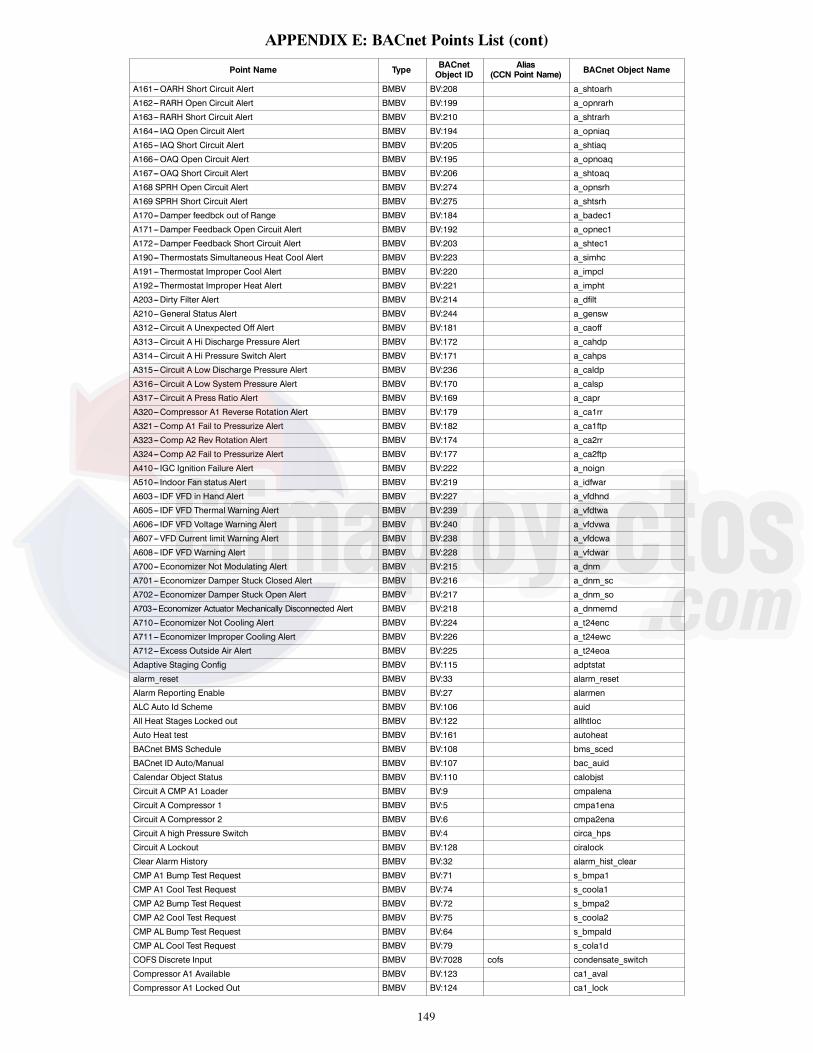
149
APPENDIX E: BACnet Points List (cont)
Point Name Type BACnetObject ID
Alias(CCN Point Name) BACnet Object Name
A161---OARH Short Circuit Alert BMBV BV:208 a_shtoarh
A162---RARH Open Circuit Alert BMBV BV:199 a_opnrarh
A163---RARH Short Circuit Alert BMBV BV:210 a_shtrarh
A164--- IAQ Open Circuit Alert BMBV BV:194 a_opniaq
A165--- IAQ Short Circuit Alert BMBV BV:205 a_shtiaq
A166---OAQ Open Circuit Alert BMBV BV:195 a_opnoaq
A167---OAQ Short Circuit Alert BMBV BV:206 a_shtoaq
A168 SPRH Open Circuit Alert BMBV BV:274 a_opnsrh
A169 SPRH Short Circuit Alert BMBV BV:275 a_shtsrh
A170---Damper feedbck out of Range BMBV BV:184 a_badec1
A171---Damper Feedback Open Circuit Alert BMBV BV:192 a_opnec1
A172---Damper Feedback Short Circuit Alert BMBV BV:203 a_shtec1
A190---Thermostats Simultaneous Heat Cool Alert BMBV BV:223 a_simhc
A191---Thermostat Improper Cool Alert BMBV BV:220 a_impcl
A192---Thermostat Improper Heat Alert BMBV BV:221 a_impht
A203---Dirty Filter Alert BMBV BV:214 a_dfilt
A210---General Status Alert BMBV BV:244 a_gensw
A312---Circuit A Unexpected Off Alert BMBV BV:181 a_caoff
A313---Circuit A Hi Discharge Pressure Alert BMBV BV:172 a_cahdp
A314---Circuit A Hi Pressure Switch Alert BMBV BV:171 a_cahps
A315---Circuit A Low Discharge Pressure Alert BMBV BV:236 a_caldp
A316---Circuit A Low System Pressure Alert BMBV BV:170 a_calsp
A317---Circuit A Press Ratio Alert BMBV BV:169 a_capr
A320---Compressor A1 Reverse Rotation Alert BMBV BV:179 a_ca1rr
A321---Comp A1 Fail to Pressurize Alert BMBV BV:182 a_ca1ftp
A323---Comp A2 Rev Rotation Alert BMBV BV:174 a_ca2rr
A324---Comp A2 Fail to Pressurize Alert BMBV BV:177 a_ca2ftp
A410--- IGC Ignition Failure Alert BMBV BV:222 a_noign
A510--- Indoor Fan status Alert BMBV BV:219 a_idfwar
A603--- IDF VFD in Hand Alert BMBV BV:227 a_vfdhnd
A605--- IDF VFD Thermal Warning Alert BMBV BV:239 a_vfdtwa
A606--- IDF VFD Voltage Warning Alert BMBV BV:240 a_vfdvwa
A607---VFD Current limit Warning Alert BMBV BV:238 a_vfdcwa
A608--- IDF VFD Warning Alert BMBV BV:228 a_vfdwar
A700---Economizer Not Modulating Alert BMBV BV:215 a_dnm
A701---Economizer Damper Stuck Closed Alert BMBV BV:216 a_dnm_sc
A702---Economizer Damper Stuck Open Alert BMBV BV:217 a_dnm_so
A703---Economizer Actuator Mechanically Disconnected Alert BMBV BV:218 a_dnmemd
A710---Economizer Not Cooling Alert BMBV BV:224 a_t24enc
A711---Economizer Improper Cooling Alert BMBV BV:226 a_t24ewc
A712---Excess Outside Air Alert BMBV BV:225 a_t24eoa
Adaptive Staging Config BMBV BV:115 adptstat
alarm_reset BMBV BV:33 alarm_reset
Alarm Reporting Enable BMBV BV:27 alarmen
ALC Auto Id Scheme BMBV BV:106 auid
All Heat Stages Locked out BMBV BV:122 allhtloc
Auto Heat test BMBV BV:161 autoheat
BACnet BMS Schedule BMBV BV:108 bms_sced
BACnet ID Auto/Manual BMBV BV:107 bac_auid
Calendar Object Status BMBV BV:110 calobjst
Circuit A CMP A1 Loader BMBV BV:9 cmpalena
Circuit A Compressor 1 BMBV BV:5 cmpa1ena
Circuit A Compressor 2 BMBV BV:6 cmpa2ena
Circuit A high Pressure Switch BMBV BV:4 circa_hps
Circuit A Lockout BMBV BV:128 ciralock
Clear Alarm History BMBV BV:32 alarm_hist_clear
CMP A1 Bump Test Request BMBV BV:71 s_bmpa1
CMP A1 Cool Test Request BMBV BV:74 s_coola1
CMP A2 Bump Test Request BMBV BV:72 s_bmpa2
CMP A2 Cool Test Request BMBV BV:75 s_coola2
CMP AL Bump Test Request BMBV BV:64 s_bmpald
CMP AL Cool Test Request BMBV BV:79 s_cola1d
COFS Discrete Input BMBV BV:7028 cofs condensate_switch
Compressor A1 Available BMBV BV:123 ca1_aval
Compressor A1 Locked Out BMBV BV:124 ca1_lock

150
APPENDIX E: BACnet Points List (cont)
Point Name Type BACnetObject ID
Alias(CCN Point Name) BACnet Object Name
Compressor A2 Available BMBV BV:125 ca2_aval
Compressor A2 Locked Out BMBV BV:126 ca2_lock
Compressor Cooling Ok BMBV BV:302 okmechcl
Cooling Liquid Valve CirA BMBV BV:7052 clv_a
cooling liquid valve Relay Test BMBV BV:456 s_clv_a
Cooling Liq Valve CirA Enable BMBV BV:7049 clva_en
Crankcase Heater Relay 1 BMBV BV:3 cch_relay
Damper Position Error BMBV BV:21 dmpr_err
Damper Status Good BMBV BV:39 damp_good
Daylight Savings Enable BMBV BV:93 dst_cfg
Daylight Savings time Active BMBV BV:92 dst_actv
DD IDF High Speed Relay BMBV BV:448 fspdhrly
DD IDF Low Speed Relay BMBV BV:446 fspdlrly
DD IDF Med. Speed Relay BMBV BV:447 fspdmrly
Diff Bulb Lock Out BMBV BV:40 db_lock_out
Differential Dry Bulb Enable BMBV BV:41 diffbulb dif_db_ena
Differential Enthalpy Enable BMBV BV:42 dif_enth_ena
Economizer Installed BMBV BV:131 econo_cfg
Enthalpy Lockout BMBV BV:44 enthlock enth_lock_out
equip_alarm BMBV BV:7048 equip_alarm
F010---MBB low voltage Fault BMBV BV:270 f_mbblov
F011---MBB Reference voltage Fault BMBV BV:271 f_mbbref
F013---MBB Fuse 2 Open Fault BMBV BV:268 f_mbbf2
F014---MBB Fuse 3 Open Fault BMBV BV:269 f_mbbf3
F018---MBB EEPROM Read/Write Failure Fault BMBV BV:267 f_mbbeep
F20---Software Error Fault BMBV BV:243 f_bad_dd
F200---Fire Shutdown Fault BMBV BV:242 f_fire
F201---Condensate Overflow Fault BMBV BV:273 f_cofs
F202---Freeze Protection Fault BMBV BV:264 f_freeze
F204---Remote Shutdown Fault BMBV BV:272 f_remoff
F211---General Status Fault BMBV BV:265 f_gensw
F310---Circuit A Down Due To Failure Fault BMBV BV:168 f_caddf
F311---Circuit A Low Charge Fault BMBV BV:167 f_caloch
F318---Compressor Stuck on Fault BMBV BV:241 f_cstuck
F319---Compressor A1 Down due to Failure Fault BMBV BV:178 f_ca1ddf
F322---Comp A2 Down Fail Fault BMBV BV:173 f_ca2ddf
F411---Rollout without Heating BMBV BV:235 f_ronoht
F412---Run Away Heat Fault BMBV BV:266 f_hstuck
F511--- IDF off when comand on Fault BMBV BV:230 f_idfoff
F512--- IDF On When Comanded Off BMBV BV:231 f_idfon
F600--- IDF VFD Communication Error Fault BMBV BV:229 f_idfcom
F601--- IDF VFD Unexpected Fault BMBV BV:253 f_vfdune
F602--- IDF VFD Lockout Fault BMBV BV:234 f_vfdlo
F604--- IDF VFD in Hand Fault BMBV BV:233 f_vfdhnd
F611--- IDF VFD Earth Fault BMBV BV:255 f_vfdef
F612--- IDF VFD Control Word Fault BMBV BV:254 f_vfdcf
F613--- IDF VFD Over Current Fault BMBV BV:259 f_vfdoc
F614--- IDF VFD Over Temperature Fault BMBV BV:249 f_vfdot
F615--- IDF VFD Inverter Overload Fault BMBV BV:260 f_vfdol
F616--- IDF VFD Under Voltage Fault BMBV BV:263 f_vfduv
F617--- IDF VFD Over Voltage Fault BMBV BV:261 f_vfdov
F618--- IDF VFD Short Circuit Fault BMBV BV:262 f_vfdsc
F619--- IDF VFD Main Phase Loss Fault BMBV BV:258 f_vfdmpf
F620--- IDF VFD Phase U Loss Fault BMBV BV:250 f_vfdpul
F621--- IDF VFD Phase V Loss Fault BMBV BV:251 f_vfdpvl
F622--- IDF VFD Phase W Loss Fault BMBV BV:252 f_vfdpwl
F623--- IDF VFD Control Voltage Fault BMBV BV:256 f_vfdivl
F624--- IDF VFD Supply VDD Low Fault BMBV BV:257 f_vfdlve
Fan On When Occupied BMBV BV:46 fanon_oc occupied_fan
Fan shutdown on failure BMBV BV:7008 fatalfan sfan_fail_alarm
FBD SAT locked out BMBV BV:439 fbdsatlo
FBD SST locked out BMBV BV:440 fbdsstlo
Filter Status Switch BMBV BV:1016 flt_status
Fire Shutdown Switch BMBV BV:112 firedown
Free Cooling Available BMBV BV:65 okfreecl ok_free_cl
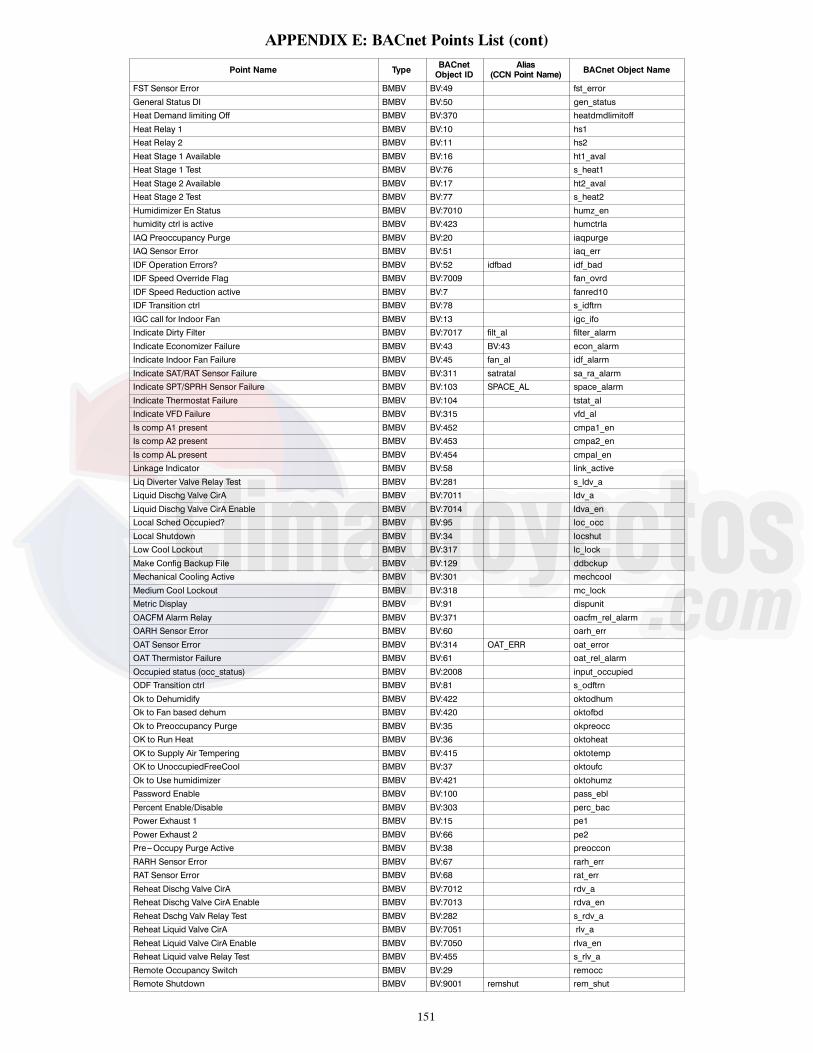
151
APPENDIX E: BACnet Points List (cont)
Point Name Type BACnetObject ID
Alias(CCN Point Name) BACnet Object Name
FST Sensor Error BMBV BV:49 fst_error
General Status DI BMBV BV:50 gen_statusHeat Demand limiting Off BMBV BV:370 heatdmdlimitoff
Heat Relay 1 BMBV BV:10 hs1Heat Relay 2 BMBV BV:11 hs2
Heat Stage 1 Available BMBV BV:16 ht1_avalHeat Stage 1 Test BMBV BV:76 s_heat1
Heat Stage 2 Available BMBV BV:17 ht2_avalHeat Stage 2 Test BMBV BV:77 s_heat2
Humidimizer En Status BMBV BV:7010 humz_enhumidity ctrl is active BMBV BV:423 humctrla
IAQ Preoccupancy Purge BMBV BV:20 iaqpurgeIAQ Sensor Error BMBV BV:51 iaq_err
IDF Operation Errors? BMBV BV:52 idfbad idf_badIDF Speed Override Flag BMBV BV:7009 fan_ovrd
IDF Speed Reduction active BMBV BV:7 fanred10IDF Transition ctrl BMBV BV:78 s_idftrn
IGC call for Indoor Fan BMBV BV:13 igc_ifoIndicate Dirty Filter BMBV BV:7017 filt_al filter_alarm
Indicate Economizer Failure BMBV BV:43 BV:43 econ_alarmIndicate Indoor Fan Failure BMBV BV:45 fan_al idf_alarm
Indicate SAT/RAT Sensor Failure BMBV BV:311 satratal sa_ra_alarmIndicate SPT/SPRH Sensor Failure BMBV BV:103 SPACE_AL space_alarm
Indicate Thermostat Failure BMBV BV:104 tstat_alIndicate VFD Failure BMBV BV:315 vfd_al
Is comp A1 present BMBV BV:452 cmpa1_enIs comp A2 present BMBV BV:453 cmpa2_en
Is comp AL present BMBV BV:454 cmpal_enLinkage Indicator BMBV BV:58 link_active
Liq Diverter Valve Relay Test BMBV BV:281 s_ldv_aLiquid Dischg Valve CirA BMBV BV:7011 ldv_a
Liquid Dischg Valve CirA Enable BMBV BV:7014 ldva_enLocal Sched Occupied? BMBV BV:95 loc_occ
Local Shutdown BMBV BV:34 locshutLow Cool Lockout BMBV BV:317 lc_lock
Make Config Backup File BMBV BV:129 ddbckupMechanical Cooling Active BMBV BV:301 mechcool
Medium Cool Lockout BMBV BV:318 mc_lockMetric Display BMBV BV:91 dispunit
OACFM Alarm Relay BMBV BV:371 oacfm_rel_alarmOARH Sensor Error BMBV BV:60 oarh_err
OAT Sensor Error BMBV BV:314 OAT_ERR oat_errorOAT Thermistor Failure BMBV BV:61 oat_rel_alarm
Occupied status (occ_status) BMBV BV:2008 input_occupiedODF Transition ctrl BMBV BV:81 s_odftrn
Ok to Dehumidify BMBV BV:422 oktodhumOk to Fan based dehum BMBV BV:420 oktofbd
Ok to Preoccupancy Purge BMBV BV:35 okpreoccOK to Run Heat BMBV BV:36 oktoheat
OK to Supply Air Tempering BMBV BV:415 oktotempOK to UnoccupiedFreeCool BMBV BV:37 oktoufc
Ok to Use humidimizer BMBV BV:421 oktohumzPassword Enable BMBV BV:100 pass_ebl
Percent Enable/Disable BMBV BV:303 perc_bacPower Exhaust 1 BMBV BV:15 pe1
Power Exhaust 2 BMBV BV:66 pe2Pre---Occupy Purge Active BMBV BV:38 preoccon
RARH Sensor Error BMBV BV:67 rarh_errRAT Sensor Error BMBV BV:68 rat_err
Reheat Dischg Valve CirA BMBV BV:7012 rdv_aReheat Dischg Valve CirA Enable BMBV BV:7013 rdva_en
Reheat Dschg Valv Relay Test BMBV BV:282 s_rdv_aReheat Liquid Valve CirA BMBV BV:7051 rlv_a
Reheat Liquid Valve CirA Enable BMBV BV:7050 rlva_enReheat Liquid valve Relay Test BMBV BV:455 s_rlv_a
Remote Occupancy Switch BMBV BV:29 remoccRemote Shutdown BMBV BV:9001 remshut rem_shut

152
APPENDIX E: BACnet Points List (cont)
Point Name Type BACnetObject ID
Alias(CCN Point Name) BACnet Object Name
Reset Filter Timer BMBV BV:109 reset_filter_timer
Run Auto Cool test BMBV BV:160 autocoolRun Auto Indepdent Test BMBV BV:163 autoindp
Run Auto System Test BMBV BV:162 autosysSA Tempering Enable BMBV BV:410 sup_air_temp_en
SAT Sensor Error BMBV BV:84 sat_errSDPA Sensor Error BMBV BV:63 sdpa_err
Shutdown A1 First BMBV BV:449 sdwn_a1Shutdown A2 First BMBV BV:450 sdwn_a2
Shutdown ALD First BMBV BV:451 sdwn_aldShutdown In VFD Hand Mode BMBV BV:8 handshut
SPTO Sensor Error BMBV BV:7002 stpt_errSPT Sensor Error BMBV BV:7001 spt_err
SSPA Sensor Error BMBV BV:89 sspa_errStart DD restore BMBV BV:130 ddrstre
System Demand Alarm BMBV BV:26 sysdmdal sys_dmd_alarmTemperature Compensated Start is active BMBV BV:133 tcs_act
Test Alarm Input BMBV BV:70 s_alarmTest CCH Relay 1 BMBV BV:73 s_cchr1
Test Power Exhaust 1 BMBV BV:82 s_peTest Power Exhaust 2 BMBV BV:83 s_pe_2
Thermostat G Input BMBV BV:1021 g g_inputThermostat W1 Input BMBV BV:1017 w1 w1_input
Thermostat W2 Input BMBV BV:1018 w2 w2_inputThermostat Y1 Input BMBV BV:1019 y1 y1_input
Thermostat Y2 Input BMBV BV:1020 y2 y2_inputThermostat Y3 Input BMBV BV:28 y3 y3_input
Today Is A Holiday BMBV BV:98 holtodayTomorrow Is A Holiday BMBV BV:96 hol_tmrw
Unoccupied Free Cooling Active BMBV BV:135 ufc_actUSB Find Restore File BMBV BV:111 backfile
VFD 1 Reverse? BMBV BV:102 vfd1mdirVFD Config OK? BMBV BV:105 vfdcfgok
VFD Reverse Select BMBV BV:69 rev_selActive Occupancy Control BMSV MSV:14 occ_ctrl
ALC Status color BMSV MSV:9 colorAlert from thermostat BMSV MSV:8 tstat_alert
BACnet BMS baud rate BMSV MSV:18 bac_baudBMS Configuration BMSV MSV:11 bms_cfg
BMS Occupancy Request BMSV MSV:12 bms_occCommunications status BMSV MSV:17 e0commst
Cool demand Limit Level BMSV MSV:56 cdlm_levelFBD Type BMSV MSV:58 fbd_type
Filter Status Switch Inp BMSV MSV:41 filter_channelFilter Status Swith Type BMSV MSV:42 filt_cfg
Firmware Release State BMSV MSV:19 fw_stateHeat demand Limit Level BMSV MSV:57 hdlm_level
Heat Type BMSV MSV:16 heattype ht_typeIAQ Analog Input Config BMSV MSV:25 iaqancfg
IDF Type BMSV MSV:450 idftypeIDF VFD Fault Detail BMSV MSV:23 svfdflt
Keep Configuration BMSV MSV:47 keepconfLinkage Occupancy request BMSV MSV:13 lnk_occ
Motor Power BMSV MSV:22 MOTPWR mot_pwrRemote Occupancy Config BMSV MSV:45 rmoc_cfg
RFI Filter BMSV MSV:4 rfi_filterRunning Mode Operation BMSV MSV:43 sub_mode
Switching Frequency BMSV MSV:7 switch_freqSystem Demand BMSV MSV:101 sys_dmde sys_demand_enum
System Mode BMSV MSV:2002 sysmode sys_modeSystemVu Type BMSV MSV:2003 sysvtype
Test Inactivity Time Out BMSV MSV:156 test_itoThermostat Type BMSV MSV:5 stattype tstat_type
Unit Control Type BMSV MSV:2 control_typeUnocpied Free Cooling config BMSV MSV:24 ufc_cfg
Ventilation Status BMSV MSV:6 ventstatVFD1 Warning Detail BMSV MSV:3001 vfd_warning

153
CONTROL SET POINT AND CONFIGURATION LOG
MODEL NO.:
SERIAL NO.:
DATE:
TECHNICIAN:
SOFTWARE VERSIONS :
MBB: CESR131651--
VFD FW VERSION --
INDICATE UNIT SETTINGS BELOW
CONTROL TYPE: Thermostat/T55 Space Temp./T--56 Space Temp./T--59 Space Temp.
SET POINT Cooling Occupied: Unoccupied:
Heating Occupied: Unoccupied:
Settings -- Main Menu LayoutDisplay Text Expanded Text Range Units Default Point Entry
SETTINGS Settings Menu
SPACE SET POINTS Space Setpoints Adjustment Menu
OCC COOL SETPOINT Occupied Cool Setpoint 55 to 80 ° F 78 OCSP
OCC HEAT SETPOINT Occupied Heat Setpoint 55 to 80 ° F 68 OHSP
UNOCC COOL SETPNT Unoccupied Cool Setpoint 65 to 95 ° F 85 UCSP
UNOCC HEAT SETPNT Unoccupied Heat Setpoint 40 to 80 ° F 60 UHSP
HEAT---COOL SP GAP Heat---Cool Setpoint Gap 2 to 10 ^F 5 HCSP_GAP
SPT SLIDER RANGE SPT Offset Range (+/--- ) 0 to 5.0 ° F 5 SPTO_RNG
OCC SPRH SET PT Occupied SPRH Setpoint 0 to 100 % 55 SPRH_OSP
UNOCC SPRH SET PT Unoccupied SPRH Setpoint 0 to 100 % 55 SPRH_USP
SA TEMPER SET PNT SA tempering Set point xx ° F 50 SATEMPSPTEMP DEMAND CONFIG Temperature Demand Configuration
menuLOW COOL DMD ON Low Cool Demand On ---1 to 2.0 ° F 0.5 DMDLCON
MED COOL DMD ON Medium Cool Demand On 0.5 to 20.0 ° F 1 DMDMCON
HIGH COOL DMD ON High Cool Demand On 0.5 to 20.0 ° F 2 DMDHCON
LOW COOL DMD OFF Low Cool Demand Off ---1 to 2.0 ° F ---0.5 DMDLCOFF
COOL DMD LEVEL UP Cool Demand Level Up ---2 to 2.0 ^F/min ---0.2 CDMD_LUP
LOW HEAT DMD ON Low Heat Demand On ---1 to 2.0 ° F 0.5 DMDLHON
HIGH HEAT DMD ON High Heat Demand On 0.5 to 20.0 ° F 2 DMDHHON
LOW HEAT DMD OFF Low Heat Demand Off ---1 to 2.0 ° F ---0.5 DMDLHOFF
HEAT DMD LEVEL UP Heat Demand Level Up ---2 to 2.0 ^F/min ---0.2 HDMD_LUP
DEMAND TIMEGUARD1 Space Demand Time Guard1 60 to 600 sec 180 TDMD_TG1
DEMAND TIMEGUARD2 Space Demand Time Guard2 0 to 600 sec 300 TDMD_TG2
DEMAND TIMEGUARD3 Space Demand Time Guard3 5 to 120 min 10 TDMD_TG3
DMD LIMIT CONFIG DEMAND LIMIT CONFIG
COOL DMD LIM LEV1 Cool DMD Offset level 1 0 to 99 ° F 1 CLDOLEV1
COOL DMD LIM LEV2 Cool DMD Offset level 2 0 to 99 ° F 3 CLDOLEV2
COOL DMD LIM LEV3 Cool DMD Offset level 3 0 to 99 ° F 5 CLDOLEV3
HEAT DMD LIM LEV1 Heat DMD Offset level 1 0 to 99 ° F 1 HTDOLEV1
HEAT DMD LIM LEV2 Heat DMD Offset level 2 0 to 99 ° F 3 HTDOLEV2
HEAT DMD LIM LEV3 Heat DMD Offset level 3 0 to 99 ° F 5 HTDOLEV3CLOCK Clock Adjustment Menu
TIME Clock Hour and Minute xx:xx hh.mm TIME
DATE Current Date MM/DD/YYYY DATE
DAYLIGHT SAVINGS Daylight Savings Configuration Menu DST Menu
DAYLIGHT SAVINGS? DST allowed? Enable/Disable Enable DST_CFG
DST START MONTH DST Start Month 1=JANUARY,2=FEBRUARY,3=MARCH,4=APRIL,5=MAY,6=JUNE,7=JULY,8=AUGUST,9=SEPTEMBER,10=OCTOBER,11=NOVEBER,12=DECEMBER
3 STARTM
DST START WEEK DST Start Week 1 to 5 2 STARTW
DST START DAY DST Start Day 1=MONDAY,2=TUESDAY,3=WEDNESDAY,4=THURSDAY,5=FRIDAY,6=SATURDAY,7=SUNDAY
7 STARTD
DST MINS TO ADD DST Minutes to Add 0 to 90 min 60 MINADD

154
Settings -- Main Menu Layout (cont)Display Text Expanded Text Range Units Default Point Entry
CLOCK (cont) Clock Adjustment MenuDST STOP MONTH DST Stop Month 1=JANUARY,
2=FEBRUARY,3=MARCH,4=APRIL,5=MAY,6=JUNE,7=JULY,8=AUGUST,9=SEPTEMBER,10=OCTOBER,11=NOVEBER,12=DECEMBER
1 STOPM
DST STOP WEEK DST Stop Week 1 to 5 1 STOPW
DST STOP DAY DST Stop Day 1=MONDAY,2=TUESDAY,3=WEDNESDAY,4=THURSDAY,5=FRIDAY,6=SATURDAY,7=SUNDAY
7 STOPD
DST MINS TO SUB DST Minutes to Subtract 0 to 90 min 60 MINSUB
START TIME IN DAY Time in day to start DST 0 to 600 min 120 DST_TOD
SCHEDULES Schedules Adjustment Menu
SCHEDULE NUMBER CCN Schedule Number 0 = Always Occupied,1---64 = Local Schedule,65---99 = Global Schedule
0 SCHEDNUM
OCCUPANCY SCHEDULE OCCUPANCY SCHEDULE DATA
HOLIDAYS Holiday adjustment Menu
ALLOW G. HOLIDAY? Accept Global Holidays? Yes/No No HOLIDAYT
TIMED OVR LENGTH Timed Override Duration 0 to 4 hours 4 OTL_CFG
UNIT CONFIGURATIONS Unit Configurations Menu
GENERAL General Unit Configurations Menu
STARTUP DELAY Unit Startup Delay 10 to 600 sec 30 STARTDLY
UNIT CONTROL TYPE Unit Control Type 0=TSTAT,1=SPACE SEN,2=RAT SEN
0=TSTAT CTRLTYPE
THERMOSTAT TYPE Thermostat Hardware Type 0=CONV 2C2H,1=DIGI 2C2H,2=CONV 3C2H,3=DIGI 3C2H4=DIGI 2C2H_S
2=CONV 3C2H STATTYPE
ADAPTIVE TSTAT Tstat Adaptive Staging Yes/No Yes ADPTSTAT
DIRTY FILTER TIME Change Filter Timer 0 to 9999 hours 600 FILTLIFE
TEST MODE TIMEOUT Test inactivity time out 0=Disabled,1=30 minutes,2=1 hour,3=2 hours,4=4 hours,5=8 hours,6=12 hours
4=4 hours TEST_ITO
CCH MAX TEMP CCH Max Temperature 40 to 90 ° F 65 CCHMAXT
STD BARO PRESSURE Std Barometric Pressure 13.00 to 35.00 in.Hg 29.92 STD_BARP
LINK STAGEUP TIME Linkage Stage inc. time 60 to 600 sec 180 LSTAGINC
UNIT’S MAX SAT Unit’s Maximum SAT 130 to 210 ° F 200 UMAX_SAT
AUTO SAT FAULTS? Auto Clr SAT Limit Fault Yes/No No SATLACLR
ADAPTIVE TCS? Adaptive Temp Comp Start Enable/Disable Yes TCS_CFG
USER TCS BIASTIME User TCS Start bias time 0 to 180 min 0 TCSUBIAS
SWITCH INPUTS CONFIGS DI Config Menu
FIRE SHUTDOWN SW Fire Shutdown Switch 0=NORM OPEN,1=NORM CLSD,2=NO SWITCH
2: no FIOP0: FIOP
FIRE_CFG
HUMSTAT CHANNEL HumidistatStatus Channel 0=None,1=MBB DI12,2=MBB DI13.3=MBB DI14,4=MBB DI02,5=MBB DI04,6=SIOB Di01
0=for all exceptHumidimizer6=Humidimizer units
HUMDCHAN
HUMSTAT SW TYPE Humidistat Switch Type 0=NORM OPEN,1=NORM CLSD,
0=NORM OPEN HUMD_CFG
FILTER SW CHANNEL Filter Status Sw Channel 0=None,1=MBB DI12,2=MBB DI13,3=MBB DI14,4=MBB DI02,5=MBB DI04
0=None FILTCHAN
FILTER SW TYPE Filter Status Swith Type 0=NORM OPEN,1=NORM CLSD
0=NORM OPEN FILT_CFG
REMOTE OCC CHAN Remote Occupancy Channel 0=None,1=MBB DI12,2=MBB DI13,3=MBB DI14,4=MBB DI02,5=MBB DI04
0=None RMOCCHAN
REMOTE OCC TYPE Remote Occupancy Sw Type 0=NORM OPEN,1=NORM CLSD
0=NORM OPEN RMOC_CFG

155
Settings -- Main Menu Layout (cont)Display Text Expanded Text Range Units Default Point Entry
SWITCH INPUTS CONFIGS (cont) DI Config MenuREM.SHUTDOWN CHAN Remote Shutdown Channel 0=None,
1=MBB DI12,2=MBB DI13,3=MBB DI14,4=MBB DI02,5=MBB DI04
0=None ROFFCHAN
REM.SHUTDOWN SW T Remote Shutdown Sw Type 0=NORM OPEN,1=NORM CLSD
0=NORM OPEN ROFF_CFG
REM.SHUTDOWN TYPE Remote Shutdown ALM Type 0=Normal,1=Emergency
0=Normal ROFFTYPE
COFS CHANNEL COFS Assigned Channel 0=None,1=MBB DI12,2=MBB DI13,3=MBB DI14,4=MBB DI02,5=MBB DI04
0=None COFSCHAN
COFS TYPE COFS Switch Type 0=NORM OPEN,1=NORM CLSD
1=NORM CLSD COFS_CFG
GEN STATUS CHAN General Status Channel 0=None,1=MBB DI12,2=MBB DI13,3=MBB DI14,4=MBB DI02,5=MBB DI04
0=None GEN_CHAN
GEN STAT SW TYPE General Status Sw Type 0=NORM OPEN,1=NORM CLSD
0=NORM OPEN GENS_CFG
SHUTDOWN GEN STAT General Status shutdown? Yes/No Yes GENFATAL
ENTHALPY SW CHAN Enthalpy Sw Channel 0=None,1=MBB DI12,2=MBB DI13,3=MBB DI14,4=MBB DI02,5=MBB DI04
0=None ENTHCHAN
ENTHALPY SW TYPE Enthalpy Switch Type 0=NORM OPEN,1=NORM CLSD
0=NORM OPEN ENTH_CFG
ANALOG INPUT CONFIGS Analog Inputs Configuration Menu
IAQ SENSOR CHAN IAQ Assigned Channel 0=None,1=MBB AI06,2=MBB AI07,3=MBB AI08
0: no FIOP1: FIOP
IAQ_CHAN
SPRH SENS CHANNEL SPRH Assigned Channel 0=None,1=MBB AI06,2=MBB AI07,3=MBB AI084=SIOB AI10
0=None SPRHCHAN
SPRH RH @ 4MA SPRH Sensor Value at 4mA 0 to 100 % 0 SPRH_4MA
SPRH RH @ 20MA SPRH Sensor Value @ 20mA 0 to 100 % 1 SPRH20MA
IAQ PPM @ 4MA IAQ Sensor Value at 4mA 0 to 5000 ppm 0 IAQ_4MA
IAQ PPM @ 20MA IAQ Sensor Value at 20mA 0 to 5000 ppm 2000 IAQ_20MA
OAQ SENSOR CHAN OAQ Assigned Channel 0=None,1=MBB AI06,2=MBB AI07,3=MBB AI08
0=None OAQ_CHAN
OAQ PPM @ 4MA OAQ Sensor Value at 4mA 0 to 5000 ppm 0 OAQ_4MA
OAQ PPM @ 20MA OAQ Sensor Value at 20mA 0 to 5000 ppm 2000 OAQ_20MA
OARH SENSOR CHAN OARH Assigned Channel 0=None,1=MBB AI06,2=MBB AI07,3=MBB AI08
n/a 0: no Enthalpy FIOP3: Enthalpy FIOP
OARHCHAN
OARH RH @ 4MA OARH Sensor Value at 4mA 0 to 100 % 0 OARH_4MA
OARH RH @ 20MA OARH Sensor Val. at 20mA 0 to 100 % 100 OARH20MA
RARH SENS CHANNEL RARH Assigned Channel 0=None,1=MBB AI06,2=MBB AI07,3=MBB AI08
n/a 0=None RARHCHAN
RARH RH @ 4MA RARH Sensor Value at 4mA 0 to 100 % 0 RARH_4MA
RARH RH @ 20MA RARH Sensor Value @ 20mA 0 to 100 % 100 RARH20MA
OACFM SENSOR CHAN OACFM Assigned Channel 0=None,1=MBB AI06,2=MBB AI07,3=MBB AI08,4=SIOB AI10
n/a 0=None OCFMCHAN
OACFM @ 4MA OACFM value at 4mA 0 to 100 CFM 0 OCFM_4MA
OACFM @ 20MA OACFM Value @ 20mA 0 to 100 CFM 20 OCFM20MA
COOLING Cooling Configurations Menu
COOLING STAGE QTY Number of Cooling Stages 0 to 3 3 NUMCSTGS
LOW COOL COMP Low Cool Compressor 1 to 2 1 LC_COMP
COMP MIN ON TIME Compressor Min On Time 180 to 600 sec 300 C_MINON
COMP MIN OFF TIME Compressor Min Off Time 120 to 600 sec 180 C_MINOFF
STRIKE CLEAR TIME Runtime to Reset Strikes 120 to 999 sec 300 MIN_ON_S
COOL STAGEUP TIME Cool Stage Increase Time 120 to 999 sec 450 CSTAGINC
COOL SATTREND LEV Cooling SAT Trend Level ---1.0 to 1.0 ^F/min ---0.2 SAT_TLC
UPPER MIN SAT Cool Min SAT Upper Level 35.0 to 65.0 ° F 56 (sizes 04---06)53 (sizes 07---12)56 (sizes 14---26)
SATMIN_H

156
Settings -- Main Menu Layout (cont)Display Text Expanded Text Range Units Default Point Entry
COOLING (cont) Cooling Configurations MenuLOWER MIN SAT Cool Min SAT Lower Level 35.0 to 65.0 ° F 46 (sizes 04---06)
42 (sizes 07---12)46 (sizes 14---26)
SATMIN_L
SPRH DEADBAND Space RH Deadband 0 % 5 SPRH_D8
HUMZ LOCKOUT OAT Humidimizer Lockout Temp ---20 to 75 ° F 40 OATLHUMZ
COOL FANOFF DELAY Cooling Fan---off Delay 0 to 600 sec 75 COOL_FOD
FBD TYPE FBD CONTROL TYPE 0=None,1=Comfort,2=Max
0=None FBD_TYPE
FBD SAT MIN VALUE FBD SAT MIN VALUE 35 to 80 ° F 46 FBDH_SAT
FBD LOW SP FBD LOW SP ---20 to 0 °F delta ---2.5 FBDLO_SP
FBD SST MIN VALUE FBD SST MIN VALUE 10 to 60 ° F 32 FBDH_SST
LOW AMBIENT LOW AMBIENT CONFIGS MENU
CIR.A LOCKOUT OAT Circuit A Lockout Temp ---20 to 75 ° F 0: no Economizer FIOP40: Economizer FIOP
OATLCMPA
LOW AMBIENT TEMP Low Ambient Temperature 0 to 80 ° F 66 LA_TEMP
LOW COOL MIN OAT Low Cool lockout Temp ---20 to 60 ° F 10 (sizes 04---06)30 (sizes 07---12)40 (sizes 14---26)
LCLOCKSP
MED COOL MIN OAT Medium Cool lockout Temp ---20 to 60 ° F 20 (sizes 07---12)30 (sizes 14---26)
MCLOCKSP
LA DEHUM LEV 1 Low Ambient Dehum Lev 1 40 to 125 ° F 80 LAHTEMP1
LA DEHUM LEV 2 Low Ambient Dehum Lev 2 40 to 125 ° F 61 LAHTEMP2
LA DEHUM LEV 3 Low Ambient Dehum Lev 3 40 to 125 ° F 55 LAHTEMP3
LA DEHUM SDT SP 1 LA Dehum SDT SP Lev 1 60 to 120 ° F 82 LHSDTSP1
LA DEHUM SDT SP 2 LA Dehum SDT SP Lev 2 60 to 120 ° F 93 LHSDTSP2
LA DEHUM SDT SP 3 LA Dehum SDT SP Lev 3 60 to 120 ° F 104 LHSDTSP3
HUMZ ENABLE Humidimizer Status Yes/No enum No for all exceptHumidimizer units
HUMZ_EN
RDVA ENABLE Reheat Dischg Valve CirA Yes/No enum No for all exceptHumidimizer units
RDVA_EN
RLVA ENABLE Reheat Liquid Valve CirA Yes/No enum No for all exceptHumidimizer units sizes04---06
RLVA_EN
CLVA ENABLE Cooling Liq Valve CirA Yes/No enum No for all exceptHumidimizer units sizes04---06
CLVA_EN
LDVA ENABLE Liquid Divert Valve CirA Yes/No enum No for all exceptHumidimizer units sizes07---26
LDVA_EN
CHARGE DIAGNOSTICS Refrigerant Charge Diagnostic Config Menu
LOW CHARGE LEVEL Low Refrig Charge Level 0 to 150 psi 50 LOCHARGE
NO LOW CHARGE OAT Low Charge Disable Temp ---40 to 50 ° F 10 LOCH_LOT
CIR.A SDP LIMIT CirA High Pressure Limit 400 to 700 psig 600 HIPLIM_A
LOW DISCHARGE LEV Low Discharge Level 5.0 to 20.0 ° F 7 SDTLEV
MIN PRESS RATIO Minimum pressure ratio 0.00 to 5.00 1.35 MINPSI_R
LOW SUCTION DIAG. Low Suction Diagnostic Config Menu
LOW SUC OK TEMP Suction OK Temperature 10.0 to 50.0 ° F 18 SSTOK
LOW SUC LEVEL 1 Low Suction Level 1 Temp 10.0 to 50.0 ° F 20 SSTLEV1
LOW SUC LEVEL 2 Low Suction Level 2 Temp 5.0 to 50.0 ° F 15 SSTLEV2
LOW SUC LEVEL 3 Low Suction Level 3 Temp 0.0 to 50.0 ° F 10 SSTLEV3
LO SUC DIAG DELAY Delay On Low SST Check 0 to 300 sec 0 SSTCKDLY
COMPRESSOR TRANSISTION Compressor Transition diagnostic configmenu
COMP L2 DIAG DLY Comp level 2 diag delay 1 to 99 sec 15 (sizes 04---12)40 (sizes 14---26)
CDDTLEV2
IAG. COMP OFF Diag Comp Unexpected Off Enable/Disable Enable CD_UEOFF
CIR STUCK ON DIAG Circuit Stuck On Diag. Enable/Disable Enable DCKTOFF
CIR.A MIN DIS.P Min discharge change 0 to 99.0 psi 11 (sizes 04---12)17 sizes 14---26)
MDP_DISA
CIR.A MIN SUC.P Min Suction change 0 to 99.0 psi 4 (sizes 04---06)6.5 (size 07)8 (size 08)7 (sizes 09---12)14 (sizes 14---26)
MDP_SUCA
OFF P.RATIO CirA P.Ratio off change ---1.00 to 1.00 ---0.2 (sizes 04---06, 07,09---14)---0.3 (sizes 08, 17---26)
OFFPR_A
ODF SETTINGS Outdoor Fans Configurations Menu
ODF SIGNAL QTY Number of ODF Outputs 0 to 3 1 (sizes 04---06)2 (sizes 07,17, or 20)3 (sizes 08---14, 24---26)
NUM_ODF
ODF LOW COOL SPD ODF Low Cool Speed 0 to 1200 rpm 1000 (size 04)1075 (sizes 05---06)550 (sizes 07---12)700 (sizes 14---17, 26)650 (sizes 20---24)
ODFLCSPD

157
Settings -- Main Menu Layout (cont)Display Text Expanded Text Range Units Default Point Entry
ODF SETTINGS (cont) Outdoor Fans Configurations MenuODF MED COOL SPD ODF Med Cool Speed 0 to 1200 rpm 1000 (size 04)
1075 (sizes 05---06)700 (sizes 07, 12, or 24)600 (size 08)650 (size 09)800 (sizes 14,17, or 26)750 (size 20)
ODFMCSPD
ODF HIGH COOL SPD ODF High Cool Speed 0 to 1200 rpm 1000 (size 04)1075 (sizes 05---06)950 (sizes 07 or 09)900 (size 08)1000 (sizes 12---26)
ODFHCSPD
ODF MAXIMUM SPEED ODF Maximum Speed 0 to 1200 rpm 1000 (size 04)1075 (sizes 05---06)950 (sizes 07 or 09)900 (size 08)1000 (sizes 12---26)
ODFMAXSP
ODF MINIMUM SPEED ODF Minimum Speed 0 to 1200 rpm 160 ODFMINSP
ODF ADVANCED CONFIGS Outdoor Fan Advanced Configs Menu
ODF GAIN ODF Gain ---100 to 100.00 50 (sizes 04---06)1 (size 07)2 (sizes 08---12)1.8 (sizes 14---20)1.4 (sizes 24---26)
ODF_KC
ODF ANTI---WINDUP ODF anti ---windup factor ---100 to 100.00 0.6 ODF_NI
ODF INTEGRAL TIME ODF Integral Time ---100 to 100.00 20 (sizes 04---06)20 (sizes 07---12)40 (sizes14---26)
ODF_TI
ODF MBIAS 1 ODF Map Bias Term 1 ---200 to 200.00 72.5 (sizes 04---06)66.7 (size 07)---44.55 (sizes 08---12)10 (sizes 14---20)72.5 (sizes 24---26)
ODFBIAS1
ODF MBIAS 2 ODF Map Bias Term 2 ---200 to 200.00 100.98 (sizes 04---06)95.2 (size 07)80.59 (sizes 08---12)35.3 (sizes 14---20)100.98 (sizes 24---26)
ODFBIAS2
ODF MBIAS 3 ODF Map Bias Term 3 ---200 to 200.00 20.93 (sizes 04---06)0 (sizes 07, 14---20)65.29 (sizes 08---12)114.74 (sizes 24---26)
ODFBIAS3
ODF SWITCH POINT1 ODF Fan Switch Point 1 ---100 to 100.00 3.68 (size 07)3.4 (sizes 08---12)4.84 (sizes 14---20)1.58 (sizes 24---26)
ODFPIUP1
ODF SWITCH POINT2 ODF Fan Switch Point 2 ---100 to 100.00 17.1 (size 07)9.06 (sizes 08---12)22.3 (sizes 14---20)10.44 (sizes 24---26)
ODFPIUP2
ODF SWITCH POINT3 ODF Fans Switch Point 3 ---100 to 100.00 100 (sizes 07, 14---20)19.76 (sizes 08---12)20.93 (sizes 24---26)
ODFPIUP3
ODF PROP PR ODF Proportional ctrl Pr ---100 to 100.00 1.4 (sizes 04---06)25 (sizes 07---12)50 (sizes 14---26)
ODFPR_KC
ODF MSLOPE 1 ODF Map Slope Term 1 ---100 to 100.00 55.3 (sizes 04---06)25.3 (size 07)60.09 (sizes 08---12)31 (sizes 14---20)55.33 (sizes 24---26)
ODFSLPE1
ODF MSLOPE 2 ODF Map Slope Term 2 ---100 to 100.00 19.07 (sizes 04---06)9 (size 07)18.69 (sizes 08---12)9.6 (sizes 14---20)19.07 (sizes 24---26)
ODFSLPE2
ODF MSLOPE 3 ODF Map Slope Term 3 ---100 to 100.00 8.85 (sizes 04---06)1 (sizes 07, 14---20)9.34 (sizes 08---12)8.85 (sizes 24---26)
ODFSLPE3
HEATING Heating Configurations Menu
UNIT TYPE OF HEAT Type of Heat Installed 0=ELECTRIC1=GAS
0 (50 series)1 (48 series)
HEATTYPE
HEATING STAGE QTY Number of Heating Stages 0 to 2 2 (all except below);0 (50 series withoutFIOP heat),1 (50 Series, sizes 04---06low or medium heat)1 (50 series, sizes07---14 and low heat),1 (50 series, sizes07---12 and mediumheat)
NUMHSTGS
HEAT MIN ON Heat Minimum On Time 60 to 600 sec 120 H_MINON
HEAT MIN OFF Heat Minimum Off Time 60 to 600 sec 120 H_MINOFF
HEAT STAGEUP TIME Heat Stage Increase Time 120 to 999 sec 450 HSTAGINC
HEAT SATTREND LEV Heating SAT Trend Level ---1 to 1.0 ^F/min 0.2 SAT_TLH
LOWER MAX SAT Heat Max SAT Lower Level 85.0 to 200.0 ° F 140 SATMAX_L
UPPER MAX SAT Heat Max SAT Upper Level 85.0 to 200.0 ° F 160 SATMAX_H

158
Settings -- Main Menu Layout (cont)Display Text Expanded Text Range Units Default Point Entry
HEATING (cont) Heating Configurations Menu
HEAT FANOFF DELAY Heating Fan---off Delay 10 to 600 sec 30 (50 series)45 (48 series)
HEAT_FOD
HEAT LOCKOUT OAT Heating Lockout Temp 40 to 125 ° F 75 OATLHEATSAT DURING HEAT? SAT Heat Mode Sensing Enable/Disable Disable SAT_HEATIGC IFO TIMEOUT No IGC IFO input Timeout 0 to 60 min 5 NO_IGCTMPREHEAT W/O IDF? Pre---Heat HX without IDF? Enable/Disable Disable PREHT_HXPREHEAT FAN DELAY Pre---Heat Fan On Delay 0 to 120 sec 30 PREHT_TMSA TEMPER ENABLED SupplyAirTemperingEnable Yes/No Yes SATEMPENSA TEMPER SET PNT SA tempering Set point xx ° F 50 SATEMPSPTEMPER MAX OUT Max OAT for SA tempering ---40 to 125 ° F 48 OATSTEMP
INDOOR FAN Indoor Fan Configurations MenuOCCUPIED FAN? Fan On When Occupied Yes/No Yes FANON_OCINDOOR FAN TYPE Indoor Fan Type 0=None
1=VFD2=Direct Drive
1 1 = All Units except sizes04---06 fan option “0”2 = fan option 0 on sizes04---06
IDFTYPE
DIR DRV IDF SPDS Direct Drive Fan Speeds 2=23=3
2 2 = fan option 0 on sizes04---06
NUMFSPDS
SHUTDOWN IDF FAIL Shut Down on IDF Failure Yes/No enum No FATALFANIDF VFD VOLTAGE IDF VFD Nom. Motor Volts 50 to 1000 volts See VFD Motor Default
Configuration Tables.For sizes 04---06 seeTable 32.For size 07---26 Verticalunits see Table 39.For size 07---26 Horizon-tal units see Table 40.
MOTVOLT
IDF VFD NOM. FREQ IDF VFD Nom. Motor Freq 20 to 400 Hz 60 MOTFREQIDF VFD NOM. AMPS IDF VFD Nom. Motor Amps 0.1 to 26.0 amps See VFD Motor Default
Configuration Tables.For sizes 04---06 seeTable 32.For size 07---26 Verticalunits see Table 39.For size 07---26 Horizon-tal units see Table 40.
MOTCUR
IDF VFD NOM. RPM IDF VFD Nom. Motor RPM 100 to 60000 rpm See VFD Motor DefaultConfiguration Tables.For sizes 04---06 seeTable 32.For size 07---26 Verticalunits see Table 39.For size 07---26 Horizon-tal units see Table 40.
MOTNOMSP
IDF VFD MIN REF IDF VFD Min Reference 0 to 65.0 Hz 0 MINREF
IDF VFD MAX REF IDF VFD Max Reference 0 to 65.0 Hz 60 MAXREFVFD ACCEL. TIME IDF VFD Accel. Time 1 to 1800 sec 10 RAMPUP_TVFD DECEL. TIME IDF VFD Decel. Time 1 to 1800 sec 10 RAMPDN_TIDF VFD AMP LIMIT IDF VFD Current Limit 0 to 300 100 CURRLMTIDF VFD TIMEOUT IDF VFD Comm time out 1 to 600 sec 30 CNT_TOUTIDF VFD RESET DUR IDF VFD Auto Reset time 0 to 600 sec 30 ARSTRT_TVFD RFI FILTER IDF VFD RFI Filter On/Off On RFIFILTR
ECONOMIZER Economizer Configurations Menu
ECON INSTALLED? Economizer Installed? Yes/No No: no FIOPYes: FIOP
ECONO
ECON MAX POS Econ Max Damper Position 0 to 100 % 100 DAMPMAX
ECON TRAVEL TIME Economizer Travel Time 5 to 300 sec 150 ECONOTRV
MINIMUM POSITION CONFIGS Minimum Position Configurations menu
MIN POS @ MAX FAN Econ Min at Max Fanspeed 0 to 100 % 30 MINP_MAX
MIN POS SPEED 1 Min Pos --- User Speed 1 0 to 100 % 0 MP_USPD1
MIN POS DAMP 1 Min Pos --- User Pos 1 0 to 100 % 0 MP_UPOS1
MIN POS SPEED 2 Min Pos --- User Speed 2 0 to 100 % 0 MP_USPD2
MIN POS DAMP 2 Min Pos --- User Pos 2 0 to 100 % 0 MP_UPOS2
MIN POS SPEED 3 Min Pos --- User Speed 3 0 to 100 % 0 MP_USPD3
MIN POS DAMP 3 Min Pos --- User Pos 3 0 to 100 % 0 MP_UPOS3
FREE COOL CONFIGS Free Cooling Specific ConfigurationsMenu
LOW COOL SAT SP Low Free Cool SAT Setpnt 40 to 80 ° F 65 LCSASP
HIGH COOL SAT SP High FreeCool SAT Setpnt 40 to 80 ° F 55 HCSASP
FREE COOL MAX OAT Free Cooling Max OAT 0 to 90 ° F 65 MAXFREET
FREE COOL MIN OAT Free Cooling Min Temp ---30 to 70 ° F 0 MINFREET
DIFF DRY BULB CTL Diff. Dry Bulb Control Enable/Disable Disable DIFFBULB
DIFF DB DEADBAND Diff. Dry Bulb Deadband 0 to 20 ° F 3 OATRATDB
ENTHALPY HI LIMIT Max Enthalpy OA limit 1.0 to 99.0 Btu/lb 28 FREEMAXE
DIFF ENTHALPY CTL Diff. Enthalpy Control Enable/Disable Disable DIFFENTH
ENTHALPY DEADBAND Enthalpy Cross Deadband 0 to 20.0 Btu/lb 2 OAERAEDB
ECONO PID --- KP Economizer PID --- kP 0.00 to 99.90 2.5 ECONO_P
ECONO PID --- KI Economizer PID --- kI 0.00 to 99.90 0.12 ECONO_I
ECONO PID --- KD Economizer PID --- kD 0.00 to 99.90 1 ECONO_D
ECONO PID --- RATE Economizer PID --- rate 10 to 180 sec 15 ECONO_DT

159
Settings -- Main Menu Layout (cont)Display Text Expanded Text Range Units Default Point Entry
ECONOMIZER (cont) Economizer Configurations Menu
UNOCCUPIED FREE COOL Unoccupied Free Cooling Configs Menu
WHEN TO UNOCC FC When to Unocc Free Cool? 0=Disabled,1=PreOcc,2=Unocc
1=PreOcc UFC_CFG
UFC PREOCC TIME UFC PreOcc Time 1 to 999 min 120 UFCTIME
UFC LOW TEMP Unocc Free Cool Low Temp ---30 to 70 ° F 50 OATLUFC
POWER EXHAUST CONFIGS Power Exhaust Configurations Menu
PE1 RELAY CHANNEL PE1 Relay Channel 0=NONE,1=MBB RLY11,2=MBB RLY06
0: no FIOP2: FIOP
PE1_CHAN
PE1 POS @ MAX SPD PE Stage 1 at Max speed 0 to 100 % 40 PE1_PMAX
PE OFF DEADBAND PE Turn Off Dead band 0 to 100 % 5 PE_OFFDB
PE2 RELAY CHANNEL PE2 Relay Channel 0=NONE,1=MBB RLY11,2=MBB RLY06
0=None PE2_CHAN
PE2 POS @ MAX SPD PE Stage 2 at max speed 0 to 100 % 75 PE2_PMAX
ECON DISCONNECTDIAGNOSTIC
Econ Actuator Mechanical disconnectdiagnostic menu
MDD---H/C END DLY T24 Heat/Cool End Delay 0 to 60 min 25 T24CHDLY
MDD---MIN MOVE T24Econ Min Move for SAT 10 to 20 % 10 T24ECSTS
MDD---SAT DB Damper SAT deadband 0 to 20.0 ° F 12 T24SATDB
MDD---MIN RAT---OAT T24 Min Diff in RAT---OAT 5.0 to 20.0 ° F 15 T24RATDF
MDD---MIN TEST POS T24 Test Minimum Pos 0 to 100 % 15 T24TSTMN
MDD---MAX TEST POS T24 Test Maximum Pos 0 to 100 % 85 T24TSTMX
AIR QUALITY Air Quality Configurations Menu
ANALOG IAQ CTRL Analog Input IAQ Control 0=NO IAQ,1=DCV,2=IAQ OVRD,3=CTRL MINP
0: no FIOP1: FIOP
IAQANCFG
IAQ POS @ MAX SPD IAQ Position at Max Fan 0 to 100 % 10 IAQMINP
LOW AIR.Q DIFF AQ Differential Low 0 to 5000 ppm 100 DAQ_LOW
HIGH AIR.Q DIFF AQ Differential High 0 to 5000 ppm 700 DAQ_HIGH
PREOCC PURGE ENBL IAQ Preoccupancy Purge Yes/No Yes IAQPURGE
PURGE POS @ MAX IAQ Purge Pos at Max IDF 0 to 100 % 40 IAQPMAX
PREOCC LOW LIMIT Preocc Purge Lockout OAT 0 to 70 ° F 50 IAQP_LA
PREOCC PURGE TIME Preocc Purge Duration 5 to 120 min 15 IAQPTIME
AQ DIF HI--- IAQ OVR AQ Diff High IAQOVERRIDE 0 to 5000 PPM 700 AQD_HIGH
AQ DIF LO--- IAQ OVR AQ Diff Low--- IAQ OVERRIDE 0 to 5000 PPM 100 AQD_LOW
IAQ OVRRD ENABLE IAQ override enable Yes/No enum No IAQOVRENALARM RELAY Alarm Relay Configurations MenuALM RELAY CHANNEL ALM Relay Assigned Chan 0=NONE,
1=MBB RLY11,2=MBB RLY06
1=MBB RLY11 ALM_CHAN
THERMOSTAT ALERTS Thermostat Alerts Yes/No Yes TSTAT_ALHARDWARE ALERTS Hardware failures Alerts Yes/No Yes HW_ALSAT/RAT ALERTS SAT/RAT Sensor Alerts Yes/No Yes SATRATALOAT SENSOR ALERTS OAT Thermistor Alerts Yes/No Yes OATRL_ALSPACE SENS ALERTS Space Sensors Alerts Yes/No Yes SPACE_ALTRANSDUCER ALERTS Transducer Sensor Alerts Yes/No Yes TRANS_ALRH SENSOR ALERTS RH sensor failure Alert Yes/No Yes RHS_ALCO2 SENSOR ALERTS Air Quality CO2 Alerts Yes/No Yes CO2S_ALOACFM SENS ALERTS OACFM Alarm Relay Yes/No Yes OACFM_ALECONOMIZER ALERTS Economizer Alerts Yes/No Yes ECON_ALAIR FILTER ALERTS Dirty Filter Alerts Yes/No Yes FILT_ALGEN STATUS ALERTS General Status Alerts Yes/No Yes GENS_ALREFRIG CIR ALERTS Refrig Circuit Alerts Yes/No Yes CKT_ALCOMPRESSOR ALERTS Compressor Alerts Yes/No Yes COMP_ALHEATING ALERTS Heating failure Alerts Yes/No Yes HEAT_ALINDOOR FAN ALERTS Indoor Fan Alerts Yes/No Yes FAN_ALVFD ALERTS VFD Alerts Yes/No Yes VFD_ALIO BOARD ALERTS Relay On Active IOBA Yes/No No IOBFA_ALON ACTIVE FAULTS Relay on Active Faults Yes/No Yes FAULT_AL
NEW HARDWARE Quick Menu for New HardwareUNIT CONTROL TYPE Unit Control Type 0=TSTAT,
1=SPACE SEN,2=RAT SEN
0=TSTAT CTRLTYPE
ECON INSTALLED? Economizer Installed? Yes/No No: no FIOPYes: FIOP
ECONO
SPRH SENS CHANNEL SPRH Assigned Channel 0=None,1=MBB AI06,2=MBB AI07,3=MBB AI08,4=SIOB Ai10
0=None SPRHCHAN
IAQ SENSOR CHAN IAQ Assigned Channel 0=None,1=MBB AI06,2=MBB AI07,3=MBB AI08
1: no FIOP0: FIOP
IAQ_CHAN
OAQ SENSOR CHAN OAQ Assigned Channel 0=None,1=MBB AI06,2=MBB AI07,3=MBB AI08
0=None OAQ_CHAN

160
Settings -- Main Menu Layout (cont)Display Text Expanded Text Range Units Default Point Entry
NEW HARDWARE (cont) Quick Menu for New HardwareOARH SENSOR CHAN OARH Assigned Channel 0=None,
1=MBB AI06,2=MBB AI07,3=MBB AI08
3: no FIOP0: FIOP
OARHCHAN
RARH SENS CHANNEL RARH Assigned Channel 0=None,1=MBB AI06,2=MBB AI07,3=MBB AI08
0=None RARHCHAN
OACFM SENS CHANNEL OACFM Assigned Channel 0=None,1=MBB AI06,2=MBB AI07,3=MBB AI08,4=SIOB Ai10
0=None OCFMCHAN
FIRE SHUTDOWN SW Fire Shutdown Switch 0=NORM OPEN,1=NORM CLSD,2=NO SWITCH
2: no FIOP0: FIOP
FIRE_CFG
FILTER SW CHANNEL Filter Status Sw Channel 0=None,1=MBB DI12,2=MBB DI13,3=MBB DI14,4=MBB DI02,5=MBB DI04
0=None FILTCHAN
REMOTE OCC CHAN Remote Occupancy Channel 0=None,1=MBB DI12,2=MBB DI13,3=MBB DI14,4=MBB DI02,5=MBB DI04
0=None RMOCCHAN
REM.SHUTDOWN CHAN Remote Shutdown Channel 0=None,1=MBB DI12,2=MBB DI13,3=MBB DI14,4=MBB DI02,5=MBB DI04
0=None ROFFCHAN
COFS CHANNEL COFS Assigned Channel 0=None,1=MBB DI12,2=MBB DI13,3=MBB DI14,4=MBB DI02,5=MBB DI04
0=None COFSCHAN
GEN STATUS CHAN General Status Channel 0=None,1=MBB DI12,2=MBB DI13,3=MBB DI14,4=MBB DI02,5=MBB DI04
0=None GEN_CHAN
ENTHALPY SW CHAN Enthalpy Sw Channel 0=None,1=MBB DI12,2=MBB DI13,3=MBB DI14,4=MBB DI02,5=MBB DI04
0=None ENTHCHAN
SIOB1 INSTALLED SIOB 1 Enabled Yes/No No for all exceptHumidimizer units
SIOB1_EN
NETWORK SETTINGS Building Network Configurations MenuBAS PROTOCOL BAS Protocol Select 0=NONE,
1=CCN,2=BACNET
x 0=NONE BMS_CFG
NETWORK TIMEOUT Network Input Timeout 0 to 600 min 30 NETINTOCCN CCN Network Configuration MenuBUS NUMBER CCN Bus Number 0 to 239 0 CCNBUSCCN ELEMENT # CCN Element Number 1 to 239 1 CCNADDCCN BAUDRATE CCN Baud Rate 0=9600,
1=19200,2=38400
2=38400 BAUDENUM
BROADCAST ACK? CCN Broadcast Ack’er Yes/No No CCNBCACKBROADCAST SCHEDL? Global Schedule Broadcst Yes/No No CCN_GSBCBROADCAST TIME? CCN Time Broadcast Yes/No No CCNBCBROADCAST OAT? Broadcast OAT On Network Yes/No No OATBCBROADCAST OARH? Broadcast OARH On Netwrk Yes/No No OARHBCBROADCAST OAQ? Broadcast OAQ On Network Yes/No No OAQBCBROADCAST IAQ? Broadcast IAQ On Network Yes/No No IAQBCLOCATION Device Location text string <blank> DEV_LOCREFERENCE NUMBER Reference number text string <blank> REF_NUM
BACNET BACnet network configuration menuMAC ADDRESS BACnet Device Macaddress 1 to 127 01 BAC_MACBACNET BAUDRATE BACnet BMS baud rate 0=9600,
1=19200,2=38400,3=57600,4=76800,5=115200
4=76800 BAC_BAUD
AUTO ID SCHEME ALC Auto Id Scheme Yes/No Yes AUIDBACNET AUTO ID BACnet ID Auto ID Yes/No Yes BAC_AUIDBACNET ID BACnet ID Number 0 to 4194302 1610101 BAC_IDLINKAGE SETTINGS LINKAGE SETTINGS MENUDEVICE IAQ BACnet device for IAQ 0 to 4194303 1610100 DEVIAQOBJECT ID IAQ Object instance for IAQ 0 to 9999 1009 OBJIAQCOV IAQ Change of value for IAQ 0 to 60 0 COVIAQDEVICE OAQ BACnet device for OAQ 0 to 4194303 1610100 DEVOAQ
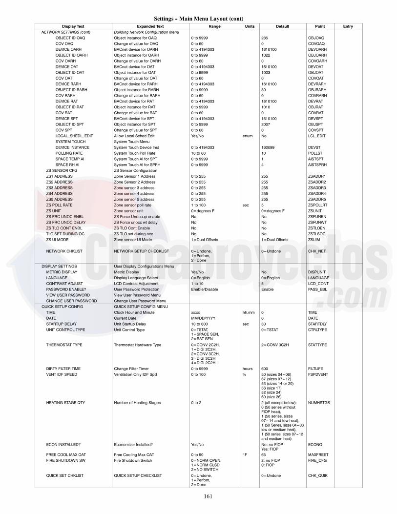
161
Settings -- Main Menu Layout (cont)Display Text Expanded Text Range Units Default Point Entry
NETWORK SETTINGS (cont) Building Network Configuration MenuOBJECT ID OAQ Object instance for OAQ 0 to 9999 285 OBJOAQCOV OAQ Change of value for OAQ 0 to 60 0 COVOAQDEVICE OARH BACnet device for OARH 0 to 4194303 1610100 DEVOARHOBJECT ID OARH Object instance for OARH 0 to 9999 1022 OBJOARHCOV OARH Change of value for OARH 0 to 60 0 COVOARHDEVICE OAT BACnet device for OAT 0 to 4194303 1610100 DEVOATOBJECT ID OAT Object instance for OAT 0 to 9999 1003 OBJOATCOV OAT Change of value for OAT 0 to 60 0 COVOATDEVICE RARH BACnet device for RARH 0 to 4194303 1610100 DEVRARHOBJECT ID RARH Object instance for RARH 0 to 9999 30 OBJRARHCOV RARH Change of value for RARH 0 to 60 0 COVRARHDEVICE RAT BACnet device for RAT 0 to 4194303 1610100 DEVRATOBJECT ID RAT Object instance for RAT 0 to 9999 1010 OBJRATCOV RAT Change of value for RAT 0 to 60 0 COVRATDEVICE SPT BACnet device for SPT 0 to 4194303 1610100 DEVSPTOBJECT ID SPT Object instance for SPT 0 to 9999 2007 OBJSPTCOV SPT Change of value for SPT 0 to 60 0 COVSPTLOCAL_SHEDL_EDIT Allow Local Sched Edit Yes/No enum No LCL_EDITSYSTEM TOUCH System Touch MenuDEVICE INSTANCE System Touch Device Inst 0 to 4194303 160099 DEVSTPOLLING RATE System Touch Poll Rate 10 to 60 10 POLLSTSPACE TEMP AI System Touch AI for SPT 0 to 9999 1 AISTSPTSPACE RH AI System Touch AI for SPRH 0 to 9999 4 AISTSPRH
ZS SENSOR CFG ZS Sensor ConfigurationZS1 ADDRESS Zone Sensor 1 Address 0 to 255 255 ZSADDR1ZS2 ADDRESS Zone Sensor 2 Address 0 to 255 255 ZSADDR2ZS3 ADDRESS Zone sensor 3 address 0 to 255 255 ZSADDR3ZS4 ADDRESS Zone sensor 4 address 0 to 255 255 ZSADDR4ZS5 ADDRESS Zone sensor 5 address 0 to 255 255 ZSADDR5ZS POLL RATE Zone sensor poll rate 1 to 100 sec 5 ZSPOLLRTZS UNIT Zone sensor unit 0=degrees F 0=degrees F ZSUNITZS FRC UNOC ENBL ZS Force Unoccup enable No No ZSFUNENZS FRC UNOC DELAY ZS Force unocc wt delay No No ZSFUNWTZS TLO CONT ENBL ZS TLO Cont Enable No No ZSTLOENTLO SET DURING OC ZS TLO set during occ No No ZSTLSOCZS UI MODE Zone sensor UI Mode 1=Dual Offsets 1=Dual Offsets ZSUIM
NETWORK CHKLIST NETWORK SETUP CHECKLIST 0=Undone,1=Perfom,2=Done
0=Undone CHK_NET
DISPLAY SETTINGS User Display Configurations MenuMETRIC DISPLAY Metric Display Yes/No No DISPUNITLANGUAGE Display Language Select 0=English 0=English LANGUAGECONTRAST ADJUST LCD Contrast Adjustment 1 to 10 5 LCD_CONTPASSWORD ENABLE? User Password Protection Enable/Disable Enable PASS_EBLVIEW USER PASSWORD View User Password MenuCHANGE USER PASSWORD Change User Password Menu
QUICK SETUP CONFIG QUICK SETUP CONFIG MENUTIME Clock Hour and Minute xx:xx hh.mm 0 TIMEDATE Current Date MM/DD/YYYY 0 DATESTARTUP DELAY Unit Startup Delay 10 to 600 sec 30 STARTDLYUNIT CONTROL TYPE Unit Control Type 0=TSTAT,
1=SPACE SEN,2=RAT SEN
0=TSTAT CTRLTYPE
THERMOSTAT TYPE Thermostat Hardware Type 0=CONV 2C2H,1=DIGI 2C2H,2=CONV 3C2H,3=DIGI 3C2H4=DIGI 2C2H
2=CONV 3C2H STATTYPE
DIRTY FILTER TIME Change Filter Timer 0 to 9999 hours 600 FILTLIFEVENT IDF SPEED Ventilation Only IDF Spd 0 to 100 % 50 (sizes 04---06)
67 (sizes 07---12)53 (sizes 14 or 20)56 (size 17)52 (size 24)60 (size 26)
FSPDVENT
HEATING STAGE QTY Number of Heating Stages 0 to 2 2 (all except below):0 (50 series withoutFIOP heat),1 (50 series, sizes07---14 and low heat),1 (50 Series, sizes 04---06low or medium heat),1 (50 series, sizes 07---12and medium heat)
NUMHSTGS
ECON INSTALLED? Economizer Installed? Yes/No No: no FIOPYes: FIOP
ECONO
FREE COOL MAX OAT Free Cooling Max OAT 0 to 90 ° F 65 MAXFREETFIRE SHUTDOWN SW Fire Shutdown Switch 0=NORM OPEN,
1=NORM CLSD,2=NO SWITCH
2: no FIOP0: FIOP
FIRE_CFG
QUICK SET CHKLIST QUICK SETUP CHECKLIST 0=Undone,1=Perfom,2=Done
0=Undone CHK_QUIK

162
ECarrier Corporation 2018 Edition Date: 5/18 Printed in U.S.A.
Manufacturer reserves the right to change, at any time, specifications and designs without notice and without obligations.
Catalog No: S---VU---LC---4---26---01T
Replaces: S---VU---LC---7---26---02T

163
UNIT START-UP CHECKLIST(Remove and Store in Job File)
NOTE: To avoid injury to personnel and damage to equipment or property whencompleting the procedures listed in this start---up checklist, use good judgement,follow safe practices, and adhere to the safety considerations/information asoutlined in the preceding sections of this Installation Instructions document.
MODEL NO.:
DATE:
I. PRE-START-UP:
SERIAL NO:
TECHNICIAN:
j VERIFY THAT ALL PACKAGING MATERIALS HAVE BEEN REMOVED FROM UNIT
j VERIFY INSTALLATION OF OUTDOOR AIR HOOD
j VERIFY INSTALLATION OF FLUE EXHAUST AND INLET HOOD (48LC ONLY)
j VERIFY THAT CONDENSATE CONNECTION IS INSTALLED PER INSTALLATION INSTRUCTIONS
j VERIFY THAT ALL ELECTRICAL CONNECTIONS AND TERMINALS ARE TIGHT
j VERIFY GAS PRESSURE TO UNIT GAS VALVE IS WITHIN SPECIFIED RANGE (48LC ONLY)
j CHECK GAS PIPING FOR LEAKS (48LC ONLY)
j CHECK THAT INDOOR--AIR FILTERS ARE CLEAN AND IN PLACE
j CHECK THAT OUTDOOR AIR INLET SCREENS ARE IN PLACE
j VERIFY THAT UNIT IS LEVEL
j CHECK FAN WHEELS AND PROPELLER FOR LOCATION IN HOUSING/ORIFICE AND VERIFY SETSCREW IS TIGHT
j VERIFY THAT FAN SHEAVES ARE ALIGNED AND BELTS ARE PROPERLY TENSIONED
j VERIFY THAT SCROLL COMPRESSORS ARE ROTATING IN THE CORRECT DIRECTION
j VERIFY INSTALLATION OF THERMOSTAT/SPACE SENSOR
j VERIFY CONFIGURATION VALUES FOR ELECTRONIC CONTROLS (REFER TO CONTROL SET UP CHECKLIST)
j VERIFY THAT CRANKCASE HEATERS HAVE BEEN ENERGIZED FOR AT LEAST 24 HOURS (48LC ONLY)
II. START-UPELECTRICAL
SUPPLY VOLTAGE L1-L2 L2-L3 L3-L1
COMPRESSOR AMPS — UNLOADED L1 L2 L3
—WITH LOADER L1 L2 L3
ELECTRIC HEAT AMPS (IF EQUIPPED) L1 L2 L3
SUPPLY FAN AMPS AT MAX SPEED L1 L2 L3
TEMPERATURES
OUTDOOR-AIR TEMPERATURE F DB (Dry Bulb) F WB (Wet Bulb)
RETURN-AIR TEMPERATURE F DB F WB
COOLING SUPPLY AIR F DB F WB
GAS HEAT SUPPLY AIR (48LC ) F F
ELECTRIC HEAT SUPPLY AIR (50LC) F F
PRESSURES
GAS INLET PRESSURE IN. WG
GAS MANIFOLD PRESSURE STAGE NO. 1 IN. WG STAGE NO. 2 IN. WG
REFRIGERANT SUCTION CIRCUIT A PSIG CIRCUIT A Superheat degF
REFRIGERANT DISCHARGE CIRCUIT A PSIG CIRCUIT A Subcooling degF
j VERIFY REFRIGERANT CHARGE USING CHARGING CHARTS
GENERALj ECONOMIZER MINIMUM VENT AND CHANGEOVER SETTINGS TO JOB REQUIREMENTS

164
III. HUMIDI--MIZERR SYSTEM START-UPSTEPS
j 1. CHECK CTB FOR JUMPER 5, 6, 7JUMPER 5, 6, 7 MUST BE CUT AND OPEN
j 2. OPEN HUMIDISTAT CONTACTS
j 3. START UNIT IN COOLING (CLOSE Y1)
OBSERVE AND RECORD
A. SUCTION PRESSURE PSIG PSIG
B. DISCHARGE PRESSURE PSIG PSIG
C. ENTERING AIR TEMPERATURE _F _F
D. LIQUID LINE TEMPERATUREAT OUTLET OR REHEAT COIL _F _F
E. CONFIRM CORRECT ROTATION FOR COMPRESSOR
F. CHECK FOR CORRECT RAMP--UP OF OUTDOOR FAN MOTOR AS CONDENSER COIL WARMS
j 3. CHECK UNIT CHARGE PER CHARGING CHART
j 4. SWITCH UNIT TO HIGH--LATENT MODE (SUBCOOLER) BY CLOSING HUMIDISTAT WITH Y1 CLOSED
OBSERVE
j A. REDUCTION IN SUCTION PRESSURE (5 TO 7 PSI EXPECTED)
j B. DISCHARGE PRESSURE UNCHANGED
j C. LIQUID TEMPERATURE DROPS TO 50 TO 55_F RANGE
j D. LSV SOLENOID ENERGIZED (VALVE CLOSES)
j 5. SWITCH UNIT TO DEHUMID (REHEAT) BY OPENING Y1
OBSERVE
j A. SUCTION PRESSURE INCREASES TO NORMAL COOLING LEVEL
j B. DISCHARGE PRESSURE DECREASES (35 TO 50 PSI)
j C. LIQUID TEMPERATURE RETURNS TO NORMAL COOLING LEVEL
j D. LSV SOLENOID ENERGIZED (VALVE CLOSES)
j E. DSV SOLENOID ENERGIZED, VALVE OPENS
j 6. WITH UNIT IN DEHUMID MODE CLOSE W1COMPRESSOR AND OUTDOOR FAN STOP; LSV AND DSV SOLENOIDS DE--ENERGIZED
j 7. OPEN W1 RESTORE UNIT TO DEHUMID MODE
j 8. OPEN HUMIDISTAT INPUTCOMPRESSOR AND OUTDOOR FAN STOP; LSV AND DSV SOLENOIDS DE--ENERGIZED
j 9. RESTORE SETPOINTS FOR THERMOSTAT AND HUMIDISTAT
REPEAT PROCESS FOR 2 COMPRESSOR SYSTEMS
ECarrier Corporation 2018 Edition Date: 5/18 Printed in U.S.A.
Manufacturer reserves the right to change, at any time, specifications and designs without notice and without obligations.
Catalog No: S---VU---LC---4---26---01T
Replaces: S---VU---LC---7---26---02T
Related Documents