OPERATION & MAINTENANCE Paver Finisher SD1800W Type 913 02-0516 4812018601

Welcome message from author
This document is posted to help you gain knowledge. Please leave a comment to let me know what you think about it! Share it to your friends and learn new things together.
Transcript

OPERATION & MAINTENANCEPaver FinisherSD1800WType 913
02-05164812018601

www.dynapac.com
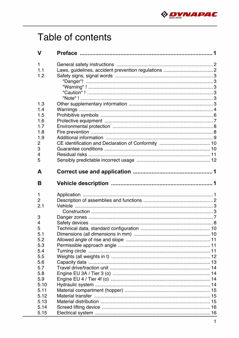
Table of contents
V Preface ..................................................................................... 1
1 General safety instructions ........................................................................ 21.1 Laws, guidelines, accident prevention regulations ..................................... 21.2 Safety signs, signal words ......................................................................... 3
"Danger"! ............................................................................................... 3"Warning" ! ............................................................................................. 3"Caution" ! .............................................................................................. 3"Note" ! ................................................................................................... 3
1.3 Other supplementary information ............................................................... 31.4 Warnings .................................................................................................... 41.5 Prohibitive symbols .................................................................................... 61.6 Protective equipment ................................................................................. 71.7 Environmental protection ........................................................................... 81.8 Fire prevention ........................................................................................... 81.9 Additional information ................................................................................ 92 CE identification and Declaration of Conformity ...................................... 103 Guarantee conditions ............................................................................... 104 Residual risks ........................................................................................... 115 Sensibly predictable incorrect usage ....................................................... 12
A Correct use and application ................................................... 1
B Vehicle description ................................................................. 1
1 Application ................................................................................................. 12 Description of assemblies and functions .................................................... 22.1 Vehicle ....................................................................................................... 3
Construction ........................................................................................... 33 Danger zones ............................................................................................. 74 Safety devices ............................................................................................ 85 Technical data, standard configuration .................................................... 105.1 Dimensions (all dimensions in mm) ......................................................... 105.2 Allowed angle of rise and slope ............................................................... 115.3 Permissible approach angle ..................................................................... 115.4 Turning circle ........................................................................................... 115.5 Weights (all weights in t) .......................................................................... 125.6 Capacity data ........................................................................................... 135.7 Travel drive/traction unit ........................................................................... 145.8 Engine EU 3A / Tier 3 (o) ......................................................................... 145.9 Engine EU 4 / Tier 4f (o) .......................................................................... 145.10 Hydraulic system ...................................................................................... 145.11 Material compartment (hopper) ................................................................ 155.12 Material transfer ....................................................................................... 155.13 Material distribution .................................................................................. 155.14 Screed lifting device ................................................................................. 165.15 Electrical system ...................................................................................... 16
1
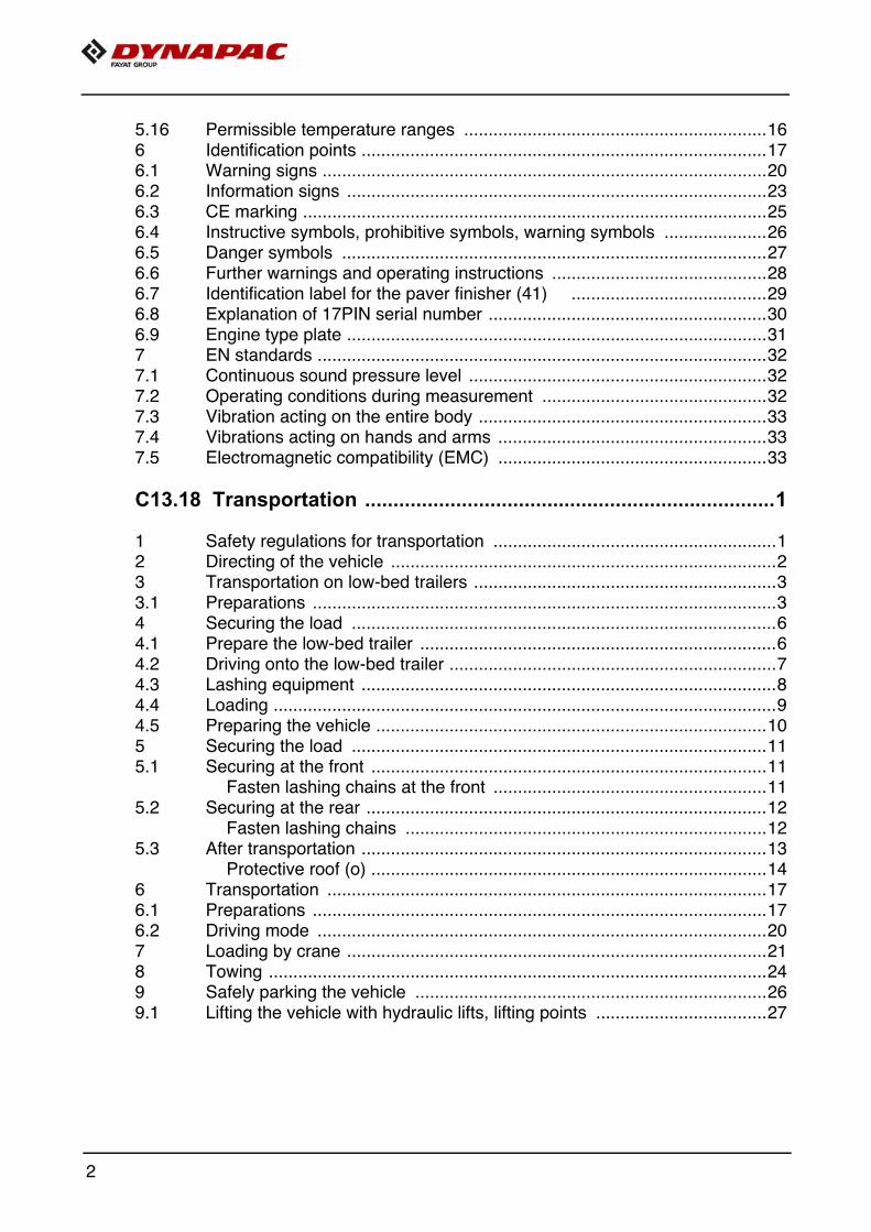
5.16 Permissible temperature ranges ..............................................................166 Identification points ...................................................................................176.1 Warning signs ...........................................................................................206.2 Information signs ......................................................................................236.3 CE marking ...............................................................................................256.4 Instructive symbols, prohibitive symbols, warning symbols .....................266.5 Danger symbols .......................................................................................276.6 Further warnings and operating instructions ............................................286.7 Identification label for the paver finisher (41) ........................................296.8 Explanation of 17PIN serial number .........................................................306.9 Engine type plate ......................................................................................317 EN standards ............................................................................................327.1 Continuous sound pressure level .............................................................327.2 Operating conditions during measurement ..............................................327.3 Vibration acting on the entire body ...........................................................337.4 Vibrations acting on hands and arms .......................................................337.5 Electromagnetic compatibility (EMC) .......................................................33
C13.18 Transportation ........................................................................1
1 Safety regulations for transportation ..........................................................12 Directing of the vehicle ...............................................................................23 Transportation on low-bed trailers ..............................................................33.1 Preparations ...............................................................................................34 Securing the load .......................................................................................64.1 Prepare the low-bed trailer .........................................................................64.2 Driving onto the low-bed trailer ...................................................................74.3 Lashing equipment .....................................................................................84.4 Loading .......................................................................................................94.5 Preparing the vehicle ................................................................................105 Securing the load .....................................................................................115.1 Securing at the front .................................................................................11
Fasten lashing chains at the front ........................................................115.2 Securing at the rear ..................................................................................12
Fasten lashing chains ..........................................................................125.3 After transportation ...................................................................................13
Protective roof (o) .................................................................................146 Transportation ..........................................................................................176.1 Preparations .............................................................................................176.2 Driving mode ............................................................................................207 Loading by crane ......................................................................................218 Towing ......................................................................................................249 Safely parking the vehicle ........................................................................269.1 Lifting the vehicle with hydraulic lifts, lifting points ...................................27
2
D13.18 Operation................................................................................ 1
1 Safety regulations ...................................................................................... 12 Controls ...................................................................................................... 32.1 Operating panel ......................................................................................... 33 Remote control ......................................................................................... 60
D23.18 Operating the display ............................................................. 1
1 Operation of the input and display terminal ............................................... 2Button layout on the display ................................................................... 2
1.1 Menu operation - procedure for adjusting parameters ............................... 4Selecting and changing an adjustment parameter in a menu ................ 6Selecting and changing a selection possibility in a menu ...................... 7
2 Menu structure ........................................................................................... 8Menu of the "Home" displays ................................................................. 8Displays: ................................................................................................ 8"HOME" menu - sub-menus .................................................................. 9"Home" functions / "Quick Settings" .................................................... 11"Engine Speed" menu / Engine measured value display ..................... 13"Material Management" measured value display ................................. 14"Screed Heater" adjustment and display menu (o) .............................. 15"Paving Area / Automatic Steering Unit" menu .................................... 16"Paving parameters" menu .................................................................. 17Adjusting the paving parameters ......................................................... 19 Overview "Course Thickness Parameters" ......................................... 20"Error Memory" menu .......................................................................... 21Detailed display "Error Messages With Travel Drive Stop" ................. 22Detailed display "Vehicle Warning Messages" .................................... 23Detailed display "Engine Error Messages" .......................................... 24"Basic" menu ....................................................................................... 25"Service" menu .................................................................................... 26"Info & Settings" menu ......................................................................... 27Display of the following information: .................................................... 27"Screed" set-up menu .......................................................................... 28"Paving / Travel" set-up menu ............................................................. 30"Truck Assist / Set Assist" set-up menu ............................................... 32"Day/Night Lighting" set-up menu ........................................................ 33"Display" set-up menu ......................................................................... 34"Licence text" display ........................................................................... 35
3 Terminal error messages ......................................................................... 36Status, warning and error messages symbols ..................................... 36
3.1 Drive engine error codes .......................................................................... 423.2 Error codes .............................................................................................. 464 Menu structure of the setting and display menus .................................. 110
3
D30.18 Operation ............................................................................... 1
1 Operating elements on the paver finisher ..................................................11.1 Control elements on the operator's control station .....................................1
Protective roof (o) ...................................................................................2Control platform, telescoping seat consoles ..........................................5Operating panel ......................................................................................6Service brake ("foot brake") (o) ..............................................................6Seat console ..........................................................................................7Storage space ........................................................................................7Protective roof (o) ...................................................................................8Windscreen wiper ...................................................................................9Sunshade ...............................................................................................9Holder for the vandalism protection facility ............................................9Driver's seat, type I .............................................................................10Driver's seat, type II ............................................................................11Fuse box ..............................................................................................12Batteries ...............................................................................................13Main battery switch ..............................................................................13Hopper transport safeguard .................................................................14Screed lock, mechanical ......................................................................14Paving thickness indicator ...................................................................15Auger lighting (o) ..................................................................................16LED working light (o) ............................................................................17Mechanical height adjustment, auger (o) .............................................18Sensor rod / sensor rod extension .......................................................19Manual separator fluid spray (o) ..........................................................21Separator fluid spraying system (o) .....................................................22Conveyor limit switches ........................................................................23Ultrasonic auger limit switches (left and right) - PLC version ...............24Ultrasonic auger limit switches (left and right) - conventional version ..2524 volt / 12 volt sockets (o) ..................................................................26Central lubrication system (o) ..............................................................27Pressure control valve for paving stop with relief .................................28Lane clearer (o) ....................................................................................29Screed eccentric adjustment ................................................................30Push roller crossbar, adjustable ...........................................................31Push roller damping, hydraulic (o) .......................................................32Fire extinguisher (o) .............................................................................33First-aid kit (o) ......................................................................................33Rotary beacon (o) ................................................................................34Illuminated balloon (o) ..........................................................................35Installation and operation .....................................................................37Decommissioning ................................................................................38Cleaning ............................................................................................38Service safety ......................................................................................38
4
D43.18 Mode of operation .................................................................. 1
1 Preparing for operation .............................................................................. 1Required devices and aids .................................................................... 1Before starting work (in the morning or when starting paving) .............. 3Check list for the machine operator ....................................................... 3
1.1 Starting the paver finisher .......................................................................... 6Before starting the paver finisher ........................................................... 6"Normal" starting .................................................................................... 6External starting (starting aid) ................................................................ 8After starting ........................................................................................ 11Observe indicator lamps ...................................................................... 13Engine coolant temperature check (A) ................................................ 13Battery charge indicator lamp (B) ........................................................ 13Diesel engine oil pressure indicator lamp (C) ...................................... 13Travel drive oil pressure indicator lamp (D) ......................................... 15
1.2 Preparation for transportation .................................................................. 17Driving and stopping the paver finisher ............................................... 19
1.3 Preparations for paving ............................................................................ 20Separator fluid ..................................................................................... 20Screed heater system .......................................................................... 20Direction marks .................................................................................... 21Loading/conveying material ................................................................. 23
1.4 Starting for paving .................................................................................... 251.5 Checks during paving .............................................................................. 26
Paver function ...................................................................................... 26Quality of the layer ............................................................................... 26Screed control with paver finisher stop / in paving operation(screed stop / paving stop / floating paving) ........................................ 28Setting pressure for screed control with paving stop + relieving: ....... 29
1.6 Interrupting/terminating operation ............................................................ 31During breaks in paving (e.g. delay due to material trucks) ................. 31During longer breaks (e.g. lunch break) .............................................. 31When work is finished .......................................................................... 33
2 Malfunctions ............................................................................................. 342.1 Problems during paving ........................................................................... 342.2 Malfunctions on the paver finisher or screed ........................................... 36
E10.18 Set-up and modification ........................................................ 1
1 Special notes on safety .............................................................................. 12 Distribution auger ....................................................................................... 32.1 Height adjustment ...................................................................................... 32.2 Auger width extension and material shaft with protective cover
(optional equipment) .................................................................................. 5Push roller crossbar, adjustable ............................................................ 6Hopper scraper ...................................................................................... 7
2.3 Crossbeam guide ....................................................................................... 83 Screed ........................................................................................................ 94 Electrical connections ................................................................................ 9
5

5 Limit switch ...............................................................................................115.1 Auger limit switches (left and right) - mount PLC version .........................115.2 Auger limit switches (left and right) - mount conventional version ...........12
F10 Maintenance .............................................................................1
1 Notes regarding safety ...............................................................................1
F23.18 Maintenance review................................................................ 1
1 Maintenance review ...................................................................................1
F30.18 Maintenance - conveyor......................................................... 1
1 Maintenance - conveyor .............................................................................11.1 Maintenance intervals ................................................................................31.2 Points of maintenance ................................................................................4
Chain tension, conveyor (1) ...................................................................4Conveyor drive - drive chains (2) ...........................................................6Conveyor deflectors / conveyor plates (3) ..............................................7
F40.18 Maintenance - auger assembly .............................................1
1 Maintenance - auger assembly ..................................................................11.1 Maintenance intervals ................................................................................31.2 Points of maintenance ................................................................................5
Auger drive chains (1) ............................................................................5Auger box (2) .........................................................................................7Seals and sealing rings (3) .....................................................................8Outer auger bearing (4) ..........................................................................9Mounting screws - outer augur bearing Check tightening (5) ................9Auger blade (6) ....................................................................................10
F50.18 Maintenance - engine assembly ............................................1
1 Maintenance - engine assembly .................................................................11.1 Maintenance intervals ................................................................................31.2 Points of maintenance ................................................................................6
Engine fuel tank (1) ...............................................................................6Engine lube oil system (2) .....................................................................7Engine fuel system (3) ..........................................................................9Engine air filter (4) ................................................................................11Engine cooling system (5) ....................................................................12Engine drive belt (6) .............................................................................14
6

F60.18 Maintenance - hydraulic system ........................................... 1
1 Maintenance - hydraulic system ................................................................ 11.1 Maintenance intervals ................................................................................ 41.2 Points of maintenance ............................................................................... 6
Hydraulic oil tank (1) .............................................................................. 6Suction/return flow hydraulic filter (2) .................................................... 8Ventilation filter ...................................................................................... 8High-pressure filter (3) ........................................................................... 9High-pressure filter (4) ......................................................................... 10Pump distribution gear (5) ................................................................... 11Bleeder ............................................................................................... 12Hydraulic hoses (6) .............................................................................. 13Marking hydraulic hoses / storage period, period of use ..................... 15Auxiliary flow filter (6) ........................................................................... 16
F71.18 Maintenance - travel drive, steering ..................................... 1
1 Maintenance - travel drive, steering ........................................................... 11.1 Maintenance intervals ................................................................................ 31.2 Points of maintenance ............................................................................... 5
Planetary gear (1) .................................................................................. 5Drive wheels (2) ..................................................................................... 6Replacing/dismantling and installing the wheels ................................... 7Lubrication points (3) ........................................................................... 11
F81.18 Maintenance - electrical system ........................................... 1
1 Maintenance - electrical system ................................................................. 11.1 Maintenance intervals ................................................................................ 31.2 Points of maintenance ............................................................................... 4
Batteries (1) ........................................................................................... 4Recharging the batteries ........................................................................ 5Alternator (2) .......................................................................................... 6Insulation faults ...................................................................................... 8Cleaning the alternator .......................................................................... 9Drive belts ........................................................................................... 10
2 Electrical fuses ......................................................................................... 122.1 Main fuses ................................................................................................ 122.2 Fuses in main terminal box ...................................................................... 13
Relays in main terminal box ................................................................. 15
F90.18 Maintenance - lubricating points ........................................... 1
1 Maintenance - lubricating points ................................................................ 11.1 Maintenance intervals ................................................................................ 21.2 Points of maintenance ............................................................................... 3
Central lubrication system (1) ................................................................ 3Bearing points (2) .................................................................................. 7
7

F100 Tests, stopping ........................................................................1
1 Tests, checks, cleaning, stopping ..............................................................11.1 Maintenance intervals ................................................................................22 General visual inspection ...........................................................................33 Check that the bolts and nuts fit firmly .......................................................34 Inspection by an expert ..............................................................................45 Cleaning .....................................................................................................55.1 Cleaning the hopper ...................................................................................65.2 Cleaning the conveyor and auger ..............................................................65.3 Cleaning optical or acoustic sensors ..........................................................76 Preserving the paver finisher ......................................................................86.1 Shutdowns for up to 6 months ....................................................................86.2 Shutdowns lasting from 6 months to 1 year ...............................................86.3 Recommissioning the machine ..................................................................87 Environmental protection, disposal ............................................................97.1 Environmental protection ............................................................................97.2 Disposal ......................................................................................................98 Bolts - torques ..........................................................................................108.1 Standard metric threads - strength class 8.8 / 10.9 / 12.9 ........................108.2 Fine metric threads - strength class 8.8 / 10.9 / 12.9 ...............................11
F111.18 Lubricants and operating substances................................ 1
1 Lubricants and operating substances .........................................................11.1 Capacities ...................................................................................................32 Operating substance specifications ............................................................42.1 Notes on diesel fuel ....................................................................................42.2 Drive engine TIER III (o) fuel specification ................................................42.3 Drive engine TIER IV (o) - fuel specification ..............................................42.4 Engine - lubricating oil ................................................................................52.5 Cooling system ...........................................................................................52.6 Hydraulic system ........................................................................................52.7 Pump distribution gear ...............................................................................52.8 Pump distribution gear, as of s/n 3309, 3510 ff. .........................................52.9 Drive unit planetary gear ............................................................................62.10 Auger box ..................................................................................................62.11 Grease .......................................................................................................62.12 Hydraulic oil ................................................................................................7
8

V Preface
Translation of the original operating instructions.
If the vehicle is to be operated safely, the information provided in these operating in-structions will be required. The information is provided in a concise, clearly structuredform. The individual chapters are arranged in alphabetical order. and every chapterstarts with page 1. The individual pages are identified by the chapter letter and thepage number.Example: Page B 2 is the second page of chapter B.
These operating instructions cover various vehicle options. Make sure that during op-eration and maintenance work the description appropriate to the vehicle option isused.
In the interest of continued development, the manufacturer reserves the right to makechanges to the vehicle (which will not, however, change the essential features of thetype of vehicle described) without updating the present operating instructions at thesame time.
Dynapac GmbHWardenburg
Ammerländer Strasse 93D-26203 Wardenburg / GermanyTelephone: +49 / (0)4407 / 972-0Fax: +49 / (0)4407 / 972-228www.dynapac.com
V 1
1 General safety instructions
1.1 Laws, guidelines, accident prevention regulations
A The locally applicable laws, guidelines and accident prevention regulations must al-ways be observed, even if these are not expressly named here. The user himself/herself is responsible for compliance with the resulting regulationsand measures!
A The following warnings, prohibitive symbols and instructive symbols indicate dangersfor persons, the vehicle and the environment due to residual risks when operating thevehicle.
A Failure to observe this information, prohibitions and instructions can result in life-threatening injuries!
A The "Guidelines for the Correct Use and Application of Paver Finishers" compiled byDynapac must also be observed!
V 2

1.2 Safety signs, signal words
In the safety instructions, the signal words "Danger", "Warning", "Caution", "Note" arepositioned in the coloured title block. They follow a certain hierarchy; in combinationwith the warning symbol, they indicate the severity of the danger or the type of note.
"Danger"!
Danger of personal injury.Indication of an immediately threatening danger that result in fatal or severe injuriesunless the corresponding actions are taken.
"Warning" !
Indication of a possible danger that can result in fatal or se-vere injuries unless the corresponding actions are taken.
"Caution" !
Indication of a possible danger that result in moderate or mi-nor injuries unless the corresponding actions are taken.
"Note" !
Indication of a possible drawback unless the correspondingactions are taken, e.g. unwanted conditions or consequences can occur.
1.3 Other supplementary information
Other information and important explanations are identified by the following picto-grams:
f Precedes safety instructions that must be observed in order to prevent danger to per-sonnel.
m Precedes notes that must be observed to prevent damage to equipment.
A Precedes general notes and explanations.
DANGER
WARNING
CAUTION
NOTE
V 3
1.4 Warnings
Warning on a dangerous area or hazard!Failure to observe the warnings can result in life-threatening inju-ries!
Warning on danger of being pulled in!
m In this working area/on this element there is a danger of being pulledin by rotating or conveying elements!Only carry out activities with elements switched off!
Warning on dangerous electrical voltage!
m All maintenance and repair work on the screed's electrical systemmust always be carried out by an electrician!
Warning on suspended loads!
m Never stand under suspended loads!
Warning on danger of crushing!
m There is a danger of crushing when certain components are operat-ed, or certain functions or vehicle movements are carried out. Always make sure that there are no persons within the endangeredareas!
Warning on hand injuries!
Warning on hot surfaces or hot liquids!
V 4

Warning on danger of falling!
Warning on dangers posed by batteries!
Warning on hazardous or irritating substances!
Warning on substances which constitute a fire hazard!
Warning on gas bottles!
V 5

1.5 Prohibitive symbols
Opening/walking on/reaching in/carrying out/setting up are prohibit-ed during operation or while the drive engine is running!
Do not start engine/drive!Maintenance and repair work may only be carried out with the dieselengine shut down!
Spraying with water is prohibited!
Extinguishing with water is prohibited!
Unauthorised maintenance is prohibited!Only qualified experts may conduct maintenance!
A Consult the Dynapac Service Department
Fire!, naked flames and smoking are prohibited!
Do not switch!
V 6

1.6 Protective equipment
A Locally applicable regulations may require the wearing of various safety equipment! Always observe these regulations!
Wear safety goggles to protect your eyes!
Wear suitable head protection!
Wear suitable hearing protection to protect your hearing!
Wear suitable safety gloves to protect your hands!
Wear safety shoes to protect your feet!
Always wear close-fitting work clothing!Wear a warning vest to be seen in time to avoid accidents!
Wear respiratory equipment if breathing air is contaminated!
V 7

1.7 Environmental protection
A The locally applicable laws, guidelines and accident prevention regulations for theproper recycling and disposal of waste must always be observed, even if these arenot expressly named here. Water-endangering substances like:
- Lubricants (oil, grease)
- Hydraulic oil
- Diesel fuel
- Coolant
- Cleaning liquids
must not get into the soil or sewer system during cleaning, maintenance and repairwork!
Substances must be caught, stored, transported and brought to pro-fessional disposal sites in suitable containers!
Environmentally hazardous substance!
1.8 Fire prevention
A Locally applicable regulations may require suitable extinguishing agents to be carriedon the vehicle! Always observe these regulations!
Fire extinguisher!(optional equipment)
V 8

1.9 Additional information
m Also observe the manufacturer's documentation and additional doc-umentation!
A For example, the maintenance instructions of the engine manufac-turer
m Description / depiction applicable when equipped with gas heater!
m Description / depiction applicable when equipped with electric heat-er!
t Used to indicate standard equipment.
o Used to indicate optional equipment.
V 9
2 CE identification and Declaration of Conformity
(only applies to machines sold in the EU/EEC)
This machine has CE identification. This identification says that the machine fulfils thebasic health and safety requirements pursuant to the Machinery Directive 2006/42/EC together with all other valid regulations. The scope of supply of the machine in-cludes a Declaration of Conformity as specified in the valid regulations and amend-ments together with harmonised standards and other valid provisions.
3 Guarantee conditions
A The guarantee conditions are included in the scope of supply of the machine. This contains a complete specification of the valid conditions.
The guarantee becomes null and void if
- damage occurrs through malfunctions caused by improper use and incorrect oper-ation.
- repairs or manipulations are carried out by persons who are neither trained nor au-thorised accordingly.
- accessories or spare parts are used that cause damage and which are not ap-proved by Dynapac.
V 10

4 Residual risks
These are risks that remain even if all possible measures and safety precautionshave been taken to help minimise dangers (risks) or to reduce their probability andscope to zero.
Residual risks in the form of
- Danger to life and limb of persons at the machine- Danger to the environment posed by the machine- Damage to property and restricted output and functionality of the machine- Damage to property in the operating range of the machine
caused by:
- wrong or improper use of the machine
- defective or missing safety devices
- use of the machine by untrained, uninstructed staff
- defective or damaged parts
- incorrect transport of the machine
- incorrect maintenance or repairs
- leaking operating substances
- emission of noise and vibrations
- impermissible operating substances
Existing residual risks can be avoided by complying and implementing the fol-lowing:
- warnings at the machine
- warnings and instructions in the safety manual for paver finishers and in the oper-ating instructions of the paver finisher
- Operating instructions of the machine operator
V 11

5 Sensibly predictable incorrect usage
Every kind of sensibly predictable incorrect usage of the machine constitutes misuse.Incorrect usage makes the manufacturer's warranty null and void: the operator bearssole responsibility.
Sensibly predictable incorrect usage of the machine includes:
- presence in the danger zone of the machine
- transporting persons
- leaving the operator's platform while the machine is operating
- removing protection or safety devices
- starting and using the machine outside the operator's platform
- operating the machine with the screed walkway plate hinged up
- failing to comply with the maintenance instructions
- omission or incorrect execution of maintenance or repair work
- spraying the machine with high pressure cleaners
V 12
A Correct use and applicationA The "Guidelines for the Correct Use and Application of Paver Finishers" compiled by
Dynapac are included in the scope of delivery for the present machine. Theguidelines are part of the present operating instructions and must always be heeded.National regulations are fully applicable.
The road construction machine described in these operating instructions is a paverfinisher that is suited for laying mixed materials, roll-down concrete or lean-mixedconcrete, track-laying ballast and unbound mineral aggregates for foundations forpaving.The paver finisher must be used, operated and maintained according to theinstructions given in the present operating instructions. Any other use is regarded asimproper use and can cause injury to persons or damage to the paver finisher or otherequipment or property.
Any use going beyond the range of applications described above is regarded asimproper use and is expressly forbidden! Especially in those cases where the paverfinisher is to be operated on inclines or where it is to be used for special purposes(construction of dumps, dams), it is absolutely necessary to contact the manufacturer.
Duties of the user: A "user" within the meaning of these operating instructions isdefined as any natural or legal person who either uses the paver finisher himself, oron whose behalf it is used. In special cases (e.g. leasing or renting), the user isconsidered to be the person who, in accordance with existing contractual agreementsbetween the owner and the user of the paver finisher, is charged with the observanceof the operating duties.The user must ensure that the paver finisher is only used in the stipulated manner andthat all danger to life and limb of the operator, or third parties, is avoided. In additionto this, it must be ensured that the relevant accident prevention regulations and othersafety-related provisions as well as the operating, servicing and maintenanceguidelines are observed. The user must also ensure that all persons operating thepaver finisher have read and understood the present operating instructions.
Mounting of attachments: The paver finisher must only be operated in conjunctionwith screeds that have been approved by the manufacturer. Mounting or installationof any attachments that will interfere with or supplement the functions of the paverfinisher is permitted only after written approval by the manufacturer has beenobtained. If necessary, the approval of local authorities must be obtained.Any approval obtained from local authorities does not, however, make approval bythe manufacturer unnecessary.
A 1

A 2

B Vehicle description
1 Application
The Dynapac paver finisher SD1800W is a wheeled paver finisher which is used forpaving bituminous mixed material, roll-down or lean-mixed concrete, track-laying bal-last and unbound mineral aggregates for foundations for paving.
B 1

2 Description of assemblies and functions
Item Designation
1 t Material compartment (hopper)
2 t Truck push rollers
3 t Sensor rod (direction indicator)
4 t Rear wheels
5 t Levelling cylinder for paving thickness
6 t Traction roller
7 t Crossbeam pull bar
8 t Paving thickness indicator
9 t Crossbeam
10 t Travel drive
11 t Auger
12 t Screed
13 t Operator’s platform
14 t Operating panel (can be moved to either side)
15 t Tandem front axle
16 o Protective roof
17 o Working lights
18 o Hydraulic front hopper flap
= Standard equipment o = Optional equipment
12 1
27 6910
14
13
16
411
17
3
15
18
B 2

2.1 Vehicle
Construction
The paver finisher has a welded steel frame on which the individual componentsare mounted.
The large drive wheels and the tandem front axle compensate uneven areas onthe ground; the suspension of the attached screed additionally helps to attain highpaving precision. The continuously adjustable hydrostatic travel drive allows the speed of the paver fin-isher to be matched to all work conditions.
The operation of the paver finisher is considerably facilitated by the automatic mate-rial handling system, the independent travel drives and the clearly structured operat-ing components and controls.
The following extra equipment (option) is available:
o Automatic levelling/slope control system
o Hopper with hydraulic front hopper
o Protective roof (control platform)
o Emulsion spraying system
o Push roller damping "Safe Impact System"
o Asphalt fume control system
o Additional headlights, warning lamps
o Central lubrication system
o Alternator
o Larger working widths
o Further equipment and upgrade options on request
B 3
Engine: The paver finisher is driven by a water cooled diesel engine. For further de-tails see the technical data and the engine's instruction manual.
Traction unit: The front axle is a tandem swing axle. As the wheels are not mountedon non-uniform lifting arms, the second front wheel is subject to a heavier load on theshorter lifting arm.This solution provides increased steering and load-bearing capabilities, especially onsoft grounds. The tyres are solid rubber tyres at the front axle and large, tubeless,pneumatic tyres at the rear axle.When equipped with an additional front wheel drive, the second front axle can beused as a second drive axle.
Hydraulic system: The diesel engine drives the hydraulic pumps for all main paverfinisher drives via the attached distribution gear and its auxiliary drive shafts.
Travel drive: The continuously adjustable travel drive pumps are connected to thetravel drive engines by means of high pressure hydraulic hoses.These oil engines drive the drive wheels via planetary gears.The multi-stage planetary gear covers the various driving ranges and the brakingfunction.
Steering system/operator's platform: The fully hydraulic steering system ensureseasy manoeuvrability.The small turning radius permits quick and easy manoeuvring.The seat consoles left/right can be moved beyond the outer edge of the vehicle, pro-viding the driver with a better view of the paving area in this position.The entire operating panel can be swivelled for operation beyond the outer edgeof the vehicle, and can be additionally be locked in several positions along thecontrol platform.
Push roller crossbar: The push rollers for material trucks are fastened to a cross barthat is pivoted at its centre. The paver finisher thus deviates less from its course andpaving in curves is made easier.For adaptation to various truck design types, the push roller crossbar can be shiftedto two positions.
Push roller damping (o) hydraulically absorbs the shocks between the material truckand paver finisher.
B 4
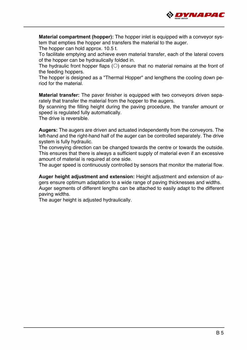
Material compartment (hopper): The hopper inlet is equipped with a conveyor sys-tem that empties the hopper and transfers the material to the auger. The hopper can hold approx. 10.5 t.To facilitate emptying and achieve even material transfer, each of the lateral coversof the hopper can be hydraulically folded in. The hydraulic front hopper flaps (o) ensure that no material remains at the front ofthe feeding hoppers.The hopper is designed as a "Thermal Hopper" and lengthens the cooling down pe-riod for the material.
Material transfer: The paver finisher is equipped with two conveyors driven sepa-rately that transfer the material from the hopper to the augers. By scanning the filling height during the paving procedure, the transfer amount orspeed is regulated fully automatically.The drive is reversible.
Augers: The augers are driven and actuated independently from the conveyors. Theleft-hand and the right-hand half of the auger can be controlled separately. The drivesystem is fully hydraulic. The conveying direction can be changed towards the centre or towards the outside.This ensures that there is always a sufficient supply of material even if an excessiveamount of material is required at one side. The auger speed is continuously controlled by sensors that monitor the material flow.
Auger height adjustment and extension: Height adjustment and extension of au-gers ensure optimum adaptation to a wide range of paving thicknesses and widths. Auger segments of different lengths can be attached to easily adapt to the differentpaving widths. The auger height is adjusted hydraulically.
B 5
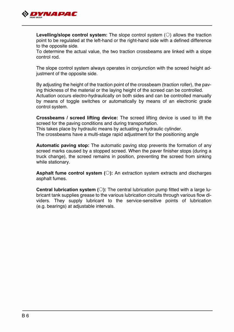
Levelling/slope control system: The slope control system (o) allows the tractionpoint to be regulated at the left-hand or the right-hand side with a defined differenceto the opposite side. To determine the actual value, the two traction crossbeams are linked with a slopecontrol rod.
The slope control system always operates in conjunction with the screed height ad-justment of the opposite side.
By adjusting the height of the traction point of the crossbeam (traction roller), the pav-ing thickness of the material or the laying height of the screed can be controlled. Actuation occurs electro-hydraulically on both sides and can be controlled manuallyby means of toggle switches or automatically by means of an electronic gradecontrol system.
Crossbeams / screed lifting device: The screed lifting device is used to lift thescreed for the paving conditions and during transportation. This takes place by hydraulic means by actuating a hydraulic cylinder.The crossbeams have a multi-stage rapid adjustment for the positioning angle
Automatic paving stop: The automatic paving stop prevents the formation of anyscreed marks caused by a stopped screed. When the paver finisher stops (during atruck change), the screed remains in position, preventing the screed from sinkingwhile stationary.
Asphalt fume control system (o): An extraction system extracts and dischargesasphalt fumes.
Central lubrication system (o): The central lubrication pump fitted with a large lu-bricant tank supplies grease to the various lubrication circuits through various flow di-viders. They supply lubricant to the service-sensitive points of lubrication(e.g. bearings) at adjustable intervals.
B 6

3 Danger zones
Danger for persons in the danger zone
Persons in the danger zone can suffer severe or fatal inju-ries from movements and functions of the vehicle!
- Remaining in the vehicle's danger zone during operation is prohibited!
- During operation, only the vehicle operator and the screed personnel are allowed on the vehicle or in the danger zone. The vehicle operator and screed personnel must keep to the respective driver's seats.
- Make sure that there is no-one in the danger zone before switching the vehicle on or starting it moving.
- The vehicle operator must ensure that no-one is in the danger zone.
- Sound the horn before driving away.- Comply with all further information in these instructions
and in the safety manual.
WARNING
B 7
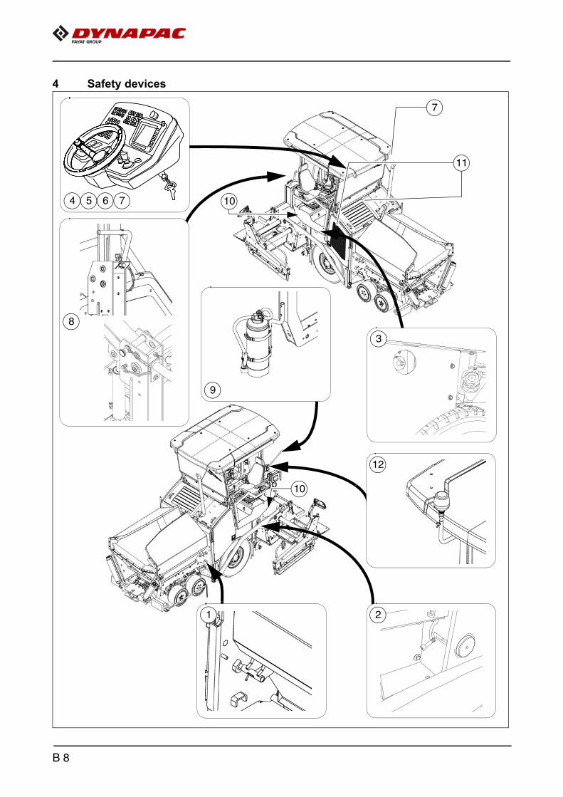
4 Safety devices
10
7
2
11
21
9
12
3
4 5 6 7
10
8
B 8

** Located on both sides of the vehicle
m Safe operation is only possible when all operating and control elements are function-ing correctly and when all safety devices are in position.
m Check the function of these devices at regular intervals.
A Functional descriptions for the individual safety facilities can be found in the follow-ing chapters.
Item Designation
1 Hopper transport safeguard **
2 Crossbeam lock, mechanical **
3 Main switch
4 Emergency stop button
5 Horn
6 Ignition key
7 Lights **
8 Protective roof latch (o) **
9 Fire extinguisher (o)
10 Screed warning light (o) **
11 Covers, lateral flaps, coverings **
12 Foot brake
13 Hazard warning flasher **
14 Rotary beacon (o)
B 9
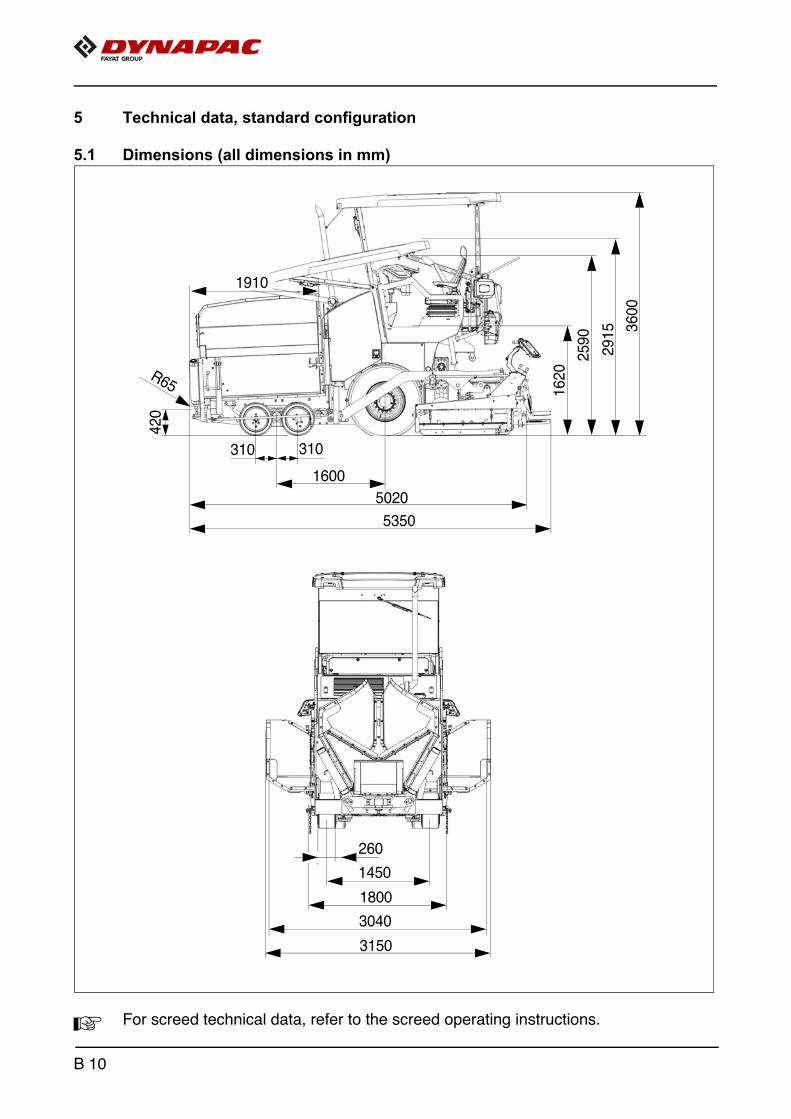
5 Technical data, standard configuration
5.1 Dimensions (all dimensions in mm)
A For screed technical data, refer to the screed operating instructions.
R65
5350
5020
1620
2590
2915 3600
3150
3040
1800
1450
260
420
1910
1600
310 310
B 10

5.2 Allowed angle of rise and slope
A Before operating your vehicle in an inclined position (gradient, slope, lateral inclina-tion) which is above the specified limit value, please consult the customer service de-partment for your vehicle!
5.3 Permissible approach angle
5.4 Turning circle
Internal turning cycle 2.51 mExternal turning cycle 4.31 m
max. 15°
max. 15° max. 15°
max. 15°
max. 15° max. 13°
B 11
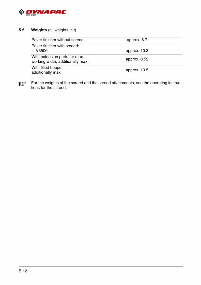
5.5 Weights (all weights in t)
A For the weights of the screed and the screed attachments, see the operating instruc-tions for the screed.
Paver finisher without screed approx. 8.7
Paver finisher with screed:- V3500 approx. 10.3
With extension parts for max. working width, additionally max.:
approx. 0.52
With filled hopperadditionally max.
approx. 10.5
B 12

5.6 Capacity data
Scre
ed u
sed
Ba
sic
wid
th(w
ithout cu
t-off s
hoes)
min
imum
pavin
g w
idth
(with
cut-
off s
hoe)
fully
variable
hyd
r.
adju
stm
ent
up t
o
maxi
mum
pavi
ng w
idth
s(w
ith e
xte
nsio
n p
art
s)
V3500TV 1.75 0.7 3.50 4.1 m
Transport speed 0 - 15 km/h
Transport speed - reversing 0 - 4.8 km/h
Operating speed 0 - 25 m/min
Paving height -120 - 200 mm
Max. grain size 30 mm
Theoretical paving performance 350 t/h
B 13

5.7 Travel drive/traction unit
5.8 Engine EU 3A / Tier 3 (o)
5.9 Engine EU 4 / Tier 4f (o)
5.10 Hydraulic system
DriveHydrostatic drive with pump and motor, continu-ously adjustable
Transmission Planetary gear
Speeds (see above)
Drive wheels 2 x 385/65R22,5 (pneumatic tyres)
Steered wheels 4 x 492/260-378 (elastic solid rubber tyres)
Front-wheel drive2- wheel hub hydraulic motor, variable drive per-formance, anti-spin control
Brakes Travel drive brake, hydraulic parking brake
Make/type Deutz TD 2.9 L4
Version 4-cylinder diesel engine
Performance 54 KW / 73 PS (at 2200 rpm)
Fuel consumption, full loadFuel consumption, 2/3 load
14 l/h9.3 l/h
Fuel tank capacity (See chapter F)
Make/type Deutz TD 2.9 L4
Version 4-cylinder diesel engine
Performance 54 KW / 73 PS (at 2200 rpm)
Fuel consumption, full loadFuel consumption, 2/3 load
15.3 l/h10.2 l/h
Fuel tank capacity (See chapter F)
Pressure generationHydraulic pumps via distribution gear(directly flanged to the engine)
Pressure distribution
Hydraulic circuits for:- Travel drive- Auger- Conveyor- Tamper / vibration- Operating functions- Fan- Separate hydraulic circuits for options
Hydraulic oil reservoir - volume (See chapter F)
B 14
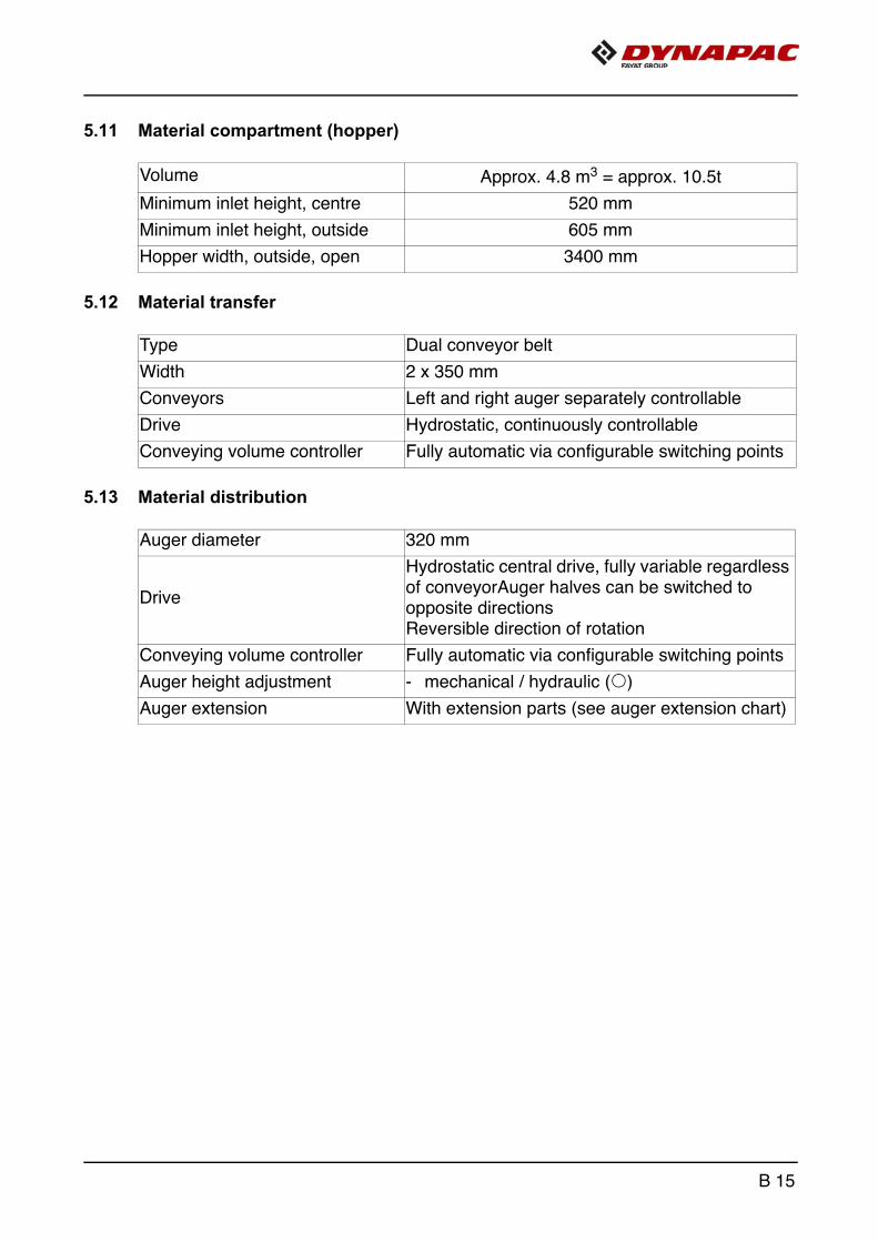
5.11 Material compartment (hopper)
5.12 Material transfer
5.13 Material distribution
Volume Approx. 4.8 m3 = approx. 10.5t
Minimum inlet height, centre 520 mm
Minimum inlet height, outside 605 mm
Hopper width, outside, open 3400 mm
Type Dual conveyor belt
Width 2 x 350 mm
Conveyors Left and right auger separately controllable
Drive Hydrostatic, continuously controllable
Conveying volume controller Fully automatic via configurable switching points
Auger diameter 320 mm
Drive
Hydrostatic central drive, fully variable regardless of conveyorAuger halves can be switched to opposite directionsReversible direction of rotation
Conveying volume controller Fully automatic via configurable switching points
Auger height adjustment - mechanical / hydraulic (o)
Auger extension With extension parts (see auger extension chart)
B 15

5.14 Screed lifting device
5.15 Electrical system
5.16 Permissible temperature ranges
Special functionsAt standstill: - Screed stop
Levelling systemMechanical grade controlOptional systems with and without slope control
On-board voltage 24 V
Batteries 2 x 12 V, 74Ah
Alternator (o) 12.5 kVA / 400V
Operation -5°C / +45°C
Storage -5°C / +45°C
B 16

6 Identification points
Danger due to missing or misunderstood vehicle signs
Missing or misunderstood vehicle signs pose a danger of injuries!
- Never remove any warnings or information signs from the vehicle.
- Damaged or lost warning or information signs must be replaced immediately.
- Make yourself familiar with the meaning and position of the warning and information signs.
- Comply with all further information in these instructions and in the safety manual.
CAUTION
B 17

22 21
22 21
22 21
8
52
4
5
72
6
50 2
1
28
29 30
3
33
32
31
3
20
60
12
25
10
26
923
6
11
27
24
34
34
B 18

71
70
4041
42
xxxxxxxxxxxxxxxxx
51
53
73
B 19

6.1 Warning signs
No. Pictogram Meaning
1
- Warning - operating instructions!Danger due to improper operation. The vehicle personnel must have read and understood the safety, operating and maintenance instructions for the vehicle before the vehicle is put into operation! Failure to comply with the operating and warning instructions can cause severe or fatal injuries. Always replace lost op-erating instructions immediately! It is your personal responsibility to take due care and attention!
2
- Warning - switch off the engine and re-move the ignition key before perform-ing any maintenance and repair work!If the drive engine is left running or func-tions are switched on, this can cause se-vere or fatal injuries! Switch the engine off and remove the ignition key.
3
- Warning - danger of crushing!Crushing points can cause severe or fatal injuries! Maintain a safe distance from the dan-ger area!
4
- Warning - hot surface - risk of burning!Hot surfaces can cause severe injuries! Keep your hands a safe distance away from the danger area! Use protective clothing or protective equipment!
5
- Warning - danger from fan!Rotating fans can cause severe injuries from cutting or severing fingers and hands. Keep your hands a safe distance away from the danger area!
B 20

No. Pictogram Meaning
6
- Warning - danger of crushing fingers and hands due to moving, accessible vehicle parts!Crushing points can cause severe inju-ries with the loss of parts of the fingers or hand. Keep your hands a safe distance away from the danger area!
8
- Caution - danger due to incorrect towing! Vehicle movements can cause severe or fatal injuries. The traction system brake must be released before towing. Always observe the operating instructions!
9
- Warning - danger from running engine!If the drive engine is left running, this can cause severe or fatal injuries.Never open the engine hood while the engine is running!
10
- Warning - danger of being pulled in by the belt drive!Being pulled in by the belt drive can cause severe injuries to the hands and arms. Keep your hands a safe distance away from the danger area!
11
- Warning - danger from improper transportation!Always sit down with the seatbelt fas-tened to drive the vehicle forwards/in re-verse at transport speed! Driving the vehicle when standing up / without the seatbelt fastened can cause severe or fatal injuries. Always observe the operating instructions!
B 21
No. Pictogram Meaning
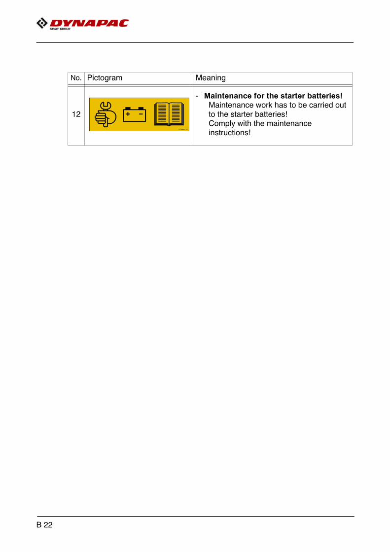
12
- Maintenance for the starter batteries!Maintenance work has to be carried out to the starter batteries! Comply with the maintenance instructions!
B 22

6.2 Information signs
No. Pictogram Meaning
20- Operating instructions
Position of the storage compartment.
21- Lifting point
Lifting the machine is only permitted at these lifting points!
22- Lashing point
Lashing the machine is only permitted at these points!
23- Main battery switch
Position of the main battery switch.
24- Diesel fuel
Position of the filling point.
24- Diesel fuel, off, sulphur level < 15 ppm
Position of the filling point, specification.
25- Fuel drainage point
Position of the drainage point.
B 23

No. Pictogram Meaning
26- Engine oil
Position of the filling and control point.
27- Engine oil drainage point
Position of the drainage point.
28- Engine coolant
Position of the filling and control point.
29- Hydraulic oil
Position of the filling point.
30- Hydraulic oil level
Position of the control point.
31- Hydraulic oil drainage point
Position of the drainage point.
32- Gear oil
Position of the filling and control point.
B 24
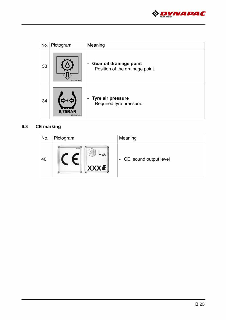
6.3 CE marking
No. Pictogram Meaning
33- Gear oil drainage point
Position of the drainage point.
34- Tyre air pressure
Required tyre pressure.
No. Pictogram Meaning
40 - CE, sound output level
B 25

6.4 Instructive symbols, prohibitive symbols, warning symbols
No. Pictogram Meaning
50 - Wear ear protectors
51 - Do not enter the area!
52 - Warning on dangers posed by batteries!
53 - First aid kit
B 26
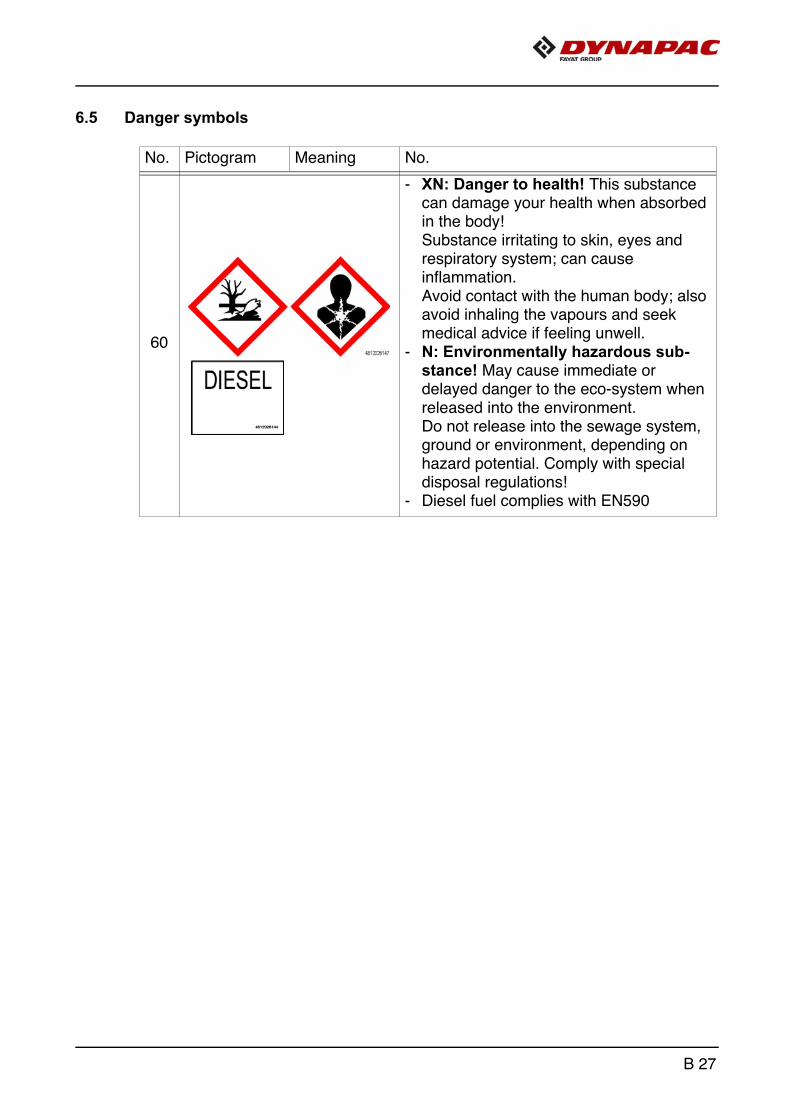
6.5 Danger symbols
No. Pictogram Meaning No.
60
- XN: Danger to health! This substance can damage your health when absorbed in the body!Substance irritating to skin, eyes and respiratory system; can cause inflammation.Avoid contact with the human body; also avoid inhaling the vapours and seek medical advice if feeling unwell.
- N: Environmentally hazardous sub-stance! May cause immediate or delayed danger to the eco-system when released into the environment. Do not release into the sewage system, ground or environment, depending on hazard potential. Comply with special disposal regulations!
- Diesel fuel complies with EN590
B 27
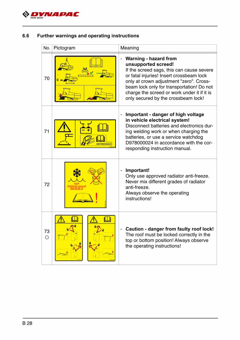
6.6 Further warnings and operating instructions
No. Pictogram Meaning
70
- Warning - hazard from unsupported screed!If the screed sags, this can cause severe or fatal injuries! Insert crossbeam lock only at crown adjustment "zero". Cross-beam lock only for transportation! Do not charge the screed or work under it if it is only secured by the crossbeam lock!
71
- Important - danger of high voltage in vehicle electrical system! Disconnect batteries and electronics dur-ing welding work or when charging the batteries, or use a service watchdog D978000024 in accordance with the cor-responding instruction manual.
72
- Important! Only use approved radiator anti-freeze. Never mix different grades of radiator anti-freeze. Always observe the operating instructions!
73
o
- Caution - danger from faulty roof lock! The roof must be locked correctly in the top or bottom position! Always observe the operating instructions!
B 28

6.7 Identification label for the paver finisher (41)
A The punched vehicle identification number (VIN) on the paver finisher must match theproduct identification number (9).
Item Designation
1 Paver finisher type
2 Year of construction
3 Operating weight, incl. all extension parts, in kg
4 Maximum permitted total weight in kg
5 Max. permissible load on the front axle, in kg
6 Max. permissible load on the rear axle, in kg
7 Maximum permissible axle load of the trailer axle in kg (o)
8 Rated performance in kW
9 Product identification number (PIN)
1
3
5
7
9
2
8
4
6
B 29

6.8 Explanation of 17PIN serial number
A - ManufacturerB - Family/ModelC - Check letterF - Serial number
>10002014JHG002076<
ABCF
B 30
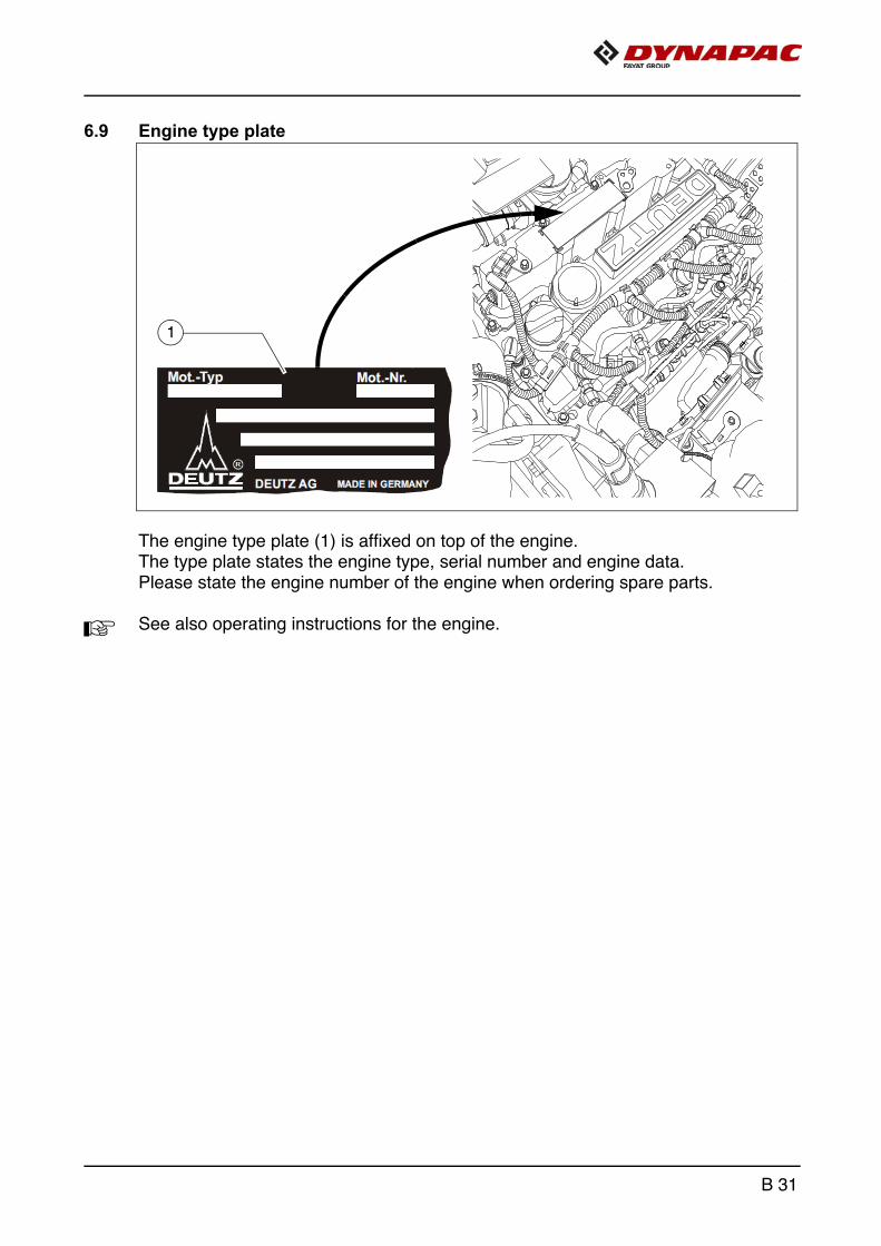
6.9 Engine type plate
The engine type plate (1) is affixed on top of the engine. The type plate states the engine type, serial number and engine data. Please state the engine number of the engine when ordering spare parts.
A See also operating instructions for the engine.
1
B 31
7 EN standards
7.1 Continuous sound pressure level
m The operator always must use ear protection. The emission value at the ear of thedriver varies depending on the materials used for paving and may even rise above85 dB(A). If no ear protection devices are used, hearing can be impaired.The sound emission level of the paver finisher was measured under free-field condi-tions according to EN 500-6:2006 and ISO 4872.
Sound pressure level at the operator’s position (at the height of the head): LAF = 87.0 dB(A)
Sound capacity level: LWA = 104.0 dB(A)
7.2 Operating conditions during measurement
The diesel engine was running at maximum speed. The screed was lowered intoworking position. The tamper and the vibrator were running at min. 50% of their max-imum speed, the augers at min. 40% and the conveyors at min. 10% of their maxi-mum speed.
B 32

7.3 Vibration acting on the entire body
When the vehicle is used properly, the weighted effective acceleration values at thedriver’s seat of aw = 0.5 m/s2 according to DIN EN 1032 are not exceeded.
7.4 Vibrations acting on hands and arms
When the vehicle is used properly, the weighted effective acceleration values at thedriver’s seat of ahw = 2.5 m/s2 according to DIN EN ISO 20643 are not exceeded.
7.5 Electromagnetic compatibility (EMC)
The following limit values are observed according to the protection requirements ofthe EMC Directive 2004/108/EC:
- Interference emission according to DIN EN 13309:< 35 dB μV/m for frequencies of 30 MHz - 1GHz measured at a distance of 10 m < 45 db μV/m for frequencies of 30 MHz - 1 GHz measured at a distance of 10 m
- Interference immunity against electrostatic discharge (ESD) according to DIN EN 13309:The paver finisher did not show any discernible reactions to contact discharges of± 4 KV and to air discharges of ± 4 KV.The modifications according to test criterion "A" are being met, i.e. the paver finish-er continues to work without malfunction during the test.
Electrical or electronic components and their arrangement may only be modified afterwritten approval has been obtained from the manufacturer.
B 33

B 34

C 13.18 Transportation1 Safety regulations for transportation
m Accidents can happen when the paver finisher and the screed are not properly pre-pared for transportation or when transportation is carried out improperly!
Reduce both the paver finisher and the screed to their basic widths. Remove all pro-truding parts (such as the automatic levelling system, auger limit switches,aprons, etc.). When transporting under a special permit, secure these parts!
Close the hopper lids and set the hopper transport safeguards. Lift the screed andengage the screed transport safeguards. Convert the protective roof and engagethe latch.
Pack all parts that are not permanently fixed to the paver finisher and the screed intothe appropriate boxes and into the hopper. Close all coverings and check that they are securely seated.
In Germany, gas bottles must not be transported on the paver finisher or onthe screed.Disconnect the gas bottles from the gas system and protect them with their caps.Use a separate vehicle to transport them.
When loading via ramps, there is a risk that the machine will slip, tilt or overturn. Drive carefully! Keep people away from the danger area!
Additional stipulations for transportation on public roads:
m Comply with the local road traffic regulations!
m On the screed, remove the floorboards and place them in the hopper.Hinged side shields must be swivelled behind the screed and secured correctly.
The operator must be in the possession of a valid permit for vehicles of this type.
The driver's seat must be on the same side as the service brake.The driving lights must be properly adjusted.
Only accessories and extension parts may be transported in the hopper, no materialor gas bottles!
If necessary, the operator must be assisted by a second person when driving on pub-lic roads – especially at road crossings and junctions.
C 13.18 1
2 Directing of the vehicle
Danger due to incorrect directing of the vehicle
A banksman must be used when visibility is impaired on roads or transport roads and when loading the vehicle. Incorrectly implemented or misunderstood directions given by the banksman can cause severe to fatal injuries!
The banksmen assigned for directing vehicles may only consist of personnel- who have been trained for directing machines and can
verify to the company that they have successfully attended the training course and hold the necessary qualifications.
- who have been assigned to act as banksmen by the company and
- who can be expected to reliably perform the tasks assigned to them.
- High-visibility clothing must be worn.- The banksman and vehicle driver must have made
themselves familiar with the dimensions of the vehicle and the transportation vehicle.
- Directions are given by radio or with hand signals. The banksman and vehicle driver must have agreed together beyond any doubt on the meaning of the used signs and signals. Only standardised hand signals may be used.
- The vehicle driver must be provided with suitable aids to get down safely from the transportation vehicle, such as approved steps or ladders. The banksman must help the driver to get down from the vehicle.
- Comply with all further information in these instructions and in the safety manual.
WARNING
C 13.18 2

3 Transportation on low-bed trailers
m Reduce the paver finisher and the screed to their basic widths; also remove any at-tached side plates. The maximum approach angle is indicated in the section entitled "Technical data"!
m Check the fill level of the operating substances so that these do not escape when driv-ing on an incline.
m Attachment and loading equipment must meet the conditions of the applicable acci-dent prevention regulations!
m The weight of the paver finisher must be taken into consideration when selecting theattachment and loading equipment!
3.1 Preparations
- Prepare the paver finisher for transportation (see chapter D).
- Remove all overlaying or loose parts from finisher and screed (see also operatinginstructions for the screed). Store these parts in a safe place.
m Move the auger to the uppermost position to avoid collisions!
f When screed is operated with the optional gas heating system:
- Remove the gas bottles of the screed heater:
- Close the main shut-off valves and the bottle valves.
- Turn off the valves on the bottles and remove the gasbottles from the holder.
- Transport the gas bottles on a second vehicle; heed all applicable safety regulations.
C 13.18 3
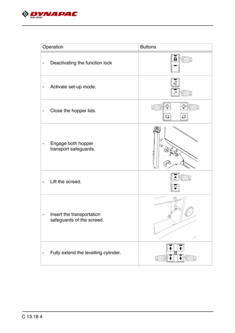
Operation Buttons
- Deactivating the function lock
- Activate set-up mode.
- Close the hopper lids.
- Engage both hopper transport safeguards.
- Lift the screed.
- Insert the transportationsafeguards of the screed.
- Fully extend the levelling cylinder.
C 13.18 4

Operation Buttons
- Retract the screed parts until the screed matches the basic width of the paver finisher.
- Deactivate set-up mode.
C 13.18 5

4 Securing the load
A The following instructions for securing the load on the low-bed trailer consist merelyin examples of how to secure the load correctly.
A Always comply with the local regulations for securing the load and for correct use ofload securing equipment.
A Normal driving mode also includes emergency braking, evasive manoeuvres andpoor road surfaces.
A Use should be made of the different methods available for securing loads(positive fit, force connection, diagonal lashing, etc.) in accordance with the specifictransport vehicle.
m The low-loader must have the necessary number of lashing points with a lashingstrength of LC 4,000 daN.
m The total height and total width must not exceed the maximum permissible dimensions.
m The ends of lashing chains and straps must be secured to prevent them workingloose and falling down unintentionally!
4.1 Prepare the low-bed trailer
m The floor of the loading space must always be undamaged, free of oil and mud, dry(residual moisture is permitted without accumulations of water) and swept clean!
C 13.18 6

4.2 Driving onto the low-bed trailer
f Make sure that there are no persons in the danger area during loading.
- Use the work gear and low engine speeds to drive onto the low-bed trailer.
C 13.18 7
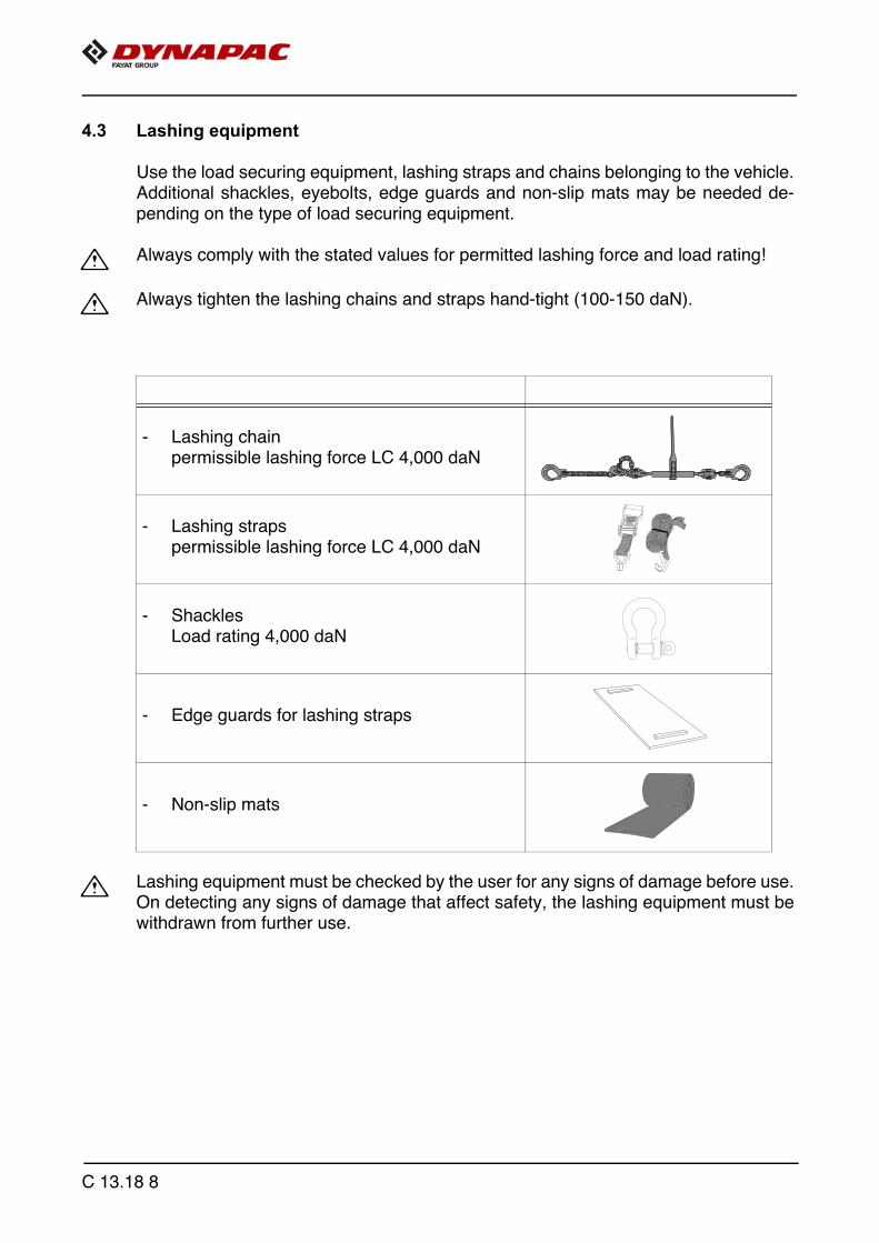
4.3 Lashing equipment
Use the load securing equipment, lashing straps and chains belonging to the vehicle.Additional shackles, eyebolts, edge guards and non-slip mats may be needed de-pending on the type of load securing equipment.
m Always comply with the stated values for permitted lashing force and load rating!
m Always tighten the lashing chains and straps hand-tight (100-150 daN).
m Lashing equipment must be checked by the user for any signs of damage before use.On detecting any signs of damage that affect safety, the lashing equipment must bewithdrawn from further use.
- Lashing chainpermissible lashing force LC 4,000 daN
- Lashing strapspermissible lashing force LC 4,000 daN
- ShacklesLoad rating 4,000 daN
- Edge guards for lashing straps
- Non-slip mats
C 13.18 8

4.4 Loading
m Pay attention to load distribution during loading! On some vehicles, the kingpin load is too low so that the load has to be positionedfurther to the back of the vehicle. Always heed the details regarding load distribution stipulated for the vehicle togetherwith the centre of gravity of the paver finisher. If the paver finisher has to be placed in the front section of the low-bed trailer for loaddistribution reasons or on account of the length of the paver finisher, ensure that itstands freely.
C 13.18 9
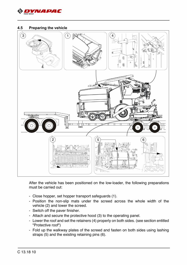
4.5 Preparing the vehicle
After the vehicle has been positioned on the low-loader, the following preparationsmust be carried out:
- Close hopper, set hopper transport safeguards (1).
- Position the non-slip mats under the screed across the whole width of thevehicle (2) and lower the screed.
- Switch off the paver finisher.
- Attach and secure the protective hood (3) to the operating panel.
- Lower the roof and set the retainers (4) properly on both sides. (see section entitled"Protective roof")
- Fold up the walkway plates of the screed and fasten on both sides using lashingstraps (5) and the existing retaining pins (6).
13
5 62
4
C 13.18 10

5 Securing the load
5.1 Securing at the front
Fasten lashing chains at the front
m Diagonal lashing secures the paver finisher at the front using the lashing points on the paver finisher and on the low-load trailer. Fasten the lashing chains as shown.
m Shackles have to be used: To ensure that lashing chains can be fitted securely on theleft and on the right, a shackle has to be fitted at each of the lashing points (1) provid-ed on the paver finisher for the lashing equipment
m The lashing angles should be: "ß" between 6°-55° and "a" between 20°-65°!
1
C 13.18 11

5.2 Securing at the rear
Fasten lashing chains
m Diagonal lashing secures the paver finisher at the rear using the lashing points on the paver finisher and on the low-load trailer. Fasten the lashing chains as shown.
A Permissible angles see "Securing at the front".
C 13.18 12

5.3 After transportation
- Remove the attachment devices.
- Raise protective roof:
A See section entitled "Protective roof"
- Start engine.
- Lift the screed to the transportation position.
- Drive from the trailer at a low engine revs/speed.
- Park the paver finisher in a secure spot, lower the screed and switch off the engine.
- Remove the key and/or cover the operating panel with the protective hood and se-cure it.
C 13.18 13
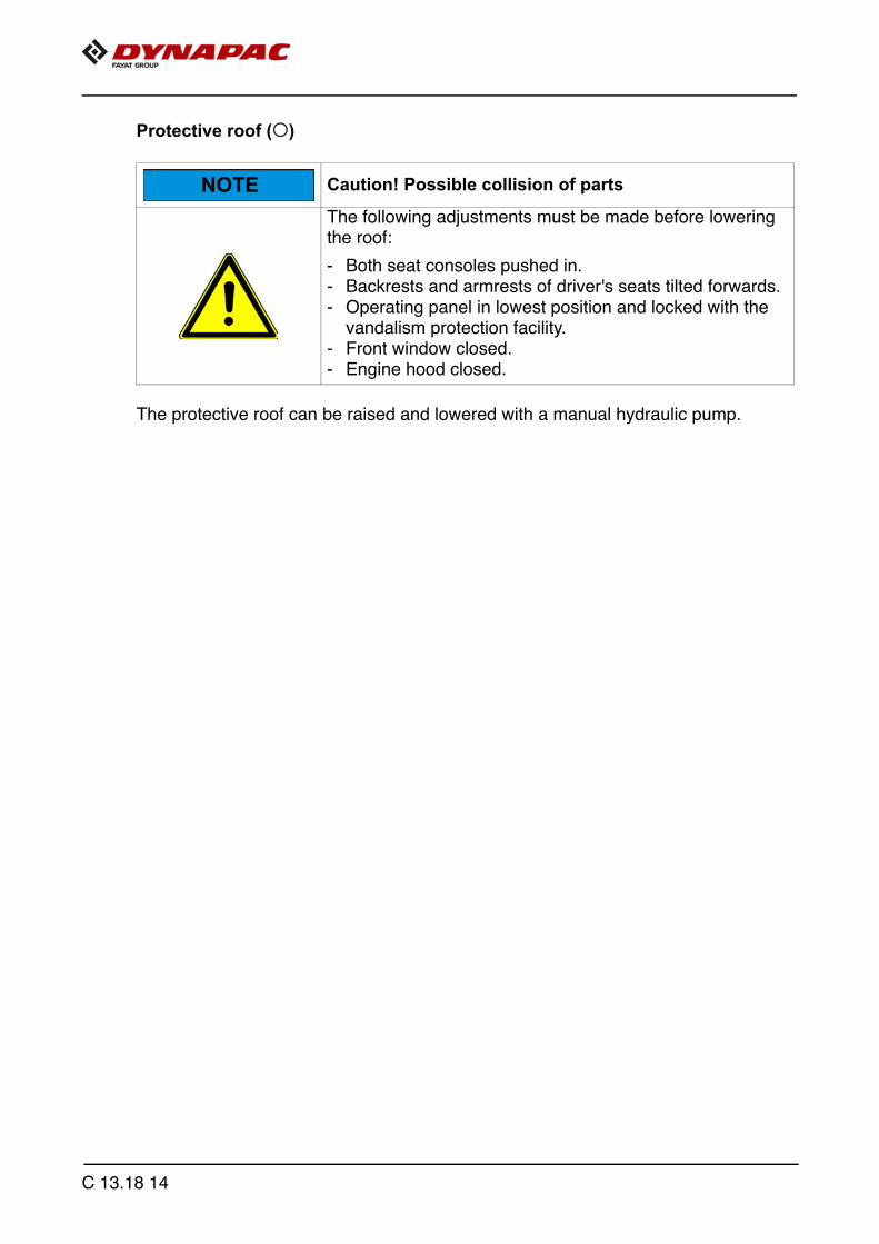
Protective roof (o)
The protective roof can be raised and lowered with a manual hydraulic pump.
Caution! Possible collision of parts
The following adjustments must be made before lowering the roof:
- Both seat consoles pushed in.- Backrests and armrests of driver's seats tilted forwards. - Operating panel in lowest position and locked with the
vandalism protection facility.- Front window closed.- Engine hood closed.
NOTE
C 13.18 14

Version 1:
A The exhaust pipe is lowered or raised together with the roof.
- Connect the pump lever (1) to the pump (2).
- Tighten bolts (3) on both sides of the roof.
- Set the adjustment lever (4) to the "Raise" or "Lower" position.
- Operate the pump lever (1) until the roof has reached the upper or lower limit position.
- Bolt (3) must be inserted in the corresponding hole on both sides of the roof:
- Position (3a): Roof raised.
- Position (3b): Roof lowered.
A The bolt must be inserted with the alignment as shown and then swivelled against theroof beam. Possibly adjust the position of the roof with the hand pump to insert the bolt.
- Position (3c): Roof raised.
- Position (3d): Roof lowered.
- Secure bolt with hook (3a).
1
2
4
3b
3e
3a
3
3c 3d
C 13.18 15
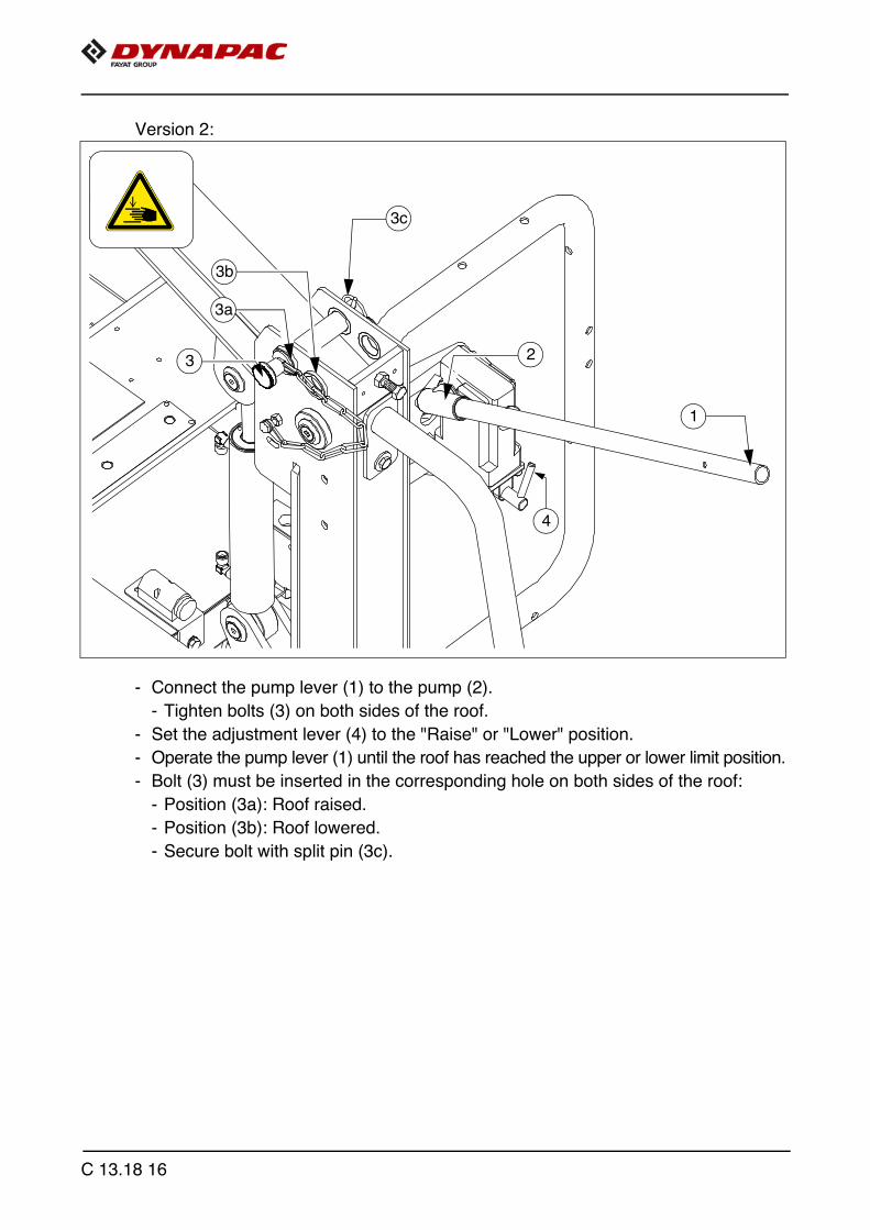
Version 2:
- Connect the pump lever (1) to the pump (2).
- Tighten bolts (3) on both sides of the roof.
- Set the adjustment lever (4) to the "Raise" or "Lower" position.
- Operate the pump lever (1) until the roof has reached the upper or lower limit position.
- Bolt (3) must be inserted in the corresponding hole on both sides of the roof:
- Position (3a): Roof raised.
- Position (3b): Roof lowered.
- Secure bolt with split pin (3c).
1
2
3b
3c
3
4
3a
C 13.18 16
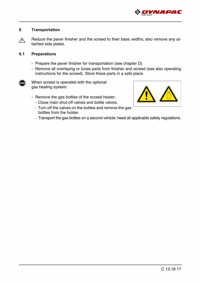
6 Transportation
m Reduce the paver finisher and the screed to their basic widths; also remove any at-tached side plates.
6.1 Preparations
- Prepare the paver finisher for transportation (see chapter D).
- Remove all overlaying or loose parts from finisher and screed (see also operatinginstructions for the screed). Store these parts in a safe place.
f When screed is operated with the optional gas heating system:
- Remove the gas bottles of the screed heater:
- Close main shut-off valves and bottle valves.
- Turn off the valves on the bottles and remove the gasbottles from the holder.
- Transport the gas bottles on a second vehicle; heed all applicable safety regulations.
C 13.18 17

Operation Buttons
- Deactivating the function lock
- Activate set-up mode.
- Close the hopper lids.
- Engage both hopper transport safeguards.
- Lift the screed.
- Insert the transportation safeguards of the screed.
- Fully extend the levelling cylinder.
C 13.18 18

Operation Buttons
- Retract the screed parts until the screed matches the basic widthof the paver finisher.
- Deactivate set-up mode.
C 13.18 19

6.2 Driving mode
f Press the emergency stop button when a dangerous situation arises!
f Use the service brake (1) to brake the vehicle!
Operation Buttons
- Set the fast/slow switch to "Hare" if necessary.
- Turn the preselector to "zero".
- Swivel the drive lever to maximum.
f The vehicle already advances slightlyon deflecting the drive lever!
- Adjust required vehicle speed withthe preselector.
- To stop the vehicle, swivel the drive lever to the middle setting and set the preselec-tor to "zero".
1
C 13.18 20

7 Loading by crane
m Use only lifting gear that can bear the load.(See chapter B for weights and dimensions).
m Attachment and loading equipment must meet the conditions of the applicable acci-dent prevention regulations!
m The vehicle's centre of gravity is dependent on the screed which is mounted.
Danger from suspended loads
Crane and/or lifted vehicle can tip when lifted and cause injuries!
- The vehicle may only be raised at the markedlifting points.
- Heed the operating weight of the vehicle.- Do not enter the danger zone.- Use only lifting gear that can bear the load.- Do not leave any load or loose parts on the vehicle.- Comply with all further information in these instructions
and in the safety manual.
WARNING
C 13.18 21

Example:
A Four lifting eyes (1, 2) are provided for loading the vehicle with a crane.
A Depending on the type of screed which is used, the paver finisher's centre of gravity,with the screed mounted, is located in the area of the front edge (3) of therear wheel.
- Secure vehicle wherever it is parked up.
- Engage the transport safeguards.
- Remove any attachments and extension parts from the paver finisher and thescreed until the basic width has been attained.
- Take off all protruding or loose parts and the gas bottles of the screed heater (seechapters E and D).
- Lower the protective roof:
1
2
3
C 13.18 22

A See section entitled "Protective roof"
- Attach lifting gear to the four attachment points (1, 2).
m The max. permissible attachment point load at the attachment points is: 73.0 kN.
m The permissible load applies in the vertical direction!
m Make sure that the paver finisher remains in a horizontal position during transportation!
C 13.18 23

8 Towing
f Heed all regulations and apply all safetymeasures applicable for towing heavyconstruction machines.
m The towing vehicle must be capable ofsecuring the paver finisher, evenon slopes.
Use only approved tow bars!
If necessary, remove any attachmentsand accessories from the paver finisherand the screed until the basic width hasbeen attained.
A A hand pump (1) is located in the enginecompartment (left side); it must be actu-ated to be able to tow the machine.Pressure for releasing the traction sys-tem brakes is built up with thehand pump.
- Release lock nut (2), screw threadeddowel (3) into pump as far as possibleand secure with lock nut.
A From serial number 2281 et seq.:
- Push knob (3a) into the valve body.While pumping (next step), checkthat the knob remains in the pressedposition.
- Actuate lever (4) of hand pump untilsufficient pressure has been built upand traction system brakes have beenreleased.
m On completion of the towing process, re-store the initial status.
m Only release the traction system brakeswhen the machine is sufficiently securedagainst accidental rolling or is already properly connected to the towing vehicle.
3
2
4
1
3a
4
1
C 13.18 24
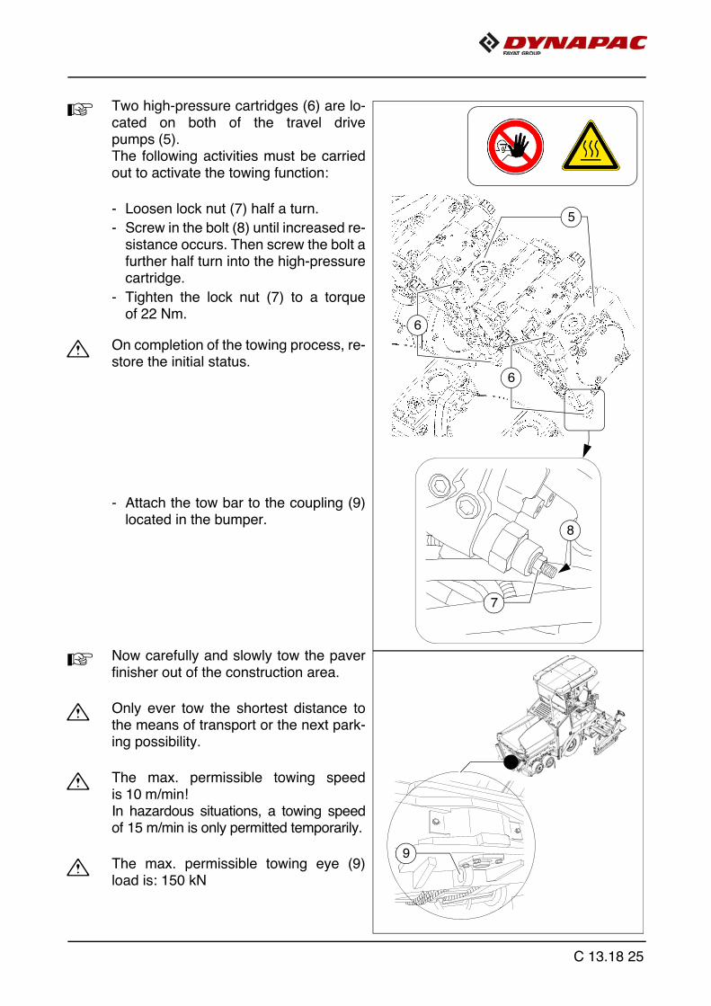
A Two high-pressure cartridges (6) are lo-cated on both of the travel drivepumps (5).The following activities must be carriedout to activate the towing function:
- Loosen lock nut (7) half a turn.
- Screw in the bolt (8) until increased re-sistance occurs. Then screw the bolt afurther half turn into the high-pressurecartridge.
- Tighten the lock nut (7) to a torqueof 22 Nm.
m On completion of the towing process, re-store the initial status.
- Attach the tow bar to the coupling (9)located in the bumper.
A Now carefully and slowly tow the paverfinisher out of the construction area.
m Only ever tow the shortest distance tothe means of transport or the next park-ing possibility.
m The max. permissible towing speedis 10 m/min! In hazardous situations, a towing speedof 15 m/min is only permitted temporarily.
m The max. permissible towing eye (9)load is: 150 kN
6
7
8
5
6
9
C 13.18 25

9 Safely parking the vehicle
m When the paver finisher is parked at a lo-cation accessible to the public, it must besecured in such a way that unauthorisedpersons or playing children cannot dam-age the vehicle.
- Pull off the ignition key and the mainswitch (1) and take it with you – do nothide them somewhere on the machine.
- Protect the operating panel with thedust cover (2) and lock it.
- Store loose parts and accessories ina safe place.
1
2
C 13.18 26

9.1 Lifting the vehicle with hydraulic lifts, lifting points
f The hydraulic lift must be rated for at least 10t.
f Always choose a horizontal surface with adequate load rating as installation surfacefor the hydraulic lift!
f Make sure that the hydraulic lift is securely and correctly positioned!
f The hydraulic lift is only intended to lift a load and not as a support. Work should onlybe performed to and under raised vehicles when they have been secured and cor-rectly supported to prevent them from tilling over and rolling or sliding away.
f Roller-type jacks must not be moved when under load.
f Chocks or supporting beams positioned so that they cannot be shifted or tilted mustbe adequately dimensioned and be able to take the corresponding weight.
f There must not be anyone on the vehicle while it is being lifted.
f All raising and lowering work must be carried out uniformly with all hydraulic lifts inuse! Always check and observe horizontal alignment of the load!
f Always carry out raising and lowering work with several people together, with an ad-ditional person monitoring progress!
f Only positions (1) and (2) in the left and right side of the vehicle are permissiblelifting points!
1 2 21
C 13.18 27

C 13.18 28

D 13.18 Operation1 Safety regulations
f Starting the engine, the travel drive, the conveyor, the auger, the screed or the liftingdevices can cause injuries or even the death of persons. Make sure before starting any of these devices that no-one is working at, in or be-neath the paver finisher or within its danger area!
- Do not start the engine or do not actuate any controls when this is expressly forbidden! Unless otherwise specified, the controls may only be actuated when the engineis running!
f Never crawl into the auger tunnel or step into the hopper or onto the conveyor.Danger to life!
- Always make sure during work that no-one is endangered by the vehicle!
- Ensure that all protective covers and hoods are fitted and secured accordingly!
- Immediately rectify damage which as been ascertained! Operation must not becontinued when the vehicle is defective!
- Do not let any persons ride on the paver finisher or the screed!
- Remove obstacles from the road and the work area!
- Always try to choose a driver’s position that is opposite to the flowing traffic!Lock the operating panel and the driver’s seat.
- Maintain sufficient safety clearance from overhanging objects, other vehicles andpoints of danger!
- Be careful when travelling on rough terrain to keep the paver finisher from slipping,tipping or turning over.
f Always be the master over the vehicle; never try to use it beyond its capacities!
D 13.18 1

Danger due to improper operation
Improper operation of the vehicles can cause severe to fatal injuries!
- The vehicle may only be used in the proper mannerfor its intended purpose.
- The vehicle may only be operated by trained staff.- The vehicle operators must have made themselves famil-
iar with the contents of the operating instructions.- Avoid jerky movements of the vehicle.- Do not exceed the permissible angle of rise and slope.- Keep hoods and covering parts closed during operation.- Comply with all further information in these instructions
and in the safety manual.
Danger of being pulled in by rotating or conveying vehicle partsRotating or conveying vehicle parts can cause severe to fatal injuries!
- Do not enter the danger zone.- Do not reach into rotating or conveying parts.- Only wear close-fitting clothing.- Comply with the warning and information signs
on the vehicle.- Stop the engine and remove the ignition key for any main-
tenance work.- Comply with all further information in these instructions and
in the safety manual.
Danger of crushing due to moving vehicle parts
Vehicle parts performing movements can cause severe to fatal injuries!
- Remaining in the vehicle's danger zone during operationis prohibited!
- Do not reach into the danger zone.- Comply with the warning and information signs
on the vehicle.- Comply with all further information in these instructions and
in the safety manual.
DANGER
WARNING
WARNING
D 13.18 2
2 Controls
2.1 Operating panel
A All detent switch functions which may pose a risk on starting the diesel engine(auger and conveyor conveying function) are set to the STOP function in the case ofEMERGENCY STOP or restarting the control system. If settings are changed whenthe diesel engine is stopped ("AUTO" or "MANUAL"), these are reset to "STOP" onstarting the diesel engine.
D 13.18 3

10
13
16
1517 11
12
9
8
7
D 13.18 4

Item Designation Brief description
7Direction of travel indicator ("flasher")
Use when changing direction of travel on roads.
8 Illumination switch
Four switch positions can be selected:- 0: Light OFF- 1: Parking lights ON (+operating panel lighting)- 2: Low-beam headlights ON (+operating panel lighting)- 3: High-beam headlights ON (+operating panel lighting)
f Avoid dazzling the oncoming traffic!
9Hazard warning flasher
m Always have the warning lights on when moving the ma-chine!
10Emergency stop button
Press in an emergency (danger to persons, impending colli-sion, etc.)! - Pressing the emergency stop button switches off the en-
gine, the drives and the steering system. Making way, lifting the screed or other actions are then no longer possible! Danger of accidents!
- The emergency stop button does not shut off the gas heat-er system (o). Close the main shut-off valve and the valves on the bottles by hand!
- To restart the engine, the button must be pulled out again.
11 Ignition lock
To activate the ignition voltage by turning the key.- Switch off by turning the key back to its starting position.
A After activating the ignition voltage, the input anddisplay terminal requires a few seconds for the bootingprocess.
A On shutting off the vehicle, first switch off the ignition,then deactivate the main switch.
A Before the main battery switch is deactivated, a periodof at least 10 seconds must elapse after switching offthe vehicle.
D 13.18 5
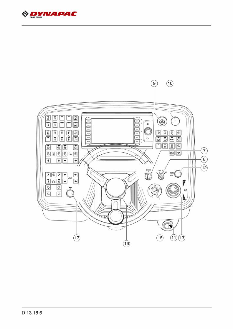
10
13
16
1517 11
12
9
8
7
D 13.18 6
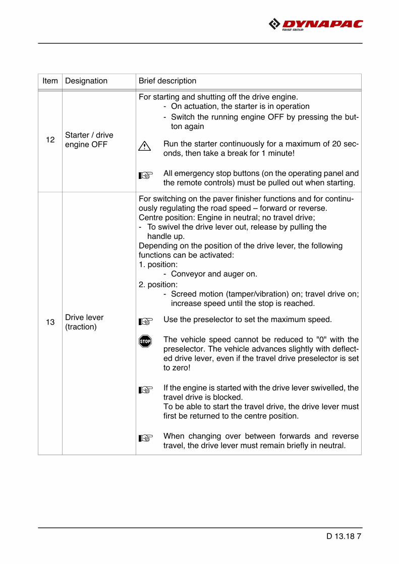
Item Designation Brief description
12Starter / drive engine OFF
For starting and shutting off the drive engine.- On actuation, the starter is in operation
- Switch the running engine OFF by pressing the but-ton again
m Run the starter continuously for a maximum of 20 sec-onds, then take a break for 1 minute!
A All emergency stop buttons (on the operating panel andthe remote controls) must be pulled out when starting.
13Drive lever (traction)
For switching on the paver finisher functions and for continu-ously regulating the road speed – forward or reverse. Centre position: Engine in neutral; no travel drive; - To swivel the drive lever out, release by pulling the
handle up. Depending on the position of the drive lever, the following functions can be activated: 1. position:
- Conveyor and auger on.
2. position:- Screed motion (tamper/vibration) on; travel drive on;
increase speed until the stop is reached.
A Use the preselector to set the maximum speed.
f The vehicle speed cannot be reduced to "0" with thepreselector. The vehicle advances slightly with deflect-ed drive lever, even if the travel drive preselector is setto zero!
A If the engine is started with the drive lever swivelled, thetravel drive is blocked. To be able to start the travel drive, the drive lever mustfirst be returned to the centre position.
A When changing over between forwards and reversetravel, the drive lever must remain briefly in neutral.
D 13.18 7

10
13
16
1517 11
12
9
8
7
D 13.18 8

Item Designation Brief description
15Travel drivepreselector
For setting the maximum speed that can be reached when the drive lever is at its stop.
A The scale roughly matches the speed in m/min(during paving).
m The vehicle must not travel at max. transport speedwhen the hopper is full!
f The vehicle speed cannot be reduced to "0" with thepreselector. The vehicle advances slightly with deflect-ed drive lever, even if the travel drive preselector is setto zero!
16 Steering wheel
The steering wheel movement is transferred hydraulically to the front wheels.
f Take the special steering ratio into consideration whentransporting the machine through tight curves(approx. 3 turns for a full steering lock). Danger of accidents!
17 Horn
Press in the case of emergencies and to indicate when the ve-hicle starts to move!
A The horn can also be used to communicate acoustical-ly with the truck driver for material loading!
D 13.18 9

18 19 20 21
D 13.18 10

Item Designation Brief description
18Front working lightsON / OFF (o)
Button with detent switch function and LED feedback:- For switching on the front working lights
- Switch OFF by pressing the button again
f Avoid dazzling other road users!
19Rear working lightsON / OFF (o)
Button with detent switch function and LED feedback:- For switching on the rear working lights
- Switch OFF by pressing the button again
f Avoid dazzling other road users!
20
Auger compart-ment working lights ON / OFF (o)
Button with detent switch function and LED feedback:- for switching on the auger compartment
working lights
- Switch OFF by pressing the button again
21Rotary beaconON / OFF (o)
Button with detent switch function and LED feedback:- For switching on the rotary beacon
- Switch OFF by pressing the button again
A Switch on for safety on roads and in the constructionsite area
D 13.18 11

22 23 24 25
D 13.18 12

Item Designation Brief description
22Windscreen wip-ers ON / OFF (o)
Detent switch function and LED feedback:- For switching on the windscreen wipers
- Switch OFF by pressing the button again
23
Windscreen wash-er system + wind-screen wiperON / OFF (o)
Detent switch function and LED feedback:- For engaging the windscreen washer system +
windscreen wipers
- Switched OFF with time control
24Extend push roller (o)
Pushbutton function with LED feedback:- To hydraulically extend the push roller crossbar.
f On actuation, heed danger zones of moving parts ofthe vehicle!
25Push roller damping "AUTO" (o)
Detent switch function and LED feedback:- To activate automatic push roller damping.
- Every time the hopper closes, the push roller auto-matically moves to the front limit position.
- Switch OFF by pressing the button again.
A Push roller damping hydraulically absorbs the shocksbetween the material truck and paver finisher.
D 13.18 13
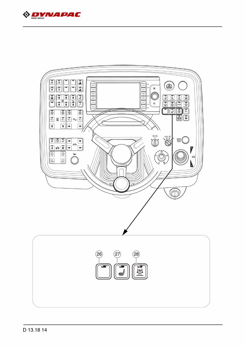
26 27 28
D 13.18 14

Item Designation Brief description
26 Not used
27Seat heating ON / OFF (o)
Button with detent switch function and LED feedback:- For switching on the seat heating
- Switch OFF by pressing the button again
28ExtractionON / OFF (o)
Detent switch function and LED feedback:- To actuate the asphalt fume control system
- Switch OFF by pressing the button again
D 13.18 15
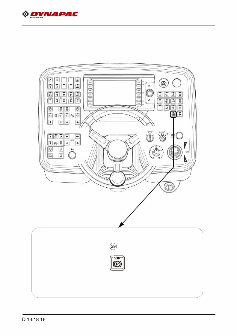
29
D 13.18 16
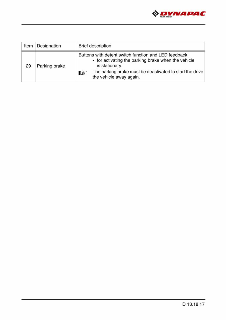
Item Designation Brief description
29 Parking brake
Buttons with detent switch function and LED feedback:- for activating the parking brake when the vehicle
is stationary.
A The parking brake must be deactivated to start the drivethe vehicle away again.
D 13.18 17

33
32
D 13.18 18

Item Designation Brief description
32Tempomat (cruise control)
Buttons with detent switch function and LED feedback. (LED ON = ready)
- The speed control is activated by pressing thefoot brake. The speed obtained after slowing down is held auto-matically.
- Pressing the button again switches the function off(LED ON) and the machine is accelerated tothe speed set by the drive lever and the preselectionpotentiometer.
A If the speed has been reduced to "zero", the drive leverfirst has to be put back into its zero position.
33Traction drive speed fast(Transport gear)
Buttons with detent switch function and LED feedback:- To preselect the speed level -
transport speed
A On restarting, the speed is set to operating speed.
A When activated, all functions set to "AUTO" are stopped(main function switch active).
D 13.18 19

35
34
36
37
D 13.18 20
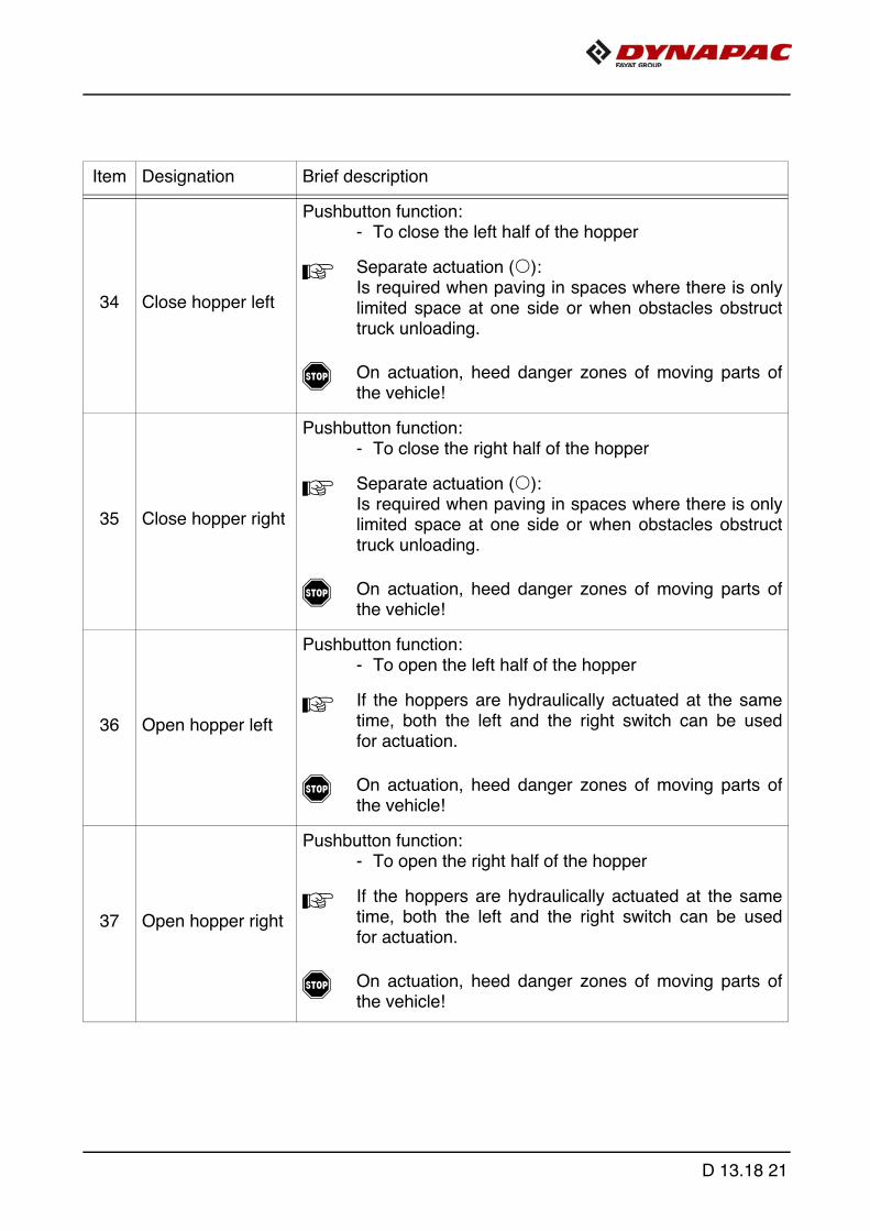
Item Designation Brief description
34 Close hopper left
Pushbutton function:- To close the left half of the hopper
A Separate actuation (o): Is required when paving in spaces where there is onlylimited space at one side or when obstacles obstructtruck unloading.
f On actuation, heed danger zones of moving parts ofthe vehicle!
35 Close hopper right
Pushbutton function:- To close the right half of the hopper
A Separate actuation (o): Is required when paving in spaces where there is onlylimited space at one side or when obstacles obstructtruck unloading.
f On actuation, heed danger zones of moving parts ofthe vehicle!
36 Open hopper left
Pushbutton function:- To open the left half of the hopper
A If the hoppers are hydraulically actuated at the sametime, both the left and the right switch can be usedfor actuation.
f On actuation, heed danger zones of moving parts ofthe vehicle!
37 Open hopper right
Pushbutton function:- To open the right half of the hopper
A If the hoppers are hydraulically actuated at the sametime, both the left and the right switch can be usedfor actuation.
f On actuation, heed danger zones of moving parts ofthe vehicle!
D 13.18 21
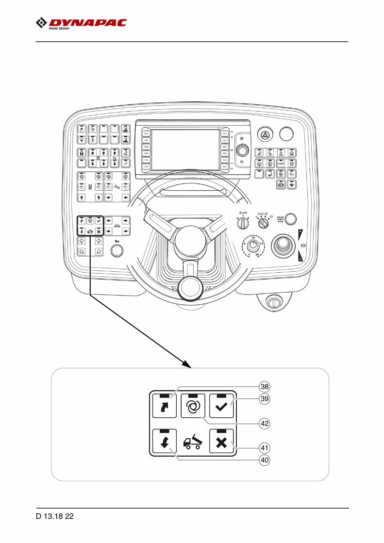
39
38
40
41
42
D 13.18 22

A The Truck Assist system is used for communication between the driver of the paverand the driver of the material truck. The corresponding signal system shows the truckdriver which action to perform (reversing / stop / tip material / depart).
Caution! Possible material damage through insuffi-cient instructionIgnored or incorrectly understood signals can cause dam-age to the paver and/or material truck!
- The paver driver and all drivers of the material trucks must be instructed in how the Truck Assist system works and understand the system.
- Comply with all further information in the operating instructions and in the safety manual.
Item Designation Brief description LED display
38Tell truckto reverse
Pushbutton function with LED feedback:- To change over to the "Start Revers-
ing" signal. (GREEN SIGNAL)
- Press button again to change signalover to "Stop". Button LED (39) on + (RED SIGNAL).
- Press button once more to switchagain to "Start Reversing" signal. (GREEN SIGNAL)
A Button (39) can also be used to changeover to "Stop".
39Tell truck tointerrupt reversing - "STOP"
Pushbutton function with LED feedback:- To change over to the "STOP" signal.
(RED SIGNAL)
A Set "STOP" signal to interrupt procedureor on reaching correct distance betweentruck and paver.
NOTE
D 13.18 23

39
38
40
41
42
D 13.18 24
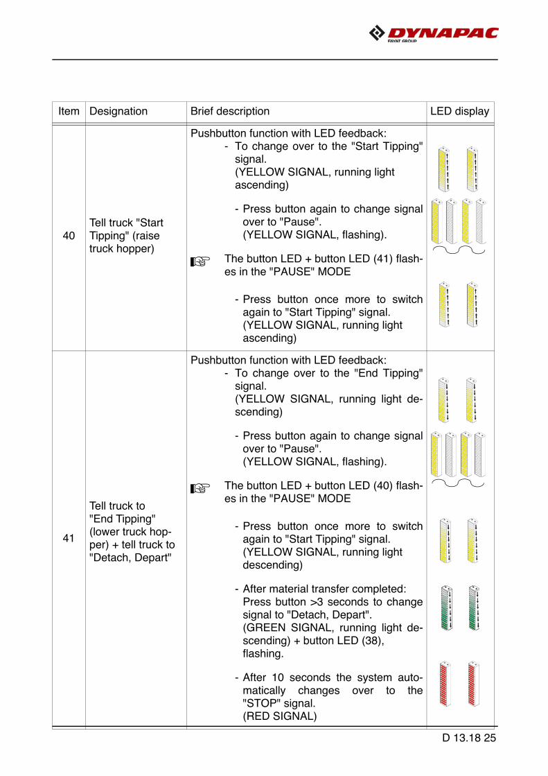
Item Designation Brief description LED display
40Tell truck "Start Tipping" (raise truck hopper)
Pushbutton function with LED feedback:- To change over to the "Start Tipping"
signal. (YELLOW SIGNAL, running light ascending)
- Press button again to change signalover to "Pause". (YELLOW SIGNAL, flashing).
A The button LED + button LED (41) flash-es in the "PAUSE" MODE
- Press button once more to switchagain to "Start Tipping" signal. (YELLOW SIGNAL, running light ascending)
41
Tell truck to"End Tipping" (lower truck hop-per) + tell truck to "Detach, Depart"
Pushbutton function with LED feedback:- To change over to the "End Tipping"
signal. (YELLOW SIGNAL, running light de-scending)
- Press button again to change signalover to "Pause". (YELLOW SIGNAL, flashing).
A The button LED + button LED (40) flash-es in the "PAUSE" MODE
- Press button once more to switchagain to "Start Tipping" signal. (YELLOW SIGNAL, running light descending)
- After material transfer completed:Press button >3 seconds to changesignal to "Detach, Depart". (GREEN SIGNAL, running light de-scending) + button LED (38), flashing.
- After 10 seconds the system auto-matically changes over to the"STOP" signal. (RED SIGNAL)
D 13.18 25

39
38
40
41
42
D 13.18 26

Item Designation Brief description LED display
42"Truck Assist" AUTO modeON / OFF
Pushbutton function with LED feedback:- The "Truck Assist" function runs auto-
matically.
- Switch OFF by pressing the buttonagain
- Press button (38) to request a truckwith material / Release for truckto approach(GREEN SIGNAL)
A The truck is detected by a laser sensor ata distance of 6 m between the paver andthe material truck. (GREEN SIGNAL, flashing)
A The flashing frequency of the display in-creases with decreasing distance be-tween paver and material truck.
- On reaching the preset minimum dis-tance, the signal changes overto "STOP". (RED SIGNAL)
A The minimum distance is adjusted in thedisplay settings.
A The other signals have to be triggeredby hand.
D 13.18 27
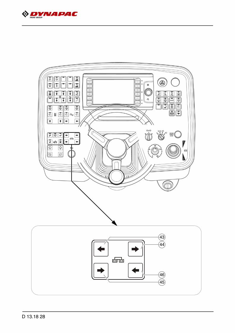
44
43
45
46
D 13.18 28

Item Designation Brief description
43Extend left screed
Pushbutton function:- To extend the left half of the screed
A This function is not used in vehicle configurations witha screed which cannot be extended.
f On actuation, heed danger zones of moving parts ofthe vehicle!
44Extend right screed
Pushbutton function:- To extend the right half of the screed
A This function is not used in vehicle configurations witha screed which cannot be extended.
f On actuation, heed danger zones of moving parts ofthe vehicle!
45Retract left screed
Pushbutton function:- To retract the left half of the screed
A This function is not used in vehicle configurations witha screed which cannot be extended.
f On actuation, heed danger zones of moving parts ofthe vehicle!
46Retract right screed
Pushbutton function:- To retract the right half of the screed
A This function is not used in vehicle configurations witha screed which cannot be extended.
f On actuation, heed danger zones of moving parts ofthe vehicle!
D 13.18 29

48
52
50
47
51
49
D 13.18 30

Item Designation Brief description
47Left conveyor"AUTO"
Button with detent switch function and LED feedback:- The conveying function of the left conveyor is
switched on when the drive lever is swivelled out andis continuously controlled via the material limit switch-es in the material tunnel.
- Switch OFF by pressing the button again
A The function is shut off by pressing the EMERGENCYSTOP button or restarting the vehicle.
A The main function switch locks the conveying function.
f On actuation, heed danger zones of moving parts ofthe vehicle!
48Right conveyor"AUTO"
Button with detent switch function and LED feedback:- The conveying function of the right conveyor is
switched on when the drive lever is swivelled out andis continuously controlled via the material limit switch-es in the material tunnel.
- Switch OFF by pressing the button again
A The function is shut off by pressing the EMERGENCYSTOP button or restarting the vehicle.
A The main function switch locks the conveying function.
f On actuation, heed danger zones of moving parts ofthe vehicle!
D 13.18 31

48
52
50
47
51
49
D 13.18 32

Item Designation Brief description
49Left conveyor"MANUAL"
Button with detent switch function and LED feedback:- The function of the left conveyor is permanently
switched on at full conveying rate and is activated/de-activated with the material limit switch in thematerial tunnel.
- Switch OFF by pressing the button again.
A To avoid excessive conveying, the system is shut offat a defined material height!
- Pressing and holding the button can result in exces-sive conveying.
A The function is shut off by pressing the EMERGENCYSTOP button or restarting the vehicle.
A The main function switch locks the conveying function.
f On actuation, heed danger zones of moving parts ofthe vehicle!
50Right conveyor"MANUAL"
Button with detent switch function and LED feedback:- The function of the right conveyor is permanently
switched on at full conveying rate and is activated/de-activated with the material limit switch in thematerial tunnel.
- Switch OFF by pressing the button again.
A To avoid excessive conveying, the system is shut offat a defined material height!
- Pressing and holding the button can result in exces-sive conveying.
A The function is shut off by pressing the EMERGENCYSTOP button or restarting the vehicle.
A The main function switch locks the conveying function.
f On actuation, heed danger zones of moving parts ofthe vehicle!
D 13.18 33

48
52
50
47
51
49
D 13.18 34
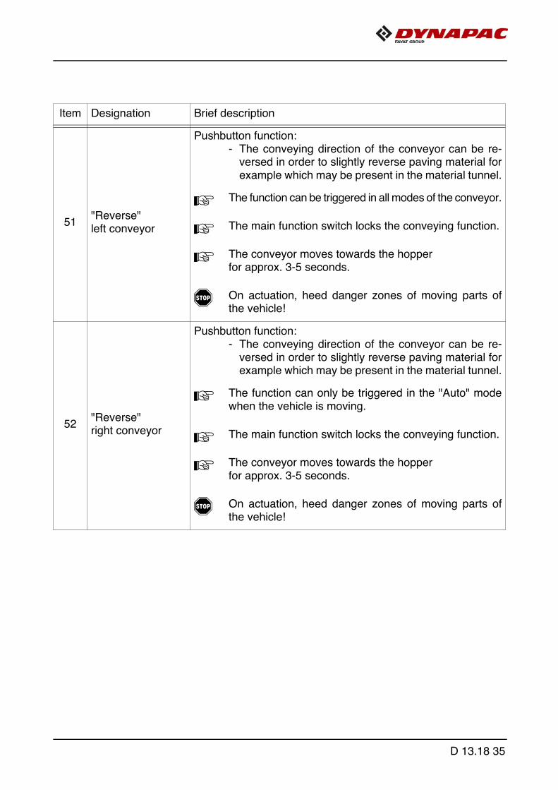
Item Designation Brief description
51"Reverse" left conveyor
Pushbutton function:- The conveying direction of the conveyor can be re-
versed in order to slightly reverse paving material forexample which may be present in the material tunnel.
A The function can be triggered in all modes of the conveyor.
A The main function switch locks the conveying function.
A The conveyor moves towards the hopperfor approx. 3-5 seconds.
f On actuation, heed danger zones of moving parts ofthe vehicle!
52"Reverse" right conveyor
Pushbutton function:- The conveying direction of the conveyor can be re-
versed in order to slightly reverse paving material forexample which may be present in the material tunnel.
A The function can only be triggered in the "Auto" modewhen the vehicle is moving.
A The main function switch locks the conveying function.
A The conveyor moves towards the hopper for approx. 3-5 seconds.
f On actuation, heed danger zones of moving parts ofthe vehicle!
D 13.18 35

54
58
56
53
57
55
D 13.18 36

Item Designation Brief description
53Left auger"AUTO"
Button with detent switch function and LED feedback:- The conveying function of the left half of the auger is
switched on when the drive lever is swivelled out and iscontinuously controlled via the material limit switches.
- Switch OFF by pressing the button again
A The function is shut off by pressing the EMERGENCYSTOP button or restarting the vehicle.
A The main function switch locks the conveying function.
f On actuation, heed danger zones of moving parts ofthe vehicle!
54Right auger"AUTO"
Button with detent switch function and LED feedback:- The conveying function of the right half of the auger is
switched on when the drive lever is swivelled out andis continuously controlled via the material limit switch-es in the material tunnel.
- Switch OFF by pressing the button again
A The function is shut off by pressing the EMERGENCYSTOP button or restarting the vehicle.
A The main function switch locks the conveying function.
f On actuation, heed danger zones of moving parts ofthe vehicle!
D 13.18 37
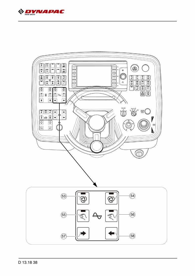
54
58
56
53
57
55
D 13.18 38
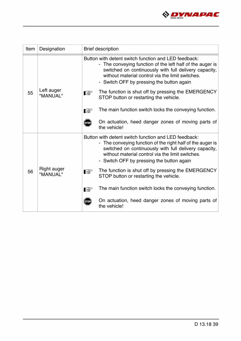
Item Designation Brief description
55Left auger"MANUAL"
Button with detent switch function and LED feedback:- The conveying function of the left half of the auger is
switched on continuously with full delivery capacity,without material control via the limit switches.
- Switch OFF by pressing the button again
A The function is shut off by pressing the EMERGENCYSTOP button or restarting the vehicle.
A The main function switch locks the conveying function.
f On actuation, heed danger zones of moving parts ofthe vehicle!
56Right auger"MANUAL"
Button with detent switch function and LED feedback:- The conveying function of the right half of the auger is
switched on continuously with full delivery capacity,without material control via the limit switches.
- Switch OFF by pressing the button again
A The function is shut off by pressing the EMERGENCYSTOP button or restarting the vehicle.
A The main function switch locks the conveying function.
f On actuation, heed danger zones of moving parts ofthe vehicle!
D 13.18 39

54
58
56
53
57
55
D 13.18 40

Item Designation Brief description
57
Left auger "MANUAL" Conveying direc-tion inwards
Pushbutton function:- To manually trigger the conveying function for the left
half of the auger, conveying direction inwards.
A The function can be triggered in all modes.
A On manual triggering, the automatic function is overrid-den with reduced delivery capacity.
A When the function is used, "AUTO" or "MANUAL" isswitched off.
58
Right auger "MANUAL" Conveying direc-tion inwards
Pushbutton function:- To manually trigger the conveying function for the
right half of the auger, conveying direction inwards.
A The function can be triggered in all modes.
A On manual triggering, the automatic function is overrid-den with reduced delivery capacity.
A When the function is used, "AUTO" or "MANUAL" isswitched off.
D 13.18 41
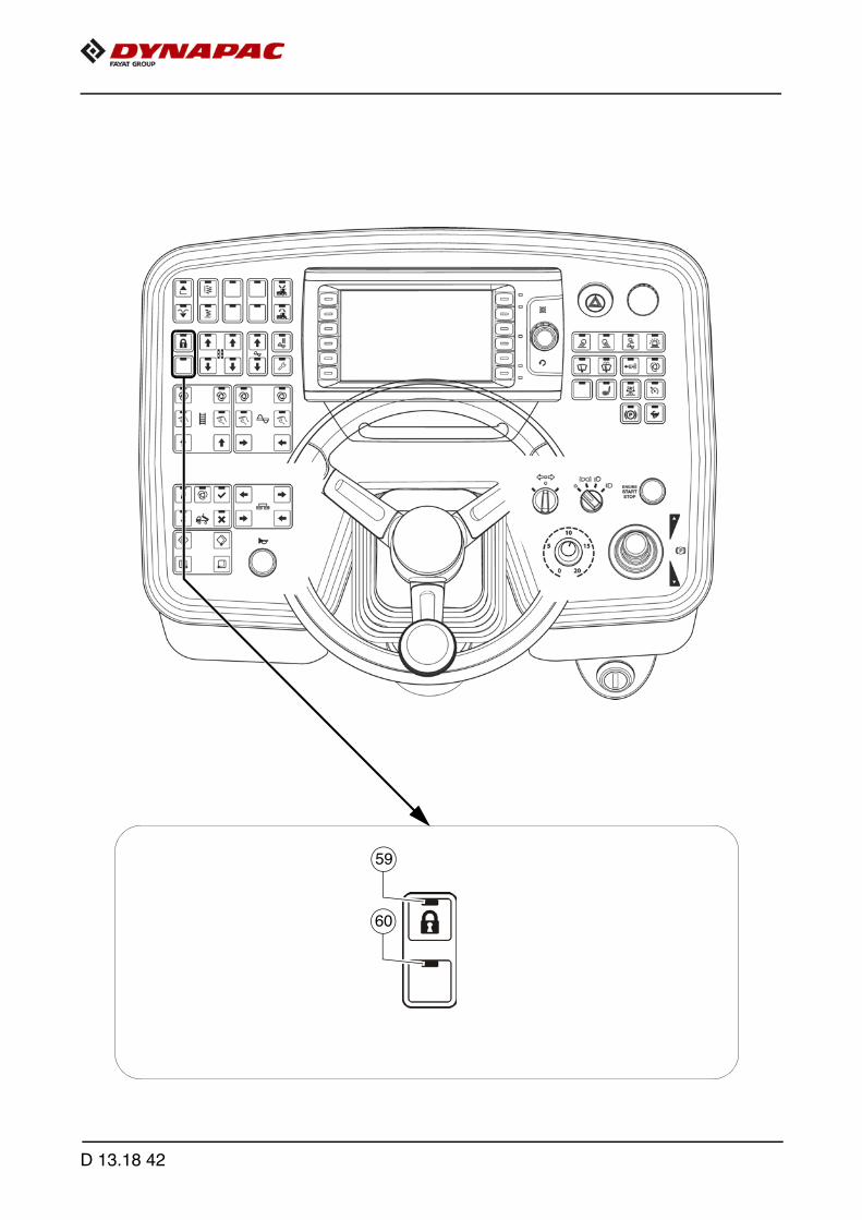
60
59
D 13.18 42
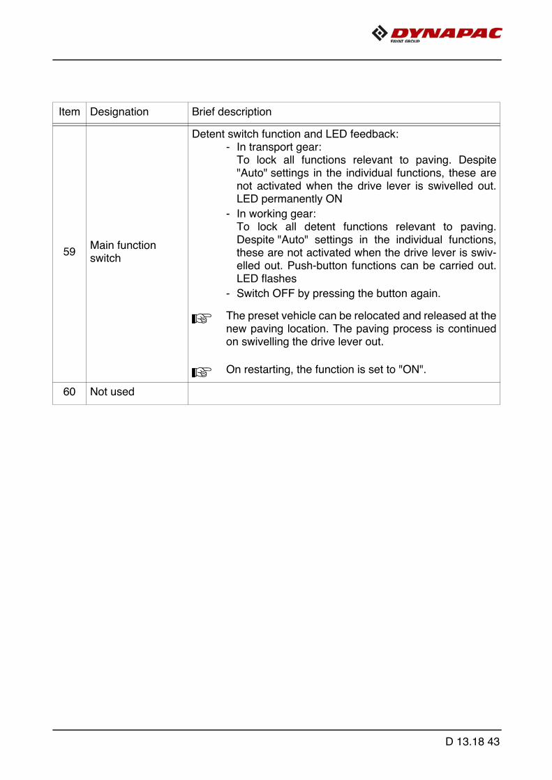
Item Designation Brief description
59Main function switch
Detent switch function and LED feedback:- In transport gear:
To lock all functions relevant to paving. Despite"Auto" settings in the individual functions, these arenot activated when the drive lever is swivelled out.LED permanently ON
- In working gear:To lock all detent functions relevant to paving.Despite "Auto" settings in the individual functions,these are not activated when the drive lever is swiv-elled out. Push-button functions can be carried out.LED flashes
- Switch OFF by pressing the button again.
A The preset vehicle can be relocated and released at thenew paving location. The paving process is continuedon swivelling the drive lever out.
A On restarting, the function is set to "ON".
60 Not used
D 13.18 43
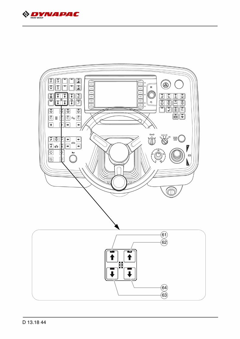
62
64
63
61
D 13.18 44

A The corresponding switch on the remote control must be switched to "Manual" forthis function.
A Levelling cylinder adjustment is carried out with the adjustment buttons in the dis-played arrow direction.
A This function is also activated when the remote control is not connected!
Item Designation Brief description
61Adjustment button: Retract / raise left levelling cylinder
Pushbutton function:- For manual actuation of the levelling cylinders in the
corresponding direction (when the automatic levellingsystem is switched off).
f On actuation, heed danger zones of moving parts ofthe vehicle!
62Adjustment button: Retract / raise right levelling cylinder
Pushbutton function:- For manual actuation of the levelling cylinders in the
corresponding direction (when the automatic levellingsystem is switched off).
f On actuation, heed danger zones of moving parts ofthe vehicle!
63Adjustment button:Extend / lower left levelling cylinder
Pushbutton function:- For manual actuation of the levelling cylinders in the
corresponding direction (when the automatic levellingsystem is switched off).
f On actuation, heed danger zones of moving parts ofthe vehicle!
64Adjustment button: Extend / lower right levelling cylinder
Pushbutton function:- For manual actuation of the levelling cylinders in the
corresponding direction (when the automatic levellingsystem is switched off).
f On actuation, heed danger zones of moving parts ofthe vehicle!
D 13.18 45
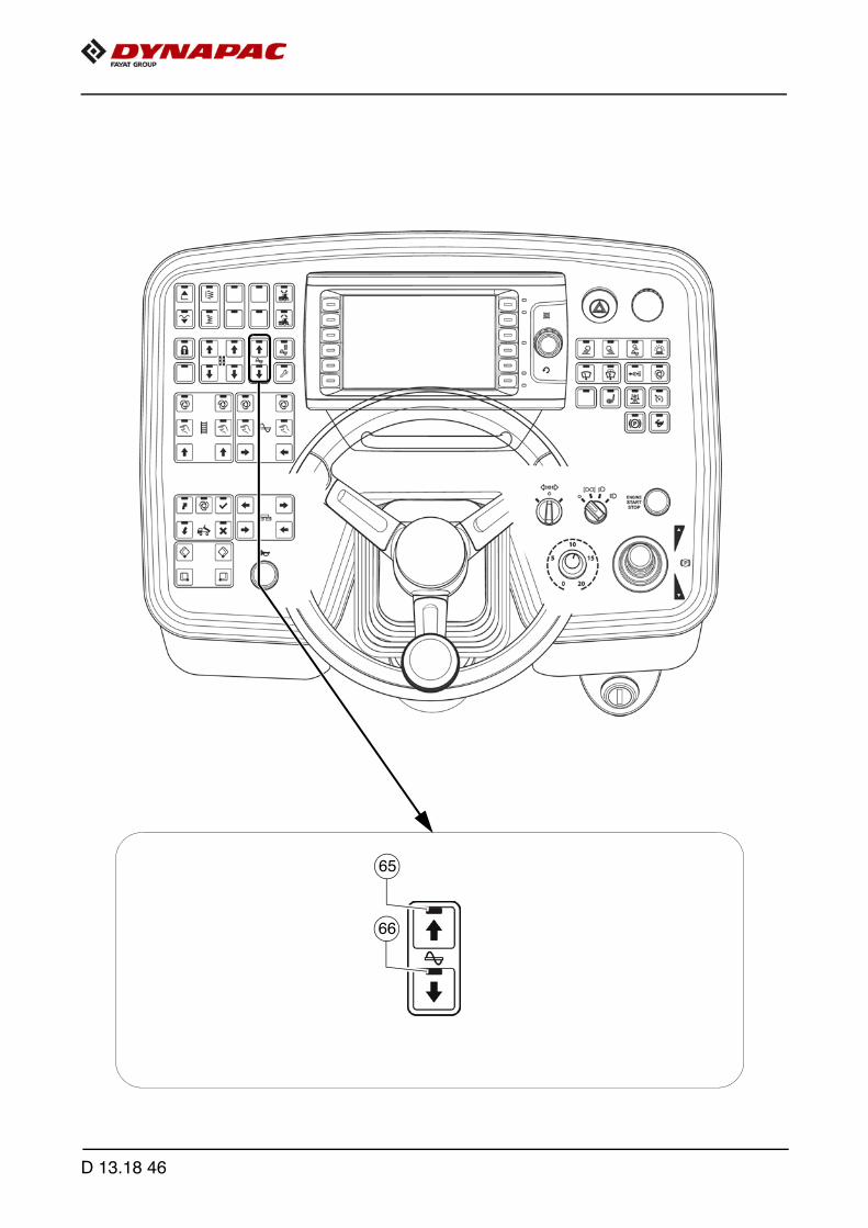
66
65
D 13.18 46

A The auger height can be read off at the corresponding scale. Rule of thumb: Paving thickness plus 5 cm (2 inches) equals the augercrossbeam height.
Item Designation Brief description
65Adjustment button: Raise auger (o)
Pushbutton function:- To adjust the auger height in the corresponding
direction.
f On actuation, heed danger zones of moving parts ofthe vehicle!
66Adjustment button: Lower auger (o)
Pushbutton function:- To adjust the auger height in the corresponding
direction.
f On actuation, heed danger zones of moving parts ofthe vehicle!
D 13.18 47

68
67
D 13.18 48

Item Designation Brief description
67Fill vehicle for paving process
Detent switch function and LED feedback:- Filling function for the paving process.
The diesel engine's speed is increased to the preselected nominal speed and all conveying functions set to "Auto-matic" (conveyor and auger) are engaged.
A The main function switch must be set to theOFF position.
- Switch OFF by pressing the button again or by swiv-elling the drive lever out to the paving position.
- On reaching the adjusted material height (materialsensor), the filling function is automaticallyswitched off.
f On actuation, heed danger zones of moving parts ofthe vehicle!
68Set-up mode/cleaning mode (o)
Detent switch function and LED feedback:- Set-up mode:
When the vehicle is stationary, this function enablesall operating functions, which are only activated whenthe drive lever is swivelled out (vehicle driving), to bestarted up.
A The main function switch must be set to theOFF position.
A The engine speed is increased to the preselected nom-inal value.
- Cleaning mode:After finishing work, this function improves the clean-ing of the conveying and compacting elements at re-duced speed:
- Set either auger, conveyor or tamper to "Auto".
- Press button for min. 2 sec. - LED flashes
- Press button again to end cleaning mode.
D 13.18 49

70
69
D 13.18 50

Item Designation Brief description
69 Lift screed
Pushbutton function with LED feedback:- For lifting the screed (LED ON) and for switching off
the "Screed floating position" function
m Check whether the screed transport safeguard is inserted!
f On actuation, heed danger zones of moving parts ofthe vehicle!
70
Paving stop + relief pressure / Lower screed + floating position
Button with detent switch function and LED feedback
A The main function switch must be set to theOFF position.
- Button function: Keep the button pressed for longerthan 1.5 seconds (LED ON). The screed is lowered aslong as the button is pressed. When the button is re-leased, the screed is held in the stop paving + reliefpressure position. (LED ON).
m Screed may lower slowly!
- Resting function: Press the button briefly (LED ON) -the screed is lowered. Press the button briefly again(LED OFF) - the screed is stopped.
- Screed floating position: Pressing the button switchesthe LED ON and the screed is in readiness in the"floating position", which is activated via the swivelledout drive lever.
- Switch off by pressing the button again or via the liftscreed button.
A During paving, the screed always remains in its floatingposition. During intermediate stops (drive lever in centreposition), the screed is switched to stop paving + reliefpressure.
m Check whether the screed transport safeguard is inserted!
f On actuation, heed danger zones of moving parts ofthe vehicle!
D 13.18 51

72
71
D 13.18 52
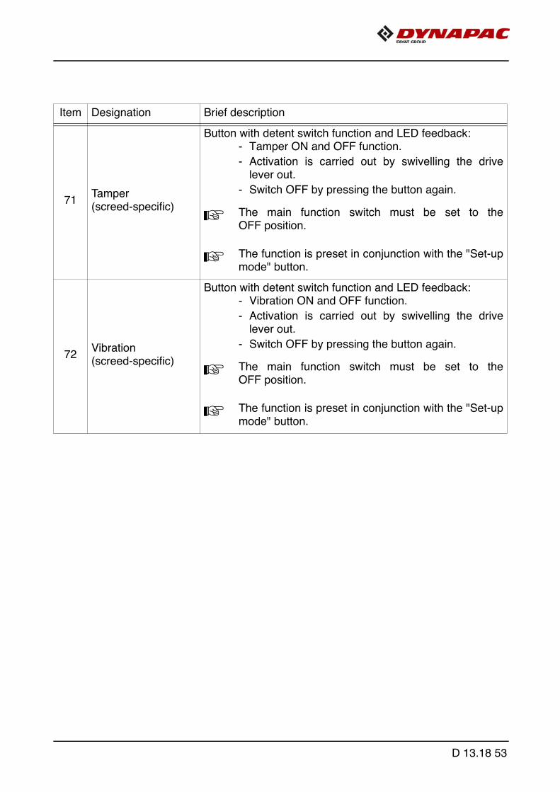
Item Designation Brief description
71Tamper (screed-specific)
Button with detent switch function and LED feedback:- Tamper ON and OFF function.
- Activation is carried out by swivelling the drivelever out.
- Switch OFF by pressing the button again.
A The main function switch must be set to theOFF position.
A The function is preset in conjunction with the "Set-upmode" button.
72Vibration (screed-specific)
Button with detent switch function and LED feedback:- Vibration ON and OFF function.
- Activation is carried out by swivelling the drivelever out.
- Switch OFF by pressing the button again.
A The main function switch must be set to theOFF position.
A The function is preset in conjunction with the "Set-upmode" button.
D 13.18 53
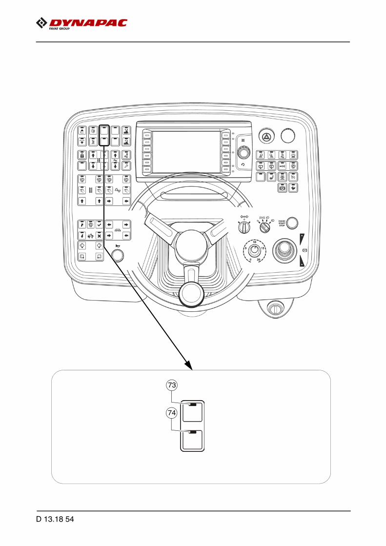
74
73
D 13.18 54

Item Designation Brief description
73 Screed relieving
Button with detent switch function and LED feedback:- For relieving the screed to influence the traction force
and compaction ratio.
- Switch OFF by pressing the button again or switchingbetween screed relieving and screed charging.
- To preset the hydraulic oil pressure, switch this button and the "Set-up mode" button to "ON".
74 Screed charging
Button with detent switch function and LED feedback:- For relieving the screed to influence the traction force
and compaction ratio.
- Switch OFF by pressing the button again or switchingbetween screed relieving and screed charging.
- To preset the hydraulic oil pressure, switch this button and the "Set-up mode" button to "ON".
D 13.18 55

76
75
D 13.18 56
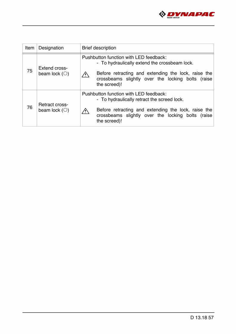
Item Designation Brief description
75Extend cross-beam lock (o)
Pushbutton function with LED feedback:- To hydraulically extend the crossbeam lock.
m Before retracting and extending the lock, raise thecrossbeams slightly over the locking bolts (raisethe screed)!
76Retract cross-beam lock (o)
Pushbutton function with LED feedback:- To hydraulically retract the screed lock.
m Before retracting and extending the lock, raise thecrossbeams slightly over the locking bolts (raisethe screed)!
D 13.18 57

78
77
D 13.18 58

A The "Set Assist" function prepares the paver to relocate to another section of road-works or for transportation.When the function is activated, previously selected vehicle functions are carried outto make the vehicle ready for transport.The function can be reset after relocating the paver. This restores the corresponding elements to the previously saved working condition /position.
A The elements that can be actuated by the function are selected in the correspondingmenu in the vehicle display.
A The working condition / current position of the corre-sponding functions and components must be saved ini-tially for later use. See display description
A The following conditions must be fulfilled to use the function:
- Drive lever (13) in neutral position, road speed "0"
- Set-up mode (68) OFF
Item Designation Brief description
77Set "Set assist" (o)
Pushbutton function with LED feedback:- To set up the transport condition.
- Press and hold button (LED flashes) until comple-tion of all functions to achieve transport condition(LED ON).
f On actuation, heed danger zones of moving parts ofthe vehicle!
78Reset"Set assist" (o)
Pushbutton function with LED feedback:- To set up the previous working condition.
- Press and hold button (LED flashes) until comple-tion of all functions to achieve last saved workingcondition (LED ON).
f On actuation, heed danger zones of moving parts ofthe vehicle!
D 13.18 59
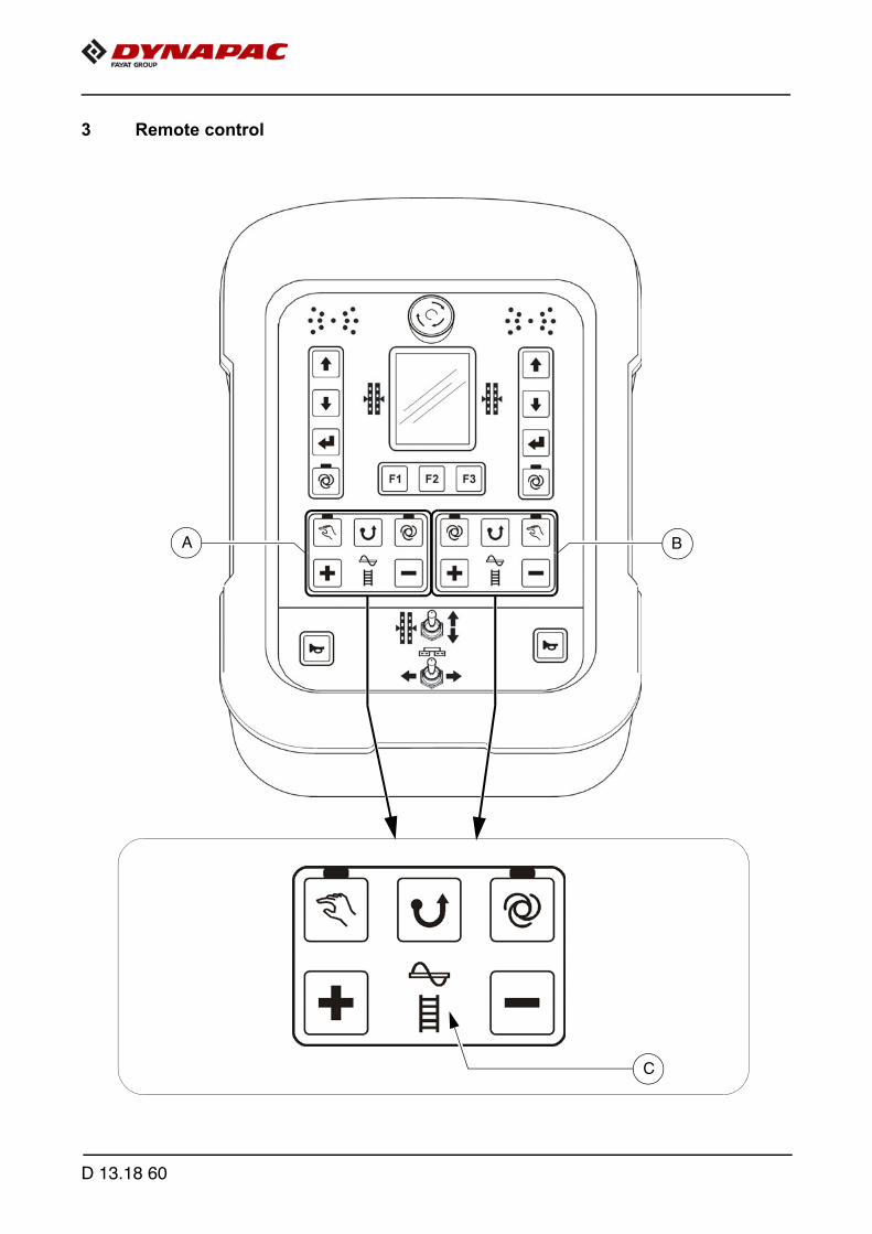
3 Remote control
A B
C
D 13.18 60
A Depending on the side of the vehicle, the button blocks (A) and (B) are assigned toeither the auger or the conveyor control system. The relevant element which is con-trolled is indicated by an illuminated symbol (C).
m Important! Do not disconnect remote controls during operation! This causes the paver finisher to be shut down!
D 13.18 61

121
120
121
D 13.18 62

Item Designation Brief description
120Emergency stop button
Press in an emergency (danger to persons, impending colli-sion, etc.)! - Pressing the emergency stop button switches off the en-
gine, the drives and the steering system. Making way, lifting the screed or other actions are then no longer possible! Danger of accidents!
- The emergency stop button does not shut off the gas heat-er system. Close the main shut-off valve and the valves on the bottles by hand!
- To restart the engine, the button must be pulled out again.
121Remote control connection socket
Connect the plug to the screed.
A Whether this involves the left-hand or the right-hand re-mote control is automatically detected.
D 13.18 63

122
124
125
123
125
122
124
D 13.18 64

Item Designation Brief description
122Auger"MANUAL"
Button with detent switch function and LED feedback:- The conveying function of the corresponding half of
the auger is switched on continuously with full deliv-ery capacity, without material control via thelimit switches.
- Switch OFF by pressing the button again
A The function is shut off by pressing the EMERGENCYSTOP button or restarting the vehicle.
A The main function switch locks the conveying function.
123Auger "AUTO"
Button with detent switch function and LED feedback:- The conveying function of the corresponding half of
the auger is switched on when the drive lever is swiv-elled out and is continuously controlled via the mate-rial limit switches.
- Switch OFF by pressing the button again
A The function is shut off by pressing the EMERGENCYSTOP button or restarting the vehicle.
A The main function switch (operating panel) locks theconveying function.
124Auger "Reversing mode"
Pushbutton function:- The auger's conveying direction can be reversed in
order to slightly reverse any paving material whichmay be positioned just in front of the auger.This enables e.g. material losses to be avoided dur-ing transportation.
- Temporally limited reversal is carried out when thebutton is pressed continuously.
A The auger function must be switched to "AUTO" or"MANUAL" for reversing mode.
A In reversing mode, the automatic function is overriddenwith reduced capacity.
D 13.18 65

122
124
125
123
125
122
124
D 13.18 66
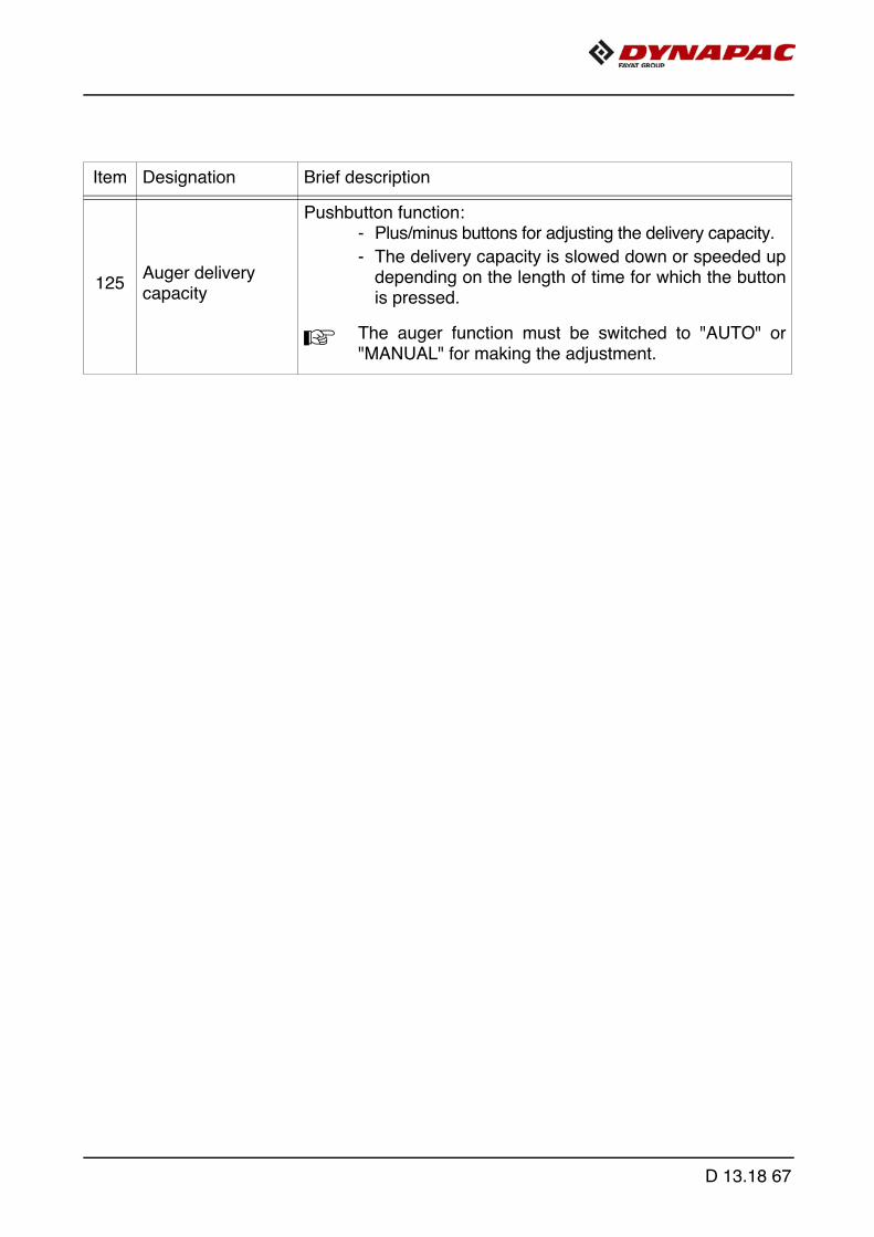
Item Designation Brief description
125 Auger delivery capacity
Pushbutton function:- Plus/minus buttons for adjusting the delivery capacity.
- The delivery capacity is slowed down or speeded updepending on the length of time for which the buttonis pressed.
A The auger function must be switched to "AUTO" or"MANUAL" for making the adjustment.
D 13.18 67
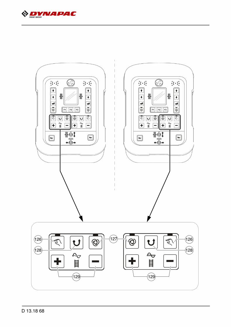
126
128
129
127
129
126
128
D 13.18 68
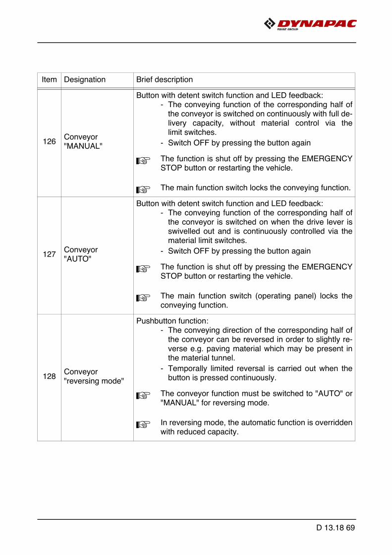
Item Designation Brief description
126Conveyor"MANUAL"
Button with detent switch function and LED feedback:- The conveying function of the corresponding half of
the conveyor is switched on continuously with full de-livery capacity, without material control via thelimit switches.
- Switch OFF by pressing the button again
A The function is shut off by pressing the EMERGENCYSTOP button or restarting the vehicle.
A The main function switch locks the conveying function.
127Conveyor "AUTO"
Button with detent switch function and LED feedback:- The conveying function of the corresponding half of
the conveyor is switched on when the drive lever isswivelled out and is continuously controlled via thematerial limit switches.
- Switch OFF by pressing the button again
A The function is shut off by pressing the EMERGENCYSTOP button or restarting the vehicle.
A The main function switch (operating panel) locks theconveying function.
128 Conveyor"reversing mode"
Pushbutton function:- The conveying direction of the corresponding half of
the conveyor can be reversed in order to slightly re-verse e.g. paving material which may be present inthe material tunnel.
- Temporally limited reversal is carried out when thebutton is pressed continuously.
A The conveyor function must be switched to "AUTO" or"MANUAL" for reversing mode.
A In reversing mode, the automatic function is overriddenwith reduced capacity.
D 13.18 69

126
128
129
127
129
126
128
D 13.18 70

Item Designation Brief description
129 Conveyor delivery capacity
Pushbutton function:- Plus/minus buttons for adjusting the delivery capacity.
- The delivery capacity is slowed down or speeded updepending on the length of time for which the buttonis pressed.
A The conveyor function must be switched to "AUTO" or"MANUAL" for making the adjustment.
D 13.18 71

131
132
133
130
D 13.18 72

Item Designation Brief description
130
Operating mode Levelling "AUTO" / "MANUAL"left
Button with detent switch function and LED feedback:- Operating mode "AUTO" (LED ON):
levelling engages automatically when the drive leveris swivelled out for paving operation.
- Operating mode "MANUAL" (LED OFF):levelling switched off.
131/
132
Levelling cylinder adjustment, left
Pushbutton function:- To retract and extend the levelling cylinder on the cor-
responding side of the vehicle.
A On adjustment, note the levelling display in the remotecontrol display!
A For direct adjustment, the levelling function must be setto "MANUAL". In "AUTO" operating mode, adjustment is carried out af-ter confirming the enter button (133).
133 Enter
Pushbutton function:- For confirming levelling cylinder adjustment in "Auto"
operating mode. Levelling cylinder adjustment is carried out by press-ing the button.
D 13.18 73
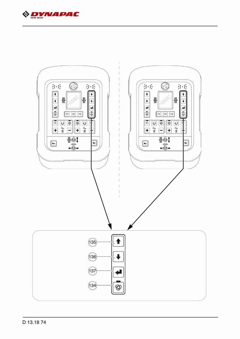
135
136
137
134
D 13.18 74
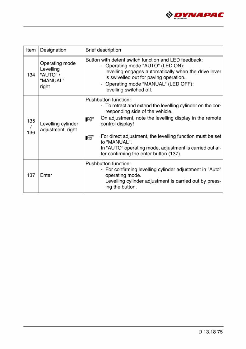
Item Designation Brief description
134
Operating mode Levelling "AUTO" / "MANUAL"right
Button with detent switch function and LED feedback:- Operating mode "AUTO" (LED ON):
levelling engages automatically when the drive leveris swivelled out for paving operation.
- Operating mode "MANUAL" (LED OFF):levelling switched off.
135/
136
Levelling cylinder adjustment, right
Pushbutton function:- To retract and extend the levelling cylinder on the cor-
responding side of the vehicle.
A On adjustment, note the levelling display in the remotecontrol display!
A For direct adjustment, the levelling function must be setto "MANUAL". In "AUTO" operating mode, adjustment is carried out af-ter confirming the enter button (137).
137 Enter
Pushbutton function:- For confirming levelling cylinder adjustment in "Auto"
operating mode. Levelling cylinder adjustment is carried out by press-ing the button.
D 13.18 75
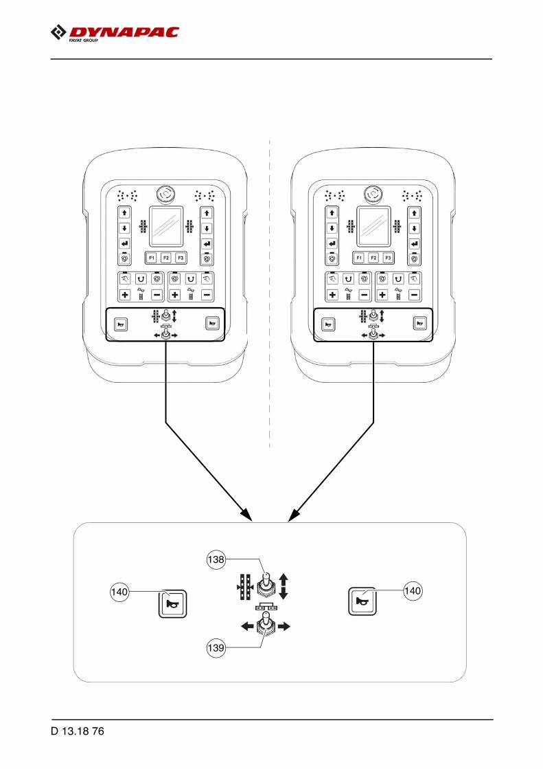
140
138
140
139
D 13.18 76

Item Designation Brief description
138Levelling cylinder manual
Pushbutton function:- For manual actuation of the levelling cylinders on the
corresponding side of the vehicle when the automaticlevelling system is switched off (LED OFF).
A On adjustment, note the levelling display in the remotecontrol display!
139Extend/retract screed
Pushbutton function:- To retract and extend the screed half on the corre-
sponding side of the vehicle.
A This function is not used in vehicle configurations with ascreed which cannot be extended.
f On actuation, heed danger zones of moving parts ofthe vehicle!
140 Horn
Press in the case of emergencies and to indicate when the ve-hicle starts to move!
A The horn can also be used to communicate acoustical-ly with the truck driver for material loading!
D 13.18 77

D 13.18 78

D 23.18 Operating the display
D 23.18 1
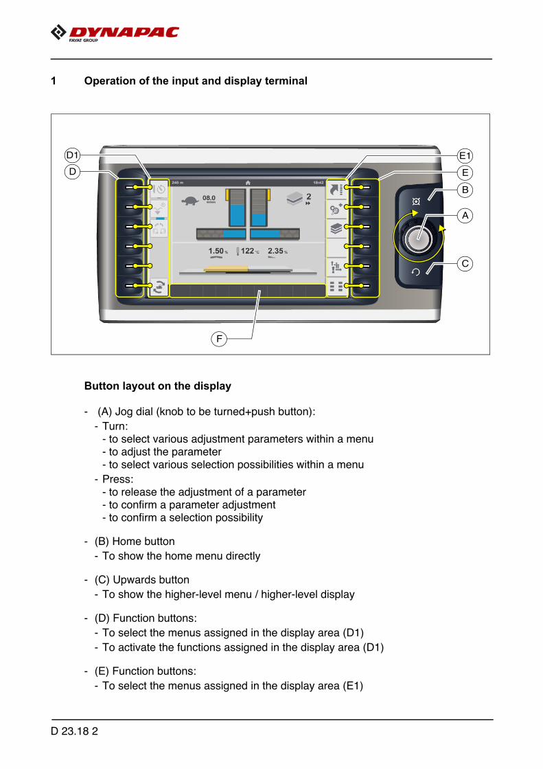
1 Operation of the input and display terminal
Button layout on the display
- (A) Jog dial (knob to be turned+push button):
- Turn: - to select various adjustment parameters within a menu- to adjust the parameter- to select various selection possibilities within a menu
- Press: - to release the adjustment of a parameter- to confirm a parameter adjustment- to confirm a selection possibility
- (B) Home button
- To show the home menu directly
- (C) Upwards button
- To show the higher-level menu / higher-level display
- (D) Function buttons:
- To select the menus assigned in the display area (D1)
- To activate the functions assigned in the display area (D1)
- (E) Function buttons:
- To select the menus assigned in the display area (E1)
E
A
E1
D
D1
F
B
C
D 23.18 2

A To confirm an active/opened menu, the colour of the cor-responding symbol changes from pale to dark grey!
- (F) Display area for status, warning and error messages:
- To show current earnings or error messages.
A The colour of the symbol indicates whether it is a status, warning or error message.
A Detailed explanations for the individual displays can be found in the section "Symbolsfor status, warning and error messages"
Colour code Explanation
- RED - error message- Reports a serious fault that must be checked and rec-
tified immediately.
- YELLOW - warning message- Reports a current condition that needs to be observed
or rectified at short notice to ensure correct working.
- BLUE / GREEN - status message- Confirms an activated function.
D 23.18 3

1.1 Menu operation - procedure for adjusting parameters
A
B
C
D 23.18 4

Example: Adjusting the screed temperature
- The "Home" menu is open in the display.
- Press button (A) to open the "Engine Speed" menu.
- The "Engine Speed" menu is open in the display.
- Press button (B) to open the "Screed Heater" menu.
- Turn jog dial (C) to make the cursor appear.
A A blue frame appears around the temperature parameter.
- Press jog dial (C) to activate the adjustment.
- Turn jog dial (C) in the corresponding direction to reach the required temperature.
- Press jog dial (C) to adopt the adjusted value.
A The blue frame around the temperature parameter disappears.
D 23.18 5
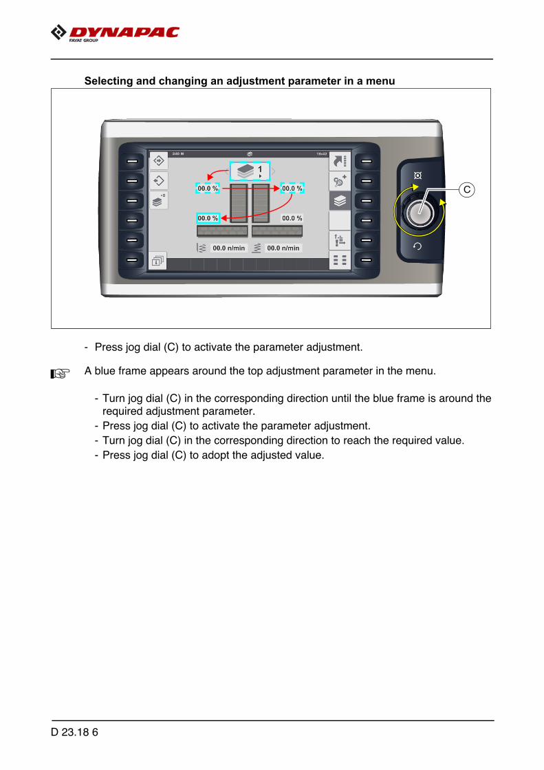
Selecting and changing an adjustment parameter in a menu
- Press jog dial (C) to activate the parameter adjustment.
A A blue frame appears around the top adjustment parameter in the menu.
- Turn jog dial (C) in the corresponding direction until the blue frame is around therequired adjustment parameter.
- Press jog dial (C) to activate the parameter adjustment.
- Turn jog dial (C) in the corresponding direction to reach the required value.
- Press jog dial (C) to adopt the adjusted value.
C
D 23.18 6

Selecting and changing a selection possibility in a menu
- Press jog dial to activate the parameter adjustment.
A A blue frame appears around the top selection possibility in the menu.
- Turn jog dial in the corresponding direction until the blue frame is around the re-quired selection possibility.
- Press jog dial to activate the selection possibility.
D 23.18 7

2 Menu structure
Menu of the "Home" displays
Displays:
- (1) Speed:
- Paving (tortoise)-(m/min) / (ft/min)
- Driving (hare) - (km/h) / (mph)
- (2) Fuel gauge
- (4) Paving material - conveyor level left / right
- (5) Paving material - auger level left / right
- (6) Actual temperature of the screen heater (°C) / (°F)
A The display shows the average temperature of all screed sections.
A Currently heated screed sections appear coloured in the corresponding graphic.
- (11) Crowning - (%) (o)
- (12) Target slope - left / right (%) (o)
- (16) Type of material control being used
- (17) Truck Assist control (o)
- (18) Distance travelled counter (m) / (ft)
- (19) Time of day (hh:mm) (AM/PM)
- (20) Menu/display symbol
116
11 12
6
5
4
18 20 19
2
1717
D 23.18 8
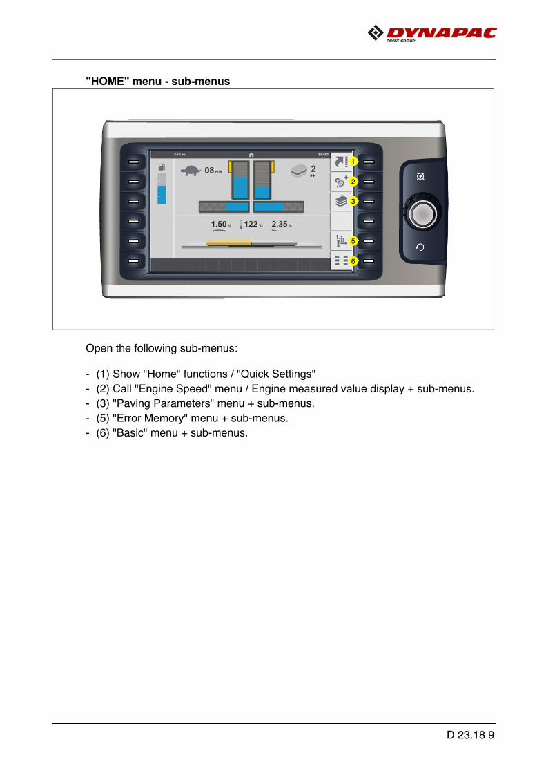
"HOME" menu - sub-menus
Open the following sub-menus:
- (1) Show "Home" functions / "Quick Settings"
- (2) Call "Engine Speed" menu / Engine measured value display + sub-menus.
- (3) "Paving Parameters" menu + sub-menus.
- (5) "Error Memory" menu + sub-menus.
- (6) "Basic" menu + sub-menus.
1
2
3
5
6
D 23.18 9
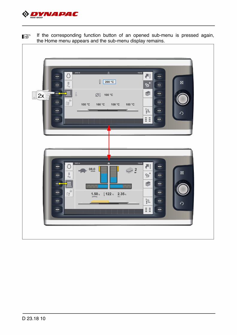
A If the corresponding function button of an opened sub-menu is pressed again,the Home menu appears and the sub-menu display remains.
2x
D 23.18 10

"Home" functions / "Quick Settings"
Menu for directly activating various functions.
- Press corresponding function button to show the functions / quick settings (1) to (6).Press once more to hide the functions again.
A Pressing the adjacent function button activates or deac-tivates the functions. The function is activated when the corresponding symbolappears blue.
- (1): "Delayed tamper start" function
- On swivelling the drive lever, the tamper function is only activated once a definedtime has elapsed.
- (2): "Delayed screed start" function
- When the drive lever is deflected, the floating function is only activated once thetime set in the relevant menu has elapsed.
- (3): "Joint hopper actuation" function
- Both hopper halves are actuated together with one of the hopper function switch-es (open hopper / close hopper).
- (6) Save function "Set Assist"
- The working condition / current position of the corresponding functions and com-ponents is saved for later use.
1
2
3
6
D 23.18 11

A As confirmation, the display changes for 5 to 10 secondsduring saving.
A The functions and elements for the "Set Assist" functionare selected in the corresponding menu.
A The "Set Assist" function prepares the paver to relocate to another section of road-works or for transportation.When the function is activated, previously selected vehicle functions are carried outto make the vehicle ready for transport.The function can be reset after relocating the paver. This restores the corresponding elements to the previous working condition /position.
D 23.18 12
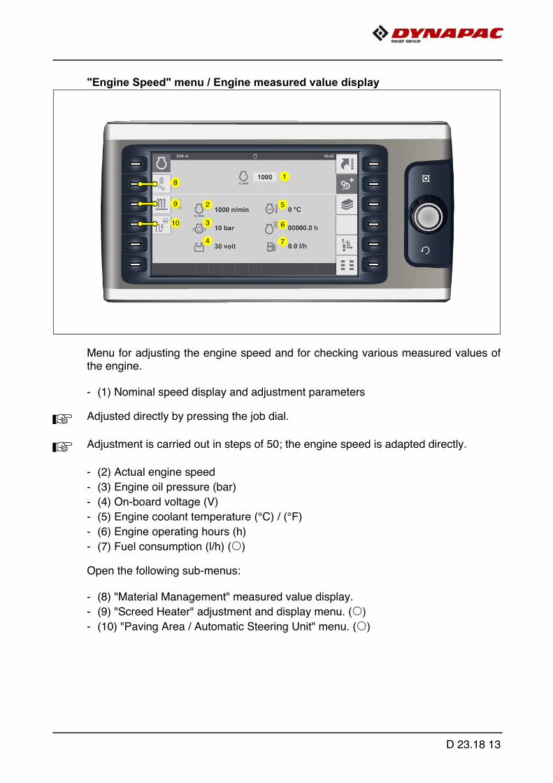
"Engine Speed" menu / Engine measured value display
Menu for adjusting the engine speed and for checking various measured values ofthe engine.
- (1) Nominal speed display and adjustment parameters
A Adjusted directly by pressing the job dial.
A Adjustment is carried out in steps of 50; the engine speed is adapted directly.
- (2) Actual engine speed
- (3) Engine oil pressure (bar)
- (4) On-board voltage (V)
- (5) Engine coolant temperature (°C) / (°F)
- (6) Engine operating hours (h)
- (7) Fuel consumption (l/h) (o)
Open the following sub-menus:
- (8) "Material Management" measured value display.
- (9) "Screed Heater" adjustment and display menu. (o)
- (10) "Paving Area / Automatic Steering Unit" menu. (o)
2
3
5
6
74
18
9
10
D 23.18 13
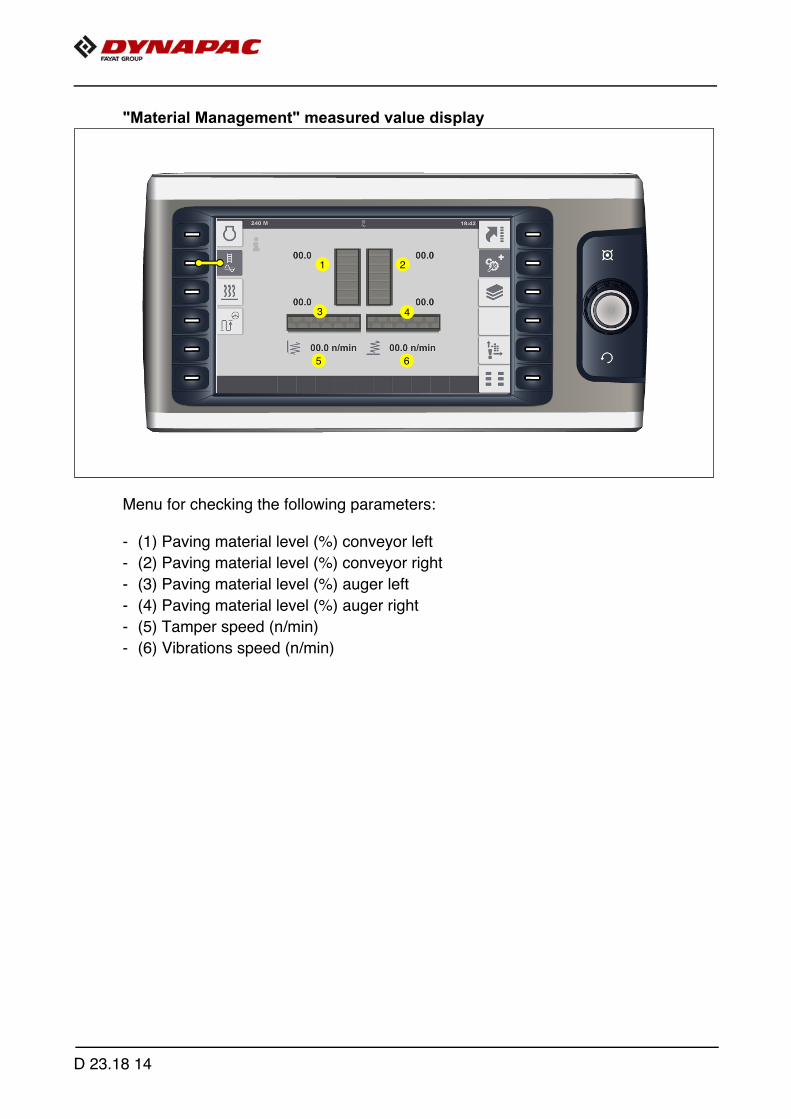
"Material Management" measured value display
Menu for checking the following parameters:
- (1) Paving material level (%) conveyor left
- (2) Paving material level (%) conveyor right
- (3) Paving material level (%) auger left
- (4) Paving material level (%) auger right
- (5) Tamper speed (n/min)
- (6) Vibrations speed (n/min)
2
3
6
1
5
4
D 23.18 14
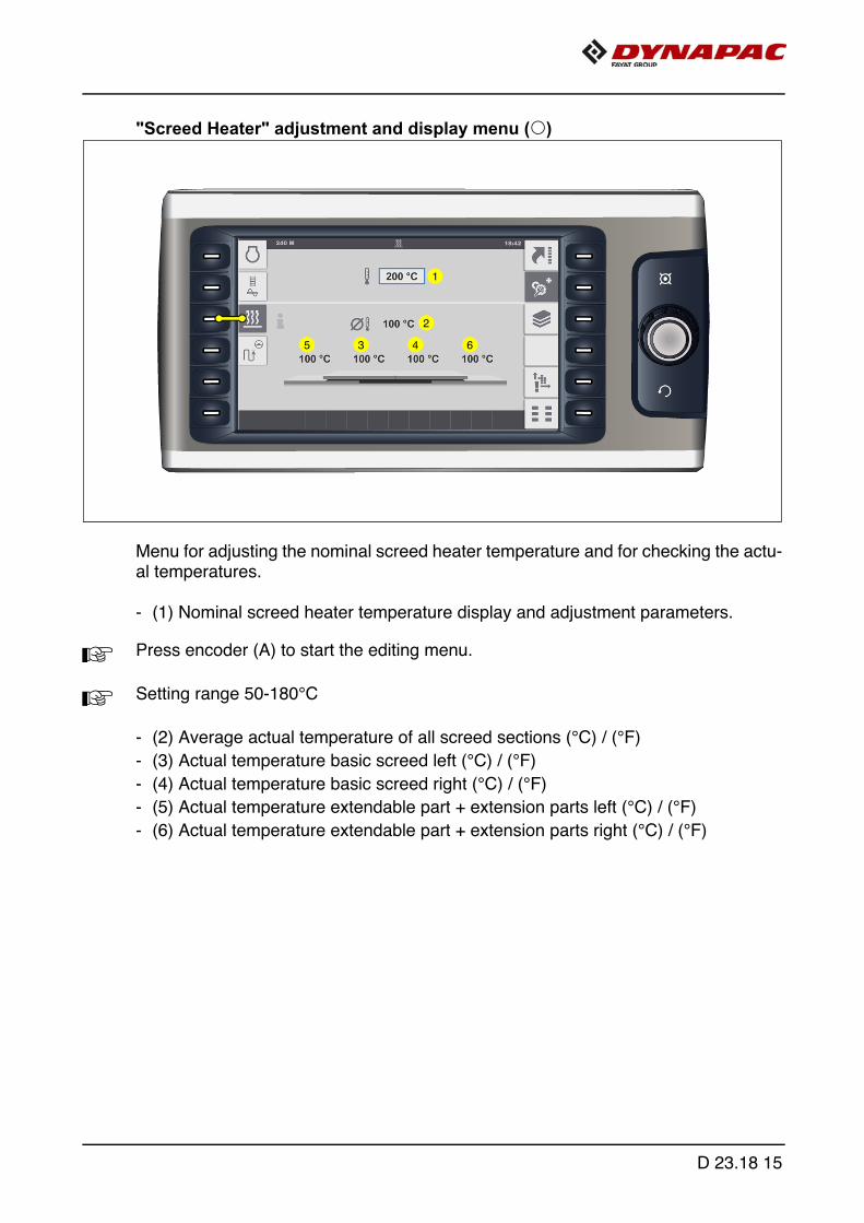
"Screed Heater" adjustment and display menu (o)
Menu for adjusting the nominal screed heater temperature and for checking the actu-al temperatures.
- (1) Nominal screed heater temperature display and adjustment parameters.
A Press encoder (A) to start the editing menu.
A Setting range 50-180°C
- (2) Average actual temperature of all screed sections (°C) / (°F)
- (3) Actual temperature basic screed left (°C) / (°F)
- (4) Actual temperature basic screed right (°C) / (°F)
- (5) Actual temperature extendable part + extension parts left (°C) / (°F)
- (6) Actual temperature extendable part + extension parts right (°C) / (°F)
5
2
4 6
1
3
D 23.18 15
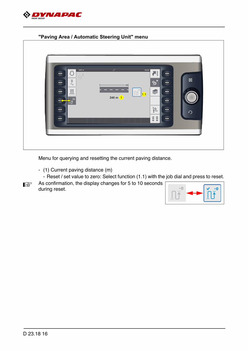
"Paving Area / Automatic Steering Unit" menu
Menu for querying and resetting the current paving distance.
- (1) Current paving distance (m)
- Reset / set value to zero: Select function (1.1) with the job dial and press to reset.
A As confirmation, the display changes for 5 to 10 secondsduring reset.
11.1
D 23.18 16
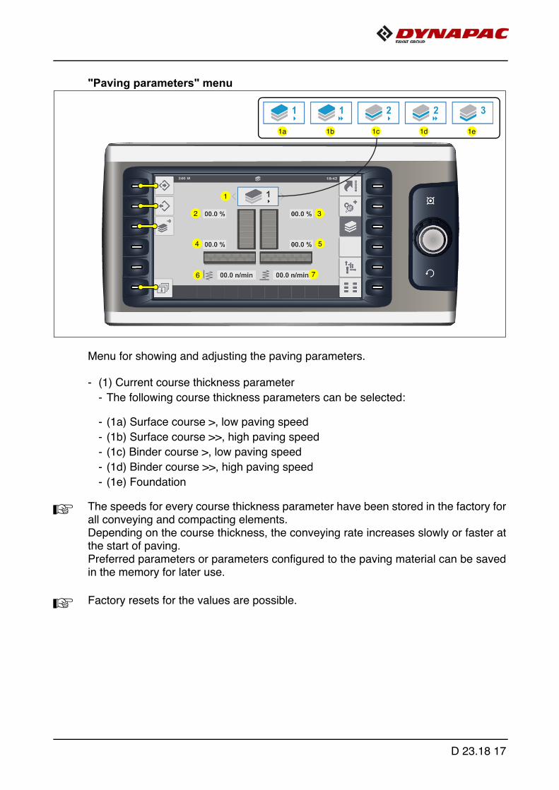
"Paving parameters" menu
Menu for showing and adjusting the paving parameters.
- (1) Current course thickness parameter
- The following course thickness parameters can be selected:
- (1a) Surface course >, low paving speed
- (1b) Surface course >>, high paving speed
- (1c) Binder course >, low paving speed
- (1d) Binder course >>, high paving speed
- (1e) Foundation
A The speeds for every course thickness parameter have been stored in the factory forall conveying and compacting elements. Depending on the course thickness, the conveying rate increases slowly or faster atthe start of paving.Preferred parameters or parameters configured to the paving material can be savedin the memory for later use.
A Factory resets for the values are possible.
76
4
32
5
1
1a 1b 1c 1d 1e
D 23.18 17
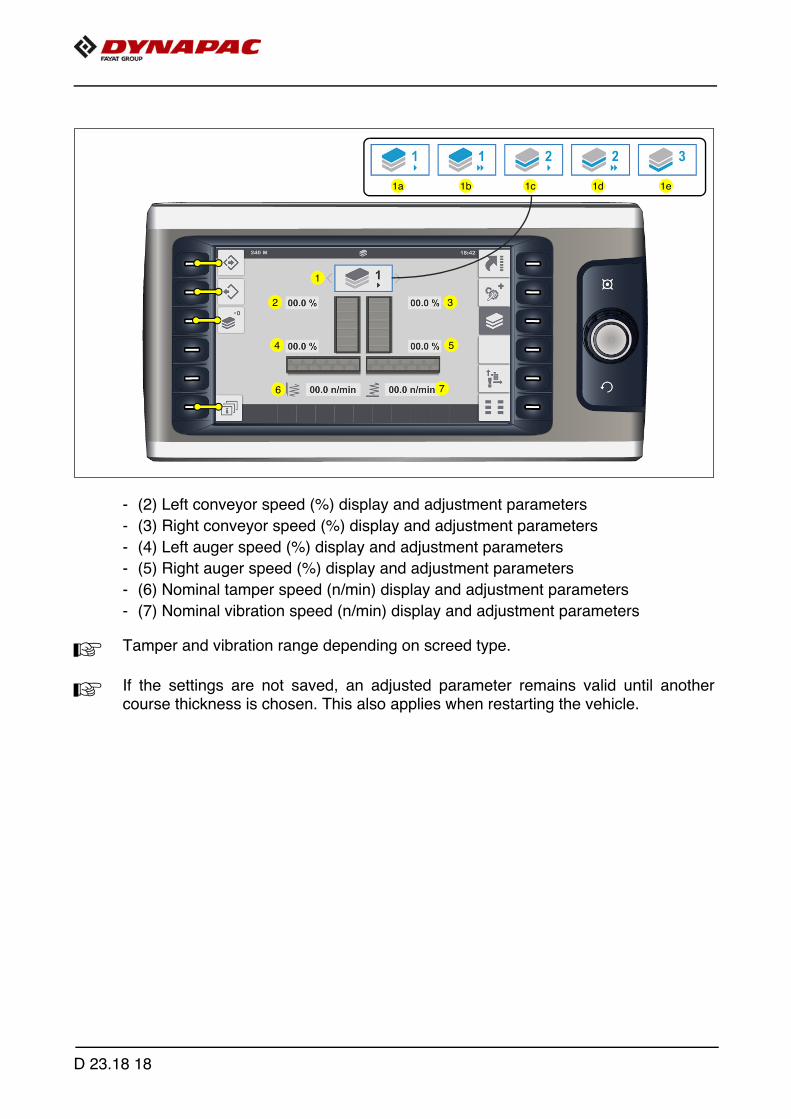
- (2) Left conveyor speed (%) display and adjustment parameters
- (3) Right conveyor speed (%) display and adjustment parameters
- (4) Left auger speed (%) display and adjustment parameters
- (5) Right auger speed (%) display and adjustment parameters
- (6) Nominal tamper speed (n/min) display and adjustment parameters
- (7) Nominal vibration speed (n/min) display and adjustment parameters
A Tamper and vibration range depending on screed type.
A If the settings are not saved, an adjusted parameter remains valid until anothercourse thickness is chosen. This also applies when restarting the vehicle.
76
4
32
5
1
1a 1b 1c 1d 1e
D 23.18 18

Adjusting the paving parameters
Functions:
- (8) "Save Parameter" function
A As confirmation, the display changes for 5 to 10 secondsduring saving.
- (9): "Load Parameter" function
A As confirmation, the display changes for 5 to 10 secondsduring loading.
- (10): "Parameter Reset - Load Factory Settings" function
A Firstly the system requests reset confirmation.Press the button again for a reset within 5 seconds. As confirmation, the display changes for 5 to 10 secondsduring reset.
Open the following sub-menus:
- (11) Overview "Course Thickness Parameters".
76
4
32
5
1
8
9
10
11
D 23.18 19

Overview "Course Thickness Parameters"
Menu for viewing the speeds saved for all conveying and compacting elements ac-cording to the course thickness parameters.
Back to the main menu:
- (1) "Paving Parameters" menu.
1
D 23.18 20

"Error Memory" menu
Menu for retrieving existing error messages.
- (1) Number of error messages with travel drive stop.
- Open detailed display "Error Messages With Travel Drive Stop": (1.1).
- (2) Number of vehicle warning messages.
- Open detailed display "Vehicle Warning Messages": (2.1).
- (3) Number of engine error messages.
- Open detailed display "Engine Error Messages": (3.1).
- (4) System error display.
A Possibly notify customer service of the system error number displayed on your paverfinisher; the customer service department will then discuss with you how to proceed.
2
1
3
4
1.1
2.1
3.1
D 23.18 21
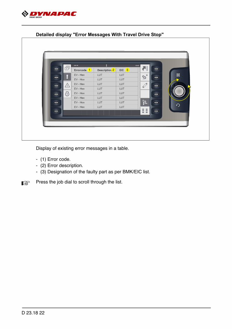
Detailed display "Error Messages With Travel Drive Stop"
Display of existing error messages in a table.
- (1) Error code.
- (2) Error description.
- (3) Designation of the faulty part as per BMK/EIC list.
A Press the job dial to scroll through the list.
1 2 3
D 23.18 22
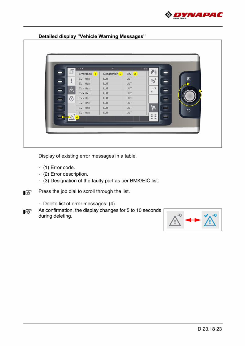
Detailed display "Vehicle Warning Messages"
Display of existing error messages in a table.
- (1) Error code.
- (2) Error description.
- (3) Designation of the faulty part as per BMK/EIC list.
A Press the job dial to scroll through the list.
- Delete list of error messages: (4).
A As confirmation, the display changes for 5 to 10 secondsduring deleting.
1 2 3
4
D 23.18 23
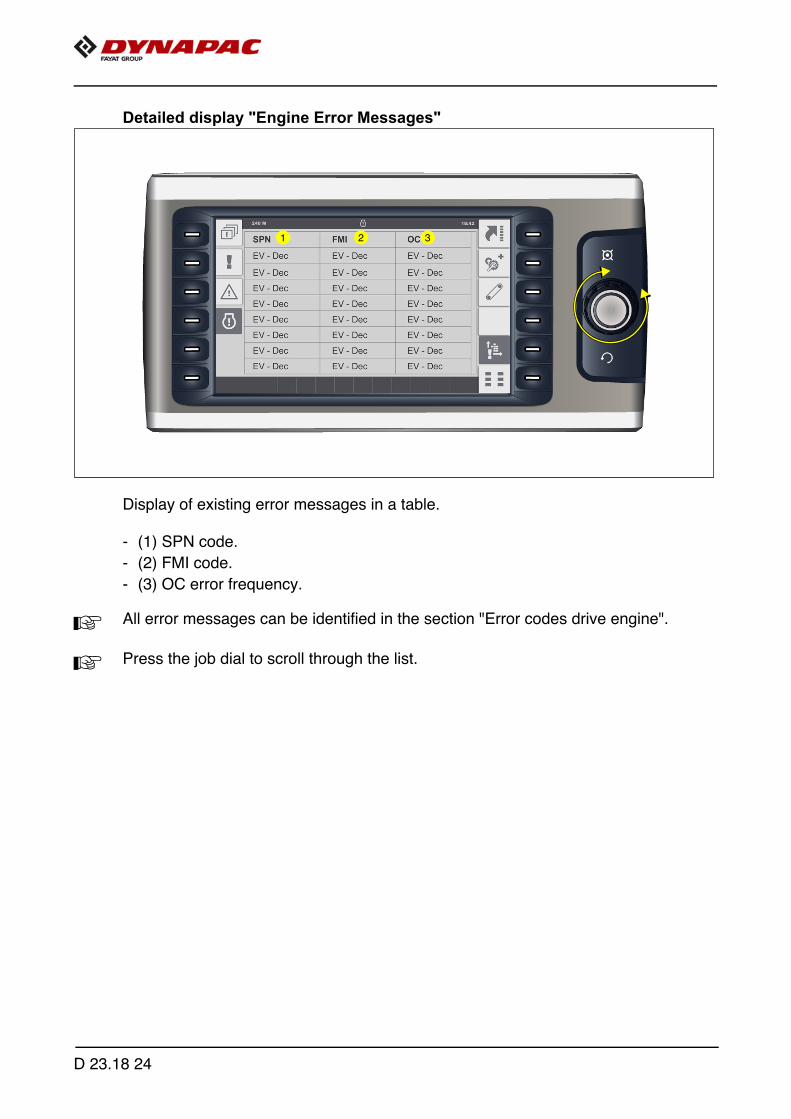
Detailed display "Engine Error Messages"
Display of existing error messages in a table.
- (1) SPN code.
- (2) FMI code.
- (3) OC error frequency.
A All error messages can be identified in the section "Error codes drive engine".
A Press the job dial to scroll through the list.
1 2 3
D 23.18 24
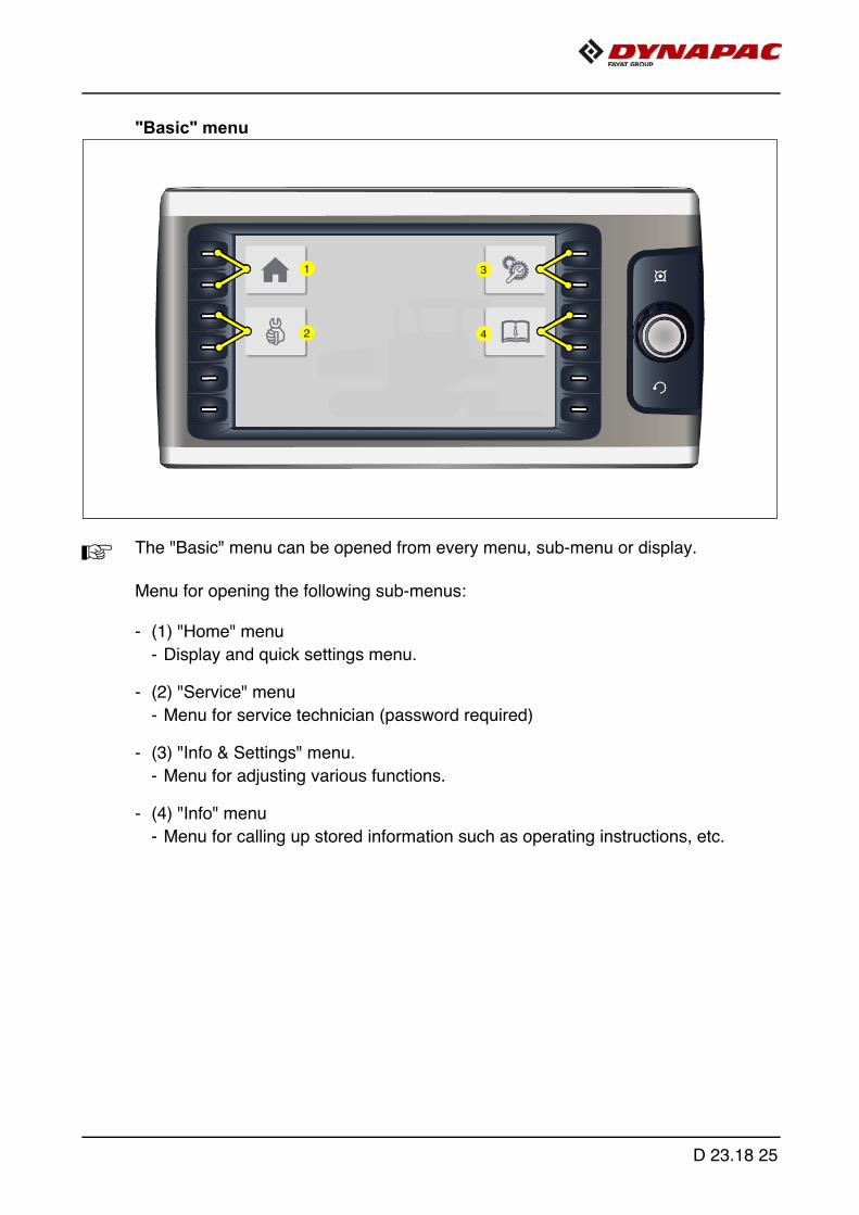
"Basic" menu
A The "Basic" menu can be opened from every menu, sub-menu or display.
Menu for opening the following sub-menus:
- (1) "Home" menu
- Display and quick settings menu.
- (2) "Service" menu
- Menu for service technician (password required)
- (3) "Info & Settings" menu.
- Menu for adjusting various functions.
- (4) "Info" menu
- Menu for calling up stored information such as operating instructions, etc.
1
2
3
4
D 23.18 25
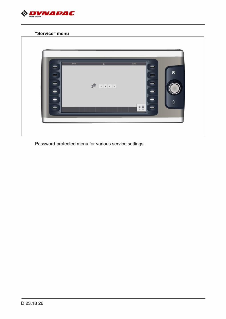
"Service" menu
Password-protected menu for various service settings.
D 23.18 26
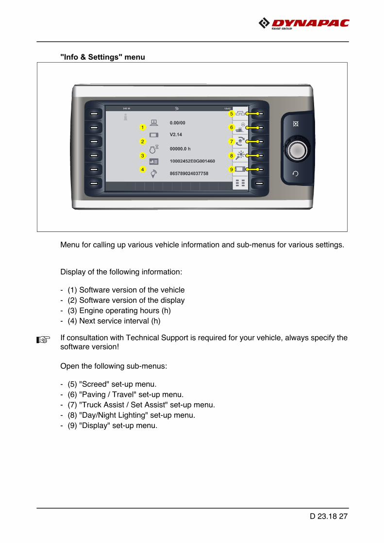
"Info & Settings" menu
Menu for calling up various vehicle information and sub-menus for various settings.
Display of the following information:
- (1) Software version of the vehicle
- (2) Software version of the display
- (3) Engine operating hours (h)
- (4) Next service interval (h)
A If consultation with Technical Support is required for your vehicle, always specify thesoftware version!
Open the following sub-menus:
- (5) "Screed" set-up menu.
- (6) "Paving / Travel" set-up menu.
- (7) "Truck Assist / Set Assist" set-up menu.
- (8) "Day/Night Lighting" set-up menu.
- (9) "Display" set-up menu.
5
6
7
8
9
1
2
3
4
D 23.18 27

"Screed" set-up menu
Menu for setting up the basic screed settings and screed functions.
- (1) Display and adjustment parame-ters for the screed type
- Screed type 1, 2, 3, 4, 5
A Please consult the screed type plate forthe parameter to be entered here, corre-sponding to the last number of thescreed type.
A If a different screed type has been con-nected to the paver finisher, the corre-sponding setting must be carried out!
- (2) Display and adjustment parameters for the screed heater
- (2.1): Electric heater
- (2.2): Gas heater
- (3) Display and adjustment parameters for "Delayed Screed Start" - delay time (sec)
A On swivelling the drive lever, the floating function is only activated once an adjustedtime has elapsed.
A Setting range 0-10 sec.
1
2
3
4
2.1 2.2
4.1 4.2 4.3
V3500TV / 3
D 23.18 28

- (4) Display and adjustment parameters for the central lubrication system
- (4.1): Extended lubrication interval
- (4.2): Standard lubrication interval
- (4.3): Shortened lubrication interval
A If necessary, the lubrication interval has to be adjusted to the prevailing paving situ-ation and to the material.
1
2
3
4
2.1 2.2
4.1 4.2 4.3
D 23.18 29

"Paving / Travel" set-up menu
Menu for setting up the vehicle and levelling functions.
- (1) Display and adjustment parameters for "Delayed Front Hopper" - delay time (sec). (o)
A After closing the hopper lids, the front hopper is only raised after the adjusted timehas expired.
A Setting range 0-25 sec.
- (2) Selection "External Levelling"
- (L): External levelling - left side of the vehicle
- (R): External levelling - right side of the vehicle
A When "External levelling" is selected, the toggle switches of the system's own remotecontrol remain active!
1
2
3
4
D 23.18 30
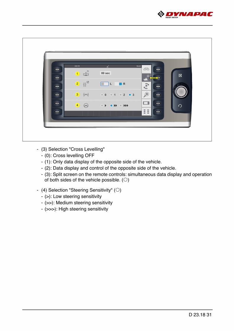
- (3) Selection "Cross Levelling"
- (0): Cross levelling OFF
- (1): Only data display of the opposite side of the vehicle.
- (2): Data display and control of the opposite side of the vehicle.
- (3): Split screen on the remote controls: simultaneous data display and operationof both sides of the vehicle possible. (o)
- (4) Selection "Steering Sensitivity" (o)
- (>): Low steering sensitivity
- (>>): Medium steering sensitivity
- (>>>): High steering sensitivity
1
2
3
4
D 23.18 31
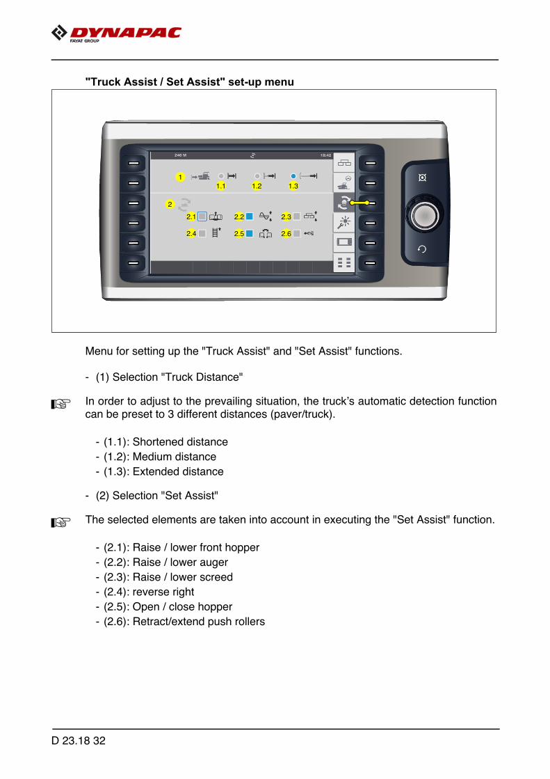
"Truck Assist / Set Assist" set-up menu
Menu for setting up the "Truck Assist" and "Set Assist" functions.
- (1) Selection "Truck Distance"
A In order to adjust to the prevailing situation, the truck’s automatic detection functioncan be preset to 3 different distances (paver/truck).
- (1.1): Shortened distance
- (1.2): Medium distance
- (1.3): Extended distance
- (2) Selection "Set Assist"
A The selected elements are taken into account in executing the "Set Assist" function.
- (2.1): Raise / lower front hopper
- (2.2): Raise / lower auger
- (2.3): Raise / lower screed
- (2.4): reverse right
- (2.5): Open / close hopper
- (2.6): Retract/extend push rollers
1
2
1.1 1.2 1.3
2.1
2.4
2.2
2.5
2.3
2.6
D 23.18 32
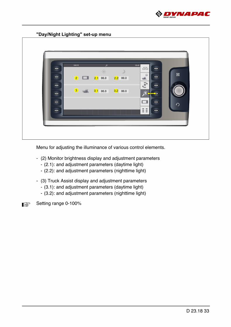
"Day/Night Lighting" set-up menu
Menu for adjusting the illuminance of various control elements.
- (2) Monitor brightness display and adjustment parameters
- (2.1): and adjustment parameters (daytime light)
- (2.2): and adjustment parameters (nighttime light)
- (3) Truck Assist display and adjustment parameters
- (3.1): and adjustment parameters (daytime light)
- (3.2): and adjustment parameters (nighttime light)
A Setting range 0-100%
2
3
2.1 2.2
3.1 3.2
D 23.18 33

"Display" set-up menu
Menu for setting up basic display settings.
- (1) Selection "System Language"
- English / German
- (2) Selection "Units of measurement"
- Metric / Imperial (US)
- (3) "Time" display and adjustment parameters
- h/h : min/min
- 24h / PM/AM
- (4) "Date" display and adjustment parameters
- dd - mm - yyyy
Open the following sub-menus:
- (5) "Licence text" display
1
3
4
5
2
D 23.18 34

"Licence text" display
Display of the software licence text.
Back to the main menu:
- (1) "Display" set-up menu.
1
D 23.18 35
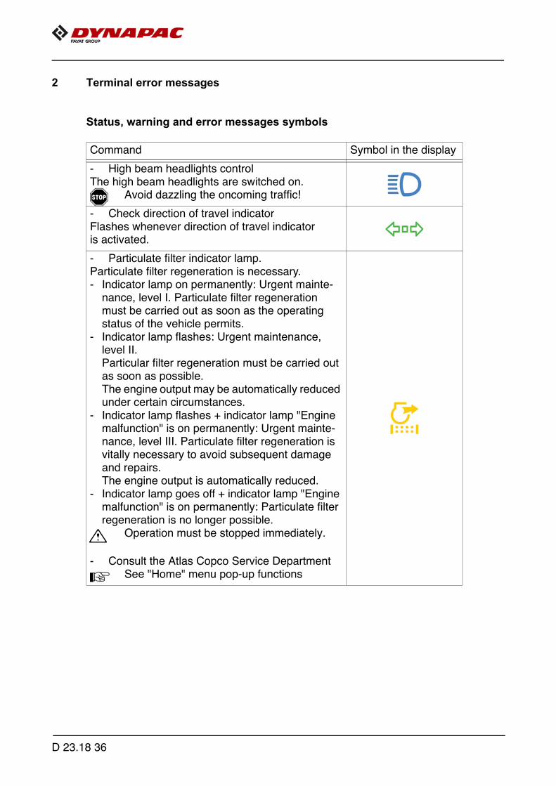
2 Terminal error messages
Status, warning and error messages symbols
Command Symbol in the display
- High beam headlights controlThe high beam headlights are switched on.
f Avoid dazzling the oncoming traffic!
- Check direction of travel indicatorFlashes whenever direction of travel indicator is activated.
- Particulate filter indicator lamp.Particulate filter regeneration is necessary. - Indicator lamp on permanently: Urgent mainte-
nance, level I. Particulate filter regeneration must be carried out as soon as the operating status of the vehicle permits.
- Indicator lamp flashes: Urgent maintenance, level II. Particular filter regeneration must be carried out as soon as possible.The engine output may be automatically reduced under certain circumstances.
- Indicator lamp flashes + indicator lamp "Engine malfunction" is on permanently: Urgent mainte-nance, level III. Particulate filter regeneration is vitally necessary to avoid subsequent damage and repairs.The engine output is automatically reduced.
- Indicator lamp goes off + indicator lamp "Engine malfunction" is on permanently: Particulate filter regeneration is no longer possible.
m Operation must be stopped immediately.
- Consult the Atlas Copco Service Department
A See "Home" menu pop-up functions
D 23.18 36

Command Symbol in the display
- Indicator lamp AdBlue® / DEF
The level of AdBlue® / DEF is insufficient. Level 10% - display flashesLevel 5% - display stays on permanentlyLevel 0% - drive engine is throttled to emergency mode
- Indicator lamp platform lock.The control platform lock is set.
- Indicator lamp automatic particulate filter re-generation - deactivated
Particulate filter regeneration is deactivated.- Automatic regeneration should only be deacti-
vated if the operating status of the paver finish-er does not permit any automatic function.
A See "Home" menu pop-up functions
- Indicator lamp fuel reserveThe fuel is down to the reserve level in the tank.
A Approx. 10% remains
m Urgent need to refuel!
- Pre-heating indicator (yellow)
A Pre-heating is started with the ignition starterby switching the ignition on. (ignition key inposition 1). Once pre-heating has finished, the indicatorlamp goes off.
m Do not switch the start button until the pre-heating phase has finished!
D 23.18 37

Command Symbol in the display
- Error messageIndicates that there is a drive engine fault. Depend-ing on the type of fault, the vehicle can temporarily continue to be operated or, in the case of serious faults, should be shut down immediately to prevent further damage from occurring. Each fault should be rectified as soon as possible!
A An error code query can be shown in thecorresponding menu of the display.
A Lights up for a few seconds once theignition has been switched on for checkingpurposes.
- Hydraulic oil temperature indicator lamp Hydraulic oil temperature too low!
m Bring vehicle up to temperature with station-ary acceleration!
A The engine speed cannot be increasedwhen the hydraulic oil temperature istoo low!
- OverspeedImportant! Machine speed too high! Reduce travel
- Warning:The vehicle has one or more errors.
A Error details can be viewed in the "ErrorMemory" display menu.
D 23.18 38

Command Symbol in the display
- Pending service:
A A maintenance interval is about to expire.
m Proceed immediately with maintenance toavoid subsequent damage!
- Service overdue:
A A maintenance interval is overdue.
m Proceed immediately with maintenance toavoid subsequent damage!
D 23.18 39
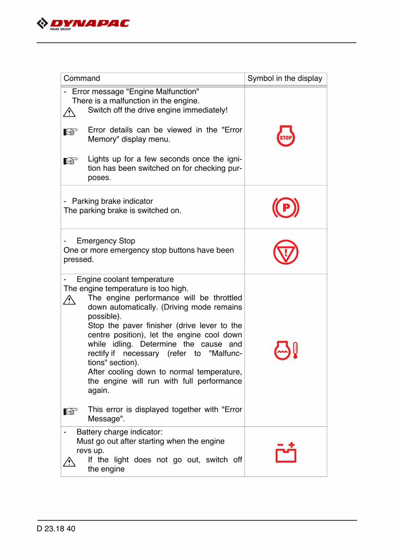
Command Symbol in the display
- Error message "Engine Malfunction"There is a malfunction in the engine.
m Switch off the drive engine immediately!
A Error details can be viewed in the "ErrorMemory" display menu.
A Lights up for a few seconds once the igni-tion has been switched on for checking pur-poses.
- Parking brake indicator The parking brake is switched on.
- Emergency StopOne or more emergency stop buttons have been pressed.
- Engine coolant temperatureThe engine temperature is too high.
m The engine performance will be throttleddown automatically. (Driving mode remainspossible). Stop the paver finisher (drive lever to thecentre position), let the engine cool downwhile idling. Determine the cause andrectify if necessary (refer to "Malfunc-tions" section). After cooling down to normal temperature,the engine will run with full performanceagain.
A This error is displayed together with "ErrorMessage".
- Battery charge indicator:Must go out after starting when the engine revs up.
m If the light does not go out, switch offthe engine
D 23.18 40

Command Symbol in the display
- Engine stop: Display for all error messages with machine stop.
- Hydraulic filter.The hydraulic filter must be replaced.
A Replace filter element acc. to MaintenanceInstructions!
- Engine oil pressure
m The oil pressure is insufficient. Switch off the engine immediately!For further possible faults, see Engine's op-erating instructions.
A This error is displayed together with "ErrorMessage".
- Hydrostatic travel drive oil pressure indicator
m The oil pressure is insufficient. Switch off the engine immediately!For further possible faults, see Engine's op-erating instructions.
- Emergency mode active
- Vehicle error.The control unit reports one or several malfunc-tions that cause the vehicle to shut down. It may be possible to continue operating the vehicle in the emergency mode.
A Error details can be viewed in the "ErrorMemory" display menu.
- Master display communication errorCommunication between master and display is interrupted / emergency stop button has been pressed
D 23.18 41

2.1 Drive engine error codes
A If a fault is detected on the engine, this is shown by the corresponding indication (1)in the display.
1
D 23.18 42

A The error message that can be viewed in the corresponding menu contains severalnumerical codes, which clearly define the fault after decoding.
A Press the job dial to scroll through the list.
m It may be possible to continue operating the vehicle, depending on the severity of theerror. The error should however be remedied quickly to prevent further damage.
A Engine malfunctions result in the engine stopping automatically to preventfurther damage.
1 2 3
D 23.18 43

Example:
?
C
D 23.18 44
Explanation:Warning light and display signal a serious fault on the drive engine with automatic ornecessary engine shut-down.Display:SPN: 157FMI: 3OC: 1
Cause: Cable break on sensor for rail pressure.Effect: Engine shut-down.Frequency: Fault occurs for the 1st time.
m Notify customer service of the error number displayed on your paver finisher; the cus-tomer service department will then discuss the further procedure with you.
D 23.18 45
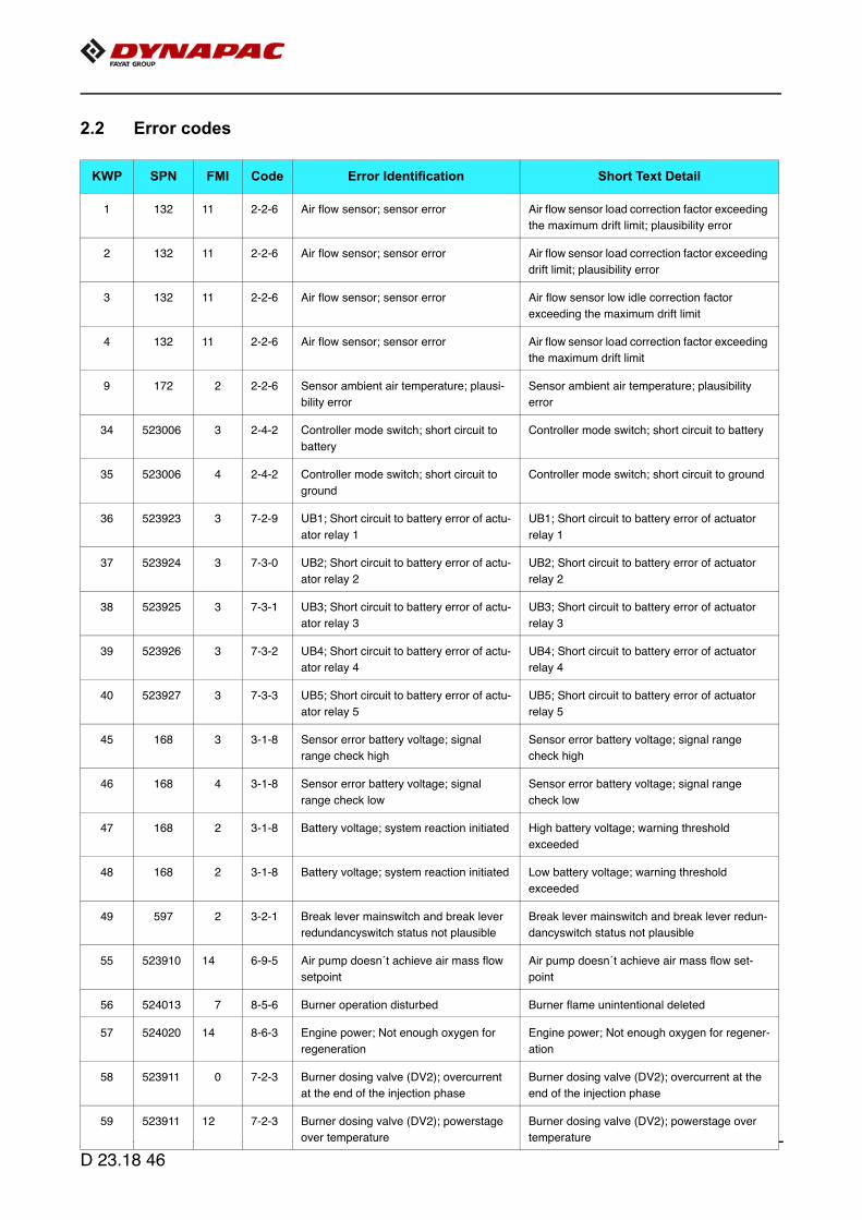
2.2 Error codes
KWP SPN FMI Code Error Identification Short Text Detail
1 132 11 2-2-6 Air flow sensor; sensor error Air flow sensor load correction factor exceeding
the maximum drift limit; plausibility error
2 132 11 2-2-6 Air flow sensor; sensor error Air flow sensor load correction factor exceeding
drift limit; plausibility error
3 132 11 2-2-6 Air flow sensor; sensor error Air flow sensor low idle correction factor
exceeding the maximum drift limit
4 132 11 2-2-6 Air flow sensor; sensor error Air flow sensor load correction factor exceeding
the maximum drift limit
9 172 2 2-2-6 Sensor ambient air temperature; plausi-
bility error
Sensor ambient air temperature; plausibility
error
34 523006 3 2-4-2 Controller mode switch; short circuit to
battery
Controller mode switch; short circuit to battery
35 523006 4 2-4-2 Controller mode switch; short circuit to
ground
Controller mode switch; short circuit to ground
36 523923 3 7-2-9 UB1; Short circuit to battery error of actu-
ator relay 1
UB1; Short circuit to battery error of actuator
relay 1
37 523924 3 7-3-0 UB2; Short circuit to battery error of actu-
ator relay 2
UB2; Short circuit to battery error of actuator
relay 2
38 523925 3 7-3-1 UB3; Short circuit to battery error of actu-
ator relay 3
UB3; Short circuit to battery error of actuator
relay 3
39 523926 3 7-3-2 UB4; Short circuit to battery error of actu-
ator relay 4
UB4; Short circuit to battery error of actuator
relay 4
40 523927 3 7-3-3 UB5; Short circuit to battery error of actu-
ator relay 5
UB5; Short circuit to battery error of actuator
relay 5
45 168 3 3-1-8 Sensor error battery voltage; signal
range check high
Sensor error battery voltage; signal range
check high
46 168 4 3-1-8 Sensor error battery voltage; signal
range check low
Sensor error battery voltage; signal range
check low
47 168 2 3-1-8 Battery voltage; system reaction initiated High battery voltage; warning threshold
exceeded
48 168 2 3-1-8 Battery voltage; system reaction initiated Low battery voltage; warning threshold
exceeded
49 597 2 3-2-1 Break lever mainswitch and break lever
redundancyswitch status not plausible
Break lever mainswitch and break lever redun-
dancyswitch status not plausible
55 523910 14 6-9-5 Air pump doesn´t achieve air mass flow
setpoint
Air pump doesn´t achieve air mass flow set-
point
56 524013 7 8-5-6 Burner operation disturbed Burner flame unintentional deleted
57 524020 14 8-6-3 Engine power; Not enough oxygen for
regeneration
Engine power; Not enough oxygen for regener-
ation
58 523911 0 7-2-3 Burner dosing valve (DV2); overcurrent
at the end of the injection phase
Burner dosing valve (DV2); overcurrent at the
end of the injection phase
59 523911 12 7-2-3 Burner dosing valve (DV2); powerstage
over temperature
Burner dosing valve (DV2); powerstage over
temperature
D 23.18 46

60 523911 3 7-2-3 Burner dosing valve (DV2); short circuit
to battery
Burner dosing valve (DV2); short circuit to bat-
tery
61 523911 3 7-2-3 Burner dosing valve (DV2); short circuit
to battery
Burner dosing valve (DV2); short circuit to bat-
tery on high side
62 523911 4 7-2-3 Burner dosing valve (DV2); short circuit
to ground
Burner dosing valve (DV2); short circuit to
ground
63 523911 11 7-2-3 Burner dosing valve (DV2); short circuit
high side powerstage
Burner dosing valve (DV2); short circuit high
side powerstage
64 523912 2 7-2-2 Burner dosing valve (DV2) downstream
pressure sensor; plausibility error
Burner dosing valve (DV2) downstream pres-
sure sensor; plausibility error
66 523912 0 7-2-2 Physical range check high for burner
dosing valve (DV2) downstream pres-
sure; shut off regeneration
Physical range check high for burner dosing
valve (DV2) downstream pressure; shut off
regeneration
69 523912 1 7-2-2 Physical range check low for burner dos-
ing valve (DV2) downstream pressure;
shut off regeneration. When burner injec-
tor is actuated, the measured pressure
does not rise above ca. 1250mbar abs
(expected: ca. 2400mbar).
Physical range check low for burner dosing
valve (DV2) downstream pressure; shut off
regeneration. When burner injector is actuated,
the measured pressure does not rise above ca.
1250mbar abs (expected: ca. 2400mbar).
72 523912 3 7-2-2 Sensor error burner dosing valve (DV2)
downstream pressure sensor; signal
range check high
Sensor error burner dosing valve (DV2) down-
stream pressure sensor; signal range check
high
73 523912 4 7-2-2 Sensor error burner dosing valve (DV2)
downstream pressure sensor; signal
range check low
Sensor error burner dosing valve (DV2) down-
stream pressure sensor; signal range check
low
74 523913 3 7-2-1 Sensor error glow plug control diagnostic
line voltage; signal range check high
Sensor error glow plug control diagnostic line
voltage; signal range check high
75 523913 4 7-2-1 Sensor error glow plug control diagnostic
line voltage; signal range check low
Sensor error glow plug control diagnostic line
voltage; signal range check low
76 523914 5 7-2-1 Glow plug control; open load Glow plug control; open load
77 523914 12 7-2-1 Glow plug control; powerstage over tem-
perature
Glow plug control; powerstage over tempera-
ture
78 523914 3 7-2-1 Glow plug control; short circuit to battery Glow plug control; short circuit to battery
79 523914 4 7-2-1 Glow plug control; short circuit to ground Glow plug control; short circuit to ground
82 1235 14 2-7-1 CAN Bus error passive; warning CAN C CAN Bus error passive; warning CAN C
84 639 14 2-7-1 CAN-Bus 0 "BusOff-Status" CAN-Bus 0 "BusOff-Status"
85 1231 14 2-7-1 CAN-Bus 1 "BusOff-Status" CAN-Bus 1 "BusOff-Status"
86 1235 14 2-7-1 CAN-Bus 2 "BusOff-Status" CAN-Bus 2 "BusOff-Status"
88 102 2 2-2-3 Charged air pressure; system reaction
initiated
Charged air pressure above warning threshold
89 102 2 2-2-3 Charged air pressure; system reaction
initiated
Charged air pressure above shut off threshold
96 110 3 2-2-5 Sensor error coolant temperature; signal
range check high
Sensor error coolant temperature; signal range
check high
KWP SPN FMI Code Error Identification Short Text Detail
D 23.18 47

97 110 4 2-2-5 Sensor error coolant temperature; signal
range check low
Sensor error coolant temperature; signal range
check low
98 110 0 2-3-2 Coolant temperature; system reaction
initiated
High coolant temperature; warning threshold
exceeded
99 110 0 2-3-2 Coolant temperature; system reaction
initiated
High coolant temperature; shut off threshold
exceeded
101 111 1 2-3-5 Coolant level too low Coolant level too low
109 523929 0 7-2-4 Fuel Balance Control integrator injector 1
(in firing order); maximum value
exceeded
Fuel Balance Control integrator injector 1 (in fir-
ing order); maximum value exceeded
110 523930 0 7-2-4 Fuel Balance Control integrator injector 2
(in firing order); maximum value
exceeded
Fuel Balance Control integrator injector 2 (in fir-
ing order); maximum value exceeded
111 523931 0 7-2-4 Fuel Balance Control integrator injector 3
(in firing order); maximum value
exceeded
Fuel Balance Control integrator injector 3 (in fir-
ing order); maximum value exceeded
112 523932 0 7-2-4 Fuel Balance Control integrator injector 4
(in firing order); maximum value
exceeded
Fuel Balance Control integrator injector 4 (in fir-
ing order); maximum value exceeded
113 523933 0 7-2-4 Fuel Balance Control integrator injector 5
(in firing order); maximum value
exceeded
Fuel Balance Control integrator injector 5 (in fir-
ing order); maximum value exceeded
114 523934 0 7-2-4 Fuel Balance Control integrator injector 6
(in firing order); maximum value
exceeded
Fuel Balance Control integrator injector 6 (in fir-
ing order); maximum value exceeded
115 523929 1 7-2-4 Fuel Balance Control integrator injector 1
(in firing order); minimum value
exceeded
Fuel Balance Control integrator injector 1 (in fir-
ing order); minimum value exceeded
116 523930 1 7-2-4 Fuel Balance Control integrator injector 2
(in firing order); minimum value
exceeded
Fuel Balance Control integrator injector 2 (in fir-
ing order); minimum value exceeded
117 523931 1 7-2-4 Fuel Balance Control integrator injector 3
(in firing order); minimum value
exceeded
Fuel Balance Control integrator injector 3 (in fir-
ing order); minimum value exceeded
118 523932 1 7-2-4 Fuel Balance Control integrator injector 4
(in firing order); minimum value
exceeded
Fuel Balance Control integrator injector 4 (in fir-
ing order); minimum value exceeded
119 523933 1 7-2-4 Fuel Balance Control integrator injector 5
(in firing order); minimum value
exceeded
Fuel Balance Control integrator injector 5 (in fir-
ing order); minimum value exceeded
120 523934 1 7-2-4 Fuel Balance Control integrator injector 6
(in firing order); minimum value
exceeded
Fuel Balance Control integrator injector 6 (in fir-
ing order); minimum value exceeded
121 1109 2 3-4-1 Engine shut off demand ignored Engine shut off demand ignored
122 523698 11 5-9-2 Shut off request from supervisory moni-
toring function
Shut off request from supervisory monitoring
function
KWP SPN FMI Code Error Identification Short Text Detail
D 23.18 48

125 523717 12 5-9-5 Timeout Error of CAN-Transmit-Frame
AmbCon; Weather environments
Timeout Error of CAN-Transmit-Frame Amb-
Con; Weather environments
126 523603 9 3-3-8 Timeout Error of CAN-Receive-Frame
AMB; Ambient Temperature Sensor
Timeout Error of CAN-Receive-Frame AMB;
Ambient Temperature Sensor
127 3224 2 5-9-6 NOx Sensor; CAN DLC error DLC Error of CAN-Receive-Frame AT1IG1
NOX Sensor (SCR-system upstream cat; DPF-
system downstream cat); length of frame incor-
rect
128 3224 9 5-9-7 NOx Sensor; CAN Timeout Timeout Error of CAN-Receive-Frame AT1IG1;
NOX sensor upstream
129 3224 2 5-9-6 NOx Sensor; CAN DLC error DLC Error of CAN-Receive-Frame AT1IG1Vol
NOX Sensor (SCR-system upstream cat; DPF-
system downstream cat); length of frame incor-
rect
130 3224 9 5-9-7 NOx Sensor; CAN Timeout Timeout Error of CAN-Receive-Frame
AT1IG1Vol; NOX sensor (SCR-system
upstream cat; DPF- system downstream cat)
133 523938 9 7-6-6 Timeout Error (BAM to packet) for CAN-
Receive-Frame AT1IGCVol1 informa-
tion; factors & Sensorcalibration for NOX
Sensor (SCR-system upstream cat;
DPF- system downstream cat)
Timeout Error (BAM to packet) for CAN-
Receive-Frame AT1IGCVol1 information; fac-
tors & Sensorcalibration for NOX Sensor (SCR-
system upstream cat; DPF-system down-
stream cat)
134 523939 9 7-6-6 Timeout Error (BAM to BAM) for CAN-
Receive-Frame AT1IGCVol1 informa-
tion; factors & Sensorcalibration for NOX
Sensor (SCR-system upstream cat;
DPF- system downstream cat)
Timeout Error (BAM to BAM) for CAN-Receive-
Frame AT1IGCVol1 information; factors & Sen-
sorcalibration for NOX Sensor (SCR-system
upstream cat; DPF-system downstream cat)
135 523940 9 7-6-6 Timeout Error (PCK2PCK) for CAN-
Receive-Frame AT1IGCVol1 informa-
tion; factors
& Sensorcalibration for NOX Sensor
(SCR-system upstream cat; DPF-system
downstream cat)
Timeout Error (PCK2PCK) for CAN-Receive-
Frame AT1IGCVol1 information; factors & Sen-
sorcalibration for NOX Sensor (SCR-system
upstream cat; DPF-system downstream cat)
137 3234 9 6-0-1 NOx Sensor; CAN Timeout Timeout Error of CAN-Receive-Frame
AT1OG1; NOX sensor (SCR-system down-
stream cat; DPF- system downstream cat)
138 3234 2 6-0-0 NOx Sensor; CAN DLC error DLC Error of CAN-Receive-Frame AT1O1Vol
NOX Sensor (SCR-system downstream cat;
DPF- system downstream cat); length of frame
incorrect
139 3234 9 6-0-1 NOx Sensor; CAN Timeout Timeout Error of CAN-Receive-Frame
AT1OG1Vol; NOX sensor (SCR-system down-
stream cat; DPF-system downstream cat)
140 523941 9 7-6-7 Timeout Error (BAM to packet) for CAN-
Receive-Frame AT1OGCVol2 informa-
tion; factors & Sensorcalibration for NOX
Sensor (SCR-system downstream cat;
DPF- system downstream cat)
Timeout Error (BAM to packet) for CAN-
Receive-Frame AT1OGCVol2 information; fac-
tors & Sensorcalibration for NOX Sensor (SCR-
system downstream cat; DPF-system down-
stream cat)
KWP SPN FMI Code Error Identification Short Text Detail
D 23.18 49

141 523942 9 7-6-7 Timeout Error (BAM to BAM) for CAN-
Receive-Frame AT1OGCVol2 informa-
tion; factors & Sensorcalibration for NOX
Sensor (SCR-system downstream cat;
DPF- system downstream cat)
Timeout Error (BAM to BAM) for CAN-Receive-
Frame AT1OGCVol2 information; factors &
Sensorcalibration for NOX Sensor (SCR-sys-
tem downstream cat; DPF-system downstream
cat)
142 523943 9 7-6-7 Timeout Error (PCK2PCK) for CAN-
Receive-Frame AT1OGCVol2 informa-
tion; factors & Sensorcalibration for NOX
Sensor (SCR-system downstream cat;
DPF- system downstream cat)
Timeout Error (PCK2PCK) for CAN-Receive-
Frame AT1OGCVol2 information; factors &
Sensorcalibration for NOX Sensor (SCR-sys-
tem downstream cat; DPF-system downstream
cat)
168 523935 12 7-6-3 Timeout Error of CAN-Transmit-Frame
EEC3VOL1; Engine send messages
Timeout Error of CAN-Transmit-Frame
EEC3VOL1; Engine send messages
169 523936 12 7-6-4 Timeout Error of CAN-Transmit-Frame
EEC3VOL2; Engine send messages
Timeout Error of CAN-Transmit-Frame
EEC3VOL2; Engine send messages
171 523212 9 3-3-3 Timeout Error of CAN-Receive-Frame
ComEngPrt; Engine Protection
Timeout Error of CAN-Receive-Frame
ComEngPrt; Engine Protection
179 523240 9 5-2-7 Timeout CAN-message FunModCtl;
Function Mode Control
Timeout CAN-message FunModCtl; Function
Mode Control
198 523216 9 3-3-7 Timeout Error of CAN-Receive-Frame
PrHtEnCmd; pre-heat command, engine
command
Timeout Error of CAN-Receive-Frame PrHt-
EnCmd; pre-heat command, engine command
202 523793 9 6-7-8 Timeout Error of CAN-Receive-Frame
UAA10; AGS sensor service message
Timeout Error of CAN-Receive-Frame UAA10;
AGS sensor service message
203 523794 9 6-7-8 Timeout Error of CAN-Receive-Frame
UAA11; AGS sensor data
Timeout Error of CAN-Receive-Frame UAA11;
AGS sensor data
212 523803 9 6-7-8 Timeout Error of CAN-Receive-Frame
RxEngPres; Status burner airpump
Timeout Error of CAN-Receive-Frame RxEng-
Pres; Status burner airpump
281 523766 9 1-1-8 Timeout Error of CAN-Receive-Frame
Active TSC1AE
Timeout Error of CAN-Receive-Frame Active
TSC1AE
282 523767 9 1-1-8 Timeout Error of CAN-Receive-Frame
Passive TSC1AE
Timeout Error of CAN-Receive-Frame Passive
TSC1AE
283 523768 9 1-1-9 Timeout Error of CAN-Receive-Frame
Active TSC1AR
Timeout Error of CAN-Receive-Frame Active
TSC1AR
284 523769 9 1-1-9 Timeout Error of CAN-Receive-Frame
Passive TSC1AR
Timeout Error of CAN-Receive-Frame Passive
TSC1AR
285 523770 9 Timeout Error of CAN-Receive-Frame
Passive TSC1DE
Timeout Error of CAN-Receive-Frame Passive
TSC1DE
291 523776 9 1-1-9 Timeout Error of CAN-Receive-Frame
TSC1TE - active
Timeout Error of CAN-Receive-Frame TSC1TE
- active
292 523777 9 1-1-9 Passive Timeout Error of CAN-Receive-
Frame TSC1TE; Setpoint
Passive Timeout Error of CAN-Receive-Frame
TSC1TE; Setpoint
293 523778 9 1-1-8 Active Timeout Errorof CAN-Receive-
Frame TSC1TR
Active Timeout Errorof CAN-Receive-Frame
TSC1TR
294 523779 9 1-1-8 Passive Timeout Error of CAN-Receive-
Frame TSC1TR
Passive Timeout Error of CAN-Receive-Frame
TSC1TR
KWP SPN FMI Code Error Identification Short Text Detail
D 23.18 50
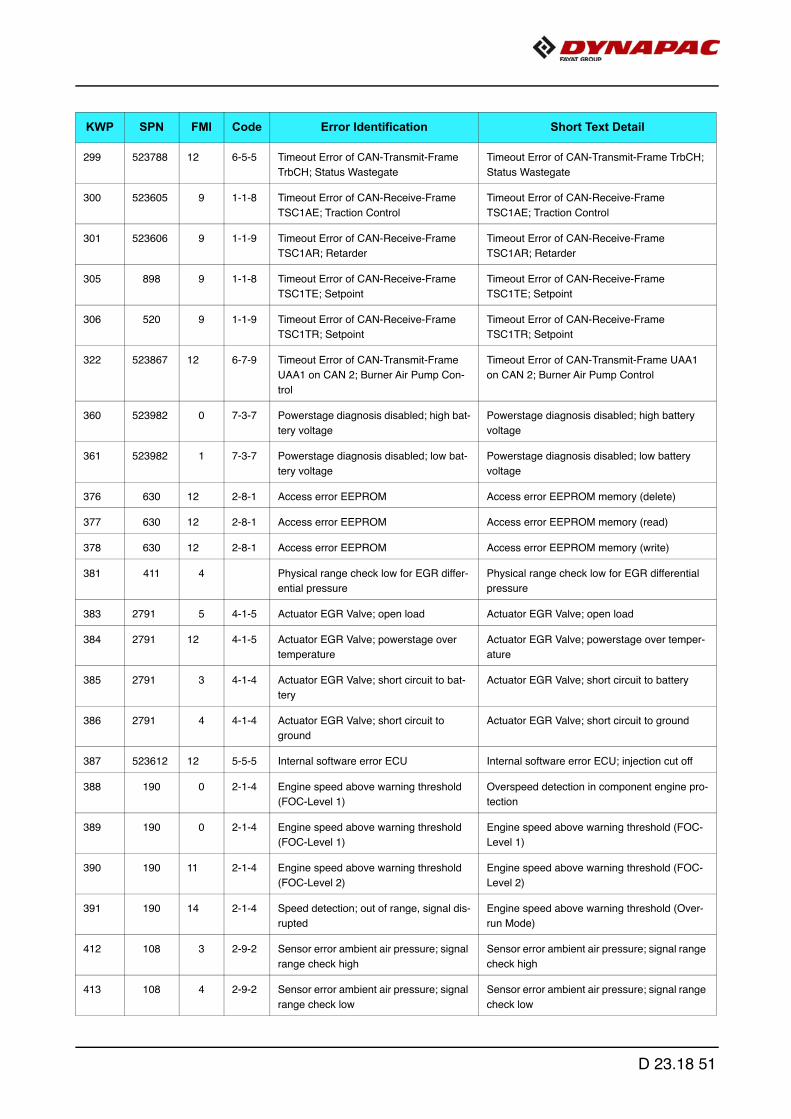
299 523788 12 6-5-5 Timeout Error of CAN-Transmit-Frame
TrbCH; Status Wastegate
Timeout Error of CAN-Transmit-Frame TrbCH;
Status Wastegate
300 523605 9 1-1-8 Timeout Error of CAN-Receive-Frame
TSC1AE; Traction Control
Timeout Error of CAN-Receive-Frame
TSC1AE; Traction Control
301 523606 9 1-1-9 Timeout Error of CAN-Receive-Frame
TSC1AR; Retarder
Timeout Error of CAN-Receive-Frame
TSC1AR; Retarder
305 898 9 1-1-8 Timeout Error of CAN-Receive-Frame
TSC1TE; Setpoint
Timeout Error of CAN-Receive-Frame
TSC1TE; Setpoint
306 520 9 1-1-9 Timeout Error of CAN-Receive-Frame
TSC1TR; Setpoint
Timeout Error of CAN-Receive-Frame
TSC1TR; Setpoint
322 523867 12 6-7-9 Timeout Error of CAN-Transmit-Frame
UAA1 on CAN 2; Burner Air Pump Con-
trol
Timeout Error of CAN-Transmit-Frame UAA1
on CAN 2; Burner Air Pump Control
360 523982 0 7-3-7 Powerstage diagnosis disabled; high bat-
tery voltage
Powerstage diagnosis disabled; high battery
voltage
361 523982 1 7-3-7 Powerstage diagnosis disabled; low bat-
tery voltage
Powerstage diagnosis disabled; low battery
voltage
376 630 12 2-8-1 Access error EEPROM Access error EEPROM memory (delete)
377 630 12 2-8-1 Access error EEPROM Access error EEPROM memory (read)
378 630 12 2-8-1 Access error EEPROM Access error EEPROM memory (write)
381 411 4 Physical range check low for EGR differ-
ential pressure
Physical range check low for EGR differential
pressure
383 2791 5 4-1-5 Actuator EGR Valve; open load Actuator EGR Valve; open load
384 2791 12 4-1-5 Actuator EGR Valve; powerstage over
temperature
Actuator EGR Valve; powerstage over temper-
ature
385 2791 3 4-1-4 Actuator EGR Valve; short circuit to bat-
tery
Actuator EGR Valve; short circuit to battery
386 2791 4 4-1-4 Actuator EGR Valve; short circuit to
ground
Actuator EGR Valve; short circuit to ground
387 523612 12 5-5-5 Internal software error ECU Internal software error ECU; injection cut off
388 190 0 2-1-4 Engine speed above warning threshold
(FOC-Level 1)
Overspeed detection in component engine pro-
tection
389 190 0 2-1-4 Engine speed above warning threshold
(FOC-Level 1)
Engine speed above warning threshold (FOC-
Level 1)
390 190 11 2-1-4 Engine speed above warning threshold
(FOC-Level 2)
Engine speed above warning threshold (FOC-
Level 2)
391 190 14 2-1-4 Speed detection; out of range, signal dis-
rupted
Engine speed above warning threshold (Over-
run Mode)
412 108 3 2-9-2 Sensor error ambient air pressure; signal
range check high
Sensor error ambient air pressure; signal range
check high
413 108 4 2-9-2 Sensor error ambient air pressure; signal
range check low
Sensor error ambient air pressure; signal range
check low
KWP SPN FMI Code Error Identification Short Text Detail
D 23.18 51

417 171 3 3-1-2 Sensor error environment temperature;
signal range check high
Sensor error environment temperature; signal
range check high
418 171 4 3-1-2 Sensor error environment temperature;
signal range check low
Sensor error environment temperature; signal
range check low
419 190 8 2-1-2 Speed detection; out of range, signal dis-
rupted
Sensor camshaft speed; disturbed signal
420 190 12 2-1-2 Speed detection; out of range, signal dis-
rupted
Sensor camshaft speed; no signal
421 190 2 2-1-3 Offset angle between crank- and cam-
shaft sensor is too large
Offset angle between crank- and camshaft sen-
sor is too large
422 190 8 2-1-2 Speed detection; out of range, signal dis-
rupted
Sensor crankshaft speed; disturbed signal
423 190 12 2-1-2 Speed detection; out of range, signal dis-
rupted
Sensor crankshaft speed; no signal
424 703 5 1-4-2 Engine running lamp; open load Engine running lamp; open load
425 703 12 1-4-2 Engine running lamp; powerstage over
temperature
Engine running lamp; powerstage over temper-
ature
426 703 3 1-4-2 Engine running lamp; short circuit to bat-
tery
Engine running lamp; short circuit to battery
427 703 4 1-4-2 Engine running lamp; short circuit to
ground
Engine running lamp; short circuit to ground
450 975 5 2-2-8 Fan control; open load Digital fan control; open load
451 975 12 2-2-8 Fan control; internal error Digital fan control; powerstage over tempera-
ture
452 975 3 2-2-8 Fan control; short circuit to battery Digital fan control; short circuit to battery
453 975 4 2-2-8 Fan control; short circuit to ground Digital fan control; short circuit to ground
455 975 5 2-2-8 Fan control; open load Fan actuator (PWM output); open load
456 975 12 2-2-8 Fan control; internal error Fan actuator (PWM output); powerstage over
temperature
457 975 3 2-2-8 Fan control; short circuit to battery Fan actuator (PWM output); short circuit to bat-
tery
458 975 4 2-2-8 Fan control; short circuit to ground Fan actuator (PWM output); short circuit to
ground
460 1639 0 2-2-8 Sensor error fan speed; signal range
check high
Sensor error fan speed; signal range check
high
461 1639 1 2-2-8 Sensor error fan speed; signal range
check low
Sensor error fan speed; signal range check
low
462 523602 0 2-2-8 Fan control; out of range, system reac-
tion initiated
High fan speed; warning threshold exceeded
463 523602 0 2-2-8 Fan control; out of range, system reac-
tion initiated
High fan speed; shut off threshold exceeded
464 97 3 2-2-8 Sensor error water in fuel; signal range
check high
Sensor error water in fuel; signal range check
high
KWP SPN FMI Code Error Identification Short Text Detail
D 23.18 52
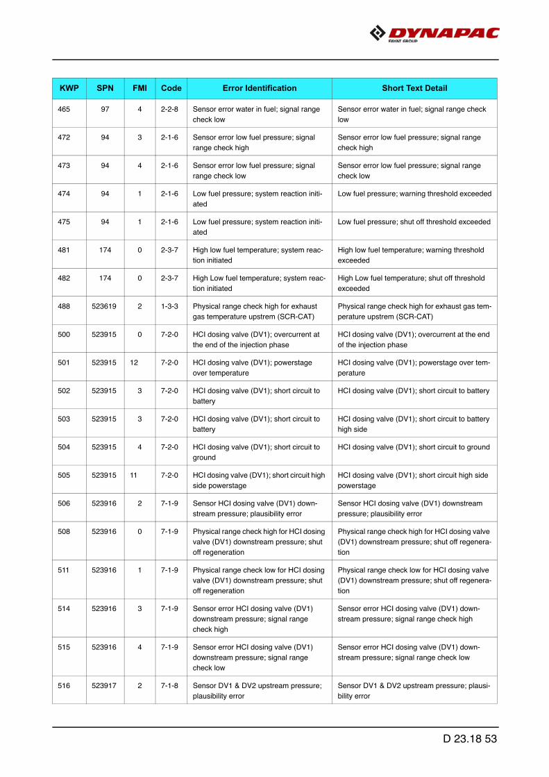
465 97 4 2-2-8 Sensor error water in fuel; signal range
check low
Sensor error water in fuel; signal range check
low
472 94 3 2-1-6 Sensor error low fuel pressure; signal
range check high
Sensor error low fuel pressure; signal range
check high
473 94 4 2-1-6 Sensor error low fuel pressure; signal
range check low
Sensor error low fuel pressure; signal range
check low
474 94 1 2-1-6 Low fuel pressure; system reaction initi-
ated
Low fuel pressure; warning threshold exceeded
475 94 1 2-1-6 Low fuel pressure; system reaction initi-
ated
Low fuel pressure; shut off threshold exceeded
481 174 0 2-3-7 High low fuel temperature; system reac-
tion initiated
High low fuel temperature; warning threshold
exceeded
482 174 0 2-3-7 High Low fuel temperature; system reac-
tion initiated
High Low fuel temperature; shut off threshold
exceeded
488 523619 2 1-3-3 Physical range check high for exhaust
gas temperature upstrem (SCR-CAT)
Physical range check high for exhaust gas tem-
perature upstrem (SCR-CAT)
500 523915 0 7-2-0 HCI dosing valve (DV1); overcurrent at
the end of the injection phase
HCI dosing valve (DV1); overcurrent at the end
of the injection phase
501 523915 12 7-2-0 HCI dosing valve (DV1); powerstage
over temperature
HCI dosing valve (DV1); powerstage over tem-
perature
502 523915 3 7-2-0 HCI dosing valve (DV1); short circuit to
battery
HCI dosing valve (DV1); short circuit to battery
503 523915 3 7-2-0 HCI dosing valve (DV1); short circuit to
battery
HCI dosing valve (DV1); short circuit to battery
high side
504 523915 4 7-2-0 HCI dosing valve (DV1); short circuit to
ground
HCI dosing valve (DV1); short circuit to ground
505 523915 11 7-2-0 HCI dosing valve (DV1); short circuit high
side powerstage
HCI dosing valve (DV1); short circuit high side
powerstage
506 523916 2 7-1-9 Sensor HCI dosing valve (DV1) down-
stream pressure; plausibility error
Sensor HCI dosing valve (DV1) downstream
pressure; plausibility error
508 523916 0 7-1-9 Physical range check high for HCI dosing
valve (DV1) downstream pressure; shut
off regeneration
Physical range check high for HCI dosing valve
(DV1) downstream pressure; shut off regenera-
tion
511 523916 1 7-1-9 Physical range check low for HCI dosing
valve (DV1) downstream pressure; shut
off regeneration
Physical range check low for HCI dosing valve
(DV1) downstream pressure; shut off regenera-
tion
514 523916 3 7-1-9 Sensor error HCI dosing valve (DV1)
downstream pressure; signal range
check high
Sensor error HCI dosing valve (DV1) down-
stream pressure; signal range check high
515 523916 4 7-1-9 Sensor error HCI dosing valve (DV1)
downstream pressure; signal range
check low
Sensor error HCI dosing valve (DV1) down-
stream pressure; signal range check low
516 523917 2 7-1-8 Sensor DV1 & DV2 upstream pressure;
plausibility error
Sensor DV1 & DV2 upstream pressure; plausi-
bility error
KWP SPN FMI Code Error Identification Short Text Detail
D 23.18 53
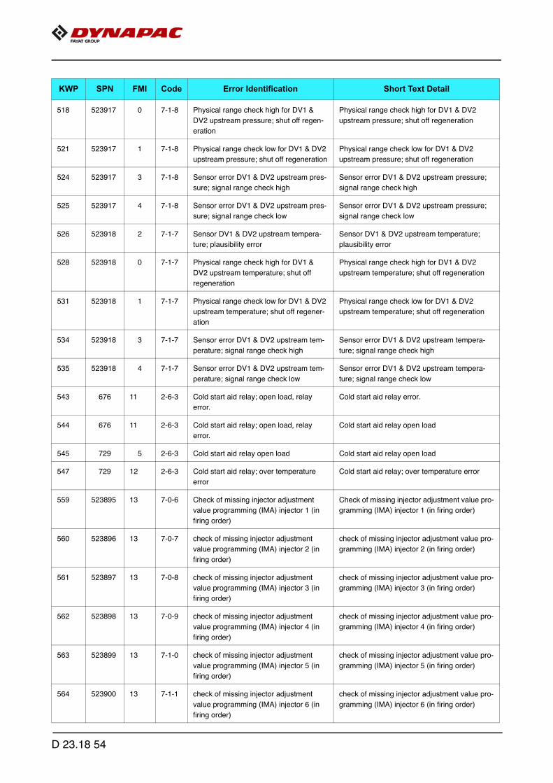
518 523917 0 7-1-8 Physical range check high for DV1 &
DV2 upstream pressure; shut off regen-
eration
Physical range check high for DV1 & DV2
upstream pressure; shut off regeneration
521 523917 1 7-1-8 Physical range check low for DV1 & DV2
upstream pressure; shut off regeneration
Physical range check low for DV1 & DV2
upstream pressure; shut off regeneration
524 523917 3 7-1-8 Sensor error DV1 & DV2 upstream pres-
sure; signal range check high
Sensor error DV1 & DV2 upstream pressure;
signal range check high
525 523917 4 7-1-8 Sensor error DV1 & DV2 upstream pres-
sure; signal range check low
Sensor error DV1 & DV2 upstream pressure;
signal range check low
526 523918 2 7-1-7 Sensor DV1 & DV2 upstream tempera-
ture; plausibility error
Sensor DV1 & DV2 upstream temperature;
plausibility error
528 523918 0 7-1-7 Physical range check high for DV1 &
DV2 upstream temperature; shut off
regeneration
Physical range check high for DV1 & DV2
upstream temperature; shut off regeneration
531 523918 1 7-1-7 Physical range check low for DV1 & DV2
upstream temperature; shut off regener-
ation
Physical range check low for DV1 & DV2
upstream temperature; shut off regeneration
534 523918 3 7-1-7 Sensor error DV1 & DV2 upstream tem-
perature; signal range check high
Sensor error DV1 & DV2 upstream tempera-
ture; signal range check high
535 523918 4 7-1-7 Sensor error DV1 & DV2 upstream tem-
perature; signal range check low
Sensor error DV1 & DV2 upstream tempera-
ture; signal range check low
543 676 11 2-6-3 Cold start aid relay; open load, relay
error.
Cold start aid relay error.
544 676 11 2-6-3 Cold start aid relay; open load, relay
error.
Cold start aid relay open load
545 729 5 2-6-3 Cold start aid relay open load Cold start aid relay open load
547 729 12 2-6-3 Cold start aid relay; over temperature
error
Cold start aid relay; over temperature error
559 523895 13 7-0-6 Check of missing injector adjustment
value programming (IMA) injector 1 (in
firing order)
Check of missing injector adjustment value pro-
gramming (IMA) injector 1 (in firing order)
560 523896 13 7-0-7 check of missing injector adjustment
value programming (IMA) injector 2 (in
firing order)
check of missing injector adjustment value pro-
gramming (IMA) injector 2 (in firing order)
561 523897 13 7-0-8 check of missing injector adjustment
value programming (IMA) injector 3 (in
firing order)
check of missing injector adjustment value pro-
gramming (IMA) injector 3 (in firing order)
562 523898 13 7-0-9 check of missing injector adjustment
value programming (IMA) injector 4 (in
firing order)
check of missing injector adjustment value pro-
gramming (IMA) injector 4 (in firing order)
563 523899 13 7-1-0 check of missing injector adjustment
value programming (IMA) injector 5 (in
firing order)
check of missing injector adjustment value pro-
gramming (IMA) injector 5 (in firing order)
564 523900 13 7-1-1 check of missing injector adjustment
value programming (IMA) injector 6 (in
firing order)
check of missing injector adjustment value pro-
gramming (IMA) injector 6 (in firing order)
KWP SPN FMI Code Error Identification Short Text Detail
D 23.18 54

565 523350 4 1-5-1 Injector cylinder-bank 1; short circuit Injector cylinder-bank 1; short circuit
566 523352 4 1-5-2 Injector cylinder-bank 2; short circuit Injector cylinder-bank 2; short circuit
567 523354 12 1-5-3 Injector powerstage output defect Injector powerstage output defect
568 651 5 1-5-4 Injector 1 (in firing order); interruption of
electric connection
Injector 1 (in firing order); interruption of electric
connection
569 652 5 1-5-5 Injector 2 (in firing order); interruption of
electric connection
Injector 2 (in firing order); interruption of electric
connection
570 653 5 1-5-6 Injector 3 (in firing order); interruption of
electric connection
Injector 3 (in firing order); interruption of electric
connection
571 654 5 1-6-1 Injector 4 (in firing order); interruption of
electric connection
Injector 4 (in firing order); interruption of electric
connection
572 655 5 1-6-2 Injector 5 (in firing order); interruption of
electric connection
Injector 5 (in firing order); interruption of electric
connection
573 656 5 1-6-3 Injector 6 (in firing order); interruption of
electric connection
Injector 6 (in firing order); interruption of electric
connection
580 651 3 1-5-4 Injector 1 (in firing order); short circuit Injector 1 (in firing order); short circuit
581 652 3 1-5-5 Injector 2 (in firing order); short circuit Injector 2 (in firing order); short circuit
582 653 3 1-5-6 Injector 3 (in firing order); short circuit Injector 3 (in firing order); short circuit
583 654 3 1-6-1 Injector 4 (in firing order); short circuit Injector 4 (in firing order); short circuit
584 655 3 1-6-2 Injector 5 (in firing order); short circuit Injector 5 (in firing order); short circuit
585 656 3 1-6-3 Injector 6 (in firing order); short circuit Injector 6 (in firing order); short circuit
586 651 4 1-5-4 High side to low side short circuit in the
injector 1 (in firing order)
High side to low side short circuit in the injector
1 (in firing order)
587 652 4 1-5-5 High side to low side short circuit in the
injector 2 (in firing order)
High side to low side short circuit in the injector
2 (in firing order)
588 653 4 1-5-6 High side to low side short circuit in the
injector 3 (in firing order)
High side to low side short circuit in the injector
3 (in firing order)
589 654 4 1-6-1 High side to low side short circuit in the
injector 4 (in firing order)
High side to low side short circuit in the injector
4 (in firing order)
590 655 4 1-6-2 High side to low side short circuit in the
injector 5 (in firing order)
High side to low side short circuit in the injector
5 (in firing order)
591 656 4 1-6-3 High side to low side short circuit in the
injector 6 (in firing order)
High side to low side short circuit in the injector
6 (in firing order)
592 523615 5 1-3-5 Metering unit (Fuel-System); open load Metering unit (Fuel-System); open load
593 523615 12 1-3-5 Metering unit (Fuel-System); powerstage
over temperature
Metering unit (Fuel-System); powerstage over
temperature
594 523615 3 1-3-5 Metering unit (Fuel-System); short cir-
cuit to battery
Metering unit (Fuel-System); short circuit to
battery highside
595 523615 4 1-3-5 Metering unit (Fuel-System); short cir-
cuit to ground
Metering unit (Fuel-System); short circuit to
ground high side
596 523615 3 1-3-5 Metering unit (Fuel-System); short cir-
cuit to battery
Metering unit (Fuel-System); short circuit to
battery low side
KWP SPN FMI Code Error Identification Short Text Detail
D 23.18 55

597 523615 4 1-3-5 Metering unit (Fuel-System); short cir-
cuit to ground
Metering Unit (Fuel-System); short circuit to
ground low side
604 1323 12 2-4-1 Too many recognized misfires in cylinder
1 (in firing order)
Too many recognized misfires in cylinder 1 (in
firing order)
605 1324 12 2-4-1 Too many recognized misfires in cylinder
2 (in firing order)
Too many recognized misfires in cylinder 2 (in
firing order)
606 1325 12 2-4-1 Too many recognized misfires in cylinder
3 (in firing order)
Too many recognized misfires in cylinder 3 (in
firing order)
607 1326 12 2-4-1 Too many recognized misfires in cylinder
4 (in firing order)
Too many recognized misfires in cylinder 4 (in
firing order)
608 1327 12 2-4-1 Too many recognized misfires in cylinder
5 (in firing order)
Too many recognized misfires in cylinder 5 (in
firing order)
609 1328 12 2-4-1 Too many recognized misfires in cylinder
6 (in firing order)
Too many recognized misfires in cylinder 6 (in
firing order)
610 1322 12 2-4-1 Too many recognized misfires in more
than one cylinder
Too many recognized misfires in more than
one cylinder
612 523612 12 5-5-5 ECU reported internal software error Internal ECU monitoring detection reported
error
613 523612 12 5-5-5 ECU reported internal software error Internal ECU monitoring detection reported
error
614 523612 12 5-5-5 ECU reported internal software error Internal ECU monitoring detection reported
error
615 523612 12 5-5-5 ECU reported internal software error Internal ECU monitoring detection reported
error
616 523612 12 5-5-5 ECU reported internal software error Internal ECU monitoring detection reported
error
617 523612 12 5-5-5 ECU reported internal software error Internal ECU monitoring detection reported
error
618 523612 12 5-5-5 ECU reported internal software error Internal ECU monitoring detection reported
error
619 523612 12 5-5-5 ECU reported internal software error Internal ECU monitoring detection reported
error
620 523612 12 5-5-5 ECU reported internal software error Internal ECU monitoring detection reported
error
621 523612 12 5-5-5 ECU reported internal software error Internal ECU monitoring detection reported
error
623 523612 12 5-5-5 ECU reported internal software error Internal ECU monitoring detection reported
error
624 523612 12 5-5-5 ECU reported internal software error Internal ECU monitoring detection reported
error
625 523612 12 5-5-5 ECU reported internal software error Internal ECU monitoring detection reported
error
627 523612 12 5-5-5 ECU reported internal software error Internal ECU monitoring detection reported
error
KWP SPN FMI Code Error Identification Short Text Detail
D 23.18 56

628 523612 12 5-5-5 ECU reported internal software error Internal ECU monitoring detection reported
error
637 523612 12 5-5-5 ECU reported internal software error Internal ECU monitoring detection reported
error
648 523008 1 4-2-4 Manipulation control was triggered Manipulation control was triggered
649 523008 2 4-2-4 Timeout error in Manipulation control Timeout error in Manipulation control
732 100 3 2-2-4 Sensor error oil pressure; signal range
check high
Sensor error oil pressure; signal range check
high
733 100 4 2-2-4 Sensor error oil pressure sensor; signal
range check low
Sensor error oil pressure sensor; signal range
check low
734 100 0 2-3-1 High oil pressure; system reaction initi-
ated
High oil pressure; warning threshold exceeded
735 100 0 2-3-1 High oil pressure; system reaction initi-
ated
High oil pressure; shut off threshold exceeded
736 100 1 2-3-1 Low oil pressure; system reaction initi-
ated
Low oil pressure; warning threshold exceeded
737 100 1 2-3-1 Low oil pressure; system reaction initi-
ated
Low oil pressure; shut off threshold exceeded
738 175 2 1-4-4 Oil temperature; plausibility error Sensor oil temperature; plausibility error
739 175 2 1-4-4 Oil temperature; plausibility error Sensor oil temperature; plausibility error oil
temperature too high
740 175 0 1-4-4 Oil temperature; out of range, system
reaction initiated
Physical range check high for oil temperature
741 175 1 1-4-4 Physical range check low for oil tempera-
ture
Physical range check low for oil temperature
743 175 3 1-4-4 Sensor error oil temperature; signal
range check high
Sensor error oil temperature; signal range
check high
744 175 4 1-4-4 Sensor error oil temperature; signal
range check low
Sensor error oil temperature; signal range
check low
745 175 0 1-4-4 Oil temperature; out of range, system
reaction initiated
High oil temperature; warning threshold
exceeded
746 175 0 1-4-4 Oil temperature; out of range, system
reaction initiated
High oil temperature; shut off threshold
exceeded
747 1237 2 1-4-5 Override switch; plausibility error Override switch; plausibility error
750 107 3 1-3-6 Sensor error airfilter differential pressure;
short circuit to battery
Sensor error airfilter differential pressure; short
circuit to battery
751 107 4 1-3-6 Sensor error airfilter differential pressure;
short circuit to ground
Sensor error airfilter differential pressure; short
circuit to ground
752 107 0 1-3-6 Air filter differential pressure; system
reaction initiated
High air filter differential pressure; warning
threshold exceeded
753 523919 2 6-9-4 Sensor airpump pressure; plausibility
error
Sensor airpump pressure; plausibility error
KWP SPN FMI Code Error Identification Short Text Detail
D 23.18 57

755 523919 0 6-9-4 Physical range check high for airpump
pressure; shut off regeneration
Physical range check high for airpump pres-
sure; shut off regeneration
758 523919 1 6-9-4 Physical range check low for airpump
pressure; shut off regeneration
Physical range check low for airpump pressure;
shut off regeneration
761 523919 3 6-9-4 Sensor error airpump pressure; signal
range check high
Sensor error airpump pressure; signal range
check high
762 523919 4 6-9-4 Sensor error airpump pressure; signal
range check low
Sensor error airpump pressure; signal range
check low
763 523920 2 7-1-6 Sensor exhaustgas back pressure; plau-
sibility error
Sensor exhaustgas back pressure; plausibility
error
765 523920 0 7-1-6 Physical range check high for exhaust-
gas back pressure burner; shut off
regeneration
Physical range check high for exhaustgas back
pressure burner; shut off regeneration
768 523920 1 7-1-6 Physical range check low for exhaustgas
back pressure burner; shut off regenera-
tion
Physical range check low for exhaustgas back
pressure burner; shut off regeneration
770 523920 3 7-1-6 Sensor error exhaustgas back pressure
burner; signal range check high
Sensor error exhaustgas back pressure burner;
signal range check high
771 523920 4 7-1-6 Sensor error exhaustgas back pressure
burner; signal range check low
Sensor error exhaustgas back pressure burner;
signal range check low
776 102 3 2-2-3 Sensor error charged air pressure; signal
range check high
Sensor error charged air pressure; signal range
check high
777 102 4 2-2-3 Sensor error charged air pressure; signal
range check low
Sensor error charged air pressure; signal range
check low
791 411 0 6-9-3 Physical range check high for differential
pressure Venturiunit (EGR)
Physical range check high for differential pres-
sure Venturiunit (EGR)
792 411 1 6-9-3 Physical range check low for differential
pressure Venturiunit (EGR)
Physical range check low for differential pres-
sure Venturiunit (EGR)
793 411 11 6-9-3 Sensor differential pressure Venturiunit
(EGR); plausibility error
Sensor differential pressure Venturiunit (EGR);
plausibility error
794 411 2 6-9-3 Sensor differential pressure Venturiunit
(EGR); CAN signal invalid
Sensor differential pressure Venturiunit (EGR);
CAN signal invalid
795 411 3 6-9-3 Sensor error differential pressure Ventu-
riunit (EGR); signal range check high
Sensor error differential pressure Venturiunit
(EGR); signal range check high
796 411 4 6-9-3 Sensor error differential pressure Ventu-
riunit (EGR); signal range check low
Sensor error differential pressure Venturiunit
(EGR); signal range check low
805 524025 14 Particulate filter; regeneration not suc-
cesful
Particulate filter; regeneration not succesful
807 3253 2 6-9-2 Sensor differential pressure (DPF); plau-
sibility error
Sensor differential pressure (DPF); plausibility
error regarding signal offset
809 3251 0 6-9-2 Physical range check high for differential
pressure (DPF); shut off regeneration
Physical range check high for differential pres-
sure (DPF); shut off regeneration
812 3251 1 6-9-2 Physical range check low for differential
pressure (DPF); shut off regeneration
Physical range check low for differential pres-
sure (DPF); shut off regeneration
KWP SPN FMI Code Error Identification Short Text Detail
D 23.18 58

814 3253 3 6-9-2 Sensor error differential pressure (DPF);
signal range check high
Sensor error differential pressure (DPF); signal
range check high
815 3253 4 6-9-2 Sensor error differential pressure (DPF);
signal range check low
Sensor error differential pressure (DPF); signal
range check low
825 523009 9 2-5-3 Pressure Relief Valve (PRV) reached
maximun allowed opening count
Pressure Relief Valve (PRV) reached maximun
allowed opening count
826 523470 2 1-4-6 Pressure Relief Valve (PRV) forced to
open
Pressure Relief Valve (PRV) forced to open;
performed by pressure increase
827 523470 2 1-4-6 Pressure Relief Valve (PRV) forced to
open
Pressure Relief Valve (PRV) forced to open;
performed by pressure shock
828 523470 12 1-4-6 Pressure Relief Valve (PRV) forced to
open; system reaction initiated
Open Pressure Relief Valve (PRV); shut off
condition
829 523470 12 1-4-6 Pressure Relief Valve (PRV) forced to
open; system reaction initiated
Open Pressure Relief Valve (PRV); warning
condition
830 523470 14 1-4-6 Pressure Relief Valve (PRV) is open Pressure Relief Valve (PRV) is open
831 523470 11 1-4-6 Pressure Relief Valve (PRV) error; Rail
pressure out of tolerance range
The PRV can not be opened at this operating
point with a pressure shock
832 523470 11 1-4-6 Rail pressure out of tolerance range Rail pressure out of tolerance range
833 523009 10 2-5-3 Pressure relief valve (PRV) reached
maximun allowed open time
Pressure relief valve (PRV) reached maximun
allowed open time
834 523906 5 7-6-1 Electrical fuel pre - supply pump; open
load
Electrical fuel pre - supply pump; open load
835 523906 12 7-6-1 Electrical fuel pre - supply pump; power-
stage over temperature
Electrical fuel pre - supply pump; powerstage
over temperature
836 523906 3 7-6-1 Electrical fuel pre - supply pump; short
circuit to battery
Electrical fuel pre - supply pump; short circuit to
battery
837 523906 4 7-6-1 Electrical fuel pre - supply pump; short
circuit to ground
Electrical fuel pre - supply pump; short circuit to
ground
838 523450 3 1-4-3 Multiple Stage Switch constant speed;
short circuit to battery
Multiple Stage Switch constant speed; short
circuit to battery
839 523450 4 1-4-3 Multiple Stage Switch constant speed;
short circuit to ground
Multiple Stage Switch constant speed; short
circuit to ground
840 523450 2 1-4-3 Multiple Stage Switch constant speed;
plausibility error
Multiple Stage Switch constant speed; plausi-
bility error
841 523451 3 1-4-3 Multiple Stage Switch engine speed con-
trol parameter; short circuit to battery
Multiple Stage Switch engine speed control
parameter; short circuit to battery
842 523451 4 1-4-3 Multiple Stage Switch engine speed con-
trol parameter; short circuit to ground
Multiple Stage Switch engine speed control
parameter; short circuit to ground
843 523451 2 1-4-3 Multiple Stage Switch engine speed con-
trol parameter; plausibility error
Multiple Stage Switch engine speed control
parameter; plausibility error
844 523452 3 1-4-3 Multiple Stage Switch engine torque limi-
tation curve; short circuit to battery
Multiple Stage Switch engine torque limitation
curve; short circuit to battery
845 523452 4 1-4-3 Multiple Stage Switch engine torque limi-
tation curve; short circuit to ground
Multiple Stage Switch engine torque limitation
curve; short circuit to ground
KWP SPN FMI Code Error Identification Short Text Detail
D 23.18 59

846 523452 2 1-4-3 Multiple Stage Switch engine torque limi-
tation curve; plausibility error
Multiple Stage Switch engine torque limitation
curve; plausibility error
849 1176 3 6-8-0 Sensor error pressure sensor upstream
turbine; signal range check high
Sensor error pressure sensor upstream tur-
bine; signal range check high
850 1176 4 6-8-0 Sensor error pressure sensor down-
stream turbine; signal range check high
Sensor error pressure sensor downstream tur-
bine; signal range check high
856 523613 0 1-3-4 Rail pressure disrupted Maximum positive deviation of rail pressure
exceeded (RailMeUn0)
857 523613 0 1-3-4 Rail pressure disrupted Maximum positive deviation of rail pressure in
metering unit exceeded (RailMeUn1)
858 523613 0 1-3-4 Rail pressure disrupted Railsystem leakage detected (RailMeUn10)
859 523613 0 1-3-4 Rail pressure disrupted Maximum negative deviation of rail pressure in
metering unit exceeded (RailMeUn2)
860 523613 0 1-3-4 Rail pressure disrupted Negative deviation of rail pressure second
stage (RailMeUn22)
861 523613 1 1-3-4 Minimum rail pressure exceeded
(RailMeUn3)
Minimum rail pressure exceeded (RailMeUn3)
862 523613 0 1-3-4 Rail pressure disrupted Maximum rail pressure exceeded (RailMeUn4)
864 523613 2 1-3-4 Setpoint of metering unit in overrun
mode not plausible
Setpoint of metering unit in overrun mode not
plausible
876 523470 7 1-4-6 Maximum rail pressure in limp home
mode exceeded (PRV)
Maximum rail pressure in limp home mode
exceeded (PRV)
877 157 3 1-4-7 Sesnor error rail pressure; signal range
check high
Sesnor error rail pressure; signal range check
high
878 157 4 1-4-7 Sensor error rail pressure; signal range
check low
Sensor error rail pressure; signal range check
low
881 523633 11 7-0-1 Nox conversion rate insufficient Nox conversion rate insufficient (SCR-Cat
defect, bad AdBule quality)
882 523633 11 7-0-1 Nox conversion rate insufficient Nox conversion rate insufficient (SCR-Cat
defect, bad AdBule quality); temperature range
1
883 523633 11 7-0-1 Nox conversion rate insufficient Nox conversion rate insufficient (SCR-Cat
defect, bad AdBule quality); temperature range
2
887 3234 11 8-0-7 Nox Sensor downstream of SCR Cataly-
sator; plausibility error "stuk in range"
Nox Sensor downstream of SCR Catalysator;
plausibility error "stuk in range"
889 3224 1 8-0-8 Nox sensor upstream of SCR Catalysa-
tor; low signal not plausible
Nox sensor upstream of SCR Catalysator; low
signal not plausible
892 4345 11 8-7-0 Sensor backflow line pressure (SCR);
plausibility error
Sensor backflow line pressure (SCR); plausibil-
ity error
893 4343 11 8-7-1 General pressure check error (SCR) General pressure check error (SCR)
894 4374 13 8-7-2 Pressure stabilisation error dosing valve
(SCR)
Pressure stabilisation error dosing valve (SCR)
KWP SPN FMI Code Error Identification Short Text Detail
D 23.18 60
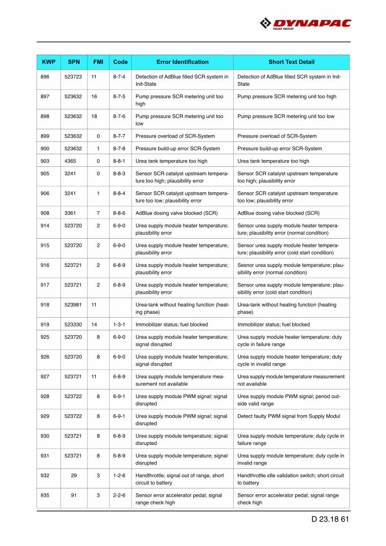
896 523723 11 8-7-4 Detection of AdBlue filled SCR system in
Init-State
Detection of AdBlue filled SCR system in Init-
State
897 523632 16 8-7-5 Pump pressure SCR metering unit too
high
Pump pressure SCR metering unit too high
898 523632 18 8-7-6 Pump pressure SCR metering unit too
low
Pump pressure SCR metering unit too low
899 523632 0 8-7-7 Pressure overload of SCR-System Pressure overload of SCR-System
900 523632 1 8-7-8 Pressure build-up error SCR-System Pressure build-up error SCR-System
903 4365 0 8-8-1 Urea tank temperature too high Urea tank temperature too high
905 3241 0 8-8-3 Sensor SCR catalyst upstream tempera-
ture too high; plausibility error
Sensor SCR catalyst upstream temperature
too high; plausibility error
906 3241 1 8-8-4 Sensor SCR catalyst upstream tempera-
ture too low; plausibility error
Sensor SCR catalyst upstream temperature
too low; plausibility error
908 3361 7 8-8-6 AdBlue dosing valve blocked (SCR) AdBlue dosing valve blocked (SCR)
914 523720 2 6-9-0 Urea supply module heater temperature;
plausibility error
Sensor urea supply module heater tempera-
ture; plausibility error (normal condition)
915 523720 2 6-9-0 Urea supply module heater temperature;
plausibility error
Sensor urea supply module heater tempera-
ture; plausibility error (cold start condition)
916 523721 2 6-8-9 Urea supply module heater temperature;
plausibility error
Sesnor urea supply module temperature; plau-
sibility error (normal condition)
917 523721 2 6-8-9 Urea supply module heater temperature;
plausibility error
Sensor urea supply module temperature; plau-
sibility error (cold start condition)
918 523981 11 Urea-tank without heating function (heat-
ing phase)
Urea-tank without heating function (heating
phase)
919 523330 14 1-3-1 Immobilizer status; fuel blocked Immobilizer status; fuel blocked
925 523720 8 6-9-0 Urea supply module heater temperature;
signal disrupted
Urea supply module heater temperature; duty
cycle in failure range
926 523720 8 6-9-0 Urea supply module heater temperature;
signal disrupted
Urea supply module heater temperature; duty
cycle in invalid range
927 523721 11 6-8-9 Urea supply module temperature mea-
surement not available
Urea supply module temperature measurement
not available
928 523722 8 6-9-1 Urea supply module PWM signal; signal
disrupted
Urea supply module PWM signal; period out-
side valid range
929 523722 8 6-9-1 Urea supply module PWM signal; signal
disrupted
Detect faulty PWM signal from Supply Modul
930 523721 8 6-8-9 Urea supply module temperature; signal
disrupted
Urea supply module temperature; duty cycle in
failure range
931 523721 8 6-8-9 Urea supply module temperature; signal
disrupted
Urea supply module temperature; duty cycle in
invalid range
932 29 3 1-2-6 Handthrottle; signal out of range, short
circuit to battery
Handthrottle idle validation switch; short circuit
to battery
935 91 3 2-2-6 Sensor error accelerator pedal; signal
range check high
Sensor error accelerator pedal; signal range
check high
KWP SPN FMI Code Error Identification Short Text Detail
D 23.18 61
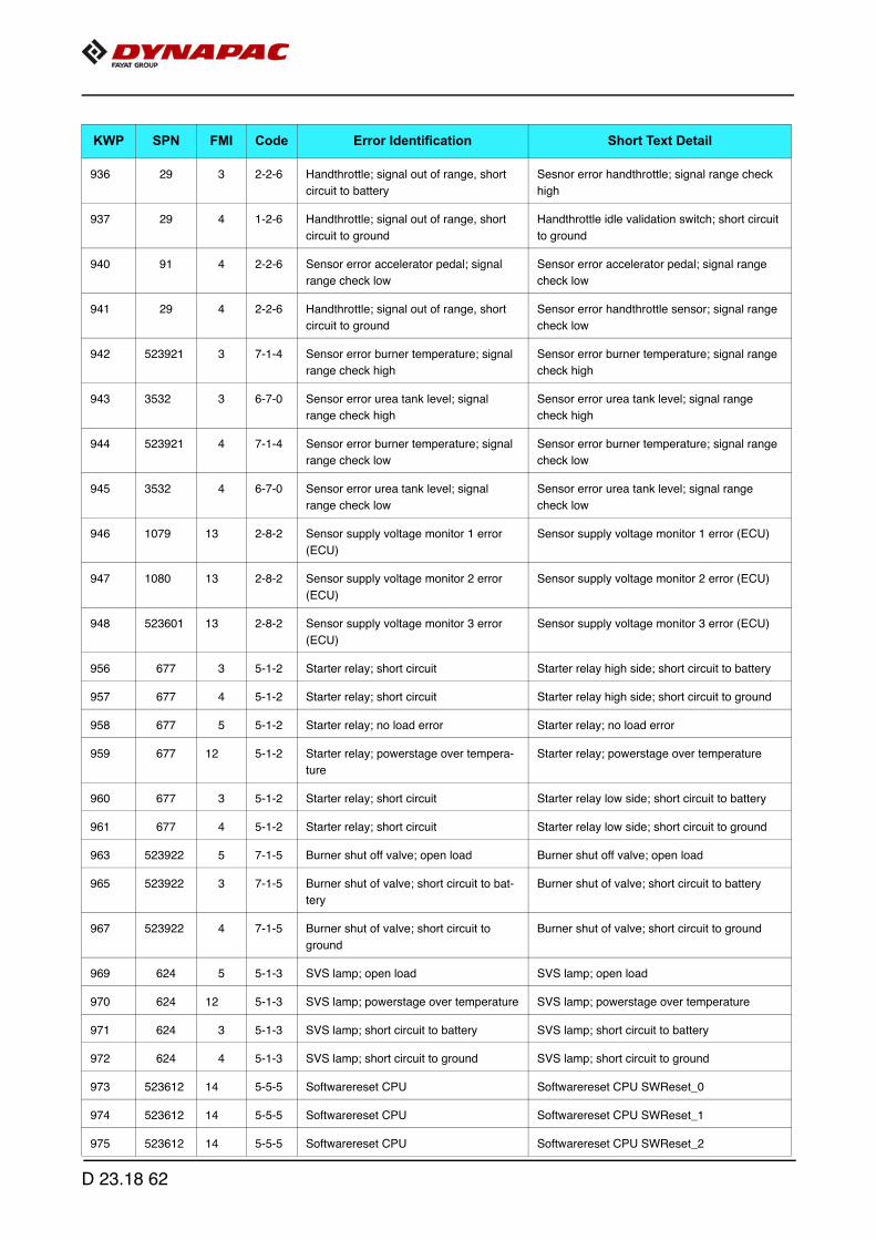
936 29 3 2-2-6 Handthrottle; signal out of range, short
circuit to battery
Sesnor error handthrottle; signal range check
high
937 29 4 1-2-6 Handthrottle; signal out of range, short
circuit to ground
Handthrottle idle validation switch; short circuit
to ground
940 91 4 2-2-6 Sensor error accelerator pedal; signal
range check low
Sensor error accelerator pedal; signal range
check low
941 29 4 2-2-6 Handthrottle; signal out of range, short
circuit to ground
Sensor error handthrottle sensor; signal range
check low
942 523921 3 7-1-4 Sensor error burner temperature; signal
range check high
Sensor error burner temperature; signal range
check high
943 3532 3 6-7-0 Sensor error urea tank level; signal
range check high
Sensor error urea tank level; signal range
check high
944 523921 4 7-1-4 Sensor error burner temperature; signal
range check low
Sensor error burner temperature; signal range
check low
945 3532 4 6-7-0 Sensor error urea tank level; signal
range check low
Sensor error urea tank level; signal range
check low
946 1079 13 2-8-2 Sensor supply voltage monitor 1 error
(ECU)
Sensor supply voltage monitor 1 error (ECU)
947 1080 13 2-8-2 Sensor supply voltage monitor 2 error
(ECU)
Sensor supply voltage monitor 2 error (ECU)
948 523601 13 2-8-2 Sensor supply voltage monitor 3 error
(ECU)
Sensor supply voltage monitor 3 error (ECU)
956 677 3 5-1-2 Starter relay; short circuit Starter relay high side; short circuit to battery
957 677 4 5-1-2 Starter relay; short circuit Starter relay high side; short circuit to ground
958 677 5 5-1-2 Starter relay; no load error Starter relay; no load error
959 677 12 5-1-2 Starter relay; powerstage over tempera-
ture
Starter relay; powerstage over temperature
960 677 3 5-1-2 Starter relay; short circuit Starter relay low side; short circuit to battery
961 677 4 5-1-2 Starter relay; short circuit Starter relay low side; short circuit to ground
963 523922 5 7-1-5 Burner shut off valve; open load Burner shut off valve; open load
965 523922 3 7-1-5 Burner shut of valve; short circuit to bat-
tery
Burner shut of valve; short circuit to battery
967 523922 4 7-1-5 Burner shut of valve; short circuit to
ground
Burner shut of valve; short circuit to ground
969 624 5 5-1-3 SVS lamp; open load SVS lamp; open load
970 624 12 5-1-3 SVS lamp; powerstage over temperature SVS lamp; powerstage over temperature
971 624 3 5-1-3 SVS lamp; short circuit to battery SVS lamp; short circuit to battery
972 624 4 5-1-3 SVS lamp; short circuit to ground SVS lamp; short circuit to ground
973 523612 14 5-5-5 Softwarereset CPU Softwarereset CPU SWReset_0
974 523612 14 5-5-5 Softwarereset CPU Softwarereset CPU SWReset_1
975 523612 14 5-5-5 Softwarereset CPU Softwarereset CPU SWReset_2
KWP SPN FMI Code Error Identification Short Text Detail
D 23.18 62
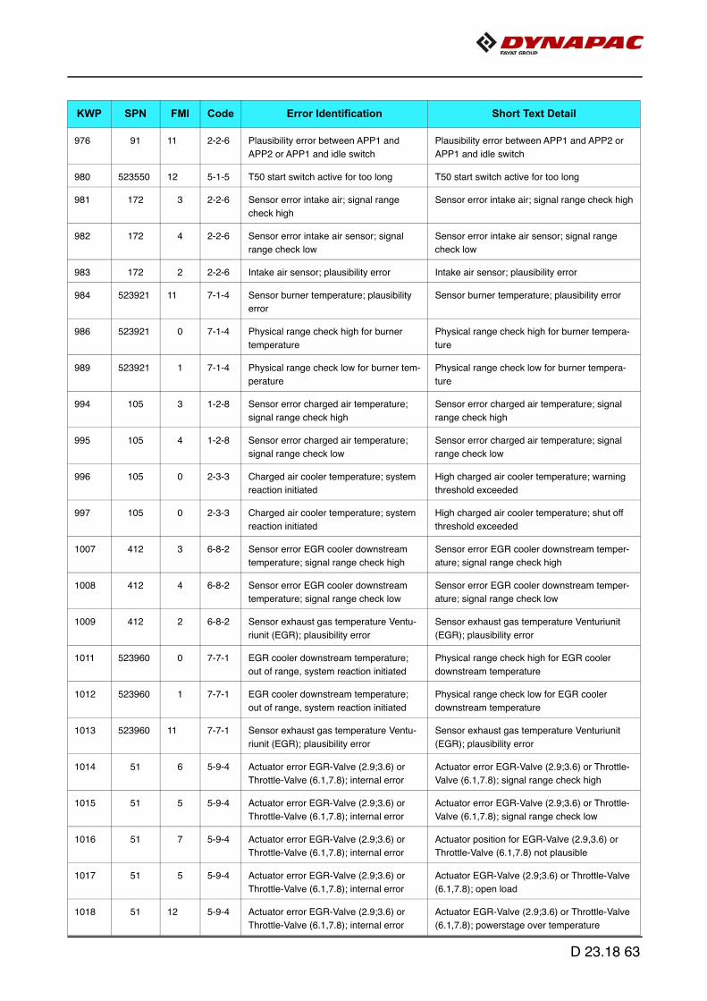
976 91 11 2-2-6 Plausibility error between APP1 and
APP2 or APP1 and idle switch
Plausibility error between APP1 and APP2 or
APP1 and idle switch
980 523550 12 5-1-5 T50 start switch active for too long T50 start switch active for too long
981 172 3 2-2-6 Sensor error intake air; signal range
check high
Sensor error intake air; signal range check high
982 172 4 2-2-6 Sensor error intake air sensor; signal
range check low
Sensor error intake air sensor; signal range
check low
983 172 2 2-2-6 Intake air sensor; plausibility error Intake air sensor; plausibility error
984 523921 11 7-1-4 Sensor burner temperature; plausibility
error
Sensor burner temperature; plausibility error
986 523921 0 7-1-4 Physical range check high for burner
temperature
Physical range check high for burner tempera-
ture
989 523921 1 7-1-4 Physical range check low for burner tem-
perature
Physical range check low for burner tempera-
ture
994 105 3 1-2-8 Sensor error charged air temperature;
signal range check high
Sensor error charged air temperature; signal
range check high
995 105 4 1-2-8 Sensor error charged air temperature;
signal range check low
Sensor error charged air temperature; signal
range check low
996 105 0 2-3-3 Charged air cooler temperature; system
reaction initiated
High charged air cooler temperature; warning
threshold exceeded
997 105 0 2-3-3 Charged air cooler temperature; system
reaction initiated
High charged air cooler temperature; shut off
threshold exceeded
1007 412 3 6-8-2 Sensor error EGR cooler downstream
temperature; signal range check high
Sensor error EGR cooler downstream temper-
ature; signal range check high
1008 412 4 6-8-2 Sensor error EGR cooler downstream
temperature; signal range check low
Sensor error EGR cooler downstream temper-
ature; signal range check low
1009 412 2 6-8-2 Sensor exhaust gas temperature Ventu-
riunit (EGR); plausibility error
Sensor exhaust gas temperature Venturiunit
(EGR); plausibility error
1011 523960 0 7-7-1 EGR cooler downstream temperature;
out of range, system reaction initiated
Physical range check high for EGR cooler
downstream temperature
1012 523960 1 7-7-1 EGR cooler downstream temperature;
out of range, system reaction initiated
Physical range check low for EGR cooler
downstream temperature
1013 523960 11 7-7-1 Sensor exhaust gas temperature Ventu-
riunit (EGR); plausibility error
Sensor exhaust gas temperature Venturiunit
(EGR); plausibility error
1014 51 6 5-9-4 Actuator error EGR-Valve (2.9;3.6) or
Throttle-Valve (6.1,7.8); internal error
Actuator error EGR-Valve (2.9;3.6) or Throttle-
Valve (6.1,7.8); signal range check high
1015 51 5 5-9-4 Actuator error EGR-Valve (2.9;3.6) or
Throttle-Valve (6.1,7.8); internal error
Actuator error EGR-Valve (2.9;3.6) or Throttle-
Valve (6.1,7.8); signal range check low
1016 51 7 5-9-4 Actuator error EGR-Valve (2.9;3.6) or
Throttle-Valve (6.1,7.8); internal error
Actuator position for EGR-Valve (2.9,3.6) or
Throttle-Valve (6.1,7.8) not plausible
1017 51 5 5-9-4 Actuator error EGR-Valve (2.9;3.6) or
Throttle-Valve (6.1,7.8); internal error
Actuator EGR-Valve (2.9;3.6) or Throttle-Valve
(6.1,7.8); open load
1018 51 12 5-9-4 Actuator error EGR-Valve (2.9;3.6) or
Throttle-Valve (6.1,7.8); internal error
Actuator EGR-Valve (2.9;3.6) or Throttle-Valve
(6.1,7.8); powerstage over temperature
KWP SPN FMI Code Error Identification Short Text Detail
D 23.18 63

1019 51 3 5-9-4 Actuator error EGR-Valve (2.9;3.6) or
Throttle-Valve (6.1,7.8); internal error
EGR-Valve (2.9;3.6) or Throttle-Valve (6.1,7.8);
short circuit to battery
1020 51 4 5-9-4 Actuator error EGR-Valve (2.9;3.6) or
Throttle-Valve (6.1,7.8); internal error
EGR-Valve (2.9;3.6) or Throttle-Valve (6.1,7.8);
short circuit to ground
1021 51 12 5-9-4 Actuator error EGR-Valve (2.9;3.6) or
Throttle-Valve (6.1,7.8); internal error
Mechanical actuator defect EGR-Valve
(2.9,3.6) or Throttle-Valve (6.1,7.8)
1022 51 6 5-9-4 Actuator error EGR-Valve (2.9;3.6) or
Throttle-Valve (6.1,7.8); internal error
Actuator error EGR-Valve (2.9;3.6) or Throttle-
Valve (6.1,7.8); signal range check high
1023 51 5 5-9-4 Actuator error EGR-Valve (2.9;3.6) or
Throttle-Valve (6.1,7.8); internal error
Actuator error EGR-Valve (2.9;3.6) or Throttle-
Valve (6.1,7.8); signal range check low
1024 51 3 5-9-4 Actuator error EGR-Valve (2.9;3.6) or
Throttle-Valve (6.1,7.8); internal error
Position sensor error of actuator EGR-Valve
(2.9;3.6) or Throttle-Valve (6.1,7.8); signal
range check high
1025 51 4 5-9-4 Actuator error EGR-Valve (2.9;3.6) or
Throttle-Valve (6.1,7.8); internal error
Position sensor error actuator EGR-Valve
(2.9;3.6) or Throttle-Valve (6.1,7.8); signal
range check low
1026 4769 2 6-8-4 Sensor exhaust gas temperature down-
stream (DOC); plausibility error
Sensor exhaust gas temperature downstream
(DOC); plausibility error
1029 4766 0 6-8-4 Physical range check high for exhaust
gas temperature downstream (DOC)
Physical range check high for exhaust gas tem-
perature downstream (DOC)
1032 4766 1 6-8-4 Physical range check low for exhaust
gas temperature downstream (DOC)
Physical range check low for exhaust gas tem-
perature downstream (DOC)
1034 4769 3 6-8-4 Sensor error exhaust gas temperature
downstream (DOC); signal range check
high
Sensor error exhaust gas temperature down-
stream (DOC); signal range check high
1035 4769 4 6-8-4 Sensor error exhaust gas temperature
downstream (DOC); signal range check
low
Sensor error exhaust gas temperature down-
stream (DOC); signal range check low
1036 4768 2 6-8-3 Sensor exhaust gas temperature
upstream (DOC); plausibility error
Sensor exhaust gas temperature upstream
(DOC); plausibility error
1039 4765 0 6-8-3 Physical range check high for exhaust
gas temperature upstream (DOC)
Physical range check high for exhaust gas tem-
perature upstream (DOC)
1042 4765 1 6-8-3 Physical range check low for exhaust
gas temperature upstream (DOC)
Physical range check low for exhaust gas tem-
perature upstream (DOC)
1044 4768 3 6-8-3 Sensor error exhaust gas temperature
upstream (DOC); signal range check
high
Sensor error exhaust gas temperature
upstream (DOC); signal range check high
1045 4768 4 6-8-3 Sensor error exhaust gas temperature
upstream (DOC); signal range check low
Sensor error exhaust gas temperature
upstream (DOC); signal range check low
1047 3248 4 6-8-5 Sensor error particle filter downstream
temperature; signal range check low
Sensor error particle filter downstream temper-
ature; signal range check low
1066 1180 11 5-5-6 Sensor exhaust gas temperature
upstream turbine; plausibility error
Sensor exhaust gas temperature upstream tur-
bine; plausibility error
1067 1180 3 5-5-6 Sensor error exhaust gas temperature
upstream turbine; signal range check
high
Sensor error exhaust gas temperature
upstream turbine; signal range check high
KWP SPN FMI Code Error Identification Short Text Detail
D 23.18 64
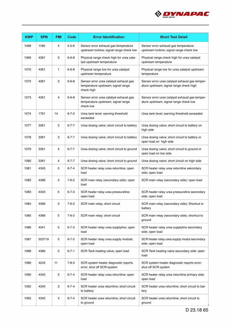
1068 1180 4 5-5-6 Sensor error exhaust gas temperature
upstream turbine; signal range check low
Sensor error exhaust gas temperature
upstream turbine; signal range check low
1069 4361 0 6-6-8 Physical range check high for urea cata-
lyst upstream temperature
Physical range check high for urea catalyst
upstream temperature
1070 4361 1 6-6-8 Physical range low for urea catalyst
upstream temperature
Physical range low for urea catalyst upstream
temperature
1072 4361 3 6-6-8 Sensor error urea catalyst exhaust gas
temperature upstream; signal range
check high
Sensor error urea catalyst exhaust gas temper-
ature upstream; signal range check high
1073 4361 4 6-6-8 Sensor error urea catalyst exhaust gas
temperature upstream; signal range
check low
Sensor error urea catalyst exhaust gas temper-
ature upstream; signal range check low
1074 1761 14 6-7-0 Urea tank level; warning threshold
exceeded
Urea tank level; warning threshold exceeded
1077 3361 3 6-7-7 Urea dosing valve; short circuit to battery Urea dosing valve; short circuit to battery on
high side
1078 3361 3 6-7-7 Urea dosing valve; short circuit to battery Urea dosing valve; short circuit to battery or
open load on high side
1079 3361 4 6-7-7 Urea dosing valve; short circuit to ground Urea dosing valve; short circuit to ground or
open load on low side
1080 3361 4 6-7-7 Urea dosing valve; short circuit to ground Urea dosing valve; short circuit on high side
1081 4345 5 6-7-4 SCR heater relay urea returnline; open
load
SCR heater relay urea returnline sekondary
side; open load
1082 4366 5 7-6-2 SCR main relay (secondary side): open
load
SCR main relay (secondary side): open load
1083 4343 5 6-7-3 SCR heater relay urea pressureline;
open load
SCR heater relay urea pressureline secondary
side; open load
1084 4366 5 7-6-2 SCR main relay; short circuit SCR main relay (secondary side); Shortcut to
battery
1085 4366 5 7-6-2 SCR main relay; short circuit SCR main relay (secondary side); shortcut to
ground
1086 4341 5 6-7-5 SCR heater relay urea supplyline; open
load
SCR heater relay urea supplyline secondary
side; open load
1087 523719 5 6-7-2 SCR heater relay urea supply module;
open load
SCR heater relay urea supply modul secondary
side; open load
1088 4366 5 6-7-1 SCR Tank heating valve; open load SCR Tank heating valve secundary side: open
load
1089 4243 11 7-8-3 SCR system heater diagnostic reports
error; shut off SCR-system
SCR system heater diagnostic reports error;
shut off SCR-system
1090 4345 5 6-7-4 SCR heater relay urea returnline; open
load
SCR heater relay urea returnline primary side;
open load
1092 4345 3 6-7-4 SCR heater urea returnline; short circuit
to battery
SCR heater urea returnline; short circuit to bat-
tery
1093 4345 4 6-7-4 SCR heater urea returnline; short circuit
to ground
SCR heater urea returnline; short circuit to
ground
KWP SPN FMI Code Error Identification Short Text Detail
D 23.18 65
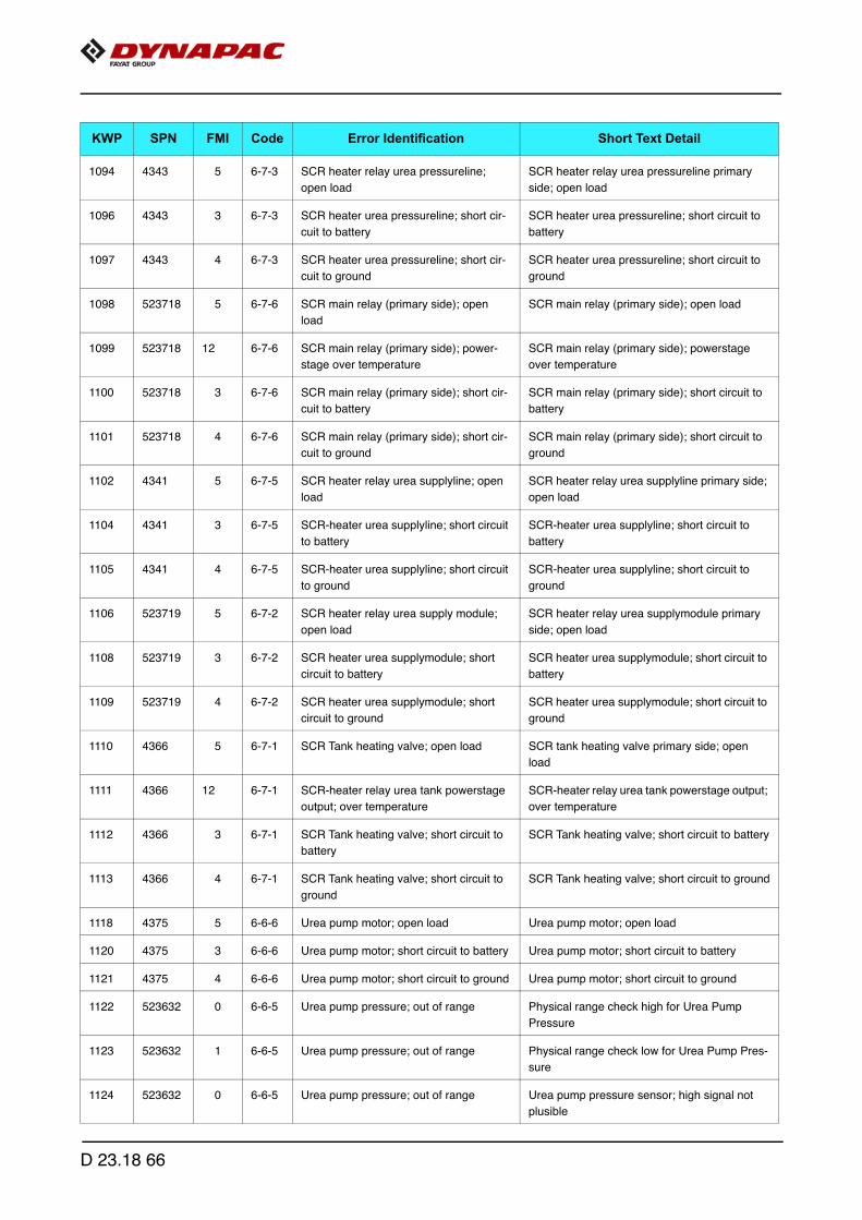
1094 4343 5 6-7-3 SCR heater relay urea pressureline;
open load
SCR heater relay urea pressureline primary
side; open load
1096 4343 3 6-7-3 SCR heater urea pressureline; short cir-
cuit to battery
SCR heater urea pressureline; short circuit to
battery
1097 4343 4 6-7-3 SCR heater urea pressureline; short cir-
cuit to ground
SCR heater urea pressureline; short circuit to
ground
1098 523718 5 6-7-6 SCR main relay (primary side); open
load
SCR main relay (primary side); open load
1099 523718 12 6-7-6 SCR main relay (primary side); power-
stage over temperature
SCR main relay (primary side); powerstage
over temperature
1100 523718 3 6-7-6 SCR main relay (primary side); short cir-
cuit to battery
SCR main relay (primary side); short circuit to
battery
1101 523718 4 6-7-6 SCR main relay (primary side); short cir-
cuit to ground
SCR main relay (primary side); short circuit to
ground
1102 4341 5 6-7-5 SCR heater relay urea supplyline; open
load
SCR heater relay urea supplyline primary side;
open load
1104 4341 3 6-7-5 SCR-heater urea supplyline; short circuit
to battery
SCR-heater urea supplyline; short circuit to
battery
1105 4341 4 6-7-5 SCR-heater urea supplyline; short circuit
to ground
SCR-heater urea supplyline; short circuit to
ground
1106 523719 5 6-7-2 SCR heater relay urea supply module;
open load
SCR heater relay urea supplymodule primary
side; open load
1108 523719 3 6-7-2 SCR heater urea supplymodule; short
circuit to battery
SCR heater urea supplymodule; short circuit to
battery
1109 523719 4 6-7-2 SCR heater urea supplymodule; short
circuit to ground
SCR heater urea supplymodule; short circuit to
ground
1110 4366 5 6-7-1 SCR Tank heating valve; open load SCR tank heating valve primary side; open
load
1111 4366 12 6-7-1 SCR-heater relay urea tank powerstage
output; over temperature
SCR-heater relay urea tank powerstage output;
over temperature
1112 4366 3 6-7-1 SCR Tank heating valve; short circuit to
battery
SCR Tank heating valve; short circuit to battery
1113 4366 4 6-7-1 SCR Tank heating valve; short circuit to
ground
SCR Tank heating valve; short circuit to ground
1118 4375 5 6-6-6 Urea pump motor; open load Urea pump motor; open load
1120 4375 3 6-6-6 Urea pump motor; short circuit to battery Urea pump motor; short circuit to battery
1121 4375 4 6-6-6 Urea pump motor; short circuit to ground Urea pump motor; short circuit to ground
1122 523632 0 6-6-5 Urea pump pressure; out of range Physical range check high for Urea Pump
Pressure
1123 523632 1 6-6-5 Urea pump pressure; out of range Physical range check low for Urea Pump Pres-
sure
1124 523632 0 6-6-5 Urea pump pressure; out of range Urea pump pressure sensor; high signal not
plusible
KWP SPN FMI Code Error Identification Short Text Detail
D 23.18 66

1125 523632 1 6-6-5 Urea pump pressure; out of range Urea pump pressure sensor; low signal not
plausible
1127 523632 3 6-6-5 Sensor error urea pump pressure; signal
range check high
Sensor error urea pump pressure; signal range
check high
1128 523632 4 6-6-5 Sensor error urea pump pressure; signal
range check low
Sensor error urea pump pressure; signal range
check low
1129 4376 5 6-6-7 SCR reversing valve; open load SCR reversing valve; open load
1130 4376 12 6-6-7 SCR reversing valve; over temperature SCR reversing valve; over temperature
1131 4376 3 6-6-7 SCR reversing valve; short circuit to bat-
tery
SCR reversing valve; short circuit to battery
1132 4376 4 6-6-7 SCR reversing valve; short circuit to
ground
SCR reversing valve; short circuit to ground
1135 4365 0 6-6-9 AdBlue-Tank temperature: maximum
exceeded
AdBlue-Tank temperature: maximum
exceeded
1136 4365 1 6-6-9 DEF-Tank temperature: below minimum DEF-Tank temperature: below minimum
1138 4365 3 6-6-9 Sensor error urea tank temperature;
short circuit to battery
Sensor error urea tank temperature; short cir-
cuit to battery
1139 4365 4 6-6-9 Sensor error urea tank temperature;
short circuit to ground
Sensor error urea tank temperature; short cir-
cuit to ground
1157 97 12 2-2-8 Water in fuel level prefilter; maximum
value exceeded
Water in fuel level prefilter; maximum value
exceeded
1158 523946 0 7-7-2 Zerofuel calibration injector 1 (in firing
order); maximum value exceeded
Zerofuel calibration injector 1 (in firing order);
maximum value exceeded
1159 523947 0 7-7-2 Zerofuel calibration injector 2 (in firing
order); maximum value exceeded
Zerofuel calibration injector 2 (in firing order);
maximum value exceeded
1160 523948 0 7-7-2 Zerofuel calibration injector 3 (in firing
order); maximum value exceeded
Zerofuel calibration injector 3 (in firing order);
maximum value exceeded
1161 523949 0 7-7-2 Zerofuel calibration injector 4 (in firing
order); maximum value exceeded
Zerofuel calibration injector 4 (in firing order);
maximum value exceeded
1162 523950 0 7-7-2 Zerofuel calibration injector 5 (in firing
order); maximum value exceeded
Zerofuel calibration injector 5 (in firing order);
maximum value exceeded
1163 523951 0 7-7-2 Zerofuel calibration injector 6 (in firing
order); maximum value exceeded
Zerofuel calibration injector 6 (in firing order);
maximum value exceeded
1164 523946 1 7-7-2 Zerofuel calibration injector 1 (in firing
order); minimum value exceeded
Zerofuel calibration injector 1 (in firing order);
minimum value exceeded
1165 523947 1 7-7-2 Zerofuel calibration injector 2 (in firing
order); minimum value exceeded
Zerofuel calibration injector 2 (in firing order);
minimum value exceeded
1166 523948 1 7-7-2 Zerofuel calibration injector 3 (in firing
order); minimum value exceeded
Zerofuel calibration injector 3 (in firing order);
minimum value exceeded
1167 523949 1 7-7-2 Zerofuel calibration injector 4 (in firing
order); minimum value exceeded
Zerofuel calibration injector 4 (in firing order);
minimum value exceeded
1168 523950 1 7-7-2 Zerofuel calibration injector 5 (in firing
order); minimum value exceeded
Zerofuel calibration injector 5 (in firing order);
minimum value exceeded
KWP SPN FMI Code Error Identification Short Text Detail
D 23.18 67
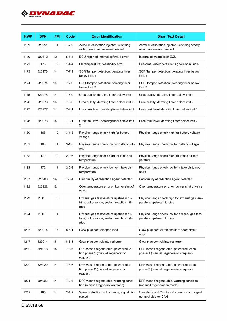
1169 523951 1 7-7-2 Zerofuel calibration injector 6 (in firing
order); minimum value exceeded
Zerofuel calibration injector 6 (in firing order);
minimum value exceeded
1170 523612 12 5-5-5 ECU reported internal software error Internal software error ECU
1171 175 2 1-4-4 Oil temperature; plausibility error Customer oiltemperature: signal unplausible
1173 523973 14 7-7-9 SCR Tamper detection; derating timer
below limit 1
SCR Tamper detection; derating timer below
limit 1
1174 523974 14 7-7-9 SCR Tamper detection; derating timer
below limit 2
SCR Tamper detection; derating timer below
limit 2
1175 523975 14 7-8-0 Urea quality; derating timer below limit 1 Urea quality; derating timer below limit 1
1176 523976 14 7-8-0 Urea qulaity; derating timer below limit 2 Urea qulaity; derating timer below limit 2
1177 523977 14 7-8-1 Urea tank level; derating timer below limit
1
Urea tank level; derating timer below limit 1
1178 523978 14 7-8-1 Urea tank level; derating timer below limit
2
Urea tank level; derating timer below limit 2
1180 168 0 3-1-8 Physikal range check high for battery
voltage
Physikal range check high for battery voltage
1181 168 1 3-1-8 Physikal range check low for battery volt-
age
Physikal range check low for battery voltage
1182 172 0 2-2-6 Physical range check high for intake air
temperature
Physical range check high for intake air tem-
perature
1183 172 1 2-2-6 Physical range check low for intake air
temperature
Physical range check low for intake air temper-
ature
1187 523980 14 7-8-4 Bad quality of reduction agent detected Bad quality of reduction agent detected
1192 523922 12 Over temperature error on burner shut of
valve
Over temperature error on burner shut of valve
1193 1180 0 Exhaust gas temperature upstream tur-
bine; out of range, system reaction initi-
ated
Physical range check high for exhaust gas tem-
perature upstream turbine
1194 1180 1 Exhaust gas temperature upstream tur-
bine; out of range, system reaction initi-
ated
Physical range check low for exhaust gas tem-
perature upstream turbine
1216 523914 5 8-5-1 Glow plug control; open load Glow plug control release line; short circuit
error
1217 523914 11 8-5-1 Glow plug control; internal error Glow plug control; internal error
1219 524018 14 7-8-6 DPF wasn´t regenerated, power reduc-
tion phase 1 (manuell regeneration
request)
DPF wasn´t regenerated, power reduction
phase 1 (manuell regeneration request)
1220 524022 14 7-8-6 DPF wasn´t regenerated, power reduc-
tion phase 2 (manuell regeneration
request)
DPF wasn´t regenerated, power reduction
phase 2 (manuell regeneration request)
1221 524023 14 7-8-6 DPF wasn´t regenerated, warning condi-
tion (manuell regeneration mode)
DPF wasn´t regenerated, warning condition
(manuell regeneration mode)
1222 190 14 2-1-2 Speed detection; out of range, signal dis-
rupted
Camshaft- and Crankshaft speed sensor signal
not available on CAN
KWP SPN FMI Code Error Identification Short Text Detail
D 23.18 68

1223 51 5 5-9-4 Actuator error EGR-Valve (2.9;3.6) or
Throttle-Valve (6.1,7.8); internal error
Actuator EGR-Valve (2.9;3.6) or Throttle-Valve
(6.1,7.8); open load
1224 51 6 5-9-4 Actuator error EGR-Valve (2.9;3.6) or
Throttle-Valve (6.1,7.8); internal error
Actuator EGR-Valve (2.9;3.6) or Throttle-Valve
(6.1,7.8); over current
1225 51 12 5-9-4 Actuator error EGR-Valve (2.9;3.6) or
Throttle-Valve (6.1,7.8); internal error
Actuator EGR-Valve (2.9;3.6) or Throttle-Valve
(6.1,7.8); over temperature
1226 51 3 5-9-4 Actuator error EGR-Valve (2.9;3.6) or
Throttle-Valve (6.1,7.8); internal error
EGR-Valve (2.9;3.6) or Throttle-Valve (6.1,7.8);
short circuit to battery (A02)
1227 51 3 5-9-4 Actuator error EGR-Valve (2.9;3.6) or
Throttle-Valve (6.1,7.8); internal error
EGR-Valve (2.9;3.6) or Throttle-Valve (6.1,7.8);
short circuit to battery (A67)
1228 51 4 5-9-4 Actuator error EGR-Valve (2.9;3.6) or
Throttle-Valve (6.1,7.8); internal error
EGR-Valve (2.9;3.6) or Throttle-Valve (6.1,7.8);
short circuit to ground (A02)
1229 51 4 5-9-4 Actuator error EGR-Valve (2.9;3.6) or
Throttle-Valve (6.1,7.8); internal error
EGR-Valve (2.9;3.6) or Throttle-Valve (6.1,7.8);
short circuit to ground (A67)
1230 51 6 5-9-4 Actuator error EGR-Valve (2.9;3.6) or
Throttle-Valve (6.1,7.8); internal error
Actuator error EGR-Valve (2.9;3.6) or Throttle-
Valve (6.1,7.8); Overload by short-circuit
1231 51 11 5-9-4 Actuator error EGR-Valve (2.9;3.6) or
Throttle-Valve (6.1,7.8); internal error
Actuator error EGR-Valve (2.9;3.6) or Throttle-
Valve (6.1,7.8); Power stage overtemperature
due to high current
1232 51 4 5-9-4 Actuator error EGR-Valve (2.9;3.6) or
Throttle-Valve (6.1,7.8); internal error
Actuator error EGR-Valve (2.9;3.6) or Throttle-
Valve (6.1,7.8); Voltage below threshold
1239 523984 3 7-8-8 UB6; Short circuit to battery error of actu-
ator relay 6
UB6; Short circuit to battery error of actuator
relay 7
1240 523985 3 7-8-9 UB7; Short circuit to battery error of actu-
ator relay 7
UB7; Short circuit to battery error of actuator
relay 8
1243 523988 5 7-9-2 Charging lamp; open load Charging lamp; open load
1244 523988 12 7-9-2 Charging lamp; over temperature Charging lamp; over temperature
1245 523988 3 7-9-2 Charging lamp; short circuit to battery Charging lamp; short circuit to battery
1246 523988 4 7-9-2 Charging lamp; short circuit to ground Charging lamp; short circuit to ground
1247 524019 11 8-6-2 Air Pump; air lines blocked Air Pump; air lines blocked
1248 523910 9 6-9-5 Air Pump; CAN communication lost Air Pump; CAN communication lost
1249 523910 7 6-9-5 Air pump; CAN communication inter-
rupted no purge function available
Air pump; CAN communication interrupted no
purge function available
1250 523910 12 6-9-5 Air Pump; internal error Air Pump; internal error
1251 523910 0 6-9-5 Air Pump; internal error Air Pump; powerstage over temperature
1252 523910 0 6-9-5 Air Pump; internal error Air Pump; operating voltage error
1253 523911 7 8-5-0 Burner dosing valve (DV2); blocked
closed
Burner dosing valve (DV2); blocked closed
1254 524014 1 8-5-8 Air pressure glow plug flush line; below
limit
Air pressure glow plug flush line; below limit
1255 524013 7 8-5-7 Burner operation disturbed Burner operation is interrupted too often
1256 523915 7 8-5-2 HCI dosing valve (DV1); blocked HCI dosing valve (DV1); blocked closed
KWP SPN FMI Code Error Identification Short Text Detail
D 23.18 69
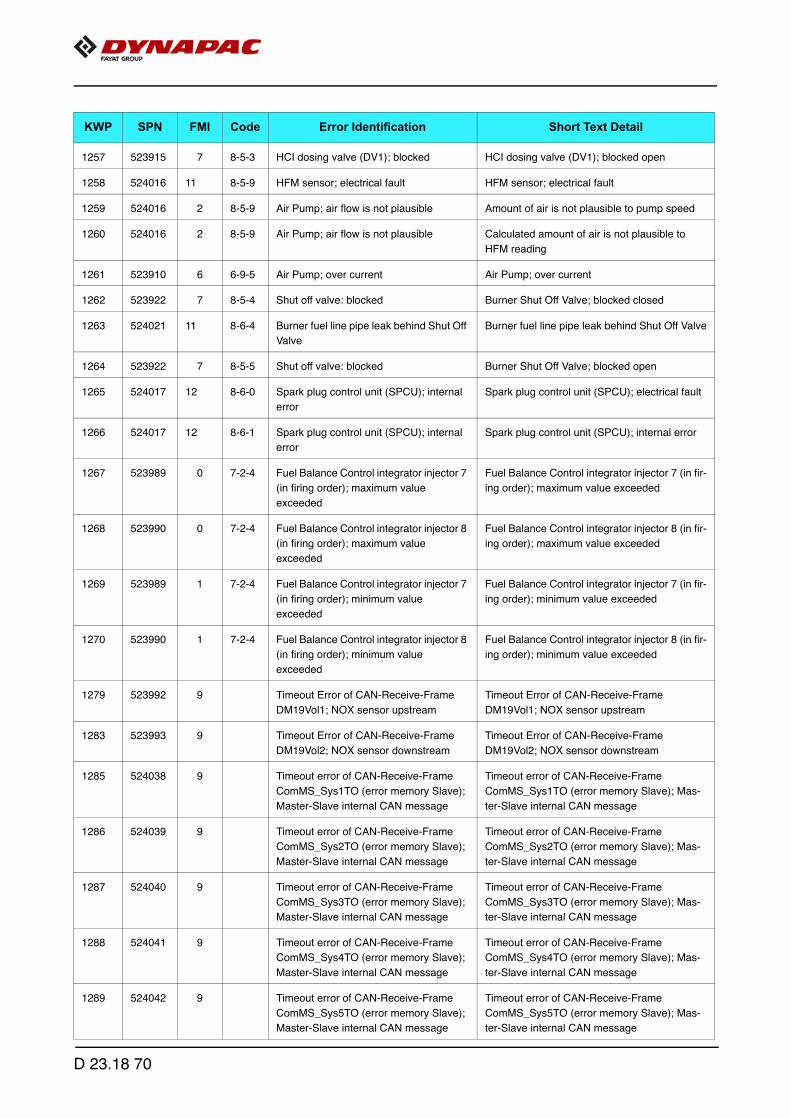
1257 523915 7 8-5-3 HCI dosing valve (DV1); blocked HCI dosing valve (DV1); blocked open
1258 524016 11 8-5-9 HFM sensor; electrical fault HFM sensor; electrical fault
1259 524016 2 8-5-9 Air Pump; air flow is not plausible Amount of air is not plausible to pump speed
1260 524016 2 8-5-9 Air Pump; air flow is not plausible Calculated amount of air is not plausible to
HFM reading
1261 523910 6 6-9-5 Air Pump; over current Air Pump; over current
1262 523922 7 8-5-4 Shut off valve: blocked Burner Shut Off Valve; blocked closed
1263 524021 11 8-6-4 Burner fuel line pipe leak behind Shut Off
Valve
Burner fuel line pipe leak behind Shut Off Valve
1264 523922 7 8-5-5 Shut off valve: blocked Burner Shut Off Valve; blocked open
1265 524017 12 8-6-0 Spark plug control unit (SPCU); internal
error
Spark plug control unit (SPCU); electrical fault
1266 524017 12 8-6-1 Spark plug control unit (SPCU); internal
error
Spark plug control unit (SPCU); internal error
1267 523989 0 7-2-4 Fuel Balance Control integrator injector 7
(in firing order); maximum value
exceeded
Fuel Balance Control integrator injector 7 (in fir-
ing order); maximum value exceeded
1268 523990 0 7-2-4 Fuel Balance Control integrator injector 8
(in firing order); maximum value
exceeded
Fuel Balance Control integrator injector 8 (in fir-
ing order); maximum value exceeded
1269 523989 1 7-2-4 Fuel Balance Control integrator injector 7
(in firing order); minimum value
exceeded
Fuel Balance Control integrator injector 7 (in fir-
ing order); minimum value exceeded
1270 523990 1 7-2-4 Fuel Balance Control integrator injector 8
(in firing order); minimum value
exceeded
Fuel Balance Control integrator injector 8 (in fir-
ing order); minimum value exceeded
1279 523992 9 Timeout Error of CAN-Receive-Frame
DM19Vol1; NOX sensor upstream
Timeout Error of CAN-Receive-Frame
DM19Vol1; NOX sensor upstream
1283 523993 9 Timeout Error of CAN-Receive-Frame
DM19Vol2; NOX sensor downstream
Timeout Error of CAN-Receive-Frame
DM19Vol2; NOX sensor downstream
1285 524038 9 Timeout error of CAN-Receive-Frame
ComMS_Sys1TO (error memory Slave);
Master-Slave internal CAN message
Timeout error of CAN-Receive-Frame
ComMS_Sys1TO (error memory Slave); Mas-
ter-Slave internal CAN message
1286 524039 9 Timeout error of CAN-Receive-Frame
ComMS_Sys2TO (error memory Slave);
Master-Slave internal CAN message
Timeout error of CAN-Receive-Frame
ComMS_Sys2TO (error memory Slave); Mas-
ter-Slave internal CAN message
1287 524040 9 Timeout error of CAN-Receive-Frame
ComMS_Sys3TO (error memory Slave);
Master-Slave internal CAN message
Timeout error of CAN-Receive-Frame
ComMS_Sys3TO (error memory Slave); Mas-
ter-Slave internal CAN message
1288 524041 9 Timeout error of CAN-Receive-Frame
ComMS_Sys4TO (error memory Slave);
Master-Slave internal CAN message
Timeout error of CAN-Receive-Frame
ComMS_Sys4TO (error memory Slave); Mas-
ter-Slave internal CAN message
1289 524042 9 Timeout error of CAN-Receive-Frame
ComMS_Sys5TO (error memory Slave);
Master-Slave internal CAN message
Timeout error of CAN-Receive-Frame
ComMS_Sys5TO (error memory Slave); Mas-
ter-Slave internal CAN message
KWP SPN FMI Code Error Identification Short Text Detail
D 23.18 70
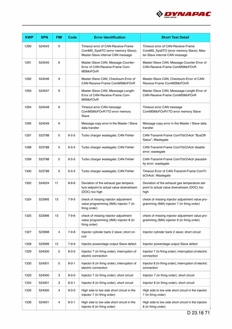
1290 524043 9 Timeout error of CAN-Receive-Frame
ComMS_Sys6TO (error memory Slave);
Master-Slave internal CAN message
Timeout error of CAN-Receive-Frame
ComMS_Sys6TO (error memory Slave); Mas-
ter-Slave internal CAN message
1291 524045 9 Master-Slave CAN; Message-Counter-
Error of CAN-Receive-Frame Com-
MSMoFOvR
Master-Slave CAN; Message-Counter-Error of
CAN-Receive-Frame ComMSMoFOvR
1292 524046 9 Master-Slave CAN; Checksum-Error of
CAN-Receive-Frame ComMSMoFOvR
Master-Slave CAN; Checksum-Error of CAN-
Receive-Frame ComMSMoFOvR
1293 524047 9 Master-Slave CAN; Messsage-Length-
Error of CAN-Receive-Frame Com-
MSMoFOvR
Master-Slave CAN; Messsage-Length-Error of
CAN-Receive-Frame ComMSMoFOvR
1294 524048 9 Timeout error CAN message
ComMSMoFOvR1TO error memory
Slave
Timeout error CAN message
ComMSMoFOvR1TO error memory Slave
1295 524049 9 Message copy error in the Master / Slave
data transfer
Message copy error in the Master / Slave data
transfer
1297 523788 0 6-5-5 Turbo charger wastegate; CAN Fehler CAN-Transmit-Frame ComTrbChActr "BusOff-
Satus"; Wastegate
1298 523788 0 6-5-5 Turbo charger wastegate; CAN Fehler CAN-Transmit-Frame ComTrbChActr disable
error; wastegate
1299 523788 0 6-5-5 Turbo charger wastegate; CAN Fehler CAN-Transmit-Frame ComTrbChActr plausibil-
ity error; wastegate
1300 523788 0 6-5-5 Turbo charger wastegate; CAN Fehler Timeout Error of CAN-Transmit-Frame ComTr-
bChActr; Wastegate
1302 524024 11 8-6-6 Deviation of the exhaust gas tempera-
ture setpoint to actual value downstream
(DOC) too high
Deviation of the exhaust gas temperature set-
point to actual value downstream (DOC) too
high
1324 523995 13 7-9-5 check of missing injector adjustment
value programming (IMA) injector 7 (in
firing order)
check of missing injector adjustment value pro-
gramming (IMA) injector 7 (in firing order)
1325 523996 13 7-9-6 check of missing injector adjustment
value programming (IMA) injector 8 (in
firing order)
check of missing injector adjustment value pro-
gramming (IMA) injector 8 (in firing order)
1327 523998 4 7-9-8 Injector cylinder bank 2 slave; short cir-
cuit
Injector cylinder bank 2 slave; short circuit
1328 523999 12 7-9-9 Injector powerstage output Slave defect Injector powerstage output Slave defect
1329 524000 5 8-0-0 Injector 7 (in firing order); interruption of
electric connection
Injector 7 (in firing order); interruption of electric
connection
1330 524001 5 8-0-1 Injector 8 (in firing order); interruption of
electric connection
Injector 8 (in firing order); interruption of electric
connection
1333 524000 3 8-0-0 Injector 7 (in firing order); short circuit Injector 7 (in firing order); short circuit
1334 524001 3 8-0-1 Injector 8 (in firing order); short circuit Injector 8 (in firing order); short circuit
1335 524000 4 8-0-0 High side to low side short circuit in the
injector 7 (in firing order)
High side to low side short circuit in the injector
7 (in firing order)
1336 524001 4 8-0-1 High side to low side short circuit in the
injector 8 (in firing order)
High side to low side short circuit in the injector
8 (in firing order)
KWP SPN FMI Code Error Identification Short Text Detail
D 23.18 71

1337 2797 4 Injector diagnostics; timeout error of
short circuit to ground measurement cyl.
Bank 0
Injector diagnostics; timeout error of short cir-
cuit to ground measurement cyl. Bank 0
1338 2798 4 Injector diagnostics; timeout error of
short circuit to ground measurement cyl.
Bank 1
Injector diagnostics; timeout error of short cir-
cuit to ground measurement cyl. Bank 1
1339 2798 4 Injector diagnostics; short circuit Bank 0,
Bank 1
Injector diagnostics; short circuit to ground
monitoring Test in Cyl. Bank 0
1340 2798 4 Injector diagnostics; short circuit Bank 0,
Bank 1
Injector diagnostics; short circuit to ground
monitoring Test in Cyl. Bank 1
1341 524035 12 5-5-5 Injector diagnostics; time out error in the
SPI communication
Injector diagnostics; time out error in the SPI
communication
1342 524036 12 Injector diagnostics Slave; time out error
in the SPI communication
Injector diagnostics Slave; time out error in the
SPI communication
1343 524004 12 8-0-4 Too many recognized misfires in cylinder
7 (in firing order)
Too many recognized misfires in cylinder 7 (in
firing order)
1344 524005 12 8-0-5 Too many recognized misfires in cylinder
8 (in firing order)
Too many recognized misfires in cylinder 8 (in
firing order)
1345 524069 9 Timeout Error of CAN-Receive-Frame
MSMon_FidFCCTO; Master-Slave CAN
communication faulty
Timeout Error of CAN-Receive-Frame
MSMon_FidFCCTO; Master-Slave CAN com-
munication faulty
1357 524052 11 MS ECU reported internal error Error memory Slave reports FID MSMonFC2;
Shut-Off Path test error of fuel injection system
1368 524052 11 MS ECU reported internal error Error memory Slave reports FID MSMonFC3;
timeout of engine state messages
(ComMS_Sys1-
7) from master ECU
1378 523919 2 6-9-4 Sensor airpump pressure; plausibility
error
Sensor air pump airpressure; plausibility error
1379 523920 2 7-1-6 Sensor exhaustgas back pressure; plau-
sibility error
Sensor exhaust gas back pressure burner;
plausibility error
1380 3253 2 6-9-2 Sensor differential pressure (DPF); plau-
sibility error
Sensor differential pressure (DPF); plausibility
error
1381 164 2 8-3-9 Rail pressure safety function is not exe-
cuted correctly
Rail pressure safety function is not executed
correctly
1389 523922 5 7-1-5 Burner Shut Off Valve; open load Burner Shut Off Valve; open load
1390 523922 12 7-1-5 Over temperature error on burner shut of
valve
Burner Shut Off Valve; powerstage over tem-
perature
1392 523922 4 7-1-5 Burner shut of valve; short circuit to
ground
Burner Shut Off Valve; short circuit to ground
1395 523921 2 7-1-4 Sensor burner temperature; plausibility
error
Sensor burner temperature; plausibility error
1398 1136 0 6-8-1 Physikal range check high for ECU tem-
perature
Physikal range check high for ECU tempera-
ture
1399 1136 1 6-8-1 Physikal range check low for ECU tem-
perature
Physikal range check low for ECU temperature
KWP SPN FMI Code Error Identification Short Text Detail
D 23.18 72

1400 1136 3 6-8-1 Sensor error ECU temperature; signal
range check high
Sensor error ECU temperature; signal range
check high
1401 1136 4 6-8-1 Sensor error ECU temperature; signal
range check low
Sensor error ECU temperature; signal range
check low
1402 4769 2 6-8-4 Sensor exhaust gas temperature (DOC)
downstream; plausibility error
Sensor exhaust gas temperature OxiCat down-
stream (normal operation); plausibility error
1403 4769 2 6-8-4 Sensor exhaust gas temperature (DOC)
downstream; plausibility error
Sensor exhaust gas temperature OxiCat down-
stream (regeneration); plausibility error
1404 3248 2 6-8-5 Sensor exhaust gas temperature down-
stream DPF; plausibility error
Sensor exhaust gas temperature downstream
DPF; plausibility error
1405 3248 0 6-8-5 Exhaust gas temperature particulate filter
downstream; out of range, system reac-
tion initiated
Physical range check high for exhaust gas tem-
perature particulate filter downstream
1406 3248 0 6-8-5 Exhaust gas temperature particulate filter
downstream; out of range, system reac-
tion initiated
Physical range check high for exhaust gas tem-
perature particulate filter downstream; shut off
regeneration
1407 3248 0 6-8-5 Exhaust gas temperature particulate filter
downstream; out of range, system reac-
tion initiated
Physical range check high for exhaust gas tem-
perature particulate filter downstream; warning
1408 3248 1 6-8-5 Exhaust gas temperature particulate filter
downstream; out of range, system reac-
tion initiated
Physical range check low for exhaust gas tem-
perature particulate filter downstream
1409 3248 1 6-8-5 Exhaust gas temperature particulate filter
downstream; out of range, system reac-
tion initiated
Physikal range check low for exhaust gas tem-
perature particulate filter downstream; shut off
regeneration
1410 3248 1 6-8-5 Exhaust gas temperature particulate filter
downstream; out of range, system reac-
tion initiated
Physical range check low for exhaust gas tem-
perature particulate filter downstream; warning
1411 1188 11 8-1-4 Turbo charger wastegate actuator; inter-
nal error
Wastegate actuator; internal error
1412 1188 11 8-1-4 Turbo charger wastegate actuator; inter-
nal error
Wastegate actuator; EOL calibration not per-
formed correctly
1413 1188 13 8-1-4 Wastegate actuator calibration deviation
too large, recalibration required
Wastegate actuator calibration deviation too
large, recalibration required
1414 1188 2 8-1-4 Wastegate; status message from ECU
missing
Wastegate; status message from ECU missing
1415 1188 7 8-1-4 Wastegate actuator; blocked Wastegate actuator; blocked
1416 1188 11 8-1-4 Turbo charger wastegate actuator; inter-
nal error
Wastegate actuator; over temperature (>
145°C)
1417 1188 11 8-1-4 Turbo charger wastegate actuator; inter-
nal error
Wastegate actuator; over temperature (>
135°C)
1418 1188 11 8-1-4 Turbo charger wastegate actuator; inter-
nal error
Wastegate actuator; operating voltage error
1419 524011 0 7-7-2 Zerofuel calibration injector 7 (in firing
order); maximum value exceeded
Zerofuel calibration injector 7 (in firing order);
maximum value exceeded
KWP SPN FMI Code Error Identification Short Text Detail
D 23.18 73
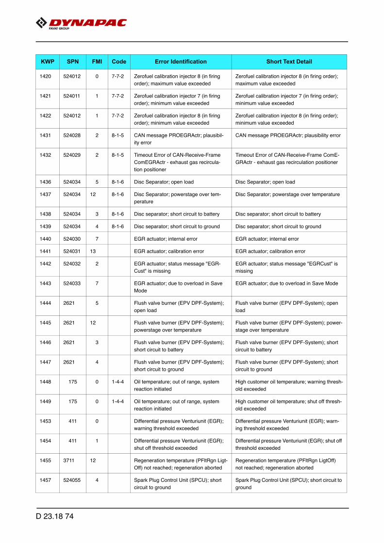
1420 524012 0 7-7-2 Zerofuel calibration injector 8 (in firing
order); maximum value exceeded
Zerofuel calibration injector 8 (in firing order);
maximum value exceeded
1421 524011 1 7-7-2 Zerofuel calibration injector 7 (in firing
order); minimum value exceeded
Zerofuel calibration injector 7 (in firing order);
minimum value exceeded
1422 524012 1 7-7-2 Zerofuel calibration injector 8 (in firing
order); minimum value exceeded
Zerofuel calibration injector 8 (in firing order);
minimum value exceeded
1431 524028 2 8-1-5 CAN message PROEGRActr; plausibil-
ity error
CAN message PROEGRActr; plausibility error
1432 524029 2 8-1-5 Timeout Error of CAN-Receive-Frame
ComEGRActr - exhaust gas recircula-
tion positioner
Timeout Error of CAN-Receive-Frame ComE-
GRActr - exhaust gas recirculation positioner
1436 524034 5 8-1-6 Disc Separator; open load Disc Separator; open load
1437 524034 12 8-1-6 Disc Separator; powerstage over tem-
perature
Disc Separator; powerstage over temperature
1438 524034 3 8-1-6 Disc separator; short circuit to battery Disc separator; short circuit to battery
1439 524034 4 8-1-6 Disc separator; short circuit to ground Disc separator; short circuit to ground
1440 524030 7 EGR actuator; internal error EGR actuator; internal error
1441 524031 13 EGR actuator; calibration error EGR actuator; calibration error
1442 524032 2 EGR actuator; status message "EGR-
Cust" is missing
EGR actuator; status message "EGRCust" is
missing
1443 524033 7 EGR actuator; due to overload in Save
Mode
EGR actuator; due to overload in Save Mode
1444 2621 5 Flush valve burner (EPV DPF-System);
open load
Flush valve burner (EPV DPF-System); open
load
1445 2621 12 Flush valve burner (EPV DPF-System);
powerstage over temperature
Flush valve burner (EPV DPF-System); power-
stage over temperature
1446 2621 3 Flush valve burner (EPV DPF-System);
short circuit to battery
Flush valve burner (EPV DPF-System); short
circuit to battery
1447 2621 4 Flush valve burner (EPV DPF-System);
short circuit to ground
Flush valve burner (EPV DPF-System); short
circuit to ground
1448 175 0 1-4-4 Oil temperature; out of range, system
reaction initiated
High customer oil temperature; warning thresh-
old exceeded
1449 175 0 1-4-4 Oil temperature; out of range, system
reaction initiated
High customer oil temperature; shut off thresh-
old exceeded
1453 411 0 Differential pressure Venturiunit (EGR);
warning threshold exceeded
Differential pressure Venturiunit (EGR); warn-
ing threshold exceeded
1454 411 1 Differential pressure Venturiunit (EGR);
shut off threshold exceeded
Differential pressure Venturiunit (EGR); shut off
threshold exceeded
1455 3711 12 Regeneration temperature (PFltRgn Ligt-
Off) not reached; regeneration aborted
Regeneration temperature (PFltRgn LigtOff)
not reached; regeneration aborted
1457 524055 4 Spark Plug Control Unit (SPCU); short
circuit to ground
Spark Plug Control Unit (SPCU); short circuit to
ground
KWP SPN FMI Code Error Identification Short Text Detail
D 23.18 74

1458 523960 0 7-7-1 Exhaust gas temperature EGR down-
stream; out of range, system reaction ini-
tiated
High exhaust gas temperature EGR cooler
downstream; warning threshold exceeded
1459 523960 1 7-7-1 Exhaust gas temperature EGR down-
stream; out of range, system reaction ini-
tiated
High exhaust gas temperature EGR cooler
downstream; shut off threshold exceeded
1460 1180 0 8-1-4 Exhaust gas temperature turbine
upstream; out of range, system reaction
initiated
Turbocharger Wastegate CAN feedback; warn-
ing threshold exceeded
1461 1180 1 8-1-4 Exhaust gas temperature turbine
upstream; out of range, system reaction
initiated
Turbocharger Wastegate CAN feedback; shut
off threshold exceeded
1462 1180 0 5-5-6 Exhaust gas temperature turbine
upstream; out of range, system reaction
initiated
Exhaust gas temperature upstream turbine;
warning threshold exceeded
1463 1180 1 5-5-6 Exhaust gas temperature turbine
upstream; out of range, system reaction
initiated
Exhaust gas temperature upstream turbine;
shut off threshold exceeded
1474 524037 5 Ashlamp; open load Ashlamp; open load
1475 84 2 5-2-1 Sensor vehicle speed; plausibility error Sensor vehicle speed; plausibility error
1477 524037 3 Ashlamp; short circuit to battery Ashlamp; short circuit to battery
1478 524037 4 Ashlamp; short circuit to ground Ashlamp; short circuit to ground
1479 524062 12 EAT-system HMI disrupted Regeneration inhibit switch not available; Com-
InhSwtNA
1480 524062 12 EAT-system HMI disrupted Regeneration release switch not available;
ComRegSwtNA
1481 524025 5 DPF system; operating voltage error DPF system; operating voltage error
1482 524044 9 CAN message ComMS_Sys7 not
received from slave
CAN message ComMS_Sys7 not received
from slave
1483 523632 2 Metering control is not performed in time
error
Metering control is not performed in time error
1484 524068 2 Master ECU and Slave ECU have been
identified as the same types
Master ECU and Slave ECU have been identi-
fied as the same types
1485 524052 11 MS ECU reported internal error Master ECU and Slave ECU data sets or soft-
ware are not identical
1486 523718 5 SCR mainrelay; open load (only CV56B) SCR mainrelay; open load (only CV56B)
1487 523718 12 SCR mainrelay; powerstage over tem-
perature (only CV56B)
SCR mainrelay; powerstage over temperature
(only CV56B)
1488 523718 3 SCR mainrelay; short circuit to battery
(only CV56B)
SCR mainrelay; short circuit to battery (only
CV56B)
1489 523718 4 SCR mainrelay; short circuit to ground
(only CV56B)
SCR mainrelay; short circuit to ground (only
CV56B)
1490 4376 5 6-6-7 SCR reversing valve; open load SCR reversing valve; open load
1491 4376 12 6-6-7 SCR reversing valve; over temperature SCR reversing valve; over temperature
KWP SPN FMI Code Error Identification Short Text Detail
D 23.18 75

1493 4376 4 6-6-7 SCR reversing valve; short circuit to
ground
SCR reversing valve; short circuit to ground
1494 2659 0 Physical range check high for EGR mass
flow
Physical range check high for EGR mass flow
1495 2659 1 Physical range check low for EGR mass
flow
Physical range check low for EGR mass flow
1496 2659 11 Exhaust gas recirculation; EGR mass
flow; shut off demand
Exhaust gas recirculation; EGR mass flow;
shut off demand
1505 524057 2 Electric fuel pump; fuel pressure build up
error
Electric fuel pump; fuel pressure build up error
1523 2659 2 Exhaust gas recirculation AGS sensor;
plausibility error
Exhaust gas recirculation AGS sensor; plausi-
bility error
1524 2659 0 Physical range check high for EGR
exhaust gas mass flow
Physical range check high for EGR exhaust
gas mass flow
1525 2659 1 Physical range check low for EGR
exhaust gas mass flow
Physical range check low for EGR exhaust gas
mass flow
1526 2659 12 Exhaust gas recirculation; AGS sensor
has "burn off" not performed
Exhaust gas recirculation; AGS sensor has
"burn off" not performed
1527 2659 2 AGS sensor temperature exhaust gas
mass flow; plausibility error
AGS sensor temperature exhaust gas mass
flow; plausibility error
1615 3699 14 Maximum stand-still-duration reached;
oil exchange required
Maximum stand-still-duration reached; oil
exchange required
1616 3699 2 DPF differential pressure sensor and a
further sensor or actuator CRT system
defective
DPF differential pressure sensor and a further
sensor or actuator CRT system defective
1617 3699 2 Temperature sensor us. and ds. DOC
simultaneously defect
Temperature sensor us. and ds. DOC simulta-
neously defect
1659 524114 9 Timeout error of CAN-Transmit-Frame
A1DOC
Timeout error of CAN-Transmit-Frame A1DOC
1660 524115 9 Timeout error of CAN-Transmit-Frame
AT1S
Timeout error of CAN-Transmit-Frame AT1S
1661 524116 9 Timeout error of CAN-Transmit-Frame
SCR2
Timeout error of CAN-Transmit-Frame SCR2
1662 524117 9 Timeout error of CAN-Transmit-Frame
SCR3
Timeout error of CAN-Transmit-Frame SCR3
1663 524097 9 Timeout error of CAN-Transmit-Frame
DPFBrnAirPmpCtl
Timeout error of CAN-Transmit-Frame
DPFBrnAirPmpCtl
1664 524098 9 Timeout error of CAN-Transmit-Frame
ComDPFBrnPT
Timeout error of CAN-Transmit-Frame ComD-
PFBrnPT
1665 524099 9 Timeout error of CAN-Transmit-Frame
ComDPFC0
Timeout error of CAN-Transmit-Frame
ComDPFC1
1666 524100 9 Timeout error of CAN-Transmit-Frame
ComDPFHisDat
Timeout error of CAN-Transmit-Frame ComD-
PFHisDat
1667 524101 9 Timeout error of CAN-Transmit-Frame
ComDPFTstMon
Timeout error of CAN-Transmit-Frame ComD-
PFTstMon
KWP SPN FMI Code Error Identification Short Text Detail
D 23.18 76

1668 524105 9 Timeout error of CAN-Transmit-Frame
ComEGRMsFlw
Timeout error of CAN-Transmit-Frame ComE-
GRMsFlw
1669 524108 9 Timeout error of CAN-Transmit-Frame
ComEGRTVActr
Timeout error of CAN-Transmit-Frame ComE-
GRTVActr
1670 524110 9 Timeout error of CAN-Transmit-Frame
ComETVActr
Timeout error of CAN-Transmit-Frame ComET-
VActr
1671 524112 9 Timeout ComITVActr Timeout ComITVActr
1672 524118 9 Timeout error of CAN-Receive-Frame
ComRxCM0
Timeout error of CAN-Receive-Frame
ComRxCM1
1673 524119 9 Timeout error of CAN-Receive-Frame
ComRxCustSCR2
Timeout error of CAN-Receive-Frame
ComRxCustSCR3
1674 524102 9 Timeout error of CAN-Receive-Frame
ComRxDPFBrnAirPmpCtl
Timeout error of CAN-Receive-Frame Com-
RxDPFBrnAirPmpCtl
1675 524103 9 Timeout error of CAN-Receive-Frame
ComRxDPFBrnAirPmp
Timeout error of CAN-Receive-Frame Com-
RxDPFBrnAirPmp
1676 524104 9 Timeout error of CAN-Receive-Frame
ComRxDPFCtl
Timeout error of CAN-Receive-Frame Com-
RxDPFCtl
1677 524106 9 Timeout error of CAN-Receive-Frame
ComRxEGRMsFlw1
Timeout error of CAN-Receive-Frame
ComRxEGRMsFlw1
1678 524107 9 Timeout error of CAN-Receive-Frame
ComRxEGRMsFlw2
Timeout error of CAN-Receive-Frame
ComRxEGRMsFlw2
1679 524109 9 Timeout error of CAN-Receive-Frame
ComRxEGRTVActr
Timeout error of CAN-Receive-Frame ComRx-
EGRTVActr
1680 524111 9 Timeout error of CAN-Receive-Frame
ComRxETVActr
Timeout error of CAN-Receive-Frame ComRx-
ETVActr
1681 524113 9 Timeout error of CAN-Receive-Frame
ComRxITVActr
Timeout error of CAN-Receive-Frame ComRx-
ITVActr
1682 524120 9 Timeout error of CAN-Receive-Frame
ComRxSCRHtDiag
Timeout error of CAN-Receive-Frame ComRx-
SCRHtDiag
1683 524121 9 Timeout error of CAN-Receive-Frame
ComRxTrbChActr
Timeout error of CAN-Receive-Frame ComRx-
TrbChActr
1684 524122 9 Timeout error of CAN-Receive-Frame
ComRxUQSens
Timeout error of CAN-Receive-Frame ComRx-
UQSens
1685 524123 9 Timeout error of CAN-Receive-Frame
ComSCRHtCtl
Timeout error of CAN-Receive-Frame Com-
SCRHtCtl
1686 524124 9 Timeout error of CAN-Receive-Frame
ComTxAT1IMG
Timeout error of CAN-Receive-Frame
ComTxAT1IMG
1687 524125 9 Timeout error of CAN-Receive-Frame
ComTxTrbChActr
Timeout error of CAN-Receive-Frame ComTx-
TrbChActr
932 3 1-2-6 Handthrottle; signal out of range, short
circuit to battery
Handthrottle idle validation switch; short circuit
to battery
936 3 2-2-6 Handthrottle; signal out of range, short
circuit to battery
Sesnor error handthrottle; signal range check
high
KWP SPN FMI Code Error Identification Short Text Detail
D 23.18 77
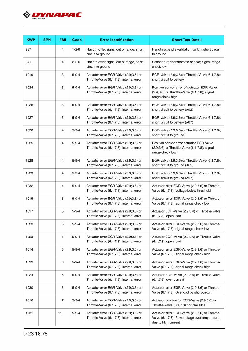
937 4 1-2-6 Handthrottle; signal out of range, short
circuit to ground
Handthrottle idle validation switch; short circuit
to ground
941 4 2-2-6 Handthrottle; signal out of range, short
circuit to ground
Sensor error handthrottle sensor; signal range
check low
1019 3 5-9-4 Actuator error EGR-Valve (2.9;3.6) or
Throttle-Valve (6.1,7.8); internal error
EGR-Valve (2.9;3.6) or Throttle-Valve (6.1,7.8);
short circuit to battery
1024 3 5-9-4 Actuator error EGR-Valve (2.9;3.6) or
Throttle-Valve (6.1,7.8); internal error
Position sensor error of actuator EGR-Valve
(2.9;3.6) or Throttle-Valve (6.1,7.8); signal
range check high
1226 3 5-9-4 Actuator error EGR-Valve (2.9;3.6) or
Throttle-Valve (6.1,7.8); internal error
EGR-Valve (2.9;3.6) or Throttle-Valve (6.1,7.8);
short circuit to battery (A02)
1227 3 5-9-4 Actuator error EGR-Valve (2.9;3.6) or
Throttle-Valve (6.1,7.8); internal error
EGR-Valve (2.9;3.6) or Throttle-Valve (6.1,7.8);
short circuit to battery (A67)
1020 4 5-9-4 Actuator error EGR-Valve (2.9;3.6) or
Throttle-Valve (6.1,7.8); internal error
EGR-Valve (2.9;3.6) or Throttle-Valve (6.1,7.8);
short circuit to ground
1025 4 5-9-4 Actuator error EGR-Valve (2.9;3.6) or
Throttle-Valve (6.1,7.8); internal error
Position sensor error actuator EGR-Valve
(2.9;3.6) or Throttle-Valve (6.1,7.8); signal
range check low
1228 4 5-9-4 Actuator error EGR-Valve (2.9;3.6) or
Throttle-Valve (6.1,7.8); internal error
EGR-Valve (2.9;3.6) or Throttle-Valve (6.1,7.8);
short circuit to ground (A02)
1229 4 5-9-4 Actuator error EGR-Valve (2.9;3.6) or
Throttle-Valve (6.1,7.8); internal error
EGR-Valve (2.9;3.6) or Throttle-Valve (6.1,7.8);
short circuit to ground (A67)
1232 4 5-9-4 Actuator error EGR-Valve (2.9;3.6) or
Throttle-Valve (6.1,7.8); internal error
Actuator error EGR-Valve (2.9;3.6) or Throttle-
Valve (6.1,7.8); Voltage below threshold
1015 5 5-9-4 Actuator error EGR-Valve (2.9;3.6) or
Throttle-Valve (6.1,7.8); internal error
Actuator error EGR-Valve (2.9;3.6) or Throttle-
Valve (6.1,7.8); signal range check low
1017 5 5-9-4 Actuator error EGR-Valve (2.9;3.6) or
Throttle-Valve (6.1,7.8); internal error
Actuator EGR-Valve (2.9;3.6) or Throttle-Valve
(6.1,7.8); open load
1023 5 5-9-4 Actuator error EGR-Valve (2.9;3.6) or
Throttle-Valve (6.1,7.8); internal error
Actuator error EGR-Valve (2.9;3.6) or Throttle-
Valve (6.1,7.8); signal range check low
1223 5 5-9-4 Actuator error EGR-Valve (2.9;3.6) or
Throttle-Valve (6.1,7.8); internal error
Actuator EGR-Valve (2.9;3.6) or Throttle-Valve
(6.1,7.8); open load
1014 6 5-9-4 Actuator error EGR-Valve (2.9;3.6) or
Throttle-Valve (6.1,7.8); internal error
Actuator error EGR-Valve (2.9;3.6) or Throttle-
Valve (6.1,7.8); signal range check high
1022 6 5-9-4 Actuator error EGR-Valve (2.9;3.6) or
Throttle-Valve (6.1,7.8); internal error
Actuator error EGR-Valve (2.9;3.6) or Throttle-
Valve (6.1,7.8); signal range check high
1224 6 5-9-4 Actuator error EGR-Valve (2.9;3.6) or
Throttle-Valve (6.1,7.8); internal error
Actuator EGR-Valve (2.9;3.6) or Throttle-Valve
(6.1,7.8); over current
1230 6 5-9-4 Actuator error EGR-Valve (2.9;3.6) or
Throttle-Valve (6.1,7.8); internal error
Actuator error EGR-Valve (2.9;3.6) or Throttle-
Valve (6.1,7.8); Overload by short-circuit
1016 7 5-9-4 Actuator error EGR-Valve (2.9;3.6) or
Throttle-Valve (6.1,7.8); internal error
Actuator position for EGR-Valve (2.9,3.6) or
Throttle-Valve (6.1,7.8) not plausible
1231 11 5-9-4 Actuator error EGR-Valve (2.9;3.6) or
Throttle-Valve (6.1,7.8); internal error
Actuator error EGR-Valve (2.9;3.6) or Throttle-
Valve (6.1,7.8); Power stage overtemperature
due to high current
KWP SPN FMI Code Error Identification Short Text Detail
D 23.18 78

1018 12 5-9-4 Actuator error EGR-Valve (2.9;3.6) or
Throttle-Valve (6.1,7.8); internal error
Actuator EGR-Valve (2.9;3.6) or Throttle-Valve
(6.1,7.8); powerstage over temperature
1021 12 5-9-4 Actuator error EGR-Valve (2.9;3.6) or
Throttle-Valve (6.1,7.8); internal error
Mechanical actuator defect EGR-Valve
(2.9,3.6) or Throttle-Valve (6.1,7.8)
1225 12 5-9-4 Actuator error EGR-Valve (2.9;3.6) or
Throttle-Valve (6.1,7.8); internal error
Actuator EGR-Valve (2.9;3.6) or Throttle-Valve
(6.1,7.8); over temperature
1475 2 5-2-1 Sensor vehicle speed; plausibility error Sensor vehicle speed; plausibility error
935 3 2-2-6 Sensor error accelerator pedal; signal
range check high
Sensor error accelerator pedal; signal range
check high
940 4 2-2-6 Sensor error accelerator pedal; signal
range check low
Sensor error accelerator pedal; signal range
check low
976 11 2-2-6 Plausibility error between APP1 and
APP2 or APP1 and idle switch
Plausibility error between APP1 and APP2 or
APP1 and idle switch
474 1 2-1-6 Low fuel pressure; system reaction initi-
ated
Low fuel pressure; warning threshold exceeded
475 1 2-1-6 Low fuel pressure; system reaction initi-
ated
Low fuel pressure; shut off threshold exceeded
472 3 2-1-6 Sensor error low fuel pressure; signal
range check high
Sensor error low fuel pressure; signal range
check high
473 4 2-1-6 Sensor error low fuel pressure; signal
range check low
Sensor error low fuel pressure; signal range
check low
464 3 2-2-8 Sensor error water in fuel; signal range
check high
Sensor error water in fuel; signal range check
high
465 4 2-2-8 Sensor error water in fuel; signal range
check low
Sensor error water in fuel; signal range check
low
1157 12 2-2-8 Water in fuel level prefilter; maximum
value exceeded
Water in fuel level prefilter; maximum value
exceeded
734 0 2-3-1 High oil pressure; system reaction initi-
ated
High oil pressure; warning threshold exceeded
735 0 2-3-1 High oil pressure; system reaction initi-
ated
High oil pressure; shut off threshold exceeded
736 1 2-3-1 Low oil pressure; system reaction initi-
ated
Low oil pressure; warning threshold exceeded
737 1 2-3-1 Low oil pressure; system reaction initi-
ated
Low oil pressure; shut off threshold exceeded
732 3 2-2-4 Sensor error oil pressure; signal range
check high
Sensor error oil pressure; signal range check
high
733 4 2-2-4 Sensor error oil pressure sensor; signal
range check low
Sensor error oil pressure sensor; signal range
check low
88 2 2-2-3 Charged air pressure; system reaction
initiated
Charged air pressure above warning threshold
89 2 2-2-3 Charged air pressure; system reaction
initiated
Charged air pressure above shut off threshold
KWP SPN FMI Code Error Identification Short Text Detail
D 23.18 79

776 3 2-2-3 Sensor error charged air pressure; signal
range check high
Sensor error charged air pressure; signal range
check high
777 4 2-2-3 Sensor error charged air pressure; signal
range check low
Sensor error charged air pressure; signal range
check low
996 0 2-3-3 Charged air cooler temperature; system
reaction initiated
High charged air cooler temperature; warning
threshold exceeded
997 0 2-3-3 Charged air cooler temperature; system
reaction initiated
High charged air cooler temperature; shut off
threshold exceeded
994 3 1-2-8 Sensor error charged air temperature;
signal range check high
Sensor error charged air temperature; signal
range check high
995 4 1-2-8 Sensor error charged air temperature;
signal range check low
Sensor error charged air temperature; signal
range check low
752 0 1-3-6 Air filter differential pressure; system
reaction initiated
High air filter differential pressure; warning
threshold exceeded
750 3 1-3-6 Sensor error airfilter differential pressure;
short circuit to battery
Sensor error airfilter differential pressure; short
circuit to battery
751 4 1-3-6 Sensor error airfilter differential pressure;
short circuit to ground
Sensor error airfilter differential pressure; short
circuit to ground
412 3 2-9-2 Sensor error ambient air pressure; signal
range check high
Sensor error ambient air pressure; signal range
check high
413 4 2-9-2 Sensor error ambient air pressure; signal
range check low
Sensor error ambient air pressure; signal range
check low
98 0 2-3-2 Coolant temperature; system reaction
initiated
High coolant temperature; warning threshold
exceeded
99 0 2-3-2 Coolant temperature; system reaction
initiated
High coolant temperature; shut off threshold
exceeded
96 3 2-2-5 Sensor error coolant temperature; signal
range check high
Sensor error coolant temperature; signal range
check high
97 4 2-2-5 Sensor error coolant temperature; signal
range check low
Sensor error coolant temperature; signal range
check low
101 1 2-3-5 Coolant level too low Coolant level too low
1 11 2-2-6 Air flow sensor; sensor error Air flow sensor load correction factor exceeding
the maximum drift limit; plausibility error
2 11 2-2-6 Air flow sensor; sensor error Air flow sensor load correction factor exceeding
drift limit; plausibility error
3 11 2-2-6 Air flow sensor; sensor error Air flow sensor low idle correction factor
exceeding the maximum drift limit
4 11 2-2-6 Air flow sensor; sensor error Air flow sensor load correction factor exceeding
the maximum drift limit
877 3 1-4-7 Sesnor error rail pressure; signal range
check high
Sesnor error rail pressure; signal range check
high
878 4 1-4-7 Sensor error rail pressure; signal range
check low
Sensor error rail pressure; signal range check
low
KWP SPN FMI Code Error Identification Short Text Detail
D 23.18 80
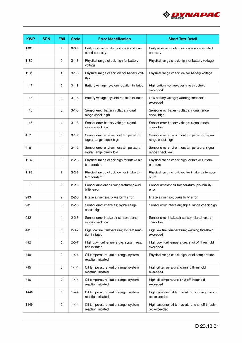
1381 2 8-3-9 Rail pressure safety function is not exe-
cuted correctly
Rail pressure safety function is not executed
correctly
1180 0 3-1-8 Physikal range check high for battery
voltage
Physikal range check high for battery voltage
1181 1 3-1-8 Physikal range check low for battery volt-
age
Physikal range check low for battery voltage
47 2 3-1-8 Battery voltage; system reaction initiated High battery voltage; warning threshold
exceeded
48 2 3-1-8 Battery voltage; system reaction initiated Low battery voltage; warning threshold
exceeded
45 3 3-1-8 Sensor error battery voltage; signal
range check high
Sensor error battery voltage; signal range
check high
46 4 3-1-8 Sensor error battery voltage; signal
range check low
Sensor error battery voltage; signal range
check low
417 3 3-1-2 Sensor error environment temperature;
signal range check high
Sensor error environment temperature; signal
range check high
418 4 3-1-2 Sensor error environment temperature;
signal range check low
Sensor error environment temperature; signal
range check low
1182 0 2-2-6 Physical range check high for intake air
temperature
Physical range check high for intake air tem-
perature
1183 1 2-2-6 Physical range check low for intake air
temperature
Physical range check low for intake air temper-
ature
9 2 2-2-6 Sensor ambient air temperature; plausi-
bility error
Sensor ambient air temperature; plausibility
error
983 2 2-2-6 Intake air sensor; plausibility error Intake air sensor; plausibility error
981 3 2-2-6 Sensor error intake air; signal range
check high
Sensor error intake air; signal range check high
982 4 2-2-6 Sensor error intake air sensor; signal
range check low
Sensor error intake air sensor; signal range
check low
481 0 2-3-7 High low fuel temperature; system reac-
tion initiated
High low fuel temperature; warning threshold
exceeded
482 0 2-3-7 High Low fuel temperature; system reac-
tion initiated
High Low fuel temperature; shut off threshold
exceeded
740 0 1-4-4 Oil temperature; out of range, system
reaction initiated
Physical range check high for oil temperature
745 0 1-4-4 Oil temperature; out of range, system
reaction initiated
High oil temperature; warning threshold
exceeded
746 0 1-4-4 Oil temperature; out of range, system
reaction initiated
High oil temperature; shut off threshold
exceeded
1448 0 1-4-4 Oil temperature; out of range, system
reaction initiated
High customer oil temperature; warning thresh-
old exceeded
1449 0 1-4-4 Oil temperature; out of range, system
reaction initiated
High customer oil temperature; shut off thresh-
old exceeded
KWP SPN FMI Code Error Identification Short Text Detail
D 23.18 81

741 1 1-4-4 Physical range check low for oil tempera-
ture
Physical range check low for oil temperature
738 2 1-4-4 Oil temperature; plausibility error Sensor oil temperature; plausibility error
739 2 1-4-4 Oil temperature; plausibility error Sensor oil temperature; plausibility error oil
temperature too high
1171 2 1-4-4 Oil temperature; plausibility error Customer oiltemperature: signal unplausible
743 3 1-4-4 Sensor error oil temperature; signal
range check high
Sensor error oil temperature; signal range
check high
744 4 1-4-4 Sensor error oil temperature; signal
range check low
Sensor error oil temperature; signal range
check low
388 0 2-1-4 Engine speed above warning threshold
(FOC-Level 1)
Overspeed detection in component engine pro-
tection
389 0 2-1-4 Engine speed above warning threshold
(FOC-Level 1)
Engine speed above warning threshold (FOC-
Level 1)
421 2 2-1-3 Offset angle between crank- and cam-
shaft sensor is too large
Offset angle between crank- and camshaft sen-
sor is too large
419 8 2-1-2 Speed detection; out of range, signal dis-
rupted
Sensor camshaft speed; disturbed signal
422 8 2-1-2 Speed detection; out of range, signal dis-
rupted
Sensor crankshaft speed; disturbed signal
390 11 2-1-4 Engine speed above warning threshold
(FOC-Level 2)
Engine speed above warning threshold (FOC-
Level 2)
420 12 2-1-2 Speed detection; out of range, signal dis-
rupted
Sensor camshaft speed; no signal
423 12 2-1-2 Speed detection; out of range, signal dis-
rupted
Sensor crankshaft speed; no signal
391 14 2-1-4 Speed detection; out of range, signal dis-
rupted
Engine speed above warning threshold (Over-
run Mode)
1222 14 2-1-2 Speed detection; out of range, signal dis-
rupted
Camshaft- and Crankshaft speed sensor signal
not available on CAN
791 0 6-9-3 Physical range check high for differential
pressure Venturiunit (EGR)
Physical range check high for differential pres-
sure Venturiunit (EGR)
1453 0 Differential pressure Venturiunit (EGR);
warning threshold exceeded
Differential pressure Venturiunit (EGR); warn-
ing threshold exceeded
792 1 6-9-3 Physical range check low for differential
pressure Venturiunit (EGR)
Physical range check low for differential pres-
sure Venturiunit (EGR)
1454 1 Differential pressure Venturiunit (EGR);
shut off threshold exceeded
Differential pressure Venturiunit (EGR); shut off
threshold exceeded
794 2 6-9-3 Sensor differential pressure Venturiunit
(EGR); CAN signal invalid
Sensor differential pressure Venturiunit (EGR);
CAN signal invalid
795 3 6-9-3 Sensor error differential pressure Ventu-
riunit (EGR); signal range check high
Sensor error differential pressure Venturiunit
(EGR); signal range check high
381 4 Physical range check low for EGR differ-
ential pressure
Physical range check low for EGR differential
pressure
KWP SPN FMI Code Error Identification Short Text Detail
D 23.18 82

796 4 6-9-3 Sensor error differential pressure Ventu-
riunit (EGR); signal range check low
Sensor error differential pressure Venturiunit
(EGR); signal range check low
793 11 6-9-3 Sensor differential pressure Venturiunit
(EGR); plausibility error
Sensor differential pressure Venturiunit (EGR);
plausibility error
1009 2 6-8-2 Sensor exhaust gas temperature Ventu-
riunit (EGR); plausibility error
Sensor exhaust gas temperature Venturiunit
(EGR); plausibility error
1007 3 6-8-2 Sensor error EGR cooler downstream
temperature; signal range check high
Sensor error EGR cooler downstream temper-
ature; signal range check high
1008 4 6-8-2 Sensor error EGR cooler downstream
temperature; signal range check low
Sensor error EGR cooler downstream temper-
ature; signal range check low
306 9 1-1-9 Timeout Error of CAN-Receive-Frame
TSC1TR; Setpoint
Timeout Error of CAN-Receive-Frame
TSC1TR; Setpoint
49 2 3-2-1 Break lever mainswitch and break lever
redundancyswitch status not plausible
Break lever mainswitch and break lever redun-
dancyswitch status not plausible
971 3 5-1-3 SVS lamp; short circuit to battery SVS lamp; short circuit to battery
972 4 5-1-3 SVS lamp; short circuit to ground SVS lamp; short circuit to ground
969 5 5-1-3 SVS lamp; open load SVS lamp; open load
970 12 5-1-3 SVS lamp; powerstage over temperature SVS lamp; powerstage over temperature
376 12 2-8-1 Access error EEPROM Access error EEPROM memory (delete)
377 12 2-8-1 Access error EEPROM Access error EEPROM memory (read)
378 12 2-8-1 Access error EEPROM Access error EEPROM memory (write)
84 14 2-7-1 CAN-Bus 0 "BusOff-Status" CAN-Bus 0 "BusOff-Status"
580 3 1-5-4 Injector 1 (in firing order); short circuit Injector 1 (in firing order); short circuit
586 4 1-5-4 High side to low side short circuit in the
injector 1 (in firing order)
High side to low side short circuit in the injector
1 (in firing order)
568 5 1-5-4 Injector 1 (in firing order); interruption of
electric connection
Injector 1 (in firing order); interruption of electric
connection
581 3 1-5-5 Injector 2 (in firing order); short circuit Injector 2 (in firing order); short circuit
587 4 1-5-5 High side to low side short circuit in the
injector 2 (in firing order)
High side to low side short circuit in the injector
2 (in firing order)
569 5 1-5-5 Injector 2 (in firing order); interruption of
electric connection
Injector 2 (in firing order); interruption of electric
connection
582 3 1-5-6 Injector 3 (in firing order); short circuit Injector 3 (in firing order); short circuit
588 4 1-5-6 High side to low side short circuit in the
injector 3 (in firing order)
High side to low side short circuit in the injector
3 (in firing order)
570 5 1-5-6 Injector 3 (in firing order); interruption of
electric connection
Injector 3 (in firing order); interruption of electric
connection
583 3 1-6-1 Injector 4 (in firing order); short circuit Injector 4 (in firing order); short circuit
589 4 1-6-1 High side to low side short circuit in the
injector 4 (in firing order)
High side to low side short circuit in the injector
4 (in firing order)
KWP SPN FMI Code Error Identification Short Text Detail
D 23.18 83

571 5 1-6-1 Injector 4 (in firing order); interruption of
electric connection
Injector 4 (in firing order); interruption of electric
connection
584 3 1-6-2 Injector 5 (in firing order); short circuit Injector 5 (in firing order); short circuit
590 4 1-6-2 High side to low side short circuit in the
injector 5 (in firing order)
High side to low side short circuit in the injector
5 (in firing order)
572 5 1-6-2 Injector 5 (in firing order); interruption of
electric connection
Injector 5 (in firing order); interruption of electric
connection
585 3 1-6-3 Injector 6 (in firing order); short circuit Injector 6 (in firing order); short circuit
591 4 1-6-3 High side to low side short circuit in the
injector 6 (in firing order)
High side to low side short circuit in the injector
6 (in firing order)
573 5 1-6-3 Injector 6 (in firing order); interruption of
electric connection
Injector 6 (in firing order); interruption of electric
connection
543 11 2-6-3 Cold start aid relay; open load, relay
error.
Cold start aid relay error.
544 11 2-6-3 Cold start aid relay; open load, relay
error.
Cold start aid relay open load
956 3 5-1-2 Starter relay; short circuit Starter relay high side; short circuit to battery
960 3 5-1-2 Starter relay; short circuit Starter relay low side; short circuit to battery
957 4 5-1-2 Starter relay; short circuit Starter relay high side; short circuit to ground
961 4 5-1-2 Starter relay; short circuit Starter relay low side; short circuit to ground
958 5 5-1-2 Starter relay; no load error Starter relay; no load error
959 12 5-1-2 Starter relay; powerstage over tempera-
ture
Starter relay; powerstage over temperature
426 3 1-4-2 Engine running lamp; short circuit to bat-
tery
Engine running lamp; short circuit to battery
427 4 1-4-2 Engine running lamp; short circuit to
ground
Engine running lamp; short circuit to ground
424 5 1-4-2 Engine running lamp; open load Engine running lamp; open load
425 12 1-4-2 Engine running lamp; powerstage over
temperature
Engine running lamp; powerstage over temper-
ature
545 5 2-6-3 Cold start aid relay open load Cold start aid relay open load
547 12 2-6-3 Cold start aid relay; over temperature
error
Cold start aid relay; over temperature error
305 9 1-1-8 Timeout Error of CAN-Receive-Frame
TSC1TE; Setpoint
Timeout Error of CAN-Receive-Frame
TSC1TE; Setpoint
452 3 2-2-8 Fan control; short circuit to battery Digital fan control; short circuit to battery
457 3 2-2-8 Fan control; short circuit to battery Fan actuator (PWM output); short circuit to bat-
tery
453 4 2-2-8 Fan control; short circuit to ground Digital fan control; short circuit to ground
458 4 2-2-8 Fan control; short circuit to ground Fan actuator (PWM output); short circuit to
ground
KWP SPN FMI Code Error Identification Short Text Detail
D 23.18 84

450 5 2-2-8 Fan control; open load Digital fan control; open load
455 5 2-2-8 Fan control; open load Fan actuator (PWM output); open load
451 12 2-2-8 Fan control; internal error Digital fan control; powerstage over tempera-
ture
456 12 2-2-8 Fan control; internal error Fan actuator (PWM output); powerstage over
temperature
946 13 2-8-2 Sensor supply voltage monitor 1 error
(ECU)
Sensor supply voltage monitor 1 error (ECU)
947 13 2-8-2 Sensor supply voltage monitor 2 error
(ECU)
Sensor supply voltage monitor 2 error (ECU)
121 2 3-4-1 Engine shut off demand ignored Engine shut off demand ignored
1398 0 6-8-1 Physikal range check high for ECU tem-
perature
Physikal range check high for ECU tempera-
ture
1399 1 6-8-1 Physikal range check low for ECU tem-
perature
Physikal range check low for ECU temperature
1400 3 6-8-1 Sensor error ECU temperature; signal
range check high
Sensor error ECU temperature; signal range
check high
1401 4 6-8-1 Sensor error ECU temperature; signal
range check low
Sensor error ECU temperature; signal range
check low
849 3 6-8-0 Sensor error pressure sensor upstream
turbine; signal range check high
Sensor error pressure sensor upstream tur-
bine; signal range check high
850 4 6-8-0 Sensor error pressure sensor down-
stream turbine; signal range check high
Sensor error pressure sensor downstream tur-
bine; signal range check high
1193 0 Exhaust gas temperature upstream tur-
bine; out of range, system reaction initi-
ated
Physical range check high for exhaust gas tem-
perature upstream turbine
1460 0 8-1-4 Exhaust gas temperature turbine
upstream; out of range, system reaction
initiated
Turbocharger Wastegate CAN feedback; warn-
ing threshold exceeded
1462 0 5-5-6 Exhaust gas temperature turbine
upstream; out of range, system reaction
initiated
Exhaust gas temperature upstream turbine;
warning threshold exceeded
1194 1 Exhaust gas temperature upstream tur-
bine; out of range, system reaction initi-
ated
Physical range check low for exhaust gas tem-
perature upstream turbine
1461 1 8-1-4 Exhaust gas temperature turbine
upstream; out of range, system reaction
initiated
Turbocharger Wastegate CAN feedback; shut
off threshold exceeded
1463 1 5-5-6 Exhaust gas temperature turbine
upstream; out of range, system reaction
initiated
Exhaust gas temperature upstream turbine;
shut off threshold exceeded
1067 3 5-5-6 Sensor error exhaust gas temperature
upstream turbine; signal range check
high
Sensor error exhaust gas temperature
upstream turbine; signal range check high
1068 4 5-5-6 Sensor error exhaust gas temperature
upstream turbine; signal range check low
Sensor error exhaust gas temperature
upstream turbine; signal range check low
KWP SPN FMI Code Error Identification Short Text Detail
D 23.18 85

1066 11 5-5-6 Sensor exhaust gas temperature
upstream turbine; plausibility error
Sensor exhaust gas temperature upstream tur-
bine; plausibility error
1414 2 8-1-4 Wastegate; status message from ECU
missing
Wastegate; status message from ECU missing
1415 7 8-1-4 Wastegate actuator; blocked Wastegate actuator; blocked
1411 11 8-1-4 Turbo charger wastegate actuator; inter-
nal error
Wastegate actuator; internal error
1412 11 8-1-4 Turbo charger wastegate actuator; inter-
nal error
Wastegate actuator; EOL calibration not per-
formed correctly
1416 11 8-1-4 Turbo charger wastegate actuator; inter-
nal error
Wastegate actuator; over temperature (>
145°C)
1417 11 8-1-4 Turbo charger wastegate actuator; inter-
nal error
Wastegate actuator; over temperature (>
135°C)
1418 11 8-1-4 Turbo charger wastegate actuator; inter-
nal error
Wastegate actuator; operating voltage error
1413 13 8-1-4 Wastegate actuator calibration deviation
too large, recalibration required
Wastegate actuator calibration deviation too
large, recalibration required
85 14 2-7-1 CAN-Bus 1 "BusOff-Status" CAN-Bus 1 "BusOff-Status"
82 14 2-7-1 CAN Bus error passive; warning CAN C CAN Bus error passive; warning CAN C
86 14 2-7-1 CAN-Bus 2 "BusOff-Status" CAN-Bus 2 "BusOff-Status"
747 2 1-4-5 Override switch; plausibility error Override switch; plausibility error
610 12 2-4-1 Too many recognized misfires in more
than one cylinder
Too many recognized misfires in more than
one cylinder
604 12 2-4-1 Too many recognized misfires in cylinder
1 (in firing order)
Too many recognized misfires in cylinder 1 (in
firing order)
605 12 2-4-1 Too many recognized misfires in cylinder
2 (in firing order)
Too many recognized misfires in cylinder 2 (in
firing order)
606 12 2-4-1 Too many recognized misfires in cylinder
3 (in firing order)
Too many recognized misfires in cylinder 3 (in
firing order)
607 12 2-4-1 Too many recognized misfires in cylinder
4 (in firing order)
Too many recognized misfires in cylinder 4 (in
firing order)
608 12 2-4-1 Too many recognized misfires in cylinder
5 (in firing order)
Too many recognized misfires in cylinder 5 (in
firing order)
609 12 2-4-1 Too many recognized misfires in cylinder
6 (in firing order)
Too many recognized misfires in cylinder 6 (in
firing order)
460 0 2-2-8 Sensor error fan speed; signal range
check high
Sensor error fan speed; signal range check
high
461 1 2-2-8 Sensor error fan speed; signal range
check low
Sensor error fan speed; signal range check
low
1074 14 6-7-0 Urea tank level; warning threshold
exceeded
Urea tank level; warning threshold exceeded
1446 3 Flush valve burner (EPV DPF-System);
short circuit to battery
Flush valve burner (EPV DPF-System); short
circuit to battery
KWP SPN FMI Code Error Identification Short Text Detail
D 23.18 86
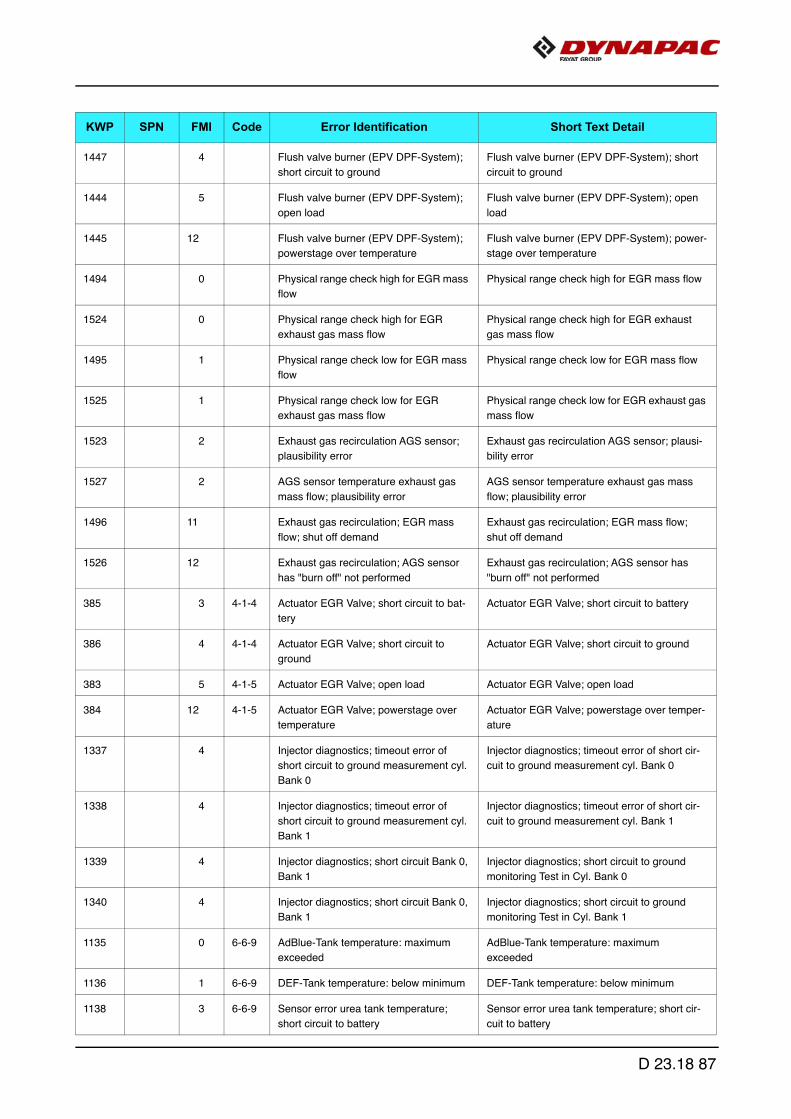
1447 4 Flush valve burner (EPV DPF-System);
short circuit to ground
Flush valve burner (EPV DPF-System); short
circuit to ground
1444 5 Flush valve burner (EPV DPF-System);
open load
Flush valve burner (EPV DPF-System); open
load
1445 12 Flush valve burner (EPV DPF-System);
powerstage over temperature
Flush valve burner (EPV DPF-System); power-
stage over temperature
1494 0 Physical range check high for EGR mass
flow
Physical range check high for EGR mass flow
1524 0 Physical range check high for EGR
exhaust gas mass flow
Physical range check high for EGR exhaust
gas mass flow
1495 1 Physical range check low for EGR mass
flow
Physical range check low for EGR mass flow
1525 1 Physical range check low for EGR
exhaust gas mass flow
Physical range check low for EGR exhaust gas
mass flow
1523 2 Exhaust gas recirculation AGS sensor;
plausibility error
Exhaust gas recirculation AGS sensor; plausi-
bility error
1527 2 AGS sensor temperature exhaust gas
mass flow; plausibility error
AGS sensor temperature exhaust gas mass
flow; plausibility error
1496 11 Exhaust gas recirculation; EGR mass
flow; shut off demand
Exhaust gas recirculation; EGR mass flow;
shut off demand
1526 12 Exhaust gas recirculation; AGS sensor
has "burn off" not performed
Exhaust gas recirculation; AGS sensor has
"burn off" not performed
385 3 4-1-4 Actuator EGR Valve; short circuit to bat-
tery
Actuator EGR Valve; short circuit to battery
386 4 4-1-4 Actuator EGR Valve; short circuit to
ground
Actuator EGR Valve; short circuit to ground
383 5 4-1-5 Actuator EGR Valve; open load Actuator EGR Valve; open load
384 12 4-1-5 Actuator EGR Valve; powerstage over
temperature
Actuator EGR Valve; powerstage over temper-
ature
1337 4 Injector diagnostics; timeout error of
short circuit to ground measurement cyl.
Bank 0
Injector diagnostics; timeout error of short cir-
cuit to ground measurement cyl. Bank 0
1338 4 Injector diagnostics; timeout error of
short circuit to ground measurement cyl.
Bank 1
Injector diagnostics; timeout error of short cir-
cuit to ground measurement cyl. Bank 1
1339 4 Injector diagnostics; short circuit Bank 0,
Bank 1
Injector diagnostics; short circuit to ground
monitoring Test in Cyl. Bank 0
1340 4 Injector diagnostics; short circuit Bank 0,
Bank 1
Injector diagnostics; short circuit to ground
monitoring Test in Cyl. Bank 1
1135 0 6-6-9 AdBlue-Tank temperature: maximum
exceeded
AdBlue-Tank temperature: maximum
exceeded
1136 1 6-6-9 DEF-Tank temperature: below minimum DEF-Tank temperature: below minimum
1138 3 6-6-9 Sensor error urea tank temperature;
short circuit to battery
Sensor error urea tank temperature; short cir-
cuit to battery
KWP SPN FMI Code Error Identification Short Text Detail
D 23.18 87
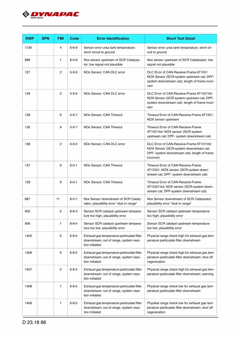
1139 4 6-6-9 Sensor error urea tank temperature;
short circuit to ground
Sensor error urea tank temperature; short cir-
cuit to ground
889 1 8-0-8 Nox sensor upstream of SCR Catalysa-
tor; low signal not plausible
Nox sensor upstream of SCR Catalysator; low
signal not plausible
127 2 5-9-6 NOx Sensor; CAN DLC error DLC Error of CAN-Receive-Frame AT1IG1
NOX Sensor (SCR-system upstream cat; DPF-
system downstream cat); length of frame incor-
rect
129 2 5-9-6 NOx Sensor; CAN DLC error DLC Error of CAN-Receive-Frame AT1IG1Vol
NOX Sensor (SCR-system upstream cat; DPF-
system downstream cat); length of frame incor-
rect
128 9 5-9-7 NOx Sensor; CAN Timeout Timeout Error of CAN-Receive-Frame AT1IG1;
NOX sensor upstream
130 9 5-9-7 NOx Sensor; CAN Timeout Timeout Error of CAN-Receive-Frame
AT1IG1Vol; NOX sensor (SCR-system
upstream cat; DPF- system downstream cat)
138 2 6-0-0 NOx Sensor; CAN DLC error DLC Error of CAN-Receive-Frame AT1O1Vol
NOX Sensor (SCR-system downstream cat;
DPF- system downstream cat); length of frame
incorrect
137 9 6-0-1 NOx Sensor; CAN Timeout Timeout Error of CAN-Receive-Frame
AT1OG1; NOX sensor (SCR-system down-
stream cat; DPF- system downstream cat)
139 9 6-0-1 NOx Sensor; CAN Timeout Timeout Error of CAN-Receive-Frame
AT1OG1Vol; NOX sensor (SCR-system down-
stream cat; DPF-system downstream cat)
887 11 8-0-7 Nox Sensor downstream of SCR Cataly-
sator; plausibility error "stuk in range"
Nox Sensor downstream of SCR Catalysator;
plausibility error "stuk in range"
905 0 8-8-3 Sensor SCR catalyst upstream tempera-
ture too high; plausibility error
Sensor SCR catalyst upstream temperature
too high; plausibility error
906 1 8-8-4 Sensor SCR catalyst upstream tempera-
ture too low; plausibility error
Sensor SCR catalyst upstream temperature
too low; plausibility error
1405 0 6-8-5 Exhaust gas temperature particulate filter
downstream; out of range, system reac-
tion initiated
Physical range check high for exhaust gas tem-
perature particulate filter downstream
1406 0 6-8-5 Exhaust gas temperature particulate filter
downstream; out of range, system reac-
tion initiated
Physical range check high for exhaust gas tem-
perature particulate filter downstream; shut off
regeneration
1407 0 6-8-5 Exhaust gas temperature particulate filter
downstream; out of range, system reac-
tion initiated
Physical range check high for exhaust gas tem-
perature particulate filter downstream; warning
1408 1 6-8-5 Exhaust gas temperature particulate filter
downstream; out of range, system reac-
tion initiated
Physical range check low for exhaust gas tem-
perature particulate filter downstream
1409 1 6-8-5 Exhaust gas temperature particulate filter
downstream; out of range, system reac-
tion initiated
Physikal range check low for exhaust gas tem-
perature particulate filter downstream; shut off
regeneration
KWP SPN FMI Code Error Identification Short Text Detail
D 23.18 88

1410 1 6-8-5 Exhaust gas temperature particulate filter
downstream; out of range, system reac-
tion initiated
Physical range check low for exhaust gas tem-
perature particulate filter downstream; warning
1404 2 6-8-5 Sensor exhaust gas temperature down-
stream DPF; plausibility error
Sensor exhaust gas temperature downstream
DPF; plausibility error
1047 4 6-8-5 Sensor error particle filter downstream
temperature; signal range check low
Sensor error particle filter downstream temper-
ature; signal range check low
809 0 6-9-2 Physical range check high for differential
pressure (DPF); shut off regeneration
Physical range check high for differential pres-
sure (DPF); shut off regeneration
812 1 6-9-2 Physical range check low for differential
pressure (DPF); shut off regeneration
Physical range check low for differential pres-
sure (DPF); shut off regeneration
807 2 6-9-2 Sensor differential pressure (DPF); plau-
sibility error
Sensor differential pressure (DPF); plausibility
error regarding signal offset
1380 2 6-9-2 Sensor differential pressure (DPF); plau-
sibility error
Sensor differential pressure (DPF); plausibility
error
814 3 6-9-2 Sensor error differential pressure (DPF);
signal range check high
Sensor error differential pressure (DPF); signal
range check high
815 4 6-9-2 Sensor error differential pressure (DPF);
signal range check low
Sensor error differential pressure (DPF); signal
range check low
1077 3 6-7-7 Urea dosing valve; short circuit to battery Urea dosing valve; short circuit to battery on
high side
1078 3 6-7-7 Urea dosing valve; short circuit to battery Urea dosing valve; short circuit to battery or
open load on high side
1079 4 6-7-7 Urea dosing valve; short circuit to ground Urea dosing valve; short circuit to ground or
open load on low side
1080 4 6-7-7 Urea dosing valve; short circuit to ground Urea dosing valve; short circuit on high side
908 7 8-8-6 AdBlue dosing valve blocked (SCR) AdBlue dosing valve blocked (SCR)
943 3 6-7-0 Sensor error urea tank level; signal
range check high
Sensor error urea tank level; signal range
check high
945 4 6-7-0 Sensor error urea tank level; signal
range check low
Sensor error urea tank level; signal range
check low
1616 2 DPF differential pressure sensor and a
further sensor or actuator CRT system
defective
DPF differential pressure sensor and a further
sensor or actuator CRT system defective
1617 2 Temperature sensor us. and ds. DOC
simultaneously defect
Temperature sensor us. and ds. DOC simulta-
neously defect
1615 14 Maximum stand-still-duration reached;
oil exchange required
Maximum stand-still-duration reached; oil
exchange required
1455 12 Regeneration temperature (PFltRgn Ligt-
Off) not reached; regeneration aborted
Regeneration temperature (PFltRgn LigtOff)
not reached; regeneration aborted
1089 11 7-8-3 SCR system heater diagnostic reports
error; shut off SCR-system
SCR system heater diagnostic reports error;
shut off SCR-system
1122 0 6-6-5 Urea pump pressure; out of range Physical range check high for Urea Pump
Pressure
KWP SPN FMI Code Error Identification Short Text Detail
D 23.18 89
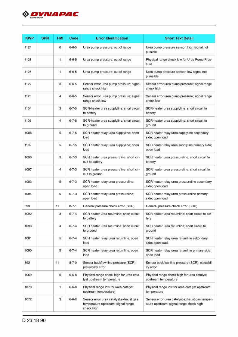
1124 0 6-6-5 Urea pump pressure; out of range Urea pump pressure sensor; high signal not
plusible
1123 1 6-6-5 Urea pump pressure; out of range Physical range check low for Urea Pump Pres-
sure
1125 1 6-6-5 Urea pump pressure; out of range Urea pump pressure sensor; low signal not
plausible
1127 3 6-6-5 Sensor error urea pump pressure; signal
range check high
Sensor error urea pump pressure; signal range
check high
1128 4 6-6-5 Sensor error urea pump pressure; signal
range check low
Sensor error urea pump pressure; signal range
check low
1104 3 6-7-5 SCR-heater urea supplyline; short circuit
to battery
SCR-heater urea supplyline; short circuit to
battery
1105 4 6-7-5 SCR-heater urea supplyline; short circuit
to ground
SCR-heater urea supplyline; short circuit to
ground
1086 5 6-7-5 SCR heater relay urea supplyline; open
load
SCR heater relay urea supplyline secondary
side; open load
1102 5 6-7-5 SCR heater relay urea supplyline; open
load
SCR heater relay urea supplyline primary side;
open load
1096 3 6-7-3 SCR heater urea pressureline; short cir-
cuit to battery
SCR heater urea pressureline; short circuit to
battery
1097 4 6-7-3 SCR heater urea pressureline; short cir-
cuit to ground
SCR heater urea pressureline; short circuit to
ground
1083 5 6-7-3 SCR heater relay urea pressureline;
open load
SCR heater relay urea pressureline secondary
side; open load
1094 5 6-7-3 SCR heater relay urea pressureline;
open load
SCR heater relay urea pressureline primary
side; open load
893 11 8-7-1 General pressure check error (SCR) General pressure check error (SCR)
1092 3 6-7-4 SCR heater urea returnline; short circuit
to battery
SCR heater urea returnline; short circuit to bat-
tery
1093 4 6-7-4 SCR heater urea returnline; short circuit
to ground
SCR heater urea returnline; short circuit to
ground
1081 5 6-7-4 SCR heater relay urea returnline; open
load
SCR heater relay urea returnline sekondary
side; open load
1090 5 6-7-4 SCR heater relay urea returnline; open
load
SCR heater relay urea returnline primary side;
open load
892 11 8-7-0 Sensor backflow line pressure (SCR);
plausibility error
Sensor backflow line pressure (SCR); plausibil-
ity error
1069 0 6-6-8 Physical range check high for urea cata-
lyst upstream temperature
Physical range check high for urea catalyst
upstream temperature
1070 1 6-6-8 Physical range low for urea catalyst
upstream temperature
Physical range low for urea catalyst upstream
temperature
1072 3 6-6-8 Sensor error urea catalyst exhaust gas
temperature upstream; signal range
check high
Sensor error urea catalyst exhaust gas temper-
ature upstream; signal range check high
KWP SPN FMI Code Error Identification Short Text Detail
D 23.18 90

1073 4 6-6-8 Sensor error urea catalyst exhaust gas
temperature upstream; signal range
check low
Sensor error urea catalyst exhaust gas temper-
ature upstream; signal range check low
903 0 8-8-1 Urea tank temperature too high Urea tank temperature too high
1112 3 6-7-1 SCR Tank heating valve; short circuit to
battery
SCR Tank heating valve; short circuit to battery
1113 4 6-7-1 SCR Tank heating valve; short circuit to
ground
SCR Tank heating valve; short circuit to ground
1082 5 7-6-2 SCR main relay (secondary side): open
load
SCR main relay (secondary side): open load
1084 5 7-6-2 SCR main relay; short circuit SCR main relay (secondary side); Shortcut to
battery
1085 5 7-6-2 SCR main relay; short circuit SCR main relay (secondary side); shortcut to
ground
1088 5 6-7-1 SCR Tank heating valve; open load SCR Tank heating valve secundary side: open
load
1110 5 6-7-1 SCR Tank heating valve; open load SCR tank heating valve primary side; open
load
1111 12 6-7-1 SCR-heater relay urea tank powerstage
output; over temperature
SCR-heater relay urea tank powerstage output;
over temperature
894 13 8-7-2 Pressure stabilisation error dosing valve
(SCR)
Pressure stabilisation error dosing valve (SCR)
1120 3 6-6-6 Urea pump motor; short circuit to battery Urea pump motor; short circuit to battery
1121 4 6-6-6 Urea pump motor; short circuit to ground Urea pump motor; short circuit to ground
1118 5 6-6-6 Urea pump motor; open load Urea pump motor; open load
1131 3 6-6-7 SCR reversing valve; short circuit to bat-
tery
SCR reversing valve; short circuit to battery
1132 4 6-6-7 SCR reversing valve; short circuit to
ground
SCR reversing valve; short circuit to ground
1493 4 6-6-7 SCR reversing valve; short circuit to
ground
SCR reversing valve; short circuit to ground
1129 5 6-6-7 SCR reversing valve; open load SCR reversing valve; open load
1490 5 6-6-7 SCR reversing valve; open load SCR reversing valve; open load
1130 12 6-6-7 SCR reversing valve; over temperature SCR reversing valve; over temperature
1491 12 6-6-7 SCR reversing valve; over temperature SCR reversing valve; over temperature
1039 0 6-8-3 Physical range check high for exhaust
gas temperature upstream (DOC)
Physical range check high for exhaust gas tem-
perature upstream (DOC)
1042 1 6-8-3 Physical range check low for exhaust
gas temperature upstream (DOC)
Physical range check low for exhaust gas tem-
perature upstream (DOC)
1029 0 6-8-4 Physical range check high for exhaust
gas temperature downstream (DOC)
Physical range check high for exhaust gas tem-
perature downstream (DOC)
1032 1 6-8-4 Physical range check low for exhaust
gas temperature downstream (DOC)
Physical range check low for exhaust gas tem-
perature downstream (DOC)
KWP SPN FMI Code Error Identification Short Text Detail
D 23.18 91

1036 2 6-8-3 Sensor exhaust gas temperature
upstream (DOC); plausibility error
Sensor exhaust gas temperature upstream
(DOC); plausibility error
1044 3 6-8-3 Sensor error exhaust gas temperature
upstream (DOC); signal range check
high
Sensor error exhaust gas temperature
upstream (DOC); signal range check high
1045 4 6-8-3 Sensor error exhaust gas temperature
upstream (DOC); signal range check low
Sensor error exhaust gas temperature
upstream (DOC); signal range check low
1026 2 6-8-4 Sensor exhaust gas temperature down-
stream (DOC); plausibility error
Sensor exhaust gas temperature downstream
(DOC); plausibility error
1402 2 6-8-4 Sensor exhaust gas temperature (DOC)
downstream; plausibility error
Sensor exhaust gas temperature OxiCat down-
stream (normal operation); plausibility error
1403 2 6-8-4 Sensor exhaust gas temperature (DOC)
downstream; plausibility error
Sensor exhaust gas temperature OxiCat down-
stream (regeneration); plausibility error
1034 3 6-8-4 Sensor error exhaust gas temperature
downstream (DOC); signal range check
high
Sensor error exhaust gas temperature down-
stream (DOC); signal range check high
1035 4 6-8-4 Sensor error exhaust gas temperature
downstream (DOC); signal range check
low
Sensor error exhaust gas temperature down-
stream (DOC); signal range check low
34 3 2-4-2 Controller mode switch; short circuit to
battery
Controller mode switch; short circuit to battery
35 4 2-4-2 Controller mode switch; short circuit to
ground
Controller mode switch; short circuit to ground
648 1 4-2-4 Manipulation control was triggered Manipulation control was triggered
649 2 4-2-4 Timeout error in Manipulation control Timeout error in Manipulation control
825 9 2-5-3 Pressure Relief Valve (PRV) reached
maximun allowed opening count
Pressure Relief Valve (PRV) reached maximun
allowed opening count
833 10 2-5-3 Pressure relief valve (PRV) reached
maximun allowed open time
Pressure relief valve (PRV) reached maximun
allowed open time
171 9 3-3-3 Timeout Error of CAN-Receive-Frame
ComEngPrt; Engine Protection
Timeout Error of CAN-Receive-Frame
ComEngPrt; Engine Protection
198 9 3-3-7 Timeout Error of CAN-Receive-Frame
PrHtEnCmd; pre-heat command, engine
command
Timeout Error of CAN-Receive-Frame PrHt-
EnCmd; pre-heat command, engine command
179 9 5-2-7 Timeout CAN-message FunModCtl;
Function Mode Control
Timeout CAN-message FunModCtl; Function
Mode Control
919 14 1-3-1 Immobilizer status; fuel blocked Immobilizer status; fuel blocked
565 4 1-5-1 Injector cylinder-bank 1; short circuit Injector cylinder-bank 1; short circuit
566 4 1-5-2 Injector cylinder-bank 2; short circuit Injector cylinder-bank 2; short circuit
567 12 1-5-3 Injector powerstage output defect Injector powerstage output defect
840 2 1-4-3 Multiple Stage Switch constant speed;
plausibility error
Multiple Stage Switch constant speed; plausi-
bility error
838 3 1-4-3 Multiple Stage Switch constant speed;
short circuit to battery
Multiple Stage Switch constant speed; short
circuit to battery
KWP SPN FMI Code Error Identification Short Text Detail
D 23.18 92

839 4 1-4-3 Multiple Stage Switch constant speed;
short circuit to ground
Multiple Stage Switch constant speed; short
circuit to ground
843 2 1-4-3 Multiple Stage Switch engine speed con-
trol parameter; plausibility error
Multiple Stage Switch engine speed control
parameter; plausibility error
841 3 1-4-3 Multiple Stage Switch engine speed con-
trol parameter; short circuit to battery
Multiple Stage Switch engine speed control
parameter; short circuit to battery
842 4 1-4-3 Multiple Stage Switch engine speed con-
trol parameter; short circuit to ground
Multiple Stage Switch engine speed control
parameter; short circuit to ground
846 2 1-4-3 Multiple Stage Switch engine torque limi-
tation curve; plausibility error
Multiple Stage Switch engine torque limitation
curve; plausibility error
844 3 1-4-3 Multiple Stage Switch engine torque limi-
tation curve; short circuit to battery
Multiple Stage Switch engine torque limitation
curve; short circuit to battery
845 4 1-4-3 Multiple Stage Switch engine torque limi-
tation curve; short circuit to ground
Multiple Stage Switch engine torque limitation
curve; short circuit to ground
826 2 1-4-6 Pressure Relief Valve (PRV) forced to
open
Pressure Relief Valve (PRV) forced to open;
performed by pressure increase
827 2 1-4-6 Pressure Relief Valve (PRV) forced to
open
Pressure Relief Valve (PRV) forced to open;
performed by pressure shock
876 7 1-4-6 Maximum rail pressure in limp home
mode exceeded (PRV)
Maximum rail pressure in limp home mode
exceeded (PRV)
831 11 1-4-6 Pressure Relief Valve (PRV) error; Rail
pressure out of tolerance range
The PRV can not be opened at this operating
point with a pressure shock
832 11 1-4-6 Rail pressure out of tolerance range Rail pressure out of tolerance range
828 12 1-4-6 Pressure Relief Valve (PRV) forced to
open; system reaction initiated
Open Pressure Relief Valve (PRV); shut off
condition
829 12 1-4-6 Pressure Relief Valve (PRV) forced to
open; system reaction initiated
Open Pressure Relief Valve (PRV); warning
condition
830 14 1-4-6 Pressure Relief Valve (PRV) is open Pressure Relief Valve (PRV) is open
980 12 5-1-5 T50 start switch active for too long T50 start switch active for too long
948 13 2-8-2 Sensor supply voltage monitor 3 error
(ECU)
Sensor supply voltage monitor 3 error (ECU)
462 0 2-2-8 Fan control; out of range, system reac-
tion initiated
High fan speed; warning threshold exceeded
463 0 2-2-8 Fan control; out of range, system reac-
tion initiated
High fan speed; shut off threshold exceeded
126 9 3-3-8 Timeout Error of CAN-Receive-Frame
AMB; Ambient Temperature Sensor
Timeout Error of CAN-Receive-Frame AMB;
Ambient Temperature Sensor
300 9 1-1-8 Timeout Error of CAN-Receive-Frame
TSC1AE; Traction Control
Timeout Error of CAN-Receive-Frame
TSC1AE; Traction Control
301 9 1-1-9 Timeout Error of CAN-Receive-Frame
TSC1AR; Retarder
Timeout Error of CAN-Receive-Frame
TSC1AR; Retarder
387 12 5-5-5 Internal software error ECU Internal software error ECU; injection cut off
KWP SPN FMI Code Error Identification Short Text Detail
D 23.18 93

612 12 5-5-5 ECU reported internal software error Internal ECU monitoring detection reported
error
613 12 5-5-5 ECU reported internal software error Internal ECU monitoring detection reported
error
614 12 5-5-5 ECU reported internal software error Internal ECU monitoring detection reported
error
615 12 5-5-5 ECU reported internal software error Internal ECU monitoring detection reported
error
616 12 5-5-5 ECU reported internal software error Internal ECU monitoring detection reported
error
617 12 5-5-5 ECU reported internal software error Internal ECU monitoring detection reported
error
618 12 5-5-5 ECU reported internal software error Internal ECU monitoring detection reported
error
619 12 5-5-5 ECU reported internal software error Internal ECU monitoring detection reported
error
620 12 5-5-5 ECU reported internal software error Internal ECU monitoring detection reported
error
621 12 5-5-5 ECU reported internal software error Internal ECU monitoring detection reported
error
623 12 5-5-5 ECU reported internal software error Internal ECU monitoring detection reported
error
624 12 5-5-5 ECU reported internal software error Internal ECU monitoring detection reported
error
625 12 5-5-5 ECU reported internal software error Internal ECU monitoring detection reported
error
627 12 5-5-5 ECU reported internal software error Internal ECU monitoring detection reported
error
628 12 5-5-5 ECU reported internal software error Internal ECU monitoring detection reported
error
637 12 5-5-5 ECU reported internal software error Internal ECU monitoring detection reported
error
1170 12 5-5-5 ECU reported internal software error Internal software error ECU
973 14 5-5-5 Softwarereset CPU Softwarereset CPU SWReset_0
974 14 5-5-5 Softwarereset CPU Softwarereset CPU SWReset_1
975 14 5-5-5 Softwarereset CPU Softwarereset CPU SWReset_2
856 0 1-3-4 Rail pressure disrupted Maximum positive deviation of rail pressure
exceeded (RailMeUn0)
857 0 1-3-4 Rail pressure disrupted Maximum positive deviation of rail pressure in
metering unit exceeded (RailMeUn1)
858 0 1-3-4 Rail pressure disrupted Railsystem leakage detected (RailMeUn10)
859 0 1-3-4 Rail pressure disrupted Maximum negative deviation of rail pressure in
metering unit exceeded (RailMeUn2)
KWP SPN FMI Code Error Identification Short Text Detail
D 23.18 94
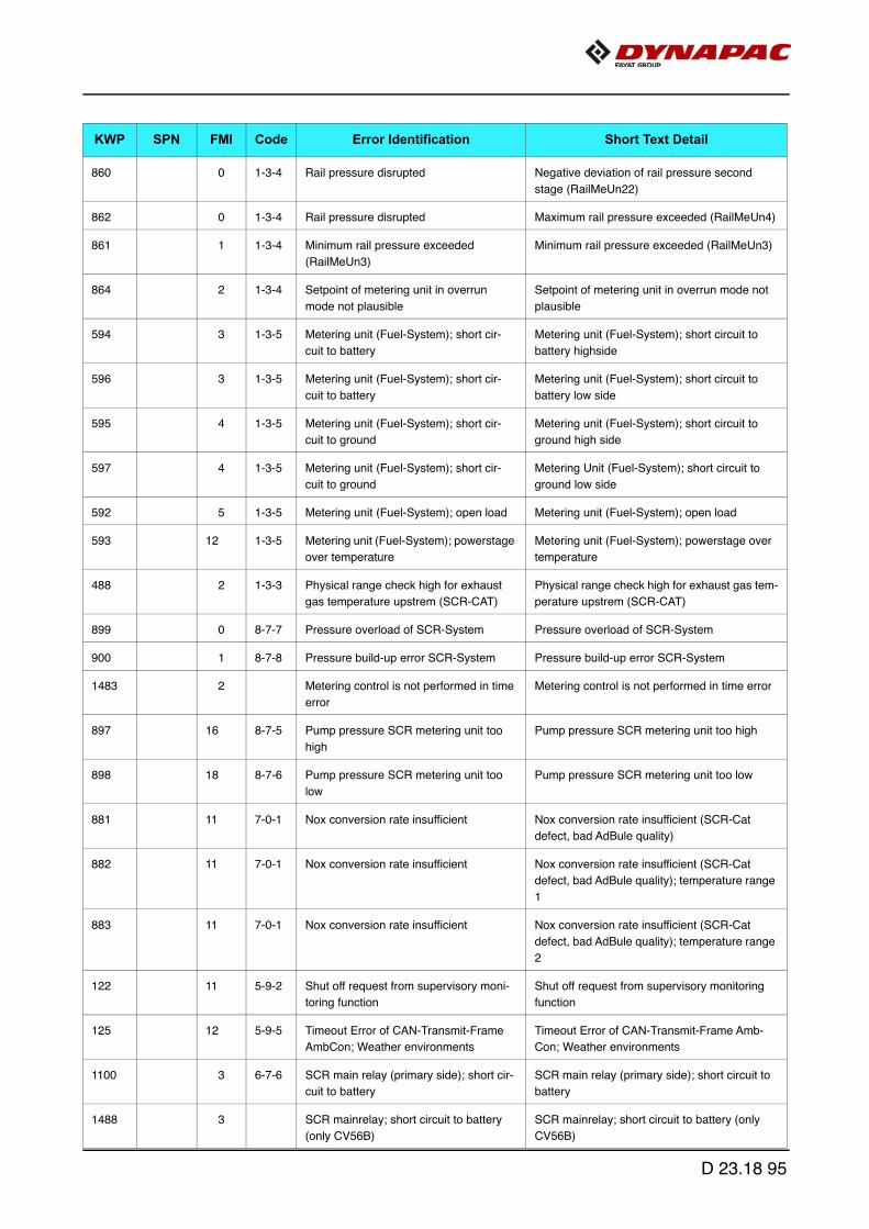
860 0 1-3-4 Rail pressure disrupted Negative deviation of rail pressure second
stage (RailMeUn22)
862 0 1-3-4 Rail pressure disrupted Maximum rail pressure exceeded (RailMeUn4)
861 1 1-3-4 Minimum rail pressure exceeded
(RailMeUn3)
Minimum rail pressure exceeded (RailMeUn3)
864 2 1-3-4 Setpoint of metering unit in overrun
mode not plausible
Setpoint of metering unit in overrun mode not
plausible
594 3 1-3-5 Metering unit (Fuel-System); short cir-
cuit to battery
Metering unit (Fuel-System); short circuit to
battery highside
596 3 1-3-5 Metering unit (Fuel-System); short cir-
cuit to battery
Metering unit (Fuel-System); short circuit to
battery low side
595 4 1-3-5 Metering unit (Fuel-System); short cir-
cuit to ground
Metering unit (Fuel-System); short circuit to
ground high side
597 4 1-3-5 Metering unit (Fuel-System); short cir-
cuit to ground
Metering Unit (Fuel-System); short circuit to
ground low side
592 5 1-3-5 Metering unit (Fuel-System); open load Metering unit (Fuel-System); open load
593 12 1-3-5 Metering unit (Fuel-System); powerstage
over temperature
Metering unit (Fuel-System); powerstage over
temperature
488 2 1-3-3 Physical range check high for exhaust
gas temperature upstrem (SCR-CAT)
Physical range check high for exhaust gas tem-
perature upstrem (SCR-CAT)
899 0 8-7-7 Pressure overload of SCR-System Pressure overload of SCR-System
900 1 8-7-8 Pressure build-up error SCR-System Pressure build-up error SCR-System
1483 2 Metering control is not performed in time
error
Metering control is not performed in time error
897 16 8-7-5 Pump pressure SCR metering unit too
high
Pump pressure SCR metering unit too high
898 18 8-7-6 Pump pressure SCR metering unit too
low
Pump pressure SCR metering unit too low
881 11 7-0-1 Nox conversion rate insufficient Nox conversion rate insufficient (SCR-Cat
defect, bad AdBule quality)
882 11 7-0-1 Nox conversion rate insufficient Nox conversion rate insufficient (SCR-Cat
defect, bad AdBule quality); temperature range
1
883 11 7-0-1 Nox conversion rate insufficient Nox conversion rate insufficient (SCR-Cat
defect, bad AdBule quality); temperature range
2
122 11 5-9-2 Shut off request from supervisory moni-
toring function
Shut off request from supervisory monitoring
function
125 12 5-9-5 Timeout Error of CAN-Transmit-Frame
AmbCon; Weather environments
Timeout Error of CAN-Transmit-Frame Amb-
Con; Weather environments
1100 3 6-7-6 SCR main relay (primary side); short cir-
cuit to battery
SCR main relay (primary side); short circuit to
battery
1488 3 SCR mainrelay; short circuit to battery
(only CV56B)
SCR mainrelay; short circuit to battery (only
CV56B)
KWP SPN FMI Code Error Identification Short Text Detail
D 23.18 95
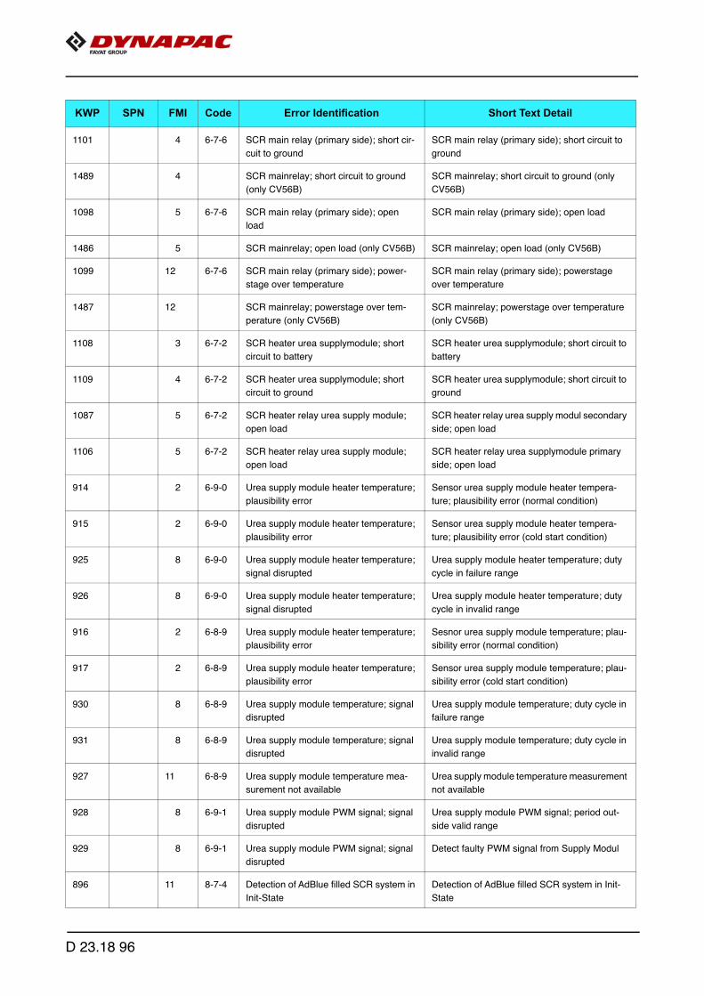
1101 4 6-7-6 SCR main relay (primary side); short cir-
cuit to ground
SCR main relay (primary side); short circuit to
ground
1489 4 SCR mainrelay; short circuit to ground
(only CV56B)
SCR mainrelay; short circuit to ground (only
CV56B)
1098 5 6-7-6 SCR main relay (primary side); open
load
SCR main relay (primary side); open load
1486 5 SCR mainrelay; open load (only CV56B) SCR mainrelay; open load (only CV56B)
1099 12 6-7-6 SCR main relay (primary side); power-
stage over temperature
SCR main relay (primary side); powerstage
over temperature
1487 12 SCR mainrelay; powerstage over tem-
perature (only CV56B)
SCR mainrelay; powerstage over temperature
(only CV56B)
1108 3 6-7-2 SCR heater urea supplymodule; short
circuit to battery
SCR heater urea supplymodule; short circuit to
battery
1109 4 6-7-2 SCR heater urea supplymodule; short
circuit to ground
SCR heater urea supplymodule; short circuit to
ground
1087 5 6-7-2 SCR heater relay urea supply module;
open load
SCR heater relay urea supply modul secondary
side; open load
1106 5 6-7-2 SCR heater relay urea supply module;
open load
SCR heater relay urea supplymodule primary
side; open load
914 2 6-9-0 Urea supply module heater temperature;
plausibility error
Sensor urea supply module heater tempera-
ture; plausibility error (normal condition)
915 2 6-9-0 Urea supply module heater temperature;
plausibility error
Sensor urea supply module heater tempera-
ture; plausibility error (cold start condition)
925 8 6-9-0 Urea supply module heater temperature;
signal disrupted
Urea supply module heater temperature; duty
cycle in failure range
926 8 6-9-0 Urea supply module heater temperature;
signal disrupted
Urea supply module heater temperature; duty
cycle in invalid range
916 2 6-8-9 Urea supply module heater temperature;
plausibility error
Sesnor urea supply module temperature; plau-
sibility error (normal condition)
917 2 6-8-9 Urea supply module heater temperature;
plausibility error
Sensor urea supply module temperature; plau-
sibility error (cold start condition)
930 8 6-8-9 Urea supply module temperature; signal
disrupted
Urea supply module temperature; duty cycle in
failure range
931 8 6-8-9 Urea supply module temperature; signal
disrupted
Urea supply module temperature; duty cycle in
invalid range
927 11 6-8-9 Urea supply module temperature mea-
surement not available
Urea supply module temperature measurement
not available
928 8 6-9-1 Urea supply module PWM signal; signal
disrupted
Urea supply module PWM signal; period out-
side valid range
929 8 6-9-1 Urea supply module PWM signal; signal
disrupted
Detect faulty PWM signal from Supply Modul
896 11 8-7-4 Detection of AdBlue filled SCR system in
Init-State
Detection of AdBlue filled SCR system in Init-
State
KWP SPN FMI Code Error Identification Short Text Detail
D 23.18 96

281 9 1-1-8 Timeout Error of CAN-Receive-Frame
Active TSC1AE
Timeout Error of CAN-Receive-Frame Active
TSC1AE
282 9 1-1-8 Timeout Error of CAN-Receive-Frame
Passive TSC1AE
Timeout Error of CAN-Receive-Frame Passive
TSC1AE
283 9 1-1-9 Timeout Error of CAN-Receive-Frame
Active TSC1AR
Timeout Error of CAN-Receive-Frame Active
TSC1AR
284 9 1-1-9 Timeout Error of CAN-Receive-Frame
Passive TSC1AR
Timeout Error of CAN-Receive-Frame Passive
TSC1AR
285 9 Timeout Error of CAN-Receive-Frame
Passive TSC1DE
Timeout Error of CAN-Receive-Frame Passive
TSC1DE
291 9 1-1-9 Timeout Error of CAN-Receive-Frame
TSC1TE - active
Timeout Error of CAN-Receive-Frame TSC1TE
- active
292 9 1-1-9 Passive Timeout Error of CAN-Receive-
Frame TSC1TE; Setpoint
Passive Timeout Error of CAN-Receive-Frame
TSC1TE; Setpoint
293 9 1-1-8 Active Timeout Errorof CAN-Receive-
Frame TSC1TR
Active Timeout Errorof CAN-Receive-Frame
TSC1TR
294 9 1-1-8 Passive Timeout Error of CAN-Receive-
Frame TSC1TR
Passive Timeout Error of CAN-Receive-Frame
TSC1TR
1297 0 6-5-5 Turbo charger wastegate; CAN Fehler CAN-Transmit-Frame ComTrbChActr "BusOff-
Satus"; Wastegate
1298 0 6-5-5 Turbo charger wastegate; CAN Fehler CAN-Transmit-Frame ComTrbChActr disable
error; wastegate
1299 0 6-5-5 Turbo charger wastegate; CAN Fehler CAN-Transmit-Frame ComTrbChActr plausibil-
ity error; wastegate
1300 0 6-5-5 Turbo charger wastegate; CAN Fehler Timeout Error of CAN-Transmit-Frame ComTr-
bChActr; Wastegate
299 12 6-5-5 Timeout Error of CAN-Transmit-Frame
TrbCH; Status Wastegate
Timeout Error of CAN-Transmit-Frame TrbCH;
Status Wastegate
202 9 6-7-8 Timeout Error of CAN-Receive-Frame
UAA10; AGS sensor service message
Timeout Error of CAN-Receive-Frame UAA10;
AGS sensor service message
203 9 6-7-8 Timeout Error of CAN-Receive-Frame
UAA11; AGS sensor data
Timeout Error of CAN-Receive-Frame UAA11;
AGS sensor data
212 9 6-7-8 Timeout Error of CAN-Receive-Frame
RxEngPres; Status burner airpump
Timeout Error of CAN-Receive-Frame RxEng-
Pres; Status burner airpump
322 12 6-7-9 Timeout Error of CAN-Transmit-Frame
UAA1 on CAN 2; Burner Air Pump Con-
trol
Timeout Error of CAN-Transmit-Frame UAA1
on CAN 2; Burner Air Pump Control
559 13 7-0-6 Check of missing injector adjustment
value programming (IMA) injector 1 (in
firing order)
Check of missing injector adjustment value pro-
gramming (IMA) injector 1 (in firing order)
560 13 7-0-7 check of missing injector adjustment
value programming (IMA) injector 2 (in
firing order)
check of missing injector adjustment value pro-
gramming (IMA) injector 2 (in firing order)
561 13 7-0-8 check of missing injector adjustment
value programming (IMA) injector 3 (in
firing order)
check of missing injector adjustment value pro-
gramming (IMA) injector 3 (in firing order)
KWP SPN FMI Code Error Identification Short Text Detail
D 23.18 97
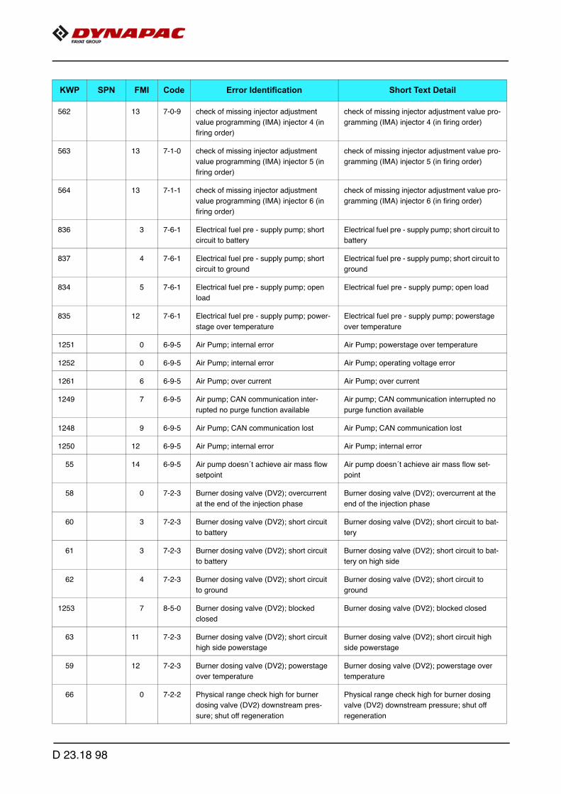
562 13 7-0-9 check of missing injector adjustment
value programming (IMA) injector 4 (in
firing order)
check of missing injector adjustment value pro-
gramming (IMA) injector 4 (in firing order)
563 13 7-1-0 check of missing injector adjustment
value programming (IMA) injector 5 (in
firing order)
check of missing injector adjustment value pro-
gramming (IMA) injector 5 (in firing order)
564 13 7-1-1 check of missing injector adjustment
value programming (IMA) injector 6 (in
firing order)
check of missing injector adjustment value pro-
gramming (IMA) injector 6 (in firing order)
836 3 7-6-1 Electrical fuel pre - supply pump; short
circuit to battery
Electrical fuel pre - supply pump; short circuit to
battery
837 4 7-6-1 Electrical fuel pre - supply pump; short
circuit to ground
Electrical fuel pre - supply pump; short circuit to
ground
834 5 7-6-1 Electrical fuel pre - supply pump; open
load
Electrical fuel pre - supply pump; open load
835 12 7-6-1 Electrical fuel pre - supply pump; power-
stage over temperature
Electrical fuel pre - supply pump; powerstage
over temperature
1251 0 6-9-5 Air Pump; internal error Air Pump; powerstage over temperature
1252 0 6-9-5 Air Pump; internal error Air Pump; operating voltage error
1261 6 6-9-5 Air Pump; over current Air Pump; over current
1249 7 6-9-5 Air pump; CAN communication inter-
rupted no purge function available
Air pump; CAN communication interrupted no
purge function available
1248 9 6-9-5 Air Pump; CAN communication lost Air Pump; CAN communication lost
1250 12 6-9-5 Air Pump; internal error Air Pump; internal error
55 14 6-9-5 Air pump doesn´t achieve air mass flow
setpoint
Air pump doesn´t achieve air mass flow set-
point
58 0 7-2-3 Burner dosing valve (DV2); overcurrent
at the end of the injection phase
Burner dosing valve (DV2); overcurrent at the
end of the injection phase
60 3 7-2-3 Burner dosing valve (DV2); short circuit
to battery
Burner dosing valve (DV2); short circuit to bat-
tery
61 3 7-2-3 Burner dosing valve (DV2); short circuit
to battery
Burner dosing valve (DV2); short circuit to bat-
tery on high side
62 4 7-2-3 Burner dosing valve (DV2); short circuit
to ground
Burner dosing valve (DV2); short circuit to
ground
1253 7 8-5-0 Burner dosing valve (DV2); blocked
closed
Burner dosing valve (DV2); blocked closed
63 11 7-2-3 Burner dosing valve (DV2); short circuit
high side powerstage
Burner dosing valve (DV2); short circuit high
side powerstage
59 12 7-2-3 Burner dosing valve (DV2); powerstage
over temperature
Burner dosing valve (DV2); powerstage over
temperature
66 0 7-2-2 Physical range check high for burner
dosing valve (DV2) downstream pres-
sure; shut off regeneration
Physical range check high for burner dosing
valve (DV2) downstream pressure; shut off
regeneration
KWP SPN FMI Code Error Identification Short Text Detail
D 23.18 98

69 1 7-2-2 Physical range check low for burner dos-
ing valve (DV2) downstream pressure;
shut off regeneration. When burner injec-
tor is actuated, the measured pressure
does not rise above ca. 1250mbar abs
(expected: ca. 2400mbar).
Physical range check low for burner dosing
valve (DV2) downstream pressure; shut off
regeneration. When burner injector is actuated,
the measured pressure does not rise above ca.
1250mbar abs (expected: ca. 2400mbar).
64 2 7-2-2 Burner dosing valve (DV2) downstream
pressure sensor; plausibility error
Burner dosing valve (DV2) downstream pres-
sure sensor; plausibility error
72 3 7-2-2 Sensor error burner dosing valve (DV2)
downstream pressure sensor; signal
range check high
Sensor error burner dosing valve (DV2) down-
stream pressure sensor; signal range check
high
73 4 7-2-2 Sensor error burner dosing valve (DV2)
downstream pressure sensor; signal
range check low
Sensor error burner dosing valve (DV2) down-
stream pressure sensor; signal range check
low
74 3 7-2-1 Sensor error glow plug control diagnostic
line voltage; signal range check high
Sensor error glow plug control diagnostic line
voltage; signal range check high
75 4 7-2-1 Sensor error glow plug control diagnostic
line voltage; signal range check low
Sensor error glow plug control diagnostic line
voltage; signal range check low
78 3 7-2-1 Glow plug control; short circuit to battery Glow plug control; short circuit to battery
79 4 7-2-1 Glow plug control; short circuit to ground Glow plug control; short circuit to ground
76 5 7-2-1 Glow plug control; open load Glow plug control; open load
1216 5 8-5-1 Glow plug control; open load Glow plug control release line; short circuit
error
1217 11 8-5-1 Glow plug control; internal error Glow plug control; internal error
77 12 7-2-1 Glow plug control; powerstage over tem-
perature
Glow plug control; powerstage over tempera-
ture
500 0 7-2-0 HCI dosing valve (DV1); overcurrent at
the end of the injection phase
HCI dosing valve (DV1); overcurrent at the end
of the injection phase
502 3 7-2-0 HCI dosing valve (DV1); short circuit to
battery
HCI dosing valve (DV1); short circuit to battery
503 3 7-2-0 HCI dosing valve (DV1); short circuit to
battery
HCI dosing valve (DV1); short circuit to battery
high side
504 4 7-2-0 HCI dosing valve (DV1); short circuit to
ground
HCI dosing valve (DV1); short circuit to ground
1256 7 8-5-2 HCI dosing valve (DV1); blocked HCI dosing valve (DV1); blocked closed
1257 7 8-5-3 HCI dosing valve (DV1); blocked HCI dosing valve (DV1); blocked open
505 11 7-2-0 HCI dosing valve (DV1); short circuit high
side powerstage
HCI dosing valve (DV1); short circuit high side
powerstage
501 12 7-2-0 HCI dosing valve (DV1); powerstage
over temperature
HCI dosing valve (DV1); powerstage over tem-
perature
508 0 7-1-9 Physical range check high for HCI dosing
valve (DV1) downstream pressure; shut
off regeneration
Physical range check high for HCI dosing valve
(DV1) downstream pressure; shut off regenera-
tion
KWP SPN FMI Code Error Identification Short Text Detail
D 23.18 99

511 1 7-1-9 Physical range check low for HCI dosing
valve (DV1) downstream pressure; shut
off regeneration
Physical range check low for HCI dosing valve
(DV1) downstream pressure; shut off regenera-
tion
506 2 7-1-9 Sensor HCI dosing valve (DV1) down-
stream pressure; plausibility error
Sensor HCI dosing valve (DV1) downstream
pressure; plausibility error
514 3 7-1-9 Sensor error HCI dosing valve (DV1)
downstream pressure; signal range
check high
Sensor error HCI dosing valve (DV1) down-
stream pressure; signal range check high
515 4 7-1-9 Sensor error HCI dosing valve (DV1)
downstream pressure; signal range
check low
Sensor error HCI dosing valve (DV1) down-
stream pressure; signal range check low
518 0 7-1-8 Physical range check high for DV1 &
DV2 upstream pressure; shut off regen-
eration
Physical range check high for DV1 & DV2
upstream pressure; shut off regeneration
521 1 7-1-8 Physical range check low for DV1 & DV2
upstream pressure; shut off regeneration
Physical range check low for DV1 & DV2
upstream pressure; shut off regeneration
516 2 7-1-8 Sensor DV1 & DV2 upstream pressure;
plausibility error
Sensor DV1 & DV2 upstream pressure; plausi-
bility error
524 3 7-1-8 Sensor error DV1 & DV2 upstream pres-
sure; signal range check high
Sensor error DV1 & DV2 upstream pressure;
signal range check high
525 4 7-1-8 Sensor error DV1 & DV2 upstream pres-
sure; signal range check low
Sensor error DV1 & DV2 upstream pressure;
signal range check low
528 0 7-1-7 Physical range check high for DV1 &
DV2 upstream temperature; shut off
regeneration
Physical range check high for DV1 & DV2
upstream temperature; shut off regeneration
531 1 7-1-7 Physical range check low for DV1 & DV2
upstream temperature; shut off regener-
ation
Physical range check low for DV1 & DV2
upstream temperature; shut off regeneration
526 2 7-1-7 Sensor DV1 & DV2 upstream tempera-
ture; plausibility error
Sensor DV1 & DV2 upstream temperature;
plausibility error
534 3 7-1-7 Sensor error DV1 & DV2 upstream tem-
perature; signal range check high
Sensor error DV1 & DV2 upstream tempera-
ture; signal range check high
535 4 7-1-7 Sensor error DV1 & DV2 upstream tem-
perature; signal range check low
Sensor error DV1 & DV2 upstream tempera-
ture; signal range check low
755 0 6-9-4 Physical range check high for airpump
pressure; shut off regeneration
Physical range check high for airpump pres-
sure; shut off regeneration
758 1 6-9-4 Physical range check low for airpump
pressure; shut off regeneration
Physical range check low for airpump pressure;
shut off regeneration
753 2 6-9-4 Sensor airpump pressure; plausibility
error
Sensor airpump pressure; plausibility error
1378 2 6-9-4 Sensor airpump pressure; plausibility
error
Sensor air pump airpressure; plausibility error
761 3 6-9-4 Sensor error airpump pressure; signal
range check high
Sensor error airpump pressure; signal range
check high
762 4 6-9-4 Sensor error airpump pressure; signal
range check low
Sensor error airpump pressure; signal range
check low
KWP SPN FMI Code Error Identification Short Text Detail
D 23.18 100

765 0 7-1-6 Physical range check high for exhaust-
gas back pressure burner; shut off
regeneration
Physical range check high for exhaustgas back
pressure burner; shut off regeneration
768 1 7-1-6 Physical range check low for exhaustgas
back pressure burner; shut off regenera-
tion
Physical range check low for exhaustgas back
pressure burner; shut off regeneration
763 2 7-1-6 Sensor exhaustgas back pressure; plau-
sibility error
Sensor exhaustgas back pressure; plausibility
error
1379 2 7-1-6 Sensor exhaustgas back pressure; plau-
sibility error
Sensor exhaust gas back pressure burner;
plausibility error
770 3 7-1-6 Sensor error exhaustgas back pressure
burner; signal range check high
Sensor error exhaustgas back pressure burner;
signal range check high
771 4 7-1-6 Sensor error exhaustgas back pressure
burner; signal range check low
Sensor error exhaustgas back pressure burner;
signal range check low
986 0 7-1-4 Physical range check high for burner
temperature
Physical range check high for burner tempera-
ture
989 1 7-1-4 Physical range check low for burner tem-
perature
Physical range check low for burner tempera-
ture
1395 2 7-1-4 Sensor burner temperature; plausibility
error
Sensor burner temperature; plausibility error
942 3 7-1-4 Sensor error burner temperature; signal
range check high
Sensor error burner temperature; signal range
check high
944 4 7-1-4 Sensor error burner temperature; signal
range check low
Sensor error burner temperature; signal range
check low
984 11 7-1-4 Sensor burner temperature; plausibility
error
Sensor burner temperature; plausibility error
965 3 7-1-5 Burner shut of valve; short circuit to bat-
tery
Burner shut of valve; short circuit to battery
967 4 7-1-5 Burner shut of valve; short circuit to
ground
Burner shut of valve; short circuit to ground
1392 4 7-1-5 Burner shut of valve; short circuit to
ground
Burner Shut Off Valve; short circuit to ground
963 5 7-1-5 Burner shut off valve; open load Burner shut off valve; open load
1389 5 7-1-5 Burner Shut Off Valve; open load Burner Shut Off Valve; open load
1262 7 8-5-4 Shut off valve: blocked Burner Shut Off Valve; blocked closed
1264 7 8-5-5 Shut off valve: blocked Burner Shut Off Valve; blocked open
1192 12 Over temperature error on burner shut of
valve
Over temperature error on burner shut of valve
1390 12 7-1-5 Over temperature error on burner shut of
valve
Burner Shut Off Valve; powerstage over tem-
perature
36 3 7-2-9 UB1; Short circuit to battery error of actu-
ator relay 1
UB1; Short circuit to battery error of actuator
relay 1
37 3 7-3-0 UB2; Short circuit to battery error of actu-
ator relay 2
UB2; Short circuit to battery error of actuator
relay 2
KWP SPN FMI Code Error Identification Short Text Detail
D 23.18 101
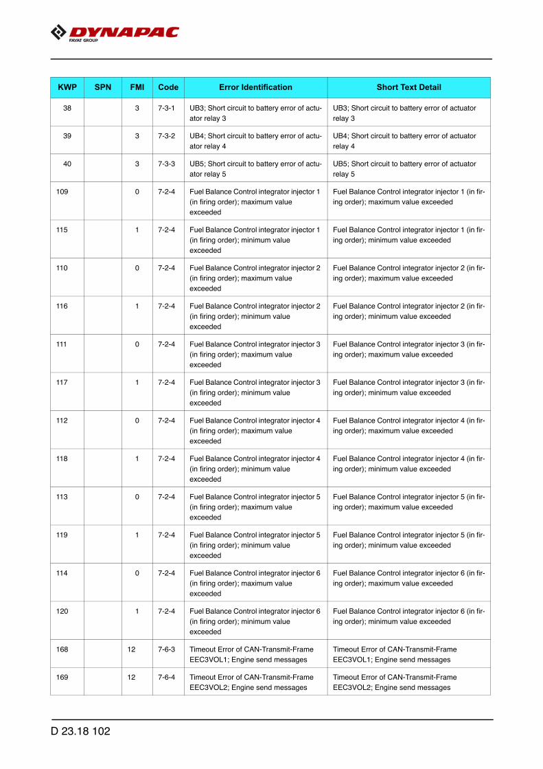
38 3 7-3-1 UB3; Short circuit to battery error of actu-
ator relay 3
UB3; Short circuit to battery error of actuator
relay 3
39 3 7-3-2 UB4; Short circuit to battery error of actu-
ator relay 4
UB4; Short circuit to battery error of actuator
relay 4
40 3 7-3-3 UB5; Short circuit to battery error of actu-
ator relay 5
UB5; Short circuit to battery error of actuator
relay 5
109 0 7-2-4 Fuel Balance Control integrator injector 1
(in firing order); maximum value
exceeded
Fuel Balance Control integrator injector 1 (in fir-
ing order); maximum value exceeded
115 1 7-2-4 Fuel Balance Control integrator injector 1
(in firing order); minimum value
exceeded
Fuel Balance Control integrator injector 1 (in fir-
ing order); minimum value exceeded
110 0 7-2-4 Fuel Balance Control integrator injector 2
(in firing order); maximum value
exceeded
Fuel Balance Control integrator injector 2 (in fir-
ing order); maximum value exceeded
116 1 7-2-4 Fuel Balance Control integrator injector 2
(in firing order); minimum value
exceeded
Fuel Balance Control integrator injector 2 (in fir-
ing order); minimum value exceeded
111 0 7-2-4 Fuel Balance Control integrator injector 3
(in firing order); maximum value
exceeded
Fuel Balance Control integrator injector 3 (in fir-
ing order); maximum value exceeded
117 1 7-2-4 Fuel Balance Control integrator injector 3
(in firing order); minimum value
exceeded
Fuel Balance Control integrator injector 3 (in fir-
ing order); minimum value exceeded
112 0 7-2-4 Fuel Balance Control integrator injector 4
(in firing order); maximum value
exceeded
Fuel Balance Control integrator injector 4 (in fir-
ing order); maximum value exceeded
118 1 7-2-4 Fuel Balance Control integrator injector 4
(in firing order); minimum value
exceeded
Fuel Balance Control integrator injector 4 (in fir-
ing order); minimum value exceeded
113 0 7-2-4 Fuel Balance Control integrator injector 5
(in firing order); maximum value
exceeded
Fuel Balance Control integrator injector 5 (in fir-
ing order); maximum value exceeded
119 1 7-2-4 Fuel Balance Control integrator injector 5
(in firing order); minimum value
exceeded
Fuel Balance Control integrator injector 5 (in fir-
ing order); minimum value exceeded
114 0 7-2-4 Fuel Balance Control integrator injector 6
(in firing order); maximum value
exceeded
Fuel Balance Control integrator injector 6 (in fir-
ing order); maximum value exceeded
120 1 7-2-4 Fuel Balance Control integrator injector 6
(in firing order); minimum value
exceeded
Fuel Balance Control integrator injector 6 (in fir-
ing order); minimum value exceeded
168 12 7-6-3 Timeout Error of CAN-Transmit-Frame
EEC3VOL1; Engine send messages
Timeout Error of CAN-Transmit-Frame
EEC3VOL1; Engine send messages
169 12 7-6-4 Timeout Error of CAN-Transmit-Frame
EEC3VOL2; Engine send messages
Timeout Error of CAN-Transmit-Frame
EEC3VOL2; Engine send messages
KWP SPN FMI Code Error Identification Short Text Detail
D 23.18 102

133 9 7-6-6 Timeout Error (BAM to packet) for CAN-
Receive-Frame AT1IGCVol1 informa-
tion; factors & Sensorcalibration for NOX
Sensor (SCR-system upstream cat;
DPF- system downstream cat)
Timeout Error (BAM to packet) for CAN-
Receive-Frame AT1IGCVol1 information; fac-
tors & Sensorcalibration for NOX Sensor (SCR-
system upstream cat; DPF-system down-
stream cat)
134 9 7-6-6 Timeout Error (BAM to BAM) for CAN-
Receive-Frame AT1IGCVol1 informa-
tion; factors & Sensorcalibration for NOX
Sensor (SCR-system upstream cat;
DPF- system downstream cat)
Timeout Error (BAM to BAM) for CAN-Receive-
Frame AT1IGCVol1 information; factors & Sen-
sorcalibration for NOX Sensor (SCR-system
upstream cat; DPF-system downstream cat)
135 9 7-6-6 Timeout Error (PCK2PCK) for CAN-
Receive-Frame AT1IGCVol1 informa-
tion; factors
& Sensorcalibration for NOX Sensor
(SCR-system upstream cat; DPF-system
downstream cat)
Timeout Error (PCK2PCK) for CAN-Receive-
Frame AT1IGCVol1 information; factors & Sen-
sorcalibration for NOX Sensor (SCR-system
upstream cat; DPF-system downstream cat)
140 9 7-6-7 Timeout Error (BAM to packet) for CAN-
Receive-Frame AT1OGCVol2 informa-
tion; factors & Sensorcalibration for NOX
Sensor (SCR-system downstream cat;
DPF- system downstream cat)
Timeout Error (BAM to packet) for CAN-
Receive-Frame AT1OGCVol2 information; fac-
tors & Sensorcalibration for NOX Sensor (SCR-
system downstream cat; DPF-system down-
stream cat)
141 9 7-6-7 Timeout Error (BAM to BAM) for CAN-
Receive-Frame AT1OGCVol2 informa-
tion; factors & Sensorcalibration for NOX
Sensor (SCR-system downstream cat;
DPF- system downstream cat)
Timeout Error (BAM to BAM) for CAN-Receive-
Frame AT1OGCVol2 information; factors &
Sensorcalibration for NOX Sensor (SCR-sys-
tem downstream cat; DPF-system downstream
cat)
142 9 7-6-7 Timeout Error (PCK2PCK) for CAN-
Receive-Frame AT1OGCVol2 informa-
tion; factors & Sensorcalibration for NOX
Sensor (SCR-system downstream cat;
DPF- system downstream cat)
Timeout Error (PCK2PCK) for CAN-Receive-
Frame AT1OGCVol2 information; factors &
Sensorcalibration for NOX Sensor (SCR-sys-
tem downstream cat; DPF-system downstream
cat)
1158 0 7-7-2 Zerofuel calibration injector 1 (in firing
order); maximum value exceeded
Zerofuel calibration injector 1 (in firing order);
maximum value exceeded
1164 1 7-7-2 Zerofuel calibration injector 1 (in firing
order); minimum value exceeded
Zerofuel calibration injector 1 (in firing order);
minimum value exceeded
1159 0 7-7-2 Zerofuel calibration injector 2 (in firing
order); maximum value exceeded
Zerofuel calibration injector 2 (in firing order);
maximum value exceeded
1165 1 7-7-2 Zerofuel calibration injector 2 (in firing
order); minimum value exceeded
Zerofuel calibration injector 2 (in firing order);
minimum value exceeded
1160 0 7-7-2 Zerofuel calibration injector 3 (in firing
order); maximum value exceeded
Zerofuel calibration injector 3 (in firing order);
maximum value exceeded
1166 1 7-7-2 Zerofuel calibration injector 3 (in firing
order); minimum value exceeded
Zerofuel calibration injector 3 (in firing order);
minimum value exceeded
1161 0 7-7-2 Zerofuel calibration injector 4 (in firing
order); maximum value exceeded
Zerofuel calibration injector 4 (in firing order);
maximum value exceeded
1167 1 7-7-2 Zerofuel calibration injector 4 (in firing
order); minimum value exceeded
Zerofuel calibration injector 4 (in firing order);
minimum value exceeded
1162 0 7-7-2 Zerofuel calibration injector 5 (in firing
order); maximum value exceeded
Zerofuel calibration injector 5 (in firing order);
maximum value exceeded
KWP SPN FMI Code Error Identification Short Text Detail
D 23.18 103

1168 1 7-7-2 Zerofuel calibration injector 5 (in firing
order); minimum value exceeded
Zerofuel calibration injector 5 (in firing order);
minimum value exceeded
1163 0 7-7-2 Zerofuel calibration injector 6 (in firing
order); maximum value exceeded
Zerofuel calibration injector 6 (in firing order);
maximum value exceeded
1169 1 7-7-2 Zerofuel calibration injector 6 (in firing
order); minimum value exceeded
Zerofuel calibration injector 6 (in firing order);
minimum value exceeded
1011 0 7-7-1 EGR cooler downstream temperature;
out of range, system reaction initiated
Physical range check high for EGR cooler
downstream temperature
1458 0 7-7-1 Exhaust gas temperature EGR down-
stream; out of range, system reaction ini-
tiated
High exhaust gas temperature EGR cooler
downstream; warning threshold exceeded
1012 1 7-7-1 EGR cooler downstream temperature;
out of range, system reaction initiated
Physical range check low for EGR cooler
downstream temperature
1459 1 7-7-1 Exhaust gas temperature EGR down-
stream; out of range, system reaction ini-
tiated
High exhaust gas temperature EGR cooler
downstream; shut off threshold exceeded
1013 11 7-7-1 Sensor exhaust gas temperature Ventu-
riunit (EGR); plausibility error
Sensor exhaust gas temperature Venturiunit
(EGR); plausibility error
1173 14 7-7-9 SCR Tamper detection; derating timer
below limit 1
SCR Tamper detection; derating timer below
limit 1
1174 14 7-7-9 SCR Tamper detection; derating timer
below limit 2
SCR Tamper detection; derating timer below
limit 2
1175 14 7-8-0 Urea quality; derating timer below limit 1 Urea quality; derating timer below limit 1
1176 14 7-8-0 Urea qulaity; derating timer below limit 2 Urea qulaity; derating timer below limit 2
1177 14 7-8-1 Urea tank level; derating timer below limit
1
Urea tank level; derating timer below limit 1
1178 14 7-8-1 Urea tank level; derating timer below limit
2
Urea tank level; derating timer below limit 2
1187 14 7-8-4 Bad quality of reduction agent detected Bad quality of reduction agent detected
918 11 Urea-tank without heating function (heat-
ing phase)
Urea-tank without heating function (heating
phase)
360 0 7-3-7 Powerstage diagnosis disabled; high bat-
tery voltage
Powerstage diagnosis disabled; high battery
voltage
361 1 7-3-7 Powerstage diagnosis disabled; low bat-
tery voltage
Powerstage diagnosis disabled; low battery
voltage
1239 3 7-8-8 UB6; Short circuit to battery error of actu-
ator relay 6
UB6; Short circuit to battery error of actuator
relay 7
1240 3 7-8-9 UB7; Short circuit to battery error of actu-
ator relay 7
UB7; Short circuit to battery error of actuator
relay 8
1245 3 7-9-2 Charging lamp; short circuit to battery Charging lamp; short circuit to battery
1246 4 7-9-2 Charging lamp; short circuit to ground Charging lamp; short circuit to ground
1243 5 7-9-2 Charging lamp; open load Charging lamp; open load
1244 12 7-9-2 Charging lamp; over temperature Charging lamp; over temperature
KWP SPN FMI Code Error Identification Short Text Detail
D 23.18 104
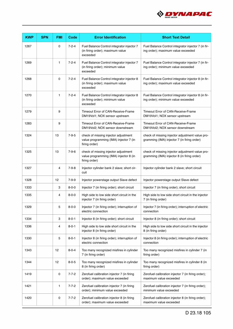
1267 0 7-2-4 Fuel Balance Control integrator injector 7
(in firing order); maximum value
exceeded
Fuel Balance Control integrator injector 7 (in fir-
ing order); maximum value exceeded
1269 1 7-2-4 Fuel Balance Control integrator injector 7
(in firing order); minimum value
exceeded
Fuel Balance Control integrator injector 7 (in fir-
ing order); minimum value exceeded
1268 0 7-2-4 Fuel Balance Control integrator injector 8
(in firing order); maximum value
exceeded
Fuel Balance Control integrator injector 8 (in fir-
ing order); maximum value exceeded
1270 1 7-2-4 Fuel Balance Control integrator injector 8
(in firing order); minimum value
exceeded
Fuel Balance Control integrator injector 8 (in fir-
ing order); minimum value exceeded
1279 9 Timeout Error of CAN-Receive-Frame
DM19Vol1; NOX sensor upstream
Timeout Error of CAN-Receive-Frame
DM19Vol1; NOX sensor upstream
1283 9 Timeout Error of CAN-Receive-Frame
DM19Vol2; NOX sensor downstream
Timeout Error of CAN-Receive-Frame
DM19Vol2; NOX sensor downstream
1324 13 7-9-5 check of missing injector adjustment
value programming (IMA) injector 7 (in
firing order)
check of missing injector adjustment value pro-
gramming (IMA) injector 7 (in firing order)
1325 13 7-9-6 check of missing injector adjustment
value programming (IMA) injector 8 (in
firing order)
check of missing injector adjustment value pro-
gramming (IMA) injector 8 (in firing order)
1327 4 7-9-8 Injector cylinder bank 2 slave; short cir-
cuit
Injector cylinder bank 2 slave; short circuit
1328 12 7-9-9 Injector powerstage output Slave defect Injector powerstage output Slave defect
1333 3 8-0-0 Injector 7 (in firing order); short circuit Injector 7 (in firing order); short circuit
1335 4 8-0-0 High side to low side short circuit in the
injector 7 (in firing order)
High side to low side short circuit in the injector
7 (in firing order)
1329 5 8-0-0 Injector 7 (in firing order); interruption of
electric connection
Injector 7 (in firing order); interruption of electric
connection
1334 3 8-0-1 Injector 8 (in firing order); short circuit Injector 8 (in firing order); short circuit
1336 4 8-0-1 High side to low side short circuit in the
injector 8 (in firing order)
High side to low side short circuit in the injector
8 (in firing order)
1330 5 8-0-1 Injector 8 (in firing order); interruption of
electric connection
Injector 8 (in firing order); interruption of electric
connection
1343 12 8-0-4 Too many recognized misfires in cylinder
7 (in firing order)
Too many recognized misfires in cylinder 7 (in
firing order)
1344 12 8-0-5 Too many recognized misfires in cylinder
8 (in firing order)
Too many recognized misfires in cylinder 8 (in
firing order)
1419 0 7-7-2 Zerofuel calibration injector 7 (in firing
order); maximum value exceeded
Zerofuel calibration injector 7 (in firing order);
maximum value exceeded
1421 1 7-7-2 Zerofuel calibration injector 7 (in firing
order); minimum value exceeded
Zerofuel calibration injector 7 (in firing order);
minimum value exceeded
1420 0 7-7-2 Zerofuel calibration injector 8 (in firing
order); maximum value exceeded
Zerofuel calibration injector 8 (in firing order);
maximum value exceeded
KWP SPN FMI Code Error Identification Short Text Detail
D 23.18 105

1422 1 7-7-2 Zerofuel calibration injector 8 (in firing
order); minimum value exceeded
Zerofuel calibration injector 8 (in firing order);
minimum value exceeded
56 7 8-5-6 Burner operation disturbed Burner flame unintentional deleted
1255 7 8-5-7 Burner operation disturbed Burner operation is interrupted too often
1254 1 8-5-8 Air pressure glow plug flush line; below
limit
Air pressure glow plug flush line; below limit
1259 2 8-5-9 Air Pump; air flow is not plausible Amount of air is not plausible to pump speed
1260 2 8-5-9 Air Pump; air flow is not plausible Calculated amount of air is not plausible to
HFM reading
1258 11 8-5-9 HFM sensor; electrical fault HFM sensor; electrical fault
1265 12 8-6-0 Spark plug control unit (SPCU); internal
error
Spark plug control unit (SPCU); electrical fault
1266 12 8-6-1 Spark plug control unit (SPCU); internal
error
Spark plug control unit (SPCU); internal error
1219 14 7-8-6 DPF wasn´t regenerated, power reduc-
tion phase 1 (manuell regeneration
request)
DPF wasn´t regenerated, power reduction
phase 1 (manuell regeneration request)
1247 11 8-6-2 Air Pump; air lines blocked Air Pump; air lines blocked
57 14 8-6-3 Engine power; Not enough oxygen for
regeneration
Engine power; Not enough oxygen for regener-
ation
1263 11 8-6-4 Burner fuel line pipe leak behind Shut Off
Valve
Burner fuel line pipe leak behind Shut Off Valve
1220 14 7-8-6 DPF wasn´t regenerated, power reduc-
tion phase 2 (manuell regeneration
request)
DPF wasn´t regenerated, power reduction
phase 2 (manuell regeneration request)
1221 14 7-8-6 DPF wasn´t regenerated, warning condi-
tion (manuell regeneration mode)
DPF wasn´t regenerated, warning condition
(manuell regeneration mode)
1302 11 8-6-6 Deviation of the exhaust gas tempera-
ture setpoint to actual value downstream
(DOC) too high
Deviation of the exhaust gas temperature set-
point to actual value downstream (DOC) too
high
1481 5 DPF system; operating voltage error DPF system; operating voltage error
805 14 Particulate filter; regeneration not suc-
cesful
Particulate filter; regeneration not succesful
1431 2 8-1-5 CAN message PROEGRActr; plausibil-
ity error
CAN message PROEGRActr; plausibility error
1432 2 8-1-5 Timeout Error of CAN-Receive-Frame
ComEGRActr - exhaust gas recircula-
tion positioner
Timeout Error of CAN-Receive-Frame ComE-
GRActr - exhaust gas recirculation positioner
1440 7 EGR actuator; internal error EGR actuator; internal error
1441 13 EGR actuator; calibration error EGR actuator; calibration error
1442 2 EGR actuator; status message "EGR-
Cust" is missing
EGR actuator; status message "EGRCust" is
missing
KWP SPN FMI Code Error Identification Short Text Detail
D 23.18 106

1443 7 EGR actuator; due to overload in Save
Mode
EGR actuator; due to overload in Save Mode
1438 3 8-1-6 Disc separator; short circuit to battery Disc separator; short circuit to battery
1439 4 8-1-6 Disc separator; short circuit to ground Disc separator; short circuit to ground
1436 5 8-1-6 Disc Separator; open load Disc Separator; open load
1437 12 8-1-6 Disc Separator; powerstage over tem-
perature
Disc Separator; powerstage over temperature
1341 12 5-5-5 Injector diagnostics; time out error in the
SPI communication
Injector diagnostics; time out error in the SPI
communication
1342 12 Injector diagnostics Slave; time out error
in the SPI communication
Injector diagnostics Slave; time out error in the
SPI communication
1477 3 Ashlamp; short circuit to battery Ashlamp; short circuit to battery
1478 4 Ashlamp; short circuit to ground Ashlamp; short circuit to ground
1474 5 Ashlamp; open load Ashlamp; open load
1285 9 Timeout error of CAN-Receive-Frame
ComMS_Sys1TO (error memory Slave);
Master-Slave internal CAN message
Timeout error of CAN-Receive-Frame
ComMS_Sys1TO (error memory Slave); Mas-
ter-Slave internal CAN message
1286 9 Timeout error of CAN-Receive-Frame
ComMS_Sys2TO (error memory Slave);
Master-Slave internal CAN message
Timeout error of CAN-Receive-Frame
ComMS_Sys2TO (error memory Slave); Mas-
ter-Slave internal CAN message
1287 9 Timeout error of CAN-Receive-Frame
ComMS_Sys3TO (error memory Slave);
Master-Slave internal CAN message
Timeout error of CAN-Receive-Frame
ComMS_Sys3TO (error memory Slave); Mas-
ter-Slave internal CAN message
1288 9 Timeout error of CAN-Receive-Frame
ComMS_Sys4TO (error memory Slave);
Master-Slave internal CAN message
Timeout error of CAN-Receive-Frame
ComMS_Sys4TO (error memory Slave); Mas-
ter-Slave internal CAN message
1289 9 Timeout error of CAN-Receive-Frame
ComMS_Sys5TO (error memory Slave);
Master-Slave internal CAN message
Timeout error of CAN-Receive-Frame
ComMS_Sys5TO (error memory Slave); Mas-
ter-Slave internal CAN message
1290 9 Timeout error of CAN-Receive-Frame
ComMS_Sys6TO (error memory Slave);
Master-Slave internal CAN message
Timeout error of CAN-Receive-Frame
ComMS_Sys6TO (error memory Slave); Mas-
ter-Slave internal CAN message
1482 9 CAN message ComMS_Sys7 not
received from slave
CAN message ComMS_Sys7 not received
from slave
1291 9 Master-Slave CAN; Message-Counter-
Error of CAN-Receive-Frame Com-
MSMoFOvR
Master-Slave CAN; Message-Counter-Error of
CAN-Receive-Frame ComMSMoFOvR
1292 9 Master-Slave CAN; Checksum-Error of
CAN-Receive-Frame ComMSMoFOvR
Master-Slave CAN; Checksum-Error of CAN-
Receive-Frame ComMSMoFOvR
1293 9 Master-Slave CAN; Messsage-Length-
Error of CAN-Receive-Frame Com-
MSMoFOvR
Master-Slave CAN; Messsage-Length-Error of
CAN-Receive-Frame ComMSMoFOvR
1294 9 Timeout error CAN message
ComMSMoFOvR1TO error memory
Slave
Timeout error CAN message
ComMSMoFOvR1TO error memory Slave
KWP SPN FMI Code Error Identification Short Text Detail
D 23.18 107
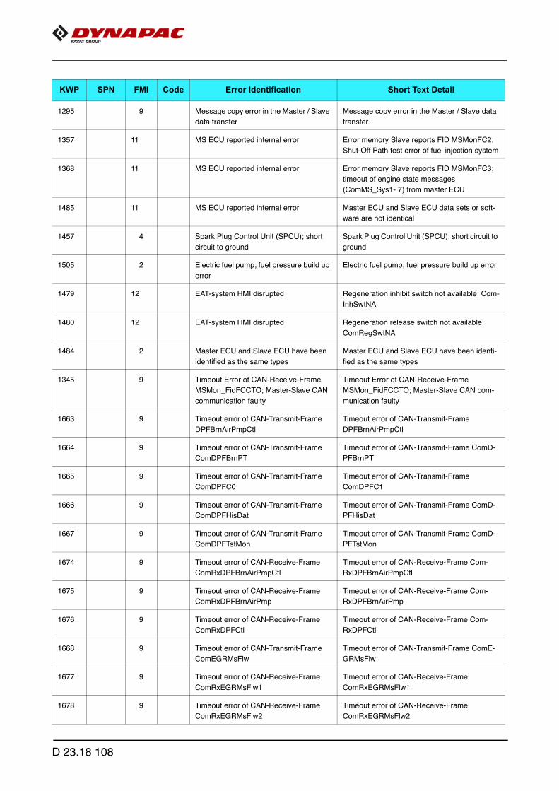
1295 9 Message copy error in the Master / Slave
data transfer
Message copy error in the Master / Slave data
transfer
1357 11 MS ECU reported internal error Error memory Slave reports FID MSMonFC2;
Shut-Off Path test error of fuel injection system
1368 11 MS ECU reported internal error Error memory Slave reports FID MSMonFC3;
timeout of engine state messages
(ComMS_Sys1- 7) from master ECU
1485 11 MS ECU reported internal error Master ECU and Slave ECU data sets or soft-
ware are not identical
1457 4 Spark Plug Control Unit (SPCU); short
circuit to ground
Spark Plug Control Unit (SPCU); short circuit to
ground
1505 2 Electric fuel pump; fuel pressure build up
error
Electric fuel pump; fuel pressure build up error
1479 12 EAT-system HMI disrupted Regeneration inhibit switch not available; Com-
InhSwtNA
1480 12 EAT-system HMI disrupted Regeneration release switch not available;
ComRegSwtNA
1484 2 Master ECU and Slave ECU have been
identified as the same types
Master ECU and Slave ECU have been identi-
fied as the same types
1345 9 Timeout Error of CAN-Receive-Frame
MSMon_FidFCCTO; Master-Slave CAN
communication faulty
Timeout Error of CAN-Receive-Frame
MSMon_FidFCCTO; Master-Slave CAN com-
munication faulty
1663 9 Timeout error of CAN-Transmit-Frame
DPFBrnAirPmpCtl
Timeout error of CAN-Transmit-Frame
DPFBrnAirPmpCtl
1664 9 Timeout error of CAN-Transmit-Frame
ComDPFBrnPT
Timeout error of CAN-Transmit-Frame ComD-
PFBrnPT
1665 9 Timeout error of CAN-Transmit-Frame
ComDPFC0
Timeout error of CAN-Transmit-Frame
ComDPFC1
1666 9 Timeout error of CAN-Transmit-Frame
ComDPFHisDat
Timeout error of CAN-Transmit-Frame ComD-
PFHisDat
1667 9 Timeout error of CAN-Transmit-Frame
ComDPFTstMon
Timeout error of CAN-Transmit-Frame ComD-
PFTstMon
1674 9 Timeout error of CAN-Receive-Frame
ComRxDPFBrnAirPmpCtl
Timeout error of CAN-Receive-Frame Com-
RxDPFBrnAirPmpCtl
1675 9 Timeout error of CAN-Receive-Frame
ComRxDPFBrnAirPmp
Timeout error of CAN-Receive-Frame Com-
RxDPFBrnAirPmp
1676 9 Timeout error of CAN-Receive-Frame
ComRxDPFCtl
Timeout error of CAN-Receive-Frame Com-
RxDPFCtl
1668 9 Timeout error of CAN-Transmit-Frame
ComEGRMsFlw
Timeout error of CAN-Transmit-Frame ComE-
GRMsFlw
1677 9 Timeout error of CAN-Receive-Frame
ComRxEGRMsFlw1
Timeout error of CAN-Receive-Frame
ComRxEGRMsFlw1
1678 9 Timeout error of CAN-Receive-Frame
ComRxEGRMsFlw2
Timeout error of CAN-Receive-Frame
ComRxEGRMsFlw2
KWP SPN FMI Code Error Identification Short Text Detail
D 23.18 108

1669 9 Timeout error of CAN-Transmit-Frame
ComEGRTVActr
Timeout error of CAN-Transmit-Frame ComE-
GRTVActr
1679 9 Timeout error of CAN-Receive-Frame
ComRxEGRTVActr
Timeout error of CAN-Receive-Frame ComRx-
EGRTVActr
1670 9 Timeout error of CAN-Transmit-Frame
ComETVActr
Timeout error of CAN-Transmit-Frame ComET-
VActr
1680 9 Timeout error of CAN-Receive-Frame
ComRxETVActr
Timeout error of CAN-Receive-Frame ComRx-
ETVActr
1671 9 Timeout ComITVActr Timeout ComITVActr
1681 9 Timeout error of CAN-Receive-Frame
ComRxITVActr
Timeout error of CAN-Receive-Frame ComRx-
ITVActr
1659 9 Timeout error of CAN-Transmit-Frame
A1DOC
Timeout error of CAN-Transmit-Frame A1DOC
1660 9 Timeout error of CAN-Transmit-Frame
AT1S
Timeout error of CAN-Transmit-Frame AT1S
1661 9 Timeout error of CAN-Transmit-Frame
SCR2
Timeout error of CAN-Transmit-Frame SCR2
1662 9 Timeout error of CAN-Transmit-Frame
SCR3
Timeout error of CAN-Transmit-Frame SCR3
1672 9 Timeout error of CAN-Receive-Frame
ComRxCM0
Timeout error of CAN-Receive-Frame
ComRxCM1
1673 9 Timeout error of CAN-Receive-Frame
ComRxCustSCR2
Timeout error of CAN-Receive-Frame
ComRxCustSCR3
1682 9 Timeout error of CAN-Receive-Frame
ComRxSCRHtDiag
Timeout error of CAN-Receive-Frame ComRx-
SCRHtDiag
1683 9 Timeout error of CAN-Receive-Frame
ComRxTrbChActr
Timeout error of CAN-Receive-Frame ComRx-
TrbChActr
1684 9 Timeout error of CAN-Receive-Frame
ComRxUQSens
Timeout error of CAN-Receive-Frame ComRx-
UQSens
KWP SPN FMI Code Error Identification Short Text Detail
D 23.18 109

3 Menu structure of the setting and display menus
The following illustration shows the menu structure and serves to simplify operationand the procedure in the case of various settings and displays.
D 23.18 110
D 30.18 Operation1 Operating elements on the paver finisher
1.1 Control elements on the operator's control station
Danger of falling from the vehicle
Entering and leaving the vehicle and the driver's seat dur-ing operation poses a risk of falling from the vehicle, which can cause severe to fatal injuries!
- During operation, the operator must be at the intended driver's seat and be seated properly.
- Never jump onto or off a moving vehicle.- Keep accessible surfaces free of any soiling, e.g. operat-
ing substances, to avoid the risk of slipping.- Use the steps provided and hold onto the handrail with
both hands.- Comply with all further information in these instructions
and in the safety manual.
WARNING
D 30.18 1

Protective roof (o)
The protective roof can be raised and lowered with a manual hydraulic pump.
Caution! Possible collision of parts
The following adjustments must be made before lowering the roof:
- Both seat consoles pushed in.- Backrests and armrests of driver's seats tilted forwards. - Operating panel in lowest position and locked with the
vandalism protection facility.- Front window closed.- Engine hood closed.
NOTE
D 30.18 2

Version 1:
A The exhaust pipe is lowered or raised together with the roof.
- Connect the pump lever (1) to the pump (2).
- Tighten bolts (3) on both sides of the roof.
- Set the adjustment lever (4) to the "Raise" or "Lower" position.
- Operate the pump lever (1) until the roof has reached the upper or lower limit position.
- Bolt (3) must be inserted in the corresponding hole on both sides of the roof:
- Position (3a): Roof raised.
- Position (3b): Roof lowered.
A The bolt must be inserted with the alignment as shown and then swivelled against the roofbeam. Possibly adjust the position of the roof with the hand pump to insert the bolt.
- Position (3c): Roof raised.
- Position (3d): Roof lowered.
- Secure bolt with hook (3e)
1
2
4
3b
3e
3a
3
3c 3d
D 30.18 3

Version 2:
- Connect the pump lever (1) to the pump (2).
- Tighten bolts (3) on both sides of the roof.
- Set the adjustment lever (4) to the "Raise" or "Lower" position.
- Operate the pump lever (1) until the roof has reached the upper or lower limit position.
- Bolt (3) must be inserted in the corresponding hole on both sides of the roof:
- Position (3a): Roof raised.
- Position (3b): Roof lowered.
- Secure bolt with split pin (3c).
1
2
3b
3c
3
4
3a
D 30.18 4
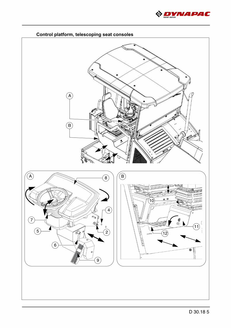
Control platform, telescoping seat consoles
10
B
A
B
11
6
4
5 2
8A
9
7
12
D 30.18 5
Operating panel
The operating panel can be adjusted to the various operating positions: left/right, sit-ting/standing. The entire operating panel can be swivelled for operation beyond theouter edge of the vehicle.
m Make sure it is latched properly!
f Only adjust the operating position whilst the vehicle is stationary!
Pushing the operating panel:
- Release the panel latch (2) and slide the panel console to the required position.
- Insert panel latch (2) into one of the detent positions (4).
Swivelling the operating panel:
- Lift latch (5), swivel operating panel to the required position and allow latch to en-gage again in one of the intended detent positions.
Raise/lower the operating panel:
- Release clamping lever (6), lift or lower operating panel. Tighten clamping lever (6) in required position.
Steering wheel, inclination adjustment (o):
- Press latch (7), swivel steering wheel to the required position and allow latch to en-gage again.
A During longer interruptions and after work has been completed, cover the operatingpanel with the vandalism protection facility (8) and lock in position.
Service brake ("foot brake") (o)
The brake pedal (9) is in front of the driver's seat.
A When the brake is actuated, the speed of the travel drive is automatically reduced (re-gardless of the drive lever position).
- If the vehicle was brought to a standstill with the service brake, it cannot be drivenaway again until after the drive lever has been put into neutral!
D 30.18 6

Seat console
The seat consoles left/right can be moved beyond the outer edge of the vehicle, pro-viding the driver with a better view of the paving area in this position.
- There is a latch at both seat consoles.
- Pull latch (10), extend left or right seat console and allow latch to engage again.
m Make sure it is latched properly!
m When extended, the seat consoles increase the basic width of the paver finisher.
f If the seat consoles are moved, ensure that there is no one in the danger area!
f Only adjust the operating position whilst the vehicle is stationary!
f During transportation in road traffic and when transporting the vehicle on transport-ers, the seat consoles must be secured in the retracted position!
Storage space
There are lockable storage compartments under both left / right seat consoles and inthe middle of the platform (11), (12).
A For storing the on-board tool kit, remote controls and other accessories.
D 30.18 7

Protective roof (o)
The protective roof is equipped with an additional front window and optionally with twoside windows.
- The front window (1) can be swivelled using the handle (3) with the latch pulled (2).To close the front window, pull the latch (2) and pull the sliding frame at the handle (3).
Risk of crushing hands
When closing the spring-loaded front window, there is a risk of crushing which can cause injuries!
- Do not reach into the danger zone.- Set the latches correctly.- Comply with further instructions in the safety manual.
A
B
3
2
4
1
B
A
CAUTION
D 30.18 8

Windscreen wiper
- Engage the windscreen wiper / screen wash on the operating panel if necessary.
A Ensure that the washer fluid tank (4) is always adequately filled.
m Replace worn wiper blades immediately.
Sunshade
A sliding sunshade (5) is available to the left and right of the protective roof to protectthe driver, for example when the seat console is extended.
- Pull the latch (6) and extend the sunshade. Set the latches in one of the intendeddetent positions.
m The sunshade must be retracted again before lowering the roof and for transport onthe low-bed trailer!
Holder for the vandalism protection facility
- Keep the vandalism protection facility in the holder (7) during operation.
6
5
5
7
D 30.18 9

Driver's seat, type I
f To avoid damage to health, the individu-al seat settings should be checked andadjusted before starting the vehicle.
f After locking the individual elements, itmust no longer be possible to shift thento another position.
- Weight setting (1): The relevant driv-er's weight should be set by turningthe weight adjustment lever when thedriver's seat is unoccupied.
- Weight indicator (2): The set driver'sweight can be read off at the viewingwindow.
- Longitudinal adjustment (3): Longi-tudinal adjustment is released by actu-ating the locking lever. The locking lever must engage in the desired position.
- Seat depth adjustment (4): The seat depth can be individually adjusted. Raise thebutton to adjust the seat depth. The desired position is set by simultaneously slidingthe seat surface forwards or backwards.
- Seat inclination adjustment (5): The seat surface's longitudinal inclination can beindividually adjusted. Raise the button to adjust the inclination. The seat surface in-clines to the desired position by simultaneously loading or relieving it.
- Armrest inclination (6): The armrest's longitudinal inclination can be adjusted byturning the hand wheel. Turning outwards raises the front of the armrest; turninginwards lowers it at the front.In addition, the armrests can be folded up fully.
- Lumbar support (7): Both the height and the extent of the convexity in the backrestpadding can be individually adjusted by turning the hand wheel to the left or right.
- Backrest adjustment (8): The backrest is adjusted via the locking lever. The lock-ing lever must engage in the desired position.
- Back extension (9): By pulling out via perceptible detents, the height can be indi-vidually adjusted up to a limit stop. To remove the back extension, the limit stop isovercome with a jolt.
- Seat heating ON/OFF (10): The seat heating is switched on and off by actuatingthe switch.
- Seat belt (11): The seat belt must be applied before starting up the vehicle.
f The seat belts must be replaced following an accident.
3
7
10
4
5
6
6
8
11
1
9
2
D 30.18 10

Driver's seat, type II
f To avoid damage to health, the individu-al seat settings should be checked andadjusted before starting the vehicle.
f After locking the individual elements, itmust no longer be possible to shift thento another position.
- Weight setting (1): The relevant driv-er's weight should be set by turningthe weight adjustment lever when thedriver's seat is unoccupied.
- Weight indicator (2): The set driver'sweight can be read off at the viewingwindow.
- Longitudinal adjustment (3): Longi-tudinal adjustment is released by actu-ating the locking lever. The locking lever must engage in the desired position.
- Seat height adjustment (4): The seat height can be individually adjusted. Turn thehandle in the desired direction to adjust the seat height.
- Backrest adjustment (5): The backrest inclination can be continuously adjusted.Turn the handle in the desired direction to adjust.
- Armrest inclination (6): The armrest's longitudinal inclination can be adjusted byturning the hand wheel. Turning outwards raises the front of the armrest; turninginwards lowers it at the front.In addition, the armrests can be folded up fully.
- Lumbar support (7): Both the height and the extent of the convexity in the backrestpadding can be individually adjusted by turning the hand wheel to the left or right.
- Seat belt (8): The seat belt must be applied before starting up the vehicle.
f The seat belts must be replaced following an accident.
seat4.tif
3
2
4
6
6
8
1
7
5
D 30.18 11

Fuse box
The terminal box, which contains all fus-es and relays, etc. is located beneath thecentral control platform floor panel.
A An assignment plan for fuses and relayscan be found in chapter F8.
D 30.18 12
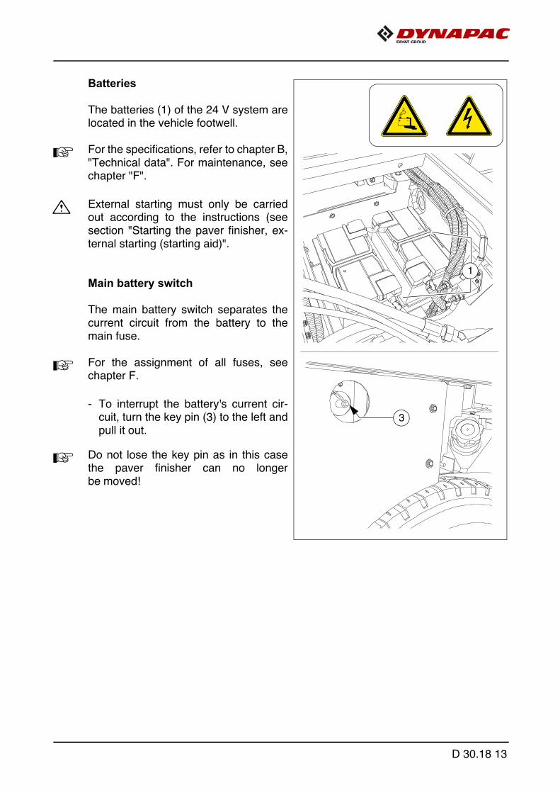
Batteries
The batteries (1) of the 24 V system arelocated in the vehicle footwell.
A For the specifications, refer to chapter B,"Technical data". For maintenance, seechapter "F".
m External starting must only be carriedout according to the instructions (seesection "Starting the paver finisher, ex-ternal starting (starting aid)".
Main battery switch
The main battery switch separates thecurrent circuit from the battery to themain fuse.
A For the assignment of all fuses, seechapter F.
- To interrupt the battery's current cir-cuit, turn the key pin (3) to the left andpull it out.
A Do not lose the key pin as in this casethe paver finisher can no longerbe moved!
1
3
D 30.18 13
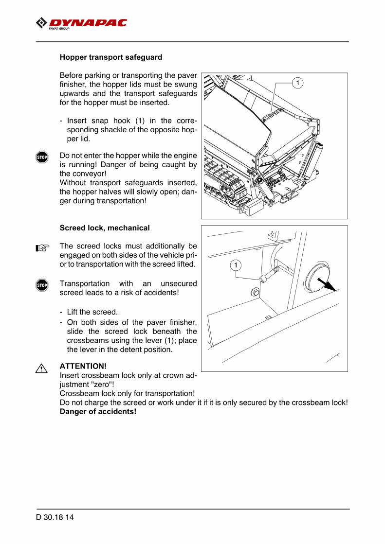
Hopper transport safeguard
Before parking or transporting the paverfinisher, the hopper lids must be swungupwards and the transport safeguardsfor the hopper must be inserted.
- Insert snap hook (1) in the corre-sponding shackle of the opposite hop-per lid.
f Do not enter the hopper while the engineis running! Danger of being caught bythe conveyor!Without transport safeguards inserted,the hopper halves will slowly open; dan-ger during transportation!
Screed lock, mechanical
A The screed locks must additionally beengaged on both sides of the vehicle pri-or to transportation with the screed lifted.
f Transportation with an unsecuredscreed leads to a risk of accidents!
- Lift the screed.
- On both sides of the paver finisher,slide the screed lock beneath thecrossbeams using the lever (1); placethe lever in the detent position.
m ATTENTION!Insert crossbeam lock only at crown ad-justment "zero"!Crossbeam lock only for transportation!Do not charge the screed or work under it if it is only secured by the crossbeam lock!Danger of accidents!
1
1
D 30.18 14

Paving thickness indicator
Two scales, on which the currently setpaving thickness can be read off, are lo-cated on the left and right sides of thevehicle.
- To change the reading position, thescale (1) can be raised and loweredagain in one of the adjacent locatingbores (2).
- The pointer (3) can be swivelled to differ-ent positions using the locking knob (4).
m The scale (1) and pointer (3) must beswivelled in completely to transportthe machine.
A In normal paving situations, the same paving thickness should be set on both sidesof the vehicle!
1
24
3
D 30.18 15

Auger lighting (o)
A Two swivelling headlights (1) are locatedat the back of the vehicle for illuminatingthe auger compartment.
- They are engaged together with theworking lights.
1
D 30.18 16

LED working light (o)
There are two LED spotlights (1) at thefront and rear of the vehicle.
f Always align the working lights to avoiddazzling the operating personnel or oth-er road users!
1
1
D 30.18 17

Mechanical height adjustment, auger (o)
For mechanical adjustment of theauger height
- Set the ratchet direction lever (1) to theclockwise or anti-clockwise direction.Turning anti-clockwise lowers the au-ger, turning clockwise lifts the auger.
- Actuate the ratchet lever (2)
- Set the desired height by alternatinglyactuating the left and right ratchets.
- The current height can be read at thescale (3).
Hydraulic height adjustment:
- Adjust the required height by pressingthe corresponding switch (ope-rating panel).
- The current height can be read atthe scale (4).
A Observe the notes on adjusting the au-ger height in the chapter "Set-up andmodification"!
1
3
2
1
D 30.18 18
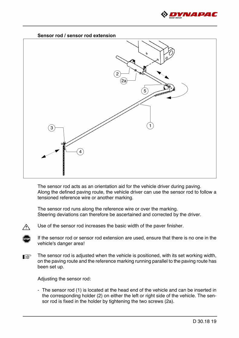
Sensor rod / sensor rod extension
The sensor rod acts as an orientation aid for the vehicle driver during paving.Along the defined paving route, the vehicle driver can use the sensor rod to follow atensioned reference wire or another marking.
The sensor rod runs along the reference wire or over the marking. Steering deviations can therefore be ascertained and corrected by the driver.
m Use of the sensor rod increases the basic width of the paver finisher.
f If the sensor rod or sensor rod extension are used, ensure that there is no one in thevehicle's danger area!
A The sensor rod is adjusted when the vehicle is positioned, with its set working width,on the paving route and the reference marking running parallel to the paving route hasbeen set up.
Adjusting the sensor rod:
- The sensor rod (1) is located at the head end of the vehicle and can be inserted inthe corresponding holder (2) on either the left or right side of the vehicle. The sen-sor rod is fixed in the holder by tightening the two screws (2a).
5
2
4
1
2a
3
D 30.18 19

- Loosen the winged nut (3) to pull the sensor rod extension (4) out for adjustment tothe required length. You can also change the angle by swivelling the joint (5).
m Tighten all assembly parts properly after setting up!
m During transportation, the sensor rod must be swivelled right back and fixed correctly.The max. transport width must not be exceeded!
D 30.18 20

Manual separator fluid spray (o)
Used to spray the parts coming into con-tact with asphalt with a separator emulsion.
- Remove the spray (1) from its bracket.
- Build up pressure by actuating thepump lever (2).
- The pressure is indicated on the ma-nometer (3).
- Actuate the manual valve (4) to spray.
- On completion of work, secure the man-ual spray in its bracket with a lock (5).
f Do not spray into open flame or on hotsurface! Danger of explosion!
5
2
1
22
3
4
D 30.18 21

Separator fluid spraying system (o)
Used to spray the parts coming into con-tact with asphalt with a separator emulsion.
- Connect the spray hose (1) with thehand piece (2).
m Only switch on the spraying systemwhen the diesel engine is running; other-wise, the battery will be discharged.Switch off after use.
- Pull the hose out of the device until aclick is audible. When released, thehose automatically engages here.The hose is automatically retractedinto the guide after pulling and dis-charging again.
- Actuate button (3) to activate and de-activate the pump.
- The indicator lamp (4) lights up whenthe emulsion pump is running.
- Actuate the manual valve (5) to spray.
f Do not spray into open flame or on hotsurface! Danger of explosion!
A The spraying system is fed by a canister(6) at the vehicle step. Check the level atthe sight tube (7).Unscrew the tank cover (8) to fillthe tank.
f Refill the canister only while the vehicleis stationary!
- If the system is not in use, place the spray lance in the holder (9) provided.
6
9
3
7
4
8
1
2
5
D 30.18 22

Conveyor limit switches
The mechanical conveyor limit switches(1) control the material flow on the rele-vant half of the conveyor. The conveyors should stop when thematerial has roughly reached the areabelow the auger tube.
A This requires that the auger height hasbeen adjusted correctly (see chapter E).
A In vehicles with a PLC control system,the deactivation point is set on the re-mote control.
1
D 30.18 23
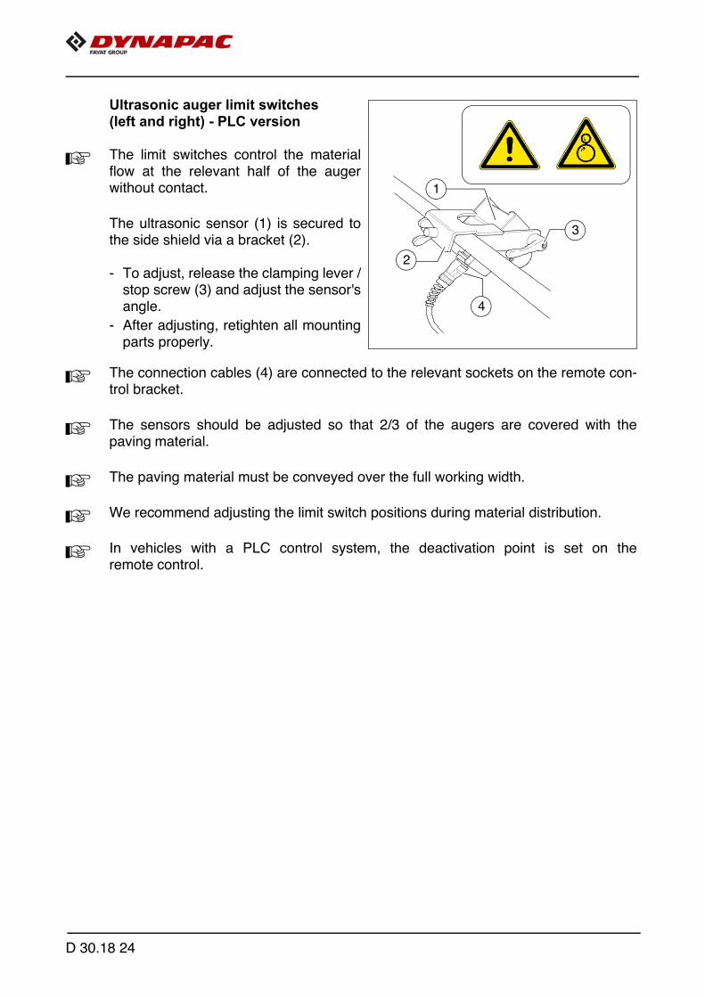
Ultrasonic auger limit switches (left and right) - PLC version
A The limit switches control the materialflow at the relevant half of the augerwithout contact.
The ultrasonic sensor (1) is secured tothe side shield via a bracket (2).
- To adjust, release the clamping lever /stop screw (3) and adjust the sensor'sangle.
- After adjusting, retighten all mountingparts properly.
A The connection cables (4) are connected to the relevant sockets on the remote con-trol bracket.
A The sensors should be adjusted so that 2/3 of the augers are covered with thepaving material.
A The paving material must be conveyed over the full working width.
A We recommend adjusting the limit switch positions during material distribution.
A In vehicles with a PLC control system, the deactivation point is set on theremote control.
1
2
4
3
D 30.18 24

Ultrasonic auger limit switches (left and right) - conventional version
A The limit switches control the materialflow at the relevant half of the augerwithout contact.
The ultrasonic sensor (1) is secured tothe side shield via a bracket (2).
- To adjust the sensor angle, loosen theclamps (3) and swivel the bracket.
- To set the sensor height / the deacti-vation point, loosen the star handles(4) and adjust the linkage to the re-quired length.
- After adjusting, retighten all mountingparts properly.
A The connection cables are connected tothe relevant sockets on the remote con-trol bracket.
A The sensors should be adjusted so that2/3 of the augers are covered with thepaving material.
A The paving material must be conveyed over the full working width.
A We recommend adjusting the limit switch positions during material distribution.
4
3
1
2
D 30.18 25
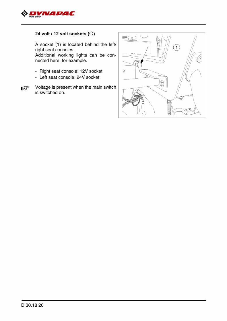
24 volt / 12 volt sockets (o)
A socket (1) is located behind the left/right seat consoles.Additional working lights can be con-nected here, for example.
- Right seat console: 12V socket
- Left seat console: 24V socket
A Voltage is present when the main switchis switched on.
1
D 30.18 26

Central lubrication system (o)
A The central lubrication system is locatedunder the maintenance flap on the oper-ator's platform.
m The pumping interval adjusted in the facto-ry must be modified to the paving situation.
A Changing the duration of lubrication andbreaks may be necessary when layingmineral or cement bound material mix.
A The adjustment is carried out in the vehi-cle control (display) for PLC vehicles.
D 30.18 27

Pressure control valve for pavingstop with relief
Adjusts the pressure for the screen con-trol with paving stop - "floating stop withrelief".
A Is engaged automatically with paving stop.
- Pressure adjustment with valve (1).
A Lock the valve with the correspondingnut after making the adjustment!
- For pressure indication, see mano-meter (2).
2 1
D 30.18 28
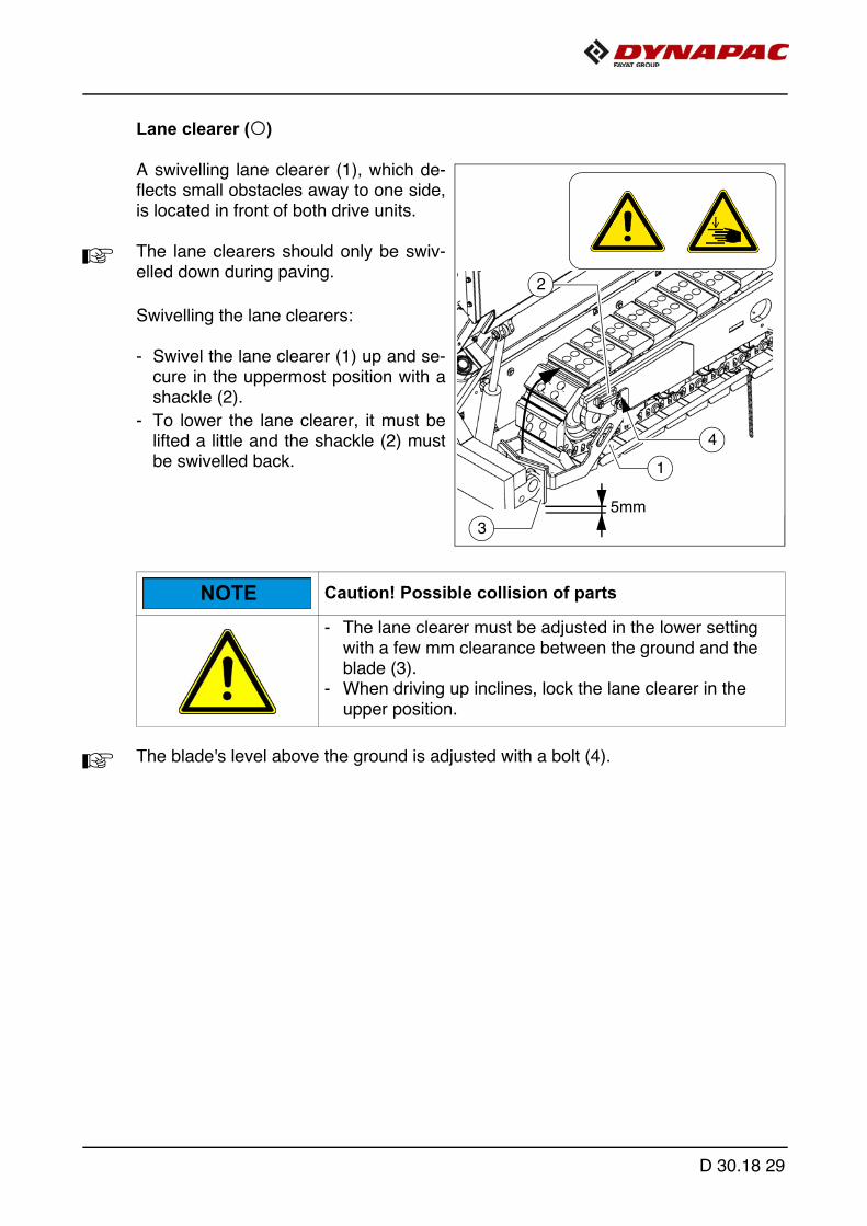
Lane clearer (o)
A swivelling lane clearer (1), which de-flects small obstacles away to one side,is located in front of both drive units.
A The lane clearers should only be swiv-elled down during paving.
Swivelling the lane clearers:
- Swivel the lane clearer (1) up and se-cure in the uppermost position with ashackle (2).
- To lower the lane clearer, it must belifted a little and the shackle (2) mustbe swivelled back.
A The blade's level above the ground is adjusted with a bolt (4).
Caution! Possible collision of parts
- The lane clearer must be adjusted in the lower setting with a few mm clearance between the ground and the blade (3).
- When driving up inclines, lock the lane clearer in the upper position.
2
3
5mm
1
4
NOTE
D 30.18 29
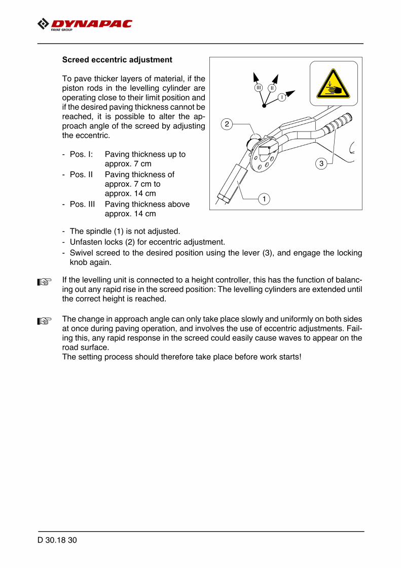
Screed eccentric adjustment
To pave thicker layers of material, if thepiston rods in the levelling cylinder areoperating close to their limit position andif the desired paving thickness cannot bereached, it is possible to alter the ap-proach angle of the screed by adjustingthe eccentric.
- Pos. I: Paving thickness up toapprox. 7 cm
- Pos. II Paving thickness of approx. 7 cm to approx. 14 cm
- Pos. III Paving thickness above approx. 14 cm
- The spindle (1) is not adjusted.
- Unfasten locks (2) for eccentric adjustment.
- Swivel screed to the desired position using the lever (3), and engage the lockingknob again.
A If the levelling unit is connected to a height controller, this has the function of balanc-ing out any rapid rise in the screed position: The levelling cylinders are extended untilthe correct height is reached.
A The change in approach angle can only take place slowly and uniformly on both sidesat once during paving operation, and involves the use of eccentric adjustments. Fail-ing this, any rapid response in the screed could easily cause waves to appear on theroad surface.The setting process should therefore take place before work starts!
2
III II
I
1
3
D 30.18 30

Push roller crossbar, adjustable
For adaptation to various truck design types, the push roller crossbar (1) can be shift-ed to two positions.
A The adjustment travel is 60mm.
- Close the hopper halves to lift the hopper flap (o).
- After removing the bolts (3), remove the locking plate (2) on the lower side ofthe crossbar.
- Remove insert plate (4).
- Remove bolt (5).
- Move the push roller crossbar as far as it will go to the front / rear position.
A Shift the push roller crossbar at the towing eye or use a suitable assembly lever in itsguide (left and right) to push it into the corresponding position.
- Turn the bolt (5) 180° and reinsert in the front or rear position.
- Turn the insert plate (5) 180° and reinsert into the groove in the front orrear position.
- Properly reinstall the locking plate (2) with bolts (3).
32
1
4
180°
4180°
D 30.18 31

Push roller damping, hydraulic (o)
A Push roller damping hydraulically absorbs the shocks between the material truck andpaver finisher.
- Activate the function on the operating panel as necessary.
D 30.18 32

Fire extinguisher (o)
A The paver finisher personnel must be fa-miliarised with operation of the fire extin-guisher (1).
A Observe the inspection interval for thefire extinguisher!
First-aid kit (o)
f Any dressings that have been used mustbe replaced immediately!
A Heed the expiry date of the first-aid kit!
1
1
D 30.18 33
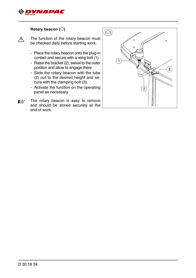
Rotary beacon (o)
m The function of the rotary beacon mustbe checked daily before starting work.
- Place the rotary beacon onto the plug-incontact and secure with a wing bolt (1).
- Raise the bracket (2), swivel to the outerposition and allow to engage there
- Slide the rotary beacon with the tube(2) out to the desired height and se-cure with the clamping bolt (3).
- Activate the function on the operatingpanel as necessary.
A The rotary beacon is easy to removeand should be stored securely at theend of work.
(o)
3
2
1
D 30.18 34

D 30.18 35
Illuminated balloon (o)
2
3
1
5
4
98
11
6
7
10
D 30.18 36
The illuminated balloon generates shadow-reducing and anti-dazzle light.
f The illuminated balloon makes the paver finisher higher and wider.
f Note the passage height of bridges and tunnels and the enlarged vehicle width.
f Always disconnect the power supply before working on the illuminated balloon!
f Never look directly in the balloon when it is switched on!
f The illuminated balloon must not be used in the vicinity of highly flammable materials(e.g. petrol and gas); a safety distance of at least 1 metre must be maintained fromcombustible materials.
f Ensure that the area above the balloon is free and open without any power lines andhindrances. There should be a linear distance of at least 50 m between overhead highvoltage power lines and the illuminated balloon. There should be a distance ofat least 2.5 m between overhead power lines and railway tracks with overhead lineson the one hand, and the balloon on the other.
f The illuminated balloon must not be operated if there is any damage to the electricsupply cables or connectors, the lamp or the balloon skin.
m Never operate the balloon unattended!

D 30.18 37
Installation and operation
- Install the bracket (1) at the vehicle step (3) using the corresponding assembly ma-terial (2).
- Fasten the illuminated balloon (4) to the holding tube (5) and tighten the clampingbolt (6).
- Guide the holding tube (5) into the premounted holder (1) and tighten the clampinglever (7) correctly to fix the holding tube.
- With one hand on the handle flagged in green (8), pull down hard to open the bal-loon before putting it into operation. When the balloon has been pulled down completely as far as it will go, a safetybrace (9) hinges out of the guide rod.
- Once the illuminated balloon is completely mounted and secured, connectthe plug (10) of the illuminated balloon in the corresponding switch cabinetsockets (11).
m Never adjust the holding tube while the illuminated balloon is in operation.
A Operation of the switch cabinet - see screed operating instructions.
m Route the supply lines so as to rule out any risk of stumbling or damage to the lines.
Danger due to electric shock
Electric shock can cause severe or fatal injuries- The Powermoon must always be completely unpacked,
assembled and aligned before it is connected to the power grid and switched on!
Danger of squeezing!
Fingers or hands can get clamped between the bracket and the holding tube!
- Caution when inserting the holding tube!
CAUTION
CAUTION

D 30.18 38
Decommissioning
- Switch off the illuminated balloon on the switch cabinet.- Disconnect the power plug from the socket (10).- To dismantle the Powermoon, pull the cable down and hinge in the safety brace (8)
until it disappears in the guide rod. Now carefully release the pressure on the cable and hinge the Powermoon down.
- Fold the Powermoon up and store in dry condition in the correspondingtransport cover.
Cleaning
m A damp cloth may be used to wipe down the Powermoon skins. Dishwashing deter-gent is recommended as the cleaning agent for the upper and lower skin. Never useaggressive cleaners such as cleaning solvent, turpentine or other products that couldcorrode the material.
Service safety
Danger due to electric shock
Electric shock can cause severe or fatal injuries- Do not start to dismantle the Powermoon until
it has been disconnected from the power grid!
High voltage! Danger due to electric shock
This unit uses high-voltage circuits that can cause severe or fatal injuries!- Only qualified electricians may be entrusted with
troubleshooting or repairing any electrical problems with this device. Only skilled staff are allowed to open the LED body. The capacitor circuit must be discharged.
CAUTION
CAUTION
D 43.18 Mode of operation1 Preparing for operation
Required devices and aids
To avoid delays on site, check before starting work whether or not the following de-vices and aids are present:
- Wheel loader for transporting heavy extension parts
- Diesel fuel
- Engine oil and hydraulic oil, lubricants
- Separator fluids (emulsion) and manual injector
- Two filled propane gas bottles
- Shovel and broom
- Scraper (spatula) for cleaning the auger and the hopper infeed area
- Parts that may become necessary for extending the auger
- Parts that may become necessary for extending the screed
- Percentage spirit level + levelling rail, 4 m long
- Levelling wire
- Protective clothing, signal vest, gloves, ear protection
D 43.18 1

Danger due to restricted vision
Restricted vision poses a risk of injury!
- Before starting work, arrange the intended driver's seat to ensure adequate vision.
- Signalmen must be used when vision is restricted, also to the sides and when reversing.
- Only reliable persons may be used as signalmen who must have been received instructions about their task before taking up their activity. This refers in particular to the hand signals to be used. Standardised hand signals must be used.
- Adequate lighting must be provided when working at night.
- Comply with all further information in these instructions and in the safety manual.
Danger of falling from the vehicle
Entering and leaving the vehicle and the driver's seat dur-ing operation poses a risk of falling from the vehicle, which can cause severe to fatal injuries!
- The operator must be at the intended driver's seat during operation.
- Never jump onto or off a moving vehicle.- Keep accessible surfaces free of any soiling, e.g. operat-
ing substances, to avoid the risk of slipping.- Use the steps provided and hold onto the handrail with
both hands.- Comply with all further information in these instructions
and in the safety manual.
CAUTION
WARNING
D 43.18 2

Before starting work(in the morning or when starting paving)
- Heed the safety instructions.
- Check the personal protective equipment .
- Take an inspection walk around the paver finisher and check for leaksand damages.
- Install parts removed for transportation or for the night.
- When screed is operated with the optional gas heating system, open the closingvalves and the main shut-off valve.
- Perform the check according to the following "Checklist for the machine operator".
Check list for the machine operator
Check! How?
Emergency stop button - on the operating panel - on both remote controls
Push in the button. The diesel engine and all running drives must stop immediately.
Steering
The paver finisher must immediately fol-low every steering wheel movement in a precise manner. Check straight ahead travel.
Horn - On the operating panel- on both remote controls
Briefly press the horn button. Horn signal must sound.
LightsSwitch on with the ignition key, walk around the paver finisher to check and switch off again.
Screed hazard flasher (with vario screeds)
With the ignition switched on, press the switches for extending/retracting the screed parts. Hazard warning flashers must flash.
Gas heater system (o): - Bottle holder - Bottle valve - Pressure reducer - Hose rupture protection - Closing valve - Main shut-off valve- Connections - Indicator lamps of the switch box
Check:- Secure seat- Cleanliness and tightness- Working pressure 1.5 bar- Function- Function- Function- Tightness- All indicator lamps must light up when
the system is switched on
D 43.18 3

Auger coveringsFor larger working widths, the walkway plates must be extended and the auger tunnels must be covered.
Screed covers and walkways
Folding walkways must be present at the basic screed and all extension parts and folded down accordingly. Check that the side shields, the side plates and the covers are securely seated.
Screed transport safeguardWhen the screed is raised / before transport, make sure that the cross-beam lock is fixed correctly.
Hopper transport safeguardWhen the hopper is closed / before transport, the locks must be fixed cor-rectly.
Protective roofBoth locking bolts must be in the pro-vided bore hole.
Other facilities: - Engine panels - Lateral flaps
Check that the hoods and flaps are securely seated.
Accessories: - First aid box
Equipment must be present on the vehicle!
A Always observe the local regulations!
Check! How?
D 43.18 4
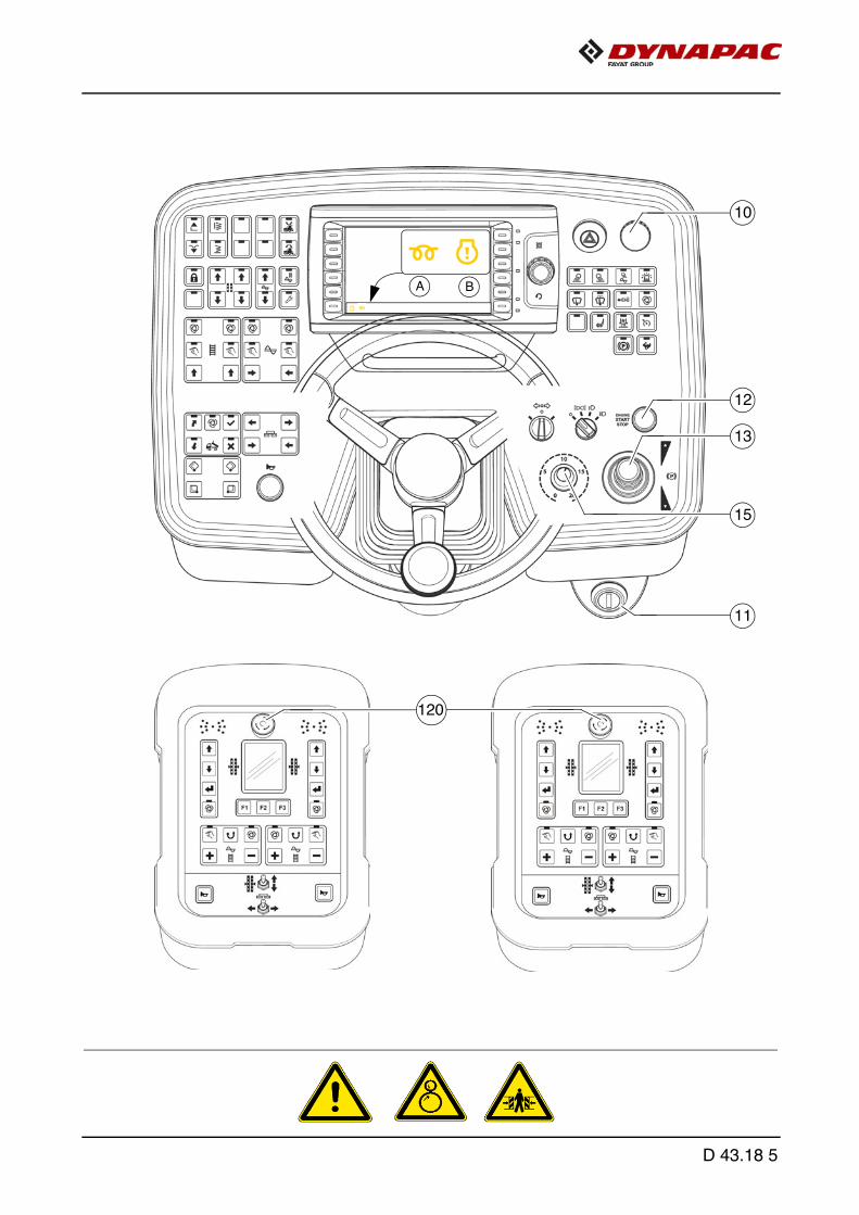
120
13
11
12
10
15
A B
D 43.18 5
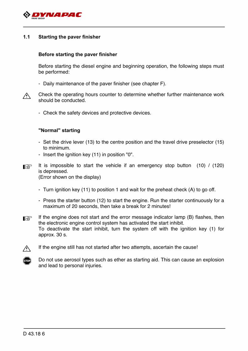
1.1 Starting the paver finisher
Before starting the paver finisher
Before starting the diesel engine and beginning operation, the following steps mustbe performed:
- Daily maintenance of the paver finisher (see chapter F).
m Check the operating hours counter to determine whether further maintenance workshould be conducted.
- Check the safety devices and protective devices.
"Normal" starting
- Set the drive lever (13) to the centre position and the travel drive preselector (15)to minimum.
- Insert the ignition key (11) in position "0".
A It is impossible to start the vehicle if an emergency stop button (10) / (120)is depressed.(Error shown on the display)
- Turn ignition key (11) to position 1 and wait for the preheat check (A) to go off.
- Press the starter button (12) to start the engine. Run the starter continuously for amaximum of 20 seconds, then take a break for 2 minutes!
A If the engine does not start and the error message indicator lamp (B) flashes, thenthe electronic engine control system has activated the start inhibit. To deactivate the start inhibit, turn the system off with the ignition key (1) forapprox. 30 s.
m If the engine still has not started after two attempts, ascertain the cause!
f Do not use aerosol types such as ether as starting aid. This can cause an explosionand lead to personal injuries.
D 43.18 6

120
13
11
12
10
15
A B
D 43.18 7
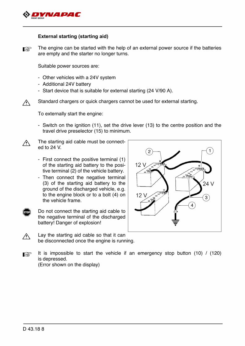
External starting (starting aid)
A The engine can be started with the help of an external power source if the batteriesare empty and the starter no longer turns.
Suitable power sources are:
- Other vehicles with a 24V system
- Additional 24V battery
- Start device that is suitable for external starting (24 V/90 A).
m Standard chargers or quick chargers cannot be used for external starting.
To externally start the engine:
- Switch on the ignition (11), set the drive lever (13) to the centre position and thetravel drive preselector (15) to minimum.
m The starting aid cable must be connect-ed to 24 V.
- First connect the positive terminal (1)of the starting aid battery to the posi-tive terminal (2) of the vehicle battery.
- Then connect the negative terminal(3) of the starting aid battery to theground of the discharged vehicle, e.g.to the engine block or to a bolt (4) onthe vehicle frame.
f Do not connect the starting aid cable tothe negative terminal of the dischargedbattery! Danger of explosion!
m Lay the starting aid cable so that it canbe disconnected once the engine is running.
A It is impossible to start the vehicle if an emergency stop button (10) / (120)is depressed.(Error shown on the display)
2 1
3
4
D 43.18 8

- If necessary, start the engine of the vehicle supplying power and leave to run for awhile.
Now try to start the other vehicle:
- Turn ignition key (11) to position 1 and wait for the preheat check (A) to go off.
- Press the starter button (12) to start the engine. Run the starter continuously for amaximum of 20 seconds, then take a break for 2 minutes!
A If the engine does not start and the error message indicator lamp (B) flashes, then theelectronic engine control system has activated the start inhibit. To deactivate the start inhibit, turn the system off with the ignition key (1) forapprox. 30 s.
m If the engine still has not started after two attempts, ascertain the cause!
- If the engine has started, disconnect the starting aid cable again in reverse order.
D 43.18 9

13
68
D 43.18 10

After starting
To increase the engine speed:
- Press button (68) to increase engine speed.
A The engine speed is increased to the preset value.
m Let the paver finisher warm up for approx. 5 minutes if the engine is cold.
D 43.18 11
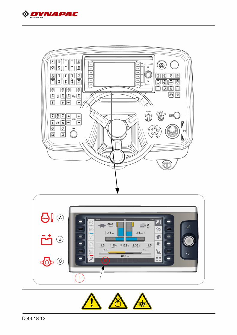
A
B
C
!
D 43.18 12

Observe indicator lamps
The following indicator lamps must be observed under all circumstances:
For further possible faults, see Engine's operating instructions.
Engine coolant temperature check (A)
Lights up when the engine temperature is outside of the permissible range.
m Stop the paver finisher (drive lever to the centre position), let the engine cool downwhile idling. Determine the cause and correct it if necessary.
A The engine performance will be throttled down automatically. (Driving moderemains possible). After cooling down to normal temperature, the engine will run with full perfor-mance again.
Battery charge indicator lamp (B)
Must go out after starting when the engine revs up.
m If the lamp does not go out or lights up during operation: Briefly rev up the engine. Switch off the engine and determine the fault if the lamp does not go out.
For further possible malfunctions, refer to the section "Malfunctions".
Diesel engine oil pressure indicator lamp (C)
Must go out at the latest 15 seconds after starting.
m If the lamp does not go out or lights up during operation: switch off engine immediatelyand determine fault.
D 43.18 13

D
!
68
50
5655
49
D 43.18 14

Travel drive oil pressure indicator lamp (D)
- Must go out after starting.
m If the lamp does not go out:Do not switch on the traction drive! Otherwise, the entire hydraulic system couldbe damaged.
When the hydraulic oil is cold:
- Activate set-up mode function (68).
- Set the conveyor function (49)/(50) to "manual" and the auger function (55)/(56)to "manual". Conveyor and auger start to operate
- Let the hydraulics warm up until the indicator lamp goes out.
A The Lamp goes out when the pressure drops below 2.8 bar = 40 psi.
For further possible malfunctions, refer to the section "Malfunctions".
D 43.18 15
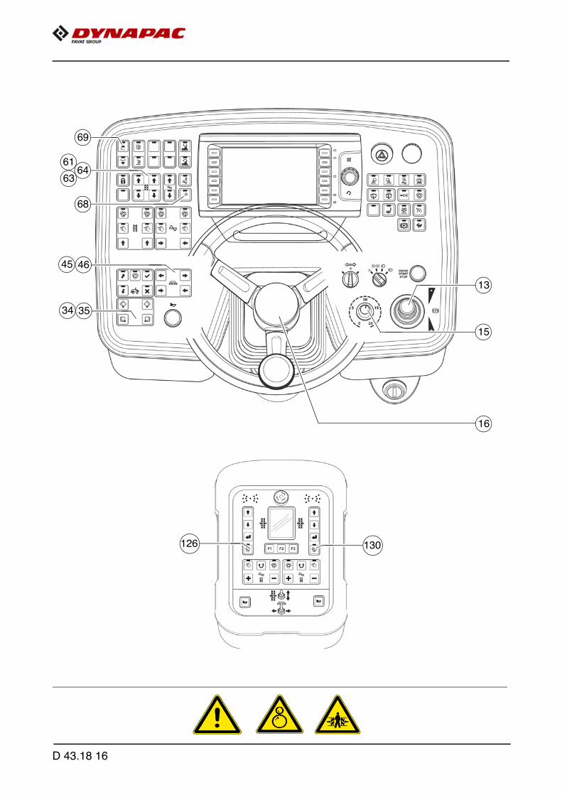
3534
15
13
16
69
63
6164
4645
68
126 130
D 43.18 16

1.2 Preparation for transportation
- Close the hopper with switch (34)/(35).
- Engage both hopper transport safeguards.
- Lift the screed completely using switch (69), set the crossbeam lock.
- Turn the travel drive preselector (15) to zero.
- Activate set-up mode function (68).
- Fully extend the levelling cylinders with switch (61),(63)/(64).
A To extend the levelling cylinders, levelling operating mode (126)/(130) must beswitched to "MANUAL" (LED OFF) on the remote controls.
- Use switch (45)/(46) to adjust the screed to the basic width of the paver finisher.
m Lift the auger if necessary!
A If the engine is started with the drive lever pivoted out, the travel drive is inhibited. To start the travel drive, first the drive lever must be returned to the centre position.
D 43.18 17
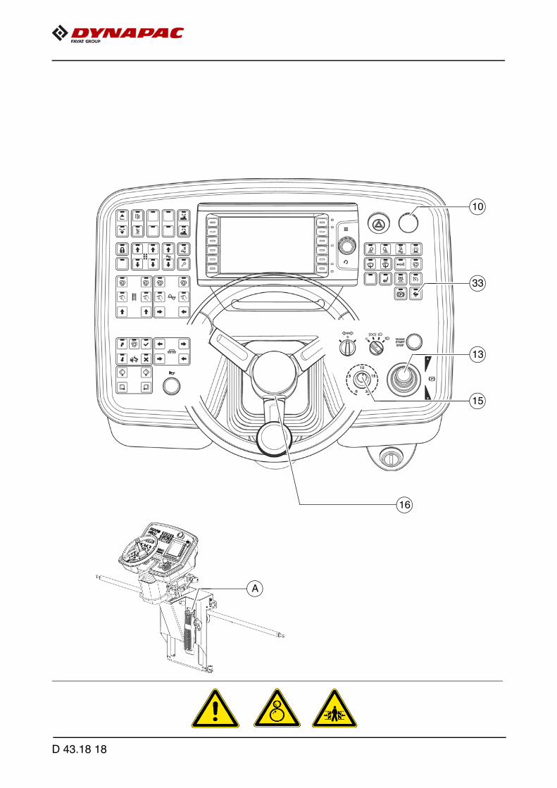
A
33
15
13
16
10
D 43.18 18
Driving and stopping the paver finisher
- Set the Fast/Slow switch (33) to "Hare".
- Set the preselector (15) to mark 10.
- For driving, carefully tilt the drive lever (13) forward or backward according to thedrive direction desired.
- Adjust the speed with the preselector (15).
- Carry out steering movements with the steering wheel (16).
f In case of an emergency, press the emergency stop button (10)!
- To stop, press the service brake (A), set the preselector (15) to "0" and move thedrive lever (13) into its centre position.
A If the vehicle was brought to a standstill with the service brake, it cannot be drivenaway again until after the drive lever has been put into neutral!
D 43.18 19

1.3 Preparations for paving
Separator fluid
Spray the parts coming into contact withasphalt (hopper, screed, auger, pushroller) with a separator fluid.
m Do not use diesel fuel as it dissolves thebitumen (prohibited in Germany!).
Screed heater system
Switch on the screed heater approx. 15–30 minutes (depending on the ambient tem-perature) before paving begins. Warming up prevents the material from sticking to thescreed plates.
F0147_A1.TIF
D 43.18 20
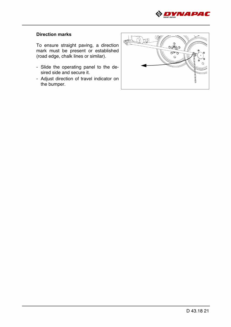
Direction marks
To ensure straight paving, a directionmark must be present or established(road edge, chalk lines or similar).
- Slide the operating panel to the de-sired side and secure it.
- Adjust direction of travel indicator onthe bumper.
D 43.18 21

A
59
67
3736
54
48
53
47
D 43.18 22
Loading/conveying material
- Button (59) has to be switched off.
- Use switch (36)/(37) to open the hopper. Instruct the truck driver to dump the material.
- Set the switches for the auger (53)/(54) and the conveyor (47)/(48) to "Auto".
- Activate function (67) to fill the vehicle for the paving process.
- Switch the conveyors on. The conveyor limit switches (A) must switch off when the material has approximate-ly reached the area beneath the auger crossbeam.
- Check that the material is transferred properly. Manually switch on or off the conveyor if the material is not conveyed properly untila sufficient amount of material lies in front of the screed.
D 43.18 23

70
54
48
53
47
71
72
15
13
33
123
127
126 130 126 130
D 43.18 24

1.4 Starting for paving
Set the switches, levers and controls listed below to the specified positions when thescreed has reached its operating temperature and a sufficient amount of material liesin front of the screed
- Push the drive lever (13) all the way to the front and start driving.
- Observe the distribution of the material and adjust the limit switches if necessary.
- Set the compacting elements (tamper / vibration) according to the required com-paction ratio.
- Let the paving master check the paving thickness after 5–6 meters and correctif necessary.
Carry out the check in the area of the caterpillar chains or drive wheels as the screedtends to level an uneven ground. The reference points for the layer thickness are thecaterpillar chains or drive wheels.
The basic setting of the screed must be corrected when the actual layer thickness de-viates significantly from the values indicated by the scales (see the operating instruc-tions for the screed).
A The basic setting is for asphalt material.
Item Travelling direction Position
13 Drive lever Centre position
33 Traction drive fast/slow Tortoise-operating speed
15 Travel drive preselector Mark 6-7
70Preparation for screed floating position
LED ON
72 Vibration LED ON
71 Tamper LED ON
53/54Auger left/right auto
123
47/48Conveyor left/right auto
127
126 / 130
Levelling auto
Speed regulator, vibration adapted to the paving situation
Speed control for the tamper adapted to the paving situation
D 43.18 25

1.5 Checks during paving
The following points must be constantly observed during paving:
Paver function
- Screed heater system
- Tamper and vibration
- Engine oil and hydraulic oil temperature
- The screed parts must be retracted and extended in time when obstacles are inthe way
- Uniform material transport and distribution or supply to the screed; may require cor-rections to settings of the material switches for conveyor and auger.
A See the section "Malfunctions" when paver functions fail.
Quality of the layer
- Paving height
- Slope
- Evenness in the driving direction and at right angles to it (check with 4 m levelling rod)
- Surface structure/texture behind the screed.
A See section "Malfunctions, problems during paving" if the paving quality is poor.
D 43.18 26
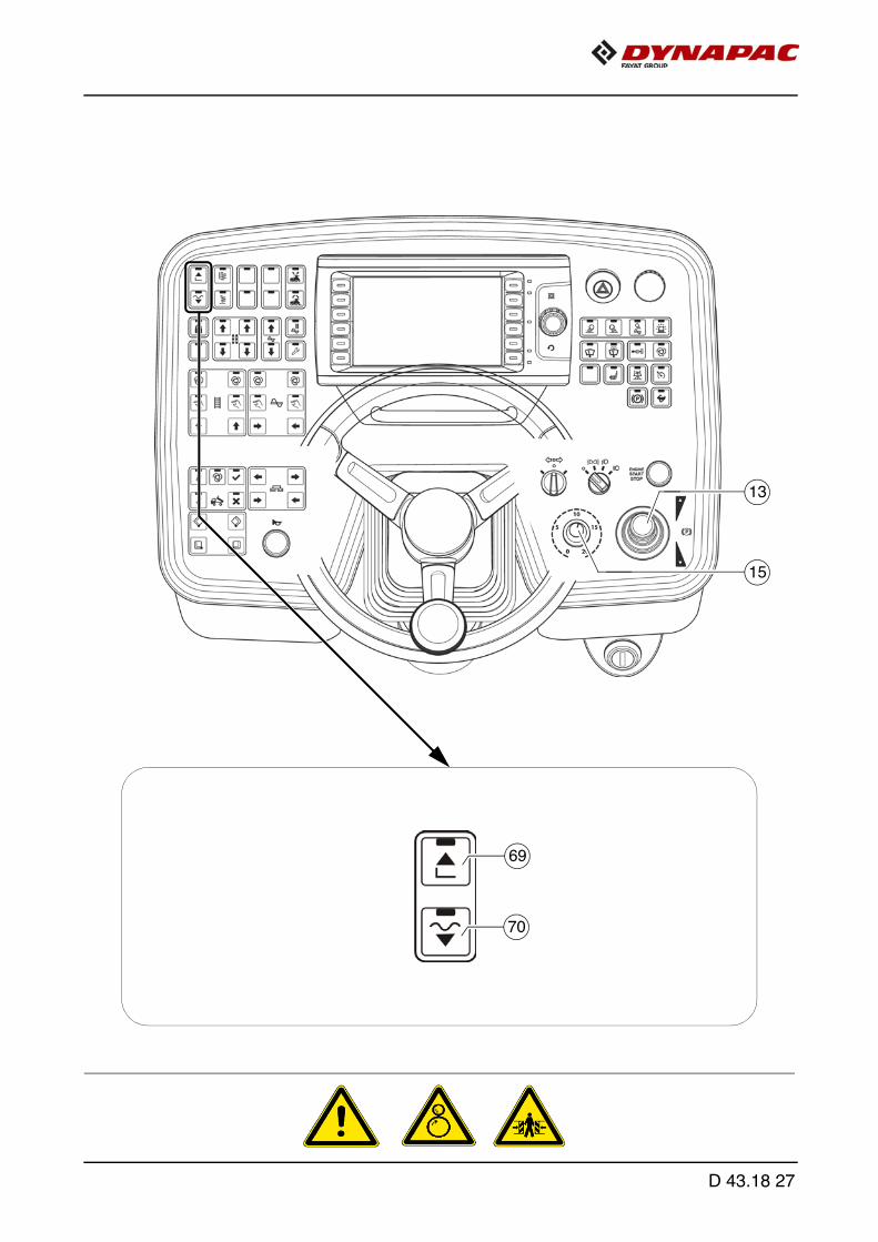
70
13
15
69
D 43.18 27

Screed control with paver finisher stop / in paving operation(screed stop / paving stop / floating paving)
Button (70) can be used to activate the following functions:
- Screed stop / floating position (OFF)-->(LED OFF)
- Screed is hydraulically held in position.
A Function for setting up the paver finisher and for lifting/lowering the screed
- Paving stop / floating paving (ON)-->(LED ON)
The following functions are active depending on operating status:
- "Paving stop": when the paver finisher is stationary.Screen is held hydraulically and by the counter pressure of the material.
- "Floating paving": during paving operation.Lower the screed to the floating position.
A Function for paving operation.
- To lift the screed press switch (69).
- To lower the screed:
- Resting function: Keep button (70) pressed for longer than 1.5 seconds.The screed is lowered as long as the button is pressed. When the button is re-leased, the screed is stopped again.
- Button function: Press button (70) briefly - the screed is lowered. Press the buttonbriefly again - the screed is stopped.
D 43.18 28

Setting pressure for screed controlwith paving stop + relieving:
A Pressure adjustments can only be madewhile the diesel engine is running.
- Set the drive lever (13) to the centreposition.
- Start the diesel engine and set thetraction controller (15) to zero.
- Activate the "floating position" (63)function (LED ON).
- Set the pressure using pressure regu-lating valve (A); read it off at themanometer (B).
A Adjustment range 0 - 100 bar.
B A
D 43.18 29
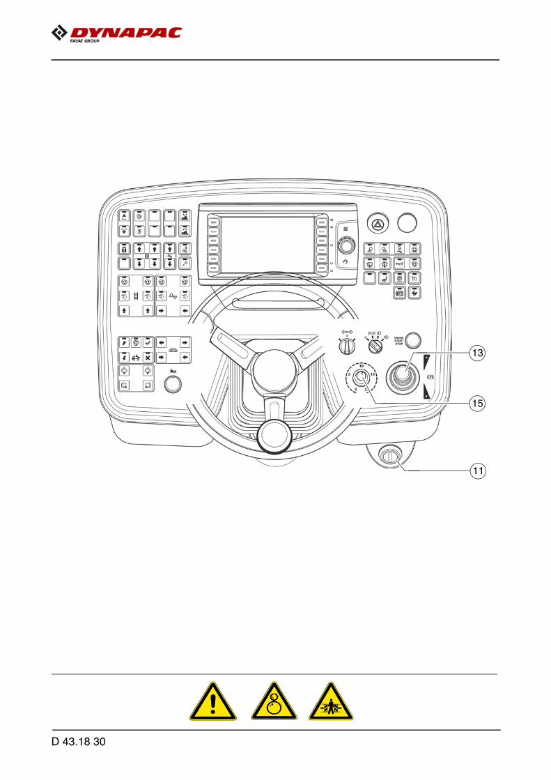
13
15
11
D 43.18 30
1.6 Interrupting/terminating operation
During breaks in paving (e.g. delay due to material trucks)
- Determine the approximate duration.
- When cooling down of the material below the minimum paving temperaturemust be expected, run the paver finisher empty and create an edge like the endof a layer.
- Set the drive lever (13) to the centre position.
During longer breaks (e.g. lunch break)
- Set the drive lever (13) to the centre position and the speed adjuster (15)to minimum.
- Switch off the ignition (11).
- Switch the screed heater system off.
- With a screed with gas heating system (o) , close the bottle valves.
A The screed must be heated up to the correct paving temperature before paving maybe restarted.
D 43.18 31
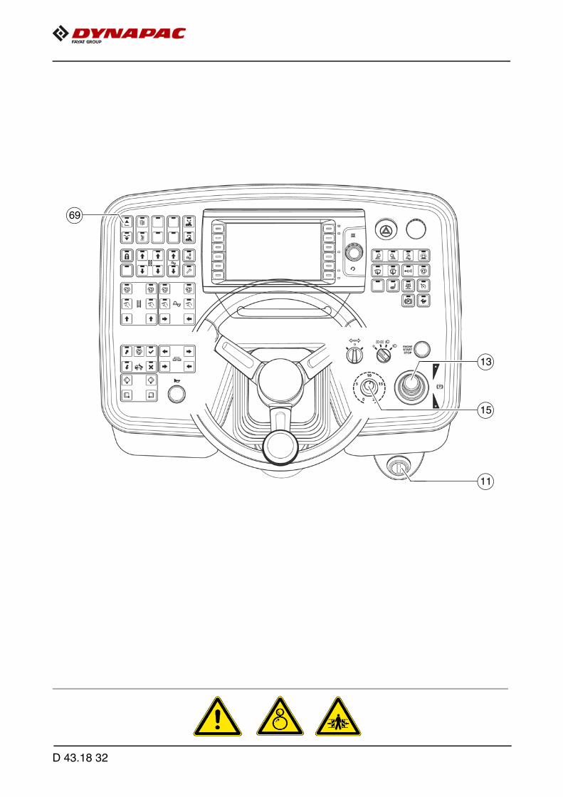
13
11
15
69
D 43.18 32

When work is finished
- Run the paver finisher empty and stop it.
- Lift the screed using switch (69), set the crossbeam lock.
- Retract the screed parts to the basic screed width and lift the auger. Where appli-cable, completely extend the levelling cylinders.
- Close hopper halves, set hopper transport safeguards.
- While operating the tampers at a low speed, let any material residues drop out.
- Set the drive lever (13) to the centre position and the speed adjuster (15)to minimum.
- Switch the screed heater system off.
- Switch off the ignition (11).
- With a screed with gas heating system (o), close the the main shut-off valve andthe bottle valve.
- Remove the levelling units and stow them away in the boxes, close all flaps.
- Remove all parts that extend beyond the paver finisher contour or secure themif the paver finisher is to be transported over public roads on a low-bed trailer.
- Read and check the operating hour meter to determine whether maintenance workmust be performed (see chapter F).
- Cover and lock the operating panel.
- Remove material residues from the screed and the paver finisher and spray allparts with separator fluid.
D 43.18 33

2 Malfunctions
2.1 Problems during paving
Problem Cause
Wavy surface("short waves")
- change in the material temperature, demixing- wrong material composition- incorrect operation of the roller- incorrectly prepared foundation- long standstill times between loads- grade control reference line is not suitable- grade control jumps to the reference line- grade control toggles between up and down
(inertia setting is too high)- bottom plates of the screed are loose- bottom plates of the screed are warped or not uniformly worn- screed is not operated in the floating position- too much play in the mechanical screed link/suspension- paver finisher speed is too high- augers are overloaded- changing material pressure against the screed
Wavy surface("long waves")
- change in the material temperature- demixing- roller has stopped on the hot material- roller has turned or roller speed has been changed too fast- incorrect operation of the roller- incorrectly prepared foundation- truck brake is applied too tight- long standstill times between loads- grade control reference line is not suitable- incorrect installation of the grade control- limit switch is not correctly set- screed is empty- screed has not been switched to the floating position- too much play in the mechanical screed link- auger is set too deep- auger is overloaded- changing material pressure against the screed
Cracks in the layer(over the entire width)
- material temperature is too low- change in the material temperature- moisture on the foundation- demixing- wrong material composition- wrong layer height for maximum grain size- cold screed- bottom plates of the screed are worn or warped- paver finisher speed is too high
D 43.18 34

Cracks in the layer(centre strip)
- material temperature- cold screed- bottom plates are worn or warped- wrong crowning
Cracks in the layer(outer strip)
- material temperature- screed extendable parts are incorrectly installed- limit switch is not correctly set- cold screed- bottom plates are worn or warped- paver finisher speed is too high
Layer composition is not uniform
- material temperature- change in the material temperature- moisture on the foundation- demixing- wrong material composition- incorrectly prepared foundation- wrong layer height for maximum grain size- long standstill times between loads- vibration is too slow- screed extendable parts are incorrectly installed- cold screed- bottom plates are worn or warped- screed is not operated in the floating position- paver finisher speed is too high- auger is overloaded- changing material pressure against the screed
Marks in the surface
- truck hits too much against the finisher while aligning to the finisher
- too much play in the mechanical screed link/suspension- truck brake is applied- vibration is too high while standing on a spot
Screed does not react to corrective measures as expected
- material temperature- change in the material temperature- wrong layer height for maximum grain size- incorrect installation of the grade control- vibration is too slow- screed is not operated in the floating position- too much play in the mechanical screed link- paver finisher speed is too high
Problem Cause
D 43.18 35

2.2 Malfunctions on the paver finisher or screed
Malfunction Cause Remedy
At the diesel engine VariousSee operating instructions for the engine
Diesel engine does not start
Batteries emptySee "External starting" (start assistance)
Various see "Towing"
Tamper or vibration is not functioning
Tamper is obstructed by cold bitumen
Properly heat the screed
Hydraulic oil level in the tank is too low
Top up oil
Pressure limiting valve is defective
Replace the valve; if necessary, repair and adjust the valve
Leak in the suction line of the pump
Seal or replace the connections
Tighten or replace the hose clamps
Oil filter is soiledClean the filter; if necessary, replace the filter
Conveyor or augers run too slowly
Hydraulic oil level in the tank is too low
Top up oil
Power supply interruptedCheck fuses and cables; replace if necessary
Switch is defective Replace the switch
One of the pressure limiting valves is defective
Repair or exchange the valves
Pump shaft broken Replace the pump
Limit switch does not switch or regulate correctly
Check the switch; replace and adjust the switch if necessary
Pump is defectiveCheck the high pressure filter for dirt particles; replace if necessary
Oil filter is soiled Replace the filter
Hopper cannot be swung open
Engine speed is too low Increase the speed
Hydraulic oil level is too low Top up oil
Leak in the suction line Tighten the connections
Flow rate regulator defective Replace
Leaking seals of the hydraulic cylinder
Replace
Control valve is defective Replace
Power supply interruptedCheck fuse and cables; replace if necessary
D 43.18 36

Malfunction Cause Remedy
Hoppers lowers inadvertently
Control valve is defective Replace
Leaking seals of the hydraulic cylinder
Replace
Screed cannot be lifted
Oil pressure too low Increase the oil pressure
Leaking seal Replace
Screed relieving or charg-ing is switched on
Switch must be in the centre position
Power supply interruptedCheck fuse and cables; replace if necessary
Crossbeams cannot be lifted or lowered
Switch on the remote con-trol is set to "Auto"
Set the switch to "Manual"
Power supply interruptedCheck fuse and cables; replace if necessary
Switch on the operating panel defective
Replace
Excess pressure valve defective
Replace
Flow rate regulator defective
Replace
Seals defective Replace
Crossbeams lower inadvertently
Control valves defective Replace
Pilot-controlled non-return valves defective
Replace
Seals defective Replace
D 43.18 37
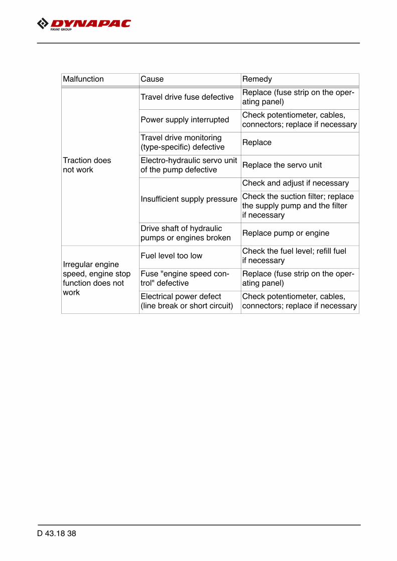
Malfunction Cause Remedy
Traction does not work
Travel drive fuse defectiveReplace (fuse strip on the oper-ating panel)
Power supply interruptedCheck potentiometer, cables, connectors; replace if necessary
Travel drive monitoring (type-specific) defective
Replace
Electro-hydraulic servo unit of the pump defective
Replace the servo unit
Insufficient supply pressure
Check and adjust if necessary
Check the suction filter; replace the supply pump and the filter if necessary
Drive shaft of hydraulic pumps or engines broken
Replace pump or engine
Irregular engine speed, engine stop function does not work
Fuel level too lowCheck the fuel level; refill fuel if necessary
Fuse "engine speed con-trol" defective
Replace (fuse strip on the oper-ating panel)
Electrical power defect(line break or short circuit)
Check potentiometer, cables, connectors; replace if necessary
D 43.18 38

E 10.18 Set-up and modification
1 Special notes on safety
f Danger to personnel by inadvertent starting of the engine, travel drive, conveyor, au-ger, screed or screed lifting devices. Unless otherwise specified, work may only be performed when the engine isat a standstill!
- To protect the paver finisher against inadvertent starting: Move drive lever into centre position and turn preselector controller to zero, removeignition key and battery main switch.
- Protect lifted vehicle parts (e.g. screed or hopper) against lowering by means ofmechanical safeguards.
- Replace parts or have them replaced as stipulated.
f When connecting or disconnecting hydraulic hoses and when working on the hydrau-lic system, hot hydraulic fluid may spurt out at high pressure. Switch off the engine and depressurise the hydraulic system! Protect your eyes!
- Mount all protective devices before re-commissioning the paver finisher.
E 10.18 1

Danger due to changes at the vehicle
Structural changes to the vehicle make the operating licence null and void and can cause severe to fatal injuries!
- Only use original spare parts and approved accessories.- After maintenance and repair work, ensure that any dis-
mantled protective and safety devices are all completely fitted again.
- Comply with all further information in these instructions and in the safety manual.
DANGER
E 10.18 2

2 Distribution auger
2.1 Height adjustment
Depending on the material, the height of the auger – measured from its lower edge –should be at least 50 mm (2 inches) above the height of the material layer.
Example: layer height 10 cmadjustment 15 cm from the ground
An incorrect height setting can result in the following problems during paving:
- Auger too high:Too much material in front of the screed; material overflow. When operating withlarger working widths, demixing and traction problems may occur.
- Auger too low:Not enough material that can be precompacted by the auger. Irregularities resultingfrom this cannot be completely compensated by the screed (wavy surface). In addition, increased auger segment wear occurs.
14
3
2
4 32 1
V1
V2
E 10.18 3
Mechanical height adjustment:
- Set the ratchet direction lever (1) to the clockwise or anti-clockwise direction.
- Adjust the required height by actuating the ratchet (2).
- The current height can be read at the scale (3).
Hydraulic height adjustment:
- Adjust the required height by pressing the corresponding switch (operating panel).
- The current height can be read at the scale (4).
E 10.18 4

2.2 Auger width extension and material shaft with protective cover(optional equipment)
To fit auger extensions, an additional auger segment (1) is fitted to the auger shaft.
Assembly:
- Remove outermost screw connection (2) from the basic auger.
- Remove plug (3).
- Fit the auger extension (1) to the corresponding side.
- Fit screw connection (2).
- Fit plugs (3) to the auger extension.
The relevant material shaft must be fitted to each auger extension.
4
6
3
5
1
2
6
4
E 10.18 5

Push roller crossbar, adjustable
For adaptation to various truck design types, the push roller crossbar (1) can be shift-ed to two positions.
A The adjustment travel is 60mm.
- Close the hopper halves to lift the hopper flap (o).
- After removing the bolts (3), remove the locking plate (2) on the lower side of thecrossbar.
- Remove insert plate (4).
- Remove bolt (5).
- Move the push roller crossbar as far as it will go to the front / rear position.
A Shift the push roller crossbar at the towing eye or use a suitable assembly lever in itsguide (left and right) to push it into the corresponding position.
- Turn the bolt (5) 180° and reinsert in the front or rear position
- Turn the insert plate (5) 180° and reinsert into the groove in the front orrear position.
- Properly reinstall the locking plate (2) with bolts (3).
32
1
4
180°
4180°
E 10.18 6
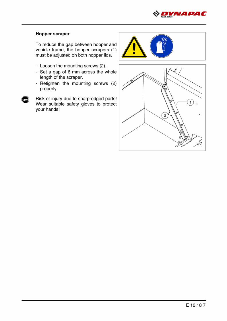
Hopper scraper
To reduce the gap between hopper andvehicle frame, the hopper scrapers (1)must be adjusted on both hopper lids.
- Loosen the mounting screws (2).
- Set a gap of 6 mm across the wholelength of the scraper.
- Retighten the mounting screws (2)properly.
f Risk of injury due to sharp-edged parts!Wear suitable safety gloves to protectyour hands!
1
2
E 10.18 7
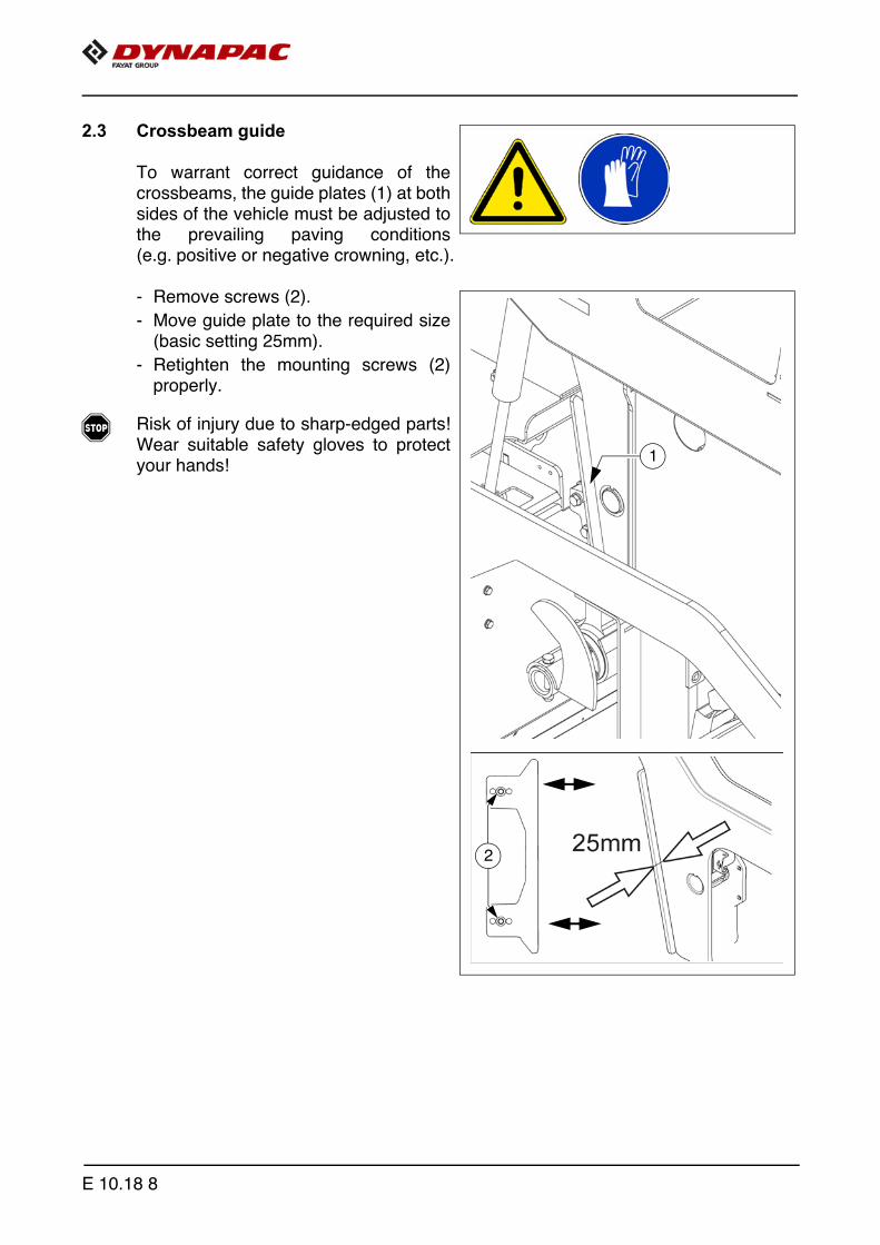
2.3 Crossbeam guide
To warrant correct guidance of thecrossbeams, the guide plates (1) at bothsides of the vehicle must be adjusted tothe prevailing paving conditions(e.g. positive or negative crowning, etc.).
- Remove screws (2).
- Move guide plate to the required size(basic setting 25mm).
- Retighten the mounting screws (2)properly.
f Risk of injury due to sharp-edged parts!Wear suitable safety gloves to protectyour hands!
1
2
E 10.18 8

3 Screed
The Screed operating instructions cover all work required for mounting, setting upand extending the screed.
4 Electrical connections
Prepare or make the following electrical connections when the mechanical compo-nents have been mounted and set up:
1
2
5
3
6
7
8
4a
4
2a
3
E 10.18 9

- Set remote control to holder (1).
- Connect plug (2) with the remote control.
m If the remote control is not implemented, the plug (2) has to be set to the bridgesocket (2a).
- Connect the connection lead (3) of the side shield with the socket (4) of the screed.
A The cover of the extendable part must be removed to install the cables. Install the cables to rule out the risk of any damage to the cables.
m If the side shield is not connected, the socket (4) has to be connected with the bridgeplug (4a).
Other connection possibilities:
- Auger limit switches (5)
- Grade control system (6)
- External levelling system (7)
- 24 volt consumers, e.g. additional lighting.
A When using an external levelling system, this must be logged in using the remote con-trol menu.
A Always seal unused sockets or plugs with the corresponding protective caps!
E 10.18 10

5 Limit switch
5.1 Auger limit switches (left and right) -mount PLC version
The auger's ultrasonic limit switch ismounted on both sides on the sideshield's handrail.
- Place the sensor bracket (1) onto thehandrail, align it and tighten with awing bolt (2).
- Align the sensor (3) and secure with aclamping lever (4).
- Connect the left or right sensor's con-nection cable (5) to the intended re-mote control bracket sockets.
A The connection cables are connected tothe relevant sockets on the remote control bracket.
A The sensors should be adjusted so that 2/3 of the augers are covered with thepaving material.
A The paving material must be conveyed over the full working width.
A We recommend adjusting the limit switch positions during material distribution.
Sonic.wmf
2
1
3
4
5
E 10.18 11

5.2 Auger limit switches (left and right) -mount conventional version
The ultrasonic sensor (1) is secured tothe side shield via a bracket (2).
- To adjust the sensor angle, loosen theclamps (3) and swivel the bracket.
- To set the sensor height / the deacti-vation point, loosen the star handles(4) and adjust the linkage to the re-quired length.
- After adjusting, retighten all mountingparts properly.
A The connection cables are connected tothe relevant sockets on the remote con-trol bracket.
A The sensors should be adjusted so that2/3 of the augers are covered with thepaving material.
A The paving material must be conveyedover the full working width.
A We recommend adjusting the limit switch positions during material distribution.
4
3
1
2
E 10.18 12

F 10 Maintenance1 Notes regarding safety
Danger due to changes at the vehicle
Structural chances to the vehicle make the operating licence null and void and can cause severe to fatal injuries!
- Only use original spare parts and approved accessories.- After maintenance and repair work, ensure that any dis-
mantled protective and safety devices are all completely fitted again.
- Comply with all further information in these instructions and in the safety manual.
Danger due to incorrect vehicle maintenance
Incorrectly performed maintenance and repair work can cause severe or fatal injuries!
- Ensure that maintenance and repair work is always only carried out by trained, specialist staff.
- All maintenance, repair and cleaning work should only be carried out with the engine turned off. Remove igni-tion key and main switch.
- Affix a sign "Do not start" to the vehicle.- Perform a visual inspection and check all functions
every day.- Proceed with all maintenance tasks according to the
maintenance schedule.- Proceed with expert inspection every twelve months.- Eliminate all ascertained faults straight away.- Do not restart the vehicle until all ascertained faults have
been eliminated.- Failure to comply with the prescribed inspection and
maintenance work renders the operating licence null and void!
- Comply with all further information in these instructions and in the safety manual.
DANGER
DANGER
F 10 1
f Cleaning:Do not use any inflammable substances (such as petrol). Avoid directly cleaning electrical parts and insulation material with a steam jet; coverthem up beforehand.
f Working in enclosed environments: Exhaust fumes must be conducted into theopen air. Propane gas bottles must not be stored in closed rooms.
m In addition to these maintenance instructions, the maintenance instructions issued bythe engine manufacturer must be adhered to under all circumstances. All mainte-nance work and service intervals itemised here are binding in nature.
A Information on how to maintain the optional equipment can be found in the individualsub-sections of this chapter!
Hot surfaces!
Surfaces including those behind covering parts, together with combustion fuels from the engine or screed heater can be very hot and cause injuries!
- Wear your personal safety gear.- Do not touch hot parts of the vehicle.- Only perform maintenance and repair work after the
vehicle has cooled down.- Comply with all further information in these instructions
and in the safety manual.
Danger due to electric shock
Injuries can be caused by touching live parts directly or indirectly!
- Do not remove any protective safeguards.- Never spray water on electric or electronic components.- Maintenance work to the electric system should only be
carried out by trained specialist staff.- When equipped with electric screed heater, check the
insulation monitoring every day according to the instructions.
- Comply with all further information in these instructions and in the safety manual.
CAUTION
CAUTION
F 10 2
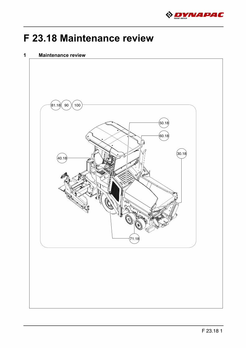
F 23.18 Maintenance review1 Maintenance review
81.18 90 100
50.18
60.18
40.18
71.18
30.18
F 23.18 1

A In this overview, you will find the maintenance intervals for optionalmachine equipment!
Assembly Chapter
Maintenance necessary after operating hours
10 50 100
250
500
1000
/ an
nual
ly20
00 /
ever
y 2
year
s50
0020
000
If ne
cess
ary
Conveyor F31.18 q q qAuger F40.18 q q q q qEngine F50.18 q q q q q qHydraulic system F60.18 q q q q q q qWheel chassis F71.18 q q q q q qElectrical system F81.18 q q q q q q qLubrication points F90 q q q qChecking/stopping F100 q q q
Maintenance required q
F 23.18 2

F 30.18 Maintenance - conveyor1 Maintenance - conveyor
F 30.18 1

Danger of being pulled in by rotating or conveying vehicle partsRotating or conveying vehicle parts can cause severe or fatal injuries!
- Do not enter the danger zone.- Do not reach into rotating or conveying parts.- Only wear close-fitting clothing.- Comply with the warning and information signs on
the vehicle.- Stop the engine and remove the ignition key before any
maintenance work.- Comply with all further information in these instructions
and in the safety manual.
Danger from heavy loads
Lowering vehicle parts may cause injuries!
- When the vehicle is parked and during maintenance and transport, close both hopper lids and fit the correspond-ing hopper transport safeguards.
- When the vehicle is parked and during maintenance and transport, raise the screen and fit the corresponding screed transport safeguards.
- Ensure that opened hoods and covering parts are locked properly.
- Comply with all further information in these instructions and in the safety manual.
Hot surfaces!
Surfaces including those behind covering parts, together with combustion gases from the engine or screed heater can be very hot and cause injuries!
- Wear your personal safety gear.- Do not touch hot parts of the vehicle.- Only perform maintenance and repair work after the
vehicle has cooled down.- Comply with all further information in these instructions
and in the safety manual.
WARNING
CAUTION
CAUTION
F 30.18 2
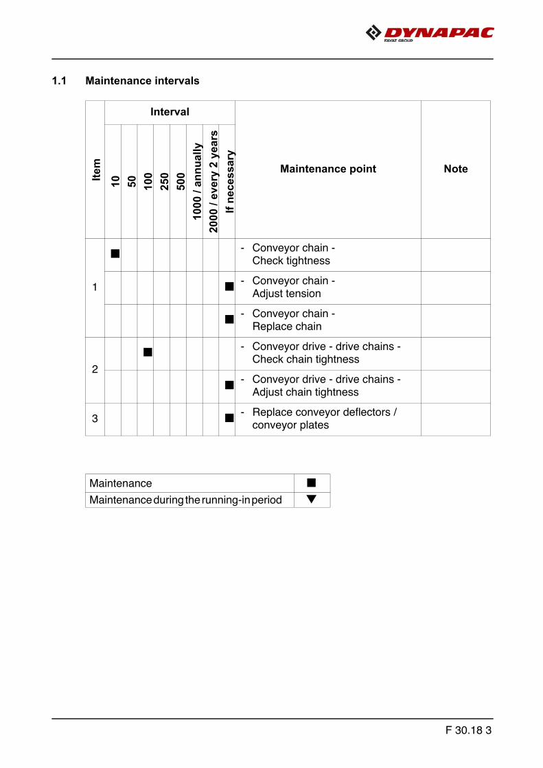
1.1 Maintenance intervalsIte
mInterval
Maintenance point Note
10 50 100
250
500
1000
/ an
nual
ly20
00 /
ever
y 2
year
sIf
nece
ssar
y
1
q - Conveyor chain -Check tightness
q - Conveyor chain -Adjust tension
q - Conveyor chain -Replace chain
2
q - Conveyor drive - drive chains -Check chain tightness
q - Conveyor drive - drive chains -Adjust chain tightness
3 q - Replace conveyor deflectors / conveyor plates
Maintenance qMaintenance during the running-in period g
F 30.18 3

1.2 Points of maintenance
Chain tension, conveyor (1)
Check chain tension:
When the conveyor chain is tensioned correctly, the lower edges of both chain sags(before and after the chain guide) hangs approx. 170 mm above the ground.
m The conveyor chains should not be too tight or too slack. An excessively taut chaincan cause the chain to be stopped or to break when material falls into the space be-tween the chain and the sprocket. An excessively slack chain may catch on protruding objects and be destroyed.
Adjustment of chain tension:
A One adjusting screw is located on bothhalves of the conveyor for adjusting thechain tension.
A The adjusting screws are located at thereversal behind the crossbeam.
A A special wrench for the lock nut (A)is included in the scope of supply ofthe vehicle.
- Unfasten lock nut (A) at the reversal.
- Adjust the chain tension using the ad-justing screw (B).
- Retighten the lock nut (A) properly.
170 mm 170 mm
B
A
F 30.18 4
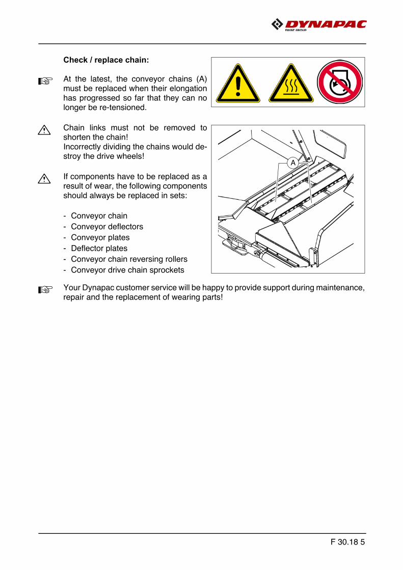
Check / replace chain:
A At the latest, the conveyor chains (A)must be replaced when their elongationhas progressed so far that they can nolonger be re-tensioned.
m Chain links must not be removed toshorten the chain! Incorrectly dividing the chains would de-stroy the drive wheels!
m If components have to be replaced as aresult of wear, the following componentsshould always be replaced in sets:
- Conveyor chain
- Conveyor deflectors
- Conveyor plates
- Deflector plates
- Conveyor chain reversing rollers
- Conveyor drive chain sprockets
A Your Dynapac customer service will be happy to provide support during maintenance,repair and the replacement of wearing parts!
A
F 30.18 5

Conveyor drive - drive chains (2)
To check the chain tension:
A There is a scale (A) on the chain guardto show the chain sag.
- Move the chain in the oblong hole ofthe chain guard: If the tension has been set properly,the chain must be able to move freelyapprox. 10 - 15 mm.
To re-tension the chains
- Unfasten mounting screws (B) andlock nut (C) slightly.
- Adjust the required chain tension us-ing the tensioning screw (C).
- Retighten fastening bolts (B) and locknuts (C) correctly.
B
D C
10mmA
F 30.18 6
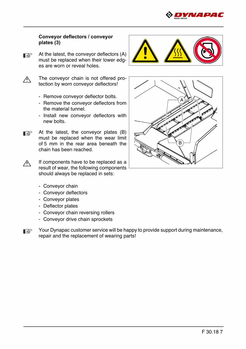
Conveyor deflectors / conveyor plates (3)
A At the latest, the conveyor deflectors (A)must be replaced when their lower edg-es are worn or reveal holes.
m The conveyor chain is not offered pro-tection by worn conveyor deflectors!
- Remove conveyor deflector bolts.
- Remove the conveyor deflectors fromthe material tunnel.
- Install new conveyor deflectors withnew bolts.
A At the latest, the conveyor plates (B)must be replaced when the wear limitof 5 mm in the rear area beneath thechain has been reached.
m If components have to be replaced as aresult of wear, the following componentsshould always be replaced in sets:
- Conveyor chain
- Conveyor deflectors
- Conveyor plates
- Deflector plates
- Conveyor chain reversing rollers
- Conveyor drive chain sprockets
A Your Dynapac customer service will be happy to provide support during maintenance,repair and the replacement of wearing parts!
A
B
F 30.18 7

F 30.18 8

F 40.18Maintenance - auger assembly 1 Maintenance - auger assembly
F 40.18 1

Danger of being pulled in by rotating or conveying vehicle partsRotating or conveying vehicle parts can cause severe or fatal injuries!
- Do not enter the danger zone.- Do not reach into rotating or conveying parts.- Only wear close-fitting clothing.- Comply with the warning and information signs
on the vehicle.- Stop the engine and remove the ignition key before any
maintenance work.- Comply with all further information in these instructions
and in the safety manual.
Hot surfaces!
Surfaces including those behind covering parts, together with combustion gases from the engine or screed heater can be very hot and cause injuries!
- Wear your personal safety gear.- Do not touch hot parts of the vehicle.- Only perform maintenance and repair work after the
vehicle has cooled down.- Comply with all further information in these instructions
and in the safety manual.
WARNING
CAUTION
F 40.18 2
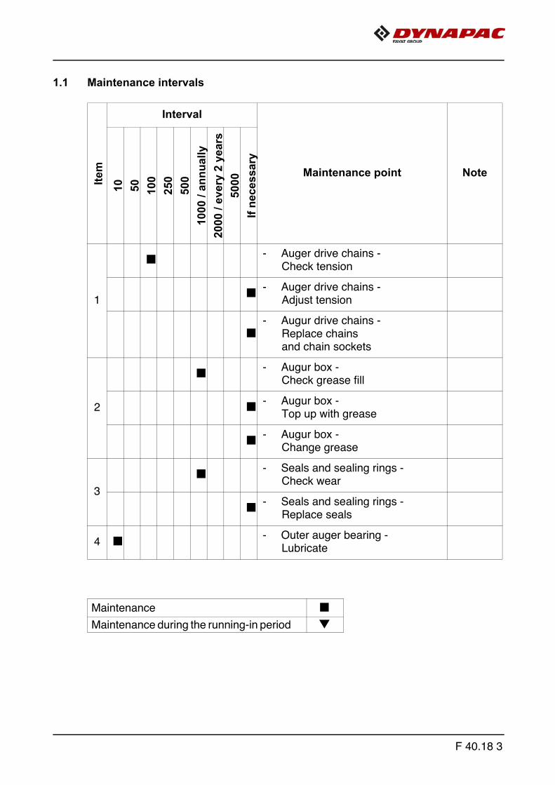
1.1 Maintenance intervalsIte
mInterval
Maintenance point Note
10 50 100
250
500
1000
/ an
nual
ly20
00 /
ever
y 2
year
s50
00If
nece
ssar
y
1
q - Auger drive chains - Check tension
q - Auger drive chains - Adjust tension
q- Augur drive chains -
Replace chains and chain sockets
2
q - Augur box - Check grease fill
q - Augur box - Top up with grease
q - Augur box - Change grease
3
q - Seals and sealing rings - Check wear
q - Seals and sealing rings - Replace seals
4 q - Outer auger bearing - Lubricate
Maintenance qMaintenance during the running-in period g
F 40.18 3

Item
Interval
Maintenance point Note
10 50 100
250
500
1000
/ an
nual
ly20
00 /
ever
y 2
year
s50
00If
nece
ssar
y
5
g g - Outer bearing bolts - Check tightening
q - Outer bearing bolts - Tighten to correct torque
6
q - Auger blade - Check wear
q - Auger blade - Replace auger blade
Maintenance qMaintenance during the running-in period g
F 40.18 4
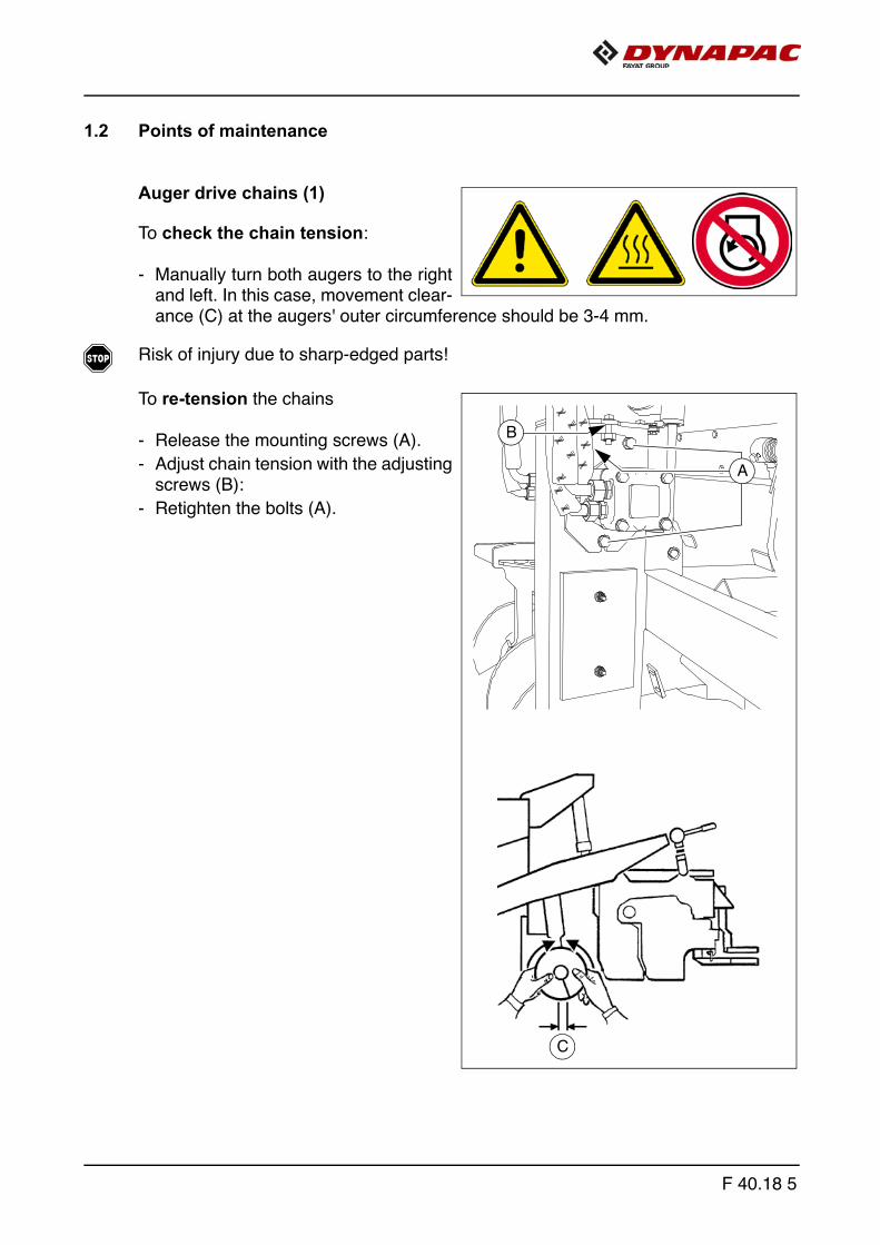
1.2 Points of maintenance
Auger drive chains (1)
To check the chain tension:
- Manually turn both augers to the rightand left. In this case, movement clear-ance (C) at the augers' outer circumference should be 3-4 mm.
f Risk of injury due to sharp-edged parts!
To re-tension the chains
- Release the mounting screws (A).
- Adjust chain tension with the adjustingscrews (B):
- Retighten the bolts (A).
C
A
B
F 40.18 5
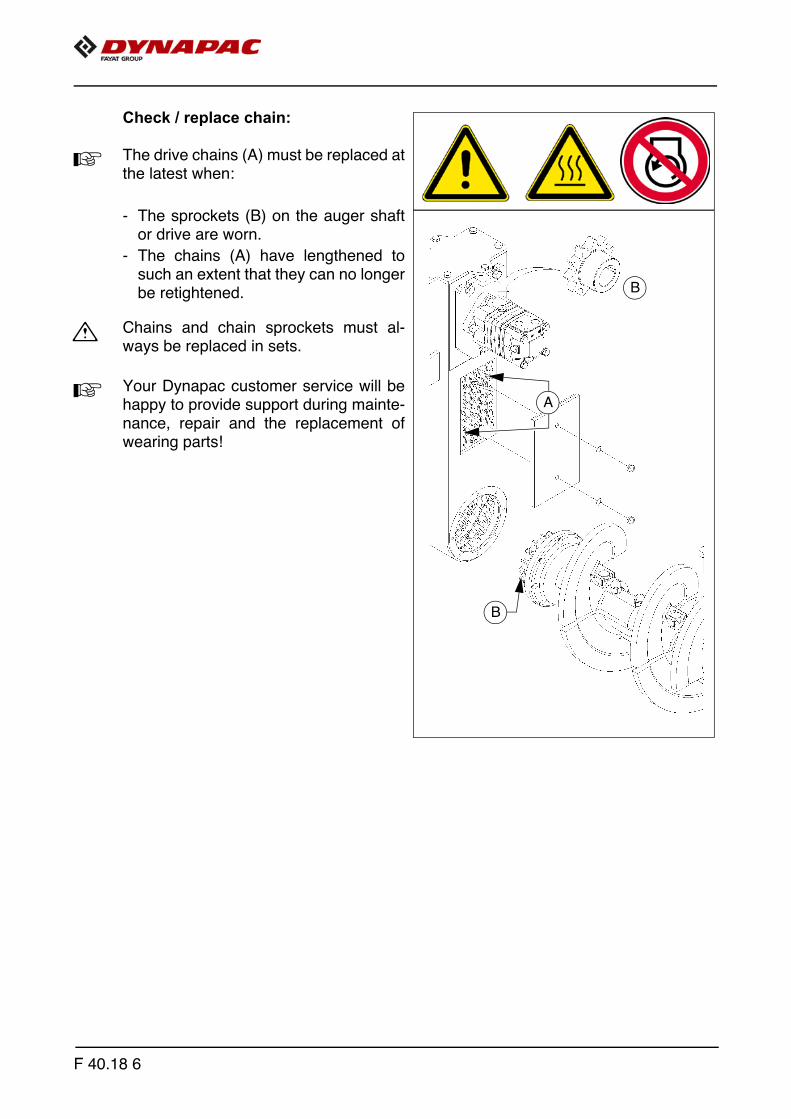
Check / replace chain:
A The drive chains (A) must be replaced atthe latest when:
- The sprockets (B) on the auger shaftor drive are worn.
- The chains (A) have lengthened tosuch an extent that they can no longerbe retightened.
m Chains and chain sprockets must al-ways be replaced in sets.
A Your Dynapac customer service will behappy to provide support during mainte-nance, repair and the replacement ofwearing parts!
A
B
B
F 40.18 6

Auger box (2)
Check grease fill
To check the grease fill:
- Remove side cover (A)
A No reduction in the quality and quantityof the grease fill is normally expected.However, the grease fill must alwaysbe replaced if there is a considerablechange in colour or any lumpshave formed.
A When grease is present in the correctquantity and quality, a film of grease ad-heres to the full length of both chains (B).
- Top up with grease if necessary.
- Reinstall cover (A).
Change grease
A The grease should be changed regularly when proceeding with wear-related changeof the chains and chain sprockets.
- After dismantling the worn parts, clean the auger box on the inside.
- Once all parts have been mounted, fill with new grease, then fit cover (A).
A Your Dynapac customer service will be happy to provide support during maintenance,repair and the replacement of wearing parts!
B
A
F 40.18 7

Seals and sealing rings (3)
A After reaching operating temperature,check the gearbox for leaks.
m In case of visible leaks, e.g. between theflange surfaces (A) of the drive, augershaft (B) or at the side cover (C), re-placement of the seals and sealing ringsis necessary.
A
C
B
F 40.18 8

Outer auger bearing (4)
The grease nipples are located oneach side at the top of the outerauger bearings.
These nipples must be lubricated at theend of work to force out any bitumen res-idues which may have entered and tosupply the bearings with fresh greasewhen warm.
A If the auger is extended, the outer ringsshould be loosened slightly when initiallygreasing the outer bearing points in or-der to improve ventilation on greasing.The outer rings must be properly se-cured again after greasing.
A New bearings must be filled with60 strokes of grease using a grease gun.
Mounting screws - outer augur bearingCheck tightening (5)
m Following the running-in period, thetightening torques of the outer augerbearing mounting screws must bechecked.
- Tighten to the following torques if necessary:
- (F): 210 Nm
m If the auger's working width is changed,the tightening check must be repeatedafter the running-in period!
6x
C
F 40.18 9
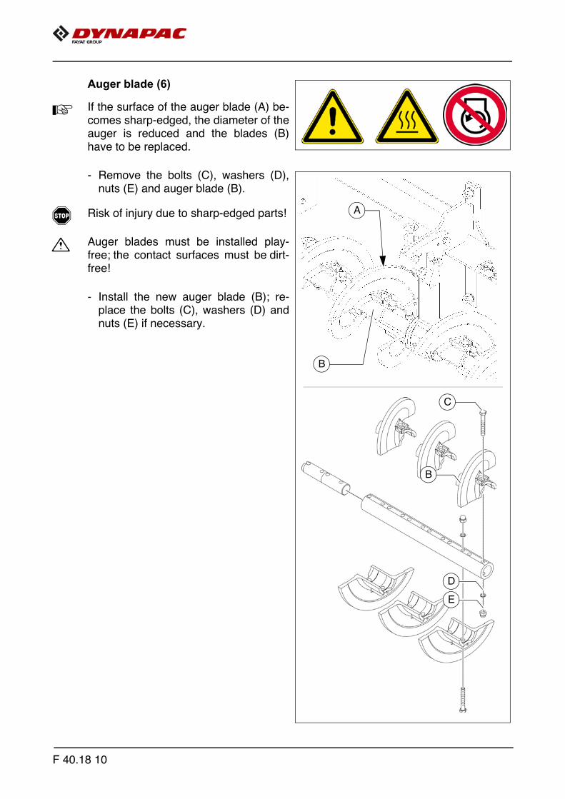
Auger blade (6)
A If the surface of the auger blade (A) be-comes sharp-edged, the diameter of theauger is reduced and the blades (B)have to be replaced.
- Remove the bolts (C), washers (D),nuts (E) and auger blade (B).
f Risk of injury due to sharp-edged parts!
m Auger blades must be installed play-free; the contact surfaces must be dirt-free!
- Install the new auger blade (B); re-place the bolts (C), washers (D) andnuts (E) if necessary.
A
B
C
D
E
B
F 40.18 10

F 50.18 Maintenance - engine assembly1 Maintenance - engine assembly
m As well as this maintenance manual, always also pay close attention to the mainte-nance manual provided by the engine manufacturer. All maintenance work and serv-ice intervals itemised here are binding in nature.
F 50.18 1

Danger of being pulled in by rotating or conveying vehicle partsRotating or conveying vehicle parts can cause severe or fatal injuries!
- Do not enter the danger zone.- Do not reach into rotating or conveying parts.- Only wear close-fitting clothing.- Comply with the warning and information signs
on the vehicle.- Stop the engine and remove the ignition key before any
maintenance work.- Comply with all further information in these instructions
and in the safety manual.
Hot surfaces!
Surfaces including those behind covering parts, together with combustion gases from the engine or screed heater can be very hot and cause injuries!
- Wear your personal safety gear.- Do not touch hot parts of the vehicle.- Only perform maintenance and repair work after the
vehicle has cooled down.- Comply with all further information in these instructions
and in the safety manual.
WARNING
CAUTION
F 50.18 2
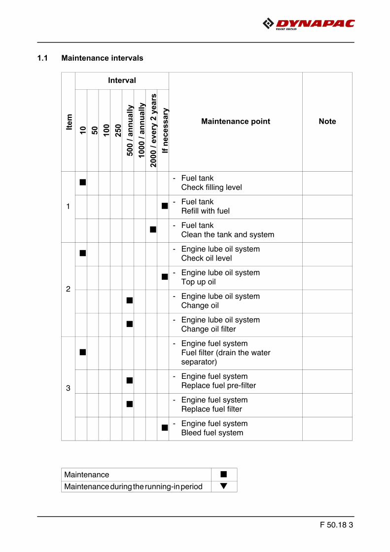
1.1 Maintenance intervalsIte
mInterval
Maintenance point Note
10 50 100
250
500
/ ann
ually
1000
/ an
nual
ly20
00 /
ever
y 2
year
sIf
nece
ssar
y
1
q - Fuel tankCheck filling level
q - Fuel tank Refill with fuel
q - Fuel tankClean the tank and system
2
q - Engine lube oil systemCheck oil level
q - Engine lube oil systemTop up oil
q - Engine lube oil systemChange oil
q - Engine lube oil systemChange oil filter
3
q- Engine fuel system
Fuel filter (drain the water separator)
q - Engine fuel systemReplace fuel pre-filter
q - Engine fuel systemReplace fuel filter
q - Engine fuel systemBleed fuel system
Maintenance qMaintenance during the running-in period g
F 50.18 3

Item
Interval
Maintenance point Note
10 50 100
250
500
/ ann
ually
1000
/ an
nual
ly20
00 /
ever
y 2
year
sIf
nece
ssar
y
4
q - Engine air filterCheck air filter
q- Engine air filter
Emptyingdust collector
q q- Engine air filter
Replaceair filter cartridge
5
q - Engine cooling systemCheck radiator fins
q q - Engine cooling systemClean radiator fins
q - Engine cooling systemCheck level of the coolant
q - Engine cooling systemTop up coolant
q - Engine cooling systemCheck coolant concentration
q - Engine cooling systemAdjust coolant concentration
q - Engine cooling systemChange coolant
Maintenance qMaintenance during the running-in period g
F 50.18 4
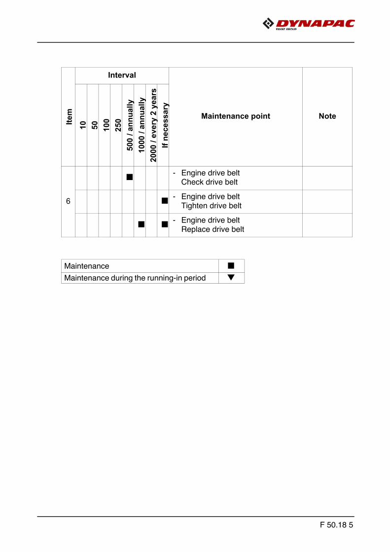
Item
Interval
Maintenance point Note
10 50 100
250
500
/ ann
ually
1000
/ an
nual
ly20
00 /
ever
y 2
year
sIf
nece
ssar
y
6
q - Engine drive beltCheck drive belt
q - Engine drive beltTighten drive belt
q q - Engine drive beltReplace drive belt
Maintenance qMaintenance during the running-in period g
F 50.18 5
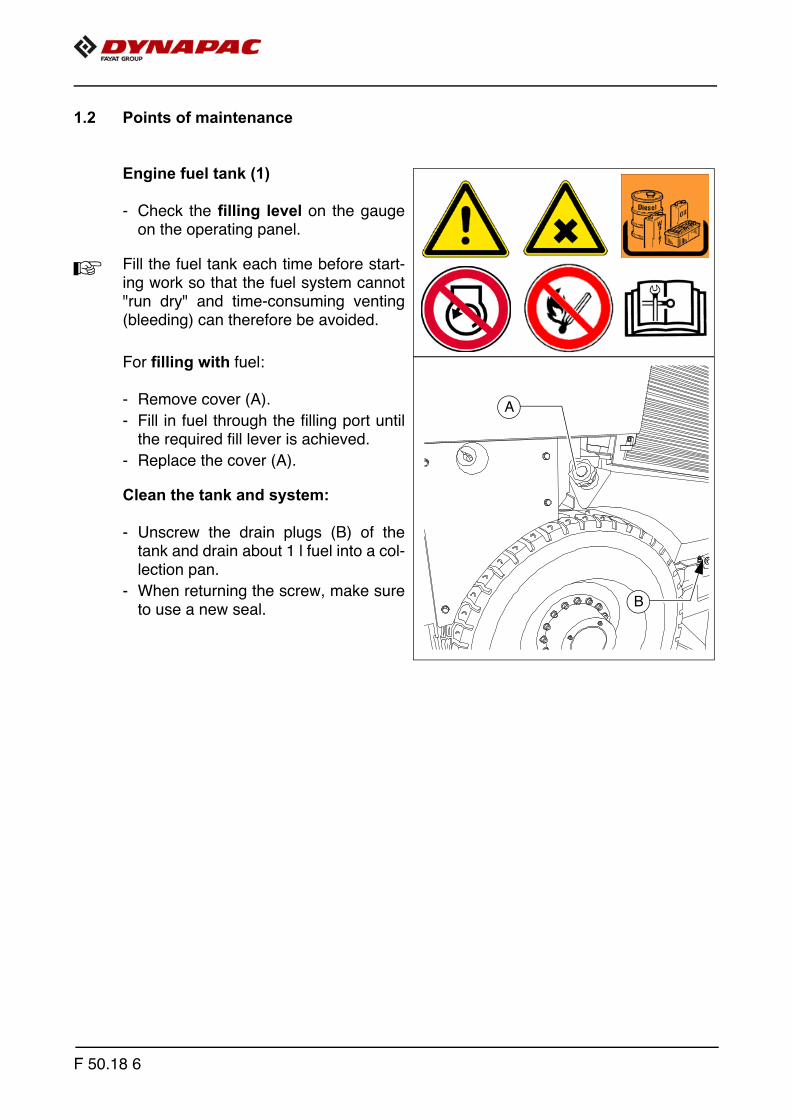
1.2 Points of maintenance
Engine fuel tank (1)
- Check the filling level on the gaugeon the operating panel.
A Fill the fuel tank each time before start-ing work so that the fuel system cannot"run dry" and time-consuming venting(bleeding) can therefore be avoided.
For filling with fuel:
- Remove cover (A).
- Fill in fuel through the filling port untilthe required fill lever is achieved.
- Replace the cover (A).
Clean the tank and system:
- Unscrew the drain plugs (B) of thetank and drain about 1 l fuel into a col-lection pan.
- When returning the screw, make sureto use a new seal.
A
B
F 50.18 6

Engine lube oil system (2)
Check oil level
A In case of correct oil level, the oil is be-tween the two notches of the dipstick (A).
A Only check the oil level when the finisheris in a horizontal position!
A The sensor rod is located at the front end of the engine.
m Too much oil in engine damages gas-kets; too little oil results in overheatingand engine destruction.
For filling with oil:
- Remove cover (B).
- Fill up oil to correct level.
- Return cover (B).
- Use dipstick to check level again.
B
A
F 50.18 7

Oil change:
A The oil should be changed when at operating temperature.
- Place the end of the oil drain port hose(C) in the collection container.
- Remove the screw cap with a wrenchand allow the oil to drain completely.
- Replace the screw cap and tightenproperly.
- Fill in the specified quality of oilthrough the filler opening (B) on theengine until the oil level rises to thecorrect mark on the dipstick (A).
Changing the oil filter:
A The new filter is inserted during an oilchange once the used oil has beendrained out.
A The oil filter is located at the front end ofthe engine. (Use the maintenance flapfor access)
- Loosen the filter (D) using a filterwrench or filter strap and unscrew.
- Collect escaping lubricating oil.
- Clean the sealing face of the filter car-rier with a clean, lint-free cloth.
- Slightly lubricate the seal of the newfilter before installing it.
- Screw the new filter in by hand until the seal makes contact and tighten with atorque of 15-17 Nm.
A After installing the oil filter, attention must be paid to the oil pressure display and goodsealing during the test run. Check oil level again.
C
D
F 50.18 8

Engine fuel system (3)
A The fuel filter system consists oftwo filters:
- Prefilter (A) with water separator
- Main filter (B)
Prefilter - draining of water
A Drain the collecting vessel at regular in-tervals, or in response to an error mes-sage from the engine control unit.
- Put a suitable drip pan underneath.
- Disconnect the electrical connection/cable connection.
- Loosen drain plug (C).
- Drain off liquid until pure diesel fuelemerges.
- Tighten the drain plug (C) again.
- Restore the electrical connection/ca-ble connection.
A
B
A
C
F 50.18 9
Changing the prefilter:
- Put a suitable drip pan underneath.
- Disconnect the electrical connection/cable connection.
- Loosen drain plug (C) and drain off liquid.
- Untighten the filter cartridge (A) using a pair of oil filter tongs or oil filter strap andunscrew it.
- Clean any dirt from the sealing face of the new filter cartridge and the opposite sideof the filter head.
- Lightly coat the oil filter cartridge seal with fuel and screw hand-tight under thebracket (17-18 Nm.
- Restore the electrical connection/cable connection.
- Tighten the drain plug (C).
- Bleed the fuel system
Bleed the fuel system:
A The fuel system is bled using the electric fuel feed pump. Do not attempt to start the ve-hicle while the fuel system is being bled to ensure that no error message is generated.
- Ignition "ON"
A The electronic fuel feed pump switches on for 20 seconds to bleed the fuel systemand build up the necessary fuel pressure.
A Wait until the electric fuel feed pump is switched off by the control unit.
- Ignition "OFF"
A Repeat at least twice until the fuel system is bled.
Replacing the main filter:
- Untighten the filter cartridge (B) using a pair of oil filter tongs or oil filter strap andunscrew it.
- Clean any dirt from the sealing face of the new filter cartridge and the opposite sideof the filter head.
- Lightly coat the oil filter cartridge seal with fuel and screw hand-tight under thebracket (17-18 Nm.
A After fitting the filter, ensure good sealing action during the test run.
F 50.18 10

Engine air filter (4)
Empty dust collector
- Empty the dust removal valve (B) onthe air cleaner housing (A) by pressingthe discharge port in the direction ofthe arrow.
- Remove any baked on dust by press-ing together the upper valve section.
A Clean the discharge port from timeto time.
Cleaning / replacing the air filter cartridge
A Pollution of the combustion air filter de-pends on the dust content of the air andthe mesh size of the filter selected.
A Filter maintenance becomes necessary if:
- Maintenance interval or
- Engine electronics service indicator
- Open the air filter lid.
- Pull out the filter cartridge (D) and thesafety cartridge (E).
A Clean the filter cartridge (D) and replaceafter one year at the latest.
- Blow out with dry pressure air (max. 5 bar) from inside out or tap it (in case of emer-gency only).
A Do not damage cartridge when doing so.
- Check the soundness of the filter papers of the filter cartridge (by exposing to light)and the soundness of the seals. Replace them as required.
A Replace the safety cartridge (E) together with the filter cartridge (D)
A
BD
E
B
F 50.18 11

Engine cooling system (5)
Checking / topping up coolant
The cooling water level must be checkedwhen the system is cold. Make sure thatthe anti-freeze and anti-corrosive liquidis sufficient (-25°C).
f When hot, the system is under pressure.When opening, there is a dangerof scalding!
A If necessary fill in a sufficient amount ofcoolant through the open port (A) of thecompensating tank.
Change coolant
f When hot, the system is under pressure.When opening, there is a dangerof scalding!
m Use only approved coolants!
A Observe the instructions in the chapterentitled "Operating substances"!
- Remove the drain screw (B) on the ra-diator and let the coolant drain com-pletely.
- Reinstall the drain screw (B) and tight-en properly.
- Fill in coolant through the filling open-ing (A) on the compensation tank untilthe coolant level rises to the centre ofthe sight glass (C).
m The air is only able to escape completelyfrom the cooling system once the enginehas reached its operating temperature(at least 90°C).Check the fluid level again, top up if necessary.
A
B
C
F 50.18 12

Checking and cleaning the radiator fins
- If necessary, remove leaves, dust or sand from the radiator.
A Observe engine's operating instructions
Checking coolant concentration
- Check the concentration using a suitable tester (hydrometer).
- Adjust the concentration if necessary.
A Observe engine's operating instructions
F 50.18 13

Engine drive belt (6)
Check drive belt
- Check the drive belt for damage.
A Small transverse cracks in the belt areacceptable.
m In the event of longitudinal cracks whichintersect with transverse cracks anddamaged material surfaces, belt re-placement is necessary.
A Observe engine's operating instructions
Replace drive belt
A Observe engine's operating instructions
F 50.18 14
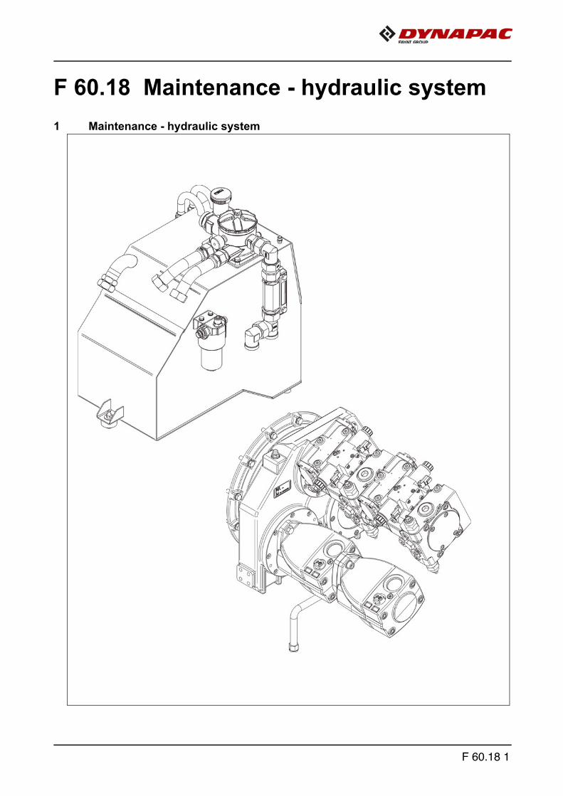
F 60.18 Maintenance - hydraulic system1 Maintenance - hydraulic system
F 60.18 1

Danger due to hydraulic oil
Hydraulic oil under high pressure can cause severe tofatal injuries!
- Only competent staff should work on the hydraulic system!
- Any hydraulic hoses that are cracked or soaked through must be replaced immediately.
- Depressurise the hydraulic system.- Lower screed and open hopper.- Stop the engine and remove the ignition key before any
maintenance work.- Secure the vehicle to prevent it being switched on again.- Consult a doctor immediately if injured.- Comply with all further information in these instructions
and in the safety manual.
Hot surfaces!
Surfaces including those behind covering parts, together with combustion gases from the engine or screed heater can be very hot and cause injuries!
- Wear your personal safety gear.- Do not touch hot parts of the vehicle.- Only perform maintenance and repair work after the
vehicle has cooled down.- Comply with all further information in these instructions
and in the safety manual.
WARNING
CAUTION
F 60.18 2

Danger from residual pressure in hydraulic lines
Residual pressure in the hydraulic system can cause severe or fatal injuries!
- Proceed as follows before working on the hydraulic system:
- Depressurise the hydraulic system for maintenance:2. Open hopper.3. Move levelling cylinder to lower limit position.4. Retract screed.5. Lower the screed to the floating position.6. Set crowning to 0°.7. Move front hopper cylinder to lower limit position.
- Stop the engine and remove the ignition key before any maintenance work.
- Secure the vehicle to prevent it being switched on again.- Let the hydraulic oil cool down.
A After depressurising, begin slowly and carefullywhen opening the threaded connections in the hy-draulic lines.Continue to loosen the threaded connections withcaution in order to notice possible dangers resultingfrom any still remaining pressure in the hydraulic fluid(here it may help to knock gently on the threaded con-nection) so that precautions can be taken.Do not continue loosening the threaded connectionif there is still any remaining pressure in the system. Depressurise the system again and check oncemore that this has been effective.
WARNING
F 60.18 3
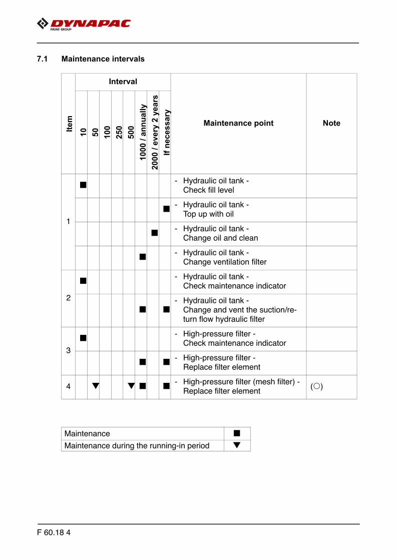
7.1 Maintenance intervalsIte
mInterval
Maintenance point Note
10 50 100
250
500
1000
/ an
nual
ly20
00 /
ever
y 2
year
sIf
nece
ssar
y
1
q - Hydraulic oil tank - Check fill level
q - Hydraulic oil tank - Top up with oil
q - Hydraulic oil tank - Change oil and clean
q - Hydraulic oil tank - Change ventilation filter
2
q - Hydraulic oil tank -Check maintenance indicator
q q- Hydraulic oil tank -
Change and vent the suction/re-turn flow hydraulic filter
3
q - High-pressure filter -Check maintenance indicator
q q - High-pressure filter -Replace filter element
4 g g q q - High-pressure filter (mesh filter) - Replace filter element
(o)
Maintenance qMaintenance during the running-in period g
F 60.18 4

Item
Interval
Maintenance point Note
10 50 100
250
500
1000
/ an
nual
ly20
00 /
ever
y 2
year
sIf
nece
ssar
y
5
q - Pump distribution gear -Check oil level
q - Pump distribution gear -Top up oil
g q - Pump distribution gear -Change oil
q - Pump distribution gear -Check bleeder
q - Pump distribution gear -Clean bleeder
6
gq
- Hydraulic hoses -Visual inspection
gq
- Hydraulic systemLeak test
q - Hydraulic system-Retighten screw connections
q q - Hydraulic hoses -Replace hoses
7 q q - Auxiliary flow filter-Replace filter element
(o)
Maintenance qMaintenance during the running-in period g
F 60.18 5

7.2 Points of maintenance
Hydraulic oil tank (1)
- Check oil level at sight glass (A).
A The oil level must be up to the centreof the sight glass when the cylindersare retracted.
A If all the cylinders are extended, the levelcan fall below the sight glass.
A The sight glass is located on the side ofthe tank.
For filling with oil:
- Remove cap (B).
- Fill in oil through the filler opening untilthe oil level rises to the centre of thesight glass (A) (+/- 5 mm).
- Screw cap (B) on again.
A Regularly remove dust and pollutionfrom the oil tank vent integrated inthe cover (B). Clean the surfaces of theoil cooler.
m Use only the recommended hydraulicoils - see section "Recommended hy-draulic oils".
A When filling for the first time, all hydrauliccylinders should by extended/retractedat least twice!
A
B
F 60.18 6
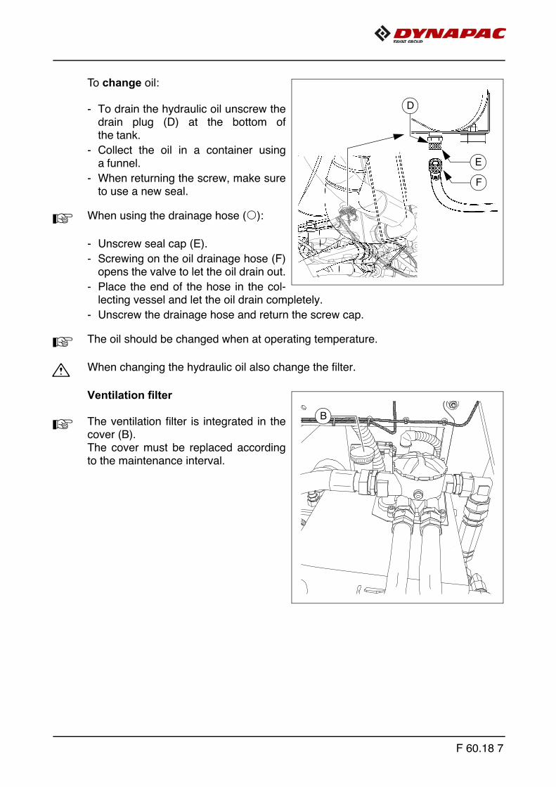
To change oil:
- To drain the hydraulic oil unscrew thedrain plug (D) at the bottom ofthe tank.
- Collect the oil in a container usinga funnel.
- When returning the screw, make sureto use a new seal.
A When using the drainage hose (o):
- Unscrew seal cap (E).
- Screwing on the oil drainage hose (F)opens the valve to let the oil drain out.
- Place the end of the hose in the col-lecting vessel and let the oil drain completely.
- Unscrew the drainage hose and return the screw cap.
A The oil should be changed when at operating temperature.
m When changing the hydraulic oil also change the filter.
Ventilation filter
A The ventilation filter is integrated in thecover (B). The cover must be replaced accordingto the maintenance interval.
D
E
F
B
F 60.18 7
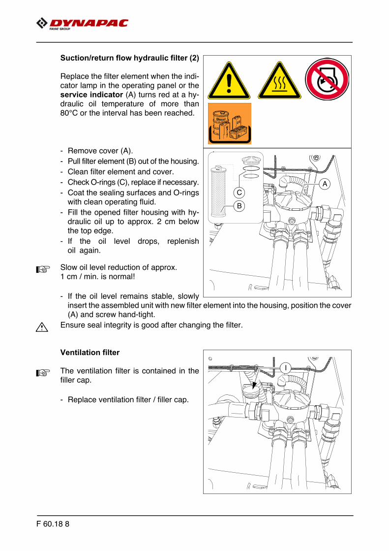
Suction/return flow hydraulic filter (2)
Replace the filter element when the indi-cator lamp in the operating panel or theservice indicator (A) turns red at a hy-draulic oil temperature of more than80°C or the interval has been reached.
- Remove cover (A).
- Pull filter element (B) out of the housing.
- Clean filter element and cover.
- Check O-rings (C), replace if necessary.
- Coat the sealing surfaces and O-ringswith clean operating fluid.
- Fill the opened filter housing with hy-draulic oil up to approx. 2 cm belowthe top edge.
- If the oil level drops, replenishoil again.
A Slow oil level reduction of approx. 1 cm / min. is normal!
- If the oil level remains stable, slowlyinsert the assembled unit with new filter element into the housing, position the cover(A) and screw hand-tight.
m Ensure seal integrity is good after changing the filter.
Ventilation filter
A The ventilation filter is contained in thefiller cap.
- Replace ventilation filter / filler cap.
A
B
C
I
F 60.18 8
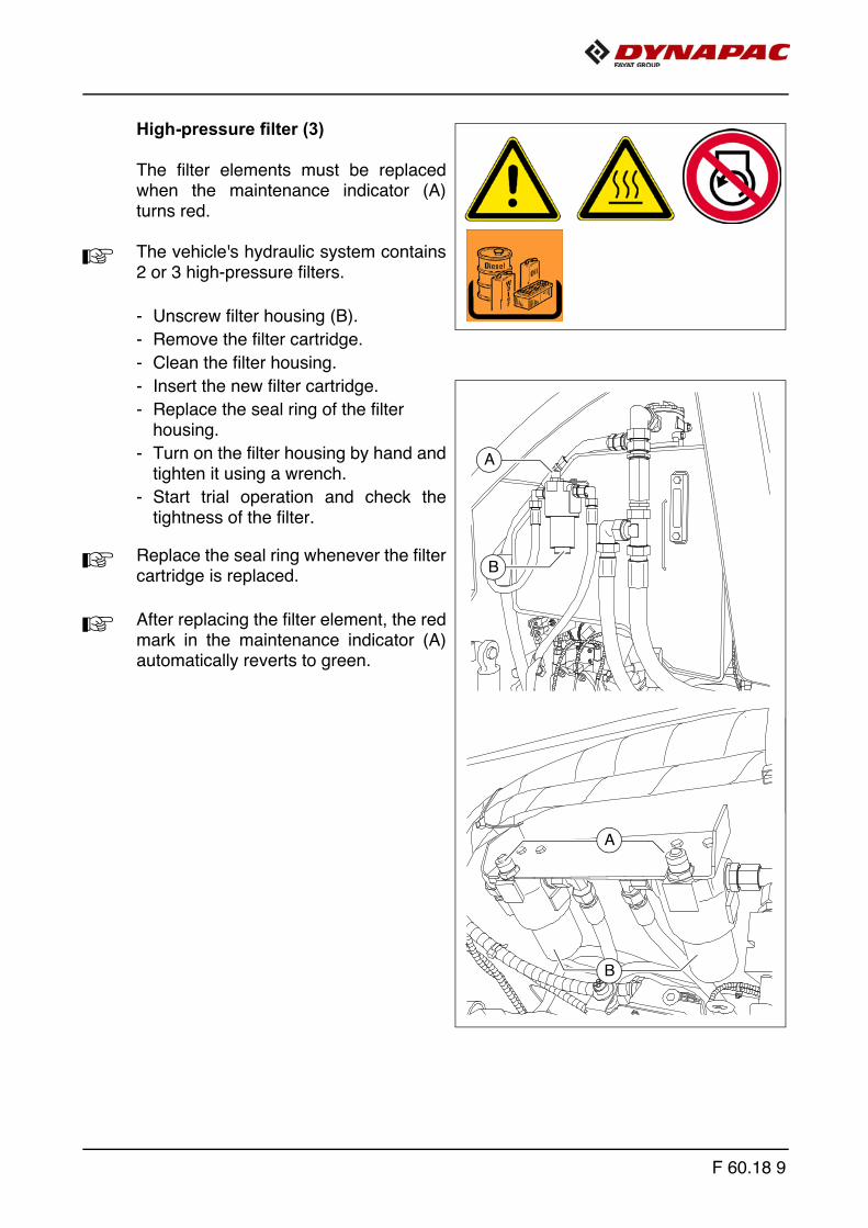
High-pressure filter (3)
The filter elements must be replacedwhen the maintenance indicator (A)turns red.
A The vehicle's hydraulic system contains2 or 3 high-pressure filters.
- Unscrew filter housing (B).
- Remove the filter cartridge.
- Clean the filter housing.
- Insert the new filter cartridge.
- Replace the seal ring of the filterhousing.
- Turn on the filter housing by hand andtighten it using a wrench.
- Start trial operation and check thetightness of the filter.
A Replace the seal ring whenever the filtercartridge is replaced.
A After replacing the filter element, the redmark in the maintenance indicator (A)automatically reverts to green.
B
A
A
B
F 60.18 9
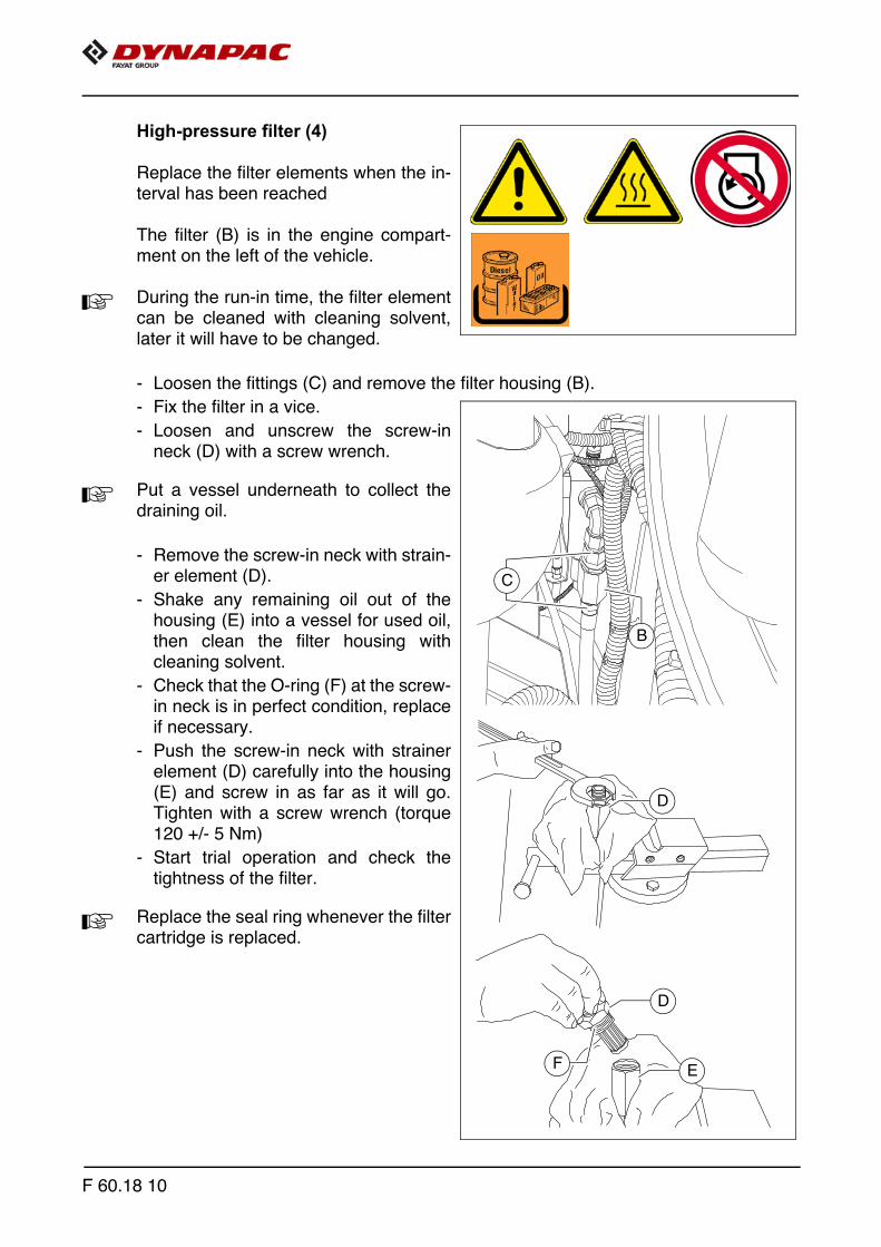
High-pressure filter (4)
Replace the filter elements when the in-terval has been reached
The filter (B) is in the engine compart-ment on the left of the vehicle.
A During the run-in time, the filter elementcan be cleaned with cleaning solvent,later it will have to be changed.
- Loosen the fittings (C) and remove the filter housing (B).
- Fix the filter in a vice.
- Loosen and unscrew the screw-inneck (D) with a screw wrench.
A Put a vessel underneath to collect thedraining oil.
- Remove the screw-in neck with strain-er element (D).
- Shake any remaining oil out of thehousing (E) into a vessel for used oil,then clean the filter housing withcleaning solvent.
- Check that the O-ring (F) at the screw-in neck is in perfect condition, replaceif necessary.
- Push the screw-in neck with strainerelement (D) carefully into the housing(E) and screw in as far as it will go.Tighten with a screw wrench (torque120 +/- 5 Nm)
- Start trial operation and check thetightness of the filter.
A Replace the seal ring whenever the filtercartridge is replaced.
C
B
D
D
EF
F 60.18 10

Pump distribution gear (5)
- Check the oil level at the sightglass (A) (at the side of thegear housing).
A The oil level must be up to the centre ofthe sight glass.
For filling with oil:
- Unscrew the filler screw (B).
- Fill oil in through the filling port until therequired filling level is achieved at thesight glass (A).
- Screw in the filler screw (B) again.
m Make sure to clean the screw and the vi-cinity of the drain bore!
Oil change:
- Place the end of the oil drain port hose(C) in the collection container.
- Remove the screw cap with a wrenchand allow the oil to drain completely.
- Replace the screw cap and tightenproperly.
- Fill in the oil of specified qualitythrough the filling port on the gearbox(B) until the oil level rises to the centreof the sight glass (A).
A The oil should be changed when at oper-ating temperature.
A
B
C
F 60.18 11
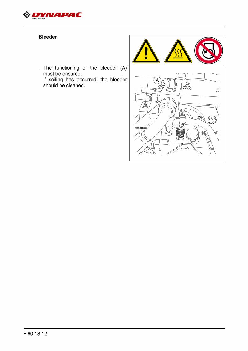
Bleeder
- The functioning of the bleeder (A)must be ensured.If soiling has occurred, the bleedershould be cleaned.
A
F 60.18 12
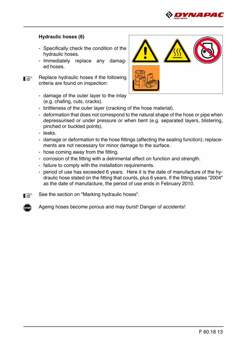
Hydraulic hoses (6)
- Specifically check the condition of thehydraulic hoses.
- Immediately replace any damag-ed hoses.
A Replace hydraulic hoses if the followingcriteria are found on inspection:
- damage of the outer layer to the inlay(e.g. chafing, cuts, cracks).
- brittleness of the outer layer (cracking of the hose material).
- deformation that does not correspond to the natural shape of the hose or pipe whendepressurised or under pressure or when bent (e.g. separated layers, blistering,pinched or buckled points).
- leaks.
- damage or deformation to the hose fittings (affecting the sealing function); replace-ments are not necessary for minor damage to the surface.
- hose coming away from the fitting.
- corrosion of the fitting with a detrimental effect on function and strength.
- failure to comply with the installation requirements.
- period of use has exceeded 6 years. Here it is the date of manufacture of the hy-draulic hose stated on the fitting that counts, plus 6 years. If the fitting states "2004"as the date of manufacture, the period of use ends in February 2010.
A See the section on "Marking hydraulic hoses".
f Ageing hoses become porous and may burst! Danger of accidents!
F 60.18 13
m Always comply with the following instructions when installing and removing hydrau-lic hoses:
- Always only use original Dynapac hydraulic hoses!
- Always observe high standards of cleanliness!
- Hydraulic hoses must always be fitted to ensure that in all operating statuses,
- there is no tensile load apart from dead weight.
- there is no compressive load for short lengths.
- any external mechanical impact on the hydraulic hoses is avoided.
- appropriate positioning and fastening of the hoses prevents them from chafing oncomponents or on each other. components with sharp edges must be covered when installing hydraulic hoses.
- bending radii are not smaller than the permitted values.
- When hydraulic hoses are connected to moving parts, the length of the hose mustbe dimensioned to ensure that the bending radii are not smaller than the permittedsmallest values right across the full range of movement and/or that the hydraulichose is not also exposed to tension.
- Fasten the hydraulic hoses to the provided fastening points. the hoses must not behindered in their natural movement and change in length.
- Painting the hydraulic hoses is forbidden!
F 60.18 14

Marking hydraulic hoses / storage pe-riod, period of use
A A number stamped onto the screwedconnection provides information aboutthe date of manufacture (A) (month /year) and the maximum pressure per-mitted for this hose (B).
m Never install hoses on top of one anoth-er and always ensure that they are at thecorrect pressure.
In individual cases, the period of use canbe stipulated according to experienceand may differ from the following generalindications:
- When producing the hose pipe, the hose (purchased by the meter) should not bemore than four years old.
- The period of use of a hose pipe should not exceed six years, including any possi-ble storage period. The storage period should not exceed two years.
DHH 03/11 225BAR
A B
F 60.18 15
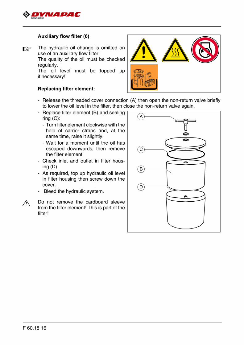
Auxiliary flow filter (6)
A The hydraulic oil change is omitted onuse of an auxiliary flow filter! The quality of the oil must be checkedregularly. The oil level must be topped upif necessary!
Replacing filter element:
- Release the threaded cover connection (A) then open the non-return valve brieflyto lower the oil level in the filter, then close the non-return valve again.
- Replace filter element (B) and sealingring (C):
- Turn filter element clockwise with thehelp of carrier straps and, at thesame time, raise it slightly.
- Wait for a moment until the oil hasescaped downwards, then removethe filter element.
- Check inlet and outlet in filter hous-ing (D).
- As required, top up hydraulic oil levelin filter housing then screw down thecover.
- Bleed the hydraulic system.
m Do not remove the cardboard sleevefrom the filter element! This is part of thefilter!
A
D
C
B
F 60.18 16

F 71.18 Maintenance - travel drive, steering
1 Maintenance - travel drive, steering
F 71.18 1

Danger of being pulled in by rotating or conveying vehicle partsRotating or conveying vehicle parts can cause severe or fatal injuries!
- Do not enter the danger zone.- Do not reach into rotating or conveying parts.- Only wear close-fitting clothing.- Comply with the warning and information signs
on the vehicle.- Stop the engine and remove the ignition key before any
maintenance work.- Comply with all further information in these instructions
and in the safety manual.
Danger from heavy loads
Lowering vehicle parts may cause injuries!
- When the vehicle is parked and during maintenance and transport, close both hopper lids and fit the correspond-ing hopper transport safeguards.
- When the vehicle is parked and during maintenance and transport, raise the screen and fit the corresponding screed transport safeguards.
- Ensure that opened hoods and covering parts are locked properly.
- Comply with all further information in these instructions and in the safety manual.
Hot surfaces!
Surfaces including those behind covering parts, together with combustion gases from the engine or screed heater can be very hot and cause injuries!
- Wear your personal safety gear.- Do not touch hot parts of the vehicle.- Only perform maintenance and repair work after the
vehicle has cooled down.- Comply with all further information in these instructions
and in the safety manual.
WARNING
CAUTION
CAUTION
F 71.18 2

1.1 Maintenance intervals
Item
Interval
Maintenance point Note
10 50 100
250
500
1000
/ an
nual
ly20
00 /
ever
y 2
year
sIf
nece
ssar
y
1
q - Planetary gear -Check oil level
q - Planetary gear -Top up oil
g q - Planetary gear -Change oil
q - Planetary gear -Check oil quality
Maintenance q
Maintenance during the running-in period g
F 71.18 3

Item
Interval
Maintenance point Note
10 50 100
250
500
1000
/ an
nual
ly20
00 /
ever
y 2
year
sIf
nece
ssar
y
2
q - Drive wheels -Check tyres for damage
q - Drive wheels - Replace tyres
q - Drive wheels - Check air pressure
q - Drive wheels - Adjust air pressure
g - Drive wheels - Check wheel nuts
q - Drive wheels - Tighten wheel nuts
3
q - Lubricating points - Lubricate king pins
q - Lubricating points - Lubricate steering
q - Lubricating points - Lubricate floating axle
q - Lubricating points - Lubricate wheel bearings (o)
Maintenance q
Maintenance during the running-in period g
F 71.18 4
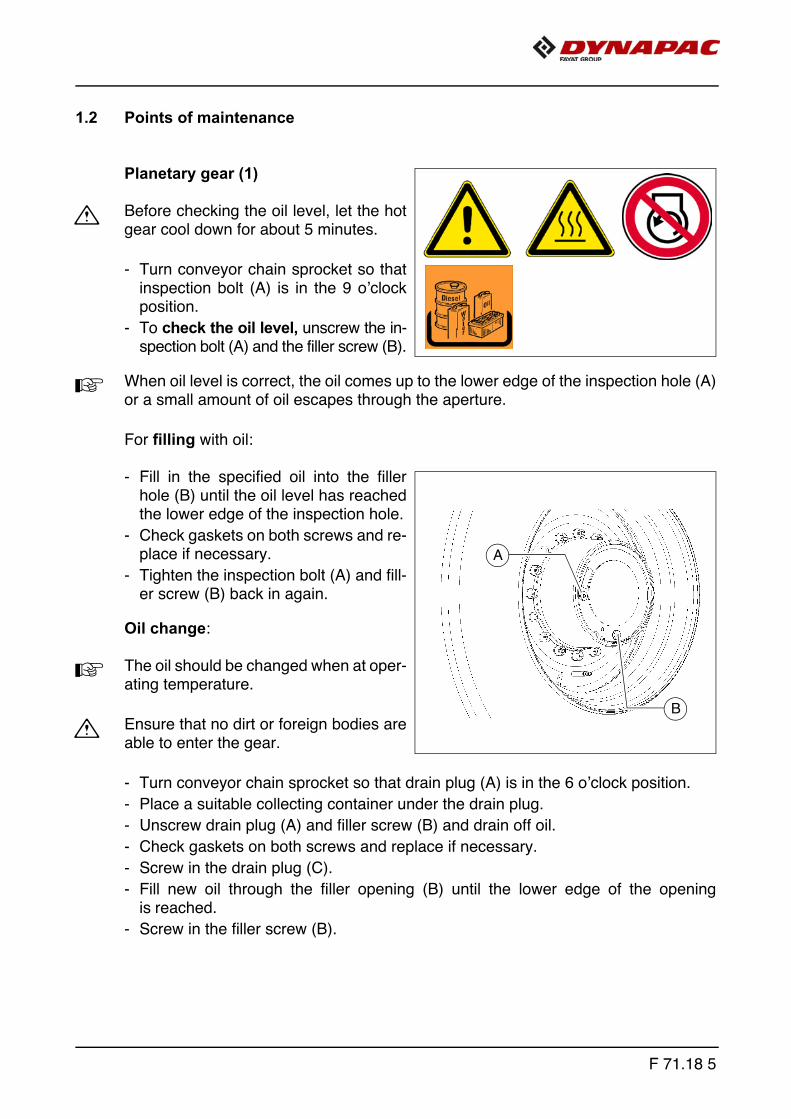
1.2 Points of maintenance
Planetary gear (1)
m Before checking the oil level, let the hotgear cool down for about 5 minutes.
- Turn conveyor chain sprocket so thatinspection bolt (A) is in the 9 o’clockposition.
- To check the oil level, unscrew the in-spection bolt (A) and the filler screw (B).
A When oil level is correct, the oil comes up to the lower edge of the inspection hole (A)or a small amount of oil escapes through the aperture.
For filling with oil:
- Fill in the specified oil into the fillerhole (B) until the oil level has reachedthe lower edge of the inspection hole.
- Check gaskets on both screws and re-place if necessary.
- Tighten the inspection bolt (A) and fill-er screw (B) back in again.
Oil change:
A The oil should be changed when at oper-ating temperature.
m Ensure that no dirt or foreign bodies areable to enter the gear.
- Turn conveyor chain sprocket so that drain plug (A) is in the 6 o’clock position.
- Place a suitable collecting container under the drain plug.
- Unscrew drain plug (A) and filler screw (B) and drain off oil.
- Check gaskets on both screws and replace if necessary.
- Screw in the drain plug (C).
- Fill new oil through the filler opening (B) until the lower edge of the openingis reached.
- Screw in the filler screw (B).
A
B
F 71.18 5
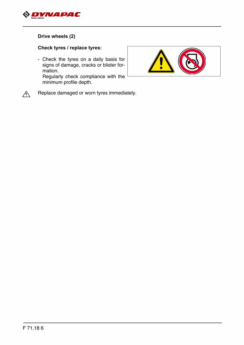
Drive wheels (2)
Check tyres / replace tyres:
- Check the tyres on a daily basis forsigns of damage, cracks or blister for-mation.Regularly check compliance with theminimum profile depth.
m Replace damaged or worn tyres immediately.
F 71.18 6

Replacing/dismantling and installing the wheels
f The jack must be rated for at least 10t.
f The jack is only intended to lift a load and not as a support. Work should only be per-formed to and under raised vehicles when they have been secured and correctly sup-ported to prevent them from tilling over and rolling or sliding away.
f The jack must only be used on smooth, firm ground.
f Roller-type jacks must not be moved when under load.
f Chocks or supporting beams positioned so that they cannot be shifted or tilted mustbe adequately dimensioned and be able to take the corresponding weight.
f There must not be anyone on the vehicle while it is being lifted.
F 71.18 7

- Lower screed, remove screed and crossbeam.
- Lift the machine with the jack at the intended position (1) under the machine frame.
- Place a wooden block under the raised wheel as a safeguard.
- Place another wooden block under the machine frame at point (2).
m The wooden block must support the vehicle frame at the side wall and rear wall.
- Remove the wooden block under the raised wheel and gently lower the vehicle ontothe remaining wooden block (2).
- Dismantle the wheel nuts and remove the wheel.
A Reassemble in reverse order.
1 2
F 71.18 8

Check air pressure / adjust air pressure:
m Never work with the tyre pressure toohigh or too low!
A Please consult the following tables forthe necessary air pressures.
Check the air pressure at valve (A), ad-just if necessary.
A Check the tyre pressure in cold condi-tion. A slight increase in tyre pressureduring operation is normal and there isno need to relieve pressure.
f Only ever set the tyre pressure using a self-regulating filler connection. Never standdirectly in front of the tyres when filling them with air!
f Please comply with the safety instructions for checking and adjusting the air pressure!
A Bear in mind that tyres may be filled with water!
A
F 71.18 9

Check wheel nuts / tighten wheel nuts:
A Following wheel replacement, check thewheel nuts after the running-in time.
- Check / tighten all wheel nuts using atorque wrench as shown.
A Adjust the torque to 288 Nm.11
3
13
91
12
4
14
6
2
5
7
1510
8
16
F 71.18 10

Lubrication points (3)
A Manual lubrication does not apply for ve-hicles with central lubrication system.
Wheel bearings (o)
A The lube nipples (A) are accessiblethrough a hole in the wheel rim.
A The number of lube nipples depends onwhether the vehicle is equipped with /without front wheel drive.
5x
A
F 71.18 11

F 71.18 12

F 81.18 Maintenance - electrical system1 Maintenance - electrical system
F 81.18 1
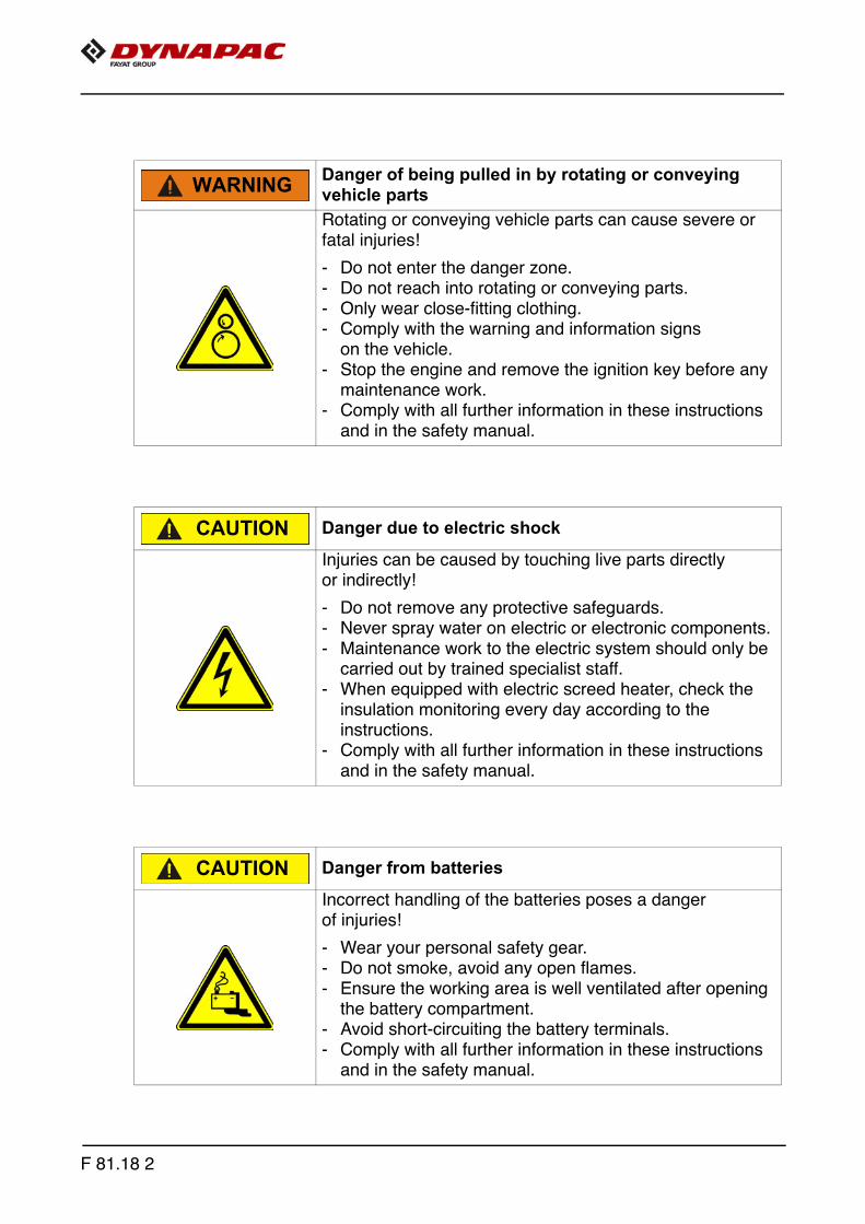
Danger of being pulled in by rotating or conveying vehicle partsRotating or conveying vehicle parts can cause severe or fatal injuries!
- Do not enter the danger zone.- Do not reach into rotating or conveying parts.- Only wear close-fitting clothing.- Comply with the warning and information signs
on the vehicle.- Stop the engine and remove the ignition key before any
maintenance work.- Comply with all further information in these instructions
and in the safety manual.
Danger due to electric shock
Injuries can be caused by touching live parts directlyor indirectly!
- Do not remove any protective safeguards.- Never spray water on electric or electronic components.- Maintenance work to the electric system should only be
carried out by trained specialist staff.- When equipped with electric screed heater, check the
insulation monitoring every day according to theinstructions.
- Comply with all further information in these instructions and in the safety manual.
Danger from batteries
Incorrect handling of the batteries poses a danger of injuries!
- Wear your personal safety gear.- Do not smoke, avoid any open flames.- Ensure the working area is well ventilated after opening
the battery compartment.- Avoid short-circuiting the battery terminals.- Comply with all further information in these instructions
and in the safety manual.
WARNING
CAUTION
CAUTION
F 81.18 2
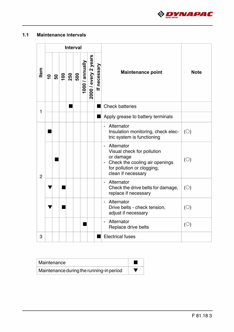
1.1 Maintenance intervalsIte
mInterval
Maintenance point Note
10 50 100
250
500
1000
/ an
nual
ly20
00 /
ever
y 2
year
sIf
nece
ssar
y
1q q Check batteries
q Apply grease to battery terminals
2
q- Alternator
Insulation monitoring, check elec-tric system is functioning
(o)
q
- AlternatorVisual check for pollution or damage
- Check the cooling air openings for pollution or clogging, clean if necessary
(o)
g q- Alternator
Check the drive belts for damage, replace if necessary
(o)
g q- Alternator
Drive belts - check tension, adjust if necessary
(o)
q - AlternatorReplace drive belts
(o)
3 q Electrical fuses
Maintenance q
Maintenance during the running-in period g
F 81.18 3
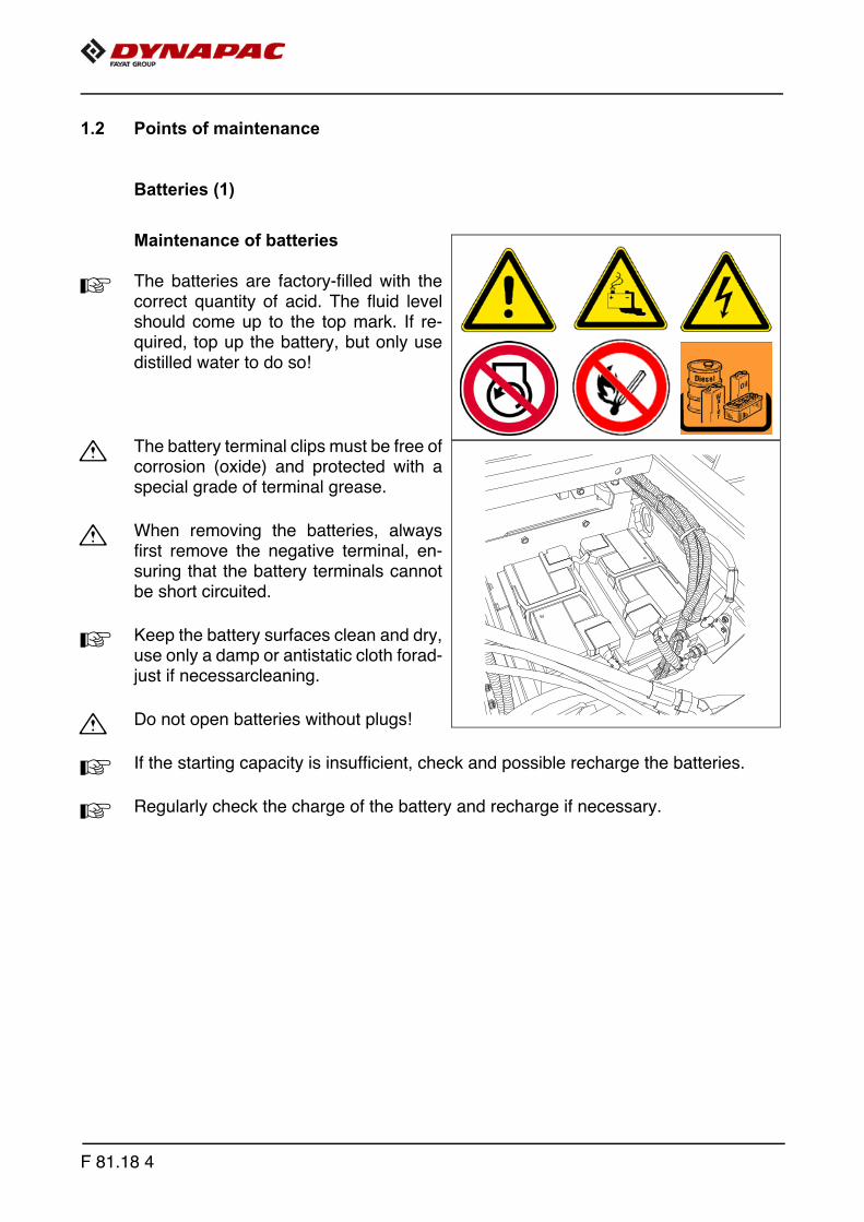
1.2 Points of maintenance
Batteries (1)
Maintenance of batteries
A The batteries are factory-filled with thecorrect quantity of acid. The fluid levelshould come up to the top mark. If re-quired, top up the battery, but only usedistilled water to do so!
m The battery terminal clips must be free ofcorrosion (oxide) and protected with aspecial grade of terminal grease.
m When removing the batteries, alwaysfirst remove the negative terminal, en-suring that the battery terminals cannotbe short circuited.
A Keep the battery surfaces clean and dry,use only a damp or antistatic cloth forad-just if necessarcleaning.
m Do not open batteries without plugs!
A If the starting capacity is insufficient, check and possible recharge the batteries.
A Regularly check the charge of the battery and recharge if necessary.
F 81.18 4
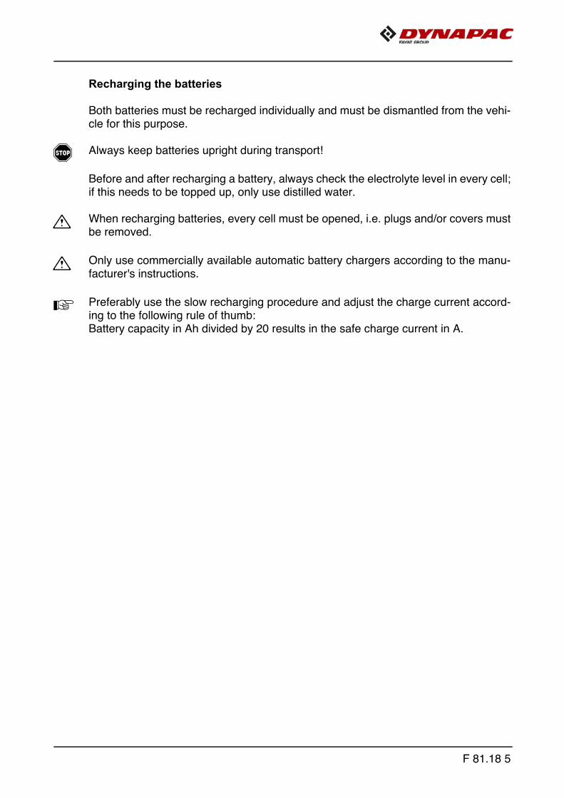
Recharging the batteries
Both batteries must be recharged individually and must be dismantled from the vehi-cle for this purpose.
f Always keep batteries upright during transport!
Before and after recharging a battery, always check the electrolyte level in every cell;if this needs to be topped up, only use distilled water.
m When recharging batteries, every cell must be opened, i.e. plugs and/or covers mustbe removed.
m Only use commercially available automatic battery chargers according to the manu-facturer's instructions.
A Preferably use the slow recharging procedure and adjust the charge current accord-ing to the following rule of thumb: Battery capacity in Ah divided by 20 results in the safe charge current in A.
F 81.18 5

Alternator (2)
Electrical system insulation monitoring
The function of the protective insulation monitoring measure must be checked everyday before starting work.
A This check only checks the function of the insulation monitor, not whether an insula-tion error has occurred on the heating sections or consumers.
- Start the paver finisher's drive engine.
- Switch heating system switch (1) to ON.
- Press test button (2).
- The indicator lamp integrated into the test button signals "insulation fault".
- Press reset button (3) for at least 3 sec. to delete the simulated fault.
- The indicator lamp goes out.
1 32
F 81.18 6
f If the test is conducted successfully, work may be undertaken with the screed and ex-ternal consumers may be used.If the "insulation fault" indicator lamp displays a fault even before the test button ispressed or if no fault is displayed during the simulation, work must not be undertakenwith the screed or with connected, external equipment.
f The screed and equipment must be checked or repaired by a specialist electri-cian. Only then may work again be undertaken with the screed and equipment.
f Danger from electric voltage
f Non-adherence to the safety precautions and safety regulationswhen operating the electric screed heating system leads to arisk of electric shock.Danger to life.All maintenance and repair work on the screed's electrical system may be car-ried out by a specialist electrician only.
F 81.18 7

Insulation faults
A If an insulation fault occurs during operation, and the indicator lamp displays an insu-lation fault, the operator may proceed as follows:
- Switch the switches of all external equipment and the heating system to OFF andpress the reset button for at least 3 seconds to delete the fault.
- If the indicator lamp does not go out, the fault lies in the alternator.
f No further work may be carried out.
- If the indicator lamp goes out, the switches of the heating system and externalequipment can be switched back to ON one after another until a message againappears and the system is shut-down.
- The equipment found to be faulty must be removed or must not be engaged, andthe reset button must be pressed for at least 3 seconds to delete the fault.
A Operation may now be continued - without the faulty equipment, of course.
A The alternator or electrical consumer found to be faulty must bechecked or repaired by a specialist electrician. Only then maywork again be carried out with the screed and equipment.
F 81.18 8

Cleaning the alternator
m The alternator must be regularlychecked for excessive dirt and must becleaned if necessary.
- The air intake (1) must be kept freeof dirt.
m Cleaning with a high-pressure cleaner isnot permissible!
1
F 81.18 9

Drive belts
Checking / adjusting belt tension:
- The tension of the belt can only be adjusted using a pre-tensioning test device.
Checking belt tension
The tension of each belt must beinspected with a pretension check-ing nstrument.
Specified tension:
- In case of initial assembly: 605-648N
- after run-in period / maintenance interval: 518-561N
A Instructions for checking tightness in thepretention measuring instrument instructions.
A A pretention measuring instrument can be ordered under Article No. 4753200045!
If necessary, adjust the belt tension:
- Unfasten lock nut (A) from the clamp-ing lock.
- Adjust belt tension to the correct val-ues by turning the clamping lock (B).
- Tighten the lock nut (A) again.
A Further instructions for checking of ten-sion - see description of the pre-tension-ing test device.
A A belt pre-tensioning test device can beordered from Dynapac as a spare part! Item number on request.
Riemensp.tif
AB
F 81.18 10
Replacing belt
- Unfasten lock nut (A) from the clamping lock.
- Turn and open clamping lock (B) until belts (C) can be replaced.
A Pre-tension the newly fitted belts using clamping lock (B).
- Check / adjust belt tension.
F 81.18 11
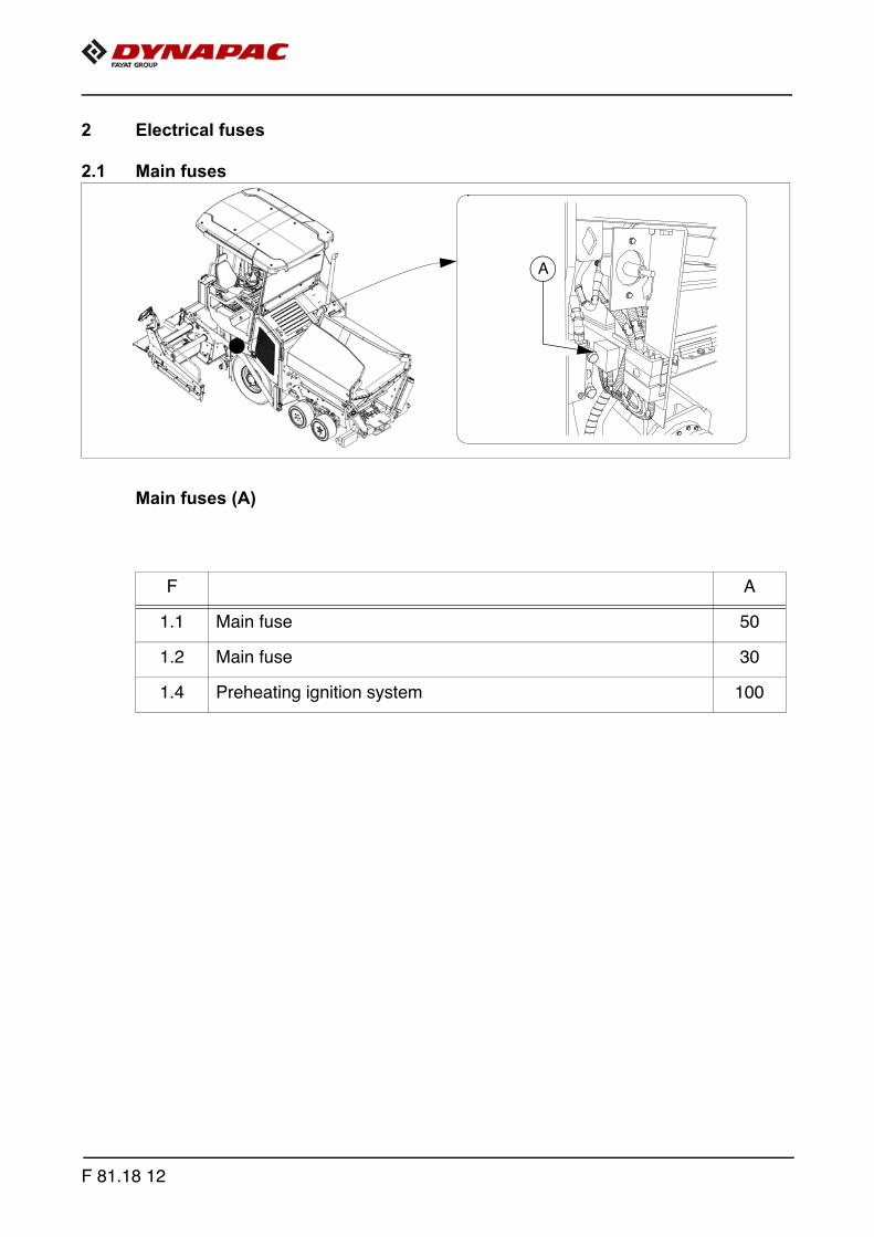
2 Electrical fuses
2.1 Main fuses
Main fuses (A)
F A
1.1 Main fuse 50
1.2 Main fuse 30
1.4 Preheating ignition system 100
A
F 81.18 12

2.2 Fuses in main terminal box
Fuse carrier (B)
F A
F1 Screed 10
F2 Screed 10
F3 Screed 10
F4 Starter 5
F5 Brake pedal 5
F6 Auger + screed light 10
F7 Hazard flashers 10
F8 Screed, steering sensor, hopper emergency STOP 5
F9 Levelling system, emulsion spraying system 10
F10 Traction unit sensors 5
F11 Screed 10
F13 24V socket left 10
F14 Power supply A7 (slave) 5
F15 Brake light 5
F16 24V socket 10
F17 Power supply A1 (master) 5
F19 12V socket 10
F20 Rotary beacon 7.5
F21 Power supply A1 (master) 25
B
F 81.18 13
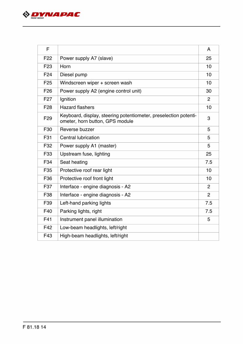
F A
F22 Power supply A7 (slave) 25
F23 Horn 10
F24 Diesel pump 10
F25 Windscreen wiper + screen wash 10
F26 Power supply A2 (engine control unit) 30
F27 Ignition 2
F28 Hazard flashers 10
F29Keyboard, display, steering potentiometer, preselection potenti-ometer, horn button, GPS module
3
F30 Reverse buzzer 5
F31 Central lubrication 5
F32 Power supply A1 (master) 5
F33 Upstream fuse, lighting 25
F34 Seat heating 7.5
F35 Protective roof rear light 10
F36 Protective roof front light 10
F37 Interface - engine diagnosis - A2 2
F38 Interface - engine diagnosis - A2 2
F39 Left-hand parking lights 7.5
F40 Parking lights, right 7.5
F41 Instrument panel illumination 5
F42 Low-beam headlights, left/right
F43 High-beam headlights, left/right
F 81.18 14

Relays in main terminal box
Relays (C)
K
K0 Engine start
K1 Switched positive
K2 Engine start / stop
K3 Control unit voltage
K4 Emergency stop
K5 Front working lights
K6 Rear working lights
K7 Auger working light
K8 Horn
K9 Brake light
K16 Rotary beacon
K17 Seat heating
K18 Windscreen wiper
K19 Windscreen wiper
K20 Reverse buzzer
K21 Central lubrication
K23 High-beam headlights
K24 Lighting ON
K25 Flashers
K26 Fuel pump
K27 Engine pre-heating function
C
F 81.18 15

F 81.18 16

F 90.18Maintenance - lubricating points1 Maintenance - lubricating points
A The information on the lubricating points for the various assemblies is assigned to thespecific maintenance descriptions and must be read there!
F 90.18 1

A Due to the use of a central lubrication system (o), the number of lubricating pointsmay deviate from the description.
1.1 Maintenance intervals
Item
Interval
Maintenance point Note
10 50 100
250
500
1000
/ an
nual
ly20
00 /
ever
y 2
year
sIf
nece
ssar
y
1
q - Check lubricant tank fill level (o)
q - Top up lubricant tank (o)
q - Bleed central lubrication system (o)
q - Check pressure limiting valve (o)
q - Check flow of lubricant at the consumer
(o)
2 q - Bearing points
Maintenance q
Maintenance during the running-in period g
F 90.18 2

1.2 Points of maintenance
Central lubrication system (1)
Danger of injuries!
f Do not reach into the tank when thepump is running!
f The central lubrication system mustonly be operated with the safetyvalve installed!
f Do not undertake any work on the pres-sure relief valve during operation!
f Risk of injury due to escaping lubricant, as the system operates at high pressures!
f Ensure that the diesel engine cannot be started when working on the system!
f Observe safety regulations for handling hydraulic systems!
m Ensure maximum cleanliness when working on the central lubrication system!
The following assemblies' lubricatingpoints can be automatically suppliedwith grease by the central lubrica-tion system:
- Auger
- Screed (tamper / vibration)
Handverl.jpg/Gefahr.jpg
F 90.18 3

Central lubrication system Check filling level
A The lubricant tank should always befilled sufficiently so that the system can-not "run dry", ensuring sufficient drivechain lubrication and eliminating theneed for time-consuming bleeding ofthe system.
- Always maintain a fill level above the"MIN" mark (A) on the tank.
Top up lubricant tank
- A filler hose (B) is located on the lubricant tank (A) for filling purposes.
- Connect the grease gun (C) included with the scope of supply to the filler hose (B)and fill the lubricant tank (A) up to the MAX mark.Alternatively, the lubricant tank can be filled with a standard grease gun at the lu-bricating nipple (D).
A When the lubricant tank is completely empty, the pump may have to run for up to 10minutes until the full delivery rate is achieved after filling.
A
D
C
B
A
F 90.18 4

Bleed central lubrication system
Bleeding the lubrication system is nec-essary if the central lubrication systemhas been operated with an empty lubri-cant tank.
- Disconnect the main lubrication line(A) at the distributor (B).
- Start up the central lubrication sys-tem with the filled lubricant tank (C).
- Allow the pump to run until lubricantemerges from the previously discon-nected main line (A).
- Reconnect the main line (A) to thedistributor.
- Disconnect all distribution lines (D)from the distributor.
- Reconnect all distribution lines as soon as lubricant has emerged.
- Check all connections and lines for leaks.
Check pressure limiting valve
m If lubricant emerges at the pressure lim-iting valve (A), this indicates a malfunc-tion in the system. The consumers are no longer adequate-ly supplied with lubricant.
- Disconnect all distribution lines (B)leading from the distributor (C) to theconsumers in succession.
- If lubricant emerges from one of thedisconnected distribution lines (B)under pressure, search in this lubri-cation circuit for the cause of theblockage which has triggered thepressure limiting valve.
- After rectifying the malfunction andreconnecting all lines, again checkthe pressure limiting valve (A) for lu-bricant emergence.
- Check all connections and linesfor leaks.
A
B
C
D
D
A
C
B
B
F 90.18 5

Check the flow of lubricant at the consumers
Each lubrication channel at the consu-mers must be checked as regards clear-ance.
- Remove the lubrication line (A) andinstall a normal lubricatingnipple (B).
- Connect the grease gun (C) includedin the scope of supply to the lubricat-ing nipple (B).
- Operate the grease gun until the lu-bricant visibly emerges.
- Rectify any faults in the flowof lubricant.
- Reinstall the lubrication lines.
- Check all connections and lines for leaks.
C
A
B
F 90.18 6

Bearing points (2)
A One lubricating nipple (A) is located ateach hydraulic cylinder bearing point(top and bottom).
2x
A
F 90.18 7

F 90.18 8

F 100 Tests, stopping ...1 Tests, checks, cleaning, stopping
F 100 1

1.1 Maintenance intervalsIte
mInterval
Maintenance point Note
10 50 100
250
500
1000
/ an
nual
ly20
00 /
ever
y 2
year
sIf
nece
ssar
y
1 q - General visual inspection
2 regularly- Check that the bolts and
nuts fit firmly
3 q q - Inspection by an expert
4 q - Cleaning
4 q - Cleaning sensors
5 q - Preserving the paver finisher
Maintenance q
Maintenance during the running-in period
g
F 100 2
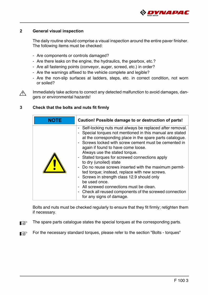
2 General visual inspection
The daily routine should comprise a visual inspection around the entire paver finisher.The following items must be checked:
- Are components or controls damaged?
- Are there leaks on the engine, the hydraulics, the gearbox, etc.?
- Are all fastening points (conveyor, auger, screed, etc.) in order?
- Are the warnings affixed to the vehicle complete and legible?
- Are the non-slip surfaces at ladders, steps, etc. in correct condition, not wornor soiled?
m Immediately take actions to correct any detected malfunction to avoid damages, dan-gers or environmental hazards!
3 Check that the bolts and nuts fit firmly
Bolts and nuts must be checked regularly to ensure that they fit firmly; retighten themif necessary.
A The spare parts catalogue states the special torques at the corresponding parts.
A For the necessary standard torques, please refer to the section "Bolts - torques"
Caution! Possible damage to or destruction of parts!
- Self-locking nuts must always be replaced after removal.- Special torques not mentioned in this manual are stated
at the corresponding place in the spare parts catalogue.- Screws locked with screw cement must be cemented in
again if found to have come loose. Always use the stated torque.
- Stated torques for screwed connections apply to dry (unoiled) state
- Do no reuse screws inserted with the maximum permit-ted torque; instead, replace with new screws.
- Screws in strength class 12.9 should only be used once.
- All screwed connections must be clean.- Check all reused components of the screwed connection
for any signs of damage.
NOTE
F 100 3

4 Inspection by an expert
A Have finisher, screed and optional gas or electric system checked by a trained spe-cialist
- when required (according to the operating conditions and the nature of application),
- however, at least once a year, check that they are all in good operational condition.
F 100 4
5 Cleaning
- Clean all parts coming into contact with paving material.
- Spray contaminated parts with the separator fluid spraying system (o).
m Before cleaning work with the high pressure cleaner, grease all lube points acc. tospecification.
- Clean the vehicle with water after laying mineral aggregates, lean-mixed concrete,etc.
m Do not spray bearing points, electrical orelectronic components with water.
- Remove residual paving material.
m After cleaning work with the high pres-sure cleaner, grease all lube points acc. to specification.
f Danger of slipping! Ensure that all stepsand ladders are free of grease and oil!
F 100 5

5.1 Cleaning the hopper
m Clean the hopper regularly
To clean the hopper, park the vehicle on a smooth surface with the hopper open. Switch off the engine.
5.2 Cleaning the conveyor and auger
m Clean the conveyor and auger regularly.
If necessary, let the conveyor and auger run at low speed during cleaning.
f There must always be an assistant at the operator's platform whenever cleaning workis being carried out to intervene in the event of any potential danger.
Danger of being pulled in by rotating or conveying vehicle partsRotating or conveying vehicle parts can cause severe or fatal injuries!
- Do not enter the danger zone.- Do not reach into rotating or conveying parts.- Only wear close-fitting clothing.- Comply with the warning and information signs on the
vehicle.- Stop the engine and remove the ignition key before any
maintenance work.- Comply with all further information in these instructions
and in the safety manual.
Hot surfaces!
Surfaces including those behind covering parts, together with combustion fuels from the engine or screed heater can be very hot and cause injuries!
- Wear your personal safety gear.- Do not touch hot parts of the vehicle.- Only perform maintenance and repair work after the
vehicle has cooled down.- Comply with all further information in these instructions
and in the safety manual.
WARNING
CAUTION
F 100 6

5.3 Cleaning optical or acoustic sensors
Heavily soiled sensors can have a negative effect on measuring results or functions.
m Daily cleaning with a dry, lint-free cloth.
F 100 7
6 Preserving the paver finisher
6.1 Shutdowns for up to 6 months
- Park the vehicle in a place where it is protected from great exposure to direct sun-light, wind, humidity and frost.
- Grease all lube points in accordance with specifications. Allow optional central lu-bricating unit to run if necessary.
- Change oil in diesel engine.
- Seal exhaust silencer to make it airtight.
- Remove batteries, charge them and store them in a well ventilated place at roomtemperature.
m Recharge removed batteries every 2 months.
- Protect all bare metal components, e.g. piston rods on hydraulic cylinders, with asuitable corrosion inhibitor.
- If it is not possible to park the vehicle is an enclosed building or under cover, it mustbe covered with a suitable size of tarpaulin. In all cases, seal all air intake and ex-haust apertures with plastic film and adhesive tape.
6.2 Shutdowns lasting from 6 months to 1 year
- Carry out all the actions listed for "Shutdowns of up to 6 months".
- Once the engine oil has been drained off, fill the diesel engine with a manufacturer-approved grade of preserving oil.
6.3 Recommissioning the machine
- Reverse all the steps described in the "Shutdown" sections.
F 100 8

7 Environmental protection, disposal
7.1 Environmental protection
A Packaging materials, used operating substances, cleaning agents and machine ac-cessories must be correctly recycled.
A Always observe the local regulations!
7.2 Disposal
A Correctly sorted disposal must be carried out after replacing wear and spare partsand after the machine has been withdrawn from service (scrapped). The materials must be sorted correctly according to metal, plastic, electronic scrap,various operating substances etc. Any oily or greasy parts (hydraulic hoses, lube pipes etc.) must be treated separately.
A Electric devices, accessories and packaging should be recycled in an environment-friendly manner.
A Always observe the local regulations!
F 100 9

8 Bolts - torques
8.1 Standard metric threads - strength class 8.8 / 10.9 / 12.9
Tre
atm
ent
dry/lightly oiled Molykote ®
Torq
ue (
Nm
)
Perm
itted
devi
atio
n (
+/-
Nm
)
Torq
ue (
Nm
)
Perm
itted
devi
atio
n (
+/-
Nm
)
Torq
ue (
Nm
)
Perm
itted
devi
atio
n (
+/-
Nm
)
Torq
ue (
Nm
)
Perm
itted
devi
atio
n (
+/-
Nm
)
Torq
ue (
Nm
)
Perm
itted
devi
atio
n (
+/-
Nm
)
Torq
ue (
Nm
)
Perm
itted
devi
atio
n (
+/-
Nm
)
Str
ength
cl
ass 8.8 8.8 10.9 10.9 12.9 12.9 8.8 8.8 10.9 10.9 12.9 12.9
M3 1 0,3 1,5 0,4 1,7 0,4 1 0,3 1,4 0,4 1,7 0,4
M4 2,4 0,6 3,5 0,9 4 1 2,3 0,6 3,3 0,8 3,9 1
M5 5 1,2 7 1,7 8 2 4,6 1,1 6,4 1,6 7,7 1,9
M6 8 2,1 12 3 14 3 7,8 1,9 11 2,7 13 3,3
M8 20 5 28 7,1 34 8 19 4,7 26 6,6 31 7,9
M10 41 10 57 14 70 17 37 9 52 13 62 16
M12 73 18 97 24 120 30 63 16 89 22 107 27
M14 115 29 154 39 195 45 100 25 141 35 169 42
M16 185 46 243 61 315 75 156 39 219 55 263 66
M18 238 60 335 84 402 100 215 54 302 76 363 91
M20 335 84 474 119 600 150 304 76 427 107 513 128
M22 462 116 650 162 759 190 410 102 575 144 690 173
M24 600 150 817 204 1020 250 522 131 734 184 881 220
M27 858 214 1206 301 1410 352 760 190 1067 267 1281 320
M30 1200 300 1622 405 1948 487 1049 262 1475 369 1770 443
M33 1581 395 2224 556 2669 667 1400 350 1969 492 2362 590
M36 2000 500 2854 714 3383 846 1819 455 2528 632 3070 767
F 100 10

8.2 Fine metric threads - strength class 8.8 / 10.9 / 12.9T
rea
tme
nt
dry/lightly oiled Molykote ®Torq
ue (
Nm
)
Perm
itte
d
devi
atio
n (
+/-
Nm
)
Torq
ue (
Nm
)
Perm
itte
d
devi
atio
n (
+/-
Nm
)
Torq
ue (
Nm
)
Perm
itte
d
devi
atio
n (
+/-
Nm
)
Torq
ue (
Nm
)
Perm
itte
d
devi
atio
n (
+/-
Nm
)
Torq
ue (
Nm
)
Perm
itte
d
devi
atio
n (
+/-
Nm
)
Torq
ue (
Nm
)
Perm
itte
d
devi
atio
n (
+/-
Nm
)
Str
en
gth
cl
ass 8.8 8.8 10.9 10.9 12.9 12.9 8.8 8.8 10.9 10.9 12.9 12.9
M3x0,35 1,2 0,3 1,7 0,4 2,1 0,5 1,1 0,3 1,5 0,4 1,8 0,5
M4x0,5 2,8 0,7 3,9 1 4,7 1,2 2,5 0,6 3,5 0,9 4,2 1
M5x0,5 5,7 1,4 8 2 9,6 2,4 5,1 1,3 7,1 1,8 8,5 2,1
M6x0,75 9,2 2,3 12,9 3,2 15,5 3,9 8,3 2,1 11,6 2,9 13,9 3,5
M8x1 21,7 5,4 30,6 7,6 36,7 9,2 19,5 4,9 27,4 6,8 32,8 8,2
M10x1,25 42,1 10,5 59,2 15 71 17,8 37,7 9,4 53 13 63,6 15,9
M12x1,25 75,7 18,9 106,2 26 127 31,9 67,2 16,8 94,5 24 113 28,3
M14x1,5 119 29,7 167 42 200 50,1 106 26 149 37 178 44,6
M16x1,5 183 45,6 257 64 308 77 162 40 227 57 273 68,2
M18x1,5 267 66,8 376 94 451 112,7 236 59 331 83 398 99,4
M20x1,5 373 93,2 524 131 629 157,3 328 82 461 115 553 138,3
M22x1,5 503 126 707 177 848 212,1 442 110 621 155 745 186,3
M24x2 630 158 886 221 1063 265,8 556 139 782 195 938 234,5
M27x2 918 229 1290 323 1548 387,1 807 202 1136 284 1363 340,7
M30x2 1281 320 1802 450 2162 540,6 1124 281 1581 395 1897 474,3
M33x2 1728 432 2430 607 2916 728,9 1514 378 2128 532 2554 638,5
M36x3 2126 532 2990 747 3588 897,1 1876 469 2638 659 3165 791,3
F 100 11

F 100 12

F 111.18 Lubricants and operating substances
1 Lubricants and operating substances
m Use only the lubricants listed below or comparable qualities of well-known brands.
m Only use containers which are clean on inside and outside for filling oil or fuel.
A Note capacities (see section "Capacities").
m Incorrect oil or lubricant levels promote rapid wear and feeder failure.
m Never mix synthetic oils with mineral oils!
m Please heed the equipment-related fuel specification requirements!
F 111.18 1

2
6
6
1
7
34
5
F 111.18 2

1.1 Capacities
m Note specifications on the following pages!
Substance Volume
1Diesel engine (with oil filter change)
Engine oil 8,2 litres
2 Engine cooling system Cooling liquid 12,0 litres
3 Fuel tank Diesel fuel 73,0 litres
4 Hydraulic oil reservoir Hydraulic oil 80,0 litres
5 Pump distribution gear Gearbox oil 2,0 litres
5Pump distribution gear,as of s/n 3309, 3510 ff.
Gearbox oil 1,5 litres
6Planetary gear Traction unit
Gearbox oilapprox. 2.4 litres(1.2 l per side)
7 Auger box Liquid grease 3,5 kg
Batteries Distilled water
F 111.18 3

2 Operating substance specifications
2.1 Notes on diesel fuel
f Danger of explosion! Never mix diesel fuel with ethanol, petrol or alcohol!
m Diesel fuel contaminated with water or dirt can cause serious damage to the fuel sys-tem! Keep fuel and fuel system free of water and impurities!
m Observe the instructions for fuel recommendations and the specification in the main-tenance instructions of the engine manufacturer!
2.2 Drive engine TIER III (o) fuel specification
Permissible diesel fuels
* Detailed information at:
http://www.deutz.com
2.3 Drive engine TIER IV (o) - fuel specification
m Low-sulphur diesel fuel is prescribed for correct operation of the exhaust-gas treat-ment system! The maximum sulphur level must not exceed 15 ppm!If low-sulphur diesel fuel is not used, the prescribed exhaust values cannot be metand damage will be caused to the engine and to the exhaust-gas treatment system!
Permissible diesel fuels
Specifications
Diesel fuel as speci-
fied in the engine
manufacturer’s requirements *
sulphur level max.
2000mg/kg
EN 590 ASTM D975JIS K 2204
HFRR max. 460μm
de \Service\Betriebsstoffe und Additive\Kraftstoffe
en \Service\Operating Liquids and Additives\Fuels
Specifications
EN 590 ASTM D975 S15JIS K 2204
HFRR max. 460μm
F 111.18 4

2.4 Engine - lubricating oil
A (*) = recommended
m Observe the instructions for lubricant recommendations and the specification in themaintenance instructions of the engine manufacturer!
2.5 Cooling system
A (*) = recommended
2.6 Hydraulic system
A (*) = recommended
2.7 Pump distribution gear
2.8 Pump distribution gear, as of s/n 3309, 3510 ff.
A (*) = filled in at the factory
Dynapac Aral BPEsso / Exxon
Fuchs Mobil Shell
Engine Oil 200(*)
Dynapac AGIP Chevron Caltex Delo Petronas Finke
Coolant 200(*)
-Antifreeze Special
ExtendedLife Coolant
Antifreeze G12
AviaticonFinkofreeze
P12+
Dynapac AGIP Chevron Caltex Fuchs Mobil Shell Finke
Hydraulic100(*)
RandoHDZ 46
RandoHDZ 46
-Tellus Oil S2 V46
-Tellus S2 VX46
AviaticonHV 46
Dynapac Aral BPEsso /
ExxonFuchs Mobil Shell
Gear Oil 100 (*)
-Omala S2 GX 220
Dynapac Aral BPEsso /
ExxonFuchs Mobil Shell
Gear Oil 400 (*)
-Titan ATF6000 SL (*)
-Spirax S4 ATF HDX-Spirax S6 ATF VM
F 111.18 5

2.9 Drive unit planetary gear
A (*) = recommended
2.10 Auger box
A (*) = recommended
2.11 Grease
A (*) = recommended
Dynapac Aral BPEsso / Exxon
Fuchs Mobil Shell
Gear Oil 100 (*)
-Omala
S2 GX 220
Dynapac Aral BPEsso /
ExxonFuchs Mobil Shell
AugerGrease
(*)
-Gadus S5
V142W 00
Dynapac Aral BPEsso / Exxon
Fuchs Mobil Shell Chevron
PaverGrease
(*)
-Gadus S5
T460 1.5
-High
Temp Premium2
F 111.18 6

2.12 Hydraulic oil
Preferred hydraulic oils:
a) Synthetic hydraulic liquids based on ester, HEES
A (*) = recommended
m When changing from mineral oil pressure fluids to biodegradable pressure fluids,please contact our factory advisory service!
Manufacturer ISO viscosity class VG 46
Dynapac Hydraulic 120 (*)
Shell Natural HF-E46
Panolin HLP SYNTH 46
Esso Univis HEES 46
Total Total Biohydran SE 46
Aral Vitam EHF 46
Finke Aviaticon HY-HE 46
F 111.18 7
F 111.18 8


www.dynapac.com
Related Documents