G E F a nuc Aut oma ti on C omputer Num erical C ont rol Products S eri es 16 i / 1 8 i / 160 i / 180 i – Model A O perati on and Ma intenance Ha ndbook GFZ-63007EN/01 September 1997

Welcome message from author
This document is posted to help you gain knowledge. Please leave a comment to let me know what you think about it! Share it to your friends and learn new things together.
Transcript
GE Fanuc Automation
Computer Numerical Control Products
Series 16 i / 18 i / 160 i / 180 i – Model A
Operation and Maintenance Handbook
GFZ-63007EN/01 September 1997
GFL-001
Warnings, Cautions, and Notes
as Used in this Publication
Warning
Warning notices are used in this publication to emphasize that hazardous voltages, currents,
temperatures, or other conditions that could cause personal injury exist in this equipment or
may be associated with its use.
In situations where inattention could cause either personal injury or damage to equipment, a
Warning notice is used.
Caution
Caution notices are used where equipment might be damaged if care is not taken.
Note
Notes merely call attention to information that is especially significant to understanding and
operating the equipment.
This document is based on information available at the time of its publication. While efforts
have been made to be accurate, the information contained herein does not purport to cover all
details or variations in hardware or software, nor to provide for every possible contingency in
connection with installation, operation, or maintenance. Features may be described herein
which are not present in all hardware and software systems. GE Fanuc Automation assumes
no obligation of notice to holders of this document with respect to changes subsequently made.
GE Fanuc Automation makes no representation or warranty, expressed, implied, or statutory
with respect to, and assumes no responsibility for the accuracy, completeness, sufficiency, or
usefulness of the information contained herein. No warranties of merchantability or fitness for
purpose shall apply.
©Copyright 1997 GE Fanuc Automation North America, Inc.
All Rights Reserved.
3
1
4
5
6
7
8
9
10
2
SAFETY PRECAUTIONS
s–1
SAFETY PRECAUTIONS
This section describes the safety precautions related to the use of CNCunits. It is essential that these precautions be observed by users toensure the safe operation of machines equipped with a CNC unit (alldescriptions in this section assume this configuration). Note that someprecautions are related only to specific functions, and thus may not beapplicable to certain CNC units.Users must also observe the safety precautions related to the machine,as described in the relevant manual supplied by the machine toolbuilder. Before attempting to operate the machine or create a programto control the operation of the machine, the operator must become fullyfamiliar with the contents of this manual and relevant manual suppliedby the machine tool builder.
CONTENTS
1. DEFINITION OF WARNING, CAUTION, AND NOTE s–2. . . . . .
2. GENERAL WARNINGS AND CAUTIONS s–3. . . . . . . . . . . . . . . .
3. WARNINGS AND CAUTIONS RELATED
TO PROGRAMMING s–5. . . . . . . . . . . . . . . . . . . . . . . . . . . . . . . . . .
4. WARNINGS AND CAUTIONS RELATED
TO HANDLING s–8. . . . . . . . . . . . . . . . . . . . . . . . . . . . . . . . . . . . . . .
5. WARNINGS RELATED TO DAILY MAINTENANCE s–11. . . . . .
3
1
4
5
6
7
8
9
10
2
SAFETY PRECAUTIONS
s–2
1. DEFINITION OF WARNING, CAUTION, AND NOTE
This manual includes safety precautions for protecting the user andpreventing damage to the machine. Precautions are classified intoWarning and Caution according to their bearing on safety. Also,supplementary information is described as a Note. Read the Warning,Caution, and Note thoroughly before attempting to use the machine.
WARNING
Applied when there is a danger of the user being injured orwhen there is a damage of both the user being injured and theequipment being damaged if the approved procedure is notobserved.
CAUTION
Applied when there is a danger of the equipment beingdamaged, if the approved procedure is not observed.
NOTE
The Note is used to indicate supplementary information otherthan Warning and Caution.
` Read this manual carefully, and store it in a safe place.
3
1
4
5
6
7
8
9
10
2
s–3
2. GENERAL WARNINGS AND CAUTIONS
WARNING
1. Never attempt to machine a workpiece without firstchecking the operation of the machine. Before starting aproduction run, ensure that the machine is operatingcorrectly by performing a trial run using, for example, thesingle block, feedrate override, or machine lock functionor by operating the machine with neither a tool norworkpiece mounted. Failure to confirm the correctoperation of the machine may result in the machinebehaving unexpectedly, possibly causing damage to theworkpiece and/or machine itself, or injury to the user.
2. Before operating the machine, thoroughly check theentered data.Operating the machine with incorrectly specified datamay result in the machine behaving unexpectedly,possibly causing damage to the workpiece and/ormachine itself, or injury to the user.
3. Ensure that the specified feedrate is appropriate for theintended operation. Generally, for each machine, there isa maximum allowable feedrate. The appropriate feedratevaries with the intended operation. Refer to the manualprovided with the machine to determine the maximumallowable feedrate. If a machine is run at other than thecorrect speed, it may behave unexpectedly, possiblycausing damage to the workpiece and/or machine itself,or injury to the user.
4. When using a tool compensation function, thoroughlycheck the direction and amount of compensation.Operating the machine with incorrectly specified datamay result in the machine behaving unexpectedly,possibly causing damage to the workpiece and/ormachine itself, or injury to the user.
5. The parameters for the CNC and PMC are factory–set.Usually, there is not need to change them. When,however, there is not alternative other than to change aparameter, ensure that you fully understand the functionof the parameter before making any change.Failure to set a parameter correctly may result in themachine behaving unexpectedly, possibly causingdamage to the workpiece and/or machine itself, or injuryto the user.
6. Immediately after switching on the power, do not touchany of the keys on the MDI panel until the position displayor alarm screen appears on the CNC unit.Some of the keys on the MDI panel are dedicated tomaintenance or other special operations. Pressing anyof these keys may place the CNC unit in other than itsnormal state. Starting the machine in this state maycause it to behave unexpectedly.
3
1
4
5
6
7
8
9
10
2
SAFETY PRECAUTIONS
s–4
WARNING
7. The operator’s manual and programming manualsupplied with a CNC unit provide an overall description ofthe machine’s functions, including any optional functions.Note that the optional functions will vary from onemachine model to another. Therefore, some functionsdescribed in the manuals may not actually be available fora particular model. Check the specification of themachine if in doubt.
8. Some functions may have been implemented at therequest of the machine–tool builder. When using suchfunctions, refer to the manual supplied by themachine–tool builder for details of their use and anyrelated cautions.
NOTE
Programs, parameters, and macro variables are stored innonvolatile memory in the CNC unit. Usually, they are retainedeven if the power is turned off. Such data may be deletedinadvertently, however, or it may prove necessary to delete alldata from nonvolatile memory as part of error recovery.To guard against the occurrence of the above, and assurequick restoration of deleted data, backup all vital data, andkeep the backup copy in a safe place.
3
1
4
5
6
7
8
9
10
2
s–5
3. WARNINGS AND CAUTIONS RELATED TO
PROGRAMMING
This section covers the major safety precautions related toprogramming. Before attempting to perform programming, read thesupplied operator’s manual and programming manual carefully suchthat you are fully familiar with their contents.
WARNING
1. Coordinate system setting
If a coordinate system is established incorrectly, themachine may behave unexpectedly as a result of theprogram issuing an otherwise valid move command.Such an unexpected operation may damage the tool, themachine itself, the workpiece, or cause injury to the user.
2. Positioning by nonlinear interpolation
When performing positioning by nonlinear interpolation(positioning by nonlinear movement between the startand end points), the tool path must be carefully confirmedbefore performing programming.Positioning involves rapid traverse. If the tool collideswith the workpiece, it may damage the tool, the machineitself, the workpiece, or cause injury to the user.
3. Function involving a rotation axis
When programming polar coordinate interpolation ornormal–direction (perpendicular) control, pay carefulattention to the speed of the rotation axis. Incorrectprogramming may result in the rotation axis speedbecoming excessively high, such that centrifugal forcecauses the chuck to lose its grip on the workpiece if thelatter is not mounted securely.Such mishap is likely to damage the tool, the machineitself, the workpiece, or cause injury to the user.
4. Inch/metric conversion
Switching between inch and metric inputs does notconvert the measurement units of data such as theworkpiece origin offset, parameter, and current position.Before starting the machine, therefore, determine whichmeasurement units are being used. Attempting toperform an operation with invalid data specified maydamage the tool, the machine itself, the workpiece, orcause injury to the user.

3
1
4
5
6
7
8
9
10
2
SAFETY PRECAUTIONS
s–6
WARNING
5. Constant surface speed control
When an axis subject to constant surface speed controlapproaches the origin of the workpiece coordinatesystem, the spindle speed may become excessivelyhigh. Therefore, it is necessary to specify a maximumallowable speed. Specifying the maximum allowablespeed incorrectly may damage the tool, the machineitself, the workpiece, or cause injury to the user.
6. Stroke check
After switching on the power, perform a manual referenceposition return as required. Stroke check is not possiblebefore manual reference position return is performed.Note that when stroke check is disabled, an alarm is notissued even if a stroke limit is exceeded, possiblydamaging the tool, the machine itself, the workpiece, orcausing injury to the user.
7. Tool post interference check
A tool post interference check is performed based on thetool data specified during automatic operation. If the toolspecification does not match the tool actually being used,the interference check cannot be made correctly,possibly damaging the tool or the machine itself, orcausing injury to the user.After switching on the power, or after selecting a tool postmanually, always start automatic operation and specifythe tool number of the tool to be used.
8. Absolute/incremental mode
If a program created with absolute values is run inincremental mode, or vice versa, the machine maybehave unexpectedly.
9. Plane selection
If an incorrect plane is specified for circular interpolation,helical interpolation, or a canned cycle, the machine maybehave unexpectedly. Refer to the descriptions of therespective functions for details.
10. Torque limit skip
Before attempting a torque limit skip, apply the torquelimit. If a torque limit skip is specified without the torquelimit actually being applied, a move command will beexecuted without performing a skip.
11. Programmable mirror image
Note that programmed operations vary considerablywhen a programmable mirror image is enabled.
3
1
4
5
6
7
8
9
10
2
s–7
WARNING
12. Compensation function
If a command based on the machine coordinate systemor a reference position return command is issued incompensation function mode, compensation istemporarily canceled, resulting in the unexpectedbehavior of the machine.Before issuing any of the above commands, therefore,always cancel compensation function mode.

3
1
4
5
6
7
8
9
10
2
SAFETY PRECAUTIONS
s–8
4. WARNINGS AND CAUTIONS RELATED TO
HANDLING
This section presents safety precautions related to the handling ofmachine tools. Before attempting to operate your machine, read thesupplied operator’s manual and programming manual carefully, suchthat you are fully familiar with their contents.
WARNING
1. Manual operation
When operating the machine manually, determine thecurrent position of the tool and workpiece, and ensurethat the movement axis, direction, and feedrate havebeen specified correctly. Incorrect operation of themachine may damage the tool, the machine itself, theworkpiece, or cause injury to the operator.
2. Manual reference position return
After switching on the power, perform manual referenceposition return as required. If the machine is operatedwithout first performing manual reference position return,it may behave unexpectedly. Stroke check is not possiblebefore manual reference position return is performed.An unexpected operation of the machine may damagethe tool, the machine itself, the workpiece, or cause injuryto the user.
3. Manual numeric command
When issuing a manual numeric command, determinethe current position of the tool and workpiece, and ensurethat the movement axis, direction, and command havebeen specified correctly, and that the entered values arevalid.Attempting to operate the machine with an invalidcommand specified may damage the tool, the machineitself, the workpiece, or cause injury to the operator.
4. Manual handle feed
In manual handle feed, rotating the handle with a largescale factor, such as 100, applied causes the tool andtable to move rapidly. Careless handling may damage thetool and/or machine, or cause injury to the user.
5. Disabled override
If override is disabled (according to the specification in amacro variable) during threading, rigid tapping, or othertapping, the speed cannot be predicted, possiblydamaging the tool, the machine itself, the workpiece, orcausing injury to the operator.
3
1
4
5
6
7
8
9
10
2
s–9
WARNING
6. Origin/preset operation
Basically, never attempt an origin/preset operation whenthe machine is operating under the control of a program.Otherwise, the machine may behave unexpectedly,possibly damaging the tool, the machine itself, the tool, orcausing injury to the user.
7. Workpiece coordinate system shift
Manual intervention, machine lock, or mirror imaging mayshift the workpiece coordinate system. Before attemptingto operate the machine under the control of a program,confirm the coordinate system carefully.If the machine is operated under the control of a programwithout making allowances for any shift in the workpiececoordinate system, the machine may behaveunexpectedly, possibly damaging the tool, the machineitself, the workpiece, or causing injury to the operator.
8. Software operator’s panel and menu switches
Using the software operator’s panel and menu switches,in combination with the MDI panel, it is possible to specifyoperations not supported by the machine operator’spanel, such as mode change, override value change, and jog feed commands.Note, however, that if the MDI panel keys are operatedinadvertently, the machine may behave unexpectedly,possibly damaging the tool, the machine itself, theworkpiece, or causing injury to the user.
9. Manual intervention
If manual intervention is performed during programmedoperation of the machine, the tool path may vary when themachine is restarted. Before restarting the machine aftermanual intervention, therefore, confirm the settings of themanual absolute switches, parameters, andabsolute/incremental command mode.
10. Feed hold, override, and single block
The feed hold, feedrate override, and single blockfunctions can be disabled using custom macro systemvariable #3004. Be careful when operating the machinein this case.
11. Dry run
Usually, a dry run is used to confirm the operation of themachine. During a dry run, the machine operates at dryrun speed, which differs from the correspondingprogrammed feedrate. Note that the dry run speed maysometimes be higher than the programmed feed rate.
3
1
4
5
6
7
8
9
10
2
SAFETY PRECAUTIONS
s–10
WARNING
12. Cutter and tool nose radius compensation in MDImode
Pay careful attention to a tool path specified by acommand in MDI mode, because cutter or tool noseradius compensation is not applied. When a command isentered from the MDI to interrupt in automatic operationin cutter or tool nose radius compensation mode, payparticular attention to the tool path when automaticoperation is subsequently resumed. Refer to thedescriptions of the corresponding functions for details.
13. Program editing
If the machine is stopped, after which the machiningprogram is edited (modification, insertion, or deletion), themachine may behave unexpectedly if machining isresumed under the control of that program. Basically, donot modify, insert, or delete commands from a machiningprogram while it is in use.

3
1
4
5
6
7
8
9
10
2
s–11
5. WARNINGS RELATED TO DAILY MAINTENANCE
WARNING
1. Memory backup battery replacement
When replacing the memory backup batteries, keep thepower to the machine (CNC) turned on, and apply anemergency stop to the machine. Because this work isperformed with the power on and the cabinet open, onlythose personnel who have received approved safety andmaintenance training may perform this work.When replacing the batteries, be careful not to touch the
high–voltage circuits (marked and fitted with an
insulating cover).Touching the uncovered high–voltage circuits presentsan extremely dangerous electric shock hazard.
NOTE
The CNC uses batteries to preserve the contents of itsmemory, because it must retain data such as programs,offsets, and parameters even while external power is notapplied.If the battery voltage drops, a low battery voltage alarm isdisplayed on the machine operator’s panel or screen.When a low battery voltage alarm is displayed, replace thebatteries within a week. Otherwise, the contents of the CNC’smemory will be lost.Refer to the maintenance section of the operator’s manual orprogramming manual for details of the battery replacementprocedure.

3
1
4
5
6
7
8
9
10
2
SAFETY PRECAUTIONS
s–12
WARNING
2. Absolute pulse coder battery replacement
When replacing the memory backup batteries, keep thepower to the machine (CNC) turned on, and apply anemergency stop to the machine. Because this work isperformed with the power on and the cabinet open, onlythose personnel who have received approved safety andmaintenance training may perform this work.When replacing the batteries, be careful not to touch the
high–voltage circuits (marked and fitted with an
insulating cover).Touching the uncovered high–voltage circuits presentsan extremely dangerous electric shock hazard.
NOTE
The absolute pulse coder uses batteries to preserve itsabsolute position.If the battery voltage drops, a low battery voltage alarm isdisplayed on the machine operator’s panel or Zscreen.When a low battery voltage alarm is displayed, replace thebatteries within a week. Otherwise, the absolute position dataheld by the pulse coder will be lost.Refer to the maintenance section of the operator’s manual orprogramming manual for details of the battery replacementprocedure.
3. Fuse replacement
For some units, the chapter covering daily maintenancein the operator’s manual or programming manualdescribes the fuse replacement procedure.Before replacing a blown fuse, however, it is necessaryto locate and remove the cause of the blown fuse.For this reason, only those personnel who have receivedapproved safety and maintenance training may performthis work.When replacing a fuse with the cabinet open, be careful
not to touch the high–voltage circuits (marked and
fitted with an insulating cover).Touching an uncovered high–voltage circuit presents anextremely dangerous electric shock hazard.
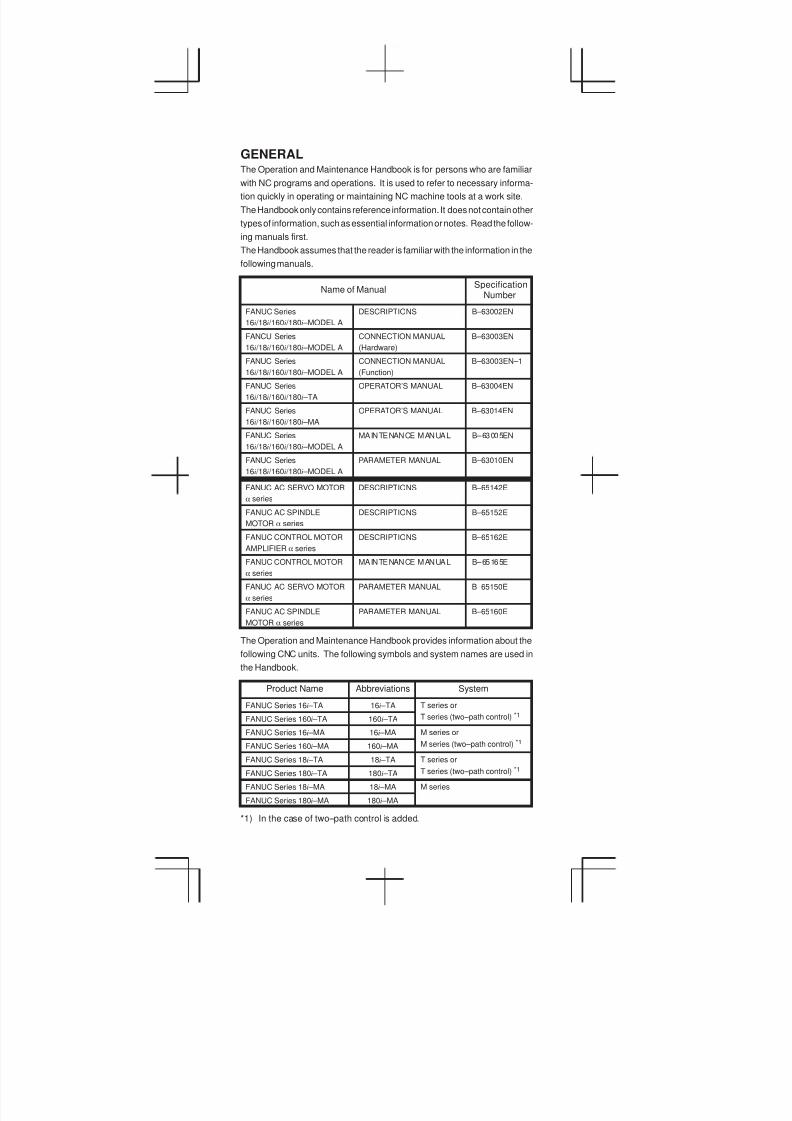
GENERALThe Operation and Maintenance Handbook is for persons who are familiar
with NC programs and operations. It is used to refer to necessary informa-
tion quickly in operating or maintaining NC machine tools at a work site.
The Handbook only contains reference information. It does not contain other
types of information, such as essential information or notes. Read the follow-
ing manuals first.
The Handbook assumes that the reader is familiar with the information in the
following manuals.
Name of ManualSpecification
Number
FANUC Series
16i /18i /160i /180i –MODEL A
DESCRIPTIONS B–63002EN
FANCU Series
16i /18i /160i /180i –MODEL A
CONNECTION MANUAL
(Hardware)
B–63003EN
FANUC Series
16i /18i /160i /180i –MODEL A
CONNECTION MANUAL
(Function)
B–63003EN–1
FANUC Series
16i /18i /160i /180i –TA
OPERATOR’S MANUAL B–63004EN
FANUC Series
16i /18i /160i /180i –MA
OPERATOR’S MANUAL B–63014EN
FANUC Series
16i /18i /160i /180i –MODEL A
MAINTENANCE MANUAL B–63005EN
FANUC Series
16i /18i /160i /180i –MODEL A
PARAMETER MANUAL B–63010EN
FANUC AC SERVO MOTOR
a series
DESCRIPTIONS B–65142E
FANUC AC SPINDLE
MOTOR a series
DESCRIPTIONS B–65152E
FANUC CONTROL MOTOR
AMPLIFIER a series
DESCRIPTIONS B–65162E
FANUC CONTROL MOTOR
a series
MAINTENANCE MANUAL B–65165E
FANUC AC SERVO MOTOR
a series
PARAMETER MANUAL B–65150E
FANUC AC SPINDLE
MOTOR a series
PARAMETER MANUAL B–65160E
The Operation and Maintenance Handbook provides information about the
following CNC units. The following symbols and system names are used in
the Handbook.
Product Name Abbreviations System
FANUC Series 16i –TA 16i –TA T series or
FANUC Series 160i –TA 160i –TA T series (two–path control) *1
FANUC Series 16i –MA 16i –MA M series or
FANUC Series 160i –MA 160i –MA M series (two–path control) *1
FANUC Series 18i –TA 18i –TA T series or
FANUC Series 180i –TA 180i –TA T series (two–path control) *1
FANUC Series 18i –MA 18i –MA M series
FANUC Series 180i –MA 180i –MA
*1) In the case of two–path control is added.

3
1
4
5
6
7
8
9
10
2
1. SCREEN DISPLAY AND OPERATION 1. . . . . . . . . . . . . . .
2. OPERATION LIST 53. . . . . . . . . . . . . . . . . . . . . . . . . . . . . . .
3. G CODE 65. . . . . . . . . . . . . . . . . . . . . . . . . . . . . . . . . . . . . . . .
4. PROGRAM FORMAT 73. . . . . . . . . . . . . . . . . . . . . . . . . . . .
5. CUSTOM MACRO 111. . . . . . . . . . . . . . . . . . . . . . . . . . . . . .
6. STATUS DISPLAY BY SELF–DIAGNOSTICDISPLAY 119. . . . . . . . . . . . . . . . . . . . . . . . . . . . . . . . . . . . . .
7. HARDWARE 197. . . . . . . . . . . . . . . . . . . . . . . . . . . . . . . . . . .
8. PARAMETERS 219. . . . . . . . . . . . . . . . . . . . . . . . . . . . . . . . .
9. ERROR CODE LIST 361. . . . . . . . . . . . . . . . . . . . . . . . . . . .
10. PMC 407. . . . . . . . . . . . . . . . . . . . . . . . . . . . . . . . . . . . . . . . . .
11. CORRESPONDENCE BETWEEN ENGLISH KEYAND SYMBOLIC KEY 438. . . . . . . . . . . . . . . . . . . . . . . . . . .
CONTENTS
11
CONTENTS
1. SCREEN DISPLAY AND OPERATION 1. . . . . . . . . . . . . . . . .
1.1 Display Unit and Key Layout 1. . . . . . . . . . . . . . . . . . . . . . . . . . . . . . .
1.2 Operation of MDI Panel 6. . . . . . . . . . . . . . . . . . . . . . . . . . . . . . . . . . .
1.2.1 Screen transition chart 6. . . . . . . . . . . . . . . . . . . . . . . . . . . . . . . .
1.2.2 Displaying the current position 10. . . . . . . . . . . . . . . . . . . . . . . .
1.2.3 Display for handle interrupt 12. . . . . . . . . . . . . . . . . . . . . . . . . . .
1.2.4 Displaying the program 13. . . . . . . . . . . . . . . . . . . . . . . . . . . . . .
1.2.5 Program restart screen 15. . . . . . . . . . . . . . . . . . . . . . . . . . . . . .
1.2.6 Editing the program 17. . . . . . . . . . . . . . . . . . . . . . . . . . . . . . . . .
1.2.7 Displaying the program list 20. . . . . . . . . . . . . . . . . . . . . . . . . . .
1.2.8 Operation in the conversational programming menu 21. . . . .
1.2.9 Transferring data to and from the floppy disk 22. . . . . . . . . . . .
1.2.10 Displaying and setting the tool compensation values 24. . . . .
1.2.11 Displaying and setting the data 25. . . . . . . . . . . . . . . . . . . . . . .
1.2.12 Displaying and setting the offset values for the workpiececoordinate system 27. . . . . . . . . . . . . . . . . . . . . . . . . . . . . . . . . .
1.2.13 Displaying and setting the custom macro variables 28. . . . . .
1.2.14 Displaying and setting the data for the software operator’spanel 29. . . . . . . . . . . . . . . . . . . . . . . . . . . . . . . . . . . . . . . . . . . . . .
1.2.15 Displaying and setting the parameters 31. . . . . . . . . . . . . . . . .
1.2.16 Displaying the internal state of the CNC(diagnostic screen) 33. . . . . . . . . . . . . . . . . . . . . . . . . . . . . . . . . .
1.2.17 Displaying the system configuration 33. . . . . . . . . . . . . . . . . . .
1.2.18 Displaying and setting the pitch error compensationvalues 35. . . . . . . . . . . . . . . . . . . . . . . . . . . . . . . . . . . . . . . . . . . . .
1.2.19 Displaying the alarm messages 35. . . . . . . . . . . . . . . . . . . . . . .
1.2.20 Displaying the operator messages 36. . . . . . . . . . . . . . . . . . . . .
1.2.21 Displaying the alarm history 36. . . . . . . . . . . . . . . . . . . . . . . . . .
1.3 Help Function 37. . . . . . . . . . . . . . . . . . . . . . . . . . . . . . . . . . . . . . . . . .
1.3.1 Alarm detail screen 37. . . . . . . . . . . . . . . . . . . . . . . . . . . . . . . . . .
1.3.2 Operation method screen 38. . . . . . . . . . . . . . . . . . . . . . . . . . . .
1.3.3 Parameter contents 38. . . . . . . . . . . . . . . . . . . . . . . . . . . . . . . . .
1.4 BOOT SYSTEM 39. . . . . . . . . . . . . . . . . . . . . . . . . . . . . . . . . . . . . . . .
2. OPERATION LIST 53. . . . . . . . . . . . . . . . . . . . . . . . . . . . . . . . .
3. G CODE 65. . . . . . . . . . . . . . . . . . . . . . . . . . . . . . . . . . . . . . . . . .
3.1 T series 65. . . . . . . . . . . . . . . . . . . . . . . . . . . . . . . . . . . . . . . . . . . . . . . .
3.2 M series 69. . . . . . . . . . . . . . . . . . . . . . . . . . . . . . . . . . . . . . . . . . . . . . .
4. PROGRAM FORMAT 73. . . . . . . . . . . . . . . . . . . . . . . . . . . . . .
5. CUSTOM MACRO 111. . . . . . . . . . . . . . . . . . . . . . . . . . . . . . . .
5.1 Types of Variables 111. . . . . . . . . . . . . . . . . . . . . . . . . . . . . . . . . . . . .
5.2 System Variable 111. . . . . . . . . . . . . . . . . . . . . . . . . . . . . . . . . . . . . . .
5.3 Argument Assignment I/II 115. . . . . . . . . . . . . . . . . . . . . . . . . . . . . . .
5.4 Arithmetic Commands 116. . . . . . . . . . . . . . . . . . . . . . . . . . . . . . . . . .
5.5 Control Command 117. . . . . . . . . . . . . . . . . . . . . . . . . . . . . . . . . . . . . .
5.6 Macro Call 117. . . . . . . . . . . . . . . . . . . . . . . . . . . . . . . . . . . . . . . . . . . .
5.7 Command Range 118. . . . . . . . . . . . . . . . . . . . . . . . . . . . . . . . . . . . . .
6. STATUS DISPLAY BY SELF–DIAGNOSTICDISPLAY 119. . . . . . . . . . . . . . . . . . . . . . . . . . . . . . . . . . . . . . . .
6.1 Displaying CNC Internal State 119. . . . . . . . . . . . . . . . . . . . . . . . . . .
6.1.1 Procedure for displaying diagnostic screen 119. . . . . . . . . . . .
6.1.2 Display of status in which command is not apparentlyexecuted (No. 000 – 015) 119. . . . . . . . . . . . . . . . . . . . . . . . . . .
6.1.3 Information indicating automatic operation stop,automatic idle statuses (No. 020 – 025) 120. . . . . . . . . . . . . . .
6.1.4 TH alarm statuses (No. 030, 031) 120. . . . . . . . . . . . . . . . . . . .
6.1.5 Digital servo system, serial pulse coder alarm(No. 200, 280) 121. . . . . . . . . . . . . . . . . . . . . . . . . . . . . . . . . . . . .
6.1.6 Positional error display (No. 300) 122. . . . . . . . . . . . . . . . . . . . .
6.1.7 Machine position display (No. 301) 122. . . . . . . . . . . . . . . . . . .
6.1.8 Reference position shift function display (No. 302) 123. . . . . .
6.1.9 Cause of the APZ bit (bit 4 of parameter 1815)brought to 0 123. . . . . . . . . . . . . . . . . . . . . . . . . . . . . . . . . . . . . . .
6.1.10 Inductosyn display (No. 380 and No. 381) 123. . . . . . . . . . . . .
6.1.11 Spindle data (No. 400–420) 124. . . . . . . . . . . . . . . . . . . . . . . . .
6.1.12 Rigid tapping display (No. 450–457) 126. . . . . . . . . . . . . . . . . .
6.1.13 Polygon synchronization mode status (No. 470–478) 126. . . .
6.1.14 Remote buffer protocol A status (No. 500–502) 128. . . . . . . . .
6.1.15 Display lated to Open CNC (No. 510–513) 128. . . . . . . . . . . . .
6.1.16 Small–diameter peck drilling cycle display(No. 520–523) 129. . . . . . . . . . . . . . . . . . . . . . . . . . . . . . . . . . . . .
6.1.17 Display of ATC for FD alpha (No. 530–531) 130. . . . . . . . . . . .
6.1.18 Simplified synchronous control display (No. 540) 130. . . . . . .
6.1.19 Display related to the dual position feedback function(No. 550–553) 131. . . . . . . . . . . . . . . . . . . . . . . . . . . . . . . . . . . . .
6.2 Waveform Diagnosis Display 132. . . . . . . . . . . . . . . . . . . . . . . . . . . .
6.3 Screen Display at Power On 141. . . . . . . . . . . . . . . . . . . . . . . . . . . . .
6.4 System Configuration Screen 144. . . . . . . . . . . . . . . . . . . . . . . . . . . .
6.5 Interface between CNC and PMC/MT andDisplaying I/O Signals 146. . . . . . . . . . . . . . . . . . . . . . . . . . . . . . . . . .
6.5.1 I/O signal list 147. . . . . . . . . . . . . . . . . . . . . . . . . . . . . . . . . . . . . .
6.5.2 Address list 165. . . . . . . . . . . . . . . . . . . . . . . . . . . . . . . . . . . . . . .
7. HARDWARE 197. . . . . . . . . . . . . . . . . . . . . . . . . . . . . . . . . . . . .
7.1 Configuration of the Control Unit 197. . . . . . . . . . . . . . . . . . . . . . . . .
7.2 Total Connection 199. . . . . . . . . . . . . . . . . . . . . . . . . . . . . . . . . . . . . . .
7.3 Configuration of Printed Circuit BoardConnectors and Cards 203. . . . . . . . . . . . . . . . . . . . . . . . . . . . . . . . . .
7.3.1 FS16i /18i motherboard 203. . . . . . . . . . . . . . . . . . . . . . . . . . . . .
7.3.2 FS160i /180i motherboard with the PC function 206. . . . . . . . .
7.3.3 Inverter P.C.B 209. . . . . . . . . . . . . . . . . . . . . . . . . . . . . . . . . . . . .
7.3.4 C language board, serial communication board,CAP–II board 210. . . . . . . . . . . . . . . . . . . . . . . . . . . . . . . . . . . . . .
7.3.5 Sub–CPU board 212. . . . . . . . . . . . . . . . . . . . . . . . . . . . . . . . . . .
7.3.6 RISC board 213. . . . . . . . . . . . . . . . . . . . . . . . . . . . . . . . . . . . . . .

7.3.7 Data server board 214. . . . . . . . . . . . . . . . . . . . . . . . . . . . . . . . . .
7.3.8 Loader control board 214. . . . . . . . . . . . . . . . . . . . . . . . . . . . . . .
7.3.9 HSSB interface board 215. . . . . . . . . . . . . . . . . . . . . . . . . . . . . .
7.4 Printed Circuit Boards of the Control Unit 216. . . . . . . . . . . . . . . . . .
7.5 Maintenance Parts 218. . . . . . . . . . . . . . . . . . . . . . . . . . . . . . . . . . . . .
8. PARAMETERS 219. . . . . . . . . . . . . . . . . . . . . . . . . . . . . . . . . . .
8.1 How to Enter the Parameters 219. . . . . . . . . . . . . . . . . . . . . . . . . . . .
8.2 Parameter List 221. . . . . . . . . . . . . . . . . . . . . . . . . . . . . . . . . . . . . . . . .
9. ERROR CODE LIST 361. . . . . . . . . . . . . . . . . . . . . . . . . . . . . .
9.1 Alarms Displayed on NC Screen 361. . . . . . . . . . . . . . . . . . . . . . . . .
9.1.1 Program errors (P/S alarm) 361. . . . . . . . . . . . . . . . . . . . . . . . . .
9.1.2 Background edit alarm (BP/S alarm) 387. . . . . . . . . . . . . . . . . .
9.1.3 Absolute pulse coder (APC) alarm 387. . . . . . . . . . . . . . . . . . . .
9.1.4 Serial pulse coder (APC) alarm 388. . . . . . . . . . . . . . . . . . . . . .
9.1.5 Servo alarms 390. . . . . . . . . . . . . . . . . . . . . . . . . . . . . . . . . . . . . .
9.1.6 Overtravel alarms 395. . . . . . . . . . . . . . . . . . . . . . . . . . . . . . . . . .
9.1.7 Overheat alarms 396. . . . . . . . . . . . . . . . . . . . . . . . . . . . . . . . . . .
9.1.8 Rigid tapping alarms 396. . . . . . . . . . . . . . . . . . . . . . . . . . . . . . . .
9.1.9 Serial spindle alarms 397. . . . . . . . . . . . . . . . . . . . . . . . . . . . . . .
9.1.10 System alarms 399. . . . . . . . . . . . . . . . . . . . . . . . . . . . . . . . . . . .
9.1.11 Alarms displayed on spindle servo unit and CNC 400. . . . . . .
10. PMC 407. . . . . . . . . . . . . . . . . . . . . . . . . . . . . . . . . . . . . . . . . . . .
10.1 Dynamic Display of Sequence Program 407. . . . . . . . . . . . . . . . . . .
10.2 Display of PMC Diagnosis Screen 412. . . . . . . . . . . . . . . . . . . . . . . .
10.2.1 Title screen (TITLE) 412. . . . . . . . . . . . . . . . . . . . . . . . . . . . . . . .
10.2.2 Status screen (STATUS) 413. . . . . . . . . . . . . . . . . . . . . . . . . . . .
10.2.3 Alarm screen (ALARM) 413. . . . . . . . . . . . . . . . . . . . . . . . . . . . .
10.2.4 Trace screen (TRACE) 414. . . . . . . . . . . . . . . . . . . . . . . . . . . . .
10.2.5 Displaying memory data (M.SRCH) 415. . . . . . . . . . . . . . . . . . .
10.2.6 Signal waveform display function screen (ANALYS) 415. . . . .
10.3 PMC Parameter 418. . . . . . . . . . . . . . . . . . . . . . . . . . . . . . . . . . . . . . .
10.3.1 Input of PMC parameter from MDI 418. . . . . . . . . . . . . . . . . . . .
10.3.2 Timer screen (TIMER) 418. . . . . . . . . . . . . . . . . . . . . . . . . . . . . .
10.3.3 Counter screen (COUNTER) 419. . . . . . . . . . . . . . . . . . . . . . . .
10.3.4 Keep relay screen (KEEPRL) 419. . . . . . . . . . . . . . . . . . . . . . . .
10.3.5 Data table screen (DATA) 422. . . . . . . . . . . . . . . . . . . . . . . . . . .
10.3.6 Setting screen 423. . . . . . . . . . . . . . . . . . . . . . . . . . . . . . . . . . . . .
10.4 Input/Output of PMC Data 424. . . . . . . . . . . . . . . . . . . . . . . . . . . . . . .
10.4.1 Start of the built-in type PMC programmer 424. . . . . . . . . . . . .
10.4.2 Input/output method 424. . . . . . . . . . . . . . . . . . . . . . . . . . . . . . . .
10.4.3 Copy function (COPY) 425. . . . . . . . . . . . . . . . . . . . . . . . . . . . . .
10.5 Functional Instruction 426. . . . . . . . . . . . . . . . . . . . . . . . . . . . . . . . . . .
10.5.1 Functional instruction list 426. . . . . . . . . . . . . . . . . . . . . . . . . . . .
10.5.2 Detail of function command 429. . . . . . . . . . . . . . . . . . . . . . . . . .
11. CORRESPONDENCE BETWEEN ENGLISH KEYAND SYMBOLIC KEY 438. . . . . . . . . . . . . . . . . . . . . . . . . . . . .
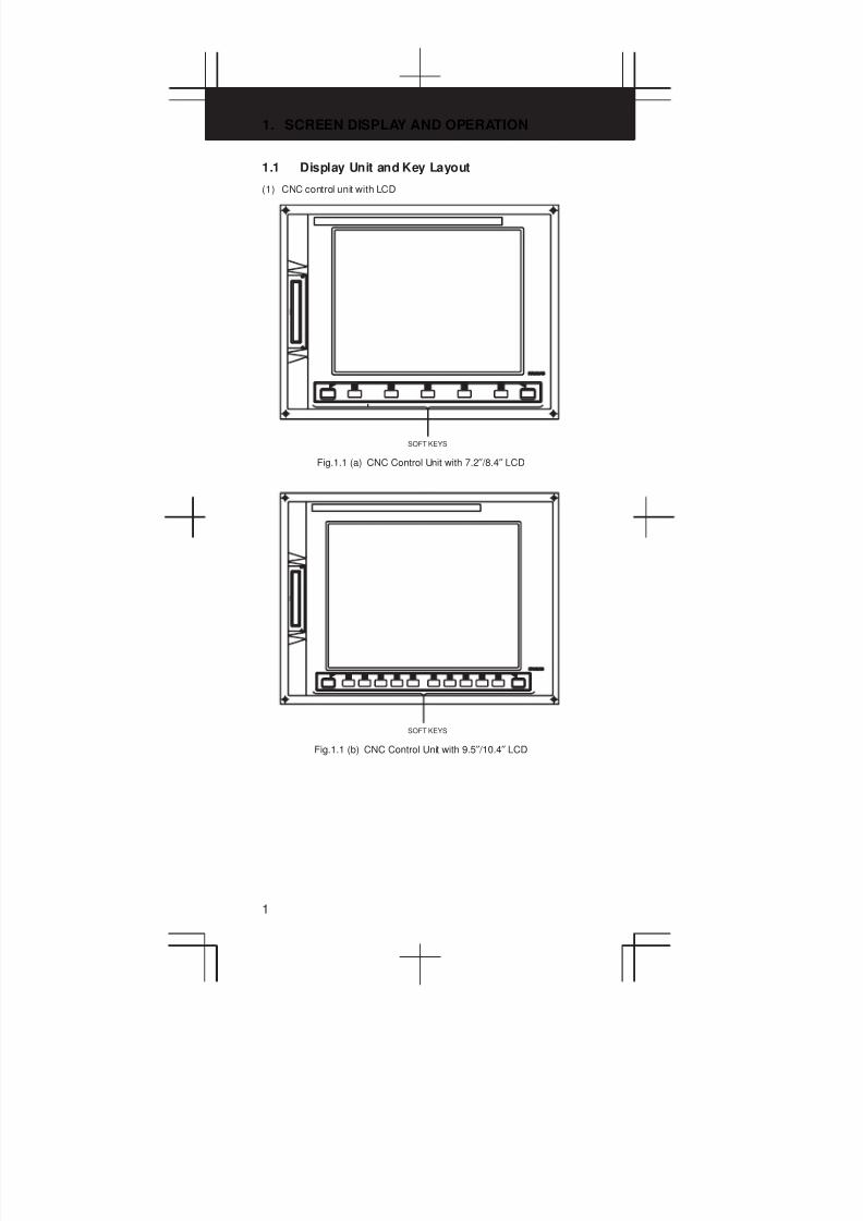
1. SCREEN DISPLAY AND OPERATION
1
1.1 Display Unit and Key Layout
(1) CNC control unit with LCD
SOFT KEYS
Fig.1.1 (a) CNC Control Unit with 7.2″ /8.4″ LCD
SOFT KEYS
Fig.1.1 (b) CNC Control Unit with 9.5″ /10.4″ LCD
3
1
4
5
6
7
8
9
10
2
2
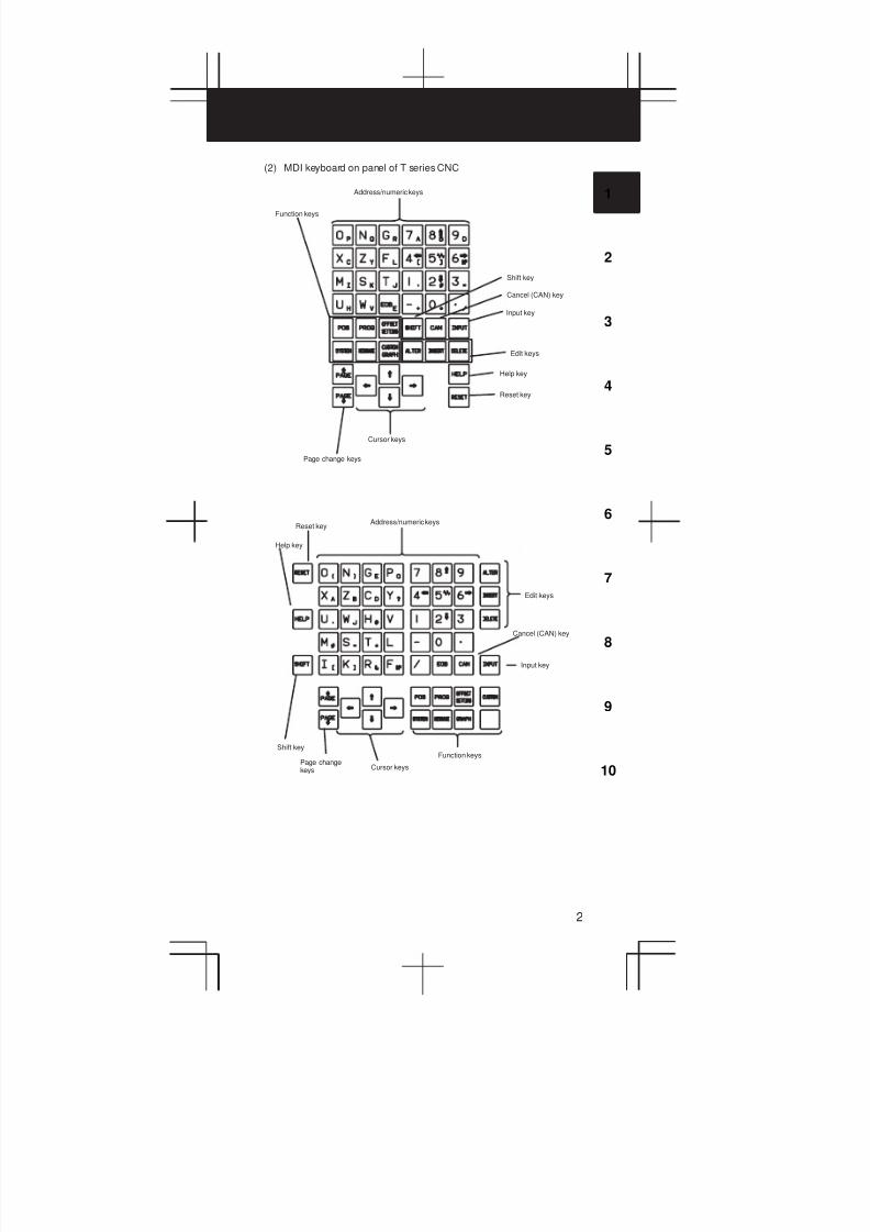
(2) MDI keyboard on panel of T series CNC
Function keys
Address/numeric keys
Shift key
Cancel (CAN) key
Input key
Edit keys
Help key
Reset key
Page change keys
Cursor keys
Page changekeys
Help key
Reset keyAddress/numeric keys
Edit keys
Cancel (CAN) key
Input key
Function keys
Cursor keys
Shift key
1. SCREEN DISPLAY AND OPERATION
3
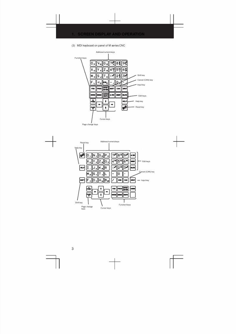
(3) MDI keyboard on panel of M series CNC
Function keys
Address/numeric keys
Shift key
Cancel (CAN) key
Input key
Edit keys
Help key
Reset key
Page change keys
Cursor keys
Page changekeys
Help key
Reset keyAddress/numeric keys
Edit keys
Cancel (CAN) key
Input key
Function keys
Cursor keys
Shift key
3
1
4
5
6
7
8
9
10
2
4
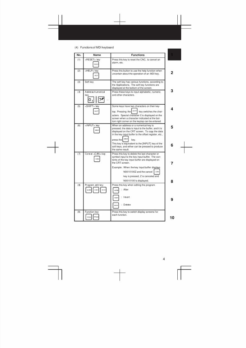
(4) Functions of MDI keyboard
No. Name Functions
(1) <RESET> key
RESET
Press this key to reset the CNC, to cancel an
alarm, etc.
(2) <HELP> key
HELP
Press this button to use the help function when
uncertain about the operation of an MDI key.
(3) Soft key The soft key has various functions, according to
the Applications. The soft key functions are
displayed at the bottom of the screen.
(4) Address/numerical
key
...
Press these keys to input alphabetic, numeric,
and other characters.
(5) <SHIFT> key
SHIFT
Some keys have two characters on their key-
top. Pressing the key switches the char-
acters. Special character £ is displayed on the
screen when a character indicated at the bot-
tom right corner on the keytop can be entered.
SHIFT
(6) <INPUT> key
INPUT
When an address or a numerical key is
pressed, the data is input to the buffer, and it is
displayed on the CRT screen. To copy the data
in the key input buffer to the offset register, etc.,
press the key.
This key is equivalent to the [INPUT] key of the
soft keys, and either can be pressed to produce
the same result.
INPUT
(7) Cancel <CAN> key
CAN
Press this key to delete the last character or
symbol input to the key input buffer. The con-
tents of the key input buffer are displayed on
the CRT screen.
Example: When the key input buffer displays
N001X100Z and the cancel
key is pressed, Z is canceled and
N001X100 is displayed.
CAN
(8) Program edit key
ALTER IN SER T DE LET E
Press this key when editing the program.
: Alter
: Inser t
: Delete
ALTER
INSERT
DELETE
(9) Function key
POS PROG
Press this key to switch display screens for
each function.
1. SCREEN DISPLAY AND OPERATION
5
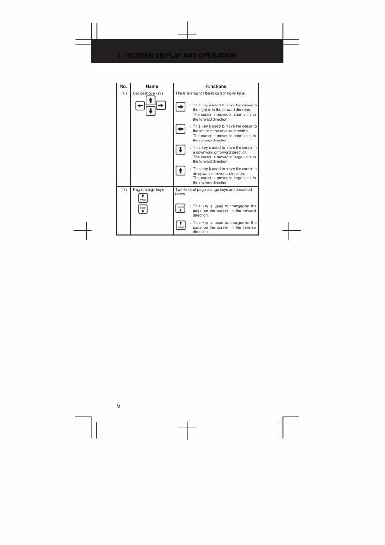
No. Name Functions
(10) Cursor move keys There are four dif ferent cursor move keys.
: This key is used to move the cursor to
the right or in the forward direction.
The cursor is moved in short units in
the forward direction.
: This key is used to move the cursor to
the left or in the reverse direction.
The cursor is moved in short units in
the reverse direction.
: This key is used to move the cursor in
a downward or forward direction.
The cursor is moved in large units in
the forward direction.
: This key is used to move the cursor in
an upward or reverse direction.
The cursor is moved in large units in
the reverse direction.
(11) Page change keys
PAGE
PAGE
Two kinds of page change keys are described
below.
: This key is used to changeover the
page on the screen in the forward
direction.
: This key is used to changeover the
page on the screen in the reverse
direction.
PAGE
PAGE
3
1
4
5
6
7
8
9
10
2
6
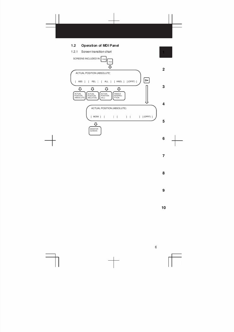
1.2 Operation of MDI Panel
1.2.1 Screen transition chart
ABS[ ] [ ] [ ] [ ] [ ]REL ALL HNDL (OPRT)
ACTUAL POSITION (ABSOLUTE)
ACTUALPOSITION(ABSOLUTE)
ACTUALPOSITION(RELATIVE)
ACTUALPOSITION(ALL)
HANDLEINTERRU-PTION
MONI[ ] [ ] [ ] [ ] [ ](OPRT)
ACTUAL POSITION (ABSOLUTE)
MONITORSCREEN
POSSCREENS INCLUDED IN
POS

1. SCREEN DISPLAY AND OPERATION
7
DIR
REL
PRGRM[ ] [ ] [ ] [ ] [ ]CHECK CURRNT NEXT (OPRT)
PROGRAM
CONTENTSOFPROGRAM
PROGRAM(CURRENTBLOCK)
PROGRAM(NEXTBLOCK)
RSTR[ ] [ ] [ ] [ ] [ ]FL.SDL (OPRT)
PROGRAM
PROGRAMRESTART
SCREENS INCLUDED IN (MEM mode)PROG
PROG
MEM
ABS[ ] [ ]
PROGRAMCHECK(ABSOLUTE)
PROGRAMCHECK(RELATIVE)
MEM
[ ] [ ]PRGRM
FILEDIRECTORY
SCHEDULESETTING
SCHDUL[ ]

3
1
4
5
6
7
8
9
10
2
8
PRGRM[ ] [ ] [ ] [ ] [ ]LIB C.A.P (OPRT)
PROGRAM
PROGRAMEDITINGSCREEN
PROGRAMDIRECTORYSCREEN
C.A.P.SCREEN
FLOPPY[ ] [ ] [ ] [ ] [ ](OPRT)
PROGRAM
FILEDIRECTORYOF FLOPPY
SCREENS INCLUDED IN (EDIT mode)PROG
PROG
EDIT
EDIT
OFFSET[ ] [ ] [ ] [ ] [ ]SETING WORK (OPRT)
OFFSET/GEOMETRY
TOOLOFFSETSCREEN
SETTINGSCREEN
WORKCOORDINATESCREEN
MACRO[ ] [ ] [ ] [ ] [ ]MENU OPR (OPRT)
VARIABLE
MACROVARIABLEDISPLAY
SCREENS INCLUDED IN
MENUPROGRAMMING
OPERATOR’SPANEL
SETTINGOFFSET
SETTINGOFFSET

1. SCREEN DISPLAY AND OPERATION
9
PARAM[ ] [ ] [ ] [ ] [ ]DGNOS PMC SYSTEM (OPRT)
PARAMETER
PARAMETERSETTINGSCREEN
DIAGNOSISSCREEN
PMCSCREEN
SYSTEMSTRUCTUALSCREEN
[ ] [ ] [ ] [ ] [ ]PITCH SV.PRM SP.PRM (OPRT)
PARAMETER
SCREENS INCLUDED IN SYSTEM
SYSTEM
WAVEFORMDIAGNOSISSCREEN
PITCHERROR COM-PENSATION
SERVOPARAMETERSCREEN
SPINDLEPARAMETERSCREEN
W.DGNS[ ] [ ] [ ] [ ] [ ](OPRT)
PARAMETER
ALARM[ ] [ ] [ ] [ ] [ ]MSG HISTRY
ALARM MESSAGE
ALARMMESSAGESCREEN
OPERATORMESSAGESCREEN
ALARMHISTORYSCREEN
SCREENS INCLUDED IN
MESSAGE
MESSAGE
MDI
1 ALAM[ ] [ ] [ ] [ ] [ ]2 OPR 3 PARA
HELP (INITIAL MENU)
HELP(ALARMDETAIL)
HELP(OPERATIONMETHOD)
HELP(PARAME-TER TABLE)
SCREENS INCLUDED IN
HELP
HELP
3
1
4
5
6
7
8
9
10
2
10
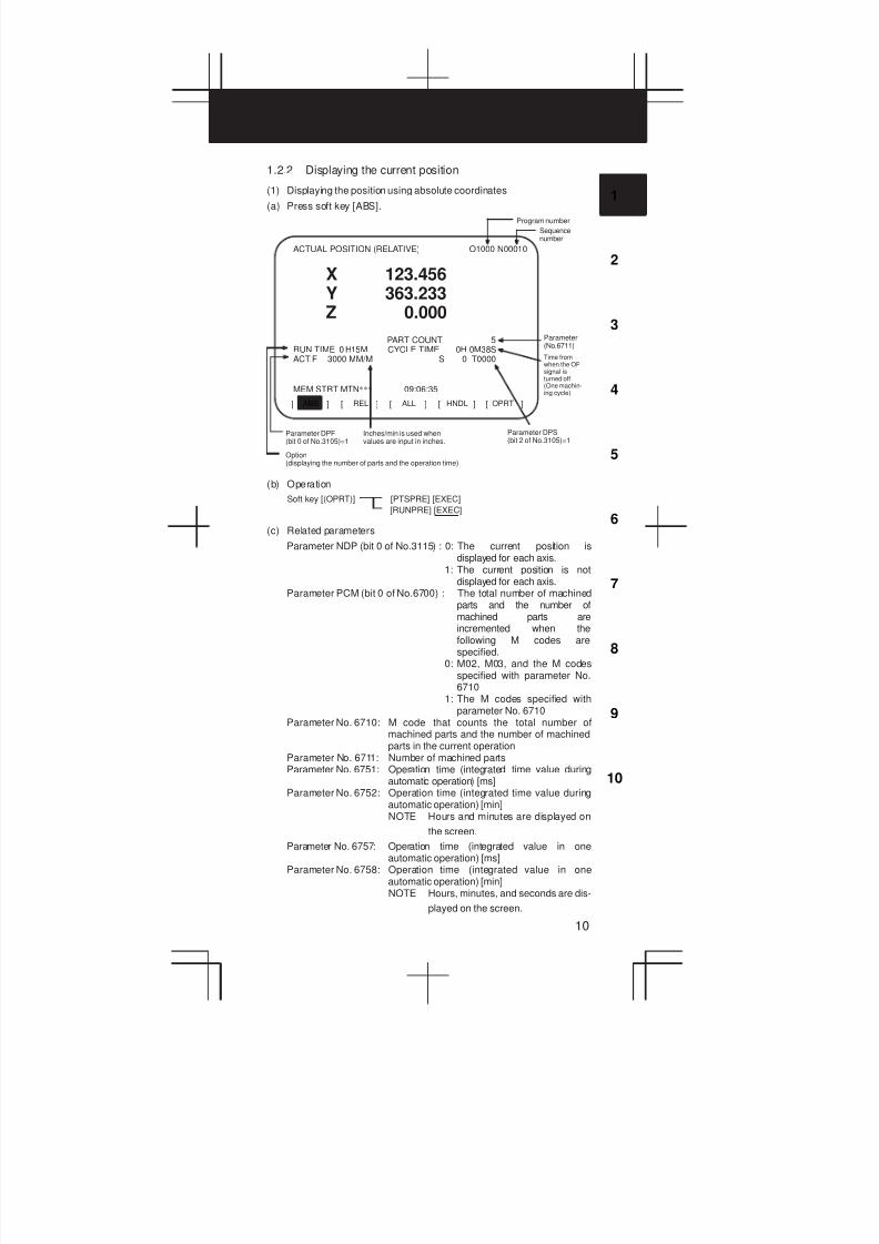
1.2.2 Displaying the current position
(1) Displaying the position using absolute coordinates
(a) Press soft key [ABS].
ABS[ ] [ ] [ ] [ ] [ ]REL ALL HNDL OPRT
ACTUAL POSITION (RELATIVE) O1000 N00010
Program number
Sequencenumber
X 123.456Y 363.233Z 0.000
PART COUNT 5RUN TIME 0 H15M CYCLE TIME 0H 0M38SACT.F 3000 MM/M S 0 T0000
MEM STRT MTN*** 09:06:35
Parameter(No.6711)
Time fromwhen the OPsignal isturned off(One machin-ing cycle)
Parameter DPS(bit 2 of No.3105)=1
Inches/min is used whenvalues are input in inches.
Parameter DPF(bit 0 of No.3105)=1
Option(displaying the number of parts and the operation time)
(b) Operation
Soft key [(OPRT)] [PTSPRE] [EXEC]
[RUNPRE] [EXEC]
(c) Related parameters
Parameter NDP (bit 0 of No.3115) : 0: The current position isdisplayed for each axis.
1: The current position is notdisplayed for each axis.
Parameter PCM (bit 0 of No.6700) : The total number of machinedparts and the number ofmachined parts areincremented when thefollowing M codes arespecified.
0: M02, M03, and the M codesspecified with parameter No.6710
1: The M codes specified withparameter No. 6710
Parameter No. 6710: M code that counts the total number ofmachined parts and the number of machinedparts in the current operation
Parameter No. 6711: Number of machined partsParameter No. 6751: Operation time (integrated time value during
automatic operation) [ms]Parameter No. 6752: Operation time (integrated time value during
automatic operation) [min]NOTE Hours and minutes are displayed on
the screen.
Parameter No. 6757: Operation time (integrated value in oneautomatic operation) [ms]
Parameter No. 6758: Operation time (integrated value in oneautomatic operation) [min]NOTE Hours, minutes, and seconds are dis-
played on the screen.
1. SCREEN DISPLAY AND OPERATION
11
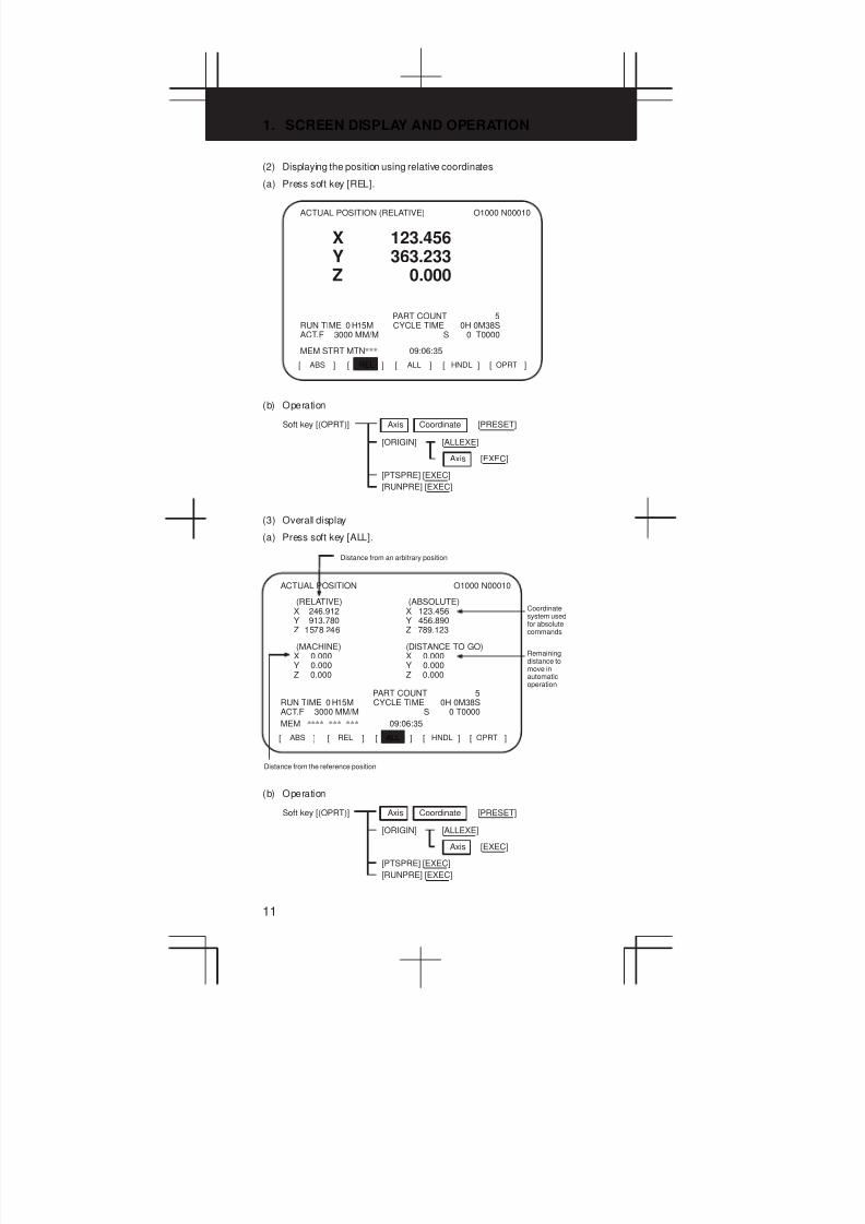
(2) Displaying the position using relative coordinates
(a) Press soft key [REL].
ABS[ ] [ ] [ ] [ ] [ ]REL ALL HNDL OPRT
ACTUAL POSITION (RELATIVE) O1000 N00010
X 123.456Y 363.233Z 0.000
PART COUNT 5RUN TIME 0 H15M CYCLE TIME 0H 0M38SACT.F 3000 MM/M S 0 T0000
MEM STRT MTN*** 09:06:35
(b) Operation
Soft key [(OPRT)] Axis
[ORIGIN]
[PRESET]Coordinate
[ALLEXE]
Axis [EXEC]
[PTSPRE] [EXEC]
[RUNPRE] [EXEC]
(3) Overall display
(a) Press soft key [ALL].
ABS[ ] [ ] [ ] [ ] [ ]REL ALL HNDL OPRT
ACTUAL POSITION O1000 N00010
Distance from an arbitrary position
(RELA
TIVE)X 246.912Y 913.780Z 1578.246
PART COUNT 5RUN TIME 0 H15M CYCLE TIME 0H 0M38SACT.F 3000 MM/M S 0 T0000
MEM **** *** *** 09:06:35
Coordinatesystem usedfor absolutecommands
Distance from the reference position
(ABSOLUTE)X 123.456Y 456.890Z 789.123
(MACHINE)X 0.000Y 0.000Z 0.000
(DISTANCE TO GO)X 0.000Y 0.000Z 0.000
Remainingdistance tomove inautomaticoperation
(b) Operation
Soft key [(OPRT)] Axis
[ORIGIN]
[PRESET]Coordinate
[ALLEXE]
Axis [EXEC]
[PTSPRE] [EXEC]
[RUNPRE] [EXEC]

3
1
4
5
6
7
8
9
10
2
12
1.2.3 Display for handle interrupt
(1) Press soft key [HNDL].
The distance traveled due to a handle interrupt is displayed.
ABS[ ] [ ] [ ] [ ] [ ]REL ALL HNDL OPRT
HANDLE INTERRUPTION O0000 N02000
The displayed unit is switched between inch andmetric (by setting in G20 and G21)
(INPUT UNIT)X 69.594Y 137.783Z –61.439
PART COUNT 5RUN TIME 0 H15M CYCLE TIME 0H 0M38SACT.F 3000 MM/M S 0 T0000
MEM **** *** *** 10:29:51
Displayed inthe unitspecified byparameter INM(bit 0 ofNo.100)(mm/inch)
(OUTPUT UNIT)X 69.594Y 137.783Z –61.439
(RELATIVE)X 0.000Y 0.000Z 0.000
(DISTANCE TO GO)X 0.000Y 0.000Z 0.000
(2) Operation
Soft key [(OPRT)] [PTSPRE] [EXEC]
[RUNPRE] [EXEC]
(3) Related signals
DGN#7 #6 #5 #4 #3 #2 #1 #0
G041 HS2ID HS2IC HS2IB HS2IA HS1ID HS1IC HS1IB HS1IA
DGN#7 #6 #5 #4 #3 #2 #1 #0
G042 HS3ID HS3IC HS3IB HS3IA
NOTE HS3In is effective only in the M series.

1. SCREEN DISPLAY AND OPERATION
13
1.2.4 Displaying the program
(1) Program contents screen
(a) Press soft key [PRGRM].
PRGRM[ ] [ ] [ ] [ ] [ ]CHECK CURRNT NEXT (OPRT)
PROGRAM O2000 N00130
O2000 ;N100 G92 X0 Y0 Z70. ;N110 G91 G00 Y–70. ;N120 Z–70. ;
N140 G41 G03 X–17.5 Y17.5 R17.5 ;N150 G01 X–25. ;N160 G02 X27.5 Y27.5 R27.5 ;N170 G01 X20. ;N180 G02 X45. Y45. R45. ;
>_ S 0 T0000
MEM STRT *** 16:05:59
Sequencenumber
N130 G42 G39 I–17.5 ;Programnumber
(b) Operation
Soft key [(OPRT)] [BG–EDT] ³ See the EDIT mode screen.
Program number [O SRH]
[REWIND]
O
N Sequence number [NO.SRH]
N Sequence number [P TYPE]
N Sequence number [O TYPE]
(c) Related parameter
Parameter No.7310: The sequence of the axes along which themachine moves to the restart point after theprogram is restarted
(d) Related signal
SRN<G006#0>: Program restart
3
1
4
5
6
7
8
9
10
2
14
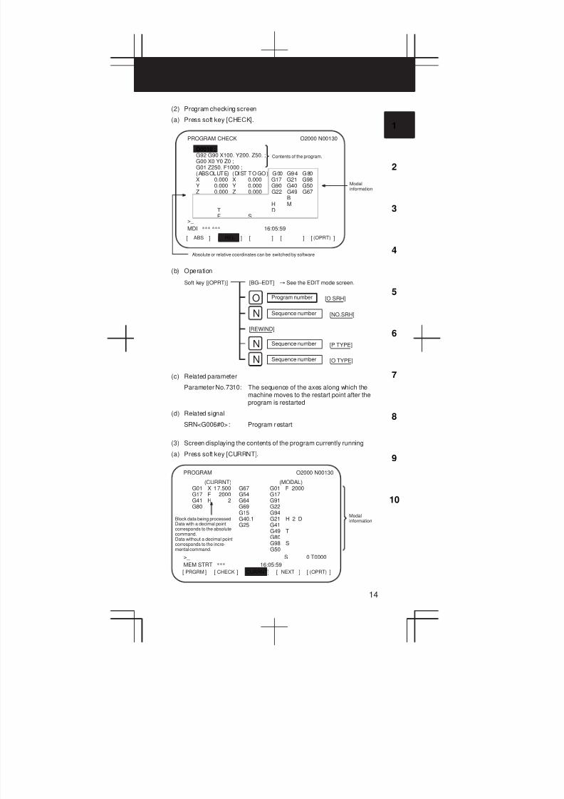
(2) Program checking screen
(a) Press soft key [CHECK].
RELABS[ ] [ ] [ ] [ ] [ ](OPRT)
PROGRAM CHECK O2000 N00130
O0010 ;G92 G90 X100. Y200. Z50. ;G00 X0 Y0 Z0 ;G01 Z250. F1000 ;(ABSOLUTE) (DIST TO GO) G00 G94 G80X 0.000 X 0.000 G17 G21 G98Y 0.000 Y 0.000 G90 G40 G50Z 0.000 Z 0.000 G22 G49 G67
BH M
T DF S
>_
MDI *** *** 16:05:59
Modalinformation
Absolute or relative coordinates can be switched by software
Contents of the program.
(b) Operation
Soft key [(OPRT)] [BG–EDT] ³ See the EDIT mode screen.
Program number [O SRH]
[REWIND]
O
N Sequence number [NO.SRH]
N Sequence number [P TYPE]
N Sequence number [O TYPE]
(c) Related parameter
Parameter No.7310: The sequence of the axes along which themachine moves to the restart point after theprogram is restarted
(d) Related signal
SRN<G006#0>: Program restart
(3) Screen displaying the contents of the program currently running
(a) Press soft key [CURRNT].
PRGRM[ ] [ ]
[ ] [ ] [ ]CHECK CURRNT NEXT (OPRT)
PROGRAM O2000 N00130
>_ S 0 T0000
MEM STRT *** 16:05:59
Modalinformation
(CURRNT) (MODAL)G01 X 17.500 G67 G01 F 2000G17 F 2000 G54 G17G41 H 2 G64 G91G80 G69 G22
G15 G94G40.1 G21 H 2 DG25 G41
G49 TG80G98 SG50
Block data being processedData with a decimal pointcorresponds to the absolutecommand.Data without a decimal pointcorresponds to the incre-mental command.
1. SCREEN DISPLAY AND OPERATION
15
(b) Operation
Soft key [(OPRT)] [BG-EDT] → See the EDIT mode screen.
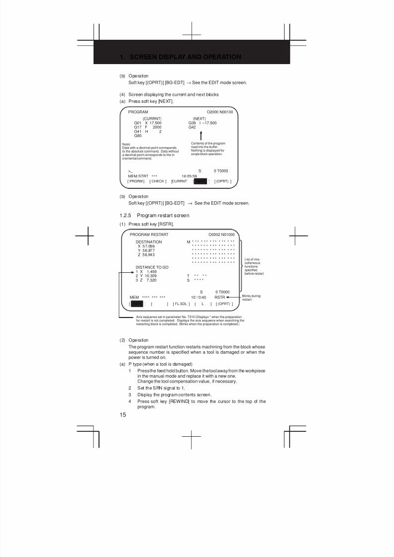
(4) Screen displaying the current and next blocks
(a) Press soft key [NEXT].
PRGRM[ ] [ ] [ ] [ ] [ ]CHECK CURRNT NEXT (OPRT)
PROGRAM O2000 N00130
>_ S 0 T0000
MEM STRT *** 16:05:59
(CURRNT) (NEXT)G01 X 17.500 G39 I –17.500G17 F 2000 G42G41 H 2G80
Note)Data with a decimal point correspondsto the absolute command. Data withouta decimal point corresponds to the in-cremental command.
Contents of the programread into the buffer.Nothing is displayed forsingle block operation.
(b) Operation
Soft key [(OPRT)] [BG-EDT] → See the EDIT mode screen.
1.2.5 Program restart screen
(1) Press soft key [RSTR].
RSTR[ ] [ ] [ ] [ ] [ ]FL.SDL L (OPRT)
PROGRAM RESTART O0002 N01000
Axis sequence set in parameter No. 7310 (Displays * when the preparationfor restart is not completed. Displays the axis sequence when searching therestarting block is completed. Blinks when the preparation is completed.)
DESTINATIONX 57.096Y 56.877Z 56.943
S 0 T0000
MEM **** *** *** 10:10:40 RSTR
List of mis-cellaneousfunctionsspecifiedbefore restart
M * * * * * * * * * * * * * * ** * * * * * * * * * * * * * ** * * * * * * * * * * * * * ** * * * * * * * * * * * * * ** * * * * * * * * * * * * * ** * * * * * * * * * * * * * *
T * * * *S * * * *
DISTANCE TO GO1 X 1.4592 Y 10.3093 Z 7.320
Blinks duringrestart.
(2) Operation
The program restart function restarts machining from the block whosesequence number is specified when a tool is damaged or when thepower is turned on.
(a) P type (when a tool is damaged)
1 Press the feed hold button. Move the tool away from the workpiecein the manual mode and replace it with a new one.Change the tool compensation value, if necessary.
2 Set the SRN signal to 1.
3 Display the program contents screen.
4 Press soft key [REWIND] to move the cursor to the top of theprogram.

3
1
4
5
6
7
8
9
10
2
16
5 Enter N followed by the sequence number of the program to be
restarted. Press soft key [P TYPE] to search for the sequencenumber.
6 The program restart screen is displayed. The position at whichmachining is restarted and the specified M, S, T, and B codes areshown on the screen.
7 Set the SRN signal to 0.
8 Specify M, S, T, or B codes in the MDI mode, if necessary.
9 Return to the automatic operation mode and press the cycle startbutton.
(b) Q type (When machining is restarted after being stopped for somereason)
Used when machining is restarted after the power is turned off, theemergency stop button is pressed, or the operation is stopped tochange the coordinate system.
1 Return the machine to the reference position, if necessary, after thepower is turned on.
2 Move the machine to the restart point in the manual mode and setthe restarting data and coordinate system.
3 Ensure that the offset value is correct.
4 Set the SRN signal to 1.
5 Display the program contents screen.Press soft key [REWIND] to move the cursor to the start of theprogram.
6 Enter N followed by the sequence number of the program to be
restarted. Press soft key [Q TYPE] to search for the sequencenumber.
7 The program restart screen is displayed. The position at whichmachining is restarted and the specified M, S, T, and B codes areshown in the screen.
8 Set the SRN signal to 0.
9 Specify M, S, T, or B codes in the MDI mode, if necessary.
10 Return to the automatic operation mode and press the cycle startbutton.
1. SCREEN DISPLAY AND OPERATION
17
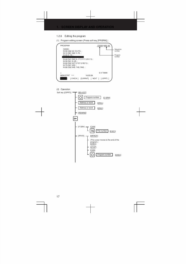
1.2.6 Editing the program
(1) Program editing screen (Press soft key [PRGRM].)
PRGRM[ ] [ ] [ ] [ ] [ ]CHECK CURRNT NEXT (OPRT)
PROGRAM O2000 N00130
O2000 ;N100 G92 X0 Y0 Z70. ;N110 G91 G00 Y–70. ;N120 Z–70. ;
N140 G41 G03 X–17.5 Y17.5 R17.5 ;N150 G01 X–25. ;N160 G02 X27.5 Y27.5 R27.5 ;N170 G01 X20. ;N180 G02 X45. Y45. R45. ;
>_ S 0 T0000
MEM STRT *** 16:05:59
Sequencenumber
ProgramnumberN130 G42 G39 I–17.5 ;
(2) Operation
Program number
Soft key [(OPRT)] [BG–EDT]
Program number [O SRH]O
Address or word [SRH±]
N File number [EXEC]
[REWIND]
Address or word [SRH°]
[F SRH] [CAN]
[READ] [MERGE]
(The cursor moves to the end of theprogram.)[EXEC]
[STOP]
[CAN]
[EXEC]O

3
1
4
5
6
7
8
9
10
2
18
Program number
N File number [EXEC]
[DELETE] [CAN]
[PUNCH] [STOP]
[CAN]
[EXEC]O
Note) To specify all the programs, enter0–9999.
[EX–EDT] [COPY]
[CRSRX]
[XCRSR]
[XBTTM]
Programnumber
[EXEC]INPUT
[ALL]
[MOVE]
[CRSRX]
[XCRSR]
[XBTTM]
Programnumber
[EXEC]INPUT
[ALL]
[MERGE]
[X’GCRSR]
[XBTTM’]
Programnumber
[EXEC]INPUT
[CHANGE]
[SKIP]
[EX–SGL]
ADDRESS/WORD [BEFORE]
ADDRESS/WORD [AFTER]
[EXEC]

1. SCREEN DISPLAY AND OPERATION
19
(3) Operation of expanded editing function
(a) When copying or moving the program
[EX–EDT]
[COPY]
Move the cursor to the start of the section t o be copied
[CRSRX]
Move the cursor to the end of the section to be copied[XBTTM]
[XCRSR]
Type the program number and press INPUT
[ALL]
[EXEC]
NOTE[MOVE] when moving
(b) When inserting another program in the program being edited
[EX–EDT]
[MERGE]
Move the cursor to the position to which the otherprogram is to be inserted
[X’CRSR]
Type the program number and press INPUT
[EXEC]
When inserting afterthe end of the program
[XBTTM’]
(c) When replacing an address or word
[EX–EDT]
[CHANGE]
Word or address to be replaced
[BEFORE]
New word or address
[AFTER]
[SKIP] [EX–SGL] [EXEC]

3
1
4
5
6
7
8
9
10
2
20
1.2.7 Displaying the program list
(1) Press soft key [LIB].
(a) When parameter NAM (bit 0 of No. 3107) = 0
PRGRM[ ] [ ] [ ] [ ] [ ]LIB C.A.P. (OPRT)
PROGRAM DIRECTORY O0001 N00010
PROGRAM (NUM.) MEMORY (CHAR.)USED: 60 3321FREE: 2 429
O0240 (SHAFT XSF301 ) : ( )O0010 O0001 O0003 O0002 O0555 O0999O0062 O0004 O0005 O1111 O0969 O6666O0021 O1234 O0588 O0020 O0040
>_ S 0 T0000
MDI **** *** *** 16:05:59
Memoryutilizationcondition.One–meterpaper tapecontainsabout 400characters.
Program numbers
(b) When parameter NAM (bit 0 of No. 3107) = 1
PRGRM[ ] [ ] [ ] [ ] [ ]LIB C.A.P. (OPRT)
PROGRAM (NUM.) MEMORY (CHAR.)USED: 60 3321FREE: 2 429
O0240 (SHAFT XSF301 ) : ( )O0001 (MACRO–GCODE.MAIN)O0002 (MACRO–GCODE.SUB1)O0010 (TEST–PROGRAM.ARTHMETIC NO.1)O0020 (TEST–PROGRAM.F10–MACRO)O0040 (TEST–PROGRAM.OFFSET)O0050O0100 (INCH/MM CONVERT CHECK NO.1)O0200 (MACRO–MCODE.MAIN)
>_
EDIT **** *** *** 16:05:59
PROGRAM DIRECTORY O0001 N00010
(2) Operation
Program number
Soft key [(OPRT)] [BG–EDT] ³ Same as PRGRM
Program number [O SRH]O
[READ] [MERGE]
[STOP]
[CAN]
[EXEC]O
Program number
[PUNCH] [STOP]
[CAN]
O [EXEC]
(3) Related parameters
Parameter NAM (No. 3107#0): Only program numbers are listed/ Program numbers and programnames are listed.
Parameter SOR (No. 3107#4): Programs are listed in the order ofregistration/in the order of programnumber.
1. SCREEN DISPLAY AND OPERATION
21
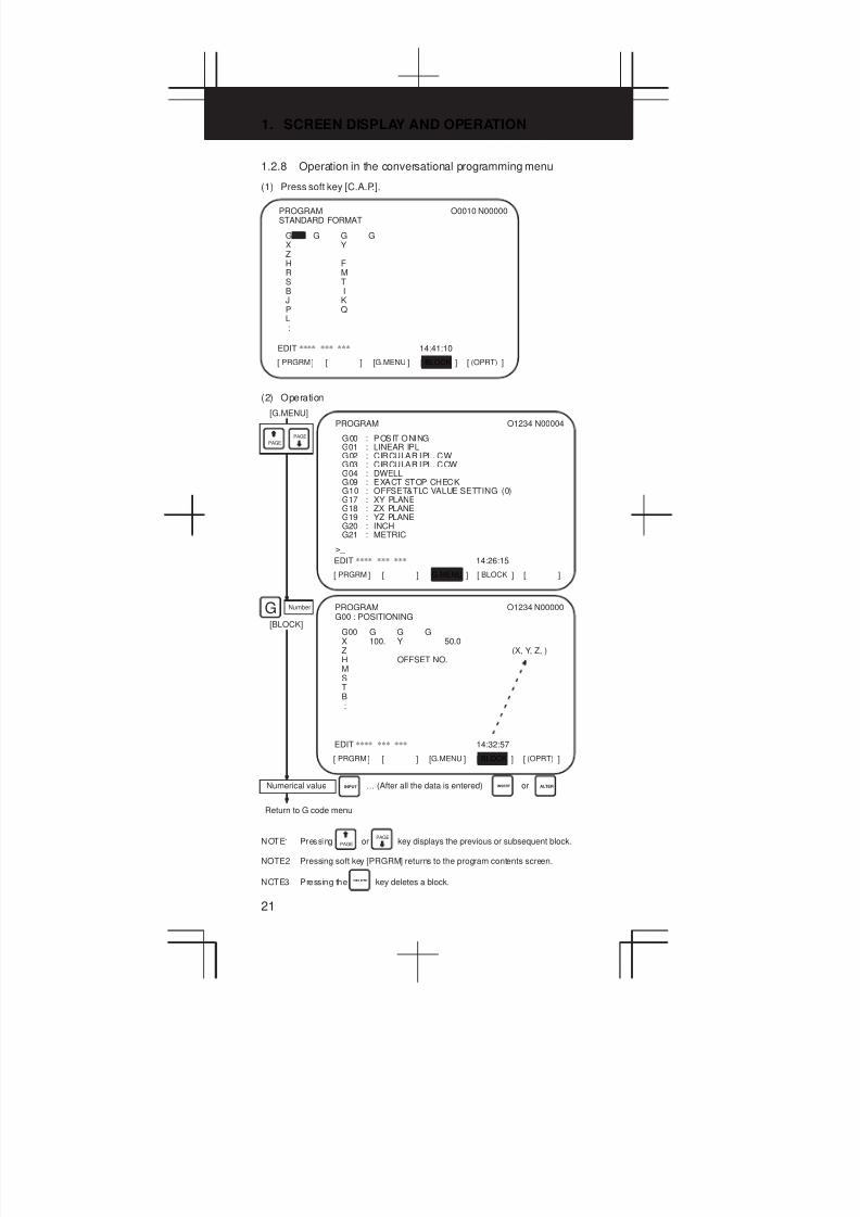
1.2.8 Operation in the conversational programming menu
(1) Press soft key [C.A.P.].
G G G GX YZH FR MS TB IJ KP QL:
PRGRM[ ] [ ] [ ] [ ] [ ]G.MENU BLOCK (OPRT)
PROGRAMSTANDARD FORMAT
O0010 N00000
EDIT **** *** *** 14:41:10
(2) Operation
G00 : POSITIONINGG01 : LINEAR IPLG02 : CIRCULAR IPL. CWG03 : CIRCULAR IPL. CCWG04 : DWELLG09 : EXACT STOP CHECKG10 : OFFSET&TLC VALUE SETTING (0)G17 : XY PLANEG18 : ZX PLANEG19 : YZ PLANEG20 : INCHG21 : METRIC
PRGRM[ ] [ ] [ ] [ ] [ ]G.MENU BLOCK
PROGRAM O1234 N00004
>_
EDIT **** *** *** 14:26:15
[G.MENU]
PAGE
PAGE
G00 G G GX 100. Y 50.0Z (X, Y, Z, )H OFFSET NO.MSTB:
PRGRM[ ] [ ] [ ] [ ] [ ]G.MENU BLOCK (OPRT)
PROGRAMG00 : POSITIONING
O1234 N00000
EDIT **** *** *** 14:32:57
G Number
[BLOCK]
Numerical value … (After all the data is entered)INPUT INSERT ALTERor
Return to G code menu
NOTE1 Pressing PAGE orPAGE
key displays the previous or subsequent block.
NOTE2 Pressing soft key [PRGRM] returns to the program contents screen.
NOTE3 Pressing the DELETE key deletes a block.
3
1
4
5
6
7
8
9
10
2
22
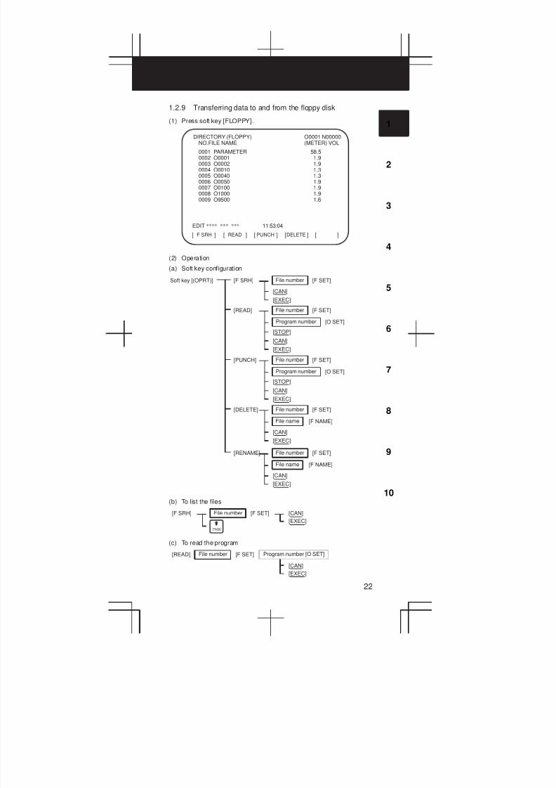
1.2.9 Transferring data to and from the floppy disk
(1) Press soft key [FLOPPY].
F SRH[ ] [ ] [ ] [ ] [ ]READ PUNCH DELETE
DIRECTORY (FLOPPY)NO.FILE NAME
O0001 N00000(METER) VOL
0001 PARAMETER 58.50002 O0001 1.90003 O0002 1.90004 O0010 1.30005 O0040 1.30006 O0050 1.90007 O0100 1.90008 O1000 1.90009 O9500 1.6
EDIT **** *** *** 11:53:04
(2) Operation
(a) Soft key configuration
Soft key [(OPRT)] File number [F SET][F SRH]
[CAN]
[EXEC]
File number [F SET][READ]
[CAN]
[EXEC]
Program number [O SET]
[STOP]
File number [F SET][PUNCH]
[CAN]
[EXEC]
Program number [O SET]
[STOP]
File number [F SET][DELETE]
[CAN]
[EXEC]
File name [F NAME]
File number [F SET][RENAME]
[CAN]
[EXEC]
File name [F NAME]
(b) To list the files
File number [F SET][F SRH] [CAN]
[EXEC]
PAGE
(c) To read the program
File number [F SET][READ]
[CAN]
[EXEC]
Program number [O SET]

1. SCREEN DISPLAY AND OPERATION
23
(d) To output the program
Program number
Can be omitted when theprogram is added to thesame file.
[PUNCH]
[CAN]
[EXEC]
File number [F SET] [O SET]
To specify all theprograms, enter“–9999”
(e) To delete the program
File number [F SET][DELETE] [CAN]
[EXEC]
File name [F NAME] [CAN]
[EXEC]
(f) To rename the program
File number [F SET][RENAME] New file name [F NAME]
[CAN]
[EXEC]
(3) Related parameters
Channel I/O=0 I/O=1 I/O=2 I/O=3 (remote buffer)
Common Parameter (No. 0100)
Output
format
Parameter
(No. 0101)
Parameter
(No. 0111)
Parameter
(No. 0121)
Parameter (No. 0131)
Specifica-
tion number
Parameter
(No. 0102)
Parameter
(No. 0112)
Parameter
(No. 0122)
Parameter (No. 0132)
Transfer
rate
Parameter
(No. 0103)
Parameter
(No. 0113)
Parameter
(No. 0123)
Parameter (No. 0133)
Transfer
method
Not defined Parameter
R42 (No.
0135#3)=0
Parameter
R42 (No.
0135#2)=1
Connector JD36A JD36B JD28A JD6A
0020 I/O channel selection
0: Channel 1 (JD36A on the main CPU board)
1: Channel 1 (JD36A on the main CPU board)
2: Channel 2 (JD36B on the main CPU board)
3: Channel 3 (JD28A on the option 1 board)
#7 #6 #5 #4 #3 #2 #1 #0
0101 NFD ASI SB2
#7(NFD)0: The feed code is output when data is punched out.
1: The feed code is not output when data is punched out.
#3(ASI) 0: EIA or ISO code is used when data is input.
1: ASCII code is used when data is input.
#0(SB2) 0: The number of stop bits is one.
1: The number of stop bits is two.
3
1
4
5
6
7
8
9
10
2
24
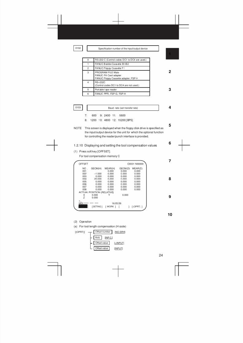
0102 Specification number of the input/output device
0 RS-232-C (Control codes DC1 to DC4 are used.)
1 FANUC Bubble Casset te B1/B2
2 FANUC Floppy Casset te F1
3 PROGRAM FILE Mate
FANUC FA Card adapter
FANUC Floppy Cassette adapter, FSP-H
4 RS–232C
(Control codes DC1 to DC4 are not used.)
5 Portable t ape reader
6 FANUC PPR, FSP-G, FSP-H
0103 Baud rate (set transfer rate)
7: 600 9: 2400 11: 9600
8: 1200 10: 4800 12: 19200 [ BPS]
NOTE This screen is displayed when the floppy disk drive is specified as
the input/output device for the unit for which the optional function
for controlling the reader/punch interface is provided.
1.2.10 Displaying and setting the tool compensation values
(1) Press soft key [OFFSET].
For tool compensation memory C
OFFSET[ ] [ ] [ ] [ ] [ ]SETING WORK (OPRT)
OFFSET O0001 N00000
NO . GEOM(H) WEAR(H) GEOM(D) WEAR(D)001 0.000 0.000 0.000002 –1.000 0.000 0.000 0.000003 0.000 0.000 0.000 0.000004 20.000 0.000 0.000 0.000005 0.000 0.000 0.000 0.000006 0.000 0.000 0.000 0.000007 0.000 0.000 0.000 0.000008 0.000 0.000 0.000 0.000
>_ MDI **** *** *** 16:05:59
ACTUAL POSITION (RELATIVE)X 0.000 Y 0.000Z 0.000
(2) Operation
(a) For tool length compensation (H code)
Offset number [NO.SRH][(OPRT)]
Axis [INP.C.]
Offset value [+INPUT]
Offset value [INPUT]
1. SCREEN DISPLAY AND OPERATION
25
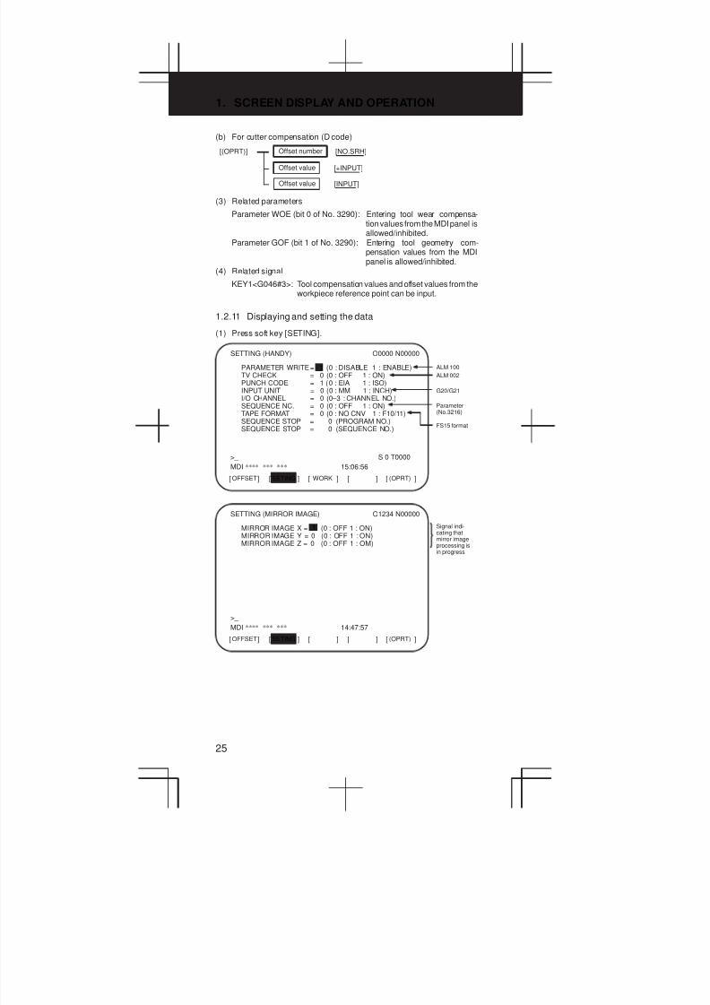
(b) For cutter compensation (D code)
Offset number [NO.SRH][(OPRT)]
Offset value [+INPUT]
Offset value [INPUT]
(3) Related parameters
Parameter WOE (bit 0 of No. 3290): Entering tool wear compensa-tion values from the MDI panel isallowed/inhibited.
Parameter GOF (bit 1 of No. 3290): Entering tool geometry com-pensation values from the MDIpanel is allowed/inhibited.
(4) Related signal
KEY1<G046#3>: Tool compensation values and offset values from theworkpiece reference point can be input.
1.2.11 Displaying and setting the data
(1) Press soft key [SETING].
OFFSET[ ] [ ] [ ] [ ] [ ]SETING WORK (OPRT)
SETTING (HANDY) O0000 N00000
PARAMETER WRITE= 1 (0 : DISABLE 1 : ENABLE)TV CHECK = 0 (0 : OFF 1 : ON)PUNCH CODE = 1 (0 : EIA 1 : ISO)INPUT UNIT = 0 (0 : MM 1 : INCH)I/O CHANNEL = 0 (0–3 : CHANNEL NO.)SEQUENCE NC. = 0 (0 : OFF 1 : ON)TAPE FORMAT = 0 (0 : NO CNV 1 : F10/11)SEQUENCE STOP = 0 (PROGRAM NO.)SEQUENCE STOP = 0 (SEQUENCE NO.)
>_ S 0 T0000
MDI **** *** *** 15:06:56
ALM 100
ALM 002
G20/G21
FS15 format
Parameter(No.3216)
OFFSET[ ] [ ] [ ] [ ] [ ]SETING (OPRT)
SETTING (MIRROR IMAGE) O1234 N00000
MIRROR IMAGE X = (0 : OFF 1 : ON)MIRROR IMAGE Y = 0 (0 : OFF 1 : ON)MIRROR IMAGE Z = 0 (0 : OFF 1 : OM)
>_
MDI **** *** *** 14:47:57
Signal indi-cating thatmirror imageprocessing isin progress
1
3
1
4
5
6
7
8
9
10
2
26
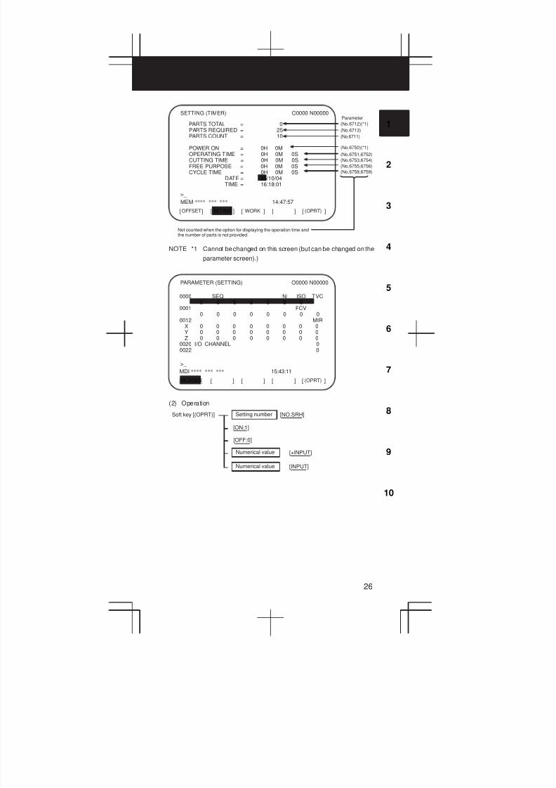
OFFSET[ ] [ ] [ ] [ ] [ ]SETING WORK (OPRT)
SETTING (TIMER) O0000 N00000
PARTS TOTAL = 0PARTS REQUIRED = 25PARTS COUNT = 10
POWER ON = 0H 0MOPERATING TIME = 0H 0M 0SCUTTING TIME = 0H 0M 0SFREE PURPOSE = 0H 0M 0SCYCLE TIME = 0H 0M 0S
DATE = 95 /10/04TIME = 16:18:01
>_
MEM **** *** *** 14:47:57
(No.6712)(*1)
(No.6713)
(No.6750)(*1)
Parameter
(No.6751,6752)
(No.6711)
(No.6753,6754)
(No.6755,6756)
(No.6758,6759)
Not counted when the option for displaying the operation time andthe number of parts is not provided.
NOTE *1 Cannot be changed on this screen (but can be changed on the
parameter screen).)
0000 SEQ INI ISO TVC0 0 0 0 0 0 0
0001 FCV0 0 0 0 0 0 0 0
0012 MIRX 0 0 0 0 0 0 0 0Y 0 0 0 0 0 0 0 0Z 0 0 0 0 0 0 0 0
0020 I/O CHANNEL 00022 0
W.DGNS[ ] [ ] [ ] [ ] [ ](OPRT)
PARAMETER (SETTING) O0000 N00000
>_
MDI **** *** *** 15:43:11
(2) Operation
Setting number [NO.SRH]Soft key [(OPRT)]
[ON:1]
[OFF:0]
Numerical value [+INPUT]
Numerical value [INPUT]

1. SCREEN DISPLAY AND OPERATION
27
1.2.12 Displaying and setting the offset values for the workpiece
coordinate system
(1) Press soft key [WORK].
NO. DATA02 X 152.580(G55) Z 58.284
03 X 300.000(G56) Z 200.000
OFFSET[ ] [ ] [ ] [ ] [ ]SETING WORK (OPRT)
WORK COORDINATES O0100 N00001
NO. DATA00 X 0.000(EXT) Z 0.000
01 X 100.000(G54) Z 50.000
>_
MEM **** *** *** 16:24:18
(2) Operation
Coordinate system number [NO.SRH]Soft key [(OPRT)]
Compensation value [+INPUT]
Axis [MEASUR]Numeral
Compensation value [INPUT]
(3) Related parameters
Parameter WZO (bit 3 of No. 3290): Entering shift values of thecoordinate system (T series) oroffsets from the workpiecereference point (M series) fromthe MDI panel is allowed/inhibited.
Parameter No.1220: External shift value of the workpiece coordinatesystem (T series).External offset from the workpiece referencepoint (M series)
Parameter No.1221: Offset from the workpiece reference point forG54
Parameter No.1222: Offset from the workpiece reference point forG55
Parameter No.1223: Offset from the workpiece reference point forG56
Parameter No.1224: Offset from the workpiece reference point forG57
Parameter No.1225: Offset from the workpiece reference point forG58
Parameter No.1226: Offset from the workpiece reference point forG59
3
1
4
5
6
7
8
9
10
2
28
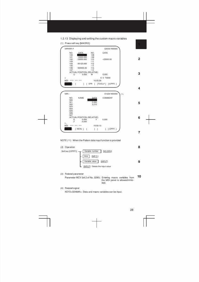
1.2.13 Displaying and setting the custom macro variables
(1) Press soft key [MACRO].
MACRO[ ] [ ] [ ] [ ] [ ]OPR TOOLLF (OPRT)
VARIABLE O0000 N00000
NO. DATA NO. DATA100 01000.000 108101 10000.000 109102 23000.000 110 –22000.00103 111104 00120.000 112105 113106 500000.00 114107 115ACTUAL POSITION (RELATIVE)
U 0.000 W 0.000
>_ S 0 T0000
MDI **** *** *** 16:05:59
MACRO[ ] [ ] [ ] [ ] [ ]MENU (OPRT)
VAR. : O1234 N00000
NO. NAME DATA COMMENT500 123.456501 0.000502 3.210503504505506507ACTUAL POSITION (RELATIVE)
X 0.000 Y 0.000Z 0.000
>_
MDI **** *** *** 15:50:13
(*1)
NOTE (*1) When the Pattern data input function is provided
(2) Operation
Variable number [NO.SRH]Soft key [(OPRT)]
Variable value [INPUT]
Axis [INP.C.]
[INPUT] : Delete the input value
(3) Related parameter
Parameter MCV (bit 2 of No. 3290): Entering macro variables fromthe MDI panel is allowed/inhib-ited.
(4) Related signal
KEY2<G046#4>: Data and macro variables can be input.
1. SCREEN DISPLAY AND OPERATION
29
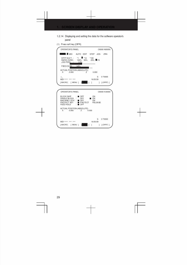
1.2.14 Displaying and setting the data for the software operator’s
panel
(1) Press soft key [OPR].
MODE : MDI AUTO EDIT STEP JOG ZRN
STEP MULTI. : *1 *10 *100RAPID OVRD.: 100% 50% 25% F0JOG FEED : 1.0%
**************FEED OVRD. : 140%
***ACTUAL POSITION (ABSOLUTE)
X 0.000 Z 0.000
MACRO[ ] [ ] [ ] [ ] [ ]MENU OPR (OPRT)
OPERATOR’S PANEL O0000 N00000
>_ S 0 T0000
MDI **** *** *** 16:05:59
BLOCK SKIP : J OFF ONSINGLE BLOCK : OFF J ONMACHINE LOCK : J OFF ONPROTECT KEY : J PROTECT RELEASEFEED HOLD : J OFF
ACTUAL POSITION (ABSOLUTE)X 0.000 Z 0.000
MACRO[ ] [ ] [ ] [ ] [ ]MENU OPR (OPRT)
OPERATOR’S PANEL O0000 N00000
S 0 T0000
MDI **** *** *** 16:05:59

3
1
4
5
6
7
8
9
10
2
30
(2) Related signals
#7 #6 #5 #4 #3 #2 #1 #0
F072 OUT7 OUT6 OUT5 OUT4 OUT3 OUT2 OUT1 OUT0
F073 ZRNO MD4O MD2O MD1O
F075 SPO KEYO DRNO MLKO SBKO BDTO
F076 ROV2O ROV1O MP2O MP1O
F077 RTO HS1DO HS1CO HS1BO HS1AO
F078 *FV7O *FV6O *FV5O *FV4O *FV3O *FV2O *FV1O *FV0O
F079 *JV7O *JV6O *JV5O *JV4O *JV3O *JV2O *JV1O *JV0O
F080 *JV15O *JV14O *JV13O *JV12O *JV11O *JV10O *JV9O *JV8O
F081 –J4O +J4O –J3O +J3O –J2O +J2O –J1O +J1O
(3) Related parameters
Parameter #7 #6 #5 #4 #3 #2 #1 #0
7200 OP7 OP6 OP5 OP4 OP3 OP2 OP1
Selects the operations performed on the software operator’s panel.
#6(OP7) Feed hold
#5(OP6) Program protection
#4(OP5) Optional block skip, single block operation, machine lock,and dry run
#3(OP4) Manual feedrate override and rapid traverse override
#2(OP3) Selecting the axis and magnification for the manual pulsegenerator
#1(OP2) Manual feed axis selection and manual rapid traverse
#0(OP1) Mode selection

1. SCREEN DISPLAY AND OPERATION
31
7220 Names of general–purpose software switches
7283 Names of general–purpose software switches
Decimals converted from ASCII codes are set as character codes.
Parameters No. 7220 to No. 7227: Name of general-purpose switch 1
Parameters No. 7228 to No. 7235: Name of general-purpose switch 2
Parameters No. 7236 to No. 7243: Name of general-purpose switch 3
Parameters No. 7244 to No. 7251: Name of general-purpose switch 4
Parameters No. 7252 to No. 7259: Name of general-purpose switch 5
Parameters No. 7260 to No. 7267: Name of general-purpose switch 6
Parameters No. 7268 to No. 7275: Name of general-purpose switch 7
Parameters No. 7276 to No. 7283: Name of general-purpose switch 8
To set “FANUC” as the name of general-purpose switch 1, set theparameters as follows: No. 7220 = 70, No. 7221 = 65, No. 7212 = 78, No.7213 = 85, and No. 7214 = 67.
1.2.15 Displaying and setting the parameters
(1) Press soft key [PARAM].
0000 SEQ INI ISO TVC0 0 0 0 0 0 0
0001 FCV0 0 0 0 0 0 0 0
0012 MIRX 0 0 0 0 0 0 0 0Y 0 0 0 0 0 0 0 0Z 0 0 0 0 0 0 0 0
0020 I/O CHANNEL 00022 0
[ ] [ ] [ ] [ ] [ ]DGNOS PMC SYSTEM (OPRT)
PARAMETER (SETTING) O0010 N00002
>_
MDI **** *** *** 15:43:11
PARAM
(2) Entering values from the MDI panel
1 Enter the MDI mode or emergency stop state.
2 Set PARAMETER WRITE to 1 in the setting screen.
3 Alarm 100 occurs. Press the CAN and RESET keys simultaneously
to temporarily stop the alarm.
4 Press soft key [(OPRT)] to display the operation menu includingthe following:
a) Enter a parameter number and press [NO.SRH]:Searches for the specified number.
3
1
4
5
6
7
8
9
10
2
32
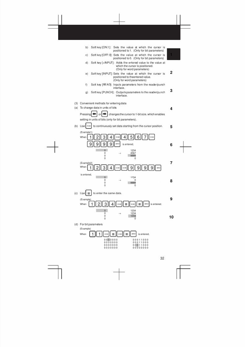
b) Soft key [ON:1]: Sets the value at which the cursor ispositioned to 1. (Only for bit parameters)
c) Soft key [OFF:0]: Sets the value at which the cursor ispositioned to 0. (Only for bit parameters)
d) Soft key [+INPUT]: Adds the entered value to the value atwhich the cursor is positioned.(Only for word parameters)
e) Soft key [INPUT]: Sets the value at which the cursor ispositioned to theentered value.(Only for word parameters)
f) Soft key [READ]: Inputs parameters from the reader/punchinterface.
g) Soft key [PUNCH]: Outputs parameters to the reader/punchinterface.
(3) Convenient methods for entering data
(a) To change data in units of bits
Pressing or changes the cursor to 1-bit size, which enables
setting in units of bits (only for bit parameters).
(b) Use EOB to continuously set data starting from the cursor position.
9 9
EOB
is entered,
(Example1)
When
0 12340 → 45670 99990 0
is entered,
(Example2)
When
0 12340 → 00 99990 0
1 2 3 4 4 5 6 7 EOB
9 9 9 9 INPUT
EOB1 2 3 4 EOB 9 9 INPUT
(c) Use = to enter the same data.
= is entered,
(Example)
When
0 12340 → 12340 12340 0
EOB1 2 3 4 EOB = INPUT
(d) For bit parameters
1 is entered,
(Example)
When
0 0 0 0 0 0 0 0 0 0 1 1 0 0 00 0 0 0 0 0 0 0 0 0 1 1 0 0 00 0 0 0 0 0 0 0 0 0 1 1 0 0 00 0 0 0 0 0 0 0 0 0 0 0 0 0 0
1 =EOB EOB = INPUT

1. SCREEN DISPLAY AND OPERATION
33
1.2.16 Displaying the internal state of the CNC (diagnostic screen)
See Chapter 6 for details of self-diagnosis.
(1) Press soft key[DGNOS].
PARAM[ ] [ ] [ ] [ ] [ ]DGNOS PMC SYSTEM (OPRT)
DIAGNOSTIC (GENERAL) O1234 N00000
000 WAITING FOR FIN SIGNAL :0001 MOTION :0002 DWELL :0003 IN–POSITION CHECK :0004 FEEDRATE OVERRIDE 0% :0005 INTERLOCK/START–LOCK :0006 SPINDLE SPEED ARRIVAL CHECK :0
>_
MDI **** *** *** 15:50:47
1.2.17 Displaying the system configuration
(1) Press soft key [SYSTEM].
PARAM[ ] [ ] [ ] [ ] [ ]DGNOS PMC SYSTEM (OPRT)
SYSTEM CONFIG (SLOT) O1234 N00000
SLOT MODULE I D SERIES VERSION00 10D5 : 40 B0F1 000201 00CF : 66 B435 0001
>_
MDI **** *** *** 15:51:25
Software seriesfor a modulewith CPU
Slot number(80 to 8F areon the second-ary side.)
Softwareversionfor a modulewith CPU
Software ID
Module ID
(2) Software configuration screen
SYSTEM CONFIG (SOFTWARE) 01234 N12345PAGE:02
SYSTEM B0F0 0001BASIC+OPTION–A1
SERVO 9090 0001PMC(SYS) 406A 0001
406B 00014099 0001
PMC(LAD) FS16 0001MACRO LIB BZG1 0001MACRO APL AAAA BBBBBOOT 60M3 0004GRAPHIC–1 600W 001Z
MEM **** *** *** 12:14:59[ PARMA ] [ DGNOS ] [ PMC ] [ SYSTEM ] [ (OPRT) ]
Kind of softwareSoftware series
Software version
Software configuration
Character written onPMC title screen
Character written onmacro compiler or onCAP.
3
1
4
5
6
7
8
9
10
2
34
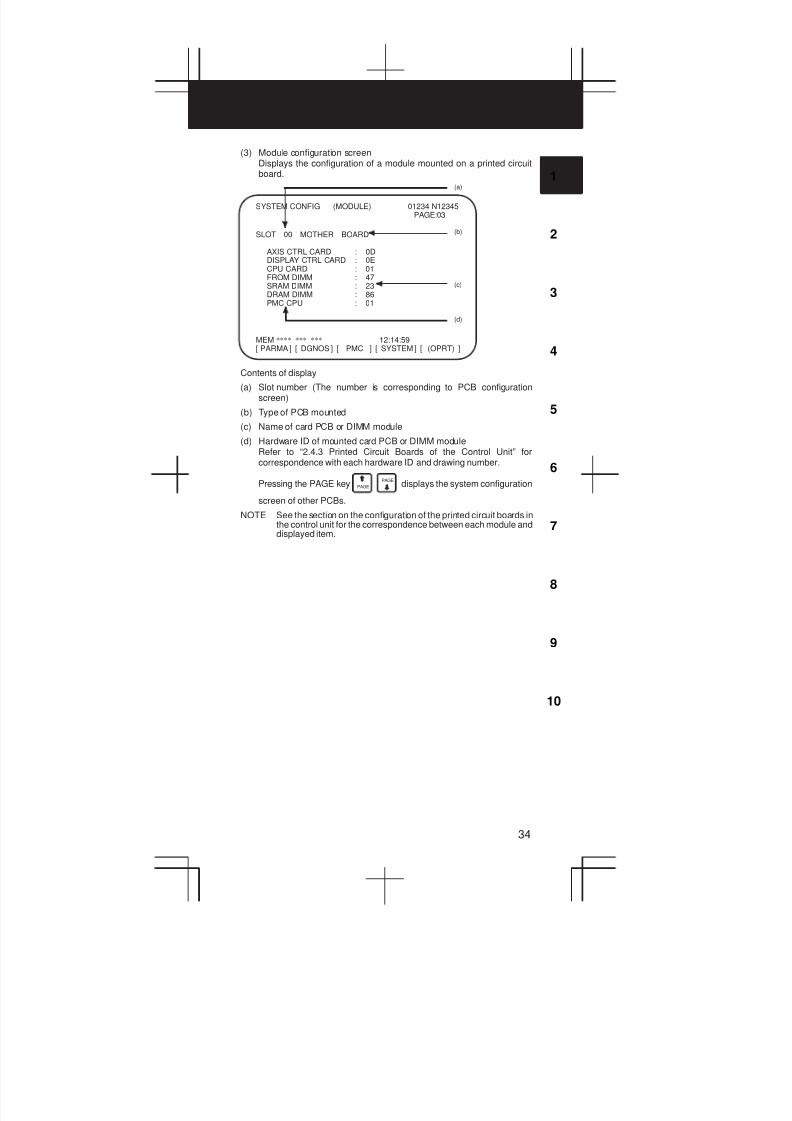
(3) Module configuration screenDisplays the configuration of a module mounted on a printed circuitboard.
SYSTEM CONFIG (MODULE) 01234 N12345PAGE:03
SLOT 00 MOTHER BOARD
AXIS CTRL CARD : 0DDISPLAY CTRL CARD : 0ECPU CARD : 01FROM DIMM : 47SRAM DIMM : 23DRAM DIMM : 86PMC CPU : 01
MEM **** *** *** 12:14:59[ PARMA ] [ DGNOS ] [ PMC ] [ SYSTEM ] [ (OPRT) ]
(b)
(c)
(d)
(a)
Contents of display
(a) Slot number (The number is corresponding to PCB configurationscreen)
(b) Type of PCB mounted
(c) Name of card PCB or DIMM module
(d) Hardware ID of mounted card PCB or DIMM moduleRefer to “2.4.3 Printed Circuit Boards of the Control Unit” forcorrespondence with each hardware ID and drawing number.
Pressing the PAGE key PAGE PAGE
displays the system configuration
screen of other PCBs.
NOTE See the section on the configuration of the printed circuit boards inthe control unit for the correspondence between each module anddisplayed item.
1. SCREEN DISPLAY AND OPERATION
35
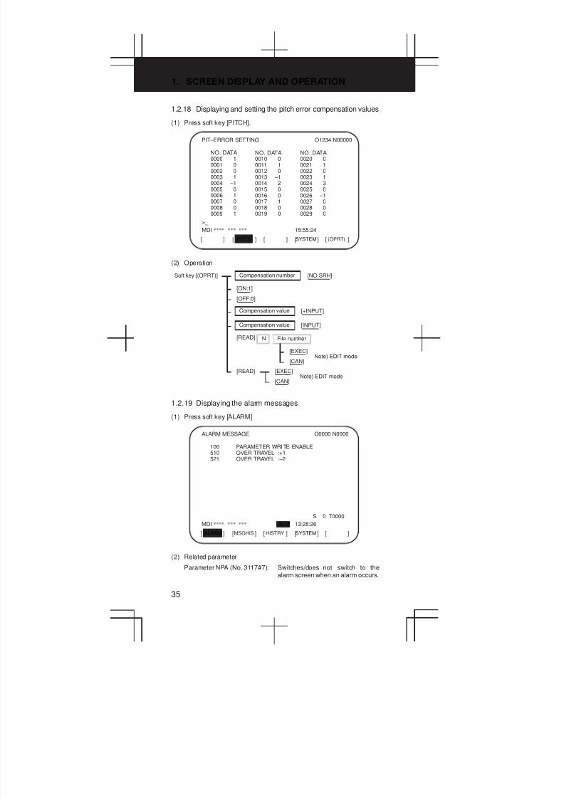
1.2.18 Displaying and setting the pitch error compensation values
(1) Press soft key [PITCH].
PITCH[ ] [ ] [ ] [ ] [ ]SYSTEM (OPRT)
PIT–ERROR SETTING O1234 N00000
NO. DATA0000 10001 00002 00003 10004 –10005 00006 10007 00008 00009 1
>_
MDI **** *** *** 15:55:24
NO. DATA0010 00011 10012 00013 –10014 20015 00016 00017 10018 00019 0
NO. DATA0020 00021 10022 00023 10024 30025 00026 –10027 00028 00029 0
(2) Operation
Compensation number [NO.SRH]Soft key [(OPRT)]
Compensation value [+INPUT]
[ON:1]
Compensation value [INPUT]
[OFF:0]
[READ] N File number
[EXEC]
[CAN]Note) EDIT mode
[READ] [EXEC]
[CAN]Note) EDIT mode
1.2.19 Displaying the alarm messages
(1) Press soft key [ALARM]
MSGHISALARM[ ] [ ] [ ] [ ] [ ]HISTRY SYSTEM
ALARM MESSAGE O0000 N0000
100 PARAMETER WRITE ENABLE510 OVER TRAVEL :+1521 OVER TRAVEL :–2
S 0 T0000
MDI **** *** *** ALM 13:28:26
(2) Related parameter
Parameter NPA (No. 3117#7): Switches/does not switch to thealarm screen when an alarm occurs.

3
1
4
5
6
7
8
9
10
2
36
1.2.20 Displaying the operator messages
(1) Press soft key [MSG].
ALARM[ ] [ ] [ ] [ ] [ ]MSGHIS HISTRY
MESSAGE HISTORY97/04/01 17:25:00No. ****
O1234 N12345PAGE : 1
(Up to 255characters)
MEM STRT MTN FIN ALM 17:25:00
Displayrange
Date, time,and pageMessageNo.
1.2.21 Displaying the alarm history
(1) Press soft key [HISTRY].
MSGALARM[ ] [ ] [ ] [ ] [ ]HISTRY (OPRT)
ALARM HISTORY O1234 N12345
97/04/18 20:56:26506 OVERTRAVEL : +X
97/04/18 19:58:11000 TURN OFF POWER
97/04/18 19:52:45000 TURN OFF POWER
97/04/18 19:48:43300 APC ALARM : X–AXIS ZERO RETURN REQUEST
97/04/18 18:10:10507 OVERTRAVEL : +B
(2) Deleting the alarm history
Press soft key [(OPRT)] and then [CLEAR].
(3) About alarms
D When the parameter (No. 3112#3)=0
1 Alarms generated by a custom macro
The alarms have numbers in the range of 3000 to 3999 and arereferred to as macro alarms in the message.
(Example) #3000=1(ERROR1)
→Found as 3001 macro alarm in the history
2 Alarms generated by a DISP or DISPB instruction in the PMC
The alarms have numbers in the range of 1000 to 1999 and arereferred to as external alarms in the message.
(Example) DISP instruction A000.0 1000 ERROR1
→Found as 1000 external alarm in the history

1. SCREEN DISPLAY AND OPERATION
37
1.3 Help Function
1 Pressing HELP in any screen displays the help screen (except in the
PMC screen).
ALARM[ ] [ ] [ ] [ ] [ ]OPERAT PARAM
HELP (INITIAL MENU) O1234 N00001
*****HELP*****1. ALARM DETAIL2. OPERATION METHOD3. PARAMETER TABLE
S 0 T0000
MEM **** *** *** 00:00:00
1.3.1 Alarm detail screen
1 Pressing soft key [ALARM] while an alarm is generated displays thehelp message for the alarm.
ALARM[ ] [ ] [ ] [ ] [ ]OPERAT PARAM (OPRT)
HELP (ALARM DETAIL) O1234 N00001
NUMBER:094M’SAGE:P TYPE NOT ALLOWED (COORD CHG)FUNCTION:RESTART PROGRAMALARM:WHEN COORDINATE SYSTEM SETTING ISCONDUCTED AFTER HOLDINGAUTOMATIC OPERATION, P–TYPE (WHEN TOOLIS DAMAGED) PROGRAMRESTART CANNOT BE EXECUTED.
S 0 T0000
MEM **** *** *** 00:00:00
6
2 Press soft key [(OPRT)], enter the alarm number, and then press softkey [SELECT] to display the help message for the alarm correspondingto the entered number.
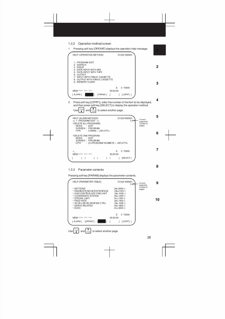
3
1
4
5
6
7
8
9
10
2
38
1.3.2 Operation method screen
1 Pressing soft key [OPERAT] displays the operation help message.
ALARM[ ] [ ] [ ] [ ] [ ]OPERAT PARAM (OPRT)
HELP (OPERATION METHOD) O1234 N00001
1. PROGRAM EDIT2. SEARCH3. RESET4. DATA INPUT WITH MDI5. DATA INPUT WITH TAPE6. OUTPUT7. INPUT WITH FANUC CASSETTE8. OUTPUT WITH FANUC CASSETTE9. MEMORY CLEAR
S 0 T0000
MEM **** *** *** 00:00:00
2 Press soft key [(OPRT)], enter the number of the item to be displayed,and then press soft key [SELECT] to display the operation method.
UsePAGE
and PAGE to select another page.
[ ] [ ] [ ] [ ] [ ]SELECT
HELP (ALARM METHOD)<< 1. PROGRAM EDIT >>
O1234 N000011/4
*DELETE ALL PROGRAMSMODE : EDITSCREEN : PROGRAMOPR : (O9999) – <DELETE>
*DELETE ONE PROGRAMMODE : EDITSCREEN : PROGRAMOPR : (O+PROGRAM NUMBER) – <DELETE>
>_ S 0 T0000
MEM **** *** *** 00:00:00
Currentpage/totalnumber ofpages
1.3.3 Parameter contents
Pressing soft key [PARAM] displays the parameter contents.
ALARM[ ] [ ] [ ] [ ] [ ]OPERAT PARAM (OPRT)
HELP (PARAMETER TABLE) O1234 N000011/4
* SETTEING (No.0000–)* READER/PUNCHER INTERFACE (No.0100–)* AXIS CONTROL/SETTING UNIT (No.1000–)* COORDINATE SYSTEM (No.1200–)* STROKE LIMIT (No.1300–)* FEED RATE (No.1400–)* ACCEL/DECELERATION CTRL (No.1600–)* SERVO RELATED (No.1800–)* DI/DO (No.3000–)
S 0 T0000
MEM **** *** *** 00:00:00
Currentpage/totalnumber ofpages
UsePAGE
and PAGE to select another page.
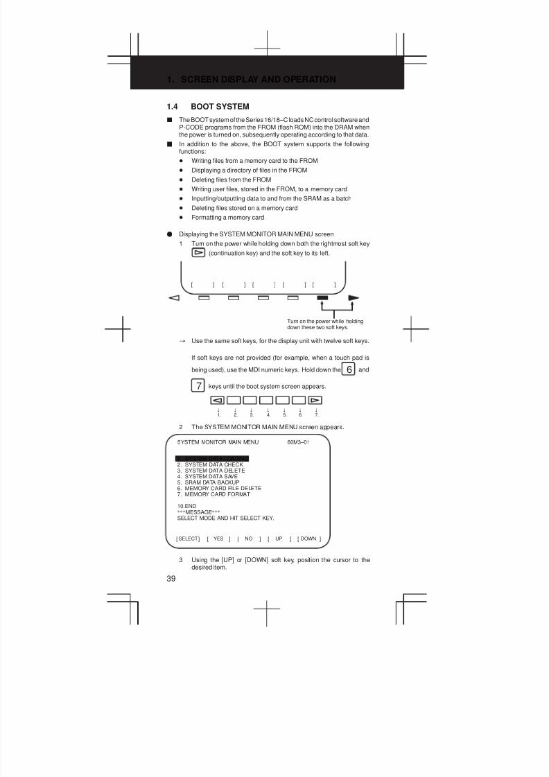
1. SCREEN DISPLAY AND OPERATION
39
1.4 BOOT SYSTEM
J The BOOT system of the Series 16/18–C loads NC control software andP-CODE programs from the FROM (flash ROM) into the DRAM whenthe power is turned on, subsequently operating according to that data.
J In addition to the above, the BOOT system supports the followingfunctions:
D Writing files from a memory card to the FROM
D Displaying a directory of files in the FROM
D Deleting files from the FROM
D Writing user files, stored in the FROM, to a memory card
D Inputting/outputting data to and from the SRAM as a batch
D Deleting files stored on a memory card
D Formatting a memory card
F Displaying the SYSTEM MONITOR MAIN MENU screen
1 Turn on the power while holding down both the rightmost soft key
(continuation key) and the soft key to its left.
[ ] [ ] [ ] [ ] [ ]
Turn on the power while holdingdown these two soft keys.
³ Use the same soft keys, for the display unit with twelve soft keys.
If soft keys are not provided (for example, when a touch pad is
being used), use the MDI numeric keys. Hold down the 6 and
7 keys until the boot system screen appears.
±
1.±
2.±
3.±
4.±
5.±
6.±
7.
2 The SYSTEM MONITOR MAIN MENU screen appears.
SELECT[ ] [ ] [ ] [ ] [ ]YES NO UP DOWN
SYSTEM MONITOR MAIN MENU 60M3–01
1. SYSTEM DATA LOADING2. SYSTEM DATA CHECK3. SYSTEM DATA DELETE4. SYSTEM DATA SAVE5. SRAM DATA BACKUP6. MEMORY CARD FILE DELETE7. MEMORY CARD FORMAT
10.END***MESSAGE***
SELECT MODE AND HIT SELECT KEY.
3 Using the [UP] or [DOWN] soft key, position the cursor to thedesired item.
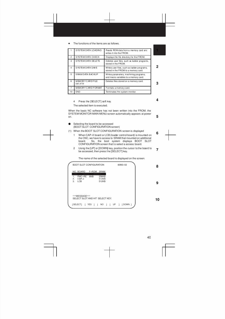
3
1
4
5
6
7
8
9
10
2
40
D The functions of the items are as follows.
1 SYSTEM DATA LOADING Reads ROM data from a memory card and
writes it into the FROM.
2 SYSTEM DATA CHECK Displays the fi le directory for the FROM.
3 SYSTEM DATA DELETE Deletes user files, such as ladder programs,
stored in the FROM.
4 SYSTEM DATA SAVE Writes user f iles, such as ladder programs,
stored in the FROM to a memory card.
5 SRAM DATA BACKUP Writes parameters, machining programs,
and macro variables to a memory card.
6 MEMORY CARD FILE
DELETE
Deletes files stored on a memory card.
7 MEMORY CARD FORMAT Formats a memory card.
10 END Terminates the system monitor.
4 Press the [SELECT] soft key.
The selected item is executed.
When the basic NC software has not been written into the FROM, theSYSTEM MONITOR MAIN MENU screen automatically appears at poweron.
F Selecting the board to be accessed(BOOT SLOT CONFIGURATION screen)
(1) When the BOOT SLOT CONFIGURATION screen is displayed
1 When CAP–II board or LCB (loader control board) is mounted onthe CNC, we have to access to SRAM that mounted on additionalboard. So, the boot system displays BOOT SLOTCONFIGURATION screen that to select a access board.
2 Using the [UP] or [DOWN] key, position the cursor to the board tobe accessed, then press the [SELECT] key.
The name of the selected board is displayed on the screen.
SELECT[ ] [ ] [ ] [ ] [ ]YES NO UP DOWN
BOOT SLOT CONFIGURATION 60M3–02
NO. BOARD F–ROM SRAM0. MAIN 4MB 1.0MB1. PMC–RE 6MB 256KB2. CAP–II 512KB3. LCB 512KB
***MESSAGE***SELECT SLOT AND HIT SELECT KEY.
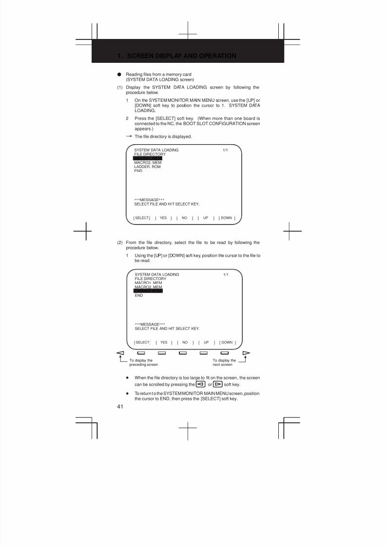
1. SCREEN DISPLAY AND OPERATION
41
F Reading files from a memory card(SYSTEM DATA LOADING screen)
(1) Display the SYSTEM DATA LOADING screen by following theprocedure below.
1 On the SYSTEM MONITOR MAIN MENU screen, use the [UP] or[DOWN] soft key to position the cursor to 1. SYSTEM DATALOADING.
2 Press the [SELECT] soft key. (When more than one board isconnected to the NC, the BOOT SLOT CONFIGURATION screenappears.)
³ The file directory is displayed.
SELECT[ ] [ ] [ ] [ ] [ ]YES NO UP DOWN
SYSTEM DATA LOADINGFILE DIRECTORYMACRO1. MEMMACRO2. MEMLADDER. ROMEND
1/1
***MESSAGE***SELECT FILE AND HIT SELECT KEY.
(2) From the file directory, select the file to be read by following theprocedure below.
1 Using the [UP] or [DOWN] soft key, position the cursor to the file tobe read.
SELECT[ ] [ ] [ ] [ ] [ ]YES NO UP DOWN
SYSTEM DATA LOADINGFILE DIRECTORYMACRO1. MEMMACRO2. MEMLADDER. ROMEND
1/1
***MESSAGE***SELECT FILE AND HIT SELECT KEY.
To display thepreceding screen
To display thenext screen
D When the file directory is too large to fit on the screen, the screen
can be scrolled by pressing the or soft key.
D To return to the SYSTEM MONITOR MAIN MENU screen, positionthe cursor to END, then press the [SELECT] soft key.
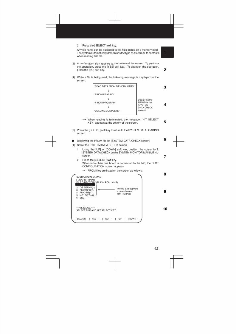
3
1
4
5
6
7
8
9
10
2
42
2 Press the [SELECT] soft key.
Any file name can be assigned to the files stored on a memory card.The system automatically determines the type of a file from its contentswhen reading that file.
(3) A confirmation sign appears at the bottom of the screen. To continuethe operation, press the [YES] soft key. To abandon the operation,press the [NO] soft key.
(4) While a file is being read, the following message is displayed on thescreen.
“READ DATA FROM MEMORY CARD”
±
“F-ROM ERASING”
±
“F-ROM PROGRAM”
±
“LOADING COMPLETE”
Displaying theFROM file list(SYSTEMDATA CHECKscreen)
³ When reading is terminated, the message, “HIT SELECTKEY,” appears at the bottom of the screen.
(5) Press the [SELECT] soft key to return to the SYSTEM DATA LOADINGscreen.
F Displaying the FROM file list (SYSTEM DATA CHECK screen)
(1) Select the SYSTEM DATA CHECK screen.
1 Using the [UP] or [DOWN] soft key, position the cursor to 2.SYSTEM DATA CHECK on the SYSTEM MONITOR MAIN MENUscreen.
2 Press the [SELECT] soft key.When more than one board is connected to the NC, the SLOTCONFIGURATION screen appears.
³ FROM files are listed on the screen as follows:
SELECT[ ] [ ] [ ] [ ] [ ]YES NO UP DOWN
SYSTEM DATA CHECK[ BOARD : MAIN ]FILE DIRECTORY (FLASH ROM : 4MB)1. NC BASIC(10)2. DG SERVO(1)3. PMC0BSC(2)4. PMC–RB(1)5. NC1 OPTN(8)6. END
***MESSAGE***SELECT FILE AND HIT SELECT KEY.
The file size appearsin parentheses(unit : 128KB)
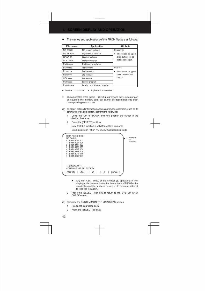
1. SCREEN DISPLAY AND OPERATION
43
D The names and applications of the FROM files are as follows:
File name Application Attribute
NC BASIC NC system software System file
DG SERVO Digital servo software D The file can be typed
GRAPHIC Graphic software over, but cannot be
lNCn OPTN Optional function deleted or output.
PMCnxxxx PMC control software
PDnxnnnx 1st executor User file
P1nxnnnx 2nd executor D The file can be typed
P2nxnnnx 3rd executor over, deleted, and
CEX xxxx C executor output.
PMC-xxxx Ladder program
PMC@xxxx Loader control ladder program
n: Numeric character x: Alphabetic character
D The object files of the macro P-CODE program and the C executor canbe saved to the memory card, but cannot be decompiled into theircorresponding source code.
(2) To obtain detailed information about a particular system file, such as itssoftware series and edition, perform the following:
1 Using the [UP] or [DOWN] soft key, position the cursor to thedesired file name.
2 Press the [SELECT] soft key.
Note that this function is valid for system files only.
Example screen (when NC BASIC has been selected)
SELECT[ ] [ ] [ ] [ ] [ ]YES NO UP DOWN
ROM FILE CHECKNC BASIC0 B0B1 801F 0001 B0B1 802F 0012 B0B1 841F 0023 B0B1 842F 0034 B0B1 881F 0045 B0B1 882F 0056 B0B1 8C1F 0067 B0B1 8C2F 007
***MESSAGE***
CONTINUE. HIT SELECT KEY.
ExampleofM series
D Any non-ASCII code, or the symbol @, appearing in thedisplayed file name indicates that the contents of FROM or thedata in the read file has been destroyed. In this case, attemptto read the file again.
3 Press the [SELECT] soft key to return to the SYSTEM DATACHECK screen.
(3) Return to the SYSTEM MONITOR MAIN MENU screen.
1 Position the cursor to END.
2 Press the [SELECT] soft key.
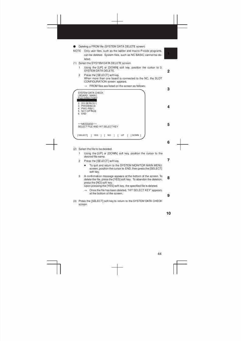
3
1
4
5
6
7
8
9
10
2
44
F Deleting a FROM file (SYSTEM DATA DELETE screen)
NOTE Only user files, such as the ladder and macro P-code programs,
can be deleted. System files, such as NC BASIC, cannot be de-
leted.
(1) Select the SYSTEM DATA DELETE screen.
1 Using the [UP] or [DOWN] soft key, position the cursor to 3.SYSTEM DATA DELETE.
2 Press the [SELECT] soft key.When more than one board is connected to the NC, the SLOTCONFIGURATION screen appears.
³ FROM files are listed on the screen as follows:
SELECT[ ] [ ] [ ] [ ] [ ]YES NO UP DOWN
SYSTEM DATA CHECK[ BOARD : MAIN ]FILE DIRECTORY1. NC BASIC(10)2. DG SERVO(1)3. PMC0BSC(2)4. PMC–RB(1)5. NC1 OPTN(8)6. END
***MESSAGE***SELECT FILE AND HIT SELECT KEY.
(2) Select the file to be deleted.
1 Using the [UP] or [DOWN] soft key, position the cursor to thedesired file name.
2 Press the [SELECT] soft key.
D To quit and return to the SYSTEM MONITOR MAIN MENUscreen, position the cursor to END, then press the [SELECT]soft key.
3 A confirmation message appears at the bottom of the screen. Todelete the file, press the [YES] soft key. To abandon the deletion,press the [NO] soft key.Upon pressing the [YES] soft key, the specified file is deleted.
³ Once the file has been deleted, “HIT SELECT KEY” appearsat the bottom of the screen.
(3) Press the [SELECT] soft key to return to the SYSTEM DATA CHECKscreen.
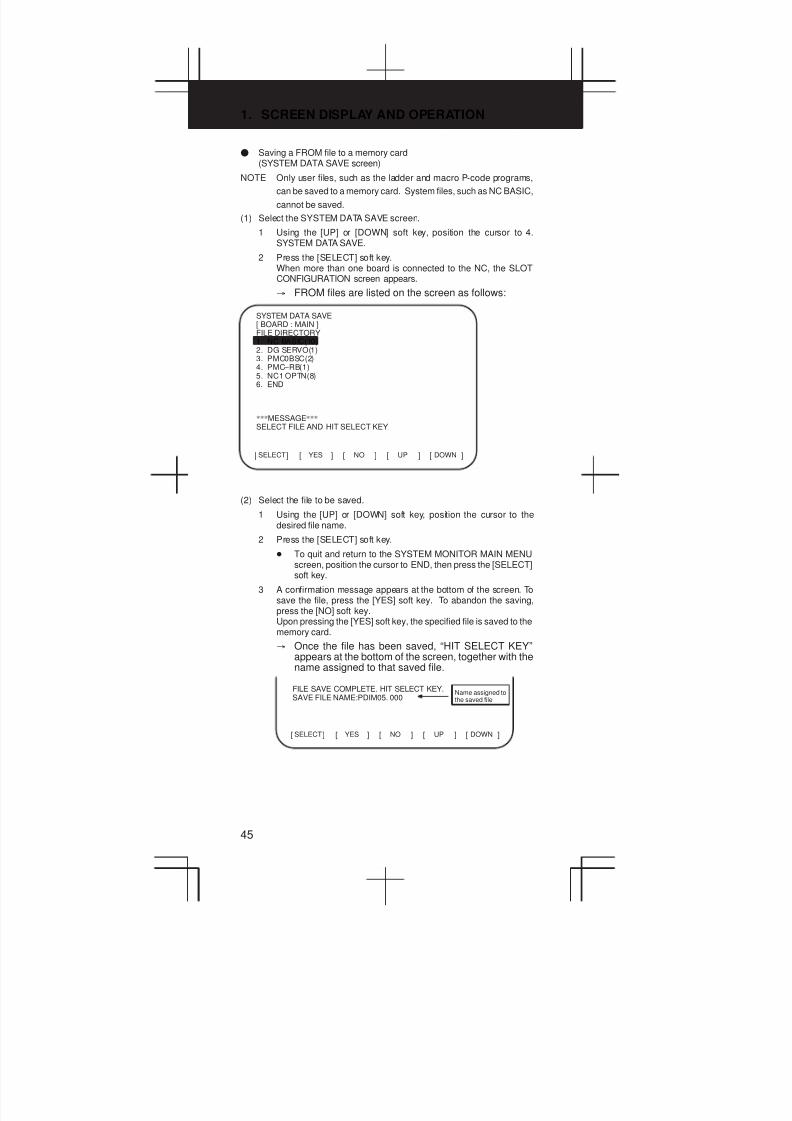
1. SCREEN DISPLAY AND OPERATION
45
F Saving a FROM file to a memory card(SYSTEM DATA SAVE screen)
NOTE Only user files, such as the ladder and macro P-code programs,
can be saved to a memory card. System files, such as NC BASIC,
cannot be saved.
(1) Select the SYSTEM DATA SAVE screen.
1 Using the [UP] or [DOWN] soft key, position the cursor to 4.SYSTEM DATA SAVE.
2 Press the [SELECT] soft key.When more than one board is connected to the NC, the SLOTCONFIGURATION screen appears.
³ FROM files are listed on the screen as follows:
SELECT[ ] [ ] [ ] [ ] [ ]YES NO UP DOWN
SYSTEM DATA SAVE[ BOARD : MAIN ]FILE DIRECTORY1. NC BASIC(10)2. DG SERVO(1)3. PMC0BSC(2)4. PMC–RB(1)5. NC1 OPTN(8)6. END
***MESSAGE***SELECT FILE AND HIT SELECT KEY.
(2) Select the file to be saved.
1 Using the [UP] or [DOWN] soft key, position the cursor to thedesired file name.
2 Press the [SELECT] soft key.
D To quit and return to the SYSTEM MONITOR MAIN MENUscreen, position the cursor to END, then press the [SELECT]soft key.
3 A confirmation message appears at the bottom of the screen. Tosave the file, press the [YES] soft key. To abandon the saving,press the [NO] soft key.Upon pressing the [YES] soft key, the specified file is saved to thememory card.
³ Once the file has been saved, “HIT SELECT KEY”appears at the bottom of the screen, together with thename assigned to that saved file.
SELECT[ ] [ ] [ ] [ ] [ ]YES NO UP DOWN
FILE SAVE COMPLETE. HIT SELECT KEY.SAVE FILE NAME:PDIM05. 000
Name assigned tothe saved file
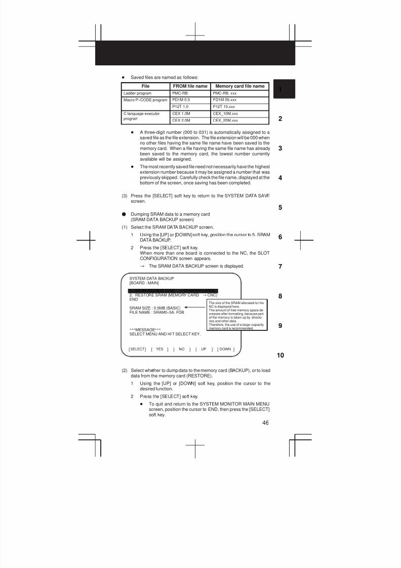
3
1
4
5
6
7
8
9
10
2
46
D Saved files are named as follows:
File FROM file name Memory card file name
Ladder program PMC-RB PMC-RB. xxx
Macro P–CODE program PD1M 0.5 PD1M 05.xxx
P12T 1.0 P12T 10.xxx
C language executor CEX 1.0M CEX_10M.xxx
program CEX 2.0M CEX_20M.xxx
D A three-digit number (000 to 031) is automatically assigned to asaved file as the file extension. The file extension will be 000 whenno other files having the same file name have been saved to thememory card. When a file having the same file name has alreadybeen saved to the memory card, the lowest number currentlyavailable will be assigned.
D The most recently saved file need not necessarily have the highestextension number because it may be assigned a number that waspreviously skipped. Carefully check the file name, displayed at thebottom of the screen, once saving has been completed.
(3) Press the [SELECT] soft key to return to the SYSTEM DATA SAVEscreen.
F Dumping SRAM data to a memory card(SRAM DATA BACKUP screen)
(1) Select the SRAM DATA BACKUP screen.
1 Using the [UP] or [DOWN] soft key, position the cursor to 5. SRAMDATA BACKUP.
2 Press the [SELECT] soft key.When more than one board is connected to the NC, the SLOTCONFIGURATION screen appears.
³ The SRAM DATA BACKUP screen is displayed.
SELECT[ ] [ ] [ ] [ ] [ ]YES NO UP DOWN
SYSTEM DATA BACKUP[BOARD : MAIN]
1. SRAM BACKUP (CNC ³MEMORY CARD)2. RESTORE SRAM (MEMORY CARD ³ CNC)END
SRAM SIZE : 0.5MB (BASIC)FILE NAME : SRAM0–5A. FDB
***MESSAGE***SELECT MENU AND HIT SELECT KEY.
The size of the SRAM allocated to t heNC is displayed here.The amount of free memory space de-creases after formatting, because partof the memory is taken up by directo-ries and other data.Therefore, the use of a large–capacitymemory card is recommended.
(2) Select whether to dump data to the memory card (BACKUP), or to loaddata from the memory card (RESTORE).
1 Using the [UP] or [DOWN] soft key, position the cursor to thedesired function.
2 Press the [SELECT] soft key.
D To quit and return to the SYSTEM MONITOR MAIN MENUscreen, position the cursor to END, then press the [SELECT]soft key.
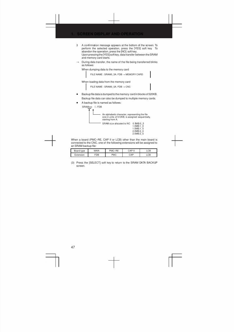
1. SCREEN DISPLAY AND OPERATION
47
3 A confirmation message appears at the bottom of the screen. Toperform the selected operation, press the [YES] soft key. Toabandon the operation, press the [NO] soft key.Upon pressing the [YES] soft key, data transfer between the SRAMand memory card starts.
³ During data transfer, the name of the file being transferred blinksas follows:
When dumping data to the memory card
FILE NAME : SRAM0_5A. FDB → MEMORY CARD
When loading data from the memory card
FILE NAME : SRAM0_5A. FDB → CNC
D Backup file data is dumped to the memory card in blocks of 520KB.
Backup file data can also be dumped to multiple memory cards.
D A backup file is named as follows:
SRAMxxx V. FDB
An alphabetic character, representing the filesize in units of 512KB, is assigned sequentially,starting from A.
SRAM size allocated to NC 0.5MB:0_51.0MB:1_01.5MB:1_52.0MB:2_02.5MB:2_5
When a board (PMC–RE, CAP II or LCB) other than the main board isconnected to the CNC, one of the following extensions will be assigned toan SRAM backup file:
Board type MAIN PMC–RE CAP II LCB
Extension FDB PMC CAP LCB
(3) Press the [SELECT] soft key to return to the SRAM DATA BACKUPscreen.
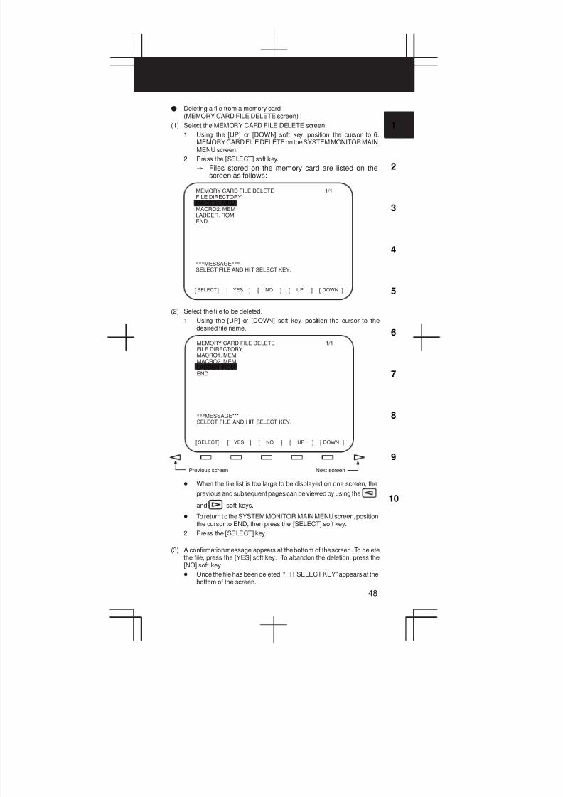
3
1
4
5
6
7
8
9
10
2
48
F Deleting a file from a memory card(MEMORY CARD FILE DELETE screen)
(1) Select the MEMORY CARD FILE DELETE screen.
1 Using the [UP] or [DOWN] soft key, position the cursor to 6.MEMORY CARD FILE DELETE on the SYSTEM MONITOR MAINMENU screen.
2 Press the [SELECT] soft key.
³ Files stored on the memory card are listed on thescreen as follows:
SELECT[ ] [ ] [ ] [ ] [ ]YES NO UP DOWN
MEMORY CARD FILE DELETEFILE DIRECTORYMACRO1. MEMMACRO2. MEMLADDER. ROMEND
1/1
***MESSAGE***
SELECT FILE AND HIT SELECT KEY.
(2) Select the file to be deleted.
1 Using the [UP] or [DOWN] soft key, position the cursor to thedesired file name.
SELECT[ ] [ ] [ ] [ ] [ ]YES NO UP DOWN
MEMORY CARD FILE DELETEFILE DIRECTORYMACRO1. MEMMACRO2. MEMLADDER. ROMEND
1/1
***MESSAGE***SELECT FILE AND HIT SELECT KEY.
Previous screen Next screen
D When the file list is too large to be displayed on one screen, the
previous and subsequent pages can be viewed by using the
and soft keys.
D To return to the SYSTEM MONITOR MAIN MENU screen, positionthe cursor to END, then press the [SELECT] soft key.
2 Press the [SELECT] key.
(3) A confirmation message appears at the bottom of the screen. To deletethe file, press the [YES] soft key. To abandon the deletion, press the[NO] soft key.
D Once the file has been deleted, “HIT SELECT KEY” appears at thebottom of the screen.
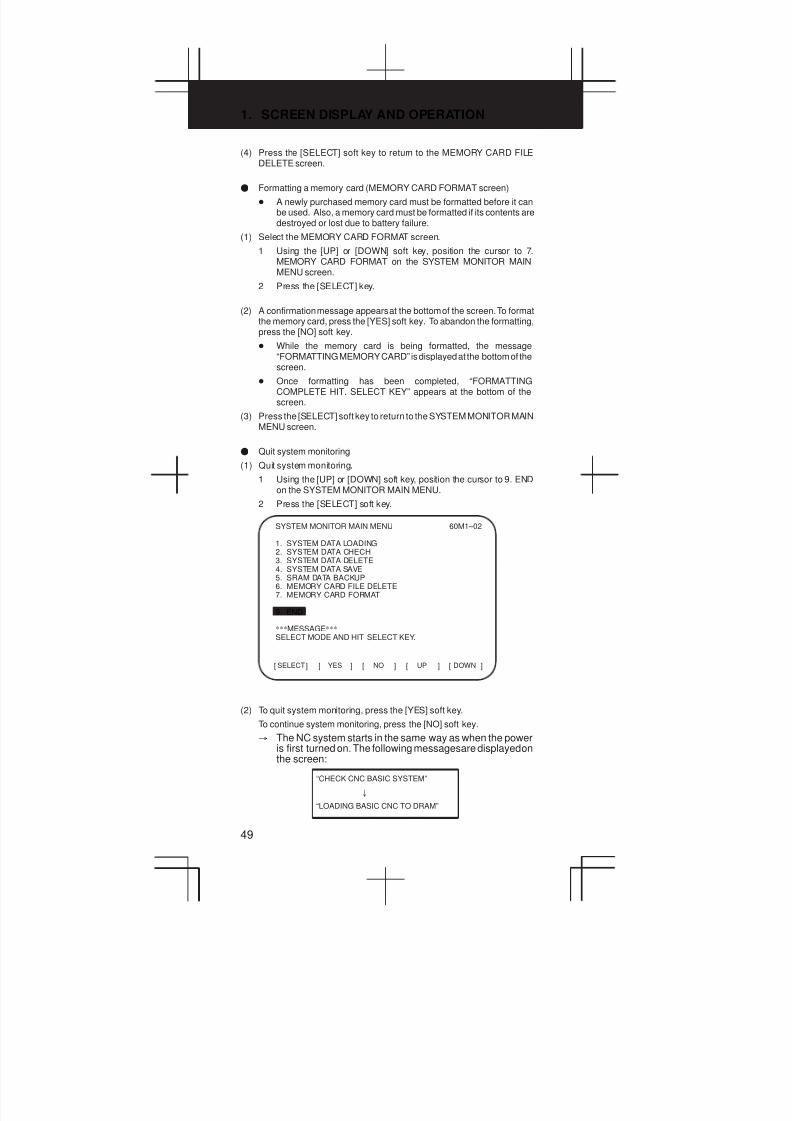
1. SCREEN DISPLAY AND OPERATION
49
(4) Press the [SELECT] soft key to return to the MEMORY CARD FILEDELETE screen.
F Formatting a memory card (MEMORY CARD FORMAT screen)
D A newly purchased memory card must be formatted before it canbe used. Also, a memory card must be formatted if its contents aredestroyed or lost due to battery failure.
(1) Select the MEMORY CARD FORMAT screen.
1 Using the [UP] or [DOWN] soft key, position the cursor to 7.MEMORY CARD FORMAT on the SYSTEM MONITOR MAINMENU screen.
2 Press the [SELECT] key.
(2) A confirmation message appears at the bottom of the screen. To formatthe memory card, press the [YES] soft key. To abandon the formatting,press the [NO] soft key.
D While the memory card is being formatted, the message“FORMATTING MEMORY CARD” is displayed at the bottom of thescreen.
D Once formatting has been completed, “FORMATTINGCOMPLETE HIT. SELECT KEY” appears at the bottom of thescreen.
(3) Press the [SELECT] soft key to return to the SYSTEM MONITOR MAINMENU screen.
F Quit system monitoring
(1) Quit system monitoring.
1 Using the [UP] or [DOWN] soft key, position the cursor to 9. ENDon the SYSTEM MONITOR MAIN MENU.
2 Press the [SELECT] soft key.
SELECT[ ] [ ] [ ] [ ] [ ]YES NO UP DOWN
SYSTEM MONITOR MAIN MENU
1. SYSTEM DATA LOADING2. SYSTEM DATA CHECH3. SYSTEM DATA DELETE4. SYSTEM DATA SAVE5. SRAM DATA BACKUP6. MEMORY CARD FILE DELETE7. MEMORY CARD FORMAT
9. END
60M1–02
***MESSAGE***SELECT MODE AND HIT SELECT KEY.
(2) To quit system monitoring, press the [YES] soft key.
To continue system monitoring, press the [NO] soft key.
³ The NC system starts in the same way as when the poweris first turned on. The following messages are displayed onthe screen:
“CHECK CNC BASIC SYSTEM”
±
“LOADING BASIC CNC TO DRAM”
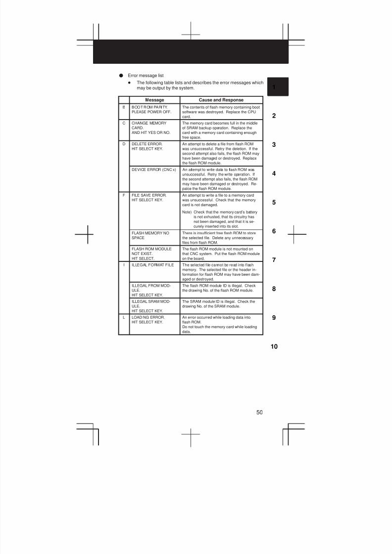
3
1
4
5
6
7
8
9
10
2
50
F Error message list
D The following table lists and describes the error messages whichmay be output by the system.
Message Cause and Response
B BOOT ROM PARITY.
PLEASE POWER OFF.
The contents of flash memory containing boot
software was destroyed. Replace the CPU
card.
C CHANGE MEMORY
CARD.
AND HIT YES OR NO.
The memory card becomes full in the middle
of SRAM backup operation. Replace the
card with a memory card containing enough
free space.
D DELETE ERROR.
HIT SELECT KEY.
An attempt to delete a file from flash ROM
was unsuccessful. Retry the deletion. If the
second attempt also fails, the flash ROM may
have been damaged or destroyed. Replace
the flash ROM module.
DEVICE ERROR (CNC x) An attempt to write data to flash ROM was
unsuccessful. Retry the write operation. If
the second attempt also fails, the flash ROM
may have been damaged or destroyed. Re-
palce the flash ROM module.
F FILE SAVE ERROR.
HIT SELECT KEY.
An attempt to write a file to a memory card
was unsuccessful. Check that the memory
card is not damaged.
Note) Check that the memory card’s battery
is not exhusted, that its circuitry has
not been damaged, and that it is se-
curely inserted into its slot.
FLASH MEMORY NO
SPACE
There is insufficient free flash ROM to store
the selected file. Delete any unnecessary
files from flash ROM.
FLASH ROM MODULE
NOT EXIST.
HIT SELECT.
The flash ROM module is not mounted on
that CNC system. Put the flash ROM module
on the board.
I ILLEGAL FORMAT FILE The selected file cannot be read into flash
memory. The selected file or the header in-
formation for flash ROM may have been dam-
aged or destroyed.
ILLEGAL FROM MOD-
ULE.
HIT SELECT KEY.
The flash ROM module ID is illegal. Check
the drawing No. of the flash ROM module.
ILLEGAL SRAM MOD-
ULE.
HIT SELECT KEY.
The SRAM module ID is illegal. Check the
drawing No. of the SRAM module.
L LOADING ERROR.
HIT SELECT KEY.
An error occurred while loading data into
flash ROM.
Do not touch the memory card while loading
data.

1. SCREEN DISPLAY AND OPERATION
51
Cause and ResponseMessage
M MAX EXTENSION OVER.
HIT SELECT KEY.
The extension number added to a file name
exceeds 031. Delete any unnecessary back-
up files from the memory card.
MEMORY CARD BAT-
TERY ALARM.
HIT SELECT.
The memory card’s battery is exhausted. Re-
place the battery.
MEMORY CARD FULL.
HIT SELECT KEY.
The memory card is full. Delete any unnec-
essary files from the memory card. Alterna-
tively, replace the memory card with another
card having sufficient free space.
MEMORY CARD IS NOT
AVAILABLE. HIT SEL.
The use of this memory card is not sup-
ported. Use only FANUC–recommended
memory cards, as described in the order list.
MEMORY CARD MOUNT
ERROR.
HIT SELECT KEY
The memory card could not be accessed.
Check that the memory card is normal.
MEMORY CARD NOT EX-
IST.
HIT SELECT KEY.
The memory card is not inserted into its slot.
Check that the memory card is pushed fully
home.
MEMORY CARD PRO-
TECTED.HIT SELECT
KEY.
Although writing to the memory card was se-
lected, the write inhibit switch is set. Disable
the write inhibit switch.
Note) Check that the memory card’s battery
is not exhusted, that its circuitry has
not been damaged, and that it is se-
curely inserted into its slot.
MEMORY CARD TYPE IS
NOT AVAILABLE.
Write has been attempted to an incompatible
flash memory card. Use only the flash ROM
cards recommended by FANUC. Recom-
mended flash ROM cards are listed in the
ordering list.
MEMORY CARD RESET
ERROR.
HIT SELECT KEY.
Access to a memory card failed. The
memory card’s battery may have gone dead,
the memory card may have been damaged
electrically, or the memory card may not be
inserted in the slot securely.
MEMORY CARD WRITE
ERROR.
HIT SELECT KEY.
Access to the memory card has failed.
Check whether the memory card is defective.
Note) Check that the memory card’s battery
is not exhusted, that its circuitry has
not been damaged, and that it is se-
curely inserted into its slot.
N NMI OCCURRED.
PLEASE POWER OFF.
A hardware or software error occurred. De-
termine the procedure which causes the er-
ror, and report it to FANUC together with the
series and edition of the boot software.
P PLEASE FORMAT FLASH
TYPE CARD.HIT SEL.
It is not possible to delete only specific files
from a flash ROM card, due to the character-
istics of the memory used. To delete a file it
is necessary to delete all files on the card, by
using the FORMAT function.
R ROM PARITY ERROR:
NC BASIC. HIT SELECT.
The NC BASIC is parity error. Check whether
NC BASIC is in flash ROM, using SYSTEM
DATA CHECK.
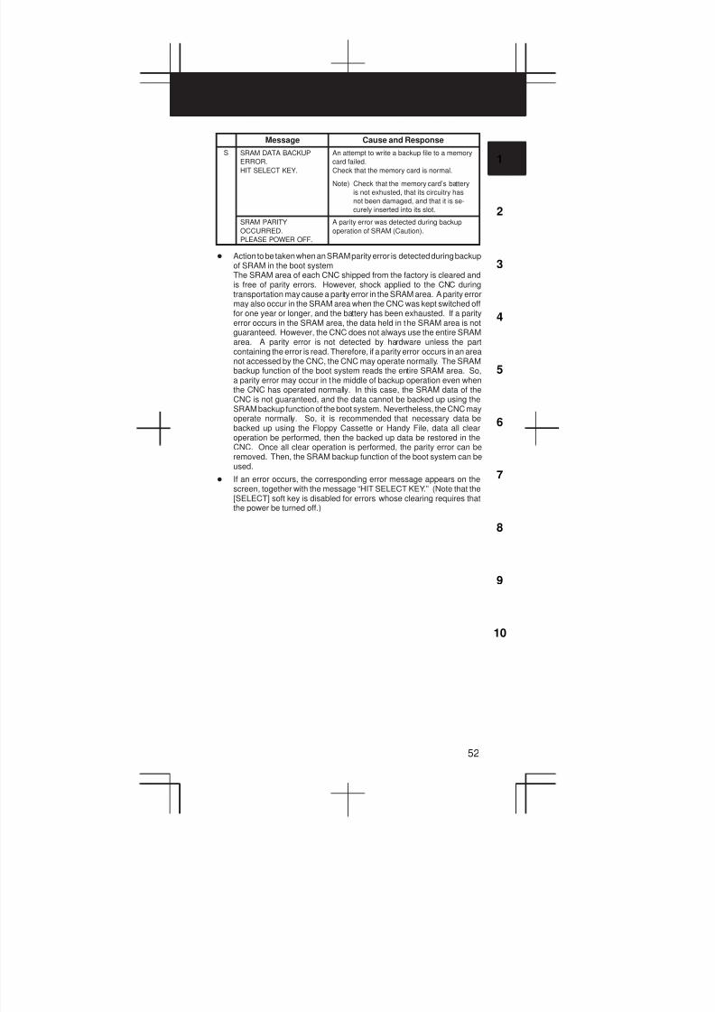
3
1
4
5
6
7
8
9
10
2
52
Cause and ResponseMessage
S SRAM DATA BACKUP
ERROR.
HIT SELECT KEY.
An attempt to write a backup file to a memory
card failed.
Check that the memory card is normal.
Note) Check that the memory card’s battery
is not exhusted, that its circuitry has
not been damaged, and that it is se-
curely inserted into its slot.
SRAM PARITY
OCCURRED.
PLEASE POWER OFF.
A parity error was detected during backup
operation of SRAM (Caution).
D Action to be taken when an SRAM parity error is detected during backupof SRAM in the boot systemThe SRAM area of each CNC shipped from the factory is cleared andis free of parity errors. However, shock applied to the CNC duringtransportation may cause a parity error in the SRAM area. A parity errormay also occur in the SRAM area when the CNC was kept switched offfor one year or longer, and the battery has been exhausted. If a parityerror occurs in the SRAM area, the data held in the SRAM area is notguaranteed. However, the CNC does not always use the entire SRAMarea. A parity error is not detected by hardware unless the partcontaining the error is read. Therefore, if a parity error occurs in an areanot accessed by the CNC, the CNC may operate normally. The SRAMbackup function of the boot system reads the entire SRAM area. So,a parity error may occur in the middle of backup operation even whenthe CNC has operated normally. In this case, the SRAM data of theCNC is not guaranteed, and the data cannot be backed up using theSRAM backup function of the boot system. Nevertheless, the CNC mayoperate normally. So, it is recommended that necessary data bebacked up using the Floppy Cassette or Handy File, data all clearoperation be performed, then the backed up data be restored in theCNC. Once all clear operation is performed, the parity error can beremoved. Then, the SRAM backup function of the boot system can beused.
D If an error occurs, the corresponding error message appears on thescreen, together with the message “HIT SELECT KEY.” (Note that the[SELECT] soft key is disabled for errors whose clearing requires thatthe power be turned off.)
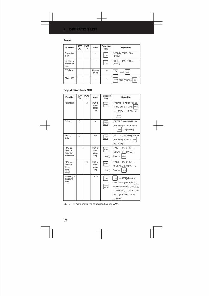
2. OPERATION LIST
53
Reset
FunctionKEY
SW
PWE
= 1Mode
Function
keyOperation
Operating
time
– POS
[(OPRT)] [TIME: 0]→
[EXEC]
Number of
machined
parts
– POS
[(OPRT)] [PART: 0]→
[EXEC]
OT alarm At pow-
er-up
– and CAN
Alarm 100 – – CANRESET while pressing
Registration from MDI
FunctionKEY
SW
PWE
= 1Mode
Function
keyOperation
Parameter f MDI or
emer-
gency
stop
SYSTEM
[PARAM] → Parameter No.
→ [NO.SRH]→ Data
→ or [INPUT]→ PWE = 0 →
INPUT
RESET
Offset f – SETTINGOFFSET
[OFFSET]→ Offset No.→
[NO. SRH]→ Offset value
→ or [INPUT]INPUT
Setting
data
f MDI
SETTINGOFFSET
[SETTING]→ Setting No. →
[NO. SRH]→Data→
or [INPUT]
INPUT
PMC pa-
rameter
(Counter,
data table)
f MDI or
emer-
gency
stop (PMC)
SYSTEM
[PMC]→ [PMCPRM]→
[COUNTR] or [DATA] →
Data → INPUT
PMC pa-
rameter
(timer,
keep
relay)
f MDI or
emer-
gency
stop (PMC)
SYSTEM
[PMC]→ [PMCPRM]→
[TIMER] or [KEEPRL] →
Data → INPUT
Tool length
measure-
ment
JOG
³
POS
SETTINGOFFSET
→ [REL] (Relative
coordinate system display)
→ Axis → [ORIGIN] →
→ [OFFSET]→ Offset num-
ber → [NO.SRH]→ Axis →
[C INPUT]
POS
SETTINGOFFSET
NOTE f mark shows the corresponding key is “1”.
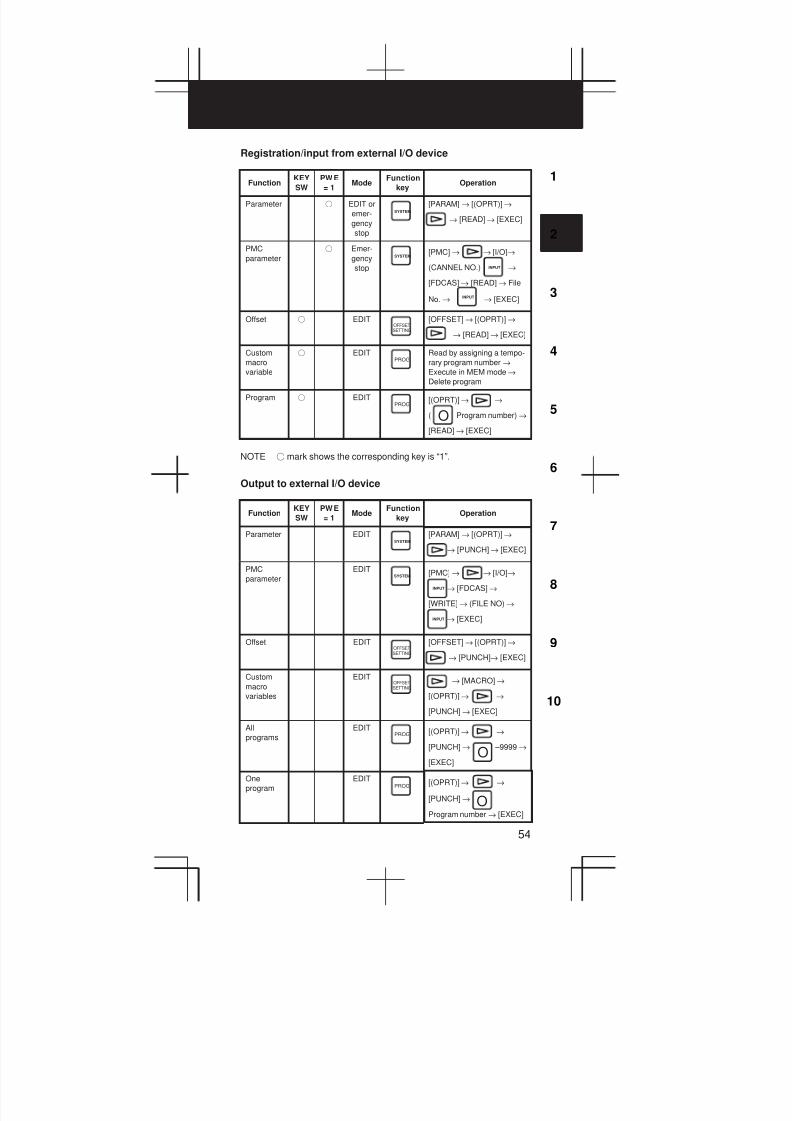
3
1
4
5
6
7
8
9
10
2
54
Registration/input from external I/O device
FunctionKEY
SW
PWE
= 1Mode
Function
keyOperation
Parameter f EDIT or
emer-
gency
stop
SYSTEM
[PARAM] → [(OPRT)]→
→ [READ]→ [EXEC]
PMC
parameter
f Emer-
gency
stop
SYSTEM[PMC]→ → [I/O]→
(CANNEL NO.) →
[FDCAS]→ [READ]→ File
No. → → [EXEC]
INPUT
INPUT
Offset f EDIT
SETTINGOFFSET
[OFFSET]→ [(OPRT)]→
→ [READ] → [EXEC]
Custom
macro
variable
f EDITPROG
Read by assigning a tempo-
rary program number →
Execute in MEM mode→
Delete program
Program f EDITPROG
[(OPRT)]→ →
( Program number) →
[READ] → [EXEC]
O
NOTE f mark shows the corresponding key is “1”.
Output to external I/O device
FunctionKEY
SW
PWE
= 1Mode
Function
keyOperation
Parameter EDITSYSTEM
[PARAM] → [(OPRT)]→
→ [PUNCH]→ [EXEC]
PMC
parameter
EDITSYSTEM [PMC]→ → [I/O]→
→ [FDCAS]→
[WRITE]→ (FILE NO) →
→ [EXEC]
INPUT
INPUT
Offset EDIT
SETTINGOFFSET
[OFFSET]→ [(OPRT)]→
→ [PUNCH]→ [EXEC]
Custom
macro
variables
EDIT
SETTINGOFFSET → [MACRO]→
[(OPRT)]→ →
[PUNCH] → [EXEC]
All
programs
EDITPROG [(OPRT)]→ →
[PUNCH] → –9999 →
[EXEC]O
One
program
EDITPROG
[(OPRT)]→ →
[PUNCH] →
Program number → [EXEC]
O
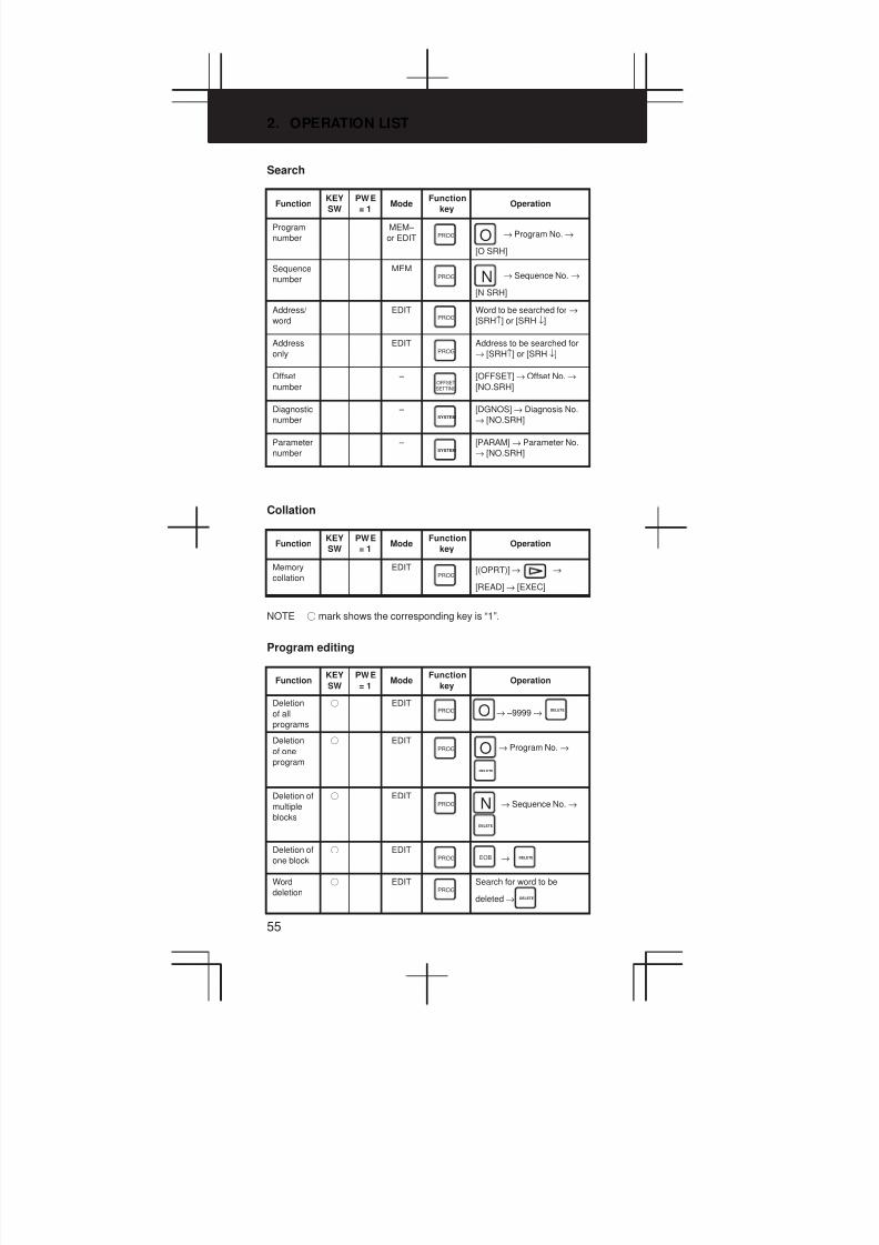
2. OPERATION LIST
55
Search
FunctionKEY
SW
PWE
= 1Mode
Function
keyOperation
Program
number
MEM–
or EDIT PROG → Program No. →
[O SRH]
O
Sequence
number
MEMPROG → Sequence No. →
[N SRH]
N
Address/
word
EDITPROG
Word to be searched for →
[SRH↑] or [SRH ↓]
Address
only
EDITPROG
Address to be searched for
→ [SRH↑] or [SRH ↓]
Offset
number
–
SETTINGOFFSET
[OFFSET]→ Offset No.→
[NO.SRH]
Diagnostic
number
– SYSTEM
[DGNOS]→ Diagnosis No.
→ [NO.SRH]
Parameter
number
– SYSTEM
[PARAM] → Parameter No.
→ [NO.SRH]
Collation
FunctionKEY
SW
PWE
= 1Mode
Function
keyOperation
Memory
collation
EDITPROG
[(OPRT)]→ →
[READ] → [EXEC]
NOTE f mark shows the corresponding key is “1”.
Program editing
FunctionKEY
SW
PWE
= 1Mode
Function
keyOperation
Deletion
of all
programs
f EDITPROG → –9999 →O DELETE
Deletion
of one
program
f EDITPROG → Program No. →O
DELETE
Deletion of
multiple
blocks
f EDITPROG → Sequence No. →N
DELETE
Deletion of
one block
f EDITPROG →EOB DELETE
Word
deletion
f EDITPROG
Search for word to be
deleted → DELETE

3
1
4
5
6
7
8
9
10
2
56
Function OperationFunction
keyMode
PWE
= 1
KEY
SW
Word
alteration
f EDITPROG
Search for word to be
changed→ New data →
ALTER
Word
insertion
f EDITPROG
Search for word immediately
before insertion location →
New data → INSERT
NOTE f mark shows the corresponding key is “1”.
I/O to and from FANUC Cassette
FunctionKEY
SW
PWE
= 1Mode
Function
keyOperation
File head
search
EDITPROG → FILE No. →
→ [F SRH] → [EXEC]
N
File
deletion
f EDITPROG → FILE No. →
→ [F DELETE] → [EXEC]
N
Program
registra-
tion
f EDITPROG → FILE No. →
→ [READ] → [EXEC]
N
Output of
all
programs
EDITPROG → –9999 →
→ [PUNCH]→ [EXEC]
O
Output of
one
program
EDITPROG → Program No. →
→ [PUNCH]→
[EXEC]
O
Program
collation
EDITPROG File head search →
Program No. → →
[READ] → [EXEC]
O
NOTE f mark shows the corresponding key is “1”.
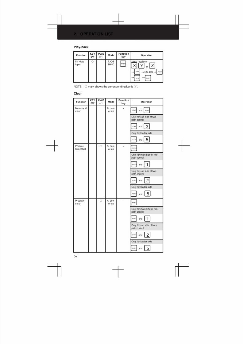
2. OPERATION LIST
57
Play-back
FunctionKEY
SW
PWE
= 1Mode
Function
keyOperation
NC data
input
f TJOG
THND PROG
Move machine. →
or
→ → NC data →
→ →
X Y ZINSERT INSERT
EOB INSERT
NOTE f mark shows the corresponding key is “1”.
Clear
FunctionKEY
SW
PWE
= 1Mode
Function
keyOperation
Memory all
clear
At pow-
er-up –
andRESET DELETE
Only for sub side of two-
path control
andCAN 2
Only for loader side
andCAN 5
Parame-
ters/offset
f At pow-
er-up –
RESET
Only for main side of two-
path control
andRESET 1
Only for sub side of two-
path control
andRESET 2
Only for loader side
andRESET 5
Program
clear
f At pow-
er-up –
DELETE
Only for main side of two-
path control
andDELETE 1
Only for sub side of two-
path control
andDELETE 2
Only for loader side
andDELETE 5
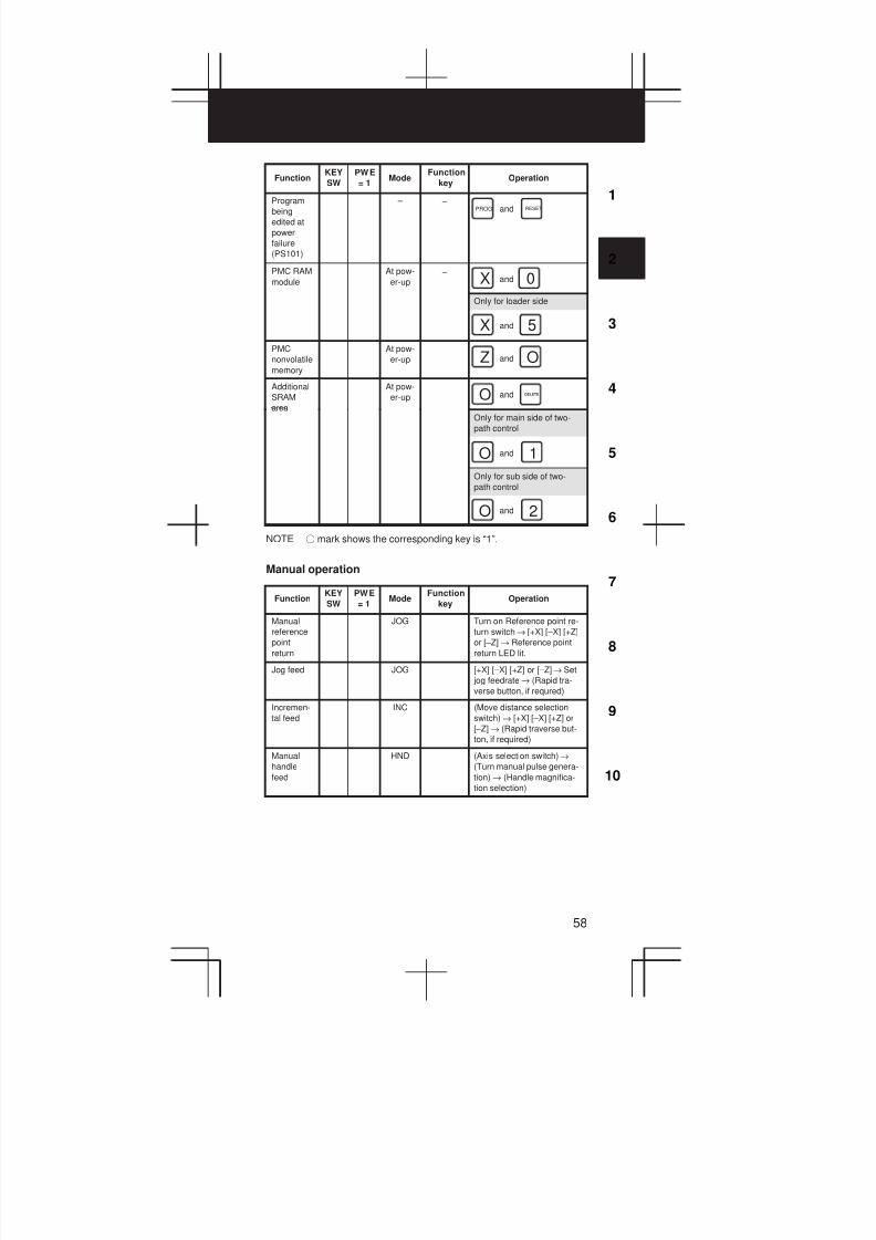
3
1
4
5
6
7
8
9
10
2
58
Function OperationFunction
keyMode
PWE
= 1
KEY
SW
Program
being
edited at
power
failure
(PS101)
– – andPROG RESET
PMC RAM
module
At pow-
er-up –
andX 0
Only for loader side
andX 5
PMC
nonvolatile
memory
At pow-
er-up andZ O
Additional
SRAM
area
At pow-
er-up andO DELETE
Only for main side of two-
path control
andO 1
Only for sub side of two-
path control
andO 2
NOTE f mark shows the corresponding key is “1”.
Manual operation
FunctionKEY
SW
PWE
= 1Mode
Function
keyOperation
Manual
reference
point
return
JOG Turn on Reference point re-
turn switch→ [+X] [–X] [+Z]
or [–Z] → Reference point
return LED lit.
Jog feed JOG [+X] [–X] [+Z] or [–Z]→ Set
jog feedrate→ (Rapid tra-
verse button, if requred)
Incremen-
tal feed
INC (Move distance selection
switch) → [+X] [–X] [+Z] or
[–Z] → (Rapid traverse but-
ton, if required)
Manual
handle
feed
HND (Axis selection switch)→
(Turn manual pulse genera-
tion) → (Handle magnifica-
tion selection)

2. OPERATION LIST
59
Registration from NC tape
FunctionKEY
SW
PWE
= 1Mode
Function
keyOperation
One
program
registera-
tion
f EDITPROG [(OPRT)]→ →
→ Program No. → [READ]
→ [EXEC]
O
Plural
program
registera-
tion
f EDITPROG [(OPRT)]→ → (
→ Program No. )→[READ]
→[EXEC]
O
Collation
of program
in memory
and NC
tape
EDITPROG
[(OPRT)]→ →
[READ] → [EXEC]
NOTE f mark shows the corresponding key is “1”.
DISPLAY
FunctionKEY
SW
PWE
= 1Mode
Function
keyOperation
Program
memory
used
EDITPROG
[LIB]
Command MEM or
MDI PROG
Current command, Modal
command
[CURRENT]
Current command, Next
command
[NEXT]
MDI command, Modal com-
mand
[MDI ]
Current program in memory
[PRGRM]
Current block and Current
position
[CHECK]
Current
position POS
Position in workpiece coor-
dinate
[ABS]
Position in relative coordi-
nate
[REL]
Overall coordinate
[ALL]
Alarm – MESSAGE
[ALARM]
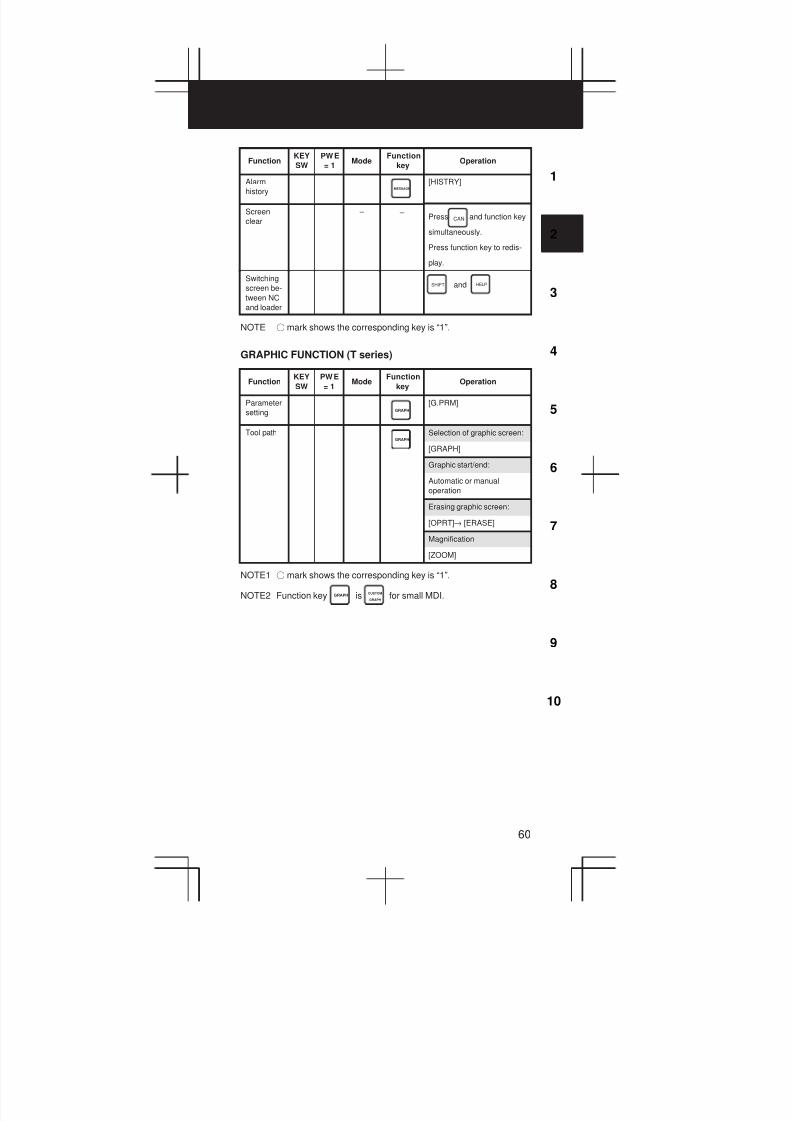
3
1
4
5
6
7
8
9
10
2
60
Function OperationFunction
keyMode
PWE
= 1
KEY
SW
Alarm
historyMESSAGE
[HISTRY]
Screen
clear
– – Press and function key
simultaneously.
Press function key to redis-
play.
CAN
Switching
screen be-
tween NC
and loader
andSHIFT HELP
NOTE f mark shows the corresponding key is “1”.
GRAPHIC FUNCTION (T series)
FunctionKEY
SW
PWE
= 1Mode
Function
keyOperation
Parameter
setting GRAPH
[G.PRM]
Tool pathGRAPH
Selection of graphic screen:
[GRAPH]
Graphic start/end:
Automatic or manual
operation
Erasing graphic screen:
[OPRT]→ [ERASE]
Magnification
[ZOOM]
NOTE1 f mark shows the corresponding key is “1”.
NOTE2 Function key GRAPH is CUSTOM
GRAPHfor small MDI.

2. OPERATION LIST
61
GRAPHIC FUNCTION (M series)
FunctionKEY
SW
PWE
= 1Mode
Function
keyOperation
Parameter
settingGRAPH
[PARAM]
Tool pathGRAPH
Selection of graphic screen:
[GRAPH]
Graphic start/end:
Automatic or manual opera-
tion
Data
setting of
dynamic
path
graphic
GRAPHPress several times
→ PATH GRAPHIC screen
→ [PARAM]→ numeric key
→
GRAPH
INPUT
Dynamic
path
graphic
MEMGRAPH
Press several times
→ PATH GRAPHIC screen
→ [EXEC] → [(OPRT)]→
[AUTO] or [START]
GRAPH
Temporary stop of graph
[STOP]
Execu-
tion af-
Execution after
temporaly stop
er em-
poraly [START]
stop Execution from
program heading
after temporary
stop:
[REWIND]→
[START]
Partial en-
largement
path
graphic
GRAPH Press several times
→ PATH GRAPHIC screen
→ [SCALE]→ [(OPRT)]→
[←] [→] [↑] [↓] →
or → [EXEC]
GRAPH
M
Displaying
tool posi-
tion mark
GRAPHPress several times
→ PATH GRAPHIC screen
→ [POSITION]
GRAPH
Displaying
solid
graphic
data
GRAPH Press several times
→ PATH GRAPHIC screen
→ Enter numerics →
GRAPH
INPUT
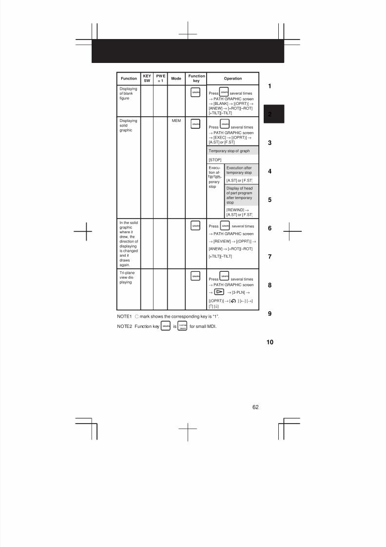
3
1
4
5
6
7
8
9
10
2
62
Function OperationFunction
keyMode
PWE
= 1
KEY
SW
Displaying
of blank
figure
GRAPH Press several times
→ PATH GRAPHIC screen
→ [BLANK]→ [(OPRT)]→
[ANEW] → [+ROT][–ROT]
[+TILT][–TILT]
GRAPH
Displaying
solid
graphic
MEMGRAPH
Press several times
→ PATH GRAPHIC screen
→ [EXEC] → [(OPRT)]→
[A.ST] or [F.ST]
GRAPH
Temporary stop of graph
[STOP]
Execu-
tion af-
Execution after
temporary stop
er em-
porary [A.ST] or [F.ST]
stop Display of head
of part program
after temporary
stop
[REWIND]→
[A.ST] or [F.ST]
In the solid
graphic
where it
drew, the
direction of
displaying
is changed
and it
draws
again.
GRAPH Press several times
→ PATH GRAPHIC screen
→ [REVIEW]→ [(OPRT)]→
[ANEW] → [+ROT][–ROT]
[+TILT][–TILT]
GRAPH
Tri-plane
view dis-
playing
GRAPH
Press several times
→ PATH GRAPHIC screen
→ → [3-PLN] →
[(OPRT)]→ [ ] [←] [→]
[↑] [↓]
GRAPH
NOTE1 f mark shows the corresponding key is “1”.
NOTE2 Function key GRAPH is CUSTOM
GRAPHfor small MDI.

2. OPERATION LIST
63
HELP FUNCTION
FunctionKEY
SW
PWE
= 1Mode
Function
keyOperation
Displaying
INITIAL
MENU
screen
HELP HELP
Displaying
ALARM
DETAIL
screen
HELP
[ALARM]→ Alarm No. →
[SELECT]
Displaying
OPERA-
TION
METHOD
screen
HELP
[OPERAT] → Item No. of op-
eration method → [SELECT]
Displaying
PARAME-
TER
TABLE
screen
HELP[PARAM]
SELF DIAGNOSTIC FUNCTION
FunctionKEY
SW
PWE
= 1Mode
Function
keyOperation
Displaying
DIAGNOS-
TIC screen
SYSTEM
[DGNOS]
↓
1. Page change keys
2. Number of the diagnos-
tic data→ [NO.SRH]
PAGE
PAGE
BOOT
FunctionKEY
SW
PWE
= 1Mode
Function
keyOperation
Displaying
system
monitor
screen
At
power-
up
– and the soft key to its
left
Reading
file from
memory
card
Move cursor to
1. SYSTEM DATA LODING
on system monitor screen
→ [SELECT]→ Move cur-
sor to file to be read →
[SELECT]→ [YES]
Displaying
detail
screen for
flash ROM
file list
Move cursor to
2. SYSTEM DATA CHECK
on system monitor screen
→ [SELECT]→ Move cur-
sor to item of which to dis-
play details → [SELECT]
Deleting
file in flash
ROM
Move cursor to
3. SYSTEM DATA DELETE
on system monitor screen
→ [SELECT]→ Move cur-
sor to file to be deleted →
[SELECT]→ [YES]

3
1
4
5
6
7
8
9
10
2
64
Function OperationFunction
keyMode
PWE
= 1
KEY
SW
Outputting
file in flash
ROM to
memory
card
Move cursor to
4. SYSTEM DATA SAVE on
system monitor screen→
[SELECT]→ Move cursor to
file to be output →
[SELECT]→ [YES]
Batch out-
put of
SRAM
data to
memory
card
Batch in-
put of
SRAM
data from
memory
card
Move cursor to
5. SYSTEM DATA BACKUP
on system monitor screen
→ [SELECT]→ Move cur-
sor to 1. SRAM BACKUP or
2. RESTORE SRAM →
[SELECT]→ [YES]
Deleting
file in
memory
card
Move cursor to
6. MEMORY CARD FILE on
system monitor screen→
[SELECT]→ Move cursor to
file to be deleted →
[SELECT]→ [YES]
Formatting
memory
card
Move cursor to
7. MEMORY CARD FOR-
MAT on system monitor
screen→ [SELECT]→
[YES]
Exiting
system
monitor
Move cursor to 9. END on
system monitor screen→
[SELECT]→ [YES]
P-CODE LOADER
FunctionKEY
SW
PWE
= 1Mode
Function
keyOperation
Starting P-
CODE
LOADER
At
power-
up
– andCAN PROG

3. G CODE
65
3.1 T series
G code list (T series) (1/3)
G code
A B Cu u
G00 G00 G00 Positioning (Rapid traverse)
G01 G01 G01 Linear interpolation (Cutting feed)
G02 G02 G02 01 Circular interpolation CW or Helical in-
terpolation CW
G03 G03 G03 Circular interpolation CCW or Helical
interpolation CCW
G04 G04 G04 Dwell
G05 G05 G05 High speed cycle cutting
G07 G07 G07 Hypothetical axis interpolation
G07.1
(G107)
G07.1
(G107)
G07.1
(G107)00
Cylindrical interpolation
G10 G10 G10 Programmable data input
G10.6 G10.6 G10.6 Tool retract & recover
G11 G11 G11 Programmable data input cancel
G12.1
(G112)
G12.1
(G112)
G12.1
(G112)
Polar coordinate interpolation mode
G13.1
(G113)
G13.1
(G113)
G13.1
(G113)Polar coordinate interpolation cancel
mode
G17 G17 G17 XpYp plane
selection
Xp: X axis or
parallel axis
G18 G18 G18 16ZpXp plane
selection
Yp: Y axis or
parallel axis
G19 G19 G19 YpZp plane
selection
Zp: Z axis or
parallel axis
G20 G20 G70 Input in inch
G21 G21 G71 Input in mm
G22 G22 G2209
Stored stroke check function on
G23 G23 G23 Stored stroke check function off
G25 G25 G25 Spindle speed fluctuation detection off
G26 G26 G26 Spindle speed fluctuation detection on
G27 G27 G27 Reference position return check
G28 G28 G28 Return to reference position
G30 G30 G30
00
2nd, 3rd and 4th reference position re-
turn
G30.1 G30.1 G30.1 Floating reference position return
G31 G31 G31 Skip function, multi–step skip function,
torque limit skip
G32 G33 G33 Thread cutting
G34 G34 G34 Variable–lead thread cutting
G35 G35 G35 Circular thread cutting CW
G36 G36 G36 Circular thread cutting CCW
G36 G36 G36 Automatic tool compensation X
G37 G37 G37 00 Automatic tool compensation Z
G39 G39 G39 Corner circular interpolation
G40 G40 G40 Tool nose radius compensation cancel
G41 G41 G41 07 Tool nose radius compensation left
G42 G42 G42 Tool nose radius compensation right

3
1
4
5
6
7
8
9
10
2
66
G code list (T series) (2/3)
G codeFunctionGroup
AFunctionGroup
CB
G50 G92 G92
00
Coordinate system setting or max.
spindle speed setting
G50.3 G92.1 G92.1 Workpiece coordinate system preset
G50.2
(G250)G50.2
(G250)
G50.2
(G250)
Polygonal turning cancel
G51.2
(G251)
G51.2
(G251)
G51.2
(G251)
20Polygonal turning
G52 G52 G52 Local coordinate system setting
G53 G53 G53 Machine coordinate system setting
G54 G54 G54 Workpiece coordinate system 1 selec-
tion
G55 G55 G55 Workpiece coordinate system 2 selec-
tion
G56 G56 G5614
Workpiece coordinate system 3 selec-
tion
G57 G57 G57 Workpiece coordinate system 4 selec-
tion
G58 G58 G58 Workpiece coordinate system 5 selec-
tion
G59 G59 G59 Workpiece coordinate system 6 selec-
tion
G65 G65 G65 00 Macro calling
G66 G66 G66 Macro modal call
G67 G67 G67 Macro modal call cancel
G68 G68 G68 Mirror image for double turrets ON or
balance cut mode
G69 G69 G69 Mirror image for double turrets OFF or
balance cut mode cancel
G70 G70 G72 Finishing cycle
G71 G71 G73 Stock removal in turning
G72 G72 G74 Stock removal in facing
G73 G73 G75 00 Pattern repeating
G74 G74 G76 End face peck drilling
G75 G75 G77 Outer diameter/internal diameter drilling
G76 G76 G78 Multiple threading cycle
G71 G71 G72 Traverse grinding cycle
(for grinding machine)
G72 G72 G73 Traverse direct constant–dimension
grinding cycle (for grinding machine)
G73 G73 G74 Oscilation grinding cycle
(for grinding machine)
G74 G74 G75 Oscilation direct constant–dimension
grinding cycle (for grinding machine)
G80 G80 G80 Canned cycle for drilling cancel
G83 G83 G83 Cycle for face drilling
G84 G84 G84 Cycle for face tapping
G86 G86 G86 10 Cycle for face boring
G87 G87 G87 Cycle for side drilling
G88 G88 G88 Cycle for side tapping
G89 G89 G89 Cycle for side boring
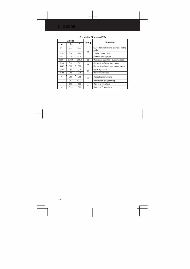
3. G CODE
67
G code list (T series) (3/3)
G codeFunctionGroup
AFunctionGroup
CB
G90 G77 G20 Outer diameter/internal diameter cutting
cycle
G92 G78 G21 Thread cutting cycle
G94 G79 G24 Endface turning cycle
G92.1 G92.1 G92.1 00 Workpiece coordinate system preset
G96 G96 G96 Constant surface speed control
G97 G97 G97 Constant surface speed control cancel
G98 G94 G94 Per minute feed
G99 G95 G95 Per revolution feed
– G90 G90 03 Absolute programming
– G91 G90 Incremental programming
– G98 G9811
Return to initial level
– G99 G99 Return to R point level
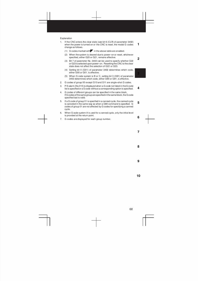
3
1
4
5
6
7
8
9
10
2
68
Explanation
1. If the CNC enters the clear state (see bit 6 (CLR) of parameter 3402)when the power is turned on or the CNC is reset, the modal G codeschange as follows.
(1) G codes marked with in the above table are enabled.
(2) When the system is cleared due to power–on or reset, whicheverspecified, either G20 or G21, remains effective.
(3) Bit 7 of parameter No. 3402 can be used to specify whether G22or G23 is selected upon power–on. Resetting the CNC to the clearstate does not affect the selection of G22 or G23.
(4) Setting bit 0 (G01) of parameter 3402 determines which code,either G00 or G01, is effective.
(5) When G code system is B or C, setting bit 3 (G91) of parameter3402 determines which code, either G90 or G91, is effective.
2. G codes of group 00 except G10 and G11 are single–shot G codes.
3. P/S alarm (No.010) is displayed when a G code not listed in the G codelist is specified or a G code without a corresponding option is specified.
4. G codes of different groups can be specified in the same block.If G codes of the same group are specified in the same block, the G codespecified last is valid.
5. If a G code of group 01 is specified in a canned cycle, the canned cycleis canceled in the same way as when a G80 command is specified. Gcodes of group 01 are not affected by G codes for specifying a cannedcycle.
6. When G code system A is used for a canned cycle, only the initial levelis provided at the return point.
7. G codes are displayed for each group number.
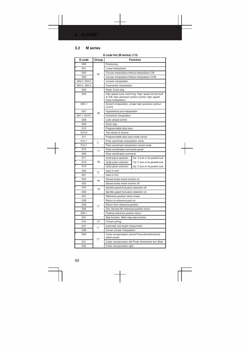
3. G CODE
69
3.2 M series
G code list (M series) (1/3)
G code Group Function
G00 Positioning
G01 Linear interpolation
G0201
Circular interpolation/Helical interpolation CW
G03 Circular interpolation/Helical interpolation CCW
G02.2, G03.2 Involute interpolation
G02.3, G03.3 Exponential interpolation
G04 Dwell, Exact stop
G05 High speed cycle machining, High–speed remote buff-
er A/B, high–precision contour control, high–speed
linear interpolation
G05.1 Smooth interpolation, simple high–precision contour
control
G0700
Hypothetical axis interpolation
G07.1 (G107) Cylindrical interpolation
G08 Look–ahead control
G09 Exact stop
G10 Programmable data input
G10.6 Tool retract & recover
G11 Programmable data input mode cancel
G12.1 Polar coordinate interpolation mode
G13.1 Polar coordinate interpolation cancel mode
G1517
Polar coordinates command cancel
G06 Polar coordinates command
G17 XpYp plane selection Xp: X axis or its parallel axis
G18 02 ZpXp plane selection Yp: Y axis or its parallel axis
G19 YpZp plane selection Zp: Z axis or its parallel axis
G20 Input in inch
G21 Input in mm
G2204
Stored stroke check function on
G23 Stored stroke check function off
G2519
Spindle speed fluctuation detection off
G26 Spindle speed fluctuation detection on
G27 Reference position return check
G28 Return to reference position
G29 Return from reference position
G30 2nd, 3rd and 4th reference position return
G30.1 Floating reference position return
G31 Skip function, Multi–step skip function
G33 01 Thread cutting
G37 Automatic tool length measurment
G39 Corner circular interpolation
G40 Cutter compensation cancel/Three dimentional tool
offset cancel
G41 Cutter compensation left/Three dimentional tool offset
G42 Cutter compensation right

3
1
4
5
6
7
8
9
10
2
70
G code list (M series) (2/3)
G code FunctionGroup
G40.1 (G150) Normal direction control cancel mode
G41.1 (G151) 18 Normal direction control left side on
G42.1 (G152) Normal direction control right side on
G43 Tool length compensation + direction
G44 Tool length compensation – direction
G45 Tool offset increase
G46 Tool offset decrease
G47 Tool offset double increase
G48 Tool offset double decrease
G49 08 Tool length compensation cancel
G5011
Scaling cancel
G51 Scaling
G50.122
Programmable mirror image cancel
G51.1 Programmable mirror image
G52 Local coordinate system setting
G53 Machine coordinate system selection
G54 Workpiece coordinate system 1 selection
G54.1 Additional workpiece coordinate system selection
G55 Workpiece coordinate system 2 selection
G56 14 Workpiece coordinate system 3 selection
G57 Workpiece coordinate system 4 selection
G58 Workpiece coordinate system 5 selection
G59 Workpiece coordinate system 6 selection
G60 00/01 Single direction positioning
G61 Exact stop mode
G62 Automatic corner override
G63 Tapping mode
G64 Cutting mode
G65 00 Macro call
G66 Macro modal call
G67 Macro modal call cancel
G68 Coordinate rotation/Three dimensional coordinate
conversion
G69 Coordinate rotation cancel/Three dimensional coordi-
nate conversion cancel
G72.1 Rotation copy
G72.2 Parallel copy
G73 Peck drilling cycle
G74 Counter tapping cycle
G75 01 Plunge grinding cycle (for grinding machine)
G76 09 Fine boring cycle
G77 Direct constant–dimension plunge grinding cycle
(for grinding machine)
G7801
Continuous–feed surface grinding cycle
(for grinding machine)
G79 Intermittent–feed surface grinding cycle
(for grinding machine)
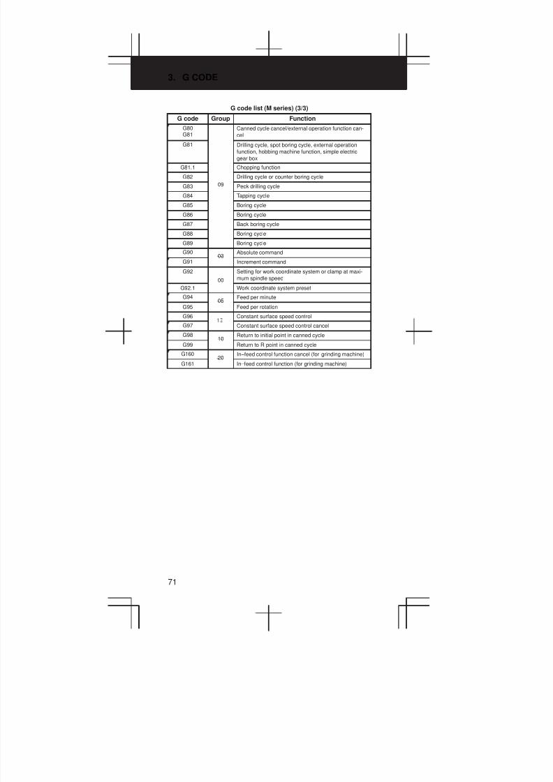
3. G CODE
71
G code list (M series) (3/3)
G code FunctionGroup
G80G81
Canned cycle cancel/external operation function can-
cel
G81 Drilling cycle, spot boring cycle, external operation
function, hobbing machine function, simple electric
gear box
G81.1 Chopping function
G82 Drilling cycle or counter boring cycle
G83 09 Peck drilling cycle
G84 Tapping cycle
G85 Boring cycle
G86 Boring cycle
G87 Back boring cycle
G88 Boring cycle
G89 Boring cycle
G9003
Absolute command
G91 Increment command
G92
00
Setting for work coordinate system or clamp at maxi-
mum spindle speed
G92.1 Work coordinate system preset
G9405
Feed per minute
G95 Feed per rotation
G96 Constant surface speed control
G97 Constant surface speed control cancel
G9810
Return to initial point in canned cycle
G99 Return to R point in canned cycle
G16020
In–feed control function cancel (for grinding machine)
G161 In–feed control function (for grinding machine)
3
1
4
5
6
7
8
9
10
2
72
Explanation
1. When the clear state (bit 6 (CLR) of parameter No. 3402) is set atpower–up or reset, the modal G codes are placed in the statesdescribed below.
(1) The modal G codes are placed in the states marked with asindicated in the above table.
(2) G20 and G21 remain unchanged when the clear state is set atpower–up or reset.
(3) Which status G22 or G23 at power on is set by parameter G23(No.3402#7). However, G22 and G23 remain unchanged when theclear state is set at reset.
(4) The user can select G00 or G01 by setting bit 0 (G01) of parameterNo. 3402.
(5) The user can select G90 or G91 by setting bit 3 (G91) of parameterNo. 3402.
(6) The user can select G17, G18, or G19 by setting bit 1 (parameterG18) and bit 2 (parameter G19) of parameter No. 3402.
2. G codes other than G10 and G11 are one–shot G codes.
3. When a G code not listed in the G code list is specified, or a G code thathas no corresponding option is specified, P/S alarm No. 010 is output.
4. Multiple G codes can be specified in the same block if each G codebelongs to a different group. If multiple G codes that belong to the samegroup are specified in the same block, only the last G code specified isvalid.
5. If a G code belonging to group 01 is specified in a canned cycle, thecanned cycle is cancelled. This means that the same state set byspecifying G80 is set. Note that the G codes in group 01 are not affectedby a G code specifying a canned cycle.
6. G codes are indicated by group.
7. The group of G60 is switched according to the setting of the MDL bit (bit0 of parameter 5431). (When the MDL bit is set to 0, the 00 group isselected. When the MDL bit is set to 1, the 01 group is selected.)
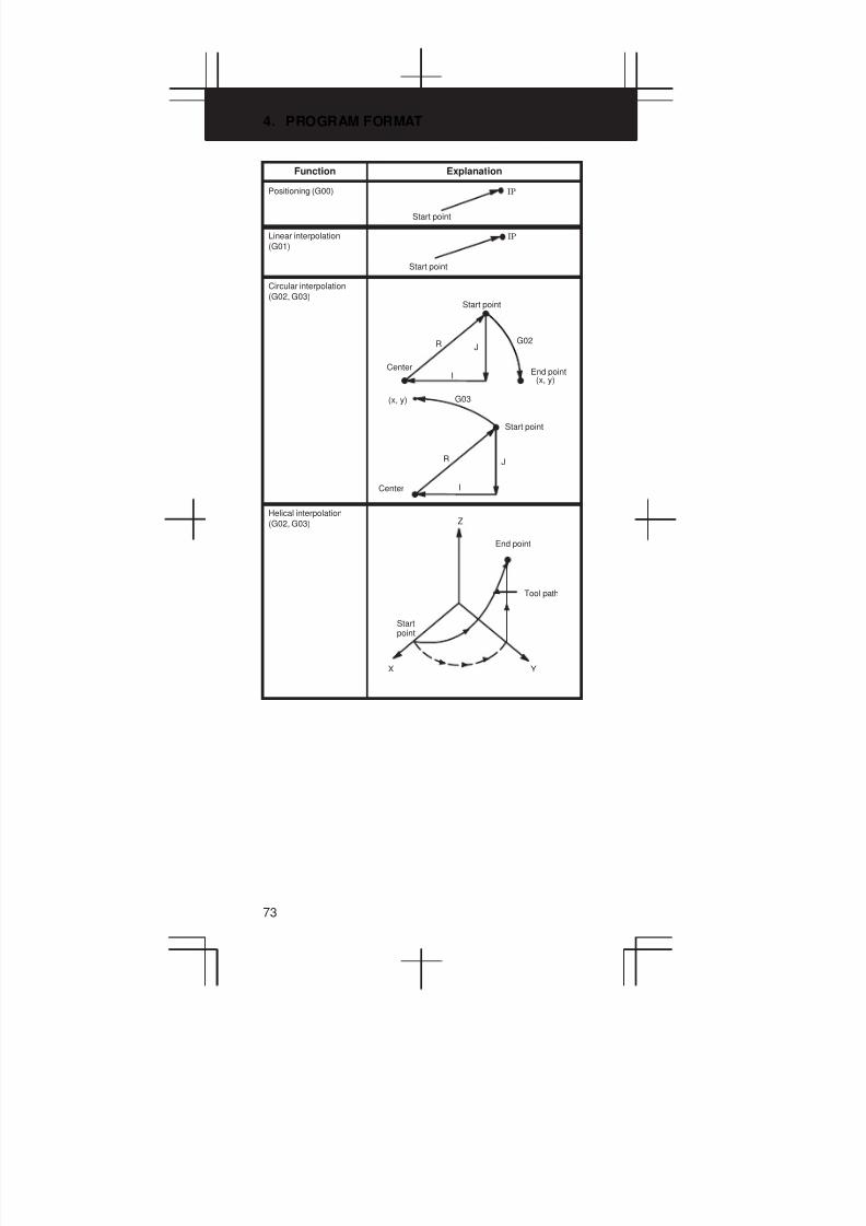
4. PROGRAM FORMAT
73
Function Explanation
Positioning (G00)
Start point
IP
Linear interpolation
(G01)
Start point
IP
Circular interpolation
(G02, G03)
(x, y)
G03(x, y)
JR
I
G02
Start point
Start point
R
I
J
CenterEnd point
Center
Helical interpolation
(G02, G03) Z
Tool path
YX
Startpoint
End point
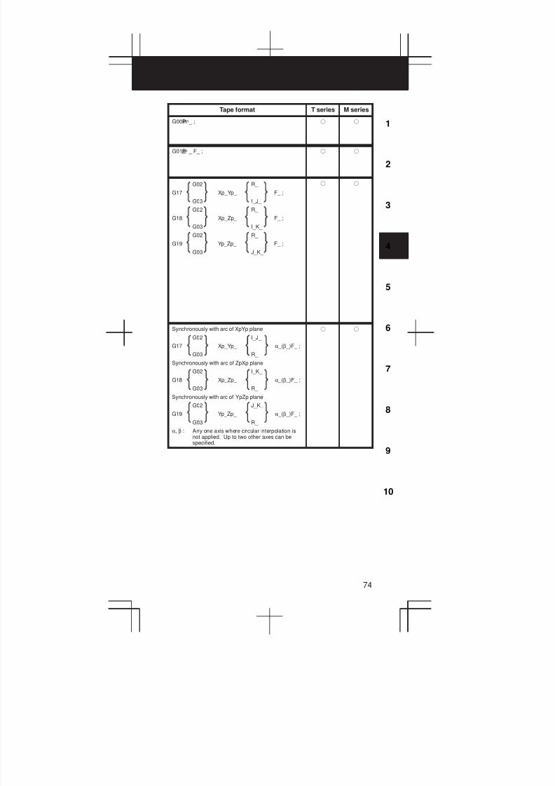
3
1
4
5
6
7
8
9
10
2
74
Tape format T series M series
G00P _ ;IP f f
G01P _ F_ ;IP f f
G02 R_
G17 Xp_Yp_ F_ ;
G03 I_J_
G02 R_
G18 Xp_Zp_ F_ ;
G03 I_K_
G02 R_
G19 Yp_Zp_ F_ ;
G03 J_K_
f f
Synchronously with arc of XpYp plane
G02 I_J_
G17 Xp_Yp_ α _(β _)F_ ;
G03 R_
Synchronously with arc of ZpXp plane
G02 I_K_
G18 Xp_Zp_ α _(β _)F_ ;
G03 R_
Synchronously with arc of YpZp plane
G02 J_K_
G19 Yp_Zp_ α _(β _)F_ ;
G03 R_
α, β : Any one axis where circular interpolation isnot applied. Up to two other axes can bespecified.
f f
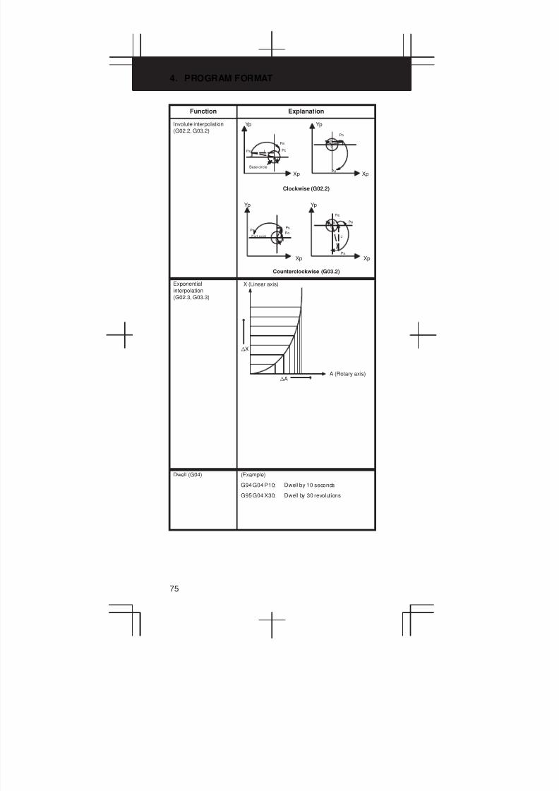
4. PROGRAM FORMAT
75
Function Explanation
Involute interpolation
(G02.2, G03.2)
I
Clockwise (G02.2)
Counterclockwise (G03.2)
J
Yp Yp
Pe
0 R
Xp
Ps
Pe
Po
Po
R
0
IJ
Xp
PePs
Po
R0
Pe
0
Ro
IJ J
I
R
Ps
Xp Xp
Base circle
End point
Yp Yp
Exponential
interpolation
(G02.3, G03.3)
X (Linear axis)
nX
A (Rotary axis)nA
Dwell (G04) (Example)
G94 G04 P10; Dwell by 10 seconds
G95 G04 X30; Dwell by 30 revolutions
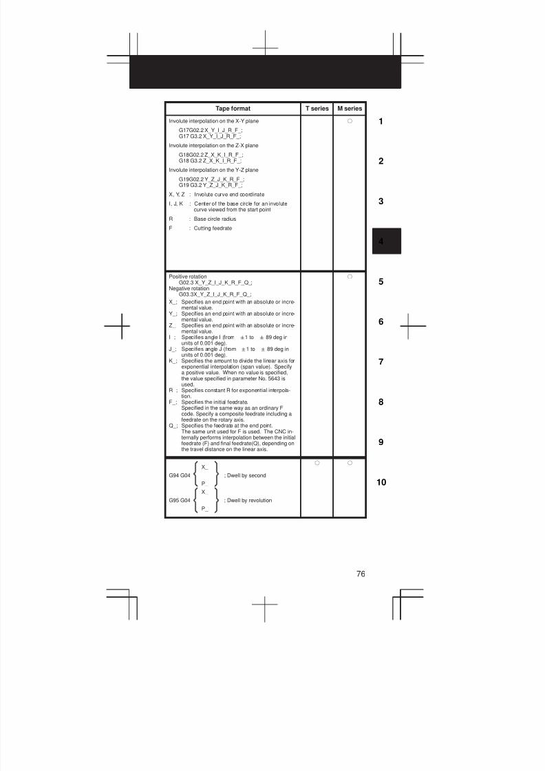
3
1
4
5
6
7
8
9
10
2
76
Tape format T series M series
Involute interpolation on the X-Y plane
G17G02.2 X_Y_I_J_R_F_;G17 G3.2 X_Y_I_J_R_F_;
Involute interpolation on the Z-X plane
G18G02.2 Z_X_K_I_R_F_;G18 G3.2 Z_X_K_I_R_F_;
Involute interpolation on the Y-Z plane
G19G02.2 Y_Z_J_K_R_F_;G19 G3.2 Y_Z_J_K_R_F_;
X, Y, Z : Involute curve end coordinate
I, J, K : Center of the base circle for an involutecurve viewed from the start point
R : Base circle radius
F : Cutting feedrate
f
Positive rotationG02.3 X_Y_Z_I_J_K_R_F_Q_;
Negative rotationG03.3X_Y_Z_I_J_K_R_F_Q_;
X_; Specifies an end point with an absolute or incre-mental value.
Y_; Specifies an end point with an absolute or incre-mental value.
Z_; Specifies an end point with an absolute or incre-mental value.
I_; Specifies angle I (from "1 to " 89 deg inunits of 0.001 deg).
J_; Specifies angle J (from "1 to " 89 deg inunits of 0.001 deg).
K_; Specifies the amount to divide the linear axis forexponential interpolation (span value). Specifya positive value. When no value is specified,the value specified in parameter No. 5643 isused.
R_; Specifies constant R for exponential interpola-tion.
F_; Specifies the initial feedrate.Specified in the same way as an ordinary Fcode. Specify a composite feedrate including afeedrate on the rotary axis.
Q_; Specifies the feedrate at the end point.The same unit used for F is used. The CNC in-ternally performs interpolation between the initialfeedrate (F) and final feedrate(Q), depending onthe travel distance on the linear axis.
f
X_
G94 G04 ; Dwell by second
P_
X_
G95 G04 ; Dwell by revolution
P_
f f

4. PROGRAM FORMAT
77
Function Explanation
High-speed cycle
machining (G05)
(Example)
Cycle 1: connection 2, repetition 1
Cycle 2: connection 3, repetition 3
Cycle 3: connection 0, repetition 1
G05P10001L2;
Cycle is executed as 1, 2, 2, 2, 3, 1, 2, 2, 2, 3
High-speed remote
buffer A (G05)
Specify G05 only in a block using normal NC com-
mand format. Then specify move data in the special
format shown below. When zero is specified as the
travel distance along all axes, normal NC command
format can be used again for subsequent command
specification.
High-speed remote
buffer B
(G05)
High-speed remote buffer A uses binary data. On the
other hand, high-speed remote buffer B can directly
use NC language coded with equipment such as an
automatic programming unit to perform high-speed
machining.
High-precision contour
control
(G05)
Some machining errors are due to the CNC. Such
errors include machining errors caused by accelera-
tion/deceleration after interpolation. To eliminate
these errors, the following functions are performed at
high speed by an RISC processor. These functions
are called high-precision contour control functions.
(1) Function for multiple-block look-ahead accelera-
tion/deceleration before interpolation. This func-
tion eliminates machining errors due to accelera-
tion/deceleration.
(2) Automatic speed control function which enables
smooth acceleration/deceleration by considering
changes in the figure and speed and allowable
acceleration for the machine. This is performed
by reading multiple blocks in advance.
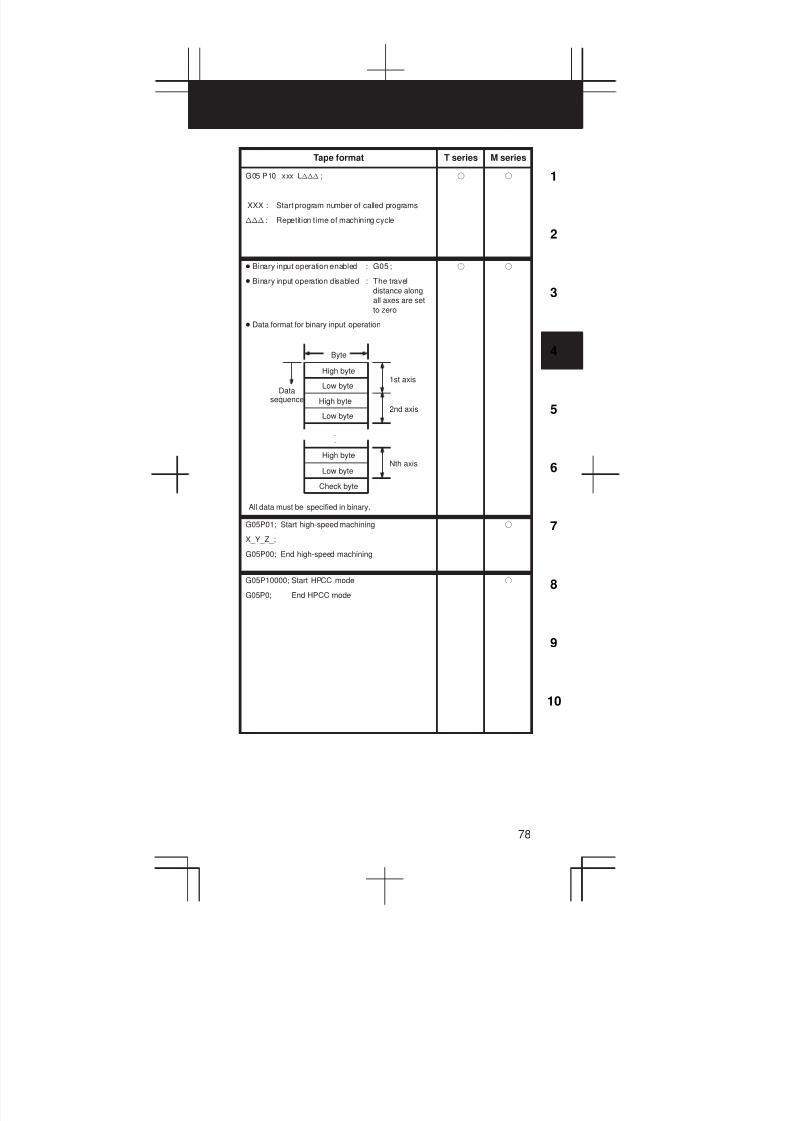
3
1
4
5
6
7
8
9
10
2
78
Tape format T series M series
G05 P10 xxx Lnnn ;
XXX : Start program number of called programs
nnn : Repetition time of machining cycle
f f
D Binary input operation enabled : G05 ;
D Binary input operation disabled : The travel
distance along
all axes are set
to zero
D Data format for binary input operation
Byte
High byte
Low byte
High byte
Low byte
High byte
Low byte
Check byte
1st axis
2nd axis
Nth axis
Datasequence
All data must be specified in binary.
.
.
f f
G05P01; Start high-speed machining
X_Y_Z_;
G05P00; End high-speed machining
f
G05P10000; Start HPCC mode
G05P0; End HPCC mode
f
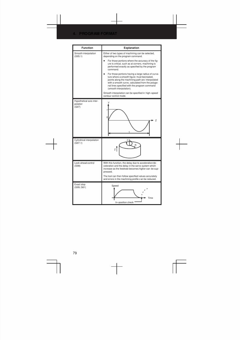
4. PROGRAM FORMAT
79
Function Explanation
Smooth interpolation
(G05.1)
Either of two types of machining can be selected,
depending on the program command.
D For those portions where the accuracy of the fig-
ure is critical, such as at corners, machining is
performed exactly as specified by the program
command.
D For those portions having a large radius of curva-
ture where a smooth figure must becreated,
points along the machining path are interpolated
with a smooth curve, calculated from the polygo-
nal lines specified with the program command
(smooth interpolation).
Smooth interpolation can be specified in high–speed
contour control mode.
Hypothetical axis inter-
polation
(G07)
Y
r
0
Z
1
Cylindrical interpolation
(G07.1)
Z
C
R
Look-ahead control
(G08)
With this function, the delay due to acceleration/de-
celeration and the delay in the servo system which
increase as the feedrate becomes higher can be sup-
pressed.
The tool can then follow specified values accurately
and errors in the machining profile can be reduced.
Exact stop
(G09, G61)Speed
Time
In–position check
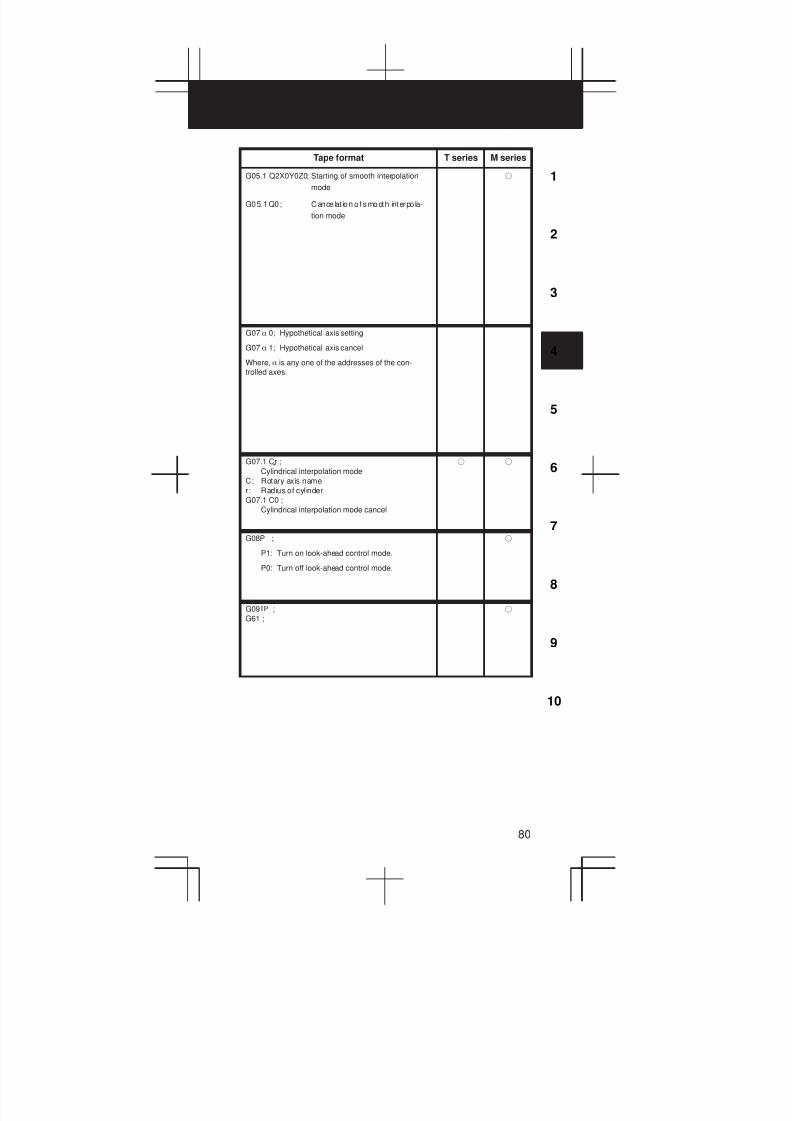
3
1
4
5
6
7
8
9
10
2
80
Tape format T series M series
G05.1 Q2X0Y0Z0; Starting of smooth interpolation
mode
G05.1 Q0; Cancelat ion of smooth interpo la-
tion mode
f
G07 a 0; Hypothetical axis setting
G07 a 1; Hypothetical axis cancel
Where, a is any one of the addresses of the con-
trolled axes.
G07.1 Cr ;
Cylindrical interpolation mode
C: Rotary axis name
r: Radius of cylinder
G07.1 C0 ;
Cylindrical interpolation mode cancel
f f
G08P_ ;
P1: Turn on look-ahead control mode.
P0: Turn off look-ahead control mode.
f
G09 ;
G61 ;
IP f

4. PROGRAM FORMAT
81
Function Explanation
Change of offset values
by program
(G10)
The tool compensation amount can be set or
changed with the G10 command.
When G10 is used in absolute input (G90), the com-
pensation amount specified in the command be-
comes the new tool compensation amount. When
G10 is used in incremental input (G91), the com-
pensation amount specified in the command is added
lo e amoun currenly se .
Tool withdrawal and
return
(G10.6)
⊗: Position where the TOOL WITHDRAW switchis turned on
F: Programmed position
f: Position to which the tool is retracted by manu-al operation
X
Y
: Retraction path
: Manual operation (withdraw path)
: Return path
: Repositioning
Z
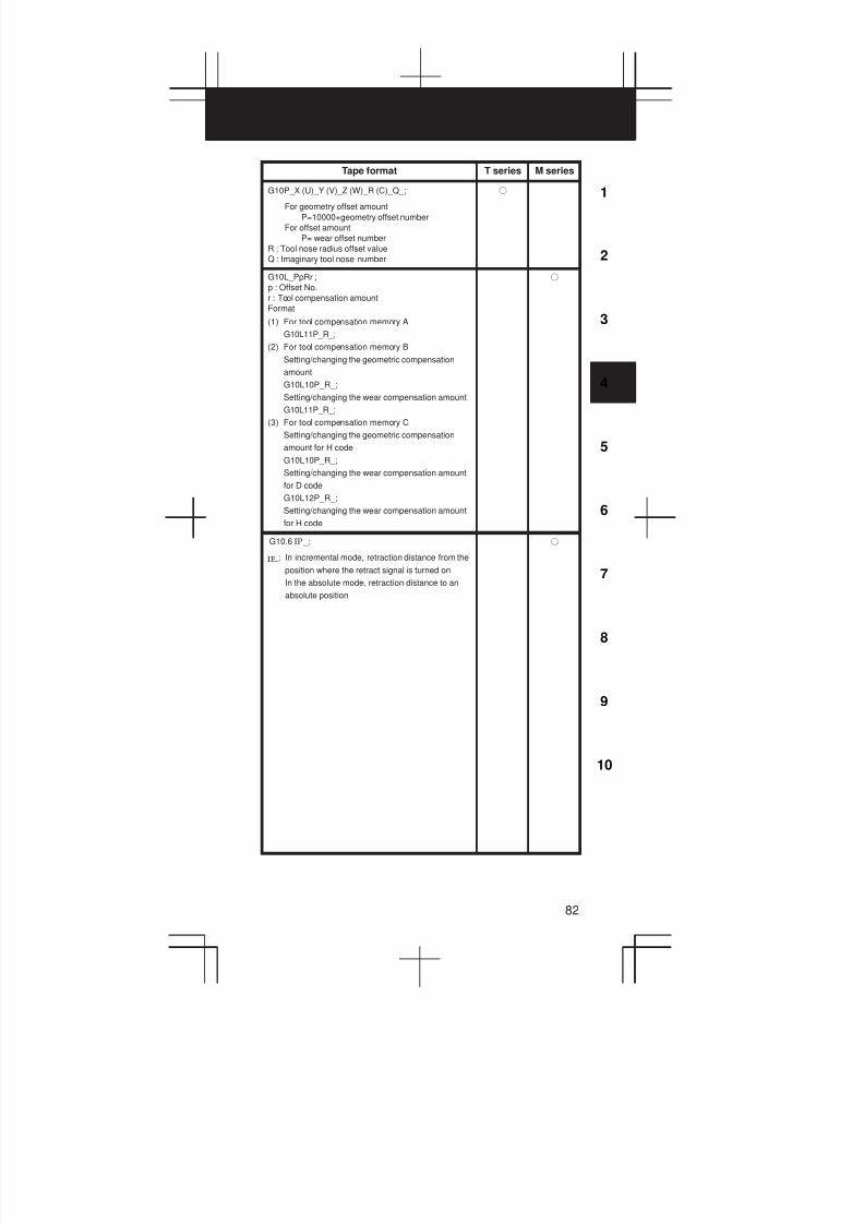
3
1
4
5
6
7
8
9
10
2
82
Tape format T series M series
G10P_X (U)_Y (V)_Z (W)_R (C)_Q_;
For geometry offset amount
P=10000+geometry offset number
For offset amount
P= wear offset number
R : Tool nose radius offset value
Q : Imaginary tool nose number
f
G10L_PpRr ;
p : Offset No.
r : Tool compensation amount
Format
(1) For tool compensation memory A
G10L11P_R_;
(2) For tool compensation memory B
Setting/changing the geometric compensation
amount
G10L10P_R_;
Setting/changing the wear compensation amount
G10L11P_R_;
(3) For tool compensation memory C
Setting/changing the geometric compensation
amount for H code
G10L10P_R_;
Setting/changing the wear compensation amount
for D code
G10L12P_R_;
Setting/changing the wear compensation amount
for H code
f
G10.6 _;
_: In incremental mode, retraction distance from the
position where the retract signal is turned on
In the absolute mode, retraction distance to an
absolute position
IP
IP
f
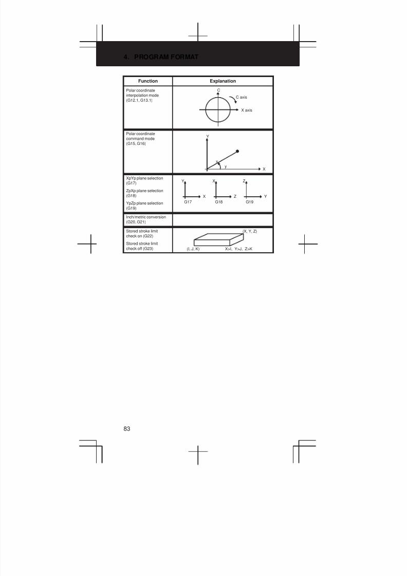
4. PROGRAM FORMAT
83
Function Explanation
Polar coordinate
interpolation mode
(G12.1, G13.1)
X axis
C
C axis
Polar coordinate
command mode
(G15, G16)
X
Y
x
y
XpYp plane selection
(G17)
ZpXp plane selection
(G18)
YpZp plane selection
(G19)
G17
X
Y
G18 G19
Z
X
Y
Z
Inch/metric conversion
(G20, G21)
Stored stroke limit
check on (G22)
Stored stroke limit
check off (G23) (I, J, K)
(X, Y, Z)
X>I, Y>J, Z>K

3
1
4
5
6
7
8
9
10
2
84
Tape format T series M series
G12.1 ;
Polar coordinate interpolation mode
G13.1 ;
Polar coordinate interpolation mode cancel
f f
G16 ;
Polar coordinate command Xx Yy ;
X: radius, Y: angle (°)
G15 ;
Polar coordinate command cancel
f
G17 ;
G18 ;
G19 ;
f f
G20 ; Inch input
G21 ; Metric input
f f
G22X_Y_Z_I_J_K_ ; on
G23 ; off
f f

4. PROGRAM FORMAT
85
Function Explanation
Spindle speed
fluctuation detection on
(G26)
Spindle speed
fluctuation detection off
(G25)
d
dq
q
(Example)
(1) When an alarm is raised after a specifiedspindle speed is reached
(2) When an alarm is raised before a specifiedspindle speed is reached
Spindle speed
r
r
Specifiedspeed
Actual speed
Check
Nocheck Check
Specification ofanother speed
Start of check Alar m
Time
Specifiedspeed
Actual speed
Spindle speed
q d
q d
r
r
p
Check No check Check
Specification ofanother speed
Start ofcheck
Alarm
Time
pecified speed : (Speed specified by address S andfive–digit value)×(spindle override)
Actual speed :Speed detected with a position coder
p : Time elapses since the specified speed changesuntil a check starts.
q : (Percentage tolerance for a check to start)×(speci-fied speed)
r : (Percentage fluctuation detected as an alarmcondition)×(specified speed)
d : Fluctuation detected as an alarm (specified in pa-rameter (No.4913))
An alarm is issued when the difference between thespecified speed and the actual speed exceeds both rand d.
Reference position
return check
(G27)Start point
Reference position
IP
Reference position
return (G28)
2nd, 3rd, 4th reference
position return (G30)
Floating reference
position return (G30.1)Start point
Reference poisition (G28)
2nd referenceposition (G30)
IP
IPIntermediate position
Return to reference
position return start
position (G29)
Intermediate position
Reference position
IP
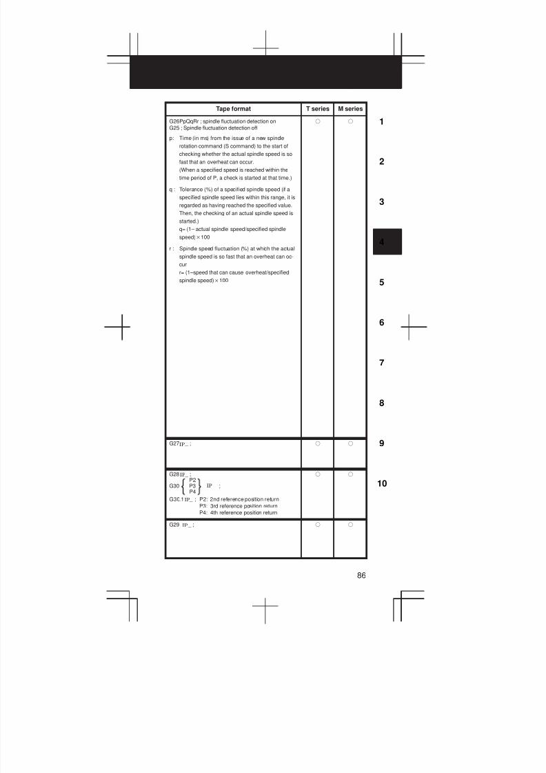
3
1
4
5
6
7
8
9
10
2
86
Tape format T series M series
G26PpQqRr ; spindle fluctuation detection on
G25 ; Spindle fluctuation detection off
p: Time (in ms) from the issue of a new spindle
rotation command (S command) to the start of
checking whether the actual spindle speed is so
fast that an overheat can occur.
(When a specified speed is reached within the
time period of P, a check is started at that time.)
q : Tolerance (%) of a specified spindle speed (if a
specified spindle speed lies within this range, it is
regarded as having reached the specified value.
Then, the checking of an actual spindle speed is
started.)
q= (1– actual spindle speed/specified spindle
speed)100
r : Spindle speed fluctuation (%) at which the actual
spindle speed is so fast that an overheat can oc-
cur
r= (1–speed that can cause overheat/specified
spindle speed)100
f f
G27 _ ;IP f f
G28 _ ;P2
G30 P3 _ ;P4
G30.1 _ ; P2: 2nd reference position return
P3: 3rd reference position return
P4: 4th reference position return
IP
IP
IP
f f
G29 _ ;IP f f
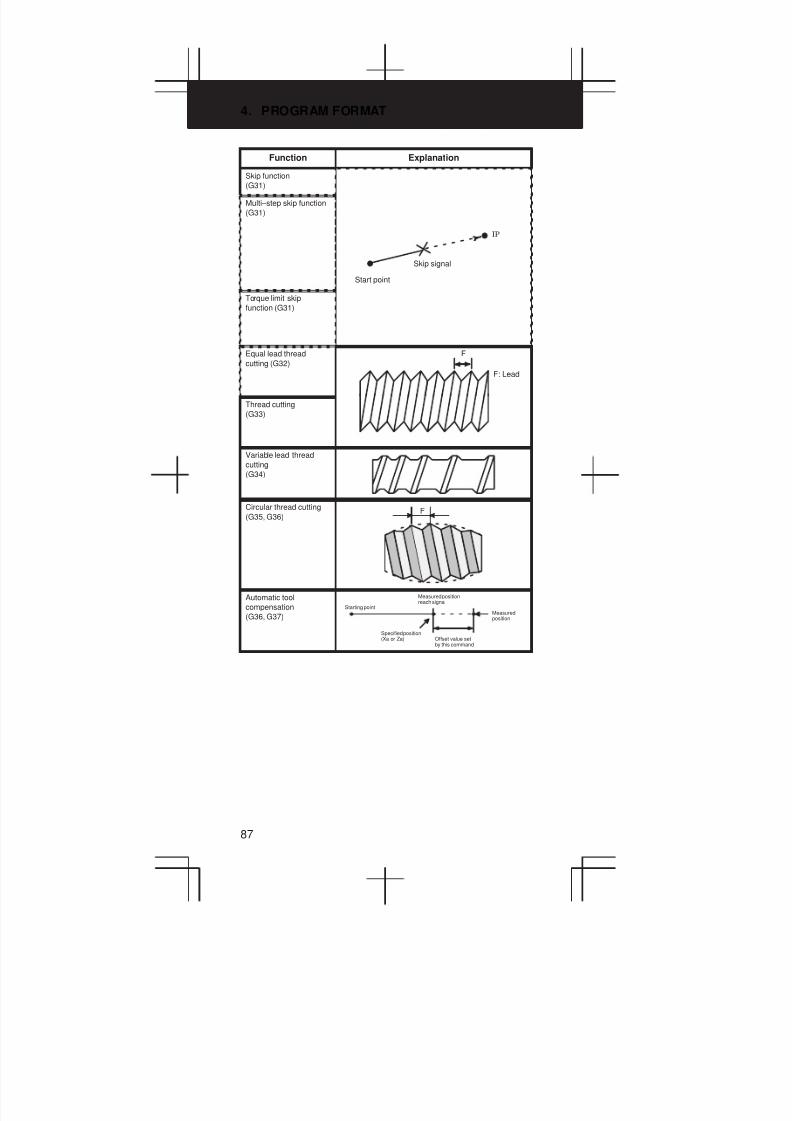
4. PROGRAM FORMAT
87
Function Explanation
Skip function
(G31)
Multi–step skip function
(G31)
Start point
Skip signal
IP
Torque limit skip
function (G31)
Equal lead thread
cutting (G32)
F
F: Lead
Thread cutting
(G33)
Variable lead thread
cutting
(G34)
Circular thread cutting
(G35, G36)F
Automatic tool
compensation
(G36, G37)
Specified position(Xa or Za)
Starting point
Measured positionreach signal
Offset value setby this command
Measuredposition

3
1
4
5
6
7
8
9
10
2
88
Tape format T series M series
G31 _F_ ;IP f f
Move command
G31 _F_P_;
F_: Feedrate
P_: P1-P4
Dwell
G04X (U, P)_(Q_);
X(U, P)_: Dwell time
Q_: Q1-Q4
IP
f f
G31 P99 _F_;
G31 P98 _F_;
G31: One-shot G code (G code effective only in theblock in which it is issued)
IP
IP
f
G32 _F_ ;IP f
G33 _F_ ;IP f
G34 _FfKk ;
f: longer axis lead at the start position
k: increase/decrease value per spindle
revolution
IP f
IP_G35G36 F _ Q _
I _ K _ R _ _
f
G36X xa ;
G37Z za ;
Specified position
f
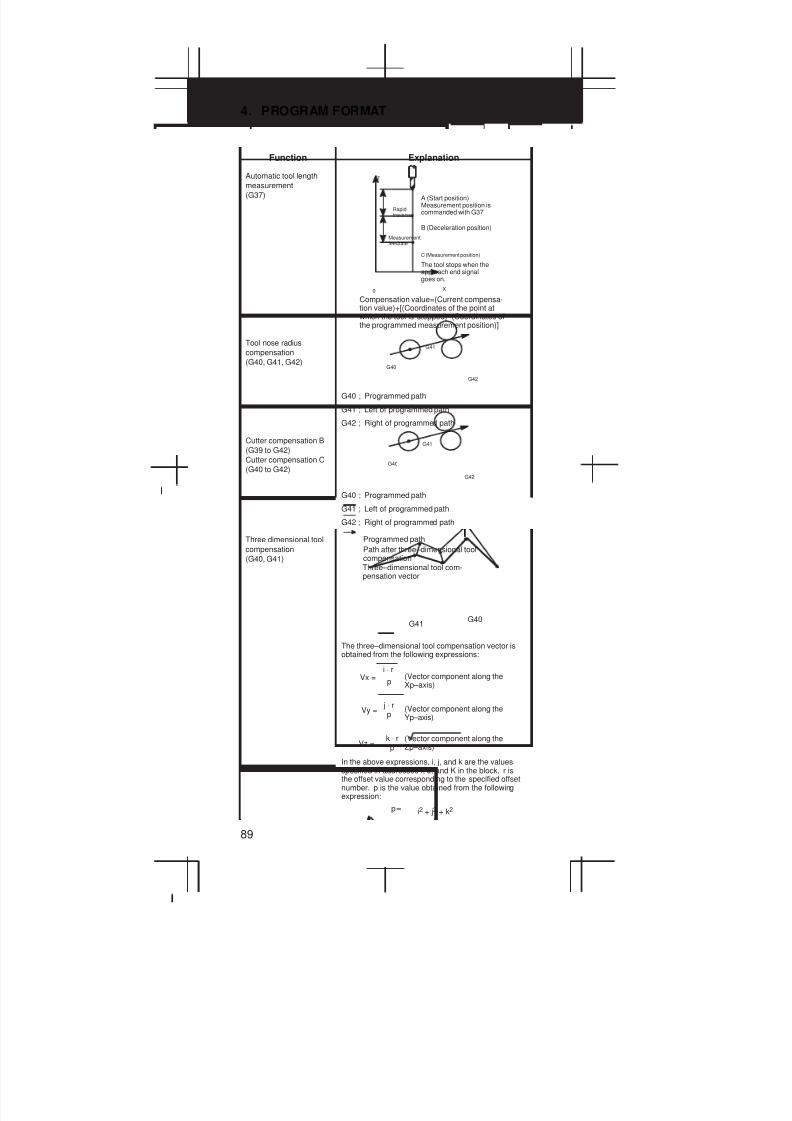
4. PROGRAM FORMAT
89
Function Explanation
Automatic tool length
measurement
(G37)Ç
Ç
Z
0 X
Rapidtraverse
Measurementfeedrate
A (Start position)Measurement position iscommanded with G37
B (Deceleration position)
C (Measurement position)
The tool stops when theapproach end signalgoes on.
Compensation value=(Current compensa-tion value)+[(Coordinates of the point atwhich the tool is stopped)–(Coordinates ofthe programmed measurement position)]
Tool nose radius
compensation
(G40, G41, G42)
G41
G42
G40Ç Ç
Ç Ç
Ç Ç Ç
Ç Ç Ç
Ç Ç
Ç Ç
G40 ; Programmed path
G41 ; Left of programmed path
G42 ; Right of programmed path
Cutter compensation B
(G39 to G42)
Cutter compensation C
(G40 to G42) Ç Ç
Ç Ç
Ç Ç
Ç Ç
Ç Ç
Ç Ç
G41
G42
G40
G40 ; Programmed path
G41 ; Left of programmed path
G42 ; Right of programmed path
Three dimensional tool
compensation
(G40, G41)
Programmed path
Path after three–dimensional toolcompensationThree–dimensional tool com-pensation vector
G41G40
Vx =p
i ⋅ r
Vy =p
j ⋅ r
Vz =p
k ⋅ r
p= i2 + j2 + k2
The three–dimensional tool compensation vector isobtained from the following expressions:
(Vector component along theXp–axis)
(Vector component along theYp–axis)
(Vector component along theZp–axis)
In the above expressions, i, j, and k are the valuesspecified in addresses I, J, and K in the block. r isthe offset value corresponding to the specified offsetnumber. p is the value obtained from the followingexpression:
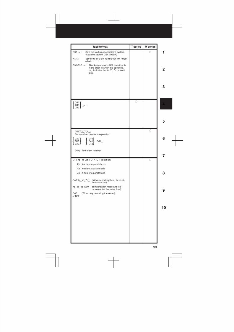
3
1
4
5
6
7
8
9
10
2
90
Tape format T series M series
G92 _; Sets the workpiece coordinate system.(It can be set with G54 to G59.)
Hff; Specifies an offset number for tool lengthoffset.
G90 G37 _; Absolute command·G37 is valid onlyin the block in which it is specified.
indicates the X-, Y-, Z-, or fourthaxis.
IP
IP
IP_
f
IP
G40G41 _ ;G42
f
G39X(I)_Y(J)_ ;
Corner offset circular interpolation
G17 G40G18 G41 D(H)_ ;G19 G42
D(H): Tool offset number
f
G41 Xp_Yp_Zp_I_J_K_D_; (Start up)
Xp: X-axis or a parallel axis
Yp: Y-axis or a parallel axis
Zp: Z-axis or a parallel axis
G40 Xp_Yp_Zp_; (When canceling the or three-di-mensional tool
Xp_Yp_Zp_D00; compensation mode and toolmovement at the same time)
G40; (When only canceling the vector)
or D00;
f
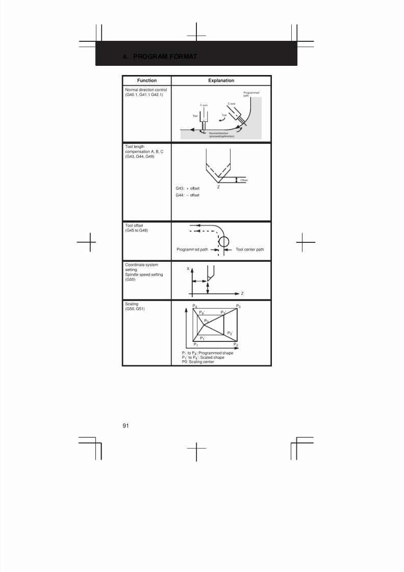
4. PROGRAM FORMAT
91
Function Explanation
Normal direction control
(G40.1, G41.1 G42.1)Á Á Á Á Á Á Á Á
Á Á Á Á Á Á Á Á
Á Á Á Á Á Á Á Á
Á Á Á Á Á Á Á Á
Á Á Á Á Á Á Á Á
Normal direction(proceeding direction)
Programmedpath
C axis
Tool
C axis
Tool
Tool length
compensation A, B, C
(G43, G44, G49)
Z
Offset
G43: + offset
G44: – offset
Tool offset
(G45 to G48)
Programmed path Tool center path
Coordinate system
setting
Spindle speed setting
(G50)
X
Z
Scaling
(G50, G51)P4
P4’
P3
P3’
P0
P1’
P1
P2’
P2
P1 to P4: Programmed shapeP1’ to P4’: Scaled chapeP0: Scaling center
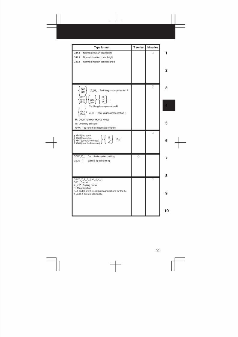
3
1
4
5
6
7
8
9
10
2
92
Tape format T series M series
G41.1 ; Normal direction control left
G42.1 ; Normal direction control right
G40.1 ; Normal direction control cancel
f
(Z_)H_ ; Tool length compensation A
Tool length compensation B
α _H_ ; Tool length compensation C
H: Offset number (H00 to H999)
α : Arbitrary one axis
G49 ; Tool length compensation cancel
G43G44
G17G18G19
G43G44
X_ Y_ Z_
G43G44
;
f
G45 (increase)G46 (decrease)G47 (double increase)G48 (double decrease)
X_ Y_ Z_
Dxx;
f
G50X_Z_ ; Coordinate system setting
G50S_ ; Spindle speed setting
f
G51X_Y_Z_P_ (or I_J_K_) ;
G50 ; Cancel
X, Y, Z: Scaling center
P: Magnification
(I, J, and K are the scaling magnifications for the X-,
Y-, and Z-axes respectively.)
f

4. PROGRAM FORMAT
93
Function Explanation
Programmable
mirror image
(G50.1, G51.1)
a/b : X–axis scaling magnificationc/d : Y–axis scaling magnification
0 : Scaling center
Y
X
d
c0
ab
Programmedshape
Scaled shape
Polygon turning
(G51.2, G50.2)
ToolWorkpieceWorkpiece
Local coordinate system
setting
(G52)
(Local coordinatesystem)
(Machine coordinate system)
(Local coor-dinate sys-tem)
(Workpiece referenceposition offset)
(Workpiececoordinate sys-tem 1: G54)
(Origin of the machine coordinate system)
(Parametervalue)
(Reference position)
IP
IP
(Warkpiece coordinatesystem 2:G55)
(Warkpiece coordinatesystem)
(Warkpiece coordinatesystem 6:G59)
Machine coordinate
system setting
(G53)
β
Machine zero
α
X
Machine coordinatesystem
Reference position
Machine referenceposition
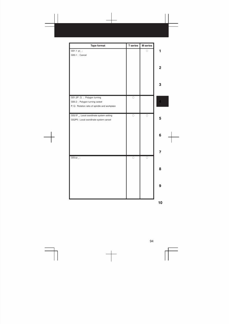
3
1
4
5
6
7
8
9
10
2
94
Tape format T series M series
G51.1 _ ;
G50.1 ; Cancel
IP f
G51.2P_Q_ ; Polygon turning
G50.2 ; Polygon turning cancel
P, Q: Rotation ratio of spindle and workpiece
f
G52 _; Local coordinate system setting
G52P0 ; Local coordinate system cancel
IP f f
G53 _ ;IP f f
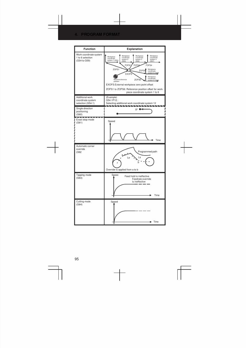
4. PROGRAM FORMAT
95
Function Explanation
Work coordinate system
1 to 6 selection
(G54 to G59)
EXOFS
ZOFS2 ZOFS3 ZOFS4
ZOFS5ZOFS1
ZOFS6
Workpiececoordinatesystem 1 (G54)
Workpiececoordinatesystem 2(G55)
Workpiececoordinatesystem 3(G56)
Workpiececoordinatesystem 4(G57)
Workpiececoordinatesystem 5 (G58)
Workpiececoordinatesystem 6 (G59)Machine reference
position
EXOFS:External workpiece zero point offset
ZOFS1 to ZOFS6: Reference position offset for work-
piece coordinate system 1 to 6
Additional work
coordinate system
selection (G54.1)
(Example)
G54.1P12 ;
Selecting additional work coordinate system 12
Single direction
positioning
(G60)
IP
Exact stop mode
(G61)Speed
Time
Automatic corner
override
(G62 Programmed path
a
b
Le Ls
Override is applied from a to b
Tapping mode
(G63) Feedrate overrideis ineffective
Feed hold is ineffective
Time
Speed
Cutting mode
(G64)
Time
Speed
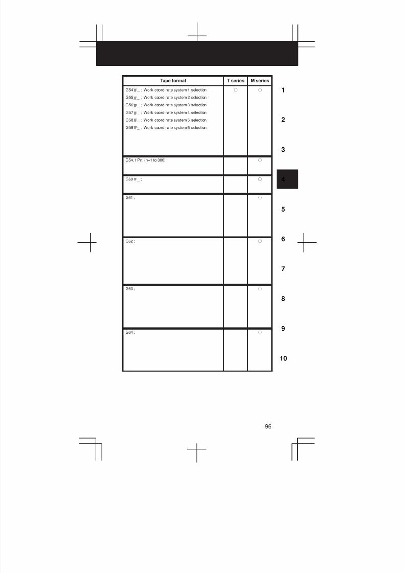
3
1
4
5
6
7
8
9
10
2
96
Tape format T series M series
G54 _ ; Work coordinate system 1 selection
G55 _ ; Work coordinate system 2 selection
G56 _ ; Work coordinate system 3 selection
G57 _ ; Work coordinate system 4 selection
G58 _ ; Work coordinate system 5 selection
G59 _ ; Work coordinate system 6 selection
IP
IP
IP
IP
IP
IP
f f
G54.1 Pn; (n=1 to 300) f
G60 _ ;IP f
G61 ; f
G62 ; f
G63 ; f
G64 ; f

4. PROGRAM FORMAT
97
Function Explanation
Macro call
(G65)Main program Macro program
O_:
G65P0001L_;
_
G67;
O0001;
M99;
Macro modal call
(G66, G67)Main program Macro program
O_:
G66P0001L_;
X_
Y_
G67;
O0001;
M99;
Mirror image for double
turrets
(G68, G69)
(Only when two-path
control)
Coordinate rotation
(G68, G69)
(G68.1, G69.1 in the
case of T series)
Y’ X’
Y
XR
Three-dimentional
coordinate conversion
(G68, G69)
Coordinate conversion about an axis can be carried
out if the center of rotation, direction of the axis of
rotation, and angular displacement are specified.
X
Y
Z
Y
Three–dimensionalcoordinate conversion
X
Z
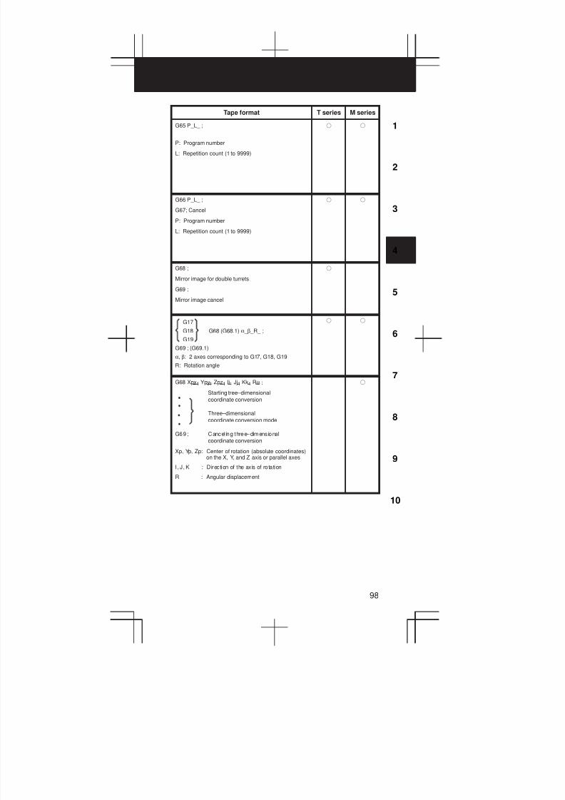
3
1
4
5
6
7
8
9
10
2
98
Tape format T series M series
G65 P_L_ ;
P: Program number
L: Repetition count (1 to 9999)
f f
G66 P_L_ ;
G67; Cancel
P: Program number
L: Repetition count (1 to 9999)
f f
G68 ;
Mirror image for double turrets
G69 ;
Mirror image cancel
f
G17
G18 G68 (G68.1) α _ β _R_ ;
G19
G69 ; (G69.1)
α, β: 2 axes corresponding to G17, G18, G19
R: Rotation angle
f f
G68 Xpx1 Ypy1 Zpz1 Ii1 Jj1 Kk1 Rα ;
Starting tree–dimensional
coordinate conversion
Three–dimensional
coordinate conversion mode
G69 ; Cancel ing three–dimensional
coordinate conversion
Xp, Yp, Zp: Center of rotation (absolute coordinates)on the X, Y, and Z axis or parallel axes
I, J, K : Direction of the axis of rotation
R : Angular displacement
f
4. PROGRAM FORMAT
99
Function Explanation
Figure copy
(G72.1, G72.2)
Machining can be repeated after moving or rotating
the figure using a subprogram.

3
1
4
5
6
7
8
9
10
2
100
Tape format T series M series
Rotational copy
Xp-Yp plane (specified by G17):
G72.1 P_L_Xp_Yp_R_;
Zp-Xp plane (specified by G18):
G72.1 P_L_Zp_Xp_R_;
Yp-Zp plane (specified by G19):
G72.1 P_L_Yp_Zp_R_;
P : Subprogram number
L : Number of t imes the operation is re-
peated
Xp : Center of rotation on the Xp axis
(Xp: X-axis or an axis parallel to the X-
axis)
Yp : Center of rotation on the Yp axis
(Yp; Y-axis or an axis parallel to the Y-
axis)
Zp : Center of rotation on the Zp axis
(Zp: Z-axis or an axis parallel to the Z-
axis)
R : Angular displacement
(A positive value indicates a counter-
clockwise angular displacement. Speci-
fy an incremental value.)
Linear copy
Xp-Yp plane (specified by G17):
G72.2 P_L_I_J_;
Zp-Xp plane (specified by G18):
G72.2 P_L_K_I_;
Yp-Zp plane (specified by G19):
G72.2 P_L_J_K_;
P : Subprogram number
L : Number of t imes the operation is re-
peated
I : Shift along the Xp axis
J : Shift along the Yp axis
K : Shift along the Zp axis
f

4. PROGRAM FORMAT
101
Function Explanation
Canned cycle for lathes
(G70 to G76)
(G90, G92, G94)
Canned cycle
G90: Outer diameter/internal diameter cuttingcycle
G92: Thread cutting cycle
G94: End face turning cycle
Multiple repetitive cycle
G70: Finishing
G71: Stock removal in turning
G72: Stock removal in facing
G73: Pattern repeating
G74: End face peck drilling cycle
G75: Outer diameter/internal diameter drillingcycle
G76: Multiple thread cutting cycle
(Example) G92
X axis
Z W
Zero point
3(R)4(R)
3(R)
1(R) U/2
X/2
Z axis
Approx.
45,
r
L
R Rap idtraverse
F Specifiedby F code
(The chamfered angle inthe left figure is 45 degrees or less because of thedelay in the servo system.)
Detailed chamfered thread
Canned cycle for
grinding
(G71 – G74)
G71: Traverse grinding cycle
G72: Traverse direct fixed-dimension grindingcycle
G73: Oscillation grinding cycle
G74: Oscillation direct fixed-dimention grindingcycle
(Example) G71
G71A__B__W__U__I__K__H__ ;
A: First depth of cut
B: Second depth of cut
W: Grinding range
U: Dwell t ime
Maximum specification time: 99999.999 seconds
I: Feedrate of A and B
K: Feedrate of W
H: Number of repetitions
Setting value: 1 to 9999
X
Z
A
BU
(K)
(K)
W
(I)
(I)
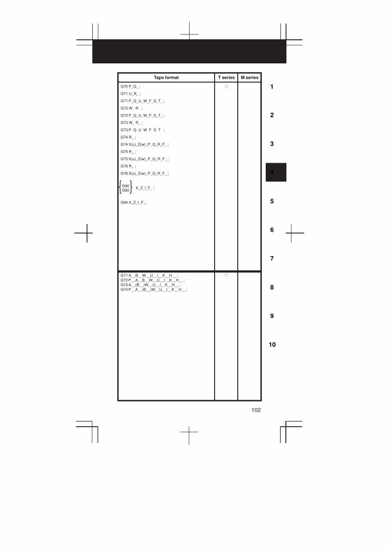
3
1
4
5
6
7
8
9
10
2
102
Tape format T series M series
G70 P_Q_ ;
G71 U_R_ ;
G71 P_Q_U_W_F_S_T_ ;
G72 W_ R_ ;
G72 P_Q_U_W_F_S_T_ ;
G73 W_ R_ ;
G73 P_Q_U_W_F_S_T_ ;
G74 R_ ;
G74 X(u)_Z(w)_P_Q_R_F_ ;
G75 R_ ;
G75 X(u)_Z(w)_P_Q_R_F_ ;
G76 R_ ;
G76 X(u)_Z(w)_P_Q_R_F_ ;
X_Z_I_F_ ;
G94 X_Z_I_F_;
G90G92
f
G71 A__B__W__U__I__K__H__ ;
G72 P__A__B__W__U__I__K__H__ ;
G73 A__(B__)W__U__I__K__H__ ;
G74 P__A__(B__)W__U__I__K__H__ ;
f
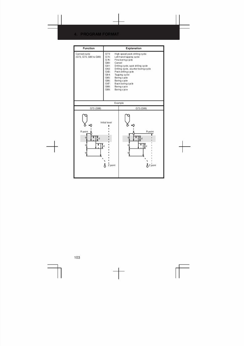
4. PROGRAM FORMAT
103
Function Explanation
Canned cycle
(G73, G74, G80 to G89)
G73: High-speed peck drilling cycle
G74: Left-hand tapping cycle
G76: Fine boring cycle
G80: Cancel
G81: Drilling cycle, spot drilling cycle
G82: Drilling cycle, counter boring cycle
G83: Peck dri ll ing cycle
G84: Tapping cycle
G85: Boring cycle
G86: Boring cycle
G87: Back boring cycle
G88: Boring cycle
G89: Boring cycle
Example
G73 (G98)
R point
q
q
q
d
d
G73 (G99)
R point
q
q
q
d
d
Initial level
Z point Z point
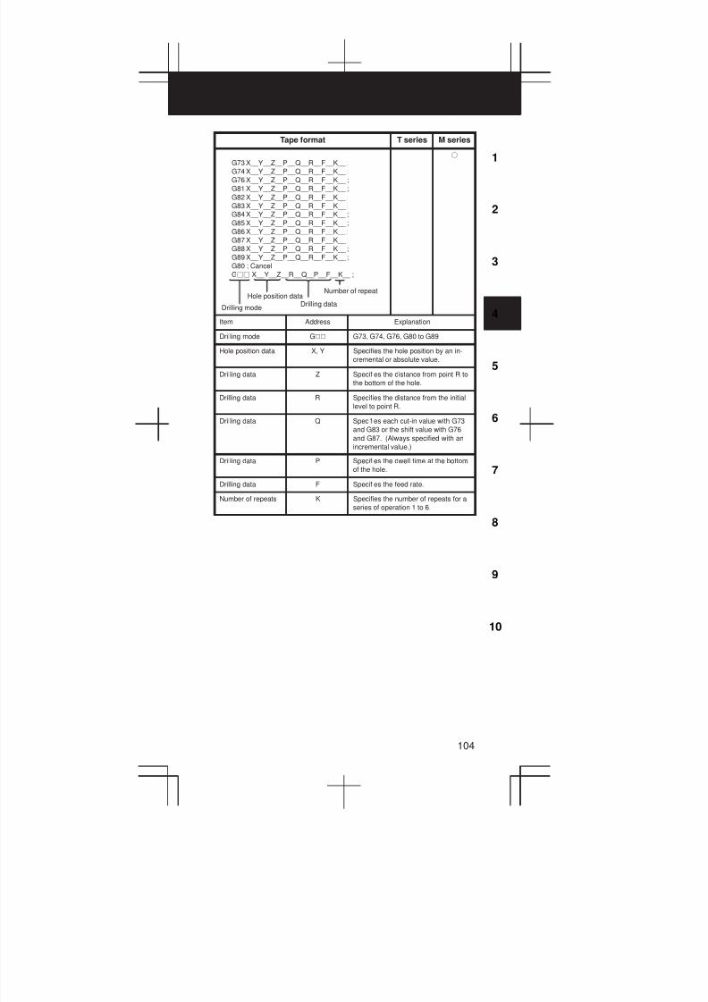
3
1
4
5
6
7
8
9
10
2
104
Tape format T series M series
Hole position dataDrilling data
Number of repeat
Drilling mode
G73 X__Y__Z__P__Q__R__F__K__ ;
G74 X__Y__Z__P__Q__R__F__K__ ;
G76 X__Y__Z__P__Q__R__F__K__ ;
G81 X__Y__Z__P__Q__R__F__K__ ;
G82 X__Y__Z__P__Q__R__F__K__ ;
G83 X__Y__Z__P__Q__R__F__K__ ;
G84 X__Y__Z__P__Q__R__F__K__ ;
G85 X__Y__Z__P__Q__R__F__K__ ;
G86 X__Y__Z__P__Q__R__F__K__ ;
G87 X__Y__Z__P__Q__R__F__K__ ;
G88 X__Y__Z__P__Q__R__F__K__ ;
G89 X__Y__Z__P__Q__R__F__K__ ;
G80 ; Cancel
Gjj X__Y__Z__R__Q__P__F__K__ ;
f
Item Address Explanation
Drilling mode GVV G73, G74, G76, G80 to G89
Hole position data X, Y Specifies the hole position by an in-
cremental or absolute value.
Drilling data Z Specifies the distance from point R to
the bottom of the hole.
Drilling data R Specifies the distance from the initial
level to point R.
Drilling data Q Specifies each cut-in value with G73
and G83 or the shift value with G76
and G87. (Always specified with an
incremental value.)
Drilling data P Specifies the dwell time at the bottom
of the hole.
Drilling data F Specifies the feed rate.
Number of repeats K Specifies the number of repeats for a
series of operation 1 to 6.
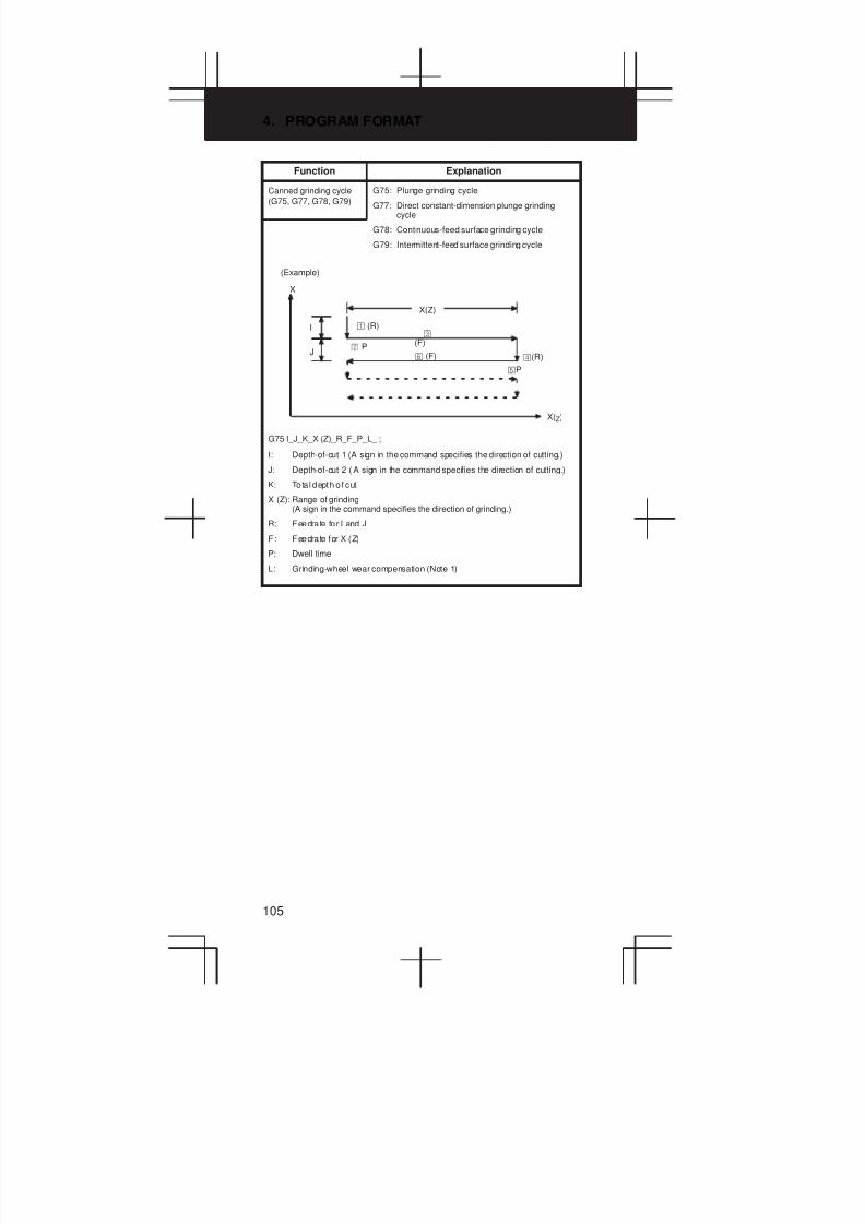
4. PROGRAM FORMAT
105
Function Explanation
Canned grinding cycle
(G75, G77, G78, G79)
G75: Plunge grinding cycle
G77: Direct constant-dimension plunge grindingcycle
G78: Continuous-feed surface grinding cycle
G79: Intermittent-feed surface grinding cycle
X
I
X(Z)
J
X(Z)
(R)
P
(F)
(R)
P
(F)
(Example)
G75 I_J_K_X (Z)_R_F_P_L_ ;
I: Depth-of-cut 1 (A sign in the command specifies the direction of cutting.)
J: Depth-of-cut 2 ( A sign in the command specifies the direction of cutting.)
K: Tota l depth of cut
X (Z): Range of grinding(A sign in the command specifies the direction of grinding.)
R: Feedrate for I and J
F: Feedrate for X (Z)
P: Dwell time
L: Grinding-wheel wear compensation (Note 1)
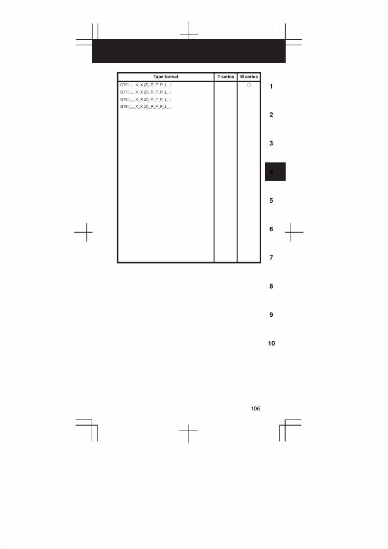
3
1
4
5
6
7
8
9
10
2
106
Tape format T series M series
G75 I_J_K_X (Z)_R_F_P_L_ ;
G77 I_J_K_X (Z)_R_F_P_L_ ;
G78 I_J_K_X (Z)_R_F_P_L_ ;
G79 I_J_K_X (Z)_R_F_P_L_ ;
f
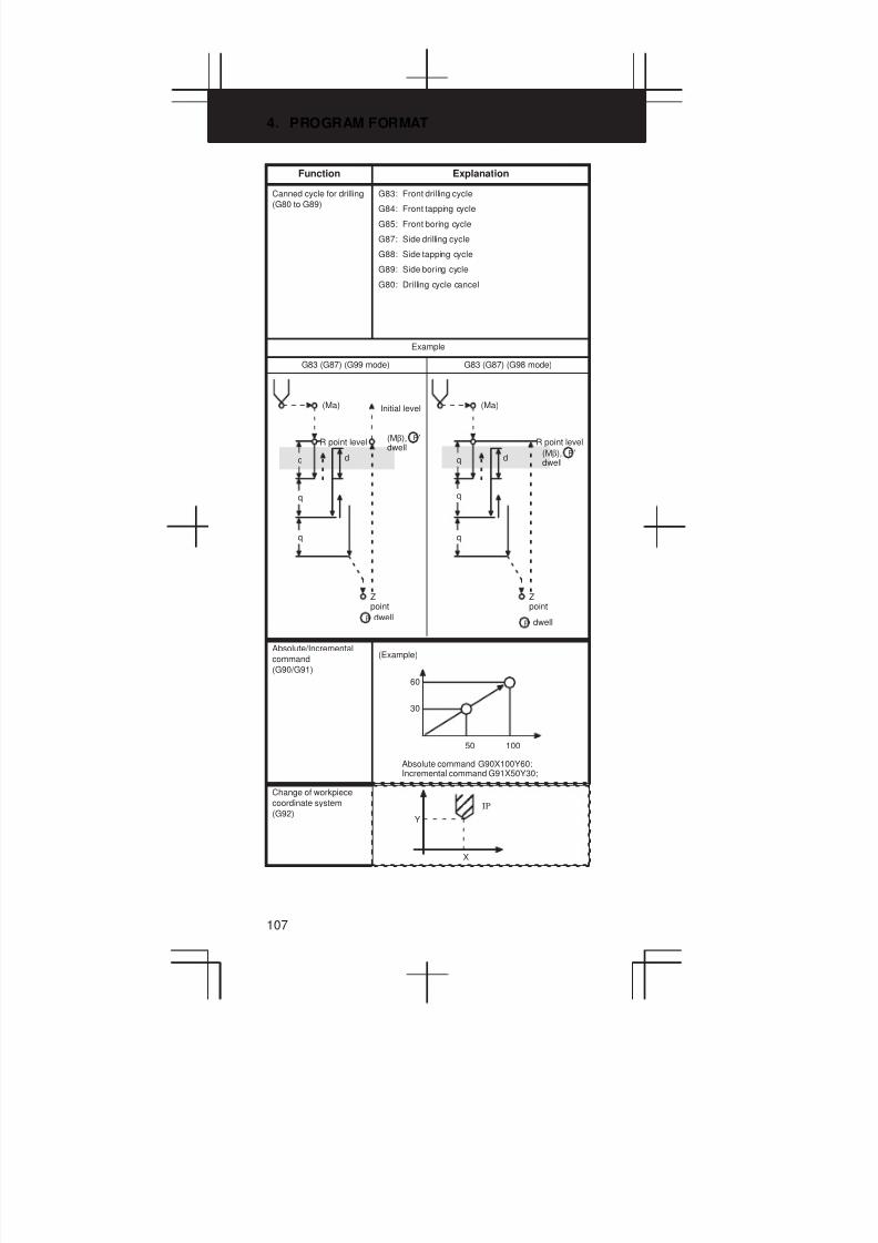
4. PROGRAM FORMAT
107
Function Explanation
Canned cycle for drilling
(G80 to G89)
G83: Front drilling cycle
G84: Front tapping cycle
G85: Front boring cycle
G87: Side drilling cycle
G88: Side tapping cycle
G89: Side boring cycle
G80: Drilling cycle cancel
Example
G83 (G87) (G99 mode) G83 (G87) (G98 mode)
q
(Ma)
d
Zpoint
R point level
q
q
(Ma)
d
Zpoint
q
q
R point level
Initial level
dwell
(Mβ), ’dwell
P
PdwellP
q
(Mβ), ’dwell
P
Absolute/Incremental
command
(G90/G91)
(Example)
60
30
50 100
Absolute command G90X100Y60;Incremental command G91X50Y30;
Change of workpiece
coordinate system
(G92)
Ç Ç
Ç Ç
Y
X
IP

3
1
4
5
6
7
8
9
10
2
108
Tape format T series M series
G83 X(Z)_C_Z(X)_R_Q_P_F_K_(M_) ;
G84 X(Z)_C_Z(X)_R_Q_P_F_K_(M_) ;
G86 X(Z)_C_Z(X)_R_Q_P_F_K_(M_) ;
G87 X(Z)_C_Z(X)_R_Q_P_F_K_(M_) ;
G88 X(Z)_C_Z(X)_R_Q_P_F_K_(M_) ;
G89 X(Z)_C_Z(X)_R_Q_P_F_K_(M_) ;
G80 ; Cancel
GVV X(Z)_C_Z(X)_R_Q_P_F_K_(MVV) ;
Hole positiondata
Drilling data
Number of repeat
Drilling mode
f
Designation Address Description
Drilling mode GVV G80, G83, G84, G86, G87, G88, G89
Hole position X/U(Z/W)C/H Specifies t he hole pos it ion by an in-
cremental or absolute value.
Drilling data Z(X) Specif ies the distance from point R to
the bottom of the hole.
R Specifies t he distance from the initial
level to point R level.
Q Specifies each cut-in value with G83
(G87). This value is always specified
with an incremental value to specify
radius.
P Specifies the dwell time at the bottom
of the hole.
F Specifies the feedrate.
Number of repeats K Specifies the number of repeats for a
series of operations.
M code of
C-axis clamp
MVV M-code (specified by a parameter) of
C-axis clamp.
G90_; Absolute command
G91_; Incremental command
G90_G91_; Change of workpiece coordinate system
f f
G92 _ ;IP f
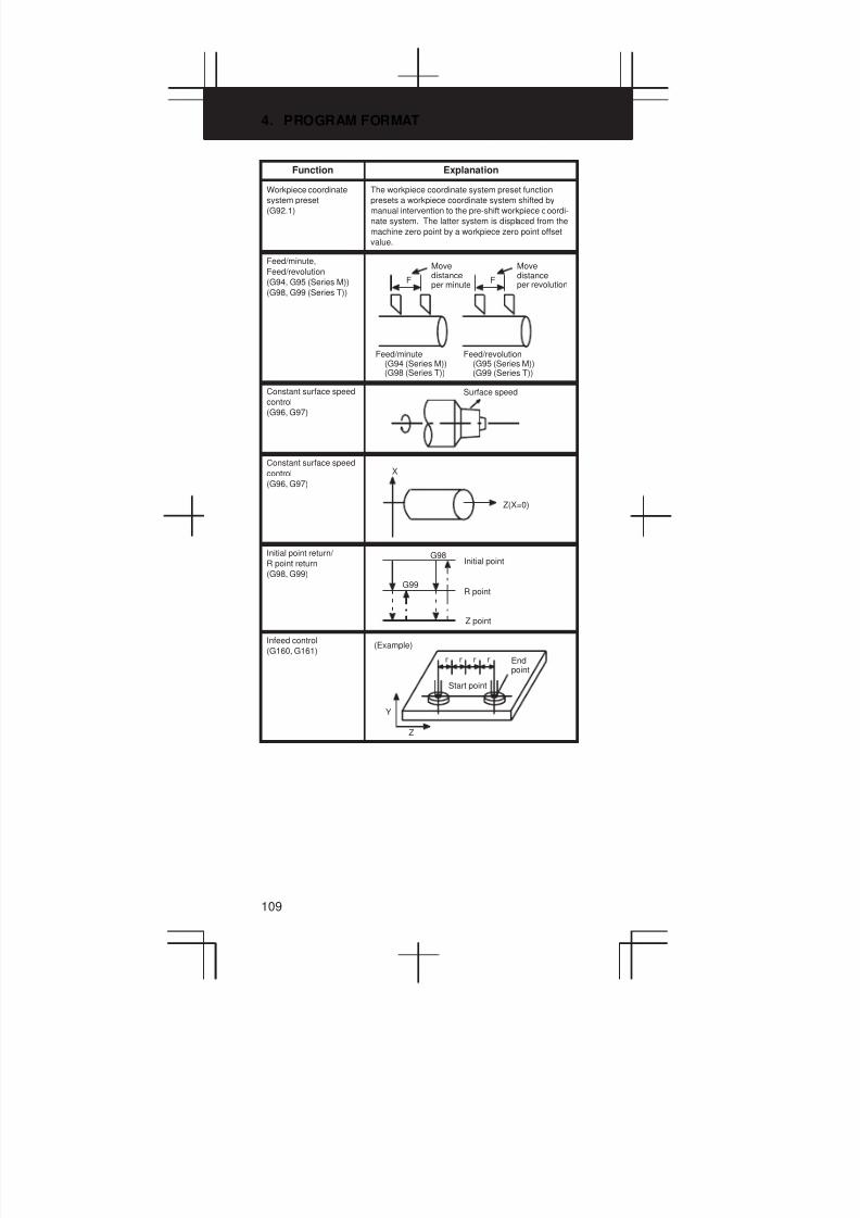
4. PROGRAM FORMAT
109
Function Explanation
Workpiece coordinate
system preset
(G92.1)
The workpiece coordinate system preset function
presets a workpiece coordinate system shifted by
manual intervention to the pre-shift workpiece coordi-
nate system. The latter system is displaced from the
machine zero point by a workpiece zero point offset
value.
Feed/minute,
Feed/revolution
(G94, G95 (Series M))
(G98, G99 (Series T))
F
Movedistanceper minute
F
Movedistanceper revolution
Feed/minute(G94 (Series M))(G98 (Series T))
Feed/revolution(G95 (Series M))(G99 (Series T))
Constant surface speed
control
(G96, G97)
Surface speed
Constant surface speed
control
(G96, G97)
X
Z(X=0)
Initial point return/
R point return
(G98, G99)
G98Initial point
R point
Z point
G99
Infeed control
(G160, G161)
Start point
(Example)
Endpoint
r r r r
Y
Z
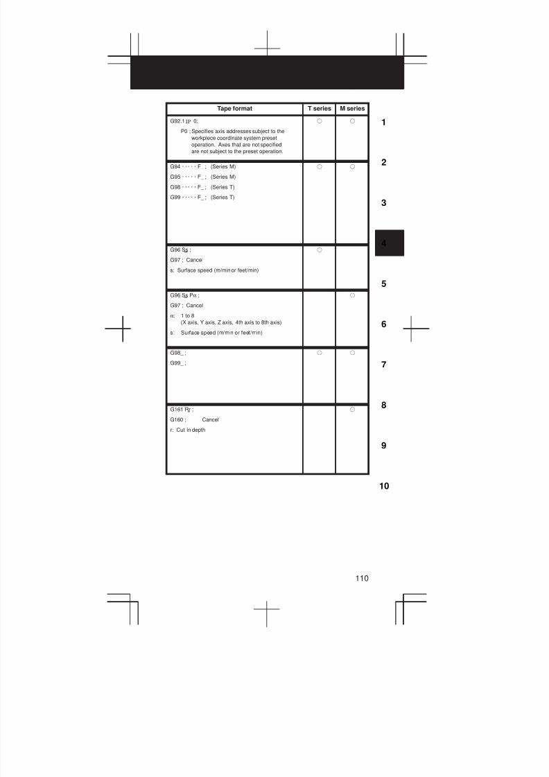
3
1
4
5
6
7
8
9
10
2
110
Tape format T series M series
G92.1 0;
P0 ; Specifies axis addresses subject to the
workpiece coordinate system preset
operation. Axes that are not specified
are not subject to the preset operation.
IP f f
G94 · · · · · F_ ; (Series M)
G95 · · · · · F_ ; (Series M)
G98 · · · · · F_ ; (Series T)
G99 · · · · · F_ ; (Series T)
f f
G96 Ss ;
G97 ; Cancel
s: Surface speed (m/min or feet/min)
f
G96 Ss Pα ;
G97 ; Cancel
α: 1 to 8
(X axis, Y axis, Z axis, 4th axis to 8th axis)
s: Surface speed (m/min or feet/min)
f
G98_ ;
G99_ ;
f f
G161 Rr ;
G160 ; Cancel
r: Cut in depth
f

5. CUSTOM MACRO
111
5.1 Types of Variables
Type of variable Variable number
Local variable #1 – #33
Common variable #100 – #149
#500 – #531
Additional common variable (Note 1) #100 – #199
#500 – #999
System variable (Note 2) #1000 – #19099
NOTE1 Common variables #150 to #199 and #532 to #999 can be added.
Part program length reduces by 8.5 m.
NOTE2 Details are shown in 5.2.
5.2 System Variable
Variable
numberContents Purpose Series
#1000–#1015 Corresponds to UI000 to UI015 Interface input
i l
T/M
#1032 Unified input of UI000 to UO015 signal
#1100–#1115 Corresponds to UO000 to
UO015
Interface
output signal
T/M
#1132 Unified output of UO000 to
UO015
#1133 Unified output of UO100 to
UO131
#2001–#2064 Wear offset value
(Offset No. 1–64)
X axis offset T
#2701–#2749 Geometry offset value
(Offset No. 1–49)
#10001–#10099 Wear offset value
(Offset No. 1–99)
#15001–#15099 Geometry offset value
(Offset No. 1–99)
#2101–#2164 Wear offset value
(Offset No. 1–64)
Z axis offset T
#2801–#2849 Geometry offset value
(Offset No. 1–49)
#11001–#11099 Wear offset value
(Offset No. 1–99)
#16001–#16099 Geometry offset value
(Offset No. 1–99)
#2201–#2264 Wear offset value
(Offset No. 1–64)
Tool nose
radius com-
i
T
#2901–#2969 Geometry offset value
(Offset No. 1–64)
pensation
#12001–#12099 Wear offset value
(Offset No. 1–99)
#17001–#17099 Geometry offset value
(Offset No. 1–99)
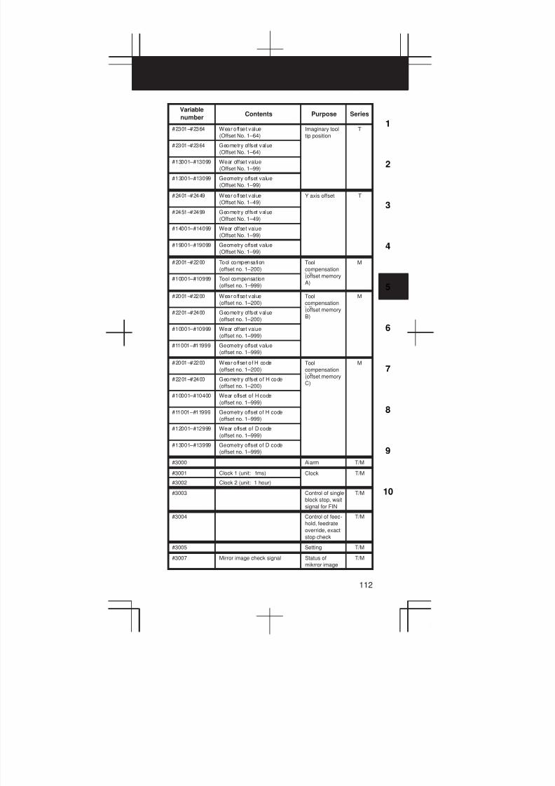
3
1
4
5
6
7
8
9
10
2
112
Variable
numberSeriesPurposeContents
#2301–#2364 Wear offset value
(Offset No. 1–64)
Imaginary tool
tip position
T
#2301–#2364 Geometry offset value
(Offset No. 1–64)
#13001–#13099 Wear offset value
(Offset No. 1–99)
#13001–#13099 Geometry offset value
(Offset No. 1–99)
#2401–#2449 Wear offset value
(Offset No. 1–49)
Y axis offset T
#2451–#2499 Geometry offset value
(Offset No. 1–49)
#14001–#14099 Wear offset value
(Offset No. 1–99)
#19001–#19099 Geometry offset value
(Offset No. 1–99)
#2001–#2200 Tool compensation
(offset no. 1–200)
Tool
compensation
M
#10001–#10999 Tool compensation
(offset no. 1–999)
(offset memory
A)
#2001–#2200 Wear offset value
(offset no. 1–200)
Tool
compensation
M
#2201–#2400 Geometry offset value
(offset no. 1–200)
(offset memory
B)
#10001–#10999 Wear offset value
(offset no. 1–999)
#11001–#11999 Geometry offset value
(offset no. 1–999)
#2001–#2200 Wear offset of H code
(offset no. 1–200)
Tool
compensation
M
#2201–#2400 Geometry offset of H code
(offset no. 1–200)
(offset memory
C)
#10001–#10400 Wear offset of H code
(offset no. 1–999)
#11001–#11999 Geometry offset of H code
(offset no. 1–999)
#12001–#12999 Wear offset of D code
(offset no. 1–999)
#13001–#13999 Geometry offset of D code
(offset no. 1–999)
#3000 Alarm T/M
#3001 Clock 1 (unit: 1ms) Clock T/M
#3002 Clock 2 (unit: 1 hour)
#3003 Control of single
block stop, wait
signal for FIN
T/M
#3004 Control of feed-
hold, feedrate
override, exact
stop check
T/M
#3005 Setting T/M
#3007 Mirror image check signal Status of
mikrror image
T/M
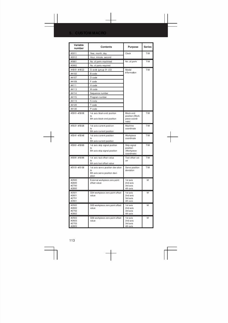
5. CUSTOM MACRO
113
Variable
numberSeriesPurposeContents
#3011 Year, month, day Clock T/M
#3012 Hour, minute, second
#3901 No. of parts machined No. of parts T/M
#3902 No. of parts required
#4001–#4022 G code (group 01–22) Modal
i i
T/M
#4102 B codeinformation
#4107 D code
#4109 F code
#4111 H code
#4113 M code
#4114 Sequence number
#4115 Program number
#4119 S code
#4120 T code
#4130 P code
#5001–#5008 1st axis block end position
to
8th axis block end position
Block end
position (Work-
piece coordi-
nate)
T/M
#5021–#5028 1st axis current position
to
8th axis current position
Machine
coordinate
T/M
#5041–#5048 1st axis current position
to
8th axis current position
Workpiece
coordinate
T/M
#5061–#5068 1st axis skip signal position
to
8th axis skip signal position
Skip signal
position
(Workpiece
coordinate)
T/M
#5081–#5088 1st axis tool offset value
to
8th axis tool offset value
Tool offset val-
ue
T/M
#5101–#5108 1st axis servo position deviation
to
8th axis servo position devi-
ation
Servo position
deviation
T/M
#2500
#2600
#2700
#2800
External workpiece zero point
offset value
1st axis
2nd axis
3rd axis
4th axis
M
#2501
#2601
#2701
#2801
G54 workpiece zero point offset
value
1st axis
2nd axis
3rd axis
4th axis
M
#2502
#2602
#2702
#2802
G55 workpiece zero point offset
value
1st axis
2nd axis
3rd axis
4th axis
M
#2503
#2603
#2703
#2803
G56 workpiece zero point offset
value
1st axis
2nd axis
3rd axis
4th axis
M
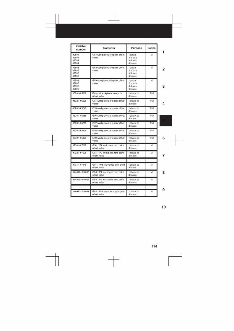
3
1
4
5
6
7
8
9
10
2
114
Variable
numberSeriesPurposeContents
#2504
#2604
#2704
#2804
G57 workpiece zero point offset
value
1st axis
2nd axis
3rd axis
4th axis
M
#2505
#2605
#2705
#2805
G58 workpiece zero point offset
value
1st axis
2nd axis
3rd axis
4th axis
M
#2506
#2606
#2706
#2806
G59 workpiece zero point offset
value
1st axis
2nd axis
3rd axis
4th axis
M
#5201–#5208 External workpiece zero point
offset value
1st axis to
8th axis
T/M
#5221–#5228 G54 workpiece zero point offset
value
1st axis to
8th axis
T/M
#5241–#5248 G55 workpiece zero point offset
value
1st axis to
8th axis
T/M
#5261–#5268 G56 workpiece zero point offset
value
1st axis to
8th axis
T/M
#5281–#5288 G57 workpiece zero point offset
value
1st axis to
8th axis
T/M
#5301–#5308 G58 workpiece zero point offset
value
1st axis to
8th axis
T/M
#5321–#5328 G59 workpiece zero point offset
value
1st axis to
8th axis
T/M
#7001–#7008 G54.1 P1 workpiece zero point
offset value
1st axis to
8th axis
M
#7021–#7028 G54.1 P2 workpiece zero point
offset value
1st axis to
8th axis
M
: :
#7941–#7948 G54.1 P48 workpiece zero point
offset value
1st axis to
8th axis
M
#14001–#14008 G54.1 P1 workpiece zero point
offset value
1st axis to
8th axis
M
#14021–#14028 G54.1 P2 workpiece zero point
offset value
1st axis to
8th axis
M
: :
#19980–#19988 G54.1 P48 workpiece zero point
offset value
1st axis to
8th axis
M

5. CUSTOM MACRO
115
5.3 Argument Assignment I/II
Correspondence Table between
Argument Assignment I Addresses and
Macro Variables
Correspondence Table between
Argument Assignment II Addresses
and Macro Variables
Argument
Assignment I
Addresses
Macro
Variables
Argument
Assignment II
Addresses
Macro
Variables
A #1 A #1
B #2 B #2
C #3 C #3
D #7 I1 #4
E #8 J1 #5
F #9 K1 #6
H #11 I2 #7
I #4 J2 #8
J #5 K2 #9
K #6 I3 #10
M #13 J3 #11
Q #17 K3 #12
R #18 I4 #13
S #19 J4 #14
T #20 K4 #15
U #21 I5 #16
V #22 J5 #17
W #23 K5 #18
X #24 I6 #19
Y #25 J6 #20
Z #26 K6 #21
I7 #22
J7 #23
K7 #24
I8 #25
J8 #26
K8 #27
I9 #28
J9 #29
K9 #30
I10 #31
J10 #32
K10 #33
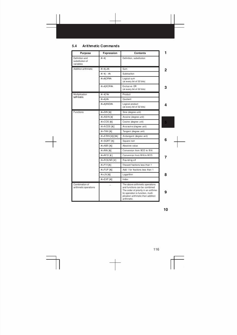
3
1
4
5
6
7
8
9
10
2
116
5.4 Arithmetic Commands
Purpose Expression Contents
Definition and
substitution of
variables
#i=#j Definition, substitution
Addition arithmetic #i=#j+#k Sum
#i=#j – #k Subtraction
#i=#jOR#k Logical sum
(at every bit of 32 bits)
#i=#jXOR#k Exclusive OR
(at every bit of 32 bits)
Multiplication
i i
#i=#j*#k Product
ari me i c#i=#j/#k Quotient
#i=#jAND#k Logical product
(at every bit of 32 bits)
Functions #i=SIN [#j] Sine (degree unit)
#i=ASIN [#j] Arcsine (degree unit)
#i=COS [#j] Cosine (degree unit)
# i=ACOS [#j ] Arccos ine (degree un it )
#i=TAN [#j] Tangent (degree unit)
#i=ATAN [#j]/[#k] Arctangent (degree unit)
#i=SQRT [#j] Square root
#i=ABS [#j] Absolute value
#i=BIN [#j] Conversion from BCD to BIN
#i=BCD [#j] Convers ion from BIN to BCD
#i=ROUND [#j] Rounding off
#i=FIX [#j] Discard f ractions less than 1
#i=FUP [#j] Add 1 for fractions less than 1
#i=LN [#j] Logarithm
#i=EXP [#j] Index
Combination of
arithmetic operations– The above arithmetic operations
and functions can be combined.
The order of priority in an arithme-
tic operation is function, multi-
plication arithmetic then addition
arithmetic.

5. CUSTOM MACRO
117
5.5 Control Command
Purpose ExpressionKind of
operation
Conditional branch IF [<conditional expression>] #j EQ #k (=)
n#j NE #k (0)
Conditional execution
.
IF <conditional expression>#j GT #k (>)
i i l i i i l i
THEN st #j LT #k (<)
Execute macro statement st. #j GE #k (y)
#j LE #k (x)
Iteration WHILE [<conditional expres-
i
#j EQ #k (=)
sion> m
=#j NE #k (0)
= , ,
If omitted conditional expression#j GT #k (>)
i i i l i ,
blocks from DO m to END m are
ll
#j LT #k (<)
executed eternally.#j GE #k (y)
#j LE #k (x)
5.6 Macro Call
Name FormatProgram
No.
Parame-
ter No.Remarks
Simple
call
G65P (program number)
L (repetition count)
<argument assignment>
Refer to 5.3 for
argument
assignment.
Modal
call
G66P (program number)
L (repetition count)
<argument assignment>
Macro
call by
Gxx
<argument assignment>
9010
to
6050
to
Refer to 5.3 for
argument
i
co eMax. 10 G codes from
G01–G64 and
G68–G9999
9019 6059
assignmen .
Set G or M code
that calls a pro-
p i i iMacro
call by
Mxx
<argument assignment>
9020
to
6080
to
i i i
the parameter.
co eMax. 10 M codes from
M006 to M999999999029 6089
Sub-
pro-
gram
ll
Mxx ; 9001
to
6071
to
Displayed on pro-
gram check screen
but no MF nor M
i
call by
M codeMxx ;
Max. 9 M codes from
M006–M99999999
9009 6079 code is sent.
Set an M code that
calls a sub-pro-
gram specified by
the parameter.
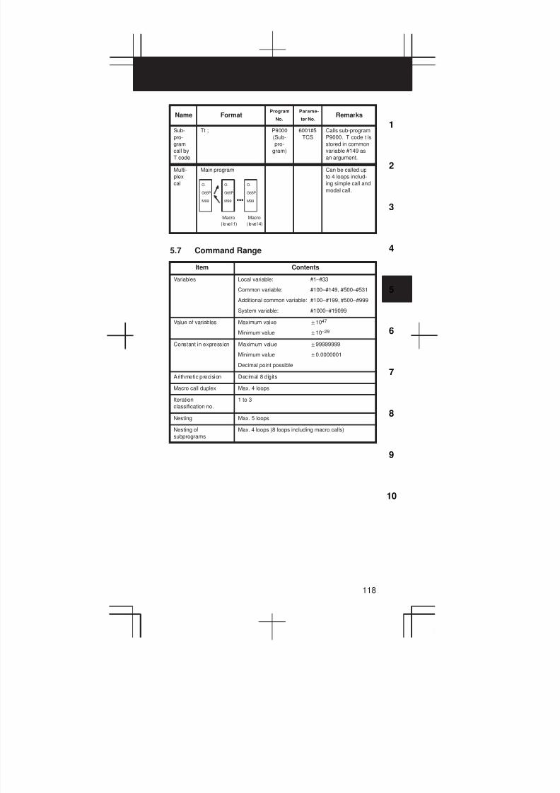
3
1
4
5
6
7
8
9
10
2
118
Name RemarksParame-
ter No.
Program
No.Format
Sub-
pro-
gram
call by
T code
Tt ; P9000
(Sub-
pro-
gram)
6001#5
TCS
Calls sub-program
P9000. T code t is
stored in common
variable #149 as
an argument.
Multi-
plex
call
Main program
O.
G65P.
M99
O.
G65P.
M99 DDD
O.
G65P.
M99
Macro Macro
( leve l 1) ( leve l 4)
Can be called up
to 4 loops includ-
ing simple call and
modal call.
5.7 Command Range
Item Contents
Variables Local variable: #1–#33
Common variable: #100–#149, #500–#531
Additional common variable: #100–#199, #500–#999
System variable: #1000–#19099
Value of variables Maximum value "1047
Minimum value "10 –29
Constant in expression Maximum value "99999999
Minimum value "0.0000001
Decimal point possible
Arithmetic precision Decimal 8 digits
Macro call duplex Max. 4 loops
Iteration
classification no.
1 to 3
Nesting Max. 5 loops
Nesting of
subprograms
Max. 4 loops (8 loops including macro calls)
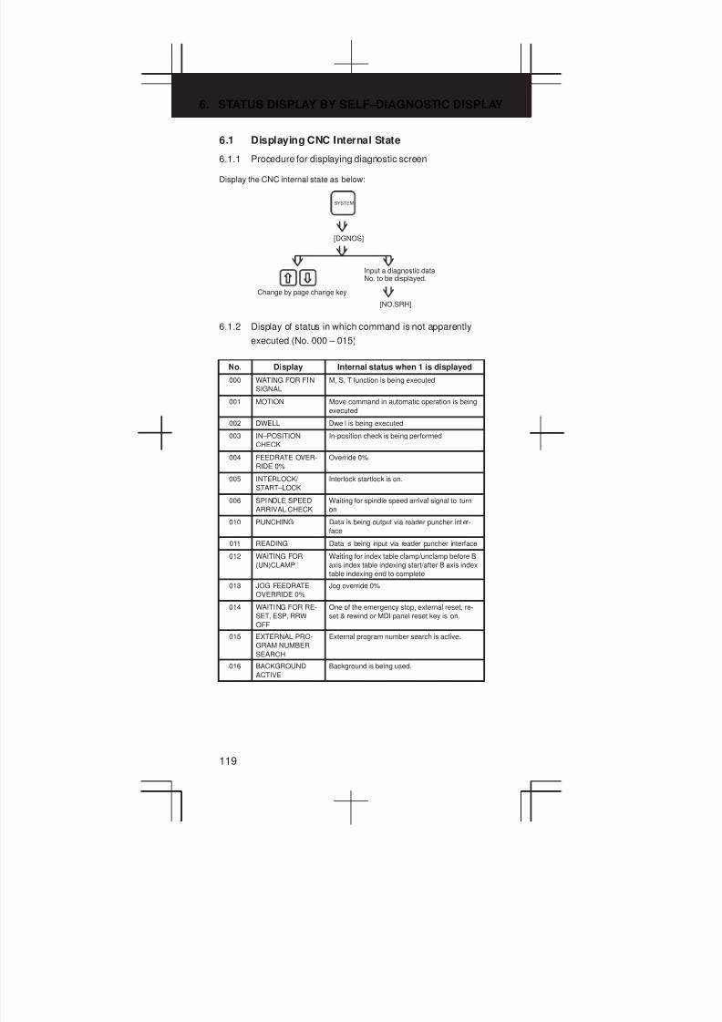
6. STATUS DISPLAY BY SELF–DIAGNOSTIC DISPLAY
119
6.1 Displaying CNC Internal State
6.1.1 Procedure for displaying diagnostic screen
Display the CNC internal state as below:
Change by page change key
Input a diagnostic dataNo. to be displayed.
[NO.SRH]
SYSTEM
[DGNOS]
6.1.2 Display of status in which command is not apparently
executed (No. 000 – 015)
No. Display Internal status when 1 is displayed
000 WATING FOR FIN
SIGNAL
M, S, T function is being executed
001 MOTION Move command in automatic operation is being
executed
002 DWELL Dwell is being executed
003 IN–POSITION
CHECK
In-position check is being performed
004 FEEDRATE OVER-
RIDE 0%
Override 0%
005 INTERLOCK/
START–LOCK
Interlock startlock is on.
006 SPINDLE SPEED
ARRIVAL CHECK
Waiting for spindle speed arrival signal to turn
on
010 PUNCHING Data is being output via reader puncher inter-
face
011 READING Data is being input via reader puncher interface
012 WAITING FOR
(UN)CLAMP
Waiting for index table clamp/unclamp before B
axis index table indexing start/after B axis index
table indexing end to complete
013 JOG FEEDRATE
OVERRIDE 0%
Jog override 0%
014 WAITING FOR RE-
SET, ESP, RRW
OFF
One of the emergency stop, external reset, re-
set & rewind or MDI panel reset key is on.
015 EXTERNAL PRO-
GRAM NUMBER
SEARCH
External program number search is active.
016 BACKGROUND
ACTIVE
Background is being used.

3
1
4
5
6
7
8
9
10
2
120
6.1.3 Information indicating automatic operation stop, automatic
idle statuses (No. 020 – 025)
No. Display Internal status when 1 is displayed
020 CUT SPEED UP/
DOWN
Set when emergency stop turns on or when ser-
vo alarm occurs
021 RESET BUTTON
ON
Set when reset key turns on
022 RESET AND
REWIND ON
Reset and rewind turned on
023 EMERGENCY
STOP ON
Set when emergency stop turns on
024 RESET ON Set when external reset, emergency stop, reset
or reset & rewind key is on.
025 STOP MOTION OR
DWELL
A flag which stops pulse distribution. It is set to
1 in the following cases.
(1) External reset is set to on.
(2) Reset & rewind is set to on.
(3) Emergency stop is set to on.
(4) Feed hold is set to on.
(5) The MDI panel reset key turned on.
(6) Switched to the manual mode(JOG/HANDLE/INC).
(7) Other alarm occurred.(There is also an alarm which is not set.)
Causes for cycle start LED turned off
020 CUT SPEED UP/DOWN 1 0 0 0 1 0 0
021 RESET BUTTON ON 0 0 1 0 0 0 0
022 RESET AND REWIND ON 0 0 0 1 0 0 0
023 EMERGENCY STOP ON 1 0 0 0 0 0 0
024 RESET ON 1 1 1 1 0 0 0
025 STOP MOTION OR DWELL 1 1 1 1 1 1 0
Emergency stop signal input
External reset signal input
MDI reset button turned on
Reset & rewind input
Servo alarm generation
Changed to another mode or feed hold
Single block stop
6.1.4 TH alarm statuses (No. 030, 031)
No. Display Internal status when 1 is displayed
030 CHARACTER
NUMBER TH DATA
The position of the character which turned TH
alarm on is displayed in the number of charac-
ters from the beginning of the block at TH
alarm.
031 TH DATA Read code of character which turned TH alarm
on
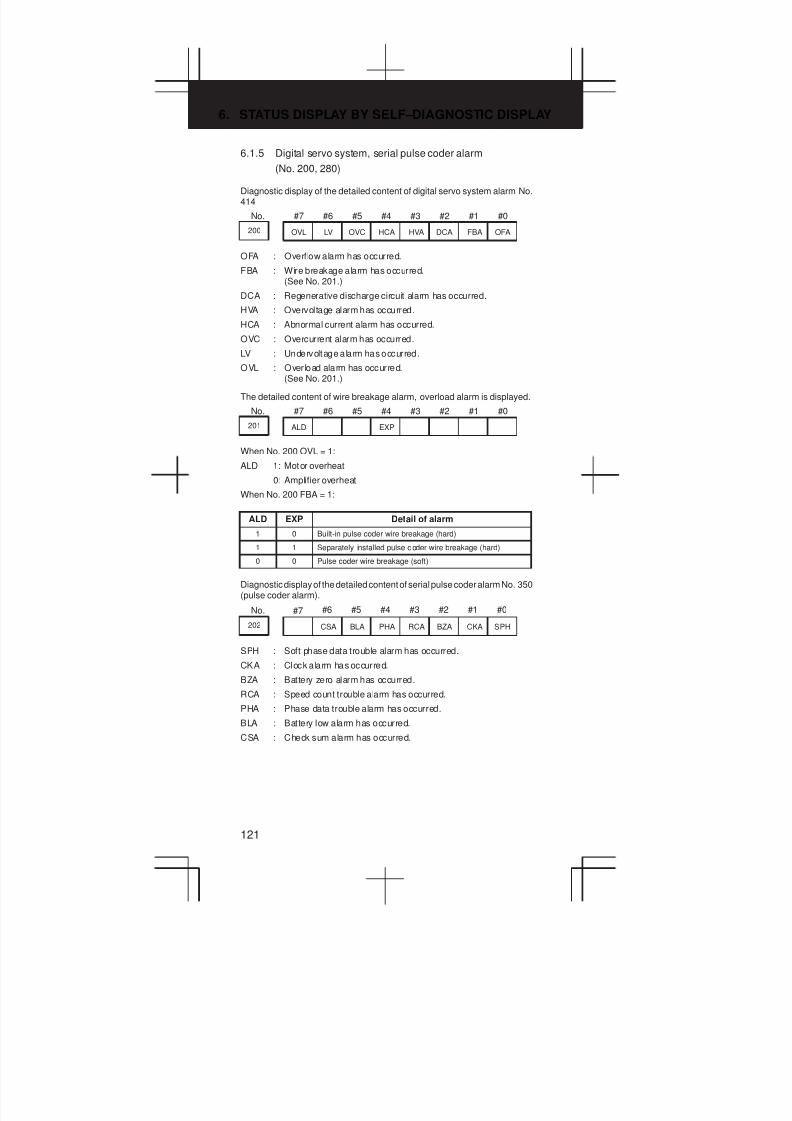
6. STATUS DISPLAY BY SELF–DIAGNOSTIC DISPLAY
121
6.1.5 Digital servo system, serial pulse coder alarm
(No. 200, 280)
Diagnostic display of the detailed content of digital servo system alarm No.414
No. #7 #6 #5 #4 #3 #2 #1 #0
200 OVL LV OVC HCA HVA DCA FBA OFA
OFA : Overflow alarm has occurred.
FBA : Wire breakage alarm has occurred.(See No. 201.)
DCA : Regenerative discharge circuit alarm has occurred.
HVA : Overvoltage alarm has occurred.
HCA : Abnormal current alarm has occurred.
OVC : Overcurrent alarm has occurred.
LV : Undervoltage alarm has occurred.
OVL : Overload alarm has occurred.(See No. 201.)
The detailed content of wire breakage alarm, overload alarm is displayed.
No. #7 #6 #5 #4 #3 #2 #1 #0
201 ALD EXP
When No. 200 OVL = 1:
ALD 1: Motor overheat
0: Amplifier overheat
When No. 200 FBA = 1:
ALD EXP Detail of alarm
1 0 Built-in pulse coder wire breakage (hard)
1 1 Separately installed pulse coder wire breakage (hard)
0 0 Pulse coder wire breakage (soft)
Diagnostic display of the detailed content of serial pulse coder alarm No. 350(pulse coder alarm).
BZARCAPHA
No.
202 CSA BLA CKA SPH
#7 #6 #5 #4 #3 #2 #1 #0
SPH : Soft phase data trouble alarm has occurred.
CKA : Clock alarm has occurred.
BZA : Battery zero alarm has occurred.
RCA : Speed count trouble alarm has occurred.
PHA : Phase data trouble alarm has occurred.
BLA : Battery low alarm has occurred.
CSA : Check sum alarm has occurred.
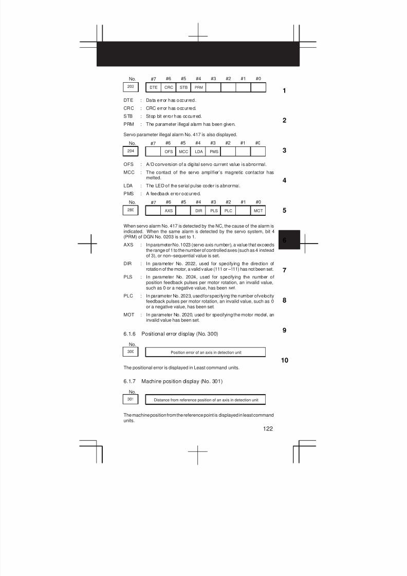
3
1
4
5
6
7
8
9
10
2
122
No.
203 DTE CRC STB PRM
#7 #6 #5 #4 #3 #2 #1 #0
DTE : Data error has occurred.
CRC : CRC error has occurred.
STB : Stop bit error has occurred.
PRM : The parameter illegal alarm has been given.
Servo parameter illegal alarm No. 417 is also displayed.
No.
204 OFS MCC LDA PMS
#7 #6 #5 #4 #3 #2 #1 #0
OFS : A/D conversion of a digital servo current value is abnormal.
MCC : The contact of the servo amplifier’s magnetic contactor hasmelted.
LDA : The LED of the serial pulse coder is abnormal.
PMS : A feedback error occurred.
No.
280 AXS DIR PLS PLC MOT
#7 #6 #5 #4 #3 #2 #1 #0
When servo alarm No. 417 is detected by the NC, the cause of the alarm isindicated. When the same alarm is detected by the servo system, bit 4(PRM) of DGN No. 0203 is set to 1.
AXS : In parameter No. 1023 (servo axis number), a value that exceedsthe range of 1 to the number of controlled axes (such as 4 insteadof 3), or non–sequential value is set.
DIR : In parameter No. 2022, used for specifying the direction ofrotation of the motor, a valid value (111 or –111) has not been set.
PLS : In parameter No. 2024, used for specifying the number ofposition feedback pulses per motor rotation, an invalid value,such as 0 or a negative value, has been set.
PLC : In parameter No. 2023, used for specifying the number of velocityfeedback pulses per motor rotation, an invalid value, such as 0or a negative value, has been set.
MOT : In parameter No. 2020, used for specifying the motor model, aninvalid value has been set.
6.1.6 Positional error display (No. 300)
No.
300 Position error of an axis in detection unit
The positional error is displayed in Least command units.
6.1.7 Machine position display (No. 301)
No.
301 Distance from reference position of an axis in detection unit
The machine position from the reference point is displayed in least commandunits.
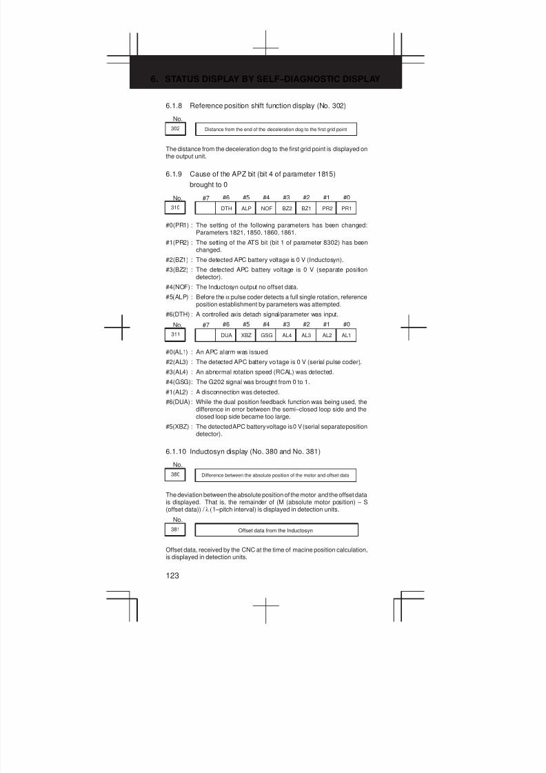
6. STATUS DISPLAY BY SELF–DIAGNOSTIC DISPLAY
123
6.1.8 Reference position shift function display (No. 302)
No.
302 Distance from the end of the deceleration dog to the first grid point
The distance from the deceleration dog to the first grid point is displayed onthe output unit.
6.1.9 Cause of the APZ bit (bit 4 of parameter 1815)
brought to 0
No. #7 #6 #5 #4 #3 #2 #1 #0
310 DTH ALP NOF BZ2 BZ1 PR2 PR1
#0(PR1) : The setting of the following parameters has been changed:Parameters 1821, 1850, 1860, 1861.
#1(PR2) : The setting of the ATS bit (bit 1 of parameter 8302) has beenchanged.
#2(BZ1) : The detected APC battery voltage is 0 V (Inductosyn).
#3(BZ2) : The detected APC battery voltage is 0 V (separate positiondetector).
#4(NOF) : The Inductosyn output no offset data.
#5(ALP) : Before the α pulse coder detects a full single rotation, referenceposition establishment by parameters was attempted.
#6(DTH) : A controlled axis detach signal/parameter was input.
No. #7 #6 #5 #4 #3 #2 #1 #0
311 DUA XBZ GSG AL4 AL3 AL2 AL1
#0(AL1) : An APC alarm was issued.
#2(AL3) : The detected APC battery voltage is 0 V (serial pulse coder).
#3(AL4) : An abnormal rotation speed (RCAL) was detected.
#4(GSG): The G202 signal was brought from 0 to 1.
#1(AL2) : A disconnection was detected.
#6(DUA): While the dual position feedback function was being used, thedifference in error between the semi–closed loop side and theclosed loop side became too large.
#5(XBZ) : The detected APC battery voltage is 0 V (serial separate positiondetector).
6.1.10 Inductosyn display (No. 380 and No. 381)
No.
380 Difference between the absolute position of the motor and offset data
The deviation between the absolute position of the motor and the offset datais displayed. That is, the remainder of (M (absolute motor position) – S(offset data)) / l (1–pitch interval) is displayed in detection units.
No.
381 Offset data from the Inductosyn
Offset data, received by the CNC at the time of macine position calculation,is displayed in detection units.
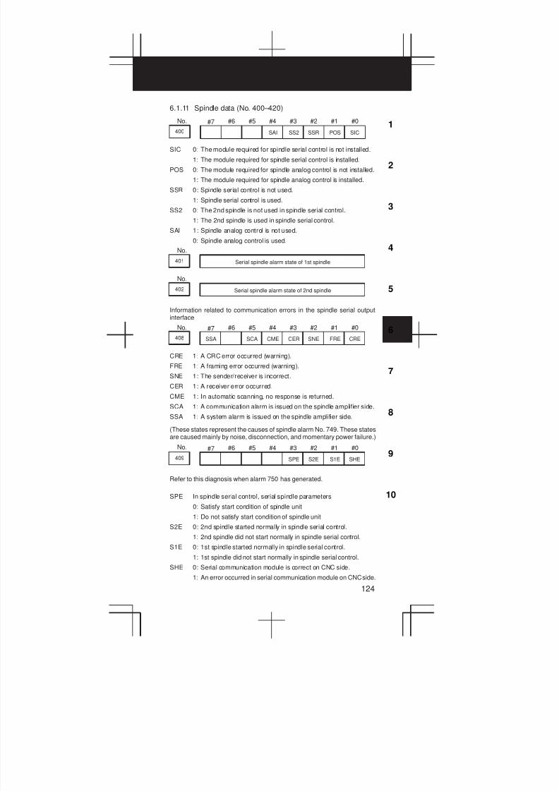
3
1
4
5
6
7
8
9
10
2
124
6.1.11 Spindle data (No. 400–420)
No. #7 #6 #5 #4 #3 #2 #1 #0
400 SAI SS2 SSR POS SIC
SIC 0: The module required for spindle serial control is not installed.
1: The module required for spindle serial control is installed.
POS 0: The module required for spindle analog control is not installed.
1: The module required for spindle analog control is installed.
SSR 0: Spindle serial control is not used.
1: Spindle serial control is used.
SS2 0: The 2nd spindle is not used in spindle serial control.
1: The 2nd spindle is used in spindle serial control.
SAI 1: Spindle analog control is not used.
0: Spindle analog control is used.
No.
401 Serial spindle alarm state of 1st spindle
No.
402 Serial spindle alarm state of 2nd spindle
Information related to communication errors in the spindle serial outputinterface
No. #7 #6 #5 #4 #3 #2 #1 #0
408 SSA SCA CME CER SNE FRE CRE
CRE 1: A CRC error occurred (warning).
FRE 1: A framing error occurred (warning).
SNE 1: The sender/receiver is incorrect.
CER 1: A receiver error occurred.
CME 1: In automatic scanning, no response is returned.
SCA 1: A communication alarm is issued on the spindle amplifier side.
SSA 1: A system alarm is issued on the spindle amplifier side.
(These states represent the causes of spindle alarm No. 749. These statesare caused mainly by noise, disconnection, and momentary power failure.)
No. #7 #6 #5 #4 #3 #2 #1 #0
409 SPE S2E S1E SHE
Refer to this diagnosis when alarm 750 has generated.
SPE In spindle serial control, serial spindle parameters
0: Satisfy start condition of spindle unit
1: Do not satisfy start condition of spindle unit
S2E 0: 2nd spindle started normally in spindle serial control.
1: 2nd spindle did not start normally in spindle serial control.
S1E 0: 1st spindle started normally in spindle serial control.
1: 1st spindle did not start normally in spindle serial control.
SHE 0: Serial communication module is correct on CNC side.
1: An error occurred in serial communication module on CNC side.

6. STATUS DISPLAY BY SELF–DIAGNOSTIC DISPLAY
125
No.
410 Display of the load meter for the 1st spindle (%)
No.
411 Display of the speed meter for the 1st spindle (rpm)
No.
412 Display of the load meter for the 2nd spindle (%)
No.
413 Display of the speed meter for the 2nd spindle (rpm)
No.
414 Position error in 1st spindle synchronous control mode
Motion error on the 1st spindle during synchronous control
No.
415 Position error in 2nd spindle synchronous control mode
No.
416 Absolute value of synchronization error between 1st and 2nd spindles
Absolute value of the synchronous error between the 1st and the 2nd spindlesynchronous control
No.
417 Feedback information of 1st spindle position coder
Data returned by the 1st spindle position coder
No.
418 Position error of 1st spindle position loop mode
Positional shift of the 1st spindle in each mode, including a positional loop
No.
419 Feedback information of 2nd spindle position coder
Data returned by the 2nd spindle position coder
No.
420 Feedback information of 2nd spindle position coder
Positional shift of the 2nd spindle in each mode, including a positional loop
The above four DGN items (No. 417 to 420) directly display the data receivedfrom the serial spindle control unit.
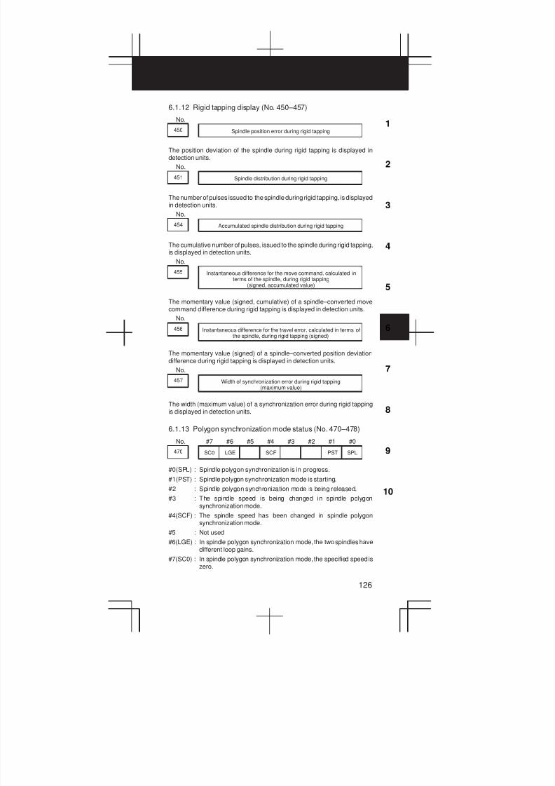
3
1
4
5
6
7
8
9
10
2
126
6.1.12 Rigid tapping display (No. 450–457)
No.
450 Spindle position error during rigid tapping
The position deviation of the spindle during rigid tapping is displayed indetection units.
No.
451 Spindle distribution during rigid tapping
The number of pulses issued to the spindle during rigid tapping, is displayedin detection units.
No.
454 Accumulated spindle distribution during rigid tapping
The cumulative number of pulses, issued to the spindle during rigid tapping,is displayed in detection units.
No.
455 Instantaneous difference for the move command, calculated interms of the spindle, during rigid tapping
(signed, accumulated value)
The momentary value (signed, cumulative) of a spindle–converted movecommand difference during rigid tapping is displayed in detection units.
No.
456 Instantaneous difference for the travel error, calculated in terms ofthe spindle, during rigid tapping (signed)
The momentary value (signed) of a spindle–converted position deviationdifference during rigid tapping is displayed in detection units.
No.
457 Width of synchronization error during rigid tapping(maximum value)
The width (maximum value) of a synchronization error during rigid tappingis displayed in detection units.
6.1.13 Polygon synchronization mode status (No. 470–478)
No. #7 #6 #5 #4 #3 #2 #1 #0
470 SC0 LGE SCF PST SPL
#0(SPL) : Spindle polygon synchronization is in progress.
#1(PST) : Spindle polygon synchronization mode is starting.
#2 : Spindle polygon synchronization mode is being released.
#3 : The spindle speed is being changed in spindle polygonsynchronization mode.
#4(SCF) : The spindle speed has been changed in spindle polygonsynchronization mode.
#5 : Not used
#6(LGE) : In spindle polygon synchronization mode, the two spindles havedifferent loop gains.
#7(SC0) : In spindle polygon synchronization mode, the specified speed iszero.
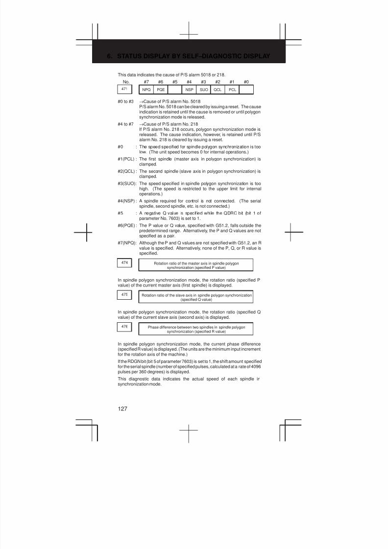
6. STATUS DISPLAY BY SELF–DIAGNOSTIC DISPLAY
127
This data indicates the cause of P/S alarm 5018 or 218.
No. #7 #6 #5 #4 #3 #2 #1 #0
471 NPQ PQE NSP SUO QCL PCL
#0 to #3 →Cause of P/S alarm No. 5018P/S alarm No. 5018 can be cleared by issuing a reset. The causeindication is retained until the cause is removed or until polygonsynchronization mode is released.
#4 to #7 →Cause of P/S alarm No. 218If P/S alarm No. 218 occurs, polygon synchronization mode isreleased. The cause indication, however, is retained until P/Salarm No. 218 is cleared by issuing a reset.
#0 : The speed specified for spindle polygon synchronization is toolow. (The unit speed becomes 0 for internal operations.)
#1(PCL) : The first spindle (master axis in polygon synchronization) isclamped.
#2(QCL) : The second spindle (slave axis in polygon synchronization) isclamped.
#3(SUO): The speed specified in spindle polygon synchronization is toohigh. (The speed is restricted to the upper limit for internaloperations.)
#4(NSP) : A spindle required for control is not connected. (The serialspindle, second spindle, etc. is not connected.)
#5 : A negative Q value is specified while the QDRC bit (bit 1 ofparameter No. 7603) is set to 1.
#6(PQE) : The P value or Q value, specified with G51.2, falls outside thepredetermined range. Alternatively, the P and Q values are notspecified as a pair.
#7(NPQ): Although the P and Q values are not specified with G51.2, an Rvalue is specified. Alternatively, none of the P, Q, or R value isspecified.
474 Rotation ratio of the master axis in spindle polygonsynchronization (specified P value)
In spindle polygon synchronization mode, the rotation ratio (specified Pvalue) of the current master axis (first spindle) is displayed.
475 Rotation ratio of the slave axis in spindle polygon synchronization(specified Q value)
In spindle polygon synchronization mode, the rotation ratio (specified Qvalue) of the current slave axis (second axis) is displayed.
476 Phase difference between two spindles in spindle polygonsynchronization (specified R value)
In spindle polygon synchronization mode, the current phase difference(specified R value) is displayed. (The units are the minimum input incrementfor the rotation axis of the machine.)
If the RDGN bit (bit 5 of parameter 7603) is set to 1, the shift amount specifiedfor the serial spindle (number of specified pulses, calculated at a rate of 4096pulses per 360 degrees) is displayed.
This diagnostic data indicates the actual speed of each spindle insynchronization mode.
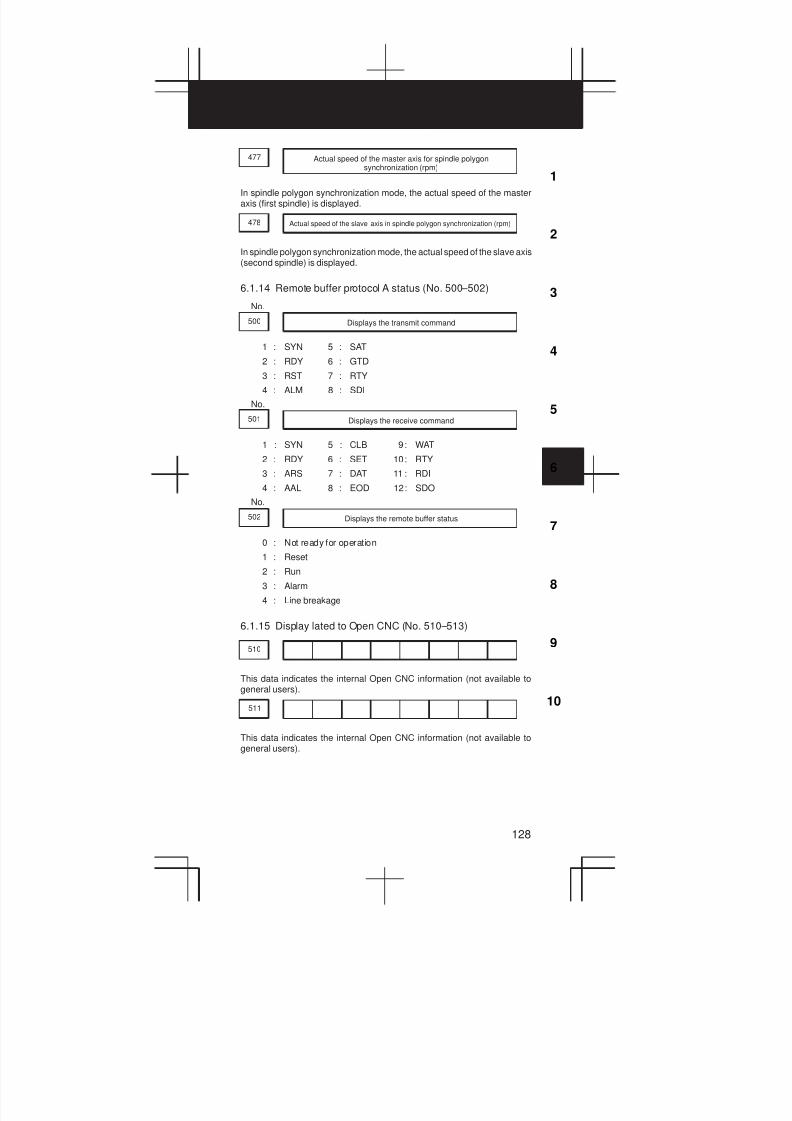
3
1
4
5
6
7
8
9
10
2
128
Actual speed of the master axis for spindle polygonsynchronization (rpm)
477
In spindle polygon synchronization mode, the actual speed of the masteraxis (first spindle) is displayed.
478 Actual speed of the slave axis in spindle polygon synchronization (rpm)
In spindle polygon synchronization mode, the actual speed of the slave axis(second spindle) is displayed.
6.1.14 Remote buffer protocol A status (No. 500–502)
No.
500 Displays the transmit command
1 : SYN 5 : SAT
2 : RDY 6 : GTD
3 : RST 7 : RTY
4 : ALM 8 : SDI
No.
501 Displays the receive command
1 : SYN 5 : CLB 9: WAT
2 : RDY 6 : SET 10: RTY
3 : ARS 7 : DAT 11 : RDI
4 : AAL 8 : EOD 12: SDO
No.
502 Displays the remote buffer status
0 : Not ready for operation
1 : Reset
2 : Run
3 : Alarm
4 : Line breakage
6.1.15 Display lated to Open CNC (No. 510–513)
510
This data indicates the internal Open CNC information (not available togeneral users).
511
This data indicates the internal Open CNC information (not available togeneral users).
6. STATUS DISPLAY BY SELF–DIAGNOSTIC DISPLAY
129
512 PA1 PA0 BNK THH THL PRA
This data indicates the cause of a system alarm that has occurred in OpenCNC.
#0(PRA) 1 : A RAM parity error occurred in shared RAM.
#2(THL) 0 : The temperature of the harddisk of Open CNC is too low.
1 : Normal
#3(THH) 0 : The temperature of the harddisk of Open CNC is too high.
1 : Normal
#4 0 : Normal
1 : An NMI has occurred in HSSB.
#5(BNK) If bit 0 (PRA) is set to 1,
0 : An alarm occurred in the lower half of shared RAM.
1 : An alarm occurred in the upper half of shared RAM.
#6 (PA0) If bit 0 (PRA) is set to 1,
1 : An alarm occurred at an even–numbered address.
#7 (PA1) If bit 0 (PRA) is set to 1,
1 : An alarm occurred at an odd–numbered address.
6.1.16 Small–diameter peck drilling cycle display (No. 520–523)
No.
520 Total number of retractions during cutting after G83 is specified
The total count of the retract movements, performed during cutting after G83is specified, is displayed. This count is cleared to zero when G83 is nextspecified.
No.
521 Total number of retractions made by receiving the overload signalduring cutting after G83 is specified
The total count of the retract movements, performed by overload signalreception during cutting after G83 is specified, is displayed. This count iscleared to zero when G83 is next specified.
No.
522 Position on the drill axis from which retraction is started
The coordinates of the drilling axis where a retract movement was startedare displayed in units of the least input increment.
No.
523 Difference between the position on the drill axis from which theprevious retraction was started and the position from which the
current retraction is started
The difference between the coordinates of the drilling axis where theprevious retract movement was started, and the coordinates of the drillingaxis where the current retract movement was started, is displayed in unitsof the least input increment.

3
1
4
5
6
7
8
9
10
2
130
6.1.17 Display of ATC for FD alpha (No. 530–531)
No. #7 #6 #5 #4 #3 #2 #1 #0
530 A99 A98 A97 A96 A95 A43
A43 : An unusable T code is specified with M06Tjj.
A95 : M06 is specified when the machine coordinate along the Z–axisis positive.
A96 : Parameter No. 7810 for the current tool number is set to 0.
A97 : In canned cycle mode, M06 is specified.In a block containing a reference position return command, M06is specified.In tool compensation mode, M06 is specified.
A98 : M06 is specified when a reference position return operation hasnot been performed after the power was turned on or theemergency stop state was released.During a tool exchange operation, the machine lock signal orZ–axis ignore signal was turned on for the Z–axis.
A99 : During a tool exchange operation, a wrench alarm was detected.
No. #7 #6 #5 #4 #3 #2 #1 #0
531 585 584 583 582 581 580 502
502 : Excessive pulse distribution to the spindle (system error)
580 : Spindle servo alarm (excessive error in the stop state)
581 : Spindle servo alarm (excessive error during movement)
582 : Spindle servo alarm (excessive drift)
583 : Spindle servo alarm (LSI overflow)
584 : ATC and spindle positioning sequence error (system error)
585 : Spindle servo alarm (excessive error during ATC magazineindexing)
6.1.18 Simplified synchronous control display (No. 540)
No.
540 Difference in the position error between the master and slaveaxes in simple synchronas control
No.
541 Difference in the position error between the master and slaveaxes in simple synchronas control
DGN 540 indicates the difference in the position error between the masterand slave axes when a single axis pair is subjected to simple synchronouscontrol. DGN 541 is used when two or more pairs are subjected to simplesynchronous control. The position error is indicated for the master axis.

6. STATUS DISPLAY BY SELF–DIAGNOSTIC DISPLAY
131
6.1.19 Display related to the dual position feedback function
(No. 550–553)
No.
550 Closed loop error
Data is displayed in detection units.
No.
551 Semi–closed loop error
Data is displayed in detection units.
No.
552 Error between semi–closed and closed loops
Data is displayed in detection units.
No.
553 Amount of dual position compensation
Data is displayed in detection units.

3
1
4
5
6
7
8
9
10
2
132
6.2 Waveform Diagnosis Display
The purpose of this function is to tune the servo motor easily by graphicallydisplaying the changes in servo motor error, torque and pulse distribution inwaveform.
(1) Setting a parameter
1 Set the parameter for wave analysis
#7 #6 #5 #4 #3 #2 #1 #0
3112 SGD
SGD 0: Graphic function is effective
*1: Wave analysis is effective(The usual graphic function cannot be used)
2 Turn off the power once, then on again.
(2) Displaying parameter screen for wave diagnosis.
1 Display SYSTEM contents screen by pressing SYSTEM key.
2 Press key twice to display [W.DGNS] soft key.
3 Display the parameter screen of Waveform diagnoses by pressing[W.DGNS] soft key.
4 Position the cursor and enter the required data. Data can be
entered from the keyboard. Press the INPUT key after entering the
required data.
5 Those items indicated by ***** cannot be set.When the cursor is positioned to an item to be set, guidanceinformation for that item is displayed in the box displayed in theright-hand half of the screen. Use the displayed information forreference. When one screen cannot display all the guidance
information, press the page change keys ( PAGE andPAGE
) to
display the remaining part of the information.
W.PRM[ ] [ ] [ ] [ ] [ ]W.GRPH W.MEM
WAVE DIAGNOS. (PARAMETER) O1234 N12345
GRP CONDITION 100
SAMPLING TIME *****MS
TRIGGER *******
(CH–1) (CH–2)
DATA NO. 11 22UNIT 1000 10SIGNAL ******* *******
>_ S 0 T0000
EDIT **** *** *** 08:20:52
GRP CONDITION
(ONE–S TYPE)0:START1:START &TRG↑2:START &TRG↓(MEMORY TYPE)100:DATA OF
MEMORY1/3
(a) One-shot type waveform diagnosis (parameter)
Display start condition
0: Starts data collection when the [START] soft key is pressed. Datais collected for a specified sampling period, after which the data isplotted.
1: Starts data collection on a rising edge of a trigger signal after the[START] soft key is pressed. Data is collected for a specifiedsampling period, after which the data is plotted.
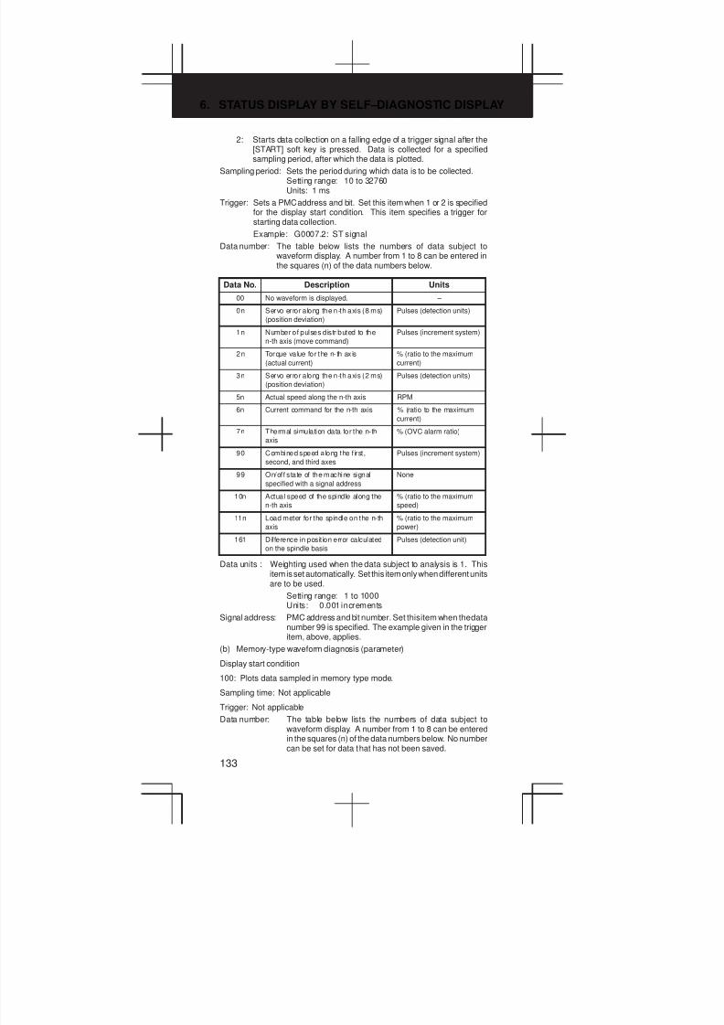
6. STATUS DISPLAY BY SELF–DIAGNOSTIC DISPLAY
133
2: Starts data collection on a falling edge of a trigger signal after the[START] soft key is pressed. Data is collected for a specifiedsampling period, after which the data is plotted.
Sampling period: Sets the period during which data is to be collected.Setting range: 10 to 32760Units: 1 ms
Trigger: Sets a PMC address and bit. Set this item when 1 or 2 is specifiedfor the display start condition. This item specifies a trigger forstarting data collection.
Example: G0007.2: ST signal
Data number: The table below lists the numbers of data subject towaveform display. A number from 1 to 8 can be entered inthe squares (n) of the data numbers below.
Data No. Description Units
00 No waveform is displayed. –
0n Servo error along the n-th axis (8 ms)
(position deviation)
Pulses (detection units)
1n Number of pulses distr ibuted to the
n-th axis (move command)
Pulses (increment system)
2n Torque va lue for the n- th ax is
(actual current)
% (ratio to the maximum
current)
3n Servo error along the n-th axis (2 ms)
(position deviation)
Pulses (detection units)
5n Actual speed along the n-th axis RPM
6n Current command for the n-th axis % (ratio to the maximum
current)
7n Thermal simulation data for the n-th
axis
% (OVC alarm ratio)
90 Combined speed along the f irst,
second, and third axes
Pulses (increment system)
99 On/off state of the machine signal
specified with a signal address
None
10n Actual speed of the spindle along the
n-th axis
% (ratio to the maximum
speed)
11n Load meter for the spindle on the n-th
axis
% (ratio to the maximum
power)
161 Difference in position error calculated
on the spindle basis
Pulses (detection unit)
Data units : Weighting used when the data subject to analysis is 1. Thisitem is set automatically. Set this item only when different unitsare to be used.
Setting range: 1 to 1000Units: 0.001 increments
Signal address: PMC address and bit number. Set this item when the datanumber 99 is specified. The example given in the triggeritem, above, applies.
(b) Memory-type waveform diagnosis (parameter)
Display start condition
100: Plots data sampled in memory type mode.
Sampling time: Not applicable
Trigger: Not applicable
Data number: The table below lists the numbers of data subject towaveform display. A number from 1 to 8 can be enteredin the squares (n) of the data numbers below. No numbercan be set for data that has not been saved.
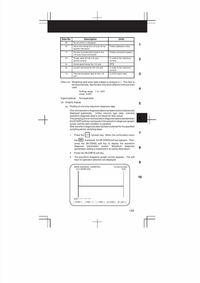
3
1
4
5
6
7
8
9
10
2
134
Data No. Description Units
00 No waveform is displayed. –
0n Servo error along the n-th axis (8 ms)
(position deviation)
Pulses (detection units)
1n Number of pulses distr ibuted to the
n-th axis (move command)
Pulses (increment system)
2n Torque va lue for the n- th ax is
(actual current)
% (ratio to the maximum
current)
5n Actual speed along the n-th axis RPM
6n Current command for the n-th axis % (ratio to the maximum
current)
7n Thermal simulation data for the n-th
axis
% (OVC alarm ratio)
Data unit : Weighting used when data subject to analysis is 1. This item isset automatically. Set this item only when different units are to beused.
Setting range: 1 to 1000Units: 0.001
Signal address: Not applicable
(3) Graphic display
(a) Plotting of one-shot waveform diagnosis data
One-shot waveform diagnosis data is sampled and simultaneouslydisplayed graphically. Unlike memory type data, one-shotwaveform diagnosis data is not saved for later output.The sampling of one-shot waveform diagnosis data is started whenthe [START] soft key is pressed on the waveform diagnosis (graph)screen and the start condition is satisfied.After waveform diagnosis data has been collected for the specifiedsampling period, sampling stops.
1 Press the SYSTEM function key. When the continuation menu
key is pressed, the [W.DGNS] soft key appears. Then,
press the [W.DGNS] soft key to display the waveformdiagnosis (parameter) screen. Waveform diagnosis(parameter) setting is explained in an earlier description.
2 Press the [W.GRPH] soft key.
3 The waveform diagnosis (graph) screen appears. The softkeys for operation selection are displayed.
START[ ] [ ] [ ] [ ] [ ]TIME³ ²TIME H–DOBL H–HALF
WAVE DIAGNOS. (GRAPHIC)CH1 SAMPLING
O1234 N12345CH2
EDIT **** *** ***
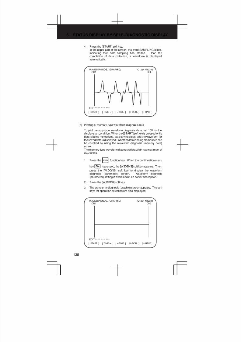
6. STATUS DISPLAY BY SELF–DIAGNOSTIC DISPLAY
135
4 Press the [START] soft key.In the upper part of the screen, the word SAMPLING blinks,indicating that data sampling has started. Upon thecompletion of data collection, a waveform is displayedautomatically.
START[ ] [ ] [ ] [ ] [ ]TIME³ ²TIME H–DOBL H–HALF
WAVE DIAGNOS. (GRAPHIC)CH1
O1234 N12345CH2
EDIT **** *** ***
(b) Plotting of memory-type waveform diagnosis data
To plot memory-type waveform diagnosis data, set 100 for thedisplay start condition. When the [START] soft key is pressed whiledata is being memorized, data saving stops, and the waveform forthe saved data is displayed. Whether data is being memorized canbe checked by using the waveform diagnosis (memory data)screen.The memory-type waveform diagnosis data width is a maximum of32,760 ms.
1 Press the SYSTEM function key. When the continuation menu
key is pressed, the [W.DGNS] soft key appears. Then,
press the [W.DGNS] soft key to display the waveformdiagnosis (parameter) screen. Waveform diagnosis(parameter) setting is explained in an earlier description.
2 Press the [W.GRPH] soft key.
3 The waveform diagnosis (graphic) screen appears. The softkeys for operation selection are also displayed.
START[ ] [ ] [ ] [ ] [ ]TIME³ ²TIME H–DOBL H–HALF
WAVE DIAGNOS. (GRAPHIC)CH1
O1234 N12345CH2
EDIT **** *** ***
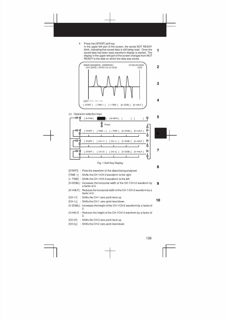
3
1
4
5
6
7
8
9
10
2
136
4 Press the [START] soft key.In the upper-left part of the screen, the words NOT READYblink, indicating that saved data is still being read. Once thesaved data has been read, waveform display is started. Thedisplay in the upper-left part of the screen changes from NOTREADY to the date on which the data was saved.
START[ ] [ ] [ ] [ ] [ ]TIME³ ²TIME H–DOBL H–HALF
WAVE DIAGNOS. (GRAPHIC)CH1 DATE = 97/01/13 12:15:00
O1234 N12345CH2
EDIT **** *** ***
(c) Operation selection keys
W.PRM[ ] [ ] [ ] [ ] [ ]W.GRPH W.MEM
Press
START[ ] [ ] [ ] [ ] [ ]TIME³ ²TIME H–DOBL H–HALF
START[ ] [ ] [ ] [ ] [ ]CH–1° CH–1± V–DOBL V–HALF
START[ ] [ ] [ ] [ ] [ ]CH–2° CH–2± V–DOBL V–HALF
Fig. 1 Soft Key Display
[START] : Plots the waveform of the object being analyzed.
[TIME³] : Shifts the CH-1/CH-2 waveform to the right.
[²TIME] : Shifts the CH-1/CH-2 waveform to the left.
[H-DOBL] : Increases the horizontal width of the CH-1/CH-2 waveform bya factor of 2.
[H-HALF] : Reduces the horizontal width of the CH-1/CH-2 waveform by afactor of 2.
[CH-1°] : Shifts the CH-1 zero point level up.
[CH-1±] : Shifts the CH-1 zero point level down.
[V-DOBL] : Increases the height of the CH-1/CH-2 waveform by a factor of2.
[V-HALF] : Reduces the height of the CH-1/CH-2 waveform by a factor of2.
[CH-2°] : Shifts the CH-2 zero point level up.
[CH-2±] : Shifts the CH-2 zero point level down.
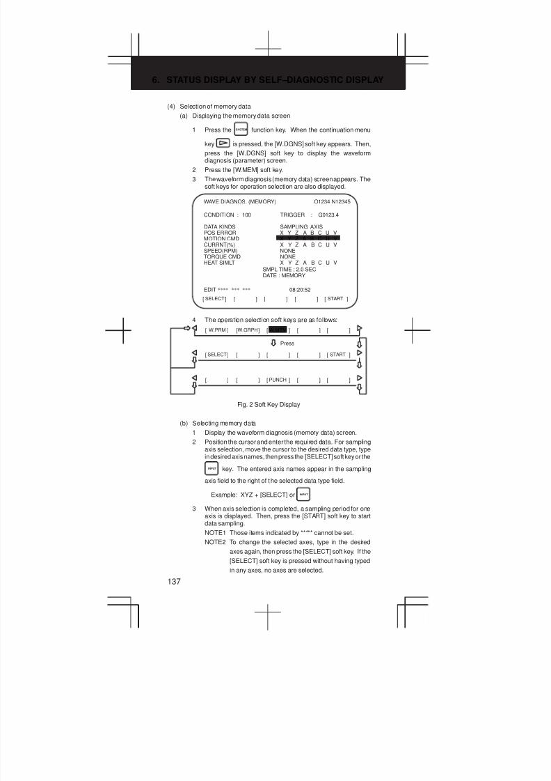
6. STATUS DISPLAY BY SELF–DIAGNOSTIC DISPLAY
137
(4) Selection of memory data
(a) Displaying the memory data screen
1 Press the SYSTEM function key. When the continuation menu
key is pressed, the [W.DGNS] soft key appears. Then,
press the [W.DGNS] soft key to display the waveformdiagnosis (parameter) screen.
2 Press the [W.MEM] soft key.
3 The waveform diagnosis (memory data) screen appears. Thesoft keys for operation selection are also displayed.
SELECT[ ] [ ] [ ] [ ] [ ]START
WAVE DIAGNOS. (MEMORY) O1234 N12345
CONDITION : 100 TRIGGER : G0123.4
DATA KINDS SAMPLING AXISPOS ERROR X Y Z A B C U VMOTION CMD X Y Z A B C U VCURRNT(%) X Y Z A B C U VSPEED(RPM) NONETORQUE CMD NONEHEAT SIMLT X Y Z A B C U V
SMPL TIME : 2.0 SECDATE : MEMORY
EDIT **** *** *** 08:20:52
4 The operation selection soft keys are as follows:
W.PRM[ ] [ ] [ ] [ ] [ ]W.GRPH W.MEM
Press
SELECT[ ] [ ] [ ] [ ] [ ]START
[ ] [ ] [ ] [ ] [ ]PUNCH
Fig. 2 Soft Key Display
(b) Selecting memory data
1 Display the waveform diagnosis (memory data) screen.
2 Position the cursor and enter the required data. For samplingaxis selection, move the cursor to the desired data type, typein desired axis names, then press the [SELECT] soft key or the
INPUT key. The entered axis names appear in the sampling
axis field to the right of the selected data type field.
Example: XYZ + [SELECT] or INPUT
3 When axis selection is completed, a sampling period for oneaxis is displayed. Then, press the [START] soft key to startdata sampling.
NOTE1 Those items indicated by ***** cannot be set.
NOTE2 To change the selected axes, type in the desired
axes again, then press the [SELECT] soft key. If the
[SELECT] soft key is pressed without having typed
in any axes, no axes are selected.

3
1
4
5
6
7
8
9
10
2
138
NOTE3 If selected axes are changed during waveform data
sampling, the sampling operation stops. In such a
case, press the [START] soft key to restart data sam-
pling.
NOTE4 The initial sampling axis setting is such that no sam-
pling axis is selected.
(c) Memory data parameter
1 Data saving termination condition
100: Terminates data saving when a servo alarm is issued.
101: Terminates data saving when a servo alarm is issued orthe rising edge of a trigger signal is detected.
102: Terminates data saving when a servo alarm is issued orthe falling edge of a trigger signal is detected.
The data saving width is 32,760 ms, maximum. If a specifiedsaving termination condition is not satisfied upon the elapse of32760 ms, older data is replaced by newer data.In the case of data saving termination by the issue of a servo alarm,the termination of data saving can be delayed by the period (in ms)set in parameter No. 3120.
2 Trigger: Sets a PMC address and bit. Set this item when101 or 102 is specified for the terminationcondition. This item specifies a trigger forterminating data collection.
Example: G0007.2: ST signal
3 Data type: The table below lists the data types subject towaveform display.
Data type Description Unit
Position
deviation
Servo error along the n-th axis (8 ms) Pulses (detection units)
Move
command
Number of pulses distributed to the n-th
axis
Pulses
(increment system)
Actual
current
Torque value on the n-th axis % (ratio to the maxi-
mum current)
Actual
speed
Actual speed along the n-th axis RPM
Current
command
Current command for the n-th axis % (rat io to the maxi-
mum current)
Thermal
simulation
Thermal simulation data for the n-th axis % (OVC alarm ratio)
4 Sampling axis: Displays the names of the axes subject tosampling.
5 Sampling time: Displays a sampling period for one axis.
6 Date and time of saving: Displays MEMORY during datasampling. When data sampling isterminated, the date of thetermination is displayed.
(5) Output of waveform diagnosis data
Servo alarm type waveform diagnosis data can be output to aninput/output unit connected to the reader/punch interface.Set the input/output unit to be used for output in parameter No. 0020 andNos. 0100 to 0135.In addition, set a code in bit 1 (ISO) of parameter No. 0020.
(a) Output of waveform diagnosis data
Servo alarm type waveform diagnosis data can be output to aninput/output unit, according to the procedure below.
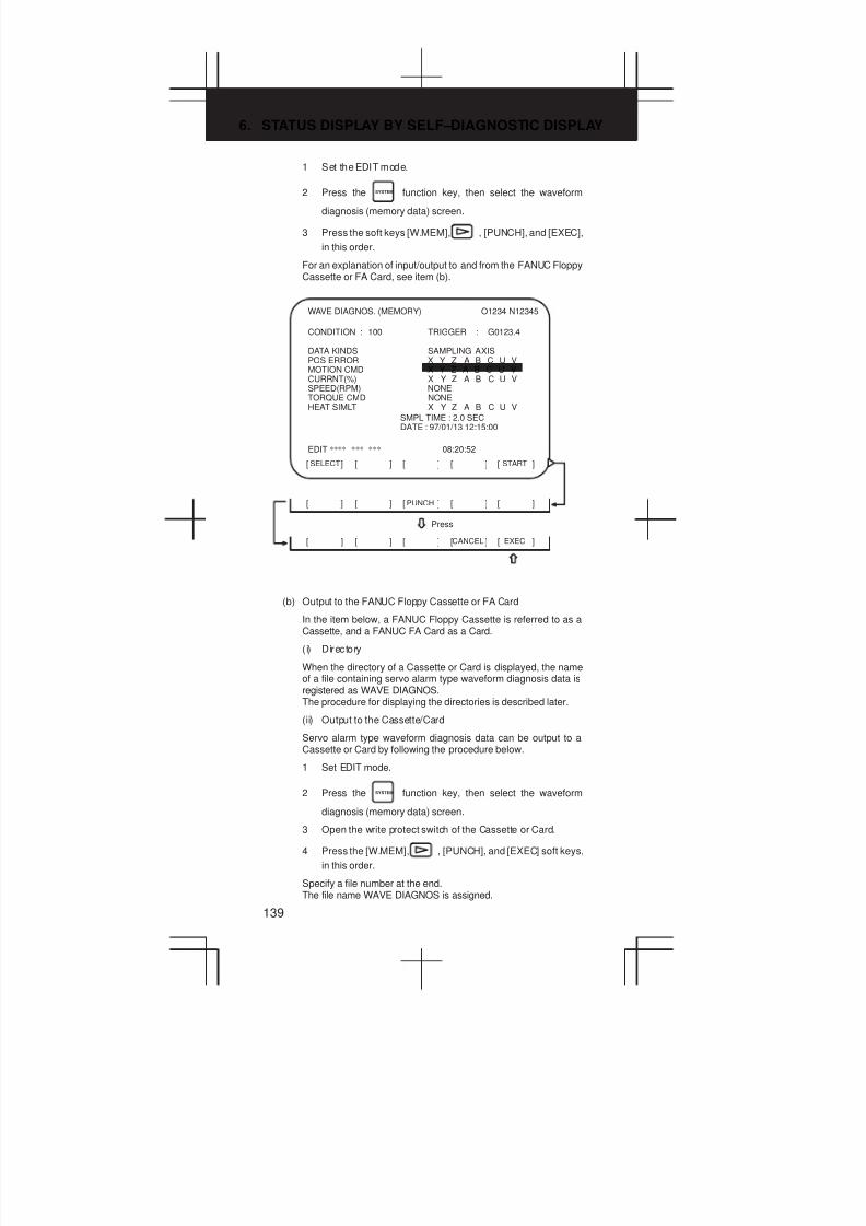
6. STATUS DISPLAY BY SELF–DIAGNOSTIC DISPLAY
139
1 Set the EDIT mode.
2 Press the SYSTEM function key, then select the waveform
diagnosis (memory data) screen.
3 Press the soft keys [W.MEM], , [PUNCH], and [EXEC],
in this order.
For an explanation of input/output to and from the FANUC FloppyCassette or FA Card, see item (b).
SELECT[ ] [ ] [ ] [ ] [ ]START
WAVE DIAGNOS. (MEMORY) O1234 N12345
CONDITION : 100 TRIGGER : G0123.4
DATA KINDS SAMPLING AXISPOS ERROR X Y Z A B C U VMOTION CMD X Y Z A B C U VCURRNT(%) X Y Z A B C U VSPEED(RPM) NONETORQUE CMD NONEHEAT SIMLT X Y Z A B C U V
SMPL TIME : 2.0 SECDATE : 97/01/13 12:15:00
EDIT **** *** *** 08:20:52
[ ] [ ] [ ] [ ] [ ]PUNCH
[ ] [ ] [ ] [ ] [ ]CANCEL EXEC
Press
(b) Output to the FANUC Floppy Cassette or FA Card
In the item below, a FANUC Floppy Cassette is referred to as aCassette, and a FANUC FA Card as a Card.
( i) Directory
When the directory of a Cassette or Card is displayed, the nameof a file containing servo alarm type waveform diagnosis data isregistered as WAVE DIAGNOS.The procedure for displaying the directories is described later.
(ii) Output to the Cassette/Card
Servo alarm type waveform diagnosis data can be output to aCassette or Card by following the procedure below.
1 Set EDIT mode.
2 Press the SYSTEM function key, then select the waveform
diagnosis (memory data) screen.
3 Open the write protect switch of the Cassette or Card.
4 Press the [W.MEM], , [PUNCH], and [EXEC] soft keys,
in this order.
Specify a file number at the end.The file name WAVE DIAGNOS is assigned.
3
1
4
5
6
7
8
9
10
2
140
If the Cassette or Card used as the output destination alreadycontains a file having the same name as that specified, P/S alarmNo. 86 is issued. To a Cassette or Card, only one file of waveformdiagnosis data of servo alarm type can be output. When output toa Cassette or Card containing unnecessary servo alarm typewaveform diagnosis data is needed, delete the file having the samename from the Cassette or Card beforehand.Deleting a file is described later.
(iii) Displaying the directory of a Cassette or Card
The directory of a Cassette or Card can be displayed by followingthe procedure below.
1 Set EDIT mode.
2 Press the PROG function key, then select the program screen.
3 Press . Then press [FLOPPY].
4 Press the page change keyPAGE
.
In this way, the directory is displayed.
(iv) Deleting a file from a Cassette or Card
A file can be deleted from a Cassette or Card by following theprocedure below.
1 Set EDIT mode.
2 Press the PROG function key, then select the program screen.
3 Open the write protect switch of the Cassette or Card.
4 Press [FLOPPY].
5 Press [DELETE].
6 Type in a file number, then press [F SET].
7 Press [EXEC] .The file having the specified file number is deleted. After thefile is deleted, all subsequent file numbers are decremented by1.
NOTE The floppy directory display function is optional.
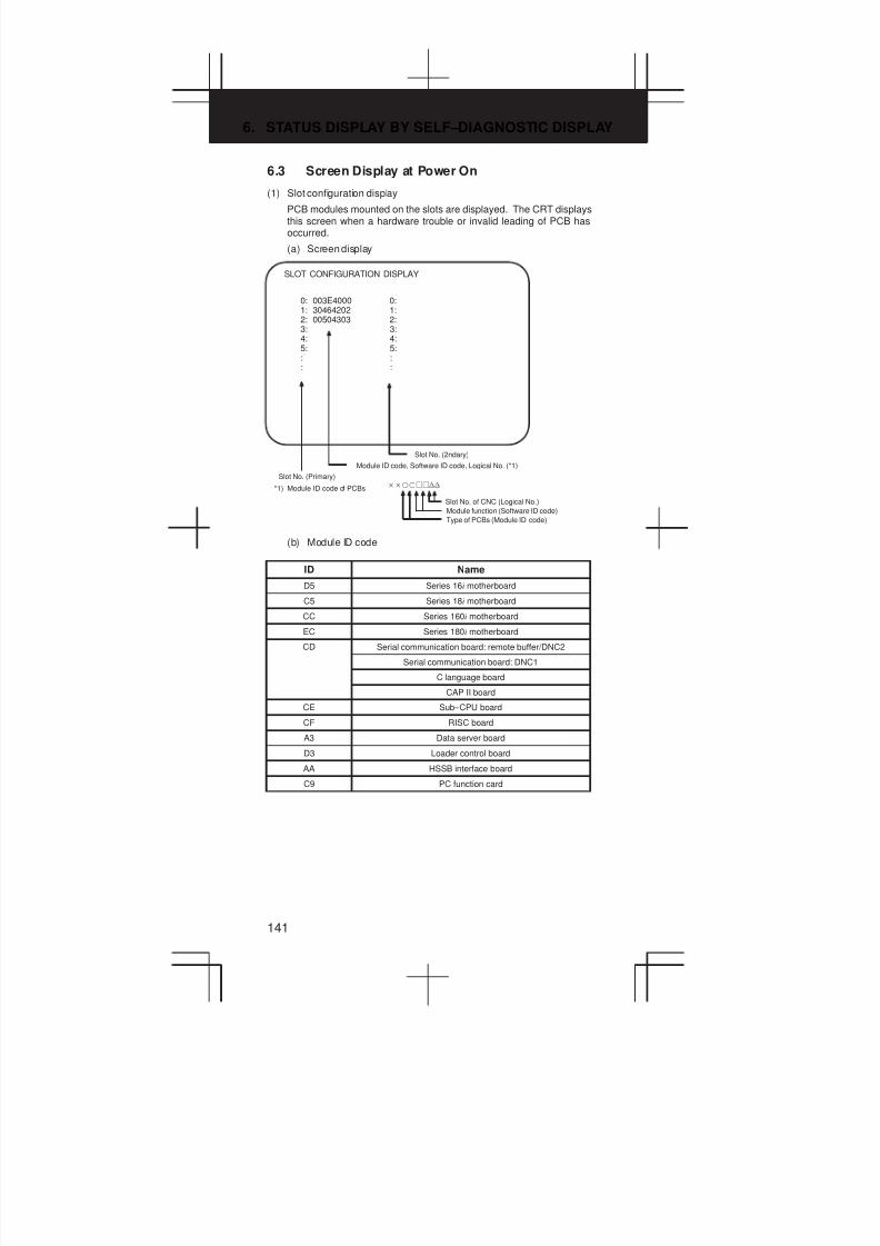
6. STATUS DISPLAY BY SELF–DIAGNOSTIC DISPLAY
141
6.3 Screen Display at Power On
(1) Slot configuration display
PCB modules mounted on the slots are displayed. The CRT displaysthis screen when a hardware trouble or invalid leading of PCB hasoccurred.
(a) Screen display
SLOT CONFIGURATION DISPLAY
0: 003E4000 0:1: 30464202 1:2: 00504303 2:3: 3:4: 4:5: 5:: :: :
Slot No. (2ndary)
Module ID code, Software ID code, Logical No. (*1)
Slot No. (Primary)
*1) Module ID code of PCBs ĘĘjjnn
Slot No. of CNC (Logical No.)
Module function (Software ID code)
Type of PCBs (Module ID code)
(b) Module ID code
ID Name
D5 Series 16i motherboard
C5 Series 18i motherboard
CC Series 160i motherboard
EC Series 180i motherboard
CD Serial communication board: remote buffer/DNC2
Serial communication board: DNC1
C language board
CAP II board
CE Sub–CPU board
CF RISC board
A3 Data server board
D3 Loader control board
AA HSSB interface board
C9 PC function card
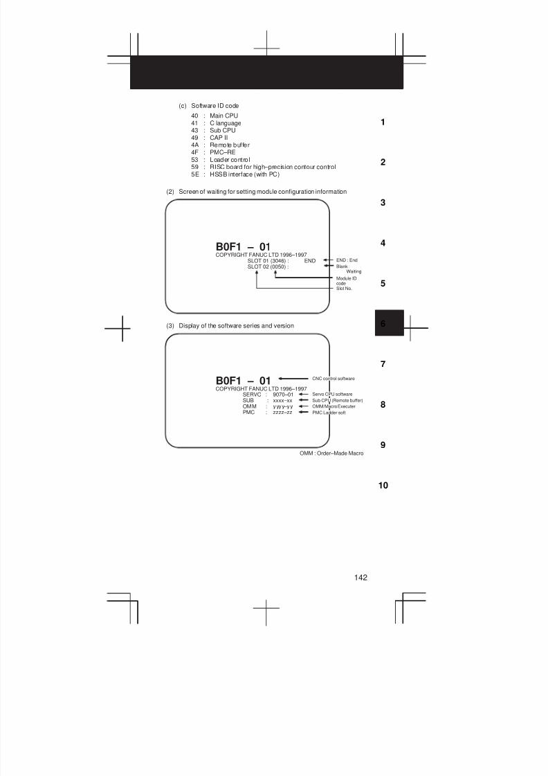
3
1
4
5
6
7
8
9
10
2
142
(c) Software ID code
40 : Main CPU41 : C language43 : Sub CPU49 : CAP II4A : Remote buffer4F : PMC–RE53 : Loader control59 : RISC board for high–precision contour control5E : HSSB interface (with PC)
(2) Screen of waiting for setting module configuration information
COPYRIGHT FANUC LTD 1996–1997SLOT 01 (3046) : ENDSLOT 02 (0050) :
B0F1 – 01END : End
Blank :Waiting
Module IDcodeSlot No.
(3) Display of the software series and version
B0F1 – 01Å Å Å Å Å
Å Å Å Å Å
Servo CPU softwareSERVO : 9070–01SUB : xxxx–xxOMM : yyyy–yyPMC : zzzz–zz
Å Å Å Å Å
Sub CPU (Remote buffer)
OMM : Order–Made Macro
Å Å Å Å Å
Å Å Å Å Å
OMM/Macro Executer
Å Å Å Å Å
PMC Ladder soft
Å Å Å Å Å
Å Å Å Å Å
CNC control software
COPYRIGHT FANUC LTD 1996–1997
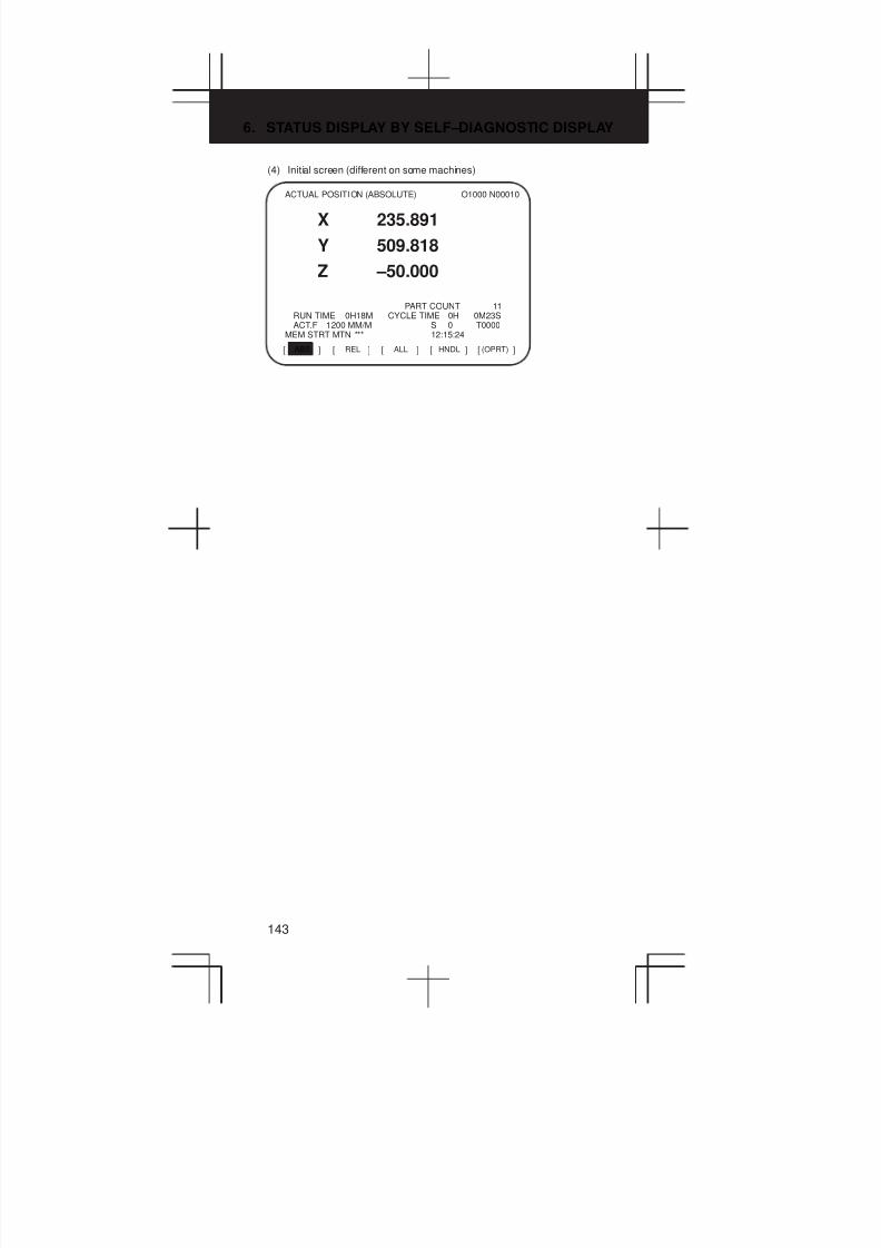
6. STATUS DISPLAY BY SELF–DIAGNOSTIC DISPLAY
143
(4) Initial screen (different on some machines)
ABS[ ] [ ] [ ] [ ] [ ]REL ALL HNDL (OPRT)
ACTUAL POSITION (ABSOLUTE) O1000 N00010
X 235.891
Y 509.818
Z –50.000
PART COUNT 11RUN TIME 0H18M CYCLE TIME 0H 0M23SACT.F 1200 MM/M S 0 T0000
MEM STRT MTN *** 12:15:24
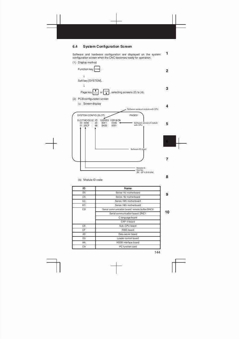
3
1
4
5
6
7
8
9
10
2
144
6.4 System Configuration Screen
Software and hardware configuration are displayed on the systemconfiguration screen when the CNC becomes ready for operation.
(1) Display method
Function key SYSTEM .
±
Soft key [SYSTEM].
±
Page key PAGE orPAGE
, selecting screens (2) to (4).
(2) PCB configuration screen
(a) Screen display
SYSTEM CONFIG (SLOT)
SLOTMODULE ID SERIES VERSION00 0090 : 40 B0F1 000601 00CF : 66 B435 0001
Å Å Å Å Å
Software ID (type)
Module IDSlot No.(80X8F is 2nd side)
PAGE01
Å Å Å Å Å
Å Å Å Å Å
Software version of modulewith CPU
Software series of module with CPU
(b) Module ID code
ID Name
D5 Series 16i motherboard
C5 Series 18i motherboard
CC Series 160i motherboard
EC Series 180i motherboard
CD Serial communication board: remote buffer/DNC2
Serial communication board: DNC1
C language board
CAP–II board
CE Sub–CPU board
CF RISC board
A3 Data server board
D3 Loader control board
AA HSSB interface board
C9 PC function card

6. STATUS DISPLAY BY SELF–DIAGNOSTIC DISPLAY
145
(c) Software ID code
40 : Main CPU41 : C language43 : Sub CPU49 : CAP II4A : Remote buffer4F : PMC–RE53 : Loader control59 : RISC board for high–precision contour control5E : HSSB interface (with PC)
(3) Software configuration screen
SYSTEM CONFIG (SOFTWARE) 01234 N12345PAGE:02
SYSTEM B0F1 0001BASIC+OPTION–A1
SERVO 9090 0001PMC(SYS) 406A 0001
406B 00014099 0001
PMC(LAD) FS16 0001MACRO LIB BZG1 0001MACRO APL AAAA BBBBBOOT 60M3 0004GRAPHIC–1 600W 001Z
MEM **** *** *** 12:14:59[ PARMA ] [ DGNOS ] [ PMC ] [ SYSTEM ] [ (OPRT) ]
Kind of softwareSoftware series
Software version
Software configuration
Character written onPMC title screen
Character written onmacro compiler or onCAP.
(4) Module configuration screen
The configuration of the modules mounted on each board isdisplayed.
SYSTEM CONFIG (MODULE) 01234 N12345PAGE:03
SLOT 00 MOTHER BOARD
AXIS CTRL CARD : 0DDISPLAY CTRL CARD : 0ECPU CARD : 01FROM DIMM : 47SRAM DIMM : 23DRAM DIMM : 86PMC CPU : 01
MEM **** *** *** 12:14:59[ PARMA ] [ DGNOS ] [ PMC ] [ SYSTEM ] [ (OPRT) ]
(2)
(4)
(3)
(1)
System configuration of another PCB is displayed by page key
(PAGE
or PAGE ).
NOTE See Maintenance Manual for display of each module.

3
1
4
5
6
7
8
9
10
2
146
6.5 Interface between CNC and PMC/MT and
Displaying I/O Signals
(1) One–path control
Addresses of interface signals between CNC and PMC/MT.
Y000X
X000X
F000X
G000X
CNC MTPMC
(2) Two-path control
The figure below shows the addresses of the interface signals betweenthe CNC and the PMC.
Note, however, that some of signals common to paths 1 and 2 areallocated to path 1.
Y000X
X000X
G1000X
F1000X
G000X
F000X
CNC MTPMC
Path 1
Path 2
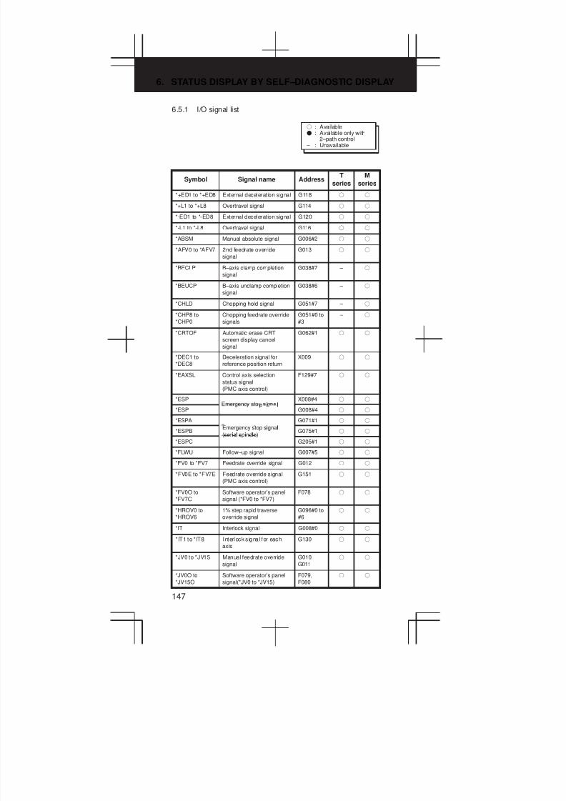
6. STATUS DISPLAY BY SELF–DIAGNOSTIC DISPLAY
147
6.5.1 I/O signal list
f : AvailableF : Available only with
2–path control – : Unavailable
Symbol Signal name AddressT
series
M
series
*+ED1 to *+ED8 External deceleration signal G118 f f
*+L1 to *+L8 Overtravel signal G114 f f
*-ED1 to *-ED8 External deceleration signal G120 f f
*-L1 to *-L8 Overtravel signal G116 f f
*ABSM Manual absolute signal G006#2 f f
*AFV0 to *AFV7 2nd feedrate override
signal
G013 f f
*BECLP B–axis clamp completion
signal
G038#7 – f
*BEUCP B–axis unclamp completion
signal
G038#6 – f
*CHLD Chopping hold signal G051#7 – f
*CHP8 to
*CHP0
Chopping feedrate override
signals
G051#0 to
#3
– f
*CRTOF Automatic erase CRT
screen display cancel
signal
G062#1 f f
*DEC1 to
*DEC8
Deceleration signal for
reference position return
X009 f f
*EAXSL Control axis selection
status signal
(PMC axis control)
F129#7 f f
*ESPp i l
X008#4 f f
*ESPi l
G008#4 f f
*ESPA
i l
G071#1 f f
*ESPB
Emergency stop signal
(serial spindle)G075#1 f f
*ESPC
i l i l
G205#1 f f
*FLWU Follow–up signal G007#5 f f
*FV0 to *FV7 Feedrate override signal G012 f f
*FV0E to *FV7E Feedrate override signal
(PMC axis control)
G151 f f
*FV0O to
*FV7O
Software operator’s panel
signal (*FV0 to *FV7)
F078 f f
*HROV0 to
*HROV6
1% step rapid traverse
override signal
G096#0 to
#6
f f
*IT Interlock signal G008#0 f f
* IT1 to * IT8 Interlock s ignal for each
axis
G130 f f
*JV0 to *JV15 Manual feedrate override
signal
G010,
G011
f f
*JV0O to
*JV15O
Software operator’s panel
signal(*JV0 to *JV15)
F079,
F080
f f
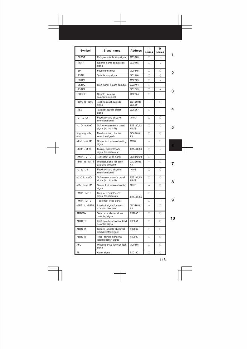
3
1
4
5
6
7
8
9
10
2
148
SymbolM
series
T
seriesAddressSignal name
*PLSST Polygon spindle stop signal G038#0 f -
*SCPF Spindle clamp completion
signal
G028#5 f -
*SP Feed hold signal G008#5 f f
*SSTP Spindle stop signal G029#6 f f
*SSTP1 G027#3 f –
*SSTP2 Stop signal in each spindle G027#4 f –
*SSTP3 G027#5 f –
*SUCPF Spindle unclamp
completion signal
G028#4 f –
*TLV0 to *TLV9 Tool life count override
signal
G049#0 to
G050#1
– f
*TSB Tailstock barrier select
signal
G060#7 f –
+J1 to +J8 Feed axis and direc tion
selection signal
G100 f f
+J1O to +J4O Software operator’s panel
signal (+J1 to +J4)
F081#0,#2,
#4,#6
f f
+Jg, –Jg, +Ja,
–Ja
Feed axis and direction
selection signals
G086#0 to
#3
f f
+LM1 to +LM8 Stroke limit external setting
signal
G110 – f
+MIT1,+MIT2 Manual feed interlock
signal for each axis
X004#2,#4 f –
+MIT1,+MIT2 Tool offset write signal X004#2,#4 f –
+MIT1 to +MIT4 Interlock signal for each
axis and direction
G132#0 to
#3
– f
–J1 to –J8 Feed axis and direction
selection signal
G102 f f
–J1O to –J4O Software operator’s panel
signal (–J1 to –J4)
F081#1,#3,
#5,#7
f f
–LM1 to –LM8 Stroke limit external setting
signal
G112 – f
–MIT1,–MIT2 Manual feed interlock
signal for each axis X004#3,#5
f –
–MIT1,–MIT2 Tool offset write signal f –
–MIT1 to –MIT4 Interlock signal for each
axis and direction
G134#0 to
#3
– f
ABTQSV Servo axis abnormal load
detected signal
F090#0 f f
ABTSP1 First–spindle abnormal load
detected signal
F090#1 f f
ABTSP2 Second–spindle abnormal
load detected signal
F090#2 f f
ABTSP3 Third–spindle abnormal
load detection signal
F090#3 f f
AFL Miscellaneous function lock
signal
G005#6 f f
AL Alarm signal F001#0 f f
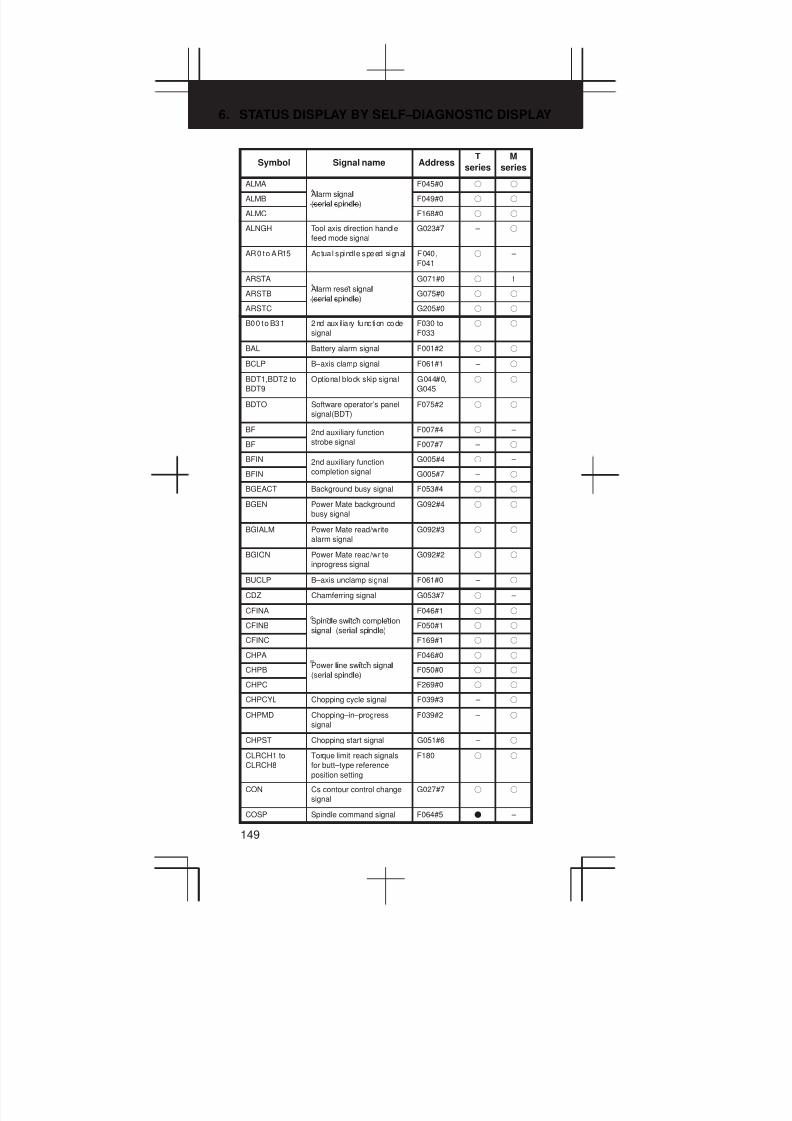
6. STATUS DISPLAY BY SELF–DIAGNOSTIC DISPLAY
149
SymbolM
series
T
seriesAddressSignal name
ALMA
l i l
F045#0 f f
ALMBAlarm signal
(serial spindle)F049#0 f f
ALMC
i l i l
F168#0 f f
ALNGH Tool axis direction handle
feed mode signal
G023#7 – f
AR0 to AR15 Actua l spindle speed signal F040,
F041
f –
ARSTA
l i l
G071#0 f f
ARSTB
Alarm reset signal
(serial spindle)G075#0 f f
ARSTC
i l i l
G205#0 f f
B00 to B31 2nd aux il ia ry function code
signal
F030 to
F033
f f
BAL Battery alarm signal F001#2 f f
BCLP B–axis clamp signal F061#1 – f
BDT1,BDT2 to
BDT9
Optional block skip signal G044#0,
G045
f f
BDTO Software operator’s panel
signal(BDT)
F075#2 f f
BF 2nd auxiliary function F007#4 f –
BF strobe signal F007#7 – f
BFIN 2nd auxiliary function G005#4 f –
BFIN completion signal G005#7 – f
BGEACT Background busy signal F053#4 f f
BGEN Power Mate background
busy signal
G092#4 f f
BGIALM Power Mate read/write
alarm signal
G092#3 f f
BGION Power Mate read/write
inprogress signal
G092#2 f f
BUCLP B–axis unclamp signal F061#0 – f
CDZ Chamferring signal G053#7 f –
CFINA
i l i l i
F046#1 f f
CFINB
Spindle switch completion
signal (serial spindle)F050#1 f f
CFINC
i l i l i l
F169#1 f f
CHPA
li i i l
F046#0 f f
CHPB
Power line switch signal
(serial spindle)F050#0 f f
CHPC
i l i l
F269#0 f f
CHPCYL Chopping cycle signal F039#3 – f
CHPMD Chopping–in–progress
signal
F039#2 – f
CHPST Chopping start signal G051#6 – f
CLRCH1 to
CLRCH8
Torque limit reach signals
for butt–type reference
position setting
F180 f f
CON Cs contour control change
signal
G027#7 f f
COSP Spindle command signal F064#5 F –

3
1
4
5
6
7
8
9
10
2
150
SymbolM
series
T
seriesAddressSignal name
CSS Constant surface speed
signal
F002#2 f f
CTH1A,CTH2A
l i l
G070#3,#2 f f
CTH1B,CTH2BClutch/gear signal
(serial spindle)G074#3,#2 f f
CTH1C,CTH2C
i l i l
G204#3,#2 f f
CUT Cutting feed signal F002#6 f f
DEFMDA
i i l
G072#3 f f
DEFMDB
Differential mode command
si nal (serial spindle)G076#3 f f
DEFMDC
i l i l i l
G206#3 f f
DEN Distribution end signal F001#3 f f
DM00 F009#7 f f
DM01i l
F009#6 f f
DM02i l
F009#5 f f
DM30 F009#4 f f
DMMC Direct operation select
signal
G042#7 f f
DNCI DNC operation select
signal
G043#5 f f
DRN Dry run signal G046#7 f f
DRNE Dry run signal
(PMC axis control)
G150#7 f f
DRNO Software operator’s panel
signal(DRN)
F075#5 f f
DSP1, DSP2,
DSP3
Spindle motor speed
detection signals
Y(n+1)
#0 to #2
f f
DSV1 to DSV8 Servo motor speed
detection signals
Y(n+0) f f
DTCH1 to
DTCH8
Controlled axis detach
signal
G124 f f
EA0 to EA6 Address signal for external
data input
G002#0 to
#6
f f
EABUFA F131#1 f f
EABUFB Buffer full signal F134#1 f f
EABUFC (PMC axis control) F137#1 f f
EABUFD F140#1 f f
EACNT1 to
EACNT8
Controlling signal
(PMC axis control)
F182 f f
EADEN1 to
EADEN8
Distribution completion
signal (PMC axis control)
F112 f f
EAX1 to EAX8 Control axis select signal
(PMC axis control)
G136 f f
EBSYA F130#7 f f
EBSYB Axis control command read
pl i i lF133#7 f f
EBSYCl i i l
(PMC axis control) F136#7 f f
EBSYD F139#7 f f
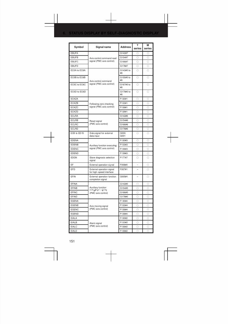
6. STATUS DISPLAY BY SELF–DIAGNOSTIC DISPLAY
151
SymbolM
series
T
seriesAddressSignal name
EBUFA G142#7 f f
EBUFB Axis control command read G154#7 f f
EBUFC signal (PMC axis control) G166#7 f f
EBUFD G178#7 f f
EC0A to EC6A G143#0 to
#6
f f
EC0B to EC6B
Axis control command
G155#0 to
#6
f f
EC0C to EC6C signal (PMC axis control) G167#0 to
#6
f f
EC0D to EC6D G179#0 to
#6
f f
ECKZA F130#1 f f
ECKZB Following zero checking F133#1 f f
ECKZC signal (PMC axis control) F136#1 f f
ECKZD F139#1 f f
ECLRA G142#6 f f
ECLRB Reset signal G154#6 f f
ECLRC (PMC axis control) G166#6 f f
ECLRD G178#6 f f
ED0 to ED15 Data signal for external
data input
G000,
G001
f f
EDENA F130#3 f f
EDENB Auxiliary function executing F133#3 f f
EDENC signal (PMC axis control) F136#3 f f
EDEND F139#3 f f
EDGN Slave diagnosis selection
signal
F177#7 f f
EF External operation signal F008#0 – f
EFD External operation signal
for high–speed interface
F007#1 – f
EFIN External operation function
completion signal
G005#1 – f
EFINA G142#0 f f
EFINB Auxiliary function
pl i i lG154#0 f f
EFINCl i i l
(PMC axis control) G166#0 f f
EFIND G178#0 f f
EGENA F130#4 f f
EGENB Axis moving signal F133#4 f f
EGENC (PMC axis control) F136#4 f f
EGEND F139#4 f f
EIALA F130#2 f f
EIALB Alarm signal F133#2 f f
EIALC (PMC axis control) F136#2 f f
EIALD F139#2 f f
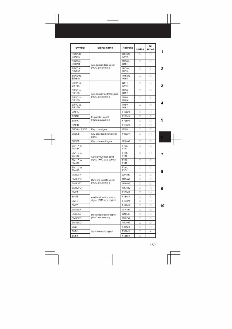
3
1
4
5
6
7
8
9
10
2
152
SymbolM
series
T
seriesAddressSignal name
EID0A to
EID31A
G146 to
G149
f f
EID0B to
EID31B Axis control data signal
G158 to
G161
f f
EID0C to
EID31C
(PMC axis control) G170 to
G173
f f
EID0D to
EID31D
G182 to
G185
f f
EIF0A to
EIF15A
G144,
G145
f f
EIF0B to
EIF15B Axis control feedrate signal
G156,
G157
f f
EIF0C to
EIF15C
(PMC axis control) G168,
G169
f f
EIF0D to
EIF15D
G180,
G181
f f
EINPA F130#0 f f
EINPB In–position signal F133#0 f f
EINPC (PMC axis control) F136#0 f f
EINPD F139#0 f f
EKC0 to EKC7 Key code signal G098 f f
EKENB Key code read completion
signal
F053#7 f f
EKSET Key code read signal G066#7 f f
EM11A to
EM48A
F132,
F142
f f
EM11B to
EM48B Auxiliary function code
F135,
F145
f f
EM11C to
EM48C
signal (PMC axis control) F138,
F148
f f
EM11D to
EM48D
F141,
F151
f f
EMBUFA G142#2 f f
EMBUFB Buffering disable signal G154#2 f f
EMBUFC (PMC axis control) G166#2 f f
EMBUFD G178#2 f f
EMFA F131#0 f f
EMFB Auxiliary function strobe F134#0 f f
EMFC signal (PMC axis control) F137#0 f f
EMFD F140#0 f f
EMSBKA G143#7 f f
EMSBKB Block stop disable signal G155#7 f f
EMSBKC (PMC axis control) G167#7 f f
EMSBKD G179#7 f f
ENB F001#4 f f
ENB2 Spindle enable signal F038#2 f –
ENB3 F038#3 f –

6. STATUS DISPLAY BY SELF–DIAGNOSTIC DISPLAY
153
SymbolM
series
T
seriesAddressSignal name
ENBKY External key input mode
selection signal
G066#1 f f
EOTNA F130#6 f f
EOTNB Negative–direction
l i lF133#6 f f
EOTNCl i l
(PMC axis control) F136#6 f f
EOTND F139#6 f f
EOTPA F130#5 f f
EOTPB Positive–direction
l i lF133#5 f f
EOTPCl i l
(PMC axis control) F136#5 f f
EOTPD F139#5 f f
EOV0 Override 0% signal
(PMC axis control)
F129#5 f f
EPARM Slave parameter selection
signal
F177#6 f f
EPRG Slave program selection
signal
F177#4 f f
ERDIO Slave external read start
signal
F177#1 f f
EREND Read completion signal for
external data input
F060#0 f f
ERS External reset signal G008#7 f f
ESBKA G142#3 f f
ESBKB Block stop signal G154#3 f f
ESBKC (PMC axis control) G166#3 f f
ESBKD G178#3 f f
ESEND Search completion signal
for external data input
F060#1 f f
ESKIP Skip signal
(PMC axis control)
X004#6 f f
ESOFA G142#4 f f
ESOFB Servo off signal G154#4 f f
ESOFC (PMC axis control) G166#4 f f
ESOFD G178#4 f f
ESRSYC Simple spindle
synchronous control signal
G064#6 f f
ESTB Read signal for external
data input
G002#7 f f
ESTPA G142#5 f f
ESTPB Axis control temporary stop G154#5 f f
ESTPC signal (PMC axis control) G166#5 f f
ESTPD G178#5 f f
ESTPIO Slave read/write stop signal F177#2 f f
EVAR Slave macro variable
selection signal
F177#5 f f
EXHPCC HPCC operation signal F066#7 – f
EXLM Stored stroke limit select
signal
G007#6 f f
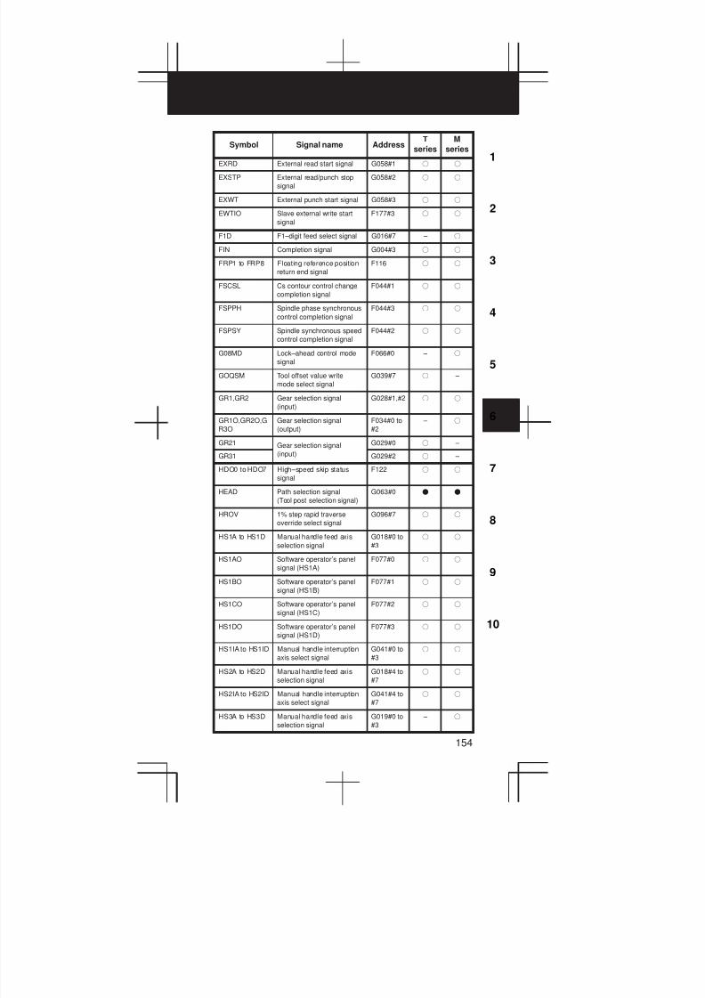
3
1
4
5
6
7
8
9
10
2
154
SymbolM
series
T
seriesAddressSignal name
EXRD External read start signal G058#1 f f
EXSTP External read/punch stop
signal
G058#2 f f
EXWT External punch start signal G058#3 f f
EWTIO Slave external write start
signal
F177#3 f f
F1D F1–digit feed select signal G016#7 – f
FIN Completion signal G004#3 f f
FRP1 to FRP8 Floating reference position
return end signal
F116 f f
FSCSL Cs contour control change
completion signal
F044#1 f f
FSPPH Spindle phase synchronous
control completion signal
F044#3 f f
FSPSY Spindle synchronous speed
control completion signal
F044#2 f f
G08MD Lock–ahead control mode
signal
F066#0 – f
GOQSM Tool offset value write
mode select signal
G039#7 f –
GR1,GR2 Gear selection signal
(input)
G028#1,#2 f f
GR1O,GR2O,G
R3O
Gear selection signal
(output)
F034#0 to
#2
– f
GR21 Gear selection signal G029#0 f –
GR31 (input) G029#2 f –
HDO0 to HDO7 High–speed skip status
signal
F122 f f
HEAD Path selection signal
(Tool post selection signal)
G063#0 F F
HROV 1% step rapid traverse
override select signal
G096#7 f f
HS1A to HS1D Manual handle feed axis
selection signal
G018#0 to
#3
f f
HS1AO Software operator’s panel
signal (HS1A)
F077#0 f f
HS1BO Software operator’s panel
signal (HS1B)
F077#1 f f
HS1CO Software operator’s panel
signal (HS1C)
F077#2 f f
HS1DO Software operator’s panel
signal (HS1D)
F077#3 f f
HS1IA to HS1ID Manual handle interruption
axis select signal
G041#0 to
#3
f f
HS2A to HS2D Manual handle feed axis
selection signal
G018#4 to
#7
f f
HS2IA to HS2ID Manual handle interruption
axis select signal
G041#4 to
#7
f f
HS3A to HS3D Manual handle feed axis
selection signal
G019#0 to
#3
– f

6. STATUS DISPLAY BY SELF–DIAGNOSTIC DISPLAY
155
SymbolM
series
T
seriesAddressSignal name
HS3IA to HS3ID Manual handle interruption
axis select signal
G042#0 to
#3
– f
IGNVRY All–axis VRDY OFF alarm
ignore signal
G066#0 f f
IGVRY1 to
IGVRY8
Each–axis VRDY OFF
alarm ignore signal
G192 f f
INCH Inch input signal F002#0 f f
INCMDA Incremental command
l i
G072#5 f f
INCMDBexternal setting type
orientation signal (serialG076#5 f f
INCMDC
i i i l i l
spindle) G206#5 f f
INCSTAIncremental method
F047#1 f f
INCSTB
l
orientation signal
i l i l
F051#1 f f
INCSTC
(serial spindle)F170#1 f f
INDXAOrientation stop position
G072#0 f f
INDXB
i i i i
change signal
i l i l
G076#0 f f
INDXC
(serial spindle)G206#0 f f
INFD In–feed cutting start signal G063#6 – f
INHKY Key input disable signal F053#0 f f
INP1 to INP8 In–position signal F104 f f
INTGASi nal for controllin
G071#5 f f
INTGB
i l lli
velocity integration
i l i l
G075#5 f f
INTGC
(serial spindle)G205#5 f f
IOLACK I/O Link confirmation signal G092#0 f f
IOLNK Slave I/O Link selection
signal
F177#0 f f
IOLS I/O Link specification signal G092#1 f f
KEY1 to KEY4 Memory protect signal G046#3 to
#6
f f
KEYO Software operator’s panel
signal (KEY1 to KEY4)
F075#6 f f
LDT1A
i i l
F045#4 f f
LDT1BLoad detection signal 1
(serial spindle)F049#4 f f
LDT1C
i l i l
F168#4 f f
LDT2A
i i l
F045#5 f f
LDT2B
Load detection signal 2
(serial spindle)F049#5 f f
LDT2C
i l i l
F168#5 f f
M00 to M31 Miscel laneous funct ion
code signal
F010 to
F013
f f
M200 to M215 2nd M function code signal F014 to
F015
f f
M300 to M315 3rd M funct ion code s ignal F016 to
F017
f f
MA CNC ready signal F001#7 f f
MABSM Manual absolute check
signal
F004#2 f f
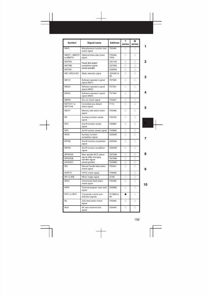
3
1
4
5
6
7
8
9
10
2
156
SymbolM
series
T
seriesAddressSignal name
MAFL Miscellaneous function lock
check signal
F004#4 f f
MBDT1, MBDT2
to MBDT9
Optional block skip check
signal
F004#0,
F005
f f
MCFNAPower line switch
G071#3 f f
MCFNB
li i
completion signal
i l i l
G075#3 f f
MCFNC
(serial spindle)G205#3 f f
MD1,MD2,MD4 Mode selection signal G043#0 to
#2
f f
MD1O Software operator’s panel
signal (MD1)
F073#0 f f
MD2O Software operator’s panel
signal (MD2)
F073#1 f f
MD4O Software operator’s panel
signal (MD4)
F073#2 f f
MDRN Dry run check signal F002#7 f f
MDTCH1 to
MDTCH8
Controlled axis detach
status signal
F110 f f
MEDT Memory edit select check
signal
F003#6 f f
MF Auxiliary function strobe
signal
F007#0 f f
MF2 2nd M function strobe
signal
F008#4 f f
MF3 3rd M function strobe signal F008#5 f f
MFIN Auxiliary function
completion signal
G005#0 f f
MFIN2 2nd M function completion
signal
G004#4 f f
MFIN3 3rd M function completion
signal
G004#5 f f
MFNHGA Main spindle MCC status
i l il i
G072#6 f f
MFNHGBsignal while changing
spindles signalG076#6 f f
MFNHGC
i l i l
(serial spindle) G206#6 f f
MH Manual handle feed select
check signal
F003#1 f f
MHPCC HPCC mode signal F066#6 – f
MI1 to MI8 Mirror image signal G106 f f
MINC Incremental feed select
check signal
F003#0 f f
MINP External program input start
signal
G058#0 f f
MIX1 to MIX7 Composite control axis
selection signals
G128#0 to
#6
F –
MJ JOG feed select check
signal
F003#2 f f
MLK All–axis machine lock
signal
G044#1 f f
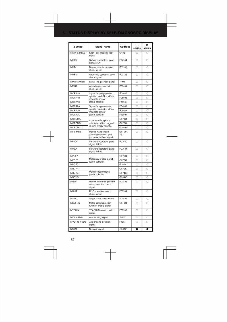
6. STATUS DISPLAY BY SELF–DIAGNOSTIC DISPLAY
157
SymbolM
series
T
seriesAddressSignal name
MLK1 to MLK8 Each–axis machine lock
signal
G108 f f
MLKO Software operator’s panel
signal(MLK)
F075#4 f f
MMDI Manual data input select
check signal
F003#3 f f
MMEM Automatic operation select
check signal
F003#5 f f
MMI1 to MMI8 Mirror image check s ignal F108 f f
MMLK All–axis machine lock
check signal
F004#1 f f
MORA1A Signal for completion of
i l i i i
F046#6 f f
MORA1Bspindle orientation with a
magnetic sensorF050#6 f f
MORA1C
i
(serial spindle) F169#6 f f
MORA2A Signal for approximate
i l i i i
F046#7 f f
MORA2B
spindle orientation with a
magnetic sensorF050#7 f f
MORA2C
i
(serial spindle) F169#7 f f
MORCMACommand for spindle
G073#0 f f
MORCMB
i l
orientaion with a magnetic
i l i l
G077#0 f f
MORCMC
sensor (serial spindle)G207#0 f f
MP1, MP2 Manual handle feed
amount selection signal
(incremental feed signal)
G019#4,
#5
f f
MP1O Software operator’s panel
signal (MP1)
F076#0 f f
MP2O Software operator’s panel
signal (MP2)
F076#1 f f
MPOFA
i l
G073#2 f f
MPOFBMotor power stop signal
(serial spindle)G077#2 f f
MPOFC
i l i l
G207#2 f f
MRDYA
i i l
G070#7 f f
MRDYB
Machine ready signal
(serial spindle)G074#7 f f
MRDYC
i l i l
G204#7 f f
MREF Manual reference position
return selection check
signal
F004#5 f f
MRMT DNC operation select
check signal
F003#4 f f
MSBK Single block check signal F004#3 f f
MSDFON Motor speed detection
function enable signal
G016#0 f f
MTCHIN TEACH IN select check
signal
F003#7 f f
MV1 to MV8 Axis moving signal F102 f f
MVD1 to MVD8 Axis moving direction
signal
F106 f f
NOWT No–wait signal G063#1 F F

3
1
4
5
6
7
8
9
10
2
158
SymbolM
series
T
seriesAddressSignal name
NOZAGC Perpendicular/angular axis
control disable signal
G063#5 f f
NPOS1 to
NPOS8
Position display neglect
signal
G198 f f
NRROA Short–distant movement
il i
G072#2 f f
NRROBcommand while changing
the orientation stop positionG076#2 f f
NRROC
i i i i
signal (serial spindle) G206#2 f f
OFN0 to
OFN5,OFN6
Tool offset number select
signal
G039#0
to #5,
G040#0
f –
OP Automatic operation signal F000#7 f f
ORARA
i i l i
F045#7 f f
ORARB
Orientation completion
signal (serial spindle)F049#7 f f
ORARC
i l i l i l
F168#7 f f
ORCMA
i i
G070#6 f f
ORCMB
Orientation command
signal (serial spindle)G074#6 f f
ORCMC
i l i l i l
G204#6 f f
OUT0 to OUT7 Software operator’s panel
general–purpose switch
signal
F072 f f
OVC Override cancel signal G006#4 f f
OVCE Override cancellation signal
(PMC axis control)
G150#5 f f
OVLS1 to
OVLS7
Superimposed control axis
selection signals
G190#0 to
#6
F –
OVRIDA
l i
G072#4 f f
OVRIDB
Analog override command
si nal (serial spindle)G076#4 f f
OVRIDC
i l i l i l
G206#4 f f
PC1DEA Signal indicating the status F047#0 f f
PC1DEB
of the detected
one–rotation position coderF051#0 f f
PC1DEC
i i i
signal (serial spindle) F170#0 f f
PC2SLC 2nd position coder
selection signal
G028#7 f –
PDT1 Conversational mode
selection signal
G062#4 f –
PDT2 Restart operation
notification signal
G062#5 f –
PECK2 Small–diameter peck
drilling in progress signal
F066#5 – f
PK1 to PK8 Parking signals G122 f –
PK1 to PK7 Parking signals G122#0 to
#6
F –
PKESS1 First spindle synchronous
control signal
G122#6
(G031#6)
f f
PKESS2 Second spindle
synchronous control signal
G122#7
(G031#7)
f f
PN1, PN2, PN4,
PN8, PN16
Workpiece number search
signal
G009#0 to
4
f f
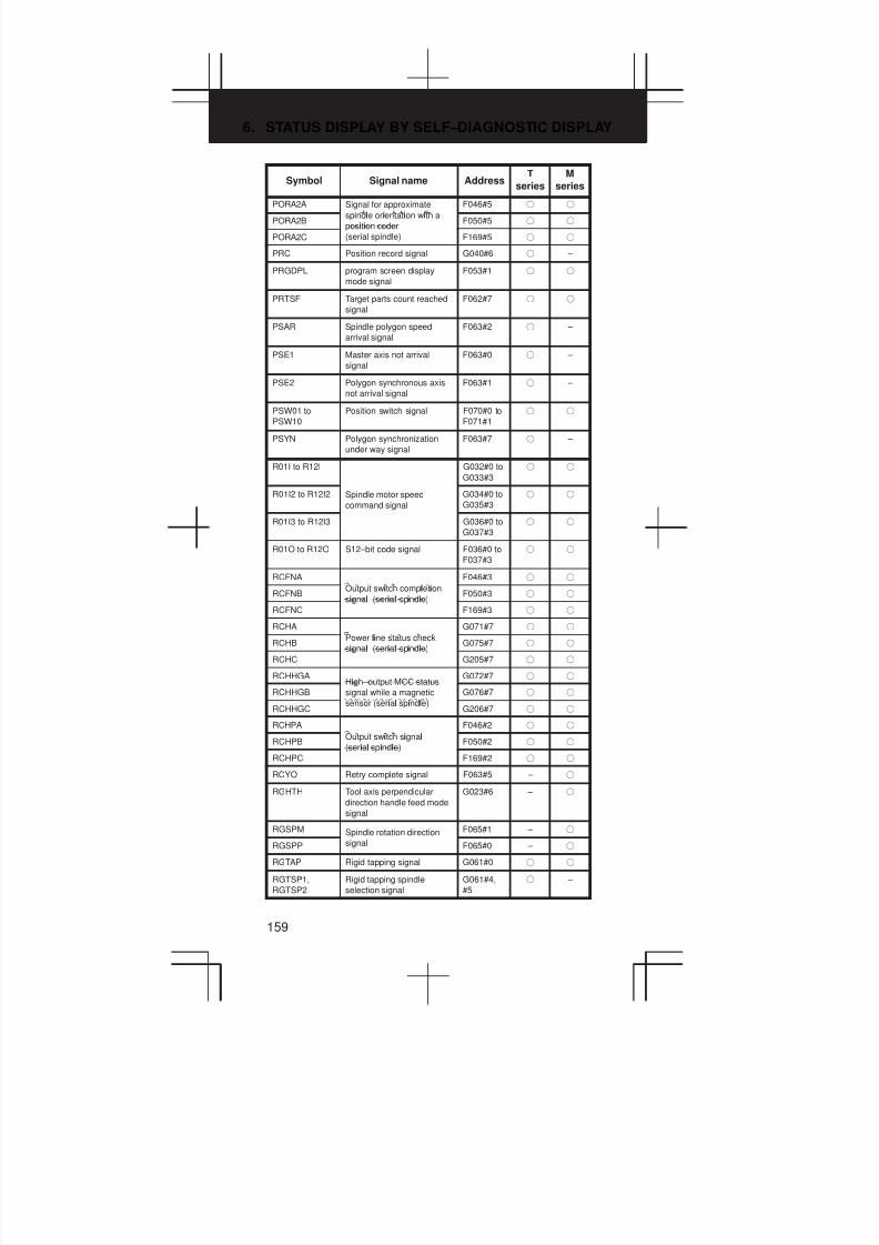
6. STATUS DISPLAY BY SELF–DIAGNOSTIC DISPLAY
159
SymbolM
series
T
seriesAddressSignal name
PORA2A Signal for approximate
i l i i i
F046#5 f f
PORA2Bspindle orientation with a
position coderF050#5 f f
PORA2C
i i
(serial spindle) F169#5 f f
PRC Position record signal G040#6 f –
PRGDPL program screen display
mode signal
F053#1 f f
PRTSF Target parts count reached
signal
F062#7 f f
PSAR Spindle polygon speed
arrival signal
F063#2 f –
PSE1 Master axis not arrival
signal
F063#0 f –
PSE2 Polygon synchronous axis
not arrival signal
F063#1 f –
PSW01 to
PSW10
Position switch signal F070#0 to
F071#1
f f
PSYN Polygon synchronization
under way signal
F063#7 f –
R01I to R12I G032#0 to
G033#3
f f
R01I2 to R12I2 Spindle motor speed
command signal
G034#0 to
G035#3
f f
R01I3 to R12I3 G036#0 to
G037#3
f f
R01O to R12O S12–bit code signal F036#0 to
F037#3
f f
RCFNA
i l i
F046#3 f f
RCFNB
Output switch completion
signal (serial spindle)F050#3 f f
RCFNC
i l i l i l
F169#3 f f
RCHA
li
G071#7 f f
RCHB
Power line status check
signal (serial spindle)G075#7 f f
RCHC
i l i l i l
G205#7 f f
RCHHGAHigh–output MCC status
G072#7 f f
RCHHGB
i
signal while a magnetic
i l i l
G076#7 f f
RCHHGC
sensor (serial spindle)G206#7 f f
RCHPA
i i l
F046#2 f f
RCHPBOutput switch signal
(serial spindle)F050#2 f f
RCHPC
i l i l
F169#2 f f
RCYO Retry complete signal F063#5 – f
RGHTH Tool axis perpendicular
direction handle feed mode
signal
G023#6 – f
RGSPM Spindle rotation direction F065#1 – f
RGSPP signal F065#0 – f
RGTAP Rigid tapping signal G061#0 f f
RGTSP1,
RGTSP2
Rigid tapping spindle
selection signal
G061#4,
#5
f –
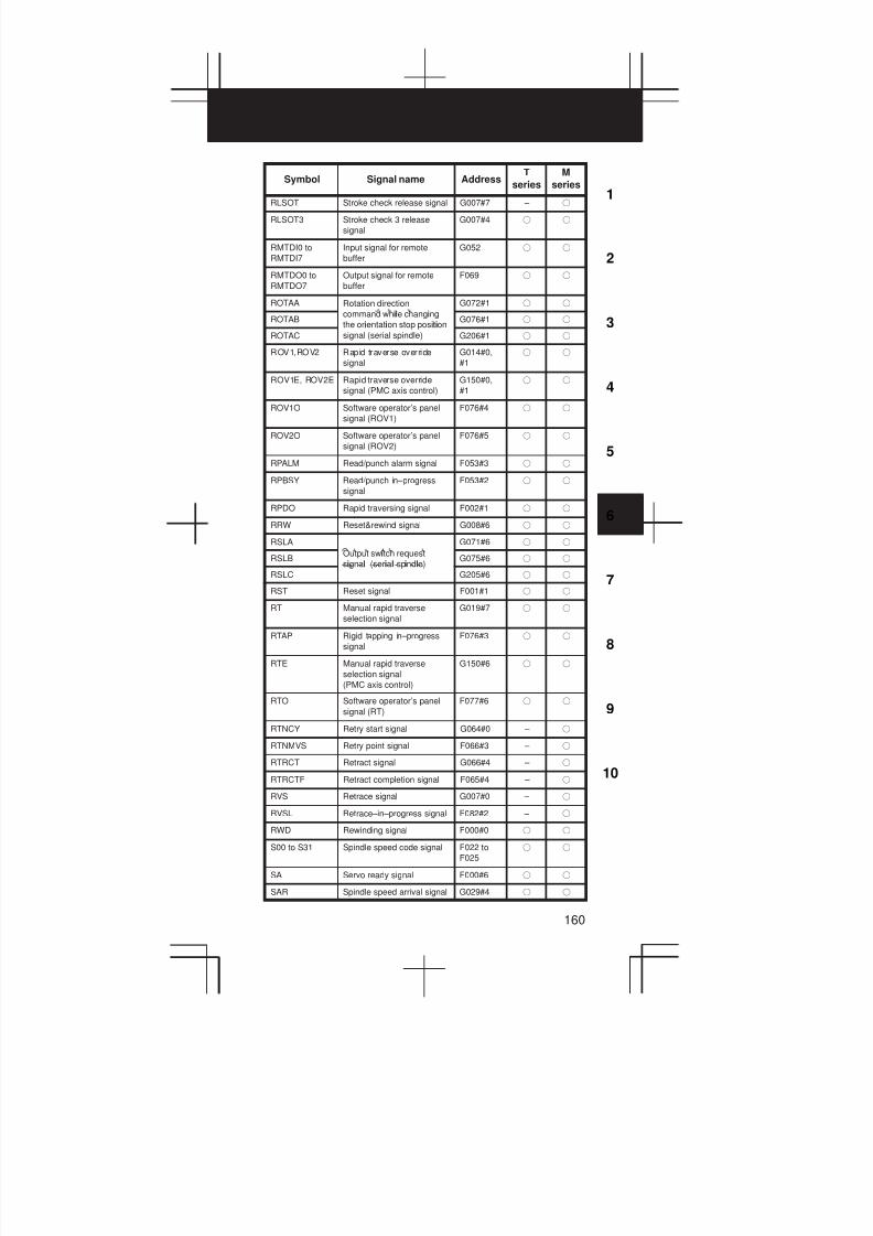
3
1
4
5
6
7
8
9
10
2
160
SymbolM
series
T
seriesAddressSignal name
RLSOT Stroke check release signal G007#7 – f
RLSOT3 Stroke check 3 release
signal
G007#4 f f
RMTDI0 to
RMTDI7
Input signal for remote
buffer
G052 f f
RMTDO0 to
RMTDO7
Output signal for remote
buffer
F069 f f
ROTAA Rotation direction
il i
G072#1 f f
ROTABcommand while changing
the orientation stop positionG076#1 f f
ROTAC
i i i i
signal (serial spindle) G206#1 f f
ROV1,ROV2 Rapid traverse override
signal
G014#0,
#1
f f
ROV1E, ROV2E Rapid traverse override
signal (PMC axis control)
G150#0,
#1
f f
ROV1O Software operator’s panel
signal (ROV1)
F076#4 f f
ROV2O Software operator’s panel
signal (ROV2)
F076#5 f f
RPALM Read/punch alarm signal F053#3 f f
RPBSY Read/punch in–progress
signal
F053#2 f f
RPDO Rapid traversing signal F002#1 f f
RRW Reset&rewind signal G008#6 f f
RSLA
i
G071#6 f f
RSLBOutput switch request
signal (serial spindle)G075#6 f f
RSLC
i l i l i l
G205#6 f f
RST Reset signal F001#1 f f
RT Manual rapid traverse
selection signal
G019#7 f f
RTAP Rigid tapping in–progress
signal
F076#3 f f
RTE Manual rapid traverse
selection signal
(PMC axis control)
G150#6 f f
RTO Software operator’s panel
signal (RT)
F077#6 f f
RTNCY Retry start signal G064#0 – f
RTNMVS Retry point signal F066#3 – f
RTRCT Retract signal G066#4 – f
RTRCTF Retract completion signal F065#4 – f
RVS Retrace signal G007#0 – f
RVSL Retrace–in–progress signal F082#2 – f
RWD Rewinding signal F000#0 f f
S00 to S31 Spindle speed code signal F022 to
F025
f f
SA Servo ready signal F000#6 f f
SAR Spindle speed arrival signal G029#4 f f
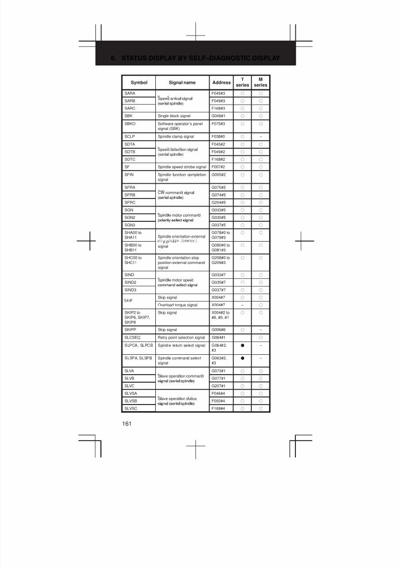
6. STATUS DISPLAY BY SELF–DIAGNOSTIC DISPLAY
161
SymbolM
series
T
seriesAddressSignal name
SARA
i l i l
F045#3 f f
SARBSpeed arrival signal
(serial spindle)F049#3 f f
SARC
i l i l
F168#3 f f
SBK Single block signal G046#1 f f
SBKO Software operator’s panel
signal (SBK)
F075#3 f f
SCLP Spindle clamp signal F038#0 f –
SDTA
i i l
F045#2 f f
SDTB
Speed detection signal
(serial spindle)F049#2 f f
SDTC
i l i l
F168#2 f f
SF Spindle speed strobe signal F007#2 f f
SFIN Spindle function completion
signal
G005#2 f f
SFRA
i l
G070#5 f f
SFRB
CW command signal
(serial spindle)G074#5 f f
SFRC
i l i l
G204#5 f f
SGN
i l
G033#5 f f
SGN2
Spindle motor command
polarity select signalG035#5 f f
SGN3
l i l i l
G037#5 f f
SHA00 to
SHA11 Spindle orientation external
p p i i
G078#0 to
G079#3
f f
SHB00 to
SHB11
i i
signal G080#0 to
G081#3
f f
SHC00 to
SHC11
Spindle orientation stop
position external command
signal
G208#0 to
G209#3
f f
SIND
i l
G033#7 f f
SIND2
Spindle motor speed
command select signalG035#7 f f
SIND3
l i l
G037#7 f f
Skip signal X004#7 f f
Overload torque signal X004#7 – f
SKIP2 to
SKIP6, SKIP7,
SKIP8
Skip signal X004#2 to
#6, #0, #1
f f
SKIPP Skip signal G006#6 f –
SLCSEQ Retry point selection signal G064#1 f
SLPCA, SLPCB Spindle return select signal G064#2,
#3
F –
SLSPA, SLSPB Spindle command select
signal
G063#2,
#3
F –
SLVA
l i
G073#1 f f
SLVB
Slave operation command
signal (serial spindle)G077#1 f f
SLVC
i l i l i l
G207#1 f f
SLVSA
l i
F046#4 f f
SLVSB
Slave operation status
signal (serial spindle)F050#4 f f
SLVSC
i l i l i l
F169#4 f f
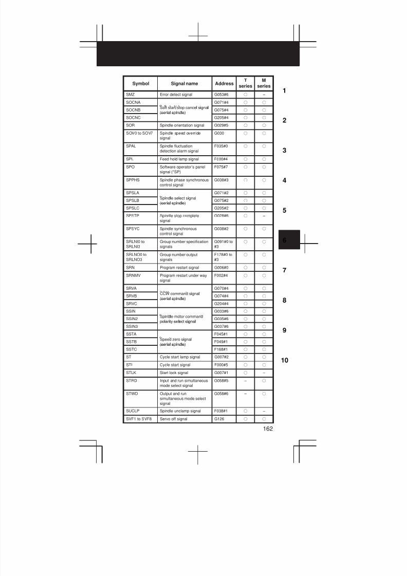
3
1
4
5
6
7
8
9
10
2
162
SymbolM
series
T
seriesAddressSignal name
SMZ Error detect signal G053#6 f –
SOCNA
l i l
G071#4 f f
SOCNBSoft start/stop cancel signal
(serial spindle)G075#4 f f
SOCNC
i l i l
G205#4 f f
SOR Spindle orientation signal G029#5 f f
SOV0 to SOV7 Spindle speed override
signal
G030 f f
SPAL Spindle fluctuation
detection alarm signal
F035#0 f f
SPL Feed hold lamp signal F000#4 f f
SPO Software operator’s panel
signal (*SP)
F075#7 f f
SPPHS Spindle phase synchronous
control signal
G038#3 f f
SPSLA
i l l i l
G071#2 f f
SPSLB
Spindle select signal
(serial spindle)G075#2 f f
SPSLC
i l i l
G205#2 f f
SPSTP Spindle stop complete
signal
G028#6 f –
SPSYC Spindle synchronous
control signal
G038#2 f f
SRLNI0 to
SRLNI3
Group number specification
signals
G091#0 to
#3
f f
SRLNO0 to
SRLNO3
Group number output
signals
F178#0 to
#3
f f
SRN Program restart signal G006#0 f f
SRNMV Program restart under way
signal
F002#4 f f
SRVA
i l
G070#4 f f
SRVB
CCW command signal
(serial spindle)G074#4 f f
SRVC
i l i l
G204#4 f f
SSIN
i l
G033#6 f f
SSIN2
Spindle motor command
polarity select signalG035#6 f f
SSIN3
l i l i l
G037#6 f f
SSTA
i l
F045#1 f f
SSTB
Speed zero signal
(serial spindle)F049#1 f f
SSTC
i l i l
F168#1 f f
ST Cycle start lamp signal G007#2 f f
STL Cycle start signal F000#5 f f
STLK Start lock signal G007#1 f –
STRD Input and run simultaneous
mode select signal
G058#5 – f
STWD Output and run
simultaneous mode select
signal
G058#6 – f
SUCLP Spindle unclamp signal F038#1 f –
SVF1 to SVF8 Servo off signal G126 f f

6. STATUS DISPLAY BY SELF–DIAGNOSTIC DISPLAY
163
SymbolM
series
T
seriesAddressSignal name
SWS1 G027#0 f –
SWS2 Spindle selection signal G027#1 f –
SWS3 G027#2 f –
SYCAL Spindle synchronous
control alarm signal/
phase error monitor signal
F044#4 f f
SYN1O to
SYN8O
Synchronous control under
way signals
F118 f –
SYN1O to
SYN7O
Synchronous/composite/
superimposed control
under way signals
F118#0 to
#6
F –
SYNC1 to
SYNC8
Simple synchronous axis
select signal
G138 f f
SYNC to
SYNC8
Synchronous control axis
selection signals
G138 f –
SYNC to
SYNC7
Synchronous control axis
selection signals
G138#0 to
#6
F –
SYNCJ1 to
SYNCJ8
Simple synchronous
manual feed axis select
signal
G140 – f
SYNMOD EGB mode signal F065#6 f
T00 to T31 Tool function code signal F026 to
F029
f f
TAP Tapping signal F001#5 f f
TF Tool function strobe signal F007#3 f f
TFIN Tool function completion
signal
G005#3 f f
THRD Thread cutting signal F002#3 f f
TIALM Tool post interference alarm
signal
F064#7 F –
TICHK Tool post interference
check signal
F064#6 F –
TL01 to TL64
Tool group number select
G047#0 to
#6
f –
TL01 to TL256 signal G047#0 to
G048#0
– f
TLCH Tool change signal F064#0 f f
TLCHI Individual tool change
signal
F064#2 – f
TLMA
li i i l
F045#6 f f
TLMBTorque limit signal
(serial spindle)F049#6 f f
TLMC
i l i l
F168#6 f f
TLMHATorque limit command
G070#1 f f
TLMHB
li i
HIGH signal
i l i l
G074#1 f f
TLMHC
(serial spindle)G204#1 f f
TLMLA
li i
G070#0 f f
TLMLBTorque limit command LOW
signal (serial spindle)G074#0 f f
TLMLC
i l i l i l
G204#0 f f

3
1
4
5
6
7
8
9
10
2
164
SymbolM
series
T
seriesAddressSignal name
TLNW New tool select signal F064#1 f f
TLRST Tool change reset signal G048#7 f f
TLRSTI Individual tool change reset
signal
G048#6 – f
TLSKP Tool skip signal G048#5 f f
TMRON General–purpose
integrating meter start
signal
G053#0 f f
TRACT Tool retraction mode signal F092#3 f f
TRESC Tool retraction signal G059#0 f f
TRQL1 to
TRQL8
Torque limit reached signal F114 f –
TRRTN Tool return signal G059#1 f f
TRSPS Tool return completion
signal
F092#5 f f
UI000 to UI015 Input signal for custom
macro
G054,
G055
f f
UINT Interrupt signal for custom
macro
G053#3 f f
UO000 to
UO015 Output signal for custom
F054,
F055
f f
UO100 to
UO131
macro F056 to
F059
f f
WATO Waiting signal F063#6 F F
WOQSM Workpiece coordinate
system shift value write
mode select signal
G039#6 f –
WOSET Workpiece coordinate
system shift value write
signal
G040#7 f –
XAE X004#0 f f
YAE Measuring position reached X004#1 – f
ZAE signal X004#1 f –
ZAE X004#2 – f
ZP1 to ZP8 Reference pos it ion return
end signal
F094 f f
ZP21 to ZP28 2nd reference position
return end signal
F096 f f
ZP31 to ZP38 3rd reference position
return end signal
F098 f f
ZP41 to ZP48 4th reference position
return end signal
F100 f f
ZPX Spindle orientation
completion signal
F094 f –
ZRF1 to ZRF8 Reference position
establishment signal
F120 f f
ZRN Manual reference position
return selection signal
G043#7 f f
ZRNO Software operator’s panel
signal (ZRN)
F073#4 f f
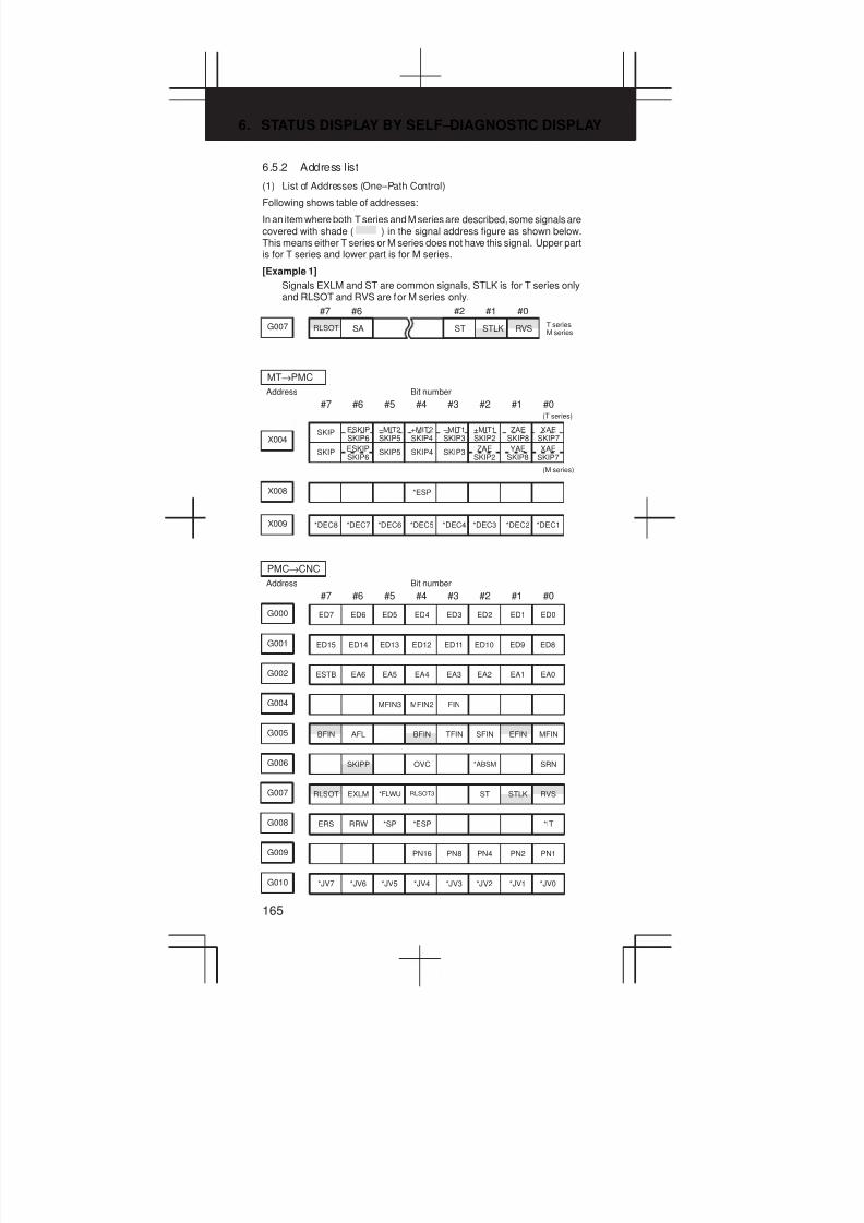
6. STATUS DISPLAY BY SELF–DIAGNOSTIC DISPLAY
165
6.5.2 Address list
(1) List of Addresses (One–Path Control)
Following shows table of addresses:
In an item where both T series and M series are described, some signals arecovered with shade ( ) in the signal address figure as shown below.This means either T series or M series does not have this signal. Upper partis for T series and lower part is for M series.
[Example 1]
Signals EXLM and ST are common signals, STLK is for T series onlyand RLSOT and RVS are for M series only.
#7 #6 #2 #1 #0
G007 RLSOT SA ST STLK RVST seriesM series
#7 #6 #5 #4 #3 #2 #1 #0
Address
MT→PMC
Bit number
–MIT1SKIP3
–MIT2SKIP5X004
SKIP SKIP5 SKIP4 SKIP3
SKIP ESKIPSKIP6
+MIT2SKIP4
+MIT1SKIP2
ZAESKIP8
XAESKIP7
(M series)
(T series)
ESKIPSKIP6
ZAESKIP2
YAESKIP8
XAESKIP7
X008 *ESP
X009 *DEC8 *DEC7 *DEC6 *DEC5 *DEC4 *DEC3 *DEC2 *DEC1
#7 #6 #5 #4 #3 #2 #1 #0
Address
PMC→CNC
Bit number
G000 ED7 ED6 ED5 ED4 ED3 ED2 ED1 ED0
G001 ED15 ED14 ED13 ED12 ED11 ED10 ED9 ED8
G002 ESTB EA6 EA5 EA4 EA3 EA2 EA1 EA0
G004 MFIN3 MFIN2 FIN
G005 BFIN AFL BFIN TFIN SFIN EFIN MFIN
G006 SKIPP OVC *ABSM SRN
G007 RLSOT EXLM *FLWU RLSOT3 ST STLK RVS
G008 ERS RRW *SP *ESP *IT
G009 PN16 PN8 PN4 PN2 PN1
G010 *JV7 *JV6 *JV5 *JV4 *JV3 *JV2 *JV1 *JV0

3
1
4
5
6
7
8
9
10
2
166
#7 #6 #5 #4 #3 #2 #1 #0
G011 *JV15 *JV14 *JV13 *JV12 *JV11 *JV10 *JV9 *JV8
G012 *FV7 *FV6 *FV5 *FV4 *FV3 *FV2 *FV1 *FV0
G013 *AFV7 *AFV6 *AFV5 *AFV4 *AFV3 *AFV2 *AFV1 *AFV0
G014 ROV2 ROV1
G016 F1D MSDFON
G018 HS2D HS2C HS2B HS2A HS1D HS1C HS1B HS1A
HS3BMP1G019 RT MP2 HS3D HS3C HS3A
G023 ALNGH RGHTH
G027 CON *SSTP3 *SSTP2 *SSTP1 SWS3 SWS2 SWS1
GR1*SUCPFG028 PC2SLC SPSTP *SCPF GR2
G029 *SSTP SOR SAR GR31 GR21
G030 SOV7 SOV6 SOV5 SOV4 SOV3 SOV2 SOV1 SOV0
G031 PKESS2 PKESS1
G032 R08I R07I R06I R05I R04I R03I R02I R01I
G033 SIND SSIN SGN R12I R11I R10I R09I
G034 R08I2 R07I2 R06I2 R05I2 R04I2 R03I2 R02I2 R01I2
G035 SIND2 SSIN2 SGN2 R12I2 R11I2 R10I2 R09I2
G036 R08I3 R07I3 R06I3 R05I3 R04I3 R03I3 R02I3 R01I3
G037 SIND3 SSIN3 SGN3 R12I3 R11I3 R10I3 R09I3
G038 *BECLP *BEUCP SPPHS SPSYC *PLSST
OFN1OFN4G039 GOQSM WOQSM OFN5 OFN3 OFN2 OFN0
G040 WOSET PRC OFN6
G041 HS2ID HS2IC HS2IB HS2IA HS1ID HS1IC HS1IB HS1IA
HS3IBG042 DMMC HS3ID HS3IC HS3IA

6. STATUS DISPLAY BY SELF–DIAGNOSTIC DISPLAY
167
#7 #6 #5 #4 #3 #2 #1 #0
G043 ZRN DNCI MD4 MD2 MD1
G044 MLK BDT1
G045 BDT9 BDT8 BDT7 BDT6 BDT5 BDT4 BDT3 BDT2
G046 DRN KEY4 KEY3 KEY2 KEY1 SBK
TL02TL16G047 TL128 TL64 TL32 TL08 TL04 TL01
G048 TLRST TLRSTI TLSKP TL256
*TOV1*TLV4G049 *TLV7 *TLV6 *TLV5 *TLV3 *TLV2 *TLV0
*TLV9G050 *TLV8
*CHP2G051 *CHLD CHPST *CHP8 *CHP4 *CHP0
G052 RMTDI7 RMTDI6 RMTDI5 RMTDI4 RMTDI3 RMTDI2 RMTDI1 RMTDI0
G053 CDZ SMZ UINT TMRON
G054 UI007 UI006 UI005 UI004 UI003 UI002 UI001 UI000
G055 UI015 UI014 UI013 UI012 UI011 UI010 UI009 UI008
EXRDG058 STWD STRD EXWT EXSTP MINP
G059 TRRTN TRESC
G060 *TSB
RGTSP1G061 RGTSP2 RGTAP
G062 PDT2 PDT1 *CRTOF
G063 INFD NOZAGC
SLCSEQG064 ESRSYC RTNCY
G065
ENBKYRTRCTG066 EKSET IGNVRY
G070 MRDYA ORCMA SFRA SRVA CTH1A CTH2A TLMHA TLMLA
G071 RCHA RSLA INTGA SOCNA MCFNA SPSLA *ESPA ARSTA
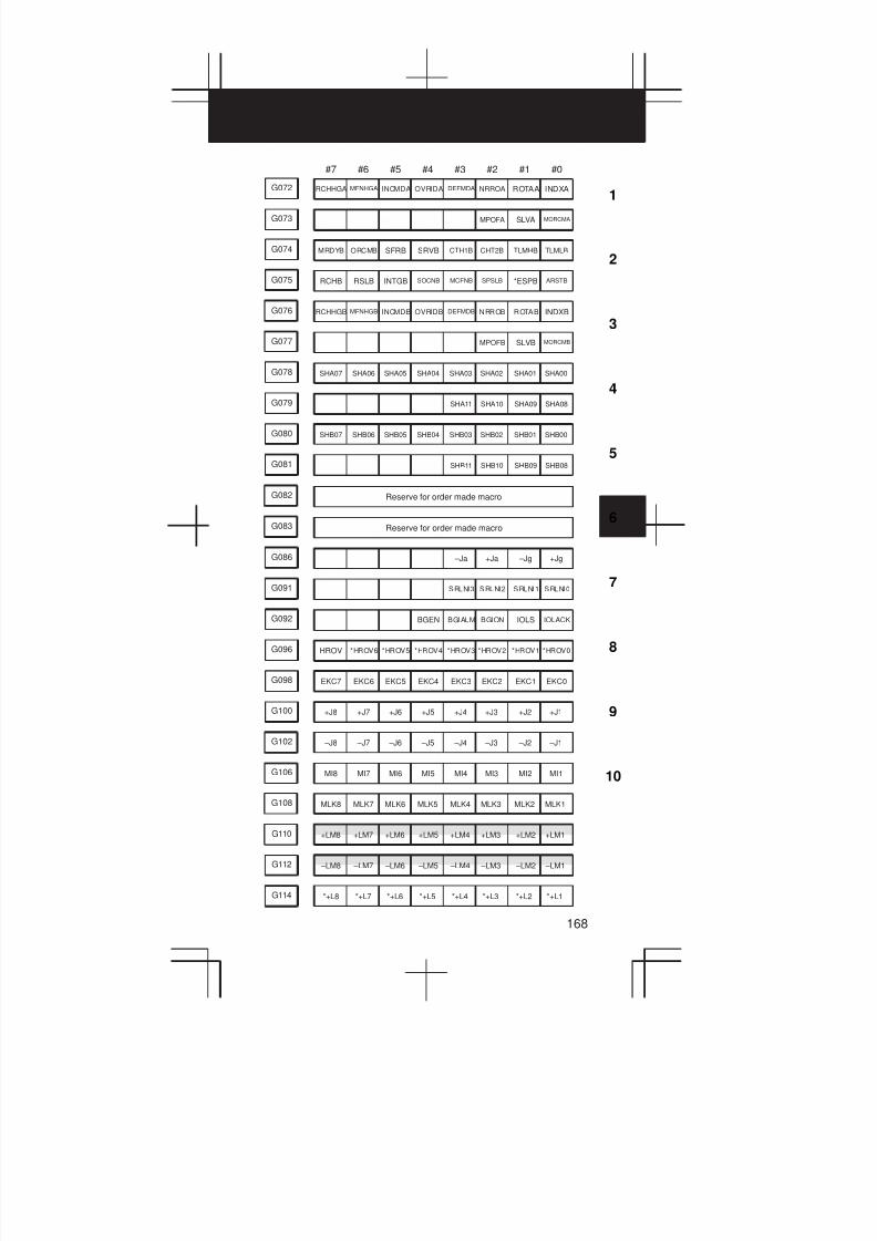
3
1
4
5
6
7
8
9
10
2
168
#7 #6 #5 #4 #3 #2 #1 #0
G072 RCHHGA MFNHGA INCMDA OVRIDA DEFMDA NRROA ROTAA INDXA
G073 MPOFA SLVA MORCMA
G074 MRDYB ORCMB SFRB SRVB CTH1B CHT2B TLMHB TLMLB
G075 RCHB RSLB INTGB SOCNB MCFNB SPSLB *ESPB ARSTB
G076 RCHHGB MFNHGB INCMDB OVRIDB DEFMDB NRROB ROTAB INDXB
G077 MPOFB SLVB MORCMB
G078 SHA07 SHA06 SHA05 SHA04 SHA03 SHA02 SHA01 SHA00
G079 SHA11 SHA10 SHA09 SHA08
G080 SHB07 SHB06 SHB05 SHB04 SHB03 SHB02 SHB01 SHB00
G081 SHB11 SHB10 SHB09 SHB08
G082 Reserve for order made macro
G083 Reserve for order made macro
G086 –Ja +Ja –Jg +Jg
G091 SRLNI3 SRLNI2 SRLNI1 SRLNI0
G092 BGEN BGIALM BGION IOLS IOLACK
G096 HROV *HROV6 *HROV5 *HROV4 *HROV3 *HROV2 *HROV1 *HROV0
G098 EKC7 EKC6 EKC5 EKC4 EKC3 EKC2 EKC1 EKC0
G100 +J8 +J7 +J6 +J5 +J4 +J3 +J2 +J1
G102 –J8 –J7 –J6 –J5 –J4 –J3 –J2 –J1
G106 MI8 MI7 MI6 MI5 MI4 MI3 MI2 MI1
G108 MLK8 MLK7 MLK6 MLK5 MLK4 MLK3 MLK2 MLK1
+LM2+LM5G110 +LM8 +LM7 +LM6 +LM4 +LM3 +LM1
–LM2 –LM5G112 –LM8 –LM7 –LM6 –LM4 –LM3 –LM1
G114 *+L8 *+L7 *+L6 *+L5 *+L4 *+L3 *+L2 *+L1
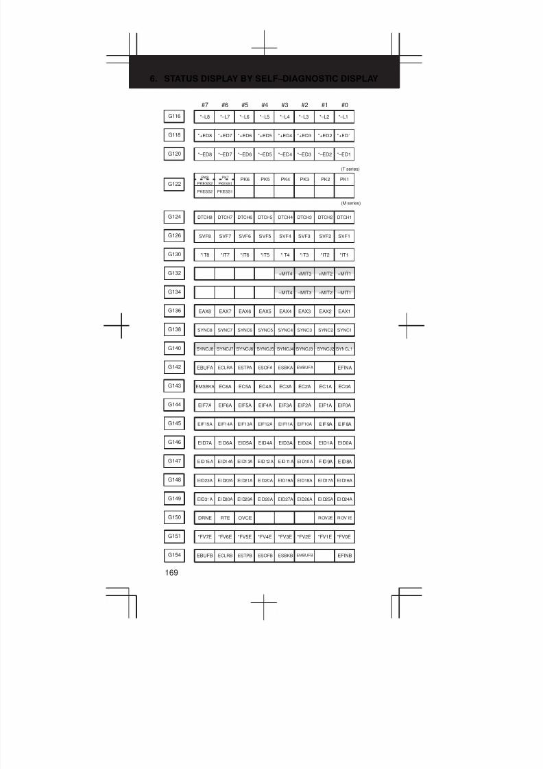
6. STATUS DISPLAY BY SELF–DIAGNOSTIC DISPLAY
169
#7 #6 #5 #4 #3 #2 #1 #0
G116 *–L8 *–L7 *–L6 *–L5 *–L4 *–L3 *–L2 *–L1
G118 *+ED8 *+ED7 *+ED6 *+ED5 *+ED4 *+ED3 *+ED2 *+ED1
G120 *–ED8 *–ED7 *–ED6 *–ED5 *–ED4 *–ED3 *–ED2 *–ED1
PK4PK6G122
PKESS2
PK8
PKESS2
PK7
PKESS1PK5 PK3 PK2 PK1
(M series)
(T series)
PKESS1
G124 DTCH8 DTCH7 DTCH6 DTCH5 DTCH4 DTCH3 DTCH2 DTCH1
G126 SVF8 SVF7 SVF6 SVF5 SVF4 SVF3 SVF2 SVF1
G130 *IT8 *IT7 *IT6 *IT5 *IT4 *IT3 *IT2 *IT1
+MIT2G132 +MIT4 +MIT3 +MIT1
–MIT2G134 –MIT4 –MIT3 –MIT1
G136 EAX8 EAX7 EAX6 EAX5 EAX4 EAX3 EAX2 EAX1
SYNC2SYNC5G138 SYNC8 SYNC7 SYNC6 SYNC4 SYNC3 SYNC1
SYNCJ2SYNCJ5G140 SYNCJ8 SYNCJ7 SYNCJ6 SYNCJ4 SYNCJ3 SYNCJ1
G142 EBUFA ECLRA ESTPA ESOFA ESBKA EMBUFA EFINA
G143 EMSBKA EC6A EC5A EC4A EC3A EC2A EC1A EC0A
G144 EIF7A EIF6A EIF5A EIF4A EIF3A EIF2A EIF1A EIF0A
G145 EIF15A EIF14A EIF13A EIF12A EI F11A EIF10A EIF9A EIF8A
G146 EID7A EID6A EID5A EID4A EID3A EID2A EID1A EID0A
G147 EID15A EID14A EID13A EID12A EID11A EID10A EID9A EID8A
G148 EID23A EI D22A EI D21A EID20A EID19A EID18A EI D17A EI D16A
G149 EID31A EI D30A EI D29A EID28A EID27A EID26A EI D25A EI D24A
G150 DRNE RTE OVCE ROV2E ROV1E
G151 *FV7E *FV6E *FV5E *FV4E *FV3E *FV2E *FV1E *FV0E
G154 EBUFB ECLRB ESTPB ESOFB ESBKB EMBUFB EFINB
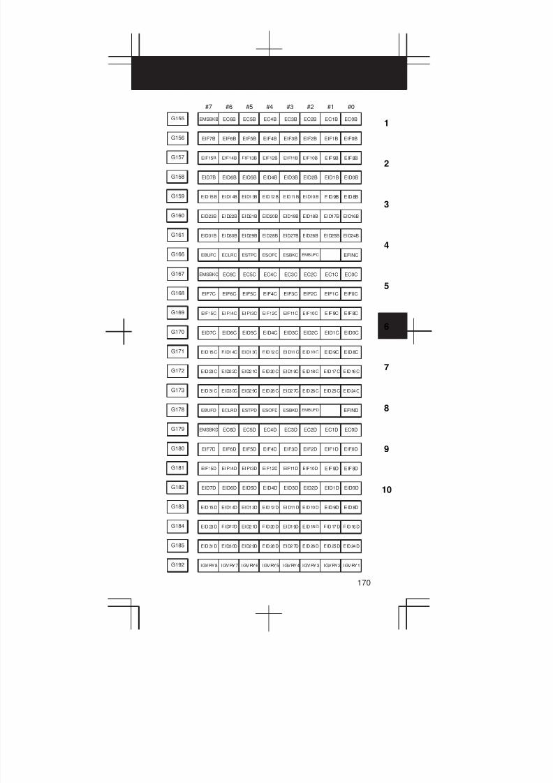
3
1
4
5
6
7
8
9
10
2
170
#7 #6 #5 #4 #3 #2 #1 #0
G155 EMSBKB EC6B EC5B EC4B EC3B EC2B EC1B EC0B
G156 EIF7B EIF6B EIF5B EIF4B EIF3B EIF2B EIF1B EIF0B
G157 EIF15B EIF14B EIF13B EIF12B EI F11B EIF10B EIF9B EIF8B
G158 EID7B EID6B EID5B EID4B EID3B EID2B EID1B EID0B
G159 EID15B EID14B EID13B EID12B EID11B EID10B EID9B EID8B
G160 EID23B EI D22B EI D21B EID20B EID19B EID18B EI D17B EI D16B
G161 EID31B EI D30B EI D29B EID28B EID27B EID26B EI D25B EI D24B
G166 EBUFC ECLRC ESTPC ESOFC ESBKC EMBUFC EFINC
G167 EMSBKC EC6C EC5C EC4C EC3C EC2C EC1C EC0C
G168 EIF7C EIF6C EIF5C EIF4C EIF3C EIF2C EIF1C EIF0C
G169 EIF15C EI F14C EI F13C EIF12C EIF11C EIF10C EIF9C EIF8C
G170 EID7C EID6C EID5C EID4C EID3C EID2C EID1C EID0C
G171 EID15C EID14C EID13C EID12C EID11C EID10C EID9C EID8C
G172 EID23C EID22C EID21C EID20C EID19C EID18C EID17C EID16C
G173 EID31C EID30C EID29C EID28C EID27C EID26C EID25C EID24C
G178 EBUFD ECLRD ESTPD ESOFD ESBKD EMBUFD EFIND
G179 EMSBKD EC6D EC5D EC4D EC3D EC2D EC1D EC0D
G180 EIF7D EIF6D EIF5D EIF4D EIF3D EIF2D EIF1D EIF0D
G181 EIF15D EI F14D EI F13D EIF12D EIF11D EIF10D EIF9D EIF8D
G182 EID7D EID6D EID5D EID4D EID3D EID2D EID1D EID0D
G183 EID15D EID14D EID13D EID12D EID11D EID10D EID9D EID8D
G184 EID23D EID22D EID21D EID20D EID19D EID18D EID17D EID16D
G185 EID31D EID30D EID29D EID28D EID27D EID26D EID25D EID24D
G192 IGVRY8 IGVRY7 IGVRY6 IGVRY5 IGVRY4 IGVRY3 IGVRY2 IGVRY1

6. STATUS DISPLAY BY SELF–DIAGNOSTIC DISPLAY
171
#7 #6 #5 #4 #3 #2 #1 #0
G198 NPOS8 NPOS7 NPOS6 NPOS5 NPOS4 NPOS3 NPOS2 NPOS1
G204 MRDYC ORCML SFRC SRVC CTH1C CTH2C TLMHC TLMLC
G205 RCHC RSLC INTGC SOCNC MCFNC SPSLC *ESPC ARSTC
G206 RCHHGC MFNHGC INCMDC OVRIDC DEFMDCNRROC ROTAC INDXC
G207 MPOFC SLVC MORCMC
G208 SHC07 SHC06 SHC05 SHC04 SHC03 SHC02 SHC01 SHC00
G209 SHC11 SHC10 SHC09 SHC08
#7 #6 #5 #4 #3 #2 #1 #0
Address
CNC→PMC
Bit number
F000 OP SA STL SPL RWD
F001 MA TAP ENB DEN BAL RST AL
F002 MDRN CUT SRNMV THRD CSS RPDO INCH
F003 MTCHIN MEDT MMEM MRMT MMDI MJ MH MINC
F004 MREF MAFL MSBK MABSM MMLK MBDT1
F005 MBDT9 MBDT8 MBDT7 MBDT6 MBDT5 MBDT4 MBDT3 MBDT2
EFDBFF007 BF TF SF MF
MF2F008 MF3 EF
F009 DM00 DM01 DM02 DM30
F010 M07 M06 M05 M04 M03 M02 M01 M00
F011 M15 M14 M13 M12 M11 M10 M09 M08
F012 M23 M22 M21 M20 M19 M18 M17 M16
F013 M31 M30 M29 M28 M27 M26 M25 M24
F014 M207 M206 M205 M204 M203 M202 M201 M200
F015 M215 M214 M213 M212 M211 M210 M209 M208

3
1
4
5
6
7
8
9
10
2
172
#7 #6 #5 #4 #3 #2 #1 #0
F016 M307 M306 M305 M304 M303 M302 M301 M300
F017 M315 M314 M313 M312 M311 M310 M309 M308
F022 S07 S06 S05 S04 S03 S02 S01 S00
F023 S15 S14 S13 S12 S11 S10 S09 S08
F024 S23 S22 S21 S20 S19 S18 S17 S16
F025 S31 S30 S29 S28 S27 S26 S25 S24
F026 T07 T06 T05 T04 T03 T02 T01 T00
F027 T15 T14 T13 T12 T11 T10 T09 T08
F028 T23 T22 T21 T20 T19 T18 T17 T16
F029 T31 T30 T29 T28 T27 T26 T25 T24
F030 B07 B06 B05 B04 B03 B02 B01 B00
F031 B15 B14 B13 B12 B11 B10 B09 B08
F032 B23 B22 B21 B20 B19 B18 B17 B16
F033 B31 B30 B29 B28 B27 B26 B25 B24
GR2OF034 GR3O GR1O
F035 SPAL
F036 R08O R07O R06O R05O R04O R03O R02O R01O
F037 R12O R11O R10O R09O
SUCLPF038 ENB3 ENB2 SCLP
F039 CHPCYL CHPMD
AR1AR4F040 AR7 AR6 AR5 AR3 AR2 AR0
AR09AR12F041 AR15 AR14 AR13 AR11 AR10 AR08
F044 SYCAL FSPPH FSPSY FSCSL
F045 ORARA TLMA LDT2A LDT1A SARA SDTA SSTA ALMA
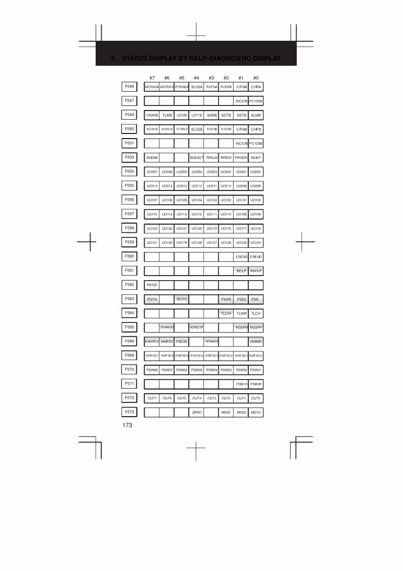
6. STATUS DISPLAY BY SELF–DIAGNOSTIC DISPLAY
173
#7 #6 #5 #4 #3 #2 #1 #0
F046 MORA2A MORA1A PORA2A SLVSA RCFNA RCHPA CFINA CHPA
F047 INCSTA PC1DEA
F049 ORARB TLMB LDT2B LDT1B SARB SDTB SSTB ALMB
F050 MO RA 2B M ORA 1B PO RA2 B SLVSB R CF NB R CH PB CFINB CHPB
F051 INCSTB PC1DEB
F053 EKENB BGEACT RPALM RPBSY PRGDPL INHKY
F054 UO007 UO006 UO005 UO004 UO003 UO002 UO001 UO000
F055 UO015 UO014 UO013 UO012 UO011 UO010 UO009 UO008
F056 UO107 UO106 UO105 UO104 UO103 UO102 UO101 UO100
F057 UO115 UO114 UO113 UO112 UO111 UO110 UO109 UO108
F058 UO123 UO122 UO121 UO120 UO119 UO118 UO117 UO116
F059 UO131 UO130 UO129 UO128 UO127 UO126 UO125 UO124
F060 ESEND EREND
BCLPF061 BUCLP
F062 PRTSF
PSE2F063 PSYN RCYO PSAR PSE1
TLNWF064 TLCHI TLCH
RGSPMRTRCTFF065 SYNMOD RGSPP
F066 EXHPCC MMPCC PECK2 RTNMVS G08MD
F069 RMTDO7 RMTDO6 RMTDO5 RMTDO4 RMTDO3 RMTDO2 RMTDO1 RMTDO0
F070 PSW08 PSW07 PSW06 PSW05 PSW04 PSW03 PSW02 PSW01
F071 PSW10 PSW09
F072 OUT7 OUT6 OUT5 OUT4 OUT3 OUT2 OUT1 OUT0
F073 ZRNO MD4O MD2O MD1O
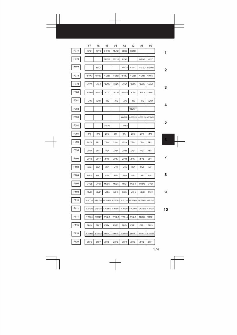
3
1
4
5
6
7
8
9
10
2
174
#7 #6 #5 #4 #3 #2 #1 #0
F075 SPO KEYO DRNO MLKO SBKO BDTO
F076 ROV2O ROV1O RTAP MP2O MP1O
F077 RTO H S1D O H S1C O HS1BO HS1AO
F078 *FV7O *FV6O *FV5O *FV4O *FV3O *FV2O *FV1O *FV0O
F079 *JV7O *JV6O *JV5O *JV4O *JV3O *JV2O *JV1O *JV0O
F080 *JV15O *JV14O *JV13O *JV12O *JV11O *JV10O *JV9O *JV8O
F081 –J4O +J4O –J3O +J3O –J2O +J2O –J1O +J1O
F082 RVSL
F090 ABTSP3 ABTSP2 ABTSP1 ABTQSV
F092 TRSPS TRACT
F094 ZP8 ZP7 ZP6 ZP5 ZP4 ZP3 ZP2 ZP1
F096 ZP28 ZP27 ZP26 ZP25 ZP24 ZP23 ZP22 ZP21
F098 ZP38 ZP37 ZP36 ZP35 ZP34 ZP33 ZP32 ZP31
F100 ZP48 ZP47 ZP46 ZP45 ZP44 ZP43 ZP42 ZP41
F102 MV8 MV7 MV6 MV5 MV4 MV3 MV2 MV1
F104 INP8 INP7 INP6 INP5 INP4 INP3 INP2 INP1
F106 MVD8 MVD7 MVD6 MVD5 MVD4 MVD3 MVD2 MVD1
F108 MMI8 MMI7 MMI6 MMI5 MMI4 MMI3 MMI2 MMI1
F110 MDTCH8 MDTCH7 MDTCH6 MDTCH5 MDTCH4 MDTCH3 MDTCH2 MDTCH1
F112 E AD EN 8 E AD EN 7 E AD EN 6 E AD EN 5 E AD EN 4 E AD EN 3 E AD EN 2 E AD EN 1
TRQL2TRQL5F114 TRQL8 TRQL7 TRQL6 TRQL4 TRQL3 TRQL1
F116 FRP8 FRP7 FRP6 FRP5 FRP4 FRP3 FRP2 FRP1
SYN2OSYN5OF118 SYN8O SYN7O SYN6O SYN4O SYN3O SYN1O
F120 ZRF8 ZRF7 ZRF6 ZRF5 ZRF4 ZRF3 ZRF2 ZRF1
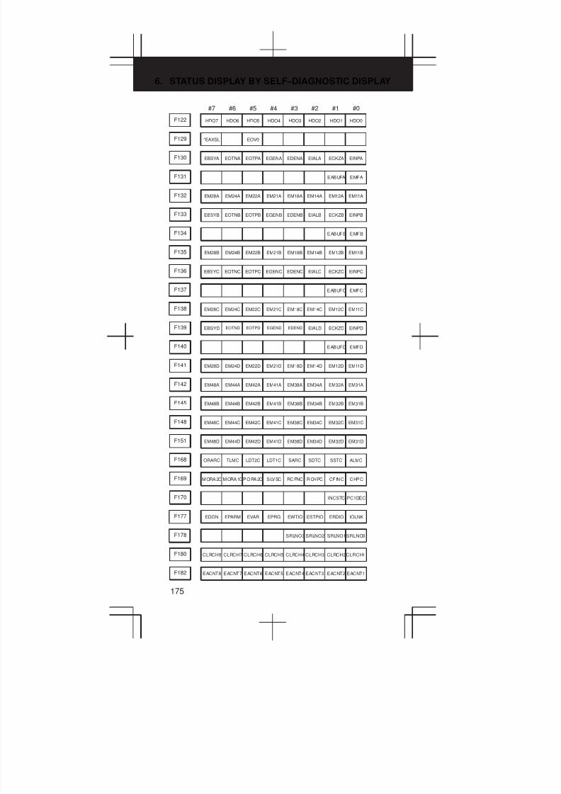
6. STATUS DISPLAY BY SELF–DIAGNOSTIC DISPLAY
175
#7 #6 #5 #4 #3 #2 #1 #0
F122 HDO7 HDO6 HDO5 HDO4 HDO3 HDO2 HDO1 HDO0
F129 *EAXSL EOV0
F130 EBSYA EOTNA EOTPA EGENA EDENA EIALA ECKZA EINPA
F131 EABUFA EMFA
F132 EM28A EM24A EM22A EM21A EM18A EM14A EM12A EM11A
F133 EBSYB EOTNB EOTPB EGENB EDENB EIALB ECKZB EINPB
F134 EABUFB EMFB
F135 EM28B EM24B EM22B EM21B EM18B EM14B EM12B EM11B
F136 EBSYC EOTNC EOTPC EGENC EDENC EIALC ECKZC EINPC
F137 EABUFC EMFC
F138 EM28C EM24C EM22C EM21C EM18C EM14C EM12C EM11C
F139 EBSYD EOTND EOTPD EGEND EDEND EIALD ECKZD EINPD
F140 EABUFD EMFD
F141 EM28D EM24D EM22D EM21D EM18D EM14D EM12D EM11D
F142 EM48A EM44A EM42A EM41A EM38A EM34A EM32A EM31A
F145 EM48B EM44B EM42B EM41B EM38B EM34B EM32B EM31B
F148 EM48C EM44C EM42C EM41C EM38C EM34C EM32C EM31C
F151 EM48D EM44D EM42D EM41D EM38D EM34D EM32D EM31D
F168 ORARC TLMC LDT2C LDT1C SARC SDTC SSTC ALMC
F169 MORA2C MORA1CPORA2C SLVSC RCFNC RCHPC CFINC CHPC
F170 INCSTC PC1DEC
F177 EDGN EPARM EVAR EPRG EWTIO ESTPIO ERDIO IOLNK
F178 SRLNO3 SRLNO2 SRLNO1SRLNO0
F180 CLRCH8 CLRCH7 CLRCH6 CLRCH5 CLRCH4 CLRCH3 CLRCH2CLRCH1
F182 EACNT8 EACNT7 EACNT6 EACNT5 EACNT4 EACNT3 EACNT2 EACNT1
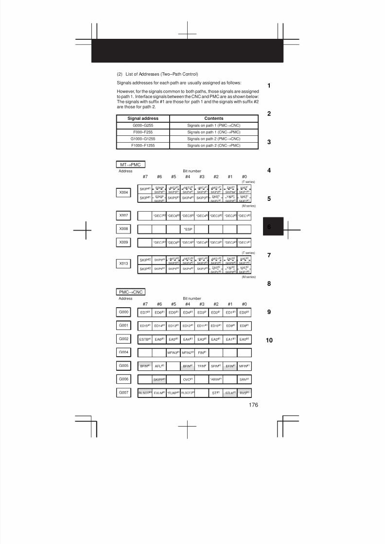
3
1
4
5
6
7
8
9
10
2
176
(2) List of Addresses (Two–Path Control)
Signals addresses for each path are usually assigned as follows:
However, for the signals common to both paths, those signals are assignedto path 1. Interface signals between the CNC and PMC are as shown below:The signals with suffix #1 are those for path 1 and the signals with suffix #2are those for path 2.
Signal address Contents
G000–G255 Signals on path 1 (PMC→CNC)
F000–F255 Signals on path 1 (CNC→PMC)
G1000–G1255 Signals on path 2 (PMC→CNC)
F1000–F1255 Signals on path 2 (CNC→PMC)
#7 #6 #5 #4 #3 #2 #1 #0
Address
MT→PMC
Bit number
SKIP5#1 SKIP3#1
–MIT1#1
SKIP3#1
–MIT2#1
SKIP5#1X004
SKIP#1 SKIP4#1
SKIP#1 ESKIP
SKIP6#1
+MIT2#1
SKIP4#1
+MIT1#1
SKIP2#1
ZAE#1
SKIP8#1
XAE#1
SKIP7#1
(M series)
(T series)
ESKIP
SKIP6#1
ZAE#1
SKIP2#1
YAE#1
SKIP8#1
XAE#1
SKIP7#1
X007 *DEC7#2 *DEC6#2 *DEC5#2 *DEC4#2 *DEC3#2 *DEC2#2 *DEC1#2
X008 *ESP
X009 *DEC7#1 *DEC6#1 *DEC5#1 *DEC4#1 *DEC3#1 *DEC2#1 *DEC1#1
SKIP3#2SKIP5#2
–MIT1#2
SKIP3#2
–MIT2#2
SKIP5#2X013
SKIP#2 SKIP4#2
SKIP#2 +MIT2#2
SKIP4#2
+MIT1#2
SKIP2#2
ZAE#2
SKIP8#2
XAE#2
SKIP7#2
SKIP6#2 ZAE#2
SKIP2#2
YAE#2
SKIP8#2
XAE#2
SKIP7#2
SKIP6#2
(M series)
(T series)
#7 #6 #5 #4 #3 #2 #1 #0
Address
PMC→CNC
Bit number
G000 ED7#1 ED6#1 ED5#1 ED4#1 ED3#1 ED2#1 ED1#1 ED0#1
G001 ED15#1 ED14#1 ED13#1 ED12#1 ED11#1 ED10#1 ED9#1 ED8#1
G002 ESTB#1 EA6#1 EA5#1 EA4#1 EA3#1 EA2#1 EA1#1 EA0#1
G004 MFIN3#1 MFIN2#1 FIN#1
G005 BFIN#1 AFL#1 BFIN#1 TFIN#1 SFIN#1 EFIN#1 MFIN#1
G006 SKIPP#1 OVC#1 *ABSM#1 SRN#1
G007 RLSOT#1 EXLM#1 *FLWP#1 RLSOT3#1 ST#1 STLK#1 RVS#1
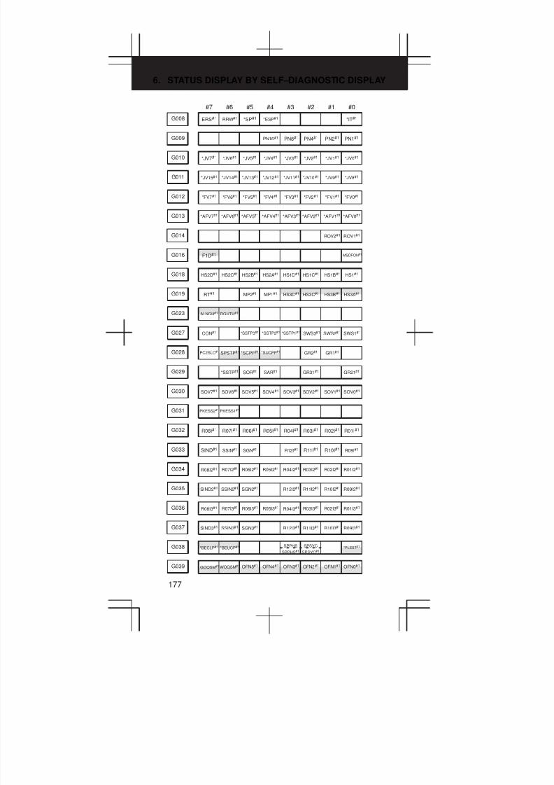
6. STATUS DISPLAY BY SELF–DIAGNOSTIC DISPLAY
177
#7 #6 #5 #4 #3 #2 #1 #0
G008 ERS#1 RRW#1 *SP#1 *ESP#1 *IT#1
G009 PN16#1 PN8#1 PN4#1 PN2#1 PN1#1
G010 *JV7#1 *JV6#1 *JV5#1 *JV4#1 *JV3#1 *JV2#1 *JV1#1 *JV0#1
G011 *JV15#1 *JV14#1 *JV13#1 *JV12#1 *JV11#1 *JV10#1 *JV9#1 *JV8#1
G012 *FV7#1 *FV6#1 *FV5#1 *FV4#1 *FV3#1 *FV2#1 *FV1#1 *FV0#1
G013 *AFV7#1 *AFV6#1 *AFV5#1 *AFV4#1 *AFV3#1 *AFV2#1 *AFV1#1 *AFV0#1
G014 ROV2#1 ROV1#1
G016 F1D#1 MSDFON#1
G018 HS2D#1 HS2C#1 HS2B#1 HS2A#1 HS1D#1 HS1C#1 HS1B#1 HS1#1
HS3B#1MP1#1G019 RT#1 MP2#1 HS3D#1 HS3C#1 HS3A#1
G023 ALNGH#1 RGHTH#1
G027 CON#1 *SSTP3#1 *SSTP2#1 *SSTP1#1 SWS3#1 SWS2#1 SWS1#1
GR1#1*SUCPF#1G028 PC2SLC#1 SPSTP#1 *SCPF#1 GR2#1
G029 *SSTP#1 SOR#1 SAR#1 GR31#1 GR21#1
G030 SOV7#1 SOV6#1 SOV5#1 SOV4#1 SOV3#1 SOV2#1 SOV1#1 SOV0#1
G031 PKESS2#1 PKESS1#1
G032 R08I#1 R07I#1 R06I#1 R05I#1 R04I#1 R03I#1 R02I#1 R01I#1
G033 SIND#1 SSIN#1 SGN#1 R12I#1 R11I#1 R10I#1 R09I#1
G034 R08I2#1 R07I2#1 R06I2#1 R05I2#1 R04I2#1 R03I2#1 R02I2#1 R01I2#1
G035 SIND2#1 SSIN2#1 SGN2#1 R12I2#1 R11I2#1 R10I2#1 R09I2#1
G036 R08I3#1 R07I3#1 R06I3#1 R05I3#1 R04I3#1 R03I3#1 R02I3#1 R01I3#1
G037 SIND3#1 SSIN3#1 SGN3#1 R12I3#1 R11I3#1 R10I3#1 R09I3#1
G038 *BECLP#1 *BEUCP#1 SPPHS
SPPHS#1*PLSST#1SPSYC
SPSYC#1
OFN1#1OFN4#1G039 GOQSM#1WOQSM#1 OFN5#1 OFN3#1 OFN2#1 OFN0#1

3
1
4
5
6
7
8
9
10
2
178
#7 #6 #5 #4 #3 #2 #1 #0
G040 WOSET#1 PRC#1 OFN6#1
G041 HS2ID#1 HS2IC#1 HS2IB#1 HS2IA#1 HS1ID#1 HS1IC#1 HS1IB#1 HS1IA#1
HS3IB#1G042 HS3ID#1 HS3IC#1 HS3IA #1
G043 ZRN#1 DNCI#1 MD4#1 MD2#1 MD1#1
G044 MLK#1 BDT1#1
G045 BDT9#1 BDT8#1 BDT7#1 BDT6#1 BDT5#1 BDT4#1 BDT3#1 BDT2#1
G046 DRN#1 KEY4#1 KEY3#1 KEY2#1 KEY1#1 SBK#1
TL02#1TL16#1G047 TL128#1 TL64#1 TL32#1 TL08#1 TL04#1 TL01#1
G048 TLRST#1 TLRSTI#1 TLSKP#1TL256#1
*TOV1#1*TLV4#1G049 *TLV7#1 *TLV6#1 *TLV5#1 *TLV3#1 *TLV2#1 *TLV0#1
*TLV9#1G050 *TLV8#1
*CHP2#1G051 *CHLD#1 CHPST#1 *CHP8#1 *CHP4#1 *CHP0#1
G053 CDZ#1 SMZ#1 UINT#1 TMRON#1
G054 UI007#1 UI006#1 UI005#1 UI004#1 UI003#1 UI002#1 UI001#1 UI000#1
G055 UI015#1 UI014#1 UI013#1 UI012#1 UI011#1 UI010#1 UI009#1 UI008#1
EXRD#1G058 EXWT#1 EXSTP#1 MINP#1
G059 TRRTN#1 TRESC#1
G060 *TSB#1
RGTSP1#1G061 RGTSP2#1 RGTAP#1
G062 PDT2#1 PDT1#1 *CRTOF#1
G063 INFD#1 NOZAGC#1 SLSPB SLSPA NOWT HEAD
SLCSEQ#1G064 ESRSYC#1 SLPCB SLPCA RTNCY#1
ENBKYRTRCTG066 EKSET IGNVRY#1
G070 MRDYA#1 ORCMA#1 SFRA#1 SRVA#1 CTH1A#1 CTH2A#1 TLMHA#1 TLMLA#1

6. STATUS DISPLAY BY SELF–DIAGNOSTIC DISPLAY
179
#7 #6 #5 #4 #3 #2 #1 #0
G071 RCHA#1 RSLA#1 INTGA#1 SOCNA#1 MCFNA#1 SPSLA#1 *ESPA#1 ARSTA#1
G072 RCHHGA#1 MFNHGA#1 INCMDA#1 OVRIDA#1 DEFMDA#1 NRROA#1 ROTAA#1 INDXA#1
G073 MPOFA#1 SLVA#1 MORCMA#1
G074 MRDYB#1 ORCMB#1 SFRB#1 SRVB#1 CTH1B#1 CTH2B#1 TLMHB#1 TLMLB#1
G075 RCHB#1 RSLB#1 INTGB#1 SOCNB#1 MCFNB#1 SPSLB#1 *ESPB#1 ARSTB#1
G076 RCHHGB#1 MFNHGB#1 INCMDB#1 OVRIDB#1 DEFMDB#1 NRROB#1 ROTAB#1 INDXB#1
G077 MPOFB#1 SLVB#1 MORCMB#1
G078 SHA07#1 SHA06#1 SHA05#1 SHA04#1 SHA03#1 SHA02#1 SHA01#1 SHA00#1
G079 SHA11#1 SHA10#1 SHA09#1 SHA08#1
G080 SHB07#1 SHB06#1 SHB05#1 SHB04#1 SHB03#1 SHB02#1 SHB01#1 SHB00#1
G081 SHB11#1 SHB10#1 SHB09#1 SHB08#1
G082 Reserved for order made macro
G083 Reserved for order made macro
G091 SRLNI3#1 SRLNI2#1 SRLNI1#1 SRLNI0#1
G092 BGEN#1 BGIALM#1 BGION#1 IOLS#1 IOLACK#1
G096 HROV#1 *HROV6#1 *HROV5#1 *HROV4#1 *HROV3#1 *HROV2#1 *HROV1#1 *HROV0#1
G098 EKC7 EKC6 EKC5 EKC4 EKC3 EKC2 EKC1 EKC0
G100 +J7#1 +J6#1 +J5#1 +J4#1 +J3#1 +J2#1 +J1#1
G102 –J7#1 –J6#1 –J5#1 –J4#1 –J3#1 –J2#1 –J1#1
G106 MI7#1 MI6#1 MI5#1 MI4#1 MI3#1 MI2#1 MI1#1
G108 MLK7#1 MLK6#1 MLK5#1 MLK4#1 MLK3#1 MLK2#1 MLK1#1
+LM2#1+LM5#1G110 +LM7#1 +LM6#1 +LM4#1 +LM3#1 +LM1#1
–LM2#1 –LM5#1G112 –LM7#1 –LM6#1 –LM4#1 –LM3#1 –LM1#1
G114 *+L7#1 *+L6#1 *+L5#1 *+L4#1 *+L3#1 *+L2#1 *+L1#1

3
1
4
5
6
7
8
9
10
2
180
#7 #6 #5 #4 #3 #2 #1 #0
G116 *–L7#1 *–L6#1 *–L5#1 *–L4#1 *–L3#1 *–L2#1 *–L1#1
G118 *+ED7#1 *+ED6#1 *+ED5#1 *+ED4#1 *+ED3#1 *+ED2#1 *+ED1#1
G120 *–ED7#1 *–ED6#1 *–ED5#1 *–ED4#1 *–ED3#1 *–ED2#1 *–ED1#1
PK7#1
PKESS1#1
PKESS1#1
PKESS2#1 PK4#1PK6#1
G122
PKESS2#1
PK5#1 PK3#1 PK2#1 PK1#1
(M series)
(T series)
G124 DTCH7#1 DTCH6#1 DTCH5#1 DTCH4#1DTCH3#1 DTCH2#1DTCH1#1
G126 SVF7#1 SVF6#1 SVF5#1 SVF4#1 SVF3#1 SVF2#1 SVF1#1
MIX2MIX5G128 MIX7 MIX6 MIX4 MIX3 MIX1
G130 *IT7#1 *IT6#1 *IT5#1 *IT4#1 *IT3#1 *IT2#1 *IT1#1
+MIT2#1G132 +MIT4#1 +MIT3#1 +MIT1#1
–MIT2#1G134 –MIT4#1 –MIT3#1 –MIT1#1
G136 EAX7#1 EAX6#1 EAX5#1 EAX4#1 EAX3#1 EAX2#1 EAX1#1
SYNC2#1SYNC5#1G138 SYNC7#1 SYNC6#1 SYNC4#1 SYNC3#1 SYNC1#1
SYNCJ2#1SYNCJ5#1G140 SYNCJ7#1 SYNCJ6#1 SYNCJ4#1 SYNCJ3#1 SYNCJ1#1
G142 EBUFA#1 ECLRA#1 ESTPA#1 ESOFA#1 ESBKA#1 EMBUFA#1 EFINA#1
G143 EMSBKA#1 EC6A#1 EC5A#1 EC4A#1 EC3A#1 EC2A#1 EC1A#1 EC0A#1
G144 EIF7A#1 EIF6A#1 EIF5A#1 EIF4A#1 EIF3A#1 EIF2A#1 EIF1A#1 EIF0A#1
G145 EIF15A#1 EIF14A#1 EIF13A#1 EIF12A#1 EIF11A#1 EIF10A#1 EIF9A#1 EIF8A#1
G146 EID7A#1 EID6A#1 EID5A#1 EID4A#1 EID3A#1 EID2A#1 EID1A#1 EID0A#1
G147 EID15A#1 EID14A#1 EID13A#1 EID12A#1 EID11A#1 EID10A#1 EID9A#1 EID8A#1
G148 EID23A#1 EID22A#1 EID21A#1 EID20A#1 EID19A#1 EID18A#1 EID17A#1 EID16A#1
G149 EID31A#1 EID30A#1 EID29A#1 EID28A#1 EID27A#1 EID26A#1 EID25A#1 EID24A#1
G150 DRNE#1 RTE#1 OVCE#1 ROV2E#1ROV1E#1
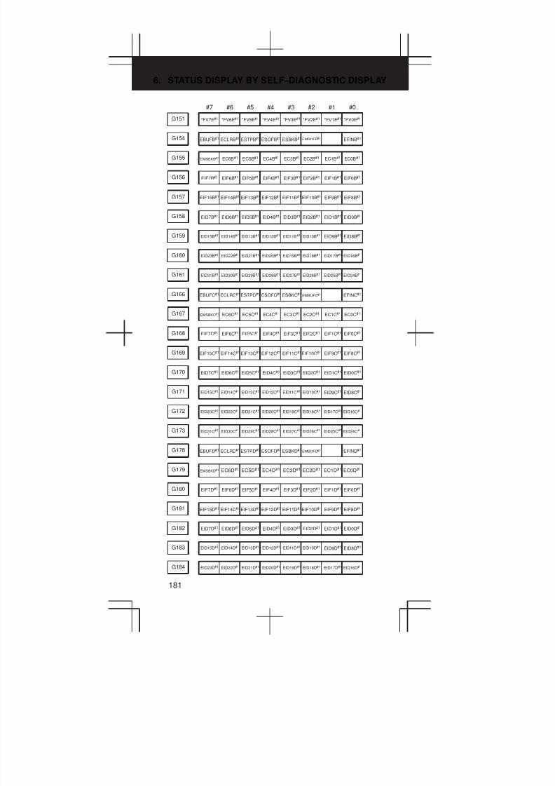
6. STATUS DISPLAY BY SELF–DIAGNOSTIC DISPLAY
181
#7 #6 #5 #4 #3 #2 #1 #0
G151 *FV7E#1 *FV6E#1 *FV5E#1 *FV4E#1 *FV3E#1 *FV2E#1 *FV1E#1 *FV0E#1
G154 EBUFB#1 ECLRB#1 ESTPB#1 ESOFB#1 ESBKB#1 EMBUFB#1 EFINB#1
G155 EMSBKB#1 EC6B#1 EC5B#1 EC4B#1 EC3B#1 EC2B#1 EC1B#1 EC0B#1
G156 EIF7B#1 EIF6B#1 EIF5B#1 EIF4B#1 EIF3B#1 EIF2B#1 EIF1B#1 EIF0B#1
G157 EIF15B#1 EIF14B#1 EIF13B#1 EIF12B#1 EIF11B#1 EIF10B#1 EIF9B#1 EIF8B#1
G158 EID7B#1 EID6B#1 EID5B#1 EID4B#1 EID3B#1 EID2B#1 EID1B#1 EID0B#1
G159 EID15B#1 EID14B#1 EID13B#1 EID12B#1 EID11B#1 EID10B#1 EID9B#1 EID8B#1
G160 EID23B#1 EID22B#1 EID21B#1 EID20B#1 EID19B#1 EID18B#1 EID17B#1 EID16B#1
G161 EID31B#1 EID30B#1 EID29B#1 EID28B#1 EID27B#1 EID26B#1 EID25B#1 EID24B#1
G166 EBUFC#1 ECLRC#1 ESTPC#1 ESOFC#1 ESBKC#1 EMBUFC#1 EFINC#1
G167 EMSBKC#1 EC6C#1 EC5C#1 EC4C#1 EC3C#1 EC2C#1 EC1C#1 EC0C#1
G168 EIF7C#1 EIF6C#1 EIF5C#1 EIF4C#1 EIF3C#1 EIF2C#1 EIF1C#1 EIF0C#1
G169 EIF15C#1 EIF14C#1 EIF13C#1 EIF12C#1 EIF11C#1EIF10C#1 EIF9C#1 EIF8C#1
G170 EID7C#1 EID6C#1 EID5C#1 EID4C#1 EID3C#1 EID2C#1 EID1C#1 EID0C#1
G171 EID15C#1 EID14C#1 EID13C#1 EID12C#1 EID11C#1 EID10C#1 EID9C#1 EID8C#1
G172 EID23C#1 EID22C#1 EID21C#1 EID20C#1 EID19C#1 EID18C#1 EID17C#1 EID16C#1
G173 EID31C#1 EID30C#1 EID29C#1 EID28C#1 EID27C#1 EID26C#1 EID25C#1 EID24C#1
G178 EBUFD#1 ECLRD#1 ESTPD#1 ESOFD#1 ESBKD#1 EMBUFD#1 EFIND#1
G179 EMSBKD#1 EC6D#1 EC5D#1 EC4D#1 EC3D#1 EC2D#1 EC1D#1 EC0D#1
G180 EIF7D#1 EIF6D#1 EIF5D#1 EIF4D#1 EIF3D#1 EIF2D#1 EIF1D#1 EIF0D#1
G181 EIF15D#1 EIF14D#1 EIF13D#1 EIF12D#1 EIF11D#1EIF10D#1 EIF9D#1 EIF8D#1
G182 EID7D#1 EID6D#1 EID5D#1 EID4D#1 EID3D#1 EID2D#1 EID1D#1 EID0D#1
G183 EID15D#1 EID14D#1 EID13D#1 EID12D#1 EID11D#1 EID10D#1 EID9D#1 EID8D#1
G184 EID23D#1 EID22D#1 EID21D#1 EID20D#1 EID19D#1 EID18D#1 EID17D#1 EID16D#1

3
1
4
5
6
7
8
9
10
2
182
#7 #6 #5 #4 #3 #2 #1 #0
G185 EID31D#1 EID30D#1 EID29D#1 EID28D#1 EID27D#1 EID26D#1 EID25D#1 EID24D#1
OVLS2#1OVLS5#1G190 OVLS7#1 OVLS6#1 OVLS4#1 OVLS3#1 OVLS1#1
G192 IGVRY7#1 IGVRY6#1 IGVRY5#1 IGVRY4#1 IGVRY3#1 IGVRY2#1 IGVRY1#1
G198 NPOS7#1 NPOS6#1 NPOS5#1 NPOS4#1 NPOS3#1 NPOS2#1 NPOS1#1
#7 #6 #5 #4 #3 #2 #1 #0
Address
PMC→CNC
Bit number
G1000 ED7#2 ED6#2 ED5#2 ED4#2 ED3#2 ED2#2 ED1#2 ED0#2
G1001 ED15#2 ED14#2 ED13#2 ED12#2 ED11#2 ED10#2 ED9#2 ED8#2
G1002 ESTB#2 EA6#2 EA5#2 EA4#2 EA3#2 EA2#2 EA1#2 EA0#2
G1004 MFIN3#2 MFIN2#2 FIN#2
G1005 BFIN#2 AFL#2 BFIN#2 TFIN#2 SFIN#2 EFIN#2 MFIN#2
G1006 SKIPP#2 OVC#2 *ABSM#2 SRN#2
G1007 RLSOT#2 EXLM#2 *FLWP#2 RLSOT3#2 ST#2 STLK#2 RVS#2
G1008 ERS#2 RRW#2 *SP#2 *ESP#2 *IT#2
G1009 PN16#2 PN8#2 PN4#2 PN2#2 PN1#2
G1010 *JV7#2 *JV6#2 *JV5#2 *JV4#2 *JV3#2 *JV2#2 *JV1#2 *JV0#2
G1011 *JV15#2 *JV14#2 *JV13#2 *JV12#2 *JV11#2 *JV10#2 *JV9#2 *JV8#2
G1012 *FV7#2 *FV6#2 *FV5#2 *FV4#2 *FV3#2 *FV2#2 *FV1#2 *FV0#2
G1013 *AFV7#2 *AFV6#2 *AFV5#2 *AFV4#2 *AFV3#2 *AFV2#2 *AFV1#2 *AFV0#2
G1014 ROV2#2 ROV1#2
G1016 F1D#2 MSDFON#2
G1018 HS2D#2 HS2C#2 HS2B#2 HS2A#2 HS1D#2 HS1C#2 HS1B#2 HS1A#2
HS3B#2MP1#2G1019 RT#2 MP2#2 HS3D#2 HS3C#2 HS3A#2
G1023 ALNGH#2 RGHTH#2

6. STATUS DISPLAY BY SELF–DIAGNOSTIC DISPLAY
183
#7 #6 #5 #4 #3 #2 #1 #0
G1027 CON#2 *SSTP3#2 *SSTP2#2 *SSTP1#2 SWS3#2 SWS2#2 SWS1#2
GR1#2*SUCPF#2G1028 PC2SLC#2 SPSTP#2 *SCPF#2 GR2#2
G1029 *SSTP#2 SOR#2 SAR#2 GR31#2 GR21#2
G1030 SOV7#2 SOV6#2 SOV5#2 SOV4#2 SOV3#2 SOV2#2 SOV1#2 SOV0#2
G1031 PKESS2#2 PKESS1#2
G1032 R08I#2 R07I#2 R06I#2 R05I#2 R04I#2 R03I#2 R02I#2 R01I#2
G1033 SIND#2 SSIN#2 SGN#2 R12I#2 R11I#2 R10I#2 R09I#2
G1034 R08I2#2 R07I2#2 R06I2#2 R05I2#2 R04I2#2 R03I2#2 R02I2#2 R01I2#2
G1035 SIND2#2 SSIN2#2 SGN2#2 R12I2#2 R11I2#2 R10I2#2 R09I2#2
G1036 R08I3#2 R07I3#2 R06I3#2 R05I3#2 R04I3#2 R03I3#2 R02I3#2 R01I3#2
G1037 SIND3#2 SSIN3#2 SGN3#2 R12I3#2 R11I3#2 R10I3#2 R09I3#2
G1038 *BECLP#2 *BEUCP#2 SPPHS#2 *PLSST#2SPSYC#2
OFN1#2OFN4#2G1039 GOQSM#2 WOQSM#2 OFN5#2 OFN3#2 OFN2#2 OFN0#2
G1040 WOSET#2 PRC#2 OFN6#2
G1041 HS2ID#2 HS2IC#2 HS2IB#2 HS2IA#2 HS1ID#2 HS1IC#2 HS1IB#2 HS1IA#2
HS3IB#2G1042 HS3ID#2 HS3IC#2 HS3IA#2
G1043 ZRN#2 DNCI#2 MD4#2 MD2#2 MD1#2
G1044 MLK#2 BDT1#2
G1045 BDT9#2 BDT8#2 BDT7#2 BDT6#2 BDT5#2 BDT4#2 BDT3#2 BDT2#2
G1046 DRN#2 KEY4#2 KEY3#2 KEY2#2 KEY1#2 SBK#2
TL02#2TL16#2G1047 TL128#2 TL64#2 TL32#2 TL08#2 TL04#2 TL01#2
G1048 TLRST#2 TLRSTI#2 TLSKP#2 TL256#2
*TOV1#2*TLV4#2G1049 *TLV7#2 *TLV6#2 *TLV5#2 *TLV3#2 *TLV2#2 *TLV0#2
*TLV9#2G1050 *TLV8#2

3
1
4
5
6
7
8
9
10
2
184
#7 #6 #5 #4 #3 #2 #1 #0
*CHP2#2G1051 *CHLD#2 CHPST#2 *CHP8#2 *CHP4#2 *CHP0#2
G1053 CDZ#2 SMZ#2 UINT#2 TMRON#2
G1054 UI007#2 UI006#2 UI005#2 UI004#2 UI003#2 UI002#2 UI001#2 UI000#2
G1055 UI015#2 UI014#2 UI013#2 UI012#2 UI011#2 UI010#2 UI009#2 UI008#2
EXRD#2G1058 EXWT#2 EXSTP#2 MINP#2
G1059 TRRTN#2 TRESC#2
G1060 *TSB#2
RGTSP1#2G1061 RGTSP2#2 RGTAP#2
G1062 PDT2#2 PDT1#2 *CRTOF#2
G1063 INFD#2 NOZAGC#2
SLCSEQ#2G1064 ESRSYC#2 RTNCY#2
RTRCT#2G1066 IGNVRY#2
G1070 MRDYA#2 ORCMA#2 SFRA#2 SRVA#2 CTH1A#2 CTH2A#2 TLMHA#2 TLMLA#2
G1071 RCHA#2 RSLA#2 INTGA#2 SOCNA#2 MCFNA#2 SPSLA#2 *ESPA#2 ARSTA#2
G1072 RCHHGA#2 MFNHGA#2 INCMDA#2 OVRIDA#2 DEFMDA#2 NRROA#2 ROTAA#2 INDXA#2
G1073 MPOFA#2 SLVA#2 MORCMA#2
G1074 MRDYB#2 ORCMB#2 SFRB#2 SRVB#2 CTH1B#2 CTH2B#2 TLMHB#2 TLMLB#2
G1075 RCHB#2 RSLB#2 INTGB#2 SOCNB#2 MCFNB#2 SPSLB#2 *ESPB#2 ARSTB#2
G1076 RCHHGB#2 MFNHGB#2 INCMDB#2 OVRIDB#2 DEFMDB#2 NRROB#2 ROTAB#2 INDXB#2
G1077 MPOFB#2 SLVB#2 MORCMB#2
G1078 SHA07#2 SHA06 #2 SHA05#2 SHA04#2 SHA03#2 SHA02#2 SHA01#2 SHA00#2
G1079 SHA11#2 SHA10#2 SHA09#2 SHA08#2
G1080 SHB07#2 SHB06#2 SHB05#2 SHB04#2 SHB03#2 SHB02#2 SHB01#2 SHB00#2
G1081 SHB11#2 SHB10#2 SHB09#2 SHB08#2
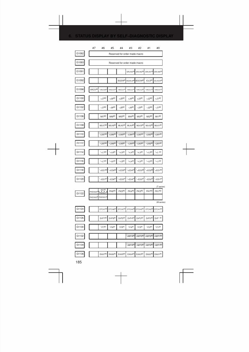
6. STATUS DISPLAY BY SELF–DIAGNOSTIC DISPLAY
185
#7 #6 #5 #4 #3 #2 #1 #0
G1082 Reserved for order made macro
G1083 Reserved for order made macro
G1091 SRLNI3#2 SRLNI2#2 SRLNI1#2 SRLNI0#2
G1092 BGEN#2 BGIALM#2 BGION#2 IOLS#2 IOLACK#2
G1096 HROV#2 *HROV6#2 *HROV5#2 *HROV4#2 *HROV3#2 *HROV2#2 *HROV1#2 *HROV0#2
G1100 +J7#2 +J6#2 +J5#2 +J4#2 +J3#2 +J2#2 +J1#2
G1102 –J7#2 –J6#2 –J5#2 –J4#2 –J3#2 –J2#2 –J1#2
G1106 MI7#2 MI6#2 MI5#2 MI4#2 MI3#2 MI2#2 MI1#2
G1108 MLK7#2 MLK6#2 MLK5#2 MLK4#2 MLK3#2 MLK2#2 MLK1#2
+LM2#2+LM5#2G1110 +LM7#2 +LM6#2 +LM4#2 +LM3#2 +LM1#2
–LM2#2 –LM5#2G1112 –LM7#2 –LM6#2 –LM4#2 –LM3#2 –LM1#2
G1114 *+L7#2 *+L6#2 *+L5#2 *+L4#2 *+L3#2 *+L2#2 *+L1#2
G1116 *–L7#2 *–L6#2 *–L5#2 *–L4#2 *–L3#2 *–L2#2 *–L1#2
G1118 *+ED7#2 *+ED6#2 *+ED5#2 *+ED4#2 *+ED3#2 *+ED2#2 *+ED1#2
G1120 *–ED7#2 *–ED6#2 *–ED5#2 *–ED4#2 *–ED3#2 *–ED2#2 *–ED1#2
PKESS1#2
PK7#2
PKESS1#2PKESS2#2 PK4#2PK6#2
G1122
PKESS2#2
PK5#2 PK3#2 PK2#2 PK1#2
(M series)
(T series)
G1124 DTCH7#2 DTCH6#2 DTCH5#2 DTCH4#2 DTCH3#2 DTCH2#2 DTCH1#2
G1126 SVF7#2 SVF6#2 SVF5#2 SVF4#2 SVF3#2 SVF2#2 SVF1#2
G1130 *IT7#2 *IT6#2 *IT5#2 *IT4#2 *IT3#2 *IT2#2 *IT1#2
+MIT2#2G1132 +MIT4#2 +MIT3#2 +MIT1#2
–MIT2#2G1134 –MIT4#2 –MIT3#2 –MIT1#2
G1136 EAX7#2 EAX6#2 EAX5#2 EAX4#2 EAX3#2 EAX2#2 EAX1#2

3
1
4
5
6
7
8
9
10
2
186
#7 #6 #5 #4 #3 #2 #1 #0
SYNC2#2SYNC5#2G1138 SYNC7#2 SYNC6#2 SYNC4#2 SYNC3#2 SYNC1#2
SYNCJ2#2SYNCJ5#2G1140 SYNCJ7#2 SYNCJ6#2 SYNCJ4#2 SYNCJ3#2 SYNCJ1#2
G1142 EBUFA#2 ECLRA#2 ESTPA#2 ESOFA#2 ESBKA#2 EMBUFA#2 EFINA#2
G1143 EMSBKA#2 EC6A#2 EC5A#2 EC4A#2 EC3A#2 EC2A#2 EC1A#2 EC0A#2
G1144 EIF7A#2 EIF6A#2 EIF5A#2 EIF4A#2 EIF3A#2 EIF2A#2 EIF1A#2 EIF0A#2
G1145 EIF15A#2 EIF14A#2 EIF13A#2 EIF12A#2 EIF11A#2 EIF10A#2 EIF9A#2 EIF8A#2
G1146 EID7A#2 EID6A#2 EID5A#2 EID4A#2 EID3A#2 EID2A#2 EID1A#2 EID0A#2
G1147 EID15A#2 EID14A#2 EID13A#2 EID12A#2 EID11A#2 EID10A#2 EID9A#2 EID8A#2
G1148 EID23A#2 EID22A#2 EID21A#2 EID20A#2 EID19A#2 EID18A#2 EID17A#2 EID16A#2
G1149 EID31A#2 EID30A#2 EID29A#2 EID28A#2 EID27A#2 EID26A#2 EID25A#2 EID24A#2
G1150 DRNE#2 RTE#2 OVCE#2 ROV2E#2ROV1E#2
G1151 *FV7E#2 *FV6E#2 *FV5E#2 *FV4E#2 *FV3E#2 *FV2E#2 *FV1E#2 *FV0E#2
G1154 EBUFB#2 ECLRB#2 ESTPB#2 ESOFB#2 ESBKB#2 EMBUFB#2 EFINB#2
G1155 EMSBKB#2 EC6B#2 EC5B#2 EC4B#2 EC3B#2 EC2B#2 EC1B#2 EC0B#2
G1156 EIF7B#2 EIF6B#2 EIF5B#2 EIF4B#2 EIF3B#2 EIF2B#2 EIF1B#2 EIF0B#2
G1157 EIF15B#2 EIF14B#2 EIF13B#2 EIF12B#2 EIF11B#2 EIF10B#2 EIF9B#2 EIF8B#2
G1158 EID7B#2 EID6B#2 EID5B#2 EID4B#2 EID3B#2 EID2B#2 EID1B#2 EID0B#2
G1159 EID15B#2 EID14B#2 EID13B#2 EID12B#2 EID11B#2 EID10B#2 EID9B#2 EID8B#2
G1160 EID23B#2 EID22B#2 EID21B#2 EID20B#2 EID19B#2 EID18B#2 EID17B#2 EID16B#2
G1161 EID31B#2 EID30B#2EID29B#2 EID28B#2 EID27B#2EID26B#2 EID25B#2EID24B#2
G1166 EBUFC#2 ECLRC#2 ESTPC#2 ESOFC#2 ESBKC#2 EMBUFC#2 EFINC#2
G1167 EMSBKC#2 EC6C#2 EC5C#2 EC4C#2 EC3C#2 EC2C#2 EC1C#2 EC0C#2
G1168 EIF7C#2 EIF6C#2 EIF5C#2 EIF4C#2 EIF3C#2 EIF2C#2 EIF1C#2 EIF0C#2
G1169 EIF15C#2 EIF14C#2 EIF13C#2 EIF12C#2 EIF11C#2EIF10C#2 EIF9C#2 EIF8C#2
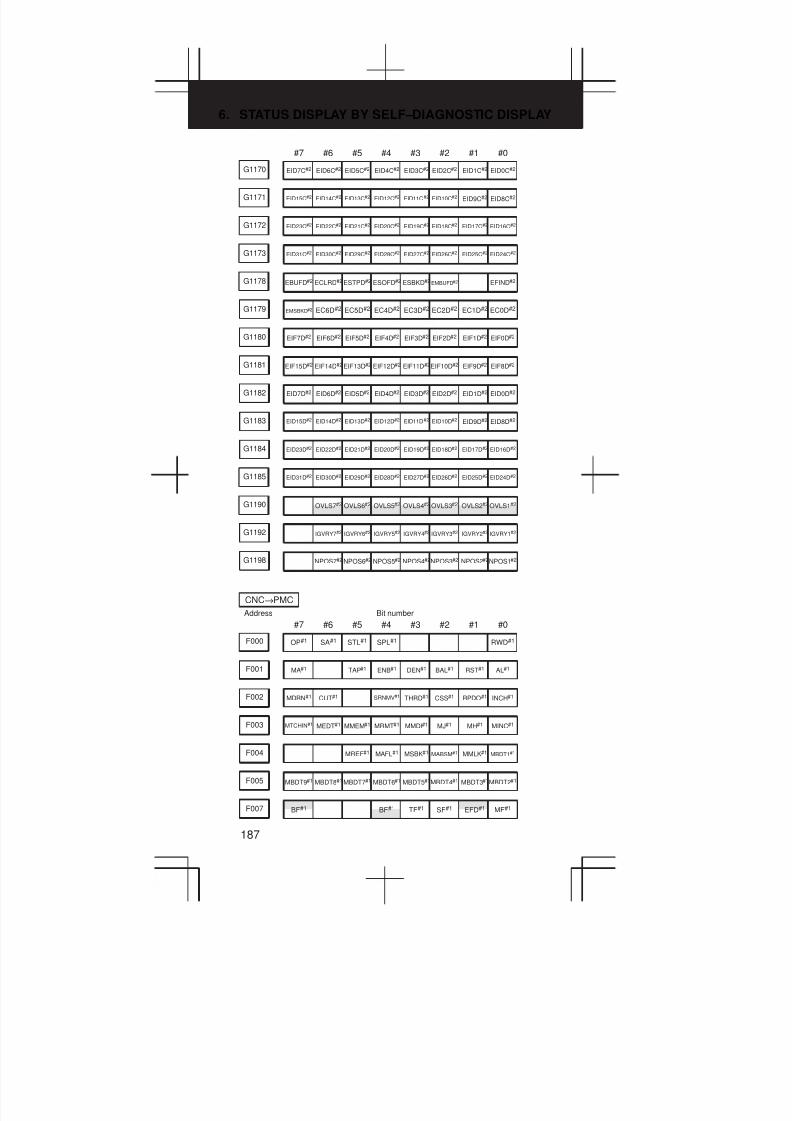
6. STATUS DISPLAY BY SELF–DIAGNOSTIC DISPLAY
187
#7 #6 #5 #4 #3 #2 #1 #0
G1170 EID7C#2 EID6C#2 EID5C#2 EID4C#2 EID3C#2 EID2C#2 EID1C#2 EID0C#2
G1171 EID15C#2 EID14C#2 EID13C#2 EID12C#2 EID11C#2 EID10C#2 EID9C#2 EID8C#2
G1172 EID23C#2 EID22C#2 EID21C#2 EID20C#2 EID19C#2 EID18C#2 EID17C#2 EID16C#2
G1173 EID31C#2 EID30C#2 EID29C#2 EID28C#2 EID27C#2 EID26C#2 EID25C#2 EID24C#2
G1178 EBUFD#2 ECLRD#2 ESTPD#2 ESOFD#2 ESBKD#2 EMBUFD#2 EFIND#2
G1179 EMSBKD#2 EC6D#2 EC5D#2 EC4D#2 EC3D#2 EC2D#2 EC1D#2 EC0D#2
G1180 EIF7D#2 EIF6D#2 EIF5D#2 EIF4D#2 EIF3D#2 EIF2D#2 EIF1D#2 EIF0D#2
G1181 EIF15D#2 EIF14D#2 EIF13D#2 EIF12D#2 EIF11D#2EIF10D#2 EIF9D#2 EIF8D#2
G1182 EID7D#2 EID6D#2 EID5D#2 EID4D#2 EID3D#2 EID2D#2 EID1D#2 EID0D#2
G1183 EID15D#2 EID14D#2 EID13D#2 EID12D#2 EID11D#2 EID10D#2 EID9D#2 EID8D#2
G1184 EID23D#2 EID22D#2 EID21D#2 EID20D#2 EID19D#2 EID18D#2 EID17D#2 EID16D#2
G1185 EID31D#2 EID30D#2 EID29D#2 EID28D#2 EID27D#2 EID26D#2 EID25D#2 EID24D#2
OVLS2#2OVLS5#2G1190 OVLS7#2 OVLS6#2 OVLS4#2 OVLS3#2 OVLS1#2
G1192 IGVRY7#2 IGVRY6#2 IGVRY5#2 IGVRY4#2 IGVRY3#2 IGVRY2#2 IGVRY1#2
G1198 NPOS7#2 NPOS6#2 NPOS5#2 NPOS4#2NPOS3#2 NPOS2#2NPOS1#2
#7 #6 #5 #4 #3 #2 #1 #0
Address
CNC→PMC
Bit number
F000 OP#1 SA#1 STL#1 SPL#1 RWD#1
F001 MA#1 TAP#1 ENB#1 DEN#1 BAL#1 RST#1 AL#1
F002 MDRN#1 CUT#1 SRNMV#1 THRD#1 CSS#1 RPDO#1 INCH#1
F003 MTCHIN#1 MEDT#1 MMEM#1 MRMT#1 MMDI#1 MJ#1 MH#1 MINC#1
F004 MREF#1 MAFL#1 MSBK#1 MABSM#1 MMLK#1 MBDT1#1
F005 MBDT9#1 MBDT8#1 MBDT7#1 MBDT6#1 MBDT5#1MBDT4#1 MBDT3#1MBDT2#1
EFD#1BF#1F007 BF#1 TF#1 SF#1 MF#1

3
1
4
5
6
7
8
9
10
2
188
#7 #6 #5 #4 #3 #2 #1 #0
MF2#1F008 MF3#1 EF#1
F009 DM00#1 DM01#1 DM02#1 DM30#1
F010 M07#1 M06#1 M05#1 M04#1 M03#1 M02#1 M01#1 M00#1
F011 M15#1 M14#1 M13#1 M12#1 M11#1 M10#1 M09#1 M08#1
F012 M23#1 M22#1 M21#1 M20#1 M19#1 M18#1 M17#1 M16#1
F013 M31#1 M30#1 M29#1 M28#1 M27#1 M26#1 M25#1 M24#1
F014 M207#1 M206#1 M205#1 M204#1 M203#1 M202#1 M201#1 M200#1
F015 M215#1 M214#1 M213#1 M212#1 M211#1 M210#1 M209#1 M208#1
F016 M307#1 M306#1 M305#1 M304#1 M303#1 M302#1 M301#1 M300#1
F017 M315#1 M314#1 M313#1 M312#1 M311#1 M310#1 M309#1 M308#1
F022 S07#1 S06#1 S05#1 S04#1 S03#1 S02#1 S01#1 S00#1
F023 S15#1 S14#1 S13#1 S12#1 S11#1 S10#1 S09#1 S08#1
F024 S23#1 S22#1 S21#1 S20#1 S19#1 S18#1 S17#1 S16#1
F025 S31#1 S30#1 S29#1 S28#1 S27#1 S26#1 S25#1 S24#1
F026 T07#1 T06#1 T05#1 T04#1 T03#1 T02#1 T01#1 T00#1
F027 T15#1 T14#1 T13#1 T12#1 T11#1 T10#1 T09#1 T08#1
F028 T23#1 T22#1 T21#1 T20#1 T19#1 T18#1 T17#1 T16#1
F029 T31#1 T30#1 T29#1 T28#1 T27#1 T26#1 T25#1 T24#1
F030 B07#1 B06#1 B05#1 B04#1 B03#1 B02#1 B01#1 B00#1
F031 B15#1 B14#1 B13#1 B12#1 B11#1 B10#1 B09#1 B08#1
F032 B23#1 B22#1 B21#1 B20#1 B19#1 B18#1 B17#1 B16#1
F033 B31#1 B30#1 B29#1 B28#1 B27#1 B26#1 B25#1 B24#1
GR2O#1F034 GR3O#1 GR1O#1
F035 SPAL#1
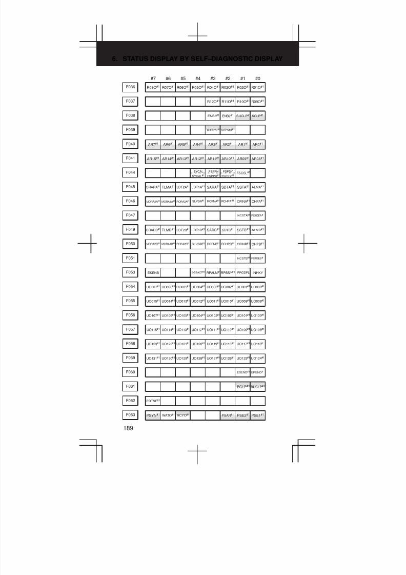
6. STATUS DISPLAY BY SELF–DIAGNOSTIC DISPLAY
189
#7 #6 #5 #4 #3 #2 #1 #0
F036 R08O#1 R07O#1 R06O#1 R05O#1 R04O#1 R03O#1 R02O#1 R01O#1
F037 R12O#1 R11O#1 R10O#1 R09O#1
SUCLP#1F038 ENB3#1 ENB2#1 SCLP#1
F039 CHPCYL#1 CHPMD#1
AR1#1AR4#1F040 AR7#1 AR6#1 AR5#1 AR3#1 AR2#1 AR0#1
AR09#1AR12#1F041 AR15#1 AR14#1 AR13#1 AR11#1 AR10#1 AR08#1
F044 SYCAL
SYCAL#1
FSPPH
FSPPH#1
FSPSY
FSPSY#1FSCSL#1
F045 ORARA#1 TLMA#1 LDT2A#1 LDT1A#1 SARA#1 SDTA#1 SSTA#1 ALMA#1
F046 MORA2A#1 MORA1A#1 PORA2A#1 SLVSA#1 RCFNA#1 RCHPA#1 CFINA#1 CHPA#1
F047 INCSTA#1 PC1DEA#1
F049 ORARB#1 TLMB#1 LDT2B#1 LDT1B#1 SARB#1 SDTB#1 SSTB#1 ALMB#1
F050 MORA2B#1 MORA1B#1 PORA2B#1 SLVSB#1 RCFNB#1 RCHPB#1 CFINB#1 CHPB#1
F051 INCSTB#1 PC1DEB#1
F053 EKENB BGEACT#1 RPALM#1RPBSY#1 PRGDPL INHKY
F054 UO007#1 UO006#1 UO005#1 UO004#1 UO003#1 UO002#1 UO001#1 UO000#1
F055 UO015#1 UO014#1 UO013#1 UO012#1 UO011#1 UO010#1 UO009#1 UO008#1
F056 UO107#1 UO106#1 UO105#1 UO104#1 UO103#1 UO102#1 UO101#1 UO100#1
F057 UO115#1 UO114#1 UO113#1 UO112#1 UO111#1 UO110#1 UO109#1 UO108#1
F058 UO123#1 UO122#1 UO121#1 UO120#1 UO119#1 UO118#1 UO117#1 UO116#1
F059 UO131#1 UO130#1 UO129#1 UO128#1 UO127#1 UO126#1 UO125#1 UO124#1
F060 ESEND#1 EREND#1
BCLP#1F061 BUCLP#1
F062 PRTSF#1
PSE2#1F063 PSYN#1 WATO#1 RCYO#1 PSAR#1 PSE1#1

3
1
4
5
6
7
8
9
10
2
190
#7 #6 #5 #4 #3 #2 #1 #0
TLNW#1F064 TIALM TICHK COSP TLCHI#1 TLCH#1
RGSPM#1RTRCTF#1F065 SYNMOD#1 RGSPP#1
F066 PECK2#1 RTNMVS#1 G08MD#1
F070 PSW08#1 PSW07#1 PSW06#1 PSW05#1 PSW04#1 PSW03#1 PSW02#1 PSW01#1
F071 PSW10#1 PSW09#1
F072 OUT7#1 OUT6#1 OUT5#1 OUT4#1 OUT3#1 OUT2#1 OUT1#1 OUT0#1
F073 ZRNO#1 MD4O#1 MD2O#1 MD1O#1
F075 SPO#1 KEYO#1 DRNO#1 MLKO#1 SBKO#1 BDTO#1
F076 ROV2O#1 ROV1O#1 RTAP#1 MP2O#1 MP1O#1
F077 RTO#1 HS1DO#1 HS1CO#1 HS1BO#1 HS1AO#1
F078 *FV7O#1 *FV6O#1 *FV5O#1 *FV4O#1 *FV3O#1 *FV2O#1 *FV1O#1 *FV0O#1
F079 *JV7O#1 *JV6O#1 *JV5O#1 *JV4O#1 *JV3O#1 *JV2O#1 *JV1O#1 *JV0O#1
F080 *FV15O#1 *FV14O#1 *FV13O#1 *FV12O#1 *FV11O#1 *FV10O#1 *FV9O#1 *FV8O#1
F081 –J4O#1 +J4O#1 –J3O#1 +J3O#1 –J2O#1 +J2O#1 –J1O#1 +J1O#1
F082 RVSL#1
F090 ABTSP2#1 ABTSP1#1 ABTQSV#1
F092 TRSPS#1 TRACT#1
F094 ZP7#1 ZP6#1 ZP5#1 ZP4#1 ZP3#1 ZP2#1 ZP1#1
F096 ZP27#1 ZP26#1 ZP25#1 ZP24#1 ZP23#1 ZP22#1 ZP21#1
F098 ZP37#1 ZP36#1 ZP35#1 ZP34#1 ZP33#1 ZP32#1 ZP31#1
F100 ZP47#1 ZP46#1 ZP45#1 ZP44#1 ZP43#1 ZP42#1 ZP41#1
F102 MV7#1 MV6#1 MV5#1 MV4#1 MV3#1 MV2#1 MV1#1
F104 INP7#1 INP6#1 INP5#1 INP4#1 INP3#1 INP2#1 INP1#1
F106 MVD7#1 MVD6#1 MVD5#1 MVD4#1 MVD3#1 MVD2#1 MVD1#1
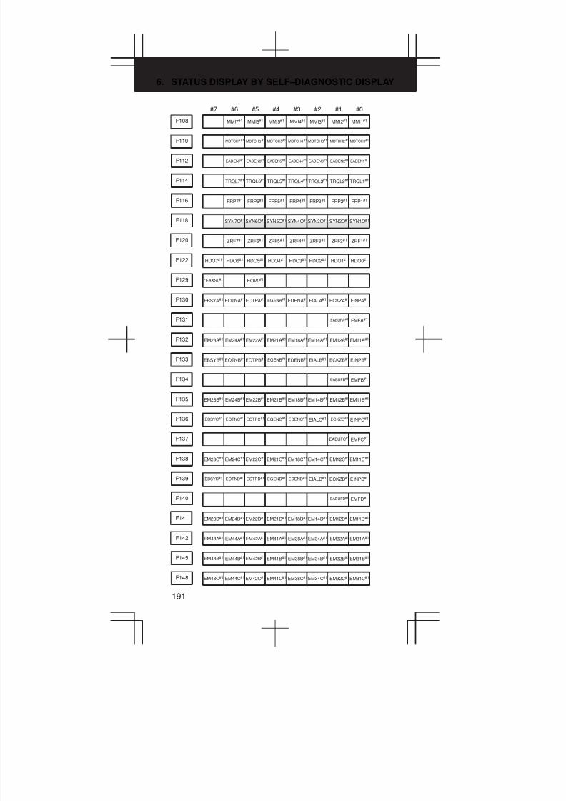
6. STATUS DISPLAY BY SELF–DIAGNOSTIC DISPLAY
191
#7 #6 #5 #4 #3 #2 #1 #0
F108 MMI7#1 MMI6#1 MMI5#1 MMI4#1 MMI3#1 MMI2#1 MMI1#1
F110 MDTCH7#1 MDTCH6#1 MDTCH5#1 MDTCH4#1 MDTCH3#1 MDTCH2#1 MDTCH1#1
F112 EADEN7#1 EADEN6#1 EADEN5#1 EADEN4#1 EADEN3#1 EADEN2#1 EADEN1#1
TRQL2#1TRQL5#1F114 TRQL7#1 TRQL6#1 TRQL4#1 TRQL3#1 TRQL1#1
F116 FRP7#1 FRP6#1 FRP5#1 FRP4#1 FRP3#1 FRP2#1 FRP1#1
SYN2O#1SYN5O#1F118 SYN7O#1 SYN6O#1 SYN4O#1SYN3O#1 SYN1O#1
F120 ZRF7#1 ZRF6#1 ZRF5#1 ZRF4#1 ZRF3#1 ZRF2#1 ZRF1#1
F122 HDO7#1 HDO6#1 HDO5#1 HDO4#1 HDO3#1 HDO2#1 HDO1#1 HDO0#1
F129 *EAXSL#1 EOV0#1
F130 EBSYA#1 EOTNA#1 EOTPA#1 EGENA#1 EDENA#1 EIALA#1 ECKZA#1 EINPA#1
F131 EABUFA#1 EMFA#1
F132 EM28A#1 EM24A#1 EM22A#1 EM21A#1 EM18A#1EM14A#1 EM12A#1 EM11A#1
F133 EBSYB#1 EOTNB#1EOTPB#1 EGENB#1 EDENB#1 EIALB#1 ECKZB#1 EINPB#1
F134 EABUFB#1 EMFB#1
F135 EM28B#1 EM24B#1 EM22B#1 EM21B#1 EM18B#1EM14B#1 EM12B#1 EM11B#1
F136 EBSYC#1 EOTNC#1 EOTPC#1 EGENC#1 EDENC#1 EIALC#1 ECKZC#1 EINPC#1
F137 EABUFC#1 EMFC#1
F138 EM28C#1 EM24C#1 EM22C#1 EM21C#1 EM18C#1EM14C#1 EM12C#1EM11C#1
F139 EBSYD#1 EOTND#1 EOTPD#1 EGEND#1 EDEND#1 EIALD#1 ECKZD#1 EINPD#1
F140 EABUFD#1 EMFD#1
F141 EM28D#1 EM24D#1 EM22D#1 EM21D#1 EM18D#1EM14D#1 EM12D#1EM11D#1
F142 EM48A#1 EM44A#1 EM42A#1 EM41A#1 EM38A#1EM34A#1 EM32A#1 EM31A#1
F145 EM48B#1 EM44B#1 EM42B#1 EM41B#1 EM38B#1EM34B#1 EM32B#1 EM31B#1
F148 EM48C#1 EM44C#1 EM42C#1 EM41C#1 EM38C#1EM34C#1 EM32C#1EM31C#1
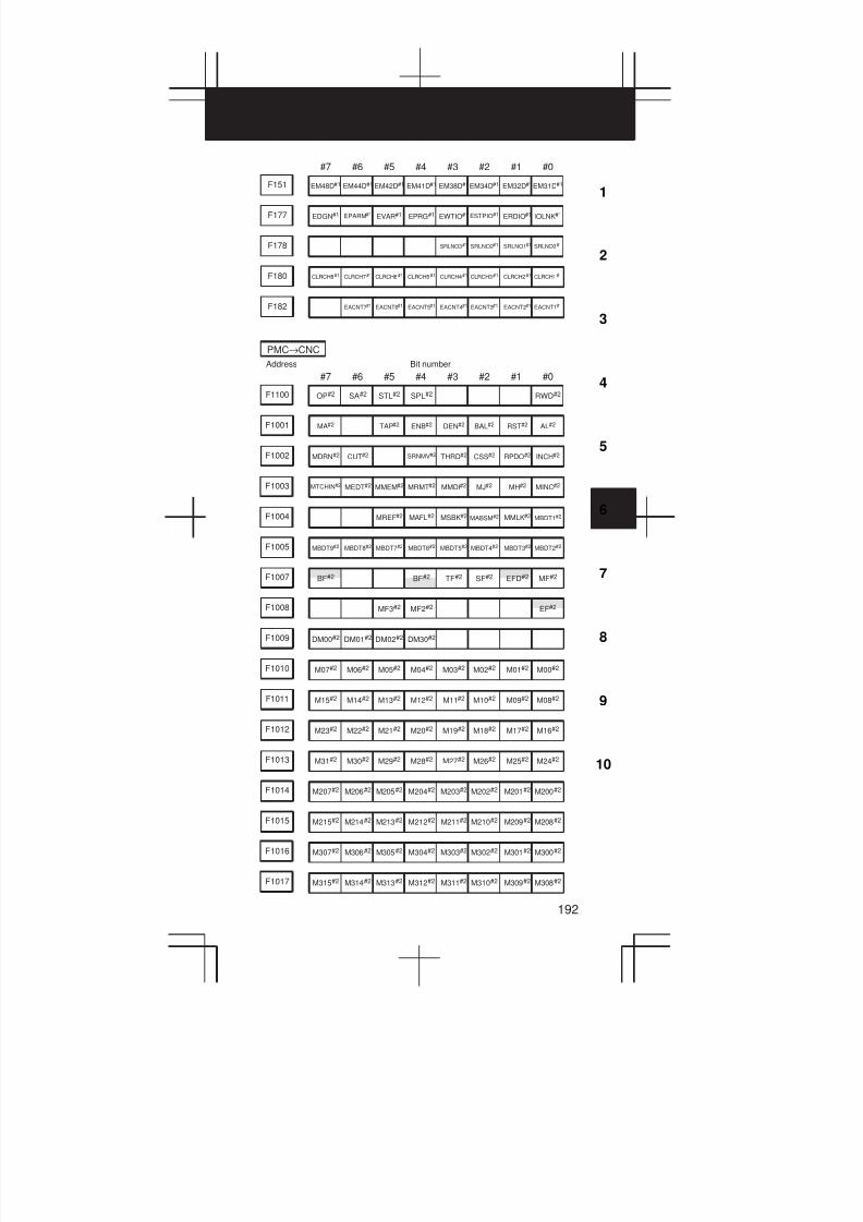
3
1
4
5
6
7
8
9
10
2
192
#7 #6 #5 #4 #3 #2 #1 #0
F151 EM48D#1 EM44D#1 EM42D#1 EM41D#1 EM38D#1EM34D#1 EM32D#1EM31D#1
F177 EDGN#1 EPARM#1 EVAR#1 EPRG#1 EWTIO#1 ESTPIO#1 ERDIO#1 IOLNK#1
F178 SRLNO3#1 SRLNO2#1 SRLNO1#1 SRLNO0#1
F180 CLRCH8#1 CLRCH7#1 CLRCH6#1 CLRCH5#1 CLRCH4#1 CLRCH3#1 CLRCH2#1 CLRCH1#1
F182 EACNT7#1 EACNT6#1 EACNT5#1 EACNT4#1 EACNT3#1 EACNT2#1 EACNT1#1
#7 #6 #5 #4 #3 #2 #1 #0
Address
PMC→CNC
Bit number
F1100 OP#2 SA#2 STL#2 SPL#2 RWD#2
F1001 MA#2 TAP#2 ENB#2 DEN#2 BAL#2 RST#2 AL#2
F1002 MDRN#2 CUT#2 SRNMV#2 THRD#2 CSS#2 RPDO#2 INCH#2
F1003 MTCHIN#2 MEDT#2 MMEM#2 MRMT#2 MMDI#2 MJ#2 MH#2 MINC#2
F1004 MREF#2 MAFL#2 MSBK#2 MABSM#2 MMLK#2 MBDT1#2
F1005 MBDT9#2 MBDT8#2 MBDT7#2 MBDT6#2 MBDT5#2 MBDT4#2 MBDT3#2 MBDT2#2
EFD#2BF#2F1007 BF#2 TF#2 SF#2 MF#2
MF2#2F1008 MF3#2 EF#2
F1009 DM00#2 DM01#2 DM02#2 DM30#2
F1010 M07#2 M06#2 M05#2 M04#2 M03#2 M02#2 M01#2 M00#2
F1011 M15#2 M14#2 M13#2 M12#2 M11#2 M10#2 M09#2 M08#2
F1012 M23#2 M22#2 M21#2 M20#2 M19#2 M18#2 M17#2 M16#2
F1013 M31#2 M30#2 M29#2 M28#2 M27#2 M26#2 M25#2 M24#2
F1014 M207#2 M206#2 M205#2 M204#2 M203#2 M202#2 M201#2 M200#2
F1015 M215#2 M214#2 M213#2 M212#2 M211#2 M210#2 M209#2 M208#2
F1016 M307#2 M306#2 M305#2 M304#2 M303#2 M302#2 M301#2 M300#2
F1017 M315#2 M314#2 M313#2 M312#2 M311#2 M310#2 M309#2 M308#2

6. STATUS DISPLAY BY SELF–DIAGNOSTIC DISPLAY
193
#7 #6 #5 #4 #3 #2 #1 #0
F1022 S07#2 S06#2 S05#2 S04#2 S03#2 S02#2 S01#2 S00#2
F1023 S15#2 S14#2 S13#2 S12#2 S11#2 S10#2 S09#2 S08#2
F1024 S23#2 S22#2 S21#2 S20#2 S19#2 S18#2 S17#2 S16#2
F1025 S31#2 S30#2 S29#2 S28#2 S27#2 S26#2 S25#2 S24#2
F1026 T07#2 T06#2 T05#2 T04#2 T03#2 T02#2 T01#2 T00#2
F1027 T15#2 T14#2 T13#2 T12#2 T11#2 T10#2 T09#2 T08#2
F1028 T23#2 T22#2 T21#2 T20#2 T19#2 T18#2 T17#2 T16#2
F1029 T31#2 T30#2 T29#2 T28#2 T27#2 T26#2 T25#2 T24#2
F1030 B07#2 B06#2 B05#2 B04#2 B03#2 B02#2 B01#2 B00#2
F1031 B15#2 B14#2 B13#2 B12#2 B11#2 B10#2 B09#2 B08#2
F1032 B23#2 B22#2 B21#2 B20#2 B19#2 B18#2 B17#2 B16#2
F1033 B31#2 B30#2 B29#2 B28#2 B27#2 B26#2 B25#2 B24#2
GR2O#2F1034 GR3O#2 GR1O#2
F1035 SPAL#2
F1036 R08O#2 R07O#2 R06O#2 R05O#2 R04O#2 R03O#2 R02O#2 R01O#2
F1037 R12O#2 R11O#2 R10O#2 R09O#2
SUCLP#2F1038 ENB3#2 ENB2#2 SCLP#2
F1039 CHPCYL#2 CHPMD#2
AR1#2AR4#2F1040 AR7#2 AR6#2 AR5#2 AR3#2 AR2#2 AR0#2
AR09#2AR12#2F1041 AR15#2 AR14#2 AR13#2 AR11#2 AR10#2 AR08#2
F1044 SYCAL#2 FSPPH#2 FSPSY#2 FSCSL#2
F1045 ORARA#2 TLMA#2 LDT2A#2 LDT1A#2 SARA#2 SDTA#2 SSTA#2 ALMA#2
F1046 MORA2A#2 MORA1A#2 PORA2A#2 SLVSA#2 RCFNA#2 RCHPA#2 CFINA#2 CHPA#2
F1047 INCSTA#2 PC1DEA#2

3
1
4
5
6
7
8
9
10
2
194
#7 #6 #5 #4 #3 #2 #1 #0
F1049 ORARB#2 TLMB#2 LDT2B#2 LDT1B#2 SARB#2 SDTB#2 SSTB#2 ALMB#2
F1050 MORA2B#2 MORA1B#2 PORA2B#2 SLVSB#2 RCFNB#2 RCHPB#2 CFINB#2 CHPB#2
F1051 INCSTB#2 PC1DEB#2
F1053 BGEACT#2 RPALM#2 RPBSY#2
F1054 UO007#2 UO006#2 UO005#2 UO004#2 UO003#2 UO002#2 UO001#2 UO000#2
F1055 UO015#2 UO014#2 UO013#2 UO012#2 UO011#2 UO010#2 UO009#2 UO008#2
F1056 UO107#2 UO106#2 UO105#2 UO104#2 UO103#2 UO102#2 UO101#2 UO100#2
F1057 UO115#2 UO114#2 UO113#2 UO112#2 UO111#2 UO110#2 UO109#2 UO108#2
F1058 UO123#2 UO122#2 UO121#2 UO120#2 UO119#2 UO118#2 UO117#2 UO116#2
F1059 UO131#2 UO130#2 UO129#2 UO128#2 UO127#2 UO126#2 UO125#2 UO124#2
F1060 ESEND#2 EREND#2
BCLP#2F1061 BUCLP#2
F1062 PRTSF#2
PSE2#2F1063 PSYN#2 WATO#2 RCYO#2 PSAR#2 PSE1#2
TLNW#2F1064 TLCHI#2 TLCH#2
RGSPM#2RTRCTF#2F1065 SYNMOD#2 RGSPP#2
F1066 PECK2#2 RTNMVS#2 G08MD#2
F1070 PSW08#2 PSW07#2 PSW06#2 PSW05#2 PSW04#2 PSW03#2 PSW02#2 PSW01#2
F1071 PSW10#2 PSW09#2
F1072 OUT7#2 OUT6#2 OUT5#2 OUT4#2 OUT3#2 OUT2#2 OUT1#2 OUT0#2
F1073 ZRNO#2 MD4O#2 MD2O#2 MD1O#2
F1075 SPO#2 KEYO#2 DRNO#2 MLKO#2 SBKO#2 BDTO#2
F1076 ROV2O#2 ROV1O#2 RTAP#2 MP2O#2 MP1O#2
F1077 RTO#2 HS1DO#2 HS1CO#2 HS1BO#2 HS1AO#2

6. STATUS DISPLAY BY SELF–DIAGNOSTIC DISPLAY
195
#7 #6 #5 #4 #3 #2 #1 #0
F1078 *FV7O#2 *FV6O#2 *FV5O#2 *FV4O#2 *FV3O#2 *FV2O#2 *FV1O#2 *FV0O#2
F1079 *JV7O#2 *JV6O#2 *JV5O#2 *JV4O#2 *JV3O#2 *JV2O#2 *JV1O#2 *JV0O#2
F1080 *FV15O#2 *FV14O#2 *FV13O#2 *FV12O#2 *FV11O#2 *FV10O#2 *FV09O#2 *FV08O#2
F1081 –J4O#2 +J4O#2 –J3O#2 +J3O#2 –J2O#2 +J2O#2 –J1O#2 +J1O#2
F1082 RVSL#2
F1090 ABTSP2#2 ABTSP1#2 ABTQSV#2
F1092 TRSPS#2 TRACT#2
F1094 ZP7#2 ZP6#2 ZP5#2 ZP4#2 ZP3#2 ZP2#2 ZP1#2
F1096 ZP27#2 ZP26#2 ZP25#2 ZP24#2 ZP23#2 ZP22#2 ZP21#2
F1098 ZP37#2 ZP36#2 ZP35#2 ZP34#2 ZP33#2 ZP32#2 ZP31#2
F1100 ZP47#2 ZP46#2 ZP45#2 ZP44#2 ZP43#2 ZP42#2 ZP41#2
F1102 MV7#2 MV6#2 MV5#2 MV4#2 MV3#2 MV2#2 MV1#2
F1104 INP7#2 INP6#2 INP5#2 INP4#2 INP3#2 INP2#2 INP1#2
F1106 MVD7#2 MVD6#2 MVD5#2 MVD4#2 MVD3#2 MVD2#2 MVD1#2
F1108 MMI7#2 MMI6#2 MMI5#2 MMI4#2 MMI3#2 MMI2#2 MMI1#2
F1110 MDTCH7#2 MDTCH6#2 MDTCH5#2 MDTCH4#2 MDTCH3#2 MDTCH2#2 MDTCH1#2
F1112 EADEN7#2 EADEN6#2 EADEN5#2 EADEN4#2 EADEN3#2 EADEN2#2 EADEN1#2
TRQL2#2TRQL5#2F1114 TRQL7#2 TRQL6#2 TRQL4#2 TRQL3#2 TRQL1#2
F1116 FRP7#2 FRP6#2 FRP5#2 FRP4#2 FRP3#2 FRP2#2 FRP1#2
SYN2O#2SYN5O#2F1118 SYN7O#2 SYN6O#2 SYN4O#2 SYN3O#2 SYN1O#2
F1120 ZRF7#2 ZRF6#2 ZRF5#2 ZRF4#2 ZRF3#2 ZRF2#2 ZRF1#2
F1122 HDO7#2 HDO6#2 HDO5#2 HDO4#2 HDO3#2 HDO2#2 HDO1#2 HDO0#2
F1129 *EAXSL#2 EOV0#2
F1130 EBSYA#2 EOTNA#2 EOTA#2 EGENA#2 EDENA#2 EIALA#2 ECKZA#2 EINPA#2
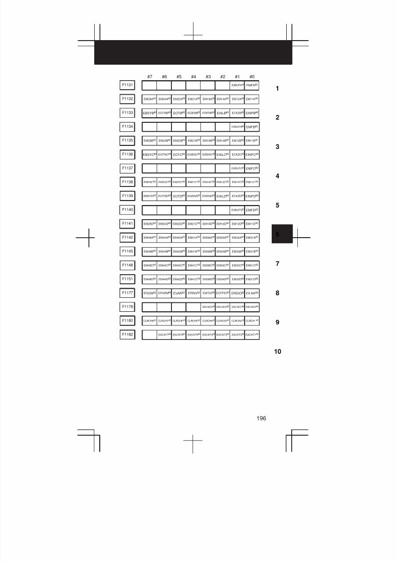
3
1
4
5
6
7
8
9
10
2
196
#7 #6 #5 #4 #3 #2 #1 #0
F1131 EABUFA#2 EMFA#2
F1132 EM28A#2 EM24A#2 EM22A#2 EM21A#2 EM18A#2 EM14A#2 EM12A#2 EM11A#2
F1133 EBSYB#2 EOTNB#2 EOTB#2 EGENB#2 EDENB#2 EIALB#2 ECKZB#2 EINPB#2
F1134 EABUFB#2 EMFB#2
F1135 EM28B#2 EM24B#2 EM22B#2 EM21B#2 EM18B#2 EM14B#2 EM12B#2 EM11B#2
F1136 EBSYC#2 EOTNC#2 EOTC#2 EGENC#2 EDENC#2 EIALC#2 ECKZC#2 EINPC#2
F1137 EABUFC#2 EMFC#2
F1138 EM28C#2 EM24C#2 EM22C#2 EM21C#2 EM18C#2 EM14C#2 EM12C#2 EM11C#2
F1139 EBSYD#2 EOTND#2 EOTD#2 EGEND#2 EDEND#2 EIALD#2 ECKZD#2 EINPD#2
F1140 EABUFD#2 EMFD#2
F1141 EM28D#2 EM24D#2 EM22D#2 EM21D#2 EM18D#2 EM14D#2 EM12D#2 EM11D#2
F1142 EM48A#2 EM44A#2 EM42A#2 EM41A#2 EM38A#2 EM34A#2 EM32A#2 EM31A#2
F1145 EM48B#2 EM44B#2 EM42B#2 EM41B#2 EM38B#2 EM34B#2 EM32B#2 EM31B#2
F1148 EM48C#2 EM44C#2 EM42C#2 EM41C#2 EM38C#2 EM34C#2 EM32C#2 EM31C#2
F1151 EM48D#2 EM44D#2 EM42D#2 EM41D#2 EM38D#2 EM34D#2 EM32D#2 EM31D#2
F1177 EDGN#2 EPARM#2 EVAR#2 EPRG#2 EWTIO#2 ESTPIO#2 ERDIO#2 IOLNK#2
F1178 SRLNO3#2 SRLNO2#2 SRLNO1#2 SRLNO0#2
F1180 CLRCH8#2 CLRCH7#2 CLRCH6#2 CLRCH5#2 CLRCH4#2 CLRCH3#2 CLRCH2#2 CLRCH1#2
F1182 EACNT7#2 EACNT6#2 EACNT5#2 EACNT4#2 EACNT3#2 EACNT2#2 EACNT1#2
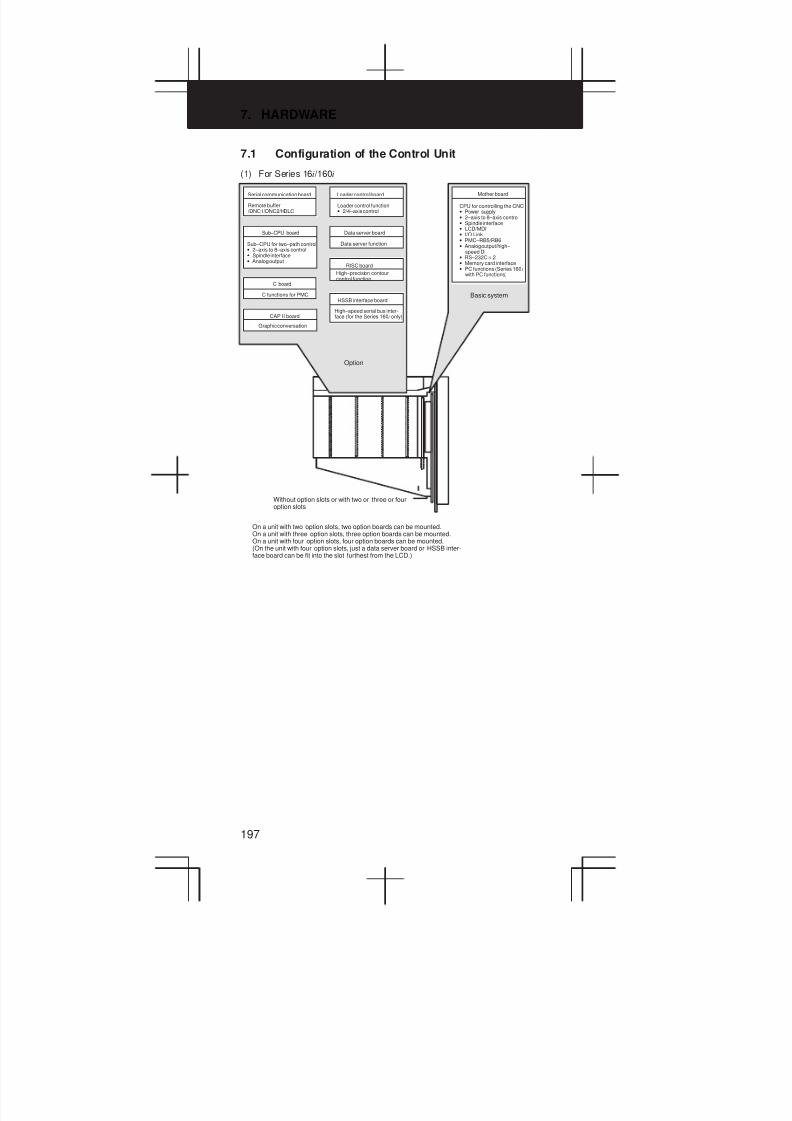
7. HARDWARE
197
7.1 Configuration of the Control Unit
(1) For Series 16i /160i
Serial communication board
Remote buffer /DNC1/DNC2/HDLC
Loader control board
Loader control function• 2/4–axis control
Sub–CPU board
Sub–CPU for two–path control• 2–axis to 8–axis control• Spindle interface• Analog output
Data server board
Data server function
RISC board
High–precision contourcontrol function
C board
C functions for PMCHSSB interface board
High–speed serial bus inter-face (for the Series 160i only)CAP II board
Graphic conversation
Option
Mother board
CPU for controlling the CNC• Power supply• 2–axis to 8–axis control• Spindle interface• LCD/MDI• I/O Link• PMC–RB5/RB6• Analog output/high–
speed DI• RS–232C × 2• Memory card interface• PC functions (Series 160 i
with PC functions)
Basic system
Without option slots or with two or three or fouroption slots
On a unit with two option slots, two option boards can be mounted.On a unit with three option slots, three option boards can be mounted.On a unit with four option slots, four option boards can be mounted.(On the unit with four option slots, just a data server board or HSSB inter-face board can be fit into the slot furthest from the LCD.)
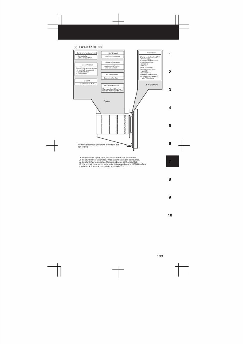
3
1
4
5
6
7
8
9
10
2
198
(2) For Series 18i /180i
Serial communication board
Remote buffer /DNC1/DNC2/HDLC
CAP II board
Graphic conversation
Sub–CPU board
Sub–CPU for two–path control• 2–axis to 6–axis control• Spindle interface• Analog output
Loader control board
Loader control function• 2/4–axis control
Data server board
Data server function
C board
C functions for PMCHSSB interface board
High–speed serial bus inter-face (for the Series 180 i only)
Option
Mother board
CPU for controlling the CNC• Power supply• 2–axis to 6–axis control• Spindle interface• LCD/MDI• I/O Link• PMC–RB5/RB6• Analog output/high–
speed DI• RS–232C × 2• Memory card interface• PC functions (Series 180i
with PC functions)
Basic system
Without option slots or with two or three or fouroption slots
On a unit with two option slots, two option boards can be mounted.On a unit with three option slots, three option boards can be mounted.On a unit with four option slots, four option boards can be mounted.(On the unit with four option slots, just a data server board or HSSB interfaceboard can be fit into the slot furthest from the LCD.)
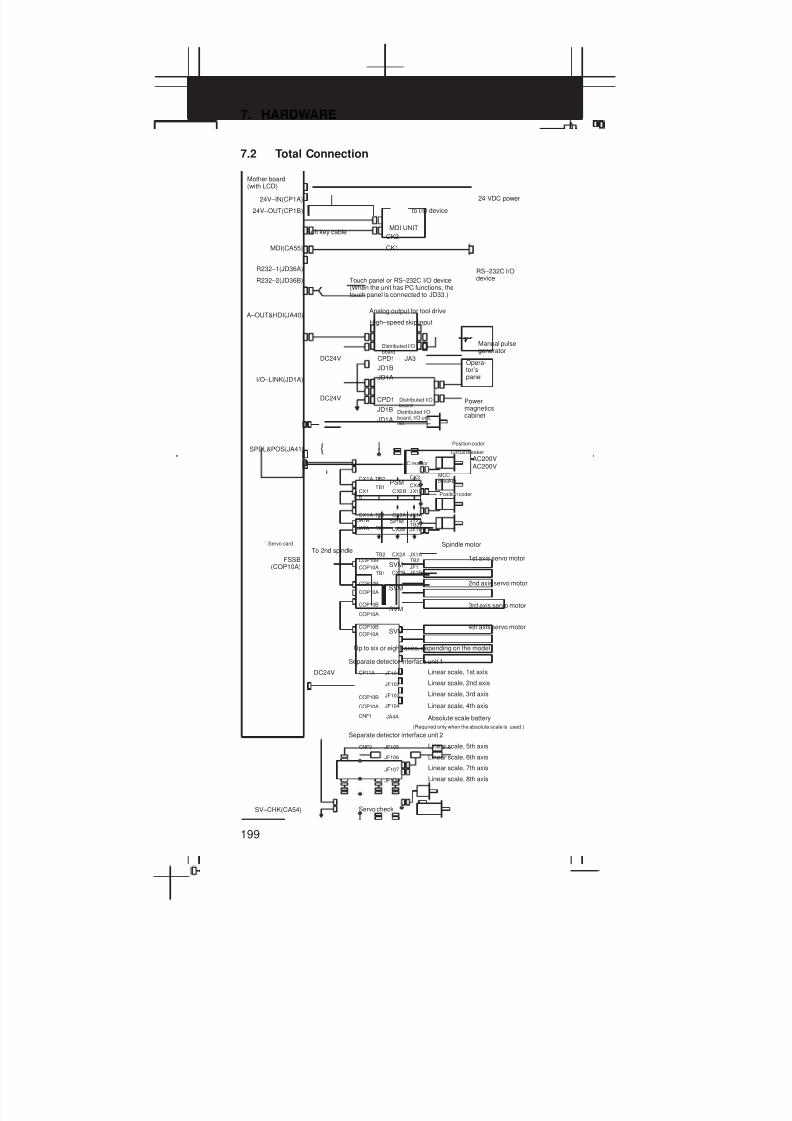
7. HARDWARE
199
7.2 Total Connection
24V–IN(CP1A)
24V–OUT(CP1B)
MDI(CA55)
R232–1(JD36A)
R232–2(JD36B)
A–OUT&HDI(JA40)
I/O–LINK(JD1A)
Soft key cable
CPD1
JD1B
JD1A
DC24V
MDI UNIT
CK2
CK1
DC24V
Distributed I/Oboard, I/O unit,etc.
CPD1 JA3
JD1B
JD1A
RS–232C I/Odevice
to I/O device
24 VDC power
Mother board(with LCD)
Touch panel or RS–232C I/O device(When the unit has PC functions, thetouch panel is connected to JD33.)
Analog output for tool drive
High–speed skip input
Distributed I/Oboard
Manual pulsegenerator
Opera-tor’spanel
Distributed I/Oboard
Powermagneticscabinet
JA7B
CX4
SPDL&POS(JA41)
FSSB(COP10A)
AC200VAC200V
MCCBreaker
AC reactor
SVM
SVM
SVM
SPM
PSM
TB2
CX2A
JX1A
TB1
CX2B
JX1B
TB1
CX2B
JX1B
CX1A TB1
CX2A
JX1A
CX1B
TB1CX2B JX1B
COP10B
JA7A
COP10A JF1
JY2
TB2
TB2
CX3CX1A TB2
SVM
CP11A
COP10B
COP10A
DC24V
COP10B
COP10A
COP10B
COP10A
COP10B
COP10A
JF101
JF104
JF103
JA4A
JF102
CNF1
JF105
JF108
JF107
JF106
CNF2
SV–CHK(CA54)
{Position coder
Circuit breaker
Position coder
Servo card
To 2nd spindleSpindle motor
1st axis servo motor
2nd axis servo motor
3rd axis servo motor
4th axis servo motor
Up to six or eight axes, depending on the model
Separate detector interface unit 1
Linear scale, 1st axis
Linear scale, 2nd axis
Linear scale, 3rd axis
Linear scale, 4th axis
Absolute scale battery
(Required only when the absolute scale is used.)
Separate detector interface unit 2
Linear scale, 5th axis
Linear scale, 6th axis
Linear scale, 7th axis
Linear scale, 8th axis
Servo check

3
1
4
5
6
7
8
9
10
2
200
R232–3(JD28A)
R422–1(JD6A)
SVM
SVM
SVM
SPM
PSM
COP10B
COP10A
A–OUT(JA40)
SPDL&POS(JA41)
FSSB(COP10A)
SV–CHK(CA54)
COP10B
COP10A
COP10B
COP10A
SVM
COP10B
COP10A
{
RS–232C I/O device(When the remote buffer board or DNC2 board is used)
Serial communicationboardRemote buffer cardDNC1 boardDNC2 board
RS–422 I/O device(When the remote buffer board or DNC1 board is used)
Sub–CPU board
Analog output for tool drive
Position coder
Position coder
Spindle motor
Servo card To 2nd spindle
Sub 1st servomotor
Sub 2nd servomotor
Sub 3rd servomotor
Sub 4th servomotor
Up to six or eight axes, depending on the model
Servo check
HDD(CNH1)
10BASE5(CD27)
DC24V
JD1B
JD1A
I/O Link (JD1A)
FSSB(COP10A)
SV–CHK(CA54)
SVM
SVM
SVM
PSM
COP10B
COP10A
Ethernet
COP10B
COP10A
COP10B
COP10A
SVMCOP10B
COP10A
HSSB(COP7) Personal Computer
Data server board
Hard diskunit
The hard disk unit is mounted in the rear ofthe MDI unit.The cable for the hard disk unit is providedby FANUC.
Loader controlboard
Loader I/Oboard
Servo card
Loader 1staxis servomotor
Loader 2ndaxis servomotor
Loader 3rdaxis servomotor
Loader 4thaxis servomotor
Servo check
HSSB board
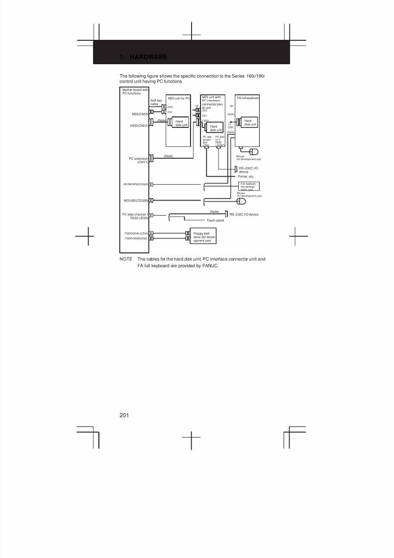
7. HARDWARE
201
The following figure shows the specific connection to the Series 160i /180i
control unit having PC functions.
MDI(CA55)
HDD(CNH1)
PC extension(CNY1)
KEYBOARD(CD32A)
MOUSE(CD32B)
PC side channel 1R232 (JD33)
FDDSIGNAL(CD34)
FDDPOWER(CN2)
Soft keycable
CK2
CK1
{
{
{
RS–232C I/Odevice
CK2
CNY2
CK1
RS–232C I/O device
Mother board withPC functions
MDI unit for PC
or
MDI unit withPC interfaceconnector pan-el unit
FA full keyboard
or
(Note)
(Note)
(Note)
Harddisk unitTo
CNH
(Note)
PC sideparallelport(JD9)
PC sidech 2R232(JD36F)
Touch panel
Floppy diskdrive (for devel-opment use)
Harddisk unit
Harddisk unit
Mouse(for development use)
Mouse(for development use)
Printer, etc.
Full keyboard(for develop-ment use)
(Note)
NOTE The cables for the hard disk unit, PC interface connector unit and
FA full keyboard are provided by FANUC.

3
1
4
5
6
7
8
9
10
2
202
Without PC function
MDI(CA55)
HDD(CNH1)
KEYBOARD(CD32A)
MOUSE(CD32B)
Soft key
Mouse
CK2
CK1
MDI unit for PC
Hard diskunit{
FA fullkeyboard
Hard diskunit
or
With PC function
MDI(CA55)
HDD(CNH1)
KEYBOARD(CD32A)
MOUSE(CD32B)
Soft key
Mouse
CK2
CK1
MDI unit for PC
{
FA full keyboard
PC side parallel part
JD9
or
Hard disk unit
Printer, etc.
RS–232C I/O devicePC side ch 2
JD36F
PC interface connecterpanel unit
Hard disk unit
Printer, etc.
RS–232C I/O device
PC side parallel part
JD9
PC side ch 2JD36F
PC interface connecterpanel unit
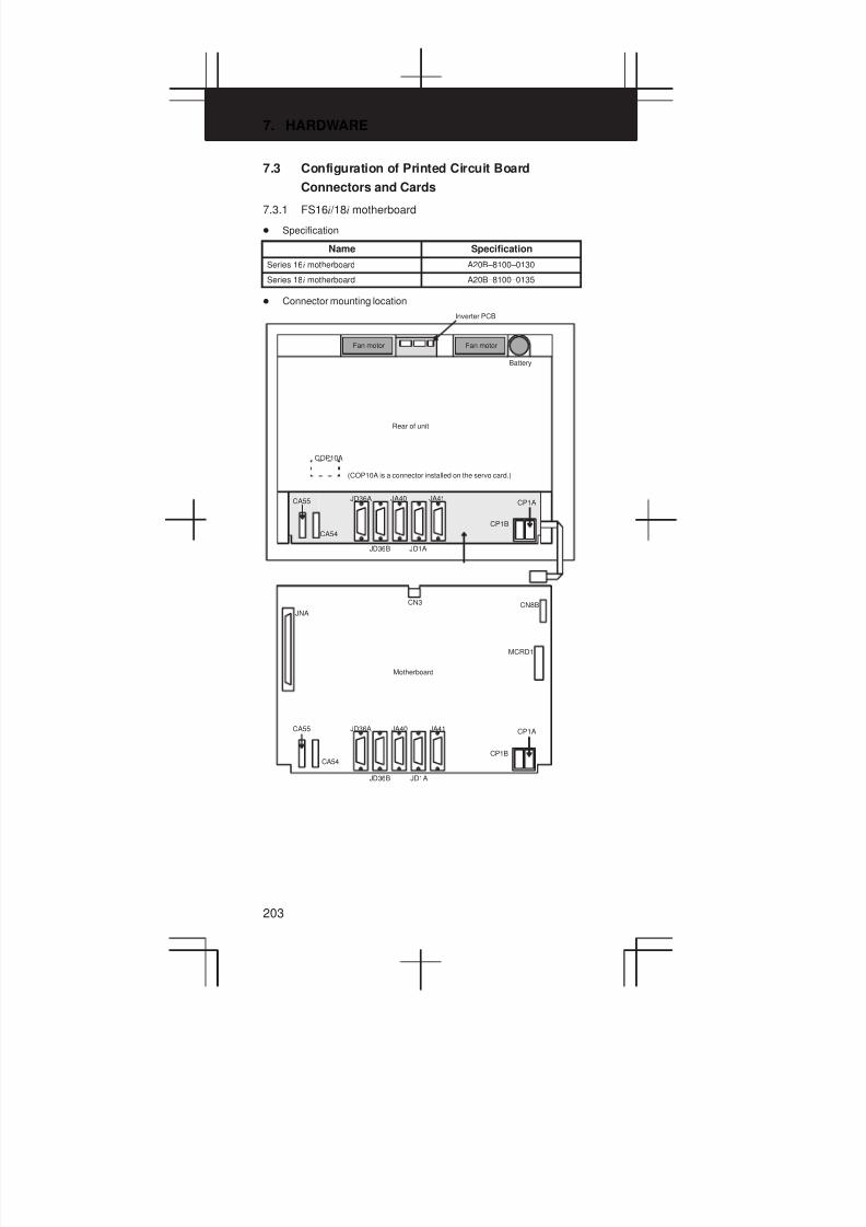
7. HARDWARE
203
7.3 Configuration of Printed Circuit Board
Connectors and Cards
7.3.1 FS16i /18i motherboard
D Specification
Name Specification
Series 16i motherboard A20B–8100–0130
Series 18i motherboard A20B–8100–0135
D Connector mounting location
JD36A JA41JA40
JD36B JD1A
CP1B
CP1A
COP10A
CA54
CA55
JNA
JD36A JA41JA40
JD36B JD1A
CN3
CP1B
CN8B
MCRD1
CP1A
CA54
CA55
Inverter PCB
Fan motor Fan motor
Battery
Rear of unit
(COP10A is a connector installed on the servo card.)
Motherboard
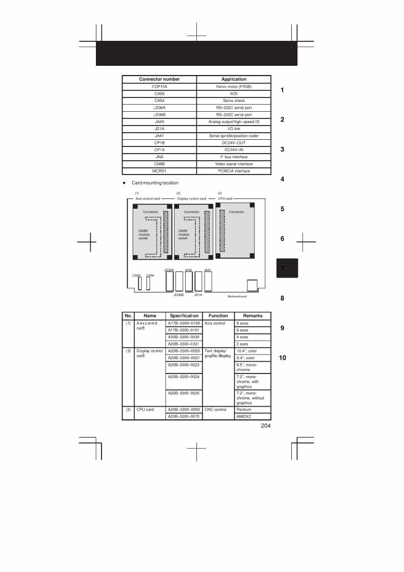
3
1
4
5
6
7
8
9
10
2
204
Connector number Application
COP10A Servo motor (FSSB)
CA55 MDI
CA54 Servo check
JD36A RS–232C serial port
JD36B RS–232C serial port
JA40 Analog output/high–speed DI
JD1A I/O link
JA41 Serial spindle/position coder
CP1B DC24V–OUT
CP1A DC24V–IN
JNA F–bus interface
CN8B Video signal interface
MCRD1 PCMCIA interface
D Card mounting location
JA40 JA41JD36A
JD1A
CA54CA55
JD36B
(1) (3)(2)
Axis control card Display control card CPU card
Connector Connector Connector
DIMMmodulesocket
DIMMmodulesocket
Motherboard
No. Name Specification Function Remarks
(1) Axis control A17B–3300–0100 Axis control 8 axes
cardA17B–3300–0101 6 axes
A20B–3300–0030 4 axes
A20B–3300–0031 2 axes
(2) Display control A20B–3300–0020 Text display/
i i l
10.4″, color
cardA20B–3300–0021
graphic display8.4″, color
A20B–3300–0023 9.5″, mono-
chrome
A20B–3300–0024 7.2″, mono-
chrome, with
graphics
A20B–3300–0025 7.2″, mono-
chrome, without
graphics
(3) CPU card A20B–3300–0050 CNC control Pentium
A20B–3300–0070 486DX2

7. HARDWARE
205
D DIMM module mounting location
JA40 JA41JD36A
JD1AJD36B
CA54CA55
(2)(1)
FROM module SRAM module
Connector Connector Connector
DIMM module socket DIMM module socket
Motherboard
No. Name Specification Function Remarks
(1) FROM module A20B–3900–0010 CNC system 16M
A20B–3900–0011Servo system
12M
A20B–3900–0012 8M
A20B–3900–0013 6M
A20B–3900–0014 4M
A20B–3900–0015 2M
(2) SRAM module A20B–3900–0020 SRAM for the 3M
A20B–3900–0060system
2M
A20B–3900–0061 1M
A20B–3900–0052 512K
A20B–3900–0053 256K
D DIMM module mounting location (continued)
(3)
DRAM module
Connector
DIMM modulesocket
CPU card
Side–B
No. Name Specification Function Remarks
(3) DRAM module A20B–3900–0040 CNC system 12M
A20B–3900–0041RAM
8M
A20B–3900–0042 4M

3
1
4
5
6
7
8
9
10
2
206
7.3.2 FS160i/ 180i motherboard with the PC function
D Specification
Name Specification
Series 160i motherboard A20B–8100–0140
Series 180i motherboard A20B–8100–0145
CD34
JD36B
JD36B
JD1A
JD1A
CA54
CP1ACA55 CN2
CD32B
CD32ACP1B
JA41JA40JD36A
JD33
CNY1
CNH1
COP10A
CD34
CA54
CP1ACA55 CN2
CD32B
CD32ACP1B
JA41JA40JD36A
JD33
CNY1
CNH1
CN8BJNA
CN3
PCMCIA2
Inverter PCB
Fan motor Fan motor
Battery
Rear of unit
(COP10A is a connector installed on the servo card.)
Motherboard
Soft key cable
Motherbord
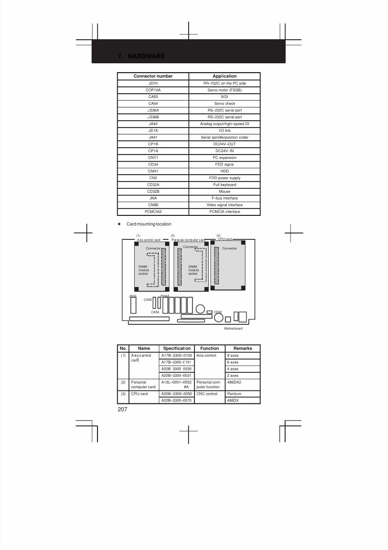
7. HARDWARE
207
Connector number Application
JD33 RS–232C on the PC side
COP10A Servo motor (FSSB)
CA55 MDI
CA54 Servo check
JD36A RS–232C serial port
JD36B RS–232C serial port
JA40 Analog output/high–speed DI
JD1A I/O link
JA41 Serial spindle/position coder
CP1B DC24V–OUT
CP1A DC24V–IN
CNY1 PC expansion
CD34 FDD signal
CNH1 HDD
CN2 FDD power supply
CD32A Full keyboard
CD32B Mouse
JNA F–bus interface
CN8B Video signal interface
PCMCIA2 PCMCIA interface
D Card mounting location
JD36A
CA54
CA55
CD32
JD33
(3)(2)(1)
Axis contro l card Personal computer card CPU card
ConnectorConnector
Connector
DIMMmodulesocket
DIMMmodulesocket
Motherboard
No. Name Specification Function Remarks
(1) Axis control A17B–3300–0100 Axis control 8 axes
cardA17B–3300–0101 6 axes
A20B–3300–0030 4 axes
A20B–3300–0031 2 axes
(2) Personal
computer card
A15L–0001–0052
#A
Personal com-
puter function
486DX2
(3) CPU card A20B–3300–0050 CNC control Pentium
A20B–3300–0070 486DX

3
1
4
5
6
7
8
9
10
2
208
D DIMM module mounting location
JD36A
CA54
CA55
CD32
JD33
(2)(1)
FROM module SRAM module
ConnectorConnector
Connector
DIMM module socket
MotherboardDIMM modulesocket
No. Name Specification Function Remarks
(1) FROM module A20B–3900–0010 CNC system 16M
A20B–3900–0011Servo system
12M
A20B–3900–0012 8M
A20B–3900–0013 6M
A20B–3900–0014 4M
A20B–3900–0015 2M
(2) SRAM module A20B–3900–0020 SRAM for the 3M
A20B–3900–0060system
2M
A20B–3900–0061 1M
A20B–3900–0052 512K
A20B–3900–0053 256K
D DIMM module mounting location (continued)
CPU card
DRAM moduleDRAM module
(3) (4)
Connector
Connector
DIMM modulesocket
DIMM modulesocket
Side–B
Personal computer card
Side–A

7. HARDWARE
209
No. Name Specification Function Remarks
(3) DRAM module A20B–3900–0040 CNC system 12M
A20B–3900–0041RAM
8M
A20B–3900–0042 4M
A20B–3900–0030 2M
A20B–3900–0031 1M
(4) DRAM module A76L–0500–0008 8M
A76L–0500–0009 16M
7.3.3 Inverter P.C.B
D Specification
Name Specification
Inverter 10.4″, color, for 2 slots A20B–2002–0500
8.4″, color, for 2 slots A20B–2002–0501
10.4″, color, for 4 slots A20B–8100–0200
8.4″, color, for 4 slots A20B–8100–0201
7.2″, 9.5″, monochrome, for 2 slots A20B–2002–0480
7.2″, 9.5″, monochrome, for 4 slots A20B–2002–0550
D Connector mounting location
1) For 4 slots
CP8
CN39DCN39CCN39BCN39A
Inverter P.C.B
Fan motor Fan motor
Rear of unit
2) For 2 slots
Battery
CP8
CN39BCN39A
Inverter P.C.B
Fan motor Fan motor
Rear of unit
Motherboard
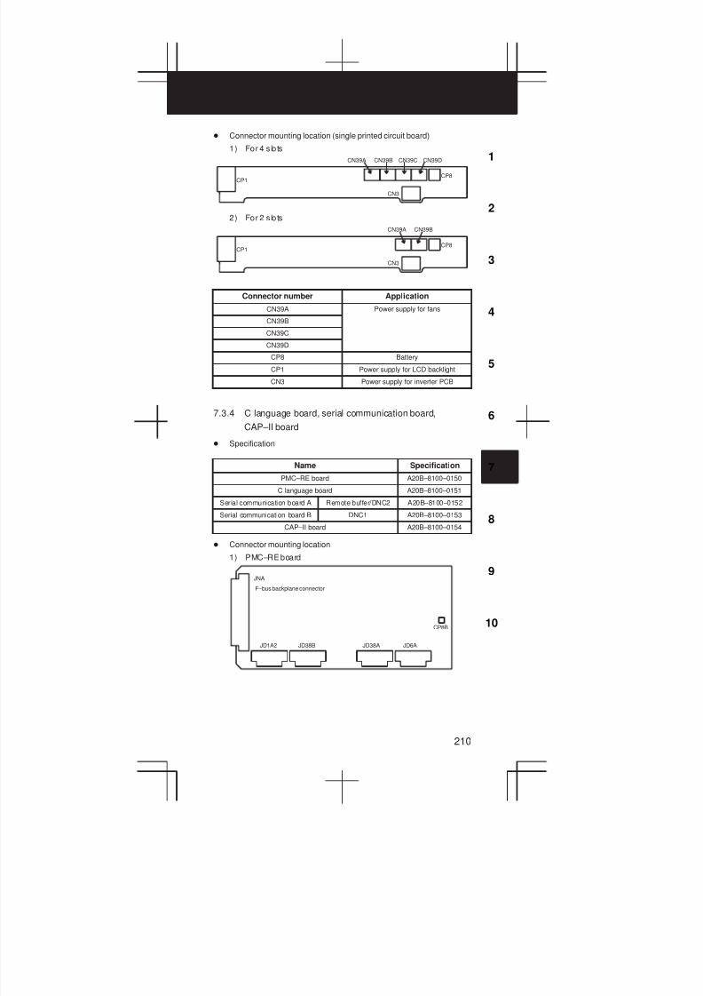
3
1
4
5
6
7
8
9
10
2
210
D Connector mounting location (single printed circuit board)
1) For 4 slots
CN39DCN39CCN39BCN39A
CP8CP1
CN3
2) For 2 slots
CN39BCN39A
CP8CP1
CN3
Connector number Application
CN39A Power supply for fans
CN39B
CN39C
CN39D
CP8 Battery
CP1 Power supply for LCD backlight
CN3 Power supply for inverter PCB
7.3.4 C language board, serial communication board,
CAP–II board
D Specification
Name Specification
PMC–RE board A20B–8100–0150
C language board A20B–8100–0151
Serial communication board A Remote buffer/DNC2 A20B–8100–0152
Serial communication board B DNC1 A20B–8100–0153
CAP–II board A20B–8100–0154
D Connector mounting location
1) PMC–RE board
JNA
CP8B
JD6AJD38AJD1A2 JD38B
F–bus backplane connector

7. HARDWARE
211
2) C language board
JNA
F–bus backplane connector
3) Serial communication board ARemote buffer/DNC2
JNA
JD6AJD28A
F–bus backplane connector
4) Serial communication board BDNC1
JNA
JD6AJD28A
F–bus backplane connector
5) CAP–II board
JNA
CP8B
F–bus backplane connector

3
1
4
5
6
7
8
9
10
2
212
Connector number Application
JD1A2 I/O link
JD38B RS–232C serial port
JD38A RS–232C serial port
JD28A RS–232C serial port
JD6A RS–422 serial port
CP8B For SRAM backup battery
D Card mounting location
1) CPU card
C language board/serial communication board /CAP–II board
CP8B
JD6AJD28AJD1A2 JD38B
Connector
DIMM module socket(mounted on the CPU card)
No. Name Specification Function Remarks
1) CPU card A20B–3300–0070 PMC/communication/
conversation control
486DX2
7.3.5 Sub–CPU board
D Specification
Name Specification
Sub–CPU board A20B–8001–0630
D Connector mounting location
JNA
JA41 JA40CA54
F–bus backplane connector
Connector number Application
CA54 Servo check
JA41 Serial spindle/position coder
JA40 Analog output
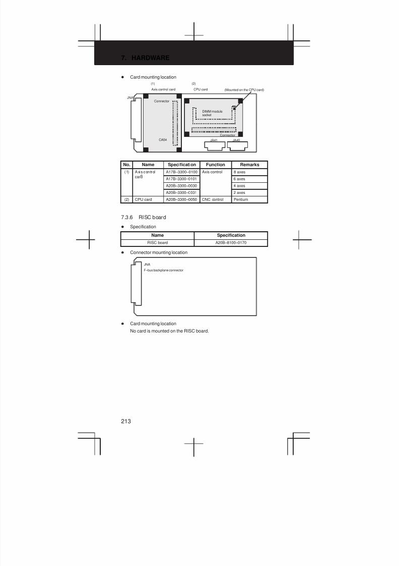
7. HARDWARE
213
D Card mounting location
JNA
(2)(1)
CA54 JA41 JA40
Axis control card CPU card (Mounted on the CPU card)
Connector
Connector
DIMM modulesocket
No. Name Specification Function Remarks
(1) Axis control A17B–3300–0100 Axis control 8 axes
cardA17B–3300–0101 6 axes
A20B–3300–0030 4 axes
A20B–3300–0031 2 axes
(2) CPU card A20B–3300–0050 CNC control Pentium
7.3.6 RISC board
D Specification
Name Specification
RISC board A20B–8100–0170
D Connector mounting location
JNA
F–bus backplane connector
D Card mounting location
No card is mounted on the RISC board.
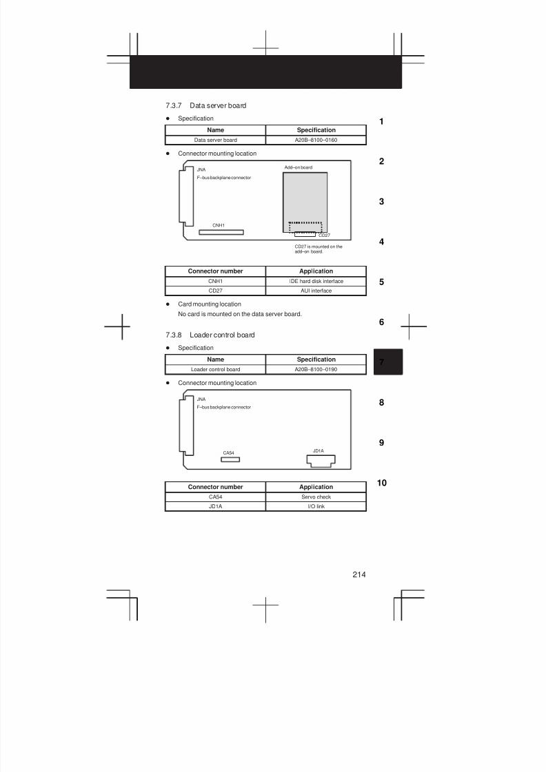
3
1
4
5
6
7
8
9
10
2
214
7.3.7 Data server board
D Specification
Name Specification
Data server board A20B–8100–0160
D Connector mounting location
JNA
CNH1
CD27
F–bus backplane connector
Add–on board
CD27 is mounted on theadd–on board.
Connector number Application
CNH1 IDE hard disk interface
CD27 AUI interface
D Card mounting location
No card is mounted on the data server board.
7.3.8 Loader control board
D Specification
Name Specification
Loader control board A20B–8100–0190
D Connector mounting location
JNA
JD1ACA54
F–bus backplane connector
Connector number Application
CA54 Servo check
JD1A I/O link

7. HARDWARE
215
D Card mounting location
JNA
(2)(1)
Axis control card CPU card
Connector Connector
DIMM module socket(mounted on the CPUcard)
No. Name Specification Function Remarks
(1) Axis control A20B–3300–0030 Axis control 4 axes
cardA20B–3300–0031 2 axes
(2) CPU card A20B–3300–0070 CNC control 486DX2
7.3.9 HSSB interface board
D Specification
Name Specification
HSSB interface board A20B–8001–0640
D Connector mounting location
JNA
COP7
F–bus backplane connector
Connector number Application
COP7 High–speed serial bus interface
D Card mounting location
No card is mounted on the HSSB interface board.
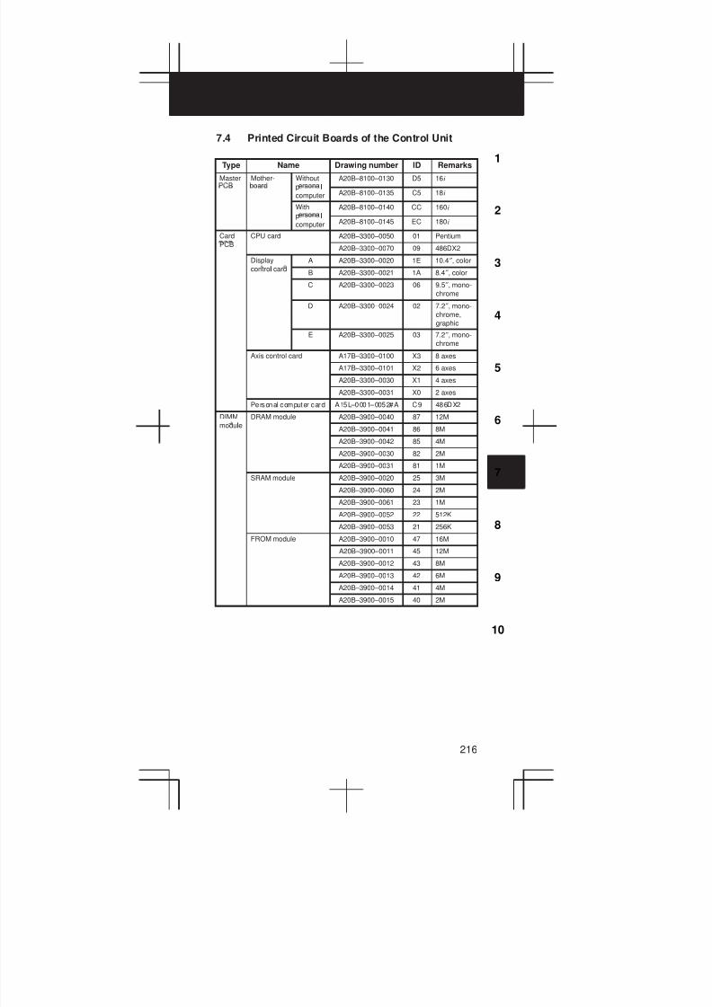
3
1
4
5
6
7
8
9
10
2
216
7.4 Printed Circuit Boards of the Control Unit
Type Name Drawing number ID Remarks
Master Mother- Without
p l
A20B–8100–0130 D5 16i
l
computer A20B–8100–0135 C5 18i
With
p l
A20B–8100–0140 CC 160i
l
computer A20B–8100–0145 EC 180i
Card CPU card A20B–3300–0050 01 Pentium
PCBA20B–3300–0070 09 486DX2
Display
l
A A20B–3300–0020 1E 10.4″, color
control cardB A20B–3300–0021 1A 8.4″, color
C A20B–3300–0023 06 9.5″, mono-
chrome
D A20B–3300–0024 02 7.2″, mono-
chrome,
graphic
E A20B–3300–0025 03 7.2″, mono-
chrome
Axis control card A17B–3300–0100 X3 8 axes
A17B–3300–0101 X2 6 axes
A20B–3300–0030 X1 4 axes
A20B–3300–0031 X0 2 axes
Personal computer card A15L–0001–0052#A C9 486DX2
DIMM
l
DRAM module A20B–3900–0040 87 12M
moduleA20B–3900–0041 86 8M
A20B–3900–0042 85 4M
A20B–3900–0030 82 2M
A20B–3900–0031 81 1M
SRAM module A20B–3900–0020 25 3M
A20B–3900–0060 24 2M
A20B–3900–0061 23 1M
A20B–3900–0052 22 512K
A20B–3900–0053 21 256K
FROM module A20B–3900–0010 47 16M
A20B–3900–0011 45 12M
A20B–3900–0012 43 8M
A20B–3900–0013 42 6M
A20B–3900–0014 41 4M
A20B–3900–0015 40 2M
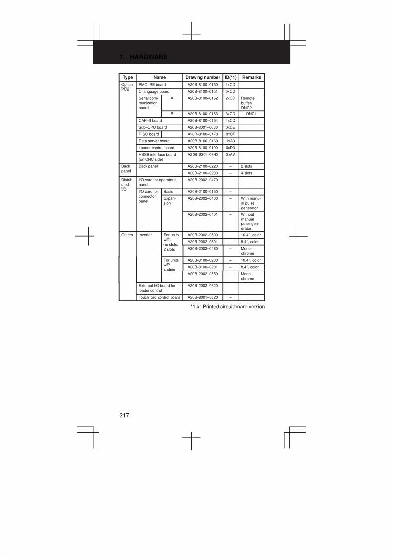
7. HARDWARE
217
Type Name Drawing number ID(*1) Remarks
Option PMC–RE board A20B–8100–0150 1xCD
PCBC language board A20B–8100–0151 0xCD
Serial com-
munication
board
A A20B–8100–0152 2xCD Remote
buffer/
DNC2
B A20B–8100–0153 3xCD DNC1
CAP–II board A20B–8100–0154 4xCD
Sub–CPU board A20B–8001–0630 0xCE
RISC board A20B–8100–0170 0xCF
Data server board A20B–8100–0160 1xA3
Loader control board A20B–8100–0190 0xD3
HSSB interface board
(on CNC side)
A20B–8001–0640 0xAA
Back
l
Back panel A20B–2100–0220 – 2 slots
panelA20B–2100–0230 – 4 slots
Distrib-
uted
I/O card for operator’s
panel
A20B–2002–0470 –
I/OI/O card for Basic A20B–2100–0150 –
connector
panelExpan-
sion
A20B–2002–0400 – With manu-
al pulse
generator
A20B–2002–0401 – Without
manual
pulse gen-
erator
Others Inverter For units
i
A20B–2002–0500 – 10.4″, color
with
no slots/ A20B–2002–0501 – 8.4″, color
l
2 slots A20B–2002–0480 – Mono-
chrome
For units
i
A20B–8100–0200 – 10.4″, color
with
4 slotsA20B–8100–0201 – 8.4″, color
lA20B–2002–0550 – Mono-
chrome
External I/O board for
loader control
A20B–2002–0620 –
Touch pad control board A20B–8001–0620 –
*1 x: Printed circuit board version
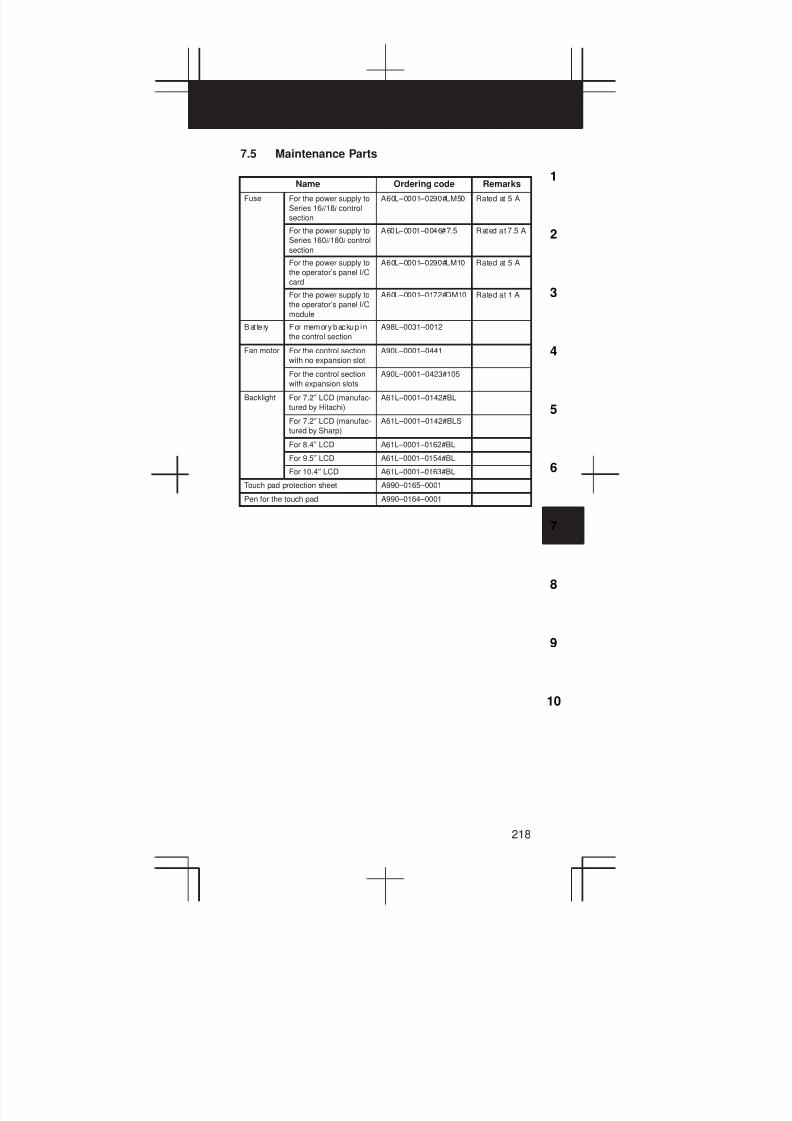
3
1
4
5
6
7
8
9
10
2
218
7.5 Maintenance Parts
Name Ordering code Remarks
Fuse For the power supply to
Series 16i /18i control
section
A60L–0001–0290#LM50 Rated at 5 A
For the power supply to
Series 160i /180i control
section
A60L–0001–0046#7.5 Rated at 7.5 A
For the power supply to
the operator’s panel I/O
card
A60L–0001–0290#LM10 Rated at 5 A
For the power supply to
the operator’s panel I/O
module
A60L–0001–0172#DM10 Rated at 1 A
Bat tery For memory backup in
the control section
A98L–0031–0012
Fan motor For the control section
with no expansion slot
A90L–0001–0441
For the control section
with expansion slots
A90L–0001–0423#105
Backlight For 7.2″ LCD (manufac-
tured by Hitachi)
A61L–0001–0142#BL
For 7.2″ LCD (manufac-
tured by Sharp)
A61L–0001–0142#BLS
For 8.4″ LCD A61L–0001–0162#BL
For 9.5″ LCD A61L–0001–0154#BL
For 10.4″ LCD A61L–0001–0163#BL
Touch pad protection sheet A990–0165–0001
Pen for the touch pad A990–0164–0001

8. PARAMETERS
219
8.1 How to Enter the Parameters
(1) Enabling writing the parameters
1 Enter the MDI mode or emergency stop state.
2 Press the SETTINGOFFSET key several times to display the handy screen for
setting.
3 Move the cursor to the PARAMETER WRITE field and enter 1
and then INPUT .
4 Alarm 100 occurs. Press the CAN and RESET keys simultaneously
to temporarily stop the alarm.
(2) Entering the parameters
1 Press the SYSTEM key on the MDI panel several times to select the
parameter screen.
PARAMETER (SETTING) O1234 N12345
0000 SEQ INI ISO TVC0 0 0 0 0 0 0 0
0001 FCV0 0 0 0 0 0 0 0
0012 RMV MIRX 0 0 0 0 0 0 0 0Y 0 0 0 0 0 0 0 0Z 0 0 0 0 0 0 0 0B 0 0 0 0 0 0 0 0
0020 I/O CHANNEL 0S 0 T0000
REF **** *** *** 10:15:30[PARAM] [DGNOS] [PMC] [SYSTEM] [(OPRT)]
2 Pressing soft key [(OPRT)] displays the operation menu includingthe items below.
Enter a parameter number and press [NO.SRH] : Searches for thespecified number.
Soft key [ON:1] : Sets the value at which the cursor is positioned to 1.(Only for bit parameters)
Soft key [OFF:0] : Sets the value at which the cursor is positioned to 0.(Only for bit parameters)
Soft key [+INPUT]: Adds the entered value to the value at which thecursor is positioned. (Only for word parameters)
Soft key [INPUT]: Sets the value at which the cursor is positioned tothe entered value. (Only for word parameters)
Soft key [READ] : Inputs parameters from the reader/punch interface.
Soft key [PUNCH] : Outputs parameters to the reader/punch interface.

3
1
4
5
6
7
8
9
10
2
220
3 Convenient methods for entering data
3–1 To change data in units of bits
Pressing or changes the cursor to 1-bit size,
which enables setting data in units of bits (only for bitparameters).
3–2 Use EOB to continuously set data starting from the cursor
position.
(Example 1)
When 1 2 3 4 EOB 4 5 6 7
EOB 9 9 9 9 INPUT is entered,
0 1234
0 4567
0 9999
0 0
³
(Example 2)
When 1 2 3 4 EOB EOB 9 9 9
9 INPUT is entered,
0 1234
0 0
0 9999
0 0
³
3–3 Use = to enter the same data.
(Example)
When 1 2 3 4 EOB = EOB = INPUT is
entered,
0 1234
0 1234
0 1234
0 0
³
3–4 For bit parameters
(Example)
When 1 1 EOB = EOB = INPUT is entered,
0 0 0 0 0 0 0 0 0 0 0 1 1 0 0 0
0 0 0 0 0 0 0 0 0 0 0 1 1 0 0 0
0 0 0 0 0 0 0 0 0 0 0 1 1 0 0 0
0 0 0 0 0 0 0 0 0 0 0 0 0 0 0 0
³
4 After all necessary parameters are entered, reset thePARAMETER WRITE field to 0 on the SETTING screen.
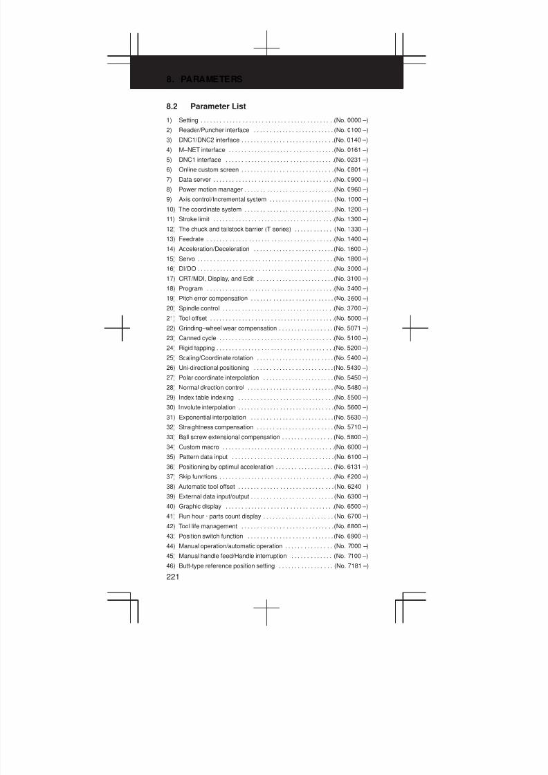
8. PARAMETERS
221
8.2 Parameter List
1) Setting (No. 0000 –). . . . . . . . . . . . . . . . . . . . . . . . . . . . . . . . . . . . . . . . . .
2) Reader/Puncher interface (No. 0100 –). . . . . . . . . . . . . . . . . . . . . . . . .
3) DNC1/DNC2 interface (No. 0140 –). . . . . . . . . . . . . . . . . . . . . . . . . . . . .
4) M–NET interface (No. 0161 –). . . . . . . . . . . . . . . . . . . . . . . . . . . . . . . . .
5) DNC1 interface (No. 0231 –). . . . . . . . . . . . . . . . . . . . . . . . . . . . . . . . . .
6) Online custom screen (No. 0801 –). . . . . . . . . . . . . . . . . . . . . . . . . . . . .
7) Data server (No. 0900 –). . . . . . . . . . . . . . . . . . . . . . . . . . . . . . . . . . . . . .
8) Power motion manager (No. 0960 –). . . . . . . . . . . . . . . . . . . . . . . . . . . .
9) Axis control/Incremental system (No. 1000 –). . . . . . . . . . . . . . . . . . . .
10) The coordinate system (No. 1200 –). . . . . . . . . . . . . . . . . . . . . . . . . . . .
11) Stroke limit (No. 1300 –). . . . . . . . . . . . . . . . . . . . . . . . . . . . . . . . . . . . . .
12) The chuck and tailstock barrier (T series) (No. 1330 –). . . . . . . . . . . .
13) Feedrate (No. 1400 –). . . . . . . . . . . . . . . . . . . . . . . . . . . . . . . . . . . . . . . .
14) Acceleration/Deceleration (No. 1600 –). . . . . . . . . . . . . . . . . . . . . . . . .
15) Servo (No. 1800 –). . . . . . . . . . . . . . . . . . . . . . . . . . . . . . . . . . . . . . . . . . .
16) DI/DO (No. 3000 –). . . . . . . . . . . . . . . . . . . . . . . . . . . . . . . . . . . . . . . . . . .
17) CRT/MDI, Display, and Edit (No. 3100 –). . . . . . . . . . . . . . . . . . . . . . . .
18) Program (No. 3400 –). . . . . . . . . . . . . . . . . . . . . . . . . . . . . . . . . . . . . . . .
19) Pitch error compensation (No. 3600 –). . . . . . . . . . . . . . . . . . . . . . . . . .
20) Spindle control (No. 3700 –). . . . . . . . . . . . . . . . . . . . . . . . . . . . . . . . . . .
21) Tool offset (No. 5000 –). . . . . . . . . . . . . . . . . . . . . . . . . . . . . . . . . . . . . . .
22) Grinding–wheel wear compensation (No. 5071 –). . . . . . . . . . . . . . . . .
23) Canned cycle (No. 5100 –). . . . . . . . . . . . . . . . . . . . . . . . . . . . . . . . . . . .
24) Rigid tapping (No. 5200 –). . . . . . . . . . . . . . . . . . . . . . . . . . . . . . . . . . . . .
25) Scaling/Coordinate rotation (No. 5400 –). . . . . . . . . . . . . . . . . . . . . . . .
26) Uni-directional positioning (No. 5430 –). . . . . . . . . . . . . . . . . . . . . . . . .
27) Polar coordinate interpolation (No. 5450 –). . . . . . . . . . . . . . . . . . . . . .
28) Normal direction control (No. 5480 –). . . . . . . . . . . . . . . . . . . . . . . . . . .
29) Index table indexing (No. 5500 –). . . . . . . . . . . . . . . . . . . . . . . . . . . . . .
30) Involute interpolation (No. 5600 –). . . . . . . . . . . . . . . . . . . . . . . . . . . . . .
31) Exponential interpolation (No. 5630 –). . . . . . . . . . . . . . . . . . . . . . . . . .
32) Straightness compensation (No. 5710 –). . . . . . . . . . . . . . . . . . . . . . . .
33) Ball screw extensional compensation (No. 5800 –). . . . . . . . . . . . . . . .
34) Custom macro (No. 6000 –). . . . . . . . . . . . . . . . . . . . . . . . . . . . . . . . . . .
35) Pattern data input (No. 6100 –). . . . . . . . . . . . . . . . . . . . . . . . . . . . . . . .
36) Positioning by optimul acceleration (No. 6131 –). . . . . . . . . . . . . . . . . .
37) Skip functions (No. 6200 –). . . . . . . . . . . . . . . . . . . . . . . . . . . . . . . . . . . .
38) Automatic tool offset (No. 6240 –). . . . . . . . . . . . . . . . . . . . . . . . . . . . . .
39) External data input/output (No. 6300 –). . . . . . . . . . . . . . . . . . . . . . . . . .
40) Graphic display (No. 6500 –). . . . . . . . . . . . . . . . . . . . . . . . . . . . . . . . . .
41) Run hour · parts count display (No. 6700 –). . . . . . . . . . . . . . . . . . . . . .
42) Tool life management (No. 6800 –). . . . . . . . . . . . . . . . . . . . . . . . . . . . .
43) Position switch function (No. 6900 –). . . . . . . . . . . . . . . . . . . . . . . . . . .
44) Manual operation/automatic operation (No. 7000 –). . . . . . . . . . . . . . .
45) Manual handle feed/Handle interruption (No. 7100 –). . . . . . . . . . . . .
46) Butt-type reference position setting (No. 7181 –). . . . . . . . . . . . . . . . .

3
1
4
5
6
7
8
9
10
2
222
47) Software operator’s panel (No. 7200 –). . . . . . . . . . . . . . . . . . . . . . . . .
48) Program restart (No. 7300 –). . . . . . . . . . . . . . . . . . . . . . . . . . . . . . . . . .
49) High speed machining (No. 7500 –). . . . . . . . . . . . . . . . . . . . . . . . . . . .
High speed cycle machining
High speed remote buffer
50) Polygon turning (No. 7600 –). . . . . . . . . . . . . . . . . . . . . . . . . . . . . . . . . .
51) External pulse input (No. 7680 –). . . . . . . . . . . . . . . . . . . . . . . . . . . . . . .
52) Hobbing machine and electric gear box (No. 7700 –). . . . . . . . . . . . . .
53) Attitude control (No. 7941 –). . . . . . . . . . . . . . . . . . . . . . . . . . . . . . . . . . .
54) Axis control by PMC (No. 8000 –). . . . . . . . . . . . . . . . . . . . . . . . . . . . . .
55) Two-path control (No. 8100 –). . . . . . . . . . . . . . . . . . . . . . . . . . . . . . . . .
56) Checking interference between tool posts(Two–path control) (No. 8140 –). . . . . . . . . . . . . . . . . . . . . . . . . . . . . . . .
57) Path axis reassignment (No. 8160 –). . . . . . . . . . . . . . . . . . . . . . . . . . .
58) Inclined axis control (No. 8200 –). . . . . . . . . . . . . . . . . . . . . . . . . . . . . . .
59) B-axis function (T series) (No. 8240 –). . . . . . . . . . . . . . . . . . . . . . . . . .
60) Simple synchronous control (No. 8300 –). . . . . . . . . . . . . . . . . . . . . . . .
61) Sequence number check termination (No. 8341 –). . . . . . . . . . . . . . . .
62) Chopping (No. 8360 –). . . . . . . . . . . . . . . . . . . . . . . . . . . . . . . . . . . . . . . .
63) High–speed High–precision contour control by RIS(M series) (No. 8400 –). . . . . . . . . . . . . . . . . . . . . . . . . . . . . . . . . . . . . . .
64) Other (No. 8650 –). . . . . . . . . . . . . . . . . . . . . . . . . . . . . . . . . . . . . . . . . . .
65) Maintenance (No. 8901 –). . . . . . . . . . . . . . . . . . . . . . . . . . . . . . . . . . . . .
Data Types and Valid Data Ranges of Parameters
Data Type Valid data range Data Type Valid data range
Bit Word –
Bit axis
Word axis –
Byte –128 to 127 2–word –99999999 to
Byte axis 0 to 255 2–word axis 99999999
NOTE1 There is something to which the range of setting is limited depend-
ing on the parameter No.
NOTE2 A part of the parameter can be input with the setting screen.
NOTE3 In the description of a bit-type parameter, the explanation written
at the left-hand side of a slash (/) corresponds to setting 0, and that
at the right-hand side corresponds to setting 1.
NOTE4 <Axis> indicated at the right column in a parameter list shows that
the corresponding parameters are specified for each axis.
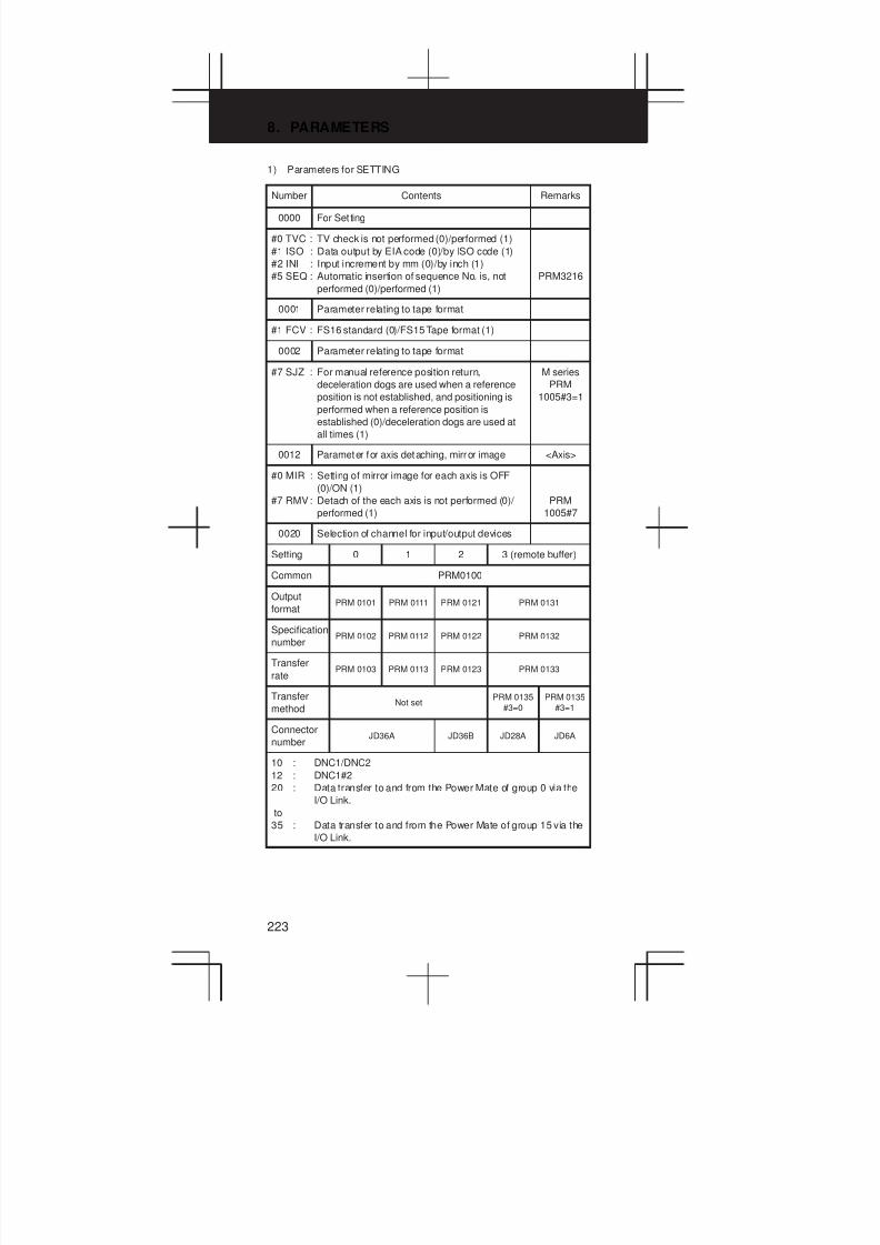
8. PARAMETERS
223
1) Parameters for SETTING
Number Contents Remarks
0000 For Set ting
#0 TVC : TV check is not performed (0)/performed (1)
#1 ISO : Data output by EIA code (0)/by ISO code (1)
#2 INI : Input increment by mm (0)/by inch (1)
#5 SEQ : Automatic insertion of sequence No. is, not
performed (0)/performed (1)
PRM3216
0001 Parameter relating to tape format
#1 FCV : FS16 standard (0)/FS15 Tape format (1)
0002 Parameter relating to tape format
#7 SJZ : For manual reference position return,
deceleration dogs are used when a reference
position is not established, and positioning is
performed when a reference position is
established (0)/deceleration dogs are used at
all times (1)
M series
PRM
1005#3=1
0012 Parameter for axis detaching, mirror image <Axis>
#0 MIR : Setting of mirror image for each axis is OFF
(0)/ON (1)
#7 RMV: Detach of the each axis is not performed (0)/
performed (1)
PRM
1005#7
0020 Selection of channel for input/output devices
Setting 0 1 2 3 (remote buffer)
Common PRM0100
Output
formatPRM 0101 PRM 0111 PRM 0121 PRM 0131
Specification
numberPRM 0102 PRM 0112 PRM 0122 PRM 0132
Transfer
ratePRM 0103 PRM 0113 PRM 0123 PRM 0133
Transfer
methodNot set
PRM 0135
#3=0
PRM 0135
#3=1
Connector
numberJD36A JD36B JD28A JD6A
10 : DNC1/DNC2
12 : DNC1#2
20 : Data transfer to and from the Power Mate of group 0 via the
I/O Link.
to
35 : Data transfer to and from the Power Mate of group 15 via the
I/O Link.

3
1
4
5
6
7
8
9
10
2
224
2) For reader/puncher interface
Number Contents Remarks
0024 Port for communication with the PMC ladder
development tool (FAPT LADDER–II)
0 : HSSB (COP7)
1 : RS–232C serial port 1 (JD36A)
2 : RS–232C serial port 2 (JD36B)
3 : Remote buffer interface (RS–232C) (JD28A)
0100 Common to each channel
#1 CTV : TV check in the comment section of a program
is performed (0)/not performed (1)
#3 NCR : When output EOB by ISO code, LF, CR, CR
(0)/CR output (1)
#5 ND3 : DNC operation is performed to read blocks one
by one (0)/until the buffer becomes full (1).
#6 IOP : Input/output of an NC program is stopped by
resetting the CNC (0)/by pressing the [STOP]
soft key (1).
#7 ENS : Reading of data by EIA code, if NULL code is
red in the data, ignore it (0)/make alarm (1)
ALM001
0101 Parameter relating to CHANNEL 1
(I/O CHANNEL=0)
#0 SB2 : Number of stop bit is 1 bit (0)/2 bits (1)
#3 ASI : Data input by EIA or ISO code (0)/ASCII code
(1)
#7 NFD : FEED before & after of data is output (0)/not
output (1)
0102 Spec. No. of I/O devices of CHANNEL 1
(I/O CHANNEL=0)
0 : RS-232-C (Used control codes DC1 to DC4)
1 : FANUC CASSETTE B1/B2
2 : FANUC CASSETTE F1
3 : FANUC PROGRAM FILE Mate, FANUC FA
Card, FSP-H, FANUC FLOPPY CASSETTE
4 : RS-232-C (Control codes DC1 to DC4 are not
used.)
5 : PORTABLE TAPE READER
6 : FSP-G, FSP-H, FANUC PPR
0103 Baud rate setting of CHANNEL 1
(I/O CHANNEL=0)
1 : 50 Baud 7 : 600 Baud
2 : 100 Baud 8 : 1200 bps
3 : 110 Baud 9 : 2400 Baud
4 : 150 Baud 10 : 4800 Baud
5 : 2000 bps 11 : 9600 Baud
6 : 300 Baud 12 :19200 Baud
0111 Parameter relating to CHANNEL 1
(I/O CHANNEL=1)
PRM0101
0112 Spec. No. of I/O devices of CHANNEL 1
(I/O CHANNEL=1)
PRM0102
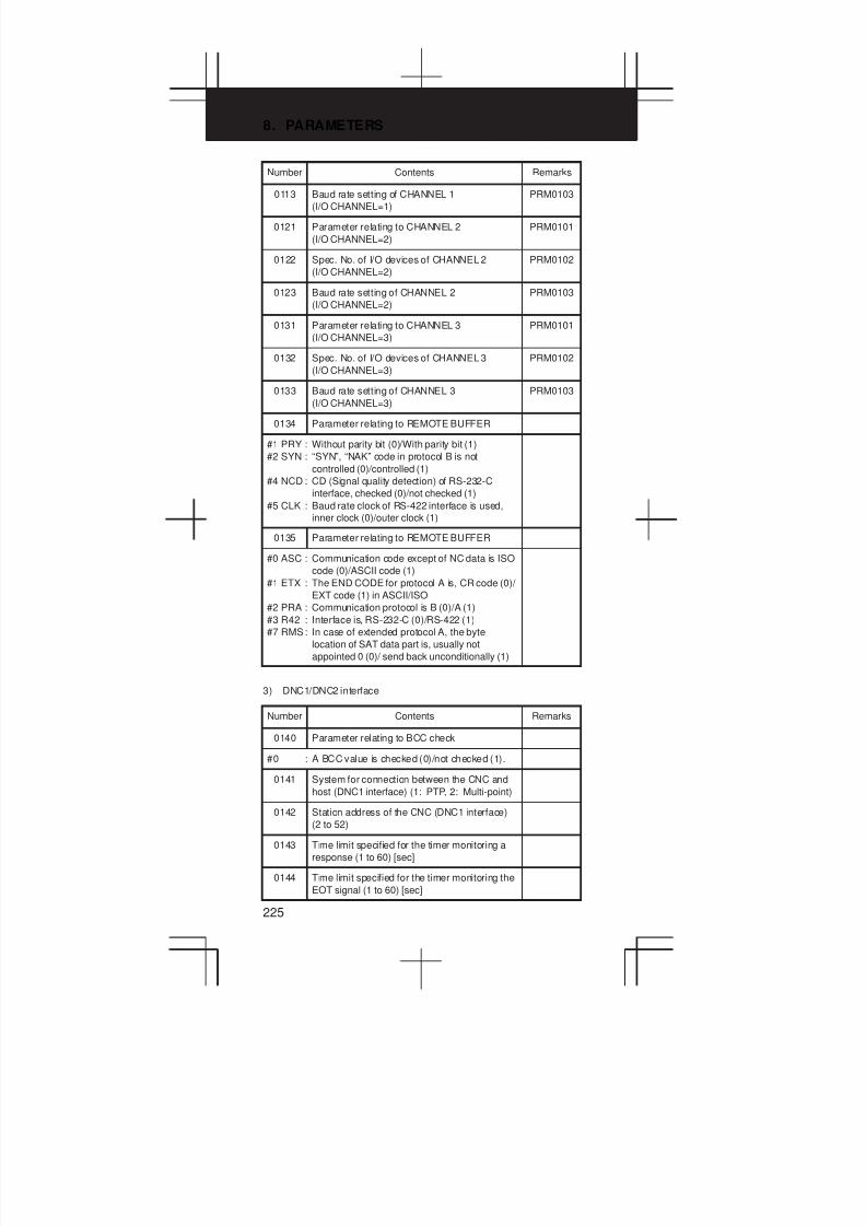
8. PARAMETERS
225
Number RemarksContents
0113 Baud rate setting of CHANNEL 1
(I/O CHANNEL=1)
PRM0103
0121 Parameter relating to CHANNEL 2
(I/O CHANNEL=2)
PRM0101
0122 Spec. No. of I/O devices of CHANNEL 2
(I/O CHANNEL=2)
PRM0102
0123 Baud rate setting of CHANNEL 2
(I/O CHANNEL=2)
PRM0103
0131 Parameter relating to CHANNEL 3
(I/O CHANNEL=3)
PRM0101
0132 Spec. No. of I/O devices of CHANNEL 3
(I/O CHANNEL=3)
PRM0102
0133 Baud rate setting of CHANNEL 3
(I/O CHANNEL=3)
PRM0103
0134 Parameter relating to REMOTE BUFFER
#1 PRY : Without parity bit (0)/With parity bit (1)
#2 SYN : “SYN”, “NAK” code in protocol B is not
controlled (0)/controlled (1)
#4 NCD : CD (Signal quality detection) of RS-232-C
interface, checked (0)/not checked (1)
#5 CLK : Baud rate clock of RS-422 interface is used,
inner clock (0)/outer clock (1)
0135 Parameter relating to REMOTE BUFFER
#0 ASC : Communication code except of NC data is ISO
code (0)/ASCII code (1)
#1 ETX : The END CODE for protocol A is, CR code (0)/
EXT code (1) in ASCII/ISO
#2 PRA : Communication protocol is B (0)/A (1)
#3 R42 : Interface is, RS-232-C (0)/RS-422 (1)
#7 RMS: In case of extended protocol A, the byte
location of SAT data part is, usually not
appointed 0 (0)/ send back unconditionally (1)
3) DNC1/DNC2 interface
Number Contents Remarks
0140 Parameter relating to BCC check
#0 : A BCC value is checked (0)/not checked (1).
0141 System for connection between the CNC and
host (DNC1 interface) (1: PTP, 2: Multi-point)
0142 Station address of the CNC (DNC1 interface)
(2 to 52)
0143 Time limit specified for the timer monitoring a
response (1 to 60) [sec]
0144 Time limit specified for the timer monitoring the
EOT signal (1 to 60) [sec]
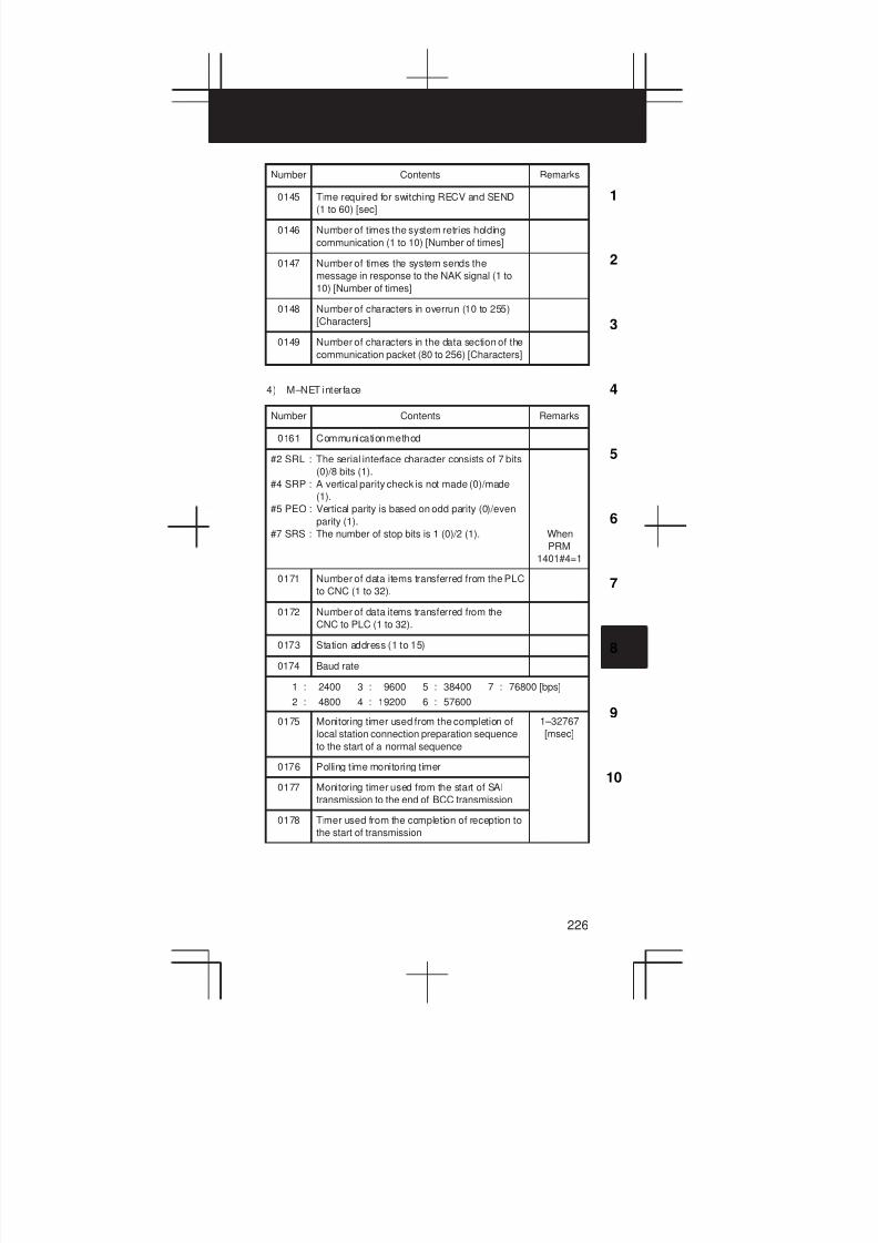
3
1
4
5
6
7
8
9
10
2
226
Number RemarksContents
0145 Time required for switching RECV and SEND
(1 to 60) [sec]
0146 Number of times the system retries holding
communication (1 to 10) [Number of times]
0147 Number of times the system sends the
message in response to the NAK signal (1 to
10) [Number of times]
0148 Number of characters in overrun (10 to 255)
[Characters]
0149 Number of characters in the data section of the
communication packet (80 to 256) [Characters]
4) M–NET interface
Number Contents Remarks
0161 Communication method
#2 SRL : The serial interface character consists of 7 bits
(0)/8 bits (1).
#4 SRP : A vertical parity check is not made (0)/made
(1).
#5 PEO : Vertical parity is based on odd parity (0)/even
parity (1).
#7 SRS : The number of stop bits is 1 (0)/2 (1). When
PRM
1401#4=1
0171 Number of data items transferred from the PLC
to CNC (1 to 32).
0172 Number of data items transferred from the
CNC to PLC (1 to 32).
0173 Station address (1 to 15)
0174 Baud rate
1 : 2400 3 : 9600 5 : 38400 7 : 76800 [bps]
2 : 4800 4 : 19200 6 : 57600
0175 Monitoring timer used from the completion of
local station connection preparation sequence
to the start of a normal sequence
1–32767
[msec]
0176 Polling time monitoring timer
0177 Monitoring timer used from the start of SAI
transmission to the end of BCC transmission
0178 Timer used from the completion of reception to
the start of transmission

8. PARAMETERS
227
5) Parameters of DNC1 interface
Number Contents Remarks
0231 Output format for DNC1 interface #2 PRM 0101
0233 Baud rate for DNC1 interface #2 PRM 0103
0241 System for connection between the CNC and
host (DNC1 interface) (1 : PTP, 2 : Multi–point)
0242 Station address of the CNC (DNC1 interface
#2) (2 to 52)
6) Parameters of FACTOLINK
Number Contents Remarks
0801
#0 SB2 : The number of stop bits is: 1 bit (0)/2 bits (1)
0802 Communication channel for the FACTOLINK
0803 Communication baud rate for the FACTOLINK
0810
#0 BGS : When the online custom screen is not
displayed, online custom screen alarm task
communication is: not activated (0)/activated
(1)
0811 Logging type for the online custom screen
0812 PMC address of logging data for the online
custom screen
0813 Logging data length for the online custom
screen
0814 Logging wait address for the online custom
screen
0820 Online custom screen device address (1)
0821 Online custom screen device address (2)
0822 Online custom screen device address (3)
0823 Online custom screen device address (4)
0824 Online custom screen device address (5)
0825 Online custom screen device address (6)
0826 Online custom screen device address (7)
0827 Online custom screen device address (8)
0828 Online custom screen device address (9)
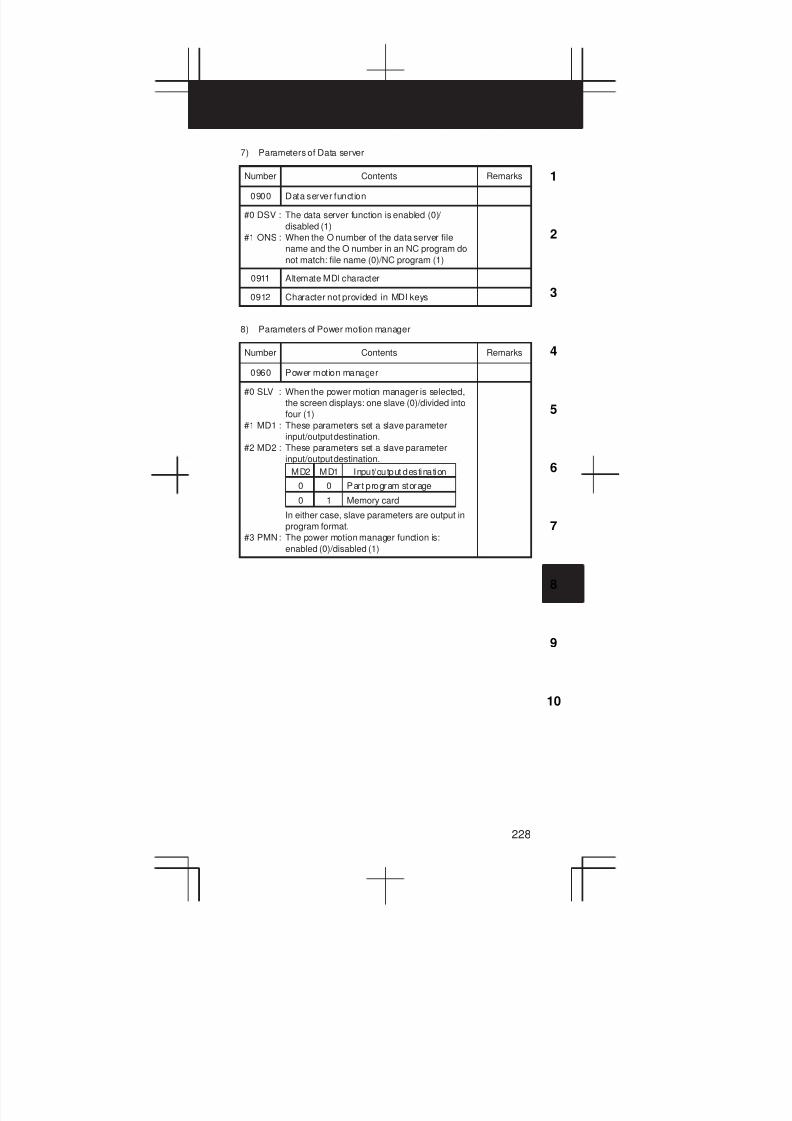
3
1
4
5
6
7
8
9
10
2
228
7) Parameters of Data server
Number Contents Remarks
0900 Data server function
#0 DSV : The data server function is enabled (0)/
disabled (1)
#1 ONS : When the O number of the data server file
name and the O number in an NC program do
not match: file name (0)/NC program (1)
0911 Altemate MDI character
0912 Character not provided in MDI keys
8) Parameters of Power motion manager
Number Contents Remarks
0960 Power motion manager
#0 SLV : When the power motion manager is selected,
the screen displays: one slave (0)/divided into
four (1)
#1 MD1 : These parameters set a slave parameter
input/output destination.
#2 MD2 : These parameters set a slave parameter
input/output destination.
In either case, slave parameters are output in
program format.
#3 PMN: The power motion manager function is:
enabled (0)/disabled (1)
0
MD2 MD1 Input/output destination
0 Part program storage
0 1 Memory card

8. PARAMETERS
229
9) Parameter for Axis control/Incremental system
Number Contents Remarks
1001 Parameter relating to least input increment
#0 INM : Least command increment on linear axis is,
mm system (0)/inch system (1)
1002 Parameter relating to number of control axis
#0 JAX : Number of simultaneous controlled axis in
manual operation is, 1 axis (0)/3 axis (1)
#1 DLZ : Reference position return function without dog
is, disable (0)/enable (1)
#2 SFD : The reference position shift function is not used
(0)/used (1).
#3 AZR : For G28, specified when a reference position
has not yet been established, deceleration
dogs are used (0)/ALM 90 is issued (1).
#4 XIK : When an axis-by-axis interlock signal is applied
during nonlinear positioning, only the interlock
axis is stopped (0)/all axes are stopped (1).
#7 IDG : When the reference position is set without
dogs, automatic setting of the parameter (bit 0
of parameter No.1012) is: not performed (0)/
performed (1)
PRM
1005#1
M series
1004 Parameter relating to least input increment
#0 ISA :
#1 ISC :
#7 IPR : Least input increment of each axis is set to 1
time (0)/10 times (1) as of least command
increment
ISC ISA CODE Least input increment
0 0 IS–B 0.001 mm or 0.001 deg
0 1 IS–A 0.01 mm or 0.01 deg
1 0 IS–C 0.0001 mm or 0.0001 deg
M series
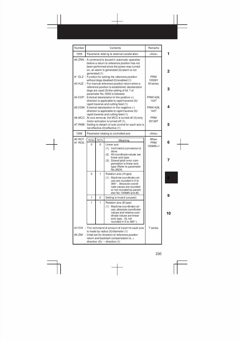
3
1
4
5
6
7
8
9
10
2
230
Number RemarksContents
1005 Parameter relating to external decelerat ion <Axis>
#0 ZRN : A command is issued in automatic operation
before a return to reference position has not
been performed since the power was turned
on, an alarm is generated (0)/alarm is not
generated (1)
#1 DLZ : Function for setting the reference position
without dogs disabled (0)/enabled (1)
#3 HJZ : For manual reference position return when a
reference position is established, deceleration
dogs are used (0)/the setting of bit 7 of
parameter No. 0002 is followed.
#4 EDP : External deceleration in the positive (+)
direction is applicable to rapid traverse (0)/
rapid traverse and cutting feed (1).
#5 EDM: External deceleration in the negative (–)
direction is applicable to rapid traverse (0)/
rapid traverse and cutting feed (1).
#6 MCC: At axis removal, the MCC is turned off (0)/only
motor activation is turned off (1).
#7 RMB: Setting to detach of axis control for each axis is
not effective (0)/effective (1)
PRM
1002#1
M series
PRM1426,
1427
PRM1426,
1427
PRM
0012#7
1006 Parameter relating to controlled axis <Axis>
#0 ROT :
#1 ROS :
#3 DIA : The command of amount of travel for each axis
is made by radius (0)/diameter (1)
#5 ZMI : Initial set for direction of reference position
return and backlash compensation is, +
direction (0)/ – direction (1)
0
ROSx ROTx Meaning
0 Linear axis
(1) Inch/metric conversion isdone.
(2) All coordinate values arelinear axis type.
(3) Stored pitch error com-pensation is linear axistype (Refer to parameterNo.3624)
0 1 Rotation axis (A type)
(1) Machine coordinate val-ues are rounded in 0 to360_. Absolute coordi-nate values are roundedor not rounded by param-eter No.1008#0 and #2.
1 0 Setting is invalid (unused)
1 1 Rotation axis (B type)
(1) Machine coordinate val-ues, absolute coordinatevalues and relative coor-dinate values are linearaxis type. (Is notrounded in 0 to 360_).
When
PRM
1006#0=1
T series
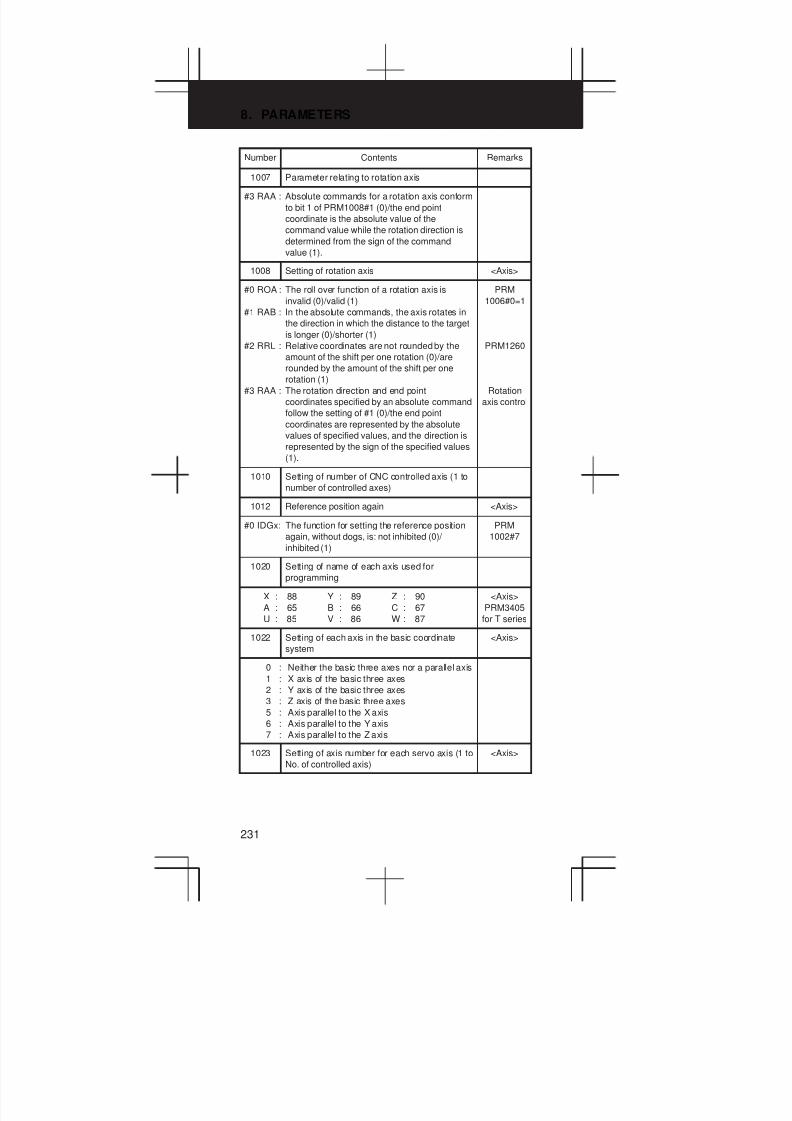
8. PARAMETERS
231
Number RemarksContents
1007 Parameter relating to rotation axis
#3 RAA : Absolute commands for a rotation axis conform
to bit 1 of PRM1008#1 (0)/the end point
coordinate is the absolute value of the
command value while the rotation direction is
determined from the sign of the command
value (1).
1008 Setting of rotation axis <Axis>
#0 ROA : The roll over function of a rotation axis is
invalid (0)/valid (1)
#1 RAB : In the absolute commands, the axis rotates in
the direction in which the distance to the target
is longer (0)/shorter (1)
#2 RRL : Relative coordinates are not rounded by the
amount of the shift per one rotation (0)/are
rounded by the amount of the shift per one
rotation (1)
#3 RAA : The rotation direction and end point
coordinates specified by an absolute command
follow the setting of #1 (0)/the end point
coordinates are represented by the absolute
values of specified values, and the direction is
represented by the sign of the specified values
(1).
PRM
1006#0=1
PRM1260
Rotation
axis control
1010 Setting of number of CNC controlled axis (1 to
number of controlled axes)
1012 Reference position again <Axis>
#0 IDGx: The function for setting the reference position
again, without dogs, is: not inhibited (0)/
inhibited (1)
PRM
1002#7
1020 Setting of name of each axis used for
programming
X : 88 Y : 89 Z : 90
A : 65 B : 66 C : 67
U : 85 V : 86 W : 87
<Axis>
PRM3405
for T series
1022 Setting of each axis in the basic coordinate
system
<Axis>
0 : Neither the basic three axes nor a parallel axis
1 : X axis of the basic three axes
2 : Y axis of the basic three axes
3 : Z axis of the basic three axes
5 : Axis parallel to the X axis
6 : Axis parallel to the Y axis
7 : Axis parallel to the Z axis
1023 Setting of axis number for each servo axis (1 to
No. of controlled axis)
<Axis>
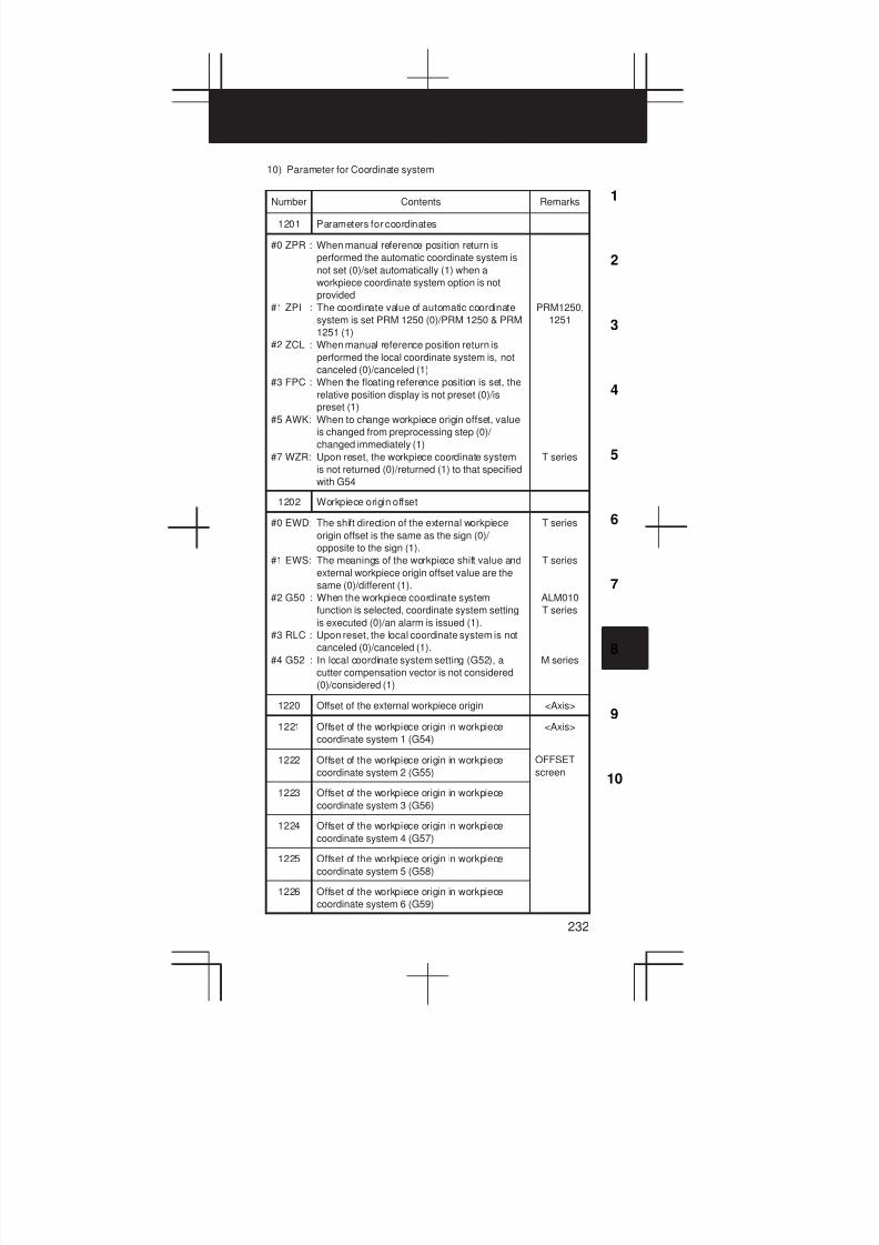
3
1
4
5
6
7
8
9
10
2
232
10) Parameter for Coordinate system
Number Contents Remarks
1201 Parameters for coordinates
#0 ZPR : When manual reference position return is
performed the automatic coordinate system is
not set (0)/set automatically (1) when a
workpiece coordinate system option is not
provided
#1 ZPI : The coordinate value of automatic coordinate
system is set PRM 1250 (0)/PRM 1250 & PRM
1251 (1)
#2 ZCL : When manual reference position return is
performed the local coordinate system is, not
canceled (0)/canceled (1)
#3 FPC : When the floating reference position is set, the
relative position display is not preset (0)/is
preset (1)
#5 AWK: When to change workpiece origin offset, value
is changed from preprocessing step (0)/
changed immediately (1)
#7 WZR: Upon reset, the workpiece coordinate system
is not returned (0)/returned (1) to that specified
with G54
PRM1250,
1251
T series
1202 Workpiece origin offset
#0 EWD: The shift direction of the external workpiece
origin offset is the same as the sign (0)/
opposite to the sign (1).
#1 EWS: The meanings of the workpiece shift value and
external workpiece origin offset value are the
same (0)/different (1).
#2 G50 : When the workpiece coordinate system
function is selected, coordinate system setting
is executed (0)/an alarm is issued (1).
#3 RLC : Upon reset, the local coordinate system is not
canceled (0)/canceled (1).
#4 G52 : In local coordinate system setting (G52), a
cutter compensation vector is not considered
(0)/considered (1)
T series
T series
ALM010
T series
M series
1220 Offset of the external workpiece origin <Axis>
1221 Offset of the workpiece origin in workpiece
coordinate system 1 (G54)
<Axis>
1222 Offset of the workpiece origin in workpiece
coordinate system 2 (G55)
OFFSET
screen
1223 Offset of the workpiece origin in workpiece
coordinate system 3 (G56)
1224 Offset of the workpiece origin in workpiece
coordinate system 4 (G57)
1225 Offset of the workpiece origin in workpiece
coordinate system 5 (G58)
1226 Offset of the workpiece origin in workpiece
coordinate system 6 (G59)

8. PARAMETERS
233
Number RemarksContents
1240 Coordinate value of the first reference position
on each axis in the machine coordinate system
<Axis>
1241 Coordinate value of the second reference
position on each axis in the machine coordinate
system
<Axis>
1242 Coordinate value of the third reference position
on each axis in the machine coordinate system
<Axis>
1243 Coordinate value of the fourth reference
position on each axis in the machine coordinate
system
<Axis>
1244 Coordinate value of the floating reference
position
<Axis>
Set auto-
matically
1250 Coordinate value of the reference position used
when automatic coordinate system setting is
performed (mm input)
<Axis>
PRM
1201#1=0
1251 Coordinate value of the reference position on
each axis used for setting a coordinate system
automatically when input is performed in inches
<Axis>
PRM
1201#1=1
1260 The amount of travel per rotation <Axis>
1290 Distance between two opposed tool posts in
mirror image
T series
11) Parameters of Stored stroke check
Number Contents Remarks
1300 Relating to Stroke check
#0 OUT : An inhibition area of the second stored stroke
check is set, inside (0)/outside (1)
#2 LMS : The EXLM signal for switching stored stroke
check is disable (0)/enable (1)
#5 RL3 : Stored stroke check3 release signal RLSOT3
is disabled (0)/enabled (1)
#6 LZR : The stored stroke check are checked during
the time from power-on to manual return to the
reference position (0)/not checked (1)
#7 BFA : When a command that exceeds a stored
stroke check is issued, an alarm is generated
after the stroke check is exceeded (0)/before
the check is exceeded (1)
PRM1320,
1321,
1326, 1327

3
1
4
5
6
7
8
9
10
2
234
Number RemarksContents
1301 Stroke limit check performed before movement
#2 NPC : As part of the stroke limit check performed
before movement, the movement specified in
G31 (skip) and G37 (automatic tool length
measurement (for M series) or automatic tool
compensation (for T series)) blocks is checked
(0)/not checked (1)
#7 PLC : Stroke limit check before movement is not
performed (0)/performed (1)
1310 Relating to stored stroke check <Axis>
#0 OT2 : When the inside of the stored stroke check 2 is
set as the inhibition area, whether stored
stroke check 2 are checked for each axis is
set, stored stroke check 2 are not checked (0)/
checked (1)
#1 OT3 : Stored stroke check 3 for each axis are, not
checked (0)/checked (1)
1320 Coordinate value I of stored stroke check 1 in
the positive direction on each axis
<Axis>
1321 Coordinate value I of stored stroke check 1 in
the negative direction on each axis
<Axis>
1322 Coordinate value of stored stroke check 2 in
the positive direction on each axis
<Axis>
1323 Coordinate value of stored stroke check 2 in
the negative direction on each axis
<Axis>
1324 Coordinate value of stored stroke check 3 in
the positive direction on each axis
<Axis>
1325 Coordinate value of stored stroke check 3 in
the negative direction on each axis
<Axis>
1326 Coordinate value II of stored stroke check 1 in
the positive direction on each axis
<Axis>
PRM
1300#2=1
1327 Coordinate value II of stored stroke check 1 in
the negative direction on each axis
<Axis>
PRM
1300#2=1
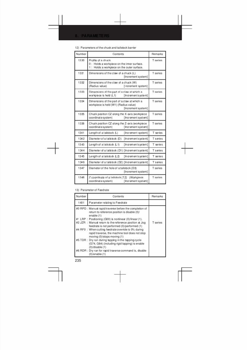
8. PARAMETERS
235
12) Parameters of the chuck and tailstock barrier
Number Contents Remarks
1330 Prof ile of a chuck
0 : Holds a workpiece on the inner surface.
1 : Holds a workpiece on the outer surface.
T series
1331 Dimensions of the claw of a chuck (L)
[Increment system]
T series
1332 Dimensions of the claw of a chuck (W)
(Radius value) [Increment system]
T series
1333 Dimensions of the part of a claw at which a
workpiece is held (L1) [Increment system]
T series
1334 Dimensions of the part of a claw at which a
workpiece is held (W1) (Radius value)
[Increment system]
T series
1335 Chuck position CZ along the X-axis (workpiece
coordinate system) [ Increment system]
T series
1336 Chuck position CZ along the Z-axis (workpiece
coordinate system) [ Increment system]
T series
1341 Length of a tailstock (L) [ Increment system] T ser ies
1342 Diameter of a tailstock (D) [Increment system] T series
1343 Length of a tai lstock (L1) [ Increment system] T ser ies
1344 Diameter of a tailstock (D1) [Increment system] T series
1345 Length of a tai lstock (L2) [ Increment system] T ser ies
1346 Diameter of a tailstock (D2) [Increment system] T series
1347 Diameter of the hole of a tailstock (D3)
[Increment system]
T series
1348 Z coordinate of a tailstock (TZ) (Workpiece
coordinate system) [ Increment system]
T series
13) Parameter of Feedrate
Number Contents Remarks
1401 Parameter relating to Feedrate
#0 RPD : Manual rapid traverse before the completion of
return to reference position is disable (0)/
enable (1)
#1 LRP : Positioning (G00) is nonlinear (0)/linear (1).
#2 JZR : Manual return to the reference position at Jog
feedrate is not performed (0)/performed (1)
#4 RF0 : When cutting feedrate override is 0% during
rapid traverse, the machine tool does not stop
moving (0)/stops moving (1)
#5 TDR : Dry run during tapping in the tapping cycle
(G74, G84) (including rigid tapping) is enable
(0)/disable (1)
#6 RDR : Dry run for rapid traverse command is, disable
(0)/enable (1)
T series

3
1
4
5
6
7
8
9
10
2
236
Number RemarksContents
1402 Parameter relating to Manual feed per
revolution
#0 NPC : The feed per rotation command is ineffective
when a position coder is not provided (0)/
provided (1)
#3 OV2 : The secondary feedrate override value is 1%
(0)/0.01% (1).
#4 JRV : Manual continuous feed (jog feed) is performed
at feed per minute (0)/at feed per rotation (1)
T series
1403 Units used for feed per minute, threading retract T series
#0 MIF : The unit of F for feed per minute is [mm/min]
(0)/0.001 mm/min] (1).
#7 RTV : Overriding during threading retraction is
enabled (0)/disabled (1).
1404 Helical interpolation, reference position return
#0 HFC : The feedrate for helical interpolation is:
clamped along an arc and linear axis (0)/along
an arc and linear axis (1)
#1 DLF : After a reference position has been
established, a manual reference position return
operation is performed at the rapid traverse
rate (PRM1420) (0)/at the manual rapid
traverse rate (PRM1424) (1).
#2 F8A : With inch input, Valid data range for an F
command in feed per minute mode 9600
deg/min (0)/24000 deg/min (1)
#3 FRV : For inch input, the valid range of the feedrate
specified for feed per revolution is: F9.999999
inches per revolution (0)/F50.000000 inches
per revolution (1)
PRM 1422
1430
T series
1410 Dry run rate (feedrate of jog override is 100%)
The jog feedrate for manual linear or circular
interpolation [mm/min]
1411 Cutting feedrate in the automatic mode at
power-on [mm/min]
M series
1414 Feedrate for reverse movement by the retrace
function [mm/min]
M series
0: Pro-
grammed
command
1420 Rapid traverse rate for each axis
(Rapid traverse override is 100%) [mm/min]
<Axis>
1421 F0 rate of rapid traverse override for each axis
[mm/min]
<Axis>
1422 Maximum cutting feedrate for each axis
[mm/min]
<Axis>
PRM1430
1423 Manual continuous feedrate for each axis (jog
feedrate) [mm/min]
<Axis>
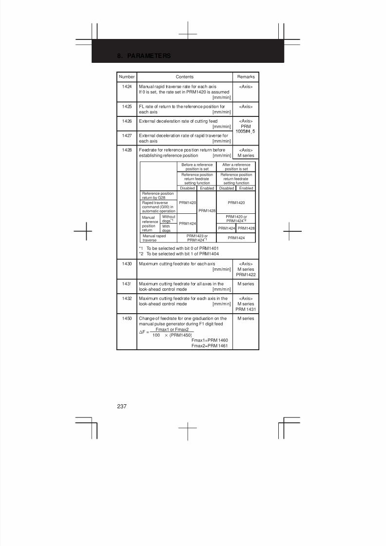
8. PARAMETERS
237
Number RemarksContents
1424 Manual rapid traverse rate for each axis
If 0 is set, the rate set in PRM1420 is assumed
[mm/min]
<Axis>
1425 FL rate of return to the reference position for
each axis [mm/min]
<Axis>
1426 External deceleration rate of cutting feed
[mm/min]
<Axis>
PRM
1427 External deceleration rate of rapid traverse for
each axis [mm/min]
,
1428 Feedrate for reference position return before
establishing reference position [mm/min]
*1 To be selected with bit 0 of PRM1401
*2 To be selected with bit 1 of PRM1404
Reference positionreturn by G28
Raped traversecommand (G00) inautomatic operation
Manualreferencepositionreturn
Withoutdogs*1
Withdogs
Manual rapedtraverse
PRM1428
PRM1420 orPRM1424*2
PRM1424
PRM1420
PRM1424
EnabledDisabled
Reference positionreturn feedratesetting function
After a referenceposition is set
PRM1428
PRM1424
PRM1423 orPRM1424*1
EnabledDisabled
Reference positionreturn feedratesetting function
Before a referenceposition is set
PRM1420
<Axis>
M series
1430 Maximum cutting feedrate for each axis
[mm/min]
<Axis>
M series
PRM1422
1431 Maximum cutting feedrate for all axes in the
look-ahead control mode [mm/min]
M series
1432 Maximum cutting feedrate for each axis in the
look-ahead control mode [mm/min]
<Axis>
M series
PRM 1431
1450 Change of feedrate for one graduation on the
manual pulse generator during F1 digit feed
Fmax1=PRM 1460
Fmax2=PRM 1461
nF =Fmax1 or Fmax2
100 (PRM1450)
M series
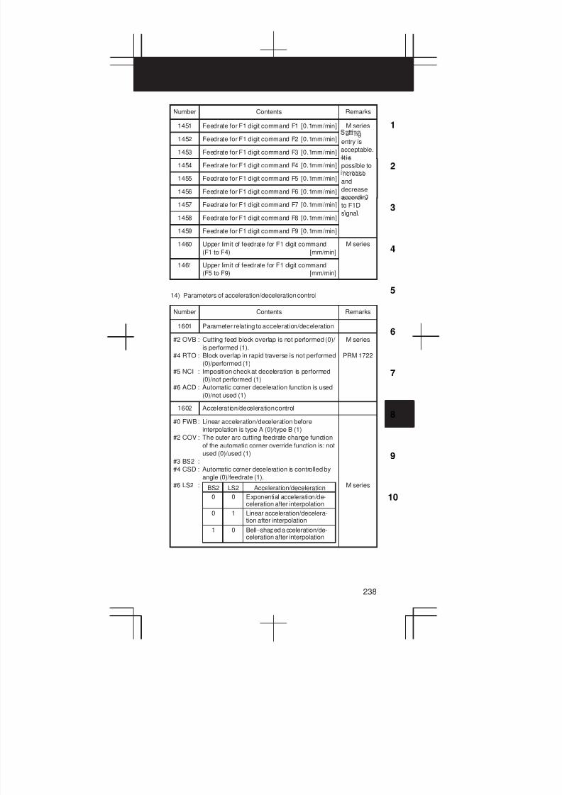
3
1
4
5
6
7
8
9
10
2
238
Number RemarksContents
1451 Feedrate for F1 digit command F1 [0.1mm/min] M series
1452 Feedrate for F1 digit command F2 [0.1mm/min]e ng
entry is
1453 Feedrate for F1 digit command F3 [0.1mm/min] acceptable.
I t is1454 Feedrate for F1 digit command F4 [0.1mm/min]
possible to
1455 Feedrate for F1 digit command F5 [0.1mm/min]
ncrease
and
1456 Feedrate for F1 digit command F6 [0.1mm/min] decrease
accordin1457 Feedrate for F1 digit command F7 [0.1mm/min] to F1D
1458 Feedrate for F1 digit command F8 [0.1mm/min]
signal.
1459 Feedrate for F1 digit command F9 [0.1mm/min]
1460 Upper limit of feedrate for F1 digit command
(F1 to F4) [mm/min]
M series
1461 Upper limit of feedrate for F1 digit command
(F5 to F9) [mm/min]
14) Parameters of acceleration/deceleration control
Number Contents Remarks
1601 Parameter relating to acceleration/deceleration
#2 OVB : Cutting feed block overlap is not performed (0)/
is performed (1).
#4 RTO : Block overlap in rapid traverse is not performed
(0)/performed (1)
#5 NCI : Imposition check at deceleration is performed
(0)/not performed (1)
#6 ACD : Automatic corner deceleration function is used
(0)/not used (1)
M series
PRM 1722
1602 Acceleration/deceleration control
#0 FWB: Linear acceleration/deceleration before
interpolation is type A (0)/type B (1)
#2 COV : The outer arc cutting feedrate change function
of the automatic corner override function is: not
used (0)/used (1)
#3 BS2 :
#4 CSD : Automatic corner deceleration is controlled by
angle (0)/feedrate (1).
#6 LS2 :
0
BS2 LS2 Acceleration/deceleration
0 Exponential acceleration/de-celeration after interpolation
0 1 Linear acceleration/decelera-tion after interpolation
1 0 Bell–shaped a cceleration/de-celeration after interpolation
M series
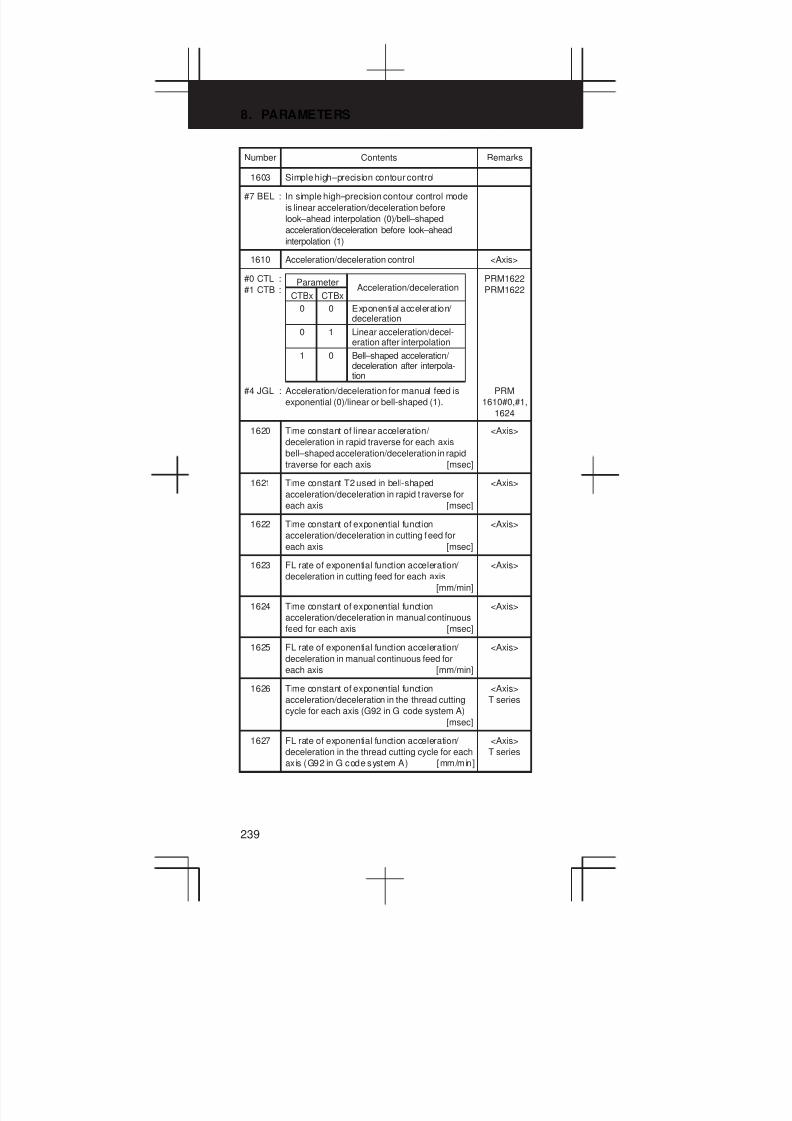
8. PARAMETERS
239
Number RemarksContents
1603 Simple high–precision contour control
#7 BEL : In simple high–precision contour control mode
is linear acceleration/deceleration before
look–ahead interpolation (0)/bell–shaped
acceleration/deceleration before look–ahead
interpolation (1)
1610 Acceleration/deceleration control <Axis>
#0 CTL :
#1 CTB :
#4 JGL : Acceleration/deceleration for manual feed is
exponential (0)/linear or bell-shaped (1).
0
CTBx CTBxAcceleration/deceleration
0 Exponential acceleration/ deceleration
Parameter
0 1 Linear acceleration/decel-eration after interpolation
1 0 Bell–shaped acceleration/ deceleration after interpola-tion
PRM1622
PRM1622
PRM
1610#0,#1,
1624
1620 Time constant of linear acceleration/
deceleration in rapid traverse for each axis
bell–shaped acceleration/deceleration in rapid
traverse for each axis [msec]
<Axis>
1621 Time constant T2 used in bell-shaped
acceleration/deceleration in rapid t raverse for
each axis [msec]
<Axis>
1622 Time constant of exponential function
acceleration/deceleration in cutting feed for
each axis [msec]
<Axis>
1623 FL rate of exponential function acceleration/
deceleration in cutting feed for each axis
[mm/min]
<Axis>
1624 Time constant of exponential function
acceleration/deceleration in manual continuous
feed for each axis [msec]
<Axis>
1625 FL rate of exponential function acceleration/
deceleration in manual continuous feed for
each axis [mm/min]
<Axis>
1626 Time constant of exponential function
acceleration/deceleration in the thread cutting
cycle for each axis (G92 in G code system A)
[msec]
<Axis>
T series
1627 FL rate of exponential function acceleration/
deceleration in the thread cutting cycle for each
axis (G92 in G code system A) [mm/min]
<Axis>
T series

3
1
4
5
6
7
8
9
10
2
240
Number RemarksContents
1630 Maximum machining speed during linear
acceleration/deceleration before interpolation
[mm/min]
In
look-ahead
control
1631 Time until the machining speed reaches the
maximum speed during acceleration/
decelerat ion before interpolation [msec]
,
PRM1770,
1771 are
enabled.
1710 Minimum deceleration ratio (MDR) of the inner
circular cutting rate in automatic corner
override [%]
M series
Automatic
corner
1711 Angle (θp) to recognize the inner corner in
automatic override [deg]
overr e
1712 Amount of automatic override for an inner
corner [%]
1713 Distance Le from the starting point in inner
corner automatic override
1714 Distance Ls up to the ending point in inner
corner automatic override
1722 Rapid traverse deceleration ratio when blocks
in rapid traverse are overlapped [%]
<Axis>
PRM
1601#4
1730 Maximum allowable feedrate for arc radius R M series
Feedrate
1731 Arc radius R for a maximum allowable feedrate
based on an arc radius
clamping
for
feedrate
1732 Minimum allowable clamping feedrate for
feedrate based on an arc radius
based on
an arc
radius
1740 Critical angle subtended by two blocks
specifying automatic corner deceleration
[0.001 deg]
M series
1741 Feedrate for terminating automatic corner
deceleration (for acceleration/deceleration after
interpolation)
<Axis>
M series
1762 Time constant of exponential acceleration/
deceleration in cutting feed in look-ahead
control mode [msec]
<Axis>
M series
1763 FL rate for exponential acceleration/
deceleration in cutting feed in look-ahead
control mode [mm/min]
<Axis>
M series
1768 Time constant of linear acceleration/
deceleration in cutting feed in look-ahead
control mode [msec]
M series
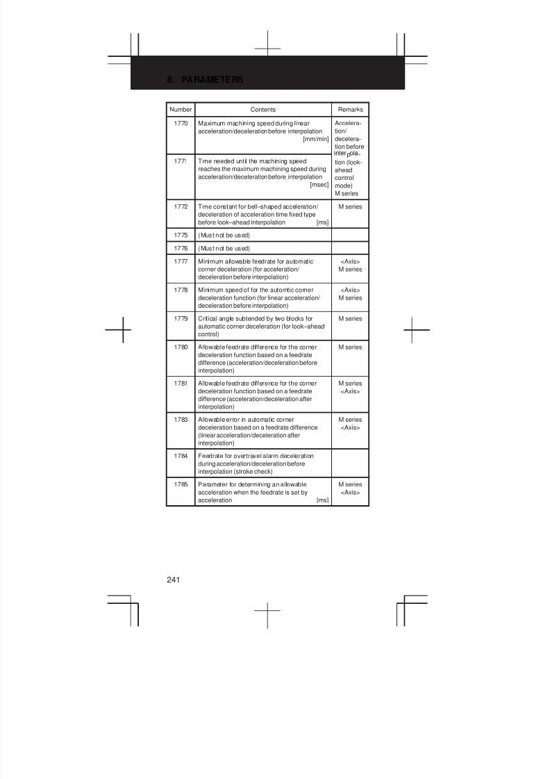
8. PARAMETERS
241
Number RemarksContents
1770 Maximum machining speed during linear
acceleration/deceleration before interpolation
[mm/min]
Accelera-
tion/
decelera-
tion before
p -1771 Time needed until the machining speed
reaches the maximum machining speed during
acceleration/deceleration before interpolation
[msec]
-
tion (look-
ahead
control
mode)
M series
1772 Time constant for bell–shaped acceleration/
deceleration of acceleration time fixed type
before look–ahead interpolation [ms]
M series
1775 (Must not be used)
1776 (Must not be used)
1777 Minimum allowable feedrate for automatic
corner deceleration (for acceleration/
deceleration before interpolation)
<Axis>
M series
1778 Minimum speed of for the automtic corner
deceleration function (for linear acceleration/
deceleration before interpolation)
<Axis>
M series
1779 Critical angle subtended by two blocks for
automatic corner deceleration (for look–ahead
control)
M series
1780 Allowable feedrate difference for the corner
deceleration function based on a feedrate
difference (acceleration/deceleration before
interpolation)
M series
1781 Allowable feedrate difference for the corner
deceleration function based on a feedrate
difference (acceleration/deceleration after
interpolation)
M series
<Axis>
1783 Allowable error in automatic corner
deceleration based on a feedrate difference
(linear acceleration/deceleration after
interpolation)
M series
<Axis>
1784 Feedrate for overtravel alarm deceleration
during acceleration/deceleration before
interpolation (stroke check)
1785 Parameter for determining an allowable
acceleration when the feedrate is set by
acceleration [ms]
M series
<Axis>
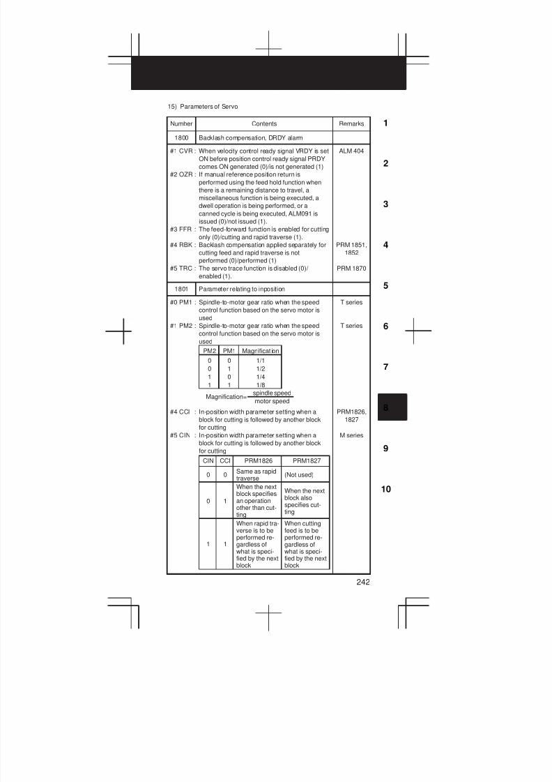
3
1
4
5
6
7
8
9
10
2
242
15) Parameters of Servo
Number Contents Remarks
1800 Backlash compensation, DRDY alarm
#1 CVR : When velocity control ready signal VRDY is set
ON before position control ready signal PRDY
comes ON generated (0)/is not generated (1)
#2 OZR : If manual reference position return is
performed using the feed hold function when
there is a remaining distance to travel, a
miscellaneous function is being executed, a
dwell operation is being performed, or a
canned cycle is being executed, ALM091 is
issued (0)/not issued (1).
#3 FFR : The feed-forward function is enabled for cutting
only (0)/cutting and rapid traverse (1).
#4 RBK : Backlash compensation applied separately for
cutting feed and rapid traverse is not
performed (0)/performed (1)
#5 TRC : The servo trace function is disabled (0)/
enabled (1).
ALM 404
PRM 1851,
1852
PRM 1870
1801 Parameter relating to inposition
0
0
1
1
#0 PM1 : Spindle-to-motor gear ratio when the speed
control function based on the servo motor is
used
#1 PM2 : Spindle-to-motor gear ratio when the speed
control function based on the servo motor is
used
#4 CCI : In-position width parameter setting when a
block for cutting is followed by another block
for cutting
#5 CIN : In-position width parameter setting when a
block for cutting is followed by another block
for cutting
PRM1826CIN CCI
Same as rapidtraverse
PRM1827
(Not used)0 0
When the nextblock specifiesan operationother than cut-ting
When the nextblock alsospecifies cut-ting
0 1
When rapid tra-verse is to beperformed re-gardless ofwhat is speci-fied by the nextblock
When cuttingfeed is to beperformed re-gardless ofwhat is speci-fied by the nextblock
1 1
PM2 PM1 Magnificat ion
0
1
0
1
1/1
1/2
1/4
1/8
Magnification=spindle speed
motor speed
T series
T series
PRM1826,
1827
M series
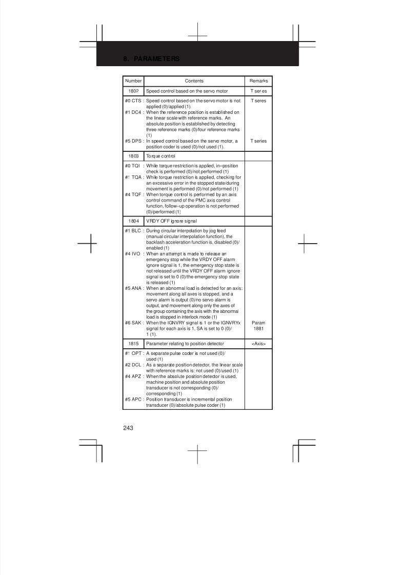
8. PARAMETERS
243
Number RemarksContents
1802 Speed control based on the servo motor T series
#0 CTS : Speed control based on the servo motor is not
applied (0)/applied (1).
#1 DC4 : When the reference position is established on
the linear scale with reference marks. An
absolute position is established by detecting
three reference marks (0)/four reference marks
(1)
#5 DPS : In speed control based on the servo motor, a
position coder is used (0)/not used (1).
T seres
T series
1803 Torque control
#0 TQI : While torque restriction is applied, in–position
check is performed (0)/not performed (1)
#1 TQA : While torque restriction is applied, checking for
an excessive error in the stopped state/during
movement is performed (0)/not performed (1)
#4 TQF : When torque control is performed by an axis
control command of the PMC axis control
function, follow–up operation is not performed
(0)/performed (1)
1804 VRDY OFF ignore signal
#1 BLC : During circular interpolation by jog feed
(manual circular interpolation function), the
backlash acceleration function is, disabled (0)/
enabled (1)
#4 IVO : When an attempt is made to release an
emergency stop while the VRDY OFF alarm
ignore signal is 1, the emergency stop state is
not released until the VRDY OFF alarm ignore
signal is set to 0 (0)/the emergency stop state
is released (1)
#5 ANA : When an abnormal load is detected for an axis:
movement along all axes is stopped, and a
servo alarm is output (0)/no servo alarm is
output, and movement along only the axes of
the group containing the axis with the abnormal
load is stopped in interlock mode (1)
#6 SAK : When the IGNVRY signal is 1 or the IGNVRYx
signal for each axis is 1, SA is set to 0 (0)/
1 (1).
Param
1881
1815 Parameter relating to position detector <Axis>
#1 OPT : A separate pulse coder is not used (0)/
used (1)
#2 DCL : As a separate position detector, the linear scale
with reference marks is: not used (0)/used (1)
#4 APZ : When the absolute position detector is used,
machine position and absolute position
transducer is not corresponding (0)/
corresponding (1)
#5 APC : Position transducer is incremental position
transducer (0)/absolute pulse coder (1)
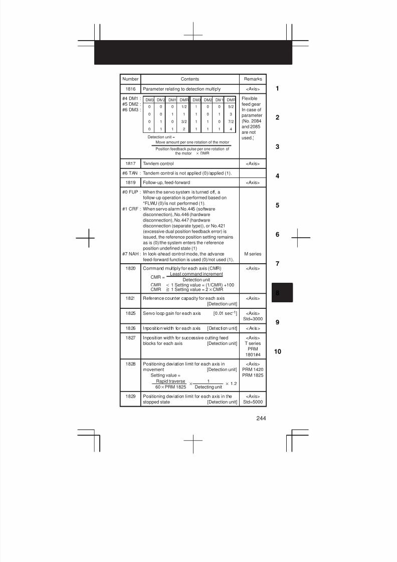
3
1
4
5
6
7
8
9
10
2
244
Number RemarksContents
1816 Parameter relating to detection multiply <Axis>
#4 DM1 :
#5 DM2 :
#6 DM3 :
DM3 DM2 DM1 DMR DM3 DM2 DM1 DMR
0 0 0 1/2
0 0 1 1
0 1 0 3/2
0 1 1 2
1 0 0 5/2
1 0 1 3
1 1 0 7/2
1 1 1 4
Move amount per one rotation of the motor
Position feedback pulse per one rotation ofthe motor DMR
Detection unit =
Flexible
feed gear
In case of
parameter
(No. 2084
and 2085
are not
used.)
1817 Tandem control <Axis>
#6 TAN : Tandem control is not applied (0)/applied (1).
1819 Follow-up, feed-forward <Axis>
#0 FUP : When the servo system is turned off, a
follow-up operation is performed based on
*FLWU (0)/is not performed (1).
#1 CRF : When servo alarm No.445 (software
disconnection), No.446 (hardware
disconnection), No.447 (hardware
disconnection (separate type)), or No.421
(excessive dual position feedback error) is
issued, the reference position setting remains
as is (0)/the system enters the reference
position undefined state (1)
#7 NAH : In look-ahead control mode, the advance
feed-forward function is used (0)/not used (1).
M series
1820 Command multiply for each axis (CMR)
CMR =
CMR t 1 Setting value = (1/CMR) +100CMR y 1 Setting value = 2CMR
Least command increment
Detection unit
<Axis>
1821 Reference counter capacity for each axis
[Detection unit]
<Axis>
1825 Servo loop gain for each axis [0.01 sec –1] <Axis>
Std=3000
1826 Inposit ion width for each axis [Detection unit] <Axis>
1827 Inposition width for successive cutting feed
blocks for each axis [Detection unit]
<Axis>
T series
PRM
1801#4
1828 Positioning deviation limit for each axis in
movement [Detection unit]
Setting value =
Rapid traverse
60PRM 1825
1
Detecting unit 1.2
<Axis>
PRM 1420
PRM 1825
1829 Positioning deviation limit for each axis in the
stopped state [Detection unit]
<Axis>
Std=5000
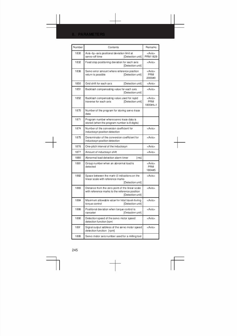
8. PARAMETERS
245
Number RemarksContents
1830 Axis–by–axis positional deviation limit at
servo–off time [Detection unit]
<Axis>
PRM 1829
1832 Feed stop positioning deviation for each axis
[Detection unit]
<Axis>
1836 Servo error amount where reference position
return is possible [Detection unit]
<Axis>
PRM
2000#0
1850 Grid shift for each axis [Detection unit] <Axis>
1851 Backlash compensating value for each axis
[Detection unit]
<Axis>
1852 Backlash compensating value used for rapid
traverse for each axis [Detection unit]
<Axis>
PRM
1800#4=1
1870 Number of the program for storing servo trace
data
1871 Program number where servo trace data is
stored (when the program number is 8 digits)
1874 Number of the conversion coefficient for
inductosyn position detection
<Axis>
1875 Denominator of the conversion coefficient for
inductosyn position detection
<Axis>
1876 One-pitch interval of the inductosyn <Axis>
1877 Amount of inductosyn shift <Axis>
1880 Abnormal load detection alarm t imer [ms]
1881 Group number when an abnormal load is
detected
<Axis>
PRM
1804#5
1882 Space between the mark–2 indications on the
linear scale with reference marks
[Detection unit]
<Axis>
1883 Distance from the zero point of the linear scale
with reference marks to the reference position
[Detection unit]
<Axis>
1884 Maximum allowable value for total travel during
torque control [Detection unit]
<Axis>
1886 Positional deviation when torque control is
canceled [Detection unit]
<Axis>
1890 Detection speed of the servo motor speed
detection function [rpm]
<Axis>
1891 Signal output address of the servo motor speed
detection function [rpm]
<Axis>
1895 Servo motor axis number used for a milling tool

3
1
4
5
6
7
8
9
10
2
246
Number RemarksContents
1896 Number of gear teeth on the servo motor axis
side
1897 Number of gear teeth on the milling axis side
1902 FSSB Setting
#0 FMD : The FSSB setting mode is, automatic setting
mode (0)/manual setting 2 mode (1)
#1 ASE : When automatic setting mode is selected for
FSSB setting (when the FMD parameter (bit 0 of
parameter No.1902) is set to 0), automatic setting
is, not completed (0)/completed (1)
1904 Using status of DSP
#0 DSP : Two axes use one DSP (0)/one axis uses one
DSP (1)
1905 Type of servo interface
#0 FSL : The type of interface used between the servo
amplifier and servo software is, fast type (0)/slow
type (1)
#6 PM1 : The first pulse module is, not used (0)/used (1)
#7 PM2 : The second pulse module is, not used (0)/used
(1)
1910 Address conversion table value for slave 1
(ATR)
1911 Address conversion table value for slave 2
(ATR)
1912 Address conversion table value for slave 3
(ATR)
1913 Address conversion table value for slave 4
(ATR)
1914 Address conversion table value for slave 5
(ATR)
1915 Address conversion table value for slave 6
(ATR)
1916 Address conversion table value for slave 7
(ATR)
1917 Address conversion table value for slave 8
(ATR)
1918 Address conversion table value for slave 9
(ATR)
1919 Address conversion table value for slave 10
(ATR)
1920 Controlled axis number for slave 1 (dedicated
to the FSSB setting screen)
1921 Controlled axis number for slave 2 (dedicated
to the FSSB setting screen)
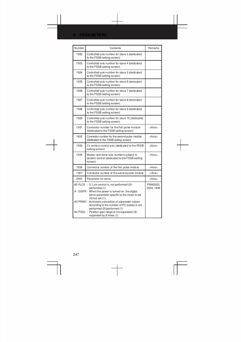
8. PARAMETERS
247
Number RemarksContents
1922 Controlled axis number for slave 3 (dedicated
to the FSSB setting screen)
1923 Controlled axis number for slave 4 (dedicated
to the FSSB setting screen)
1924 Controlled axis number for slave 5 (dedicated
to the FSSB setting screen)
1925 Controlled axis number for slave 6 (dedicated
to the FSSB setting screen)
1926 Controlled axis number for slave 7 (dedicated
to the FSSB setting screen)
1927 Controlled axis number for slave 8 (dedicated
to the FSSB setting screen)
1928 Controlled axis number for slave 9 (dedicated
to the FSSB setting screen)
1929 Controlled axis number for slave 10 (dedicated
to the FSSB setting screen)
1931 Connector number for the first pulse module
(dedicated to the FSSB setting screen)
<Axis>
1932 Connector number for the second pulse module
(dedicated to the FSSB setting screen)
<Axis>
1933 Cs contour control axis (dedicated to the FSSB
setting screen)
<Axis>
1934 Master and slave axis numbers subject to
tandem control (dedicated to the FSSB setting
screen)
<Axis>
1936 Connector number of the f irst pulse module <Axis>
1937 Connector number of the second pulse module <Axis>
2000 Parameter for servo <Axis>
#0 PLC0 : 0.1 mm control is, not performed (0)/
performed (1)
#1 DGPR : When the power is turned on, the digital
servo parameter specific to the motor is set
(0)/not set (1).
#3 PRMC : Automatic calculation of parameter values
according to the number of PC pulses is not
performed (0)/performed (1)
#4 PGEx : Position gain range is not expanded (0)/
expanded by 8 times (1)
PRM2023,
2024, 1836
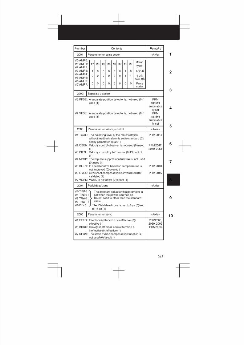
3
1
4
5
6
7
8
9
10
2
248
Number RemarksContents
2001 Parameter for pulse coder <Axis>
#0 AMR0:
#1 AMR1:
#2 AMR2:
#3 AMR3:
#4 AMR4:
#5 AMR5:
#6 AMR6:
#7 AMR7:
1
0
0
#7
0
0
0
#6
0
0
0
#5
0
0
0
#4
0
0
0
#3
0
0
0
#2 #1
1
1
0
#0
0
1
0
Motor
type
AC5-0
4-0S,AC3-0S
Pulsecoder
2002 Separate detector
#3 PFSE: A separate position detector is, not used (0)/
used (1)
#7 VFSE: A separate position detector is, not used (0)/
used (1)
PRM
1815#1
automatica
lly set
PRM
1815#1
automatica
lly set
2003 Parameter for velocity control <Axis>
#1 TGAL : The detecting level of the motor rotation
without feedback alarm is set to standard (0)/
set by parameter 1892 (1)
#2 OBEN: Velocity control observer is not used (0)/used
(1)
#3 PIEN : Velocity control by I–P control (0)/PI control
(1)
#4 NPSP: The N pulse suppression function is, not used
(0)/used (1)
#5 BLEN: In speed control, backlash compensation is,
not improved (0)/proved (1)
#6 OVSC: Overshoot compensation is invalidated (0)/
validated (1)
#7 VOFS: VCMD is not offset (0)/offset (1)
PRM 2064
PRM 2047,
2050, 2051
PRM 2048
PRM 2045
2004 PWM dead zone <Axis>
#0 TINA0 :
#1 TINB0 :
#2 TRW0 :
#3 TRW1 :
#6 DLY0 : The PWM dead zone is, set to 8 ms (0)/set
to 16 ms (1)
The standard value for this parameter isset when the power is turned on.Do not set it to other than the standardvalue
2005 Parameter for servo <Axis>
#1 FEED: Feedforward function is ineffective (0)/
effective (1)
#6 BRKC: Gravity shaft break control function is
ineffective (0)/effective (1)
#7 SFCM: The static friction compensation function is,
not used (0)/used (1)
PRM2068,
2069, 2092
PRM2083
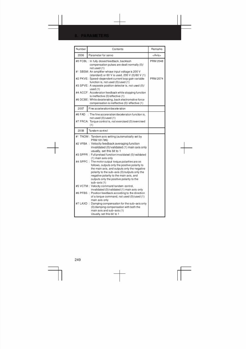
8. PARAMETERS
249
Number RemarksContents
2006 Parameter for servo <Axis>
#0 FCBL : In fully closed feedback, backlash
compensation pulses are dealt normally (0)/
not used (1)
#1 SBSM: An amplifier whose input voltage is 200 V
(standard) or 60 V is used, 200 V (0)/60 V (1)
#2 PKVE: Speed–dependent current loop gain variable
function is, not used (0)/used (1)
#3 SPVE: A separate position detector is, not used (0)/
used (1)
#4 ACCF: Acceleration feedback while stopping function
is ineffective (0)/effective (1)
#6 DCBE: While decelerating, back electromotive force
compensation is ineffective (0)/ effective (1)
PRM 2048
PRM 2074
2007 Fine acceleration/deceleration
#6 FAD : The fine acceleration/deceleration function is,
not used (0)/used (1)
#7 FRCA: Torque control is, not exercised (0)/exercised
(1)
2008 Tandem control
#1 TNOM : Tandem axis setting (automatically set by
PRM 1817#6)
#2 VFBA : Velocity feedback averaging function
invalidated (0)/validated (1) main axis only
usually, set this bit to 1#3 SPPR : Full preload function invalidated (0)/validated
(1) main axis only
#4 SPPC : The motor output torque polarities are as
follows, outputs only the positive polarity to
the main axis, and outputs only the negative
polarity to the sub–axis (0)/outputs only the
negative polarity to the main axis, and
outputs only the positive polarity to the
sub–axis (1)
#5 VCTM : Velocity command tandem control,
invalidated (0)/validated (1) main axis only
#6 PFBS : Position feedback according to the direction
of a torque command, not used (0)/used (1)
main axis only
#7 LAXD : Damping compensation for the sub–axis only
(0)/damping compensation with both the
main axis and sub–axis (1)
Usually, set this bit to 1
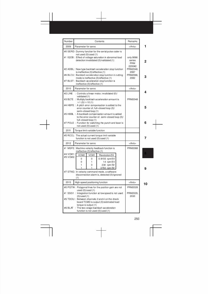
3
1
4
5
6
7
8
9
10
2
250
Number RemarksContents
2009 Parameter for servo <Axis>
#0 SERD: Dummy function for the serial pulse coder is
not used (0)/used (1)
#1 IQOB : Effect of voltage saturation in abnormal load
detection invalidated (0)/validated (1)
#2 ADBL : New type backlash acceleration stop function
is ineffective (0)/effective (1)
#6 BLCU: Backlash acceleration stop function in cutting
mode is ineffective (0)/effective (1)
#7 BLST : Backlash acceleration stop function is
ineffective (0)/effective (1)
only 9066
series
PRM
2200#2
PRM2048,
2087
PRM2066,
2082
2010 Parameter for servo <Axis>
#2 LINE : Controls a linear motor, invalidated (0)/
validated (1)
#3 BLTE : Multiply backlash acceleration amount is
1 (0)/ 10 (1)
#4 HBPE : A pitch error compensation is added to the
error counter of, full–closed loop (0)/
semi–closed loop (1)
#5 HBBL : A backlash compensation amount is added
to the error counter of, semi–closed loop (0)/
full–closed loop (1)
#7 POLE : Function for switching the punch and laser is
not used (0)/used (1)
PRM2048
2011 Torque limit variable function
#5 RCCL: The actual current torque limit variable
function is not used (0)/used (1)
2012 Parameter for servo <Axis>
#1 MSFE: Machine velocity feedback function is
ineffective (0)/effective (1)
#4 VCM1:
#5 VCM2:
#7 STNG: In velocity command mode, a software
disconnection alarm is, detected (0)/ignored
(1)
0
0
1
1
VCM2
0
1
0
1
VCM1
0.9155 rpm/5V
14 rpm/5V
234 rpm/5V
3750 rpm/5V
Revolution/5V
PRM2088
2015 High-speed positioning function <Axis>
#0 PGTW : Polygonal lines for the position gain are not
used (0)/used (1)
#1 SSG1 : Integration function at low speed is not used
(0)/used (1)
#5 TDOU : Between channels 2 and 4 on the check
board TCMD is output (0)/estimated load
torque is output (1)
#6 BLAT : The two–stage backlash acceleration
function is not used (0)/used (1)
PRM2028
PRM2029,
2030

8. PARAMETERS
251
Number RemarksContents
2016 Abnormal load detection function <Axis>
#0 ABNT: The abnormal load detection function (option)
is not used (0)/used (1)
#3 K2VC: The function for changing the proportional
gain in the stop state is not used (0)/used (1)
#5 NFL5 : Cut–off area = 0.8(center frequency) to
1.25(center frequency)
#6 NFL7 : Cut–off area = 0.7(center frequency) to
1.4(center frequency)
#7 NFL8 : Cut–off area = 0.5(center frequency) to
2.0(center frequency)
2017 Stop distance reduction function <Axis>
#0 DBST : The stop distance reduction function is not
used (0)/used (1)
This bit is not supported by the Power
Mate–E
#4 HTNG : In velocity command mode, the hardware
disconnection alarm of a separate detector
is: detected (0)/ignored (1)
#5 RISC : When RISC is used, the feed–forward
response characteristics remain as is (0)/
improved (1)
#6 OVCR : The OVC alarm remains as is (0)/improved
(1)
#7 PK25 : High–speed velocity loop proportional
processing is not used (0)/used (1)
2018 Observer stop time disable function <Axis>
#1 MOVO : The observer stop time disable function is:
not used (0)/used (1)
#7 PFBC : The motor feedback signal for the main axis
is shared by the sub–axis (0)/is not shared
by the sub–axis (1)
2019 Digital servo function <Axis>
#4 SPSY: A separate velocity detector is not used (0)/
used(1)
#7 DPFB: The dual feedback function is not used (0)/
used (1).
2020 Motor model <Axis>
2021 Load inertia ratio <Axis>
2022 Motor rotation direction
111=CCW, –111=CW
<Axis>
2023 No. of speed pulses <Axis>
PRM
2000#0
8192Serial PC A/ a PC
PRM2000#0=0
PRM2000#0=1
819
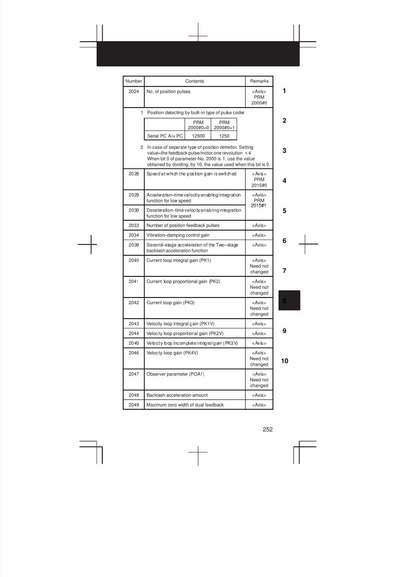
3
1
4
5
6
7
8
9
10
2
252
Number RemarksContents
2024 No. of position pulses <Axis>
PRM
2000#0
1 Position detecting by built-in type of pulse coder
2 In case of separate type of position detector, Setting
value=the feedback pulse/motor one revolution4
When bit 0 of parameter No. 2000 is 1, use the value
obtained by dividing, by 10, the value used when this bit is 0.
12500Serial PC A/ a PC
PRM2000#0=0
PRM2000#0=1
1250
2028 Speed at which the posit ion gain is switched <Axis>
PRM
2015#0
2029 Acceleration–time velocity enabling integration
function for low speed.
<Axis>
PRM
2030 Deceleration–time velocity enabling integration
function for low speed
2033 Number of position feedback pulses <Axis>
2034 Vibration–damping control gain <Axis>
2039 Second–stage acceleration of the Two–stage
backlash acceleration function
<Axis>
2040 Current loop integral gain (PK1) <Axis>
Need not
changed
2041 Current loop proportional gain (PK2) <Axis>
Need not
changed
2042 Current loop gain (PK3) <Axis>
Need not
changed
2043 Velocity loop integral gain (PK1V) <Axis>
2044 Velocity loop proportional gain (PK2V) <Axis>
2045 Velocity loop incomplete integral gain (PK3V) <Axis>
2046 Velocity loop gain (PK4V) <Axis>
Need not
changed
2047 Observer parameter (POA1) <Axis>
Need not
changed
2048 Backlash acceleration amount <Axis>
2049 Maximum zero width of dual feedback <Axis>
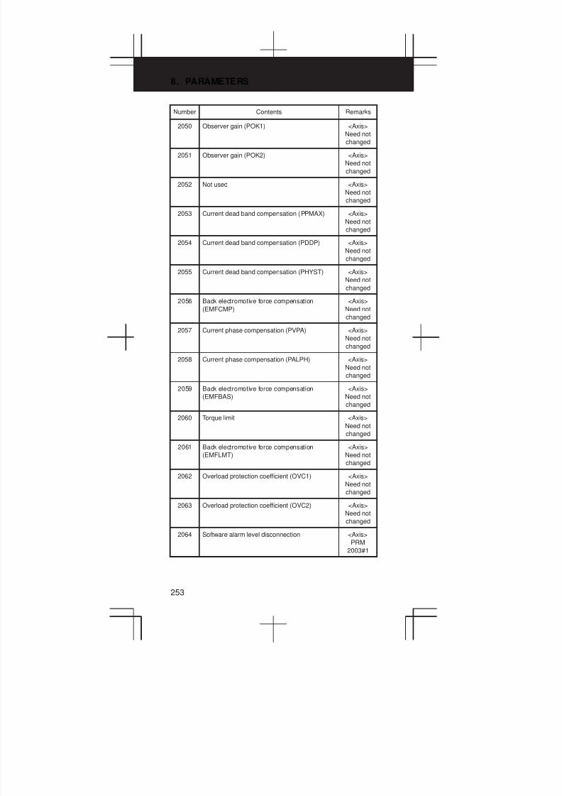
8. PARAMETERS
253
Number RemarksContents
2050 Observer gain (POK1) <Axis>
Need not
changed
2051 Observer gain (POK2) <Axis>
Need not
changed
2052 Not used <Axis>
Need not
changed
2053 Current dead band compensation (PPMAX) <Axis>
Need not
changed
2054 Current dead band compensation (PDDP) <Axis>
Need not
changed
2055 Current dead band compensation (PHYST) <Axis>
Need not
changed
2056 Back electromotive force compensation
(EMFCMP)
<Axis>
Need not
changed
2057 Current phase compensation (PVPA) <Axis>
Need not
changed
2058 Current phase compensation (PALPH) <Axis>
Need not
changed
2059 Back electromotive force compensation
(EMFBAS)
<Axis>
Need not
changed
2060 Torque limit <Axis>
Need not
changed
2061 Back electromotive force compensation
(EMFLMT)
<Axis>
Need not
changed
2062 Overload protection coefficient (OVC1) <Axis>
Need not
changed
2063 Overload protection coefficient (OVC2) <Axis>
Need not
changed
2064 Software alarm level disconnection <Axis>
PRM
2003#1

3
1
4
5
6
7
8
9
10
2
254
Number RemarksContents
2065 Overload protection coefficient (OVCLMT) <Axis>
Need not
changed
2066 250 m sec acceleration feedback (PK2VAUX) <Axis>
2067 Torque command filter (TCFIL) <Axis>
2068 Feedforward coefficient <Axis>
2069 Speed feedforward <Axis>
2070 Backlash acceleration timing <Axis>
2071 Time during which backlash acceleration is
effective
<Axis>
2072 Static–friction compensation <Axis>
2073 Stop time determination parameter <Axis>
2074 Velocity depending type current loop gain
(AALPH)
<Axis>
2076 Acceleration feedback gain (WKAC) <Axis>
2077 Overshoot provention counter (OSCTP) <Axis>
2078 Numerator of dual position feedback
conversion coefficient
<Axis>
2079 Denominator of dual position feedback
conversion coefficient
<Axis>
2080 Primary delay time constant of dual position
feedback
<Axis>
2081 Zero width of dual position feedback <Axis>
2082 Backlash acceleration stop amount <Axis>
2083 Gravity axis break control timer (MOFCT) <Axis>
PRM
2005#6
2084 Flexible feed gear numerator n <Axis>
2085 Flexible feed gear denominator m <Axis>
Position feedbackpulses/motor rev.
1,000,000
nm
=
2086 Rated current parameter <Axis>
Need not
changed
2087 Torque offset <Axis>
2088 Machine velocity feedback gain <Axis>
PRM
2012#2
2089 Base pulse for backlash acceleration (BLBSL) <Axis>

8. PARAMETERS
255
Number RemarksContents
2091 Nonlinear control parameter <Axis>
2092 Advance feed-forward coefficient [0.01%] <Axis>
2097 Stat ic–friction compensation stop parameter <Axis>
2098 Current phase compensation coefficient <Axis>
2099 N pulse suppress level <Axis>
2101 Overshoot compensation valid level
2102 Final clamp value of the actual cur rent limit <Axis>
2103 Track back amount applied when an abnormal
load is detected
<Axis>
2104 Threshold of abnormal load detection in cutting <Axis>
2105 Torque constant (TRQCST) <Axis>
2109 Fine acceleration/deceleration time constant
(in ms)
2110 Magnetic saturation compensation
(base/coefficient)
2111 Deceleration torque limit (base/coefficient)
2112 AMR conversion coefficient 1
2113 Notch filter center frequency (Hz)
2116 Abnormal load detection dynamic friction
cancel
2118 Dual position feedback
Semi–closed/full–closed error overestimation
level
2119 Function for changing the proportional gain in
the stop state: Stop level
2121 Conversion coefficient for number of feedback
pulses
2122 Detection resistance conversion coefficient
2126 Position feedback switching time constant t
2127 Non–interactive control coefficient
2128 Weak magnetic flux compensation (coefficient)
2129 Weak magnetic flux compensation (base/limit)
2130 Correction of two thrust ripples per magnetic
pole pair
2131 Correction of four thrust ripples per magnetic
pole pair
2132 Correction of six thrust ripples per magnetic
pole pair
2138 AMR conversion coefficient 2
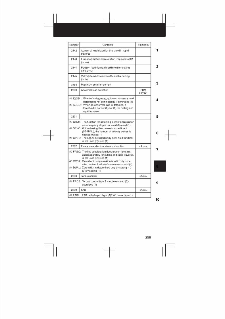
3
1
4
5
6
7
8
9
10
2
256
Number RemarksContents
2142 Abnormal load detection threshold in rapid
traverse
2143 Fine acceleration/deceleration time constant 2
(in ms)
2144 Position feed–forward coefficient for cutting
(in 0.01%)
2145 Velocity feed–forward coefficient for cutting
(in %)
2165 Maximum amplifier current
2200 Abnormal load detection PRM
2009#1
#2 IQOB : Effect of voltage saturation on abnormal load
detection is not eliminated (0)/ eliminated (1)
#3 ABGO : When an abnormal load is detected, a
threshold is not set (0)/set (1) for cutting and
rapid traverse
2201
#0 CROF: The function for obtaining current offsets upon
an emergency stop is not used (0)/used (1)
#4 SPVC: Without using the conversion coefficient
(SBPDNL), the number of velocity pulses is
not set (0)/set (1)
#6 CPEE: The actual current display peak hold function
is not used (0)/used (1)
2202 Fine acceleration/deceleration function <Axis>
#0 FAGO: The fine acceleration/deceleration function,
used separately for cutting and rapid traverse,
is not used (0)/used (1)
#3 OVS1: Overshoot compensation is valid only once
after the termination of a move command (1)
#4 DUAL: Zero width is determined only by setting = 0
(0)/by setting (1)
2203 Torque control <Axis>
#4 FRC2: Torque control type 2 is not exercised (0)/
exercised (1)
2209 FAD <Axis>
#2 FADL : FAD bell–shaped type (0)/FAD linear type (1)
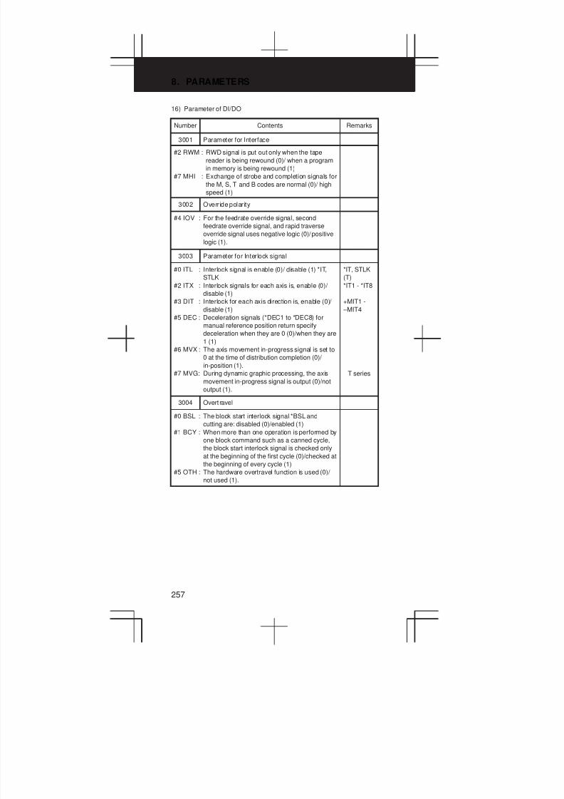
8. PARAMETERS
257
16) Parameter of DI/DO
Number Contents Remarks
3001 Parameter for Interface
#2 RWM : RWD signal is put out only when the tape
reader is being rewound (0)/ when a program
in memory is being rewound (1)
#7 MHI : Exchange of strobe and completion signals for
the M, S, T and B codes are normal (0)/ high
speed (1)
3002 Override polarity
#4 IOV : For the feedrate override signal, second
feedrate override signal, and rapid traverse
override signal uses negative logic (0)/positive
logic (1).
3003 Parameter for Interlock signal
#0 ITL : Interlock signal is enable (0)/ disable (1) *IT,
STLK
#2 ITX : Interlock signals for each axis is, enable (0)/
disable (1)
#3 DIT : Interlock for each axis direction is, enable (0)/
disable (1)
#5 DEC : Deceleration signals (*DEC1 to *DEC8) for
manual reference position return specify
deceleration when they are 0 (0)/when they are
1 (1)
#6 MVX : The axis movement in-progress signal is set to
0 at the time of distribution completion (0)/
in-position (1).
#7 MVG: During dynamic graphic processing, the axis
movement in-progress signal is output (0)/not
output (1).
*IT, STLK
(T)
*IT1 - *IT8
+MIT1 -
–MIT4
T series
3004 Overt ravel
#0 BSL : The block start interlock signal *BSL and
cutting are: disabled (0)/enabled (1)
#1 BCY : When more than one operation is performed by
one block command such as a canned cycle,
the block start interlock signal is checked only
at the beginning of the first cycle (0)/checked at
the beginning of every cycle (1)
#5 OTH : The hardware overtravel function is used (0)/
not used (1).

3
1
4
5
6
7
8
9
10
2
258
Number RemarksContents
3006 Reference position return deceleration signal
#0 GDC: The address of the reference position return
deceleration signal is X009 X007 (0)/G196
G197 (1).
#1 EPN : Workpiece number search signals are
assigned to PN1, PN2, PN4, PN8, and PN16
(0)/EPN0 to EPN13 (1)
#2 EPS : When a program is searched using the
workpiece number search function, it is started
by automatic operation start signal ST (when
automatic operation (memory operation) is
started) (0)/workpiece number search start
signal EPNS. (Search is not started by ST.) (1)
3010 Delay time of strobe signals MF, SF, TF, BF
[ms]
3011 Acceptable width of M, S, T and B function
completion signal (FIN) [ms]
3017 Output time of reset signal RST [16 ms]
3030 Allowable number of digits for the M code
(1 to 8)
3031 Allowable number of digits for the S code
(1 to 5)
3032 Allowable number of digits for the T code
(1 to 8)
3033 Allowable number of digits for the B code
(1 to 8)
17) Parameters of Display, and Edit
Number Contents Remarks
3100 Parameter for MDI panel
#1 CEM: On screens such as the operation history
screen and help screen, keys on the MDI panel
are indicated in English (0)/with graphics
qualifying for CE marking (1)
#2 SKY : On the 7.2– or 8.4–inch LCD, the keyboard in
14–inch display format uses: standard keys
(0)/small keys (1)
#3 FKY : The standard keys are used for MDI keyboard
(0)/The full keys are used (1)
#4 FPT : The CAP-II keyboard is not used (0)/used (1).
#7 COR: Display is used as a monochrome display (0)/
color display (1)
Seven soft
keys
Twelve
soft keys
T series

8. PARAMETERS
259
Number RemarksContents
3101 Display
#1 KBF : At screen or mode switching, the key buffer is
cleared (0)/not cleared (1).
#4 BGD : The display of a foreground program in the
background is disabled (0)/enabled (1).
#7 SBA : The current positions are displayed in the order
of tool post 1 then tool post 2 (0)/tool post 2
then tool post 1 (1).
2-path
control
3102 The selection of language used in the display
(Option)
English is
a standard
#0 JPN : Japanese
#1 GRM: German
#2 FRN : French
#3 CHI : Chinese (Taiwanese)
#4 ITA : Italian
#5 HNG : Korean (Hangul character)
#6 SPN : Spanish
When all
the bits are
set to 0,
English is
used.
PRM 3119
3103 Current position display order
#1 DIP : When two–path control is applied, the current
position display screen in display format
displays two paths (0)/a path (1)
#7 ABR : When the absolute and relative current
positions are displayed, tool post 1 is displayed
on the first screen, then tool post 2 is displayed
on the second screen (0)/ a selected tool post
is displayed on the first screen, then the tool
post that is not selected is displayed on the
second screen (1).
T series
T series
(2-path
control)
3104 Parameters for position display
#0 MCN: The machine position display is not displayed
according to the unit of input (0)/displayed
according to the unit of input (1)
#3 PPD : When a coordinate system is set, the relative
position display is not preset (0)/preset (1)
#4 DRL : For displaying relative positions, tool length
compensation (M series) or tool offset (T
series) is considered (0)/not considered (1)
#5 DRC : For displaying relative positions, cutter
compensation (M series) or tool-tip radius
compensation (T series) is considered (0)/not
considered (1)
#6 DAL : For displaying absolute positions, tool length
compensation (M series) or tool offset (T
series) is considered (0)/not considered (1)
#7 DAC : For displaying absolute positions, cutter
compensation (M series) or tool-tip radius
compensation (T series) is considered (0)/not
considered (1)
PRM
0000#2

3
1
4
5
6
7
8
9
10
2
260
Number RemarksContents
3105 Parameters for data display
#0 DPF : Display of the actual speed on the current
position display screen, program check screen
and program screen(MDI mode)is, not
displayed (0)/displayed (1)
#1 PCF : The movement of the PMC controlled axes are
added to the actual speed display (0)/not
added (1)
#2 DPS : Actual spindle speed and T code are not
always displayed (0)/always displayed (1)
#7 SMF : During simplified synchronous control,
movement along a slave axis is included (0)/
not included (1) in the actual speed display.
M series
3106 Operation history
#1 GPL : On the program list screen, the list–by–group
function is disabled1 (0)/enabled (1).
#3 SPD : Names for actual spindle speed values are
displayed regardless (0)/depending (1) of the
selected spindle position coder.
#4 OPH : The operation history screen is not displayed
(0)/displayed (1).
#5 SOV : A spindle override value is not displayed (0)/
displayed (1).
#6 DAK : For absolute coordinate display in
three-dimensional coordinate conversion,
programmed coordinates are displayed (0)/
coordinates in the workpiece coordinate
system are displayed (1).
#7 OHS : Operation history sampling is performed (0)/not
performed (1).
T series
PRM
3105#2
M series
3107 Parameters for program display
#0 NAM: In the Program list, only program numbers are
indicated (0)/program numbers and program
names (1)
#2 DNC : Upon reset, the program display for DNC
operation is not cleared (0)/cleared (1)
#4 SOR : In the Display of the program directory,
programs are listed in the order of registration
(0)/in the order of program number (1)
#7 MDL : Display of the modal state on the program
display screen is, not displayed (0)/displayed
(1)
MDI mode
3108 T code display
#2 PCT : For T code display, programmed T numbers
are displayed (0)/PMC T numbers are
displayed (1).
#4 WCI : On the workpiece coordinate system screen, a
counter input is disabled (0)/enabled (1)
#6 SLM : The spindle load meter is not displayed (0)/
displayed (1)
#7 JSP : On the current position display screen and
program check screen, jog feed is not
displayed (0)/displayed (1)
M series
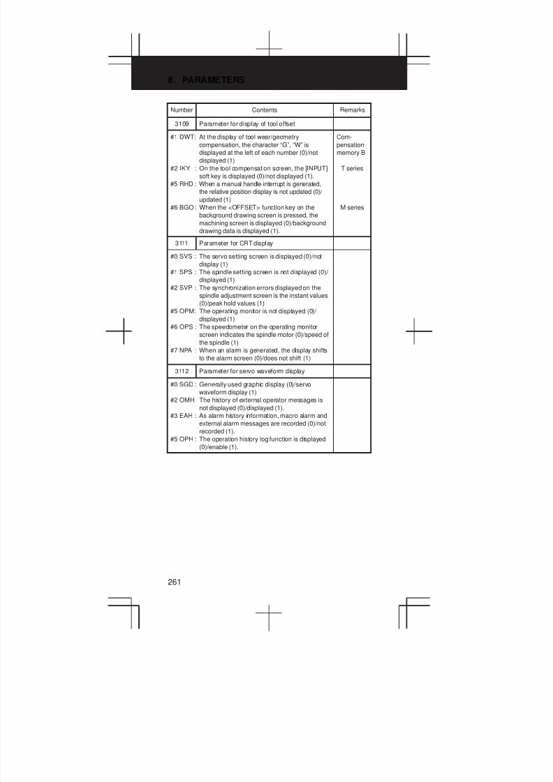
8. PARAMETERS
261
Number RemarksContents
3109 Parameter for display of tool offset
#1 DWT: At the display of tool wear/geometry
compensation, the character “G”, “W” is
displayed at the left of each number (0)/not
displayed (1)
#2 IKY : On the tool compensation screen, the [INPUT]
soft key is displayed (0)/not displayed (1).
#5 RHD : When a manual handle interrupt is generated,
the relative position display is not updated (0)/
updated (1)
#6 BGO : When the <OFFSET> function key on the
background drawing screen is pressed, the
machining screen is displayed (0)/background
drawing data is displayed (1).
Com-
pensation
memory B
T series
M series
3111 Parameter for CRT display
#0 SVS : The servo setting screen is displayed (0)/not
display (1)
#1 SPS : The spindle setting screen is not displayed (0)/
displayed (1)
#2 SVP : The synchronization errors displayed on the
spindle adjustment screen is the instant values
(0)/peak hold values (1)
#5 OPM: The operating monitor is not displayed (0)/
displayed (1)
#6 OPS : The speedometer on the operating monitor
screen indicates the spindle motor (0)/speed of
the spindle (1)
#7 NPA : When an alarm is generated, the display shifts
to the alarm screen (0)/does not shift (1)
3112 Parameter for servo waveform display
#0 SGD : Generally used graphic display (0)/servo
waveform display (1)
#2 OMH: The history of external operator messages is
not displayed (0)/displayed (1).
#3 EAH : As alarm history information, macro alarm and
external alarm messages are recorded (0)/not
recorded (1).
#5 OPH : The operation history log function is displayed
(0)/enable (1).
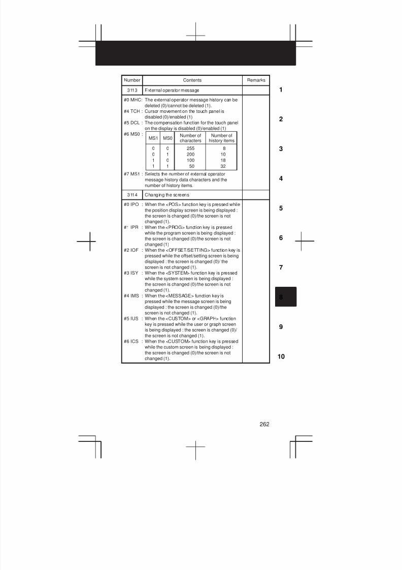
3
1
4
5
6
7
8
9
10
2
262
Number RemarksContents
3113 External operator message
#0 MHC: The external operator message history can be
deleted (0)/cannot be deleted (1).
#4 TCH : Cursor movement on the touch panel is
disabled (0)/enabled (1)
#5 DCL : The compensation function for the touch panel
on the display is disabled (0)/enabled (1)
#6 MS0 :
#7 MS1 : Selects the number of external operator
message history data characters and the
number of history items.
0
0
1
1
MS1 MS0Number ofcharacters
0
1
0
1
255
200
100
50
Number ofhistory items
8
10
18
32
3114 Changing the screens
#0 IPO : When the <POS> function key is pressed while
the position display screen is being displayed :
the screen is changed (0)/the screen is not
changed (1).
#1 IPR : When the <PROG> function key is pressed
while the program screen is being displayed :
the screen is changed (0)/the screen is not
changed (1)
#2 IOF : When the <OFFSET/SETTING> function key is
pressed while the offset/setting screen is being
displayed : the screen is changed (0)/ the
screen is not changed (1).
#3 ISY : When the <SYSTEM> function key is pressed
while the system screen is being displayed :
the screen is changed (0)/the screen is not
changed (1).
#4 IMS : When the <MESSAGE> function key is
pressed while the message screen is being
displayed : the screen is changed (0)/the
screen is not changed (1).
#5 IUS : When the <CUSTOM> or <GRAPH> function
key is pressed while the user or graph screen
is being displayed : the screen is changed (0)/
the screen is not changed (1).
#6 ICS : When the <CUSTOM> function key is pressed
while the custom screen is being displayed :
the screen is changed (0)/the screen is not
changed (1).
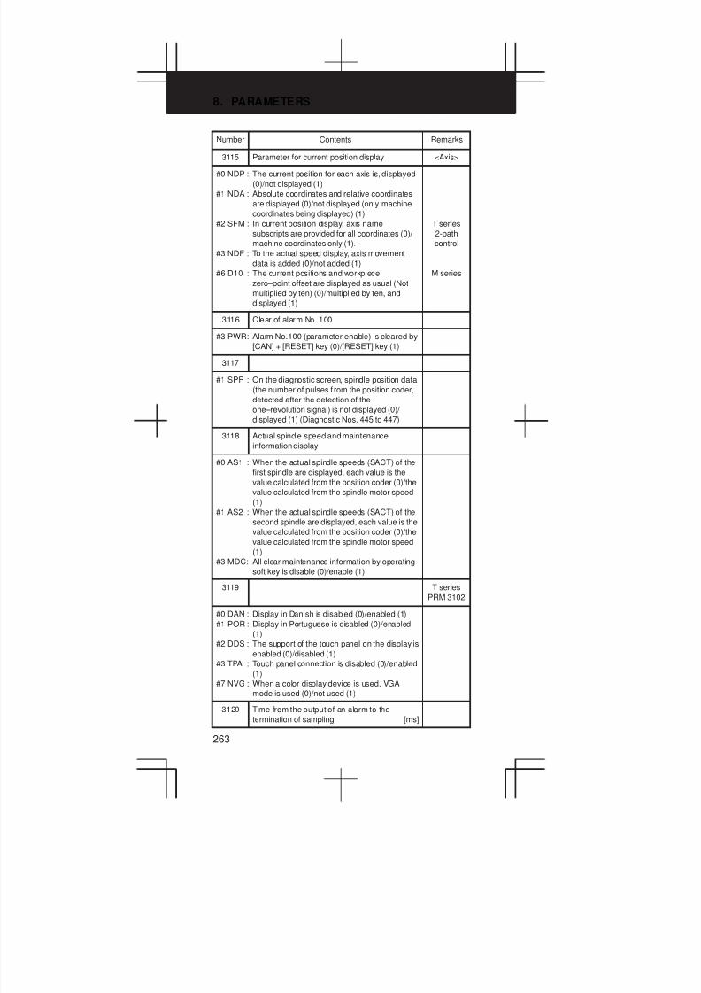
8. PARAMETERS
263
Number RemarksContents
3115 Parameter for current position display <Axis>
#0 NDP : The current position for each axis is, displayed
(0)/not displayed (1)
#1 NDA : Absolute coordinates and relative coordinates
are displayed (0)/not displayed (only machine
coordinates being displayed) (1).
#2 SFM : In current position display, axis name
subscripts are provided for all coordinates (0)/
machine coordinates only (1).
#3 NDF : To the actual speed display, axis movement
data is added (0)/not added (1)
#6 D10 : The current positions and workpiece
zero–point offset are displayed as usual (Not
multiplied by ten) (0)/multiplied by ten, and
displayed (1)
T series
2-path
control
M series
3116 Clear of alarm No. 100
#3 PWR: Alarm No.100 (parameter enable) is cleared by
[CAN] + [RESET] key (0)/[RESET] key (1)
3117
#1 SPP : On the diagnostic screen, spindle position data
(the number of pulses f rom the position coder,
detected after the detection of the
one–revolution signal) is not displayed (0)/
displayed (1) (Diagnostic Nos. 445 to 447)
3118 Actual spindle speed and maintenance
information display
#0 AS1 : When the actual spindle speeds (SACT) of the
first spindle are displayed, each value is the
value calculated from the position coder (0)/the
value calculated from the spindle motor speed
(1)
#1 AS2 : When the actual spindle speeds (SACT) of the
second spindle are displayed, each value is the
value calculated from the position coder (0)/the
value calculated from the spindle motor speed
(1)
#3 MDC: All clear maintenance information by operating
soft key is disable (0)/enable (1)
3119 T series
PRM 3102
#0 DAN : Display in Danish is disabled (0)/enabled (1)
#1 POR : Display in Portuguese is disabled (0)/enabled
(1)
#2 DDS : The support of the touch panel on the display is
enabled (0)/disabled (1)
#3 TPA : Touch panel connection is disabled (0)/enabled
(1)
#7 NVG : When a color display device is used, VGA
mode is used (0)/not used (1)
3120 Time from the output of an alarm to the
termination of sampling [ms]

3
1
4
5
6
7
8
9
10
2
264
Number RemarksContents
3122 Time interval used to record time data in
operation history [Minute]
3123 Time until screen clear function is applied
[Minute]
3124 Modal G code display
#0 D01 : On program check screen display, the 01
group G code is display (0)/not displayed (1)
#1 D02 : On program check screen display, the 02
group G code is display (0)/not displayed (1)
#2 D03 : On program check screen display, the 03
group G code is display (0)/not displayed (1)
#3 D04 : On program check screen display, the 04
group G code is display (0)/not displayed (1)
#4 D05 : On program check screen display, the 05
group G code is display (0)/not displayed (1)
#5 D06 : On program check screen display, the 06
group G code is display (0)/not displayed (1)
#6 D07 : On program check screen display, the 07
group G code is display (0)/not displayed (1)
#7 D08 : On program check screen display, the 08
group G code is display (0)/not displayed (1)
3125 Modal G code display
#0 D09 : On program check screen display, the 09
group G code is display (0)/not displayed (1)
#1 D10 : On program check screen display, the 10
group G code is display (0)/not displayed (1)
#2 D11 : On program check screen display, the 11
group G code is display (0)/not displayed (1)
#3 D12 : On program check screen display, the 12
group G code is display (0)/not displayed (1)
#4 D13 : On program check screen display, the 13
group G code is display (0)/not displayed (1)
#5 D14 : On program check screen display, the 14
group G code is display (0)/not displayed (1)
#6 D15 : On program check screen display, the 15
group G code is display (0)/not displayed (1)
#7 D16 : On program check screen display, the 16
group G code is display (0)/not displayed (1)

8. PARAMETERS
265
Number RemarksContents
3126 Modal G code display
#0 D17 : On program check screen display, the 17
group G code is display (0)/not displayed (1)
#1 D18 : On program check screen display, the 18
group G code is display (0)/not displayed (1)
#2 D19 : On program check screen display, the 19
group G code is display (0)/not displayed (1)
#3 D20 : On program check screen display, the 20
group G code is display (0)/not displayed (1)
#4 D21 : On program check screen display, the 21
group G code is display (0)/not displayed (1)
#5 D22 : On program check screen display, the 22
group G code is display (0)/not displayed (1)
#6 D23 : On program check screen display, the 23
group G code is display (0)/not displayed (1)
#7 D24 : On program check screen display, the 24
group G code is display (0)/not displayed (1)
3127 Modal G code display
#0 D25 : On program check screen display, the 25
group G code is display (0)/not displayed (1)
3130 Axis display order for current position display
screens
T series
2-path
control
3131 Subscript for the name of each axis 2-path
control
3132 Axis name (absolute coordinate) for current
position display
3133 Axis name (relative coordinate) for current
position display
3134 Axis display order on workpiece coordinate
system screen and workpiece shift screen
3140 Display color for tool post name
3141 Name of the path (first character) 2-path
L L
con ro
3147 Name of the path (seventh character)
3151 Number of the axis for which the first load
meter for the servo motor is used
PRM
3111#5
L L
3158 Number of the axis for which the eighth load
meter for servo motor is used
3161 Channel number of an A/D converter
3162 Load meter reading at maximum output
3163 Time required to smooth the spindle load meter
readings

3
1
4
5
6
7
8
9
10
2
266
Number RemarksContents
3201 Parameter for program registration
#0 RDL : In case of program registration by MINP signal,
the new program is registered following the
programs already registered (0)/all registered
programs are deleted, then the new program is
registered (1)
#1 RAL : In case of the program registeration, all
programs are registered (0)/only one program
is registered (1)
#2 REP : When program registration, if the program
number is same as an existing one, an alarm is
generated (0)/the existing program is deleted
then the new program is registered (1)
#3 PUO : When address O of a program number is
output in ISO code “:” is output (0)/“O” is output
(1)
#5 N99 : When an M99 block is specified, program
registration is terminated (0)/not terminated (1)
#6 NPE : At the program registration, M02, M30 and M99
is assumed as completion of registration (0)/
not assumed (1)
#7 MIP : Program registration by external start signal
(MINP) not performed (0)/performed (1)
EXRD
signal
PRM
3201#6=0
3202 Parameter for program protect
#0 NE8 : Editing of programs with program numbers
8000 to 8999 are not inhibited (0)/inhibited (1)
#1 OLV : When a program other than the selected
program is deleted or output the display of the
selected program is not held (0)/held (1).
#2 CND : With the [ARRANGE] soft key, main program
arrangement is not performed (0)/performed
(1).
#3 OSR : In programming number search, when pressing
soft key [O–SEARCH] without inputting
program number by key search the following
program number (0)/operation is invalid (1)
#4 NE9 : Editing of programs with program numbers
9000 to 9999 are not inhibited (0)/inhibited (1)
#5 CPD : When an NC program is deleted, a
confirmation message and confirmation soft
key are not output (0)/output (1)
#6 PSR : Search for the program number of a protected
program is disabled (0)/enabled (1)
3203 MDI operation
#4 PIO : Program input/output is performed on a
tool-post-by-tool-post basis (0)/on a two-path
basis (1).
#5 MIE : During MDI operation, program editing is
enabled (0)/disabled (1).
#6 MER: When MDI operation is terminated in single
block mode, program deletion is not performed
(0)/performed (1).
#7 MCL : Whether a program coded in the MDI mode is
cleared by reset (0)/not cleared (1)
T series
(2-path
control)
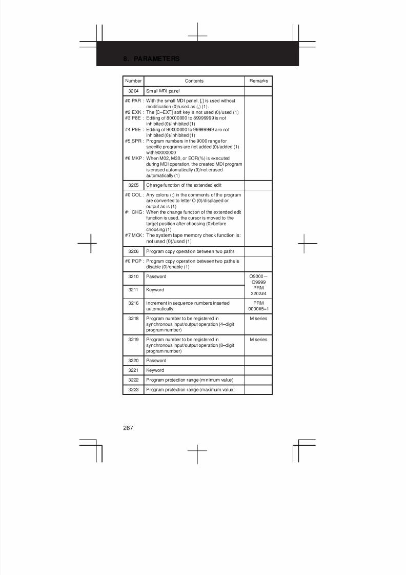
8. PARAMETERS
267
Number RemarksContents
3204 Small MDI panel
#0 PAR : With the small MDI panel, [,] is used without
modification (0)/used as (,) (1).
#2 EXK : The [C–EXT] soft key is not used (0)/used (1)
#3 P8E : Editing of 80000000 to 89999999 is not
inhibited (0)/inhibited (1)
#4 P9E : Editing of 90000000 to 99999999 are not
inhibited (0)/inhibited (1)
#5 SPR : Program numbers in the 9000 range for
specific programs are not added (0)/added (1)
with 90000000
#6 MKP : When M02, M30, or EOR(%) is executed
during MDI operation, the created MDI program
is erased automatically (0)/not erased
automatically (1)
3205 Change function of the extended edit
#0 COL : Any colons (:) in the comments of the program
are converted to letter O (0)/displayed or
output as is (1)
#1 CHG: When the change function of the extended edit
function is used, the cursor is moved to the
target position after choosing (0)/before
choosing (1)
#7 MCK: The system tape memory check function is:
not used (0)/used (1)
3206 Program copy operation between two paths
#0 PCP : Program copy operation between two paths is
disable (0)/enable (1)
3210 Password O9000X
O9999
3211 Keyword PRM
3202#4
3216 Increment in sequence numbers inserted
automatically
PRM
0000#5=1
3218 Program number to be registered in
synchronous input/output operation (4–digit
program number)
M series
3219 Program number to be registered in
synchronous input/output operation (8–digit
program number)
M series
3220 Password
3221 Keyword
3222 Program protection range (minimum value)
3223 Program protection range (maximum value)
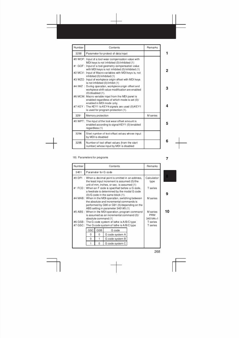
3
1
4
5
6
7
8
9
10
2
268
Number RemarksContents
3290 Parameter for protect of data input
#0 WOF: Input of a tool wear compensation value with
MDI keys is not inhibited (0)/inhibited (1)
#1 GOF : Input of a tool geometry compensation value
with MDI keys is not inhibited (0)/inhibited (1)
#2 MCV: Input of Macro variables with MDI keys is, not
inhibited (0)/inhibited (1)
#3 WZO: Input of workpiece origin offset with MDI keys
is not inhibited (0)/inhibit (1)
#4 IWZ : During operation, workpiece origin offset and
workpiece shift value modification are enabled
(0)/disabled (1).
#6 MCM: Macro variable input from the MDI panel is
enabled regardless of which mode is set (0)/
enabled in MDI mode only.
#7 KEY : The KEY1 to KEY4 signals are used (0)/KEY1
is used for program protection (1).
3291 Memory protection M series
#0 WPT: The input of the tool wear offset amount is
enabled according to signal KEY1 (0)/enabled
regardless (1)
3294 Start number of tool offset values whose input
by MDI is disabled
3295 Number of tool offset values (from the start
number) whose input by MDI is disabled
18) Parameters for programs
Number Contents Remarks
3401 Parameter for G code
#0 DPI : When a decimal point is omitted in an address,
the least input increment is assumed (0)/the
unit of mm, inches, or sec. is assumed (1)
#1 FCD : When an F code is specified before a G code,
a feedrate is determined by the modal G code
(0)/G code in the same block (1).
#4 MAB : When in the MDI operation, switching between
the absolute and incremental commands is
performed by G90 or G91 (0)/depending on the
ABS setting in parameter 3401#5 (1)
#5 ABS : When in the MDI operation, program command
is assumed as an incremental command (0)/
absolute command (1)
#6 GSB : The G code system of lathe is A/B/C type
#7 GSC : The G code system of lathe is A/B/C type
0
GSC GSB G code
0 G code system A
0 1 G code system B
1 0 G code system C
Calculation
type
T series
M series
M series
PRM
3401#4=1
T series
T series
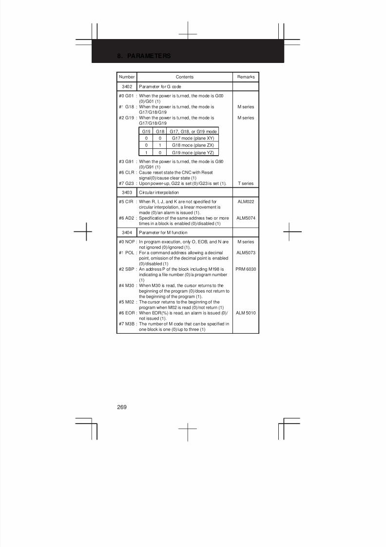
8. PARAMETERS
269
Number RemarksContents
3402 Parameter for G code
#0 G01 : When the power is turned, the mode is G00
(0)/G01 (1)
#1 G18 : When the power is turned, the mode is
G17/G18/G19
#2 G19 : When the power is turned, the mode is
G17/G18/G19
#3 G91 : When the power is turned, the mode is G90
(0)/G91 (1)
#6 CLR : Cause reset state the CNC with Reset
signal(0)/cause clear state (1)
#7 G23 : Upon power-up, G22 is set (0)/G23 is set (1).
0
G19 G18 G17, G18, or G19 mode
0 G17 mode (plane XY)
0 1 G18 mode (plane ZX)
1 0 G19 mode (plane YZ)
M series
M series
T series
3403 Circular interpolation
#5 CIR : When R, I, J, and K are not specified for
circular interpolation, a linear movement is
made (0)/an alarm is issued (1).
#6 AD2 : Specification of the same address two or more
times in a block is enabled (0)/disabled (1)
ALM022
ALM5074
3404 Parameter for M function
#0 NOP : In program execution, only O, EOB, and N are
not ignored (0)/ignored (1).
#1 POL : For a command address allowing a decimal
point, omission of the decimal point is enabled
(0)/disabled (1)
#2 SBP : An address P of the block including M198 is
indicating a file number (0)/a program number
(1)
#4 M30 : When M30 is read, the cursor returns to the
beginning of the program (0)/does not return to
the beginning of the program (1).
#5 M02 : The cursor returns to the beginning of the
program when M02 is read (0)/not return (1)
#6 EOR : When EOR(%) is read, an alarm is issued (0)/
not issued (1).
#7 M3B : The number of M code that can be specified in
one block is one (0)/up to three (1)
M series
ALM5073
PRM 6030
ALM 5010
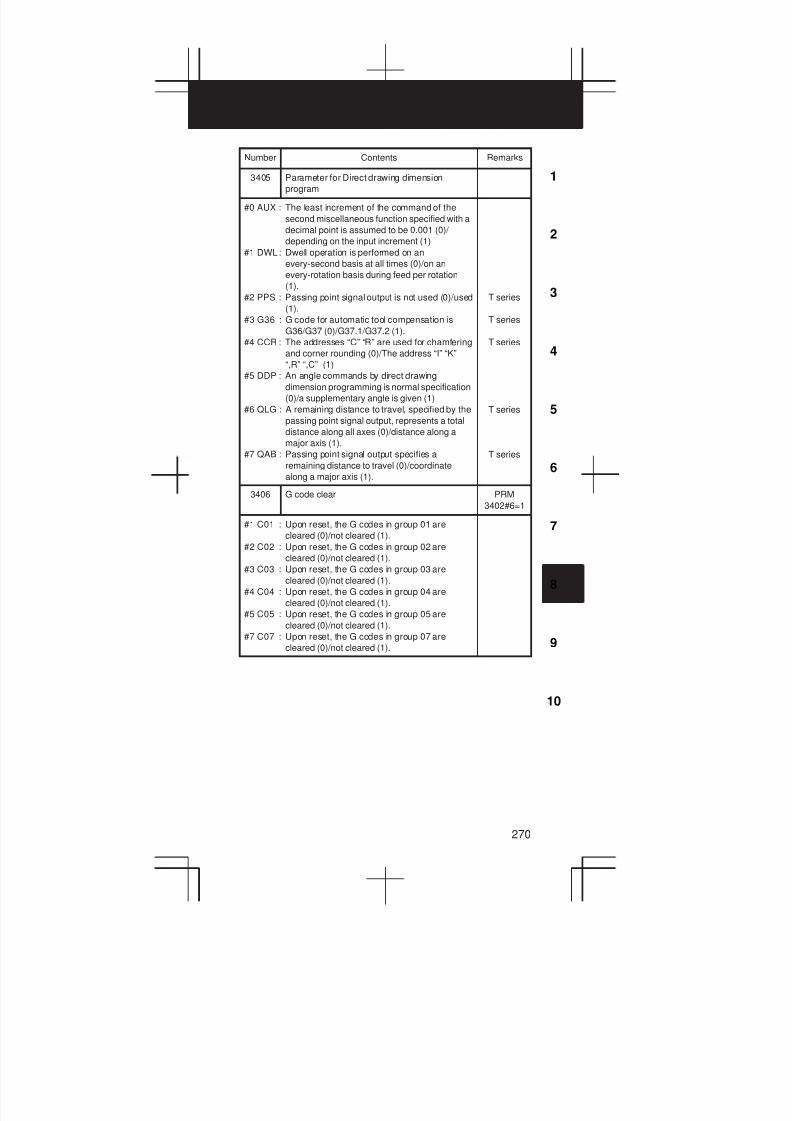
3
1
4
5
6
7
8
9
10
2
270
Number RemarksContents
3405 Parameter for Direct drawing dimension
program
#0 AUX : The least increment of the command of the
second miscellaneous function specified with a
decimal point is assumed to be 0.001 (0)/
depending on the input increment (1)
#1 DWL: Dwell operation is performed on an
every-second basis at all times (0)/on an
every-rotation basis during feed per rotation
(1).
#2 PPS : Passing point signal output is not used (0)/used
(1).
#3 G36 : G code for automatic tool compensation is
G36/G37 (0)/G37.1/G37.2 (1).
#4 CCR : The addresses “C” “R” are used for chamfering
and corner rounding (0)/The address “I” “K”
“,R” “,C” (1)
#5 DDP : An angle commands by direct drawing
dimension programming is normal specification
(0)/a supplementary angle is given (1)
#6 QLG : A remaining distance to travel, specified by the
passing point signal output, represents a total
distance along all axes (0)/distance along a
major axis (1).
#7 QAB : Passing point signal output specifies a
remaining distance to travel (0)/coordinate
along a major axis (1).
T series
T series
T series
T series
T series
3406 G code clear PRM
3402#6=1
#1 C01 : Upon reset, the G codes in group 01 are
cleared (0)/not cleared (1).
#2 C02 : Upon reset, the G codes in group 02 are
cleared (0)/not cleared (1).
#3 C03 : Upon reset, the G codes in group 03 are
cleared (0)/not cleared (1).
#4 C04 : Upon reset, the G codes in group 04 are
cleared (0)/not cleared (1).
#5 C05 : Upon reset, the G codes in group 05 are
cleared (0)/not cleared (1).
#7 C07 : Upon reset, the G codes in group 07 are
cleared (0)/not cleared (1).
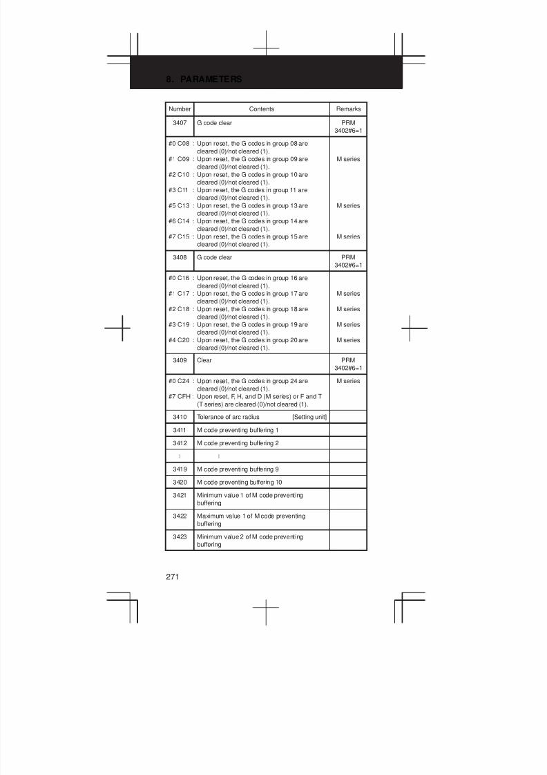
8. PARAMETERS
271
Number RemarksContents
3407 G code clear PRM
3402#6=1
#0 C08 : Upon reset, the G codes in group 08 are
cleared (0)/not cleared (1).
#1 C09 : Upon reset, the G codes in group 09 are
cleared (0)/not cleared (1).
#2 C10 : Upon reset, the G codes in group 10 are
cleared (0)/not cleared (1).
#3 C11 : Upon reset, the G codes in group 11 are
cleared (0)/not cleared (1).
#5 C13 : Upon reset, the G codes in group 13 are
cleared (0)/not cleared (1).
#6 C14 : Upon reset, the G codes in group 14 are
cleared (0)/not cleared (1).
#7 C15 : Upon reset, the G codes in group 15 are
cleared (0)/not cleared (1).
M series
M series
M series
3408 G code clear PRM
3402#6=1
#0 C16 : Upon reset, the G codes in group 16 are
cleared (0)/not cleared (1).
#1 C17 : Upon reset, the G codes in group 17 are
cleared (0)/not cleared (1).
#2 C18 : Upon reset, the G codes in group 18 are
cleared (0)/not cleared (1).
#3 C19 : Upon reset, the G codes in group 19 are
cleared (0)/not cleared (1).
#4 C20 : Upon reset, the G codes in group 20 are
cleared (0)/not cleared (1).
M series
M series
M series
M series
3409 Clear PRM
3402#6=1
#0 C24 : Upon reset, the G codes in group 24 are
cleared (0)/not cleared (1).
#7 CFH : Upon reset, F, H, and D (M series) or F and T
(T series) are cleared (0)/not cleared (1).
M series
3410 Tolerance of arc radius [Setting unit]
3411 M code preventing buffering 1
3412 M code preventing buffering 2
L L
3419 M code preventing buffering 9
3420 M code preventing buffering 10
3421 Minimum value 1 of M code preventing
buffering
3422 Maximum value 1 of M code preventing
buffering
3423 Minimum value 2 of M code preventing
buffering

3
1
4
5
6
7
8
9
10
2
272
Number RemarksContents
3424 Maximum value 2 of M code preventing
buffering
3425 Minimum value 3 of M code preventing
buffering
3426 Maximum value 3 of M code preventing
buffering
3427 Minimum value 4 of M code preventing
buffering
3428 Maximum value 4 of M code preventing
buffering
3429 Minimum value 5 of M code preventing
buffering
3430 Maximum value 5 of M code preventing
buffering
3431 Minimum value 6 of M code preventing
buffering
3432 Maximum value 6 of M code preventing
buffering
3441 Start number of the M codes corresponding to
the set numbers 100 to 199
3442 Start number of the M codes corresponding to
the set numbers 200 to 299
3443 Start number of the M codes corresponding to
the set numbers 300 to 399
3444 Start number of the M codes corresponding to
the set numbers 400 to 499
3450 Second miscellaneous function command
#0 AUP : When a command for the second
miscellaneous function contains a decimal
point or negative sign the command is invalid
(0)/valid (1).
#3 CQD: The method used for determining the amount
of travel in circular interpolation is Series 16
type (0)/Series 15 type (1)
#4 NPS : A block that contains M98 Pxxx or M99, and
which contains no addresses other than O and
N functions as a one–block NC statement
involving no movement (0)/as a macro
statement (1)
M series
T series
3460 Address for second miscellaneous function
Address B is assumed when a value other than
the above is set.
W
87
Addres
Set value
V
86
U
85
C
67
B
66
A
65
M series

8. PARAMETERS
273
Number RemarksContents
3471 Allowable difference between the specified end
position and the end position obtained from the
increase/decrease and frequency in spiral
interpolation or conic interpolation
M series
<Axis>
3472 Minimum radius needed to maintain the actual
speed in spiral or conic interpolation
M series
19) Parameters for Pitch Error Compensation
Number Contents Remarks
3620 Number of the pitch error compensation point
for the reference position for each axis
Valid data
range :
3621 Number of pitch error compensation points of
negative direction for each axis
-
<Axis>
3622 Number of pitch error compensation points of
positive direction for each axis
3623 Magnification for pitch error compensation for
each axis
<Axis>
3624 Interval between pitch error compensation
points for each axis [Setting unit]
<Axis>
20) Parameters for Spindle Control
Number Contents Remarks
3700 Parameter for Cs axis
#1 NRF : At the first G00 command after the serial
spindle is switched to C axis conturing control
mode, the positioning is done after returning to
the reference position (0)/with normal
positioning (1)
Serial
spindle
3701 Parameter for the number of connections in
serial spindle control
#1 ISI : Specifies whether the serial spindle interface is
used (0)/note used (1)
#4 SS2 : The second spindle is not used (0)/used (1)
#5 SS3 : The third spindle is not used (0)/used (1)

3
1
4
5
6
7
8
9
10
2
274
Number RemarksContents
3702 Parameter for spindle orientation function
(O.S.S)
#0 OR3 : The spindle orientation function based on an
externally set stop position is not used (0)/
used (1) by the third spindle motor.
#1 EMS : Multi–spindle control function is used (0)/not
used (1)
#2 OR1 : The stop position external-setting type
orientation function O.S.S is not used at the
first spindle motor (0)/used (1)
#3 OR2 : The stop position external-setting type
orientation function O.S.S is not used at the
second spindle motor (0)/used (1)
#4 ESI : The spindle positioning function is used (0)/not
used (1).
#5 EAS : With path 1, S analog output is used (0)/not
used (1).
#6 ESS : With path 1, a serial output is used (0)/not used
(1).
#7 ECS : With path 1, Cs contour control is used (0)/not
used (1).
T series
(2-path
control)
T series
(2-path
control)
T series
(2-path
control)
T series
(2-path
control)
T series
(2-path
control)
3703 Number of spindles T series
(2-path
control)
#0 2SP : 1 spindle control (0)/2 spindle control (1)
#1 RSI : Spindle command selection affects (0)/does
not affect (1) commands from SIND for the first
spindle

8. PARAMETERS
275
Number RemarksContents
3705 Parameter for gear shift of spindle
#0 ESF : The SF signal output condition is such that S
codes and SF are output with all S commands
(0)/not output when constant surface speed
control is used or the spindle speed is clamped
(1).
#1 GST : The SOR signal is used for spindle orientation
(0)/gear shift (1)
#2 SGB : The gear switching method is method A (0)/
method B (1)
#3 SGT : The gear switching method during G84 and
G74 is method A (0)/method B (1)
#4 EVS : With an S command, S codes and SF are not
output (0)/output (1).
#5 NSF : When an S code command is issued in
constant surface-speed control, SF is output
(0)/not output (1)
#6 SFA : The SF signal is output when gears are
switched (0)/irrespective of whether gears are
switched (1)
PRM
3705#5
M series
PRM3751,
3752
M series
PRM3741,
3743
M series
PRM3761,
3762
T series
M series
M series
3706 Parameter for the voltage polarity of spindle
#0 PG1 : The gear ratio of spindle to position coder
(1,2,4,8)
#1 PG2 : The gear ratio of spindle to position coder
(1,2,4,8)
#3 PCS : When multi-spindle control is used, feedback
signal selection, independent of the position
coder selection signal of the other tool post, is
disabled (0)/enabled (1).
#4 GTT : Spindle gear selection is based on M type (0)/
T type (1).
#5 ORM : The voltage polarity during spindle orientation
is positive (0)/negative (1)
#6 CWM : The voltage polarity when the spindle speed
voltage is output
#7 TCW : The voltage polarity when the spindle speed
voltage is output
1
2
4
8
PG2
0
0
1
1
0
0
1
1
TCW CWM Volt. polarity
0
1
0
1
M03, M04 = +
M03, M04 = –
M03 = +, M04 = –
M03 = –, M04 = +
PG1
0
1
0
1
T series
(2-path
control)
SLPCA
signal
SLPCB
signal
M series
PRM
3705#0

3
1
4
5
6
7
8
9
10
2
276
Number RemarksContents
3707 Parameter for gear shift of spindle T series
#0 P21 : The gear ratio of spindle to second position
coder
#1 P22 : The gear ratio of spindle to second position
coder
P22
0
0
1
1
P21
0
1
0
1
1
2
4
8
3708 Parameter for spindle speed arrival signal
#0 SAR : The spindle speed arrival signal is not checked
(0)/checked (1)
#1 SAT : The check of the spindle speed arrival signal at
the start of executing the thread cutting block is
performed with PRM3708#0=1 (0)/always
performed (1)
#4 SVD : When the SIND signal is on, the detection of
spindle speed fluctuation is disable (0)/enable
(1)
SAR signal
T series
3709 Parameter for spindle
#0 SAM : The sampling frequency to obtain the average
spindle speed is 4 (0)/1 (1)
#2 MSI : The SIND signal in multi-spindle control is valid
only when the first spindle is selected (0)/for
each spindle (1)
#3 MRS: Actual spindle speed signals and S 12–bit code
signals to be output when multi–spindle control
is performed, signals common to the first and
second spindles are used (0)/separate signals
are used (1)
T series
3715 Confirmation of the spindle speed signal
#0 NSAx : This parameter specifies an axis for which
confirmation of the spindle speed reached
signal (SAR) is necessary (0)/unnecessary
(1)
3730 Dta used for adjusting the gain of the analog
output of spindle speed [0.1%]
3731 Compensation value for the offset voltage of
the analog output of the spindle speed
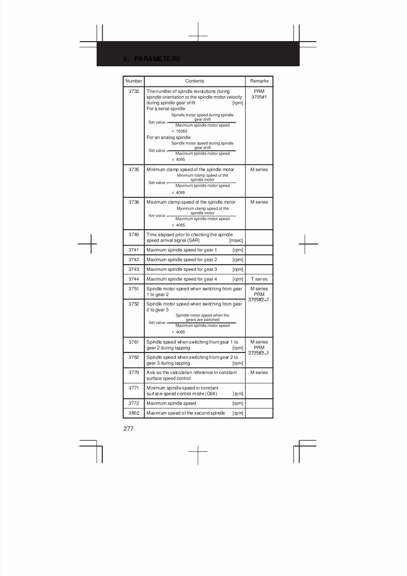
8. PARAMETERS
277
Number RemarksContents
3732 The number of spindle revolutions during
spindle orientation or the spindle motor velocity
during spindle gear shift [rpm]
For a serial spindle
For an analog spindle
Spindle motor speed during spindlegear shift
Set value =
16383
Maximum spindle motor speed
Spindle motor speed during spindlegear shift
Set value =
4095
Maximum spindle motor speed
PRM
3705#1
3735 Minimum clamp speed of the spindle motor
Minimum clamp speed of thespindle motor
Set value =
4095
Maximum spindle motor speed
M series
3736 Maximum clamp speed of the spindle motor
Maximum clamp speed of thespindle motor
Set value =
4095
Maximum spindle motor speed
M series
3740 Time elapsed prior to checking the spindle
speed arrival signal (SAR) [msec]
3741 Maximum spindle speed for gear 1 [rpm]
3742 Maximum spindle speed for gear 2 [rpm]
3743 Maximum spindle speed for gear 3 [rpm]
3744 Maximum spindle speed for gear 4 [rpm] T series
3751 Spindle motor speed when switching from gear
1 to gear 2
M series
PRM
3752 Spindle motor speed when switching from gear
2 to gear 3Spindle motor speed when the
gears are switchedSet value =
4095
Maximum spindle motor speed
=
3761 Spindle speed when switching from gear 1 to
gear 2 during tapping [rpm]
M series
PRM
3762 Spindle speed when switching from gear 2 to
gear 3 during tapping [rpm]
=
3770 Axis as the calculation reference in constant
surface speed control
M series
3771 Minimum spindle speed in constant
surface-speed control mode (G96) [rpm]
3772 Maximum spindle speed [rpm]
3802 Maximum speed of the second spindle [rpm]
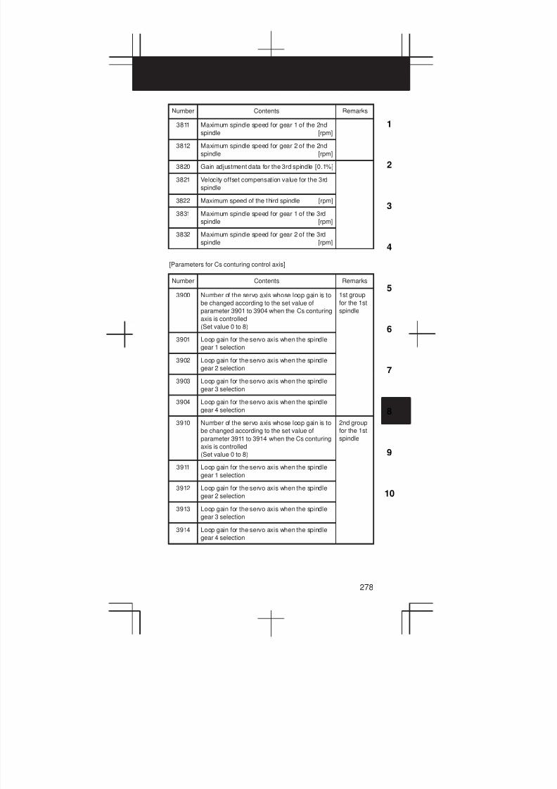
3
1
4
5
6
7
8
9
10
2
278
Number RemarksContents
3811 Maximum spindle speed for gear 1 of the 2nd
spindle [rpm]
3812 Maximum spindle speed for gear 2 of the 2nd
spindle [rpm]
3820 Gain adjustment data for the 3rd spindle [0.1%]
3821 Velocity offset compensation value for the 3rd
spindle
3822 Maximum speed of the third spindle [rpm]
3831 Maximum spindle speed for gear 1 of the 3rd
spindle [rpm]
3832 Maximum spindle speed for gear 2 of the 3rd
spindle [rpm]
[Parameters for Cs conturing control axis]
Number Contents Remarks
3900 Number of the servo axis whose loop gain is to
be changed according to the set value of
parameter 3901 to 3904 when the Cs conturing
axis is controlled
(Set value 0 to 8)
1st group
for the 1st
spindle
3901 Loop gain for the servo axis when the spindle
gear 1 selection
3902 Loop gain for the servo axis when the spindle
gear 2 selection
3903 Loop gain for the servo axis when the spindle
gear 3 selection
3904 Loop gain for the servo axis when the spindle
gear 4 selection
3910 Number of the servo axis whose loop gain is to
be changed according to the set value of
parameter 3911 to 3914 when the Cs conturing
axis is controlled
(Set value 0 to 8)
2nd group
for the 1st
spindle
3911 Loop gain for the servo axis when the spindle
gear 1 selection
3912 Loop gain for the servo axis when the spindle
gear 2 selection
3913 Loop gain for the servo axis when the spindle
gear 3 selection
3914 Loop gain for the servo axis when the spindle
gear 4 selection
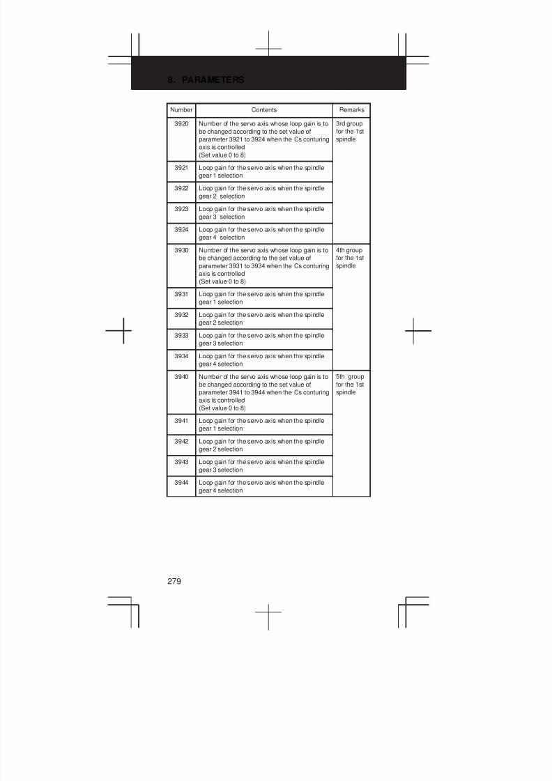
8. PARAMETERS
279
Number RemarksContents
3920 Number of the servo axis whose loop gain is to
be changed according to the set value of
parameter 3921 to 3924 when the Cs conturing
axis is controlled
(Set value 0 to 8)
3rd group
for the 1st
spindle
3921 Loop gain for the servo axis when the spindle
gear 1 selection
3922 Loop gain for the servo axis when the spindle
gear 2 selection
3923 Loop gain for the servo axis when the spindle
gear 3 selection
3924 Loop gain for the servo axis when the spindle
gear 4 selection
3930 Number of the servo axis whose loop gain is to
be changed according to the set value of
parameter 3931 to 3934 when the Cs conturing
axis is controlled
(Set value 0 to 8)
4th group
for the 1st
spindle
3931 Loop gain for the servo axis when the spindle
gear 1 selection
3932 Loop gain for the servo axis when the spindle
gear 2 selection
3933 Loop gain for the servo axis when the spindle
gear 3 selection
3934 Loop gain for the servo axis when the spindle
gear 4 selection
3940 Number of the servo axis whose loop gain is to
be changed according to the set value of
parameter 3941 to 3944 when the Cs conturing
axis is controlled
(Set value 0 to 8)
5th group
for the 1st
spindle
3941 Loop gain for the servo axis when the spindle
gear 1 selection
3942 Loop gain for the servo axis when the spindle
gear 2 selection
3943 Loop gain for the servo axis when the spindle
gear 3 selection
3944 Loop gain for the servo axis when the spindle
gear 4 selection
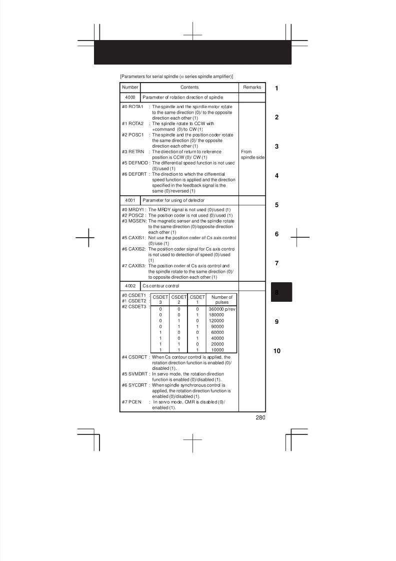
3
1
4
5
6
7
8
9
10
2
280
[Parameters for serial spindle (a series spindle amplifier)]
Number Contents Remarks
4000 Parameter of rotation direction of spindle
#0 ROTA1 : The spindle and the spindle motor rotate
to the same direction (0)/ to the opposite
direction each other (1)
#1 ROTA2 : The spindle rotate to CCW with
+command (0)/to CW (1)
#2 POSC1 : The spindle and the position coder rotate
the same direction (0)/ the opposite
direction each other (1)
#3 RETRN : The direction of return to reference
position is CCW (0)/ CW (1)
#5 DEFMOD : The differential speed function is not used
(0)/used (1)
#6 DEFDRT : The direction to which the differential
speed function is applied and the direction
specified in the feedback signal is the
same (0)/reversed (1)
From
spindle side
4001 Parameter for using of detector
#0 MRDY1 : The MRDY signal is not used (0)/used (1)
#2 POSC2 : The position coder is not used (0)/used (1)
#3 MGSEN: The magnetic senser and the spindle rotate
to the same direction (0)/opposite direction
each other (1)
#5 CAXIS1: Not use the position coder of Cs axis control
(0)/use (1)
#6 CAXIS2: The position coder signal for Cs axis control
is not used to detection of speed (0)/used
(1)
#7 CAXIS3: The position coder of Cs axis control and
the spindle rotate to the same direction (0)/
to opposite direction each other (1)
4002 Cs contour control
#0 CSDET1 :
#1 CSDET2 :
#2 CSDET3 :
#4 CSDRCT : When Cs contour control is applied, the
rotation direction function is enabled (0)/
disabled (1).
#5 SVMDRT : In servo mode, the rotation direction
function is enabled (0)/disabled (1).
#6 SYCDRT : When spindle synchronous control is
applied, the rotation direction function is
enabled (0)/disabled (1).
#7 PCEN : In servo mode, CMR is disabled (0)/
enabled (1).
0
0
0
0
1
1
1
1
CSDET3
360000 p/rev
180000
120000
90000
60000
40000
20000
10000
0
0
1
1
0
0
1
1
Number ofpulses
0
1
0
1
0
1
0
1
CSDET2
CSDET1
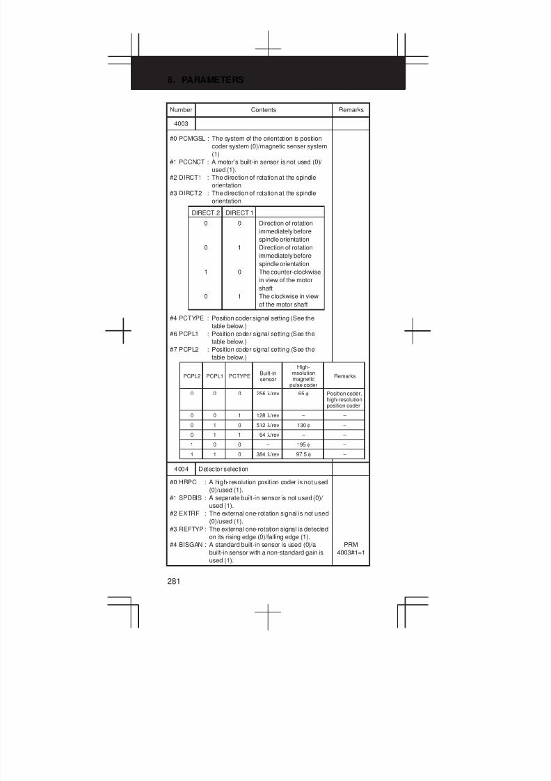
8. PARAMETERS
281
Number RemarksContents
4003
#0 PCMGSL : The system of the orientation is position
coder system (0)/magnetic senser system
(1)
#1 PCCNCT : A motor’s built-in sensor is not used (0)/
used (1).
#2 DIRCT1 : The direction of rotation at the spindle
orientation
#3 DIRCT2 : The direction of rotation at the spindle
orientation
#4 PCTYPE : Position coder signal setting (See the
table below.)
#6 PCPL1 : Position coder signal setting (See the
table below.)
#7 PCPL2 : Position coder signal setting (See the
table below.)
0
PCPL2
0
PCPL1
0
PCTYPE
256 λ /rev
Built-insensor
65 φ
High-resolutionmagnetic
pulse coder
Position coder,high-resolutionposition coder
Remarks
0 0 1 128 λ /rev – –
0 1 0 512 λ /rev 130 φ –
0 1 1 64 λ /rev – –
1 0 0 – 195 φ –
1 1 0 384 λ /rev 97.5 φ –
0
0
1
0
DIRECT 2
Direction of rotation
immediately before
spindle orientation
Direction of rotation
immediately before
spindle orientation
The counter-clockwise
in view of the motor
shaft
The clockwise in view
of the motor shaft
0
1
0
1
DIRECT 1
4004 Detector selection
#0 HRPC : A high-resolution position coder is not used
(0)/used (1).
#1 SPDBIS : A separate built-in sensor is not used (0)/
used (1).
#2 EXTRF : The external one-rotation signal is not used
(0)/used (1).
#3 REFTYP: The external one-rotation signal is detected
on its rising edge (0)/falling edge (1).
#4 BISGAN : A standard built-in sensor is used (0)/a
built-in sensor with a non-standard gain is
used (1).
PRM
4003#1=1

3
1
4
5
6
7
8
9
10
2
282
Number RemarksContents
4006
#1 GRUNIT : The gear ratio resolution is 0.01 (0)/0.001
(1).
#2 SPDUNT : The unit of motor speed is 1 rpm (0)/10
rpm (1).
#3 SYCREF : In spindle synchronization, the
one-rotation signal is automatically
detected (0)/not detected (1).
#5 ALGOVR : The spindle analog override value is 0% to
100% (0)/0% to 120% (1).
#6 PRMCHK : Parameters are transferred from the NC
(0)/the data being used currently is
checked (1).
#7 BLTRGD : Rigid tapping using a motor’s built-in
sensor is not performed (0)/performed (1).
PRM4056
to 4059
4007
#5 PCLS : Disconnection of a high-resolution
magnetic pulse coder and position coder is
detected (0)/not detected (1).
#6 PCALCL : Alarms related to the position coder signal
are detected (0)/not detected (1).
#7 PHAICL : Motor voltage pattern when no load is
applied
4009
#0 VLPGAN : The setting of a velocity loop gain is used
without modification (0)/used after division
by 16 (1).
#1 RVSVCM : In slave operation, the sub-spindle and
main spindle rotate in the same direction
(0)/opposite directions (1).
#2 ALSP : When a serial communication alarm is
issued, the power is not turned off until the
motor has stopped (0)/the power is turned
off immediately (1).
#3 PCGEAR : The arbitrary gear function between the
spindle and position coder is disabled (0)/
enabled (1).
#4 LDTOUT : During acceleration/deceleration, the load
detection signal is not output (0)/output
(1).
#5 TRSPRM : Output compensation method
#6 OVRTYP : Analog override is of linear function type
(0)/quadratic function type (1).
Depends
on the
motor
model.

8. PARAMETERS
283
Number RemarksContents
4011 Number of speed detector pulses
#0 VDT1 : Speed detector setting (Following table)
#1 VDT2 : Speed detector setting (Following table)
#2 VDT3 : Speed detector setting (Following table)
#3 POLE1: The number of motor poles is 2 (0)/4 (1).
#4 MXPW: Setting of maximum power during
acceleration/deceleration (for each model)
#5 ADJG : Acceleration/deceleration status
determination condition (for each model)
#7 POLE2: The number of motor poles is set by bit 3 (0)/
is 8 (1).
0
0
0
0
1
1
VDT3
64 λ /rev
128 λ /rev
256 λ /rev
512 λ /rev
192 λ /rev
384 λ /rev
Number of pulse
0
0
1
1
0
0
VDT2
0
1
0
1
0
1
VDT1
4012
#0 PWM1 :
#1 PWM2 :PWM setting (Set 00 usually.)}
4013 Data of the dead zone of current
#0 ESEC : The position coder one-rotation signal is
detected on either edge (0)/on the rising
edge at all times (1).
#1 ESED : The Cs contour control one-rotation signal
is detected on either edge (0)/on the rising
edge at all times (1).
#2 DS1 :
#3 DS2 :
#4 DS3 :
#5 DS4 :
#6 DS5 :
#7 PWM3K: Setting of a PWM carrier wave in the
output switching low-speed characteristics
area (for each model)
The data of the dead zone of current(Set automatically)
4014 Spindle switching, MCC confirmation
#0 AXISSL : The spindle switching function is disabled
(0)/enabled (1).
#1 AXSUB : During sub-spindle rotation, the spindle
switching function is disabled (0)/enabled
(1).
#2 AXSLCT : The spindle switching (between the main
spindle and sub-spindle) MCC contact
check function is disabled (0)/enabled (1).
#3 CHGCLT: Output switching (between high speed and
low speed) is checked using the RCH
signal (0)/the MCC contact signal (1).
#5 SLVEN : The slave operation function is disabled
(0)/enabled (1).
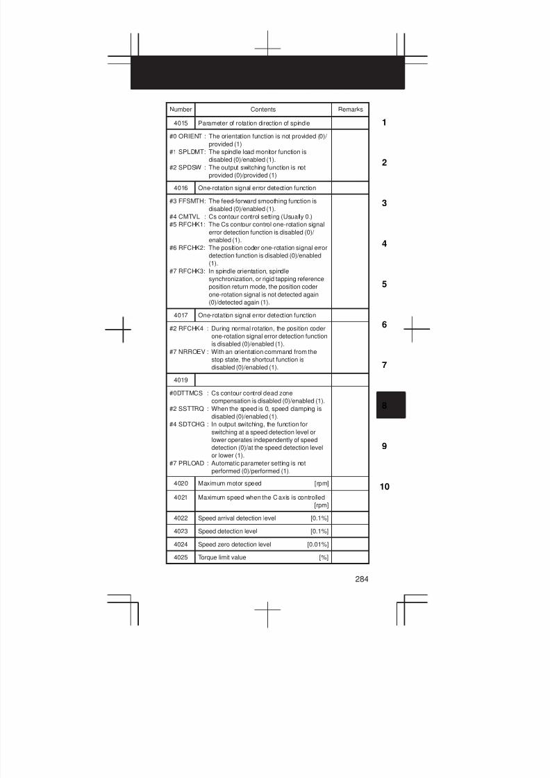
3
1
4
5
6
7
8
9
10
2
284
Number RemarksContents
4015 Parameter of rotation direction of spindle
#0 ORIENT : The orientation function is not provided (0)/
provided (1)
#1 SPLDMT: The spindle load monitor function is
disabled (0)/enabled (1).
#2 SPDSW : The output switching function is not
provided (0)/provided (1)
4016 One-rotation signal error detection function
#3 FFSMTH: The feed-forward smoothing function is
disabled (0)/enabled (1).
#4 CMTVL : Cs contour control setting (Usually 0.)
#5 RFCHK1: The Cs contour control one-rotation signal
error detection function is disabled (0)/
enabled (1).
#6 RFCHK2: The position coder one-rotation signal error
detection function is disabled (0)/enabled
(1).
#7 RFCHK3: In spindle orientation, spindle
synchronization, or rigid tapping reference
position return mode, the position coder
one-rotation signal is not detected again
(0)/detected again (1).
4017 One-rotation signal error detection function
#2 RFCHK4 : During normal rotation, the position coder
one-rotation signal error detection function
is disabled (0)/enabled (1).
#7 NRROEV : With an orientation command from the
stop state, the shortcut function is
disabled (0)/enabled (1).
4019
#0DTTMCS : Cs contour control dead zone
compensation is disabled (0)/enabled (1).
#2 SSTTRQ : When the speed is 0, speed clamping is
disabled (0)/enabled (1).
#4 SDTCHG : In output switching, the function for
switching at a speed detection level or
lower operates independently of speed
detection (0)/at the speed detection level
or lower (1).
#7 PRLOAD : Automatic parameter setting is not
performed (0)/performed (1).
4020 Maximum motor speed [rpm]
4021 Maximum speed when the C axis is controlled
[rpm]
4022 Speed arrival detection level [0.1%]
4023 Speed detection level [0.1%]
4024 Speed zero detection level [0.01%]
4025 Torque limit value [%]
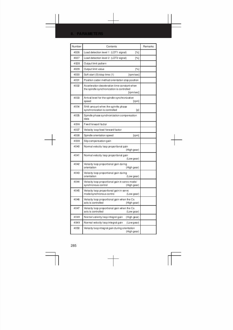
8. PARAMETERS
285
Number Contents Remarks
4026 Load detection level 1 (LDT1 signal) [%]
4027 Load detection level 2 (LDT2 signal) [%]
4028 Output l imit pattern
4029 Output limit value [%]
4030 Soft start (0)/stop time (1) [rpm/sec]
4031 Position coder method orientation stop position
4032 Acceleration deceleration time constant when
the spindle synchronization is controlled
[rpm/sec]
4033 Arrival level for the spindle synchronization
speed [rpm]
4034 Shift amount when the spindle phase
synchronization is controlled [p]
4035 Spindle phase synchronization compensation
data
4036 Feed forward factor
4037 Velocity loop feed forward factor
4038 Spindle orientation speed [rpm]
4039 Slip compensation gain
4040 Normal velocity loop proportional gain
(High gear)
4041 Normal velocity loop proportional gain
(Low gear)
4042 Velocity loop proportional gain during
orientation (High gear)
4043 Velocity loop proportional gain during
orientation (Low gear)
4044 Velocity loop proportional gain in servo mode/
synchronous control (High gear)
4045 Velocity loop proportional gain in servo
mode/synchronous control (Low gear)
4046 Velocity loop proportional gain when the Cs
axis is controlled (High gear)
4047 Velocity loop proportional gain when the Cs
axis is controlled (Low gear)
4048 Normal velocity loop integral gain (High gear)
4049 Normal velocity loop integral gain (Low gear)
4050 Velocity loop integral gain during orientation
(High gear)
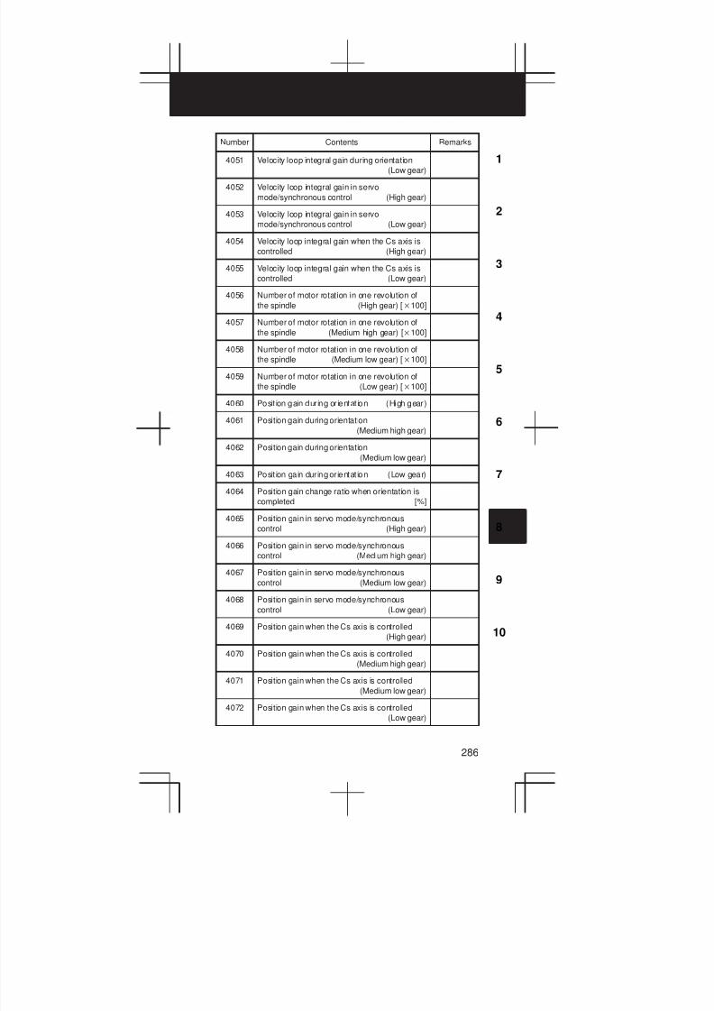
3
1
4
5
6
7
8
9
10
2
286
Number RemarksContents
4051 Velocity loop integral gain during orientation
(Low gear)
4052 Velocity loop integral gain in servo
mode/synchronous control (High gear)
4053 Velocity loop integral gain in servo
mode/synchronous control (Low gear)
4054 Velocity loop integral gain when the Cs axis is
controlled (High gear)
4055 Velocity loop integral gain when the Cs axis is
controlled (Low gear)
4056 Number of motor rotation in one revolution of
the spindle (High gear) [100]
4057 Number of motor rotation in one revolution of
the spindle (Medium high gear) [100]
4058 Number of motor rotation in one revolution of
the spindle (Medium low gear) [100]
4059 Number of motor rotation in one revolution of
the spindle (Low gear) [100]
4060 Posit ion gain during or ientat ion (High gear)
4061 Position gain during orientation
(Medium high gear)
4062 Position gain during orientation
(Medium low gear)
4063 Posit ion gain during or ientat ion (Low gear)
4064 Position gain change ratio when orientation is
completed [%]
4065 Position gain in servo mode/synchronous
control (High gear)
4066 Position gain in servo mode/synchronous
control (Medium high gear)
4067 Position gain in servo mode/synchronous
control (Medium low gear)
4068 Position gain in servo mode/synchronous
control (Low gear)
4069 Position gain when the Cs axis is controlled
(High gear)
4070 Position gain when the Cs axis is controlled
(Medium high gear)
4071 Position gain when the Cs axis is controlled
(Medium low gear)
4072 Position gain when the Cs axis is controlled
(Low gear)
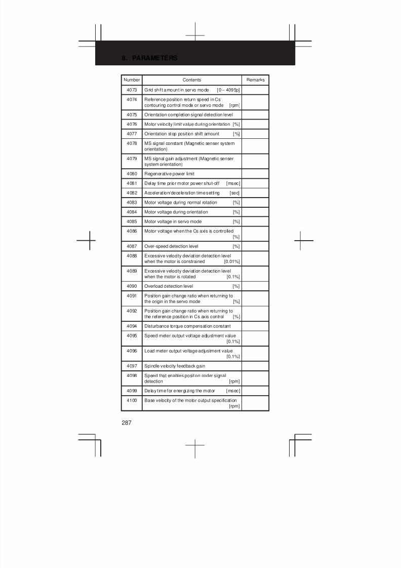
8. PARAMETERS
287
Number RemarksContents
4073 Grid shif t amount in servo mode [0 – 4095p]
4074 Reference position return speed in Cs
contouring control mode or servo mode [rpm]
4075 Orientation completion signal detection level
4076 Motor velocity limit value during orientation [%]
4077 Orientation stop posit ion shift amount [%]
4078 MS signal constant (Magnetic senser system
orientation)
4079 MS signal gain adjustment (Magnetic senser
system orientation)
4080 Regenerative power limit
4081 Delay time prior motor power shut-off [msec]
4082 Acceleration/deceleration time setting [sec]
4083 Motor voltage during normal rotation [%]
4084 Motor voltage during orientation [%]
4085 Motor voltage in servo mode [%]
4086 Motor voltage when the Cs axis is controlled
[%]
4087 Over-speed detection level [%]
4088 Excessive velocity deviation detection level
when the motor is constrained [0.01%]
4089 Excessive velocity deviation detection level
when the motor is rotated [0.1%]
4090 Overload detection level [%]
4091 Position gain change ratio when returning to
the origin in the servo mode [%]
4092 Position gain change ratio when returning to
the reference position in Cs axis control [%]
4094 Disturbance torque compensation constant
4095 Speed meter output voltage adjustment value
[0.1%]
4096 Load meter output voltage adjustment value
[0.1%]
4097 Spindle velocity feedback gain
4098 Speed that enables position coder signal
detection [rpm]
4099 Delay t ime for energizing the motor [msec]
4100 Base velocity of the motor output specification
[rpm]
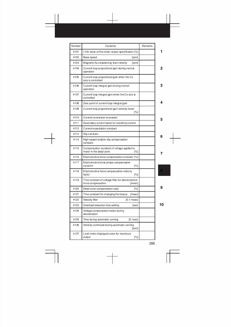
3
1
4
5
6
7
8
9
10
2
288
Number RemarksContents
4101 Limit value of the motor output specification [%]
4102 Base speed [rpm]
4103 Magnetic flux weakening start velocity [rpm]
4104 Current loop proportional gain during normal
operation
4105 Current loop proportional gain when the Cs
axis is controlled
4106 Current loop integral gain during normal
operation
4107 Current loop integral gain when the Cs axis is
controlled
4108 Zero point of current loop integral gain
4109 Current loop proportional gain velocity factor
[%]
4110 Current conversion sconstant
4111 Secondary current factor for exceiting current
4112 Current expectation constant
4113 Sl ip constant
4114 High-speed rotation slip compensation
constant
4115 Compensation constant of voltage applied to
motor in the dead zone [%]
4116 Electromotive force compensation constant [%]
4117 Electromotive force phase compensation
constant [%]
4118 Electromotive force compensation velocity
factor [%]
4119 Time constant of voltage filter for electromotive
force compensation [msec]
4120 Dead zone compensation data [%]
4121 Time constant for changing the torque [msec]
4122 Velocity filter [0.1 msec]
4123 Overload detection time setting [sec]
4124 Voltage compensation factor during
deceleration
4125 Time during automatic running [0.1sec]
4126 Velocity command during automatic running
[rpm]
4127 Load meter displayed value for maximum
output [%]

8. PARAMETERS
289
Number RemarksContents
4128 Maximum output zero point [rpm]
4129 Secondary current factor during rigid tapping
4130 Constant for compensating for the phase of the
electromotive force at deceleration
4131 Time constant of the speed detection filter at
the Cs contour control
4132 Conversation constant of the phase-V current
4133 Motor model code
4135 Grid shift amount when the Cs axis is
controlled
[Parameter for low speed driving when the output switching function is used]
Number Contents Remarks
4136 Motor voltage during normal rotation [%]
4137 Motor voltage in the servo mode [%]
4138 Base speed of the motor output specifications
[rpm]
4139 Limit value of the motor output specifications
[%]
4140 Base speed [rpm]
4141 Magnetic flux weakening start velocity [rpm]
4142 Current loop proportional gain during normal
operation
4143 Current loop integral gain during normal
operation
4144 Zero speed of the current loop integral gain
4145 Velocity factor of the current loop proportional
gain [%]
4146 Current conversion constan
4147 Secondary current factor for activating current
4148 Current expectation constant
4149 Sl ip constant
4150 High speed rotation slip compensation constant
4151 Compensation constant for voltage applied to
motor in the dead zone [%]
4152 Electromotive force compensation constant [%]
4153 Electromotive force phase compensation
constant [%]
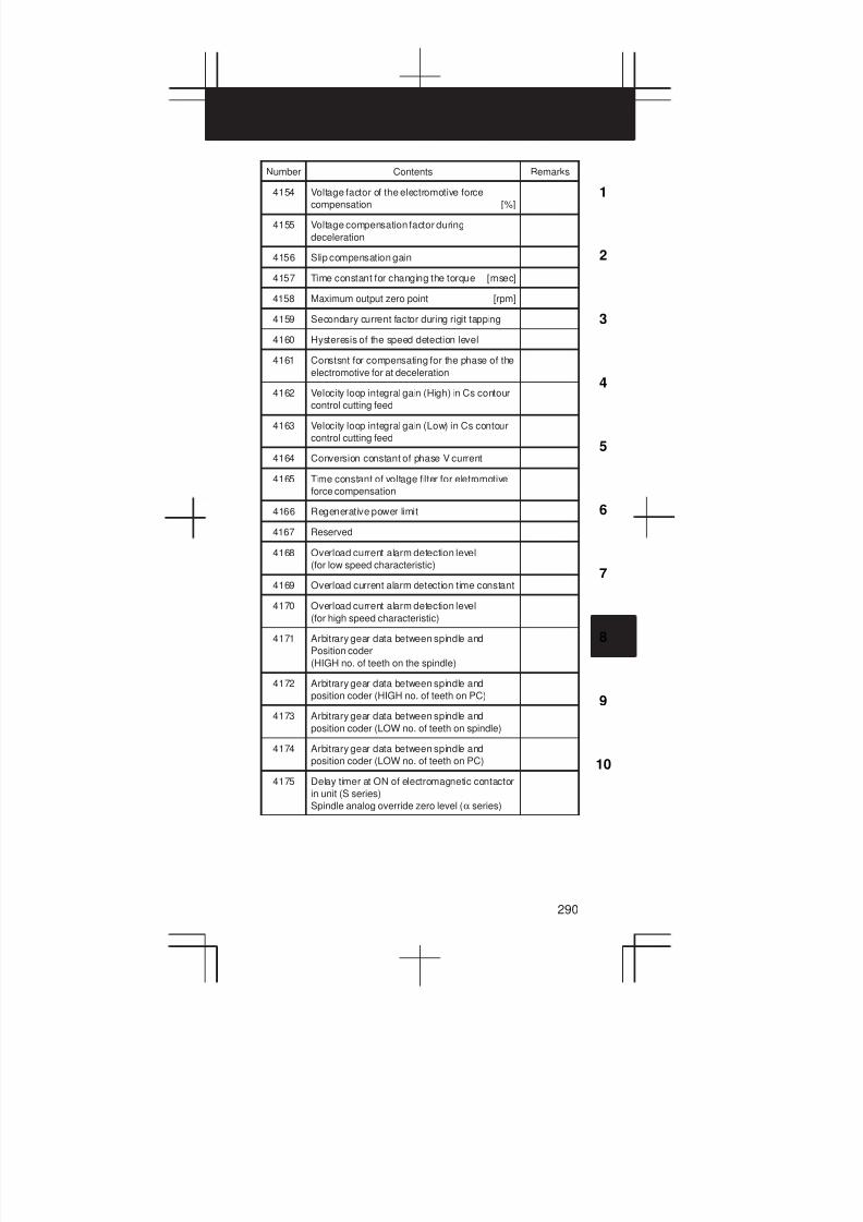
3
1
4
5
6
7
8
9
10
2
290
Number RemarksContents
4154 Voltage factor of the electromotive force
compensation [%]
4155 Voltage compensation factor during
deceleration
4156 Slip compensation gain
4157 Time constant for changing the torque [msec]
4158 Maximum output zero point [rpm]
4159 Secondary current factor during rigit tapping
4160 Hysteresis of the speed detection level
4161 Constsnt for compensating for the phase of the
electromotive for at deceleration
4162 Velocity loop integral gain (High) in Cs contour
control cutting feed
4163 Velocity loop integral gain (Low) in Cs contour
control cutting feed
4164 Conversion constant of phase V current
4165 Time constant of voltage filter for eletromotive
force compensation
4166 Regenerative power limit
4167 Reserved
4168 Overload current alarm detection level
(for low speed characteristic)
4169 Overload current alarm detection time constant
4170 Overload current alarm detection level
(for high speed characteristic)
4171 Arbitrary gear data between spindle and
Position coder
(HIGH no. of teeth on the spindle)
4172 Arbitrary gear data between spindle and
position coder (HIGH no. of teeth on PC)
4173 Arbitrary gear data between spindle and
position coder (LOW no. of teeth on spindle)
4174 Arbitrary gear data between spindle and
position coder (LOW no. of teeth on PC)
4175 Delay timer at ON of electromagnetic contactor
in unit (S series)
Spindle analog override zero level (α series)
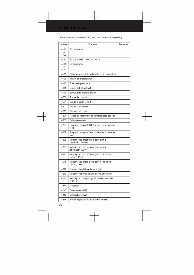
8. PARAMETERS
291
[Parameters for spindle switching function is used (Sub–spindle)]
Number Contents Remarks
4176
to
4190
Bit parameter
4191 Bit parameter (User can not set)
4192
to
4194
Bit parameter
4195 Bit parameter (Automatic setting by parameter)
4196 Maximum motor speed
4197 Reached speed level
4198 Speed detection level
4199 Speed zero detection level
4200 Torque limit value
4201 Load detection level 1
4202 Output l imit pattern
4203 Output l imit value
4204 Position coder method orientation stop position
4205 Orientation speed
4206 Proportional gain (HIGH) of the normal velocity
loop
4207 Proportional gain (LOW) of the normal velocity
loop
4208 Velocity loop proportional gain during
orientation (HIGH)
4209 Velocity loop proportional gain during
orientation (LOW)
4210 Velocity loop proportional gain in the servo
mode (HIGH)
4211 Velocity loop proportional gain in the servo
mode (LOW)
4212 Normal velocity loop integral gain
4213 Velocity loop integral gain during orientation
4214 Velocity loop integral gain in the servo mode
(HIGH)
4215 Reserved
4216 Gear rat io (HIGH)
4217 Gear rat io (LOW)
4218 Position gain during orientation (HIGH)
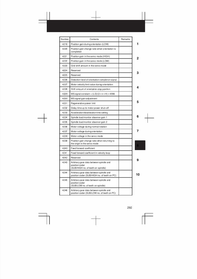
3
1
4
5
6
7
8
9
10
2
292
Number RemarksContents
4219 Position gain during orientation (LOW)
4220 Position gain change ratio when orientation is
completed
4221 Position gain in the servo mode (HIGH)
4222 Position gain in the servo mode (LOW)
4223 Grid shift amount in the servo mode
4224 Reserved
4225 Reserved
4226 Detection level of orientation completion signal
4227 Motor velocity limit value during orientation
4228 Shift amount of orientation stop position
4229 MS signal constant = (L/2)/(2πH)4096
4230 MS signal gain adjustment
4231 Regenerative power limit
4232 Delay time up to motor power shut–off
4233 Acceleration/deceleration time setting
4234 Spindle load monitor observer gain 1
4235 Spindle load monitor observer gain 2
4236 Motor voltage during normal rotation
4237 Motor voltage during orientation
4238 Motor voltage in the servo mode
4239 Position gain change ratio when returning to
the origin in the servo mode
4240 Feed forward coefficient
4241 Feed forward coefficient in velocity loop
4242 Reserved
4243 Arbitrary gear data between spindle and
position coder
(SUB/HIGH no. of teeth on spindle)
4244 Arbitrary gear data between spindle and
position coder (SUB/HIGH no. of teeth on PC)
4245 Arbitrary gear data between spindle and
position coder
(SUB/LOW no. of teeth on spindle)
4246 Arbitrary gear data between spindle and
position coder (SUB/LOW no. of teeth on PC)

8. PARAMETERS
293
Number RemarksContents
4247 Spindle load monitor magnetic flux
compensation time constant (for high–speed
characteristic on the MAIN side)
4248 Spindle load motor torque constant (for
high–speed characteristic on the MAIN side)
4249 Spindle load monitor observer gain 1
(on the MAIN side)
4250 Spindle load monitor observer gain 2
(on the MAIN side)
4251 Spindle load monitor magnetic flux
compensation time constant (for low–speed
characteristic on the MAIN side)
4252 Spindle load monitor magnetic flux
compensation time constant
(for high–speed characteristic)
4253 Spindle load monitor magnetic flux
compensation time constant
(for low–speed characteristic)
4254 Slip correction gain
(for high–speed characteristic)
4255 Slip correction gain
(for low–speed characteristic)
4256 Base velocity of the motor output specifications
4257 Limit value for the motor output specifications
4258 Base speed
4259 Magnetic flux weakening start velocity
4260 Current loop proportional gain during normal
operation
4261 Current loop integral gain during normal
operation
4262 Zero point of current loop integral gain
4263 Velocity factor of current loop proportional gain
4264 Current conversion constant
4265 Secondary current factor for excitation current
4266 Current expectation constant
4267 Sl ip constant
4268 Compensation constant for high–speed rotation
slip
4269 Compensation constant for voltage applied to
motor in the dead zone
4270 Electromotive force compensation constant

3
1
4
5
6
7
8
9
10
2
294
Number RemarksContents
4271 Phase compensation constant of electromotive
force
4272 Compensation velocity factor for electromotive
force
4273 Time constant for changing the torque
4274 Displayed value of load meter for maximum
output
4275 Maximum output zero point
4276 Secondary current factor in rigid tapping
4277 Constant for compensating for the phase of
the electromotive force at deceleration
4278 Time constant of the speed detection filter
4279 Reserved
4280 Time constant of voltage filter for electromotive
force compensation
4281 Spindle load monitor torque constant (for
low–speed characteristic on the MAIN side)
4282 Spindle load monitor torque constant
(for high–speed characteristic)
4283 Spindle load monitor torque constant
(for low–speed characteristic)
4284 Motor voltage during normal rotation
4285 Motor voltage in the servo mode
4286 Base speed of the motor output specifications
4287 Limit value for the motor output specifications
4288 Base speed
4289 Magnetic flux weakening start velocity
4290 Current loop proportional gain during normal
operation
4291 Current loop integral gain during normal
operation
4292 Zero point of current loop integral gain
4293 Velocity factor of current loop proportional gain
4294 Current conversion constant
4295 Secondary current factor for excitation current
4296 Current expectation constant
4297 Sl ip constant
4298 Compensation constant for high–speed rotation
slip
4299 Compensation constant for voltage applied to
motor in the dead zone
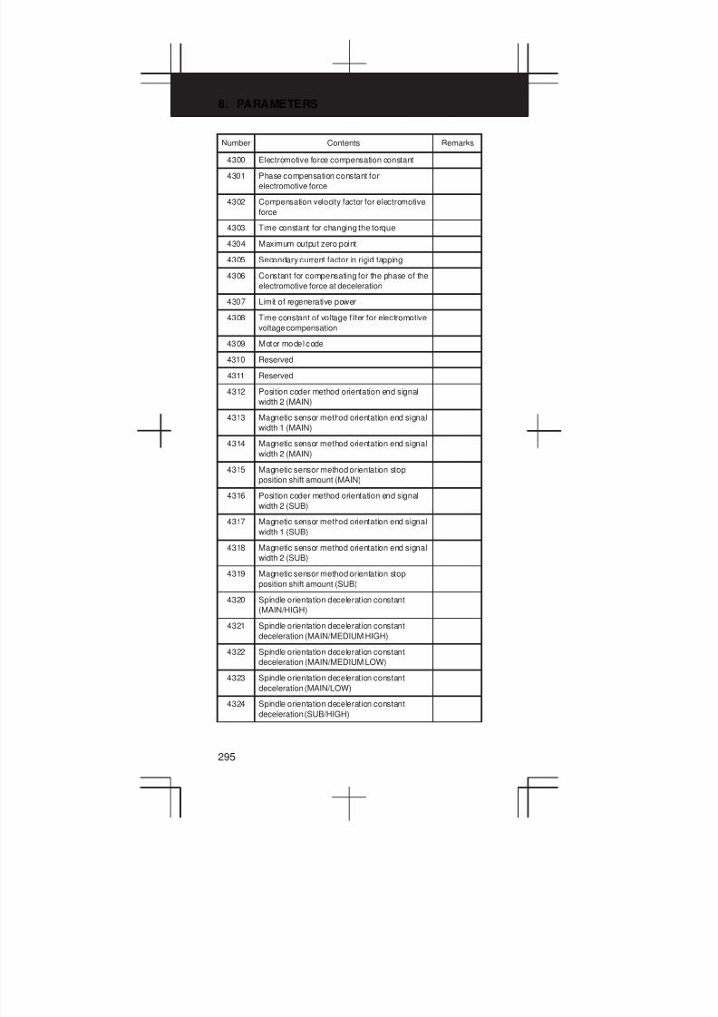
8. PARAMETERS
295
Number RemarksContents
4300 Electromotive force compensation constant
4301 Phase compensation constant for
electromotive force
4302 Compensation velocity factor for electromotive
force
4303 Time constant for changing the torque
4304 Maximum output zero point
4305 Secondary current factor in rigid tapping
4306 Constant for compensating for the phase of the
electromotive force at deceleration
4307 Limit of regenerative power
4308 Time constant of voltage filter for electromotive
voltage compensation
4309 Motor model code
4310 Reserved
4311 Reserved
4312 Position coder method orientation end signal
width 2 (MAIN)
4313 Magnetic sensor method orientation end signal
width 1 (MAIN)
4314 Magnetic sensor method orientation end signal
width 2 (MAIN)
4315 Magnetic sensor method orientation stop
position shift amount (MAIN)
4316 Position coder method orientation end signal
width 2 (SUB)
4317 Magnetic sensor method orientation end signal
width 1 (SUB)
4318 Magnetic sensor method orientation end signal
width 2 (SUB)
4319 Magnetic sensor method orientation stop
position shift amount (SUB)
4320 Spindle orientation deceleration constant
(MAIN/HIGH)
4321 Spindle orientation deceleration constant
deceleration (MAIN/MEDIUM HIGH)
4322 Spindle orientation deceleration constant
deceleration (MAIN/MEDIUM LOW)
4323 Spindle orientation deceleration constant
deceleration (MAIN/LOW)
4324 Spindle orientation deceleration constant
deceleration (SUB/HIGH)
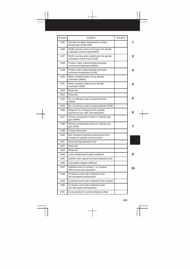
3
1
4
5
6
7
8
9
10
2
296
Number RemarksContents
4325 Spindle orientation deceleration constant
deceleration (SUB/LOW)
4326 Width of pulses when switching to the spindle
orientation control mode (MAIN)
4327 Width of pulses when switching to the spindle
orientation control mode (SUB)
4328 Position coder–based spindle orientation
command multiplication (MAIN)
4329 Position coder–based spindle orientation
command multiplication (SUB)
4330 Motor excitation delay time at spindle
orientation (MAIN)
4331 Motor excitation delay time at spindle
orientation (SUB)
4332 Reserved
4333 Reserved
4334 No. of arbitrary pulses of speed detector
(MAIN)
4335 No. of arbitrary pulses of speed detector (SUB)
4336 Magnetic flux change point for spindle
synchronus acc./dec. time calculation.
4337 Velocity compensation factor of velocity loop
gain (MAIN)
4338 Velocity compensation factor of velocity loop
gain (SUB)
4339 Torque clamp level
4340 Bell–shaped acceleration/deceleration time
constant for spindle synchronization
4341 Abnormal load detection level
4342 Reserved
4343 Reserved
4344 Loock–ahead feed forward coefficient
4345 Spindle motor speed command detection level
4346 Incomplete integral coefficient
4347 Detection level for spindle 1–to–2 speed
difference at slave operation
4348 Overload current alarm detection level
(for low speed characteristic)
4349 Overload current alarm detection time constant
4350 Overload current alarm detection level
(for high speed characteristic)
4351 Compensation for current detection offset

8. PARAMETERS
297
Number Contents Remarks
4800 Parameter for synchronization control of
spindle
#0 ND1 : In controlling the spindle synchronization, the
direction of the first spindle motor rotation is the
direction indicated by the command sign (0)/the
opposite direction (1)
#1 ND2 : In controlling the spindle synchronization, the
direction of the second spindle motor rotation is
the direction indicated by the command sign
(0)/the opposite direction (1)
#7 SPK : As the parking signals for simple spindle
synchronous control PKESS1 <G122#6> and
PKESS2 <G122#7> are used (0)/PKESS1
<G031#6> and PKESS2 <G031#7> are used
(1)
4810 Error pulse between two spindles when phase
synchronizing in the serial spindle
synchronization control mode
4811 Allowable error count for the error pulse
between two spindles in the serial spindle
synchronization control mode
4900 Spindle fluctuation detection T series
#0 FLR : The allowable rate and fluctuation rate of
parameter No. 4911 and No. 4912 are
indicated in 1% steps (0)/0.1% steps (1).
T sereis
4911 Ratio (q) of the spindle speed which is
assumed to the specified spindle speed
4912 Spindle speed fluctuation ratio (r) for which no
alarm is activated in the spindle speed
fluctuation detection function
4913 Spindle speed fluctuation value (d) for which no
alarm is activated in the spindle speed
fluctuation detection function
4914 Time (p) elapsed from when the commanded
spindle speed is changed to the start of spindle
speed fluctuation detection

3
1
4
5
6
7
8
9
10
2
298
Number RemarksContents
4950 Spindle positioning T series
#0 IOR : Resetting the system in the spindle positioning
mode does not releases the mode (0)/releases
the mode (1)
#1 IDM : The positioning direction for the spindle using a
M code is the positive direction (0)/the negative
direction (1)
#2 ISZ : When an M code for orientation is specified,
orientation by canceling rotation mode is
performed (0)/not performed (1).
#5 TRV : Rotation direction of spindle positioning is set
to the positive direction (0)/the reverse
direction (1)
#6 ESI : Spindle positioning conforms to the
conventional specification (0)/extended
specification (1).
#7 IMB : Semi-fixed angle positioning by M code follows
specification A (0)/specification B (1).
4960 M code specifying the spindle orientation
4961 M code releasing the spindle positioning mode
4962 M code specifying the angle for the spindle
positioning
4963 Basic rotation angle specified by a M code in
the spindle positioning mode T series
4964 Number of M codes for specifying a spindle
positioning angle
4970 Servo loop gain of the spindle
4971 Servo loop gain multiplier of the spindle for
gear 1
4972 Servo loop gain multiplier of the spindle for
gear 2
4973 Servo loop gain multiplier of the spindle for
gear 3
4974 Servo loop gain multiplier of the spindle for
gear 4
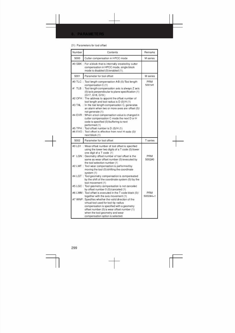
8. PARAMETERS
299
21) Parameters for tool offset
Number Contents Remarks
5000 Cutter compensation in HPCC mode M series
#0 SBK : For a block that is internally created by cutter
compensation in HPCC mode, single block
mode is disabled (0)/enabled (1).
5001 Parameter for tool offset M series
#0 TLC : Tool length compensation A·B (0)/Tool length
compensation C (1)
#1 TLB : Tool length compensation axis is always Z axis
(0)/axis perpendicular to plane specification (1)
(G17, G18, G19 )
#2 OFH : The address to appoint the offset number of
tool length and tool radius is D (0)/H (1)
#3 TAL : In the tool length compensation C, generates
an alarm when two or more axes are offset (0)/
not generate (1)
#4 EVR : When a tool compensation value is changed in
cutter compensation C mode the next D or H
code is specified (0)/buffering is next
performed (1)
#5 TPH : Tool offset number is D (0)/H (1)
#6 EVO : Tool offset is effective from next H code (0)/
next block (1)
PRM
5001#1
5002 Parameter for tool offset T series
#0 LD1 : Wear offset number of tool offset is specified
using the lower two digits of a T code (0)/lower
one digit of a T code (1)
#1 LGN : Geometry offset number of tool offset is the
same as wear offset number (0)/executed by
the tool selection number (1)
#2 LWT : Tool wear compensation is performed by
moving the tool (0)/shifting the coordinate
system (1)
#4 LGT : Tool geometry compensation is compensated
by the shift of the coordinate system (0)/by the
tool movement (1)
#5 LGC : Tool geometry compensation is not canceled
by offset number 0 (0)/canceled (1)
#6 LWM : Tool offset is executed in the T code block (0)/
together with the axis movement (1)
#7 WNP: Specifies whether the valid direction of the
virtual tool used for tool-tip radius
compensation is specified with a geometry
offset number (0)/a wear offset number (1)
when the tool geometry and wear
compensation option is selected.
PRM
5002#0
PRM
5002#4=1
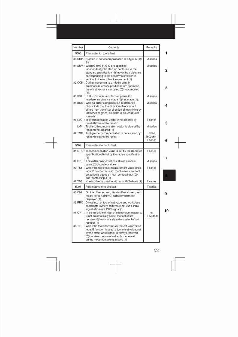
3
1
4
5
6
7
8
9
10
2
300
Number RemarksContents
5003 Parameter for tool offset
#0 SUP : Start up in cutter compensation C is type A (0)/
B (1)
#1 SUV : When G40,G41,G42 are specified
independently, the start up conforms to the
standard specification (0)/moves by a distance
corresponding to the offset vector which is
vertical to the next block movement (1)
#2 CCN : During movement to a middle point in
automatic reference position return operation,
the offset vector is canceled (0)/not canceled
(1).
#3 ICK : In HPCC mode, a cutter compensation
interference check is made (0)/not made (1).
#4 BCK : When a cutter compensation interference
check finds that the direction of movement
differs from the offset direction of machining by
90 to 270 degrees, an alarm is issued (0)/not
issued (1).
#6 LVC : Tool compensation vector is not cleared by
reset (0)/cleared by reset (1)
LVK : Tool length compensation vector is cleared by
reset (0)/not cleared (1)
#7 TGC : Tool geometry compensation is not cleared by
reset (0)/cleared by reset (1)
M series
M series
M series
M series
T series
M series
PRM
5003#6=1
T series
5004 Parameters for tool offset
#1 ORC: Tool compensation value is set by the diameter
specification (0)/set by the radius specification
(1)
#2 ODI : The cutter compensation value is a radius
value (0)/diameter value (1).
#3 TS1 : When the tool offset measurement value direct
input B function is used, touch sensor contact
detection is based on four–contact input (0)/
one–contact input (1)
#7 Y03 : Y axis offset is used for 4th axis (0)/3rd axis (1)
T series
M series
T series
T series
5005 Parameters for tool offset T series
#0 CNI : On the offset screen, Y-axis offset screen, and
macro screen, [INP.C] is displayed (0)/not
displayed (1).
#2 PRC : Direct input of tool offset value and workpiece
coordinate-system shift value not use a PRC
signal (0)/uses a PRC signal (1)
#5 QNI : In the function of input of offset value measured
B not automatically select the tool offset
number (0)/automatically selects a tool offset
number (1)
#6 TLE : When the tool offset measurement value direct
input B function is used, a tool offset value, set
by the offset write signal, is always received
(0)/received only in offset write mode and
during movement along an axis (1)
0:
PRM5020
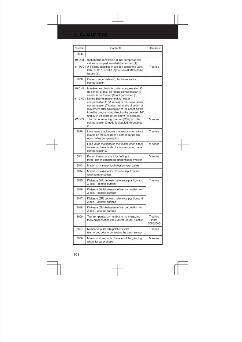
8. PARAMETERS
301
Number RemarksContents
5006
#0 OIM : Inch-metric conversion of tool compensation
values is not performed (0)/performed (1).
#1 TGC : A T code, specified in a block containing G50,
G04, or G10, is valid (0)/causes ALM254 to be
issued (1).
T series
5008 Cutter compensation C, Tool nose radius
compensation
#0 CN1 : Interference check for cutter compensation C
(M series) or tool–tip radius compensation (T
series) is performed (0)/not performed (1).
#1 CNC : During interference check for cutter
compensation C (M series) or tool nose radius
compensation (T series), when the direction of
movement after application of the offset differs
from the programmed direction by between 90°
and 270° an alarm (0)/no alarm (1) is issued.
#2 G39 : The corner rounding function (G39) in cutter
compensation C mode is disabled (0)/enabled
(1)
M series
5010 Limit value that ignores the vector when a tool
moves on the outside of a corner during tool
nose radius compensation
T series
Limit value that ignores the vector when a tool
moves on the outside of a corner during cutter
compensation C
M series
5011 Denominator constant for finding a
three–dimensional tool compennsation vector
M series
5013 Maximum value of tool wear compensation
5014 Maximum value of incremental input for tool
wear compensation
5015 Distance (XP) between reference position and
X axis + contact surface
T series
5016 Distance (XM) between reference position and
X axis – contact surface
5017 Distance (ZP) between reference position and
Z axis + contact surface
5018 Distance (ZM) between reference position and
Z axis – contact surface
5020 Tool compensation number in the measured
tool compensation value direct input B function
T series
PRM
5005#5=0
5021 Number of pulse interpolation cycles
memorized prior to contacting the touch sensor
T series
5030 Minimum acceptable diameter of the grinding
wheel for wear check
M series
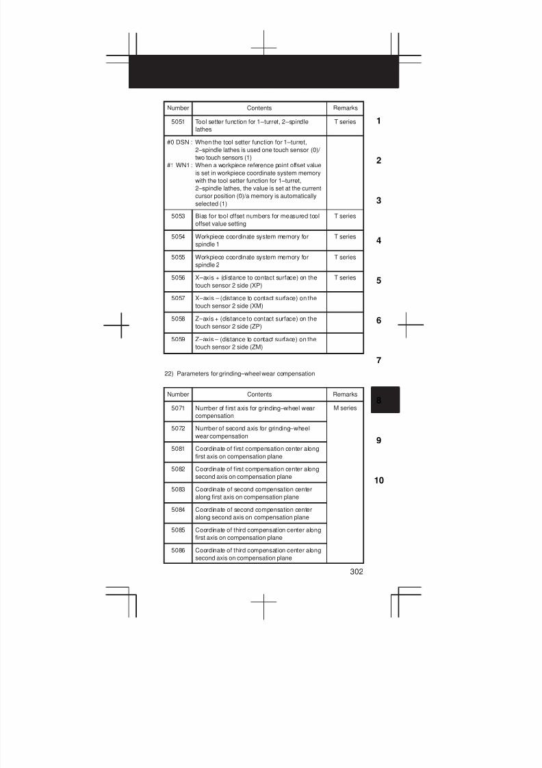
3
1
4
5
6
7
8
9
10
2
302
Number RemarksContents
5051 Tool setter function for 1–turret, 2–spindle
lathes
T series
#0 DSN : When the tool setter function for 1–turret,
2–spindle lathes is used one touch sensor (0)/
two touch sensors (1)
#1 WN1: When a workpiece reference point offset value
is set in workpiece coordinate system memory
with the tool setter function for 1–turret,
2–spindle lathes, the value is set at the current
cursor position (0)/a memory is automatically
selected (1)
5053 Bias for tool offset numbers for measured tool
offset value setting
T series
5054 Workpiece coordinate system memory for
spindle 1
T series
5055 Workpiece coordinate system memory for
spindle 2
T series
5056 X–axis + (distance to contact surface) on the
touch sensor 2 side (XP)
T series
5057 X–axis – (distance to contact surface) on the
touch sensor 2 side (XM)
5058 Z–axis + (distance to contact surface) on the
touch sensor 2 side (ZP)
5059 Z–axis – (distance to contact surface) on the
touch sensor 2 side (ZM)
22) Parameters for grinding–wheel wear compensation
Number Contents Remarks
5071 Number of first axis for grinding–wheel wear
compensation
M series
5072 Number of second axis for grinding–wheel
wear compensation
5081 Coordinate of first compensation center along
first axis on compensation plane
5082 Coordinate of first compensation center along
second axis on compensation plane
5083 Coordinate of second compensation center
along first axis on compensation plane
5084 Coordinate of second compensation center
along second axis on compensation plane
5085 Coordinate of third compensation center along
first axis on compensation plane
5086 Coordinate of third compensation center along
second axis on compensation plane

8. PARAMETERS
303
23) Parameters for canned cycles
Number Contents Remarks
5101 Parameter for canned cycles
#0 FXY : The drilling axis in drilling canned cycle is
always Z axis (0)/an axis selected using
program (1)
#1 EXC : An external operation command (EF) is not
sent out #y G81 (0)/sent out by G81 (1)
#2 RTR : G83 and G87 specify a high-speed peck
drilling cycle (0)/specify a peck drilling cycle (1)
#3 ILV : The initial point position in drilling canned cycle
is not updated by reset (0)/updated by reset (1)
#4 RD1 : Set the axis and direction in which the tool in
G76 and G87 is got free
#5 RD2 : Set the axis and direction in which the tool in
G76 and G87 is got free
#6 M5T : In tapping cycles G74 and G84, not output M05
(0)/output M05 (1) before the spindle rotation
direction is turned to reverse
#6 M5T : In tapping cycles G74 and G84, output M05
(0)/not output M05 (1) before the spindle
rotation direction is turned to reverse
#7 M5B : In drilling canned cycles G76 and G87, output
M05 before an oriented spindle stop (0)/not
output (1)
0
0
1
1
RD2 RD1
0
1
0
1
G17
+X
–X
+Y
–Y
G18
+Z
–Z
+X
–X
G19
+Y
–Y
+Z
–Z
M series
T series
PRM5114
T series
M series
M series
T series
M series
M series
5102 Canned cycle T series
#1 MRC: With G71/72, a command other than for
monotone increase or decrease does not issue
an alarm (0)/issues an alarm (1).
#2 QSR : Before execution of G70 to G73, a Q sequence
number check is not made (0)/made (1).
#3 F16 : In a canned cycle for drilling, the FS15 format
is enabled (0)/disabled (1).
#4 K0E : When K0 is specified in a hole machining
canned cycle (G80 to G89) hole machining is
performed once (0)/hole machining is not
performed (1)
#6 RAB : In the FS15 format, R in a canned cycle for
drilling is incremental (0)/absolute with G code
system A, or depends on G90/G91 for G code
systems B and C (1).
#7 RDI : In the FS15 format, R in a canned cycle for
drilling specifies a radius (0)/axis (1).
ALM 064

3
1
4
5
6
7
8
9
10
2
304
Number RemarksContents
5103 Canned cycle M series
#0 SIJ : In the FS15 format, a shift value in a boring
canned cycle G76 or G86 is specified by
address Q (0)/address I, J, or K (1).
#1 QZA : When the specification of the depth of cut (Q)
for each time is omitted, or if Q0 is specified in
a high–speed peck drilling canned cycle (G73)
or peck drilling canned cycle (G83) no alarm is
issued (0)/an alarm (No.045) is issued (1)
#2 P15 : When the FS15 command format is used, the
machining sequence for pocketing using
multiple repetitive canned cycle G71 or G72
follows FS16 specification (0)/FS15
specification (1)
M series
ALM 045
T series
T sereis
5110 C-axis clamp M code in dr ill ing canned cycle T ser ies
5111 Dwell time when C axis unclamping is specified
in drilling canned cycle
T series
5112 Spindle forward-rotation M code in drilling
canned cycle
T series
5113 Spindle reverse-rotation M code in drilling
canned cycle
T series
5114 Return and clearance of drilling canned cycle
G83
T series
PRM
5101#2
Return of high-speed, peck drilling cycle G73 M series
5115 Clearance of canned cycle G83 M series
5130 Chamfering in thread cutting cycles G76 and
G92
T series
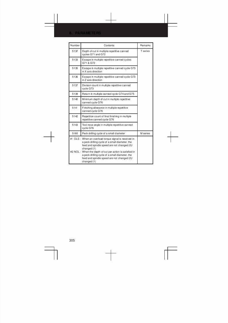
8. PARAMETERS
305
Number RemarksContents
5132 Depth of cut in multiple repetitive canned
cycles G71 and G72
T series
5133 Escape in multiple repetitive canned cycles
G71 & G72
5135 Escape in multiple repetitive canned cycle G73
in X axis direction
5136 Escape in multiple repetitive canned cycle G73
in Z axis direction
5137 Division count in multiple repetitive canned
cycle G73
5139 Return in multiple canned cycle G74 and G75
5140 Minimum depth of cut in multiple repetitive
canned cycle G76
5141 Finishing allowance in multiple repetitive
canned cycle G76
5142 Repetition count of final finishing in multiple
repetitive canned cycle G76
5143 Tool nose angle in multiple repetitive canned
cycle G76
5160 Peck drilling cycle of a small diameter M series
#1 OLS : When an overload torque signal is received in
a peck drilling cycle of a small diameter, the
feed and spindle speed are not changed (0)/
changed (1)
#2 NOL : When the depth of cut per action is satisfied in
a peck drilling cycle of a small diameter, the
feed and spindle speed are not changed (0)/
changed (1)
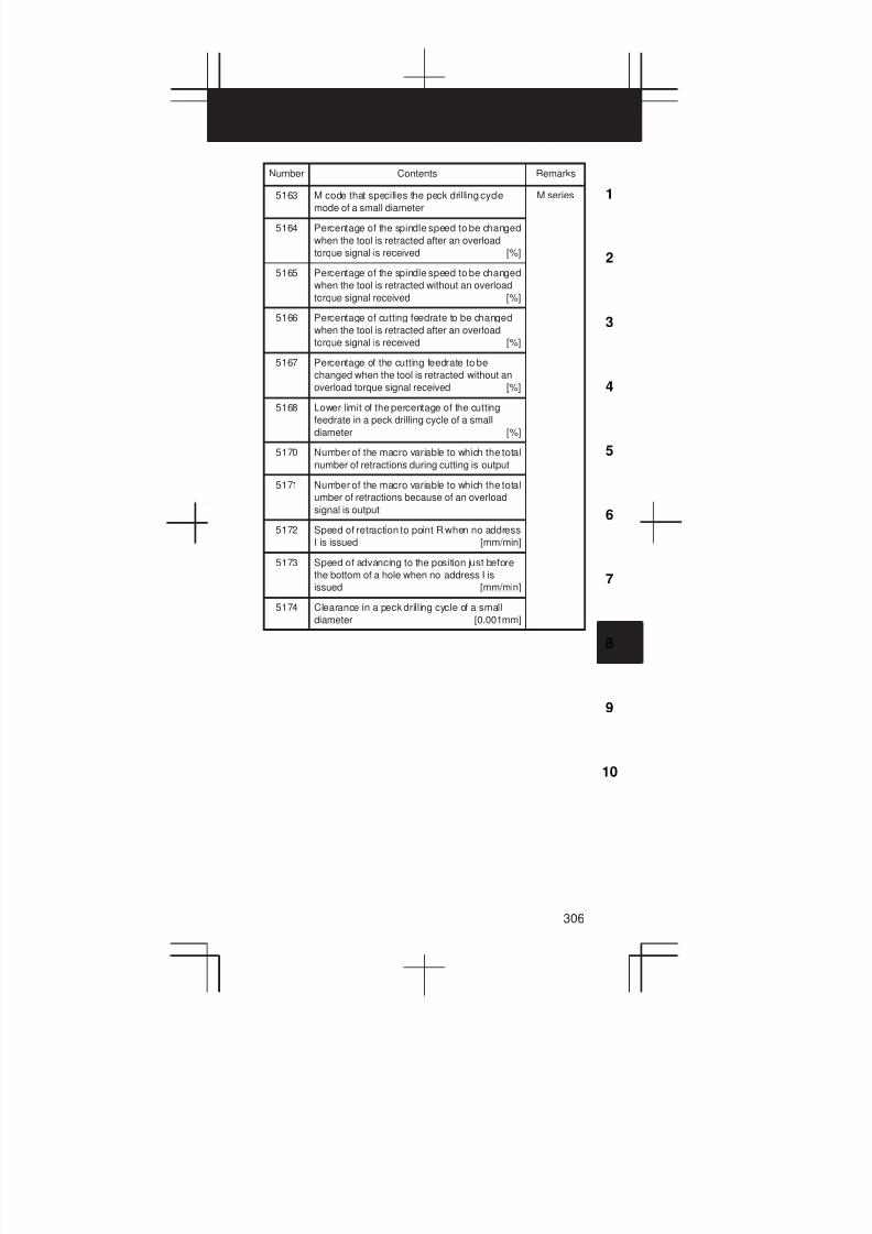
3
1
4
5
6
7
8
9
10
2
306
Number RemarksContents
5163 M code that specifies the peck drilling cycle
mode of a small diameter
M series
5164 Percentage of the spindle speed to be changed
when the tool is retracted after an overload
torque signal is received [%]
5165 Percentage of the spindle speed to be changed
when the tool is retracted without an overload
torque signal received [%]
5166 Percentage of cutting feedrate to be changed
when the tool is retracted after an overload
torque signal is received [%]
5167 Percentage of the cutting feedrate to be
changed when the tool is retracted without an
overload torque signal received [%]
5168 Lower limit of the percentage of the cutting
feedrate in a peck drilling cycle of a small
diameter [%]
5170 Number of the macro variable to which the total
number of retractions during cutting is output
5171 Number of the macro variable to which the total
umber of retractions because of an overload
signal is output
5172 Speed of retraction to point R when no address
I is issued [mm/min]
5173 Speed of advancing to the position just before
the bottom of a hole when no address I is
issued [mm/min]
5174 Clearance in a peck drilling cycle of a small
diameter [0.001mm]
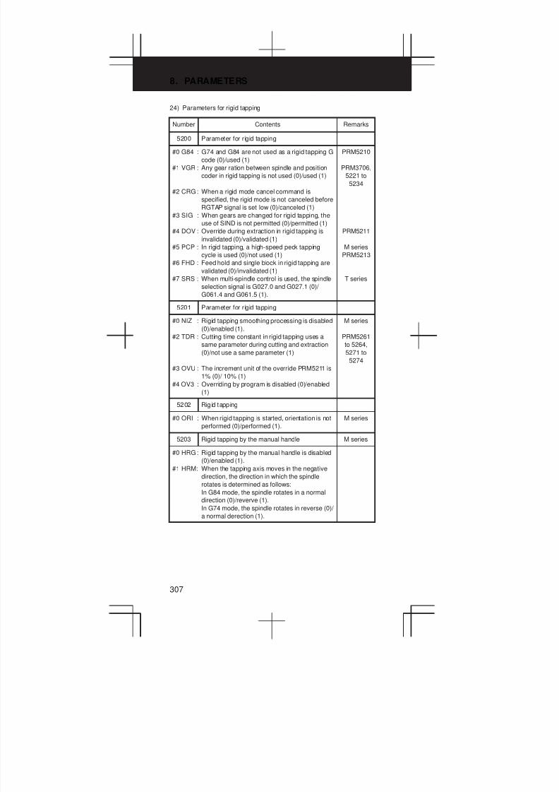
8. PARAMETERS
307
24) Parameters for rigid tapping
Number Contents Remarks
5200 Parameter for rigid tapping
#0 G84 : G74 and G84 are not used as a rigid tapping G
code (0)/used (1)
#1 VGR : Any gear ration between spindle and position
coder in rigid tapping is not used (0)/used (1)
#2 CRG: When a rigid mode cancel command is
specified, the rigid mode is not canceled before
RGTAP signal is set low (0)/canceled (1)
#3 SIG : When gears are changed for rigid tapping, the
use of SIND is not permitted (0)/permitted (1)
#4 DOV : Override during extraction in rigid tapping is
invalidated (0)/validated (1)
#5 PCP : In rigid tapping, a high-speed peck tapping
cycle is used (0)/not used (1)
#6 FHD : Feed hold and single block in rigid tapping are
validated (0)/invalidated (1)
#7 SRS : When multi-spindle control is used, the spindle
selection signal is G027.0 and G027.1 (0)/
G061.4 and G061.5 (1).
PRM5210
PRM3706,
5221 to
5234
PRM5211
M series
PRM5213
T series
5201 Parameter for rigid tapping
#0 NIZ : Rigid tapping smoothing processing is disabled
(0)/enabled (1).
#2 TDR : Cutting time constant in rigid tapping uses a
same parameter during cutting and extraction
(0)/not use a same parameter (1)
#3 OVU : The increment unit of the override PRM5211 is
1% (0)/ 10% (1)
#4 OV3 : Overriding by program is disabled (0)/enabled
(1)
M series
PRM5261
to 5264,
5271 to
5274
5202 Rigid tapping
#0 ORI : When rigid tapping is started, orientation is not
performed (0)/performed (1).
M series
5203 Rigid tapping by the manual handle M series
#0 HRG: Rigid tapping by the manual handle is disabled
(0)/enabled (1).
#1 HRM: When the tapping axis moves in the negative
direction, the direction in which the spindle
rotates is determined as follows:
In G84 mode, the spindle rotates in a normal
direction (0)/reverve (1).
In G74 mode, the spindle rotates in reverse (0)/
a normal derection (1).
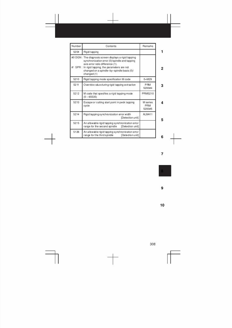
3
1
4
5
6
7
8
9
10
2
308
Number RemarksContents
5204 Rigid tapping
#0 DGN: The diagnosis screen displays a rigid tapping
synchronization error (0)/spindle and tapping
axis error ratio difference (1).
#1 SPR : In rigid tapping, the parameters are not
changed on a spindle–by–spindle basis (0)/
changed (1)
5210 Rigid tapping mode specification M code 0=M29
5211 Override value during r igid tapping extraction PRM
5200#4
5212 M code that specifies a rigid tapping mode
(0 – 65535)
PRM5210
5213 Escape or cutting start point in peck tapping
cycle
M series
PRM
5200#5
5214 Rigid tapping synchronization error width
[Detection unit]
ALM411
5215 An allowable rigid tapping synchronization error
range for the second spindle [Detection unit]
5126 An allowable rigid tapping synchronization error
range for the third spindle [Detection unit]
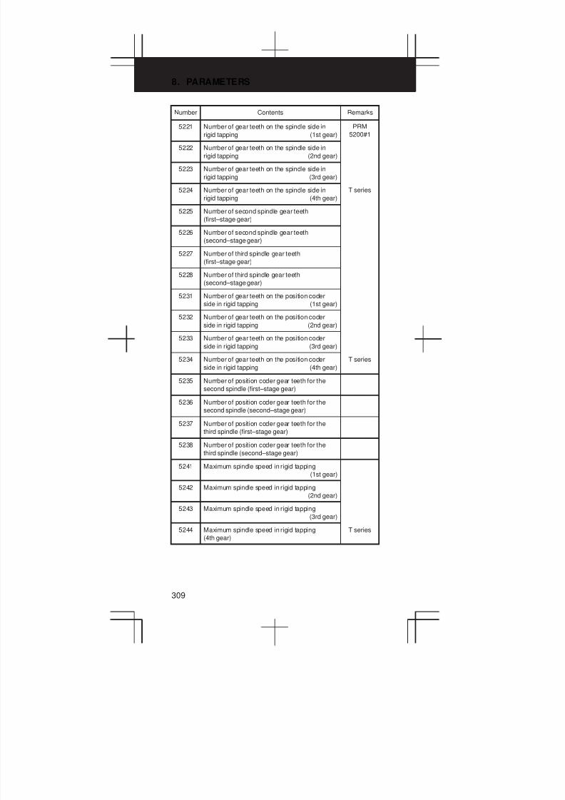
8. PARAMETERS
309
Number RemarksContents
5221 Number of gear teeth on the spindle side in
rigid tapping (1st gear)
PRM
5200#1
5222 Number of gear teeth on the spindle side in
rigid tapping (2nd gear)
5223 Number of gear teeth on the spindle side in
rigid tapping (3rd gear)
5224 Number of gear teeth on the spindle side in
rigid tapping (4th gear)
T series
5225 Number of second spindle gear teeth
(first–stage gear)
5226 Number of second spindle gear teeth
(second–stage gear)
5227 Number of third spindle gear teeth
(first–stage gear)
5228 Number of third spindle gear teeth
(second–stage gear)
5231 Number of gear teeth on the position coder
side in rigid tapping (1st gear)
5232 Number of gear teeth on the position coder
side in rigid tapping (2nd gear)
5233 Number of gear teeth on the position coder
side in rigid tapping (3rd gear)
5234 Number of gear teeth on the position coder
side in rigid tapping (4th gear)
T series
5235 Number of position coder gear teeth for the
second spindle (first–stage gear)
5236 Number of position coder gear teeth for the
second spindle (second–stage gear)
5237 Number of position coder gear teeth for the
third spindle (first–stage gear)
5238 Number of position coder gear teeth for the
third spindle (second–stage gear)
5241 Maximum spindle speed in rigid tapping
(1st gear)
5242 Maximum spindle speed in rigid tapping
(2nd gear)
5243 Maximum spindle speed in rigid tapping
(3rd gear)
5244 Maximum spindle speed in rigid tapping
(4th gear)
T series

3
1
4
5
6
7
8
9
10
2
310
Number RemarksContents
5245 Maximum spindle speed in rigid tapping using
the second spindle (first–stage gear)
5246 Maximum spindle speed in rigid tapping using the
second spindle (second–stage gear)
5247 Maximum spindle speed in rigid tapping using
the third spindle (first–stage gear)
5248 Maximum spindle speed in rigid tapping using
the third spindle (second–stage gear)
5261 Linear acceleration/deceleration time constant
for the spindle and tapping axis
(first–stage gear)
PRM
5201#2
5262 Linear acceleration/deceleration time constant
for the spindle and tapping axis
(second–stage gear)
5263 Linear acceleration/deceleration time constant
for the spindle and tapping axis
(third–stage gear)
5264 Linear acceleration/deceleration time constant
for the spindle and tapping axis
(fourth–stage gear)
T series
5271 Time constant for the spindle and tapping axis in
extraction operation (first–stage gear) [ms]
PRM
5201#2
5272 Time constant for the spindle and tapping axis
in extraction operation (second–stage gear)
[ms]
5273 Time constant for the spindle and tapping axis in
extraction operation (third–stage gear) [ms]
5274 Time constant for the spindle and tapping axis
in extraction operation (fourth–stage gear) [ms]
T series
5280 Position control loop gain of spindle and
tapping axis in rigid tapping
(Common in each gear)
PRM5281
to 5284
5281 Position control loop gain of spindle and
tapping axis in rigid tapping (1st gear)
PRM
5280=0
5282 Position control loop gain of spindle and
tapping axis in rigid tapping (2nd gear)
5283 Position control loop gain of spindle and
tapping axis in rigid tapping (3rd gear)
5284 Position control loop gain of spindle and
tapping axis in rigid tapping (4th gear)
T series
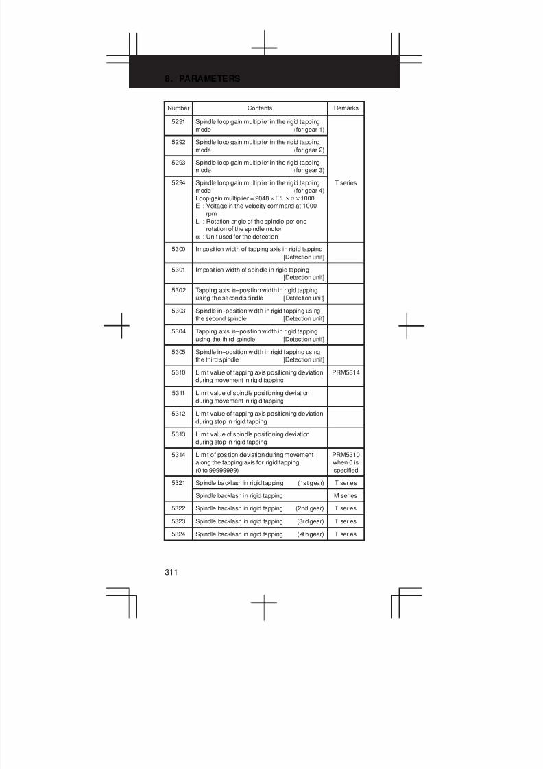
8. PARAMETERS
311
Number RemarksContents
5291 Spindle loop gain multiplier in the rigid tapping
mode (for gear 1)
5292 Spindle loop gain multiplier in the rigid tapping
mode (for gear 2)
5293 Spindle loop gain multiplier in the rigid tapping
mode (for gear 3)
5294 Spindle loop gain multiplier in the rigid tapping
mode (for gear 4)
Loop gain multiplier = 2048E/Lα1000
E : Voltage in the velocity command at 1000
rpm
L : Rotation angle of the spindle per one
rotation of the spindle motor
α : Unit used for the detection
T series
5300 Imposition width of tapping axis in rigid tapping
[Detection unit]
5301 Imposition width of spindle in rigid tapping
[Detection unit]
5302 Tapping axis in–position width in rigid tapping
using the second spindle [Detection unit]
5303 Spindle in–position width in rigid tapping using
the second spindle [Detection unit]
5304 Tapping axis in–position width in rigid tapping
using the third spindle [Detection unit]
5305 Spindle in–position width in rigid tapping using
the third spindle [Detection unit]
5310 Limit value of tapping axis positioning deviation
during movement in rigid tapping
PRM5314
5311 Limit value of spindle positioning deviation
during movement in rigid tapping
5312 Limit value of tapping axis positioning deviation
during stop in rigid tapping
5313 Limit value of spindle positioning deviation
during stop in rigid tapping
5314 Limit of position deviation during movement
along the tapping axis for rigid tapping
(0 to 99999999)
PRM5310
when 0 is
specified
5321 Spindle backlash in rigid tapping (1st gear) T ser ies
Spindle backlash in rigid tapping M series
5322 Spindle backlash in rigid tapping (2nd gear) T ser ies
5323 Spindle backlash in rigid tapping (3rd gear) T ser ies
5324 Spindle backlash in rigid tapping (4th gear) T ser ies
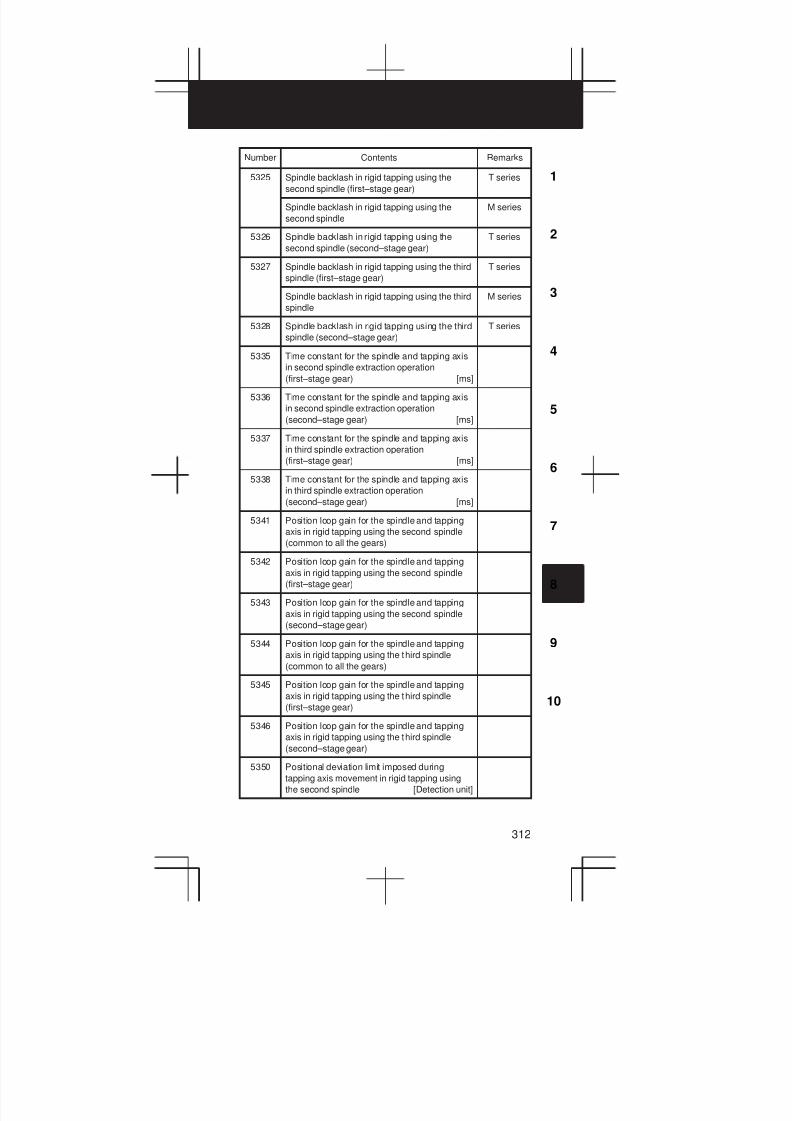
3
1
4
5
6
7
8
9
10
2
312
Number RemarksContents
5325 Spindle backlash in rigid tapping using the
second spindle (first–stage gear)
T series
Spindle backlash in rigid tapping using the
second spindle
M series
5326 Spindle backlash in rigid tapping using the
second spindle (second–stage gear)
T series
5327 Spindle backlash in rigid tapping using the third
spindle (first–stage gear)
T series
Spindle backlash in rigid tapping using the third
spindle
M series
5328 Spindle backlash in rigid tapping using the third
spindle (second–stage gear)
T series
5335 Time constant for the spindle and tapping axis
in second spindle extraction operation
(first–stage gear) [ms]
5336 Time constant for the spindle and tapping axis
in second spindle extraction operation
(second–stage gear) [ms]
5337 Time constant for the spindle and tapping axis
in third spindle extraction operation
(first–stage gear) [ms]
5338 Time constant for the spindle and tapping axis
in third spindle extraction operation
(second–stage gear) [ms]
5341 Position loop gain for the spindle and tapping
axis in rigid tapping using the second spindle
(common to all the gears)
5342 Position loop gain for the spindle and tapping
axis in rigid tapping using the second spindle
(first–stage gear)
5343 Position loop gain for the spindle and tapping
axis in rigid tapping using the second spindle
(second–stage gear)
5344 Position loop gain for the spindle and tapping
axis in rigid tapping using the third spindle
(common to all the gears)
5345 Position loop gain for the spindle and tapping
axis in rigid tapping using the third spindle
(first–stage gear)
5346 Position loop gain for the spindle and tapping
axis in rigid tapping using the third spindle
(second–stage gear)
5350 Positional deviation limit imposed during
tapping axis movement in rigid tapping using
the second spindle [Detection unit]
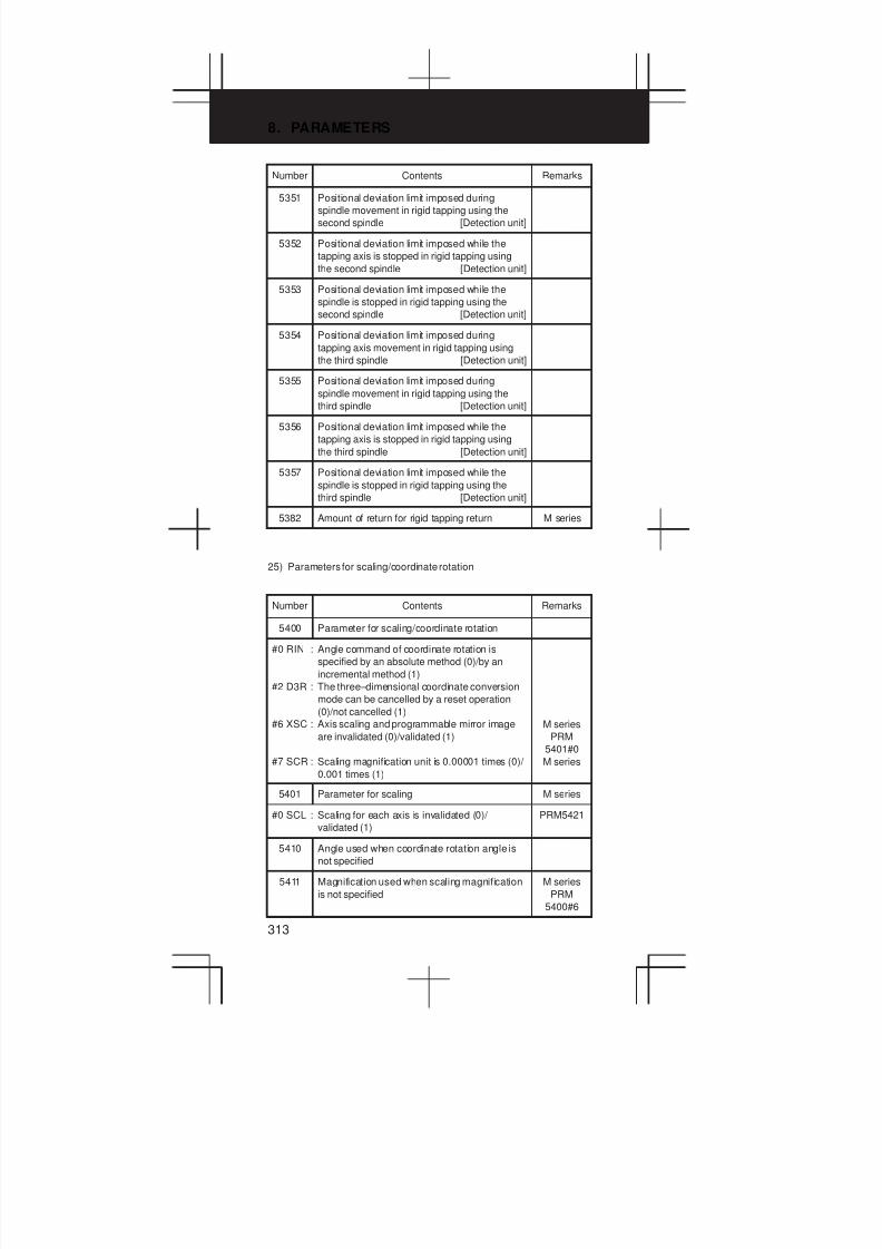
8. PARAMETERS
313
Number RemarksContents
5351 Positional deviation limit imposed during
spindle movement in rigid tapping using the
second spindle [Detection unit]
5352 Positional deviation limit imposed while the
tapping axis is stopped in rigid tapping using
the second spindle [Detection unit]
5353 Positional deviation limit imposed while the
spindle is stopped in rigid tapping using the
second spindle [Detection unit]
5354 Positional deviation limit imposed during
tapping axis movement in rigid tapping using
the third spindle [Detection unit]
5355 Positional deviation limit imposed during
spindle movement in rigid tapping using the
third spindle [Detection unit]
5356 Positional deviation limit imposed while the
tapping axis is stopped in rigid tapping using
the third spindle [Detection unit]
5357 Positional deviation limit imposed while the
spindle is stopped in rigid tapping using the
third spindle [Detection unit]
5382 Amount of return for rigid tapping return M series
25) Parameters for scaling/coordinate rotation
Number Contents Remarks
5400 Parameter for scaling/coordinate rotation
#0 RIN : Angle command of coordinate rotation is
specified by an absolute method (0)/by an
incremental method (1)
#2 D3R : The three–dimensional coordinate conversion
mode can be cancelled by a reset operation
(0)/not cancelled (1)
#6 XSC : Axis scaling and programmable mirror image
are invalidated (0)/validated (1)
#7 SCR : Scaling magnification unit is 0.00001 times (0)/
0.001 times (1)
M series
PRM
5401#0
M series
5401 Parameter for scaling M series
#0 SCL : Scaling for each axis is invalidated (0)/
validated (1)
PRM5421
5410 Angle used when coordinate rotation angle is
not specified
5411 Magnification used when scaling magnification
is not specified
M series
PRM
5400#6
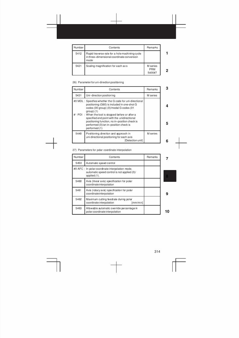
3
1
4
5
6
7
8
9
10
2
314
Number RemarksContents
5412 Rapid traverse rate for a hole machining cycle
in three–dimensional coordinate conversion
mode
5421 Scaling magnification for each axis M series
PRM
5400#7
26) Parameter for uni-direction positioning
Number Contents Remarks
5431 Uni–direction positioning M series
#0 MDL : Specifies whether the G code for uni-directional
positioning (G60) is included in one-shot G
codes (00 group) (0)/modal G codes (01
group) (1)
#1 PDI : When the tool is stopped before or after a
specified end point with the unidirectional
positioning function, no in–position check is
performed (0)/an in–position check is
performed (1)
5440 Positioning direction and approach in
uni-directional positioning for each axis
[Detection unit]
M series
27) Parameters for polar coordinate interpolation
Number Contents Remarks
5450 Automatic speed control
#0 AFC : In polar coordinate interpolation mode,
automatic speed control is not applied (0)/
applied (1).
5460 Axis (linear axis) specification for polar
coordinate interpolation
5461 Axis (rotary axis) specification for polar
coordinate interpolation
5462 Maximum cutting feedrate during polar
coordinate interpolation [mm/min]
5463 Allowable automatic override percentage in
polar coordinate interpolation
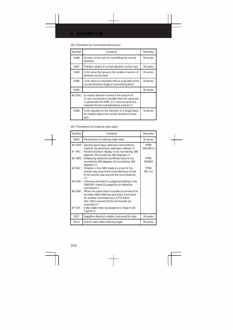
8. PARAMETERS
315
28) Parameter for normal direction control
Number Contents Remarks
5480 Number of the axis for controlling the normal
direction
M series
5481 Rotation speed of normal direction control axis M series
5482 Limit value that ignores the rotation insertion of
direction control axis
M series
5483 Limit value of movement that is executed at the
normal direction angle of a preceding block
M series
5484 M series
#0 SDC : In normal direction control if the amount of
C–axis movement is smaller than the value set
in parameter No.5485, a C–axis movement is
inserted (0)/not inserted before a block (1)
5485 Limit imposed on the insertion of a single block
for rotation about the normal direction control
axis
M series
29) Parameters for indexing index table
Number Contents Remarks
5500 Parameters of indexing index table M series
#0 DDP : Decimal point input method is conventional
method (0)/electronic calculator method (1)
#1 REL : Relative position display is not rounded by 360
degrees (0)/rounded by 360 degrees (1)
#2 ABS : Displaying absolute coordinate value is not
rounded by 360 degrees (0)/rounded by 360
degrees (1)
#3 INC : Rotation in the G90 mode is not set to the
shorter way around the circumference (0)/set
to the shorter way around the circumference
(1)
#4 G90 : Indexing command is judged according to the
G90/G91 mode (0)/judged by an absolute
command (1)
#6 SIM : When the same block includes a command for
an index table indexing axis and a command
for another controlled axis, a P/S alarm
(No.136) is issued (0)/the commands are
executed (1)
#7 IDX : Index table indexing sequence is Type A (0)/
Type B (1)
PRM
3401#0=0
PRM
5500#3
PRM
5511=0
5511 Negative-direction rotation command M code M series
5512 Unit of index table indexing angle M series
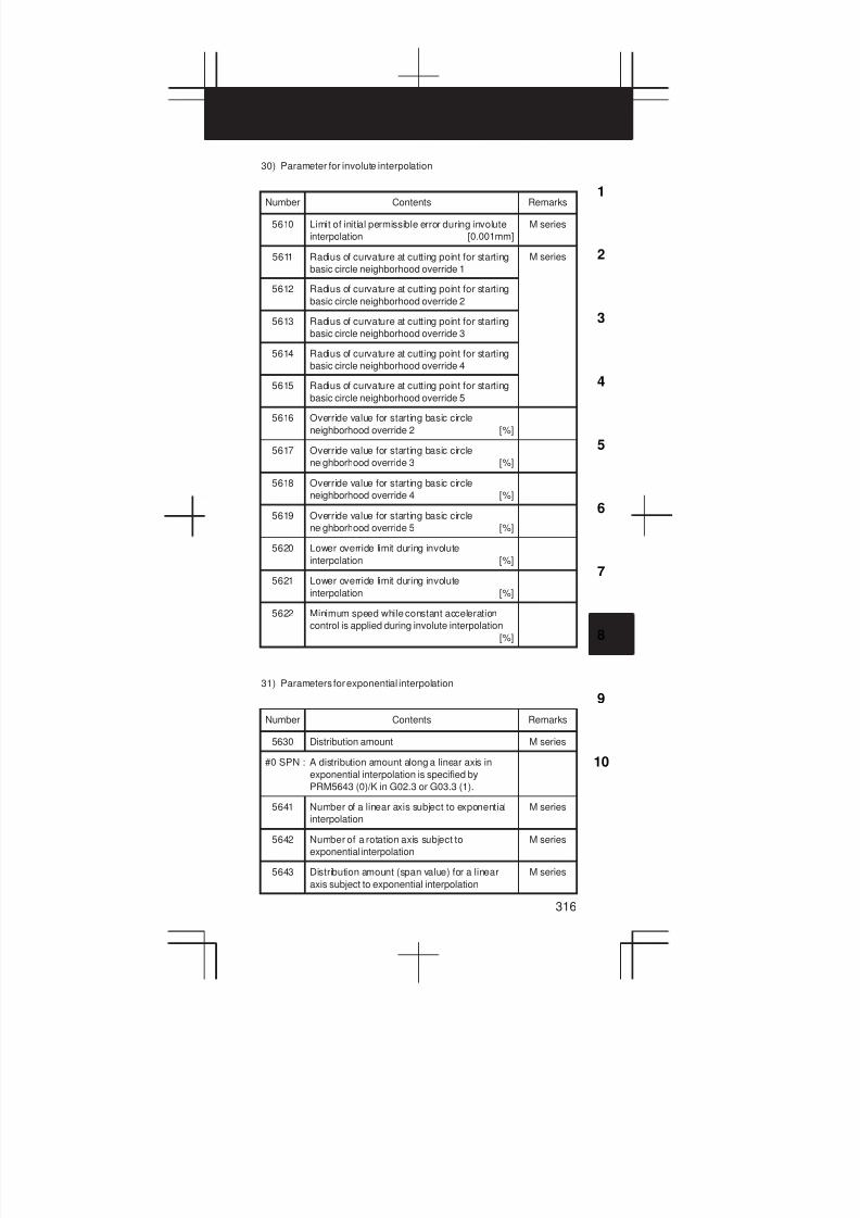
3
1
4
5
6
7
8
9
10
2
316
30) Parameter for involute interpolation
Number Contents Remarks
5610 Limit of initial permissible error during involute
interpolation [0.001mm]
M series
5611 Radius of curvature at cutting point for starting
basic circle neighborhood override 1
M series
5612 Radius of curvature at cutting point for starting
basic circle neighborhood override 2
5613 Radius of curvature at cutting point for starting
basic circle neighborhood override 3
5614 Radius of curvature at cutting point for starting
basic circle neighborhood override 4
5615 Radius of curvature at cutting point for starting
basic circle neighborhood override 5
5616 Override value for starting basic circle
neighborhood override 2 [%]
5617 Override value for starting basic circle
neighborhood override 3 [%]
5618 Override value for starting basic circle
neighborhood override 4 [%]
5619 Override value for starting basic circle
neighborhood override 5 [%]
5620 Lower override limit during involute
interpolation [%]
5621 Lower override limit during involute
interpolation [%]
5622 Minimum speed while constant acceleration
control is applied during involute interpolation
[%]
31) Parameters for exponential interpolation
Number Contents Remarks
5630 Distribution amount M series
#0 SPN : A distribution amount along a linear axis in
exponential interpolation is specified by
PRM5643 (0)/K in G02.3 or G03.3 (1).
5641 Number of a linear axis subject to exponential
interpolation
M series
5642 Number of a rotation axis subject to
exponential interpolation
M series
5643 Distribution amount (span value) for a linear
axis subject to exponential interpolation
M series

8. PARAMETERS
317
32) Parameters for straightness compensation
Number Contents Remarks
5711 Axis number of moving axis 1
5712 Axis number of moving axis 2
5713 Axis number of moving axis 3
5721 Axis number of compensation axis 1 for moving
axis 1
5722 Axis number of compensation axis 2 for moving
axis 2
5723 Axis number of compensation axis 3 for moving
axis 3
5731 Compensation point number a of moving axis 1
5732 Compensation point number b of moving axis 1
5733 Compensation point number c of moving axis 1
5734 Compensation point number d of moving axis 1
5741 Compensation point number a of moving axis 2
5742 Compensation point number b of moving axis 2
5743 Compensation point number c of moving axis 2
5744 Compensation point number d of moving axis 2
5751 Compensation point number a of moving axis 3
5752 Compensation point number b of moving axis 3
5753 Compensation point number c of moving axis 3
5754 Compensation point number d of moving axis 3
5761 Compensation corresponding compensation
point number a of moving axis 1
5762 Compensation corresponding compensation
point number b of moving axis 1
5763 Compensation corresponding compensation
point number c of moving axis 1
5764 Compensation corresponding compensation
point number d of moving axis 1
5771 Compensation corresponding compensation
point number a of moving axis 2
5772 Compensation corresponding compensation
point number b of moving axis 2
5773 Compensation corresponding compensation
point number c of moving axis 2
5774 Compensation corresponding compensation
point number d of moving axis 2
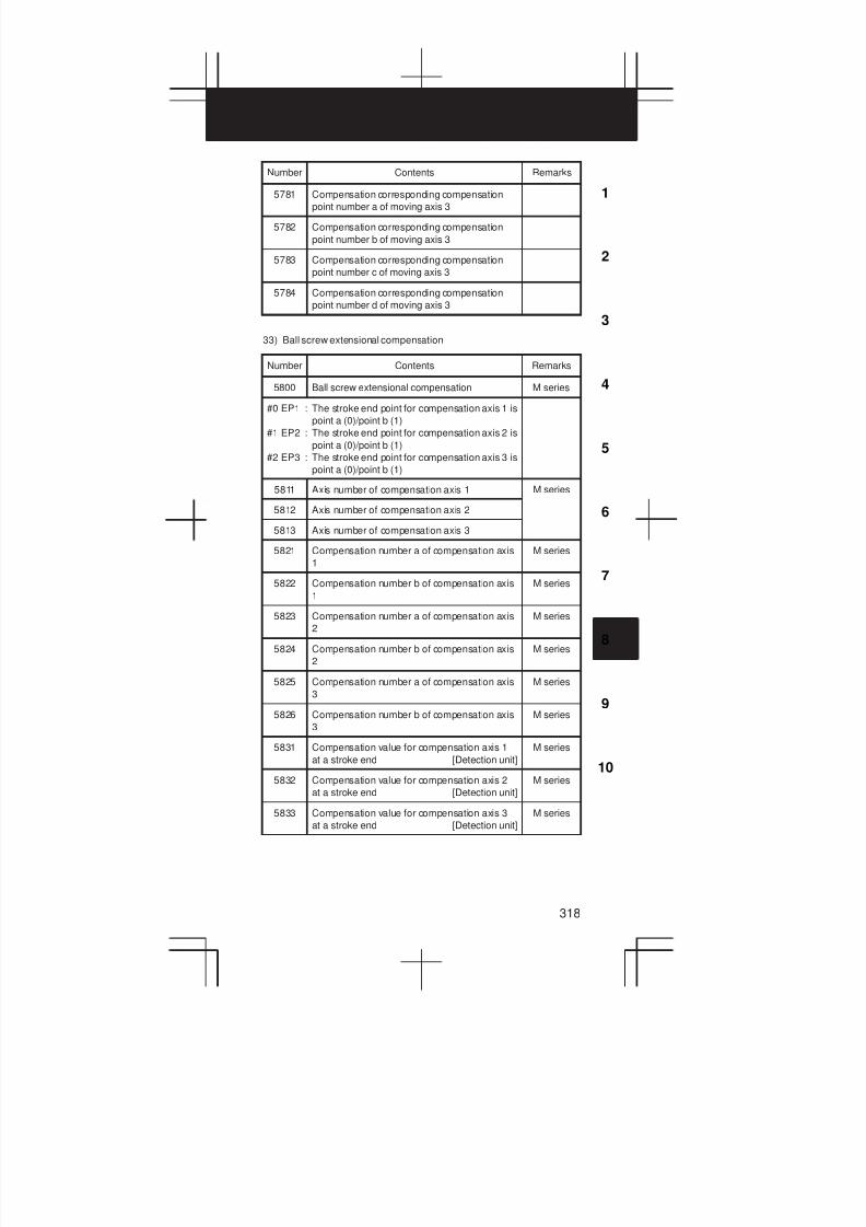
3
1
4
5
6
7
8
9
10
2
318
Number RemarksContents
5781 Compensation corresponding compensation
point number a of moving axis 3
5782 Compensation corresponding compensation
point number b of moving axis 3
5783 Compensation corresponding compensation
point number c of moving axis 3
5784 Compensation corresponding compensation
point number d of moving axis 3
33) Ball screw extensional compensation
Number Contents Remarks
5800 Ball screw extensional compensation M series
#0 EP1 : The stroke end point for compensation axis 1 is
point a (0)/point b (1)
#1 EP2 : The stroke end point for compensation axis 2 is
point a (0)/point b (1)
#2 EP3 : The stroke end point for compensation axis 3 is
point a (0)/point b (1)
5811 Axis number of compensation axis 1 M series
5812 Axis number of compensation axis 2
5813 Axis number of compensation axis 3
5821 Compensation number a of compensation axis
1
M series
5822 Compensation number b of compensation axis
1
M series
5823 Compensation number a of compensation axis
2
M series
5824 Compensation number b of compensation axis
2
M series
5825 Compensation number a of compensation axis
3
M series
5826 Compensation number b of compensation axis
3
M series
5831 Compensation value for compensation axis 1
at a stroke end [Detection unit]
M series
5832 Compensation value for compensation axis 2
at a stroke end [Detection unit]
M series
5833 Compensation value for compensation axis 3
at a stroke end [Detection unit]
M series

8. PARAMETERS
319
34) Parameters for custom macro
Number Contents Remarks
6000 Parameter for custom macro
#0 G67 : A G67 specified in modal call cancel mode
issues an alarm (0)/is ignored (1).
#1 MGO: When a GOTO statement is executed, a
high–speed branch to 20 sequence numbers
executed from the start of the program is, a
high–speed branch is not caused (0)/a
high–speed branch is caused (1)
#3 V15 : The system variables for tool compensation
are the standard those used with FS16 (0)/
FS15 (1).
#4 HGO: When a GOTO statement is executed a
high–speed branch is not caused (0)/a
high–speed branch is caused (1)
#5 SBM : In the custom macro statement, the single
block stop is not valid (0)/valid (1)
M series
6001 Parameter for custom macro
#1 PRT : When data is output using a DPRINT
command, outputs a space for reading zero
(0)/outputs no data (1)
#3 PV5 : The output macro variables are #500 and up
(0)/#100 and up and #500 and up (1).
#4 CRO: When ISO code is used in the B/D PRINT
mode, output only “LF” (0)/output “LF” and
“CR” (1)
#5 TCS : Custom macro is not called using a T code (0)/
called (1)
#6 CCV : Common variables #100 through #149 (to 199)
are cleared to “vacant” by reset (0)/not cleared
by reset (1)
#7 CLV : Local variables #1 through #33 are cleared to
“vacant” by reset (0)/not cleared by reset (1)
O9000
6003 Parameter for custom macro
#1 MSK : Absolute coordinate during custom macro
interrupt is not set to the skip coordinate (0)/set
(1)
#2 MIN : Custom macro interrupt is Type I (0)/Type II (1)
#3 TSE : Interrupt signal UNIT uses edge trigger method
(0)/status trigger method (1)
#4 MPR: M code for custom macro interrupt valid/invalid
is standard (M96/M97) (0)/using parameter
setting (1)
#5 MSB : The local variable of interrupt program is
macrotype (0)/subprogram type (1)
#6 MCY: Custom macro interrupt during cycle operation
is not performed (0)/performed (1)
#7 MUS: Interrupt-type custom macro is not used (0)/
used (1)
M96:
PRM6033
to 6034

3
1
4
5
6
7
8
9
10
2
320
Number RemarksContents
6004 Result of ATAN, ASIN
#0 NAT : Specification of the results of custom macro
functions ATAN and ASIN ATAN = 0 to 360.0
ASIN = 270.0 to 0 to 90.0 (0)/ATAN = –180 to 0
to 180.0 ASIN = –90.0 to 0 to 90.0 (1)
#2 VHD : With system variables #5121 through #5128
tool position offset values (geometry offset
values) are read (0)/the amount of interrupt
shift caused by a manual handle interrupt is
read (1)
#5 DI5 : When tool compensation memory C is used,
for reading or writing tool offset values (for up
to offset number 200) for D code (tool radius),
the same system variables, #2401 through
#2800, as Series 15 are not used (0)/used (1)
T series
M series
6010 Setting of hole pattern “*” of EIA code (*0 to *7)
6011 Setting of hole pattern “=” of EIA code
(=0 to =7)
6012 Setting of hole pattern “#” of EIA code
(#0 to #7)
6013 Setting of hole pattern “ [ ” of EIA code ([0 to [7)
6014 Setting of hole pattern “ ] ” of EIA code (]0 to ]7)
6030 M code that calls the program entered in file M198
6033 M code that validates a custom macro interrupt PRM
6034 M code that invalidates a custom macro
interrupt
=
6036 Number of custom macro valiables common to
paths (100 - 199)
T series
(2-path
control)
6037 Number of custom macro valiables common to
paths (500 - 599)
T series
(2-path
control)
6050 G code that calls the custom macro of program
number 9010
6051 G code that calls the custom macro of program
number 9011
6052 G code that calls the custom macro of program
number 9012
6053 G code that calls the custom macro of program
number 9013
6054 G code that calls the custom macro of program
number 9014
6055 G code that calls the custom macro of program
number 9015
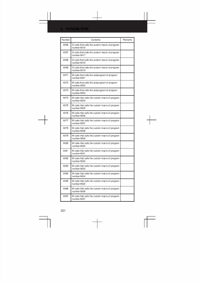
8. PARAMETERS
321
Number RemarksContents
6056 G code that calls the custom macro of program
number 9016
6057 G code that calls the custom macro of program
number 9017
6058 G code that calls the custom macro of program
number 9018
6059 G code that calls the custom macro of program
number 9019
6071 M code that calls the subprogram of program
number 9001
6072 M code that calls the subprogram of program
number 9002
6073 M code that calls the subprogram of program
number 9003
6074 M code that calls the custom macro of program
number 9004
6075 M code that calls the custom macro of program
number 9005
6076 M code that calls the custom macro of program
number 9006
6077 M code that calls the custom macro of program
number 9007
6078 M code that calls the custom macro of program
number 9008
6079 M code that calls the custom macro of program
number 9009
6080 M code that calls the custom macro of program
number 9020
6081 M code that calls the custom macro of program
number 9021
6082 M code that calls the custom macro of program
number 9022
6083 M code that calls the custom macro of program
number 9023
6084 M code that calls the custom macro of program
number 9024
6085 M code that calls the custom macro of program
number 9025
6086 M code that calls the custom macro of program
number 9026
6087 M code that calls the custom macro of program
number 9027

3
1
4
5
6
7
8
9
10
2
322
Number RemarksContents
6088 M code that calls the custom macro of program
number 9028
6089 M code that calls the custom macro of program
number 9029
6090 ASCII code that calls the subprogram of
program number 9004
6091 ASCII code that calls the subprogram of
program number 9005
35) Parameters for pattern data input
Number Contents Remarks
6101 First variable number displayed on pattern data
screen 1
6102 First variable number displayed on pattern data
screen 2
6103 First variable number displayed on pattern data
screen 3
6104 First variable number displayed on pattern data
screen 4
6105 First variable number displayed on pattern data
screen 5
6106 First variable number displayed on pattern data
screen 6
6107 First variable number displayed on pattern data
screen 7
6108 First variable number displayed on pattern data
screen 8
6109 First variable number displayed on pattern data
screen 9
6110 First variable number displayed on pattern data
screen 10
36) Positioning by optimul acceleration
Number Contents Remarks
6131 Positioning by optimul acceleration
#0 OAD : The function for positioning by optimul
acceleration is used (0)/not used (1)
6141 Distance D1 for level 1 (metric input)
6142 Distance D2 for level 2 (metric input)
6143 Distance D3 for level 3 (metric input)
6144 Distance D4 for level 4 (metric input)
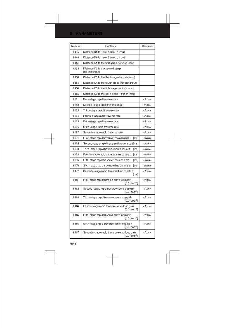
8. PARAMETERS
323
Number RemarksContents
6145 Distance D5 for level 5 (metric input)
6146 Distance D6 for level 6 (metric input)
6151 Distance D1 to the first stage (for inch input)
6152 Distance D2 to the second stage
(for inch input)
6153 Distance D3 to the third stage (for inch input)
6154 Distance D4 to the fourth stage (for inch input)
6155 Distance D5 to the fifth stage (for inch input)
6156 Distance D6 to the sixth stage (for inch input)
6161 First–stage rapid traverse rate <Axis>
6162 Second–stage rapid traverse rate <Axis>
6163 Third–stage rapid traverse rate <Axis>
6164 Fourth–stage rapid traverse rate <Axis>
6165 Fifth–stage rapid traverse rate <Axis>
6166 Sixth–stage rapid traverse rate <Axis>
6167 Seventh–stage rapid traverse rate <Axis>
6171 First–stage rapid traverse t ime constant [ms] <Axis>
6172 Second–stage rapid traverse time constant[ms] <Axis>
6173 Third–stage rapid traverse t ime constant [ms] <Axis>
6174 Fourth–stage rapid traverse time constant [ms] <Axis>
6175 Fifth–stage rapid traverse t ime constant [ms] <Axis>
6176 Sixth–stage rapid traverse t ime constant [ms] <Axis>
6177 Seventh–stage rapid traverse time constant
[ms]
<Axis>
6181 First–stage rapid traverse servo loop gain
[0.01sec –1]
<Axis>
6182 Second–stage rapid traverse servo loop gain
[0.01sec –1]
<Axis>
6183 Third–stage rapid traverse servo loop gain
[0.01sec –1]
<Axis>
6184 Fourth–stage rapid traverse servo loop gain
[0.01sec –1]
<Axis>
6185 Fifth–stage rapid traverse servo loop gain
[0.01sec –1]
<Axis>
6186 Sixth–stage rapid traverse servo loop gain
[0.01sec –1]
<Axis>
6187 Seventh–stage rapid traverse servo loop gain
[0.01sec –1]
<Axis>
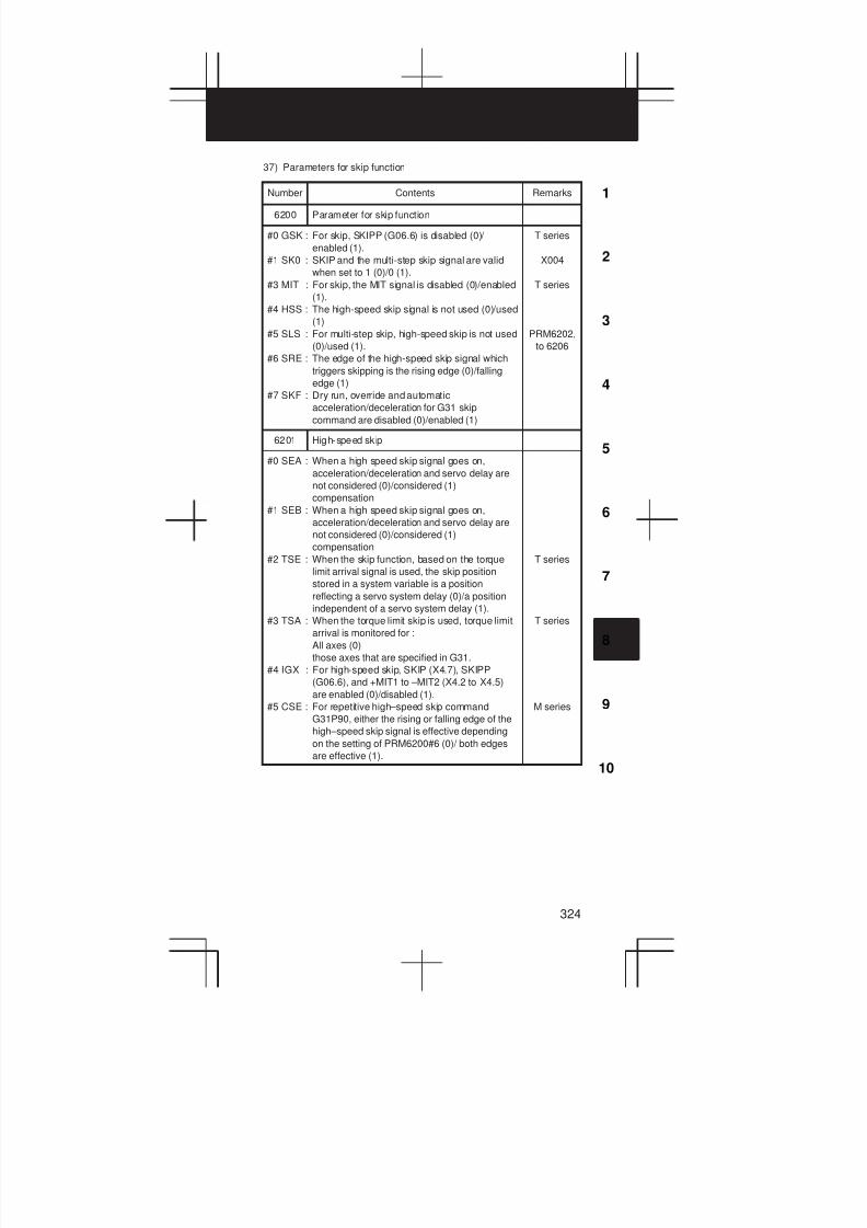
3
1
4
5
6
7
8
9
10
2
324
37) Parameters for skip function
Number Contents Remarks
6200 Parameter for skip function
#0 GSK : For skip, SKIPP (G06.6) is disabled (0)/
enabled (1).
#1 SK0 : SKIP and the multi-step skip signal are valid
when set to 1 (0)/0 (1).
#3 MIT : For skip, the MIT signal is disabled (0)/enabled
(1).
#4 HSS : The high-speed skip signal is not used (0)/used
(1)
#5 SLS : For multi-step skip, high-speed skip is not used
(0)/used (1).
#6 SRE : The edge of the high-speed skip signal which
triggers skipping is the rising edge (0)/falling
edge (1)
#7 SKF : Dry run, override and automatic
acceleration/deceleration for G31 skip
command are disabled (0)/enabled (1)
T series
X004
T series
PRM6202,
to 6206
6201 High-speed skip
#0 SEA : When a high speed skip signal goes on,
acceleration/deceleration and servo delay are
not considered (0)/considered (1)
compensation
#1 SEB : When a high speed skip signal goes on,
acceleration/deceleration and servo delay are
not considered (0)/considered (1)
compensation
#2 TSE : When the skip function, based on the torque
limit arrival signal is used, the skip position
stored in a system variable is a position
reflecting a servo system delay (0)/a position
independent of a servo system delay (1).
#3 TSA : When the torque limit skip is used, torque limit
arrival is monitored for :
All axes (0)
those axes that are specified in G31.
#4 IGX : For high-speed skip, SKIP (X4.7), SKIPP
(G06.6), and +MIT1 to –MIT2 (X4.2 to X4.5)
are enabled (0)/disabled (1).
#5 CSE : For repetitive high–speed skip command
G31P90, either the rising or falling edge of the
high–speed skip signal is effective depending
on the setting of PRM6200#6 (0)/ both edges
are effective (1).
T series
T series
M series
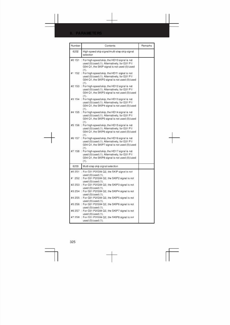
8. PARAMETERS
325
Number RemarksContents
6202 High-speed skip signal/multi-step skip signal
selection
#0 1S1 : For high-speed skip, the HD10 signal is not
used (0)/used (1). Alternatively, for G31 P1/
G04 Q1, the SKIP signal is not used (0)/used
(1).
#1 1S2 : For high-speed skip, the HD11 signal is not
used (0)/used (1). Alternatively, for G31 P1/
G04 Q1, the SKIP2 signal is not used (0)/used
(1).
#2 1S3 : For high-speed skip, the HD12 signal is not
used (0)/used (1). Alternatively, for G31 P1/
G04 Q1, the SKIP3 signal is not used (0)/used
(1).
#3 1S4 : For high-speed skip, the HD13 signal is not
used (0)/used (1). Alternatively, for G31 P1/
G04 Q1, the SKIP4 signal is not used (0)/used
(1).
#4 1S5 : For high-speed skip, the HD14 signal is not
used (0)/used (1). Alternatively, for G31 P1/
G04 Q1, the SKIP5 signal is not used (0)/used
(1).
#5 1S6 : For high-speed skip, the HD15 signal is not
used (0)/used (1). Alternatively, for G31 P1/
G04 Q1, the SKIP6 signal is not used (0)/used
(1).
#6 1S7 : For high-speed skip, the HD16 signal is not
used (0)/used (1). Alternatively, for G31 P1/
G04 Q1, the SKIP7 signal is not used (0)/used
(1).
#7 1S8 : For high-speed skip, the HD17 signal is not
used (0)/used (1). Alternatively, for G31 P1/
G04 Q1, the SKIP8 signal is not used (0)/used
(1).
6203 Multi-step skip signal selection
#0 2S1 : For G31 P2/G04 Q2, the SKIP signal is not
used (0)/used (1).
#1 2S2 : For G31 P2/G04 Q2, the SKIP2 signal is not
used (0)/used (1).
#2 2S3 : For G31 P2/G04 Q2, the SKIP3 signal is not
used (0)/used (1).
#3 2S4 : For G31 P2/G04 Q2, the SKIP4 signal is not
used (0)/used (1).
#4 2S5 : For G31 P2/G04 Q2, the SKIP5 signal is not
used (0)/used (1).
#5 2S6 : For G31 P2/G04 Q2, the SKIP6 signal is not
used (0)/used (1).
#6 2S7 : For G31 P2/G04 Q2, the SKIP7 signal is not
used (0)/used (1).
#7 2S8 : For G31 P2/G04 Q2, the SKIP8 signal is not
used (0)/used (1).
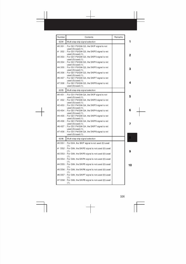
3
1
4
5
6
7
8
9
10
2
326
Number RemarksContents
6204 Multi-step skip signal selection
#0 3S1 : For G31 P3/G04 Q3, the SKIP signal is not
used (0)/used (1).
#1 3S2 : For G31 P3/G04 Q3, the SKIP2 signal is not
used (0)/used (1).
#2 3S3 : For G31 P3/G04 Q3, the SKIP3 signal is not
used (0)/used (1).
#3 3S4 : For G31 P3/G04 Q3, the SKIP4 signal is not
used (0)/used (1).
#4 3S5 : For G31 P3/G04 Q3, the SKIP5 signal is not
used (0)/used (1).
#5 3S6 : For G31 P3/G04 Q3, the SKIP6 signal is not
used (0)/used (1).
#6 3S7 : For G31 P3/G04 Q3, the SKIP7 signal is not
used (0)/used (1).
#7 3S8 : For G31 P3/G04 Q3, the SKIP8 signal is not
used (0)/used (1).
6205 Multi-step skip signal selection
#0 4S1 : For G31 P4/G04 Q4, the SKIP signal is not
used (0)/used (1).
#1 4S2 : For G31 P4/G04 Q4, the SKIP2 signal is not
used (0)/used (1).
#2 4S3 : For G31 P4/G04 Q4, the SKIP3 signal is not
used (0)/used (1).
#3 4S4 : For G31 P4/G04 Q4, the SKIP4 signal is not
used (0)/used (1).
#4 4S5 : For G31 P4/G04 Q4, the SKIP5 signal is not
used (0)/used (1).
#5 4S6 : For G31 P4/G04 Q4, the SKIP6 signal is not
used (0)/used (1).
#6 4S7 : For G31 P4/G04 Q4, the SKIP7 signal is not
used (0)/used (1).
#7 4S8 : For G31 P4/G04 Q4, the SKIP8 signal is not
used (0)/used (1).
6206 Multi-step skip signal selection
#0 DS1 : For G04, the SKIP signal is not used (0)/used
(1).
#1 DS2 : For G04, the SKIP2 signal is not used (0)/used
(1).
#2 DS3 : For G04, the SKIP3 signal is not used (0)/used
(1).
#3 DS4 : For G04, the SKIP4 signal is not used (0)/used
(1).
#4 DS5 : For G04, the SKIP5 signal is not used (0)/used
(1).
#5 DS6 : For G04, the SKIP6 signal is not used (0)/used
(1).
#6 DS7 : For G04, the SKIP7 signal is not used (0)/used
(1).
#7 DS8 : For G04, the SKIP8 signal is not used (0)/used
(1).

8. PARAMETERS
327
Number RemarksContents
6208 Continuous high-speed skip signal selection M series
#0 9S1 : For continuous high-speed skip, the HD10
signal is not used (0)/used (1).
#1 9S2 : For continuous high-speed skip, the HD11
signal is not used (0)/used (1).
#2 9S3 : For continuous high-speed skip, the HD12
signal is not used (0)/used (1).
#3 9S4 : For continuous high-speed skip, the HD13
signal is not used (0)/used (1).
#4 9S5 : For continuous high-speed skip, the HD14
signal is not used (0)/used (1).
#5 9S6 : For continuous high-speed skip, the HD15
signal is not used (0)/used (1).
#6 9S7 : For continuous high-speed skip, the HD16
signal is not used (0)/used (1).
#7 9S8 : For continuous high-speed skip, the HD17
signal is not used (0)/used (1).
6220 Period during which input is ignored for
continuous high–speed skip signal [8msec]
M series
38) Parameters for automatic tool compensation (T series) andautomatic tool length measurement (M series)
Number Contents Remarks
6240 Signal logic
#0 AE0 : A measuring position is assumed to be
reached when XAE, YAE, ZAE, or AZE is 1 (0)/
0 (1).
6241 Feedrate during measurement of automatic tool
compensation
T series
Feedrate during measurement of automatic tool
length compensation
M series
6251 γ value on X axis during automatic tool
compensation
T series
γ value during automatic tool length
compensation
M series
6252 γ value on Z axis during automatic tool
compensation
T series
6254 ε value on X axis during automatic tool
compensation
T series
ε value during automatic tool length
compensation
M series
6255 ε value on Z axis during automatic tool
compensation
T series

3
1
4
5
6
7
8
9
10
2
328
39) Parameters for external data input/output
Number Contents Remarks
6300 Parameter for external program number search
#4 ESR : External program number search is disabled
(0)/ enabled (1)
40) Parameters for graphic display
Number Contents Remarks
6500 Parameter for graphic display
#0 GRL : Graphic display
Tool post 1 is displayed on the left, and tool
post 2 is displayed on the right (0)
Tool post 1 is displayed on the right, and tool
post 2 is displayed on the left (1)
#1 SPC : Graphic display (2–path control) is done on two
spindles and two tool posts (0)/on one spindle
and two tool posts (1)
#2 GUL : The positions of X1– and X2–axes are not
replaced (0)/are replaced (1) with each other in
the coordinate system specified with
PRM6509.
#3 DPA : Current position display is the actual position to
ensure tool nose radius compensation (0)/
programmed position (1)
#5 DPO : Current position is not appear on the machining
profile drawing or tool path drawing screen (0)/
appear (1)
#6 NZM : The screen image is not enlarged (0)/enlarged
(1) by specifying the center of the screen and
magnification.
T series
(2-path
control)
T series
(2-path
control)
T series
(2-path
control)
T series
M series
T series
6501 Parameter for graphic display
#0 ORG: Drawing when coordinate system is altered
during drawing, draws in the same coordinate
system (0)/draws in the new coordinate system
(1)
#1 TLC : In solid drawing, the tool length compensation
is not executed (0)/executed (1)
#2 3PL : Tri-plane drawing in solid drawing is drawn by
the third angle projection (0)/first angle
projection (1)
#3 RID : In solid drawing, a plane is drawn without
edges (0)/with edges (1)
#4 FIM : Machining profile drawing in solid drawing is
displayed in the coarse mode (0)/fine mode (1)
#5 CSR : Center position of tool in tool path drawing is
marked withJ (0)/with (1)
M series
M series
M series
M series
M series
6503 Check drawing
#1 MST : In check drawing (animated simulation) using
the dynamic graphic display function, the M, S,
and T code commands in the program are
ignored (0)/output to the machine in the same
way (1)

8. PARAMETERS
329
Number RemarksContents
6509 Coordinate system for drawing a single spindle T series
(2–path
control)
6510 Drawing coordinate system T series
6511 Right margin in solid drawing M series
6512 Left margin in solid drawing
6513 Upper margin in solid drawing
6514 Lower margin in solid drawing
6515 Change in cross-section position in tri-plane
drawing
6520 C-axis number for dynamic graphic display T ser ies
6561 Standard color data for graphic color number 1
6562 Standard color data for graphic color number 2
6563 Standard color data for graphic color number 3
6564 Standard color data for graphic color number 4
6565 Standard color data for graphic color number 5
6566 Standard color data for graphic color number 6
6567 Standard color data for graphic color number 7
6568 Standard color data for graphic color number 8
6569 Standard color data for graphic color number 9
6570 Standard color data for graphic color number
10
6571 Standard color data for graphic color number
11
6572 Standard color data for graphic color number
12
6573 Standard color data for graphic color number
13
6574 Standard color data for graphic color number
14
6575 Standard color data for graphic color number
15
6581 Standard color data for character color number
1
6582 Standard color data for character color number
2
6583 Standard color data for character color number
3
6584 Standard color data for character color number
4

3
1
4
5
6
7
8
9
10
2
330
Number RemarksContents
6585 Standard color data for character color number
5
6586 Standard color data for character color number
6
6587 Standard color data for character color number
7
6588 Standard color data for character color number
8
6589 Standard color data for character color number
9
6590 Standard color data for character color number
10
6591 Standard color data for character color number
11
6592 Standard color data for character color number
12
6593 Standard color data for character color number
13
6594 Standard color data for character color number
14
6595 Standard color data for character color number
15
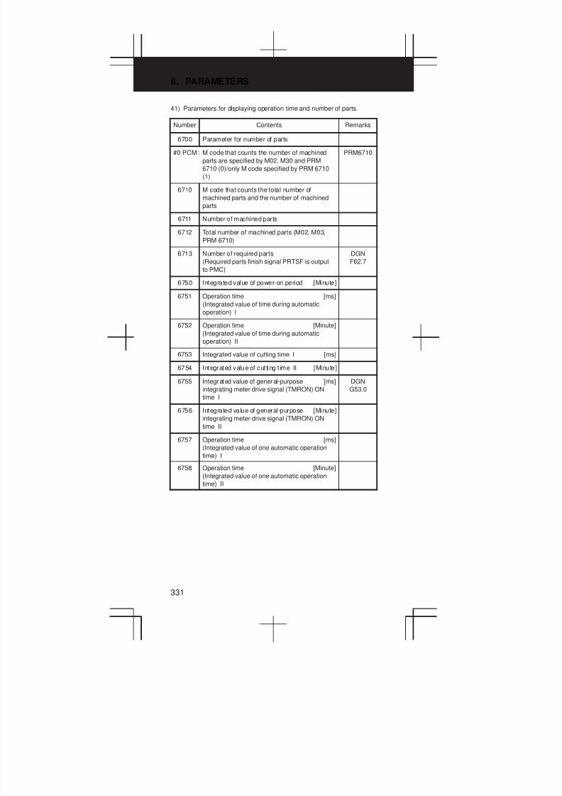
8. PARAMETERS
331
41) Parameters for displaying operation time and number of parts
Number Contents Remarks
6700 Parameter for number of parts
#0 PCM: M code that counts the number of machined
parts are specified by M02, M30 and PRM
6710 (0)/only M code specified by PRM 6710
(1)
PRM6710
6710 M code that counts the total number of
machined parts and the number of machined
parts
6711 Number of machined parts
6712 Total number of machined parts (M02, M03,
PRM 6710)
6713 Number of required parts
(Required parts finish signal PRTSF is output
to PMC)
DGN
F62.7
6750 Integrated value of power-on period [Minute]
6751 Operation time [ms]
(Integrated value of time during automatic
operation) I
6752 Operation time [Minute]
(Integrated value of time during automatic
operation) II
6753 Integrated value of cutting time I [ms]
6754 Integrated value of cutting t ime II [Minute]
6755 Integrated value of general-purpose [ms]
integrating meter drive signal (TMRON) ON
time I
DGN
G53.0
6756 Integrated value of general-purpose [Minute]
integrating meter drive signal (TMRON) ON
time II
6757 Operation time [ms]
(Integrated value of one automatic operation
time) I
6758 Operation time [Minute]
(Integrated value of one automatic operation
time) II
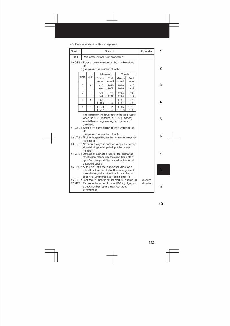
3
1
4
5
6
7
8
9
10
2
332
42) Parameters for tool life management
Number Contents Remarks
6800 Parameter for tool life management
#0 GS1 : Setting the combination of the number of tool
life
: groups and the number of tools
The values on the lower row in the table apply
when the 512–(M series) or 128–(T series)
–tool–life–management–group option is
provided.
#1 GS2 : Setting the combination of the number of tool
life
: groups and the number of tools
#2 LTM : Tool life is specified by the number of times (0)
/by time (1)
#3 SIG : Not input the group number using a tool group
signal during tool skip (0)/input the group
number (1)
#4 GRS : Data clear during the input of tool exchange
reset signal clears only the execution data of
specified groups (0)/the execution data of all
entered groups (1)
#5 SNG : At the input of a tool skip signal when tools
other than those under tool life management
are selected, skips a tool that is used last or
specified (0)/ignores a tool skip signal (1)
#6 IGI : Tool back number is not ignored (0)/ignored (1)
#7 M6T : T code in the same block as M06 is judged as
a back number (0)/as a next tool group
command (1)
0
GS2 GS1
0
M series
Groupcount
Toolcount
1–161–64
1–161–32
Groupcount
Toolcount
1–161–16
1–161–32
T series
0 1 1–321–28
1–81–16
1–321–32
1–81–16
1 0 1–641–256
1–41–8
1–641–64
1–41–8
1 1 1–1281–512
1–21–4
1–161–128
1–161–4
M series
M series
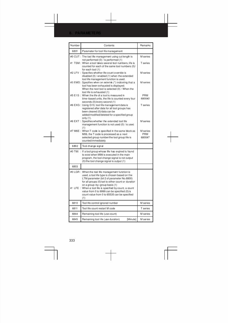
8. PARAMETERS
333
Number RemarksContents
6801 Parameter for tool life management
#0 CUT : The tool life management using cut length is
not performed (0) / is performed (1)
#1 TSM : When a tool takes several tool numbers, life is
counted for each of the same tool numbers (0)/
for each tool (1)
#2 LFV : Specifies whether life count override is
disabled (0) / enabled (1) when the extended
tool life management function is used.
#3 EMD: Specifies when an asterisk (*) indicating that a
tool has been exhausted is displayed.
When the next tool is selected (0) / When the
tool life is exhausted (1)
#5 E1S : When the life of a tool is measured in
time–based units, the life is counted every four
seconds (0)/every second (1)
#6 EXG : Using G10, tool life management data is
registered after data for all tool groups has
been cleared (0)/data can be
added/modified/deleted for a specified group
only (1).
#6 EXT : Specifies whether the extended tool life
management function is not used (0) / is used
(1)
#7 M6E : When T code is specified in the same block as
M06, the T code is processed as a next
selected group number/the tool group life is
counted immediately
M series
T series
M series
M series
PRM
6800#2
T series
M series
M series
PRM
6800#7
6802 Tool change signal
#0 T99 : If a tool group whose life has expired is found
to exist when M99 is executed in the main
program, the tool change signal is not output
(0)/the tool change signal is output (1)
6803
#0 LGR : When the tool life management function is
used, a tool life type is chosen based on the
LTM parameter (bit 2 of parameter No.6800)
for all groups (0)/set to either count or duration
on a group–by–group basis (1)
#1 LFE : When a tool life is specified by count, a count
value from 0 to 9999 can be specified (0)/a
count value from 0 to 65535 can be specified
(1)
6810 Tool life control ignored number M series
6811 Tool life count restart M code T series
6844 Remaining tool life (use count) M series
6845 Remaining tool life (use duration) [Minute] M ser ies
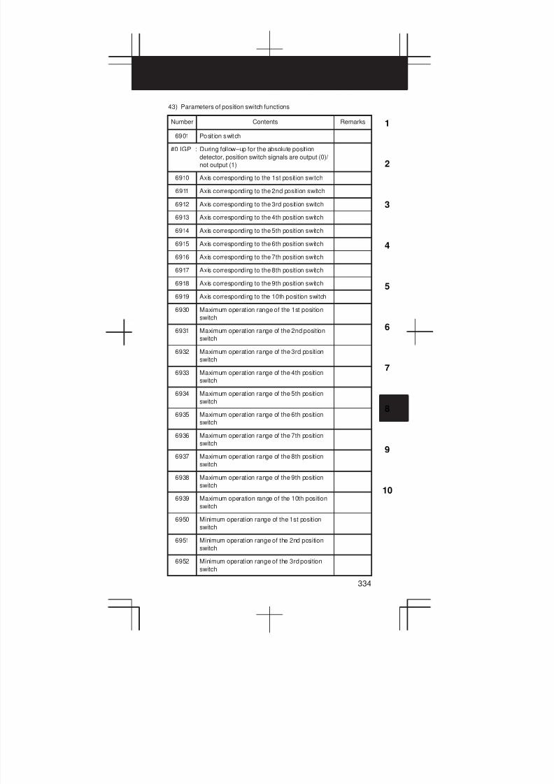
3
1
4
5
6
7
8
9
10
2
334
43) Parameters of position switch functions
Number Contents Remarks
6901 Posit ion switch
#0 IGP : During follow–up for the absolute position
detector, position switch signals are output (0)/
not output (1)
6910 Axis corresponding to the 1st position switch
6911 Axis corresponding to the 2nd position switch
6912 Axis corresponding to the 3rd position switch
6913 Axis corresponding to the 4th position switch
6914 Axis corresponding to the 5th position switch
6915 Axis corresponding to the 6th position switch
6916 Axis corresponding to the 7th position switch
6917 Axis corresponding to the 8th position switch
6918 Axis corresponding to the 9th position switch
6919 Axis corresponding to the 10th position switch
6930 Maximum operation range of the 1st position
switch
6931 Maximum operation range of the 2nd position
switch
6932 Maximum operation range of the 3rd position
switch
6933 Maximum operation range of the 4th position
switch
6934 Maximum operation range of the 5th position
switch
6935 Maximum operation range of the 6th position
switch
6936 Maximum operation range of the 7th position
switch
6937 Maximum operation range of the 8th position
switch
6938 Maximum operation range of the 9th position
switch
6939 Maximum operation range of the 10th position
switch
6950 Minimum operation range of the 1st position
switch
6951 Minimum operation range of the 2nd position
switch
6952 Minimum operation range of the 3rd position
switch
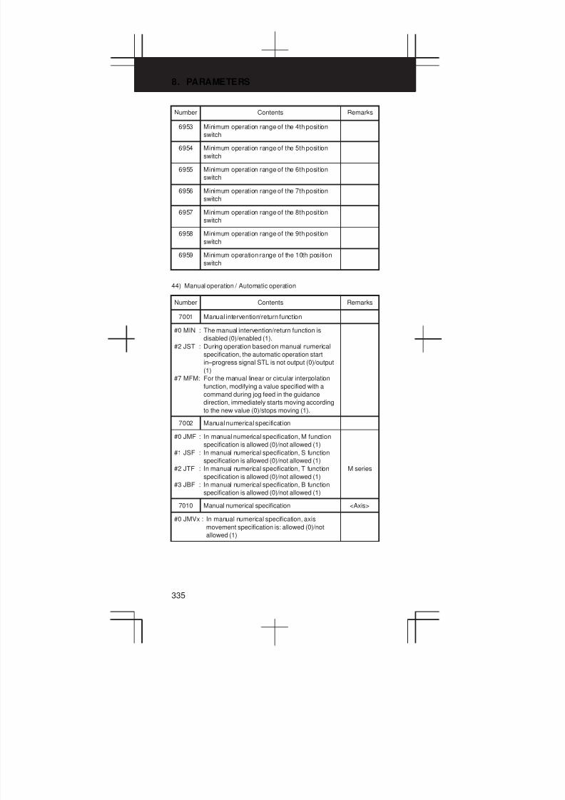
8. PARAMETERS
335
Number RemarksContents
6953 Minimum operation range of the 4th position
switch
6954 Minimum operation range of the 5th position
switch
6955 Minimum operation range of the 6th position
switch
6956 Minimum operation range of the 7th position
switch
6957 Minimum operation range of the 8th position
switch
6958 Minimum operation range of the 9th position
switch
6959 Minimum operation range of the 10th position
switch
44) Manual operation / Automatic operation
Number Contents Remarks
7001 Manual intervention/return function
#0 MIN : The manual intervention/return function is
disabled (0)/enabled (1).
#2 JST : During operation based on manual numerical
specification, the automatic operation start
in–progress signal STL is not output (0)/output
(1)
#7 MFM: For the manual linear or circular interpolation
function, modifying a value specified with a
command during jog feed in the guidance
direction, immediately starts moving according
to the new value (0)/stops moving (1).
7002 Manual numerical specification
#0 JMF : In manual numerical specification, M function
specification is allowed (0)/not allowed (1)
#1 JSF : In manual numerical specification, S function
specification is allowed (0)/not allowed (1)
#2 JTF : In manual numerical specification, T function
specification is allowed (0)/not allowed (1)
#3 JBF : In manual numerical specification, B function
specification is allowed (0)/not allowed (1)
M series
7010 Manual numerical specification <Axis>
#0 JMVx : In manual numerical specification, axis
movement specification is: allowed (0)/not
allowed (1)

3
1
4
5
6
7
8
9
10
2
336
Number RemarksContents
7050 Retrace function
#0 RV1 : When the tool moves backwards after feed
hold during forward feed with the retrace
function, the block is split at the feed hold
position and stored (0)/stored without being
split (1).
#5 MI0 : Set below value
#6 MI1 : Set below value
0
MI1 MI0 Fine acceleration/deceleration
0 Used
0 1 Not used
M series
M series
M series
7052 Simple high–precision contour control
#0 NMI : In simple high–precision contour control mode,
batch pass for each axis is enabled (0)/
disabled (1)
45) Parameters for manual handle feed / Interrupts / Tool axial direction
Number Contents Remarks
7100 Parameter for manual pulse generator
#0 JHD : Manual pulse generator in JOG mode is invalid
(0)/valid (1)
#1 THD : Manual pulse generator in TEACH IN JOG
mode is invalid (0)/valid (1)
#2 IHD : The travel increment for manual handle
interrupt is output unit, and acceleration/
deceleration after interpolation is disabled
(0)/input unit, and acceleration/deceleration
after interpolation is enabled (1)
#3 HCL : The clearing of a handle interrupt travel
distance is invalid (0)/valid (1).
#4 HPF : If the specified manual handle feedrate
exceeds the rapid traverse rate, handle pulses
exceeding the rapid traverse rate are ignored
(0)/are not ignored such that the tool is moved
then stopped (1).
7102 Rotation direction <Axis>
#0 HNG: Axis movement direction for rotation direction
of manual pulse generator is same in direction
(0) / reverse in direction (1)
T series

8. PARAMETERS
337
Number RemarksContents
7104 Handle feed in the tool axis direction M series
#0 TLX : When the rotation axis is at the origin, the tool
axis is in the Z direction (0)/X direction (1).
#2 CXC : Tool axis direction handle feed or perpendicular
direction handle feed is performed with 5–axis
machine (0)/4–axis machine (1).
#3 3D1 : For tool axis direction handle feed and right
angle direction handle feed, the machine
coordinates when the mode is set or when a
reset is performed (0)/the coordinates specified
with PRM7144 (1) are set as the coordinates of
the first rotation axis.
#4 3D2 : For tool axis direction handle feed and right
angle direction handle feed, the machine
coordinates when the mode is set or when a
reset is performed (0)/the coordinates specified
with PRM7145 (1) are set as the coordinates of
the second rotation axis.
#5 HHI : Manual handle interrupt during high–speed
machining is disabled (0)/enabled (1)
M series
M series
M series
M series
7110 Number of manual pulse generator used
7113 Manual handle feed magnification m (1–127)
7114 Manual handle feed magnification n (0–1000)
7117 Allowable number of pulses that can be
accumulated during manual handle feed
7120 Axis configuration for using the tool axis
direction handle feed or perpendicular direction
handle feed
1: A-C 2: B-C 3: A-B (A: Master)
4: A-B (B: Master)
M series
7121 Axis selection in tool axis direction handle feed
mode
M series
7141 Axis selection in the X direction for the radial
tool axis handle feed
M series
7142 Axis selection in the Y direction for the radial
tool axis handle feed
M series
7144 Coordinate of the first rotation axis for tool axis
direction handle feed and radial tool axis
handle feed
M series
7145 Coordinate of the second rotation axis for tool
axis handle feed and radial tool axis handle
feed
M series
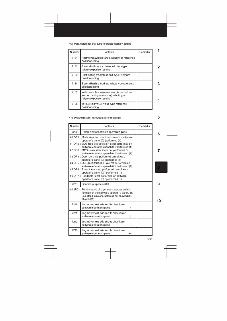
3
1
4
5
6
7
8
9
10
2
338
46) Parameters for butt-type reference position setting
Number Contents Remarks
7181 First withdrawal distance in butt-type reference
position setting
7182 Second withdrawal distance in butt-type
reference position setting
7183 First butting feedrate in butt-type reference
position setting
7184 Second butting feedrate in butt-type reference
position setting
7185 Withdrawal feedrate (common to the first and
second butting operations) in butt-type
reference position setting
7186 Torque limit value in butt-type reference
position setting
47) Parameters for software operator’s panel
Number Contents Remarks
7200 Parameter for software operator’s panel
#0 OP1 : Mode selection is not performed on software
operator’s panel (0) /performed (1)
#1 OP2 : JOG feed axis selection is not performed on
software operator’s panel (0) / performed (1)
#2 OP3 : MPG’s axis selection is not performed on
software operator’s panel (0) / performed (1)
#3 OP4 : Override is not performed on software
operator’s panel (0) /performed (1)
#4 OP5 : OBS,SBK,MLK,DRN are not performed on
software operator’s panel (0) / performed (1)
#5 OP6 : Protect key is not performed on software
operator’s panel (0) / performed (1)
#6 OP7 : Feed hold is not performed on software
operator’s panel (0) / performed (1)
7201 General–purpose switch
#0 JPC : For the name of a general–purpose switch
function on the software operator’s panel, the
use of full–size characters is not allowed (0)/
allowed (1)
7210 Jog movement axis and its direction on
software operator’s panel °
7211 Jog movement axis and its direction on
software operator’s panel ±
7212 Jog movement axis and its direction on
software operator’s panel ³
7213 Jog movement axis and its direction on
software operator’s panel ²
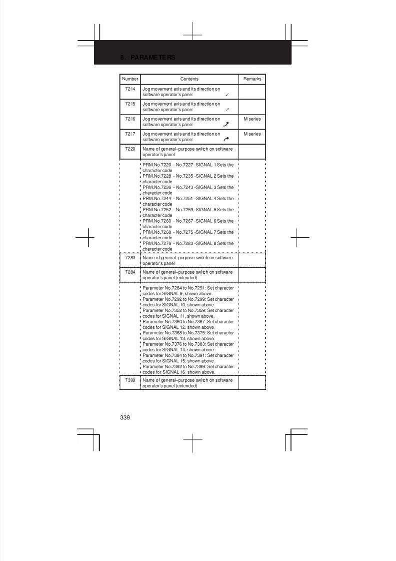
8. PARAMETERS
339
Number RemarksContents
7214 Jog movement axis and its direction on
software operator’s panel ¼
7215 Jog movement axis and its direction on
software operator’s panel ½
7216 Jog movement axis and its direction on
software operator’s panel
M series
7217 Jog movement axis and its direction on
software operator’s panel
M series
7220 Name of general–purpose switch on software
operator’s panel
PRM.No.7220 - No.7227 -SIGNAL 1 Sets the
character code
PRM.No.7228 - No.7235 -SIGNAL 2 Sets the
character code
PRM.No.7236 - No.7243 -SIGNAL 3 Sets the
character code
PRM.No.7244 - No.7251 -SIGNAL 4 Sets the
character code
PRM.No.7252 - No.7259 -SIGNAL 5 Sets the
character code
PRM.No.7260 - No.7267 -SIGNAL 6 Sets the
character code
PRM.No.7268 - No.7275 -SIGNAL 7 Sets the
character code
PRM.No.7276 - No.7283 -SIGNAL 8 Sets the
character code
7283 Name of general–purpose switch on software
operator’s panel
7284 Name of general–purpose switch on software
operator’s panel (extended)
Parameter No.7284 to No.7291: Set character
codes for SIGNAL 9, shown above.
Parameter No.7292 to No.7299: Set character
codes for SIGNAL 10, shown above.
Parameter No.7352 to No.7359: Set character
codes for SIGNAL 11, shown above.
Parameter No.7360 to No.7367: Set character
codes for SIGNAL 12, shown above.
Parameter No.7368 to No.7375: Set character
codes for SIGNAL 13, shown above.
Parameter No.7376 to No.7383: Set character
codes for SIGNAL 14, shown above.
Parameter No.7384 to No.7391: Set character
codes for SIGNAL 15, shown above.
Parameter No.7392 to No.7399: Set character
codes for SIGNAL 16 shown above.
7399 Name of general–purpose switch on software
operator’s panel (extended)
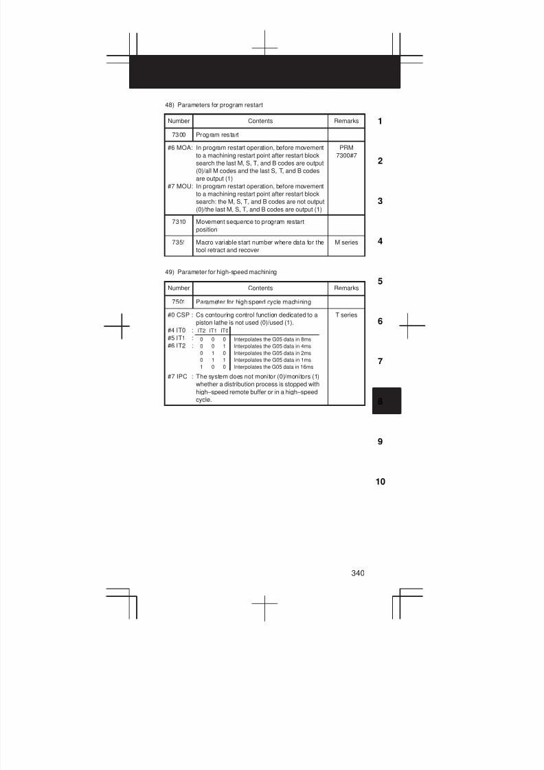
3
1
4
5
6
7
8
9
10
2
340
48) Parameters for program restart
Number Contents Remarks
7300 Program restart
#6 MOA: In program restart operation, before movement
to a machining restart point after restart block
search the last M, S, T, and B codes are output
(0)/all M codes and the last S, T, and B codes
are output (1)
#7 MOU: In program restart operation, before movement
to a machining restart point after restart block
search: the M, S, T, and B codes are not output
(0)/the last M, S, T, and B codes are output (1)
PRM
7300#7
7310 Movement sequence to program restart
position
7351 Macro variable start number where data for the
tool retract and recover
M series
49) Parameter for high-speed machining
Number Contents Remarks
7501 Parameter for high speed cycle machining
#0 CSP : Cs contouring control function dedicated to a
piston lathe is not used (0)/used (1).
#4 IT0 :
#5 IT1 :
#6 IT2 :
#7 IPC : The system does not monitor (0)/monitors (1)
whether a distribution process is stopped with
high–speed remote buffer or in a high–speed
cycle.
IT2 IT1 IT0
0 0 0
0 0 1
0 1 0
0 1 1
1 0 0
Interpolates the G05 data in 8ms
Interpolates the G05 data in 4ms
Interpolates the G05 data in 2ms
Interpolates the G05 data in 1ms
Interpolates the G05 data in 16ms
T series
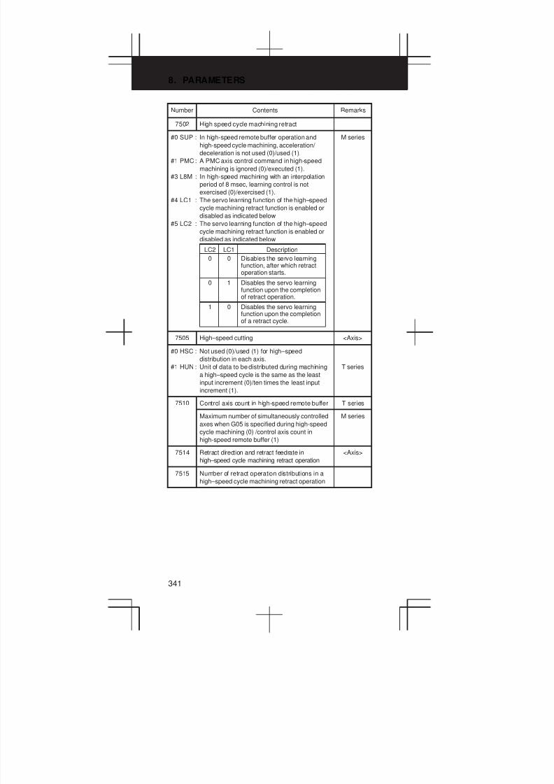
8. PARAMETERS
341
Number RemarksContents
7502 High speed cycle machining retract
#0 SUP : In high-speed remote buffer operation and
high-speed cycle machining, acceleration/
deceleration is not used (0)/used (1).
#1 PMC: A PMC axis control command in high-speed
machining is ignored (0)/executed (1).
#3 L8M : In high-speed machining with an interpolation
period of 8 msec, learning control is not
exercised (0)/exercised (1).
#4 LC1 : The servo learning function of the high–speed
cycle machining retract function is enabled or
disabled as indicated below
#5 LC2 : The servo learning function of the high–speed
cycle machining retract function is enabled or
disabled as indicated below
0
LC2 LC1 Description
0 Disables the servo learningfunction, after which retractoperation starts.
0 1 Disables the servo learningfunction upon the completionof retract operation.
1 0 Disables the servo learningfunction upon the completionof a retract cycle.
M series
7505 High–speed cutting <Axis>
#0 HSC : Not used (0)/used (1) for high–speed
distribution in each axis.
#1 HUN : Unit of data to be distributed during machining
a high–speed cycle is the same as the least
input increment (0)/ten times the least input
increment (1).
T series
7510 Control axis count in high-speed remote buffer T series
Maximum number of simultaneously controlled
axes when G05 is specified during high-speed
cycle machining (0) /control axis count in
high-speed remote buffer (1)
M series
7514 Retract direction and retract feedrate in
high–speed cycle machining retract operation
<Axis>
7515 Number of retract operation distributions in a
high–speed cycle machining retract operation
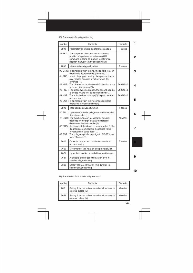
3
1
4
5
6
7
8
9
10
2
342
50) Parameters for polygon turning
Number Contents Remarks
7600 Parameter for returns to reference posit ion T ser ies
#7 PLZ : The sequence of returns to the reference
position of synchronous axis using G28
command is same as a return to reference
position manually (0)/by positioning (1)
7602 Inter-spindle polygon function T series
#0 MNG: In spindle polygon turning, the spindle rotation
direction is not reversed (0)/reversed (1).
#1 SNG : In spindle polygon turning, the synchronization
axis rotation direction is not reversed (0)/
reversed (1).
#2 HDR : The phase synchronization shift direction is not
reversed (0)/reversed (1).
#3 HSL : For phase synchronization, the second spindle
is shifted (0)/the first spindle is shifted (1).
#4 HST : The spindle does not stop (0)/stops to set the
polygon mode (1).
#5 COF : In spindle polygon turning, phase control is
exercised (0)/not exercised (1).
7602#5=0
7602#5=0
7602#5=0
7603 Inter-spindle polygon function T series
#0 RPL : Upon reset, spindle polygon mode is canceled
(0)/not canceled (1).
#1 QDR: The synchronization axis rotation direction
depends on the sign of Q (0)/the rotation
direction of the first spindle (1).
#5 RDG: As display of the phase command value R, the
diagnosis screen displays a specified value
(0)/actual shift pulse data (1).
#7 PST : The polygon spindle stop signal *PLSST is not
used (0)/used (1).
ALM218
7610 Control axis number of tool rotation axis for
polygon turning
T series
7620 Movement of tool rotation axis per revolution
7621 Upper-limit rotation speed of tool rotation axis
7631 Allowable spindle speed deviation level in
spindle polygon turning
7632 Steady state confirmation time duration in
spindle polygon turning
51) Parameters for the external pulse input
Number Contents Remarks
7681 Setting 1 for the ratio of an axis shift amount to
external pulses (M)
M series
7682 Setting 2 for the ratio of an axis shift amount to
external pulses (N)
M series
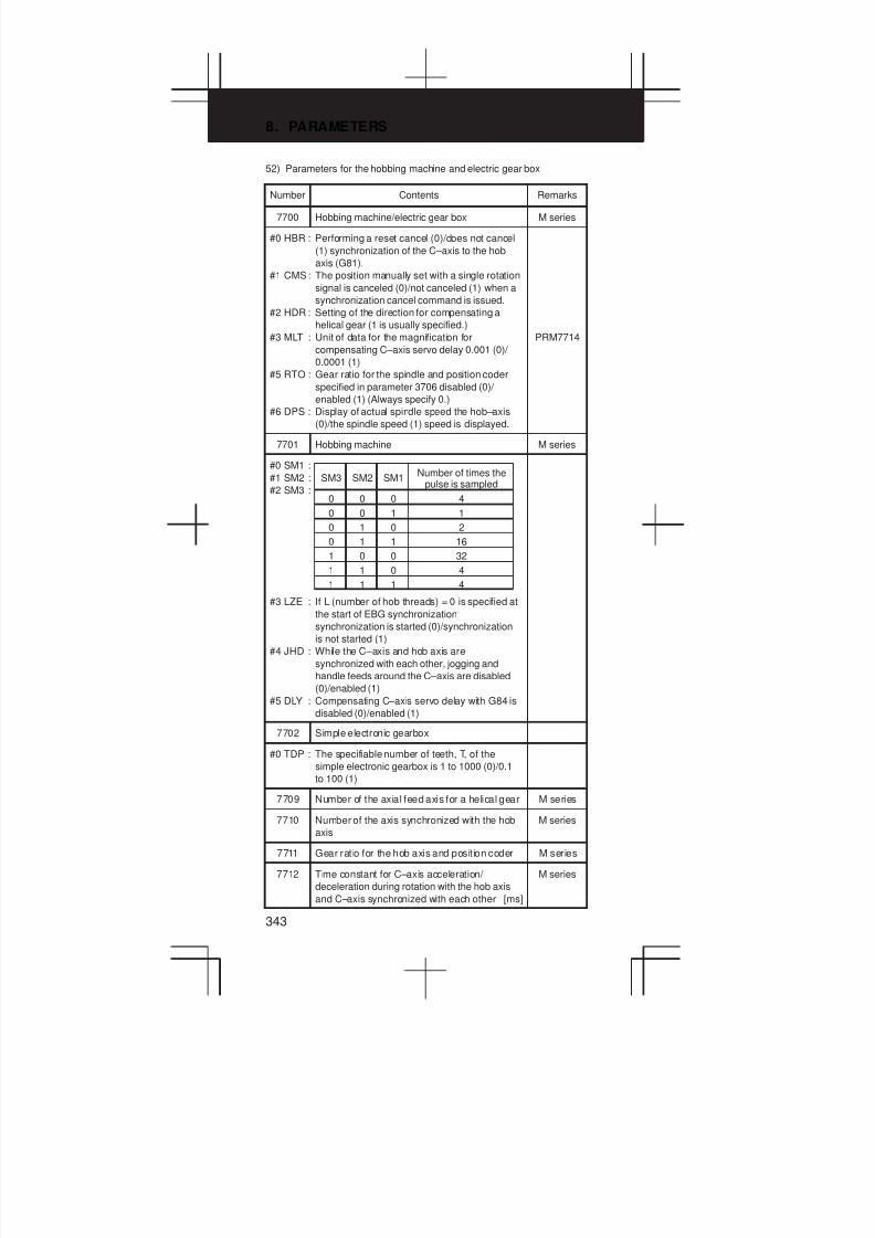
8. PARAMETERS
343
52) Parameters for the hobbing machine and electric gear box
Number Contents Remarks
7700 Hobbing machine/electric gear box M series
#0 HBR : Performing a reset cancel (0)/does not cancel
(1) synchronization of the C–axis to the hob
axis (G81).
#1 CMS: The position manually set with a single rotation
signal is canceled (0)/not canceled (1) when a
synchronization cancel command is issued.
#2 HDR : Setting of the direction for compensating a
helical gear (1 is usually specified.)
#3 MLT : Unit of data for the magnification for
compensating C–axis servo delay 0.001 (0)/
0.0001 (1)
#5 RTO : Gear ratio for the spindle and position coder
specified in parameter 3706 disabled (0)/
enabled (1) (Always specify 0.)
#6 DPS : Display of actual spindle speed the hob–axis
(0)/the spindle speed (1) speed is displayed.
PRM7714
7701 Hobbing machine M series
#0 SM1 :
#1 SM2 :
#2 SM3 :
#3 LZE : If L (number of hob threads) = 0 is specified at
the start of EBG synchronization
synchronization is started (0)/synchronization
is not started (1)
#4 JHD : While the C–axis and hob axis are
synchronized with each other, jogging and
handle feeds around the C–axis are disabled
(0)/enabled (1)
#5 DLY : Compensating C–axis servo delay with G84 is
disabled (0)/enabled (1)
0
SM3 SM1Number of times the
pulse is sampled
0 4
SM2
0
0 1 10
0 0 21
0 1 161
1 0 320
1 0 41
1 1 41
7702 Simple electronic gearbox
#0 TDP : The specifiable number of teeth, T, of the
simple electronic gearbox is 1 to 1000 (0)/0.1
to 100 (1)
7709 Number of the axial feed axis for a helical gear M series
7710 Number of the axis synchronized with the hob
axis
M series
7711 Gear ratio for the hob axis and position coder M series
7712 Time constant for C–axis acceleration/
deceleration during rotation with the hob axis
and C–axis synchronized with each other [ms]
M series
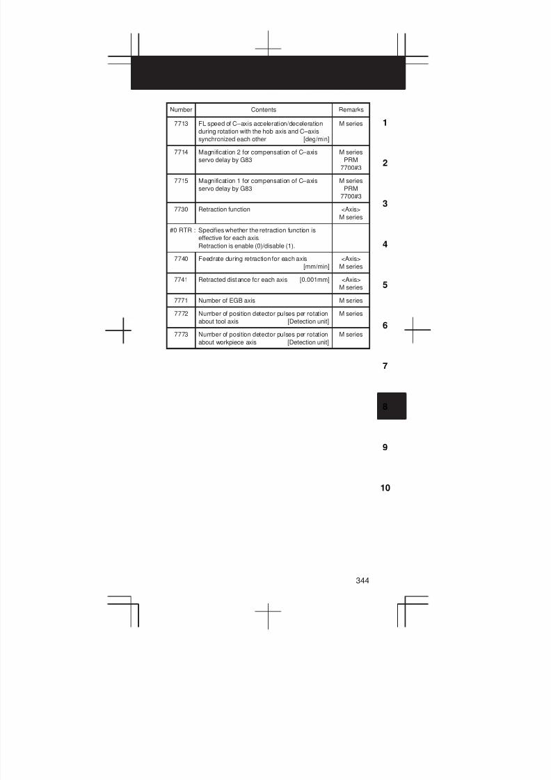
3
1
4
5
6
7
8
9
10
2
344
Number RemarksContents
7713 FL speed of C–axis acceleration/deceleration
during rotation with the hob axis and C–axis
synchronized each other [deg/min]
M series
7714 Magnification 2 for compensation of C–axis
servo delay by G83
M series
PRM
7700#3
7715 Magnification 1 for compensation of C–axis
servo delay by G83
M series
PRM
7700#3
7730 Retraction function <Axis>
M series
#0 RTR : Specifies whether the retraction function is
effective for each axis.
Retraction is enable (0)/disable (1).
7740 Feedrate during retraction for each axis
[mm/min]
<Axis>
M series
7741 Retracted distance for each axis [0.001mm] <Axis>
M series
7771 Number of EGB axis M series
7772 Number of position detector pulses per rotation
about tool axis [Detection unit]
M series
7773 Number of position detector pulses per rotation
about workpiece axis [Detection unit]
M series
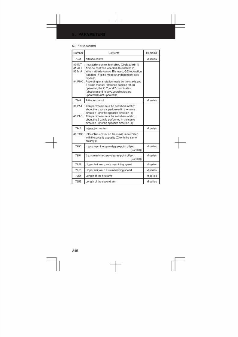
8. PARAMETERS
345
53) Attitude control
Number Contents Remarks
7941 Attitude control M series
#0 INT : Interaction control is enabled (0)/disabled (1)
#1 ATT : Attitude control is enabled (0)/disabled (1)
#3 MIA : When attitude control B is used, G53 operation
is placed in tip fix mode (0)/independent axis
mode (1)
#4 RNC : According to a rotation made on theα axis and
β axis in manual reference position return
operation, the X, Y, and Z coordinates
(absolute) and relative coordinates are:
updated (0)/not updated (1)
7942 Attitude control M series
#0 PA4 : This parameter must be set when rotation
about the α axis is performed in the same
direction (0)/in the opposite direction (1)
#1 PA5 : This parameter must be set when rotation
about the β axis is performed in the same
direction (0)/in the opposite direction (1)
7943 Interaction control M series
#0 TGC : Interaction control on theα axis is exercised
with the polarity opposite (0)/with the same
polarity (1)
7950 α axis machine zero–degree point offset
[0.01deg]
M series
7951 β axis machine zero–degree point offset
[0.01deg]
M series
7952 Upper limit on α axis machining speed M series
7953 Upper limit on β axis machining speed M series
7954 Length of the first arm M series
7955 Length of the second arm M series

3
1
4
5
6
7
8
9
10
2
346
54) Parameters for axis control by PMC
Number Contents Remarks
8001 Parameter for axis control by PMC
#0 MLE : Machine lock for PMC control axis is valid (0)/
invalid (1)
#2 OVE : Dry run and override signals use the same
signal as CNC (0) / PMC particular signal (1)
#3 RDE : Dry run signal for rapid traverse command is
invalid (0) / valid (1)
#5 NCC : If a program command is specified for a
PMC–controlled axis, an alarm is issued if the
axis is controlled by the PMC, the CNC
command otherwise being valid (0)/an alarm is
always issued (1).
#6 AUX : The number of bytes for the code of an
auxiliary function (12H) command to be output
is 1 (0 to 255) (0)/2 (0 to 65535) (1)
#7 SKE : Skip signal uses same as CNC (0) / PMC
particular signal (1)
DGN
G150,151
P/S 139
DGN
X004#6
DGN
X004#7
8002 Parametr for axis control by PMC
#0 RPD : Rapid traverse rate of PMC control axis is set
by PRM 1420 (0)/specified by rapid traverse
rate (1)
#1 DWE: With IS-C, dwell is 1 msec (0)/0.1 msec (1).
#2 SUE : In external pulse synchronization,
acceleration/deceleration is enabled
(exponential) (0)/disabled (1).
#3 F10 : Sets the command unit of feedrate per minute
1mm/min (0)/10mm/min (1)
#4 PF1 : Set the the feedrate unit of feed
#5 PF2 :
#6 FR1 : Set the command unit of feedrate per revolution
#7 FR2 :
0 0
FR2 FR1 Metric input
0.0001 mm/rev
0
PF2 PF1 Feedrate unit
00 1/1
Inch input
0.000001 inch/rev1 1
0 1 0.001 mm/rev 0.00001 inch/rev
1 0 0.01 mm/rev 0.0001 inch/rev
0
1 1/100
0 1/1001
1 1/10001
8003 Inch input/Metric input
#0 PIM : When only the axes controlled by the PMC are
used, the linear axis is influenced (0)/not
influenced (1) by inch/millimeter input.

8. PARAMETERS
347
Number RemarksContents
8004 Axis cont rol
#0 CMW : When a move command and auxiliary function
are specified from the CNC, an alarm
(No.130) is issued from the PMC for the same
axis (0)/an axis control command, is executed
(1)
#1 NMT : If the PMC and NC specify commands at the
same time, an alarm is issued (0)/no alarm is
issued if the commands do not include a move
command (1).
#2 JFM : A feedrate for continuous feed is normal (0)/
multiplied by 200 (1).
#3 G8C : For cutting feed along a PMC axis, look-ahead
control is disabled (0)/enabled (1).
#4 G8R : For rapid traverse and cutting feed along a
PMC axis, look-ahead control is disabled (0)/
enabled (1).
#5 DSL : If axis switching is specified when axis
switching is disabled, ALM139 is issued (0)/
axis switching is valid for a system not
specified (1).
#6 NCI : In deceleration, an in-position check is made
(0)/not made (1).
#7 NDI : For PMC axis control, when diameter
programming is specified the amount of t ravel
and feedrate are each specified with a radius
(0)/with a diameter (1)
ALM130
PRM
1819#7=0
PRM
1819#7=0
ALM139
T series
PRM
1006#3=1
8005
#0 EDC : In PMC–based axis control, an external
deceleration signal is disabled (0)/enabled (1)
#1 CDI : If diameter input is specified for
PMC–controlled axes, the amount of travel
becomes double the specified value while the
specified feedrate is used as is (0)/both the
specified amount of travel and feedrate are
used as is (1).
#2 R10 : When the parameter No.8002#0 is set to 1, the
unit for specifying a rapid traverse rate for the
PMC axis is 1 mm/min (0)/10 mm/min (1)
#3 DRR : For cutting feed per rotation in PMC axis
control, the dry run function is disabled (0)/
enabled (1)
#7 MFD : Output by each auxiliary function of the PMC
axis control function is disabled (0)/enabled (1)
T series
PRM
1006#3
8010 DI/DO group selection for each axis during
PMC axis control
8022 Upper-limit rate of feed per revolution during
PMC axis control
8028 Linear acceleration/deceleration time constant
for speed commands for PMC axis control
[ms/1000rpm]
<Axis>
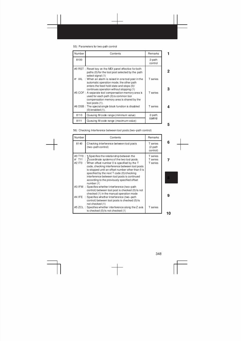
3
1
4
5
6
7
8
9
10
2
348
55) Parameters for two-path control
Number Contents Remarks
8100 2-path
control
#0 RST : Reset key on the MDI panel effective for both
paths (0)/for the tool post selected by the path
select signal (1)
#1 IAL : When an alarm is raised in one tool post in the
automatic operation mode, the other path
enters the feed hold state and stops (0)/
continues operation without stopping (1)
#5 COF : A separate tool compensation memory area is
used for each path (0)/a common tool
compensation memory area is shared by the
tool posts (1).
#6 DSB : The special single block function is disabled
(0)/enabled (1).
T series
T series
T series
8110 Queuing M code range (minimum value) 2-path
8111 Queuing M code range (maximum value)con ro
56) Checking Interference between tool posts (two–path control)
Number Contents Remarks
8140 Checking interference between tool posts
(two–path control)
T series
(2-path
control)
#0 TY0 : Specifies the relationship between the
#1 TY1 : coordinate systems of the two tool posts.
#2 IT0 : When offset number 0 is specified by the T
code, checking interference between tool posts
is stopped until an offset number other than 0 is
specified by the next T code (0)/checking
interference between tool posts is continued
according to the previously specified offset
number (1)
#3 IFM : Specifies whether interference (two–path
control) between tool post is checked (0)/is not
checked (1) in the manual operation mode
#4 IFE : Specifies whether interference (two–path
control) between tool posts is checked (0)/is
not checked (1)
#5 ZCL : Specifies whether interference along the Z axis
is checked (0)/is not checked (1)
T series
T series
T series
T series
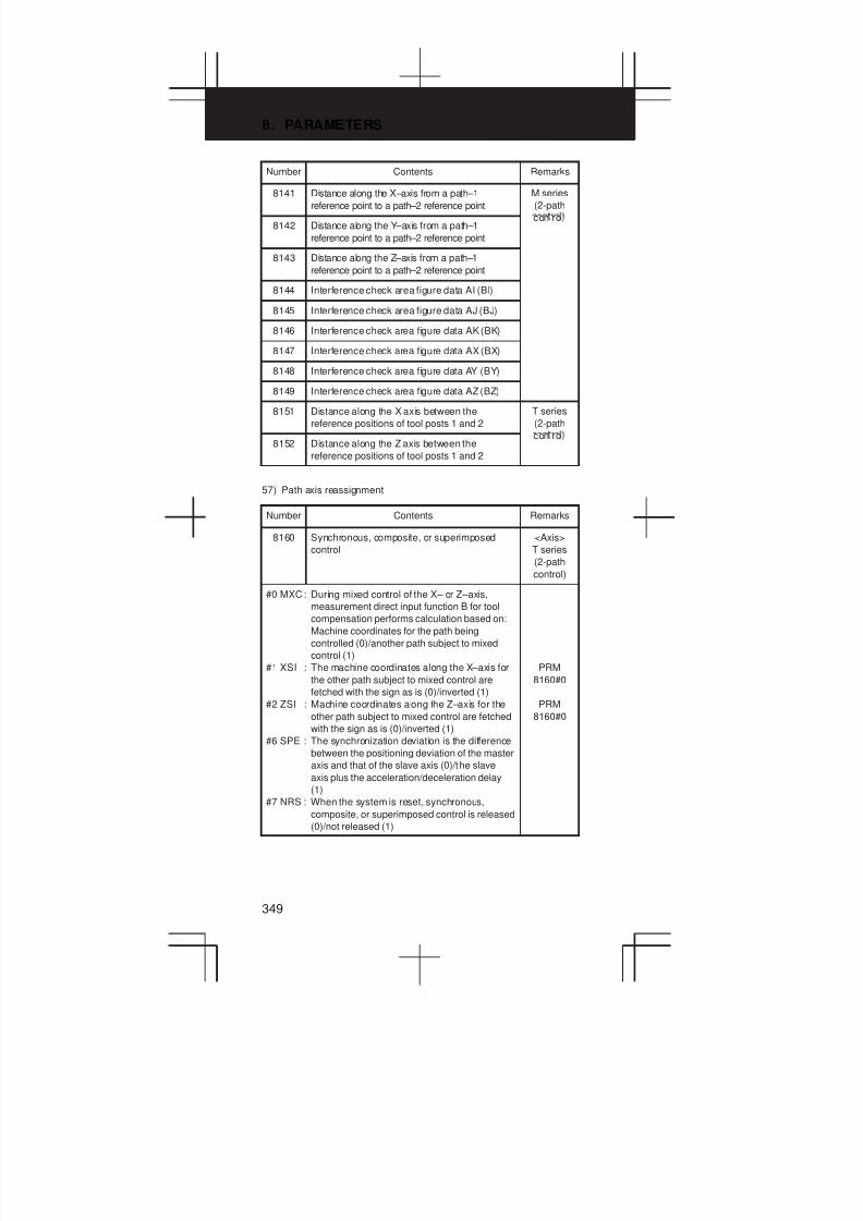
8. PARAMETERS
349
Number RemarksContents
8141 Distance along the X–axis from a path–1
reference point to a path–2 reference point
M series
(2-path
8142 Distance along the Y–axis from a path–1
reference point to a path–2 reference point
con ro
8143 Distance along the Z–axis from a path–1
reference point to a path–2 reference point
8144 Interference check area figure data AI (BI)
8145 Interference check area figure data AJ (BJ)
8146 Interference check area figure data AK (BK)
8147 Interference check area figure data AX (BX)
8148 Interference check area figure data AY (BY)
8149 Interference check area figure data AZ (BZ)
8151 Distance along the X axis between the
reference positions of tool posts 1 and 2
T series
(2-path
8152 Distance along the Z axis between the
reference positions of tool posts 1 and 2
con ro
57) Path axis reassignment
Number Contents Remarks
8160 Synchronous, composite, or superimposed
control
<Axis>
T series
(2-path
control)
#0 MXC: During mixed control of the X– or Z–axis,
measurement direct input function B for tool
compensation performs calculation based on:
Machine coordinates for the path being
controlled (0)/another path subject to mixed
control (1)
#1 XSI : The machine coordinates along the X–axis for
the other path subject to mixed control are
fetched with the sign as is (0)/inverted (1)
#2 ZSI : Machine coordinates along the Z–axis for the
other path subject to mixed control are fetched
with the sign as is (0)/inverted (1)
#6 SPE : The synchronization deviation is the difference
between the positioning deviation of the master
axis and that of the slave axis (0)/the slave
axis plus the acceleration/deceleration delay
(1)
#7 NRS : When the system is reset, synchronous,
composite, or superimposed control is released
(0)/not released (1)
PRM
8160#0
PRM
8160#0

3
1
4
5
6
7
8
9
10
2
350
Number RemarksContents
8161 Composite control T series
(2-path
control)
#0 NMR: When an axis subject to mixed control is
placed in servo–off state mixed control is
stopped (0)/mixed control is not stopped to
disable follow–up for the axis (1)
#1 CZM : When two Cs contour axes are subject to
mixed control, the function for mixing zero point
return commands for Cs contour axes is not
used (0)/used (1)
8162 Synchronous, composite, superimposed
control
<Axis>
T series
(2-path
control)
#0 SMR: Synchronous mirror–image control is not
applied (0)/applied (1)
#1 SER : The synchronization deviation is not detected
(0)/detected (1)
#2 PKU : In the parking state,
The absolute, relative, and machine
coordinates are not updated (0)/
The absolute and relative coordinates are
updated. The machine coordinates are not
updated (1)
#3 OMR: Superimposed mirror–image control is not
applied (0)/applied (1)
#4 MPM: When composite control is started, the
workpiece coordinate system is not set
automatically (0)/set automatically (1)
#5 MPS : When composite control is terminated, the
workpiece coordinate system is not set (0)/set
(1) automatically
#6 MCD: When mixed control is applied, the coordinate
system direction for the relevant axes remains
the same without applying mirror image (0)/is
reversed by applying mirror image (1).
#7 MUM: During axis recomposition, a movement along
an axis is enabled (0)/disabled (1).
ALM 226
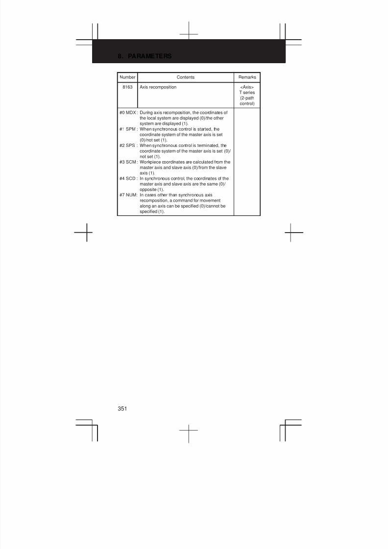
8. PARAMETERS
351
Number RemarksContents
8163 Axis recomposition <Axis>
T series
(2-path
control)
#0 MDX: During axis recomposition, the coordinates of
the local system are displayed (0)/the other
system are displayed (1).
#1 SPM : When synchronous control is started, the
coordinate system of the master axis is set
(0)/not set (1).
#2 SPS : When synchronous control is terminated, the
coordinate system of the master axis is set (0)/
not set (1).
#3 SCM: Workpiece coordinates are calculated from the
master axis and slave axis (0)/from the slave
axis (1).
#4 SCD : In synchronous control, the coordinates of the
master axis and slave axis are the same (0)/
opposite (1).
#7 NUM: In cases other than synchronous axis
recomposition, a command for movement
along an axis can be specified (0)/cannot be
specified (1).

3
1
4
5
6
7
8
9
10
2
352
Number RemarksContents
8164 Composite control <Axis>
#0 MWSx : In automatic workpiece coordinate system
setting, performed when composite control is
started, a workpiece shift and position offset
are: not considered (0)/considered (1)
#1 MWEx : In automatic workpiece coordinate system
setting, performed when composite control is
canceled, a workpiece shift and position
offset are: not considered (0)/considered (1)
#2 MCSx : In automatic workpiece coordinate system
setting, performed when composite control is
started: a workpiece coordinate system is
automatically set in the same way as normal
(0)/the coordinate system of the other path
subject to axis recomposition is used (1)
#3 MCEx : In automatic workpiece coordinate system
setting, performed when composite control is
canceled: a workpiece coordinate system is
automatically set in the same way as normal
(0)/the coordinate system of the other path
subject to axis recomposition is used (1)
#4 SPNx : The workpiece coordinate and relative
coordinate of a slave axis subject to
synchronous control is updated (0)/not
updated (1)
#5 OPSx : When superimposed control is canceled,
control in which an amount of movement
along a master axis subject to superimposed
control is added to the workpiece coordinate
of a slave axis is not applied (0)/applied (1)
#6 SOKx : If a master axis subject to superimposed
control is also subject to synchronous control
an alarm is issued (0)/no alarm is issued (1)
PRM
8162#4
PRM
8162#5
PRM
8162#4
PRM
8162#5
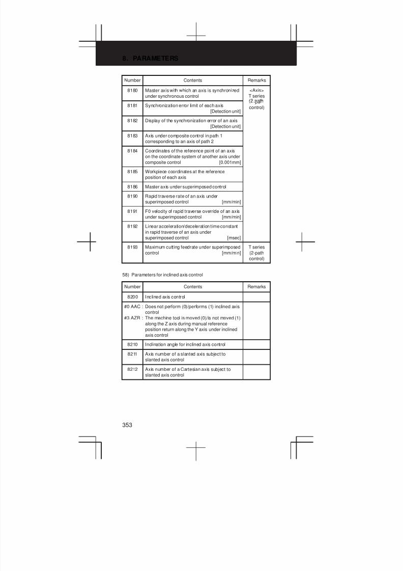
8. PARAMETERS
353
Number RemarksContents
8180 Master axis with which an axis is synchronized
under synchronous control
<Axis>
T series
8181 Synchronization error limit of each axis
[Detection unit]
-pa
control)
8182 Display of the synchronization error of an axis
[Detection unit]
8183 Axis under composite control in path 1
corresponding to an axis of path 2
8184 Coordinates of the reference point of an axis
on the coordinate system of another axis under
composite control [0.001mm]
8185 Workpiece coordinates at the reference
position of each axis
8186 Master axis under superimposed control
8190 Rapid traverse rate of an axis under
superimposed control [mm/min]
8191 F0 velocity of rapid traverse override of an axis
under superimposed control [mm/min]
8192 Linear acceleration/deceleration time constant
in rapid traverse of an axis under
superimposed control [msec]
8193 Maximum cutting feedrate under superimposed
control [mm/min]
T series
(2-path
control)
58) Parameters for inclined axis control
Number Contents Remarks
8200 Inclined axis control
#0 AAC : Does not perform (0)/performs (1) inclined axis
control
#3 AZR : The machine tool is moved (0)/is not moved (1)
along the Z axis during manual reference
position return along the Y axis under inclined
axis control
8210 Inclination angle for inclined axis control
8211 Axis number of a slanted axis subject to
slanted axis control
8212 Axis number of a Cartesian axis subject to
slanted axis control
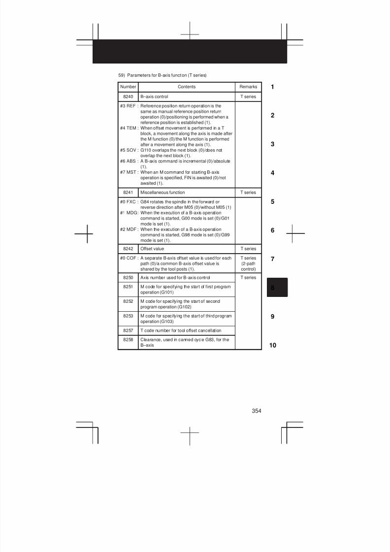
3
1
4
5
6
7
8
9
10
2
354
59) Parameters for B-axis function (T series)
Number Contents Remarks
8240 B–axis control T series
#3 REF : Reference position return operation is the
same as manual reference position return
operation (0)/positioning is performed when a
reference position is established (1).
#4 TEM : When offset movement is performed in a T
block, a movement along the axis is made after
the M function (0)/the M function is performed
after a movement along the axis (1).
#5 SOV : G110 overlaps the next block (0)/does not
overlap the next block (1).
#6 ABS : A B-axis command is incremental (0)/absolute
(1).
#7 MST : When an M command for starting B-axis
operation is specified, FIN is awaited (0)/not
awaited (1).
8241 Miscellaneous function T series
#0 FXC : G84 rotates the spindle in the forward or
reverse direction after M05 (0)/without M05 (1)
#1 MDG: When the execution of a B-axis operation
command is started, G00 mode is set (0)/G01
mode is set (1).
#2 MDF : When the execution of a B-axis operation
command is started, G98 mode is set (0)/G99
mode is set (1).
8242 Offset value T series
#0 COF : A separate B-axis offset value is used for each
path (0)/a common B-axis offset value is
shared by the tool posts (1).
T series
(2-path
control)
8250 Axis number used for B-axis control T series
8251 M code for specifying the start of first program
operation (G101)
8252 M code for specifying the start of second
program operation (G102)
8253 M code for specifying the start of third program
operation (G103)
8257 T code number for tool offset cancellation
8258 Clearance, used in canned cycle G83, for the
B–axis
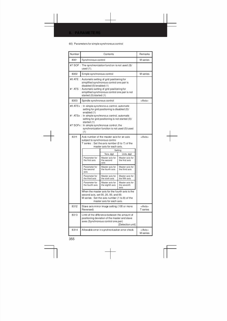
8. PARAMETERS
355
60) Parameters for simple synchronous control
Number Contents Remarks
8301 Synchronous control M series
#7 SOF : The synchronization function is not used (0)/
used (1).
8302 Simple synchronous control M series
#0 ATE : Automatic setting of grid positioning for
simplified synchronous control one pair is
disabled (0)/enabled (1)
#1 ATS : Automatic setting of grid positioning for
simplified synchronous control one pair is not
started (0)/started (1)
8303 Spindle synchronous control <Axis>
#0 ATEx : In simple synchronous control, automatic
setting for grid positioning is disabled (0)/
enabled (1)
#1 ATSx : In simple synchronous control, automatic
setting for grid positioning is not started (0)/
started (1)
#7 SOFx : In simple synchronous control, the
synchronization function is not used (0)/used
(1)
8311 Axis number of the master axis for an axis
subject to synchronous control
T series : Set the axis number (0 to 7) of the
master axis for each axis.
When the master axis for the fourth axis is the
second axis, set 00, 20, 00, and 00.
M series: Set the axis number (1 to 8) of the
master axis for each axis.
Parameter forthe first axis
Setting
Tens digit Units digit
Master axis forthe secondaxis
Master axis forthe first axis
Parameter forthe secondaxis
Master axis forthe fourth axis
Master axis forthe third axis
Parameter forthe third axis
Master axis forthe sixth axis
Master axis forthe fifth axis
Master axis forthe eighth axis
Master axis forthe seventhaxis
Parameter forthe fourth axis
<Axis>
8312 Slave axis mirror image setting (100 or more:
Reversed)
<Axis>
T series
8313 Limit of the difference between the amount of
positioning deviation of the master and slave
axes (Synchronous control one pair)
[Detection unit]
8314 Allowable error in synchronization error check <Axis>
M series
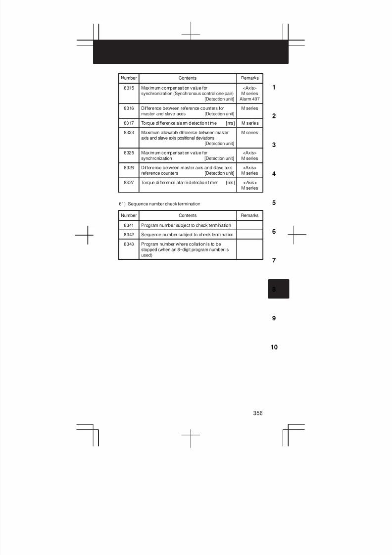
3
1
4
5
6
7
8
9
10
2
356
Number RemarksContents
8315 Maximum compensation value for
synchronization (Synchronous control one pair)
[Detection unit]
<Axis>
M series
Alarm 407
8316 Difference between reference counters for
master and slave axes [Detection unit]
M series
8317 Torque di fference alarm detection t ime [ms] M series
8323 Maximum allowable difference between master
axis and slave axis positional deviations
[Detection unit]
M series
8325 Maximum compensation value for
synchronization [Detection unit]
<Axis>
M series
8326 Difference between master axis and slave axis
reference counters [Detection unit]
<Axis>
M series
8327 Torque di fference alarm detect ion t imer [ms] <Axis>
M series
61) Sequence number check termination
Number Contents Remarks
8341 Program number subject to check termination
8342 Sequence number subject to check termination
8343 Program number where collation is to be
stopped (when an 8–digit program number is
used)
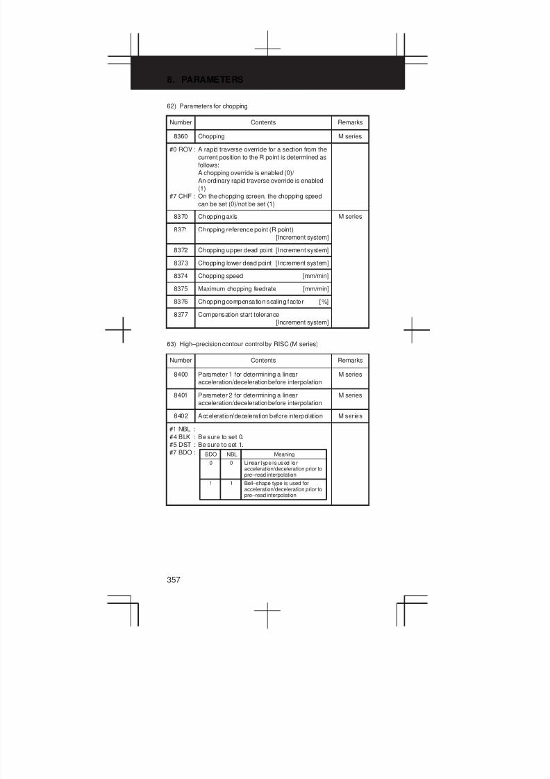
8. PARAMETERS
357
62) Parameters for chopping
Number Contents Remarks
8360 Chopping M series
#0 ROV : A rapid traverse override for a section from the
current position to the R point is determined as
follows:
A chopping override is enabled (0)/
An ordinary rapid traverse override is enabled
(1)
#7 CHF : On the chopping screen, the chopping speed
can be set (0)/not be set (1)
8370 Chopping axis M series
8371 Chopping reference point (R point)
[Increment system]
8372 Chopping upper dead point [Increment system]
8373 Chopping lower dead point [Increment system]
8374 Chopping speed [mm/min]
8375 Maximum chopping feedrate [mm/min]
8376 Chopping compensation scal ing factor [%]
8377 Compensation start tolerance
[Increment system]
63) High–precision contour control by RISC (M series)
Number Contents Remarks
8400 Parameter 1 for determining a linear
acceleration/deceleration before interpolation
M series
8401 Parameter 2 for determining a linear
acceleration/deceleration before interpolation
M series
8402 Acceleration/deceleration before interpolation M series
#1 NBL :
#4 BLK : Be sure to set 0.
#5 DST : Be sure to set 1.
#7 BDO :
0
BDO NBL Meaning
0 Linear type is used foracceleration/deceleration prior topre–read interpolation
1 1 Bell–shape type is used foracceleration/deceleration prior topre–read interpolation

3
1
4
5
6
7
8
9
10
2
358
Number RemarksContents
8403 Stored stroke check M series
#1 MSU: If A G00, M, S, T, or B code is specified in
HPCC mode, an alarm is issued (0)/the
command is executed (1).
#2 LM1 : In HPCC mode, a strokek check before
movement for stored stroke check 1 is not
performed (0)/performed (1)
#3 LM2 : In HPCC mode, a strokek check before
movement for the stored stroke check –2 is not
performed (0)/performed (1)
#7 SG0 : When a G00 code is specified in the RISC
mode, the setting of 8403#1 is followed (0)/G00
is executed in a simplified manner in HPCC
mode (1).
PRM
8403#1=1
8404 Position command M series
PRM
8403#7
#0 STG : The positioning command (G00) is: executed
with the RISC board in a simplified manner
(0)/in the same way as normal (1)
8410 Allowable velocity difference in velocity
determination considering the velocity
difference at corners [mm/min]
M series
8416 Look-ahead bell-shaped
acceleration/deceleration before interpolation
M series
8451 Automatic velocity control M series
#0 USE : Automatic velocity control is not applied (0)/
applied (1)
#4 ZAG : The velocity is not determined (0)/determined
(1) according to the angle at which the machine
descends along the Z–axis
#7 NOF : In a block where automatic velocity control is
validated, the F command is validated (0)/
ignored (1)
8452 Range of velocity fluctuation to be ignored [%]
(Standard setting: 10)
M series
8456 Area–2 override [%] (Standard sett ing: 80) M ser ies
8457 Area–3 override [%] (Standard sett ing: 70) M ser ies
8458 Area–4 override [%] (Standard sett ing: 60) M ser ies
8455 Automatic velocity control
#0 CDC : Be sure to set to 0.
#1 CTY : Be sure to set to 1.
8464 Init ia l feedrate for automatic feedrate control M series
8465 Maximum allowable feedrate for automatic
feedrate control
M series

8. PARAMETERS
359
Number RemarksContents
8470 Parameter for determining allowable
acceleration in velocity calculation considering
acceleration [msec]
M series
8475 Automatic velocity control M series
#2 BIP : The function of deceleration at corners is not
used (0)/used (1). (Always set 1.)
#3 CIR : The function of automatic velocity control
considering acceleration and deceleration
during circular interpolation is not used (0)/
used (1)
PRM 8470
8480 Interpolation period M series
#4 RI0 : Always set the following values.
#5 RI1 :
#6 RI2 :0
RI2 RI1
1
RI0
0
8481 Rapid traverse rate in HPCC mode M series
PRM
8403#7
8485 Smooth interpolation, scaling M series
#0 G51 : In high–precision contour control (HPCC)
mode, scaling/coordinate system rotation is
disabled (0)/enabled (1)
#1 G81 : In high–precision contour control (HPCC)
mode, a hole machining canned cycle is
disabled (0)/enabled (1)
#2 G02 : In high–precision contour control (HPCC)
mode, helical interpolation is disabled (0)/
enabled (1)
#3 PRW: In high–precision contour control (HPCC)
mode, parameter rewriting using the PMC
window is disabled (0)/enabled (1)
#4 INV : In high–precision contour control (HPCC)
mode, involute interpolation is disabled (0)/
enabled (1)
#5 CDS : Disables (0)/enables (1) smooth interpolation in
HPCC mode.
8486 Maximum travel distance of a block where
smooth interpolation is applied
[Input increment]
M series

3
1
4
5
6
7
8
9
10
2
360
64) Parameters for macro executor and etc.
Number Contents Remarks
8650 Key code
#0 RSK : Upon reset, key codes are not passed to the
application (0)/passed to the application (1).
#1 CNA : If an NC alarm is issued while the C executor
user screen is displayed, the screen is
changed according to PRM3111#7 (0)/is not
changed (1).
8701 Read method
#1 PLD : Read operation is performed after the P-code
loader is cleared (0)/without clearing the
P-code loader (1).
#2 WPR: The function that allows parameters that are
rewritten using the PMC window to be enabled
during automatic operation is disabled (0)/
enabled (1)
#6 CTV : When CAP II is provided, 1 must be specified. T series
8703 MAP
#0 DLF : If file transfer using MAP, for example, is
terminated, an incomplete file is not deleted (0)/
deleted (1).
#1 LCL : A change in the internal state of the CNC is not
reported to the host (0)/reported to the host (1).
8760 Number of a program transferred to the Power
Mate by using the I/O Link
8781 Amount of DRAM used with the C executor
[64k Byte]
8790 Timing for executing an auxiliary macro
8801 Bit parameter 1 for machine tool builder
8802 Bit parameter 2 for machine tool builder
8811 2–word parameter 1 for machine tool builder
8812 2–word parameter 2 for machine tool builder
8813 2–word parameter 3 for machine tool builder
65) Maintenance
Number Contents Remarks
8901 Maintenance
#0 FAN : A fan motor error is detected (0)/not detected
(1). (Use inhibited)
8911 Ratio of the items on the periodic maintenance
screen to the respective lives [%]

9. ERROR CODE LIST
361
9.1 Alarms Displayed on NC Screen
9.1.1 Program errors (P/S alarm)
Number Message Contents
000 PLEASE TURN OFF
POWER
A parameter which requires the pow-
er off was input, turn off power.
001 TH PARITY ALARM TH alarm (A character with incorrect
parity was input).
Correct the program or tape.
002 TV PARITY ALARM TV alarm (The number of characters
in a block is odd). This alarm will be
generated only when the TV check is
effective.
003 TOO MANY DIGITS Data exceeding the maximum allow-
able number of digits was input. (Re-
fer to the item of max. programmable
dimensions.)
004 ADDRESS NOT FOUND A numeral or the sign “ – ” was input
without an address at the beginning
of a block. Modify the program .
005 NO DATA AFTER
ADDRESS
The address was not followed by the
appropriate data but was followed by
another address or EOB code.
Modify the program.
006 ILLEGAL USE OF
NEGATIVE SIGN
Sign “ – ” input error (Sign “ – ” was
input after an address with which it
cannot be used. Or two or more “ – ”
signs were input.)
Modify the program.
007 ILLEGAL USE OF DECIMAL
POINT
Decimal point “ . ” input error (A deci-
mal point was input after an address
with which it can not be used. Or two
decimal points were input.)
Modify the program.
009 ILLEGAL ADDRESS INPUT Unusable character was input in sig-
nificant area.
Modify the program.
010 IMPROPER G–CODE An unusable G code or G code corre-
sponding to the function not provided
is specified. Modify the program.
011 NO FEEDRATE
COMMANDED
Feedrate was not commanded to a
cutting feed or the feedrate was inad-
equate. Modify the program.
014 ILLEGAL LEAD COMMAND
(T series)
In variable lead threading, the lead
incremental and decremental out-
putted by address K exceed the
maximum command value or a com-
mand such that the lead becomes a
negative value is given.
Modify the program.
CAN NOT COMMAND G95
(M series)
A synchronous feed is specified
without the option for threading / syn-
chronous feed.
Modify the program.
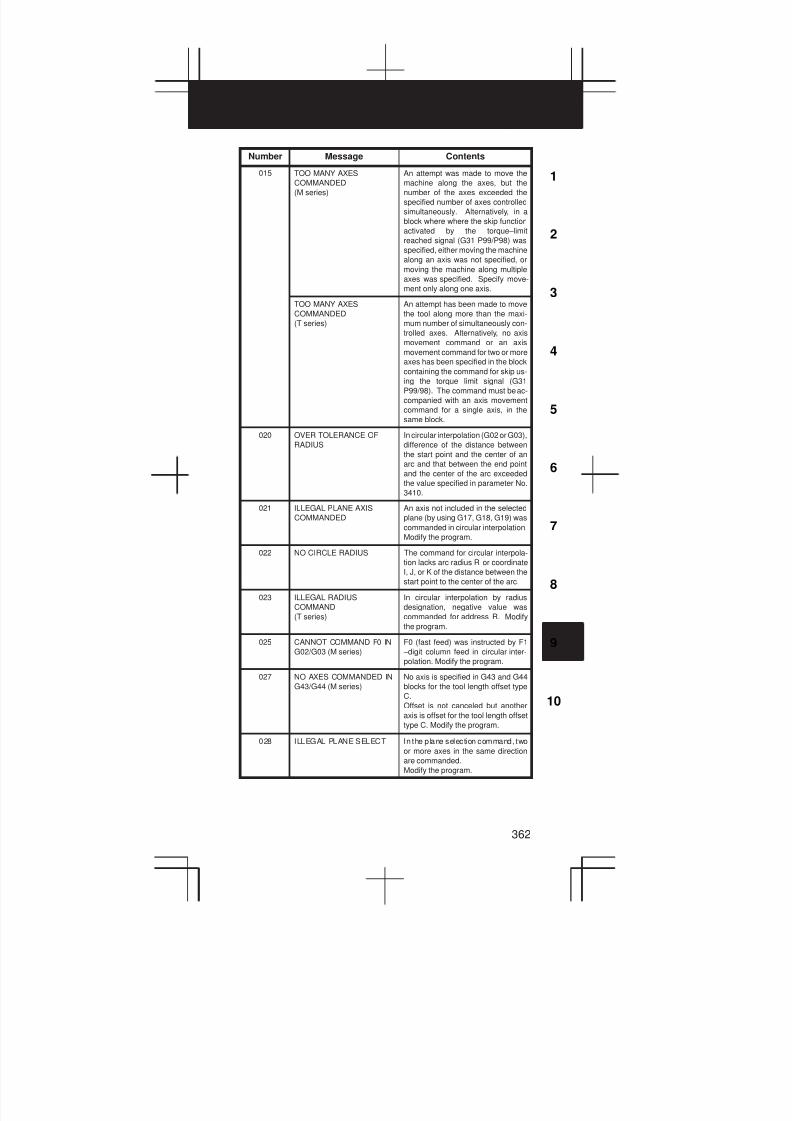
3
1
4
5
6
7
8
9
10
2
362
Number ContentsMessage
015 TOO MANY AXES
COMMANDED
(M series)
An attempt was made to move the
machine along the axes, but the
number of the axes exceeded the
specified number of axes controlled
simultaneously. Alternatively, in a
block where where the skip function
activated by the torque–limit
reached signal (G31 P99/P98) was
specified, either moving the machine
along an axis was not specified, or
moving the machine along multiple
axes was specified. Specify move-
ment only along one axis.
TOO MANY AXES
COMMANDED
(T series)
An attempt has been made to move
the tool along more than the maxi-
mum number of simultaneously con-
trolled axes. Alternatively, no axis
movement command or an axis
movement command for two or more
axes has been specified in the block
containing the command for skip us-
ing the torque limit signal (G31
P99/98). The command must be ac-
companied with an axis movement
command for a single axis, in the
same block.
020 OVER TOLERANCE OF
RADIUS
In circular interpolation (G02 or G03),
difference of the distance between
the start point and the center of an
arc and that between the end point
and the center of the arc exceeded
the value specified in parameter No.
3410.
021 ILLEGAL PLANE AXIS
COMMANDED
An axis not included in the selected
plane (by using G17, G18, G19) was
commanded in circular interpolation.
Modify the program.
022 NO CIRCLE RADIUS The command for circular interpola-
tion lacks arc radius R or coordinate
I, J, or K of the distance between the
start point to the center of the arc.
023 ILLEGAL RADIUS
COMMAND
(T series)
In circular interpolation by radius
designation, negative value was
commanded for address R. Modify
the program.
025 CANNOT COMMAND F0 IN
G02/G03 (M series)
F0 (fast feed) was instructed by F1
–digit column feed in circular inter-
polation. Modify the program.
027 NO AXES COMMANDED IN
G43/G44 (M series)
No axis is specified in G43 and G44
blocks for the tool length offset type
C.
Offset is not canceled but another
axis is offset for the tool length offset
type C. Modify the program.
028 ILLEGAL PLANE SELECT In the plane selection command, two
or more axes in the same direction
are commanded.
Modify the program.
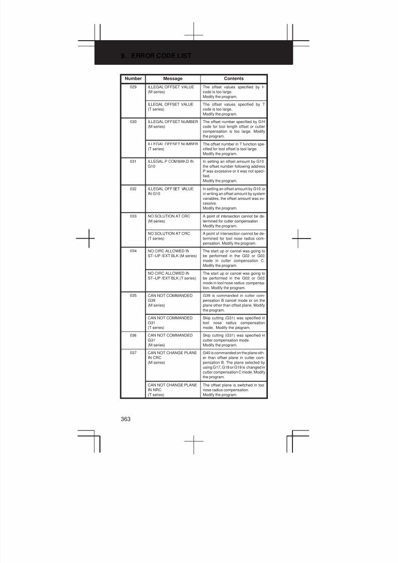
9. ERROR CODE LIST
363
Number ContentsMessage
029 ILLEGAL OFFSET VALUE
(M series)
The offset values specified by H
code is too large.
Modify the program.
ILLEGAL OFFSET VALUE
(T series)
The offset values specified by T
code is too large.
Modify the program.
030 ILLEGAL OFFSET NUMBER
(M series)
The offset number specified by D/H
code for tool length offset or cutter
compensation is too large. Modify
the program.
ILLEGAL OFFSET NUMBER
(T series)
The offset number in T function spe-
cified for tool offset is tool large.
Modify the program.
031 ILLEGAL P COMMAND IN
G10
In setting an offset amount by G10,
the offset number following address
P was excessive or it was not speci-
fied.
Modify the program.
032 ILLEGAL OFFSET VALUE
IN G10
In setting an offset amount by G10 or
in writing an offset amount by system
variables, the offset amount was ex-
cessive.
Modify the program.
033 NO SOLUTION AT CRC
(M series)
A point of intersection cannot be de-
termined for cutter compensation.
Modify the program.
NO SOLUTION AT CRC
(T series)
A point of intersection cannot be de-
termined for tool nose radius com-
pensation. Modify the program.
034 NO CIRC ALLOWED IN
ST–UP /EXT BLK (M series)
The start up or cancel was going to
be performed in the G02 or G03
mode in cutter compensation C.
Modify the program.
NO CIRC ALLOWED IN
ST–UP /EXT BLK (T series)
The start up or cancel was going to
be performed in the G02 or G03
mode in tool nose radius compensa-
tion. Modify the program.
035 CAN NOT COMMANDED
G39
(M series)
G39 is commanded in cutter com-
pensation B cancel mode or on the
plane other than offset plane. Modify
the program.
CAN NOT COMMANDED
G31
(T series)
Skip cutting (G31) was specified in
tool nose radius compensation
mode. Modify the program.
036 CAN NOT COMMANDED
G31
(M series)
Skip cutting (G31) was specified in
cutter compensation mode.
Modify the program.
037 CAN NOT CHANGE PLANE
IN CRC
(M seires)
G40 is commanded on the plane oth-
er than offset plane in cutter com-
pensation B. The plane selected by
using G17, G18 or G19 is changed in
cutter compensation C mode. Modify
the program.
CAN NOT CHANGE PLANE
IN NRC
(T seires)
The offset plane is switched in tool
nose radius compensation.
Modify the program.

3
1
4
5
6
7
8
9
10
2
364
Number ContentsMessage
038 INTERFERENCE IN
CIRCULAR BLOCK
(M seires)
Overcutting will occur in cutter com-
pensation C because the arc start
point or end point coincides with the
arc center.
Modify the program.
INTERFERENCE IN
CIRCULAR BLOCK
(T series)
Overcutting will occur in tool nose ra-
dius compensation because the arc
start point or end point coincides with
the arc center.
Modify the program.
039 CHF/CNR NOT ALLOWED
IN NRC
(T series)
Chamfering or corner R was speci-
fied with a start–up, a cancel, or
switching between G41 and G42 in
tool nose radius compensation. The
program may cause overcutting to
occur in chamfering or corner R.
Modify the program.
040 INTERFERENCE IN
G90/G94 BLOCK (T series)
Overcutting will occur in tool nose ra-
dius compensation in canned cycle
G90 or G94. Modify the program.
041 INTERFERENCE IN CRC
(M seires)
Overcutting will occur in cutter com-
pensation C. Two or more blocks are
consecutively specified in which
functions such as the auxiliary func-
tion and dwell functions are per-
formed without movement in the cut-
ter compensation mode. Modify the
program.
INTERFERENCE IN NRC
(T seires)
Overcutting will occur in tool nose ra-
dius compensation.
Modify the program.
042 G45/G48 NOT ALLOWED IN
CRC
(M series)
Tool offset (G45 to G48) is comman-
ded in cutter compensation. Modify
the program.
043 ILLEGAL T–CODE
COMMAND
(M series)
In a system using the DRILL–MATE
with an ATC, a T code was not speci-
fied together with the M06 code in a
block. Alternatively, the Tcode was
out of range.
044 G27–G30 NOT ALLOWED
IN FIXED CYC (M sries)
One of G27 to G30 is commanded in
canned cycle mode.
Modify the program.
046 ILLEGAL REFERENCE
RETURN COMMAND
Other than P2, P3 and P4 are com-
manded for 2nd, 3rd and 4th refer-
ence position return command.
Modify the program.
047 ILLEGAL AXIS SELECT
(M series)
Two or more parallel axes (in parallel
with a basic axis) have been speci-
fied upon start–up of three–dimen-
sional tool compensation or three–
dimensional coordinate conversion.
048 BASIC 3 AXIS NOT FOUND
(M series)
Start–up of three–dimensional tool
compensation or three–dimensional
coordinate conversion has been at-
tempted, but the three basic axes
used when Xp, Yp, or Zp is omitted
are not set in parameter No. 1022.
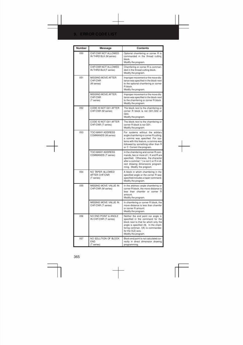
9. ERROR CODE LIST
365
Number ContentsMessage
050 CHF/CNR NOT ALLOWED
IN THRD BLK (M series)
Optional chamfering or corner R is
commanded in the thread cutting
block.
Modify the program.
CHF/CNR NOT ALLOWED
IN THRD BLK(T series)
Chamfering or corner R is comman-
ded in the thread cutting block.
Modify the program.
051 MISSING MOVE AFTER
CHF/CNR
(M series)
Improper movement or the move dis-
tance was specified in the block next
to the optional chamfering or corner
R block.
Modify the program.
MISSING MOVE AFTER
CHF/CNR
(T series)
Improper movement or the move dis-
tance was specified in the block next
to the chamfering or corner R block.
Modify the program.
052 CODE IS NOT G01 AFTER
CHF/CNR (M series)
The block next to the chamfering or
corner R block is not G01,G02 or
G03.
Modify the program.
CODE IS NOT G01 AFTER
CHF/CNR (T series)
The block next to the chamfering or
corner R block is not G01.
Modify the program.
053 TOO MANY ADDRESS
COMMANDS (M series)
For systems without the arbitary
angle chamfering or corner R cutting,
a comma was specified. For sys-
tems with this feature, a comma was
followed by something other than R
or C Correct the program.
TOO MANY ADDRESS
COMMANDS (T seires)
In the chamfering and corner R com-
mands, two or more of I, K and R are
specified. Otherwise, the character
after a comma(“,”) is not C or R in di-
rect drawing dimensions program-
ming. Modify the program.
054 NO TAPER ALLOWED
AFTER CHF/CNR
(T series)
A block in which chamfering in the
specified angle or the corner R was
specified includes a taper command.
Modify the program.
055 MISSING MOVE VALUE IN
CHF/CNR (M series)
In the arbitrary angle chamfering or
corner R block, the move distance is
less than chamfer or corner R
amount.
Modify the program.
MISSING MOVE VALUE IN
CHF/CNR (T series)
In chamfering or corner R block, the
move distance is less than chamfer
or corner R amount.
Modify the program.
056 NO END POINT & ANGLE
IN CHF/CNR (T series)
Neither the end point nor angle is
specified in the command for the
block next to that for which only the
angle is specified (A). In the cham-
fering comman, I(K) is commanded
for the X(Z) axis.
Modify the program.
057 NO SOLUTION OF BLOCK
END
(T series)
Block end point is not calculated cor-
rectly in direct dimension drawing
programming.

3
1
4
5
6
7
8
9
10
2
366
Number ContentsMessage
058 END POINT NOT FOUND
(M series)
In a arbitrary angle chamfering or
corner R cutting block, a specified
axis is not in the selected plane.
Modify the program.
END POINT NOT FOUND
(T series)
Block end point is not found in direct
dimension drawing programming.
Modify the program.
059 PROGRAM NUMBER NOT
FOUND
In an external program number
search, a specified program number
was not found. Otherwise, a program
specified for searching is being
edited in background processing.
Check the program number and ex-
ternal signal. Or discontinue the
background eiting.
060 SEQUENCE NUMBER NOT
FOUND
Commanded sequence number was
not found in the sequence number
search. Check the sequence num-
ber.
061 ADDRESS P/Q NOT
FOUND IN G70–G73
(T series)
Address P or Q is not specified in
G70, G71, G72, or G73 command.
Modify the program.
062 ILLEGAL COMMAND IN
G71–G76
(T series)
1) The depth of cut in G71 or G72 is
zero or negative value.
2) The repetitive count in G73 is
zero or negative value.
3) The negative value is specified
to ∆i or ∆k is zero in G74 or G75.
4) A value other than zero is speci-
fied to address U or W though ∆i
or ∆k is zero in G74 or G75.
5) A negative value is specified to
∆d, though the relief direction in
G74 or G75 is determined.
6) Zero or a negative value is speci-
fied to the height of thread or
depth of cut of first time in G76.
7) The specified minimum depth of
cut in G76 is greater than the
height of thread.
8) An unusable angle of tool tip is
specified in G76.
Modify the program.
063 SEQUENCE NUMBER NOT
FOUND
(T series)
The sequence number specified by
address P in G70, G71, G72, or G73
command cannot be searched.
Modify the program.
064 SHAPE PROGRAM NOT
MONOTONOUSLY
(T series)
A target shape which cannot be
made by monotonic machining was
specified in a repetitive canned cycle
(G71 or G72).
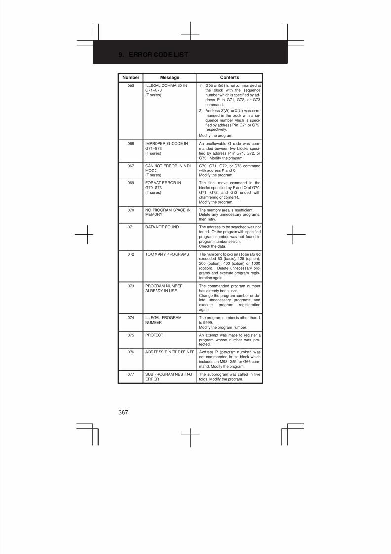
9. ERROR CODE LIST
367
Number ContentsMessage
065 ILLEGAL COMMAND IN
G71–G73
(T series)
1) G00 or G01 is not commanded at
the block with the sequence
number which is specified by ad-
dress P in G71, G72, or G73
command.
2) Address Z(W) or X(U) was com-
manded in the block with a se-
quence number which is speci-
fied by address P in G71 or G72,
respectively.
Modify the program.
066 IMPROPER G–CODE IN
G71–G73
(T series)
An unallowable G code was com-
manded beween two blocks speci-
fied by address P in G71, G72, or
G73. Modify the program.
067 CAN NOT ERROR IN MDI
MODE
(T series)
G70, G71, G72, or G73 command
with address P and Q.
Modify the program.
069 FORMAT ERROR IN
G70–G73
(T series)
The final move command in the
blocks specified by P and Q of G70,
G71, G72, and G73 ended with
chamfering or corner R.
Modify the program.
070 NO PROGRAM SPACE IN
MEMORY
The memory area is insufficient.
Delete any unnecessary programs,
then retry.
071 DATA NOT FOUND The address to be searched was not
found. Or the program with specified
program number was not found in
program number search.
Check the data.
072 TOO MANY PROGRAMS The number o f programs to be s tored
exceeded 63 (basic), 125 (option),
200 (option), 400 (option) or 1000
(option). Delete unnecessary pro-
grams and execute program regis-
teration again.
073 PROGRAM NUMBER
ALREADY IN USE
The commanded program number
has already been used.
Change the program number or de-
lete unnecessary programs and
execute program registeration
again.
074 ILLEGAL PROGRAM
NUMBER
The program number is other than 1
to 9999.
Modify the program number.
075 PROTECT An attempt was made to register a
program whose number was pro-
tected.
076 ADDRESS P NOT DEFINED Address P (program number) was
not commanded in the block which
includes an M98, G65, or G66 com-
mand. Modify the program.
077 SUB PROGRAM NESTING
ERROR
The subprogram was called in five
folds. Modify the program.

3
1
4
5
6
7
8
9
10
2
368
Number ContentsMessage
078 NUMBER NOT FOUND A program number or a sequence
number which was specified by ad-
dress P in the block which includes
an M98, M99, M65 or G66 was not
found. The sequence number speci-
fied by a GOTO statement was not
found. Otherwise, a called program
is being edited in background pro-
cessing. Correct the program, or dis-
continue the background editing.
079 PROGRAM VERIFY ERROR In memory or program col lation, a
program in memory does not agree
with that read from an external I/O
device. Check both the programs in
memory and those from the external
device.
080 G37 ARRIVAL SIGNAL NOT
ASSERTED
(M series)
In the automatic tool length mea-
surement function (G37), the mea-
surement position reach signal
(XAE, YAE, or ZAE) is not t urned on
within an area specified in parameter
6254 6255 (value ε).
This is due to a setting or operator er-
ror.
G37 ARRIVAL SIGNAL NOT
ASSERTED
(T series)
In the automatic tool compensation
function (G36, G37), the measure-
ment position reach signal (XAE or
ZAE) is not turned on within an area
specified in parameter 6254 (value
ε).
This is due to a setting or operator er-
ror.
081 OFFSET NUMBER NOT
FOUND IN G37
(M series)
Tool length automatic measurement
(G37) was specified without a H
code. (Automatic tool length mea-
surement function) Modify the pro-
gram.
OFFSET NUMBER NOT
FOUND IN G37 (T series)
Automatic tool compensation (G36,
G37) was specified without a T code.
(Automatic tool compensation func-
tion) Modify the program.
082 H–CODE NOT ALLOWED
IN G37
(M series)
H code and automatic tool com-
pensation (G37) were specified in
the same block. (Automatic tool
length measurement function)
Modify the program.
T–CODE NOT ALLOWED IN
G37
(T series)
T code and automatic tool com-
pensation (G36, G37) were specified
in the same block. (Automatic tool
compensation function)
Modify the program.
083 ILLEGAL AXIS COMMAND
IN G37
(M series)
In automatic tool length measure-
ment, an invalid axis was specified
or the command is incremental.
Modify the program.
ILLEGAL AXIS COMMAND
IN G37
(T series)
In automatic tool compensation
(G36, G37), an invalid axis was spe-
cified or the command is incremen-
tal. Modify the program.

9. ERROR CODE LIST
369
Number ContentsMessage
085 COMMUNICATION ERROR When entering data in the memory
by using Reader / Puncher interface,
an overrun, parity or framing error
was generated. The number of bits of
input data or setting of baud rate or
specification No. of I/O unit is incor-
rect.
086 DR SIGNAL OFF When entering data in the memory
by using Reader / Puncher interface,
the ready signal (DR) of reader /
puncher was turned off.
Power supply of I/O unit is off or
cable is not connected or a P.C.B. is
defective.
087 BUFFER OVERFLOW When entering data in the memory
by using Reader / Puncher interface,
though the read terminate command
is specified, input is not interrupted
after 10 characters read. I/O unit or
P.C.B. is defective.
088 LAN FILE TRANS ERROR
(CHANNEL–1)
File data transfer via OSI–ETHER-
NET has been stopped due to a
transfer error.
089 LAN FILE TRANS ERROR
(CHANNEL–2)
File data transfer via OSI–ETHER-
NET has been stopped due to a
transfer error.
090 REFERENCE RETURN
INCOMPLETE
The reference position return cannot
be performed normally because the
reference position return start point
is too close to the reference position
or the speed is too slow. Separate
the start point far enough from the
reference position, or specify a suffi-
ciently fast speed for reference posi-
tion return. Check the program con-
tents.
091 REFERENCE RETURN
INCOMPLETE
Manual reference position return
cannot be performed when automat-
ic operation is halted.
092 AXES NOT ON THE
REFERENCE POINT
The commanded axis by G27 (Refer-
ence position return check) did not
return to the reference position.
094 P TYPE NOT ALLOWED
(COORD CHG)
P type cannot be specified when the
program is restarted. (After the auto-
matic operation was interrupted, the
coordinate system setting operation
was performed.)
Perform the correct operation ac-
cording to th operator’s manual.
095 P TYPE NOT ALLOWED
(EXT OFS CHG)
P type cannot be specified when the
program is restarted. (After the auto-
matic operation was interrupted, the
external workpiece offset amount
changed.)
Perform the correct operation ac-
cording to th operator’s manual.
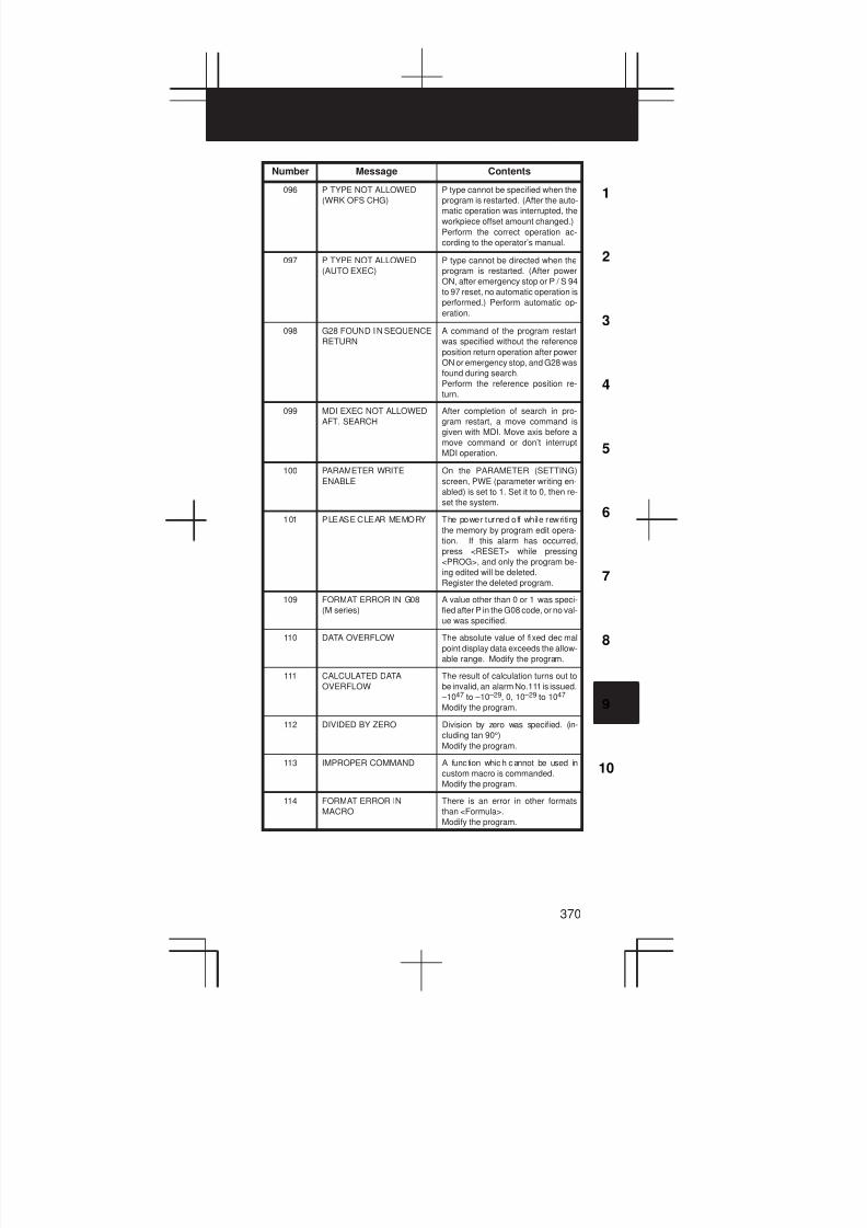
3
1
4
5
6
7
8
9
10
2
370
Number ContentsMessage
096 P TYPE NOT ALLOWED
(WRK OFS CHG)
P type cannot be specified when the
program is restarted. (After the auto-
matic operation was interrupted, the
workpiece offset amount changed.)
Perform the correct operation ac-
cording to the operator’s manual.
097 P TYPE NOT ALLOWED
(AUTO EXEC)
P type cannot be directed when the
program is restarted. (After power
ON, after emergency stop or P / S 94
to 97 reset, no automatic operation is
performed.) Perform automatic op-
eration.
098 G28 FOUND IN SEQUENCE
RETURN
A command of the program restart
was specified without the reference
position return operation after power
ON or emergency stop, and G28 was
found during search.
Perform the reference position re-
turn.
099 MDI EXEC NOT ALLOWED
AFT. SEARCH
After completion of search in pro-
gram restart, a move command is
given with MDI. Move axis before a
move command or don’t interrupt
MDI operation.
100 PARAMETER WRITE
ENABLE
On the PARAMETER (SETTING)
screen, PWE (parameter writing en-
abled) is set to 1. Set it to 0, then re-
set the system.
101 PLEASE CLEAR MEMORY The power turned off while rewriting
the memory by program edit opera-
tion. If this alarm has occurred,
press <RESET> while pressing
<PROG>, and only the program be-
ing edited will be deleted.
Register the deleted program.
109 FORMAT ERROR IN G08
(M series)
A value other than 0 or 1 was speci-
fied after P in the G08 code, or no val-
ue was specified.
110 DATA OVERFLOW The absolute value of fixed decimal
point display data exceeds the allow-
able range. Modify the program.
111 CALCULATED DATA
OVERFLOW
The result of calculation turns out to
be invalid, an alarm No.111 is issued.
–1047 to –10 –29, 0, 10 –29 to 1047
Modify the program.
112 DIVIDED BY ZERO Division by zero was specified. (in-
cluding tan 90°)
Modify the program.
113 IMPROPER COMMAND A func tion which cannot be used in
custom macro is commanded.
Modify the program.
114 FORMAT ERROR IN
MACRO
There is an error in other formats
than <Formula>.
Modify the program.

9. ERROR CODE LIST
371
Number ContentsMessage
115 ILLEGAL VARIABLE
NUMBER
A value not defined as a variable
number is designated in the custom
macro or in high–speed cycle ma-
chining.
The header contents are improper.
This alarm is given in the following
cases:
High speed cycle machining
1) The header corresponding to the
specified machining cycle num-
ber called is not found.
2) The cycle connection data value
is out of the allowable range (0 –
999).
3) The number of data in the header
is out of the allowable range (0 –
32767).
4) The start data variable number of
executable format data is out of
the allowable range (#20000 –
#85535).
5) The last storing data variable
number of executable format
data is out of t he allowable range
(#85535).
6) The storing start data variable
number of executable format
data is overlapped with the vari-
able number used in the header.
Modify the program.
116 WRITE PROTECTED
VARIABLE
The left side of substitution state-
ment is a variable whose substitution
is inhibited. Modify the program.
118 PARENTHESIS NESTING
ERROR
The nesting of bracket exceeds the
upper limit (quintuple).
Modify the program.
119 ILLEGAL ARGUMENT The SQRT argument is negative. Or
BCD argument is negative, and other
values than 0 to 9 are present on
each line of BIN argument.
Modify the program.
122 FOUR FOLD MACRO
MODAL–CALL
The macro modal call is specified
four fold.
Modify the program.
123 CAN NOT USE MACRO
COMMAND IN DNC
Macro control command is used dur-
ing DNC operation.
Modify the program.
124 MISSING END STATEMENT DO – END does not correspond to 1
: 1. Modify the program.
125 FORMAT ERROR IN
MACRO
<Formula> format is erroneous.
Modify the program.
126 ILLEGAL LOOP NUMBER In DOn, 1x nx3 is not established.
Modify the program.
127 NC, MACRO STATEMENT
IN SAME BLOCK
NC and custom macro commands
coexist.
Modify the program.

3
1
4
5
6
7
8
9
10
2
372
Number ContentsMessage
128 ILLEGAL MACRO
SEQUENCE NUMBER
The sequence number specified in
the branch command was not 0 to
9999. Or, it cannot be searched.
Modify the program.
129 ILLEGAL ARGUMENT
ADDRESS
An address which is not allowed in
<Argument Designation > is used.
Modify the program.
130 ILLEGAL AXIS OPERATION An axis control command was given
by PMC to an axis controlled by
CNC. Or an axis control command
was given by CNC to an axis con-
trolled by PMC. Modify the program.
131 TOO MANY EXTERNAL
ALARM MESSAGES
Five or more alarms have generated
in external alarm message.
Consult the PMC ladder diagram to
find the cause.
132 ALARM NUMBER NOT
FOUND
No alarm No. concerned exists in ex-
ternal alarm message clear.
Check the PMC ladder diagram.
133 ILLEGAL DATA IN EXT.
ALARM MSG
Small section data is erroneous in
external alarm message or external
operator message. Check the PMC
ladder diagram.
135 ILLEGAL ANGLE
COMMAND
(M series)
The index table indexing positioning
angle was instructed in other than an
integral multiple of the value of the
minimum angle.
Modify the program.
SPINDLE ORIENTATION
PLEASE
(T series)
Without any spindle orientation , an
attept was made for spindle index-
ing. Perform spindle orientation.
136 ILLEGAL AXIS COMMAND
(M series)
In index table indexing.Another con-
trol axis was instructed together with
the B axis.
Modify the program.
C/H–CODE & MOVE CMD
IN SAME BLK. (T series)
A move command of other axes was
specified to the same block as
spindle indexing addresses C, H.
Modify the program.
137 M–CODE & MOVE CMD IN
SAME BLK.
(T series)
A move command of other axes was
specified to the same block as M–
code related to spindle indexing.
Modify the program.
138 SUPERIMPOSED D ATA
OVERFLOW
The total distribution amount of the
CNC and PMC is too large during su-
perimposed control of the extended
functions for PMC axis control.
139 CAN NOT CHANGE PMC
CONTROL AXIS
An axis is selected in commanding
by PMC axis control.
Modify the program.
141 CAN NOT COMMAND G51
IN CRC
(M series)
G51 (Scaling ON) is commanded in
the tool offset mode.
Modify the program.
142 ILLEGAL SCALE RATE
(M series)
Scaling magnification is comman-
ded in other than 1 – 999999.
Correct the scaling magnification
setting (G51 Pp… or parameter 5411
or 5421).

9. ERROR CODE LIST
373
Number ContentsMessage
143 SCALED MOTION DATA
OVERFLOW
(M series)
The scaling results, move distance,
coordinate value and circular radius
exceed the maximum command val-
ue. Correct the program or scaling
mangification.
144 ILLEGAL PLANE
SELECTED
(M series)
The coordinate rotation plane and
arc or cutter compensation C plane
must be the same. Modify the pro-
gram.
145 ILLEGAL CONDITIONS IN
POLAR COORDINATE
INTERPOLATION
The conditions are incorrect when
the polar coordinate interpolation
starts or it is canceled.
1) In modes other than G40,
G12.1/G13.1 was specified.
2) An error is found in the plane
selection. Parameters No. 5460
and No. 5461 are incorrectly spe-
cified.
Modify the value of program or
parameter.
146 IMPROPER G CODE G codes which cannot be specified
in the polar coordinate interpolation
mode was specified. See Chapter 4
and modify the program.
148 ILLEGAL SETTING DATA
(M series)
Automatic corner override decelera-
tion rate is out of the settable range
of judgement angle. Modify the pa-
rameters (No.1710 to No.1714)
149 FORMAT ERROR IN G10L3
(M series)
A code other than Q1,Q2,P1 or P2
was specified as the life count type in
the extended tool life management.
150 ILLEGAL TOOL GROUP
NUMBER
Tool Group No. exceeds the maxi-
mum allowable value.
Modify the program.
151 TOOL GROUP NUMBER
NOT FOUND
The tool group commanded in the
machining program is not set.
Modify the value of program or pa-
rameter.
152 NO SPACE FOR TOOL
ENTRY
The number of tools within one group
exceeds the maximum value regis-
terable. Modify the number of tools.
153 T–CODE NOT FOUND In tool life data registration, a T code
was not specified where one should
be. Modify the program.
154 NOT USING TOOL IN LIFE
GROUP (M series)
When the group is not commanded,
H99 or D99 was commanded.
Modify the program.
155 ILLEGAL T–CODE IN M06
(M series)
In the machining program, M06 and
T code in the same block do not cor-
respond to the group in use.
Modify the program.
ILLEGAL T–CODE IN M06
(T series)
Group No.∆∆ which is specified with
T∆∆ 88 of the machining program do
not included in the tool group in use.
Modify the program.
156 P/L COMMAND NOT
FOUND
P and L commands are missing at
the head of program in which the tool
group is set. Modify the program.

3
1
4
5
6
7
8
9
10
2
374
Number ContentsMessage
157 TOO MANY TOOL GROUPS The number of tool groups to be set
exceeds the maximum allowable
value. (See parameter No. 6800 bit 0
and 1) Modify the program.
158 ILLEGAL TOOL LIFE DATA The tool li fe to be set is too exces-
sive. Modify the setting value.
159 TOOL DATA SETTING
INCOMPLETE
During executing a life data setting
program, power was turned off.
Set again.
160 MISMATCH WATING
M–CODE
T series (At two–path)
Diffrent M code is commanded in
heads 1 and 2 as waiting M code.
Modify the program.
G72.1 NESTING ERROR
(M series)
A subprogram which performs rota-
tional copy with G72.1 contains
another G72.1 command.
161 G72.2 NESTING ERROR
(M series)
A subprogram which performs paral-
lel copy with G72.2 contains another
G72.2 command.
163 COMMAND G68/G69
INDEPENDENTLY
(T series (At two–path))
G68 and G69 are not independently
commanded in balance cut.
Modify the program.
169 ILLEGAL TOOL
GEOMETRY DATA
(T series (At two–path))
Incorrect tool figure data in interfer-
ence check.
Set correct data, or select correct
tool figure data.
175 ILLEGAL G107 COMMAND Conditions when performing circular
interpolation start or cancel not cor-
rect. To change the mode to the cy-
lindrical interpolation mode, specify
the command in a format of “G07.1
rotation–axis name radius of cylin-
der.”
176 IMPROPER G–CODE IN
G107
(M series)
Any of the following G codes which
cannot be specified in the cylindrical
interpolation mode was specified.
1) G codes for positioning: G28,,
G73, G74, G76, G81 – G89, in-
cluding the codes specifying the
rapid traverse cycle
2) G codes for setting a coordinate
system: G52,G92,
3) G code for selecting coordinate
system: G53, G54–G59
Modify the program.
IMPROPER G–CODE IN
G107
(T series)
Any of the following G codes which
cannot be specified in the cylindrical
interpolation mode was specified.
1) G codes for positioning: G28,
G76, G81 – G89, including the
codes specifying the rapid tra-
verse cycle
2) G codes for setting a coordinate
system: G50, G52
3) G code for selecting coordinate
system: G53, G54–G59
Modify the program.
177 CHECK SUM ERROR
(G05 MODE)
Check sum error
Modify the program.
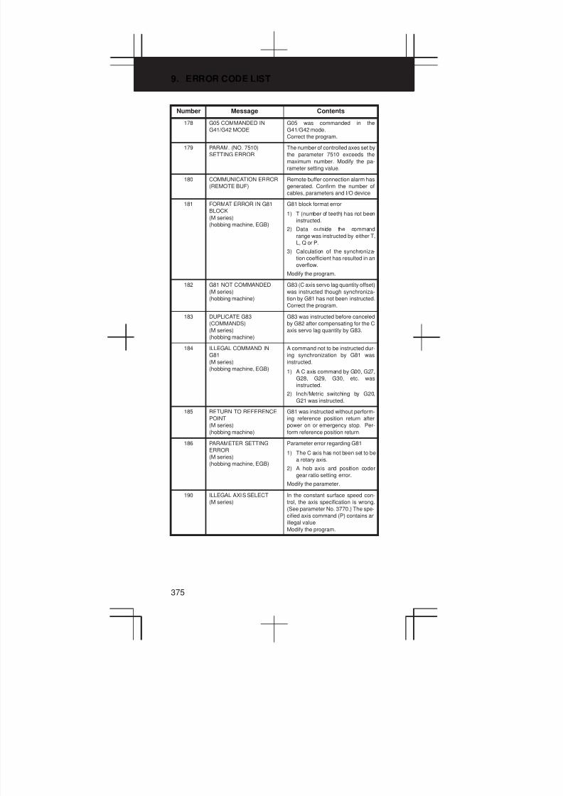
9. ERROR CODE LIST
375
Number ContentsMessage
178 G05 COMMANDED IN
G41/G42 MODE
G05 was commanded in the
G41/G42 mode.
Correct the program.
179 PARAM. (NO. 7510)
SETTING ERROR
The number of controlled axes set by
the parameter 7510 exceeds the
maximum number. Modify the pa-
rameter setting value.
180 COMMUNICATION ERROR
(REMOTE BUF)
Remote buffer connection alarm has
generated. Confirm the number of
cables, parameters and I/O device.
181 FORMAT ERROR IN G81
BLOCK
(M series)
(hobbing machine, EGB)
G81 block format error
1) T (number of teeth) has not been
instructed.
2) Data outside the command
range was instructed by either T,
L, Q or P.
3) Calculation of the synchroniza-
tion coefficient has resulted in an
overflow.
Modify the program.
182 G81 NOT COMMANDED
(M series)
(hobbing machine)
G83 (C axis servo lag quantity offset)
was instructed though synchroniza-
tion by G81 has not been instructed.
Correct the program.
183 DUPLICATE G83
(COMMANDS)
(M series)
(hobbing machine)
G83 was instructed before canceled
by G82 after compensating for the C
axis servo lag quantity by G83.
184 ILLEGAL COMMAND IN
G81
(M series)
(hobbing machine, EGB)
A command not to be instructed dur-
ing synchronization by G81 was
instructed.
1) A C axis command by G00, G27,
G28, G29, G30, etc. was
instructed.
2) Inch/Metric switching by G20,
G21 was instructed.
185 RETURN TO REFERENCE
POINT
(M series)
(hobbing machine)
G81 was instructed without perform-
ing reference position return after
power on or emergency stop. Per-
form reference position return.
186 PARAMETER SETTING
ERROR
(M series)
(hobbing machine, EGB)
Parameter error regarding G81
1) The C axis has not been set to be
a rotary axis.
2) A hob axis and position coder
gear ratio setting error.
Modify the parameter.
190 ILLEGAL AXIS SELECT
(M series)
In the constant surface speed con-
trol, the axis specification is wrong.
(See parameter No. 3770.) The spe-
cified axis command (P) contains an
illegal value.
Modify the program.
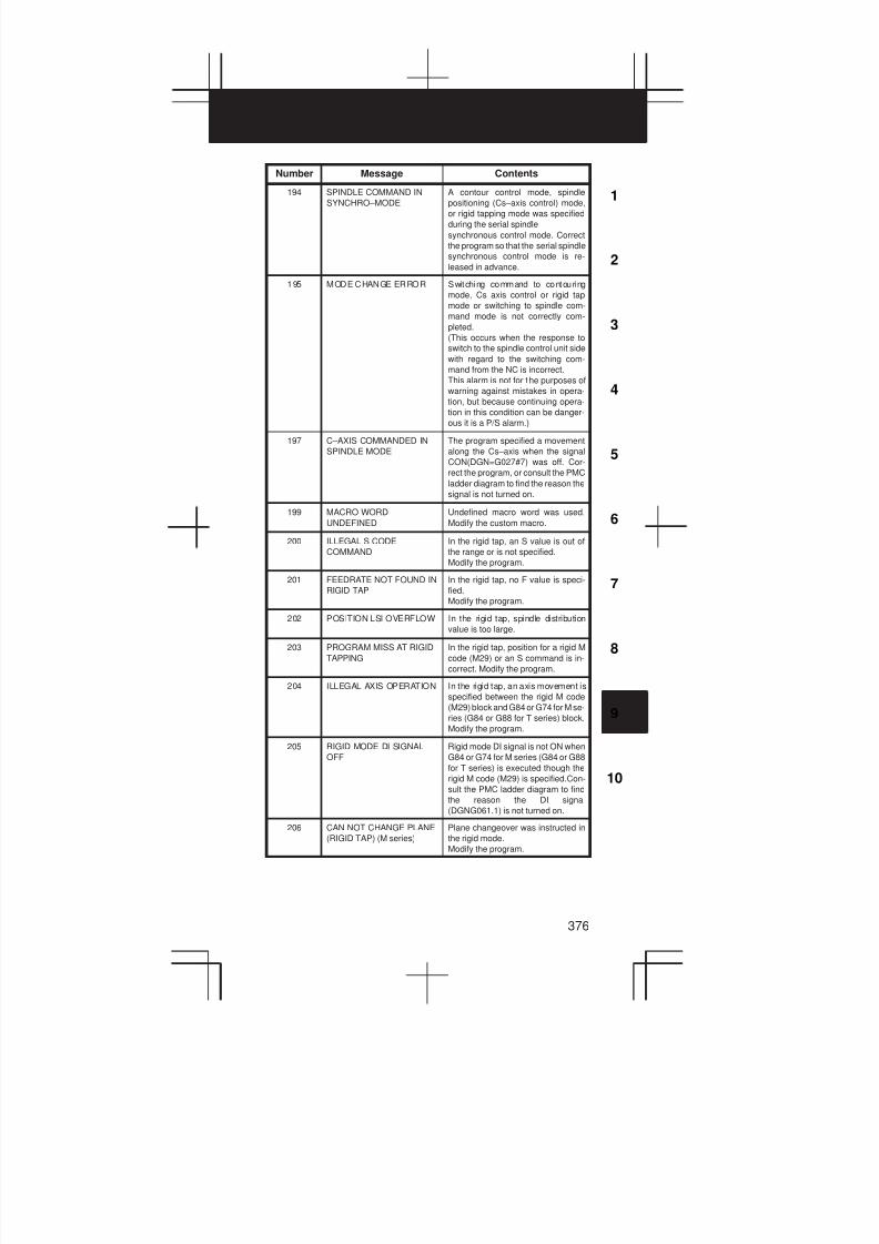
3
1
4
5
6
7
8
9
10
2
376
Number ContentsMessage
194 SPINDLE COMMAND IN
SYNCHRO–MODE
A contour control mode, spindle
positioning (Cs–axis control) mode,
or rigid tapping mode was specified
during the serial spindle
synchronous control mode. Correct
the program so that the serial spindle
synchronous control mode is re-
leased in advance.
195 MODE CHANGE ERROR Switching command to contouring
mode, Cs axis control or rigid tap
mode or switching to spindle com-
mand mode is not correctly com-
pleted.
(This occurs when the response to
switch to the spindle control unit side
with regard to the switching com-
mand from the NC is incorrect.
This alarm is not for t he purposes of
warning against mistakes in opera-
tion, but because continuing opera-
tion in this condition can be danger-
ous it is a P/S alarm.)
197 C–AXIS COMMANDED IN
SPINDLE MODE
The program specified a movement
along the Cs–axis when the signal
CON(DGN=G027#7) was off. Cor-
rect the program, or consult the PMC
ladder diagram to find the reason the
signal is not turned on.
199 MACRO WORD
UNDEFINED
Undefined macro word was used.
Modify the custom macro.
200 ILLEGAL S CODE
COMMAND
In the rigid tap, an S value is out of
the range or is not specified.
Modify the program.
201 FEEDRATE NOT FOUND IN
RIGID TAP
In the rigid tap, no F value is speci-
fied.
Modify the program.
202 POSITION LSI OVERFLOW In the rigid tap, spindle distribution
value is too large.
203 PROGRAM MISS AT RIGID
TAPPING
In the rigid tap, position for a rigid M
code (M29) or an S command is in-
correct. Modify the program.
204 ILLEGAL AXIS OPERATION In the rigid tap, an axis movement is
specified between the rigid M code
(M29) block and G84 or G74 for M se-
ries (G84 or G88 for T series) block.
Modify the program.
205 RIGID MODE DI SIGNAL
OFF
Rigid mode DI signal is not ON when
G84 or G74 for M series (G84 or G88
for T series) is executed though the
rigid M code (M29) is specified.Con-
sult the PMC ladder diagram to find
the reason the DI signal
(DGNG061.1) is not turned on.
206 CAN NOT CHANGE PLANE
(RIGID TAP) (M series)
Plane changeover was instructed in
the rigid mode.
Modify the program.

9. ERROR CODE LIST
377
Number ContentsMessage
210 CAN NOT COMAND
M198/M199
M198 and M199 are executed in the
schedule operation. M198 is
executed in the DNC operation.
Modify the program.
1) The execution of an M198 or
M99 command was attempted
during scheduled operation. Al-
ternatively, the execution of an
M198 command was attempted
during DNC operation. Modify
the program.
2) The execution of an M99 com-
mand was attempted by an inter-
rupt macro during pocket ma-
chining in a multiple repetitive
canned cycle.
211 G31 (HIGH) NOT ALLOWED
IN G99
G31 is commanded in the per revolu-
tion command when the high–speed
skip option is provided. Modify the
program.
212 ILLEGAL PLANE SELECT
(M series)
The arbitrary angle chamfering or a
corner R is commanded or the plane
including an additional axis. Modify
the program.
ILLEGAL PLANE SELECT
(T series)
The direct drawing dimensions pro-
gramming is commanded for the
plane other than the Z–X plane.
Modify the program.
213 ILLEGAL COMMAND IN
SYNCHRO–MODE
(M series)
Movement is commanded for the
axis to be synchronously controlled.
Any of the following alarms occurred
in the operation with the simple syn-
chronization control.
1) The program issued the move
command to the slave axis.
2) The program issued the manual
continuous feed/manual handle
feed/incremental feed command
to the slave axis.
3) The program issued the auto-
matic reference position return
command without specifying the
manual reference position return
after the power was turned on.
4) The difference between the posi-
tion error amount of the master
and slave axes exceeded the
value specified in parameter
NO.8313.
ILLEGAL COMMAND IN
SYNCHRO–MODE
(T series)
A move command has been speci-
fied for an axis subject to synchro-
nous control.
214 ILLEGAL COMMAND IN
SYNCHRO–MODE
Coordinate system is set or tool com-
pensation of the shift type is
executed in the synchronous con-
trol. Modify the program.
217 DUPLICATE G51.2
(COMMANDS)
(T series)
G51.2/G251 is further commanded
in the G51.2/G251 mode. Modify the
program.
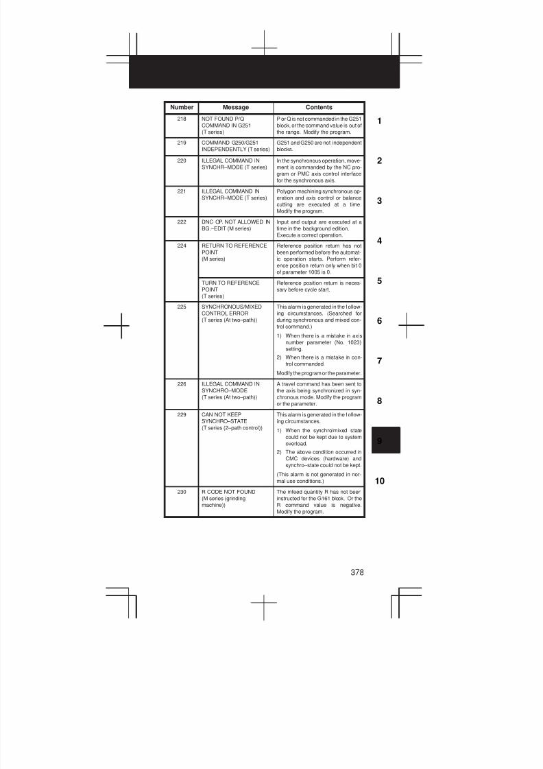
3
1
4
5
6
7
8
9
10
2
378
Number ContentsMessage
218 NOT FOUND P/Q
COMMAND IN G251
(T series)
P or Q is not commanded in the G251
block, or the command value is out of
the range. Modify the program.
219 COMMAND G250/G251
INDEPENDENTLY (T series)
G251 and G250 are not independent
blocks.
220 ILLEGAL COMMAND IN
SYNCHR–MODE (T series)
In the synchronous operation, move-
ment is commanded by the NC pro-
gram or PMC axis control interface
for the synchronous axis.
221 ILLEGAL COMMAND IN
SYNCHR–MODE (T series)
Polygon machining synchronous op-
eration and axis control or balance
cutting are executed at a time.
Modify the program.
222 DNC OP. NOT ALLOWED IN
BG.–EDIT (M series)
Input and output are executed at a
time in the background edition.
Execute a correct operation.
224 RETURN TO REFERENCE
POINT
(M series)
Reference position return has not
been performed before the automat-
ic operation starts. Perform refer-
ence position return only when bit 0
of parameter 1005 is 0.
TURN TO REFERENCE
POINT
(T series)
Reference position return is neces-
sary before cycle start.
225 SYNCHRONOUS/MIXED
CONTROL ERROR
(T series (At two–path))
This alarm is generated in the f ollow-
ing circumstances. (Searched for
during synchronous and mixed con-
trol command.)
1) When there is a mistake in axis
number parameter (No. 1023)
setting.
2) When there is a mistake in con-
trol commanded.
Modify the program or the parameter.
226 ILLEGAL COMMAND IN
SYNCHRO–MODE
(T series (At two–path))
A travel command has been sent to
the axis being synchronized in syn-
chronous mode. Modify the program
or the parameter.
229 CAN NOT KEEP
SYNCHRO–STATE
(T series (2–path control))
This alarm is generated in the f ollow-
ing circumstances.
1) When the synchro/mixed state
could not be kept due to system
overload.
2) The above condition occurred in
CMC devices (hardware) and
synchro–state could not be kept.
(This alarm is not generated in nor-
mal use conditions.)
230 R CODE NOT FOUND
(M series (grinding
machine))
The infeed quantity R has not been
instructed for the G161 block. Or the
R command value is negative.
Modify the program.
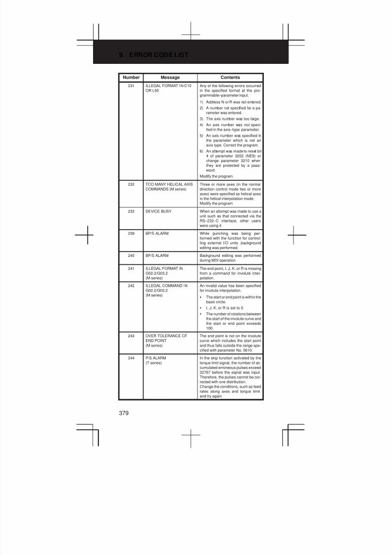
9. ERROR CODE LIST
379
Number ContentsMessage
231 ILLEGAL FORMAT IN G10
OR L50
Any of the following errors occurred
in the specified format at the pro-
grammable–parameter input.
1) Address N or R was not entered.
2) A number not specified for a pa-
rameter was entered.
3) The axis number was too large.
4) An axis number was not speci-
fied in the axis–type parameter.
5) An axis number was specified in
the parameter which is not an
axis type. Correct the program.
6) An attempt was made to reset bit
4 of parameter 3202 (NE9) or
change parameter 3210 when
they are protected by a pass-
word.
Modify the program.
232 TOO MANY HELICAL AXIS
COMMANDS (M series)
Three or more axes (in the normal
direction control mode two or more
axes) were specified as helical axes
in the helical interpolation mode.
Modify the program
233 DEVICE BUSY When an attempt was made to use a
unit such as that connected via the
RS–232–C interface, other users
were using it.
239 BP/S ALARM While punching was being per-
formed with the function for control-
ling external I/O units ,background
editing was performed.
240 BP/S ALARM Background editing was performed
during MDI operation.
241 ILLEGAL FORMAT IN
G02.2/G03.2
(M series)
The end point, I, J, K, or R is missing
from a command for involute inter-
polation.
242 ILLEGAL COMMAND IN
G02.2/G03.2
(M series)
An invalid value has been specified
for involute interpolation.
S The start or end point is within the
basic circle.
S I, J, K, or R is set to 0.
S The number of rotations between
the start of the involute curve and
the start or end point exceeds
100.
243 OVER TOLERANCE OF
END POINT
(M series)
The end point is not on the involute
curve which includes the start point
and thus falls outside the range spe-
cified with parameter No. 5610.
244 P/S ALARM
(T series)
In the skip function activated by the
torque limit signal, the number of ac-
cumulated erroneous pulses exceed
32767 before the signal was input.
Therefore, the pulses cannot be cor-
rected with one distribution.
Change the conditions, such as feed
rates along axes and torque limit,
and try again.

3
1
4
5
6
7
8
9
10
2
380
Number ContentsMessage
245 T–CODE NOT ALOWEE IN
THIS BLOCK (T series)
One of the G codes, G50, G10, and
G04, which cannot be specified in
the same block as a T code, was
specified with a T code.
250 Z AXIS WRONG COMMAND
(ATC)
(M series)
A value for the Z–axis has been spe-
cified in a block for the t ool exchange
command (M06T_) on a system with
DRILL–MATE ARC installed.
251 ATC ERROR
(M series)
This alarm is issued in the following
cases (DRILL–MATE):
S An M06T_ command contains
an unusable T code.
S An M06 command has been spe-
cified when the Z machine coordi
nate is positive.
S The parameter for the current
tool number (No. 7810) is set to
0.
S An M06 command has been spe-
cified in canned cycle mode.
S A reference position return com-
mand (G27 to G44) and M06
command have been specified
in the same block.
S An M06 command has been spe-
cified in tool compensation mode
(G41 to G44).
S An M06 command has been spe-
cified without performing refer-
ence position return after power–
on or the release of emergency
stop.
S The machine lock signal or Z–
axis ignore signal has been
turned on during tool exchange.
S A pry alarm has been detected
during tool exchange.
Refer to diagnosis No. 530 to deter-
mine the cause.
252 ATC SPINDLE ALARM
(M series)
An excessive error arose during
spindle positioning for ATC. For de-
tails, refer to diagnosis No. 531.
(Only for DRILL–MATE)
253 G05 IS NOT AVAILABLE
(M series)
Binary input operation using high–
speed remote buffer (G05) or high–
speed cycle machining (G05) has
been specified in advance control
mode (G08P1). Execute G08P0; to
cancel advance control mode, be-
fore executing these G05 com-
mands.
5000 ILLEGAL COMMAND CODE
(M series)
The specified code was incorrect in
the high–precision contour control
(HPCC) mode.
5003 ILLEGAL PARAMETER
(HPCC)
(M series)
There is an invalid parameter.
5004 HPCC NOT READY
(M series)
High–precision contour control is not
ready.
NOTE High–precision contour control.
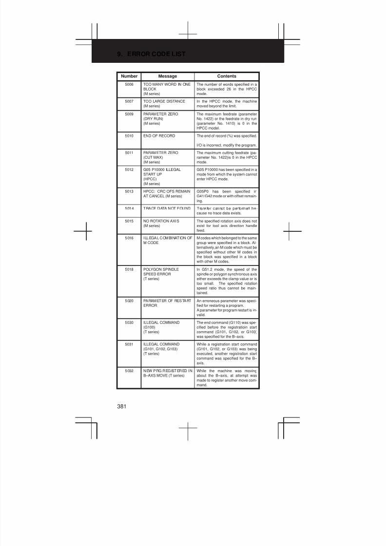
9. ERROR CODE LIST
381
Number ContentsMessage
5006 TOO MANY WORD IN ONE
BLOCK
(M series)
The number of words specified in a
block exceeded 26 in the HPCC
mode.
5007 TOO LARGE DISTANCE
(M series)
In the HPCC mode, the machine
moved beyond the limit.
5009 PARAMETER ZERO
(DRY RUN)
(M series)
The maximum feedrate (parameter
No. 1422) or the feedrate in dry run
(parameter No. 1410) is 0 in the
HPCC model.
5010 END OF RECORD The end of record (%) was specified.
I/O is incorrect. modify the program.
5011 PARAMETER ZERO
(CUT MAX)
(M series)
The maximum cutting feedrate (pa-
rameter No. 1422)is 0 in the HPCC
mode.
5012 G05 P10000 ILLEGAL
START UP
(HPCC)
(M series)
G05 P10000 has been specified in a
mode from which the system cannot
enter HPCC mode.
5013 HPCC: CRC OFS REMAIN
AT CANCEL (M series)
G05P0 has been specified in
G41/G42 mode or with offset remain-
ing.
5014 TRACE DATA NOT FOUND Transfer cannot be performed be-
cause no trace data exists.
5015 NO ROTATION AXIS
(M series)
The specified rotation axis does not
exist for tool axis direction handle
feed.
5016 ILLEGAL COMBINATION OF
M CODE
M codes which belonged to the same
group were specified in a block. Al-
ternatively,an M code which must be
specified without other M codes in
the block was specified in a block
with other M codes.
5018 POLYGON SPINDLE
SPEED ERROR
(T series)
In G51.2 mode, the speed of the
spindle or polygon synchronous axis
either exceeds the clamp value or is
too small. The specified rotation
speed ratio thus cannot be main-
tained.
5020 PARAMETER OF RESTART
ERROR
An erroneous parameter was speci-
fied for restarting a program.
A parameter for program restart is in-
valid.
5030 ILLEGAL COMMAND
(G100)
(T series)
The end command (G110) was spe-
cified before the registratioin start
command (G101, G102, or G103)
was specified for the B–axis.
5031 ILLEGAL COMMAND
(G101, G102, G103)
(T series)
While a registration start command
(G101, G102, or G103) was being
executed, another registration start
command was specified for the B–
axis.
5032 NEW PRG REGISTERED IN
B–AXS MOVE (T series)
While the machine was moving
about the B–axis, at attempt was
made to register another move com-
mand.

3
1
4
5
6
7
8
9
10
2
382
Number ContentsMessage
5033 NO PROG SPACE IN
MEMORY B–AXS (T series)
Commands for movement about the
B–axis were not registered because
of insufficient program memory.
5034 PLURAL COMMAND IN
G110
(T series)
Multiple movements were specified
with the G110 code for the B–axis.
5035 NO FEEDRATE
COMMANDED B–AXS
(T series)
A feedrate was not specified for cut-
ting feed about the B–axis.
5036 ADDRESS R NOT DEFINED
IN G81–G86 (T series)
Point R was not specified for the
canned cycle for the B–axis.
5037 ADDRESS Q NOT DEFINED
IN G83
(T series)
Depth of cut Q was not specified for
the G83 code (peck drilling cycle).
Alternatively, 0 was specified in Q for
the B–axis.
5038 TOO MANY START
M–CODE COMMAND
(T series)
More than six M codes for starting
movement about the B–axis were
specified.
5039 START UNREGISTERED
B–AXS PROG (T series)
An attempt was made to execute a
program for the B–axis which had not
been registered.
5040 CAN NOT COMMANDED
B–AXS MOVE (T series)
The machine could not move about
the B–axis because parameter
No.8250 was incorrectly specified,
or because the PMC axis system
could not be used.
5041 CAN NOT COMMANDED
G110 BLOCK (T series)
Blocks containing the G110 codes
were successively specified in tool–
tip radius compensation for the B–
axis.
5043 TOO MANY G68 NESTING
(M series)
Three–dimensional coordinate con-
version G68 has been specified
three or more times.
5044 G68 FORMAT ERROR
(M series)
A G68 command block contains a
format error. This alarm is issued in
the following cases:
1) I, J, or K is missing from a G68
command block (missing coordi
nate rotation option).
2) I, J, and K are 0 in a G68 com-
mand block.
3) R is missing from a G68 com-
mand block.
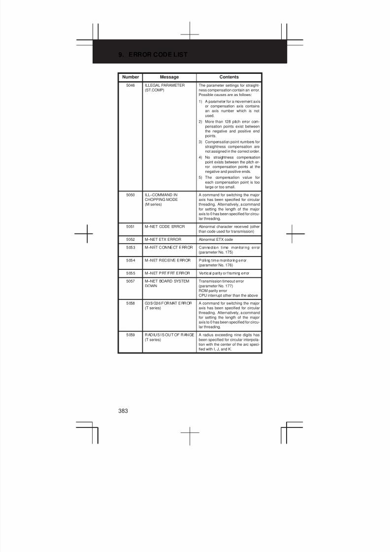
9. ERROR CODE LIST
383
Number ContentsMessage
5046 ILLEGAL PARAMETER
(ST.COMP)
The parameter settings for straight-
ness compensation contain an error.
Possible causes are as follows:
1) A parameter for a movement axis
or compensation axis contains
an axis number which is not
used.
2) More than 128 pitch error com-
pensation points exist between
the negative and positive end
points.
3) Compensation point numbers for
straightness compensation are
not assigned in the correct order.
4) No straightness compensation
point exists between the pitch er-
ror compensation points at the
negative and positive ends.
5) The compensation value for
each compensation point is too
large or too small.
5050 ILL–COMMAND IN
CHOPPING MODE
(M series)
A command for switching the major
axis has been specified for circular
threading. Alternatively, a command
for setting the length of the major
axis to 0 has been specified for circu-
lar threading.
5051 M–NET CODE ERROR Abnormal character received (other
than code used for transmission)
5052 M–NET ETX ERROR Abnormal ETX code
5053 M–NET CONNECT ERROR Connection t ime monitoring error
(parameter No. 175)
5054 M–NET RECEIVE ERROR Polling t ime monitoring error
(parameter No. 176)
5055 M–NET PRT/FRT ERROR Vertical parity or framing error
5057 M–NET BOARD SYSTEM
DOWN
Transmission timeout error
(parameter No. 177)
ROM parity error
CPU interrupt other than the above
5058 G35/G36 FORMAT ERROR
(T series)
A command for switching the major
axis has been specified for circular
threading. Alternatively, a command
for setting the length of the major
axis to 0 has been specified for circu-
lar threading.
5059 RADIUS IS OUT OF RANGE
(T series)
A radius exceeding nine digits has
been specified for circular interpola-
tion with the center of the arc speci-
fied with I, J, and K.

3
1
4
5
6
7
8
9
10
2
384
Number ContentsMessage
5060 ILLEGAL PARAMETER IN
G02.3/G03.3
(M series)
Parameter setting is illegal.
No. 5641 (setting of the linear axis) is
not specified.
No. 5641 specifies an axis other than
a linear axis.
No. 5642 (setting of the rotation axis)
is not specified.
No. 5642 specifies an axis other than
a rotation axis.
The CNC cannot control the linear or
rotation axis (the value of No. 1010 is
exceeded).
5061 ILLEGAL FORMAT IN
G02.3/G03.3
(M series)
The command for exponential inter-
polation (G02.3/G03.3) contains a
format error.
Address I, J, or K is not specified.
Addresses I, J, and K are 0.
5062 ILLEGAL COMMAND IN
G02.3/G03.3
(M series)
The command for exponential inter-
polation (G02.3/G03.3) contains an
illegal value.
The specified value is not suitable for
exponential interpolation (for exam-
ple, a negative value is subject to ln).
5063 IS NOT PRESET AFTER
REF.
(M series)
The position counter was not preset
before the start of workpiece thick-
ness measurement. This alarm is is-
sued in the following cases:
(1) An attempt has been made to
start measurement without first
establishing the origin.
(2) An attempt has been made to
start measurement without first
presetting the position counter
after manual return to the origin.
5064 DIFFERRENT AXIS UNIT
(IS–B, IS–C)
(M series)
Circular interpolation has been spe-
cified on a plane consisting of axes
having different increment systems.
5065 DIFFERENT AXIS UNIT
(PMC AXIS)
(M series)
Axes having different increment sys-
tems have been specified in the
same DI/DO group for PMC axis con-
trol. Modify the setting of parameter
No. 8010.
5066 RESTART ILLEGAL
SEQUENCE NUMBER
(M series)
Sequence number 7xxx has been
read during search for the next se-
quence number at program restart
for the return/restart function.
5068 G31 P90 FORMAT ERROR
(M series)
No movement axis or more than one
movement axis has been specified.
5069 WHL–C ; ILLEGAL P–DATA Erroneous P data has been specified
for center selection during grinding
wheel wear compensation.
5073 NO DECIMAL POINT No decimal point has been specified
for an address requiring a decimal
point.
5074 ADDRESS DUPLICATION
ERROR
The same address has been speci-
fied two or more times in a single
block. Alternatively, two or more G
codes in the same group have been
specified in a single block.

9. ERROR CODE LIST
385
Number ContentsMessage
5082 DATA SERVER ERROR This alarm is detai led on the data
server message screen.
5085 SMOOTH IPL ERROR 1 The smooth interpo lat ion command
block contains an invalid command
format.
5110 IMPROPER G–CODE
(G05.1 G1 MODE)
(M series)
An illegal G code was specified in
simple high–precision contour con-
trol mode.
A command was specified for the in-
dex table indexing axis in simple
high–precision contour control
mode.
5111 IMPROPER MODAL
G–CODE (G05.1 G1)
(M series)
An illegal G code is left modal when
simple high–precision contour con-
trol mode was specified.
5112 G08 CAN NOT BE
COMMANDED (G05.1 G1)
(M series)
Look–ahead control (G08) was spe-
cified in simple high–precision con-
tour control mode.
5113 CAN NOT ERROR IN MDI
MODE (G05.1)
(M series)
Simple high–precision contour con-
trol (G05.1) was specified in MDI
mode.
5114 NOT STOP POSITION
(G05.1 Q1)
(M series)
At the time of restart after manual in-
tervention, the coordinates at which
the manual intervention occurred
have not been restored.
5115 SPL : ERROR
(M series)
There is an error in the specification
of the rank.
No knot is specified.
The knot specification has an error.
The number of axes exceeds the lim-
its.
Other program errors
5116 SPL : ERROR
(M series)
There is a program error in a block
under look–ahead control.
Monotone increasing of knots is not
observed.
In NURBS interpolation mode, a
mode that cannot be used together is
specified.
5117 SPL : ERROR
(M series)
The first control point of NURBS is in-
correct.
5118 SPL : ERROR
(M series)
After manual intervention with manu-
al absolute mode set to on, NURBS
interpolation was restarted.

3
1
4
5
6
7
8
9
10
2
386
Number ContentsMessage
5122 ILLEGAL COMMAND IN
SPIRAL
(M series)
A spiral interpolation or conical inter-
polation command has an error.
Specifically, this error is caused by
one of the following:
1) L = 0 is specified.
2) Q = 0 is specified.
3) R/, R/, C is specified.
4) Zero is specified as height incre-
ment.
5) Three or more axes are specified
as the height axes.
6) A height increment is specified
when there are two height axes.
7) Conical interpolation is specified
when the helical interpolation
function is not selected.
8) Q < 0 is specified when radius
difference > 0.
9) Q > 0 is specified when radius
difference < 0.
10) A height increment is specified
when no height axis is specified.
5123 OVER TOLERANCE OF
END POINT
(M series)
The difference between a specified
end point and the calculated end
point exceeds the allowable range
(parameter 3471).
5124 CAN NOT COMMAND
SPIRAL
(M series)
A spiral interpolation or conical inter-
polation was specified in any of the
following modes:
1) Scaling
2) Programmable mirror image
3) Polar coordinate interpolation
In cutter compensation C mode, the
center is set as the start point or end
point.
5134 FSSB : OPEN READY TIME
OUT
Initialization did not place FSSB in
the open ready state.
5135 FSSB : ERROR MODE FSSB has entered error mode.
5136 FSSB : NUMBER OF AMPS
IS SMALL
In comparison with the number of
controlled axes, the number of am-
plifiers recognized by FSSB is not
enough.
5137 FSSB : CONFIGURATION
ERROR
FSSB detected a configuration error.
5138 FSSB : AXIS SETTING NOT
COMPLETE
In automatic setting mode, axis set-
ting has not been made yet.
Perform axis setting on the FSSB
setting screen.
5156 ILLEGAL AXIS OPERATION
(SHPCC)
(M series)
In simple high–precision contour
control mode, the controlled axis
selection signal (PMC axis control)
changes.
In simple high–precision contour
control mode, the simple synchro-
nous axis selection signal changes.

9. ERROR CODE LIST
387
Number ContentsMessage
5197 FSSB : OPEN TIME OUT The CNC permi tted FSSB to open,
but FSSB was not opened.
5198 FSSB : ID DATA NOT READ Temporary assignment failed, so
amplifier initial ID information could
not be read.
NOTE SHPCC : Simple high–precision contour control
9.1.2 Background edit alarm (BP/S alarm)
Number Message Contents
??? BP/S alarm BP/S alarm occurs in the same num-
ber as the P/S alarm that occurs in
ordinary program edit. (070, 071,
072, 073, 074 085,086,087 etc.)
140 BP/S alarm It was attempted to select or delete in
the background a program being se-
lected in the foreground. (Note) Use
background editing correctly.
NOTE Alarm in background edit is displayed in the key input line of the
background edit screen instead of the ordinary alarm screen and
is resettable by any of the MDI key operation.
9.1.3 Absolute pulse coder (APC) alarm
Number Message Contents
300 APC Alarm : n th–axis orig in
return
Manual reference position return is
required for the nth–axis (n=1 to 8).
301 APC alarm: nth–axis
communication
nth–axis (n=1 to 8) APC communica-
tion error. Failure in data transmis-
sion
Possible causes include a faulty
APC, cable, or servo interface mod-
ule.
302 APC alarm: nth–ax is over
time
nth–axis (n=1 to 8) APC overtime er-
ror.
Failure in data transmission.
Possible causes include a faulty
APC, cable, or servo interface mod-
ule.
303 APC alarm: nth–axis framing nth–axis (n=1 to 8) APC framing er-
ror. Failure in data transmission.
Possible causes include a faulty
APC, cable, or servo interface mod-
ule.
304 APC alarm: nth–axis parity nth–axis (n=1 to 8) APC parity error.
Failure in data transmission.
Possible causes include a faulty
APC, cable, or servo interface mod-
ule.
305 APC alarm: nth–axis pulse
error
nth–axis (n=1 to 8) APC pulse error
alarm.
APC alarm.APC or cable may be
faulty.
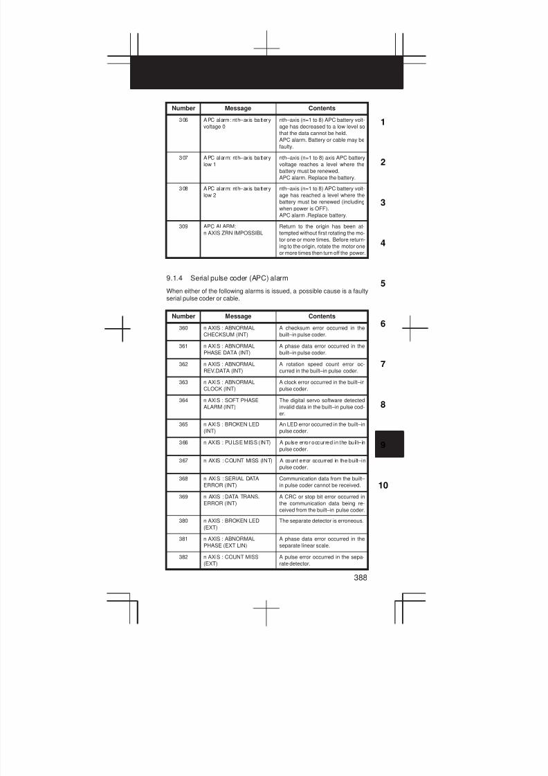
3
1
4
5
6
7
8
9
10
2
388
Number ContentsMessage
306 APC alarm: nth–ax is battery
voltage 0
nth–axis (n=1 to 8) APC battery volt-
age has decreased to a low level so
that the data cannot be held.
APC alarm. Battery or cable may be
faulty.
307 APC alarm: nth–ax is battery
low 1
nth–axis (n=1 to 8) axis APC battery
voltage reaches a level where the
battery must be renewed.
APC alarm. Replace the battery.
308 APC alarm: nth–ax is battery
low 2
nth–axis (n=1 to 8) APC battery volt-
age has reached a level where the
battery must be renewed (including
when power is OFF).
APC alarm .Replace battery.
309 APC ALARM:
n AXIS ZRN IMPOSSIBL
Return to the origin has been at-
tempted without first rotating the mo-
tor one or more times. Before return-
ing to the origin, rotate the motor one
or more times then turn off the power.
9.1.4 Serial pulse coder (APC) alarm
When either of the following alarms is issued, a possible cause is a faultyserial pulse coder or cable.
Number Message Contents
360 n AXIS : ABNORMAL
CHECKSUM (INT)
A checksum error occurred in the
built–in pulse coder.
361 n AXIS : ABNORMAL
PHASE DATA (INT)
A phase data error occurred in the
built–in pulse coder.
362 n AXIS : ABNORMAL
REV.DATA (INT)
A rotation speed count error oc-
curred in the built–in pulse coder.
363 n AXIS : ABNORMAL
CLOCK (INT)
A clock error occurred in the built–in
pulse coder.
364 n AXIS : SOFT PHASE
ALARM (INT)
The digital servo software detected
invalid data in the built–in pulse cod-
er.
365 n AXIS : BROKEN LED
(INT)
An LED error occurred in the built–in
pulse coder.
366 n AXIS : PULSE MISS (INT) A pulse error occurred in the buil t–in
pulse coder.
367 n AXIS : COUNT MISS (INT) A count error occurred in the built–in
pulse coder.
368 n AXIS : SERIAL DATA
ERROR (INT)
Communication data from the built–
in pulse coder cannot be received.
369 n AXIS : DATA TRANS.
ERROR (INT)
A CRC or stop bit error occurred in
the communication data being re-
ceived from the built–in pulse coder.
380 n AXIS : BROKEN LED
(EXT)
The separate detector is erroneous.
381 n AXIS : ABNORMAL
PHASE (EXT LIN)
A phase data error occurred in the
separate linear scale.
382 n AXIS : COUNT MISS
(EXT)
A pulse error occurred in the sepa-
rate detector.
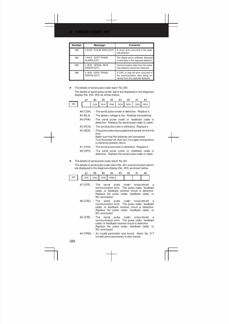
9. ERROR CODE LIST
389
Number ContentsMessage
383 n AXIS : PULSE MISS (EXT) A count error occurred in the sepa-
rate detector.
384 n AXIS : SOFT PHASE
ALARM (EXT)
The digital servo software detected
invalid data in the separate detector.
385 n AXIS : SERIAL DATA
ERROR (EXT)
Communication data from the sepa-
rate detector cannot be received.
386 n AXIS : DATA TRANS.
ERROR (EXT)
A CRC or stop bit error occurred in
the communication data being re-
ceived from the separate detector.
D The details of serial pulse coder alarm No.350
The details of serial pulse corder alarm are displayed in the diagnosisdisplay (No. 202, 203) as shown below.
#7 #6 #5 #4 #3 #2 #1 #0
202 CSA BLA PHA RCA BZA CKA SPH
#6 (CSA) : The serial pulse corder is defective. Replace it.
#5 (BLA) : The battery voltage is low. Replace the batteries.
#4 (PHA) : The serial pulse coder or feedback cable isdefective. Replace the serial pulse coder or cable.
#3 (RCA) : The serial pulse coder is defective. Replace it.
#2 (BZA) : The pulse coder was supplied with power for the firsttime.Make sure that the batteries are connected.Turn the power off, then turn it on again and performa reference position return.
#1 (CKA) : The serial pulse coder is defective. Replace it.
#0 (SPH) : The serial pulse coder or feedback cable isdefective. Replace the serial pulse coder or cable.
D The details of serial pulse coder alarm No.351
The details of serial pulse coder alarm No. 351 (communication alarm)are displayed in the diagnosis display (No. 203) as shown below.
#7 #6 #5 #4 #3 #2 #1 #0
203 DTE CRC STB PRM
#7 (DTE) : The serial pulse coder encountered acommunication error. The pulse coder, feedbackcable, or feedback receiver circuit is defective.Replace the pulse coder, feedback cable, orNC–axis board.
#6 (CRC) : The serial pulse coder encountered acommunication error. The pulse coder, feedbackcable, or feedback receiver circuit is defective.Replace the pulse coder, feedback cable, orNC–axis board.
#5 (STB) : The serial pulse coder encountered acommunication error. The pulse coder, feedbackcable, or feedback receiver circuit is defective.Replace the pulse coder, feedback cable, orNC–axis board.
#4 (PRM) : An invalid parameter was found. Alarm No. 417(invalid servo parameter) is also issued.
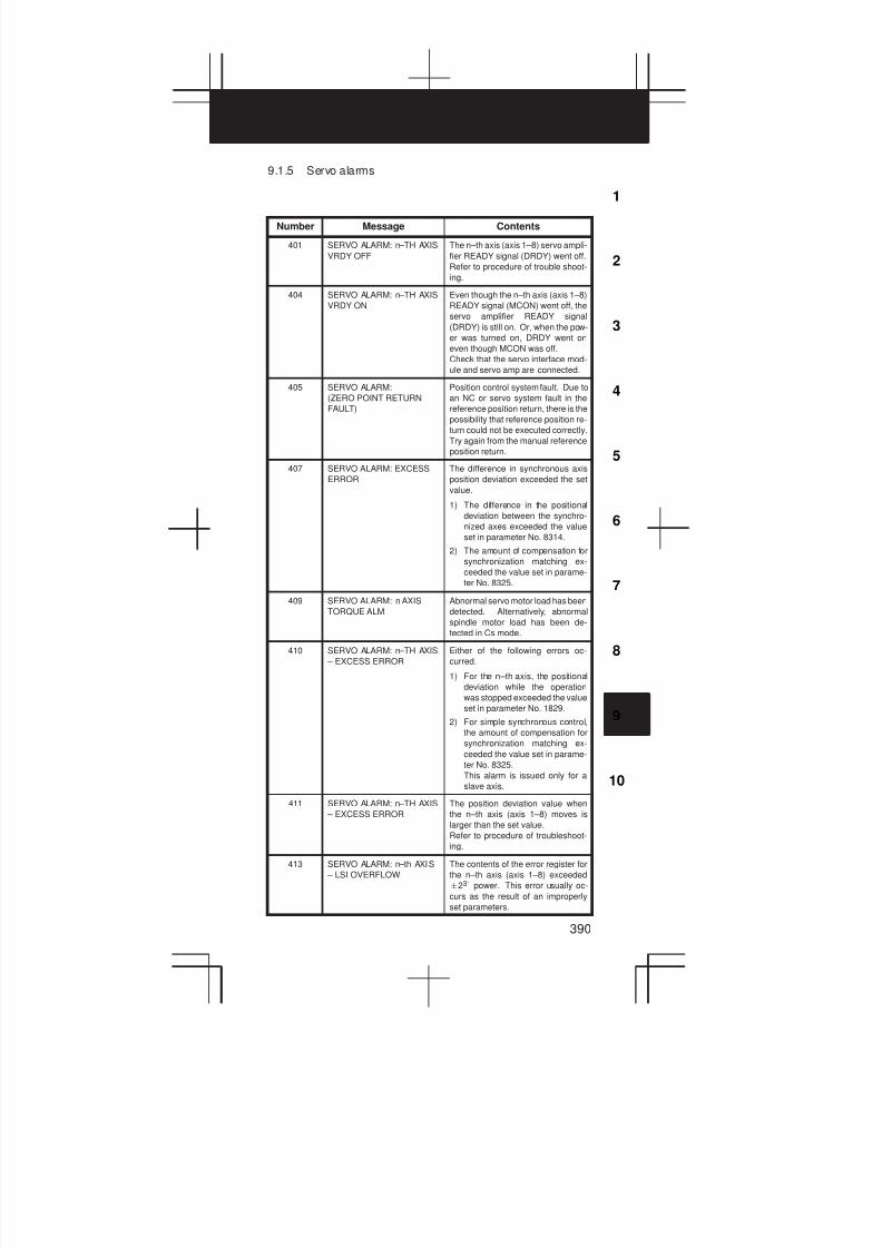
3
1
4
5
6
7
8
9
10
2
390
9.1.5 Servo alarms
Number Message Contents
401 SERVO ALARM: n–TH AXIS
VRDY OFF
The n–th axis (axis 1–8) servo ampli-
fier READY signal (DRDY) went off.
Refer to procedure of trouble shoot-
ing.
404 SERVO ALARM: n–TH AXIS
VRDY ON
Even though the n–th axis (axis 1–8)
READY signal (MCON) went off, the
servo amplifier READY signal
(DRDY) is still on. Or, when the pow-
er was turned on, DRDY went on
even though MCON was off.
Check that the servo interface mod-
ule and servo amp are connected.
405 SERVO ALARM:
(ZERO POINT RETURN
FAULT)
Position control system fault. Due to
an NC or servo system fault in the
reference position return, there is the
possibility that reference position re-
turn could not be executed correctly.
Try again from the manual reference
position return.
407 SERVO ALARM: EXCESS
ERROR
The difference in synchronous axis
position deviation exceeded the set
value.
1) The difference in the positional
deviation between the synchro-
nized axes exceeded the value
set in parameter No. 8314.
2) The amount of compensation for
synchronization matching ex-
ceeded the value set in parame-
ter No. 8325.
409 SERVO ALARM: n AXIS
TORQUE ALM
Abnormal servo motor load has been
detected. Alternatively, abnormal
spindle motor load has been de-
tected in Cs mode.
410 SERVO ALARM: n–TH AXIS
– EXCESS ERROR
Either of the following errors oc-
curred.
1) For the n–th axis, the positional
deviation while the operation
was stopped exceeded the value
set in parameter No. 1829.
2) For simple synchronous control,
the amount of compensation for
synchronization matching ex-
ceeded the value set in parame-
ter No. 8325.
This alarm is issued only for a
slave axis.
411 SERVO ALARM: n–TH AXIS
– EXCESS ERROR
The position deviation value when
the n–th axis (axis 1–8) moves is
larger than the set value.
Refer to procedure of troubleshoot-
ing.
413 SERVO ALARM: n–th AXIS
– LSI OVERFLOW
The contents of the error register for
the n–th axis (axis 1–8) exceeded
"231 power. This error usually oc-
curs as the result of an improperly
set parameters.
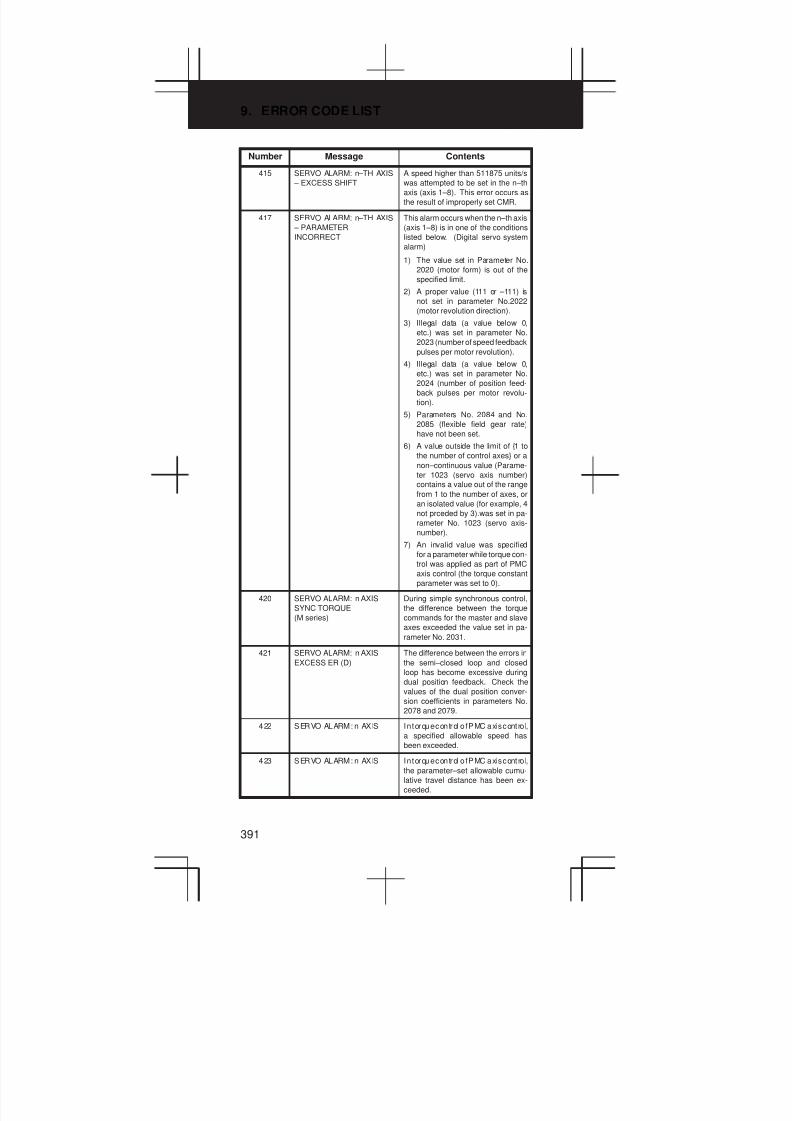
9. ERROR CODE LIST
391
Number ContentsMessage
415 SERVO ALARM: n–TH AXIS
– EXCESS SHIFT
A speed higher than 511875 units/s
was attempted to be set in the n–th
axis (axis 1–8). This error occurs as
the result of improperly set CMR.
417 SERVO ALARM: n–TH AXIS
– PARAMETER
INCORRECT
This alarm occurs when the n–th axis
(axis 1–8) is in one of the conditions
listed below. (Digital servo system
alarm)
1) The value set in Parameter No.
2020 (motor form) is out of the
specified limit.
2) A proper value (111 or –111) is
not set in parameter No.2022
(motor revolution direction).
3) Illegal data (a value below 0,
etc.) was set in parameter No.
2023 (number of speed feedback
pulses per motor revolution).
4) Illegal data (a value below 0,
etc.) was set in parameter No.
2024 (number of position feed-
back pulses per motor revolu-
tion).
5) Parameters No. 2084 and No.
2085 (flexible field gear rate)
have not been set.
6) A value outside the limit of {1 to
the number of control axes} or a
non–continuous value (Parame-
ter 1023 (servo axis number)
contains a value out of the range
from 1 to the number of axes, or
an isolated value (for example, 4
not prceded by 3).was set in pa-
rameter No. 1023 (servo axis-
number).
7) An invalid value was specified
for a parameter while torque con-
trol was applied as part of PMC
axis control (the torque constant
parameter was set to 0).
420 SERVO ALARM: n AXIS
SYNC TORQUE
(M series)
During simple synchronous control,
the difference between the torque
commands for the master and slave
axes exceeded the value set in pa-
rameter No. 2031.
421 SERVO ALARM: n AXIS
EXCESS ER (D)
The difference between the errors in
the semi–closed loop and closed
loop has become excessive during
dual position feedback. Check the
values of the dual position conver-
sion coefficients in parameters No.
2078 and 2079.
422 SERVO ALARM: n AXIS In torque control o f PMC axis cont ro l,
a specified allowable speed has
been exceeded.
423 SERVO ALARM: n AXIS In torque control o f PMC axis cont ro l,
the parameter–set allowable cumu-
lative travel distance has been ex-
ceeded.
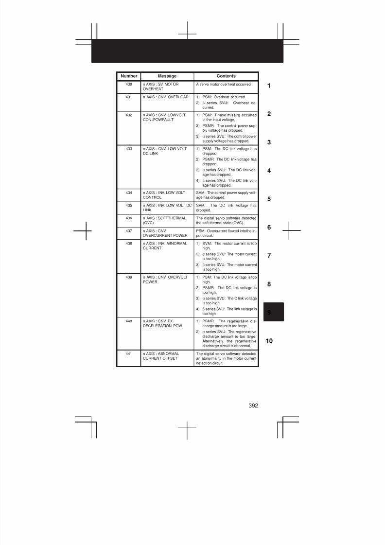
3
1
4
5
6
7
8
9
10
2
392
Number ContentsMessage
430 n AXIS : SV. MOTOR
OVERHEAT
A servo motor overheat occurred.
431 n AXIS : CNV. OVERLOAD 1) PSM: Overheat occurred.
2) β series SVU: Overheat oc-
curred.
432 n AXIS : CNV. LOWVOLT
CON./POWFAULT
1) PSM: Phase missing occurred
in the input voltage.
2) PSMR: The control power sup-
ply voltage has dropped.
3) α series SVU: The control power
supply voltage has dropped.
433 n AXIS : CNV. LOW VOLT
DC LINK
1) PSM: The DC link voltage has
dropped.
2) PSMR: The DC link voltage has
dropped.
3) α series SVU: The DC link volt-
age has dropped.
4) β series SVU: The DC link volt-
age has dropped.
434 n AXIS : INV. LOW VOLT
CONTROL
SVM: The control power supply volt-
age has dropped.
435 n AXIS : INV. LOW VOLT DC
LINK
SVM: The DC link voltage has
dropped.
436 n AXIS : SOFTTHERMAL
(OVC)
The digital servo software detected
the soft thermal state (OVC).
437 n AXIS : CNV.
OVERCURRENT POWER
PSM: Overcurrent flowed into the in-
put circuit.
438 n AXIS : INV. ABNORMAL
CURRENT
1) SVM: The motor current is too
high.
2) α series SVU: The motor current
is too high.
3) β series SVU: The motor current
is too high.
439 n AXIS : CNV. OVERVOLT
POWER
1) PSM: The DC link voltage is too
high.
2) PSMR: The DC link voltage is
too high.
3) α series SVU: The C link voltage
is too high.
4) β series SVU: The link voltage is
too high.
440 n AXIS : CNV. EX
DECELERATION POW.
1) PSMR: The regenerative dis-
charge amount is too large.
2) α series SVU: The regenerative
discharge amount is too large.
Alternatively, the regenerative
discharge circuit is abnormal.
441 n AXIS : ABNORMAL
CURRENT OFFSET
The digital servo software detected
an abnormality in the motor current
detection circuit.
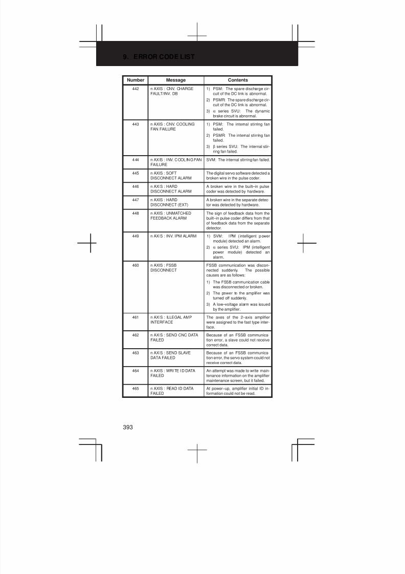
9. ERROR CODE LIST
393
Number ContentsMessage
442 n AXIS : CNV. CHARGE
FAULT/INV. DB
1) PSM: The spare discharge cir-
cuit of the DC link is abnormal.
2) PSMR: The spare discharge cir-
cuit of the DC link is abnormal.
3) α series SVU: The dynamic
brake circuit is abnormal.
443 n AXIS : CNV. COOLING
FAN FAILURE
1) PSM: The internal stirring fan
failed.
2) PSMR: The internal stirring fan
failed.
3) β series SVU: The internal stir-
ring fan failed.
444 n AXIS : INV. COOLING FAN
FAILURE
SVM: The internal stirring fan failed.
445 n AXIS : SOFT
DISCONNECT ALARM
The digital servo software detected a
broken wire in the pulse coder.
446 n AXIS : HARD
DISCONNECT ALARM
A broken wire in the built–in pulse
coder was detected by hardware.
447 n AXIS : HARD
DISCONNECT (EXT)
A broken wire in the separate detec-
tor was detected by hardware.
448 n AXIS : UNMATCHED
FEEDBACK ALARM
The sign of feedback data from the
built–in pulse coder differs from that
of feedback data from the separate
detector.
449 n AXIS : INV. IPM ALARM 1) SVM: IPM ( intelligent power
module) detected an alarm.
2) α series SVU: IPM (intelligent
power module) detected an
alarm.
460 n AXIS : FSSB
DISCONNECT
FSSB communication was discon-
nected suddenly. The possible
causes are as follows:
1) The FSSB communication cable
was disconnected or broken.
2) The power to the amplifier was
turned off suddenly.
3) A low–voltage alarm was issued
by the amplifier.
461 n AXIS : ILLEGAL AMP
INTERFACE
The axes of the 2–axis amplifier
were assigned to the fast type inter-
face.
462 n AXIS : SEND CNC DATA
FAILED
Because of an FSSB communica-
tion error, a slave could not receive
correct data.
463 n AXIS : SEND SLAVE
DATA FAILED
Because of an FSSB communica-
tion error, the servo system could not
receive correct data.
464 n AXIS : WRITE ID DATA
FAILED
An attempt was made to write main-
tenance information on the amplifier
maintenance screen, but it failed.
465 n AXIS : READ ID DATA
FAILED
At power–up, amplifier initial ID in-
formation could not be read.
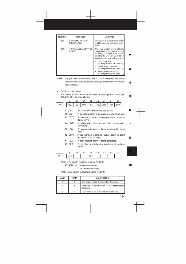
3
1
4
5
6
7
8
9
10
2
394
Number ContentsMessage
466 n AXIS : MOTOR/AMP
COMBINATION
The maximum current rating for the
amplifier does not match that for t he
motor.
467 n AXIS : ILLEGAL SETTING
OF AXIS
The servo function for the following
has not been enabled when an axis
occupying a single DSP (corre-
sponding to two ordinary axes) is
specified on the axis setting screen.
1. Learning control
(bit 5 of parameter No. 2008 = 1)
2. High–speed current loop
(bit 0 of parameter No. 2004 = 1)
3. High–speed interface axis
(bit 4 of parameter No. 2005 = 1)
NOTE If any of servo alarms 400 to 421 occurs, investigate the cause of
the alarm and take appropriate action, as described in the mainte-
nance manual.
D Details of servo alarm
The details of servo alarm are displayed in the diagnosis display (No.200, 201, 204) as shown below.
#7 #6 #5 #4 #3 #2 #1 #0
200 OVL LV OVC HCA HVA DCA FBA OFA
#7 (OVL) : An overload alarm is being generated.
#6 (LV) : A low voltage alarm is being generated in servo amp.
#5 (OVC) : A overcurrent alarm is being generated inside ofdigital servo.
#4 (HCA) : An abnormal current alarm is being generated inservo amp.
#3 (HVA) : An overvoltage alarm is being generated in servoamp.
#2 (DCA) : A regenerative discharge circuit alarm is beinggenerated in servo amp.
#1 (FBA) : A disconnection alarm is being generated.
#0 (OFA) : An overflow alarm is being generated inside of digitalservo.
#7 #6 #5 #4 #3 #2 #1 #0
201 ALD EXP
When OVL equal 1 in diagnostic data No.200 :
#7 (ALD) 0 : Motor overheating
1 : Amplifier overheating
When FBAL equal 1 in diagnostic data No.200 :
ALD EXP Alarm details
1 0 Built–in pulse coder disconnection (hardware)
1 1 Separately installed pulse coder disconnection
(hardware)
0 0 Pulse coder is not connected due to software.
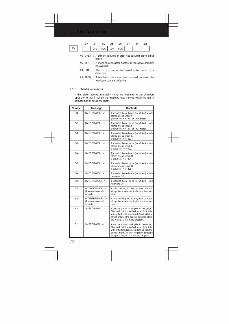
9. ERROR CODE LIST
395
#7 #6 #5 #4 #3 #2 #1 #0
204 OFS MCC LDA PMS
#6 (OFS) : A current conversion error has occured in the digitalservo.
#5 (MCC) : A magnetic contactor contact in the servo amplifierhas welded.
#4 (LDA) : The LED indicates that serial pulse coder C isdefective
#3 (PMS) : A feedback pulse error has occured because thefeedback cable is defective.
9.1.6 Overtravel alarms
If this alarm occurs, manually move the machine in the directionopposite to that in which the machine was moving when the alarmoccurred, then reset the alarm.
Number Message Contents
500 OVER TRAVEL : +n Exceeded the n–th ax is (axis 1 to 8) + s ide
stored stroke check I.
(Parameter No.1320 or 1326 Note)
501 OVER TRAVEL : –n Exceeded the n–th axis (axis 1 to 8) – s ide
stored stroke check I.
(Parameter No.1321 or 1327 Note)
502 OVER TRAVEL : +n Exceeded the n–th ax is (axis 1 to 8) + s ide
stored stroke check II.
(Parameter No.1322 )
503 OVER TRAVEL : –n Exceeded the n–th axis (axis 1 to 8) – s ide
stored stroke check II.
(Parameter No.1323)
504 OVER TRAVEL : +n Exceeded the n–th ax is (axis 1 to 8) + s ide
stored stroke check III.
(Parameter No.1324 )
505 OVER TRAVEL : –n Exceeded the n–th axis (axis 1 to 8) – s ide
stored stroke check III.
(Parameter No.1325 )
506 OVER TRAVEL : +n Exceeded the n–th ax is (axis 1 to 8) + s ide
hardware OT.
507 OVER TRAVEL : –n Exceeded the n–th axis (axis 1 to 8) – s ide
hardware OT.
508 INTERFERENCE: +n
(T series (two–path
control))
A tool moving in the positive direction
along the n axis has fouled another tool
post.
509 INTERFERENCE: –n
(T series (two–path
control))
A tool moving in the negative direction
along the n axis has fouled another tool
post.
510 OVER TRAVEL: +n Alarm for st roke check pr ior to movement.
The end point specified in a block falls
within the forbidden area defined with the
stroke check in the positive direction along
the N axis. Correct the program.
511 OVER TRAVEL: –n Alarm for st roke check pr ior to movement.
The end point specified in a block falls
within the forbidden area defined with the
stroke check in the negative direction
along the N axis. Correct the program.

3
1
4
5
6
7
8
9
10
2
396
NOTE Parameters 1326 and 1327 are effective when EXLM(stroke check
switch signal) is on.
9.1.7 Overheat alarms
Number Message Contents
700 OVERHEAT:
CONTROL UNIT
Control unit overheat
Check that the fan motor operates normal-
ly, and clean the air filter.
701 OVERHEAT: FAN
MOTOR
The fan motor on the top of the cabinet for
the contorl unit is overheated. Check the
operation of the fan motor and replace the
motor if necessary.
704 OVERHEAT: SPINDLE Spindle overheat in the spindle fluctuation
detection
1) If the cutting load is heavy, relieve the
cutting condition.
2) Check whether the cutting tool is
share.
3) Another possible cause is a faulty
spindle amp.
9.1.8 Rigid tapping alarms
Number Message Contents
740 RIGID TAP ALARM:
EXCESS ERROR
The positional deviation of the stopped
spindle has exceeded the set value dur-
ing rigid tapping.
741 RIGID TAP ALARM:
EXCESS ERROR
The positional deviation of the moving
spindle has exceeded the set value dur-
ing rigid tapping.
742 RIGID TAP ALARM:
LSI OVERFLOW
An LSI overflow has occurred for the
spindle during rigid tapping.
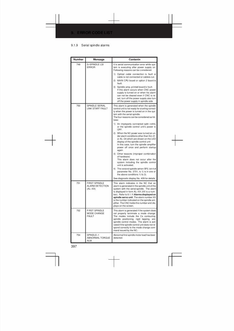
9. ERROR CODE LIST
397
9.1.9 Serial spindle alarms
Number Message Contents
749 S–SPINDLE LSI
ERROR
It is serial communication error while sys-
tem is executing after power supply on.
Following reasons can be considered.
1) Optical cable connection is fault or
cable is not connected or cableis cut.
2) MAIN CPU board or option 2 board is
fault.
3) Spindle amp. printed board is fault.
If this alarm occurs when CNC power
supply is turned on or when his alarm
can not be cleared even if CNC is re-
set, turn off the power supply also turn
off the power supply in spindle side.
750 SPINDLE SERIAL
LINK START FAULT
This alarm is generated when the spindle
control unit is not ready for starting correct-
ly when the power is turned on in the sys-
tem with the serial spindle.
The four reasons can be considered as fol-
lows:
1) An improperly connected optic cable,
or the spindle control unit’s power is
OFF.
2) When the NC power was turned on un-
der alarm conditions other than SU–01
or AL–24 which are shown on the LED
display of the spindle control unit.
In this case, turn the spindle amplifier
power off once and perform startup
again.
3) Other reasons (improper combination
of hardware)
This alarm does not occur after the
system including the spindle control
unit is activated.
4) The second spindle (when SP2, bit 4 of
parameter No. 3701, is 1) is in one of
the above conditions 1) to 3).
See diagnostic display No. 409 for details.
751 FIRST SPINDLE
ALARM DETECTION
(AL–XX)
This alarm indicates in the NC that an
alarm is generated in the spindle unit of the
system with the serial spindle. The alarm
is displayed in form AL–XX (XX is a num-
ber). Refer to 9.1.11Alarms displayed on
spindle servo unit .The alarm number XX
is the number indicated on the spindle am-
plifier. The CNC holds this number and dis-
plays on the screen.
752 FIRST SPINDLE
MODE CHANGE
FAULT
This alarm is generated if the system does
not properly terminate a mode change.
The modes include the Cs contouring,
spindle positioning, rigid tapping, and
spindle control modes. The alarm is acti-
vated if the spindle control unit does not re-
spond correctly to the mode change com-
mand issued by the NC.
754 SPINDLE–1
ABNORMAL TORQUE
ALM
Abnormal first spindle motor load has been
detected.
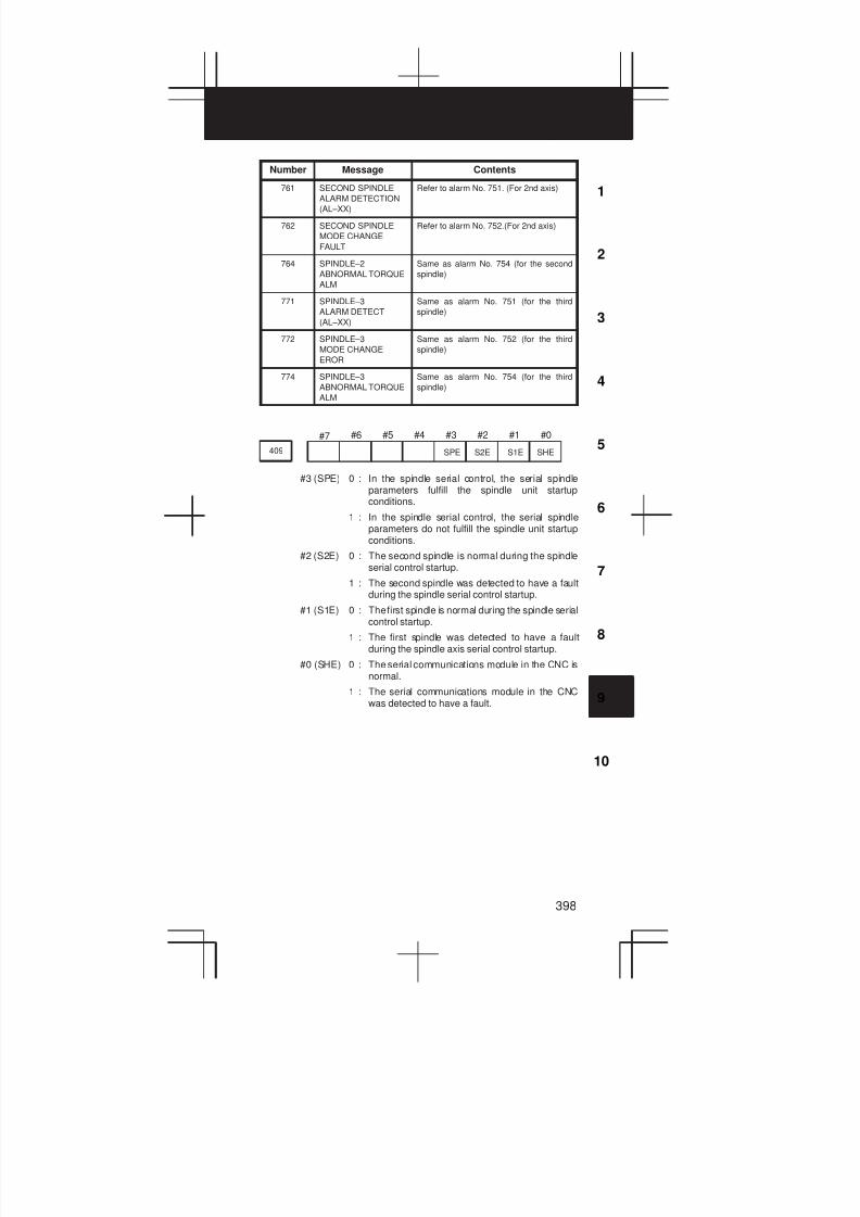
3
1
4
5
6
7
8
9
10
2
398
Number ContentsMessage
761 SECOND SPINDLE
ALARM DETECTION
(AL–XX)
Refer to alarm No. 751. (For 2nd axis)
762 SECOND SPINDLE
MODE CHANGE
FAULT
Refer to alarm No. 752.(For 2nd axis)
764 SPINDLE–2
ABNORMAL TORQUE
ALM
Same as alarm No. 754 (for the second
spindle)
771 SPINDLE–3
ALARM DETECT
(AL–XX)
Same as alarm No. 751 (for the third
spindle)
772 SPINDLE–3
MODE CHANGE
EROR
Same as alarm No. 752 (for the third
spindle)
774 SPINDLE–3
ABNORMAL TORQUE
ALM
Same as alarm No. 754 (for the third
spindle)
#7 #6 #5 #4 #3 #2 #1 #0
409 SPE S2E S1E SHE
#3 (SPE) 0 : In the spindle serial control, the serial spindleparameters fulfill the spindle unit startupconditions.
1 : In the spindle serial control, the serial spindleparameters do not fulfill the spindle unit startupconditions.
#2 (S2E) 0 : The second spindle is normal during the spindleserial control startup.
1 : The second spindle was detected to have a faultduring the spindle serial control startup.
#1 (S1E) 0 : The first spindle is normal during the spindle serialcontrol startup.
1 : The first spindle was detected to have a faultduring the spindle axis serial control startup.
#0 (SHE) 0 : The serial communications module in the CNC isnormal.
1 : The serial communications module in the CNCwas detected to have a fault.

9. ERROR CODE LIST
399
9.1.10 System alarms
(These alarms cannot be reset with reset key.)
Number Message Contents
900 ROM PARITY A parity error occurred in the CNC, macro,
or servo ROM. Correct the contents of the
flash ROM having the displayed number.
910 SRAM PARITY :
(BYTE 0)
A RAM parity error occurred in the part pro-
gram storage RAM. Clear the RAM, or re-
place the SRAM module or motherboard.911 SRAM PARITY :
(BYTE 1)
l l .
Subsequently, re–set the parameters and
all other data.
912 DRAM PARITY :
(BYTE 0)
A RAM parity error occurred in the DRAM
module. Replace the DRAM module.
913 DRAM PARITY :
(BYTE 1)
914 DRAM PARITY :
(BYTE 2)
915 DRAM PARITY :
(BYTE 3)
916 DRAM PARITY :
(BYTE 4)
917 DRAM PARITY :
(BYTE 5)
918 DRAM PARITY :
(BYTE 6)
919 DRAM PARITY :
(BYTE 7)
920 SERVO ALARM
(1–4 AXIS)
Servo alarm (first to fourth axis). A watch-
dog alarm condition occurred, or a RAM
parity error occurred in the axis control
card.
Replace the axis control card.
921 SERVO ALARM
(5–8 AXIS)
Servo alarm (fifth to eighth axis). A watch-
dog alarm condition occurred, or a RAM
parity error occurred in the axis control
card.
Replace the axis control card.
926 FSSB ALARM FSSB alarm.
Replace the axis control card.
930 CPU INTERRUPT CPU error (abnormal interrupt).
The motherboard or CPU card may be
faulty.
950 PMC SYSTEM ALARM An error occurred in the PMC.
The PMC control circuit on the mother-
board may be faulty.
951 PMC WATCH DOG
ALARM
An error occurred in the PMC.
(Watchdog alarm)
The motherboard may be faulty.
972 NMI OCCURRED IN
OTHER MODULE
An NMI occurred on a board other than the
motherboard.
The option board may be faulty.
973 NON MASK
INTERRUPT
An NMI occurred as a result of an unknown
cause.
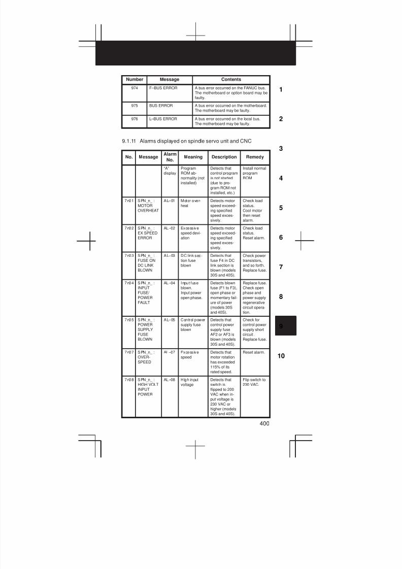
3
1
4
5
6
7
8
9
10
2
400
Number ContentsMessage
974 F–BUS ERROR A bus error occurred on the FANUC bus.
The motherboard or option board may be
faulty.
975 BUS ERROR A bus error occurred on the motherboard.
The motherboard may be faulty.
976 L–BUS ERROR A bus error occurred on the local bus.
The motherboard may be faulty.
9.1.11 Alarms displayed on spindle servo unit and CNC
No. MessageAlarm
No.Meaning Description Remedy
“A”
display
Program
ROM ab-
normality (not
installed)
Detects that
control program
is not started
(due to pro-
gram ROM not
installed, etc.)
Install normal
program
ROM
7n01 SPN_n_ :
MOTOR
OVERHEAT
AL–01 Motor over-
heat
Detects motor
speed exceed-
ing specified
speed exces-
sively.
Check load
status.
Cool motor
then reset
alarm.
7n02 SPN_n_ :
EX SPEED
ERROR
AL–02 Excess ive
speed devi-
ation
Detects motor
speed exceed-
ing specified
speed exces-
sively.
Check load
status.
Reset alarm.
7n03 SPN_n_ :
FUSE ON
DC LINK
BLOWN
AL–03 DC l ink sec-
tion fuse
blown
Detects that
fuse F4 in DC
link section is
blown (models
30S and 40S).
Check power
transistors,
and so forth.
Replace fuse.
7n04 SPN_n_ :
INPUT
FUSE/
POWER
FAULT
AL–04 Input fuse
blown.
Input power
open phase.
Detects blown
fuse (F1 to F3),
open phase or
momentary fail-
ure of power
(models 30S
and 40S).
Replace fuse.
Check open
phase and
power supply
regenerative
circuit opera-
tion.
7n05 SPN_n_ :
POWER
SUPPLY
FUSE
BLOWN
AL–05 Control power
supply fuse
blown
Detects that
control power
supply fuse
AF2 or AF3 is
blown (models
30S and 40S).
Check for
control power
supply short
circuit .
Replace fuse.
7n07 SPN_n_ :
OVER-
SPEED
AL–07 Excess ive
speed
Detects that
motor rotation
has exceeded
115% of its
rated speed.
Reset alarm.
7n08 SPN_n_ :
HIGH VOLT
INPUT
POWER
AL–08 High input
voltage
Detects that
switch is
flipped to 200
VAC when in-
put voltage is
230 VAC or
higher (models
30S and 40S).
Flip switch to
230 VAC.
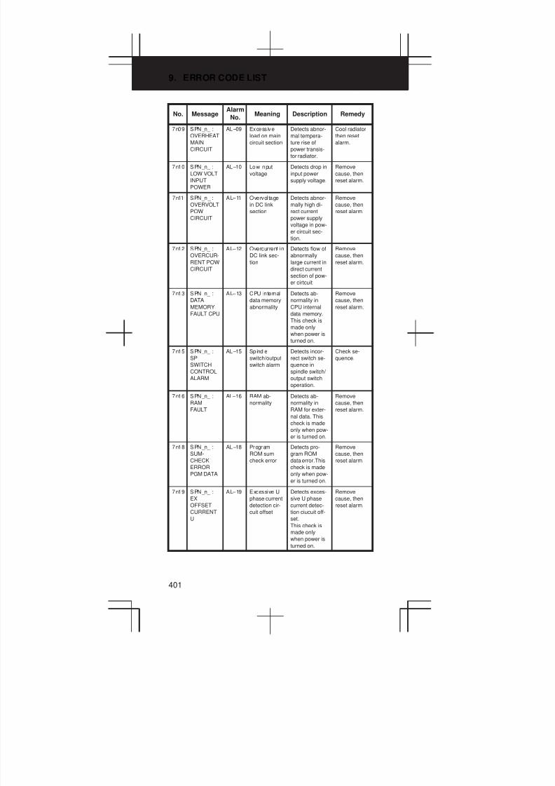
9. ERROR CODE LIST
401
No. RemedyDescriptionMeaningAlarm
No.Message
7n09 SPN_n_ :
OVERHEAT
MAIN
CIRCUIT
AL–09 Excess ive
load on main
circuit section
Detects abnor-
mal tempera-
ture rise of
power transis-
tor radiator.
Cool radiator
then reset
alarm.
7n10 SPN_n_ :
LOW VOLT
INPUT
POWER
AL–10 Low input
voltage
Detects drop in
input power
supply voltage.
Remove
cause, then
reset alarm.
7n11 SPN_n_ :
OVERVOLT
POW
CIRCUIT
AL–11 Overvoltage
in DC link
section
Detects abnor-
mally high di-
rect current
power supply
voltage in pow-
er circuit sec-
tion.
Remove
cause, then
reset alarm.
7n12 SPN_n_ :
OVERCUR-
RENT POW
CIRCUIT
AL–12 Overcurrent in
DC link sec-
tion
Detects flow of
abnormally
large current in
direct current
section of pow-
er cirtcuit
Remove
cause, then
reset alarm.
7n13 SPN_n_ :
DATA
MEMORY
FAULT CPU
AL–13 CPU internal
data memory
abnormality
Detects ab-
normality in
CPU internal
data memory.
This check is
made only
when power is
turned on.
Remove
cause, then
reset alarm.
7n15 SPN_n_ :
SP
SWITCH
CONTROL
ALARM
AL–15 Spind le
switch/output
switch alarm
Detects incor-
rect switch se-
quence in
spindle switch/
output switch
operation.
Check se-
quence.
7n16 SPN_n_ :
RAM
FAULT
AL–16 RAM ab-
normality
Detects ab-
normality in
RAM for exter-
nal data. This
check is made
only when pow-
er is turned on.
Remove
cause, then
reset alarm.
7n18 SPN_n_ :
SUM-
CHECK
ERROR
PGM DATA
AL–18 Program
ROM sum
check error
Detects pro-
gram ROM
data error.This
check is made
only when pow-
er is turned on.
Remove
cause, then
reset alarm.
7n19 SPN_n_ :
EX
OFFSET
CURRENT
U
AL–19 Excessive U
phase current
detection cir-
cuit offset
Detects exces-
sive U phase
current detec-
tion ciucuit off-
set.
This check is
made only
when power is
turned on.
Remove
cause, then
reset alarm.
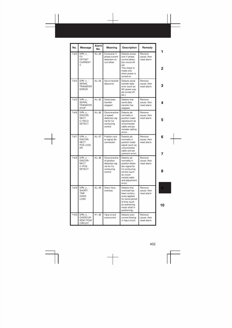
3
1
4
5
6
7
8
9
10
2
402
No. RemedyDescriptionMeaningAlarm
No.Message
7n20 SPN_n_ :
EX
OFFSET
CURRENT
V
AL–20 Excessive V
phase current
detection cir-
cuit offset
Detects exces-
sive V phase
current detec-
tion circuit off-
set.
This check is
made only
when power is
turned on.
Remove
cause, then
reset alarm.
7n24 SPN_n_ :
SERIAL
TRANSFER
ERROR
AL–24 Serial transfer
data error
Detects serial
transfer data
error (such as
NC power sup-
ply turned off,
etc.)
Remove
cause, then
reset alarm.
7n25 SPN_n_ :
SERIAL
TRANSFER
STOP
AL–25 Serial data
transfer
stopped
Detects that
serial data
transfer has
stopped.
Remove
cause, then
reset alarm.
7n26 SPN_n_ :
DISCON-
NECT
C–VELO
DETECT
AL–26 Disconnection
of speed
detection sig-
nal for Cs
contouring
control
Detects ab-
normality in
position coder
signal(such as
unconnected
cable and pa-
rameter setting
error).
Remove
cause, then
reset alarm.
7n27 SPN_n_ :
DISCON-
NECT
POS–COD-
ER
AL–27 Posit ion cod-
er signal dis-
connection
Detects ab-
normality in
position coder
signal (such as
unconnected
cable and ad-
justment error).
Remove
cause, then
reset alarm.
7n28 SPN_n_ :
DISCON-
NECT
C–POS
DETECT
AL–28 Disconnection
of position
detection sig-
nal for Cs
contouring
control
Detects ab-
normality in
position detec-
tion signal for
Cs contouring
control (such
as uncon-
nected cable
and adjustment
error).
Remove
cause, then
reset alarm.
7n29 SPN_n_ :
SHORT-
TIME
OVER-
LOAD
AL–29 Short–t ime
overload
Detects that
overload has
been continu-
ously applied
for some period
of time (such
as restraining
motor shaft in
positioning).
Remove
cause, then
reset alarm.
7n30 SPN_n_ :
OVERCUR-
RENT POW
CIRCUIT
AL–30 Input circuit
overcurrent
Detects over-
current flowing
in input circuit.
Remove
cause, then
reset alarm.

9. ERROR CODE LIST
403
No. RemedyDescriptionMeaningAlarm
No.Message
7n31 SPN_n_ :
MOTOR
LOCK OR
V–SIG LOS
AL–31 Speed detec-
tion signal
disconnection
motor re-
straint alarm
or motor is
clamped.
Detects that
motor cannot
rotate at speci-
fied speed or it
is detected that
the motor is
clamped. (but
rotates at very
slow speed or
has stopped).
(This includes
checking of
speed detec-
tion signal
cable.)
Remove
cause, then
reset alarm.
7n32 SPN_n_ :
RAM
FAULT
SERIAL LSI
AL–32 Abnormali ty
in RAM inside
the LSI used
for serial data
transfer. This
check is
made only
when power
is turned on.
Detects ab-
normality in
RAM inside the
LSI used for
serial data
transfer. This
check is made
only when pow-
er is turned on.
Remove
cause, then
reset alarm.
7n33 SPN_n_ :
SHORT-
AGE
POWER
CHARGE
AL–33 Insufficient
DC link sec-
tion charging
Detects insuffi-
cient charging
of direct current
power supply
voltage in pow-
er circuit sec-
tion when mag-
netic contactor
in amplifier is
turned on (such
as open phase
and defectifve
charging resis-
tor).
Remove
cause, then
reset alarm.
7n34 SPN_n_ :
PARAME-
TER
SETTING
ERROR
AL–34 Parameter
data setting
beyond allow-
able range of
values
Detects param-
eter data set
beyond allow-
able range of
values.
Set correct
data.
7n35 SPN_n_ :
EX
SETTING
GEAR
RATIO
AL–35 Excess ive
gear ratio
data setting
Detects gear
ratio data set
beyond allow-
able range of
values.
Set correct
data.
7n36 SPN_n_ :
OVER-
FLOW
ERROR
COUNTER
AL–36 Error counter
overflow
Detects error
counter over-
flow.
Correct
cause, then
reset alarm.
7n37 SPN_n_ :
SPEED
DETECT
PAR.
ERROR
AL–37 Speed detec-
tor parameter
setting error
Detects incor-
rect setting of
parameter for
number of
speed detec-
tion pulses.
Set correct
data.
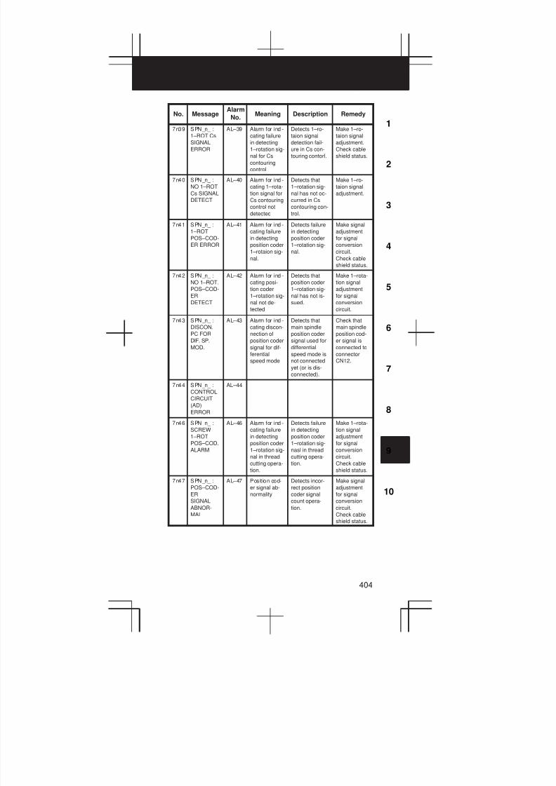
3
1
4
5
6
7
8
9
10
2
404
No. RemedyDescriptionMeaningAlarm
No.Message
7n39 SPN_n_ :
1–ROT Cs
SIGNAL
ERROR
AL–39 Alarm for indi-
cating failure
in detecting
1–rotation sig-
nal for Cs
contouring
control
Detects 1–ro-
taion signal
detection fail-
ure in Cs con-
touring contorl.
Make 1–ro-
taion signal
adjustment.
Check cable
shield status.
7n40 SPN_n_ :
NO 1–ROT
Cs SIGNAL
DETECT
AL–40 Alarm for indi-
cating 1–rota-
tion signal for
Cs contouring
control not
detected
Detects that
1–rotation sig-
nal has not oc-
curred in Cs
contouring con-
trol.
Make 1–ro-
taion signal
adjustment.
7n41 SPN_n_ :
1–ROT
POS–COD-
ER ERROR
AL–41 Alarm for indi-
cating failure
in detecting
position coder
1–rotaion sig-
nal.
Detects failure
in detecting
position coder
1–rotation sig-
nal.
Make signal
adjustment
for signal
conversion
circuit.
Check cable
shield status.
7n42 SPN_n_ :
NO 1–ROT.
POS–COD-
ER
DETECT
AL–42 Alarm for indi-
cating posi-
tion coder
1–rotation sig-
nal not de-
tected
Detects that
position coder
1–rotation sig-
nal has not is-
sued.
Make 1–rota-
tion signal
adjustment
for signal
conversion
circuit.
7n43 SPN_n_ :
DISCON.
PC FOR
DIF. SP.
MOD.
AL–43 Alarm for indi-
cating discon-
nection of
position coder
signal for dif-
ferential
speed mode
Detects that
main spindle
position coder
signal used for
differential
speed mode is
not connected
yet (or is dis-
connected).
Check that
main spindle
position cod-
er signal is
connected to
connector
CN12.
7n44 SPN_n_ :
CONTROL
CIRCUIT
(AD)
ERROR
AL–44
7n46 SPN_n_ :
SCREW
1–ROT
POS–COD.
ALARM
AL–46 Alarm for indi-
cating failure
in detecting
position coder
1–rotation sig-
nal in thread
cutting opera-
tion.
Detects failure
in detecting
position coder
1–rotation sig-
nasl in thread
cutting opera-
tion.
Make 1–rota-
tion signal
adjustment
for signal
conversion
circuit.
Check cable
shield status.
7n47 SPN_n_ :
POS–COD-
ER
SIGNAL
ABNOR-
MAL
AL–47 Posit ion cod-
er signal ab-
normality
Detects incor-
rect position
coder signal
count opera-
tion.
Make signal
adjustment
for signal
conversion
circuit.
Check cable
shield status.

9. ERROR CODE LIST
405
No. RemedyDescriptionMeaningAlarm
No.Message
7n49 SPN_n_ :
HIGH
CONV. DIF.
SPEED
AL–49 The con-
verted differ-
ential speed
is too high.
Detects that
speed of other
spindle con-
verted to speed
of local spindle
has exceeded
allowable limit
in differential
mode.
Calculate dif-
ferential
speed by
multiplying
speed of oth-
er spindle by
gear ratio.
Check if cal-
culated value
is not greater
than maxi-
mum speed
of motor.
7n50 SPN_n_ :
SPNDL
CONTROL
OVER-
SPEED
AL–50 Excess ive
speed com-
mand calcula-
tion value in
spindle syn-
chronization
control
Detects that
speed com-
mand calcula-
tion value ex-
ceeded allow-
able range in
spindle syn-
chronization
control.
Calculate mo-
tor speed by
multiplying
specified
spindle
speed by
gear ratio.
Check if cal-
culated value
is not greater
than maxi-
mum speed
of motor.
7n51 SPN_n_ :
LOW VOLT
DC LINK
AL–51 Undervoltage
at DC link
section
Detects that
DC power sup-
ply voltage of
power circuit
has dropped
(due to mo-
mentary power
failure or loose
contact of mag-
netic contac-
tor).
Remove
cause, then
reset alarm.
7n52 SPN_n_ :
ITP
SIGNAL
ABNOR-
MAL I
AL–52 ITP signal ab-
normality I
Detects ab-
normality in
synchroniza-
tion signal (ITP
signal ) used in
software.
Replace ser-
vo amp. PCB.
7n53 SPN_n_ :
ITP
SIGNAL
ABNOR-
MAL II
AL–53 ITP signal ab-
normality II
Detects ab-
normality in
synchroniza-
tion signal (ITP
signal) used in
hardware.
Replace ser-
vo amp. PCB.
7n56 SPN_n_ :
INNER
COOLING
FAN STOP
AL–56 The cooling
fan in the unit
stopped.
The cooling fan
in the control
circuit section
stopped.
Check the
turning state
of the cooling
fan. Replace
the cooling
fan.
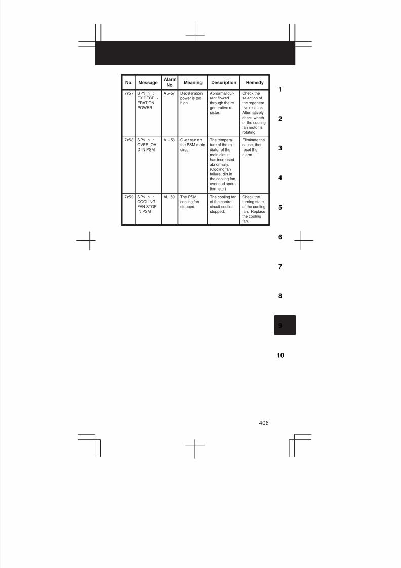
3
1
4
5
6
7
8
9
10
2
406
No. RemedyDescriptionMeaningAlarm
No.Message
7n57 SPN_n_ :
EX DECEL-
ERATION
POWER
AL–57 Deceleration
power is too
high.
Abnormal cur-
rent flowed
through the re-
generative re-
sistor.
Check the
selection of
the regenera-
tive resistor.
Alternatively,
check wheth-
er the cooling
fan motor is
rotating.
7n58 SPN_n_ :
OVERLOA
D IN PSM
AL–58 Overload on
the PSM main
circuit
The tempera-
ture of the ra-
diator of the
main circuit
has increased
abnormally.
(Cooling fan
failure, dirt in
the cooling fan,
overload opera-
tion, etc.)
Eliminate the
cause, then
reset the
alarm.
7n59 SPN_n_ :
COOLING
FAN STOP
IN PSM
AL–59 The PSM
cooling fan
stopped.
The cooling fan
of the control
circuit section
stopped.
Check the
turning state
of the cooling
fan. Replace
the cooling
fan.
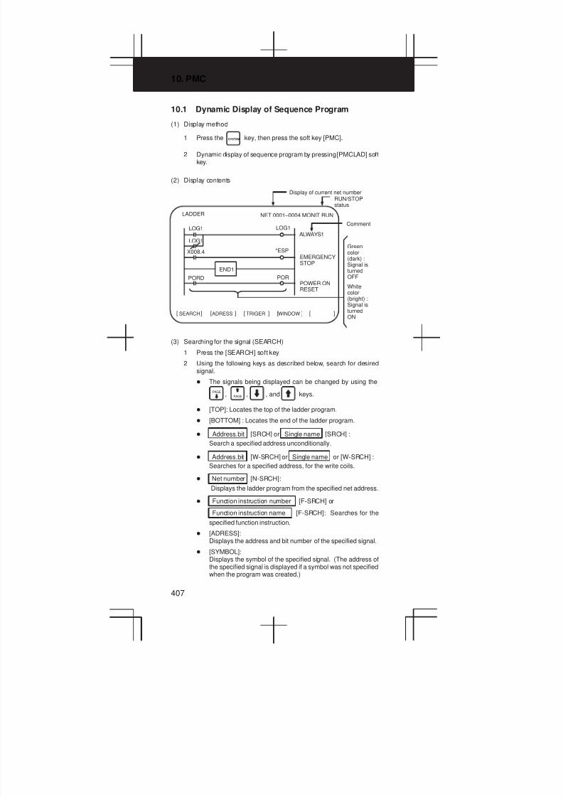
10. PMC
407
10.1 Dynamic Display of Sequence Program
(1) Display method
1 Press the SYSTEM key, then press the soft key [PMC].
2 Dynamic display of sequence program by pressing [PMCLAD] softkey.
(2) Display contents
[ ]WINDOWSEARCH[ ] [ ] [ ] [ ]ADRESS TRIGER
LADDER NET 0001–0004 MONIT RUN
END1
LOG1
X008.4
LOG1ALWAYS1
EMERGENCYSTOP
POWER ONRESET
LOG1
*ESP
PORPORD
Greencolor(dark) :Signal isturnedOFF
Whitecolor(bright) :Signal isturnedON
Display of current net numberRUN/STOPstatus
Comment
(3) Searching for the signal (SEARCH)
1 Press the [SEARCH] soft key.
2 Using the following keys as described below, search for desiredsignal.
D The signals being displayed can be changed by using the
PAGE, PAGE , , and keys.
D [TOP]: Locates the top of the ladder program.
D [BOTTOM] : Locates the end of the ladder program.
D
Address.bit [SRCH] or Single name [SRCH] :
Search a specified address unconditionally.
D Address.bit [W-SRCH] or Single name or [W-SRCH] :
Searches for a specified address, for the write coils.
D Net number [N-SRCH]:
Displays the ladder program from the specified net address.
D Function instruction number [F-SRCH] or
Function instruction name [F-SRCH]: Searches for the
specified function instruction.
D [ADRESS]:Displays the address and bit number of the specified signal.
D [SYMBOL]:Displays the symbol of the specified signal. (The address ofthe specified signal is displayed if a symbol was not specifiedwhen the program was created.)
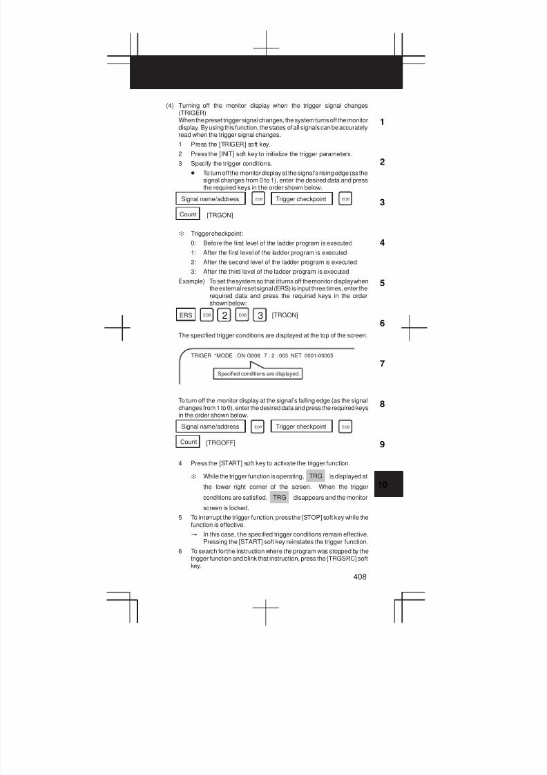
3
1
4
5
6
7
8
9
10
2
408
(4) Turning off the monitor display when the trigger signal changes(TRIGER)When the preset trigger signal changes, the system turns off the monitordisplay. By using this function, the states of all signals can be accuratelyread when the trigger signal changes.
1 Press the [TRIGER] soft key.
2 Press the [INIT] soft key to initialize the trigger parameters.
3 Specify the trigger conditions.
D To turn off the monitor display at the signal’s rising edge (as thesignal changes from 0 to 1), enter the desired data and pressthe required keys in the order shown below.
Count
Signal name/address Trigger checkpoint
[TRGON]
EOB EOB
: Trigger checkpoint:
0: Before the first level of the ladder program is executed
1: After the first level of the ladder program is executed
2: After the second level of the ladder program is executed
3: After the third level of the ladder program is executed
Example) To set the system so that it turns off the monitor display whenthe external reset signal (ERS) is input three times, enter therequired data and press the required keys in the ordershown below:
ERS [TRGON]EOB 2 3EOB
The specified trigger conditions are displayed at the top of the screen.
TRIGER *MODE : ON G008. 7 : 2 : 003 NET 0001-00005
Specified conditions are displayed.
To turn off the monitor display at the signal’s falling edge (as the signalchanges from 1 to 0), enter the desired data and press the required keysin the order shown below.
Count
Signal name/address Trigger checkpoint
[TRGOFF]
EOB EOB
4 Press the [START] soft key to activate the trigger function.
: While the trigger function is operating, TRG is displayed at
the lower right corner of the screen. When the trigger
conditions are satisfied, TRG disappears and the monitor
screen is locked.
5 To interrupt the trigger function, press the [STOP] soft key while thefunction is effective.
³ In this case, the specified trigger conditions remain effective.Pressing the [START] soft key reinstates the trigger function.
6 To search for the instruction where the program was stopped by thetrigger function and blink that instruction, press the [TRGSRC] softkey.

10. PMC
409
(5) Displaying a divided ladder program (WINDOW)A ladder program can be divided into up to six sections, and theindividual sections displayed on the screen simultaneously.
1 Press the [WINDOW] soft key.
2 Press the [DIVIDE] soft key to divide the dynamic display screeninto the desired number of sections.
: Each time the key is pressed, the screen is divided.
An unselected divided screenis indicated by a blue low-in-tensity bar.
LOG1
*SP
ST
A selected divided screen isindicated by the purple high-intensity bar.
LADDER
LOG1
DOOR. ST.
* XXX. . . . . . . . . . . . . XXX * MONIT RUN
LOG1
*SP.
NET 0001-0002
SKIP1. SKIP1
NET 0020-0021
3 To select the desired divided screen, press the [SELECT] soft keyas many times as necessary to move the purple bar to the desiredscreen.
: The normal search function can be used within each dividedscreen.
4 To change the width of a selected divided screen, press the[WIDTH] soft key.
D Pressing the [EXPAND] soft key increases the number of linesdisplayed on a divided screen.
D Pressing the [SHRINK] soft key decreases the number of linesdisplayed on a divided screen.
5 To terminate the display of a selected divided screen, press the[DELETE] soft key.
: To terminate screen division, press the [CANCEL] soft key.
(6) Dumping (DUMP)The states of the signals corresponding to a ladder program can bedisplayed in hexadecimal, together with the ladder program itself.
1 Press the [DUMP] soft key.
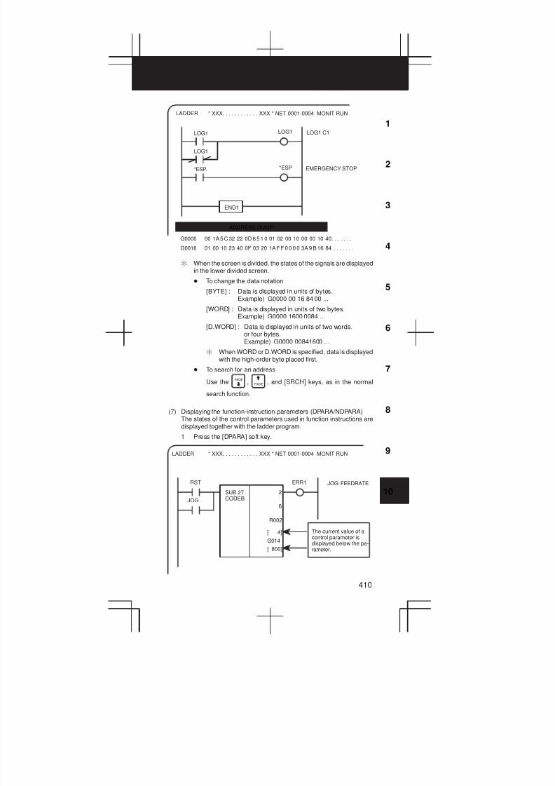
3
1
4
5
6
7
8
9
10
2
410
LOG1 LOG1
LOG1
*ESP. *ESP
LOG1 C1
EMERGENCY STOP
END1
G0000 00 1A 5 C 32 22 0D 6 5 1 0 01 02 00 10 00 00 10 40. . . . . . .
G0016 01 00 10 23 40 0F 03 20 1A F F 0 0 0 0 3A 9 B 16 84 . . . . . . .
ADDRESS DUMP
* XXX. . . . . . . . . . . . XXX * NET 0001-0004 MONIT RUNLADDER
: When the screen is divided, the states of the signals are displayedin the lower divided screen.
D To change the data notation
[BYTE] : Data is displayed in units of bytes.Example) G0000 00 16 84 00 ...
[WORD] : Data is displayed in units of two bytes.Example) G0000 1600 0084 ...
[D.WORD] : Data is displayed in units of two words,or four bytes.Example) G0000 00841600 ...
: When WORD or D.WORD is specified, data is displayedwith the high-order byte placed first.
D To search for an address
Use thePAGE
, PAGE , and [SRCH] keys, as in the normal
search function.
(7) Displaying the function-instruction parameters (DPARA/NDPARA)The states of the control parameters used in function instructions aredisplayed together with the ladder program.
1 Press the [DPARA] soft key.
* XXX. . . . . . . . . . . . XXX * NET 0001-0004 MONIT RUNLADDER
RST ERR1
JOG
JOG FEEDRATE
SUB 27CODEB
2
6
R002
[ 4]
G014
[ 800]
The current value of acontrol parameter isdisplayed below the pa-rameter.
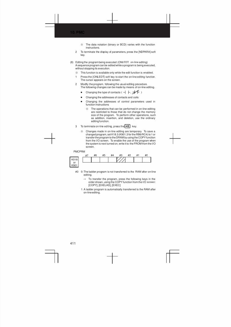
10. PMC
411
: The data notation (binary or BCD) varies with the functioninstructions.
2 To terminate the display of parameters, press the [NDPARA] softkey.
(8) Editing the program being executed (ONLEDT: on-line editing)A sequence program can be edited while a program is being executed,without stopping its execution.
: This function is available only while the edit function is enabled.
1 Press the [ONLEDT] soft key to start the on-line editing function.The cursor appears on the screen.
2 Modify the program, following the usual editing procedure.The following changes can be made by means of on-line editing.
D Changing the type of contacts ( , )
D Changing the addresses of contacts and coils
D Changing the addresses of control parameters used infunction instructions
: The operations that can be performed in on-line editingare restricted to those that do not change the memorysize of the program. To perform other operations, suchas addition, insertion, and deletion, use the ordinaryediting function.
3 To terminate on-line editing, press the key.
: Changes made in on-line editing are temporary. To save achanged program, set K18.3 (K901.3 for the RB6/RC4) to 1 ortransfer the program to the DRAM by using the COPY functionfrom the I/O screen. To enable the use of the program whenthe system is next turned on, write it to the FROM from the I/Oscreen.
K018or
K901
#7 #6 #5 #4 #3 #2 #1 #0
PMCPRM
 Â
 Â
#3 0: The ladder program is not transferred to the RAM after on-lineediting.
³ To transfer the program, press the following keys in theorder shown, using the COPY function from the I/O screen:[COPY], [EXELAD], [EXEC]
1: A ladder program is automatically transferred to the RAM afteron-line editing.

3
1
4
5
6
7
8
9
10
2
412
10.2 Display of PMC Diagnosis Screen
(1) Display method
1 Press the SYSTEM key.
2 Press the [PMC] soft key.
3 Display of PMC diagnosis screen by pressing [PMC/DGN] soft key.
10.2.1 Title screen (TITLE)
Display of the title data which is wrote at the ladder programming time.
PMC TITLE DATA #1
PMC PROGRAM NO. :
EDITION NO. :
PMC CONTROL PROGRAM
SERIES : 4067 EDITION : 01
(SERIES : EDITION : )
PMC TYPE CONTROL : RB5 PROGRAM : RB5
MEMORY USED : KB
LADDER : KB
SYMBOL : KB
MESSAGE : KB
SCAN TIME : MS
SCAN MAX : MS MIN : MS
MONIT RUN
TITLE[ ] [ ] [ ] [ ] [ ]STATUS ANALYS TRACE
1) 1st page
PMC PROGRAM NO. :
EDITION NO. :
PMC CONTROL PROGRAM
SERIES : EDITTION :
(SERIES: EDITTION : )
PMC TYPE CONTROL : PROGRAM :
MEMORY USED : KB
LADDER : KB
SYMBOL : KB
MESSAGE : KB
SCAN TIME : MS
SXAN MAX : MS MIN : MS
Display of aserial numberand versionnumber ofPMC controlsoftware, usedmemory areaand scan time.
Set atLADDERprogrammingtime.
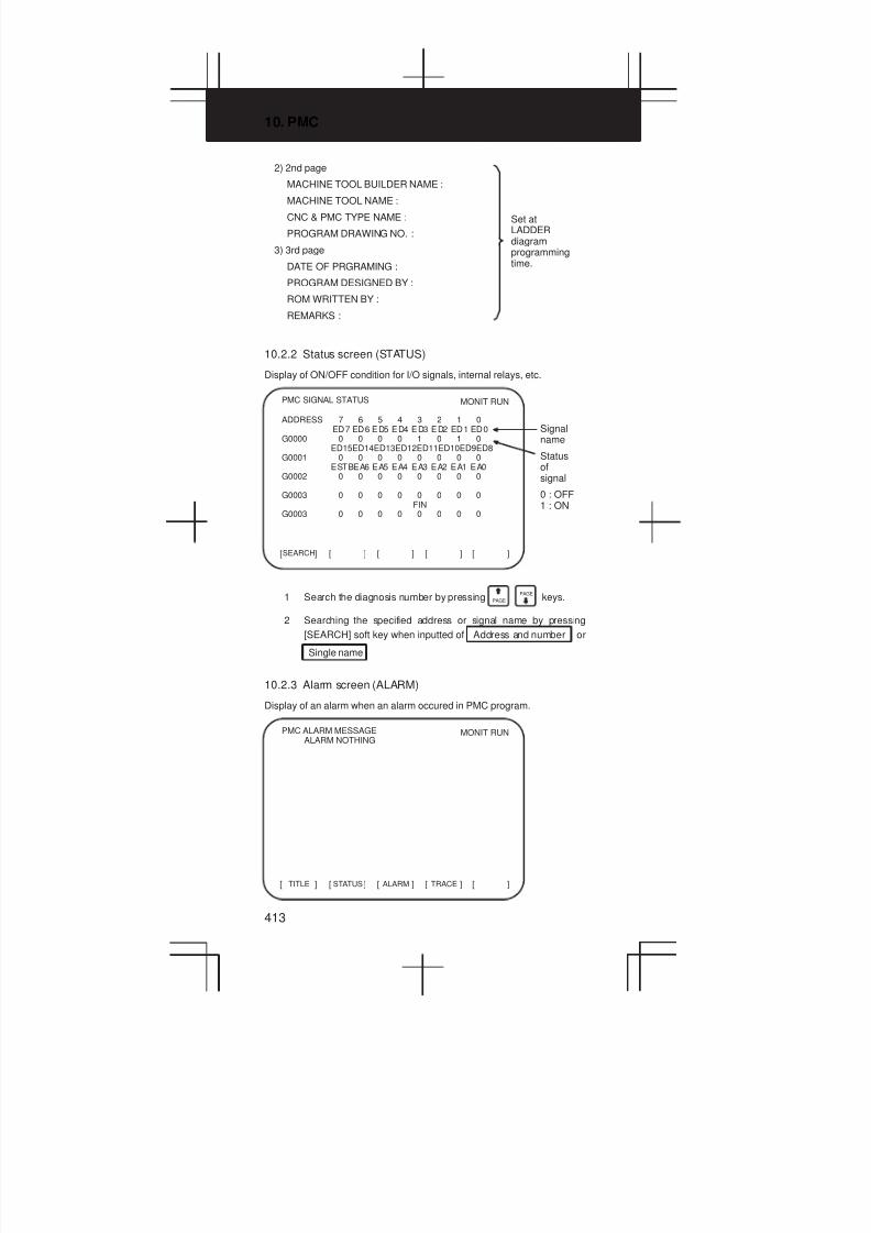
10. PMC
413
2) 2nd page
MACHINE TOOL BUILDER NAME :
MACHINE TOOL NAME :
CNC & PMC TYPE NAME :
PROGRAM DRAWING NO. :
3) 3rd page
DATE OF PRGRAMING :
PROGRAM DESIGNED BY :
ROM WRITTEN BY :
REMARKS :
Set atLADDERdiagramprogrammingtime.
10.2.2 Status screen (STATUS)
Display of ON/OFF condition for I/O signals, internal relays, etc.
SEARCH[ ] [ ] [ ] [ ] [ ]
PMC SIGNAL STATUS MONIT RUN
ADDRESS 7 6 5 4 3 2 1 0ED7 ED6 ED5 ED4 ED3 ED2 ED1 ED0
G0000 0 0 0 0 1 0 1 0ED15ED14ED13ED12ED11ED10ED9ED8
G0001 0 0 0 0 0 0 0 0ESTBEA6 EA5 EA4 EA3 EA2 EA1 EA0
G0002 0 0 0 0 0 0 0 0
G0003 0 0 0 0 0 0 0 0FIN
G0003 0 0 0 0 0 0 0 0
Signalname
Statusofsignal
0 : OFF1 : ON
1 Search the diagnosis number by pressing PAGE PAGE
keys.
2 Searching the specified address or signal name by pressing
[SEARCH] soft key when inputted of Address and number or
Single name
10.2.3 Alarm screen (ALARM)
Display of an alarm when an alarm occured in PMC program.
TITLE[ ] [ ] [ ] [ ] [ ]STATUS ALARM TRACE
PMC ALARM MESSAGEALARM NOTHING
MONIT RUN
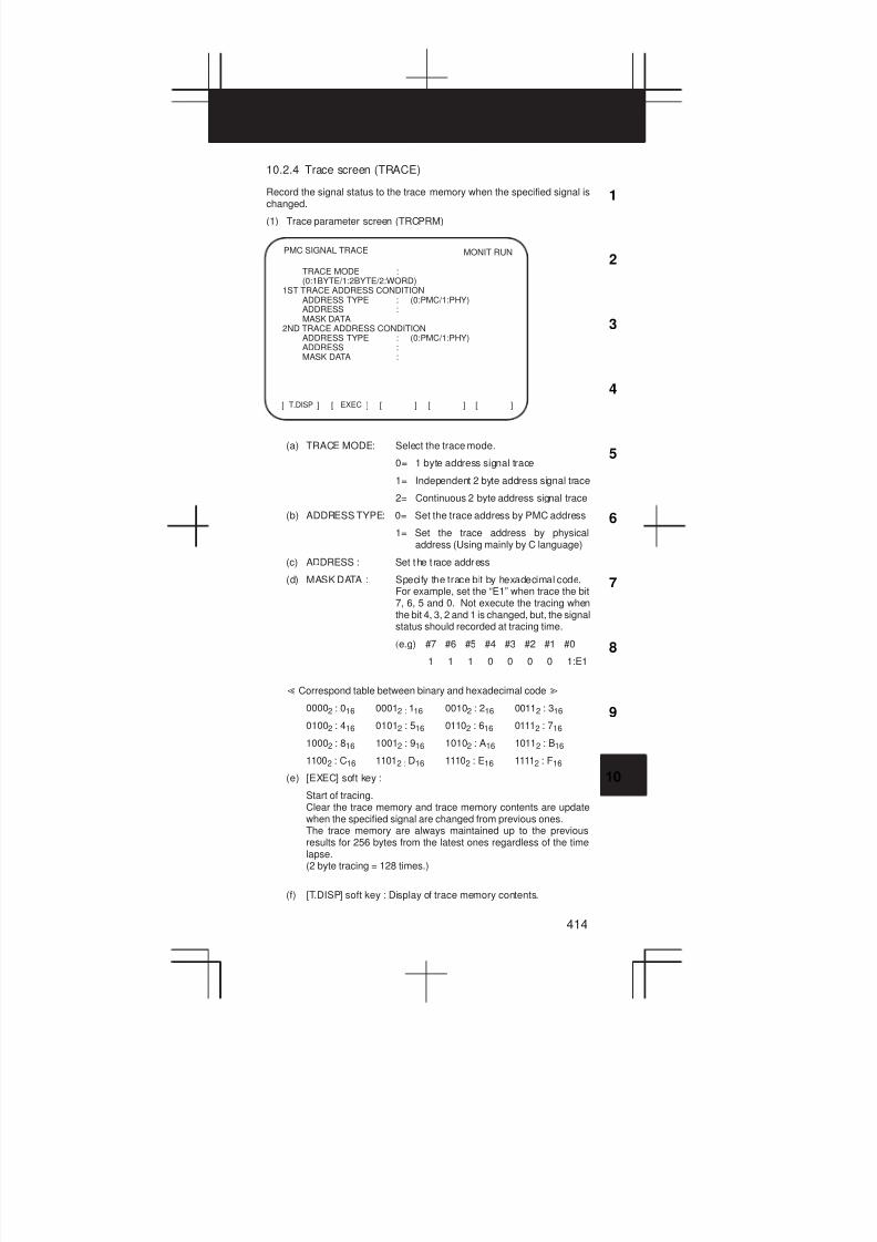
3
1
4
5
6
7
8
9
10
2
414
10.2.4 Trace screen (TRACE)
Record the signal status to the trace memory when the specified signal ischanged.
(1) Trace parameter screen (TRCPRM)
T.DISP[ ] [ ] [ ] [ ] [ ]EXEC
PMC SIGNAL TRACE MONIT RUN
TRACE MODE :(0:1BYTE/1:2BYTE/2:WORD)
1ST TRACE ADDRESS CONDITIONADDRESS TYPE : (0:PMC/1:PHY)ADDRESS :MASK DATA
2ND TRACE ADDRESS CONDITIONADDRESS TYPE : (0:PMC/1:PHY)ADDRESS :MASK DATA :
(a) TRACE MODE: Select the trace mode.
0= 1 byte address signal trace
1= Independent 2 byte address signal trace
2= Continuous 2 byte address signal trace
(b) ADDRESS TYPE: 0= Set the trace address by PMC address
1= Set the trace address by physicaladdress (Using mainly by C language)
(c) ADDRESS : Set the t race address
(d) MASK DATA : Specify the trace bit by hexadecimal code.For example, set the “E1” when trace the bit7, 6, 5 and 0. Not execute the tracing whenthe bit 4, 3, 2 and 1 is changed, but, the signalstatus should recorded at tracing time.
(e.g) #7 #6 #5 #4 #3 #2 #1 #0
1 1 1 0 0 0 0 1:E1
Ơ Correspond table between binary and hexadecimal codeơ
00002 : 016 00012 : 116 00102 : 216 00112 : 316
01002 : 416 01012 : 516 01102 : 616 01112 : 716
10002 : 816 10012 : 916 10102 : A16 10112 : B16
11002 : C16 11012 : D16 11102 : E16 11112 : F16
(e) [EXEC] soft key :
Start of tracing.Clear the trace memory and trace memory contents are updatewhen the specified signal are changed from previous ones.The trace memory are always maintained up to the previousresults for 256 bytes from the latest ones regardless of the timelapse.(2 byte tracing = 128 times.)
(f) [T.DISP] soft key : Display of trace memory contents.
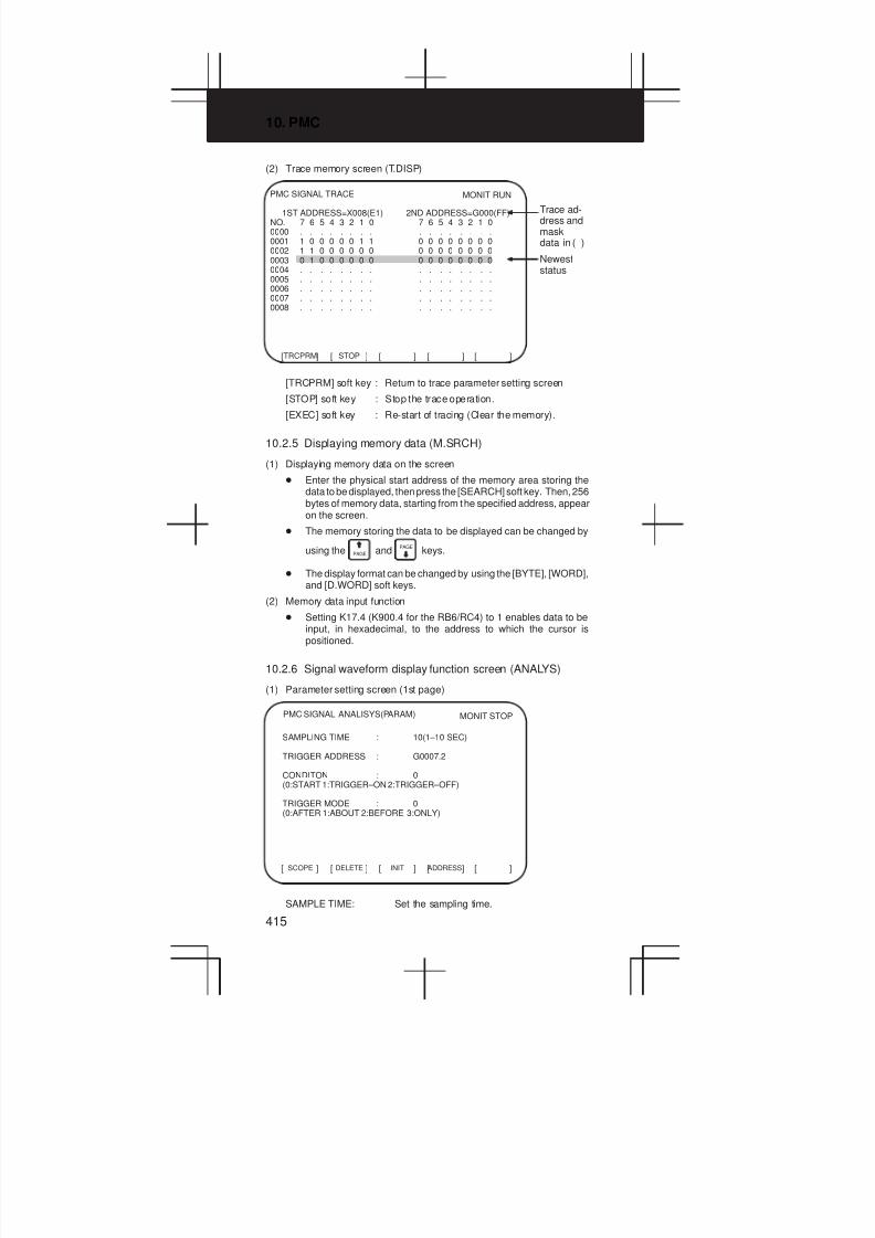
10. PMC
415
(2) Trace memory screen (T.DISP)
PMC SIGNAL TRACE
1ST ADDRESS=X008(E1) 2ND ADDRESS=G000(FF)NO. 7 6 5 4 3 2 1 0 7 6 5 4 3 2 1 00000 . . . . . . . . . . . . . . . .0001 1 0 0 0 0 0 1 1 0 0 0 0 0 0 0 00002 1 1 0 0 0 0 0 0 0 0 0 0 0 0 0 00003 0 1 0 0 0 0 0 0 0 0 0 0 0 0 0 00004 . . . . . . . . . . . . . . . .0005 . . . . . . . . . . . . . . . .0006 . . . . . . . . . . . . . . . .0007 . . . . . . . . . . . . . . . .0008 . . . . . . . . . . . . . . . .
Trace ad-dress andmaskdata in ( )
Neweststatus
TRCPRM[ ] [ ] [ ] [ ] [ ]STOP
MONIT RUN
[TRCPRM] soft key : Return to trace parameter setting screen
[STOP] soft key : Stop the trace operation.
[EXEC] soft key : Re-start of tracing (Clear the memory).
10.2.5 Displaying memory data (M.SRCH)
(1) Displaying memory data on the screen
D Enter the physical start address of the memory area storing thedata to be displayed, then press the [SEARCH] soft key. Then, 256bytes of memory data, starting from the specified address, appearon the screen.
D The memory storing the data to be displayed can be changed by
using the PAGE andPAGE
keys.
D The display format can be changed by using the [BYTE], [WORD],and [D.WORD] soft keys.
(2) Memory data input function
D Setting K17.4 (K900.4 for the RB6/RC4) to 1 enables data to beinput, in hexadecimal, to the address to which the cursor ispositioned.
10.2.6 Signal waveform display function screen (ANALYS)
(1) Parameter setting screen (1st page)
SCOPE[ ] [ ] [ ] [ ] [ ]DELETE INIT ADDRESS
PMC SIGNAL ANALISYS(PARAM) MONIT STOP
SAMPLING TIME : 10(1–10 SEC)
TRIGGER ADDRESS : G0007.2
CONDITON : 0(0:START 1:TRIGGER–ON 2:TRIGGER–OFF)
TRIGGER MODE : 0(0:AFTER 1:ABOUT 2:BEFORE 3:ONLY)
SAMPLE TIME: Set the sampling time.
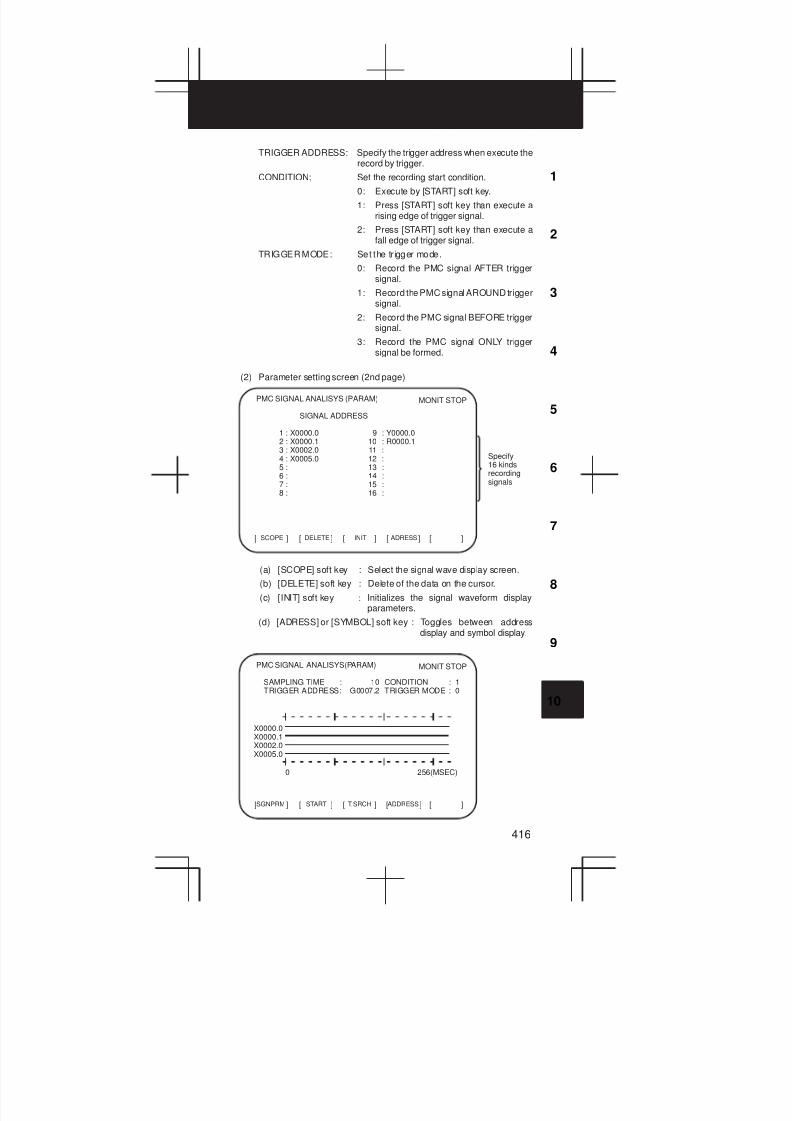
3
1
4
5
6
7
8
9
10
2
416
TRIGGER ADDRESS: Specify the trigger address when execute therecord by trigger.
CONDITION: Set the recording start condition.
0: Execute by [START] soft key.
1: Press [START] soft key than execute arising edge of trigger signal.
2: Press [START] soft key than execute afall edge of trigger signal.
TRIGGER MODE: Set the tr igger mode.
0: Record the PMC signal AFTER triggersignal.
1: Record the PMC signal AROUND triggersignal.
2: Record the PMC signal BEFORE triggersignal.
3: Record the PMC signal ONLY triggersignal be formed.
(2) Parameter setting screen (2nd page)
SCOPE[ ] [ ] [ ] [ ] [ ]DELETE INIT ADRESS
PMC SIGNAL ANALISYS (PARAM)
SIGNAL ADDRESS
1 : X0000.0 9 : Y0000.02 : X0000.1 10 : R0000.13 : X0002.0 11 :4 : X0005.0 12 :5 : 13 :6 : 14 :7 : 15 :8 : 16 :
MONIT STOP
Specify16 kindsrecordingsignals
(a) [SCOPE] soft key : Select the signal wave display screen.
(b) [DELETE] soft key : Delete of the data on the cursor.
(c) [INIT] soft key : Initializes the signal waveform displayparameters.
(d) [ADRESS] or [SYMBOL] soft key : Toggles between addressdisplay and symbol display.
SGNPRM[ ] [ ] [ ] [ ] [ ]START T.SRCH ADDRESS
PMC SIGNAL ANALISYS(PARAM)
SAMPLING TIME : 10 CONDITION : 1TRIGGER ADDRESS: G0007.2 TRIGGER MODE : 0
MONIT STOP
0 256(MSEC)
X0000.0X0000.1X0002.0X0005.0
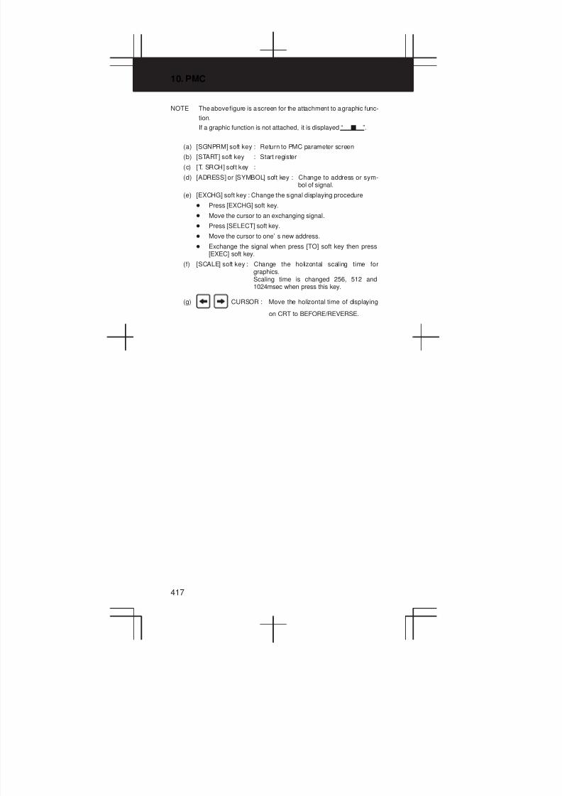
10. PMC
417
NOTE The above figure is a screen for the attachment to a graphic func-
tion.
If a graphic function is not attached, it is displayed “ J ”.
(a) [SGNPRM] soft key : Return to PMC parameter screen
(b) [START] soft key : Start register
(c) [T. SRCH] soft key :
(d) [ADRESS] or [SYMBOL] soft key : Change to address or sym-bol of signal.
(e) [EXCHG] soft key : Change the signal displaying procedure
D Press [EXCHG] soft key.
D Move the cursor to an exchanging signal.
D Press [SELECT] soft key.
D Move the cursor to one’ s new address.
D Exchange the signal when press [TO] soft key then press[EXEC] soft key.
(f) [SCALE] soft key : Change the holizontal scaling time forgraphics.Scaling time is changed 256, 512 and1024msec when press this key.
(g) CURSOR : Move the holizontal time of displaying
on CRT to BEFORE/REVERSE.

3
1
4
5
6
7
8
9
10
2
418
10.3 PMC Parameter
10.3.1 Input of PMC parameter from MDI
1 Select MDI mode or depress EMERGENCY STOP button.
2 [PWE] set to “1” on SETTING screen or PROGRAM PROTECTsignal (KEY4) turn to “1”.
PWE KEY4
f
f
f
f
f either one
Timer
Counter
Keep relay
Data table f either one
3 Select the display screen by soft key.
[TIMER] : Timer screen
[COUNTER] : Counter screen
[KEEPRL] : Keep relay screen
[DATA] : Data table screen
4 Move the cursor to desired number.
5 Input the Numeral and press INPUT key then the data
inputted.
6 [PWE] on SETTING screen or [KEY4] return to “0” after data set.
10.3.2 Timer screen (TIMER)
The variable timer (SUB 3) time is set.
TIMER[ ] [ ] [ ] [ ] [ ]COUNTR KEEPRL DATA SETING
PMC PARAMETER (TIMER) #001
NO. ADDRESS DATA NO. ADDRESS DATA01 T00 480 11 T20 002 T02 960 12 T22 003 T04 0 13 T24 004 T06 0 14 T26 005 T08 0 15 T28 006 T10 0 16 T30 007 T12 0 17 T32 008 T14 0 18 T34 009 T16 0 19 T36 010 T18 0 20 T38 0
MONIT RUN
Setting
time by
msec unit
Refer the address by ladder
program
Specified timer number by program
Page number (change by page cursor key)
Setting time : Timer No. 1 – 8 =Max.=1572.8 sec, each 48msec.Up to 262.1 seconds in units of 8 ms for timer Nos.9 to 40 subsequent timers (timer Nos. 9 to 150 inthe RB6/RC4)
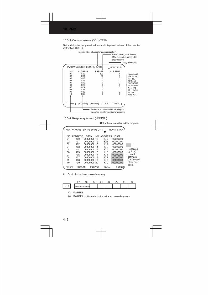
10. PMC
419
10.3.3 Counter screen (COUNTER)
Set and display the preset values and integrated values of the counterinstruction (SUB 5).
Page number (change by page cursor key)
TIMER[ ] [ ] [ ] [ ] [ ]COUNTR KEEPRL DATA SETING
PMC PARAMETER (COUNTER) #001
NO. ADDRESS PRESET CURRENT01 C00 100 102 C04 50 203 C08 0 004 C12 0 005 C16 0 006 C20 0 007 C24 0 008 C28 0 009 C32 0 010 C36 0 0
MONIT RUN
Preset value (MAX. value)
(The min. value specified in
the program)
Refer the address by ladder program
Specified counter number by program
Integrated value
Up to 9999can be setfor PRE-SET andCURRENTfor counterNos. 1 to20 (1 to 50for theRB6/RC4)
10.3.4 Keep relay screen (KEEPRL)
:
Reservedby PMCcontrolsoftware.Can’ t usedother pur-pose.
PMC PARAMETER (KEEP RELAY) MONIT STOP
NO. ADDRESS DATA01 K00 0000000002 K01 0000000003 K02 0000000004 K03 0000000005 K04 0000000006 K05 0000000007 K06 0000000008 K07 0000000009 K08 0000000010 K09 00000000
[KEEPRL] [DATA][COUNTR][TIMER] [SETING]
Refer the address by ladder program
NO. ADDRESS DATA11 K10 0000000012 K11 0000000013 K12 0000000014 K13 0000000015 K14 0000000016 K15 0000000017 K16 0000000018 K17 0000000019 K18 0000000020 K19 00000000
i) Control of battery-powered memory
#7 #6 #5 #4 #3 #2 #1 #0
K16 MWRTF2 MWRTF1
#7 MWRTF2
#6 MWRTF1 : Write status for battery-powered memory
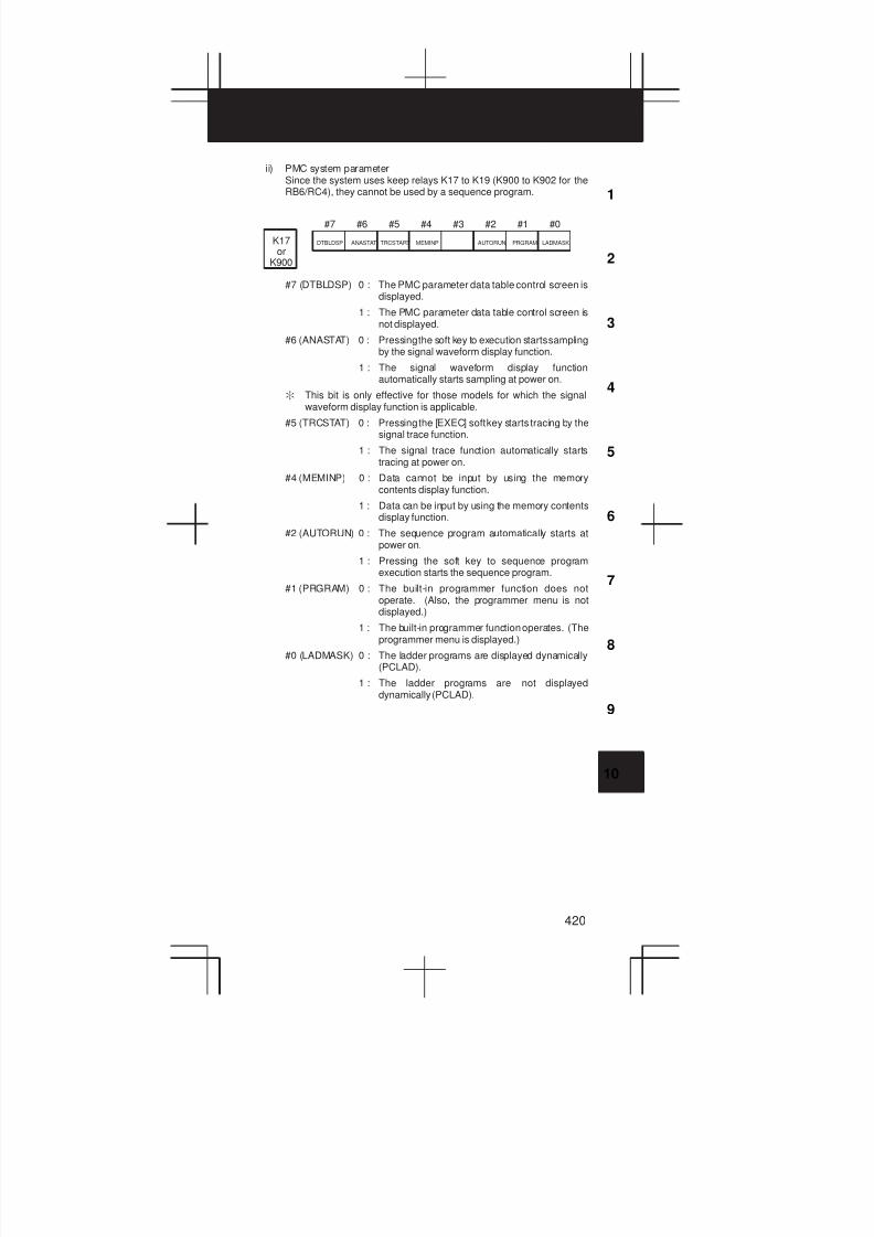
3
1
4
5
6
7
8
9
10
2
420
ii) PMC system parameterSince the system uses keep relays K17 to K19 (K900 to K902 for theRB6/RC4), they cannot be used by a sequence program.
K17or
K900
#7 #6 #5 #4 #3 #2 #1 #0
DTBLDSP ANASTAT TRCSTART MEMINP AUTORUN PRGRAM LADMASK
#7 (DTBLDSP) 0 : The PMC parameter data table control screen isdisplayed.
1 : The PMC parameter data table control screen isnot displayed.
#6 (ANASTAT) 0 : Pressing the soft key to execution starts samplingby the signal waveform display function.
1 : The signal waveform display functionautomatically starts sampling at power on.
: This bit is only effective for those models for which the signalwaveform display function is applicable.
#5 (TRCSTAT) 0 : Pressing the [EXEC] soft key starts tracing by thesignal trace function.
1 : The signal trace function automatically startstracing at power on.
#4 (MEMINP) 0 : Data cannot be input by using the memorycontents display function.
1 : Data can be input by using the memory contentsdisplay function.
#2 (AUTORUN) 0 : The sequence program automatically starts atpower on.
1 : Pressing the soft key to sequence programexecution starts the sequence program.
#1 (PRGRAM) 0 : The built-in programmer function does notoperate. (Also, the programmer menu is notdisplayed.)
1 : The built-in programmer function operates. (Theprogrammer menu is displayed.)
#0 (LADMASK) 0 : The ladder programs are displayed dynamically(PCLAD).
1 : The ladder programs are not displayeddynamically (PCLAD).
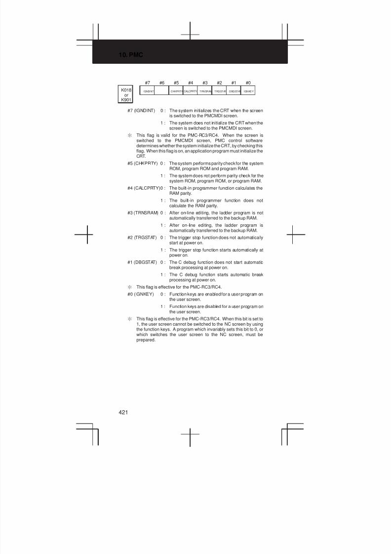
10. PMC
421
K018or
K901
#7 #6 #5 #4 #3 #2 #1 #0
IGNDINT CHKPRTY CALCPRTY TRNSRAM TRGSTAT DBGSTAT IGNKEY
#7 (IGNDINT) 0 : The system initializes the CRT when the screenis switched to the PMCMDI screen.
1 : The system does not initialize the CRT when thescreen is switched to the PMCMDI screen.
: This flag is valid for the PMC-RC3/RC4. When the screen isswitched to the PMCMDI screen, PMC control softwaredetermines whether the system initialize the CRT, by checking thisflag. When this flag is on, an application program must initialize theCRT.
#5 (CHKPRTY) 0 : The system performs parity check for the systemROM, program ROM and program RAM.
1 : The system does not perform parity check for thesystem ROM, program ROM, or program RAM.
#4 (CALCPRTY)0 : The built-in programmer function calculates theRAM parity.
1 : The built-in programmer function does notcalculate the RAM parity.
#3 (TRNSRAM) 0 : After on-line editing, the ladder program is notautomatically transferred to the backup RAM.
1 : After on-line editing, the ladder program isautomatically transferred to the backup RAM.
#2 (TRGSTAT) 0 : The trigger stop function does not automaticallystart at power on.
1 : The trigger stop function starts automatically atpower on.
#1 (DBGSTAT) 0 : The C debug function does not start automaticbreak processing at power on.
1 : The C debug function starts automatic breakprocessing at power on.
: This flag is effective for the PMC-RC3/RC4.
#0 (IGNKEY) 0 : Function keys are enabled for a user program onthe user screen.
1 : Function keys are disabled for a user program onthe user screen.
: This flag is effective for the PMC-RC3/RC4. When this bit is set to1, the user screen cannot be switched to the NC screen by usingthe function keys. A program which invariably sets this bit to 0, orwhich switches the user screen to the NC screen, must beprepared.
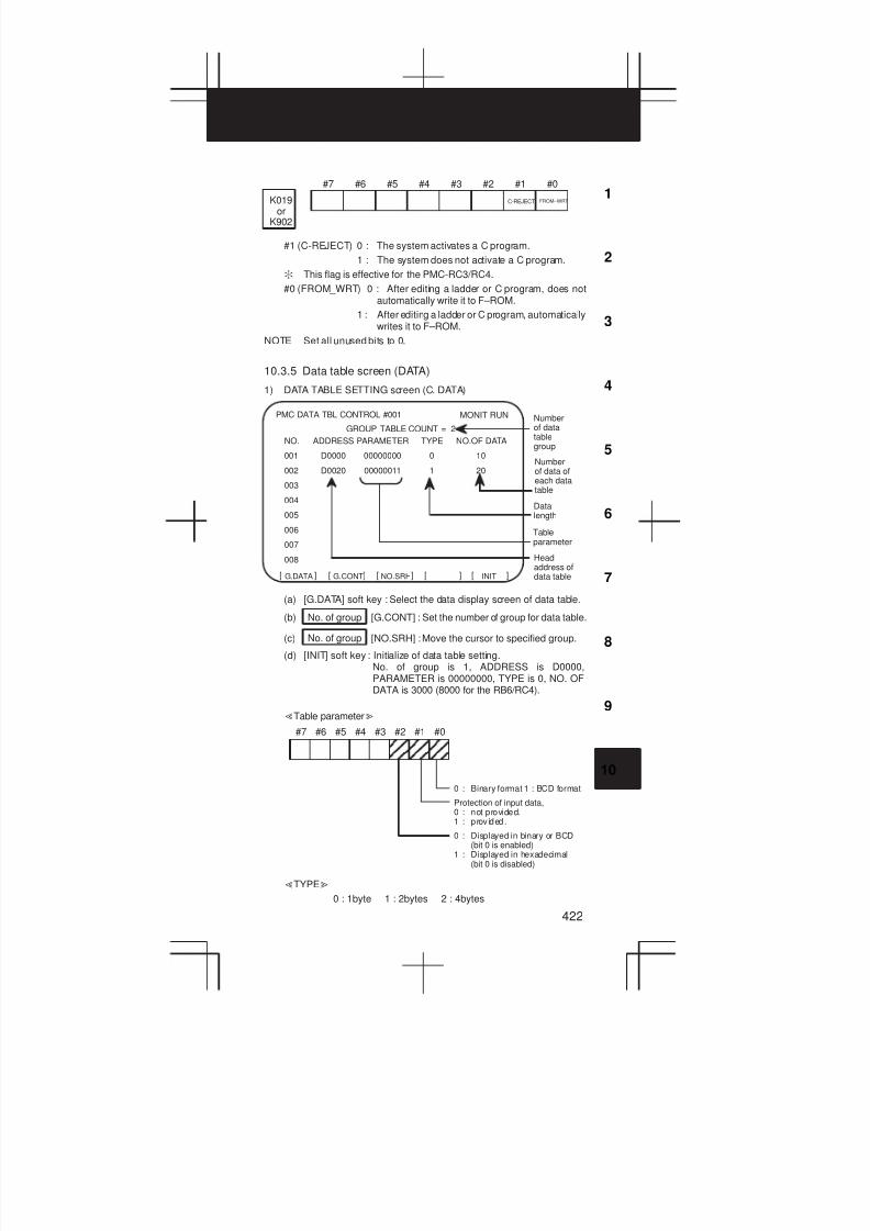
3
1
4
5
6
7
8
9
10
2
422
K019or
K902
#7 #6 #5 #4 #3 #2 #1 #0
C-REJECT FROM–WRT
#1 (C-REJECT) 0 : The system activates a C program.
1 : The system does not activate a C program.
: This flag is effective for the PMC-RC3/RC4.
#0 (FROM_WRT) 0 : After editing a ladder or C program, does notautomatically write it to F–ROM.
1 : After editing a ladder or C program, automaticallywrites it to F–ROM.
NOTE Set all unused bits to 0.
10.3.5 Data table screen (DATA)
1) DATA TABLE SETTING screen (C. DATA)
INITNO.SRHG.CONTG.DATA[ ]
NO. ADDRESS PARAMETER TYPE NO.OF DATA
001 D0000 00000000 0 10
002 D0020 00000011 1 20
003
004
005
006
007
008
PMC DATA TBL CONTROL #001
GROUP TABLE COUNT = 2
[ ] [ ] [ ] [ ]
MONIT RUN Numberof datatablegroup
Numberof data ofeach datatable
Datalength
Tableparameter
Headaddress ofdata table
(a) [G.DATA] soft key : Select the data display screen of data table.
(b) No. of group [G.CONT] : Set the number of group for data table.
(c) No. of group [NO.SRH] :Move the cursor to specified group.
(d) [INIT] soft key : Initialize of data table setting.No. of group is 1, ADDRESS is D0000,PARAMETER is 00000000, TYPE is 0, NO. OFDATA is 3000 (8000 for the RB6/RC4).
ƠTable parameterơ
Ç Ç
Ç Ç
Ç Ç
Ç Ç
Ç Ç
Ç Ç
#7 #6 #5 #4 #3 #2 #1 #0
0 : Binary format 1 : BCD format
Protection of input data,0 : not provided.1 : prov ided.
0 : Displayed in binary or BCD(bit 0 is enabled)
1 : Displayed in hexadecimal(bit 0 is disabled)
ƠTYPEơ
0 : 1byte 1 : 2bytes 2 : 4bytes
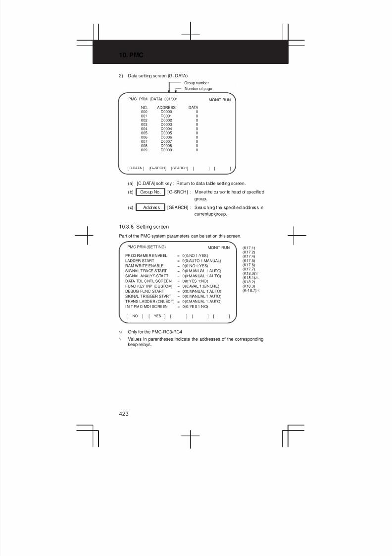
10. PMC
423
2) Data setting screen (G. DATA)
C.DATA[ ] [ ] [ ] [ ] [ ]G–SRCH SEARCH
PMC PRM (DATA) 001/001
NO. ADDRESS DATA000 D0000 0001 D0001 0002 D0002 0003 D0003 0004 D0004 0005 D0005 0006 D0006 0007 D0007 0008 D0008 0009 D0009 0
MONIT RUN
Group number
Number of page
(a) [C.DATA] soft key : Return to data table setting screen.
(b) Group No. [G-SRCH] : Move the cursor to head of specified
group.
(c) Address [SEARCH] : Searching the specif ied address in
currentup group.
10.3.6 Setting screen
Part of the PMC system parameters can be set on this screen.
NO[ ] [ ] [ ] [ ] [ ]YES
PMC PRM (SETTING) MONIT RUN
PROGRMMER ENABEL = 0(0:NO 1:YES)
LADDER START = 0(0:AUTO 1:MANUAL)
RAM WRITE ENABLE = 0(0:NO 1:YES)
SIGNAL TRACE START = 0(0:MANUAL 1:AUTO)
SIGNAL ANALYS START = 0(0:MANUAL 1:AUTO)
DATA TBL CNTL SCREEN = 0(0:YES 1:NO)
FUNC KEY INP (CUSTOM) = 0(0:AVAL 1:IGNORE)
DEBUG FUNC START = 0(0:MANUAL 1:AUTO)
SIGNAL TRIGGER START = 0(0:MANUAL 1:AUTO)
TRANS LADDER (ONLEDT) = 0(0:MANUAL 1:AUTO)
INIT PMC-MDI SCREEN = 0(0:YES 1:NO)
(K17.1)(K17.2)(K17.4)(K17.5)(K17.6)(K17.7)(K18.0):(K18.1):(K18.2)(K18.3)(K-18.7):
: Only for the PMC-RC3/RC4
: Values in parentheses indicate the addresses of the correspondingkeep relays.
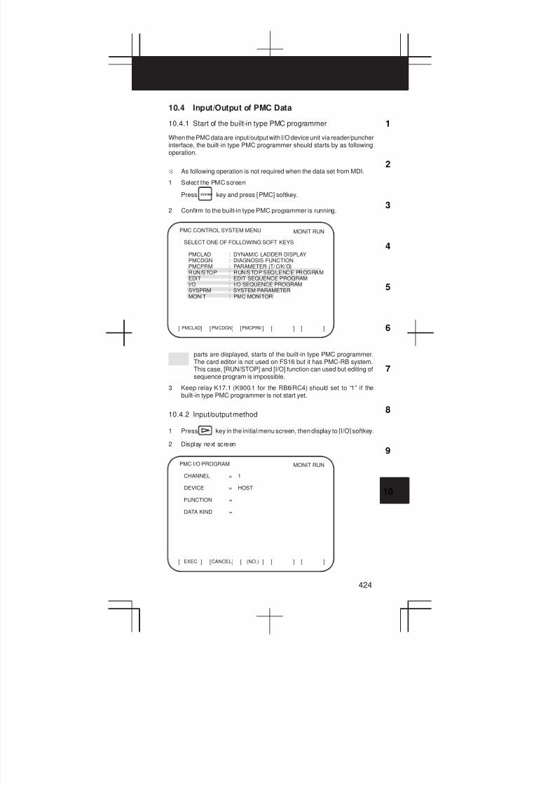
3
1
4
5
6
7
8
9
10
2
424
10.4 Input/Output of PMC Data
10.4.1 Start of the built-in type PMC programmer
When the PMC data are input/output with I/O device unit via reader/puncherinterface, the built-in type PMC programmer should starts by as followingoperation.
: As following operation is not required when the data set from MDI.
1 Select the PMC screen
Press SYSTEM key and press [PMC] softkey.
2 Confirm to the built-in type PMC programmer is running.
PMC CONTROL SYSTEM MENU
SELECT ONE OF FOLLOWING SOFT KEYS
PMCLAD : DYNAMIC LADDER DISPLAYPMCDGN : DIAGNOSIS FUNCTIONPMCPRM : PARAMETER (T/C/K/D)RUN/STOP : RUN/STOP SEQUENCE PROGRAMEDIT : EDIT SEQUENCE PROGRAMI/O : I/O SEQUENCE PROGRAMSYSPRM : SYSTEM PARAMETERMONIT : PMC MONITOR
PMCLAD[ ] [ ] [ ] [ ] [ ]PMCDGN PMCPRM
MONIT RUN
parts are displayed, starts of the built-in type PMC programmer.The card editor is not used on FS16 but it has PMC-RB system.This case, [RUN/STOP] and [I/O] function can used but editing ofsequence program is impossible.
3 Keep relay K17.1 (K900.1 for the RB6/RC4) should set to “1” if thebuilt-in type PMC programmer is not start yet.
10.4.2 Input/output method
1 Press key in the initial menu screen, then display to [I/O] softkey.
2 Display next screen
EXEC[ ] [ ] [ ] [ ] [ ]CANCEL (NO.)
MONIT RUNPMC I/O PROGRAM
CHANNEL = 1
DEVICE = HOST
FUNCTION =
DATA KIND =

10. PMC
425
3 Enter the desired channel number, then press the INPUT key to set the
number for CHANNEL.
1 : JD5A of the main CPU board
2 : JD5B of the main CPU board
4 Specify the I/O unit to be used for DEVICE.
HOST: I/O operation with FAPT LADDER (on the P-G, P-G Mate,or personal computer)
FDCAS: I/O operation with a Floppy Cassette Adaptor
F-ROM: I/O operation with a flash EEPROM
M-CARD: I/O operation with a memory card
OTHERS: I/O operation with other I/O units
5 Specify the desired function with FUNCTION.
WRITE: Outputting data
READ: Inputting data
COMPARE: Comparing data in memory with that in an external device
DELETE: Deleting files on a floppy disk or memory card
LIST: Listing the files on a floppy disk or memory card
BLANK: Checking whether the flash EEPROM is empty
ERASE: Clearing the data in the flash EEPROM
FORMAT: Formatting a memory card (all data on the memory cardis deleted.)
6 Specify the desired type of data to be output at KIND DATA.
ALL: Ladder programs and executable C data
LADDER: Ladder programs
PARAM: PMC parameters
7 When FDCAS or M-CARD is specified for the device, a file can bespecified for FILE NO. by either its file number or file name.
8 Specify the RS-232C conditions for each device with SPEED.
9 Check that the settings are correct. Then, press the [EXEC] soft key.
10.4.3 Copy function (COPY)
Changes made during on-line editing are transferred to the correspondingediting ladder program.

3
1
4
5
6
7
8
9
10
2
426
10.5 Functional Instruction
10.5.1 Functional instruction list
1) Kind of functional instruction and contents of processing
No. Instruc-
tion
SU B
No.
Contents of
processing
PMC
-RB5
PMC
-RB6
PMC
-RC3
PMC
-RC3
1 END 1 1 1st level
program end
2 END 2 2 2nd level
program end
3 END 3 48 3rd level
program end
Not
Pro-
vided
Not
pro-
vided
4 TMR 3 Timer
5 TMRB 24 Fixed timer
6 TMRC 54 Timer
7 DEC 4 Decording
8 DECB 25 Binary code de-
cording
9 CTR 5 Counter
10 CTRC 55 Counter
11 ROT 6 Rotation
control
12 ROTB 26 Binary rotation
control
13 COD 7 Code
conversion
14 CODB 27 Binary code
conversion
15 MOVE 8 Data transfer
after logical
product
16 MOVOR 28 Data transfer
after logical
sum
17 MOVB 43 One-byte
transfer
18 MOVW 44 Two-byte
transfer
19 MOVN 45 Specified-byte
transfer
20 COM 9 Common line
control
21 COME 29 Common line
control end
22 JMP 10 Jump
23 JMPE 30 Jump end
24 JMPB 68 Label jump 1
25 JMPC 73 Label jump 2
26 LBL 69 Label
designation
27 PARI 11 Parity check
28 DCNV 14 Data
conversion
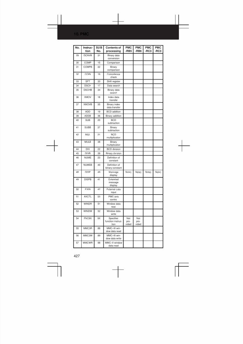
10. PMC
427
No. PMC
-RC3
PMC
-RC3
PMC
-RB6
PMC
-RB5
Contents of
processing
SU B
No.
Instruc-
tion
29 DCNVB 31 Binary data
conversion
30 COMP 15 Comparison
31 COMPB 32 Binary
comparison
32 COIN 16 Coincidence
check
33 SFT 33 Shift register
34 DSCH 17 Data search
35 DSCHB 34 Binary data
search
36 XMOV 18 Index data
transfer
37 XMOVB 35 Binary index
data transfer
38 ADD 19 BCD addition
39 ADDB 36 Binary addition
40 SUB 20 BCD
subtraction
41 SUBB 37 Binary
subtraction
42 MUL 21 BCD
multiplication
43 MULB 38 Binary
multiplication
44 DIV 22 BCD division
45 DIVB 39 Binary division
46 NUME 23 Definition of
constant
47 NUMEB 40 Definition of
binary constant
48 DISP 49 Message
display
Note) Note) Note) Note)
49 DISPB 41 Extended
message
display
50 EXIN 42 External data
input
51 AXCTL 53 PMC axis
control
52 WINDR 51 Window data
read
53 WINDW 52 Window data
write
54 FNC9X 9X Specified
function instruc-
tion
Not
pro-
vided
Not
pro-
vided
55 MMC3R 88 MMC–III win-
dow data read
56 MMC3W 89 MMC–III win-
dow data write
57 MMCWR 98 MMC–II window
data read
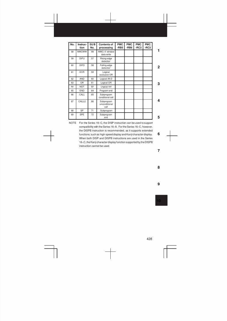
3
1
4
5
6
7
8
9
10
2
428
No. PMC
-RC3
PMC
-RC3
PMC
-RB6
PMC
-RB5
Contents of
processing
SU B
No.
Instruc-
tion
58 MMCWW 99 MMC–II window
data write
59 DIFU 57 Rising-edge
detection
60 DIFD 58 Falling-edge
detection
61 EOR 59 Logical
exclusive OR
62 AND 60 Logical AND
63 OR 61 Logical OR
64 NOT 62 Logical not
65 END 64 Program end
66 CALL 65 Subprogram
conditional call
67 CALLU 66 Subprogram
unconditional
call
68 SP 71 Subprogram
69 SPE 72 Subprogram
end
NOTE For the Series 16–C, the DISP instruction can be used to support
compatibility with the Series 16–A. For the Series 16–C, however,
the DISPB instruction is recommended, as it supports extended
functions, such as high-speed display and Kanji character display.
When both DISP and DISPB instructions are used in the Series
16–C, the Kanji character display function supported by the DISPB
instruction cannot be used.

10. PMC
429
10.5.2 Detail of function command
END1SUB 1
(1)
1st level program end
END2SUB 2
(2)
2nd level program end
END3SUB 48
(3)
3rd level program end(PMC–RC3/RC4 only)
ACT
TMR
SUB 3ff
W1(4)
Valiable timer
Timer no. (1-40)*1-150 for the RB6/RC4
ACT
TMRB
SUB 24 ff
ffff
W1(5)
Fixed timer
Timer no. (1-100)Preset time (unit : msec)
ACT
TMRC
SUB 54
W1(6)
Valiable timerff
ffff
ffff
Timer type(0:8ms unit,1:48ms unit)Timer address (2-byte)Timer register address (4-byte)
ACT
DEC
SUB 4 ffff
ffff
W1(7)
Decode
Address of BCD outputDecode instruction
[Decode instruction]ff ff ← Pos. of digit
01 : Decodes lower 1-digit only.10 : Decodes upper 1-digit only.11 : Decodes 2-digit.
Number : Number to be decoded.
ACT
DECB
SUB 25 f
ffff
ffff
ffff
W1(8)
Binarydecode
Length of byte(1:1-byte, 2:2-byte, 4:4-byte)Address of code dataDecode instructionOutput address
CNOCTR
SUB 5 ff
UPDOWN
RST
ACT
(9)
Counter
Counter no. (1-20)*1-50 for the RB6/RC4
W1 (Count up)
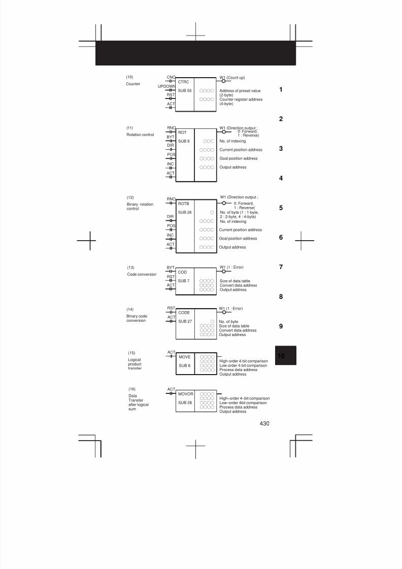
3
1
4
5
6
7
8
9
10
2
430
CNOCTRC
SUB 55 ffff
ffff
UPDOWN
RST
ACT
(10)
Counter
W1 (Count up)
Address of preset value(2-byte)Counter register address(4-byte)
RNOROT
SUB 6 fff
ffff
ffff
ffff
BYT
DIR
POS
INC
ACT
(11)
Rotation control
W1 (Direction output ;
No. of indexing
Current position address
Goal position address
Output address
0: Forward,1 : Reverse)
RNOROTB
SUB 26 f
ffff
ffff
ffff
ffff
DIR
POS
INC
ACT
(12)
Binary rotationcontrol
Current position address
Goal position address
Output address
No. of byte (1 : 1-byte,2 : 2-byte, 4 : 4-byte)
W1 (Direction output ;
0: Forward,1 : Reverse)
No. of indexing
BYTCOD
SUB 7 ffff
ffff
ffff
RST
ACT
(13)
Code conversion
W1 (1 : Error)
Size of data tableConvert data addressOutput address
(14)
Binary codeconversion
W1 (1 : Error)
No. of byteSize of data tableConvert data addressOutput address
RSTCODB
SUB 27 f
ffff
ffff
ffff
ACT
(15)
Logicalproducttransfer
ACTMOVE
SUB 8
ffff
ffff
ffff
ffff
High-order 4-bit comparisonLow-order 4-bit comparisonProcess data addressOutput address
(16)
DataTransferafter logicalsum
ACTMOVOR
SUB 28
ffff
ffff
ffff
ffff
High–order 4–bit comparisonLow–order 4bit comparisonProcess data addressOutput address
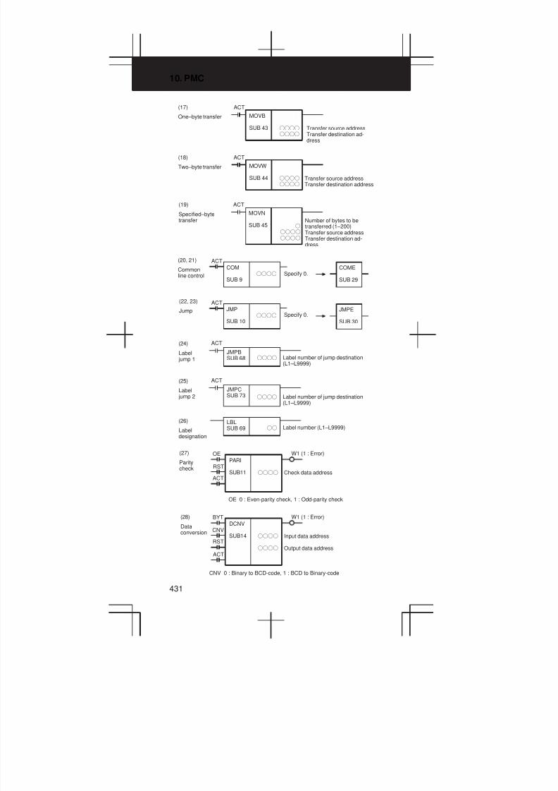
10. PMC
431
ACT
MOVB
SUB 43 ffff
ffff
(17)
One–byte transfer
Transfer source addressTransfer destination ad-dress
(18)
Two–byte transfer
ACT
MOVW
SUB 44 ffff
ffff
Transfer source addressTransfer destination address
(19)
Specified–bytetransfer
ACT
MOVN
SUB 45 f
ffff
ffff
Number of bytes to betransferred (1–200)Transfer source addressTransfer destination ad-dress
(20, 21)
Commonline control
ACTCOM
SUB 9ffff
COME
SUB 29Specify 0.
ACTJMP
SUB 10ffff
JMPE
SUB 30
(22, 23)
JumpSpecify 0.
JMPBSUB 68 ffff
ACT(24)
Label jump 1 Label number of jump destination
(L1–L9999)
JMPCSUB 73 ffff
ACT(25)
Label jump 2 Label number of jump destination
(L1–L9999)
(26)
Labeldesignation
LBLSUB 69 ff Label number (L1–L9999)
W1 (1 : Error)
Check data address
(27)
Paritycheck
OEPARI
SUB11 ffff
RST
ACT
OE 0 : Even-parity check, 1 : Odd-parity check
CNV 0 : Binary to BCD-code, 1 : BCD to Binary-code
W1 (1 : Error)
Input data address
Output data address
BYTDCNV
SUB14 ffff
ffff
CNV
RST
ACT
(28)
Dataconversion

3
1
4
5
6
7
8
9
10
2
432
(29)
Extendeddataconversion
V : Overflow, Z : Zero, N : Negative
W1 (1 : Error)
No. of byte(1 : 1-byte, 2 : 2-byte, 4 : 4-byte)Input data address
Output address
SINDCNVB
SUB 31 f
ffff
ffff
CNV
RST
ACT
#0
R9000 Z
#1
N
#2#3#4#5
V
#6#7
SIN When converts BCD to binary ; 0 : Positive, 1 : Negative
[Operation output register]
BYTCOMP
SUB 15 f
ffff
ffff
ACT
(30)
Comparison
W1
Format of reference data(0 : Constant data, 1 : Address)Reference value(Constant data or address)Comparison value
(0 : Ref. data > Comp. data),
(1 : Ref. datav Comp. data)
(31)
Comparisonfor binarydata
ACTCOMPBSUB 32
ffff
ffff
ffff
#0
R9000 Z
#1
N
#2#3#4#5
V
#6#7
Format of reference dataReference value(Constant data or address)Comparison value
[Format of ref. data]
0 0 1 : 1-byte, 2 : 2-byte, 4 : 4-byte
0 : Constant data, 1 : Address
[Operation output register]
V : Overflow, Z : Ref. data=Comp. data,N : Ref. data<Comp. data
W1
Format of reference data(0 : Constant data, 1 : Address)Reference value(Constant data or address)Comparison value
(32)
Coincidencecheck
BYTCOIN
SUB 16 f
ffff
ffff
ACT
(0 : Ref. data0Cop. data,1 : Ref. data=Cop. data)

10. PMC
433
(33)
Shiftregister
DIRSFT
SUB 33 ffff
CONT
RST
ACT
W1 (Shufted out)
Data address
DIR 0 : Left-shift, 1 : Right-shift
CONT 0 : Shift in with 0, 1 : Shift in with 0/1 depend last bit
(34)
Dataserch
BYTDSCH
SUB 17 ffff
ffff
ffff
ffff
RST
ACT
W1
Size of data tableStarting address of data tableSearch data addressOutput address
(0 : Searched data exist,1 : Searched data not exist)
(35)
Binarydatasearch
RSTDSCHB
SUB 34 f
ffff
ffff
ffff
ffff
ACT
W1
No. of byte (1 : 1-byte, 2 : 2-byte, 4 :4-byte)Address for size of data table
Starting address of data tableSearch data addressOutput address
(0 : Searched data exist,1 : Searched data not exist)
(36)
Indexeddatatransfer
BYTXMOV
SUB 18 ffff
ffff
ffff
ffff
RW
RST
ACT
W1 (1 : Error)
Size of data tableStarting address of data tableInput/output data storage addressTable no. storage address
RW 0 : Read mode, 1 : Write mode
(37)
Binaryindexmodifierdatatransfer
RWXMOVB
SUB 35 f
ffff
ffff
ffff
ffff
RST
ACT
W1 (1 : Error)
No. of byte (1 : 1-byte, 2 : 2-byte, 4 :4-byte)Storage address of no. of dataStarting address of data tableInput/output data storage addressTable no. storage address
RW 0 : Read mode, 1 : Write mode
(38)
Addition
BYTADD
SUB 19 f
ffff
ffff
ffff
RST
ACT
W1 (1 : Error)
Data format(0 : Constant data, 1 : Address)Summand addressAddend value(Address or constant data)Output address

3
1
4
5
6
7
8
9
10
2
434
ffff
ffff
ffff
ffff
(39)
Binaryaddition
RSTADDB
SUB 36ACT
#0
R9000 Z
#1
N
#2#3#4#5
V
#6#7
W1 (1 : Error)
Data formatSummand addressAddend value(Address or constant data)Output address
[Data format]
0 0 1 : 1-byte, 2 : 2-byte, 4 : 4-byte
0 : Addend value or address, 1 : Address
[Operation output register]
V : Overflow, Z : Zero, N : Negative
BYTSUB
SUB20 f
ffff
ffff
ffff
RST
ACT
(40)
Subtraction
W1
Data format(0 : Constant data, 1 : Address)Subtrahend addressSubtrahend value(Address or constant data)Output address
(1 : Error, in case of theresult is negative.)
ffff
ffff
ffff
ffff
(41)
BinarySubtraction
RSTSUBB
SUB37ACT
W1 (1 : Error)
Data format(The conditions are same as ADDB.)Subtrahend addressSubtrahend value(Address or constant data)Output address
BYTMUL
SUB21 f
ffff
ffff
ffff
RST
ACT
(42)
Multiplication
W1 (1 : Error)
Data format(0 : Constant data, 1 : Address)Multiplicand addressMultiplier value(Address or constant data)Output address
RSTMULB
SUB38 ffff
ffff
ffff
ffff
ACT
(43)
BinaryMultiplication
W1 (1 : Error)
Data format(The conditions are same as ADDB.)Multiplicand addressMultiplier value(Address or constant data)Output address
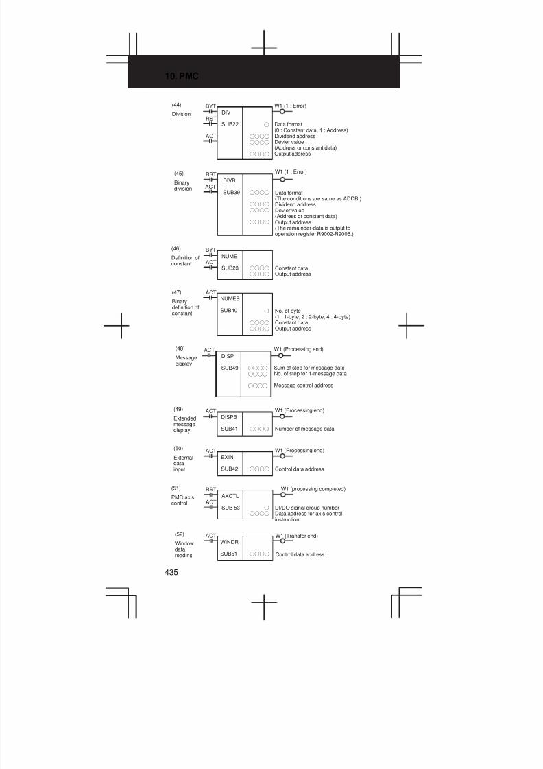
10. PMC
435
(44)
Division
BYTDIV
SUB22 f
ffff
ffff
ffff
RST
ACT
W1 (1 : Error)
Data format(0 : Constant data, 1 : Address)Dividend addressDevier value(Address or constant data)Output address
ffff
ffff
ffff
ffff
W1 (1 : Error)
Data format(The conditions are same as ADDB.)Dividend addressDevier value(Address or constant data)Output address(The remainder-data is putput tooperation register R9002-R9005.)
(45)
Binarydivision
DIVB
SUB39
RST
ACT
(46)
Definition ofconstant
BYTNUME
SUB23 ffff
ffff
ACTConstant dataOutput address
(47)
Binarydefinition ofconstant
ACTNUMEB
SUB40 f
ffff
ffff
No. of byte(1 : 1-byte, 2 : 2-byte, 4 : 4-byte)Constant dataOutput address
(48)
Messagedisplay
ACTDISP
SUB49 ffff
ffff
ffff
W1 (Processing end)
Sum of step for message dataNo. of step for 1-message data
Message control address
(49)
Extendedmessagedisplay
ACTDISPB
SUB41 ffff
W1 (Processing end)
Number of message data
W1 (Processing end)
Control data address
(50)
Externaldatainput
EXIN
SUB42
ACT
ffff
(51)
PMC axiscontrol
RSTAXCTL
SUB 53 f
ffff
ACTDI/DO signal group numberData address for axis controlinstruction
W1 (processing completed)
(52)
Windowdatareading
ACTWINDR
SUB51 ffff
W1 (Transfer end)
Control data address
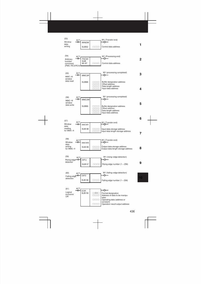
3
1
4
5
6
7
8
9
10
2
436
(53)
Windowdatawriting
ACTWINDW
SUB52 ffff
W1 (Transfer end)
Control data address
(54)
Arbitraryfunctioncommand(PMC–RC3/RC4)
ACTFNC9XSUB90–97 ffff
W1 (Processing end)
Control data address
(55)
MMC–IIIwindowdata read
ACTMMC3R
SUB88 ffff
ffff
ffff
ffff
W1 (processing completed)
Buffer designation addressOffset addressData length addressInput data address
(56)
MMC–IIIwindowdata write
ACTMMC3W
SUB89 ffff
ffff
ffff
ffff
W1 (processing completed)
Buffer designation addressOffset addressData length addressInput data address
ffff
ffff
(57)
Windowdatareadingfor MMC–II
ACTMMCWR
SUB 98
W1 (Transfer end)
Input data storage addressInput data length storage address
ffff
ffff
(58)
Windowdatawritingfor MMC–II
ACTMMCWW
SUB 99
W1 (Transfer end)
Output data storage addressOutput data length storage address
(59)
Rising edgedetection
ACTDIFU
SUB 57 ffff
W1 (rising–edge detection)
Rising edge number (1 – 256)
(60)
Falling edgedetection
ACTDIFD
SUB 58 ffff
W1 (falling–edge detection)
Falling edge number (1 – 256)
(61)
LogicalexclusiveOR
ffff
ffff
ffff
Format designationAddress of data to be manipu-latedOperating data (address orconstant)Operation result output address
ACTEORSUB 59 j 0 0j

10. PMC
437
Format designationAddress of data to be manipu-latedOperating data (address orconstant)Operation result output address
(62)
LogicalAND
ffff
ffff
ffff
ACTANDSUB 60 j 0 0j
(63)
LogicalOR
ACTORSUB 61 Format designation
Address of data to be manipu-latedOperating data (address orconstant)Operation result output address
ffff
ffff
ffff
j 0 0j
(64)
LogicalNOT
ffff
ffff
Format specificationAddress of data to be manipu-latedOperation result output address
ACTNOTSUB 62 j 0 0j
(65)
Program endENDSUB 64
(66)
Subprogramconditionalcall
ACTCALLSUB 65 ffff Subprogram number
(P1 to P512 for the PMC– RB5/RC3)(P1 to P2000 for the PMC– RB6/RC4)
(67)
Subprogramuniconditionalcall
CALLUSUB 66 ffff Subprogram number
(P1 to P512 for the PMC– RB5/RC3)(P1 to P2000 for the PMC– RB6/RC4)
SPSUB71
(68)
Subprogram ffff Subprogram number(P1 to P512 for the PMC– RB5/RC3)(P1 to P2000 for the PMC– RB6/RC4)
(69)
Subprogramend
SPESUB72
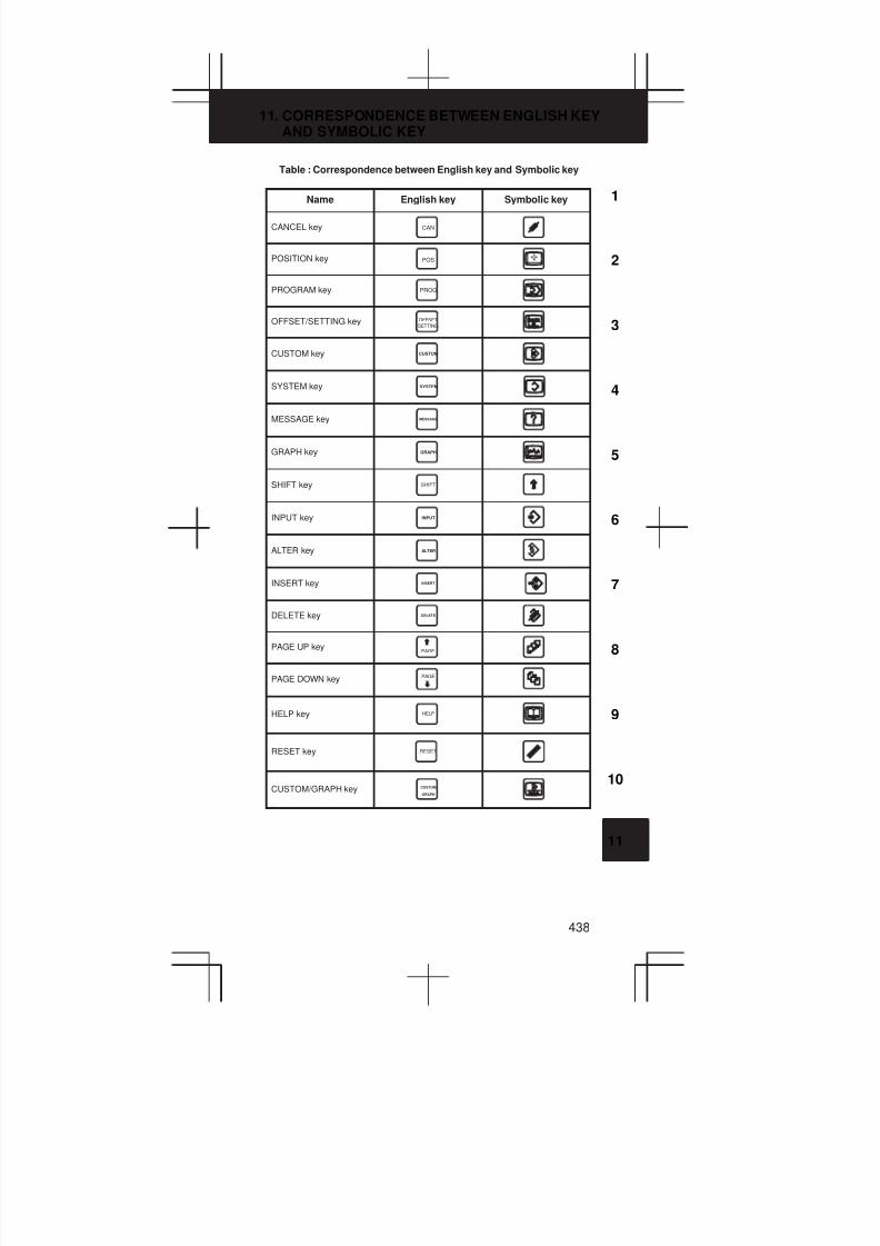
3
1
4
5
6
7
8
9
10
2
11
11. CORRESPONDENCE BETWEEN ENGLISH KEYAND SYMBOLIC KEY
438
Table : Correspondence between English key and Symbolic key
Name English key Symbolic key
CANCEL key CAN
POSITION key POS
PROGRAM key PROG
OFFSET/SETTING keySETTINGOFFSET
CUSTOM key CUSTOM
SYSTEM key SYSTEM
MESSAGE key MESSAGE
GRAPH key GRAPH
SHIFT key SHIFT
INPUT key INPUT
ALTER key ALTER
INSERT key INSERT
DELETE key DELETE
PAGE UP keyPAGE
PAGE DOWN key PAGE
HELP key HELP
RESET key RESET
CUSTOM/GRAPH key CUSTOM
GRAPH

· No part of this manual may be
reproduced in any form.
· All specifications and designs
are subject to change without
notice.
Related Documents