Operating and Maintenance Manual Models: TruckForce 3500 TruckForce 1200

Welcome message from author
This document is posted to help you gain knowledge. Please leave a comment to let me know what you think about it! Share it to your friends and learn new things together.
Transcript

Operating andMaintenance Manual
Models:
TruckForce 3500TruckForce 1200

1
Congratulations and thank you for buying a TRUCK-FORCE® portable extractor. The TruckForce is designed togive you truckmount performance in a portable machine thatis versatile to use and easy to transport. Years of experience,engineering, planning, and practical know-how has gone intothe design and manufacture of the TruckForce. We take agreat deal of pride in TruckForce and want you to be com-pletely satisfied with your purchase. Please take the time toread this manual before operating the machine—it will betime well spent.
SETUP AND OPERATION
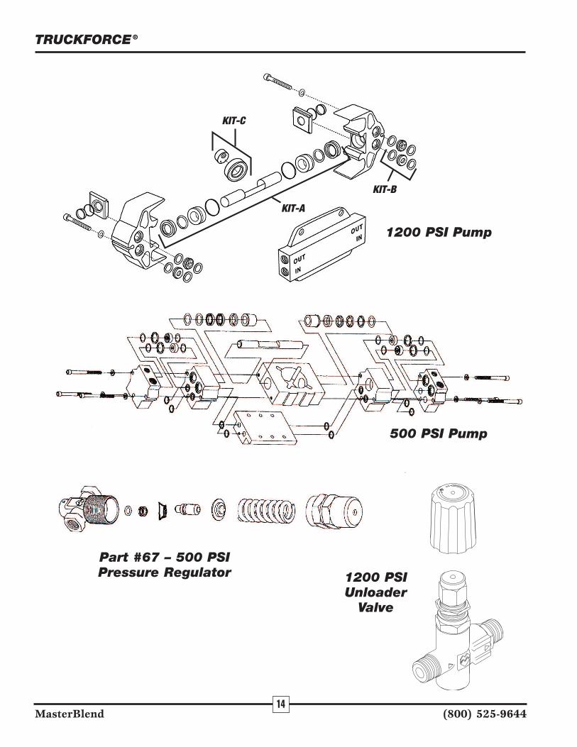
ELECTRICAL CONNECTIONSPlug electrical cords into grounded wall outlets. Truck-
Force is designed to run on a 15 AMP and a 20 AMP circuit(the left hand cord). You will normally find 20 AMP separatecircuits in the kitchen and in bathrooms. Never remove theground plug from the end of the cord. If a circuit breaker tripsduring operation, reset the breaker and move electrical cordto different outlet and resume operation. When cords areplugged into “live” receptacles, the control switches willglow. If the lights on the switches do not glow, this indicatesthat the wall receptacle may be dead. Simply move the cord toa different outlet.
WARNING: The TruckForce is designed for usewith water based cleaning solutions, such as, lowfoaming detergents or acid rinses. NEVER USE DRYSOLVENT SOLUTIONS! The use of dry solvents inyour TruckForce will void the warranty.
AUTOMATIC CHEMICAL FEEDChemical Metering:The TruckForce may be equipped with
an automatic water fill/chemical feed metering system. As thesolution tank fills with water, cleaning concentrate is drawninto the solution tank at a designated rate via a metering tip. Acomplete set of metering tips is included.
To adjust the amountof cleaning concentratebeing drawn, simplyremove the plastic sup-ply tube from thechemical feed meteringvalve (see Figure 1).Unscrew the coloredmetering tip andreplace with the tipthat corresponds to theportable dilution ratio
for your cleaning product (refer to Figure 2). Reconnect theplastic supply tube.
Liquid Concentrates: TruckForce comes with the purplemetering tip installed at the factory. This tip is rated for .25oz. of chemical per gallon of water, which is a standard dilu-tion ratio for the most popular liquid cleaning products on themarket. Refer to your product’s dilution ratio for portableextractors, and select the proper metering tip from Figure 2(“Liquid Concentrated Dilution Ratio”).
Powder Concentrates: For powdered cleaning detergents,a liquid concentrate must be made. Combine two (2) cups ofpowder in a one gallon solution jug. Fill the jug with water upto the one gallon mark. Use the tip that corresponds to theportable dilution ratio for your powdered cleaning product(refer to Figure 2, “Powder Concentrated Dilution Ratio”).
Fresh Water Rinse: For fresh water rinsing simply leavethe chemical supply tube in the solution tank.
Manual Filling: To use the TruckForce without the auto-matic filling system, simply pre-mix your solution in a bucketof water, and pour into the solution tank. See Figure 3 for adetailed break-down of the chemical feed system.
Figure 2
Setup: Inside the solution tank is a bottle float suspendedon a chain. The length of the chain determines the level ofsolution in the tank and can be adjusted. Check the chemicalfeed supply foot valve for debris, and clean if necessary.Insert the line into the cleaning concentrate so that it touchesthe bottom of the bottle. Set cleaning concentrate in the solu-tion holder/pouring funnel provided.
TRUCKFORCE®
MasterBlend (800) 525-9644
Figure 1
Metering Tip Replacement
Concentrated DilutionRatio (oz/gal)
Tip Color Liquids PowdersClear 0.25 —Purple 0.50 —Yellow 1.00 —Green 1.50 —Pink 2.00 0.25Turquoise 3.20 0.40Black 4.00 0.50Gray 5.00 0.63Red 6.50 0.81Blue 8.00 1.00Brown 10.50 —White 13.00 —Orange 16.00 —None 35.00 —
Metering Tip Dilution Ratios

2
TRUCKFORCE®
Connect the fill hose to the quick disconnect located on theside of the machine. Attach the water supply hose to anyavailable faucet. A faucet-to-hose adapter is provided to prop-erly attach your water supply hose to the most commonlyfound faucets. It may require adapters to fit the various faucetcombinations you will encounter. Never force a threaded fit-ting. Place a towel over the faucet connection so that anyspray will be controlled. Turn on the water and check thehose connections for leaks.
The solution tank will fill approximately 14 gallons, whichcan be increased by shortening the chain. As the tank is filling,cleaning concentrate is being drawn into the solution tank.
Shutdown: Before the end of each job, turn off the watersupply, to prevent the solution tank from being completely full.With the cleaning completed and the solution pump turned off,disconnect the fill hose from the faucet, drain the water in thefill hose back into the solution tank, and remove the fill hose.Remove the chemical feed supply tube from the chemical solu-tion jug and clean the filter. Vacuum out the solution tank.
MODEL SPECIFICATIONS
The TruckForce utilizes either a PumpTec™ twin piston500 PSI or 1200 PSI pump. Both pumps are adjustable fromeither 50–500 PSI for the TruckForce 3500 or 100–1200 PSIfor the TruckForce 1200. Do not exceed the pressure limita-tions of 500 PSI for the TruckForce 3500 or 1200 PSI for theTruckForce 1200. The TruckForce 3500 pump is adjustablewith a pressure relief valve shown on page 14. The pressureregulator is located by the pressure gauge on the front of themachine and is easily adjusted by turning the regulator clock-wise to increase the pressure and counterclockwise todecrease the pressure. The TruckForce 1200 pump isadjustable with an unloader valve which is also located by thepressure gauge on the front of the machine. The pressuregauge on the TruckForce 1200 will register pressure whenyour wand or other tool is hooked up to your high pressuresolution line and the valve is depressed, allowing solution togo through the wand or tool. The pressure on the TruckForce1200 is adjusted by turning the unloader valve clockwise toincrease pressure and counter-clockwise to lower the pres-sure. Do not exceed 1200 PSI on the TruckForce 1200.
Priming the Solution Pump: If you are experiencingpressure fluctuations, pulsation in the solution hose, or notmaintaining pressure, you will need to prime the solutionpump by engaging the Power Prime Valve located next to thepressure regulator on the front of the machine. Making surethere is sufficient water in the solution tank, depress thePower Prime Valve and any air will be immediately purgedout of the pump system and pressure should immediately berestored. Caution: Please be aware that depressing the PowerPrime Valve will also spray both air and water out the bot-tom of the valve. If you wish to avoid having water on thefloor, you should have your vacuum hose hooked up to themachine, have the vacuum motors on and have the vacuumcuff on the end of the vacuum hose held under the PowerPrime Valve to catch any water coming out of the valve.
VACUUM SYSTEMVacuum Motors: The TruckForce utilizes a unique two-
or three-vacuum system which produces both outstandingvacuum lift and air flow for superior extraction and dryingtimes. The vacuum system can be used with one or two vac-uum motors for cleaning delicate fabrics, or all three vacuummotors for carpet cleaning and water extraction.
Waste Tank: The vacuum system requires proper mainte-nance of the waste tank filter bag. Refer to theMAINTENANCE section for removal and proper cleaning ofthe filter.
It is also necessary to use a defoamer to eliminate foambuild-up in the waste tank which could lead to foam/moistureentering the vacuums and contributing to early failure of thevacuum motors. Failure to properly maintain the filtrationsystem and utilize defoamer, will void the warranty on thevacuum motors.
If moisture does enter the vacuum motors, refer to “WD-40Vac Motors” under MAINTENANCE. To prevent moisturefrom damaging the vacuum motors during storage, empty thewaste tank and store with the lid open.
AUTOMATIC WASTE PUMP-OUTConnect the black 1-1/4˝ x 50´ drain hose to the automatic
pump-out port located in the upper left corner on the front ofthe machine. Secure the other end of hose where you wish todirect the discharge of waste water, such as a toilet or sink.
Fasten the discharge end of hose tightly. Turn on the Auto-matic Pump-Out switch. The pump will turn onautomatically when water in the waste tank is approximately2/3 full. The pump will discharge the waste water down to alevel of about 2 inches in the waste tank. DO NOT TURNON THE AUTOMATIC PUMP-OUT SWITCH WITHOUTTHE DRAIN HOSE IN PLACE. This pump-out system hasbeen designed to stay up with flood restoration work and iscapable of pumping 20 gallons per minute.
Electrical 115 Volt, 60 hz (230 Volt, 50 hz)Vacuum Dual 2-stage; Three 2-stageSolution Pump 500 PSI
1200 PSISolution Tank 22 Gallons (83 liter)Waste Tank 15 Gallons (56 liter)Height 451/2 inches (116cm)Length 32 inches (81cm)Width 241/2 inches (62cm)Power Cords 50 feet (15m)
MasterBlend (800) 525-9644

3
TRUCKFORCE®
ITEM# PART# PART DESCRIPTION1 740100 COMPLETE ASSEMBLY2 740102 BODY/DIAPHRAGM ASSEMBLY3 740103 BODY4 740104 DIAPHRAGM5 740105 CLOSING SPRING6 740106 VALVE COVER O-RING7 740107 VALVE COVER8 740108 VALVE COVER SCREWS (PAIR)9 740109 SHUT OFF VALVE ASSEMBLY10 A SHUT OFF DISC & STEM ASSM11 B SHUT OFF SPRING12 C SHUT OFF PLATE13 D SHUT OFF STEM O-RING
ITEM# PART# PART DESCRIPTION14 E SHUT OFF COVER O-RING15 F SHUT OFF COVER16 G STEM NUT WITH SET SCREW17 H LEVER ASSEMBLY18 I LEVER ASSEMBLY SCREWS (2)19 740119 RUBBER WASHER20 740120 BACKFLOW PREVENTER21 740121 PROPORTIONER22 740122 METERING TIP KIT23 740123 CHEMICAL SUPPLY TUBING24 740124 FOOT VALVE25 740125 DISCHARGE TUBING26 740126 FLOAT ASSEMBLY
Figure 3
AUTOMATIC CHEMICAL FEED SYSTEM
MasterBlend (800) 525-9644

4
TRUCKFORCE®
ACCESSING COMPONENTSDrain the solution and waste tanks, disconnect all hoses,
and unplug the electrical cord(s).
To access the pump/motor, fresh water filter, and plumb-ing components, lay the TruckForce on its back and removethe 6 Phillips-head screws holding the bottom plate to thebody. Slowly lower the bottom plate to the ground.
To access the vacuum motors, cooling fan(s), switches, andother electrial components: remove the 6 Phillips-head screwson the back plate and the 3 Phillips-head screws securing theswitch plate. Slowly lower the back plate. When the back plateis partially open, loosen and remove the vacuum hose fromvacuum #1 by loosening the clamp with a 5/16 driver orscrewdriver. This vacuum hose is not long enough to allowthe back plate to be completely lowered to the ground.
To retrun to operation, reverse the above steps. Make surethe vacuum hose is properly re-installed on vacuum #1 andthat the hose clamp is secure.
FILL HOSE SCREENLocated in the female garden hose fitting on the Automatic
Fill Hose. Remove screen, clean, and replace.
CHEMICAL FEED FOOT VALVEThe foot valve is on the end of the chemical supply tube of
the automatic chemical feed system. It is not necessary toremove the filter from the tubing. Just rinse with fresh water.If necessary, use a tooth brush to remove detergent build-up.Note: a heavy build-up is a warning sign that the solution sys-tem should be flushed—see “Flushing Solution System.”
FRESH WATER TANK FILTERLocated inside the bottom plate by the pump at the bottom
of the solution tank. Unscrew the filter counterclockwise andrinse with fresh water. If necessary use a tooth brush toremove detergent build-up. Note: a heavy build-up is a warn-ing sign that the solution system should be flushed—see“Flushing Solution System.”
WASTE TANK FILTER BAGThe waste tank filter bag should be cleaned out after every
job. This filter bag will catch the larger debris and most lint.The filter bag is attached by a drawstring. Loosen the draw-string, clean the filter bag, and reinstall. Never operate theTruckForce without the filter bag in place.
OPERATION INTERVAL
Clean Fill Hose Screen Each Job/Daily
Clean Chemical Feed Foot Valve Each Job/Daily
Clean Fresh Water Filter Weekly
Clean Waste Tank Filter Bag Each Job/Daily
Clean Vac Shut Off Screen Daily
Clean Auto Pump-out Daily As Needed
Clean Wand Jets Weekly
Run Auto Pump-out Every Two Weeks
Flush Solution System Monthly
WD-40 Vac Motors As Needed
The above operations are fully outlined on the following two pages. Proper maintenance is necessary toachieve maximum operating performance from your TruckForce. Failure to properly maintain yourmachine could void the warranty.
Maintenance
MasterBlend (800) 525-9644

5
VAC SHUT OFFThe TruckForce utilizes a ball float shutoff system, which
shuts off the flow to the vacuum motors when solutionreaches the appropriate level to activiate the ball shutoff. Thisshutoff has been designed to protect the vacuum motors fromexcess water entering the vacuum motors provided that theowner is utilizing a defoamer chemical to prevent foamand moisture from entering the vacuum stack and,therefore, the vacuum motors.
Twist off the ball assembly from the stand pipe, and cleanthe screen. It may be rinsed with water. This screen shouldbe cleaned frequently if the TruckForce is being operated inan environment which has an abnormal buildup of lint anddebris, such as cleaning newly installed carpet. Loss of vac-uum is most normally associated with lint and hair buildup inthe waste filter bag and the float ball shutoff assemble at thetop of the vacuum stand pipe.
AUTO PUMP-OUTThe Automatic Pump-Out system is capable of handling
most debris that passes through the waste filter bag. How-ever, for optimum performance, keep the waste tank cleanand remove debris from the filter screen of the pump-out.This should be done on a daily basis, or as needed, dependingupon use, and amount of debris.
Every two weeks, run the pump-out with a full tank ofclean water, to insure that debris and lint are not accumulat-ing in the base of the pump.
To service the pump-out more thoroughly, unhook the vac-uum cuff, cut the zip tie around the looped electrical cord,and lift it out of the waste tank. Unsnap the screen from thebottom, clean the screen, and clean out the area inside.
If necessary, remove the six screws holding the base to themotor housing, and clean the base. If the impeller is removedmake sure that a spacing of .050” with shaft pushed towardhousing is maintained when reassembled.
WAND JETSRemove jets and visually check for wear and debris. Water
or compressed air is best for cleaning—NEVER use a metalobject to remove debris, as it may damage the jet orifice. Ifexcessive wear is apparent, the jet should be replaced. If thewand is equipped with jet screens, those should be cleaned byrinsing with water. Hook up the wand to machine, and checkjet alignment.
FLUSH SOLUTION SYSTEMAt least once a month, the TruckForce, hoses, and tools
should be flushed to remove alkaline residues. Follow thesteps on page 8 of the “Recommended Procedure for Stor-age,” using a solution of one part warm water with threeparts white vinegar, in place of the antifreeze solution. Then,repeat the steps using two gallons of fresh water.
WD-40 VAC MOTORSShould moisture ever enter the vacuum motors, completely
drain the waste tank, open the waste tank lid, remove the vacshut off ball assembly, turn on all vacuum motors, and spraya five second burst of WD-40 into the standpipe. Continue torun the vacuum motors for at least three minutes.
To prevent moisture from damaging the vacuum motors dur-ing storage, empty the waste tank and store with the lid open.
TRUCKFORCE®
MasterBlend (800) 525-9644

6
STORAGE AND FREEZE PROTECTIONCare must be taken to protect your TRUCKFORCE® from freezing. Freezing could seriously damage the TruckForce as
well as fittings and valves. Freezing is not covered under the limited warranty and you should always store your equipmentin areas where the temperature remains above 40° F. If you plan on storing the TruckForce for a prolonged period of time,the following procedure should help prevent your TruckForce from freezing, and prevent the pump seals from drying out.
Recommended Procedure for Storage:STEP ONE: In a separate container, mix 1 gallon of water with 1 gallon of automotive radiator antifreeze
(ethylene glycol type). Mix well, and pour into the solution tank, keeping approximately 1pint for use in Step Five.
STEP TWO: Connect the pressure hose to the female quick disconnect (QD) on the front of the machine.Turn the shut off valve on the pressure hose to the off position. Insert an open-ended maleQD into the female QD on the end of the pressure hose.
STEP THREE: Prime the solution pump, directing the flow of solution back into the solution tank. Whenprimed, turn down the pressure to 100psi.
STEP FOUR: Disconnect the open-ended QD and connect the solution hose to the male QD at the autofill/chemical feed connection.
CAUTION: Applying high pressure (over 100 psi) to the chemical feed system will damagethe mechanism.
STEP FIVE: Place the chemical feed supply tube into the container with the pint of anitfreeze from StepOne, turn on the pump, and allow to circulate for 10 minutes. Check to make sure the chemi-cal supply tube is drawing the antifreeze solution. This will introduce antifreeze into thechemical feed system.
STEP SIX: Disconnect the solution hose from the chemical feed, and allow the system to bypass for 10minutes. This will work antifreeze into the pressure gauge.
STEP SEVEN: Attach any wands and hand tools that will also be stored with your TruckForce. Open valvefor 30 seconds, directing the spray to the solution tank. Disconnect hose and with valve openand the jets pointing down, depress the dimple on the male QD. This will drain the solutionout of the tool. Drain thoroughly before storing.
STEP EIGHT: Vacuum out the solution tank and thoroughly drain the waste tank and vacuum hose. Turnoff the pump and disconnect all hoses and tools.
The automatic pump-out does not require freeze protection, as long as the waste tank iscompletely drained, and allowed to thoroughly dry.
Return to Service: To return the TruckForce to service, flush the pressure system by repeating the above steps,using fresh water in place of the antifreeze solution.
TRUCKFORCE®
MasterBlend (800) 525-9644

1 740215 1 SOLUTION TANK2 740100 1 CHEMICAL FEED COMPLETE SEE FIGURE 33 700236 1 HEX NIPPLE 1/2˝X1/4˝4 700313 1 ELBOW STREET 1/4˝ 45*5 780617 4 SCREW-MACH PHIL– 4X1/2˝ SS6 740235 1 SIGN PLATE7 780214 1 WASHER– 9/16˝X1 1/8˝ SS8 700111 1 MALE QD 1/4˝9 740181 1 PVC ELBOW BARB 2˝X2˝MPT
10 740041 1 VAC HOSE/TANK TO VAC 24.5˝11 705110 2 DRAIN VALVE 45* EXT-2˝12 705102 1 DRAIN VALVE 2˝ X 1 1/2˝ MPT13 740033 1 PVC BARB 2˝ X 2˝ MPT14 740027 1 CAM LOCK MALE 1-1/4˝ MPT15 740256 2 RUBBER WASHER 5/16˝X1-3/8˝16 780213 2 WASHER-3/8˝X1-1/2˝17 780017 2 BOLT-1/4-20SAE X 1˝ SS
18 & 28 740232 1 PUMPOUT ASSEMBLY W/SWITCH(115V)18 & 28 740260 1 PUMPOUT ASSEMBLY W/SWITCH(230V)
19 705008 2 VAC CUFF 1-1/4˝ X 1-1/4˝20 705107 1 DRAIN VALVE NUT 1-1/4˝21 740028 1 CHECK VALVE 1-1/4˝22 740029 2 PVC BARB 1-1/4˝ X 1-1/4˝ MPT23 740092 1 VAC HOSE/ AUTO PUMPOUT-9˝24 740257 1 8˝ DECK LID W/ GASKET
- 740173 GASKET ONLY- 740174 8˝ DECK LID ONLY
25 740218 1 FLOAT SHUTOFF ELBOW26 740200 1 FLOAT BALL SHUTOFF27 702905 3 HOSE CLAMP 2 1/4˝
28 & 18 740232 1 PUMPOUT ASSEMBLY W/SWITCH(115V)28 & 18 740260 1 PUMPOUT ASSEMBLY W/SWITCH(230V)
29 705105 1 DRAIN VALVE NUT 2˝30 740253 1 PVC 2˝ ELBOW WASTE BAG RET.31 740036 1 WASTE FILTER BAG32 740214 1 WASTE TANK33 740258 1 VAC HOSE/VAC II TO MUFFLER 7.5˝ 120034 780401 32/35 NUT-NYLOC 1/4˝X20SAE35 780201 68/80 WASHER-1/4˝36 740231 1 VACUUM MANIFOLD 2-2 STAGE 120037 740226 6/9 VAC SPACER38 740209 2/3 VAC GASKET39 740043 2/3 2˝ VAC MOTOR INTAKE FLANGE40 780016 6/9 BOLT-1/4˝-20SAE X 3 1/2˝41 724001 1 VAC MOTOR 2-STAGE/093/120V42 740219 1/2 AXIAL FAN 115V42 740236 1/2 AXIAL FAN 230V43 740203 1 BACK PLATE W/CORD WRAPS44 780001 18 BOLT-1/4˝-20SAE X 3/4˝45 780613 12 SCREW-PHIL TRUSS 1/4˝-20X 5/8˝46 724000 1/2 VAC MOTOR 2-STAGE/096/115V
41 & 46 724003 2/3 VAC MOTOR 2-STAGE/196/230V ALL MODELS
TRUCKFORCE® PARTS LIST
7
TRUCKFORCE®
MasterBlend (800) 525-9644
ITEM # PART # QTY DESCRIPTION NOTES1200/3500

47 780615 4/8 SCREW-PHIL/PAN 6-32X1/2˝48 780413 4/8 NUT-NYLOC 6-32 18.849 740208 1 VACUUM MANIFOLD 3-2 STAGE 3500* 740233 1 CHEMICAL HOLDER/FUNNEL
50 740206 1 SWITCH PLATE (specify model)51 740193 1 HOUR METER52 740211 1 SWITCH DPST RED LIGHTED53 740210 3/4 SWITCH DPST GREEN LIGHTED54 780614 3 SCREW-PHIL-TRUSS-10-24X3/8˝55 780411 2 NUT-NYLOC-5/8˝X11SAE56 780218 4 WASHER-5/8˝X1-1/8˝57 740212 2 WHEEL 12˝ FOAM58 740213 2 CASTER 4˝ X 1.25˝59 700270 2 COUPLER 1/4˝ X 1/4˝ FPT60 719000 1 PRESSURE GAUGE “U” CLAMP61 719003 1 PRESSURE GAUGE-1200 PSI 120061 719002 1 PRESSURE GAUGE-1000 PSI 350062 780617 4 SCREW-PHIL/PAN 10-32X1/2˝63 780221 4 WASHER-#10SS64 780410 4 NUT-10-3265 700101 1 QD 1/4˝ FEMALE66 780214 1 WASHER-9/16˝X1-1/16˝SS67 715011 1 UNLOADER – 1200 PSI 120067 715022 1 REGULATOR-600PSI 3500
- 715023 PRESSURE REG. KIT/PISTON/UCUP/68 715025 1 PRESSURE REG. BACK PLATE69 700307 8 ELBOW STREET 3/8˝70 715024 1 PRESSURE REG. FRONT PLATE71 721122 1 PULSEHOSE- 3/8˝ MPT X 3/8˝ FPT72 721023 1 PULSEHOSE- 3/8˝ FPT X 1/4˝ MPT73 721221 1 PULSEHOSE- 3/8˝ MPT X 1/4˝ FPT74 740259 2 HOSE 1/2˝ CLEAR 9˝ SOLUTION/PUMP75 702902 2 HOSE CLAMP 1/2˝
76,77,78,79 740221 1 FRESH WATER FILTER 1/2˝ BARBS80 721401 1 1200 PSI PUMP 120080 720010 500 PSI PUMP 350081 721402 MOTOR/115VDC/FOR 1200 PSI PUMP 120081 726001 MOTOR/115V/.5HP/FOR 500 PSI PUMP 350082 740142 4 MOTOR MOUNT83 740055 1 HOSE BYPASS TO SOLUTION TANK84 700293 1 HEX PLUG 1/4˝85 740202 1 BOTTOM PLATE/AXEL/HINGE86 700303 1 ELBOW STREET 1/4˝87 700350 1 FLARE 1/2˝ X 1/2˝ MPT 90° ELBOW88 700329 2 TEE MALE BRANCH - 3/8˝89 700284 1 BUSHING 3/8˝ x 1/4˝90 721113 1 POWER PRIME VALVE91 740195 1 PRIME VALVE HOSE
*NOT SHOWN ON SCHEMATIC
ITEM # PART # QTY DESCRIPTION NOTES1200/3500
8
TRUCKFORCE®
MasterBlend (800) 525-9644

1
2
34
5
6
7
8
9
10
9
TRUCKFORCE®
MasterBlend (800) 525-9644

2021
22 19 2324
25
26
11
2728
29
30
31
32
9
11
12
13
14
18
1719
16
15
10
TRUCKFORCE®
MasterBlend (800) 525-9644

5152
5353
5353
54
5044 45
35
49
34
46
38
39
46
4742
10
27
27
34
34
35
35
37
35
40
41
35
38
48
11
TRUCKFORCE®
MasterBlend (800) 525-9644
Model 3500
Model 3500

12
TRUCKFORCE®
MasterBlend (800) 525-9644
41 42 43
44
45
35
34
46
27
33
42
27
35
37
38
39
35
35
40
36
35
34
27 10
48 Model 1200

74 7576 75 74
69
77 78 34
71
85
44
91
88
57
44
65
6768
8669
69
80
72
59
70
63
89
64
66
62 61 3458
35
34
60
34
59
5655
69 73
35 82
81
83
69
79
87
90
69 69
13
TRUCKFORCE®
MasterBlend (800) 525-9644
KIT-A
KIT-B
KIT-C
14
TRUCKFORCE®
MasterBlend (800) 525-9644
1200 PSI Pump
500 PSI Pump
Part #67 – 500 PSIPressure Regulator 1200 PSI
UnloaderValve
15
TRUCKFORCE®
MasterBlend (800) 525-9644

16
TRUCKFORCE®
MasterBlend (800) 525-9644

17
TRUCKFORCE®
TRUCKFORCE® ONE YEAR LIMITED WARRANTY
TRUCKFORCE® is warranted to be free of defects in material and workmanship for a period oftwelve (12) months under normal use and service from the date of original purchase when oper-ated and maintained in accordance with our Operating and Maintenance instructions. Thiswarranty does not apply to damage or failure caused by improper use, abuse, or neglect. Duringthe warranty period, we will repair or replace, at our sole option, any part found to be defectiveupon our examination, but will not pay shipping costs, labor, or other costs. To obtain warrantyservice, write us at MasterBlend, 5285 Fox Street, Denver, CO 80216, or call (800) 525-9644 or(303) 373-0702. Parts may not be returned without prior permission and must be returned to uswith freight prepaid.
This warranty does not cover normal wear items such as hoses, power cords, filters, gaskets,valves, quick disconnects and other parts that require replacement in ordinary use.
Replacement parts are warranted only for the remaining period of the original warranty.
This warranty is for the replacement of defective parts or workmanship only. It does not pro-vide for the replacement of entire units due to defective parts or workmanship.
This warranty does not cover labor or any other charges in connection with the replacement ofdefective parts. No local service or repair charges are allowed.
This warranty service is an exclusive remedy and we are not responsible for any consequentialor incidental damages or injury to person or property.
WARRANTY INFORMATION
SERIAL NUMBER: _________________________________________
DATE OF PURCHASE: _____________________________________
PURCHASED FROM: ______________________________________
PLEASE RETURN THE WARRANTY REGISTRATION CARD
MasterBlend (800) 525-9644
Related Documents