SERIES Y80 DIESEL ENGINE OPERATION & MAINTENANCEMANUAL

Welcome message from author
This document is posted to help you gain knowledge. Please leave a comment to let me know what you think about it! Share it to your friends and learn new things together.
Transcript

SERIES Y80 DIESEL ENGINE
OPERATION &MAINTENANCEMANUAL

FOREWORD
Series Y88multi..cylinder diesel engines are ideal power·,' units for liebt vehicle,
aeromotor,small tractor,air conditioner in bus,aenerator set and ensdneeriD2machinery.
.Tbenormal and reliable operation and lone service lire of tbe enRine depend Bot only
on the manufacturine quality,but also on the reasonable operation~ and ~orrect
main_nance.
In order to provide the detailed description and instruction of tbis eneine for
operators to manipulate itcorrectly in sbort time,we offer this manual which brietly
describ~ the performance of series Y80 diesel eneines to operators,maintenance workers
and relevant maneers.
Since the construction of this eneine is sub.iect to frequent improvement and
development durine production aod practice,it is possible that the eneine supplied is
somewhere not exactly the same as one descri.bed herein.Please pay attention to that when
readio2 the manual.
\

Warning Notice
1,lt ~'f§4riC;tlY (orb:idd~~to, use inferior and.dirtw. die$elfu~I.·o~ "labe, oiL}P'leas~ ~"oose
to use.f.... 8tUl:.Jllbo"oil,.witb stipulated Du,mber aceordinz to: the instruc:tioD.'
2.lt; .is~stritt~,; forbidden·· to leakDtltfrom: an ~intake~system(8ir~rdters.pipeliDes and
t()ft~ti"rcombUhents)~
3.lt is strictly forbidden to have' hard water(well water or soprioe water)8s "CöÖline
water.lfrt~cess~ry'~to'~aVPtV· the' hardtw~ter),So~il it 'first.
.. ··4_1t\s~tric~yr()rbidden lö start· under tbe >~ircu"*stanc~ oflatk'oil~be oilorWiltet:
5.It isJ~{~ii~il~~'f~;rbidd~n't~oper~te at overload ~r"under othel9 co~ditions 8eainst the
ruJes•.
6.It is strictly forbidden to re2ulate tbe fuel io.iection pump at will.
7~lt is strictly forbidden to chanee the diameter ofthe pullev.
8o)To control tbe startio2 time(less than J5 seconds) and the startin2 interval (more
than 2 minutes) strictly.
9. It's a must to maintain the diesel eii2in.e techanicaJlv in tbe allotted time.
lO.Unskilled workers are not allowed to disillantie and assemble the enf!ine and its
spare parts.

CONTENTS
I .Configuration and Installation Ditnensions ofModel Y480 DieselEn~ine I
11 .Configuration and Installation Dimensions 01" Model' Y380 Diesel iEngine 11III .Performance Curves of Model YD480 I)ieselEngine .., .•. -\6" •• ,,' •• ; ,~" 111
SECTION 1. DIESEL ENGINE SPE,CIFICA1'IONS AND
TECHNICA.L DATAI . 'Specifications of diesel engines ••• U~ He eH U u ••• ~u I-I
11 . Specifications of the main acces,sories · .. " u H.. ~ " alt 1-2
TIT '. Main technical data of diesel engines ~u *e6 ••••••• .; 1-3
N "Fit clearance andwear limit of main parts · u ~. u : 1- 4
SECTION 2~ OPERATIONI . Fuel oiJ!lube oH and cooling water ,. "H •• " u U. floH> 2-1
11 .. Preparation before starting 8$ ""1\ ~ 0 ••••.••••••••• 2-2
111 ~ Starting ~. ".' 10 c ••••• "' ••• ".' ~ 2-2
N .. Operating "H lt ') " " •••••• ·"·2-3
V . Stopping :10 ••• "'iD •••••••••••••••••• ·······························2-3
SECTION 3. MAINTENANCEI: .. ROtltille maintenaJ1Ce ", "" '* " ••• ••• .. <' 3-1
11 .. Maintenance after every 100 accurriulated operating hours '"' 3-1
111 .. Maintenance after every 500 accurnulated operating hours 3-2
N . Preservation and storage of engine "' " ~e. fl~ ••• ~ ~ " ., 11 3-3
SECTION 4. ENGINE AnJUSTl\tIENTJ .. Ac\j-ustment of vaJve lash ";t •••••• " '" ., " 4-1
11 .. ,\diustment of iniection tinling .., U'l .0. ,. ···4-1
III 4Adjustmetlt ot~ iniector ..•. c •••• ~e •••••••••• 4O fI." c ···4..,2
I\l .Acljustl'nent 01' lube oB pressure u u· uo. 4-4
V . Adjustnlent of injection pump 9.,' .., 4 4
VI. Adjusttnent of decorrlpression aml !ash .u 0 liU ~It$ ···4-4
S.ECTION 5. CONST'RlJCTION OF~ DIESEL ENGINEI . Cylinder head " ",.•...•.. " " Co ••• " ,,"' ••••••• .... 10." -10 "SI'" ···5-·'
11 . Cylinderblock ~ " "6c. ..... ••••• ~ ~tl " •• " c ., 5-2
Irr . Piston and conIlecting rod OS".... • "............ .. " 5 3
['\1 • (~rankshaft and fl)t\vlleel " ~ ~ c ••••••••••••••••••••••• ···5-5

v .. Camshaf t •......'........ .... ... ... ... ...•......•.•......••.•.... •...•.•••••.................•. 5-5
VI .. Gear.tran.smission system •••••• · •• •••••••••••• ••· •••••.•.•••.•. ••••••• · •· •.• •.•. · · .•. ... 5-6
\'11 .. Fuel and- ~overning system ..•...•..•.•.,•.•..••••.....•.••.•••••.•..•.•••...•.....•....•.. 5-7
'VIII .. Lubricating system ·.....•. · ••• ••• •.• ••. •.• ... •.••.•.•.••.......•.••.••.. . .....•.. ~.. 5-8
IX . Cooli.,g system •..••. · .. · · · .. · .• ••• ..• •.. ..•..••.•.•..••......•••... . ..,.......... 5-10
X .. Electric' system ... ... ... ......•...........•........ ..••.••.•......•...•....•.. ••.......... 5-11
SECTION 6. FAULTS AND REMEDlES FOR DIESELENGINEI . Hard or refuse to start .....••..........•....•. ~.. •.••...•. ~ .•.•.•.••.•...•'.. ~........... . .. 6-1
11 .. Power insufficiency ,.............................................. ..•••.....•• .•.•.. 6-1
Irr . Smokin~ exhaust ...•.......••.••.•....••••• ••....•...•......••.•.•.... .......•.... . 6-2
IV .. Knockin,g noise in en~ine .....••...•..••.•••..•...•.•....•.,.. •.. •.• ••. . 6-2
V . Lube oil insufficiency or no pressure~··....•........•.•••.•.•••.• ~ ...... ••. 6-2
VI . Overheating of engine .....•...........•..••..... .• ~ '.•. · ~. ••• ...••. ••...•......... 6-3
W .. En~ine running-away············ .. ····· ·6-3

578
V_ A lcyIi'lder bIockI
6-MIO
~....
....~lri
~ '"~
View BlcyIi'lder bIockI6-MIO
~.
475
561.5
-
DinensIons ofwater inleIIoutlet
74
4-1117
424.5
Oonkshall cenlerIhe
lnstc*Ilton dl'nensions clenghe belse lool
Connecflng dinensklnsofllywheel and Is housi1g
I·
I . Configuration and Installation Dimensions of Model Y480 Diesl Engine

525
V_AlqI_1IIeck)
~i i~
C:Soop__
...-- :;;
"1_B(<yIl.....bIodtl~
LiI~
4/8
___ :zoo
.llO
375
eo.-tiac.........ora,-.... ilI-..cSoppIr_.flO2OS .H2HB('-)-.."'...-'.~1bedi_
-'*- ...-..'"r-or -..._or.lwa,-i1
n. Configuration and Installation Dimensions of Model Y380 Diesl Engine

Me(N..m)
104
96
88
Ne(kw)
20
16
Me_l.-
V ~ ~ r--.......~
V ~~V r---....
~~
..
~~
----------~.......
Ne-----V ~
~
/"~
V~~
r-.......~ ge Y', l/~
r---.....~ _l-..---~-.
ge(glkw.h) ..
255
245
235I I. I' I I. ,
1600 1700 1800 1900 2000 2100 2200 2300 2400 2500 2600 2700 2880
m Pertonnance Curves· of Model YD480 Diesel· Enging
m

SECTION 1. DIESEL ENGINE SPECIFICATIONS ANDTECHNICAL DATA
l.Specifications of Diesel Eneines(see Table 1)
Table 1
195
587 X494 x623
185
676.5 X494 X608687X494X61O587X494X61O
_~odel L y~~Q ~ y3_~QT__~-__Y48Q __ ~__ Y~~Q9-----,-_~.ll<L_i_X_S.@}8()_ YS380 _y~~ '_ XS~-t80 J Y~.!A4~QType I Vertical,water-cooling,foUr stroke,direct injection,dry liner -: Vertical,water-cooling,four stroke,direct injection ,wet liner.·.------------f-.---...·_--.---.-.-.. ------.----..- _ .... ....:.. . -.__.~ __ .._~ . ~._ .. _l__. .. - --',----.'- ..._ ....~ ..~ .. _---._- .----- ._-- ..._ .._ ... ~ _..... ,.,__ "
Combustion Chamber Type I Vortex chamber Direct injection Vortex chamber__ -.-..---'--~------".------t-- --- --.' -0 •••• '•. • •••__• __" .••• ._ __ .. _ ..••• ..•.__ •. __ .L....... -'.'. . --__.__ .__•.__._--- .• _.•. - _.-_._-~ . ._~
Nwnber ofcylinders j 3 ! 4 ; 3 i 4
.-~~=~f_=----~~=-=-~~--~ __-~~-~~==~_~=:==--=;~~:.:=~=~is=:---= _" 90
--~rnz:~~)--+---------lj57----~--~21~-----------l809 Ll8
1.357 1.282 i ~.~~9 --------..809---------------------!--------------------------"---------------- ------------ - - --,.------- -----r--------------- -- ---------- __L_ -------------
Firingorder I 1-3-2! 1-3-4-2 - tl 1-3-2 I 1-3-4-2--.---.----- --+.----.-----.- --.---.------~~.--.-_:_---.------.-,..---._-._-.---.-,_.-.--------..- .. ----" ._--- --',.--- ..~ -- --.---4-------.-------- -.', -'._-_. --r . _.- -_...._ .. _-...z: __ Rate4power(kW) l J~-20.5 L ~O-~ ~I~-':-~9~~c_l--l0--=~~--' 10-:-2~~~ L__I0-~~ 10-28.5 10-29
Rate4spee«rlmin) l 2200-3000 i - 2200-3200 I 2200-2800 2200-3200---------~----f_____---------------------- - ------ ~ J --------------------------- ---------------- - -- ---- -------
Max.torqlll(N.m) i - ~43.4------------------+-----------c------------,------------------------.-------- ---------- -- ----------- ------------
Min.spe~cfuel~n i ~274.7 i ~278.8 i ~272 I 247 ~272 ~270 ~269.3___.JL~~ +-----------.J-----------l----- 1_______ _ _ _
-~::C+~lo±lßOOOiwid;~Jk.O';"~i8± tmoo,-! I2±U>llO\~~o.;;;;;:--.-,O± U~iOOC(wnhA;;''''';; 0;;,';;;: lS±112800: -...(before1'DCXf(I'JIII)! 16±112600. 15±1124oo. 14±1/22oo iI8±1126OO. 16±112400, 1S±1122OO i 16±112600. 15±112400, 14±1/2200
----------r-------------------------------- ---------t------------ ------------ ---- ----i- --- - -------------- ---------------- ------- - -- ---------
InjectionPresslre : 13.2±0.5 ! 19.6+01-: 13.2±0.5
~t=~:-= .. ~===_===_===.c-=~~ __:_~==-====~=:_ ..... _CooIing metOOd ! Forced _water Cooling
-----------------+--- ---------- --- ----- -------------------------------------- -- ---------- ----- ---
_._~tarting melhod__~---------- ~~i~-- _____ Ne!_~kgl-.:__ ,165 , 1_95 •---------------1--- _
OveraU dimensioos(LXWXHXmm)

II .spedfication of Main Accessories(see Table 2)Table2
4000
160
8
YSAD3S0
No accessory
7.5, 7. 6.5
I.Iw or BQ pump
2.5
1300
IS
J0810H
3000
SO
5
PF68509ZCK154S423 CN-LLA154S423
Four holes <lJ0.23
19.6+0'
YD4110
QD13l5A, D138Y
Iower inertia series 5
12
Rotor
Series DC motor--_.,--, ..__.._,-_._--_ .._._-,---
Si~~~~tl!!e,~~r~lc:ment
K13l7A
0.4-- ._---,---_.__ __._-_.
___C_c~~!u~!:,:o~'!.te:s~~~~~uet~n4000
160
S
. ._S~~~l!et.!!YiJ.t.g~l~un~ (\ynaJ1.1()JFll
350
14
__ .~iggI~. ~!!!!c;J!lI~ 1l_~~I!~.
C0506A--- ... _-_ ...._-.- - .. - -_._.. ~--_._._ .. ,--,_.-
Single stage,paper element
7
Specification
Y3S0T Y4Soo Y4S0 YS,A4S0
, IW or BQ pump.. - ----
i\!I~s~-,m~c~l!I!!~~lcentrifl1j81
Shrouded10-12-65
J070SorJ081O
I or BQ pump
P21-_.. ._-_.'.._~i!lgl~JIO!e,pi~I~~~p~,?:~S1
I
13.2±0.5
QD1322, QD13l5A, D138Y, QD138C
1·. " -'-'----',- ',-"'-
l.80r2.5
YS380 YS4S0 YSA480 Y3S0
Type
Designation
______Vol~..se(_"L_ _ _L. _
_.,-_ ____-R~eri~)"._---_.__!~- -
Model
Power(W)-~ . ---.----~-.- ....- --' ---. .- -._- -1""--_._-------- • _. -+.--.-..------...--.--. -
Voltage(V).---'.'_.. ---.-_ - _.,._._"---~ --_ .._. --.
___ TYK _Model
• .-_.~-_ .•• _ ••.•_- _._--- .,._+.__ ._._.-
Type---. __••.. -~" --._---_...,*.__._..
Model__..• ,__•••• , __ .,__•• _ • - _ •• __ ~ '-0""-
T~__ .
Model.. _ ... -_..---.-.... --.+.-.----- -
:r~Model
pumpGovernor,-_. __._._-- .. -_.- --
_Plungerdillltlel~(rrtl1l)_
_.!IJ~I ~~ive,ry.YJJI~p_
Model" ..._._-_.... _... -_....--_ ..
Nozzle set.~--_. --_._- ---
Dial\leter ofnozzle hole(mm)--"" ._-_._-_...•.•.•._._... _-_.... - '.""f- - - ._.' ------ ..•.,-- ...
_______________!nject~~_pre..!~~~
--_!.~.s~5r!~i~L _. .________ 1300
_~~C!ty(U~i!1L _ __ 150rlS
_... _.. __!!~s~ur~J'll) _Type•._._- ._....._-----_ ...-
Speed(r/min) 3000
~~_~:-~-c;;~itY<~~in) __-_~-' ----~=-~_- SO
______ .. __~~~I1IL_ 5
• InJe_.. Model
Lubepump
Waterpump
Fuel injector
Fuel injection
Starting motor5
2
6 Dynamo
7 Fuel filter- _.....---_.__ ._ ..-
S Lube oil filter
9 Air filter
10 Electrothermicplug

rn.Main technicalData of Diesel Enldne
1~VaJve lash(mrn)
Intake valve(coJd)
Exhaust valve(cold)
2. sinkage ofvaJve(mr~)
0.20--- O~25
0.25-··- 0.30
O.7~' 0.9
3.Torquelimits ofnlain bolts and nuts(N • "1)CyI;indefhe.ad bOlts 150""-' 170 (Y380, Y380T, Y480G, Y480,
YSv;\480~ YS480" lT~}\..480, )'S380)
175"~"''i95 (YD480,\ YS4A..D380)
Main bearin~ cap balts
Connecting rod bolts
Flywheel. bolts
4.Temperatureand pressU:Te limits
(1 )Exhaust temperature(~C )
n~ 3200rpJn
3200rpm>n>2600rpm
n~ 2600rpm
(2)Lube oiJ teolperature(OC ')
110---·- 130
50'-~" 60
60"'-~ 70
t~ 620
t~ 600
t~ 550
~ 100
(3)Lube on pressure in ~fIain Passage(Mpa)
At norrnal operat;on
At nlin. Steady Speed
5.Govemor Characteri.stics
Mift. idling ste~dY~Speed
Steady regulation
0.2"" 0.4
~ 0.05
-~ 900rt.,-m -''1',;<
5 ~/o -- 10 ~~t;
1.,·3
N .Fit Clearance aod Wear Limit of Mai.. Parts(see Table 3)
Table 3
0.25
Designation
9 iCrankshaft-mainjoumar andmainbearing
, 1
:Assenbly limit I Wear limit
! (mm) I, -..._..- j--' .... -_.- _._-------- .-..-_. .- --_.- -.-_.-- -+ .._._- ------_. ----!--- ----_.. _---_..-
1 !Connecting rod j6urnal and corinecting Tod bushing 1I 0.040-0.0891' 0.20i, ~._.-i-_--- '-' ---.-------- ..-.-~-. ,.---- ---.-----..--.-----~ ~.,..,.,...- ..-.--" -- -4----- ---.- - --t------. -"--
21'Piston pin and,c<?unectingrod srnall endbushing . I 0.025-0.046 l 0.10-- ;------- ---- -------.----- ----- -----.---------- -.--- -- f . --- - -+----- -----3 IPiston skirt and cylinder liner ! 0.106-0.160 i 0.46
-T---- .-- .-...---.-':--, -:-.. "-,- .-- .... --.---. ---.---..- ..,.,- -.-.--~ .....-.--:,.-..... --·--···+-··---·-·---···---r··-·---- .-.;-4 iSide clearance between the 1st ring and its groovt: . i 0.060-0.092 -: 0.20, . I . . ,
I .....__ ... _. ...._... _._.. .__.._.... _. ._.. i 1-.---- ','------ -_. _.... --···-'r------····--··---·--_··· .. _. ----'-1--
5 :Side ckarance between the 2nd ring its groove j 0.040-0.072: 0.18.-~-..l-.. _.'._'_' . '_" .....:.......:----J •.,.__~ __~•.__ ,_,..__.: •. __ "_'__'~"_~_~__~"" .. ~~_)i'::": '__' "__"__':~""";""l""".~ __'_:' _... .l,. _ _ .... ...c._...~. J....__.__._.... ,.,...-,- ~....__.....
, I '
.61 Side. cI~rapce. 9P,ween the qi! scraper ring ilnd its .groove i 0.030-0.067 j 0.18---"'-" '---" .. - .. ---.--.' - -. '.'--- -.---..-----t----..-. -··--····---·-1··--·--··-----·--
7 igap of thtHst rittg I 0.250.:.0.400 I 1.60.... -+.- ....- ..--.- -...-- -. --.- - . . ...-'.- '-". - -- -'-'- '-',"-- .-- ... .-----------c--..-----------.-- .
8 igap of tlle 2nd ring 811d oi! scraper ring ! 0.250-0.400: 2.20I ! I ~
•• --1-. • _._ .•. , __._._._. __ .. ,_._"_'_" ....__ .._.__.v_..~ ...__.._.. -. .......--.-.-.--.-.. --_._. -~- "1 '__ .._.-~ ••_ .._._..•. ._...•• _ ..._...._._- -- " .•_ ••.
t ' !
, 0.070-0.139 1
._L
10 ,Carnshaft' journal a~d bushing 0.050-0.100 0.18
11 fldle genr shaft journal and bushing 0.025-0.075 0.18_____L .. ..__.. _. _
12 :Intakc valve stern and valve guide 0.025-0.069 0.15
...__ ._;-_ .. - -_._.. -- .-13 ;Exhaust valve stern and valve guide
i0.040-0.077 0.15
t4 Rocker arm silaft and bushing 0.016-0.061 0.20_._,.__.__...._.. _. .. L.._.__~..
15 !Axial cJearancc of crankshan
16 :Axial clearance uf camshaft
0.075-0.265
I0.050-0,220 I
•.__.;..'l..! ...... _
1-4

SECTION2. OPERATION
I . Fuel on ,Lube Oil and eooline Water
I.Fueloil
Users can select the proper grade of fuel oil accrdin~ to .the Iocal ambient temperature. In
tbe ~eneral area in. China,the ~de of fuel oil is according to the standard GB252 light diesel
fuel.Use ~de "0" Ji~ht diesel fuel in summer, whiJe in winter, use grade "- 10" li~ht diesel
fuel.Before bein~ filled into the en~ine fuel tank,the diesel fuel must be settled for a lon~ period
(normaJly' at least 48 h).Then draw out the upper part.The fuel should be filterd by silk cloth
while fillin~ it into the en12;ine fuel tank.!t will extend service life of injectors and injection
pumps by usin~ the weH settle diesel fuel.
2.Lube oil
In the ~eneral area in China.,users can select the .proper ~rade accordin~ to GB/T11122
Lube Oil of Diesel En~ine.Use JUade CD40 lube oU in summer,while in winter use ~de CD30
lube oil.When bein~ fiUed into the en~ine oil tank,the oil should be filter~d by sereen.
3.Coolin~water
It is recommended to use soft water sueh as rain water,city tap water,or ciean river water for
en~ine coolin~.WeH water or tap water from weil water could not be used. Coolin~ water
containin~ too lnuch minerals will form. water scall in an en~ine cooling system,affecting the\.
engine cooling efficiency alld givin~ rise to engine troubles.
Hard water(wel"l or spring water,etc.) should be softened before being used.There are two
.softenin~ methods;
(I )Boilin~ up the hard water;
(2)Addin~ 20~ caustic soda (sodium hydroxide) to eaeh 30L hard water to make up a
solution.
When the en~ine operates in cold weather where the cooling water is liable to freeze,anti
freezer can be added to the cooling water to prevent it from freezin~. Glycol or alcohol aqueous
solution is most ordinary.
If it is difficult to start the en~ine under lower ambient temperature, heat the water to about
80 Ge before fil1ing it into the cooling system.
2-1
n .Preparation betore S*ar1ia2
I.Check the' tifdltness and reliability of al1 connecting parts. Check control levers (speed
control lever and stoppin~ lever) to see whethcr they can be moved· freely.
2.Rotate the·crankshaft several turns,be sure that all movin~ paTts move freely.
3.Check the oillevel in the oil sump and iniection. pump to see whether it is kept within two
marks on the dipsticks.Make .sure that the fue) tank has sufficient fuet and that the fuel pipelines
are unblocked'.
4.0pen' the fuel tank cock..Checkwhether there iso air in·the fuet system. If necessary,loosen
the vent screws on the fuel filter and· in;ectien pump,operate the primin~" pump on the fuel
delivery pump by hand until the fuel flows out Qfthese screws without bubbles,and retighten the
vent screws.After that,loosen the union nuts of injection pipes on the iQiectors an~ rotate thc
cankshaft to bleed' air from iniection pipes,then reti~hten the union nuts.Check all fittings of the
fuel system to se,e whether there is any leakage at all joints.
5.Check the radiator to see whether it is filled fully with water and whether there is any
leakage at all ioints.
6.Che·ck the. accessories to see whetber they arefinnly and' reHably connected.Check the
. electrical system: to see whether the battery is fuHy char~ed,alJ wirings are correct and all
connections are ti~tened.
7.Check the clutch to see vvhether it has disengaged.
m. StartiR2
I.Set the speed control lever at the middle speed position.
2.Turn the ignition switch to "preheating~' position to heat the electrothermic plug for 20 ....~
30s.
3.Turn the ignition switch to "on" position.Press the starting button to start the engine.If it
fails to· start,reJease the button immediately.Wait 2tninutes 3 rninutes,before starting the engine
againJfthe engine fails to start after 3 attempts,check the cause and remedy the fault.
4.As soon as the engine has been started.,release the press button immediately.T'hen turn the
ignition switch to another position to charge the battery. At the sanle titne move the fuel control
lever untiJ the engine runs at idJing speed.Check the operation condition of the engine to see
\vhether there is any abnormal' noiseeEspcciaHy pay close attention to the readings of oil pressure
gauge,which should be within specifi'ed pressure Hmits.Then wann thc enginc up with engine
speed' ~aduaHy increasing to 1800~-'.J 2000r/m'in
2-2.

IV •Operatioe
1.00 not load the en~ine untiJ the eooling \\'ater tempemture is overSO°C arid the lube oil
temperature is over 40 oe . The en~ine should not be opcrated undrer rated operated under rated
output before the outtet water temperature reaches approximately sqoc .2.Increase or d~erase tbe engine load and speed gradually andevenly.In normal case!do not
load and.unload,the en~ine suddenly.
3.During operation,observe thc gauges on the instrument panel frequentlywher~ the
readin~s should be within the speeified limits.Pay eloseattention to the exbaustgas color and the
operatin~"noise.Ifthere is any.fault,stop the engin~ aod inspeet it.
v·. Stoppine
1.Before stopping,take off the load ·and reduce the enginespeed gradually.Letit ron at
idlin~ speed for a few minutes.Do not stop engine until the outlet water tetnperature falls to
belo\v 70°C.
2.After stopping the engine.. the ignition switch should be tumed 1'0 the middle position.
3.In winter.,when ambienttemperature falls to bello\v 5 oe ,aftertheen~~ine' stops and thc
cooJing water temperature falls to beJow 60 oe ,open aB drain eocks on"the .cyHnder block. and
ra.diator to drain otl:' all \vater remnant within the cooling system,in order to avoid damages of
parts due to freezing.If anti - freezer is added to the eooling water,it is not necessary to drain
off.
2-3

SECTION3. MAINTENANCE
For reliable engine operation with Jess wear and Jonger service Jife,all maintenance work
nlust be carried out as foJlo\vs.
I . Routine l\taintenance
] .Check the oB level in the oiJ sump and it should be between t\\'o marks on the dipstick
and ncar theupper one.For a new enfl;ine or the engine reused after stoppin~ for. a long period,the
lube oillnust be 11.IJed to the upper mar~and op,erate the engine at lower speed for 5 "--.J 1Onlin,
then stop the en~ine and measure the ·tube oi I level oncea~ain.
2.Check the cooJing \vater level in the radiator.
3.Check the lube oil level in the govemor of the iniection pump,replenish the oH to the
specitied level ifneeded.
4.Eliminate oil'lwater and gas )eakags of the engine.
5.Check ti~htness and correctness ofan conlponents attached tothe engine.
6.Check tightness and reliability ofen~ine foundation 'bolts'and theconnectionbetween the
englne and the dirven ·machinery.
7.Keep the engine clean.Oil,\vater and dust gathered on the engine surface should bewiped
away with a dry rag or cloth dipped in gasölinc.Especial1y keep the electric equipment clean and ·
dry and clean out the dust on the tins ofthe radiator.
8.For the new engine..after 50h tr.ial running,renew the lube oil in the oil sump,fuel injection
pump and govemor~andflush the oi1 filter eJement..oil sump and oil strainer.
9.Promptly eliminate the troubles and faults found.·
11 •Maintenance after Every 100 Accumulated Qperatine: Hours
Besides the n routine maintenance" work,and the fol1owin~ items:
1.Rene"w the oil in the sump.
2.Clean the oil filter or ,renew the paper element ifnecessary.
3.Clean the fuel filter or renew the paper element if necessary.(lt mayas \vell be replaced
after every 200 accumulated·operating hours.)
4.CJean the oll filter or rene\\! the papereJementifnecessary.
5.Clean the va.lve lashes..readjust them accordillg to the recommended procedure jf
necessary.
3-1

6.Check the tension ofthe fan beh,and readjust it ifnecessary.
7.Fill the nipple of cooling water 'pump bearing with ZG- 4 calciumbased grease with a
grease gun.
8.Clean out the dust in intake manifold,clean the inside of the aircleaner..brush off thedust
gathered on the 'paper element surtace,and clean the inside of the exhaust manifold and sileneer.
9.After every 200 accumulated operating hours,check the injection pressure and spray
pattern of injection.If necessary,dismantle the iniector"clean the nozzle set,and readjust thc
iniection pressure.
IO.Check the voltage of battery and the specific gravity of battery acid,which should be
~'ithjn 1.27/"---, 1.2~(at ambient temperature of20°C ).W'hen it is less than I. 14,the battery should
be rccharged.The .Ievel of battery acidshould be J0"-' 15mm above th~ pole plate.lf insufficierlt,
add distilled water to the required level.
1I.AII' parts dismantled tor maintenance should be ,washed.,and cJeaned and correctly
reassembled.After reassembly,start the engine and check \vhether it is in proper operation"AlJ
faults should be renledied.
m .Maintenanee after Every 500 Accumulated Operatine
Resides the work of Inaintenance atter every 100 accumulated operating hours,the
foHowing items are needed:
1~Check the injection pressure and spray ·pattern of tbe injector.If necessary,dismantle the
injector.,c·lean the nozzle set and readjust the injection pressure.
2~Check fuel delivery of theinjection pump,and recalibrate it ona test beneh if possible.
Check the injection timing,and readjust it ifnecessary.
3.Check the seaJing of the intake and exhaust valves.If necesary,grind and lap the valve
seats and reaQ;ust the valvelashes.
4.Check the tightness ofthe connecting ?a rod,mian bearing cap and tlywheelboJts.
5.Retighten thc cylinder head bolts and ad;ust the valve lashes according to directions given
in section 4.
6.Clcan or replace the paper elelnent 01' air cleaner.
7.Clean the cooling system.The cleaning solution can be prepared byadding 150 graIns of
caustic soda(NaOH) to every litre of \vater.Before cJeaning~drainthe system complctely and then
till in the salne capacity 'with cleanlng solution. Let it remain in the systeln for 8"',-.1 ]2h:rhen start
the engine and run it until the temperdture of cleaning solution reaches nonnal operating
telnperature.Stop the engine and drain the system immediately in order to avoid settling of scale
\vithin the system.Finally..flush the system with clean water untjJ all sediment is flushed out.
3-2

,8~Check whetherthe thermostat is in ~ood ·order.Examine ·.the .waterdropp.i~out froma
weep hole ofthe -water pump.It is necessary to renew the water seal,if tlowinll;out too muchof
water.
9.Check the wirin~ contacts of.the electric equipment-to see whether. they :are connected
firm~ly and welLBumt marks should be removed.
10.Afterevery 1,000 accumulatedoperatin~hours,add the' followingitems;
(I)Make an overall check on an' pafft; and components.Make necessary .adiustments and
repairs.
{2)Dismantle the dynam'o and startin~ motor.Clean out tlle dirty ~ase··i.n tOO bearin~ and
refuH them -with clean ~rease.rhec·kthepinion ofstartin~motor.
II.After every :J ,500 accunulated opera1jn~hours,add the followioll; items:
(1 )Remove the cylinder head,check the valve and valve seats and other parts of ;cylinder
!lead asselnbly.
(2)Remove .the carbon de,posits 6n the surfacesof cylinder head,Hner,piston andpiston ring,
etc,and wash,down them.
(3)Check and measure -wear ofthepistonsandpiston rings.
(4)Check and measure wearofthe,cylinder:lUler.
('5)Checkand measurewearof1hecrankshaft main joumalsandcrank .pins;Clean :htbe oil
passa~es of the crankshaft.
(6)Check wear'ofthe 'main 'bearin~ andconnecting-rod hearing shens.
(7)C·lean,oil "passages ofthe cyJinderblockand replace -Iube oiJ.
:W .PreservatiOll and.Steraaeof,Enaine
'If the -engine is tobe put out of service for a comparativeJy longperiod of time,it is
necessary to .pr.eserve itaccording to the 1ollowin~procedure:
I.After tbe ,engine 'steps and st.ill does not coal yet,drain out complete)y the ]'ubeaiJ.,cold
water·and fuel immediate'ly.Clean the oil sump and oB strainer.
2.Clear out the dust andoi:Jon the engine surface.With ,antirnst oil smearal'l tbe UDJ!Ilinted
. ex'posed surfaces 'ofengine e)(cept rubber and .plasticparts.
3Jieat :the fiJ.tel:ed ,Iube oil to 110r-.., ~120 oe ,unti·)all J!lubbles in the surta.ce oGf·.oil .wsappear.
"fhen pour the dehydrated -,oilintß ·tl:le oil sunp unti·loillev.el :reaches the uppermark,and turn the
engine,in orderto,make s'urelhat thelube system is completely filJed up with this oiL
3-3

~;'4:Poursome;'~dehydratedbil ,into' cylinder throu~h iniector'"~ assembled holes" Oll the
cylindef:heaa,sndtumfhe'crank..4;haft tomake sure that the piston,piston rinR,cyJinder liner lind
valve seat are all covered \vith a layer ofthis on.,,'5'~Block'theoutletsof intake andexhaust manifolds (silencer)with.wooden plugs Of\Vrap up
properly with plastic film in order to prevent any dust froln getting in.
6.~rhe engine shouldbe:stored in a clean' roornwith goodventiJationandJow humidity,The
erit-iine- sh<)ulElbe covered.Chemicals neaf it'are strictly 'prohibited.
The preservation according to the above procedure may be vaJid tor 3 nlonths~Over tbis
perl00,fe))eattheprocooute. .
3-4
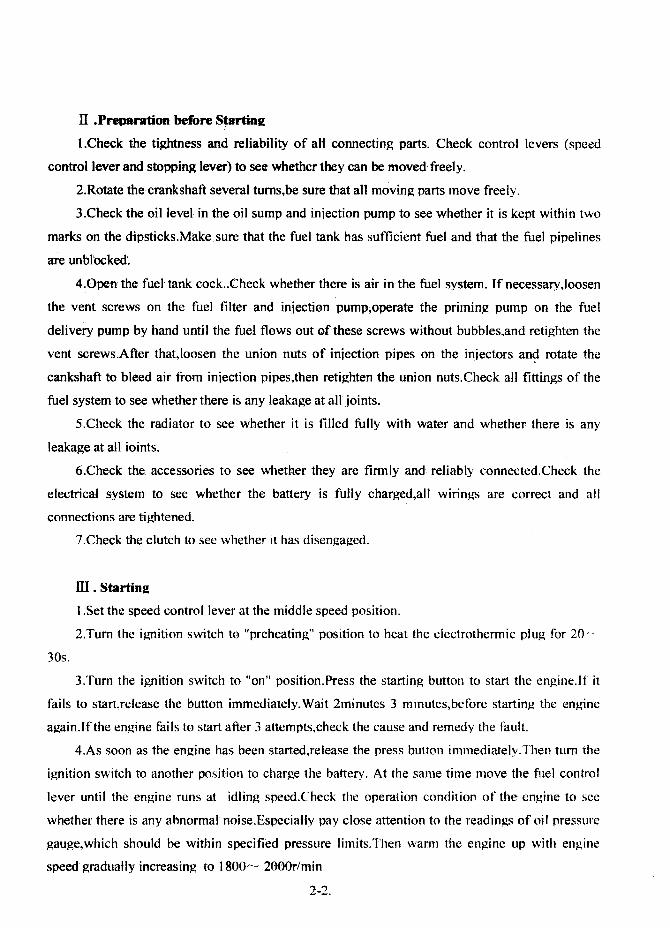
Fig. 1 Adjustment oe valve l8shes
SECTION.4 ENG'INE ADJUSTMENT
I . Ad.iustment of Valve Lash
When .thc en~ine is nlaintained and repaired,it is necessary ·to check and, adi~st tbe va)ve
Jashes.The recommended Jnethod of a4iusting the
valve system and valve lash isas folIows:
I.Remove the, cylinder head cover.Check and
tighten the nuts fastening the rocker arm shafl
stands.
2.Tum the crankshaft to rnake sure that thc
piston of 1st cylinder is at the compression. TDC
position.Thc timing mark on the inspection window
of thc fly\vheel housing exactly points to the " OU
1l1ark ~n the tlywhcel rim ,or the" 0" mark on the
c.rankshaft puJleyis ali~ed \\,ith the pointer on the
cover oftHning gear housing.
3. slip a feeler gauge bet,;veen the rocker arnl
and the tip of the intake or.exhaust valve sterns of
the 1st cylinder respectiv\;~ly to check and ad,iust the
valve lashes.fntake 'valve lash' and exhaust valve
lash in cold nlust be the value specified in section 1.Then after turnlng the crankshafl by 18()'J
to adiust the valve lashof other cytinders a(,:cording to the engine firing order( 1-' 3- 4-2)for tlle
tour cylinder enginc arid'l-3-2 für three cylinder enginc.
11. Adiustment of lß"iection Timing
'ro ohtain the most econolnical specific filet consumption and to chsure normal operation of
the enginc,injection titnin.g shouJd be adjusted properly.For the Model 485 diesel en~jncs,the
angle at \vhichinjection be~ins should be the value specified in se'ctionl .
The adiusting method of injection timing is as follo~'s:
I. Vent the air trapped in the tuel system~and turn·the crankshafl'to filJ up tlle" ini"ection
pump wtih fuel.f)isconnect the in;ection pipe ofthelst cyljnder~turn'thecranksh3.ftslowly in the
direction of its rotation and atthe s3tne time obscrve the fuel'level in thc hole offuel pipeunion~
When this fuel level lust starts to rise,stoptum the cranksha1t itnmediately.
4-1

Fig. 2 AdJlIIInleIIt er spedIIed
adv~ bijecdon ugIe
2.Check the' timin~ mark on the inspection window of flywheel housing to see. whether it
aligns witll' the. correct gradulated mark of specified' advanced in.iection an~le on. the tlywheel rim
(or ontbe crankshaftpulley).
, 3.In case· that tbey do not matchwith each other,the advaneed~ injection an~le can be
adjusterl by re.movinfl;' off the front cover on the timing ~ear housjn~ and loosenjn~ the three
screws fastening thei~iection·.pump timing ~ear support(..see fi~.2).If the iniection timin~' is too
advanced,tum .the timing ~ear support anticlockwise to' the 'proper angJe.Otherwise,turn the
support clockwise.lfa<liustin~ range is not enough
due to litnitation ofthe three elongated holes,loosen a
little the three fastening, nuts on the triangular flange
of the inJection~'pump and: turn the injection ptl1np.
Facin~ the·front end' of en~s,when the in.iection,
pump rotates clockwise,the' fuel i~icctif)n wiU· t:etard~;
"vhile the' pump rotates' anti-clockwise,the' fuel
iniection wi.ll' advance~
4.Additionally,if the engine has injection an'gle
advan~edevice,the advanced 'injection angle can be
adjusted' by loosening the three nuts on· the
triangular flan~e of injection pump and turn the
iniection pump shaft.Facing the front end' ef'engines,
when the iniection pump rotates clockwise,the fue)
iniection will retard;while the pump, rotates,
anticlockwise,the fuel injection will advance.After
turn the injection pump once.. it is must to tighten the three nuts and check the advance iniection
an~de a~ain until1 the 'ldvance inJection an~le fits the spcified value.
ill. Ad.iustrnent of In.iector
lniector test and adiustment must be performed on a injector tester in order to adiust
injectin~.pressure,inspect sprary pattenl and remedy faults.
Too Ili~ or 100' lewer injectol' in.,jectinJ{ pressure,and abnoflooJ spray on damaged injector
partswil-l cause e~ine traubles,such as, biack snl0kin~·,power anS' speed; drollPlng~incr~asing
exhaust ternperature and diesel' knocking,etc.GenerallyJhe "shut off" method is recommended to
4-2'
check a fauly injector,Le.loosen the nuts of injection pipe ·from the iniector ofevery cylinder
sl1ccessively,and observe the exhaust smoke.When the cylinder with the faulty iniector stops
firin~black smoke would disappear.and en~ine speed is not appreciably affected or not affected
at al1.1t mayaiso be checked by IisteninJ]; to the chattering action of the injector of every cylinder
with the flywheel rotatingJf the distinct clear sharp sound of certRin cylinder could· not be heard,
the injector in this cylinder may be faulty.
1.Procedure of injector testing and adi ustment
(1 )Work thc iniector tester hand pump until the gauge pressure reaches about specified
iniection pressure. Then operate the hand pump slowly and adjust the in.iection pressure at
which injection begins.The nozzle should not show any signs of leaka~e. If fuel drips around the
nozzle tip after several tests,the nozzle set must be dismantled for cleaning and winding.Then
test it again.
(2)Relnove. the lock nut~turn the adiusting screw to gel the pressure at the beginning of
iniection \vhich should be specified value in section I.Then tighten thelock nut,and test it again.
(3)Work the hand pump at a rate of approximately 1 stroke per second and observe the
nozzle spray.The fuef spray should be even,and weil atomized in a shape of cone.At any cros~
section of the cone.. the atomized fnet should be finely and evenly distributed.Fuel drop)ets and
irregular pattern wh~ch can be seen by naked eyes should not be present in the spray.There
should be a distinct clear sharp sound at the end of injection.Generally,irregular pattern of the
spray is caused by needJe valve seizure,füeJ dripping is generated by damaged conical sealing
surface of needle valve and spray split results froln carbon deposits on the tip of nozzle and its
heat deformation.
2.1niector dismantlement and repair
( I)Before dismantJing the injector.clean off thc dirt gathered on it .Clamp the nozzle body
in a vice lined by copper sheets on its iaw \vith the nozzle upward.l'um off the 'nozzle cap nut
and take out the nozzle set.Draw out the needle valve from the nozzle body and soak it in clean
flle) oil.Then clamp the injectorin the vicc upside down again.Dismantle the adiusting nut,and
adjusting scrc\v,then take out the injector spring and spindie.
(2) If the nozzle set is seized or clnits fllel hadly,it Inust be cleaned.Soak the scized nozzle
in fitel oB for a \vhile.and clamp the needle valve by a pliers \vith cloth Iined.Then rota.te and
dra\v it out slowlY.iust to avoid scratchin~ it5 surface.Decarbonize the needle valve and nozzle
body with wooden (~hip soaked in fuel oil.lt is forbidden to clean thein ,"'ith InetaI chip. If the
4-3

guiding surfaceofthe needle vaJveand nozzle.body is not smooth enougp,it may. be lapped. \vith
a.littlebitofclean fueloit,th.en clean off any metaLparticulatesin clean. fue.l.While lappj~ of
needJe valve with n(}ZZlebqdY,l1ever knock the neOOle valve ~ainst the body.
IV • Ad.iustmentofLube Oil·Pressure
See fig.3.Lossen the lock nut and turn the adjusting screw with a wrench to take thelubeoil
pressure within 200 ~- 400kPa(in cold state,. the pressure maybe bigh~r slightly). After
adiustment.the pressure adjusting screw must bc·locked ·by the lock nut.·
V'.' Ad.iustment ofln.iectio·n Pump
The ·injection pump has tested and calibrated at
the' factory.lf it i5 necessary to readiust,the
readjüstment must be perfonned in a iniection pump
test bench with ·astandard· injectorand injection. pipes
of standard len~haccording to the instructions in
Operation M.anual of the Injection Pump.
I
Fig. 3 AdJustment of lobe oil pressoreVI ·.Adiustment of DecompressioR Arm Lash
Turn the crankshaft to make that the piston of Ist
cylinder is atthe conlpressionT.D.C:. position.'I'unl the decolnpression arm to decompresslon
position.IJoosen the lock nut.Turn the adjusting screw to bring just ioto contact with the lock arm
of intake valve (Le.no valve lash).Screw the adjusting screw by 3/5---4/5 turns a~ain (nlake the
intake valve lifting to O.6~ O.8Inm).Then tighten the lock nut.After this ..according to Item 3 of"
Adjustrnent of Valve Lash", make the piston of another cylindersat the compression TDC
position one by one and adiust by·the same methode
4-4

Flg. 4 Tlghtening sequenc:e 01 eyUnderbead botts
SECTION 5. CONSTRUCTION OF DIESEL ENGINE
I . Cvlinder Head
When assembting.cylinder headis fixed on the cylinder block with cylinder headboJts.A
torsion spanner should be used during ti~tening the bolts.The bolts are tightened several times
in sequence shown in Fig.4 until they reach the specified torque Iimit.After dismantling and
assembling the cylinder
head.it is necessary to shut
down the engine when first
warming up period is over.
Retighten each bolt on the
cyl inder head according to
the specified value of torque
limit and readiust the valve
lashes.
The intake and exhaust
valves are made of different materials.Each couple of the valve and valve seat should be ground
inorder to prevent leakage.
It is necessary to grind when gas leaks out duc to burning out,mechanical pitting and wear
appeared on the sealing face of valve and valve seal.When grinding,apply a grinding paste(fine
valve sand)on the conic sealing surface ofvalve.Thenthe valve and valve seat are lapped in pair
unitl a even,continuous and lustreless sealing band appears.Itis strictly forbidden that the
grinding paste enters the valve guide.After lapping,c1ean the valve.valve seat and valve guide
carefully.Wearing of the valve guide may cause the eccentric wear of valve sealing band which
results in abnormal sealing.Pour some kerosene or diesel fuel into the gas passage,and observe
whether there is any leakage.then check the valve sealing.
The sealing band of valve and valve seat is normally 1.2~1.6 mm in width.Atler a long
period 01' service and regrinding many times,the width of valve sealing band may get wider.
which may causc abnormal sealing.Being kept concentrical with respect to the valve guide hole,
the contact band on valve seat is to be refaced by a reamer.Then gring the valve and valve seat
in pair.
5-1

·After service for a
... Fig. 5 Valve sinkage
and
frequently.The
period .
lashes
long
recommended adiusting
method is shown on
paragraph J of Sectjon 4.
If the lashes are too large,it may affect the correctness of valve timing and the noise level of
regrinding many times,
the sinkage wi11 increase.
When it exceeds 2.Qmm,
replacing the valve seat
should be considered.
Check the valve
valve device rises.On the contrary.it may cause leakageor valve bllrnt out.
Fig. 6 Protruding height or tbe liner ßange plane
relative to tbe plane or cyllnder block
11 • Cvlinder BLock
The cylinder block is made of cast iron and is of crankshaft centerline off- split face
stmcture. Besides the fitting bores for the liner and the cylinder head boltholes,on the top plane
of the block there are holes Jeading water to the cylinder head.Near thc rear end of the· block
there are channeJs delivering
lube .oil upward to thecylinder
head.
The water pump is mounted
on the upper front face of
cylinder block ,and the gear
system is on the lower part.The
flywheel housing is installed at
the rear face of the block.On the block bottom,there are a lube oit inlet,a hole for the lube oil
pump and tap holes for installing the sllmp. There are a side cover and a breather on the Jeft sidc
ofthe block(facing to the front end).There are the Ilibe oil filter,fucl filter and drain cock on tlle
right side ofthis block. The main lube oil line and its branches are arranged in horizon.The lube
oil passages delivering Ilibe oil to the camshaft bllshes are slant. When dismantling and repairing
5-2

the diesel engine,tlush all lube oil passages"and be sure that they are clean and unb locked. All
passage plugs shouid bc sealed reliably and leakproof.
·-rhe tnain bearing:~\ are of cornplete suspension- support type"Since the main hearing caps
and cylinder block are inatchcd to bore.Jhe matching marks are both on tbe bolck and main
bearing ~aps.Misplaccnlent or inverted installation,when assembling,are prohibited.The Inain
hearing shelJs are made of high- tin aluminilun-base alJoy.When dismantling for cleaninR,be sure
that the upper and lower hearing shells are in right places(the upper shell \vith an oil groove).The
crankshaft thrust plates are assetnbled on the last main bearing with an upper piece and a lower
piece on each side.l~he thrust platcs bear the axial force from the crankshaft.There are oil
channelson its operatin~ surJacewhich should be located against the thrust planes on the crank,
and it5 back surfaceis smoolh.Never loeate thenl in reverse. When tightening the tnain bearing
blots~tw() bolts on the bearing cap should he tightened several tilnes in turn.Before tfghtening the
main bearirlg cap~strjkc the crankshaftlOf\Vard and back\vard in order to keep the upper and
lo\ver thrust plates in th(~ sanle plane."fhen tighten the bolts until t'hey reach the sp-ecified
tightening torquc. When completing the crankshaft assembly,turn it at the flywheel end by hand
10 check whether it can be lnoved freely.
T'he liner 1S slipped into the cylinder bore vertically so that deformation of the liner may be
avoided. 'I'he liner flange plane should protrude out the top plane of cylinder block by 0.07--- 0.15
mnl to keep an excellant sealing bet\veen the cylinder Jiner.and cylinder head,as sho\vn in Fig6.
m. Piston and Connectin2-rod .
The piston and connecting- rod assembly c.omprises thc piston,piston rin~s,piston pin, re
taining rings.~connecting-rod..connecting rod cap,connecting-rod bolts and connecting-rod hearing
sh.ells and bush,ctc:rhe mass difference of piston and connecting- rod assenlblies in the same
engine should be within 20g.
iL\11 ofthe compression rings are lnade of alloy cast iron.The outer circle surface ofthe first
ring is plated \vith porous chrome in order to decrease the wear between the cylinder liner alld
piston ring.The second ring has a conica) surface.When assembling,the surface marked with a
sign HUp" should be keptagainst the top ofpiston and be careful to avoid assemblin~ in reverse.
'[he oil,.control ring is of tensioning ring type:rhe radial force of oil ring is still kept while
decreasing the elasticity duc to \vear.'Thus the service life of oil ring ls prolonged.
5-3

2
Fil. 7 Meuurement of piston ring end pp1. Tbldmess leeler(puge) 2. Pistonring 3. CyUnder IiDer
Fig. 8 Measurement 01 slde surlaeepp of piston ring
Check the ring end ,gap before
assemblinJ!. the pi,st()~ ring.~rhe method,
Ineasuri~g this gapis .reconlmended as
follows:Press .down the piston ring
evenly into the cyJinder Jinerby 15--
20mm ft:Q~the top surfa~e of liner.
Measure the clearance with a feeler
gauge.In oonnal- case,the meas;urin~
value should be O.2·--0.4mln(Fig.7).ln
case the gap value is less ..enlarge it by
a fi.le.lf it, is excess.,replace it \vith
another one.ln addition.,ineasurement should be made with a feeler(gauge)to check the side
clearance between the ·piston ring and
r~ng groove.The side clearance for the
first ring should be O.07~O.102mm and o.05.--..0.082mm for the second ring as
shown in FiR8.
When dismantling and asselnbling
the piston ring,a special tool may be lIsed.
The ring end gap of piston rings should
be set off with each other by J20 (je to
prevent being in Jine with the piston pin
seat hole.
Ifthe piston rin1~ is seized and could not nlove when 'checking,soak it in diesel fuel(kerosine
or gasoline)for 24h 0 .. more.Then knock the piston ring slightJy to ~ake it become flexible of
itselt:On getting outthe piston ring.,clean it in diesel fnel or carbon tetTal~hloridec
Check the piston to see whether there is any cracks or scars.Change the defective piston and
rene\v itsrin~s.
The cross section of the connecting- rod is 1- shaped"with the' splitting surface of large end
being perPendicular to the center line of connecting- rod.Roring the connecting- rod hole and
connecting-rod cap must be mated.Therefore \vhen asselnbling"pay elose attention to the matin~
5-4

nlarks on both the connecting- rod and {;onnecting- rod cap in order to avoid Inaking Qlistakes.
'fhe connecting- rod hearing sheJl is Inade of steel \vith high tin aluminium alJoy.When the
cJ\~ar3nce betwcen the connecting- rod bushes and crankshaft ;oumal exceeds the specified value
after wear'n~~ or severe stripping and buming occur on their surfaces,they must be renewed in
pair.. .
r)urin.g (~ngine overhaul or rene\ving the connecting-rod,check the axis parallelism of the
connecting-rod smal! end to the large end.,which is specified to be within O.Otmm/lOOmm(both
in vcrtical and horizontal direction).If it goes beyond the scope.,alignment should be made.
Before dismantJing the piston and connecting-rod asselnbly in cylinder ,liner or assetpbling,
it is necessary to scrape and clean the carbon deposit and greasy dirt on the top part of cylinder
liner.Before assembling.,smear some clean oil on the cylinder liner bore,external surface of
piston and piston rings"connecting- rod hearing shells and crankshaft jounlal.Then place the
piston guidc s)eeve in the cylinder liner,tit the piston and connecting...rod assembly into the
cylinder line'r carefullY,and tighten in turn the connecting-rod bolts according to the speciticd
tightening torque linlit in several separate times.A"fter finishing the assembly..turn the c·rankshaft..
be sllre that it fotates smoothly.
IV·. Crankshaftand Flywheel
'fhe crankshatl timing gear and pulley are fitted on the front output end of crankshafl:.,
Positioned by the locating pin,the tlywheel is fitted on the rear end tlange ofthe crankshaft with
six boJts lightened according to the specified torque value.A hearing· E60203 ..which supports the
transmission shaft of gear, box,is fitted on the flange center at the rear endof the crankshaft.An
angularcalibrating line is marked on the crankshaft pulley and a pointer,which is fitted on the
cover of the timing gear housing,indicates the reading of advanced iniection angle.
A flywheel gear ring is· bound on the outside diameter of tlywheelin shrinkin~' fit.r\
calibrating line,which provides observation for advanced iniection angle,is marked on the
tlywheeL
V'. Camshaft
There is a gear driving the lube oB plJnlp in'the front ofthe last set ofcams(facing to the
front end).When the calTIshaft revolves,the cam on the shaft drives the tappets,push rods,valve
rocker anus and valves, \\;hich respectiveiy control the intake and exhaust valvcs tor each
cylinder.
5-5

There' is a thmst flan~e at the front end of camshaft,and a thrust plate of camshaft is located
at the front end to control the camshaft axial movin~. The lube oil is delivered to the camshaft- 1
bushings separately through the main oil line.Before assembling the front bushing of camshaft,
check whether the oH holes on the bushing and oil passa~e in the cylinder block communicate
witheach other. As the camshaft gear is engaged with the driven gear o-~.the oil pump.Jheretore,
before dismantlinJ;t the camshaft,it is necessary to disassemble the lube oil pump,then dra\v the
camshaft out from the front end.
'fhe axis of the tappet deviates from the center line of cam width .During operating,the
tappet rotates so as to provide an even wearing on the bottom surface and the cylindrical surface
oftappet.
VI •Gear Transmission Svstem
The gear transmission system consists of thecrankshaft timing gear.,timing idler,camshaft
timing gear,injection pump timing gear and hydraulic pump gear.
Except the hydraulic pump gear.,all the timing gears are all marked with timing sifms which.,
when assembling,should align wtih each other at the lneshing position (the single -tooth marked
with a sign is inlaid between the two adiacent marked teeth)in order to ensurethe movement
relationship ofall movin~pa~s"as shown in Fig.9.
Fig. 9 Timing gear meshiDg signs
5-6

Special tools are necessary tor dismantling or assembling the crankshaft timing gear.The
camshaft timing gear can be got out by two bolts M8 on the gear spoke which are tumed
stag,geringly and evenly.The timing idler is located on the cylinder block by slide fit.The
injection pump timing gear is assembled on the timing gear seat which is tixed on the camshaft
of the injection pump.Whenever three bolts setting the iniection pump gear are loosened,the
injection pump gear can be drawn out.The iniection pump gear is pushed out when the·three
bolts M8 X 35 are staggeringly ti.gbtened on the gear seat.
VH.Fuel aod Goveroin2 SystemfII
The fuel and governing system is the main operating section of the diesel engine . It is
composed of the fuel delivery pump, (uel filter, iniection pump.. governor, fuel injection and fuel
combustion chamber.
return pipes, etc.as
shown in Fig. 10.
The fuel 1S
pu,nped by the fuel
delivery pump from
the fucl tank into the
iniection pump
through the fucl filter.
The diesel fue) is
delivered through the
injection pipe under
high .. pressure
produced in the plunp..
and is then atomized
by the iniector beforc
2
1_~_--3
Fig. 10 Fuel and governing system1. Fuel return pipe 2. Fuel injedion pipe 3.lnjedor4. lnjection pump S. Fuel filter 6. Govemor 7. ("'oel delivery pump
theinburning
The fuel deJivery
pUlnp is a single-acting piston type pump located on the outside of the iniection pump.The
eccentric caln,\\'hich is set on the camshatl of injection pump"dnves the file I delivery pump..
\vhich finalJy presses the fuel into the tue) cavity in the iniection pump.
5-7

'fhe inj-ectionpump hasbeen calibrated by the manutacturer.Be sure not to dismantle it a1'
\vill. When the. dismantlementrepairment and adjustnlent are required,it is t()rbidden to
inter("llan~e'the -pluger sets, and discharging vaJve sets,and,-be sure to keep clean\-vhen
assembling.
"'rhealt speedmcchanical- centrifugai govemor is applied. l'he governing handle can be
opemled: -tocontroJ the speed -ofdiesel en~ine~When the governing handle is turned in the
direction of tightening the governing spring"the fuel supply \vould increase and the engine speed
would bc up consequently. Whcn this fliel supply \vould dccerease and the relevant engine speed
\vould go do\-vnJ)o not move cither the high speed or the idling speed, set scre\\'s or screw the
rnaxinlal,fuel supp)y set scre"v.on (he governor at will d~ring operating.
On the governor housing,a stop handle is mounted which'lif necessary,can be operated to
stop the engine at clnergencv.
'rhe necdlcvaive and its body.are a preCJse set lapped in c;ouple .,theretore,closc attention is
paid to that,\\'hen dislnantling and assenlbling thenl.Be sure not to interchange thern and to keep
them clean. .'
\I. LubricatineSvstem
l'hc lubricating system is composed of the strainerj)ube oilpurnp,oil filter and pipelines,as
sho\\'n in Fig.ll, e
l'he engine adopts pressure and splash Jubrication.l~hepressure lubrication is applied to tlle
main bearjn~connectin~-rodbearing,carnshaft bushing.The cylinder sieeve,piston.,piston pin.,
connccting- rod bushing..camand its tappet,as '.vell as va)ve 'and its guide are lubricated by
splashed oil spray.'Thl~ hearings f(lr the \vater pump shaft are lubicated regularly by adding
lubricating greasc.
rrhe luhe oil is slu:~ked up to thelube oil pump frotn the oil sump through the strainer and
the oil inlet pipc,and ,pumped into Inain oil ,Hne through rhe oiltilter.()nc path of the lube oil
luhricates tlle lnain beari-ng and tlle connectlng..rodbearingthrough the oB hole on the crankshaft:
other path 01' tlle nil 'ubricat\~s thc camshan bushing..and also ~he oil is supplied intermittently to
the rocker arrn shatl b1.1shing throrgh the ccccntric oil channel in the rear journal 01' the camshaft;
and the third pathof the nil is ted to the tilnin~ idler bearing.-rhe lubc oil PUITIP is of slantingly
ITIounted type.A single sta~e paper cartridge oll pUlnp is used.The filter element can be replaced
regulariy.ln casc of blockin~updurin~_ xoperation.,the oil tlO\VS into the main oilline by opening
5-8

the safety valve while the oil filter loses the fimction of filtration,so it is necessary für the
cartridge to be c1eaned or replaced regularly according to the maintenance.
Fig. 11 Lubricating S)'stem1. Oll IUlDp 1. StraiDer 3. Lube oB pump 4. PIston and ceinnertmg- rod _mbly and cyUnder Uner 5. Lube oll01..,' 6. Gear tralD 7. Oll preIIlIUre puge 8. Rocker arm 9. Valve pub rod. valve tappet and bIock hole furtappet 10. Rocker arm ....n 11. Valve and valve gulde 12. Camshaft and bIL~hing 13. Oil Iines In tbe block14. CruUhaft andbearing'
5-9
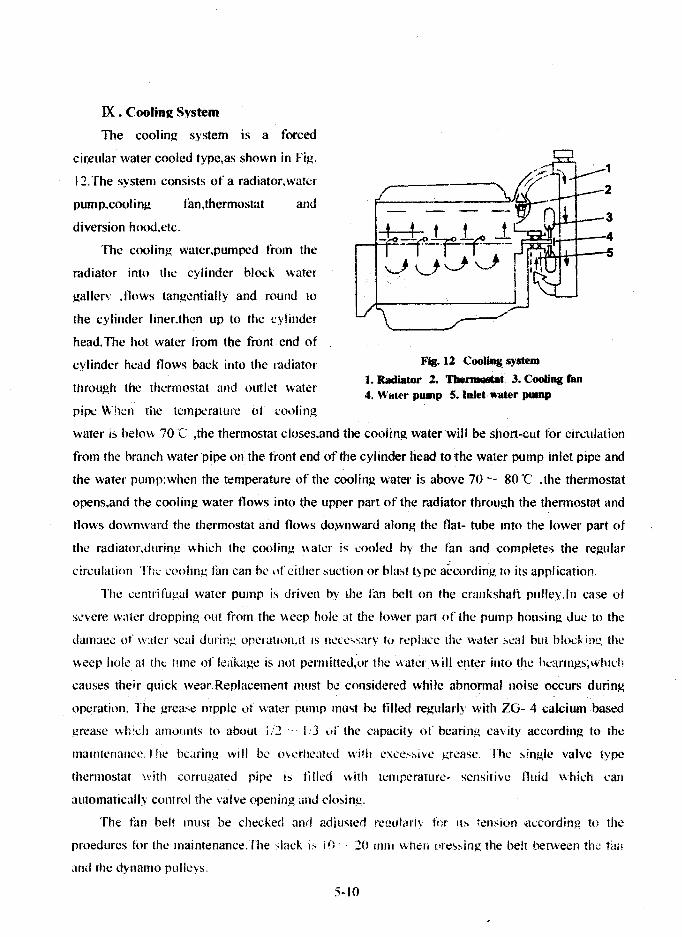
Fig. 12 Cooling system
1. Radiator 1. Tbe.......t 3. Cooling faJI4. Watl'r pump 5. Iolet water pump
IX • Coolin2 System
The cooling system is a forced
cir,elliar water cooled type,as shown in Fig.
J2.The system consists of a radiator,water
pump.cooling tim,thermostat and
diversion hood.etc.
The cooling water,pumped from the
radiator into the cyJinder block water
gallcry Jlows tangentially and round to
the eylinder hner.then up to the cylinder
head.The hot water from tbe front end 01
cvJinder head flows back into thc ladiator
throllgh the thermostat and out let water
pipe When thc temperature ot l:ooling
water is helm... 70C ,the thermostat closes,and the cooling water will be short-cut tür circulation
from the hrunch waterpipe on the front end ofthe cylinder head tothe water pump inlet pipe and
the water pump:when the temperature uf the cooling water is abovc 70',- 80'e .the thermostat
opens,and the cooling water flows into the upper part of thc radiator throllgh the thermostat and
tlows downward tlle thermostat and flows do~nward along thc flat- tube Into thc lower part of
the radiator.dllring whieh the cooling watel' i5 ~ooled by thc fan and cornpletes the regular
circlIlation Th:.: cooling tan can ht' ilf cither suction 01' hlast type according to its application.
Thc ecntrifllgal water pump is driven by lhe lan belt on the crankshaft pulley.Jn case ot
severe water dropping out frorn the weep hole :lt the lower pan 01' thc pump hOllsing duc to the
damuge of water seal during operation,it b 11CCC'iSary to replacc the water "cal hlll blockinl!, the
weep hole at the fllne 01' leakage is not perlllitted,or thc water will enter ;nto the hcarings;which
causeS their quick wear.Replacement must bc considett~d whilc abnormal nöise occurs dllring
operation. The grease nipple 01 water pump must hc tilled reglllarly with ZG- 4 calcium based
I!rease which amounts to abOlll 1/2 1·3 üf thc capacit} 01' bearing cavity according to the
maintenance.l!w bearing will b(' ovcrheatcd Wilh excc-:sjyC grcase. Thc single valve type
thermostat with corrugated pipe is ti lied with 1CmpcralUre- sensitive Iluid whkh can
automatically contml tht~ valve opening und closing.
The fun beft 1fI1iSl be cheeked and adiuslcd rt.'uulariv jiir Ils tension ·according to the
proedllrcs for the maintenance.The slack is i I} 20 UJlH wllcn pres~.ing the be!t between th" tim
and the dynamo pllllevs.
5-10

,X . Elemi,! System
The electric system is composed of the battery,starting motor,dynamo,electrothennal plug.
starting button and instruments,etc.,as shown in Fig.13.
The parallel excited silicon rectifying dynamo model JFl1 comprises the three - phase
8 9
Fig. 13 Electric system
1. Battery 2. Starting motor 3. Wire 4. Glow plug 5. Preheating and starting
switeh 6. Galvanometer 7. Ignition switch 8. Regulator 9. Dynamo
alternator and silicon diode rectilier.Be careful thm thc armmure must be negitive pole grounded.
orthe dynamo will be damaged.
Refer to operation and maintcnancc manual for JF senes ~i1icon rectifying dynamo for the
operation and maintcnance ofthe dynamo.
After tuming on the starting switch.the flywheel gear ring 15 engaged with the motor pinion
by the solenoid.meanwhile the tlywheel is driven by c10sing the current circuit of starting motor.
As soon as the engine is started.thc starting swnch mus! be turncd off immediate!', .Then thc
corc a!ong with the pinion returns 10 the original plaC\.~ under the actuation 01' spring. The
continuotls workin!..' timl: fi)r thc startlll.C: lTlotor. shOltid not cxceed 1:' sccond"The interval
bdwecn two startin.g operations 15 2 3 minutes.1l j.:; ncces:-d!'y to check ami c1iminate the t:utlts
in ease 01' starting failure t~)r threc attcmpts. Thc elcctrifying time 01' thc glow plug each time
during operation I~ not permitted to be over 30 seconds.
5-11

SECTION6. FAULTS AND REMEDlES FOR DIESELENGINE
I .Hard or refuse to Start (see Table 4)
Table 4.. _---_.._._------,;.._..__ .. - .'_" __ "'-- .. __ ..._-- ---
Causes Remedies"'''-' .. . _~~. -._,..__ ...•_..• '._._----. _.
I.FueJ filters and fuel pipelines bolcked.
2.Air trapped in fuel system.
3.Advanced fuel)tljection angle incorrect." .~. ..
4.FueJ sprayabn0ima/.
5.Compression preessure low.
6.Valve lash incorrect
7.Battery charge insuffcient.
8.Wire connections loosened.
9.Ambient temperature 100 low, and oil
too viscous
II.Power Insuffic:ient(see Table 5)
Table S
Causes
I.Clean.
2.Exhaust air and tightenall fuel pipdline connector.
3.Readjust it accoi'ding to specifications.
4.Readjust tucl injection pressurea<:cordi~{()specifica
tionsatld cleanor replacei.jector needle ~lve sets.
5.Cheak or replace piston rings,and cylinder liners.
Grind·valVes.Cylnderhead nuts should be tightencd in
case of leakage on. cYlinderhead~~ets.
6.Adjust itaccording to~fita!io,s~d align gear
marks.
7.Charge it.
8.Check andtighten wire connections. Clean up contact
points.
·9.Preheat coolihg waterand lube oiJ.
Remedies
'.Compression pressurc inside cylinddcrs too low.
2.Advanced filet injection angle incorTecl.
3.Valvc lash incorrcel.
4.FlId supply tor cach cylinder lInhalanccd.
5.Ari. tilter c10qrcd.6.Fuel injection pumps, tue! if\j\.--c!or sets worn olr
or fue! injectioo presslIre incolT\.-'Cl.
7.Rotat(on speed incorrect.
I.Reler to item 5 in pnragatph I and replace
compont,'nts exceeding wear limit. .
2.Adjust it according to specifications.
3.Adjust it according to speciftcations.
4.Adjust lue! iniection pumps to proper supply.
5.C!can.
6.Rcplace them with n\.-'w sets. aqjust fud injectiön
presSllrc and check fuel spray.
7 Aqjus! it with speed govcming handle in Ord\.-T to rench
sr-.~citicd speed.
6-1

m.Smokin! Exhaust(see Table 6)
Table 6
Causes
1.Engines overloaded.
2.Fuel il1jectors not weil atomized
3,Fuel unqualitied
4.Combustion incomp!ete
Remedies
l.Reduce the load properly and in case ofunsuited
matching. adjustment should be made.
2.Check the injection pressurc and fuel spray. Rcplace
then in case of damage.
3.Use qualitied fue!.
4.Mainly caused by unqualified fuelinjectors, incorrect
advanced fuel injection angleJeakage atcylinder head
gaskets and low compression pressure.Remdy in
accordance with specitic problems.
IV.Knackin! Noise in En2ine (see Table 7)
Table 7
Causes
I .Advanced fuel injection angle incorrect.
2.Air trapped in fucl systems.
3.Fuel supply for each cylinder unbalanced.
4.Fuel unqualitied.
5.Wear of ccrtain componcnt'i c"ceeds lirnils
Remedies
1.Rea(Uust ;t according to specification.
j 2.Exhaust air.,
I 3.Rcadiust fud suppl)'.
, 4.Use qualified suppl).
i 5.Replace themI
V .Lube Oillnsumcient or No Pressure (see Tablc 8)
Table 8
Causes
1.0illevel in oil sumps too low.
2.Serious leakage from oil pipelines.
3.0il stminers,oil filters and pipe1ines clogged.4.0il gauges damaged or gauge lines c1ogged.5.0il too thin.6.0il pump gears seriously worn ofr ,\Vith exccssive
c1earance.7.Pressure relief valves ofoil filter cease to function.
8.Main bearings, connecting-rod hearings and carnshaftbushings seriously worn on with excessive c1eamnce.
6-2
Renedies
] .Add oil up to mark fine on dip sticks.
2.Eliminate leakagc.
3.Clean and replace elements if nc"cssary.4.Check and rcplace elements if llcccssary5.l:se qualified oil.6.Adjust the c1earance 01' rcplacc HICIll.
7.Check and repair 01' readJllst them.8.Check and repair 01' replace them.

MANUFACTURING UCENSE: XK06 -205 -00141PRODUCT STANDARD:Q/321284 JCA03(35) -2002NO. OF EXPORT UCENSE FOR QUALITY: 2000112013UCENSE APPRQVAL DATE: OCT.10,2000
Related Documents