Rev. 0040504000 1416 englisch 1.0 General information on operating instructions ........................................ 2-2 2.0 Notes on possible dangers ................................ 2-2 2.1 Significance of symbols .................................... 2-2 2.2 Explanatory notes on safety information ........... 2-2 3.0 Storage and transport ........................................ 2-3 4.0 Description .......................................................... 2-3 4.1 Scope of applications ........................................ 2-3 4.2 Operating principles .......................................... 2-3 4.3 Diagram............................................................. 2-4 4.4 Technical data ................................................. 2-10 4.5 Marking ............................................................ 2-11 5.0 Installation .......................................................... 2-11 5.1 General notes on installation............................ 2-11 5.2 Requirements at the place of installation ........ 2-12 5.3 Valve with actuator .......................................... 2-13 5.4 Control pressure connection ........................... 2-15 5.5 Assembling the valve, operating mode „actuator stem extends by spring force“ ............ 2-15 5.6 Setting the starting point, operating mode „actuator stem extends by spring force“ .......... 2-16 5.7 Assembling the valve, operating mode „actuator stem retracts by spring force“ ........... 2-16 5.8 Setting the starting point, operating mode „actuator stem retracts by spring force“ ........... 2-17 6.0 Putting the valve into operation....................... 2-17 7.0 Disassembly of the actuator unit from the valve ............................................ 2-18 7.1 Disassembly of the actuator unit ..................... 2-18 8.0 Care and maintenance ...................................... 2-19 8.1 Replacing the rolling diaphragm...................... 2-19 8.2 Replacing the guiding band and the o-ring...... 2-21 9.0 Alterations.......................................................... 2-21 9.1 Replacing the spring set .................................. 2-21 9.1.1 Replacement by operation mode "actuator stem extends by spring force" ........ 2-21 9.1.2 Replacement by operation mode "actuator stem retracts by spring force" ......... 2-22 9.2 Change of operating mode .............................. 2-23 9.2.1 Change of operating mode "actuator stem extends by spring force" in "actuator stem retracts by spring force" ................................. 2-23 9.2.2 Change of operating mode "actuator stem retracts by spring force" in "actuator stem extends by spring force" ................................ 2-24 10.0 Troubleshooting .............................................. 2-27 11.0 Troubleshooting table .................................... 2-27 12.0 Warranty / Guarantee ...................................... 2-28 Contents Operating and installation instructions Pneumatic actuators - DP30 / DP32 / DP33 / DP34 DP32 DP33 DP34 DP30

Welcome message from author
This document is posted to help you gain knowledge. Please leave a comment to let me know what you think about it! Share it to your friends and learn new things together.
Transcript
Rev. 0040504000 1416 englisch
1.0 General information on operating instructions ........................................ 2-2
2.0 Notes on possible dangers ................................ 2-2
2.1 Significance of symbols .................................... 2-2
2.2 Explanatory notes on safety information ........... 2-2
3.0 Storage and transport ........................................ 2-3
4.0 Description .......................................................... 2-3
4.1 Scope of applications ........................................ 2-3
4.2 Operating principles .......................................... 2-3
4.3 Diagram............................................................. 2-4
4.4 Technical data ................................................. 2-10
4.5 Marking ............................................................2-11
5.0 Installation ..........................................................2-11
5.1 General notes on installation............................2-11
5.2 Requirements at the place of installation ........ 2-12
5.3 Valve with actuator .......................................... 2-13
5.4 Control pressure connection ........................... 2-15
5.5 Assembling the valve, operating mode
„actuator stem extends by spring force“............ 2-15
5.6 Setting the starting point, operating mode „actuator stem extends by spring force“ .......... 2-16
5.7 Assembling the valve, operating mode „actuator stem retracts by spring force“........... 2-16
5.8 Setting the starting point, operating mode „actuator stem retracts by spring force“........... 2-17
6.0 Putting the valve into operation....................... 2-17
7.0 Disassembly of the actuator unit from the valve ............................................ 2-18
7.1 Disassembly of the actuator unit ..................... 2-18
8.0 Care and maintenance ...................................... 2-19
8.1 Replacing the rolling diaphragm...................... 2-19
8.2 Replacing the guiding band and the o-ring...... 2-21
9.0 Alterations.......................................................... 2-21
9.1 Replacing the spring set.................................. 2-219.1.1 Replacement by operation mode
"actuator stem extends by spring force" ........ 2-219.1.2 Replacement by operation mode
"actuator stem retracts by spring force" ......... 2-22
9.2 Change of operating mode.............................. 2-239.2.1 Change of operating mode "actuator stem
extends by spring force" in "actuator stem retracts by spring force" ................................. 2-23
9.2.2 Change of operating mode "actuator stem retracts by spring force" in "actuator stem extends by spring force" ................................ 2-24
10.0 Troubleshooting .............................................. 2-27
11.0 Troubleshooting table .................................... 2-27
12.0 Warranty / Guarantee ...................................... 2-28
Contents
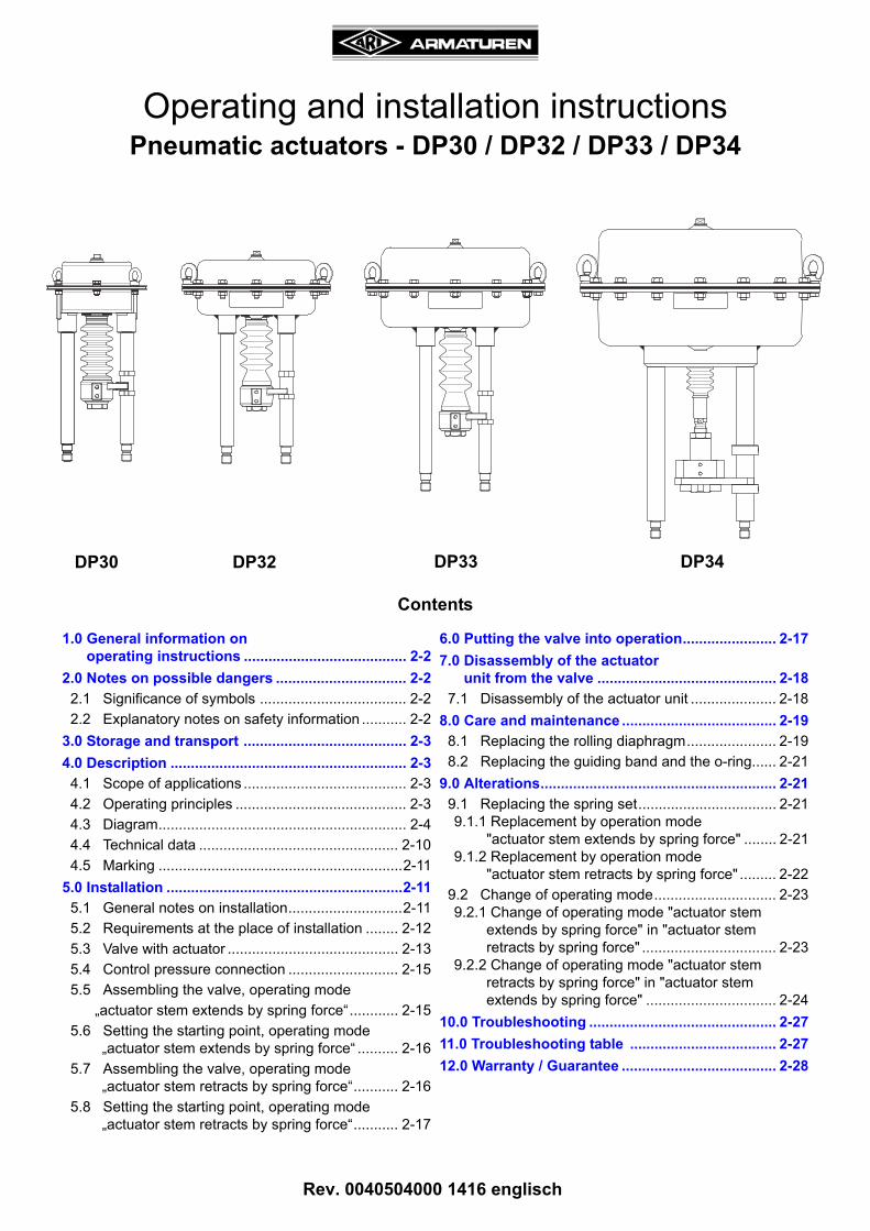
Operating and installation instructionsPneumatic actuators - DP30 / DP32 / DP33 / DP34
DP32 DP33 DP34DP30
Page 2-2 0040504000 1416
Operating and installation instructionsPneumatic actuators - DP30 / DP32 / DP33 / DP34
1.0 General information on operating instructionsThese operating instructions provide information on mounting and maintaining the actuators. Please contact the supplier or the manufacturer in case of problems which cannot be solved by reference to the operating instructions.
They are binding on the transport, storage, installation, start-up, operation, maintenance and repair.The notes and warnings must be observed and adhered to.
- Handling and all work must be carried out by expert personnel or all activities must be supervised and checked.
It is the owner’s responsibility to define areas of responsibility and competence and to monitor the personnel.
- In addition, current regional safety requirements must be applied and observed when taking the fittings out of service as well as when maintaining and repairing them.
The manufacturer reserves the right to introduce technical modifications at any time.
These Operating Instructions comply with the requirements of EU Directives.
2.0 Notes on possible dangers
2.1 Significance of symbols
2.2 Explanatory notes on safety information
In these Operating and Installation Instructions dangers, risks and items of safety information are highlighted to attract special attention.
Information marked with the above symbol and “ATTENTION ! ” describe practices, a failure to comply with which can result in serious injury or danger of death for users or third parties or in material damage to the system or the environment. It is vital to comply with these practices and to monitor compliance.
All other information not specifically emphasised such as transport, installation, operating and maintenance instructions as well as technical data (in the operating instructions, product documentation and on the device itself) must also be complied with to the fullest extent in order to avoid faults which in turn can cause serious injury to persons or damage to property.
ATTENTION !
. . . Warning of general danger.
Exposed to injury!Don‘t put your hand into the up or downwards moving appliance.
0040504000 1416 Page 2-3
Operating and installation instructionsPneumatic actuators - DP30 / DP32 / DP33 / DP34
3.0 Storage and transport
- At -20°C to +65°C.- Do not damage paint protection. (The actuators should rest in the packing till installation.)
4.0 Description
4.1 Scope of applications
The pneumatic actuators are to be mounted on the top of valves and are necessary to operate the valves (stem movement) under service conditions.The units are suitable for being employed in control systems used in the chemical industry.
Please contact the supplier or the manufacturer if you have any questions.
4.2 Operating principles
By means of the pneumatic actuator units, pneumatic control signals are converted into a translatory motion. The necessary restoring force is generated by means of the compression springs on the bulk of the diaphragm plate.
In case of air fall-off, the actuator will be restored by means of the spring force in the starting position.
The operating mode of the actuator is the following:„actuator stem extends by spring force“ (on air failure) or„actuator stem retracts by spring force“ (on air failure)
This operation is obtained and dependent on the assembly of the springs.
By using a rolling diaphragm, linear rod forces during long lifts can be obtained.
The pneumatic actuators with manual emergency adjustment can be operated without operating pressure by turning the handwheel. In case of usual operating the handwheel is locked by a locking device. This prevents the handwheel from turning. To engage the handwheel, the locking device must first be pulled out.
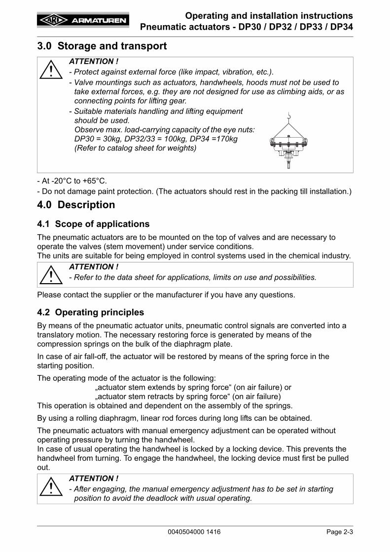
ATTENTION ! - Protect against external force (like impact, vibration, etc.).- Valve mountings such as actuators, handwheels, hoods must not be used to
take external forces, e.g. they are not designed for use as climbing aids, or as connecting points for lifting gear.
- Suitable materials handling and lifting equipment should be used.Observe max. load-carrying capacity of the eye nuts: DP30 = 30kg, DP32/33 = 100kg, DP34 =170kg (Refer to catalog sheet for weights)
ATTENTION ! - Refer to the data sheet for applications, limits on use and possibilities.
ATTENTION ! - After engaging, the manual emergency adjustment has to be set in starting
position to avoid the deadlock with usual operating.
Page 2-4 0040504000 1416
Operating and installation instructionsPneumatic actuators - DP30 / DP32 / DP33 / DP34
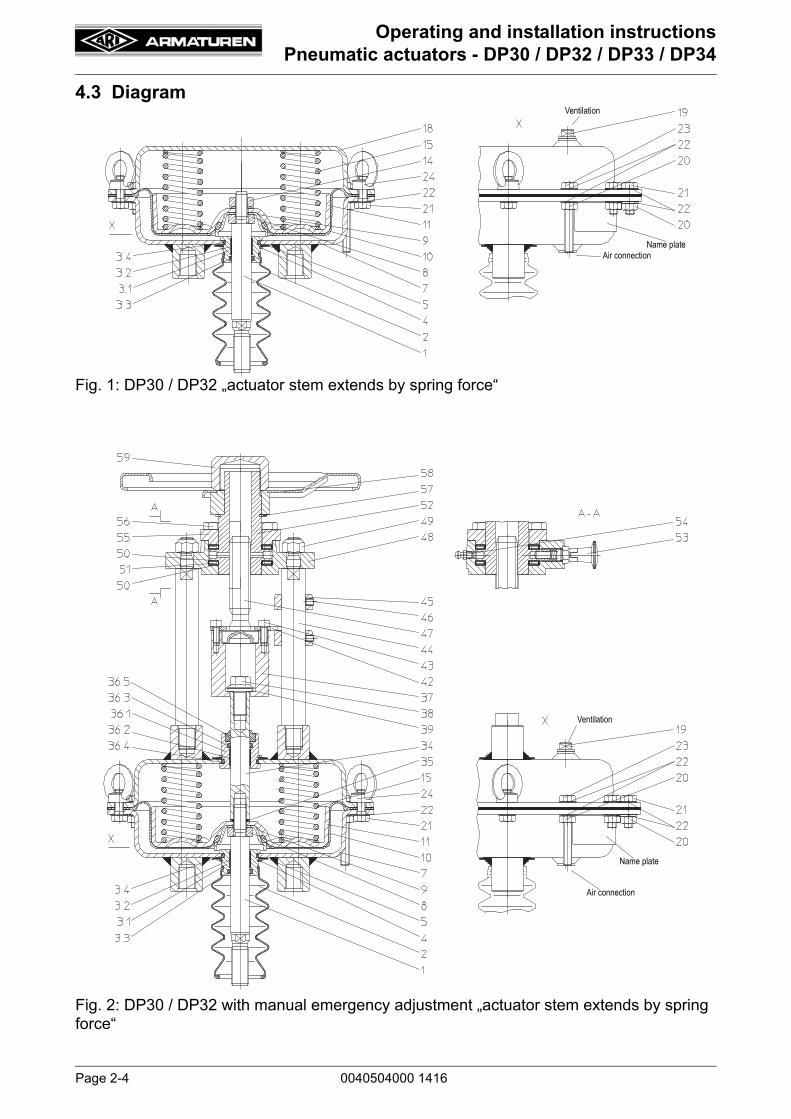
4.3 Diagram
Fig. 1: DP30 / DP32 „actuator stem extends by spring force“
Fig. 2: DP30 / DP32 with manual emergency adjustment „actuator stem extends by spring force“
Ventilation
Name plateAir connection
Ventilation
Name plate
Air connection

0040504000 1416 Page 2-5
Operating and installation instructionsPneumatic actuators - DP30 / DP32 / DP33 / DP34
Fig. 3: DP30 / DP32 „actuator stem retracts by spring force“
Fig. 4: DP30 / DP32 with manual emergency adjustment „actuator stem retracts by spring force“
Air connection
Name plate
Ventilation
Air connection
Name plate
Ventilation

Page 2-6 0040504000 1416
Operating and installation instructionsPneumatic actuators - DP30 / DP32 / DP33 / DP34
Fig. 5: DP33 „actuator stem extends by spring force“
Fig. 6: DP33 with manual emergency adjustment „actuator stem extends by spring force“
Air connection
Name plate
Ventilation
Air connection
Name plate
Ventilation
0040504000 1416 Page 2-7
Operating and installation instructionsPneumatic actuators - DP30 / DP32 / DP33 / DP34
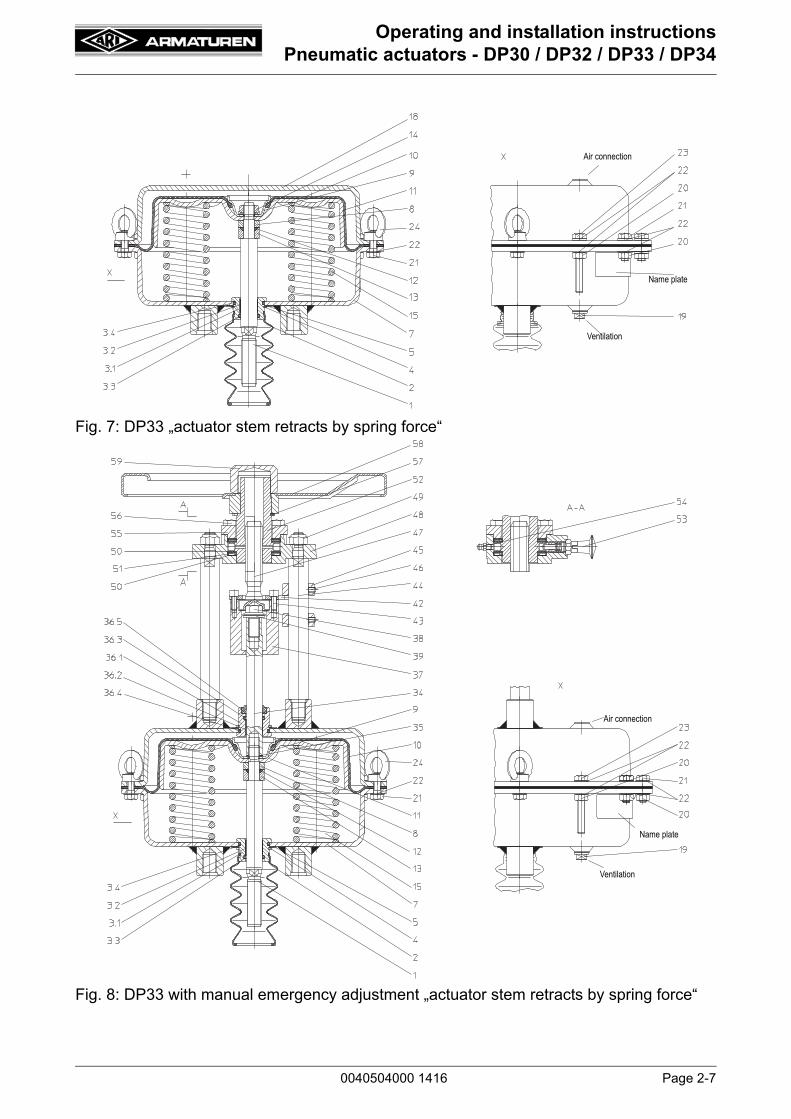
Fig. 7: DP33 „actuator stem retracts by spring force“
Fig. 8: DP33 with manual emergency adjustment „actuator stem retracts by spring force“
Air connection
Name plate
Ventilation
Air connection
Name plate
Ventilation

Page 2-8 0040504000 1416
Operating and installation instructionsPneumatic actuators - DP30 / DP32 / DP33 / DP34
Fig. 9: DP34 „actuator stem extends by spring force“
Fig. 10: DP34 with manual emergency adjustment „actuator stem extends by spring force“
Air connection
Name
Ventilation
plate
Air connection
Name plate
Ventilation
25° rotated view

0040504000 1416 Page 2-9
Operating and installation instructionsPneumatic actuators - DP30 / DP32 / DP33 / DP34
Fig. 11: DP34 „actuator stem retracts by spring force“
Fig. 12: DP34 with manual emergency adjustment „actuator stem retracts by spring force“
Air connection
Name plate
Ventilation
Air connection
Name plate
Ventilation
25° rotated view
Page 2-10 0040504000 1416
Operating and installation instructionsPneumatic actuators - DP30 / DP32 / DP33 / DP34
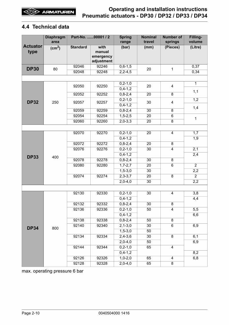
4.4 Technical data
max. operating pressure 6 bar
Actuator type
Diaphragm area
Part-No. ......00001 / 2 Spring range
Nominal travel
Number of springs
Filling-volume
(cm2) Standard with manual
emergency adjustment
(bar) (mm) (Pieces) (Litre)
DP30 8092046 92246 0,6-1,5
20 10,37
92048 92248 2,2-4,5 0,34
DP32 250
92050 922500,2-1,0
20 41
0,4-1,21,1
92052 92252 0,8-2,4 20 8
92057 922570,2-1,0
30 41,2
0,4-1,21,4
92059 92259 0,8-2,4 30 8
92054 92254 1,5-2,5 20 61
92060 92260 2,0-3,3 20 8
DP33 400
92070 92270 0,2-1,0 20 4 1,7
0,4-1,2 1,9
92072 92272 0,8-2,4 20 8
92076 92276 0,2-1,0 30 4 2,1
0,4-1,2 2,4
92078 92278 0,8-2,4 30 8
92080 92280 1,7-2,7 20 6 2
1,5-3,0 30 2,2
92074 92274 2,3-3,7 20 8 2
2,0-4,0 30 2,2
DP34 800
92130 92330 0,2-1,0 30 4 3,8
0,4-1,2 4,4
92132 92332 0,8-2,4 30 8
92136 92336 0,2-1,0 50 4 5,5
0,4-1,2 6,6
92138 92338 0,8-2,4 50 8
92140 92340 2,1-3,0 30 6 6,9
1,5-3,0 50
92134 92334 2,4-3,6 30 8 6,1
2,0-4,0 50 6,9
92144 92344 0,2-1,0 65 4
0,4-1,2 8,2
92126 92326 1,0-2,0 65 4 6,8
92128 92328 2,0-4,0 65 8

0040504000 1416 Page 2-11
Operating and installation instructionsPneumatic actuators - DP30 / DP32 / DP33 / DP34
4.5 Marking
5.0 Installation
5.1 General notes on installation
The following points should be taken into account besides the general principles governing installation work:
Fig. 13
- Address of manufacturer: refer to item 12.0 Warranty / Guarantee
ATTENTION ! - Observe the information provided in the operating manual of the applicable
valve.- Observe the information provided in the operating manuals of all components
(for ex. position adjuster, filter reduction station, interlocking relay ...).- Valve (all included) with traverse.- Observe the applicable current driving power and the provided line length of the
chosen line cross section.- The actuator unit’s technical data must be in agreement with the requirements
for operation.- The control air must be in accordance with the instructions given on the
nameplates of the actuator unit.- The air quality should be in accordance with DIN IEC 60654-2.- The actuator unit must be provided in full, with distance columns and coupling
parts, for the extension on the applicable valve.- Personnel with knowledge of the rules and regulations is required for the
construction of the compressed air system.
Manufacturer
Mode of
Travel +
Figure-NumberType +
operation
operating pressure
Serial-No. Year of manufacture
Spring range
(min./max.)
clear speach
EAC-marking
Page 2-12 0040504000 1416
Operating and installation instructionsPneumatic actuators - DP30 / DP32 / DP33 / DP34
5.2 Requirements at the place of installation
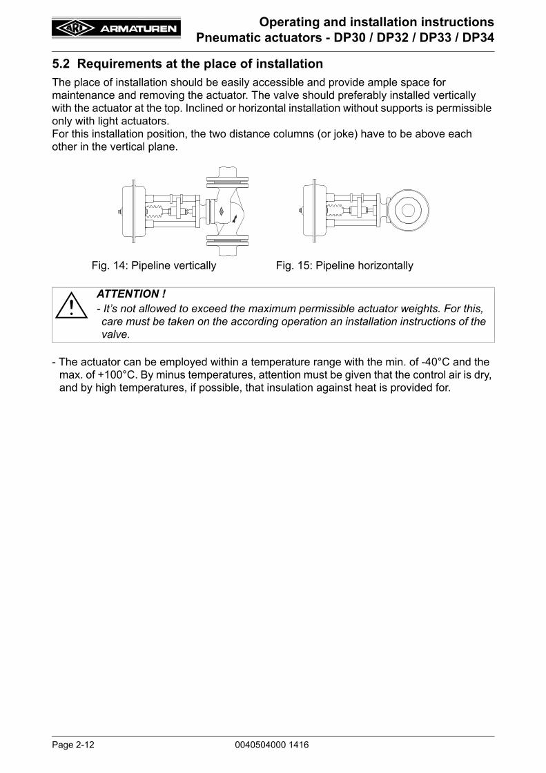
The place of installation should be easily accessible and provide ample space for maintenance and removing the actuator. The valve should preferably installed vertically with the actuator at the top. Inclined or horizontal installation without supports is permissible only with light actuators. For this installation position, the two distance columns (or joke) have to be above each other in the vertical plane.
- The actuator can be employed within a temperature range with the min. of -40°C and the max. of +100°C. By minus temperatures, attention must be given that the control air is dry, and by high temperatures, if possible, that insulation against heat is provided for.
Fig. 14: Pipeline vertically Fig. 15: Pipeline horizontally
ATTENTION ! - It’s not allowed to exceed the maximum permissible actuator weights. For this, care must be taken on the according operation an installation instructions of the valve.

0040504000 1416 Page 2-13
Operating and installation instructionsPneumatic actuators - DP30 / DP32 / DP33 / DP34
5.3 Valve with actuator
Fig. 16: Pneumatic straight through control valve Operating mode of the actuator: „actuator stem extends by spring force“Spring closes on air failure.
Fig. 17: Pneumatic three-way control valve as a mixing valve (path AB-B)Operating mode of the actuator: „actuator stem extends by spring force “Spring closes B - AB on air failure.
Valve stemLocking nut
Hexagon nut
Cylinder screw
Travel indicator
Coupling flangeLocking nutDistance column
Valve stemLocking nut
Hexagon nut
Thread bush
Travel indicator
Securing flangeCoupling flange
Locking nutDistance column
Coupling
Set screw(90°rotated view)
Securing flange
Thread bush
DP 30 - 33DP 34
Valve stemLocking nut
Hexagon nut
Cylinder screw
Travel indicator
Coupling flange
Locking nutDistance column
Valve stemLocking nut
Hexagon nut
Thread bush
Travel indicator
Securing flangeCoupling flange
Locking nutDistance column
Coupling
Set screw(90°rotated view)
Securing flange
Thread bush
DP 30 - 33DP 34

Page 2-14 0040504000 1416
Operating and installation instructionsPneumatic actuators - DP30 / DP32 / DP33 / DP34
Fig. 18: Pneumatic straight through control valve Operating mode of the actuator: „actuator stem retracts by spring force“Spring opens on air failure.
Fig. 19: Pneumatic three-way control valve as a mixing valve (path AB-B)Operating mode of the actuator: „actuator stem retracts by spring force“Spring opens on air failure.
Valve stemLocking nut
Hexagon nut
Securing flange
Coupling flangeLocking nutDistance column
Valve stemLocking nut
Hexagon nut
Thread bush
Travel indicator
Securing flangeCoupling flange
Locking nutDistance column
Coupling
Set screw(90°rotated view)
Travel indicator
Thread bush
Cylinder screw
DP 30 - 33
DP 34
Valve stemLocking nut
Hexagon nut
Cylinder screw
Coupling flangeLocking nutDistance column
Valve stemLocking nut
Hexagon nut
Thread bush
Travel indicator
Securing flangeCoupling flange
Locking nutDistance column
Coupling
Set screw(90°rotated view)
Travel indicator
Thread bush
Securing flange
DP 30 - 33
DP 34

0040504000 1416 Page 2-15
Operating and installation instructionsPneumatic actuators - DP30 / DP32 / DP33 / DP34
5.4 Control pressure connection
The control pressure-connecting line is to be hooked up to the diaphragm base (pos. 7) during the „Spring closes“ operating mode and to the diaphragm cover (pos. 18) during the „actuator stem retracts by spring force“ operating mode.
The threaded joint connection is the following. By actuators DP30 / DP 32 and DP 33: G1/4“ and by the actuator DP 34: G3/8“.
5.5 Assembling the valve, operating mode „actuator stem extends by spring force“
Straight through valves will be closed by spring force on air failure (Fig. 16).
Flow B - AB of 3-way mixing valves will be closed by spring force on air failure (Fig. 17).
- In the case that the valve and actuator have been delivered separately, the plug with stem are to be set into the terminal position by means of pressing „ CLOSE. “
- In the case of the three-way mixing valves, the end position is the path B-AB.
- DP30, DP32, DP33:Unscrew set screw and coupling with thread bush from the securing flange.DP34:Loosen cylinder screws. Remove the lock washer, securing flange and thread bush from the actuator connection.
- Screw the lock nut onto the valve stem.
- DP30, DP32, DP33:Place the coupling over the valve stem and screw the thread bush onto the valve stem.DP34:Place the lock washer and securing flange over the valve stem and screw the thread bush onto the valve stem.
- Check that the actuator has been set into the correct operating mode.
- Actuators with manual emergency adjustment: Check the position of the manual emergency adjustment, please refer to Fig. 2, Fig. 6 and Fig. 10.
- Connect the control pressure line to the connection of the diaphragm base (pos. 7) and pressure measuring equipment.
- Drive the actuator with control pressure in midtravel (in the middle of the spring range).
- Place the actuator onto the valve-traverse and fasten by means of hexagon nuts.
ATTENTION ! - The actuator diaphragm is only allowed to be admitted control air on the
opposite side of the springs (pressure chamber). The component hole (ventilation) on the spring side must always be open.
ATTENION ! - During assembly jobs, the plug is not allowed to be turned on the valve seat
while under contact pressure.
Page 2-16 0040504000 1416
Operating and installation instructionsPneumatic actuators - DP30 / DP32 / DP33 / DP34
5.6 Setting the starting point, operating mode „actuator stem extends by spring force“
- Set the actuator unit to the desired starting point of the spring range.
- Screw the thread bush on the valve stem respectively screw the coupling flange on the actuator stem until the thread bush is fastened into the coupling flange.Simultaneously, the plug on the valve seat must also be tight.
- Observe, that the valve stem is deep enough into the thread bush, respectively the actuator stem is deep enough into the coupling flange.If necessary, screw back the coupling flange or the thread bush.
- DP30, DP32, DP33:Screw coupling into the securing flange and tighten. Lock with set screw.DP34:Fasten the safety flange and lock washer with cylinder screws onto the coupling flange.
- Check to see if at the starting point of the spring range (of the plug), lifts from the seat.
- After a test run adjust the position indicator to the terminal positions and screw both locking nuts tightly (at ca. 50% lifting positioning).(Do not turn the plug on the valve seat while under contact pressure).
5.7 Assembling the valve, operating mode „actuator stem retracts by spring force“
Straight through valves will be opened by spring force on air failure (Fig. 18).
Flow B - AB of 3-way mixing valves will be opened by spring force on air failure (Fig. 19).
- In case the valve and actuator have been delivered separately, the plug with stem are to be set into the terminal position by means of pressing „OPEN.“
- In the case of the three-way mixing valves, the terminal position is the horizontal throughway A-AB.
- DP30, DP32, DP33: Unscrew set screw and coupling with thread bush from the securing flange.DP34: Loosen cylinder screws.Remove the lock washer, securing flange and thread bush from the actuator connection.
- Screw the lock nut onto the valve stem.
- DP30, DP32, DP33:Place the coupling over the valve stem and screw the thread bush onto the valve stem.DP34:Place the lock washer and securing flange over the valve stem and screw the thread bush onto the valve stem.
- Check that the actuator has been set into the correct operating mode.
- Actuators with manual emergency adjustment: Check the position of the manual emergency adjustment, please refer to Fig. 4, Fig. 8 and Fig. 12.
- Connect the control pressure line to the diaphragm cover connection (pos. 18) and pressure measuring equipment.
- Drive the actuator with control pressure in midtravel (in the middle of the spring range).
- Place onto the valve traverse and fasten by means of hexagon nuts.
ATTENION ! - During assembly jobs, the plug is not allowed to be turned on the valve seat
while under contact pressure.
0040504000 1416 Page 2-17
Operating and installation instructionsPneumatic actuators - DP30 / DP32 / DP33 / DP34
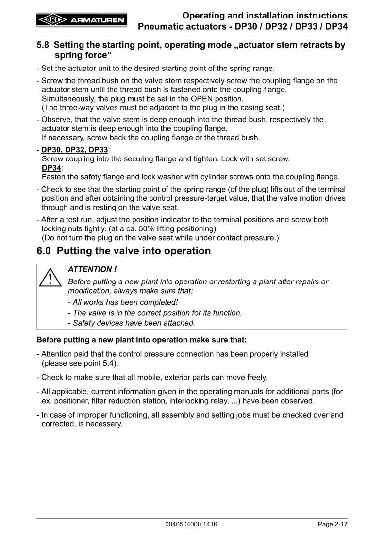
5.8 Setting the starting point, operating mode „actuator stem retracts by spring force“
- Set the actuator unit to the desired starting point of the spring range.
- Screw the thread bush on the valve stem respectively screw the coupling flange on the actuator stem until the thread bush is fastened onto the coupling flange. Simultaneously, the plug must be set in the OPEN position.(The three-way valves must be adjacent to the plug in the casing seat.)
- Observe, that the valve stem is deep enough into the thread bush, respectively the actuator stem is deep enough into the coupling flange.If necessary, screw back the coupling flange or the thread bush.
- DP30, DP32, DP33:Screw coupling into the securing flange and tighten. Lock with set screw.DP34:Fasten the safety flange and lock washer with cylinder screws onto the coupling flange.
- Check to see that the starting point of the spring range (of the plug) lifts out of the terminal position and after obtaining the control pressure-target value, that the valve motion drives through and is resting on the valve seat.
- After a test run, adjust the position indicator to the terminal positions and screw both locking nuts tightly. (at a ca. 50% lifting positioning) (Do not turn the plug on the valve seat while under contact pressure.)
6.0 Putting the valve into operation
Before putting a new plant into operation make sure that:
- Attention paid that the control pressure connection has been properly installed (please see point 5.4).
- Check to make sure that all mobile, exterior parts can move freely.
- All applicable, current information given in the operating manuals for additional parts (for ex. positioner, filter reduction station, interlocking relay, ...) have been observed.
- In case of improper functioning, all assembly and setting jobs must be checked over and corrected, is necessary.
ATTENTION !
Before putting a new plant into operation or restarting a plant after repairs or modification, always make sure that:
- All works has been completed!- The valve is in the correct position for its function.- Safety devices have been attached.

Page 2-18 0040504000 1416
Operating and installation instructionsPneumatic actuators - DP30 / DP32 / DP33 / DP34
7.0 Disassembly of the actuator unit from the valve The following points should be taken into account basides the general principles governing installation work:
To proceed with the disassembly of the actuator unit from the valve, the following must be observed:- Drive the actuator with control pressure into the middle position. - DP30, DP32, DP33:
Unscrew set screw and coupling with thread bush from the securing flange.DP34:Loosen cylinder screws.Remove the lock washer, securing flange and thread bush from the actuator connection.
- Loosen the hexagon nuts and remove the actuator from the valve.
7.1 Disassembly of the actuator unit- Unscrew coupling flange and locking nur from the actuator stem.- Reduce the control pressure to „0“ and separate the control pressure connection line from
the compressed air.- Loosen the screws (pos. 21) of the actuator unit and remove the diaphragm covering (pos.
18).
ATTENTION ! - Due to safety reasons, the system must be driven down prior to disassembly of the actuator unit (in a pressureless state!).
ATTENTION ! - For operations with increased initial spring tension (see Fig. 20), additional
screws have been provided for. For the sizes DP30 / DP32 and DP33, there are an additional two screws and for DP34, there are four longer screws (23) provided. As the last step, the screws are to be loosened equally, in order to disassemble the initial spring tension.
- The procedure must be followed according to this sequence, or else there is a risk of INJURY.
Fig. 20

0040504000 1416 Page 2-19
Operating and installation instructionsPneumatic actuators - DP30 / DP32 / DP33 / DP34
8.0 Care and maintenanceMaintenance and maintenance intervals have to be defined by the operator according to the service conditions.
- For each operating mode, the actuator unit, if need be, should be freed from exterior dirt.
- The actuator unit may not be cleaned with high-pressure equipment or with aggressive cleaning products, that are a health hazard, or with flammable cleaning products or solvents.
- After cleaning, for example, an inspection should be carried out checking the sealings of the actuator unit.
- In order to ensure smooth running, the operation device for the control air should be furnished with a maintenance unit.
- The rolling diaphragm (pos. 10) and the stem guiding with O-ring-sealing are wearing parts and must be replaced when necessary (see point 8.1).
- Actuators with manual emergency adjustment: Lubricate with grease by using lubricating nipple (pos. 54).
8.1 Replacing the rolling diaphragm
- Remove the actuator from the valve, as described in point 7.0, and disassemble.
- Take out the construction units: stem (pos. 1) / diaphragm plate (pos. 11) / rolling diaphragm (pos. 10) / diaphragm flange (pos. 9).
- Loosen the flange nut (pos. 14).
- Remove the diaphragm flange (pos. 9) .
- Replace the rolling diaphragm (pos. 10) and reassemble.
ATTENTION ! - When replacing the rolling diaphragme, the springs must be changed, too.
Fig. 21: „actuator stem extends by spring force“

Page 2-20 0040504000 1416
Operating and installation instructionsPneumatic actuators - DP30 / DP32 / DP33 / DP34
Concerning the unit DP30/32/33, attention must be given, that during the assembly of this construction unit, a borehole be made in the rolling diaphragm (pos. 10) and that it is aligned with the camber in the diaphragm plate (pos. 11). - When inserting the assembly group into the actuator „actuator stem extends by spring
force“, one mould of the diaphragm plate (pos. 11) must align with one hole of the diaphragm (pos. 10) which must also be exact over the air connection hole of the diaphragm base (pos. 7) (Fig. 21 and Fig. 23).
- When inserting the assembly group into the actuator „actuator stem retracts by spring force“, one mould of the diaphragm plate (pos. 11) must align with one hole of the diaphragm (pos. 10) which must also be exact over the air connection hole of the diaphragm cover (pos. 18) (Fig. 22 and Fig. 23).
Tightening torques of the flange nuts:
Tightening torques of the screws on the periphery:
Fig. 22: „actuator stem retracts by spring force“
Fig. 23ATTENTION ! - The springs will only have an optimal contact surface if they are aligned
correctly.
DP 30 / 32 / 33 M 12 50 Nm
DP 34 M 16x1,5 120 Nm
DP 30 / 32 / 33 M 8 5 Nm
DP 34 M 10 15 Nm
Rolling diaphragm
Diaphragm plate
SpringVentilation
0040504000 1416 Page 2-21
Operating and installation instructionsPneumatic actuators - DP30 / DP32 / DP33 / DP34
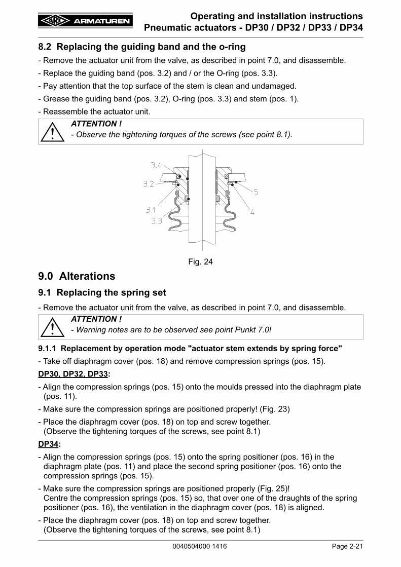
8.2 Replacing the guiding band and the o-ring
- Remove the actuator unit from the valve, as described in point 7.0, and disassemble.
- Replace the guiding band (pos. 3.2) and / or the O-ring (pos. 3.3).
- Pay attention that the top surface of the stem is clean and undamaged.
- Grease the guiding band (pos. 3.2), O-ring (pos. 3.3) and stem (pos. 1).
- Reassemble the actuator unit.
9.0 Alterations
9.1 Replacing the spring set
- Remove the actuator unit from the valve, as described in point 7.0, and disassemble.
9.1.1 Replacement by operation mode "actuator stem extends by spring force"
- Take off diaphragm cover (pos. 18) and remove compression springs (pos. 15).
DP30, DP32, DP33:
- Align the compression springs (pos. 15) onto the moulds pressed into the diaphragm plate (pos. 11).
- Make sure the compression springs are positioned properly! (Fig. 23)
- Place the diaphragm cover (pos. 18) on top and screw together. (Observe the tightening torques of the screws, see point 8.1)
DP34:
- Align the compression springs (pos. 15) onto the spring positioner (pos. 16) in the diaphragm plate (pos. 11) and place the second spring positioner (pos. 16) onto the compression springs (pos. 15).
- Make sure the compression springs are positioned properly (Fig. 25)! Centre the compression springs (pos. 15) so, that over one of the draughts of the spring positioner (pos. 16), the ventilation in the diaphragm cover (pos. 18) is aligned.
- Place the diaphragm cover (pos. 18) on top and screw together. (Observe the tightening torques of the screws, see point 8.1)
ATTENTION ! - Observe the tightening torques of the screws (see point 8.1).
Fig. 24
ATTENTION ! - Warning notes are to be observed see point Punkt 7.0!

Page 2-22 0040504000 1416
Operating and installation instructionsPneumatic actuators - DP30 / DP32 / DP33 / DP34
- Change spring range on name plate or fix a new name plate.
- Mounting of actuator with valve and adjustment of the starting pressure signal as described under point 5.5 and 5.6.
9.1.2 Replacement by operation mode "actuator stem retracts by spring force"
- Take off diaphragm cover (pos. 18) and take out the unit assembly group rolling diaphragm (pos. 10), diaphragm plate (pos. 11), stem (pos. 1) and the compression springs (pos. 15).
DP30, DP32, DP33:
- Place the diaphragm plate (pos. 11) with rolling diaphragm (pos. 10) into the diaphragm cover (pos. 18).
- Arrange the compression springs (pos. 15) onto the moulds pressed into the diaphragm plate (pos. 11).
- Make sure the compression springs stay properly arranged! (Fig. 23)
- Mount diaphragm base (pos. 7) with stem guiding unit (pos. 3) over the stem (pos. 1) and screw together. (Observe the tightening torques of the flange nuts, see point 8.1)
DP34:
- Place rolling diaphragm (pos. 10) with diaphragm plate (pos. 11) and spring positioner (pos. 16) into the diaphragm cover (pos. 18).
- Align the compression springs (pos. 15) onto the spring positioner (pos. 16) into the diaphragm plate (pos. 11) and place the second spring positioner (pos. 16) onto the compression springs (pos. 15).
- Make sure the compression springs are positioned properly (Fig. 26)! Centre the compression springs (pos. 15) so, that over one of the draughts of the spring positioner (pos. 16), the ventilation in the diaphragm base (pos. 7) is aligned.
- Mount diaphragm base (pos. 7) with stem guiding unit (pos. 3) over the stem (pos. 1) and screw together. (Observe the tightening torques of the screws, see point 8.1)
Fig. 25ATTENTION ! - Use the longer screws to mount the long compression springs! Tighten the screws equally!
Ventilation
Air connection
Name plate

0040504000 1416 Page 2-23
Operating and installation instructionsPneumatic actuators - DP30 / DP32 / DP33 / DP34
- Change spring range on name plate or fix a new name plate.- Mounting of actuator with valve and adjustment of the starting pressure signal as
described under point 5.7 and 5.8.
9.2 Change of operating modeThe actuator operating mode can be reversed even when the valve is installed in the piping. No special equipment is required.- Remove the actuator unit from the valve, as described in point 7.0, and disassemble.
9.2.1 Change of operating mode "actuator stem extends by spring force" in "actuator stem retracts by spring force"
For diagrams refer to point 4.3DP30, DP32, DP33, DP34:- Take off diaphragm cover (pos. 18) and take out the compression springs (pos. 15) and
the unit assembly group rolling diaphragm (pos. 10) with diaphragm plate (pos. 11) and stem (pos. 1).
DP30, DP32:- Loosen flange nut (pos. 14) and remove diaphragm plate (pos. 11) with rolling diaphragm
(pos. 10), diaphragm flange (pos. 9) and bushing (pos. 8).- Turn 180° and mount in this order over the stem (pos. 1): bushing (pos. 8), diaphragm
flange (pos. 9), rolling diaphragm (pos. 10), diaphragm plate (pos. 11).- Tighten with flange nut (pos. 14).
(Observe the tightening torques of the screws, see point 8.1)DP33, DP34:- Loosen flange nut (pos. 14) and remove bushing (pos. 13), O-ring (pos. 12), diaphragm
plate (pos. 11) with rolling diaphragm (pos. 10) and diaphragm flange (pos. 9) and the bushing (pos. 8).
- Turn bushing (pos. 13) and O-ring (pos. 12) 180° and mount in this order over the stem (pos. 1). Then mount the bushing (pos. 8) over the stem (pos. 1).
Fig. 26ATTENTION ! - Use the longer screws to mount the long compression springs! Tighten the
screws equally!
ATTENTION ! - Warning notes are to be observed see point 7.0!
Ventilation
Name plate
Air connection
Page 2-24 0040504000 1416
Operating and installation instructionsPneumatic actuators - DP30 / DP32 / DP33 / DP34
- Turn diaphragm plate (pos. 11) with rolling diaphragm (pos. 10) and diaphragm flange (pos. 9) 180° and mount in this order over the stem (pos. 1) too.
- Tighten with flange nut (pos. 14). (Observe the tightening torques of the screws, see point 8.1)
DP30, DP32, DP33, DP34:- Make sure the stem (pos. 1) surface isn’t damaged.- Grease stem surface, guiding (pos. 3.1) and O-ring (pos. 3.3).- Inserting of the compression springs (pos. 15) and Assembling of the actuator as
described under point 9.1.2 - Screw the ventilation, screw cap (pos. 19), in the diaphragm base (pos. 7) and the control
pressure line has to be connected to the diaphragm cover (pos. 18).- Mounting of actuator with valve and adjustment of starting pressure signal as described
under point 5.7 and 5.8. 9.2.2 Change of operating mode "actuator stem retracts by spring force" in "actuator
stem extends by spring force"For diagrams refer to point 4.3DP30, DP32, DP33, DP34:- Take off diaphragm cover (pos. 18) and take out the unit assembly group diaphragm plate
(pos. 11), rolling diaphragm (pos. 10), stem (pos. 1) and then the compression springs (pos. 15).
DP30, DP32:- Loosen flange nut (pos. 14) and remove diaphragm flange (pos. 9), rolling diaphragm
(pos. 10), diaphragm plate (pos. 11) and bushing (pos. 8).- Turn 180° and mount in this order over the stem (pos. 1): bushing (pos. 8), diaphragm
flange (pos. 9), rolling diaphragm (pos. 10), diaphragm plate (pos. 11).- Tighten with flange nut (pos. 14).
(Observe the tightening torques of the screws, see point 8.1)DP33, DP34:- Loosen flange nut (pos. 14) and remove diaphragm flange (pos. 9), rolling diaphragm
(pos. 10), diaphragm plate (pos. 11), bushing (pos. 8) and O-ring (pos. 12) with bushing (pos. 13).
- Mount bushing (pos. 8) over the stem (pos. 1).- Turn diaphragm flange (pos. 9) with rolling diaphragm (pos. 10) and diaphragm plate (pos.
11) 180° and mount in this order over the stem (pos. 1).- Turn O-ring (pos. 12) and bushing (pos. 13) 180° and mount in this order over the stem
(pos. 1), too.- Tighten with flange nut (pos. 14). (Observe the tightening torques of the screws, please
see point 8.1)DP30, DP32, DP33, DP34:- Make sure the stem (1) surface isn’t damaged.- Grease stem surface, guiding (3.1) and O-ring (3.3).- Inserting of the compression springs (15) and Assembling of the actuator as described
under point 9.1.1. - Screw the ventilation, screw cap (19), in the diaphragm cover (18) and the control
pressure line has to be connected to the diaphragm base (7).- Mounting of actuator with valve and adjustment of starting pressure signal as described
under point 5.5 and 5.6

0040504000 1416 Page 2-25
Operating and installation instructionsPneumatic actuators - DP30 / DP32 / DP33 / DP34
Fig. 27: DP 33 „actuator stem extends by spring force“
Page 2-26 0040504000 1416
Operating and installation instructionsPneumatic actuators - DP30 / DP32 / DP33 / DP34
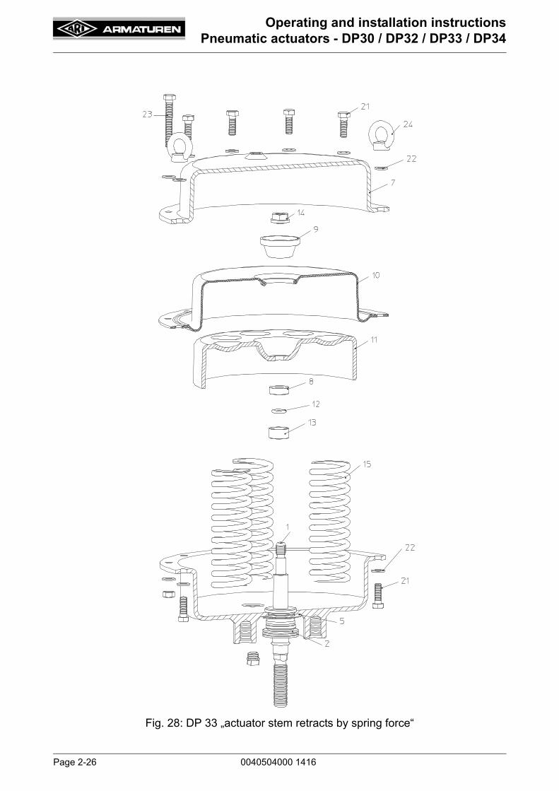
Fig. 28: DP 33 „actuator stem retracts by spring force“
0040504000 1416 Page 2-27
Operating and installation instructionsPneumatic actuators - DP30 / DP32 / DP33 / DP34
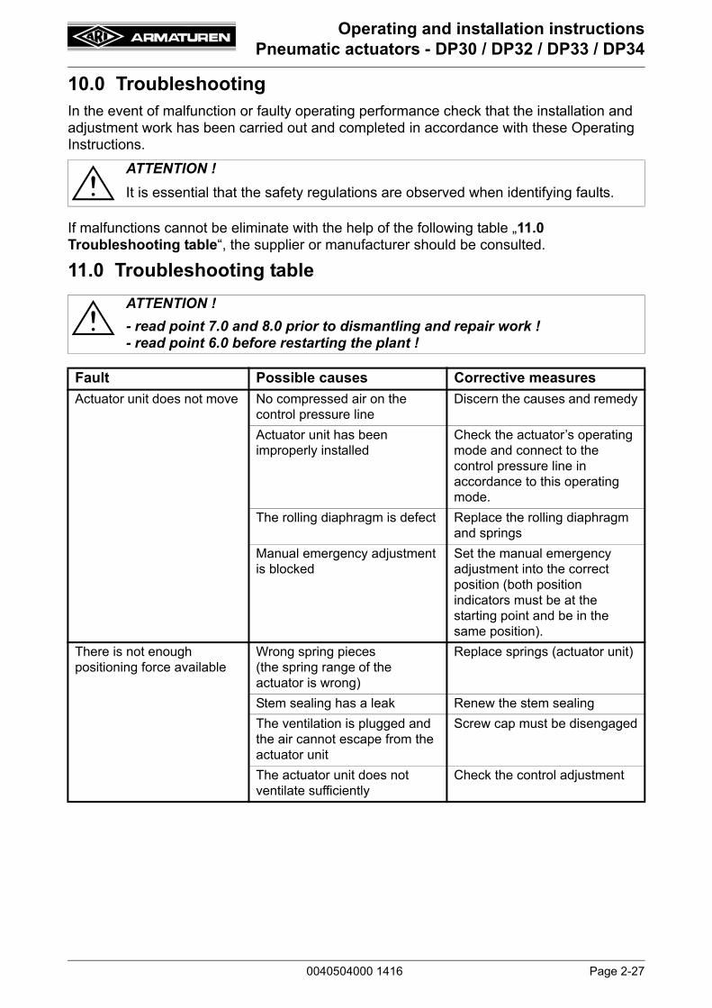
10.0 TroubleshootingIn the event of malfunction or faulty operating performance check that the installation and adjustment work has been carried out and completed in accordance with these Operating Instructions.
If malfunctions cannot be eliminate with the help of the following table „11.0 Troubleshooting table“, the supplier or manufacturer should be consulted.
11.0 Troubleshooting table
ATTENTION !
It is essential that the safety regulations are observed when identifying faults.
ATTENTION !
- read point 7.0 and 8.0 prior to dismantling and repair work !- read point 6.0 before restarting the plant !
Fault Possible causes Corrective measures
Actuator unit does not move No compressed air on the control pressure line
Discern the causes and remedy
Actuator unit has been improperly installed
Check the actuator’s operating mode and connect to the control pressure line in accordance to this operating mode.
The rolling diaphragm is defect Replace the rolling diaphragm and springs
Manual emergency adjustment is blocked
Set the manual emergency adjustment into the correct position (both position indicators must be at the starting point and be in the same position).
There is not enough positioning force available
Wrong spring pieces(the spring range of the actuator is wrong)
Replace springs (actuator unit)
Stem sealing has a leak Renew the stem sealing
The ventilation is plugged and the air cannot escape from the actuator unit
Screw cap must be disengaged
The actuator unit does not ventilate sufficiently
Check the control adjustment

Page 2-28 0040504000 1416
Operating and installation instructionsPneumatic actuators - DP30 / DP32 / DP33 / DP34
12.0 Warranty / GuaranteeThe extent and period of warranty cover are specified in the "Standard Terms and Conditions of Albert Richter GmbH & Co. KG“ valid at the time of delivery or, by way of departure, in the contract of sale itself.
We guarantee freedom of faults in compliance with state-of-the-art technology and the confirmed application.
No warranty claims can be made for any damage caused as the result of incorrect handling or disregard of operating and installation instructions, datasheets and relavant regulations.
This warranty also does not cover any damage which occurs during operation under conditions deviating from those laid down by specifications or other agreements.
Justified complaints will be eliminated by repair carried out by us or by a specialist appointed by us.
No claims will be accepted beyond the scope of this warranty. The right to replacement delivery is excluded.
The warranty shall not cover maintenance work, installation of external parts, design modifications or natural wear.
Any damage incurred during transport should not be reported to us but rather to the competent cargo-handling depot, the railway company or carrier company immediately or else claims for replacements from these companies will be invalidated.
Technology for the Future.GERMAN QUALITY VALVES
ARI-Armaturen Albert Richter GmbH & Co. KG, D-33750 Schloß Holte-StukenbrockTelephone (+49 5207) 994-0 Telefax (+49 5207) 994-158 or 159
Internet: http://www.ari-armaturen.com E-mail: [email protected]
Related Documents


![DP34 manual-1 [Converted] (Manual).pdfTitle: DP34 manual-1 [Converted] Created Date: 9/30/2016 4:57:56 AM](https://static.cupdf.com/doc/110x72/60e0940c71cc6a6a921ac6f9/dp34-manual-1-converted-manualpdf-title-dp34-manual-1-converted-created.jpg)


