1 Olsson Associates 2111 South 67 th Street, Suite 200 Omaha, NE 68106 DATE: October 11, 2017 ADDENDUM NO.: 1 PROJECT NAME: 84 TH STREET REDEVELOPMENT AREA CITY CENTRE INFRASTRUCTURE PAVEMENT & SEWERS CD-17-008 CITY OF LA VISTA, NEBRASKA TO ALL WHO HAVE RECEIVED PLANS AND SPECIFICATIONS FOR THE REFERENCED PROJECT. 1. Refer to the Specifications – PROPOSAL & BID FORM – BASIS OF BID, PagesP1-P8; The Bid Form has been revised per this Addendum, which is hereby attached. Project Quantities have been updated. • Added bid item 38A: “CONSTRUCT 48” BLACK VINYL CHAIN LINK FENCE” – 418 LF • Changed bid item 19: “EXCAVATION – ON SITE” from 19234 CY to 19263 CY • Changed bid item 68: “CONSTRUCT 96” ID STORM MANHOLE” from 142.7 VF to 143.9 VF • Changed bid item 74: “CONSTRUCT REINFORCED CURB INLET – TYPE III” from 1 EA to 2 EA • Changed bid item 76: “CONSTRUCT CURB INLET – TYPE III” from 3 EA to 2 EA • Changed bid item 117: “INSTALL EROSION CHECK (WATTLE)” from 3097 LF to 2953 LF 2. Refer to the Special Provisions and Technical Specifications; the following sections have been modified and are hereby attached to this addendum: • Page SP-5 – Section 2 – Progress of Work: Added Lot 1 carwash to list of properties that access must be maintained at all times. • Page TS-33 – Section 130 – Detectable Warning Panels: Added note that color of panel shall be selected by Engineer. • Page TS-70 – Section 137 – Colored, Imprinted Concrete Surfacing: Added information on stamped pattern to be used. Proline Rotating Ashlar Blue Stone and Roman Slate. • Page TS-83 thru TS-87 – Section 141 – Chain Link Fence and Gates: Added new specification for chain link fence for use on the project.

Welcome message from author
This document is posted to help you gain knowledge. Please leave a comment to let me know what you think about it! Share it to your friends and learn new things together.
Transcript

1
Olsson Associates
2111 South 67th Street, Suite 200
Omaha, NE 68106
DATE: October 11, 2017
ADDENDUM NO.: 1
PROJECT NAME: 84TH STREET REDEVELOPMENT AREA
CITY CENTRE INFRASTRUCTURE
PAVEMENT & SEWERS
CD-17-008
CITY OF LA VISTA, NEBRASKA
TO ALL WHO HAVE RECEIVED PLANS AND SPECIFICATIONS FOR THE REFERENCED
PROJECT.
1. Refer to the Specifications – PROPOSAL & BID FORM – BASIS OF BID, PagesP1-P8;
The Bid Form has been revised per this Addendum, which is hereby attached. Project Quantities
have been updated.
• Added bid item 38A: “CONSTRUCT 48” BLACK VINYL CHAIN LINK FENCE” –
418 LF
• Changed bid item 19: “EXCAVATION – ON SITE” from 19234 CY to 19263 CY
• Changed bid item 68: “CONSTRUCT 96” ID STORM MANHOLE” from 142.7 VF to
143.9 VF
• Changed bid item 74: “CONSTRUCT REINFORCED CURB INLET – TYPE III” from
1 EA to 2 EA
• Changed bid item 76: “CONSTRUCT CURB INLET – TYPE III” from 3 EA to 2 EA
• Changed bid item 117: “INSTALL EROSION CHECK (WATTLE)” from 3097 LF to
2953 LF
2. Refer to the Special Provisions and Technical Specifications; the following sections have been
modified and are hereby attached to this addendum:
• Page SP-5 – Section 2 – Progress of Work: Added Lot 1 carwash to list of properties that
access must be maintained at all times.
• Page TS-33 – Section 130 – Detectable Warning Panels: Added note that color of panel
shall be selected by Engineer.
• Page TS-70 – Section 137 – Colored, Imprinted Concrete Surfacing: Added information
on stamped pattern to be used. Proline Rotating Ashlar Blue Stone and Roman Slate.
• Page TS-83 thru TS-87 – Section 141 – Chain Link Fence and Gates: Added new
specification for chain link fence for use on the project.

2
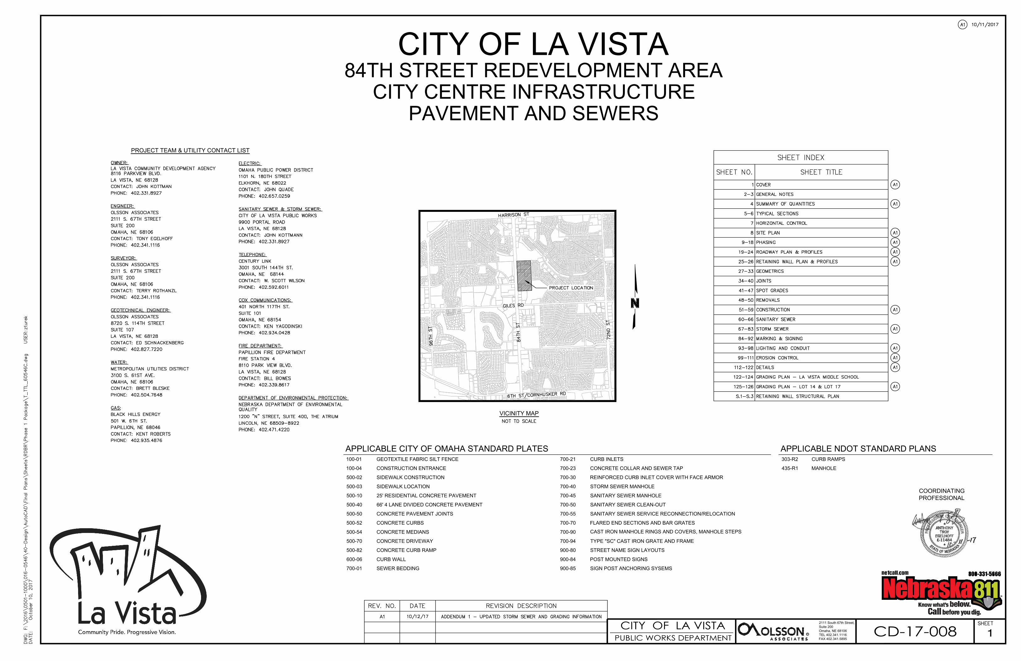
3. Refer to the Plans, the following sheets have been modified:
Sheet 1: TITLE
• Added addendum description to revision box
Sheet 4: QUANTITIES
• Added addendum cloud to project quantities table.
Sheet 8: OVERVIEW
• Added addendum cloud to updated storm sewer area
Sheet 10: PHASING
• Updated note 4.
Sheet 14: PHASE 2 STORM & SANITARY
• Added addendum cloud to updated storm sewer area
Sheet 22: ROADWAY PROFILES
• Added addendum cloud to updated storm sewer area
Sheet 26: RETAINING WALL PLAN & PROFILE
• Added addendum cloud to updated storm sewer area
Sheet 53: CONSTRUCTION
• Updated bid tab: “CONSTRUCT REINFORCED CONCRETE CURB INLET – STD.
PLT. 700-30” to “CONSTRUCT REINFORCED CONCRETE CURB INLET – SEE
SHEET 122”
Sheet 54: CONSTRUCTION
• Added bid tab: “CONSTRUCT 48” BLACK VINYL CHAIN LINK FENCE”
• Added and clouded new fence construction

3
Sheet 56: CONSTRUCTION
• Added addendum cloud to updated storm sewer area
• Updated information for MH G5
• Changed bid tab “CONSTRUCT CURB INLET – STD. PLT. 700-21” to “CONSTRUCT
REINFORCED CURB INLET – STD. PLT. 700-30”
• Updated all information for CI G3
• Updated bid tab: “CONSTRUCT REINFORCED CONCRETE CURB INLET – STD.
PLT. 700-30” to “CONSTRUCT REINFORCED CONCRETE CURB INLET – SEE
SHEET 122”
• 24” pipe from CI G3 to MH G5 changed from 11.90% to 0.54%
• 24” pipe from CI G3 to stubout changed from 0.72% to 0.52%
• 42” pipe from MH G4 to MH G5 changed from 2.26% to 3.74%
• Added note to Contractor to verify slopes of sanitary sewer service connection slopes for
Manhole GS3.
Sheet 58: CONSTRUCTION
• Added bid tab: “CONSTRUCT 48” BLACK VINYL CHAIN LINK FENCE”
• Added and clouded new fence construction
Sheet 59: CONSTRUCTION
• 42” pipe from G5 to G6 changed from 2.03% to 1.43%
• MH G7 changed from 16.7 VF to 17.5 VF
Sheet 67: STORM SEWER MAP
• Added addendum cloud to updated storm sewer area
Sheet 79: STORM SEWER PROFILES
• Added addendum cloud to updated storm sewer area
• Updated information for MH G5
• 42” pipe from MH G4 to MH G5 changed from 2.26% to 3.74%
• Modified existing ground to reflect changes to mass grading surface
Sheet 80: STORM SEWER PROFILES
• Added addendum cloud to updated storm sewer area
• Updated information for MH G5
• Updated information for MH G7
• Updated information for CI G3
• 24” pipe from CI G3 to MH G5 changed from 11.90% to 0.54%
• 24” pipe from CI G3 to stubout changed from 0.72% to 0.52%
• 42” pipe from G5 to G6 changed from 2.03% to 1.43%
• Modified existing ground to reflect changes to mass grading surface

4
Sheet 81: STORM SEWER PROFILES
• Modified existing ground to reflect changes to mass grading surface
• Updated information for MH G7
Sheet 98: LIGHTING
• Added note specifying light fixture and light pole with Philips Lumec Textured Bronze
Finish.
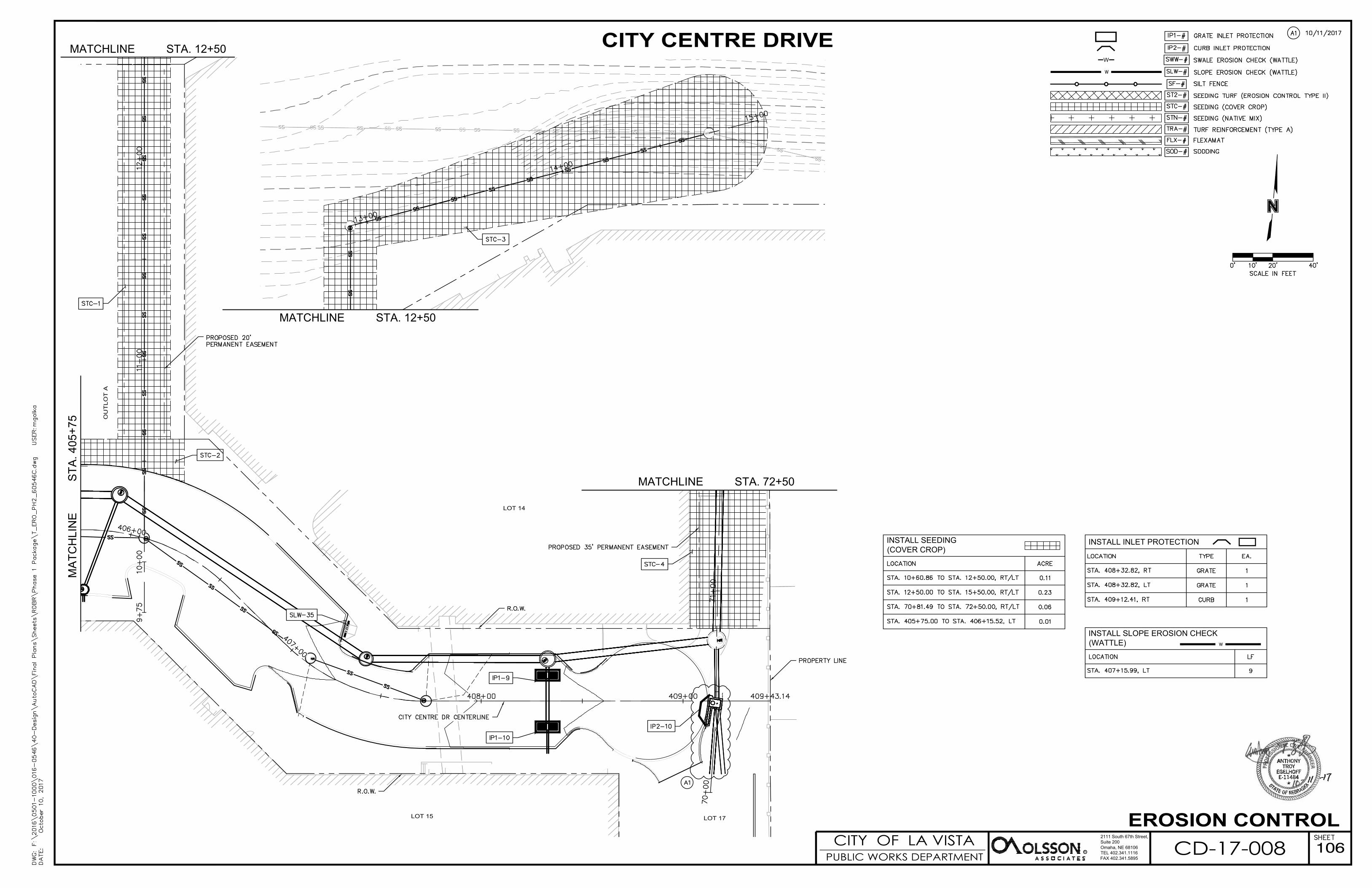
Sheet 106: EROSION CONTROL
• Added addendum cloud to updated storm sewer area
Sheet 107: EROSION CONTROL
• Removed swale wattles from previous 100-year diversion route.
Sheet 117: DETAILS
• Added detail for 48” black vinyl chain link fence
Sheet 118: DETAILS
• Revised callouts to include choice of stamp pattern for imprinted crosswalks.
Sheet 122: REINFORCED CURB INLET DETAILS
• Revised inlet top callout to reference the correct standard plate (700-30)
Sheet 125: LOT 14/17 GRADING PLAN
• Added addendum cloud to updated grading area
Sheet 126: LOT 14/17 GRADING PLAN
• Added addendum cloud to updated grading area and earthwork table
4. See Contractor Questions, and Answers below.
Question 1: Regarding the solider pile wall, are drilled shaft or auger cast piles acceptable?
Response: Either method is acceptable as long as the reinforcing and diameter match the plan
details.
Question 2: Regarding the solider pile wall, is there a temporary lagging method specified?
Response: This is a means and methods that the Contractor is responsible to determine if necessary
per chosen method of construction. The duration after excavation of exposed vertical soils shall be
no more than 24 hours.

P-1
PROPOSAL & BID FORM
84TH STREET REDEVELOPMENT AREA
CITY CENTRE INFRASTRUCTURE
PAVEMENT & SEWERS
CD-17-008
City of La Vista, Nebraska
TO: Pamela Buethe, City Clerk
I have received bidding documents dated September 18, 2017 on the above-referenced project. I have also received
Addenda No.'s _______ through _______ and have included their provisions in my bid. I have examined the bidding
documents and submit the following bid:
In submitting this bid, I agree:
1. To hold my bid open for 60 days after the receipt of bids.
2. To enter into and execute an "Owner-Contractor Agreement", based upon this bid, if this bid is accepted by
the Owner.
3. To perform all work required by the Contract Documents.
4. To start work on April 2, 2018 and to complete all work by November 16, 2018.
I agree to perform the above in consideration of the amounts hereinafter scheduled.
Item
No. Description Unit Quantity Unit Price Total Price
1 MOBILIZATION LS 1
2 REMOVE PAVEMENT SY 5,453
3 REMOVE SIDEWALK SF 523
4 REMOVE MEDIAN SURFACING SF 1,136
5 REMOVE 12" OR SMALLER SEWER PIPE LF 526
6 REMOVE 15" TO 18" SEWER PIPE LF 311
7 REMOVE 48" SEWER PIPE LF 418
8 REMOVE 54" SEWER PIPE LF 53
9 REMOVE MANHOLE EA 3
10 REMOVE FLARED END SECTION OVER 36" TO 48"
EA 1

P-2
11 REMOVE FLARED END SECTION OVER 48" TO 60"
EA 1
12 REMOVE LIGHT POLE EA 2
13 REMOVE AREA INLET EA 1
14 REMOVE CURB INLET EA 3
15 REMOVE SIGN EA 2
16 REMOVE FENCE LF 856
17 REMOVE SEGMENTAL RETAINING WALL SF 2,883
18 SAW CUT - FULL DEPTH LF 457
19 EXCAVATION - ON SITE CY 19,263
20 UNSUITABLE MATERIAL CY 500
21 SECURITY FENCE LF 1,300
22 TEMPORARY CONTRACTOR ACCESS ROAD SY 2,914
23 TEMPORARY 8-INCH SURFACING SY 912
24 RECONSTRUCT MANHOLE TO GRADE VF 15.9
25 ADJUST MANHOLE TO GRADE EA 1
26 ADJUST INLET TO GRADE EA 1
27 CONSTRUCT 6-INCH CONCRETE PAVEMENT (TYPE L65)
SY 4,799
28 CONSTRUCT 8-INCH CONCRETE PAVEMENT (TYPE L65)
SY 10,354
29 CONSTRUCT 8-INCH COMBINATION CURB AND GUTTER
LF 286
30 CONSTRUCT 8-INCH IMPRINTED CONCRETE SURFACING
SF 3249
31 CONSTRUCT 4-INCH PCC SIDEWALK SF 4,175
32 CONSTRUCT 6-INCH CONCRETE MEDIAN SURFACING
SF 317
33 CONSTRUCT CONCRETE CURB RAMP SF 255
34 ARMOR-TILE DETECTABLE WARNING PANELS SF 53
35 CONSTRUCT GRAVITY BLOCK RETAINING WALL
SF 996
36 CONSTRUCT SOLDIER PILE RETAINING WALL SF 3,530
37 CONSTRUCT SMALL BLOCK RETAINING WALL SF 382

P-3
38 CONSTRUCT PIPE RAILING LF 539
38A CONSTRUCT 48” BLACK VINYL CHAIN LINK FENCE
LF 418
39 CONSTRUCT CURB WALL SF 503
40 AGGREGATE BEDDING FOR 10" STORM SEWER PIPE
LF 49
41 AGGREGATE BEDDING FOR 12" STORM SEWER PIPE
LF 38
42 AGGREGATE BEDDING FOR 15" STORM SEWER PIPE
LF 382
43 AGGREGATE BEDDING FOR 18" STORM SEWER PIPE
LF 473
44 AGRREGATE BEDDING FOR 24" STORM SEWER PIPE
LF 812
45 AGRREGATE BEDDING FOR 30" STORM SEWER PIPE
LF 1,232
46 AGRREGATE BEDDING FOR 36" STORM SEWER PIPE
LF 956
47 AGRREGATE BEDDING FOR 42" STORM SEWER PIPE
LF 899
48 AGRREGATE BEDDING FOR 54" STORM SEWER PIPE
LF 484
49 CONSTRUCT 8" HDPE STORM SEWER PIPE LF 24
50 CONSTRUCT 10" HDPE STORM SEWER PIPE LF 46
51 CONSTRUCT 12" HDPE STORM SEWER PIPE LF 38
52 CONSTRUCT 15" HDPE STORM SEWER PIPE LF 60
53 CONSTRUCT 18" HDPE STORM SEWER PIPE LF 25
54 CONSTRUCT 24" HDPE STORM SEWER PIPE LF 38
55 CONSTRUCT 15" RCP, CLASS III LF 322
56 CONSTRUCT 18" RCP, CLASS III LF 448
57 CONSTRUCT 24" RCP, CLASS III LF 774
58 CONSTRUCT 30" RCP, CLASS III LF 1,232
59 CONSTRUCT 36" RCP, D(0.01) = 1350 LF 956
60 CONSTRUCT 36" RCP, D(0.01) = 1350 (OR HDPE) LF 157
61 CONSTRUCT 42" RCP, D(0.01) = 1350 LF 899
62 CONSTRUCT 54" RCP, D(0.01) = 1350 (OR HDPE) LF 484
63 CONSTRUCT 36" CONCRETE COLLAR EA 1

P-4
64 CONSTRUCT 54" I.D. STORM MANHOLE VF 24.3
65 CONSTRUCT 60" I.D. STORM MANHOLE VF 43.8
66 CONSTRUCT 72" I.D. STORM MANHOLE VF 33.0
67 CONSTRUCT 84" I.D. STORM MANHOLE VF 87.0
68 CONSTRUCT 96" I.D. STORM MANHOLE VF 143.9
69 CONSTRUCT TYPE "C" MANHOLE - NDOR STANDARD PLAN 435-R1
EA 1
70 PREPARATION OF STRUCTURE LS 1
71 CONSTRUCT 30" RC FLARED END SECTION EA 1
72 CONSTRUCT 36" RC FLARED END SECTON EA 1
73 CONSTRUCT 42" RC FLARED END SECTION EA 1
74 CONSTRUCT REINFORCED CURB INLET - TYPE III
EA 2
75 CONSTRUCT CURB INLET - TYPE I EA 3
76 CONSTRUCT CURB INLET - TYPE III EA 2
77 CONSTRUCT CURB INLET - TYPE IV EA 4
78 CONSTRUCT GRATED INLET - TYPE "SADDLE CREEK" INLET
EA 11
79 INSTALL FILTERRA INLET EA 3
80 AGGREGATE BEDDING FOR 6" SANITARY SEWER PIPE
LF 657
81 AGGREGATE BEDDING FOR 8" SANITARY SEWER PIPE
LF 1,531
82 AGGREGATE BEDDING FOR 10" SANITARY SEWER PIPE
LF 627
83 CONSTRUCT 6" PVC SANITARY SEWER PIPE LF 657
84 CONSTRUCT 8" PVC SANITRAY SEWER PIPE LF 1,531
85 CONSTRUCT 10" PVC SANITARY SEWER PIPE LF 163
86 CONSTRUCT 10" DIP SANITARY SEWER PIPE LF 464
87 CONSTRUCT 6"x8" WYE EA 1
88 CONSTRUCT 6" CLEANOUT EA 1
89 INSTALL EXTERNAL FRAME SEAL EA 49
90 CONNECT SANITARY SEWER MANHOLE TAP EA 1

P-5
91 CONNECT SANITARY SEWER MANHOLE TAP - EXTRA DEEP
EA 1
92 CONSTRUCT 54" I.D. SANITARY MANHOLE VF 149.2
93 CONSTRUCT RIPRAP - TYPE "B" TONS 204
94 1" DIA. SCH 40 PVC IN TRENCH LF 12,380
95 #8 AWG STRANDED COPPER WIRE W/ THWN INSUL.
LF 18,590
96 LED GLOBE POST-TOP LUMINARE W/ TAPERED STEEL POLE AND CONC. BASE
EA 66
97 ELECTRIAL HANDHOLE/PULLBOX EA 14
98 LIGHTING SERVICE CABINET EA 1
99 PERMANENT PAINT MARKING - 4" WHITE LF 4,682
100 PERMANENT PAINT MARKING - 5" YELLOW LF 325
101 PERMANENT PREFORMED TAPE MARKING - TYPE 4, 5" WHITE, GROOVED
LF 972
102 PERMANENT PREFORMED TAPE MARKING -TYPE 3, 12" WHITE, GROOVED
LF 80
103 PERMANENT PREFORMED TAPE MARKING - TYPE 3, 24" WHITE, GROOVED
LF 310
104 PERMANENT PREFORMED MARKING TAPE SYMBOL - WHITE DIRECTIONAL LEFT ARROW, GROOVED
EA 4
105 PERMANENT PREFORMED MARKING TAPE SYMBOL - WHITE DIRECTIONAL RIGHT ARROW, GROOVED
EA 3
106 ADA STALL PAVEMENT MARKING SYMBOL EA 7
107 REMOVE MARKING LINES - 5" WHITE LF 62
108 REMOVE MARKING LINES - 12" WHITE LF 40
109 REMOVE MARKING LINES - 24" WHITE LF 120
110 REMOVE MARKING SYMBOL - DIRECTIONAL ARROW
EA 2
111 INSTALL TRAFFIC POSTS AND SIGNS, CONTRACTOR PROVIDED
LS 1
112 PROVIDE TEMPORARY TRAFFIC CONTROL LS 1
113 INSTALL SEEDING (COVER CROP) AC 1.20
114 INSTALL SEEDING (NATIVE MIX) AC 0.52
115 INSTALL SEEDING TURF (EROSION CONTROL TYPE 2)
AC 6.06
116 INSTALL INLET PROTECTION EA 22

P-6
117 INSTALL EROSION CHECK (WATTLE) LF 2,953
118 INSTALL SODDING SY 185
119 INSTALL SILT FENCE LF 460
120 INSTALL FLEXAMAT SY 174
121 INSTALL TURF REINFORCEMENT MAT (TYPE A) SY 491
122 INSTALL SAFL BAFFLE EA 3
123 INSTALL SNOUT EA 1
124 INSTALL 18" I.D. PRESERVER EA 1
125 INSTALL 24" I.D. PRESERVER EA 1
126 INSTALL 30" I.D. PRESERVER EA 1
127 INSTALL 36" I.D. SKIMMER EA 1
128 CONSTRUCT WATER QUALITY STRUCTURE LS 1
129 INSTALL CONSTRUCTION ENTRANCE EA 1
130 RENTAL OF LOADER, FULLY OPERATED HR 20
131 RENTAL OF BACKHOE, FULLY OPERATED HR 20
132 RENTAL OF DUMP TRUCK, FULLY OPERATED HR 20
133 RENTAL OF SKID LOADER, FULLY OPERATED HR 20
134 RENTAL OF CRAWLER MOUNTED HYDRAULIC EXCAVATOR, FULLY OPERATED
HR 20
135 RENTAL OF VACUUM TRUCK, FULLY OPERATED
HR 20
Total Bid Amount $
ALTERNATIVE BID ITEMS
Item
No. Description Unit Quantity Unit Price Total Price
A1 CONSTRUCT GRAVITY BLOCK RETAINING WALL
SF 3,530

P-7
The undersigned agrees, upon receipt of written notice of award of the contract within sixty (60) days after opening of
bids, that he will execute "Agreement Between Contractor and Owner" on the standard form issued by the Owner in
accordance with his Bid Proposal.
In submitting this Bid, the undersigned further agrees:
1. To furnish all material, labor, tools, expendable equipment, and all utility and transportation services
necessary to perform and complete, in a workmanlike manner, all of the Work required in accord with the
Bidding Documents.
2. To hold his Bid open for sixty (60) days after the receipt of Bids and to accept the provisions of the
Instructions to Bidders regarding disposition of Bid Security.
3. To enter into and execute a Contract if awarded on the basis of this Bid, to furnish a Performance Bond and a
Labor and Material Payment Bond in accord with the General Conditions and General Requirements of this
Contract, and to deliver executed Owner-Contractor Agreements and Bonds within ten (10) working days
after notification of award.
Time is of the essence for the faithful and timely performance of the terms of the Contract. The parties hereto
agree that it is not possible to predetermine an amount in actual damages due The City of La Vista whenever
timely completion is not accomplished; therefore, in lieu of actual damages, the parties to this Contract agree that
Liquidated Damages shall be charged at a rate of One Thousand Five Hundred Dollars ($1,500.00) per calendar
day for each day that the construction required for Total Project Completion of this project extends beyond the
total number of calendar days as specified in the Contract with any additional days granted by the engineer,
provided that full safe use of the newly graded site is denied the Owner. Liquidated damages shall apply for each
major phase of the project.
Milestone Calendar Days Accumulative Days Anticipated Date
Pre-Con. Mtg. - - March 22, 2018
Notice to Proceed 0 0 April 2, 2018
Phase 1A Substantial Complete 20
Phase 2A Substantial Complete 35
Phase 2B Substantial Complete 50
Phase 2C Substantial Complete 35
Phase 1&2 Substantial Complete 164 164 September 12, 2018
Phase 3 Substantial Complete 40 204 October 22, 2018
Project Final Completion 25 229 November 16, 2018
P-8
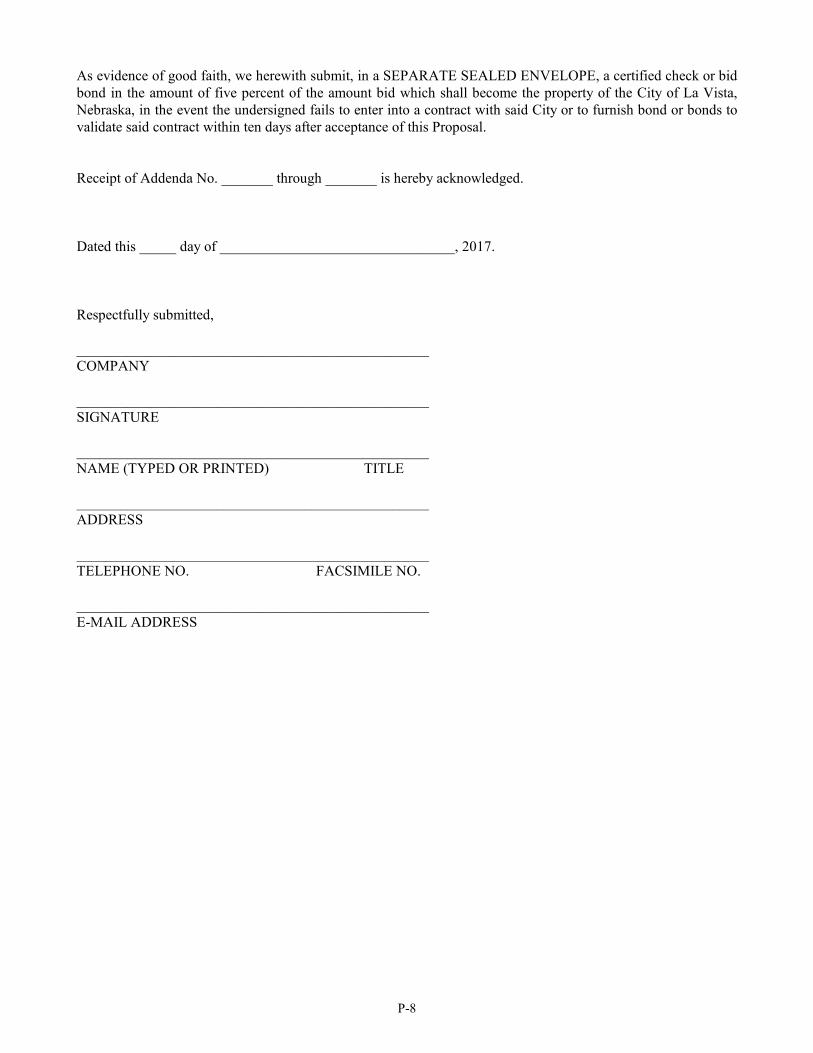
As evidence of good faith, we herewith submit, in a SEPARATE SEALED ENVELOPE, a certified check or bid
bond in the amount of five percent of the amount bid which shall become the property of the City of La Vista,
Nebraska, in the event the undersigned fails to enter into a contract with said City or to furnish bond or bonds to
validate said contract within ten days after acceptance of this Proposal.
Receipt of Addenda No. _______ through _______ is hereby acknowledged.
Dated this _____ day of ________________________________, 2017.
Respectfully submitted,
________________________________________________
COMPANY
________________________________________________
SIGNATURE
________________________________________________
NAME (TYPED OR PRINTED) TITLE
________________________________________________
ADDRESS
________________________________________________
TELEPHONE NO. FACSIMILE NO.
________________________________________________
E-MAIL ADDRESS
CITY OF LA VISTA84TH STREET REDEVELOPMENT AREA
CITY CENTRE INFRASTRUCTUREPAVEMENT AND SEWERS
PROJECT TEAM & UTILITY CONTACT LIST
VICINITY MAP
CITY OF LA VISTAPUBLIC WORKS DEPARTMENT R
2111 South 67th Street,Suite 200Omaha, NE 68106TEL 402.341.1116FAX 402.341.5895
CD-17-008
APPLICABLE CITY OF OMAHA STANDARD PLATES100-01 GEOTEXTILE FABRIC SILT FENCE
100-04 CONSTRUCTION ENTRANCE
500-02 SIDEWALK CONSTRUCTION
500-03 SIDEWALK LOCATION
500-10 25' RESIDENTIAL CONCRETE PAVEMENT
500-40 66' 4 LANE DIVIDED CONCRETE PAVEMENT
500-50 CONCRETE PAVEMENT JOINTS
500-52 CONCRETE CURBS
500-54 CONCRETE MEDIANS
500-70 CONCRETE DRIVEWAY
500-82 CONCRETE CURB RAMP
600-06 CURB WALL
700-01 SEWER BEDDING
700-21 CURB INLETS
700-23 CONCRETE COLLAR AND SEWER TAP
700-30 REINFORCED CURB INLET COVER WITH FACE ARMOR
700-40 STORM SEWER MANHOLE
700-45 SANITARY SEWER MANHOLE
700-50 SANITARY SEWER CLEAN-OUT
700-55 SANITARY SEWER SERVICE RECONNECTION/RELOCATION
700-70 FLARED END SECTIONS AND BAR GRATES
700-90 CAST IRON MANHOLE RINGS AND COVERS, MANHOLE STEPS
700-94 TYPE "SC" CAST IRON GRATE AND FRAME
900-80 STREET NAME SIGN LAYOUTS
900-84 POST MOUNTED SIGNS
900-85 SIGN POST ANCHORING SYSEMS
APPLICABLE NDOT STANDARD PLANS303-R2 CURB RAMPS
435-R1 MANHOLE
1
COORDINATINGPROFESSIONAL

SUMMARY OF APPROXIMATE QUANTITIES
CITY OF LA VISTAPUBLIC WORKS DEPARTMENT R
2111 South 67th Street,
Suite 200
Omaha, NE 68106
TEL 402.341.1116
FAX 402.341.5895
CD-17-008
ITEM No. DESCRIPTION UNITQNTY
FINAL
1 MOBILIZATION LS
1
2 REMOVE PAVEMENT SY5453
3 REMOVE SIDEWALK SF523
4 REMOVE MEDIAN SURFACING SF1136
5 REMOVE 12" OR SMALLER SEWER PIPE LF526
6 REMOVE 15" TO 18" SEWER PIPE LF311
7 REMOVE 48" SEWER PIPE LF418
8 REMOVE 54" SEWER PIPE LF53
9 REMOVE MANHOLE EA3
10 REMOVE FLARED END SECTION OVER 36" TO 48" EA1
11 REMOVE FLARED END SECTION OVER 48" TO 60" EA1
12 REMOVE LIGHT POLE EA2
13 REMOVE AREA INLET EA1
14 REMOVE CURB INLET EA3
15 REMOVE SIGN EA2
16 REMOVE FENCE LF856
17 REMOVE SEGMENTAL RETAINING WALL SF2883
18 SAW CUT - FULL DEPTH LF457
19 EXCAVATION - ON SITE CY19263
20 UNSUITABLE MATERIAL CY500
21 SECURITY FENCE LF1300
22 TEMPORARY CONTRACTOR ACCESS ROAD SY2914
23 TEMPORARY 8-INCH SURFACING SY912
24 RECONSTRUCT MANHOLE TO GRADE VF15.9
25 ADJUST MANHOLE TO GRADE EA1
26 ADJUST INLET TO GRADE EA1
27
CONSTRUCT 6-INCH CONCRETE PAVEMENT (TYPE L65)
SY4799
28
CONSTRUCT 8-INCH CONCRETE PAVEMENT (TYPE L65)
SY10354
29 CONSTRUCT 8-INCH COMBINATION CURB AND GUTTER LF286
30 CONSTRUCT 8-INCH IMPRINTED CONCRETE SURFACING SF3249
31 CONSTRUCT 4-INCH PCC SIDEWALK SF4175
32 CONSTRUCT 6-INCH CONCRETE MEDIAN SURFACING SF317
33 CONSTRUCT CONCRETE CURB RAMP SF255
34 ARMOR-TILE DETECTABLE WARNING PANELS SF53
35 CONSTRUCT GRAVITY BLOCK RETAINING WALL SF996
36 CONSTRUCT SOLDIER PILE RETAINING WALL SF3530
37 CONSTRUCT SMALL BLOCK RETAINING WALL SF382
38 CONSTRUCT PIPE RAILING LF539
38A CONSTRUCT 48" BLACK VINYL CHAIN LINK FENCE LF418
39 CONSTRUCT CURB WALL SF503
40 AGGREGATE BEDDING FOR 10" STORM SEWER PIPE LF49
41 AGGREGATE BEDDING FOR 12" STORM SEWER PIPE LF38
42 AGGREGATE BEDDING FOR 15" STORM SEWER PIPE LF382
43 AGGREGATE BEDDING FOR 18" STORM SEWER PIPE LF473
44 AGRREGATE BEDDING FOR 24" STORM SEWER PIPE LF812
45 AGRREGATE BEDDING FOR 30" STORM SEWER PIPE LF1232
46 AGRREGATE BEDDING FOR 36" STORM SEWER PIPE LF956
47 AGRREGATE BEDDING FOR 42" STORM SEWER PIPE LF899
48 AGRREGATE BEDDING FOR 54" STORM SEWER PIPE LF484
49 CONSTRUCT 8" HDPE STORM SEWER PIPE LF24
50 CONSTRUCT 10" HDPE STORM SEWER PIPE LF46
51 CONSTRUCT 12" HDPE STORM SEWER PIPE LF38
52 CONSTRUCT 15" HDPE STORM SEWER PIPE LF60
53 CONSTRUCT 18" HDPE STORM SEWER PIPE LF25
54 CONSTRUCT 24" HDPE STORM SEWER PIPE LF38
55
CONSTRUCT 15" RCP, CLASS III
LF322
56
CONSTRUCT 18" RCP, CLASS III
LF448
57
CONSTRUCT 24" RCP, CLASS III
LF774
58
CONSTRUCT 30" RCP, CLASS III
LF1232
59
CONSTRUCT 36" RCP, D(0.01) = 1350
LF956
60
CONSTRUCT 36" RCP, D(0.01) = 1350 (OR HDPE)
LF 157
61
CONSTRUCT 42" RCP, D(0.01) = 1350
LF899
62
CONSTRUCT 54" RCP, D(0.01) = 1350 (OR HDPE)
LF484
63 CONSTRUCT 36" CONCRETE COLLAR EA1
64 CONSTRUCT 54" I.D. STORM MANHOLE VF24.3
65 CONSTRUCT 60" I.D. STORM MANHOLE VF43.8
66 CONSTRUCT 72" I.D. STORM MANHOLE VF33.0
67 CONSTRUCT 84" I.D. STORM MANHOLE VF87.0
68 CONSTRUCT 96" I.D. STORM MANHOLE VF143.9
69 CONSTRUCT TYPE "C" MANHOLE - NDOR STANDARD PLAN 435-R1 EA1
ITEM No. DESCRIPTION UNITQNTY
FINAL
71 CONSTRUCT 30" RC FLARED END SECTION EA1
72 CONSTRUCT 36" RC FLARED END SECTON EA1
73 CONSTRUCT 42" RC FLARED END SECTION EA1
74 CONSTRUCT REINFORCED CURB INLET - TYPE III EA2
75 CONSTRUCT CURB INLET - TYPE I EA3
76 CONSTRUCT CURB INLET - TYPE III EA2
77 CONSTRUCT CURB INLET - TYPE IV EA4
78 CONSTRUCT GRATED INLET - TYPE "SADDLE CREEK" INLET EA11
79 INSTALL FILTERRA INLET EA3
80 AGGREGATE BEDDING FOR 6" SANITARY SEWER PIPE LF657
81 AGGREGATE BEDDING FOR 8" SANITARY SEWER PIPE LF1531
82 AGGREGATE BEDDING FOR 10" SANITARY SEWER PIPE LF627
83 CONSTRUCT 6" PVC SANITARY SEWER PIPE LF657
84 CONSTRUCT 8" PVC SANITRAY SEWER PIPE LF1531
85 CONSTRUCT 10" PVC SANITARY SEWER PIPE LF163
86 CONSTRUCT 10" DIP SANITARY SEWER PIPE LF464
87 CONSTRUCT 6"x8" WYE EA1
88 CONSTRUCT 6" CLEANOUT EA1
89 INSTALL EXTERNAL FRAME SEAL EA49
90 CONNECT SANITARY SEWER MANHOLE TAP EA1
91 CONNECT SANITARY SEWER MANHOLE TAP - EXTRA DEEP EA1
92 CONSTRUCT 54" I.D. SANITARY MANHOLE VF149.2
93 CONSTRUCT RIPRAP - TYPE "B" TONS204
94 1" DIA. SCH 40 PVC IN TRENCH LF12380
95 #8 AWG STRANDED COPPER WIRE W/ THWN INSUL. LF18590
96 LED GLOBE POST-TOP LUMINARE W/ TAPERED STEEL POLE AND CONC. BASE EA66
97 ELECTRIAL HANDHOLE/PULLBOX EA14
98 LIGHTING SERVICE CABINET EA1
99 PERMANENT PAINT MARKING - 4" WHITE LF4682
100 PERMANENT PAINT MARKING - 5" YELLOW LF325
101
PERMANENT PREFORMED TAPE MARKING - TYPE 4, 5" WHITE, GROOVED
LF972
102
PERMANENT PREFORMED TAPE MARKING -TYPE 3, 12" WHITE, GROOVED
LF80
103
PERMANENT PREFORMED TAPE MARKING - TYPE 3, 24" WHITE, GROOVED
LF310
104
PERMANENT PREFORMED MARKING TAPE SYMBOL - WHITE DIRECTIONAL LEFT ARROW, GROOVED
EA4
105
PERMANENT PREFORMED MARKING TAPE SYMBOL - WHITE DIRECTIONAL RIGHT ARROW, GROOVED
EA3
106 ADA STALL PAVEMENT MARKING SYMBOL EA7
107 REMOVE MARKING LINES - 5" WHITE LF62
108 REMOVE MARKING LINES - 12" WHITE LF40
109 REMOVE MARKING LINES - 24" WHITE LF120
110 REMOVE MARKING SYMBOL - DIRECTIONAL ARROW EA2
111
INSTALL TRAFFIC POSTS AND SIGNS, CONTRACTOR PROVIDED
LS1
112 PROVIDE TEMPORARY TRAFFIC CONTROL LS1
113
INSTALL SEEDING (COVER CROP)
AC1.20
114
INSTALL SEEDING (NATIVE MIX)
AC0.52
115
INSTALL SEEDING TURF (EROSION CONTROL TYPE 2)
AC6.06
116 INSTALL INLET PROTECTION EA22
117
INSTALL EROSION CHECK (WATTLE)
LF3097
118 INSTALL SODDING SY185
119 INSTALL SILT FENCE LF460
120 INSTALL FLEXAMAT SY174
121
INSTALL TURF REINFORCEMENT MAT (TYPE A)
SY491
122 INSTALL SAFL BAFFLE EA3
123 INSTALL SNOUT EA1
124 INSTALL 18" I.D. PRESERVER EA1
125 INSTALL 24" I.D. PRESERVER EA1
126 INSTALL 30" I.D. PRESERVER EA1
127 INSTALL 36" I.D. SKIMMER EA1
128CONSTRUCT WATER QUALITY STRUCTURE
LS1
129 INSTALL CONSTRUCTION ENTRANCE EA1
130
RENTAL OF LOADER, FULLY OPERATED
HR20
131
RENTAL OF BACKHOE, FULLY OPERATED
HR20
132
RENTAL OF DUMP TRUCK, FULLY OPERATED
HR20
133
RENTAL OF SKID LOADER, FULLY OPERATED
HR20
134
RENTAL OF CRAWLER MOUNTED HYDRAULIC EXCAVATOR, FULLY OPERATED
HR20
135
RENTAL OF VACUUM TRUCK, FULLY OPERATED
HR20
4

T
CITY OF LA VISTAPUBLIC WORKS DEPARTMENT R
2111 South 67th Street,
Suite 200
Omaha, NE 68106
TEL 402.341.1116
FAX 402.341.5895
CD-17-008OVERVIEW
8

CITY OF LA VISTAPUBLIC WORKS DEPARTMENT R
2111 South 67th Street,
Suite 200
Omaha, NE 68106
TEL 402.341.1116
FAX 402.341.5895
CD-17-008PHASE 1 - STORM AND SANITARY SEWER
10
PHASING NOTES
BARRICADING LEGEND
NOTES

CITY OF LA VISTAPUBLIC WORKS DEPARTMENT R
2111 South 67th Street,Suite 200Omaha, NE 68106TEL 402.341.1116FAX 402.341.5895
CD-17-008PHASE 2 - STORM AND SANITARY SEWER
14
PHASING NOTES
BARRICADING LEGEND
NOTES

CITY CENTRE DRIVE (400+00 - 409+43.14)
1110
1115
1120
1125
1130
1135
1140
1145
1110
1115
1120
1125
1130
1135
1140
1145
400+00 401+00 402+00 403+00 404+00 405+00 406+00 407+00 408+00 409+00409+43.14
CITY OF LA VISTAPUBLIC WORKS DEPARTMENT R
2111 South 67th Street,Suite 200Omaha, NE 68106TEL 402.341.1116FAX 402.341.5895
CD-17-008ROADWAY PROFILES
22

1110
1115
1120
1125
1130
1135
1140
1145
1150
1110
1115
1120
1125
1130
1135
1140
1145
1150
0+00 1+00 2+00 3+00 4+00 5+00 5+50
1123.00
1124.50
1126.00
1127.50
1128.50
1129.50
1130.50
1131.50
1132.50
1126.50
1128.00
1129.50
1130.50
1131.50
1132.50
1133.50
LOT 17 WALL ALIGNMENT DATA
CITY OF LA VISTAPUBLIC WORKS DEPARTMENT R
2111 South 67th Street,Suite 200Omaha, NE 68106TEL 402.341.1116FAX 402.341.5895
CD-17-008RETAINING WALL PLAN & PROFILE
CIT
YC
ENTR
ED
RIV
E
RETAINING WALL GEOMETRIC DATA
NOTE:
·
·
·
CO
TTO
NW
OO
DA
VEN
UE
LOT 17 RETAINING WALL
LOT 17 OUTLOT C
CONSTRUCT PIPE RAILING - SEE DETAIL SHEET 117 CONSTRUCT RETAINING WALL
·
26

MAIN STREET (NORTH)
MATCHLINE STA. 405+75
MA
TCH
LIN
E
STA
. 111
+50
MATCHLINE STA. 404+25
8" CONCRETE PAVEMENT (TYPE L65)
CONSTRUCT STORM MANHOLE - STD. PLT. 700-40
CONSTRUCT REINFORCED CONCRETE PIPE - CLASS III
CONSTRUCT PVC SANITARY SEWER PIPE
CONSTRUCT GRATED INLET SEE SADDLE CREEK INLET DETAIL
CONSTRUCT CURB INLET - STD. PLT. 700-21
CITY OF LA VISTAPUBLIC WORKS DEPARTMENT R
2111 South 67th Street,Suite 200Omaha, NE 68106TEL 402.341.1116FAX 402.341.5895
CD-17-008CONSTRUCTION
6" CONCRETE PAVEMENT (TYPE L65)
CONSTRUCT REINFORCED CONCRETE PIPE, D(0.01) = 1350
OUTLOT A
LOT 13
OUTLOT ALOT 15
LOT 10
4" P.C.C. SIDEWALK
CONSTRUCT REINFORCED CONCRETE CURB INLET - SEE SHEET 122
CONSTRUCT HDPE STORM SEWER PIPE
8" IMPRINTED P.C.C. SURFACECONSTRUCT 8" CONCRETE CURB & GUTTER - 2' WIDTH
53

COTTONWOOD AVENUE (EAST)
MATCHLINE
S
TA. 300
+50
8" CONCRETE PAVEMENT (TYPE L65)
CITY OF LA VISTAPUBLIC WORKS DEPARTMENT R
2111 South 67th Street,Suite 200Omaha, NE 68106TEL 402.341.1116FAX 402.341.5895
CD-17-008CONSTRUCTION
CONSTRUCT SANITARY MANHOLE - STD. PLT. 700-45
CONSTRUCT REINFORCED CONCRETE PIPE - CLASS III
CONSTRUCT PVC SANITARY SEWER PIPE
CONSTRUCT GRATED INLET SEE SADDLE CREEK INLET DETAIL
CONSTRUCT CURB INLET - STD. PLT. 700-21
CONSTRUCT STORM MANHOLE - STD. PLT. 700-40
4" P.C.C. SIDEWALK
CONSTRUCT CONCRETE CURB RAMP - STD. PLT. 500-82
6" CONCRETE PAVEMENT (TYPE L65)
CONSTRUCT REINFORCED CONCRETE PIPE, D(0.01) = 1350
LOT 16 LOT 17
OUTLOT C
OUTLOT B
CONSTRUCT PVC SANITARY SERVICE LINE
INSTALL FILTERRA INLET SEE FILTERA INLET DETAIL
CONSTRUCT SANITARY SEWER MANHOLE TAP- STD. PLT. 700-23
RECONSTRUCT MANHOLE TO GRADE
INSTALL WATER QUALITY DEVICE
CONSTRUCT HDPE STORM SEWER PIPE
8" IMPRINTED P.C.C. SURFACE
ARMOR-TILE DETECTABLE WARNING PANELS
CONSTRUCT 8" CONCRETE CURB & GUTTER - 2' WIDTH
54
CONSTRUCT 48" BLACK VINYL CHAIN LINK FENCE

CITY CENTRE DRIVE
MA
TC
HL
IN
E S
TA
. 4
05
+7
5
CITY OF LA VISTAPUBLIC WORKS DEPARTMENT R
2111 South 67th Street,
Suite 200
Omaha, NE 68106
TEL 402.341.1116
FAX 402.341.5895
CD-17-008CONSTRUCTION
8" CONCRETE PAVEMENT (TYPE L65)
CONSTRUCT SANITARY MANHOLE - STD. PLT. 700-45
CONSTRUCT REINFORCED CONCRETE PIPE - CLASS III CONSTRUCT GRATED INLET SEE SADDLE CREEK INLET DETAIL
CONSTRUCT REINFORCED CURB INLET - SEE SHEET 122
CONSTRUCT STORM MANHOLE - STD. PLT. 700-40
CONSTRUCT PVC SANITARY SEWER PIPE
6" CONCRETE PAVEMENT (TYPE L65)
CONSTRUCT REINFORCED CONCRETE PIPE, D(0.01) = 1350
OUTLOT A
LOT 14
LOT 15
LOT 17
CONSTRUCT PVC SANITARY SERVICE LINE
LOT 14
INSTALL WATER QUALITY DEVICE
CONSTRUCT SANITARY SEWER MANHOLE TAP -
EXTRA DEEP - STD. PLT. 700-23
RECONSTRUCT MANHOLE TO GRADE
CONSTRUCT HDPE STORM SEWER PIPE
CONSTRUCT DIP SANITARY SEWER PIPE
CONSTRUCT 6" SANITARY CLEANOUT - STD. PLT. 700-50
56

CITY OF LA VISTAPUBLIC WORKS DEPARTMENT R
2111 South 67th Street,Suite 200Omaha, NE 68106TEL 402.341.1116FAX 402.341.5895
CD-17-008CONSTRUCTION
CONSTRUCT STORM MANHOLE - STD. PLT. 700-40
CITY CENTRE OUTLET
CONSTRUCT REINFORCED CONCRETE PIPE, D(0.01) = 1350 CONSTRUCT FLARED END SECTION - STD. PLT. 700-70
CONSTRUCT RIPRAP, TYPE "B"
CONSTRUCT REINFORCED CONCRETE PIPE, CLASS III
LOT 14
CONSTRUCT HDPE STORM SEWER PIPE
59

CITY OF LA VISTAPUBLIC WORKS DEPARTMENT R
2111 South 67th Street,Suite 200Omaha, NE 68106TEL 402.341.1116FAX 402.341.5895
CD-17-008
CONSTRUCT STORM MANHOLE - STD. PLT. 700-40 CONSTRUCT FLARED END SECTION - STD. PLT. 700-70
CITY CENTRE OUTLET & 54" BYPASS
CONSTRUCT TYPE "C" MANHOLE - NDOT STANDARD PLAN 435-R1
CONSTRUCT WATER QUALITY STRUCTURE
CONSTRUCT CONCRETE COLLAR - STD. PLT. 700-23 CONSTRUCT RIPRAP, TYPE "B"
CONSTRUCT REINFORCED CONCRETE PIPE, D(0.01) = 1350O
UT
LOT
CPREPARATION OF STRUCTURE - SEE DETAIL SHEET 121
CONSTRUCTION58
CONSTRUCT 48" BLACK VINYL CHAIN LINK FENCE

COTTONWOOD AVE EAST OUTLET
CITY CENTRE STORM OUTLET
CITY OF LA VISTAPUBLIC WORKS DEPARTMENT R
2111 South 67th Street,Suite 200Omaha, NE 68106TEL 402.341.1116FAX 402.341.5895
CD-17-008STORM SEWER MAP
INSTALL WATER QUALITY DEVICE
67

1090
1095
1100
1105
1110
1115
1120
1125
1130
1135
1090
1095
1100
1105
1110
1115
1120
1125
1130
1135
8+50 9+00 10+00 11+00 12+00 12+75
CITY OF LA VISTAPUBLIC WORKS DEPARTMENT R
2111 South 67th Street,Suite 200Omaha, NE 68106TEL 402.341.1116FAX 402.341.5895
CD-17-008STORM SEWER PLAN & PROFILES
CITY CENTRE DRIVE
LOT 14
LOT 15
LOT 17
79

1075
1080
1085
1090
1095
1100
1105
1110
1115
1120
1125
1130
1075
1080
1085
1090
1095
1100
1105
1110
1115
1120
1125
1130
70+00 71+00 72+00 73+00 74+00 75+00 75+99.9970+00 71+00 72+00 73+00 74+00 75+00 75+99.99
CITY OF LA VISTAPUBLIC WORKS DEPARTMENT R
2111 South 67th Street,
Suite 200
Omaha, NE 68106
TEL 402.341.1116
FAX 402.341.5895
CD-17-008STORM SEWER PLAN & PROFILES
CITY CENTRE DRIVE OUTLET
LOT 14
LOT 15
80

1080
1085
1090
1095
1100
1105
1110
1115
1120
1125
1080
1085
1090
1095
1100
1105
1110
1115
1120
1125
0+00 1+00 2+000+00 1+00 2+00
CITY OF LA VISTAPUBLIC WORKS DEPARTMENT R
2111 South 67th Street,
Suite 200
Omaha, NE 68106
TEL 402.341.1116
FAX 402.341.5895
CD-17-008STORM SEWER PLAN & PROFILES
CITY CENTRE DRIVE OUTLET
LOT 14
81

5
10 6
9
7
8
SHEET NOTES: (SYMBOLS , , ETC.)
1. POWER CO. PRIMARY. PROVIDE (1) 4" CONDUIT FROM TRANSFORMER TO POWER CO. SWITCH.
2. TRANSFORMER PAD (BY ELECTRICAL CONTRACTOR). SEE OPPD METER SPECIFICATION MANUAL
1Ø PADMOUNT TRANSFORMER SLAB DETAIL 8.08.1 FOR ADDITIONAL INFORMATION.
3. POWER CO. SECONDARY. PROVIDE (3) #4 IN 1-1/4" CONDUIT.
4. LIGHTING SERVICE CABINET CONCRETE PAD. PROVIDE A 5" THICK (MIN.) PAD WITH 3/4" CHAMFER
ON EDGES AND 6"X6" WELDED WIRE MESH REINFORCEMENT. PROVIDE (2) 12" DIA. BY 48" DEEP
CONCRETE PIERS, ONE AT EACH END, BELOW PAD. EXTEND PAD 6" BEYOND FOOTPRINT OF
LIGHTING SERVICE CABINET IN ALL DIRECTIONS.
5. POWER CO. METER SOCKET (BY ELECTRICAL CONTRACTOR). COORDINATE LOCATION AND
INSTALLATION WITH POWER CO. INSTALL PER OPPD METER SPECIFICATION MANUAL. PROVIDE
STAINLESS STEEL MOUNTING HARDWARE AND WEATHERPROOF FITTINGS.
6. PROVIDE (3) #4 IN 1-1/4" CONDUIT.
7. PROVIDE (1) #8 IN 1" CONDUIT TO (1) 5/8" DIA. X 10'-0" (MIN.) COPPER CLAD GROUND ROD.
8. PROVIDE (3) 1" CONDUITS AND EXTEND 5'-0" (MIN.) BEYOND FOOTPRINT OF CONCRETE PAD INTO
ADJACENT GRASS AREA. CAP AND FLAG CONDUIT ENDS.
9. PROVIDE (2) GFCI DUPLEX RECEPTACLES WITH DEDICATED 120V ELECTRICAL CONNECTION TO
PANEL "L1".
10. LIGHTING CONTROL RELAY PANEL "RP1". PROVIDE LC&D BLUE BOX LT RELAY PANEL, CATALOG
#GR1408 LT ENC SM NE4 GR1408 LT INT 04DPNC DTC DV D14 (OR APPROVED EQUAL). PROVIDE
DEDICATED 120V ELECTRICAL CONNECTION TO PANEL "L1". INSTALL PER MANUFACTURER'S
INSTRUCTIONS.
11. LIGHTING SERVICE CABINET. PROVIDE HOFFMAN (OR APPROVED EQUAL) FREE STANDING NEMA 4X
STAINLESS STEEL ELECTRICAL EQUIPMENT ENCLOSURE SIZED TO ACCOMMODATE THE
ELECTRICAL EQUIPMENT INDICATED. ENCLOSURE TO HAVE (2) FULL HEIGHT LOCKABLE HINGED
DOORS. PROVIDE ALL MOUNTING HARDWARE AND ACCESSORIES NECESSARY FOR A COMPLETE
INSTALL.
1 2
2
3 1
POWER CO. XFMR
4
PANEL
"L1"
PANEL
"RP1"
RELAY
11
NOT TO SCALE
LIGHTING SERVICE CABINET DETAIL2
106
SECTION 260526 - GROUNDING
THE ELECTRICAL SERVICE, ALL TRANSFORMERS, CONDUCTORS, CONDUITS, MOTOR FRAMES, AND SIMILAR CONDUCTING
SURFACES IN THIS CONTRACT WHICH REQUIRE GROUNDING SHALL BE PERMANENTLY AND EFFECTIVELY GROUNDED BY THIS
CONTRACTOR IN A THOROUGH AND EFFICIENT MANNER IN CONFORMANCE TO THE NATIONAL ELECTRICAL CODE. ALL CIRCUITS
SHALL HAVE SEPARATE GREEN GROUND CONDUCTOR ROUTED WITH PHASE CONDUCTORS.
SECTION 260533 - RACEWAYS
GENERAL REQUIREMENTS
ALL CONDUIT SHALL BE RUN CONCEALED EXCEPT WHERE OTHERWISE NOTED. ALL CONDUIT RUN UNDERGROUND SHALL BE
RIGID STEEL OR PVC SCHEDULE 40. ALL CONDUIT EXPOSED TO WEATHER, OR OTHER HAZARDOUS CONDITIONS SHALL BE RIGID
STEEL. ALL OTHER CONDUIT MAY BE THIN-WALL EMT WHERE APPROVED BY LOCAL CODE.
FINAL CONNECTION TO EACH MOTOR AND TRANSFORMER, AND TO ANY DEVICE WHICH WOULD OTHERWISE TRANSMIT MOTION,
VIBRATION OR NOISE, SHALL BE IN FLEXIBLE METAL CONDUIT. WHERE FLEXIBLE METAL CONDUIT IS EXPOSED TO LIQUIDS,
VAPORS OR SUNLIGHT, LIQUID-TIGHT FLEXIBLE METAL CONDUIT SHALL BE USED. ALL FLEXIBLE METAL CONDUIT SHALL BE
PROVIDED WITH AN INSULATED GROUND WIRE.
CONDUIT INSTALLATION
ALL WIRING SHALL BE RUN IN CONDUIT. ALL CONDUIT RUNS SHOWN ARE DIAGRAMMATIC, EXACT LOCATIONS SHALL BE
DETERMINED IN THE FIELD.
CONDUIT SHALL BE INSTALLED CONCEALED ABOVE SUSPENDED CEILINGS OR CONCEALED IN WALL OR IN OR BENEATH FLOORS
WHEREVER POSSIBLE. RUN PARALLEL TO BUILDING
CONDUIT SHALL BE INSTALLED TO REQUIREMENTS OF STRUCTURE AND TO REQUIREMENTS OF ALL OTHER WORK ON THE
PROJECT. CONDUIT SHALL BE INSTALLED TO CLEAR ALL OPENINGS, DEPRESSIONS, PIPES, DUCTS, REINFORCING STEEL, AND
SIMILAR ITEMS. CONDUIT SET IN FORMS FOR CONCRETE STRUCTURE SHALL BE INSTALLED IN SUCH A MANNER THAT
INSTALLATION WILL NOT AFFECT THE STRENGTH OF THE STRUCTURE. EXCEPT WHERE APPROVED IN WRITING BY THE
ARCHITECT, NO CONDUIT SHALL BE RUN IN A SLAB ON GRADE. CONDUIT SHALL BE LOCATED IN GRANULAR FILL BELOW
SLABS-ON GRADE.
CONDUITS SHALL BE INSTALLED CONTINUOUS BETWEEN CONNECTIONS TO OUTLETS, BOXES AND CABINETS WITH A MINIMUM
POSSIBLE NUMBER OF BENDS AND NOT MORE THAN THE EQUIVALENT OF FOUR 90 BENDS BETWEEN CONNECTIONS. BENDS
SHALL BE SMOOTH AND EVEN AND SHALL BE MADE WITHOUT FLATTENING CONDUIT OR FLAKING ENAMEL. RADIUS OF BENDS
SHALL BE AS LONG AS POSSIBLE AND NEVER SHORTER THAN THE CORRESPONDING TRADE ELBOW. LONG RADIUS ELBOWS
SHALL BE USED WHERE NECESSARY.
CONDUITS SHALL BE SECURELY FASTENED IN PLACE WITH APPROVED STRAPS, HANGERS AND STEEL SUPPORTS AS REQUIRED.
SINGLE CONDUITS FOR FEEDERS SHALL BE HUNG WITH MALLEABLE SPLIT RING HANGERS WITH ROD AND TURNBUCKLE
SUSPENSION FROM INSERTS SPACED NOT OVER 10 FEET APART IN CONSTRUCTION ABOVE. GROUPS OF HORIZONTAL FEEDER
CONDUITS SHALL BE CLAMPED TO UNISTRUT STEEL CHANNELS AND SUSPENDED FROM INSERTS SPACED NOT OVER 10 FEET
APART IN CONSTRUCTION ABOVE. VERTICAL FEEDER CONDUITS SHALL BE SECURELY CLAMPED TO STRUCTURAL STEEL
MEMBERS ATTACHED TO STRUCTURE. CABLE CLAMPS SHALL BE INSTALLED FOR SUPPORT OF VERTICAL FEEDERS WHERE
REQUIRED. CONDUIT SUPPORTS SHALL BE ADDED WITHIN 12" AT ONE END OF ALL BENDS. CONDUIT SHALL NOT BE SUPPORTED
FROM SUSPENDED CEILING COMPONENTS.
CONDUIT ENDS SHALL BE REAMED BEFORE INSTALLATION AND ALL CONDUIT SHALL BE THOROUGHLY CLEANED BEFORE
INSTALLATION AND KEPT CLEAN AFTER INSTALLATION. OPENINGS AND BOXES SHALL BE PLUGGED OR COVERED AS REQUIRED
TO KEEP CONDUIT CLEAN DURING CONSTRUCTION AND ALL CONDUIT SHALL BE FISHED CLEAR OF OBSTRUCTIONS BEFORE THE
PULLING OF WIRES. ALL CONDUIT SHALL BE OF AMPLE SIZE FOR PULLING OF WIRE AND SHALL NOT BE SMALLER THAN CODE
REQUIREMENTS AND NOT LESS THAN 3/4" IN SIZE.
ALL ELECTRICAL WORK SHALL BE PROTECTED AGAINST DAMAGE DURING CONSTRUCTION. ANY WORK DAMAGED OR MOVED
OUT OF LINE AFTER ROUGHING-IN SHALL BE REPAIRED TO MET ENGINEER'S APPROVAL WITHOUT ADDITIONAL COST TO THE
OWNER.
CONDUIT TERMINATIONS AT PANELBOARDS, SWITCHBOARDS, MOTOR CONTROL EQUIPMENT AND JUNCTION BOXES SHALL BE
ALIGNED AND INSTALLED TRUE AND PLUMB.
INSTALL APPROVED EXPANSION FITTINGS WHERE CONDUIT OR EMT PASSES THROUGH EXPANSION JOINTS.
INSTALL A PULL WIRE IN EACH EMPTY CONDUIT WHICH IS LEFT BY THE CONTRACTOR FOR INSTALLATION OF WIRES OR CABLES
BY OTHERS.
MAKE ALL JOINTS AND CONNECTIONS IN A MANNER WHICH WILL INSURE MECHANICAL STRENGTH AND ELECTRICAL CONTINUITY.
THRU-WIRING OF LIGHT FIXTURES IS NOT PERMITTED.
BUSHINGS AND LOCKNUTS
WHERE CONDUITS ENTER BOXES, THEY SHALL BE RIGIDLY CLAMPED TO THE BOX BY A BUSHING ON THE INSIDE AND A LOCKNUT
ON THE OUTSIDE, AND CONDUIT SHALL ENTER THE BOX SQUARELY. BUSHINGS AND LOCKNUTS SHALL BE MADE OF GALVANIZED
MALLEABLE IRON AND SHALL HAVE SHARP, CLEAN-CUT THREADS. WHERE THIN-WALL CONDUIT ENTERS BOX, PROVIDE
APPROVED E.M.T. CONNECTORS. USE INSULATED GROUNDING BUSHINGS WHEREVER CONNECTION IS SUBJECT TO VIBRATION
OR MOISTURE.
SECTION 260553 - EQUIPMENT IDENTIFICATION
THIS CONTRACTOR SHALL FURNISH AND INSTALL EQUIPMENT IDENTIFICATION NAMEPLATES ON ALL PANELBOARDS, SWITCHES,
STARTERS, ETC., INCLUDING SWITCHES IN DISTRIBUTION PANELS. NAMEPLATES SHALL BE ENGRAVED PHENOLIC PLASTIC AND
SHALL BE FIRMLY ATTACHED TO THE EQUIPMENT WITH SELF-TAPPING, STAINLESS STEEL SCREWS OR STAINLESS STEEL
MACHINE SCREWS WITH NUTS AN FLAT AND LOCK WASHERS. NAMEPLATES SHALL CLEARLY IDENTIFY EACH ITEM AND WHAT IT
CONTROLS.
SECTION 262416 - PANELBOARDS
DESCRIPTION: NEMA PB1, CIRCUIT BREAKER TYPE, LIGHTING AND APPLIANCE BRANCH CIRCUIT PANELBOARD.
PANELBOARD BUS: COPPER, RATINGS AS INDICATED. PROVIDE COPPER GROUND BUS IN EACH PANELBOARD; PROVIDE
INSULATED GROUND BUS WHERE SCHEDULED.
MINIMUM INTEGRATED SHORT CIRCUIT RATING: 10,000 AMPERES RMS SYMMETRICAL FOR 240 VOLT PANELBOARDS; 14,000
AMPERES RMS SYMMETRICAL FOR 480 VOLT PANELBOARDS.
MOLDED CASE CIRCUIT BREAKERS: NEMA AB 1, BOLT-ON TYPE THERMAL MAGNETIC TRIP CIRCUIT BREAKERS, WITH COMMON
TRIP HANDLE FOR ALL POLES, LISTED AS TYPE SWD FOR LIGHTING CIRCUITS, TYPE HACR FOR AIR CONDITIONING EQUIPMENT
CIRCUITS, CLASS A GROUND FAULT INTERRUPTER CIRCUIT BREAKERS WHERE SCHEDULED. DO NOT USE TANDEM CIRCUIT
BREAKERS.
ENCLOSURE: NEMA PB 1, TYPE 1.
CABINET BOX: 6 INCHES (153 MM) DEEP, 20 INCHES WIDE.
CABINET FRONT: SURFACE CABINET FRONT AS INDICATED WITH CONCEALED TRIM CLAMPS, CONCEALED HINGE, METAL
DIRECTORY FRAME, AND FLUSH LOCK ALL KEYED ALIKE. FINISH IN MANUFACTURER'S STANDARD GRAY ENAMEL.
ACCEPTABLE MANUFACTURERS SHALL BE SQUARE D, SIEMENS, GENERAL ELECTRIC AND CUTLER HAMMER.
INSTALLATION
INSTALL PANELBOARDS IN ACCORDANCE WITH NEMA PB 1.1 AND THE NECA "STANDARD OF INSTALLATION."
INSTALL PANELBOARDS PLUMB. INSTALL RECESSED PANELBOARDS FLUSH WITH WALL FINISHES.
HEIGHT: 6 FEET (1800 MM) TO TOP OF PANELBOARD; INSTALL PANELBOARDS TALLER THAN 6 FEET (1800 MM) WITH BOTTOM NO
MORE THAN 4 INCHES (100 MM) ABOVE FLOOR.
PROVIDE FILLER PLATES FOR UNUSED SPACES IN PANELBOARDS.
PROVIDE TYPED CIRCUIT DIRECTORY FOR EACH BRANCH CIRCUIT PANELBOARD. REVISE DIRECTORY TO REFLECT CIRCUITING
CHANGES REQUIRED TO BALANCE PHASE LOADS.
PROVIDE ENGRAVED PLASTIC NAMEPLATES.
GROUND AND BOND PANELBOARD ENCLOSURE ACCORDING TO NEC.
MEASURE STEADY STATE LOAD CURRENTS AT EACH PANELBOARD FEEDER; REARRANGE CIRCUITS IN THE PANELBOARD TO
BALANCE THE PHASE LOADS TO WITHIN 20 PERCENT OF EACH OTHER. MAINTAIN PROPER PHASING FOR MULTI-WIRE BRANCH
CIRCUITS.
SECTION 262726 - WIRING DEVICES
FURNISH AND INSTALL THE FOLLOWING OUTLETS AND SWITCHES WHERE SHOWN OR REQUIRED. MINOR CHANGES RELATIVE TO
THE LOCATION OF ELECTRICAL EQUIPMENT MAY BE MADE BY THIS CONTRACTOR TO COMPLY WITH STRUCTURAL AND BUILDING
REQUIREMENTS AS DETERMINED IN THE COURSE OF CONSTRUCTION. ALL OUTLETS AND SWITCHES MUST BE OF THE SAME
MANUFACTURER AND NOT MIXED ON THE PROJECT. COLOR OF TOGGLES AND RECEPTACLES SHALL BE AS REQUIRED BY THE
ARCHITECT.
DUPLEX RECEPTACLE: PASS & SEYMOUR #5362
SINGLE POLE SWITCH: PASS & SEYMOUR #20AC1
THREE-WAY SWITCH: PASS & SEYMOUR #20AC3
PILOT LIGHT SWITCH: PASS & SEYMOUR #20AC1-RPL
KEY SWITCH: PASS & SEYMOUR #20AC1-L
GFCI DUPLEX RECEPTACLE: PASS & SEYMOUR #2091
ISOLATED GROUND RECEPTACLE: PASS & SEYMOUR #IG6300 (NEMA 5-20IG)
EQUIVALENT HUBBELL, LEVITON AND BRYANT, WILL BE ACCEPTABLE. OTHER DEVICES SHOWN ON THE PLANS BUT NOT CALLED
OUT ABOVE SHALL BE OF THE SAME CONSTRUCTION QUALITY AS DEFINED BY THE MODEL NUMBERS SHOWN.
SWITCH AND OUTLET COVER PLATES
ALL SWITCH AND OUTLET PLATES SHALL BE P&S SMOOTH PLASTIC. SWITCH PLATES IN UNFINISHED ROOMS AND SPACES SHALL
BE STAMPED STEEL PLATES, CADMIUM PLATED. GROUPS OF SWITCHES SHALL BE UNDER ONE GANG-PLATE, USUALLY MOUNTED
HORIZONTALLY; WHERE REQUIRED BY DETAILS, VERTICAL MOUNTING SHALL BE USED INSTEAD. PLATES SHALL BE SET PLUMB,
PARALLEL, AND SHALL FINISH FLUSH WITH THE WALL. WEATHERPROOF COVER PLATES SHALL BE CAST ALUMINUM LISTED AND
LABELED EXTRA DUTY WITH PVC GASKETING AND RATED FOR "WHILE-IN-USE".
LOCATIONS OF OUTLETS, SWITCHES AND OTHER WIRING DEVICES
OUTLETS MUST BE CENTERED WITH REGARD TO PANELING, FURRING, AND TRIM. ANY OUTLET WHICH IS IMPROPERLY LOCATED
MUST BE CORRECTED AT THE CONTRACTOR"S EXPENSE. OUTLETS MUST BE SET PLUMB OR HORIZONTAL AND SHALL EXTEND
TO THE FINISHED SURFACE OF THE WALL, CEILING OR FLOOR AS THE CASE MAY BE WITHOUT PROJECTING BEYOND SAME.
RECEPTACLES, SWITCHES, AND OTHER WIRING DEVICES SHOWN ON WOOD TRIM, CASES OR OTHER FIXTURES SHALL BE
INSTALLED SYMMETRICALLY ON SUCH TRIM OR FIXTURE AND WHERE NECESSARY, SHALL BE SET WITH THE LONG DIMENSION OF
THE PLATE HORIZONTAL, OR SHALL BE GANGED IN TANDEM.
DIVISION 26 - ELECTRICAL SPECIFICATIONS
SECTION 260100 - GENERAL PROVISIONS
GENERAL REQUIREMENTS
ALL REQUIREMENTS UNDER DIVISION ONE AND THE GENERAL AND SUPPLEMENTARY CONDITIONS OF THESE SPECIFICATIONS
SHALL BE A PART OF THIS SECTION. EACH CONTRACTOR SHALL BE RESPONSIBLE TO BECOME THOROUGHLY FAMILIAR WITH ALL
ITS CONTENTS AS TO REQUIREMENTS WHICH AFFECT THIS DIVISION OR SECTION. THE WORK REQUIRED UNDER THIS SECTION
INCLUDES ALL MATERIAL, EQUIPMENT, APPLIANCES, AND LABOR REQUIRED TO COMPLETE THE ENTIRE SYSTEM AS REQUIRED BY
THE DRAWINGS AND SPECIFICATIONS, OR REASONABLY INFERRED TO BE NECESSARY TO FACILITATE EACH SYSTEMS
FUNCTIONING AS INDICATED BY THE DESIGN AND THE EQUIPMENT SPECIFIED.
INSPECTION OF SITE
THE CONTRACTOR SHALL PERSONALLY INSPECT THE SITE OF THE PROPOSED WORK AND BECOME FULLY INFORMED AS TO THE
CONDITIONS UNDER WHICH THE WORK IS TO BE DONE. FAILURE TO DO SO WILL NOT BE CONSIDERED SUFFICIENT
JUSTIFICATION TO REQUEST OR OBTAIN EXTRA COMPENSATION OVER AND ABOVE THE CONTRACT PRICE.
MATERIAL AND WORKMANSHIP
ALL MATERIAL AND APPARATUS SHALL BE NEW AND IN FIRST CLASS CONDITION. ALL MATERIAL AND APPARATUS SHALL HAVE
MARKINGS OR A NAMEPLATE IDENTIFYING THE MANUFACTURER AND PROVIDING SUFFICIENT REFERENCE TO ESTABLISH
QUALITY, SIZE AND CAPACITY. ALL WORKMANSHIP SHALL BE OF THE FINEST POSSIBLE BY EXPERIENCED MECHANICS OF THE
PROPER TRADE. IN GENERAL, ALL MATERIALS AND EQUIPMENT SHALL BE OF COMMERCIAL SPECIFICATION GRADE IN QUALITY.
LIGHT DUTY AND RESIDENTIAL TYPE EQUIPMENT WILL NOT BE ACCEPTABLE. ALL HOISTS, SCAFFOLDS, STAGING, RUNWAYS,
TOOLS, MACHINERY AND EQUIPMENT REQUIRED FOR THE PERFORMANCE OF THE ELECTRICAL WORK SHALL BE FURNISHED BY
THIS CONTRACTOR. MATERIAL AND EQUIPMENT SHALL BE STORED AND MAINTAINED IN CLEAN CONDITION, AND PROTECTED
FROM WEATHER, MOISTURE, AND PHYSICAL DAMAGE. ALL ELECTRICAL MATERIALS USED IN THIS WORK SHALL BE APPROVED BY
THE UNDERWRITER'S LABORATORIES AND SHALL BEAR THEIR LABEL OF APPROVAL.
COORDINATION
THE CONTRACTOR SHALL COORDINATE ALL WORK WITH OTHER CONTRACTORS AND SUBCONTRACTORS SO THAT VARIOUS
COMPONENTS OF THE ELECTRICAL SYSTEMS WILL BE INSTALLED AT THE PROPER TIME, WILL FIT THE AVAILABLE SPACE AND
WILL ALLOW PROPER SERVICE ACCESS TO ALL EQUIPMENT. THE CONTRACTOR SHALL REFER TO ARCHITECTURAL,
STRUCTURAL AND MECHANICAL DRAWINGS AND TO RELEVANT EQUIPMENT DRAWINGS TO DETERMINE THE EXTENT OF CLEAR
SPACES. THE CONTRACTOR SHALL MAKE ALL OFFSETS REQUIRED TO CLEAR EQUIPMENT, BEAMS AND OTHER STRUCTURAL
MEMBERS; AND TO FACILITATE CONCEALING CONDUIT IN THE MANNER ANTICIPATED IN THE DESIGN. THE CONTRACTOR SHALL
PROVIDE MATERIALS WITH TRIM WHICH WILL FIT PROPERLY THE TYPES OF CEILING, WALL, OR FLOOR FINISHES ACTUALLY
INSTALLED.
SUBMITTALS
SUBMIT ONE ELECTRONIC VERSION OF SHOP DRAWINGS AND PRODUCT DATA ON ALL ELECTRICAL EQUIPMENT TO BE PROVIDED
BY THE CONTRACTOR.
TITLE EACH DRAWING WITH PROJECT NAME AND NUMBER; IDENTIFY EACH ELEMENT OF DRAWINGS BY REFERENCE TO SHEET
NUMBER AND DETAIL, SCHEDULE OR ROOM NUMBER OF CONTRACT DOCUMENTS.
SEQUENTIALLY NUMBER SUBMITTALS ACCORDING THEIR SPECIFICATION SECTION NUMBER. REVISED SUBMITTALS SHOULD
INCLUDE ORIGINAL NUMBER AND A SEQUENTIAL ALPHABETIC SUFFIX.
CONTRACTOR AND SUPPLIER SHALL REVIEW AND STAMP AND SIGN SUBMITTALS PRIOR TO TRANSMITTAL; DETERMINE AND
VERIFY FIELD MEASUREMENTS, FIELD CONSTRUCTION CRITERIA, MANUFACTURERS CATALOG NUMBERS AND CONFORMANCE OF
SUBMITTAL WITH REQUIREMENTS OF CONTRACT DOCUMENTS. IDENTIFY IN WRITING AT TIME OF SUBMITTAL OF ANY DEVIATIONS
FROM REQUIREMENTS OF CONTRACT DOCUMENTS.
MARK DIMENSIONS AND VALUES IN UNITS TO MATCH THOSE SPECIFIED.
MARK ANY FEATURES/OPTIONS BEING PROVIDED. DELETE OR PUT A LINE THROUGH FEATURES/OPTIONS THAT ARE NOT BEING
PROVIDED.
DO NOT FABRICATE OR ORDER PRODUCTS OR BEGIN WORK THAT REQUIRES SUBMITTALS UNTIL APPROVAL OF SUBMITTAL.
APPROVAL OF EQUIPMENT DOES NOT CONSTRUE APPROVAL OF EQUIPMENT, COMPONENTS, ETC. THAT NO INFORMATION IS
FURNISHED TO SHOW COMPLIANCE WITH CONTRACT DOCUMENTS.
CONTRACTOR SHALL PAY A SHOP DRAWING REVIEW FEE OF $100.00, TO THE ENGINEER, FOR EACH SHOP DRAWING REVIEW
AFTER TWO REVIEWS THAT ARE MARKED "RETURNED FOR CORRECTIONS" BY THE ENGINEER.
SUBSTITUTIONS
THE ENGINEER SHALL BE THE SOLE AND FINAL JUDGE AS TO THE SUITABILITY OF ITEMS SUBSTITUTED FOR THOSE SPECIFIED.
REQUESTS FOR SUBSTITUTIONS SHALL BE SUBMITTED NO LATER THAN TEN (10) DAYS PRIOR TO THE DAY OF BID OPENING. IF
PRIOR APPROVAL IS NOT GRANTED, EQUIPMENT SHALL BE FURNISHED AS SPECIFIED OR AS SHOWN ON THE PLANS.
THE ENTIRE COST OF ALL CHANGES OF ANY TYPE DUE TO SUBSTITUTIONS FOR MATERIALS SPECIFIED SHALL BE BORNE BY THE
CONTRACTOR AT NO EXTRA COST TO THE OWNER AND SHALL REIMBURSE OTHER TRADES OF ADDITIONAL COST DUE TO
SUBSTITUTION.
DOCUMENT EACH REQUEST WITH COMPLETE DATA SUBSTANTIATING COMPLIANCE OF PROPOSED SUBSTITUTION WITH
CONTRACT DOCUMENTS.
REQUEST CONSTITUTES A REPRESENTATION THAT CONTRACTOR:
1. HAS INVESTIGATED PROPOSED PRODUCT AND DETERMINED THAT IT MEETS OR EXCEEDS, IN ALL RESPECTS, SPECIFIED
PRODUCT.
2. WILL PROVIDE THE SAME WARRANTY FOR SUBSTITUTION AS FOR SPECIFIED PRODUCT.
3. WILL COORDINATE INSTALLATION AND MAKE OTHER CHANGES THAT MAY BE REQUIRED FOR WORK TO BE COMPLETE IN
ALL RESPECTS.
4. WAIVES CLAIMS FOR ADDITIONAL COSTS OR TIME EXTENSION THAT MAY SUBSEQUENTLY BECOME APPARENT.
5. WILL REIMBURSE OWNER FOR REVIEW OR REDESIGN SERVICES ASSOCIATED WITH RE-APPROVAL BY AUTHORITIES.
SUBSTITUTIONS WILL NOT BE CONSIDERED WHEN THEY ARE INDICATED OR IMPLIED ON SHOP DRAWING OR PRODUCT DATA
SUBMITTALS WITHOUT SEPARATE WRITTEN REQUEST, OR WHEN ACCEPTANCE WILL REQUIRE SUBSTANTIAL REVISION OF
CONTRACT DOCUMENTS.
DIMENSIONS AND LAYOUTS
THE DRAWINGS ARE SCHEMATIC IN NATURE, BUT SHOW THE VARIOUS COMPONENTS OF THE SYSTEMS APPROXIMATELY TO
SCALE AND ATTEMPT TO INDICATE HOW THEY ARE TO BE INTEGRATED WITH OTHER PARTS OF THE BUILDING. FIGURED
DIMENSIONS SHALL BE TAKEN IN PREFERENCE TO SCALE DIMENSIONS. DETERMINE EXACT LOCATIONS BY JOB MEASUREMENTS,
BY CHECKING THE REQUIREMENTS OF OTHER TRADES, AND BY REVIEWING ALL CONTRACT DOCUMENTS. THE CONTRACTOR
WILL BE HELD RESPONSIBLE FOR ERRORS WHICH COULD HAVE BEEN AVOIDED BY PROPER CHECKING AND INSPECTION.
ORDINANCES AND CODES
CONTRACTOR'S PERFORMANCE, WORKMANSHIP AND MATERIALS SHALL COMPLY WITH NATIONAL FIRE PROTECTION
ASSOCIATION CODES, STATE AND LOCAL BUILDING CODES, AND/OR ALL OTHER APPLICABLE CODES AND ORDINANCES.
CONTRACTOR SHALL COMPLY WITH RULES AND REGULATIONS OF PUBLIC UTILITIES AND MUNICIPAL DEPARTMENTS AFFECTED
BY CONNECTION OF SERVICES. CONTRACTOR SHALL OBTAIN AND PAY FOR ALL PERMITS, LICENSES, FEES AND INSPECTIONS
REQUIRED FOR THE WORK UNDER THIS CONTRACT UNLESS OTHERWISE SPECIFIED. CONTRACTOR SHALL BE HELD
RESPONSIBLE FOR ANY VIOLATION OF THE LAW. CONTRACTOR SHALL MAINTAIN ALL NECESSARY SIGNAL LIGHTS AND GUARDS
FOR THE SAFETY OF THE PUBLIC.
ADJUSTING, ALIGNING AND TESTING
ALL ELECTRICAL EQUIPMENT ON THIS PROJECT FURNISHED UNDER THIS DIVISION AND ALL ELECTRICAL EQUIPMENT FURNISHED
BY OTHERS SHALL BE ADJUSTED, ALIGNED AND TESTED FOR PROPER OPERATION BY THE ELECTRICAL CONTRACTOR.
COMPLETE WIRING SYSTEMS SHALL BE FREE FROM SHORT CIRCUITS. ALL MOTORS SHALL BE VERIFIED FOR PROPER ROTATION.
THE CONTRACTOR SHALL MAINTAIN ON THE PROJECT PREMISES THE FOLLOWING AT ALL TIMES: A TRUE RMS READING
VOLTMETER, A TRUE RMS READING AMMETER, AND A MEGGER INSULATION RESISTANCE TESTER. THE CONTRACTOR SHALL
PROVIDE TEST DATA RATINGS AS REQUESTED OR AS REQUIRED.
GUARANTEE
GUARANTEE AGAINST DEFECTIVE WORKMANSHIP AND MATERIAL FOR A PERIOD OF ONE YEAR FROM DATE OF WRITTEN FINAL
ACCEPTANCE. GUARANTEE SHALL INCLUDE MATERIAL TO BE REPLACED AND ALL LABOR REQUIRED.
SECTION 260519 - WIRE
ALL WIRE SHALL HAVE COPPER CONDUCTORS, WITH U.L. LABEL, AND 600 VOLT INSULATION. ALL WIRE SHALL BE RUN IN
CONDUIT. SERVICE ENTRANCE CABLE SHALL BE TYPE USE, THWN OR XHHW WITH STRANDED CONDUCTORS. ALL FEEDER AND
BRANCH CIRCUIT WIRE #8 AWG AND LARGER SHALL BE TYPE THWN OR XHHW, BOTH WITH STRANDED CONDUCTORS. ALL WIRE
#10 AWG AND SMALLER SHALL BE TYPE THWN (WET OR DAMP LOCATIONS, OR IN CONDUIT BELOW GRADE OR SLAB) OR THHN
(DRY LOCATIONS ONLY AND ABOVE GRADE), BOTH WITH SOLID CONDUCTORS. WIRE WITHIN FLUORESCENT FIXTURE CHANNELS
SHALL BE TYPE THHN. ALL BRANCH CIRCUIT WIRING SHALL BE NOT SMALLER THAN #12 AWG WIRE. IF NO WIRE SIZE IS
INDICATED ON THE PLANS FOR A BRANCH CIRCUIT, PROVIDE #12AWG WIRE AND A 20A CIRCUIT BREAKER. CONTROL WIRING
SHALL HAVE 600V INSULATION AND BE OF THE PROPER TYPE, SIZE AND NUMBER AS REQUIRED TO ACCOMPLISHED SPECIFIED
FUNCTION. NO MORE THAN 6 RECEPTACLES OR 16 AMPS OF LOAD PER CIRCUIT.
WIRING INSTALLATION
ALL WIRING SHALL BE INSTALLED IN APPROVED RACEWAY AND ENCLOSURES.
SUPPORT ALL WIRE AND CABLES IN VERTICAL INSTALLATIONS AS REQUIRED BY CODE BY INSTALLING CABLE SUPPORTERS OR
PLUG-TYPE CONDUIT RISER SUPPORTS.
ALL WIRE AND CABLE IN CONDUIT SHALL BE CONTINUOUS WITHOUT TAPS OR SPLICES. ALL SPLICES OR TAPS SHALL OCCUR IN
APPROVED BOXES AND ENCLOSURES AND SHALL BE KEPT TO THE MINIMUM REQUIRED, AND SHALL BE MADE UP WITH
APPROVED SOLDERLESS CONNECTORS. ALL SPLICES, TAPS, AND JOINTS SHALL BE INSULATED AS REQUIRED BY CODE.
ALL MATERIALS USED TO TERMINATE, SPLICE OR TAP CONDUCTORS SHALL BE DESIGNED FOR, PROPERLY SIZED FOR, AND U.L.
LISTED FOR THE SPECIFIC APPLICATION AND CONDUCTORS INVOLVED, AND SHALL BE INSTALLED IN STRICT ACCORDANCE WITH
THE MANUFACTURER'S RECOMMENDATIONS, USING THE MANUFACTURER'S RECOMMENDED TOOLS.
WHERE WIRE IS INDICATED TO BE INSTALLED, BUT THE CONNECTION IS INDICATED "FUTURE" OR "BY OTHERS", CONTRACTOR
SHALL LEAVE A MINIMUM OF 3 FEET OF "PIGTAIL" AT THE BOX, TAPE THE ENDS OF THE CONDUCTORS, AND COVER THE BOX.
CONDUCTORS SHALL HAVE INSULATION OF THE PROPER COLOR TO MATCH NEC COLOR CODE SYSTEM AND IN THE TABLE
BELOW. IN LARGER WIRE SIZES WHERE PROPERLY COLORED INSULATION IS NOT AVAILABLE, THE CONTRACTOR SHALL USE
VINYL PLASTIC ELECTRICAL TAPE OF THE APPROPRIATE COLOR AROUND EACH CABLE AT ALL TERMINATION POINTS, JUNCTION
AND PULL BOXES.
SYSTEM VOLTAGE, CONDUCTOR TYPE, COLOR:
208Y/120 480Y/277
BLACK PHASE A BROWN
RED PHASE B ORANGE
BLUE PHASE C YELLOW
WHITE NEUTRAL GRAY
GREEN EQUIPMENT GROUND GREEN
GREEN W/ ISOLATED GROUND
YELLOW STRIPE
ALL TERMINAL BLOCKS AND WIRE TERMINALS FOR CONTROL WIRING SHALL BE PROPERLY NUMBERED FOR IDENTIFICATION WITH
VINYL STICK-ON MARKERS OR EQUIVALENT.
ALL RECEPTACLE AND NON-LIGHTING EQUIPMENT BRANCH CIRCUITS SHALL HAVE AN EQUIPMENT GROUND CONDUCTOR
INSTALLED IN THE BRANCH CIRCUIT RACEWAY, SIZED IN ACCORDANCE WITH NEC TABLE 250.122.
VOLTAGE DROP IN BRANCH CIRCUITS SHALL NOT EXCEED 2%.
" " " "
" "
BOLT CIRCLE DIA,
COORDINATE WITH
POLE REQUIREMENTS
EXP. JOINT FILLER
1'' PREFORMED
EXP. JOINT FILLER
1'' PREFORMED
SIDEWALK
PROJECTION 2 3/4''
ANCHOR BOLT
JOINT SEALING FILLER
(HOT POURED TYPE)
SIDEWALK
3'' MIN.
PVC CONDUIT FOR GROUND
CONDUCTOR
GROUND ROD
5/8'' X 10'-0'' MIN. COPPER
CLAD ONE PIECE
1'' CHAMFER
ANCHOR BOLTS BY
POLE MANUFACTURER
BELL END
FURNISH AND INSTALL
IN-LINE BALLAST FUSES IN
BUSSMANN "TRON"
WEATHERPROOF FUSE
HOLDERS #HEB WITH #KTK
FUSES. FUSE EACH
LUMINAIRE SEPARATELY
(SIZE AS REQUIRED, 5A MAX.)
METAL BOLT COVER
PVC OR RIGID CONDUIT
FOR FEEDER CABLE
(SIZE AS SPECIFIED)
3'' M
IN
. A
LL
S
ID
ES
N0.4 BARS EQUALLY
SPACED MAX. 12" O.C.
7-NO.6 BARS SPACED
EVENLY AROUND REBAR
STRUCTURE
CIRCUMFERENCE
A
B
30
" M
IN
.
2'-0"
12
" M
IN
.
NOT TO SCALE
BOLT DETAIL
ANCHOR
GALVANIZED 8''
MIN.
6"
4"
3'-0
"
NOT TO SCALE
CONCRETE FOUNDATION
CONCRETE CLASS ''47B-3000''
REINFORCING STEEL: GRADE 60
ANCHOR BOLTS: 1'' DIA. (AASHTO M314, GR.55)
HEAVY HEX GALVANIZED NUTS: (AASHTO M291, GR A)
FLAT WASHERS GALVANIZED: (AASHTO M293)
2'-6''41' TO 50'
2'-0''
2'-0''
31' TO 40'
UP TO 30'
1.10 CU. YDS.
0.58 CU. YDS.
0.64 CU. YDS.
LIGHTING FOUNDATION DATA
MOUNTING HEIGHT A B
6'-0''
5'-6''
5'-0''
STEEL CONCRETE
63 lb.
55 lb.
50 lb.
1
106
ATTACH GROUNDING
CONDUCTOR TO GROUNDING
LUG IN POLE OR TRANSFORMER
BASE
CITY OF LA VISTAPUBLIC WORKS DEPARTMENT R
2111 South 67th Street,
Suite 200
Omaha, NE 68106
TEL 402.341.1116
FAX 402.341.5895
CD-17-008 98
W
W
W
W
W
W
CITY OF LA VISTAPUBLIC WORKS DEPARTMENT R
2111 South 67th Street,Suite 200Omaha, NE 68106TEL 402.341.1116FAX 402.341.5895
CD-17-008
CITY CENTRE DRIVEM
ATC
HLI
NE
S
TA. 4
05+7
5 OU
TLO
T A
LOT 14
LOT 15 LOT 17 EROSION CONTROL
MATCHLINE STA. 72+50
MATCHLINE STA. 12+50
MATCHLINE STA. 12+50
INSTALL INLET PROTECTION
INSTALL SLOPE EROSION CHECK(WATTLE)
W
INSTALL SEEDING(COVER CROP)
106

W W W W W W
W
CITY OF LA VISTAPUBLIC WORKS DEPARTMENT R
2111 South 67th Street,Suite 200Omaha, NE 68106TEL 402.341.1116FAX 402.341.5895
CD-17-008
CITY CENTRE STORM OUTLET
EROSION CONTROL
MA
TCH
LIN
E
STA
. 72+
50
INSTALL SEEDING(COVER CROP)
INSTALL TURF REINFORCEMENT MAT(TYPE A)
INSTALL SLOPE EROSION CHECK(WATTLE)
INSTALL SWALE EROSION CHECK(WATTLE)
W
W
LOT 14
107

CITY OF LA VISTAPUBLIC WORKS DEPARTMENT R
2111 South 67th Street,Suite 200Omaha, NE 68106TEL 402.341.1116FAX 402.341.5895
CD-17-008DETAILS
TYPICAL PIPE RAILING ON GRAVITY BLOCK WALL DETAIL
FENCE SLEEVE DETAILGRAVITY BLOCK RETAINING WALL SECTION
SOLDIER PILE RETAINING WALL SECTION
TYPICAL PIPE RAILING BEHIND SOLDIER PILE WALL DETAIL
117
TYPICAL BLACK VINYL CHAIN LINK FENCE DETAIL

EXPANSION JOINT DETAIL
DECORATIVE CROSSWALK DETAIL SECTION
CONSTRUCTION JOINT DETAIL
CONTROL JOINT DETAIL"V" CUT DETAIL
CITY OF LA VISTAPUBLIC WORKS DEPARTMENT R
2111 South 67th Street,Suite 200Omaha, NE 68106TEL 402.341.1116FAX 402.341.5895
CD-17-008
STANDARD CROSSWALK DETAIL LAYOUT
STANDARD CROSSWALK DETAIL SECTION
118
DETAILS

CITY OF LA VISTAPUBLIC WORKS DEPARTMENT R
2111 South 67th Street,Suite 200Omaha, NE 68106TEL 402.341.1116FAX 402.341.5895
CD-17-008DETAILS
122

CITY OF LA VISTAPUBLIC WORKS DEPARTMENT R
2111 South 67th Street,
Suite 200
Omaha, NE 68106
TEL 402.341.1116
FAX 402.341.5895
CD-17-008LOT 14 & LOT 17 GRADING PLAN
LOT 14
LOT 17
OUTLOT C
125

CITY OF LA VISTAPUBLIC WORKS DEPARTMENT R
2111 South 67th Street,
Suite 200
Omaha, NE 68106
TEL 402.341.1116
FAX 402.341.5895
CD-17-008LOT 14 & LOT 17 CUT/FILL PLAN
LOT 17
OUTLOT C
LOT 14
Cut/Fill Summary
Name
OA_VOL-LOT17
OA_VOL-LOT14
Totals
Cut Factor
1.00
1.00
Fill Factor
1.25
1.25
2d Area
23302.74 Sq. Ft.
8347.87 Sq. Ft.
31650.62 Sq. Ft.
Cut
4257.27 Cu. Yd.
32.81 Cu. Yd.
4290.08 Cu. Yd.
Fill
0.14 Cu. Yd.
1127.78 Cu. Yd.
1127.92 Cu. Yd.
Net
4257.13 Cu. Yd.<Cut>
1094.97 Cu. Yd.<Fill>
3162.16 Cu. Yd.<Cut>
126

84th Street Redevelopment Area
City Centre Infrastructure
Pavement and Sewers
SP-5
SPECIAL PROVISIONS
1. CRITICAL PATH METHOD (CPM) SCHEDULE
See Section 8.03, Prosecution of the Work, in the City of Omaha Specifications for Public Works
Construction, 2014 or Later Edition including all Addenda.
Delete all references to an Activities Schedule Chart (ASC).
The Contractor’s CPM schedule shall include the activities of all utility companies having facilities
on the project.
The Contractor shall submit a revised CPM schedule whenever the Contractor’s progress falls behind
his/her schedule. The Contractor shall submit the revised schedule within seven (7) days of falling
behind his/her schedule.
2. PROGRESSION OF WORK
The Contractor is made aware of the Migratory Bird Treaty Act. The Contractor should schedule
clearing and grubbing outside of the primary nesting season, generally occurring between April 1st
and July 15th, to the extent practicable. Should it appear that clearing and grubbing will result in
unavoidable conflict with a nesting bird’s eggs or young, the Contractor will be required to complete
a nesting survey. This may require the Contractor to restructure their activities to avoid an area,
thereby allowing fledging of the nest.
The Contractor shall coordinate with the adjacent businesses and property owners impacted by
roadway or driveway closures to clearly identify routes for ingress and egress to the properties as
required throughout all phases of the project. The Contractor shall notify all adjacent property owners
in writing a minimum of forty-eight (48) hours in advance of any changes in access, parking, or use
of their property that may be required to complete the work throughout the duration of the project. A
copy of the written notice shall be provided to the Engineer for approval prior to property notification.
The Contractor shall place signs along the roadways a minimum of five (5) calendar days in advance
of the start of work that would close or shift traffic along the public roadways (subsidiary to
Barricades and Warning Signs).
The Contractor shall maintain access at all times to the McDonald’s, Chili’s, Lot 1 carwash, and First
National Bank within the project boundaries. The Contractor shall also maintain access to the private
development lot contractors and private utilities contractors.
See the “UTILITIES” section of these special provisions for a description and anticipated schedule
for completion of the utility work on the project.

84th Street Redevelopment Area
City Centre Infrastructure
Pavement and Sewers
TS-33
PART 3 EXECUTION
A. Method of Measurement and Basis of Payment
1. Measurement and payment shall be made at the contract unit price per LF for the item “Security
Fence”. Payment shall be full compensation to install, adjust, and remove the security fence, and for all materials, equipment, tools, labor, and incidentals necessary to complete the work.
130. DETECTABLE WARNING PANELS
PART 1 GENERAL
A. Description
1. This item shall consist of all work necessary for installing detectable warning panels at sidewalk
curb ramps, and shall be in accordance with Section 504 of the Standard Specifications, and be installed per manufacture’s recommendations.
PART 2 PRODUCTS
1. The detectable warning panels shall be from the Armor-Tile product line, manufactured by Armor-
Tile. A sample product shall be provided for approval prior to installation. Color shall be selected by Engineer.
PART 3 EXECUTION
A. Method of Measurement and Basis of Payment
1. Measurement and payment for the Detectable Warning Panels shall be made at the contract unit
price bid per Each. Said payment shall be full compensation for all labor, equipment, materials and incidentals required to complete the work.
131. CONSTRUCT SEGMENTAL RETAINING WALL - SMALL
BLOCK
PART 1: GENERAL
1.01 Description
A. This item shall consist of all work necessary for furnishing and installing segmental retaining wall
(SRW) units to the lines and grades shown on the plans and as specified herein, and shall be in
accordance with Section 605 of the Standard Specifications, and per manufacture’s
recommendations. Also included is furnishing and installing appurtenant materials required for
construction of the complete system.
1.02 Submittals
A. Submit for review 2 sets of shop drawings for the retaining wall system prepared by a Professional
Engineer registered in the state where the project is located. The shop drawings shall indicate the
layout, height, and geogrid reinforcement (if any) of the retaining wall system. Design shall

84th Street Redevelopment Area
City Centre Infrastructure
Pavement and Sewers
TS-70
G. Curing Materials (for colored and/or stamped concrete pavement):
1. As recommended by chemical stain manufacturer for compatibility.
H. Related Materials:
1. Expansion- and Isolation-Joint-Filler Strips: ASTM D 1751, asphalt-saturated cellulosic fiber.
2.3 CONCRETE MIXES AND MIXING
A. Concrete Mixes: See Project Specifications.
B. Ready-Mixed Concrete: See Project Specifications.
2.4 ACCESSORIES
A. Comply with ASTM C309 and be approved by color additive manufacturer for use with colored
concrete. Provide W-1000 Clear Cure & Seal Color and/or Seal II tinted to match colored concrete
and manufactured by Davis Colors.
B. Pattern-Stamping Tools and Materials:
1. Tools: Mat-type and Cookie cutter-type stamping tools; Pattern shall be Proline Rotating
Ashlar Blue Stone and Roman Slate (see plans for specific locations)
a. Plastic Film: 2 mil polyethylene sheet.
b. Release Agent: Provide release agent recommended by pattern tool manufacturer and
compatible with integral color additives. Release agent shall be selected from
manufacturer's standard colors.
c. Surface Retarders to meet manufacturer's specifications.
d. Sealants: Joint sealers shall be type specified in Section 137. Provide in color to match
colored concrete.
2.5 MIXES
A. Color Additives: Mix in accordance with manufacturer's instructions. Mix until color additives are
uniformly dispersed throughout mixture and disintegrating bags, if used, have disintegrated.
B. Do not retemper mix by adding water in field.
2.6 CONCRETE COLORS
A. Concrete Colors for crosswalk borders see plans:
1. Cement: Color shall be GRAY.
2. Sand: Color shall be locally available natural sand.
3. Aggregate: Concrete supplier's standard aggregate to comply with the city of Omaha Standard
specifications.
4. Color Additives: as directed by manufacturer's percent dosage rate of Davis Colors color
additives. Dosage rate shall be based on weight of Portland cement, fly ash, silica fume, lime
and other cementitious materials but not aggregate or sand.

84th Street Redevelopment Area City Centre Infrastructure
Pavement and Sewers
TS-83
142. CHAIN LINK FENCES AND GATES
PART 1 - GENERAL
1.1 SUMMARY
A. All work shall meet the material requirements and construction methods of Section 808 – Fence of the City of Omaha Standard Specifications for Public Works Construction, 2014.
B. Section Includes: 1. Chain link fences and gates associated with sitework.
1.2 REFERENCES
A. American Society for Testing and Materials (ASTM) 1. ASTM F668 – Specifications for Polymer-Coated Chain-Link Fence Fabric. 2. ASTM F934 – Specification for Standard Colors for Polymer-Coated Chain Link 3. ASTM C 94 - Ready-Mixed Concrete.
B. Chain Link Fence Manufacturers Institute (CLFMI) latest edition Product Manual.
1.3 SUBMITTALS
A. Product material details.
1.4 QUALITY ASSURANCE
A. Chain link fabric, posts, and components, and installation shall conform to the requirements of the CLFMI Product Manual unless otherwise shown or specified.
B. Manufacturer Qualifications: Company specializing in manufacturing the products specified in this Section with minimum 3 years documented experience.
PART 2 - PRODUCTS
2.1 MATERIALS
A. All fence system components shall be polymer coated fused and bonded to the material, of black color per the associated ASTM specifications.
B. Steel Posts: Type I or II or roll formed "C" Section steel conforming to CLFMI and as specified hereinafter. Polymer coated framework shall have a PVC coating fused and adhered to the exterior zinc coating of the post or rail. PVC coating shall have minimum thickness 10-mils (0.254 mm) per ASTM F1043. Color to match fabric black per ASTM F934
C. Fabric: Polymer Coated Steel Fabric: ASTM F668, Class 2B fused and bonded, black in conformance with ASTM F934, No. 9 gage (0.148 nominal) galvanized steel wire in 2 inch mesh; ASTM A 392, knuckle top and bottom selvages, height as shown. Furnish 1-piece fabric widths.

84th Street Redevelopment Area City Centre Infrastructure
Pavement and Sewers
TS-84
D. End, Corner, and Pull Posts: Minimum sizes and weights as follows: 1. Up to 13 Foot Fabric Height: Type I or II in accordance with CLFMI Product Manual. 2. 13 foot and over Fabric Height (If required):
a. Type I Posts: Round; 4.0 inch outside diameter pipe, 9.10 lbs/lin ft. b. Type II Posts: 4.0 inch outside diameter pipe, 6.56 lbs/lin ft.
E. Line (Intermediate) Posts: Minimum sizes and weights as follows: 1. Up to 8 Foot Fabric Height: Type I, II, or "C" Section in accordance with CLFMI Product
Manual. 2. Over 8 Foot Fabric Height:
a. Type I Posts: 1) Round: 2.875 inch outside diameter pipe, 5.79 lbs/lin ft. 2) Square: 2.5" x 2.5" outside dimension, 5.10 lbs/lin ft.
b. Type II Posts: 2.875 inch outside diameter pipe, 4.64 lbs/lin ft.
F. Gate Posts: Type I or II in accordance with CLFMI Product Manual.
G. Top, Bottom, and Intermediate Rails: Type I or II in accordance with CLFMI Product Manual. 1. Manufacturer's longest lengths. 2. Couplings: Expansion type, approximately 6 inches long. 3. Attaching Devices: Means of attaching top rail securely to each gate, corner, pull, and end
post.
H. Sleeves: Galvanized steel pipe not less than 6-inches long with inside diameter not less than ½ inch greater than outside diameter of pipe. Provide steel plate closure welded to bottom of sleeve of width and length not less than 1 inch greater than outside diameter of sleeve.
I. Tension Wire: 7 gage galvanized steel conforming to CLFMI, Marcelled, located at bottom of fabric. Match coating class and color to that of the chain link fabric.
J. Polymer Coated Color Fittings: In compliance with ASTM F626. Polymer coating minimum thickness 0.006 in. (0.152 mm) fused and adhered to zinc coated fittings. Match color to fence system.
K. Wire Ties: Class 1 galvanized steel, no less than 9 gage.
L. Post Brace Assembly: Manufacturer's standard adjustable brace at end of gate posts and at both sides of corner and pull posts, with horizontal brace located at mid-height of fabric. Use same material as top rail for brace, and truss to line posts with 0.375-inch diameter rod and adjustable tightener.
M. Post Tops: Galvanized steel, weather tight closure cap for each tubular post. Furnish caps with openings to permit passage of top rail.
N. Stretcher Bars: Galvanized steel, 1 piece lengths equal to full height of fabric, with minimum cross-section of 3/16-inch x 3/4-inch. Provide one stretch bar for each gate and end post, and two for each corner and pull post.

84th Street Redevelopment Area City Centre Infrastructure
Pavement and Sewers
TS-85
O. Stretch Bar Bands: Manufacturer's standard.
P. Gate Cross-bracing: 3/8-inch diameter galvanized steel adjustable length truss rods.
Q. Ready Mix Concrete: ASTM C94, mix design as follows: 1. Design mix to produce normal weight concrete consisting of Portland cement, aggregate,
water-reducing admixture, air-entraining admixture, and water to produce following: a. Compressive Strength: 3,500 psi, minimum at 28 days, unless otherwise indicated on
Construction Drawings. b. Slump Range: 1 to 3 inches at time of placement. c. Air Entrainment: 5 to 8 percent.
R. Swinging Gate Hardware: 1. Hinges: Size and material to suit gate size, non-lift-off type, offset to permit full 180-degree
gate opening. Provide a pair of 1 1/2-inch hinges for each leaf over 6'-0" nominal height. 2. Latch: Forked type or plunger-bar type to permit operation from either side of gate, with
padlock eye as integral part of latch.
S. Double Gates Hardware: Provide gate stops for double gates, consisting of mushroom type of flush plate with anchors set in concrete, to engage center drop rod or plunger bar. Include locking device and padlock eye as integral part of latch, using 1 padlock for locking both gate leaves.
T. Sliding Gate Hardware: Provide manufacturer's standard heavy-duty track, ball-bearing hanger sheaves, overhead framing and supports, guides, stays, bracing, and accessories as required.
2.2 GATE FABRICATION
A. Fabricate swing gate perimeter frames of 1.90-inch OD pipe, galvanized steel. Provide horizontal and vertical members to ensure proper gate operation and attachment of fabric, hardware, and accessories. Space frame members maximum of 8'-0" apart.
B. Assemble gate frames by welding or special fittings and rivets, for rigid connections. Install same fabric as for fence with stretcher bars at vertical edges. Install diagonal cross-bracing on gates as required ensuring rigid frame without sag or twist. Bars may be used at top and bottom edges. Attach stretchers to gate frame at 15 inches o.c. maximum.
C. Attach hardware to provide security against removal or breakage.
2.3 FINISH
A. Fabric, Framing, and Other Iron Parts: Black vinyl coated in accordance with CLFMI Product Manual.
PART 3 - EXECUTION
3.1 INSTALLATION
A. Install chain link fence in accordance with CLFMI Product Manual unless otherwise specified herein.

84th Street Redevelopment Area City Centre Infrastructure
Pavement and Sewers
TS-86
B. Comply with recommended procedures and instructions of fencing manufacturer. Provide secure, aligned installation with line posts spaced at 10'-0" o.c. maximum.
C. Methods for Setting Posts: 1. Grade-Set Posts:
a. Drill or hand excavate to a depth approximately 3 inches lower than post bottom. Set post bottom not less than 36 inches below finish grade.
b. Excavate each post hole to 12 inch diameter, or not less than four times diameter of post.
c. Place concrete around posts and vibrate or tamp for consolidation. Check each post for vertical and top alignment, and hold in position during placement and finishing operations. Extend concrete footing 2-inches above grade and trowel crown to shed water.
d. Post shall be set plumb within 1/4" in 10 feet. 2. Sleeve Set Posts: Anchor posts by means of pipe sleeves preset and anchored into concrete.
After posts have been inserted into sleeves, fill annular space between post and sleeve solid with nonshrink, non-metallic grout, mixed and placed to comply with grout manufacturer's directions.
D. Top Rails: Run rail continuously, bending to form radius for curved runs. Provide expansion couplings as recommended by manufacturer.
E. Center Rails: Provide center rails where indicated. Install in 1 piece between posts and flush with post on fabric side, using special offset fittings where necessary.
F. Brace Assemblies: Install braces so posts are plumb when diagonal rod are under proper tension.
G. Tension Wire: Install tension wires through post cap loops before stretching fabric and tie to each post cap with not less than 6 gauge galvanized wire. Fasten fabric to tension wire using 11 gauge galvanized steel hog rings spaced 24-inches o.c.
H. Fabric: Leave approximately 2 inches between finish grade and bottom selvage. Pull fabric taut and tie to posts, rails, and tension wires. Install fabric on security side of fence, and anchor to framework so that fabric remains in tension after pulling force is released.
I. Stretcher Bars: Secure at end, corner, pull, and gate posts by threading through or clamping to fabric at 4 inches o.c. and secure to posts with metal bands spaced at 15 inches o.c.
J. Tie Wires: 1. Use U-shaped wire, conforming to diameter of pipe to which attached, clasping pipe and
fabric firmly when ends twisted at least 2 full turns. Bend ends of wire to minimize hazard to persons or clothing.
2. Tie fabric to line posts with wire ties spaced 12 inches o.c. Tie fabric to rails and braces with wire ties spaced 24 inches o.c. Tie fabric to tension wires with hog rings spaced 24-inches o.c.
3. Manufacturer's standard procedure will be accepted if of equal strength and durability.
K. Fasteners: Install nuts for tension bands and hardware bolts on side of fence opposite fabric side. Peen ends of bolts or score threads to prevent removal of nuts.

84th Street Redevelopment Area City Centre Infrastructure
Pavement and Sewers
TS-87
L. Gates: Install gates plumb, level, and secure for full opening without interference. Install ground-set items in concrete for anchorage. Adjust hardware for smooth operation and lubrication.
3.2 ADDITIONAL INSTALLATION PROVISIONS
A. Use U-shape tie wires, conforming to the diameters of pipe, that clasp the pipe and fabric firmly with ends twisted at least 2 full turns.
B. Bend ends of exposed wires to minimize hazards to persons or clothing.
C. Install nuts for fasteners on tension bands and hardware bolts on the side of the fence opposite the fabric. The ends of bolts, once secure and checked for smooth operation, shall be peened to prevent removal of nuts.
D. Repair coatings damaged in the field with methods and techniques as recommended by the manufacturer.
3.3 MEASUREMENT AND PAYMENT
A. Method of Measurement and Basis of Payment 1. Measurement and payment shall be made at the contract unit price per Linear Feet for the
item “Construct Black Vinyl Chain Link Fence". Payment shall be full compensation site preparation, excavation, backfilling, furnishing and installing all footings, materials, fittings, fence fabric, and posts; installing electrical grounding wire and rods, and for all materials, equipment, tools, labor, and incidentals necessary to complete the work.
Related Documents